US9718457B2 - Hybrid electrical vehicle and method for controlling the same - Google Patents
Hybrid electrical vehicle and method for controlling the same Download PDFInfo
- Publication number
- US9718457B2 US9718457B2 US14/917,878 US201414917878A US9718457B2 US 9718457 B2 US9718457 B2 US 9718457B2 US 201414917878 A US201414917878 A US 201414917878A US 9718457 B2 US9718457 B2 US 9718457B2
- Authority
- US
- United States
- Prior art keywords
- hybrid electrical
- electrical vehicle
- power
- mode
- engine
- Prior art date
- Legal status (The legal status is an assumption and is not a legal conclusion. Google has not performed a legal analysis and makes no representation as to the accuracy of the status listed.)
- Active
Links
- 238000000034 method Methods 0.000 title claims abstract description 47
- 230000005540 biological transmission Effects 0.000 claims abstract description 21
- 239000003638 chemical reducing agent Substances 0.000 claims abstract description 10
- 230000000295 complement effect Effects 0.000 claims description 12
- 230000006870 function Effects 0.000 description 14
- 230000001133 acceleration Effects 0.000 description 6
- 238000011217 control strategy Methods 0.000 description 6
- 238000010586 diagram Methods 0.000 description 6
- 238000007599 discharging Methods 0.000 description 6
- 230000008901 benefit Effects 0.000 description 3
- 239000000446 fuel Substances 0.000 description 3
- 230000007774 longterm Effects 0.000 description 3
- 230000001960 triggered effect Effects 0.000 description 3
- 238000002485 combustion reaction Methods 0.000 description 2
- 239000000463 material Substances 0.000 description 2
- 230000007246 mechanism Effects 0.000 description 2
- 230000015654 memory Effects 0.000 description 2
- 238000012986 modification Methods 0.000 description 2
- 230000004048 modification Effects 0.000 description 2
- 230000002028 premature Effects 0.000 description 2
- 230000006399 behavior Effects 0.000 description 1
- 230000009194 climbing Effects 0.000 description 1
- 238000004891 communication Methods 0.000 description 1
- 238000001514 detection method Methods 0.000 description 1
- 230000005611 electricity Effects 0.000 description 1
- 238000005265 energy consumption Methods 0.000 description 1
- 238000005516 engineering process Methods 0.000 description 1
- 238000002347 injection Methods 0.000 description 1
- 239000007924 injection Substances 0.000 description 1
- 238000010248 power generation Methods 0.000 description 1
- 230000008569 process Effects 0.000 description 1
Images


Classifications
-
- B—PERFORMING OPERATIONS; TRANSPORTING
- B60—VEHICLES IN GENERAL
- B60W—CONJOINT CONTROL OF VEHICLE SUB-UNITS OF DIFFERENT TYPE OR DIFFERENT FUNCTION; CONTROL SYSTEMS SPECIALLY ADAPTED FOR HYBRID VEHICLES; ROAD VEHICLE DRIVE CONTROL SYSTEMS FOR PURPOSES NOT RELATED TO THE CONTROL OF A PARTICULAR SUB-UNIT
- B60W20/00—Control systems specially adapted for hybrid vehicles
- B60W20/10—Controlling the power contribution of each of the prime movers to meet required power demand
- B60W20/13—Controlling the power contribution of each of the prime movers to meet required power demand in order to stay within battery power input or output limits; in order to prevent overcharging or battery depletion
-
- B60K35/28—
-
- B—PERFORMING OPERATIONS; TRANSPORTING
- B60—VEHICLES IN GENERAL
- B60K—ARRANGEMENT OR MOUNTING OF PROPULSION UNITS OR OF TRANSMISSIONS IN VEHICLES; ARRANGEMENT OR MOUNTING OF PLURAL DIVERSE PRIME-MOVERS IN VEHICLES; AUXILIARY DRIVES FOR VEHICLES; INSTRUMENTATION OR DASHBOARDS FOR VEHICLES; ARRANGEMENTS IN CONNECTION WITH COOLING, AIR INTAKE, GAS EXHAUST OR FUEL SUPPLY OF PROPULSION UNITS IN VEHICLES
- B60K6/00—Arrangement or mounting of plural diverse prime-movers for mutual or common propulsion, e.g. hybrid propulsion systems comprising electric motors and internal combustion engines ; Control systems therefor, i.e. systems controlling two or more prime movers, or controlling one of these prime movers and any of the transmission, drive or drive units Informative references: mechanical gearings with secondary electric drive F16H3/72; arrangements for handling mechanical energy structurally associated with the dynamo-electric machine H02K7/00; machines comprising structurally interrelated motor and generator parts H02K51/00; dynamo-electric machines not otherwise provided for in H02K see H02K99/00
- B60K6/20—Arrangement or mounting of plural diverse prime-movers for mutual or common propulsion, e.g. hybrid propulsion systems comprising electric motors and internal combustion engines ; Control systems therefor, i.e. systems controlling two or more prime movers, or controlling one of these prime movers and any of the transmission, drive or drive units Informative references: mechanical gearings with secondary electric drive F16H3/72; arrangements for handling mechanical energy structurally associated with the dynamo-electric machine H02K7/00; machines comprising structurally interrelated motor and generator parts H02K51/00; dynamo-electric machines not otherwise provided for in H02K see H02K99/00 the prime-movers consisting of electric motors and internal combustion engines, e.g. HEVs
- B60K6/42—Arrangement or mounting of plural diverse prime-movers for mutual or common propulsion, e.g. hybrid propulsion systems comprising electric motors and internal combustion engines ; Control systems therefor, i.e. systems controlling two or more prime movers, or controlling one of these prime movers and any of the transmission, drive or drive units Informative references: mechanical gearings with secondary electric drive F16H3/72; arrangements for handling mechanical energy structurally associated with the dynamo-electric machine H02K7/00; machines comprising structurally interrelated motor and generator parts H02K51/00; dynamo-electric machines not otherwise provided for in H02K see H02K99/00 the prime-movers consisting of electric motors and internal combustion engines, e.g. HEVs characterised by the architecture of the hybrid electric vehicle
- B60K6/48—Parallel type
-
- B—PERFORMING OPERATIONS; TRANSPORTING
- B60—VEHICLES IN GENERAL
- B60K—ARRANGEMENT OR MOUNTING OF PROPULSION UNITS OR OF TRANSMISSIONS IN VEHICLES; ARRANGEMENT OR MOUNTING OF PLURAL DIVERSE PRIME-MOVERS IN VEHICLES; AUXILIARY DRIVES FOR VEHICLES; INSTRUMENTATION OR DASHBOARDS FOR VEHICLES; ARRANGEMENTS IN CONNECTION WITH COOLING, AIR INTAKE, GAS EXHAUST OR FUEL SUPPLY OF PROPULSION UNITS IN VEHICLES
- B60K6/00—Arrangement or mounting of plural diverse prime-movers for mutual or common propulsion, e.g. hybrid propulsion systems comprising electric motors and internal combustion engines ; Control systems therefor, i.e. systems controlling two or more prime movers, or controlling one of these prime movers and any of the transmission, drive or drive units Informative references: mechanical gearings with secondary electric drive F16H3/72; arrangements for handling mechanical energy structurally associated with the dynamo-electric machine H02K7/00; machines comprising structurally interrelated motor and generator parts H02K51/00; dynamo-electric machines not otherwise provided for in H02K see H02K99/00
- B60K6/20—Arrangement or mounting of plural diverse prime-movers for mutual or common propulsion, e.g. hybrid propulsion systems comprising electric motors and internal combustion engines ; Control systems therefor, i.e. systems controlling two or more prime movers, or controlling one of these prime movers and any of the transmission, drive or drive units Informative references: mechanical gearings with secondary electric drive F16H3/72; arrangements for handling mechanical energy structurally associated with the dynamo-electric machine H02K7/00; machines comprising structurally interrelated motor and generator parts H02K51/00; dynamo-electric machines not otherwise provided for in H02K see H02K99/00 the prime-movers consisting of electric motors and internal combustion engines, e.g. HEVs
- B60K6/50—Architecture of the driveline characterised by arrangement or kind of transmission units
- B60K6/54—Transmission for changing ratio
-
- B—PERFORMING OPERATIONS; TRANSPORTING
- B60—VEHICLES IN GENERAL
- B60W—CONJOINT CONTROL OF VEHICLE SUB-UNITS OF DIFFERENT TYPE OR DIFFERENT FUNCTION; CONTROL SYSTEMS SPECIALLY ADAPTED FOR HYBRID VEHICLES; ROAD VEHICLE DRIVE CONTROL SYSTEMS FOR PURPOSES NOT RELATED TO THE CONTROL OF A PARTICULAR SUB-UNIT
- B60W10/00—Conjoint control of vehicle sub-units of different type or different function
- B60W10/04—Conjoint control of vehicle sub-units of different type or different function including control of propulsion units
- B60W10/06—Conjoint control of vehicle sub-units of different type or different function including control of propulsion units including control of combustion engines
-
- B—PERFORMING OPERATIONS; TRANSPORTING
- B60—VEHICLES IN GENERAL
- B60W—CONJOINT CONTROL OF VEHICLE SUB-UNITS OF DIFFERENT TYPE OR DIFFERENT FUNCTION; CONTROL SYSTEMS SPECIALLY ADAPTED FOR HYBRID VEHICLES; ROAD VEHICLE DRIVE CONTROL SYSTEMS FOR PURPOSES NOT RELATED TO THE CONTROL OF A PARTICULAR SUB-UNIT
- B60W10/00—Conjoint control of vehicle sub-units of different type or different function
- B60W10/04—Conjoint control of vehicle sub-units of different type or different function including control of propulsion units
- B60W10/08—Conjoint control of vehicle sub-units of different type or different function including control of propulsion units including control of electric propulsion units, e.g. motors or generators
-
- B—PERFORMING OPERATIONS; TRANSPORTING
- B60—VEHICLES IN GENERAL
- B60W—CONJOINT CONTROL OF VEHICLE SUB-UNITS OF DIFFERENT TYPE OR DIFFERENT FUNCTION; CONTROL SYSTEMS SPECIALLY ADAPTED FOR HYBRID VEHICLES; ROAD VEHICLE DRIVE CONTROL SYSTEMS FOR PURPOSES NOT RELATED TO THE CONTROL OF A PARTICULAR SUB-UNIT
- B60W10/00—Conjoint control of vehicle sub-units of different type or different function
- B60W10/24—Conjoint control of vehicle sub-units of different type or different function including control of energy storage means
- B60W10/26—Conjoint control of vehicle sub-units of different type or different function including control of energy storage means for electrical energy, e.g. batteries or capacitors
-
- B—PERFORMING OPERATIONS; TRANSPORTING
- B60—VEHICLES IN GENERAL
- B60W—CONJOINT CONTROL OF VEHICLE SUB-UNITS OF DIFFERENT TYPE OR DIFFERENT FUNCTION; CONTROL SYSTEMS SPECIALLY ADAPTED FOR HYBRID VEHICLES; ROAD VEHICLE DRIVE CONTROL SYSTEMS FOR PURPOSES NOT RELATED TO THE CONTROL OF A PARTICULAR SUB-UNIT
- B60W20/00—Control systems specially adapted for hybrid vehicles
- B60W20/10—Controlling the power contribution of each of the prime movers to meet required power demand
-
- B—PERFORMING OPERATIONS; TRANSPORTING
- B60—VEHICLES IN GENERAL
- B60W—CONJOINT CONTROL OF VEHICLE SUB-UNITS OF DIFFERENT TYPE OR DIFFERENT FUNCTION; CONTROL SYSTEMS SPECIALLY ADAPTED FOR HYBRID VEHICLES; ROAD VEHICLE DRIVE CONTROL SYSTEMS FOR PURPOSES NOT RELATED TO THE CONTROL OF A PARTICULAR SUB-UNIT
- B60W20/00—Control systems specially adapted for hybrid vehicles
- B60W20/20—Control strategies involving selection of hybrid configuration, e.g. selection between series or parallel configuration
-
- B—PERFORMING OPERATIONS; TRANSPORTING
- B60—VEHICLES IN GENERAL
- B60W—CONJOINT CONTROL OF VEHICLE SUB-UNITS OF DIFFERENT TYPE OR DIFFERENT FUNCTION; CONTROL SYSTEMS SPECIALLY ADAPTED FOR HYBRID VEHICLES; ROAD VEHICLE DRIVE CONTROL SYSTEMS FOR PURPOSES NOT RELATED TO THE CONTROL OF A PARTICULAR SUB-UNIT
- B60W20/00—Control systems specially adapted for hybrid vehicles
- B60W20/40—Controlling the engagement or disengagement of prime movers, e.g. for transition between prime movers
-
- B—PERFORMING OPERATIONS; TRANSPORTING
- B60—VEHICLES IN GENERAL
- B60W—CONJOINT CONTROL OF VEHICLE SUB-UNITS OF DIFFERENT TYPE OR DIFFERENT FUNCTION; CONTROL SYSTEMS SPECIALLY ADAPTED FOR HYBRID VEHICLES; ROAD VEHICLE DRIVE CONTROL SYSTEMS FOR PURPOSES NOT RELATED TO THE CONTROL OF A PARTICULAR SUB-UNIT
- B60W50/00—Details of control systems for road vehicle drive control not related to the control of a particular sub-unit, e.g. process diagnostic or vehicle driver interfaces
- B60W50/08—Interaction between the driver and the control system
- B60W50/082—Selecting or switching between different modes of propelling
-
- B—PERFORMING OPERATIONS; TRANSPORTING
- B60—VEHICLES IN GENERAL
- B60K—ARRANGEMENT OR MOUNTING OF PROPULSION UNITS OR OF TRANSMISSIONS IN VEHICLES; ARRANGEMENT OR MOUNTING OF PLURAL DIVERSE PRIME-MOVERS IN VEHICLES; AUXILIARY DRIVES FOR VEHICLES; INSTRUMENTATION OR DASHBOARDS FOR VEHICLES; ARRANGEMENTS IN CONNECTION WITH COOLING, AIR INTAKE, GAS EXHAUST OR FUEL SUPPLY OF PROPULSION UNITS IN VEHICLES
- B60K6/00—Arrangement or mounting of plural diverse prime-movers for mutual or common propulsion, e.g. hybrid propulsion systems comprising electric motors and internal combustion engines ; Control systems therefor, i.e. systems controlling two or more prime movers, or controlling one of these prime movers and any of the transmission, drive or drive units Informative references: mechanical gearings with secondary electric drive F16H3/72; arrangements for handling mechanical energy structurally associated with the dynamo-electric machine H02K7/00; machines comprising structurally interrelated motor and generator parts H02K51/00; dynamo-electric machines not otherwise provided for in H02K see H02K99/00
- B60K6/20—Arrangement or mounting of plural diverse prime-movers for mutual or common propulsion, e.g. hybrid propulsion systems comprising electric motors and internal combustion engines ; Control systems therefor, i.e. systems controlling two or more prime movers, or controlling one of these prime movers and any of the transmission, drive or drive units Informative references: mechanical gearings with secondary electric drive F16H3/72; arrangements for handling mechanical energy structurally associated with the dynamo-electric machine H02K7/00; machines comprising structurally interrelated motor and generator parts H02K51/00; dynamo-electric machines not otherwise provided for in H02K see H02K99/00 the prime-movers consisting of electric motors and internal combustion engines, e.g. HEVs
- B60K6/42—Arrangement or mounting of plural diverse prime-movers for mutual or common propulsion, e.g. hybrid propulsion systems comprising electric motors and internal combustion engines ; Control systems therefor, i.e. systems controlling two or more prime movers, or controlling one of these prime movers and any of the transmission, drive or drive units Informative references: mechanical gearings with secondary electric drive F16H3/72; arrangements for handling mechanical energy structurally associated with the dynamo-electric machine H02K7/00; machines comprising structurally interrelated motor and generator parts H02K51/00; dynamo-electric machines not otherwise provided for in H02K see H02K99/00 the prime-movers consisting of electric motors and internal combustion engines, e.g. HEVs characterised by the architecture of the hybrid electric vehicle
- B60K6/48—Parallel type
- B60K2006/4808—Electric machine connected or connectable to gearbox output shaft
-
- B—PERFORMING OPERATIONS; TRANSPORTING
- B60—VEHICLES IN GENERAL
- B60K—ARRANGEMENT OR MOUNTING OF PROPULSION UNITS OR OF TRANSMISSIONS IN VEHICLES; ARRANGEMENT OR MOUNTING OF PLURAL DIVERSE PRIME-MOVERS IN VEHICLES; AUXILIARY DRIVES FOR VEHICLES; INSTRUMENTATION OR DASHBOARDS FOR VEHICLES; ARRANGEMENTS IN CONNECTION WITH COOLING, AIR INTAKE, GAS EXHAUST OR FUEL SUPPLY OF PROPULSION UNITS IN VEHICLES
- B60K6/00—Arrangement or mounting of plural diverse prime-movers for mutual or common propulsion, e.g. hybrid propulsion systems comprising electric motors and internal combustion engines ; Control systems therefor, i.e. systems controlling two or more prime movers, or controlling one of these prime movers and any of the transmission, drive or drive units Informative references: mechanical gearings with secondary electric drive F16H3/72; arrangements for handling mechanical energy structurally associated with the dynamo-electric machine H02K7/00; machines comprising structurally interrelated motor and generator parts H02K51/00; dynamo-electric machines not otherwise provided for in H02K see H02K99/00
- B60K6/20—Arrangement or mounting of plural diverse prime-movers for mutual or common propulsion, e.g. hybrid propulsion systems comprising electric motors and internal combustion engines ; Control systems therefor, i.e. systems controlling two or more prime movers, or controlling one of these prime movers and any of the transmission, drive or drive units Informative references: mechanical gearings with secondary electric drive F16H3/72; arrangements for handling mechanical energy structurally associated with the dynamo-electric machine H02K7/00; machines comprising structurally interrelated motor and generator parts H02K51/00; dynamo-electric machines not otherwise provided for in H02K see H02K99/00 the prime-movers consisting of electric motors and internal combustion engines, e.g. HEVs
- B60K6/42—Arrangement or mounting of plural diverse prime-movers for mutual or common propulsion, e.g. hybrid propulsion systems comprising electric motors and internal combustion engines ; Control systems therefor, i.e. systems controlling two or more prime movers, or controlling one of these prime movers and any of the transmission, drive or drive units Informative references: mechanical gearings with secondary electric drive F16H3/72; arrangements for handling mechanical energy structurally associated with the dynamo-electric machine H02K7/00; machines comprising structurally interrelated motor and generator parts H02K51/00; dynamo-electric machines not otherwise provided for in H02K see H02K99/00 the prime-movers consisting of electric motors and internal combustion engines, e.g. HEVs characterised by the architecture of the hybrid electric vehicle
- B60K6/48—Parallel type
- B60K2006/4833—Step up or reduction gearing driving generator, e.g. to operate generator in most efficient speed range
-
- B60K2360/172—
-
- B—PERFORMING OPERATIONS; TRANSPORTING
- B60—VEHICLES IN GENERAL
- B60W—CONJOINT CONTROL OF VEHICLE SUB-UNITS OF DIFFERENT TYPE OR DIFFERENT FUNCTION; CONTROL SYSTEMS SPECIALLY ADAPTED FOR HYBRID VEHICLES; ROAD VEHICLE DRIVE CONTROL SYSTEMS FOR PURPOSES NOT RELATED TO THE CONTROL OF A PARTICULAR SUB-UNIT
- B60W2510/00—Input parameters relating to a particular sub-units
- B60W2510/24—Energy storage means
- B60W2510/242—Energy storage means for electrical energy
- B60W2510/244—Charge state
-
- B—PERFORMING OPERATIONS; TRANSPORTING
- B60—VEHICLES IN GENERAL
- B60W—CONJOINT CONTROL OF VEHICLE SUB-UNITS OF DIFFERENT TYPE OR DIFFERENT FUNCTION; CONTROL SYSTEMS SPECIALLY ADAPTED FOR HYBRID VEHICLES; ROAD VEHICLE DRIVE CONTROL SYSTEMS FOR PURPOSES NOT RELATED TO THE CONTROL OF A PARTICULAR SUB-UNIT
- B60W2520/00—Input parameters relating to overall vehicle dynamics
- B60W2520/10—Longitudinal speed
-
- B—PERFORMING OPERATIONS; TRANSPORTING
- B60—VEHICLES IN GENERAL
- B60W—CONJOINT CONTROL OF VEHICLE SUB-UNITS OF DIFFERENT TYPE OR DIFFERENT FUNCTION; CONTROL SYSTEMS SPECIALLY ADAPTED FOR HYBRID VEHICLES; ROAD VEHICLE DRIVE CONTROL SYSTEMS FOR PURPOSES NOT RELATED TO THE CONTROL OF A PARTICULAR SUB-UNIT
- B60W2540/00—Input parameters relating to occupants
- B60W2540/215—Selection or confirmation of options
-
- B—PERFORMING OPERATIONS; TRANSPORTING
- B60—VEHICLES IN GENERAL
- B60W—CONJOINT CONTROL OF VEHICLE SUB-UNITS OF DIFFERENT TYPE OR DIFFERENT FUNCTION; CONTROL SYSTEMS SPECIALLY ADAPTED FOR HYBRID VEHICLES; ROAD VEHICLE DRIVE CONTROL SYSTEMS FOR PURPOSES NOT RELATED TO THE CONTROL OF A PARTICULAR SUB-UNIT
- B60W2552/00—Input parameters relating to infrastructure
- B60W2552/15—Road slope
-
- B—PERFORMING OPERATIONS; TRANSPORTING
- B60—VEHICLES IN GENERAL
- B60W—CONJOINT CONTROL OF VEHICLE SUB-UNITS OF DIFFERENT TYPE OR DIFFERENT FUNCTION; CONTROL SYSTEMS SPECIALLY ADAPTED FOR HYBRID VEHICLES; ROAD VEHICLE DRIVE CONTROL SYSTEMS FOR PURPOSES NOT RELATED TO THE CONTROL OF A PARTICULAR SUB-UNIT
- B60W2710/00—Output or target parameters relating to a particular sub-units
- B60W2710/06—Combustion engines, Gas turbines
- B60W2710/0666—Engine torque
-
- B—PERFORMING OPERATIONS; TRANSPORTING
- B60—VEHICLES IN GENERAL
- B60W—CONJOINT CONTROL OF VEHICLE SUB-UNITS OF DIFFERENT TYPE OR DIFFERENT FUNCTION; CONTROL SYSTEMS SPECIALLY ADAPTED FOR HYBRID VEHICLES; ROAD VEHICLE DRIVE CONTROL SYSTEMS FOR PURPOSES NOT RELATED TO THE CONTROL OF A PARTICULAR SUB-UNIT
- B60W2710/00—Output or target parameters relating to a particular sub-units
- B60W2710/06—Combustion engines, Gas turbines
- B60W2710/0677—Engine power
-
- B—PERFORMING OPERATIONS; TRANSPORTING
- B60—VEHICLES IN GENERAL
- B60W—CONJOINT CONTROL OF VEHICLE SUB-UNITS OF DIFFERENT TYPE OR DIFFERENT FUNCTION; CONTROL SYSTEMS SPECIALLY ADAPTED FOR HYBRID VEHICLES; ROAD VEHICLE DRIVE CONTROL SYSTEMS FOR PURPOSES NOT RELATED TO THE CONTROL OF A PARTICULAR SUB-UNIT
- B60W2710/00—Output or target parameters relating to a particular sub-units
- B60W2710/08—Electric propulsion units
- B60W2710/083—Torque
-
- B—PERFORMING OPERATIONS; TRANSPORTING
- B60—VEHICLES IN GENERAL
- B60W—CONJOINT CONTROL OF VEHICLE SUB-UNITS OF DIFFERENT TYPE OR DIFFERENT FUNCTION; CONTROL SYSTEMS SPECIALLY ADAPTED FOR HYBRID VEHICLES; ROAD VEHICLE DRIVE CONTROL SYSTEMS FOR PURPOSES NOT RELATED TO THE CONTROL OF A PARTICULAR SUB-UNIT
- B60W2710/00—Output or target parameters relating to a particular sub-units
- B60W2710/24—Energy storage means
- B60W2710/242—Energy storage means for electrical energy
- B60W2710/244—Charge state
-
- Y—GENERAL TAGGING OF NEW TECHNOLOGICAL DEVELOPMENTS; GENERAL TAGGING OF CROSS-SECTIONAL TECHNOLOGIES SPANNING OVER SEVERAL SECTIONS OF THE IPC; TECHNICAL SUBJECTS COVERED BY FORMER USPC CROSS-REFERENCE ART COLLECTIONS [XRACs] AND DIGESTS
- Y02—TECHNOLOGIES OR APPLICATIONS FOR MITIGATION OR ADAPTATION AGAINST CLIMATE CHANGE
- Y02T—CLIMATE CHANGE MITIGATION TECHNOLOGIES RELATED TO TRANSPORTATION
- Y02T10/00—Road transport of goods or passengers
- Y02T10/10—Internal combustion engine [ICE] based vehicles
- Y02T10/40—Engine management systems
-
- Y—GENERAL TAGGING OF NEW TECHNOLOGICAL DEVELOPMENTS; GENERAL TAGGING OF CROSS-SECTIONAL TECHNOLOGIES SPANNING OVER SEVERAL SECTIONS OF THE IPC; TECHNICAL SUBJECTS COVERED BY FORMER USPC CROSS-REFERENCE ART COLLECTIONS [XRACs] AND DIGESTS
- Y02—TECHNOLOGIES OR APPLICATIONS FOR MITIGATION OR ADAPTATION AGAINST CLIMATE CHANGE
- Y02T—CLIMATE CHANGE MITIGATION TECHNOLOGIES RELATED TO TRANSPORTATION
- Y02T10/00—Road transport of goods or passengers
- Y02T10/60—Other road transportation technologies with climate change mitigation effect
- Y02T10/62—Hybrid vehicles
-
- Y02T10/6286—
-
- Y—GENERAL TAGGING OF NEW TECHNOLOGICAL DEVELOPMENTS; GENERAL TAGGING OF CROSS-SECTIONAL TECHNOLOGIES SPANNING OVER SEVERAL SECTIONS OF THE IPC; TECHNICAL SUBJECTS COVERED BY FORMER USPC CROSS-REFERENCE ART COLLECTIONS [XRACs] AND DIGESTS
- Y02—TECHNOLOGIES OR APPLICATIONS FOR MITIGATION OR ADAPTATION AGAINST CLIMATE CHANGE
- Y02T—CLIMATE CHANGE MITIGATION TECHNOLOGIES RELATED TO TRANSPORTATION
- Y02T10/00—Road transport of goods or passengers
- Y02T10/80—Technologies aiming to reduce greenhouse gasses emissions common to all road transportation technologies
- Y02T10/84—Data processing systems or methods, management, administration
-
- Y—GENERAL TAGGING OF NEW TECHNOLOGICAL DEVELOPMENTS; GENERAL TAGGING OF CROSS-SECTIONAL TECHNOLOGIES SPANNING OVER SEVERAL SECTIONS OF THE IPC; TECHNICAL SUBJECTS COVERED BY FORMER USPC CROSS-REFERENCE ART COLLECTIONS [XRACs] AND DIGESTS
- Y10—TECHNICAL SUBJECTS COVERED BY FORMER USPC
- Y10S—TECHNICAL SUBJECTS COVERED BY FORMER USPC CROSS-REFERENCE ART COLLECTIONS [XRACs] AND DIGESTS
- Y10S903/00—Hybrid electric vehicles, HEVS
- Y10S903/902—Prime movers comprising electrical and internal combustion motors
- Y10S903/903—Prime movers comprising electrical and internal combustion motors having energy storing means, e.g. battery, capacitor
- Y10S903/93—Conjoint control of different elements
Abstract
A hybrid electrical vehicle and a method for controlling a hybrid electrical vehicle are provided. The vehicle includes: a transmission device (1) connected with wheels (2 a and 2 b) of the hybrid electrical vehicle; an engine (3) and a gearbox (4), wherein the engine (3) is connected with the transmission device (1) via the gearbox (4); an electric motor (5) and a gear reducer (6), wherein the electric motor (5) is connected with the transmission device (1) via the gear reducer (6); a power battery (7) configured to supply power to the electric motor (5); and a control module configured to start the engine (3) and the electric motor (5) according to a working mode selected by a user from a plurality of working modes, and to control the vehicle to switch between the plurality of working modes according to a driving state of the vehicle and/or a working state of the power battery.
Description
This application claims priority to and benefits of Chinese Patent Application No. 201310444535.3, filed with State Intellectual Property Office on Sep. 26, 2013, and Chinese Patent Application No. 201310409911.5, filed with State Intellectual Property Office on Sep. 9, 2013, the entire content of which are incorporated herein by reference.
Embodiments of the present disclosure generally relate to a vehicle technology field, and more particularly, to a hybrid electrical vehicle and a method for controlling the hybrid electrical vehicle.
A hybrid electrical vehicle (HEV) refers to a vehicle equipped with two types of power sources, i.e., a thermal power source (generating power by a conventional gasoline engine or diesel engine) and an electric power source (generating power by a battery and an electric motor). With disposing the electric motor in the hybrid electrical vehicle, the power system can be adjusted flexibly according to the practical working conditions of the hybrid electrical vehicle and the engine can keep working in regions with the optimum comprehensive properties, thus reducing the oil wear and the emission.
Some of the existing hybrid electrical vehicles adopt a series-parallel hybrid power system, which is characterized by disposing one mechanical gear shifting mechanism in the internal combustion engine system and the electric motor drive system respectively. The two mechanical gear shifting mechanisms are connected via a planetary wheel structure, such that the rotating speed relationship between the internal combustion engine system and the electric motor drive system can be adjusted synthetically.
However, the driving mode of the conventional hybrid electrical vehicle is simplex and the driver cannot select the driving mode according to individual driving habits, the long term and constant driving condition. For example, considering that Asians often live in concentrated districts and have a relatively constant driving path to and from work which is mostly less than 50 km, it is very appropriate to drive in a pure electric mode. However, the conventional hybrid electrical vehicle reduces the oil wear by adjusting the engine via the electric motor instead of eliminating the oil wear totally. Therefore, the conventional hybrid electrical vehicle generally does not have the manual electrical vehicle (EV) mode switching function. Even if the conventional electrical vehicle has the manual EV mode switching function, the pure electric driving mileage of the vehicle is short due to the limitation of the electric quantity of the battery.
Moreover, since the purpose of the conventional hybrid electrical vehicle is to reduce the oil wear, the electric motor and engine with a high power and a high torque will not be selected, and thus the power performance of the hybrid electrical vehicle is low and the driving fun is greatly reduced. For example, some hybrid electrical vehicles take more than 10 s to accelerate from 0 to 100 km/h and provide a poor high speed performance.
Furthermore, some conventional hybrid electrical vehicles adopt the series-parallel structure and the method for controlling the series-parallel structure, and the strategy in which the engine drives the vehicle solely does not exist. In other words, even if in the relatively economical working regions, the engine still charges the battery via a first electric motor MG1 and adjusts the rotating speed thereof via the first electric motor MG1 to implement the gear shift; moreover, in the heavy load acceleration condition, due to the limitation of the battery capacity, only if a part of the power of the engine is used to drive the first electric motor MG1 to generate power, can the engine provide the electric energy to the second electric motor MG2 together with the battery. The above facts reduce the driving efficiency of the engine. In addition, in the engine stop-start strategy, the predetermined demanded power and speed threshold are relatively low, and the speed switching condition is set as a point instead of an internal, thus resulting in a premature and frequent start of the engine.
In addition, some conventional hybrid electrical vehicles do not adopt the plug-in structure due to the small capacity of the battery, and the electric quantity of the battery is converted from the gasoline totally, thus increasing the cost. Moreover, the series-parallel structure is complex and it is difficult to match with the Electronic Continuously Variable Transmission (ECVT), and the cost is high.
Embodiments of the present disclosure seek to solve at least one of the problems existing in the related art to at least some extent.
An object of the present disclosure is to provide a hybrid electrical vehicle including an engine and an electric motor connected in parallel, which can greatly improve an economic performance on the premise of ensuring a power performance of the hybrid electrical vehicle, and can improve an operability of the vehicle and enhance a driving fun of a driver.
Another object of the present disclosure is to provide a method for controlling a hybrid electrical vehicle.
In order to achieve above objects, embodiments of a first aspect of the present disclosure provide a hybrid electrical vehicle, including: a transmission device connected with wheels of the hybrid electrical vehicle; an engine and a gearbox, in which the engine is connected with the transmission device via the gearbox; an electric motor and a gear reducer, in which the electric motor is connected with the transmission device via the gear reducer; a power battery configured to supply power to the electric motor; and a control module configured to control the electric motor and the engine according to a working mode selected by a user from a plurality of working modes, and to control the hybrid electrical vehicle to switch between the plurality of working modes according to a driving state of the hybrid electrical vehicle and/or a working state of the power battery, in which the plurality of working modes comprise an electrical-economical mode, an electrical-sport mode, a hybrid electrical-economical mode and a hybrid electrical-sport mode.
With the hybrid electrical vehicle according to embodiments of the present disclosure, the engine and the electric motor are connected in parallel, which can effectively improve an energy utilization factor as compared with a series connection structure adopted in a power system of the conventional hybrid electrical vehicle. Moreover, the parallel connection is simple in structure and can avoid a complex ECVT match in a series-parallel connection, which reduces a risk of driving uncomfortably caused by the match failure, and thus the economy of the hybrid electrical vehicle is greatly improved on the premise of ensuring the power performance of the hybrid electrical vehicle. In addition, the switching between a plurality of working modes provides the driver with a high operability and much driving fun.
In order to achieve the above objects, embodiments of a second aspect of the present disclosure provide a method for controlling a hybrid electrical vehicle, including: receiving a working mode selected by a user of the hybrid electrical vehicle from a plurality of working modes, in which the working modes include an electrical-economical mode, an electrical-sport mode, a hybrid electrical-economical mode and a hybrid electrical-sport mode; controlling the hybrid electrical vehicle to work in the working mode selected by the user; detecting a driving state of the hybrid electrical vehicle and/or a working state of a power battery; and controlling the hybrid electrical vehicle to switch between the plurality of working modes according to driving state of the hybrid electrical vehicle and/or the working state of the power battery.
With the method according to embodiments of the present disclosure, by providing a plurality of working modes, a driving requirement of the user in different working conditions can be satisfied, i.e., not only pure electric consumption in a city working condition can be satisfied, but also power performance requirement in a suburban district working condition can be satisfied, and thus the hybrid electrical vehicle can be driven according to subjective operation intentions of the user and the driving fun is improved. Moreover, the method for controlling the hybrid electrical vehicle is simple and reliable and is easy to operate by users.
Additional aspects and advantages of embodiments of present disclosure will be given in part in the following descriptions, become apparent in part from the following descriptions, or be learned from the practice of the embodiments of the present disclosure.
These and other aspects and advantages of embodiments of the present disclosure will become apparent and more readily appreciated from the following descriptions made with reference to the accompanying drawings, in which:
Reference will be made in detail to embodiments of the present disclosure. Embodiments of the present disclosure will be shown in drawings, in which the same or similar elements and the elements having same or similar functions are denoted by like reference numerals throughout the descriptions. The embodiments described herein according to drawings are explanatory and illustrative, not construed to limit the present disclosure.
The following description provides a plurality of embodiments or examples configured to achieve different structures of the present disclosure. In order to simplify the publishment of the present disclosure, components and dispositions of the particular embodiment are described in the following, which are only explanatory and not construed to limit the present disclosure. In addition, the present disclosure may repeat the reference number and/or letter in different embodiments for the purpose of simplicity and clarity, and the repeat does not indicate the relationship of the plurality of embodiments and/or dispositions. Moreover, in description of the embodiments, the structure of the second characteristic “above” the first characteristic may include an embodiment formed by the first and second characteristic contacted directly, and also may include another embodiment formed between the first and the second characteristic, in which the first characteristic and the second characteristic may not contact directly.
In the description of the present disclosure, unless specified or limited otherwise, it should be noted that, terms “mounted,” “connected” and “coupled” may be understood broadly, such as electronic connection or mechanical connection, inner communication between two elements, direct connection or indirect connection via intermediary. These having ordinary skills in the art should understand the specific meanings in the present disclosure according to specific situations.
With reference to the following descriptions and drawings, these and other aspects of embodiments of the present disclosure will be distinct. In the descriptions and drawings, some particular embodiments are described in order to show means of the principles of embodiments according to the present disclosure, however, it should be appreciated that the scope of embodiments according to the present disclosure is not limited. On the contrary, embodiments of the present disclosure include all the changes, alternatives, and modifications falling into the scope of the spirit and principles of the attached claims.
In the following, a hybrid electrical vehicle and a method for controlling a hybrid electrical vehicle are described in detail with reference to drawings.
The transmission device 1 is configured to drive the wheels 2 a and 2 b of the hybrid electrical vehicle, the engine 3 is connected with the transmission device 1 via the gearbox 4, the electric motor 5 is connected with the transmission device 1 via the gear reducer 6, the power battery 7 is configured to provide power to the electric motor 5, and the control module controls the engine 3 and the electric motor 5 according a working mode selected by a user to start the hybrid electrical vehicle.
In an embodiment of the present disclosure, the above hybrid electrical vehicle is a plug-in dual-mode hybrid electrical vehicle, in which the engine 3 is an efficient turbocharged direct injection engine capable of outputting power for driving the vehicle, and the gearbox 4 is a double clutch gearbox capable of transmitting the power output from the engine 3, and the power battery 7 is connected with the inverter 8 via a DC (direct current) bus, and the inverter 8 is connected with the electric motor 5 via an AC three-phase wire, and then electric power and fuel power are coupled at the transmission device 1 and transmitted to the wheels 2 a and 2 b. The user can select the working mode of the hybrid electrical vehicle via an EV mode selecting button, a HEV mode selecting button and an operating mode selecting knob.
In an embodiment of the present disclosure, the working mode includes an electrical-economical mode (EV-eco mode), an electrical-sport mode (EV-s mode), a hybrid electrical-economical mode (HEV-eco mode) and a hybrid electrical-sport mode (HEV-s mode). The EV mode selecting button is configured to select an EV mode manually, the HEV mode selecting button is configured to select a HEV mode manually, and the operating mode selecting knob is configured to switch between an economical mode and a sport mode manually.
In an embodiment of the present disclosure, one of the EV mode and HEV mode can be selected and one of the economical mode and sport mode can be selected, and thus four working modes can be obtained by switching between each two modes, i.e., the EV-eco mode, the EV-s mode, the HEV-eco mode and the HEV-s mode can be obtained. In the EV mode, the hybrid electrical vehicle is in a pure electric power mode and the engine is kept out of work. In the HEV mode, the hybrid electrical vehicle is in a hybrid power mode, and the electric motor cooperates with the engine or drives the engine or adjusts the engine so as to make the engine to work in a working region with an optimal comprehensive property. In the economical mode, maximum outputs of the electric motor, the engine and the power battery are limited to ensure the electric motor, the engine and the power battery to work in a most economical region. In the Sport mode, a power performance of the hybrid electrical vehicle is satisfied preferentially, maximum outputs of the electric motor, the engine and the power battery are not limited, such that total power of the power system can be obtained.
In an embodiment of the present disclosure, the control module controls the hybrid electrical vehicle to switch among the electrical-economical mode, the electrical-sport mode, the hybrid electrical-economical and the hybrid electrical-sport mode according to a driving state of the hybrid electrical vehicle and a working state of the power battery.
Specifically, in an embodiment of the present disclosure, as shown in FIG. 3 , when the hybrid electrical vehicle is in the electrical-economical mode, the control module controls the hybrid electrical vehicle to switch to the hybrid electrical-economical mode from the electrical-economical mode if a current electric quantity of the power battery is less than or equal to a first electric quantity threshold such as 20%, or a maximum allowable discharge power of the power battery is less than or equal to a first power threshold such as 12 KW, or a slope detected by the hybrid electrical vehicle is greater than or equal to a maximum slope such as 15%.
In other words, in the embodiment as shown in FIG. 3 , when the hybrid electrical vehicle is driving in the EV-eco mode and no mode switching condition is triggered, the power battery provides power to the electric motor to drive the vehicle and the engine is kept out of work. When the HEV mode selecting button is pressed manually, the hybrid electrical vehicle is switched to the HEV-eco mode; when the operating mode selecting knob is rotated to the Sport mode, the hybrid electrical vehicle is switched to the EV-s mode; when there is no manual input to the mode selecting buttons, the control module controls the hybrid electrical vehicle to switch to the HEV-eco mode automatically if the current electric quantity of the power battery is less than or equal to the first electric quantity threshold, or the maximum allowable discharge power of the power battery is less than or equal to the first power threshold, or the slope detected by the hybrid electrical vehicle is greater than or equal to the maximum slope. In the EV-eco mode, in order to improve an electric energy consumption efficiency to lengthen a driving mileage, a maximum output power of the electric motor is limited, moreover considering an accelerating ability of the hybrid electrical vehicle, a maximum output torque of the electric motor is not limited. In other words, when the hybrid electrical vehicle is in the EV-eco mode, the control module controls the hybrid electrical vehicle to drive with a limited power.
In another embodiment of the present disclosure, as shown in FIG. 4 , when the hybrid electrical vehicle is in the electrical-sport mode, the control module controls the hybrid electrical vehicle to switch to the hybrid electrical-sport mode from the electrical-sport mode if the current electric quantity of the power battery is less than or equal to the first electric quantity threshold such as 20%, or the maximum allowable discharge power of the power battery is less than or equal to the first power threshold such as 12 KW, or the slope detected by the hybrid electrical vehicle is greater than or equal to the maximum slope such as 15%.
In other words, in the embodiment as shown in FIG. 4 , when the hybrid electrical vehicle is driving in the EV-s mode and no mode switching condition is triggered, the power battery provides power to the electric motor to drive the vehicle and the engine is kept out of work. When the HEV mode selecting button is pressed manually, the hybrid electrical vehicle is switched to the HEV-s mode; when the operating mode selecting knob is rotated to the economical mode, the hybrid electrical vehicle is switched to the EV-eco mode; when there is no manual input to the mode selecting buttons, the control module controls the hybrid electrical vehicle to switch to the HEV-s mode automatically if the current electric quantity of the power battery is less than or equal to the first electric quantity threshold, or the maximum allowable discharge power of the power battery is less than or equal to the first power threshold, or the slope detected by the hybrid electrical vehicle is greater than or equal to the maximum slope. In the EV-s mode, the most important task is to obtain better power performance, and thus the output power of the electric motor is not limited.
As shown in FIGS. 3 and 4 , when the hybrid electrical vehicle is in the electrical-economical mode or the electrical-sport mode and an mode switching instruction is input from the user (i.e., the mode switching condition is triggered), the control module controls the hybrid electrical vehicle to switch to a working mode corresponding to the mode switching instruction.
In yet another embodiment of the present disclosure, as shown in FIG. 5 , when the hybrid electrical vehicle is in the hybrid electrical-economical mode and the control module receives the mode switching instruction to switch to the electrical-economical mode, the control module controls the hybrid electrical vehicle to switch to the electric-economical mode if the current electric quantity of the power battery is larger than or equal to a second electric quantity threshold such as 30%, or a current speed of the hybrid electrical vehicle is less than or equal to a first speed threshold such as 150 km/h.
Further, when the hybrid electrical vehicle is in the hybrid electrical-economical mode, the control module controls the hybrid electrical vehicle to work in a first manner if the slope detected by the hybrid electrical vehicle is less than or equal to a minimum slope such as 5%, and the current electric quantity of the power battery is larger than or equal to the second electric quantity threshold such as 30% and the maximum allowable discharge power of the power battery is larger than or equal to a second power threshold such as 30 kw. When the hybrid electrical vehicle is in the hybrid electrical-economical mode, the control module controls the hybrid electrical vehicle to work in a second manner if the slope detected by the hybrid electrical vehicle is less than or equal to the minimum slope such as 5% and the current electric quantity of the power battery is less than or equal to the first electric quantity threshold 20%, or if the current slope detected by the hybrid electrical vehicle is less than or equal to the minimum slope such as 5% and the maximum allowable discharge power of the power battery is less than or equal to the first power threshold such as 12 KW, in which the second electric quantity threshold is larger than the first electric quantity threshold, and the second power threshold is larger than the first power threshold. It should be noted that, in embodiments of the present disclosure, the first manner may be an economic manner, and the second manner may be a low power manner in which the engine drives the electric motor to generate power quickly so as to get rid of a low power state, such that the electric motor again has the ability of adjusting the working region of the engine, thus ensuring the economy of the hybrid electrical vehicle.
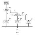
In an embodiment of the present disclosure, as shown in FIG. 6 , when the hybrid electrical vehicle works in the economic manner and the speed of the hybrid electrical vehicle is less than or equal to a second speed threshold such as 15 km/h, the control module controls the hybrid electrical vehicle to switch to the electrical-economical mode. Further, when the hybrid electrical vehicle works in the economical manner and the speed of the hybrid electrical vehicle is larger than or equal to a third speed threshold such as 30 km/h, the control module controls the engine to output a torque with a predetermined torque upper limit curve and controls the electric motor to complement the torque if a torque requirement of the hybrid electrical vehicle exceeds the predetermined torque upper limit curve of the engine (i.e., a torque required to keep the hybrid electrical vehicle driving normally in a current state); the control module controls the engine to output a torque with a predetermined torque lower limit curve and controls the electric motor to generate power if the torque requirement of the hybrid electrical vehicle is below the predetermined torque lower limit curve of the engine; and the control module controls the engine to output a torque satisfying the torque requirement of the hybrid electrical vehicle and controls the electric motor to generate power if the torque requirement of the hybrid electrical vehicle exceeds the predetermined torque lower limit curve of the engine and is below the predetermined torque upper limit curve of the engine. In this embodiment of the present disclosure, the predetermined torque upper limit curve and the predetermined torque lower limit curve of the engine are shown in FIG. 7 . When the torque requirement of the hybrid electrical vehicle exceeds the predetermined torque lower limit curve of the engine and is below the predetermined torque upper limit curve of the engine, a relationship between a generation power of the electric motor and the state of charge (SOC) of the power battery is shown in FIG. 8 .
In an embodiment of the present disclosure, as shown in FIG. 9 , when the hybrid electrical vehicle works in the low power manner and is in a non-P gear, the control module controls the engine to output a torque with the predetermined torque upper limit curve and controls the electric motor to complement the torque if the torque requirement of the hybrid electrical vehicle exceeds the predetermined torque upper limit curve of the engine; the control module controls the engine to output a torque with the predetermined torque lower limit curve and controls the electric motor to generate power if the torque requirement of the hybrid electrical vehicle is below the predetermined torque lower limit curve of the engine; and the control module controls the engine to output a torque satisfying the torque requirement of the hybrid electrical vehicle and controls the electric motor to generate power if the torque requirement of the hybrid electrical vehicle exceeds the predetermined torque lower limit curve of the engine and is below the predetermined torque upper limit curve of the engine. Moreover, when the hybrid electrical vehicle works in the low power manner and is in a P gear, the control module controls the hybrid electrical vehicle to enter an idle stop-start mode.
In other words, in the embodiment of the present disclosure as shown in FIG. 5 , when the hybrid electrical vehicle is driving in the HEV-eco mode and the EV mode selecting button is pressed manually, the hybrid electrical vehicle is allowed to switch to the EV-eco mode only if the current electric quantity of the power battery is larger than or equal to the second electric quantity threshold such as 30% or the current speed of the hybrid electrical vehicle is less than or equal to the first speed threshold such as 150 km/h, otherwise the hybrid electrical vehicle cannot be switched to the EV-eco mode. When the hybrid electrical vehicle is driving in the HEV-eco mode and the operating mode knob is rotated to the sport mode, the hybrid electrical vehicle is switched to the HEV-s mode. When the hybrid electrical vehicle is in the HEV-eco mode and there is no manual input to the mode selecting buttons, the hybrid electrical vehicle is kept in the HEV-eco mode, and the engine and the electric motor perform power distribution in terms of the economic strategy and the low power strategy respectively according to region division of the electric quantity of the power battery and the maximum allowable discharge power of the power battery. As shown in FIG. 6 , in the economic manner, if the current speed of the hybrid electrical vehicle is less than or equal to the second speed threshold such as 15 km/h, the hybrid electrical vehicle is in the pure electric mode; if the current speed of the hybrid electrical vehicle is larger than or equal to the third speed threshold such as 30 km/h, the engine takes part in driving the vehicle until the speed of the vehicle is reduced to the second speed threshold, and then the vehicle returns to the pure electric mode. In the pure electric mode, if the electric motor sends an alarm indicating the driving capability is not enough, the engine is started. As shown in FIG. 9 , in the low power manner, the pure electric mode at a low speed is cancelled and an engine stop-start function with engaging the P gear is added. For the economic strategy and the low power strategy, control methods after the engine starts are the same, in which the torque upper limit curve of the engine and the torque lower limit curve of the engine are predetermined, as shown in FIG. 7 . Principle of designing the curves is that a region between the upper limit curve and the lower limit curve includes as many most economical regions of the engine as possible. Since the engine has a poor economy outside the upper limit curve and the lower limit curve, in this region, the electric motor assists the engine to drive the vehicle. During a light load operation, under the premise of satisfying the requirement of the whole vehicle, the engine outputs the torque with the predetermined torque lower limit curve and the redundant torque is used to generate power. During a heavy load operation, the engine outputs the torque with the predetermined torque upper limit and the insufficient torque is complemented by the electric motor. If the electric motor has an insufficient charging-discharging capability due to the limitation of itself or the power battery, the electric motor charges or discharges with a maximum allowable capability of itself and the power battery, and the upper limit and lower limit of the output of the engine are cancelled and the engine outputs the torque with reference to requirements of the hybrid electrical vehicle. In the region between the upper limit curve and the lower limit curve, the electric motor mainly takes part in generating power, in which the generation power of the electric motor has a certain function relation with the current SOC of the power battery, as shown in FIG. 8 . However, a total output torque of the engine does not exceed the predetermined torque upper limit curve, and if the electric motor has an insufficient charging-discharging capability due to the limitation of itself or the power battery, the electric motor charges or discharges with the maximum allowable capability of itself and the power battery. The above HEV-eco mode driving strategy is performed when the slope detected by the vehicle is less than or equal to the maximum slope such as 15%. When the slope detected by the vehicle is larger than the maximum slope such as 15%, in order to satisfy the grade ability of the hybrid electrical vehicle, it is ruled that the engine must start at this time, and the torque upper limit of the engine, the torque lower limit curve of the engine and the output power limit of the electric motor are cancelled, and the original driving strategy is not performed until the slope detected by the vehicle is less than the minimum slope such as 5%.
In still yet another embodiment of the present disclosure, as shown in FIG. 10 , when the hybrid electrical vehicle is in the hybrid electrical-sport mode and the control module receives a mode switching instruction to switch to the electrical-sport mode, the control module controls the hybrid electrical vehicle to switch to the electrical-sport mode if the current electric quantity of the power battery is larger than or equal to the second electric quantity threshold such as 30%, or the current speed of the hybrid electrical vehicle is less than the first speed threshold such as 150 km/h.
Moreover, when the hybrid electrical vehicle works in the hybrid electrical-sport mode and is in the P gear, the control module controls the hybrid electrical vehicle to enter the idle stop-start mode. When the hybrid electrical vehicle works in the hybrid electrical-sport mode and is in a non-P gear, the control module controls the engine to output a predetermined peak torque of the engine and controls the electric motor to complement the torque if the torque requirement of the hybrid electrical vehicle exceeds the predetermined peak torque; and the control module controls the engine to output a torque satisfying the torque requirement of the hybrid electrical vehicle and controls the electric motor to generate power if the torque requirement of the hybrid electrical vehicle is less than or equal to the predetermined peak torque of the engine.
In other words, in the embodiment of the present disclosure as shown in FIG. 10 , for the hybrid electrical vehicle driving in the HEV-s mode, when the EV mode selecting button is pressed manually, only if the current electric quantity of the power battery is larger than or equal to the second electric quantity threshold such as 30%, or the current speed of the electrical vehicle is less than or equal to the first speed threshold such as 150 km/h, can the hybrid electrical vehicle be switched to the EV-s mode, otherwise no mode switching is performed; when the operating mode knob is rotated to the economical mode, the hybrid electrical vehicle is switched to the HEV-eco mode; when there is no manual input to the mode selecting buttons, the hybrid electrical vehicle is kept in the HEV-s mode. The HEV-s mode is similar to the low power manner in the HEV-eco mode, the pure electric mode at a low speed is cancelled and the engine stop-start function with engaging the P gear is added. Furthermore, the output power of the electric motor is not limited, and the torque upper limit and the torque lower limit of the engine are also cancelled, such that the engine and the electric motor can output the peak values, thus obtaining the best power performance in the HEV-s mode.
In embodiments of the present disclosure, when the engine starts to operate, the double-clutch gearbox transmits the power from the engine and performs the gear shift. When the hybrid electrical vehicle is in the HEV-eco mode or in the HEV-s mode, two gear shift strategies are used respectively. The HEV-eco mode focuses on reducing the oil wear, and a principle of the gear shift strategy thereof is to ensure the engine works in efficient regions as far as possible, and thus a shift point of each gear may be a little earlier and the engine mainly works in a rotating speed region of 1500-2000 rpm during driving. The HEV-s mode focuses on the power performance, and a principle of the gear shift strategy thereof is to ensure the torque transmitted to the wheels from the engine is as large as possible so as to obtain better driving performance, and thus the shift point of each gear may be a little later. Furthermore, with respect to the rapid acceleration with a full throttle, the shift point is defined as a maximum torque point of the engine calibrated under each gear, thus extremely improving the acceleration performance.
In an embodiment of the present disclosure, when the hybrid electrical vehicle is in the electrical-economical mode, the maximum output power of the power battery is less than a first predetermined power; when the hybrid electrical vehicle works in the electrical-sport mode, the maximum output power of the power battery is less than a second predetermined power, in which the second predetermined power is greater than the first predetermined power; when the hybrid electrical vehicle works in the hybrid electrical-economical mode, each of the maximum output power of the power battery and the maximum output power of the engine is less than the first predetermined power, and a maximum output torque of the engine is less than a first torque threshold; when the hybrid electrical vehicle works in the hybrid electrical-sport mode, the maximum output power of the power battery is less than the second predetermined power, and the control module allows the engine to output the maximum output torque and the maximum output power. In an embodiment of the present disclosure, the first predetermined power is 70 KW, the second predetermined power is 110 KW and the first torque threshold is 185 N·M.
In other words, in the electrical-economical mode, the hybrid electrical vehicle consumes the electric power purely, the maximum output power of the power battery is less than a maximum output power (such as 70 KW) in the economical mode and the power battery works in the most economical regions; in the electrical-sport mode, the hybrid electrical vehicle consumes the electric power purely, the maximum output power of the power battery is less than the maximum output power (such as 110 KW) in the sport mode; in the hybrid electrical-economical mode, the hybrid electrical vehicle consumes both the electric power and the thermal power, the maximum output power of the engine is less than the maximum output power (such as 70 KW) in the economical mode, and the maximum output torque of the engine is less than a maximum output torque (such as 185 N·M) in the economical mode, such that the engine and the electric motor work in the most economical regions; in the hybrid electrical-sport mode, the hybrid electrical vehicle consumes both the electric power and the thermal power, the maximum output power of the power battery is less than the maximum output power such as 110 KW in the sport mode, and the control module allows the engine to output the maximum output torque and the maximum output power.
It should be noted that, in embodiments of the present disclosure, the most economical region in the pure electric mode refers to the region in which the power battery works with a relatively lower discharging power preferentially on the premise of satisfying the power performance (operating performance and acceleration performance) of the vehicle, this is because the working efficiency of the power battery reduces with the increment of the discharging power of the power battery. The most economical region in the hybrid mode refers to the region in which the power battery works with a relatively lower discharging power preferentially on the premise of satisfying the power performance (operating performance and acceleration performance) of the vehicle, this is because the working efficiency of the power battery reduces with the increment of the discharging power of the power battery. The most economical region of the engine is determined by the torque and rotating speed of engine. As shown in FIG. 7 , a horizontal ordinate represents the rotating speed of the engine and a longitudinal coordinate represents the torque of the engine, and the most economical region of the engine can be obtained by matching an appropriate rotating speed with a certain torque. In other words, if the torque of the engine is too large, the torque of the engine can be reduced and the rest torque is complemented by the electric motor; if the torque of the engine is too small, the torque of the engine can be increased, but it does not need the increased torque to drive the vehicle, and thus energy generated by the increased torque is recovered to be used for power generation of the electric motor.
Further, the maximum output power in the economical mode can be understood as a maximum output power for keeping the power battery or the engine working in the most economical regions. The maximum output power in the sport mode is a unique property, in which the engine outputs the maximum torque or the maximum power, and the power battery outputs the maximum power, and thus the power system provides the maximum output torque or the maximum output power for the vehicle.
In addition, it can be understood that the working mode when the hybrid electrical vehicle starts is still the working mode when the hybrid electrical vehicle is stalled at last time. Moreover, the hybrid electrical vehicle also has a pure fuel mode which is a fault mode.
With the hybrid electrical vehicle according to embodiments of the present disclosure, the engine and the electric motor are connected in a parallel, which can effectively improve an energy utilization factor as compared with a series connection structure adopted in a power system of the conventional hybrid electrical vehicle. Moreover, the parallel connection is simple in structure and can avoid a complex ECVT match in a series-parallel connection, which reduces a risk of riding uncomfortably caused by the match failure, and thus the economy of the hybrid electrical vehicle is greatly improved on the premise of ensuring the power performance of the hybrid electrical vehicle. In addition, the switching between a plurality of working modes provides the driver with a high operability, thus improving driving fun.
In the following, a method for controlling the hybrid electrical vehicle is described in detail with reference to FIGS. 3-11 , in which the hybrid electrical vehicle is the hybrid electrical vehicle described in above embodiments of the present disclosure.
At step S1, a working mode selected by a user of the hybrid electrical vehicle from a plurality of working modes is received. The plurality of working modes include an electrical-economical mode, an electrical-sport mode, a hybrid electrical-economical mode and a hybrid electrical-sport mode
At step S2, the hybrid electrical vehicle is controlled to work in the working mode selected by the user.
At step S3, a driving state of the hybrid electrical vehicle and/or a working state of a power battery are detected.
At step S4, the hybrid electrical vehicle is controlled to switch between the plurality of working modes according to driving state of the hybrid electrical vehicle and/or the working state of the power battery.
In an embodiment of the present disclosure, as shown in FIG. 3 , a method for controlling the hybrid electrical vehicle in an electrical-economical includes following steps.
At step S101, manual switching information is obtained, in which the manual switching information may be about whether a HEV mode selecting button switching operation is performed, whether a Sport mode selecting button switching operation is performed or whether no mode selecting button switching operation is performed. In other words, it is determined whether a manual switch is performed, if yes, execute step S102; and if no, execute step S103.
At step S102, a working mode switching is performed and a corresponding control strategy of a power system is performed. In other words, when the hybrid electrical vehicle is in the electrical-economical mode and a mode switching instruction is received from a user, the control module controls the hybrid electrical vehicle to switch to a working mode corresponding to the mode switching instruction from the user.
At step S103, the working mode is not switched, and then a current electric quantity (state of charge, SOC) of the power battery, a maximum allowable discharge power Pb of the power battery and a slope i detected by the hybrid electrical vehicle are compared with predetermined thresholds (i.e., the lower threshold of the electric quantity SOCdown (such as 20%), the lower threshold of the maximum allowable discharge power Pbdown (such as 12 KW), and the upper threshold of the slope iup (such as 15%)) respectively to determine whether SOC SOCdown, whether PbPbdown and whether iup i.
At step S104, if at least one of the above three conditions is satisfied, the hybrid electrical vehicle is witched to the HEV-eco mode automatically. In other words, if the current electric quantity of the power battery is less than or equal to the first electric quantity threshold such as 20%, or the maximum allowable discharge power of the power battery is less than or equal to the first power threshold such as 12 KW, or the slope detected by the hybrid electrical vehicle is greater than or equal to a maximum slope such as 15%, the control module controls the hybrid electrical vehicle to switch to the hybrid electrical-economical mode.
At step S105, if each of the above three conditions is not satisfied, the hybrid electrical vehicle is not switched to the HEV-eco mode and is kept driving in the EV-eco mode.
When the hybrid electrical vehicle is driven in the EV-eco mode and no manual or automatic mode switching is performed, the electric motor drives the hybrid electrical vehicle continuously as a single power source. The EV-eco mode focuses on saving electric power on the premise of satisfying a power performance requirement of the hybrid electrical vehicle, and also focuses on improving the electricity efficiency by avoiding the long term and high power consumption, and thus the maximum output power of the electric motor is limited to a certain value such as 70 KW. Furthermore, in order to satisfy the grade ability of the hybrid electrical vehicle, the maximum output torque of the electric motor is not limited, i.e., when the hybrid electrical vehicle is in the EV-eco mode, the control module controls the hybrid electrical vehicle to drive with a limited power.
With the method for controlling the hybrid electrical vehicle in the EV-eco mode, by determining the current electric quantity of the power battery, the maximum allowable discharge power of the power battery and the slope detected by the hybrid electrical vehicle to control the vehicle to switch to the HEV-eco mode automatically, normal driving of the hybrid electrical vehicle can be ensured and risks of reducing the power performance can be avoided. In conclusion, with the method for controlling the hybrid electrical vehicle in the EV-eco mode, on the premise of satisfying the power performance of the whole vehicle, the power battery keeps working in high efficient regions, thus realizing a long driving mileage, a low operation cost and a low emission.
In another embodiment of the present disclosure, as shown in FIG. 4 , a method for controlling the hybrid electrical vehicle in the electrical-sport mode includes following steps.
At step S201, manual switching information is obtained, in which the manual switching information may be about whether a HEV mode selecting button switching operation is performed, whether an economical mode selecting button switching operation is performed or whether no mode selecting button switching operation is performed. In other words, it is determined whether a manual switch is performed, if yes, execute step S202; and if no, execute step S103.
At step S202, a working mode switching is performed and a corresponding control strategy of the power system is performed. In other words, when the hybrid electrical vehicle is in the electrical-sport mode and a mode switching instruction is received from the user, the control module controls the hybrid electrical vehicle to switch to a working mode corresponding to the mode switching instruction from the user.
At step S203, the working mode is not switched, and then the current electric quantity (state of charge, SOC) of the power battery, the maximum allowable discharge power Pb of the power battery and a slope i detected by the hybrid electrical vehicle are compared with predetermined thresholds (i.e., the lower threshold of the electric quantity SOCdown (such as 20%), the lower threshold of the maximum allowable discharge power Pbdown (such as 12 KW), and the upper threshold of the slope iup (such as 15%)) respectively to determine whether SOCSOCdown, whether PbPbdown and whether iup i.
At step S204, if at least one of the above three conditions is satisfied, the hybrid electrical vehicle is witched to the HEV-s mode automatically. In other words, if the current electric quantity of the power battery is less than or equal to the first electric quantity threshold such as 20%, or the maximum allowable discharge power of the power battery is less than or equal to the first power threshold such as 12 KW, or the slope detected by the hybrid electrical vehicle is greater than or equal to the maximum slope such as 15%, the control module controls the hybrid electrical vehicle to switch to the hybrid electrical-economical mode.
At step S205, if each of the above three conditions is not satisfied, the hybrid electrical vehicle is not switched to the HEV-s mode and is kept driving in the EV-s mode.
When the hybrid electrical vehicle is driven in the EV-s mode and no manual or automatic mode switching is performed, the electric motor drives the hybrid electrical vehicle continuously as the single power source. In the EV-s mode, the maximum output torque and the maximum output power of the electric motor are not limited, and thus the electric motor drives the vehicle with the maximum capacity, and a higher power performance requirement (such as overtaking acceleration and fast climbing) can be achieved in the EV mode.
With the method for controlling the hybrid electrical vehicle in the EV-s mode, by determining the current electric quantity of the power battery, the maximum allowable discharge power of the power battery and the slope detected by the hybrid electrical vehicle to control the vehicle to switch to the HEV-s mode automatically, normal driving of the hybrid electrical vehicle can be ensured and risks of reducing the power performance can be avoided. In conclusion, with the method for controlling the hybrid electrical vehicle in the EV-s mode, the vehicle can be driven in the pure electric mode and a better power performance can be achieved, and the working mode is flexible and changeable, thus providing the user with more driving fun.
In yet another embodiment of the present disclosure, as shown in FIG. 5 , a method for controlling the hybrid electrical vehicle in the hybrid electrical-economical mode includes following steps.
At step S301, switching information about the EV mode selecting button is obtained, and it is determined whether a manual switching to the EV mode is performed, if yes, execute step S302 or step S303; and if no, execute step S306.
At step S302, the current electric quantity (state of charge, SOC) of the power battery is compared with the predetermined upper electric quantity threshold SOCup such as 30% to determine whether SOCup SOC, if yes, execute step S304; and if no, execute step S305.
At step S303, the current speed of the hybrid electrical vehicle is compared with the maximum speed threshold Vmax (i.e., a highest speed which allows the hybrid electric vehicle to switch to the EV mode from the HEV mode, such as 150 km/h) to determine whether vVmax, if yes, execute step 304; and if no, execute step S305.
At step S304, the hybrid electrical vehicle is controlled to switch to the EV-eco mode and a corresponding control strategy of the power system is performed.
In other words, when the hybrid electrical vehicle is in the hybrid electrical-economical mode and the control module receives the mode switching instruction to switch to the electrical-economical mode, the control module controls the hybrid electrical vehicle to switch to the electrical-economical mode if the current electric quantity of the power battery is larger than or equal to the second electric quantity threshold such as 30%, or the current speed of the hybrid electrical vehicle is less than or equal to the first speed threshold such as 150 km/h.
At step S305, the hybrid electrical vehicle keeps driving in the HEV-eco mode.
At step S306, switching information about the Sport mode selecting button is obtained, and it is determined whether a manual switching to the sport mode is performed, if yes, execute step S307; and if no, execute step S308.
At step S307, the hybrid electrical vehicle is controlled to switch to the HEV-s mode and a corresponding control strategy of the power system is performed.
At step S308, the working mode is not switched, and then slope information is obtained, i.e., the slope i is detected.
At step S309, it is determined whether iidown, if yes, execute step S310, and if no, execute step S317.
At step S310, the current electric quantity (state of charge, SOC) of the power battery and the maximum allowable discharge power Pb of the power battery are detected, and are compared with the thresholds (i.e., the upper electric quantity threshold SOCup (such as 30%), the lower electric quantity threshold SOCdown (such as 20%), the upper threshold of the maximum allowable discharge power Pbup (such as 30 KW), the lower threshold of the maximum allowable discharge power Pbdown (such as 12 KW)) respectively.
At step S311, it is determined whether SOCup SOC and whether Pbup Pb, if yes, execute step S312.
At step S312, the hybrid electrical vehicle is controlled in the economical manner.
In other words, when the hybrid electrical vehicle is in the hybrid electrical-economical mode, the control module controls the hybrid electrical vehicle to work in the economical manner if the slope detected by the hybrid electrical vehicle is less than or equal to the minimum slope such as 5%, and the current electric quantity of the power battery is larger than or equal to the second electric quantity threshold such as 30% and the maximum allowable discharge power of the power battery is larger than or equal to the second power threshold such as 30 KW.
At step S313, it is determined whether SOCup>SOC>SOCdown and Pbup Pb, or whether SOCup SOC and Pbup>Pb>Pbdown, if yes, execute step S314.
At step S314, the hybrid electrical vehicle is controlled in the original manner, i.e., if the original manner is the economical manner, the hybrid electrical vehicle still works in the economical manner; if the original manner is the low power manner, the hybrid electrical vehicle still works in the low power manner.
At step S315, it is determined whether SOCSOCdown or whether PbPbdown, if yes, execute step S316.
At step S316, the hybrid electrical vehicle is controlled in the low power manner.
In other words, when the hybrid electrical vehicle is in the hybrid electrical-economical mode, the control module controls the hybrid electrical vehicle to work in the economical manner if the slope detected by the hybrid electrical vehicle is less than or equal to the minimum slope such as 5% and the current electric quantity of the power battery is less than or equal to the first electric quantity threshold such as 20%, or if the current slope detected by the hybrid electrical vehicle is less than or equal to the minimum slope such as 5% and the maximum allowable discharge power of the power battery is less than or equal to the first power threshold such as 12 KW, in which the second electric quantity threshold is larger than the first electric quantity threshold, and the second power threshold is larger than the first power threshold.
At step S317, it is determined whether iup>i>idown, and if yes, execute step S318.
At step S318, the hybrid electrical vehicle is controlled in the original manner.
At step S319, it is determined whether iup i, and if yes, execute step S320.
At step 320, the hybrid electrical vehicle is controlled to work in the economical manner, moreover, the pure electric mode at a low speed, the upper limit of the engine, and the upper limit of the electric motor are cancelled.
It should be noted that, in embodiments of the present disclosure, in the low power manner, the engine drives the electric motor to generate power quickly so as to get rid of a low power state, such that the electric motor again has the ability of adjusting the working region of the engine, thus ensuring the economy of the hybrid electrical vehicle.
In the embodiment of the present disclosure as shown in FIG. 6 , a method for controlling the hybrid electrical vehicle in the economical manner includes following steps.
At step S401, the current speed of the hybrid electrical vehicle is obtained and the current speed v of the hybrid electrical vehicle is compared with the second speed threshold such as 15 km/h and the third speed threshold such as 30 km/h.
At step S402, it is determined whether vup v, and if yes, execute step S403.
At step S403, it is determined whether the torque requirement of the hybrid electrical vehicle exceeds the predetermined torque upper limit curve of the engine as shown in FIG. 7 , and if yes, execute step S404.
At step S404, it is determined whether a fault occurs in the power system of the hybrid electrical vehicle, if yes, execute step S406; and if no, execute step S405.
At step S405, the engine is controlled to output a torque with the predetermined torque upper limit curve and the electric motor is controlled to complement the torque. In other words, when the hybrid electrical vehicle works in the economical manner and the current speed of the hybrid electrical vehicle is larger than or equal to the third speed threshold such as 30 km/h, the control module controls the engine to output a torque with the predetermined torque upper limit curve and controls the electric motor to complement the torque if a torque requirement of the hybrid electrical vehicle exceeds the predetermined torque upper limit curve of the engine.
At step S406, the fault is processed.
At step S407, it is determined whether the torque requirement of the hybrid electrical vehicle is below the predetermined torque lower limit curve of the engine as shown in FIG. 7 , and if yes, execute step S408.
At step S408, it is determined whether a fault occurs in the power system of the hybrid electrical vehicle, if yes, execute step S410; and if no, execute step S409.
At step S409, the engine is controlled to output a torque with the predetermined torque lower limit curve and the electric motor is controlled to generate power. In other words, when the hybrid electrical vehicle works in the economical manner and the current speed of the hybrid electrical vehicle is larger than or equal to the third speed threshold such as 30 km/h, the control module controls the engine to output a torque with the predetermined torque lower limit curve and controls the electric motor to generate power if the torque requirement of the hybrid electrical vehicle is below the predetermined torque lower limit curve of the engine.
At step S410, the fault is processed.
At step S411, it is determined whether the torque requirement of the hybrid electrical vehicle exceeds the predetermined torque lower limit curve of the engine and is below the predetermined torque upper limit curve of the engine as shown in FIG. 7 , and if yes, execute step S412.
At step S412, it is determined whether a fault occurs in the power system of the hybrid electrical vehicle, if yes, execute step S414; and if no, execute step S413.
At step S413, the engine is controlled to satisfy the torque requirement of the hybrid electrical vehicle preferentially, and also controlled to output another more torque for generating power. In other words, when the hybrid electrical vehicle works in the economical manner and the current speed of the hybrid electrical vehicle is larger than or equal to the third speed threshold such as 30 km/h, the control module controls the engine to output the torque satisfying the torque requirement of the hybrid electrical vehicle and controls the electric motor to generate power if the torque requirement of the hybrid electrical vehicle exceeds the predetermined torque lower limit curve of the engine and is below the predetermined torque upper limit curve of the engine. A principle of generating power follows the functional relationship between the generation power and SOC of the power battery as shown in FIG. 8 , and following two conditions should be satisfied simultaneously: (1) a generating torque converted to the electric motor is not larger than Tmmax; (2) a total output torque of the engine does not exceed the predetermined torque upper limit curve as shown in FIG. 7 . If the torque of the engine calculated from a generation power curve does not satisfy any of the above two conditions, the above two conditions are used as upper limits to constraint the torque of the engine configured to generate power.
At step S414, the fault is processed.
At step S415, it is determined whether vup>v>vdown, and if yes, execute step S416.
At step S416, it is determined whether a fault occurs in the power system of the hybrid electrical vehicle, if yes, execute step S418; and if no, execute step S417.
At step S417, the hybrid electrical vehicle is controlled to work in the original manner, i.e., the hybrid electrical vehicle is still driven by the electric motor only, or the electric motor still assists the engine to drive the hybrid electrical vehicle.
At step S418, the fault is processed.
At step S419, it is determined whether vvdown, and if yes, execute step S420.
At step S420, it is determined whether a fault occurs in the power system, if yes, execute step S422; and if no, execute step S421.
At step S421, the hybrid electrical vehicle is driven by the electric motor only and the engine is stalled. In other words, when the hybrid electrical vehicle works in the economical manner and the speed of the hybrid electrical vehicle is less than or equal to the second speed threshold such as 15 km/h, the control module controls the hybrid electrical vehicle to switch to the pure electric mode.
At step S422, the fault is processed.
In the embodiment of the present disclosure as shown in FIG. 9 , a method for controlling the hybrid electrical vehicle in the low power manner includes following steps.
At step S501, gear information is obtained.
At step S502, it is determined whether the hybrid electrical vehicle is in a non-P gear, and if yes, execute step S503 or step S507 or step S511.
At step 503, it is determined whether the torque requirement of the hybrid electrical vehicle exceeds the predetermined torque upper limit curve of the engine as shown in FIG. 7 , and if yes, execute step S504.
At step S504, it is determined whether a fault occurs in the power system of the hybrid electrical vehicle, if yes, execute step S506; and if no, execute step S505.
At step S505, the engine is controlled to output a torque with the predetermined torque upper limit curve and the electric motor is controlled to complement the torque. In other words, when the hybrid electrical vehicle works in the low power manner and is in a non-P gear, the control module controls the engine to output a torque with the predetermined torque upper limit curve and controls the electric motor to complement the torque if a torque requirement of the hybrid electrical vehicle exceeds the predetermined torque upper limit curve of the engine.
At step S506, the fault is processed.
At step S507, it is determined whether the torque requirement of the hybrid electrical vehicle is below the predetermined torque lower limit curve of the engine as shown in FIG. 7 , and if yes, execute step S508.
At step S508, it is determined whether a fault occurs in the power system of the hybrid electrical vehicle, if yes, execute step S510; and if no, execute step S509.
At step S509, the engine is controlled to output a torque with the predetermined torque lower limit curve and the electric motor is controlled to generate power. In other words, when the hybrid electrical vehicle works in the low power manner and is in the non-P gear, the control module controls the engine to output a torque with the predetermined torque lower limit curve and controls the electric motor to generate power if the torque requirement of the hybrid electrical vehicle is below the predetermined torque lower limit curve of the engine.
At step S510, the fault is processed.
At step S511, it is determined whether the torque requirement of the hybrid electrical vehicle exceeds the predetermined torque lower limit curve of the engine and is below the predetermined torque upper limit curve of the engine, and if yes, execute step S512.
At step S512, it is determined whether a fault occurs in the power system, if yes, execute step S514; and if no, execute step S513.
At step S513, the engine is controlled to satisfy the torque requirement of the hybrid electrical vehicle preferentially, and also controlled to output another more torque for generating power. In other words, when the hybrid electrical vehicle works in the low power manner and is in the non-P gear, the control module controls the engine to output the torque satisfying the torque requirement of the hybrid electrical vehicle and controls the electric motor to generate power if the torque requirement of the hybrid electrical vehicle exceeds the predetermined torque lower limit curve of the engine and is below the predetermined torque upper limit curve of the engine. The principle of generating power follows the functional relationship between the generation power and SOC of the power battery as shown in FIG. 8 , and following two conditions should be satisfied simultaneously: (1) the generating torque converted to the electric motor is not larger than Tmmax; (2) the total output torque of the engine does not exceed the predetermined torque upper limit curve as shown in FIG. 7 . If the torque of the engine calculated from the generation power curve does not satisfy any of the above two conditions, the above two conditions are used as upper limits to constraint the torque of the engine configured to generate power.
At step S514, the fault is processed.
At step S515, it is determined whether the hybrid electrical vehicle is in the P gear, and if yes, execute step S516.
At step S516, an idle stop-start strategy is performed. In other words, when the hybrid electrical vehicle works in the low power manner and is in the P gear, the control module controls the hybrid electrical vehicle to enter an idle stop-start mode, and the engine is stalled.
When the hybrid electrical vehicle is driven in the HEV-eco mode, the electric motor cooperates with the engine to improve the energy utilization factor, and general procedures are shown as follows. When the hybrid electrical vehicle works in the non-economical regions of the engine, the electric motor is used more often than the engine; when the hybrid electrical vehicle works in the economical regions of the engine, the engine can generate some power to charge the power battery, and the less the electric quantity of the power battery is, the higher the generation power of the engine is. Moreover, in this mode, the maximum output power of the electric motor is limited so as to avoid a long term high power consumption, such that the electric quantity of the power battery is kept in a relatively high level and the electric motor always has electric energy to adjust the engine to work in high efficiency regions, thus reducing the oil wear during the hybrid electrical driving as much as possible and ensuring the economy and emission behavior of the hybrid electrical vehicle. When the hybrid electrical vehicle requires heavy load output, the electric motor can assist the engine to drive the vehicle together, and thus the power performance is greatly improved as compared with that in the EV mode. When the user needs a long distance driving and wants to reduce the oil wear as much as possible, he can choose the above mode.
In an embodiment of the present disclosure as shown in FIG. 10 , a method for controlling the hybrid electrical vehicle in the hybrid electrical-sport mode includes following steps.
At step S601, switching information about the EV mode selecting button is obtained and it is determined whether a manual switch to the EV mode is performed, if yes, execute step S602 or step S603; and if no, execute step S606.
At step S602, the current electric quantity SOC of the power battery is compared with the second electric quantity threshold such as 30% and it is determined whether SOCup SOC, if yes, execute step S604; and if no, execute step S605.
At step S603, the current speed of the hybrid electrical vehicle is compared with the first speed threshold Vmax (i.e., the highest speed that allows the hybrid electric vehicle to switch to the EV mode from the HEV mode, such as 150 km/h), and it is determined whether vVmax, if yes, execute step 604; and if no, execute step S605.
At step S604, the hybrid electrical vehicle is controlled to switch to the EV-s mode and a corresponding control strategy of the power system is performed.
In other words, when the hybrid electrical vehicle is in the hybrid electrical-sport mode and the mode switching instruction to switch to the electrical-sport mode is received, the control module controls the hybrid electrical vehicle to switch to the electrical-sport mode if the current electric quantity of the power battery is larger than or equal to the second electric quantity threshold such as 30%, or the current speed of the hybrid electrical vehicle is less than or equal to the first speed threshold such as 150 km/h.
At step S605, the hybrid electrical vehicle keeps driving in the HEV-s mode.
At step S606, switching information about the economical mode selecting button is obtained, and it is determined whether a manual switch to the economical mode is performed, if yes, execute step S607; and if no, execute step S608.
At step S607, the hybrid electrical vehicle is controlled to switch to the HEV-eco mode and a corresponding control strategy of the power system is performed.
At step S608, the working mode is not switched, and the gear information is obtained to determine the current gear of the hybrid electrical vehicle.
At step S609, it is determined whether the hybrid electrical vehicle is in the P gear, and if yes, execute step S610.
At step S610, the idle stop-start strategy is performed. In other words, when the hybrid electrical vehicle works in the hybrid electrical-sport mode and is in the P gear, the control module controls the hybrid electrical vehicle to enter the idle stop-start mode.
At step S611, it is determined whether the hybrid electrical vehicle is in the non-P gear, and if yes, execute step S312.
At step S612, the torque requirement of the hybrid electrical vehicle is compared with a predetermined peak torque of the engine and it is determined whether the torque requirement of the hybrid electrical vehicle exceeds the predetermined peak torque, if yes, execute step S613; and if no, execute step S614.
At step S613, the engine is controlled to output the predetermined peak torque and the electric motor is controlled to complement the torque. When the electric motor is limited by the current capability of itself or of the power battery, it drives with the maximum capabilities of itself and the power battery. In other words, when the hybrid electrical vehicle is in the hybrid electrical-sport mode and is in the non-P gear, the control module controls the engine to output the predetermined peak torque of the engine and controls the electric motor to complement the torque if the torque requirement of the hybrid electrical vehicle exceeds the predetermined peak torque of the engine.
At step S614, the engine is controlled to satisfy the torque requirement of the hybrid electrical vehicle preferentially, and also controlled to output another more torque for generating power. In other words, when the hybrid electrical vehicle is in the hybrid electrical-sport mode and is in the non-P gear, the control module controls the engine to output a torque satisfying the torque requirement of the hybrid electrical vehicle and controls the electric motor to generate power if the torque requirement of the hybrid electrical vehicle is less than or equal to the predetermined peak torque of the engine. The principle of generating power follows the relationship between the generation power and SOC of the power battery as shown in FIG. 8 , and following two conditions should be satisfied simultaneously: (1) the generating torque converted to the electric motor is not larger than Tmax; (2) the total output torque of the engine does not exceed the predetermined torque upper limit curve as shown in FIG. 7 . If the torque of the engine calculated from the generation power curve does not satisfy any of the above two conditions, the above two conditions are used as upper limits to constraint the torque of the engine configured to generate power.
When the hybrid electrical vehicle is driven in the HEV-s mode and is in the non-P gear, the engine is kept in a starting state. Only if the hybrid electrical vehicle is in the P gear and the idle stop-start conditions are satisfied, can the engine be stalled. In the HEV-s mode, the maximum output torque and the maximum output power of the engine and the electric motor are not limited any more, and thus a maximum driving capability of the power system can be achieved. Thus, the HEV-s mode realizes the best power performance among the four working modes. However, since the engine keeps working during the driving process of the hybrid electrical vehicle (either cooperating with the electric motor to drive the vehicle or driving the vehicle and driving the electric motor to generate power synchronously (when the electric quantity of the power battery is less than a certain threshold)), the oil wear is relatively high and the economy of the hybrid electrical vehicle cannot be ensured. The HEV-s mode is suitable for users who have a high requirement of the power performance, and has enough power equal to that of the fuel vehicle with a high emission.
In embodiments of the present disclosure, by providing the EV, HEV, economical and Sport mode selecting buttons, four different working modes (i.e., the EV-eco mode, the EV-s mode, the HEV-eco mode and the HEV-s mode) can be obtained, each of which has different power performance requirement and economy requirement and thus has different driving strategies. Moreover, the power system of the hybrid electrical vehicle adopts the parallel connection mode instead of the series connection mode or the series-parallel connection mode. In addition, in the driving strategies, a starting point of the engine is optimized, a speed threshold is increased, the slope detection is added and a determination about the demanded power is cancelled. In the economical manner of the HEV-eco mode, the engine is limited to work in the region between the predetermined torque upper limit curve and the predetermined torque lower limit curve, and the generation power is represented by a dynamic curve taking the SOC value of the power battery as its independent variable.
With the method according to embodiments of the present disclosure, by providing a plurality of working modes, a driving requirement of the user in different working conditions can be satisfied, i.e., not only pure electric consumption in a city working condition can be satisfied, but also power performance requirement in a suburban district working condition can be satisfied, and thus the hybrid electrical vehicle can be driven according to subjective operation intentions of the user and the driving fun is improved. The power system of the hybrid electrical vehicle adopts the parallel connection mode which can effectively improve the energy utilization factor as compared with the series connection mode. Moreover, the parallel connection is simple in structure and can avoid a complex ECVT match in the series-parallel connection, which reduces a risk of driving uncomfortably caused by the match failure. Furthermore, in the driving strategy, the starting point of the engine is optimized to avoid premature and frequent start of the engine, such that noise when the engine starts can be reduced effectively, a working life of a starting system can be improved and a risk of pulling down a low voltage frequently caused by frequent start can also be reduced, and thus other low voltage electrical equipments can be ensured to operate normally. The working region of the engine is also optimized so as to ensure that the engine keeps working in the high efficiency region, and the generation power is also optimized so as to ensure that there are high power equilibrium points during the driving of the vehicle, thus facilitating the hybrid electrical vehicle mostly being in the economical strategy and reducing the oil wear efficiently. Moreover, the method for controlling the hybrid electrical vehicle is simple and reliable and is easy to operate by users.
Any procedure or method described in the flow charts or described in any other way herein may be understood to comprise one or more modules, portions or parts for storing executable codes that realize particular logic functions or procedures. Moreover, advantageous embodiments of the present disclosure comprises other implementations in which the order of execution is different from that which is depicted or discussed, including executing functions in a substantially simultaneous manner or in an opposite order according to the related functions. This should be understood by those skilled in the art which embodiments of the present disclosure belong to.
The logic and/or step described in other manners herein or shown in the flow chart, for example, a particular sequence table of executable instructions for realizing the logical function, may be specifically achieved in any computer readable medium to be used by the instruction execution system, device or equipment (such as the system based on computers, the system comprising processors or other systems capable of obtaining the instruction from the instruction execution system, device and equipment and executing the instruction), or to be used in combination with the instruction execution system, device and equipment.
It is understood that each part of the present disclosure may be realized by the hardware, software, firmware or their combination. In the above embodiments, a plurality of steps or methods may be realized by the software or firmware stored in the memory and executed by the appropriate instruction execution system. For example, if it is realized by the hardware, likewise in another embodiment, the steps or methods may be realized by one or a combination of the following techniques known in the art: a discrete logic circuit having a logic gate circuit for realizing a logic function of a data signal, an application-specific integrated circuit having an appropriate combination logic gate circuit, a programmable gate array (PGA), a field programmable gate array (FPGA), etc.
Those skilled in the art shall understand that all or parts of the steps in the above exemplifying method of the present disclosure may be achieved by commanding the related hardware with programs. The programs may be stored in a computer readable storage medium, and the programs comprise one or a combination of the steps in the method embodiments of the present disclosure when run on a computer.
In addition, each function cell of the embodiments of the present disclosure may be integrated in a processing module, or these cells may be separate physical existence, or two or more cells are integrated in a processing module. The integrated module may be realized in a form of hardware or in a form of software function modules. When the integrated module is realized in a form of software function module and is sold or used as a standalone product, the integrated module may be stored in a computer readable storage medium.
The storage medium mentioned above may be read-only memories, magnetic disks or CD, etc.
Reference throughout this specification to “an embodiment,” “some embodiments,” “one embodiment”, “another example,” “an example,” “a specific example,” or “some examples,” means that a particular feature, structure, material, or characteristic described in connection with the embodiment or example is included in at least one embodiment or example of the present disclosure. Thus, the appearances of the phrases such as “in some embodiments,” “in one embodiment”, “in an embodiment”, “in another example,” “in an example,” “in a specific example,” or “in some examples,” in various places throughout this specification are not necessarily referring to the same embodiment or example of the present disclosure. Furthermore, the particular features, structures, materials, or characteristics may be combined in any suitable manner in one or more embodiments or examples.
Although explanatory embodiments have been shown and described, it would be appreciated by those skilled in the art that the above embodiments cannot be construed to limit the present disclosure, and changes, alternatives, and modifications can be made in the embodiments without departing from spirit, principles and scope of the present disclosure.
Claims (21)
1. A hybrid electrical vehicle, comprising:
a transmission device connected with wheels of the hybrid electrical vehicle;
an engine and a gearbox, wherein the engine is connected with the transmission device via the gearbox;
an electric motor and a gear reducer, wherein the electric motor is connected with the transmission device via the gear reducer;
a power battery configured to supply power to the electric motor; and
a control module configured to control the electric motor and the engine according to a working mode selected by a user from a plurality of working modes and to control the hybrid electrical vehicle to switch between the plurality of working modes according to a driving state of the hybrid electrical vehicle and/or a working state of the power battery, wherein the plurality of working modes comprise at least two of an electrical-economical mode, an electrical-sport mode, a hybrid electrical-economical mode and a hybrid electrical-sport mode,
wherein when the hybrid electrical vehicle is in at least one of the electrical-economical mode and the electrical-sport mode, when the hybrid electrical vehicle is in the electrical-economical mode, a maximum output power of the power battery is less than a first predetermined power, or when the hybrid electrical vehicle is in the electrical-sport mode, the maximum output power of the power battery is less than a second predetermined power, wherein the second predetermined power is greater than the first predetermined power; and
wherein when the hybrid electrical vehicle is in at least one of the hybrid electrical-economical mode and the hybrid electrical-sport mode, when the hybrid electrical vehicle is in the hybrid electrical-economical mode, each of the maximum output power of the power battery and a maximum output power of the engine is less than the first predetermined power, and a maximum output torque of the engine is less than a first torque threshold, or when the hybrid electrical vehicle is in the hybrid electrical-sport mode, the maximum output power of the power battery is less than the second predetermined power, and the control module allows the engine to output the maximum output torque and the maximum output power.
2. The hybrid electrical vehicle according to claim 1 , wherein
when the hybrid electrical vehicle is in the electrical-economical mode, a maximum output power of the power battery is less than a first predetermined power;
when the hybrid electrical vehicle is in the electrical-sport mode, the maximum output power of the power battery is less than a second predetermined power, wherein the second predetermined power is greater than the first predetermined power;
when the hybrid electrical vehicle is in the hybrid electrical-economical mode, each of the maximum output power of the power battery and a maximum output power of the engine is less than the first predetermined power, and a maximum output torque of the engine is less than a first torque threshold; and
when the hybrid electrical vehicle is in the hybrid electrical-sport mode, the maximum output power of the power battery is less than the second predetermined power, and the control module allows the engine to output the maximum output torque and the maximum output power.
3. The hybrid electrical vehicle according to claim 1 , wherein the control module is configured to control the hybrid electrical vehicle to switch to the hybrid electrical-economical mode from the electrical-economical mode if a current electric quantity of the power battery is less than or equal to a first electric quantity threshold, or a maximum allowable discharge power of the power battery is less than or equal to a first power threshold, or a slope detected by the hybrid electrical vehicle is greater than or equal to a maximum slope.
4. The hybrid electrical vehicle according to claim 1 , wherein the control module is configured to control the hybrid electrical vehicle to switch to the hybrid electrical-sport mode from the electrical-sport mode if a current electric quantity of the power battery is less than or equal to a first electric quantity threshold, or a maximum allowable discharge power of the power battery is less than or equal to a first power threshold, or a slope detected by the hybrid electrical vehicle is greater than or equal to a maximum slope.
5. The hybrid electrical vehicle according to claim 1 , wherein the control module is configured to control the hybrid electrical vehicle to drive with a limited power if the hybrid electrical vehicle is in the electrical-economical mode.
6. The hybrid electrical vehicle according to claim 1 , wherein if the hybrid electrical vehicle is in the electrical-economical mode or the electrical-sport mode and a mode switching instruction is received, the control module is configured to control the hybrid electrical vehicle to switch to the working mode corresponding to the mode switching instruction.
7. The hybrid electrical vehicle according to claim 1 , wherein if the hybrid electrical vehicle is in the hybrid electrical-economical mode and the control module receives a mode switching instruction to switch to the electrical-economical mode, the control module is configured to control the hybrid electrical vehicle to switch to the electric-economical mode if a current electric quantity of the power battery is larger than or equal to a second electric quantity threshold, or a current speed of the hybrid electrical vehicle is less than or equal to a first speed threshold.
8. The hybrid electrical vehicle according to claim 1 , wherein if the hybrid electrical vehicle is in the hybrid electrical-economical mode,
the control module is configured to control the hybrid electrical vehicle to operate in a first manner if a slope detected by the hybrid electrical vehicle is less than or equal to a minimum slope, a current electric quantity of the power battery is larger than or equal to the second electric quantity threshold, and a maximum allowable discharge power of the power battery is larger than or equal to a second power threshold; and
the control module is configured to control the hybrid electrical vehicle to operate in a second manner if the slope detected by the hybrid electrical vehicle is less than or equal to the minimum slope and the current electric quantity of the power battery is less than or equal to the first electric quantity threshold or if the current slope detected by the hybrid electrical vehicle is less than or equal to the minimum slope and the maximum allowable discharge power of the power battery is less than or equal to the first power threshold;
wherein the second electric quantity threshold is larger than the first electric quantity threshold, and the second power threshold is larger than the first power threshold.
9. The hybrid electrical vehicle according to claim 8 , wherein if the hybrid electrical vehicle operates in the first manner and the speed of the hybrid electrical vehicle is less than or equal to a second speed threshold, the control module is configured to control the hybrid electrical vehicle to switch to the electrical-economical mode.
10. The hybrid electrical vehicle according to claim 8 , wherein if the hybrid electrical vehicle operates in the first manner and the speed of the hybrid electrical vehicle is larger than a third speed threshold,
the control module is configured to control the engine to output a torque with a predetermined torque upper limit curve and to control the electric motor to complement the torque if a torque requirement of the hybrid electrical vehicle exceeds a predetermined torque upper limit curve of the engine;
the control module is configured to control the engine to output a torque with a predetermined torque lower limit curve and to control the electric motor to generate power if the torque requirement of the hybrid electrical vehicle is below a predetermined torque lower limit curve of the engine; and
the control module is configured to control the engine to output a torque satisfying the torque requirement of the hybrid electrical vehicle and to control the electric motor to generate power if the torque requirement of the hybrid electrical vehicle exceeds the predetermined torque lower limit curve of the engine and is below the predetermined torque upper limit curve of the engine.
11. The hybrid electrical vehicle according to claim 8 , wherein if the hybrid electrical vehicle operates in the second manner and is in a non-P gear,
the control module is configured to control the engine to output a torque with a predetermined torque upper limit curve and to control the electric motor to complement the torque if a torque requirement of the hybrid electrical vehicle exceeds a predetermined torque upper limit curve of the engine;
the control module is configured to control the engine to output a torque with a predetermined torque lower limit curve and to control the electric motor to generate power if the torque requirement of the hybrid electrical vehicle is below the predetermined torque lower limit curve of the engine; and
the control module is configured to control the engine to output a torque satisfying the torque requirement of the hybrid electrical vehicle and to control the electric motor to generate power if the torque requirement of the hybrid electrical vehicle exceeds the predetermined torque lower limit curve of the engine and is below the predetermined torque upper limit curve of the engine.
12. The hybrid electrical vehicle according to claim 8 , wherein if the hybrid electrical vehicle operates in the second manner and is in a P gear, the control module is configured to control the hybrid electrical vehicle to enter an idle stop-start mode.
13. The hybrid electrical vehicle according to claim 1 , wherein if the hybrid electrical vehicle is in the hybrid electrical-sport mode and the control module receives a mode switching instruction to switch to the electrical-sport mode, the control module is configured to control the hybrid electrical vehicle to switch to the electrical-sport mode if a current electric quantity of the power battery is larger than or equal to a second electric quantity threshold or a current speed of the hybrid electrical vehicle is less than a first speed threshold.
14. The hybrid electrical vehicle according to claim 1 , wherein if the hybrid electrical vehicle is in the hybrid electrical-sport mode and is in a P gear, the control module is configured to control the hybrid electrical vehicle to enter an idle stop-start mode.
15. The hybrid electrical vehicle according to claim 1 , wherein if the hybrid electrical vehicle is in the hybrid electrical-sport mode and is in a non-P gear,
the control module is configured to control the engine to output a predetermined peak torque of the engine and to control the electric motor to complement the torque if a torque requirement of the hybrid electrical vehicle exceeds the predetermined peak torque; and
the control module is configured to control the engine to output a torque satisfying the torque requirement of the hybrid electrical vehicle and to control the electric motor to generate power if the torque requirement of the hybrid electrical vehicle is less than or equal to the predetermined peak torque of the engine.
16. A method for controlling a hybrid electrical vehicle, comprising steps of:
receiving a working mode selected by a user of the hybrid electrical vehicle from a plurality of working modes, wherein the plurality of working modes comprises at least two of an electrical-economical mode, an electrical-sport mode, a hybrid electrical-economical mode and a hybrid electrical-sport mode;
controlling the hybrid electrical vehicle to operate in the working mode selected by the user;
detecting a driving state of the hybrid electrical vehicle and/or a working state of a power battery; and
controlling the hybrid electrical vehicle to switch between the plurality of working modes according to driving state of the hybrid electrical vehicle and/or the working state of the power battery,
wherein when the hybrid electrical vehicle is in at least one of the electrical-economical mode and the electrical-sport mode, when the hybrid electrical vehicle is in the electrical-economical mode, a maximum output power of the power battery is less than a first predetermined power, or when the hybrid electrical vehicle is in the electrical-sport mode, the maximum output power of the power battery is less than a second predetermined power, wherein the second predetermined power is greater than the first predetermined power; and
wherein when the hybrid electrical vehicle is in at least one of the hybrid electrical-economical mode and the hybrid electrical-sport mode, when the hybrid electrical vehicle is in the hybrid electrical-economical mode, each of the maximum output power of the power battery and a maximum output power of the engine is less than the first predetermined power, and a maximum output torque of the engine is less than a first torque threshold, or when the hybrid electrical vehicle is in the hybrid electrical-sport mode, the maximum output power of the power battery is less than the second predetermined power, and the control module allows the engine to output the maximum output torque and the maximum output power.
17. The method according to claim 16 , wherein the hybrid electrical vehicle is controlled to switch to the hybrid electrical-economical mode from the electrical-economical mode if a current electric quantity of the power battery is less than or equal to a first electric quantity threshold, or a maximum allowable discharge power of the power battery is less than or equal to a first power threshold, or a slope detected by the hybrid electrical vehicle is greater than or equal to a maximum slope.
18. The method according to claim 17 , wherein the hybrid electrical vehicle is controlled to switch to the hybrid electrical-sport mode from the electrical-sport mode if the current electric quantity of the power battery is less than or equal to the first electric quantity threshold, the maximum allowable discharge power of the power battery is less than or equal to the first power threshold, or the slope detected by the hybrid electrical vehicle is greater than or equal to the maximum slope.
19. The method according to claim 16 , wherein the hybrid electrical vehicle is controlled to drive with a limited power if the hybrid electrical vehicle is in the electrical-economical mode.
20. The method according to claim 16 , wherein if the hybrid electrical vehicle is in the electrical-economical mode or the electrical-sport mode and a mode switching instruction is received, the hybrid electrical vehicle is controlled to switch to the working mode corresponding to the mode switching instruction.
21. A hybrid electrical vehicle, comprising:
a transmission device connected with wheels of the hybrid electrical vehicle;
an engine and a gearbox, wherein the engine is connected with the transmission device via the gearbox;
an electric motor and a gear reducer, wherein the electric motor is connected with the transmission device via the gear reducer;
a power battery configured to supply power to the electric motor; and
a control module configured to control the electric motor and the engine according to a working mode selected by a user from a plurality of working modes and to control the hybrid electrical vehicle to switch between the plurality of working modes according to a driving state of the hybrid electrical vehicle and/or a working state of the power battery,
wherein the plurality of working modes comprise an electrical-economical mode, an electrical-sport mode, a hybrid electrical-economical mode and a hybrid electrical-sport mode, wherein if the hybrid electrical vehicle is in the hybrid electrical-economical mode,
wherein the control module is configured to control the hybrid electrical vehicle to operate in a first manner if a slope detected by the hybrid electrical vehicle is less than or equal to a minimum slope, a current electric quantity of the power battery is larger than or equal to the second electric quantity threshold, and a maximum allowable discharge power of the power battery is larger than or equal to a second power threshold; and
the control module is configured to control the hybrid electrical vehicle to operate in a second manner if the slope detected by the hybrid electrical vehicle is less than or equal to the minimum slope and the current electric quantity of the power battery is less than or equal to the first electric quantity threshold or if the current slope detected by the hybrid electrical vehicle is less than or equal to the minimum slope and the maximum allowable discharge power of the power battery is less than or equal to the first power threshold;
wherein the second electric quantity threshold is larger than the first electric quantity threshold, and the second power threshold is larger than the first power threshold.
Applications Claiming Priority (7)
| Application Number | Priority Date | Filing Date | Title |
|---|---|---|---|
| CN201310409911.5 | 2013-09-09 | ||
| CN201310409911 | 2013-09-09 | ||
| CN201310409911 | 2013-09-09 | ||
| CN201310444535.3 | 2013-09-26 | ||
| CN201310444535 | 2013-09-26 | ||
| CN201310444535.3A CN104417344B (en) | 2013-09-09 | 2013-09-26 | Hybrid vehicle and its drive control method |
| PCT/CN2014/086023 WO2015032345A1 (en) | 2013-09-09 | 2014-09-05 | Hybrid electrical vehicle and method for controlling the same |
Publications (2)
| Publication Number | Publication Date |
|---|---|
| US20160221569A1 US20160221569A1 (en) | 2016-08-04 |
| US9718457B2 true US9718457B2 (en) | 2017-08-01 |
Family
ID=52627823
Family Applications (1)
| Application Number | Title | Priority Date | Filing Date |
|---|---|---|---|
| US14/917,878 Active US9718457B2 (en) | 2013-09-09 | 2014-09-05 | Hybrid electrical vehicle and method for controlling the same |
Country Status (4)
| Country | Link |
|---|---|
| US (1) | US9718457B2 (en) |
| EP (1) | EP3044022A4 (en) |
| CN (1) | CN104417344B (en) |
| WO (1) | WO2015032345A1 (en) |
Cited By (4)
| Publication number | Priority date | Publication date | Assignee | Title |
|---|---|---|---|---|
| WO2019126160A1 (en) * | 2017-12-18 | 2019-06-27 | Magna International Inc. | Powertrain control unit and method of controlling the transmission of a hybrid vehicle |
| US20190324090A1 (en) * | 2018-04-23 | 2019-10-24 | Hyundai Motor Company | Energy storage system for vehicle |
| US10793135B2 (en) | 2018-01-12 | 2020-10-06 | Ford Global Technologies, Llc | Hybrid electric vehicle fuel conservation system |
| CN112744212A (en) * | 2019-10-30 | 2021-05-04 | 比亚迪股份有限公司 | Vehicle control method and device and vehicle |
Families Citing this family (32)
| Publication number | Priority date | Publication date | Assignee | Title |
|---|---|---|---|---|
| CN106143483B (en) * | 2015-04-07 | 2018-10-16 | 比亚迪股份有限公司 | The control method and device of hybrid vehicle |
| CN106143481B (en) * | 2015-04-07 | 2018-12-21 | 比亚迪股份有限公司 | The control method and device of hybrid vehicle |
| CN106143467B (en) * | 2015-04-07 | 2018-10-16 | 比亚迪股份有限公司 | The control method and device of hybrid vehicle |
| CN106143482B (en) * | 2015-04-07 | 2019-04-19 | 比亚迪股份有限公司 | Hybrid vehicle and its control method and device |
| DE102017100878A1 (en) * | 2017-01-18 | 2017-03-09 | Fev Gmbh | Hybrid motor vehicle and method for operating a hybrid motor vehicle |
| CN108656921B (en) * | 2017-03-31 | 2020-04-24 | 比亚迪股份有限公司 | Power system and power generation control method of hybrid electric vehicle and hybrid electric vehicle |
| CN108657158B (en) * | 2017-03-31 | 2020-10-20 | 比亚迪股份有限公司 | Hybrid electric vehicle, power system and power generation control method thereof |
| CN108656929B (en) * | 2017-03-31 | 2020-04-24 | 比亚迪股份有限公司 | Power system and power generation control method of hybrid electric vehicle and hybrid electric vehicle |
| CN108657165B (en) * | 2017-03-31 | 2020-02-21 | 比亚迪股份有限公司 | Hybrid electric vehicle, power system and power generation control method thereof |
| CN108657159B (en) * | 2017-03-31 | 2020-09-15 | 比亚迪股份有限公司 | Hybrid electric vehicle, power system and power generation control method thereof |
| SE540980C2 (en) * | 2017-06-07 | 2019-02-12 | Scania Cv Ab | Method and system for propelling a vehicle |
| DE102017215172A1 (en) * | 2017-08-30 | 2019-02-28 | Zf Friedrichshafen Ag | Method for operating a drive train of a motor vehicle, and drive train module of such a motor vehicle |
| CN109774701B (en) * | 2017-11-13 | 2021-06-29 | 厦门雅迅网络股份有限公司 | Parallel hybrid power switching method and computer readable storage medium |
| CN107914704B (en) * | 2017-12-14 | 2023-12-22 | 上海汽车变速器有限公司 | Integrated control method for new energy automobile driving device |
| CN108248433A (en) * | 2018-01-31 | 2018-07-06 | 华晨鑫源重庆汽车有限公司 | Vehicle energy optimum management method and device |
| CN108973979B (en) * | 2018-07-18 | 2021-09-28 | 乾碳国际公司 | Hybrid vehicle predictive power control system scheme |
| CN111098856B (en) * | 2018-10-25 | 2021-05-14 | 本田技研工业(中国)投资有限公司 | Control method and control device of electric automobile and electric automobile |
| CN111942367A (en) * | 2019-05-17 | 2020-11-17 | 上汽通用汽车有限公司 | Method for torque distribution of a powertrain of a hybrid vehicle |
| CN112406845B (en) * | 2019-08-23 | 2022-04-15 | 比亚迪股份有限公司 | Vehicle and power generation control method and control device thereof |
| CN113715800A (en) * | 2020-05-22 | 2021-11-30 | 广州汽车集团股份有限公司 | Controller and control method of vehicle with hybrid power coupling system and vehicle |
| CN113715802A (en) * | 2020-05-22 | 2021-11-30 | 广州汽车集团股份有限公司 | Controller and control method of vehicle with hybrid power coupling system and vehicle |
| CN113715804B (en) * | 2020-05-22 | 2024-04-12 | 广汽埃安新能源汽车有限公司 | Controller of vehicle with hybrid power coupling system, control method and vehicle |
| CN113715801A (en) * | 2020-05-22 | 2021-11-30 | 广州汽车集团股份有限公司 | Controller and control method of vehicle with hybrid power coupling system and vehicle |
| CN113715803A (en) * | 2020-05-22 | 2021-11-30 | 广州汽车集团股份有限公司 | Controller, control method and medium for vehicle with hybrid coupling system |
| DE102020122102A1 (en) * | 2020-08-25 | 2022-03-03 | Audi Aktiengesellschaft | Charge Mode Eco |
| CN114312737A (en) * | 2020-09-28 | 2022-04-12 | 比亚迪股份有限公司 | Engine control method, device and system of hybrid vehicle and vehicle |
| CN112356823A (en) * | 2020-10-29 | 2021-02-12 | 大运汽车股份有限公司 | Power control method suitable for hybrid commercial vehicle |
| CN112477843B (en) * | 2020-11-24 | 2022-09-06 | 上汽通用五菱汽车股份有限公司 | Torque distribution method, system, device and storage medium for hybrid vehicle |
| CN113060015A (en) * | 2021-04-22 | 2021-07-02 | 恒大新能源汽车投资控股集团有限公司 | Vehicle torque processing method, device and equipment |
| CN114103927A (en) * | 2021-12-09 | 2022-03-01 | 安徽江淮汽车集团股份有限公司 | Control method of double-motor series-parallel hybrid electric vehicle |
| CN114683969B (en) * | 2022-04-12 | 2024-04-16 | 潍柴动力股份有限公司 | Method, device and equipment for controlling loading of fuel cell engine |
| CN115556594A (en) * | 2022-09-15 | 2023-01-03 | 中车株洲电力机车有限公司 | Energy supply control method and device and hybrid vehicle |
Citations (110)
| Publication number | Priority date | Publication date | Assignee | Title |
|---|---|---|---|---|
| EP0867323A2 (en) | 1997-03-24 | 1998-09-30 | Toyota Jidosha Kabushiki Kaisha | Energy flow management in hybrid vehicle power output apparatus |
| US5927415A (en) | 1995-10-20 | 1999-07-27 | Toyota Jidosha Kabushiki Kaisha | Hybrid vehicle controller |
| US6137250A (en) | 1997-07-16 | 2000-10-24 | Nissan Motor Co., Ltd. | Controller for electric vehicle and electric vehicle using the same |
| US6177773B1 (en) | 1998-09-18 | 2001-01-23 | Honda Giken Kogyo Kabushiki Kaisha | Regeneration control device for a hybrid vehicle |
| US20010039230A1 (en) | 1998-09-14 | 2001-11-08 | Severinsky Alex J. | Hybrid vehicles |
| CN1528612A (en) | 2003-10-17 | 2004-09-15 | 清华大学 | Power output changing-over method and control system for power assembly of mixed powder car |
| US20040210356A1 (en) | 2000-12-27 | 2004-10-21 | Transportation Techniques, Llc | Method and apparatus for selective operation of a hybrid electric vehicle in various driving modes |
| US20050256631A1 (en) | 2004-05-14 | 2005-11-17 | Cawthorne William R | Method of determining engine output power in a hybrid electric vehicle |
| US20060021808A1 (en) | 2004-07-30 | 2006-02-02 | Ford Global Technologies, Llc | Vehicle and method for controlling engine start in a vehicle |
| JP2006050704A (en) | 2004-08-02 | 2006-02-16 | Nissan Motor Co Ltd | Electromotive transmission |
| JP2006094626A (en) | 2004-09-24 | 2006-04-06 | Toyota Motor Corp | Hybrid vehicle and its control method |
| US20060108956A1 (en) | 2004-10-28 | 2006-05-25 | Textron Inc. | AC drive system for electrically operated vehicle |
| JP2006183547A (en) | 2004-12-27 | 2006-07-13 | Nissan Motor Co Ltd | Engine start device for hybrid vehicle |
| US20070112496A1 (en) | 2005-11-17 | 2007-05-17 | Ji Sang W | Apparatus and method for controlling driving of hybrid electric vehicle on slope |
| US20070173372A1 (en) | 2005-12-21 | 2007-07-26 | Nissan Motor Co., Ltd. | Coasting deceleration control for a vehicle |
| EP1813794A1 (en) | 2006-01-30 | 2007-08-01 | Peugeot Citroën Automobiles S.A. | Method of controlling a drive train of an automobile |
| US20070293994A1 (en) | 2006-06-20 | 2007-12-20 | Zerbini Mark A | Hybrid road grade determination system |
| US20080029319A1 (en) | 2006-07-28 | 2008-02-07 | Dr. Ing. H.C. F. Porsche Aktiengesellschaft | Method and Device for Controlling a Hybrid Vehicle |
| CN101161523A (en) | 2006-10-12 | 2008-04-16 | 日产自动车株式会社 | Mode change control system for hybrid vehcile |
| US20080105477A1 (en) | 2005-01-31 | 2008-05-08 | Tetsuya Abe | Hybrid Vehicle And Control Method Of Hybrid Vehicle |
| CN101186209A (en) | 2007-09-04 | 2008-05-28 | 深圳先进技术研究院 | Mixed power system using electrical system to implement series-parallel power distribution |
| US20080146407A1 (en) | 2006-12-19 | 2008-06-19 | Tuckfield Christopher A | Fixed speed operation in a hybrid transmission including sport and economy modes |
| JP2008168700A (en) | 2007-01-10 | 2008-07-24 | Nissan Motor Co Ltd | Hybrid vehicle |
| WO2008108498A1 (en) | 2007-03-06 | 2008-09-12 | Toyota Jidosha Kabushiki Kaisha | Vehicle controlling apparatus and controlling method |
| DE102007016515A1 (en) | 2007-04-05 | 2008-10-09 | Daimler Ag | Method for controlling a drive system for a motor vehicle |
| WO2009008546A1 (en) | 2007-07-12 | 2009-01-15 | Toyota Jidosha Kabushiki Kaisha | Hybrid vehicle and hybrid vehicle control method |
| KR100887797B1 (en) | 2007-09-28 | 2009-03-09 | 현대자동차주식회사 | Method for controlling auto cruise mode of hev |
| CN201214410Y (en) | 2007-12-29 | 2009-04-01 | 桂林吉星电子等平衡动力有限公司 | Speed cruising control device of oil-electric mixed power electric vehicle |
| CN101402314A (en) | 2007-10-05 | 2009-04-08 | 福特全球技术公司 | Creep control of a hybrid electric vehicle |
| EP2063088A1 (en) | 2006-12-06 | 2009-05-27 | Toyota Jidosha Kabushiki Kaisha | Vehicle and its control method |
| EP2112015A1 (en) | 2007-02-13 | 2009-10-28 | Toyota Jidosha Kabushiki Kaisha | Electric vehicle control device |
| EP2127981A1 (en) | 2007-02-21 | 2009-12-02 | Toyota Jidosha Kabushiki Kaisha | Vehicle and its control method |
| CN101618718A (en) | 2008-06-30 | 2010-01-06 | 比亚迪股份有限公司 | Hybrid power system and control method thereof |
| US20100030416A1 (en) | 2007-01-15 | 2010-02-04 | Toyota Jidosha Kaisha | Vehicle and control method thereof |
| CN101652538A (en) | 2007-04-10 | 2010-02-17 | 丰田自动车株式会社 | Control unit and control method for variable valve timing mechanism, program for implementing the control method, and recording medium on which the program is recorded |
| US20100038159A1 (en) | 2007-01-09 | 2010-02-18 | Toyota Jidosha Kabushiki Kaisha | Vehicle and control method thereof |
| EP2168827A1 (en) | 2007-07-12 | 2010-03-31 | Honda Motor Co., Ltd. | Control device for hybrid vehicle |
| US20100106355A1 (en) | 2007-04-10 | 2010-04-29 | Masayoshi Hattori | Control unit and control method for variable valve timing mechanism, program for implementing the control method, and recording medium on which the program is recorded |
| JP2010179789A (en) | 2009-02-06 | 2010-08-19 | Nissan Motor Co Ltd | Controller for hybrid vehicle |
| EP2226229A1 (en) | 2007-12-29 | 2010-09-08 | Chery Automobile Co., Ltd. | A protection method for limited charging/discharging current of hybrid electric vehicle battery and a device and a system thereof |
| CN101830222A (en) | 2010-03-01 | 2010-09-15 | 盛能动力科技(深圳)有限公司 | Hybrid vehicle and control method thereof |
| CN101830219A (en) | 2009-03-12 | 2010-09-15 | 福特全球技术公司 | Hybrid electric vehicle |
| JP2010241260A (en) | 2009-04-06 | 2010-10-28 | Toyota Motor Corp | Controller and control method for hybrid vehicle |
| JP2010242575A (en) | 2009-04-03 | 2010-10-28 | Denso Corp | Fuel injection valve |
| WO2010143077A2 (en) | 2009-06-10 | 2010-12-16 | Scania Cv Ab | Method and system for controlling an electric motor in a hybrid vehicle |
| DE102009039615A1 (en) | 2009-09-01 | 2011-03-03 | Bayerische Motoren Werke Aktiengesellschaft | Deceleration system controlling method for motor vehicle, involves applying recuperation torque reduced with respect to determined target torque during existence of preset reduction conditions, and applying brake torque to wheel by brakes |
| US20110071748A1 (en) * | 2009-09-18 | 2011-03-24 | Toyota Jidosha Kabushiki Kaisha | Control device for an engine |
| US20110082611A1 (en) | 2008-06-27 | 2011-04-07 | Toyota Jidosha Kabushiki Kaisha | Control apparatus and control method for hybrid vehicle |
| EP2308732A1 (en) | 2008-06-30 | 2011-04-13 | Toyota Jidosha Kabushiki Kaisha | Hybrid vehicle |
| CN102009652A (en) | 2010-12-01 | 2011-04-13 | 重庆长安汽车股份有限公司 | Method for controlling hybrid electric vehicle to enter hybrid drive mode from pure electric mode |
| CN102030005A (en) | 2010-12-10 | 2011-04-27 | 上海中科深江电动车辆有限公司 | Automatic mechanical transmission control method in inertia sliding state of electric automobile |
| US20110130906A1 (en) * | 2009-12-01 | 2011-06-02 | Ise Corporation | Location Based Vehicle Data Logging and Diagnostic System and Method |
| US20110130916A1 (en) * | 2009-12-01 | 2011-06-02 | Ise Corporation | Location Based Vehicle Data Logging and Diagnostic System and Method |
| US20110166733A1 (en) | 2010-01-07 | 2011-07-07 | Ford Global Technologies, Llc | Plug-in hybrid electric vehicle battery state of charge hold function and energy management |
| US20110172865A1 (en) | 2010-06-10 | 2011-07-14 | Ford Global Technologies, Llc | Method For Optimizing Powertrain Efficiency For A Vehicle |
| CN102126496A (en) | 2011-01-24 | 2011-07-20 | 浙江大学 | Parallel hybrid management control system and management control method thereof |
| CN102166963A (en) | 2011-03-29 | 2011-08-31 | 重庆长安汽车股份有限公司 | Brake energy feedback control method of pure electric automobile |
| US8018190B2 (en) * | 2005-12-08 | 2011-09-13 | Renault S.A.S. | Method and device for controlling and monitoring a hybrid four-wheel drive vehicle |
| CN102180169A (en) | 2011-04-15 | 2011-09-14 | 合肥工业大学 | Cost based method for optimizing external PHEV (Plug-in Hybrid Electric Vehicle) power assembly and application thereof |
| JP2011189814A (en) | 2010-03-12 | 2011-09-29 | Toyota Motor Corp | Braking control device for four-wheel drive car |
| EP2371646A1 (en) | 2010-03-31 | 2011-10-05 | General Electric Company | Apparatus for hybrid drive torque control and method of manufacturing same |
| EP2371645A1 (en) | 2010-03-25 | 2011-10-05 | Iveco S.p.A. | Method for actuation the stop & start function in a moving vehicle, especially an industrial or commercial or special vehicle |
| CN102224047A (en) | 2008-11-20 | 2011-10-19 | 丰田自动车株式会社 | Hybrid vehicle and method of controlling hybrid vehicle |
| JP2011213166A (en) | 2010-03-31 | 2011-10-27 | Honda Motor Co Ltd | Driving device for hybrid vehicle |
| US20110269599A1 (en) | 2009-01-27 | 2011-11-03 | Toru Nakasako | Hybrid vehicle |
| US20110288708A1 (en) | 2008-12-03 | 2011-11-24 | Honda Motor Co., Ltd. | Battery unit heating apparatus |
| CN102267458A (en) | 2010-05-13 | 2011-12-07 | 科达汽车公司 | Selectable driving modes |
| EP2409871A2 (en) | 2010-07-23 | 2012-01-25 | Hitachi, Ltd. | Drive control device for electric vehicle, and electric vehicle |
| CN102336148A (en) | 2010-07-19 | 2012-02-01 | 深圳市汇川技术股份有限公司 | Electric vehicle and kinetic energy recovery control system and method thereof |
| CN102358283A (en) | 2011-08-19 | 2012-02-22 | 奇瑞汽车股份有限公司 | Driving shaft torque analysis control method of hybrid vehicle |
| US20120082536A1 (en) * | 2009-06-09 | 2012-04-05 | Sumitomo Heavy Industries, Ltd. | Hybrid excavator and method of controlling hybrid excavator |
| US20120083948A1 (en) | 2010-10-01 | 2012-04-05 | Gm Global Technology Operations, Inc. | Method and apparatus for managing multiple battery packs in a hybrid or electric vehicle |
| CN102427980A (en) | 2009-04-27 | 2012-04-25 | 丰田自动车株式会社 | Hybrid car, and method for controlling the same |
| WO2012059999A1 (en) | 2010-11-04 | 2012-05-10 | トヨタ自動車株式会社 | Control device of hybrid vehicle |
| JP2012086701A (en) | 2010-10-20 | 2012-05-10 | Nissan Motor Co Ltd | Control device of hybrid vehicle |
| JP2012091563A (en) | 2010-10-25 | 2012-05-17 | Nissan Motor Co Ltd | Hybrid vehicle control device |
| DE102010060681A1 (en) | 2010-11-19 | 2012-05-24 | Dr. Ing. H.C. F. Porsche Aktiengesellschaft | Parallel-hybrid vehicle operating method, involves lowering torque rate of electric machine during detection of sporty operation mode against torque rate of electric machine during not-sporty operation mode |
| EP2460704A1 (en) | 2010-12-06 | 2012-06-06 | Iveco S.p.A. | Method for actuating the cruise control function in a vehicle equipped with hybrid driving, especially an industrial or commercial vehicle |
| CN102490722A (en) | 2011-12-28 | 2012-06-13 | 重庆长安汽车股份有限公司 | Method and system for recycling sliding energy of automobile |
| CN102612448A (en) | 2010-11-10 | 2012-07-25 | 本田技研工业株式会社 | Electric vehicle |
| CN102658817A (en) | 2012-05-07 | 2012-09-12 | 奇瑞汽车股份有限公司 | Control method for realizing purely-electric function of hybrid vehicle |
| CN102712313A (en) | 2010-06-25 | 2012-10-03 | 丰田自动车株式会社 | Hybrid vehicle and method of controlling the same |
| CN102745092A (en) | 2012-07-27 | 2012-10-24 | 浙江吉利汽车研究院有限公司杭州分公司 | Control method and control device for extended range type hybrid car generating set |
| US20120323430A1 (en) | 2010-03-01 | 2012-12-20 | Toyota Jidosha Kabushiki Kaisha | Electrically powered vehicle and method of controlling the same |
| CN102849066A (en) | 2012-09-24 | 2013-01-02 | 重庆长鹏实业(集团)有限公司 | Fuel generator controller and control method on basis of oil-electric hybrid electric vehicle |
| CN102849064A (en) | 2011-06-30 | 2013-01-02 | 通用汽车环球科技运作有限责任公司 | System and method for operating a hybrid vehicle |
| EP2546089A2 (en) | 2011-07-15 | 2013-01-16 | Mitsubishi Jidosha Kogyo Kabushiki Kaisha | Regeneration control device of electrically powered vehicle |
| US20130030634A1 (en) | 2010-04-07 | 2013-01-31 | Toyota Jidosha Kabushiki Kaisha | Control device for hybrid vehicle, and hybrid vehicle incorporating control device |
| US20130060409A1 (en) | 2010-05-17 | 2013-03-07 | Honda Motor Co., Ltd. | Control device and control method for electric vehicle |
| JP2013086704A (en) | 2011-10-20 | 2013-05-13 | Toyota Motor Corp | Hybrid vehicle and control method of the same |
| US20130124026A1 (en) | 2010-07-21 | 2013-05-16 | Nissan Motor Co., Ltd. | Apparatus and method for controlling hybrid vehicle |
| CN103158695A (en) | 2011-12-16 | 2013-06-19 | 北汽福田汽车股份有限公司 | Control method of hybrid power vehicle power distribution |
| DE102011122307A1 (en) | 2011-12-23 | 2013-06-27 | Daimler Ag | Hybrid vehicle i.e. plug-in hybrid vehicle, has powertrain control device operated in different operating mode programs, and common pressing button provided for control function and another control function |
| CN103189258A (en) | 2010-11-04 | 2013-07-03 | 丰田自动车株式会社 | Hybrid drive device for vehicle |
| US20130173107A1 (en) | 2010-12-06 | 2013-07-04 | Hino Motors, Ltd. | Regenerative control device, hybrid vehicle, regenerative control method, and program |
| WO2013110706A1 (en) | 2012-01-25 | 2013-08-01 | Jaguar Land Rover Limited | Hybrid electric vehicle and method of control thereof |
| CN103249624A (en) | 2011-12-13 | 2013-08-14 | 丰田自动车株式会社 | Control device for hybrid system |
| US8657045B2 (en) | 2012-07-02 | 2014-02-25 | Ford Global Technologies, Llc | Hybrid vehicle and associated engine speed control method |
| US20140076085A1 (en) | 2012-09-18 | 2014-03-20 | Dr. Ing. H.C. F. Porsche Aktiengesellschaft | Operator control element |
| US8834317B2 (en) | 2012-07-02 | 2014-09-16 | Ford Global Technologies, Llc | Hybrid vehicle and associated control method |
| US20140274522A1 (en) * | 2013-03-15 | 2014-09-18 | Stored Energy Solutions Inc. | Hydraulic hybrid system |
| US20140288757A1 (en) | 2011-11-14 | 2014-09-25 | Toyota Jidosha Kabushiki Kaisha | Hybrid vehicle |
| US20150002053A1 (en) | 2012-01-23 | 2015-01-01 | Toyota Jidosha Kabushiki Kaisha | Vehicle and method of controlling vehicle |
| US20150126329A1 (en) * | 2013-11-06 | 2015-05-07 | Ford Global Technologies, Llc | System and method for upshift torque modification using an upstream clutch in a hybrid vehicle |
| US20150134160A1 (en) * | 2013-11-08 | 2015-05-14 | Ford Global Technologies Llc | Method and system for selecting an engine operating point for a hybrid vehicle |
| US9145146B2 (en) | 2011-03-15 | 2015-09-29 | Jaguar Land Rover Limited | Vehicle and method of control thereof |
| US20160221570A1 (en) * | 2013-09-09 | 2016-08-04 | Byd Company Limited | Control system of hybrid electrical vehicle and control method for the same |
| US20160221571A1 (en) * | 2013-09-09 | 2016-08-04 | Byd Company Limited | Hybrid electrical vehicle and method for controlling same |
| US20160325728A1 (en) | 2014-01-30 | 2016-11-10 | Byd Company Limited | Vehicle and coasting feedback control method for the same |
| US20170036662A1 (en) * | 2013-09-09 | 2017-02-09 | Byd Company Limited | Hybrid electrical vehicle and method for controlling the same |
Family Cites Families (10)
| Publication number | Priority date | Publication date | Assignee | Title |
|---|---|---|---|---|
| CN1895942A (en) * | 2005-07-15 | 2007-01-17 | 中国第一汽车集团公司 | Kinetic system control for double-motor mixed-kinetic automobile |
| JP4793233B2 (en) * | 2006-11-24 | 2011-10-12 | トヨタ自動車株式会社 | POWER OUTPUT DEVICE, VEHICLE HAVING THE SAME AND ITS CONTROL METHOD |
| JP4229185B2 (en) * | 2007-01-12 | 2009-02-25 | トヨタ自動車株式会社 | Hybrid vehicle and control method thereof |
| CN101072381B (en) | 2007-06-14 | 2015-04-15 | 华为技术有限公司 | Terminal control message processing method and message processor and media server |
| CN101445105B (en) * | 2007-11-26 | 2011-07-06 | 比亚迪股份有限公司 | Drive control method of hybrid power drive system |
| CN101445040B (en) * | 2008-10-11 | 2011-03-02 | 比亚迪股份有限公司 | Hybrid vehicle with changeover panel assembly |
| JP2009166516A (en) * | 2008-01-10 | 2009-07-30 | Toyota Motor Corp | Hybrid vehicle and its control method |
| JP2009198223A (en) * | 2008-02-19 | 2009-09-03 | Toyota Motor Corp | Vehicle and its control method |
| JP5704232B2 (en) * | 2011-05-10 | 2015-04-22 | トヨタ自動車株式会社 | Display device for hybrid vehicle |
| CN102815295B (en) * | 2012-08-23 | 2015-10-28 | 浙江吉利汽车研究院有限公司杭州分公司 | A kind of power-control method of series parallel hybrid power vehicle |
-
2013
- 2013-09-26 CN CN201310444535.3A patent/CN104417344B/en active Active
-
2014
- 2014-09-05 US US14/917,878 patent/US9718457B2/en active Active
- 2014-09-05 EP EP14841488.1A patent/EP3044022A4/en active Pending
- 2014-09-05 WO PCT/CN2014/086023 patent/WO2015032345A1/en active Application Filing
Patent Citations (123)
| Publication number | Priority date | Publication date | Assignee | Title |
|---|---|---|---|---|
| US5927415A (en) | 1995-10-20 | 1999-07-27 | Toyota Jidosha Kabushiki Kaisha | Hybrid vehicle controller |
| EP0867323A2 (en) | 1997-03-24 | 1998-09-30 | Toyota Jidosha Kabushiki Kaisha | Energy flow management in hybrid vehicle power output apparatus |
| US6137250A (en) | 1997-07-16 | 2000-10-24 | Nissan Motor Co., Ltd. | Controller for electric vehicle and electric vehicle using the same |
| US20060231304A1 (en) | 1998-09-14 | 2006-10-19 | Paice Llc | Hybrid vehicles |
| US20010039230A1 (en) | 1998-09-14 | 2001-11-08 | Severinsky Alex J. | Hybrid vehicles |
| US6554088B2 (en) | 1998-09-14 | 2003-04-29 | Paice Corporation | Hybrid vehicles |
| US6177773B1 (en) | 1998-09-18 | 2001-01-23 | Honda Giken Kogyo Kabushiki Kaisha | Regeneration control device for a hybrid vehicle |
| US20040210356A1 (en) | 2000-12-27 | 2004-10-21 | Transportation Techniques, Llc | Method and apparatus for selective operation of a hybrid electric vehicle in various driving modes |
| CN1528612A (en) | 2003-10-17 | 2004-09-15 | 清华大学 | Power output changing-over method and control system for power assembly of mixed powder car |
| US20050256631A1 (en) | 2004-05-14 | 2005-11-17 | Cawthorne William R | Method of determining engine output power in a hybrid electric vehicle |
| US20060021808A1 (en) | 2004-07-30 | 2006-02-02 | Ford Global Technologies, Llc | Vehicle and method for controlling engine start in a vehicle |
| JP2006050704A (en) | 2004-08-02 | 2006-02-16 | Nissan Motor Co Ltd | Electromotive transmission |
| JP2006094626A (en) | 2004-09-24 | 2006-04-06 | Toyota Motor Corp | Hybrid vehicle and its control method |
| US20060108956A1 (en) | 2004-10-28 | 2006-05-25 | Textron Inc. | AC drive system for electrically operated vehicle |
| US20080121443A1 (en) | 2004-10-28 | 2008-05-29 | Textron Inc. | Ac drive system for electrically operated vehicle |
| JP2006183547A (en) | 2004-12-27 | 2006-07-13 | Nissan Motor Co Ltd | Engine start device for hybrid vehicle |
| US20080105477A1 (en) | 2005-01-31 | 2008-05-08 | Tetsuya Abe | Hybrid Vehicle And Control Method Of Hybrid Vehicle |
| US20070112496A1 (en) | 2005-11-17 | 2007-05-17 | Ji Sang W | Apparatus and method for controlling driving of hybrid electric vehicle on slope |
| US8018190B2 (en) * | 2005-12-08 | 2011-09-13 | Renault S.A.S. | Method and device for controlling and monitoring a hybrid four-wheel drive vehicle |
| US20070173372A1 (en) | 2005-12-21 | 2007-07-26 | Nissan Motor Co., Ltd. | Coasting deceleration control for a vehicle |
| EP1813794A1 (en) | 2006-01-30 | 2007-08-01 | Peugeot Citroën Automobiles S.A. | Method of controlling a drive train of an automobile |
| US20070293994A1 (en) | 2006-06-20 | 2007-12-20 | Zerbini Mark A | Hybrid road grade determination system |
| US20080029319A1 (en) | 2006-07-28 | 2008-02-07 | Dr. Ing. H.C. F. Porsche Aktiengesellschaft | Method and Device for Controlling a Hybrid Vehicle |
| CN101161523A (en) | 2006-10-12 | 2008-04-16 | 日产自动车株式会社 | Mode change control system for hybrid vehcile |
| US20080091314A1 (en) | 2006-10-12 | 2008-04-17 | Nissan Motor Co., Ltd. | Mode change control system for hybrid vehcile |
| EP2063088A1 (en) | 2006-12-06 | 2009-05-27 | Toyota Jidosha Kabushiki Kaisha | Vehicle and its control method |
| CN101674950A (en) | 2006-12-19 | 2010-03-17 | 克莱斯勒集团有限责任公司 | Fixed speed operation in a hybrid transmission including sport and economy modes |
| US20080146407A1 (en) | 2006-12-19 | 2008-06-19 | Tuckfield Christopher A | Fixed speed operation in a hybrid transmission including sport and economy modes |
| US20100038159A1 (en) | 2007-01-09 | 2010-02-18 | Toyota Jidosha Kabushiki Kaisha | Vehicle and control method thereof |
| JP2008168700A (en) | 2007-01-10 | 2008-07-24 | Nissan Motor Co Ltd | Hybrid vehicle |
| US20100030416A1 (en) | 2007-01-15 | 2010-02-04 | Toyota Jidosha Kaisha | Vehicle and control method thereof |
| EP2112015A1 (en) | 2007-02-13 | 2009-10-28 | Toyota Jidosha Kabushiki Kaisha | Electric vehicle control device |
| EP2127981A1 (en) | 2007-02-21 | 2009-12-02 | Toyota Jidosha Kabushiki Kaisha | Vehicle and its control method |
| US20100063661A1 (en) | 2007-03-06 | 2010-03-11 | Kimio Saito | Control device and control method for vehicle |
| EP2133252A1 (en) | 2007-03-06 | 2009-12-16 | Toyota Jidosha Kabushiki Kaisha | Vehicle controlling apparatus and controlling method |
| WO2008108498A1 (en) | 2007-03-06 | 2008-09-12 | Toyota Jidosha Kabushiki Kaisha | Vehicle controlling apparatus and controlling method |
| DE102007016515A1 (en) | 2007-04-05 | 2008-10-09 | Daimler Ag | Method for controlling a drive system for a motor vehicle |
| CN101652538A (en) | 2007-04-10 | 2010-02-17 | 丰田自动车株式会社 | Control unit and control method for variable valve timing mechanism, program for implementing the control method, and recording medium on which the program is recorded |
| US20100106355A1 (en) | 2007-04-10 | 2010-04-29 | Masayoshi Hattori | Control unit and control method for variable valve timing mechanism, program for implementing the control method, and recording medium on which the program is recorded |
| CN101687507A (en) | 2007-07-12 | 2010-03-31 | 丰田自动车株式会社 | Hybrid vehicle and hybrid vehicle control method |
| EP2168827A1 (en) | 2007-07-12 | 2010-03-31 | Honda Motor Co., Ltd. | Control device for hybrid vehicle |
| WO2009008546A1 (en) | 2007-07-12 | 2009-01-15 | Toyota Jidosha Kabushiki Kaisha | Hybrid vehicle and hybrid vehicle control method |
| CN101186209A (en) | 2007-09-04 | 2008-05-28 | 深圳先进技术研究院 | Mixed power system using electrical system to implement series-parallel power distribution |
| KR100887797B1 (en) | 2007-09-28 | 2009-03-09 | 현대자동차주식회사 | Method for controlling auto cruise mode of hev |
| CN101402314A (en) | 2007-10-05 | 2009-04-08 | 福特全球技术公司 | Creep control of a hybrid electric vehicle |
| EP2226229A1 (en) | 2007-12-29 | 2010-09-08 | Chery Automobile Co., Ltd. | A protection method for limited charging/discharging current of hybrid electric vehicle battery and a device and a system thereof |
| CN201214410Y (en) | 2007-12-29 | 2009-04-01 | 桂林吉星电子等平衡动力有限公司 | Speed cruising control device of oil-electric mixed power electric vehicle |
| US20110082611A1 (en) | 2008-06-27 | 2011-04-07 | Toyota Jidosha Kabushiki Kaisha | Control apparatus and control method for hybrid vehicle |
| CN101618718A (en) | 2008-06-30 | 2010-01-06 | 比亚迪股份有限公司 | Hybrid power system and control method thereof |
| EP2308732A1 (en) | 2008-06-30 | 2011-04-13 | Toyota Jidosha Kabushiki Kaisha | Hybrid vehicle |
| US20110276209A1 (en) | 2008-11-20 | 2011-11-10 | Toyota Jidosha Kabushiki Kaisha | Hybrid vehicle and method of controlling hybrid vehicle |
| CN102224047A (en) | 2008-11-20 | 2011-10-19 | 丰田自动车株式会社 | Hybrid vehicle and method of controlling hybrid vehicle |
| US20110288708A1 (en) | 2008-12-03 | 2011-11-24 | Honda Motor Co., Ltd. | Battery unit heating apparatus |
| US20110269599A1 (en) | 2009-01-27 | 2011-11-03 | Toru Nakasako | Hybrid vehicle |
| JP2010179789A (en) | 2009-02-06 | 2010-08-19 | Nissan Motor Co Ltd | Controller for hybrid vehicle |
| CN101830219A (en) | 2009-03-12 | 2010-09-15 | 福特全球技术公司 | Hybrid electric vehicle |
| JP2010242575A (en) | 2009-04-03 | 2010-10-28 | Denso Corp | Fuel injection valve |
| JP2010241260A (en) | 2009-04-06 | 2010-10-28 | Toyota Motor Corp | Controller and control method for hybrid vehicle |
| CN102427980A (en) | 2009-04-27 | 2012-04-25 | 丰田自动车株式会社 | Hybrid car, and method for controlling the same |
| US20120082536A1 (en) * | 2009-06-09 | 2012-04-05 | Sumitomo Heavy Industries, Ltd. | Hybrid excavator and method of controlling hybrid excavator |
| WO2010143077A2 (en) | 2009-06-10 | 2010-12-16 | Scania Cv Ab | Method and system for controlling an electric motor in a hybrid vehicle |
| DE102009039615A1 (en) | 2009-09-01 | 2011-03-03 | Bayerische Motoren Werke Aktiengesellschaft | Deceleration system controlling method for motor vehicle, involves applying recuperation torque reduced with respect to determined target torque during existence of preset reduction conditions, and applying brake torque to wheel by brakes |
| US20110071748A1 (en) * | 2009-09-18 | 2011-03-24 | Toyota Jidosha Kabushiki Kaisha | Control device for an engine |
| US20110130916A1 (en) * | 2009-12-01 | 2011-06-02 | Ise Corporation | Location Based Vehicle Data Logging and Diagnostic System and Method |
| US20110130906A1 (en) * | 2009-12-01 | 2011-06-02 | Ise Corporation | Location Based Vehicle Data Logging and Diagnostic System and Method |
| US20110166733A1 (en) | 2010-01-07 | 2011-07-07 | Ford Global Technologies, Llc | Plug-in hybrid electric vehicle battery state of charge hold function and energy management |
| US20120323430A1 (en) | 2010-03-01 | 2012-12-20 | Toyota Jidosha Kabushiki Kaisha | Electrically powered vehicle and method of controlling the same |
| CN101830222A (en) | 2010-03-01 | 2010-09-15 | 盛能动力科技(深圳)有限公司 | Hybrid vehicle and control method thereof |
| JP2011189814A (en) | 2010-03-12 | 2011-09-29 | Toyota Motor Corp | Braking control device for four-wheel drive car |
| EP2371645A1 (en) | 2010-03-25 | 2011-10-05 | Iveco S.p.A. | Method for actuation the stop & start function in a moving vehicle, especially an industrial or commercial or special vehicle |
| EP2371646A1 (en) | 2010-03-31 | 2011-10-05 | General Electric Company | Apparatus for hybrid drive torque control and method of manufacturing same |
| JP2011213166A (en) | 2010-03-31 | 2011-10-27 | Honda Motor Co Ltd | Driving device for hybrid vehicle |
| US20130030634A1 (en) | 2010-04-07 | 2013-01-31 | Toyota Jidosha Kabushiki Kaisha | Control device for hybrid vehicle, and hybrid vehicle incorporating control device |
| CN102267458A (en) | 2010-05-13 | 2011-12-07 | 科达汽车公司 | Selectable driving modes |
| US20130060409A1 (en) | 2010-05-17 | 2013-03-07 | Honda Motor Co., Ltd. | Control device and control method for electric vehicle |
| US20110172865A1 (en) | 2010-06-10 | 2011-07-14 | Ford Global Technologies, Llc | Method For Optimizing Powertrain Efficiency For A Vehicle |
| CN102712313A (en) | 2010-06-25 | 2012-10-03 | 丰田自动车株式会社 | Hybrid vehicle and method of controlling the same |
| CN102336148A (en) | 2010-07-19 | 2012-02-01 | 深圳市汇川技术股份有限公司 | Electric vehicle and kinetic energy recovery control system and method thereof |
| US20130124026A1 (en) | 2010-07-21 | 2013-05-16 | Nissan Motor Co., Ltd. | Apparatus and method for controlling hybrid vehicle |
| EP2409871A2 (en) | 2010-07-23 | 2012-01-25 | Hitachi, Ltd. | Drive control device for electric vehicle, and electric vehicle |
| US20120083948A1 (en) | 2010-10-01 | 2012-04-05 | Gm Global Technology Operations, Inc. | Method and apparatus for managing multiple battery packs in a hybrid or electric vehicle |
| JP2012086701A (en) | 2010-10-20 | 2012-05-10 | Nissan Motor Co Ltd | Control device of hybrid vehicle |
| JP2012091563A (en) | 2010-10-25 | 2012-05-17 | Nissan Motor Co Ltd | Hybrid vehicle control device |
| CN103201153A (en) | 2010-11-04 | 2013-07-10 | 丰田自动车株式会社 | Control device of hybrid vehicle |
| WO2012059999A1 (en) | 2010-11-04 | 2012-05-10 | トヨタ自動車株式会社 | Control device of hybrid vehicle |
| CN103189258A (en) | 2010-11-04 | 2013-07-03 | 丰田自动车株式会社 | Hybrid drive device for vehicle |
| CN102612448A (en) | 2010-11-10 | 2012-07-25 | 本田技研工业株式会社 | Electric vehicle |
| DE102010060681A1 (en) | 2010-11-19 | 2012-05-24 | Dr. Ing. H.C. F. Porsche Aktiengesellschaft | Parallel-hybrid vehicle operating method, involves lowering torque rate of electric machine during detection of sporty operation mode against torque rate of electric machine during not-sporty operation mode |
| CN102009652A (en) | 2010-12-01 | 2011-04-13 | 重庆长安汽车股份有限公司 | Method for controlling hybrid electric vehicle to enter hybrid drive mode from pure electric mode |
| EP2460704A1 (en) | 2010-12-06 | 2012-06-06 | Iveco S.p.A. | Method for actuating the cruise control function in a vehicle equipped with hybrid driving, especially an industrial or commercial vehicle |
| US20130245912A1 (en) | 2010-12-06 | 2013-09-19 | Iveco S.P.A. | Method for actuating the cruise control function in a vehicle equipped with hybrid driving, especially an industrial or commercial vehicle |
| CN103269926A (en) | 2010-12-06 | 2013-08-28 | 依维柯公司 | Method for actuating the cruise control function in a vehicle equipped with hybrid driving, especially an industrial or commercial vehicle |
| US20130173107A1 (en) | 2010-12-06 | 2013-07-04 | Hino Motors, Ltd. | Regenerative control device, hybrid vehicle, regenerative control method, and program |
| CN102030005A (en) | 2010-12-10 | 2011-04-27 | 上海中科深江电动车辆有限公司 | Automatic mechanical transmission control method in inertia sliding state of electric automobile |
| CN102126496A (en) | 2011-01-24 | 2011-07-20 | 浙江大学 | Parallel hybrid management control system and management control method thereof |
| US9145146B2 (en) | 2011-03-15 | 2015-09-29 | Jaguar Land Rover Limited | Vehicle and method of control thereof |
| CN102166963A (en) | 2011-03-29 | 2011-08-31 | 重庆长安汽车股份有限公司 | Brake energy feedback control method of pure electric automobile |
| CN102180169A (en) | 2011-04-15 | 2011-09-14 | 合肥工业大学 | Cost based method for optimizing external PHEV (Plug-in Hybrid Electric Vehicle) power assembly and application thereof |
| CN102849064A (en) | 2011-06-30 | 2013-01-02 | 通用汽车环球科技运作有限责任公司 | System and method for operating a hybrid vehicle |
| EP2546089A2 (en) | 2011-07-15 | 2013-01-16 | Mitsubishi Jidosha Kogyo Kabushiki Kaisha | Regeneration control device of electrically powered vehicle |
| CN102358283A (en) | 2011-08-19 | 2012-02-22 | 奇瑞汽车股份有限公司 | Driving shaft torque analysis control method of hybrid vehicle |
| JP2013086704A (en) | 2011-10-20 | 2013-05-13 | Toyota Motor Corp | Hybrid vehicle and control method of the same |
| US20140288757A1 (en) | 2011-11-14 | 2014-09-25 | Toyota Jidosha Kabushiki Kaisha | Hybrid vehicle |
| JPWO2013072992A1 (en) | 2011-11-14 | 2015-04-02 | トヨタ自動車株式会社 | Hybrid vehicle |
| CN103249624A (en) | 2011-12-13 | 2013-08-14 | 丰田自动车株式会社 | Control device for hybrid system |
| CN103158695A (en) | 2011-12-16 | 2013-06-19 | 北汽福田汽车股份有限公司 | Control method of hybrid power vehicle power distribution |
| DE102011122307A1 (en) | 2011-12-23 | 2013-06-27 | Daimler Ag | Hybrid vehicle i.e. plug-in hybrid vehicle, has powertrain control device operated in different operating mode programs, and common pressing button provided for control function and another control function |
| CN102490722A (en) | 2011-12-28 | 2012-06-13 | 重庆长安汽车股份有限公司 | Method and system for recycling sliding energy of automobile |
| US20150002053A1 (en) | 2012-01-23 | 2015-01-01 | Toyota Jidosha Kabushiki Kaisha | Vehicle and method of controlling vehicle |
| WO2013110706A1 (en) | 2012-01-25 | 2013-08-01 | Jaguar Land Rover Limited | Hybrid electric vehicle and method of control thereof |
| CN102658817A (en) | 2012-05-07 | 2012-09-12 | 奇瑞汽车股份有限公司 | Control method for realizing purely-electric function of hybrid vehicle |
| US8657045B2 (en) | 2012-07-02 | 2014-02-25 | Ford Global Technologies, Llc | Hybrid vehicle and associated engine speed control method |
| US8834317B2 (en) | 2012-07-02 | 2014-09-16 | Ford Global Technologies, Llc | Hybrid vehicle and associated control method |
| CN102745092A (en) | 2012-07-27 | 2012-10-24 | 浙江吉利汽车研究院有限公司杭州分公司 | Control method and control device for extended range type hybrid car generating set |
| US20140076085A1 (en) | 2012-09-18 | 2014-03-20 | Dr. Ing. H.C. F. Porsche Aktiengesellschaft | Operator control element |
| CN102849066A (en) | 2012-09-24 | 2013-01-02 | 重庆长鹏实业(集团)有限公司 | Fuel generator controller and control method on basis of oil-electric hybrid electric vehicle |
| US20140274522A1 (en) * | 2013-03-15 | 2014-09-18 | Stored Energy Solutions Inc. | Hydraulic hybrid system |
| US20160221570A1 (en) * | 2013-09-09 | 2016-08-04 | Byd Company Limited | Control system of hybrid electrical vehicle and control method for the same |
| US20160221571A1 (en) * | 2013-09-09 | 2016-08-04 | Byd Company Limited | Hybrid electrical vehicle and method for controlling same |
| US20170036662A1 (en) * | 2013-09-09 | 2017-02-09 | Byd Company Limited | Hybrid electrical vehicle and method for controlling the same |
| US20150126329A1 (en) * | 2013-11-06 | 2015-05-07 | Ford Global Technologies, Llc | System and method for upshift torque modification using an upstream clutch in a hybrid vehicle |
| US20150134160A1 (en) * | 2013-11-08 | 2015-05-14 | Ford Global Technologies Llc | Method and system for selecting an engine operating point for a hybrid vehicle |
| US20160325728A1 (en) | 2014-01-30 | 2016-11-10 | Byd Company Limited | Vehicle and coasting feedback control method for the same |
Non-Patent Citations (24)
| Title |
|---|
| "Cruise Control-Wikipedia, the free encyclopedia." [retrieved May, 8, 2017]. Retrieved via the Internet Archive Wayback Machine at <URL:https://web.archive.org/web/20130828091003/https://en.wikipedia.org/wiki/Cruise-control>. (dated Aug. 13, 2013). 8 pages. |
| "Cruise Control—Wikipedia, the free encyclopedia." [retrieved May, 8, 2017]. Retrieved via the Internet Archive Wayback Machine at <URL:https://web.archive.org/web/20130828091003/https://en.wikipedia.org/wiki/Cruise—control>. (dated Aug. 13, 2013). 8 pages. |
| EPO machine translation of DE 102010060681 (original DE document published May 24, 2012), 4 pages. |
| Extended European Search Report for European Patent Application No. 14841488.1, dated May 4, 2017, 9 pages. |
| Extended European Search Report for European Patent Application No. 14842235.5, dated Apr. 20, 2017, 8 pages. |
| Extended European Search Report for European Patent Application No. 14842364.3, dated Apr. 11, 2017, 11 pages. |
| Extended European Search Report for European Patent Application No. 14842391.6, dated Apr. 20, 2017, 9 pages. |
| Extended European Search Report for European Patent Application No. 14842721.4, dated Apr. 20, 2017, 8 pages. |
| Extended European Search Report for European Patent Application No. 14842854.3, dated May 11, 2017, 10 pages. |
| Extended European Search Report for European Patent Application No. 14843096-0, dated Apr. 20, 2017, 8 pages. |
| International Search Report and Written Opinion from International Application No. PCT/CN2014/085825 dated Nov. 13, 2014. |
| International Search Report and Written Opinion from International Application No. PCT/CN2014/085826 dated Nov. 15, 2014. |
| International Search Report and Written Opinion from International Application No. PCT/CN2014/085828 dated Dec. 1, 2014. |
| International Search Report and Written Opinion from International Application No. PCT/CN2014/085829 dated Dec. 3, 2014. |
| International Search Report and Written Opinion from International Application No. PCT/CN2014/085830 dated Nov. 19, 2014. |
| International Search Report and Written Opinion from International Application No. PCT/CN2014/086018 dated Dec. 17, 2014. |
| International Search Report and Written Opinion from International Application No. PCT/CN2014/086023 dated Dec. 12, 2014. |
| International Search Report and Written Opinion from International Application No. PCT/CN2014/086025 dated Dec. 10, 2014. |
| International Search Report and Written Opinion from International Application No. PCT/CN2014/086031 dated Dec. 3, 2014. |
| JPO machine translation of JP 2010-241260 (original JP document published Oct. 28, 2010), 16 pages. |
| Office Action for U.S. Appl. No. 14/917,884, dated Apr. 3, 2017, 35 pages. |
| Office Action for U.S. Appl. No. 14/917,895, dated Apr. 7, 2017, 31 pages. |
| Office Action from Chinese Patent Application No. 201310405003.9 dated Dec. 11, 2013. |
| Office Action from Chinese Patent Application No. 201310444535.3 dated Dec. 11, 2013. |
Cited By (5)
| Publication number | Priority date | Publication date | Assignee | Title |
|---|---|---|---|---|
| WO2019126160A1 (en) * | 2017-12-18 | 2019-06-27 | Magna International Inc. | Powertrain control unit and method of controlling the transmission of a hybrid vehicle |
| US10793135B2 (en) | 2018-01-12 | 2020-10-06 | Ford Global Technologies, Llc | Hybrid electric vehicle fuel conservation system |
| US20190324090A1 (en) * | 2018-04-23 | 2019-10-24 | Hyundai Motor Company | Energy storage system for vehicle |
| US10859634B2 (en) * | 2018-04-23 | 2020-12-08 | Hyundai Motor Company | Energy storage system for vehicle |
| CN112744212A (en) * | 2019-10-30 | 2021-05-04 | 比亚迪股份有限公司 | Vehicle control method and device and vehicle |
Also Published As
| Publication number | Publication date |
|---|---|
| EP3044022A1 (en) | 2016-07-20 |
| US20160221569A1 (en) | 2016-08-04 |
| EP3044022A4 (en) | 2017-05-31 |
| CN104417344B (en) | 2017-03-15 |
| CN104417344A (en) | 2015-03-18 |
| WO2015032345A1 (en) | 2015-03-12 |
Similar Documents
| Publication | Publication Date | Title |
|---|---|---|
| US9718457B2 (en) | Hybrid electrical vehicle and method for controlling the same | |
| US10077040B2 (en) | Hybrid electrical vehicle and method for controlling same | |
| US10077039B2 (en) | Hybrid electrical vehicle and method for controlling the same | |
| US10011264B2 (en) | Control system of hybrid electrical vehicle and control method for the same | |
| US10099690B2 (en) | Hybrid electrical vehicle and method for cruising control of the same | |
| US10017174B2 (en) | Control system and control method of hybrid electric vehicle | |
| US9475486B2 (en) | Controller for hybrid vehicle | |
| WO2015032321A1 (en) | Hybrid electrical vehicle control system and method | |
| KR100992755B1 (en) | Method for determination optimum working point of HEV | |
| KR101371465B1 (en) | System for start control of hybrid electric vehicle and method thereof | |
| US20140195092A1 (en) | Control device for hybrid vehicle | |
| EP2944494A1 (en) | Hybrid-vehicle control device and control method | |
| US20100292047A1 (en) | Hybrid vehicle drive control apparatus | |
| CN104417523A (en) | Control system and control method of hybrid electrical vehicle (HEV) | |
| CN110615000A (en) | Plug-in hybrid electric vehicle work control mode | |
| EP2808213A1 (en) | Hybrid vehicle management system, hybrid vehicle control apparatus, and hybrid vehicle control method | |
| JP2007230431A (en) | Drive control device for vehicle | |
| JP2012030668A (en) | Control device of hybrid vehicle | |
| JP2021109603A (en) | Assist control device | |
| JP2017100473A (en) | Motor assist control device of hybrid vehicle | |
| JP2021070353A (en) | Vehicle control device |
Legal Events
| Date | Code | Title | Description |
|---|---|---|---|
| AS | Assignment |
Owner name: BYD COMPANY LIMITED, CHINA Free format text: ASSIGNMENT OF ASSIGNORS INTEREST;ASSIGNORS:CHEN, HAO;RUAN, OU;SIGNING DATES FROM 20160316 TO 20160317;REEL/FRAME:038084/0604 |
|
| STCF | Information on status: patent grant |
Free format text: PATENTED CASE |
|
| MAFP | Maintenance fee payment |
Free format text: PAYMENT OF MAINTENANCE FEE, 4TH YEAR, LARGE ENTITY (ORIGINAL EVENT CODE: M1551); ENTITY STATUS OF PATENT OWNER: LARGE ENTITY Year of fee payment: 4 |