US9723535B1 - Wireless network neighbor list optimization based on group delay metrics - Google Patents
Wireless network neighbor list optimization based on group delay metrics Download PDFInfo
- Publication number
- US9723535B1 US9723535B1 US14/536,908 US201414536908A US9723535B1 US 9723535 B1 US9723535 B1 US 9723535B1 US 201414536908 A US201414536908 A US 201414536908A US 9723535 B1 US9723535 B1 US 9723535B1
- Authority
- US
- United States
- Prior art keywords
- neighbor
- sector
- sectors
- group delay
- base station
- Prior art date
- Legal status (The legal status is an assumption and is not a legal conclusion. Google has not performed a legal analysis and makes no representation as to the accuracy of the status listed.)
- Active
Links
- 238000005457 optimization Methods 0.000 title description 5
- 238000000034 method Methods 0.000 claims abstract description 49
- 230000000977 initiatory effect Effects 0.000 claims abstract description 4
- 238000004891 communication Methods 0.000 claims description 37
- 230000006870 function Effects 0.000 claims description 15
- 230000004044 response Effects 0.000 claims description 3
- 238000004519 manufacturing process Methods 0.000 claims 2
- 238000013500 data storage Methods 0.000 description 11
- 230000005540 biological transmission Effects 0.000 description 7
- 238000010586 diagram Methods 0.000 description 6
- 238000005259 measurement Methods 0.000 description 5
- 230000003287 optical effect Effects 0.000 description 5
- 230000007246 mechanism Effects 0.000 description 2
- 230000002441 reversible effect Effects 0.000 description 2
- 230000011664 signaling Effects 0.000 description 2
- 230000002411 adverse Effects 0.000 description 1
- 230000001413 cellular effect Effects 0.000 description 1
- 230000008859 change Effects 0.000 description 1
- 230000006735 deficit Effects 0.000 description 1
- 230000000694 effects Effects 0.000 description 1
- 238000005516 engineering process Methods 0.000 description 1
- 230000007774 longterm Effects 0.000 description 1
- 238000010295 mobile communication Methods 0.000 description 1
- ORQBXQOJMQIAOY-UHFFFAOYSA-N nobelium Chemical compound [No] ORQBXQOJMQIAOY-UHFFFAOYSA-N 0.000 description 1
- 230000010363 phase shift Effects 0.000 description 1
- 238000012913 prioritisation Methods 0.000 description 1
- 230000008569 process Effects 0.000 description 1
- 230000003068 static effect Effects 0.000 description 1
Images


Classifications
-
- H—ELECTRICITY
- H04—ELECTRIC COMMUNICATION TECHNIQUE
- H04W—WIRELESS COMMUNICATION NETWORKS
- H04W36/00—Hand-off or reselection arrangements
- H04W36/24—Reselection being triggered by specific parameters
- H04W36/32—Reselection being triggered by specific parameters by location or mobility data, e.g. speed data
-
- H—ELECTRICITY
- H04—ELECTRIC COMMUNICATION TECHNIQUE
- H04W—WIRELESS COMMUNICATION NETWORKS
- H04W36/00—Hand-off or reselection arrangements
- H04W36/0005—Control or signalling for completing the hand-off
- H04W36/0083—Determination of parameters used for hand-off, e.g. generation or modification of neighbour cell lists
- H04W36/00835—Determination of neighbour cell lists
-
- H—ELECTRICITY
- H04—ELECTRIC COMMUNICATION TECHNIQUE
- H04W—WIRELESS COMMUNICATION NETWORKS
- H04W36/00—Hand-off or reselection arrangements
- H04W36/0005—Control or signalling for completing the hand-off
- H04W36/0083—Determination of parameters used for hand-off, e.g. generation or modification of neighbour cell lists
- H04W36/00837—Determination of triggering parameters for hand-off
-
- H—ELECTRICITY
- H04—ELECTRIC COMMUNICATION TECHNIQUE
- H04W—WIRELESS COMMUNICATION NETWORKS
- H04W36/00—Hand-off or reselection arrangements
- H04W36/08—Reselecting an access point
-
- H—ELECTRICITY
- H04—ELECTRIC COMMUNICATION TECHNIQUE
- H04W—WIRELESS COMMUNICATION NETWORKS
- H04W36/00—Hand-off or reselection arrangements
- H04W36/14—Reselecting a network or an air interface
-
- H—ELECTRICITY
- H04—ELECTRIC COMMUNICATION TECHNIQUE
- H04W—WIRELESS COMMUNICATION NETWORKS
- H04W36/00—Hand-off or reselection arrangements
- H04W36/16—Performing reselection for specific purposes
- H04W36/22—Performing reselection for specific purposes for handling the traffic
-
- H—ELECTRICITY
- H04—ELECTRIC COMMUNICATION TECHNIQUE
- H04W—WIRELESS COMMUNICATION NETWORKS
- H04W36/00—Hand-off or reselection arrangements
- H04W36/34—Reselection control
- H04W36/38—Reselection control by fixed network equipment
-
- H—ELECTRICITY
- H04—ELECTRIC COMMUNICATION TECHNIQUE
- H04W—WIRELESS COMMUNICATION NETWORKS
- H04W36/00—Hand-off or reselection arrangements
- H04W36/0005—Control or signalling for completing the hand-off
- H04W36/0009—Control or signalling for completing the hand-off for a plurality of users or terminals, e.g. group communication or moving wireless networks
Definitions
- Cellular wireless networks typically include a number of base stations that radiate to define wireless coverage areas, such as cells and/or cell sectors, in which user equipment devices (UEs) (also known as wireless communication devices (WCDs)) such as cell phones, “smart” phones, tablet computers, tracking devices, embedded wireless modules, and other wirelessly equipped communication devices, can operate.
- UEs user equipment devices
- WCDs wireless communication devices
- Each base station is coupled to network infrastructure that provides connectivity with one or more transport networks, such as the public switched telephone network (PSTN) for voice communications and/or the Internet for voice and/or data communications.
- PSTN public switched telephone network
- a wireless network operates in accordance with a particular air interface protocol or radio access technology, with communications from the base stations to UEs defining a downlink or forward link and communications from the UEs to the base stations defining an uplink or reverse link.
- air interface protocols include, without limitation, Orthogonal Frequency Division Multiple Access (OFDMA (e.g., Long Term Evolution (LTE) or Wireless Interoperability for Microwave Access (WiMAX)), Code Division Multiple Access (CDMA) (e.g., 1 ⁇ RTT and 1 ⁇ EV-DO), and Global System for Mobile Communications (GSM), among others.
- OFDMA Orthogonal Frequency Division Multiple Access
- CDMA Code Division Multiple Access
- GSM Global System for Mobile Communications
- Wireless network base stations typically operate within a configured frequency range.
- some base stations may have band-pass filters to pass the configured frequency range (i.e., the pass band of the filter), and band-stop filters to block frequencies outside of the configured frequency range.
- some base stations may be configured with filters that pass an entire LTE band (e.g., LTE Band 41) and block frequencies outside of the band.
- some base stations may be configured with filters that pass a portion of an LTE band (e.g., a 50 MHz range of frequencies within LTE Band 41 and block frequencies outside of the desired portion the LTE band (e.g., outside of the desired 50 MHz frequency range).
- Group delay is a measure of the time delay of the amplitude envelopes of the various sinusoidal components (e.g., subcarriers in multi-carrier transmission systems) of the signal as the signal propagates through a filter.
- Group delay is inversely proportional to filter bandwidth and nearly proportional to the order of the filter. Because group delay is a function of the filter configuration, the group delay is a static value that can be measured and quantified.
- Base stations that provide service on multiple sectors typically have a set of one or more filters for each sector. For such deployments, the group delay for each sector of the base station can be measured and quantified.
- LTE Long Term Evolution
- OFDMA Orthogonal Frequency Division Multiple Access
- LTE uses a pre-coded version of OFDM known as Single Carrier Frequency Division Multiple Access (SC-FDMA), where data is spread across the subcarriers of one or more resource blocks, which are modulated using, for example, QPSK, 16-QAM, 64-QAM, or perhaps other digital modulation schemes.
- SC-FDMA Single Carrier Frequency Division Multiple Access
- Differences in the group delay between the subcarriers of a resource block, as well as differences in the group delay between subcarriers of different resource blocks can cause signal distortions that reduce signal quality.
- Group delay variation based distortion may render some subcarriers unable support higher order modulation schemes (e.g., 16-QAM and 64-QAM).
- the affected subcarriers may only be able to support lower order modulation schemes (e.g., QPSK), thereby reducing the effective throughput that can be achieved with the affected subcarriers.
- a typical LTE base station i.e., LTE eNodeB
- ANR Automatic Neighbor Relation
- NRT Neighbor Relation Table
- a base station may add neighbor sectors to and/or remove neighbor sectors from a particular sector's NRT based on a group delay metric for each of the neighbor sectors, such as each neighbor sector's group delay or group delay variation. For example, in some embodiments, a base station may only add neighbor sectors to a particular sector's NRT that have a group delay variation that is less than a threshold group delay variation. Similarly, in some embodiments, a base station may remove neighbor sectors from a particular sector's NRT that have a group delay variation that exceeds the threshold group delay variation.
- a base station may additionally or alternatively, prioritize the neighbor sectors in a particular sector's NRT based at least in part on each neighbor sector's group delay or group delay variation. For example, a base station may rank the neighbor sectors in a particular sector's NRT according to each neighbor sector's group delay variation alone. Then once the base station determines that a particular UE should be handed over to another sector, the base station may use the prioritized NRT to select a neighbor sector to which the base station will handover the particular UE.
- Some embodiments also include a base station making a handover determination for a UE (i.e., deciding that a particular UE should be handed over to another sector), and in response to making the handover determination, selecting one neighbor sector from a plurality of neighbor sectors (e.g., from the NRT comprising the plurality of neighbor sectors) based at least in part on each neighbor sector's group delay metric (e.g., group delay or group delay variation). After selecting the one neighbor sector as the target neighbor sector for the handover, the base station then initiates handover of the UE to the selected neighbor sector by, for example, sending a handover request for the UE to the base station providing service on the selected neighbor sector.
- group delay metric e.g., group delay or group delay variation
- the step of selecting the one neighbor sector may include choosing a set of candidate neighbor sectors for the handover from the plurality of neighbor sectors and selecting the one neighbor sector as the target sector from the set of candidate neighbor sectors, where the selected neighbor sector (i.e. the target sector) has the lowest group delay metric of the chosen set of candidate neighbor sectors.
- the base station chooses the set of candidate neighbor sectors based on one or both of (i) handover success rates and/or (ii) Reference Signal Receive Power (RSRP) values reported by the UE for which the base station has made the handover determination.
- RSRP Reference Signal Receive Power
- FIG. 1 is a simplified network diagram of an example wireless communications network according to some embodiments of the disclosed systems and methods.
- FIG. 2 is a simplified block diagram of an example base station according to some embodiments of the disclosed systems and methods.
- FIG. 3 is a simplified block diagram of an example UE according to some embodiments of the disclosed systems and methods.
- FIG. 4 is a method flow chart depicting aspects of some embodiments of the disclosed systems and methods.
- FIG. 5 is a method flow chart depicting aspects of some embodiments of the disclosed systems and methods.
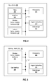
- FIG. 1 is a simplified network diagram of a wireless network 100 configured for wireless network neighbor list optimization and/or handover based on group delay metrics according to embodiments of the systems and methods described herein.
- Wireless network 100 includes a plurality of base stations 102 - 106 .
- Each base station 102 - 106 may include one or more base transceiver stations (BTSs), access nodes, node-Bs, eNodeBs (eNBs), and/or other supporting network infrastructure for providing wireless service in one or more sectors.
- BTSs base transceiver stations
- eNBs eNodeBs
- the wireless network is an LTE network and each base station 102 - 106 includes one or more LTE eNodeBs.
- the wireless network 100 may operate according to other wireless protocols, including but not limited to any of the wireless protocols disclosed herein.
- Each base station in network 100 is configured to provide wireless service in a plurality of sectors.
- each base station provides wireless service in three sectors.
- base station 102 provides wireless service in sectors 102 - 1 , 102 - 2 , and 102 - 3 ;
- base station 104 provides wireless service in sectors 104 - 1 , 104 - 2 , and 104 - 3 ;
- base station 106 provides wireless service in sectors 106 - 1 , 106 - 2 , and 106 - 3 .
- base station 102 is providing wireless service in sector 102 - 2 to UE 110 via wireless link 120 .
- individual base stations may provide service on more or fewer than three sectors.
- element 102 may represent a single tower with three separate base stations, where each base station provides wireless service on a single sector, i.e., a first base station providing wireless service in sector 102 - 1 , a second base station providing wireless service in sector 102 - 2 , and a third base station providing wireless service in sector 102 - 3 .
- each base station 102 - 106 maintains an NRT for each sector for which the base station provides wireless service.
- base station 102 maintains an NRT for sector 102 - 1 , an NRT for sector 102 - 2 , and an NRT for sector 102 - 3
- base station 104 maintains an NRT for sector 104 - 1 , an NRT for sector 104 - 2 , and an NRT for sector 104 - 3
- base station 106 maintains an NRT for sector 106 - 1 , an NRT for sector 106 - 2 , and an NRT for sector 106 - 3 .
- Each sector's NRT includes a listing of that sector's neighbor sectors.
- a particular sector's neighbor sectors include sectors that are adjacent to and/or at least partially overlap with that particular sector. Sectors that are adjacent to and/or overlap with a particular sector can be determined in a number of ways.
- a network operator may manually provision a particular sector's NRT with neighbor sectors based on the network operator's knowledge of the wireless network implementation.
- a base station may execute an ANR function that determines the neighbor sectors for a particular sector via any number of different methods, such as, for example: (i) inter base station signaling, (ii) intra base station signaling for base stations that support multiple sectors, (iii) collecting data from UEs served by a particular sector about all of the other sectors that the UEs detect; and/or (iv) any combination of the above-described manual and/or automated methods.
- a particular sector's neighbor sectors include sectors that are adjacent to and/or at least partially overlap with that particular sector.
- Table 130 shows an example NRT for sector 102 - 2 , which includes: (i) adjacent sectors 102 - 1 and 102 - 3 ; and (ii) overlapping sectors 104 - 2 , 104 - 3 , 106 - 1 , and 106 - 3 . Although sectors 102 - 1 and 102 - 3 are shown as adjacent to each other in FIG.
- sector 102 - 2 will overlap at least somewhat with adjacent sectors 102 - 1 and 102 - 3 , although perhaps not necessarily to the same extent that sector 102 - 2 overlaps with sectors 104 - 2 , 104 - 3 , 106 - 1 , and 106 - 3 .
- a particular sector's neighbor sectors may additionally include sectors that are adjacent to that particular sector's overlapping sectors.
- the NRT for sector 102 - 2 might additionally include sectors 104 - 1 and 106 - 2 .
- the NRT for a particular sector may include a variety of information about each neighbor sector.
- the NRT for a particular sector may comprise, for each neighbor sector in the NRT, (i) an identification of the neighbor sector, such as the neighbor sector's cell identifier, sector identifier, or similar identification, (ii) a handover success rate for that neighbor sector, and (iii) a group delay metric for the neighbor sector, such as a measure of the group delay or group delay variation for the sector.
- a sector's cell identifier is a value typically set by the network operator when the sector is implemented in the network.
- a sector's handover success rate may be determined or calculated by the base station by dividing the number of successful handovers to that sector by the total number of handover attempts to that sector.
- the group delay variation for a sector is a fixed value that may be determined from the particular filters in use for that sector.
- each sector in the wireless network 100 provides service within a range of frequencies determined by the network operator.
- a base station that provides service in a sector is typically equipped with one or more band pass filters that are designed to pass the range of frequencies for the sector and/or one or more band stop filters that are designed to block frequencies outside of the range of frequencies for the sector.
- These band pass and/or band stop filters introduce group delay and cause corresponding group delay variation between the frequencies within the frequency range of the sector. Most of the group delay variation is experienced by frequencies near the upper and lower limits of the frequency range.
- the extent of the group delay and resulting group delay variation is based on the particular filter configuration, where group delay is inversely proportional to filter bandwidth and nearly proportional to the order of the filter. Because group delay is based on the filter configuration, the group delay for a particular sector equipped with filters is a value that is known in advance by the network operator and would likely not change over time unless the filter configuration is later changed.
- the example NRT shown in table 130 of FIG. 1 includes a listing of each neighbor sector for sector 102 - 2 .
- the NRT includes that neighbor sector's (i) handover success rate as a percentage of successful handovers and (ii) group delay variation in nanoseconds.
- base station 102 may prioritize the NRT for sector 102 - 2 based on group delay variation.
- Table 132 in FIG. 1 shows the NRT for sector 102 - 2 after base station 102 has prioritized the NRT according to each neighbor sector's group delay variation. As shown in table 132 , the prioritized NRT has neighbor sectors with lower group delay variation positioned higher in the list than neighbor sectors with higher group delay variation.
- base station 102 may additionally execute an ANR function to add neighbor sectors to or remove neighbor sectors from the NRT based on each neighbor sector's group delay variation.
- the base station may (i) include neighbor sectors in the NRT based on their having a group delay variation metric that is less than a predetermined group delay variation threshold, and/or (ii) remove neighbor sectors from the NRT based on their having a group delay variation that exceeds the predetermined group delay variation threshold.
- the prioritized NRT may not include sectors 102 - 3 or 104 - 3 if the predetermined group delay variation threshold is set to 150 nanoseconds.
- base station 102 may refer to the prioritized NRT shown in table 132 to select a neighbor sector as the target sector for the handover of UE 110 .
- base station 102 may further limit the set of neighbor sectors in the prioritized NRT to a set of candidate neighbor sectors for UE 110 .
- UE 110 may report a list of candidate sectors to base station 102 , and base station 102 may in turn select one of the candidate sectors from the prioritized list of neighbor sectors in the prioritized NRT 132 as the target sector for the handover of UE 110 .
- the base station 102 may determine a set of candidate sectors from RSRP metrics for the neighbor sectors reported to the base station 102 by the UE 110 and/or handover success ratios of the neighbor sectors in the NRT.
- the selected neighbor sector is a candidate sector from the set of candidate sectors in the NRT 130 (or prioritized NRT 132 ) having the lowest group delay variation.
- Table 134 shows the candidate neighbor sectors from which base station 102 may select the target sector for the handover of UE 110 .
- base station 102 selects neighbor sector 106 - 1 as the target sector for the handover of UE 110 because, as between neighbor sectors 106 - 1 and 104 - 3 (the two candidate sectors for the handover chosen from the NRT for sector 102 - 2 ), sector 106 - 1 has the lower group delay variation.
- base station 102 selects neighbor sector 106 - 1 for the handover over neighbor sector 104 - 3 even though neighbor sector 104 - 3 has a higher handover success rate (94.6% for 104 - 3 as compared to 91.2% for 106 - 1 ).
- base station 102 may then initiate the handover of UE 110 from sector 102 - 2 to sector 106 - 3 served by base station 106 by, for example, sending a handover request message to base station 106 .
- base station 102 may use group delay variation in combination with one or more other metrics for selecting the target sector for a handover. For example, in some embodiments, base station 102 may consider both the group delay variation and the handover success rate of each neighbor sector when selecting a target sector for handover. In some embodiments, for the target sector, the base station 102 may select the neighbor sector having the lowest group delay variation that also has a handover success rate that is greater than a particular handover success rate threshold. In such embodiments, the base station may select as the target sector for a handover, a particular neighbor sector that may not have the lowest group delay variation of all of the neighbor sectors.
- the base station may select the second neighbor sector over the first and third neighbor sectors for handover because the second neighbor sector has the lowest group delay variation among the neighbor sectors with a handover success rate over a preconfigured handover success rate threshold of 85%.
- Handover success rate thresholds other than 85% could be used as well.
- the base station is selecting a particular neighbor sector as the target sector for handover based at least in part on each neighbor sector's group delay variation metric. After selecting the target sector for the handover, the base station may then initiate the handover of the UE to the target sector by, for example, sending a handover request to the base station that is providing service on the selected target sector.
- a base station may use group delay variation in combination with RSRP for selecting a target sector for handover of a UE.
- the base station may select the neighbor sector having the lowest group delay variation that also has a reported RSRP for the UE that is greater than a particular RSRP threshold.
- the base station may select as the target sector for a handover, a particular neighbor sector that may not have the lowest group delay variation of all of the neighbor sectors.
- the base station may select the third neighbor sector over the first and second neighbor sectors for handover of the UE because the third neighbor sector has the lowest group delay variation among the neighbor sectors with a reported RSRP by UE over a preconfigured RSRP threshold of ⁇ 100 dBm.
- RSRP thresholds other than 100 dBm could be used as well.
- the base station is selecting a particular neighbor sector as the target sector for handover based at least in part on each neighbor sector's group delay variation metric. After selecting the target sector for the handover, the base station may then initiate the handover of the UE to the target sector by, for example, sending a handover request to the base station that is providing service on the selected target sector.
- a base station may use group delay variation in combination with both handover success rate and RSRP for selecting a target sector for handover of a UE.
- the base station may select the neighbor sector having the lowest group delay variation that also has both (i) a reported RSRP for the UE that is greater than a particular RSRP threshold and (ii) a handover success rate that is greater than a particular handover success rate threshold.
- a base station may use group delay variation in combination with one or more other factors for selecting a target sector for handover of a UE.
- FIG. 2 is a simplified block diagram of an example base station 200 according to some embodiments of the disclosed systems and methods, including, for example, base stations 102 - 106 of FIG. 1 .
- base station 200 there can be numerous specific implementations of a base station, such as base station 200 , in which the disclosed methods for wireless network neighbor list optimization and/or handover based on group delay metrics could be implemented.
- base station 200 is representative of a means for carrying out wireless network neighbor list optimization and/or handover determination based on group delay metrics, in accordance with the methods and steps described herein by way of example.
- the example base station 200 includes one or more wireless communications interfaces 202 , one or more network communications interfaces 208 , one or more processors 210 , and data storage 212 , all of which may be coupled together by a system bus 216 or similar mechanism.
- the base station 200 may also include external storage, such as magnetic or optical disk storage (not shown). Variations from this arrangement are possible as well, including addition and/or omission of components, combination of components, and distribution of components in any of a variety of ways.
- the base station components may be arranged to support wireless communications in a wireless communication network that is compliant with one or more of the variety of wireless air-interface protocols noted herein, in addition to other protocols now known or later developed.
- the components of the example base station 200 are configured to support wireless network neighbor list optimization and/or handover determination based on group delay metrics in accordance with the example embodiments described herein.
- the one or more wireless communications interfaces 202 may include one or more transceivers, amplifiers 206 , filters 204 , antennas, and other associated components that enable the base station 200 to engage in air interface communication with one or more wireless communications devices, such as UE 110 shown in FIG. 1 , according to any of the air interface protocols described herein (e.g., CDMA, GSM, LTE, etc.).
- the one or more amplifiers 206 and filters 204 are configured to support transmissions within a configured frequency range on (1) the downlink (or forward link) from the base station 200 to a wireless communications device and (2) the uplink (or reverse link) from the wireless communications device to the base station 200 . Some embodiments may use different frequency ranges for the uplink and downlink.
- the one or more wireless communications interfaces 202 are configured to support transmissions to and from one or more wireless communications interfaces of one or more relays associated with the base station 200 .
- the one or more network interfaces 208 include physical network interfaces (e.g., optical, electrical) that enable the base station 200 to send and receive traffic directly or indirectly to/from other networks, such as the Public Switched Telephone Network (PSTN), the Internet, or other networks.
- the one or more network interfaces 208 may take the form of Ethernet network interface cards/ports, optical network interface cards/ports or other physical interfaces to one or more transmission networks that directly or indirectly connect the base station 102 to its neighboring base stations as well as to the PSTN, the Internet, and/or other networks. Additionally, in some embodiments, the one or more network interfaces 208 are configured to support transmissions to and from one or more network interfaces of one or more relays associated with the base station 200 .
- the one or more processors 210 comprise one or more general-purpose processors (e.g., microprocessors) and/or one or more special-purpose processors (e.g., dedicated digital signal processors (DSPs), application specific integrated circuits (ASICs), etc.).
- the non-transitory data storage 212 comprises one or more volatile and/or non-volatile storage components, such as magnetic or optical memory or disk storage. Non-transitory data storage 212 can be integrated in whole or in part with the one or more processors 210 , as cache memory or registers for instance. As further shown, non-transitory data storage 212 is equipped to hold program instructions 214 . In some embodiments, one or more of the processors 210 and non-transitory data storage 212 may be integrated in whole or in part with one or more of the wireless communications interfaces 202 and/or network communications interfaces 208 .
- the program instructions 214 comprise machine language instructions that define routines and software program code executable by the one or more processors 210 (alone or in combination with the wireless communications interface(s) 202 and network communications interface(s) 208 ) to carry out various functions described herein.
- the program code 214 , wireless communications interfaces 202 , and network communications interfaces 208 may operate cooperatively to carry out one or more aspects of the neighbor sector prioritization and/or handover methods described herein.
- FIG. 3 is a simplified block diagram of a UE 300 according to some embodiments of the disclosed systems and methods, including, for example, UE 110 shown in FIG. 1 .
- the UE 300 is configured to operate in a communication system, such as the wireless communication system 100 of FIG. 1 for example, and may execute one or more functions described herein.
- the UE 300 includes one or more wireless communication interfaces 302 , one or more processors 306 , a user interface 304 , and non-transitory data storage 308 configured to store program instructions 304 , all of which may be communicatively linked together by a system bus 312 or other similar mechanism. Variations from this arrangement are possible as well, including addition and/or omission of components, combination of components, and distribution of components in any of a variety of ways.
- Wireless communication interface(s) 302 includes components (e.g., radios, antennas, communications processors) configured to engage in air interface communication within a configured frequency range of a base station.
- the wireless communication interface 302 may include one or more antenna structures and chipsets arranged to support wireless communication according to one or more air interface protocols, such as the ones disclosed and described herein (e.g., CDMA, GSM, LTE) and perhaps others (e.g., WiFi, Bluetooth, etc.)
- the one or more processors 306 include one or more general purpose processors (e.g., microprocessors) and/or special purpose processors (e.g., application specific integrated circuits or the like). In some embodiments, the one or more processors 306 may be integrated in whole or in part with the one or more wireless communication interfaces 302 .
- general purpose processors e.g., microprocessors
- special purpose processors e.g., application specific integrated circuits or the like.
- the one or more processors 306 may be integrated in whole or in part with the one or more wireless communication interfaces 302 .
- the non-transitory data storage 308 comprises one or more volatile and/or non-volatile storage components.
- the storage components may include one or more magnetic, optical, and/or flash memory components for example.
- the non-transitory data storage 308 may be integrated in whole or in part with the one or more processors 306 and/or the wireless communication interface(s) 302 . Additionally or alternatively, the non-transitory data storage 308 may be provided separately as a non-transitory machine readable medium.
- the non-transitory data storage 308 may hold (e.g., contain, store, or otherwise be encoded with) program instructions 310 (e.g., machine language instructions or other program logic, markup or the like) executable by the one or more processors 306 to carry out the various functions described herein.
- the non-transitory data storage 308 may also hold reference data for use in carrying out various functions described herein, e.g., information relating to RSRP measurements for sectors that the UE periodically reports to its serving base station.
- FIG. 4 is a method flow chart depicting method 400 , which includes aspects of some embodiments of the disclosed systems and methods of performing UE handovers.
- Method 400 may be performed by any type of base station now known or later developed, including, for example any of the base stations described herein.
- method 400 is performed by a base station such as base station 102 operating in network 100 shown and described with reference to FIG. 1 , where the base station provides service to UEs on at least one sector, and where that sector has a plurality of neighbor sectors.
- Method 400 begins at step 402 where the base station makes a handover determination for a particular UE.
- the base station may determine that the UE should be handed over to another sector in a variety of ways.
- the base station may analyze data in the Measurement Report that the UE sends to the base station, such as the list of sectors the UE can detect, the signal quality of the sectors that the UE can detect, or any other factor or combination of factors in the UE's Measurement Report.
- the base station might also rely upon any other factor or group of factors to determine that a particular UE should be handed over to another sector.
- step 404 the base station selects one neighbor sector from a plurality of neighbor sectors as the target neighbor sector for the handover.
- each neighbor sector of the plurality of neighbor sectors has a group delay metric, and the base station's selection of the neighbor sector is based at least in part on each neighbor sector's group delay metric.
- the group delay metric for a particular neighbor sector may be either the particular neighbor sector's group delay or the particular neighbor sector's group variation, both of which are a function of the filters in use by the base station that is providing service on that particular neighbor sector as described previously.
- selecting the one neighbor sector includes first choosing a set of candidate neighbor sectors from the plurality of neighbor sectors, and then selecting the one neighbor sector (as the target sector) from the set of candidate neighbor sectors.
- the selected one neighbor sector is the neighbor sector having the lowest group delay metric of the chosen set of candidate neighbor sectors.
- the chosen set of candidate neighbor sectors may be based on one or both of each neighbor sector's (i) handover success rate and/or (ii) RSRP value, as reported by the UE for which the base station made the handover determination in step 402 .
- the chosen set of candidate neighbor sectors consists of the neighbor sectors of the plurality of neighbor sectors having a handover success rate that exceeds a threshold handover success rate.
- the chosen set of candidate neighbor sectors consists of the neighbor sectors of the plurality of neighbor sectors having an RSRP value that exceeds a threshold RSRP value.
- the chosen set of candidate neighbor sectors consists of the neighbor sectors of the plurality of neighbor sectors having both (i) a handover success rate that exceeds a handover success rate threshold and (ii) a RSRP value that exceeds a RSRP value threshold.
- step 406 the base station initiates handover of the UE to the selected neighbor sector.
- the base station may send a handover request message to the base station providing wireless service on the selected neighbor sector.
- FIG. 5 is a method flow chart depicting method 500 , which includes aspects of some embodiments of the disclosed systems and methods for prioritizing a neighbor relation table and/or selecting a target sector for handover.
- Method 500 may be performed by any type of base station now known or later developed, including, for example any of the base stations described herein.
- method 500 is performed by a base station such as base station 102 operating in network 100 shown and described with reference to FIG. 1 , where the base station provides service to UEs on at least one sector, and where that sector has a plurality of neighbor sectors.
- Method 500 begins at step 502 , where the base station creates a neighbor relation table (NRT) that includes a group delay metric for each neighbor sector.
- the group delay metric for a particular neighbor sector may be either the particular neighbor sector's group delay or the particular neighbor sector's group delay variation, both of which are a function of the filters in use by the base station that is providing service on that particular neighbor sector, as described previously.
- the base station may create the NRT for a particular sector by including in the NRT, only those neighbor sectors that have a group delay metric that is less than a group delay metric threshold. In other embodiments, the base station may create the NRT for a particular sector by excluding from the NRT, any neighbor sector that has a group delay metric that exceeds the group delay metric threshold.
- the base station prioritizes the neighbor sectors in the NRT created at step 502 .
- the base station prioritizes the neighbor sectors in the NRT according to each neighbor sector's group delay metric.
- the group delay metric for a particular neighbor sector may be the group delay introduced by the filters used by the base station to provide wireless service in that particular neighbor sector.
- the group delay metric for a particular neighbor sector may be the group delay variation caused by the group delay introduced by the filters used by the base station to provide wireless service in that particular neighbor sector.
- prioritizing the neighbor sectors in the NRT in step 504 based at least in part on each neighbor sector's group delay metric includes ordering the neighbor sectors from lowest group delay (or group delay variation) to highest group delay (or group delay variation) within the NRT.
- the base station makes a handover determination for a UE.
- the base station may make the handover determination (i.e., determine that the UE should be handed over to another sector) in a variety of ways.
- the base station may analyze data in the Measurement Report that the UE sends to the base station, such as the list of sectors the UE can detect, the signal quality of the sectors that the UE can detect, or any other factor or combination of factors in the UE's Measurement Report. Additionally or alternatively, the base station might also rely upon any other factor or group of factors to determine that a particular UE should be handed over to another sector.
- step 508 the base station chooses a set of candidate neighbor sectors from the NRT to consider for the handover of the UE.
- the base station chooses the set of candidate neighbor sectors based on one or both of each neighbor sector's (i) handover completion percentage (or success rate) and/or (ii) RSRP value reported by the UE for which the base station made the handover determination in step 506 .
- the chosen set of candidate neighbor sectors consists of the neighbor sectors in the NRT that have a handover success rate that exceeds a threshold handover success rate.
- the chosen set of candidate neighbor sectors consists of the neighbor sectors in the NRT that have a RSRP value reported by the UE that exceeds a threshold RSRP value.
- the chosen set of candidate neighbor sectors consists of the neighbor sectors in the NRT that have both (i) a handover success rate that exceeds a threshold handover success rate and (ii) a RSRP value reported by the UE that exceeds a threshold RSRP value.
- the base station selects one neighbor sector from the chosen set of candidate neighbor sectors to be the target neighbor sector for the handover.
- the base station's selection of the target neighbor sector for the handover is based at least in part on each candidate neighbor sector's priority in the NRT, which in step 504 , is based at least in part on each neighbor sector's group delay (or group delay variation).
- method 500 comprises selecting the target neighbor sector from a plurality of neighbor sectors based at least in part on each neighbor sector's group delay metric.
- step 510 After selecting one of the neighbor sectors from the chosen set of candidate neighbor sectors in step 510 as the target neighbor sector for the handover of the UE, method 500 proceeds to step 512 where the base station initiates the handover of the UE to the selected neighbor sector (i.e., the target neighbor sector) by, for example, sending a handover request message to the base station providing service on the selected target neighbor sector.
- the selected neighbor sector i.e., the target neighbor sector
Landscapes
- Engineering & Computer Science (AREA)
- Computer Networks & Wireless Communication (AREA)
- Signal Processing (AREA)
- Mobile Radio Communication Systems (AREA)
Abstract
Description
Claims (20)
Priority Applications (1)
| Application Number | Priority Date | Filing Date | Title |
|---|---|---|---|
| US14/536,908 US9723535B1 (en) | 2014-11-10 | 2014-11-10 | Wireless network neighbor list optimization based on group delay metrics |
Applications Claiming Priority (1)
| Application Number | Priority Date | Filing Date | Title |
|---|---|---|---|
| US14/536,908 US9723535B1 (en) | 2014-11-10 | 2014-11-10 | Wireless network neighbor list optimization based on group delay metrics |
Publications (1)
| Publication Number | Publication Date |
|---|---|
| US9723535B1 true US9723535B1 (en) | 2017-08-01 |
Family
ID=59382712
Family Applications (1)
| Application Number | Title | Priority Date | Filing Date |
|---|---|---|---|
| US14/536,908 Active US9723535B1 (en) | 2014-11-10 | 2014-11-10 | Wireless network neighbor list optimization based on group delay metrics |
Country Status (1)
| Country | Link |
|---|---|
| US (1) | US9723535B1 (en) |
Cited By (3)
| Publication number | Priority date | Publication date | Assignee | Title |
|---|---|---|---|---|
| US10045346B1 (en) * | 2016-08-02 | 2018-08-07 | Sprint Spectrum L.P. | Assigning a low-GDV carrier to a high-speed UE |
| CN111343680A (en) * | 2020-03-02 | 2020-06-26 | 东南大学 | Switching time delay reduction method based on reference signal received power prediction |
| US11140590B2 (en) * | 2016-11-15 | 2021-10-05 | Telefonaktiebolaget Lm Ericsson (Publ) | Handling neighbour relationships |
Citations (7)
| Publication number | Priority date | Publication date | Assignee | Title |
|---|---|---|---|---|
| US6119005A (en) * | 1998-05-27 | 2000-09-12 | Lucent Technologies Inc. | System for automated determination of handoff neighbor list for cellular communication systems |
| US6175587B1 (en) * | 1997-12-30 | 2001-01-16 | Motorola, Inc. | Communication device and method for interference suppression in a DS-CDMA system |
| US20090073031A1 (en) * | 2006-05-16 | 2009-03-19 | Ktfreetel Co., Ltd. | Method and system for measuring location using round trip time information in mobile communication network |
| US20090125220A1 (en) * | 2006-03-20 | 2009-05-14 | Shin-Jae Kim | Method and system for measuring traffic information in cdma network |
| US8391870B1 (en) * | 2010-05-20 | 2013-03-05 | Sprint Communications Company L.P. | Wireless handoffs based upon past handoff metrics |
| US20130143577A1 (en) * | 2011-12-01 | 2013-06-06 | Broadcom Corporation | Frequency offset correction |
| US9002359B1 (en) * | 2012-04-12 | 2015-04-07 | Sprint Spectrum L.P. | Method and system for intelligent determination of pseudonoise (PN) offsets |
-
2014
- 2014-11-10 US US14/536,908 patent/US9723535B1/en active Active
Patent Citations (7)
| Publication number | Priority date | Publication date | Assignee | Title |
|---|---|---|---|---|
| US6175587B1 (en) * | 1997-12-30 | 2001-01-16 | Motorola, Inc. | Communication device and method for interference suppression in a DS-CDMA system |
| US6119005A (en) * | 1998-05-27 | 2000-09-12 | Lucent Technologies Inc. | System for automated determination of handoff neighbor list for cellular communication systems |
| US20090125220A1 (en) * | 2006-03-20 | 2009-05-14 | Shin-Jae Kim | Method and system for measuring traffic information in cdma network |
| US20090073031A1 (en) * | 2006-05-16 | 2009-03-19 | Ktfreetel Co., Ltd. | Method and system for measuring location using round trip time information in mobile communication network |
| US8391870B1 (en) * | 2010-05-20 | 2013-03-05 | Sprint Communications Company L.P. | Wireless handoffs based upon past handoff metrics |
| US20130143577A1 (en) * | 2011-12-01 | 2013-06-06 | Broadcom Corporation | Frequency offset correction |
| US9002359B1 (en) * | 2012-04-12 | 2015-04-07 | Sprint Spectrum L.P. | Method and system for intelligent determination of pseudonoise (PN) offsets |
Cited By (4)
| Publication number | Priority date | Publication date | Assignee | Title |
|---|---|---|---|---|
| US10045346B1 (en) * | 2016-08-02 | 2018-08-07 | Sprint Spectrum L.P. | Assigning a low-GDV carrier to a high-speed UE |
| US11140590B2 (en) * | 2016-11-15 | 2021-10-05 | Telefonaktiebolaget Lm Ericsson (Publ) | Handling neighbour relationships |
| CN111343680A (en) * | 2020-03-02 | 2020-06-26 | 东南大学 | Switching time delay reduction method based on reference signal received power prediction |
| CN111343680B (en) * | 2020-03-02 | 2022-04-01 | 东南大学 | Switching time delay reduction method based on reference signal received power prediction |
Similar Documents
| Publication | Publication Date | Title |
|---|---|---|
| RU2683582C1 (en) | Method for implementing communication and communication device | |
| JP6648153B2 (en) | Method and apparatus for allocating carrier aggregation based on multi-band capability | |
| WO2017121217A1 (en) | Handover method, base station, and terminal device | |
| US9071980B2 (en) | Method and apparatus for signal quality determination in a communication network | |
| US9585072B1 (en) | SCell triggered handover notwithstanding good PCell condition | |
| EP3026950A2 (en) | Telecommunications control with service aware optimization in a selforganizing network | |
| US9999052B1 (en) | Selecting primary and secondary component carrier for carrier aggregation based on carrier group delay variation, insertion loss, and other carrier attributes | |
| CN108702697A (en) | Target cell determining method, base station and management equipment | |
| CN102448102A (en) | Method, device and system for measuring and sending interference coordination | |
| WO2018126824A1 (en) | Base station, terminal, measurement control method and measurement method | |
| CN108924823B (en) | Dual-connection configuration method and device, base station and user equipment | |
| US10904771B1 (en) | Method and apparatus for invoking beamforming responsive to carrier transition | |
| US20200383031A1 (en) | Communication method, device and computer readable storage medium for relay device | |
| CN110856200A (en) | Measurement gap configuration for 5G | |
| US20160173358A1 (en) | Systems, apparatuses, and methods for managing user equipment mobility information | |
| US9479989B1 (en) | Controlling handover based on carrier-aggregation policies | |
| US9253662B1 (en) | Method and system for dynamically activating a relay | |
| US10129889B1 (en) | Selecting primary and secondary component carriers for carrier aggregation based on carrier receive power at a UE, transmit power, frequency, and other carrier attributes | |
| US9723535B1 (en) | Wireless network neighbor list optimization based on group delay metrics | |
| KR20180059508A (en) | Carrier Selection Method and Device in Carrier Aggregation Technology | |
| CN105744534B (en) | FDD-LTE pilot frequency networking method based on frequency migration | |
| US10045346B1 (en) | Assigning a low-GDV carrier to a high-speed UE | |
| US9439202B1 (en) | Systems and methods for allocating resources between frequency bands in a wireless network | |
| US9198182B1 (en) | Method and systems for optimizing carrier aggregation implementation for UE in-building coverage in LTE networks | |
| US9877253B1 (en) | Controlling base station power status based on quality of service load |
Legal Events
| Date | Code | Title | Description |
|---|---|---|---|
| AS | Assignment |
Owner name: SPRINT SPECTRUM L.P., KANSAS Free format text: ASSIGNMENT OF ASSIGNORS INTEREST;ASSIGNORS:MARUPADUGA, SREEKAR;GOSWAMI, GAURAVPURI;WURTENBERGER, ANDREW M;AND OTHERS;SIGNING DATES FROM 20141105 TO 20141107;REEL/FRAME:034194/0830 |
|
| AS | Assignment |
Owner name: DEUTSCHE BANK TRUST COMPANY AMERICAS, NEW YORK Free format text: GRANT OF FIRST PRIORITY AND JUNIOR PRIORITY SECURITY INTEREST IN PATENT RIGHTS;ASSIGNOR:SPRINT SPECTRUM L.P.;REEL/FRAME:041937/0632 Effective date: 20170203 |
|
| STCF | Information on status: patent grant |
Free format text: PATENTED CASE |
|
| AS | Assignment |
Owner name: DEUTSCHE BANK TRUST COMPANY AMERICAS, NEW YORK Free format text: SECURITY AGREEMENT;ASSIGNORS:T-MOBILE USA, INC.;ISBV LLC;T-MOBILE CENTRAL LLC;AND OTHERS;REEL/FRAME:053182/0001 Effective date: 20200401 |
|
| AS | Assignment |
Owner name: SPRINT SPECTRUM L.P., KANSAS Free format text: TERMINATION AND RELEASE OF FIRST PRIORITY AND JUNIOR PRIORITY SECURITY INTEREST IN PATENT RIGHTS;ASSIGNOR:DEUTSCHE BANK TRUST COMPANY AMERICAS;REEL/FRAME:052313/0299 Effective date: 20200401 |
|
| MAFP | Maintenance fee payment |
Free format text: PAYMENT OF MAINTENANCE FEE, 4TH YEAR, LARGE ENTITY (ORIGINAL EVENT CODE: M1551); ENTITY STATUS OF PATENT OWNER: LARGE ENTITY Year of fee payment: 4 |
|
| AS | Assignment |
Owner name: SPRINT SPECTRUM LLC, WASHINGTON Free format text: CHANGE OF NAME;ASSIGNOR:SPRINT SPECTRUM L.P.;REEL/FRAME:059044/0022 Effective date: 20210325 |
|
| AS | Assignment |
Owner name: SPRINT SPECTRUM LLC, KANSAS Free format text: RELEASE BY SECURED PARTY;ASSIGNOR:DEUTSCHE BANK TRUST COMPANY AMERICAS;REEL/FRAME:062595/0001 Effective date: 20220822 Owner name: SPRINT INTERNATIONAL INCORPORATED, KANSAS Free format text: RELEASE BY SECURED PARTY;ASSIGNOR:DEUTSCHE BANK TRUST COMPANY AMERICAS;REEL/FRAME:062595/0001 Effective date: 20220822 Owner name: SPRINT COMMUNICATIONS COMPANY L.P., KANSAS Free format text: RELEASE BY SECURED PARTY;ASSIGNOR:DEUTSCHE BANK TRUST COMPANY AMERICAS;REEL/FRAME:062595/0001 Effective date: 20220822 Owner name: SPRINTCOM LLC, KANSAS Free format text: RELEASE BY SECURED PARTY;ASSIGNOR:DEUTSCHE BANK TRUST COMPANY AMERICAS;REEL/FRAME:062595/0001 Effective date: 20220822 Owner name: CLEARWIRE IP HOLDINGS LLC, KANSAS Free format text: RELEASE BY SECURED PARTY;ASSIGNOR:DEUTSCHE BANK TRUST COMPANY AMERICAS;REEL/FRAME:062595/0001 Effective date: 20220822 Owner name: CLEARWIRE COMMUNICATIONS LLC, KANSAS Free format text: RELEASE BY SECURED PARTY;ASSIGNOR:DEUTSCHE BANK TRUST COMPANY AMERICAS;REEL/FRAME:062595/0001 Effective date: 20220822 Owner name: BOOST WORLDWIDE, LLC, KANSAS Free format text: RELEASE BY SECURED PARTY;ASSIGNOR:DEUTSCHE BANK TRUST COMPANY AMERICAS;REEL/FRAME:062595/0001 Effective date: 20220822 Owner name: ASSURANCE WIRELESS USA, L.P., KANSAS Free format text: RELEASE BY SECURED PARTY;ASSIGNOR:DEUTSCHE BANK TRUST COMPANY AMERICAS;REEL/FRAME:062595/0001 Effective date: 20220822 Owner name: T-MOBILE USA, INC., WASHINGTON Free format text: RELEASE BY SECURED PARTY;ASSIGNOR:DEUTSCHE BANK TRUST COMPANY AMERICAS;REEL/FRAME:062595/0001 Effective date: 20220822 Owner name: T-MOBILE CENTRAL LLC, WASHINGTON Free format text: RELEASE BY SECURED PARTY;ASSIGNOR:DEUTSCHE BANK TRUST COMPANY AMERICAS;REEL/FRAME:062595/0001 Effective date: 20220822 Owner name: PUSHSPRING, LLC, WASHINGTON Free format text: RELEASE BY SECURED PARTY;ASSIGNOR:DEUTSCHE BANK TRUST COMPANY AMERICAS;REEL/FRAME:062595/0001 Effective date: 20220822 Owner name: LAYER3 TV, LLC, WASHINGTON Free format text: RELEASE BY SECURED PARTY;ASSIGNOR:DEUTSCHE BANK TRUST COMPANY AMERICAS;REEL/FRAME:062595/0001 Effective date: 20220822 Owner name: IBSV LLC, WASHINGTON Free format text: RELEASE BY SECURED PARTY;ASSIGNOR:DEUTSCHE BANK TRUST COMPANY AMERICAS;REEL/FRAME:062595/0001 Effective date: 20220822 |