US9740534B2 - System for controlling resources, control pattern generation apparatus, control apparatus, method for controlling resources and program - Google Patents
System for controlling resources, control pattern generation apparatus, control apparatus, method for controlling resources and program Download PDFInfo
- Publication number
- US9740534B2 US9740534B2 US14/761,800 US201414761800A US9740534B2 US 9740534 B2 US9740534 B2 US 9740534B2 US 201414761800 A US201414761800 A US 201414761800A US 9740534 B2 US9740534 B2 US 9740534B2
- Authority
- US
- United States
- Prior art keywords
- resources
- control
- virtual
- virtual system
- control pattern
- Prior art date
- Legal status (The legal status is an assumption and is not a legal conclusion. Google has not performed a legal analysis and makes no representation as to the accuracy of the status listed.)
- Active, expires
Links
- 238000000034 method Methods 0.000 title claims description 20
- 230000008859 change Effects 0.000 claims abstract description 87
- 238000013468 resource allocation Methods 0.000 claims abstract description 79
- 230000006399 behavior Effects 0.000 claims abstract description 12
- 230000015654 memory Effects 0.000 claims description 56
- 238000012545 processing Methods 0.000 claims description 54
- 238000004088 simulation Methods 0.000 claims description 34
- 238000010276 construction Methods 0.000 claims description 31
- 238000011156 evaluation Methods 0.000 claims description 16
- 238000009795 derivation Methods 0.000 claims description 13
- 238000005259 measurement Methods 0.000 claims description 5
- 230000002194 synthesizing effect Effects 0.000 claims 3
- 230000001276 controlling effect Effects 0.000 description 34
- 238000012544 monitoring process Methods 0.000 description 25
- 238000007726 management method Methods 0.000 description 18
- 238000004891 communication Methods 0.000 description 14
- 230000005540 biological transmission Effects 0.000 description 8
- 230000006870 function Effects 0.000 description 4
- 230000007704 transition Effects 0.000 description 4
- 238000004590 computer program Methods 0.000 description 3
- 230000000875 corresponding effect Effects 0.000 description 3
- 238000010586 diagram Methods 0.000 description 3
- 238000000491 multivariate analysis Methods 0.000 description 3
- 230000003466 anti-cipated effect Effects 0.000 description 2
- 238000012937 correction Methods 0.000 description 2
- 230000002596 correlated effect Effects 0.000 description 2
- 230000003247 decreasing effect Effects 0.000 description 2
- 230000005055 memory storage Effects 0.000 description 2
- 238000012935 Averaging Methods 0.000 description 1
- 230000008901 benefit Effects 0.000 description 1
- 230000000694 effects Effects 0.000 description 1
- 230000004044 response Effects 0.000 description 1
- 238000006467 substitution reaction Methods 0.000 description 1
- 230000001052 transient effect Effects 0.000 description 1
Images


Classifications
-
- G—PHYSICS
- G06—COMPUTING; CALCULATING OR COUNTING
- G06F—ELECTRIC DIGITAL DATA PROCESSING
- G06F9/00—Arrangements for program control, e.g. control units
- G06F9/06—Arrangements for program control, e.g. control units using stored programs, i.e. using an internal store of processing equipment to receive or retain programs
- G06F9/46—Multiprogramming arrangements
- G06F9/50—Allocation of resources, e.g. of the central processing unit [CPU]
- G06F9/5061—Partitioning or combining of resources
- G06F9/5077—Logical partitioning of resources; Management or configuration of virtualized resources
-
- G—PHYSICS
- G06—COMPUTING; CALCULATING OR COUNTING
- G06F—ELECTRIC DIGITAL DATA PROCESSING
- G06F11/00—Error detection; Error correction; Monitoring
- G06F11/30—Monitoring
- G06F11/34—Recording or statistical evaluation of computer activity, e.g. of down time, of input/output operation ; Recording or statistical evaluation of user activity, e.g. usability assessment
- G06F11/3447—Performance evaluation by modeling
-
- G—PHYSICS
- G06—COMPUTING; CALCULATING OR COUNTING
- G06F—ELECTRIC DIGITAL DATA PROCESSING
- G06F11/00—Error detection; Error correction; Monitoring
- G06F11/30—Monitoring
- G06F11/34—Recording or statistical evaluation of computer activity, e.g. of down time, of input/output operation ; Recording or statistical evaluation of user activity, e.g. usability assessment
- G06F11/3457—Performance evaluation by simulation
-
- G—PHYSICS
- G06—COMPUTING; CALCULATING OR COUNTING
- G06F—ELECTRIC DIGITAL DATA PROCESSING
- G06F9/00—Arrangements for program control, e.g. control units
- G06F9/06—Arrangements for program control, e.g. control units using stored programs, i.e. using an internal store of processing equipment to receive or retain programs
- G06F9/44—Arrangements for executing specific programs
- G06F9/455—Emulation; Interpretation; Software simulation, e.g. virtualisation or emulation of application or operating system execution engines
- G06F9/45533—Hypervisors; Virtual machine monitors
- G06F9/45558—Hypervisor-specific management and integration aspects
-
- H—ELECTRICITY
- H04—ELECTRIC COMMUNICATION TECHNIQUE
- H04L—TRANSMISSION OF DIGITAL INFORMATION, e.g. TELEGRAPHIC COMMUNICATION
- H04L47/00—Traffic control in data switching networks
- H04L47/70—Admission control; Resource allocation
- H04L47/82—Miscellaneous aspects
- H04L47/823—Prediction of resource usage
-
- H—ELECTRICITY
- H04—ELECTRIC COMMUNICATION TECHNIQUE
- H04L—TRANSMISSION OF DIGITAL INFORMATION, e.g. TELEGRAPHIC COMMUNICATION
- H04L47/00—Traffic control in data switching networks
- H04L47/70—Admission control; Resource allocation
- H04L47/83—Admission control; Resource allocation based on usage prediction
-
- G—PHYSICS
- G06—COMPUTING; CALCULATING OR COUNTING
- G06F—ELECTRIC DIGITAL DATA PROCESSING
- G06F9/00—Arrangements for program control, e.g. control units
- G06F9/06—Arrangements for program control, e.g. control units using stored programs, i.e. using an internal store of processing equipment to receive or retain programs
- G06F9/44—Arrangements for executing specific programs
- G06F9/455—Emulation; Interpretation; Software simulation, e.g. virtualisation or emulation of application or operating system execution engines
- G06F9/45533—Hypervisors; Virtual machine monitors
- G06F9/45558—Hypervisor-specific management and integration aspects
- G06F2009/4557—Distribution of virtual machine instances; Migration and load balancing
-
- G—PHYSICS
- G06—COMPUTING; CALCULATING OR COUNTING
- G06F—ELECTRIC DIGITAL DATA PROCESSING
- G06F9/00—Arrangements for program control, e.g. control units
- G06F9/06—Arrangements for program control, e.g. control units using stored programs, i.e. using an internal store of processing equipment to receive or retain programs
- G06F9/44—Arrangements for executing specific programs
- G06F9/455—Emulation; Interpretation; Software simulation, e.g. virtualisation or emulation of application or operating system execution engines
- G06F9/45533—Hypervisors; Virtual machine monitors
- G06F9/45558—Hypervisor-specific management and integration aspects
- G06F2009/45595—Network integration; Enabling network access in virtual machine instances
-
- G—PHYSICS
- G06—COMPUTING; CALCULATING OR COUNTING
- G06Q—INFORMATION AND COMMUNICATION TECHNOLOGY [ICT] SPECIALLY ADAPTED FOR ADMINISTRATIVE, COMMERCIAL, FINANCIAL, MANAGERIAL OR SUPERVISORY PURPOSES; SYSTEMS OR METHODS SPECIALLY ADAPTED FOR ADMINISTRATIVE, COMMERCIAL, FINANCIAL, MANAGERIAL OR SUPERVISORY PURPOSES, NOT OTHERWISE PROVIDED FOR
- G06Q50/00—Systems or methods specially adapted for specific business sectors, e.g. utilities or tourism
- G06Q50/10—Services
Definitions
- the present invention relates to a system for controlling resources, an apparatus for generating a control pattern, a control apparatus, a method for controlling resources and a program. More particularly, it relates to a system for controlling resources, an apparatus for generating a control pattern, a control apparatus, a method for controlling the resources and a program, in which control is exercised on resources allocated to a virtual system operating on a virtual datacenter.
- vDCs virtual datacenters for users, referred to below as (vDCs).
- vDCs virtual datacenters for users
- vDCs a plurality of virtual datacenters for users, referred to below as (vDCs)
- the virtual datacenters are run as they share physical resources on the cloud platform
- a diversity of virtual systems such as Web servers or systems for distribution of animated pictures, are run on the vDCs.
- Patent Literature 1 shows a system for brokering resources, in which priority levels for services allocated to respective nodes of resources are associatively set for the nodes of resources, and in which the priority levels set for the respective nodes of resources are updated to higher levels with lapse of processing time of the respective services rendered by the nodes. If there are no vacant nodes of resources to be allocated to a new service, the service(s) allocated to one of a first node of resources and a second node of resources, the services are already allocated to, is changed over to the new service, providing that the node of resources, for which the service has thus been changed over to the new service, has an as-updated priority level lower than the other node of resources.
- Patent Literature 2 shows a communication service control system in which the transmission priority level and the call loss ratio are synthesized together to differentiate the service level to implement multiple classes of the quality levels of communication services. It is stated in Patent Literature 2 that the communication service control system includes a transmission control means, controlling the information transmission over a network, based on the transmission priority level, a management means for resources and an admission control means.
- the management means for resources causes a threshold value of the quantity of resources to be stored in a memory in which the threshold value is correlated with the values of preset multiple admission priority levels of requests for exploiting the communication services. In more detail, the threshold value stored in the memory becomes greater the higher the values of the preset multiple admission priority levels.
- the admission control means sums the quantity of use of the resources requested to the current quantity of use of the resources by links used for the communication services of interest.
- the admission control means then reads out from the memory the threshold value of the quantity of resources corresponding to the admission priority level of the request(s) for use of the resources in question, and compares the so read out threshold value to the sum of the quantities of use of the resources. If the sum of the quantities of use of the resources is not greater than the threshold value, the admission control means admits the request(s) for use. If otherwise, the admission control means refuses the request(s) for use.
- the standard or reference of the quantity of residual resources that may be admitted is varied for communication services of the same transmission priority level in dependence upon the admission priority level to differentiate the communication quality levels of the communication services having the same transmission priority level. It is also stated that, by so doing, communication services can be provided at a plurality of communication quality levels resulting from combination of the transmission control which is based on the transmission priority level with the admission control which is based on the admission priority level.
- Patent Literature 3 shows a distributed work flow simulation system which takes into consideration the influence of resource sharing in a distributed work flow system that manages the flow of business processing by a plurality of work flow execution units.
- Non-Patent literatures 1, 2 introduce a technique, termed OpenFlow, enabling dynamic control of network resources.
- Patent Literatures 1, 2 suffer a drawback that desirable results may not necessarily be obtained should they be put to use in allocating the resources for the virtual system on the vDC.
- the system for brokering the resources according to Patent literature 1 it is possible to allocate resources to the nodes of resources, however, the network resources are not taken into consideration.
- the communication service control system of Patent Literature 2 it is possible to optimize network resources, however, the server resources are not taken into consideration.
- a system for controlling the resources including a control pattern generation unit that generates a plurality of control patterns from a virtual system model, produced by modeling the behaviors of a network element(s) and a server(s) of a virtual system(s) operating on a virtual datacenter(s), and from a resource allocation change policy stipulating a policy or policies of change of allocation of resources to the virtual system(s), with the control patterns proving candidates for control commands to network resources and server resources of the virtual system(s), and a control unit that carries out prediction of a service level, with the use of the control patterns, selecting, with the use of the result of prediction, such control pattern that satisfies the service level of the virtual system(s) and that also satisfies a preset standard or reference for selection, from among the plurality of control patterns, and putting the control pattern selected to use.
- a control pattern generating apparatus for generating a plurality of control patterns from a virtual system model(s), produced by modeling the behaviors of a network element(s) and a server(s) of a virtual system(s) operating on a virtual datacenter(s), and from a resource allocation change policy stipulating a policy or policies of change of allocation of resources to the virtual system(s), with the control patterns proving candidates for control commands to network resources and server resources of the virtual system(s).
- a control apparatus that carries out prediction of a service level, using a plurality of control patterns, with the control patterns proving candidates for control commands to network resources and server resources of a virtual system(s), selects, with the use of the result of prediction, such control pattern that satisfies a service level of the virtual system(s) and that also satisfies a preset standard or reference for selection, from among the plurality of control patterns, and puts the control pattern selected to use.
- a method for controlling resources comprising generating a plurality of control patterns from a virtual system model(s), produced by modeling the behaviors of a network element(s) and a server(s) of a virtual system(s) operating on a virtual datacenter(s), and from a resource allocation change policy stipulating a policy or policies of change of allocation of resources to the virtual system(s), with the control patterns proving candidates for control commands to network resources and server resources of the virtual system(s), carrying out prediction of a service level, with the use of the plurality of control patterns, selecting, with the use of the result of prediction, such control pattern that satisfies a service level of the virtual system(s) and that also satisfies a preset standard or reference for selection, from among the plurality of control patterns, and putting the control pattern selected to use.
- the present method is bound up with a particular machine which is a system for controlling the resources that controls resources allocated to the virtual system(s) operating on the virtual datacenter(s).
- a program that causes a computer, making up a system for controlling the resources, to perform a processing of generating a plurality of control patterns from a virtual system model(s), produced by modeling the behaviors of a network element(s) and a server(s) of a virtual system(s) operating on a virtual datacenter(s), and from a resource allocation change policy stipulating a policy or policies of change of allocation of resources to the virtual system(s), with the control patterns proving candidates for control commands to network resources and server resources of the virtual system(s), and a processing of carrying out prediction of a service level, with the use of the plurality of control patterns, selecting, with the use of the result of prediction, such control pattern that satisfies a service level of the virtual system(s) and that also satisfies a preset standard or reference for selection, from among the plurality of control patterns, and putting the control pattern selected to use.
- the present program can be recorded on a computer-readable (non-transient)
- resources can be efficiently allocated to the virtual system(s) operating on the virtual datacenter(s). That means that the present invention transforms the prior art structure into the a virtual system(s) in which resources are optimally allocated.
- FIG. 1 is a schematic view showing a configuration of an exemplary embodiment according to the present disclosure.
- FIG. 2 is a schematic view showing a system configuration of an exemplary embodiment 1 according to the present disclosure.
- FIG. 3 is a functional block diagram showing a detailed configuration of the exemplary embodiment 1 according to the present disclosure.
- FIG. 4 is a schematic view showing an example virtual system operating on a virtual datacenter (vDC).
- vDC virtual datacenter
- FIG. 5 is a flowchart showing the operation (processing of generation of a control pattern) of a system for controlling the resources of the exemplary embodiment 1 according to the present disclosure.
- FIG. 6 is a flowchart showing the operation (autonomous control) of the system for controlling the resources of the exemplary embodiment 1 according to the present disclosure.
- FIG. 7 is a tabular view showing an example of the monitoring information of the virtual system operating on the virtual datacenter (vDC).
- FIG. 8 is a graph showing the virtual system of FIG. 4 .
- FIG. 9 is a schematic view showing the construction information of the virtual system shown in FIG. 8 .
- FIG. 10 is a tabular view showing an example of an equation for prediction generated by the system for controlling the resources of the exemplary embodiment 1 according to the present disclosure.
- FIG. 11 is a schematic view showing an example system model generated by the system for controlling the resources of the exemplary embodiment 1 according to the present disclosure.
- FIG. 12 shows two example resource allocation policies.
- FIG. 13 is a schematic view showing resource allocation change policies for matching corresponding to the resource allocation policies of FIG. 12 .
- FIG. 14 is a schematic view showing a control pattern obtained on applying the resource allocation change policy (changing over load balancers) of FIG. 12 to the virtual system model of FIG. 11 .
- FIG. 15 is a graph showing the control pattern of FIG. 14 .
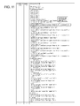
- FIG. 16 is a schematic view showing a control pattern obtained on applying the resource allocation change policy (addition of server resources for DB) of FIG. 12 to the virtual system model of FIG. 11 .
- FIG. 17 is a schematic view continuing to FIG. 16 .
- FIG. 18 is a graph showing the control pattern of FIG. 16 and FIG. 17 .
- FIG. 19 is a graph showing other example resource allocation change policies.
- FIG. 20 is a graph showing further example resource allocation change policies.
- FIG. 21 is a tabular view showing example results of simulation made using the control pattern shown in FIG. 14 , FIG. 16 and FIG. 17 .
- FIG. 22 is a tabular view showing example service level designations of virtual systems operating on the virtual datacenters (vDCs).
- FIG. 23 is a tabular view showing control patterns already evaluated (selected).
- FIG. 24 is a graph showing another virtual system for illustrating the selection of control patterns.
- FIG. 25 is a graph showing candidates for resource allocation change policies applicable to the virtual system shown in FIG. 24 .
- FIG. 26 is a schematic view for illustrating the results of the simulation with the use of the control pattern generated using the resource allocation change policies of FIG. 25 and a candidate selected.
- a preferred form of the present disclosure may be implemented by a control pattern generation unit 11 , configured for producing a plurality of control patterns, and a control unit 12 , configured for controlling a virtual system using one selected out of the control patterns, as shown in FIG. 1 .
- the control patterns are to become candidates of control commands to network resources and server resources of the virtual system.
- control pattern generation unit 11 generates a plurality of control patterns from a virtual system model and from policies of changes of the allocation of resources to the virtual system.
- the virtual system model has been generated by modeling the behaviors of network elements and servers of the virtual system operating on a virtual datacenter.
- the control patterns are to become candidates of control commands to the network resources and server resources of the virtual system.
- the control unit 12 predicts service levels, using the above mentioned multiple control patterns. Then, based on predicted results, the control unit selects and applies such a one of the multiple control patterns which will satisfy the service levels of the virtual system as well as satisfying a preset standard or reference.
- vDCs virtual datacenters
- control pattern may be selected which will lead to a decreased quantity of consumption of whichever one of server resources or network resources that is higher in priority level in consideration of states of global tightness of the resources.
- control pattern may also be selected which will be in keeping with the anticipated state at some future time in consideration of the statistically estimated service demand or the network traffic.
- the preferred form of the present disclosure may enable optimum allocation of network and server resources.
- the preferred form of the present disclosure enables management costs of the virtual systems on the virtual datacenters (vDCs) to be reduced. The reason is that, since the allocated quantities of the server resources and network resources can automatically be controlled, it is possible to reduce the work load on management operators.
- FIG. 2 shows a system configuration of an exemplary embodiment 1 of the present disclosure.
- a configuration including a plurality of virtual datacenters 400 , co-residing on a cloud platform, a virtual resource management unit 300 , configured for allocating resources to the virtual system(s) on the virtual datacenter 400 , and a system for controlling the resources 100 , in a state interconnected over a network.
- FIG. 3 depicts a block diagram showing a detailed configuration of the exemplary embodiment 1 of the present disclosure.
- a virtual datacenter (vDC) 400 provides a plurality of users of the virtual datacenter with a virtual system(s) composed by a virtual appliance(s) and a virtual server(s).
- FIG. 4 shows an example virtual system which the virtual datacenter (vDC) 400 may provide for virtual datacenter users.
- a configuration including a firewall, controlling the communication between the Internet and the virtual system, a load balancer, distributing accesses from the side Internet to a plurality of Web servers, an application server and a database server (DB server).
- the application server and the DB server render services in response to a request(s) from the Web server(s).
- these units do not have to be physically independent and may be constructed by a virtual entity or entities.
- the Web servers, application server or the DB server may be virtual servers constructed by server virtualization techniques.
- the firewall or the load balancer may be implemented by a particular switch or switches according to the Non-Patent Literatures 1, 2 provided that the switch or switches is configured for operating like the firewall or the load balancer.
- the virtual resource management unit 300 performs the functions of managing the quantities of resources allocated to the virtual system on the virtual datacenter 400 or monitoring the use states of the virtual system.
- the virtual resource management unit 300 includes a virtual server resource management unit 301 , a virtual network resource management unit 302 and a virtual datacenter (vDC) monitoring unit 303 .
- the virtual server resource management unit 301 manages the resources of the virtual servers, such as the above mentioned Web servers, application server or DB server, and the virtual network resource management unit 302 manages network resources.
- the vDC monitoring unit 303 outputs use states of the virtual system to a vDC monitoring information memory 304 at a preset time interval to provide monitoring functions for the virtual system.
- the system for controlling the resources 100 includes a control pattern generation unit 110 and an autonomous control unit 120 , and provides the function of generating control patterns which will prove candidates for control commands as well as the function of selecting one control pattern which is in keeping with the operating state of the virtual system, so as to change the allocation of the resources through the virtual resource management unit.
- a vDC construction memory 201 stores the construction information of the virtual system operating on the virtual datacenter (vDC) configured to be controlled by the system for controlling the resources 100 .
- the construction information is shown for example in FIG. 7 and FIG. 8 .
- a resource allocation change policy memory 203 stores resource allocation change policies that may be applied to components making up the virtual system. See for example FIG. 13 , FIG. 15 and FIG. 16 .
- the values of consumption of resources, quantifying the additional resources, needed for control, are set in the resource allocation change policies. For example, see the field of the quantities of consumption of resources of FIG. 14 .
- the control pattern generation unit 110 includes a prediction equation generation unit 111 , a model generation unit 112 and a control pattern derivation unit 113 .
- the prediction equation generation unit 111 takes out the component information of components being predicted, such as virtual appliances or virtual servers of the virtual systems, from the construction information of the virtual system stored in the vDC construction memory 201 .
- the prediction equation generation unit then generates an equation of prediction from which to find the processing time following the changing of the quantities of the resources allocated to the respective components.
- the equation of prediction can be generated with the use of multivariate statistics based on the real processing time per unit request of each virtual appliance or virtual server and on the monitoring information for the quantities of resources already allocated.
- the processing time as being the result of the prediction can be obtained by entering the number of concurrent requests for processing anticipated at the time of the prediction as well as the quantities of allocated resources.
- the model generation unit 112 synthesizes the equation of prediction into the construction information of the virtual system stored in the vDC construction memory 201 to generate a virtual system model which is an abstraction of the behaviors of the virtual system operating within the virtual datacenter (vDC).
- the control pattern derivation unit 113 selects the resource allocation change policies that may be applied to the virtual system model and synthesizes the resource allocation change policies to the system model to generate a plurality of control patterns which may prove candidates of the contents of control commands.
- the control pattern derivation unit 113 stores the control patterns generated in a control pattern memory 101 .
- the autonomous control unit 120 includes a simulation execution unit 121 , a control pattern evaluation unit 122 and a control pattern exercising unit 123 . From the control patterns, the monitoring information for the virtual system on the virtual datacenter (vDC) and from the service level information of the virtual system, the autonomous control unit selects an optimum control pattern for the server resources and the network resources and applies or exercises the so selected optimum control pattern. The information concerning the quantities of consumption of resources may be appended as necessary to the control patterns.
- vDC virtual datacenter
- the simulation execution unit 121 takes out the control patterns of the virtual system being simulated from the control pattern memory 101 and enters the contents of the vDC monitoring information to simulate the behavior of the respective control patterns to predict the average processing time.
- the results simulated are stored in a simulation result memory 124 .
- the control pattern evaluation unit 122 selects the control pattern to be applied or exercised from among the respective control patterns predicted by the simulation execution unit 121 .
- a control pattern selection rule stating that such a control pattern is to be selected that the average processing time will satisfy the service level stored in a service level memory 202 and the quantity of consumption of resources will be minimal.
- the results of evaluation by the control pattern evaluation unit 122 are stored in an evaluated control pattern memory 125 .
- the control pattern exercising unit 123 resolves the control pattern, selected by the control pattern evaluation unit 122 , into a server resource control command and a network resource control command, and informs the virtual resource management unit 300 about the resolution so as to change the allocation of the resources.
- respective parts (processing unit) of the system for controlling the resources may be implemented by a computer program that causes a computer(s) making up the system for controlling the resources to execute the above mentioned processing operations using the computer hardware.
- components expressed as ‘means’ may also be expressed as ‘members’ or ‘units’ to denote units of the hardware, units of component parts by a computer program, or system component units.
- FIG. 5 depicts a flowchart showing the operation of the system for controlling the resources of the exemplary embodiment 1 of the present disclosure (the processing of generating the control pattern).
- the prediction equation generation unit 111 of the control pattern generation unit 110 initially takes out, from the vDC construction memory 201 , the information concerning the virtual servers and the virtual appliances that make up the virtual system operating on the virtual datacenter (vDC).
- the prediction equation generation unit then generates an equation of prediction that may be used to find the processing time for each of the virtual servers and the virtual appliances (loop of step A 1 to step A 4 ).
- the prediction equation generation unit 111 takes out the monitoring information of a virtual system of interest from the vDC monitoring information memory 304 , and acquires the processing time per a request made to the virtual server or the virtual appliance, an equation of prediction for which is being formed.
- the prediction equation generation unit also acquires an average number of requests within the processing time, while also acquiring, from the vDC construction memory 201 , the quantities of memory resources as well as the number of CPU cores, etc. allocated to the virtual servers or the virtual appliances, the equations of prediction for which are being formed (step A 2 ).
- the prediction equation generation unit 111 formulates an equation showing the relationship among the per-request processing time, an average number of concurrent requests within the processing time, and the quantities of resources.
- the prediction equation generation unit stores the so formulated equation for prediction in a prediction equation memory 114 (step A 3 ).
- the model generation unit 112 uses the virtual system construction information, taken out from the vDC construction memory 201 , and the above mentioned equation for prediction, the model generation unit 112 generates a virtual system model for each of the virtual systems, the virtual system models for which are being generated (loop of steps A 5 to A 7 ).
- the model generation unit 112 takes out the equation for prediction from the prediction equation memory 114 and appends it to the construction information of the virtual system, the virtual system model for which is being generated. This generates a virtual system model(s), which is then stored in a model memory 115 (step A 6 ).
- the control pattern derivation unit 113 then collates the virtual system models, taken out from the model memory 115 , against the resource allocation change policies, stating the method for changing the resource allocation, taken out from the resource allocation change policy memory 203 . This selects the resource allocation change policies that may be applied to respective virtual systems (loop of steps A 8 to A 10 ).
- control pattern derivation unit 113 pattern-matches the resource allocation change policies against the virtual system model, taken out from the model memory 115 , so as to select the matching resource allocation change policy or policies (step A 9 ).
- the control pattern derivation unit 113 synthesizes the resource allocation change policy or policies, applicable to the virtual system model, taken out from the model memory 115 , to one another so as to generate a control pattern(s) which is to prove a candidate for the content of the control command for the relevant system.
- the control pattern derivation unit stores the so generated control pattern(s) in the control pattern memory 101 (loop of steps A 11 to A 13 ).
- the quantities of consumption of resources of the respective control pattern(s) are also associated with the control pattern(s) stored in the control pattern memory 101 for storage together with the control pattern(s).
- a sum of the quantities of consumption of resources of the resource allocation change policies synthesized is used as the quantity of consumption of resources of the control pattern(s).
- FIG. 6 depicts a flowchart showing the operation (autonomous control) of a system for controlling the resources of the exemplary embodiment 1 of the present disclosure.
- the simulation execution unit 121 of the autonomous control unit 120 reads out a set of control patterns concerning the virtual system operating on the virtual datacenter (vDC) from the control pattern memory 101 , while taking out the latest monitoring information of the virtual system from the vDC monitoring information memory 304 .
- the simulation execution unit 121 simulates the total of the control patterns to predict the average processing time for each control pattern to store the results of the simulation in the simulation result memory 124 (step B 1 ).
- the control pattern evaluation unit 122 then takes out the results of the simulation from the simulation result memory 124 , while taking out the service level designation of the virtual system in question from the service level memory 202 , so as to decide whether or not the average processing time is less than the service level (step B 2 ).
- control pattern evaluation unit 122 exempts the control pattern from the candidates to be applied (step B 3 ).
- the control pattern evaluation unit 122 compares the control patterns, having the average processing time less than the service level, to one another, and selects the control pattern with the least quantity of consumption of resources, as an example.
- the control pattern evaluation unit stores the so selected control pattern in the evaluated control pattern memory 125 (step B 4 ). This selects the control pattern that is in keeping with the latest operating states of the virtual system.
- the control pattern exercising unit 123 then takes out the selected control pattern from the control pattern memory 101 based on the information stored in the evaluated control pattern memory 125 .
- the control pattern exercising unit 123 resolves the control pattern into a server resource control command and a network resource control command, and issues control commands to the virtual server resource management unit 301 and to the virtual network resource management unit 302 . This changes the allocation of resources to the virtual system on the virtual datacenter (vDC).
- the autonomous control unit 120 selects and applies the optimum control pattern in keeping with the latest operating states of the virtual system on the virtual datacenter (vDC), so that it is possible to optimize allocation of resources to the virtual system.
- vDC virtual datacenter
- a virtual system having, as components, virtual appliances and virtual servers, such as firewalls, load balancers, Web servers, application servers and DB servers, is in operation on the virtual datacenter (vDC), as shown in FIG. 4 .
- virtual appliances are meant virtual machines, operating as network appliances, such as firewalls or load balancers.
- the vDC monitoring unit 303 monitors the operating states of the present system from component to component to store the monitored result in the vDC monitoring information memory 304 .
- FIG. 7 shows examples of the monitoring information stored in the vDC monitoring information memory 304 .
- the monitoring information for the Web server (Web 1 ) as well as the firewall (FW 1 ) is stored in a virtual datacenter having a virtual data center ID (vDCID) equal to 1.
- vDCID virtual data center ID
- the present virtual system can be expressed by a directed bipartite graph in which a component is represented by a transition and a corresponding message by a place (circle), as shown in FIG. 8 . It is only sufficient that the construction information equivalent to this directed bipartite graph is stored in the vDC construction memory 201 .
- FIG. 9 shows the construction information of the virtual system stored in the vDC construction memory 201 .
- places are first defined and components of the virtual system of the virtual datacenter vDC are stated as transitions.
- the information representing the concerting relationship (relationship of interconnections) among these places and transitions is stored.
- the prediction equation generation unit 111 of the control pattern generation unit 110 takes out the construction information of the virtual system shown in FIG. 9 from the vDC construction memory 201 . Then, using the names of the virtual servers and the virtual appliances, such as FW 1 and Web 1 , stated as transitions in the above construction information, as keys, the prediction equation generation unit 111 takes out the monitoring information of relevant components from the vDC monitoring information memory 304 . The prediction equation generation unit 111 then gets the processing time of requests of the components and the average number of the requests made within the processing time.
- the prediction equation generation unit 111 also acquires, from the vDC construction memory 201 , the quantities of resources already allocated, such as the memory storage capacity or the number of CPU cores allocated to the virtual servers and appliances. Then, using the multivariate statistics, the prediction equation generation unit 111 formulates the relationship among the processing time per request, the average number of concurrent requests within the processing time and the quantities of resources, as an equation of prediction.
- FIG. 10 shows example equations of prediction generated by the prediction equation generation unit 111 and stored in the prediction equation memory 114 .
- ⁇ 3 , ⁇ 3 , ⁇ 3 and ⁇ 3 are coefficients and an intercept as found by the multivariate statistics.
- the component such as Web server “Web 1 ”
- the processing time for these requests may be separately calculated and weighted averaging taken of the so calculated processing time.
- the requests may be handled as requests of the same sort.
- the model generation unit 112 introduces the equation of prediction taken out from the prediction equation memory 114 into the construction information of the virtual system, taken out from the vDC construction memory 201 , shown in FIG. 9 , to generate a virtual system model, which is then stored in the model memory 115 .
- FIG. 11 shows an example virtual system model generated by the model generation unit 112 and stored in the model memory 115 .
- the equation of prediction is added to each component of the construction information of the virtual system shown in FIG. 9 .
- the control pattern derivation unit 113 then collates the virtual system model, shown in FIG. 11 , against the resource allocation change policies, so as to extract the resource allocation change policy or policies applicable to the virtual system model of interest.
- FIG. 12 depicts a diagram showing resource allocation change policies A, B applicable to a load balancer on the virtual system.
- the resource allocation change policies are shown in the same way as the above mentioned Petri Net.
- the resource allocation change policy A of FIG. 12 changes over a load balancer to a single flow controller (FC 1 ) and two load balancers.
- the resource allocation change policy B of FIG. 12 adds resources (memory and the number of CPU cores) to a load balancer.
- FIG. 13 depicts a tabular view showing resource allocation change policies equivalent to the resource allocation change policies shown in FIG. 12 .
- An example shown in FIG. 13 shows entries in which not only the policy IDs and policy names but also the information concerning patterns of application used in matching against the virtual system, detailed contents of the resource allocation change policies and the quantities of consumption of resources in case of using the resource allocation change policies of FIG. 12 , are correlated to one another.
- the resource allocation change policy A shown in FIG. 12 and FIG. 13 in which a load balancer is changed over to one flow controller and two load balancers, matches the construction information concerning the load balancer in the virtual system model shown in FIG. 11 .
- the resource allocation change policy B shown in FIG. 12 and FIG. 13 in which resources of a server for DB are added, matches the construction information concerning the DB server in the virtual system model shown in FIG. 11 .
- the control pattern derivation unit 113 synthesizes the resource allocation change policy or policies, obtained as described above, to generate the control pattern.
- FIG. 14 shows an example in which just the resource allocation change policy A of changing over the load balancer shown in FIG. 12 and FIG. 13 is applied to the virtual system model shown in FIG. 11 .
- FIG. 15 depicts a graph equivalent to FIG. 14 .
- FIG. 16 and FIG. 17 show an example in which both the resource allocation change policy A of changing over a load balancer and the resource allocation change policy B of adding resources of the server for DB, shown in FIG. 12 and FIG. 13 , are applied to the virtual system model shown in FIG. 11 .
- FIG. 18 depicts a graph equivalent to FIG. 16 and FIG. 17 .
- both the resource allocation change policy A of changing over the load balancer and the resource allocation change policy B of adding resources to the load balancer, shown in FIG. 12 and FIG. 13 are applied.
- the quantity of consumption of resources is equal to the sum of the consumption of the resources of the respective resource allocation change policies, that is, equal to “6”.
- control pattern derivation unit 113 formulates a control pattern in which just the resource allocation change policy B of adding the server resources for DB shown in FIG. 12 and FIG. 13 is applied to the virtual system model shown in FIG. 11 .
- FIG. 19 shows, like FIG. 12 , a resource allocation change policy in which a clone is added to a component by way of scale-out as well as a resource allocation change policy in which resources are added to a component.
- a resource allocation change policy shown in an upper part of FIG. 20 , adds not only a clone but also a flow controller to a component to exercise path control.
- a resource allocation change policy shown in a lower part of FIG. 20 , adds a flow controller ahead of a component to exercise flow control.
- the control pattern derivation unit 113 uses these resource allocation change policies alone or in combination to generate a control pattern(s).
- the simulation execution unit 121 of the autonomous control unit 120 reads out, from the control pattern memory 101 , a set of control patterns of a virtual system, as a subject of the autonomous control, as shown in FIG. 14 , FIG. 16 and FIG. 17 . Moreover, the simulation execution unit 121 takes out, from the vDC monitoring information memory 304 , the latest monitoring information (the information continuing for 30 minutes) of a firewall part of the monitoring information of the virtual system in question so as to deliver the so taken out information to the virtual system. The simulation execution unit delivers the information as input to the respective control patterns to predict the average processing time of each control pattern.
- FIG. 21 shows the result of the simulation of the control patterns by the simulation execution unit 121 shown in FIG. 14 , FIG. 16 and FIG. 17 .
- the control pattern evaluation unit 122 takes out the result of the simulation from the simulation result memory 124 , while also taking out the service level designations of the virtual system, shown in FIG. 22 , from the service level memory 202 , in order decide whether or not the average processing time predicted for the case of using each control pattern is below the service level.
- control pattern evaluation unit 122 If, as a result of the above decision, the average processing time of one or more control patterns exceeds a service level, the control pattern evaluation unit 122 exempts the control pattern(s) from the set of applicable candidates.
- the control pattern evaluation unit 122 compares the control patterns, having average processing time less than the service level, one to another, and selects the control pattern having the least consumption of resources.
- both of the control patterns of FIG. 21 may be said to satisfy the service level.
- the control pattern evaluation unit 122 compares the result of the simulation shown in FIG. 21 to select the control pattern of the control pattern ID of ‘pattern 1 ’ having the least quantity of consumption of resources.
- FIG. 23 shows an example of the information on the control patterns already evaluated.
- the information is stored in the evaluated control patterns has been stored in the evaluated control pattern memory 125 .
- the control pattern exercising unit 123 takes out the information on the control pattern, which is the control pattern already evaluated, from the control pattern memory 101 , and issues a control command to the virtual server resource management unit 301 and the virtual network resource management unit 302 of the resource management unit 300 .
- the virtual system having resources allocated as shown in FIG. 8 , now has resources allocated as shown in FIG. 15 .
- the new post-change allocation of the resources has been selected based on the results of prediction by the simulation execution unit 121 , and hence satisfies the service level required of the virtual system in question, as well as minimizing the quantity of consumption of resources.
- FIG. 24 depicts a directed bipartite graph showing a virtual system.
- FIG. 25 shows certain example resource allocation change policies applicable to the above virtual system.
- a candidate 1 is an example resource allocation change policy in which a load balancer and a clone Web server are added to a Web server in a virtual system.
- a candidate 2 is an example resource allocation change policy in which the performance of the Web server in a virtual system is reinforced.
- a candidate 3 is an example resource allocation change policy in which a flow controller is arranged in a pre-stage of a Web server in a virtual system and in which limitations are imposed on the number of connections.
- FIG. 26 shows the results of service level prediction by the simulation execution unit 121 for cases where a control pattern generated with the use of each one of the above candidates is applied. If, for example, the service level is set at 5 (seconds), the candidate 3 is a control pattern that is not down to the service level, and hence is exempted from use as the control pattern.
- the control pattern evaluation unit 122 then compares the candidates 1 and 2 to each other to select the candidate 2 with the lesser quantity of consumption of resources. As a result, the allocation of resources to the virtual system shown in FIG. 24 is changed over to that in which the Web server performance has been reinforced, as shown in a lower part of FIG. 26 .
- control pattern with the least quantity of the consumption of resources is to be selected out of the control patterns satisfying the service level.
- control pattern may also be selected with the use of some other standard or reference. For example, even if a control pattern has the least quantity of the consumption of resources, but the service level predicted of the control pattern is extremely close to the required service level, such control pattern may not be selected. By so doing, it is possible to select such control pattern that is able to satisfy the service level even though the number of request has increased beyond the latest monitoring value.
- control pattern selection standard or reference that selects the control pattern that will increase the server resources by “2” may be used.
- control pattern selection standard or reference may be used in which the control pattern that has a greater quantity of consumption of resources but that will not increase the quantity of consumption of network resources is selected.
- such a resource allocation change policy is used in which allocation of resources is changed in an increasing direction. It is however also possible to use a resource allocation change policy in which allocation of resources is changed in a decreasing direction.
- the graph shown on the right side of FIG. 12 is a pattern of application and the graph shown on the left side of FIG. 12 is a resource allocation change policy. In this case, the quantity of consumption of resources will have a negative value.
- control pattern generation unit generates a plurality of control patterns for each of the virtual systems of the virtual datacenters co-residing on a cloud platform;
- control unit selects the control pattern(s) for the virtual system(s) of each virtual datacenter and putting the control pattern(s) to use.
- the preset standard or reference for selection is such a one that selects, from among a plurality of the control patterns satisfying the service level, such a control pattern having a lesser quantity of consumption of resources.
- the preset standard or reference for selection is such a one that selects, from among a plurality of the control patterns satisfying the service level, such a control pattern having a lesser quantity of consumption of resources of the server resources or the network resources, whichever are higher in the priority level.
- control pattern generation unit includes
- a prediction equation generation unit that generates, for each of the network element(s) and the server(s) of the virtual system(s), operating on the virtual datacenter(s), an equation of prediction for predicting the processing time for the case of having changed the resources allocated based on the quantity of resources already allocated and on the results of measurement of processing time for the case of using the quantity of resources already allocated;
- a virtual system model generation unit that generates the virtual system model(s) using the construction information of the virtual system(s) operating on the virtual datacenter(s) and also using the equation of prediction generated by the prediction equation generation unit;
- control pattern derivation unit that synthesizes a configuration included in the virtual system model generated by the virtual system model generation unit and the resource allocation change policy applicable together so as to form the control pattern.
- control unit includes
- a simulation execution unit that executes simulation of predicting a service level using the plurality of the control patterns
- control pattern evaluation unit that selects, based on the result of the simulation, such control pattern that satisfies the service level of the virtual system as well as satisfying the preset standard or reference;
- control pattern applying unit that changes the allocation of the network resources and the server resources in accordance with the selected control pattern.
- a resource allocation change policy or policies for carrying out path control and flow control is among the resource allocation change policies.
- modes 8 to the mode 11 may be expanded to the modes 2 to 7 as is the mode 1.
- Patent Literatures and Non-Patent Literatures are to be incorporated herein by reference.
- the exemplary embodiments or Examples may be modified or adjusted within the concept of the total disclosures of the present invention, inclusive of claims, based on the fundamental technical concept of the invention.
- a series of combinations or selections of elements herein disclosed may be made within the context of the claims of the present invention. That is, the present invention may include a wide variety of changes or corrections that may occur to those skilled in the art in accordance with the total disclosures inclusive of the claims and the drawings as well as the technical concept of the invention.
Abstract
Description
- Patent Literature 1: JP Patent 4557949
- Patent Literature 2: JP Patent 4627461
- Patent Literature 3: JP Patent 4872702
- Non-Patent Literature 1: Nick McKeown and seven others, “OpenFlow: Enabling Innovation in Campus Networks”, [online], [retrieved on January 9, Heisei25 (2013)], Internet <URL:http:/www.openflow.org/documents/openflow-wp-latest.pdf>
- Non-Patent Literature 2: “OpenFlow Switch Specification” Version 1.3.1 (Wire Protocol 0x04), [online], [retrieved on January 9, Heisei25 (2013)], Internet <URL: http://www.opennetworking.org/images/stories/downloads/specification/openflow-spec-v1.3.1.pdf>
T=γM+δ
may be obtained, where T is the processing time for the virtual server or the virtual appliance, an equation for prediction for which is being produced, M is an average number of concurrent requests, and γ, δ are coefficient and a constant used for expression as an equation.
T_web1=α3*X_p04/(γ3*cpu3+δ3*ram3)+β3
is formed, where X_p04 is the number of concurrent requests in Web1, cpu3 the number of allocated virtual CPU cores and ram3 a parameter representing an allocated RAM memory storage capacity. α3, γ3, δ3 and β3 are coefficients and an intercept as found by the multivariate statistics. By the way, there are cases where the component, such as Web server “Web1”, receives requests of different sorts. In such case, the processing time for these requests may be separately calculated and weighted averaging taken of the so calculated processing time. Or, if the requests are of different sorts but there is no difference in the processing time, the requests may be handled as requests of the same sort.
- (Reference is made to the system for controlling the resources according to the first aspect).
[Mode 2]
- (Reference is made to the apparatus for generating a control pattern according to the second aspect).
[Mode 9] - (Reference is made to the control apparatus according to the third aspect).
[Mode 10] - (Reference is made to the method for controlling resources according to the fourth aspect).
[Mode 11] - (Reference is made to the program according to the fifth aspect).
Claims (20)
Applications Claiming Priority (3)
| Application Number | Priority Date | Filing Date | Title |
|---|---|---|---|
| JP2013-018202 | 2013-02-01 | ||
| JP2013018202 | 2013-02-01 | ||
| PCT/JP2014/052239 WO2014119719A1 (en) | 2013-02-01 | 2014-01-31 | Resource control system, control pattern generation device, control device, resource control method and program |
Publications (2)
| Publication Number | Publication Date |
|---|---|
| US20150363240A1 US20150363240A1 (en) | 2015-12-17 |
| US9740534B2 true US9740534B2 (en) | 2017-08-22 |
Family
ID=51262416
Family Applications (1)
| Application Number | Title | Priority Date | Filing Date |
|---|---|---|---|
| US14/761,800 Active 2034-09-10 US9740534B2 (en) | 2013-02-01 | 2014-01-31 | System for controlling resources, control pattern generation apparatus, control apparatus, method for controlling resources and program |
Country Status (5)
| Country | Link |
|---|---|
| US (1) | US9740534B2 (en) |
| EP (1) | EP2953024A1 (en) |
| JP (1) | JP6380110B2 (en) |
| CN (1) | CN104981782B (en) |
| WO (1) | WO2014119719A1 (en) |
Families Citing this family (13)
| Publication number | Priority date | Publication date | Assignee | Title |
|---|---|---|---|---|
| US10097410B2 (en) | 2014-06-26 | 2018-10-09 | Vmware, Inc. | Methods and apparatus to scale application deployments in cloud computing environments |
| EP3281368B1 (en) * | 2015-04-07 | 2020-05-06 | Umbra Technologies Ltd. | Network system having virtual interfaces and a routing module for a virtual network |
| US10678596B2 (en) * | 2016-02-24 | 2020-06-09 | Alibaba Group Holding Limited | User behavior-based dynamic resource capacity adjustment |
| US10796035B1 (en) * | 2016-03-21 | 2020-10-06 | EMC IP Holding Company LLC | Computing system with simulated hardware infrastructure to support development and testing of management and orchestration software |
| JP6879360B2 (en) * | 2017-03-30 | 2021-06-02 | 日本電気株式会社 | Recommendation systems and methods, equipment, programs |
| US11347561B1 (en) * | 2018-04-30 | 2022-05-31 | Vmware, Inc. | Core to resource mapping and resource to core mapping |
| JP2019211890A (en) * | 2018-06-01 | 2019-12-12 | 日本電信電話株式会社 | Device and method for managing resource reservations |
| CA3057032C (en) | 2018-09-28 | 2023-03-21 | Element Ai Inc. | System and method for managing network resources |
| US11184234B2 (en) * | 2019-04-16 | 2021-11-23 | Ciena Corporation | Self-optimizing fabric architecture and self-assembling network |
| DE112021000708T5 (en) * | 2020-01-24 | 2023-01-12 | Fanuc Corporation | data collection device |
| US11635981B2 (en) * | 2020-08-25 | 2023-04-25 | Microsoft Technology Licensing, Llc | Virtualizing shared computing resources |
| US11956213B2 (en) | 2022-05-18 | 2024-04-09 | VMware LLC | Using firewall policies to map data messages to secure tunnels |
| US20230388180A1 (en) * | 2022-05-31 | 2023-11-30 | Microsoft Technology Licensing, Llc | Techniques for provisioning workspaces in cloud-based computing platforms |
Citations (33)
| Publication number | Priority date | Publication date | Assignee | Title |
|---|---|---|---|---|
| US20070006218A1 (en) * | 2005-06-29 | 2007-01-04 | Microsoft Corporation | Model-based virtual system provisioning |
| JP2007028035A (en) | 2005-07-14 | 2007-02-01 | Nippon Telegr & Teleph Corp <Ntt> | Communication service control system, method, and program |
| US20070220149A1 (en) * | 2006-03-15 | 2007-09-20 | Masanori Kawashima | Load balance control method and load balance control apparatus in data-processing system |
| JP2007305101A (en) | 2006-04-10 | 2007-11-22 | Fujitsu Ltd | Resource brokering program, recording medium recording this program, resource brokering device, and resource brokering method |
| US20070271560A1 (en) * | 2006-05-18 | 2007-11-22 | Microsoft Corporation | Deploying virtual machine to host based on workload characterizations |
| US20080034093A1 (en) * | 2006-08-01 | 2008-02-07 | Hiromi Sutou | System and method for managing resources |
| US20080163194A1 (en) * | 2007-01-02 | 2008-07-03 | Daniel Manuel Dias | Method and apparatus for deploying a set of virtual software resource templates to a set of nodes |
| US20080172673A1 (en) * | 2007-01-15 | 2008-07-17 | International Business Machines Corporation | Prediction based resource matching for grid environments |
| JP2008203934A (en) | 2007-02-16 | 2008-09-04 | Nec Corp | Distributed workflow simulation system, method and program |
| US20080221941A1 (en) * | 2007-03-09 | 2008-09-11 | Ludmila Cherkasova | System and method for capacity planning for computing systems |
| US20080270595A1 (en) * | 2007-04-30 | 2008-10-30 | Jerome Rolia | System and method for generating synthetic workload traces |
| US20080271039A1 (en) * | 2007-04-30 | 2008-10-30 | Jerome Rolia | Systems and methods for providing capacity management of resource pools for servicing workloads |
| WO2009144822A1 (en) | 2008-05-30 | 2009-12-03 | 富士通株式会社 | Device configuration information management program, device configuration information management device, and device configuration information management method |
| US20100050172A1 (en) * | 2008-08-22 | 2010-02-25 | James Michael Ferris | Methods and systems for optimizing resource usage for cloud-based networks |
| US20100199267A1 (en) * | 2009-01-30 | 2010-08-05 | Jerome Rolia | Sizing an infrastructure configuration optimized for a workload mix using a predictive model |
| US20100281478A1 (en) * | 2009-05-01 | 2010-11-04 | Microsoft Corporation | Multiphase virtual machine host capacity planning |
| US20110214124A1 (en) * | 2010-02-26 | 2011-09-01 | James Michael Ferris | Systems and methods for generating cross-cloud computing appliances |
| US20110307901A1 (en) * | 2009-01-30 | 2011-12-15 | Blanding William H | System and method for integrating capacity planning and workload management |
| US8087025B1 (en) * | 2004-06-30 | 2011-12-27 | Hewlett-Packard Development Company, L.P. | Workload placement among resource-on-demand systems |
| US8104038B1 (en) * | 2004-06-30 | 2012-01-24 | Hewlett-Packard Development Company, L.P. | Matching descriptions of resources with workload requirements |
| US8117613B2 (en) * | 2009-04-08 | 2012-02-14 | Microsoft Corporation | Optimized virtual machine migration mechanism |
| US20120060167A1 (en) * | 2010-09-08 | 2012-03-08 | Salsburg Michael A | Method and system of simulating a data center |
| US20120284380A1 (en) * | 2011-05-03 | 2012-11-08 | International Business Machines Corporation | Identifying optimal virtual machine images in a networked computing environment |
| US20120284408A1 (en) * | 2011-05-04 | 2012-11-08 | International Business Machines Corporation | Workload-aware placement in private heterogeneous clouds |
| US20130138812A1 (en) * | 2011-11-25 | 2013-05-30 | Marcos Dias De Assuncao | System, method and program product for cost-aware selection of templates for provisioning shared resources |
| US20130185433A1 (en) * | 2012-01-13 | 2013-07-18 | Accenture Global Services Limited | Performance interference model for managing consolidated workloads in qos-aware clouds |
| US8555287B2 (en) * | 2006-08-31 | 2013-10-08 | Bmc Software, Inc. | Automated capacity provisioning method using historical performance data |
| US8627309B2 (en) * | 2010-02-25 | 2014-01-07 | Microsoft Corporation | Automated deployment and servicing of distributed applications |
| US20140019965A1 (en) * | 2012-07-13 | 2014-01-16 | Douglas M. Neuse | System and method for automated assignment of virtual machines and physical machines to hosts with right-sizing |
| US8645529B2 (en) * | 2010-10-06 | 2014-02-04 | Infosys Limited | Automated service level management of applications in cloud computing environment |
| US20140095693A1 (en) * | 2012-09-28 | 2014-04-03 | Caplan Software Development S.R.L. | Automated Capacity Aware Provisioning |
| US8756307B1 (en) * | 2007-07-30 | 2014-06-17 | Hewlett-Packard Development Company, L.P. | Translating service level objectives to system metrics |
| US8806487B2 (en) * | 2011-01-14 | 2014-08-12 | Nec Laboratories America, Inc. | Calculating virtual machine resource utilization information |
Family Cites Families (3)
| Publication number | Priority date | Publication date | Assignee | Title |
|---|---|---|---|---|
| JP2010218307A (en) * | 2009-03-17 | 2010-09-30 | Hitachi Ltd | Distributed calculation controller and method |
| JP5556507B2 (en) * | 2010-08-30 | 2014-07-23 | 富士通株式会社 | Virtual machine management program, virtual machine management method, and virtual machine management apparatus |
| CN102004671B (en) * | 2010-11-15 | 2013-03-13 | 北京航空航天大学 | Resource management method of data center based on statistic model in cloud computing environment |
-
2014
- 2014-01-31 JP JP2014559769A patent/JP6380110B2/en active Active
- 2014-01-31 WO PCT/JP2014/052239 patent/WO2014119719A1/en active Application Filing
- 2014-01-31 CN CN201480007043.0A patent/CN104981782B/en active Active
- 2014-01-31 EP EP14746471.3A patent/EP2953024A1/en not_active Withdrawn
- 2014-01-31 US US14/761,800 patent/US9740534B2/en active Active
Patent Citations (35)
| Publication number | Priority date | Publication date | Assignee | Title |
|---|---|---|---|---|
| US8087025B1 (en) * | 2004-06-30 | 2011-12-27 | Hewlett-Packard Development Company, L.P. | Workload placement among resource-on-demand systems |
| US8104038B1 (en) * | 2004-06-30 | 2012-01-24 | Hewlett-Packard Development Company, L.P. | Matching descriptions of resources with workload requirements |
| US20070006218A1 (en) * | 2005-06-29 | 2007-01-04 | Microsoft Corporation | Model-based virtual system provisioning |
| JP2007028035A (en) | 2005-07-14 | 2007-02-01 | Nippon Telegr & Teleph Corp <Ntt> | Communication service control system, method, and program |
| US20070220149A1 (en) * | 2006-03-15 | 2007-09-20 | Masanori Kawashima | Load balance control method and load balance control apparatus in data-processing system |
| JP2007249445A (en) | 2006-03-15 | 2007-09-27 | Hitachi Ltd | Load distribution control method and its device for cluster system |
| JP2007305101A (en) | 2006-04-10 | 2007-11-22 | Fujitsu Ltd | Resource brokering program, recording medium recording this program, resource brokering device, and resource brokering method |
| US20070271560A1 (en) * | 2006-05-18 | 2007-11-22 | Microsoft Corporation | Deploying virtual machine to host based on workload characterizations |
| US20080034093A1 (en) * | 2006-08-01 | 2008-02-07 | Hiromi Sutou | System and method for managing resources |
| JP2008033852A (en) | 2006-08-01 | 2008-02-14 | Hitachi Ltd | Resource management system and its method |
| US8555287B2 (en) * | 2006-08-31 | 2013-10-08 | Bmc Software, Inc. | Automated capacity provisioning method using historical performance data |
| US20080163194A1 (en) * | 2007-01-02 | 2008-07-03 | Daniel Manuel Dias | Method and apparatus for deploying a set of virtual software resource templates to a set of nodes |
| US20080172673A1 (en) * | 2007-01-15 | 2008-07-17 | International Business Machines Corporation | Prediction based resource matching for grid environments |
| JP2008203934A (en) | 2007-02-16 | 2008-09-04 | Nec Corp | Distributed workflow simulation system, method and program |
| US20080221941A1 (en) * | 2007-03-09 | 2008-09-11 | Ludmila Cherkasova | System and method for capacity planning for computing systems |
| US20080271039A1 (en) * | 2007-04-30 | 2008-10-30 | Jerome Rolia | Systems and methods for providing capacity management of resource pools for servicing workloads |
| US20080270595A1 (en) * | 2007-04-30 | 2008-10-30 | Jerome Rolia | System and method for generating synthetic workload traces |
| US8756307B1 (en) * | 2007-07-30 | 2014-06-17 | Hewlett-Packard Development Company, L.P. | Translating service level objectives to system metrics |
| WO2009144822A1 (en) | 2008-05-30 | 2009-12-03 | 富士通株式会社 | Device configuration information management program, device configuration information management device, and device configuration information management method |
| US20100050172A1 (en) * | 2008-08-22 | 2010-02-25 | James Michael Ferris | Methods and systems for optimizing resource usage for cloud-based networks |
| US20100199267A1 (en) * | 2009-01-30 | 2010-08-05 | Jerome Rolia | Sizing an infrastructure configuration optimized for a workload mix using a predictive model |
| US20110307901A1 (en) * | 2009-01-30 | 2011-12-15 | Blanding William H | System and method for integrating capacity planning and workload management |
| US8117613B2 (en) * | 2009-04-08 | 2012-02-14 | Microsoft Corporation | Optimized virtual machine migration mechanism |
| US20100281478A1 (en) * | 2009-05-01 | 2010-11-04 | Microsoft Corporation | Multiphase virtual machine host capacity planning |
| US8627309B2 (en) * | 2010-02-25 | 2014-01-07 | Microsoft Corporation | Automated deployment and servicing of distributed applications |
| US20110214124A1 (en) * | 2010-02-26 | 2011-09-01 | James Michael Ferris | Systems and methods for generating cross-cloud computing appliances |
| US20120060167A1 (en) * | 2010-09-08 | 2012-03-08 | Salsburg Michael A | Method and system of simulating a data center |
| US8645529B2 (en) * | 2010-10-06 | 2014-02-04 | Infosys Limited | Automated service level management of applications in cloud computing environment |
| US8806487B2 (en) * | 2011-01-14 | 2014-08-12 | Nec Laboratories America, Inc. | Calculating virtual machine resource utilization information |
| US20120284380A1 (en) * | 2011-05-03 | 2012-11-08 | International Business Machines Corporation | Identifying optimal virtual machine images in a networked computing environment |
| US20120284408A1 (en) * | 2011-05-04 | 2012-11-08 | International Business Machines Corporation | Workload-aware placement in private heterogeneous clouds |
| US20130138812A1 (en) * | 2011-11-25 | 2013-05-30 | Marcos Dias De Assuncao | System, method and program product for cost-aware selection of templates for provisioning shared resources |
| US20130185433A1 (en) * | 2012-01-13 | 2013-07-18 | Accenture Global Services Limited | Performance interference model for managing consolidated workloads in qos-aware clouds |
| US20140019965A1 (en) * | 2012-07-13 | 2014-01-16 | Douglas M. Neuse | System and method for automated assignment of virtual machines and physical machines to hosts with right-sizing |
| US20140095693A1 (en) * | 2012-09-28 | 2014-04-03 | Caplan Software Development S.R.L. | Automated Capacity Aware Provisioning |
Non-Patent Citations (3)
| Title |
|---|
| "OpenFlow Switch Specification" Version 1.3.1 (Wire Protocol 0×04), Sep. 6, 2012. |
| International Search Report for PCT Application No. PCT/JP2014/052239, mailed on Mar. 18, 2014. |
| Nick McKeown and seven others, "OpenFlow: Enabling Innovation in Campus Networks", Mar. 14, 2008. |
Also Published As
| Publication number | Publication date |
|---|---|
| US20150363240A1 (en) | 2015-12-17 |
| WO2014119719A1 (en) | 2014-08-07 |
| CN104981782A (en) | 2015-10-14 |
| JP6380110B2 (en) | 2018-08-29 |
| EP2953024A1 (en) | 2015-12-09 |
| JPWO2014119719A1 (en) | 2017-01-26 |
| CN104981782B (en) | 2019-03-26 |
Similar Documents
| Publication | Publication Date | Title |
|---|---|---|
| US9740534B2 (en) | System for controlling resources, control pattern generation apparatus, control apparatus, method for controlling resources and program | |
| Gouareb et al. | Virtual network functions routing and placement for edge cloud latency minimization | |
| Huang et al. | Service chaining for hybrid network function | |
| Gao et al. | Optimal orchestration of virtual network functions | |
| Yoshida et al. | MORSA: A multi-objective resource scheduling algorithm for NFV infrastructure | |
| CN110011863B (en) | Network bandwidth resource balanced scheduling method and device | |
| Rankothge et al. | Experimental results on the use of genetic algorithms for scaling virtualized network functions | |
| He et al. | SLA-aware multiple migration planning and scheduling in SDN-NFV-enabled clouds | |
| CN113348651B (en) | Dynamic inter-cloud placement of sliced virtual network functions | |
| Leivadeas et al. | VNF placement problem: A multi-tenant intent-based networking approach | |
| Tajiki et al. | CECT: computationally efficient congestion-avoidance and traffic engineering in software-defined cloud data centers | |
| Bolodurina et al. | Development and research of models of organization distributed cloud computing based on the software-defined infrastructure | |
| Addad et al. | AI-based network-aware service function chain migration in 5G and beyond networks | |
| Baresi et al. | PAPS: A Framework for Decentralized Self-management at the Edge | |
| CN114172937A (en) | Dynamic service function chain arrangement method and system based on deep reinforcement learning | |
| Dezhabad et al. | Learning-based dynamic scalable load-balanced firewall as a service in network function-virtualized cloud computing environments | |
| Shang et al. | Network congestion-aware online service function chain placement and load balancing | |
| Mostafa | Cooperative fog communications using a multi-level load balancing | |
| Lin et al. | Column generation based service function chaining embedding in multi-domain networks | |
| Sun et al. | Efficient VNF placement for Poisson arrived traffic | |
| Doan et al. | SAP: Subchain-aware NFV service placement in mobile edge cloud | |
| Shang et al. | Online service function chain placement for cost-effectiveness and network congestion control | |
| Dalgkitsis et al. | SCHE2MA: Scalable, energy-aware, multidomain orchestration for beyond-5G URLLC services | |
| Gadre et al. | Centralized approaches for virtual network function placement in SDN-enabled networks | |
| Garg et al. | Heuristic and reinforcement learning algorithms for dynamic service placement on mobile edge cloud |
Legal Events
| Date | Code | Title | Description |
|---|---|---|---|
| AS | Assignment |
Owner name: NEC CORPORATION, JAPAN Free format text: ASSIGNMENT OF ASSIGNORS INTEREST;ASSIGNOR:KOIZUMI, SEIICHI;REEL/FRAME:036117/0503 Effective date: 20150624 |
|
| STCF | Information on status: patent grant |
Free format text: PATENTED CASE |
|
| MAFP | Maintenance fee payment |
Free format text: PAYMENT OF MAINTENANCE FEE, 4TH YEAR, LARGE ENTITY (ORIGINAL EVENT CODE: M1551); ENTITY STATUS OF PATENT OWNER: LARGE ENTITY Year of fee payment: 4 |
|
| AS | Assignment |
Owner name: NEC ASIA PACIFIC PTE LTD., SINGAPORE Free format text: ASSIGNMENT OF ASSIGNORS INTEREST;ASSIGNOR:NEC CORPORATION;REEL/FRAME:063349/0459 Effective date: 20230414 |
|
| AS | Assignment |
Owner name: IP WAVE PTE LTD., SINGAPORE Free format text: ASSIGNMENT OF ASSIGNORS INTEREST;ASSIGNOR:NEC ASIA PACIFIC PTE LTD.;REEL/FRAME:066376/0276 Effective date: 20240118 |