US9752933B2 - Optical emission system including dichroic beam combiner - Google Patents
Optical emission system including dichroic beam combiner Download PDFInfo
- Publication number
- US9752933B2 US9752933B2 US14/614,381 US201514614381A US9752933B2 US 9752933 B2 US9752933 B2 US 9752933B2 US 201514614381 A US201514614381 A US 201514614381A US 9752933 B2 US9752933 B2 US 9752933B2
- Authority
- US
- United States
- Prior art keywords
- light
- wavelengths
- entrance aperture
- beam combiner
- dichroic beam
- Prior art date
- Legal status (The legal status is an assumption and is not a legal conclusion. Google has not performed a legal analysis and makes no representation as to the accuracy of the status listed.)
- Active, expires
Links
- 230000003287 optical effect Effects 0.000 title claims abstract description 55
- 238000005259 measurement Methods 0.000 claims abstract description 47
- 238000001514 detection method Methods 0.000 claims abstract description 35
- 238000004458 analytical method Methods 0.000 claims abstract description 11
- 238000009616 inductively coupled plasma Methods 0.000 claims description 9
- 238000001914 filtration Methods 0.000 claims description 8
- 238000001228 spectrum Methods 0.000 description 6
- 230000008901 benefit Effects 0.000 description 5
- 230000006870 function Effects 0.000 description 2
- 238000000034 method Methods 0.000 description 2
- 239000011669 selenium Substances 0.000 description 2
- 230000035945 sensitivity Effects 0.000 description 2
- 239000011734 sodium Substances 0.000 description 2
- DGAQECJNVWCQMB-PUAWFVPOSA-M Ilexoside XXIX Chemical compound C[C@@H]1CC[C@@]2(CC[C@@]3(C(=CC[C@H]4[C@]3(CC[C@@H]5[C@@]4(CC[C@@H](C5(C)C)OS(=O)(=O)[O-])C)C)[C@@H]2[C@]1(C)O)C)C(=O)O[C@H]6[C@@H]([C@H]([C@@H]([C@H](O6)CO)O)O)O.[Na+] DGAQECJNVWCQMB-PUAWFVPOSA-M 0.000 description 1
- WHXSMMKQMYFTQS-UHFFFAOYSA-N Lithium Chemical compound [Li] WHXSMMKQMYFTQS-UHFFFAOYSA-N 0.000 description 1
- ZLMJMSJWJFRBEC-UHFFFAOYSA-N Potassium Chemical compound [K] ZLMJMSJWJFRBEC-UHFFFAOYSA-N 0.000 description 1
- BUGBHKTXTAQXES-UHFFFAOYSA-N Selenium Chemical compound [Se] BUGBHKTXTAQXES-UHFFFAOYSA-N 0.000 description 1
- 238000003491 array Methods 0.000 description 1
- 229910052785 arsenic Inorganic materials 0.000 description 1
- RQNWIZPPADIBDY-UHFFFAOYSA-N arsenic atom Chemical compound [As] RQNWIZPPADIBDY-UHFFFAOYSA-N 0.000 description 1
- 230000003190 augmentative effect Effects 0.000 description 1
- 230000005540 biological transmission Effects 0.000 description 1
- 230000003247 decreasing effect Effects 0.000 description 1
- 230000023077 detection of light stimulus Effects 0.000 description 1
- 230000000694 effects Effects 0.000 description 1
- 238000007689 inspection Methods 0.000 description 1
- 229910052744 lithium Inorganic materials 0.000 description 1
- 238000005457 optimization Methods 0.000 description 1
- 229910052700 potassium Inorganic materials 0.000 description 1
- 239000011591 potassium Substances 0.000 description 1
- 229910052711 selenium Inorganic materials 0.000 description 1
- 238000011896 sensitive detection Methods 0.000 description 1
- 229910052708 sodium Inorganic materials 0.000 description 1
Images


Classifications
-
- G—PHYSICS
- G01—MEASURING; TESTING
- G01B—MEASURING LENGTH, THICKNESS OR SIMILAR LINEAR DIMENSIONS; MEASURING ANGLES; MEASURING AREAS; MEASURING IRREGULARITIES OF SURFACES OR CONTOURS
- G01B9/00—Measuring instruments characterised by the use of optical techniques
- G01B9/02—Interferometers
-
- G—PHYSICS
- G01—MEASURING; TESTING
- G01B—MEASURING LENGTH, THICKNESS OR SIMILAR LINEAR DIMENSIONS; MEASURING ANGLES; MEASURING AREAS; MEASURING IRREGULARITIES OF SURFACES OR CONTOURS
- G01B9/00—Measuring instruments characterised by the use of optical techniques
- G01B9/02—Interferometers
- G01B9/02015—Interferometers characterised by the beam path configuration
-
- G—PHYSICS
- G01—MEASURING; TESTING
- G01J—MEASUREMENT OF INTENSITY, VELOCITY, SPECTRAL CONTENT, POLARISATION, PHASE OR PULSE CHARACTERISTICS OF INFRARED, VISIBLE OR ULTRAVIOLET LIGHT; COLORIMETRY; RADIATION PYROMETRY
- G01J3/00—Spectrometry; Spectrophotometry; Monochromators; Measuring colours
- G01J3/02—Details
- G01J3/0205—Optical elements not provided otherwise, e.g. optical manifolds, diffusers, windows
- G01J3/0208—Optical elements not provided otherwise, e.g. optical manifolds, diffusers, windows using focussing or collimating elements, e.g. lenses or mirrors; performing aberration correction
-
- G—PHYSICS
- G01—MEASURING; TESTING
- G01J—MEASUREMENT OF INTENSITY, VELOCITY, SPECTRAL CONTENT, POLARISATION, PHASE OR PULSE CHARACTERISTICS OF INFRARED, VISIBLE OR ULTRAVIOLET LIGHT; COLORIMETRY; RADIATION PYROMETRY
- G01J3/00—Spectrometry; Spectrophotometry; Monochromators; Measuring colours
- G01J3/02—Details
- G01J3/0205—Optical elements not provided otherwise, e.g. optical manifolds, diffusers, windows
- G01J3/0229—Optical elements not provided otherwise, e.g. optical manifolds, diffusers, windows using masks, aperture plates, spatial light modulators or spatial filters, e.g. reflective filters
-
- G—PHYSICS
- G01—MEASURING; TESTING
- G01J—MEASUREMENT OF INTENSITY, VELOCITY, SPECTRAL CONTENT, POLARISATION, PHASE OR PULSE CHARACTERISTICS OF INFRARED, VISIBLE OR ULTRAVIOLET LIGHT; COLORIMETRY; RADIATION PYROMETRY
- G01J3/00—Spectrometry; Spectrophotometry; Monochromators; Measuring colours
- G01J3/02—Details
- G01J3/10—Arrangements of light sources specially adapted for spectrometry or colorimetry
-
- G—PHYSICS
- G01—MEASURING; TESTING
- G01J—MEASUREMENT OF INTENSITY, VELOCITY, SPECTRAL CONTENT, POLARISATION, PHASE OR PULSE CHARACTERISTICS OF INFRARED, VISIBLE OR ULTRAVIOLET LIGHT; COLORIMETRY; RADIATION PYROMETRY
- G01J3/00—Spectrometry; Spectrophotometry; Monochromators; Measuring colours
- G01J3/12—Generating the spectrum; Monochromators
-
- G—PHYSICS
- G01—MEASURING; TESTING
- G01J—MEASUREMENT OF INTENSITY, VELOCITY, SPECTRAL CONTENT, POLARISATION, PHASE OR PULSE CHARACTERISTICS OF INFRARED, VISIBLE OR ULTRAVIOLET LIGHT; COLORIMETRY; RADIATION PYROMETRY
- G01J3/00—Spectrometry; Spectrophotometry; Monochromators; Measuring colours
- G01J3/28—Investigating the spectrum
- G01J3/443—Emission spectrometry
-
- G—PHYSICS
- G01—MEASURING; TESTING
- G01J—MEASUREMENT OF INTENSITY, VELOCITY, SPECTRAL CONTENT, POLARISATION, PHASE OR PULSE CHARACTERISTICS OF INFRARED, VISIBLE OR ULTRAVIOLET LIGHT; COLORIMETRY; RADIATION PYROMETRY
- G01J3/00—Spectrometry; Spectrophotometry; Monochromators; Measuring colours
- G01J3/12—Generating the spectrum; Monochromators
- G01J2003/1213—Filters in general, e.g. dichroic, band
- G01J2003/1217—Indexed discrete filters or choppers
Definitions
- ICP inductively coupled plasma
- selecting light emitted along an axis of an ICP light source (axial viewing) for detection and measurement provides increased signal-to-background ratios, and consequently improved limits of detection, as compared to selecting light emitted along a direction perpendicular to the axis of the ICP light source (radial viewing).
- This advantage is particularly important for certain elements, such as arsenic (As), selenium (Se), lead (Pb) and others having optical emission lines in the ultraviolet region of the spectrum.
- selecting the light emitted perpendicular to the axis of the inductively coupled plasma source is advantageous, in that it enables measurement of a greater range of concentrations and allows optimization of the position of light selection to minimize inter-element interference effects. This may be particularly important for easily-ionized elements, such as potassium (K), sodium (Na), lithium (Li) and others having optical emission lines in the visible region of the spectrum.
- easily-ionized elements such as potassium (K), sodium (Na), lithium (Li) and others having optical emission lines in the visible region of the spectrum.
- axial viewing generally provides high sensitivity and poor linearity
- radial viewing generally provides lower sensitivity and better linearity.
- one spectrometer In order to achieve simultaneous axial viewing and radial viewing of the light, one spectrometer must be used for axial viewing and another spectrometer must be used for radial viewing. In other words, conventional systems require either two separate views using one spectrometer (increasing analysis time and sample consumption), or two simultaneous views, using separate spectrometers for each view (a very costly alternative).
- an optical emission spectrometer system includes a light source and a dichroic beam combiner.
- the light source is configured to emit first light in a first direction and second light in a second direction different from the first direction.
- the dichroic beam combiner is configured to receive the first light via a first light path and the second light via a second light path, to reflect a portion of the first light into an entrance aperture of a light detection and measurement apparatus, and to transmit a portion of the second light into the entrance aperture, enabling the light detection and measurement apparatus to analyze or measure characteristics of both the first light and the second light.
- the portion of the first light reflected into the entrance aperture predominately has wavelengths in a first range of wavelengths and the portion of the second light transmitted into the entrance aperture predominately has wavelengths in a second range of wavelengths, different from the first range of wavelengths.
- an optical emission spectrometer apparatus includes optical directing means, optical filtering means and optical combining means.
- the optical directing means are configured to direct first light emitted from a light source in a first direction along a first light path to a single light detection and measurement apparatus, and to direct second light emitted from the light source in a second direction, different from the first direction, along a second light path to the same light detection and measurement apparatus.
- the optical filtering means are configured to simultaneously filter the first and second light into predominantly different wavelength ranges.
- the optical combining means are configured to combine the filtered first and second light prior to the single light detection and measurement apparatus.
- an optical emission spectrometer system in another representative embodiment, includes a plasma light source configured to emit first light in a first direction and second light in a second direction substantially perpendicular to the first direction; a first plurality of mirrors for directing the first light along a first light path; a second plurality of mirrors for directing the second light along a second light path; and a mode selector including mode sections corresponding to positions of the mode selector.
- the mode selector is selectively movable, such that the first and second light paths intersect one of the mode sections.
- the mode sections include a dichroic beam combiner, a mirrored section and a transparent section.
- the dichroic beam combiner is configured to reflect wavelengths of the first light predominantly in a predetermined first wavelength range into an entrance aperture of a detector, and to transmit wavelengths of the second light predominantly in a predetermined second wavelength range into the entrance aperture, enabling analysis of both the first light and the second light, the second wavelength range being different from the first wavelength range.
- the mirrored section is configured to reflect all wavelengths of the first light into the entrance aperture of the detector, and to reflect all wavelengths of the second light away from the entrance aperture of the detector, enabling analysis of the first light.
- the transparent section is configured to transmit all wavelengths of the second light into the entrance aperture of the detector, and to transmit all wavelengths of the first light away from the entrance aperture of the detector, enabling analysis of the second light.
- FIG. 1 is an isometric view of an optical emission spectrometer system, according to a representative embodiment.
- FIG. 2 is a cross-sectional view of a dichroic beam combiner of the optical emission spectrometer system of FIG. 1 , according to a representative embodiment.
- FIG. 3 is an isometric view of an optical emission spectrometer system, according to a representative embodiment.
- FIG. 4 is a top plan view of a movable member, including a dichroic beam combiner, of the optical emission spectrometer system of FIG. 3 , according to a representative embodiment.
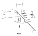
- FIG. 5 is a cross-sectional view of the movable member of FIGS. 3 and 4 in a first position, according to a representative embodiment.
- FIG. 6 is a cross-sectional view of the movable member of FIGS. 3 and 4 in a second position, according to a representative embodiment.
- FIG. 7 is a cross-sectional view of the movable member of FIGS. 3 and 4 in a third position, according to a representative embodiment.
- FIG. 8 illustrates a trace indicating a portion of light transmitted by a dichroic beam combiner, depending on wavelength, according to a representative embodiment.
- FIG. 9 illustrates a trace indicating a portion of light reflected by a dichroic beam combiner, depending on wavelength, according to a representative embodiment.
- an optical emission spectrometer system may be used for spectrochemical analysis.
- the optical emission spectrometer system includes an inductively coupled plasma light source, an optical filter, and a spectrometer, or other light detection and measurement apparatus.
- light is emitted by the plasma light source in a direction along a longitudinal axis of the plasma light source (axially-emitted light) and in a direction different from the direction along the longitudinal axis of the plasma light source (radially-emitted).
- the radially-emitted light may be emitted in a direction substantially perpendicular to the longitudinal axis.
- the optical filter directs portions of both the axially-emitted light and the radially emitted light to the spectrometer based on wavelengths, where each portion includes wavelengths predominately within a range above or below a predetermined wavelength value.
- the spectrometer is thus able to simultaneously collect the axially-emitted light (axial viewing) and the radially-emitted light (radial viewing).
- the optical filter may allow only light predominately having wavelengths shorter than the predetermined wavelength value to enter the spectrometer for axial viewing, and may allow only light predominately having wavelengths above the predetermined wavelength value to enter the spectrometer for radial viewing.
- optical emission spectrometer system enables simultaneous axial viewing and radial viewing, as mentioned above.
- the single spectrometer is able to receive and measure light intensity from two light paths simultaneously.
- FIG. 1 is an isometric view of an optical emission spectrometer system, according to a representative embodiment.
- optical emission spectrometer system 100 includes a light source 101 for emitting light that can be detected and measured with respect to wavelength by a light detection and measurement apparatus 140 , e.g., for detecting and measuring light and analyzing wavelength.
- the light source 101 may be an inductively coupled plasma light source, for example.
- the light detection and measurement apparatus 140 may be a monochromator or a polychromator, for example, together with at least one associated light detector.
- the light from the light source 101 enters the light detection and measurement apparatus 140 via slit or entrance aperture 145 .
- the optical emission spectrometer system 100 further includes first light path 110 and second light path 120 .
- the first light path 110 includes a first set of mirrors, depicted by representative mirrors 111 and 112 , configured to direct light emitted by the light source 101 in a first direction (referred to as first light 115 ) onto an optical filter, such as representative dichroic beam combiner 130 .
- first light 115 is emitted axially from the light source 101 , i.e., along the longitudinal axis, and is reflected by the mirror 111 onto the mirror 112 , and by the mirror 112 onto the dichroic beam combiner 130 .
- the second light path 120 includes a second set of mirrors, depicted by representative mirrors 121 and 122 , configured to direct light emitted by the plasma light source 101 in a second direction (referred to as second light 125 ), substantially perpendicular to the first direction, onto the dichroic beam combiner 130 .
- the second light 125 is emitted radially from the light source 101 , and is reflected by the mirror 121 onto the mirror 122 , and by the mirror 122 onto the dichroic beam combiner 130 .
- first direction of the first light 115 emitted from the light source 101 and the second direction of the second light 125 emitted from the light source 101 may vary without departing from the scope of the present teachings.
- first direction of the first light 115 may be at an angle departing from the longitudinal axis of the light source 101 , rather than along the longitudinal axis.
- second direction of the second light 125 may be any direction different from the first direction, and therefore does not need to be substantially perpendicular to the longitudinal axis of the light source 101 and/or substantially perpendicular to the first direction of the first light 115 .
- At least one of the mirrors 111 , 112 in the first light path 110 and at least one of the mirrors 121 , 122 in the second light path 120 may be adjustable using an electric motor, such as a step motor, for example. Adjustment of the mirrors 111 , 112 and 121 , 122 enables the first and second light 115 and 125 to be properly focused onto the dichroic beam combiner 130 and/or the entrance aperture 145 , respectively.
- the motor may be manually or automatically operable, e.g., using a controller or other processing device (not shown).
- the processing device may be implemented by a computer processor, application specific integrated circuits (ASICs), field-programmable gate arrays (FPGAs), or combinations thereof, using software, firmware, hard-wired logic circuits, or combinations thereof.
- ASICs application specific integrated circuits
- FPGAs field-programmable gate arrays
- a memory may be included, such as a non-transitory computer readable medium, for storing executable software/firmware and/or executable code that allows it to perform the various functions.
- the dichroic beam combiner 130 receives the first light 115 via the first light path 110 and the second light 125 via the second light path 120 .
- the dichroic beam combiner 130 is configured to reflect only a portion the first light 115 into the entrance aperture 145 of the light detection and measurement apparatus 140 , and to transmit a only portion of the second light 125 into the entrance aperture 145 , enabling the light detection and measurement apparatus 140 to analyze and measure simultaneously characteristics of both the first light 115 and the second light 125 using the respective portions of the first light 115 and the second light 125 .
- the dichroic beam combiner 130 may be configured to transmit the portion the first light 115 and to reflect the portion of the second light 125 into the entrance aperture 145 of the light detection and measurement apparatus 140 , without departing from the scope of the present teachings.
- the dichroic beam combiner 130 reflects or transmits the portions of the first and second light 115 and 125 depending on wavelength.
- the dichroic beam combiner 130 has an associated predetermined wavelength value, which is essentially a demarcation between wavelengths that are predominately reflected and wavelengths that are predominately transmitted by the dichroic beam combiner 130 .
- the dichroic beam combiner 130 may reflect portions of the first and second light 115 and 125 predominantly having wavelengths below the predetermined wavelength value, and transmit portions of the first and second light 115 and 125 predominantly having wavelengths above the predetermined wavelength value. In this context, predominantly means greater than 50 percent of the total amount of the respective portion of light.
- the dichroic beam combiner 130 thus effectively filters the first and second light 115 and 125 into predominantly different wavelength ranges, and combines the filtered first and second light 115 and 125 for input into the entrance aperture 145 of the light detection and measurement apparatus 140 .
- the predetermined wavelength value may be about 500 nanometers (nm), for example, although other predetermined wavelength values may be implemented, to provide unique benefits for any particular situation or to meet application specific design requirements, without departing from the scope of the present teachings.
- the wavelengths below the predetermined wavelength value e.g., less than 500 nm
- the wavelengths above the predetermined wavelength value e.g., greater than 500 nm
- the optical filter may be implemented using filtering means augmenting the dichroic beam combiner 130 , as well.
- a further variation of this embodiment includes optical filters placed separately in the first light path 110 and second light path 120 , in order to select substantially different wavelength ranges from the first light 115 and the second light 125 , and a beam combiner to recombine the filtered first and second light 115 and 125 .
- FIG. 2 is a cross-sectional view of the dichroic beam combiner 130 of the optical emission spectrometer system 100 shown in FIG. 1 , according to a representative embodiment.
- the dichroic beam combiner 130 is tilted so that the portions of the first and second light 115 and 125 that it reflects are either directed into or away from the entrance aperture 145 of the light detection and measurement apparatus 140 . More particularly, when the dichroic beam combiner 130 receives the first light 115 , it reflects a reflected portion 115 R into the entrance aperture 145 and transmits a transmitted portion 115 T away from the entrance aperture 145 (meaning the transmitted portion 115 T does not enter the entrance aperture 145 ).
- the dichroic beam combiner 130 When the dichroic beam combiner 130 receives the second light 125 , at the same time as receiving the first light 115 , it reflects a reflected portion 125 R away from the entrance aperture 145 and transmits a transmitted portion 125 T into the entrance aperture 145 .
- the dichroic beam combiner 130 reflects portions of the first and second light 115 and 125 predominately having wavelengths below the predetermined wavelength value, the reflected portion 115 R of the first light 115 and the reflected portion 125 R of the second light 125 have wavelengths predominately in the first range of wavelengths. Therefore, in the depicted example, the light detection and measurement apparatus 140 receives the portion of the first light 115 having wavelengths predominately in the first range of wavelengths.
- the dichroic beam combiner 130 transmits portions of the first and second light 115 and 125 predominately having wavelengths above the predetermined wavelength value, the transmitted portion 115 T of the first light 115 and the transmitted portion 125 T of the second light 125 have wavelengths predominately in the second range of wavelengths. Therefore, in the depicted example, the light detection and measurement apparatus 140 receives the portion of the second light 125 having wavelengths predominately in the second range of wavelengths.
- the light detection and measurement apparatus 140 generally receives shorter wavelengths (e.g., in the ultraviolet region of the spectrum) of the first light 115 and longer wavelengths (e.g., in the visible region of the spectrum) of the second light 125 .
- the dichroic beam combiner 130 may be configured to transmit portions of the first and second light 115 and 125 predominately having wavelengths below the predetermined wavelength value, and to reflect portions of the first and second light 115 and 125 predominately having wavelengths above the predetermined wavelength value, without departing from the scope of the present teachings.
- FIG. 8 shows trace 800 indicating portions of light (such as the first and second light 115 and 125 ) transmitted by the dichroic beam combiner 130 (transmission model), and FIG. 9 shows trace 900 indicating portions of light reflected by the dichroic beam combiner 130 (reflection model), depending on wavelength.
- the predetermined wavelength value at which transmitted and reflected light is separated is assumed to be about 500 nm.
- the portion of light transmitted by the dichroic beam combiner 130 predominantly has wavelengths above about 500 nm, as discussed above. That is, the dichroic beam combiner 130 generally transmits light having wavelengths longer than about 500 nm and does not transmit (or reflects) light having wavelengths shorter than about 500 nm. In the depicted example, the dichroic beam combiner 130 transmits between about 75% to about 90% of the light having wavelengths longer than about 500 nm, but transmits only about 0% to about 10% of the light having wavelengths shorter than about 500 nm.
- the portion of light reflected by the dichroic beam combiner 130 predominantly has wavelengths below about 500 nm, as discussed above. That is, the dichroic beam combiner 130 generally reflects light having wavelengths shorter than about 500 nm and does not reflect (or transmits) light having wavelengths longer than about 500 nm. In the depicted example, the dichroic beam combiner 130 reflects between about 70% to about 95% of the light having wavelengths shorter than about 500 nm (and above about 200 nm), but reflects only about 10% to about 15% of the light having wavelengths longer than about 500 nm.
- a user of an optical emission spectrometer system may want to reflect or transmit light of all wavelengths under various circumstances. To do so would generally require replacement of the dichroic beam combiner with a reflecting surface or a transmitting surface, respectively, which would be time consuming and otherwise inefficient.
- FIG. 3 is an isometric view of an optical emission spectrometer system, according to a representative embodiment, which includes a movable member having different sections to control the directivity of light, e.g., emitted by an inductively coupled plasma light source.
- FIG. 4 is a top plan view of the movable member included in the optical emission spectrometer system of FIG. 3 , according to a representative embodiment.
- optical emission spectrometer system 200 is substantially the same as the optical emission spectrometer system 100 of FIG. 1 , with the addition of movable member 230 . That is, the optical emission spectrometer system 200 includes light source 101 for emitting light that can be detected and measured with respect to wavelength by light detection and measurement apparatus 140 . The optical emission spectrometer system 200 further includes first light path 110 and second light path 120 .
- the first light path 110 includes representative mirrors 111 and 112 , configured to direct light emitted by the light source 101 in the first direction (first light 115 ) onto the movable member 230
- the second light path 120 includes representative mirrors 121 and 122 , configured to direct light emitted by the light source 101 in the second direction (second light 125 ), substantially perpendicular to the first direction, onto the movable member 230 .
- the movable member 230 includes three mode sections respectively corresponding to first, second and third positions of the movable member 230 .
- the three mode sections include dichroic beam combiner 231 (or other optical filter), mirrored section 232 and transparent section 233 .
- the movable member 230 is selectively movable, such that operation of the movable member 230 places one of the dichroic beam combiner 231 , the mirrored section 232 and the transparent section 233 into the first and second light paths 110 and 120 for receiving the first and second light 115 and 125 , respectively.
- the movable member 230 is a mode wheel rotatable around axis 236 , using a hub and shaft arrangement 237 , for example.
- the mode wheel is substantially circular in shape, and the dichroic beam combiner 231 , the mirrored section 232 and the transparent section 233 respectively occupy equal sized sectors (pie-shaped regions) of the mode wheel.
- the movable member 230 is thus rotatable among a first position for selecting the dichroic beam combiner 231 , a second position for selecting the mirrored section 232 and a third position for selecting the transparent section 233 .
- Rotation of the movable member 230 may be enabled by controllable rotating means (not shown), such as a manual selector and/or an electric (step) motor, for example.
- the motor may be manually or automatically operable, e.g., using the controller or other processing device (not shown), discussed above.
- the processing device may be implemented by a computer processor, ASICs, FPGAs, or combinations thereof, using software, firmware, hard-wired logic circuits, or combinations thereof.
- a memory may be included, such as a non-transitory computer readable medium, for storing executable software/firmware and/or executable code that allows it to perform the various functions.
- the movable member 230 may have different configurations without departing from the scope of the present teachings.
- the movable member 230 may include a rotatable mode wheel having any of a variety of shapes other than a circle and/or sectors (or sections) having corresponding sizes/shapes different from one another.
- the movable member 230 may not be rotatable, but rather may incorporate other means of movement to enable selection of the dichroic beam combiner 231 , the mirrored section 232 or the transparent section 233 .
- the movable member 230 may be slideable in various directions among the first, second and third positions in order to place the corresponding one of the dichroic beam combiner 231 , the mirrored section 232 and the transparent section 233 into the first and second light paths 110 and 120 .
- FIG. 5 is a cross-sectional view of the movable member 230 of the optical emission spectrometer system 200 shown in FIGS. 3 and 4 in a first position, according to a representative embodiment.
- the first position places the dichroic beam combiner 231 within the first and second light paths 110 and 120 .
- the movable member 230 is tilted so that the portions of the first and second light 115 and 125 reflected by the dichroic beam combiner 231 are either directed into or away from the entrance aperture 145 of the light detection and measurement apparatus 140 , as discussed above.
- the dichroic beam combiner 231 When the dichroic beam combiner 231 receives the first light 115 , it reflects a reflected portion 115 R into the entrance aperture 145 and transmits a transmitted portion 115 T away from the entrance aperture 145 (meaning the transmitted portion 115 T does not enter the entrance aperture 145 ). When the dichroic beam combiner 231 receives the second light 125 , at the same time as receiving the first light 115 , it reflects a reflected portion 125 R away from the entrance aperture 145 and transmits a transmitted portion 125 T into the entrance aperture 145 . Each of the reflected portions 115 R and 125 R and the transmitted portions 115 T and 125 T is determined by the wavelengths of the first light 115 and the second light 125 , respectively, in comparison to a predetermined wavelength value, as discussed above.
- FIG. 6 is a cross-sectional view of the movable member 230 of the optical emission spectrometer system 200 shown in FIGS. 3 and 4 in a second position, according to a representative embodiment.
- the second position places the mirrored section 232 within the first and second light paths 110 and 120 .
- the movable member 230 is tilted so that the portions of the first light 115 reflected by the mirrored section 232 are directed into the entrance aperture 145 of the light detection and measurement apparatus 140 . That is, when the mirrored section 232 receives the first light 115 , it reflects a reflected portion 115 R into the entrance aperture 145 , where the reflected portion 115 R includes substantially all wavelengths of the first light 115 .
- the mirrored section 232 When the mirrored section 232 receives the second light 125 , at the same time as receiving the first light 115 , it reflects a reflected portion 125 R away from the entrance aperture 145 , where the reflected portion 125 R includes substantially all of the wavelengths of the second light 125 . In other words, when the movable member 230 is in the second position, the light detection and measurement apparatus 140 only receives the first light 115 via the entrance aperture 145 , including substantially all of the wavelengths.
- FIG. 7 is a cross-sectional view of the movable member 230 of the optical emission spectrometer system 200 shown in FIGS. 3 and 4 in a third position, according to a representative embodiment.
- the third position places the transparent section 233 within the first and second light paths 110 and 120 .
- the transparent section 233 receives the first light 115 , it transmits a transmitted portion 115 T away from the entrance aperture 145 , where the transmitted portion 115 T includes substantially all of the wavelengths of the first light 115 .
- the transparent section 233 When the transparent section 233 receives the second light 125 , at the same time as receiving the first light 115 , it transmits a transmitted portion 125 T into the entrance aperture 145 , where the transmitted portion 125 T includes substantially all of the wavelengths of the second light 125 .
- the light detection and measurement apparatus 140 only receives the second light 125 via the entrance aperture 145 , including substantially all of the wavelengths.
- the mirrored section 232 in the movable member 230 enables measurement of substantially the entire wavelength range of the axially emitted light (first light 115 ), in the depicted illustrative configuration, which allows for more sensitive detection of light in the wavelengths that would otherwise have been transmitted away from the aperture 145 by the dichroic beam combiner (e.g., beam combiner 231 ).
- the dichroic beam combiner e.g., beam combiner 231
- Better detection limits may be achieved because the axial light path (first light path 110 ) is approximately ten to forty times more intense than the radial light path (second light path 120 ), but axial only measurements may suffer from Easily Ionized Element Interferences when easily ionized elements are present.
- the transparent section 233 in the movable member 230 enables measurement of substantially the entire wavelength range of the radially emitted light (second light 125 ), in the depicted illustrative configuration.
- the availability of the less intense radial light increases the dynamic range of measurement (when used in conjunction with the axial light measurements) by allowing measurement of intense sample concentrations that would otherwise over-range an axial light measurement. This may result in lower detection limits due to the reduction of available light compared to the axial light path.
- measurements of the intensity of axially-emitted light e.g., originating along the direction of the axis of the light source
- measurements of the intensity of radially-emitted light e.g., originating along the direction substantially perpendicular to the axis of the light source
- conventional systems measure axially-emitted light and radially-emitted light sequentially using one spectrometer, or simultaneously using two spectrometers.
- the measurements may be completed in about half the time, as compared to conventional systems.
Abstract
An optical emission spectrometer system includes a light source and a dichroic beam combiner. The light source emits first light in a first direction and second light in a second direction different from the first direction. The dichroic beam combiner receives the first light via a first light path and the second light via a second light path, reflects a portion the first light into an entrance aperture of a light detection and measurement apparatus, and transmits a portion of the second light into the entrance aperture, enabling analysis and measurement of both first and second light characteristics simultaneously. The portion of the first light reflected into the entrance aperture predominately has wavelengths in a first range of wavelengths and the portion of the second light transmitted into the entrance aperture predominately has wavelengths in a second range of wavelengths, different from the first range of wavelengths.
Description
The present application is a continuation application under 37 C.F.R. §1.53(b) of U.S. patent application Ser. No. 13/460,308, filed on Apr. 30, 2012, naming Michael Bolles et al. as inventors (published as U.S. Patent App. Pub. No. 2013/0286390 on Oct. 31, 2012). Priority under 35 U.S.C. §120 is claimed from U.S. patent application Ser. No. 13/460,308, and the entire disclosure of U.S. patent application Ser. No. 13/460,308 is specifically incorporated herein by reference.
Conventional optical emission spectrometers may include inductively coupled plasma (ICP) light sources for spectrochemical analysis. Generally, selecting light emitted along an axis of an ICP light source (axial viewing) for detection and measurement provides increased signal-to-background ratios, and consequently improved limits of detection, as compared to selecting light emitted along a direction perpendicular to the axis of the ICP light source (radial viewing). This advantage is particularly important for certain elements, such as arsenic (As), selenium (Se), lead (Pb) and others having optical emission lines in the ultraviolet region of the spectrum. However, under certain circumstances, selecting the light emitted perpendicular to the axis of the inductively coupled plasma source is advantageous, in that it enables measurement of a greater range of concentrations and allows optimization of the position of light selection to minimize inter-element interference effects. This may be particularly important for easily-ionized elements, such as potassium (K), sodium (Na), lithium (Li) and others having optical emission lines in the visible region of the spectrum. In addition, axial viewing generally provides high sensitivity and poor linearity, while radial viewing generally provides lower sensitivity and better linearity.
Attempts have been made to enable selection of light emitted along or perpendicular to the axis of an inductively coupled plasma source. For example, light for detection and measurement may be selected as required from either light emitted along the axis or light at right angles to the axis of the light source, but not both at the same time. That is, only one mode of viewing may be selected at any time. Accordingly, when a modern simultaneous spectrometer is used, for example, it is necessary to take separate measurements (e.g., separated in time) in each of the axial and radial viewing modes to obtain best performance for each element of interest. In order to achieve simultaneous axial viewing and radial viewing of the light, one spectrometer must be used for axial viewing and another spectrometer must be used for radial viewing. In other words, conventional systems require either two separate views using one spectrometer (increasing analysis time and sample consumption), or two simultaneous views, using separate spectrometers for each view (a very costly alternative).
In a representative embodiment, an optical emission spectrometer system includes a light source and a dichroic beam combiner. The light source is configured to emit first light in a first direction and second light in a second direction different from the first direction. The dichroic beam combiner is configured to receive the first light via a first light path and the second light via a second light path, to reflect a portion of the first light into an entrance aperture of a light detection and measurement apparatus, and to transmit a portion of the second light into the entrance aperture, enabling the light detection and measurement apparatus to analyze or measure characteristics of both the first light and the second light. The portion of the first light reflected into the entrance aperture predominately has wavelengths in a first range of wavelengths and the portion of the second light transmitted into the entrance aperture predominately has wavelengths in a second range of wavelengths, different from the first range of wavelengths.
In another representative embodiment, an optical emission spectrometer apparatus includes optical directing means, optical filtering means and optical combining means. The optical directing means are configured to direct first light emitted from a light source in a first direction along a first light path to a single light detection and measurement apparatus, and to direct second light emitted from the light source in a second direction, different from the first direction, along a second light path to the same light detection and measurement apparatus. The optical filtering means are configured to simultaneously filter the first and second light into predominantly different wavelength ranges. The optical combining means are configured to combine the filtered first and second light prior to the single light detection and measurement apparatus.
In another representative embodiment, an optical emission spectrometer system includes a plasma light source configured to emit first light in a first direction and second light in a second direction substantially perpendicular to the first direction; a first plurality of mirrors for directing the first light along a first light path; a second plurality of mirrors for directing the second light along a second light path; and a mode selector including mode sections corresponding to positions of the mode selector. The mode selector is selectively movable, such that the first and second light paths intersect one of the mode sections. The mode sections include a dichroic beam combiner, a mirrored section and a transparent section. The dichroic beam combiner is configured to reflect wavelengths of the first light predominantly in a predetermined first wavelength range into an entrance aperture of a detector, and to transmit wavelengths of the second light predominantly in a predetermined second wavelength range into the entrance aperture, enabling analysis of both the first light and the second light, the second wavelength range being different from the first wavelength range. The mirrored section is configured to reflect all wavelengths of the first light into the entrance aperture of the detector, and to reflect all wavelengths of the second light away from the entrance aperture of the detector, enabling analysis of the first light. The transparent section is configured to transmit all wavelengths of the second light into the entrance aperture of the detector, and to transmit all wavelengths of the first light away from the entrance aperture of the detector, enabling analysis of the second light.
The illustrative embodiments are best understood from the following detailed description when read with the accompanying drawing figures. It is emphasized that the various features are not necessarily drawn to scale. In fact, the dimensions may be arbitrarily increased or decreased for clarity of discussion. Wherever applicable and practical, like reference numerals refer to like elements.
In the following detailed description, for purposes of explanation and not limitation, illustrative embodiments disclosing specific details are set forth in order to provide a thorough understanding of embodiments according to the present teachings. However, it will be apparent to one having had the benefit of the present disclosure that other embodiments according to the present teachings that depart from the specific details disclosed herein remain within the scope of the appended claims. Moreover, descriptions of well-known devices and methods may be omitted so as not to obscure the description of the example embodiments. Such methods and devices are within the scope of the present teachings.
An optical emission spectrometer system may be used for spectrochemical analysis. According to various embodiments, the optical emission spectrometer system includes an inductively coupled plasma light source, an optical filter, and a spectrometer, or other light detection and measurement apparatus. In an embodiment, light is emitted by the plasma light source in a direction along a longitudinal axis of the plasma light source (axially-emitted light) and in a direction different from the direction along the longitudinal axis of the plasma light source (radially-emitted). For example, the radially-emitted light may be emitted in a direction substantially perpendicular to the longitudinal axis. The optical filter directs portions of both the axially-emitted light and the radially emitted light to the spectrometer based on wavelengths, where each portion includes wavelengths predominately within a range above or below a predetermined wavelength value. The spectrometer is thus able to simultaneously collect the axially-emitted light (axial viewing) and the radially-emitted light (radial viewing). For example, the optical filter may allow only light predominately having wavelengths shorter than the predetermined wavelength value to enter the spectrometer for axial viewing, and may allow only light predominately having wavelengths above the predetermined wavelength value to enter the spectrometer for radial viewing.
Generally, advantages of axial viewing are typically associated with elements having their most sensitive emission lines in the ultraviolet region of the spectrum, whereas advantages of radial viewing are typically associated with elements having their most sensitive emission lines in the visible region of the spectrum. The optical emission spectrometer system, according to representative embodiments, enables simultaneous axial viewing and radial viewing, as mentioned above. Thus, the single spectrometer is able to receive and measure light intensity from two light paths simultaneously.
Referring to FIG. 1 , optical emission spectrometer system 100 includes a light source 101 for emitting light that can be detected and measured with respect to wavelength by a light detection and measurement apparatus 140, e.g., for detecting and measuring light and analyzing wavelength. The light source 101 may be an inductively coupled plasma light source, for example. Also, the light detection and measurement apparatus 140 may be a monochromator or a polychromator, for example, together with at least one associated light detector. The light from the light source 101 enters the light detection and measurement apparatus 140 via slit or entrance aperture 145.
The optical emission spectrometer system 100 further includes first light path 110 and second light path 120. The first light path 110 includes a first set of mirrors, depicted by representative mirrors 111 and 112, configured to direct light emitted by the light source 101 in a first direction (referred to as first light 115) onto an optical filter, such as representative dichroic beam combiner 130. In the depicted example, the first light 115 is emitted axially from the light source 101, i.e., along the longitudinal axis, and is reflected by the mirror 111 onto the mirror 112, and by the mirror 112 onto the dichroic beam combiner 130. The second light path 120 includes a second set of mirrors, depicted by representative mirrors 121 and 122, configured to direct light emitted by the plasma light source 101 in a second direction (referred to as second light 125), substantially perpendicular to the first direction, onto the dichroic beam combiner 130. In the depicted embodiment, the second light 125 is emitted radially from the light source 101, and is reflected by the mirror 121 onto the mirror 122, and by the mirror 122 onto the dichroic beam combiner 130.
Of course, the first direction of the first light 115 emitted from the light source 101 and the second direction of the second light 125 emitted from the light source 101 may vary without departing from the scope of the present teachings. For example, the first direction of the first light 115 may be at an angle departing from the longitudinal axis of the light source 101, rather than along the longitudinal axis. Likewise, the second direction of the second light 125 may be any direction different from the first direction, and therefore does not need to be substantially perpendicular to the longitudinal axis of the light source 101 and/or substantially perpendicular to the first direction of the first light 115.
In various embodiments, at least one of the mirrors 111, 112 in the first light path 110 and at least one of the mirrors 121, 122 in the second light path 120 may be adjustable using an electric motor, such as a step motor, for example. Adjustment of the mirrors 111, 112 and 121, 122 enables the first and second light 115 and 125 to be properly focused onto the dichroic beam combiner 130 and/or the entrance aperture 145, respectively. The motor may be manually or automatically operable, e.g., using a controller or other processing device (not shown). For example, the processing device may be implemented by a computer processor, application specific integrated circuits (ASICs), field-programmable gate arrays (FPGAs), or combinations thereof, using software, firmware, hard-wired logic circuits, or combinations thereof. When using a processor, a memory may be included, such as a non-transitory computer readable medium, for storing executable software/firmware and/or executable code that allows it to perform the various functions.
The dichroic beam combiner 130 receives the first light 115 via the first light path 110 and the second light 125 via the second light path 120. In the depicted embodiment, the dichroic beam combiner 130 is configured to reflect only a portion the first light 115 into the entrance aperture 145 of the light detection and measurement apparatus 140, and to transmit a only portion of the second light 125 into the entrance aperture 145, enabling the light detection and measurement apparatus 140 to analyze and measure simultaneously characteristics of both the first light 115 and the second light 125 using the respective portions of the first light 115 and the second light 125. Of course, in alternative embodiments, the dichroic beam combiner 130 may be configured to transmit the portion the first light 115 and to reflect the portion of the second light 125 into the entrance aperture 145 of the light detection and measurement apparatus 140, without departing from the scope of the present teachings.
More particularly, the dichroic beam combiner 130 reflects or transmits the portions of the first and second light 115 and 125 depending on wavelength. For example, the dichroic beam combiner 130 has an associated predetermined wavelength value, which is essentially a demarcation between wavelengths that are predominately reflected and wavelengths that are predominately transmitted by the dichroic beam combiner 130. For example, the dichroic beam combiner 130 may reflect portions of the first and second light 115 and 125 predominantly having wavelengths below the predetermined wavelength value, and transmit portions of the first and second light 115 and 125 predominantly having wavelengths above the predetermined wavelength value. In this context, predominantly means greater than 50 percent of the total amount of the respective portion of light. In other words, in this example, more than 50 percent of the portion of the first light 115 reflected by the dichroic beam combiner 130 has wavelengths below the predetermined wavelength value. The dichroic beam combiner 130 thus effectively filters the first and second light 115 and 125 into predominantly different wavelength ranges, and combines the filtered first and second light 115 and 125 for input into the entrance aperture 145 of the light detection and measurement apparatus 140.
The predetermined wavelength value may be about 500 nanometers (nm), for example, although other predetermined wavelength values may be implemented, to provide unique benefits for any particular situation or to meet application specific design requirements, without departing from the scope of the present teachings. The wavelengths below the predetermined wavelength value (e.g., less than 500 nm) may be referred to as a first range of wavelengths, and the wavelengths above the predetermined wavelength value (e.g., greater than 500 nm) may be referred to as a second range of wavelengths, for convenience of explanation. Notably, the optical filter may be implemented using filtering means augmenting the dichroic beam combiner 130, as well. A further variation of this embodiment includes optical filters placed separately in the first light path 110 and second light path 120, in order to select substantially different wavelength ranges from the first light 115 and the second light 125, and a beam combiner to recombine the filtered first and second light 115 and 125.
As mentioned above, since the dichroic beam combiner 130 reflects portions of the first and second light 115 and 125 predominately having wavelengths below the predetermined wavelength value, the reflected portion 115R of the first light 115 and the reflected portion 125R of the second light 125 have wavelengths predominately in the first range of wavelengths. Therefore, in the depicted example, the light detection and measurement apparatus 140 receives the portion of the first light 115 having wavelengths predominately in the first range of wavelengths. Likewise, since the dichroic beam combiner 130 transmits portions of the first and second light 115 and 125 predominately having wavelengths above the predetermined wavelength value, the transmitted portion 115T of the first light 115 and the transmitted portion 125T of the second light 125 have wavelengths predominately in the second range of wavelengths. Therefore, in the depicted example, the light detection and measurement apparatus 140 receives the portion of the second light 125 having wavelengths predominately in the second range of wavelengths.
In other words, the light detection and measurement apparatus 140 generally receives shorter wavelengths (e.g., in the ultraviolet region of the spectrum) of the first light 115 and longer wavelengths (e.g., in the visible region of the spectrum) of the second light 125. Of course, in alternative embodiments, the dichroic beam combiner 130 may be configured to transmit portions of the first and second light 115 and 125 predominately having wavelengths below the predetermined wavelength value, and to reflect portions of the first and second light 115 and 125 predominately having wavelengths above the predetermined wavelength value, without departing from the scope of the present teachings.
Referring to FIG. 8 , the portion of light transmitted by the dichroic beam combiner 130 predominantly has wavelengths above about 500 nm, as discussed above. That is, the dichroic beam combiner 130 generally transmits light having wavelengths longer than about 500 nm and does not transmit (or reflects) light having wavelengths shorter than about 500 nm. In the depicted example, the dichroic beam combiner 130 transmits between about 75% to about 90% of the light having wavelengths longer than about 500 nm, but transmits only about 0% to about 10% of the light having wavelengths shorter than about 500 nm.
Referring to FIG. 9 , the portion of light reflected by the dichroic beam combiner 130 predominantly has wavelengths below about 500 nm, as discussed above. That is, the dichroic beam combiner 130 generally reflects light having wavelengths shorter than about 500 nm and does not reflect (or transmits) light having wavelengths longer than about 500 nm. In the depicted example, the dichroic beam combiner 130 reflects between about 70% to about 95% of the light having wavelengths shorter than about 500 nm (and above about 200 nm), but reflects only about 10% to about 15% of the light having wavelengths longer than about 500 nm.
In addition to reflecting a portion of light and transmitting a portion of light based on wavelength, described above, a user of an optical emission spectrometer system may want to reflect or transmit light of all wavelengths under various circumstances. To do so would generally require replacement of the dichroic beam combiner with a reflecting surface or a transmitting surface, respectively, which would be time consuming and otherwise inefficient.
Referring to FIGS. 3 and 4 , optical emission spectrometer system 200 is substantially the same as the optical emission spectrometer system 100 of FIG. 1 , with the addition of movable member 230. That is, the optical emission spectrometer system 200 includes light source 101 for emitting light that can be detected and measured with respect to wavelength by light detection and measurement apparatus 140. The optical emission spectrometer system 200 further includes first light path 110 and second light path 120. The first light path 110 includes representative mirrors 111 and 112, configured to direct light emitted by the light source 101 in the first direction (first light 115) onto the movable member 230, and the second light path 120 includes representative mirrors 121 and 122, configured to direct light emitted by the light source 101 in the second direction (second light 125), substantially perpendicular to the first direction, onto the movable member 230.
In the depicted embodiment, the movable member 230 includes three mode sections respectively corresponding to first, second and third positions of the movable member 230. The three mode sections include dichroic beam combiner 231 (or other optical filter), mirrored section 232 and transparent section 233. The movable member 230 is selectively movable, such that operation of the movable member 230 places one of the dichroic beam combiner 231, the mirrored section 232 and the transparent section 233 into the first and second light paths 110 and 120 for receiving the first and second light 115 and 125, respectively.
In the depicted embodiment, the movable member 230 is a mode wheel rotatable around axis 236, using a hub and shaft arrangement 237, for example. The mode wheel is substantially circular in shape, and the dichroic beam combiner 231, the mirrored section 232 and the transparent section 233 respectively occupy equal sized sectors (pie-shaped regions) of the mode wheel. The movable member 230 is thus rotatable among a first position for selecting the dichroic beam combiner 231, a second position for selecting the mirrored section 232 and a third position for selecting the transparent section 233.
Rotation of the movable member 230 may be enabled by controllable rotating means (not shown), such as a manual selector and/or an electric (step) motor, for example. The motor may be manually or automatically operable, e.g., using the controller or other processing device (not shown), discussed above. For example, the processing device may be implemented by a computer processor, ASICs, FPGAs, or combinations thereof, using software, firmware, hard-wired logic circuits, or combinations thereof. When using a processor, a memory may be included, such as a non-transitory computer readable medium, for storing executable software/firmware and/or executable code that allows it to perform the various functions.
Of course, the movable member 230 may have different configurations without departing from the scope of the present teachings. For example, the movable member 230 may include a rotatable mode wheel having any of a variety of shapes other than a circle and/or sectors (or sections) having corresponding sizes/shapes different from one another. In addition, the movable member 230 may not be rotatable, but rather may incorporate other means of movement to enable selection of the dichroic beam combiner 231, the mirrored section 232 or the transparent section 233. For example, the movable member 230 may be slideable in various directions among the first, second and third positions in order to place the corresponding one of the dichroic beam combiner 231, the mirrored section 232 and the transparent section 233 into the first and second light paths 110 and 120.
Generally, the mirrored section 232 in the movable member 230 enables measurement of substantially the entire wavelength range of the axially emitted light (first light 115), in the depicted illustrative configuration, which allows for more sensitive detection of light in the wavelengths that would otherwise have been transmitted away from the aperture 145 by the dichroic beam combiner (e.g., beam combiner 231). Better detection limits may be achieved because the axial light path (first light path 110) is approximately ten to forty times more intense than the radial light path (second light path 120), but axial only measurements may suffer from Easily Ionized Element Interferences when easily ionized elements are present. The transparent section 233 in the movable member 230 enables measurement of substantially the entire wavelength range of the radially emitted light (second light 125), in the depicted illustrative configuration. The availability of the less intense radial light increases the dynamic range of measurement (when used in conjunction with the axial light measurements) by allowing measurement of intense sample concentrations that would otherwise over-range an axial light measurement. This may result in lower detection limits due to the reduction of available light compared to the axial light path.
According to various embodiments, measurements of the intensity of axially-emitted light (e.g., originating along the direction of the axis of the light source) and measurements of the intensity of radially-emitted light (e.g., originating along the direction substantially perpendicular to the axis of the light source) are made simultaneously by the same spectrometer. In contrast, conventional systems measure axially-emitted light and radially-emitted light sequentially using one spectrometer, or simultaneously using two spectrometers. Therefore, in carrying out an analysis of a sample for which it is required to make measurements of both axially-emitted light and radially-emitted light using a single spectrometer capable of simultaneous measurements, according to various embodiments, only one set of measurements needs to be made. Therefore, the measurements may be completed in about half the time, as compared to conventional systems.
While specific embodiments are disclosed herein, many variations are possible, which remain within the concept and scope of the invention. Such variations would become clear after inspection of the specification, drawings and claims herein. The invention therefore is not to be restricted except within the scope of the appended claims.
Claims (20)
1. An optical emission spectrometer system, comprising:
a light source configured to emit first light in a first direction and second light in a second direction different from the first direction;
a dichroic beam combiner configured to receive the first light via a first light path and the second light via a second light path, to reflect a portion of the first light into an entrance aperture of a light detection and measurement apparatus, and to transmit a portion of the second light into the entrance aperture, wherein the portion of the first light reflected into the entrance aperture predominately has wavelengths in a first range of wavelengths and the portion of the second light transmitted into the entrance aperture predominately has wavelengths in a second range of wavelengths different from the first range of wavelengths; and
a movable member including the dichroic beam combiner, a mirrored section and a transparent section, the movable member being operable to place one of the dichroic beam combiner, the mirrored section and the transparent section into the first and second light paths for receiving the first and second light.
2. The system of claim 1 , wherein the mirrored section of the movable member is configured to reflect substantially all wavelengths of the first light into the entrance aperture of the detector, and to reflect substantially all wavelengths of the second light away from the entrance aperture of the detector.
3. The system of claim 1 , wherein the transparent section of the movable member is configured to transmit substantially all wavelengths of the first light away from the entrance aperture of the detector, and to transmit substantially all wavelengths of the second light into the entrance aperture of the detector.
4. The system of claim 1 , wherein the first direction is along art axis of the light source and the second direction is substantially perpendicular to the axis of the light source.
5. The system of claim 1 , wherein the first range of wavelengths is below a predetermined wavelength value, and the second range of wavelengths is above the predetermined wavelength value.
6. The system of claim 5 , wherein the predetermined wavelength value is about 500 nm.
7. The system of claim 1 , wherein the first range of wavelengths is above a predetermined wavelength value, and the second range of wavelengths is below the predetermined wavelength value.
8. The system of claim 7 , wherein the predetermined wavelength value is about 500 nm.
9. The system of claim 1 , wherein the first light path comprises a first set of mirrors configured to direct the first light to the dichroic beam combiner; and
wherein the second light path comprises a second set of mirrors configured to direct the second light to the dichroic beam combiner.
10. The system of claim 1 , wherein the light detection and measurement apparatus comprises one of a monochromator or a polychromator, and at least one associated light detector.
11. An optical emission spectrometer system, comprising:
a light source configured to emit first light in a first direction and second light in a second direction different from the first direction; and
a dichroic beam combiner configured to receive the first light via a first light path and the second light via a second light path, to reflect a portion of the first light into an entrance aperture of a light detection and measurement apparatus, and to transmit a portion of the second light into the entrance aperture,
wherein the portion of the first light reflected into the entrance aperture predominately has wavelengths in a first range of wavelengths and the portion of the second light transmitted into the entrance aperture predominately has wavelengths in a second range of wavelengths different from the first range of wavelengths, and
wherein the light source comprises an inductively coupled plasma light source.
12. The system of claim 11 , wherein the first direction is along an axis of the light source and the second direction is substantially perpendicular to the axis of the light source.
13. The system of claim 11 , wherein the first light path comprises a first set of mirrors configured to direct the first light to the dichroic beam combiner; and
wherein the second light path comprises a second set of mirrors configured to direct the second light to the dichroic beam combiner.
14. An optical emission spectrometer apparatus, comprising:
optical directing means configured to direct first light emitted from a light source in a first direction along a first light path to a single light detection and measurement apparatus, and to direct second light emitted from the light source in a second direction, different from the first direction, along a second light path to the same light detection and measurement apparatus;
optical filtering means configured to simultaneously filter the first and second light into predominantly different wavelength ranges;
optical combining means to combine the filtered first and second light prior to the single lioht detection and measuremc apparatus; and
a movable member selectively movable among first, second and third positions corresponding to the optical filtering means, a mirrored section and a transparent section, respectively, wherein operation of the movable member places one of the optical filtering means, the mirror section and the transparent section into the first and second light paths for receiving the first and second light.
15. The apparatus of claim 14 , wherein the mirror section is configured to reflect substantially all wavelengths of only one of the first and second light into the entrance aperture when the movable member is in the second position, and
wherein the transparent section is configured to transmit substantially all wavelengths of only one of the first and second light into the entrance aperture when the movable member is in the third position.
16. The system of claim 14 , wherein the light detection and measurement apparatus comprises one of a monochromator or a polychromator, and at least one associated light detector.
17. The apparatus according to claim 14 , wherein at least one of the optical filtering means and the optical combining means comprises a dichroic beam combiner configured to reflect a portion of the first light having wavelengths below a predetermined value and to transmit a portion of the second light having wavelengths above the nominal value into the entrance aperture.
18. The apparatus according to claim 14 , wherein at least one of the optical filtering means and the optical combining means comprises a dichroic beam combiner configured to transmit a portion of the first light having wavelengths below a nominal value and to reflect a portion of the second light having wavelengths above the nominal value into the entrance aperture.
19. An optical emission spectrometer system, comprising:
a plasma light source configured to emit first light in a first direction and second light in a second direction substantially perpendicular to the first direction;
a first plurality of mirrors for directing the first light along a first light path;
a second plurality of mirrors for directing the second light along a second light path; and
a mode selector comprising a plurality of mode sections corresponding to a plurality of positions of the mode selector, the mode selector being selectively movable such that the first and second light paths intersect one of the plurality of mode sections, the plurality of mode sections comprising:
a dichroic beam combiner configured to reflect wavelengths of the first light predominantly in a predetermined first wavelength range into an entrance aperture of a detector, and to transmit wavelengths of the second light predominantly in a predetermined second wavelength range into the entrance aperture, enabling analysis of both the first light and the second light, the second wavelength range being different from the first wavelength range;
a mirrored section configured to reflect all wavelengths of the first light into the entrance aperture of the detector, and to reflect all wavelengths of the second light away from the entrance aperture of the detector, enabling analysis of the first light; and
a transparent section configured to transmit all wavelengths of the second light into the entrance aperture of the detector, and to transmit all wavelengths of the first light away from the entrance aperture of the detector, enabling analysis of the second light.
20. The system of claim 19 , wherein the first wavelength range comprises wavelengths below a predetermined, wavelength value and the second wavelength range comprises wavelengths above the predetermined wavelength value.
Priority Applications (2)
| Application Number | Priority Date | Filing Date | Title |
|---|---|---|---|
| US14/614,381 US9752933B2 (en) | 2012-04-30 | 2015-02-04 | Optical emission system including dichroic beam combiner |
| US15/679,969 US10401221B2 (en) | 2012-04-30 | 2017-08-17 | Optical emission system including dichroic beam combiner |
Applications Claiming Priority (2)
| Application Number | Priority Date | Filing Date | Title |
|---|---|---|---|
| US13/460,308 US9279722B2 (en) | 2012-04-30 | 2012-04-30 | Optical emission system including dichroic beam combiner |
| US14/614,381 US9752933B2 (en) | 2012-04-30 | 2015-02-04 | Optical emission system including dichroic beam combiner |
Related Parent Applications (1)
| Application Number | Title | Priority Date | Filing Date |
|---|---|---|---|
| US13/460,308 Continuation US9279722B2 (en) | 2012-04-30 | 2012-04-30 | Optical emission system including dichroic beam combiner |
Related Child Applications (1)
| Application Number | Title | Priority Date | Filing Date |
|---|---|---|---|
| US15/679,969 Continuation US10401221B2 (en) | 2012-04-30 | 2017-08-17 | Optical emission system including dichroic beam combiner |
Publications (2)
| Publication Number | Publication Date |
|---|---|
| US20150138548A1 US20150138548A1 (en) | 2015-05-21 |
| US9752933B2 true US9752933B2 (en) | 2017-09-05 |
Family
ID=48142319
Family Applications (3)
| Application Number | Title | Priority Date | Filing Date |
|---|---|---|---|
| US13/460,308 Active 2032-11-01 US9279722B2 (en) | 2012-04-30 | 2012-04-30 | Optical emission system including dichroic beam combiner |
| US14/614,381 Active 2033-01-07 US9752933B2 (en) | 2012-04-30 | 2015-02-04 | Optical emission system including dichroic beam combiner |
| US15/679,969 Active 2032-05-03 US10401221B2 (en) | 2012-04-30 | 2017-08-17 | Optical emission system including dichroic beam combiner |
Family Applications Before (1)
| Application Number | Title | Priority Date | Filing Date |
|---|---|---|---|
| US13/460,308 Active 2032-11-01 US9279722B2 (en) | 2012-04-30 | 2012-04-30 | Optical emission system including dichroic beam combiner |
Family Applications After (1)
| Application Number | Title | Priority Date | Filing Date |
|---|---|---|---|
| US15/679,969 Active 2032-05-03 US10401221B2 (en) | 2012-04-30 | 2017-08-17 | Optical emission system including dichroic beam combiner |
Country Status (3)
| Country | Link |
|---|---|
| US (3) | US9279722B2 (en) |
| CN (2) | CN103376158B (en) |
| GB (1) | GB2501802B (en) |
Cited By (1)
| Publication number | Priority date | Publication date | Assignee | Title |
|---|---|---|---|---|
| US10401221B2 (en) * | 2012-04-30 | 2019-09-03 | Agilent Technologies, Inc. | Optical emission system including dichroic beam combiner |
Families Citing this family (8)
| Publication number | Priority date | Publication date | Assignee | Title |
|---|---|---|---|---|
| US9151672B2 (en) * | 2013-11-21 | 2015-10-06 | Agilent Technologies, Inc. | Optical absorption spectrometry system including dichroic beam combiner and splitter |
| CN105157953A (en) * | 2015-08-10 | 2015-12-16 | 北京市计量检测科学研究院 | Non-dispersive atomic fluorescence excitation light source purity detection method |
| CN106441580B (en) * | 2016-06-16 | 2018-07-13 | 电子科技大学 | The incident terahertz time-domain spectroscopy instrument for surveying transmission and reflection simultaneously of variable-angle |
| US10589508B2 (en) | 2016-12-15 | 2020-03-17 | General Electric Company | Additive manufacturing systems and methods |
| EP3364232A1 (en) * | 2017-02-21 | 2018-08-22 | Siemens Aktiengesellschaft | Light collection architecture for combustion appliances |
| CN108037076A (en) * | 2017-12-30 | 2018-05-15 | 杭州谱育科技发展有限公司 | Light path system before inductively-coupled plasma spectrometer |
| CN108551078B (en) * | 2018-04-26 | 2020-09-08 | 中国科学院长春光学精密机械与物理研究所 | Semiconductor laser beam combining device |
| CN109655156B (en) * | 2018-12-10 | 2021-03-30 | 三明学院 | Solar grating spectrometer optical system optimization method, device, equipment and storage medium |
Citations (135)
| Publication number | Priority date | Publication date | Assignee | Title |
|---|---|---|---|---|
| DE1291533B (en) | 1966-02-25 | 1969-03-27 | Zeiss Carl Fa | Device for separating and recombining optical radiation |
| US3704061A (en) | 1970-03-25 | 1972-11-28 | David Neil Travis | Wavelength selective mirror systems |
| US4795256A (en) | 1987-03-09 | 1989-01-03 | Photon Technology International, Inc. | Dual-wavelength spectrophotometry system |
| US4846154A (en) | 1988-06-13 | 1989-07-11 | Macanally Richard B | Dual view endoscope |
| DE3915421A1 (en) | 1989-05-11 | 1990-11-15 | Bayer Ag | Periodic, alternating monochromatisation of polychromatic light beam - is used esp. for top illumination microscopy, and has dichroitical colour dividers, chopper and interference filters |
| US5124552A (en) | 1991-01-28 | 1992-06-23 | Measurex Corporation | Sensor and method for measuring web moisture with optimal temperature insensitivity over a wide basis weight range |
| US5200595A (en) | 1991-04-12 | 1993-04-06 | Universite De Sherbrooke | High performance induction plasma torch with a water-cooled ceramic confinement tube |
| DE4221063A1 (en) | 1992-06-26 | 1994-01-05 | Thomas Dr Heiden | Optical system for incident light illumination fluorescence microscopy - splits light from source into several beams for independent modification before recombination |
| US5303139A (en) | 1991-07-31 | 1994-04-12 | Magtron Magneto Elektronische Gerate Gmbh | Low frequency, pulsed, bipolar power supply for a plasma chamber |
| US5362939A (en) | 1993-12-01 | 1994-11-08 | Fluidyne Engineering Corporation | Convertible plasma arc torch and method of use |
| EP0635705A2 (en) | 1993-07-21 | 1995-01-25 | Hewlett-Packard Company | Angular michelson interferometer and optical wavemeter based on a rotating periscope |
| US5394061A (en) | 1993-01-14 | 1995-02-28 | Adtec Co., Ltd. | High frequency plasma power source and impedance matching device for supplying power to a semiconductor processing apparatus |
| US5455422A (en) | 1991-11-04 | 1995-10-03 | Measurex Corporation | Multiple coat measurement and control apparatus and method |
| US5459572A (en) | 1993-06-17 | 1995-10-17 | Temet Instruments Oy | Mirror arrangement in a focusing interferometer |
| US5477280A (en) | 1993-06-11 | 1995-12-19 | Samsung Electronics Co., Ltd. | Liquid crystal projector having a video monitor |
| US5477321A (en) | 1994-08-31 | 1995-12-19 | Bayer Corporation | Dual beam tunable spectrometer |
| US5483337A (en) | 1994-10-19 | 1996-01-09 | Barnard; Thomas W. | Spectrometer with selectable radiation from induction plasma light source |
| US5560844A (en) | 1994-05-26 | 1996-10-01 | Universite De Sherbrooke | Liquid film stabilized induction plasma torch |
| US5642190A (en) | 1995-09-01 | 1997-06-24 | Thermo Jarrell Ash Corp. | Dual-axis plasma imaging system for use in spectroscopic analysis |
| US5681418A (en) | 1994-12-06 | 1997-10-28 | Fujitsu Limited | Plasma processing with inductive coupling |
| US5684581A (en) | 1995-12-11 | 1997-11-04 | Mds Health Group Limited | Torch for inductively coupled plasma spectrometry |
| US5726415A (en) | 1996-04-16 | 1998-03-10 | The Lincoln Electric Company | Gas cooled plasma torch |
| US5747935A (en) | 1992-04-16 | 1998-05-05 | Advanced Energy Industries, Inc. | Method and apparatus for stabilizing switch-mode powered RF plasma processing |
| US5792272A (en) | 1995-07-10 | 1998-08-11 | Watkins-Johnson Company | Plasma enhanced chemical processing reactor and method |
| US5828450A (en) | 1995-07-19 | 1998-10-27 | Kyoto Dai-Ichi Kagaku Co., Ltd. | Spectral measuring apparatus and automatic analyzer |
| US5827370A (en) | 1997-01-13 | 1998-10-27 | Mks Instruments, Inc. | Method and apparatus for reducing build-up of material on inner surface of tube downstream from a reaction furnace |
| US5864139A (en) | 1997-02-13 | 1999-01-26 | Spectra-Tech Inc. | Confocal microspectrometer system |
| US5877471A (en) | 1997-06-11 | 1999-03-02 | The Regents Of The University Of California | Plasma torch having a cooled shield assembly |
| US5880426A (en) | 1996-08-28 | 1999-03-09 | Doryokuro Kakunenryo Kaihatsu Jigyodan | Indirectly-cooled plasma jet torch |
| US5897059A (en) | 1994-11-11 | 1999-04-27 | Sulzer Metco Ag | Nozzle for use in a torch head of a plasma torch apparatus |
| US5906758A (en) | 1997-09-30 | 1999-05-25 | The Esab Group, Inc. | Plasma arc torch |
| US5908566A (en) | 1997-09-17 | 1999-06-01 | The United States Of America As Represented By The Secretary Of The Navy | Modified plasma torch design for introducing sample air into inductively coupled plasma |
| US5917286A (en) | 1996-05-08 | 1999-06-29 | Advanced Energy Industries, Inc. | Pulsed direct current power supply configurations for generating plasmas |
| US5936481A (en) | 1997-09-10 | 1999-08-10 | Adtec Corporation Limited | System for impedance matching and power control for apparatus for high frequency plasma treatment |
| US5944899A (en) | 1996-08-22 | 1999-08-31 | Applied Materials, Inc. | Inductively coupled plasma processing chamber |
| US5962987A (en) | 1996-12-03 | 1999-10-05 | Patent-Treuhand-Gesellschaft Fuer Elektrische Gluehlampen Mbh | Operating circuit for an electrodeless low-pressure discharge lamp |
| US5965039A (en) | 1995-02-13 | 1999-10-12 | Komatsu Ltd. | Plasma torch |
| US6020794A (en) | 1998-02-09 | 2000-02-01 | Eni Technologies, Inc. | Ratiometric autotuning algorithm for RF plasma generator |
| US6093660A (en) | 1996-03-18 | 2000-07-25 | Hyundai Electronics Industries Co., Ltd. | Inductively coupled plasma chemical vapor deposition technology |
| EP1024539A2 (en) | 1999-01-29 | 2000-08-02 | Hewlett-Packard Company | Solid state based illumination source utilizing dichroic reflectors |
| US6130831A (en) | 1998-10-21 | 2000-10-10 | Haiden Laboratory Inc. | Positive-negative pulse type high frequency switching power supply unit |
| US6137078A (en) | 1998-12-21 | 2000-10-24 | Sulzer Metco Ag | Nozzle for use in a torch head of a plasma torch apparatus |
| US6184984B1 (en) | 1999-02-09 | 2001-02-06 | Kla-Tencor Corporation | System for measuring polarimetric spectrum and other properties of a sample |
| US6184535B1 (en) | 1997-09-19 | 2001-02-06 | Olympus Optical Co., Ltd. | Method of microscopic observation |
| US6217175B1 (en) | 1998-06-26 | 2001-04-17 | Intel Corporation | Laser marking process on retro-reflective material for security labels |
| US6268583B1 (en) | 1999-05-21 | 2001-07-31 | Komatsu Ltd. | Plasma torch of high cooling performance and components therefor |
| US6288780B1 (en) | 1995-06-06 | 2001-09-11 | Kla-Tencor Technologies Corp. | High throughput brightfield/darkfield wafer inspection system using advanced optical techniques |
| US6385977B1 (en) | 1998-08-03 | 2002-05-14 | Tokyo Electron Limited | ESRF chamber cooling system and process |
| US20020068012A1 (en) | 2000-10-02 | 2002-06-06 | Platt Robert C. | Sterilization system employing a switching module adapted to pulsate the low frequency power applied to a plasma |
| US6410880B1 (en) | 2000-01-10 | 2002-06-25 | Archimedes Technology Group, Inc. | Induction plasma torch liquid waste injector |
| US6424416B1 (en) | 1999-10-25 | 2002-07-23 | Textron Systems Corporation | Integrated optics probe for spectral analysis |
| US20020097402A1 (en) | 1998-11-04 | 2002-07-25 | Manning Christopher J. | Fourier-transform spectrometers |
| US6447719B1 (en) | 2000-10-02 | 2002-09-10 | Johnson & Johnson | Power system for sterilization systems employing low frequency plasma |
| US20020125226A1 (en) | 1997-06-26 | 2002-09-12 | Applied Science & Technology, Inc. | Toroidal low-field reactive gas source |
| US20020125223A1 (en) | 1999-07-13 | 2002-09-12 | Johnson Wayne L. | Radio frequency power source for generating an inductively coupled plasma |
| US6469919B1 (en) | 1999-07-22 | 2002-10-22 | Eni Technology, Inc. | Power supplies having protection circuits |
| CN1389722A (en) | 2002-07-18 | 2003-01-08 | 上海交通大学 | Spatial multichannel fiber coupler with laser induced synchronous fluorescence detection |
| US20030047546A1 (en) | 2001-06-13 | 2003-03-13 | Orbotech Ltd | Laser energy delivery system employing a beam splitter outputting a selectable number of sub-beams |
| US20030059340A1 (en) | 2000-10-02 | 2003-03-27 | John Chien | Sterilization system with a plasma generator controlled by a digital signal processor |
| US20030067600A1 (en) | 2001-10-10 | 2003-04-10 | Brian Curtiss | System and method for multiplexing inputs into a single spectrometer |
| US20030071035A1 (en) | 2001-10-16 | 2003-04-17 | Brailove Adam Alexander | Induction plasma reactor |
| US20030080097A1 (en) | 2001-10-05 | 2003-05-01 | Maher Boulos | Multi-coil induction plasma torch for solid state power supply |
| US20030090673A1 (en) | 2001-11-13 | 2003-05-15 | Adc Telecommunications, Inc. | Birefringent Mach-Zehnder interferometer |
| US20030147770A1 (en) | 2001-05-17 | 2003-08-07 | Purepulse Technologies, Inc. | Light treatment monitoring and data collection in a fluid treatment system using light for the treatment of fluid products |
| US20030150710A1 (en) | 2001-10-09 | 2003-08-14 | Evans John D. | Plasma production device and method and RF driver circuit |
| US6621674B1 (en) | 1999-08-13 | 2003-09-16 | Hüttinger Elektronik GmbH & Co. KG | Electric supply unit for plasma installations |
| US20030174526A1 (en) | 2000-04-17 | 2003-09-18 | Mark G?Uuml;Nter | Power supply unit for bipolar power supply |
| US20030213783A1 (en) | 2002-04-19 | 2003-11-20 | Kinerson Kevin J. | Plasma arc torch cooling system |
| US20030215373A1 (en) | 2002-05-20 | 2003-11-20 | Reyzelman Leonid E. | Method and apparatus for VHF plasma processing with load mismatch reliability and stability |
| US6687000B1 (en) | 2000-06-26 | 2004-02-03 | Wisconsin Alumni Research Foundation | Photon-sorting spectroscopic microscope system |
| US6690509B2 (en) | 2000-12-01 | 2004-02-10 | Auburn University | High-resolution optical microscope |
| US20040026231A1 (en) | 2001-10-09 | 2004-02-12 | Pribyl Patrick A. | Plasma production device and method and RF driver circuit with adjustable duty cycle |
| US20040032212A1 (en) | 2002-08-09 | 2004-02-19 | Kyosan Electric Mfg. Co., Ltd. | Power supply apparatus for generating plasma |
| US6752972B1 (en) | 2000-05-10 | 2004-06-22 | Essox Research And Development, Inc. | Plasma processing method and apparatus |
| US20040156043A1 (en) | 2003-01-09 | 2004-08-12 | Orbotech Ltd | Method and apparatus for simultaneous 2-D and topographical inspection |
| US6791274B1 (en) | 2003-07-15 | 2004-09-14 | Advanced Energy Industries, Inc. | RF power control device for RF plasma applications |
| US20040179363A1 (en) | 2003-03-14 | 2004-09-16 | Leica Microsystems Semiconductor Gmbh | Illumination apparatus for an optical system and microscope |
| US20040195219A1 (en) | 2003-04-07 | 2004-10-07 | Conway Christopher J. | Plasma arc torch electrode |
| US20040195217A1 (en) | 2003-04-07 | 2004-10-07 | Conway Christopher J. | Plasma arc torch |
| US20040200810A1 (en) | 2003-04-11 | 2004-10-14 | Hypertherm, Inc. | Method and apparatus for alignment of components of a plasma arc torch |
| US6815633B1 (en) | 1997-06-26 | 2004-11-09 | Applied Science & Technology, Inc. | Inductively-coupled toroidal plasma source |
| US20040256365A1 (en) | 2003-06-20 | 2004-12-23 | Depetrillo Albert R. | Modular icp torch assembly |
| US20050001172A1 (en) | 2003-01-16 | 2005-01-06 | Harrison Dale A. | Vacuum ultraviolet reflectometer system and method |
| US20050002037A1 (en) | 2003-01-16 | 2005-01-06 | Harrison Dale A. | Vacuum ultraviolet referencing reflectometer |
| US20050001173A1 (en) | 2003-01-16 | 2005-01-06 | Harrison Dale A. | Semiconductor processing techniques utilizing vacuum ultraviolet reflectometer |
| US20050000442A1 (en) | 2003-05-13 | 2005-01-06 | Tokyo Electron Limited | Upper electrode and plasma processing apparatus |
| US20050006590A1 (en) | 2003-01-16 | 2005-01-13 | Harrison Dale A. | Broad band referencing reflectometer |
| US20050040144A1 (en) | 2003-08-18 | 2005-02-24 | Eni Technology, Inc. | Control of plasma transitions in sputter processing systems |
| US20050082263A1 (en) | 2003-10-16 | 2005-04-21 | Koike Sanso Kogyo Co., Ltd. | Nozzle for plasma torch |
| US20050088855A1 (en) | 2001-12-15 | 2005-04-28 | Thomas Kirchmeier | High frequency excitation system |
| US6887339B1 (en) | 2000-09-20 | 2005-05-03 | Applied Science And Technology, Inc. | RF power supply with integrated matching network |
| US20050099133A1 (en) | 2001-03-23 | 2005-05-12 | Quon Bill H. | Inductively coupled high-density plasma source |
| US20050098430A1 (en) | 2002-03-15 | 2005-05-12 | Gerhard Tuymer | Vacuum plasma generator |
| US20050134186A1 (en) | 2003-12-19 | 2005-06-23 | Brouk Victor L. | Stabilizing plasma and generator interactions |
| US6943317B1 (en) | 2004-07-02 | 2005-09-13 | Advanced Energy Industries, Inc. | Apparatus and method for fast arc extinction with early shunting of arc current in plasma |
| US20060049831A1 (en) | 2004-09-04 | 2006-03-09 | Applied Materials, Inc. | Detection and suppression of electrical arcing |
| US7078650B2 (en) | 2003-09-12 | 2006-07-18 | Orbotech Ltd | Micro-machining employing multiple independently focused and independently steered beams |
| US7079252B1 (en) | 2000-06-01 | 2006-07-18 | Lifescan, Inc. | Dual beam FTIR methods and devices for use in analyte detection in samples of low transmissivity |
| US7126080B1 (en) | 2005-07-07 | 2006-10-24 | Thermal Dynamics Corporation | Plasma gas distributor with integral metering and flow passageways |
| US20060262304A1 (en) | 2005-04-22 | 2006-11-23 | Keith Carron | Apparatus for automated real-time material identification |
| US7167249B1 (en) | 2003-11-25 | 2007-01-23 | Kestrel Corporation | High efficiency spectral imager |
| US7180758B2 (en) | 1999-07-22 | 2007-02-20 | Mks Instruments, Inc. | Class E amplifier with inductive clamp |
| US20070046659A1 (en) | 2005-08-04 | 2007-03-01 | Pioneer Corporation | Drive circuit and display apparatus including the same |
| US20070084834A1 (en) | 2005-09-30 | 2007-04-19 | Hanus Gary J | Plasma torch with corrosive protected collimator |
| US20070103092A1 (en) | 2005-11-07 | 2007-05-10 | Alan Millner | Method and apparatus of providing power to ignite and sustain a plasma in a reactive gas generator |
| US20070145018A1 (en) | 1997-06-26 | 2007-06-28 | Mks Instruments, Inc. | Inductively-coupled toroidal plasma source |
| US20070175871A1 (en) | 2006-01-31 | 2007-08-02 | Glass Expasion Pty Ltd | Plasma Torch Assembly |
| US20070210037A1 (en) | 2006-02-24 | 2007-09-13 | Toshifumi Ishida | Cooling block forming electrode |
| US20070235417A1 (en) | 2006-04-03 | 2007-10-11 | Yueh-Yu Kuo | Plasma Jet Electrode Device and System thereof |
| US20070258274A1 (en) | 2006-05-05 | 2007-11-08 | Huettinger Elektronik Gmbh + Co. Kg | Medium frequency power generator |
| US20070284242A1 (en) | 2004-01-06 | 2007-12-13 | Michel Moisan | Method For Treating Gases By High Frequency Discharges |
| US20070292321A1 (en) | 2004-07-20 | 2007-12-20 | Plischke Juergen K | Apparatus for making metal oxide nanopowder |
| US20070295701A1 (en) | 2004-04-19 | 2007-12-27 | Bodroghkozy Laszlo G | Novel Plasmatorch and Its Application in Methods for Conversion of Matter |
| US20080011426A1 (en) | 2006-01-30 | 2008-01-17 | Applied Materials, Inc. | Plasma reactor with inductively coupled source power applicator and a high temperature heated workpiece support |
| US20080074255A1 (en) | 2006-09-21 | 2008-03-27 | Applied Materials, Inc. | Frequency Monitoring to Detect Plasma Process Abnormality |
| US20080210669A1 (en) | 2007-02-09 | 2008-09-04 | Hypertherm, Inc. | Plasma Arch Torch Cutting Component With Optimized Water Cooling |
| US20080218264A1 (en) | 2007-03-09 | 2008-09-11 | Huettinger Gmbh + Co. Kg | Class d amplifier arrangement |
| US20080239265A1 (en) | 2007-03-30 | 2008-10-02 | Asml Netherlands B.V. | Angularly resolved scatterometer, inspection method, lithographic apparatus, lithographic processing cell device manufacturing method and alignment sensor |
| US20080259318A1 (en) | 2007-04-17 | 2008-10-23 | Everfine Photo-E-Info Co., Ltd. | Multi-channel array spectrometer and method for using the same |
| US20080285613A1 (en) | 2007-05-17 | 2008-11-20 | Synrad, Inc. | Colpitts rf power oscillator for a gas discharge laser |
| US20090026181A1 (en) | 2007-07-23 | 2009-01-29 | Huettinger Elektronik Gmbh + Co. Kg | Radio frequency power supply |
| US20090026180A1 (en) | 2007-02-09 | 2009-01-29 | Hypertherm, Inc. | Plasma arc torch cutting component with optimized water cooling |
| US7544913B2 (en) | 2003-09-17 | 2009-06-09 | Tomion Oy | Cooled plasma torch and method for cooling the torch |
| US20090273954A1 (en) | 2008-05-02 | 2009-11-05 | Walde Hendrik V | Protection Method, System and Apparatus for a Power Converter |
| US20100026186A1 (en) | 2008-07-31 | 2010-02-04 | Advanced Energy Industries, Inc. | Power supply ignition system and method |
| US20100043973A1 (en) | 2007-03-28 | 2010-02-25 | Toshihiro Hayami | Plasma processor |
| US20100097613A1 (en) | 2007-01-26 | 2010-04-22 | Valtion Teknillinen Tutkimuskeskus | Spectrometer and a method for controlling the spectrometer |
| US20100264120A1 (en) | 2006-08-16 | 2010-10-21 | Kjellberg Finsterwalde Plasma Und Maschinen Gmbh | Plasma Torch Head, Plasma Torch Shaft and Plasma Torch |
| US20100278999A1 (en) | 2009-05-01 | 2010-11-04 | Tokyo Electron Limited | Plasma process apparatus and plasma process method |
| US7839504B1 (en) | 2007-08-09 | 2010-11-23 | Ball Aerospace & Technologies Corp. | Multiple order common path spectrometer |
| US20110204258A1 (en) | 2009-12-11 | 2011-08-25 | Heller Daniel A | Spectral imaging of photoluminescent materials |
| US20110259855A1 (en) | 2010-04-21 | 2011-10-27 | Hypertherm, Inc. | Plasma Torch Electrode with Improved Cooling Capability |
| US20110284502A1 (en) | 2008-10-09 | 2011-11-24 | Volker Krink | Nozzle for a Liquid-Cooled Plasma Torch, Nozzle Cap for a Liquid-Cooled Plasma Torch and Plasma Torch Head Comprising the Same |
| US20120055906A1 (en) | 2006-09-13 | 2012-03-08 | Hypertherm, Inc. | Forward Flow, High Access Consumables for a Plasma Arc Cutting Torch |
| US9279722B2 (en) * | 2012-04-30 | 2016-03-08 | Agilent Technologies, Inc. | Optical emission system including dichroic beam combiner |
Family Cites Families (6)
| Publication number | Priority date | Publication date | Assignee | Title |
|---|---|---|---|---|
| FR2601778B1 (en) * | 1986-07-17 | 1988-09-16 | Commissariat Energie Atomique | BASIC DOSING DEVICE IN RADIOACTIVE MEDIA BY LASER INDUCED FLUORESCENCE IN HIGH FREQUENCY PLASMA |
| US5751416A (en) * | 1996-08-29 | 1998-05-12 | Mississippi State University | Analytical method using laser-induced breakdown spectroscopy |
| JP2002214047A (en) * | 2001-01-17 | 2002-07-31 | Noritake Co Ltd | Measuring method and device for temperature distribution |
| US7092087B2 (en) * | 2003-09-16 | 2006-08-15 | Mississippi State University | Laser-induced breakdown spectroscopy for specimen analysis |
| GB2416043B (en) * | 2004-07-06 | 2008-02-06 | Cairn Res Ltd | Optical imaging device |
| US7742167B2 (en) * | 2005-06-17 | 2010-06-22 | Perkinelmer Health Sciences, Inc. | Optical emission device with boost device |
-
2012
- 2012-04-30 US US13/460,308 patent/US9279722B2/en active Active
-
2013
- 2013-03-04 GB GB1303761.9A patent/GB2501802B/en active Active
- 2013-04-01 CN CN201310111452.2A patent/CN103376158B/en active Active
- 2013-04-01 CN CN201710532694.7A patent/CN107505045B/en active Active
-
2015
- 2015-02-04 US US14/614,381 patent/US9752933B2/en active Active
-
2017
- 2017-08-17 US US15/679,969 patent/US10401221B2/en active Active
Patent Citations (223)
| Publication number | Priority date | Publication date | Assignee | Title |
|---|---|---|---|---|
| DE1291533B (en) | 1966-02-25 | 1969-03-27 | Zeiss Carl Fa | Device for separating and recombining optical radiation |
| US3704061A (en) | 1970-03-25 | 1972-11-28 | David Neil Travis | Wavelength selective mirror systems |
| US4795256A (en) | 1987-03-09 | 1989-01-03 | Photon Technology International, Inc. | Dual-wavelength spectrophotometry system |
| US4846154A (en) | 1988-06-13 | 1989-07-11 | Macanally Richard B | Dual view endoscope |
| DE3915421A1 (en) | 1989-05-11 | 1990-11-15 | Bayer Ag | Periodic, alternating monochromatisation of polychromatic light beam - is used esp. for top illumination microscopy, and has dichroitical colour dividers, chopper and interference filters |
| US5124552A (en) | 1991-01-28 | 1992-06-23 | Measurex Corporation | Sensor and method for measuring web moisture with optimal temperature insensitivity over a wide basis weight range |
| US5200595A (en) | 1991-04-12 | 1993-04-06 | Universite De Sherbrooke | High performance induction plasma torch with a water-cooled ceramic confinement tube |
| US5303139A (en) | 1991-07-31 | 1994-04-12 | Magtron Magneto Elektronische Gerate Gmbh | Low frequency, pulsed, bipolar power supply for a plasma chamber |
| US5455422A (en) | 1991-11-04 | 1995-10-03 | Measurex Corporation | Multiple coat measurement and control apparatus and method |
| US6046546A (en) | 1992-04-16 | 2000-04-04 | Advanced Energy Industries, Inc. | Stabilizer for switch-mode powered RF plasma |
| US5747935A (en) | 1992-04-16 | 1998-05-05 | Advanced Energy Industries, Inc. | Method and apparatus for stabilizing switch-mode powered RF plasma processing |
| DE4221063A1 (en) | 1992-06-26 | 1994-01-05 | Thomas Dr Heiden | Optical system for incident light illumination fluorescence microscopy - splits light from source into several beams for independent modification before recombination |
| US5394061A (en) | 1993-01-14 | 1995-02-28 | Adtec Co., Ltd. | High frequency plasma power source and impedance matching device for supplying power to a semiconductor processing apparatus |
| US5477280A (en) | 1993-06-11 | 1995-12-19 | Samsung Electronics Co., Ltd. | Liquid crystal projector having a video monitor |
| US5459572A (en) | 1993-06-17 | 1995-10-17 | Temet Instruments Oy | Mirror arrangement in a focusing interferometer |
| EP0635705A2 (en) | 1993-07-21 | 1995-01-25 | Hewlett-Packard Company | Angular michelson interferometer and optical wavemeter based on a rotating periscope |
| US5362939A (en) | 1993-12-01 | 1994-11-08 | Fluidyne Engineering Corporation | Convertible plasma arc torch and method of use |
| US5560844A (en) | 1994-05-26 | 1996-10-01 | Universite De Sherbrooke | Liquid film stabilized induction plasma torch |
| US5477321A (en) | 1994-08-31 | 1995-12-19 | Bayer Corporation | Dual beam tunable spectrometer |
| US5483337A (en) | 1994-10-19 | 1996-01-09 | Barnard; Thomas W. | Spectrometer with selectable radiation from induction plasma light source |
| US5897059A (en) | 1994-11-11 | 1999-04-27 | Sulzer Metco Ag | Nozzle for use in a torch head of a plasma torch apparatus |
| US5681418A (en) | 1994-12-06 | 1997-10-28 | Fujitsu Limited | Plasma processing with inductive coupling |
| US5965039A (en) | 1995-02-13 | 1999-10-12 | Komatsu Ltd. | Plasma torch |
| US6288780B1 (en) | 1995-06-06 | 2001-09-11 | Kla-Tencor Technologies Corp. | High throughput brightfield/darkfield wafer inspection system using advanced optical techniques |
| US5792272A (en) | 1995-07-10 | 1998-08-11 | Watkins-Johnson Company | Plasma enhanced chemical processing reactor and method |
| US5828450A (en) | 1995-07-19 | 1998-10-27 | Kyoto Dai-Ichi Kagaku Co., Ltd. | Spectral measuring apparatus and automatic analyzer |
| US5642190A (en) | 1995-09-01 | 1997-06-24 | Thermo Jarrell Ash Corp. | Dual-axis plasma imaging system for use in spectroscopic analysis |
| US5684581A (en) | 1995-12-11 | 1997-11-04 | Mds Health Group Limited | Torch for inductively coupled plasma spectrometry |
| US6093660A (en) | 1996-03-18 | 2000-07-25 | Hyundai Electronics Industries Co., Ltd. | Inductively coupled plasma chemical vapor deposition technology |
| US5726415A (en) | 1996-04-16 | 1998-03-10 | The Lincoln Electric Company | Gas cooled plasma torch |
| US6222321B1 (en) | 1996-05-08 | 2001-04-24 | Advanced Energy Industries, Inc. | Plasma generator pulsed direct current supply in a bridge configuration |
| US5917286A (en) | 1996-05-08 | 1999-06-29 | Advanced Energy Industries, Inc. | Pulsed direct current power supply configurations for generating plasmas |
| US5944899A (en) | 1996-08-22 | 1999-08-31 | Applied Materials, Inc. | Inductively coupled plasma processing chamber |
| US5880426A (en) | 1996-08-28 | 1999-03-09 | Doryokuro Kakunenryo Kaihatsu Jigyodan | Indirectly-cooled plasma jet torch |
| US5962987A (en) | 1996-12-03 | 1999-10-05 | Patent-Treuhand-Gesellschaft Fuer Elektrische Gluehlampen Mbh | Operating circuit for an electrodeless low-pressure discharge lamp |
| US5827370A (en) | 1997-01-13 | 1998-10-27 | Mks Instruments, Inc. | Method and apparatus for reducing build-up of material on inner surface of tube downstream from a reaction furnace |
| US5864139A (en) | 1997-02-13 | 1999-01-26 | Spectra-Tech Inc. | Confocal microspectrometer system |
| US5877471A (en) | 1997-06-11 | 1999-03-02 | The Regents Of The University Of California | Plasma torch having a cooled shield assembly |
| US20020125226A1 (en) | 1997-06-26 | 2002-09-12 | Applied Science & Technology, Inc. | Toroidal low-field reactive gas source |
| US7541558B2 (en) | 1997-06-26 | 2009-06-02 | Mks Instruments, Inc. | Inductively-coupled toroidal plasma source |
| US6664497B2 (en) | 1997-06-26 | 2003-12-16 | Applied Science And Technology, Inc. | Toroidal low-field reactive gas source |
| US6815633B1 (en) | 1997-06-26 | 2004-11-09 | Applied Science & Technology, Inc. | Inductively-coupled toroidal plasma source |
| US6559408B2 (en) | 1997-06-26 | 2003-05-06 | Applied Science & Technology, Inc. | Toroidal low-field reactive gas source |
| US20020125225A1 (en) | 1997-06-26 | 2002-09-12 | Applied Science & Technology, Inc. | Toroidal low-field reactive gas source |
| US20070145018A1 (en) | 1997-06-26 | 2007-06-28 | Mks Instruments, Inc. | Inductively-coupled toroidal plasma source |
| US5936481A (en) | 1997-09-10 | 1999-08-10 | Adtec Corporation Limited | System for impedance matching and power control for apparatus for high frequency plasma treatment |
| US5908566A (en) | 1997-09-17 | 1999-06-01 | The United States Of America As Represented By The Secretary Of The Navy | Modified plasma torch design for introducing sample air into inductively coupled plasma |
| US6184535B1 (en) | 1997-09-19 | 2001-02-06 | Olympus Optical Co., Ltd. | Method of microscopic observation |
| US5906758A (en) | 1997-09-30 | 1999-05-25 | The Esab Group, Inc. | Plasma arc torch |
| US6020794A (en) | 1998-02-09 | 2000-02-01 | Eni Technologies, Inc. | Ratiometric autotuning algorithm for RF plasma generator |
| US6217175B1 (en) | 1998-06-26 | 2001-04-17 | Intel Corporation | Laser marking process on retro-reflective material for security labels |
| US6385977B1 (en) | 1998-08-03 | 2002-05-14 | Tokyo Electron Limited | ESRF chamber cooling system and process |
| US6130831A (en) | 1998-10-21 | 2000-10-10 | Haiden Laboratory Inc. | Positive-negative pulse type high frequency switching power supply unit |
| US20020097402A1 (en) | 1998-11-04 | 2002-07-25 | Manning Christopher J. | Fourier-transform spectrometers |
| US6137078A (en) | 1998-12-21 | 2000-10-24 | Sulzer Metco Ag | Nozzle for use in a torch head of a plasma torch apparatus |
| EP1024539A2 (en) | 1999-01-29 | 2000-08-02 | Hewlett-Packard Company | Solid state based illumination source utilizing dichroic reflectors |
| US20020008874A1 (en) | 1999-02-09 | 2002-01-24 | Shing Lee | System for measuring polarimetric spectrum and other properties of a sample |
| US6184984B1 (en) | 1999-02-09 | 2001-02-06 | Kla-Tencor Corporation | System for measuring polarimetric spectrum and other properties of a sample |
| US6611330B2 (en) | 1999-02-09 | 2003-08-26 | Kla-Tencor Corporation | System for measuring polarimetric spectrum and other properties of a sample |
| US6268583B1 (en) | 1999-05-21 | 2001-07-31 | Komatsu Ltd. | Plasma torch of high cooling performance and components therefor |
| US6740842B2 (en) | 1999-07-13 | 2004-05-25 | Tokyo Electron Limited | Radio frequency power source for generating an inductively coupled plasma |
| US20020125223A1 (en) | 1999-07-13 | 2002-09-12 | Johnson Wayne L. | Radio frequency power source for generating an inductively coupled plasma |
| US7180758B2 (en) | 1999-07-22 | 2007-02-20 | Mks Instruments, Inc. | Class E amplifier with inductive clamp |
| US6618276B2 (en) | 1999-07-22 | 2003-09-09 | Eni Technology, Inc. | Power supplies having protection circuits |
| US6469919B1 (en) | 1999-07-22 | 2002-10-22 | Eni Technology, Inc. | Power supplies having protection circuits |
| US6885567B2 (en) | 1999-07-22 | 2005-04-26 | Eni Technology, Inc. | Class E amplifier with inductive clamp |
| US6621674B1 (en) | 1999-08-13 | 2003-09-16 | Hüttinger Elektronik GmbH & Co. KG | Electric supply unit for plasma installations |
| US6424416B1 (en) | 1999-10-25 | 2002-07-23 | Textron Systems Corporation | Integrated optics probe for spectral analysis |
| US6410880B1 (en) | 2000-01-10 | 2002-06-25 | Archimedes Technology Group, Inc. | Induction plasma torch liquid waste injector |
| US20030174526A1 (en) | 2000-04-17 | 2003-09-18 | Mark G?Uuml;Nter | Power supply unit for bipolar power supply |
| US6735099B2 (en) | 2000-04-17 | 2004-05-11 | Melec Gmbh | Power supply unit for bipolar power supply |
| US6752972B1 (en) | 2000-05-10 | 2004-06-22 | Essox Research And Development, Inc. | Plasma processing method and apparatus |
| US7079252B1 (en) | 2000-06-01 | 2006-07-18 | Lifescan, Inc. | Dual beam FTIR methods and devices for use in analyte detection in samples of low transmissivity |
| US6687000B1 (en) | 2000-06-26 | 2004-02-03 | Wisconsin Alumni Research Foundation | Photon-sorting spectroscopic microscope system |
| US6887339B1 (en) | 2000-09-20 | 2005-05-03 | Applied Science And Technology, Inc. | RF power supply with integrated matching network |
| US6852277B2 (en) | 2000-10-02 | 2005-02-08 | Ethicon, Inc. | Sterilization system employing a switching module adapted to pulsate the low frequency power applied to a plasma |
| US20030059340A1 (en) | 2000-10-02 | 2003-03-27 | John Chien | Sterilization system with a plasma generator controlled by a digital signal processor |
| US20020195330A1 (en) | 2000-10-02 | 2002-12-26 | Mitch Agamohamadi | Power system for sterilization systems employing low frequency plasma |
| US6841124B2 (en) | 2000-10-02 | 2005-01-11 | Ethicon, Inc. | Sterilization system with a plasma generator controlled by a digital signal processor |
| US20020068012A1 (en) | 2000-10-02 | 2002-06-06 | Platt Robert C. | Sterilization system employing a switching module adapted to pulsate the low frequency power applied to a plasma |
| US6447719B1 (en) | 2000-10-02 | 2002-09-10 | Johnson & Johnson | Power system for sterilization systems employing low frequency plasma |
| US6690509B2 (en) | 2000-12-01 | 2004-02-10 | Auburn University | High-resolution optical microscope |
| US20050099133A1 (en) | 2001-03-23 | 2005-05-12 | Quon Bill H. | Inductively coupled high-density plasma source |
| US7482757B2 (en) | 2001-03-23 | 2009-01-27 | Tokyo Electron Limited | Inductively coupled high-density plasma source |
| US20030147770A1 (en) | 2001-05-17 | 2003-08-07 | Purepulse Technologies, Inc. | Light treatment monitoring and data collection in a fluid treatment system using light for the treatment of fluid products |
| US20030047546A1 (en) | 2001-06-13 | 2003-03-13 | Orbotech Ltd | Laser energy delivery system employing a beam splitter outputting a selectable number of sub-beams |
| US6693253B2 (en) | 2001-10-05 | 2004-02-17 | Universite De Sherbrooke | Multi-coil induction plasma torch for solid state power supply |
| US20030080097A1 (en) | 2001-10-05 | 2003-05-01 | Maher Boulos | Multi-coil induction plasma torch for solid state power supply |
| US20040026231A1 (en) | 2001-10-09 | 2004-02-12 | Pribyl Patrick A. | Plasma production device and method and RF driver circuit with adjustable duty cycle |
| US7132996B2 (en) | 2001-10-09 | 2006-11-07 | Plasma Control Systems Llc | Plasma production device and method and RF driver circuit |
| US20030150710A1 (en) | 2001-10-09 | 2003-08-14 | Evans John D. | Plasma production device and method and RF driver circuit |
| US7084832B2 (en) | 2001-10-09 | 2006-08-01 | Plasma Control Systems, Llc | Plasma production device and method and RF driver circuit with adjustable duty cycle |
| US20030067600A1 (en) | 2001-10-10 | 2003-04-10 | Brian Curtiss | System and method for multiplexing inputs into a single spectrometer |
| US20030071035A1 (en) | 2001-10-16 | 2003-04-17 | Brailove Adam Alexander | Induction plasma reactor |
| US6855906B2 (en) | 2001-10-16 | 2005-02-15 | Adam Alexander Brailove | Induction plasma reactor |
| US20030090673A1 (en) | 2001-11-13 | 2003-05-15 | Adc Telecommunications, Inc. | Birefringent Mach-Zehnder interferometer |
| US20090015314A1 (en) | 2001-12-15 | 2009-01-15 | Huettinger Elektronik Gmbh + Co. Kg | High frequency excitation system |
| US7652901B2 (en) | 2001-12-15 | 2010-01-26 | Huettinger Elektronik Gmbh + Co. Kg | High frequency excitation system |
| US7440301B2 (en) | 2001-12-15 | 2008-10-21 | Huettinger Elektronik Gmbh & Co. Kg | High frequency excitation system |
| US7161818B2 (en) | 2001-12-15 | 2007-01-09 | Huttinger Elektronik Gmbh + Co. Kg | High frequency excitation system |
| US20050088855A1 (en) | 2001-12-15 | 2005-04-28 | Thomas Kirchmeier | High frequency excitation system |
| US20070085133A1 (en) | 2001-12-15 | 2007-04-19 | Huettinger Elektronik Gmbh + Co. Kg | High frequency excitation system |
| US8025775B2 (en) | 2002-03-15 | 2011-09-27 | Oerlikon Trading Ag, Truebbach | Vacuum plasma generator |
| US20050098430A1 (en) | 2002-03-15 | 2005-05-12 | Gerhard Tuymer | Vacuum plasma generator |
| US6919526B2 (en) | 2002-04-19 | 2005-07-19 | Thermal Dynamics Corporation | Plasma arc torch head connections |
| US20030213784A1 (en) | 2002-04-19 | 2003-11-20 | Mackenzie Darrin H. | Plasma arc torch consumables cartridge |
| US6989505B2 (en) | 2002-04-19 | 2006-01-24 | Thermal Dynamics Corporation | Plasma arc torch consumables cartridge |
| US6998566B2 (en) | 2002-04-19 | 2006-02-14 | Thermal Dynamics Corporation | Plasma arc torch electrode |
| US7005600B2 (en) | 2002-04-19 | 2006-02-28 | Thermal Dynamics Corporation | Plasma arc torch tip |
| US20040079735A1 (en) | 2002-04-19 | 2004-04-29 | Kinerson Kevin J. | Plasma arc torch head connections |
| US7145098B2 (en) | 2002-04-19 | 2006-12-05 | Thermal Dynamics Corporation | Plasma arc torch |
| US20040000538A1 (en) | 2002-04-19 | 2004-01-01 | Conway Christopher J. | Plasma arc torch tip |
| US20040094519A1 (en) | 2002-04-19 | 2004-05-20 | Conway Christopher J. | Plasma arc torch electrode |
| US6946616B2 (en) | 2002-04-19 | 2005-09-20 | Thermal Dynamics Corporation | Plasma arc torch cooling system |
| US20030213783A1 (en) | 2002-04-19 | 2003-11-20 | Kinerson Kevin J. | Plasma arc torch cooling system |
| US20060016789A1 (en) | 2002-04-19 | 2006-01-26 | Mackenzie Darrin H | Plasma arc torch |
| US20030213782A1 (en) | 2002-04-19 | 2003-11-20 | Mackenzie Darrin H. | Plasma arc torch |
| US7019254B2 (en) | 2002-04-19 | 2006-03-28 | Thermal Dynamics Corporation | Plasma arc torch |
| US20030215373A1 (en) | 2002-05-20 | 2003-11-20 | Reyzelman Leonid E. | Method and apparatus for VHF plasma processing with load mismatch reliability and stability |
| US6703080B2 (en) | 2002-05-20 | 2004-03-09 | Eni Technology, Inc. | Method and apparatus for VHF plasma processing with load mismatch reliability and stability |
| CN1389722A (en) | 2002-07-18 | 2003-01-08 | 上海交通大学 | Spatial multichannel fiber coupler with laser induced synchronous fluorescence detection |
| US6777881B2 (en) | 2002-08-09 | 2004-08-17 | Kyosan Electric Mfg. Co., Ltd. | Power supply apparatus for generating plasma |
| US20040032212A1 (en) | 2002-08-09 | 2004-02-19 | Kyosan Electric Mfg. Co., Ltd. | Power supply apparatus for generating plasma |
| CN1788194A (en) | 2003-01-09 | 2006-06-14 | 奥博泰克有限公司 | Method and apparatus for simultaneous 2-D and topographical inspection |
| US20040156043A1 (en) | 2003-01-09 | 2004-08-12 | Orbotech Ltd | Method and apparatus for simultaneous 2-D and topographical inspection |
| US7126131B2 (en) | 2003-01-16 | 2006-10-24 | Metrosol, Inc. | Broad band referencing reflectometer |
| US20050002037A1 (en) | 2003-01-16 | 2005-01-06 | Harrison Dale A. | Vacuum ultraviolet referencing reflectometer |
| US20100328648A1 (en) | 2003-01-16 | 2010-12-30 | Jordan Valley Semiconductors Ltd. | Broad band referencing reflectometer |
| US20050006590A1 (en) | 2003-01-16 | 2005-01-13 | Harrison Dale A. | Broad band referencing reflectometer |
| US7271394B2 (en) | 2003-01-16 | 2007-09-18 | Metrosol, Inc. | Vacuum ultraviolet reflectometer having collimated beam |
| US7026626B2 (en) | 2003-01-16 | 2006-04-11 | Metrosol, Inc. | Semiconductor processing techniques utilizing vacuum ultraviolet reflectometer |
| US7189973B2 (en) | 2003-01-16 | 2007-03-13 | Metrosol, Inc. | Vacuum ultraviolet reflectometer integrated with processing system |
| US7067818B2 (en) | 2003-01-16 | 2006-06-27 | Metrosol, Inc. | Vacuum ultraviolet reflectometer system and method |
| US7394551B2 (en) | 2003-01-16 | 2008-07-01 | Metrosol, Inc. | Vacuum ultraviolet referencing reflectometer |
| US8054453B2 (en) | 2003-01-16 | 2011-11-08 | Jordan Valley Semiconductors Ltd. | Broad band referencing reflectometer |
| US20050001173A1 (en) | 2003-01-16 | 2005-01-06 | Harrison Dale A. | Semiconductor processing techniques utilizing vacuum ultraviolet reflectometer |
| US7446876B2 (en) | 2003-01-16 | 2008-11-04 | Metrosol Inc. | Vacuum ultra-violet reflectometer with stray light correction |
| US20060192958A1 (en) | 2003-01-16 | 2006-08-31 | Metrosol, Inc. | Vacuum ultraviolet reflectometer having collimated beam |
| US20050001172A1 (en) | 2003-01-16 | 2005-01-06 | Harrison Dale A. | Vacuum ultraviolet reflectometer system and method |
| US20040179363A1 (en) | 2003-03-14 | 2004-09-16 | Leica Microsystems Semiconductor Gmbh | Illumination apparatus for an optical system and microscope |
| US7071443B2 (en) | 2003-04-07 | 2006-07-04 | Thermal Dynamics Corporation | Plasma arc torch |
| US20040195217A1 (en) | 2003-04-07 | 2004-10-07 | Conway Christopher J. | Plasma arc torch |
| US20040195219A1 (en) | 2003-04-07 | 2004-10-07 | Conway Christopher J. | Plasma arc torch electrode |
| US7132619B2 (en) | 2003-04-07 | 2006-11-07 | Thermal Dynamics Corporation | Plasma arc torch electrode |
| US20050092718A1 (en) | 2003-04-11 | 2005-05-05 | Hypertherm, Inc. | Method and apparatus for alignment of components of a plasma ARC torch |
| US20040200810A1 (en) | 2003-04-11 | 2004-10-14 | Hypertherm, Inc. | Method and apparatus for alignment of components of a plasma arc torch |
| US6946617B2 (en) | 2003-04-11 | 2005-09-20 | Hypertherm, Inc. | Method and apparatus for alignment of components of a plasma arc torch |
| US20050000442A1 (en) | 2003-05-13 | 2005-01-06 | Tokyo Electron Limited | Upper electrode and plasma processing apparatus |
| US7429714B2 (en) | 2003-06-20 | 2008-09-30 | Ronal Systems Corporation | Modular ICP torch assembly |
| US20040256365A1 (en) | 2003-06-20 | 2004-12-23 | Depetrillo Albert R. | Modular icp torch assembly |
| USRE42917E1 (en) | 2003-07-15 | 2011-11-15 | Advanced Energy Industries, Inc. | RF power control device for RF plasma applications |
| US6791274B1 (en) | 2003-07-15 | 2004-09-14 | Advanced Energy Industries, Inc. | RF power control device for RF plasma applications |
| US20050040144A1 (en) | 2003-08-18 | 2005-02-24 | Eni Technology, Inc. | Control of plasma transitions in sputter processing systems |
| US6967305B2 (en) | 2003-08-18 | 2005-11-22 | Mks Instruments, Inc. | Control of plasma transitions in sputter processing systems |
| US8089026B2 (en) | 2003-08-18 | 2012-01-03 | Mks Instruments, Inc. | Methods for control of plasma transitions in sputter processing systems using a resonant circuit |
| US20060011591A1 (en) | 2003-08-18 | 2006-01-19 | Mks Instruments, Inc. | Control of plasma transitions in sputter processing systems |
| US7078650B2 (en) | 2003-09-12 | 2006-07-18 | Orbotech Ltd | Micro-machining employing multiple independently focused and independently steered beams |
| US7544913B2 (en) | 2003-09-17 | 2009-06-09 | Tomion Oy | Cooled plasma torch and method for cooling the torch |
| US20050082263A1 (en) | 2003-10-16 | 2005-04-21 | Koike Sanso Kogyo Co., Ltd. | Nozzle for plasma torch |
| US7167249B1 (en) | 2003-11-25 | 2007-01-23 | Kestrel Corporation | High efficiency spectral imager |
| US20050134186A1 (en) | 2003-12-19 | 2005-06-23 | Brouk Victor L. | Stabilizing plasma and generator interactions |
| US7157857B2 (en) | 2003-12-19 | 2007-01-02 | Advanced Energy Industries, Inc. | Stabilizing plasma and generator interactions |
| US20070284242A1 (en) | 2004-01-06 | 2007-12-13 | Michel Moisan | Method For Treating Gases By High Frequency Discharges |
| US20070295701A1 (en) | 2004-04-19 | 2007-12-27 | Bodroghkozy Laszlo G | Novel Plasmatorch and Its Application in Methods for Conversion of Matter |
| US6943317B1 (en) | 2004-07-02 | 2005-09-13 | Advanced Energy Industries, Inc. | Apparatus and method for fast arc extinction with early shunting of arc current in plasma |
| US7465430B2 (en) | 2004-07-20 | 2008-12-16 | E. I. Du Pont De Nemours And Company | Apparatus for making metal oxide nanopowder |
| US20070292321A1 (en) | 2004-07-20 | 2007-12-20 | Plischke Juergen K | Apparatus for making metal oxide nanopowder |
| US7514936B2 (en) | 2004-09-04 | 2009-04-07 | Applied Materials, Inc. | Detection and suppression of electrical arcing |
| US20080061793A1 (en) | 2004-09-04 | 2008-03-13 | Applied Materials, Inc. | Detection and Suppression of Electrical Arcing |
| US20060049831A1 (en) | 2004-09-04 | 2006-03-09 | Applied Materials, Inc. | Detection and suppression of electrical arcing |
| US7292045B2 (en) | 2004-09-04 | 2007-11-06 | Applied Materials, Inc. | Detection and suppression of electrical arcing |
| US20060262304A1 (en) | 2005-04-22 | 2006-11-23 | Keith Carron | Apparatus for automated real-time material identification |
| US7126080B1 (en) | 2005-07-07 | 2006-10-24 | Thermal Dynamics Corporation | Plasma gas distributor with integral metering and flow passageways |
| US20070046659A1 (en) | 2005-08-04 | 2007-03-01 | Pioneer Corporation | Drive circuit and display apparatus including the same |
| US20070084834A1 (en) | 2005-09-30 | 2007-04-19 | Hanus Gary J | Plasma torch with corrosive protected collimator |
| US20070103092A1 (en) | 2005-11-07 | 2007-05-10 | Alan Millner | Method and apparatus of providing power to ignite and sustain a plasma in a reactive gas generator |
| US7353771B2 (en) | 2005-11-07 | 2008-04-08 | Mks Instruments, Inc. | Method and apparatus of providing power to ignite and sustain a plasma in a reactive gas generator |
| US20080011426A1 (en) | 2006-01-30 | 2008-01-17 | Applied Materials, Inc. | Plasma reactor with inductively coupled source power applicator and a high temperature heated workpiece support |
| US20070175871A1 (en) | 2006-01-31 | 2007-08-02 | Glass Expasion Pty Ltd | Plasma Torch Assembly |
| US20110056918A1 (en) | 2006-01-31 | 2011-03-10 | Glass Expansion Pty Ltd | Plasma torch assembly |
| US20070210037A1 (en) | 2006-02-24 | 2007-09-13 | Toshifumi Ishida | Cooling block forming electrode |
| US20070235417A1 (en) | 2006-04-03 | 2007-10-11 | Yueh-Yu Kuo | Plasma Jet Electrode Device and System thereof |
| US7335850B2 (en) | 2006-04-03 | 2008-02-26 | Yueh-Yun Kuo | Plasma jet electrode device and system thereof |
| US20070258274A1 (en) | 2006-05-05 | 2007-11-08 | Huettinger Elektronik Gmbh + Co. Kg | Medium frequency power generator |
| US7692936B2 (en) | 2006-05-05 | 2010-04-06 | Huettinger Elektronik Gmbh + Co. Kg | Medium frequency power generator |
| US20100264120A1 (en) | 2006-08-16 | 2010-10-21 | Kjellberg Finsterwalde Plasma Und Maschinen Gmbh | Plasma Torch Head, Plasma Torch Shaft and Plasma Torch |
| US20120055906A1 (en) | 2006-09-13 | 2012-03-08 | Hypertherm, Inc. | Forward Flow, High Access Consumables for a Plasma Arc Cutting Torch |
| US20110241892A1 (en) | 2006-09-21 | 2011-10-06 | Beom Soo Park | Frequency Monitoring to Detect Plasma Process Abnormality |
| US7902991B2 (en) | 2006-09-21 | 2011-03-08 | Applied Materials, Inc. | Frequency monitoring to detect plasma process abnormality |
| US20080074255A1 (en) | 2006-09-21 | 2008-03-27 | Applied Materials, Inc. | Frequency Monitoring to Detect Plasma Process Abnormality |
| US20100097613A1 (en) | 2007-01-26 | 2010-04-22 | Valtion Teknillinen Tutkimuskeskus | Spectrometer and a method for controlling the spectrometer |
| US20080210669A1 (en) | 2007-02-09 | 2008-09-04 | Hypertherm, Inc. | Plasma Arch Torch Cutting Component With Optimized Water Cooling |
| US20090026180A1 (en) | 2007-02-09 | 2009-01-29 | Hypertherm, Inc. | Plasma arc torch cutting component with optimized water cooling |
| US20080218264A1 (en) | 2007-03-09 | 2008-09-11 | Huettinger Gmbh + Co. Kg | Class d amplifier arrangement |
| US7705676B2 (en) | 2007-03-09 | 2010-04-27 | Huettinger Elektronik Gmbh + Co. Kg | Class D amplifier arrangement |
| US20100043973A1 (en) | 2007-03-28 | 2010-02-25 | Toshihiro Hayami | Plasma processor |
| US20090262366A1 (en) | 2007-03-30 | 2009-10-22 | Asml Netherlands B.V. | Angularly Resolved Scatterometer |
| US7570358B2 (en) | 2007-03-30 | 2009-08-04 | Asml Netherlands Bv | Angularly resolved scatterometer, inspection method, lithographic apparatus, lithographic processing cell device manufacturing method and alignment sensor |
| US20080239265A1 (en) | 2007-03-30 | 2008-10-02 | Asml Netherlands B.V. | Angularly resolved scatterometer, inspection method, lithographic apparatus, lithographic processing cell device manufacturing method and alignment sensor |
| US8031337B2 (en) | 2007-03-30 | 2011-10-04 | Asml Netherlands B.V. | Angularly resolved scatterometer |
| US7978324B2 (en) | 2007-04-17 | 2011-07-12 | Everfine Photo-E-Info Co., Ltd. | Multi-channel array spectrometer and method for using the same |
| US20080259318A1 (en) | 2007-04-17 | 2008-10-23 | Everfine Photo-E-Info Co., Ltd. | Multi-channel array spectrometer and method for using the same |
| US20080285613A1 (en) | 2007-05-17 | 2008-11-20 | Synrad, Inc. | Colpitts rf power oscillator for a gas discharge laser |
| US20090026964A1 (en) | 2007-07-23 | 2009-01-29 | Huettinger Elektronik Gmbh + Co. Kg | High Frequency Power Supply |
| US20100194280A1 (en) | 2007-07-23 | 2010-08-05 | Huettinger Elektronik Gmbh + Co. Kg | Plasma Supply Device |
| US8154897B2 (en) | 2007-07-23 | 2012-04-10 | Huettinger Elektronik Gmbh + Co. Kg | RF power supply |
| US8129653B2 (en) | 2007-07-23 | 2012-03-06 | Huettinger Elektronik Gmbh + Co. Kg | Plasma supply device |
| US20090027936A1 (en) | 2007-07-23 | 2009-01-29 | Huettinger Elektronik Gmbh + Co. Kg | Rf power supply |
| US20090026968A1 (en) | 2007-07-23 | 2009-01-29 | Huettinger Elektronik Gmbh + Co. Kg | Plasma supply device |
| US20090027937A1 (en) | 2007-07-23 | 2009-01-29 | Huettinger Elektronik Gmbh + Co. Kg | High frequency power supply |
| US20100171427A1 (en) | 2007-07-23 | 2010-07-08 | Huettinger Elektronik Gmbh + Co. Kg | Protecting High-Frequency Amplifers |
| US20100171428A1 (en) | 2007-07-23 | 2010-07-08 | Huettinger Elektronik Gmbh + Co. Kg | Driving switches of a plasma load power suuply |
| US20100170640A1 (en) | 2007-07-23 | 2010-07-08 | Huettinger Elektronik Gmbh + Co. Kg | Determining high frequency operating parameters in a plasma system |
| US20090026181A1 (en) | 2007-07-23 | 2009-01-29 | Huettinger Elektronik Gmbh + Co. Kg | Radio frequency power supply |
| US7839504B1 (en) | 2007-08-09 | 2010-11-23 | Ball Aerospace & Technologies Corp. | Multiple order common path spectrometer |
| US7791912B2 (en) | 2008-05-02 | 2010-09-07 | Advanced Energy Industries, Inc. | Protection method, system and apparatus for a power converter |
| US20090273954A1 (en) | 2008-05-02 | 2009-11-05 | Walde Hendrik V | Protection Method, System and Apparatus for a Power Converter |
| US20100026186A1 (en) | 2008-07-31 | 2010-02-04 | Advanced Energy Industries, Inc. | Power supply ignition system and method |
| US20110284502A1 (en) | 2008-10-09 | 2011-11-24 | Volker Krink | Nozzle for a Liquid-Cooled Plasma Torch, Nozzle Cap for a Liquid-Cooled Plasma Torch and Plasma Torch Head Comprising the Same |
| US20100278999A1 (en) | 2009-05-01 | 2010-11-04 | Tokyo Electron Limited | Plasma process apparatus and plasma process method |
| US20110204258A1 (en) | 2009-12-11 | 2011-08-25 | Heller Daniel A | Spectral imaging of photoluminescent materials |
| US20110259855A1 (en) | 2010-04-21 | 2011-10-27 | Hypertherm, Inc. | Plasma Torch Electrode with Improved Cooling Capability |
| US9279722B2 (en) * | 2012-04-30 | 2016-03-08 | Agilent Technologies, Inc. | Optical emission system including dichroic beam combiner |
Non-Patent Citations (6)
| Title |
|---|
| Chinese Office Action for 201310111452.2 with mailing date of Mar. 2, 2016. |
| Dubuisson et al., "Comparison of Axially and Radially Viewed Inductively Coupled Plasma Atomic Emission Spectrometry in Terms of Signal-to-Background ratio and Matrix Effects Plenary Lecture," Journal of Analytical Atomic Spectrometry (Mar. 1997), 12, 281-286. |
| Final Office Action dated Aug. 5, 2015 from U.S. Appl. No. 13/460,308. |
| GB Search Report dated Aug. 20, 2013. |
| Hill et al., "Basic Concepts and Instrumentation for Plasma Spectrometry," Inductively Coupled Plasma Spectrometry and its Applications (2007), 61-97. |
| Office Action dated Mar. 13, 2015 from U.S. Appl. No. 13/460,308. |
Cited By (1)
| Publication number | Priority date | Publication date | Assignee | Title |
|---|---|---|---|---|
| US10401221B2 (en) * | 2012-04-30 | 2019-09-03 | Agilent Technologies, Inc. | Optical emission system including dichroic beam combiner |
Also Published As
| Publication number | Publication date |
|---|---|
| CN107505045A (en) | 2017-12-22 |
| CN103376158A (en) | 2013-10-30 |
| GB201303761D0 (en) | 2013-04-17 |
| GB2501802B (en) | 2018-05-16 |
| GB2501802A (en) | 2013-11-06 |
| US20170343414A1 (en) | 2017-11-30 |
| CN107505045B (en) | 2021-01-12 |
| US10401221B2 (en) | 2019-09-03 |
| US9279722B2 (en) | 2016-03-08 |
| US20150138548A1 (en) | 2015-05-21 |
| CN103376158B (en) | 2017-08-11 |
| US20130286390A1 (en) | 2013-10-31 |
Similar Documents
| Publication | Publication Date | Title |
|---|---|---|
| US10401221B2 (en) | Optical emission system including dichroic beam combiner | |
| US9151672B2 (en) | Optical absorption spectrometry system including dichroic beam combiner and splitter | |
| US20170184453A1 (en) | Compact spectrometer | |
| US9921050B2 (en) | Spectral control system | |
| WO2016059946A1 (en) | Spectroscopic measurement method and spectroscopic measurement device | |
| US7456950B2 (en) | Spectroscope with spatial resolution control | |
| US9316581B2 (en) | Method, apparatus, and article to facilitate evaluation of substances using electromagnetic energy | |
| JP2018066693A (en) | Chromatic confocal sensor and measurement method | |
| KR101987506B1 (en) | Measurement apparatus and measurement method | |
| US20190186992A1 (en) | Spectrometer arrangement, method for producing a two-dimensional spectrum by means of such a spectrometer arrangement | |
| KR20150133259A (en) | Inspection system including parallel imaging paths with multiple and selectable spectral bands | |
| JP2010048640A (en) | Absolute spectroradiometer | |
| CN105572058B (en) | Sample analyzer and absorbance measuring device thereof | |
| JPWO2018037973A1 (en) | Optical unit for multi-angle optical characteristic measuring apparatus and multi-angle optical characteristic measuring apparatus | |
| TWI685660B (en) | Optical detecting apparatus | |
| JP6330900B2 (en) | Spectrometer and integrating sphere | |
| CN111094918B (en) | Micro-spectrometer module and method for recording a spectrum by means of a micro-spectrometer module | |
| US9658154B2 (en) | Spectrometer and gas analyzer | |
| US9207118B2 (en) | Apparatus, system and method for scanning monochromator and diode array spectrometer instrumentation | |
| CN106461543B (en) | Spectrum sensor device and method for operating a spectrum sensor device | |
| WO2018003045A1 (en) | Beam splitter with aperture function, and detector provided with said beam splitter | |
| JP7342022B2 (en) | Optical device that allows simultaneous measurement of the angular and spectral radiation of an object | |
| US10557791B2 (en) | Optical Analyzer | |
| JP2006125972A (en) | Spectrophotometer |
Legal Events
| Date | Code | Title | Description |
|---|---|---|---|
| AS | Assignment |
Owner name: AGILENT TECHNOLOGIES, INC., COLORADO Free format text: ASSIGNMENT OF ASSIGNORS INTEREST;ASSIGNORS:BOLLES, MICHAEL;SUN, YIN SHENG;BUCK, LINDSAY;AND OTHERS;REEL/FRAME:043066/0256 Effective date: 20120501 |
|
| STCF | Information on status: patent grant |
Free format text: PATENTED CASE |
|
| CC | Certificate of correction | ||
| MAFP | Maintenance fee payment |
Free format text: PAYMENT OF MAINTENANCE FEE, 4TH YEAR, LARGE ENTITY (ORIGINAL EVENT CODE: M1551); ENTITY STATUS OF PATENT OWNER: LARGE ENTITY Year of fee payment: 4 |