US9755149B2 - Organic EL display unit, method of manufacturing the same, ink, and electronic apparatus - Google Patents
Organic EL display unit, method of manufacturing the same, ink, and electronic apparatus Download PDFInfo
- Publication number
- US9755149B2 US9755149B2 US14/431,984 US201314431984A US9755149B2 US 9755149 B2 US9755149 B2 US 9755149B2 US 201314431984 A US201314431984 A US 201314431984A US 9755149 B2 US9755149 B2 US 9755149B2
- Authority
- US
- United States
- Prior art keywords
- light
- emitting layer
- organic
- group
- emits
- Prior art date
- Legal status (The legal status is an assumption and is not a legal conclusion. Google has not performed a legal analysis and makes no representation as to the accuracy of the status listed.)
- Active, expires
Links
- 238000004519 manufacturing process Methods 0.000 title description 15
- 239000000463 material Substances 0.000 claims abstract description 181
- 239000002861 polymer material Substances 0.000 claims abstract description 72
- 239000002019 doping agent Substances 0.000 claims abstract description 46
- 229920000642 polymer Polymers 0.000 claims description 45
- 230000005525 hole transport Effects 0.000 claims description 25
- 239000000412 dendrimer Substances 0.000 claims description 8
- 229920000736 dendritic polymer Polymers 0.000 claims description 8
- 239000002562 thickening agent Substances 0.000 claims description 6
- 239000010410 layer Substances 0.000 description 260
- 238000005401 electroluminescence Methods 0.000 description 136
- -1 poly(methyl methacrylate) Polymers 0.000 description 105
- 239000000976 ink Substances 0.000 description 57
- 238000000034 method Methods 0.000 description 32
- 238000007645 offset printing Methods 0.000 description 32
- 239000010408 film Substances 0.000 description 29
- 238000002347 injection Methods 0.000 description 23
- 239000007924 injection Substances 0.000 description 23
- 239000000203 mixture Substances 0.000 description 22
- 239000000758 substrate Substances 0.000 description 21
- 230000014509 gene expression Effects 0.000 description 19
- 230000008569 process Effects 0.000 description 13
- 238000007639 printing Methods 0.000 description 12
- 125000004432 carbon atom Chemical group C* 0.000 description 11
- 229910052751 metal Inorganic materials 0.000 description 11
- 239000002184 metal Substances 0.000 description 11
- 238000004528 spin coating Methods 0.000 description 11
- 229910045601 alloy Inorganic materials 0.000 description 9
- 239000000956 alloy Substances 0.000 description 9
- 238000012546 transfer Methods 0.000 description 9
- CTQNGGLPUBDAKN-UHFFFAOYSA-N O-Xylene Chemical compound CC1=CC=CC=C1C CTQNGGLPUBDAKN-UHFFFAOYSA-N 0.000 description 8
- 150000001875 compounds Chemical class 0.000 description 8
- 238000010586 diagram Methods 0.000 description 8
- 239000000126 substance Substances 0.000 description 8
- 238000001771 vacuum deposition Methods 0.000 description 8
- 239000008096 xylene Substances 0.000 description 8
- MWPLVEDNUUSJAV-UHFFFAOYSA-N anthracene Chemical compound C1=CC=CC2=CC3=CC=CC=C3C=C21 MWPLVEDNUUSJAV-UHFFFAOYSA-N 0.000 description 7
- 125000003118 aryl group Chemical group 0.000 description 7
- 230000015572 biosynthetic process Effects 0.000 description 7
- 230000003595 spectral effect Effects 0.000 description 7
- 239000000975 dye Substances 0.000 description 6
- 239000011159 matrix material Substances 0.000 description 6
- 239000000178 monomer Substances 0.000 description 6
- 239000011347 resin Substances 0.000 description 6
- 229920005989 resin Polymers 0.000 description 6
- 229910052782 aluminium Inorganic materials 0.000 description 5
- 125000006615 aromatic heterocyclic group Chemical group 0.000 description 5
- 238000006243 chemical reaction Methods 0.000 description 5
- 238000000576 coating method Methods 0.000 description 5
- 230000000052 comparative effect Effects 0.000 description 5
- 239000011521 glass Substances 0.000 description 5
- 125000000623 heterocyclic group Chemical group 0.000 description 5
- 239000011810 insulating material Substances 0.000 description 5
- 239000011777 magnesium Substances 0.000 description 5
- UWRZIZXBOLBCON-VOTSOKGWSA-N (e)-2-phenylethenamine Chemical compound N\C=C\C1=CC=CC=C1 UWRZIZXBOLBCON-VOTSOKGWSA-N 0.000 description 4
- GWHJZXXIDMPWGX-UHFFFAOYSA-N 1,2,4-trimethylbenzene Chemical compound CC1=CC=C(C)C(C)=C1 GWHJZXXIDMPWGX-UHFFFAOYSA-N 0.000 description 4
- 230000001413 cellular effect Effects 0.000 description 4
- 229910052741 iridium Inorganic materials 0.000 description 4
- GKOZUEZYRPOHIO-UHFFFAOYSA-N iridium atom Chemical compound [Ir] GKOZUEZYRPOHIO-UHFFFAOYSA-N 0.000 description 4
- UEEXRMUCXBPYOV-UHFFFAOYSA-N iridium;2-phenylpyridine Chemical compound [Ir].C1=CC=CC=C1C1=CC=CC=N1.C1=CC=CC=C1C1=CC=CC=N1.C1=CC=CC=C1C1=CC=CC=N1 UEEXRMUCXBPYOV-UHFFFAOYSA-N 0.000 description 4
- 229920000123 polythiophene Polymers 0.000 description 4
- 239000011241 protective layer Substances 0.000 description 4
- 238000005215 recombination Methods 0.000 description 4
- 230000006798 recombination Effects 0.000 description 4
- 230000004044 response Effects 0.000 description 4
- 238000007789 sealing Methods 0.000 description 4
- 239000010409 thin film Substances 0.000 description 4
- TVIVIEFSHFOWTE-UHFFFAOYSA-K tri(quinolin-8-yloxy)alumane Chemical compound [Al+3].C1=CN=C2C([O-])=CC=CC2=C1.C1=CN=C2C([O-])=CC=CC2=C1.C1=CN=C2C([O-])=CC=CC2=C1 TVIVIEFSHFOWTE-UHFFFAOYSA-K 0.000 description 4
- UHOVQNZJYSORNB-UHFFFAOYSA-N Benzene Chemical compound C1=CC=CC=C1 UHOVQNZJYSORNB-UHFFFAOYSA-N 0.000 description 3
- PXHVJJICTQNCMI-UHFFFAOYSA-N Nickel Chemical compound [Ni] PXHVJJICTQNCMI-UHFFFAOYSA-N 0.000 description 3
- BQCADISMDOOEFD-UHFFFAOYSA-N Silver Chemical compound [Ag] BQCADISMDOOEFD-UHFFFAOYSA-N 0.000 description 3
- YXFVVABEGXRONW-UHFFFAOYSA-N Toluene Chemical compound CC1=CC=CC=C1 YXFVVABEGXRONW-UHFFFAOYSA-N 0.000 description 3
- XAGFODPZIPBFFR-UHFFFAOYSA-N aluminium Chemical compound [Al] XAGFODPZIPBFFR-UHFFFAOYSA-N 0.000 description 3
- 229910021417 amorphous silicon Inorganic materials 0.000 description 3
- 150000004982 aromatic amines Chemical group 0.000 description 3
- 125000002029 aromatic hydrocarbon group Chemical group 0.000 description 3
- 239000011575 calcium Substances 0.000 description 3
- 239000003990 capacitor Substances 0.000 description 3
- 229920001940 conductive polymer Polymers 0.000 description 3
- 150000004696 coordination complex Chemical class 0.000 description 3
- KPUWHANPEXNPJT-UHFFFAOYSA-N disiloxane Chemical class [SiH3]O[SiH3] KPUWHANPEXNPJT-UHFFFAOYSA-N 0.000 description 3
- 230000005684 electric field Effects 0.000 description 3
- 125000005678 ethenylene group Chemical group [H]C([*:1])=C([H])[*:2] 0.000 description 3
- 238000001704 evaporation Methods 0.000 description 3
- GVVPGTZRZFNKDS-JXMROGBWSA-N geranyl diphosphate Chemical compound CC(C)=CCC\C(C)=C\CO[P@](O)(=O)OP(O)(O)=O GVVPGTZRZFNKDS-JXMROGBWSA-N 0.000 description 3
- RAXXELZNTBOGNW-UHFFFAOYSA-N imidazole Natural products C1=CNC=N1 RAXXELZNTBOGNW-UHFFFAOYSA-N 0.000 description 3
- 229910052744 lithium Inorganic materials 0.000 description 3
- 229910052749 magnesium Inorganic materials 0.000 description 3
- 229910052757 nitrogen Inorganic materials 0.000 description 3
- 239000003960 organic solvent Substances 0.000 description 3
- 230000035699 permeability Effects 0.000 description 3
- BASFCYQUMIYNBI-UHFFFAOYSA-N platinum Chemical compound [Pt] BASFCYQUMIYNBI-UHFFFAOYSA-N 0.000 description 3
- 229920003227 poly(N-vinyl carbazole) Polymers 0.000 description 3
- 229920000767 polyaniline Polymers 0.000 description 3
- 229920002098 polyfluorene Polymers 0.000 description 3
- 239000004332 silver Substances 0.000 description 3
- 238000001228 spectrum Methods 0.000 description 3
- CXWXQJXEFPUFDZ-UHFFFAOYSA-N tetralin Chemical compound C1=CC=C2CCCCC2=C1 CXWXQJXEFPUFDZ-UHFFFAOYSA-N 0.000 description 3
- QNLZIZAQLLYXTC-UHFFFAOYSA-N 1,2-dimethylnaphthalene Chemical compound C1=CC=CC2=C(C)C(C)=CC=C21 QNLZIZAQLLYXTC-UHFFFAOYSA-N 0.000 description 2
- OHVLMTFVQDZYHP-UHFFFAOYSA-N 1-(2,4,6,7-tetrahydrotriazolo[4,5-c]pyridin-5-yl)-2-[4-[2-[[3-(trifluoromethoxy)phenyl]methylamino]pyrimidin-5-yl]piperazin-1-yl]ethanone Chemical compound N1N=NC=2CN(CCC=21)C(CN1CCN(CC1)C=1C=NC(=NC=1)NCC1=CC(=CC=C1)OC(F)(F)F)=O OHVLMTFVQDZYHP-UHFFFAOYSA-N 0.000 description 2
- NPDIDUXTRAITDE-UHFFFAOYSA-N 1-methyl-3-phenylbenzene Chemical group CC1=CC=CC(C=2C=CC=CC=2)=C1 NPDIDUXTRAITDE-UHFFFAOYSA-N 0.000 description 2
- QPUYECUOLPXSFR-UHFFFAOYSA-N 1-methylnaphthalene Chemical compound C1=CC=C2C(C)=CC=CC2=C1 QPUYECUOLPXSFR-UHFFFAOYSA-N 0.000 description 2
- HBEDSQVIWPRPAY-UHFFFAOYSA-N 2,3-dihydrobenzofuran Chemical compound C1=CC=C2OCCC2=C1 HBEDSQVIWPRPAY-UHFFFAOYSA-N 0.000 description 2
- IXHWGNYCZPISET-UHFFFAOYSA-N 2-[4-(dicyanomethylidene)-2,3,5,6-tetrafluorocyclohexa-2,5-dien-1-ylidene]propanedinitrile Chemical compound FC1=C(F)C(=C(C#N)C#N)C(F)=C(F)C1=C(C#N)C#N IXHWGNYCZPISET-UHFFFAOYSA-N 0.000 description 2
- WZFUQSJFWNHZHM-UHFFFAOYSA-N 2-[4-[2-(2,3-dihydro-1H-inden-2-ylamino)pyrimidin-5-yl]piperazin-1-yl]-1-(2,4,6,7-tetrahydrotriazolo[4,5-c]pyridin-5-yl)ethanone Chemical compound C1C(CC2=CC=CC=C12)NC1=NC=C(C=N1)N1CCN(CC1)CC(=O)N1CC2=C(CC1)NN=N2 WZFUQSJFWNHZHM-UHFFFAOYSA-N 0.000 description 2
- ZZLCFHIKESPLTH-UHFFFAOYSA-N 4-Methylbiphenyl Chemical group C1=CC(C)=CC=C1C1=CC=CC=C1 ZZLCFHIKESPLTH-UHFFFAOYSA-N 0.000 description 2
- WFDIJRYMOXRFFG-UHFFFAOYSA-N Acetic anhydride Chemical compound CC(=O)OC(C)=O WFDIJRYMOXRFFG-UHFFFAOYSA-N 0.000 description 2
- PAYRUJLWNCNPSJ-UHFFFAOYSA-N Aniline Chemical compound NC1=CC=CC=C1 PAYRUJLWNCNPSJ-UHFFFAOYSA-N 0.000 description 2
- IJGRMHOSHXDMSA-UHFFFAOYSA-N Atomic nitrogen Chemical compound N#N IJGRMHOSHXDMSA-UHFFFAOYSA-N 0.000 description 2
- ZOXJGFHDIHLPTG-UHFFFAOYSA-N Boron Chemical compound [B] ZOXJGFHDIHLPTG-UHFFFAOYSA-N 0.000 description 2
- KAKZBPTYRLMSJV-UHFFFAOYSA-N Butadiene Chemical compound C=CC=C KAKZBPTYRLMSJV-UHFFFAOYSA-N 0.000 description 2
- OKTJSMMVPCPJKN-UHFFFAOYSA-N Carbon Chemical compound [C] OKTJSMMVPCPJKN-UHFFFAOYSA-N 0.000 description 2
- WHXSMMKQMYFTQS-UHFFFAOYSA-N Lithium Chemical compound [Li] WHXSMMKQMYFTQS-UHFFFAOYSA-N 0.000 description 2
- FYYHWMGAXLPEAU-UHFFFAOYSA-N Magnesium Chemical compound [Mg] FYYHWMGAXLPEAU-UHFFFAOYSA-N 0.000 description 2
- 229910019015 Mg-Ag Inorganic materials 0.000 description 2
- UFWIBTONFRDIAS-UHFFFAOYSA-N Naphthalene Chemical compound C1=CC=CC2=CC=CC=C21 UFWIBTONFRDIAS-UHFFFAOYSA-N 0.000 description 2
- ZCQWOFVYLHDMMC-UHFFFAOYSA-N Oxazole Chemical compound C1=COC=N1 ZCQWOFVYLHDMMC-UHFFFAOYSA-N 0.000 description 2
- 229920001609 Poly(3,4-ethylenedioxythiophene) Polymers 0.000 description 2
- 229920000265 Polyparaphenylene Polymers 0.000 description 2
- KYQCOXFCLRTKLS-UHFFFAOYSA-N Pyrazine Chemical compound C1=CN=CC=N1 KYQCOXFCLRTKLS-UHFFFAOYSA-N 0.000 description 2
- SMWDFEZZVXVKRB-UHFFFAOYSA-N Quinoline Chemical compound N1=CC=CC2=CC=CC=C21 SMWDFEZZVXVKRB-UHFFFAOYSA-N 0.000 description 2
- PJANXHGTPQOBST-VAWYXSNFSA-N Stilbene Natural products C=1C=CC=CC=1/C=C/C1=CC=CC=C1 PJANXHGTPQOBST-VAWYXSNFSA-N 0.000 description 2
- WYURNTSHIVDZCO-UHFFFAOYSA-N Tetrahydrofuran Chemical compound C1CCOC1 WYURNTSHIVDZCO-UHFFFAOYSA-N 0.000 description 2
- YTPLMLYBLZKORZ-UHFFFAOYSA-N Thiophene Chemical compound C=1C=CSC=1 YTPLMLYBLZKORZ-UHFFFAOYSA-N 0.000 description 2
- 0 [1*]C1=C2C=C([2*])C([3*])=CC2=C([4*])C2=C1C=C([6*])C([5*])=C2 Chemical compound [1*]C1=C2C=C([2*])C([3*])=CC2=C([4*])C2=C1C=C([6*])C([5*])=C2 0.000 description 2
- DGEZNRSVGBDHLK-UHFFFAOYSA-N [1,10]phenanthroline Chemical compound C1=CN=C2C3=NC=CC=C3C=CC2=C1 DGEZNRSVGBDHLK-UHFFFAOYSA-N 0.000 description 2
- DZBUGLKDJFMEHC-UHFFFAOYSA-N acridine Chemical compound C1=CC=CC2=CC3=CC=CC=C3N=C21 DZBUGLKDJFMEHC-UHFFFAOYSA-N 0.000 description 2
- 239000012790 adhesive layer Substances 0.000 description 2
- 150000001412 amines Chemical class 0.000 description 2
- 125000003277 amino group Chemical group 0.000 description 2
- 150000001454 anthracenes Chemical class 0.000 description 2
- 229910052796 boron Inorganic materials 0.000 description 2
- 229910052792 caesium Inorganic materials 0.000 description 2
- TVFDJXOCXUVLDH-UHFFFAOYSA-N caesium atom Chemical compound [Cs] TVFDJXOCXUVLDH-UHFFFAOYSA-N 0.000 description 2
- FJDQFPXHSGXQBY-UHFFFAOYSA-L caesium carbonate Chemical compound [Cs+].[Cs+].[O-]C([O-])=O FJDQFPXHSGXQBY-UHFFFAOYSA-L 0.000 description 2
- 229910000024 caesium carbonate Inorganic materials 0.000 description 2
- 229910052791 calcium Inorganic materials 0.000 description 2
- 125000002915 carbonyl group Chemical group [*:2]C([*:1])=O 0.000 description 2
- 230000015556 catabolic process Effects 0.000 description 2
- 239000011651 chromium Substances 0.000 description 2
- 239000011248 coating agent Substances 0.000 description 2
- 239000010949 copper Substances 0.000 description 2
- JHIVVAPYMSGYDF-UHFFFAOYSA-N cyclohexanone Chemical compound O=C1CCCCC1 JHIVVAPYMSGYDF-UHFFFAOYSA-N 0.000 description 2
- 238000006731 degradation reaction Methods 0.000 description 2
- DMBHHRLKUKUOEG-UHFFFAOYSA-N diphenylamine Chemical compound C=1C=CC=CC=1NC1=CC=CC=C1 DMBHHRLKUKUOEG-UHFFFAOYSA-N 0.000 description 2
- 230000002349 favourable effect Effects 0.000 description 2
- YLQWCDOCJODRMT-UHFFFAOYSA-N fluoren-9-one Chemical compound C1=CC=C2C(=O)C3=CC=CC=C3C2=C1 YLQWCDOCJODRMT-UHFFFAOYSA-N 0.000 description 2
- 125000003983 fluorenyl group Chemical group C1(=CC=CC=2C3=CC=CC=C3CC12)* 0.000 description 2
- 150000002222 fluorine compounds Chemical class 0.000 description 2
- 238000005227 gel permeation chromatography Methods 0.000 description 2
- 239000010931 gold Substances 0.000 description 2
- 229910052738 indium Inorganic materials 0.000 description 2
- APFVFJFRJDLVQX-UHFFFAOYSA-N indium atom Chemical compound [In] APFVFJFRJDLVQX-UHFFFAOYSA-N 0.000 description 2
- 239000003446 ligand Substances 0.000 description 2
- 150000002739 metals Chemical class 0.000 description 2
- 125000001434 methanylylidene group Chemical group [H]C#[*] 0.000 description 2
- 230000004048 modification Effects 0.000 description 2
- 238000012986 modification Methods 0.000 description 2
- WCPAKWJPBJAGKN-UHFFFAOYSA-N oxadiazole Chemical compound C1=CON=N1 WCPAKWJPBJAGKN-UHFFFAOYSA-N 0.000 description 2
- 229910052760 oxygen Inorganic materials 0.000 description 2
- 125000002080 perylenyl group Chemical group C1(=CC=C2C=CC=C3C4=CC=CC5=CC=CC(C1=C23)=C45)* 0.000 description 2
- CSHWQDPOILHKBI-UHFFFAOYSA-N peryrene Natural products C1=CC(C2=CC=CC=3C2=C2C=CC=3)=C3C2=CC=CC3=C1 CSHWQDPOILHKBI-UHFFFAOYSA-N 0.000 description 2
- YNPNZTXNASCQKK-UHFFFAOYSA-N phenanthrene Chemical compound C1=CC=C2C3=CC=CC=C3C=CC2=C1 YNPNZTXNASCQKK-UHFFFAOYSA-N 0.000 description 2
- IEQIEDJGQAUEQZ-UHFFFAOYSA-N phthalocyanine Chemical compound N1C(N=C2C3=CC=CC=C3C(N=C3C4=CC=CC=C4C(=N4)N3)=N2)=C(C=CC=C2)C2=C1N=C1C2=CC=CC=C2C4=N1 IEQIEDJGQAUEQZ-UHFFFAOYSA-N 0.000 description 2
- 229920003229 poly(methyl methacrylate) Polymers 0.000 description 2
- 229920000553 poly(phenylenevinylene) Polymers 0.000 description 2
- 229920000548 poly(silane) polymer Polymers 0.000 description 2
- 125000003367 polycyclic group Chemical group 0.000 description 2
- 229920000139 polyethylene terephthalate Polymers 0.000 description 2
- 239000005020 polyethylene terephthalate Substances 0.000 description 2
- 239000004926 polymethyl methacrylate Substances 0.000 description 2
- 229920000128 polypyrrole Polymers 0.000 description 2
- 150000004032 porphyrins Chemical class 0.000 description 2
- UOHMMEJUHBCKEE-UHFFFAOYSA-N prehnitene Chemical compound CC1=CC=C(C)C(C)=C1C UOHMMEJUHBCKEE-UHFFFAOYSA-N 0.000 description 2
- 230000001681 protective effect Effects 0.000 description 2
- BBEAQIROQSPTKN-UHFFFAOYSA-N pyrene Chemical compound C1=CC=C2C=CC3=CC=CC4=CC=C1C2=C43 BBEAQIROQSPTKN-UHFFFAOYSA-N 0.000 description 2
- 239000010453 quartz Substances 0.000 description 2
- 125000005493 quinolyl group Chemical group 0.000 description 2
- VYPSYNLAJGMNEJ-UHFFFAOYSA-N silicon dioxide Inorganic materials O=[Si]=O VYPSYNLAJGMNEJ-UHFFFAOYSA-N 0.000 description 2
- 229910052709 silver Inorganic materials 0.000 description 2
- PJANXHGTPQOBST-UHFFFAOYSA-N stilbene Chemical compound C=1C=CC=CC=1C=CC1=CC=CC=C1 PJANXHGTPQOBST-UHFFFAOYSA-N 0.000 description 2
- 235000021286 stilbenes Nutrition 0.000 description 2
- PCCVSPMFGIFTHU-UHFFFAOYSA-N tetracyanoquinodimethane Chemical compound N#CC(C#N)=C1C=CC(=C(C#N)C#N)C=C1 PCCVSPMFGIFTHU-UHFFFAOYSA-N 0.000 description 2
- 125000001544 thienyl group Chemical group 0.000 description 2
- 150000003852 triazoles Chemical class 0.000 description 2
- XLYOFNOQVPJJNP-UHFFFAOYSA-N water Substances O XLYOFNOQVPJJNP-UHFFFAOYSA-N 0.000 description 2
- POILWHVDKZOXJZ-ARJAWSKDSA-M (z)-4-oxopent-2-en-2-olate Chemical compound C\C([O-])=C\C(C)=O POILWHVDKZOXJZ-ARJAWSKDSA-M 0.000 description 1
- GEYOCULIXLDCMW-UHFFFAOYSA-N 1,2-phenylenediamine Chemical compound NC1=CC=CC=C1N GEYOCULIXLDCMW-UHFFFAOYSA-N 0.000 description 1
- WZEYZMKZKQPXSX-UHFFFAOYSA-N 1,3,5-trimethylbenzene Chemical compound CC1=CC(C)=CC(C)=C1.CC1=CC(C)=CC(C)=C1 WZEYZMKZKQPXSX-UHFFFAOYSA-N 0.000 description 1
- YZVWKHVRBDQPMQ-UHFFFAOYSA-N 1-aminopyrene Chemical class C1=C2C(N)=CC=C(C=C3)C2=C2C3=CC=CC2=C1 YZVWKHVRBDQPMQ-UHFFFAOYSA-N 0.000 description 1
- SJADXKHSFIMCRC-UHFFFAOYSA-N 1-n,1-n,4-n,4-n-tetrakis(4-methylphenyl)benzene-1,4-diamine Chemical compound C1=CC(C)=CC=C1N(C=1C=CC(=CC=1)N(C=1C=CC(C)=CC=1)C=1C=CC(C)=CC=1)C1=CC=C(C)C=C1 SJADXKHSFIMCRC-UHFFFAOYSA-N 0.000 description 1
- 125000001637 1-naphthyl group Chemical group [H]C1=C([H])C([H])=C2C(*)=C([H])C([H])=C([H])C2=C1[H] 0.000 description 1
- RUFPHBVGCFYCNW-UHFFFAOYSA-N 1-naphthylamine Chemical class C1=CC=C2C(N)=CC=CC2=C1 RUFPHBVGCFYCNW-UHFFFAOYSA-N 0.000 description 1
- LIWRTHVZRZXVFX-UHFFFAOYSA-N 1-phenyl-3-propan-2-ylbenzene Chemical group CC(C)C1=CC=CC(C=2C=CC=CC=2)=C1 LIWRTHVZRZXVFX-UHFFFAOYSA-N 0.000 description 1
- FBTOLQFRGURPJH-UHFFFAOYSA-N 1-phenyl-9h-carbazole Chemical group C1=CC=CC=C1C1=CC=CC2=C1NC1=CC=CC=C12 FBTOLQFRGURPJH-UHFFFAOYSA-N 0.000 description 1
- PMPBFICDXLLSRM-UHFFFAOYSA-N 1-propan-2-ylnaphthalene Chemical compound C1=CC=C2C(C(C)C)=CC=CC2=C1 PMPBFICDXLLSRM-UHFFFAOYSA-N 0.000 description 1
- 125000001462 1-pyrrolyl group Chemical group [*]N1C([H])=C([H])C([H])=C1[H] 0.000 description 1
- 125000002941 2-furyl group Chemical group O1C([*])=C([H])C([H])=C1[H] 0.000 description 1
- ACWRSZKNNOJCJE-UHFFFAOYSA-N 2-n-naphthalen-1-yl-2-n-phenylbenzene-1,2-diamine Chemical compound NC1=CC=CC=C1N(C=1C2=CC=CC=C2C=CC=1)C1=CC=CC=C1 ACWRSZKNNOJCJE-UHFFFAOYSA-N 0.000 description 1
- 125000001622 2-naphthyl group Chemical group [H]C1=C([H])C([H])=C2C([H])=C(*)C([H])=C([H])C2=C1[H] 0.000 description 1
- 125000000389 2-pyrrolyl group Chemical group [H]N1C([*])=C([H])C([H])=C1[H] 0.000 description 1
- 125000003682 3-furyl group Chemical group O1C([H])=C([*])C([H])=C1[H] 0.000 description 1
- 125000001397 3-pyrrolyl group Chemical group [H]N1C([H])=C([*])C([H])=C1[H] 0.000 description 1
- MSHFRERJPWKJFX-UHFFFAOYSA-N 4-Methoxybenzyl alcohol Chemical compound COC1=CC=C(CO)C=C1 MSHFRERJPWKJFX-UHFFFAOYSA-N 0.000 description 1
- RMTFQLKKBBWGAH-UHFFFAOYSA-N 4-methyl-n-(4-methylphenyl)-n-[4-(2-phenylethenyl)phenyl]aniline Chemical compound C1=CC(C)=CC=C1N(C=1C=CC(C=CC=2C=CC=CC=2)=CC=1)C1=CC=C(C)C=C1 RMTFQLKKBBWGAH-UHFFFAOYSA-N 0.000 description 1
- OSQXTXTYKAEHQV-WXUKJITCSA-N 4-methyl-n-[4-[(e)-2-[4-[4-[(e)-2-[4-(4-methyl-n-(4-methylphenyl)anilino)phenyl]ethenyl]phenyl]phenyl]ethenyl]phenyl]-n-(4-methylphenyl)aniline Chemical compound C1=CC(C)=CC=C1N(C=1C=CC(\C=C\C=2C=CC(=CC=2)C=2C=CC(\C=C\C=3C=CC(=CC=3)N(C=3C=CC(C)=CC=3)C=3C=CC(C)=CC=3)=CC=2)=CC=1)C1=CC=C(C)C=C1 OSQXTXTYKAEHQV-WXUKJITCSA-N 0.000 description 1
- VIZUPBYFLORCRA-UHFFFAOYSA-N 9,10-dinaphthalen-2-ylanthracene Chemical compound C12=CC=CC=C2C(C2=CC3=CC=CC=C3C=C2)=C(C=CC=C2)C2=C1C1=CC=C(C=CC=C2)C2=C1 VIZUPBYFLORCRA-UHFFFAOYSA-N 0.000 description 1
- VIJYEGDOKCKUOL-UHFFFAOYSA-N 9-phenylcarbazole Chemical compound C1=CC=CC=C1N1C2=CC=CC=C2C2=CC=CC=C21 VIJYEGDOKCKUOL-UHFFFAOYSA-N 0.000 description 1
- 229910001316 Ag alloy Inorganic materials 0.000 description 1
- 229910001148 Al-Li alloy Inorganic materials 0.000 description 1
- NLZUEZXRPGMBCV-UHFFFAOYSA-N Butylhydroxytoluene Chemical compound CC1=CC(C(C)(C)C)=C(O)C(C(C)(C)C)=C1 NLZUEZXRPGMBCV-UHFFFAOYSA-N 0.000 description 1
- LNIWIPYHNYKODR-UHFFFAOYSA-N C.C.C.C.CCC(CC(C)N1C2=CC=CC=C2C2=C1C=CC=C2)C1=CC=C(CCC2=O[Ir]34(O=C(C)C2)(C2=CC=CC=C2C2=CC=CC=N23)C2=CC=CC=C2C2=CC=CC=N24)C=C1.CCCCCCCCC1(CCCCCCCC)C2=C(C=CC(C3=C4C=C5C=CC=CC5=CC4=C(C)C4=C3C=CC=C4)=C2)C2=C\C=C(C)/C=C\21 Chemical compound C.C.C.C.CCC(CC(C)N1C2=CC=CC=C2C2=C1C=CC=C2)C1=CC=C(CCC2=O[Ir]34(O=C(C)C2)(C2=CC=CC=C2C2=CC=CC=N23)C2=CC=CC=C2C2=CC=CC=N24)C=C1.CCCCCCCCC1(CCCCCCCC)C2=C(C=CC(C3=C4C=C5C=CC=CC5=CC4=C(C)C4=C3C=CC=C4)=C2)C2=C\C=C(C)/C=C\21 LNIWIPYHNYKODR-UHFFFAOYSA-N 0.000 description 1
- POANGQIAMVQKCL-UHFFFAOYSA-N C.C.C.CC1=O[Ir]23(O=C(CCC4=CC=C(C(C)CC(C)N5C6=CC=CC=C6C6=C5C=CC=C6)C=C4)C1)(C1=C(SC4=C1C=CC=C4)C1=CC=CC=N12)/C1=C(/SC2=C1C=CC=C2)C1=CC=CC=N13.CCCCCCCCC1(CCCCCCCC)C2=C(C=CC(C3=C4C=C5C=C6C=CC=CC6=CC5=CC4=C(C)C4=C3C=CC=C4)=C2)C2=C\C=C(C)/C=C\21 Chemical compound C.C.C.CC1=O[Ir]23(O=C(CCC4=CC=C(C(C)CC(C)N5C6=CC=CC=C6C6=C5C=CC=C6)C=C4)C1)(C1=C(SC4=C1C=CC=C4)C1=CC=CC=N12)/C1=C(/SC2=C1C=CC=C2)C1=CC=CC=N13.CCCCCCCCC1(CCCCCCCC)C2=C(C=CC(C3=C4C=C5C=C6C=CC=CC6=CC5=CC4=C(C)C4=C3C=CC=C4)=C2)C2=C\C=C(C)/C=C\21 POANGQIAMVQKCL-UHFFFAOYSA-N 0.000 description 1
- ZOUGQZGTONAGED-UHFFFAOYSA-N C1=CC=C(C2=C(N(C3=CC=CC=C3)C3=CC=C(C4=CC=C(N5C6=CC=CC=C6C6=C5C=CC=C6)C=C4)C=C3)C=CC=C2)C=C1.C1=CC=C(C2=CC=C(N(C3=CC=CC=C3)C3=CC=C(C4=CC=C(N5C6=CC=CC=C6C6=C5C=CC=C6)C=C4)C=C3)C=C2)C=C1.C1=CC=C(C2=CC=CC(N(C3=CC=CC=C3)C3=CC=C(C4=CC=C(N5C6=CC=CC=C6C6=C5C=CC=C6)C=C4)C=C3)=C2)C=C1.C1=CC=C(N(C2=CC=CC=C2)C2=CC=C(C3=CC=C(N4C5=CC=CC=C5C5=C4C=CC=C5)C=C3)C=C2)C=C1 Chemical compound C1=CC=C(C2=C(N(C3=CC=CC=C3)C3=CC=C(C4=CC=C(N5C6=CC=CC=C6C6=C5C=CC=C6)C=C4)C=C3)C=CC=C2)C=C1.C1=CC=C(C2=CC=C(N(C3=CC=CC=C3)C3=CC=C(C4=CC=C(N5C6=CC=CC=C6C6=C5C=CC=C6)C=C4)C=C3)C=C2)C=C1.C1=CC=C(C2=CC=CC(N(C3=CC=CC=C3)C3=CC=C(C4=CC=C(N5C6=CC=CC=C6C6=C5C=CC=C6)C=C4)C=C3)=C2)C=C1.C1=CC=C(N(C2=CC=CC=C2)C2=CC=C(C3=CC=C(N4C5=CC=CC=C5C5=C4C=CC=C5)C=C3)C=C2)C=C1 ZOUGQZGTONAGED-UHFFFAOYSA-N 0.000 description 1
- XMWRBQBLMFGWIX-UHFFFAOYSA-N C60 fullerene Chemical compound C12=C3C(C4=C56)=C7C8=C5C5=C9C%10=C6C6=C4C1=C1C4=C6C6=C%10C%10=C9C9=C%11C5=C8C5=C8C7=C3C3=C7C2=C1C1=C2C4=C6C4=C%10C6=C9C9=C%11C5=C5C8=C3C3=C7C1=C1C2=C4C6=C2C9=C5C3=C12 XMWRBQBLMFGWIX-UHFFFAOYSA-N 0.000 description 1
- GDHRQDYGUDOEIZ-UHFFFAOYSA-N CC(C)CN(C)C Chemical compound CC(C)CN(C)C GDHRQDYGUDOEIZ-UHFFFAOYSA-N 0.000 description 1
- HLVXSYWUSHRCLU-UHFFFAOYSA-N CC1(C)C2=CC(N(C3=CC4=C(C=CC=C4)C=C3)C3=CC=CC4=C3C=CC=C4)=CC=C2C2=CC=C(N3C4=CC=CC=C4C4=C3C=CC=C4)C=C21.CC1(C)C2=CC(N(C3=CC=CC=C3)C3=C4C=CC=CC4=CC=C3)=CC=C2C2=CC=C(N3C4=CC=C(C5=CC=CC=C5)C=C4C4=C3C=CC(C3=CC=CC=C3)=C4)C=C21.CC1(C)C2=CC(N(C3=CC=CC=C3)C3=CC4=C(C=CC=C4)C=C3)=CC=C2C2=CC=C(N3C4=CC=CC=C4C4=C3C=CC=C4)C=C21.CC1(C)C2=CC(N(C3=CC=CC=C3)C3=CC=C(C4=CC=CC=C4)C=C3)=CC=C2C2=CC=C(N3C4=CC=CC=C4C4=C3C=CC=C4)C=C21 Chemical compound CC1(C)C2=CC(N(C3=CC4=C(C=CC=C4)C=C3)C3=CC=CC4=C3C=CC=C4)=CC=C2C2=CC=C(N3C4=CC=CC=C4C4=C3C=CC=C4)C=C21.CC1(C)C2=CC(N(C3=CC=CC=C3)C3=C4C=CC=CC4=CC=C3)=CC=C2C2=CC=C(N3C4=CC=C(C5=CC=CC=C5)C=C4C4=C3C=CC(C3=CC=CC=C3)=C4)C=C21.CC1(C)C2=CC(N(C3=CC=CC=C3)C3=CC4=C(C=CC=C4)C=C3)=CC=C2C2=CC=C(N3C4=CC=CC=C4C4=C3C=CC=C4)C=C21.CC1(C)C2=CC(N(C3=CC=CC=C3)C3=CC=C(C4=CC=CC=C4)C=C3)=CC=C2C2=CC=C(N3C4=CC=CC=C4C4=C3C=CC=C4)C=C21 HLVXSYWUSHRCLU-UHFFFAOYSA-N 0.000 description 1
- ACADTESWTKKOIE-UHFFFAOYSA-N CC1(C)C2=CC(N(C3=CC=C(C4=CC=CC=C4)C=C3)C3=C4C=CC=CC4=CC=C3)=CC=C2C2=CC=C(N3C4=CC=CC=C4C4=C3C=CC=C4)C=C21.CC1(C)C2=CC(N(C3=CC=C(C4=CC=CC=C4)C=C3)C3=CC=C(C4=CC=CC=C4)C=C3)=CC=C2C2=CC=C(N3C4=CC=CC=C4C4=C3C=CC=C4)C=C21.CC1(C)C2=CC(N(C3=CC=CC=C3)C3=C4C=CC=CC4=C4C=CC=CC4=C3)=CC=C2C2=CC=C(N3C4=CC=CC=C4C4=C3C=CC=C4)C=C21.CC1(C)C2=CC(N(C3=CC=CC=C3)C3=C4C=CC=CC4=CC=C3)=CC=C2C2=CC=C(N3C4=CC=CC=C4C4=C3C=CC=C4)C=C21 Chemical compound CC1(C)C2=CC(N(C3=CC=C(C4=CC=CC=C4)C=C3)C3=C4C=CC=CC4=CC=C3)=CC=C2C2=CC=C(N3C4=CC=CC=C4C4=C3C=CC=C4)C=C21.CC1(C)C2=CC(N(C3=CC=C(C4=CC=CC=C4)C=C3)C3=CC=C(C4=CC=CC=C4)C=C3)=CC=C2C2=CC=C(N3C4=CC=CC=C4C4=C3C=CC=C4)C=C21.CC1(C)C2=CC(N(C3=CC=CC=C3)C3=C4C=CC=CC4=C4C=CC=CC4=C3)=CC=C2C2=CC=C(N3C4=CC=CC=C4C4=C3C=CC=C4)C=C21.CC1(C)C2=CC(N(C3=CC=CC=C3)C3=C4C=CC=CC4=CC=C3)=CC=C2C2=CC=C(N3C4=CC=CC=C4C4=C3C=CC=C4)C=C21 ACADTESWTKKOIE-UHFFFAOYSA-N 0.000 description 1
- OJNAZBGMXMCMIB-LWFKIUJUSA-M CC1=CC(C)=O[Ir]2(O1)C1=C(SC3=C1C=CC=C3)C1=CC=CC=N12 Chemical compound CC1=CC(C)=O[Ir]2(O1)C1=C(SC3=C1C=CC=C3)C1=CC=CC=N12 OJNAZBGMXMCMIB-LWFKIUJUSA-M 0.000 description 1
- OLZKTUCMUFQAJH-YOLRLSNNSA-M CC1=CC(C)=O[Ir]2(O1)C1=CC=CC=C1C1=[SH]C3=C(C=CC=C3)N12.CCCCCCCCC1(CCCCCCCC)C2=C(C=CC(C3=C4C=CC=CC4=C(C)C4=C3C=CC=C4)=C2)C2=C\C=C(C)/C=C\21.CCCCCCCCC1(CCCCCCCC)C2=C(C=CC(N3C4=C(C=CC=C4)C4=C3C=CC=C4)=C2)C2=C\C=C(N3C4=C(C=CC=C4)C4=C3C=CC=C4)/C=C\21 Chemical compound CC1=CC(C)=O[Ir]2(O1)C1=CC=CC=C1C1=[SH]C3=C(C=CC=C3)N12.CCCCCCCCC1(CCCCCCCC)C2=C(C=CC(C3=C4C=CC=CC4=C(C)C4=C3C=CC=C4)=C2)C2=C\C=C(C)/C=C\21.CCCCCCCCC1(CCCCCCCC)C2=C(C=CC(N3C4=C(C=CC=C4)C4=C3C=CC=C4)=C2)C2=C\C=C(N3C4=C(C=CC=C4)C4=C3C=CC=C4)/C=C\21 OLZKTUCMUFQAJH-YOLRLSNNSA-M 0.000 description 1
- DAZXVJBJRMWXJP-UHFFFAOYSA-N CCN(C)C Chemical compound CCN(C)C DAZXVJBJRMWXJP-UHFFFAOYSA-N 0.000 description 1
- GETQZCLCWQTVFV-UHFFFAOYSA-N CN(C)C Chemical compound CN(C)C GETQZCLCWQTVFV-UHFFFAOYSA-N 0.000 description 1
- OYPRJOBELJOOCE-UHFFFAOYSA-N Calcium Chemical compound [Ca] OYPRJOBELJOOCE-UHFFFAOYSA-N 0.000 description 1
- VYZAMTAEIAYCRO-UHFFFAOYSA-N Chromium Chemical compound [Cr] VYZAMTAEIAYCRO-UHFFFAOYSA-N 0.000 description 1
- RYGMFSIKBFXOCR-UHFFFAOYSA-N Copper Chemical compound [Cu] RYGMFSIKBFXOCR-UHFFFAOYSA-N 0.000 description 1
- 108010043121 Green Fluorescent Proteins Proteins 0.000 description 1
- CERQOIWHTDAKMF-UHFFFAOYSA-M Methacrylate Chemical compound CC(=C)C([O-])=O CERQOIWHTDAKMF-UHFFFAOYSA-M 0.000 description 1
- 229910000861 Mg alloy Inorganic materials 0.000 description 1
- 229920000557 Nafion® Polymers 0.000 description 1
- PCNDJXKNXGMECE-UHFFFAOYSA-N Phenazine Natural products C1=CC=CC2=NC3=CC=CC=C3N=C21 PCNDJXKNXGMECE-UHFFFAOYSA-N 0.000 description 1
- 229920000292 Polyquinoline Polymers 0.000 description 1
- 239000004793 Polystyrene Substances 0.000 description 1
- XUIMIQQOPSSXEZ-UHFFFAOYSA-N Silicon Chemical compound [Si] XUIMIQQOPSSXEZ-UHFFFAOYSA-N 0.000 description 1
- ATJFFYVFTNAWJD-UHFFFAOYSA-N Tin Chemical compound [Sn] ATJFFYVFTNAWJD-UHFFFAOYSA-N 0.000 description 1
- SLGBZMMZGDRARJ-UHFFFAOYSA-N Triphenylene Natural products C1=CC=C2C3=CC=CC=C3C3=CC=CC=C3C2=C1 SLGBZMMZGDRARJ-UHFFFAOYSA-N 0.000 description 1
- XLOMVQKBTHCTTD-UHFFFAOYSA-N Zinc monoxide Chemical compound [Zn]=O XLOMVQKBTHCTTD-UHFFFAOYSA-N 0.000 description 1
- 229910001297 Zn alloy Inorganic materials 0.000 description 1
- 238000010521 absorption reaction Methods 0.000 description 1
- CUJRVFIICFDLGR-UHFFFAOYSA-N acetylacetonate Chemical compound CC(=O)[CH-]C(C)=O CUJRVFIICFDLGR-UHFFFAOYSA-N 0.000 description 1
- 125000001931 aliphatic group Chemical group 0.000 description 1
- 229910052783 alkali metal Inorganic materials 0.000 description 1
- 150000001340 alkali metals Chemical class 0.000 description 1
- 229910052784 alkaline earth metal Inorganic materials 0.000 description 1
- 125000003342 alkenyl group Chemical group 0.000 description 1
- 125000003545 alkoxy group Chemical group 0.000 description 1
- 125000003282 alkyl amino group Chemical group 0.000 description 1
- 125000000217 alkyl group Chemical group 0.000 description 1
- 229910021431 alpha silicon carbide Inorganic materials 0.000 description 1
- 230000004075 alteration Effects 0.000 description 1
- APLQAVQJYBLXDR-UHFFFAOYSA-N aluminum quinoline Chemical compound [Al+3].N1=CC=CC2=CC=CC=C12.N1=CC=CC2=CC=CC=C12.N1=CC=CC2=CC=CC=C12 APLQAVQJYBLXDR-UHFFFAOYSA-N 0.000 description 1
- 229910003481 amorphous carbon Inorganic materials 0.000 description 1
- RDOXTESZEPMUJZ-UHFFFAOYSA-N anisole Chemical compound COC1=CC=CC=C1 RDOXTESZEPMUJZ-UHFFFAOYSA-N 0.000 description 1
- YUENFNPLGJCNRB-UHFFFAOYSA-N anthracen-1-amine Chemical class C1=CC=C2C=C3C(N)=CC=CC3=CC2=C1 YUENFNPLGJCNRB-UHFFFAOYSA-N 0.000 description 1
- 125000002078 anthracen-1-yl group Chemical group [H]C1=C([H])C([H])=C2C([H])=C3C([*])=C([H])C([H])=C([H])C3=C([H])C2=C1[H] 0.000 description 1
- 125000000748 anthracen-2-yl group Chemical group [H]C1=C([H])C([H])=C2C([H])=C3C([H])=C([*])C([H])=C([H])C3=C([H])C2=C1[H] 0.000 description 1
- 125000001691 aryl alkyl amino group Chemical group 0.000 description 1
- 125000001769 aryl amino group Chemical group 0.000 description 1
- QVGXLLKOCUKJST-UHFFFAOYSA-N atomic oxygen Chemical compound [O] QVGXLLKOCUKJST-UHFFFAOYSA-N 0.000 description 1
- 229910052788 barium Inorganic materials 0.000 description 1
- DSAJWYNOEDNPEQ-UHFFFAOYSA-N barium atom Chemical compound [Ba] DSAJWYNOEDNPEQ-UHFFFAOYSA-N 0.000 description 1
- 230000004888 barrier function Effects 0.000 description 1
- 239000002585 base Substances 0.000 description 1
- IOJUPLGTWVMSFF-UHFFFAOYSA-N benzothiazole Chemical group C1=CC=C2SC=NC2=C1 IOJUPLGTWVMSFF-UHFFFAOYSA-N 0.000 description 1
- 239000000872 buffer Substances 0.000 description 1
- 229910052799 carbon Inorganic materials 0.000 description 1
- 238000005229 chemical vapour deposition Methods 0.000 description 1
- 229910052804 chromium Inorganic materials 0.000 description 1
- OQENBJBTQPIZKA-UHFFFAOYSA-N chrysen-1-amine Chemical class C1=CC2=C3C=CC=CC3=CC=C2C2=C1C(N)=CC=C2 OQENBJBTQPIZKA-UHFFFAOYSA-N 0.000 description 1
- 239000003086 colorant Substances 0.000 description 1
- 239000004020 conductor Substances 0.000 description 1
- 239000000356 contaminant Substances 0.000 description 1
- 229910052802 copper Inorganic materials 0.000 description 1
- 125000004093 cyano group Chemical group *C#N 0.000 description 1
- 125000004122 cyclic group Chemical group 0.000 description 1
- HHNHBFLGXIUXCM-GFCCVEGCSA-N cyclohexylbenzene Chemical compound [CH]1CCCC[C@@H]1C1=CC=CC=C1 HHNHBFLGXIUXCM-GFCCVEGCSA-N 0.000 description 1
- 230000003247 decreasing effect Effects 0.000 description 1
- 230000000994 depressogenic effect Effects 0.000 description 1
- 238000013461 design Methods 0.000 description 1
- 230000006866 deterioration Effects 0.000 description 1
- 238000011161 development Methods 0.000 description 1
- 125000004915 dibutylamino group Chemical group C(CCC)N(CCCC)* 0.000 description 1
- 125000001664 diethylamino group Chemical group [H]C([H])([H])C([H])([H])N(*)C([H])([H])C([H])([H])[H] 0.000 description 1
- XUCJHNOBJLKZNU-UHFFFAOYSA-M dilithium;hydroxide Chemical compound [Li+].[Li+].[OH-] XUCJHNOBJLKZNU-UHFFFAOYSA-M 0.000 description 1
- 125000002147 dimethylamino group Chemical group [H]C([H])([H])N(*)C([H])([H])[H] 0.000 description 1
- 125000004185 ester group Chemical group 0.000 description 1
- 125000000816 ethylene group Chemical group [H]C([H])([*:1])C([H])([H])[*:2] 0.000 description 1
- 230000008020 evaporation Effects 0.000 description 1
- 230000005284 excitation Effects 0.000 description 1
- GVEPBJHOBDJJJI-UHFFFAOYSA-N fluoranthrene Natural products C1=CC(C2=CC=CC=C22)=C3C2=CC=CC3=C1 GVEPBJHOBDJJJI-UHFFFAOYSA-N 0.000 description 1
- 239000007850 fluorescent dye Substances 0.000 description 1
- 239000011888 foil Substances 0.000 description 1
- 229910003472 fullerene Inorganic materials 0.000 description 1
- 125000002541 furyl group Chemical group 0.000 description 1
- 239000007789 gas Substances 0.000 description 1
- PCHJSUWPFVWCPO-UHFFFAOYSA-N gold Chemical compound [Au] PCHJSUWPFVWCPO-UHFFFAOYSA-N 0.000 description 1
- 229910052737 gold Inorganic materials 0.000 description 1
- 239000001046 green dye Substances 0.000 description 1
- 229910052736 halogen Inorganic materials 0.000 description 1
- 150000002367 halogens Chemical class 0.000 description 1
- 238000010438 heat treatment Methods 0.000 description 1
- RBTKNAXYKSUFRK-UHFFFAOYSA-N heliogen blue Chemical compound [Cu].[N-]1C2=C(C=CC=C3)C3=C1N=C([N-]1)C3=CC=CC=C3C1=NC([N-]1)=C(C=CC=C3)C3=C1N=C([N-]1)C3=CC=CC=C3C1=N2 RBTKNAXYKSUFRK-UHFFFAOYSA-N 0.000 description 1
- 125000005842 heteroatom Chemical group 0.000 description 1
- 150000007857 hydrazones Chemical class 0.000 description 1
- 150000002430 hydrocarbons Chemical group 0.000 description 1
- 229910052739 hydrogen Inorganic materials 0.000 description 1
- 239000001257 hydrogen Substances 0.000 description 1
- 125000004435 hydrogen atom Chemical class [H]* 0.000 description 1
- 125000002887 hydroxy group Chemical group [H]O* 0.000 description 1
- 125000005945 imidazopyridyl group Chemical group 0.000 description 1
- 238000007641 inkjet printing Methods 0.000 description 1
- 230000003993 interaction Effects 0.000 description 1
- 125000000040 m-tolyl group Chemical group [H]C1=C([H])C(*)=C([H])C(=C1[H])C([H])([H])[H] 0.000 description 1
- 230000014759 maintenance of location Effects 0.000 description 1
- 239000011259 mixed solution Substances 0.000 description 1
- YPJRZWDWVBNDIW-MBALSZOMSA-N n,n-diphenyl-4-[(e)-2-[4-[4-[(e)-2-[4-(n-phenylanilino)phenyl]ethenyl]phenyl]phenyl]ethenyl]aniline Chemical group C=1C=C(N(C=2C=CC=CC=2)C=2C=CC=CC=2)C=CC=1/C=C/C(C=C1)=CC=C1C(C=C1)=CC=C1\C=C\C(C=C1)=CC=C1N(C=1C=CC=CC=1)C1=CC=CC=C1 YPJRZWDWVBNDIW-MBALSZOMSA-N 0.000 description 1
- DCZNSJVFOQPSRV-UHFFFAOYSA-N n,n-diphenyl-4-[4-(n-phenylanilino)phenyl]aniline Chemical group C1=CC=CC=C1N(C=1C=CC(=CC=1)C=1C=CC(=CC=1)N(C=1C=CC=CC=1)C=1C=CC=CC=1)C1=CC=CC=C1 DCZNSJVFOQPSRV-UHFFFAOYSA-N 0.000 description 1
- KKFHAJHLJHVUDM-UHFFFAOYSA-N n-vinylcarbazole Chemical compound C1=CC=C2N(C=C)C3=CC=CC=C3C2=C1 KKFHAJHLJHVUDM-UHFFFAOYSA-N 0.000 description 1
- 150000002790 naphthalenes Chemical class 0.000 description 1
- LKKPNUDVOYAOBB-UHFFFAOYSA-N naphthalocyanine Chemical compound N1C(N=C2C3=CC4=CC=CC=C4C=C3C(N=C3C4=CC5=CC=CC=C5C=C4C(=N4)N3)=N2)=C(C=C2C(C=CC=C2)=C2)C2=C1N=C1C2=CC3=CC=CC=C3C=C2C4=N1 LKKPNUDVOYAOBB-UHFFFAOYSA-N 0.000 description 1
- 229910052759 nickel Inorganic materials 0.000 description 1
- VOFUROIFQGPCGE-UHFFFAOYSA-N nile red Chemical compound C1=CC=C2C3=NC4=CC=C(N(CC)CC)C=C4OC3=CC(=O)C2=C1 VOFUROIFQGPCGE-UHFFFAOYSA-N 0.000 description 1
- 125000000449 nitro group Chemical group [O-][N+](*)=O 0.000 description 1
- 239000012299 nitrogen atmosphere Substances 0.000 description 1
- QJGQUHMNIGDVPM-UHFFFAOYSA-N nitrogen group Chemical group [N] QJGQUHMNIGDVPM-UHFFFAOYSA-N 0.000 description 1
- 125000003261 o-tolyl group Chemical group [H]C1=C([H])C(*)=C(C([H])=C1[H])C([H])([H])[H] 0.000 description 1
- 239000012044 organic layer Substances 0.000 description 1
- 239000011368 organic material Substances 0.000 description 1
- 239000001301 oxygen Substances 0.000 description 1
- 125000001037 p-tolyl group Chemical group [H]C1=C([H])C(=C([H])C([H])=C1*)C([H])([H])[H] 0.000 description 1
- XEXYATIPBLUGSF-UHFFFAOYSA-N phenanthro[9,10-b]pyridine-2,3,4,5,6,7-hexacarbonitrile Chemical group N1=C(C#N)C(C#N)=C(C#N)C2=C(C(C#N)=C(C(C#N)=C3)C#N)C3=C(C=CC=C3)C3=C21 XEXYATIPBLUGSF-UHFFFAOYSA-N 0.000 description 1
- 125000001997 phenyl group Chemical group [H]C1=C([H])C([H])=C(*)C([H])=C1[H] 0.000 description 1
- 125000000843 phenylene group Chemical group C1(=C(C=CC=C1)*)* 0.000 description 1
- 238000009832 plasma treatment Methods 0.000 description 1
- 229910052697 platinum Inorganic materials 0.000 description 1
- 229920005668 polycarbonate resin Polymers 0.000 description 1
- 239000004431 polycarbonate resin Substances 0.000 description 1
- 229920000728 polyester Polymers 0.000 description 1
- 239000011112 polyethylene naphthalate Substances 0.000 description 1
- 229920001296 polysiloxane Polymers 0.000 description 1
- 229920002223 polystyrene Polymers 0.000 description 1
- 125000003373 pyrazinyl group Chemical group 0.000 description 1
- 125000004076 pyridyl group Chemical group 0.000 description 1
- 125000000168 pyrrolyl group Chemical group 0.000 description 1
- 125000001567 quinoxalinyl group Chemical group N1=C(C=NC2=CC=CC=C12)* 0.000 description 1
- 239000001044 red dye Substances 0.000 description 1
- 229910052710 silicon Inorganic materials 0.000 description 1
- 239000010703 silicon Substances 0.000 description 1
- HBMJWWWQQXIZIP-UHFFFAOYSA-N silicon carbide Chemical compound [Si+]#[C-] HBMJWWWQQXIZIP-UHFFFAOYSA-N 0.000 description 1
- HQVNEWCFYHHQES-UHFFFAOYSA-N silicon nitride Chemical compound N12[Si]34N5[Si]62N3[Si]51N64 HQVNEWCFYHHQES-UHFFFAOYSA-N 0.000 description 1
- 125000003808 silyl group Chemical group [H][Si]([H])([H])[*] 0.000 description 1
- 150000003384 small molecules Chemical class 0.000 description 1
- 239000011734 sodium Substances 0.000 description 1
- 239000000243 solution Substances 0.000 description 1
- 239000002904 solvent Substances 0.000 description 1
- 125000003003 spiro group Chemical group 0.000 description 1
- 238000004544 sputter deposition Methods 0.000 description 1
- 229910052717 sulfur Inorganic materials 0.000 description 1
- 239000002344 surface layer Substances 0.000 description 1
- 238000004381 surface treatment Methods 0.000 description 1
- 125000001935 tetracenyl group Chemical class C1(=CC=CC2=CC3=CC4=CC=CC=C4C=C3C=C12)* 0.000 description 1
- YLQBMQCUIZJEEH-UHFFFAOYSA-N tetrahydrofuran Natural products C=1C=COC=1 YLQBMQCUIZJEEH-UHFFFAOYSA-N 0.000 description 1
- YNHJECZULSZAQK-UHFFFAOYSA-N tetraphenylporphyrin Chemical compound C1=CC(C(=C2C=CC(N2)=C(C=2C=CC=CC=2)C=2C=CC(N=2)=C(C=2C=CC=CC=2)C2=CC=C3N2)C=2C=CC=CC=2)=NC1=C3C1=CC=CC=C1 YNHJECZULSZAQK-UHFFFAOYSA-N 0.000 description 1
- 229920001187 thermosetting polymer Polymers 0.000 description 1
- 229930192474 thiophene Natural products 0.000 description 1
- ODHXBMXNKOYIBV-UHFFFAOYSA-N triphenylamine Chemical compound C1=CC=CC=C1N(C=1C=CC=CC=1)C1=CC=CC=C1 ODHXBMXNKOYIBV-UHFFFAOYSA-N 0.000 description 1
- 125000005580 triphenylene group Chemical group 0.000 description 1
- WFKWXMTUELFFGS-UHFFFAOYSA-N tungsten Chemical compound [W] WFKWXMTUELFFGS-UHFFFAOYSA-N 0.000 description 1
- 229910052721 tungsten Inorganic materials 0.000 description 1
- 239000010937 tungsten Substances 0.000 description 1
- 229920002554 vinyl polymer Polymers 0.000 description 1
- YVTHLONGBIQYBO-UHFFFAOYSA-N zinc indium(3+) oxygen(2-) Chemical compound [O--].[Zn++].[In+3] YVTHLONGBIQYBO-UHFFFAOYSA-N 0.000 description 1
Images


Classifications
-
- H01L51/0035—
-
- C—CHEMISTRY; METALLURGY
- C09—DYES; PAINTS; POLISHES; NATURAL RESINS; ADHESIVES; COMPOSITIONS NOT OTHERWISE PROVIDED FOR; APPLICATIONS OF MATERIALS NOT OTHERWISE PROVIDED FOR
- C09D—COATING COMPOSITIONS, e.g. PAINTS, VARNISHES OR LACQUERS; FILLING PASTES; CHEMICAL PAINT OR INK REMOVERS; INKS; CORRECTING FLUIDS; WOODSTAINS; PASTES OR SOLIDS FOR COLOURING OR PRINTING; USE OF MATERIALS THEREFOR
- C09D11/00—Inks
- C09D11/02—Printing inks
- C09D11/03—Printing inks characterised by features other than the chemical nature of the binder
- C09D11/037—Printing inks characterised by features other than the chemical nature of the binder characterised by the pigment
-
- C—CHEMISTRY; METALLURGY
- C09—DYES; PAINTS; POLISHES; NATURAL RESINS; ADHESIVES; COMPOSITIONS NOT OTHERWISE PROVIDED FOR; APPLICATIONS OF MATERIALS NOT OTHERWISE PROVIDED FOR
- C09D—COATING COMPOSITIONS, e.g. PAINTS, VARNISHES OR LACQUERS; FILLING PASTES; CHEMICAL PAINT OR INK REMOVERS; INKS; CORRECTING FLUIDS; WOODSTAINS; PASTES OR SOLIDS FOR COLOURING OR PRINTING; USE OF MATERIALS THEREFOR
- C09D11/00—Inks
- C09D11/02—Printing inks
- C09D11/10—Printing inks based on artificial resins
- C09D11/106—Printing inks based on artificial resins containing macromolecular compounds obtained by reactions only involving carbon-to-carbon unsaturated bonds
-
- C—CHEMISTRY; METALLURGY
- C09—DYES; PAINTS; POLISHES; NATURAL RESINS; ADHESIVES; COMPOSITIONS NOT OTHERWISE PROVIDED FOR; APPLICATIONS OF MATERIALS NOT OTHERWISE PROVIDED FOR
- C09D—COATING COMPOSITIONS, e.g. PAINTS, VARNISHES OR LACQUERS; FILLING PASTES; CHEMICAL PAINT OR INK REMOVERS; INKS; CORRECTING FLUIDS; WOODSTAINS; PASTES OR SOLIDS FOR COLOURING OR PRINTING; USE OF MATERIALS THEREFOR
- C09D11/00—Inks
- C09D11/52—Electrically conductive inks
-
- C—CHEMISTRY; METALLURGY
- C09—DYES; PAINTS; POLISHES; NATURAL RESINS; ADHESIVES; COMPOSITIONS NOT OTHERWISE PROVIDED FOR; APPLICATIONS OF MATERIALS NOT OTHERWISE PROVIDED FOR
- C09K—MATERIALS FOR MISCELLANEOUS APPLICATIONS, NOT PROVIDED FOR ELSEWHERE
- C09K11/00—Luminescent, e.g. electroluminescent, chemiluminescent materials
- C09K11/06—Luminescent, e.g. electroluminescent, chemiluminescent materials containing organic luminescent materials
-
- H01L27/3206—
-
- H01L27/3211—
-
- H01L51/5036—
-
- H—ELECTRICITY
- H10—SEMICONDUCTOR DEVICES; ELECTRIC SOLID-STATE DEVICES NOT OTHERWISE PROVIDED FOR
- H10K—ORGANIC ELECTRIC SOLID-STATE DEVICES
- H10K50/00—Organic light-emitting devices
- H10K50/10—OLEDs or polymer light-emitting diodes [PLED]
- H10K50/11—OLEDs or polymer light-emitting diodes [PLED] characterised by the electroluminescent [EL] layers
- H10K50/125—OLEDs or polymer light-emitting diodes [PLED] characterised by the electroluminescent [EL] layers specially adapted for multicolour light emission, e.g. for emitting white light
-
- H—ELECTRICITY
- H10—SEMICONDUCTOR DEVICES; ELECTRIC SOLID-STATE DEVICES NOT OTHERWISE PROVIDED FOR
- H10K—ORGANIC ELECTRIC SOLID-STATE DEVICES
- H10K59/00—Integrated devices, or assemblies of multiple devices, comprising at least one organic light-emitting element covered by group H10K50/00
- H10K59/30—Devices specially adapted for multicolour light emission
- H10K59/35—Devices specially adapted for multicolour light emission comprising red-green-blue [RGB] subpixels
-
- H—ELECTRICITY
- H10—SEMICONDUCTOR DEVICES; ELECTRIC SOLID-STATE DEVICES NOT OTHERWISE PROVIDED FOR
- H10K—ORGANIC ELECTRIC SOLID-STATE DEVICES
- H10K71/00—Manufacture or treatment specially adapted for the organic devices covered by this subclass
- H10K71/40—Thermal treatment, e.g. annealing in the presence of a solvent vapour
-
- H—ELECTRICITY
- H10—SEMICONDUCTOR DEVICES; ELECTRIC SOLID-STATE DEVICES NOT OTHERWISE PROVIDED FOR
- H10K—ORGANIC ELECTRIC SOLID-STATE DEVICES
- H10K85/00—Organic materials used in the body or electrodes of devices covered by this subclass
- H10K85/10—Organic polymers or oligomers
- H10K85/111—Organic polymers or oligomers comprising aromatic, heteroaromatic, or aryl chains, e.g. polyaniline, polyphenylene or polyphenylene vinylene
-
- C—CHEMISTRY; METALLURGY
- C09—DYES; PAINTS; POLISHES; NATURAL RESINS; ADHESIVES; COMPOSITIONS NOT OTHERWISE PROVIDED FOR; APPLICATIONS OF MATERIALS NOT OTHERWISE PROVIDED FOR
- C09K—MATERIALS FOR MISCELLANEOUS APPLICATIONS, NOT PROVIDED FOR ELSEWHERE
- C09K2211/00—Chemical nature of organic luminescent or tenebrescent compounds
- C09K2211/14—Macromolecular compounds
- C09K2211/1408—Carbocyclic compounds
- C09K2211/1416—Condensed systems
-
- C—CHEMISTRY; METALLURGY
- C09—DYES; PAINTS; POLISHES; NATURAL RESINS; ADHESIVES; COMPOSITIONS NOT OTHERWISE PROVIDED FOR; APPLICATIONS OF MATERIALS NOT OTHERWISE PROVIDED FOR
- C09K—MATERIALS FOR MISCELLANEOUS APPLICATIONS, NOT PROVIDED FOR ELSEWHERE
- C09K2211/00—Chemical nature of organic luminescent or tenebrescent compounds
- C09K2211/14—Macromolecular compounds
- C09K2211/1441—Heterocyclic
- C09K2211/1466—Heterocyclic containing nitrogen as the only heteroatom
-
- C—CHEMISTRY; METALLURGY
- C09—DYES; PAINTS; POLISHES; NATURAL RESINS; ADHESIVES; COMPOSITIONS NOT OTHERWISE PROVIDED FOR; APPLICATIONS OF MATERIALS NOT OTHERWISE PROVIDED FOR
- C09K—MATERIALS FOR MISCELLANEOUS APPLICATIONS, NOT PROVIDED FOR ELSEWHERE
- C09K2211/00—Chemical nature of organic luminescent or tenebrescent compounds
- C09K2211/14—Macromolecular compounds
- C09K2211/1441—Heterocyclic
- C09K2211/1483—Heterocyclic containing nitrogen and sulfur as heteroatoms
-
- C—CHEMISTRY; METALLURGY
- C09—DYES; PAINTS; POLISHES; NATURAL RESINS; ADHESIVES; COMPOSITIONS NOT OTHERWISE PROVIDED FOR; APPLICATIONS OF MATERIALS NOT OTHERWISE PROVIDED FOR
- C09K—MATERIALS FOR MISCELLANEOUS APPLICATIONS, NOT PROVIDED FOR ELSEWHERE
- C09K2211/00—Chemical nature of organic luminescent or tenebrescent compounds
- C09K2211/18—Metal complexes
- C09K2211/185—Metal complexes of the platinum group, i.e. Os, Ir, Pt, Ru, Rh or Pd
-
- H01L2227/323—
-
- H01L51/0002—
-
- H01L51/0024—
-
- H01L51/003—
-
- H01L51/0085—
-
- H01L51/5012—
-
- H01L51/5016—
-
- H01L51/5024—
-
- H01L51/56—
-
- H—ELECTRICITY
- H10—SEMICONDUCTOR DEVICES; ELECTRIC SOLID-STATE DEVICES NOT OTHERWISE PROVIDED FOR
- H10K—ORGANIC ELECTRIC SOLID-STATE DEVICES
- H10K2101/00—Properties of the organic materials covered by group H10K85/00
- H10K2101/10—Triplet emission
-
- H—ELECTRICITY
- H10—SEMICONDUCTOR DEVICES; ELECTRIC SOLID-STATE DEVICES NOT OTHERWISE PROVIDED FOR
- H10K—ORGANIC ELECTRIC SOLID-STATE DEVICES
- H10K50/00—Organic light-emitting devices
- H10K50/10—OLEDs or polymer light-emitting diodes [PLED]
- H10K50/11—OLEDs or polymer light-emitting diodes [PLED] characterised by the electroluminescent [EL] layers
- H10K50/12—OLEDs or polymer light-emitting diodes [PLED] characterised by the electroluminescent [EL] layers comprising dopants
-
- H—ELECTRICITY
- H10—SEMICONDUCTOR DEVICES; ELECTRIC SOLID-STATE DEVICES NOT OTHERWISE PROVIDED FOR
- H10K—ORGANIC ELECTRIC SOLID-STATE DEVICES
- H10K59/00—Integrated devices, or assemblies of multiple devices, comprising at least one organic light-emitting element covered by group H10K50/00
- H10K59/10—OLED displays
- H10K59/12—Active-matrix OLED [AMOLED] displays
- H10K59/1201—Manufacture or treatment
-
- H—ELECTRICITY
- H10—SEMICONDUCTOR DEVICES; ELECTRIC SOLID-STATE DEVICES NOT OTHERWISE PROVIDED FOR
- H10K—ORGANIC ELECTRIC SOLID-STATE DEVICES
- H10K71/00—Manufacture or treatment specially adapted for the organic devices covered by this subclass
-
- H—ELECTRICITY
- H10—SEMICONDUCTOR DEVICES; ELECTRIC SOLID-STATE DEVICES NOT OTHERWISE PROVIDED FOR
- H10K—ORGANIC ELECTRIC SOLID-STATE DEVICES
- H10K71/00—Manufacture or treatment specially adapted for the organic devices covered by this subclass
- H10K71/10—Deposition of organic active material
-
- H—ELECTRICITY
- H10—SEMICONDUCTOR DEVICES; ELECTRIC SOLID-STATE DEVICES NOT OTHERWISE PROVIDED FOR
- H10K—ORGANIC ELECTRIC SOLID-STATE DEVICES
- H10K71/00—Manufacture or treatment specially adapted for the organic devices covered by this subclass
- H10K71/50—Forming devices by joining two substrates together, e.g. lamination techniques
-
- H—ELECTRICITY
- H10—SEMICONDUCTOR DEVICES; ELECTRIC SOLID-STATE DEVICES NOT OTHERWISE PROVIDED FOR
- H10K—ORGANIC ELECTRIC SOLID-STATE DEVICES
- H10K71/00—Manufacture or treatment specially adapted for the organic devices covered by this subclass
- H10K71/80—Manufacture or treatment specially adapted for the organic devices covered by this subclass using temporary substrates
-
- H—ELECTRICITY
- H10—SEMICONDUCTOR DEVICES; ELECTRIC SOLID-STATE DEVICES NOT OTHERWISE PROVIDED FOR
- H10K—ORGANIC ELECTRIC SOLID-STATE DEVICES
- H10K85/00—Organic materials used in the body or electrodes of devices covered by this subclass
- H10K85/30—Coordination compounds
- H10K85/341—Transition metal complexes, e.g. Ru(II)polypyridine complexes
- H10K85/342—Transition metal complexes, e.g. Ru(II)polypyridine complexes comprising iridium
Definitions
- the present disclosure relates to an organic EL display unit that emits light with use of an organic electroluminescence (EL) phenomenon, a method of manufacturing the same, an ink, and an electronic apparatus.
- EL organic electroluminescence
- organic EL devices that have attracted attention as next-generation display devices have advantages, as self-luminous type display devices, of not only a wide viewing angle and excellent contrast but also fast response speed.
- Organic films configuring a light-emitting layer and the like in the organic EL devices are broadly classified into a low-molecular-weight material and a polymer material, and as a method of forming these organic films, in a case where the low-molecular-weight material is used, dry methods such as a vacuum evaporation method are adopted.
- dry methods such as a vacuum evaporation method are adopted.
- wet methods such as spin coating, ink jet printing, nozzle coating, relief printing, reverse offset printing, and laser transfer are adopted.
- the laser transfer that is a contact transfer system
- a technique using a donor film with recessions and protrusions is disclosed (refer to PTL 1).
- an organic film is formed on the recessions and protrusions of the donor film; therefore, it is difficult to secure uniformity in a film thickness of the organic film.
- reverse offset printing as described in PTL 2 have attracted attention, because in the reverse offset printing, film formation accuracy is high and high-definition printing is possible by coating a blanket for transfer with an organic film with a uniform film thickness.
- a pattern for transfer is formed on a blanket with use of a plate. Therefore, in a case where light-emitting layers of different colors are pattern-formed for respective pixels, the following issue arises. Namely, a dye remains in an area where the dye has been taken off by the plate on a surface of the blanket, and the remaining dye is adhered to a non-pattern region (an adjacent pixel or the like). This remaining dye causes color mixture or degradation in light emission efficiency, thereby resulting in degradation in display quality.
- an organic EL display unit capable of improving display quality by suppressing color mixture when a plurality of light-emitting layers that emit color light of different wavelengths are pattern-formed, a method of manufacturing the same, an ink, and an electronic apparatus.
- An organic EL display unit includes: a first organic EL device and a second organic EL device, the first organic EL device including a first light-emitting layer that emits first color light, and the second organic EL device including a second light-emitting layer that emits second color light of a shorter wavelength than the first color light, in which the first light-emitting layer includes, as a host material, a polymer material that does not emit the first color light or does not mainly emit the first color light, and includes, as a dopant, a low-molecular-weight material or a polymer material that emits the first color light.
- the low-molecular-weight material may be desirably, for example, a monomer with a weight-average molecular weight of 50000 or less.
- the first light-emitting layer includes, as the host material, the polymer material that does not emit the first color light or does not mainly emit the first color light, and includes, as the dopant, the low-molecular-weight material or the polymer material that emits the first color light. Therefore, for example, in a case where the first light-emitting layer is formed by reverse offset printing, in the second organic EL device, mixture of the first color light and the second color light is suppressed.
- a method of manufacturing an organic EL display unit including a first organic EL device and a second organic EL device, the first organic EL device including a first light-emitting layer that emits first color light, and the second organic EL device including a second light-emitting layer that emits second color light of a shorter wavelength than the first color light
- the method includes: forming the first light-emitting layer using a polymer material as a host material and a low-molecular-weight material or a polymer material as a dopant, the polymer material that does not emit the first color light or does not mainly emit the first color light, and the low-molecular-weight material or the polymer material that emits the first color light.
- the polymer material that does not emit the first color light or does not mainly emit the first color light is used as the host material, and the low-molecular-weight material or the polymer material that emits the first color light is used as the dopant. Therefore, for example, in a case where the first light-emitting layer is formed by reverse offset printing, an organic EL display unit in which mixture of the first color light and the second color light is suppressed in the second organic EL device is allowed to be manufactured.
- An ink according to an embodiment of the present disclosure used to form a first light-emitting layer of an organic EL display unit, the organic EL display unit including a first organic EL device and a second organic EL device, the first organic EL device including the first light-emitting layer that emits first color light, and the second organic EL device including a second light-emitting layer that emits second color light of a shorter wavelength than the first color light, the ink includes: a polymer material that does not emit the first color light or does not mainly emit the first color light as a host material and a low-molecular-weight material or a polymer material that emits the first color light as a dopant.
- An electronic apparatus includes the above-described organic EL display unit according to the embodiment of the present disclosure.
- the first light-emitting layer includes, as the host material, the polymer material that does not emit the first color light or does not mainly emit the first color light, and includes, as the dopant, the low-molecular-weight material or the polymer material that emits the first color light. Therefore, for example, in a case where the first light-emitting layer is formed by reverse offset printing, in the second organic EL device, mixture of the first color light and the second color light are allowed to be suppressed. Accordingly, in a case where a plurality of light-emitting layers that emit color light of different wavelengths are pattern-formed, color mixture is allowed to be suppressed, thereby improving display quality.
- the polymer material that does not emit the first color light or does not mainly emit the first color light is included as the host material, and the low-molecular-weight material or the polymer material that emits the first color light is included as the dopant; therefore, in a case where the first light-emitting layer is formed with use of the ink, in the second organic EL device, mixture of the first color light and the second color light is allowed to be suppressed. Therefore, when a plurality of light-emitting layers that emit color light of different wavelengths are pattern-formed, color mixture is allowed to be suppressed, thereby improving display quality.
- FIG. 1 is a diagram illustrating an entire configuration of an organic EL display unit according to a first embodiment of the present disclosure.
- FIG. 2 is a diagram illustrating an example of a pixel drive circuit illustrated in FIG. 1 .
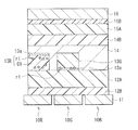
- FIG. 3 is a sectional view illustrating a configuration of the organic EL display unit illustrated in FIG. 1 .
- FIG. 4 is a sectional view illustrating a method of manufacturing the organic EL display unit illustrated in FIG. 1 in process order.
- FIG. 5A is a sectional view illustrating a process following FIG. 4 .
- FIG. 5B is a sectional view illustrating a process following FIG. 5A .
- FIG. 6A is a schematic view for describing the process illustrated in FIG. 5A .
- FIG. 6B is a sectional view illustrating a process following FIG. 6A .
- FIG. 7A is a sectional view illustrating a process following FIG. 6B .
- FIG. 7B is a sectional view illustrating a process following FIG. 7A .
- FIG. 7C is a sectional view illustrating a process following FIG. 7B .
- FIG. 8A is a sectional view illustrating a process following FIG. 7C .
- FIG. 8B is a sectional view illustrating a process following FIG. 8A .
- FIG. 8C is a sectional view illustrating a process following FIG. 8B .
- FIG. 9 is a characteristic diagram illustrating G light emission intensity of an example and a comparative example.
- FIG. 10 is a characteristic diagram illustrating G light emission intensity of examples and the comparative example.
- FIG. 11 is a characteristic diagram illustrating a relationship between a ratio of an R dopant to a polymer light-emitting material G 1 and G light emission intensity.
- FIG. 12 is a sectional view illustrating a configuration of an organic EL display unit according to a second embodiment of the present disclosure.
- FIG. 13A is a perspective view illustrating an appearance of Application Example 1 of the organic EL display units of the above-described embodiments.
- FIG. 13B is a perspective view illustrating an appearance of Application Example 1 of the organic EL display units of the above-described embodiments.
- FIG. 14 is a perspective view illustrating an appearance of Application Example 2 of the organic EL display units of the above-described embodiments.
- FIG. 15A is a perspective view illustrating an appearance viewed from a front side of Application Example 3.
- FIG. 15B is a perspective view illustrating an appearance viewed from a back side of Application Example 3.
- FIG. 16 is a perspective view illustrating an appearance of Application Example 4.
- FIG. 17 is a perspective view illustrating an appearance of Application Example 5.
- FIG. 18A is a front view, a left side view, a right side view, a top view, and a bottom view in a state in which Application Example 6 is closed.
- FIG. 18B is a front view and a side view in a state in which Application Example 6 is opened.
- First Embodiment (An example of an organic EL display unit in which a red light-emitting layer (an R low-molecular-weight material and a polymer light-emitting material G 1 ) and a green light-emitting layer are formed by reverse offset printing and a blue light-emitting layer is formed by a vacuum evaporation method) 2.
- Second Embodiment (An example of an organic EL display unit in which the red light-emitting layer (the R low-molecular-weight material and a thickener) and the green light-emitting layer are formed by reverse offset printing and the blue light-emitting layer is formed by a vacuum evaporation method) 3.
- Application Examples 1 to 6 (Examples of an electronic apparatus)
- FIG. 1 illustrates a configuration of an organic EL display unit according to a first embodiment of the present disclosure.
- This organic EL display unit is used as an organic EL television or the like, and may be configured, for example, by arranging a plurality of organic EL devices 10 R, a plurality of organic EL devices 10 G, and a plurality of organic EL devices 10 B that will be described later in a matrix as a display region 110 A on a substrate 110 .
- a signal line drive circuit 120 and a scanning line drive circuit 130 as drivers for image display are provided around the display region 110 A.
- a pixel drive circuit 140 is provided in the display region 110 A.
- FIG. 2 illustrates an example of the pixel drive circuit 140 .
- the pixel drive circuit 140 is an active drive circuit formed below a lower electrode 11 that will be described later.
- the pixel drive circuit 140 includes a driving transistor Tr 1 , a writing transistor Tr 2 , a capacitor (a retention capacitor) Cs located between these transistors Tr 1 and Tr 2 , and the organic EL device 10 R (or the organic EL device 10 G or the organic EL device 10 B) connected in series to the driving transistor Tr 1 between a first power supply line (Vcc) and a second power supply line (GND).
- Each of the driving transistor Tr 1 and the writing transistor Tr 2 is configured of a typical thin film transistor (TFT), and may have, for example, an inverted stagger configuration (a so-called bottom gate type) or a stagger configuration (a top gate type).
- a plurality of signal lines 120 A are arranged along a column direction, and a plurality of scanning lines 130 A are arranged along a row direction. An intersection of each signal line 120 A and each scanning line 130 A corresponds to one of the organic EL devices 10 R, 10 G, and 10 B (sub-pixels).
- Each of the signal lines 120 A is connected to the signal line drive circuit 120 , and an image signal is supplied from the signal line drive circuit 120 to a source electrode of the writing transistor Tr 2 through the signal line 120 A.
- Each of the scanning lines 130 A is connected to the scanning line drive circuit 130 , and a scanning signal is sequentially supplied from the scanning line drive circuit 130 to a gate electrode of the writing transistor Tr 2 through the scanning line 130 .
- the organic EL devices 10 R (first organic EL devices) that generate red light
- the organic EL devices 10 G (second organic EL devices) that generate green light
- the organic EL devices 10 B that generate blue light are arranged in a matrix as a whole.
- a combination of adjacent organic EL devices 10 R, 10 G, and 10 B configures one pixel.
- FIG. 3 illustrates a sectional configuration of the organic EL display unit illustrated in FIG. 1 .
- the lower electrode 11 as an anode
- a hole injection layer (HIL) 12 B and a hole transport layer (HTL) 12 A are laminated in this order from the substrate 110 (not illustrated in FIG. 3 ) side.
- HIL hole injection layer
- HTL hole transport layer
- connection layer (HCL) 14 is so formed as to cover the hole transport layer 12 A, the red light-emitting layer 13 R, and the green light-emitting layer 13 G, and a blue light-emitting layer 14 B, an electron transport layer 15 A, an electron injection layer 15 B, and an upper electrode 16 as a cathode are laminated in this order on the connection layer 14 .
- the red light-emitting layer 13 R and the green light-emitting layer 13 G may be pattern-formed by, for example, reverse offset printing, and the blue light-emitting layer 14 B may be formed by, for example, a vacuum evaporation method.
- the red light-emitting layer 13 R and the green light-emitting layer 13 G of organic layers located between the lower electrode 11 and the upper electrode 16 are provided for each device region (each pixel), and other layers are provided as common layers for respective device regions.
- these organic EL devices 10 R, 10 G, and 10 B are coated with a protective layer, and a sealing substrate made of glass or the like is further bonded onto the protective layer with an adhesive layer made of a thermosetting resin, an ultraviolet curable resin, or the like in between to seal the organic EL devices 10 R, 10 G, and 10 B.
- the substrate 110 is a supporting body with one main surface on which the organic EL devices 10 R, 10 G, and 10 B are formed in an array, and may be a publicly known substrate, and, for example, quartz, glass, metal foil, a film or a sheet made of a resin, or the like may be used.
- quartz and glass may be preferable, and in a case of a substrate made of a resin, as a material of the substrate, methacrylate resins typified by poly(methyl methacrylate) (PMMA), kinds of polyester such as polyethylene terephthalate (PET), polyethylene naphthalate (PEN), and polybutylene naphthalate (PBN), a polycarbonate resin, and the like may be adopted; however, a laminate configuration or execution of surface treatment that suppresses water permeability and gas permeability is necessary.
- PMMA poly(methyl methacrylate)
- PET polyethylene terephthalate
- PEN polyethylene naphthalate
- PBN polybutylene naphthalate
- a polycarbonate resin and the like
- the lower electrode 11 is provided for each of the organic EL devices 10 R, 10 G, and 10 B (for each pixel).
- the lower electrode 11 may have a thickness in a laminate direction (hereinafter simply referred to as “thickness”) of 10 nm to 1000 nm both inclusive, and may include a simple substance or an alloy of a metal element such as chromium (Cr), gold (Au), platinum (Pt), nickel (Ni), copper (Cu), tungsten (W) or silver (Ag).
- the lower electrode 11 may have a laminate configuration of a metal film made of the simple substance or the alloy of the metal element and a transparent conductive film made of an oxide of indium and tin (ITO), InZnO (indium zinc oxide), an alloy of zinc oxide (ZnO) and aluminum (Al), or the like. It is to be noted that, in a case where the lower electrode 11 is used as an anode, the lower electrode 11 may be desirably made of a material with a high hole injection property.
- the hole injection layer 12 B is configured to enhance hole injection efficiency to each of the light-emitting layers (the red light-emitting layer 13 R, the green light-emitting layer 13 G, and the blue light-emitting layer 14 B), and is a buffer layer configured to prevent leakage.
- a material of the hole injection layer 12 B may be appropriately selected in relation to a material of an electrode or an adjacent layer, and examples of the material of the hole injection layer 12 B may include polyaniline, polythiophene, polypyrrole, polyphenylene vinylene, polythienylene vinylene, polyquinoline, polyquinoxaline, and derivatives thereof, a conductive polymer such as a polymer including an aromatic amine structure in a main chain or a side chain, metal phthalocyanine (such as copper phthalocyanine), and carbon.
- a conductive polymer such as a polymer including an aromatic amine structure in a main chain or a side chain
- metal phthalocyanine such as copper phthalocyanine
- a weight-average molecular weight (Mw) of the polymer material may be within a range of 10000 to 300000 both inclusive, and may be preferably within a range of about 5000 to about 200000 both inclusive.
- an oligomer with a weight-average molecular weight of about 2000 to about 10000 both inclusive may be used; however, in a case where the Mw is less than 5000, the hole injection layer may be dissolved when the hole transport layer and layers following the hole transport layer are formed. Further, when the Mw exceeds 300000, the material may be gelated, thereby causing difficulty in film formation.
- Examples of a typical conductive polymer used as the material of the hole injection layer 12 B may include polydioxythiophene such as polyaniline, oligoaniline, and poly(3,4-ethylenedioxythiophene) (PEDOT).
- PEDOT poly(3,4-ethylenedioxythiophene)
- a polymer commercially available under Nafion (trademark) from H.C. Starck GmbH and a polymer commercially available in a dissolved state under the trade name of Liquion (trademark), ELsource (trademark) manufactured by Nissan Chemical Industries, Ltd., a conductive polymer called Verazol (trademark) manufactured by Soken Chemical & Engineering Co., Ltd. or the like may be used.
- a thickness of the hole injection layer 12 B depends on an entire device configuration, but may be within a range of 5 nm to 100 nm both inclusive.
- the hole transport layer 12 A is configured to enhance hole transport efficiency to each of the light-emitting layers (the red light-emitting layer 13 R, the green light-emitting layer 13 G, and the blue light-emitting layer 14 B).
- a polymer material forming the hole transport layer 12 A a light-emitting material soluble in an organic solvent, for example, polyvinylcarbazole, polyfluorene, polyaniline, polysilane, or a derivative thereof, a polysiloxane derivative having an aromatic amine in a side chain or a main chain, or polythiophene or a derivative thereof, polypyrrole, or the like may be used.
- poly[(9,9-dioctylfluorenyl-2,7-diyl)-co-4,4′-(N-(4-sec-butylphenyl))diphenylamine)] (TFB, Expression (1-1)
- poly[(9,9-dioctylfluorenyl-2,7-diyl)-alt-co-(N,N′-bis ⁇ 4-butylphenyl ⁇ -benzidine N,N′- ⁇ 1,4-diphenylene ⁇ )] (Expression (1-2)
- poly[(9,9-dioctylfluorenyl-2,7-diyl)] may be preferable, but the polymer material is not limited thereto.
- a weight-average molecular weight (Mw) of the polymer material as the material used for the hole transport layer 12 A may be preferably within a range of 50000 to 300000 both inclusive, and may be specifically preferably within a range of 100000 to 200000 both inclusive.
- Mw molecular weight
- the Mw is less than 50000, when the light-emitting layer is formed, a low-molecular-weight component in the polymer material is lost to cause a dot in the hole injection layer 12 B and the hole transport layer 12 A; therefore, initial performance of the organic EL device may be degraded, or deterioration in the device may be caused.
- the Mw exceeds 300000, the material is gelated; therefore, film formation may be difficult.
- the weight-average molecular weight (Mw) is a value determined by gel permeation chromatography (GPC) using polystyrene standards with use of tetrahydrofuran as a solvent.
- a thickness of the hole transport layer 12 A depends on the entire device configuration, but may be within a range of 10 nm to 200 nm both inclusive.
- the red light-emitting layer 13 R is configured to generate light by the recombination of electrons and holes in response to the application of an electric field.
- a thickness of the red light-emitting layer 13 R depends on the entire device configuration, but may be within a range of 10 nm to 200 nm both inclusive.
- This red light-emitting layer 13 R includes, as a host material (a base material), a polymer material that does not emit (or does not mainly emit, the same applies hereinafter) red light (first color light), and includes, as a dopant, a low-molecular-weight material that emits red light.
- the low-molecular-weight material may be preferably a monomer or an oligomer, in which two to ten monomers are bonded to one another, with a weight-average molecular weight of 50000 or less.
- a low-molecular-weight material with a weight-average molecular weight exceeding the above-described range is not necessarily excluded.
- the polymer material included as the host material in the red light-emitting layer 13 R may be, for example, a polymer material that emits color light of a shorter wavelength (higher energy) than red light (for example, a wavelength of 620 to 750 nm both inclusive).
- a polymer material for example, a polymer material (a polymer light-emitting material G 1 ) that emits color light (green light) having a spectral peak in a wavelength range of 500 to 550 nm both inclusive may be used.
- red light with low energy is allowed to be emitted by so-called down-conversion (red light having lower energy than green light is emitted with use of green light as excitation light).
- the polymer light-emitting material G 1 may include a polyfluorene-based polymer derivative, a (poly)paraphenylene vinylene derivative, a polyphenylene derivative, a polyvinylcarbazole derivative, a polythiophene derivative, and a ci-dibenzofuran derivative.
- this polymer light-emitting material G 1 may be desirably a dendrimer including tris(2-phenylpyridine)iridium (III) in a core thereof or a polymer material with such a dendritic structure.
- a phenyl carbazole group, a phenylene group, an ethylene group, or a fluorene group may be included in a dendron or a terminal group of the dendrimer.
- a light emission wavelength of the polymer light-emitting material G 1 may be changed by changing a ligand of an iridium (Ir) complex in a side chain.
- GPP represented by the following general expression (1-1) or PNDOF represented by the following general expression (1-2)
- GPP is a green phosphorescent light-emitting material, but GPP may include, in addition to a phosphorescent light-emitting group, a hole transport group (for example, HMTPD) or an electron transport group (for example, TBPhB) in a side chain of a polyvinyl main chain skeleton.
- a hole transport group for example, HMTPD
- TBPhB electron transport group
- a low-molecular-weight material included as a dopant in the red light-emitting layer 13 R may be a low-molecular-weight material having a red phosphorescent light-emitting property. More specifically, for example, bis(2-(2′-benzo[4,5-a]thienyl)pyridinato-N,C3′)iridium acetyl-acetate (BtpIr) represented by the following general expression (2-1) may be adopted.
- the low-molecular-weight light-emitting material r 1 may be, for example, Nile red, DCM, or DJCT. However, to obtain red fluorescence with high efficiency, the low-molecular-weight light-emitting material r 1 may be desirably the above-described Ir complex. Moreover, as long as the low-molecular-weight light-emitting material r 1 has the red phosphorescent property, the low-molecular-weight light-emitting material r 1 is not necessarily limited to the low-molecular-weight material, and polymer materials such as RPP represented by the following general expression (2-2) and PPDOF represented by the following general expression (2-3) may be adopted.
- RPP represented by the following general expression (2-2)
- PPDOF represented by the following general expression (2-3)
- the above-described red light-emitting layer 13 R (and the green light-emitting layer 13 G) may be formed by, for example, reverse offset printing.
- the above-described polymer light-emitting material G 1 and the low-molecular-weight light-emitting material r 1 may be dissolved with use of, for example, one or more kinds of organic solvents such as toluene, xylene, anisol, cyclohexanone, mesitylene (1,3,5-trimethylbenzene), pseudocumene (1,2,4-trimethylbenzene), dihydrobenzofuran, 1,2,3,4-tetramethylbenzene, tetralin, cyclohexylbenzene, 1-methylnaphthalene, p-anisylalcohol, dimethylnaphthalene, 3-methylbiphenyl, 4-methylbiphenyl, 3-isopropylbiphenyl, and mono-iso
- organic solvents such as tol
- R ink an ink including the polymer light-emitting material G 1 , the low-molecular-weight light-emitting material r 1 , and the organic solvent may be used to be applied to a blanket by, for example, spin coating or the like.
- a doping concentration of a dopant material in the host material may be desirably 10 wt % or less in terms of efficiency.
- doping concentration may be desirably 10 wt % or less in terms of efficiency.
- the host material is the polymer light-emitting material G 1 ; therefore, when the doping concentration of the low-molecular-weight light-emitting material r 1 is too low, G light emission is stronger than R light emission, and the color of light may become, for example, an orange color at color coordinates of (0.47, 0.50) in the CIE-xy chromaticity diagram. In this case, in G spectral intensity actually measured, the concentration of the low-molecular-weight light-emitting material r 1 in the red light-emitting layer 13 R is reduced to about 1 ⁇ 5 of that in the R ink.
- the concentration of the low-molecular-weight light-emitting material r 1 in the red light-emitting layer 13 R is 4 wt % or more, G light emission is allowed to be suppressed. Therefore, the concentration of the low-molecular light-emitting material r 1 in the R ink may be desirably 20 wt % or more. As will be described later, in a case where the concentration of the low-molecular-weight light-emitting material r 1 is 30 wt % or more, for example, red at color coordinates of (0.60, 0.39) and 14.2 cd/A is allowed to be obtained.
- the low-molecular-weight material refers to a material having substantially a single molecular weight other than a compound configured of molecules of a polymer or a condensate with a high molecular weight generated by chain-like repetition of same or similar reaction of the low-molecular-weight compound. Moreover, in the low-molecular-weight material, a new chemical bond between molecules by heating does not occur, and the low-molecular-weight material exists as a single molecule.
- the weight-average molecular weight (Mw) of such a low-molecular material may be preferably 50000 or less.
- the concentration of the R polymer light-emitting material in the R ink may be desirably higher than that in a case where the low-molecular-weight material is used, and may be desirably, for example, 30 wt % or more.
- the red light-emitting layer 13 R may include the following low-molecular-weight material as a low-molecular-weight hole transport material, a low-molecular-weight host material, or a spiro-based material.
- a low-molecular-weight hole transport material for example, benzene, styrylamine, triphenylamine, porphyrin, triphenylene, azatriphenylene, tetracyanoquinodimethane, triazole, imidazole, oxadiazole, polyarylalkane, phenylenediamine, arylamine, oxazole, anthracene, fluorenone, hydrazone, stilbene, or a derivative thereof, or a heterocyclic conjugated monomer or oligomer such as a polysilane-based compound, a vinylcarbazole-based compound, a thiophene-based compound, or an aniline-based compound may be adopted.
- low-molecular-weight materials represented by the following expressions (3-1) to (3-3) may be used.
- Each of A1 to A3 is an aromatic hydrocarbon group, a heterocyclic group, or a derivative thereof.
- (Z is a nitrogen-containing hydrocarbon group or a derivative thereof.
- L1 is a group formed by bonding one to four divalent aromatic ring groups, more specifically, a divalent group in which one to four aromatic rings are connected to one another, or a derivative thereof.
- Each of A4 and A5 is an aromatic hydrocarbon group or an aromatic heterocyclic group, or a derivative thereof. However, A4 and A5 may be bonded to each other to form a cyclic structure.
- L2 is a group formed by bonding two to six divalent aromatic ring groups. More specifically, L2 is a divalent group formed by connecting two to six aromatic rings to one another, or a derivative thereof.
- Each of A6 to A9 is a group formed by bonding one to ten aromatic hydrocarbon groups, one to ten heterocyclic groups, or one to ten derivatives thereof.
- a hole transport low-molecular-weight material having a T2 level between a T2 level of a green light-emitting polymer and a T1 level of a red light-emitting polymer may be added.
- Examples of such a low-molecular-weight material may include amine-based low-molecular-weight materials as represented by the following general expressions (4-1) to (4-16).
- the green light-emitting layer 13 G is configured to generate green light by the recombination of electrons and holes in response to the application of an electric field.
- a thickness of the green light-emitting layer 13 G depends on the entire device configuration, but may be within a range of 10 nm to 200 nm both inclusive.
- the green light-emitting layer 13 R includes a polymer light-emitting material or a low-molecular-weight light-emitting material that emits green light, or both.
- the polymer light-emitting material used in the green light-emitting layer 13 G similar materials listed as the above-described polymer light-emitting material G 1 may be adopted.
- a polyfluorene-based polymer derivative a (poly)paraphenylene vinylene derivative, a polyphenylene derivative, a polyvinylcarbazole derivative, a polythiophene derivative, or a ci-dibenzofuran derivative may be adopted.
- the polymer light-emitting material may be desirably cross-linked as a polymer, but may be a dendrimer with a molecular weight of 5000 or more or a polymer material having such a dendritic structure.
- a light emission wavelength of the polymer light-emitting material in the green light-emitting layer 13 G may be changed by changing a ligand of an iridium (Ir) complex in a side chain.
- the green light-emitting layer 13 G may also include the low-molecular-weight material as represented by the above-described expressions (3-1) to (3-3); however, an amine-based low-molecular-weight material as the G quencher may not be desirably included.
- a thin film layer 13 a including siloxane or the like is formed, and the low-molecular-weight light-emitting material r 1 included in the red light-emitting layer 13 R is adhered.
- the thin film layer 13 a and the low-molecular-weight light-emitting material r 1 are formed in the device region of the organic EL device 10 G in reverse offset printing that will be described later (as imprints of the reverse offset printing).
- connection layer 14 may be formed by, for example, a vacuum evaporation method
- the connection layer 14 may be preferably made of a low-molecular-weight material (in particular, a monomer). This is because polymerized molecules such as an oligomer or a polymer material may be decomposed during evaporation. It is to be noted that, in the connection layer 14 , a mixture of two or more kinds of low-molecular-weight materials with different molecular weights may be used, or the two or more kinds of the low-molecular-weight materials may be laminated. It is to be noted that a thickness of this connection layer 14 may be desirably 1 nm or more, and characteristics of the blue light-emitting layer 14 B are allowed to be improved accordingly.
- the blue light-emitting layer 14 B is configured to generate blue light by the recombination of electrons and holes in response to the application of an electric field.
- an anthracene compound as a host material is doped with a blue or green fluorescent dye as a guest material, and the blue light-emitting layer 14 B generates blue or green emission light.
- an anthracene derivative represented by the following general expression (5) may be preferably used as the host material.
- R1 to R6 are independently hydrogen, a halogen, a hydroxyl group, a substituted or unsubstituted carbonyl group with 20 or less carbon atoms, a substituted or unsubstituted carbonyl ester group with 20 or less carbon atoms, a substituted or unsubstituted alkyl group with 20 or less carbon atoms, a substituted or unsubstituted alkenyl group with 20 or less carbon atoms, a substituted or unsubstituted alkoxyl group with 20 or less carbon atoms, a cyano group, a nitro group, a substituted or unsubstituted silyl group with 30 or less carbon atoms, a substituted or unsubstituted aryl group with 30 or less carbon atoms, a substituted or unsubstituted heterocyclic group with 30 or less carbon atoms, or a substituted or unsubstituted
- aryl group may include a phenyl group, a 1-naphthyl group, a 2-naphthyl group, a fluorenyl group, a 1-anthryl group, a 2-anthryl group, a 9-anthryl group, a 1-phenanthryl group, a 2-phenanthryl group, a 3-phenanthryl group, a 4-phenanthryl group, a 9-phenanthryl group, a 1-naphthacenyl group, a 2-naphthacenyl group, a 9-naphthacenyl group, a 1-pyrenyl group, a 2-pyrenyl group, a 4-pyrenyl group, a 1-chrysenyl group, a 6-chrysenyl group, a 2-fluoranthenyl group, a 3-fluoranthenyl group, a 2-biphenylyl group, a 3-biphenylyl
- heterocyclic group may include a five- or six-membered ring aromatic heterocyclic group containing O, N, and S as hetero atoms, or a condensed polycyclic aromatic heterocyclic group with 2 to 20 carbon atoms.
- aromatic heterocyclic group and the condensed polycyclic aromatic heterocyclic group may include a thienyl group, a furyl group, a pyrrolyl group, a pyridyl group, a quinolyl group, a quinoxalyl group, an imidazopyridyl group, and a benzothiazole group.
- Representative examples may include a 1-pyrrolyl group, a 2-pyrrolyl group, a 3-pyrrolyl group, a pyrazinyl group, a 2-pyridinyl group, a 3-pyridinyl group, a 4-pyridinyl group, a 1-indolyl group, a 2-indolyl group, a 3-indolyl group, a 4-indolyl group, a 5-indolyl group, a 6-indolyl group, a 7-indolyl group, a 1-isoindolyl group, a 2-isoindolyl group, a 3-isoindolyl group, a 4-isoindolyl group, a 5-isoindolyl group, a 6-isoindolyl group, a 7-isoindolyl group, a 2-furyl group, a 3-furyl group, a 2-benzofuranyl group,
- the amino group may be any of an alkylamino group, an arylamino group, an aralkylamino group, and the like. They may preferably include an aliphatic group with 1 to 6 carbon atoms in total and/or one to four aromatic carbon rings. Such groups may include a dimethylamino group, a diethylamino group, a dibutylamino group, a diphenylamino group, a ditolylamino group, a bisbiphenylylamino group, and a dinaphthylamino group.
- two or more kinds of the above-described substituted groups may form a condensed ring or may further include a substituted group.
- the blue light-emitting guest material refers to a compound having a peak in a light emission wavelength range of about 400 nm to about 490 nm both inclusive.
- organic materials such as a naphthalene derivative, an anthracene derivative, a naphthacene derivative, a styrylamine derivative, and a bis(azinyl)methene boron complex are used.
- the blue light-emitting guest material may be preferably selected from an aminonaphthalene derivative, an aminoanthracene derivative, an aminochrysene derivative, an aminopyrene derivative, a styrylamine derivative, and a bis(azinyl)methene boron complex. More specifically, for example, a material mixed with 2.5 wt % of 4,4′-bis[2- ⁇ 4-(N,N-diphenylamino)phenyl ⁇ vinyl]biphenyl (DPAVBi) may be adopted.
- DPAVBi 4,4′-bis[2- ⁇ 4-(N,N-diphenylamino)phenyl ⁇ vinyl]biphenyl
- the electron transport layer 15 A is configured to enhance electron transport efficiency to the red light-emitting layer 13 R, the green light-emitting layer 13 G, and the blue light-emitting layer 14 B, and is provided as a common layer on an entire surface of the blue light-emitting layer 14 B.
- Examples of a material of the electron transport layer 15 A may include quinoline, perylene, phenanthroline, bisstyryl, pyrazine, triazole, oxazole, fullerene, oxadiazole, fluorenone, and a derivative thereof, and a metal complex.
- tris(8-hydroxyquinoline)aluminum Alq3 for short
- anthracene naphthalene
- phenanthrene pyrene
- anthracene perylene
- butadiene coumarin
- C60 acridine
- stilbene 1,10-phenanthroline
- a derivative thereof or a metal complex
- the electron injection layer 15 B is configured to enhance electron injection efficiency, and is provided as a common layer on an entire surface of the electron transport layer 15 A.
- a material of the electron injection layer 15 B for example, lithium oxide (Li 2 O) as an oxide of lithium (Li), cesium carbonate (Cs 2 CO 3 ) as a complex oxide of cesium (Cs), and a mixture of the oxide and the complex oxide may be used.
- the electron injection layer 15 B is not limited to such materials, and, for example, an alkali earth metal such as calcium (Ca) and barium (Ba), lithium, an alkali metal such as cesium, a metal with a small work function such as indium (In) and magnesium (Mg), and oxides, complex oxides, fluorides, and the like of these metals may be used in a simple substance form or as a mixture or an alloy of these metals, these oxides, these complex oxides, and these fluorides to enhance stability.
- an alkali earth metal such as calcium (Ca) and barium (Ba)
- lithium an alkali metal such as cesium
- a metal with a small work function such as indium (In) and magnesium (Mg)
- oxides, complex oxides, fluorides, and the like of these metals may be used in a simple substance form or as a mixture or an alloy of these metals, these oxides, these complex oxides, and these fluorides to enhance stability.
- the upper electrode 16 may have, for example, a thickness of 2 nm to 15 nm both inclusive, and may be configured of a metal conductive film. More specifically, an alloy of Al, Mg, Ca, or Na may be adopted. In particular, an alloy of magnesium and silver (a Mg—Ag alloy) may be preferable, because the alloy has both conductivity and small absorption in a thin film.
- a material of the upper electrode 16 may be an alloy of Al and Li (an Al—Li alloy).
- the upper electrode 16 may be configured of a mixture layer including an organic light-emitting material such as an aluminum quinoline complex, a styrylamine derivative, or a phthalocyanine derivative.
- the upper electrode 16 may separately include a layer with light transparency such as MgAg as a third layer. It is to be noted that the upper electrode 16 is used as a common electrode for the organic EL devices 10 R, 10 G, and 10 B.
- a protective layer (not illustrated) formed on the upper electrode 16 may have, for example, a thickness of 2 to 3 ⁇ m both inclusive, and may be made of one of an insulating material or a conductive material.
- an inorganic amorphous insulating material for example, amorphous silicon ( ⁇ -Si), amorphous silicon carbide ( ⁇ -SiC), amorphous silicon nitride ( ⁇ -Si 1-x N x ), amorphous carbon ( ⁇ -C), or the like may be preferable.
- the sealing substrate is made of a material, such as glass, transparent to light generated by the organic EL devices 10 R, 10 G, and 10 B, and, for example, a color filter and a light-shielding film (both not illustrated) may be provided to the sealing substrate.
- a color filter and a light-shielding film both not illustrated
- this organic EL display unit may be manufactured as follows.
- FIGS. 4 to 5B illustrate a method of manufacturing the above-described organic EL display unit in process order.
- the pixel drive circuit 140 including the driving transistor Tr 1 is formed on the substrate 110 made of the above-described material, and a planarization insulating film (not illustrated) made of, for example, a photosensitive resin is provided.
- the lower electrodes 11 for respective device regions 10 r 1 , 10 g 1 , and 10 b 1 of the organic EL devices 10 R, 10 G, and 10 B are formed.
- oxygen plasma treatment is performed on a surface where the lower electrodes 11 are formed of the substrate 110 to remove contaminants such as an organic substance adhered to the surface, thereby improving wettability.
- the lower electrodes 11 are coated with the hole injection layer 12 B (for example, ELsource or ND1501 manufactured by Nissan Chemical Industries. Ltd.) by, for example, spin coating, and the hole injection layer 12 B is heated for 1 hour at a temperature of 220° C. in air with use of a hot plate to be thermally cured.
- the hole transport layer 12 A (TFB) is applied by, for example, spin coating, and is heated for 1 hour at a temperature of 180° C. in nitrogen with use of a hot plate to be thermally cured.
- the red light-emitting layer 13 R and the green light-emitting layer 13 G are pattern-formed on the hole transport layer 12 A by reverse offset printing.
- the formation order of the red light-emitting layer 13 R and the green light-emitting layer 13 G is not specifically limited; however, in this embodiment, a case where the red light-emitting layer 13 R is formed as a first color, and the green light-emitting layer 13 G is formed as a second color is adopted as an example.
- the red light-emitting layer 13 R (the polymer light-emitting material G 1 and the low-molecular-weight light-emitting material r 1 ) is formed in the device region 10 r 1 on the hole transport layer 12 A by reverse offset printing.
- FIGS. 6A to 8C schematically illustrate a specific procedure of the reverse offset printing.
- a blanket 60 made of silicon (for example, Fujikura Rubber Ltd. (STD700)) is prepared, and a surface of the blanket 60 is swollen.
- An entire surface on the blanket 60 is coated with, for example, a solution including a hole transport material such as siloxane by, for example, a spin coating method. Accordingly, a surface layer of the blanket 60 is turned to a swollen state, and the surface of the blanket 60 is allowed to be maintained at moderate humidity, and favorable film formation is possible in the following transfer process accordingly.
- the above-described R ink (an ink prepared, for example, by adding 30 wt % of the low-molecular-weight light-emitting material r 1 (BtpIr) to the polymer light-emitting material G 1 and dissolving the resultant in xylene) is dropped on the entire surface of the blanket 60 .
- the blanket 60 is rotated at, for example, 3000 rpm 2 /sec to perform spin coating.
- a printing pattern layer (a printing pattern layer 13 r 1 ) of the red light-emitting layer 13 R is formed on the blanket 60 . More specifically, first, as illustrated in FIG. 7A , an intaglio plate 61 having a depressed portion corresponding to the device region 10 r 1 and a layer of an ink D 1 r of the blanket 60 are arranged to face each other, and as illustrated in FIG. 7B , the intaglio plate 61 is pressed against the layer of the ink D 1 r on the blanket 60 , and is pressurized by a roller or the like. After that, as illustrated in FIG.
- an unnecessary portion (D 1 r ′) of the layer of the ink D 1 r is transferred to a protruded portion of the intaglio plate 61 by peeling the blanket 60 from the intanglio plate 61 to be removed (taken off) from the blanket 60 .
- the printing pattern 13 r 1 corresponding to the device region 10 r 1 of the red light-emitting layer 13 R is formed on the blanket 60 . It is to be noted that a linear pattern is illustrated in the diagram; however, as long as the pattern is consistent with a TFT pixel arrangement, the shape of the pattern is not limited to the linear pattern.
- the printing pattern layer 13 r 1 of the red light-emitting layer 13 R on the blanket 60 is transferred to the substrate 110 side. More specifically, first, as illustrated in FIG. 8A , the substrate 110 on which the hole injection layer 12 B and the hole transport layer 12 A have been already formed and the blanket 60 are arranged to face each other. At this time, more specifically, as illustrated in a right diagram in the FIG. 8A , a residual portion Xr that has not been taken off by the intaglio plate 61 is formed in a region other than the printing pattern layer 13 r 1 on the surface of the blanket 60 before transfer.
- This residual portion Xr may include, for example, the hole transport material (such as siloxane) and the low-molecular-weight light-emitting material r 1 , and is transferred to other device regions (for example, the device region 10 g 1 ) by being transferred together with the printing pattern layer 13 r 1 .
- the hole transport material such as siloxane
- the low-molecular-weight light-emitting material r 1 is transferred to other device regions (for example, the device region 10 g 1 ) by being transferred together with the printing pattern layer 13 r 1 .
- the substrate 110 and the printing pattern layer 13 r 1 are aligned, and as illustrated in FIG. 8B , the printing pattern layer 13 r 1 of the blanket 60 is pressed against the substrate 110 .
- the red light-emitting layer 13 R is pattern-formed on the substrate 110 by peeling the blanket 60 from the substrate 110 ( FIG. 8C ).
- the residual portion Xr formed on the blanket 60 is also transferred to the substrate 110 concurrently.
- the green light-emitting layer 13 G is formed in the device region 10 g 1 by reverse offset printing.
- an ink used at this time for example, an ink prepared by dissolving, in xylene, a dendrimer type polymer material including the above-described tris(2-phenylpyridine)iridium (III) in a core thereof may be used.
- the substrate 110 on which the red light-emitting layer 13 R and the green light-emitting layer 13 G have been formed by transfer is heated for 30 minutes at 130° C. in an nitrogen atmosphere with use of a hot plate to be thermally cured.
- connection layer 14 , the blue light-emitting layer 14 B, and the electron transport layer 15 A that are made of the above-described materials or the like are formed on the red light-emitting layer 13 R and the green light-emitting layer 13 G by, for example, a vacuum evaporation method.
- the blue light-emitting layer 14 B for example, ADN (9,10-di(2-naphthyl)anthracene) and a blue dopant at a weight ratio of 95:5 are co-evaporated.
- the electron transport layer 15 A for example, a film of Alq3 (8-hydroxyquinoline aluminum) may be formed with a thickness of 15 nm by a vacuum evaporation method.
- a film of LiF may be formed with a thickness of 0.3 nm.
- the upper electrode 16 is formed on the electron injection layer 15 B by, for example, a vacuum evaporation method or a sputtering method.
- the upper electrode 16 for example, aluminum may be evaporated to 150 nm.
- a protective film made of the above-described material is formed by, for example, an evaporation method or a CVD method, and then a sealing substrate provided with the color filter and the like is bonded onto the protective layer with an adhesive layer in between.
- the organic EL display unit illustrated in FIG. 3 is allowed to be formed.
- the red light-emitting layer 13 R includes, as a host material, the polymer material (the polymer light-emitting material G 1 ) that does not emit red light, and includes, as a dopant, the low-molecular-weight material (the low-molecular-weight light-emitting material r 1 ) that emits red light. Therefore, in the organic EL device 10 R, red light emission is obtained by so-called down-conversion.
- red light-emitting layer 13 R is formed by, for example, reverse offset printing
- color mixture into other pixels due to a residue on the blanket is an issue.
- the concentration of the polymer light-emitting material G 1 that emits green light is higher than that of the low-molecular-weight material r 1 that emits red light.
- the organic EL device 10 G even in a case where the above-described dye residue (the residual portion Xr) is transferred, compared to a case where an ink made of a red light-emitting polymer material is used, an amount of an adhered red dye is reduced to reduce an influence of red light.
- the polymer light-emitting material G 1 is allowed to be used as the host material with use of down-conversion, and while viscosity necessary for reverse offset printing is maintained in the ink D 1 r , an influence of the ink D 1 r on the green light-emitting layer 13 G is allowed to be suppressed.
- Example 1 the above-described organic EL devices 10 R and 10 G were formed, and when xy chromaticity and light emission intensity of the organic EL device 10 G were measured, mixture of red light into the green light-emitting layer 13 G was not observed, and xy chromaticity coordinates of (0.31, 0.64) and efficiency of 30 cd/A were allowed to be obtained. Moreover, as illustrated in FIG. 9 , spectral intensity at a wavelength of 600 nm was 0.015, and a sub-peak was not observed in a spectrum. Further, in the red light-emitting layer 13 R, red at (0.60, 0.39) and 14 cd/A was allowed to be obtained.
- an ink prepared by adding the low-molecular-weight light-emitting material r 1 (BtpIr) at a concentration of 30 wt % in the polymer light-emitting material G 1 to the dendrimer type polymer material including tris(2-phenylpyridine)iridium (III) in a core thereof and dissolving a resultant in xylene was used.
- an ink prepared by dissolving a dendrimer type polymer material including tris(2-phenylpyridine)iridium (III) in a core thereof in xylene was used.
- Example 1 As a comparative example of the above-described Example 1, when reverse offset printing was performed with use of, as an R ink, an ink prepared by dissolving a polymer light-emitting material (RPP) in xylene, mixture of red into the green light-emitting layer was observed, and xy chromaticity coordinates of (0.33, 0.62) and efficiency of 29 cd/A were obtained. Moreover, as illustrated in FIG. 9 , spectral intensity at a wavelength of 600 nm was 0.02, and a sub-peak was observed. Further, in the red light-emitting layer, (0.62, 0.34) and 15 cd/A were obtained.
- RRP polymer light-emitting material
- xy chromaticity and light emission intensity of the organic EL device 10 G were measured in a manner similar to the above-described Example 1, except that an ink prepared by adding 20 wt % of a red polymer phosphorescent dopant (RPP) to the polymer light-emitting material G 1 similar to that in the above-described Example 1 and dissolving a resultant in xylene was used as the R ink.
- RPP red polymer phosphorescent dopant
- Example 1 spectral intensity at a wavelength of 600 nm was 0.015, and a sub-peak was hardly observed in a spectrum. Further, in the red light-emitting layer 13 R, red at (0.60, 0.39) and 13 cd/A was allowed to be obtained. It is to be noted that, in FIG. 10 , results of Example 1 and the comparative example are also illustrated. Moreover, it was found that, in the above-described Example 1 using an R low-molecular-weight dopant, compared to Example 2 using an R polymer dopant, spectral intensity around a wavelength of 600 nm was decreased.
- xy chromaticity and light emission intensity of the organic EL device 10 G were measured in a manner similar to the above-described Example 1, except that an ink prepared by adding 27 wt % of a red low-molecular-weight phosphorescent dopant (BtpIr) and a compound represented by the above-described general expression (4-2) to the polymer light-emitting material G 1 similar to that in the above-described Example 1 and dissolving a resultant in xylene was used as the R ink.
- BtpIr red low-molecular-weight phosphorescent dopant
- 4-2 red low-molecular-weight phosphorescent dopant
- spectral intensity at a wavelength of 600 nm was 0.015, and a sub-peak was not observed in a spectrum. Further, in the red light-emitting layer 13 R, red at (0.61, 0.37) and 14 cd/A was allowed to be obtained.
- a suitable R dopant concentration (a mixture ratio of the low-molecular-weight light-emitting material r 1 in the polymer light-emitting material G 1 ) in the R ink including the polymer light-emitting material G 1 and the low-molecular-weight light-emitting material r 1 is different depending on intended use.
- a suitable range of the R dopant concentration is different between a case where a film is formed by a spin coating method and a case where a film is formed by reverse offset printing as with this embodiment.
- Example 4-1 an R ink for spin coating (R ink I 1 for the sake of convenience) was adjusted, and peak intensity of G light in a red light-emitting layer formed with use of this R ink I 1 was measured. At that time, the R dopant concentration of the R ink I 1 was changed to 1%, 2%, and 10%.
- Example 4-2 an R ink for reverse offset printing (R ink I 2 for the sake of convenience) was adjusted, and peak intensity of G light in a red light-emitting layer formed with use of this R ink I 2 was measured. At that time, the R dopant concentration of the R ink I 2 was changed to 10%, 27%, and 30%.
- a ratio noted in brackets indicates a volume ratio (G 1 :r 1 ) between the polymer light-emitting material G 1 (a polymer material similar to that in Example 1) and the low-molecular-weight light-emitting material r 1 (BtpIr) in each of the R inks I 1 and I 2 .
- G 1 a polymer material similar to that in Example 1
- BtpIr low-molecular-weight light-emitting material
- Example 4-2 using the R ink I 2 for reverse offset printing even though the R dopant concentration was 10%, the peak intensity was about 0.03; therefore, to reduce an influence of G light emission, it may be desirable that the R dopant concentration be 20%, that is twice higher than 10%, or more.
- the peak intensity was about 0.01, and when the R dopant concentration was 30%, the peak intensity was 0.
- a suitable R dopant concentration in the R ink is different depending on a forming method, and the R dopant concentration in the R ink for reverse offset printing may be desirably higher than that in the R ink for spin coating.
- the R ink (“ink” in the present disclosure) described in this embodiment is applicable to not only reverse offset printing but also other film formation methods.
- the polymer light-emitting material G 1 that emits green light is the host material; however, as long as the host material causes down-conversion in combination, the host material is not limited thereto.
- the red light-emitting layer 13 R may include a blue light-emitting polymer material (PADOF) represented by the following general expression (6) as the host material instead of the polymer light-emitting material G 1 .
- PADOF blue light-emitting polymer material
- the green light-emitting layer 13 G may include, as a host material, the blue light-emitting polymer material represented by the general expression (6) and may include, as a dopant, a green light-emitting low-molecular-weight material represented by the following general expression (7). Even in this case, mixture of green light into the blue light-emitting layer caused by adhesion of a green dye to the device region of the organic EL device 10 B in a case where the green light-emitting layer 13 G is formed by reverse offset printing is allowed to be suppressed. Moreover, a configuration provided with a yellow light-emitting layer instead of the red light-emitting layer 13 R may be adopted.
- This yellow light-emitting layer may include, as a dopant, a yellow light-emitting low-molecular-weight material represented by the following general expression (8), i.e., bis(2-phenylbenzothiozolato-N,C2)Iridium(acetylacetonate) (Bt 2 Ir(acac)), for example.
- a yellow light-emitting low-molecular-weight material represented by the following general expression (8), i.e., bis(2-phenylbenzothiozolato-N,C2)Iridium(acetylacetonate) (Bt 2 Ir(acac)), for example.
- FIG. 12 illustrates a sectional configuration of the organic EL unit in the second embodiment.
- the polymer material as the host material used for the red light-emitting layer 13 R may be a so-called thickener.
- the thickener may include polymer materials represented by the following general expressions (9-1) to (9-3).
- the polymer material used for the red light-emitting layer 13 R (or the green light-emitting layer 13 G) may be a polymer material that does not have a phosphorescence property.
- the organic EL display units of the above-described embodiments are applicable to display units of electronic apparatuses in any fields that display, as an image or a picture, an image signal input from outside or an image signal produced inside, such as televisions, digital cameras, notebook personal computers, portable terminal devices such as cellular phones, and video cameras.
- FIGS. 13A and 13B illustrate an appearance of a smartphone.
- This smartphone may include, for example, a display section 110 (an organic EL display unit), a non-display section (an enclosure) 120 , and an operation section 130 .
- the operation section 30 may be disposed on a front surface of the non-display section 120 as illustrated in FIG. 13A , or may be disposed on a top surface of the non-display section 120 as illustrated in FIG. 13B .
- FIG. 14 illustrates an appearance configuration of a television.
- This television may include, for example, an image display screen section 200 (a display unit 1 ) including a front panel 210 and a filter glass 220 .
- FIGS. 15A and 15B illustrate appearance configurations viewed from a front side and a back side of a digital still camera, respectively.
- This digital still camera may include, for example, a light-emitting section 10 for a flash, a display section 320 (the organic EL display unit), a menu switch 330 , and a shutter button 340 .
- FIG. 16 illustrates an appearance configuration of a notebook personal computer.
- This personal computer may include, for example, a main body 410 , a keyboard 420 for operation of inputting characters and the like, and a display section 430 (the organic EL display unit) that displays an image.
- FIG. 17 illustrates an appearance configuration of a video camera.
- This video camera may include, for example, a main body section 510 , a lens 520 provided on a front side surface of the main body section 510 and for shooting an image of a subject, a shooting start and stop switch 530 , and a display section 540 (the organic EL display unit).
- FIGS. 18A and 18B illustrate an appearance configuration of a cellular phone.
- This cellular phone may have a configuration in which, for example, a top-side enclosure 610 and a bottom-side enclosure 620 are connected together through a connection section (hinge section) 630 , and the cellular phone may include a display 640 (the display unit 1 ), a sub-display 650 , a picture light 660 , and a camera 670 .
- the present disclosure is described referring to the embodiments and the examples, the present disclosure is not limited thereto, and may be variously modified.
- the ink of the present disclosure the ink used for reverse offset printing is described as an example; however, the ink of the present disclosure is not limited thereto, and is applicable to other various methods (a coating method or a printing method) in which, to a pixel of a certain color (a G pixel in the above-described example), an ink of another color (the R ink in the above-described example) may be adhered.
- the first light-emitting layer is not limited to a layer formed by reverse offset printing.
- each layer the material and thickness of each layer, the method and conditions of forming each layer are not limited to those described in the above-described embodiments and the examples, and each layer may be made of any other material with any other thickness by any other method under any other conditions.
- a case of an active matrix display unit is described: however, the present disclosure is applicable to a passive matrix display unit.
- the configuration of a pixel drive circuit for active matrix drive is not limited to that described in the above-described embodiments, and, if necessary, a capacitor device or a transistor may be further included.
- a necessary drive circuit may be included in addition to the above-described signal line drive circuit 120 and the above-described scanning line drive circuit 130 according to a modification of the pixel drive circuit.
- An organic EL display unit including:
- first organic EL device including a first light-emitting layer that emits first color light
- second organic EL device including a second light-emitting layer that emits second color light of a shorter wavelength than the first color light
- the first light-emitting layer includes, as a host material, a polymer material that does not emit the first color light or does not mainly emit the first color light, and includes, as a dopant, a low-molecular-weight material or a polymer material that emits the first color light.
- the first light-emitting layer is a red light-emitting layer that emits red light as the first color light
- the second light-emitting layer is a green light-emitting layer that emits green light as the second color light.
- the organic EL display unit according to (3) further including a third organic EL device including a blue light-emitting layer that emits blue light,
- red light-emitting layer and the green light-emitting layer are provided for respective devices
- the blue light-emitting layer is provided as a common layer for the first organic EL device, the second organic EL device, and the third organic EL device.
- connection layer having a hole transport property is provided between the red light-emitting layer and the blue light-emitting layer and between the green light-emitting layer and the blue light-emitting layer.
- the first light-emitting layer is a red light-emitting layer that emits red light as the first color light
- the second light-emitting layer is a blue light-emitting layer that emits blue light as the second color light.
- the first light-emitting layer is a green light-emitting layer that emits green light as the first color light
- the second light-emitting layer is a blue light-emitting layer that emits blue light as the second color light.
- a method of manufacturing an organic EL display unit including a first organic EL device and a second organic EL device, the first organic EL device including a first light-emitting layer that emits first color light, and the second organic EL device including a second light-emitting layer that emits second color light of a shorter wavelength than the first color light, the method including:
- the first light-emitting layer using a polymer material as a host material and a low-molecular-weight material or a polymer material as a dopant, the polymer material that does not emit the first color light or does not mainly emit the first color light, and the low-molecular-weight material or the polymer material that emits the first color light.
- the first light-emitting layer is a red light-emitting layer that emits red light as the first color light
- the second light-emitting layer is a green light-emitting layer that emits green light as the second color light.
- the method of manufacturing the organic EL display unit according to (15) further including a step of forming, by an evaporation method, a blue light-emitting layer configured to emit blue light after the red light-emitting layer and the green light-emitting layer are formed.
- An ink used to form a first light-emitting layer of an organic EL display unit the organic EL display unit including a first organic EL device and a second organic EL device, the first organic EL device including the first light-emitting layer that emits first color light, and the second organic EL device including a second light-emitting layer that emits second color light of a shorter wavelength than the first color light, the ink including:
- a polymer material that does not emit the first color light or does not mainly emit the first color light as a host material and a low-molecular-weight material or a polymer material that emits the first color light as a dopant a polymer material that does not emit the first color light or does not mainly emit the first color light as a host material and a low-molecular-weight material or a polymer material that emits the first color light as a dopant.
- first organic EL device including a first light-emitting layer that emits first color light
- second organic EL device including a second light-emitting layer that emits second color light of a shorter wavelength than the first color light
- the first light-emitting layer includes, as a host material, a polymer material that does not emit the first color light or does not mainly emit the first color light, and includes, as a dopant, a low-molecular-weight material or a polymer material that emits the first color light.
Abstract
Description
2. Second Embodiment (An example of an organic EL display unit in which the red light-emitting layer (the R low-molecular-weight material and a thickener) and the green light-emitting layer are formed by reverse offset printing and the blue light-emitting layer is formed by a vacuum evaporation method)
3. Application Examples 1 to 6 (Examples of an electronic apparatus)


(Each of A1 to A3 is an aromatic hydrocarbon group, a heterocyclic group, or a derivative thereof.)

(Z is a nitrogen-containing hydrocarbon group or a derivative thereof. L1 is a group formed by bonding one to four divalent aromatic ring groups, more specifically, a divalent group in which one to four aromatic rings are connected to one another, or a derivative thereof. Each of A4 and A5 is an aromatic hydrocarbon group or an aromatic heterocyclic group, or a derivative thereof. However, A4 and A5 may be bonded to each other to form a cyclic structure.)

(L2 is a group formed by bonding two to six divalent aromatic ring groups. More specifically, L2 is a divalent group formed by connecting two to six aromatic rings to one another, or a derivative thereof. Each of A6 to A9 is a group formed by bonding one to ten aromatic hydrocarbon groups, one to ten heterocyclic groups, or one to ten derivatives thereof.)


Claims (12)
Applications Claiming Priority (3)
| Application Number | Priority Date | Filing Date | Title |
|---|---|---|---|
| JP2012225750 | 2012-10-11 | ||
| JP2012-225750 | 2012-10-11 | ||
| PCT/JP2013/075279 WO2014057782A1 (en) | 2012-10-11 | 2013-09-19 | Organic el display device, manufacturing method therefor, ink and electronic apparatus |
Publications (2)
| Publication Number | Publication Date |
|---|---|
| US20150287926A1 US20150287926A1 (en) | 2015-10-08 |
| US9755149B2 true US9755149B2 (en) | 2017-09-05 |
Family
ID=50477253
Family Applications (1)
| Application Number | Title | Priority Date | Filing Date |
|---|---|---|---|
| US14/431,984 Active 2033-10-01 US9755149B2 (en) | 2012-10-11 | 2013-09-19 | Organic EL display unit, method of manufacturing the same, ink, and electronic apparatus |
Country Status (6)
| Country | Link |
|---|---|
| US (1) | US9755149B2 (en) |
| JP (1) | JP6205571B2 (en) |
| KR (1) | KR102080672B1 (en) |
| CN (1) | CN104737625B (en) |
| TW (1) | TWI569491B (en) |
| WO (1) | WO2014057782A1 (en) |
Families Citing this family (2)
| Publication number | Priority date | Publication date | Assignee | Title |
|---|---|---|---|---|
| CN104600201A (en) * | 2015-01-30 | 2015-05-06 | 京东方科技集团股份有限公司 | Organic light-emitting device, preparation method of organic light-emitting device and display device |
| KR102569733B1 (en) * | 2016-06-01 | 2023-08-23 | 삼성디스플레이 주식회사 | Organic light emitting device and method of manufacturing the same |
Citations (34)
| Publication number | Priority date | Publication date | Assignee | Title |
|---|---|---|---|---|
| US20030082404A1 (en) | 2001-08-29 | 2003-05-01 | Fujitsu Limited | Condensed eight-ring aromatic compound, and organic EL element and organic EL display using the same |
| US6670772B1 (en) * | 2002-06-27 | 2003-12-30 | Eastman Kodak Company | Organic light emitting diode display with surface plasmon outcoupling |
| US20040036421A1 (en) * | 2002-08-20 | 2004-02-26 | Eastman Kodak Company | Color organic light emitting diode display with improved lifetime |
| US20040094768A1 (en) * | 2002-09-06 | 2004-05-20 | Gang Yu | Methods for producing full-color organic electroluminescent devices |
| JP2004186111A (en) | 2002-12-06 | 2004-07-02 | Sony Corp | Polymeric organic el material composition |
| US20050057150A1 (en) * | 2003-09-15 | 2005-03-17 | Mu-Hyun Kim | Full color organic electroluminescent device and method for fabricating the same |
| US20050173700A1 (en) * | 2004-02-06 | 2005-08-11 | Eastman Kodak Company | Full-color organic display having improved blue emission |
| US20050212728A1 (en) * | 2004-03-29 | 2005-09-29 | Eastman Kodak Company | Color OLED display with improved power efficiency |
| US20050225232A1 (en) * | 2004-04-07 | 2005-10-13 | Eastman Kodak Company | Color OLED with added color gamut pixels |
| US20050236981A1 (en) * | 2003-06-11 | 2005-10-27 | Eastman Kodak Company | OLED device |
| US20060006792A1 (en) * | 2004-07-09 | 2006-01-12 | Eastman Kodak Company | Flat panel light emitting devices with two sided |
| US20060105201A1 (en) * | 2004-11-12 | 2006-05-18 | Jun-Yeob Lee | Organic electroluminescent device |
| JP2006216563A (en) | 2005-02-04 | 2006-08-17 | Samsung Sdi Co Ltd | Method of manufacturing organic electroluminescent element |
| US20060214596A1 (en) * | 2005-03-23 | 2006-09-28 | Eastman Kodak Company | Oled display device |
| US20060244370A1 (en) * | 2005-05-02 | 2006-11-02 | Eastman Kodak Company | Light-emitting layer spacing in tandem OLED devices |
| US20060269782A1 (en) * | 2005-05-25 | 2006-11-30 | Eastman Kodak Company | OLED electron-transporting layer |
| US20070096640A1 (en) * | 2005-08-19 | 2007-05-03 | Gang Yu | Methods for producing full color organic electroluminescent devices |
| WO2007060854A1 (en) | 2005-11-28 | 2007-05-31 | Seiko Epson Corporation | Method for manufacturing organic light-emitting device, organic light-emitting device and electronic device |
| US20070178331A1 (en) * | 2006-01-27 | 2007-08-02 | Jong-Jin Park | Organic electroluminescent device |
| US20070200492A1 (en) * | 2006-02-24 | 2007-08-30 | Eastman Kodak Company | Top-emitter OLED device structure and method |
| US20070200124A1 (en) * | 2004-07-23 | 2007-08-30 | Konica Minolta Holdings, Inc. | Organic Electroluminescent Element, Display And Illuminator |
| US20080108270A1 (en) * | 2006-10-24 | 2008-05-08 | Fuji Electric Holdings Co., Ltd. | Method of manufacturing a white light emitting organic el device |
| JP2008112875A (en) | 2006-10-31 | 2008-05-15 | Dainippon Printing Co Ltd | Organic electroluminescent element, and its manufacturing method |
| US20080157663A1 (en) * | 2006-12-28 | 2008-07-03 | Yeun-Joo Sung | Organic light emitting diode display device and method of fabricating the same |
| US20100045171A1 (en) * | 2006-09-08 | 2010-02-25 | Konica Minolta Holdings, Inc. | Organic electroluminescence element, lighting device and display device |
| US20100148662A1 (en) * | 2008-12-17 | 2010-06-17 | City University Of Hong Kong | Organic electroluminescence device |
| US20110108819A1 (en) * | 2008-08-18 | 2011-05-12 | Poopathy Kathirgamanathan | Compounds having electron transport properties, their preparation and use |
| JP2011108531A (en) | 2009-11-18 | 2011-06-02 | Seiko Epson Corp | Display device and electronic equipment |
| JP2012079631A (en) | 2010-10-05 | 2012-04-19 | Sony Corp | Organic el display device and method for manufacturing the same |
| US20120098002A1 (en) * | 2010-10-22 | 2012-04-26 | Song Jung-Bae | Organic light emitting device |
| US8253115B1 (en) * | 2005-11-22 | 2012-08-28 | Lockheed Martin Corporation | Infrared fluorescing optical signature agent for real time change detection |
| US20130240842A1 (en) * | 2010-12-07 | 2013-09-19 | Andrew Gabriel Rinzler | Active matrix dilute source enabled vertical organic light emitting transistor |
| US20130303777A1 (en) * | 2010-10-06 | 2013-11-14 | Sharp Kabushiki Kaisha | Luminescent material, and organic light-emitting element, wavelength-converting light-emitting element, light-converting light-emitting element, organic laser diode light-emitting element, dye laser, display device, and illumination device using same |
| US20130303776A1 (en) * | 2010-10-06 | 2013-11-14 | Sharp Kabushiki Kaisha | Luminescent material, and organic light-emitting element, wavelength-converting light-emitting element, light-converting light-emitting element, organic laser diode light-emitting element, dye laser, display device, and illumination device using same |
Family Cites Families (9)
| Publication number | Priority date | Publication date | Assignee | Title |
|---|---|---|---|---|
| JP2003077673A (en) * | 2001-06-19 | 2003-03-14 | Honda Motor Co Ltd | Organic electroluminescent element |
| US6936964B2 (en) * | 2002-09-30 | 2005-08-30 | Eastman Kodak Company | OLED lamp |
| US7554257B2 (en) * | 2005-03-02 | 2009-06-30 | Osram Opto Semiconductors Gmbh | Method to generate high efficient devices which emit high quality light for illumination |
| JP4167678B2 (en) * | 2005-08-26 | 2008-10-15 | 株式会社神戸製鋼所 | Electric vehicle traveling system |
| JP4692257B2 (en) * | 2005-12-06 | 2011-06-01 | 富士電機ホールディングス株式会社 | Color conversion film and multicolor organic EL device using the same |
| JP2009048811A (en) * | 2007-08-16 | 2009-03-05 | Sony Corp | Transcription substrate and method for manufacturing organic electroluminescent element |
| JP5458554B2 (en) * | 2008-11-19 | 2014-04-02 | ソニー株式会社 | Organic electroluminescence device and display device |
| KR101351410B1 (en) * | 2009-09-29 | 2014-01-14 | 엘지디스플레이 주식회사 | White Organic Light Emitting Device |
| JP5178795B2 (en) * | 2010-09-07 | 2013-04-10 | 株式会社東芝 | Novel compound and organic electroluminescent element, display device and lighting device using the same |
-
2013
- 2013-09-10 TW TW102132644A patent/TWI569491B/en active
- 2013-09-19 CN CN201380052077.7A patent/CN104737625B/en active Active
- 2013-09-19 WO PCT/JP2013/075279 patent/WO2014057782A1/en active Application Filing
- 2013-09-19 KR KR1020157005782A patent/KR102080672B1/en active IP Right Grant
- 2013-09-19 US US14/431,984 patent/US9755149B2/en active Active
- 2013-09-19 JP JP2014540790A patent/JP6205571B2/en active Active
Patent Citations (36)
| Publication number | Priority date | Publication date | Assignee | Title |
|---|---|---|---|---|
| US20030082404A1 (en) | 2001-08-29 | 2003-05-01 | Fujitsu Limited | Condensed eight-ring aromatic compound, and organic EL element and organic EL display using the same |
| JP2003151775A (en) | 2001-08-29 | 2003-05-23 | Fujitsu Ltd | Condensed polycyclic (8-ring) aromatic compound, organic el element using the same, and organic el display |
| US6670772B1 (en) * | 2002-06-27 | 2003-12-30 | Eastman Kodak Company | Organic light emitting diode display with surface plasmon outcoupling |
| US20040036421A1 (en) * | 2002-08-20 | 2004-02-26 | Eastman Kodak Company | Color organic light emitting diode display with improved lifetime |
| US20040094768A1 (en) * | 2002-09-06 | 2004-05-20 | Gang Yu | Methods for producing full-color organic electroluminescent devices |
| JP2004186111A (en) | 2002-12-06 | 2004-07-02 | Sony Corp | Polymeric organic el material composition |
| US20050236981A1 (en) * | 2003-06-11 | 2005-10-27 | Eastman Kodak Company | OLED device |
| US20050057150A1 (en) * | 2003-09-15 | 2005-03-17 | Mu-Hyun Kim | Full color organic electroluminescent device and method for fabricating the same |
| US20050173700A1 (en) * | 2004-02-06 | 2005-08-11 | Eastman Kodak Company | Full-color organic display having improved blue emission |
| US20050212728A1 (en) * | 2004-03-29 | 2005-09-29 | Eastman Kodak Company | Color OLED display with improved power efficiency |
| US20050225232A1 (en) * | 2004-04-07 | 2005-10-13 | Eastman Kodak Company | Color OLED with added color gamut pixels |
| US20060006792A1 (en) * | 2004-07-09 | 2006-01-12 | Eastman Kodak Company | Flat panel light emitting devices with two sided |
| US20070200124A1 (en) * | 2004-07-23 | 2007-08-30 | Konica Minolta Holdings, Inc. | Organic Electroluminescent Element, Display And Illuminator |
| US20060105201A1 (en) * | 2004-11-12 | 2006-05-18 | Jun-Yeob Lee | Organic electroluminescent device |
| JP2006216563A (en) | 2005-02-04 | 2006-08-17 | Samsung Sdi Co Ltd | Method of manufacturing organic electroluminescent element |
| US20060214596A1 (en) * | 2005-03-23 | 2006-09-28 | Eastman Kodak Company | Oled display device |
| US20060244370A1 (en) * | 2005-05-02 | 2006-11-02 | Eastman Kodak Company | Light-emitting layer spacing in tandem OLED devices |
| US20060269782A1 (en) * | 2005-05-25 | 2006-11-30 | Eastman Kodak Company | OLED electron-transporting layer |
| US20070096640A1 (en) * | 2005-08-19 | 2007-05-03 | Gang Yu | Methods for producing full color organic electroluminescent devices |
| US8253115B1 (en) * | 2005-11-22 | 2012-08-28 | Lockheed Martin Corporation | Infrared fluorescing optical signature agent for real time change detection |
| WO2007060854A1 (en) | 2005-11-28 | 2007-05-31 | Seiko Epson Corporation | Method for manufacturing organic light-emitting device, organic light-emitting device and electronic device |
| US20070178331A1 (en) * | 2006-01-27 | 2007-08-02 | Jong-Jin Park | Organic electroluminescent device |
| US20070200492A1 (en) * | 2006-02-24 | 2007-08-30 | Eastman Kodak Company | Top-emitter OLED device structure and method |
| US20100045171A1 (en) * | 2006-09-08 | 2010-02-25 | Konica Minolta Holdings, Inc. | Organic electroluminescence element, lighting device and display device |
| US20080108270A1 (en) * | 2006-10-24 | 2008-05-08 | Fuji Electric Holdings Co., Ltd. | Method of manufacturing a white light emitting organic el device |
| JP2008112875A (en) | 2006-10-31 | 2008-05-15 | Dainippon Printing Co Ltd | Organic electroluminescent element, and its manufacturing method |
| US20080157663A1 (en) * | 2006-12-28 | 2008-07-03 | Yeun-Joo Sung | Organic light emitting diode display device and method of fabricating the same |
| US20110108819A1 (en) * | 2008-08-18 | 2011-05-12 | Poopathy Kathirgamanathan | Compounds having electron transport properties, their preparation and use |
| US20100148662A1 (en) * | 2008-12-17 | 2010-06-17 | City University Of Hong Kong | Organic electroluminescence device |
| JP2011108531A (en) | 2009-11-18 | 2011-06-02 | Seiko Epson Corp | Display device and electronic equipment |
| JP2012079631A (en) | 2010-10-05 | 2012-04-19 | Sony Corp | Organic el display device and method for manufacturing the same |
| US20120097933A1 (en) | 2010-10-05 | 2012-04-26 | Sony Corporation | Organic el display device and manufacturing method of the same |
| US20130303777A1 (en) * | 2010-10-06 | 2013-11-14 | Sharp Kabushiki Kaisha | Luminescent material, and organic light-emitting element, wavelength-converting light-emitting element, light-converting light-emitting element, organic laser diode light-emitting element, dye laser, display device, and illumination device using same |
| US20130303776A1 (en) * | 2010-10-06 | 2013-11-14 | Sharp Kabushiki Kaisha | Luminescent material, and organic light-emitting element, wavelength-converting light-emitting element, light-converting light-emitting element, organic laser diode light-emitting element, dye laser, display device, and illumination device using same |
| US20120098002A1 (en) * | 2010-10-22 | 2012-04-26 | Song Jung-Bae | Organic light emitting device |
| US20130240842A1 (en) * | 2010-12-07 | 2013-09-19 | Andrew Gabriel Rinzler | Active matrix dilute source enabled vertical organic light emitting transistor |
Non-Patent Citations (1)
| Title |
|---|
| Japanese Office Action issued Mar. 14, 2017, for JP2014-540790. |
Also Published As
| Publication number | Publication date |
|---|---|
| KR20150063038A (en) | 2015-06-08 |
| TW201417367A (en) | 2014-05-01 |
| KR102080672B1 (en) | 2020-02-25 |
| WO2014057782A1 (en) | 2014-04-17 |
| CN104737625A (en) | 2015-06-24 |
| US20150287926A1 (en) | 2015-10-08 |
| JPWO2014057782A1 (en) | 2016-09-05 |
| CN104737625B (en) | 2016-11-16 |
| TWI569491B (en) | 2017-02-01 |
| JP6205571B2 (en) | 2017-10-04 |
Similar Documents
| Publication | Publication Date | Title |
|---|---|---|
| US8823255B2 (en) | Organic el display device and method of manufacturing the same | |
| JP5678487B2 (en) | Organic EL display device | |
| US9054331B2 (en) | Organic EL display and method of manufacturing the same | |
| US9954169B2 (en) | Organic EL display and method of manufacturing the same | |
| JP5515661B2 (en) | Manufacturing method of organic EL display device | |
| JP5825773B2 (en) | Organic EL display device and manufacturing method thereof | |
| US20120242218A1 (en) | Organic electroluminescence display device and manufacturing method thereof | |
| JP5819069B2 (en) | Organic EL display device | |
| JP5837316B2 (en) | Organic EL display device and manufacturing method thereof | |
| WO2014199745A1 (en) | Organic el display device | |
| US9755149B2 (en) | Organic EL display unit, method of manufacturing the same, ink, and electronic apparatus |
Legal Events
| Date | Code | Title | Description |
|---|---|---|---|
| AS | Assignment |
Owner name: SONY CORPORATION, JAPAN Free format text: ASSIGNMENT OF ASSIGNORS INTEREST;ASSIGNORS:IMAI, TOSHIAKI;YOSHINAGA, TADAHIKO;SIGNING DATES FROM 20150213 TO 20150222;REEL/FRAME:035275/0055 |
|
| AS | Assignment |
Owner name: JOLED INC., JAPAN Free format text: ASSIGNMENT OF ASSIGNORS INTEREST;ASSIGNOR:SONY CORPORATION;REEL/FRAME:043073/0792 Effective date: 20170630 |
|
| STCF | Information on status: patent grant |
Free format text: PATENTED CASE |
|
| CC | Certificate of correction | ||
| MAFP | Maintenance fee payment |
Free format text: PAYMENT OF MAINTENANCE FEE, 4TH YEAR, LARGE ENTITY (ORIGINAL EVENT CODE: M1551); ENTITY STATUS OF PATENT OWNER: LARGE ENTITY Year of fee payment: 4 |
|
| AS | Assignment |
Owner name: INCJ, LTD., JAPAN Free format text: SECURITY INTEREST;ASSIGNOR:JOLED, INC.;REEL/FRAME:063396/0671 Effective date: 20230112 |
|
| AS | Assignment |
Owner name: JOLED, INC., JAPAN Free format text: CORRECTION BY AFFIDAVIT FILED AGAINST REEL/FRAME 063396/0671;ASSIGNOR:JOLED, INC.;REEL/FRAME:064067/0723 Effective date: 20230425 |
|
| AS | Assignment |
Owner name: JDI DESIGN AND DEVELOPMENT G.K., JAPAN Free format text: ASSIGNMENT OF ASSIGNORS INTEREST;ASSIGNOR:JOLED, INC.;REEL/FRAME:066382/0619 Effective date: 20230714 |