US9768602B1 - Cable housing system - Google Patents
Cable housing system Download PDFInfo
- Publication number
- US9768602B1 US9768602B1 US15/255,941 US201615255941A US9768602B1 US 9768602 B1 US9768602 B1 US 9768602B1 US 201615255941 A US201615255941 A US 201615255941A US 9768602 B1 US9768602 B1 US 9768602B1
- Authority
- US
- United States
- Prior art keywords
- housing
- cable
- surface lid
- lid sections
- travel path
- Prior art date
- Legal status (The legal status is an assumption and is not a legal conclusion. Google has not performed a legal analysis and makes no representation as to the accuracy of the status listed.)
- Active
Links
Images


Classifications
-
- H—ELECTRICITY
- H02—GENERATION; CONVERSION OR DISTRIBUTION OF ELECTRIC POWER
- H02G—INSTALLATION OF ELECTRIC CABLES OR LINES, OR OF COMBINED OPTICAL AND ELECTRIC CABLES OR LINES
- H02G9/00—Installations of electric cables or lines in or on the ground or water
-
- E—FIXED CONSTRUCTIONS
- E01—CONSTRUCTION OF ROADS, RAILWAYS, OR BRIDGES
- E01F—ADDITIONAL WORK, SUCH AS EQUIPPING ROADS OR THE CONSTRUCTION OF PLATFORMS, HELICOPTER LANDING STAGES, SIGNS, SNOW FENCES, OR THE LIKE
- E01F13/00—Arrangements for obstructing or restricting traffic, e.g. gates, barricades ; Preventing passage of vehicles of selected category or dimensions
- E01F13/04—Arrangements for obstructing or restricting traffic, e.g. gates, barricades ; Preventing passage of vehicles of selected category or dimensions movable to allow or prevent passage
- E01F13/048—Arrangements for obstructing or restricting traffic, e.g. gates, barricades ; Preventing passage of vehicles of selected category or dimensions movable to allow or prevent passage with obstructing members moving in a translatory motion, e.g. vertical lift barriers, sliding gates
-
- H—ELECTRICITY
- H02—GENERATION; CONVERSION OR DISTRIBUTION OF ELECTRIC POWER
- H02G—INSTALLATION OF ELECTRIC CABLES OR LINES, OR OF COMBINED OPTICAL AND ELECTRIC CABLES OR LINES
- H02G3/00—Installations of electric cables or lines or protective tubing therefor in or on buildings, equivalent structures or vehicles
- H02G3/02—Details
- H02G3/08—Distribution boxes; Connection or junction boxes
- H02G3/081—Bases, casings or covers
-
- H—ELECTRICITY
- H02—GENERATION; CONVERSION OR DISTRIBUTION OF ELECTRIC POWER
- H02G—INSTALLATION OF ELECTRIC CABLES OR LINES, OR OF COMBINED OPTICAL AND ELECTRIC CABLES OR LINES
- H02G9/00—Installations of electric cables or lines in or on the ground or water
- H02G9/02—Installations of electric cables or lines in or on the ground or water laid directly in or on the ground, river-bed or sea-bottom; Coverings therefor, e.g. tile
- H02G9/025—Coverings therefor, e.g. tile
Definitions
- the present invention is related to barriers and traffic control devices, and more particularly, an embedded and enclosed housing system which stores cables across a travel path and allows for selectively raising and lowering the cables to control traffic.
- a cable housing system provides much utility by fully enclosing and protecting stored cables, and readily allowing the raising and lowering of the cables across a travel path for use as a barrier or traffic control device, and providing an unobstructed flush surface while the cables are in the stored position. Otherwise, the traffic control or barrier cable will lie above the surface across the travel path, exposed and accessible, or the cable must otherwise be completely removed from the travel path and stored elsewhere.
- the cable is raised and lowered in a vertical direction and is stored in the housing system extending in a longitudinal direction generally perpendicular to the travel path. Following the slope or crown across the travel path is necessary, so that the housing system remains flush with the adjacent surfaces.
- cables lie on the surface and are protected by covering them with a wider matting material which lies over top of the cable.
- the cable underneath creates a bump.
- the matting material wears out if traveled across frequently.
- the matting material must be adjusted or re-attached after raising the cable.
- cables are raised and lowered into grooves within a plastic mold embedded into the surface or pavement.
- the cables fall into the grooves when lowered.
- the cables are not covered by a lid when lying in the plastic mold, and are accessible from the surface and exposed.
- the grooves are sometimes missed which results in the cable lying exposed above the travel path creating a surface obstruction which impedes snow plows, lawn mowers, bicycles, and vehicles traveling across.
- Rainwater collects inside the grooves since there is no lid or cover. Rainwater in the grooves turns to ice in freezing temperatures, resulting in a slippery surface across the travel path. Once ice forms inside the grooves, the cables will no longer lay inside when lowered.
- the surface width of the installed housing system exceeds 24 inches, and creates caution in persons traveling across it, resulting in them slowing down.
- Heavy vehicles such as tractor trailer loads, cannot typically be supported. This restricts use of the travel path to only light weight traffic.
- the cable housing system is comprised of a hinging surface lid, and a below grade housing support structure. It is installed generally perpendicular to the travel path.
- the housing support structure is embedded below the grade level or pavement, and the hinging surface lid lies flush with the adjacent surface while in the closed position.
- the cable housing system extends in a longitudinal direction generally perpendicular to the travel path.
- the cable housing system is prefabricated in sections that are selectively attached to form a customized curved shape that follows the existing slope or crown across the travel path.
- the surface lid is typically only 8 inches wide and is readily opened or closed when raising or lowering the cable.
- Single or multiple connected cables are housed within the covered housing support structure embedded below the pavement surface, leaving the travel path unobstructed.
- the cables remain unexposed and protected while stored inside the housing support structure.
- Utility lines may also be stored inside.
- the surface lid may have ridges on its outside surface to enhance traction. The surface lid also functions to inhibit rain water from entering inside the housing support structure. However, if water seeps inside it will drain away by gravity since it is sloped.
- a heating element may be provided to melt ice forming inside the housing support structure.
- the housing system is durable and may be supported by a concrete foundation to support heavy vehicles, such as tractor trailers.
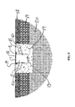
- FIG. 1 is a top elevation view of the cable housing system illustrating multiple surface lid sections connected across the travel path;
- FIG. 2 is a front elevation view of the cable housing system of FIG. 1 , illustrating the embedded housing support structure and drainage pipe, with the surface lid in the closed position;
- FIG. 3 is a front elevation view of the cable housing system of FIG. 1 , illustrating the embedded housing support structure and drainage pipe, with the surface lid in the open position:
- FIG. 4 is a front elevation detail of two (2) adjacent surface lid sections in the open position and the lid interlocking mechanism
- FIG. 5 is cross sectional view of one embodiment of the cable housing system with rectangular shaped cross section embedded in a concrete foundation;
- FIG. 6 is cross sectional view of a second embodiment of the cable housing system with a circular shaped cross section embedded in an earthen foundation;
- the embedded cable housing system holds one or more cables below the surface so that traffic may pass without being obstructed.
- the cable housing has a hinging surface lid that protects the stored cable, and the lid remains flush with the adjacent surface when in the closed position.
- the surface lid may be locked when in the down position.
- traffic comprises pedestrians, vehicles, motorcycles, bicycles, or the like to list non-limiting examples.
- the surface lid may have ridges on its outside surface for traction.
- the term cable comprises one (1) or more steel cables, ropes, net, synthetic fiber, straps, or the like to list several non-limiting examples.
- the cable is raised generally in a vertical direction to obstruct traffic.
- the term travel path comprises the area where traffic passes, where the surface may be asphalt, concrete, earth gravel, or the like to list non-limiting examples.
- the present invention may extend relatively long distances perpendicular to the travel path, such as distances of forty feet or more, to list one non-limiting example.
- the cable is selected based on the type of traffic to obstruct. Ends of the cables may contain a handle, hook, or other attachment to facilitate raising, lowering, and attaching the cable to an end support.
- the surface lid 1 of FIG. 1 in the closed position and divided into sections.
- the surface lid sections may be comprised of steel, titanium, high density plastic, or the like to list non-limiting examples, and the thickness of the lid varies depending upon the application.
- the surface lid extends generally perpendicular across the travel path's outside borders 4 of FIG. 1 .
- the travel path will vary in width and type of surface.
- the surface lid is connected to the embedded housing support structure 5 of FIG. 2 by an attachment mechanism 2 of FIG. 1 .
- the attachment mechanism 2 allows the lid to open and close.
- Non-limiting examples of the attachment mechanism include a hinge and pin connection and sliding lid with groove connection.
- the attachment mechanism may incorporate a stopping device so that the lid opens less than 90 degrees perpendicular to the surface of the travel path, so that it closes automatically by gravity.
- the lid may be locked while in the closed position.
- a locking device is a non-standard bolt 14 of FIG. 5 screwed down through the lid into the concrete subsurface, that has a specialized head requiring a nonstandard tool to remove and install the bolt.
- Enclosed within the housing support structure is a single cable 13 of FIG. 5 or multiple cables 22 of FIG. 6 .
- the cables remain unexposed and protected while enclosed within the housing support structure.
- the enclosed cable may be raised either by hand or using a lifting device such as a winch.
- ends of the cables may be fastened to an end support 3 of FIG. 2 .
- end support include a pole, truck trailer hitch, concrete jersey barrier, steel structure, and bollard.
- Ends of the cables may have a handle or connection device 7 of FIG. 2 to facilitate raising and lowering the cable, and securing it to the end support.
- the end support may have a cover 6 of FIG. 2 .
- Consecutive sections of the housing support structure 5 of FIG. 4 are prefabricated, and then selectively attached using watertight connection to prevent subsurface infiltration of water. After prefabrication is complete, the support structure is installed to match the existing crown or slope across the travel path.
- the attached surface lid lies approximately flush with the adjacent surfaces.
- the outside surface of the lid may have non-skid surface 18 of FIG. 5 to enhance traction. Rainwater which may seep into the embedded housing support structure will drain away by gravity, and the flexible drainage pipe 8 of FIG. 2 carries the water away from the travel path.
- a surface lid interlocking mechanism 10 of FIG. 3 connects consecutive sections of the surface lid. Because the embedded housing support structure is sloped, the attached surface lid sections separate when opening and a gap forms 12 of FIG. 4 .
- the lid interlocking mechanism is comprised of a horizontal pin 9 of FIG. 4 attached to the underside of one lid section, and a receiving stay 11 of FIG. 4 attached to the underside of the adjacent lid section. As the lid sections open, the horizontal pin slides laterally through the receiving stay allowing the adjacent lid sections to separate while still remaining connected. Because of the interlocking mechanism, the divided lid sections remain connected while opening simultaneously. All divided lid sections remain connected while opening simultaneously across the crowned or sloping travel path.
- the embedded housing support structure may be comprised of steel, high density plastic, or the like to list non-limiting examples.
- the embedded structure may be protected against rusting and corrosion using paint, galvanized coating, rubber coating, tar, sacrificial anode or combination thereof to list non-limiting examples.
- the embedded housing support structure may be rectangular in shape 15 of FIG. 5 and embedded in concrete 17 of FIG. 5 . This embodiment provides for passage of heavy traffic and loads across the travel path.
- the adjacent surface is asphalt 18 of FIG. 5 with stone base 19 and earthen sub-base 20 .
- the embedded housing support structure is round in shape 16 of FIG. 6 and embedded in earth 20 of FIG. 6 .
- a heating element 21 of FIG. 5 may be attached to the inside wall of the embedded housing support structure to melt snow or ice.
Abstract
Description
Claims (20)
Priority Applications (3)
| Application Number | Priority Date | Filing Date | Title |
|---|---|---|---|
| US15/255,941 US9768602B1 (en) | 2007-12-17 | 2016-09-02 | Cable housing system |
| US15/704,381 US10236670B1 (en) | 2007-12-17 | 2017-09-14 | Cable housing system |
| US16/351,791 US10594125B1 (en) | 2007-12-17 | 2019-03-13 | Cable housing system |
Applications Claiming Priority (2)
| Application Number | Priority Date | Filing Date | Title |
|---|---|---|---|
| US11/957,642 US9441337B2 (en) | 2007-12-17 | 2007-12-17 | Cable housing system |
| US15/255,941 US9768602B1 (en) | 2007-12-17 | 2016-09-02 | Cable housing system |
Related Parent Applications (1)
| Application Number | Title | Priority Date | Filing Date |
|---|---|---|---|
| US11/957,642 Continuation US9441337B2 (en) | 2007-12-17 | 2007-12-17 | Cable housing system |
Related Child Applications (1)
| Application Number | Title | Priority Date | Filing Date |
|---|---|---|---|
| US15/704,381 Continuation US10236670B1 (en) | 2007-12-17 | 2017-09-14 | Cable housing system |
Publications (1)
| Publication Number | Publication Date |
|---|---|
| US9768602B1 true US9768602B1 (en) | 2017-09-19 |
Family
ID=40751719
Family Applications (5)
| Application Number | Title | Priority Date | Filing Date |
|---|---|---|---|
| US11/957,642 Active US9441337B2 (en) | 2007-12-17 | 2007-12-17 | Cable housing system |
| US12/963,716 Abandoned US20110081200A1 (en) | 2007-12-17 | 2010-12-09 | Cable Housing System with Angled Lid Sections |
| US15/255,941 Active US9768602B1 (en) | 2007-12-17 | 2016-09-02 | Cable housing system |
| US15/704,381 Active US10236670B1 (en) | 2007-12-17 | 2017-09-14 | Cable housing system |
| US16/351,791 Active US10594125B1 (en) | 2007-12-17 | 2019-03-13 | Cable housing system |
Family Applications Before (2)
| Application Number | Title | Priority Date | Filing Date |
|---|---|---|---|
| US11/957,642 Active US9441337B2 (en) | 2007-12-17 | 2007-12-17 | Cable housing system |
| US12/963,716 Abandoned US20110081200A1 (en) | 2007-12-17 | 2010-12-09 | Cable Housing System with Angled Lid Sections |
Family Applications After (2)
| Application Number | Title | Priority Date | Filing Date |
|---|---|---|---|
| US15/704,381 Active US10236670B1 (en) | 2007-12-17 | 2017-09-14 | Cable housing system |
| US16/351,791 Active US10594125B1 (en) | 2007-12-17 | 2019-03-13 | Cable housing system |
Country Status (1)
| Country | Link |
|---|---|
| US (5) | US9441337B2 (en) |
Cited By (1)
| Publication number | Priority date | Publication date | Assignee | Title |
|---|---|---|---|---|
| US10236670B1 (en) | 2007-12-17 | 2019-03-19 | Michael John Lamore | Cable housing system |
Families Citing this family (4)
| Publication number | Priority date | Publication date | Assignee | Title |
|---|---|---|---|---|
| CN106193115A (en) * | 2016-08-30 | 2016-12-07 | 中建科技(福州)有限公司 | A kind of concrete prefabricated groove |
| GB2566062A (en) * | 2017-09-01 | 2019-03-06 | Gerrard Robert | Surface mount security barrier |
| US11060581B1 (en) | 2018-02-19 | 2021-07-13 | Barrier1 Systems, Llc | Flexible tensile member with releasable convolutions for absorbing tensile energy |
| CN109403232A (en) * | 2018-10-04 | 2019-03-01 | 佛山市集知汇科技有限公司 | A kind of automobile crosses brake system and lockage detection method |
Citations (38)
| Publication number | Priority date | Publication date | Assignee | Title |
|---|---|---|---|---|
| US156238A (en) * | 1874-10-27 | Improvement in bolts | ||
| US319112A (en) * | 1885-06-02 | nevius | ||
| US1353591A (en) * | 1915-11-29 | 1920-09-21 | John F Hope | Process of and apparatus for drying wood veneer or other substances |
| US1652186A (en) * | 1922-08-12 | 1927-12-13 | Joseph B Strauss | Yielding barrier for vehicles |
| US1653487A (en) * | 1924-01-05 | 1927-12-20 | Elijah D White | Safety lock |
| US2192369A (en) * | 1938-07-27 | 1940-03-05 | Edward B Sparrow | Highway construction |
| US2403065A (en) * | 1943-11-15 | 1946-07-02 | Engert Harry | Latch |
| US2504635A (en) * | 1945-12-26 | 1950-04-18 | Harry S Bradley | Hinge construction |
| US3058703A (en) * | 1960-01-21 | 1962-10-16 | Fonden Per Borje | Storing mechanism for airplane arresting nets |
| US3722140A (en) * | 1971-02-17 | 1973-03-27 | J Newton | Automatic gate |
| US3748782A (en) * | 1972-11-14 | 1973-07-31 | D Reynolds | Traffic flow controller |
| US4275910A (en) * | 1978-03-30 | 1981-06-30 | Budish Joseph D | Door latch |
| US4332503A (en) * | 1977-06-10 | 1982-06-01 | Hurst Jr George H | Apparatus for signaling direction of travel on a road bed |
| US4576507A (en) * | 1984-11-28 | 1986-03-18 | Terio Charles J | Terrorist vehicle barrier |
| US4824282A (en) * | 1987-11-06 | 1989-04-25 | Waldecker Donald E | Methods and apparatus for quickly erecting a vehicle barrier across a roadway |
| US5181793A (en) * | 1990-12-24 | 1993-01-26 | Joseph Dekel | Gutter drain apparatus |
| US5245787A (en) * | 1992-04-23 | 1993-09-21 | Swenson Kermit L | Cable gate apparatus |
| US5267367A (en) * | 1992-01-13 | 1993-12-07 | Wegmann Jr Gerald A | Safety ramp and method for protecting hoses and conduits |
| US5466088A (en) * | 1994-01-24 | 1995-11-14 | Nasatka; Ralph G. | Vehicle barrier having a pivotal vehicle barricade and a cooperating pivotal signal barrier |
| US5762443A (en) * | 1996-02-26 | 1998-06-09 | Universal Safety Response, Inc. | Ground retractable automobile barrier |
| US5890613A (en) * | 1997-07-21 | 1999-04-06 | Williams; Warren Bret | Modular cooler construction |
| US6079898A (en) * | 1999-02-01 | 2000-06-27 | St. Amant, Iii; Dennis J. | Roadway cover system for utility lines |
| FR2792014A1 (en) * | 1999-04-07 | 2000-10-13 | Gerard Desclos | Device, for regulating vehicle flow in car park or through private properties entrance, comprises oscillating barrier, chain, or beam, moving using its own weight or counterweight, and motorized winch |
| US6224291B1 (en) * | 1998-10-02 | 2001-05-01 | Jonathon R. Mateychuk | Spiked road barrier |
| US6322486B1 (en) * | 1997-05-16 | 2001-11-27 | Topack Verpackungstechnik Gmbh | Method of and apparatus for folding flaps on blanks of packets for rod-shaped smokers' products |
| US6810191B2 (en) * | 2001-07-20 | 2004-10-26 | Adc Telecommunications, Inc. | Cable trough cover |
| US6860678B2 (en) * | 2003-01-13 | 2005-03-01 | Abt, Inc. | Method and apparatus for aligning channel sections with an adjustable alignment key |
| US6942419B2 (en) * | 2002-02-04 | 2005-09-13 | Balco, Inc. | Grate assembly |
| US7060901B2 (en) * | 2003-11-05 | 2006-06-13 | Adc Telecommunications, Inc. | Cover for cable trough |
| US7172368B2 (en) * | 2002-10-29 | 2007-02-06 | Abt, Inc. | Assembly and method of forming a trench of a predetermined shape |
| US7214000B2 (en) * | 2004-11-03 | 2007-05-08 | The United States Of America As Represented By The Secretary Of The Army | On-grade barrier and method of its use |
| US20070258761A1 (en) * | 2006-03-30 | 2007-11-08 | Orner Richard L Jr | Arresting systems and methods |
| US7293937B2 (en) * | 2003-03-25 | 2007-11-13 | Aco Severin Ahlmann Gmbh & Co. Kg | Cover arrangement |
| US20070264080A1 (en) * | 2006-05-10 | 2007-11-15 | Gary Dale Miracle | Vehicle Barrier Deployment System |
| US7332672B2 (en) * | 2005-12-16 | 2008-02-19 | Henry Stephen K | Cable protector with raised barrier lid |
| US7413372B2 (en) * | 2005-04-20 | 2008-08-19 | Tuf-Tite, Inc. | Trench drain frame and grate assembly |
| US20090022546A1 (en) * | 2003-07-17 | 2009-01-22 | Omnitek Partners Llc | Traffic control speed bump |
| US7964796B2 (en) * | 2006-09-29 | 2011-06-21 | Sumitomo Wiring Systems, Ltd. | Protector |
Family Cites Families (27)
| Publication number | Priority date | Publication date | Assignee | Title |
|---|---|---|---|---|
| US1848516A (en) * | 1932-03-08 | Railroad crossing guard | ||
| US2957657A (en) * | 1955-01-04 | 1960-10-25 | Fricder | Aircraft net barrier |
| US4502812A (en) * | 1982-09-27 | 1985-03-05 | Stanley Zucker | Roadway barrier and restraining cap combination |
| US4567851A (en) * | 1983-02-22 | 1986-02-04 | Janet Rose Larsen | Gate assembly |
| US4844653A (en) * | 1987-06-23 | 1989-07-04 | Dickinson Harry D | Cable-beam trafficway barrier |
| US4780020A (en) * | 1987-08-07 | 1988-10-25 | Terio Charles J | Terrorist vehicle barrier |
| US4989835A (en) * | 1988-04-15 | 1991-02-05 | The United States Of America As Represented By The United States Department Of Energy | Vehicle barrier |
| US5066165A (en) | 1990-08-13 | 1991-11-19 | Wofford Ray F | Modular and componential trench drain system |
| US5192159A (en) * | 1991-03-22 | 1993-03-09 | Barry Higginson | Security post |
| US5459963A (en) * | 1993-12-16 | 1995-10-24 | The Serco Corporation | Safety gate for loading docks |
| WO2000020692A1 (en) * | 1998-10-01 | 2000-04-13 | Matilda Products Ltd. | Cable gate |
| US6382869B1 (en) * | 1999-12-09 | 2002-05-07 | Harry D. Dickinson | Above grade mass displacement trafficway barrier |
| US20020182007A1 (en) * | 2001-05-07 | 2002-12-05 | Yodock Leo J. | Portable security system |
| GB2392507B (en) * | 2001-07-06 | 2005-03-09 | Honda Motor Co Ltd | Vehicle crash test apparatus |
| US20030016996A1 (en) | 2001-07-23 | 2003-01-23 | Gelfand Matthew A. | Energy absorbing system |
| US7785031B2 (en) | 2002-02-07 | 2010-08-31 | Universal Safety Response, Inc. | Energy absorbing system |
| WO2003066967A2 (en) | 2002-02-07 | 2003-08-14 | Universal Safety Response, Inc. | Energy absorbing system |
| US6857227B2 (en) * | 2002-02-28 | 2005-02-22 | Automatic Power, Inc. | Vehicle crash barrier |
| US7210873B2 (en) | 2003-12-02 | 2007-05-01 | Universal Safety Response, Inc. | Energy absorbing system with support |
| CN1950572A (en) | 2004-03-31 | 2007-04-18 | 通用安全应急公司 | Net and mat |
| US7530759B2 (en) | 2004-11-17 | 2009-05-12 | Universal Safety Response, Inc. | Retractable energy absorbing system |
| US7140802B2 (en) * | 2004-12-29 | 2006-11-28 | Lamore Michael J | Retractable wide-span vehicle barrier system |
| US7484905B2 (en) | 2005-04-18 | 2009-02-03 | Universal Safety Response, Inc. | Energy absorbing bollard system |
| US7862252B2 (en) | 2006-04-10 | 2011-01-04 | Universal Safety Response, Inc. | Vehicle barrier system |
| US7832957B2 (en) | 2006-09-22 | 2010-11-16 | Universal Safety Response, Inc. | Removable barricade system |
| US7845877B2 (en) | 2006-09-22 | 2010-12-07 | Universal Safety Response, Inc. | Enhanced vehicle barrier system |
| US9441337B2 (en) | 2007-12-17 | 2016-09-13 | Michael John Lamore | Cable housing system |
-
2007
- 2007-12-17 US US11/957,642 patent/US9441337B2/en active Active
-
2010
- 2010-12-09 US US12/963,716 patent/US20110081200A1/en not_active Abandoned
-
2016
- 2016-09-02 US US15/255,941 patent/US9768602B1/en active Active
-
2017
- 2017-09-14 US US15/704,381 patent/US10236670B1/en active Active
-
2019
- 2019-03-13 US US16/351,791 patent/US10594125B1/en active Active
Patent Citations (40)
| Publication number | Priority date | Publication date | Assignee | Title |
|---|---|---|---|---|
| US156238A (en) * | 1874-10-27 | Improvement in bolts | ||
| US319112A (en) * | 1885-06-02 | nevius | ||
| US1353591A (en) * | 1915-11-29 | 1920-09-21 | John F Hope | Process of and apparatus for drying wood veneer or other substances |
| US1652186A (en) * | 1922-08-12 | 1927-12-13 | Joseph B Strauss | Yielding barrier for vehicles |
| US1653487A (en) * | 1924-01-05 | 1927-12-20 | Elijah D White | Safety lock |
| US2192369A (en) * | 1938-07-27 | 1940-03-05 | Edward B Sparrow | Highway construction |
| US2403065A (en) * | 1943-11-15 | 1946-07-02 | Engert Harry | Latch |
| US2504635A (en) * | 1945-12-26 | 1950-04-18 | Harry S Bradley | Hinge construction |
| US3058703A (en) * | 1960-01-21 | 1962-10-16 | Fonden Per Borje | Storing mechanism for airplane arresting nets |
| US3722140A (en) * | 1971-02-17 | 1973-03-27 | J Newton | Automatic gate |
| US3748782A (en) * | 1972-11-14 | 1973-07-31 | D Reynolds | Traffic flow controller |
| US4332503A (en) * | 1977-06-10 | 1982-06-01 | Hurst Jr George H | Apparatus for signaling direction of travel on a road bed |
| US4275910A (en) * | 1978-03-30 | 1981-06-30 | Budish Joseph D | Door latch |
| US4576507A (en) * | 1984-11-28 | 1986-03-18 | Terio Charles J | Terrorist vehicle barrier |
| US4824282A (en) * | 1987-11-06 | 1989-04-25 | Waldecker Donald E | Methods and apparatus for quickly erecting a vehicle barrier across a roadway |
| US5181793A (en) * | 1990-12-24 | 1993-01-26 | Joseph Dekel | Gutter drain apparatus |
| US5267367A (en) * | 1992-01-13 | 1993-12-07 | Wegmann Jr Gerald A | Safety ramp and method for protecting hoses and conduits |
| US5245787A (en) * | 1992-04-23 | 1993-09-21 | Swenson Kermit L | Cable gate apparatus |
| US5466088A (en) * | 1994-01-24 | 1995-11-14 | Nasatka; Ralph G. | Vehicle barrier having a pivotal vehicle barricade and a cooperating pivotal signal barrier |
| US5762443A (en) * | 1996-02-26 | 1998-06-09 | Universal Safety Response, Inc. | Ground retractable automobile barrier |
| US6322486B1 (en) * | 1997-05-16 | 2001-11-27 | Topack Verpackungstechnik Gmbh | Method of and apparatus for folding flaps on blanks of packets for rod-shaped smokers' products |
| US5890613A (en) * | 1997-07-21 | 1999-04-06 | Williams; Warren Bret | Modular cooler construction |
| US6224291B1 (en) * | 1998-10-02 | 2001-05-01 | Jonathon R. Mateychuk | Spiked road barrier |
| US6079898A (en) * | 1999-02-01 | 2000-06-27 | St. Amant, Iii; Dennis J. | Roadway cover system for utility lines |
| FR2792014A1 (en) * | 1999-04-07 | 2000-10-13 | Gerard Desclos | Device, for regulating vehicle flow in car park or through private properties entrance, comprises oscillating barrier, chain, or beam, moving using its own weight or counterweight, and motorized winch |
| US6810191B2 (en) * | 2001-07-20 | 2004-10-26 | Adc Telecommunications, Inc. | Cable trough cover |
| US6942419B2 (en) * | 2002-02-04 | 2005-09-13 | Balco, Inc. | Grate assembly |
| US7172368B2 (en) * | 2002-10-29 | 2007-02-06 | Abt, Inc. | Assembly and method of forming a trench of a predetermined shape |
| US6860678B2 (en) * | 2003-01-13 | 2005-03-01 | Abt, Inc. | Method and apparatus for aligning channel sections with an adjustable alignment key |
| US7293937B2 (en) * | 2003-03-25 | 2007-11-13 | Aco Severin Ahlmann Gmbh & Co. Kg | Cover arrangement |
| US20090022546A1 (en) * | 2003-07-17 | 2009-01-22 | Omnitek Partners Llc | Traffic control speed bump |
| US7060901B2 (en) * | 2003-11-05 | 2006-06-13 | Adc Telecommunications, Inc. | Cover for cable trough |
| US7214000B2 (en) * | 2004-11-03 | 2007-05-08 | The United States Of America As Represented By The Secretary Of The Army | On-grade barrier and method of its use |
| US7413372B2 (en) * | 2005-04-20 | 2008-08-19 | Tuf-Tite, Inc. | Trench drain frame and grate assembly |
| US7332672B2 (en) * | 2005-12-16 | 2008-02-19 | Henry Stephen K | Cable protector with raised barrier lid |
| US7467909B2 (en) * | 2006-03-30 | 2008-12-23 | Engineered Arresting Systems Corporation | Arresting systems and methods |
| US20070258761A1 (en) * | 2006-03-30 | 2007-11-08 | Orner Richard L Jr | Arresting systems and methods |
| US20070264080A1 (en) * | 2006-05-10 | 2007-11-15 | Gary Dale Miracle | Vehicle Barrier Deployment System |
| US7641416B2 (en) * | 2006-05-10 | 2010-01-05 | Gary Dale Miracle | Vehicle barrier deployment system |
| US7964796B2 (en) * | 2006-09-29 | 2011-06-21 | Sumitomo Wiring Systems, Ltd. | Protector |
Cited By (2)
| Publication number | Priority date | Publication date | Assignee | Title |
|---|---|---|---|---|
| US10236670B1 (en) | 2007-12-17 | 2019-03-19 | Michael John Lamore | Cable housing system |
| US10594125B1 (en) | 2007-12-17 | 2020-03-17 | Michael John Lamore | Cable housing system |
Also Published As
| Publication number | Publication date |
|---|---|
| US9441337B2 (en) | 2016-09-13 |
| US10236670B1 (en) | 2019-03-19 |
| US20110081200A1 (en) | 2011-04-07 |
| US10594125B1 (en) | 2020-03-17 |
| US20090151971A1 (en) | 2009-06-18 |
Similar Documents
| Publication | Publication Date | Title |
|---|---|---|
| US10236670B1 (en) | Cable housing system | |
| KR101039711B1 (en) | Grating for waterway | |
| JP4704874B2 (en) | Structure of paved road with U-shaped groove | |
| CA2772369A1 (en) | Transportable vehicle access control system | |
| JP5537530B2 (en) | Road drainage cover plate | |
| KR200275255Y1 (en) | Entanglements for preventing invasion from animal | |
| US5152632A (en) | Self-guidance bicycle track | |
| KR101728128B1 (en) | Road drainage facility and construction methods accordingly | |
| KR20060135586A (en) | Opening-closing type falling rock fence | |
| KR100525944B1 (en) | Overspeed prevention prominence on admissionpassage of ahousing/apartment complex having drainage equipment | |
| JP3127873U (en) | Side groove and lid structure | |
| CN108385461A (en) | Reinforcing road bed ecological environment-friendly type widening road and construction method can be protected | |
| JP2021102882A (en) | Sidewalk-roadway boundary block | |
| JP3143782B2 (en) | Drainage channel for drainage pavement | |
| KR200267743Y1 (en) | Reducing speed apparatus of drainwater way construction of steep slope | |
| JP3130944U (en) | Cross-type side gutter unit and side drainage type grating lid that do not require iron frame and iron receiving frame | |
| JP5010770B2 (en) | Side gutter construction method with water collection performance and water collecting fitting used in the construction method | |
| JP2000328641A (en) | Side drain with lid slab having curb | |
| KR100606261B1 (en) | Catch drain structure for asphalt road of apartment house | |
| JPH10245814A (en) | Drainage construction of bridge deck paving body | |
| JP2007063887A (en) | Box culvert-type side ditch with enhanced tractive performance constituted by placing top slab lid with drainage function throughout extended section | |
| RU210602U1 (en) | curb rainwater inlet | |
| CN216378984U (en) | Anti rut bituminous paving structure of formula of irritating | |
| CN211256527U (en) | Road drainage brick and road drainage system | |
| KR102219577B1 (en) | Sidewalk structure for decreasing outflowing water |
Legal Events
| Date | Code | Title | Description |
|---|---|---|---|
| STCF | Information on status: patent grant |
Free format text: PATENTED CASE |
|
| MAFP | Maintenance fee payment |
Free format text: PAYMENT OF MAINTENANCE FEE, 4TH YR, SMALL ENTITY (ORIGINAL EVENT CODE: M2551); ENTITY STATUS OF PATENT OWNER: SMALL ENTITY Year of fee payment: 4 |
|
| AS | Assignment |
Owner name: BARRIER1 SYSTEMS, INC., NORTH CAROLINA Free format text: ASSIGNMENT OF ASSIGNORS INTEREST;ASSIGNOR:LAMORE, MICHAEL JOHN;REEL/FRAME:056409/0405 Effective date: 20201120 |
|
| AS | Assignment |
Owner name: BARRIER1 SYSTEMS, LLC, NORTH CAROLINA Free format text: ASSIGNMENT OF ASSIGNORS INTEREST;ASSIGNOR:BARRIER1 SYSTEMS, INC.;REEL/FRAME:056470/0094 Effective date: 20201120 |
|
| FEPP | Fee payment procedure |
Free format text: PETITION RELATED TO MAINTENANCE FEES GRANTED (ORIGINAL EVENT CODE: PTGR); ENTITY STATUS OF PATENT OWNER: SMALL ENTITY |