US9775336B2 - Acoustic projector with source level monitoring and control - Google Patents
Acoustic projector with source level monitoring and control Download PDFInfo
- Publication number
- US9775336B2 US9775336B2 US14/099,281 US201314099281A US9775336B2 US 9775336 B2 US9775336 B2 US 9775336B2 US 201314099281 A US201314099281 A US 201314099281A US 9775336 B2 US9775336 B2 US 9775336B2
- Authority
- US
- United States
- Prior art keywords
- acoustic
- transducer
- signal
- level
- monitored
- Prior art date
- Legal status (The legal status is an assumption and is not a legal conclusion. Google has not performed a legal analysis and makes no representation as to the accuracy of the status listed.)
- Active, expires
Links
- 238000012544 monitoring process Methods 0.000 title claims description 25
- 230000005855 radiation Effects 0.000 claims abstract description 21
- 230000004044 response Effects 0.000 claims abstract description 12
- 238000000034 method Methods 0.000 claims description 16
- 241000283153 Cetacea Species 0.000 claims description 7
- 229920006254 polymer film Polymers 0.000 claims description 4
- 230000001846 repelling effect Effects 0.000 claims description 4
- 239000002033 PVDF binder Substances 0.000 claims description 3
- 239000000919 ceramic Substances 0.000 claims description 3
- 230000007547 defect Effects 0.000 claims description 3
- 229920002981 polyvinylidene fluoride Polymers 0.000 claims description 3
- 230000011664 signaling Effects 0.000 claims 1
- 241000251468 Actinopterygii Species 0.000 description 11
- 238000004891 communication Methods 0.000 description 11
- XLYOFNOQVPJJNP-UHFFFAOYSA-N water Substances O XLYOFNOQVPJJNP-UHFFFAOYSA-N 0.000 description 9
- 238000002592 echocardiography Methods 0.000 description 5
- 238000010586 diagram Methods 0.000 description 4
- 238000005259 measurement Methods 0.000 description 4
- 230000005540 biological transmission Effects 0.000 description 3
- 230000006870 function Effects 0.000 description 3
- 239000004593 Epoxy Substances 0.000 description 2
- 241000124008 Mammalia Species 0.000 description 2
- 238000006243 chemical reaction Methods 0.000 description 2
- 238000005516 engineering process Methods 0.000 description 2
- 239000006260 foam Substances 0.000 description 2
- 238000002847 impedance measurement Methods 0.000 description 2
- 230000003993 interaction Effects 0.000 description 2
- 238000002955 isolation Methods 0.000 description 2
- 230000008569 process Effects 0.000 description 2
- 238000005070 sampling Methods 0.000 description 2
- JOYRKODLDBILNP-UHFFFAOYSA-N Ethyl urethane Chemical compound CCOC(N)=O JOYRKODLDBILNP-UHFFFAOYSA-N 0.000 description 1
- IAYPIBMASNFSPL-UHFFFAOYSA-N Ethylene oxide Chemical group C1CO1 IAYPIBMASNFSPL-UHFFFAOYSA-N 0.000 description 1
- 241000283203 Otariidae Species 0.000 description 1
- 230000002457 bidirectional effect Effects 0.000 description 1
- 239000003990 capacitor Substances 0.000 description 1
- 230000008859 change Effects 0.000 description 1
- 239000004020 conductor Substances 0.000 description 1
- 230000008878 coupling Effects 0.000 description 1
- 238000010168 coupling process Methods 0.000 description 1
- 238000005859 coupling reaction Methods 0.000 description 1
- 238000005336 cracking Methods 0.000 description 1
- 239000013078 crystal Substances 0.000 description 1
- 230000009189 diving Effects 0.000 description 1
- 230000000694 effects Effects 0.000 description 1
- 239000000835 fiber Substances 0.000 description 1
- 239000011152 fibreglass Substances 0.000 description 1
- 238000011065 in-situ storage Methods 0.000 description 1
- 238000009434 installation Methods 0.000 description 1
- 239000002085 irritant Substances 0.000 description 1
- 231100000021 irritant Toxicity 0.000 description 1
- HFGPZNIAWCZYJU-UHFFFAOYSA-N lead zirconate titanate Chemical compound [O-2].[O-2].[O-2].[O-2].[O-2].[Ti+4].[Zr+4].[Pb+2] HFGPZNIAWCZYJU-UHFFFAOYSA-N 0.000 description 1
- 229910052451 lead zirconate titanate Inorganic materials 0.000 description 1
- 239000002184 metal Substances 0.000 description 1
- 230000000737 periodic effect Effects 0.000 description 1
- 229920000131 polyvinylidene Polymers 0.000 description 1
- 230000000087 stabilizing effect Effects 0.000 description 1
Images


Classifications
-
- A—HUMAN NECESSITIES
- A01—AGRICULTURE; FORESTRY; ANIMAL HUSBANDRY; HUNTING; TRAPPING; FISHING
- A01M—CATCHING, TRAPPING OR SCARING OF ANIMALS; APPARATUS FOR THE DESTRUCTION OF NOXIOUS ANIMALS OR NOXIOUS PLANTS
- A01M29/00—Scaring or repelling devices, e.g. bird-scaring apparatus
- A01M29/16—Scaring or repelling devices, e.g. bird-scaring apparatus using sound waves
-
- G—PHYSICS
- G01—MEASURING; TESTING
- G01H—MEASUREMENT OF MECHANICAL VIBRATIONS OR ULTRASONIC, SONIC OR INFRASONIC WAVES
- G01H11/00—Measuring mechanical vibrations or ultrasonic, sonic or infrasonic waves by detecting changes in electric or magnetic properties
- G01H11/06—Measuring mechanical vibrations or ultrasonic, sonic or infrasonic waves by detecting changes in electric or magnetic properties by electric means
-
- G—PHYSICS
- G01—MEASURING; TESTING
- G01S—RADIO DIRECTION-FINDING; RADIO NAVIGATION; DETERMINING DISTANCE OR VELOCITY BY USE OF RADIO WAVES; LOCATING OR PRESENCE-DETECTING BY USE OF THE REFLECTION OR RERADIATION OF RADIO WAVES; ANALOGOUS ARRANGEMENTS USING OTHER WAVES
- G01S7/00—Details of systems according to groups G01S13/00, G01S15/00, G01S17/00
- G01S7/52—Details of systems according to groups G01S13/00, G01S15/00, G01S17/00 of systems according to group G01S15/00
- G01S7/52004—Means for monitoring or calibrating
-
- G—PHYSICS
- G01—MEASURING; TESTING
- G01S—RADIO DIRECTION-FINDING; RADIO NAVIGATION; DETERMINING DISTANCE OR VELOCITY BY USE OF RADIO WAVES; LOCATING OR PRESENCE-DETECTING BY USE OF THE REFLECTION OR RERADIATION OF RADIO WAVES; ANALOGOUS ARRANGEMENTS USING OTHER WAVES
- G01S7/00—Details of systems according to groups G01S13/00, G01S15/00, G01S17/00
- G01S7/52—Details of systems according to groups G01S13/00, G01S15/00, G01S17/00 of systems according to group G01S15/00
- G01S7/523—Details of pulse systems
- G01S7/524—Transmitters
-
- G—PHYSICS
- G01—MEASURING; TESTING
- G01S—RADIO DIRECTION-FINDING; RADIO NAVIGATION; DETERMINING DISTANCE OR VELOCITY BY USE OF RADIO WAVES; LOCATING OR PRESENCE-DETECTING BY USE OF THE REFLECTION OR RERADIATION OF RADIO WAVES; ANALOGOUS ARRANGEMENTS USING OTHER WAVES
- G01S7/00—Details of systems according to groups G01S13/00, G01S15/00, G01S17/00
- G01S7/52—Details of systems according to groups G01S13/00, G01S15/00, G01S17/00 of systems according to group G01S15/00
- G01S7/52004—Means for monitoring or calibrating
- G01S2007/52007—Means for monitoring or calibrating involving adjustment of transmitted power
Definitions
- a typical acoustic deterrent system for repelling marine mammals from a region of water has circuitry including transmission and control circuitry which drives one or more acoustic projectors located beneath the surface of the region of water.
- the acoustic projector includes a transmit transducer that delivers periodic bursts of high-frequency pulsed acoustic signals, e.g., between about 7 and 10 kHz, into the water under the fish pens, causing the marine mammals to swim away from the pens.
- a sonar system typically includes a sonar unit and an acoustic projector that includes a transmit/receive transducer.
- the sonar unit includes a display for providing information to the operator.
- the acoustic projector is mounted under the waterline and is responsible for generating a sound pulse and receiving echoes from objects in the water, from the bottom surface, or both.
- a typical application of the sonar system is for use as a fish finder.
- the sonar unit includes circuitry that produces the sound pulse consisting of several cycles of a sonic signal at a fairly high output power. This pulse is delivered to the transmit/receive transducer via a shielded twisted pair cable. After transmission of the pulse in a transmit mode, the transmit/receive transducer is used to “listen” for echoes in a receive mode. Received echoes produce very small signals, on the order of a few millivolts, which are sent to a receiver circuitry in the sonar unit. In the sonar unit, the received echoes are amplified, filtered, and analyzed.
- the present invention relates to acoustic source level monitoring and control of the sound projector using a separate receive transducer such as a hydrophone.
- an acoustic projector includes an acoustic transmit transducer capable of producing a sound pressure radiation in response to a driver signal received from a transmit source, an acoustic receive transducer capable of producing a source level signal in response to receiving at least a portion of the sound pressure radiation, and a controller configured to monitor the source level signal and report the source level signal monitored.
- the controller may be configured to report the source level signal monitored to a remote controller configured to control the drive signal based on the source level signal.
- the acoustic projector may include a voltage monitoring circuit configured to measure a voltage level of the driver signal, with the controller configured to monitor the measured voltage level and report the monitored voltage level.
- the controller may be configured to report the monitored voltage level to a remote controller configured to control the drive signal based on the voltage level signal.
- the acoustic projector may include a current monitoring circuit configured to measure a current level of the driver signal, with the controller configured to monitor the measured current level and report the monitored current level.
- the controller may be configured to report the monitored current level to a remote controller configured to control the drive signal based on the current level signal.
- the acoustic projector may include a voltage monitoring circuit configured to measure a voltage level of the driver signal and a current monitoring circuit configured to measure a current level of the driver signal, with the controller configured to monitor the measured voltage level and the measured current level and to derive an indication of impedance of the acoustic transmit transducer based on the monitored voltage level and the monitored current level.
- the controller may be configured to report the indication of impedance to a remote controller configured to control the drive signal based on the impedance indication.
- the acoustic receive transducer may comprise a hydrophone.
- the hydrophone comprises a polymer film such as piezoelectric polyvinylidene Flouride (PVDF).
- the hydrophone comprises a piezoelectric ceramic.
- a method in another aspect, includes producing a sound pressure radiation at an acoustic transmit transducer in response to a drive signal received from a transmit source, producing a source level signal at an acoustic receive transducer in response to receiving at least a portion of the sound pressure radiation, and monitoring the source level signal and reporting the source level signal monitored.
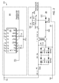
- FIG. 1 illustrates a block diagram of an example embodiment.
- FIG. 2 illustrates a circuit block diagram of an example embodiment of signal monitoring circuitry.
- FIG. 3 illustrates a schematic perspective of an example acoustic projector.
- FIGS. 4A and 4B illustrate an example circuit board of FIG. 3 .
- FIG. 1 illustrates a block diagram of an example embodiment of a sounder system that includes an acoustic projector 102 connected to a transmit source 118 and a microprocessor 120 .
- the connection between the acoustic projector 102 and the transmit source 118 is via a twisted pair cable 122 , 124 .
- the connection between the acoustic projector 102 and the microprocessor 120 is via a communication bus 126 .
- the acoustic projector 102 includes an acoustic transmit transducer 104 , an acoustic receive transducer 106 , signal monitoring circuitry 208 , and a microprocessor 110 .
- the acoustic transmit transducer 104 may contain one or more piezoelectric elements having varying characteristics.
- the acoustic transmit transducer 104 is configured to produce a sound pressure radiation 128 in response to a drive signal 130 received from the transmit source 118 .
- the drive signal 130 may be any drive signal selected to have appropriate characteristics, including using the appropriate frequencies, at a suitable voltage level, and for an appropriate pulse duration and pulse repetition rate, to cause the acoustic transmit transducer 104 to radiate sound.
- the microprocessor 110 is configured to provide source level monitoring of the output of acoustic transmit transducer 104 including monitoring acoustic source level received by acoustic receive transducer 106 , monitoring transmit voltage into acoustic transmit transducer 104 , monitoring transmit current into acoustic transmit transducer 104 , and determining instantaneous impedance from voltage and current readings.
- Measuring the acoustic source level and the transmit voltage can be used to assure proper operation of the acoustic transmit transducer 104 . Changes in signal waveform from such measurements can indicate problems, such as damage to the transmit transducer (e.g., cracking of the piezoelectric element).
- Measuring the transmit current can provide an indication of the instantaneous transducer impedance, which impedance can change with overdriving or excess temperature.
- Overdrive may include excess voltage, excess current, excess power, excess pulse duration, excess duty cycle, or combination thereof.
- the impedance measurements over frequency can indicate the frequency band where the maximum energy is transferred to the water. This can be different for different hull designs and installations, based on the hull thickness and acoustic properties.
- the acoustic receive transducer 106 is configured to produce a source level signal in response to receiving at least a portion of the sound pressure radiation 128 .
- the source level signal output 132 from the acoustic receive transducer 106 is provided to acoustic source level 116 input of microprocessor 110 .
- a buffer amplifier (not shown) may be used to boost the signal 132 from the acoustic receive transducer 106 .
- the signal monitoring circuitry 208 includes current circuit 202 and voltage circuit 204 which provide respective outputs to the monitored transducer voltage 112 and transducer current 114 inputs of microprocessor 110 .
- the transducer voltage 112 , transducer current 114 , and acoustic source level 116 inputs to the microprocessor 110 are coupled internally to respective analog-to-digital converters in the microprocessor 110 .
- the embodiment shown in FIG. 1 includes a transmit source 118 that sends a drive signal to an acoustic transmit transducer 104 , which may be used in an embodiment of a sonar system such as used for an echosounder or a fish finder.
- a transmit source 118 that sends a drive signal to an acoustic transmit transducer 104
- an acoustic transmit transducer 104 which may be used in an embodiment of a sonar system such as used for an echosounder or a fish finder.
- the transducer in the echosounder or fish finder also functions in a receive mode to “listen” to the echoes, which is a separate and distinct function from the monitoring provided by the acoustic receive transducer 106 .
- Embodiments of the acoustic transducer 102 may employ Transducer ID system technology (XducerID®, available from Airmar Technology Corp. Milford, N.H.).
- XducerID® Transducer ID system technology
- the microprocessor 110 includes a communications and control module 140 for communications and control interactions with a corresponding communications and control module 150 at microprocessor 120 .
- the communications includes the interactions with respect to communicating monitoring information as described herein.
- microprocessor 110 may be controlled by microprocessor 120 (master, slave). In other embodiments, there may be only one microprocessor.
- the monitored information may indicate that the acoustic projector is radiating too much acoustic power, which may result in the source sending a drive signal 130 having a lower voltage. Subsequent monitoring information then will show a decrease in the measured current and the measured hydrophone voltage. Similarly, if the derived impedance is unusually too low or too high from a prior established value, this indication may result in either microprocessor 110 , 120 making a determination that there is a defect somewhere in the system and shutting down the power delivered to the system.
- the microprocessor 110 may further include a non-volatile memory device (not shown) that contains the characteristic information of the transducer.
- the microprocessor 110 upon system initialization or power-up, may communicate the characteristic information of the transducer from the memory device to the corresponding microprocessor 120 via the communication bus 126 .
- the communication bus 126 may be a single conductor (wire) plus a ground return in the transducer cable, a multi wire bus, or a fiber optic cable.
- the transmit source 118 may provide power to the circuitry in the acoustic projector 102 .
- the communication bus 126 may provide power to the memory device and the microprocessor 110 in addition to providing bidirectional serial communication (e.g., half duplex) between the microprocessors 110 , 120 .
- the microprocessors 110 , 120 may communicate via an optional wireless communications link (not shown). Generally, any form of communications available in the art may be used to communicate between the microprocessors.
- the acoustic receive transducer 106 comprises a hydrophone.
- the hydrophone may be made from a polymer film such as piezoelectric polyvinylidene Fluoride (PVDF).
- the hydrophone comprises a piezoelectric ceramic such as lead zirconate titanate.
- the acoustic receive transducer 106 may be positioned in the nearfield of the acoustic transmit transducer 104 , e.g., self-contained within a waterproof (e.g., rubber) housing that contains the acoustic projector.
- the acoustic receive transducer 106 may be housed separately and attached to a small jumper cable to allow the acoustic receive transducer 106 to be several feet away and thereby in the farfield.
- Such an assembly of cable and receive transducer may be made to be heavier-than-water which would allow it to sink beneath the transmit transducer position. In another embodiment, the assembly may be made to be lighter-than-water which would allow it to float above the transmit transducer.
- FIG. 2 illustrates a circuit block diagram of an example embodiment of the signal monitoring circuitry 208 .
- the transducer current circuit 202 includes a current sensor chip (e.g., ACS716 available from Allegro MicroSystems, Inc.) that is connected so that the current from transmit source 118 ( FIG. 1 ) on line 122 passes through the chip in proximity to a Hall cell, which measures the magnetic field generated by the current passing through the wire. This is then converted to an output voltage (pin 12 ) representing the value of instantaneous current with a scale factor of 100 mV/A (for this particular chip). At zero current, the output voltage is Vcc/2 (where Vcc is the power supply to the chip, which is 3.3V in this case). Positive and negative current is indicated by deviations above and below Vcc/2.
- the output voltage 212 is connected to the ADC input 112 of microprocessor 110 ( FIG. 1 ).
- An isolation transformer T 1 converts the balanced signal to an unbalanced signal referenced to ground.
- Capacitor C 2 provides AC coupling to the A/D input, while resistors R 1 and R 2 provide a DC offset of Vcc/2 so that positive and negative voltages can be input to the ADC input 114 of microprocessor 110 ( FIG. 1 ).
- D 4 provides clamping to protect the A/D input in case the signal gets too large.
- Diodes D 1 , D 2 , D 5 , D 6 clamp the input voltage, e.g., to +/ ⁇ (4*0.4V) or 3.2Vp ⁇ p.
- the microprocessor 110 may be configured to perform the several monitoring functions described herein. For hydrophone measurements, the output signal 132 is connected to ADC input 116 of the microprocessor 110 . When commanded, e.g., by an XID command sent from microprocessor 120 , the microprocessor 110 waits for a specified delay, starts the ADC conversion, and reads a specified number of samples at a specified sampling rate. To process the samples, the microprocessor 110 may be configured to find minimum and maximum values in the captured hydrophone waveform data, and convert those min/max values to a Peak to Peak Voltage. The microprocessor 110 may be further configured to find a captured transmit pulse (ping) in the hydrophone waveform data, and calculate an RMS value of the transmit pulse.
- ping captured transmit pulse
- the output signals 212 , 214 from respective current and voltage circuits 202 , 204 are connected to corresponding ADC inputs 112 , 114 of the microprocessor 110 .
- the microprocessor 110 waits for a specified delay, simultaneously starts the voltage and current ADC conversions, and reads a specified number of samples at a specified sampling rate.
- the microprocessor 110 may be configured to find the corresponding captured transmit pulse (ping) in the Voltage/Current waveform data.
- the microprocessor 110 may be further configured to calculate parameters that may include Impedance Imaginary Part in Ohms, Impedance Real Part in Ohms (0-250), Current in 10ths of Amps (0-25.0), Voltage in tens of Volts (0-2500).
- the microprocessor 110 may be configured to capture the waveform, and send the digitally sampled waveform to the transmit source over the bus, in addition to calculating and sending the calculated status information.
- Corresponding XID commands may include:
- SLM_SETUP_CAPTURE Setup capture parameters (Delay, Samples, and Sample Rate).
- SLM_CAPTURE_IMPEDANCE Start simultaneous capture of Voltage and Current data after delay specified in capture parameters. Sample rate and number of samples to capture are also specified in capture parameters.
- SLM_CAPTURE_HYDROPHONE Start capture of hydrophone data after delay specified in capture parameters. Sample rate and number of samples to capture are also specified in capture parameters.
- SLM_STATUS_IMPEDANCE report impedance, current, and voltage values calculated from captured Voltage and Current data.
- SLM_STATUS_HYDROPHONE Report Hydrophone RMS and Peak to Peak values calculated from captured hydrophone data.
- SLM_XMIT_VOLTAGE_WF transmit requested blocks of the Voltage Waveform from the capture impedance command.
- SLM_XMIT_CURRENT_WF transmit requested blocks of the Current Waveform from the capture impedance command.
- SLM_XMIT_HYDROPHONE_WF transmit requested blocks of the Hydrophone Waveform from the capture hydrophone command.
- FIG. 3 illustrates a schematic perspective of an example acoustic projector 300 in accordance with the principles of the present invention.
- the projector 300 may be enclosed within an outer shell not shown.
- a transducer assembly includes annular ring-shaped piezoelectric elements 304 A, 304 B (corresponding to the acoustic transmit transducer 104 shown in FIG. 1 ) sandwiched between two layers of epoxy or urethane foam 306 A, 306 C.
- a third layer of epoxy or foam 306 B separates the pair of piezoelectric elements 304 A, 304 B.
- An electric cable 302 connects at the top to deliver the drive signal to the piezoelectric elements 304 A, 304 B.
- a threaded collar 310 is exposed to the exterior to allow stabilizing weights or cables to be threaded into the bottom of the projector 300 to steady it in the water.
- the ring shape of the piezoelectric elements 304 A, 304 B produces a torroidal signal in all directions emanating from the projector 300 . It should be noted that other shapes for the piezoelectric elements can be used.
- the projector 300 includes a circuit board 400 positioned on top of the transducer assembly.
- an example circuit board 400 includes a JTAG connector 402 for microprocessor debugging, a PVDF acoustic receive transducer 404 , current monitor circuit 406 , isolation transformer 408 for voltage measurement circuit, and RS232 transceiver 410 for bootloading microprocessor.
- Microprocessor 412 , voltage and current monitoring circuitry 414 , and crystal oscillator 416 are shown in FIG. 4B on the opposite side of the circuit board 400 .
Abstract
Description
Claims (28)
Priority Applications (5)
| Application Number | Priority Date | Filing Date | Title |
|---|---|---|---|
| US14/099,281 US9775336B2 (en) | 2013-12-06 | 2013-12-06 | Acoustic projector with source level monitoring and control |
| NO20160990A NO347140B1 (en) | 2013-12-06 | 2014-12-04 | Acoustic projector with source level monitoring and control |
| PCT/US2014/068575 WO2015085072A1 (en) | 2013-12-06 | 2014-12-04 | Acoustic projector with source level monitoring and control |
| JP2016557531A JP6616781B2 (en) | 2013-12-06 | 2014-12-04 | Acoustic projector with source level monitoring and control functions |
| US15/724,043 US20180020656A1 (en) | 2013-12-06 | 2017-10-03 | Acoustic Projector with Source Level Monitoring and Control |
Applications Claiming Priority (1)
| Application Number | Priority Date | Filing Date | Title |
|---|---|---|---|
| US14/099,281 US9775336B2 (en) | 2013-12-06 | 2013-12-06 | Acoustic projector with source level monitoring and control |
Related Child Applications (1)
| Application Number | Title | Priority Date | Filing Date |
|---|---|---|---|
| US15/724,043 Continuation US20180020656A1 (en) | 2013-12-06 | 2017-10-03 | Acoustic Projector with Source Level Monitoring and Control |
Publications (2)
| Publication Number | Publication Date |
|---|---|
| US20150157007A1 US20150157007A1 (en) | 2015-06-11 |
| US9775336B2 true US9775336B2 (en) | 2017-10-03 |
Family
ID=52134440
Family Applications (2)
| Application Number | Title | Priority Date | Filing Date |
|---|---|---|---|
| US14/099,281 Active 2035-02-17 US9775336B2 (en) | 2013-12-06 | 2013-12-06 | Acoustic projector with source level monitoring and control |
| US15/724,043 Abandoned US20180020656A1 (en) | 2013-12-06 | 2017-10-03 | Acoustic Projector with Source Level Monitoring and Control |
Family Applications After (1)
| Application Number | Title | Priority Date | Filing Date |
|---|---|---|---|
| US15/724,043 Abandoned US20180020656A1 (en) | 2013-12-06 | 2017-10-03 | Acoustic Projector with Source Level Monitoring and Control |
Country Status (4)
| Country | Link |
|---|---|
| US (2) | US9775336B2 (en) |
| JP (1) | JP6616781B2 (en) |
| NO (1) | NO347140B1 (en) |
| WO (1) | WO2015085072A1 (en) |
Cited By (1)
| Publication number | Priority date | Publication date | Assignee | Title |
|---|---|---|---|---|
| US10436938B2 (en) * | 2013-12-30 | 2019-10-08 | Pgs Geophysical As | Control system for marine vibrators to reduce friction effects |
Families Citing this family (5)
| Publication number | Priority date | Publication date | Assignee | Title |
|---|---|---|---|---|
| US9775336B2 (en) | 2013-12-06 | 2017-10-03 | Airmar Technology Corporation | Acoustic projector with source level monitoring and control |
| CN105548992B (en) * | 2015-12-07 | 2018-07-24 | 天津工业大学 | A kind of full digital active sonar transmitter and sonar method for generation |
| CA3191381A1 (en) * | 2019-12-27 | 2021-07-01 | Chia-Hung Chen | Device and system for determining property of object |
| CN111780862A (en) * | 2020-07-20 | 2020-10-16 | 中国计量大学 | Very low frequency self-contained piezoelectric hydrophone |
| WO2024014216A1 (en) * | 2022-07-14 | 2024-01-18 | 古野電気株式会社 | Underwater detecting device, transmission condition optimization method, and program |
Citations (47)
| Publication number | Priority date | Publication date | Assignee | Title |
|---|---|---|---|---|
| US1610674A (en) | 1916-02-29 | 1926-12-14 | Firm Signal Ges M B H | Submarine sound-signaling device |
| US2064911A (en) | 1935-10-09 | 1936-12-22 | Harvey C Hayes | Sound generating and directing apparatus |
| US2451509A (en) | 1944-07-05 | 1948-10-19 | Ollie M Owsley | Testing device for sound projectors |
| US3264772A (en) | 1963-11-06 | 1966-08-09 | Douglas Aircraft Co Inc | Method of controlling predatory fish |
| US3307285A (en) | 1964-04-22 | 1967-03-07 | Western Geophysical Co | Pneumatic method for catching or scaring fish |
| US3317889A (en) | 1963-09-30 | 1967-05-02 | Roy A Bartram | Method of and means for repelling sharks |
| US3414873A (en) | 1967-07-12 | 1968-12-03 | Joseph D. Richard | Fish attracting apparatus |
| US3524276A (en) | 1968-01-26 | 1970-08-18 | Us Navy | Elimination of jellyfish and the like |
| US3872472A (en) | 1973-12-11 | 1975-03-18 | Robert G Moschgat | Ultrasonic system for repelling noxious fauna |
| US4453238A (en) | 1982-04-15 | 1984-06-05 | The United States Of America As Represented By The Secretary Of The Navy | Apparatus and method for determining the phase sensitivity of hydrophones |
| US4556010A (en) | 1981-03-20 | 1985-12-03 | Bert Persson | Method of controlling noxious insects |
| US4580525A (en) | 1984-08-01 | 1986-04-08 | Maschinenfabrik Helmut Geiger Gmbh | Electrical fish chasing device |
| US4593648A (en) | 1984-04-23 | 1986-06-10 | Maschinenfabrik Hellmut Geiger Gmbh & Co. Kg | Electric fish-repelling device |
| US4642801A (en) | 1983-04-12 | 1987-02-10 | Thomson-Csf | Visual display process for sonars |
| US4646276A (en) | 1986-04-07 | 1987-02-24 | Kowalewski Janusz J | Acoustic fish behavioral control device |
| US4750451A (en) | 1987-02-03 | 1988-06-14 | Smith David V | Fish repelling apparatus using a plurality of series connected pulse generators to produce an optimized electric field |
| US4825810A (en) | 1987-09-16 | 1989-05-02 | Sharber Norman G | Electric barrier for fish |
| WO1990001758A1 (en) | 1988-08-11 | 1990-02-22 | Robert Jones | Security system |
| US4918668A (en) * | 1989-01-30 | 1990-04-17 | Halliburton Geophysical Services, Inc. | Marine vibrator tuneable array |
| US4922468A (en) | 1989-06-02 | 1990-05-01 | Sonalysts, Inc. | Method and apparatus for controlling aquatic population in defined areas |
| US4932007A (en) | 1988-10-07 | 1990-06-05 | Underwater Acoustics Systems, Inc. | Fish behavior control system |
| US4933918A (en) | 1988-02-11 | 1990-06-12 | Landsrath Walter J | Apparatus for frightening noxious animals by means of ultrasonic signals |
| US4955005A (en) | 1988-10-05 | 1990-09-04 | Loeffelman Paul H | Underwater acoustic animal guidance system |
| US5117572A (en) | 1991-03-20 | 1992-06-02 | Parra Jorge M | Method and apparatus for separating dolphin from tuna and steering dolphin to a safe area |
| US5134592A (en) | 1990-12-28 | 1992-07-28 | Parra Jorge M | Method and apparatus for separating dolphin from tuna |
| US5214619A (en) | 1991-07-31 | 1993-05-25 | Hajime Industries Ltd. | Supersonic sound emission device |
| US5390152A (en) | 1993-09-09 | 1995-02-14 | Airmar Technology Corporation | Forward looking echosounder |
| US5610876A (en) | 1993-06-22 | 1997-03-11 | Airmar Technology Corporation | Acoustic deterrent system and method |
| US5978316A (en) * | 1997-09-29 | 1999-11-02 | Western Atlas International, Inc. | Marine seismic source |
| US6243654B1 (en) | 1997-10-07 | 2001-06-05 | Telemonitor, Inc. | Transducer assembly with smart connector |
| US6388949B1 (en) * | 1999-08-30 | 2002-05-14 | Sound Technique Systems Llc | Marine turtle acoustic repellent/alerting apparatus and method |
| US20030040882A1 (en) * | 2001-08-23 | 2003-02-27 | Sheard Stuart Nicholas | Data acquisition system |
| US20030088372A1 (en) * | 2001-11-02 | 2003-05-08 | Caulfield David D | Array calibration and quality assurance |
| US20040004907A1 (en) * | 2000-05-04 | 2004-01-08 | Peter Austad | Acoustic emitters for use in marine seismic surveying |
| US20050093706A1 (en) * | 2003-10-30 | 2005-05-05 | Robert Hoenig | Pool monitoring |
| US20050232638A1 (en) * | 2004-04-02 | 2005-10-20 | Woods Hole Oceanographic Institution | Methods and apparatus for underwater wireless optical communication |
| US7229411B2 (en) | 1997-10-14 | 2007-06-12 | Guided Therapy Systems, Inc. | Imaging, therapy, and temperature monitoring ultrasonic system |
| US20070274531A1 (en) | 2006-05-24 | 2007-11-29 | Sony Ericsson Mobile Communications Ab | Sound pressure monitor |
| US7369458B2 (en) | 2004-05-10 | 2008-05-06 | Airmar Technology Corporation | Transducer identification |
| US7521023B2 (en) | 1998-10-28 | 2009-04-21 | Covaris, Inc. | Apparatus and methods for controlling sonic treatment |
| US20090171342A1 (en) | 2007-12-30 | 2009-07-02 | Klimovitch Gleb V | Method and system for using common subchannel to assess the operating characteristics of transducers |
| US20100046772A1 (en) * | 2008-08-21 | 2010-02-25 | Texas Instruments Incorporated | Sound level control |
| US20100272270A1 (en) | 2005-09-02 | 2010-10-28 | Harman International Industries, Incorporated | Self-calibrating loudspeaker system |
| US20100322028A1 (en) * | 2009-06-23 | 2010-12-23 | Pgs Geophysical As | Control system for marine vibrators and seismic acquisition system using such control system |
| US20110056267A1 (en) * | 2007-12-21 | 2011-03-10 | Kulicke And Soffa Industries, Inc. | Method of calibrating a constant voltage supply for an ultrasonic transducer of a wire bonding machine |
| US20110228634A1 (en) * | 2009-09-18 | 2011-09-22 | Airmar Technology Corporation | Method and apparatus for controlling temperature of an acoustic transducer |
| WO2015085072A1 (en) | 2013-12-06 | 2015-06-11 | Airmar Technology Corporation | Acoustic projector with source level monitoring and control |
Family Cites Families (7)
| Publication number | Priority date | Publication date | Assignee | Title |
|---|---|---|---|---|
| FR2486674A1 (en) * | 1980-07-08 | 1982-01-15 | Cgr | REMOTE ACOUSTIC CONTROL DEVICE TESTING BY VARIATION OF POWER SUPPLY VOLTAGE |
| JPS59144298A (en) * | 1983-02-07 | 1984-08-18 | Nec Corp | Public-address device equipped with automatic sound volume control function |
| JP3548347B2 (en) * | 1996-08-12 | 2004-07-28 | ティーオーエー株式会社 | Automatic volume control |
| US6208584B1 (en) * | 1999-09-16 | 2001-03-27 | L-3 Communications Corporation | Place calibration of sonar receive array |
| US6525990B2 (en) * | 2001-02-27 | 2003-02-25 | The United States Of America As Represented By The Secretary Of The Navy | Target simulation system and method |
| JP2007250062A (en) * | 2006-03-15 | 2007-09-27 | Fujitsu Ten Ltd | Reproduction apparatus |
| US8194869B2 (en) * | 2010-03-17 | 2012-06-05 | Harman International Industries, Incorporated | Audio power management system |
-
2013
- 2013-12-06 US US14/099,281 patent/US9775336B2/en active Active
-
2014
- 2014-12-04 NO NO20160990A patent/NO347140B1/en unknown
- 2014-12-04 WO PCT/US2014/068575 patent/WO2015085072A1/en active Application Filing
- 2014-12-04 JP JP2016557531A patent/JP6616781B2/en active Active
-
2017
- 2017-10-03 US US15/724,043 patent/US20180020656A1/en not_active Abandoned
Patent Citations (49)
| Publication number | Priority date | Publication date | Assignee | Title |
|---|---|---|---|---|
| US1610674A (en) | 1916-02-29 | 1926-12-14 | Firm Signal Ges M B H | Submarine sound-signaling device |
| US2064911A (en) | 1935-10-09 | 1936-12-22 | Harvey C Hayes | Sound generating and directing apparatus |
| US2451509A (en) | 1944-07-05 | 1948-10-19 | Ollie M Owsley | Testing device for sound projectors |
| US3317889A (en) | 1963-09-30 | 1967-05-02 | Roy A Bartram | Method of and means for repelling sharks |
| US3264772A (en) | 1963-11-06 | 1966-08-09 | Douglas Aircraft Co Inc | Method of controlling predatory fish |
| US3307285A (en) | 1964-04-22 | 1967-03-07 | Western Geophysical Co | Pneumatic method for catching or scaring fish |
| US3414873A (en) | 1967-07-12 | 1968-12-03 | Joseph D. Richard | Fish attracting apparatus |
| US3524276A (en) | 1968-01-26 | 1970-08-18 | Us Navy | Elimination of jellyfish and the like |
| US3872472A (en) | 1973-12-11 | 1975-03-18 | Robert G Moschgat | Ultrasonic system for repelling noxious fauna |
| US4556010A (en) | 1981-03-20 | 1985-12-03 | Bert Persson | Method of controlling noxious insects |
| US4453238A (en) | 1982-04-15 | 1984-06-05 | The United States Of America As Represented By The Secretary Of The Navy | Apparatus and method for determining the phase sensitivity of hydrophones |
| US4642801A (en) | 1983-04-12 | 1987-02-10 | Thomson-Csf | Visual display process for sonars |
| US4593648A (en) | 1984-04-23 | 1986-06-10 | Maschinenfabrik Hellmut Geiger Gmbh & Co. Kg | Electric fish-repelling device |
| US4580525A (en) | 1984-08-01 | 1986-04-08 | Maschinenfabrik Helmut Geiger Gmbh | Electrical fish chasing device |
| US4646276A (en) | 1986-04-07 | 1987-02-24 | Kowalewski Janusz J | Acoustic fish behavioral control device |
| US4750451A (en) | 1987-02-03 | 1988-06-14 | Smith David V | Fish repelling apparatus using a plurality of series connected pulse generators to produce an optimized electric field |
| US4825810A (en) | 1987-09-16 | 1989-05-02 | Sharber Norman G | Electric barrier for fish |
| US4933918A (en) | 1988-02-11 | 1990-06-12 | Landsrath Walter J | Apparatus for frightening noxious animals by means of ultrasonic signals |
| WO1990001758A1 (en) | 1988-08-11 | 1990-02-22 | Robert Jones | Security system |
| US4955005A (en) | 1988-10-05 | 1990-09-04 | Loeffelman Paul H | Underwater acoustic animal guidance system |
| US4932007A (en) | 1988-10-07 | 1990-06-05 | Underwater Acoustics Systems, Inc. | Fish behavior control system |
| US4918668A (en) * | 1989-01-30 | 1990-04-17 | Halliburton Geophysical Services, Inc. | Marine vibrator tuneable array |
| US4922468A (en) | 1989-06-02 | 1990-05-01 | Sonalysts, Inc. | Method and apparatus for controlling aquatic population in defined areas |
| US5134592A (en) | 1990-12-28 | 1992-07-28 | Parra Jorge M | Method and apparatus for separating dolphin from tuna |
| US5117572A (en) | 1991-03-20 | 1992-06-02 | Parra Jorge M | Method and apparatus for separating dolphin from tuna and steering dolphin to a safe area |
| US5214619A (en) | 1991-07-31 | 1993-05-25 | Hajime Industries Ltd. | Supersonic sound emission device |
| US5610876A (en) | 1993-06-22 | 1997-03-11 | Airmar Technology Corporation | Acoustic deterrent system and method |
| US5390152A (en) | 1993-09-09 | 1995-02-14 | Airmar Technology Corporation | Forward looking echosounder |
| US5978316A (en) * | 1997-09-29 | 1999-11-02 | Western Atlas International, Inc. | Marine seismic source |
| US6243654B1 (en) | 1997-10-07 | 2001-06-05 | Telemonitor, Inc. | Transducer assembly with smart connector |
| US7229411B2 (en) | 1997-10-14 | 2007-06-12 | Guided Therapy Systems, Inc. | Imaging, therapy, and temperature monitoring ultrasonic system |
| US7521023B2 (en) | 1998-10-28 | 2009-04-21 | Covaris, Inc. | Apparatus and methods for controlling sonic treatment |
| US6388949B1 (en) * | 1999-08-30 | 2002-05-14 | Sound Technique Systems Llc | Marine turtle acoustic repellent/alerting apparatus and method |
| US20040004907A1 (en) * | 2000-05-04 | 2004-01-08 | Peter Austad | Acoustic emitters for use in marine seismic surveying |
| US20030040882A1 (en) * | 2001-08-23 | 2003-02-27 | Sheard Stuart Nicholas | Data acquisition system |
| US20030088372A1 (en) * | 2001-11-02 | 2003-05-08 | Caulfield David D | Array calibration and quality assurance |
| US20050093706A1 (en) * | 2003-10-30 | 2005-05-05 | Robert Hoenig | Pool monitoring |
| US20050232638A1 (en) * | 2004-04-02 | 2005-10-20 | Woods Hole Oceanographic Institution | Methods and apparatus for underwater wireless optical communication |
| US7369458B2 (en) | 2004-05-10 | 2008-05-06 | Airmar Technology Corporation | Transducer identification |
| US20100272270A1 (en) | 2005-09-02 | 2010-10-28 | Harman International Industries, Incorporated | Self-calibrating loudspeaker system |
| US20070274531A1 (en) | 2006-05-24 | 2007-11-29 | Sony Ericsson Mobile Communications Ab | Sound pressure monitor |
| US20110056267A1 (en) * | 2007-12-21 | 2011-03-10 | Kulicke And Soffa Industries, Inc. | Method of calibrating a constant voltage supply for an ultrasonic transducer of a wire bonding machine |
| US20090171342A1 (en) | 2007-12-30 | 2009-07-02 | Klimovitch Gleb V | Method and system for using common subchannel to assess the operating characteristics of transducers |
| US20100046772A1 (en) * | 2008-08-21 | 2010-02-25 | Texas Instruments Incorporated | Sound level control |
| US20100322028A1 (en) * | 2009-06-23 | 2010-12-23 | Pgs Geophysical As | Control system for marine vibrators and seismic acquisition system using such control system |
| US7974152B2 (en) * | 2009-06-23 | 2011-07-05 | Pgs Geophysical As | Control system for marine vibrators and seismic acquisition system using such control system |
| US20110228634A1 (en) * | 2009-09-18 | 2011-09-22 | Airmar Technology Corporation | Method and apparatus for controlling temperature of an acoustic transducer |
| US8582393B2 (en) | 2009-09-18 | 2013-11-12 | Airmar Technology Corporation | Method and apparatus for controlling temperature of an acoustic transducer |
| WO2015085072A1 (en) | 2013-12-06 | 2015-06-11 | Airmar Technology Corporation | Acoustic projector with source level monitoring and control |
Non-Patent Citations (22)
| Title |
|---|
| Armson, M., "Good News for Sensor Users: IEEE P1451.4 Meets Plug and Play," 1-7, (Oct. 2002). |
| International Preliminary Report on Patentability, for International Application No. PC/US2014/068575, dated Jun. 7, 2016, entitled Acoustic Projector With Source Level Monitoring and Control. |
| Johnson, R., "Defining the Core Features of Smart Sensors to Facilitate Broader Adoption," Smart Transducer Interface Standard-IEEE 1451, Sensors Expo, Chicago, 1-17, (Jun. 3, 2003). |
| Johnson, R., "Proposed IEEE Standard P1451.0, Defining the Core Features of Smart Sensors to Facilitate Broader Adoption,", 1-9, (Jun. 2003). |
| Lee, K., "A Synopsis of the IEEE P1451-Standards for Smart Transducer Communication," National Institute of Standards and Technology, 1-6, 1999. |
| Lee, K., "IEEE 1451: A Standard in Support of Smart Transducer Networking," IEEE Instrumentation and Measurement Technology Conference, 1-4, (May 1-4, 2000). |
| Lee, K., "Smart Sensor Interface Standards," Sensors Conference/Expo 2002, National Institute of Standards and Technology United States Department of Commerce, (May 20, 2002). |
| Mark, J., and Hufnagel, P., "The IEEE 1451.4 Standard for Smart Transducers," 1-13, (Jun. 9, 2004). |
| PCT/US2014/068575 Notification of Transmittal of the International Search Report and the Written Opinion of the International Searching Authority, or the Declaration dated Mar. 19, 2015 entitled Acoustic Projector With Source Level Monitoring and Control. |
| Rolt, K. D., "History of the flextensional electroacoustic transducer," Journal Acoust. Soc. Am., vol. 87; No. 9; 1340-1349 (1990). |
| Russell, R., "Equalizers," Retrieved from the Internet URL: http://roger-russell.com/equalizers/equalizers.htm [retrieved Mar. 28, 2017]. |
| Schiefer, M., and Lally, M., "A Framework for Smart Transducer Interface Systems," 1999. |
| Valk, R., "Control of Voicecoil transducers: Design and implementation of a Motional Feedback Loudspeaker Woofer," Department of Precision and Microsystems Engineerings: Control of Voicecoil transducers, M.S. Thesis, Delft University of Technology (2013). |
| Weinberg, H., "Accelerometers-Fantasy & Reality", Retrieved from the Internet URL: http://www.analog.com/en/analog-dialogue/articles/accelerometers-fantasy-and-reality.html [retrieved Mar. 28, 2017]. |
| Weinberg, H., "Accelerometers—Fantasy & Reality", Retrieved from the Internet URL: http://www.analog.com/en/analog-dialogue/articles/accelerometers-fantasy-and-reality.html [retrieved Mar. 28, 2017]. |
| Wikipedia: The Free Encyclopedia [online]. Definition of Fraunhofer diffraction; Retrieved from the Internet URL: https://en.wikipedia.org/wiki/Fraunhofer-diffraction [retrieved Mar. 21, 2017]. |
| Wikipedia: The Free Encyclopedia [online]. Definition of Fraunhofer diffraction; Retrieved from the Internet URL: https://en.wikipedia.org/wiki/Fraunhofer—diffraction [retrieved Mar. 21, 2017]. |
| Wikipedia: The Free Encyclopedia [online]. Definition of Fresnel diffraction; Retrieved from the Internet URL: https://en.wikipedia.org/wiki/Fresnel-diffraction [retrieved Mar. 21, 2017]. |
| Wikipedia: The Free Encyclopedia [online]. Definition of Fresnel diffraction; Retrieved from the Internet URL: https://en.wikipedia.org/wiki/Fresnel—diffraction [retrieved Mar. 21, 2017]. |
| Wikipedia: The Free Encyclopedia [online]. Definition of Near and far field; Retrieved from the Internet URL: https://en.wikipedia.org/wiki/Near-and-far-field [retrieved Mar. 21, 2017]. |
| Wikipedia: The Free Encyclopedia [online]. Definition of Near and far field; Retrieved from the Internet URL: https://en.wikipedia.org/wiki/Near—and—far—field [retrieved Mar. 21, 2017]. |
| Wikipedia: The Free Encyclopedia [online]. Definition of Tonpilz; Retrieved from the Internet URL: https://en.wikipedia.org/wiki/Tonpilz [retrieved Mar. 20, 2017]. |
Cited By (1)
| Publication number | Priority date | Publication date | Assignee | Title |
|---|---|---|---|---|
| US10436938B2 (en) * | 2013-12-30 | 2019-10-08 | Pgs Geophysical As | Control system for marine vibrators to reduce friction effects |
Also Published As
| Publication number | Publication date |
|---|---|
| WO2015085072A1 (en) | 2015-06-11 |
| NO347140B1 (en) | 2023-06-05 |
| US20150157007A1 (en) | 2015-06-11 |
| US20180020656A1 (en) | 2018-01-25 |
| NO20160990A1 (en) | 2016-06-10 |
| WO2015085072A8 (en) | 2016-06-16 |
| JP6616781B2 (en) | 2019-12-04 |
| JP2017510194A (en) | 2017-04-06 |
Similar Documents
| Publication | Publication Date | Title |
|---|---|---|
| US20180020656A1 (en) | Acoustic Projector with Source Level Monitoring and Control | |
| US9180936B2 (en) | Control device for positioning an instrumented cable towed in water | |
| CN105988117A (en) | Acoustic seabed distance measurement system and method thereof | |
| CN111780852B (en) | Device and method for measuring deep sea performance of low-frequency transducer in real time | |
| CN114199224A (en) | Positioning system and positioning method of underwater robot and underwater robot assembly | |
| CN110058213B (en) | Adjustable acoustic isolation testing system and method | |
| KR102315004B1 (en) | Apparatus for measuring fluctuating pressure | |
| CN103557843B (en) | Compact underwater microtopography measurement apparatus | |
| US3561268A (en) | Expendable bathythermograph | |
| CN204462385U (en) | A kind of acoustics seabed Range Measurement System | |
| CN111220969A (en) | Land networking training and performance testing integrated device of underwater communication sonar | |
| Schinault et al. | Investigation and design of a towable hydrophone array for general ocean sensing | |
| CN211291536U (en) | Data acquisition device | |
| CN207972762U (en) | Drauht detecting system | |
| CN105806321A (en) | Deepsea off-bottom height measuring system | |
| CN108414026A (en) | Thermohaline probe and thermohaline deep investigation system deeply | |
| CN211855615U (en) | Detection and control circuit of warm salt depth probe | |
| CN102841351A (en) | Wireless network depthometer | |
| KR102163834B1 (en) | Buried depth measuring apparatus of submarine cable | |
| US3566345A (en) | System for transmitting to a vessel information from a submerged unit trailing behind the vessel | |
| CN108394530A (en) | Drauht detecting system | |
| CN211401184U (en) | Wave height measuring device | |
| CN213903795U (en) | Intelligent sitting bottom observation device | |
| Lee et al. | Miniature flextensional acoustic transducers for long range location tracking | |
| Józwiak | The use of underwater communication modem in stand–alone measuring module |
Legal Events
| Date | Code | Title | Description |
|---|---|---|---|
| AS | Assignment |
Owner name: AIRMAR TECHNOLOGY CORPORATION, NEW HAMPSHIRE Free format text: ASSIGNMENT OF ASSIGNORS INTEREST;ASSIGNORS:BOERICKE, FREDERIC S., II;ROLT, KENNETH D.;FLADUNG, DANNY J.;SIGNING DATES FROM 20140220 TO 20140221;REEL/FRAME:032406/0504 |
|
| STCF | Information on status: patent grant |
Free format text: PATENTED CASE |
|
| CC | Certificate of correction | ||
| MAFP | Maintenance fee payment |
Free format text: PAYMENT OF MAINTENANCE FEE, 4TH YR, SMALL ENTITY (ORIGINAL EVENT CODE: M2551); ENTITY STATUS OF PATENT OWNER: SMALL ENTITY Year of fee payment: 4 |
|
| FEPP | Fee payment procedure |
Free format text: ENTITY STATUS SET TO UNDISCOUNTED (ORIGINAL EVENT CODE: BIG.); ENTITY STATUS OF PATENT OWNER: LARGE ENTITY |