US9775771B2 - Apparatus for reanimation of a patient - Google Patents
Apparatus for reanimation of a patient Download PDFInfo
- Publication number
- US9775771B2 US9775771B2 US13/422,263 US201213422263A US9775771B2 US 9775771 B2 US9775771 B2 US 9775771B2 US 201213422263 A US201213422263 A US 201213422263A US 9775771 B2 US9775771 B2 US 9775771B2
- Authority
- US
- United States
- Prior art keywords
- plunger
- reanimation
- board
- pillar
- patient
- Prior art date
- Legal status (The legal status is an assumption and is not a legal conclusion. Google has not performed a legal analysis and makes no representation as to the accuracy of the status listed.)
- Active, expires
Links
Images


Classifications
-
- A—HUMAN NECESSITIES
- A61—MEDICAL OR VETERINARY SCIENCE; HYGIENE
- A61H—PHYSICAL THERAPY APPARATUS, e.g. DEVICES FOR LOCATING OR STIMULATING REFLEX POINTS IN THE BODY; ARTIFICIAL RESPIRATION; MASSAGE; BATHING DEVICES FOR SPECIAL THERAPEUTIC OR HYGIENIC PURPOSES OR SPECIFIC PARTS OF THE BODY
- A61H31/00—Artificial respiration or heart stimulation, e.g. heart massage
- A61H31/004—Heart stimulation
- A61H31/006—Power driven
-
- A—HUMAN NECESSITIES
- A61—MEDICAL OR VETERINARY SCIENCE; HYGIENE
- A61H—PHYSICAL THERAPY APPARATUS, e.g. DEVICES FOR LOCATING OR STIMULATING REFLEX POINTS IN THE BODY; ARTIFICIAL RESPIRATION; MASSAGE; BATHING DEVICES FOR SPECIAL THERAPEUTIC OR HYGIENIC PURPOSES OR SPECIFIC PARTS OF THE BODY
- A61H31/00—Artificial respiration or heart stimulation, e.g. heart massage
- A61H31/004—Heart stimulation
- A61H31/005—Heart stimulation with feedback for the user
-
- A—HUMAN NECESSITIES
- A61—MEDICAL OR VETERINARY SCIENCE; HYGIENE
- A61H—PHYSICAL THERAPY APPARATUS, e.g. DEVICES FOR LOCATING OR STIMULATING REFLEX POINTS IN THE BODY; ARTIFICIAL RESPIRATION; MASSAGE; BATHING DEVICES FOR SPECIAL THERAPEUTIC OR HYGIENIC PURPOSES OR SPECIFIC PARTS OF THE BODY
- A61H31/00—Artificial respiration or heart stimulation, e.g. heart massage
- A61H31/008—Supine patient supports or bases, e.g. improving air-way access to the lungs
-
- A—HUMAN NECESSITIES
- A61—MEDICAL OR VETERINARY SCIENCE; HYGIENE
- A61H—PHYSICAL THERAPY APPARATUS, e.g. DEVICES FOR LOCATING OR STIMULATING REFLEX POINTS IN THE BODY; ARTIFICIAL RESPIRATION; MASSAGE; BATHING DEVICES FOR SPECIAL THERAPEUTIC OR HYGIENIC PURPOSES OR SPECIFIC PARTS OF THE BODY
- A61H2201/00—Characteristics of apparatus not provided for in the preceding codes
- A61H2201/01—Constructive details
- A61H2201/0119—Support for the device
-
- A—HUMAN NECESSITIES
- A61—MEDICAL OR VETERINARY SCIENCE; HYGIENE
- A61H—PHYSICAL THERAPY APPARATUS, e.g. DEVICES FOR LOCATING OR STIMULATING REFLEX POINTS IN THE BODY; ARTIFICIAL RESPIRATION; MASSAGE; BATHING DEVICES FOR SPECIAL THERAPEUTIC OR HYGIENIC PURPOSES OR SPECIFIC PARTS OF THE BODY
- A61H2201/00—Characteristics of apparatus not provided for in the preceding codes
- A61H2201/01—Constructive details
- A61H2201/0157—Constructive details portable
-
- A—HUMAN NECESSITIES
- A61—MEDICAL OR VETERINARY SCIENCE; HYGIENE
- A61H—PHYSICAL THERAPY APPARATUS, e.g. DEVICES FOR LOCATING OR STIMULATING REFLEX POINTS IN THE BODY; ARTIFICIAL RESPIRATION; MASSAGE; BATHING DEVICES FOR SPECIAL THERAPEUTIC OR HYGIENIC PURPOSES OR SPECIFIC PARTS OF THE BODY
- A61H2201/00—Characteristics of apparatus not provided for in the preceding codes
- A61H2201/01—Constructive details
- A61H2201/0192—Specific means for adjusting dimensions
-
- A—HUMAN NECESSITIES
- A61—MEDICAL OR VETERINARY SCIENCE; HYGIENE
- A61H—PHYSICAL THERAPY APPARATUS, e.g. DEVICES FOR LOCATING OR STIMULATING REFLEX POINTS IN THE BODY; ARTIFICIAL RESPIRATION; MASSAGE; BATHING DEVICES FOR SPECIAL THERAPEUTIC OR HYGIENIC PURPOSES OR SPECIFIC PARTS OF THE BODY
- A61H2201/00—Characteristics of apparatus not provided for in the preceding codes
- A61H2201/12—Driving means
- A61H2201/1207—Driving means with electric or magnetic drive
- A61H2201/1215—Rotary drive
-
- A—HUMAN NECESSITIES
- A61—MEDICAL OR VETERINARY SCIENCE; HYGIENE
- A61H—PHYSICAL THERAPY APPARATUS, e.g. DEVICES FOR LOCATING OR STIMULATING REFLEX POINTS IN THE BODY; ARTIFICIAL RESPIRATION; MASSAGE; BATHING DEVICES FOR SPECIAL THERAPEUTIC OR HYGIENIC PURPOSES OR SPECIFIC PARTS OF THE BODY
- A61H2201/00—Characteristics of apparatus not provided for in the preceding codes
- A61H2201/14—Special force transmission means, i.e. between the driving means and the interface with the user
- A61H2201/1481—Special movement conversion means
- A61H2201/149—Special movement conversion means rotation-linear or vice versa
-
- A—HUMAN NECESSITIES
- A61—MEDICAL OR VETERINARY SCIENCE; HYGIENE
- A61H—PHYSICAL THERAPY APPARATUS, e.g. DEVICES FOR LOCATING OR STIMULATING REFLEX POINTS IN THE BODY; ARTIFICIAL RESPIRATION; MASSAGE; BATHING DEVICES FOR SPECIAL THERAPEUTIC OR HYGIENIC PURPOSES OR SPECIFIC PARTS OF THE BODY
- A61H2201/00—Characteristics of apparatus not provided for in the preceding codes
- A61H2201/16—Physical interface with patient
- A61H2201/1602—Physical interface with patient kind of interface, e.g. head rest, knee support or lumbar support
- A61H2201/1619—Thorax
-
- A—HUMAN NECESSITIES
- A61—MEDICAL OR VETERINARY SCIENCE; HYGIENE
- A61H—PHYSICAL THERAPY APPARATUS, e.g. DEVICES FOR LOCATING OR STIMULATING REFLEX POINTS IN THE BODY; ARTIFICIAL RESPIRATION; MASSAGE; BATHING DEVICES FOR SPECIAL THERAPEUTIC OR HYGIENIC PURPOSES OR SPECIFIC PARTS OF THE BODY
- A61H2201/00—Characteristics of apparatus not provided for in the preceding codes
- A61H2201/16—Physical interface with patient
- A61H2201/1657—Movement of interface, i.e. force application means
- A61H2201/1664—Movement of interface, i.e. force application means linear
-
- A—HUMAN NECESSITIES
- A61—MEDICAL OR VETERINARY SCIENCE; HYGIENE
- A61H—PHYSICAL THERAPY APPARATUS, e.g. DEVICES FOR LOCATING OR STIMULATING REFLEX POINTS IN THE BODY; ARTIFICIAL RESPIRATION; MASSAGE; BATHING DEVICES FOR SPECIAL THERAPEUTIC OR HYGIENIC PURPOSES OR SPECIFIC PARTS OF THE BODY
- A61H2201/00—Characteristics of apparatus not provided for in the preceding codes
- A61H2201/16—Physical interface with patient
- A61H2201/1683—Surface of interface
- A61H2201/1685—Surface of interface interchangeable
-
- A—HUMAN NECESSITIES
- A61—MEDICAL OR VETERINARY SCIENCE; HYGIENE
- A61H—PHYSICAL THERAPY APPARATUS, e.g. DEVICES FOR LOCATING OR STIMULATING REFLEX POINTS IN THE BODY; ARTIFICIAL RESPIRATION; MASSAGE; BATHING DEVICES FOR SPECIAL THERAPEUTIC OR HYGIENIC PURPOSES OR SPECIFIC PARTS OF THE BODY
- A61H2201/00—Characteristics of apparatus not provided for in the preceding codes
- A61H2201/50—Control means thereof
- A61H2201/5007—Control means thereof computer controlled
-
- A—HUMAN NECESSITIES
- A61—MEDICAL OR VETERINARY SCIENCE; HYGIENE
- A61H—PHYSICAL THERAPY APPARATUS, e.g. DEVICES FOR LOCATING OR STIMULATING REFLEX POINTS IN THE BODY; ARTIFICIAL RESPIRATION; MASSAGE; BATHING DEVICES FOR SPECIAL THERAPEUTIC OR HYGIENIC PURPOSES OR SPECIFIC PARTS OF THE BODY
- A61H2201/00—Characteristics of apparatus not provided for in the preceding codes
- A61H2201/50—Control means thereof
- A61H2201/5023—Interfaces to the user
- A61H2201/5043—Displays
-
- A—HUMAN NECESSITIES
- A61—MEDICAL OR VETERINARY SCIENCE; HYGIENE
- A61H—PHYSICAL THERAPY APPARATUS, e.g. DEVICES FOR LOCATING OR STIMULATING REFLEX POINTS IN THE BODY; ARTIFICIAL RESPIRATION; MASSAGE; BATHING DEVICES FOR SPECIAL THERAPEUTIC OR HYGIENIC PURPOSES OR SPECIFIC PARTS OF THE BODY
- A61H2201/00—Characteristics of apparatus not provided for in the preceding codes
- A61H2201/50—Control means thereof
- A61H2201/5058—Sensors or detectors
- A61H2201/5064—Position sensors
-
- A—HUMAN NECESSITIES
- A61—MEDICAL OR VETERINARY SCIENCE; HYGIENE
- A61H—PHYSICAL THERAPY APPARATUS, e.g. DEVICES FOR LOCATING OR STIMULATING REFLEX POINTS IN THE BODY; ARTIFICIAL RESPIRATION; MASSAGE; BATHING DEVICES FOR SPECIAL THERAPEUTIC OR HYGIENIC PURPOSES OR SPECIFIC PARTS OF THE BODY
- A61H2201/00—Characteristics of apparatus not provided for in the preceding codes
- A61H2201/50—Control means thereof
- A61H2201/5058—Sensors or detectors
- A61H2201/5069—Angle sensors
-
- A—HUMAN NECESSITIES
- A61—MEDICAL OR VETERINARY SCIENCE; HYGIENE
- A61H—PHYSICAL THERAPY APPARATUS, e.g. DEVICES FOR LOCATING OR STIMULATING REFLEX POINTS IN THE BODY; ARTIFICIAL RESPIRATION; MASSAGE; BATHING DEVICES FOR SPECIAL THERAPEUTIC OR HYGIENIC PURPOSES OR SPECIFIC PARTS OF THE BODY
- A61H2201/00—Characteristics of apparatus not provided for in the preceding codes
- A61H2201/50—Control means thereof
- A61H2201/5097—Control means thereof wireless
-
- A—HUMAN NECESSITIES
- A61—MEDICAL OR VETERINARY SCIENCE; HYGIENE
- A61H—PHYSICAL THERAPY APPARATUS, e.g. DEVICES FOR LOCATING OR STIMULATING REFLEX POINTS IN THE BODY; ARTIFICIAL RESPIRATION; MASSAGE; BATHING DEVICES FOR SPECIAL THERAPEUTIC OR HYGIENIC PURPOSES OR SPECIFIC PARTS OF THE BODY
- A61H2203/00—Additional characteristics concerning the patient
- A61H2203/04—Position of the patient
- A61H2203/0443—Position of the patient substantially horizontal
- A61H2203/0456—Supine
-
- A—HUMAN NECESSITIES
- A61—MEDICAL OR VETERINARY SCIENCE; HYGIENE
- A61H—PHYSICAL THERAPY APPARATUS, e.g. DEVICES FOR LOCATING OR STIMULATING REFLEX POINTS IN THE BODY; ARTIFICIAL RESPIRATION; MASSAGE; BATHING DEVICES FOR SPECIAL THERAPEUTIC OR HYGIENIC PURPOSES OR SPECIFIC PARTS OF THE BODY
- A61H2205/00—Devices for specific parts of the body
- A61H2205/08—Trunk
- A61H2205/084—Chest
Landscapes
- Health & Medical Sciences (AREA)
- Cardiology (AREA)
- Heart & Thoracic Surgery (AREA)
- Emergency Medicine (AREA)
- Pulmonology (AREA)
- Epidemiology (AREA)
- Pain & Pain Management (AREA)
- Physical Education & Sports Medicine (AREA)
- Rehabilitation Therapy (AREA)
- Life Sciences & Earth Sciences (AREA)
- Animal Behavior & Ethology (AREA)
- General Health & Medical Sciences (AREA)
- Public Health (AREA)
- Veterinary Medicine (AREA)
- Percussion Or Vibration Massage (AREA)
Abstract
An apparatus for reanimation of a patient that includes a plunger driven by a drive to perform a compressive massage on the patient's body, a position measuring device that measures the respective position of the plunger during its compressive massaging motion, and a holding device for the drive and the plunger.
Description
This application claims priority under 35 U.S.C. §119 to German Patent Application No. 10 2011 014 304.1, filed Mar. 17, 2011, the entire disclosure of which is herein expressly incorporated by reference.
The invention relates to an apparatus for reanimation of a patient. Reanimation using cardiopulmonary resuscitation (CPR) is known as a way of increasing the chances of survival in cases of cardiac arrest. The aim thereby is to achieve a sufficient flow of blood containing oxygen to essential organs by exerting extreme pressure on the patient's chest, in combination with artificial respiration. A device for such reanimation treatment, with which compressive massage in the chest region is performed on the patient's body with the aid of an electromotor, is known from WO 2009/136831. The electromotive drive causes the plunger to move back and forth, thus performing mechanical compressive massage on the patient's body.
The object of the invention is to provide an apparatus of this kind, with which efficacious CPR treatment of the patient is achieved and which is also simple to operate.
With this invention, an patient reanimation apparatus is proposed that comprises a plunger driven by a drive means to perform compressive massage on the patient's body. A position measuring device may be provided, with which the respective position of the plunger during compressive massaging motion is detected. A securing device is used to secure the patient during the compressive massage. A holding device for the drive means and the plunger is provided, wherein the drive means and the plunger can form an assembly on the holding device and are provided in vertically adjustable form, preferably on a cross-member. The holding device may also comprise a curved support that extends substantially along a 90° arc.
In the invention, the holding device on which the drive means and the plunger are mounted is supported on a reanimation board. To that end, the cross-member or curved support may be supported vertically adjustably on the reanimation board, and/or the assembly which receives the drive means and the plunger may be disposed vertically adjustably on the cross-member or curved support. One pillar may be provided in order to support the cross-member on the reanimation board, or two pillars may be provided. The one pillar or the two pillars may be attachable to the reanimation board on which the patient lies during treatment with the plunger.
The reanimation board, the cross-member and the one or both pillars, or the reanimation board and the curved support preferably form a force-locked or positive engagement structure, wherein the positive engagement can be produced with suitable locking and latching between the components of the structure. When compressive massage is performed with the plunger, the forces exerted are absorbed by the aforementioned structure.
In the embodiment in which a vertical pillar is provided to support the horizontally extending cross-member, or in which the drive means is provided on the curved support, this pillar or curved support can be advantageously mounted rotatably and/or movably about a vertical axis in order to set the desired treatment position on the reanimation board. For treatment with the plunger, the cross-member is fixed in a suitable rotation angle position over the pillar, and a suitable locking mechanism is fixed non-rotatingly on the reanimation board. The one pillar or the curved support may be detachably fixed to the reanimation board, in particular by means of a plug and snap connection. The cross-member borne by the one pillar is preferably articulated, the cross-member having at least two articulated arms connected to each other by an articulated joint. The one articulated arm is preferably mounted to the pillar at the top end of the pillar, the connection to the pillar preferably being swivelable and the swivelable connection being locked during treatment of the patient. The drive means and the plunger are disposed on the other articulated arm. The plunger is preferably disposed at the free end of that other articulated arm. The curved support, also, is preferably designed to be hingeable about horizontal axes of articulation.
The reanimation board on which the patient lies during treatment may be embodied in multiple parts, in particular in two parts and can be taken apart. The board parts can be joined together by means of suitable plug and snap-locking means. However, it is also possible to use an integral reanimation board. Pivotable support plates may be provided on the reanimation board. The support plates are used to support the holding device. The reanimation board may also be embodied as a stretcher, in particular a mobile stretcher.
The reanimation board may have a recess for a base plate, to which a pillar or to which both pillars must be attached. The base plate is preferably disposed on one board part and during treatment is located underneath the chest region on which the plunger exerts the required pressure during reanimation treatment. Guide mechanisms for lateral insertion of the base plate may be provided in the region of the recess. The base plate can be secured in the desired position on the reanimation board against movement by means of a suitable catch mechanism.
In this embodiment of the invention, the base plate and the holding device connected to the base plate form a structure that is force-locked and in positive engagement during the treatment, and which can absorb the forces exerted by the plunger during compressive massage. In order to fix the patient in place during the reanimation treatment, straps for securing the patient may be provided on the reanimation board. The base plate can also be used as an integral reanimation board.
In another embodiment of the invention, two lateral pillars may be provided to support the cross-member, between which the patient may be laterally secured when lying on the reanimation board during compressive massage treatment. Depending on the size of the patient's body, the two pillars may be locked in different fixing positions on the reanimation board. A cross-member provided with a holder for the drive means and the plunger can be supported vertically adjustably on the two pillars. The cross-member can also be adjustable in length. In this way, the device can be adjusted to different body sizes of patient to be treated, in particular for laterally securing the patient during the compressive massage treatment. By means of the holder, it is also possible for the drive means and the plunger, which as already described may be embodied as one assembly, to be advantageously held in place on the cross-member in a vertically adjustable manner. This also makes it possible to adjust for different sizes of patient, especially in the chest region to be treated.
The plunger and the drive means are held in place by means of an anti-rotation means on the cross-member or curved support. A display device for displaying reanimation progress may also be provided, said display device preferably being disposed on the top side of the holding device. The drive means preferably includes an electric motor, the torque of which is converted by a transmission gear into compressive massaging motion, which is a substantially linear back-and-forth motion. In order to detect the position of the plunger during compressive massaging motion, the rotation angle position of the motor armature or the position of a transmission part can be measured by means of the position measuring device in order to determine the respective position of the plunger from these measurement results. The position of the plunger can be used to control the motor.
The transmission part may be a transmission part that transfers the rotational movement of the electric motor, for example a drive belt, which transfers the rotational movement of the electric motor to another transmission part in which the rotational movement is converted into the linear movement. The transmission part which transfers the rotational movement of the electric motor may also be a gear wheel whose respective rotation angle position is detected. The electric motor is preferably a reversing electric motor.
Other objects, advantages and novel features of the present invention will become apparent from the following detailed description of one or more preferred embodiments when considered in conjunction with the accompanying drawings.
Embodiments of the invention shall now be described in detail with reference to the Figures, in which
The embodiments shown are designed as electromechanical devices for reanimating patients with cardiac arrest. Cardiac massage can be carried out autonomously over a long period with such devices. The devices shown have a reanimation board 9 on which a patient is laid for compressive massage, as shown schematically in FIG. 3 .
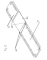
In the embodiments in FIGS. 1-3 , a holding device 4 embodied as a portal is provided. Said holding device 4 has lateral pillars 7, 8, between which the patient is placed during treatment, said two pillars 7, 8 being used to secure the patient at the sides during compressive massage. The two pillars 7 and 8 can be locked in different fixing positions 10 on the reanimation board 9. The distance between the two pillars 7 and 8 can be adjusted in this way according to the width of the patient's body, in order to secure the patient at the sides. Fixing positions 10 are disposed for this purpose in a plurality of adjacent rows along the longitudinal edges of reanimation board 9.
To prevent the patient from sliding upwards during compressive massage, stop members 15 against which the patient's shoulder regions rest can be locked into additional fixing positions 16. These latter fixing positions 16 are likewise provided in the region of the patient's shoulders in a plurality of rows on reanimation board 9. At the head end of reanimation board 9, a head recess 17 is provided in the form of a hollow.
The portal of the holding device 4 also includes a cross-member 11. Said cross-member 11 is supported vertically adjustably on the two pillars 7 and 8. Cross-member 11 is connected to the top ends of gates 18 that can be slid into pillars 7 and 8. Gates 18 can be locked to pillars 7 and 8 in the respective vertical positions adjusted to the size of the patient's body in the thorax region. Cross-member 11 is adjustable in length. Telescoping cross-member elements 19 are provided for this purpose on a middle section of cross-member 11. The telescoping cross-member elements 19 are preferably connected by articulated joints to the top ends of gates 18. The articulated joints may be embodied in such a way that gates 18, together with pillars 7 and 8, can be folded together on cross-member 11 to form a space-saving arrangement when not in use.
In the middle of cross-member 11, a holder is provided into which an active head 20 can be inserted. Said active head 20 forms an assembly in which a plunger 3 and a drive means for plunger 3 are disposed. Due to the symmetrical longitudinal placement of cross-member 11, said active head can be placed exactly in the middle between the two pillars 7 and 8. However, it is also possible, due to the fact that cross-member 11 can be telescoped, to dispose active head 20 at any other desired place between the two pillars 7 and 8. Plunger 3 and the drive means are disposed at active head 20 in a housing which can be fixed to cross-member 11. The housing can be inserted by a plug connection into the holder provided on cross-member 11 and can be varied in height. Locking projections are provided for this purpose in a vertical arrangement on the housing and act simultaneously as anti-rotation means 12 due to their linear embodiment. By means of the vertically adjustable plug connection of active head 20 to cross-member 11, active head 20 can be disposed in a neutral position in which a pressure plate 14 provided at the bottom end of plunger 3 rests on the patient's sternum. In this position, the active head 20 is locked to cross-member 11.
In the embodiment shown in FIGS. 4-12 , a holding device 5 is provided which comprises a single pillar 32 that extends substantially vertically. A cross-member 31 extending substantially at right angles to said pillar is attached like a cantilever arm thereto. Cross-member 31 is fixed to the top end of pillar 32, which is preferably embodied as a telescopic pillar. The cross-member can be swivelled about a pillar axis forming a vertical axis 57. This swivelling is achieved by the upper end of the pillar being rotatable in relation to the lower part of the pillar, as will be described below.
For reanimation treatment, the base 48 of telescoping pillar 32 is inserted with a base locking plate 58 into recesses in a base plate 39. Plug and snap connections 33 are located on base plate 39 in the region of the recesses. The base locking plate 58 is connected to plug and snap connections 33 by positive engagement in one of the two recesses. In this way, holding device 5 is securely connected to base plate 39. The bottom pillar base 48 and the telescopic part of pillar 32 connected thereto are connected non-rotatingly about vertical axis 57 (pillar axis) to base plate 39. By means of a release mechanism 49, pillar base 48 can be detached from base plate 49. For reanimation treatment, it may suffice to secure the patient to the base plate 39 and to fix the described holding device 5 to base plate 39. The base plate then acts as a reanimation board.
The upper board part 40 and the lower board part 41 can be securely attached to each other by a plug-in system. Locking pins 43 and a plug-in projection 45 are located for this purpose on the lower board part 41. Plug-in projection 45 is inserted into a plug-in opening 59 on the upper board part during assembly. Locking pins 43 are simultaneously inserted into engagement holes 44 of the upper board part 40. Behind engagement holes 44, snap-locking means 42 with which the locking pins are securely held on rotation in engagement holes 44 are provided in the upper board part. This results in a rigid connection between the upper board part 40 and the lower board part 41. For reanimation treatment, the patient is laid on the assembled reanimation board, and the chest region on which the compressive massage is performed by plunger 3 and pressure plate 14 provided thereon is placed on base plate 39.
The cross-member 31 provided on pillar 32 is designed in such a way that it can be adjusted, in combination with its swivelability about vertical axis 57 (pillar axis), in such a way that the pressure plate 14 provided at the bottom end of plunger 3 can be made to rest on the sternum of the patient. Cross-member 31 is articulated for this purpose and has two articulated arms 35, 36 which are connected to each other in the embodiment shown via an articulated joint 34 having an axis of articulation 63. One articulated arm 35 is pivotably fixed to the top end of pillar 32, and the other articulated arm 36 has the active head 20 with the drive means and plunger 3. In the embodiment shown, articulated arm 35 is pivotably connected to the top part of pillar 32, and the bottom part of the pillar, as already mentioned, can be securely connected to base plate 39 by designing the pillar base 48 accordingly. By virtue of the articulated design of cross-member 31 and its pivotability about vertical axis 57 (pillar axis), the pressure plate 14 provided at the bottom end of plunger 3 can be laid on the chest region on which compressive massage is be performed. Holding device 5 can be adjusted to the desired height in that regard due to the telescopic design of pillar 32.
Articulated joint 34 is locked in this position, so the two articulated arms 35 and 36 are rigidly connected to each other. Pivotability about vertical axis 57 (pillar axis) is simultaneously locked, for example with the aid of a locking mechanism 61 which is provided in pillar 32 and which will be described further below with reference to FIGS. 15 and 16 . This locking can preferably be performed with the aid of a central locking mechanism 47 which is provided at the top end of pillar 32 and which will be described further below with reference to FIGS. 15 and 16 .
In this locked state, the two articulated arms 35, 36, pillar 32 and base plate 39 form a rigid structure which absorbs, by positive engagement, the forces arising when the compressive massage is performed on the patient. On the lateral longitudinal edges of upper board part 40 and on lower board part 41, attachment points 59, 60 are provided, for example in the form of holes, to which securing straps for securing the patient on the board as well as stop members 15 in the shoulder region of the patient can be detachably fixed.
The connection point 78 between the two operating levers 79, 80 is in active engagement with a control cam 77 mounted rotatably on articulated arm 35. Control cam 77 has two detent positions in which it interacts with connection point 78. In the detent point shown in FIGS. 15, 16 , locking mechanism 61 and joint lock mechanism 62 are released. In this position, articulated arms 35, 36 can be turned in relation to each other, and articulated arm 35 and hence the entire cross-member 31 can be swivelled about pillar axis 57.
In the second position, which is shown in FIGS. 17, 18 , locking mechanism 61 and joint lock mechanism 62 are in their blocking position, with the result that the two articulated arms 35, 36 are connected together non-rotatingly about articulated joint 34. Articulated arm 35 and hence cross-member 31 are also blocked against rotating about pillar axis 57.
In order to operate control cam 77, a lever 64 is provided that can be manually pivoted between the two positions shown in FIGS. 16, 18 . In this way, control cam 77 is brought into the two positions in which the central locking mechanism is opened (FIGS. 15, 16 ) and in which the locking mechanism is closed (FIGS. 17, 18 ).
The joint lock mechanism 62 has a slider 66 which has locking teeth 67 on the side facing articulation joint 34. The slider can be moved longitudinally in a slider guide 70 fixed to articulated arm 35. The sliding movement runs perpendicularly to the axis of articulation 63 of articulated joint 34. A pressure spring 69 which is supported at a support point 81 adapted to the cross-section of the spring and which can be plate-shaped in design acts on slider 66. Support point 81 is fixed to articulated arm 35. Slider 66 is connected to operating lever 79 in an articulated joint 82. In the position shown in FIGS. 15, 16 , the joint lock mechanism 62 is in its opened position. This is achieved by moving slider 66 away from articulated joint 34, so that locking teeth 67 are removed from engagement with respective locking teeth on a rotating joint member 68 (FIGS. 9, 10 ) which is fixedly connected to articulated arm 36. Said position is shown in FIGS. 15, 16 . In this position, the two articulated arms 35, 36 can be pivoted in relation to each other about axis of articulation 63.
When moving lever 64 anti-clockwise out of the position in FIGS. 15, 16 into the position shown in FIGS. 17, 18 , control cam 77 and thus connection point 78 are brought into positions in which pressure spring 69 moves slider 66 towards articulation axis 63, in which position locking teeth 67 come into engagement with respective locking teeth on rotating joint member 68, which is fixedly connected to articulated arm 36. In this position, the two articulated arms 35, 36 are blocked against any further rotation. The two articulated arms are now in a preselected pivot angle in relation to each other.
Pivoting lever 64 simultaneously causes operating lever 80 to move between the two positions that are shown in FIGS. 15, 16 and 17, 18 . Operating lever 80 is pivotably supported on a rotatable part 84. Rotatable part 84 is fixedly connected to articulated arm 35 and can be rotated about pillar axis 57 when the central locking mechanism 47 is in the position shown in FIGS. 15, 16 . Operating lever 80 is mounted in a lever axis 85 on a support 86 on rotatable part 84. One end of the lever is rotatably connected at a hinging point 87 to the top end of push rod 76. The bottom end of the push rod is fixedly connected to a ring holding part 75. Push rod 57 is guided through another ring holding part 74, and an elastically deformable locking ring 73 is held between the two ring holding parts 74, 75. The lower ring holding part 75 can be moved by push rod 76 against the upper ring holding part 74 in the axial direction relative to pillar axis 57. In the position shown in FIGS. 15, 16 , the lower ring holding part 75 is in its lower position, in which the rotatable part and thus cross-member 34 with the two articulated arms 35, 36 can be rotated or swivelled, respectively, about vertical axis 57. When setting lever 74 to the position shown in FIGS. 17, 18 , push rod 76 is moved upward by the movement of operating lever 18, with the result that the distance between the two ring holding parts 74, 75 is reduced and the deformable locking ring 73 is compressed, thus preventing any rotation about vertical axis 57. In the process, the deformed locking ring 73 is pressed with increased force (F) against the inner wall of pillar base 48 and also against the contact surfaces on the two ring holding parts 74, 75, thus preventing any rotation of these parts in relation to each other. As can be seen from the Figures, the upper ring holding part 74 is fixedly connected by a telescopic part 72 to rotatable part 84 and thus fixedly to articulated arm 35. This causes articulated arm 35 to be blocked from rotation relative to pillar base 48 and thus from rotation about vertical axis 57.
In the embodiment shown, telescopic part 72 and pillar base 48 are tubular in design and are disposed moveably in relation to each other when central locking mechanism 47 is released. This permits vertical adjustment of the pillar and also of plunger 3. Vertical adjustment can be carried out manually, pneumatically or hydraulically.
The embodiment of a holding device 95 shown in FIG. 21 includes an arc-shaped support 96. The latter extends substantially along a 90° arc from an articulated joint member 98 which can be supported on reanimation board 9. Arc-shaped support 96 has a plurality of articulated arms 35, 36 and 100 which are connected to each other by articulated joints having horizontal axes of articulation 97. Arc-shaped support 96, which can be fixed by its articulated joint member 98 to the reanimation board, can be swivelled about vertical axis 57 when locking mechanism 47 is released. In combination with the pivotability in articulated joints 99 and due to any vertical adjustability of active head 20, suitable adaptation to the size of the patient's body is achieved. With the aid of the central locking mechanism 47, the two articulated arms 35 and 100 can be locked into a desired angular position, as in the embodiment shown in FIGS. 15-18 , and the articulated joint member 98 can be blocked against rotating in relation to base locking plate 58 about vertical axis 57. The articulated joint 99 between the two articulated arms 35 and 36 can also be blocked by frictional or positive engagement against rotation, so that the direction of movement of plunger 3 and pressure plate 14 extends in the vertical direction.
In FIG. 19 , a reducing plunger 89 is shown. At its top end, said reducing plunger has snap-locking means 91 with which reducing plunger 89 can be detachably fixed to the bottom end of the plunger driven by electric motor 1, as shown in FIG. 20 . A pressure plate 90 is provided at the bottom end of reducing plunger 89. Reducing plunger 89 is used for treating children and forms an additional compression member which is detachably fixed to the bottom end of plunger 2 in place of pressure plate 14.
The drive means for plunger 3 includes an electric motor 1, the torque of which is converted via a transmission gear 2 into the back-and-forth compressive massage motion of plunger 3. The rotational movement of the motor armature 104 is transferred via a gear wheel 21 connected to the motor shaft and via a drive belt 6 to a gear wheel 22 provided on transmission gear 2. The rotation of the motor, which is preferably a reversing rotational movement, is transferred to transmission gear 2 via the toothed belt drive formed in the manner described above. Transmission gear 2 is embodied in such a way that the rotational movement transferred by the toothed belt drive is converted into a linear back-and-forth movement for the plunger 3. In this regard, the transmission gear may have a plunger 3 which can be extended by a ball screw spindle 23, a ball screw nut mounted in rubber and which engages with the ball screw spindle being provided at the top end of plunger 3. At its bottom end, plunger 3 is guided in a sliding bearing 24 which is fixed to the bottom end of the housing that forms holding device 5 (FIG. 11 ). A trapezoidal screw may also be used. A belt tightener rests tangentially against drive belt 6. A rotary transducer 51 embodied as a gear transmission detects the rotational movement transferred by drive belt 6. In this way, it is possible to detect the respective absolute position of plunger 3. Rotary transducer 51 interacts with a position measuring device 25, which may be embodied as an angle encoder. The respective rotation angle position of the motor armature 104, or the position of the drive belt or also of gear wheel 22 and thus the respective position of plunger 3 can be detected in absolute terms in this manner. The respective stroke length of plunger 3 can also be detected directly at the motor, in particular at the motor armature 104 or at plunger 3. Instead of the transmission consisting of a toothed belt and gear wheels, a transmission consisting only of gear wheels can also be used.
A circumferentially sealing cover 28 can be placed on flange plate 27. On its inner side, said cover 28 may have a printed circuit board with a start/stop button for starting and stopping compressive massage treatment. In addition, light-emitting diodes forming a display device 13 on the inner side of transparent cover 25 may be arranged in the form of a lightbar 26. This display device can display, with different colours of light-emitting diodes, whether the reanimation phase or the artificial respiration phase is running. The cover is transparent in design, at least in the region of the lightbar display of display device 13. During treatment of the patient, display device 13 is easily seen from everywhere by the person delivering the treatment, thus making it easier to monitor the progress of treatment.
The connection between the drive means in active head 20, as shown in FIG. 13 , and controller 30, a block diagram of which is shown in FIG. 14 , is established by means of a schematically represented connecting cable 29. With the aid of a keyboard 54, it is possible to operate all the essential controls at controller 30, such as start, stop, stroke frequency and stroke depth of the plunger, and to activate predefined logs. Controller 30 can be installed in cross-member 31, for example in articulated joint 34. However, it may also be embodied as a separate device which can be detachably mounted on cross-member 31, if necessary. Connecting cable 29 can contain the data line between a data interface 88 for the electrical systems of the active head (FIG. 13 ) and a microprocessor 56 in controller 30, as well as the voltage supply for the data interface. However, the data can also be transmitted wirelessly. Also shown in FIG. 14 as being connected to microprocessor 56 is Bluetooth communication module 105, memory card 106, loudspeaker 107, and power supply buffer 108. The motor current for the electric motor 1 and signals from an incremental position encoder indicating the rotation angle position of electric motor 1 may also be supplied via connecting cable 29. Power is supplied to electric motor 1 via connecting cable 29 from a battery 55 or from a rechargeable accumulator. The progress of treatment can be displayed on a screen 53. Connecting cable 29 can be connected to controller 30 by a plug.
The motor current is supplied to electric motor 1 from battery 55 or the rechargeable accumulator via a motor controller 92. The battery may be located inside controller 30 or preferably outside the controller in cross-member 31 and particularly in articulated arm 35 below locking mechanism 47. The battery 55 or accumulator can be charged via a charging circuit 93 accommodated inside controller 30. The charging current can be supplied from an external source of current, for example from the alternator of a motor vehicle or from the power grid. The respective charge state of the battery or accumulator can be indicated via microprocessor 56 on display 53.
A switch, preferably in the form of a pushbutton switch 94 which is disposed on or in the immediate vicinity of active head 20, is used to start and stop treatment of the patient. The motor current fed to electric motor 1 is switched on by means of pushbutton switch 94. Said pushbutton switch 94 interacts with locking mechanism 47 in such a way that treatment of the patient can only be started with pushbutton switch 94 when the locking mechanism is in its blocking position (FIGS. 17, 18 ). More particularly, the motor current can only be switched on when locking mechanism 47 is in its blocking position (FIGS. 17, 18 ). Locking mechanism 47 can interact with pushbutton switch 94 by mechanical means, for example a suitably releasable lock, or microprocessor 56 detects the respective position of locking mechanism 47 and releases the supply of current via motor controller 92 to motor 1 only when locking mechanism 47 is in its blocking position. When, after starting treatment of the patient, pushbutton switch 94 is pressed in order to stop treatment, electric motor 1 is controlled in such a way that plunger 3 is returned to the starting position from which it was released by the patient. This is done with the aid of the suitably programmed microprocessor 56 and with the aid of motor controller 92. All that is preferably required to operate the apparatus is a switch, in the form of pushbutton switch 94 having one direction of actuation for switching on and switching off.
The stroke length of plunger 3 can be monitored by position measuring device 25 and correlated via microprocessor 56 and motor controller 92 with the signals from the incremental position encoder, wherein the signals from the incremental position encoder can be made to match the desired stroke length by the motor controller. A specific force profile for treatment of the patient may also be predefined in microprocessor 56. Said force profile can then be correlated with the supply current drawn by the motor, which is proportional to the torque delivered by the motor, and the current supplied to the motor can then be controlled by motor controller 92.
The foregoing disclosure has been set forth merely to illustrate the invention and is not intended to be limiting. Since modifications of the disclosed embodiments incorporating the spirit and substance of the invention may occur to persons skilled in the art, the invention should be construed to include everything within the scope of the appended claims and equivalents thereof.
| List of reference signs |
| 1 | Electric motor |
| 2 | Transmission gear |
| 3 | Plunger |
| 4 | Holding device |
| 5 | Holding device |
| 6 | Drive belt |
| 7, 8 | Pillars |
| 9 | Reanimation board |
| 10 | Fixing positions |
| 11 | Cross-member |
| 12 | Anti-rotation means/vertical adjuster |
| 13 | Display device |
| 14 | Pressure plate |
| 15 | Stop members |
| 16 | Fixing positions |
| 17 | Head recess |
| 18 | Gate |
| 19 | Cross-member elements |
| 20 | Active head |
| 21, 22 | Gear wheels |
| 23 | Ball screw |
| 24 | Sliding bearing |
| 25 | Position measuring device |
| 26 | Lightbar |
| 27 | Flange plate |
| 28 | Cover |
| 29 | Connector cable |
| 30 | Controller |
| 31 | Cross-member |
| 32 | Pillar |
| 33 | Plug and snap-lock connection |
| 34 | Articulated joint |
| 35, 36 | Articulated arms |
| 37 | Recess |
| 38 | Guide mechanism |
| 39 | Base plate |
| 40, 41 | Board parts |
| 42 | Snap-locking means |
| 43 | Locking pins |
| 44 | Engagement holes |
| 45 | Plug-in projection |
| 46 | Locking lever |
| 47 | Locking mechanism |
| 48 | Foot of pillar |
| 49 | Release mechanism |
| 50 | Fan |
| 51 | Rotary transducer |
| 52 | Belt tightener |
| 53 | Screen |
| 54 | Keyboard |
| 55 | Battery/accumulator |
| 56 | Microprocessor |
| 57 | Vertical axis |
| 58 | Base locking plate |
| 59 | Plug-in opening |
| 59, 60 | Attachment points |
| 61 | Locking device |
| 62 | Joint lock mechanism |
| 63 | Axis of articulation |
| 64 | Lever |
| 65 | Lever axis |
| 66 | Slider |
| 67 | Locking teeth |
| 68 | Reanimation board |
| 69 | Spring |
| 70 | Slider guide |
| 72 | Telescopic part |
| 73 | Locking ring |
| 74, 75 | Ring holding parts |
| 76 | Push rod |
| 77 | Control cam |
| 78 | Connecting point |
| 79, 80 | Actuating lever |
| 81 | Support point |
| 82 | Articulated joint |
| 83 | Locking teeth |
| 84 | Rotatable part |
| 85 | Lever axis |
| 86 | Support |
| 87 | Hinging point |
| 88 | Data interface |
| 89 | Reducing plunger |
| 90 | Pressure plate |
| 91 | Snap-locking means |
| 92 | Motor controller |
| 93 | Charging switch |
| 94 | Pushbutton switch |
| 95 | Holding device |
| 96 | Arc-shaped support |
| 97 | Axes of articulation |
| 98 | Articulated joint member |
| 99 | Articulated joint |
| 100 | Articulated arm |
| 101 | Support plate |
| 102 | Attachment point |
| 103 | Circumferential seal |
| 104 | Armature |
| 105 | Bluetooth Communication |
| 106 | Memory card |
| 107 | Loudspeaker |
| 108 | Power supply buffer |
Claims (23)
1. An apparatus for reanimation of a patient, comprising:
a plunger;
an electric motor configured to drive the plunger and to perform a compressive massage on a patient's body;
a holding device for the electric motor and the plunger; and
a reanimation board,
wherein the holding device includes a vertically adjustable cross-member on which the electric motor and the plunger are mounted, and which is supported on the reanimation board,
wherein the vertically adjustable cross-member is supported on one pillar,
wherein the vertically adjustable cross-member is articulated and has at least two articulated arms that are connected to each other by an articulated joint having an axis of articulation, wherein a central lock fixes the two articulated arms in specific angular positions relative to each other in a plane perpendicular to the axis of articulation,
wherein one of the articulated arms is rotatably mounted about a vertical axis of the one pillar,
wherein the axis of articulation is parallel to the vertical axis of the one pillar, and
wherein the central lock also fixes the cross member in a specific angular position about the vertical axis of the one pillar.
2. The apparatus according to claim 1 , wherein the one pillar is attachable to the reanimation board on which the patient lies.
3. The apparatus according to claim 1 , wherein the holding device and the reanimation board form a force-locked structure that absorbs forces exercised by the plunger during compressive massage.
4. The apparatus according to claim 1 , wherein the holding device is detachably fixed to the reanimation board by a plug and snap connection.
5. The apparatus according to claim 1 , wherein the holding device is moveable in a longitudinal direction in relation to the reanimation board or is fixable in different positions.
6. The apparatus according to claim 1 , wherein the reanimation board includes two detachable parts.
7. The apparatus according to claim 1 , wherein the reanimation board includes a recess for a base plate on which the one pillar is securable.
8. The apparatus according to claim 7 , wherein a guide mechanism for lateral insertion of the base plate is provided in a region of the recess.
9. The apparatus according to claim 7 , wherein the holding device and the base plate or at least one support plate to which it is connected form a force-locked structure that absorbs the forces exercised by the plunger during compressive massage.
10. The apparatus according to claim 1 , wherein at least one support plate is pivotably mounted on the reanimation board, said at least one support plate being pivotable away from the reanimation board and comprising an attachment point for the holding device.
11. The apparatus according to claim 10 , wherein the at least one support plate is lockable in different pivot angle positions.
12. The apparatus according to claim 1 , wherein the plunger is configured for detachably attaching a reducing plunger to a bottom end of the plunger, the reducing plunger configured for treatment of children.
13. The apparatus according to claim 1 , wherein a circumferential gas-tight seal is provided on a pressure plate and under-pressure is produced in a space enclosed between the patient's body and the pressure plate by the seal.
14. The apparatus according to claim 1 , wherein a torque of the electric motor is converted via a transmission gear into the compressive massage motion of the plunger.
15. The apparatus according to claim 14 , further comprising a locking mechanism configured to release a power supply to the electric motor.
16. The apparatus according to claim 14 , wherein the motor includes a position measuring device configured to detect a rotation angle position of the motor, or a position of a transmission part, and is employed for determining the position of the plunger during its compressive massaging motion.
17. The apparatus according to claim 16 , wherein the transmission part is a drive belt or gear wheel configured to transfer a rotational movement of the electric motor.
18. The apparatus according to claim 14 , further comprising a control unit configured to control the electric motor by comparing a motor current drawn by the electric motor with a current profile corresponding to a predefined force profile for a stroke length of the plunger.
19. The apparatus according to claim 18 , wherein a number of revolutions of the motor in a respective direction of rotation is adjusted by the control unit according to the predefined force profile.
20. The apparatus according to claim 18 , wherein a motor speed is adjusted by the control unit according to the predefined force profile.
21. The apparatus according to claim 1 , further comprising a display device configured to display a reanimation process, the display device being provided on the holding device.
22. The apparatus according to claim 21 , wherein the display device is a light-bar.
23. The apparatus according to claim 1 , further comprising a pushbutton switch with a single direction of switch actuation to operate the apparatus during treatment of the patient.
Applications Claiming Priority (3)
| Application Number | Priority Date | Filing Date | Title |
|---|---|---|---|
| DE102011014304.1 | 2011-03-17 | ||
| DE102011014304A DE102011014304A1 (en) | 2011-03-17 | 2011-03-17 | Device for resuscitating a patient |
| DE102011014304 | 2011-03-17 |
Publications (2)
| Publication Number | Publication Date |
|---|---|
| US20120238922A1 US20120238922A1 (en) | 2012-09-20 |
| US9775771B2 true US9775771B2 (en) | 2017-10-03 |
Family
ID=45930546
Family Applications (1)
| Application Number | Title | Priority Date | Filing Date |
|---|---|---|---|
| US13/422,263 Active 2034-11-03 US9775771B2 (en) | 2011-03-17 | 2012-03-16 | Apparatus for reanimation of a patient |
Country Status (4)
| Country | Link |
|---|---|
| US (1) | US9775771B2 (en) |
| EP (1) | EP2500008B1 (en) |
| JP (1) | JP5926991B2 (en) |
| DE (1) | DE102011014304A1 (en) |
Cited By (3)
| Publication number | Priority date | Publication date | Assignee | Title |
|---|---|---|---|---|
| US11020312B2 (en) | 2014-06-06 | 2021-06-01 | Physio-Control, Inc. | Adjustable piston |
| US11246796B2 (en) | 2014-06-06 | 2022-02-15 | Physio-Control, Inc. | Adjustable piston |
| WO2022240949A1 (en) * | 2021-05-12 | 2022-11-17 | Fabian Ariel | Adjustable automated cpr positioning apparatus |
Families Citing this family (42)
| Publication number | Priority date | Publication date | Assignee | Title |
|---|---|---|---|---|
| US8920348B2 (en) * | 2012-09-28 | 2014-12-30 | Zoll Medical Corporation | Method and device for performing alternating chest compression and decompression |
| US9629776B2 (en) | 2012-10-25 | 2017-04-25 | Physio-Control, Inc. | Back plates for mechanical CPR compression |
| JP6235615B2 (en) * | 2013-02-04 | 2017-11-22 | コーニンクレッカ フィリップス エヌ ヴェKoninklijke Philips N.V. | Disposable (leg) cover for automatic CPR device |
| US9539173B2 (en) | 2013-02-05 | 2017-01-10 | Physio-Control, Inc. | Fixation of device to back plate |
| US9603772B2 (en) | 2013-02-05 | 2017-03-28 | Physio-Control, Inc. | Beam mechanical compression device |
| US10143619B2 (en) * | 2013-05-10 | 2018-12-04 | Physio-Control, Inc. | CPR chest compression machine performing prolonged chest compression |
| US8942803B1 (en) * | 2013-08-30 | 2015-01-27 | Zoll Medical Corporation | System and method for distinguishing manual from automated CPR |
| EP3073979B1 (en) * | 2013-11-25 | 2019-06-05 | Koninklijke Philips N.V. | Compact electro-mechanical chest compression drive |
| WO2015075592A1 (en) * | 2013-11-25 | 2015-05-28 | Koninklijke Philips N.V. | Cardiopulmonary compression device receiving flip-up legs |
| CN105792790B (en) * | 2013-12-03 | 2018-10-02 | 皇家飞利浦有限公司 | Mobile box automatic CPR equipment |
| ITRM20130691A1 (en) * | 2013-12-18 | 2015-06-19 | Massimiliano Volpicelli | DEVICE FOR CARRYING OUT THE EXTERNAL CARDIAC MASSAGE. |
| US20150182419A1 (en) * | 2013-12-31 | 2015-07-02 | Randal N. CLOWDUS | Mechanical device to provide and enhance external chest compression for cardiac resuscitation and method |
| DE102015101706A1 (en) * | 2015-02-06 | 2016-08-11 | GS Elektromedizinische Geräte G. Stemple GmbH | Device for cardiopulmonary massage and / or resuscitation |
| US10667989B2 (en) * | 2015-02-24 | 2020-06-02 | Jolife Ab | Cardio-pulmonary resuscitation machines with stabilizing members and methods |
| KR101687414B1 (en) * | 2015-04-10 | 2016-12-28 | 주식회사메디아나 | Package module set type auto cardio pulmonary resuscitation device |
| US11957635B2 (en) | 2015-06-20 | 2024-04-16 | Therabody, Inc. | Percussive therapy device with variable amplitude |
| US10639234B2 (en) | 2015-10-16 | 2020-05-05 | Zoll Circulation, Inc. | Automated chest compression device |
| US10682282B2 (en) | 2015-10-16 | 2020-06-16 | Zoll Circulation, Inc. | Automated chest compression device |
| KR101956776B1 (en) | 2016-01-29 | 2019-03-11 | 서울대학교산학협력단 | Apparatus for automatic cardiopulmonary resuscitation and controlling method thereof |
| DE102016104679A1 (en) * | 2016-03-14 | 2017-09-14 | GS Elektromedizinische Geräte G. Stemple GmbH | Device for cardiopulmonary massage and / or resuscitation |
| CN106551782A (en) * | 2016-11-21 | 2017-04-05 | 河南迈松医用设备制造有限公司 | A kind of electronic cardio-pulmonary resuscitation press device |
| US10874583B2 (en) | 2017-04-20 | 2020-12-29 | Zoll Circulation, Inc. | Compression belt assembly for a chest compression device |
| US11246795B2 (en) | 2017-04-20 | 2022-02-15 | Zoll Circulation, Inc. | Compression belt assembly for a chest compression device |
| US11179293B2 (en) | 2017-07-28 | 2021-11-23 | Stryker Corporation | Patient support system with chest compression system and harness assembly with sensor system |
| US10905629B2 (en) | 2018-03-30 | 2021-02-02 | Zoll Circulation, Inc. | CPR compression device with cooling system and battery removal detection |
| CN108814917B (en) * | 2018-04-24 | 2021-05-04 | 河北现代钢木制品有限公司 | Massage device based on intelligent furniture |
| US10940081B2 (en) * | 2019-05-07 | 2021-03-09 | Theragun, Inc. | Percussive massage device with force meter |
| US11890253B2 (en) | 2018-12-26 | 2024-02-06 | Therabody, Inc. | Percussive therapy device with interchangeable modules |
| US20200306134A1 (en) * | 2019-03-26 | 2020-10-01 | Sunnybrook Research Institute | Mechanical cardiopulmonary resuscitation device |
| US11813221B2 (en) | 2019-05-07 | 2023-11-14 | Therabody, Inc. | Portable percussive massage device |
| CN110547951B (en) * | 2019-10-15 | 2024-03-12 | 乐山市人民医院 | Auxiliary stair climbing device |
| CN111166645B (en) * | 2020-01-14 | 2021-09-28 | 王晓宇 | Sudden cardiac arrest monitoring and emergency rescue device |
| CN111134691B (en) * | 2020-02-28 | 2023-01-24 | 青岛市中心医院 | Clinical laboratory presses sampling device |
| CN111420298B (en) * | 2020-05-04 | 2022-11-22 | 宁波大桔科技有限公司 | Novel low-frequency far-infrared health-preserving rehabilitation physiotherapy equipment |
| CN111588954B (en) * | 2020-05-14 | 2023-04-11 | 东莞市永超塑胶科技有限公司 | Medical adjustable angle's breathing machine support pipe support ware |
| EP3925589B1 (en) * | 2020-06-17 | 2023-12-06 | MO.S.A.I.C. - Motion System and Information Control S.r.l. | Cardiopulmonary resuscitation system |
| CN112074115B (en) * | 2020-09-01 | 2021-10-29 | 河南天朗生态科技有限公司 | Patrol route recommendation system based on model algorithm |
| CN112248454B (en) * | 2020-10-23 | 2023-01-13 | 泉州台商投资区海雅达新材料有限公司 | Special welding equipment and method for anti-freezing nylon pipe fitting special for maritime work platform |
| CN112674922B (en) * | 2020-12-24 | 2023-01-13 | 甘肃中医药大学附属医院 | Adjustable self-gravity traction lumbar vertebra resetting device |
| CN112618173B (en) * | 2021-01-06 | 2022-06-03 | 青岛大学附属医院 | Multifunctional stretcher for emergency department and use method thereof |
| CN113876431B (en) * | 2021-10-29 | 2022-09-09 | 中国人民解放军总医院第五医学中心 | Tracking and measuring mechanical arm device of operation sickbed |
| US11857481B2 (en) | 2022-02-28 | 2024-01-02 | Therabody, Inc. | System for electrical connection of massage attachment to percussive therapy device |
Citations (25)
| Publication number | Priority date | Publication date | Assignee | Title |
|---|---|---|---|---|
| US978760A (en) * | 1910-12-13 | Solon M Langworthy | Surgical table. | |
| US3254645A (en) * | 1962-04-20 | 1966-06-07 | Rand Dev Corp | Reciprocating heart resuscitation device means for adjusting pressure |
| US3277887A (en) * | 1963-11-21 | 1966-10-11 | Westinghouse Electric Corp | Portable heart massage apparatus |
| US3364925A (en) * | 1965-09-02 | 1968-01-23 | Michigan Instr Inc | External cardial compressor |
| US3489140A (en) | 1960-08-05 | 1970-01-13 | Hyman Hurvitz | Apparatus to restore heartbeat |
| US3552390A (en) * | 1968-04-15 | 1971-01-05 | John T Muller | Cardiopulmonary resuscitating apparatus |
| US3779249A (en) * | 1972-04-19 | 1973-12-18 | H Semler | Artery clamp |
| US3985126A (en) * | 1975-02-07 | 1976-10-12 | Michigan Instruments, Inc. | Patient retention and support |
| US4297556A (en) * | 1979-02-21 | 1981-10-27 | Taylor Glenn R | Pushbutton operator |
| US4509528A (en) * | 1981-12-16 | 1985-04-09 | Harvinder Sahota | Hemostat with blood flow sensor |
| US5304201A (en) * | 1992-09-11 | 1994-04-19 | Rice Mold Design Service, Inc. | Radial arm quick adjusting artery clamp |
| US5304186A (en) * | 1992-06-23 | 1994-04-19 | Semler Herbert J | Artery clamp |
| US5327887A (en) * | 1993-01-25 | 1994-07-12 | Ludwik Nowakowski | Cardiopulmonary resuscitation device |
| US5351676A (en) * | 1991-08-05 | 1994-10-04 | Putman John M | Endoscope stabilizer |
| US5597146A (en) * | 1991-08-05 | 1997-01-28 | Putman; J. Michael | Rail-mounted stabilizer for surgical instrument |
| US5645522A (en) * | 1991-04-17 | 1997-07-08 | The Regents Of The University Of California | Devices and methods for controlled external chest compression |
| US6290660B1 (en) * | 1999-11-12 | 2001-09-18 | Charlene Epps | Automated chest percussor apparatus |
| US20030135085A1 (en) * | 2002-01-16 | 2003-07-17 | Bassuk Jorge I. | Combined horizontal and vertical CPR device |
| US6648841B1 (en) * | 1998-12-12 | 2003-11-18 | Stefan Sessler | Device for reanimating patients suffering from cardiac arrest |
| WO2004058136A1 (en) * | 2002-04-17 | 2004-07-15 | Abiola Fatunla | External cardiac massage machine |
| US20080092677A1 (en) * | 2006-10-23 | 2008-04-24 | Oyvind Tjolsen | Transmission device and chest compression device using same |
| US20080097261A1 (en) | 2006-10-20 | 2008-04-24 | Frederik Hansen | Support for chest compression system |
| WO2009136831A1 (en) | 2008-05-07 | 2009-11-12 | Jolife Ab | Cpr apparatus and method |
| US20090314923A1 (en) * | 2006-09-28 | 2009-12-24 | Wojciech Timoszyk | Medical equipment transfer arrangement |
| US20100198118A1 (en) * | 2009-02-05 | 2010-08-05 | Michael Itai Itnati | Augmenting force-delivery in belt-type ECM devices |
Family Cites Families (3)
| Publication number | Priority date | Publication date | Assignee | Title |
|---|---|---|---|---|
| FR2140920A5 (en) * | 1971-06-07 | 1973-01-19 | Derouineau Rene | |
| US3739771A (en) * | 1971-12-29 | 1973-06-19 | G Gaquer | External heart massage apparatus |
| GB0810060D0 (en) * | 2008-06-02 | 2008-07-09 | Poems Ltd | Cardiac massage device |
-
2011
- 2011-03-17 DE DE102011014304A patent/DE102011014304A1/en not_active Withdrawn
-
2012
- 2012-03-16 US US13/422,263 patent/US9775771B2/en active Active
- 2012-03-19 EP EP12001926.0A patent/EP2500008B1/en active Active
- 2012-03-19 JP JP2012062391A patent/JP5926991B2/en active Active
Patent Citations (27)
| Publication number | Priority date | Publication date | Assignee | Title |
|---|---|---|---|---|
| US978760A (en) * | 1910-12-13 | Solon M Langworthy | Surgical table. | |
| US3489140A (en) | 1960-08-05 | 1970-01-13 | Hyman Hurvitz | Apparatus to restore heartbeat |
| US3254645A (en) * | 1962-04-20 | 1966-06-07 | Rand Dev Corp | Reciprocating heart resuscitation device means for adjusting pressure |
| US3277887A (en) * | 1963-11-21 | 1966-10-11 | Westinghouse Electric Corp | Portable heart massage apparatus |
| US3364925A (en) * | 1965-09-02 | 1968-01-23 | Michigan Instr Inc | External cardial compressor |
| US3552390A (en) * | 1968-04-15 | 1971-01-05 | John T Muller | Cardiopulmonary resuscitating apparatus |
| US3779249A (en) * | 1972-04-19 | 1973-12-18 | H Semler | Artery clamp |
| US3985126A (en) * | 1975-02-07 | 1976-10-12 | Michigan Instruments, Inc. | Patient retention and support |
| US4297556A (en) * | 1979-02-21 | 1981-10-27 | Taylor Glenn R | Pushbutton operator |
| US4509528A (en) * | 1981-12-16 | 1985-04-09 | Harvinder Sahota | Hemostat with blood flow sensor |
| US5645522A (en) * | 1991-04-17 | 1997-07-08 | The Regents Of The University Of California | Devices and methods for controlled external chest compression |
| US5351676A (en) * | 1991-08-05 | 1994-10-04 | Putman John M | Endoscope stabilizer |
| US5597146A (en) * | 1991-08-05 | 1997-01-28 | Putman; J. Michael | Rail-mounted stabilizer for surgical instrument |
| US5304186A (en) * | 1992-06-23 | 1994-04-19 | Semler Herbert J | Artery clamp |
| US5304201A (en) * | 1992-09-11 | 1994-04-19 | Rice Mold Design Service, Inc. | Radial arm quick adjusting artery clamp |
| US5327887A (en) * | 1993-01-25 | 1994-07-12 | Ludwik Nowakowski | Cardiopulmonary resuscitation device |
| US6648841B1 (en) * | 1998-12-12 | 2003-11-18 | Stefan Sessler | Device for reanimating patients suffering from cardiac arrest |
| US6290660B1 (en) * | 1999-11-12 | 2001-09-18 | Charlene Epps | Automated chest percussor apparatus |
| US20030135085A1 (en) * | 2002-01-16 | 2003-07-17 | Bassuk Jorge I. | Combined horizontal and vertical CPR device |
| WO2004058136A1 (en) * | 2002-04-17 | 2004-07-15 | Abiola Fatunla | External cardiac massage machine |
| US20090314923A1 (en) * | 2006-09-28 | 2009-12-24 | Wojciech Timoszyk | Medical equipment transfer arrangement |
| US20080097261A1 (en) | 2006-10-20 | 2008-04-24 | Frederik Hansen | Support for chest compression system |
| US8002720B2 (en) * | 2006-10-20 | 2011-08-23 | Laerdal Medical As | Support for chest compression system |
| US20080092677A1 (en) * | 2006-10-23 | 2008-04-24 | Oyvind Tjolsen | Transmission device and chest compression device using same |
| WO2009136831A1 (en) | 2008-05-07 | 2009-11-12 | Jolife Ab | Cpr apparatus and method |
| US20100185127A1 (en) * | 2008-05-07 | 2010-07-22 | Anders Nilsson | Cpr apparatus and method |
| US20100198118A1 (en) * | 2009-02-05 | 2010-08-05 | Michael Itai Itnati | Augmenting force-delivery in belt-type ECM devices |
Cited By (4)
| Publication number | Priority date | Publication date | Assignee | Title |
|---|---|---|---|---|
| US11020312B2 (en) | 2014-06-06 | 2021-06-01 | Physio-Control, Inc. | Adjustable piston |
| US11246796B2 (en) | 2014-06-06 | 2022-02-15 | Physio-Control, Inc. | Adjustable piston |
| WO2022240949A1 (en) * | 2021-05-12 | 2022-11-17 | Fabian Ariel | Adjustable automated cpr positioning apparatus |
| US11744772B2 (en) | 2021-05-12 | 2023-09-05 | Ariel Fabian | Adjustable automated CPR positioning apparatus |
Also Published As
| Publication number | Publication date |
|---|---|
| US20120238922A1 (en) | 2012-09-20 |
| DE102011014304A1 (en) | 2012-09-20 |
| EP2500008A3 (en) | 2012-11-07 |
| JP2012192190A (en) | 2012-10-11 |
| EP2500008B1 (en) | 2016-08-10 |
| EP2500008A2 (en) | 2012-09-19 |
| JP5926991B2 (en) | 2016-05-25 |
Similar Documents
| Publication | Publication Date | Title |
|---|---|---|
| US9775771B2 (en) | Apparatus for reanimation of a patient | |
| KR101611682B1 (en) | X-ray imaging apparatus capable of shooting multi photographing modes | |
| US9603768B1 (en) | Foot flexion and extension machine | |
| US20160106613A1 (en) | Whole body exercise machine capable of circular orbital movement of waist | |
| US20180184994A1 (en) | Medical device | |
| RU2012140477A (en) | SUPPORT DEVICE FOR A SKIN THERAPEUTIC SYSTEM | |
| KR101528562B1 (en) | Remedial exercise device for rotator cuff | |
| CN110314060B (en) | Surgical operation fixing device | |
| ITPI20070063A1 (en) | AUTONOMOUS EXECUTION MACHINE FOR PHYSIOTHERAPY EXERCISES. | |
| CN111655217B (en) | Joint support unit and walking support device | |
| KR101523014B1 (en) | Apparatus for supporting a muscular strength and a kit having the same | |
| CN109414367B (en) | Movable module and movable furniture | |
| KR101854539B1 (en) | Continuous passive motion machine for easy changing of left arm and right arm | |
| CN112890488A (en) | Formula of can keeping flat removal computer chair is followed to massage to shoulder neck wrist | |
| US10456308B2 (en) | Removable leg rest for wheelchairs | |
| CN112716704A (en) | Transfer bed | |
| KR100448449B1 (en) | a cardiopulmonary resuscitation apparatus with a chest band | |
| CN210228625U (en) | Rehabilitation and nursing device for surgery | |
| CN111407635A (en) | Lymphedema therapeutic instrument | |
| KR200462107Y1 (en) | Backbone remedy apparatus | |
| CN210844070U (en) | Portable training system | |
| CN208823344U (en) | Recovery exercising robot | |
| CN203122705U (en) | Pneumatic traction therapeutic apparatus for cervical vertebrae | |
| CN216318515U (en) | Bed is used in bed and is tempered bed | |
| KR102628161B1 (en) | Shoulder rehabilitation apparatus |
Legal Events
| Date | Code | Title | Description |
|---|---|---|---|
| AS | Assignment |
Owner name: GS ELEKTROMEDIZINISCHE GERAETE G. STEMPLE GMBH, GE Free format text: ASSIGNMENT OF ASSIGNORS INTEREST;ASSIGNORS:STEMPLE, GUENTER;GELLERT, DIETER;HELLER, MICHAEL;SIGNING DATES FROM 20120417 TO 20120507;REEL/FRAME:028303/0489 |
|
| STCF | Information on status: patent grant |
Free format text: PATENTED CASE |
|
| MAFP | Maintenance fee payment |
Free format text: PAYMENT OF MAINTENANCE FEE, 4TH YEAR, LARGE ENTITY (ORIGINAL EVENT CODE: M1551); ENTITY STATUS OF PATENT OWNER: LARGE ENTITY Year of fee payment: 4 |