US9785496B1 - Process for making semiconductor dies, chips, and wafers using non-contact measurements obtained from DOEs of NCEM-enabled fill cells on wafers that include multiple steps for enabling NC detecteion of AACNT-TS via opens - Google Patents
Process for making semiconductor dies, chips, and wafers using non-contact measurements obtained from DOEs of NCEM-enabled fill cells on wafers that include multiple steps for enabling NC detecteion of AACNT-TS via opens Download PDFInfo
- Publication number
- US9785496B1 US9785496B1 US15/456,482 US201715456482A US9785496B1 US 9785496 B1 US9785496 B1 US 9785496B1 US 201715456482 A US201715456482 A US 201715456482A US 9785496 B1 US9785496 B1 US 9785496B1
- Authority
- US
- United States
- Prior art keywords
- ncem
- enabled fill
- fill cells
- short
- aacnt
- Prior art date
- Legal status (The legal status is an assumption and is not a legal conclusion. Google has not performed a legal analysis and makes no representation as to the accuracy of the status listed.)
- Active
Links
- 238000000034 method Methods 0.000 title claims abstract description 123
- 238000005259 measurement Methods 0.000 title claims abstract description 29
- 235000012431 wafers Nutrition 0.000 title abstract description 116
- 230000008569 process Effects 0.000 title abstract description 68
- 239000004065 semiconductor Substances 0.000 title abstract description 17
- 238000001514 detection method Methods 0.000 claims abstract description 611
- 238000012360 testing method Methods 0.000 claims description 207
- 238000013400 design of experiment Methods 0.000 claims description 89
- 238000012545 processing Methods 0.000 claims description 63
- 238000000059 patterning Methods 0.000 claims description 62
- 229910021332 silicide Inorganic materials 0.000 claims description 4
- FVBUAEGBCNSCDD-UHFFFAOYSA-N silicide(4-) Chemical compound [Si-4] FVBUAEGBCNSCDD-UHFFFAOYSA-N 0.000 claims description 4
- 238000004519 manufacturing process Methods 0.000 abstract description 98
- 238000013461 design Methods 0.000 abstract description 20
- 238000002474 experimental method Methods 0.000 abstract description 5
- FBAHJDMPCMAQDG-PRJDIBJQSA-N (2r)-2-(1-carboxyethylamino)-4-methylsulfanylbutanoic acid Chemical compound CSCC[C@H](C(O)=O)NC(C)C(O)=O FBAHJDMPCMAQDG-PRJDIBJQSA-N 0.000 abstract 1
- 239000010410 layer Substances 0.000 description 198
- 239000011229 interlayer Substances 0.000 description 78
- 239000007787 solid Substances 0.000 description 75
- 239000000047 product Substances 0.000 description 40
- 241000270295 Serpentes Species 0.000 description 30
- 239000000758 substrate Substances 0.000 description 28
- 230000007547 defect Effects 0.000 description 20
- 238000007689 inspection Methods 0.000 description 19
- 230000037361 pathway Effects 0.000 description 19
- 238000011156 evaluation Methods 0.000 description 13
- 239000012467 final product Substances 0.000 description 11
- 230000001747 exhibiting effect Effects 0.000 description 10
- 239000002184 metal Substances 0.000 description 10
- 230000035945 sensitivity Effects 0.000 description 10
- 239000000203 mixture Substances 0.000 description 7
- 230000002159 abnormal effect Effects 0.000 description 6
- 230000006399 behavior Effects 0.000 description 5
- 239000002131 composite material Substances 0.000 description 5
- 230000004044 response Effects 0.000 description 4
- 239000004020 conductor Substances 0.000 description 3
- 238000009826 distribution Methods 0.000 description 3
- 239000000945 filler Substances 0.000 description 3
- 238000007667 floating Methods 0.000 description 3
- 238000000691 measurement method Methods 0.000 description 3
- 238000005457 optimization Methods 0.000 description 3
- 239000002245 particle Substances 0.000 description 3
- 238000003860 storage Methods 0.000 description 3
- 238000004458 analytical method Methods 0.000 description 2
- 239000003990 capacitor Substances 0.000 description 2
- 238000013401 experimental design Methods 0.000 description 2
- 230000006870 function Effects 0.000 description 2
- 238000003384 imaging method Methods 0.000 description 2
- 238000002955 isolation Methods 0.000 description 2
- 239000000463 material Substances 0.000 description 2
- 238000012544 monitoring process Methods 0.000 description 2
- 239000002356 single layer Substances 0.000 description 2
- 235000001892 vitamin D2 Nutrition 0.000 description 2
- -1 (Ga Inorganic materials 0.000 description 1
- 229910004613 CdTe Inorganic materials 0.000 description 1
- 206010010144 Completed suicide Diseases 0.000 description 1
- 229910005542 GaSb Inorganic materials 0.000 description 1
- 229910001218 Gallium arsenide Inorganic materials 0.000 description 1
- 229910000530 Gallium indium arsenide Inorganic materials 0.000 description 1
- 229910000661 Mercury cadmium telluride Inorganic materials 0.000 description 1
- 229910020328 SiSn Inorganic materials 0.000 description 1
- 229910000577 Silicon-germanium Inorganic materials 0.000 description 1
- 230000004075 alteration Effects 0.000 description 1
- UHYPYGJEEGLRJD-UHFFFAOYSA-N cadmium(2+);selenium(2-) Chemical compound [Se-2].[Cd+2] UHYPYGJEEGLRJD-UHFFFAOYSA-N 0.000 description 1
- 230000008859 change Effects 0.000 description 1
- 230000008021 deposition Effects 0.000 description 1
- 238000011161 development Methods 0.000 description 1
- 230000000694 effects Effects 0.000 description 1
- 238000005516 engineering process Methods 0.000 description 1
- 238000005530 etching Methods 0.000 description 1
- 238000002513 implantation Methods 0.000 description 1
- 239000012212 insulator Substances 0.000 description 1
- 230000001788 irregular Effects 0.000 description 1
- 230000004807 localization Effects 0.000 description 1
- 238000013507 mapping Methods 0.000 description 1
- 230000000873 masking effect Effects 0.000 description 1
- 230000015654 memory Effects 0.000 description 1
- 238000012986 modification Methods 0.000 description 1
- 230000004048 modification Effects 0.000 description 1
- 229910003465 moissanite Inorganic materials 0.000 description 1
- 229910021421 monocrystalline silicon Inorganic materials 0.000 description 1
- 238000004886 process control Methods 0.000 description 1
- 238000005389 semiconductor device fabrication Methods 0.000 description 1
- 229910010271 silicon carbide Inorganic materials 0.000 description 1
- 229910052950 sphalerite Inorganic materials 0.000 description 1
- 238000007619 statistical method Methods 0.000 description 1
- 230000009897 systematic effect Effects 0.000 description 1
- 230000008685 targeting Effects 0.000 description 1
- 238000012876 topography Methods 0.000 description 1
- 229910052984 zinc sulfide Inorganic materials 0.000 description 1
Images


Classifications
-
- G—PHYSICS
- G06—COMPUTING; CALCULATING OR COUNTING
- G06F—ELECTRIC DIGITAL DATA PROCESSING
- G06F11/00—Error detection; Error correction; Monitoring
- G06F11/07—Responding to the occurrence of a fault, e.g. fault tolerance
- G06F11/0703—Error or fault processing not based on redundancy, i.e. by taking additional measures to deal with the error or fault not making use of redundancy in operation, in hardware, or in data representation
- G06F11/079—Root cause analysis, i.e. error or fault diagnosis
-
- G—PHYSICS
- G06—COMPUTING; CALCULATING OR COUNTING
- G06F—ELECTRIC DIGITAL DATA PROCESSING
- G06F30/00—Computer-aided design [CAD]
- G06F30/30—Circuit design
-
- G—PHYSICS
- G06—COMPUTING; CALCULATING OR COUNTING
- G06F—ELECTRIC DIGITAL DATA PROCESSING
- G06F30/00—Computer-aided design [CAD]
- G06F30/30—Circuit design
- G06F30/39—Circuit design at the physical level
-
- G—PHYSICS
- G06—COMPUTING; CALCULATING OR COUNTING
- G06F—ELECTRIC DIGITAL DATA PROCESSING
- G06F30/00—Computer-aided design [CAD]
- G06F30/30—Circuit design
- G06F30/39—Circuit design at the physical level
- G06F30/398—Design verification or optimisation, e.g. using design rule check [DRC], layout versus schematics [LVS] or finite element methods [FEM]
-
- H—ELECTRICITY
- H01—ELECTRIC ELEMENTS
- H01L—SEMICONDUCTOR DEVICES NOT COVERED BY CLASS H10
- H01L21/00—Processes or apparatus adapted for the manufacture or treatment of semiconductor or solid state devices or of parts thereof
- H01L21/70—Manufacture or treatment of devices consisting of a plurality of solid state components formed in or on a common substrate or of parts thereof; Manufacture of integrated circuit devices or of parts thereof
- H01L21/77—Manufacture or treatment of devices consisting of a plurality of solid state components or integrated circuits formed in, or on, a common substrate
- H01L21/78—Manufacture or treatment of devices consisting of a plurality of solid state components or integrated circuits formed in, or on, a common substrate with subsequent division of the substrate into plural individual devices
- H01L21/82—Manufacture or treatment of devices consisting of a plurality of solid state components or integrated circuits formed in, or on, a common substrate with subsequent division of the substrate into plural individual devices to produce devices, e.g. integrated circuits, each consisting of a plurality of components
- H01L21/822—Manufacture or treatment of devices consisting of a plurality of solid state components or integrated circuits formed in, or on, a common substrate with subsequent division of the substrate into plural individual devices to produce devices, e.g. integrated circuits, each consisting of a plurality of components the substrate being a semiconductor, using silicon technology
- H01L21/8232—Field-effect technology
- H01L21/8234—MIS technology, i.e. integration processes of field effect transistors of the conductor-insulator-semiconductor type
- H01L21/823437—MIS technology, i.e. integration processes of field effect transistors of the conductor-insulator-semiconductor type with a particular manufacturing method of the gate conductors, e.g. particular materials, shapes
-
- H—ELECTRICITY
- H01—ELECTRIC ELEMENTS
- H01L—SEMICONDUCTOR DEVICES NOT COVERED BY CLASS H10
- H01L21/00—Processes or apparatus adapted for the manufacture or treatment of semiconductor or solid state devices or of parts thereof
- H01L21/70—Manufacture or treatment of devices consisting of a plurality of solid state components formed in or on a common substrate or of parts thereof; Manufacture of integrated circuit devices or of parts thereof
- H01L21/77—Manufacture or treatment of devices consisting of a plurality of solid state components or integrated circuits formed in, or on, a common substrate
- H01L21/78—Manufacture or treatment of devices consisting of a plurality of solid state components or integrated circuits formed in, or on, a common substrate with subsequent division of the substrate into plural individual devices
- H01L21/82—Manufacture or treatment of devices consisting of a plurality of solid state components or integrated circuits formed in, or on, a common substrate with subsequent division of the substrate into plural individual devices to produce devices, e.g. integrated circuits, each consisting of a plurality of components
- H01L21/822—Manufacture or treatment of devices consisting of a plurality of solid state components or integrated circuits formed in, or on, a common substrate with subsequent division of the substrate into plural individual devices to produce devices, e.g. integrated circuits, each consisting of a plurality of components the substrate being a semiconductor, using silicon technology
- H01L21/8232—Field-effect technology
- H01L21/8234—MIS technology, i.e. integration processes of field effect transistors of the conductor-insulator-semiconductor type
- H01L21/823475—MIS technology, i.e. integration processes of field effect transistors of the conductor-insulator-semiconductor type interconnection or wiring or contact manufacturing related aspects
-
- H—ELECTRICITY
- H01—ELECTRIC ELEMENTS
- H01L—SEMICONDUCTOR DEVICES NOT COVERED BY CLASS H10
- H01L22/00—Testing or measuring during manufacture or treatment; Reliability measurements, i.e. testing of parts without further processing to modify the parts as such; Structural arrangements therefor
- H01L22/20—Sequence of activities consisting of a plurality of measurements, corrections, marking or sorting steps
- H01L22/26—Acting in response to an ongoing measurement without interruption of processing, e.g. endpoint detection, in-situ thickness measurement
-
- H—ELECTRICITY
- H01—ELECTRIC ELEMENTS
- H01L—SEMICONDUCTOR DEVICES NOT COVERED BY CLASS H10
- H01L22/00—Testing or measuring during manufacture or treatment; Reliability measurements, i.e. testing of parts without further processing to modify the parts as such; Structural arrangements therefor
- H01L22/30—Structural arrangements specially adapted for testing or measuring during manufacture or treatment, or specially adapted for reliability measurements
- H01L22/32—Additional lead-in metallisation on a device or substrate, e.g. additional pads or pad portions, lines in the scribe line, sacrificed conductors
-
- H—ELECTRICITY
- H01—ELECTRIC ELEMENTS
- H01L—SEMICONDUCTOR DEVICES NOT COVERED BY CLASS H10
- H01L22/00—Testing or measuring during manufacture or treatment; Reliability measurements, i.e. testing of parts without further processing to modify the parts as such; Structural arrangements therefor
- H01L22/30—Structural arrangements specially adapted for testing or measuring during manufacture or treatment, or specially adapted for reliability measurements
- H01L22/34—Circuits for electrically characterising or monitoring manufacturing processes, e. g. whole test die, wafers filled with test structures, on-board-devices incorporated on each die, process control monitors or pad structures thereof, devices in scribe line
-
- H—ELECTRICITY
- H01—ELECTRIC ELEMENTS
- H01L—SEMICONDUCTOR DEVICES NOT COVERED BY CLASS H10
- H01L23/00—Details of semiconductor or other solid state devices
- H01L23/52—Arrangements for conducting electric current within the device in operation from one component to another, i.e. interconnections, e.g. wires, lead frames
- H01L23/522—Arrangements for conducting electric current within the device in operation from one component to another, i.e. interconnections, e.g. wires, lead frames including external interconnections consisting of a multilayer structure of conductive and insulating layers inseparably formed on the semiconductor body
- H01L23/5226—Via connections in a multilevel interconnection structure
-
- H—ELECTRICITY
- H01—ELECTRIC ELEMENTS
- H01L—SEMICONDUCTOR DEVICES NOT COVERED BY CLASS H10
- H01L23/00—Details of semiconductor or other solid state devices
- H01L23/52—Arrangements for conducting electric current within the device in operation from one component to another, i.e. interconnections, e.g. wires, lead frames
- H01L23/522—Arrangements for conducting electric current within the device in operation from one component to another, i.e. interconnections, e.g. wires, lead frames including external interconnections consisting of a multilayer structure of conductive and insulating layers inseparably formed on the semiconductor body
- H01L23/528—Geometry or layout of the interconnection structure
-
- H—ELECTRICITY
- H01—ELECTRIC ELEMENTS
- H01L—SEMICONDUCTOR DEVICES NOT COVERED BY CLASS H10
- H01L27/00—Devices consisting of a plurality of semiconductor or other solid-state components formed in or on a common substrate
- H01L27/02—Devices consisting of a plurality of semiconductor or other solid-state components formed in or on a common substrate including semiconductor components specially adapted for rectifying, oscillating, amplifying or switching and having at least one potential-jump barrier or surface barrier; including integrated passive circuit elements with at least one potential-jump barrier or surface barrier
- H01L27/0203—Particular design considerations for integrated circuits
- H01L27/0207—Geometrical layout of the components, e.g. computer aided design; custom LSI, semi-custom LSI, standard cell technique
-
- H—ELECTRICITY
- H01—ELECTRIC ELEMENTS
- H01L—SEMICONDUCTOR DEVICES NOT COVERED BY CLASS H10
- H01L27/00—Devices consisting of a plurality of semiconductor or other solid-state components formed in or on a common substrate
- H01L27/02—Devices consisting of a plurality of semiconductor or other solid-state components formed in or on a common substrate including semiconductor components specially adapted for rectifying, oscillating, amplifying or switching and having at least one potential-jump barrier or surface barrier; including integrated passive circuit elements with at least one potential-jump barrier or surface barrier
- H01L27/04—Devices consisting of a plurality of semiconductor or other solid-state components formed in or on a common substrate including semiconductor components specially adapted for rectifying, oscillating, amplifying or switching and having at least one potential-jump barrier or surface barrier; including integrated passive circuit elements with at least one potential-jump barrier or surface barrier the substrate being a semiconductor body
- H01L27/08—Devices consisting of a plurality of semiconductor or other solid-state components formed in or on a common substrate including semiconductor components specially adapted for rectifying, oscillating, amplifying or switching and having at least one potential-jump barrier or surface barrier; including integrated passive circuit elements with at least one potential-jump barrier or surface barrier the substrate being a semiconductor body including only semiconductor components of a single kind
- H01L27/085—Devices consisting of a plurality of semiconductor or other solid-state components formed in or on a common substrate including semiconductor components specially adapted for rectifying, oscillating, amplifying or switching and having at least one potential-jump barrier or surface barrier; including integrated passive circuit elements with at least one potential-jump barrier or surface barrier the substrate being a semiconductor body including only semiconductor components of a single kind including field-effect components only
- H01L27/088—Devices consisting of a plurality of semiconductor or other solid-state components formed in or on a common substrate including semiconductor components specially adapted for rectifying, oscillating, amplifying or switching and having at least one potential-jump barrier or surface barrier; including integrated passive circuit elements with at least one potential-jump barrier or surface barrier the substrate being a semiconductor body including only semiconductor components of a single kind including field-effect components only the components being field-effect transistors with insulated gate
-
- H—ELECTRICITY
- H01—ELECTRIC ELEMENTS
- H01L—SEMICONDUCTOR DEVICES NOT COVERED BY CLASS H10
- H01L29/00—Semiconductor devices adapted for rectifying, amplifying, oscillating or switching, or capacitors or resistors with at least one potential-jump barrier or surface barrier, e.g. PN junction depletion layer or carrier concentration layer; Details of semiconductor bodies or of electrodes thereof ; Multistep manufacturing processes therefor
- H01L29/02—Semiconductor bodies ; Multistep manufacturing processes therefor
- H01L29/06—Semiconductor bodies ; Multistep manufacturing processes therefor characterised by their shape; characterised by the shapes, relative sizes, or dispositions of the semiconductor regions ; characterised by the concentration or distribution of impurities within semiconductor regions
- H01L29/0603—Semiconductor bodies ; Multistep manufacturing processes therefor characterised by their shape; characterised by the shapes, relative sizes, or dispositions of the semiconductor regions ; characterised by the concentration or distribution of impurities within semiconductor regions characterised by particular constructional design considerations, e.g. for preventing surface leakage, for controlling electric field concentration or for internal isolations regions
- H01L29/0642—Isolation within the component, i.e. internal isolation
- H01L29/0649—Dielectric regions, e.g. SiO2 regions, air gaps
-
- H—ELECTRICITY
- H01—ELECTRIC ELEMENTS
- H01L—SEMICONDUCTOR DEVICES NOT COVERED BY CLASS H10
- H01L29/00—Semiconductor devices adapted for rectifying, amplifying, oscillating or switching, or capacitors or resistors with at least one potential-jump barrier or surface barrier, e.g. PN junction depletion layer or carrier concentration layer; Details of semiconductor bodies or of electrodes thereof ; Multistep manufacturing processes therefor
- H01L29/40—Electrodes ; Multistep manufacturing processes therefor
- H01L29/41—Electrodes ; Multistep manufacturing processes therefor characterised by their shape, relative sizes or dispositions
- H01L29/417—Electrodes ; Multistep manufacturing processes therefor characterised by their shape, relative sizes or dispositions carrying the current to be rectified, amplified or switched
- H01L29/41725—Source or drain electrodes for field effect devices
-
- H—ELECTRICITY
- H01—ELECTRIC ELEMENTS
- H01L—SEMICONDUCTOR DEVICES NOT COVERED BY CLASS H10
- H01L29/00—Semiconductor devices adapted for rectifying, amplifying, oscillating or switching, or capacitors or resistors with at least one potential-jump barrier or surface barrier, e.g. PN junction depletion layer or carrier concentration layer; Details of semiconductor bodies or of electrodes thereof ; Multistep manufacturing processes therefor
- H01L29/40—Electrodes ; Multistep manufacturing processes therefor
- H01L29/43—Electrodes ; Multistep manufacturing processes therefor characterised by the materials of which they are formed
- H01L29/45—Ohmic electrodes
-
- G06F17/5045—
-
- G06F17/5072—
-
- G06F17/5081—
-
- G—PHYSICS
- G06—COMPUTING; CALCULATING OR COUNTING
- G06F—ELECTRIC DIGITAL DATA PROCESSING
- G06F30/00—Computer-aided design [CAD]
- G06F30/30—Circuit design
- G06F30/39—Circuit design at the physical level
- G06F30/392—Floor-planning or layout, e.g. partitioning or placement
-
- H—ELECTRICITY
- H01—ELECTRIC ELEMENTS
- H01L—SEMICONDUCTOR DEVICES NOT COVERED BY CLASS H10
- H01L27/00—Devices consisting of a plurality of semiconductor or other solid-state components formed in or on a common substrate
- H01L27/02—Devices consisting of a plurality of semiconductor or other solid-state components formed in or on a common substrate including semiconductor components specially adapted for rectifying, oscillating, amplifying or switching and having at least one potential-jump barrier or surface barrier; including integrated passive circuit elements with at least one potential-jump barrier or surface barrier
- H01L27/04—Devices consisting of a plurality of semiconductor or other solid-state components formed in or on a common substrate including semiconductor components specially adapted for rectifying, oscillating, amplifying or switching and having at least one potential-jump barrier or surface barrier; including integrated passive circuit elements with at least one potential-jump barrier or surface barrier the substrate being a semiconductor body
- H01L27/08—Devices consisting of a plurality of semiconductor or other solid-state components formed in or on a common substrate including semiconductor components specially adapted for rectifying, oscillating, amplifying or switching and having at least one potential-jump barrier or surface barrier; including integrated passive circuit elements with at least one potential-jump barrier or surface barrier the substrate being a semiconductor body including only semiconductor components of a single kind
- H01L27/085—Devices consisting of a plurality of semiconductor or other solid-state components formed in or on a common substrate including semiconductor components specially adapted for rectifying, oscillating, amplifying or switching and having at least one potential-jump barrier or surface barrier; including integrated passive circuit elements with at least one potential-jump barrier or surface barrier the substrate being a semiconductor body including only semiconductor components of a single kind including field-effect components only
- H01L27/088—Devices consisting of a plurality of semiconductor or other solid-state components formed in or on a common substrate including semiconductor components specially adapted for rectifying, oscillating, amplifying or switching and having at least one potential-jump barrier or surface barrier; including integrated passive circuit elements with at least one potential-jump barrier or surface barrier the substrate being a semiconductor body including only semiconductor components of a single kind including field-effect components only the components being field-effect transistors with insulated gate
- H01L27/092—Devices consisting of a plurality of semiconductor or other solid-state components formed in or on a common substrate including semiconductor components specially adapted for rectifying, oscillating, amplifying or switching and having at least one potential-jump barrier or surface barrier; including integrated passive circuit elements with at least one potential-jump barrier or surface barrier the substrate being a semiconductor body including only semiconductor components of a single kind including field-effect components only the components being field-effect transistors with insulated gate complementary MIS field-effect transistors
-
- H—ELECTRICITY
- H01—ELECTRIC ELEMENTS
- H01L—SEMICONDUCTOR DEVICES NOT COVERED BY CLASS H10
- H01L29/00—Semiconductor devices adapted for rectifying, amplifying, oscillating or switching, or capacitors or resistors with at least one potential-jump barrier or surface barrier, e.g. PN junction depletion layer or carrier concentration layer; Details of semiconductor bodies or of electrodes thereof ; Multistep manufacturing processes therefor
- H01L29/02—Semiconductor bodies ; Multistep manufacturing processes therefor
- H01L29/06—Semiconductor bodies ; Multistep manufacturing processes therefor characterised by their shape; characterised by the shapes, relative sizes, or dispositions of the semiconductor regions ; characterised by the concentration or distribution of impurities within semiconductor regions
- H01L29/0684—Semiconductor bodies ; Multistep manufacturing processes therefor characterised by their shape; characterised by the shapes, relative sizes, or dispositions of the semiconductor regions ; characterised by the concentration or distribution of impurities within semiconductor regions characterised by the shape, relative sizes or dispositions of the semiconductor regions or junctions between the regions
Definitions
- One NC measurement technique useful in connection with certain embodiments of the invention, involves measuring or inspecting the surface of a partially processed wafer (in-line) with a scanning electron microscope (“SEM”) or other charged particle-based scanning/imaging device. As the measuring/inspecting proceeds, the SEM (or other device) induces charge on all electrically floating elements, whereas any grounded elements remain at zero potential. This voltage contrast becomes visible to the scanning/imaging device as a NCEM.
- SEM scanning electron microscope
- NC measurement or “NCEM” in this application should not be limited to these preferred methods in the absence of specific language (e.g., “selectively targeting . . . ”, “ . . . fewer than 10 pixels”) that indicates an intent to so limit a claim.
- DOE Design of Experiments
- Experimental Design refers to the design of any information-gathering exercise where variation is present, whether under the full control of the experimenter or not.
- NCEM-enabled fill cells all have some common elements (e.g., height, supply rail configuration, and gate patterning that is consistent with standard cells in the library), then vary according to the measurement type (e.g., short, open, leakage, or resistance), layer(s) involved, and/or structure(s) to be evaluated/tested.
- Such NCEM-enabled fill cells also generally include a pad, configured to accelerate targeted NC evaluation by, for example, determining an associated NCEM from a small number of enlarged pixels (e.g., 10 or fewer), or without creating any image at all.
- pads can be formed from a variety of low-resistance materials and configured in a variety of shapes.
- such NCEM-enabled fill cells may additionally include two or more mask-patterned features that define a rectangular test area, such test area being characterized by two parameters (e.g., X/Y or r/ ⁇ dimensions).
- an expanded test area surrounds the cell's test area, the expanded test area being defined by a predetermined expansion of each boundary of the test area, or by predetermined proportionate expansion of the test area's area.
- test areas may be characterized as “test volumes,” with one or more additional parameter(s) characterizing the layers of the defining, mask-patterned features.
- changes that lie within an expanded test area an area that encompasses a predetermined expansion of the test area by, for example 50-200%, or more
- changes that lie within an expanded test area are preferably limited in number. Limiting the number of such changes to fewer than three, five, ten, twenty, or thirty “background pattern variants” facilitates analysis of data that the experiment produces.
- PSR pattern similarity ratio
- one aspect of the invention relates to ICs that include, for example: a standard cell area that includes a mix of at least one thousand logic cells and fill cells of different widths and uniform heights, placed into at least twenty adjacent rows, with at least twenty cells placed side-by-side in each row; wherein the integrated circuit includes at least a first DOE, the first DOE comprising a plurality of similarly-configured, NCEM-enabled fill cells, wherein each NCEM-enabled fill cell comprises at least: first and second elongated conductive supply rails, formed in a connector or interconnect stack, extending across the entire width of the cell, and configured for compatibility with corresponding supply rails contained in the logic cells of the standard cell region; a NCEM pad, formed in a conductive layer, the pad being at least two times larger, in at least one dimension, than a minimum size permitted by design rules; a rectangular test area defined by selected boundaries of at least first and second distinct, mask-patterned features, the test area
- the first selected manufacturing failure may involve short or leakage defects that present as abnormally high pad-to-ground conductance or leakage
- the second selected manufacturing failure may involve open or resistance defects that present as abnormally low pad-to-ground conductance or abnormally high pad-to-ground resistance.
- Both the first and second selected manufacturing failures may involve layers in a connector stack region of the IC.
- Such ICs may further include: a third DOE, comprising a plurality of similarly-configured, NCEM-enabled fill cells, wherein each NCEM-enabled fill cell comprises at least: first and second elongated conductive supply rails, formed in a connector or interconnect stack, extending across the entire width of the cell, and configured for compatibility with corresponding supply rails contained in the logic cells of the standard cell region; a NCEM pad, formed in a conductive layer, the pad being at least two times larger, in at least one dimension, than a minimum size permitted by design rules; a rectangular test area defined by selected boundaries of at least first and second distinct, mask-patterned features, the test area being characterized by two dimensional parameters; a first conductive pathway that electrically connects the first mask-patterned feature to the pad; and, a second conductive pathway that electrically connects the second mask-patterned feature to a permanently or virtually grounded structure; wherein each of the similarly-configured NCEM-enabled fill cells in the third DOE is configured to render a third
- Each of the first, second, and third DOEs preferably include NCEM-enabled fill cells in at least three, five, seven, or ten variants.
- the NCEM-enabled fill cells of the first, second, and third DOEs are preferably irregularly distributed within the standard cell area of the IC.
- Each variant may differ from the other(s) only in the position, size, or shape of its first or second mask-patterned feature, or only by a single dimensional parameter that characterizes their respective test areas.
- ICs that include, for example: a standard cell area that includes a mix of at least one thousand logic cells and fill cells of different widths and uniform heights, placed into at least twenty adjacent rows, with at least twenty cells placed side-by-side in each row; wherein the IC includes at least a first DOE, the first DOE comprising a plurality of similarly-configured, NCEM-enabled fill cells, wherein each NCEM-enabled fill cell comprises at least: first and second elongated conductive supply rails, formed in a connector or interconnect stack, extending across the entire width of the cell, and configured for compatibility with corresponding supply rails contained in the logic cells of the standard cell region; a NCEM pad, formed in a conductive layer, the pad being at least two times larger, in at least one dimension, than a minimum size permitted by design rules; a rectangular test area defined by selected boundaries of first and second distinct, mask-patterned features, the test area characterized by
- the first and/or second distinct, mask-patterned features may each represent either a control element, or a portion thereof, and/or a portion of a control element connector or a substrate connector, and/or a portion of a control element jumper, substrate jumper, or interconnect jumper.
- the first and second distinct, mask-patterned features may appear in a tip-to-tip configuration, a tip-to-side configuration, a side-to-side configuration, a diagonal configuration, or an interlayer overlap configuration.
- ICs that include, for example: a standard cell area that includes a mix of at least one thousand logic cells and fill cells of different widths and uniform heights, placed into at least twenty adjacent rows, with at least twenty cells placed side-by-side in each row; wherein the IC includes at least a first DOE, the first DOE comprising a plurality of similarly-configured, NCEM-enabled fill cells, wherein each NCEM-enabled fill cell comprises at least: first and second elongated conductive supply rails, formed in a connector or interconnect stack, extending across the entire width of the cell, and configured for compatibility with corresponding supply rails contained in the logic cells of the standard cell region; a NCEM pad, formed in one or more conductive layer(s), the pad being at least two times larger, in at least one dimension, than a minimum size permitted by design rules; a rectangular test area defined by selected boundaries of a plurality of mask-patterned features, the test area
- another aspect of the invention relates methods for making ICs that include, for example: (a) performing initial processing steps on a semiconductor wafer, the initial processing steps including: patterning a standard cell area that includes a mix of at least one thousand logic cells and fill cells of different widths and uniform heights, placed into at least twenty adjacent rows, with at least twenty cells placed side-by-side in each row; and, patterning a first DOE by instantiating a plurality of similarly-configured, NCEM-enabled fill cells in at least two variants, the NCEM-enabled fill cells configured for compatibility with logic cells in the standard cell area, each of the cells in the first DOE configured to enable evaluation of a first manufacturing failure by voltage contrast examination of a NCEM of a pad contained in the cell, the variants exhibiting different NCEM sensitivity to the first manufacturing failure; (b) determining a presence or absence of the first manufacturing failure by: performing a voltage contrast examination of NCEM-enabled fill cells in the first DOE;
- Step (a) may further involve: patterning a second DOE by instantiating a plurality of similarly-configured NCEM-enabled fill cells in at least two variants, the NCEM-enabled fill cells configured for compatibility with logic cells in the standard cell area and fill cells in the first DOE, each of the cells in the second DOE configured to enable evaluation of a second manufacturing failure, different from the first manufacturing failure, by voltage contrast examination of a NCEM of a pad contained in the cell, the variants exhibiting different NCEM sensitivity to the second manufacturing failure; and wherein step (b) further comprises: performing a voltage contrast examination of NCEM-enabled fill cells in the second DOE; and, determining whether NCEMs of pads contained in the NCEM-enabled fill cells of the second DOE represent instance(s) of the second manufacturing failure and, if so, determining whether different cell variants exhibit a different prevalence of the second manufacturing failure.
- Step (a) may further involve: patterning a third DOE by instantiating a plurality of similarly-configured NCEM-enabled fill cells in at least two variants, the NCEM-enabled fill cells configured for compatibility with logic cells in the standard cell area and fill cells in the first and second DOEs, each of the cells in the third DOE configured to enable evaluation of a third manufacturing failure, different from the first and second manufacturing failures, by voltage contrast examination of a NCEM of a pad contained in the cell, the variants exhibiting different NCEM sensitivity to the third manufacturing failure; and wherein step (b) further comprises: performing a voltage contrast examination of NCEM-enabled fill cells in the third DOE; and, determining whether NCEMs of pads contained in the NCEM-enabled fill cells of the third DOE represent instance(s) of the third manufacturing failure and, if so, determining whether different cell variants exhibit a different prevalence of the third manufacturing failure.
- At least one of the first, second, or third manufacturing failures preferably involves unintended shorts or leakages, and at least one of the first, second, or third manufacturing failures preferably involves unintended opens or excessive resistances.
- Instantiating the NCEM-enabled fill cells preferably comprises distributing the cells irregularly within the standard cell area.
- each variant may differ from the other(s) only in the position, size, or shape of a single mask-patterned feature.
- At least one of the first, second, or third manufacturing failures may involve unintended shorts between structures in a tip-to-tip configuration, or unintended shorts between structures in a tip-to-side configuration, or unintended shorts between structures in a side-to-side configuration, or unintended shorts between structures in a diagonal configuration, or unintended shorts between structures in an interlayer overlap configuration, or unintended interlayer shorts or leakages between structures in a corner configuration, unintended opens in snake-shaped structures, unintended opens in stitched structures, unintended opens in via-connected structures.
- Each of the first, second, and third DOEs preferably includes NCEM-enabled fill cells in at least three, five, seven, 11, 21, or more variants.
- another aspect of the invention relates to methods for making ICs that include, for example: (a) performing initial processing steps on a first semiconductor wafer, the initial processing steps including, at least: patterning a first DOE by instantiating a plurality of similarly-configured NCEM-enabled fill cells in at least two variants, the NCEM-enabled fill cells configured for compatibility with logic cells in the standard cell library, each of the cells in the first DOE configured to enable evaluation of a first manufacturing failure by voltage contrast examination of a NCEM of a pad contained in the cell, the variants exhibiting different NCEM sensitivity to the first manufacturing failure; patterning a second DOE by instantiating a plurality of similarly-configured NCEM-enabled fill cells in at least two variants, the NCEM-enabled fill cells configured for compatibility with logic cells in the standard cell library and fill cells in the first DOE, each of the cells in the second DOE configured to enable evaluation of a second manufacturing failure, different from the first manufacturing failure,
- another aspect of the invention relates to methods for making ICs that include, for example: (a) performing initial processing steps on an initial product wafer, the initial processing steps including, at least: patterning a standard cell area that includes a mix of at least one thousand logic cells and fill cells of different widths and uniform heights, placed into at least twenty adjacent rows, with at least twenty cells placed side-by-side in each row; and, patterning, within the standard cell area, a first DOE by instantiating a plurality of similarly-configured NCEM-enabled fill cells in at least two variants, the NCEM-enabled fill cells configured for compatibility with logic cells in the standard cell area, each of the cells in the first DOE configured to enable evaluation of a first manufacturing failure by voltage contrast examination of a NCEM of a pad contained in the cell, the variants exhibiting different NCEM sensitivity to the first manufacturing failure; patterning a second DOE by instantiating a plurality of similarly-configured NCEM-enabled fill cells
- Still further aspects of the invention relate to wafers, chips, and processes for making them that include/utilize DOEs based on means/steps for enabling NC detection of tip-to-tip shorts, including but not limited to:
- FIG. 52 et seq. in this application refers to the figures of the incorporated '256, '267, and '274 parent applications.
- FIGS. 52-96 in this application correspond, respectively, to FIGS. 1629-1673 of the '256, '267, and '274 parent applications.
- Still further aspects of the invention relate to wafers, chips, and processes for making them that include/utilize DOEs based on means/steps for enabling NC detection of tip-to-side shorts, including but not limited to:
- Still further aspects of the invention relate to wafers, chips, and processes for making them that include/utilize DOEs based on means/steps for enabling NC detection of side-to-side shorts, including but not limited to:
- Still further aspects of the invention relate to wafers, chips, and processes for making them that include/utilize DOEs based on means/steps for enabling NC detection of L-shape interlayer shorts, including but not limited to:
- Still further aspects of the invention relate to wafers, chips, and processes for making them that include/utilize DOEs based on means/steps for enabling NC detection of diagonal shorts, including but not limited to:
- Still further aspects of the invention relate to wafers, chips, and processes for making them that include/utilize DOEs based on means/steps for enabling NC detection of merged-via shorts, including but not limited to:
- Still further aspects of the invention relate to wafers, chips, and processes for making them that include/utilize DOEs based on means/steps for enabling NC detection of stitch opens, including but not limited to:
- Still further aspects of the invention relate to wafers, chips, and processes for making them that include/utilize DOEs based on means/steps for enabling NC detection of via opens, including but not limited to:
- Still further aspects of the invention relate to wafers, chips, and processes for making them that include/utilize DOEs based on means/steps for enabling NC detection of metal island opens, including but not limited to:
- Still further aspects of the invention relate to wafers, chips, and processes for making them that include/utilize DOEs based on means/steps for enabling NC detection of merged-via opens, including but not limited to:
- Still further aspects of the invention relate to wafers, chips, and processes for making them that include/utilize DOEs based on means/steps for enabling NC detection of tip-to-tip leakages, including but not limited to:
- Still further aspects of the invention relate to wafers, chips, and processes for making them that include/utilize DOEs based on means/steps for enabling NC detection of tip-to-side leakages, including but not limited to:
- Still further aspects of the invention relate to wafers, chips, and processes for making them that include/utilize DOEs based on means/steps for enabling NC detection of side-to-side leakages, including but not limited to:
- Still further aspects of the invention relate to wafers, chips, and processes for making them that include/utilize DOEs based on means/steps for enabling NC detection of L-shape interlayer leakages, including but not limited to:
- Still further aspects of the invention relate to wafers, chips, and processes for making them that include/utilize DOEs based on means/steps for enabling NC detection of diagonal leakages, including but not limited to:
- Still further aspects of the invention relate to wafers, chips, and processes for making them that include/utilize DOEs based on means/steps for enabling NC detection of corner leakages, including but not limited to:
- Still further aspects of the invention relate to wafers, chips, and processes for making them that include/utilize DOEs based on means/steps for enabling NC detection of interlayer-overlap leakages, including but not limited to:
- Still further aspects of the invention relate to wafers, chips, and processes for making them that include/utilize DOEs based on means/steps for enabling NC detection of via-chamfer leakages, including but not limited to:
- Still further aspects of the invention relate to wafers, chips, and processes for making them that include/utilize DOEs based on means/steps for enabling NC detection of merged-via leakages, including but not limited to:
- Still further aspects of the invention relate to wafers, chips, and processes for making them that include/utilize DOEs based on means/steps for enabling NC detection of snake resistances, including but not limited to:
- Still further aspects of the invention relate to wafers, chips, and processes for making them that include/utilize DOEs based on means/steps for enabling NC detection of stitch resistances, including but not limited to:
- Still further aspects of the invention relate to wafers, chips, and processes for making them that include/utilize DOEs based on means/steps for enabling NC detection of via resistances, including but not limited to:
- Still further aspects of the invention relate to wafers, chips, and processes for making them that include/utilize DOEs based on means/steps for enabling NC detection of metal island resistances, including but not limited to:
- Still further aspects of the invention relate to wafers, chips, and processes for making them that include/utilize DOEs based on means/steps for enabling NC detection of merged-via resistances, including but not limited to:
- Still further aspects of the invention relate to mesh-style NCEM pads, and their use with in-line process control/optimization, such pads comprising, for example: at least two parallel, elongated AACNT features, extending longitudinally in a first direction; at least two parallel, elongated GATECNT features, extending longitudinally in a second direction, perpendicular to the first direction; wherein the features are positioned such that each of the AANCT features intersects each of the GATECNT features.
- Such pads may include at least three (or four, or five, or six, etc.) parallel, elongated AACNT features that extend longitudinally in the first direction, and/or at least three (or four, or five, or six, etc.) parallel, elongated GATECNT features that extend longitudinally in the second direction.
- Such pads may be part of an assembly that includes: a mesh-style NCEM pad; and, an upper layer NCEM pad, overlying the mesh-style NCEM pad, said upper layer NCEM pad comprising: one or more mask-patterned features, in a first wiring layer (M1), that substantially cover the mesh-style NCEM pad; and, one or more mask-patterned features, in a via to interconnect stack (V0) layer, that provide electrical connection(s) between the M1 feature(s) and the mesh-style NCEM pad.
- V0 features may be positioned at the intersections of the underlying AACNT and GATECNT features, or may be positioned to avoid intersections of the underlying AACNT and GATECNT features.
- the one or more M1 features may include multiple, parallel, elongated M1 features. Any of the aforesaid features may be single-patterned, double-patterned, triple-patterned, etc.
- Such mesh-style NCEM pads may be used in NCEM-enabled fill cells, including but not limited to: AA-tip-to-tip-short-configured, NCEM-enabled fill cells; AACNT-tip-to-tip-short-configured, NCEM-enabled fill cells; AACNT-AA-tip-to-tip-short-configured, NCEM-enabled fill cells; AACNT-TS-tip-to-tip-short-configured, NCEM-enabled fill cells; TS-tip-to-tip-short-configured, NCEM-enabled fill cells; GATE-tip-to-tip-short-configured, NCEM-enabled fill cells; GATECNT-GATE-tip-to-tip-short-configured, NCEM-enabled fill cells;
- a method for processing a semiconductor substrate may include: using a first mask to pattern a plurality of adjacent AACNT stripes on the substrate; using a second mask to pattern a plurality of adjacent GATECNT stripes on the substrate, where the GATECNT stripes perpendicularly overlap the AACNT stripes to form a mesh-style NCEM pad; and, obtaining in-line NCEM from the mesh-style NCEM pad.
- Such process may further include: using a third mask to pattern a plurality of V0 vias above at least some of the GATECNT and/or AACNT stripes of the mesh-style NCEM pad; and, using a fourth mask to pattern one or more M1 features above one or more of said V0 vias to form an M1 NCEM pad, and may further include: obtaining in-line NCEM from the M1 NCEM pad.
- step (c) includes: selecting, for inclusion on the product wafer, a plurality of NCEM-enabled, AACNT-TS-via-open-configured fill cells, if step (b) indicated a presence of any AACNT-TS via opens. In some embodiments, step (c) includes: omitting, from inclusion on the product wafer, any NCEM-enabled, AACNT-TS-via-open-configured fill cells, if step (b) indicated an absence of any AACNT-TS via opens.
- the first and second means for enabling NC detection of AACNT-TS via opens are both selected from the list consisting of: a D_PDF_VCI_VFILLE_12S02_0053_1 means for enabling NC detection of AACNT-TS via opens; a D_PDF_VCI_VFILLE_12S02_0051_1 means for enabling NC detection of AACNT-TS via opens; and a D_PDF_VCI_VFILLE_12S02_0050_1 means for enabling NC detection of AACNT-TS via opens.
- the first and second means for enabling NC detection of AACNT-TS via opens are both selected from the list consisting of: a K_V549_PDF_VCI_3000122_01 means for enabling NC detection of AACNT-TS via opens; a K_V549_PDF_VCI_3000D22_13 means for enabling NC detection of AACNT-TS via opens; and a K_V549_PDF_VCI_3001922_25 means for enabling NC detection of AACNT-TS via opens.
- the first and second means for enabling NC detection of AACNT-TS via opens are both selected from the list consisting of: a L_V54C_M_PDF_VCI_3001A21_26 means for enabling NC detection of AACNT-TS via opens; a L_V54C_M_PDF_VCI_3002221_34 means for enabling NC detection of AACNT-TS via opens; and a L_V54C_M_PDF_VCI_3002A21_42 means for enabling NC detection of AACNT-TS via opens.
- another aspect of the invention relates to methods for making ICs, comprising, for example, at least: (a) performing initial processing steps to produce a test wafer that includes a first DOE of NCEM-enabled, AACNT-TS-via-open-configured fill cells, said initial processing steps including: (i) patterning, on the test wafer, a first means for enabling NC detection of AACNT-TS via opens; and (ii) patterning, on the test wafer, a second means for enabling NC detection of AACNT-TS via opens; wherein the first and second means for enabling NC detection of AACNT-TS via opens are different; (b) determining a presence or absence of AACNT-TS via opens on the test wafer by: performing a voltage contrast examination of NCEM-enabled fill cells in the first DOE, including at least the first and second means for enabling NC detection of AACNT-TS via opens; and (c) using the results from step (b) in processing of
- another aspect of the invention relates to methods for making ICs, comprising, for example, at least: (a) performing initial processing steps to produce a test wafer that includes a first DOE of NCEM-enabled, AACNT-TS-via-open-configured fill cells, said initial processing steps including: (i) first step for enabling, on the test wafer, NC detection of AACNT-TS via opens; and (ii) second step for enabling, on the test wafer, NC detection of AACNT-TS via opens; wherein the first and second steps for enabling NC detection of AACNT-TS via opens are different; (b) determining a presence or absence of AACNT-TS via opens on the test wafer by: performing a voltage contrast examination of NCEM-enabled fill cells in the first DOE; and (c) using the results from step (b) to select NCEM-enabled fill cells for inclusion on a subsequent product wafer.
- the first and second steps for enabling NC detection of AACNT-TS via opens are both selected from the list consisting of: a D_PDF_VCI_VFILLE_12S02_0053_1 step for enabling NC detection of AACNT-TS via opens; a D_PDF_VCI_VFILLE_12S02_0051_1 step for enabling NC detection of AACNT-TS via opens; and a D_PDF_VCI_VFILLE_12S02_0050_1 step for enabling NC detection of AACNT-TS via opens.
- the first and second steps for enabling NC detection of AACNT-TS via opens are both selected from the list consisting of: a D_PDF_VCI_VFILL4_12S01_0094_1 step for enabling NC detection of AACNT-TS via opens; a D_PDF_VCI_VFILL4_12S01_0015_1 step for enabling NC detection of AACNT-TS via opens; a E_PDF_VCI_FILL8_17S1_0033_1 step for enabling NC detection of AACNT-TS via opens; a E_PDF_VCI_FILL8_17S1_0029_1 step for enabling NC detection of AACNT-TS via opens; a F_PDF_VCI_FILL64_24S1_0082_1 step for enabling NC detection of AACNT-TS via opens; a F_PDF_VCI_FILL64_24S1_0081_1 step for enabling NC detection of AACNT-TS via opens; a F_PDF_VCI_F
- the first and second steps for enabling NC detection of AACNT-TS via opens are both selected from the list consisting of: a K_V549_PDF_VCI_3001A21_26 step for enabling NC detection of AACNT-TS via opens; a K_V549_PDF_VCI_3002221_34 step for enabling NC detection of AACNT-TS via opens; and a K_V549_PDF_VCI_3002A21_42 step for enabling NC detection of AACNT-TS via opens.
- the first and second steps for enabling NC detection of AACNT-TS via opens are both selected from the list consisting of: a K_V549_PDF_VCI_3000122_01 step for enabling NC detection of AACNT-TS via opens; a K_V549_PDF_VCI_3000D22_13 step for enabling NC detection of AACNT-TS via opens; and a K_V549_PDF_VCI_3001922_25 step for enabling NC detection of AACNT-TS via opens.
- the first and second steps for enabling NC detection of AACNT-TS via opens are both selected from the list consisting of: a K_V549_PDF_VCI_3001A22_26 step for enabling NC detection of AACNT-TS via opens; a K_V549_PDF_VCI_3002222_34 step for enabling NC detection of AACNT-TS via opens; and a K_V549_PDF_VCI_3002A22_42 step for enabling NC detection of AACNT-TS via opens.
- the first and second step for enabling NC detection of AACNT-TS via opens are both selected from the list consisting of: a L_V54C_M_PDF_VCI_3000122_01 step for enabling NC detection of AACNT-TS via opens; a L_V54C_M_PDF_VCI_3000D22_13 step for enabling NC detection of AACNT-TS via opens; and a L_V54C_M_PDF_VCI_3001922_25 step for enabling NC detection of AACNT-TS via opens.
- the first and second step for enabling NC detection of AACNT-TS via opens are both selected from the list consisting of: a L_V54C_M_PDF_VCI_3001A22_26 step for enabling NC detection of AACNT-TS via opens; a L_V54C_M_PDF_VCI_3002222_34 step for enabling NC detection of AACNT-TS via opens; and a L_V54C_M_PDF_VCI_3002A22_42 step for enabling NC detection of AACNT-TS via opens.
- the first and second step for enabling NC detection of AACNT-TS via opens are both selected from the list consisting of: a L_V54C_M_PDF_VCI_3001A21_26 step for enabling NC detection of AACNT-TS via opens; a L_V54C_M_PDF_VCI_3002221_34 step for enabling NC detection of AACNT-TS via opens; and a L_V54C_M_PDF_VCI_3002A21_42 step for enabling NC detection of AACNT-TS via opens.
- step (a) further includes patterning at least three additional fill cells selected from the list consisting of: AA-tip-to-tip-short-configured, NCEM-enabled fill cells; AACNT-tip-to-tip-short-configured, NCEM-enabled fill cells; AACNT-AA-tip-to-tip-short-configured, NCEM-enabled fill cells; TS-tip-to-tip-short-configured, NCEM-enabled fill cells; GATE-tip-to-tip-short-configured, NCEM-enabled fill cells; GATECNT-GATE-tip-to-tip-short-configured, NCEM-enabled fill cells; GATECNT-tip-to-tip-short-configured, NCEM-enabled fill cells; GATECNT-AACNT-tip-to-tip-short-configured, NCEM-enabled fill cells; M1-tip-to-tip-short-configured, NCEM-enabled
- FIG. 1 depicts an outline of illustrative fill cells, suitable for use in connection certain embodiments of the invention
- FIG. 2 depicts an exemplary standard cell logic section with (shaded) NCEM-enabled fill cells, of various widths;
- FIG. 3 depicts an exemplary standard cell logic section with a row (or portion thereof) that contains NCEM-enabled fill cells, of various widths;
- FIG. 4 depicts an exemplary standard cell logic section with a test block area (lower right portion) populated with NCEM-enabled fill cells, of various widths;
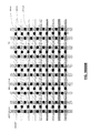
- FIG. 5 depicts an exemplary portion of a test chip/wafer comprised of NCEM-enabled fill cells, of various widths
- FIG. 6 conceptually depicts a portion of an exemplary chip/wafer in which a region comprised only (or almost only) of NCEM-enabled fill cells is positioned between two or more standard cell regions;
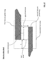
- FIG. 7 depicts a cross-sectional, topological view of a monolithic IC structure
- FIGS. 9A-9F depict several illustrative designs for a NCEM-enabled pad, suitable for use in connection with certain embodiments of the invention.
- FIG. 9H depicts an exemplary mesh-style, NCEM-enabled pad, formed from a 10 ⁇ 9 grid of double-patterned GATECNT and single-patterned AACNT stripes;
- FIG. 9K depicts an exemplary mesh-style, NCEM-enabled pad, formed from a 10 ⁇ 9 grid of triple-patterned GATECNT and single-patterned AACNT stripes;
- FIG. 9L depicts an exemplary mesh-style, NCEM-enabled pad, formed from a 10 ⁇ 9 grid of triple-patterned GATECNT and double-patterned AACNT stripes;
- FIG. 9M depicts an exemplary mesh-style, NCEM-enabled pad, formed from a 10 ⁇ 9 grid of single-patterned GATECNT and triple-patterned AACNT stripes;
- FIG. 9Q depicts an exemplary mesh-style, NCEM-enabled pad, formed from a 10 ⁇ 9 grid of double-patterned GATECNT and single-patterned AACNT stripes, with an overlying, solid M1 pad, and a plurality of V0 vias positioned at GATECNT-AACNT junction points;
- FIG. 9R depicts an exemplary mesh-style, NCEM-enabled pad, formed from a 10 ⁇ 9 grid of single-patterned GATECNT and double-patterned AACNT stripes, with an overlying, solid M1 pad, and a plurality of V0 vias positioned at GATECNT-AACNT junction points;
- FIG. 9S depicts an exemplary mesh-style, NCEM-enabled pad, formed from a 10 ⁇ 9 grid of double-patterned GATECNT and double-patterned AACNT stripes, with an overlying, solid M1 pad, and a plurality of V0 vias positioned at GATECNT-AACNT junction points;
- FIG. 9T depicts an exemplary mesh-style, NCEM-enabled pad, formed from a 10 ⁇ 9 grid of triple-patterned GATECNT and single-patterned AACNT stripes, with an overlying, solid M1 pad, and a plurality of V0 vias positioned at GATECNT-AACNT junction points;
- FIG. 9V depicts an exemplary mesh-style, NCEM-enabled pad, formed from a 10 ⁇ 9 grid of single-patterned GATECNT and triple-patterned AACNT stripes, with an overlying, solid M1 pad, and a plurality of V0 vias positioned at GATECNT-AACNT junction points;
- FIG. 9W depicts an exemplary mesh-style, NCEM-enabled pad, formed from a 10 ⁇ 9 grid of double-patterned GATECNT and triple-patterned AACNT stripes, with an overlying, solid M1 pad, and a plurality of V0 vias positioned at GATECNT-AACNT junction points;
- FIG. 9Y depicts an exemplary mesh-style, NCEM-enabled pad, formed from a 10 ⁇ 9 grid of single-patterned GATECNT and single-patterned AACNT stripes, with an overlying, solid M1 pad, and a plurality of V0 vias positioned to avoid GATECNT-AACNT junction points;
- FIG. 9Z depicts an exemplary mesh-style, NCEM-enabled pad, formed from a 10 ⁇ 9 grid of double-patterned GATECNT and single-patterned AACNT stripes, with an overlying, solid M1 pad, and a plurality of V0 vias positioned to avoid GATECNT-AACNT junction points;
- FIG. 9AA depicts an exemplary mesh-style, NCEM-enabled pad, formed from a 10 ⁇ 9 grid of single-patterned GATECNT and double-patterned AACNT stripes, with an overlying, solid M1 pad, and a plurality of V0 vias positioned to avoid GATECNT-AACNT junction points;
- FIG. 9BB depicts an exemplary mesh-style, NCEM-enabled pad, formed from a 10 ⁇ 9 grid of double-patterned GATECNT and double-patterned AACNT stripes, with an overlying, solid M1 pad, and a plurality of V0 vias positioned to avoid GATECNT-AACNT junction points;
- FIG. 9CC depicts an exemplary mesh-style, NCEM-enabled pad, formed from a 10 ⁇ 9 grid of triple-patterned GATECNT and single-patterned AACNT stripes, with an overlying, solid M1 pad, and a plurality of V0 vias positioned to avoid GATECNT-AACNT junction points;
- FIG. 9DD depicts an exemplary mesh-style, NCEM-enabled pad, formed from a 10 ⁇ 9 grid of triple-patterned GATECNT and double-patterned AACNT stripes, with an overlying, solid M1 pad, and a plurality of V0 vias positioned to avoid GATECNT-AACNT junction points;
- FIG. 9EE depicts an exemplary mesh-style, NCEM-enabled pad, formed from a 10 ⁇ 9 grid of single-patterned GATECNT and triple-patterned AACNT stripes, with an overlying, solid M1 pad, and a plurality of V0 vias positioned to avoid GATECNT-AACNT junction points;
- FIG. 9GG depicts an exemplary mesh-style, NCEM-enabled pad, formed from a 10 ⁇ 9 grid of triple-patterned GATECNT and triple-patterned AACNT stripes, with an overlying, solid M1 pad, and a plurality of V0 vias positioned to avoid GATECNT-AACNT junction points;
- FIG. 9HH depicts an exemplary mesh-style, NCEM-enabled pad, formed from a 10 ⁇ 9 grid of single-patterned GATECNT and single-patterned AACNT stripes, with an overlying, non-solid M1 pad, and a plurality of V0 vias positioned at GATECNT-AACNT junction points;
- FIG. 9II depicts an exemplary mesh-style, NCEM-enabled pad, formed from a 10 ⁇ 9 grid of double-patterned GATECNT and single-patterned AACNT stripes, with an overlying, non-solid M1 pad, and a plurality of V0 vias positioned at GATECNT-AACNT junction points;
- FIG. 9JJ depicts an exemplary mesh-style, NCEM-enabled pad, formed from a 10 ⁇ 9 grid of single-patterned GATECNT and double-patterned AACNT stripes, with an overlying, non-solid M1 pad, and a plurality of V0 vias positioned at GATECNT-AACNT junction points;
- FIG. 9KK depicts an exemplary mesh-style, NCEM-enabled pad, formed from a 10 ⁇ 9 grid of double-patterned GATECNT and double-patterned AACNT stripes, with an overlying, non-solid M1 pad, and a plurality of V0 vias positioned at GATECNT-AACNT junction points;
- FIG. 9LL depicts an exemplary mesh-style, NCEM-enabled pad, formed from a 10 ⁇ 9 grid of triple-patterned GATECNT and single-patterned AACNT stripes, with an overlying, non-solid M1 pad, and a plurality of V0 vias positioned at GATECNT-AACNT junction points;
- FIG. 9MM depicts an exemplary mesh-style, NCEM-enabled pad, formed from a 10 ⁇ 9 grid of triple-patterned GATECNT and double-patterned AACNT stripes, with an overlying, non-solid M1 pad, and a plurality of V0 vias positioned at GATECNT-AACNT junction points;
- FIG. 9NN depicts an exemplary mesh-style, NCEM-enabled pad, formed from a 10 ⁇ 9 grid of single-patterned GATECNT and triple-patterned AACNT stripes, with an overlying, non-solid M1 pad, and a plurality of V0 vias positioned at GATECNT-AACNT junction points;
- FIG. 9OO depicts an exemplary mesh-style, NCEM-enabled pad, formed from a 10 ⁇ 9 grid of double-patterned GATECNT and triple-patterned AACNT stripes, with an overlying, non-solid M1 pad, and a plurality of V0 vias positioned at GATECNT-AACNT junction points;
- FIG. 9PP depicts an exemplary mesh-style, NCEM-enabled pad, formed from a 10 ⁇ 9 grid of triple-patterned GATECNT and triple-patterned AACNT stripes, with an overlying, non-solid M1 pad, and a plurality of V0 vias positioned at GATECNT-AACNT junction points;
- FIG. 9QQ depicts an exemplary mesh-style, NCEM-enabled pad, formed from a 10 ⁇ 9 grid of single-patterned GATECNT and single-patterned AACNT stripes, with an overlying, non-solid M1 pad, and a plurality of V0 vias positioned to avoid GATECNT-AACNT junction points;
- FIG. 9RR depicts an exemplary mesh-style, NCEM-enabled pad, formed from a 10 ⁇ 9 grid of double-patterned GATECNT and single-patterned AACNT stripes, with an overlying, non-solid M1 pad, and a plurality of V0 vias positioned to avoid GATECNT-AACNT junction points;
- FIG. 9SS depicts an exemplary mesh-style, NCEM-enabled pad, formed from a 10 ⁇ 9 grid of single-patterned GATECNT and double-patterned AACNT stripes, with an overlying, non-solid M1 pad, and a plurality of V0 vias positioned to avoid GATECNT-AACNT junction points;
- FIG. 9TT depicts an exemplary mesh-style, NCEM-enabled pad, formed from a 10 ⁇ 9 grid of double-patterned GATECNT and double-patterned AACNT stripes, with an overlying, non-solid M1 pad, and a plurality of V0 vias positioned to avoid GATECNT-AACNT junction points;
- FIG. 9UU depicts an exemplary mesh-style, NCEM-enabled pad, formed from a 10 ⁇ 9 grid of triple-patterned GATECNT and single-patterned AACNT stripes, with an overlying, non-solid M1 pad, and a plurality of V0 vias positioned to avoid GATECNT-AACNT junction points;
- FIG. 9VV depicts an exemplary mesh-style, NCEM-enabled pad, formed from a 10 ⁇ 9 grid of triple-patterned GATECNT and double-patterned AACNT stripes, with an overlying, non-solid M1 pad, and a plurality of V0 vias positioned to avoid GATECNT-AACNT junction points;
- FIG. 9WW depicts an exemplary mesh-style, NCEM-enabled pad, formed from a 10 ⁇ 9 grid of single-patterned GATECNT and triple-patterned AACNT stripes, with an overlying, non-solid M1 pad, and a plurality of V0 vias positioned to avoid GATECNT-AACNT junction points;
- FIG. 9XX depicts an exemplary mesh-style, NCEM-enabled pad, formed from a 10 ⁇ 9 grid of double-patterned GATECNT and triple-patterned AACNT stripes, with an overlying, non-solid M1 pad, and a plurality of V0 vias positioned to avoid GATECNT-AACNT junction points;
- FIG. 9YY depicts an exemplary mesh-style, NCEM-enabled pad, formed from a 10 ⁇ 9 grid of triple-patterned GATECNT and triple-patterned AACNT stripes, with an overlying, non-solid M1 pad, and a plurality of V0 vias positioned to avoid GATECNT-AACNT junction points;
- FIG. 9ZZ depicts an exemplary mesh-style, NCEM-enabled pad, formed from a 10 ⁇ 9 grid of single-patterned GATECNT and single-patterned AACNT stripes, with an overlying, non-solid, double-patterned M1 pad, and a plurality of V0 vias positioned at GATECNT-AACNT junction points;
- FIG. 9 AAA depicts an exemplary mesh-style, NCEM-enabled pad, formed from a 10 ⁇ 9 grid of double-patterned GATECNT and single-patterned AACNT stripes, with an overlying, non-solid, double-patterned M1 pad, and a plurality of V0 vias positioned at GATECNT-AACNT junction points;
- FIG. 9 BBB depicts an exemplary mesh-style, NCEM-enabled pad, formed from a 10 ⁇ 9 grid of single-patterned GATECNT and double-patterned AACNT stripes, with an overlying, non-solid, double-patterned M1 pad, and a plurality of V0 vias positioned at GATECNT-AACNT junction points;
- FIG. 9 CCC depicts an exemplary mesh-style, NCEM-enabled pad, formed from a 10 ⁇ 9 grid of double-patterned GATECNT and double-patterned AACNT stripes, with an overlying, non-solid, double-patterned M1 pad, and a plurality of V0 vias positioned at GATECNT-AACNT junction points;
- FIG. 9 DDD depicts an exemplary mesh-style, NCEM-enabled pad, formed from a 10 ⁇ 9 grid of triple-patterned GATECNT and single-patterned AACNT stripes, with an overlying, non-solid, double-patterned M1 pad, and a plurality of V0 vias positioned at GATECNT-AACNT junction points;
- FIG. 9 GGG depicts an exemplary mesh-style, NCEM-enabled pad, formed from a 10 ⁇ 9 grid of double-patterned GATECNT and triple-patterned AACNT stripes, with an overlying, non-solid, double-patterned M1 pad, and a plurality of V0 vias positioned at GATECNT-AACNT junction points;
- FIG. 9 JJJ depicts an exemplary mesh-style, NCEM-enabled pad, formed from a 10 ⁇ 9 grid of double-patterned GATECNT and single-patterned AACNT stripes, with an overlying, non-solid, double-patterned M1 pad, and a plurality of V0 vias positioned to avoid GATECNT-AACNT junction points;
- FIG. 9 LLL depicts an exemplary mesh-style, NCEM-enabled pad, formed from a 10 ⁇ 9 grid of double-patterned GATECNT and double-patterned AACNT stripes, with an overlying, non-solid, double-patterned M1 pad, and a plurality of V0 vias positioned to avoid GATECNT-AACNT junction points;
- FIG. 9 NNN depicts an exemplary mesh-style, NCEM-enabled pad, formed from a 10 ⁇ 9 grid of triple-patterned GATECNT and double-patterned AACNT stripes, with an overlying, non-solid, double-patterned M1 pad, and a plurality of V0 vias positioned to avoid GATECNT-AACNT junction points;
- FIG. 9 PPP depicts an exemplary mesh-style, NCEM-enabled pad, formed from a 10 ⁇ 9 grid of double-patterned GATECNT and triple-patterned AACNT stripes, with an overlying, non-solid, double-patterned M1 pad, and a plurality of V0 vias positioned to avoid GATECNT-AACNT junction points;
- FIG. 9 QQQ depicts an exemplary mesh-style, NCEM-enabled pad, formed from a 10 ⁇ 9 grid of triple-patterned GATECNT and triple-patterned AACNT stripes, with an overlying, non-solid, double-patterned M1 pad, and a plurality of V0 vias positioned to avoid GATECNT-AACNT junction points;
- FIG. 9 RRR depicts an exemplary mesh-style, NCEM-enabled pad, formed from a 10 ⁇ 9 grid of single-patterned GATECNT and single-patterned AACNT stripes, with an overlying, non-solid, triple-patterned M1 pad, and a plurality of V0 vias positioned at GATECNT-AACNT junction points;
- FIG. 9 SSS depicts an exemplary mesh-style, NCEM-enabled pad, formed from a 10 ⁇ 9 grid of double-patterned GATECNT and single-patterned AACNT stripes, with an overlying, non-solid, triple-patterned M1 pad, and a plurality of V0 vias positioned at GATECNT-AACNT junction points;
- FIG. 9 TTT depicts an exemplary mesh-style, NCEM-enabled pad, formed from a 10 ⁇ 9 grid of single-patterned GATECNT and double-patterned AACNT stripes, with an overlying, non-solid, triple-patterned M1 pad, and a plurality of V0 vias positioned at GATECNT-AACNT junction points;
- FIG. 9 UUU depicts an exemplary mesh-style, NCEM-enabled pad, formed from a 10 ⁇ 9 grid of double-patterned GATECNT and double-patterned AACNT stripes, with an overlying, non-solid, triple-patterned M1 pad, and a plurality of V0 vias positioned at GATECNT-AACNT junction points;
- FIG. 9 VVV depicts an exemplary mesh-style, NCEM-enabled pad, formed from a 10 ⁇ 9 grid of triple-patterned GATECNT and single-patterned AACNT stripes, with an overlying, non-solid, triple-patterned M1 pad, and a plurality of V0 vias positioned at GATECNT-AACNT junction points;
- FIG. 9 WWW depicts an exemplary mesh-style, NCEM-enabled pad, formed from a 10 ⁇ 9 grid of triple-patterned GATECNT and double-patterned AACNT stripes, with an overlying, non-solid, triple-patterned M1 pad, and a plurality of V0 vias positioned at GATECNT-AACNT junction points;
- FIG. 9 XXX depicts an exemplary mesh-style, NCEM-enabled pad, formed from a 10 ⁇ 9 grid of single-patterned GATECNT and triple-patterned AACNT stripes, with an overlying, non-solid, triple-patterned M1 pad, and a plurality of V0 vias positioned at GATECNT-AACNT junction points;
- FIG. 9 YYY depicts an exemplary mesh-style, NCEM-enabled pad, formed from a 10 ⁇ 9 grid of double-patterned GATECNT and triple-patterned AACNT stripes, with an overlying, non-solid, triple-patterned M1 pad, and a plurality of V0 vias positioned at GATECNT-AACNT junction points;
- FIG. 9 ZZZ depicts an exemplary mesh-style, NCEM-enabled pad, formed from a 10 ⁇ 9 grid of triple-patterned GATECNT and triple-patterned AACNT stripes, with an overlying, non-solid, triple-patterned M1 pad, and a plurality of V0 vias positioned at GATECNT-AACNT junction points;
- FIG. 9 AAAA depicts an exemplary mesh-style, NCEM-enabled pad, formed from a 10 ⁇ 9 grid of single-patterned GATECNT and single-patterned AACNT stripes, with an overlying, non-solid, triple-patterned M1 pad, and a plurality of V0 vias positioned to avoid GATECNT-AACNT junction points;
- FIG. 9 BBBB depicts an exemplary mesh-style, NCEM-enabled pad, formed from a 10 ⁇ 9 grid of double-patterned GATECNT and single-patterned AACNT stripes, with an overlying, non-solid, triple-patterned M1 pad, and a plurality of V0 vias positioned to avoid GATECNT-AACNT junction points;
- FIG. 9 CCCC depicts an exemplary mesh-style, NCEM-enabled pad, formed from a 10 ⁇ 9 grid of single-patterned GATECNT and double-patterned AACNT stripes, with an overlying, non-solid, triple-patterned M1 pad, and a plurality of V0 vias positioned to avoid GATECNT-AACNT junction points;
- FIG. 9 DDDD depicts an exemplary mesh-style, NCEM-enabled pad, formed from a 10 ⁇ 9 grid of double-patterned GATECNT and double-patterned AACNT stripes, with an overlying, non-solid, triple-patterned M1 pad, and a plurality of V0 vias positioned to avoid GATECNT-AACNT junction points;
- FIG. 9 EEEE depicts an exemplary mesh-style, NCEM-enabled pad, formed from a 10 ⁇ 9 grid of triple-patterned GATECNT and single-patterned AACNT stripes, with an overlying, non-solid, triple-patterned M1 pad, and a plurality of V0 vias positioned to avoid GATECNT-AACNT junction points;
- FIG. 9 FFFF depicts an exemplary mesh-style, NCEM-enabled pad, formed from a 10 ⁇ 9 grid of triple-patterned GATECNT and double-patterned AACNT stripes, with an overlying, non-solid, triple-patterned M1 pad, and a plurality of V0 vias positioned to avoid GATECNT-AACNT junction points;
- FIG. 9 GGGG depicts an exemplary mesh-style, NCEM-enabled pad, formed from a 10 ⁇ 9 grid of single-patterned GATECNT and triple-patterned AACNT stripes, with an overlying, non-solid, triple-patterned M1 pad, and a plurality of V0 vias positioned to avoid GATECNT-AACNT junction points;
- FIG. 9 HHHH depicts an exemplary mesh-style, NCEM-enabled pad, formed from a 10 ⁇ 9 grid of double-patterned GATECNT and triple-patterned AACNT stripes, with an overlying, non-solid, triple-patterned M1 pad, and a plurality of V0 vias positioned to avoid GATECNT-AACNT junction points;
- FIG. 9 IIII depicts an exemplary mesh-style, NCEM-enabled pad, formed from a 10 ⁇ 9 grid of triple-patterned GATECNT and triple-patterned AACNT stripes, with an overlying, non-solid, triple-patterned M1 pad, and a plurality of V0 vias positioned to avoid GATECNT-AACNT junction points;
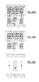
- FIGS. 10-11 depict the overall physical structure and connectivity of short-configured (and/or leakage-configured), NCEM-enabled fill cells in accordance with certain aspects of the invention
- FIGS. 12-13 depict the overall physical structure and connectivity of open-configured (and/or resistance-configured), NCEM-enabled fill cells in accordance with certain aspects of the invention
- FIG. 14 depicts a plan view of exemplary test area geometry for an exemplary tip-to-tip-short-configured, NCEM-enabled fill cell
- FIG. 15 depicts another plan view of exemplary test area geometry for an exemplary tip-to-tip-short-configured, NCEM-enabled fill cell
- FIG. 17 depicts a plan view of exemplary test area geometry for an exemplary side-to-side-short-configured, NCEM-enabled fill cell;
- FIG. 18 depicts a plan view of exemplary test area geometry for an exemplary L-shape-interlayer-short-configured, NCEM-enabled fill cell;
- FIG. 19 depicts a plan view of exemplary test area geometry for another exemplary L-shape-interlayer-short-configured, NCEM-enabled fill cell;
- FIG. 20 depicts a plan view of exemplary test area geometry for another exemplary L-shape-interlayer-short-configured, NCEM-enabled fill cell;
- FIG. 21 depicts a plan view of exemplary test area geometry for another exemplary L-shape-interlayer-short-configured, NCEM-enabled fill cell;
- FIG. 22 depicts a plan view of exemplary test area geometry for another exemplary L-shape-interlayer-short-configured, NCEM-enabled fill cell;
- FIG. 23 depicts a plan view of exemplary test area geometry for an exemplary diagonal-short-configured, NCEM-enabled fill cell
- FIG. 25 depicts a plan view of exemplary test area geometry for another exemplary corner-short-configured, NCEM-enabled fill cell
- FIG. 27 depicts a plan view of exemplary test area geometry for an exemplary interlayer-overlap-short-configured, NCEM-enabled fill cell
- FIG. 28 depicts a plan view of exemplary test area geometry for an exemplary via-chamfer-short-configured, NCEM-enabled fill cell
- FIG. 29 depicts a plan view of exemplary test area geometry for an exemplary merged-via-short-configured, NCEM-enabled fill cell
- FIG. 30 depicts a plan view of exemplary test area geometry for an exemplary snake-open-configured, NCEM-enabled fill cell
- FIG. 31 depicts a plan view of exemplary test area geometry for an exemplary stitch-open-configured, NCEM-enabled fill cell
- FIG. 32 depicts a plan view of exemplary test area geometry for another exemplary stitch-open-configured, NCEM-enabled fill cell;
- FIG. 33 depicts a plan view of exemplary test area geometry for an exemplary via-open-configured, NCEM-enabled fill cell
- FIG. 34 depicts a plan view of exemplary test area geometry for an exemplary metal-island-open-configured, NCEM-enabled fill cell
- FIG. 35 depicts a cross-sectional view of exemplary test area geometry for the exemplary metal-island-open-configured, NCEM-enabled fill cell;
- FIG. 37 shows exemplary expanded test area geometry from a 1 st variant of a NCEM-enabled fill cell
- FIG. 38 shows exemplary expanded test area geometry from a 2 nd variant of a NCEM-enabled fill cell
- FIG. 39 shows the logical AND of patterning within both expanded test areas (of FIGS. 37 & 38 );
- FIG. 40 shows the logical OR of patterning within both expanded test areas (of FIGS. 37 & 38 );
- FIG. 41 depicts an exemplary process flow, suitable for use in connection with certain embodiments of the invention.
- FIG. 42 depicts an exemplary process flow for obtaining and (optionally) using measurements from mesh-style NCEM pads
- FIG. 43 depicts another exemplary process flow, suitable for use in accordance with certain embodiments of the invention.
- FIG. 44 depicts a plan view of an exemplary M1-snake-open-configured, NCEM-enabled fill cell
- FIG. 45 depicts a plan view of an exemplary AACNT-tip-to-side-short-configured, NCEM-enabled fill cell
- FIGS. 46A-C respectively depict plan views of—(A) all layers; (B) NWELL, AA, GATE, GATECNT, TS, and AACNT layers; (C) V0 and M1 layers—of an exemplary TS-GATE-side-to-side-short-configured, NCEM-enabled fill cell of type PDF_D_VCI_V16_14S1_01;
- FIGS. 47A-C respectively depict plan views of—(A) all layers; (B) NWELL, AA, GATE, GATECNT, TS, and AACNT layers; (C) V0 and M1 layers—of an exemplary GATECNT-AACNT-side-to-side-short-configured, NCEM-enabled fill cell of type PDF_D_VCI_V16_14S1_05;
- FIGS. 49A-C respectively depict plan views of—(A) all layers; (B) NWELL, AA, GATE, GATECNT, TS, and AACNT layers; (C) V0 and M1 layers—of an exemplary GATE-AA-tip-to-side-short-configured, NCEM-enabled fill cell of type PDF_D_VCI_V16_14S1_11;
- FIG. 51 contains a layer legend for FIGS. 1629A-C , 1630A-C, 1631A-C, etc., which follow;
- FIGS. 53A-C respectively depict plan views of—(A) all layers; (B) NWELL, AA, GATE, GATECNT, TS, and AACNT layers; (C) V0, and M1 layers—of an exemplary AACNT-TS-via-open-configured, NCEM-enabled fill cell of type D_PDF_VCI_VFILLE_12S02_0052_1;
- FIGS. 55A-C respectively depict plan views of—(A) all layers; (B) NWELL, AA, GATE, GATECNT, TS, and AACNT layers; (C) V0, and M1 layers—of an exemplary AACNT-TS-via-open-configured, NCEM-enabled fill cell of type D_PDF_VCI_VFILLE_12S02_0050_1;
- FIGS. 58A-C respectively depict plan views of—(A) all layers; (B) NWELL, AA, GATE, GATECNT, TS, and AACNT layers; (C) V0, and M1 layers—of an exemplary AACNT-TS-via-open-configured, NCEM-enabled fill cell of type E_PDF_VCI_FILL8_17S1_0033_1;
- FIGS. 59A-C respectively depict plan views of—(A) all layers; (B) NWELL, AA, GATE, GATECNT, TS, and AACNT layers; (C) V0, and M1 layers—of an exemplary AACNT-TS-via-open-configured, NCEM-enabled fill cell of type E_PDF_VCI_FILL8_17S1_0029_1;
- FIGS. 60A-C respectively depict plan views of—(A) all layers; (B) NWELL, AA, GATE, GATECNT, TS, and AACNT layers; (C) V0, and M1 layers—of an exemplary AACNT-TS-via-open-configured, NCEM-enabled fill cell of type F_PDF_VCI_FILL64_24S1_0082_1;
- FIGS. 63A-C respectively depict plan views of—(A) all layers; (B) NWELL, AA, GATE, GATECNT, TS, and AACNT layers; (C) V0, and M1 layers—of an exemplary AACNT-TS-via-open-configured, NCEM-enabled fill cell of type F_PDF_VCI_FILL08_24S1_0078_1;
- FIGS. 65A-C respectively depict plan views of—(A) all layers; (B) NWELL, AA, GATE, GATECNT, TS, and AACNT layers; (C) V0, and M1 layers—of an exemplary AACNT-TS-via-open-configured, NCEM-enabled fill cell of type F_PDF_VCI_FILL32_24S1_0078_1;
- FIGS. 66A-C respectively depict plan views of—(A) all layers; (B) NWELL, AA, GATE, GATECNT, TS, and AACNT layers; (C) V0, and M1 layers—of an exemplary AACNT-TS-via-open-configured, NCEM-enabled fill cell of type F_PDF_VCI_FILL16_24S1_0038_1;
- FIGS. 68A-C respectively depict plan views of—(A) all layers; (B) NWELL, AA, GATE, GATECNT, TS, and AACNT layers; (C) V0, and M1 layers—of an exemplary AACNT-TS-via-open-configured, NCEM-enabled fill cell of type I_V421_VCI_20S3000122_001;
- FIGS. 69A-C respectively depict plan views of—(A) all layers; (B) NWELL, AA, GATE, GATECNT, TS, and AACNT layers; (C) V0, and M1 layers—of an exemplary AACNT-TS-via-open-configured, NCEM-enabled fill cell of type J_PDF_VCI_VFILLCV4_7S210_0038_1;
- FIGS. 70A-C respectively depict plan views of—(A) all layers; (B) NWELL, AA, GATE, GATECNT, TS, and AACNT layers; (C) V0, and M1 layers—of an exemplary AACNT-TS-via-open-configured, NCEM-enabled fill cell of type J_PDF_VCI_VFILLCV4_7S210_0020_1;
- FIGS. 71A-C respectively depict plan views of—(A) all layers; (B) NWELL, AA, GATE, GATECNT, TS, and AACNT layers; (C) V0, and M1 layers—of an exemplary AACNT-TS-via-open-configured, NCEM-enabled fill cell of type J_PDF_VCI_VFILLCV4_7S210_0019_1;
- FIGS. 72A-C respectively depict plan views of—(A) all layers; (B) NWELL, AA, GATE, GATECNT, TS, and AACNT layers; (C) V0, and M1 layers—of an exemplary AACNT-TS-via-open-configured, NCEM-enabled fill cell of type J_PDF_VCI_VFILLCV4_7S210_0001_1;
- FIGS. 73A-C respectively depict plan views of—(A) all layers; (B) NWELL, AA, GATE, GATECNT, TS, and AACNT layers; (C) V0, and M1 layers—of an exemplary AACNT-TS-via-open-configured, NCEM-enabled fill cell of type K_V549_PDF_VCI_3000121_01;
- FIGS. 74A-C respectively depict plan views of—(A) all layers; (B) NWELL, AA, GATE, GATECNT, TS, and AACNT layers; (C) V0, and M1 layers—of an exemplary AACNT-TS-via-open-configured, NCEM-enabled fill cell of type K_V549_PDF_VCI_3000D21_13;
- FIGS. 75A-C respectively depict plan views of—(A) all layers; (B) NWELL, AA, GATE, GATECNT, TS, and AACNT layers; (C) V0, and M1 layers—of an exemplary AACNT-TS-via-open-configured, NCEM-enabled fill cell of type K_V549_PDF_VCI_3001921_25;
- FIGS. 79A-C respectively depict plan views of—(A) all layers; (B) NWELL, AA, GATE, GATECNT, TS, and AACNT layers; (C) V0, and M1 layers—of an exemplary AACNT-TS-via-open-configured, NCEM-enabled fill cell of type K_V549_PDF_VCI_3000122_01;
- FIGS. 82A-C respectively depict plan views of—(A) all layers; (B) NWELL, AA, GATE, GATECNT, TS, and AACNT layers; (C) V0, and M1 layers—of an exemplary AACNT-TS-via-open-configured, NCEM-enabled fill cell of type K_V549_PDF_VCI_3001A22_26;
- FIGS. 83A-C respectively depict plan views of—(A) all layers; (B) NWELL, AA, GATE, GATECNT, TS, and AACNT layers; (C) V0, and M1 layers—of an exemplary AACNT-TS-via-open-configured, NCEM-enabled fill cell of type K_V549_PDF_VCI_3002222_34;
- FIGS. 91A-C respectively depict plan views of—(A) all layers; (B) NWELL, AA, GATE, GATECNT, TS, and AACNT layers; (C) V0, and M1 layers—of an exemplary AACNT-TS-via-open-configured, NCEM-enabled fill cell of type L_V54C_M_PDF_VCI_3000121_01;
- FIGS. 92A-C respectively depict plan views of—(A) all layers; (B) NWELL, AA, GATE, GATECNT, TS, and AACNT layers; (C) V0, and M1 layers—of an exemplary AACNT-TS-via-open-configured, NCEM-enabled fill cell of type L_V54C_M_PDF_VCI_3000D21_13;
- FIGS. 93A-C respectively depict plan views of—(A) all layers; (B) NWELL, AA, GATE, GATECNT, TS, and AACNT layers; (C) V0, and M1 layers—of an exemplary AACNT-TS-via-open-configured, NCEM-enabled fill cell of type L_V54C_M_PDF_VCI_3001921_25;
- FIG. 1 depicts an outline of illustrative fill cells suitable for use in connection certain embodiments of the invention, such fill cells are typically provided in a uniform height and various widths, traditionally multiples of the minimum contacted poly pitch (CPP) permitted by the fabrication process.
- FIG. 1 includes fill cells of width 4 CPP, 8 CPP, 16 CPP, 32 CPP, and 64 CPP, but any collection of widths—or just a single width—is possible.
- certain embodiments of the invention may include double or triple height fill cells, as well.
- traditional fill cells include certain features necessary for compatibility with the logic cells used to form circuits on the chip.
- Such necessary features include a height that is consistent with logic cells in the library (or an integer multiple of that height), as well as power/ground rails that extend horizontally across the fill cells (traditionally, though not necessarily, at the top and bottom of each cell). Such necessary features are preferably maintained in the NCEM-enabled fill cells used in connection with the present invention.
- FIG. 2 depicts an exemplary standard cell logic section with (shaded) NCEM-enabled fill cells, of various widths.
- the NCEM-enabled fill cells are preferably instantiated wherever a traditional fill cell would otherwise be placed.
- the invention places no restriction on the distribution of such NCEM-enabled fill cells. While they would typically appear in each standard cell row, they need not.
- the fill cell placement can be regular, semi-regular (e.g., at least one fill cell every X nm, or every Y cells), or irregular.
- Two fill cells can be adjacent to each other. There may be some double height (or greater) fill cells.
- the logic section may include both NCEM-enabled as well as other types of fill cells.
- FIG. 3 depicts an exemplary standard cell logic section with a row (or portion thereof) that contains NCEM-enabled fill cells, of various widths.
- certain embodiments of the invention may include complete row(s), or contiguous portion(s) thereof, populated entirely with NCEM-enabled fill cells.
- Such row(s) may include fill cells of varying or fixed widths, and such row(s) may be adjacent or separated, and may be distributed regularly, semi-regularly or irregularly throughout the logic section.
- FIG. 4 depicts an exemplary standard cell logic section with a test block area (lower right portion) populated with NCEM-enabled fill cells, of various widths.
- test block section(s) need not be entirely contiguous, need not be generally rectangular or square, may include fill cells of a single width or multiple widths, and one or multiple heights.
- test vehicles may comprise a die, a chip, a wafer, or a portion of any of these.
- Such test vehicles need not be entirely contiguous, may have any overall shape, and may include fill cells of a single width or multiple widths, and one or multiple heights.
- FIG. 6 conceptually depicts a portion of an exemplary chip/die/wafer with a region comprised only (or almost only) of NCEM-enabled fill cells positioned between two or more standard cell regions (such as those of FIGS. 2-5 ).
- FIG. 6 illustrates how various embodiments of the invention may instantiate/distribute the inventive NCEM-enabled fill cells (and DOEs based on them) in any manner whatsoever, and that the distribution patterns—both regular and irregular—may vary throughout different regions of a chip or wafer.
- FIGS. 2-5 and 6 are mere examples of many available possibilities, and are not intended to be limiting or exhaustive. Furthermore, such skilled persons will appreciate that any given die, chip or wafer may include a combination of these and/or other possible configurations.
- FIG. 7 depicts cross-sectional, topological view of a monolithic IC structure to which the invention may be applied.
- This topological view depicts—from bottom to top—three vertically defined portions: (i) substrate; (ii) connector stack; and (iii) interconnect stack.
- the substrate preferably comprises a wafer, die, or other portion of monocrystalline silicon, or another substrate suitable for forming semiconductor devices, such as silicon-on-insulator (SOI), Ge, C, GaAs, InP, GaInAs, AlAs, GaSb, (Ga,Mn)As, GaP, GaN, InAS, SiGe, SiSn, CdSe, CdTe, CdHgTe, ZnS, SiC, etc.
- SOI silicon-on-insulator
- Ge silicon-on-insulator
- C GaAs, InP, GaInAs, AlAs, GaSb, (Ga,Mn)As
- GaP GaN, InAS, SiGe, SiSn, CdSe, CdTe, CdHgTe, ZnS, SiC, etc.
- the substrate represents the object to which manufacturing steps (e.g., deposition, masking, etching, implantation) are initially applied, and is the object within which, or upon which, switching devices (e.g., FETs, bipolar transistors, photodiodes, magnetic devices, etc.) or storage devices (e.g., charged oxides, capacitors, phase change memories, etc.) are built.
- manufacturing steps e.g., deposition, masking, etching, implantation
- switching devices e.g., FETs, bipolar transistors, photodiodes, magnetic devices, etc.
- storage devices e.g., charged oxides, capacitors, phase change memories, etc.
- the connector stack is a collection of multiple layers, generally formed on top of the substrate, that supports localized connections between devices in, or on, the substrate, and/or connections to wires in an interconnect stack located above.
- the layers that make up the connector stack need not be strictly “stacked”; some can be partially or fully co-planar.
- FIG. 8 which depicts a physical view of an exemplary CMOS layer stack
- the source/drain contact and gate contact layers are partially co-planar because they share vertical extent, but on the bottom, the source/drain contact layer extends below the bottom of the gate contact layer, and on the top, the gate contact layer extends above the top of the source/drain contact layer.
- An example of full co-planarity would be where these two layers had identical vertical extent.
- the connector stack supports various types of “connectors” and “jumpers,” as illustrated in FIG. 7 . These illustrative connectors and jumpers are not intended to represent individual physical layers, but rather conductive pathways that connect the identified elements. As persons skilled in the art will appreciate, each connector or jumper can be implemented using one or more manufactured “layers,” where some layers may appear as parts of multiple types of connectors/jumpers.
- FIG. 7 specifically illustrates the following connectors/jumpers:
- the interconnect stack is comprised of conductive wiring layers (labeled “m1,” “m2,” etc.—that need only be conductive, not necessarily metallic) with conductive vias (labeled “v1,” “v2,” etc.) that connect adjacent wiring layers. While three wiring layers are shown in FIGS. 7-8 , it is understood that this number could vary from one to ten or more. Furthermore, while the vias and wiring layers in FIGS. 7-8 are shown as non-overlapping, it is possible for vias to extend into one or both of the wiring layers that they connect, or traverse more than two wiring layers.
- FIG. 8 depicts a (simplified) layer stack for an exemplary CMOS process, with the correspondence between major regions—substrate, connector stack, interconnect stack—and process layers indicated on the drawing.
- the substrate hosts the source(s)/drain(s) of the FETs, the device isolation trenches (STI), and a lower portion of the gate(s).
- the connector stack implements the upper portions of the gate(s), the source/drain silicide(s), source/drain contact(s), gate contact(s), and via(s) to the interconnect stack.
- the interconnect stack contains multiple wiring (m1, m2, . . . ) layers, with vias (v1, v2, . . . ) between adjacent wiring layers.
- the vendor-independent layers of FIG. 8 can be readily mapped to those of commercial CMOS processes, such as GlobalFoundries (“GF”) (see U.S. Pat. Pub. Nos. US2014/0302660A1 and US2015/0170735A1 re the “GF layers”) or Taiwan Semiconductor Manufacturing Co. (“TSMC”) (see U.S. Pat. Pub. No. US2014/0210014A1 re the “TSMC layers”).
- GF GlobalFoundries
- TSMC Taiwan Semiconductor Manufacturing Co.
- FIG. 8 layer GF layer TSMC layer gate (GATE) PC PO source/drain (AA) RX OD source/drain suicide (TS) TS M0_OD1 gate contact (GATECNT) CB M0_PO source/drain contact (AACNT) CA M0_OD2 via to interconnect stack (V0) V0 Via0 first wiring layer (M1) M1 M1 Indicated in parentheses are the names used to label these layers in FIGS. 10, 11 , et seq. of this application. Persons skilled in the art will realize that these represent a minority of the many layers/masks/etc. used in the fabrication of modern devices.
- some potentially relevant detail(s) may be obscured by the exposure merging; however, such obscured detail(s) will nonetheless be readily apparent to the skilled artisan (by, for example, the fact that the named structure, e.g., M1-M1-stitch-overlap-open-configured, NCEM-enabled fill cell, must contain at least one overlap test region, as per FIG. 32 , that is rendered in different exposures of M1, and located on the M1 path between the NCEM pad and ground).
- short-configured cells can exist in both “same color” and “different color” varieties.
- the M1-tip-to-tip-configured, NCEM-enabled fill cells would come in two varieties: M1-tip-to-tip-same-color-short-configured cells, as well as M1-tip-to-tip-different-color-short-configured cells.
- M1-tip-to-tip-same-color-short-configured cells as well as M1-tip-to-tip-different-color-short-configured cells.
- other short configurations such as side-to-side, diagonal, etc.
- FIGS. 9A-9E depict several illustrative designs for a NCEM pad, suitable for use in connection with embodiments of the invention. Additional NCEM pads are disclosed in the incorporated '841 application.
- FIG. 9A shows a simple, solid conductive pad, typically, though not necessarily, formed in M1.
- FIGS. 9B-9D depict several options for a non-solid, segmented, single-conductor pad. (As persons skilled in the art will appreciate, the variety of shapes for such pads is endless.)
- FIG. 9E depicts an example of a presently preferred, multi-conductor, mesh-style pad.
- FIGS. 9F - 9 IIII depict additional embodiments of mesh pad structures. As persons skilled in the art will appreciate, these structures can be rendered in any size (e.g., 2 ⁇ 2, 2 ⁇ 3, 3 ⁇ 2, 3 ⁇ 3, etc.), and not just the specifically depicted 10 ⁇ 9 and 5 ⁇ 2 examples.
- Such fill cells preferably have certain common elements (e.g., height, supply rails, and GATE pitch (CPP) that is consistent with standard cells in the library), then vary according to the measurement type, layer(s) involved, and structure(s) to be evaluated/tested.
- NCEM-enabled fill cells come in two basic types: short[/leakage] and open[/resistance].
- Relevant layers typically involve either a single process layer (e.g., GATE-to-GATE) or two process layers (e.g. GATECNT-to-GATE).
- Structural configurations are many, and include a set of standard structures (e.g., tip-to-tip, tip-to-side, side-to-side, etc.), as well as reference or ad hoc structures.
- the general structure of an open[/resistance]-configured, NCEM-enabled fill cell preferably includes four overlaid components: (i) “standard” patterning; (ii) a NCEM pad; (iii) “test area” patterning; and (iv) pad/ground wiring.
- standard patterning is that which appears in essentially all of the standard library cells, such as supply rails, etc.
- the NCEM pads can take a variety of shapes/patterns, as is non-exhaustively exemplified in FIGS. 9A - 9 IIII. Standard structures used for test structure patterning are depicted in FIGS.
- the pad/ground wiring for opens comprises low-resistance wiring from one side of the test structure patterning to the pad, and from the other side of the test structure patterning to a permanent or virtual ground.
- Open-configured, NCEM-enabled fill cells can, and often do, include multiple test areas, in which case the pad/ground wiring connects all relevant test structures in a series-connected chain.
- NCEM-enabled fill cells will be used with a highly regular style cell library
- an additional constraint on the NCEM-enabled fill cells is that they preferably conform, as closely as reasonably possible, to the regular patterns used for the library's functional cells.
- Preferred methods for measuring compliance with regular patterns, and/or constructing pattern-compliant cells are described in U.S. Pat. Applic. Nos. 61/887,271 (“Template Based Design with LibAnalyzer”) and 62/186,677 (“Template Based Design with LibAnalyzer”), both to Langnese et al., and both incorporated by reference herein.
- the structure to-be-evaluated may not, itself, be an “allowable” pattern (e.g., the pattern rules for the library may not allow any structure that spaces a GATE tip from a GATECNT side at minimum design rule dimensions, thus dictating that the “GATE-GATECNT-tip-to-side-short-configured, NCEM-enabled fill cell” will necessarily include at least one pattern violation).
- DOEs typically involve several small variations in at least one minimum-spaced dimension, whereas regular patterning rules will typically only permit one of the variants.
- the patterning used for the NCEM pad is preferably selected to match the operational capabilities of the scanner, but may well violate the library's pattern regularity constraints. Thus, ignoring these “necessary” pattern regularity violations, NCEM-enabled fill cells for use with highly regular libraries will preferably contain very few, if any, additional pattern regularity violations.
- FIGS. 14-15 depict plan views of two exemplary test area geometries for tip-to-tip-short-configured, NCEM-enabled fill cells.
- Cells that utilize these geometric configurations may include:
- FIG. 16 depicts a plan view of exemplary test area geometry for tip-to-side-short-configured, NCEM-enabled fill cells.
- Cells that utilize this geometric configuration may include:
- FIG. 17 depicts a plan view of exemplary test area geometry for side-to-side-short-configured, NCEM-enabled fill cells.
- Cells that utilize this geometric configuration may include:
- FIGS. 18, 19, 20, 21, and 22 depicts a plan view of exemplary test area geometry for L-shape-interlayer-short-configured, NCEM-enabled fill cells.
- Cells that utilize these geometric configurations may include:
- FIG. 23 depicts a plan view of exemplary test area geometry for diagonal-short-configured, NCEM-enabled fill cells.
- Cells that utilize this geometric configuration may include:
- FIGS. 24, 25, and 26 depicts a plan view of exemplary test area geometry for corner-short-configured, NCEM-enabled fill cells. These configurations differ from the diagonal configuration because, in these corner configurations, at least one of the first and/or second features is non-rectangular. Cells that utilize these geometric configurations may include:
- DOEs of these structures are preferably constructed by varying the dimensional parameters that define the test area (e.g., gap dimension and/or gap angle), or by varying other, same- or adjacent-layer patterning within the expanded test area.
- FIG. 28 depicts a plan view of exemplary test area geometry for via-chamfer-short-configured, NCEM-enabled fill cells.
- Cells that utilize this geometric configuration may include:
- FIG. 29 depicts a plan view of exemplary test area geometry for merged-via-short-configured, NCEM-enabled fill cells.
- Cells that utilize this geometric configuration may include:
- FIGS. 31-32 depict plan views of exemplary test area geometries for stitch-open-configured, NCEM-enabled fill cells.
- Cells that utilize these geometric configurations may include:
- FIGS. 34 and 35 respectively depict plan and cross-sectional views of exemplary test area geometry for metal-island-open-configured, NCEM-enabled fill cells.
- Cells that utilize this geometric configuration may include:
- FIG. 37 shows exemplary expanded test area geometry from a 1 st variant of a NCEM-enabled fill cell
- FIG. 38 shows exemplary expanded test area geometry from a 2 nd variant of a NCEM-enabled fill cell.
- FIG. 39 shows the logical AND of (depicted layer) patterning within both expanded test areas (of FIGS. 37 & 38 ).
- FIG. 40 shows the logical OR of patterning within both expanded test areas (of FIGS. 37 & 38 ).
- the PSR pattern similarity ratio
- PSR is a measure of how much of the patterning within the common expanded test areas is new. In other words, if the two cells are identical (within the layer(s)-at-issue, and within the common expanded test area), then the PSR will be 1.0. Conversely, if they share no common patterning (within the layer(s)-at-issue, and within the common expanded test area), then the AND patterns will be nil, and the PSR will be 0.0.
- FIG. 41 depicts an exemplary process flow, suitable for use in connection with certain embodiments of the invention.
- FF1 an initial set of product masks is produced (or otherwise obtained); these initial product masks include a first collection of NCEM-enabled fill cells.
- processing of wafers is initiated using the initial product masks.
- Such processing preferably includes at least FEOL and/or MOL processing, but may also include BEOL processing.
- NCEM measurements are preferably obtained from some or all of the NCEM-enabled fill cells on the partially-processed initial product wafers.
- some or all of the obtained NCEM measurements are “used” to continue processing of the initial product wafers.
- Such “use” may include determining whether to continue or abandon processing of one or more of the wafers, modifying one or more processing, inspection or metrology steps in the continued processing of one or more of the wafers (and/or other product wafers currently being manufactured using process flows relevant to observed manufacturing failures), and/or performing additional processing, metrology or inspection steps on one or more of the wafers (and/or other product wafers currently being manufactured using process flows relevant to observed manufacturing failures).
- final product masks are produced (or otherwise obtained) “using” at least some of the NCEM measurements obtained during the processing of initial product wafers.
- use preferably includes selecting and instantiating a second collection of NCEM-enabled fill cells that is better and/or optimally matched to failure modes observed during processing of the initial product wafers.
- the second collection of NCEM-enabled fill cells would preferably omit GATE-side-to-side-short-configured cells, and instead replace them with other NCEM-enabled fill cells that are better matched to the observed or expected failure modes on the final product wafers.
- processing of wafers is initiated using the final product masks.
- Such processing preferably includes at least FEOL and/or MOL processing, but may also include BEOL processing.
- NCEM measurements are preferably obtained from some or all of the NCEM-enabled fill cells on the partially-processed final product wafers.
- some or all of the obtained NCEM measurements are “used” to continue processing of the final product wafers.
- Such “use” may include determining whether to continue or abandon processing of one or more of the wafers, modifying one or more processing, inspection or metrology steps in the continued processing of one or more of the wafers (and/or other product wafers currently being manufactured using process flows relevant to observed manufacturing failures), and/or performing additional processing, metrology or inspection steps on one or more of the wafers (and/or other product wafers currently being manufactured using process flows relevant to observed manufacturing failures).
- FIG. 42 depicts an exemplary process flow for obtaining and (optionally) using measurements from mesh-style NCEM pads.
- this process can be utilized either with or without NCEM-enabled fill cells; in other words, the mesh-style NCEM pads can be instantiated within NCEM-enabled fill cells, but can also be instantiated anywhere on a chip, die, or wafer.
- steps FF7 & FF8 can be reversed, or performed simultaneously, to accommodate processes where the order of AACNT & GATECNT patterning is different.
- test mask e.g., masks to produce a “test” or “engineering” wafer
- test masks include a first collection of NCEM-enabled fill cells.
- processing of the test wafer(s) is initiated.
- processing preferably includes FEOL and/or MOL processing, but may also include BEOL processing.
- NCEM measurements are obtained from NCEM-enabled fill cells on the partially-processed test wafer(s).
- the second collection of NCEM-enabled fill cells would preferably omit GATE-side-to-side-short-configured cells.
- product masks that include the second collection of NCEM-enabled fill cells are produced, or otherwise obtained.
- processing of the product wafer(s) is initiated. Such processing preferably includes at least FEOL and/or MOL processing, but may also include BEOL processing.
- NCEM measurements are obtained from at least some of the NCEM-enabled fill cells on the partially-processed product wafer(s).
- some or all of the obtained NCEM measurements are “used” to continue processing of the product wafer(s).
- Such “use” may include determining whether to continue or abandon processing of one or more of the product wafers, modifying one or more processing, inspection or metrology steps in the continued processing of one or more of the product wafers (and/or other product wafers currently being manufactured using process flows relevant to observed manufacturing failures), and/or performing additional processing, metrology or inspection steps on one or more of the product wafers (and/or other product wafers currently being manufactured using process flows relevant to observed manufacturing failures).
- FF1-3 and/or GG5-7 could be practiced as stand-alone process flows.
- FIG. 44 depicts a plan view of an exemplary M1-snake-open-configured, NCEM-enabled fill cell.
- This cell contains a left-facing-E-shaped NCEM pad, a snake-open-configured test area, and is NCEM-enabled to detect the following failure mode: M1 snake open.
- FIG. 45 depicts a plan view of an exemplary AACNT-tip-to-side-short-configured, NCEM-enabled fill cell.
- This cell contains four test areas, and an E-shaped NCEM pad that overlies the test areas. It is NC-configured for inline measurement of the following failure mode: AACNT tip-to-side short.
- FIGS. 46A-C respectively depict plan views of—(A) all layers; (B) NWELL, AA, GATE, GATECNT, TS, and AACNT layers; (C) V0 and M1 layers—of an exemplary TS-GATE-side-to-side-short-configured, NCEM-enabled fill cell of type PDF_D_VCI_V16_14S1_01. This cell utilizes a composite NCEM pad, as depicted in FIG. 9E .
- FIGS. 47A-C respectively depict plan views of—(A) all layers; (B) NWELL, AA, GATE, GATECNT, TS, and AACNT layers; (C) V0 and M1 layers—of an exemplary GATECNT-AACNT-side-to-side-short-configured, NCEM-enabled fill cell of type PDF_D_VCI_V16_14S1_05. This cell also utilizes a composite NCEM pad.
- FIGS. 48A-C respectively depict plan views of—(A) all layers; (B) NWELL, AA, GATE, GATECNT, TS, and AACNT layers; (C) V0 and M1 layers—of an exemplary GATECNT-GATE-via-open-configured, NCEM-enabled fill cell of type PDF_D_VCI_V16_14S1_08. This cell also utilizes a composite NCEM pad.
- FIGS. 49A-C respectively depict plan views of—(A) all layers; (B) NWELL, AA, GATE, GATECNT, TS, and AACNT layers; (C) V0 and M1 layers—of an exemplary GATE-AA-tip-to-side-short-configured, NCEM-enabled fill cell of type PDF_D_VCI_V16_14S1_11. This cell also utilizes a composite NCEM pad.
- FIGS. 50(A) -(C) respectively depict plan views of—(A) all layers; (B) NWELL, AA, GATE, GATECNT, TS, and AACNT layers; (C) V0 and M1 layers—of another exemplary GATE-AA-tip-to-side-short-configured, NCEM-enabled fill cell of type PDF_D_VCI_V16_14S1_12. This cell also utilizes a composite NCEM pad.
- FIGS. 1646-1647 depict two variants of the same cell.
- FIGS. 1646(A)-(C) show the nominal case, whereas the other figures represent intentionally misaligned conditions.
- FIGS. 1648-1649 depict two variants of the same cell.
- FIGS. 1648(A)-(C) show the nominal case, whereas the other figures represent intentionally misaligned conditions.
- FIGS. 1650-1652 depict three variants of the same cell.
- FIGS. 1651(A)-(C) show the nominal case, whereas the other figures represent intentionally misaligned conditions.
- FIGS. 1653-1655 depict three variants of the same cell.
- FIGS. 1654(A)-(C) show the nominal case, whereas the other figures represent intentionally misaligned conditions.
- FIGS. 1656-1658 depict three variants of the same cell.
- FIGS. 1657(A)-(C) show the nominal case, whereas the other figures represent intentionally misaligned conditions.
- FIGS. 1659-1661 depict three variants of the same cell.
- FIGS. 1660(A)-(C) show the nominal case, whereas the other figures represent intentionally misaligned conditions.
- FIGS. 1663-1664 depict two variants of the same cell.
- FIGS. 1663(A)-(C) show the nominal case, whereas the other figures represent intentionally misaligned conditions.
Abstract
Improved processes for manufacturing semiconductor wafers, chips, or dies utilize in-line data obtained from non-contact electrical measurements (“NCEM”) of fill cells that contain structures configured to target/expose a variety of open-circuit, short-circuit, leakage, and/or excessive resistance failure modes. Such processes include evaluating one or more Designs of Experiments (“DOEs”), each comprised of multiple NCEM-enabled fill cells, in at least two variants, targeted to the same failure mode. Such DOEs include multiple means/steps for enabling non-contact (NC) detection of AACNT-TS via opens.
Description
This application is a divisional of U.S. patent application Ser. No. 15/281,508, entitled “Process for Making Semiconductor Dies, Chips, and Wafers Using Non-Contact Measurements Obtained From DOEs of NCEM-enabled Fill Cells on Test Wafers that Include Multiple Means/Steps for Enabling NC Detection of AACNT-TS Via Opens,” filed Sep. 30, 2016, by applicant PDF Solutions, Inc., which '508 application is incorporated by reference herein.
This application is also a continuation of U.S. patent application Ser. No. 15/090,256, entitled “Integrated Circuit Containing DOEs of NCEM-enabled Fill Cells,” filed Apr. 4, 2016, by applicant PDF Solutions, Inc., which '256 application is incorporated by reference herein.
This application is also a continuation of U.S. patent application Ser. No. 15/090,267, entitled “Process for Making Semiconductor Dies, Chips, and Wafers Using In-Line Measurements Obtained From DOEs of NCEM-enabled Fill Cells,” filed Apr. 4, 2016, by applicant PDF Solutions, Inc., which '267 application is incorporated by reference herein.
This application is also a continuation of U.S. patent application Ser. No. 15/090,274, entitled “Mesh-Style NCEM Pads, and Process for Making Semiconductor Dies, Chips, and Wafers Using In-Line Measurements from Such Pads,” filed Apr. 4, 2016, by applicant PDF Solutions, Inc., which '274 application is incorporated by reference herein.
A portion of the disclosure of this patent document (including its incorporated documents) contains material which is subject to mask work protection, *M*, PDF Solutions, Inc. The mask work owner (PDF Solutions, Inc.) has no objection to the facsimile reproduction by anyone of the patent document (including its incorporated documents) or the patent disclosure, as it appears in the Patent and Trademark Office patent file or records, but otherwise reserves all mask work rights whatsoever.
This invention relates generally to improved processes for manufacturing semiconductor wafers and chips through use of in-line measurements obtained via non-contact electrical measurements (“NCEM”), to on-chip structures configured to provide useful information via NCEM, and to implementation of NCEM structures in library compatible fill cells.
U.S. Pat. No. 5,008,727 (“Standard cell having test pad for probing and semiconductor integrated circuit device containing the standard cells”) to Katsura et al., incorporated by reference herein, discloses placement of a testing pad in a standard cell.
U.S. Pat. No. 6,091,249 A (“Method and apparatus for detecting defects in wafers”) to Graham et al., incorporated by reference herein, discloses structures and methods for testing certain defects using a non-contact (“NC”) technique.
U.S. Pat. No. 6,452,412 B1 (“Drop-in test structure and methodology for characterizing an integrated circuit process flow and topography”) to Jarvis et al., incorporated by reference herein, discloses structures and methods for testing certain defects using an NC technique.
U.S. Pat. No. 6,949,765 B2 (“Padless structure design for easy identification of bridging defects in lines by passive voltage contrast”) to Song et al., incorporated by reference herein, discloses structures and methods for testing certain defects using an NC technique.
U.S. Pat. No. 7,101,722 B1 (“In-line voltage contrast determination of tunnel oxide weakness in integrated circuit technology development”) to Wang et al., incorporated by reference herein, discloses structures and methods for testing certain defects using an NC technique.
U.S. Pat. No. 7,105,436 B2 (“Method for in-line monitoring of via/contact holes etch process based on test structures in semiconductor wafer manufacturing”) to Zhao et al., incorporated by reference herein, discloses structures and methods for testing certain defects using an NC technique.
U.S. Pat. No. 7,518,190 B2 (“Grounding front-end-of-line structures on a SOI substrate”) to Cote et al., incorporated by reference herein, discloses structures and methods for testing certain defects using an NC technique.
U.S. Pat. No. 7,930,660 B2 (“Measurement structure in a standard cell for controlling process parameters during manufacturing of an integrated circuit”), to Ruderer et al., incorporated by reference herein, describes the use of test structures in fill cells for manufacturing optimization.
U.S. Pat. No. 7,939,348 B2 (“E-beam inspection structure for leakage analysis”), to Seng et al., incorporated by reference herein, discloses structures and methods for testing certain defects using an NC technique.
U.S. Pat. No. 8,039,837 B2 (“In-line voltage contrast detection of PFET silicide encroachment”) to Patterson et al., incorporated by reference herein, discloses structures and methods for testing certain defects using an NC technique.
U.S. Pat. No. 8,339,449 B2 (“Defect monitoring in semiconductor device fabrication”), to Fong et al., incorporated by reference herein, discloses structures and methods for testing certain defects using an NC technique.
U.S. Pat. No. 8,399,266 B2 (“Test structure for detection of gap in conductive layer of multilayer gate stack”) to Mo et al., incorporated by reference herein, discloses structures and methods for testing certain defects using an NC technique.
U.S. Pat. No. 8,421,009 B2 (“Test structure for charged particle beam inspection and method for defect determination using the same”) to Xiao, incorporated by reference herein, discloses structures and methods for testing certain defects using an NC technique.
U.S. Pat. No. 8,575,955 B1 (“Apparatus and method for electrical detection and localization of shorts in metal interconnect lines”) to Brozek, incorporated by reference herein, discloses structures and methods for testing certain defects using an NC technique.
U.S. Patent Publication 20090102501 A1 (“Test structures for e-beam testing of systematic and random defects in integrated circuits”) to Guldi et al., incorporated by reference herein, discloses structures and methods for testing certain defects using an NC technique.
The invention generally involves the placement of NC-testable structures, and DOEs (Designs of Experiments) based on such structures, preferably within the “fill cells” typically used in standard cell logic regions. As used in this application, “fill cells” (or “filler cells”) refer to cells configured for placement in standard cell rows, but not configured to perform any logical or information storage function(s). Modern, standard-cell layouts commonly use such fill cells to relieve routing congestion. See, e.g., Cong, J., et al. “Optimizing routability in large-scale mixed-size placement,” ASP-DAC, 2013; and Menezes, C., et al. “Design of regular layouts to improve predictability,” Proceedings of the 6th IEEE International Caribbean Conference on Devices, Circuits and Systems, 2006. See also U.S. Pat. No. 8,504,969 (“Filler Cells for Design Optimization in a Place-and-Route System”) to Lin et al., incorporated by reference herein. As used herein “fill cells” may include structures designed to perform ancillary (i.e., not logical or storage) functions, for example, well ties and/or decoupling capacitors.
One NC measurement technique, useful in connection with certain embodiments of the invention, involves measuring or inspecting the surface of a partially processed wafer (in-line) with a scanning electron microscope (“SEM”) or other charged particle-based scanning/imaging device. As the measuring/inspecting proceeds, the SEM (or other device) induces charge on all electrically floating elements, whereas any grounded elements remain at zero potential. This voltage contrast becomes visible to the scanning/imaging device as a NCEM.
This NC measurement technique, commonly known as “voltage contrast inspection,” has been used in the semiconductor industry for many years, see, e.g., U.S. Pat. No. 6,344,750 B1 (“Voltage contrast method for semiconductor inspection using low voltage particle beam”), and exists in many different flavors—as demonstrated by the dozens of subsequent patents that cite the '750 patent as prior art.
U.S. patent application Ser. No. 14/612,841 (“Opportunistic placement of IC test structures and/or e-beam target pads in areas otherwise used for filler cells, tap cells, decap cells, scribe lines, and/or dummy fill, as well as product IC chips containing same”), filed Feb. 3, 2015, by inventors De et al., incorporated by reference herein, and owned by the assignee of the present application, discloses a number of highly efficient—and herein preferred—methods for obtaining NCEMs from the NCEM-enabled test structures utilized in the present invention. While these '841 methods represent the applicant's preferred NC measurement methods, it is applicant's intent that usage of the terms “NC measurement” or “NCEM” in this application should not be limited to these preferred methods in the absence of specific language (e.g., “selectively targeting . . . ”, “ . . . fewer than 10 pixels”) that indicates an intent to so limit a claim.
In general usage, the term Design of Experiments (DOE) or Experimental Design refers to the design of any information-gathering exercise where variation is present, whether under the full control of the experimenter or not.
Experimental Design is an established field, well known to persons skilled in the art. See NIST/SEMATECH e-Handbook of Statistical Methods, http://www.itl.nist.gov/div898/handbook/, updated Oct. 30, 2013, incorporated by reference herein.
As will be apparent to the skilled reader, the typical DOE herein relates to an experiment involving one or more semiconductor die(s) and/or wafer(s), wherein said one or more die(s) and/or wafer(s) contain multiple instances of a substantially similar test structure, at least some of which vary in terms of one or more layout-related parameters (including, but not limited to, size, spacing, offset, overlap, width, extension, run length, periodicity, density, neighborhood patterning, including underlayers) or process related parameters (including, but not limited to, dose, rate, exposure, processing time, temperature, or any tool-specifiable setting). As the person skilled in the art knows, the selection of specific parameter(s) to vary, the amount/distribution of their variation, and the number and location of test structures that express such variation will be selected based upon the goals of the experiment, the involved process, and the availability of appropriate places (e.g., fill cell locations, tap cell locations, decap cell locations, scribe line areas, etc.) to instantiate the test structures.
Preferred embodiments of the invention utilize DOEs constructed from NCEM-enabled fill cells. In accordance with certain preferred embodiments of the invention, NCEM-enabled fill cells all have some common elements (e.g., height, supply rail configuration, and gate patterning that is consistent with standard cells in the library), then vary according to the measurement type (e.g., short, open, leakage, or resistance), layer(s) involved, and/or structure(s) to be evaluated/tested. Such NCEM-enabled fill cells also generally include a pad, configured to accelerate targeted NC evaluation by, for example, determining an associated NCEM from a small number of enlarged pixels (e.g., 10 or fewer), or without creating any image at all. Such pads can be formed from a variety of low-resistance materials and configured in a variety of shapes.
In certain preferred embodiments, such NCEM-enabled fill cells may additionally include two or more mask-patterned features that define a rectangular test area, such test area being characterized by two parameters (e.g., X/Y or r/θ dimensions). Additionally, for such NCEM-enabled fill cells, an expanded test area surrounds the cell's test area, the expanded test area being defined by a predetermined expansion of each boundary of the test area, or by predetermined proportionate expansion of the test area's area. Alternatively, in the case of cells designed to measure or characterize inter-layer effects, such test areas may be characterized as “test volumes,” with one or more additional parameter(s) characterizing the layers of the defining, mask-patterned features.
For fill cells designed to measure, detect, or characterize electrical short circuit behavior (so-called, “short-configured, NCEM-enabled fill cells”), the test area may represent an intended gap between two pattern-defined features that, in the absence of a manufacturing anomaly, would be electrically isolated. Alternatively, in such short-configured, NCEM-enabled fill cells, the test area may represent an overlap between two pattern-defined features that, in the absence of a manufacturing anomaly, would be electrically isolated. A single short-configured, NCEM-enabled fill cell may contain one or multiple test areas. In the case of a NCEM-enabled fill cell with multiple test areas, each of the cell's test areas is preferably wired in parallel, and each of the cell's test areas (and preferably each of its extended test areas, too) is identically or nearly identically configured.
Fill cells designed to measure, detect, or characterize electrical leakage behavior (so-called, “leakage-configured, NCEM-enabled fill cells”) typically resemble short-configured cells. Like the short-configured cells, such leakage-configured cells may include a test area that represents an intended gap between two pattern-defined features that, in ideality, should be electrically isolated, but in reality, inevitably exhibit some amount of leakage. Alternatively, in such leakage-configured, NCEM-enabled fill cells, the test area may represent an overlap between two pattern-defined features that, in ideality, would be electrically isolated, but in reality, inevitably exhibit some amount of leakage. A single leakage-configured, NCEM-enabled fill cell may contain one, but preferably contains multiple test areas. In the case of a cell with multiple test areas, each of the cell's test areas is preferably wired in parallel, and each of the cell's test areas (and preferably each of its extended test areas, too) is identically or nearly identically configured.
For fill cells designed to measure, detect, or characterize electrical open circuit behavior (so-called, “open-configured, NCEM-enabled fill cells”), the test area typically represents an intended overlap, or extension, between two pattern-defined features that, in the absence of a manufacturing anomaly, would be electrically connected. (It may also represent a single-layer pattern, such as a snake.) A single open-configured, NCEM-enabled fill cell may contain one or multiple test areas. In the case of multiple test areas, each of the cell's test areas is preferably connected in series, and each of the cell's test areas (and preferably each of the extended test areas, too) is identically or nearly identically configured.
Fill cells designed to measure, detect, or characterize electrical resistance behavior (so-called, “resistance-configured, NCEM-enabled fill cells”) typically resemble open-configured cells. Like the open-configured cells, such resistance-configured cells may include a test area that represents an intended overlap, or extension, between two pattern-defined features that, in ideality, would be connected by a nearly zero-resistance path, but in reality, inevitably produce a measurable level of resistance. (Such test area may also represent a single-layer pattern, such as a snake.) A single resistance-configured, NCEM-enabled fill cell may contain one, but preferably contains multiple test areas. In the case of multiple test areas, each of the cell's test areas is preferably connected in series, and each of the cell's test areas (and preferably each of the extended test areas, too) is identically or nearly identically configured.
DOEs, in accordance with such preferred embodiments, comprise a collection of substantially similarly configured NCEM-enabled fill cells, in a plurality of variants. Within a given DOE, such similarly configured fill cells would typically all be configured to measure, detect, or characterize the same behavior (e.g., gate-to-gate, or control-element-to-control-element, shorts, for example), in the same structural configuration (e.g., tip-to-tip, as per FIG. 14 , for example). In single-parameter DOEs, the differences between variants may be limited to differences in the size, shape, or position of one of the features that defines the cells' test area. In multi-parameter DOEs, the differences between variants may involve differences in two or more such parameters. And in more complex DOEs, the differences may involve other non-incremental changes (e.g., the presence or absence of certain features, or changes in nearby or underlying patterning), either alone or in combination with additional to single- or multi-parameter variations.
In the case of DOEs involving complex changes to nearby patterning, changes that lie within an expanded test area (an area that encompasses a predetermined expansion of the test area by, for example 50-200%, or more) and involve either the test area-defining layer(s) or any layers that overlap or lie immediately above or below the test area-defining layers, are preferably limited in number. Limiting the number of such changes to fewer than three, five, ten, twenty, or thirty “background pattern variants” facilitates analysis of data that the experiment produces.
Another way to characterize the degree of relevant patterning variation between DOE variants—in certain embodiments of the invention—involves the concept of a pattern similarity ratio (“PSR”), whose computation is pictorially depicted in FIGS. 37-40 (and described later herein). In accordance with this aspect of the invention, for each variant in a DOE, there should exist another variant in the DOE that has a PSR of at least 0.90 (or preferably 0.95, or more preferably 0.97) for every test-area defining layer, and at least 0.75 (or preferably 0.85, or more preferably 0.90) for each layer that lies immediately below any of the test-area defining layer(s), when the expanded test areas are defined to be at least 150-200% of the corresponding test area sizes.
Another aspect of DOEs, in accordance with the preferred embodiments, is that they include multiple instances (e.g., 3, 5, 10, 20, 500, 100, 200, or 500+) of each NCEM-enabled fill cell variant. Furthermore, such variants are preferably distributed, either regularly or irregularly, throughout the space available for instantiation of fill cells.
Accordingly, generally speaking, and without intending to be limiting, one aspect of the invention relates to ICs that include, for example: a standard cell area that includes a mix of at least one thousand logic cells and fill cells of different widths and uniform heights, placed into at least twenty adjacent rows, with at least twenty cells placed side-by-side in each row; wherein the integrated circuit includes at least a first DOE, the first DOE comprising a plurality of similarly-configured, NCEM-enabled fill cells, wherein each NCEM-enabled fill cell comprises at least: first and second elongated conductive supply rails, formed in a connector or interconnect stack, extending across the entire width of the cell, and configured for compatibility with corresponding supply rails contained in the logic cells of the standard cell region; a NCEM pad, formed in a conductive layer, the pad being at least two times larger, in at least one dimension, than a minimum size permitted by design rules; a rectangular test area defined by selected boundaries of at least first and second distinct, mask-patterned features, the test area being characterized by two dimensional parameters; a first conductive pathway that electrically connects the first mask-patterned feature to the pad; and, a second conductive pathway that electrically connects the second mask-patterned feature to a permanently or virtually grounded structure; wherein each of the similarly-configured, NCEM-enabled fill cells in the first DOE is configured to render a first selected manufacturing failure observable as an abnormal pad-to-ground leakage or conductance, detected by VC inspection of the pad; and, wherein the similarly-configured, NCEM-enabled fill cells of the first DOE include a plurality of variants, where the variants differ in terms of their respective probability of presenting an abnormal pad-to-ground leakage or resistance as a result of the first selected manufacturing failure. Such ICs may further include: a second DOE, comprising a plurality of similarly-configured, NCEM-enabled fill cells, wherein each NCEM-enabled fill cell comprises at least: first and second elongated conductive supply rails, formed in a connector or interconnect stack, extending across the entire width of the cell, and configured for compatibility with corresponding supply rails contained in the logic cells of the standard cell region; a NCEM pad, formed in a conductive layer, the pad being at least two times larger, in at least one dimension, than a minimum size permitted by design rules; a rectangular test area defined by selected boundaries of at least first and second distinct, mask-patterned features, the test area being characterized by two dimensional parameters; a first conductive pathway that electrically connects the first mask-patterned feature to the pad; and, a second conductive pathway that electrically connects the second mask-patterned feature to a permanently or virtually grounded structure; wherein each of the similarly-configured, NCEM-enabled fill cells in the second DOE is configured to render a second selected manufacturing failure observable as an abnormal pad-to-ground leakage or conductance, detected by VC inspection of the pad, and wherein the second selected manufacturing failure is different than the first selected manufacturing failure; and, wherein the similarly-configured, NCEM-enabled fill cells of the second DOE include a plurality of variants, where the variants differ in terms of their respective probability of presenting an abnormal pad-to-ground leakage or conductance as a result of the second selected manufacturing failure. The first selected manufacturing failure may involve short or leakage defects that present as abnormally high pad-to-ground conductance or leakage, and the second selected manufacturing failure may involve open or resistance defects that present as abnormally low pad-to-ground conductance or abnormally high pad-to-ground resistance. Both the first and second selected manufacturing failures may involve layers in a connector stack region of the IC. Such ICs may further include: a third DOE, comprising a plurality of similarly-configured, NCEM-enabled fill cells, wherein each NCEM-enabled fill cell comprises at least: first and second elongated conductive supply rails, formed in a connector or interconnect stack, extending across the entire width of the cell, and configured for compatibility with corresponding supply rails contained in the logic cells of the standard cell region; a NCEM pad, formed in a conductive layer, the pad being at least two times larger, in at least one dimension, than a minimum size permitted by design rules; a rectangular test area defined by selected boundaries of at least first and second distinct, mask-patterned features, the test area being characterized by two dimensional parameters; a first conductive pathway that electrically connects the first mask-patterned feature to the pad; and, a second conductive pathway that electrically connects the second mask-patterned feature to a permanently or virtually grounded structure; wherein each of the similarly-configured NCEM-enabled fill cells in the third DOE is configured to render a third selected manufacturing failure observable as an abnormal pad-to-ground leakage, conductance or resistance, detected by VC inspection of the pad, and wherein the third selected manufacturing failure is different than the first selected manufacturing failure, and is different than the second selected manufacturing failure; and, wherein the similarly-configured NCEM-enabled fill cells of the third DOE include a plurality of variants, where the variants differ in terms of their respective probability of presenting an abnormal pad-to-ground leakage, conductance or resistance as a result of the third selected manufacturing failure. Each of the first, second, and third DOEs preferably include NCEM-enabled fill cells in at least three, five, seven, or ten variants. The NCEM-enabled fill cells of the first, second, and third DOEs are preferably irregularly distributed within the standard cell area of the IC. Each variant may differ from the other(s) only in the position, size, or shape of its first or second mask-patterned feature, or only by a single dimensional parameter that characterizes their respective test areas.
Again, generally speaking, and without intending to be limiting, another aspect of the invention relates to ICs that include, for example: a standard cell area that includes a mix of at least one thousand logic cells and fill cells of different widths and uniform heights, placed into at least twenty adjacent rows, with at least twenty cells placed side-by-side in each row; wherein the IC includes at least a first DOE, the first DOE comprising a plurality of similarly-configured, NCEM-enabled fill cells, wherein each NCEM-enabled fill cell comprises at least: first and second elongated conductive supply rails, formed in a connector or interconnect stack, extending across the entire width of the cell, and configured for compatibility with corresponding supply rails contained in the logic cells of the standard cell region; a NCEM pad, formed in a conductive layer, the pad being at least two times larger, in at least one dimension, than a minimum size permitted by design rules; a rectangular test area defined by selected boundaries of first and second distinct, mask-patterned features, the test area characterized by two dimensional parameters, the test area configured to provide electrical isolation between the first and second mask-patterned features in the absence of a first selected manufacturing failure; a first conductive pathway that electrically connects the first mask-patterned feature to the pad; and, a second conductive pathway that electrically connects the second mask-patterned feature to a permanently or virtually grounded structure; wherein each of the similarly-configured, NCEM-enabled fill cells in the first DOE is configured to render a first selected manufacturing failure observable as an abnormally high pad-to-ground conductance or leakage, detected by VC inspection of the pad; and, wherein the similarly-configured, NCEM-enabled fill cells of the first DOE include a plurality of variants, where the variants differ in terms of their respective probability of presenting an abnormally high pad-to-ground conductance or leakage as a result of the first selected manufacturing failure. In each of the NCEM-enabled fill cells of the first DOE, the first and/or second distinct, mask-patterned features may each represent either a control element, or a portion thereof, and/or a portion of a control element connector or a substrate connector, and/or a portion of a control element jumper, substrate jumper, or interconnect jumper. In each of the NCEM-enabled fill cells of the first and/or second DOE(s), the first and second distinct, mask-patterned features may appear in a tip-to-tip configuration, a tip-to-side configuration, a side-to-side configuration, a diagonal configuration, or an interlayer overlap configuration.
Again, generally speaking, and without intending to be limiting, another aspect of the invention relates to ICs that include, for example: a standard cell area that includes a mix of at least one thousand logic cells and fill cells of different widths and uniform heights, placed into at least twenty adjacent rows, with at least twenty cells placed side-by-side in each row; wherein the IC includes at least a first DOE, the first DOE comprising a plurality of similarly-configured, NCEM-enabled fill cells, wherein each NCEM-enabled fill cell comprises at least: first and second elongated conductive supply rails, formed in a connector or interconnect stack, extending across the entire width of the cell, and configured for compatibility with corresponding supply rails contained in the logic cells of the standard cell region; a NCEM pad, formed in one or more conductive layer(s), the pad being at least two times larger, in at least one dimension, than a minimum size permitted by design rules; a rectangular test area defined by selected boundaries of a plurality of mask-patterned features, the test area characterized by two dimensional parameters, the plurality of mask-patterned features including at least first and second features that are electrically connected in the absence of a first manufacturing failure; a first conductive pathway that electrically connects the first mask-patterned feature to the pad; and, a second conductive pathway that electrically connects the second mask-patterned feature to a permanently or virtually grounded structure; wherein each of the similarly-configured NCEM-enabled fill cells in the first DOE is configured to render a first selected manufacturing failure observable as an abnormally high pad-to-ground conductance or leakage, detected by VC inspection of the pad; wherein the similarly-configured NCEM-enabled fill cells of the first DOE include a plurality of variants, where the variants differ in terms of their respective probability of presenting an abnormally high pad-to-ground conductance or leakage as a result of the first selected manufacturing failure; and, wherein the similarly-configured NCEM-enabled fill cells of the first DOE are selected from the list consisting of: AA-tip-to-tip-short-configured, NCEM-enabled fill cells; AACNT-tip-to-tip-short-configured, NCEM-enabled fill cells; AACNT-AA-tip-to-tip-short-configured, NCEM-enabled fill cells; TS-tip-to-tip-short-configured, NCEM-enabled fill cells; GATE-tip-to-tip-short-configured, NCEM-enabled fill cells; GATECNT-GATE-tip-to-tip-short-configured, NCEM-enabled fill cells; GATECNT-tip-to-tip-short-configured, NCEM-enabled fill cells; GATECNT-AACNT-tip-to-tip-short-configured, NCEM-enabled fill cells; M1-tip-to-tip-short-configured, NCEM-enabled fill cells; V0-tip-to-tip-short-configured, NCEM-enabled fill cells; M1-V0-tip-to-tip-short-configured, NCEM-enabled fill cells; V1-M1-tip-to-tip-short-configured, NCEM-enabled fill cells; V1-tip-to-tip-short-configured, NCEM-enabled fill cells; M2-tip-to-tip-short-configured, NCEM-enabled fill cells; M2-V1-tip-to-tip-short-configured, NCEM-enabled fill cells; V2-M2-tip-to-tip-short-configured, NCEM-enabled fill cells; M3-tip-to-tip-short-configured, NCEM-enabled fill cells; V2-tip-to-tip-short-configured, NCEM-enabled fill cells; M3-V2-tip-to-tip-short-configured, NCEM-enabled fill cells; AA-tip-to-side-short-configured, NCEM-enabled fill cells; AACNT-tip-to-side-short-configured, NCEM-enabled fill cells; AACNT-AA-tip-to-side-short-configured, NCEM-enabled fill cells; GATE-AA-tip-to-side-short-configured, NCEM-enabled fill cells; GATECNT-GATE-tip-to-side-short-configured, NCEM-enabled fill cells; GATECNT-tip-to-side-short-configured, NCEM-enabled fill cells; TS-GATECNT-tip-to-side-short-configured, NCEM-enabled fill cells; GATECNT-AACNT-tip-to-side-short-configured, NCEM-enabled fill cells; M1-tip-to-side-short-configured, NCEM-enabled fill cells; V0-tip-to-side-short-configured, NCEM-enabled fill cells; M1-V0-tip-to-side-short-configured, NCEM-enabled fill cells; V1-M1-tip-to-side-short-configured, NCEM-enabled fill cells; V1-tip-to-side-short-configured, NCEM-enabled fill cells; M2-tip-to-side-short-configured, NCEM-enabled fill cells; M2-V1-tip-to-side-short-configured, NCEM-enabled fill cells; V2-M2-tip-to-side-short-configured, NCEM-enabled fill cells; M3-tip-to-side-short-configured, NCEM-enabled fill cells; V2-tip-to-side-short-configured, NCEM-enabled fill cells; M3-V2-tip-to-side-short-configured, NCEM-enabled fill cells; AA-side-to-side-short-configured, NCEM-enabled fill cells; AACNT-side-to-side-short-configured, NCEM-enabled fill cells; AACNT-AA-side-to-side-short-configured, NCEM-enabled fill cells; AACNT-GATE-side-to-side-short-configured, NCEM-enabled fill cells; GATE-side-to-side-short-configured, NCEM-enabled fill cells; GATECNT-GATE-side-to-side-short-configured, NCEM-enabled fill cells; TS-GATE-side-to-side-short-configured, NCEM-enabled fill cells; GATECNT-side-to-side-short-configured, NCEM-enabled fill cells; GATECNT-AACNT-side-to-side-short-configured, NCEM-enabled fill cells; M1-side-to-side-short-configured, NCEM-enabled fill cells; V0-side-to-side-short-configured, NCEM-enabled fill cells; M1-V0-side-to-side-short-configured, NCEM-enabled fill cells; V1-M1-side-to-side-short-configured, NCEM-enabled fill cells; V1-side-to-side-short-configured, NCEM-enabled fill cells; M2-side-to-side-short-configured, NCEM-enabled fill cells; M2-V1-side-to-side-short-configured, NCEM-enabled fill cells; V2-M2-side-to-side-short-configured, NCEM-enabled fill cells; M3-side-to-side-short-configured, NCEM-enabled fill cells; V2-side-to-side-short-configured, NCEM-enabled fill cells; M3-V2-side-to-side-short-configured, NCEM-enabled fill cells; AA-L-shape-interlayer-short-configured, NCEM-enabled fill cells; AACNT-L-shape-interlayer-short-configured, NCEM-enabled fill cells; AACNT-AA-L-shape-interlayer-short-configured, NCEM-enabled fill cells; GATE-AA-L-shape-interlayer-short-configured, NCEM-enabled fill cells; GATE-TS-L-shape-interlayer-short-configured, NCEM-enabled fill cells; GATECNT-GATE-L-shape-interlayer-short-configured, NCEM-enabled fill cells; GATECNT-AA-L-shape-interlayer-short-configured, NCEM-enabled fill cells; GATECNT-TS-L-shape-interlayer-short-configured, NCEM-enabled fill cells; GATECNT-AACNT-L-shape-interlayer-short-configured, NCEM-enabled fill cells; V0-AA-L-shape-interlayer-short-configured, NCEM-enabled fill cells; V0-TS-L-shape-interlayer-short-configured, NCEM-enabled fill cells; V0-AACNT-L-shape-interlayer-short-configured, NCEM-enabled fill cells; V0-GATE-L-shape-interlayer-short-configured, NCEM-enabled fill cells; V0-GATECNT-L-shape-interlayer-short-configured, NCEM-enabled fill cells; M1-AACNT-L-shape-interlayer-short-configured, NCEM-enabled fill cells; M1-GATECNT-L-shape-interlayer-short-configured, NCEM-enabled fill cells; M1-V0-L-shape-interlayer-short-configured, NCEM-enabled fill cells; V1-M1-L-shape-interlayer-short-configured, NCEM-enabled fill cells; V1-V0-L-shape-interlayer-short-configured, NCEM-enabled fill cells; M2-M1-L-shape-interlayer-short-configured, NCEM-enabled fill cells; M2-V1-L-shape-interlayer-short-configured, NCEM-enabled fill cells; V2-V1-L-shape-interlayer-short-configured, NCEM-enabled fill cells; V2-M2-L-shape-interlayer-short-configured, NCEM-enabled fill cells; M3-M2-L-shape-interlayer-short-configured, NCEM-enabled fill cells; M3-V2-L-shape-interlayer-short-configured, NCEM-enabled fill cells; AA-diagonal-short-configured, NCEM-enabled fill cells; TS-diagonal-short-configured, NCEM-enabled fill cells; AACNT-diagonal-short-configured, NCEM-enabled fill cells; AACNT-AA-diagonal-short-configured, NCEM-enabled fill cells; GATE-diagonal-short-configured, NCEM-enabled fill cells; GATE-AACNT-diagonal-short-configured, NCEM-enabled fill cells; GATECNT-GATE-diagonal-short-configured, NCEM-enabled fill cells; GATECNT-diagonal-short-configured, NCEM-enabled fill cells; GATECNT-AACNT-diagonal-short-configured, NCEM-enabled fill cells; M1-diagonal-short-configured, NCEM-enabled fill cells; V0-diagonal-short-configured, NCEM-enabled fill cells; M1-V0-diagonal-short-configured, NCEM-enabled fill cells; V1-M1-diagonal-short-configured, NCEM-enabled fill cells; V1-diagonal-short-configured, NCEM-enabled fill cells; M2-diagonal-short-configured, NCEM-enabled fill cells; M2-V1-diagonal-short-configured, NCEM-enabled fill cells; M3-diagonal-short-configured, NCEM-enabled fill cells; V2-M2-diagonal-short-configured, NCEM-enabled fill cells; V2-diagonal-short-configured, NCEM-enabled fill cells; M3-V2-diagonal-short-configured, NCEM-enabled fill cells; AA-corner-short-configured, NCEM-enabled fill cells; AACNT-corner-short-configured, NCEM-enabled fill cells; AACNT-AA-corner-short-configured, NCEM-enabled fill cells; GATE-corner-short-configured, NCEM-enabled fill cells; GATECNT-GATE-corner-short-configured, NCEM-enabled fill cells; GATECNT-TS-corner-short-configured, NCEM-enabled fill cells; GATECNT-corner-short-configured, NCEM-enabled fill cells; GATECNT-AACNT-corner-short-configured, NCEM-enabled fill cells; M1-corner-short-configured, NCEM-enabled fill cells; V0-corner-short-configured, NCEM-enabled fill cells; M1-V0-corner-short-configured, NCEM-enabled fill cells; V1-M1-corner-short-configured, NCEM-enabled fill cells; V1-corner-short-configured, NCEM-enabled fill cells; M2-corner-short-configured, NCEM-enabled fill cells; M2-V1-corner-short-configured, NCEM-enabled fill cells; M3-corner-short-configured, NCEM-enabled fill cells; V2-M2-corner-short-configured, NCEM-enabled fill cells; V2-corner-short-configured, NCEM-enabled fill cells; M3-V2-corner-short-configured, NCEM-enabled fill cells; GATE-AA-interlayer-overlap-short-configured, NCEM-enabled fill cells; GATE-TS-interlayer-overlap-short-configured, NCEM-enabled fill cells; GATE-AACNT-interlayer-overlap-short-configured, NCEM-enabled fill cells; GATECNT-TS-interlayer-overlap-short-configured, NCEM-enabled fill cells; GATECNT-AA-interlayer-overlap-short-configured, NCEM-enabled fill cells; V0-AA-interlayer-overlap-short-configured, NCEM-enabled fill cells; V0-AACNT-interlayer-overlap-short-configured, NCEM-enabled fill cells; V0-TS-interlayer-overlap-short-configured, NCEM-enabled fill cells; V0-GATE-interlayer-overlap-short-configured, NCEM-enabled fill cells; M1-GATECNT-interlayer-overlap-short-configured, NCEM-enabled fill cells; M1-AACNT-interlayer-overlap-short-configured, NCEM-enabled fill cells; V1-V0-interlayer-overlap-short-configured, NCEM-enabled fill cells; M2-M1-interlayer-overlap-short-configured, NCEM-enabled fill cells; V2-V1-interlayer-overlap-short-configured, NCEM-enabled fill cells; M3-M2-interlayer-overlap-short-configured, NCEM-enabled fill cells; V0-GATECNT-via-chamfer-short-configured, NCEM-enabled fill cells; V0-AACNT-via-chamfer-short-configured, NCEM-enabled fill cells; V1-M1-via-chamfer-short-configured, NCEM-enabled fill cells; V2-M2-via-chamfer-short-configured, NCEM-enabled fill cells; V0-merged-via-short-configured, NCEM-enabled fill cells; V1-merged-via-short-configured, NCEM-enabled fill cells; and, V2-merged-via-short-configured, NCEM-enabled fill cells; a second DOE, comprising a plurality of similarly-configured, NCEM-enabled fill cells, wherein each NCEM-enabled fill cell comprises at least: first and second elongated conductive supply rails, formed in a connector or interconnect stack, extending across the entire width of the cell, and configured for compatibility with corresponding supply rails contained in the logic cells of the standard cell region; a NCEM pad, formed in a conductive layer, the pad being at least two times larger, in at least one dimension, than a minimum size permitted by design rules; a rectangular test area defined by selected boundaries of at least first and second distinct, mask-patterned features, the test area being characterized by two dimensional parameters; a first conductive pathway that electrically connects the first mask-patterned feature to the pad; and, a second conductive pathway that electrically connects the second mask-patterned feature to a permanently or virtually grounded structure; wherein each of the similarly-configured, NCEM-enabled fill cells in the second DOE is configured to render a second selected manufacturing failure observable as an abnormally low pad-to-ground conductance or abnormally high pad-to-ground resistance, detected by VC inspection of the pad; and, wherein the similarly-configured, NCEM-enabled fill cells of the second DOE include a plurality of variants, where the variants differ in terms of their respective probability of presenting an abnormally low pad-to-ground conductance or abnormally high pad-to-ground resistance as a result of the second selected manufacturing failure; and, wherein the similarly-configured NCEM-enabled fill cells of the second DOE are selected from the list consisting of: AA-snake-open-configured, NCEM-enabled fill cells; TS-snake-open-configured, NCEM-enabled fill cells; AACNT-snake-open-configured, NCEM-enabled fill cells; GATE-snake-open-configured, NCEM-enabled fill cells; GATECNT-snake-open-configured, NCEM-enabled fill cells; V0-snake-open-configured, NCEM-enabled fill cells; M1-snake-open-configured, NCEM-enabled fill cells; V1-snake-open-configured, NCEM-enabled fill cells; M2-snake-open-configured, NCEM-enabled fill cells; V2-snake-open-configured, NCEM-enabled fill cells; M3-snake-open-configured, NCEM-enabled fill cells; AA-stitch-open-configured, NCEM-enabled fill cells; TS-stitch-open-configured, NCEM-enabled fill cells; AACNT-stitch-open-configured, NCEM-enabled fill cells; GATECNT-stitch-open-configured, NCEM-enabled fill cells; V0-stitch-open-configured, NCEM-enabled fill cells; M1-stitch-open-configured, NCEM-enabled fill cells; V1-stitch-open-configured, NCEM-enabled fill cells; M2-stitch-open-configured, NCEM-enabled fill cells; V2-stitch-open-configured, NCEM-enabled fill cells; M3-stitch-open-configured, NCEM-enabled fill cells; AACNT-TS-via-open-configured, NCEM-enabled fill cells; AACNT-AA-via-open-configured, NCEM-enabled fill cells; TS-AA-via-open-configured, NCEM-enabled fill cells; GATECNT-GATE-via-open, NCEM-enabled fill cells; V0-GATECNT-via-open-configured, NCEM-enabled fill cells; V0-AA-via-open-configured, NCEM-enabled fill cells; V0-TS-via-open-configured, NCEM-enabled fill cells; V0-AACNT-via-open-configured, NCEM-enabled fill cells; V0-GATE-via-open-configured, NCEM-enabled fill cells; V0-via-open-configured, NCEM-enabled fill cells; M1-V0-via-open-configured, NCEM-enabled fill cells; V1-M1-via-open-configured, NCEM-enabled fill cells; V1-M2-via-open-configured, NCEM-enabled fill cells; M1-GATECNT-via-open-configured, NCEM-enabled fill cells; M1-AANCT-via-open-configured, NCEM-enabled fill cells; V2-M2-via-open-configured, NCEM-enabled fill cells; V2-M3-via-open-configured, NCEM-enabled fill cells; M1-metal-island-open-configured, NCEM-enabled fill cells; M2-metal-island-open-configured, NCEM-enabled fill cells; M3-metal-island-open-configured, NCEM-enabled fill cells; V0-merged-via-open-configured, NCEM-enabled fill cells; V0-AACNT-merged-via-open-configured, NCEM-enabled fill cells; V0-GATECNT-merged-via-open-configured, NCEM-enabled fill cells; V1-merged-via-open-configured, NCEM-enabled fill cells; V2-merged-via-open-configured, NCEM-enabled fill cells; V1-M1-merged-via-open-configured, NCEM-enabled fill cells; V2-M2-merged-via-open-configured, NCEM-enabled fill cells.
Again, generally speaking, and without intending to be limiting, another aspect of the invention relates methods for making ICs that include, for example: (a) performing initial processing steps on a semiconductor wafer, the initial processing steps including: patterning a standard cell area that includes a mix of at least one thousand logic cells and fill cells of different widths and uniform heights, placed into at least twenty adjacent rows, with at least twenty cells placed side-by-side in each row; and, patterning a first DOE by instantiating a plurality of similarly-configured, NCEM-enabled fill cells in at least two variants, the NCEM-enabled fill cells configured for compatibility with logic cells in the standard cell area, each of the cells in the first DOE configured to enable evaluation of a first manufacturing failure by voltage contrast examination of a NCEM of a pad contained in the cell, the variants exhibiting different NCEM sensitivity to the first manufacturing failure; (b) determining a presence or absence of the first manufacturing failure by: performing a voltage contrast examination of NCEM-enabled fill cells in the first DOE; and, determining whether NCEMs of pads contained in the NCEM-enabled fill cells of the first DOE represent instance(s) of the first manufacturing failure and, if so, determining whether different cell variants exhibit a different prevalence of the first manufacturing failure; and, (c) based, at least in part, on results from step (b), selectively performing additional processing, metrology or inspection steps on the wafer, and/or on other wafer(s) currently being manufactured using a process flow(s) relevant to the observed first manufacturing failure. Step (a) may further involve: patterning a second DOE by instantiating a plurality of similarly-configured NCEM-enabled fill cells in at least two variants, the NCEM-enabled fill cells configured for compatibility with logic cells in the standard cell area and fill cells in the first DOE, each of the cells in the second DOE configured to enable evaluation of a second manufacturing failure, different from the first manufacturing failure, by voltage contrast examination of a NCEM of a pad contained in the cell, the variants exhibiting different NCEM sensitivity to the second manufacturing failure; and wherein step (b) further comprises: performing a voltage contrast examination of NCEM-enabled fill cells in the second DOE; and, determining whether NCEMs of pads contained in the NCEM-enabled fill cells of the second DOE represent instance(s) of the second manufacturing failure and, if so, determining whether different cell variants exhibit a different prevalence of the second manufacturing failure. Step (a) may further involve: patterning a third DOE by instantiating a plurality of similarly-configured NCEM-enabled fill cells in at least two variants, the NCEM-enabled fill cells configured for compatibility with logic cells in the standard cell area and fill cells in the first and second DOEs, each of the cells in the third DOE configured to enable evaluation of a third manufacturing failure, different from the first and second manufacturing failures, by voltage contrast examination of a NCEM of a pad contained in the cell, the variants exhibiting different NCEM sensitivity to the third manufacturing failure; and wherein step (b) further comprises: performing a voltage contrast examination of NCEM-enabled fill cells in the third DOE; and, determining whether NCEMs of pads contained in the NCEM-enabled fill cells of the third DOE represent instance(s) of the third manufacturing failure and, if so, determining whether different cell variants exhibit a different prevalence of the third manufacturing failure. At least one of the first, second, or third manufacturing failures preferably involves unintended shorts or leakages, and at least one of the first, second, or third manufacturing failures preferably involves unintended opens or excessive resistances. Instantiating the NCEM-enabled fill cells preferably comprises distributing the cells irregularly within the standard cell area. Within each of the DOEs, each variant may differ from the other(s) only in the position, size, or shape of a single mask-patterned feature. At least one of the first, second, or third manufacturing failures may involve unintended shorts between structures in a tip-to-tip configuration, or unintended shorts between structures in a tip-to-side configuration, or unintended shorts between structures in a side-to-side configuration, or unintended shorts between structures in a diagonal configuration, or unintended shorts between structures in an interlayer overlap configuration, or unintended interlayer shorts or leakages between structures in a corner configuration, unintended opens in snake-shaped structures, unintended opens in stitched structures, unintended opens in via-connected structures. Each of the first, second, and third DOEs preferably includes NCEM-enabled fill cells in at least three, five, seven, 11, 21, or more variants. Each of the first, second, and third DOEs may consist of cells selected from the list of: AA-tip-to-tip-short-configured, NCEM-enabled fill cells; AACNT-tip-to-tip-short-configured, NCEM-enabled fill cells; AACNT-AA-tip-to-tip-short-configured, NCEM-enabled fill cells; TS-tip-to-tip-short-configured, NCEM-enabled fill cells; GATE-tip-to-tip-short-configured, NCEM-enabled fill cells; GATECNT-GATE-tip-to-tip-short-configured, NCEM-enabled fill cells; GATECNT-tip-to-tip-short-configured, NCEM-enabled fill cells; GATECNT-AACNT-tip-to-tip-short-configured, NCEM-enabled fill cells; M1-tip-to-tip-short-configured, NCEM-enabled fill cells; V0-tip-to-tip-short-configured, NCEM-enabled fill cells; M1-V0-tip-to-tip-short-configured, NCEM-enabled fill cells; V1-M1-tip-to-tip-short-configured, NCEM-enabled fill cells; V1-tip-to-tip-short-configured, NCEM-enabled fill cells; M2-tip-to-tip-short-configured, NCEM-enabled fill cells; M2-V1-tip-to-tip-short-configured, NCEM-enabled fill cells; V2-M2-tip-to-tip-short-configured, NCEM-enabled fill cells; M3-tip-to-tip-short-configured, NCEM-enabled fill cells; V2-tip-to-tip-short-configured, NCEM-enabled fill cells; M3-V2-tip-to-tip-short-configured, NCEM-enabled fill cells; AA-tip-to-side-short-configured, NCEM-enabled fill cells; AACNT-tip-to-side-short-configured, NCEM-enabled fill cells; AACNT-AA-tip-to-side-short-configured, NCEM-enabled fill cells; GATE-AA-tip-to-side-short-configured, NCEM-enabled fill cells; GATECNT-GATE-tip-to-side-short-configured, NCEM-enabled fill cells; GATECNT-tip-to-side-short-configured, NCEM-enabled fill cells; TS-GATECNT-tip-to-side-short-configured, NCEM-enabled fill cells; GATECNT-AACNT-tip-to-side-short-configured, NCEM-enabled fill cells; M1-tip-to-side-short-configured, NCEM-enabled fill cells; V0-tip-to-side-short-configured, NCEM-enabled fill cells; M1-V0-tip-to-side-short-configured, NCEM-enabled fill cells; V1-M1-tip-to-side-short-configured, NCEM-enabled fill cells; V1-tip-to-side-short-configured, NCEM-enabled fill cells; M2-tip-to-side-short-configured, NCEM-enabled fill cells; M2-V1-tip-to-side-short-configured, NCEM-enabled fill cells; V2-M2-tip-to-side-short-configured, NCEM-enabled fill cells; M3-tip-to-side-short-configured, NCEM-enabled fill cells; V2-tip-to-side-short-configured, NCEM-enabled fill cells; M3-V2-tip-to-side-short-configured, NCEM-enabled fill cells; AA-side-to-side-short-configured, NCEM-enabled fill cells; AACNT-side-to-side-short-configured, NCEM-enabled fill cells; AACNT-AA-side-to-side-short-configured, NCEM-enabled fill cells; AACNT-GATE-side-to-side-short-configured, NCEM-enabled fill cells; GATE-side-to-side-short-configured, NCEM-enabled fill cells; GATECNT-GATE-side-to-side-short-configured, NCEM-enabled fill cells; TS-GATE-side-to-side-short-configured, NCEM-enabled fill cells; GATECNT-side-to-side-short-configured, NCEM-enabled fill cells; GATECNT-AACNT-side-to-side-short-configured, NCEM-enabled fill cells; M1-side-to-side-short-configured, NCEM-enabled fill cells; V0-side-to-side-short-configured, NCEM-enabled fill cells; M1-V0-side-to-side-short-configured, NCEM-enabled fill cells; V1-M1-side-to-side-short-configured, NCEM-enabled fill cells; V1-side-to-side-short-configured, NCEM-enabled fill cells; M2-side-to-side-short-configured, NCEM-enabled fill cells; M2-V1-side-to-side-short-configured, NCEM-enabled fill cells; V2-M2-side-to-side-short-configured, NCEM-enabled fill cells; M3-side-to-side-short-configured, NCEM-enabled fill cells; V2-side-to-side-short-configured, NCEM-enabled fill cells; M3-V2-side-to-side-short-configured, NCEM-enabled fill cells; AA-L-shape-interlayer-short-configured, NCEM-enabled fill cells; AACNT-L-shape-interlayer-short-configured, NCEM-enabled fill cells; AACNT-AA-L-shape-interlayer-short-configured, NCEM-enabled fill cells; GATE-AA-L-shape-interlayer-short-configured, NCEM-enabled fill cells; GATE-TS-L-shape-interlayer-short-configured, NCEM-enabled fill cells; GATECNT-GATE-L-shape-interlayer-short-configured, NCEM-enabled fill cells; GATECNT-AA-L-shape-interlayer-short-configured, NCEM-enabled fill cells; GATECNT-TS-L-shape-interlayer-short-configured, NCEM-enabled fill cells; GATECNT-AACNT-L-shape-interlayer-short-configured, NCEM-enabled fill cells; V0-AA-L-shape-interlayer-short-configured, NCEM-enabled fill cells; V0-TS-L-shape-interlayer-short-configured, NCEM-enabled fill cells; V0-AACNT-L-shape-interlayer-short-configured, NCEM-enabled fill cells; V0-GATE-L-shape-interlayer-short-configured, NCEM-enabled fill cells; V0-GATECNT-L-shape-interlayer-short-configured, NCEM-enabled fill cells; M1-AACNT-L-shape-interlayer-short-configured, NCEM-enabled fill cells; M1-GATECNT-L-shape-interlayer-short-configured, NCEM-enabled fill cells; M1-V0-L-shape-interlayer-short-configured, NCEM-enabled fill cells; V1-M1-L-shape-interlayer-short-configured, NCEM-enabled fill cells; V1-V0-L-shape-interlayer-short-configured, NCEM-enabled fill cells; M2-M1-L-shape-interlayer-short-configured, NCEM-enabled fill cells; M2-V1-L-shape-interlayer-short-configured, NCEM-enabled fill cells; V2-V1-L-shape-interlayer-short-configured, NCEM-enabled fill cells; V2-M2-L-shape-interlayer-short-configured, NCEM-enabled fill cells; M3-M2-L-shape-interlayer-short-configured, NCEM-enabled fill cells; M3-V2-L-shape-interlayer-short-configured, NCEM-enabled fill cells; AA-diagonal-short-configured, NCEM-enabled fill cells; TS-diagonal-short-configured, NCEM-enabled fill cells; AACNT-diagonal-short-configured, NCEM-enabled fill cells; AACNT-AA-diagonal-short-configured, NCEM-enabled fill cells; GATE-diagonal-short-configured, NCEM-enabled fill cells; GATE-AACNT-diagonal-short-configured, NCEM-enabled fill cells; GATECNT-GATE-diagonal-short-configured, NCEM-enabled fill cells; GATECNT-diagonal-short-configured, NCEM-enabled fill cells; GATECNT-AACNT-diagonal-short-configured, NCEM-enabled fill cells; M1-diagonal-short-configured, NCEM-enabled fill cells; V0-diagonal-short-configured, NCEM-enabled fill cells; M1-V0-diagonal-short-configured, NCEM-enabled fill cells; V1-M1-diagonal-short-configured, NCEM-enabled fill cells; V1-diagonal-short-configured, NCEM-enabled fill cells; M2-diagonal-short-configured, NCEM-enabled fill cells; M2-V1-diagonal-short-configured, NCEM-enabled fill cells; M3-diagonal-short-configured, NCEM-enabled fill cells; V2-M2-diagonal-short-configured, NCEM-enabled fill cells; V2-diagonal-short-configured, NCEM-enabled fill cells; M3-V2-diagonal-short-configured, NCEM-enabled fill cells; AA-corner-short-configured, NCEM-enabled fill cells; AACNT-corner-short-configured, NCEM-enabled fill cells; AACNT-AA-corner-short-configured, NCEM-enabled fill cells; GATE-corner-short-configured, NCEM-enabled fill cells; GATECNT-GATE-corner-short-configured, NCEM-enabled fill cells; GATECNT-TS-corner-short-configured, NCEM-enabled fill cells; GATECNT-corner-short-configured, NCEM-enabled fill cells; GATECNT-AACNT-corner-short-configured, NCEM-enabled fill cells; M1-corner-short-configured, NCEM-enabled fill cells; V0-corner-short-configured, NCEM-enabled fill cells; M1-V0-corner-short-configured, NCEM-enabled fill cells; V1-M1-corner-short-configured, NCEM-enabled fill cells; V1-corner-short-configured, NCEM-enabled fill cells; M2-corner-short-configured, NCEM-enabled fill cells; M2-V1-corner-short-configured, NCEM-enabled fill cells; M3-corner-short-configured, NCEM-enabled fill cells; V2-M2-corner-short-configured, NCEM-enabled fill cells; V2-corner-short-configured, NCEM-enabled fill cells; M3-V2-corner-short-configured, NCEM-enabled fill cells; GATE-AA-interlayer-overlap-short-configured, NCEM-enabled fill cells; GATE-AACNT-interlayer-overlap-short-configured, NCEM-enabled fill cells; GATE-TS-interlayer-overlap-short-configured, NCEM-enabled fill cells; GATECNT-TS-interlayer-overlap-short-configured, NCEM-enabled fill cells; GATECNT-AA-interlayer-overlap-short-configured, NCEM-enabled fill cells; V0-AA-interlayer-overlap-short-configured, NCEM-enabled fill cells; V0-AACNT-interlayer-overlap-short-configured, NCEM-enabled fill cells; V0-TS-interlayer-overlap-short-configured, NCEM-enabled fill cells; V0-GATE-interlayer-overlap-short-configured, NCEM-enabled fill cells; M1-GATECNT-interlayer-overlap-short-configured, NCEM-enabled fill cells; M1-AACNT-interlayer-overlap-short-configured, NCEM-enabled fill cells; V1-V0-interlayer-overlap-short-configured, NCEM-enabled fill cells; M2-M1-interlayer-overlap-short-configured, NCEM-enabled fill cells; V2-V1-interlayer-overlap-short-configured, NCEM-enabled fill cells; M3-M2-interlayer-overlap-short-configured, NCEM-enabled fill cells; V0-GATECNT-via-chamfer-short-configured, NCEM-enabled fill cells; V0-AACNT-via-chamfer-short-configured, NCEM-enabled fill cells; V1-M1-via-chamfer-short-configured, NCEM-enabled fill cells; V2-M2-via-chamfer-short-configured, NCEM-enabled fill cells; V0-merged-via-short-configured, NCEM-enabled fill cells; V1-merged-via-short-configured, NCEM-enabled fill cells; V2-merged-via-short-configured, NCEM-enabled fill cells; AA-snake-open-configured, NCEM-enabled fill cells; TS-snake-open-configured, NCEM-enabled fill cells; AACNT-snake-open-configured, NCEM-enabled fill cells; GATE-snake-open-configured, NCEM-enabled fill cells; GATECNT-snake-open-configured, NCEM-enabled fill cells; V0-snake-open-configured, NCEM-enabled fill cells; M1-snake-open-configured, NCEM-enabled fill cells; V1-snake-open-configured, NCEM-enabled fill cells; M2-snake-open-configured, NCEM-enabled fill cells; V2-snake-open-configured, NCEM-enabled fill cells; M3-snake-open-configured, NCEM-enabled fill cells; AA-stitch-open-configured, NCEM-enabled fill cells; TS-stitch-open-configured, NCEM-enabled fill cells; AACNT-stitch-open-configured, NCEM-enabled fill cells; GATECNT-stitch-open-configured, NCEM-enabled fill cells; V0-stitch-open-configured, NCEM-enabled fill cells; M1-stitch-open-configured, NCEM-enabled fill cells; V1-stitch-open-configured, NCEM-enabled fill cells; M2-stitch-open-configured, NCEM-enabled fill cells; V2-stitch-open-configured, NCEM-enabled fill cells; M3-stitch-open-configured, NCEM-enabled fill cells; AACNT-TS-via-open-configured, NCEM-enabled fill cells; AACNT-AA-via-open-configured, NCEM-enabled fill cells; TS-AA-via-open-configured, NCEM-enabled fill cells; GATECNT-GATE-via-open, NCEM-enabled fill cells; V0-GATECNT-via-open-configured, NCEM-enabled fill cells; V0-AA-via-open-configured, NCEM-enabled fill cells; V0-TS-via-open-configured, NCEM-enabled fill cells; V0-AACNT-via-open-configured, NCEM-enabled fill cells; V0-GATE-via-open-configured, NCEM-enabled fill cells; V0-via-open-configured, NCEM-enabled fill cells; M1-V0-via-open-configured, NCEM-enabled fill cells; V1-M1-via-open-configured, NCEM-enabled fill cells; V1-M2-via-open-configured, NCEM-enabled fill cells; M1-GATECNT-via-open-configured, NCEM-enabled fill cells; M1-AANCT-via-open-configured, NCEM-enabled fill cells; V2-M2-via-open-configured, NCEM-enabled fill cells; V2-M3-via-open-configured, NCEM-enabled fill cells; M1-metal-island-open-configured, NCEM-enabled fill cells; M2-metal-island-open-configured, NCEM-enabled fill cells; M3-metal-island-open-configured, NCEM-enabled fill cells; V0-merged-via-open-configured, NCEM-enabled fill cells; V0-AACNT-merged-via-open-configured, NCEM-enabled fill cells; V0-GATECNT-merged-via-open-configured, NCEM-enabled fill cells; V1-merged-via-open-configured, NCEM-enabled fill cells; V2-merged-via-open-configured, NCEM-enabled fill cells; V1-M1-merged-via-open-configured, NCEM-enabled fill cells; V2-M2-merged-via-open-configured, NCEM-enabled fill cells.
Again, generally speaking, and without intending to be limiting, another aspect of the invention relates to methods for making ICs that include, for example: (a) performing initial processing steps on a first semiconductor wafer, the initial processing steps including, at least: patterning a first DOE by instantiating a plurality of similarly-configured NCEM-enabled fill cells in at least two variants, the NCEM-enabled fill cells configured for compatibility with logic cells in the standard cell library, each of the cells in the first DOE configured to enable evaluation of a first manufacturing failure by voltage contrast examination of a NCEM of a pad contained in the cell, the variants exhibiting different NCEM sensitivity to the first manufacturing failure; patterning a second DOE by instantiating a plurality of similarly-configured NCEM-enabled fill cells in at least two variants, the NCEM-enabled fill cells configured for compatibility with logic cells in the standard cell library and fill cells in the first DOE, each of the cells in the second DOE configured to enable evaluation of a second manufacturing failure, different from the first manufacturing failure, by voltage contrast examination of a NCEM of a pad contained in the cell, the variants exhibiting different NCEM sensitivity to the second manufacturing failure; and, patterning a third DOE by instantiating a plurality of similarly-configured NCEM-enabled fill cells in at least two variants, the NCEM-enabled fill cells configured for compatibility with logic cells in the standard cell library and fill cells in the first and second DOEs, each of the cells in the third DOE configured to enable evaluation of a third manufacturing failure, different from the first and second manufacturing failures, by voltage contrast examination of a NCEM of a pad contained in the cell, the variants exhibiting different NCEM sensitivity to the third manufacturing failure; and, (b) determining a presence or absence of the first, second, and third manufacturing failures by: performing a voltage contrast examination of NCEM-enabled fill cells in the first DOE; determining whether NCEMs of pads contained in the NCEM-enabled fill cells of the first DOE represent instance(s) of the first manufacturing failure and, if so, determining whether different cell variants exhibit a different prevalence of the first manufacturing failure; performing a voltage contrast examination of NCEM-enabled fill cells in the second DOE; determining whether NCEMs of pads contained in the NCEM-enabled fill cells of the second DOE represent instance(s) of the second manufacturing failure and, if so, determining whether different cell variants exhibit a different prevalence of the second manufacturing failure; performing a voltage contrast examination of NCEM-enabled fill cells in the third DOE; and, determining whether NCEMs of pads contained in the NCEM-enabled fill cells of the third DOE represent instance(s) of the third manufacturing failure and, if so, determining whether different cell variants exhibit a different prevalence of the third manufacturing failure; and, (c) based, at least in part, on results from step (b), fabricating product masks that include: a standard cell area that includes a mix of at least one thousand logic cells, from the standard cell library, and fill cells of different widths and uniform heights, placed into at least twenty adjacent rows, with at least twenty cells placed side-by-side in each row; and, a fourth DOE that includes a plurality of similarly-configured NCEM-enabled fill cells in at least two variants, the NCEM-enabled fill cells configured for compatibility with logic cells in the standard cell area, each of the cells in the fourth DOE configured to enable evaluation of the first manufacturing failure by voltage contrast examination of a NCEM of a pad contained in the cell, the variants exhibiting different NCEM sensitivity to the first manufacturing failure; and, the product masks not including any DOEs configured to enable evaluation of the second or third manufacturing failures; and, (d) using the product masks, performing initial processing steps on a product wafer, the initial processing steps including: patterning the standard cell area; and, patterning the fourth DOE; (e) determining a presence or absence of the first manufacturing failure on the product wafer by: performing a voltage contrast examination of NCEM-enabled fill cells in the fourth DOE; and, determining whether NCEMs of pads contained in the NCEM-enabled fill cells of the fourth DOE represent instance(s) of the first manufacturing failure and, if so, determining whether different cell variants exhibit a different prevalence of the first manufacturing failure; and, (f) based, at least in part, on results from step (e), selectively performing additional processing, metrology or inspection steps on the product wafer, and/or on other product wafer(s) currently being manufactured using a process flow(s) relevant to the observed first manufacturing failure.
Again, generally speaking, and without intending to be limiting, another aspect of the invention relates to methods for making ICs that include, for example: (a) performing initial processing steps on an initial product wafer, the initial processing steps including, at least: patterning a standard cell area that includes a mix of at least one thousand logic cells and fill cells of different widths and uniform heights, placed into at least twenty adjacent rows, with at least twenty cells placed side-by-side in each row; and, patterning, within the standard cell area, a first DOE by instantiating a plurality of similarly-configured NCEM-enabled fill cells in at least two variants, the NCEM-enabled fill cells configured for compatibility with logic cells in the standard cell area, each of the cells in the first DOE configured to enable evaluation of a first manufacturing failure by voltage contrast examination of a NCEM of a pad contained in the cell, the variants exhibiting different NCEM sensitivity to the first manufacturing failure; patterning a second DOE by instantiating a plurality of similarly-configured NCEM-enabled fill cells in at least two variants, the NCEM-enabled fill cells configured for compatibility with logic cells in the standard cell area and fill cells in the first DOE, each of the cells in the second DOE configured to enable evaluation of a second manufacturing failure, different from the first manufacturing failure, by voltage contrast examination of a NCEM of a pad contained in the cell, the variants exhibiting different NCEM sensitivity to the second manufacturing failure; and, (b) determining a presence or absence of the first and second manufacturing failures on the initial product wafer by: performing a voltage contrast examination of NCEM-enabled fill cells in the first DOE; determining whether NCEMs of pads contained in the NCEM-enabled fill cells of the first DOE represent instance(s) of the first manufacturing failure and, if so, determining whether different cell variants exhibit a different prevalence of the first manufacturing failure; performing a voltage contrast examination of NCEM-enabled fill cells in the second DOE; and, determining whether NCEMs of pads contained in the NCEM-enabled fill cells of the second DOE represent instance(s) of the second manufacturing failure and, if so, determining whether different cell variants exhibit a different prevalence of the second manufacturing failure; and, (c) based, at least in part, on results from step (b), fabricating final product masks that include: a standard cell area that includes a mix of at least one thousand logic cells and fill cells of different widths and uniform heights, placed into at least twenty adjacent rows, with at least twenty cells placed side-by-side in each row; and, a third DOE that includes a plurality of similarly-configured NCEM-enabled fill cells in at least two variants, the NCEM-enabled fill cells configured for compatibility with logic cells in the standard cell area, each of the cells in the third DOE configured to enable evaluation of the first manufacturing failure by voltage contrast examination of a NCEM of a pad contained in the cell, the variants exhibiting different NCEM sensitivity to the first manufacturing failure; the final product masks not including any DOEs configured to enable evaluation of the second manufacturing failure; and, (d) using the final product masks, performing initial processing steps on a final product wafer, the initial processing steps including: patterning the standard cell area; and, patterning the third DOE; and, (e) determining a presence or absence of the first manufacturing failure on the final product wafer by: performing a voltage contrast examination of NCEM-enabled fill cells in the third DOE; and, determining whether NCEMs of pads contained in the NCEM-enabled fill cells of the third DOE represent instance(s) of the first manufacturing failure and, if so, determining whether different cell variants exhibit a different prevalence of the first manufacturing failure; and, (f) based, at least in part, on results from step (e), selectively performing additional processing, metrology or inspection steps on the final product wafer, and/or on other product wafer(s) currently being manufactured using a process flow(s) relevant to the observed first manufacturing failure.
Still further aspects of the invention relate to wafers, chips, and processes for making them that include/utilize DOEs based on means/steps for enabling NC detection of tip-to-tip shorts, including but not limited to:
[The figure references for FIG. 52 et seq. in this application refer to the figures of the incorporated '256, '267, and '274 parent applications. FIGS. 52-96 in this application correspond, respectively, to FIGS. 1629-1673 of the '256, '267, and '274 parent applications.]
-
- means/steps for enabling NC detection of AA tip-to-tip shorts [see
FIGS. 10-11, 14-15, 41, 43, and 1298-1326 for corresponding §112(f) structure/acts]; - means/steps for enabling NC detection of AACNT tip-to-tip shorts [see
FIGS. 10-11, 14-15, 41, 43, and 1327-1405 for corresponding §112(f) structure/acts]; - means/steps for enabling NC detection of TS tip-to-tip shorts [see
FIGS. 10-11, 14-15, 41, and 43 for corresponding §112(f) structure/acts]; - means/steps for enabling NC detection of AACNT-AA tip-to-tip shorts [see
FIGS. 10-11, 14-15, 41, and 43 for corresponding §112(f) structure/acts]; - means/steps for enabling NC detection of GATE tip-to-tip shorts [see
FIGS. 10-11, 14-15, 41, 43, and 1413-1461 for corresponding §112(f) structure/acts]; - means/steps for enabling NC detection of GATECNT-GATE tip-to-tip shorts [see
FIGS. 10-11, 14-15, 41, and 43 for corresponding §112(f) structure/acts]; - means/steps for enabling NC detection of GATECNT tip-to-tip shorts [see
FIGS. 10-11, 14-15, 41, 43, and 1462-1548 for corresponding §112(f) structure/acts]; - means/steps for enabling NC detection of GATECNT-AACNT tip-to-tip shorts [see
FIGS. 10-11, 14-15, 41, and 43 for corresponding §112(f) structure/acts]; - means/steps for enabling NC detection of M1 tip-to-tip shorts [see
FIGS. 10-11, 14-15, 41, 43, and 1549-1556 for corresponding §112(f) structure/acts]; - means/steps for enabling NC detection of V0 tip-to-tip shorts [see
FIGS. 10-11, 14-15, 41, and 43 for corresponding §112(f) structure/acts]; - means/steps for enabling NC detection of M1-V0 tip-to-tip shorts [see
FIGS. 10-11, 14-15, 41, and 43 for corresponding §112(f) structure/acts]; - means/steps for enabling NC detection of V1-M1 tip-to-tip shorts [see
FIGS. 10-11, 14-15, 41, and 43 for corresponding §112(f) structure/acts]; - means/steps for enabling NC detection of V1 tip-to-tip shorts [see
FIGS. 10-11, 14-15, 41, and 43 for corresponding §112(f) structure/acts]; - means/steps for enabling NC detection of M2 tip-to-tip shorts [see
FIGS. 10-11, 14-15, 41, and 43 for corresponding §112(f) structure/acts]; - means/steps for enabling NC detection of V2-M2 tip-to-tip shorts [see
FIGS. 10-11, 14-15, 41, and 43 for corresponding §112(f) structure/acts]; - means/steps for enabling NC detection of M2-V1 tip-to-tip shorts [see
FIGS. 10-11, 14-15, 41, and 43 for corresponding §112(f) structure/acts]; - means/steps for enabling NC detection of M3 tip-to-tip shorts [see
FIGS. 10-11, 14-15, 41, and 43 for corresponding §112(f) structure/acts]; - means/steps for enabling NC detection of V2 tip-to-tip shorts [see
FIGS. 10-11, 14-15, 41, and 43 for corresponding §112(f) structure/acts]; and, - means/steps for enabling NC detection of M3-V2 tip-to-tip shorts [see
FIGS. 10-11, 14-15, 41, and 43 for corresponding §112(f) structure/acts].
- means/steps for enabling NC detection of AA tip-to-tip shorts [see
Still further aspects of the invention relate to wafers, chips, and processes for making them that include/utilize DOEs based on means/steps for enabling NC detection of tip-to-side shorts, including but not limited to:
-
- means/steps for enabling NC detection of AA tip-to-side shorts [see
FIGS. 10-11, 16, 41, and 43 for corresponding §112(f) structure/acts]; - means/steps for enabling NC detection of AACNT tip-to-side shorts [see
FIGS. 10-11, 16, 41, 43, and 45 for corresponding §112(f) structure/acts]; - means/steps for enabling NC detection of AACNT-AA tip-to-side shorts [see
FIGS. 10-11, 16, 41, and 43 for corresponding §112(f) structure/acts]; - means/steps for enabling NC detection of GATE-AA tip-to-side shorts [see
FIGS. 10-11, 16, 41, 43, 49, 50, and 1084-1119 for corresponding §112(f) structure/acts]; - means/steps for enabling NC detection of TS-GATECNT tip-to-side shorts [see
FIGS. 10-11, 16, 41, 43, and 1239-1263 for corresponding §112(f) structure/acts]; - means/steps for enabling NC detection of GATECNT-GATE tip-to-side shorts [see
FIGS. 10-11, 16, 41, 43, and 1201-1238 for corresponding §112(f) structure/acts]; - means/steps for enabling NC detection of GATECNT tip-to-side shorts [see
FIGS. 10-11, 16, 41, 43, and 1120-1149 for corresponding §112(f) structure/acts]; - means/steps for enabling NC detection of GATECNT-AACNT tip-to-side shorts [see
FIGS. 10-11, 16, 41, 43, 1150-1188 for corresponding §112(f) structure/acts]; - means/steps for enabling NC detection of M1 tip-to-side shorts [see
FIGS. 10-11, 16, 41, 43, and 1264-1297 for corresponding §112(f) structure/acts]; - means/steps for enabling NC detection of V0 tip-to-side shorts [see
FIGS. 10-11, 16, 41, and 43 for corresponding §112(f) structure/acts]; - means/steps for enabling NC detection of M1-V0 tip-to-side shorts [see
FIGS. 10-11, 16, 41, and 43 for corresponding §112(f) structure/acts]; - means/steps for enabling NC detection of V1-M1 tip-to-side shorts [see
FIGS. 10-11, 16, 41, and 43 for corresponding §112(f) structure/acts]; - means/steps for enabling NC detection of V1 tip-to-side shorts [see
FIGS. 10-11, 16, 41, and 43 for corresponding §112(f) structure/acts]; - means/steps for enabling NC detection of M2-V1 tip-to-side shorts [see
FIGS. 10-11, 16, 41, and 43 for corresponding §112(f) structure/acts]; - means/steps for enabling NC detection of M2 tip-to-side shorts [see
FIGS. 10-11, 16, 41, and 43 for corresponding §112(f) structure/acts]; - means/steps for enabling NC detection of V2-M2 tip-to-side shorts [see
FIGS. 10-11, 16, 41, and 43 for corresponding §112(f) structure/acts]; - means/steps for enabling NC detection of M3 tip-to-side shorts [see
FIGS. 10-11, 16, 41, and 43 for corresponding §112(f) structure/acts]; - means/steps for enabling NC detection of V2 tip-to-side shorts [see
FIGS. 10-11, 16, 41, and 43 for corresponding §112(f) structure/acts]; and, - means/steps for enabling NC detection of M3-V2 tip-to-side shorts [see
FIGS. 10-11, 16, 41, and 43 for corresponding §112(f) structure/acts].
- means/steps for enabling NC detection of AA tip-to-side shorts [see
Still further aspects of the invention relate to wafers, chips, and processes for making them that include/utilize DOEs based on means/steps for enabling NC detection of side-to-side shorts, including but not limited to:
-
- means/steps for enabling NC detection of AA side-to-side shorts [see
FIGS. 10-11, 17, 41, and 43 for corresponding §112(f) structure/acts]; - means/steps for enabling NC detection of AACNT side-to-side shorts [see
FIGS. 10-11, 17, 41, 43, and 786-804 for corresponding §112(f) structure/acts]; - means/steps for enabling NC detection of AACNT-AA side-to-side shorts [see
FIGS. 10-11, 17, 41, and 43 for corresponding §112(f) structure/acts]; - means/steps for enabling NC detection of GATE side-to-side shorts [see
FIGS. 10-11, 17, 41, 43, and 833-859 for corresponding §112(f) structure/acts]; - means/steps for enabling NC detection of GATECNT-GATE side-to-side shorts [see
FIGS. 10-11, 17, 41, 43, and 886-903 for corresponding §112(f) structure/acts]; - means/steps for enabling NC detection of GATECNT side-to-side shorts [see
FIGS. 10-11, 17, 41, 43, and 860-872 for corresponding §112(f) structure/acts]; - means/steps for enabling NC detection of GATECNT-AACNT side-to-side shorts [see
FIGS. 10-11, 17, 41, 43, 47A -C, and 873-885 for corresponding §112(f) structure/acts]; - means/steps for enabling NC detection of M1 side-to-side shorts [see
FIGS. 10-11, 17, 41, 43, and 904-928 for corresponding §112(f) structure/acts]; - means/steps for enabling NC detection of V0 side-to-side shorts [see
FIGS. 10-11, 17, 41, and 43 for corresponding §112(f) structure/acts]; - means/steps for enabling NC detection of M1-V0 side-to-side shorts [see
FIGS. 10-11, 17, 41, 43, and 929-936 for corresponding §112(f) structure/acts]; - means/steps for enabling NC detection of V1-M1 side-to-side shorts [see
FIGS. 10-11, 17, 41, and 43 for corresponding §112(f) structure/acts]; - means/steps for enabling NC detection of V1 side-to-side shorts [see
FIGS. 10-11, 17, 41, and 43 for corresponding §112(f) structure/acts]; - means/steps for enabling NC detection of M2-V1 side-to-side shorts [see
FIGS. 10-11, 17, 41, and 43 for corresponding §112(f) structure/acts]; - means/steps for enabling NC detection of M2 side-to-side shorts [see
FIGS. 10-11, 17, 41, and 43 for corresponding §112(f) structure/acts]; - means/steps for enabling NC detection of V2-M2 side-to-side shorts [see
FIGS. 10-11, 17, 41, and 43 for corresponding §112(f) structure/acts]; - means/steps for enabling NC detection of M3 side-to-side shorts [see
FIGS. 10-11, 17, 41, and 43 for corresponding §112(f) structure/acts]; - means/steps for enabling NC detection of V2 side-to-side shorts [see
FIGS. 10-11, 17, 41, and 43 for corresponding §112(f) structure/acts]; and, - means/steps for enabling NC detection of M3-V2 side-to-side shorts [see
FIGS. 10-11, 17, 41, and 43 for corresponding §112(f) structure/acts].
- means/steps for enabling NC detection of AA side-to-side shorts [see
Still further aspects of the invention relate to wafers, chips, and processes for making them that include/utilize DOEs based on means/steps for enabling NC detection of L-shape interlayer shorts, including but not limited to:
-
- means/steps for enabling NC detection of AA L-shape interlayer shorts [see
FIGS. 10-11, 18-22, 41, and 43 for corresponding §112(f) structure/acts]; - means/steps for enabling NC detection of AACNT-L-shape interlayer shorts [see
FIGS. 10-11, 18-22, 41, and 43 for corresponding §112(f) structure/acts]; - means/steps for enabling NC detection of AACNT-AA-L-shape interlayer shorts [see
FIGS. 10-11, 18-22, 41, and 43 for corresponding §112(f) structure/acts]; - means/steps for enabling NC detection of GATE-AA-L-shape interlayer shorts [see
FIGS. 10-11, 18-22, 41, and 43 for corresponding §112(f) structure/acts]; - means/steps for enabling NC detection of GATE-TS L-shape interlayer shorts [see
FIGS. 10-11, 18-22, 41, and 43 for corresponding §112(f) structure/acts]; - means/steps for enabling NC detection of GATECNT-GATE-L-shape interlayer shorts [see
FIGS. 10-11, 18-22, 41, and 43 for corresponding §112(f) structure/acts]; - means/steps for enabling NC detection of GATECNT-AA L-shape interlayer shorts [see
FIGS. 10-11, 18-22, 41, and 43 for corresponding §112(f) structure/acts]; - means/steps for enabling NC detection of GATE-TS L-shape interlayer shorts [see
FIGS. 10-11, 18-22, 41, and 43 for corresponding §112(f) structure/acts]; - means/steps for enabling NC detection of GATECNT-AACNT-L-shape interlayer shorts [see
FIGS. 10-11, 18-22, 41, and 43 for corresponding §112(f) structure/acts]; - means/steps for enabling NC detection of V0-AA L-shape interlayer shorts [see
FIGS. 10-11, 18-22, 41, and 43 for corresponding §112(f) structure/acts]; - means/steps for enabling NC detection of V0-TS L-shape interlayer shorts [see
FIGS. 10-11, 18-22, 41, and 43 for corresponding §112(f) structure/acts]; - means/steps for enabling NC detection of V0-AACNT L-shape interlayer shorts [see
FIGS. 10-11, 18-22, 41, and 43 for corresponding §112(f) structure/acts]; - means/steps for enabling NC detection of V0-GATE L-shape interlayer shorts [see
FIGS. 10-11, 18-22, 41, and 43 for corresponding §112(f) structure/acts]; - means/steps for enabling NC detection of V0-GATECNT L-shape interlayer shorts [see
FIGS. 10-11, 18-22, 41, and 43 for corresponding §112(f) structure/acts]; - means/steps for enabling NC detection of M1-AACNT L-shape interlayer shorts [see
FIGS. 10-11, 18-22, 41, and 43 for corresponding §112(f) structure/acts]; - means/steps for enabling NC detection of M1-GATECNT L-shape interlayer shorts [see
FIGS. 10-11, 18-22, 41, and 43 for corresponding §112(f) structure/acts]; - means/steps for enabling NC detection of M1-V0-L-shape interlayer shorts [see
FIGS. 10-11, 18-22, 41, and 43 for corresponding §112(f) structure/acts]; - means/steps for enabling NC detection of V1-M1-L-shape interlayer shorts [see
FIGS. 10-11, 18-22, 41, and 43 for corresponding §112(f) structure/acts]; - means/steps for enabling NC detection of V1-V0 L-shape interlayer shorts [see
FIGS. 10-11, 18-22, 41, and 43 for corresponding §112(f) structure/acts]; - means/steps for enabling NC detection of M2-V1-L-shape interlayer shorts [see
FIGS. 10-11, 18-22, 41, and 43 for corresponding §112(f) structure/acts]; - means/steps for enabling NC detection of V2-V1 L-shape interlayer shorts [see
FIGS. 10-11, 18-22, 41, and 43 for corresponding §112(f) structure/acts]; - means/steps for enabling NC detection of V2-M2 L-shape interlayer shorts [see
FIGS. 10-11, 18-22, 41, and 43 for corresponding §112(f) structure/acts]; - means/steps for enabling NC detection of M3-M2 L-shape interlayer shorts [see
FIGS. 10-11, 18-22, 41, and 43 for corresponding §112(f) structure/acts]; - means/steps for enabling NC detection of M3-V2 L-shape interlayer shorts [see
FIGS. 10-11, 18-22, 41, and 43 for corresponding §112(f) structure/acts].
- means/steps for enabling NC detection of AA L-shape interlayer shorts [see
Still further aspects of the invention relate to wafers, chips, and processes for making them that include/utilize DOEs based on means/steps for enabling NC detection of diagonal shorts, including but not limited to:
-
- means/steps for enabling NC detection of AA diagonal shorts [see
FIGS. 10-11, 23, 41, and 43 for corresponding §112(f) structure/acts]; - means/steps for enabling NC detection of TS diagonal shorts [see
FIGS. 10-11, 23, 41, and 43 for corresponding §112(f) structure/acts]; - means/steps for enabling NC detection of AACNT diagonal shorts [see
FIGS. 10-11, 23, 41, and 43 for corresponding §112(f) structure/acts]; - means/steps for enabling NC detection of AACNT-AA diagonal shorts [see
FIGS. 10-11, 23, 41, and 43 for corresponding §112(f) structure/acts]; - means/steps for enabling NC detection of GATE diagonal shorts [see
FIGS. 10-11, 23, 41, and 43 for corresponding §112(f) structure/acts]; - means/steps for enabling NC detection of GATE-AACNT diagonal shorts [see
FIGS. 10-11, 23, 41, and 43 for corresponding §112(f) structure/acts]; - means/steps for enabling NC detection of GATECNT-GATE diagonal shorts [see
FIGS. 10-11, 23, 41, and 43 for corresponding §112(f) structure/acts]; - means/steps for enabling NC detection of GATECNT diagonal shorts [see
FIGS. 10-11, 23, 41, 43, and 495-554 for corresponding §112(f) structure/acts]; - means/steps for enabling NC detection of GATECNT-AACNT diagonal shorts [see
FIGS. 10-11, 23, 41, 43, and 555-632 for corresponding §112(f) structure/acts]; - means/steps for enabling NC detection of M1 diagonal shorts [see
FIGS. 10-11, 23, 41, and 43 for corresponding §112(f) structure/acts]; - means/steps for enabling NC detection of V0 diagonal shorts [see
FIGS. 10-11, 23, 41, and 43 for corresponding §112(f) structure/acts]; - means/steps for enabling NC detection of M1-V0 diagonal shorts [see
FIGS. 10-11, 23, 41, and 43 for corresponding §112(f) structure/acts]; - means/steps for enabling NC detection of V1-M1 diagonal shorts [see
FIGS. 10-11, 23, 41, and 43 for corresponding §112(f) structure/acts]; - means/steps for enabling NC detection of V1 diagonal shorts [see
FIGS. 10-11, 23, 41, and 43 for corresponding §112(f) structure/acts]; - means/steps for enabling NC detection of M2 diagonal shorts [see
FIGS. 10-11, 23, 41, and 43 for corresponding §112(f) structure/acts]; - means/steps for enabling NC detection of M2-V1 diagonal shorts [see
FIGS. 10-11, 23, 41, and 43 for corresponding §112(f) structure/acts]; - means/steps for enabling NC detection of M3 diagonal shorts [see
FIGS. 10-11, 23, 41, and 43 for corresponding §112(f) structure/acts]; - means/steps for enabling NC detection of V2-M2 diagonal shorts [see
FIGS. 10-11, 23, 41, and 43 for corresponding §112(f) structure/acts]; - means/steps for enabling NC detection of V2 diagonal shorts [see
FIGS. 10-11, 23, 41, and 43 for corresponding §112(f) structure/acts]; and, - means/steps for enabling NC detection of M3-V2 diagonal shorts [see
FIGS. 10-11, 23, 41, and 43 for corresponding §112(f) structure/acts].
- means/steps for enabling NC detection of AA diagonal shorts [see
Still further aspects of the invention relate to wafers, chips, and processes for making them that include/utilize DOEs based on means/steps for enabling NC detection of corner shorts, including but not limited to:
-
- means/steps for enabling NC detection of AA corner shorts [see
FIGS. 10-11, 24-26, 41, and 43 for corresponding §112(f) structure/acts]; - means/steps for enabling NC detection of AACNT corner shorts [see
FIGS. 10-11, 24-26, 41, and 43 for corresponding §112(f) structure/acts]; - means/steps for enabling NC detection of AACNT-AA corner shorts [see
FIGS. 10-11, 24-26, 41, and 43 for corresponding §112(f) structure/acts]; - means/steps for enabling NC detection of GATE corner shorts [see
FIGS. 10-11, 24-26, 41, and 43 for corresponding §112(f) structure/acts]; - means/steps for enabling NC detection of GATECNT-GATE corner shorts [see
FIGS. 10-11, 24-26, 41, and 43 for corresponding §112(f) structure/acts]; - means/steps for enabling NC detection of GATECNT-TS corner shorts [see
FIGS. 10-11, 24-26, 41, and 43 for corresponding §112(f) structure/acts]; - means/steps for enabling NC detection of GATECNT corner shorts [see
FIGS. 10-11, 24-26, 41, and 43 for corresponding §112(f) structure/acts]; - means/steps for enabling NC detection of GATECNT-AA corner shorts [see
FIGS. 10-11, 24-26, 41, 43, and 263-286 for corresponding §112(f) structure/acts]; - means/steps for enabling NC detection of GATECNT-AACNT corner shorts [see
FIGS. 10-11, 24-26, 41, and 43 for corresponding §112(f) structure/acts]; - means/steps for enabling NC detection of M1 corner shorts [see
FIGS. 10-11, 24-26, 41, 43, and 416-494 for corresponding §112(f) structure/acts]; - means/steps for enabling NC detection of V0 corner shorts [see
FIGS. 10-11, 24-26, 41, and 43 for corresponding §112(f) structure/acts]; - means/steps for enabling NC detection of M1-V0 corner shorts [see
FIGS. 10-11, 24-26, 41, and 43 for corresponding §112(f) structure/acts]; - means/steps for enabling NC detection of V1-M1 corner shorts [see
FIGS. 10-11, 24-26, 41, and 43 for corresponding §112(f) structure/acts]; - means/steps for enabling NC detection of V1 corner shorts [see
FIGS. 10-11, 24-26, 41, and 43 for corresponding §112(f) structure/acts]; - means/steps for enabling NC detection of M2 corner shorts [see
FIGS. 10-11, 24-26, 41, and 43 for corresponding §112(f) structure/acts]; - means/steps for enabling NC detection of M2-V1 corner shorts [see
FIGS. 10-11, 24-26, 41, and 43 for corresponding §112(f) structure/acts]; - means/steps for enabling NC detection of M3 corner shorts [see
FIGS. 10-11, 24-26, 41, and 43 for corresponding §112(f) structure/acts]; - means/steps for enabling NC detection of V2-M2 corner shorts [see
FIGS. 10-11, 24-26, 41, and 43 for corresponding §112(f) structure/acts]; - means/steps for enabling NC detection of V2 corner shorts [see
FIGS. 10-11, 24-26, 41, and 43 for corresponding §112(f) structure/acts]; and, - means/steps for enabling NC detection of M3-V2 corner shorts [see
FIGS. 10-11, 24-26, 41, and 43 for corresponding §112(f) structure/acts].
- means/steps for enabling NC detection of AA corner shorts [see
Still further aspects of the invention relate to wafers, chips, and processes for making them that include/utilize DOEs based on means/steps for enabling NC detection of interlayer-overlap shorts, including but not limited to:
-
- means/steps for enabling NC detection of GATE-AA interlayer overlap shorts [see
FIGS. 10-11, 27, 41, 43, and 692-734 for corresponding §112(f) structure/acts]; - means/steps for enabling NC detection of GATE-AACNT interlayer overlap shorts [see
FIGS. 10-11, 27, 41, 43, and 633-691 for corresponding §112(f) structure/acts]; - means/steps for enabling NC detection of GATE-TS interlayer overlap shorts [see
FIGS. 10-11, 27, 41, and 43 for corresponding §112(f) structure/acts]; - means/steps for enabling NC detection of GATECNT-TS interlayer overlap shorts [see
FIGS. 10-11, 27, 41, and 43 for corresponding §112(f) structure/acts]; - means/steps for enabling NC detection of GATECNT-AA interlayer overlap shorts [see
FIGS. 10-11, 27, 41, and 43 for corresponding §112(f) structure/acts]; - means/steps for enabling NC detection of V0-AA interlayer overlap shorts [see
FIGS. 10-11, 27, 41, and 43 for corresponding §112(f) structure/acts]; - means/steps for enabling NC detection of V0-AACNT interlayer overlap shorts [see
FIGS. 10-11, 27, 41, and 43 for corresponding §112(f) structure/acts]; - means/steps for enabling NC detection of V0-TS interlayer overlap shorts [see
FIGS. 10-11, 27, 41, and 43 for corresponding §112(f) structure/acts]; - means/steps for enabling NC detection of V0-GATE interlayer overlap shorts [see
FIGS. 10-11, 27, 41, and 43 for corresponding §112(f) structure/acts]; - means/steps for enabling NC detection of M1-GATECNT interlayer overlap shorts [see
FIGS. 10-11, 27, 41, and 43 for corresponding §112(f) structure/acts]; - means/steps for enabling NC detection of M1-AACNT interlayer overlap shorts [see
FIGS. 10-11, 27, 41, and 43 for corresponding §112(f) structure/acts]; - means/steps for enabling NC detection of V1-V0 interlayer overlap shorts [see
FIGS. 10-11, 27, 41, and 43 for corresponding §112(f) structure/acts]; - means/steps for enabling NC detection of M2-M1-interlayer-overlap shorts [see
FIGS. 10-11, 27, 41, and 43 for corresponding §112(f) structure/acts]; - means/steps for enabling NC detection of V2-V1-interlayer-overlap shorts [see
FIGS. 10-11, 27, 41, and 43 for corresponding §112(f) structure/acts]; and, - means/steps for enabling NC detection of M3-M2-interlayer-overlap shorts [see
FIGS. 10-11, 27, 41, and 43 for corresponding §112(f) structure/acts].
- means/steps for enabling NC detection of GATE-AA interlayer overlap shorts [see
Still further aspects of the invention relate to wafers, chips, and processes for making them that include/utilize DOEs based on means/steps for enabling NC detection of via-chamfer shorts, including but not limited to:
-
- means/steps for enabling NC detection of V0-GATECNT via chamfer shorts [see
FIGS. 10-11, 28, 41, and 43 for corresponding §112(f) structure/acts]; - means/steps for enabling NC detection of V0-AACNT via chamfer shorts [see
FIGS. 10-11, 28, 41, 43, and 52-256 for corresponding §112(f) structure/acts]; - means/steps for enabling NC detection of V1-M1 via chamfer shorts [see
FIGS. 10-11, 28, 41, and 43 for corresponding §112(f) structure/acts]; - means/steps for enabling NC detection of V2-M2 via chamfer shorts [see
FIGS. 10-11, 28, 41, and 43 for corresponding §112(f) structure/acts]; and, - means/step for enabling NC detection of V3-M3 via chamfer shorts [see
FIGS. 10-11, 28, 41, 43, and 257-262 for corresponding §112(f) structure/acts].
- means/steps for enabling NC detection of V0-GATECNT via chamfer shorts [see
Still further aspects of the invention relate to wafers, chips, and processes for making them that include/utilize DOEs based on means/steps for enabling NC detection of merged-via shorts, including but not limited to:
-
- means/steps for enabling NC detection of V0 merged via shorts [see
FIGS. 10-11, 29, 41, and 43 for corresponding §112(f) structure/acts]; - means/steps for enabling NC detection of V1 merged via shorts [see
FIGS. 10-11, 29, 41, and 43 for corresponding §112(f) structure/acts]; and, - means/steps for enabling NC detection of V2 merged via shorts [see
FIGS. 10-11, 29, 41, and 43 for corresponding §112(f) structure/acts].
- means/steps for enabling NC detection of V0 merged via shorts [see
Still further aspects of the invention relate to wafers, chips, and processes for making them that include/utilize DOEs based on means/steps for enabling NC detection of snake opens, including but not limited to:
-
- means/steps for enabling NC detection of AA snake opens [see
FIGS. 12-13, 30, 41, and 43 for corresponding §112(f) structure/acts]; - means/steps for enabling NC detection of TS snake opens [see
FIGS. 12-13, 30, 41, and 43 for corresponding §112(f) structure/acts]; - means/steps for enabling NC detection of AACNT snake opens [see
FIGS. 12-13, 30, 41, and 43 for corresponding §112(f) structure/acts]; - means/steps for enabling NC detection of GATE snake opens [see
FIGS. 12-13, 30, 41, 43, and 1041-1048 for corresponding §112(f) structure/acts]; - means/steps for enabling NC detection of GATECNT snake opens [see
FIGS. 12-13, 30, 41, and 43 for corresponding §112(f) structure/acts]; - means/steps for enabling NC detection of V0 snake opens [see
FIGS. 12-13, 30, 41, and 43 for corresponding §112(f) structure/acts]; - means/steps for enabling NC detection of M1 snake opens [see
FIGS. 12-13, 30, 41, 43, 44, and 1049-1066 for corresponding §112(f) structure/acts]; - means/steps for enabling NC detection of M1-V0-AACNT snake opens [see
FIGS. 12-13, 30, 41, 43, and 1067-1071 for corresponding §112(f) structure/acts]; - means/steps for enabling NC detection of V1 snake opens [see
FIGS. 12-13, 30, 41, and 43 for corresponding §112(f) structure/acts]; - means/steps for enabling NC detection of M2 snake opens [see
FIGS. 12-13, 30, 41, and 43 for corresponding §112(f) structure/acts]; - means/steps for enabling NC detection of V2 snake opens [see
FIGS. 12-13, 30, 41, and 43 for corresponding §112(f) structure/acts]; and, - means/steps for enabling NC detection of M3 snake opens [see
FIGS. 12-13, 30, 41, and 43 for corresponding §112(f) structure/acts].
- means/steps for enabling NC detection of AA snake opens [see
Still further aspects of the invention relate to wafers, chips, and processes for making them that include/utilize DOEs based on means/steps for enabling NC detection of stitch opens, including but not limited to:
-
- means/steps for enabling NC detection of AA stitch opens [see
FIGS. 12-13, 31-32, 41, and 43 for corresponding §112(f) structure/acts]; - means/steps for enabling NC detection of TS stitch opens [see
FIGS. 12-13, 31-32, 41, and 43 for corresponding §112(f) structure/acts]; - means/steps for enabling NC detection of AACNT stitch opens [see
FIGS. 12-13 31-32, 41, and 43 for corresponding §112(f) structure/acts]; - means/steps for enabling NC detection of GATECNT stitch opens [see
FIGS. 12-13, 31-32, 41, and 43 for corresponding §112(f) structure/acts]; - means/steps for enabling NC detection of V0 stitch opens [see
FIGS. 12-1, 31-32, 41, and 43 for corresponding §112(f) structure/acts]; - means/steps for enabling NC detection of M1 stitch opens [see
FIGS. 12-13, 31-32, 41, 43, and 1072-1083 for corresponding §112(f) structure/acts]; - means/steps for enabling NC detection of V1 stitch opens [see
FIGS. 12-13, 31-32, 41, and 43 for corresponding §112(f) structure/acts]; - means/steps for enabling NC detection of M2 stitch opens [see
FIGS. 12-1, 31-32, 41, and 43 for corresponding §112(f) structure/acts]; - means/steps for enabling NC detection of V2 stitch opens [see
FIGS. 12-13, 31-32, 41, and 43 for corresponding §112(f) structure/acts]; and, - means/steps for enabling NC detection of M3 stitch opens [see
FIGS. 12-13, 31-32, 41, and 43 for corresponding §112(f) structure/acts].
- means/steps for enabling NC detection of AA stitch opens [see
Still further aspects of the invention relate to wafers, chips, and processes for making them that include/utilize DOEs based on means/steps for enabling NC detection of via opens, including but not limited to:
-
- means/steps for enabling NC detection of AACNT-TS via opens [see
FIGS. 12-13 33, 41, 43, and 1629-1673 for corresponding §112(f) structure/acts]; - means/steps for enableing NC detection of AACNT-AA via opens [see
FIGS. 12-13, 33, 41, 43, and 1557-1628 for corresponding §112(f) structure/acts]; - means/steps for enabling NC detection of TS-AA via opens [see
FIGS. 12-13, 33, 41, 43, and 2315-2330 for corresponding §112(f) structure/acts]; - means/steps for enabling NC detection of GATECNT-GATE via opens [see
FIGS. 12-13, 33, 41, 43, 48, and 1699-2005 for corresponding §112(f) structure/acts]; - means/steps for enabling NC detection of GATECNT-AACNT via opens [see
FIGS. 12-13, 33, 41, 43, and 1674-1682 for corresponding §112(f) structure/acts]; - means/steps for enabling NC detection of GATECNT-AACNT-GATE via opens [see
FIGS. 12-13, 33, 41, 43, and 1683-1698 for corresponding §112(f) structure/acts]; - means/steps for enabling NC detection of V0-GATECNT via opens [see
FIGS. 12-13, 33, 41, 43, and 2375-2439 for corresponding §112(f) structure/acts]; - means/steps for enabling NC detection of V0-AA via opens [see
FIGS. 12-13, 33, 41, and 43 for corresponding §112(f) structure/acts]; - means/steps for enabling NC detection of V0 via opens [see
FIGS. 12-13, 33, 41, 43, and 2331-2344 for corresponding §112(f) structure/acts]; - means/steps for enabling NC detection of V0-TS via opens [see
FIGS. 12-1, 33, 41, and 43 for corresponding §112(f) structure/acts]; - means/steps for enabling NC detection of V0-AACNT via opens [see
FIGS. 12-13 33, 41, 43, and 2345-2374 for corresponding §112(f) structure/acts]; - means/steps for enabling NC detection of V0-GATE via opens [see
FIGS. 12-13 33, 41, and 43 for corresponding §112(f) structure/acts]; - means/steps for enabling NC detection of V1 via opens [see
FIGS. 12-13, 33, 41, 43, and 2440-2441 for corresponding §112(f) structure/acts]; - means/steps for enabling NC detection of M1-V0 via opens [see
FIGS. 12-13, 33, 41, 43, and 2006-2220 for corresponding §112(f) structure/acts]; - means/steps for enabling NC detection of V1-M1 via opens [see
FIGS. 12-13, 33, 41, 43, and 2442-2459 for corresponding §112(f) structure/acts]; - means/steps for enabling NC detection of V1-M2 via opens [see
FIGS. 12-13, 33, 41, 43, and 2221-2256 for corresponding §112(f) structure/acts]; - means/steps for enabling NC detection of M1-GATECNT via opens [see
FIGS. 12-13, 33, 41, and 43 for corresponding §112(f) structure/acts]; - means/steps for enabling NC detection of V2-M3 via opens [see
FIGS. 12-13, 33, 41, 43, and 2257-2274 for corresponding §112(f) structure/acts]; - means/steps for enabling NC detection of M1-AANCT via opens [see
FIGS. 12-13 33, 41, and 43 for corresponding §112(f) structure/acts]; - means/steps for enabling NC detection of V2-M2 via opens [see
FIGS. 12-13, 33, 41, and 43 for corresponding §112(f) structure/acts]; - means/steps for enabling NC detection V3 via opens [see
FIGS. 12-13, 33, 41, 43 , and 2460-2461 for corresponding §112(f) structure/acts]; - means/steps for enabling NC detection of M4-V3 via opens [see
FIGS. 12-13, 33, 41, 43, and 2275-2296 for corresponding §112(f) structure/acts]; and, - means/steps for enabling NC detection of M5-V4 via opens [see
FIGS. 12-13, 33, 41, 43, and 2297-2314 for corresponding §112(f) structure/acts].
- means/steps for enabling NC detection of AACNT-TS via opens [see
Still further aspects of the invention relate to wafers, chips, and processes for making them that include/utilize DOEs based on means/steps for enabling NC detection of metal island opens, including but not limited to:
-
- means/steps for enabling NC detection of M1 metal island opens [see
FIGS. 12-13, 34-35, 41, and 43 for corresponding §112(f) structure/acts]; - means/steps for enabling NC detection of M2 metal island opens [see
FIGS. 12-13, 34-35, 41, and 43 for corresponding §112(f) structure/acts]; - means/steps for enabling NC detection of M3 metal island opens [see
FIGS. 12-13, 34-35, 41, and 43 for corresponding §112(f) structure/acts];
- means/steps for enabling NC detection of M1 metal island opens [see
Still further aspects of the invention relate to wafers, chips, and processes for making them that include/utilize DOEs based on means/steps for enabling NC detection of merged-via opens, including but not limited to:
-
- means/steps for enabling NC detection of V0-GATECNT merged via opens [see
FIGS. 12-13, 36, 41, and 43 for corresponding §112(f) structure/acts]; - means/steps for enabling NC detection of V0 merged via opens [see
FIGS. 12-13 36, 41, 43, and 735-785 for corresponding §112(f) structure/acts]; - means/steps for enabling NC detection of V0-AACNT merged via opens [see
FIGS. 12-13, 36, 41, and 43 for corresponding §112(f) structure/acts]; - means/steps for enabling NC detection of V1 merged via opens [see
FIGS. 12-13 36, 41, and 43 for corresponding §112(f) structure/acts]; - means/steps for enabling NC detection of V2 merged via opens [see
FIGS. 12-13 36, 41, and 43 for corresponding §112(f) structure/acts]; - means/steps for enabling NC detection of V1-M1 merged via opens [see
FIGS. 12-13, 36, 41, and 43 for corresponding §112(f) structure/acts]; and, - means/steps for enabling NC detection of V2-M2 merged via opens [see
FIGS. 12-13, 36, 41, and 43 for corresponding §112(f) structure/acts].
- means/steps for enabling NC detection of V0-GATECNT merged via opens [see
Still further aspects of the invention relate to wafers, chips, and processes for making them that include/utilize DOEs based on means/steps for enabling NC detection of tip-to-tip leakages, including but not limited to:
-
- means/steps for enabling NC detection of AA tip-to-tip leakages [see
FIGS. 10-11, 14-15, 41, 43, and 1298-1326 for corresponding §112(f) structure/acts]; - means/steps for enabling NC detection of AACNT tip-to-tip leakages [see
FIGS. 10-11, 14-15, 41, 43, and 1327-1405 for corresponding §112(f) structure/acts]; - means/steps for enabling NC detection of TS tip-to-tip leakages [see
FIGS. 10-11, 14-15, 41, and 43 for corresponding §112(f) structure/acts]; - means/steps for enabling NC detection of AACNT-AA tip-to-tip leakages [see
FIGS. 10-11, 14-15, 41, and 43 for corresponding §112(f) structure/acts]; - means/steps for enabling NC detection of GATE tip-to-tip leakages [see
FIGS. 10-11, 14-15, 41, 43, and 1413-1461 for corresponding §112(f) structure/acts]; - means/steps for enabling NC detection of GATECNT-GATE tip-to-tip leakages [see
FIGS. 10-11, 14-15, 41, and 43 for corresponding §112(f) structure/acts]; - means/steps for enabling NC detection of GATECNT tip-to-tip leakages [see
FIGS. 10-11, 14-15, 41, 43, and 1462-1548 for corresponding §112(f) structure/acts]; - means/steps for enabling NC detection of GATECNT-AACNT tip-to-tip leakages [see
FIGS. 10-11, 14-15, 41, and 43 for corresponding §112(f) structure/acts]; - means/steps for enabling NC detection of M1 tip-to-tip leakages [see
FIGS. 10-11, 14-15, 41, 43, and 1549-1556 for corresponding §112(f) structure/acts]; - means/steps for enabling NC detection of V0 tip-to-tip leakages [see
FIGS. 10-11, 14-15, 41, and 43 for corresponding §112(f) structure/acts]; - means/steps for enabling NC detection of M1-V0 tip-to-tip leakages [see
FIGS. 10-11, 14-15, 41, and 43 for corresponding §112(f) structure/acts]; - means/steps for enabling NC detection of V1-M1 tip-to-tip leakages [see
FIGS. 10-11, 14-15, 41, and 43 for corresponding §112(f) structure/acts]; - means/steps for enabling NC detection of V1 tip-to-tip leakages [see
FIGS. 10-11, 14-15, 41, and 43 for corresponding §112(f) structure/acts]; - means/steps for enabling NC detection of M2 tip-to-tip leakages [see
FIGS. 10-11, 14-15, 41, and 43 for corresponding §112(f) structure/acts]; - means/steps for enabling NC detection of V2-M2 tip-to-tip leakages [see
FIGS. 10-11, 14-15, 41, and 43 for corresponding §112(f) structure/acts]; - means/steps for enabling NC detection of M2-V1 tip-to-tip leakages [see
FIGS. 10-11, 14-15, 41, and 43 for corresponding §112(f) structure/acts]; - means/steps for enabling NC detection of M3 tip-to-tip leakages [see
FIGS. 10-11, 14-15, 41, and 43 for corresponding §112(f) structure/acts]; - means/steps for enabling NC detection of V2 tip-to-tip leakages [see
FIGS. 10-11, 14-15, 41, and 43 for corresponding §112(f) structure/acts]; and, - means/steps for enabling NC detection of M3-V2 tip-to-tip leakages [see
FIGS. 10-11, 14-15, 41, and 43 for corresponding §112(f) structure/acts].
- means/steps for enabling NC detection of AA tip-to-tip leakages [see
Still further aspects of the invention relate to wafers, chips, and processes for making them that include/utilize DOEs based on means/steps for enabling NC detection of tip-to-side leakages, including but not limited to:
-
- means/steps for enabling NC detection of AA tip-to-side leakages [see
FIGS. 10-11, 16, 41, and 43 for corresponding §112(f) structure/acts]; - means/steps for enabling NC detection of AACNT tip-to-side leakages [see
FIGS. 10-11, 16, 41, 43, and 45 for corresponding §112(f) structure/acts]; - means/steps for enabling NC detection of AACNT-AA tip-to-side leakages [see
FIGS. 10-11, 16, 41, and 43 for corresponding §112(f) structure/acts]; - means/steps for enabling NC detection of GATE-AA tip-to-side leakages [see
FIGS. 10-11, 16, 41, 43, 49, 50, and 1084-1119 for corresponding §112(f) structure/acts]; - means/steps for enabling NC detection of TS-GATECNT tip-to-side leakages [see
FIGS. 10-11, 16, 41, 43, and 1239-1263 for corresponding §112(f) structure/acts]; - means/steps for enabling NC detection of GATECNT-GATE tip-to-side leakages [see
FIGS. 10-11, 16, 41, 43, and 1201-1238 for corresponding §112(f) structure/acts]; - means/steps for enabling NC detection of GATECNT tip-to-side leakages [see
FIGS. 10-11, 16, 41, 43, and 1120-1149 for corresponding §112(f) structure/acts]; - means/steps for enabling NC detection of GATECNT-AACNT tip-to-side leakages [see
FIGS. 10-11, 16, 41, 43, 1150-1188 for corresponding §112(f) structure/acts]; - means/steps for enabling NC detection of M1 tip-to-side leakages [see
FIGS. 10-11, 16, 41, 43, and 1264-1297 for corresponding §112(f) structure/acts]; - means/steps for enabling NC detection of V0 tip-to-side leakages [see
FIGS. 10-11, 16, 41, and 43 for corresponding §112(f) structure/acts]; - means/steps for enabling NC detection of M1-V0 tip-to-side leakages [see
FIGS. 10-11, 16, 41, and 43 for corresponding §112(f) structure/acts]; - means/steps for enabling NC detection of V1-M1 tip-to-side leakages [see
FIGS. 10-11, 16, 41, and 43 for corresponding §112(f) structure/acts]; - means/steps for enabling NC detection of V1 tip-to-side leakages [see
FIGS. 10-11, 16, 41, and 43 for corresponding §112(f) structure/acts]; - means/steps for enabling NC detection of M2-V1 tip-to-side leakages [see
FIGS. 10-11, 16, 41, and 43 for corresponding §112(f) structure/acts]; - means/steps for enabling NC detection of M2 tip-to-side leakages [see
FIGS. 10-11, 16, 41, and 43 for corresponding §112(f) structure/acts]; - means/steps for enabling NC detection of V2-M2 tip-to-side leakages [see
FIGS. 10-11, 16, 41, and 43 for corresponding §112(f) structure/acts]; - means/steps for enabling NC detection of M3 tip-to-side leakages [see
FIGS. 10-11, 16, 41, and 43 for corresponding §112(f) structure/acts]; - means/steps for enabling NC detection of V2 tip-to-side leakages [see
FIGS. 10-11, 16, 41, and 43 for corresponding §112(f) structure/acts]; and, - means/steps for enabling NC detection of M3-V2 tip-to-side leakages [see
FIGS. 10-11, 16, 41, and 43 for corresponding §112(f) structure/acts].
- means/steps for enabling NC detection of AA tip-to-side leakages [see
Still further aspects of the invention relate to wafers, chips, and processes for making them that include/utilize DOEs based on means/steps for enabling NC detection of side-to-side leakages, including but not limited to:
-
- means/steps for enabling NC detection of AA side-to-side leakages [see
FIGS. 10-11, 17, 41, and 43 for corresponding §112(f) structure/acts]; - means/steps for enabling NC detection of AACNT side-to-side leakages [see
FIGS. 10-11, 17, 41, 43, and 786-804 for corresponding §112(f) structure/acts]; - means/steps for enabling NC detection of AACNT-AA side-to-side leakages [see
FIGS. 10-11, 17, 41, and 43 for corresponding §112(f) structure/acts]; - means/steps for enabling NC detection of GATE side-to-side leakages [see
FIGS. 10-11, 17, 41, 43, and 833-859 for corresponding §112(f) structure/acts]; - means/steps for enabling NC detection of GATECNT-GATE side-to-side leakages [see
FIGS. 10-11, 17, 41, 43, and 886-903 for corresponding §112(f) structure/acts]; - means/steps for enabling NC detection of GATECNT side-to-side leakages [see
FIGS. 10-11, 17, 41, 43, and 860-872 for corresponding §112(f) structure/acts]; - means/steps for enabling NC detection of GATECNT-AACNT side-to-side leakages [see
FIGS. 10-11, 17, 41, 43, 47A -C, and 873-885 for corresponding §112(f) structure/acts]; - means/steps for enabling NC detection of M1 side-to-side leakages [see
FIGS. 10-11, 17, 41, 43, and 904-928 for corresponding §112(f) structure/acts]; - means/steps for enabling NC detection of V0 side-to-side leakages [see
FIGS. 10-11, 17, 41, and 43 for corresponding §112(f) structure/acts]; - means/steps for enabling NC detection of M1-V0 side-to-side leakages [see
FIGS. 10-11, 17, 41, 43, and 929-936 for corresponding §112(f) structure/acts]; - means/steps for enabling NC detection of V1-M1 side-to-side leakages [see
FIGS. 10-11, 17, 41, and 43 for corresponding §112(f) structure/acts]; - means/steps for enabling NC detection of V1 side-to-side leakages [see
FIGS. 10-11, 17, 41, and 43 for corresponding §112(f) structure/acts]; - means/steps for enabling NC detection of M2-V1 side-to-side leakages [see
FIGS. 10-11, 17, 41, and 43 for corresponding §112(f) structure/acts]; - means/steps for enabling NC detection of M2 side-to-side leakages [see
FIGS. 10-11, 17, 41, and 43 for corresponding §112(f) structure/acts]; - means/steps for enabling NC detection of V2-M2 side-to-side leakages [see
FIGS. 10-11, 17, 41, and 43 for corresponding §112(f) structure/acts]; - means/steps for enabling NC detection of M3 side-to-side leakages [see
FIGS. 10-11, 17, 41, and 43 for corresponding §112(f) structure/acts]; - means/steps for enabling NC detection of V2 side-to-side leakages [see
FIGS. 10-11, 17, 41, and 43 for corresponding §112(f) structure/acts]; and, - means/steps for enabling NC detection of M3-V2 side-to-side leakages [see
FIGS. 10-11, 17, 41, and 43 for corresponding §112(f) structure/acts].
- means/steps for enabling NC detection of AA side-to-side leakages [see
Still further aspects of the invention relate to wafers, chips, and processes for making them that include/utilize DOEs based on means/steps for enabling NC detection of L-shape interlayer leakages, including but not limited to:
-
- means/steps for enabling NC detection of AA L-shape interlayer leakages [see
FIGS. 10-11, 18-22, 41, and 43 for corresponding §112(f) structure/acts]; - means/steps for enabling NC detection of AACNT-L-shape interlayer leakages [see
FIGS. 10-11, 18-22, 41, and 43 for corresponding §112(f) structure/acts]; - means/steps for enabling NC detection of AACNT-AA-L-shape interlayer leakages [see
FIGS. 10-11, 18-22, 41, and 43 for corresponding §112(f) structure/acts]; - means/steps for enabling NC detection of GATE-AA-L-shape interlayer leakages [see
FIGS. 10-11, 18-22, 41, and 43 for corresponding §112(f) structure/acts]; - means/steps for enabling NC detection of GATE-TS L-shape interlayer leakages [see
FIGS. 10-11, 18-22, 41, and 43 for corresponding §112(f) structure/acts]; - means/steps for enabling NC detection of GATECNT-GATE-L-shape interlayer leakages [see
FIGS. 10-11, 18-22, 41, and 43 for corresponding §112(f) structure/acts]; - means/steps for enabling NC detection of GATECNT-AA L-shape interlayer leakages [see
FIGS. 10-11, 18-22, 41, and 43 for corresponding §112(f) structure/acts]; - means/steps for enabling NC detection of GATE-TS L-shape interlayer leakages [see
FIGS. 10-11, 18-22, 41, and 43 for corresponding §112(f) structure/acts]; - means/steps for enabling NC detection of GATECNT-AACNT-L-shape interlayer leakages [see
FIGS. 10-11, 18-22, 41, and 43 for corresponding §112(f) structure/acts]; - means/steps for enabling NC detection of V0-AA L-shape interlayer leakages [see
FIGS. 10-11, 18-22, 41, and 43 for corresponding §112(f) structure/acts]; - means/steps for enabling NC detection of V0-TS L-shape interlayer leakages [see
FIGS. 10-11, 18-22, 41, and 43 for corresponding §112(f) structure/acts]; - means/steps for enabling NC detection of V0-AACNT L-shape interlayer leakages [see
FIGS. 10-11, 18-22, 41, and 43 for corresponding §112(f) structure/acts]; - means/steps for enabling NC detection of V0-GATE L-shape interlayer leakages [see
FIGS. 10-11, 18-22, 41, and 43 for corresponding §112(f) structure/acts]; - means/steps for enabling NC detection of V0-GATECNT L-shape interlayer leakages [see
FIGS. 10-11, 18-22, 41, and 43 for corresponding §112(f) structure/acts]; - means/steps for enabling NC detection of M1-AACNT L-shape interlayer leakages [see
FIGS. 10-11, 18-22, 41, and 43 for corresponding §112(f) structure/acts]; - means/steps for enabling NC detection of M1-GATECNT L-shape interlayer leakages [see
FIGS. 10-11, 18-22, 41, and 43 for corresponding §112(f) structure/acts]; - means/steps for enabling NC detection of M1-V0-L-shape interlayer leakages [see
FIGS. 10-11, 18-22, 41, and 43 for corresponding §112(f) structure/acts]; - means/steps for enabling NC detection of V1-M1-L-shape interlayer leakages [see
FIGS. 10-11, 18-22, 41, and 43 for corresponding §112(f) structure/acts]; - means/steps for enabling NC detection of V1-V0 L-shape interlayer leakages [see
FIGS. 10-11, 18-22, 41, and 43 for corresponding §112(f) structure/acts]; - means/steps for enabling NC detection of M2-V1-L-shape interlayer leakages [see
FIGS. 10-11, 18-22, 41, and 43 for corresponding §112(f) structure/acts]; - means/steps for enabling NC detection of V2-V1 L-shape interlayer leakages [see
FIGS. 10-11, 18-22, 41, and 43 for corresponding §112(f) structure/acts]; - means/steps for enabling NC detection of V2-M2 L-shape interlayer leakages [see
FIGS. 10-11, 18-22, 41, and 43 for corresponding §112(f) structure/acts]; - means/steps for enabling NC detection of M3-M2 L-shape interlayer leakages [see
FIGS. 10-11, 18-22, 41, and 43 for corresponding §112(f) structure/acts]; - means/steps for enabling NC detection of M3-V2 L-shape interlayer leakages [see
FIGS. 10-11, 18-22, 41, and 43 for corresponding §112(f) structure/acts].
- means/steps for enabling NC detection of AA L-shape interlayer leakages [see
Still further aspects of the invention relate to wafers, chips, and processes for making them that include/utilize DOEs based on means/steps for enabling NC detection of diagonal leakages, including but not limited to:
-
- means/steps for enabling NC detection of AA diagonal leakages [see
FIGS. 10-11, 23, 41, and 43 for corresponding §112(f) structure/acts]; - means/steps for enabling NC detection of TS diagonal leakages [see
FIGS. 10-11, 23, 41, and 43 for corresponding §112(f) structure/acts]; - means/steps for enabling NC detection of AACNT diagonal leakages [see
FIGS. 10-11, 23, 41, and 43 for corresponding §112(f) structure/acts]; - means/steps for enabling NC detection of AACNT-AA diagonal leakages [see
FIGS. 10-11, 23, 41, and 43 for corresponding §112(f) structure/acts]; - means/steps for enabling NC detection of GATE diagonal leakages [see
FIGS. 10-11, 23, 41, and 43 for corresponding §112(f) structure/acts]; - means/steps for enabling NC detection of GATE-AACNT diagonal leakages [see
FIGS. 10-11, 23, 41, and 43 for corresponding §112(f) structure/acts]; - means/steps for enabling NC detection of GATECNT-GATE diagonal leakages [see
FIGS. 10-11, 23, 41, and 43 for corresponding §112(f) structure/acts]; - means/steps for enabling NC detection of GATECNT diagonal leakages [see
FIGS. 10-11, 23, 41, 43, and 495-554 for corresponding §112(f) structure/acts]; - means/steps for enabling NC detection of GATECNT-AACNT diagonal leakages [see
FIGS. 10-11, 23, 41, 43, and 555-632 for corresponding §112(f) structure/acts]; - means/steps for enabling NC detection of M1 diagonal leakages [see
FIGS. 10-11, 23, 41, and 43 for corresponding §112(f) structure/acts]; - means/steps for enabling NC detection of V0 diagonal leakages [see
FIGS. 10-11, 23, 41, and 43 for corresponding §112(f) structure/acts]; - means/steps for enabling NC detection of M1-V0 diagonal leakages [see
FIGS. 10-11, 23, 41, and 43 for corresponding §112(f) structure/acts]; - means/steps for enabling NC detection of V1-M1 diagonal leakages [see
FIGS. 10-11, 23, 41, and 43 for corresponding §112(f) structure/acts]; - means/steps for enabling NC detection of V1 diagonal leakages [see
FIGS. 10-11, 23, 41, and 43 for corresponding §112(f) structure/acts]; - means/steps for enabling NC detection of M2 diagonal leakages [see
FIGS. 10-11, 23, 41, and 43 for corresponding §112(f) structure/acts]; - means/steps for enabling NC detection of M2-V1 diagonal leakages [see
FIGS. 10-11, 23, 41, and 43 for corresponding §112(f) structure/acts]; - means/steps for enabling NC detection of M3 diagonal leakages [see
FIGS. 10-11, 23, 41, and 43 for corresponding §112(f) structure/acts]; - means/steps for enabling NC detection of V2-M2 diagonal leakages [see
FIGS. 10-11, 23, 41, and 43 for corresponding §112(f) structure/acts]; - means/steps for enabling NC detection of V2 diagonal leakages [see
FIGS. 10-11, 23, 41, and 43 for corresponding §112(f) structure/acts]; and, - means/steps for enabling NC detection of M3-V2 diagonal leakages [see
FIGS. 10-11, 23, 41, and 43 for corresponding §112(f) structure/acts].
- means/steps for enabling NC detection of AA diagonal leakages [see
Still further aspects of the invention relate to wafers, chips, and processes for making them that include/utilize DOEs based on means/steps for enabling NC detection of corner leakages, including but not limited to:
-
- means/steps for enabling NC detection of AA corner leakages [see
FIGS. 10-11, 24-26, 41, and 43 for corresponding §112(f) structure/acts]; - means/steps for enabling NC detection of AACNT corner leakages [see
FIGS. 10-11, 24-26, 41, and 43 for corresponding §112(f) structure/acts]; - means/steps for enabling NC detection of AACNT-AA corner leakages [see
FIGS. 10-11, 24-26, 41, and 43 for corresponding §112(f) structure/acts]; - means/steps for enabling NC detection of GATE corner leakages [see
FIGS. 10-11, 24-26, 41, and 43 for corresponding §112(f) structure/acts]; - means/steps for enabling NC detection of GATECNT-GATE corner leakages [see
FIGS. 10-11, 24-26, 41, and 43 for corresponding §112(f) structure/acts]; - means/steps for enabling NC detection of GATECNT-TS corner leakages [see
FIGS. 10-11, 24-26, 41, and 43 for corresponding §112(f) structure/acts]; - means/steps for enabling NC detection of GATECNT corner leakages [see
FIGS. 10-11, 24-26, 41, and 43 for corresponding §112(f) structure/acts]; - means/steps for enabling NC detection of GATECNT-AA corner leakages [see
FIGS. 10-11, 24-26, 41, 43, and 263-286 for corresponding §112(f) structure/acts]; - means/steps for enabling NC detection of GATECNT-AACNT corner leakages [see
FIGS. 10-11, 24-26, 41, and 43 for corresponding §112(f) structure/acts]; - means/steps for enabling NC detection of M1 corner leakages [see
FIGS. 10-11, 24-26, 41, 43, and 416-494 for corresponding §112(f) structure/acts]; - means/steps for enabling NC detection of V0 corner leakages [see
FIGS. 10-11, 24-26, 41, and 43 for corresponding §112(f) structure/acts]; - means/steps for enabling NC detection of M1-V0 corner leakages [see
FIGS. 10-11, 24-26, 41, and 43 for corresponding §112(f) structure/acts]; - means/steps for enabling NC detection of V1-M1 corner leakages [see
FIGS. 10-11, 24-26, 41, and 43 for corresponding §112(f) structure/acts]; - means/steps for enabling NC detection of V1 corner leakages [see
FIGS. 10-11, 24-26, 41, and 43 for corresponding §112(f) structure/acts]; - means/steps for enabling NC detection of M2 corner leakages [see
FIGS. 10-11, 24-26, 41, and 43 for corresponding §112(f) structure/acts]; - means/steps for enabling NC detection of M2-V1 corner leakages [see
FIGS. 10-11, 24-26, 41, and 43 for corresponding §112(f) structure/acts]; - means/steps for enabling NC detection of M3 corner leakages [see
FIGS. 10-11, 24-26, 41, and 43 for corresponding §112(f) structure/acts]; - means/steps for enabling NC detection of V2-M2 corner leakages [see
FIGS. 10-11, 24-26, 41, and 43 for corresponding §112(f) structure/acts]; - means/steps for enabling NC detection of V2 corner leakages [see
FIGS. 10-11, 24-26, 41, and 43 for corresponding §112(f) structure/acts]; and, - means/steps for enabling NC detection of M3-V2 corner leakages [see
FIGS. 10-11, 24-26, 41, and 43 for corresponding §112(f) structure/acts];
- means/steps for enabling NC detection of AA corner leakages [see
Still further aspects of the invention relate to wafers, chips, and processes for making them that include/utilize DOEs based on means/steps for enabling NC detection of interlayer-overlap leakages, including but not limited to:
-
- means/steps for enabling NC detection of GATE-AA interlayer overlap leakages [see
FIGS. 10-11, 27, 41, 43, and 692-734 for corresponding §112(f) structure/acts]; - means/steps for enabling NC detection of GATE-AACNT interlayer overlap leakages [see
FIGS. 10-11, 27, 41, 43, and 633-691 for corresponding §112(f) structure/acts]; - means/steps for enabling NC detection of GATE-TS interlayer overlap leakages [see
FIGS. 10-11, 27, 41, and 43 for corresponding §112(f) structure/acts]; - means/steps for enabling NC detection of GATECNT-TS interlayer overlap leakages [see
FIGS. 10-11, 27, 41, and 43 for corresponding §112(f) structure/acts]; - means/steps for enabling NC detection of GATECNT-AA interlayer overlap leakages [see
FIGS. 10-11, 27, 41, and 43 for corresponding §112(f) structure/acts]; - means/steps for enabling NC detection of V0-AA interlayer overlap leakages [see
FIGS. 10-11, 27, 41, and 43 for corresponding §112(f) structure/acts]; - means/steps for enabling NC detection of V0-AACNT interlayer overlap leakages [see
FIGS. 10-11, 27, 41, and 43 for corresponding §112(f) structure/acts]; - means/steps for enabling NC detection of V0-TS interlayer overlap leakages [see
FIGS. 10-11, 27, 41, and 43 for corresponding §112(f) structure/acts]; - means/steps for enabling NC detection of V0-GATE interlayer overlap leakages [see
FIGS. 10-11, 27, 41, and 43 for corresponding §112(f) structure/acts]; - means/steps for enabling NC detection of M1-GATECNT interlayer overlap leakages see
FIGS. 10-11, 27, 41, and 43 for corresponding §112(f) structure/acts]; - means/steps for enabling NC detection of M1-AACNT interlayer overlap leakages [see
FIGS. 10-11, 27, 41, and 43 for corresponding §112(f) structure/acts]; - means/steps for enabling NC detection of V1-V0 interlayer overlap leakages [see
FIGS. 10-11, 27, 41, and 43 for corresponding §112(f) structure/acts]; - means/steps for enabling NC detection of M2-M1-interlayer-overlap leakages [see
FIGS. 10-11, 27, 41, and 43 for corresponding §112(f) structure/acts]; - means/steps for enabling NC detection of V2-V1-interlayer-overlap leakages [see
FIGS. 10-11, 27, 41, and 43 for corresponding §112(f) structure/acts]; and, - means/steps for enabling NC detection of M3-M2-interlayer-overlap leakages [see
FIGS. 10-11, 27, 41, and 43 for corresponding §112(f) structure/acts].
- means/steps for enabling NC detection of GATE-AA interlayer overlap leakages [see
Still further aspects of the invention relate to wafers, chips, and processes for making them that include/utilize DOEs based on means/steps for enabling NC detection of via-chamfer leakages, including but not limited to:
-
- means/steps for enabling NC detection of V0-GATECNT via chamfer leakages [see
FIGS. 10-11, 28, 41, and 43 for corresponding §112(f) structure/acts]; - means/steps for enabling NC detection of V0-AACNT via chamfer leakages [see
FIGS. 10-11, 28, 41, 43, and 52-256 for corresponding §112(f) structure/acts]; - means/steps for enabling NC detection of V1-M1 via chamfer leakages [see
FIGS. 10-11, 28, 41, and 43 for corresponding §112(f) structure/acts]; - means/steps for enabling NC detection of V2-M2 via chamfer leakages [see
FIGS. 10-11, 28, 41, and 43 for corresponding §112(f) structure/acts]; and, - means/steps for enabling NC detection of V3-M3 via chamfer leakages [see
FIGS. 10-11, 28, 41, 43, and 257-262 for corresponding §112(f) structure/acts].
- means/steps for enabling NC detection of V0-GATECNT via chamfer leakages [see
Still further aspects of the invention relate to wafers, chips, and processes for making them that include/utilize DOEs based on means/steps for enabling NC detection of merged-via leakages, including but not limited to:
-
- means/steps for enabling NC detection of V0 merged via leakages [see
FIGS. 10-11, 29, 41, and 43 for corresponding §112(f) structure/acts]; - means/steps for enabling NC detection of V1 merged via leakages [see
FIGS. 10-11, 29, 41, and 43 for corresponding §112(f) structure/acts]; and, - means/steps for enabling NC detection of V2 merged via leakages [see
FIGS. 10-11, 29, 41, and 43 for corresponding §112(f) structure/acts].
- means/steps for enabling NC detection of V0 merged via leakages [see
Still further aspects of the invention relate to wafers, chips, and processes for making them that include/utilize DOEs based on means/steps for enabling NC detection of snake resistances, including but not limited to:
-
- means/steps for enabling NC detection of AA snake resistances [see
FIGS. 12-13 30, 41, and 43 for corresponding §112(f) structure/acts]; - means/steps for enabling NC detection of TS snake resistances [see
FIGS. 12-13 30, 41, and 43 for corresponding §112(f) structure/acts]; - means/steps for enabling NC detection of AACNT snake resistances [see
FIGS. 12-13, 30, 41, and 43 for corresponding §112(f) structure/acts]; - means/steps for enabling NC detection of GATE snake resistances [see
FIGS. 12-13, 30, 41, 43, and 1041-1048 for corresponding §112(f) structure/acts]; - means/steps for enabling NC detection of GATECNT snake resistances [see
FIGS. 12-13, 30, 41, and 43 for corresponding §112(f) structure/acts]; - means/steps for enabling NC detection of V0 snake resistances [see
FIGS. 12-13 30, 41, and 43 for corresponding §112(f) structure/acts]; - means/steps for enabling NC detection of M1 snake resistances [see
FIGS. 12-13 30, 41, 43, 44, and 1049-1066 for corresponding §112(f) structure/acts]; - means/steps for enabling NC detection of M1-V0-AACNT snake resistances [see
FIGS. 12-13, 30, 41, 43, and 1067-1071 for corresponding §112(f) structure/acts]; - means/steps for enabling NC detection of V1 snake resistances [see
FIGS. 12-13 30, 41, and 43 for corresponding §112(f) structure/acts]; - means/steps for enabling NC detection of M2 snake resistances [see
FIGS. 12-13 30, 41, and 43 for corresponding §112(f) structure/acts]; - means/steps for enabling NC detection of V2 snake resistances [see
FIGS. 12-13 30, 41, and 43 for corresponding §112(f) structure/acts]; and, - means/steps for enabling NC detection of M3 snake resistances [see
FIGS. 12-13 30, 41, and 43 for corresponding §112(f) structure/acts].
- means/steps for enabling NC detection of AA snake resistances [see
Still further aspects of the invention relate to wafers, chips, and processes for making them that include/utilize DOEs based on means/steps for enabling NC detection of stitch resistances, including but not limited to:
-
- means/steps for enabling NC detection of AA stitch resistances [see
FIGS. 12-13 31-32, 41, and 43 for corresponding §112(f) structure/acts]; - means/steps for enabling NC detection of TS stitch resistances [see
FIGS. 12-13 31-32, 41, and 43 for corresponding §112(f) structure/acts]; - means/steps for enabling NC detection of AACNT stitch resistances [see
FIGS. 12-13, 31-32, 41, and 43 for corresponding §112(f) structure/acts]; - means/steps for enabling NC detection of GATECNT stitch resistances [see
FIGS. 12-13, 31-32, 41, and 43 for corresponding §112(f) structure/acts]; - means/steps for enabling NC detection of V0 stitch resistances [see
FIGS. 12-13 31-32, 41, and 43 for corresponding §112(f) structure/acts]; - means/steps for enabling NC detection of M1 stitch resistances [see
FIGS. 12-13 31-32, 41, 43, and 1072-1083 for corresponding §112(f) structure/acts]; - means/steps for enabling NC detection of V1 stitch resistances [see
FIGS. 12-13 31-32, 41, and 43 for corresponding §112(f) structure/acts]; - means/steps for enabling NC detection of M2 stitch resistances [see
FIGS. 12-13 31-32, 41, and 43 for corresponding §112(f) structure/acts]; - means/steps for enabling NC detection of V2 stitch resistances [see
FIGS. 12-13 31-32, 41, and 43 for corresponding §112(f) structure/acts]; and, - means/steps for enabling NC detection of M3 stitch resistances [see
FIGS. 12-13 31-32, 41, and 43 for corresponding §112(f) structure/acts].
- means/steps for enabling NC detection of AA stitch resistances [see
Still further aspects of the invention relate to wafers, chips, and processes for making them that include/utilize DOEs based on means/steps for enabling NC detection of via resistances, including but not limited to:
-
- means/steps for enabling NC detection of AACNT-TS via resistances [see
FIGS. 12-13, 33, 41, 43, and 1629-1673 for corresponding §112(f) structure/acts]; - means/steps for enabling NC detection of AACNT-AA via resistances [see
FIGS. 12-13, 33, 41, 43, and 1557-1628 for corresponding §112(f) structure/acts]; - means/steps for enabling NC detection of TS-AA via resistances [see
FIGS. 12-13 33, 41, 43, and 2315-2330 for corresponding §112(f) structure/acts]; - means/steps for enabling NC detection of GATECNT-GATE via resistances [see
FIGS. 12-13, 33, 41, 43, 48, and 1699-2005 for corresponding §112(f) structure/acts]; - means/steps for enabling NC detection of GATECNT-AACNT via resistances [see
FIGS. 12-13, 33, 41, 43, and 1674-1682 for corresponding §112(f) structure/acts]; - means/steps for enabling NC detection of GATECNT-AACNT-GATE via resistances [see
FIGS. 12-13, 33, 41, 43, and 1683-1698 for corresponding §112(f) structure/acts]; - means/steps for enabling NC detection of V0-GATECNT via resistances [see
FIGS. 12-13, 33, 41, 43, and 2375-2439 for corresponding §112(f) structure/acts]; - means/steps for enabling NC detection of V0-AA via resistances [see
FIGS. 12-13 33, 41, and 43 for corresponding §112(f) structure/acts]; - means/steps for enabling NC detection of V0 via resistances [see
FIGS. 12-13, 33, 41, 43, and 2331-2344 for corresponding §112(f) structure/acts]; - means/steps for enabling NC detection of V0-TS via resistances [see
FIGS. 12-13 33, 41, and 43 for corresponding §112(f) structure/acts]; - means/steps for enabling NC detection of V0-AACNT via resistances [see
FIGS. 12-13, 33, 41, 43, and 2345-2374 for corresponding §112(f) structure/acts]; - means/steps for enabling NC detection of V0-GATE via resistances [see
FIGS. 12-13, 33, 41, and 43 for corresponding §112(f) structure/acts]; - means/steps for enabling NC detection of V1 via resistances [see
FIGS. 12-13, 33, 41, 43, and 2440-2441 for corresponding §112(f) structure/acts]; - means/steps for enabling NC detection of M1-V0 resistances [see
FIGS. 12-13 33, 41, 43, and 2006-2220 for corresponding §112(f) structure/acts]; - means/steps for enabling NC detection of V1-M1 via resistances [see
FIGS. 12-13 33, 41, 43, and 2442-2459 for corresponding §112(f) structure/acts]; - means/steps for enabling NC detection of V1-M2 via resistances [see
FIGS. 12-13 33, 41, 43, and 2221-2256 for corresponding §112(f) structure/acts]; - means/steps for enabling NC detection of M1-GATECNT via resistances [see
FIGS. 12-13, 33, 41, and 43 for corresponding §112(f) structure/acts]; - means/steps for enabling NC detection of V2-M3 via resistances [see
FIGS. 12-13 33, 41, 43, and 2257-2274 for corresponding §112(f) structure/acts]; - means/steps for enabling NC detection of M1-AANCT via resistances [see
FIGS. 12-13, 33, 41, and 43 for corresponding §112(f) structure/acts]; - means/steps for enabling NC detection of V2-M2 via resistances [see
FIGS. 12-13 33, 41, and 43 for corresponding §112(f) structure/acts]; - means/steps for enabling NC detection V3 via resistances [see
FIGS. 12-13,33, 41, 43, and 2460-2461 for corresponding §112(f) structure/acts]; - means/steps for enabling NC detection of M4-V3 via resistances [see
FIGS. 12-13 33, 41, 43, and 2275-2296 for corresponding §112(f) structure/acts]; and, - means/steps for enabling NC detection of M5-V4 via resistances [see
FIGS. 12-13 33, 41, 43, and 2297-2314 for corresponding §112(f) structure/acts].
- means/steps for enabling NC detection of AACNT-TS via resistances [see
Still further aspects of the invention relate to wafers, chips, and processes for making them that include/utilize DOEs based on means/steps for enabling NC detection of metal island resistances, including but not limited to:
-
- means/steps for enabling NC detection of M1 metal island resistances [see
FIGS. 12-13, 34-35, 41, and 43 for corresponding §112(f) structure/acts]; - means/steps for enabling NC detection of M2 metal island resistances [see
FIGS. 12-13, 34-35, 41, and 43 for corresponding §112(f) structure/acts]; - means/steps for enabling NC detection of M3 metal island resistances [see
FIGS. 12-13, 34-35, 41, and 43 for corresponding §112(f) structure/acts];
- means/steps for enabling NC detection of M1 metal island resistances [see
Still further aspects of the invention relate to wafers, chips, and processes for making them that include/utilize DOEs based on means/steps for enabling NC detection of merged-via resistances, including but not limited to:
-
- means/steps for enabling NC detection of V0-GATECNT merged via resistances [see
FIGS. 12-13, 36, 41, and 43 for corresponding §112(f) structure/acts]; - means/steps for enabling NC detection of V0 merged via resistances [see
FIGS. 12-13, 36, 41, 43, and 735-785 for corresponding §112(f) structure/acts]; - means/steps for enabling NC detection of V0-AACNT merged via resistances [see
FIGS. 12-13, 36, 41, and 43 for corresponding §112(f) structure/acts]; - means/steps for enabling NC detection of V1 merged via resistances [see
FIGS. 12-13, 36, 41, and 43 for corresponding §112(f) structure/acts]; - means/steps for enabling NC detection of V2 merged via resistances [see
FIGS. 12-13, 36, 41, and 43 for corresponding §112(f) structure/acts]; - means/steps for enabling NC detection of V1-M1 merged via resistances [see
FIGS. 12-13, 36, 41, and 43 for corresponding §112(f) structure/acts]; and, - means/steps for enabling NC detection of V2-M2 merged via resistances [see
FIGS. 12-13, 36, 41, and 43 for corresponding §112(f) structure/acts].
- means/steps for enabling NC detection of V0-GATECNT merged via resistances [see
Still further aspects of the invention relate to mesh-style NCEM pads, and their use with in-line process control/optimization, such pads comprising, for example: at least two parallel, elongated AACNT features, extending longitudinally in a first direction; at least two parallel, elongated GATECNT features, extending longitudinally in a second direction, perpendicular to the first direction; wherein the features are positioned such that each of the AANCT features intersects each of the GATECNT features. Such pads may include at least three (or four, or five, or six, etc.) parallel, elongated AACNT features that extend longitudinally in the first direction, and/or at least three (or four, or five, or six, etc.) parallel, elongated GATECNT features that extend longitudinally in the second direction. Such pads may be part of an assembly that includes: a mesh-style NCEM pad; and, an upper layer NCEM pad, overlying the mesh-style NCEM pad, said upper layer NCEM pad comprising: one or more mask-patterned features, in a first wiring layer (M1), that substantially cover the mesh-style NCEM pad; and, one or more mask-patterned features, in a via to interconnect stack (V0) layer, that provide electrical connection(s) between the M1 feature(s) and the mesh-style NCEM pad. Such V0 features may be positioned at the intersections of the underlying AACNT and GATECNT features, or may be positioned to avoid intersections of the underlying AACNT and GATECNT features. The one or more M1 features may include multiple, parallel, elongated M1 features. Any of the aforesaid features may be single-patterned, double-patterned, triple-patterned, etc. Such mesh-style NCEM pads may be used in NCEM-enabled fill cells, including but not limited to: AA-tip-to-tip-short-configured, NCEM-enabled fill cells; AACNT-tip-to-tip-short-configured, NCEM-enabled fill cells; AACNT-AA-tip-to-tip-short-configured, NCEM-enabled fill cells; AACNT-TS-tip-to-tip-short-configured, NCEM-enabled fill cells; TS-tip-to-tip-short-configured, NCEM-enabled fill cells; GATE-tip-to-tip-short-configured, NCEM-enabled fill cells; GATECNT-GATE-tip-to-tip-short-configured, NCEM-enabled fill cells; GATECNT-tip-to-tip-short-configured, NCEM-enabled fill cells; GATECNT-AACNT-tip-to-tip-short-configured, NCEM-enabled fill cells; M1-tip-to-tip-short-configured, NCEM-enabled fill cells; V0-tip-to-tip-short-configured, NCEM-enabled fill cells; M1-V0-tip-to-tip-short-configured, NCEM-enabled fill cells; V1-M1-tip-to-tip-short-configured, NCEM-enabled fill cells; V1-tip-to-tip-short-configured, NCEM-enabled fill cells; M2-tip-to-tip-short-configured, NCEM-enabled fill cells; M2-V1-tip-to-tip-short-configured, NCEM-enabled fill cells; V2-M2-tip-to-tip-short-configured, NCEM-enabled fill cells; M3-tip-to-tip-short-configured, NCEM-enabled fill cells; V2-tip-to-tip-short-configured, NCEM-enabled fill cells; M3-V2-tip-to-tip-short-configured, NCEM-enabled fill cells; AA-tip-to-side-short-configured, NCEM-enabled fill cells; AACNT-tip-to-side-short-configured, NCEM-enabled fill cells; AACNT-AA-tip-to-side-short-configured, NCEM-enabled fill cells; GATE-AA-tip-to-side-short-configured, NCEM-enabled fill cells; GATECNT-GATE-tip-to-side-short-configured, NCEM-enabled fill cells; GATECNT-tip-to-side-short-configured, NCEM-enabled fill cells; TS-GATECNT-tip-to-side-short-configured, NCEM-enabled fill cells; GATECNT-AACNT-tip-to-side-short-configured, NCEM-enabled fill cells; GATECNT-AACNT-TS-tip-to-side-short-configured, NCEM-enabled fill cells; M1-tip-to-side-short-configured, NCEM-enabled fill cells; V0-tip-to-side-short-configured, NCEM-enabled fill cells; M1-V0-tip-to-side-short-configured, NCEM-enabled fill cells; V1-M1-tip-to-side-short-configured, NCEM-enabled fill cells; V1-tip-to-side-short-configured, NCEM-enabled fill cells; M2-tip-to-side-short-configured, NCEM-enabled fill cells; M2-V1-tip-to-side-short-configured, NCEM-enabled fill cells; V2-M2-tip-to-side-short-configured, NCEM-enabled fill cells; M3-tip-to-side-short-configured, NCEM-enabled fill cells; V2-tip-to-side-short-configured, NCEM-enabled fill cells; M3-V2-tip-to-side-short-configured, NCEM-enabled fill cells; AA-side-to-side-short-configured, NCEM-enabled fill cells; AACNT-side-to-side-short-configured, NCEM-enabled fill cells; AACNT-AA-side-to-side-short-configured, NCEM-enabled fill cells; AACNT-GATE-side-to-side-short-configured, NCEM-enabled fill cells; GATE-side-to-side-short-configured, NCEM-enabled fill cells; GATECNT-GATE-side-to-side-short-configured, NCEM-enabled fill cells; TS-GATE-side-to-side-short-configured, NCEM-enabled fill cells; GATECNT-side-to-side-short-configured, NCEM-enabled fill cells; GATECNT-AACNT-side-to-side-short-configured, NCEM-enabled fill cells; M1-side-to-side-short-configured, NCEM-enabled fill cells; V0-side-to-side-short-configured, NCEM-enabled fill cells; M1-V0-side-to-side-short-configured, NCEM-enabled fill cells; V1-M1-side-to-side-short-configured, NCEM-enabled fill cells; V1-side-to-side-short-configured, NCEM-enabled fill cells; M2-side-to-side-short-configured, NCEM-enabled fill cells; M2-V1-side-to-side-short-configured, NCEM-enabled fill cells; V2-M2-side-to-side-short-configured, NCEM-enabled fill cells; M3-side-to-side-short-configured, NCEM-enabled fill cells; V2-side-to-side-short-configured, NCEM-enabled fill cells; M3-V2-side-to-side-short-configured, NCEM-enabled fill cells; AA-L-shape-interlayer-short-configured, NCEM-enabled fill cells; AACNT-L-shape-interlayer-short-configured, NCEM-enabled fill cells; AACNT-AA-L-shape-interlayer-short-configured, NCEM-enabled fill cells; GATE-AA-L-shape-interlayer-short-configured, NCEM-enabled fill cells; GATE-TS-L-shape-interlayer-short-configured, NCEM-enabled fill cells; GATECNT-GATE-L-shape-interlayer-short-configured, NCEM-enabled fill cells; GATECNT-AA-L-shape-interlayer-short-configured, NCEM-enabled fill cells; GATECNT-TS-L-shape-interlayer-short-configured, NCEM-enabled fill cells; GATECNT-AACNT-L-shape-interlayer-short-configured, NCEM-enabled fill cells; V0-AA-L-shape-interlayer-short-configured, NCEM-enabled fill cells; V0-TS-L-shape-interlayer-short-configured, NCEM-enabled fill cells; V0-AACNT-L-shape-interlayer-short-configured, NCEM-enabled fill cells; V0-GATE-L-shape-interlayer-short-configured, NCEM-enabled fill cells; V0-GATECNT-L-shape-interlayer-short-configured, NCEM-enabled fill cells; M1-AACNT-L-shape-interlayer-short-configured, NCEM-enabled fill cells; M1-GATECNT-L-shape-interlayer-short-configured, NCEM-enabled fill cells; M1-V0-L-shape-interlayer-short-configured, NCEM-enabled fill cells; V1-M1-L-shape-interlayer-short-configured, NCEM-enabled fill cells; V1-V0-L-shape-interlayer-short-configured, NCEM-enabled fill cells; M2-M1-L-shape-interlayer-short-configured, NCEM-enabled fill cells; M2-V1-L-shape-interlayer-short-configured, NCEM-enabled fill cells; V2-V1-L-shape-interlayer-short-configured, NCEM-enabled fill cells; V2-M2-L-shape-interlayer-short-configured, NCEM-enabled fill cells; M3-M2-L-shape-interlayer-short-configured, NCEM-enabled fill cells; M3-V2-L-shape-interlayer-short-configured, NCEM-enabled fill cells; AA-diagonal-short-configured, NCEM-enabled fill cells; TS-diagonal-short-configured, NCEM-enabled fill cells; AACNT-diagonal-short-configured, NCEM-enabled fill cells; AACNT-AA-diagonal-short-configured, NCEM-enabled fill cells; GATE-diagonal-short-configured, NCEM-enabled fill cells; GATE-AACNT-diagonal-short-configured, NCEM-enabled fill cells; GATECNT-GATE-diagonal-short-configured, NCEM-enabled fill cells; GATECNT-diagonal-short-configured, NCEM-enabled fill cells; GATECNT-AACNT-diagonal-short-configured, NCEM-enabled fill cells; M1-diagonal-short-configured, NCEM-enabled fill cells; V0-diagonal-short-configured, NCEM-enabled fill cells; M1-V0-diagonal-short-configured, NCEM-enabled fill cells; V1-M1-diagonal-short-configured, NCEM-enabled fill cells; V1-diagonal-short-configured, NCEM-enabled fill cells; M2-diagonal-short-configured, NCEM-enabled fill cells; M2-V1-diagonal-short-configured, NCEM-enabled fill cells; M3-diagonal-short-configured, NCEM-enabled fill cells; V2-M2-diagonal-short-configured, NCEM-enabled fill cells; V2-diagonal-short-configured, NCEM-enabled fill cells; M3-V2-diagonal-short-configured, NCEM-enabled fill cells; AA-corner-short-configured, NCEM-enabled fill cells; AACNT-corner-short-configured, NCEM-enabled fill cells; AACNT-AA-corner-short-configured, NCEM-enabled fill cells; GATE-corner-short-configured, NCEM-enabled fill cells; GATECNT-GATE-corner-short-configured, NCEM-enabled fill cells; GATECNT-TS-corner-short-configured, NCEM-enabled fill cells; GATECNT-corner-short-configured, NCEM-enabled fill cells; GATECNT-AA-corner-short-configured, NCEM-enabled fill cells; GATECNT-AACNT-corner-short-configured, NCEM-enabled fill cells; M1-corner-short-configured, NCEM-enabled fill cells; V0-corner-short-configured, NCEM-enabled fill cells; M1-V0-corner-short-configured, NCEM-enabled fill cells; V1-M1-corner-short-configured, NCEM-enabled fill cells; V1-corner-short-configured, NCEM-enabled fill cells; M2-corner-short-configured, NCEM-enabled fill cells; M2-V1-corner-short-configured, NCEM-enabled fill cells; M3-corner-short-configured, NCEM-enabled fill cells; V2-M2-corner-short-configured, NCEM-enabled fill cells; V2-corner-short-configured, NCEM-enabled fill cells; M3-V2-corner-short-configured, NCEM-enabled fill cells; GATE-AA-interlayer-overlap-short-configured, NCEM-enabled fill cells; GATE-AACNT-interlayer-overlap-short-configured, NCEM-enabled fill cells; GATE-TS-interlayer-overlap-short-configured, NCEM-enabled fill cells; GATECNT-TS-interlayer-overlap-short-configured, NCEM-enabled fill cells; GATECNT-AA-interlayer-overlap-short-configured, NCEM-enabled fill cells; V0-AA-interlayer-overlap-short-configured, NCEM-enabled fill cells; V0-AACNT-interlayer-overlap-short-configured, NCEM-enabled fill cells; V0-TS-interlayer-overlap-short-configured, NCEM-enabled fill cells; V0-GATE-interlayer-overlap-short-configured, NCEM-enabled fill cells; M1-GATECNT-interlayer-overlap-short-configured, NCEM-enabled fill cells; M1-AACNT-interlayer-overlap-short-configured, NCEM-enabled fill cells; V1-V0-interlayer-overlap-short-configured, NCEM-enabled fill cells; M2-M1-interlayer-overlap-short-configured, NCEM-enabled fill cells; V2-V1-interlayer-overlap-short-configured, NCEM-enabled fill cells; M3-M2-interlayer-overlap-short-configured, NCEM-enabled fill cells; V0-GATECNT-via-chamfer-short-configured, NCEM-enabled fill cells; V0-AACNT-via-chamfer-short-configured, NCEM-enabled fill cells; V1-M1-via-chamfer-short-configured, NCEM-enabled fill cells; V2-M2-via-chamfer-short-configured, NCEM-enabled fill cells; V3-M3-via-chamfer-short-configured, NCEM-enabled fill cells; V0-merged-via-short-configured, NCEM-enabled fill cells; V1-merged-via-short-configured, NCEM-enabled fill cells; V2-merged-via-short-configured, NCEM-enabled fill cells; AA-snake-open-configured, NCEM-enabled fill cells; TS-snake-open-configured, NCEM-enabled fill cells; AACNT-snake-open-configured, NCEM-enabled fill cells; GATE-snake-open-configured, NCEM-enabled fill cells; GATECNT-snake-open-configured, NCEM-enabled fill cells; V0-snake-open-configured, NCEM-enabled fill cells; M1-snake-open-configured, NCEM-enabled fill cells; M1-V0-AACNT-snake-open-configured, NCEM-enabled fill cells; V1-snake-open-configured, NCEM-enabled fill cells; M2-snake-open-configured, NCEM-enabled fill cells; V2-snake-open-configured, NCEM-enabled fill cells; M3-snake-open-configured, NCEM-enabled fill cells;
AA-stitch-open-configured, NCEM-enabled fill cells; TS-stitch-open-configured, NCEM-enabled fill cells; AACNT-stitch-open-configured, NCEM-enabled fill cells; GATECNT-stitch-open-configured, NCEM-enabled fill cells; V0-stitch-open-configured, NCEM-enabled fill cells; M1-stitch-open-configured, NCEM-enabled fill cells; V1-stitch-open-configured, NCEM-enabled fill cells; M2-stitch-open-configured, NCEM-enabled fill cells; V2-stitch-open-configured, NCEM-enabled fill cells; M3-stitch-open-configured, NCEM-enabled fill cells; AACNT-TS-via-open-configured, NCEM-enabled fill cells; AACNT-AA-via-open-configured, NCEM-enabled fill cells; TS-AA-via-open-configured, NCEM-enabled fill cells; GATECNT-GATE-via-open-configured, NCEM-enabled fill cells; GATECNT-AACNT-via-open-configured, NCEM-enabled fill cells; GATECNT-AACNT-GATE-via-open-configured, NCEM-enabled fill cells; V0-GATECNT-via-open-configured, NCEM-enabled fill cells; V0-AA-via-open-configured, NCEM-enabled fill cells; V0-TS-via-open-configured, NCEM-enabled fill cells; V0-AACNT-via-open-configured, NCEM-enabled fill cells; V0-GATE-via-open-configured, NCEM-enabled fill cells; V0-via-open-configured, NCEM-enabled fill cells; M1-V0-via-open-configured, NCEM-enabled fill cells; V1-via-open-configured, NCEM-enabled fill cells; V1-M1-via-open-configured, NCEM-enabled fill cells; V1-M2-via-open-configured, NCEM-enabled fill cells; M1-GATECNT-via-open-configured, NCEM-enabled fill cells; M1-AANCT-via-open-configured, NCEM-enabled fill cells; V2-M2-via-open-configured, NCEM-enabled fill cells; V2-M3-via-open-configured, NCEM-enabled fill cells; V3-via-open-configured, NCEM-enabled fill cells; M4-V3-via-open-configured, NCEM-enabled fill cells; M5-V4-via-open-configured, NCEM-enabled fill cells; M1-metal-island-open-configured, NCEM-enabled fill cells; M2-metal-island-open-configured, NCEM-enabled fill cells; M3-metal-island-open-configured, NCEM-enabled fill cells; V0-merged-via-open-configured, NCEM-enabled fill cells; V0-AACNT-merged-via-open-configured, NCEM-enabled fill cells; V0-GATECNT-merged-via-open-configured, NCEM-enabled fill cells; V1-merged-via-open-configured, NCEM-enabled fill cells; V2-merged-via-open-configured, NCEM-enabled fill cells; V1-M1-merged-via-open-configured, NCEM-enabled fill cells; and/or V2-M2-merged-via-open-configured, NCEM-enabled fill cells. Using such mesh-style pads, a method for processing a semiconductor substrate may include: using a first mask to pattern a plurality of adjacent AACNT stripes on the substrate; using a second mask to pattern a plurality of adjacent GATECNT stripes on the substrate, where the GATECNT stripes perpendicularly overlap the AACNT stripes to form a mesh-style NCEM pad; and, obtaining in-line NCEM from the mesh-style NCEM pad. Such process may further include: using a third mask to pattern a plurality of V0 vias above at least some of the GATECNT and/or AACNT stripes of the mesh-style NCEM pad; and, using a fourth mask to pattern one or more M1 features above one or more of said V0 vias to form an M1 NCEM pad, and may further include: obtaining in-line NCEM from the M1 NCEM pad.
Again, generally speaking, and without intending to be limiting, another aspect of the invention relates to methods for making integrated circuits (ICs), comprising, for example, at least: (a) performing initial processing steps to produce a test wafer that includes a first Design of Experiments (DOE) of Non-Contact Electrical Measurement (NCEM)-enabled, source/drain contact (AACNT)-source/drain silicide (TS)-via-open-configured fill cells, said initial processing steps including: (i) patterning, on the test wafer, a first means for enabling NC detection of AACNT-TS via opens; and (ii) patterning, on the test wafer, a second means for enabling NC detection of AACNT-TS via opens; wherein the first and second means for enabling NC detection of AACNT-TS via opens are different; (b) determining a presence or absence of AACNT-TS via opens on the test wafer by: performing a voltage contrast examination of NCEM-enabled fill cells in the first DOE, including at least the first and second means for enabling NC detection of AACNT-TS via opens; and (c) using the results from step (b) to select NCEM-enabled fill cells for inclusion on a subsequent product wafer. In some embodiments, step (c) includes: selecting, for inclusion on the product wafer, a plurality of NCEM-enabled, AACNT-TS-via-open-configured fill cells, if step (b) indicated a presence of any AACNT-TS via opens. In some embodiments, step (c) includes: omitting, from inclusion on the product wafer, any NCEM-enabled, AACNT-TS-via-open-configured fill cells, if step (b) indicated an absence of any AACNT-TS via opens. In some embodiments, the first and second means for enabling NC detection of AACNT-TS via opens are both selected from the list consisting of: a D_PDF_VCI_VFILLE_12S02_0053_1 means for enabling NC detection of AACNT-TS via opens; a D_PDF_VCI_VFILLE_12S02_0051_1 means for enabling NC detection of AACNT-TS via opens; and a D_PDF_VCI_VFILLE_12S02_0050_1 means for enabling NC detection of AACNT-TS via opens. In some embodiments, the first and second means for enabling NC detection of AACNT-TS via opens are both selected from the list consisting of: a D_PDF_VCI_VFILL4_12S01_0094_1 means for enabling NC detection of AACNT-TS via opens; a D_PDF_VCI_VFILL4_12S01_0015_1 means for enabling NC detection of AACNT-TS via opens; a E_PDF_VCI_FILL8_17S1_0033_1 means for enabling NC detection of AACNT-TS via opens; a E_PDF_VCI_FILL8_17S1_0029_1 means for enabling NC detection of AACNT-TS via opens; a F_PDF_VCI_FILL64_24S1_0082_1 means for enabling NC detection of AACNT-TS via opens; a F_PDF_VCI_FILL64_24S1_0081_1 means for enabling NC detection of AACNT-TS via opens; a F_PDF_VCI_FILL08_24S1_0079_1 means for enabling NC detection of AACNT-TS via opens; a F_PDF_VCI_FILL08_24S1_0078_1 means for enabling NC detection of AACNT-TS via opens; a F_PDF_VCI_FILL32_24S1_0079_1 means for enabling NC detection of AACNT-TS via opens; a F_PDF_VCI_FILL32_24S1_0078_1 means for enabling NC detection of AACNT-TS via opens; a F_PDF_VCI_FILL16_24S1_0038_1 means for enabling NC detection of AACNT-TS via opens; a F_PDF_VCI_FILL16_24S1_0037_1 means for enabling NC detection of AACNT-TS via opens; a I_V421_VCI_20S3000122_001 means for enabling NC detection of AACNT-TS via opens; a J_PDF_VCI_VFILLCV4_7S210_0038_1 means for enabling NC detection of AACNT-TS via opens; a J_PDF_VCI_VFILLCV4_7S210_0020_1 means for enabling NC detection of AACNT-TS via opens; a J_PDF_VCI_VFILLCV4_7S210_0019_1 means for enabling NC detection of AACNT-TS via opens; a J_PDF_VCI_VFILLCV4_7S210_0001_1 means for enabling NC detection of AACNT-TS via opens; a K_V549_PDF_VCI_3000121_01 means for enabling NC detection of AACNT-TS via opens; a K_V549_PDF_VCI_3000D21_13 means for enabling NC detection of AACNT-TS via opens; and a K_V549_PDF_VCI_3001921_25 means for enabling NC detection of AACNT-TS via opens. In some embodiments, the first and second means for enabling NC detection of AACNT-TS via opens are both selected from the list consisting of: a K_V549_PDF_VCI_3001A21_26 means for enabling NC detection of AACNT-TS via opens; a K_V549_PDF_VCI_3002221_34 means for enabling NC detection of AACNT-TS via opens; and a K_V549_PDF_VCI_3002A21_42 means for enabling NC detection of AACNT-TS via opens. In some embodiments, the first and second means for enabling NC detection of AACNT-TS via opens are both selected from the list consisting of: a K_V549_PDF_VCI_3000122_01 means for enabling NC detection of AACNT-TS via opens; a K_V549_PDF_VCI_3000D22_13 means for enabling NC detection of AACNT-TS via opens; and a K_V549_PDF_VCI_3001922_25 means for enabling NC detection of AACNT-TS via opens. In some embodiments, the first and second means for enabling NC detection of AACNT-TS via opens are both selected from the list consisting of: a K_V549_PDF_VCI_3001A22_26 means for enabling NC detection of AACNT-TS via opens; a K_V549_PDF_VCI_3002222_34 means for enabling NC detection of AACNT-TS via opens; and a K_V549_PDF_VCI_3002A22_42 means for enabling NC detection of AACNT-TS via opens. In some embodiments, the first and second means for enabling NC detection of AACNT-TS via opens are both selected from the list consisting of: a L_V54C_M_PDF_VCI_3000122_01 means for enabling NC detection of AACNT-TS via opens; a L_V54C_M_PDF_VCI_3000D22_13 means for enabling NC detection of AACNT-TS via opens; and a
L_V54C_M_PDF_VCI_3001922_25 means for enabling NC detection of AACNT-TS via opens. In some embodiments, the first and second means for enabling NC detection of AACNT-TS via opens are both selected from the list consisting of: a L_V54C_M_PDF_VCI_3001A22_26 means for enabling NC detection of AACNT-TS via opens; a L_V54C_M_PDF_VCI_3002222_34 means for enabling NC detection of AACNT-TS via opens; and a L_V54C_M_PDF_VCI_3002A22_42 means for enabling NC detection of AACNT-TS via opens. In some embodiments, the first and second means for enabling NC detection of AACNT-TS via opens are both selected from the list consisting of: a L_V54C_M_PDF_VCI_3000121_01 means for enabling NC detection of AACNT-TS via opens; a L_V54C_M_PDF_VCI_3000D21_13 means for enabling NC detection of AACNT-TS via opens; and a L_V54C_M_PDF_VCI_3001921_25 means for enabling NC detection of AACNT-TS via opens. And in some embodiments, the first and second means for enabling NC detection of AACNT-TS via opens are both selected from the list consisting of: a L_V54C_M_PDF_VCI_3001A21_26 means for enabling NC detection of AACNT-TS via opens; a L_V54C_M_PDF_VCI_3002221_34 means for enabling NC detection of AACNT-TS via opens; and a L_V54C_M_PDF_VCI_3002A21_42 means for enabling NC detection of AACNT-TS via opens.
Again, generally speaking, and without intending to be limiting, another aspect of the invention relates to methods for making ICs, comprising, for example, at least: (a) performing initial processing steps to produce a test wafer that includes a first DOE of NCEM-enabled, AACNT-TS-via-open-configured fill cells, said initial processing steps including: (i) patterning, on the test wafer, a first means for enabling NC detection of AACNT-TS via opens; and (ii) patterning, on the test wafer, a second means for enabling NC detection of AACNT-TS via opens; wherein the first and second means for enabling NC detection of AACNT-TS via opens are different; (b) determining a presence or absence of AACNT-TS via opens on the test wafer by: performing a voltage contrast examination of NCEM-enabled fill cells in the first DOE, including at least the first and second means for enabling NC detection of AACNT-TS via opens; and (c) using the results from step (b) in processing of a subsequent product wafer.
Again, generally speaking, and without intending to be limiting, another aspect of the invention relates to methods for making ICs, comprising, for example, at least: (a) performing initial processing steps to produce a test wafer that includes a first DOE of NCEM-enabled, AACNT-TS-via-open-configured fill cells, said initial processing steps including: (i) first step for enabling, on the test wafer, NC detection of AACNT-TS via opens; and (ii) second step for enabling, on the test wafer, NC detection of AACNT-TS via opens; wherein the first and second steps for enabling NC detection of AACNT-TS via opens are different; (b) determining a presence or absence of AACNT-TS via opens on the test wafer by: performing a voltage contrast examination of NCEM-enabled fill cells in the first DOE; and (c) using the results from step (b) to select NCEM-enabled fill cells for inclusion on a subsequent product wafer. In some embodiments, the first and second steps for enabling NC detection of AACNT-TS via opens are both selected from the list consisting of: a D_PDF_VCI_VFILLE_12S02_0053_1 step for enabling NC detection of AACNT-TS via opens; a D_PDF_VCI_VFILLE_12S02_0051_1 step for enabling NC detection of AACNT-TS via opens; and a D_PDF_VCI_VFILLE_12S02_0050_1 step for enabling NC detection of AACNT-TS via opens. In some embodiments, the first and second steps for enabling NC detection of AACNT-TS via opens are both selected from the list consisting of: a D_PDF_VCI_VFILL4_12S01_0094_1 step for enabling NC detection of AACNT-TS via opens; a D_PDF_VCI_VFILL4_12S01_0015_1 step for enabling NC detection of AACNT-TS via opens; a E_PDF_VCI_FILL8_17S1_0033_1 step for enabling NC detection of AACNT-TS via opens; a E_PDF_VCI_FILL8_17S1_0029_1 step for enabling NC detection of AACNT-TS via opens; a F_PDF_VCI_FILL64_24S1_0082_1 step for enabling NC detection of AACNT-TS via opens; a F_PDF_VCI_FILL64_24S1_0081_1 step for enabling NC detection of AACNT-TS via opens; a F_PDF_VCI_FILL08_24S1_0079_1 step for enabling NC detection of AACNT-TS via opens; a F_PDF_VCI_FILL08_24S1_0078_1 step for enabling NC detection of AACNT-TS via opens; a F_PDF_VCI_FILL32_24S1_0079_1 step for enabling NC detection of AACNT-TS via opens; a F_PDF_VCI_FILL32_24S1_0078_1 step for enabling NC detection of AACNT-TS via opens; a F_PDF_VCI_FILL16_24S1_0038_1 step for enabling NC detection of AACNT-TS via opens; a F_PDF_VCI_FILL16_24S1_0037_1 step for enabling NC detection of AACNT-TS via opens; a I_V421 VCI_20S3000122_001 step for enabling NC detection of AACNT-TS via opens; a J_PDF_VCI_VFILLCV4_7S210_0038_1 step for enabling NC detection of AACNT-TS via opens; a J_PDF_VCI_VFILLCV4_7S210_0020_1 step for enabling NC detection of AACNT-TS via opens; a J_PDF_VCI_VFILLCV4_7S210_0019_1 step for enabling NC detection of AACNT-TS via opens; a J_PDF_VCI_VFILLCV4_7S210_0001_1 step for enabling NC detection of AACNT-TS via opens; a K_V549_PDF_VCI_3000121_01 step for enabling NC detection of AACNT-TS via opens; a K_V549_PDF_VCI_3000D21_13 step for enabling NC detection of AACNT-TS via opens; and a K_V549_PDF_VCI_3001921_25 step for enabling NC detection of AACNT-TS via opens. In some embodiments, the first and second steps for enabling NC detection of AACNT-TS via opens are both selected from the list consisting of: a K_V549_PDF_VCI_3001A21_26 step for enabling NC detection of AACNT-TS via opens; a K_V549_PDF_VCI_3002221_34 step for enabling NC detection of AACNT-TS via opens; and a K_V549_PDF_VCI_3002A21_42 step for enabling NC detection of AACNT-TS via opens. In some embodiments, the first and second steps for enabling NC detection of AACNT-TS via opens are both selected from the list consisting of: a K_V549_PDF_VCI_3000122_01 step for enabling NC detection of AACNT-TS via opens; a K_V549_PDF_VCI_3000D22_13 step for enabling NC detection of AACNT-TS via opens; and a K_V549_PDF_VCI_3001922_25 step for enabling NC detection of AACNT-TS via opens. In some embodiments, the first and second steps for enabling NC detection of AACNT-TS via opens are both selected from the list consisting of: a K_V549_PDF_VCI_3001A22_26 step for enabling NC detection of AACNT-TS via opens; a K_V549_PDF_VCI_3002222_34 step for enabling NC detection of AACNT-TS via opens; and a K_V549_PDF_VCI_3002A22_42 step for enabling NC detection of AACNT-TS via opens. In some embodiments, the first and second step for enabling NC detection of AACNT-TS via opens are both selected from the list consisting of: a L_V54C_M_PDF_VCI_3000122_01 step for enabling NC detection of AACNT-TS via opens; a L_V54C_M_PDF_VCI_3000D22_13 step for enabling NC detection of AACNT-TS via opens; and a L_V54C_M_PDF_VCI_3001922_25 step for enabling NC detection of AACNT-TS via opens. In some embodiments, the first and second step for enabling NC detection of AACNT-TS via opens are both selected from the list consisting of: a L_V54C_M_PDF_VCI_3001A22_26 step for enabling NC detection of AACNT-TS via opens; a L_V54C_M_PDF_VCI_3002222_34 step for enabling NC detection of AACNT-TS via opens; and a L_V54C_M_PDF_VCI_3002A22_42 step for enabling NC detection of AACNT-TS via opens. In some embodiments, the first and second step for enabling NC detection of AACNT-TS via opens are both selected from the list consisting of: a L_V54C_M_PDF_VCI_3000121_01 step for enabling NC detection of AACNT-TS via opens; a L_V54C_M_PDF_VCI_3000D21_13 step for enabling NC detection of AACNT-TS via opens; and a L_V54C_M_PDF_VCI_3001921_25 step for enabling NC detection of AACNT-TS via opens. In some embodiments, the first and second step for enabling NC detection of AACNT-TS via opens are both selected from the list consisting of: a L_V54C_M_PDF_VCI_3001A21_26 step for enabling NC detection of AACNT-TS via opens; a L_V54C_M_PDF_VCI_3002221_34 step for enabling NC detection of AACNT-TS via opens; and a L_V54C_M_PDF_VCI_3002A21_42 step for enabling NC detection of AACNT-TS via opens. And in some embodiments, step (a) further includes patterning at least three additional fill cells selected from the list consisting of: AA-tip-to-tip-short-configured, NCEM-enabled fill cells; AACNT-tip-to-tip-short-configured, NCEM-enabled fill cells; AACNT-AA-tip-to-tip-short-configured, NCEM-enabled fill cells; TS-tip-to-tip-short-configured, NCEM-enabled fill cells; GATE-tip-to-tip-short-configured, NCEM-enabled fill cells; GATECNT-GATE-tip-to-tip-short-configured, NCEM-enabled fill cells; GATECNT-tip-to-tip-short-configured, NCEM-enabled fill cells; GATECNT-AACNT-tip-to-tip-short-configured, NCEM-enabled fill cells; M1-tip-to-tip-short-configured, NCEM-enabled fill cells; V0-tip-to-tip-short-configured, NCEM-enabled fill cells; M1-V0-tip-to-tip-short-configured, NCEM-enabled fill cells; V1-M1-tip-to-tip-short-configured, NCEM-enabled fill cells; V1-tip-to-tip-short-configured, NCEM-enabled fill cells; M2-tip-to-tip-short-configured, NCEM-enabled fill cells; M2-V1-tip-to-tip-short-configured, NCEM-enabled fill cells; V2-M2-tip-to-tip-short-configured, NCEM-enabled fill cells; M3-tip-to-tip-short-configured, NCEM-enabled fill cells; V2-tip-to-tip-short-configured, NCEM-enabled fill cells; M3-V2-tip-to-tip-short-configured, NCEM-enabled fill cells; AA-tip-to-side-short-configured, NCEM-enabled fill cells; AACNT-tip-to-side-short-configured, NCEM-enabled fill cells; AACNT-AA-tip-to-side-short-configured, NCEM-enabled fill cells; GATE-AA-tip-to-side-short-configured, NCEM-enabled fill cells; GATECNT-GATE-tip-to-side-short-configured, NCEM-enabled fill cells; GATECNT-tip-to-side-short-configured, NCEM-enabled fill cells; TS-GATECNT-tip-to-side-short-configured, NCEM-enabled fill cells; GATECNT-AACNT-tip-to-side-short-configured, NCEM-enabled fill cells; M1-tip-to-side-short-configured, NCEM-enabled fill cells; V0-tip-to-side-short-configured, NCEM-enabled fill cells; M1-V0-tip-to-side-short-configured, NCEM-enabled fill cells; V1-M1-tip-to-side-short-configured, NCEM-enabled fill cells; V1-tip-to-side-short-configured, NCEM-enabled fill cells; M2-tip-to-side-short-configured, NCEM-enabled fill cells; M2-V1-tip-to-side-short-configured, NCEM-enabled fill cells; V2-M2-tip-to-side-short-configured, NCEM-enabled fill cells; M3-tip-to-side-short-configured, NCEM-enabled fill cells; V2-tip-to-side-short-configured, NCEM-enabled fill cells; M3-V2-tip-to-side-short-configured, NCEM-enabled fill cells; AA-side-to-side-short-configured, NCEM-enabled fill cells; AACNT-side-to-side-short-configured, NCEM-enabled fill cells; AACNT-AA-side-to-side-short-configured, NCEM-enabled fill cells; AACNT-GATE-side-to-side-short-configured, NCEM-enabled fill cells; GATE-side-to-side-short-configured, NCEM-enabled fill cells; GATECNT-GATE-side-to-side-short-configured, NCEM-enabled fill cells; TS-GATE-side-to-side-short-configured, NCEM-enabled fill cells; GATECNT-side-to-side-short-configured, NCEM-enabled fill cells; GATECNT-AACNT-side-to-side-short-configured, NCEM-enabled fill cells; M1-side-to-side-short-configured, NCEM-enabled fill cells; V0-side-to-side-short-configured, NCEM-enabled fill cells; M1-V0-side-to-side-short-configured, NCEM-enabled fill cells; V1-M1-side-to-side-short-configured, NCEM-enabled fill cells; V1-side-to-side-short-configured, NCEM-enabled fill cells; M2-side-to-side-short-configured, NCEM-enabled fill cells; M2-V1-side-to-side-short-configured, NCEM-enabled fill cells; V2-M2-side-to-side-short-configured, NCEM-enabled fill cells; M3-side-to-side-short-configured, NCEM-enabled fill cells; V2-side-to-side-short-configured, NCEM-enabled fill cells; M3-V2-side-to-side-short-configured, NCEM-enabled fill cells; AA-L-shape-interlayer-short-configured, NCEM-enabled fill cells; AACNT-L-shape-interlayer-short-configured, NCEM-enabled fill cells; AACNT-AA-L-shape-interlayer-short-configured, NCEM-enabled fill cells; GATE-AA-L-shape-interlayer-short-configured, NCEM-enabled fill cells; GATE-TS-L-shape-interlayer-short-configured, NCEM-enabled fill cells; GATECNT-GATE-L-shape-interlayer-short-configured, NCEM-enabled fill cells; GATECNT-AA-L-shape-interlayer-short-configured, NCEM-enabled fill cells; GATECNT-TS-L-shape-interlayer-short-configured, NCEM-enabled fill cells; GATECNT-AACNT-L-shape-interlayer-short-configured, NCEM-enabled fill cells; V0-AA-L-shape-interlayer-short-configured, NCEM-enabled fill cells; V0-TS-L-shape-interlayer-short-configured, NCEM-enabled fill cells; V0-AACNT-L-shape-interlayer-short-configured, NCEM-enabled fill cells; V0-GATE-L-shape-interlayer-short-configured, NCEM-enabled fill cells; V0-GATECNT-L-shape-interlayer-short-configured, NCEM-enabled fill cells; M1-AACNT-L-shape-interlayer-short-configured, NCEM-enabled fill cells; M1-GATECNT-L-shape-interlayer-short-configured, NCEM-enabled fill cells; M1-V0-L-shape-interlayer-short-configured, NCEM-enabled fill cells; V1-M1-L-shape-interlayer-short-configured, NCEM-enabled fill cells; V1-V0-L-shape-interlayer-short-configured, NCEM-enabled fill cells; M2-M1-L-shape-interlayer-short-configured, NCEM-enabled fill cells; M2-V1-L-shape-interlayer-short-configured, NCEM-enabled fill cells; V2-V1-L-shape-interlayer-short-configured, NCEM-enabled fill cells; V2-M2-L-shape-interlayer-short-configured, NCEM-enabled fill cells; M3-M2-L-shape-interlayer-short-configured, NCEM-enabled fill cells; M3-V2-L-shape-interlayer-short-configured, NCEM-enabled fill cells; AA-diagonal-short-configured, NCEM-enabled fill cells; TS-diagonal-short-configured, NCEM-enabled fill cells; AACNT-diagonal-short-configured, NCEM-enabled fill cells; AACNT-AA-diagonal-short-configured, NCEM-enabled fill cells; GATE-diagonal-short-configured, NCEM-enabled fill cells; GATE-AACNT-diagonal-short-configured, NCEM-enabled fill cells; GATECNT-GATE-diagonal-short-configured, NCEM-enabled fill cells; GATECNT-diagonal-short-configured, NCEM-enabled fill cells; GATECNT-AACNT-diagonal-short-configured, NCEM-enabled fill cells; M1-diagonal-short-configured, NCEM-enabled fill cells; V0-diagonal-short-configured, NCEM-enabled fill cells; M1-V0-diagonal-short-configured, NCEM-enabled fill cells; V1-M1-diagonal-short-configured, NCEM-enabled fill cells;
V1-diagonal-short-configured, NCEM-enabled fill cells; M2-diagonal-short-configured, NCEM-enabled fill cells; M2-V1-diagonal-short-configured, NCEM-enabled fill cells; M3-diagonal-short-configured, NCEM-enabled fill cells; V2-M2-diagonal-short-configured, NCEM-enabled fill cells;
V2-diagonal-short-configured, NCEM-enabled fill cells; M3-V2-diagonal-short-configured, NCEM-enabled fill cells; AA-corner-short-configured, NCEM-enabled fill cells; AACNT-corner-short-configured, NCEM-enabled fill cells; AACNT-AA-corner-short-configured, NCEM-enabled fill cells; GATE-corner-short-configured, NCEM-enabled fill cells; GATECNT-GATE-corner-short-configured, NCEM-enabled fill cells; GATECNT-TS-corner-short-configured, NCEM-enabled fill cells; GATECNT-corner-short-configured, NCEM-enabled fill cells; GATECNT-AACNT-corner-short-configured, NCEM-enabled fill cells; M1-corner-short-configured, NCEM-enabled fill cells; V0-corner-short-configured, NCEM-enabled fill cells; M1-V0-corner-short-configured, NCEM-enabled fill cells; V1-M1-corner-short-configured, NCEM-enabled fill cells; V1-corner-short-configured, NCEM-enabled fill cells; M2-corner-short-configured, NCEM-enabled fill cells; M2-V1-corner-short-configured, NCEM-enabled fill cells; M3-corner-short-configured, NCEM-enabled fill cells; V2-M2-corner-short-configured, NCEM-enabled fill cells; V2-corner-short-configured, NCEM-enabled fill cells; M3-V2-corner-short-configured, NCEM-enabled fill cells; GATE-AA-interlayer-overlap-short-configured, NCEM-enabled fill cells; GATE-AACNT-interlayer-overlap-short-configured, NCEM-enabled fill cells; GATE-TS-interlayer-overlap-short-configured, NCEM-enabled fill cells; GATECNT-TS-interlayer-overlap-short-configured, NCEM-enabled fill cells; GATECNT-AA-interlayer-overlap-short-configured, NCEM-enabled fill cells; V0-AA-interlayer-overlap-short-configured, NCEM-enabled fill cells; V0-AACNT-interlayer-overlap-short-configured, NCEM-enabled fill cells; V0-TS-interlayer-overlap-short-configured, NCEM-enabled fill cells; V0-GATE-interlayer-overlap-short-configured, NCEM-enabled fill cells; M1-GATECNT-interlayer-overlap-short-configured, NCEM-enabled fill cells; M1-AACNT-interlayer-overlap-short-configured, NCEM-enabled fill cells; V1-V0-interlayer-overlap-short-configured, NCEM-enabled fill cells; M2-M1-interlayer-overlap-short-configured, NCEM-enabled fill cells; V2-V1-interlayer-overlap-short-configured, NCEM-enabled fill cells; M3-M2-interlayer-overlap-short-configured, NCEM-enabled fill cells; V0-GATECNT-via-chamfer-short-configured, NCEM-enabled fill cells; V0-AACNT-via-chamfer-short-configured, NCEM-enabled fill cells; V1-M1-via-chamfer-short-configured, NCEM-enabled fill cells; V2-M2-via-chamfer-short-configured, NCEM-enabled fill cells; V0-merged-via-short-configured, NCEM-enabled fill cells; V1-merged-via-short-configured, NCEM-enabled fill cells; V2-merged-via-short-configured, NCEM-enabled fill cells; AA-snake-open-configured, NCEM-enabled fill cells; TS-snake-open-configured, NCEM-enabled fill cells; AACNT-snake-open-configured, NCEM-enabled fill cells; GATE-snake-open-configured, NCEM-enabled fill cells; GATECNT-snake-open-configured, NCEM-enabled fill cells; V0-snake-open-configured, NCEM-enabled fill cells; M1-snake-open-configured, NCEM-enabled fill cells; V1-snake-open-configured, NCEM-enabled fill cells; M2-snake-open-configured, NCEM-enabled fill cells; V2-snake-open-configured, NCEM-enabled fill cells; M3-snake-open-configured, NCEM-enabled fill cells; AA-stitch-open-configured, NCEM-enabled fill cells; TS-stitch-open-configured, NCEM-enabled fill cells; AACNT-stitch-open-configured, NCEM-enabled fill cells; GATECNT-stitch-open-configured, NCEM-enabled fill cells; V0-stitch-open-configured, NCEM-enabled fill cells; M1-stitch-open-configured, NCEM-enabled fill cells; V1-stitch-open-configured, NCEM-enabled fill cells; M2-stitch-open-configured, NCEM-enabled fill cells; V2-stitch-open-configured, NCEM-enabled fill cells; M3-stitch-open-configured, NCEM-enabled fill cells; AACNT-AA-via-open-configured, NCEM-enabled fill cells; TS-AA-via-open-configured, NCEM-enabled fill cells; GATECNT-GATE-via-open, NCEM-enabled fill cells; V0-GATECNT-via-open-configured, NCEM-enabled fill cells; V0-AA-via-open-configured, NCEM-enabled fill cells;
V0-TS-via-open-configured, NCEM-enabled fill cells; V0-AACNT-via-open-configured, NCEM-enabled fill cells; V0-GATE-via-open-configured, NCEM-enabled fill cells; V0-via-open-configured, NCEM-enabled fill cells; M1-V0-via-open-configured, NCEM-enabled fill cells; V1-M1-via-open-configured, NCEM-enabled fill cells; V1-M2-via-open-configured, NCEM-enabled fill cells; M1-GATECNT-via-open-configured, NCEM-enabled fill cells; M1-AANCT-via-open-configured, NCEM-enabled fill cells; V2-M2-via-open-configured, NCEM-enabled fill cells; V2-M3-via-open-configured, NCEM-enabled fill cells; M1-metal-island-open-configured, NCEM-enabled fill cells; M2-metal-island-open-configured, NCEM-enabled fill cells; M3-metal-island-open-configured, NCEM-enabled fill cells; V0-merged-via-open-configured, NCEM-enabled fill cells; V0-AACNT-merged-via-open-configured, NCEM-enabled fill cells; V0-GATECNT-merged-via-open-configured, NCEM-enabled fill cells; V1-merged-via-open-configured, NCEM-enabled fill cells; V2-merged-via-open-configured, NCEM-enabled fill cells; V1-M1-merged-via-open-configured, NCEM-enabled fill cells; and V2-M2-merged-via-open-configured, NCEM-enabled fill cells.
To provide a more complete understanding of the present disclosure and features and advantages thereof, reference is made to the following set of figures, taken in conjunction with the accompanying description, in which:
[Note regarding the figures in this application, as well as in the incorporated '256, '267, and '274 parent applications: Those figures numbered 44 et seq. are to-scale layouts of the exemplified cells. While certain detail in these layouts may be difficult to see on the application or patent as published, persons skilled in the art will appreciate that the SCORE tab in USPTO's Public PAIR system provides access to the applicant's PDF drawings, as originally uploaded, which can be electronically downloaded and blown up to reveal any level of desired detail.]
FIG. 9AAA depicts an exemplary mesh-style, NCEM-enabled pad, formed from a 10×9 grid of double-patterned GATECNT and single-patterned AACNT stripes, with an overlying, non-solid, double-patterned M1 pad, and a plurality of V0 vias positioned at GATECNT-AACNT junction points;
FIG. 9BBB depicts an exemplary mesh-style, NCEM-enabled pad, formed from a 10×9 grid of single-patterned GATECNT and double-patterned AACNT stripes, with an overlying, non-solid, double-patterned M1 pad, and a plurality of V0 vias positioned at GATECNT-AACNT junction points;
FIG. 9CCC depicts an exemplary mesh-style, NCEM-enabled pad, formed from a 10×9 grid of double-patterned GATECNT and double-patterned AACNT stripes, with an overlying, non-solid, double-patterned M1 pad, and a plurality of V0 vias positioned at GATECNT-AACNT junction points;
FIG. 9DDD depicts an exemplary mesh-style, NCEM-enabled pad, formed from a 10×9 grid of triple-patterned GATECNT and single-patterned AACNT stripes, with an overlying, non-solid, double-patterned M1 pad, and a plurality of V0 vias positioned at GATECNT-AACNT junction points;
FIG. 9EEE depicts an exemplary mesh-style, NCEM-enabled pad, formed from a 10×9 grid of triple-patterned GATECNT and double-patterned AACNT stripes, with an overlying, non-solid, double-patterned M1 pad, and a plurality of V0 vias positioned at GATECNT-AACNT junction points;
FIG. 9FFF depicts an exemplary mesh-style, NCEM-enabled pad, formed from a 10×9 grid of single-patterned GATECNT and triple-patterned AACNT stripes, with an overlying, non-solid, double-patterned M1 pad, and a plurality of V0 vias positioned at GATECNT-AACNT junction points;
FIG. 9GGG depicts an exemplary mesh-style, NCEM-enabled pad, formed from a 10×9 grid of double-patterned GATECNT and triple-patterned AACNT stripes, with an overlying, non-solid, double-patterned M1 pad, and a plurality of V0 vias positioned at GATECNT-AACNT junction points;
FIG. 9HHH depicts an exemplary mesh-style, NCEM-enabled pad, formed from a 10×9 grid of triple-patterned GATECNT and triple-patterned AACNT stripes, with an overlying, non-solid, double-patterned M1 pad, and a plurality of V0 vias positioned at GATECNT-AACNT junction points;
FIG. 9III depicts an exemplary mesh-style, NCEM-enabled pad, formed from a 10×9 grid of single-patterned GATECNT and single-patterned AACNT stripes, with an overlying, non-solid, double-patterned M1 pad, and a plurality of V0 vias positioned to avoid GATECNT-AACNT junction points;
FIG. 9JJJ depicts an exemplary mesh-style, NCEM-enabled pad, formed from a 10×9 grid of double-patterned GATECNT and single-patterned AACNT stripes, with an overlying, non-solid, double-patterned M1 pad, and a plurality of V0 vias positioned to avoid GATECNT-AACNT junction points;
FIG. 9KKK depicts an exemplary mesh-style, NCEM-enabled pad, formed from a 10×9 grid of single-patterned GATECNT and double-patterned AACNT stripes, with an overlying, non-solid, double-patterned M1 pad, and a plurality of V0 vias positioned to avoid GATECNT-AACNT junction points;
FIG. 9LLL depicts an exemplary mesh-style, NCEM-enabled pad, formed from a 10×9 grid of double-patterned GATECNT and double-patterned AACNT stripes, with an overlying, non-solid, double-patterned M1 pad, and a plurality of V0 vias positioned to avoid GATECNT-AACNT junction points;
FIG. 9MMM depicts an exemplary mesh-style, NCEM-enabled pad, formed from a 10×9 grid of triple-patterned GATECNT and single-patterned AACNT stripes, with an overlying, non-solid, double-patterned M1 pad, and a plurality of V0 vias positioned to avoid GATECNT-AACNT junction points;
FIG. 9NNN depicts an exemplary mesh-style, NCEM-enabled pad, formed from a 10×9 grid of triple-patterned GATECNT and double-patterned AACNT stripes, with an overlying, non-solid, double-patterned M1 pad, and a plurality of V0 vias positioned to avoid GATECNT-AACNT junction points;
FIG. 9OOO depicts an exemplary mesh-style, NCEM-enabled pad, formed from a 10×9 grid of single-patterned GATECNT and triple-patterned AACNT stripes, with an overlying, non-solid, double-patterned M1 pad, and a plurality of V0 vias positioned to avoid GATECNT-AACNT junction points;
FIG. 9PPP depicts an exemplary mesh-style, NCEM-enabled pad, formed from a 10×9 grid of double-patterned GATECNT and triple-patterned AACNT stripes, with an overlying, non-solid, double-patterned M1 pad, and a plurality of V0 vias positioned to avoid GATECNT-AACNT junction points;
FIG. 9QQQ depicts an exemplary mesh-style, NCEM-enabled pad, formed from a 10×9 grid of triple-patterned GATECNT and triple-patterned AACNT stripes, with an overlying, non-solid, double-patterned M1 pad, and a plurality of V0 vias positioned to avoid GATECNT-AACNT junction points;
FIG. 9RRR depicts an exemplary mesh-style, NCEM-enabled pad, formed from a 10×9 grid of single-patterned GATECNT and single-patterned AACNT stripes, with an overlying, non-solid, triple-patterned M1 pad, and a plurality of V0 vias positioned at GATECNT-AACNT junction points;
FIG. 9SSS depicts an exemplary mesh-style, NCEM-enabled pad, formed from a 10×9 grid of double-patterned GATECNT and single-patterned AACNT stripes, with an overlying, non-solid, triple-patterned M1 pad, and a plurality of V0 vias positioned at GATECNT-AACNT junction points;
FIG. 9TTT depicts an exemplary mesh-style, NCEM-enabled pad, formed from a 10×9 grid of single-patterned GATECNT and double-patterned AACNT stripes, with an overlying, non-solid, triple-patterned M1 pad, and a plurality of V0 vias positioned at GATECNT-AACNT junction points;
FIG. 9UUU depicts an exemplary mesh-style, NCEM-enabled pad, formed from a 10×9 grid of double-patterned GATECNT and double-patterned AACNT stripes, with an overlying, non-solid, triple-patterned M1 pad, and a plurality of V0 vias positioned at GATECNT-AACNT junction points;
FIG. 9VVV depicts an exemplary mesh-style, NCEM-enabled pad, formed from a 10×9 grid of triple-patterned GATECNT and single-patterned AACNT stripes, with an overlying, non-solid, triple-patterned M1 pad, and a plurality of V0 vias positioned at GATECNT-AACNT junction points;
FIG. 9WWW depicts an exemplary mesh-style, NCEM-enabled pad, formed from a 10×9 grid of triple-patterned GATECNT and double-patterned AACNT stripes, with an overlying, non-solid, triple-patterned M1 pad, and a plurality of V0 vias positioned at GATECNT-AACNT junction points;
FIG. 9XXX depicts an exemplary mesh-style, NCEM-enabled pad, formed from a 10×9 grid of single-patterned GATECNT and triple-patterned AACNT stripes, with an overlying, non-solid, triple-patterned M1 pad, and a plurality of V0 vias positioned at GATECNT-AACNT junction points;
FIG. 9YYY depicts an exemplary mesh-style, NCEM-enabled pad, formed from a 10×9 grid of double-patterned GATECNT and triple-patterned AACNT stripes, with an overlying, non-solid, triple-patterned M1 pad, and a plurality of V0 vias positioned at GATECNT-AACNT junction points;
FIG. 9ZZZ depicts an exemplary mesh-style, NCEM-enabled pad, formed from a 10×9 grid of triple-patterned GATECNT and triple-patterned AACNT stripes, with an overlying, non-solid, triple-patterned M1 pad, and a plurality of V0 vias positioned at GATECNT-AACNT junction points;
FIG. 9AAAA depicts an exemplary mesh-style, NCEM-enabled pad, formed from a 10×9 grid of single-patterned GATECNT and single-patterned AACNT stripes, with an overlying, non-solid, triple-patterned M1 pad, and a plurality of V0 vias positioned to avoid GATECNT-AACNT junction points;
FIG. 9BBBB depicts an exemplary mesh-style, NCEM-enabled pad, formed from a 10×9 grid of double-patterned GATECNT and single-patterned AACNT stripes, with an overlying, non-solid, triple-patterned M1 pad, and a plurality of V0 vias positioned to avoid GATECNT-AACNT junction points;
FIG. 9CCCC depicts an exemplary mesh-style, NCEM-enabled pad, formed from a 10×9 grid of single-patterned GATECNT and double-patterned AACNT stripes, with an overlying, non-solid, triple-patterned M1 pad, and a plurality of V0 vias positioned to avoid GATECNT-AACNT junction points;
FIG. 9DDDD depicts an exemplary mesh-style, NCEM-enabled pad, formed from a 10×9 grid of double-patterned GATECNT and double-patterned AACNT stripes, with an overlying, non-solid, triple-patterned M1 pad, and a plurality of V0 vias positioned to avoid GATECNT-AACNT junction points;
FIG. 9EEEE depicts an exemplary mesh-style, NCEM-enabled pad, formed from a 10×9 grid of triple-patterned GATECNT and single-patterned AACNT stripes, with an overlying, non-solid, triple-patterned M1 pad, and a plurality of V0 vias positioned to avoid GATECNT-AACNT junction points;
FIG. 9FFFF depicts an exemplary mesh-style, NCEM-enabled pad, formed from a 10×9 grid of triple-patterned GATECNT and double-patterned AACNT stripes, with an overlying, non-solid, triple-patterned M1 pad, and a plurality of V0 vias positioned to avoid GATECNT-AACNT junction points;
FIG. 9GGGG depicts an exemplary mesh-style, NCEM-enabled pad, formed from a 10×9 grid of single-patterned GATECNT and triple-patterned AACNT stripes, with an overlying, non-solid, triple-patterned M1 pad, and a plurality of V0 vias positioned to avoid GATECNT-AACNT junction points;
FIG. 9HHHH depicts an exemplary mesh-style, NCEM-enabled pad, formed from a 10×9 grid of double-patterned GATECNT and triple-patterned AACNT stripes, with an overlying, non-solid, triple-patterned M1 pad, and a plurality of V0 vias positioned to avoid GATECNT-AACNT junction points;
FIG. 9IIII depicts an exemplary mesh-style, NCEM-enabled pad, formed from a 10×9 grid of triple-patterned GATECNT and triple-patterned AACNT stripes, with an overlying, non-solid, triple-patterned M1 pad, and a plurality of V0 vias positioned to avoid GATECNT-AACNT junction points;
Reference is now made to FIG. 1 , which depicts an outline of illustrative fill cells suitable for use in connection certain embodiments of the invention, such fill cells are typically provided in a uniform height and various widths, traditionally multiples of the minimum contacted poly pitch (CPP) permitted by the fabrication process. FIG. 1 includes fill cells of width 4 CPP, 8 CPP, 16 CPP, 32 CPP, and 64 CPP, but any collection of widths—or just a single width—is possible. Furthermore, certain embodiments of the invention may include double or triple height fill cells, as well. As persons skilled in the art will appreciate, traditional fill cells include certain features necessary for compatibility with the logic cells used to form circuits on the chip. Such necessary features include a height that is consistent with logic cells in the library (or an integer multiple of that height), as well as power/ground rails that extend horizontally across the fill cells (traditionally, though not necessarily, at the top and bottom of each cell). Such necessary features are preferably maintained in the NCEM-enabled fill cells used in connection with the present invention.
Reference is now made to FIG. 2 , which depicts an exemplary standard cell logic section with (shaded) NCEM-enabled fill cells, of various widths. As depicted, the NCEM-enabled fill cells are preferably instantiated wherever a traditional fill cell would otherwise be placed. However, the invention places no restriction on the distribution of such NCEM-enabled fill cells. While they would typically appear in each standard cell row, they need not. The fill cell placement can be regular, semi-regular (e.g., at least one fill cell every X nm, or every Y cells), or irregular. Two fill cells can be adjacent to each other. There may be some double height (or greater) fill cells. And the logic section may include both NCEM-enabled as well as other types of fill cells.
Reference is now made to FIG. 3 , which depicts an exemplary standard cell logic section with a row (or portion thereof) that contains NCEM-enabled fill cells, of various widths. As depicted, certain embodiments of the invention may include complete row(s), or contiguous portion(s) thereof, populated entirely with NCEM-enabled fill cells. Such row(s) may include fill cells of varying or fixed widths, and such row(s) may be adjacent or separated, and may be distributed regularly, semi-regularly or irregularly throughout the logic section.
Reference is now made to FIG. 4 , which depicts an exemplary standard cell logic section with a test block area (lower right portion) populated with NCEM-enabled fill cells, of various widths. Such test block section(s) need not be entirely contiguous, need not be generally rectangular or square, may include fill cells of a single width or multiple widths, and one or multiple heights.
Reference is now made to FIG. 5 , which depicts an exemplary portion of a test chip/wafer comprised of NCEM-enabled fill cells, of various widths. Such test vehicles may comprise a die, a chip, a wafer, or a portion of any of these. Such test vehicles need not be entirely contiguous, may have any overall shape, and may include fill cells of a single width or multiple widths, and one or multiple heights.
Reference is now made to FIG. 6 , which conceptually depicts a portion of an exemplary chip/die/wafer with a region comprised only (or almost only) of NCEM-enabled fill cells positioned between two or more standard cell regions (such as those of FIGS. 2-5 ). As persons skilled in the art will appreciate, FIG. 6 illustrates how various embodiments of the invention may instantiate/distribute the inventive NCEM-enabled fill cells (and DOEs based on them) in any manner whatsoever, and that the distribution patterns—both regular and irregular—may vary throughout different regions of a chip or wafer.
As persons skilled in the art will appreciate, the configurations of FIGS. 2-5 and 6 are mere examples of many available possibilities, and are not intended to be limiting or exhaustive. Furthermore, such skilled persons will appreciate that any given die, chip or wafer may include a combination of these and/or other possible configurations.
Reference is now made to FIG. 7 , which depicts cross-sectional, topological view of a monolithic IC structure to which the invention may be applied. This topological view depicts—from bottom to top—three vertically defined portions: (i) substrate; (ii) connector stack; and (iii) interconnect stack.
The substrate preferably comprises a wafer, die, or other portion of monocrystalline silicon, or another substrate suitable for forming semiconductor devices, such as silicon-on-insulator (SOI), Ge, C, GaAs, InP, GaInAs, AlAs, GaSb, (Ga,Mn)As, GaP, GaN, InAS, SiGe, SiSn, CdSe, CdTe, CdHgTe, ZnS, SiC, etc. Generally speaking, the substrate represents the object to which manufacturing steps (e.g., deposition, masking, etching, implantation) are initially applied, and is the object within which, or upon which, switching devices (e.g., FETs, bipolar transistors, photodiodes, magnetic devices, etc.) or storage devices (e.g., charged oxides, capacitors, phase change memories, etc.) are built.
The connector stack is a collection of multiple layers, generally formed on top of the substrate, that supports localized connections between devices in, or on, the substrate, and/or connections to wires in an interconnect stack located above. The layers that make up the connector stack need not be strictly “stacked”; some can be partially or fully co-planar. For example, as illustrated in FIG. 8 , which depicts a physical view of an exemplary CMOS layer stack, the source/drain contact and gate contact layers are partially co-planar because they share vertical extent, but on the bottom, the source/drain contact layer extends below the bottom of the gate contact layer, and on the top, the gate contact layer extends above the top of the source/drain contact layer. An example of full co-planarity would be where these two layers had identical vertical extent.
The connector stack supports various types of “connectors” and “jumpers,” as illustrated in FIG. 7 . These illustrative connectors and jumpers are not intended to represent individual physical layers, but rather conductive pathways that connect the identified elements. As persons skilled in the art will appreciate, each connector or jumper can be implemented using one or more manufactured “layers,” where some layers may appear as parts of multiple types of connectors/jumpers.
-
- Control element connector
- A conductive pathway between (i) one or more control elements and (ii) a wire in the first (e.g., m1) layer of the interconnect stack. Control element connectors will also contact any interconnect jumpers, substrate connectors, or control element jumpers that they cross.
- Substrate connector
- A conductive pathway between (i) a portion of the substrate and (ii) a wire in the first layer of the interconnect stack. Substrate connectors will also contact any interconnect jumpers, substrate jumpers, control element connectors, or control element jumpers that they cross.
- Substrate jumper
- A conductive pathway between two portions of the substrate that would not be connected without the substrate jumper. Substrate jumpers will also contact any substrate connectors—but not interconnect jumpers—that they cross.
- Interconnect jumper
- A conductive pathway between two wires in the first interconnect layer that would not be connected without the interconnect jumper. Interconnect jumpers will also contact any substrate connectors or control element connectors that they cross.
- Control element jumper
- A conductive pathway between two control elements. Control element jumpers will also contact any control elements, control element connectors, or substrate connectors that they cross.
- Non-adjacent control element jumper, not depicted in
FIG. 7 , but defined as follows:- A conductive pathway between two control elements. Non-adjacent control element jumpers can pass over other control elements without contacting them. Non-adjacent control element jumpers will contact any control element connectors or substrate connectors that they cross.
- Control element connector
Above the connector stack lies the interconnect stack. The interconnect stack is comprised of conductive wiring layers (labeled “m1,” “m2,” etc.—that need only be conductive, not necessarily metallic) with conductive vias (labeled “v1,” “v2,” etc.) that connect adjacent wiring layers. While three wiring layers are shown in FIGS. 7-8 , it is understood that this number could vary from one to ten or more. Furthermore, while the vias and wiring layers in FIGS. 7-8 are shown as non-overlapping, it is possible for vias to extend into one or both of the wiring layers that they connect, or traverse more than two wiring layers.
Reference is now made to FIG. 8 , which depicts a (simplified) layer stack for an exemplary CMOS process, with the correspondence between major regions—substrate, connector stack, interconnect stack—and process layers indicated on the drawing. As depicted in FIG. 8 , the substrate hosts the source(s)/drain(s) of the FETs, the device isolation trenches (STI), and a lower portion of the gate(s). The connector stack implements the upper portions of the gate(s), the source/drain silicide(s), source/drain contact(s), gate contact(s), and via(s) to the interconnect stack. The interconnect stack contains multiple wiring (m1, m2, . . . ) layers, with vias (v1, v2, . . . ) between adjacent wiring layers.
The vendor-independent layers of FIG. 8 can be readily mapped to those of commercial CMOS processes, such as GlobalFoundries (“GF”) (see U.S. Pat. Pub. Nos. US2014/0302660A1 and US2015/0170735A1 re the “GF layers”) or Taiwan Semiconductor Manufacturing Co. (“TSMC”) (see U.S. Pat. Pub. No. US2014/0210014A1 re the “TSMC layers”). Below is an exemplary mapping:
| FIG. 8 layer | GF layer | TSMC layer | ||
| gate (GATE) | PC | PO | ||
| source/drain (AA) | RX | OD | ||
| source/drain suicide (TS) | TS | M0_OD1 | ||
| gate contact (GATECNT) | CB | M0_PO | ||
| source/drain contact (AACNT) | CA | M0_OD2 | ||
| via to interconnect stack (V0) | V0 | Via0 | ||
| first wiring layer (M1) | M1 | M1 | ||
Indicated in parentheses are the names used to label these layers in
Persons skilled in the art will also understand that most of the above layers can—and often are—rendered in multiple patterning steps. Typically, in this application, the drawings will combine all exposures into a single depicted layer (e.g., M1=M1E1+M1E2, or M1E1+M1E2+M1E3). In most cases, such details are irrelevant to the operation of the invention, and are determined largely by requirements of the fabrication process. In certain cases (e.g., an M1-M1-stitch-overlap-open-configured, NCEM-enabled fill cell), some potentially relevant detail(s) may be obscured by the exposure merging; however, such obscured detail(s) will nonetheless be readily apparent to the skilled artisan (by, for example, the fact that the named structure, e.g., M1-M1-stitch-overlap-open-configured, NCEM-enabled fill cell, must contain at least one overlap test region, as per FIG. 32 , that is rendered in different exposures of M1, and located on the M1 path between the NCEM pad and ground).
Furthermore, short-configured cells can exist in both “same color” and “different color” varieties. For example, in a process that uses multi-patterned M1, the M1-tip-to-tip-configured, NCEM-enabled fill cells would come in two varieties: M1-tip-to-tip-same-color-short-configured cells, as well as M1-tip-to-tip-different-color-short-configured cells. The same applies to other short configurations, such as side-to-side, diagonal, etc.
Reference is now made to FIGS. 9A-9E , which depict several illustrative designs for a NCEM pad, suitable for use in connection with embodiments of the invention. Additional NCEM pads are disclosed in the incorporated '841 application. FIG. 9A shows a simple, solid conductive pad, typically, though not necessarily, formed in M1. FIGS. 9B-9D depict several options for a non-solid, segmented, single-conductor pad. (As persons skilled in the art will appreciate, the variety of shapes for such pads is endless.) FIG. 9E depicts an example of a presently preferred, multi-conductor, mesh-style pad. Applicants' experimentation has revealed that these mesh-style pad designs—which are more space efficient and design rule friendly than single conductor pads—still produce a usable NCEM, particularly if sampled at low resolution, as taught in the incorporated '841 application. FIGS. 9F -9IIII depict additional embodiments of mesh pad structures. As persons skilled in the art will appreciate, these structures can be rendered in any size (e.g., 2×2, 2×3, 3×2, 3×3, etc.), and not just the specifically depicted 10×9 and 5×2 examples.
Design of the NCEM-Enabled Fill Cells:
Such fill cells preferably have certain common elements (e.g., height, supply rails, and GATE pitch (CPP) that is consistent with standard cells in the library), then vary according to the measurement type, layer(s) involved, and structure(s) to be evaluated/tested. NCEM-enabled fill cells come in two basic types: short[/leakage] and open[/resistance]. Relevant layers typically involve either a single process layer (e.g., GATE-to-GATE) or two process layers (e.g. GATECNT-to-GATE). Structural configurations are many, and include a set of standard structures (e.g., tip-to-tip, tip-to-side, side-to-side, etc.), as well as reference or ad hoc structures.
As depicted in FIGS. 10-11 , the general structure of a short[/leakage]-configured, NCEM-enabled fill cell preferably includes four overlaid components: (i) “standard” patterning; (ii) a NCEM pad; (iii) “test gap” patterning; and (iv) pad/ground wiring. Standard patterning is that which appears in essentially all of the standard library cells, such as supply rails, and sometimes minimum contacted poly pitch (CPP) spaced rail-to-rail GATE stripes, etc. The NCEM pads can take a variety of shapes/patterns, as is non-exhaustively exemplified in FIGS. 9A -9IIII. The standard structures used for test gap patterning are depicted in FIGS. 14-30 , and may include tip-to-tip, tip-to-side, side-to-side, etc. (Note that a single, short-configured NCEM-enabled fill cell may include more than one test gap, with all gaps preferably wired in parallel via the pad/ground wiring; an example with multiple test gaps appears in FIG. 45 ). The pad/ground wiring comprises low-resistance wiring from one side of the test gap(s) to the pad, and from the other side of the test gap(s) to a permanent or virtual ground. Points of effective ground include either supply rail, as well as any electrical structure that can conduct to the substrate under appropriate e-beam charging conditions (e.g., a p+ diode to NWELL that becomes positively charged during e-beam measurement). Virtual grounding can be accomplished by connecting to a node with sufficient capacitance to avoid discharge during e-beam measurement, and thus act as a source and/or sink for electrons during the measurement.
As depicted in FIGS. 12-13 , the general structure of an open[/resistance]-configured, NCEM-enabled fill cell preferably includes four overlaid components: (i) “standard” patterning; (ii) a NCEM pad; (iii) “test area” patterning; and (iv) pad/ground wiring. As with the shorts, standard patterning is that which appears in essentially all of the standard library cells, such as supply rails, etc. Similarly, the NCEM pads can take a variety of shapes/patterns, as is non-exhaustively exemplified in FIGS. 9A -9IIII. Standard structures used for test structure patterning are depicted in FIGS. 28-36 , and may include snake, overlap, stitch, etc. As with the shorts, the pad/ground wiring for opens comprises low-resistance wiring from one side of the test structure patterning to the pad, and from the other side of the test structure patterning to a permanent or virtual ground. Open-configured, NCEM-enabled fill cells can, and often do, include multiple test areas, in which case the pad/ground wiring connects all relevant test structures in a series-connected chain.
In cases where the NCEM-enabled fill cells will be used with a highly regular style cell library, an additional constraint on the NCEM-enabled fill cells is that they preferably conform, as closely as reasonably possible, to the regular patterns used for the library's functional cells. Preferred methods for measuring compliance with regular patterns, and/or constructing pattern-compliant cells, are described in U.S. Pat. Applic. Nos. 61/887,271 (“Template Based Design with LibAnalyzer”) and 62/186,677 (“Template Based Design with LibAnalyzer”), both to Langnese et al., and both incorporated by reference herein. As those skilled in the art will appreciate, close, if not perfect, pattern compliance is feasible for those portions of the fill cell that do not affect the structure(s) or fail mode(s) to be evaluated. In general, however, perfect pattern compliance will prove infeasible for a several reasons. First, the structure to-be-evaluated may not, itself, be an “allowable” pattern (e.g., the pattern rules for the library may not allow any structure that spaces a GATE tip from a GATECNT side at minimum design rule dimensions, thus dictating that the “GATE-GATECNT-tip-to-side-short-configured, NCEM-enabled fill cell” will necessarily include at least one pattern violation). Second, DOEs typically involve several small variations in at least one minimum-spaced dimension, whereas regular patterning rules will typically only permit one of the variants. And third, the patterning used for the NCEM pad is preferably selected to match the operational capabilities of the scanner, but may well violate the library's pattern regularity constraints. Thus, ignoring these “necessary” pattern regularity violations, NCEM-enabled fill cells for use with highly regular libraries will preferably contain very few, if any, additional pattern regularity violations.
Reference is now made to FIGS. 14-15 , which depict plan views of two exemplary test area geometries for tip-to-tip-short-configured, NCEM-enabled fill cells. Cells that utilize these geometric configurations may include:
-
- AA-tip-to-tip-short-configured, NCEM-enabled fill cells [e.g.,
FIGS. 1298-1326 ]; - AACNT-tip-to-tip-short-configured, NCEM-enabled fill cells [e.g.,
FIGS. 1327-1405 ]; - AACNT-AA-tip-to-tip-short-configured, NCEM-enabled fill cells;
- AACNT-TS-tip-to-tip-short-configured, NCEM-enabled fill cells [e.g.,
FIGS. 1406-1412 ]; - TS-tip-to-tip-short-configured, NCEM-enabled fill cells;
- GATE-tip-to-tip-short-configured, NCEM-enabled fill cells [e.g.,
FIGS. 1413-1461 ]; - GATECNT-GATE-tip-to-tip-short-configured, NCEM-enabled fill cells;
- GATECNT-tip-to-tip-short-configured, NCEM-enabled fill cells [e.g.,
FIGS. 1462-1548 ]; - GATECNT-AACNT-tip-to-tip-short-configured, NCEM-enabled fill cells;
- M1-tip-to-tip-short-configured, NCEM-enabled fill cells [e.g.,
FIGS. 1549-1556 ]; - V0-tip-to-tip-short-configured, NCEM-enabled fill cells;
- M1-V0-tip-to-tip-short-configured, NCEM-enabled fill cells;
- V1-M1-tip-to-tip-short-configured, NCEM-enabled fill cells;
- V1-tip-to-tip-short-configured, NCEM-enabled fill cells;
- M2-tip-to-tip-short-configured, NCEM-enabled fill cells;
- M2-V1-tip-to-tip-short-configured, NCEM-enabled fill cells;
- V2-M2-tip-to-tip-short-configured, NCEM-enabled fill cells;
- M3-tip-to-tip-short-configured, NCEM-enabled fill cells;
- V2-tip-to-tip-short-configured, NCEM-enabled fill cells; and,
- M3-V2-tip-to-tip-short-configured, NCEM-enabled fill cells.
- [As persons skilled in the art will understand, for
interconnect layers 2 and higher, any NCEM-enabled fill cell of type “Mx- . . . ” can also be formed as a corresponding “M(x+n)- . . . ” cell, any “Vx- . . . ” cell can also be formed as a corresponding “V(x+n)- . . . ” cell, any “Mx-V(x+1)- . . . ” cell can also be formed as a corresponding “M(x+n)-V(x+n+1)- . . . ” cell, and any “Mx-V(x−1)- . . . ” cell can also be formed as a corresponding “M(x+n)-V(x+n−1)- . . . ” cell, assuming that the process-in-question supports the referenced interconnect layers. The present description should be read as including all such possible higher interconnect layer, and layer combination, cells, in all available failure types and geometric configurations.]
DOEs of these structures are preferably constructed by varying the dimensional parameters that define the test area (e.g., lateral and/or gap dimension), or by varying other, same- or adjacent-layer patterning within the expanded test area.
- AA-tip-to-tip-short-configured, NCEM-enabled fill cells [e.g.,
Reference is now made to FIG. 16 , which depicts a plan view of exemplary test area geometry for tip-to-side-short-configured, NCEM-enabled fill cells. Cells that utilize this geometric configuration may include:
-
- AA-tip-to-side-short-configured, NCEM-enabled fill cells;
- AACNT-tip-to-side-short-configured, NCEM-enabled fill cells [e.g.,
FIG. 45 ]; - AACNT-AA-tip-to-side-short-configured, NCEM-enabled fill cells;
- GATE-AA-tip-to-side-short-configured, NCEM-enabled fill cells [e.g.,
FIGS. 49, 50, 1084-1119 ]; - GATECNT-GATE-tip-to-side-short-configured, NCEM-enabled fill cells [e.g.,
FIGS. 1201-1238 ]; - GATECNT-tip-to-side-short-configured, NCEM-enabled fill cells [e.g.,
FIGS. 1120-1149 ]; - TS-GATECNT-tip-to-side-short-configured, NCEM-enabled fill cells [e.g.,
FIGS. 1239-1263 ]; - GATECNT-AACNT-tip-to-side-short-configured, NCEM-enabled fill cells [
FIGS. 1150-1188 ]; - GATECNT-AACNT-TS-tip-to-side-short-configured, NCEM-enabled fill cells [
FIGS. 1189-1200 ]; - M1-tip-to-side-short-configured, NCEM-enabled fill cells [e.g.,
FIGS. 1264-1297 ]; - V0-tip-to-side-short-configured, NCEM-enabled fill cells;
- M1-V0-tip-to-side-short-configured, NCEM-enabled fill cells;
- V1-M1-tip-to-side-short-configured, NCEM-enabled fill cells;
- V1-tip-to-side-short-configured, NCEM-enabled fill cells;
- M2-tip-to-side-short-configured, NCEM-enabled fill cells;
- M2-V1-tip-to-side-short-configured, NCEM-enabled fill cells;
- V2-M2-tip-to-side-short-configured, NCEM-enabled fill cells;
- M3-tip-to-side-short-configured, NCEM-enabled fill cells;
- V2-tip-to-side-short-configured, NCEM-enabled fill cells; and,
- M3-V2-tip-to-side-short-configured, NCEM-enabled fill cells.
DOEs of these structures are preferably constructed by varying the dimensional parameters that define the test area (e.g., lateral and/or gap dimension), or by varying other, same- or adjacent-layer patterning within the expanded test area.
Reference is now made to FIG. 17 , which depicts a plan view of exemplary test area geometry for side-to-side-short-configured, NCEM-enabled fill cells. Cells that utilize this geometric configuration may include:
-
- AA-side-to-side-short-configured, NCEM-enabled fill cells;
- AACNT-side-to-side-short-configured, NCEM-enabled fill cells [e.g.,
FIGS. 786-804 ]; - AACNT-AA-side-to-side-short-configured, NCEM-enabled fill cells;
- AACNT-GATE-side-to-side-short-configured, NCEM-enabled fill cells [e.g.,
FIGS. 805-832 ]; - GATE-side-to-side-short-configured, NCEM-enabled fill cells [e.g.,
FIG. 833-859 ]; - GATECNT-GATE-side-to-side-short-configured, NCEM-enabled fill cells [e.g.,
FIGS. 886-903 ]; - TS-GATE-side-to-side-short-configured, NCEM-enabled fill cells [e.g.,
FIGS. 937-1040 ]; - GATECNT-side-to-side-short-configured, NCEM-enabled fill cells [e.g.,
FIGS. 860-872 ]; - GATECNT-AACNT-side-to-side-short-configured, NCEM-enabled fill cells [e.g.,
FIGS. 47(a)-(c) , 873-885]; - M1-side-to-side-short-configured, NCEM-enabled fill cells [e.g.,
FIGS. 904-928 ]; - V0-side-to-side-short-configured, NCEM-enabled fill cells;
- M1-V0-side-to-side-short-configured, NCEM-enabled fill cells [e.g.,
FIGS. 929-936 ]; - V1-M1-side-to-side-short-configured, NCEM-enabled fill cells;
- V1-side-to-side-short-configured, NCEM-enabled fill cells;
- M2-side-to-side-short-configured, NCEM-enabled fill cells;
- M2-V1-side-to-side-short-configured, NCEM-enabled fill cells;
- V2-M2-side-to-side-short-configured, NCEM-enabled fill cells;
- M3-side-to-side-short-configured, NCEM-enabled fill cells;
- V2-side-to-side-short-configured, NCEM-enabled fill cells; and,
- M3-V2-side-to-side-short-configured, NCEM-enabled fill cells.
DOEs of these structures are preferably constructed by varying the dimensional parameters that define the test area (e.g., lateral and/or gap dimension), or by varying other, same- or adjacent-layer patterning within the expanded test area.
Reference is now made to FIGS. 18, 19, 20, 21, and 22 , each of which depicts a plan view of exemplary test area geometry for L-shape-interlayer-short-configured, NCEM-enabled fill cells. Cells that utilize these geometric configurations may include:
-
- AA-L-shape-interlayer-short-configured, NCEM-enabled fill cells;
- AACNT-L-shape-interlayer-short-configured, NCEM-enabled fill cells;
- AACNT-AA-L-shape-interlayer-short-configured, NCEM-enabled fill cells;
- GATE-AA-L-shape-interlayer-short-configured, NCEM-enabled fill cells;
- GATE-TS-L-shape-interlayer-short-configured, NCEM-enabled fill cells;
- GATECNT-GATE-L-shape-interlayer-short-configured, NCEM-enabled fill cells;
- GATECNT-AA-L-shape-interlayer-short-configured, NCEM-enabled fill cells;
- GATECNT-TS-L-shape-interlayer-short-configured, NCEM-enabled fill cells;
- GATECNT-AACNT-L-shape-interlayer-short-configured, NCEM-enabled fill cells;
- V0-AA-L-shape-interlayer-short-configured, NCEM-enabled fill cells;
- V0-TS-L-shape-interlayer-short-configured, NCEM-enabled fill cells;
- V0-AACNT-L-shape-interlayer-short-configured, NCEM-enabled fill cells;
- V0-GATE-L-shape-interlayer-short-configured, NCEM-enabled fill cells;
- V0-GATECNT-L-shape-interlayer-short-configured, NCEM-enabled fill cells;
- M1-AACNT-L-shape-interlayer-short-configured, NCEM-enabled fill cells;
- M1-GATECNT-L-shape-interlayer-short-configured, NCEM-enabled fill cells;
- M1-V0-L-shape-interlayer-short-configured, NCEM-enabled fill cells;
- V1-M1-L-shape-interlayer-short-configured, NCEM-enabled fill cells;
- V1-V0-L-shape-interlayer-short-configured, NCEM-enabled fill cells;
- M2-M1-L-shape-interlayer-short-configured, NCEM-enabled fill cells;
- M2-V1-L-shape-interlayer-short-configured, NCEM-enabled fill cells;
- V2-V1-L-shape-interlayer-short-configured, NCEM-enabled fill cells;
- V2-M2-L-shape-interlayer-short-configured, NCEM-enabled fill cells;
- M3-M2-L-shape-interlayer-short-configured, NCEM-enabled fill cells; and,
- M3-V2-L-shape-interlayer-short-configured, NCEM-enabled fill cells.
DOEs of these structures are preferably constructed by varying the dimensional parameters that define the test area, or by varying other, same- or adjacent-layer patterning within the expanded test area.
Reference is now made to FIG. 23 , which depicts a plan view of exemplary test area geometry for diagonal-short-configured, NCEM-enabled fill cells. Cells that utilize this geometric configuration may include:
-
- AA-diagonal-short-configured, NCEM-enabled fill cells;
- TS-diagonal-short-configured, NCEM-enabled fill cells;
- AACNT-diagonal-short-configured, NCEM-enabled fill cells;
- AACNT-AA-diagonal-short-configured, NCEM-enabled fill cells;
- GATE-diagonal-short-configured, NCEM-enabled fill cells;
- GATE-AACNT-diagonal-short-configured, NCEM-enabled fill cells;
- GATECNT-GATE-diagonal-short-configured, NCEM-enabled fill cells;
- GATECNT-diagonal-short-configured, NCEM-enabled fill cells [e.g.,
FIGS. 495-554 ]; - GATECNT-AACNT-diagonal-short-configured, NCEM-enabled fill cells [e.g.,
FIGS. 555-632 ]; - M1-diagonal-short-configured, NCEM-enabled fill cells;
- V0-diagonal-short-configured, NCEM-enabled fill cells;
- M1-V0-diagonal-short-configured, NCEM-enabled fill cells;
- V1-M1-diagonal-short-configured, NCEM-enabled fill cells;
- V1-diagonal-short-configured, NCEM-enabled fill cells;
- M2-diagonal-short-configured, NCEM-enabled fill cells;
- M2-V1-diagonal-short-configured, NCEM-enabled fill cells;
- M3-diagonal-short-configured, NCEM-enabled fill cells;
- V2-M2-diagonal-short-configured, NCEM-enabled fill cells;
- V2-diagonal-short-configured, NCEM-enabled fill cells; and,
- M3-V2-diagonal-short-configured, NCEM-enabled fill cells.
DOEs of these structures are preferably constructed by varying the dimensional parameters that define the test area (e.g., gap dimension and/or gap angle), or by varying other, same- or adjacent-layer patterning within the expanded test area.
Reference is now made to FIGS. 24, 25, and 26 , each of which depicts a plan view of exemplary test area geometry for corner-short-configured, NCEM-enabled fill cells. These configurations differ from the diagonal configuration because, in these corner configurations, at least one of the first and/or second features is non-rectangular. Cells that utilize these geometric configurations may include:
-
- AA-corner-short-configured, NCEM-enabled fill cells;
- AACNT-corner-short-configured, NCEM-enabled fill cells;
- AACNT-AA-corner-short-configured, NCEM-enabled fill cells;
- GATE-corner-short-configured, NCEM-enabled fill cells;
- GATECNT-GATE-corner-short-configured, NCEM-enabled fill cells;
- GATECNT-TS-corner-short-configured, NCEM-enabled fill cells [e.g.,
FIGS. 287-685 ]; - GATECNT-corner-short-configured, NCEM-enabled fill cells;
- GATECNT-AA-corner-short-configured, NCEM-enabled fill cells [e.g.,
FIGS. 263-286 ]; - GATECNT-AACNT-corner-short-configured, NCEM-enabled fill cells;
- M1-corner-short-configured, NCEM-enabled fill cells [e.g.,
FIGS. 416-494 ]; - V0-corner-short-configured, NCEM-enabled fill cells;
- M1-V0-corner-short-configured, NCEM-enabled fill cells;
- V1-M1-corner-short-configured, NCEM-enabled fill cells;
- V1-corner-short-configured, NCEM-enabled fill cells;
- M2-corner-short-configured, NCEM-enabled fill cells;
- M2-V1-corner-short-configured, NCEM-enabled fill cells;
- M3-corner-short-configured, NCEM-enabled fill cells;
- V2-M2-corner-short-configured, NCEM-enabled fill cells;
- V2-corner-short-configured, NCEM-enabled fill cells; and,
- M3-V2-corner-short-configured, NCEM-enabled fill cells.
DOEs of these structures are preferably constructed by varying the dimensional parameters that define the test area (e.g., gap dimension and/or gap angle), or by varying other, same- or adjacent-layer patterning within the expanded test area.
Reference is now made to FIG. 27 , which depicts a plan view of exemplary test area geometry for interlayer-overlap-short-configured, NCEM-enabled fill cells. Cells that utilize this geometric configuration may include:
-
- GATE-AA-interlayer-overlap-short-configured, NCEM-enabled fill cells [e.g.,
FIGS. 692-734 ]; - GATE-AACNT-interlayer-overlap-short-configured, NCEM-enabled fill cells [e.g.,
FIGS. 633-691 ]; - GATE-TS-interlayer-overlap-short-configured, NCEM-enabled fill cells;
- GATECNT-TS-interlayer-overlap-short-configured, NCEM-enabled fill cells;
- GATECNT-AA-interlayer-overlap-short-configured, NCEM-enabled fill cells;
- V0-AA-interlayer-overlap-short-configured, NCEM-enabled fill cells;
- V0-AACNT-interlayer-overlap-short-configured, NCEM-enabled fill cells;
- V0-TS-interlayer-overlap-short-configured, NCEM-enabled fill cells;
- V0-GATE-interlayer-overlap-short-configured, NCEM-enabled fill cells;
- M1-GATECNT-interlayer-overlap-short-configured, NCEM-enabled fill cells;
- M1-AACNT-interlayer-overlap-short-configured, NCEM-enabled fill cells;
- V1-V0-interlayer-overlap-short-configured, NCEM-enabled fill cells;
- M2-M1-interlayer-overlap-short-configured, NCEM-enabled fill cells;
- V2-V1-interlayer-overlap-short-configured, NCEM-enabled fill cells; and,
- M3-M2-interlayer-overlap-short-configured, NCEM-enabled fill cells.
DOEs of these structures are preferably constructed by varying the dimensional parameters that define the test area (e.g., major and/or minor dimension), or by varying other, same- or adjacent-layer patterning within the expanded test area.
- GATE-AA-interlayer-overlap-short-configured, NCEM-enabled fill cells [e.g.,
Reference is now made to FIG. 28 , which depicts a plan view of exemplary test area geometry for via-chamfer-short-configured, NCEM-enabled fill cells. Cells that utilize this geometric configuration may include:
-
- V0-GATECNT-via-chamfer-short-configured, NCEM-enabled fill cells;
- V0-AACNT-via-chamfer-short-configured, NCEM-enabled fill cells [e.g.,
FIGS. 52-256 ]; - V1-M1-via-chamfer-short-configured, NCEM-enabled fill cells;
- V2-M2-via-chamfer-short-configured, NCEM-enabled fill cells; and,
- V3-M3-via-chamfer-short-configured, NCEM-enabled fill cells [e.g.,
FIGS. 257-262 ].
DOEs of these structures are preferably constructed by varying the dimensional parameters that define the test area (e.g., gap and/or lateral dimension), or by varying other, same- or adjacent-layer patterning within the expanded test area.
Reference is now made to FIG. 29 , which depicts a plan view of exemplary test area geometry for merged-via-short-configured, NCEM-enabled fill cells. Cells that utilize this geometric configuration may include:
-
- V0-merged-via-short-configured, NCEM-enabled fill cells;
- V1-merged-via-short-configured, NCEM-enabled fill cells; and,
- V2-merged-via-short-configured, NCEM-enabled fill cells.
DOEs of these structures are preferably constructed by varying the dimensional parameters that define the test area (e.g., gap and/or lateral dimension), or by varying other, same- or adjacent-layer patterning within the expanded test area.
Reference is now made to FIG. 30 , which depicts a plan view of exemplary test area geometry for snake-open-configured, NCEM-enabled fill cells. Cells that utilize this geometric configuration may include:
-
- AA-snake-open-configured, NCEM-enabled fill cells;
- TS-snake-open-configured, NCEM-enabled fill cells;
- AACNT-snake-open-configured, NCEM-enabled fill cells;
- GATE-snake-open-configured, NCEM-enabled fill cells [e.g.,
FIGS. 1041-1048 ]; - GATECNT-snake-open-configured, NCEM-enabled fill cells;
- V0-snake-open-configured, NCEM-enabled fill cells;
- M1-snake-open-configured, NCEM-enabled fill cells [e.g.,
FIGS. 44, 1049-1066 ]; - M1-V0-AACNT-snake-open-configured, NCEM-enabled fill cells [e.g.,
FIGS. 1067-1071 ]; - V1-snake-open-configured, NCEM-enabled fill cells;
- M2-snake-open-configured, NCEM-enabled fill cells;
- V2-snake-open-configured, NCEM-enabled fill cells; and,
- M3-snake-open-configured, NCEM-enabled fill cells.
DOEs of these structures are preferably constructed by varying the dimensional parameters that define the test area (e.g., length, width, spacing, etc.), or by varying other, same- or adjacent-layer patterning within the expanded test area.
Reference is now made to FIGS. 31-32 , which each depict plan views of exemplary test area geometries for stitch-open-configured, NCEM-enabled fill cells. Cells that utilize these geometric configurations may include:
-
- AA-stitch-open-configured, NCEM-enabled fill cells;
- TS-stitch-open-configured, NCEM-enabled fill cells;
- AACNT-stitch-open-configured, NCEM-enabled fill cells;
- GATECNT-stitch-open-configured, NCEM-enabled fill cells;
- V0-stitch-open-configured, NCEM-enabled fill cells;
- M1-stitch-open-configured, NCEM-enabled fill cells [e.g.,
FIGS. 1072-1083 ]; - V1-stitch-open-configured, NCEM-enabled fill cells;
- M2-stitch-open-configured, NCEM-enabled fill cells;
- V2-stitch-open-configured, NCEM-enabled fill cells; and,
- M3-stitch-open-configured, NCEM-enabled fill cells.
DOEs of these structures are preferably constructed by varying the dimensional parameters that define the test area (e.g., major and/or minor dimension), or by varying other, same- or adjacent-layer patterning within the expanded test area.
Reference is now made to FIG. 33 , which depicts a plan view of exemplary test area geometry for via-open-configured, NCEM-enabled fill cells. Cells that utilize this geometric configuration may include:
-
- AACNT-TS-via-open-configured, NCEM-enabled fill cells [e.g.,
FIGS. 1629-1673 ]; - AACNT-AA-via-open-configured, NCEM-enabled fill cells [
FIGS. 1557-1628 ]; - TS-AA-via-open-configured, NCEM-enabled fill cells [e.g.,
FIGS. 2315-2330 ]; - GATECNT-GATE-via-open-configured, NCEM-enabled fill cells [e.g.,
FIGS. 48, 1699-2005 ]; - GATECNT-AACNT-via-open-configured, NCEM-enabled fill cells [e.g.,
FIGS. 1674-1682 ]; - GATECNT-AACNT-GATE-via-open-configured, NCEM-enabled fill cells [e.g.,
FIGS. 1683-1698 ]; - V0-GATECNT-via-open-configured, NCEM-enabled fill cells [e.g.,
FIGS. 2375-2439 ]; - V0-AA-via-open-configured, NCEM-enabled fill cells;
- V0-TS-via-open-configured, NCEM-enabled fill cells;
- V0-AACNT-via-open-configured, NCEM-enabled fill cells [e.g.,
FIGS. 2345-2374 ]; - V0-GATE-via-open-configured, NCEM-enabled fill cells;
- V0-via-open-configured, NCEM-enabled fill cells [e.g.,
FIGS. 2331-2344 ]; - M1-V0-via-open-configured, NCEM-enabled fill cells [e.g.,
FIGS. 2006-2200 ]; - V1-via-open-configured, NCEM-enabled fill cells [e.g.,
FIGS. 2440-2441 ]; - V1-M1-via-open-configured, NCEM-enabled fill cells [e.g.,
FIGS. 2442-2459 ]; - V1-M2-via-open-configured, NCEM-enabled fill cells [e.g.,
FIGS. 2221-2256 ]; - M1-GATECNT-via-open-configured, NCEM-enabled fill cells;
- M1-AANCT-via-open-configured, NCEM-enabled fill cells;
- V2-M2-via-open-configured, NCEM-enabled fill cells;
- V2-M3-via-open-configured, NCEM-enabled fill cells [e.g.,
FIGS. 2257-2274 ]; - V3-via-open-configured, NCEM-enabled fill cells [e.g.,
FIGS. 2460-2461 ]; - M4-V3-via-open-configured, NCEM-enabled fill cells [e.g.,
FIGS. 2275-2296 ]; and, - M5-V4-via-open-configured, NCEM-enabled fill cells [e.g.,
FIGS. 2297-2314 ].
DOEs of these structures are preferably constructed by varying the dimensional parameters that define the test area (e.g., upper extension, lower extension, and/or via size/shape), or by varying other, same- or adjacent-layer patterning within the expanded test area.
- AACNT-TS-via-open-configured, NCEM-enabled fill cells [e.g.,
Reference is now made to FIGS. 34 and 35 , which respectively depict plan and cross-sectional views of exemplary test area geometry for metal-island-open-configured, NCEM-enabled fill cells. Cells that utilize this geometric configuration may include:
-
- M1-metal-island-open-configured, NCEM-enabled fill cells;
- M2-metal-island-open-configured, NCEM-enabled fill cells; and,
- M3-metal-island-open-configured, NCEM-enabled fill cells.
DOEs of these structures are preferably constructed by varying the dimensional parameters that define the test area (e.g., major extension, minor extension, and/or size(s)/shape(s) of lower and/or upper stacked vias), or by varying other, same- or adjacent-layer patterning within the expanded test area.
Reference is now made to FIG. 36 , which depicts a plan view of exemplary test area geometry for merged-via-open-configured, NCEM-enabled fill cells. Cells that utilize this geometric configuration may include:
-
- V0-merged-via-open-configured, NCEM-enabled fill cells [e.g.,
FIGS. 735-785 ]; - V0-AACNT-merged-via-open-configured, NCEM-enabled fill cells;
- V0-GATECNT-merged-via-open-configured, NCEM-enabled fill cells;
- V1-merged-via-open-configured, NCEM-enabled fill cells;
- V2-merged-via-open-configured, NCEM-enabled fill cells;
- V1-M1-merged-via-open-configured, NCEM-enabled fill cells; and,
- V2-M2-merged-via-open-configured, NCEM-enabled fill cells.
DOEs of these structures are preferably constructed by varying the dimensional parameters that define the test area (e.g., gap dimension, lateral dimension, and/or size/shape of one or both vias), or by varying other, same- or adjacent-layer patterning within the expanded test area.
- V0-merged-via-open-configured, NCEM-enabled fill cells [e.g.,
Reference is now made to FIG. 37 , which shows exemplary expanded test area geometry from a 1st variant of a NCEM-enabled fill cell, and to FIG. 38 , which shows exemplary expanded test area geometry from a 2nd variant of a NCEM-enabled fill cell. These figures, and the two that follow, illustrate the computation of the PSR between (the depicted layer, which could be any layer, of) the 1st variant and the 2nd variant. FIG. 39 shows the logical AND of (depicted layer) patterning within both expanded test areas (of FIGS. 37 & 38 ). FIG. 40 shows the logical OR of patterning within both expanded test areas (of FIGS. 37 & 38 ). The PSR (pattern similarity ratio) is then defined as the area ratio of the AND patterns to the OR patterns. Conceptually, PSR is a measure of how much of the patterning within the common expanded test areas is new. In other words, if the two cells are identical (within the layer(s)-at-issue, and within the common expanded test area), then the PSR will be 1.0. Conversely, if they share no common patterning (within the layer(s)-at-issue, and within the common expanded test area), then the AND patterns will be nil, and the PSR will be 0.0.
Reference is now made to FIG. 41 , which depicts an exemplary process flow, suitable for use in connection with certain embodiments of the invention. At FF1, an initial set of product masks is produced (or otherwise obtained); these initial product masks include a first collection of NCEM-enabled fill cells.
At FF2, processing of wafers is initiated using the initial product masks. Such processing preferably includes at least FEOL and/or MOL processing, but may also include BEOL processing. Before FF3, NCEM measurements are preferably obtained from some or all of the NCEM-enabled fill cells on the partially-processed initial product wafers.
At FF3, some or all of the obtained NCEM measurements are “used” to continue processing of the initial product wafers. Such “use” may include determining whether to continue or abandon processing of one or more of the wafers, modifying one or more processing, inspection or metrology steps in the continued processing of one or more of the wafers (and/or other product wafers currently being manufactured using process flows relevant to observed manufacturing failures), and/or performing additional processing, metrology or inspection steps on one or more of the wafers (and/or other product wafers currently being manufactured using process flows relevant to observed manufacturing failures).
At FF4, final product masks are produced (or otherwise obtained) “using” at least some of the NCEM measurements obtained during the processing of initial product wafers. Here, such “use” preferably includes selecting and instantiating a second collection of NCEM-enabled fill cells that is better and/or optimally matched to failure modes observed during processing of the initial product wafers. For example, if the first collection of NCEM-enabled fill cells included GATE-side-to-side-short-configured cells, yet no GATE side-to-side shorts were observed during processing of the initial product wafers, then the second collection of NCEM-enabled fill cells would preferably omit GATE-side-to-side-short-configured cells, and instead replace them with other NCEM-enabled fill cells that are better matched to the observed or expected failure modes on the final product wafers.
At FF5, processing of wafers is initiated using the final product masks. Such processing preferably includes at least FEOL and/or MOL processing, but may also include BEOL processing. Before FF6, NCEM measurements are preferably obtained from some or all of the NCEM-enabled fill cells on the partially-processed final product wafers.
At FF6, some or all of the obtained NCEM measurements are “used” to continue processing of the final product wafers. Such “use” may include determining whether to continue or abandon processing of one or more of the wafers, modifying one or more processing, inspection or metrology steps in the continued processing of one or more of the wafers (and/or other product wafers currently being manufactured using process flows relevant to observed manufacturing failures), and/or performing additional processing, metrology or inspection steps on one or more of the wafers (and/or other product wafers currently being manufactured using process flows relevant to observed manufacturing failures).
Reference is now made to FIG. 42 , which depicts an exemplary process flow for obtaining and (optionally) using measurements from mesh-style NCEM pads. As persons skilled in the art will appreciate, this process can be utilized either with or without NCEM-enabled fill cells; in other words, the mesh-style NCEM pads can be instantiated within NCEM-enabled fill cells, but can also be instantiated anywhere on a chip, die, or wafer. Furthermore, as persons skilled in the art will also appreciate, the order of steps FF7 & FF8 can be reversed, or performed simultaneously, to accommodate processes where the order of AACNT & GATECNT patterning is different.
Reference is now made to FIG. 43 , which depicts another exemplary process flow, suitable for use in accordance with certain embodiments of the invention. At GG1, test mask (e.g., masks to produce a “test” or “engineering” wafer) are produced or otherwise obtained; such test masks include a first collection of NCEM-enabled fill cells.
At GG2, processing of the test wafer(s) is initiated. Such processing preferably includes FEOL and/or MOL processing, but may also include BEOL processing.
At GG3, NCEM measurements are obtained from NCEM-enabled fill cells on the partially-processed test wafer(s).
At GG4, the obtained measurements are “used” to select a second collection of NCEM-enabled fill cells (preferably a subset of the first collection) for instantiation on product wafers. Here, such “use” preferably includes selecting a second collection of NCEM-enabled fill cells that, given the available fill cell space on the product wafers, is optimally matched to failure modes observed during processing of the test product wafers. For example, if the first collection of NCEM-enabled fill cells included GATE-side-to-side-short-configured cells, yet no GATE side-to-side shorts were observed during processing of test wafers, then the second collection of NCEM-enabled fill cells would preferably omit GATE-side-to-side-short-configured cells.
At GG5, product masks that include the second collection of NCEM-enabled fill cells are produced, or otherwise obtained.
At GG6, processing of the product wafer(s) is initiated. Such processing preferably includes at least FEOL and/or MOL processing, but may also include BEOL processing. Prior to GG7, NCEM measurements are obtained from at least some of the NCEM-enabled fill cells on the partially-processed product wafer(s).
At GG7, some or all of the obtained NCEM measurements are “used” to continue processing of the product wafer(s). Such “use” may include determining whether to continue or abandon processing of one or more of the product wafers, modifying one or more processing, inspection or metrology steps in the continued processing of one or more of the product wafers (and/or other product wafers currently being manufactured using process flows relevant to observed manufacturing failures), and/or performing additional processing, metrology or inspection steps on one or more of the product wafers (and/or other product wafers currently being manufactured using process flows relevant to observed manufacturing failures).
In certain embodiments, FF1-3 and/or GG5-7 could be practiced as stand-alone process flows.
Reference is now made to FIG. 44 , which depicts a plan view of an exemplary M1-snake-open-configured, NCEM-enabled fill cell. This cell contains a left-facing-E-shaped NCEM pad, a snake-open-configured test area, and is NCEM-enabled to detect the following failure mode: M1 snake open. In the depicted configuration, a passing response is grounded metal=bright NCEM, whereas a failing response is floating pad=dark NCEM.
Reference is now made to FIG. 45 , which depicts a plan view of an exemplary AACNT-tip-to-side-short-configured, NCEM-enabled fill cell. This cell contains four test areas, and an E-shaped NCEM pad that overlies the test areas. It is NC-configured for inline measurement of the following failure mode: AACNT tip-to-side short. In the depicted configuration, a passing response is floating AA contacts=dark NCEM, whereas a failing response is a short to grounded contact layer=bright NCEM.
Reference is now made to FIGS. 46A-C , which respectively depict plan views of—(A) all layers; (B) NWELL, AA, GATE, GATECNT, TS, and AACNT layers; (C) V0 and M1 layers—of an exemplary TS-GATE-side-to-side-short-configured, NCEM-enabled fill cell of type PDF_D_VCI_V16_14S1_01. This cell utilizes a composite NCEM pad, as depicted in FIG. 9E .
Reference is now made to FIGS. 47A-C , which respectively depict plan views of—(A) all layers; (B) NWELL, AA, GATE, GATECNT, TS, and AACNT layers; (C) V0 and M1 layers—of an exemplary GATECNT-AACNT-side-to-side-short-configured, NCEM-enabled fill cell of type PDF_D_VCI_V16_14S1_05. This cell also utilizes a composite NCEM pad.
Reference is now made to FIGS. 48A-C , which respectively depict plan views of—(A) all layers; (B) NWELL, AA, GATE, GATECNT, TS, and AACNT layers; (C) V0 and M1 layers—of an exemplary GATECNT-GATE-via-open-configured, NCEM-enabled fill cell of type PDF_D_VCI_V16_14S1_08. This cell also utilizes a composite NCEM pad.
Reference is now made to FIGS. 49A-C , which respectively depict plan views of—(A) all layers; (B) NWELL, AA, GATE, GATECNT, TS, and AACNT layers; (C) V0 and M1 layers—of an exemplary GATE-AA-tip-to-side-short-configured, NCEM-enabled fill cell of type PDF_D_VCI_V16_14S1_11. This cell also utilizes a composite NCEM pad.
Reference is now made to FIGS. 50(A) -(C), which respectively depict plan views of—(A) all layers; (B) NWELL, AA, GATE, GATECNT, TS, and AACNT layers; (C) V0 and M1 layers—of another exemplary GATE-AA-tip-to-side-short-configured, NCEM-enabled fill cell of type PDF_D_VCI_V16_14S1_12. This cell also utilizes a composite NCEM pad.
FIGS. 1646-1647 depict two variants of the same cell. FIGS. 1646(A)-(C) show the nominal case, whereas the other figures represent intentionally misaligned conditions.
FIGS. 1648-1649 depict two variants of the same cell. FIGS. 1648(A)-(C) show the nominal case, whereas the other figures represent intentionally misaligned conditions.
FIGS. 1650-1652 depict three variants of the same cell. FIGS. 1651(A)-(C) show the nominal case, whereas the other figures represent intentionally misaligned conditions.
FIGS. 1653-1655 depict three variants of the same cell. FIGS. 1654(A)-(C) show the nominal case, whereas the other figures represent intentionally misaligned conditions.
FIGS. 1656-1658 depict three variants of the same cell. FIGS. 1657(A)-(C) show the nominal case, whereas the other figures represent intentionally misaligned conditions.
FIGS. 1659-1661 depict three variants of the same cell. FIGS. 1660(A)-(C) show the nominal case, whereas the other figures represent intentionally misaligned conditions.
FIGS. 1663-1664 depict two variants of the same cell. FIGS. 1663(A)-(C) show the nominal case, whereas the other figures represent intentionally misaligned conditions.
FIGS. 1665-1667 depict three variants of the same cell. FIGS. 1666(A)-(C) show the nominal case, whereas the other figures represent intentionally misaligned conditions.
FIGS. 1669-1670 depict two variants of the same cell. FIGS. 1669(A)-(C) show the nominal case, whereas the other figures represent intentionally misaligned conditions.
FIGS. 1671-1673 depict three variants of the same cell. FIGS. 1672(A)-(C) show the nominal case, whereas the other figures represent intentionally misaligned conditions.
FIGS. 203-223, 236-286, 389-397, 404-409, 485-494, 546-548, 552-554, 621-632, 682, 691, 731-734, 762-785, 848-859, 880-903, 1014-1040, 1096-1119, 1189-1200, 1222-1224, 1234-1238, 1249-1263, 1543-1548, 1687-1698, 1870-1872, 1876-1881, 1885-1902, 1912-1947, 1954-1980, 1984-1993, 2003-2005, 2157-2314, 2343-2344, 2357-2374, and 2404-2461 show depictions of NCEM-enabled fill cells without NCEM pads. Persons skilled in the art will understand that pads of any design (e.g., FIGS. 9A -9IIII, etc.) would be added, either at the left edge with a corresponding leftward extension of the supply rails, or overlying or partially overlying the depicted portion of the cells.
Certain of the claims that follow may contain one or more means-plus-function limitations of the form, “a <cell name> means for enabling NC detection of a GATE-tip-to-tip short.” It is applicant's intent that such limitations be construed, pursuant to 35 U.S.C. §112(f), as “the structure of the named cell, or an equivalent structure, that enables detection of a GATE-tip-to-tip short by non-contact measurement.”
Additionally, certain of the claims that follow may contain one or more step-plus-function limitations of the form, “a <cell name> step for enabling NC detection of a GATE-tip-to-tip short.” It is applicant's intent that such limitations be construed, pursuant to 35 U.S.C. §112(f), as “enabling voltage contrast detection of a GATE-tip-to-tip short by patterning an instance of the named cell, or an equivalent cell.”
While the invention has been illustrated with respect to one or more specific implementations, numerous alterations and/or modifications can be made to the illustrated examples without departing from the spirit and scope of the appended claims. In addition, while a particular feature of the invention may have been disclosed with respect to only one of several implementations, such feature may be combined with one or more other features of the other implementations as may be desired and advantageous for any given or particular application. Furthermore, to the extent that the terms “including,” “includes,” “having,” “has,” “with,” or variants thereof are used in either the detailed description or the claims, such terms are intended to be inclusive in a manner similar to the term “comprising.” As used herein, the phrase “X comprises one or more of A, B, and C” means that X can include any of the following: either A, B, or C alone; or combinations of two, such as A and B, B and C, and A and C; or combinations of three A, B and C.
Claims (12)
1. A method for making ICs, comprising at least:
(a) performing initial processing steps to produce a test wafer that includes a first design of experiments (DOE) of non-contact electrical measurement (NCEM)-enabled, source/drain contact (AACNT)-source/drain silicide (TS)-via-open-configured fill cells, said initial processing steps including:
(i) first step for enabling, on the test wafer, non-contact (NC) detection of AACNT-TS via opens; and,
(ii) second step for enabling, on the test wafer, NC detection of AACNT-TS via opens;
wherein each of the first and second steps for enabling NC detection of AACNT-TS-via opens involves patterning of standard cell compatible, NCEM-enabled fill cells, and the first and second steps for enabling NC detection of AACNT-TS via opens are different;
(b) determining a presence or absence of AACNT-TS via opens on the test wafer by:
performing a voltage contrast examination of NCEM-enabled fill cells in the first DOE; and,
(c) using the results from step (b) to select NCEM-enabled fill cells for inclusion on a subsequent product wafer.
2. A method for making ICs, as defined in claim 1 , wherein the first and second steps for enabling NC detection of AACNT-TS via opens are both selected from the list consisting of:
a D_PDF_VCI_VFILLE_12S02_0053_1 step for enabling NC detection of AACNT-TS via opens;
a D_PDF_VCI_VFILLE_12S02_0051_1 step for enabling NC detection of AACNT-TS via opens; and,
a D_PDF_VCI_VFILLE_12S02_0050_1 step for enabling NC detection of AACNT-TS via opens.
3. A method for making ICs, as defined in claim 1 , wherein the first and second steps for enabling NC detection of AACNT-TS via opens are both selected from the list consisting of:
a D_PDF_VCI_VFILL4_12S01_0094_1 step for enabling NC detection of AACNT-TS via opens;
a D_PDF_VCI_VFILL4_12S01_0015_1 step for enabling NC detection of AACNT-TS via opens;
a E_PDF_VCI_FILL8_17S1_0033_1 step for enabling NC detection of AACNT-TS via opens;
a E_PDF_VCI_FILL8_17S1_0029_1 step for enabling NC detection of AACNT-TS via opens;
a F_PDF_VCI_FILL64_24S1_0082_1 step for enabling NC detection of AACNT-TS via opens;
a F_PDF_VCI_FILL64_24S1_0081_1 step for enabling NC detection of AACNT-TS via opens;
a F_PDF_VCI_FILL08_24S1_0079_1 step for enabling NC detection of AACNT-TS via opens;
a F_PDF_VCI_FILL08_24S1_0078_1 step for enabling NC detection of AACNT-TS via opens;
a F_PDF_VCI_FILL32_24S1_0079_1 step for enabling NC detection of AACNT-TS via opens;
a F_PDF_VCI_FILL32_24S1_0078_1 step for enabling NC detection of AACNT-TS via opens;
a F_PDF_VCI_FILL16_24S1_0038_1 step for enabling NC detection of AACNT-TS via opens;
a F_PDF_VCI_FILL16_24S1_0037_1 step for enabling NC detection of AACNT-TS via opens;
a I_V421 VCI_20S3000122_001 step for enabling NC detection of AACNT-TS via opens;
a J_PDF_VCI_VFILLCV4_7S210_0038_1 step for enabling NC detection of AACNT-TS via opens;
a J_PDF_VCI_VFILLCV4_7S210_0020_1 step for enabling NC detection of AACNT-TS via opens;
a J_PDF_VCI_VFILLCV4_7S210_0019_1 step for enabling NC detection of AACNT-TS via opens;
a J_PDF_VCI_VFILLCV4_7S210_0001_1 step for enabling NC detection of AACNT-TS via opens;
a K_V549_PDF_VCI_3000121_01 step for enabling NC detection of AACNT-TS via opens;
a K_V549_PDF_VCI_3000D21_13 step for enabling NC detection of AACNT-TS via opens; and,
a K_V549_PDF_VCI_3001921_25 step for enabling NC detection of AACNT-TS via opens.
4. A method for making ICs, as defined in claim 1 , wherein the first and second steps for enabling NC detection of AACNT-TS via opens are both selected from the list consisting of:
a K_V549_PDF_VCI_3001A21_26 step for enabling NC detection of AACNT-TS via opens;
a K_V549_PDF_VCI_3002221_34 step for enabling NC detection of AACNT-TS via opens; and,
a K_V549_PDF_VCI_3002A21_42 step for enabling NC detection of AACNT-TS via opens.
5. A method for making ICs, as defined in claim 1 , wherein the first and second steps for enabling NC detection of AACNT-TS via opens are both selected from the list consisting of:
a K_V549_PDF_VCI_3000122_01 step for enabling NC detection of AACNT-TS via opens;
a K_V549_PDF_VCI_3000D22_13 step for enabling NC detection of AACNT-TS via opens; and,
a K_V549_PDF_VCI_3001922_25 step for enabling NC detection of AACNT-TS via opens.
6. A method for making ICs, as defined in claim 1 , wherein the first and second steps for enabling NC detection of AACNT-TS via opens are both selected from the list consisting of:
a K_V549_PDF_VCI_3001A22_26 step for enabling NC detection of AACNT-TS via opens;
a K_V549_PDF_VCI_3002222_34 step for enabling NC detection of AACNT-TS via opens; and,
a K_V549_PDF_VCI_3002A22_42 step for enabling NC detection of AACNT-TS via opens.
7. A method for making ICs, as defined in claim 1 , wherein the first and second step for enabling NC detection of AACNT-TS via opens are both selected from the list consisting of:
a L_V54C_M_PDF_VCI_3000122_01 step for enabling NC detection of AACNT-TS via opens;
a L_V54C_M_PDF_VCI_3000D22_13 step for enabling NC detection of AACNT-TS via opens; and,
a L_V54C_M_PDF_VCI_3001922_25 step for enabling NC detection of AACNT-TS via opens.
8. A method for making ICs, as defined in claim 1 , wherein the first and second step for enabling NC detection of AACNT-TS via opens are both selected from the list consisting of:
a L_V54C_M_PDF_VCI_3001A22_26 step for enabling NC detection of AACNT-TS via opens;
a L_V54C_M_PDF_VCI_3002222_34 step for enabling NC detection of AACNT-TS via opens; and,
a L_V54C_M_PDF_VCI_3002A22_42 step for enabling NC detection of AACNT-TS via opens.
9. A method for making ICs, as defined in claim 1 , wherein the first and second step for enabling NC detection of AACNT-TS via opens are both selected from the list consisting of:
a L_V54C_M_PDF_VCI_3000121_01 step for enabling NC detection of AACNT-TS via opens;
a L_V54C_M_PDF_VCI_3000D21_13 step for enabling NC detection of AACNT-TS via opens; and,
a L_V54C_M_PDF_VCI_3001921_25 step for enabling NC detection of AACNT-TS via opens.
10. A method for making ICs, as defined in claim 1 , wherein the first and second step for enabling NC detection of AACNT-TS via opens are both selected from the list consisting of:
a L_V54C_M_PDF_VCI_3001A21_26 step for enabling NC detection of AACNT-TS via opens;
a L_V54C_M_PDF_VCI_3002221_34 step for enabling NC detection of AACNT-TS via opens; and,
a L_V54C_M_PDF_VCI_3002A21_42 step for enabling NC detection of AACNT-TS via opens.
11. A method for making ICs, as defined in claim 1 , wherein said initial processing steps further includes patterning at least three additional fill cells selected from the list consisting of:
source/drain (AA)-tip-to-tip-short-configured, NCEM-enabled fill cells;
AACNT-tip-to-tip-short-configured, NCEM-enabled fill cells;
AACNT-AA-tip-to-tip-short-configured, NCEM-enabled fill cells;
TS-tip-to-tip-short-configured, NCEM-enabled fill cells;
gate (GATE-tip-to-tip-short-configured, NCEM-enabled fill cells;
gate contact (GATECNT-GATE-tip-to-tip-short-configured, NCEM-enabled fill cells;
GATECNT-tip-to-tip-short-configured, NCEM-enabled fill cells;
GATECNT-AACNT-tip-to-tip-short-configured, NCEM-enabled fill cells;
first wiring layer (M1)-tip-to-tip-short-configured, NCEM-enabled fill cells;
via to interconnect stack (V0)-tip-to-tip-short-configured, NCEM-enabled fill cells;
M1-V0-tip-to-tip-short-configured, NCEM-enabled fill cells;
first interconnect via (V1)-M1-tip-to-tip-short-configured, NCEM-enabled fill cells;
V1-tip-to-tip-short-configured, NCEM-enabled fill cells;
second wiring layer (M2)-tip-to-tip-short-configured, NCEM-enabled fill cells;
M2-V1-tip-to-tip-short-configured, NCEM-enabled fill cells;
second interconnect via (V2)-M2-tip-to-tip-short-configured, NCEM-enabled fill cells;
third wiring layer (M3)-tip-to-tip-short-configured, NCEM-enabled fill cells;
V2-tip-to-tip-short-configured, NCEM-enabled fill cells;
M3-V2-tip-to-tip-short-configured, NCEM-enabled fill cells;
AA-tip-to-side-short-configured, NCEM-enabled fill cells;
AACNT-tip-to-side-short-configured, NCEM-enabled fill cells;
AACNT-AA-tip-to-side-short-configured, NCEM-enabled fill cells;
GATE-AA-tip-to-side-short-configured, NCEM-enabled fill cells;
GATECNT-GATE-tip-to-side-short-configured, NCEM-enabled fill cells;
GATECNT-tip-to-side-short-configured, NCEM-enabled fill cells;
TS-GATECNT-tip-to-side-short-configured, NCEM-enabled fill cells;
GATECNT-AACNT-tip-to-side-short-configured, NCEM-enabled fill cells;
M1-tip-to-side-short-configured, NCEM-enabled fill cells;
V0-tip-to-side-short-configured, NCEM-enabled fill cells;
M1-V0-tip-to-side-short-configured, NCEM-enabled fill cells;
V1-M1-tip-to-side-short-configured, NCEM-enabled fill cells;
V1-tip-to-side-short-configured, NCEM-enabled fill cells;
M2-tip-to-side-short-configured, NCEM-enabled fill cells;
M2-V1-tip-to-side-short-configured, NCEM-enabled fill cells;
V2-M2-tip-to-side-short-configured, NCEM-enabled fill cells;
M3-tip-to-side-short-configured, NCEM-enabled fill cells;
V2-tip-to-side-short-configured, NCEM-enabled fill cells;
M3-V2-tip-to-side-short-configured, NCEM-enabled fill cells;
AA-side-to-side-short-configured, NCEM-enabled fill cells;
AACNT-side-to-side-short-configured, NCEM-enabled fill cells;
AACNT-AA-side-to-side-short-configured, NCEM-enabled fill cells;
AACNT-GATE-side-to-side-short-configured, NCEM-enabled fill cells;
GATE-side-to-side-short-configured, NCEM-enabled fill cells;
GATECNT-GATE-side-to-side-short-configured, NCEM-enabled fill cells;
TS-GATE-side-to-side-short-configured, NCEM-enabled fill cells;
GATECNT-side-to-side-short-configured, NCEM-enabled fill cells;
GATECNT-AACNT-side-to-side-short-configured, NCEM-enabled fill cells;
M1-side-to-side-short-configured, NCEM-enabled fill cells;
V0-side-to-side-short-configured, NCEM-enabled fill cells;
M1-V0-side-to-side-short-configured, NCEM-enabled fill cells;
V1-M1-side-to-side-short-configured, NCEM-enabled fill cells;
V1-side-to-side-short-configured, NCEM-enabled fill cells;
M2-side-to-side-short-configured, NCEM-enabled fill cells;
M2-V1-side-to-side-short-configured, NCEM-enabled fill cells;
V2-M2-side-to-side-short-configured, NCEM-enabled fill cells;
M3-side-to-side-short-configured, NCEM-enabled fill cells;
V2-side-to-side-short-configured, NCEM-enabled fill cells;
M3-V2-side-to-side-short-configured, NCEM-enabled fill cells;
AA-L-shape-interlayer-short-configured, NCEM-enabled fill cells;
AACNT-L-shape-interlayer-short-configured, NCEM-enabled fill cells;
AACNT-AA-L-shape-interlayer-short-configured, NCEM-enabled fill cells;
GATE-AA-L-shape-interlayer-short-configured, NCEM-enabled fill cells;
GATE-TS-L-shape-interlayer-short-configured, NCEM-enabled fill cells;
GATECNT-GATE-L-shape-interlayer-short-configured, NCEM-enabled fill cells;
GATECNT-AA-L-shape-interlayer-short-configured, NCEM-enabled fill cells;
GATECNT-TS-L-shape-interlayer-short-configured, NCEM-enabled fill cells;
GATECNT-AACNT-L-shape-interlayer-short-configured, NCEM-enabled fill cells;
V0-AA-L-shape-interlayer-short-configured, NCEM-enabled fill cells;
V0-TS-L-shape-interlayer-short-configured, NCEM-enabled fill cells;
V0-AACNT-L-shape-interlayer-short-configured, NCEM-enabled fill cells;
V0-GATE-L-shape-interlayer-short-configured, NCEM-enabled fill cells;
V0-GATECNT-L-shape-interlayer-short-configured, NCEM-enabled fill cells;
M1-AACNT-L-shape-interlayer-short-configured, NCEM-enabled fill cells;
M1-GATECNT-L-shape-interlayer-short-configured, NCEM-enabled fill cells;
M1-V0-L-shape-interlayer-short-configured, NCEM-enabled fill cells;
V1-M1-L-shape-interlayer-short-configured, NCEM-enabled fill cells;
V1-V0-L-shape-interlayer-short-configured, NCEM-enabled fill cells;
M2-M1-L-shape-interlayer-short-configured, NCEM-enabled fill cells;
M2-V1-L-shape-interlayer-short-configured, NCEM-enabled fill cells;
V2-V1-L-shape-interlayer-short-configured, NCEM-enabled fill cells;
V2-M2-L-shape-interlayer-short-configured, NCEM-enabled fill cells;
M3-M2-L-shape-interlayer-short-configured, NCEM-enabled fill cells;
M3-V2-L-shape-interlayer-short-configured, NCEM-enabled fill cells;
AA-diagonal-short-configured, NCEM-enabled fill cells;
TS-diagonal-short-configured, NCEM-enabled fill cells;
AACNT-diagonal-short-configured, NCEM-enabled fill cells;
AACNT-AA-diagonal-short-configured, NCEM-enabled fill cells;
GATE-diagonal-short-configured, NCEM-enabled fill cells;
GATE-AACNT-diagonal-short-configured, NCEM-enabled fill cells;
GATECNT-GATE-diagonal-short-configured, NCEM-enabled fill cells;
GATECNT-diagonal-short-configured, NCEM-enabled fill cells;
GATECNT-AACNT-diagonal-short-configured, NCEM-enabled fill cells;
M1-diagonal-short-configured, NCEM-enabled fill cells;
V0-diagonal-short-configured, NCEM-enabled fill cells;
M1-V0-diagonal-short-configured, NCEM-enabled fill cells;
V1-M1-diagonal-short-configured, NCEM-enabled fill cells;
V1-diagonal-short-configured, NCEM-enabled fill cells;
M2-diagonal-short-configured, NCEM-enabled fill cells;
M2-V1-diagonal-short-configured, NCEM-enabled fill cells;
M3-diagonal-short-configured, NCEM-enabled fill cells;
V2-M2-diagonal-short-configured, NCEM-enabled fill cells;
V2-diagonal-short-configured, NCEM-enabled fill cells;
M3-V2-diagonal-short-configured, NCEM-enabled fill cells;
AA-corner-short-configured, NCEM-enabled fill cells;
AACNT-corner-short-configured, NCEM-enabled fill cells;
AACNT-AA-corner-short-configured, NCEM-enabled fill cells;
GATE-corner-short-configured, NCEM-enabled fill cells;
GATECNT-GATE-corner-short-configured, NCEM-enabled fill cells;
GATECNT-TS-corner-short-configured, NCEM-enabled fill cells;
GATECNT-corner-short-configured, NCEM-enabled fill cells;
GATECNT-AACNT-corner-short-configured, NCEM-enabled fill cells;
M1-corner-short-configured, NCEM-enabled fill cells;
V0-corner-short-configured, NCEM-enabled fill cells;
M1-V0-corner-short-configured, NCEM-enabled fill cells;
V1-M1-corner-short-configured, NCEM-enabled fill cells;
V1-corner-short-configured, NCEM-enabled fill cells;
M2-corner-short-configured, NCEM-enabled fill cells;
M2-V1-corner-short-configured, NCEM-enabled fill cells;
M3-corner-short-configured, NCEM-enabled fill cells;
V2-M2-corner-short-configured, NCEM-enabled fill cells;
V2-corner-short-configured, NCEM-enabled fill cells;
M3-V2-corner-short-configured, NCEM-enabled fill cells;
GATE-AA-interlayer-overlap-short-configured, NCEM-enabled fill cells;
GATE-AACNT-interlayer-overlap-short-configured, NCEM-enabled fill cells;
GATE-TS-interlayer-overlap-short-configured, NCEM-enabled fill cells;
GATECNT-TS-interlayer-overlap-short-configured, NCEM-enabled fill cells;
GATECNT-AA-interlayer-overlap-short-configured, NCEM-enabled fill cells;
V0-AA-interlayer-overlap-short-configured, NCEM-enabled fill cells;
V0-AACNT-interlayer-overlap-short-configured, NCEM-enabled fill cells;
V0-TS-interlayer-overlap-short-configured, NCEM-enabled fill cells;
V0-GATE-interlayer-overlap-short-configured, NCEM-enabled fill cells;
M1-GATECNT-interlayer-overlap-short-configured, NCEM-enabled fill cells;
M1-AACNT-interlayer-overlap-short-configured, NCEM-enabled fill cells;
V1-V0-interlayer-overlap-short-configured, NCEM-enabled fill cells;
M2-M1-interlayer-overlap-short-configured, NCEM-enabled fill cells;
V2-V1-interlayer-overlap-short-configured, NCEM-enabled fill cells;
M3-M2-interlayer-overlap-short-configured, NCEM-enabled fill cells;
V0-GATECNT-via-chamfer-short-configured, NCEM-enabled fill cells;
V0-AACNT-via-chamfer-short-configured, NCEM-enabled fill cells;
V1-M1-via-chamfer-short-configured, NCEM-enabled fill cells;
V2-M2-via-chamfer-short-configured, NCEM-enabled fill cells;
V0-merged-via-short-configured, NCEM-enabled fill cells;
V1-merged-via-short-configured, NCEM-enabled fill cells;
V2-merged-via-short-configured, NCEM-enabled fill cells;
AA-snake-open-configured, NCEM-enabled fill cells;
TS-snake-open-configured, NCEM-enabled fill cells;
AACNT-snake-open-configured, NCEM-enabled fill cells;
GATE-snake-open-configured, NCEM-enabled fill cells;
GATECNT-snake-open-configured, NCEM-enabled fill cells;
V0-snake-open-configured, NCEM-enabled fill cells;
M1-snake-open-configured, NCEM-enabled fill cells;
V1-snake-open-configured, NCEM-enabled fill cells;
M2-snake-open-configured, NCEM-enabled fill cells;
V2-snake-open-configured, NCEM-enabled fill cells;
M3-snake-open-configured, NCEM-enabled fill cells;
AA-stitch-open-configured, NCEM-enabled fill cells;
TS-stitch-open-configured, NCEM-enabled fill cells;
AACNT-stitch-open-configured, NCEM-enabled fill cells;
GATECNT-stitch-open-configured, NCEM-enabled fill cells;
V0-stitch-open-configured, NCEM-enabled fill cells;
M1-stitch-open-configured, NCEM-enabled fill cells;
V1-stitch-open-configured, NCEM-enabled fill cells;
M2-stitch-open-configured, NCEM-enabled fill cells;
V2-stitch-open-configured, NCEM-enabled fill cells;
M3-stitch-open-configured, NCEM-enabled fill cells;
AACNT-AA-via-open-configured, NCEM-enabled fill cells;
TS-AA-via-open-configured, NCEM-enabled fill cells;
GATECNT-GATE-via-open, NCEM-enabled fill cells;
V0-GATECNT-via-open-configured, NCEM-enabled fill cells;
V0-AA-via-open-configured, NCEM-enabled fill cells;
V0-TS-via-open-configured, NCEM-enabled fill cells;
V0-AACNT-via-open-configured, NCEM-enabled fill cells;
V0-GATE-via-open-configured, NCEM-enabled fill cells;
V0-via-open-configured, NCEM-enabled fill cells;
M1-V0-via-open-configured, NCEM-enabled fill cells;
V1-M1-via-open-configured, NCEM-enabled fill cells;
V1-M2-via-open-configured, NCEM-enabled fill cells;
M1-GATECNT-via-open-configured, NCEM-enabled fill cells;
M1-AANCT-via-open-configured, NCEM-enabled fill cells;
V2-M2-via-open-configured, NCEM-enabled fill cells;
V2-M3-via-open-configured, NCEM-enabled fill cells;
M1-metal-island-open-configured, NCEM-enabled fill cells;
M2-metal-island-open-configured, NCEM-enabled fill cells;
M3-metal-island-open-configured, NCEM-enabled fill cells;
V0-merged-via-open-configured, NCEM-enabled fill cells;
V0-AACNT-merged-via-open-configured, NCEM-enabled fill cells;
V0-GATECNT-merged-via-open-configured, NCEM-enabled fill cells;
V1-merged-via-open-configured, NCEM-enabled fill cells;
V2-merged-via-open-configured, NCEM-enabled fill cells;
V1-M1-merged-via-open-configured, NCEM-enabled fill cells; and,
V2-M2-merged-via-open-configured, NCEM-enabled fill cells.
12. A method for making ICs, comprising at least:
(a) performing initial processing steps to produce a wafer that includes a first DOE of NCEM-enabled, AACNT-TS-via-open-configured fill cells, said initial processing steps including:
(i) first step for enabling, on the wafer, NC detection of AACNT-TS via opens; and,
(ii) second step for enabling, on the wafer, NC detection of AACNT-TS via opens;
wherein each of the first and second steps for enabling NC detection of AACNT-TS-via opens involves patterning of standard cell compatible, NCEM-enabled fill cells, and the first and second steps for enabling NC detection of AACNT-TS via opens are different; and,
(b) determining a presence or absence of AACNT-TS via opens on the wafer by:
performing a voltage contrast examination of NCEM-enabled fill cells in the first DOE.
Priority Applications (1)
| Application Number | Priority Date | Filing Date | Title |
|---|---|---|---|
| US15/456,482 US9785496B1 (en) | 2016-04-04 | 2017-03-11 | Process for making semiconductor dies, chips, and wafers using non-contact measurements obtained from DOEs of NCEM-enabled fill cells on wafers that include multiple steps for enabling NC detecteion of AACNT-TS via opens |
Applications Claiming Priority (5)
| Application Number | Priority Date | Filing Date | Title |
|---|---|---|---|
| US15/090,256 US9799575B2 (en) | 2015-12-16 | 2016-04-04 | Integrated circuit containing DOEs of NCEM-enabled fill cells |
| US15/090,267 US10593604B1 (en) | 2015-12-16 | 2016-04-04 | Process for making semiconductor dies, chips, and wafers using in-line measurements obtained from DOEs of NCEM-enabled fill cells |
| US15/090,274 US9805994B1 (en) | 2015-02-03 | 2016-04-04 | Mesh-style NCEM pads, and process for making semiconductor dies, chips, and wafers using in-line measurements from such pads |
| US15/281,508 US9870966B1 (en) | 2015-12-16 | 2016-09-30 | Process for making semiconductor dies, chips and wafers using non-contact measurements obtained from DOEs of NCEM-enabled fill cells on test wafers that include multiple means/steps for enabling NC detection of AACNT-TS via opens |
| US15/456,482 US9785496B1 (en) | 2016-04-04 | 2017-03-11 | Process for making semiconductor dies, chips, and wafers using non-contact measurements obtained from DOEs of NCEM-enabled fill cells on wafers that include multiple steps for enabling NC detecteion of AACNT-TS via opens |
Related Parent Applications (1)
| Application Number | Title | Priority Date | Filing Date |
|---|---|---|---|
| US15/281,508 Division US9870966B1 (en) | 2015-12-16 | 2016-09-30 | Process for making semiconductor dies, chips and wafers using non-contact measurements obtained from DOEs of NCEM-enabled fill cells on test wafers that include multiple means/steps for enabling NC detection of AACNT-TS via opens |
Publications (1)
| Publication Number | Publication Date |
|---|---|
| US9785496B1 true US9785496B1 (en) | 2017-10-10 |
Family
ID=58643469
Family Applications (6)
| Application Number | Title | Priority Date | Filing Date |
|---|---|---|---|
| US15/390,966 Expired - Fee Related US9653446B1 (en) | 2016-04-04 | 2016-12-27 | Integrated circuit containing standard logic cells and library-compatible, NCEM-enabled fill cells, including at least via-open-configured, AACNT-short-configured, TS-short-configured, and AA-short-configured, NCEM-enabled fill cells |
| US15/390,912 Expired - Fee Related US9646961B1 (en) | 2016-04-04 | 2016-12-27 | Integrated circuit containing standard logic cells and library-compatible, NCEM-enabled fill cells, including at least via-open-configured, AACNT-short-configured, TS-short-configured, and metal-short-configured, NCEM-enabled fill cells |
| US15/391,001 Active US9627370B1 (en) | 2016-04-04 | 2016-12-27 | Integrated circuit containing standard logic cells and library-compatible, NCEM-enabled fill cells, including at least via-open-configured, GATE-short-configured, GATECNT-short-configured, and TS-short-configured, NCEM-enabled fill cells |
| US15/391,018 Active US9627371B1 (en) | 2016-04-04 | 2016-12-27 | Integrated circuit containing standard logic cells and library-compatible, NCEM-enabled fill cells, including at least via-open-configured, GATE-short-configured, GATECNT-short-configured, and AA-short-configured, NCEM-enabled fill cells |
| US15/456,482 Active US9785496B1 (en) | 2016-04-04 | 2017-03-11 | Process for making semiconductor dies, chips, and wafers using non-contact measurements obtained from DOEs of NCEM-enabled fill cells on wafers that include multiple steps for enabling NC detecteion of AACNT-TS via opens |
| US15/473,542 Expired - Fee Related US9711496B1 (en) | 2016-04-04 | 2017-03-29 | Integrated circuit containing first and second DOEs of standard cell compatible, NCEM-enabled fill cells, with the first DOE including side-to-side short configured fill cells, and the second DOE including tip-to-side short configured fill cells |
Family Applications Before (4)
| Application Number | Title | Priority Date | Filing Date |
|---|---|---|---|
| US15/390,966 Expired - Fee Related US9653446B1 (en) | 2016-04-04 | 2016-12-27 | Integrated circuit containing standard logic cells and library-compatible, NCEM-enabled fill cells, including at least via-open-configured, AACNT-short-configured, TS-short-configured, and AA-short-configured, NCEM-enabled fill cells |
| US15/390,912 Expired - Fee Related US9646961B1 (en) | 2016-04-04 | 2016-12-27 | Integrated circuit containing standard logic cells and library-compatible, NCEM-enabled fill cells, including at least via-open-configured, AACNT-short-configured, TS-short-configured, and metal-short-configured, NCEM-enabled fill cells |
| US15/391,001 Active US9627370B1 (en) | 2016-04-04 | 2016-12-27 | Integrated circuit containing standard logic cells and library-compatible, NCEM-enabled fill cells, including at least via-open-configured, GATE-short-configured, GATECNT-short-configured, and TS-short-configured, NCEM-enabled fill cells |
| US15/391,018 Active US9627371B1 (en) | 2016-04-04 | 2016-12-27 | Integrated circuit containing standard logic cells and library-compatible, NCEM-enabled fill cells, including at least via-open-configured, GATE-short-configured, GATECNT-short-configured, and AA-short-configured, NCEM-enabled fill cells |
Family Applications After (1)
| Application Number | Title | Priority Date | Filing Date |
|---|---|---|---|
| US15/473,542 Expired - Fee Related US9711496B1 (en) | 2016-04-04 | 2017-03-29 | Integrated circuit containing first and second DOEs of standard cell compatible, NCEM-enabled fill cells, with the first DOE including side-to-side short configured fill cells, and the second DOE including tip-to-side short configured fill cells |
Country Status (1)
| Country | Link |
|---|---|
| US (6) | US9653446B1 (en) |
Families Citing this family (8)
| Publication number | Priority date | Publication date | Assignee | Title |
|---|---|---|---|---|
| US9799575B2 (en) * | 2015-12-16 | 2017-10-24 | Pdf Solutions, Inc. | Integrated circuit containing DOEs of NCEM-enabled fill cells |
| US9905553B1 (en) * | 2016-04-04 | 2018-02-27 | Pdf Solutions, Inc. | Integrated circuit containing standard logic cells and library-compatible, NCEM-enabled fill cells, including at least via-open-configured, AACNT-short-configured, GATECNT-short-configured, and metal-short-configured, NCEM-enabled fill cells |
| US10283496B2 (en) | 2016-06-30 | 2019-05-07 | Taiwan Semiconductor Manufacturing Co., Ltd. | Integrated circuit filler and method thereof |
| US9978682B1 (en) * | 2017-04-13 | 2018-05-22 | Qualcomm Incorporated | Complementary metal oxide semiconductor (CMOS) standard cell circuits employing metal lines in a first metal layer used for routing, and related methods |
| US10628544B2 (en) | 2017-09-25 | 2020-04-21 | International Business Machines Corporation | Optimizing integrated circuit designs based on interactions between multiple integration design rules |
| US10950178B2 (en) | 2018-02-20 | 2021-03-16 | Emagin Corporation | Microdisplay with reduced pixel size and method of forming same |
| US20210249400A1 (en) * | 2020-02-07 | 2021-08-12 | Renesas Electronics Corporation | Semiconductor device |
| CN111460747B (en) * | 2020-04-10 | 2023-03-31 | 重庆百瑞互联电子技术有限公司 | Standard unit tracking method for integrated circuit design |
Citations (120)
| Publication number | Priority date | Publication date | Assignee | Title |
|---|---|---|---|---|
| US5008727A (en) | 1988-01-22 | 1991-04-16 | Matsushita Electric Industrial Co., Ltd. | Standard cell having test pad for probing and semiconductor integrated circuit device containing the standard cells |
| US5576833A (en) | 1994-03-11 | 1996-11-19 | Kabushiki Kaisha Toshiba | Wafer pattern defect detection method and apparatus therefor |
| US5576223A (en) | 1993-03-31 | 1996-11-19 | Siemens Aktiengesellschaft | Method of defect determination and defect engineering on product wafer of advanced submicron technologies |
| US5773315A (en) | 1996-10-28 | 1998-06-30 | Advanced Micro Devices, Inc. | Product wafer yield prediction method employing a unit cell approach |
| US5959459A (en) | 1996-12-10 | 1999-09-28 | International Business Machines Corporation | Defect monitor and method for automated contactless inline wafer inspection |
| US5962867A (en) | 1996-06-19 | 1999-10-05 | Taiwan Semiconductor Manufacturing Company, Ltd. | Abatement of electron beam charging distortion during dimensional measurements of integrated circuit patterns with scanning electron microscopy by the utilization of specially designed test structures |
| US5987086A (en) | 1996-11-01 | 1999-11-16 | Motorola Inc. | Automatic layout standard cell routing |
| US6061814A (en) | 1998-04-21 | 2000-05-09 | Lsi Logic Corporation | Test circuitry for determining the defect density of a semiconductor process as a function of individual metal layers |
| US6091249A (en) | 1997-01-13 | 2000-07-18 | Schlumberger Technologies, Inc. | Method and apparatus for detecting defects in wafers |
| US6236222B1 (en) | 1997-11-19 | 2001-05-22 | Philips Electronics North America Corp. | Method and apparatus for detecting misalignments in interconnect structures |
| US6297644B1 (en) | 1999-03-04 | 2001-10-02 | Advanced Micro Devices, Inc. | Multipurpose defect test structure with switchable voltage contrast capability and method of use |
| US6348808B1 (en) | 1999-06-25 | 2002-02-19 | Lsi Logic Corporation | Mobile ionic contamination detection in manufacture of semiconductor devices |
| US6388315B1 (en) | 1999-12-15 | 2002-05-14 | Intel Corporation | Tap connections for circuits with leakage suppression capability |
| US20020093350A1 (en) | 2000-05-30 | 2002-07-18 | Keizo Yamada | Semiconductor device test method and semiconductor device tester |
| US6433561B1 (en) | 1999-12-14 | 2002-08-13 | Kla-Tencor Corporation | Methods and apparatus for optimizing semiconductor inspection tools |
| US6452412B1 (en) | 1999-03-04 | 2002-09-17 | Advanced Micro Devices, Inc. | Drop-in test structure and methodology for characterizing an integrated circuit process flow and topography |
| US6465266B1 (en) * | 2001-01-05 | 2002-10-15 | Advanced Micro Devices, Inc. | Semiconductor device short analysis |
| US6509197B1 (en) | 1999-12-14 | 2003-01-21 | Kla-Tencor Corporation | Inspectable buried test structures and methods for inspecting the same |
| US6524873B1 (en) | 1999-12-14 | 2003-02-25 | Kla-Tencor | Continuous movement scans of test structures on semiconductor integrated circuits |
| WO2003019456A1 (en) | 2001-08-23 | 2003-03-06 | Kla-Tencor Corporation | Predicting chip yields through critical area matching |
| US6539106B1 (en) | 1999-01-08 | 2003-03-25 | Applied Materials, Inc. | Feature-based defect detection |
| WO2003034492A2 (en) | 2001-10-17 | 2003-04-24 | Kla-Tencor Technologies Corporation | Apparatus and methods for semiconductor ic failure detection |
| US6576923B2 (en) | 2000-04-18 | 2003-06-10 | Kla-Tencor Corporation | Inspectable buried test structures and methods for inspecting the same |
| US6633174B1 (en) | 1999-12-14 | 2003-10-14 | Kla-Tencor | Stepper type test structures and methods for inspection of semiconductor integrated circuits |
| US6636064B1 (en) | 1999-12-14 | 2003-10-21 | Kla-Tencor | Dual probe test structures for semiconductor integrated circuits |
| WO2003104921A2 (en) | 2002-06-07 | 2003-12-18 | Praesagus, Inc. | Characterization adn reduction of variation for integrated circuits |
| US20040084671A1 (en) | 2002-11-05 | 2004-05-06 | Chartered Semiconductor Manufacturing Ltd. | Padless structure design for easy identification of bridging defects in lines by passive voltage contrast |
| US20040133868A1 (en) | 2002-11-05 | 2004-07-08 | Junji Ichimiya | Layout design method for semiconductor integrated circuit, and semiconductor integrated circuit |
| WO2004057649A2 (en) | 2002-12-19 | 2004-07-08 | Applied Materials Israel, Ltd. | Voltage contrast test structure |
| US6771806B1 (en) | 1999-12-14 | 2004-08-03 | Kla-Tencor | Multi-pixel methods and apparatus for analysis of defect information from test structures on semiconductor devices |
| US6815345B2 (en) | 2001-10-16 | 2004-11-09 | Hermes-Microvision (Taiwan) Inc. | Method for in-line monitoring of via/contact holes etch process based on test structures in semiconductor wafer manufacturing |
| US6824931B2 (en) | 2001-08-29 | 2004-11-30 | Taiwan Semiconductor Manufacturing Co., Ltd | Verification photomask |
| US6844550B1 (en) | 2000-02-19 | 2005-01-18 | Multibeam Systems, Inc. | Multi-beam multi-column electron beam inspection system |
| US6861666B1 (en) | 2001-10-17 | 2005-03-01 | Kla-Tencor Technologies Corporation | Apparatus and methods for determining and localization of failures in test structures using voltage contrast |
| WO2005020297A2 (en) | 2003-08-25 | 2005-03-03 | Tau-Metrix, Inc. | Technique for evaluating a fabrication of a semiconductor component and wafer |
| US6897444B1 (en) | 2003-03-10 | 2005-05-24 | Kla-Tencor Technologies Corporation | Multi-pixel electron emission die-to-die inspection |
| US6936920B2 (en) | 2003-08-29 | 2005-08-30 | Lsi Logic Corporation | Voltage contrast monitor for integrated circuit defects |
| US6967110B2 (en) | 2003-05-15 | 2005-11-22 | Texas Instruments Incorporated | Sensitive test structure for assessing pattern anomalies |
| US20050272174A1 (en) | 2004-06-04 | 2005-12-08 | Franklin Duan | Test structures in unused areas of semiconductor integrated circuits and methods for designing the same |
| US20060060844A1 (en) * | 2004-09-17 | 2006-03-23 | International Business Machines Corporation | Electrical open/short contact alignment structure for active region vs. gate region |
| US7026175B2 (en) | 2004-03-29 | 2006-04-11 | Applied Materials, Inc. | High throughput measurement of via defects in interconnects |
| US20060101355A1 (en) * | 2003-01-02 | 2006-05-11 | Pdf Solutions, Inc. | Yield improvement |
| US20060164881A1 (en) | 2005-01-26 | 2006-07-27 | Nec Electronics Corporation | Static semiconductor memory device |
| US20060172443A1 (en) * | 2005-02-02 | 2006-08-03 | Texas Instruments Incorporated | Method to detect and predict metal silicide defects in a microelectronic device during the manufacture of an integrated circuit |
| US20060190785A1 (en) * | 2005-02-22 | 2006-08-24 | Pilling David J | In-situ monitor of process and device parameters in integrated circuits |
| US7101722B1 (en) | 2004-05-04 | 2006-09-05 | Advanced Micro Devices, Inc. | In-line voltage contrast determination of tunnel oxide weakness in integrated circuit technology development |
| US20060202231A1 (en) | 2005-03-10 | 2006-09-14 | Nec Electronics Corporation | Semiconductor integrated circuit device, and apparatus and program for designing same |
| US7137092B2 (en) | 2003-08-21 | 2006-11-14 | Kawasaki Microelectronics, Inc. | Layout method of semiconductor integrated circuit, layout structure thereof, and photomask for forming the layout structure |
| WO2006123281A1 (en) | 2005-05-19 | 2006-11-23 | Koninklijke Philips Electronics N.V. | Test structure for combined electrical testing and voltage-contrast inspection |
| US7179661B1 (en) | 1999-12-14 | 2007-02-20 | Kla-Tencor | Chemical mechanical polishing test structures and methods for inspecting the same |
| US7198963B2 (en) | 2003-04-16 | 2007-04-03 | Kla-Tencor Technologies Corporation | Methodologies for efficient inspection of test structures using electron beam scanning and step and repeat systems |
| US7240322B2 (en) | 2005-04-04 | 2007-07-03 | International Business Machines Corporation | Method of adding fabrication monitors to integrated circuit chips |
| US20070210453A1 (en) | 2006-03-13 | 2007-09-13 | Texas Instruments Inc. | Dummy-fill-structure placement for improved device feature location and access for integrated circuit failure analysis |
| US20070229092A1 (en) * | 2006-03-29 | 2007-10-04 | International Business Machines Corporation | Test structures and method of defect detection using voltage contrast inspection |
| US7280945B1 (en) | 2001-10-17 | 2007-10-09 | Kla-Tencor Technologies Corporation | Apparatus and methods for detection of systematic defects |
| US20070296435A1 (en) | 2006-06-06 | 2007-12-27 | Formfactor, Inc. | AC coupled parameteric test probe |
| US7388979B2 (en) | 2003-11-20 | 2008-06-17 | Hitachi High-Technologies Corporation | Method and apparatus for inspecting pattern defects |
| US7393755B2 (en) | 2002-06-07 | 2008-07-01 | Cadence Design Systems, Inc. | Dummy fill for integrated circuits |
| US20080237856A1 (en) | 2007-03-26 | 2008-10-02 | International Business Machines Corporation | Semiconductor Package and Method for Fabricating the Same |
| US20080237586A1 (en) * | 2007-03-30 | 2008-10-02 | Min Chul Sun | Semiconductor Integrated Test Structures For Electron Beam Inspection of Semiconductor Wafers |
| US20080246030A1 (en) | 2000-04-18 | 2008-10-09 | Kla Tencor | Test structures and methods for inspection of semiconductor integrated circuits |
| US20080267489A1 (en) | 2007-04-24 | 2008-10-30 | Hermes- Microvision, Inc. | Method for determining abnormal characteristics in integrated circuit manufacturing process |
| US20080312875A1 (en) | 2007-06-12 | 2008-12-18 | Yu Guanyuan M | Monitoring and control of integrated circuit device fabrication processes |
| US7474107B2 (en) | 2006-03-22 | 2009-01-06 | International Business Machines Corporation | Buried short location determination using voltage contrast inspection |
| US20090037131A1 (en) | 2003-10-15 | 2009-02-05 | Christopher Hess | Method and configuration for connecting test structures or line arrays for monitoring integrated circuit manufacturing |
| US20090057664A1 (en) | 2007-08-28 | 2009-03-05 | Chartered Semiconductor Manufacturing, Ltd. | E-beam inspection structure for leakage analysis |
| US7514681B1 (en) | 2006-06-13 | 2009-04-07 | Kla-Tencor Technologies Corporation | Electrical process monitoring using mirror-mode electron microscopy |
| US7518190B2 (en) | 2006-03-22 | 2009-04-14 | International Business Machines Corporation | Grounding front-end-of-line structures on a SOI substrate |
| US20090102501A1 (en) | 2007-10-19 | 2009-04-23 | Guldi Richard L | Test structures for e-beam testing of systematic and random defects in integrated circuits |
| WO2009090516A1 (en) | 2008-01-11 | 2009-07-23 | Nxp B.V. | Monitor cell and monitor cell placement method |
| US20090193367A1 (en) * | 2008-01-30 | 2009-07-30 | Infineon Technologies Ag | Standard cell including measuring structure |
| US20090212793A1 (en) * | 2008-02-26 | 2009-08-27 | Texas Instruments Incorporated | Structures for testing and locating defects in integrated circuits |
| US7592827B1 (en) | 2007-01-12 | 2009-09-22 | Pdf Solutions, Inc. | Apparatus and method for electrical detection and localization of shorts in metal interconnect lines |
| US7635843B1 (en) * | 2007-07-13 | 2009-12-22 | Xilinx, Inc. | In-line reliability test using E-beam scan |
| US7642106B2 (en) | 2007-03-12 | 2010-01-05 | Samsung Electronics Co., Ltd. | Methods for identifying an allowable process margin for integrated circuits |
| US20100055809A1 (en) | 2008-09-02 | 2010-03-04 | Spansion Llc | Process of fabricating a workpiece using a test mask |
| US7705666B1 (en) | 2009-02-04 | 2010-04-27 | United Microelectronics Corp. | Filler circuit cell |
| US7733109B2 (en) | 2007-10-15 | 2010-06-08 | International Business Machines Corporation | Test structure for resistive open detection using voltage contrast inspection and related methods |
| US7739065B1 (en) | 2007-06-12 | 2010-06-15 | Pdf Solutions, Incorporated | Inspection plan optimization based on layout attributes and process variance |
| US7772866B2 (en) | 2007-03-07 | 2010-08-10 | International Business Machines Corporation | Structure and method of mapping signal intensity to surface voltage for integrated circuit inspection |
| US20100258798A1 (en) * | 2009-04-13 | 2010-10-14 | Sokel Ralph J | Integrated circuit having a filler standard cell |
| US20100279459A1 (en) * | 2009-05-04 | 2010-11-04 | Taiwan Semiconductor Manufacturing Company, Ltd. | Method for reducing contact resistance of cmos image sensor |
| US20100301331A1 (en) * | 2009-05-26 | 2010-12-02 | International Business Machines Corporation | Body contact structure for in-line voltage contrast detection of pfet silicide encroachment |
| US7855095B2 (en) | 2007-11-16 | 2010-12-21 | Panasonic Corporation | Method of fabricating an ultra-small condenser microphone |
| US20110006794A1 (en) | 2008-02-27 | 2011-01-13 | Scanimetrics Inc. | Method and apparatus for interrogating electronic equipment components |
| US20110013826A1 (en) | 2009-04-08 | 2011-01-20 | Hong Xiao | Test structure for charged particle beam inspection and method for defect determination using the same |
| US7895551B2 (en) | 2008-05-21 | 2011-02-22 | Texas Instruments Incorporated | Generation of standard cell library components with increased signal routing resources |
| US7895548B2 (en) | 2007-10-26 | 2011-02-22 | Synopsys, Inc. | Filler cells for design optimization in a place-and-route system |
| US7893703B2 (en) | 2005-08-19 | 2011-02-22 | Kla-Tencor Technologies Corp. | Systems and methods for controlling deposition of a charge on a wafer for measurement of one or more electrical properties of the wafer |
| US7902849B2 (en) | 2006-01-03 | 2011-03-08 | Applied Materials Israel, Ltd. | Apparatus and method for test structure inspection |
| US7902548B2 (en) | 2003-11-06 | 2011-03-08 | Chartered Semiconductor Manufacturing Ltd. | Planar voltage contrast test structure |
| US20110080180A1 (en) | 2009-10-06 | 2011-04-07 | International Business Machines Corporation | Varying capacitance voltage contrast structures to determine defect resistance |
| US8006205B2 (en) | 2003-07-23 | 2011-08-23 | Ricoh Company, Ltd. | Semiconductor device layout method, a computer program, and a semiconductor device manufacture method |
| US8089297B2 (en) | 2007-04-25 | 2012-01-03 | Hermes-Microvision, Inc. | Structure and method for determining a defect in integrated circuit manufacturing process |
| US20120074973A1 (en) * | 2010-09-24 | 2012-03-29 | Texas Instruments Incorporated | On-die parametric test modules for in-line monitoring of context dependent effects |
| US8175737B2 (en) | 2006-07-19 | 2012-05-08 | Freescale Semiconductor, Inc. | Method and apparatus for designing and integrated circuit |
| US20120139582A1 (en) | 2009-02-24 | 2012-06-07 | Syphermedia International, Inc. | Method and apparatus for camouflaging a standard cell based integrated circuit with micro circuits and post processing |
| US20120286341A1 (en) | 2011-05-12 | 2012-11-15 | Taiwan Semiconductor Manufacturing Company, Ltd. | Adding Decoupling Function for TAP Cells |
| US8339449B2 (en) | 2009-08-07 | 2012-12-25 | Globalfoundries Singapore Pte. Ltd. | Defect monitoring in semiconductor device fabrication |
| US8350583B2 (en) | 2009-08-12 | 2013-01-08 | International Business Machines Corporation | Probe-able voltage contrast test structures |
| US20130020639A1 (en) | 2009-09-30 | 2013-01-24 | Suvolta, Inc | Electronic devices and systems, and methods for making and using the same |
| US8399266B2 (en) | 2011-01-25 | 2013-03-19 | International Business Machines Corporation | Test structure for detection of gap in conductive layer of multilayer gate stack |
| US8421009B2 (en) | 2009-04-08 | 2013-04-16 | Hermes Microvision, Inc. | Test structure for charged particle beam inspection and method for defect determination using the same |
| US8546155B2 (en) | 2011-10-03 | 2013-10-01 | International Business Machines Corporation | Via chains for defect localization |
| US20130292633A1 (en) | 2012-05-03 | 2013-11-07 | Micron Technology, Inc. | Etch bias homogenization |
| US20140151699A1 (en) | 2012-12-03 | 2014-06-05 | Taiwan Semiconductor Manufacturing Company, Ltd. | Test Structure Placement on a Semiconductor Wafer |
| US8754372B2 (en) | 2008-09-29 | 2014-06-17 | Hermes Microvision Inc. | Structure and method for determining a defect in integrated circuit manufacturing process |
| US8779400B2 (en) | 2007-04-23 | 2014-07-15 | Hitachi High-Technologies Corporation | Ion source, ion beam processing/observation apparatus, charged particle beam apparatus, and method for observing cross section of sample |
| US8912052B2 (en) | 2010-07-30 | 2014-12-16 | Monolithic 3D Inc. | Semiconductor device and structure |
| US8927989B2 (en) | 2012-11-28 | 2015-01-06 | International Business Machines Corporation | Voltage contrast inspection of deep trench isolation |
| US20150270181A1 (en) * | 2013-09-27 | 2015-09-24 | Pdf Solutions, Inc. | Opportunistic placement of ic test strucutres and/or e-beam target pads in areas otherwise used for filler cells, tap cells, decap cells, scribe lines, and/or dummy fill, as well as product ic chips containing same |
| US20150356232A1 (en) | 2014-06-06 | 2015-12-10 | Synopsys, Inc. | Method and System for Generating a Circuit Design, Method for Calibration of an Inspection Apparatus and Method for Process Control and Yield Management |
| WO2015192069A1 (en) | 2014-06-12 | 2015-12-17 | Pdf Solutions, Inc. | Opportunistic placement of ic test structures and/or e-beam target pads in areas otherwise used for filler cells, tap cells, decap cells, scribe lines, and/or dummy fill, as well as product ic chips containing same |
| US9222969B2 (en) | 2007-12-24 | 2015-12-29 | Texas Instruments Incoporated | Self-isolating mixed design-rule integrated yield monitor |
| US20160085898A1 (en) | 2013-05-17 | 2016-03-24 | Cornell University | Automated layout for integrated circuits with nonstandard cells |
| US20160086863A1 (en) * | 2014-09-18 | 2016-03-24 | Hyosig WON | Semiconductor device for testing large number of devices and composing method and test method thereof |
| US20160328510A1 (en) * | 2015-05-04 | 2016-11-10 | Globalfoundries Inc. | Method wherein test cells and dummy cells are included into a layout of an integrated circuit |
| US9496119B1 (en) * | 2013-09-27 | 2016-11-15 | Pdf Solutions, Inc. | E-beam inspection apparatus and method of using the same on various integrated circuit chips |
| US9542521B2 (en) * | 2014-09-25 | 2017-01-10 | Texas Instruments Incorporated | Filler insertion in circuit layout |
| US9563733B2 (en) | 2009-05-06 | 2017-02-07 | Tela Innovations, Inc. | Cell circuit and layout with linear finfet structures |
Family Cites Families (78)
| Publication number | Priority date | Publication date | Assignee | Title |
|---|---|---|---|---|
| US3039837A (en) | 1960-01-08 | 1962-06-19 | Hartwell Corp | Latching device |
| US4443278A (en) | 1981-05-26 | 1984-04-17 | International Business Machines Corporation | Inspection of multilayer ceramic circuit modules by electrical inspection of green specimens |
| US4578279A (en) | 1981-05-26 | 1986-03-25 | International Business Machines Corporation | Inspection of multilayer ceramic circuit modules by electrical inspection of unfired green sheets |
| JPH01278065A (en) | 1988-04-28 | 1989-11-08 | Hitachi Ltd | Semiconductor storage device |
| US4994735A (en) | 1988-05-16 | 1991-02-19 | Leedy Glenn J | Flexible tester surface for testing integrated circuits |
| US5103557A (en) | 1988-05-16 | 1992-04-14 | Leedy Glenn J | Making and testing an integrated circuit using high density probe points |
| US5020219A (en) | 1988-05-16 | 1991-06-04 | Leedy Glenn J | Method of making a flexible tester surface for testing integrated circuits |
| US5034685A (en) | 1988-05-16 | 1991-07-23 | Leedy Glenn J | Test device for testing integrated circuits |
| US5225771A (en) | 1988-05-16 | 1993-07-06 | Dri Technology Corp. | Making and testing an integrated circuit using high density probe points |
| US4924589A (en) | 1988-05-16 | 1990-05-15 | Leedy Glenn J | Method of making and testing an integrated circuit |
| US6728113B1 (en) | 1993-06-24 | 2004-04-27 | Polychip, Inc. | Method and apparatus for non-conductively interconnecting integrated circuits |
| JP3111931B2 (en) | 1997-06-11 | 2000-11-27 | 日本電気株式会社 | Inspection result analyzer, analysis method, and recording medium recording analysis program |
| US6504393B1 (en) | 1997-07-15 | 2003-01-07 | Applied Materials, Inc. | Methods and apparatus for testing semiconductor and integrated circuit structures |
| WO1999009582A1 (en) | 1997-08-19 | 1999-02-25 | Nikon Corporation | Object observation device and object observation method |
| JPH11132975A (en) | 1997-10-31 | 1999-05-21 | Toshiba Corp | Inspection method and device using electron beam |
| JP3403036B2 (en) | 1997-11-14 | 2003-05-06 | 株式会社東芝 | Electron beam inspection method and apparatus |
| US6278956B1 (en) | 1998-04-30 | 2001-08-21 | International Business Machines Corporation | Method of locating a failed latch in a defective shift register |
| US6252412B1 (en) | 1999-01-08 | 2001-06-26 | Schlumberger Technologies, Inc. | Method of detecting defects in patterned substrates |
| US6344750B1 (en) | 1999-01-08 | 2002-02-05 | Schlumberger Technologies, Inc. | Voltage contrast method for semiconductor inspection using low voltage particle beam |
| JP4163344B2 (en) | 1999-03-05 | 2008-10-08 | 株式会社東芝 | Substrate inspection method and substrate inspection system |
| JP3749107B2 (en) | 1999-11-05 | 2006-02-22 | ファブソリューション株式会社 | Semiconductor device inspection equipment |
| US6625769B1 (en) | 1999-11-12 | 2003-09-23 | International Business Machines Corporation | Method for IC fault analysis using programmable built-in self test and optical emission |
| US20010053600A1 (en) | 2000-01-31 | 2001-12-20 | Guarionex Morales | Methods for characterizing and reducing adverse effects of texture of semiconductor films |
| US6847038B2 (en) | 2002-07-15 | 2005-01-25 | Hitachi, Ltd. | Scanning electron microscope |
| US6995393B2 (en) | 2000-08-25 | 2006-02-07 | Kla-Tencor Technologies Corporation | Apparatus and methods for semiconductor IC failure detection |
| US7067335B2 (en) | 2000-08-25 | 2006-06-27 | Kla-Tencor Technologies Corporation | Apparatus and methods for semiconductor IC failure detection |
| US7109483B2 (en) | 2000-11-17 | 2006-09-19 | Ebara Corporation | Method for inspecting substrate, substrate inspecting system and electron beam apparatus |
| SG117406A1 (en) | 2001-03-19 | 2005-12-29 | Miconductor Energy Lab Co Ltd | Method of manufacturing a semiconductor device |
| US6855568B2 (en) | 2001-06-29 | 2005-02-15 | Kla-Tencor Corporation | Apparatus and methods for monitoring self-aligned contact arrays using voltage contrast inspection |
| US6771077B2 (en) | 2002-04-19 | 2004-08-03 | Hitachi, Ltd. | Method of testing electronic devices indicating short-circuit |
| US7247346B1 (en) | 2002-08-28 | 2007-07-24 | Nanosolar, Inc. | Combinatorial fabrication and high-throughput screening of optoelectronic devices |
| JP2006515464A (en) | 2002-12-11 | 2006-05-25 | ピー・デイ・エフ ソリユーシヨンズ インコーポレイテツド | System and method for fast positioning of electrical faults on integrated circuits |
| JP2007500954A (en) | 2003-06-10 | 2007-01-18 | アプライド マテリアルズ イスラエル リミテッド | High current electron beam inspection |
| WO2004113942A1 (en) | 2003-06-20 | 2004-12-29 | Credence Systems Corporation | Method for fault localization in circuits |
| JP3776902B2 (en) | 2003-09-04 | 2006-05-24 | 株式会社東芝 | Substrate inspection apparatus, substrate inspection method, program, and semiconductor device manufacturing method |
| KR100614238B1 (en) | 2004-02-26 | 2006-08-18 | 삼성전자주식회사 | Apparatus and method for measuring substrates |
| JP2005286161A (en) | 2004-03-30 | 2005-10-13 | Ebara Corp | Method and apparatus for shape restoration, and manufacturing method of semiconductor device using them |
| JP2007536673A (en) | 2004-05-09 | 2007-12-13 | メンター・グラフィクス・コーポレーション | Probable defect position identification method, Probable defect position identification tool |
| JP2006040991A (en) | 2004-07-23 | 2006-02-09 | Hitachi Ltd | Method of evaluating semiconductor device and manufacturing method thereof |
| US7315022B1 (en) | 2004-08-02 | 2008-01-01 | Kla-Tencor Technologies Corporation | High-speed electron beam inspection |
| CN101151544B (en) | 2005-03-28 | 2011-08-03 | 株式会社半导体能源研究所 | Semiconductor device, and method for manufacturing and measuring same |
| US7402801B2 (en) | 2005-04-12 | 2008-07-22 | Umci Ltd | Inspecting method of a defect inspection device |
| CN101268541A (en) * | 2005-06-16 | 2008-09-17 | Pdf全解公司 | Test unit for improving semiconductor yield |
| TWI512304B (en) | 2005-09-13 | 2015-12-11 | Ebara Corp | Semiconductor device and method for inspecting the semiconductor |
| KR101285967B1 (en) | 2005-11-18 | 2013-07-12 | 케이엘에이-텐코 코포레이션 | Methods and systems for utilizing design data in combination with inspection data |
| JP4644617B2 (en) | 2006-03-23 | 2011-03-02 | 株式会社日立ハイテクノロジーズ | Charged particle beam equipment |
| JP2007281136A (en) | 2006-04-05 | 2007-10-25 | Toshiba Corp | Semiconductor substrate, and substrate inspection method |
| US7786436B1 (en) | 2006-12-22 | 2010-08-31 | Dcg Systems, Inc. | FIB based open via analysis and repair |
| NL2001369C2 (en) | 2007-03-29 | 2010-06-14 | Ims Nanofabrication Ag | METHOD FOR MASKLESS PARTICLE BEAMLIGHTING |
| US7626183B2 (en) | 2007-09-05 | 2009-12-01 | Tel Epion Inc. | Methods for modifying features of a workpiece using a gas cluster ion beam |
| US7939823B2 (en) | 2007-09-10 | 2011-05-10 | International Business Machines Corporation | Method and structures for accelerated soft-error testing |
| US7649257B2 (en) | 2008-03-20 | 2010-01-19 | International Business Machines Corporation | Discrete placement of radiation sources on integrated circuit devices |
| US7898280B2 (en) | 2008-09-08 | 2011-03-01 | Emil Kamieniecki | Electrical characterization of semiconductor materials |
| JP5321022B2 (en) | 2008-12-04 | 2013-10-23 | ソニー株式会社 | Semiconductor device manufacturing method and semiconductor device |
| US8775101B2 (en) | 2009-02-13 | 2014-07-08 | Kla-Tencor Corp. | Detecting defects on a wafer |
| KR101711193B1 (en) | 2010-06-04 | 2017-02-28 | 삼성전자 주식회사 | Method for inspecting wafer and wafer inspection system |
| JP2012226794A (en) | 2011-04-18 | 2012-11-15 | Elpida Memory Inc | Semiconductor device and method of controlling semiconductor device |
| KR101811306B1 (en) | 2011-04-25 | 2017-12-26 | 삼성전자주식회사 | Method of detecting a defect in a semiconductor device, a photomask, and a semiconductor device formed by using the photomask |
| US8750597B2 (en) | 2011-11-23 | 2014-06-10 | International Business Machines Corporation | Robust inspection alignment of semiconductor inspection tools using design information |
| US8896338B2 (en) | 2012-03-29 | 2014-11-25 | Emil Kamieniecki | Electrical characterization of semiconductor materials |
| US20130309792A1 (en) | 2012-05-21 | 2013-11-21 | Michael A. Tischler | Light-emitting dies incorporating wavelength-conversion materials and related methods |
| SG11201505225TA (en) | 2012-08-03 | 2015-08-28 | Semiconductor Energy Lab | Oxide semiconductor stacked film and semiconductor device |
| US9696372B2 (en) | 2012-10-05 | 2017-07-04 | Fei Company | Multidimensional structural access |
| US9053527B2 (en) | 2013-01-02 | 2015-06-09 | Kla-Tencor Corp. | Detecting defects on a wafer |
| US8748814B1 (en) | 2013-03-14 | 2014-06-10 | Hermes Microvision Inc. | Structure for inspecting defects in word line array fabricated by SADP process and method thereof |
| US9070551B2 (en) | 2013-06-18 | 2015-06-30 | Qualcomm Incorporated | Method and apparatus for a diffusion bridged cell library |
| JP6393590B2 (en) | 2013-11-22 | 2018-09-19 | 株式会社半導体エネルギー研究所 | Semiconductor device |
| US9092589B2 (en) | 2013-11-29 | 2015-07-28 | Taiwan Semiconductor Manufacturing Company, Ltd. | Integrated circuit design flow with device array layout generation |
| KR102143501B1 (en) | 2013-12-05 | 2020-08-11 | 삼성전자 주식회사 | Layout design system and semiconductor device fabricated by using the system |
| KR102253204B1 (en) | 2014-02-07 | 2021-05-20 | 가부시키가이샤 한도오따이 에네루기 켄큐쇼 | Device |
| JP2015165226A (en) | 2014-02-07 | 2015-09-17 | 株式会社半導体エネルギー研究所 | Device |
| US9869716B2 (en) | 2014-02-07 | 2018-01-16 | Semiconductor Energy Laboratory Co., Ltd. | Device comprising programmable logic element |
| JP6615490B2 (en) | 2014-05-29 | 2019-12-04 | 株式会社半導体エネルギー研究所 | Semiconductor device and electronic equipment |
| US10559667B2 (en) | 2014-08-25 | 2020-02-11 | Semiconductor Energy Laboratory Co., Ltd. | Semiconductor device and method for measuring current of semiconductor device |
| US20160141029A1 (en) | 2014-11-19 | 2016-05-19 | Sandisk Technologies Inc. | Health data associated with a resistance-based memory |
| US9519210B2 (en) | 2014-11-21 | 2016-12-13 | International Business Machines Corporation | Voltage contrast characterization structures and methods for within chip process variation characterization |
| JP2016178037A (en) | 2015-03-20 | 2016-10-06 | 株式会社日立ハイテクノロジーズ | Charged particle beam device, image generating method using the same and image processing device |
| US9435852B1 (en) | 2015-09-23 | 2016-09-06 | GlobalFoundries, Inc. | Integrated circuit (IC) test structure with monitor chain and test wires |
-
2016
- 2016-12-27 US US15/390,966 patent/US9653446B1/en not_active Expired - Fee Related
- 2016-12-27 US US15/390,912 patent/US9646961B1/en not_active Expired - Fee Related
- 2016-12-27 US US15/391,001 patent/US9627370B1/en active Active
- 2016-12-27 US US15/391,018 patent/US9627371B1/en active Active
-
2017
- 2017-03-11 US US15/456,482 patent/US9785496B1/en active Active
- 2017-03-29 US US15/473,542 patent/US9711496B1/en not_active Expired - Fee Related
Patent Citations (144)
| Publication number | Priority date | Publication date | Assignee | Title |
|---|---|---|---|---|
| US5008727A (en) | 1988-01-22 | 1991-04-16 | Matsushita Electric Industrial Co., Ltd. | Standard cell having test pad for probing and semiconductor integrated circuit device containing the standard cells |
| US5576223A (en) | 1993-03-31 | 1996-11-19 | Siemens Aktiengesellschaft | Method of defect determination and defect engineering on product wafer of advanced submicron technologies |
| US5576833A (en) | 1994-03-11 | 1996-11-19 | Kabushiki Kaisha Toshiba | Wafer pattern defect detection method and apparatus therefor |
| US5962867A (en) | 1996-06-19 | 1999-10-05 | Taiwan Semiconductor Manufacturing Company, Ltd. | Abatement of electron beam charging distortion during dimensional measurements of integrated circuit patterns with scanning electron microscopy by the utilization of specially designed test structures |
| US5773315A (en) | 1996-10-28 | 1998-06-30 | Advanced Micro Devices, Inc. | Product wafer yield prediction method employing a unit cell approach |
| US5987086A (en) | 1996-11-01 | 1999-11-16 | Motorola Inc. | Automatic layout standard cell routing |
| US5959459A (en) | 1996-12-10 | 1999-09-28 | International Business Machines Corporation | Defect monitor and method for automated contactless inline wafer inspection |
| US6091249A (en) | 1997-01-13 | 2000-07-18 | Schlumberger Technologies, Inc. | Method and apparatus for detecting defects in wafers |
| US6236222B1 (en) | 1997-11-19 | 2001-05-22 | Philips Electronics North America Corp. | Method and apparatus for detecting misalignments in interconnect structures |
| US6061814A (en) | 1998-04-21 | 2000-05-09 | Lsi Logic Corporation | Test circuitry for determining the defect density of a semiconductor process as a function of individual metal layers |
| US6539106B1 (en) | 1999-01-08 | 2003-03-25 | Applied Materials, Inc. | Feature-based defect detection |
| US6297644B1 (en) | 1999-03-04 | 2001-10-02 | Advanced Micro Devices, Inc. | Multipurpose defect test structure with switchable voltage contrast capability and method of use |
| US6452412B1 (en) | 1999-03-04 | 2002-09-17 | Advanced Micro Devices, Inc. | Drop-in test structure and methodology for characterizing an integrated circuit process flow and topography |
| US6348808B1 (en) | 1999-06-25 | 2002-02-19 | Lsi Logic Corporation | Mobile ionic contamination detection in manufacture of semiconductor devices |
| US7179661B1 (en) | 1999-12-14 | 2007-02-20 | Kla-Tencor | Chemical mechanical polishing test structures and methods for inspecting the same |
| US6433561B1 (en) | 1999-12-14 | 2002-08-13 | Kla-Tencor Corporation | Methods and apparatus for optimizing semiconductor inspection tools |
| US6771806B1 (en) | 1999-12-14 | 2004-08-03 | Kla-Tencor | Multi-pixel methods and apparatus for analysis of defect information from test structures on semiconductor devices |
| US6509197B1 (en) | 1999-12-14 | 2003-01-21 | Kla-Tencor Corporation | Inspectable buried test structures and methods for inspecting the same |
| US6524873B1 (en) | 1999-12-14 | 2003-02-25 | Kla-Tencor | Continuous movement scans of test structures on semiconductor integrated circuits |
| US6636064B1 (en) | 1999-12-14 | 2003-10-21 | Kla-Tencor | Dual probe test structures for semiconductor integrated circuits |
| US6633174B1 (en) | 1999-12-14 | 2003-10-14 | Kla-Tencor | Stepper type test structures and methods for inspection of semiconductor integrated circuits |
| US6388315B1 (en) | 1999-12-15 | 2002-05-14 | Intel Corporation | Tap connections for circuits with leakage suppression capability |
| US6844550B1 (en) | 2000-02-19 | 2005-01-18 | Multibeam Systems, Inc. | Multi-beam multi-column electron beam inspection system |
| US20080246030A1 (en) | 2000-04-18 | 2008-10-09 | Kla Tencor | Test structures and methods for inspection of semiconductor integrated circuits |
| US7656170B2 (en) | 2000-04-18 | 2010-02-02 | Kla-Tencor Technologies Corporation | Multiple directional scans of test structures on semiconductor integrated circuits |
| US7655482B2 (en) | 2000-04-18 | 2010-02-02 | Kla-Tencor | Chemical mechanical polishing test structures and methods for inspecting the same |
| US6576923B2 (en) | 2000-04-18 | 2003-06-10 | Kla-Tencor Corporation | Inspectable buried test structures and methods for inspecting the same |
| US20020093350A1 (en) | 2000-05-30 | 2002-07-18 | Keizo Yamada | Semiconductor device test method and semiconductor device tester |
| US6465266B1 (en) * | 2001-01-05 | 2002-10-15 | Advanced Micro Devices, Inc. | Semiconductor device short analysis |
| WO2003019456A1 (en) | 2001-08-23 | 2003-03-06 | Kla-Tencor Corporation | Predicting chip yields through critical area matching |
| US6824931B2 (en) | 2001-08-29 | 2004-11-30 | Taiwan Semiconductor Manufacturing Co., Ltd | Verification photomask |
| US6815345B2 (en) | 2001-10-16 | 2004-11-09 | Hermes-Microvision (Taiwan) Inc. | Method for in-line monitoring of via/contact holes etch process based on test structures in semiconductor wafer manufacturing |
| US7105436B2 (en) | 2001-10-16 | 2006-09-12 | Hermes-Microvision, Inc. | Method for in-line monitoring of via/contact holes etch process based on test structures in semiconductor wafer manufacturing |
| WO2003034492A2 (en) | 2001-10-17 | 2003-04-24 | Kla-Tencor Technologies Corporation | Apparatus and methods for semiconductor ic failure detection |
| US7280945B1 (en) | 2001-10-17 | 2007-10-09 | Kla-Tencor Technologies Corporation | Apparatus and methods for detection of systematic defects |
| US6861666B1 (en) | 2001-10-17 | 2005-03-01 | Kla-Tencor Technologies Corporation | Apparatus and methods for determining and localization of failures in test structures using voltage contrast |
| WO2003104921A2 (en) | 2002-06-07 | 2003-12-18 | Praesagus, Inc. | Characterization adn reduction of variation for integrated circuits |
| US8001516B2 (en) | 2002-06-07 | 2011-08-16 | Cadence Design Systems, Inc. | Characterization and reduction of variation for integrated circuits |
| US7393755B2 (en) | 2002-06-07 | 2008-07-01 | Cadence Design Systems, Inc. | Dummy fill for integrated circuits |
| US6949765B2 (en) | 2002-11-05 | 2005-09-27 | Chartered Semiconductor Manufacturing Ltd. | Padless structure design for easy identification of bridging defects in lines by passive voltage contrast |
| US20040084671A1 (en) | 2002-11-05 | 2004-05-06 | Chartered Semiconductor Manufacturing Ltd. | Padless structure design for easy identification of bridging defects in lines by passive voltage contrast |
| US20040133868A1 (en) | 2002-11-05 | 2004-07-08 | Junji Ichimiya | Layout design method for semiconductor integrated circuit, and semiconductor integrated circuit |
| WO2004057649A2 (en) | 2002-12-19 | 2004-07-08 | Applied Materials Israel, Ltd. | Voltage contrast test structure |
| US7217579B2 (en) | 2002-12-19 | 2007-05-15 | Applied Materials, Israel, Ltd. | Voltage contrast test structure |
| US7487474B2 (en) | 2003-01-02 | 2009-02-03 | Pdf Solutions, Inc. | Designing an integrated circuit to improve yield using a variant design element |
| US20060101355A1 (en) * | 2003-01-02 | 2006-05-11 | Pdf Solutions, Inc. | Yield improvement |
| US6897444B1 (en) | 2003-03-10 | 2005-05-24 | Kla-Tencor Technologies Corporation | Multi-pixel electron emission die-to-die inspection |
| US7198963B2 (en) | 2003-04-16 | 2007-04-03 | Kla-Tencor Technologies Corporation | Methodologies for efficient inspection of test structures using electron beam scanning and step and repeat systems |
| US6967110B2 (en) | 2003-05-15 | 2005-11-22 | Texas Instruments Incorporated | Sensitive test structure for assessing pattern anomalies |
| US8006205B2 (en) | 2003-07-23 | 2011-08-23 | Ricoh Company, Ltd. | Semiconductor device layout method, a computer program, and a semiconductor device manufacture method |
| US7137092B2 (en) | 2003-08-21 | 2006-11-14 | Kawasaki Microelectronics, Inc. | Layout method of semiconductor integrated circuit, layout structure thereof, and photomask for forming the layout structure |
| US7256055B2 (en) | 2003-08-25 | 2007-08-14 | Tau-Metrix, Inc. | System and apparatus for using test structures inside of a chip during the fabrication of the chip |
| WO2005020297A2 (en) | 2003-08-25 | 2005-03-03 | Tau-Metrix, Inc. | Technique for evaluating a fabrication of a semiconductor component and wafer |
| US8344745B2 (en) | 2003-08-25 | 2013-01-01 | Tau-Metrix, Inc. | Test structures for evaluating a fabrication of a die or a wafer |
| US7736916B2 (en) | 2003-08-25 | 2010-06-15 | Tau-Metrix, Inc. | System and apparatus for using test structures inside of a chip during the fabrication of the chip |
| US6936920B2 (en) | 2003-08-29 | 2005-08-30 | Lsi Logic Corporation | Voltage contrast monitor for integrated circuit defects |
| US8178876B2 (en) | 2003-10-15 | 2012-05-15 | Pdf Solutions, Inc. | Method and configuration for connecting test structures or line arrays for monitoring integrated circuit manufacturing |
| US20090037131A1 (en) | 2003-10-15 | 2009-02-05 | Christopher Hess | Method and configuration for connecting test structures or line arrays for monitoring integrated circuit manufacturing |
| US7902548B2 (en) | 2003-11-06 | 2011-03-08 | Chartered Semiconductor Manufacturing Ltd. | Planar voltage contrast test structure |
| US7388979B2 (en) | 2003-11-20 | 2008-06-17 | Hitachi High-Technologies Corporation | Method and apparatus for inspecting pattern defects |
| US7026175B2 (en) | 2004-03-29 | 2006-04-11 | Applied Materials, Inc. | High throughput measurement of via defects in interconnects |
| US7101722B1 (en) | 2004-05-04 | 2006-09-05 | Advanced Micro Devices, Inc. | In-line voltage contrast determination of tunnel oxide weakness in integrated circuit technology development |
| US20050272174A1 (en) | 2004-06-04 | 2005-12-08 | Franklin Duan | Test structures in unused areas of semiconductor integrated circuits and methods for designing the same |
| US7223616B2 (en) | 2004-06-04 | 2007-05-29 | Lsi Corporation | Test structures in unused areas of semiconductor integrated circuits and methods for designing the same |
| US20060060844A1 (en) * | 2004-09-17 | 2006-03-23 | International Business Machines Corporation | Electrical open/short contact alignment structure for active region vs. gate region |
| US7183780B2 (en) | 2004-09-17 | 2007-02-27 | International Business Machines Corporation | Electrical open/short contact alignment structure for active region vs. gate region |
| US20060164881A1 (en) | 2005-01-26 | 2006-07-27 | Nec Electronics Corporation | Static semiconductor memory device |
| US20060172443A1 (en) * | 2005-02-02 | 2006-08-03 | Texas Instruments Incorporated | Method to detect and predict metal silicide defects in a microelectronic device during the manufacture of an integrated circuit |
| US7443189B2 (en) | 2005-02-02 | 2008-10-28 | Texas Instruments Incorporated | Method to detect and predict metal silicide defects in a microelectronic device during the manufacture of an integrated circuit |
| US7594149B2 (en) | 2005-02-22 | 2009-09-22 | Integrated Device Technology, Inc. | In-situ monitor of process and device parameters in integrated circuits |
| US20060190785A1 (en) * | 2005-02-22 | 2006-08-24 | Pilling David J | In-situ monitor of process and device parameters in integrated circuits |
| US20060202231A1 (en) | 2005-03-10 | 2006-09-14 | Nec Electronics Corporation | Semiconductor integrated circuit device, and apparatus and program for designing same |
| US7240322B2 (en) | 2005-04-04 | 2007-07-03 | International Business Machines Corporation | Method of adding fabrication monitors to integrated circuit chips |
| WO2006123281A1 (en) | 2005-05-19 | 2006-11-23 | Koninklijke Philips Electronics N.V. | Test structure for combined electrical testing and voltage-contrast inspection |
| US7893703B2 (en) | 2005-08-19 | 2011-02-22 | Kla-Tencor Technologies Corp. | Systems and methods for controlling deposition of a charge on a wafer for measurement of one or more electrical properties of the wafer |
| US7902849B2 (en) | 2006-01-03 | 2011-03-08 | Applied Materials Israel, Ltd. | Apparatus and method for test structure inspection |
| US20070210453A1 (en) | 2006-03-13 | 2007-09-13 | Texas Instruments Inc. | Dummy-fill-structure placement for improved device feature location and access for integrated circuit failure analysis |
| US7474107B2 (en) | 2006-03-22 | 2009-01-06 | International Business Machines Corporation | Buried short location determination using voltage contrast inspection |
| US7518190B2 (en) | 2006-03-22 | 2009-04-14 | International Business Machines Corporation | Grounding front-end-of-line structures on a SOI substrate |
| US20070229092A1 (en) * | 2006-03-29 | 2007-10-04 | International Business Machines Corporation | Test structures and method of defect detection using voltage contrast inspection |
| US7456636B2 (en) | 2006-03-29 | 2008-11-25 | International Business Machines Corporation | Test structures and method of defect detection using voltage contrast inspection |
| US20070296435A1 (en) | 2006-06-06 | 2007-12-27 | Formfactor, Inc. | AC coupled parameteric test probe |
| US7514681B1 (en) | 2006-06-13 | 2009-04-07 | Kla-Tencor Technologies Corporation | Electrical process monitoring using mirror-mode electron microscopy |
| US8175737B2 (en) | 2006-07-19 | 2012-05-08 | Freescale Semiconductor, Inc. | Method and apparatus for designing and integrated circuit |
| US7592827B1 (en) | 2007-01-12 | 2009-09-22 | Pdf Solutions, Inc. | Apparatus and method for electrical detection and localization of shorts in metal interconnect lines |
| US8575955B1 (en) | 2007-01-12 | 2013-11-05 | Pdf Solutions, Inc. | Apparatus and method for electrical detection and localization of shorts in metal interconnect lines |
| US7772866B2 (en) | 2007-03-07 | 2010-08-10 | International Business Machines Corporation | Structure and method of mapping signal intensity to surface voltage for integrated circuit inspection |
| US7642106B2 (en) | 2007-03-12 | 2010-01-05 | Samsung Electronics Co., Ltd. | Methods for identifying an allowable process margin for integrated circuits |
| US20080237856A1 (en) | 2007-03-26 | 2008-10-02 | International Business Machines Corporation | Semiconductor Package and Method for Fabricating the Same |
| US7679083B2 (en) | 2007-03-30 | 2010-03-16 | Samsung Electronics Co., Ltd. | Semiconductor integrated test structures for electron beam inspection of semiconductor wafers |
| US20080237586A1 (en) * | 2007-03-30 | 2008-10-02 | Min Chul Sun | Semiconductor Integrated Test Structures For Electron Beam Inspection of Semiconductor Wafers |
| US8779400B2 (en) | 2007-04-23 | 2014-07-15 | Hitachi High-Technologies Corporation | Ion source, ion beam processing/observation apparatus, charged particle beam apparatus, and method for observing cross section of sample |
| US20080267489A1 (en) | 2007-04-24 | 2008-10-30 | Hermes- Microvision, Inc. | Method for determining abnormal characteristics in integrated circuit manufacturing process |
| US8089297B2 (en) | 2007-04-25 | 2012-01-03 | Hermes-Microvision, Inc. | Structure and method for determining a defect in integrated circuit manufacturing process |
| US20080312875A1 (en) | 2007-06-12 | 2008-12-18 | Yu Guanyuan M | Monitoring and control of integrated circuit device fabrication processes |
| US7739065B1 (en) | 2007-06-12 | 2010-06-15 | Pdf Solutions, Incorporated | Inspection plan optimization based on layout attributes and process variance |
| US7635843B1 (en) * | 2007-07-13 | 2009-12-22 | Xilinx, Inc. | In-line reliability test using E-beam scan |
| US7939348B2 (en) | 2007-08-28 | 2011-05-10 | Chartered Semiconductor Manufacturing, Ltd. | E-beam inspection structure for leakage analysis |
| US20090057664A1 (en) | 2007-08-28 | 2009-03-05 | Chartered Semiconductor Manufacturing, Ltd. | E-beam inspection structure for leakage analysis |
| US7733109B2 (en) | 2007-10-15 | 2010-06-08 | International Business Machines Corporation | Test structure for resistive open detection using voltage contrast inspection and related methods |
| US20090102501A1 (en) | 2007-10-19 | 2009-04-23 | Guldi Richard L | Test structures for e-beam testing of systematic and random defects in integrated circuits |
| US7895548B2 (en) | 2007-10-26 | 2011-02-22 | Synopsys, Inc. | Filler cells for design optimization in a place-and-route system |
| US7855095B2 (en) | 2007-11-16 | 2010-12-21 | Panasonic Corporation | Method of fabricating an ultra-small condenser microphone |
| US9222969B2 (en) | 2007-12-24 | 2015-12-29 | Texas Instruments Incoporated | Self-isolating mixed design-rule integrated yield monitor |
| WO2009090516A1 (en) | 2008-01-11 | 2009-07-23 | Nxp B.V. | Monitor cell and monitor cell placement method |
| US20090193367A1 (en) * | 2008-01-30 | 2009-07-30 | Infineon Technologies Ag | Standard cell including measuring structure |
| US7930660B2 (en) | 2008-01-30 | 2011-04-19 | Infineon Technologies Ag | Measurement structure in a standard cell for controlling process parameters during manufacturing of an integrated circuit |
| US20090212793A1 (en) * | 2008-02-26 | 2009-08-27 | Texas Instruments Incorporated | Structures for testing and locating defects in integrated circuits |
| US20110006794A1 (en) | 2008-02-27 | 2011-01-13 | Scanimetrics Inc. | Method and apparatus for interrogating electronic equipment components |
| US7895551B2 (en) | 2008-05-21 | 2011-02-22 | Texas Instruments Incorporated | Generation of standard cell library components with increased signal routing resources |
| US20100055809A1 (en) | 2008-09-02 | 2010-03-04 | Spansion Llc | Process of fabricating a workpiece using a test mask |
| US8754372B2 (en) | 2008-09-29 | 2014-06-17 | Hermes Microvision Inc. | Structure and method for determining a defect in integrated circuit manufacturing process |
| US7705666B1 (en) | 2009-02-04 | 2010-04-27 | United Microelectronics Corp. | Filler circuit cell |
| US20120139582A1 (en) | 2009-02-24 | 2012-06-07 | Syphermedia International, Inc. | Method and apparatus for camouflaging a standard cell based integrated circuit with micro circuits and post processing |
| US20110013826A1 (en) | 2009-04-08 | 2011-01-20 | Hong Xiao | Test structure for charged particle beam inspection and method for defect determination using the same |
| US8421009B2 (en) | 2009-04-08 | 2013-04-16 | Hermes Microvision, Inc. | Test structure for charged particle beam inspection and method for defect determination using the same |
| US8299463B2 (en) | 2009-04-08 | 2012-10-30 | Hermes Microvision, Inc. | Test structure for charged particle beam inspection and method for defect determination using the same |
| US8063402B2 (en) | 2009-04-13 | 2011-11-22 | Freescale Semiconductor, Inc. | Integrated circuit having a filler standard cell |
| US20100258798A1 (en) * | 2009-04-13 | 2010-10-14 | Sokel Ralph J | Integrated circuit having a filler standard cell |
| US20100279459A1 (en) * | 2009-05-04 | 2010-11-04 | Taiwan Semiconductor Manufacturing Company, Ltd. | Method for reducing contact resistance of cmos image sensor |
| US8247262B2 (en) | 2009-05-04 | 2012-08-21 | Taiwan Semiconductor Manufacturing Company, Ltd. | Method for reducing contact resistance of CMOS image sensor |
| US9563733B2 (en) | 2009-05-06 | 2017-02-07 | Tela Innovations, Inc. | Cell circuit and layout with linear finfet structures |
| US20100301331A1 (en) * | 2009-05-26 | 2010-12-02 | International Business Machines Corporation | Body contact structure for in-line voltage contrast detection of pfet silicide encroachment |
| US8039837B2 (en) | 2009-05-26 | 2011-10-18 | International Business Machines Corporation | In-line voltage contrast detection of PFET silicide encroachment |
| US8339449B2 (en) | 2009-08-07 | 2012-12-25 | Globalfoundries Singapore Pte. Ltd. | Defect monitoring in semiconductor device fabrication |
| US8350583B2 (en) | 2009-08-12 | 2013-01-08 | International Business Machines Corporation | Probe-able voltage contrast test structures |
| US20130020639A1 (en) | 2009-09-30 | 2013-01-24 | Suvolta, Inc | Electronic devices and systems, and methods for making and using the same |
| US20110080180A1 (en) | 2009-10-06 | 2011-04-07 | International Business Machines Corporation | Varying capacitance voltage contrast structures to determine defect resistance |
| US8912052B2 (en) | 2010-07-30 | 2014-12-16 | Monolithic 3D Inc. | Semiconductor device and structure |
| US20120074973A1 (en) * | 2010-09-24 | 2012-03-29 | Texas Instruments Incorporated | On-die parametric test modules for in-line monitoring of context dependent effects |
| US8399266B2 (en) | 2011-01-25 | 2013-03-19 | International Business Machines Corporation | Test structure for detection of gap in conductive layer of multilayer gate stack |
| US20120286341A1 (en) | 2011-05-12 | 2012-11-15 | Taiwan Semiconductor Manufacturing Company, Ltd. | Adding Decoupling Function for TAP Cells |
| US8546155B2 (en) | 2011-10-03 | 2013-10-01 | International Business Machines Corporation | Via chains for defect localization |
| US20130292633A1 (en) | 2012-05-03 | 2013-11-07 | Micron Technology, Inc. | Etch bias homogenization |
| US8927989B2 (en) | 2012-11-28 | 2015-01-06 | International Business Machines Corporation | Voltage contrast inspection of deep trench isolation |
| US20140151699A1 (en) | 2012-12-03 | 2014-06-05 | Taiwan Semiconductor Manufacturing Company, Ltd. | Test Structure Placement on a Semiconductor Wafer |
| US20160085898A1 (en) | 2013-05-17 | 2016-03-24 | Cornell University | Automated layout for integrated circuits with nonstandard cells |
| US20150270181A1 (en) * | 2013-09-27 | 2015-09-24 | Pdf Solutions, Inc. | Opportunistic placement of ic test strucutres and/or e-beam target pads in areas otherwise used for filler cells, tap cells, decap cells, scribe lines, and/or dummy fill, as well as product ic chips containing same |
| US9496119B1 (en) * | 2013-09-27 | 2016-11-15 | Pdf Solutions, Inc. | E-beam inspection apparatus and method of using the same on various integrated circuit chips |
| US20150356232A1 (en) | 2014-06-06 | 2015-12-10 | Synopsys, Inc. | Method and System for Generating a Circuit Design, Method for Calibration of an Inspection Apparatus and Method for Process Control and Yield Management |
| WO2015192069A1 (en) | 2014-06-12 | 2015-12-17 | Pdf Solutions, Inc. | Opportunistic placement of ic test structures and/or e-beam target pads in areas otherwise used for filler cells, tap cells, decap cells, scribe lines, and/or dummy fill, as well as product ic chips containing same |
| US20160086863A1 (en) * | 2014-09-18 | 2016-03-24 | Hyosig WON | Semiconductor device for testing large number of devices and composing method and test method thereof |
| US9542521B2 (en) * | 2014-09-25 | 2017-01-10 | Texas Instruments Incorporated | Filler insertion in circuit layout |
| US20160328510A1 (en) * | 2015-05-04 | 2016-11-10 | Globalfoundries Inc. | Method wherein test cells and dummy cells are included into a layout of an integrated circuit |
Non-Patent Citations (56)
| Title |
|---|
| A. J. Fixi et al., "Laser Stimulated Electron-Beam Prober for 15ps Resolution Internal Waveform Measurements of a 5 Gb/s ECL Circuit," Reliability Physics Symposium, Mar. 23, 1993. |
| B. Donovan et al., "Early Detection of Electrical Defects in Deep Trench Capacitors using Voltage Contrast Inspection," ASMC 2013, May 14, 2013. |
| B. Vandewalle et al., "Design technology co-optimization for a robust 10nm Metal1 solution for Logic design and SRAM," Proc. SPIE, Mar. 28, 2014. |
| C. Boye et al., "E-Beam Inspection for Combination Use of Defect Detection and CD Measurement," 23rd Annual SEMI Advanced Semiconductor Manufacturing Conference (ASMC), May 15, 2012. |
| C. Hess et al., "Scribe Characterization Vehicle Test Chip for Ultra Fast Product Wafer Yield Monitoring," 2006 IEEE International Conference on Microelectronic Test Structures, Mar. 6, 2006. |
| C. Holfeld et al., "Wafer Inspection as Alternative Approach to Mask Defect Qualification," Proc. SPIE 6730, Photomask Technology 2007, Oct. 25, 2007. |
| C. Menezes et al., "Design of regular layouts to improve predictability," Proceedings of the 6th IEEE International Caribbean Conference on Devices, Circuits and Systems, Apr. 26, 2006. |
| E. Solecky et al., "In-line E-beam Wafer Metrology and Defect Inspection: The End of an Era for Image-based Critical Dimensional Metrology? New life for Defect Inspection," In SPIE Advanced Lithography Symposium, vol. 8681, Apr. 10, 2013, pp. 86810D-1 to 86810D-19. |
| H. Chen et al., "Mechanism and Application of NMOS Leakage with Intra-Well Isolation Breakdown by Voltage contrast Detection," Journal of Semiconductor Technology and Science, 13(4), Jan. 2013, 402-409. |
| H. Xiao et al., "Capturing Buried Defects in Metal Interconnections with Electron Beam Inspection System," Proc. SPIE 8681, Apr. 18, 2013. |
| H. Xiao et al., "Inspection of 32nm imprinted patterns with an advanced e-beam inspection system," Proc. SPIE 7488, Photomask Technology 2009, Sep. 23, 2009. |
| H.-C. Liao et al., "Blind Contact Detection in the Irregularly Periphery Area Using Leap & Scan e-Beam Inspection," Presentation Slides, International Symposium on Semiconductor Manufacturing (ISSM) and e-Manufacturing and Design Collaboration Symposium (eMDC), Sep. 5, 2011. |
| H.Y. Li et al., "Built-in via Module Test Structure for Backend Interconnection in-line Process Monitor," Proceedings of the 12th International Symposium on the Physical and Failure Analysis of Integrated Circuits, Jun. 27, 2005. |
| International Search Report, Applic. No. PCT/US2015/035647, Oct. 7, 2015. |
| J. C Eidson, "Fast electron-beam lithography: High blanking speeds may make this new system a serious challenger in producing submicrometer ICs," IEEE Spectrum, Jul. 1981. |
| J. Cong et al., "Optimizing routability in large-scale mixed-size placement," Design Automation Conference (ASP-DAC), Jan. 22, 2013. |
| J. Jau et al., "A Novel Method for In-line Process Monitoring by Measuring the Gray Level Values of SEM Images," IEEE International Symposium on Semiconductor Manufacturing, Sep. 13, 2005. |
| J. M. Sebeson et al., "Noncontact Testing of Interconnections in Film Integrated Circuits Using an Electron Beam," Reliability Physics Symposium, Apr. 1973. |
| J. Orbon et al., "Integrated electrical and SEM based defect characterization for rapid yield ramp," Proc. of SPIE, vol. 5378, 2004. |
| J.-L. Baltzinger et al., "E-beam inspection of dislocations: product monitoring and process change validation," IEEE conference and Workshop Advanced Semiconductor Manufacturing, May 4, 2004. |
| K. Mai et al., "SPC Based In-line Reticle Monitoring on Product Wafers," 2005 IEEE/SEMI Advanced Semiconductor Manufacturing Conference and Workshop, Apr. 11, 2005. |
| L. Remy et al., "Definition of an Innovative Filling Structure for Digital Blocks: the DFM Filler Cell," ICECS 2009, Dec. 13, 2009. |
| Li, "Innovative E-Beam Applications for Advanced Technology Nano-defect Era," SEMATECH Symposium Taiwan 2012, Oct. 18, 2012. |
| M. Bhushan et al., "Microelectronic Test Structures for CMOS Technology," DOI 10.1007/978-1-4419-9377-9-1, (c) Springer Science+Business Media, LLC, 2011. |
| M. Bhushan et al., "Microelectronic Test Structures for CMOS Technology," DOI 10.1007/978-1-4419-9377-9—1, (c) Springer Science+Business Media, LLC, 2011. |
| M. Gupta, "Design and Implementation of a Scribe Line Measurement Transistor Test Array Structure in 14nm FinFET CMOS Technology," M.S. Thesis, Univ. of Texas at Austin, May 2015. |
| M. Muehlberghuber et al., "Red Team vs. Blue Team Hardware Trojan Analysis: Detection of a Hardware Trojan on an Actual ASIC," Proceedings of the 2nd International Workshop on Hardware and Architectural Support for Security and Privacy, Jun. 24, 2013. |
| M. Saito et al., "Study of ADI (After Develop Inspection) Using Electron Beam," Proc. of SPIE vol. 6152, Feb. 19, 2006. |
| M. T. Moreira, "Design and Implementation of a Standard Cell Library for Building Asynchronous ASICs," Pontifícia Universidade Católica Do Rio Grande Do Sul, 2010. |
| O.D. Patterson et al., "Detection of Resistive Shorts and Opens using Voltage Contrast Inspection," 17th Annual SEMI/IEEE Advanced Semiconductor Manufacturing Conference, May 22, 2006. |
| O.D. Patterson et al., "Detection of Sub-Design Rule Physical Defects Using E-Beam Inspection," IEEE Transactions on Semiconductor Manufacturing, vol. 26, No. 4, Sep. 24, 2013, pp. 476-481. |
| O.D. Patterson et al., "Early Detection of Systematic Patterning Problems for a 22nm SOI Technology using E-Beam Hot Spot Inspection," ASMC 2013, May 14, 2013. |
| O.D. Patterson et al., "E-Beam Inspection for Detection of Sub-Design Rule Physical Defects," ASMC 2012, May 15, 2012. |
| O.D. Patterson et al., "Enhancement of Voltage Contrast Inspection Signal Using Scan Direction," International Symposium on Semiconductor Manufacturing, Oct. 15, 2007. |
| O.D. Patterson et al., "In-Line Process Window Monitoring using Voltage Contrast Inspection," 2008 IEEE/SEMI Advanced Semiconductor Manufacturing Conference, May 5, 2008. |
| O.D. Patterson et al., "In-Line Process Window Monitoring using Voltage Contrast Inspection," IEEE/SEMI Advanced Semiconductor Manufacturing Conference, May 5, 2008. |
| O.D. Patterson et al., "Methodology for Trench Capacitor Etch Optimization using Voltage Contrast Inspection and Special Processing," ASMC 2010, Jul. 11, 2010. |
| O.D. Patterson et al., "Rapid Reduction of Gate-Level Electrical Defectivity using Voltage Contrast Test Structures," 2003 IEEEI/SEMI Advanced Semiconductor Manufacturing Conference and Workshop, Mar. 31, 2003. |
| O.D. Patterson et al., "Test Structure and e-Beam Inspection Methodology for In-line Detection of (Non-visual) Missing Spacer Defects," Advanced Semiconductor Manufacturing Conference, 2007 IEEE/SEMI , pp. 48-53, Jun. 11, 2007. |
| O.D. Patterson et al., "Voltage Contrast Test Structure for Measurement of Mask Misalignment," Advanced Semiconductor Manufacturing Conference (ASMC), 2010 IEEE/SEMI , pp. 334-340, Jul. 11, 2010. |
| O.D. Patterson, "Use of Diodes to Enable μLoop® Test Structures for Buried Defects and Voltage to Grayscale calibration," 25th Annual SEMI Advanced Semiconductor Manufacturing Conference, May 19, 2014. |
| P. De Bisschop et al., "Joint-Optimization of Layout and Litho for SRAM and Logic towards the 20 nm node, using 193i," Proc. SPIE, Mar. 23, 2011. |
| Presentation entitled, "tau-Metrix, Inc.: A Product Yield Enhancement Company," 2009. |
| R. J. Baker, "CMOS: circuit design, layout, and simulation," 3rd ed., John Wiley & Sons, Inc., 2010. |
| S.-C. Lei et al., "Contact leakage and open monitoring with an advanced e-beam inspection system," Proc. SPIE 6518, Apr. 5, 2007. |
| S.-M. Chan et al., "Development of Automated Contact Inspection System using In-line CD SEM," 2001 IEEE International Semiconductor Manufacturing Symposium, Oct. 8, 2001. |
| T. Jungeblut et al., "A modular design flow for very large design space explorations," CDNLive! EMEA 2010, May 4, 2010. |
| T. Marwah, "System-on-Chip Design and Test with Embedded Debug Capabilities," M.S. Thesis, Univ. of Tenn. at Knoxville, Aug. 2006. |
| T. Newell et al., "Detection of Electrical Defects with SEMVision in Semiconductor Production Mode Manufacturing," Proc. of SPIE vol. 9778, Feb. 21, 2016. |
| T.C. Chen, et al., "E-beam inspection for gap physical defect detection in 28nm CMOS process," 24th Annual SEMI Advanced Semiconductor Manufacturing Conference (ASMC), May 14-16, 2013, pp. 307-309. |
| W. T. Lee, "Engineering a Device for Electron-Beam Probing," IEEE Design & Test of Computers, Jun. 1989. |
| Written Opinion of International Searching Authority, Applic. No. PCT/US2015/035647, Oct. 7, 2015. |
| X. Meng et al., "Layout of Decoupling Capacitors in IP Blocks for 90-nm CMOS," IEEE Trans. on VLSI, Oct. 3, 2008. |
| X. Meng et al., "Novel Decoupling Capacitor Designs for sub-90nm CMOS Technology," Proceedings of the 7th IEEE International Symposium on Quality Electronic Design, Mar. 27, 2006. |
| X.J. Zhou et al., "Characterization of Contact Module Failure Mechanisms for SOI Technology using E-beam Inspection and In-line TEM," ASMC 2010, Jul. 11, 2010. |
| Y. Hamamura et al., "An Advanced Defect-Monitoring Test Structure for Electrical Screening and Defect Localization," IEEE Transactions on Semiconductor Manufacturing, May 10, 2004. |
Also Published As
| Publication number | Publication date |
|---|---|
| US9627370B1 (en) | 2017-04-18 |
| US9627371B1 (en) | 2017-04-18 |
| US9653446B1 (en) | 2017-05-16 |
| US9646961B1 (en) | 2017-05-09 |
| US9711496B1 (en) | 2017-07-18 |
Similar Documents
| Publication | Publication Date | Title |
|---|---|---|
| US9984944B1 (en) | Integrated circuit containing DOEs of GATECNT-tip-to-side-short-configured, NCEM-enabled fill cells | |
| US9785496B1 (en) | Process for making semiconductor dies, chips, and wafers using non-contact measurements obtained from DOEs of NCEM-enabled fill cells on wafers that include multiple steps for enabling NC detecteion of AACNT-TS via opens | |
| US9947601B1 (en) | Integrated circuit including NCEM-enabled, side-to-side gap-configured fill cells, with NCEM pads formed from at least three conductive stripes positioned between adjacent gates | |
| US9911649B1 (en) | Process for making and using mesh-style NCEM pads | |
| US10593604B1 (en) | Process for making semiconductor dies, chips, and wafers using in-line measurements obtained from DOEs of NCEM-enabled fill cells | |
| US9773774B1 (en) | Process for making and using a semiconductor wafer containing first and second DOEs of standard cell compatible, NCEM-enabled fill cells, with the first DOE including chamfer short configured fill cells, and the second DOE including corner short configured fill cells | |
| US9929063B1 (en) | Process for making an integrated circuit that includes NCEM-Enabled, tip-to-side gap-configured fill cells, with NCEM pads formed from at least three conductive stripes positioned between adjacent gates | |
| US10096530B1 (en) | Process for making and using a semiconductor wafer containing first and second DOEs of standard cell compatible, NCEM-enabled fill cells, with the first DOE including merged-via open configured fill cells, and the second DOE including stitch open configured fill cells | |
| US9786649B1 (en) | Process for making and using a semiconductor wafer containing first and second DOEs of standard cell compatible, NCEM-enabled fill cells, with the first DOE including via open configured fill cells, and the second DOE including stitch open configured fill cells | |
| US9865583B1 (en) | Process for making and using a semiconductor wafer containing first and second DOEs of standard cell compatible, NCEM-enabled fill cells, with the first DOE including snake open configured fill cells, and the second DOE including stitch open configured fill cells |
Legal Events
| Date | Code | Title | Description |
|---|---|---|---|
| AS | Assignment |
Owner name: PDF SOLUTIONS, INC., CALIFORNIA Free format text: ASSIGNMENT OF ASSIGNORS INTEREST;ASSIGNORS:LAM, STEPHEN;CIPLICKAS, DENNIS;BROZEK, TOMASZ;AND OTHERS;SIGNING DATES FROM 20160412 TO 20160506;REEL/FRAME:042170/0921 |
|
| STCF | Information on status: patent grant |
Free format text: PATENTED CASE |
|
| FEPP | Fee payment procedure |
Free format text: MAINTENANCE FEE REMINDER MAILED (ORIGINAL EVENT CODE: REM.); ENTITY STATUS OF PATENT OWNER: SMALL ENTITY |