US9789357B2 - Full body exercise equipment - Google Patents
Full body exercise equipment Download PDFInfo
- Publication number
- US9789357B2 US9789357B2 US15/048,255 US201615048255A US9789357B2 US 9789357 B2 US9789357 B2 US 9789357B2 US 201615048255 A US201615048255 A US 201615048255A US 9789357 B2 US9789357 B2 US 9789357B2
- Authority
- US
- United States
- Prior art keywords
- rail
- rails
- shuttle
- slide portion
- shuttles
- Prior art date
- Legal status (The legal status is an assumption and is not a legal conclusion. Google has not performed a legal analysis and makes no representation as to the accuracy of the status listed.)
- Active - Reinstated
Links
Images


Classifications
-
- A—HUMAN NECESSITIES
- A63—SPORTS; GAMES; AMUSEMENTS
- A63B—APPARATUS FOR PHYSICAL TRAINING, GYMNASTICS, SWIMMING, CLIMBING, OR FENCING; BALL GAMES; TRAINING EQUIPMENT
- A63B22/00—Exercising apparatus specially adapted for conditioning the cardio-vascular system, for training agility or co-ordination of movements
- A63B22/20—Exercising apparatus specially adapted for conditioning the cardio-vascular system, for training agility or co-ordination of movements using rollers, wheels, castors or the like, e.g. gliding means, to be moved over the floor or other surface, e.g. guide tracks, during exercising
- A63B22/201—Exercising apparatus specially adapted for conditioning the cardio-vascular system, for training agility or co-ordination of movements using rollers, wheels, castors or the like, e.g. gliding means, to be moved over the floor or other surface, e.g. guide tracks, during exercising for moving a support element in reciprocating translation, i.e. for sliding back and forth on a guide track
- A63B22/203—Exercising apparatus specially adapted for conditioning the cardio-vascular system, for training agility or co-ordination of movements using rollers, wheels, castors or the like, e.g. gliding means, to be moved over the floor or other surface, e.g. guide tracks, during exercising for moving a support element in reciprocating translation, i.e. for sliding back and forth on a guide track in a horizontal plane
-
- A—HUMAN NECESSITIES
- A63—SPORTS; GAMES; AMUSEMENTS
- A63B—APPARATUS FOR PHYSICAL TRAINING, GYMNASTICS, SWIMMING, CLIMBING, OR FENCING; BALL GAMES; TRAINING EQUIPMENT
- A63B21/00—Exercising apparatus for developing or strengthening the muscles or joints of the body by working against a counterforce, with or without measuring devices
- A63B21/02—Exercising apparatus for developing or strengthening the muscles or joints of the body by working against a counterforce, with or without measuring devices using resilient force-resisters
- A63B21/055—Exercising apparatus for developing or strengthening the muscles or joints of the body by working against a counterforce, with or without measuring devices using resilient force-resisters extension element type
- A63B21/0552—Elastic ropes or bands
-
- A—HUMAN NECESSITIES
- A63—SPORTS; GAMES; AMUSEMENTS
- A63B—APPARATUS FOR PHYSICAL TRAINING, GYMNASTICS, SWIMMING, CLIMBING, OR FENCING; BALL GAMES; TRAINING EQUIPMENT
- A63B21/00—Exercising apparatus for developing or strengthening the muscles or joints of the body by working against a counterforce, with or without measuring devices
- A63B21/22—Resisting devices with rotary bodies
-
- A—HUMAN NECESSITIES
- A63—SPORTS; GAMES; AMUSEMENTS
- A63B—APPARATUS FOR PHYSICAL TRAINING, GYMNASTICS, SWIMMING, CLIMBING, OR FENCING; BALL GAMES; TRAINING EQUIPMENT
- A63B21/00—Exercising apparatus for developing or strengthening the muscles or joints of the body by working against a counterforce, with or without measuring devices
- A63B21/40—Interfaces with the user related to strength training; Details thereof
- A63B21/4027—Specific exercise interfaces
- A63B21/4033—Handles, pedals, bars or platforms
- A63B21/4034—Handles, pedals, bars or platforms for operation by feet
-
- A—HUMAN NECESSITIES
- A63—SPORTS; GAMES; AMUSEMENTS
- A63B—APPARATUS FOR PHYSICAL TRAINING, GYMNASTICS, SWIMMING, CLIMBING, OR FENCING; BALL GAMES; TRAINING EQUIPMENT
- A63B21/00—Exercising apparatus for developing or strengthening the muscles or joints of the body by working against a counterforce, with or without measuring devices
- A63B21/40—Interfaces with the user related to strength training; Details thereof
- A63B21/4027—Specific exercise interfaces
- A63B21/4033—Handles, pedals, bars or platforms
- A63B21/4035—Handles, pedals, bars or platforms for operation by hand
-
- A—HUMAN NECESSITIES
- A63—SPORTS; GAMES; AMUSEMENTS
- A63B—APPARATUS FOR PHYSICAL TRAINING, GYMNASTICS, SWIMMING, CLIMBING, OR FENCING; BALL GAMES; TRAINING EQUIPMENT
- A63B22/00—Exercising apparatus specially adapted for conditioning the cardio-vascular system, for training agility or co-ordination of movements
- A63B22/20—Exercising apparatus specially adapted for conditioning the cardio-vascular system, for training agility or co-ordination of movements using rollers, wheels, castors or the like, e.g. gliding means, to be moved over the floor or other surface, e.g. guide tracks, during exercising
- A63B22/201—Exercising apparatus specially adapted for conditioning the cardio-vascular system, for training agility or co-ordination of movements using rollers, wheels, castors or the like, e.g. gliding means, to be moved over the floor or other surface, e.g. guide tracks, during exercising for moving a support element in reciprocating translation, i.e. for sliding back and forth on a guide track
-
- A—HUMAN NECESSITIES
- A63—SPORTS; GAMES; AMUSEMENTS
- A63B—APPARATUS FOR PHYSICAL TRAINING, GYMNASTICS, SWIMMING, CLIMBING, OR FENCING; BALL GAMES; TRAINING EQUIPMENT
- A63B23/00—Exercising apparatus specially adapted for particular parts of the body
- A63B23/035—Exercising apparatus specially adapted for particular parts of the body for limbs, i.e. upper or lower limbs, e.g. simultaneously
- A63B23/03516—For both arms together or both legs together; Aspects related to the co-ordination between right and left side limbs of a user
- A63B23/03533—With separate means driven by each limb, i.e. performing different movements
- A63B23/03541—Moving independently from each other
-
- A—HUMAN NECESSITIES
- A63—SPORTS; GAMES; AMUSEMENTS
- A63B—APPARATUS FOR PHYSICAL TRAINING, GYMNASTICS, SWIMMING, CLIMBING, OR FENCING; BALL GAMES; TRAINING EQUIPMENT
- A63B23/00—Exercising apparatus specially adapted for particular parts of the body
- A63B23/035—Exercising apparatus specially adapted for particular parts of the body for limbs, i.e. upper or lower limbs, e.g. simultaneously
- A63B23/03575—Apparatus used for exercising upper and lower limbs simultaneously
-
- A—HUMAN NECESSITIES
- A63—SPORTS; GAMES; AMUSEMENTS
- A63B—APPARATUS FOR PHYSICAL TRAINING, GYMNASTICS, SWIMMING, CLIMBING, OR FENCING; BALL GAMES; TRAINING EQUIPMENT
- A63B22/00—Exercising apparatus specially adapted for conditioning the cardio-vascular system, for training agility or co-ordination of movements
- A63B22/0025—Particular aspects relating to the orientation of movement paths of the limbs relative to the body; Relative relationship between the movements of the limbs
- A63B2022/0028—Particular aspects relating to the orientation of movement paths of the limbs relative to the body; Relative relationship between the movements of the limbs the movement path being non-parallel to the body-symmetrical-plane, e.g. support elements moving at an angle to the body-symmetrical-plane
-
- A—HUMAN NECESSITIES
- A63—SPORTS; GAMES; AMUSEMENTS
- A63B—APPARATUS FOR PHYSICAL TRAINING, GYMNASTICS, SWIMMING, CLIMBING, OR FENCING; BALL GAMES; TRAINING EQUIPMENT
- A63B22/00—Exercising apparatus specially adapted for conditioning the cardio-vascular system, for training agility or co-ordination of movements
- A63B22/0025—Particular aspects relating to the orientation of movement paths of the limbs relative to the body; Relative relationship between the movements of the limbs
- A63B2022/0038—One foot moving independently from the other, i.e. there is no link between the movements of the feet
-
- A—HUMAN NECESSITIES
- A63—SPORTS; GAMES; AMUSEMENTS
- A63B—APPARATUS FOR PHYSICAL TRAINING, GYMNASTICS, SWIMMING, CLIMBING, OR FENCING; BALL GAMES; TRAINING EQUIPMENT
- A63B22/00—Exercising apparatus specially adapted for conditioning the cardio-vascular system, for training agility or co-ordination of movements
- A63B22/0025—Particular aspects relating to the orientation of movement paths of the limbs relative to the body; Relative relationship between the movements of the limbs
- A63B2022/0041—Particular aspects relating to the orientation of movement paths of the limbs relative to the body; Relative relationship between the movements of the limbs one hand moving independently from the other hand, i.e. there is no link between the movements of the hands
-
- A—HUMAN NECESSITIES
- A63—SPORTS; GAMES; AMUSEMENTS
- A63B—APPARATUS FOR PHYSICAL TRAINING, GYMNASTICS, SWIMMING, CLIMBING, OR FENCING; BALL GAMES; TRAINING EQUIPMENT
- A63B22/00—Exercising apparatus specially adapted for conditioning the cardio-vascular system, for training agility or co-ordination of movements
- A63B2022/0092—Exercising apparatus specially adapted for conditioning the cardio-vascular system, for training agility or co-ordination of movements for training agility or co-ordination of movements
-
- A—HUMAN NECESSITIES
- A63—SPORTS; GAMES; AMUSEMENTS
- A63B—APPARATUS FOR PHYSICAL TRAINING, GYMNASTICS, SWIMMING, CLIMBING, OR FENCING; BALL GAMES; TRAINING EQUIPMENT
- A63B21/00—Exercising apparatus for developing or strengthening the muscles or joints of the body by working against a counterforce, with or without measuring devices
- A63B21/00058—Mechanical means for varying the resistance
- A63B21/00065—Mechanical means for varying the resistance by increasing or reducing the number of resistance units
-
- A—HUMAN NECESSITIES
- A63—SPORTS; GAMES; AMUSEMENTS
- A63B—APPARATUS FOR PHYSICAL TRAINING, GYMNASTICS, SWIMMING, CLIMBING, OR FENCING; BALL GAMES; TRAINING EQUIPMENT
- A63B21/00—Exercising apparatus for developing or strengthening the muscles or joints of the body by working against a counterforce, with or without measuring devices
- A63B21/012—Exercising apparatus for developing or strengthening the muscles or joints of the body by working against a counterforce, with or without measuring devices using frictional force-resisters
-
- A—HUMAN NECESSITIES
- A63—SPORTS; GAMES; AMUSEMENTS
- A63B—APPARATUS FOR PHYSICAL TRAINING, GYMNASTICS, SWIMMING, CLIMBING, OR FENCING; BALL GAMES; TRAINING EQUIPMENT
- A63B2208/00—Characteristics or parameters related to the user or player
- A63B2208/02—Characteristics or parameters related to the user or player posture
- A63B2208/0214—Kneeling
- A63B2208/0219—Kneeling on hands and knees
-
- A—HUMAN NECESSITIES
- A63—SPORTS; GAMES; AMUSEMENTS
- A63B—APPARATUS FOR PHYSICAL TRAINING, GYMNASTICS, SWIMMING, CLIMBING, OR FENCING; BALL GAMES; TRAINING EQUIPMENT
- A63B2208/00—Characteristics or parameters related to the user or player
- A63B2208/02—Characteristics or parameters related to the user or player posture
- A63B2208/0295—Characteristics or parameters related to the user or player posture on hands and feet
-
- A—HUMAN NECESSITIES
- A63—SPORTS; GAMES; AMUSEMENTS
- A63B—APPARATUS FOR PHYSICAL TRAINING, GYMNASTICS, SWIMMING, CLIMBING, OR FENCING; BALL GAMES; TRAINING EQUIPMENT
- A63B2210/00—Space saving
- A63B2210/50—Size reducing arrangements for stowing or transport
-
- A—HUMAN NECESSITIES
- A63—SPORTS; GAMES; AMUSEMENTS
- A63B—APPARATUS FOR PHYSICAL TRAINING, GYMNASTICS, SWIMMING, CLIMBING, OR FENCING; BALL GAMES; TRAINING EQUIPMENT
- A63B2225/00—Miscellaneous features of sport apparatus, devices or equipment
- A63B2225/09—Adjustable dimensions
-
- A—HUMAN NECESSITIES
- A63—SPORTS; GAMES; AMUSEMENTS
- A63B—APPARATUS FOR PHYSICAL TRAINING, GYMNASTICS, SWIMMING, CLIMBING, OR FENCING; BALL GAMES; TRAINING EQUIPMENT
- A63B71/00—Games or sports accessories not covered in groups A63B1/00 - A63B69/00
- A63B71/0009—Games or sports accessories not covered in groups A63B1/00 - A63B69/00 for handicapped persons
Definitions
- the present invention relates to full body exercise equipment. In using this equipment a user's arms and legs are exercised at the same time for muscular development.
- the equipment is completely adjustable to allow for different exercise configurations.
- Exercise devices are known such as described in U.S. Pat. No. 4,679,786 which describes four slides, one for each limb, slidably movable along parallel paths enabling reciprocating motion. Resistance to the reciprocating motion is accomplished with elongate cables engaging gears, clutches, a fly wheel and a power dissipating device such as a generator.
- the present invention includes four elongate rails arranged in a generally side-by-side longitudinal configuration.
- the four elongate rails are connected together to allow for selected angular arrangements between the rails and also allow for selected longitudinal arrangements between the rails.
- a slidable shuttle member is provided on each rail with the two inside rails having toe holds and the two outside rails having hand grips.
- a resilient cord is provided for each shuttle for selectable attachment to either end of the shuttle to provide selected resistance against slidable movement of the shuttle in either direction on a respective rail.
- FIG. 1 is a perspective plan view of a full body exercise equipment according to the present invention
- FIG. 2 is a plan view of the equipment shown in FIG. 1 used in a different configuration
- FIG. 3 is a perspective view of a user using the equipment shown in FIG. 2 ;
- FIG. 4 is a perspective view of a shuttle having a toe hold used with the present invention.
- FIG. 5 is a perspective view of a shuttle having a hand grip used with the present invention.
- FIG. 6 is a bottom plan view of the shuttles shown in FIGS. 4 and 5 ;
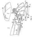
- FIG. 7 is an exploded view of a toe hold and mounting structure shown in FIG. 4 ;
- FIG. 8 is an exploded view of a hand grip and mounting structure shown in FIG. 5 ;
- FIG. 9 is an exploded view of a toe hold mounted to a shuttle shown in FIG. 4 ;
- FIG. 10 is a perspective view of a rotatable slide used with the present invention.
- FIG. 11 is an exploded view of the rotatable slide shown in FIG. 10 ;
- FIG. 12 is an exploded view of the end structure used at both ends of a rail used with the present invention.
- FIG. 13 is a cross sectional view taken along the line 13 - 13 in FIG. 1 of a shuttle mounted to a rail of the present in invention
- FIG. 14 is an end view with parts broken away of two rails joined together with a rotatable slide according to the present invention.
- FIG. 15 is a cross sectional plan view of the structure shown in FIG. 14 ;
- FIG. 16 is a partial end view with parts broken away of the structure shown in FIG. 14 ;
- FIG. 17 is a cross sectional view with parts broken away showing the connection of a rotatable slide between two adjacent rails with a locking handle in a release position;
- FIG. 18 is a cross sectional view of the structure shown in FIG. 17 with a locking handle in a locked position;
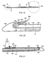
- FIG. 19 is a longitudinal cross sectional elevational view of a rail having a shuttle mounted thereon;
- FIG. 20 is an enlarged detail view taken at “B” in FIG. 19 ;
- FIG. 21 is an enlarged detail view taken at “A” in FIG. 19 ;
- FIG. 22 is a detail view of a ball connector attached to each end of a resilient cord used with the present invention.
- FIG. 23 is an exploded view of the ball connector shown in FIG. 22 ;
- FIGS. 1 and 2 A full body exercise equipment 10 is shown in FIGS. 1 and 2 .
- This equipment includes four identical elongate rails 12 A, 12 B, 12 C and 12 D.
- Four identical shuttle members 14 A, 14 B, 14 C and 14 D are each mounted to a respective rail 12 A, 12 B, 12 C and 12 D.
- a hand grip 16 is mounted to each of the shuttles 14 A and 14 B.
- a conventional toe hold 18 is mounted to each of the shuttles 14 B and 14 C.
- a rotatable slide 20 A is mounted to edges of adjacent rails 12 A and 12 B.
- a rotatable slide 20 B is mounted to edges of adjacent rails 12 B and 12 C.
- a rotatable slide 20 C is mounted to edges of adjacent rails 12 C and 12 D as shown in FIGS. 1 and 2 .
- the rotatable slides 20 A, 20 B and 20 C are of identical construction and are mounted to the rails 12 A, 12 B, 12 C and 12 D in a manner which will be described below.
- the equipment 10 may be used for exercise as illustrated in FIG. 3 .
- the shuttles 14 A, 14 B, 14 C and 14 D all have identical construction and are collectively referred to as a shuttle 14 .
- a perspective view of a shuttle 14 to which is mounted a toe hold 18 is shown in FIG. 4 .
- a perspective view of a shuttle to which is mounted a hand grip 16 is shown in FIG. 5 .
- a bottom plan view of each of the shuttles 14 A, 14 B, 14 C and 14 D is shown in FIG. 6 with the designation 14 .
- the shuttles 14 have a body 21 including parallel sidewalls 22 and 24 .
- a top cover 26 is moulded to the sidewalls 22 and 24 as shown in FIGS. 4 and 5 .
- a pad 27 is secured to the top cover 26 with screws extending through screw holes 28 (shown in FIG. 6 ) in the top cover 26 .
- Wheel support blocks 30 are mounted to the sidewalls 22 and 24 with screws 32 as shown in FIG. 6 .
- Wheels 34 are rotatably mounted to the wheel support blocks 30 with a screw axle 36 .
- the hand grip 16 and toe hold 18 are each mounted to a shuttle 14 with an identical mounting structure 38 as shown in FIGS. 7 and 8 .
- the mounting structure 38 includes a pair of upright support members 40 and 42 adjoined together with a bottom plate 44 .
- a bracing plate 46 spaced apart from the bottom plate 44 extends between the upright members 40 and 42 as shown in FIGS. 7 and 8 .
- a pivot screw 48 extends through a washer 50 resting on top of the bottom plate 44 and then through a hole provided in the bottom plate 44 and screwed into a screw hole 52 (shown in FIG. 6 ) provided in the top cover 26 .
- the friction fit of pivot screw 48 in screw hole 52 is adjusted to allow the mounting structure 38 to pivot about the pivot screw 48 .
- a protective shroud 58 is sized and shaped to cover the upright members 40 and 42 and the bottom plate 44 .
- the upright members 42 and 40 are provided with aligned holes 60 and 62 and the shroud 58 is provided with holes 64 and 66 aligned with holes 60 and 62 , respectively.
- a pin 68 extends through the holes 64 , 60 , 62 and 66 .
- the hand grip 16 is rotatably mounted on the pin 68 and the toe hold 18 is rotatably mounted on a respective pin 68 .
- an adjustment pin 54 is provided for selectively locking the mounting structure 38 in a selected rotated position.
- the adjustment pin 54 extends through a hole provided in the shroud, then through a hole provided in the bracing plate 46 through a coil compression spring 55 through a hole provided in the bottom plate 44 and extending into a selected indexing hole 56 to allow the mounting structure 38 to be secured in a selected rotated position.
- the adjustment pin 54 is retracted from a selected index hole 56 .
- the mounting structure 38 can then be rotated to a selected position and the adjustment pin 54 released.
- the compression spring 55 extends the end of the adjustment pin 54 into the selected index hole 56 .
- a cover 70 is mounted at each end of the shuttles 14 with the screws 32 as shown in FIGS. 4 and 5 .
- FIG. 9 shows an exploded view of the cover 70 mounted to one end of the shuttle 14 .
- the rotatable slides 20 A, 20 B and 20 C are of identical construction and are collectively denoted as element 20 in FIGS. 10 and 11 .
- the rotatable slides 20 have a bottom plate 72 including a locking portion 74 to be described below.
- the rotatable slides 20 further includes a top plate 76 also having a locking portion 78 to be described below.
- Sandwiched between the bottom plate 74 and the top plate 76 are plates 80 and 82 .
- the plate 80 includes a slide portion 84 and the plate 82 includes a slide portion 86 .
- the plate 80 further includes a circular concave portion 88 and the plate 82 has a circular convex portion 90 sized to slidably mate with concave portion 88 .
- a pivot bolt 94 includes a shaft portion 96 and a threaded end portion 98 .
- the pivot bolt 94 extends through a hole 100 provided in the top plate 76 and then is slidably received by hole 102 provided in the plate 82 and is threadably received by a hole 104 provided in the bottom plate 72 .
- the plate 82 will rotate about the pivot bolt 94 relative to the plates 72 , 80 and 76 which are fixedly joined together.
- a locking pin 108 having a head portion 109 is mounted to a pull handle 118 through a coil compression spring 114 and a lock washer 116 .
- the locking pin 108 is sized to extend through hole 112 provided in top plate 76 with head 109 resting in a selected index hole 106 provided in plate 82 when pull handle 118 is in the resting position.
- the index holes 106 are sized to receive the head 109 .
- a latching mechanism 120 is provided to lock the slide portion 86 to a rail 12 as described below.
- the latching mechanism includes a latch member having an end portion 124 for extending into a cutout portion 126 provided in the plate 82 and slide portion 86 .
- the end portion 124 is shaped and sized to fit within a keyway 152 as shown in FIGS. 17 and 18 .
- a cam lever arm 128 includes a handle portion joined to two spaced apart arms 132 and 134 .
- a pin 136 is sized to be slidably received by holes provided in arms 132 and 134 .
- the pin 136 includes a threaded hole 138 .
- a bolt 140 is slidably received by a hole 142 provided in middle plate 82 and a hole 144 provided in the latch member 122 and then is threadably received by hole 138 .
- the arms 132 and 134 of the handle 130 have a cam shape such that when the handle is lifted, the end portion 124 of the latch member 122 is allowed to rise and when the latch member 122 is moved to the down position, the end portion 124 is forced downwardly.
- the rails 12 A, 12 B, 12 C and 12 D are all of identical construction. These rails will be collectively referred to as element 12 in FIGS. 12 and 13 .
- the rails 12 include a central cavity 146 which extends longitudinally from one end of the rail to the opposite end of the rail.
- the rail 12 further includes wheel races 148 which extend from one end of the rail 12 to the opposite end of the rail 12 for rollably receiving wheels 34 of the shuttles 14 .
- the rails also include longitudinal slots 150 extending from one end of the rail 12 to the opposite end of rail 12 for slidably receiving the wheel support blocks 30 of the shuttle 14 .
- the rails 12 further include a longitudinal keyway provided on each side of the rail 12 for receiving the slide portion 84 or the slide portion 86 of a rotatable slide 20 as shown in FIG. 14 .
- an end plate 154 is mounted to the rail 12 with screws 156 as shown in FIG. 14 .
- Two opposed axle support plates 158 are secured to the end plate 154 as shown in FIGS. 12 and 14 .
- An axle 160 is mounted within aligned holes provided in the axle support plates 158 and pulleys 162 are rotatably mounted on the axle 160 between the axle support plates 158 as shown in FIGS. 12 and 14 .
- Slots 164 and 166 received in end plate 154 , as shown in FIG. 14 , receive the locking portions 74 and 78 , respectively, of the rotatable slide 20 (shown in FIG. 11 ). With this arrangement, the locking portions 74 and 78 prevent the rotatable slide 20 from sliding on the rail 12 in which the locking portions are mounted.
- a shroud 168 is threadably secured to a base plate 170 positioned below the axle support plates 158 with screws 172 .
- An end of the shroud 168 locks the locking portions 74 and 78 in the positions shown in FIG. 15 .
- the shroud 168 prevents the locking portions 74 and 78 from being disengaged from the slots 166 and 164 .
- the locking portions 74 and 78 of rotatable slides 20 A and 20 C are locked on the outer rails 12 A and 12 D, respectively.
- the locking portions 74 and 78 of rotatable slide 20 B are locked on rail 12 B.
- One side of the rotatable slide 20 is locked to a rail 12 as described above.
- the other side of the rotatable slide is releasably locked to an adjacent rail with the end portion 124 of the latch member 122 resting in the keyway 152 .
- the handle 130 has a cam portion resting on the latch member 122 .
- the latch member 122 rides freely within the keyway 152 , as shown in FIG. 17 .
- the latch member 122 is forced into frictional engagement with the wall 174 .
- latch member 122 With latch member 122 in the raised position, the rotatable slide 20 will slide in the keyway 152 of the rail 12 .
- the latch member 122 is in the downward position, as shown in FIG. 18 , the rotatable slide 20 is prevented from moving in the keyway 152 .
- the rotatable slide 20 A is positioned with the latching mechanism 120 engaging rail 12 B.
- the rotatable slide 20 B is positioned with the latching mechanism 120 engaging rail 12 C.
- the latching member 120 is positioned with the handle 130 in the downward position thereby locking rotatable slide 20 B to both rails 12 B and 12 C.
- the rotatable slide 12 C has the latching mechanism 120 in engagement with rail 12 C.
- the latching members 120 of rotatable slides 20 A and 20 C are positioned with the handle 130 in the raised position thereby allowing rotatable slides 20 A and 20 C to slide on rails 12 B and 12 C, respectively.
- Resilient cords 176 extend longitudinally through the rails 12 within cavity 146 as shown in FIGS. 12 and 19-21 .
- the resilient cord 176 extends around a pulley 162 through an opening 178 provided in a cord guide plate 180 (shown in FIGS. 12 and 14 ) and is attached to a ball connector 182 .
- the ball connector 182 is shown in FIGS. 22 and 23 .
- a ball 184 having a threaded shaft 186 is connected to a resilient cord attachment member 188 through a hole 190 with a nut 192 .
- a pull strap 194 is connected to the cord attachment member 188 through an opening 196 .
- the cord 176 is connected with the cord attachment member 188 by looping an end of the resilient cord 176 through an opening 198 provided in the cord attachment member 188 and then attaching the end of the resilient cord 176 to the cord 176 with a crimp 198 .
- a clamshell cover having two halves are joined together to cover the connection of the cable 176 with the cord attachment member 188 .
- An end of the resilient cord 176 may be connected to a shuttle 14 by inserting the ball 184 into a keyhole slot 202 as shown in FIGS. 4-6 , and as shown in FIG. 21 .
- the resilient cord 176 When not connected to a shuttle, the resilient cord 176 rests against the cord guide plate 180 with the clamshell cover 200 preventing the ball connector 182 from being retracted through opening 178 as shown in FIG. 20 .
- the rails 12 A, 12 B, 12 C and 12 D may be angularly oriented with respect to one another with rotatable slides 20 A, 20 B and 20 C.
- Two configurations of many are shown in FIGS. 1 and 2 .
- the pull handle 118 is pushed downwardly causing the head 109 of pin 108 to be moved out of a selected index hole 106 .
- the plate 82 can then be rotated with respect to plate 80 .
- the pull handle 118 is released allowing the head 109 to be moved into a newly selected index hole 106 .
- the handle 130 of the latching mechanism 120 is lifted, thereby releasing the end portion 124 from frictional engagement with the wall 174 of the rail 12 .
- the rotatable slide 20 B is locked to rail 12 B and is latched to rail 12 C to prevent the rotatable slide 20 B from sliding.
- the rotatable slides 20 A and 20 C have the latching mechanism 120 manipulated to a released position allowing the rotatable slides 20 A and 20 C to slide on rails 12 B and 12 C, respectively to a selected position.
- the latching mechanism 120 is manipulated to the locked position thereby locking the rails in the selected position.
- resilient cords 176 are attached to a shuttle 14 .
- An example of this is shown in FIG. 2 .
- three resilient cords are provided. The amount of resistance can be selected by hooking up a selected number of resilient cords 176 to the shuttles 14 .
- the angular orientation of the hand grip 16 and toe hold 18 can be rotated by lifting the adjustment pin 54 to allow the pin 54 to move into a selected index hole 56 .
- the pin 54 is released and the pin 54 rests in a selected index hole 56 .
- FIGS. 1, 2 and 3 many configurations of the full body exercise equipment 10 can be selected.
- This equipment provides exercise for the whole body and is very effective in increasing muscle mass, improving balance and coordination, increasing range of motion and cardiovascular capacity.
Abstract
Description
Claims (5)
Priority Applications (1)
| Application Number | Priority Date | Filing Date | Title |
|---|---|---|---|
| US15/048,255 US9789357B2 (en) | 2013-02-26 | 2016-02-19 | Full body exercise equipment |
Applications Claiming Priority (3)
| Application Number | Priority Date | Filing Date | Title |
|---|---|---|---|
| US201361850927P | 2013-02-26 | 2013-02-26 | |
| US13/999,446 US9265986B1 (en) | 2013-02-26 | 2014-02-26 | Full body exercise equipment |
| US15/048,255 US9789357B2 (en) | 2013-02-26 | 2016-02-19 | Full body exercise equipment |
Related Parent Applications (1)
| Application Number | Title | Priority Date | Filing Date |
|---|---|---|---|
| US13/999,446 Continuation US9265986B1 (en) | 2013-02-26 | 2014-02-26 | Full body exercise equipment |
Publications (2)
| Publication Number | Publication Date |
|---|---|
| US20160166878A1 US20160166878A1 (en) | 2016-06-16 |
| US9789357B2 true US9789357B2 (en) | 2017-10-17 |
Family
ID=55314488
Family Applications (2)
| Application Number | Title | Priority Date | Filing Date |
|---|---|---|---|
| US13/999,446 Expired - Fee Related US9265986B1 (en) | 2013-02-26 | 2014-02-26 | Full body exercise equipment |
| US15/048,255 Active - Reinstated US9789357B2 (en) | 2013-02-26 | 2016-02-19 | Full body exercise equipment |
Family Applications Before (1)
| Application Number | Title | Priority Date | Filing Date |
|---|---|---|---|
| US13/999,446 Expired - Fee Related US9265986B1 (en) | 2013-02-26 | 2014-02-26 | Full body exercise equipment |
Country Status (1)
| Country | Link |
|---|---|
| US (2) | US9265986B1 (en) |
Families Citing this family (12)
| Publication number | Priority date | Publication date | Assignee | Title |
|---|---|---|---|---|
| US9868023B2 (en) * | 2014-02-06 | 2018-01-16 | James Darryl Boykin | Sliding exercise device with a plurality of tracks |
| US11794066B2 (en) * | 2015-08-31 | 2023-10-24 | Joseph K. Ellis | Upper and lower body reciprocating arcing motion exercise machine with an adjustable angle user support |
| KR101932904B1 (en) * | 2017-10-17 | 2019-04-05 | 연세대학교 원주산학협력단 | Arm and leg alternately exercise apparatus and controlling method thereof |
| ES2745766A1 (en) * | 2018-09-03 | 2020-03-03 | Juarez Gabriel Orlando Fracaroli | Physical exercise machine (Machine-translation by Google Translate, not legally binding) |
| US11484751B2 (en) * | 2019-03-15 | 2022-11-01 | Vicki C. Davide | Adjustable exercise plank machine |
| GR1009813B (en) * | 2019-05-31 | 2020-09-11 | Στυλιανος Στρατηγος | Holistic exercising device |
| US20210086022A1 (en) * | 2019-09-20 | 2021-03-25 | Ronald Williams | Exercise device |
| KR102271943B1 (en) * | 2019-11-12 | 2021-07-02 | 백범준 | Prefabricated body exercise device |
| US11213719B1 (en) * | 2020-06-30 | 2022-01-04 | Lagree Technologies, Inc. | System and method of using two exercise machines |
| CN111803867A (en) * | 2020-07-23 | 2020-10-23 | 滕州市信诚阳光康复医院有限公司 | Cerebral palsy, brain injury sequelae rehabilitation training device |
| TWI741959B (en) * | 2021-03-11 | 2021-10-01 | 詹証喻 | Hand and foot exercise machine |
| US20230405387A1 (en) * | 2022-05-23 | 2023-12-21 | Marquavis Deshonte Mcculler | Multi-use Exercising Apparatus |
Citations (13)
| Publication number | Priority date | Publication date | Assignee | Title |
|---|---|---|---|---|
| US3589720A (en) | 1969-10-22 | 1971-06-29 | Alexander Agamian | Exercise apparatus with movable hand and foot platforms |
| US4679786A (en) | 1986-02-25 | 1987-07-14 | Rodgers Robert E | Universal exercise machine |
| US5224909A (en) | 1992-05-04 | 1993-07-06 | Hamilton John R | Mid-body exercise device |
| US20060019806A1 (en) | 2000-01-05 | 2006-01-26 | Mikulski Walter J | Portable excercise assembly |
| US20090105050A1 (en) * | 2007-10-17 | 2009-04-23 | Mayo Elvin A | Exercise Machine for Back Rehabilitation |
| US7780585B1 (en) | 2009-02-24 | 2010-08-24 | Esperanza Cruz | Portable dual incline adjustable resistance abdominal muscle exercise machine |
| US20100216615A1 (en) | 2009-02-26 | 2010-08-26 | Antonio Rios | Ab web systems |
| US7931570B2 (en) | 2006-01-30 | 2011-04-26 | Balanced Body, Inc. | Exercise device |
| US7951050B2 (en) | 2009-07-04 | 2011-05-31 | Raumann Kelvin A | Apparatus for aerobic leg exercise of a seated user |
| US8137250B1 (en) | 2009-02-11 | 2012-03-20 | Andrew Caban | Abdominal exercising apparatus |
| US20120244998A1 (en) | 2011-03-24 | 2012-09-27 | Fitcrawl (Shanghai) Industry Co., Ltd. | Crawling exerciser |
| US9011296B2 (en) | 2012-07-26 | 2015-04-21 | Charles A. Peralo | Therapeutic exercise apparatus with multiple selectively interlockable sliding platforms |
| US9017236B1 (en) * | 2013-04-17 | 2015-04-28 | Freddy N. Aviles | Exercising assembly |
Family Cites Families (2)
| Publication number | Priority date | Publication date | Assignee | Title |
|---|---|---|---|---|
| CN101181662B (en) | 2007-12-18 | 2010-07-21 | 周利莎 | Prostrate type creep body building apparatus |
| US8137251B2 (en) | 2009-09-28 | 2012-03-20 | Gino Adolfo Tozzi | Exercise assembly |
-
2014
- 2014-02-26 US US13/999,446 patent/US9265986B1/en not_active Expired - Fee Related
-
2016
- 2016-02-19 US US15/048,255 patent/US9789357B2/en active Active - Reinstated
Patent Citations (14)
| Publication number | Priority date | Publication date | Assignee | Title |
|---|---|---|---|---|
| US3589720A (en) | 1969-10-22 | 1971-06-29 | Alexander Agamian | Exercise apparatus with movable hand and foot platforms |
| US4679786A (en) | 1986-02-25 | 1987-07-14 | Rodgers Robert E | Universal exercise machine |
| US5224909A (en) | 1992-05-04 | 1993-07-06 | Hamilton John R | Mid-body exercise device |
| US20060019806A1 (en) | 2000-01-05 | 2006-01-26 | Mikulski Walter J | Portable excercise assembly |
| US7931570B2 (en) | 2006-01-30 | 2011-04-26 | Balanced Body, Inc. | Exercise device |
| US8500611B2 (en) | 2006-01-30 | 2013-08-06 | Balanced Body, Inc. | Dual track exercise device |
| US20090105050A1 (en) * | 2007-10-17 | 2009-04-23 | Mayo Elvin A | Exercise Machine for Back Rehabilitation |
| US8137250B1 (en) | 2009-02-11 | 2012-03-20 | Andrew Caban | Abdominal exercising apparatus |
| US7780585B1 (en) | 2009-02-24 | 2010-08-24 | Esperanza Cruz | Portable dual incline adjustable resistance abdominal muscle exercise machine |
| US20100216615A1 (en) | 2009-02-26 | 2010-08-26 | Antonio Rios | Ab web systems |
| US7951050B2 (en) | 2009-07-04 | 2011-05-31 | Raumann Kelvin A | Apparatus for aerobic leg exercise of a seated user |
| US20120244998A1 (en) | 2011-03-24 | 2012-09-27 | Fitcrawl (Shanghai) Industry Co., Ltd. | Crawling exerciser |
| US9011296B2 (en) | 2012-07-26 | 2015-04-21 | Charles A. Peralo | Therapeutic exercise apparatus with multiple selectively interlockable sliding platforms |
| US9017236B1 (en) * | 2013-04-17 | 2015-04-28 | Freddy N. Aviles | Exercising assembly |
Also Published As
| Publication number | Publication date |
|---|---|
| US20160166878A1 (en) | 2016-06-16 |
| US9265986B1 (en) | 2016-02-23 |
Similar Documents
| Publication | Publication Date | Title |
|---|---|---|
| US9789357B2 (en) | Full body exercise equipment | |
| US7674211B2 (en) | Exercise apparatus with a pull cord central pulley attached to a carriage and a pulley locking mechanism | |
| US7285078B1 (en) | Adjustable dumbbell | |
| US20190001175A1 (en) | Portable functional training device | |
| US7850584B2 (en) | Exercise apparatus with a pull cord looped about a central pulley and first and second free pulleys | |
| US7841970B2 (en) | Variable weight device | |
| US9526937B2 (en) | Exercise apparatus with a pull cord looped about a central pulley and first and second free pulleys | |
| US4093211A (en) | Combination jump rope and flexible exerciser | |
| US8579773B2 (en) | Exercise apparatus with a pull cord central pulley attached to a carriage and a pulley locking mechanism | |
| US8414461B2 (en) | Wheel type exercising device | |
| US20140141948A1 (en) | Pilates reformer | |
| US9211430B1 (en) | Exercise apparatus and method | |
| US20200238123A1 (en) | Constant force resistance cable retractor | |
| US3105682A (en) | Self-locking collar and cooperating standard | |
| CA2798748A1 (en) | Change of direction machine and method of training therefor | |
| US9884220B2 (en) | Potable cable resistance pulley exercise equipment and related methods | |
| CN109069898A (en) | Health and fitness facilities | |
| US20030211920A1 (en) | Light weight and portable exercise device with bench seat | |
| US8435163B2 (en) | Exercise apparatus with a pull cord looped about a central pulley and first and second free pulleys | |
| KR102178572B1 (en) | Sling bar of the rehabilitation device | |
| US9868015B2 (en) | Exercise device with rotatable reels | |
| US20050101455A1 (en) | Exerciser capable of doing multidirection actions | |
| WO2016018253A1 (en) | Exercise machine | |
| WO2008013750A1 (en) | Variable weight device | |
| US11052280B1 (en) | Weight bearing exercise system |
Legal Events
| Date | Code | Title | Description |
|---|---|---|---|
| STCF | Information on status: patent grant |
Free format text: PATENTED CASE |
|
| FEPP | Fee payment procedure |
Free format text: MAINTENANCE FEE REMINDER MAILED (ORIGINAL EVENT CODE: REM.); ENTITY STATUS OF PATENT OWNER: SMALL ENTITY |
|
| LAPS | Lapse for failure to pay maintenance fees |
Free format text: PATENT EXPIRED FOR FAILURE TO PAY MAINTENANCE FEES (ORIGINAL EVENT CODE: EXP.); ENTITY STATUS OF PATENT OWNER: SMALL ENTITY |
|
| STCH | Information on status: patent discontinuation |
Free format text: PATENT EXPIRED DUE TO NONPAYMENT OF MAINTENANCE FEES UNDER 37 CFR 1.362 |
|
| FP | Lapsed due to failure to pay maintenance fee |
Effective date: 20211017 |
|
| PRDP | Patent reinstated due to the acceptance of a late maintenance fee |
Effective date: 20220405 |
|
| FEPP | Fee payment procedure |
Free format text: PETITION RELATED TO MAINTENANCE FEES FILED (ORIGINAL EVENT CODE: PMFP); ENTITY STATUS OF PATENT OWNER: SMALL ENTITY Free format text: PETITION RELATED TO MAINTENANCE FEES GRANTED (ORIGINAL EVENT CODE: PMFG); ENTITY STATUS OF PATENT OWNER: SMALL ENTITY Free format text: SURCHARGE, PETITION TO ACCEPT PYMT AFTER EXP, UNINTENTIONAL. (ORIGINAL EVENT CODE: M2558); ENTITY STATUS OF PATENT OWNER: SMALL ENTITY |
|
| MAFP | Maintenance fee payment |
Free format text: PAYMENT OF MAINTENANCE FEE, 4TH YR, SMALL ENTITY (ORIGINAL EVENT CODE: M2551); ENTITY STATUS OF PATENT OWNER: SMALL ENTITY Year of fee payment: 4 |
|
| STCF | Information on status: patent grant |
Free format text: PATENTED CASE |