US9792552B2 - Prediction of available generator running time - Google Patents

Prediction of available generator running time Download PDF

Info

Publication number
US9792552B2
US9792552B2 US14/409,697 US201214409697A US9792552B2 US 9792552 B2 US9792552 B2 US 9792552B2 US 201214409697 A US201214409697 A US 201214409697A US 9792552 B2 US9792552 B2 US 9792552B2
Authority
US
United States
Prior art keywords
loads
load
predicted
generator
time
Prior art date
Legal status (The legal status is an assumption and is not a legal conclusion. Google has not performed a legal analysis and makes no representation as to the accuracy of the status listed.)
Active
Application number
US14/409,697
Other versions
US20150324696A1 (en
Inventor
Markus F. Hirschbold
John C. Van Gorp
Current Assignee (The listed assignees may be inaccurate. Google has not performed a legal analysis and makes no representation or warranty as to the accuracy of the list.)
Bloomberg Finance Holdings L P
Schneider Electric USA Inc
Bloomberg Finance LP
Original Assignee
Schneider Electric USA Inc
Priority date (The priority date is an assumption and is not a legal conclusion. Google has not performed a legal analysis and makes no representation as to the accuracy of the date listed.)
Filing date
Publication date
Application filed by Schneider Electric USA Inc filed Critical Schneider Electric USA Inc
Assigned to Schneider Electric USA, Inc. reassignment Schneider Electric USA, Inc. ASSIGNMENT OF ASSIGNORS INTEREST (SEE DOCUMENT FOR DETAILS). Assignors: HIRSCHBOLD, MARKUS F., VAN GORP, JOHN C.
Publication of US20150324696A1 publication Critical patent/US20150324696A1/en
Application granted granted Critical
Publication of US9792552B2 publication Critical patent/US9792552B2/en
Assigned to BLOOMBERG (GP) FINANCE LLC, BLOOMBERG FINANCE HOLDINGS L. P. reassignment BLOOMBERG (GP) FINANCE LLC ASSIGNMENT OF ASSIGNORS INTEREST (SEE DOCUMENT FOR DETAILS). Assignors: BLOOMBERG L. P.
Active legal-status Critical Current
Anticipated expiration legal-status Critical

Links

Images

Classifications

    • GPHYSICS
    • G06COMPUTING; CALCULATING OR COUNTING
    • G06NCOMPUTING ARRANGEMENTS BASED ON SPECIFIC COMPUTATIONAL MODELS
    • G06N5/00Computing arrangements using knowledge-based models
    • G06N5/04Inference or reasoning models
    • HELECTRICITY
    • H02GENERATION; CONVERSION OR DISTRIBUTION OF ELECTRIC POWER
    • H02JCIRCUIT ARRANGEMENTS OR SYSTEMS FOR SUPPLYING OR DISTRIBUTING ELECTRIC POWER; SYSTEMS FOR STORING ELECTRIC ENERGY
    • H02J3/00Circuit arrangements for ac mains or ac distribution networks
    • H02J3/003Load forecast, e.g. methods or systems for forecasting future load demand
    • GPHYSICS
    • G06COMPUTING; CALCULATING OR COUNTING
    • G06NCOMPUTING ARRANGEMENTS BASED ON SPECIFIC COMPUTATIONAL MODELS
    • G06N20/00Machine learning
    • G06N99/005
    • HELECTRICITY
    • H02GENERATION; CONVERSION OR DISTRIBUTION OF ELECTRIC POWER
    • H02JCIRCUIT ARRANGEMENTS OR SYSTEMS FOR SUPPLYING OR DISTRIBUTING ELECTRIC POWER; SYSTEMS FOR STORING ELECTRIC ENERGY
    • H02J3/00Circuit arrangements for ac mains or ac distribution networks
    • H02J3/12Circuit arrangements for ac mains or ac distribution networks for adjusting voltage in ac networks by changing a characteristic of the network load
    • H02J3/14Circuit arrangements for ac mains or ac distribution networks for adjusting voltage in ac networks by changing a characteristic of the network load by switching loads on to, or off from, network, e.g. progressively balanced loading
    • H02J3/144Demand-response operation of the power transmission or distribution network
    • H02J2003/003
    • HELECTRICITY
    • H02GENERATION; CONVERSION OR DISTRIBUTION OF ELECTRIC POWER
    • H02JCIRCUIT ARRANGEMENTS OR SYSTEMS FOR SUPPLYING OR DISTRIBUTING ELECTRIC POWER; SYSTEMS FOR STORING ELECTRIC ENERGY
    • H02J2310/00The network for supplying or distributing electric power characterised by its spatial reach or by the load
    • H02J2310/50The network for supplying or distributing electric power characterised by its spatial reach or by the load for selectively controlling the operation of the loads
    • H02J2310/56The network for supplying or distributing electric power characterised by its spatial reach or by the load for selectively controlling the operation of the loads characterised by the condition upon which the selective controlling is based
    • H02J2310/58The condition being electrical
    • H02J2310/60Limiting power consumption in the network or in one section of the network, e.g. load shedding or peak shaving
    • HELECTRICITY
    • H02GENERATION; CONVERSION OR DISTRIBUTION OF ELECTRIC POWER
    • H02JCIRCUIT ARRANGEMENTS OR SYSTEMS FOR SUPPLYING OR DISTRIBUTING ELECTRIC POWER; SYSTEMS FOR STORING ELECTRIC ENERGY
    • H02J9/00Circuit arrangements for emergency or stand-by power supply, e.g. for emergency lighting
    • H02J9/04Circuit arrangements for emergency or stand-by power supply, e.g. for emergency lighting in which the distribution system is disconnected from the normal source and connected to a standby source
    • H02J9/06Circuit arrangements for emergency or stand-by power supply, e.g. for emergency lighting in which the distribution system is disconnected from the normal source and connected to a standby source with automatic change-over, e.g. UPS systems
    • H02J9/08Circuit arrangements for emergency or stand-by power supply, e.g. for emergency lighting in which the distribution system is disconnected from the normal source and connected to a standby source with automatic change-over, e.g. UPS systems requiring starting of a prime-mover
    • YGENERAL TAGGING OF NEW TECHNOLOGICAL DEVELOPMENTS; GENERAL TAGGING OF CROSS-SECTIONAL TECHNOLOGIES SPANNING OVER SEVERAL SECTIONS OF THE IPC; TECHNICAL SUBJECTS COVERED BY FORMER USPC CROSS-REFERENCE ART COLLECTIONS [XRACs] AND DIGESTS
    • Y02TECHNOLOGIES OR APPLICATIONS FOR MITIGATION OR ADAPTATION AGAINST CLIMATE CHANGE
    • Y02BCLIMATE CHANGE MITIGATION TECHNOLOGIES RELATED TO BUILDINGS, e.g. HOUSING, HOUSE APPLIANCES OR RELATED END-USER APPLICATIONS
    • Y02B70/00Technologies for an efficient end-user side electric power management and consumption
    • Y02B70/30Systems integrating technologies related to power network operation and communication or information technologies for improving the carbon footprint of the management of residential or tertiary loads, i.e. smart grids as climate change mitigation technology in the buildings sector, including also the last stages of power distribution and the control, monitoring or operating management systems at local level
    • Y02B70/3225Demand response systems, e.g. load shedding, peak shaving
    • Y04S10/54
    • YGENERAL TAGGING OF NEW TECHNOLOGICAL DEVELOPMENTS; GENERAL TAGGING OF CROSS-SECTIONAL TECHNOLOGIES SPANNING OVER SEVERAL SECTIONS OF THE IPC; TECHNICAL SUBJECTS COVERED BY FORMER USPC CROSS-REFERENCE ART COLLECTIONS [XRACs] AND DIGESTS
    • Y04INFORMATION OR COMMUNICATION TECHNOLOGIES HAVING AN IMPACT ON OTHER TECHNOLOGY AREAS
    • Y04SSYSTEMS INTEGRATING TECHNOLOGIES RELATED TO POWER NETWORK OPERATION, COMMUNICATION OR INFORMATION TECHNOLOGIES FOR IMPROVING THE ELECTRICAL POWER GENERATION, TRANSMISSION, DISTRIBUTION, MANAGEMENT OR USAGE, i.e. SMART GRIDS
    • Y04S20/00Management or operation of end-user stationary applications or the last stages of power distribution; Controlling, monitoring or operating thereof
    • Y04S20/20End-user application control systems
    • Y04S20/222Demand response systems, e.g. load shedding, peak shaving
    • Y04S20/224
    • YGENERAL TAGGING OF NEW TECHNOLOGICAL DEVELOPMENTS; GENERAL TAGGING OF CROSS-SECTIONAL TECHNOLOGIES SPANNING OVER SEVERAL SECTIONS OF THE IPC; TECHNICAL SUBJECTS COVERED BY FORMER USPC CROSS-REFERENCE ART COLLECTIONS [XRACs] AND DIGESTS
    • Y04INFORMATION OR COMMUNICATION TECHNOLOGIES HAVING AN IMPACT ON OTHER TECHNOLOGY AREAS
    • Y04SSYSTEMS INTEGRATING TECHNOLOGIES RELATED TO POWER NETWORK OPERATION, COMMUNICATION OR INFORMATION TECHNOLOGIES FOR IMPROVING THE ELECTRICAL POWER GENERATION, TRANSMISSION, DISTRIBUTION, MANAGEMENT OR USAGE, i.e. SMART GRIDS
    • Y04S20/00Management or operation of end-user stationary applications or the last stages of power distribution; Controlling, monitoring or operating thereof
    • Y04S20/20End-user application control systems
    • Y04S20/248UPS systems or standby or emergency generators

Definitions

  • the present invention relates to systems and methods for predicting available generator running time.
  • Facilities often rely on electricity to operate numerous systems. Facilities can draw the electricity from an electric utility, but also have a generator to use as a backup in case of power failure or other problems. It is often useful to have an estimation of time available for running the facility on the generator. An accurate estimate of remaining time can allow facility operators to respond accordingly, such as shutting down certain systems or refueling the generator.
  • At least one aspect of the invention is directed to a power monitoring system for a facility.
  • the power monitoring system may include a generator coupled to a fuel tank, a plurality of monitors configured to monitor power drawn by loads in the facility from the generator, and a processor.
  • the processor is configured to be coupled to the plurality of monitors and configured to monitor one or more loads drawing power from the generator, monitor one or more parameters that affect the amount of power drawn by the one or more loads, and monitor a fuel consumption rate of the generator.
  • the processor is further configured to generate one or more load profiles for each of the one or more loads, each load profile determining power drawn by a corresponding load over a period of time for a set of values of the one or more parameters.
  • the processor is also configured to receive a set of the one or more loads for which a predicted time is to be generated, receive values for the one or more parameters, generate a predicted load profile for the set of the one or more loads and the values of the one or more parameters.
  • the processor is also configured to receive information indicating an amount of remaining fuel and calculate a predicted available run time based on the power drawn by the predicted load profile, the fuel consumption rate of the generator, and the amount of remaining fuel.
  • the processor is further configured to identify a first group of the one or more loads as critical loads and a second group of the one or more loads is identified as non-critical, and wherein the set of the one or more loads includes at least the first group of the one or more loads.
  • the processor is further configured to identify a first group of the one or more loads as delayable loads and a second group of the one or more loads is identified as non-delayable loads, and wherein the set of the one or more loads includes at least the second group of the one or more loads.
  • the received values for the one or more parameters include predicted values for the one or more parameters.
  • the processor is further configured to determine a plurality of sets of the one or more loads for which a predicted time is to be generated.
  • the processor is further configured to receive a length of time and provide one or more of the plurality of sets of the one or more loads for which the predicted time is longer than the length of time.
  • the loads comprise a priority ranking
  • the one or more provided sets comprises an optimized number of powered loads based on the priority ranking
  • the generator is a generator system comprising a plurality of generators coupled to a plurality of fuel tanks, and the processor is further configured to determine one or more sets of the plurality of generators to power the loads and calculate the predicted available run time for each of the one or more sets of the plurality of generators.
  • FIG. 1 is a block diagram of a power monitoring system according to aspects of some embodiments
  • FIG. 2 illustrates a process flowchart of a power monitor system according to aspects of some embodiments
  • FIG. 3 illustrates an example load profile according to aspects of some embodiments
  • FIG. 4 illustrates an example load profile according to aspects of some embodiments
  • FIG. 5 illustrates an example load profile according to aspects of some embodiments
  • FIG. 6A illustrates an example load profile according to aspects of some embodiments
  • FIG. 6B illustrates an example load profile according to aspects of some embodiments
  • FIG. 7 illustrates an example load profile according to aspects of some embodiments.
  • FIG. 8 illustrates a process flowchart of a power monitor system according to aspects of some embodiments.
  • FIG. 9 is a schematic diagram of one example of a computer system that may perform processes and functions disclosed herein.
  • a power monitoring system can provide more accurate predictions of available generator running time by more accurately predicting the load that will be drawing power from the generator.
  • the load can be predicted by monitoring individual component loads during operation and generating component load profiles.
  • the aggregate load can be for a facility, and the individual components can be the various systems in the facility that draw power, such as lighting systems and ventilation systems.
  • the load profiles can be monitored to determine parameters that affect the load profiles.
  • the parameters can include environmental parameters, operational parameters, and other variables that affect the power drawn by each system.
  • the load profiles can be used to more accurately predict future power usage and thus available running time.
  • future known or predicted parameters can also be used to more accurately predict future load.
  • FIG. 1 shows an example block diagram of a power monitoring system 100 according to some embodiments.
  • the power monitoring system 100 includes a facility 130 with monitoring devices 152 , 162 , 172 , 182 connected to a network, such as a local area network (LAN) 135 .
  • the monitoring devices 152 , 162 , 172 , 182 monitor various energy sources such as an electric utility 154 and a generator 164 .
  • the monitoring devices 152 , 162 , 172 , 182 also monitor loads that use power and transmit data to a local server 140 and/or a remote server 120 .
  • the remote server 120 and/or the local server 140 can monitor the power usage and the energy sources to predict available remaining generator time.
  • the LAN 135 can be connected to another network, such as a wide area network (WAN) 110 .
  • the remote server 120 is connected to the WAN 110 and can communicate with devices connected to the LAN 135 via the WAN 110 .
  • Each of the monitoring devices 152 , 162 , 172 , 182 monitors one or more parameters of one or more associated energy sources and/or loads and communicates data and parameter values to the local server 140 via the LAN 135 .
  • the monitoring devices 152 , 162 , 172 , 182 can communicate parameter values to the remote server 120 via the LAN 135 and the WAN 110 .
  • the remote server 120 can be located in the facility 130 , and thus connected to the monitoring devices 152 , 162 , 172 , 182 and the local server 140 via the LAN 135 .
  • the local server 140 and the remote server 120 are on a same physical device.
  • the facility 130 has two energy sources, the electric utility 154 and the generator 164 .
  • the facility 130 has two groups of energy loads, critical loads 174 and non-critical loads 184 .
  • a first monitor 152 monitors parameters of the electric utility 154 and a second monitor 162 monitors parameters of the generator 164 and a fuel tank 166 used by the generator 164 .
  • Third and fourth monitors 172 , 182 monitor parameters of the critical loads 174 and the non-critical loads 184 , respectively.
  • a single monitor can monitor a plurality of loads, or each load can have a corresponding monitor.
  • the parameters include electrical parameters such as voltage, current, power (kilowatts) and energy (kilowatt hours).
  • the parameters also include operational status of the critical and non-critical loads 174 , 184 , such as whether loads are on or off, or operating modes of loads.
  • the parameters also include environmental parameters such as indoor temperature, outdoor temperature, humidity, wind speed, time of day, and time of year.
  • the parameters also include measure of facility activity, such as occupancy.
  • the parameters also include other variables that affect the amount of power drawn by the loads, for example, the condition of the equipment.
  • the critical loads 174 can include loads that are more important to maintain a power supply, relative to non-critical loads 184 .
  • a lighting system in a facility can be considered a critical load 174 compared to a washer/dryer system.
  • loads can be categorized as delayable or non-delayable.
  • a delayable load can be a load to which power to the circuit can be temporarily cut off (interrupted) as needed (to handle overloads for example) and restored at a later time.
  • a heating, ventilation, and air conditioning (HVAC) system can be considered a delayable load if the HVAC system is designed to cycle on and off in typical operation. Thus, power can be temporarily cut off without functionally affecting the HVAC system.
  • HVAC heating, ventilation, and air conditioning
  • the monitors 152 , 162 , 172 , 182 provide a user with information to manage the critical and non-critical loads 174 , 184 given the availability of power from the electric utility 154 and the generator 164 .
  • the user can obtain the information directly from the monitors 152 , 162 , 172 , 182 or from software running on the local server 140 and/or the remote server 120 .
  • the electric utility 154 can provide power to both the critical loads 174 and the non-critical loads 184 of the facility 130 . If power from the electric utility 154 becomes unavailable, the generator 164 is brought online to supply electrical power. In some embodiments, the generator 164 can supply power only to the critical loads 174 .
  • the generator 164 can supply power to both the critical loads 174 and the non-critical loads 184 depending on the estimated time to restore power from the electrical utility 154 and the amount of fuel available in the fuel tank 166 and the predicted available running time of the generator 164 . In some embodiments, depending on the predicted available running time of the generator 164 , power can be supplied to critical loads 174 and non-delayable loads among the non-critical loads 184 .
  • the local server 140 and/or the remote server 120 can estimate how much power the facility 130 will draw from the generator 164 , and thus the rate at which the generator 164 will consume the fuel remaining in the fuel tank 166 .
  • the power monitoring system 100 estimates the power consumption of the facility by generating profiles for the loads drawing power.
  • FIG. 2 shows an example process 200 of the power monitoring system 100 .
  • the process 200 starts at stage 202 .
  • a benchmark measure is calculated to determine how much fuel the generator 164 consumes to output one or more known amounts of power.
  • loads are selected to monitor.
  • the loads that are monitored can include critical load and non-critical loads, as well as delayable and non-delayable loads.
  • the loads that are monitored are all the loads that can draw power from the generator 164 in the facility 130 .
  • parameters are selected to capture at stage 208 .
  • the parameters can include electrical parameters, operational parameters, environmental parameters, and facility parameters.
  • the system captures baseline load profiles for each of the loads and parameters selected. The process can end at stage 212 .
  • FIG. 3 shows an example load profile 300 showing an instantaneous power draw of a load over time.
  • the load profile 300 is an example of a load with basic on or off modes of operation.
  • the load is turned on and the power drawn rises to level 312 .
  • the load is turned off and the power drawn drops back to zero.
  • lighting circuits within a facility can exhibit a load profile similar to the load profile 300 .
  • FIG. 4 shows an example load profile 400 of a load with two active modes of operation.
  • the power drawn by the load rises to level 412 at time 402 and then up to level 414 at time 404 .
  • the power drawn drops back to level 412 at time 406 , and then down to zero at time 408 .
  • Loads that have multiple modes of operation with relatively constant power draw levels at each of the modes can be modeled with the load profile 400 .
  • commercial washers and dryers can exhibit a load profile similar to the load profile 400 .
  • FIG. 5 shows an example load profile 500 of a multi-stage load that is affected by one or more environmental parameters.
  • the load profile 500 shows a first load profile 510 and a second load profile 520 .
  • the first load profile 510 ramps up and then down through power draw levels 542 , 544 , and 546 , starting at time 534 and ending at time 536 .
  • the second load profile 520 also ramps up and down through levels 542 , 544 , and 546 , but begins earlier at time 532 and ends later at time 538 .
  • the second load profile 520 remains at each power level for a longer time duration than the first load profile 510 , and includes an additional power level 548 .
  • Both profiles 510 , 520 can model operation of a same complex load but under some change in one or more environmental parameters.
  • the load profiles 510 , 520 can represent operation of a multi-stage HVAC unit, with the first load profile 510 representing operation during a day with cool outdoor temperatures and the second load profile 520 representing operation during a day with warmer outdoor temperatures.
  • a peak power consumption 522 at power level 548 can represent operation of an additional component within the HVAC unit in response to the warmer outdoor temperature, such as an additional fan or compressor motor.
  • the load profile 500 shows two load profiles
  • a load profile can include any appropriate number of load profiles for varying values of one or more environmental parameters.
  • FIGS. 6A and 6B show example load profiles 600 , 650 of a load that switches rapidly between modes of operation.
  • the load profile 600 shows a load that switches between an off mode and an on mode, where it draws power level 622 , with the time duration spent in each mode varying. Between time 610 and 612 the load switches on and off at a first duty cycle, and between time 612 and 614 the load switches on and off at a second duty cycle.
  • the load profile 650 of FIG. 6B can be a simplified model of the load profile 600 of FIG. 6A .
  • the load profile 650 averages the power levels between one or more time intervals, which can be used to represent the demand the load will draw from a power source for the time intervals.
  • the load profile 650 can use a fixed time interval to calculate each average power level. Alternatively or additionally, the load profile 650 can use a varying time interval depending on the mode-switching behavior of the load.
  • a ventilation fan can exhibit a load profile similar to the load profile 600 and can be modeled by the load profile 650 .
  • the fan can be programmed to switch on and off at different duty cycles depending on occupancy within the facility.
  • the facility occupancy can be modeled according to time of day.
  • the fan can remain on at level 622 for only short durations of time early and late in the day when fewer people are present within the facility, as shown between time 610 and 612 .
  • This operation can be represented as an average power demand at level 662 between time 652 and 654 .
  • the fan can remain on at level 622 for longer periods of time, as shown between time 612 and 614 .
  • the increased running time also increases the average power demand, shown in the load profile 650 to level 664 between time 654 and 656 .
  • the fan can remain on for some length of time when the facility is at peak occupancy, which is shown in the load profile 650 at power level 668 after time 656 .
  • FIG. 7 shows an example load profile 700 of a facility.
  • the load profile 700 can be a load profile measured by monitoring the power drawn by the facility.
  • the load profile 700 can also represent a predicted load profile of the facility.
  • the power monitoring system 100 can aggregate predicted load profiles of each of the critical and non-critical loads tracked by the monitoring devices 152 , 162 , 172 , 182 .
  • the power monitoring system 100 can take into account operation parameters and environmental parameters in predicting load profiles. For example, at time 710 , the power monitoring system 100 can predict that a set of internal lights will turn on, based on either a predetermined schedule or past measurements of the lighting circuit. At time 712 , the power monitoring system 100 can predict that ventilation fans will also be turned on, raising the facility load to level 724 .
  • the power monitoring system 100 can predict that the lighting loads switch off at time 714 , dropping the facility load level to 722 .
  • one or more HVAC units can be predicted to start ramping up in operation, increasing the load over the course of the day.
  • FIG. 8 shows an example process 800 for predicting available remaining generator time.
  • the process starts at stage 802 .
  • critical and non-critical loads are selected to include in a prediction scenario.
  • a time frame is selected for a prediction scenario. The time frame can correspond to an estimated time before the electric utility will be available to provide power to the facility.
  • load profiles for the loads selected for the prediction scenario are retrieved.
  • a predicted aggregated facility load profile is generated based on the retrieved load profiles and operational, environmental, and facility parameters.
  • the amount of fuel available is measured.
  • the available remaining running time is estimated based on the predicted aggregated facility load profile.
  • the process can end at stage 816 .
  • the load profiles used to predict the aggregated facility load profile can be load profiles determined by a schedule of operation (such as the schedule for a lighting system) or a programmed sequence of operation (such as cycles of a commercial washer/dryer).
  • the load profiles can also be influenced by one or more environmental parameters resulting in multiple load profiles associated with the load.
  • the predicted amount of power drawn by the HVAC units can be determined based on the outdoor temperature or a predicted outdoor temperature, such as from a weather forecast.
  • the power monitoring system can manage a plurality of profiles for a load, such as determining a maximum, minimum, and average power levels for each load.
  • the power monitoring system can receive information to predict operational, environmental, and facility parameters to determine the load profiles used.
  • weather forecasts can be used to determine outdoor temperature. Sunrise and sunset times can be used to determine when lighting systems might be used.
  • Load profiles can span varying amounts of time. For example, a load profile can show the power drawn for a day, a week, a month, a year, or longer. Some load profiles can be relatively similar every day, regardless of time of year or other environmental parameters. Some load profiles can have weekly, monthly, or yearly cycles that can provide more accurate information depending on the point in the time interval. Monitored load profiles and models can be updated and adjusted for a predetermined amount of time, at various intervals, or constantly.
  • Predicted available generator running time can be generated for various scenarios. For example, predicted available running time can be generated for powering critical loads only, both critical loads and non-critical loads, critical loads and non-delayable non-critical loads, or any other appropriate combination. Environmental, operational, and facility parameters can also be adjusted to predict different scenarios.
  • the scenarios generated can be a preconfigured list of conditions, or entered by a user through a client interface to the power monitoring system.
  • the predicted available running time can be updated periodically and/or based on a user input.
  • the power monitoring system can generate scenarios based on the loads and parameters to provide operating conditions that would maximize the remaining time available. For example, the power monitoring system can generate and compare a set of scenarios for powering the critical loads and provide the scenario and changeable electrical, environmental, operational, and facility parameters that would allow the facility to run the longest on the remaining fuel. For example, the power monitoring system can provide various scenarios depending on the power usage. For example, if a facility has multiple generators, the power monitoring system can provide predicted available running time for one or a plurality of the generators. The power monitoring system can also generate scenarios such as powering the facility using multiple generators at the same time, or one generator after another. For example, one generator running near full capacity may be more fuel efficient in generating a similar level of power than two generators running near half capacity. The power monitoring system can take electrical parameters into consideration to optimize the efficiency of the power usage.
  • the power monitoring system can generate scenarios to maximize the loads powered given a remaining amount of time. For example, if the generators will be powering the facility for two hours, after which the electric utility will be online, the power monitoring system can generate and compare scenarios to provide various non-critical loads that can remain operational with less risk of running out of fuel.
  • the loads can be prioritized or grouped with priorities so that scenarios can be generated to maximize powering of higher prioritized loads. Additionally or alternatively, operational schedules may be adjusted based on a known fuel replenishment schedule.
  • aspects and functions described herein may be implemented as specialized hardware or software components executing in one or more computer systems.
  • computer systems There are many examples of computer systems that are currently in use. These examples include, among others, network appliances, personal computers, workstations, mainframes, networked clients, servers, media servers, application servers, database servers and web servers.
  • Other examples of computer systems may include mobile computing devices, such as cellular phones and personal digital assistants, and network equipment, such as load balancers, routers and switches.
  • aspects may be located on a single computer system or may be distributed among a plurality of computer systems connected to one or more communications networks.
  • aspects and functions may be distributed among one or more computer systems configured to provide a service to one or more client computers, or to perform an overall task as part of a distributed system. Additionally, aspects may be performed on a client-server or multi-tier system that includes components distributed among one or more server systems that perform various functions. Consequently, examples are not limited to executing on any particular system or group of systems. Further, aspects and functions may be implemented in software, hardware or firmware, or any combination thereof. Thus, aspects and functions may be implemented within methods, acts, systems, system elements and components using a variety of hardware and software configurations, and examples are not limited to any particular distributed architecture, network, or communication protocol.
  • the distributed computer system 900 includes one more computer systems that exchange information. More specifically, the distributed computer system 900 includes computer systems 902 , 904 and 906 . As shown, the computer systems 902 , 904 and 906 are interconnected by, and may exchange data through, a communication network 908 .
  • the network 908 may include any communication network through which computer systems may exchange data.
  • the computer systems 902 , 904 and 906 and the network 908 may use various methods, protocols and standards, including, among others, Fibre Channel, Token Ring, Ethernet, Wireless Ethernet, Bluetooth, IP, IPV6, TCP/IP, UDP, DTN, HTTP, FTP, SNMP, SMS, MMS, SS7, JSON, SOAP, CORBA, REST and Web Services.
  • the computer systems 902 , 904 and 906 may transmit data via the network 908 using a variety of security measures including, for example, TLS, SSL or VPN. While the distributed computer system 900 illustrates three networked computer systems, the distributed computer system 900 is not so limited and may include any number of computer systems and computing devices, networked using any medium and communication protocol.
  • the computer system 902 includes a processor 910 , a memory 912 , a bus 914 , an interface 916 and data storage 918 .
  • the processor 910 performs a series of instructions that result in manipulated data.
  • the processor 910 may be any type of processor, multiprocessor or controller. Some exemplary processors include commercially available processors such as an Intel Xeon, Itanium, Core, Celeron, or Pentium processor, an AMD Opteron processor, a Sun UltraSPARC or IBM Power5+ processor and an IBM mainframe chip.
  • the processor 910 is connected to other system components, including one or more memory devices 912 , by the bus 914 .
  • the memory 912 stores programs and data during operation of the computer system 902 .
  • the memory 912 may be a relatively high performance, volatile, random access memory such as a dynamic random access memory (DRAM) or static memory (SRAM).
  • the memory 912 may include any device for storing data, such as a disk drive or other non-volatile storage device.
  • Various examples may organize the memory 912 into particularized and, in some cases, unique structures to perform the functions disclosed herein. These data structures may be sized and organized to store values for particular data and types of data.
  • the bus 914 may include one or more physical busses, for example, busses between components that are integrated within a same machine, but may include any communication coupling between system elements including specialized or standard computing bus technologies such as IDE, SCSI, PCI and InfiniBand.
  • the bus 914 enables communications, such as data and instructions, to be exchanged between system components of the computer system 902 .
  • the computer system 902 also includes one or more interface devices 916 such as input devices, output devices and combination input/output devices.
  • Interface devices may receive input or provide output. More particularly, output devices may render information for external presentation. Input devices may accept information from external sources. Examples of interface devices include keyboards, mouse devices, trackballs, microphones, touch screens, printing devices, display screens, speakers, network interface cards, etc. Interface devices allow the computer system 902 to exchange information and to communicate with external entities, such as users and other systems.
  • the data storage 918 includes a computer readable and writeable nonvolatile, or non-transitory, data storage medium in which instructions are stored that define a program or other object that is executed by the processor 910 .
  • the data storage 918 also may include information that is recorded, on or in, the medium, and that is processed by the processor 910 during execution of the program. More specifically, the information may be stored in one or more data structures specifically configured to conserve storage space or increase data exchange performance.
  • the instructions may be persistently stored as encoded signals, and the instructions may cause the processor 910 to perform any of the functions described herein.
  • the medium may, for example, be optical disk, magnetic disk or flash memory, among others.
  • the processor 910 or some other controller causes data to be read from the nonvolatile recording medium into another memory, such as the memory 912 , that allows for faster access to the information by the processor 910 than does the storage medium included in the data storage 918 .
  • the memory may be located in the data storage 918 or in the memory 912 , however, the processor 910 manipulates the data within the memory, and then copies the data to the storage medium associated with the data storage 918 after processing is completed.
  • a variety of components may manage data movement between the storage medium and other memory elements and examples are not limited to particular data management components. Further, examples are not limited to a particular memory system or data storage system.
  • the computer system 902 is shown by way of example as one type of computer system upon which various aspects and functions may be practiced, aspects and functions are not limited to being implemented on the computer system 902 as shown in FIG. 9 .
  • Various aspects and functions may be practiced on one or more computers having a different architectures or components than that shown in FIG. 9 .
  • the computer system 902 may include specially programmed, special-purpose hardware, such as an application-specific integrated circuit (ASIC) tailored to perform a particular operation disclosed herein.
  • ASIC application-specific integrated circuit
  • another example may perform the same function using a grid of several general-purpose computing devices running MAC OS System X with Motorola PowerPC processors and several specialized computing devices running proprietary hardware and operating systems.
  • the computer system 902 may be a computer system including an operating system that manages at least a portion of the hardware elements included in the computer system 902 .
  • a processor or controller such as the processor 910 , executes an operating system.
  • Examples of a particular operating system that may be executed include a Windows-based operating system, such as, Windows NT, Windows 2000 (Windows ME), Windows XP, Windows Vista or Windows 7 operating systems, available from the Microsoft Corporation, a MAC OS System X operating system available from Apple Computer, one of many Linux-based operating system distributions, for example, the Enterprise Linux operating system available from Red Hat Inc., a Solaris operating system available from Sun Microsystems, or a UNIX operating systems available from various sources. Many other operating systems may be used, and examples are not limited to any particular operating system.
  • the processor 910 and operating system together define a computer platform for which application programs in high-level programming languages are written.
  • These component applications may be executable, intermediate, bytecode or interpreted code which communicates over a communication network, for example, the Internet, using a communication protocol, for example, TCP/IP.
  • aspects may be implemented using an object-oriented programming language, such as .Net, SmallTalk, Java, C++, Ada, or C# (C-Sharp).
  • object-oriented programming languages may also be used.
  • functional, scripting, or logical programming languages may be used.
  • various aspects and functions may be implemented in a non-programmed environment, for example, documents created in HTML, XML or other format that, when viewed in a window of a browser program, can render aspects of a graphical-user interface or perform other functions.
  • various examples may be implemented as programmed or non-programmed elements, or any combination thereof.
  • a web page may be implemented using HTML while a data object called from within the web page may be written in C++.
  • the examples are not limited to a specific programming language and any suitable programming language could be used.
  • the functional components disclosed herein may include a wide variety of elements, e.g. specialized hardware, executable code, data structures or objects, that are configured to perform the functions described herein.
  • the components disclosed herein may read parameters that affect the functions performed by the components. These parameters may be physically stored in any form of suitable memory including volatile memory (such as RAM) or nonvolatile memory (such as a magnetic hard drive). In addition, the parameters may be logically stored in a propriety data structure (such as a database or file defined by a user mode application) or in a commonly shared data structure (such as an application registry that is defined by an operating system). In addition, some examples provide for both system and user interfaces that allow external entities to modify the parameters, such as sponsor types and sectors, and thereby configure the behavior of the components.
  • volatile memory such as RAM
  • nonvolatile memory such as a magnetic hard drive
  • the parameters may be logically stored in a propriety data structure (such as a database or file defined by a user mode application) or in a commonly shared data structure (such as an application registry that is defined by an operating system).
  • a commonly shared data structure such as an application registry that is defined by an operating system.
  • some examples provide for both system

Abstract

At least one aspect of the invention is directed to a power monitoring system including a generator coupled to a fuel tank, a plurality of monitors, and a processor configured to monitor one or more loads drawing power from the generator; monitor one or more parameters that affect the amount of power drawn by the one or more loads; monitor a fuel consumption rate of the generator; generate one or more load profiles for each of the one or more loads; receive a set of the one or more loads for which a predicted time is to be generated; receive values for the one or more parameters; generate a predicted load profile for the set of the one or more loads and the values of the one or more parameters; receive information indicating an amount of remaining fuel; and calculate a predicted available run time.

Description

This application is a U.S. National Stage Application under 35 U.S.C. §371 from International Application No. PCT/US2012/045012, filed Jun. 29, 2012, which is hereby incorporated by reference in its entirety for all purposes.
BACKGROUND
Field of Invention
The present invention relates to systems and methods for predicting available generator running time.
Discussion of Related Art
Facilities often rely on electricity to operate numerous systems. Facilities can draw the electricity from an electric utility, but also have a generator to use as a backup in case of power failure or other problems. It is often useful to have an estimation of time available for running the facility on the generator. An accurate estimate of remaining time can allow facility operators to respond accordingly, such as shutting down certain systems or refueling the generator.
SUMMARY
At least one aspect of the invention is directed to a power monitoring system for a facility. The power monitoring system may include a generator coupled to a fuel tank, a plurality of monitors configured to monitor power drawn by loads in the facility from the generator, and a processor. The processor is configured to be coupled to the plurality of monitors and configured to monitor one or more loads drawing power from the generator, monitor one or more parameters that affect the amount of power drawn by the one or more loads, and monitor a fuel consumption rate of the generator. The processor is further configured to generate one or more load profiles for each of the one or more loads, each load profile determining power drawn by a corresponding load over a period of time for a set of values of the one or more parameters. The processor is also configured to receive a set of the one or more loads for which a predicted time is to be generated, receive values for the one or more parameters, generate a predicted load profile for the set of the one or more loads and the values of the one or more parameters. The processor is also configured to receive information indicating an amount of remaining fuel and calculate a predicted available run time based on the power drawn by the predicted load profile, the fuel consumption rate of the generator, and the amount of remaining fuel.
In some embodiments, the processor is further configured to identify a first group of the one or more loads as critical loads and a second group of the one or more loads is identified as non-critical, and wherein the set of the one or more loads includes at least the first group of the one or more loads.
In some embodiments, the processor is further configured to identify a first group of the one or more loads as delayable loads and a second group of the one or more loads is identified as non-delayable loads, and wherein the set of the one or more loads includes at least the second group of the one or more loads.
In some embodiments, the received values for the one or more parameters include predicted values for the one or more parameters.
In some embodiments, the processor is further configured to determine a plurality of sets of the one or more loads for which a predicted time is to be generated.
In some embodiments, the processor is further configured to receive a length of time and provide one or more of the plurality of sets of the one or more loads for which the predicted time is longer than the length of time.
In some embodiments, the loads comprise a priority ranking, and the one or more provided sets comprises an optimized number of powered loads based on the priority ranking.
In some embodiments, the generator is a generator system comprising a plurality of generators coupled to a plurality of fuel tanks, and the processor is further configured to determine one or more sets of the plurality of generators to power the loads and calculate the predicted available run time for each of the one or more sets of the plurality of generators.
Still other aspects, examples and advantages of these exemplary aspects and examples, are discussed in detail below. Moreover, it is to be understood that both the foregoing information and the following detailed description are merely illustrative examples of various aspects and examples, and are intended to provide an overview or framework for understanding the nature and character of the claimed aspects and examples. Any example disclosed herein may be combined with any other example. References to “an example,” “some examples,” “an alternate example,” “various examples,” “one example,” “at least one example,” “this and other examples” or the like are not necessarily mutually exclusive and are intended to indicate that a particular feature, structure, or characteristic described in connection with the example may be included in at least one example. The appearances of such terms herein are not necessarily all referring to the same example.
BRIEF DESCRIPTION OF DRAWINGS
The accompanying drawings are not intended to be drawn to scale. In the drawings, each identical or nearly identical component that is illustrated in various figures is represented by a like numeral. For purposes of clarity, not every component may be labeled in every drawing. In the drawings:
FIG. 1 is a block diagram of a power monitoring system according to aspects of some embodiments;
FIG. 2 illustrates a process flowchart of a power monitor system according to aspects of some embodiments;
FIG. 3 illustrates an example load profile according to aspects of some embodiments;
FIG. 4 illustrates an example load profile according to aspects of some embodiments;
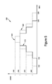
FIG. 5 illustrates an example load profile according to aspects of some embodiments;
FIG. 6A illustrates an example load profile according to aspects of some embodiments;
FIG. 6B illustrates an example load profile according to aspects of some embodiments;
FIG. 7 illustrates an example load profile according to aspects of some embodiments;
FIG. 8 illustrates a process flowchart of a power monitor system according to aspects of some embodiments; and
FIG. 9 is a schematic diagram of one example of a computer system that may perform processes and functions disclosed herein.
DETAILED DESCRIPTION
A power monitoring system can provide more accurate predictions of available generator running time by more accurately predicting the load that will be drawing power from the generator. The load can be predicted by monitoring individual component loads during operation and generating component load profiles. For example, the aggregate load can be for a facility, and the individual components can be the various systems in the facility that draw power, such as lighting systems and ventilation systems. The load profiles can be monitored to determine parameters that affect the load profiles. The parameters can include environmental parameters, operational parameters, and other variables that affect the power drawn by each system. By generating more accurate load profiles, the load profiles can be used to more accurately predict future power usage and thus available running time. By determining parameters that affect the power usage, future known or predicted parameters can also be used to more accurately predict future load.
Examples of the methods and apparatuses discussed herein are not limited in application to the details of construction and the arrangement of components set forth in the following description or illustrated in the accompanying drawings. The methods and apparatuses are capable of implementation in other examples and of being practiced or of being carried out in various ways. Examples of specific implementations are provided herein for illustrative purposes only and are not intended to be limiting. In particular, acts, components, elements and features discussed in connection with any one or more examples are not intended to be excluded from a similar role in any other examples.
Also, the phraseology and terminology used herein is for the purpose of description and should not be regarded as limiting. Any references to examples, components, elements or acts of the systems and methods herein referred to in the singular may also embrace examples including a plurality, and any references in plural to any example, component, element or act herein may also embrace examples including only a singularity. References in the singular or plural form are not intended to limit the presently disclosed systems or methods, their components, acts, or elements. The use herein of “including,” “comprising,” “having,” “containing,” “involving,” and variations thereof is meant to encompass the items listed thereafter and equivalents thereof as well as additional items. References to “or” may be construed as inclusive so that any terms described using “or” may indicate any of a single, more than one, and all of the described terms.
FIG. 1 shows an example block diagram of a power monitoring system 100 according to some embodiments. The power monitoring system 100 includes a facility 130 with monitoring devices 152, 162, 172, 182 connected to a network, such as a local area network (LAN) 135. The monitoring devices 152, 162, 172, 182 monitor various energy sources such as an electric utility 154 and a generator 164. The monitoring devices 152, 162, 172, 182 also monitor loads that use power and transmit data to a local server 140 and/or a remote server 120. The remote server 120 and/or the local server 140 can monitor the power usage and the energy sources to predict available remaining generator time.
The LAN 135 can be connected to another network, such as a wide area network (WAN) 110. The remote server 120 is connected to the WAN 110 and can communicate with devices connected to the LAN 135 via the WAN 110. Each of the monitoring devices 152, 162, 172, 182 monitors one or more parameters of one or more associated energy sources and/or loads and communicates data and parameter values to the local server 140 via the LAN 135. Alternatively or additionally, the monitoring devices 152, 162, 172, 182 can communicate parameter values to the remote server 120 via the LAN 135 and the WAN 110. In some embodiments, the remote server 120 can be located in the facility 130, and thus connected to the monitoring devices 152, 162, 172, 182 and the local server 140 via the LAN 135. In some embodiments, the local server 140 and the remote server 120 are on a same physical device.
In some example embodiments, the facility 130 has two energy sources, the electric utility 154 and the generator 164. The facility 130 has two groups of energy loads, critical loads 174 and non-critical loads 184. A first monitor 152 monitors parameters of the electric utility 154 and a second monitor 162 monitors parameters of the generator 164 and a fuel tank 166 used by the generator 164. Third and fourth monitors 172, 182 monitor parameters of the critical loads 174 and the non-critical loads 184, respectively. Alternatively or additionally, a single monitor can monitor a plurality of loads, or each load can have a corresponding monitor. The parameters include electrical parameters such as voltage, current, power (kilowatts) and energy (kilowatt hours). The parameters also include operational status of the critical and non-critical loads 174, 184, such as whether loads are on or off, or operating modes of loads. The parameters also include environmental parameters such as indoor temperature, outdoor temperature, humidity, wind speed, time of day, and time of year. The parameters also include measure of facility activity, such as occupancy. The parameters also include other variables that affect the amount of power drawn by the loads, for example, the condition of the equipment.
The critical loads 174 can include loads that are more important to maintain a power supply, relative to non-critical loads 184. For example, a lighting system in a facility can be considered a critical load 174 compared to a washer/dryer system. Alternatively or additionally, loads can be categorized as delayable or non-delayable. A delayable load can be a load to which power to the circuit can be temporarily cut off (interrupted) as needed (to handle overloads for example) and restored at a later time. For example, a heating, ventilation, and air conditioning (HVAC) system can be considered a delayable load if the HVAC system is designed to cycle on and off in typical operation. Thus, power can be temporarily cut off without functionally affecting the HVAC system.
The monitors 152, 162, 172, 182 provide a user with information to manage the critical and non-critical loads 174, 184 given the availability of power from the electric utility 154 and the generator 164. The user can obtain the information directly from the monitors 152, 162, 172, 182 or from software running on the local server 140 and/or the remote server 120. For example, the electric utility 154 can provide power to both the critical loads 174 and the non-critical loads 184 of the facility 130. If power from the electric utility 154 becomes unavailable, the generator 164 is brought online to supply electrical power. In some embodiments, the generator 164 can supply power only to the critical loads 174. Alternatively or additionally, the generator 164 can supply power to both the critical loads 174 and the non-critical loads 184 depending on the estimated time to restore power from the electrical utility 154 and the amount of fuel available in the fuel tank 166 and the predicted available running time of the generator 164. In some embodiments, depending on the predicted available running time of the generator 164, power can be supplied to critical loads 174 and non-delayable loads among the non-critical loads 184.
To predict remaining available running time, the local server 140 and/or the remote server 120 can estimate how much power the facility 130 will draw from the generator 164, and thus the rate at which the generator 164 will consume the fuel remaining in the fuel tank 166. The power monitoring system 100 estimates the power consumption of the facility by generating profiles for the loads drawing power. FIG. 2 shows an example process 200 of the power monitoring system 100. The process 200 starts at stage 202. At stage 204, a benchmark measure is calculated to determine how much fuel the generator 164 consumes to output one or more known amounts of power. At stage 206, loads are selected to monitor. The loads that are monitored can include critical load and non-critical loads, as well as delayable and non-delayable loads. In some embodiments, the loads that are monitored are all the loads that can draw power from the generator 164 in the facility 130. At stage 208, parameters are selected to capture at stage 208. The parameters can include electrical parameters, operational parameters, environmental parameters, and facility parameters. At stage 210, the system captures baseline load profiles for each of the loads and parameters selected. The process can end at stage 212.
For example, FIG. 3 shows an example load profile 300 showing an instantaneous power draw of a load over time. The load profile 300 is an example of a load with basic on or off modes of operation. At time 302, the load is turned on and the power drawn rises to level 312. At time 304, the load is turned off and the power drawn drops back to zero. For example, lighting circuits within a facility can exhibit a load profile similar to the load profile 300.
FIG. 4 shows an example load profile 400 of a load with two active modes of operation. The power drawn by the load rises to level 412 at time 402 and then up to level 414 at time 404. The power drawn drops back to level 412 at time 406, and then down to zero at time 408. Loads that have multiple modes of operation with relatively constant power draw levels at each of the modes can be modeled with the load profile 400. For example, commercial washers and dryers can exhibit a load profile similar to the load profile 400.
FIG. 5 shows an example load profile 500 of a multi-stage load that is affected by one or more environmental parameters. The load profile 500 shows a first load profile 510 and a second load profile 520. The first load profile 510 ramps up and then down through power draw levels 542, 544, and 546, starting at time 534 and ending at time 536. The second load profile 520 also ramps up and down through levels 542, 544, and 546, but begins earlier at time 532 and ends later at time 538. The second load profile 520 remains at each power level for a longer time duration than the first load profile 510, and includes an additional power level 548. Both profiles 510, 520 can model operation of a same complex load but under some change in one or more environmental parameters. For example, the load profiles 510, 520 can represent operation of a multi-stage HVAC unit, with the first load profile 510 representing operation during a day with cool outdoor temperatures and the second load profile 520 representing operation during a day with warmer outdoor temperatures. A peak power consumption 522 at power level 548 can represent operation of an additional component within the HVAC unit in response to the warmer outdoor temperature, such as an additional fan or compressor motor. While the load profile 500 shows two load profiles, a load profile can include any appropriate number of load profiles for varying values of one or more environmental parameters.
FIGS. 6A and 6B show example load profiles 600, 650 of a load that switches rapidly between modes of operation. The load profile 600 shows a load that switches between an off mode and an on mode, where it draws power level 622, with the time duration spent in each mode varying. Between time 610 and 612 the load switches on and off at a first duty cycle, and between time 612 and 614 the load switches on and off at a second duty cycle. The load profile 650 of FIG. 6B can be a simplified model of the load profile 600 of FIG. 6A. The load profile 650 averages the power levels between one or more time intervals, which can be used to represent the demand the load will draw from a power source for the time intervals. The load profile 650 can use a fixed time interval to calculate each average power level. Alternatively or additionally, the load profile 650 can use a varying time interval depending on the mode-switching behavior of the load.
For example, a ventilation fan can exhibit a load profile similar to the load profile 600 and can be modeled by the load profile 650. The fan can be programmed to switch on and off at different duty cycles depending on occupancy within the facility. The facility occupancy can be modeled according to time of day. The fan can remain on at level 622 for only short durations of time early and late in the day when fewer people are present within the facility, as shown between time 610 and 612. This operation can be represented as an average power demand at level 662 between time 652 and 654. During times of the day leading up to (and following) a peak occupancy, the fan can remain on at level 622 for longer periods of time, as shown between time 612 and 614. The increased running time also increases the average power demand, shown in the load profile 650 to level 664 between time 654 and 656. The fan can remain on for some length of time when the facility is at peak occupancy, which is shown in the load profile 650 at power level 668 after time 656.
FIG. 7 shows an example load profile 700 of a facility. The load profile 700 can be a load profile measured by monitoring the power drawn by the facility. The load profile 700 can also represent a predicted load profile of the facility. For example, the power monitoring system 100 can aggregate predicted load profiles of each of the critical and non-critical loads tracked by the monitoring devices 152, 162, 172, 182. The power monitoring system 100 can take into account operation parameters and environmental parameters in predicting load profiles. For example, at time 710, the power monitoring system 100 can predict that a set of internal lights will turn on, based on either a predetermined schedule or past measurements of the lighting circuit. At time 712, the power monitoring system 100 can predict that ventilation fans will also be turned on, raising the facility load to level 724. The power monitoring system 100 can predict that the lighting loads switch off at time 714, dropping the facility load level to 722. At time 716, one or more HVAC units can be predicted to start ramping up in operation, increasing the load over the course of the day.
Using a predicted aggregated facility load profile, the power monitoring system 100 can predict available remaining run time. For example, FIG. 8 shows an example process 800 for predicting available remaining generator time. The process starts at stage 802. At stage 804, critical and non-critical loads are selected to include in a prediction scenario. At stage 806, a time frame is selected for a prediction scenario. The time frame can correspond to an estimated time before the electric utility will be available to provide power to the facility. At stage 808, load profiles for the loads selected for the prediction scenario are retrieved. At stage 810, a predicted aggregated facility load profile is generated based on the retrieved load profiles and operational, environmental, and facility parameters. At stage 812, the amount of fuel available is measured. At stage 814, the available remaining running time is estimated based on the predicted aggregated facility load profile. The process can end at stage 816.
As described above, the load profiles used to predict the aggregated facility load profile can be load profiles determined by a schedule of operation (such as the schedule for a lighting system) or a programmed sequence of operation (such as cycles of a commercial washer/dryer). The load profiles can also be influenced by one or more environmental parameters resulting in multiple load profiles associated with the load. For example, the predicted amount of power drawn by the HVAC units can be determined based on the outdoor temperature or a predicted outdoor temperature, such as from a weather forecast. The power monitoring system can manage a plurality of profiles for a load, such as determining a maximum, minimum, and average power levels for each load. The power monitoring system can receive information to predict operational, environmental, and facility parameters to determine the load profiles used. For example, weather forecasts can be used to determine outdoor temperature. Sunrise and sunset times can be used to determine when lighting systems might be used. Load profiles can span varying amounts of time. For example, a load profile can show the power drawn for a day, a week, a month, a year, or longer. Some load profiles can be relatively similar every day, regardless of time of year or other environmental parameters. Some load profiles can have weekly, monthly, or yearly cycles that can provide more accurate information depending on the point in the time interval. Monitored load profiles and models can be updated and adjusted for a predetermined amount of time, at various intervals, or constantly.
Predicted available generator running time can be generated for various scenarios. For example, predicted available running time can be generated for powering critical loads only, both critical loads and non-critical loads, critical loads and non-delayable non-critical loads, or any other appropriate combination. Environmental, operational, and facility parameters can also be adjusted to predict different scenarios. The scenarios generated can be a preconfigured list of conditions, or entered by a user through a client interface to the power monitoring system. The predicted available running time can be updated periodically and/or based on a user input.
In some embodiments, the power monitoring system can generate scenarios based on the loads and parameters to provide operating conditions that would maximize the remaining time available. For example, the power monitoring system can generate and compare a set of scenarios for powering the critical loads and provide the scenario and changeable electrical, environmental, operational, and facility parameters that would allow the facility to run the longest on the remaining fuel. For example, the power monitoring system can provide various scenarios depending on the power usage. For example, if a facility has multiple generators, the power monitoring system can provide predicted available running time for one or a plurality of the generators. The power monitoring system can also generate scenarios such as powering the facility using multiple generators at the same time, or one generator after another. For example, one generator running near full capacity may be more fuel efficient in generating a similar level of power than two generators running near half capacity. The power monitoring system can take electrical parameters into consideration to optimize the efficiency of the power usage.
In some embodiments, the power monitoring system can generate scenarios to maximize the loads powered given a remaining amount of time. For example, if the generators will be powering the facility for two hours, after which the electric utility will be online, the power monitoring system can generate and compare scenarios to provide various non-critical loads that can remain operational with less risk of running out of fuel. In some embodiments, the loads can be prioritized or grouped with priorities so that scenarios can be generated to maximize powering of higher prioritized loads. Additionally or alternatively, operational schedules may be adjusted based on a known fuel replenishment schedule.
Various aspects and functions described herein may be implemented as specialized hardware or software components executing in one or more computer systems. There are many examples of computer systems that are currently in use. These examples include, among others, network appliances, personal computers, workstations, mainframes, networked clients, servers, media servers, application servers, database servers and web servers. Other examples of computer systems may include mobile computing devices, such as cellular phones and personal digital assistants, and network equipment, such as load balancers, routers and switches. Further, aspects may be located on a single computer system or may be distributed among a plurality of computer systems connected to one or more communications networks.
For example, various aspects and functions may be distributed among one or more computer systems configured to provide a service to one or more client computers, or to perform an overall task as part of a distributed system. Additionally, aspects may be performed on a client-server or multi-tier system that includes components distributed among one or more server systems that perform various functions. Consequently, examples are not limited to executing on any particular system or group of systems. Further, aspects and functions may be implemented in software, hardware or firmware, or any combination thereof. Thus, aspects and functions may be implemented within methods, acts, systems, system elements and components using a variety of hardware and software configurations, and examples are not limited to any particular distributed architecture, network, or communication protocol.
Referring to FIG. 9, there is illustrated a block diagram of a distributed computer system 900, in which various aspects and functions are practiced. As shown, the distributed computer system 900 includes one more computer systems that exchange information. More specifically, the distributed computer system 900 includes computer systems 902, 904 and 906. As shown, the computer systems 902, 904 and 906 are interconnected by, and may exchange data through, a communication network 908. The network 908 may include any communication network through which computer systems may exchange data. To exchange data using the network 908, the computer systems 902, 904 and 906 and the network 908 may use various methods, protocols and standards, including, among others, Fibre Channel, Token Ring, Ethernet, Wireless Ethernet, Bluetooth, IP, IPV6, TCP/IP, UDP, DTN, HTTP, FTP, SNMP, SMS, MMS, SS7, JSON, SOAP, CORBA, REST and Web Services. To ensure data transfer is secure, the computer systems 902, 904 and 906 may transmit data via the network 908 using a variety of security measures including, for example, TLS, SSL or VPN. While the distributed computer system 900 illustrates three networked computer systems, the distributed computer system 900 is not so limited and may include any number of computer systems and computing devices, networked using any medium and communication protocol.
As illustrated in FIG. 9, the computer system 902 includes a processor 910, a memory 912, a bus 914, an interface 916 and data storage 918. To implement at least some of the aspects, functions and processes disclosed herein, the processor 910 performs a series of instructions that result in manipulated data. The processor 910 may be any type of processor, multiprocessor or controller. Some exemplary processors include commercially available processors such as an Intel Xeon, Itanium, Core, Celeron, or Pentium processor, an AMD Opteron processor, a Sun UltraSPARC or IBM Power5+ processor and an IBM mainframe chip. The processor 910 is connected to other system components, including one or more memory devices 912, by the bus 914.
The memory 912 stores programs and data during operation of the computer system 902. Thus, the memory 912 may be a relatively high performance, volatile, random access memory such as a dynamic random access memory (DRAM) or static memory (SRAM). However, the memory 912 may include any device for storing data, such as a disk drive or other non-volatile storage device. Various examples may organize the memory 912 into particularized and, in some cases, unique structures to perform the functions disclosed herein. These data structures may be sized and organized to store values for particular data and types of data.
Components of the computer system 902 are coupled by an interconnection element such as the bus 914. The bus 914 may include one or more physical busses, for example, busses between components that are integrated within a same machine, but may include any communication coupling between system elements including specialized or standard computing bus technologies such as IDE, SCSI, PCI and InfiniBand. The bus 914 enables communications, such as data and instructions, to be exchanged between system components of the computer system 902.
The computer system 902 also includes one or more interface devices 916 such as input devices, output devices and combination input/output devices. Interface devices may receive input or provide output. More particularly, output devices may render information for external presentation. Input devices may accept information from external sources. Examples of interface devices include keyboards, mouse devices, trackballs, microphones, touch screens, printing devices, display screens, speakers, network interface cards, etc. Interface devices allow the computer system 902 to exchange information and to communicate with external entities, such as users and other systems.
The data storage 918 includes a computer readable and writeable nonvolatile, or non-transitory, data storage medium in which instructions are stored that define a program or other object that is executed by the processor 910. The data storage 918 also may include information that is recorded, on or in, the medium, and that is processed by the processor 910 during execution of the program. More specifically, the information may be stored in one or more data structures specifically configured to conserve storage space or increase data exchange performance. The instructions may be persistently stored as encoded signals, and the instructions may cause the processor 910 to perform any of the functions described herein. The medium may, for example, be optical disk, magnetic disk or flash memory, among others. In operation, the processor 910 or some other controller causes data to be read from the nonvolatile recording medium into another memory, such as the memory 912, that allows for faster access to the information by the processor 910 than does the storage medium included in the data storage 918. The memory may be located in the data storage 918 or in the memory 912, however, the processor 910 manipulates the data within the memory, and then copies the data to the storage medium associated with the data storage 918 after processing is completed. A variety of components may manage data movement between the storage medium and other memory elements and examples are not limited to particular data management components. Further, examples are not limited to a particular memory system or data storage system.
Although the computer system 902 is shown by way of example as one type of computer system upon which various aspects and functions may be practiced, aspects and functions are not limited to being implemented on the computer system 902 as shown in FIG. 9. Various aspects and functions may be practiced on one or more computers having a different architectures or components than that shown in FIG. 9. For instance, the computer system 902 may include specially programmed, special-purpose hardware, such as an application-specific integrated circuit (ASIC) tailored to perform a particular operation disclosed herein. While another example may perform the same function using a grid of several general-purpose computing devices running MAC OS System X with Motorola PowerPC processors and several specialized computing devices running proprietary hardware and operating systems.
The computer system 902 may be a computer system including an operating system that manages at least a portion of the hardware elements included in the computer system 902. In some examples, a processor or controller, such as the processor 910, executes an operating system. Examples of a particular operating system that may be executed include a Windows-based operating system, such as, Windows NT, Windows 2000 (Windows ME), Windows XP, Windows Vista or Windows 7 operating systems, available from the Microsoft Corporation, a MAC OS System X operating system available from Apple Computer, one of many Linux-based operating system distributions, for example, the Enterprise Linux operating system available from Red Hat Inc., a Solaris operating system available from Sun Microsystems, or a UNIX operating systems available from various sources. Many other operating systems may be used, and examples are not limited to any particular operating system.
The processor 910 and operating system together define a computer platform for which application programs in high-level programming languages are written. These component applications may be executable, intermediate, bytecode or interpreted code which communicates over a communication network, for example, the Internet, using a communication protocol, for example, TCP/IP. Similarly, aspects may be implemented using an object-oriented programming language, such as .Net, SmallTalk, Java, C++, Ada, or C# (C-Sharp). Other object-oriented programming languages may also be used. Alternatively, functional, scripting, or logical programming languages may be used.
Additionally, various aspects and functions may be implemented in a non-programmed environment, for example, documents created in HTML, XML or other format that, when viewed in a window of a browser program, can render aspects of a graphical-user interface or perform other functions. Further, various examples may be implemented as programmed or non-programmed elements, or any combination thereof. For example, a web page may be implemented using HTML while a data object called from within the web page may be written in C++. Thus, the examples are not limited to a specific programming language and any suitable programming language could be used. Accordingly, the functional components disclosed herein may include a wide variety of elements, e.g. specialized hardware, executable code, data structures or objects, that are configured to perform the functions described herein.
In some examples, the components disclosed herein may read parameters that affect the functions performed by the components. These parameters may be physically stored in any form of suitable memory including volatile memory (such as RAM) or nonvolatile memory (such as a magnetic hard drive). In addition, the parameters may be logically stored in a propriety data structure (such as a database or file defined by a user mode application) or in a commonly shared data structure (such as an application registry that is defined by an operating system). In addition, some examples provide for both system and user interfaces that allow external entities to modify the parameters, such as sponsor types and sectors, and thereby configure the behavior of the components.
Having thus described several aspects of at least one embodiment of this invention, it is to be appreciated various alterations, modifications, and improvements will readily occur to those skilled in the art. Such alterations, modifications, and improvements are intended to be part of this disclosure, and are intended to be within the spirit and scope of the invention. Accordingly, the foregoing description and drawings are by way of example only.

Claims (20)

What is claimed is:
1. A method of predicting available run time of a generator to power a facility, the method comprising:
monitoring a plurality of loads drawing power from the generator;
monitoring a plurality of parameters that affect the amount of power drawn by the plurality of loads;
monitoring a fuel consumption rate of the generator;
generating a plurality of load profiles for each load of the plurality of loads, each load profile indicating power drawn by a corresponding load over a period of time for a set of values for of each parameter of the plurality of parameters;
determining a set of loads from the plurality of loads for which a predicted time is to be generated;
receiving values for each parameter of the plurality of parameters;
generating a predicted load profile for the set of loads and the values of each parameter of the plurality of parameters;
receiving information indicating an amount of remaining fuel; and
calculating, on a computer system, a predicted available run time based on the power draw indicated by the predicted load profile, the fuel consumption rate of the generator, and the amount of remaining fuel,
wherein generating the predicated load profile includes aggregating two or more load profiles of the plurality of load profiles to predict future power usage of the set of loads, and
wherein the two or more load profiles correspond to two or more loads.
2. The method of claim 1, further comprising identifying a first group of the plurality of loads as critical loads and identifying a second group of the plurality of loads as non-critical, and wherein the set of loads includes at least the first group of the plurality of loads.
3. The method of claim 1, further comprising identifying a first group of the plurality of loads as delayable loads and identifying a second group of the plurality of loads as non-delayable loads, and wherein the set of loads includes at least the second group of the plurality of loads.
4. The method of claim 1, wherein the received values for the plurality of parameters include predicted values for the plurality of parameters.
5. The method of claim 1, further comprising determining a plurality of sets of the plurality of loads for which a predicted time is to be generated.
6. The method of claim 5, further comprising:
receiving a length of time; and
providing one or more of the plurality of sets of the plurality of loads for which the predicted time is longer than the length of time.
7. The method of claim 6, wherein the loads comprise a priority ranking, and the one or more provided sets comprises an optimized number of powered loads based on the priority ranking.
8. The method of claim 1, wherein the generator is a generator system comprising a plurality of generators coupled to a plurality of fuel tanks, the method further comprising:
determining one or more sets of the plurality of generators to power the loads; and
calculating a predicted available run time for each of the one or more sets of the plurality of generators.
9. A power monitoring system for a facility, comprising:
a generator coupled to a fuel tank;
a plurality of monitors configured to monitor power drawn by loads in the facility from the generator;
a processor configured to be coupled to the plurality of monitors and configured to:
monitor a plurality of loads drawing power from the generator using the plurality of monitors;
monitor a plurality of parameters that affect the amount of power drawn by the plurality of loads;
monitor a fuel consumption rate of the generator;
generate a plurality of load profiles for each load of the plurality of loads, each load profile indicating power drawn by a corresponding load over a period of time for a set of values for each parameter of the plurality of parameters;
receive a set of loads of the plurality of loads for which a predicted time is to be generated;
receive values for each parameter of the plurality of parameters;
generate a predicted load profile for the set of loads and the values for each parameter of the plurality of parameters;
receive information indicating an amount of remaining fuel; and
calculate a predicted available run time based on the power drawn indicated by the predicted load profile, the fuel consumption rate of the generator, and the amount of remaining fuel,
wherein generating the predicted load profile includes aggregating two or more load profiles of the plurality of load profiles to predict future power usage of the set of loads, and
wherein the two or more load profiles corresponds to two or more loads.
10. The system of claim 9, wherein the processor is further configured to identify a first group of the plurality of loads as critical loads and identify a second group of the plurality of loads as non-critical, and wherein the set of loads includes at least the first group of the plurality of loads.
11. The system of claim 9, wherein the processor is further configured to identify a first group of the plurality of loads as delayable loads and identify a second group of the plurality of loads as non-delayable loads, and wherein the set of loads includes at least the second group of the plurality of loads.
12. The system of claim 9, wherein the received values for the plurality of parameters include predicted values for the plurality of parameters.
13. The system of claim 9, wherein the processor is further configured to determine a plurality of sets of the plurality of loads for which a predicted time is to be generated.
14. The system of claim 13, wherein the processor is further configured to:
receive a length of time; and
provide one or more of the plurality of sets of the plurality of loads for which the predicted time is longer than the length of time.
15. The system of claim 14, wherein the loads comprise a priority ranking, and the one or more provided sets comprises an optimized number of powered loads based on the priority ranking.
16. The system of claim 9, wherein the generator is a generator system comprising a plurality of generators coupled to a plurality of fuel tanks, and wherein the processor is further configured to:
determine one or more sets of the plurality of generators to power the loads; and
calculate the predicted available run time for each of the one or more sets of the plurality of generators.
17. A non-transitory computer readable medium having stored thereon sequences of instruction for predicting available run time for a generator including instructions that will cause at least one processor to:
monitor plurality of loads drawing power from the generator;
monitor a plurality of parameters that affect the amount of power drawn by the plurality of loads;
monitor a fuel consumption rate of the generator;
generate a plurality of load profiles for each load of the plurality of loads, each load profile determining power drawn by a corresponding load over a period of time for a set of values for each parameter of the plurality of parameters;
determine a set of loads from the plurality of loads for which a predicted time is to be generated;
receive values for each parameter of the plurality of parameters;
generate a predicted load profile for the set of loads and the values of each parameter of the plurality of parameters;
receive information indicating an amount of remaining fuel; and
calculate, on a computer system, a predicted available run time based on the power draw indicated by the predicted load profile, the fuel consumption rate of the generator, and the amount of remaining fuel,
wherein generating the predicated load profile includes aggregating two or more load profiles of the plurality of load profiles to predict future power usage of the set of loads, and
wherein the two or more load profiles correspond to two or more loads.
18. The medium of claim 17, wherein the processor is further instructed to:
receive a length of time;
determine a plurality of sets of the plurality of loads for which a predicted time is to be generated; and
provide one or more of the plurality of sets of the plurality of loads for which the predicted time is longer than the length of time.
19. The medium of claim 17, wherein the loads comprise a priority ranking, and the one or more provided sets comprises an optimized number of powered loads based on the priority ranking.
20. The medium of claim 17, wherein the generator is a generator system comprising a plurality of generators coupled to a plurality of fuel tanks, and wherein the processor is further instructed to:
determine one or more sets of the plurality of generators to power the loads; and
calculate the predicted available run time for each of the one or more sets of the plurality of generators.
US14/409,697 2012-06-29 2012-06-29 Prediction of available generator running time Active US9792552B2 (en)

Applications Claiming Priority (1)

Application Number Priority Date Filing Date Title
PCT/US2012/045012 WO2014003788A2 (en) 2012-06-29 2012-06-29 Prediction of available generator running time

Publications (2)

Publication Number Publication Date
US20150324696A1 US20150324696A1 (en) 2015-11-12
US9792552B2 true US9792552B2 (en) 2017-10-17

Family

ID=49783980

Family Applications (1)

Application Number Title Priority Date Filing Date
US14/409,697 Active US9792552B2 (en) 2012-06-29 2012-06-29 Prediction of available generator running time

Country Status (2)

Country Link
US (1) US9792552B2 (en)
WO (1) WO2014003788A2 (en)

Cited By (2)

* Cited by examiner, † Cited by third party
Publication number Priority date Publication date Assignee Title
US11132847B2 (en) 2019-03-15 2021-09-28 Ford Global Technologies, Llc Time to empty prediction system for vehicle power source
US11875371B1 (en) 2017-04-24 2024-01-16 Skyline Products, Inc. Price optimization system

Families Citing this family (18)

* Cited by examiner, † Cited by third party
Publication number Priority date Publication date Assignee Title
US9152737B1 (en) 2014-11-26 2015-10-06 Sense Labs, Inc. Providing notifications to a user
US10175276B2 (en) 2014-11-26 2019-01-08 Sense Labs, Inc. Identifying and categorizing power consumption with disaggregation
US9443195B2 (en) 2014-11-26 2016-09-13 Sense Labs, Inc. Assisted labeling of devices with disaggregation
US9719827B2 (en) * 2014-12-09 2017-08-01 Generac Power Systems, Inc. System for calculating and displaying remaining runtime for a portable generator
US10148094B2 (en) * 2016-10-20 2018-12-04 Caterpillar Inc. Hybrid electrical power generation system and method
US9800958B1 (en) 2017-02-22 2017-10-24 Sense Labs, Inc. Training power models using network data
US10750252B2 (en) 2017-02-22 2020-08-18 Sense Labs, Inc. Identifying device state changes using power data and network data
EP3586521B1 (en) * 2017-02-22 2022-04-20 Sense Labs, Inc. Identifying device state changes using power data and network data
US9699529B1 (en) 2017-02-22 2017-07-04 Sense Labs, Inc. Identifying device state changes using power data and network data
US10727691B2 (en) * 2017-07-14 2020-07-28 Landis+Gyr Innovations, Inc. Methods and systems for adaptive load control
US11196258B2 (en) 2018-08-03 2021-12-07 Sacramento Municipal Utility District Energy control and storage system for controlling power based on a load shape
US10586177B1 (en) 2018-10-02 2020-03-10 Sense Labs, Inc. Training a mathematical model for a device using a smart plug
US11205923B1 (en) * 2018-11-30 2021-12-21 United Services Automobile Association (Usaa) System for controlling power in a facility
JP2020120167A (en) * 2019-01-18 2020-08-06 富士通コンポーネント株式会社 Wireless communication device and wireless communication method
USD944731S1 (en) 2019-07-11 2022-03-01 Sense Labs, Inc. Electrical current sensor
US11536747B2 (en) 2019-07-11 2022-12-27 Sense Labs, Inc. Current transformer with self-adjusting cores
US11296510B1 (en) 2019-07-31 2022-04-05 United Services Automobile Association (Usaa) System for controlling power in a facility
CN116455079A (en) * 2023-05-04 2023-07-18 奥斯塔娜(常州)电子有限公司 Big data-based electricity consumption integrated safety supervision system and method

Citations (74)

* Cited by examiner, † Cited by third party
Publication number Priority date Publication date Assignee Title
GB516265A (en) 1938-07-22 1939-12-28 English Electric Co Ltd Improvements in and relating to emergency power generating plant
US3705280A (en) 1971-06-04 1972-12-05 Excel Electrical Supply Co Interlock for circuit breaker switches
US4231029A (en) 1978-02-28 1980-10-28 Westinghouse Electric Corp. Automatic transfer control device and frequency monitor
US4611289A (en) 1983-09-29 1986-09-09 Coppola Anthony F Computer power management system
US4674031A (en) 1985-10-25 1987-06-16 Cara Corporation Peripheral power sequencer based on peripheral susceptibility to AC transients
US4763013A (en) 1987-09-21 1988-08-09 American Telephone And Telegraph Company, At&T Bell Laboratories Backup protection switch to prevent reverse power flow in a UPS
US4769555A (en) 1985-10-01 1988-09-06 Pulizzi Engineering Inc. Multi-time delay power controller apparatus with time delay turn-on and turn-off
US4918562A (en) 1989-01-30 1990-04-17 Pulizzi Engineering, Inc. Power controller with voltage-controlled circuit breaker
US5081367A (en) 1990-07-06 1992-01-14 Westinghouse Electric Corp. Electric power system with maintenance bypass for uninterruptible power supply using closed transition operation
US5270576A (en) 1992-03-06 1993-12-14 Compulog Corporation Electrical connector network
US5424903A (en) 1993-01-12 1995-06-13 Tandy Corporation Intelligent power switcher
US5450334A (en) 1993-11-01 1995-09-12 Pulizzi Engineering, Inc. One time programmable switched-output controller
US5462225A (en) 1994-02-04 1995-10-31 Scientific-Atlanta, Inc. Apparatus and method for controlling distribution of electrical energy to a space conditioning load
US5525898A (en) * 1994-12-16 1996-06-11 General Electric Company Programmable multi-channel load profile recorder and method of recording electrical energy metering quantities therein
US5534734A (en) 1993-12-09 1996-07-09 Compusci, Inc. Power shedding device
US5646459A (en) 1995-11-09 1997-07-08 Lucent Technologies Inc. Integrated maintenance bypass switch and method of operation thereof
US5721934A (en) 1994-06-29 1998-02-24 Intel Corporation Retrofit external power saving system and method for use
US5923103A (en) 1997-03-31 1999-07-13 Pulizzi Engineering, Inc. Switched-output controller apparatus with repeater function and method for constructing same
US5939802A (en) 1997-12-22 1999-08-17 Rantec Microwave & Electronic, Inc. Automatic bus transfer device for single phase and multiphase power systems, providing infinite isolation
US6011327A (en) 1997-12-19 2000-01-04 International Business Machines Corporation AC transfer switch
US6172428B1 (en) 1998-12-30 2001-01-09 Westwood Corporation Digital control system and method for generator sets
US6172432B1 (en) 1999-06-18 2001-01-09 Gen-Tran Corporation Automatic transfer switch
US6181028B1 (en) 1999-08-19 2001-01-30 Generac Power Systems, Inc. Transfer mechanism for transferring power between a utility source and a stand-by generator
US6285178B1 (en) 1999-02-11 2001-09-04 Battelle Memorial Institute Power supply
US6330176B1 (en) 2000-11-15 2001-12-11 Powerware Corporation Multi-input power transfer and uninterruptible power supply apparatus and methods of operation thereof
US20020024332A1 (en) 2000-06-09 2002-02-28 Gardner Jay Warren Methods and apparatus for controlling electric appliances during reduced power conditions
US20020130556A1 (en) 2000-10-23 2002-09-19 Liebert Corporation Method for apparatus for transfer control and undervoltage detection in an automatic transfer switch
US20020134567A1 (en) 2001-03-20 2002-09-26 Neil Rasmussen Adjustable scalable rack power system and method
US20030034693A1 (en) 2001-08-17 2003-02-20 Dynagen Technologies Incorporated Power transfer switch assembly
US20030048005A1 (en) 2001-09-12 2003-03-13 Goldin Andrew B. Advanced power distribution system
US20030048004A1 (en) 2001-09-12 2003-03-13 Fleming David J. Uninterruptible transfer switch
US20030062775A1 (en) 2001-10-02 2003-04-03 Gautam Sinha Direct current uninterruptible power supply method and system
US20030072977A1 (en) 2001-10-12 2003-04-17 Speranza A. John Method and system for controlling and recovering short duration bridge power to maximize backup power
US6570269B2 (en) 2000-10-13 2003-05-27 Xantrex International Method and apparatus for supplying power to a load circuit from alternate electric power sources
US20030111842A1 (en) 2001-02-05 2003-06-19 Capstone Turbine Corporation Continuous power supply with back-up generation
US6633802B2 (en) 2001-03-06 2003-10-14 Sikorsky Aircraft Corporation Power management under limited power conditions
US6683778B2 (en) 2000-02-18 2004-01-27 Sanyo Electric Co., Ltd. Device for use in electric vehicles for detecting adhesion in relay due to melting
US6721672B2 (en) 2002-01-02 2004-04-13 American Power Conversion Method and apparatus for preventing overloads of power distribution networks
US20040075343A1 (en) 2002-09-05 2004-04-22 Paul Wareham System and method for power load management
US20040084965A1 (en) 2002-10-22 2004-05-06 Welches Richard Shaun Hybrid variable speed generator/uninterruptible power supply power converter
US6741442B1 (en) 2000-10-13 2004-05-25 American Power Conversion Corporation Intelligent power distribution system
US6765373B1 (en) 2002-03-28 2004-07-20 David Harvey Control of initial current transients
US20040169972A1 (en) 2000-08-02 2004-09-02 Goss Milton E. Power grid backfeed protection apparatus
US6825578B2 (en) 2001-01-24 2004-11-30 Joseph Perttu State machine controlled automatic transfer switch system
US20040262058A1 (en) 2003-04-22 2004-12-30 Webasto Ag Vehicle electrical system with fuel cell and process for operating an electrical consumer in such a vehicle electrical system
US6876103B2 (en) 2000-12-29 2005-04-05 General Electric Company Automatic transfer switch systems and controllers
US20050165511A1 (en) * 2004-01-23 2005-07-28 Matthew Fairlie Energy network
US7015599B2 (en) 2003-06-27 2006-03-21 Briggs & Stratton Power Products Group, Llc Backup power management system and method of operating the same
US20060072262A1 (en) * 2004-09-28 2006-04-06 American Power Conversion Corporation System and method for allocating power to loads
US7058526B2 (en) 2004-07-29 2006-06-06 International Business Machines Corporation Method, apparatus and computer program product for implementing enhanced power system with optimized fuse placement and sizing
US7098555B2 (en) 2002-08-02 2006-08-29 Airbus Deutschland Gmbh Intelligent power distribution management for an on-board galley of a transport vehicle such as an aircraft
US7119457B1 (en) 2003-02-11 2006-10-10 Reliance Controls Corporation Prioritized actuation system with overload protection for a generator transfer switch
US7142950B2 (en) 2004-05-28 2006-11-28 American Power Conversion Corporation Methods and apparatus for providing and distributing standby power
US20070018506A1 (en) 2005-07-22 2007-01-25 American Power Conversion Corporation Apparatus and method for preventing an electrical backfeed
US7173347B2 (en) 2002-10-15 2007-02-06 Denso Corporation Method and apparatus for driving and controlling on-vehicle loads
US7282813B2 (en) 2004-12-10 2007-10-16 Xantrex International AC power backfeed protection based on phase shift
US20080313006A1 (en) * 2006-08-24 2008-12-18 Blue Pillar, Inc. Systems, methods, and devices for managing emergency power supply systems
US20090027932A1 (en) * 2007-05-08 2009-01-29 American Power Conversion Corporation Alternative-source energy management
US20090045804A1 (en) * 2007-08-14 2009-02-19 General Electric Company Cognitive electric power meter
US20100191487A1 (en) * 2009-01-26 2010-07-29 Geneva Clean Tech Inc. Energy usage monitoring with remote display and automatic detection of appliance including graphical user interface
US20100324962A1 (en) * 2009-06-22 2010-12-23 Johnson Controls Technology Company Smart building manager
US20110061015A1 (en) * 2009-06-22 2011-03-10 Johnson Controls Technology Company Systems and methods for statistical control and fault detection in a building management system
US20110251807A1 (en) * 2009-01-26 2011-10-13 Geneva Cleantech Inc. Automatic detection of appliances
WO2011128883A2 (en) * 2010-04-15 2011-10-20 University College Dublin - National University Of Ireland, Dublin An energy monitoring system
US20120022700A1 (en) * 2009-06-22 2012-01-26 Johnson Controls Technology Company Automated fault detection and diagnostics in a building management system
US20120029711A1 (en) * 2011-03-08 2012-02-02 General Electric Company Generator demand response behavior
US20120109553A1 (en) 2010-11-02 2012-05-03 Schneider Electric USA, Inc. Automated emergency power supply test with variable, priority-based transfer times
US20120188087A1 (en) * 2011-01-24 2012-07-26 Wang David J Method and system for generating behavior profiles for device members of a network
US20120245751A1 (en) * 2011-03-25 2012-09-27 Green Charge Networks Llc Modular Implementation of Correlative Electricity Consumption Management Systems
US20120259583A1 (en) * 2009-06-22 2012-10-11 Johnson Controls Technology Company Automated fault detection and diagnostics in a building management system
US20130085614A1 (en) * 2011-09-30 2013-04-04 Johnson Controls Technology Company Systems and methods for controlling energy use in a building management system using energy budgets
US20130191103A1 (en) * 2012-01-19 2013-07-25 Verdigris Technologies, Inc. System and Method of Waveform Analysis to Identify and Characterize Power-Consuming Devices on Electrical Circuits
US20130338947A1 (en) * 2012-06-13 2013-12-19 Tuerk John System for the monitoring and maintenance of remote autonomously powered lighting installations
US20150168975A1 (en) * 2013-12-17 2015-06-18 Eaton Corporation Method and apparatus to optimize generator start delay and runtime following outage

Patent Citations (80)

* Cited by examiner, † Cited by third party
Publication number Priority date Publication date Assignee Title
GB516265A (en) 1938-07-22 1939-12-28 English Electric Co Ltd Improvements in and relating to emergency power generating plant
US3705280A (en) 1971-06-04 1972-12-05 Excel Electrical Supply Co Interlock for circuit breaker switches
US4231029A (en) 1978-02-28 1980-10-28 Westinghouse Electric Corp. Automatic transfer control device and frequency monitor
US4611289A (en) 1983-09-29 1986-09-09 Coppola Anthony F Computer power management system
US4769555A (en) 1985-10-01 1988-09-06 Pulizzi Engineering Inc. Multi-time delay power controller apparatus with time delay turn-on and turn-off
US4674031A (en) 1985-10-25 1987-06-16 Cara Corporation Peripheral power sequencer based on peripheral susceptibility to AC transients
US4763013A (en) 1987-09-21 1988-08-09 American Telephone And Telegraph Company, At&T Bell Laboratories Backup protection switch to prevent reverse power flow in a UPS
US4918562A (en) 1989-01-30 1990-04-17 Pulizzi Engineering, Inc. Power controller with voltage-controlled circuit breaker
US5081367A (en) 1990-07-06 1992-01-14 Westinghouse Electric Corp. Electric power system with maintenance bypass for uninterruptible power supply using closed transition operation
US5270576A (en) 1992-03-06 1993-12-14 Compulog Corporation Electrical connector network
US5424903A (en) 1993-01-12 1995-06-13 Tandy Corporation Intelligent power switcher
US5450334A (en) 1993-11-01 1995-09-12 Pulizzi Engineering, Inc. One time programmable switched-output controller
US5534734A (en) 1993-12-09 1996-07-09 Compusci, Inc. Power shedding device
US5462225A (en) 1994-02-04 1995-10-31 Scientific-Atlanta, Inc. Apparatus and method for controlling distribution of electrical energy to a space conditioning load
US5721934A (en) 1994-06-29 1998-02-24 Intel Corporation Retrofit external power saving system and method for use
US5525898A (en) * 1994-12-16 1996-06-11 General Electric Company Programmable multi-channel load profile recorder and method of recording electrical energy metering quantities therein
US5646459A (en) 1995-11-09 1997-07-08 Lucent Technologies Inc. Integrated maintenance bypass switch and method of operation thereof
US5923103A (en) 1997-03-31 1999-07-13 Pulizzi Engineering, Inc. Switched-output controller apparatus with repeater function and method for constructing same
US6011327A (en) 1997-12-19 2000-01-04 International Business Machines Corporation AC transfer switch
US5939802A (en) 1997-12-22 1999-08-17 Rantec Microwave & Electronic, Inc. Automatic bus transfer device for single phase and multiphase power systems, providing infinite isolation
US6172428B1 (en) 1998-12-30 2001-01-09 Westwood Corporation Digital control system and method for generator sets
US6285178B1 (en) 1999-02-11 2001-09-04 Battelle Memorial Institute Power supply
US6172432B1 (en) 1999-06-18 2001-01-09 Gen-Tran Corporation Automatic transfer switch
US6181028B1 (en) 1999-08-19 2001-01-30 Generac Power Systems, Inc. Transfer mechanism for transferring power between a utility source and a stand-by generator
US6683778B2 (en) 2000-02-18 2004-01-27 Sanyo Electric Co., Ltd. Device for use in electric vehicles for detecting adhesion in relay due to melting
US20020024332A1 (en) 2000-06-09 2002-02-28 Gardner Jay Warren Methods and apparatus for controlling electric appliances during reduced power conditions
US20040169972A1 (en) 2000-08-02 2004-09-02 Goss Milton E. Power grid backfeed protection apparatus
US6741442B1 (en) 2000-10-13 2004-05-25 American Power Conversion Corporation Intelligent power distribution system
US7141891B2 (en) 2000-10-13 2006-11-28 American Power Conversion Corporation Intelligent power distribution system
US6570269B2 (en) 2000-10-13 2003-05-27 Xantrex International Method and apparatus for supplying power to a load circuit from alternate electric power sources
US20020130556A1 (en) 2000-10-23 2002-09-19 Liebert Corporation Method for apparatus for transfer control and undervoltage detection in an automatic transfer switch
US6879060B2 (en) 2000-10-23 2005-04-12 Liebert Corporation Method and apparatus for transfer control and undervoltage detection in an automatic transfer switch
US6330176B1 (en) 2000-11-15 2001-12-11 Powerware Corporation Multi-input power transfer and uninterruptible power supply apparatus and methods of operation thereof
US6876103B2 (en) 2000-12-29 2005-04-05 General Electric Company Automatic transfer switch systems and controllers
US6825578B2 (en) 2001-01-24 2004-11-30 Joseph Perttu State machine controlled automatic transfer switch system
US20030111842A1 (en) 2001-02-05 2003-06-19 Capstone Turbine Corporation Continuous power supply with back-up generation
US6633802B2 (en) 2001-03-06 2003-10-14 Sikorsky Aircraft Corporation Power management under limited power conditions
US20020134567A1 (en) 2001-03-20 2002-09-26 Neil Rasmussen Adjustable scalable rack power system and method
US20030034693A1 (en) 2001-08-17 2003-02-20 Dynagen Technologies Incorporated Power transfer switch assembly
US6630752B2 (en) 2001-09-12 2003-10-07 Qualmag, Inc. Uninterruptible transfer switch
US20030048004A1 (en) 2001-09-12 2003-03-13 Fleming David J. Uninterruptible transfer switch
US20030048005A1 (en) 2001-09-12 2003-03-13 Goldin Andrew B. Advanced power distribution system
US20030062775A1 (en) 2001-10-02 2003-04-03 Gautam Sinha Direct current uninterruptible power supply method and system
US20030072977A1 (en) 2001-10-12 2003-04-17 Speranza A. John Method and system for controlling and recovering short duration bridge power to maximize backup power
US6721672B2 (en) 2002-01-02 2004-04-13 American Power Conversion Method and apparatus for preventing overloads of power distribution networks
US6765373B1 (en) 2002-03-28 2004-07-20 David Harvey Control of initial current transients
US7098555B2 (en) 2002-08-02 2006-08-29 Airbus Deutschland Gmbh Intelligent power distribution management for an on-board galley of a transport vehicle such as an aircraft
US20040075343A1 (en) 2002-09-05 2004-04-22 Paul Wareham System and method for power load management
US7173347B2 (en) 2002-10-15 2007-02-06 Denso Corporation Method and apparatus for driving and controlling on-vehicle loads
US20040084965A1 (en) 2002-10-22 2004-05-06 Welches Richard Shaun Hybrid variable speed generator/uninterruptible power supply power converter
US7119457B1 (en) 2003-02-11 2006-10-10 Reliance Controls Corporation Prioritized actuation system with overload protection for a generator transfer switch
US20040262058A1 (en) 2003-04-22 2004-12-30 Webasto Ag Vehicle electrical system with fuel cell and process for operating an electrical consumer in such a vehicle electrical system
US7015599B2 (en) 2003-06-27 2006-03-21 Briggs & Stratton Power Products Group, Llc Backup power management system and method of operating the same
US20050165511A1 (en) * 2004-01-23 2005-07-28 Matthew Fairlie Energy network
US7142950B2 (en) 2004-05-28 2006-11-28 American Power Conversion Corporation Methods and apparatus for providing and distributing standby power
US7058526B2 (en) 2004-07-29 2006-06-06 International Business Machines Corporation Method, apparatus and computer program product for implementing enhanced power system with optimized fuse placement and sizing
US7514815B2 (en) 2004-09-28 2009-04-07 American Power Conversion Corporation System and method for allocating power to loads
US20060072262A1 (en) * 2004-09-28 2006-04-06 American Power Conversion Corporation System and method for allocating power to loads
US8446040B2 (en) 2004-09-28 2013-05-21 Scheider Electric IT Corporation System and method for allocating power to loads
US7786617B2 (en) 2004-09-28 2010-08-31 American Power Conversion Corporation System and method for allocating power to loads
US7282813B2 (en) 2004-12-10 2007-10-16 Xantrex International AC power backfeed protection based on phase shift
US20070018506A1 (en) 2005-07-22 2007-01-25 American Power Conversion Corporation Apparatus and method for preventing an electrical backfeed
US20080313006A1 (en) * 2006-08-24 2008-12-18 Blue Pillar, Inc. Systems, methods, and devices for managing emergency power supply systems
US20090027932A1 (en) * 2007-05-08 2009-01-29 American Power Conversion Corporation Alternative-source energy management
US20090045804A1 (en) * 2007-08-14 2009-02-19 General Electric Company Cognitive electric power meter
US20110251807A1 (en) * 2009-01-26 2011-10-13 Geneva Cleantech Inc. Automatic detection of appliances
US20100191487A1 (en) * 2009-01-26 2010-07-29 Geneva Clean Tech Inc. Energy usage monitoring with remote display and automatic detection of appliance including graphical user interface
US20120259583A1 (en) * 2009-06-22 2012-10-11 Johnson Controls Technology Company Automated fault detection and diagnostics in a building management system
US20120022700A1 (en) * 2009-06-22 2012-01-26 Johnson Controls Technology Company Automated fault detection and diagnostics in a building management system
US20110061015A1 (en) * 2009-06-22 2011-03-10 Johnson Controls Technology Company Systems and methods for statistical control and fault detection in a building management system
US20100324962A1 (en) * 2009-06-22 2010-12-23 Johnson Controls Technology Company Smart building manager
WO2011128883A2 (en) * 2010-04-15 2011-10-20 University College Dublin - National University Of Ireland, Dublin An energy monitoring system
US20120109553A1 (en) 2010-11-02 2012-05-03 Schneider Electric USA, Inc. Automated emergency power supply test with variable, priority-based transfer times
US20120188087A1 (en) * 2011-01-24 2012-07-26 Wang David J Method and system for generating behavior profiles for device members of a network
US20120029711A1 (en) * 2011-03-08 2012-02-02 General Electric Company Generator demand response behavior
US20120245751A1 (en) * 2011-03-25 2012-09-27 Green Charge Networks Llc Modular Implementation of Correlative Electricity Consumption Management Systems
US20130085614A1 (en) * 2011-09-30 2013-04-04 Johnson Controls Technology Company Systems and methods for controlling energy use in a building management system using energy budgets
US20130191103A1 (en) * 2012-01-19 2013-07-25 Verdigris Technologies, Inc. System and Method of Waveform Analysis to Identify and Characterize Power-Consuming Devices on Electrical Circuits
US20130338947A1 (en) * 2012-06-13 2013-12-19 Tuerk John System for the monitoring and maintenance of remote autonomously powered lighting installations
US20150168975A1 (en) * 2013-12-17 2015-06-18 Eaton Corporation Method and apparatus to optimize generator start delay and runtime following outage

Non-Patent Citations (7)

* Cited by examiner, † Cited by third party
Title
APC User's Guide Brochure, "InfraStruXure Manager," Mar. 2004, 181 pps.
Cutler-Hammer, "Switchboards Integrated Facility Switchboards," Jan. 2003, vol. 1, Ref. No. (0893), 1 pp.
MGE UPS Systems Brochure, "Galaxy 3000-Data Center Grade Power Protection for Critical Environments," Dec. 2001, 4 pps.
MGE UPS Systems Brochure, "Galaxy PW-Next Generation Critical Power Protection System," Jun. 2002, 2 pps.
MGE UPS Systems Brochure, "Galaxy 3000—Data Center Grade Power Protection for Critical Environments," Dec. 2001, 4 pps.
MGE UPS Systems Brochure, "Galaxy PW—Next Generation Critical Power Protection System," Jun. 2002, 2 pps.
Notification of Transmittal of the International Search Report and the Written Opinion of the International Searching Authority from corresponding PCT/US2012/045012 dated Sep. 14, 2012.

Cited By (2)

* Cited by examiner, † Cited by third party
Publication number Priority date Publication date Assignee Title
US11875371B1 (en) 2017-04-24 2024-01-16 Skyline Products, Inc. Price optimization system
US11132847B2 (en) 2019-03-15 2021-09-28 Ford Global Technologies, Llc Time to empty prediction system for vehicle power source

Also Published As

Publication number Publication date
WO2014003788A3 (en) 2014-05-08
WO2014003788A2 (en) 2014-01-03
US20150324696A1 (en) 2015-11-12

Similar Documents

Publication Publication Date Title
US9792552B2 (en) Prediction of available generator running time
Islam et al. Paying to save: Reducing cost of colocation data center via rewards
Siano et al. Designing and testing decision support and energy management systems for smart homes
US11029346B2 (en) Monitoring load operation
US20140278692A1 (en) Managing a facility
US10852805B2 (en) Data center total resource utilization efficiency (TRUE) system and method
WO2015087470A1 (en) Demand prediction device and program
Yao et al. Predictive electricity cost minimization through energy buffering in data centers
US10401401B2 (en) System and methods thereof for monitoring of energy consumption cycles
US20160283844A1 (en) Load predictor for a cooling system
Li et al. CTS2M: concurrent task scheduling and storage management for residential energy consumers under dynamic energy pricing
CN112801331B (en) Shaping of computational loads with virtual capacity and preferred location real-time scheduling
Dang et al. A unified stochastic model for energy management in solar-powered embedded systems
US9172552B2 (en) Managing an entity using a state machine abstract
US20120109391A1 (en) Managing energy demand in an infrastructure
US10503192B2 (en) Energy consumption modeling
US10409273B2 (en) Monitoring load operation
US10678285B2 (en) Systems and methods of monitoring bridging time
Toha et al. GMC: Greening MapReduce clusters considering both computational energy and cooling energy
JP2022151173A (en) Power control system and method
Estrada et al. Comparison of Traditional ML Algorithms for Energy Consumption Prediction Models
Prasad et al. Design and Implementation of Efficient Approach for Optimizing Energy Consumption for Data Centers
CN115688560A (en) Photovoltaic output evaluation method, device, equipment and medium for energy consumption of production line
WO2013168073A1 (en) Lowering data centers operational costs
Venkatesh A Context-Aware Approach for Automation of End-User Elements in the Smart Grid

Legal Events

Date Code Title Description
AS Assignment

Owner name: SCHNEIDER ELECTRIC USA, INC., ILLINOIS

Free format text: ASSIGNMENT OF ASSIGNORS INTEREST;ASSIGNORS:HIRSCHBOLD, MARKUS F.;VAN GORP, JOHN C.;REEL/FRAME:036265/0699

Effective date: 20120628

STCF Information on status: patent grant

Free format text: PATENTED CASE

MAFP Maintenance fee payment

Free format text: PAYMENT OF MAINTENANCE FEE, 4TH YEAR, LARGE ENTITY (ORIGINAL EVENT CODE: M1551); ENTITY STATUS OF PATENT OWNER: LARGE ENTITY

Year of fee payment: 4

AS Assignment

Owner name: BLOOMBERG FINANCE HOLDINGS L. P., DELAWARE

Free format text: ASSIGNMENT OF ASSIGNORS INTEREST;ASSIGNOR:BLOOMBERG L. P.;REEL/FRAME:065259/0406

Effective date: 20231006

Owner name: BLOOMBERG (GP) FINANCE LLC, DELAWARE

Free format text: ASSIGNMENT OF ASSIGNORS INTEREST;ASSIGNOR:BLOOMBERG L. P.;REEL/FRAME:065259/0406

Effective date: 20231006