US9795282B2 - Device and method for maneuvering endoscope - Google Patents
Device and method for maneuvering endoscope Download PDFInfo
- Publication number
- US9795282B2 US9795282B2 US14/154,225 US201414154225A US9795282B2 US 9795282 B2 US9795282 B2 US 9795282B2 US 201414154225 A US201414154225 A US 201414154225A US 9795282 B2 US9795282 B2 US 9795282B2
- Authority
- US
- United States
- Prior art keywords
- endoscope
- transmission means
- rotation
- axis
- tool
- Prior art date
- Legal status (The legal status is an assumption and is not a legal conclusion. Google has not performed a legal analysis and makes no representation as to the accuracy of the status listed.)
- Active, expires
Links
Images


Classifications
-
- A—HUMAN NECESSITIES
- A61—MEDICAL OR VETERINARY SCIENCE; HYGIENE
- A61B—DIAGNOSIS; SURGERY; IDENTIFICATION
- A61B1/00—Instruments for performing medical examinations of the interior of cavities or tubes of the body by visual or photographical inspection, e.g. endoscopes; Illuminating arrangements therefor
- A61B1/005—Flexible endoscopes
- A61B1/01—Guiding arrangements therefore
-
- A—HUMAN NECESSITIES
- A61—MEDICAL OR VETERINARY SCIENCE; HYGIENE
- A61B—DIAGNOSIS; SURGERY; IDENTIFICATION
- A61B1/00—Instruments for performing medical examinations of the interior of cavities or tubes of the body by visual or photographical inspection, e.g. endoscopes; Illuminating arrangements therefor
- A61B1/00147—Holding or positioning arrangements
- A61B1/00149—Holding or positioning arrangements using articulated arms
-
- A—HUMAN NECESSITIES
- A61—MEDICAL OR VETERINARY SCIENCE; HYGIENE
- A61B—DIAGNOSIS; SURGERY; IDENTIFICATION
- A61B90/00—Instruments, implements or accessories specially adapted for surgery or diagnosis and not covered by any of the groups A61B1/00 - A61B50/00, e.g. for luxation treatment or for protecting wound edges
- A61B90/50—Supports for surgical instruments, e.g. articulated arms
-
- A—HUMAN NECESSITIES
- A61—MEDICAL OR VETERINARY SCIENCE; HYGIENE
- A61B—DIAGNOSIS; SURGERY; IDENTIFICATION
- A61B34/00—Computer-aided surgery; Manipulators or robots specially adapted for use in surgery
- A61B34/30—Surgical robots
- A61B2034/301—Surgical robots for introducing or steering flexible instruments inserted into the body, e.g. catheters or endoscopes
-
- A—HUMAN NECESSITIES
- A61—MEDICAL OR VETERINARY SCIENCE; HYGIENE
- A61B—DIAGNOSIS; SURGERY; IDENTIFICATION
- A61B90/00—Instruments, implements or accessories specially adapted for surgery or diagnosis and not covered by any of the groups A61B1/00 - A61B50/00, e.g. for luxation treatment or for protecting wound edges
- A61B90/50—Supports for surgical instruments, e.g. articulated arms
- A61B2090/5025—Supports for surgical instruments, e.g. articulated arms with a counter-balancing mechanism
-
- A—HUMAN NECESSITIES
- A61—MEDICAL OR VETERINARY SCIENCE; HYGIENE
- A61B—DIAGNOSIS; SURGERY; IDENTIFICATION
- A61B90/00—Instruments, implements or accessories specially adapted for surgery or diagnosis and not covered by any of the groups A61B1/00 - A61B50/00, e.g. for luxation treatment or for protecting wound edges
- A61B90/50—Supports for surgical instruments, e.g. articulated arms
- A61B2090/506—Supports for surgical instruments, e.g. articulated arms using a parallelogram linkage, e.g. panthograph
Definitions
- the present invention generally relates to means and methods for simply maneuvering an endoscope by an endoscope user. Moreover, this present invention discloses a compact configuration of devices used for different actions upon the endoscope.
- LER which was developed by the TIMC-GMCAO Laboratory
- US. Patent application No. 200/6100501 It consists of a compact camera-holder robot that rests directly on the patient's abdomen and an electronic box containing the electricity supply and robot controllers.
- LER has relatively small dimensions but has a 110 mm diameter base ring that must be attached, or be very close to, the patient's skin.
- This ring occupies space over the patient's body, affecting the surgeon's activities: limiting the surgeon's choice of where to place other trocars, changing the surgeon's usual way of making the procedure, sometimes forcing the setup process to be as long as 40 minutes. Also the LER has only 3 degrees of freedom and has no ability to control the orientation of the picture shown to surgeon (the LER cannot rotate the endoscope around its longitudinal axis).
- Laparoscopic surgery is becoming increasingly popular with patients because the scars are smaller and their period of recovery is shorter.
- Laparoscopic surgery requires special training for the surgeon or gynecologist and the theatre nursing staff. The equipment is often expensive and is not available in all hospitals.
- laparoscopic surgery it is often required to shift the spatial placement of the endoscope in order to present the surgeon with an optimal view.
- Conventional laparoscopic surgery makes use of either human assistants that manually shift the instrumentation or alternatively robotic automated assistants (such as JP patent No. 06063003).
- a camera holder that would allow holding and controlling the endoscope steady without limiting the dexterity of the surgeon and that will provide four degrees of freedom. Furthermore, there is still a long felt need for a camera holder that will provide the ability to control the spatial position of an endoscope tube to any orientation during the laparoscopic surgery, such that the surgeon reaches any desired area within the working envelope in operated body, without putting pressure on the penetration point where the endoscope enters the body.
- first pivoting support is adapted to enable the endoscope to pivot around one first axis of rotation and the second pivoting support is adapted to enable the endoscope to pivot around a second and third axis of rotation, each of the first axis of rotation, the second axis of rotation and the third axis of rotation being substantially perpendicular to the other two axes of rotation.
- controller additionally comprises a damping mechanism adapted to prevent oscillation of the system.
- controller comprises at least one of an active mechanism and a passive mechanism to provide the dynamic equilibrium.
- controller comprises at least one selected from a group consisting of a motor and a spring.
- control is activated at least one of a group consisting of: the control is activated at all times, the control is activated when the endoscope's angle is greater than a predetermined value, and the control is activated when the torque on the endoscope is greater than a predetermined value.
- a. a first mechanism comprising:
- angle A between second axis of rotation 141 and fifth axis of rotation 142 is in the range of about 0 degrees to about 180 degrees.
- zoom mechanism comprises:
- zoom mechanism additionally comprises m coupling means adapted to couple the first connecting means to the second connecting means; where m is an integer greater than or equal to one.
- the magnetic means comprise a magnetic device, the magnetic device comprising at least one magnet and at least one selected from a group consisting of: a ferromagnet and a paramagnet.
- the third mechanism comprises a plurality of q joints, at least one of which is coupled to the pivoting support, and at least one of which is coupled to the second mechanism; where q is an integer greater than or equal to one.
- first transmission means 101 , second transmission means 102 , third transmission means 103 , fourth transmission means 104 , and fifth transmission means 105 are selected from a group consisting of gearwheels, wheels, crown gears, bevel gears, spur gears, belts, and any combination thereof.
- the system comprises attaching means adapted to reversibly couple the system to a hospital bed, the attaching means selected from a group consisting of mechanical means, magnetic means and any combination thereof.
- the magnetic means comprises a magnetic device, the magnetic device comprising at least one magnet and at least one selected from a group consisting of: a ferromagnet and a paramagnet;
- the magnetic is attached to at least one member of a group consisting of: a hospital bed, the system, and any combination thereof
- the member of the group consisting of a ferromagnet and a paramagnet is attached to at least one member of a group consisting of: a hospital bed, the system, and any combination thereof.
- angle w varies between about 0 and about 360 degrees, preferably between about 0 and about 140 degrees, when system is in its automatic configuration or in its manual configuration.
- the first mechanism additionally comprises locking means adapted to maintain in a predetermined orientation upon power failure at least one selected from a group consisting of: the first transmission means, the second transmission means and any combination thereof and to prevent any rotational movement of the same upon power failure.
- the second mechanism additionally comprises locking means adapted to maintain in a predetermined orientation upon power failure at least one selected from a group consisting of: the third transmission means, the fourth transmission means, the fifth transmission means, and any combination thereof and to prevent any rotational movement of the same upon power failure.
- MOS manual override system
- the activation means is selected from a group consisting of a pressable button, a rotatable knob, a knob, and any combination thereof.
- MOS additionally comprises means for controlling the endoscope's motion, adapted to moderate angular velocity in the ⁇ and ⁇ directions.
- the sensors are selected from of a group consisting of motion sensors, heat sensors, electric sensors, sound sensors, pressure sensors, optical sensors and any combination thereof.
- optical sensors are adapted to sense visual changes according to predetermined visual patterns.
- each of the instructing functions g i (t) is provided with a i (t) where is an integer greater than or equal to 1; where a i (t) are weighting functions of each g i (t), and n is the total number of instruction functions.
- weighting functions ai(t) are time-varying functions, wherein the value of which is determined by the operators.
- each of the instructing functions g i (t) is selected from a group consisting of: most used tool function, right tool function, left tool function, field of view function, no fly zone function, proximity function, collision prevention function, preferred volume zone function, preferred tool function, tool detection function, movement detection function, organ detection function, operator input function, prediction function, past statistical analysis function, tagged tool function, and any combination thereof.
- the most used tool function comprises a communicable database counting the amount of movement of each surgical tool located within the surgical environment; the most used tool function is adapted to output instructions to the tracking subsystem to instruct the maneuvering system to direct the endoscope to constantly position the endoscope to track the movement of the most moved surgical tool.
- the field of view function comprises a communicable database comprising n 3D spatial positions; n is an integer greater than or equal to 2; the combination of all of the n 3D spatial positions provides a predetermined field of view; the field of view function is adapted to output instructions to the tracking subsystem to instruct the maneuvering system to direct the endoscope to at least one 3D spatial position substantially within the n 3D spatial positions so as to maintain a constant field of view.
- the no fly zone function comprises a communicable database comprising n 3D spatial positions; n is an integer greater than or equal to 2; the n 3D spatial positions define a predetermined volume within the surgical environment; the no fly zone function is adapted to output instructions to the tracking subsystem to instruct the maneuvering system to direct the endoscope to at least one 3D spatial position substantially different from all the n 3D spatial positions.
- the preferred volume zone function comprises communicable database comprising n 3D spatial positions; n is an integer greater than or equal to 2; the n 3D spatial positions provide the preferred volume zone; the preferred volume zone function is adapted to output instructions to the tracking subsystem to instruct the maneuvering system to direct the endoscope to the preferred volume zone.
- the preferred tool function comprises a communicable database
- the database stores a preferred tool
- the preferred tool function is adapted to output instructions to the tracking subsystem to instruct the maneuvering system to constantly direct the endoscope to the preferred tool, such that the endoscope constantly tracks the preferred tool.
- the movement detection function comprises a communicable database comprising the real-time 3D spatial positions of each of the surgical tool in the surgical environment; is adapted to detect movement of the at least one surgical tool when a change in at least one of the 3D spatial positions is received, and is adapted to output instructions to the tracking subsystem to instruct the maneuvering system to direct the endoscope on the moved surgical tool.
- anatomical element is selected from a group consisting of tissue, organ, another surgical tool and any combination thereof.
- the operator input function comprises a communicable database; the communicable database is adapted to receive an input from the operator of the system; the input comprising n 3D spatial positions; n is an integer greater than or equal to 2; and to output instructions to the tracking subsystem to instruct the maneuvering system to direct the endoscope to the at least one 3D spatial position received.
- the prediction function comprises a communicable database storing each 3D spatial position of each surgical tool within the surgical environment, such that each movement of each surgical tool is stored; the prediction function is adapted to (a) to predict the future 3D spatial position of each of the surgical tools; and (b) to output instructions to the tracking subsystem to instruct the maneuvering system to direct the endoscope to the future 3D spatial position.
- the past statistical analysis function comprises a communicable database storing each 3D spatial position of each of surgical tool within the surgical environment, such that each movement of each surgical tool is stored; the past statistical analysis function is adapted to (a) statistically analyze the 3D spatial positions of each of the surgical tools; and, (b) to predict the future 3D spatial position of each of the surgical tools; and (c) to output instructions to the tracking subsystem to instruct the maneuvering system to direct the endoscope to the future 3D spatial position.
- the tagged tool function comprises means adapted to tag at least one surgical tool within the surgical environment and to output instructions to the tracking subsystem to instruct the maneuvering system to constantly direct the endoscope to the tagged surgical tool.
- image stabilization algorithm image improvement algorithm
- image compilation algorithm image enhancement algorithm
- image detection algorithm image classification algorithm
- image correlation with the cardiac cycle of the human body image correlation with the respiratory cycle of the human body
- smoke detection algorithm vapor detection algorithm
- algorithm for reducing steam from the endoscope any combination thereof.
- the endoscope comprises an image acquisition device selected from a group consisting of: a camera, a video camera, an electromagnetic sensor, a computer tomography imaging device, a fluoroscopic imaging device, an ultrasound imaging device, and any combination thereof.
- the at least one location estimating means is an interface subsystem between a surgeon and the at least one surgical tool, the interface subsystem comprising:
- At least one array comprising N regular or pattern light sources, where N is a positive integer;
- optical markers and means for attaching at least one the optical marker to the at least one surgical tool c. optional optical markers and means for attaching at least one the optical marker to the at least one surgical tool
- a computerized algorithm operable via the controller, the computerized algorithm adapted to record images received by each camera of each of the M cameras and to calculate therefrom the position of each of the tools, and further adapted to provide automatically the results of the calculation to the human operator of the interface.
- the predetermined set of rules comprises at least one rule selected from a group consisting of: most used tool rule, right tool rule, left tool rule, field of view rule, no fly zone rule, route rule, proximity rule; collision prevention rule, preferred volume zone rule, preferred tool rule, movement detection rule, operator input rule, environment rule, history-based rule, tool-dependent ALLOWED and RESTRICTED movements rule, tagged tool rule and any combination thereof.
- the most used tool rule comprises a communicable database counting the amount of movement of each of the surgical tools; the most used tool rule is adapted to constantly position the endoscope to track the movement of the most moved surgical tool.
- the field of view rule comprises a communicable database comprising n 3D spatial positions; n is an integer greater than or equal to 2; the combination of all of the n 3D spatial positions provides a predetermined field of view; the field of view rule is adapted to determine the ALLOWED movement of the endoscope within the n 3D spatial positions so as to maintain a constant field of view, such that the ALLOWED movements are movements in which the endoscope is located substantially in at least one of the n 3D spatial positions, and the RESTRICTED movements are movements in which the location of the endoscope is substantially different from the n 3D spatial positions.
- the no fly zone rule comprises a communicable database comprising n 3D spatial positions; n is an integer greater than or equal to 2; the n 3D spatial positions define a predetermined volume within the surgical environment; the no fly zone rule is adapted to determine the RESTRICTED movement if the movement is within the no fly zone and ALLOWED movement if the movement is outside the no fly zone, such that the RESTRICTED movements are movements in which the at least one of the surgical tool is located substantially in at least one of the n 3D spatial positions, and the ALLOWED movements are movements in which the location of the at least one surgical tool is substantially different from the n 3D spatial positions.
- the route rule comprises a communicable database storing at least one predefined route in which the at least one surgical tool is adapted to move within the surgical environment;
- the predefined route comprises n 3D spatial positions of the at least one surgical tool;
- n is an integer greater than or equal to 2;
- the ALLOWED movements are movements in which the at least one surgical tool is located substantially in at least one of the n 3D spatial positions of the predefined route, and the RESTRICTED movements are movements in which the location of the at least one surgical tool is substantially different from the n 3D spatial positions of the predefined route.
- the proximity rule is adapted to define a predetermined distance between at least two surgical tools;
- the ALLOWED movements are movements which are within the range or out of the range of the predetermined distance, and the RESTRICTED movements which are out of the range or within the range of the predetermined distance.
- the proximity rule is adapted to define a predetermined angle between at least three surgical tools; the ALLOWED movements are movements which are within the range or out of the range of the predetermined angle, and the RESTRICTED movements which are out of the range or within the range of the predetermined angle.
- the collision prevention rule is adapted to define a predetermined distance between the at least one surgical tool and an anatomical element within the surgical environment;
- the ALLOWED movements are movements which are in a range that is larger than the predetermined distance, and the RESTRICTED movements are movements which are in a range that is smaller than the predetermined distance.
- anatomical element is selected from a group consisting of tissue, organ, another surgical tool and any combination thereof.
- the preferred volume zone rule comprises a communicable database comprising n 3D spatial positions; n is an integer greater than or equal to 2; the n 3D spatial positions provides the preferred volume zone; the preferred volume zone rule is adapted to determine the ALLOWED movement of the endoscope within the n 3D spatial positions and RESTRICTED movement of the endoscope outside the n 3D spatial positions, such that the ALLOWED movements are movements in which the endoscope is located substantially in at least one of the n 3D spatial positions, and the RESTRICTED movements are movements in which the location of the endoscope is substantially different from the n 3D spatial positions.
- the preferred tool rule comprises a communicable database
- the database stores a preferred tool
- the preferred tool rule is adapted to determine the ALLOWED movement of the endoscope to constantly track the movement of the preferred tool.
- the movement detection rule comprises a communicable database comprising the real-time 3D spatial positions of each of the at least one surgical tools; the movement detection rule is adapted to detect movement of the at least one surgical tool when a change in the 3D spatial positions is received, such that the ALLOWED movements are movements in which the endoscope is re-directed to focus on the moving surgical tool.
- the operator input rule comprises a communicable database; the communicable database is adapted to receive an input from the operator of the system regarding the ALLOWED and RESTRICTED movements of the at least one surgical tool.
- n is an integer greater than or equal to 2; wherein at least one of which is defined as ALLOWED location and at least one of which is defined as RESTRICTED location, such that the ALLOWED movements are movements in which the at least one surgical tool is located substantially in at least one of the n 3D spatial positions, and the RESTRICTED movements are movements in which the location of the at least one surgical tool is substantially different from the n 3D spatial positions.
- the predetermined set of rules comprises at least one rule selected from a group consisting of: most used tool, right tool rule, left tool rule, field of view rule, no fly zone rule, route rule, environment rule, operator input rule, proximity rule; collision prevention rule, preferred volume zone rule, preferred tool rule, movement detection rule, history-based rule, tool-dependent ALLOWED and RESTRICTED movements rule, and any combination thereof.
- the environment rule comprises a communicable database
- the communicable database is adapted to receive at least one real-time image of the surgical environment and is adapted to perform real-time image processing of the same and to determine the 3D spatial position of hazards or obstacles in the surgical environment
- the environment rule is adapted to determine the ALLOWED and RESTRICTED movements according to the hazards or obstacles in the surgical environment, such that the RESTRICTED movements are movements in which the at least one surgical tool is located substantially in at least one of the 3D spatial positions of hazards or obstacles, and the ALLOWED movements are movements in which the location of the at least one surgical tool is substantially different from the 3D spatial positions of hazards or obstacles.
- the history-based rule comprises a communicable database storing each 3D spatial position of each of the at least one surgical tools, such that each movement of each surgical tool is stored; the history-based rule is adapted to determine the ALLOWED and RESTRICTED movements according to historical movements of the at least one surgical tool, such that the ALLOWED movements are movements in which the at least one surgical tool is located substantially in at least one of the 3D spatial positions comprised within at least one historical movement, and the RESTRICTED movements are movements in which the location of the at least one surgical tool is substantially different from the 3D spatial positions comprised within the historical movements.
- s tool-dependent allowed and RESTRICTED movements rule comprises a communicable database; the communicable database is adapted to store predetermined characteristics of at least one of the surgical tools; the tool-dependent ALLOWED and RESTRICTED movements rule is adapted to determine the ALLOWED and RESTRICTED movements according to the predetermined characteristics of the surgical tool; such that allowed movements are movements of the endoscope which tracks the surgical tool having the predetermined characteristics.
- the tagged tool rule comprises means adapted to tag at least one surgical tool within the surgical environment and to determine the ALLOWED movement of the endoscope to constantly track the movement of the tagged surgical tool.
- the system additionally comprises an endoscope; the endoscope is adapted to provide at least one real-time image of the surgical environment; (b) at least one of the surgical tools is an endoscope adapted to provide the at least one real-time image of the surgical environment.
- controller's database comprises n 3D spatial positions; n is an integer greater than or equal to 2; the combination of all of the n 3D spatial positions provides a predetermined field of view; the field of view rule is adapted to relocate the endoscope if movement of at least one of the surgical tools has been detected by the detection means, such that the field of view is maintained.
- the system additionally comprises a maneuvering subsystem communicable with the controller, the maneuvering subsystem is adapted to spatially reposition the at least one surgical tool during a surgery according to the predetermined set of rules; further wherein the system is adapted to alert the physician of the RESTRICTED movement of the at least one surgical tool.
- the at least one location estimating means comprises at least one endoscope adapted to acquire real-time images of the surgical environment within the human body; and at least one surgical instrument spatial location software adapted to receive the real-time images of the surgical environment and to estimate the 3D spatial position of the at least one surgical tool.
- the at least one location estimating means comprises (a) at least one element selected from a group consisting of optical imaging means, radio frequency transmitting and receiving means, at least one mark on the at least one surgical tool and any combination thereof; and (b) at least one surgical instrument spatial location software adapted to estimate the 3D spatial position of the at least one surgical tool by means of the element.
- the at least one location estimating means is an interface subsystem between a surgeon and the at least one surgical tool
- the interface subsystem comprises:
- MOS manual override system
- each of the instructing functions g i (t) is provided with ai(t) where i is an integer greater than or equal to 1; where a i (t) are weighting functions of each g i (t), and n is the total number of instruction functions.
- weighting functions a 1 (t) are time-varying functions, wherein the value of which is determined by the operators.
- each of the instructing functions g i (t) is selected from a group consisting of: most used tool function, right tool function, left tool function, field of view function, no fly zone function, proximity function, collision prevention function, preferred volume zone function, preferred tool function, tool detection function, movement detection function, organ detection function, operator input function, prediction function, past statistical analysis function, tagged tool function and any combination thereof.
- the most used tool function comprises a communicable database counting the amount of movement of each surgical tool located within the surgical environment; the most used tool function is adapted to output instructions to the tracking subsystem to instruct the maneuvering system to direct the endoscope to constantly position the endoscope to track the movement of the most moved surgical tool.
- the field of view function comprises a communicable database comprising n 3D spatial positions; n is an integer greater than or equal to 2; the combination of all of the n 3D spatial positions provides a predetermined field of view; the field of view function is adapted to output instructions to the tracking subsystem to instruct the maneuvering system to direct the endoscope to at least one 3D spatial position substantially within the n 3D spatial positions so as to maintain a constant field of view.
- controller's database comprises n 3D spatial positions; n is an integer greater than or equal to 2; the combination of all of the n 3D spatial positions provides a predetermined field of view; the field of view rule is adapted to relocate the endoscope if movement of at least one of the surgical tools has been detected by the detection means, such that the field of view is maintained.
- the no fly zone function comprises a communicable database comprising n 3D spatial positions; n is an integer greater than or equal to 2; the n 3D spatial positions define a predetermined volume within the surgical environment; the no fly zone function is adapted to output instructions to the tracking subsystem to instruct the maneuvering system to direct the endoscope to at least one 3D spatial position substantially different from all the n 3D spatial positions.
- anatomical element is selected from a group consisting of tissue, organ, another surgical tool and any combination thereof.
- the preferred volume zone function comprises a communicable database comprising n 3D spatial positions; n is an integer greater than or equal to 2; the n 3D spatial positions provide the preferred volume zone; the preferred volume zone function is adapted to output instructions to the tracking subsystem to instruct the maneuvering system to direct the endoscope to the preferred volume zone.
- the preferred tool function comprises a communicable database
- the database stores a preferred tool
- the preferred tool function is adapted to output instructions to the tracking subsystem to instruct the maneuvering system to constantly direct the endoscope to the preferred tool, such that the endoscope constantly tracks the preferred tool.
- the movement detection function comprises a communicable database comprising real-time 3D spatial positions of each surgical tool in the surgical environment; and to detect movement of at least one surgical tool when a change in the 3D spatial positions is received, and to output instructions to the tracking subsystem to instruct the maneuvering system to direct the endoscope on the moved surgical tool.
- the operator input function comprises a communicable database; the communicable database is adapted to receive an input from the operator of the system; the input comprising n 3D spatial positions; n is an integer greater than or equal to 2; and to output instructions to the tracking subsystem to instruct the maneuvering system to direct the endoscope to the at least one 3D spatial position received from the operator.
- the prediction function comprises a communicable database storing each 3D spatial position of each surgical tool within the surgical environment, such that each movement of each surgical tool is stored; the prediction function is adapted to (a) to predict the future 3D spatial position of each of the surgical tools; and (b) to output instructions to the tracking subsystem to instruct the maneuvering system to direct the endoscope to the future 3D spatial position.
- the past statistical analysis function comprises a communicable database storing each 3D spatial position of each surgical tool within the surgical environment, such that each movement of each surgical tool is stored; the past statistical analysis function is adapted to (a) statistically analyze the 3D spatial positions of each of the surgical tools; and, (b) to predict future 3D spatial positions of each of the surgical tools; and (c) to output instructions to the tracking subsystem to instruct the maneuvering system to direct the endoscope to at least one future 3D spatial position.
- the tagged tool function comprises tagging means adapted to tag at least one surgical tool within the surgical environment and to output instructions to the tracking subsystem to instruct the maneuvering system to constantly direct the endoscope to the tagged surgical tool.
- image stabilization algorithm image improvement algorithm
- image compilation algorithm image enhancement algorithm
- image detection algorithm image classification algorithm
- image correlation with the cardiac cycle or the respiratory cycle of the human body smoke detection algorithm
- vapor detection algorithm algorithm to reduce steam from the endoscope and any combination thereof.
- the endoscope comprises an image acquisition device selected from a group consisting of: a camera, a video camera, an electromagnetic sensor, a computer tomography imaging device, a fluoroscopic imaging device, an ultrasound imaging device, and any combination thereof.
- the step of controlling is performed by storing a predetermined set of rules in a controller's database; the predetermined set of rules comprises ALLOWED and RESTRICTED movements of the at least one surgical tool, such that each detected movement by the movement detection means of the at least one surgical tool is determined as either an ALLOWED movement or as a RESTRICTED movement according to the predetermined set of rules.
- the most used tool rule comprises a database counting the amount of movement of each of the surgical tools; the most used tool rule is adapted to constantly position the endoscope to track the movement of the most moved surgical tool.
- the field of view rule comprises n 3D spatial positions; n is an integer greater than or equal to 2; the combination of all of the n 3D spatial positions provides a predetermined field of view; the field of view rule is adapted to determine the ALLOWED movement of the endoscope within the n 3D spatial positions so as to maintain a constant field of view, such that the ALLOWED movements are movements in which the endoscope is located substantially in at least one of the n 3D spatial positions, and the RESTRICTED movements are movements in which the location of the endoscope is substantially different from the n 3D spatial positions.
- the no fly zone rule comprises n 3D spatial positions; n is an integer greater than or equal to 2; the n 3D spatial positions define a predetermined volume within the surgical environment; the no fly zone rule is adapted to determine a RESTRICTED movement if the movement is within said no fly zone and an ALLOWED movement if the movement is outside the no fly zone, such that RESTRICTED movements are movements in which the at least one surgical tool is located substantially in at least one of the n 3D spatial positions, and ALLOWED movements are movements in which the location of the at least one surgical tool is substantially different from the n 3D spatial positions.
- the route rule comprises a communicable database storing predefined route in which the at least one surgical tool is adapted to move within the surgical environment;
- the predefined route comprises n 3D spatial positions of the at least one surgical tool;
- n is an integer greater than or equal to 2;
- the ALLOWED movements are movements in which the at least one surgical tool is located substantially in at least one of the n 3D spatial positions of the predefined route, and the RESTRICTED movements are movements in which the location of the at least one surgical tool is substantially different from the n 3D spatial positions of the predefined route.
- anatomical element is selected from a group consisting of tissue, organ, another surgical tool and any combination thereof.
- the preferred volume zone rule comprises a communicable database comprising n 3D spatial positions; n is an integer greater than or equal to 2; the n 3D spatial positions provides the preferred volume zone; the preferred volume zone rule is adapted to determine ALLOWED movement of the endoscope within the n 3D spatial positions and RESTRICTED movement of the endoscope outside the n 3D spatial positions, such that ALLOWED movements are movements in which the endoscope is located substantially in at least one of the n 3D spatial positions, and RESTRICTED movements are movements in which the location of the endoscope is substantially different from the n 3D spatial positions.
- the preferred tool rule comprises a communicable database
- the database stores a preferred tool
- the preferred tool rule is adapted to determine ALLOWED movement of the endoscope to constantly track the movement of the preferred tool.
- the movement detection rule comprises a communicable database comprising the real-time 3D spatial positions of each of the surgical tools; and the movement detection rule detects movement of the at least one surgical tool when a change in the 3D spatial position is received, such that the ALLOWED movements are movements in which the endoscope is directed to focus on the moving surgical tool.
- the operator input rule comprises a communicable database; the communicable database is adapted to receive an input from the operator of the system regarding ALLOWED and RESTRICTED movements of the at least one surgical tool.
- n is an integer greater than or equal to 2; wherein at least one of which is defined as an ALLOWED location and at least one of which is defined as a RESTRICTED location, such that ALLOWED movements are movements in which the at least one surgical tool is located substantially in at least one of the n 3D spatial positions, and RESTRICTED movements are movements in which the location of the at least one surgical tool is substantially different from the n 3D spatial positions.
- said environment rule comprises a communicable database
- said communicable database is adapted to received at least one real-time image of said surgical environment and is adapted to perform real-time image processing of the same and to determine the 3D spatial position of hazards or obstacles in said surgical environment
- said environmental rule is adapted to determine said ALLOWED and RESTRICTED movements according to said hazards or obstacles in said surgical environment, such that said RESTRICTED movements are movements in which said at least one surgical tool is located substantially in at least one of said 3D spatial positions of said hazards or obstacles, and said ALLOWED movements are movements in which the location of said at least one surgical tool is substantially different from said 3D spatial positions of said hazards or obstacles.
- said history-based rule comprises a communicable database storing each 3D spatial position of each of said surgical tools, such that each movement of each surgical tool is stored; said history-based rule is adapted to determine said ALLOWED and RESTRICTED movements according to historical movements of said at least one surgical tool, such that said ALLOWED movements are movements in which said at least one surgical tool is located substantially in at least one of said 3D spatial positions, and said RESTRICTED movements are movements in which the location of said at least one surgical tool is substantially different from said n 3D spatial positions.
- said tool-dependent allowed and RESTRICTED movements rule comprises a communicable database; said communicable database is adapted to store predetermined characteristics of at least one of said surgical tools; said tool-dependent allowed and RESTRICTED movements rule is adapted to determine said ALLOWED and RESTRICTED movements according to said predetermined characteristics of said surgical tool.
- said tagged tool rule comprises means adapted to tag at least one surgical tool within said surgical environment and to determine said ALLOWED movement of said endoscope to constantly track the movement of said tagged surgical tool.
- said at least one location estimating means comprises at least one endoscope adapted to acquire real-time images of a surgical environment within said human body; and at least one surgical instrument spatial location software adapted to receive said real-time images of said surgical environment and to estimate said 3D spatial position of said at least one surgical tool.
- said at least one location estimating means comprises (a) at least one element selected from a group consisting of optical imaging means, radio frequency transmitting and receiving means, at least one mark on said at least one surgical tool and any combination thereof; and (b) at least one surgical instrument spatial location software adapted to estimate said 3D spatial position of said at least one surgical tool by means of said element.
- said at least one location estimating means is an interface subsystem between a surgeon and said at least one surgical tool, the interface subsystem comprising:
- FIG. 1 presents a system for maneuvering an endoscope
- FIGS. 2 a and 2 b shows two configurations of the system for maneuvering an endoscope attached to a rotating means
- FIGS. 3 a - c , 4 a - b and 5 a - b demonstrate more configurations of a system for maneuvering an endoscope
- FIG. 6 presents an endoscope attached to a pivoting support
- FIGS. 7 a and 7 b depict a zoom mechanism in two configurations
- FIGS. 8 a -8 b present the MOS system 130 ;
- FIGS. 9 a and 9 b present wearable manual override systems
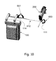
- FIG. 10 presents the axes of rotation for rotation of the endoscope about the joints.
- FIG. 11 illustrates the forces and torques on an endoscope attached to a pivoting support
- FIG. 12 schematically illustrates the normal force on the penetration point due to the endoscope
- FIG. 13 a - b and 14 presents a pivoting support with a controller
- FIG. 15 presents a system for maneuvering an endoscope with pivoting supports comprising controllers
- FIG. 16 presents a pivoting support and controller with transparent cover
- FIG. 17 presents the pivoting support, showing a connector adapted to join the pivoting supports to the connecting arm linking the pivoting supports to the endoscope;
- FIGS. 18-21 show different configurations for the motors of a system for maneuvering an endoscope
- FIG. 22 shows an examining room configuration adapted to use a system for maneuvering an endoscope
- FIG. 23 presents a configuration of system with a hospital bed and an endoscope
- FIG. 24 depicts another configuration of the system in an operating room, with an emphasis on movement range
- FIG. 25 presents a means adapted to rotate the endoscope around its longitudinal axis
- FIG. 26 a -26 d schematically illustrates operation of an embodiment of a tracking system with collision avoidance system
- FIG. 27 a -27 d schematically illustrates operation of an embodiment of a tracking system with no fly zone rule/function
- FIG. 28 a -28 d schematically illustrates operation of an embodiment of a tracking system with preferred volume zone rule/function
- FIG. 29 schematically illustrates operation of an embodiment of the organ detection function/rule
- FIG. 30 schematically illustrates operation of an embodiment of the tool detection function/rule
- FIG. 31 a -31 b schematically illustrates operation of an embodiment of the movement detection function/rule
- FIG. 32 a -32 d schematically illustrates operation of an embodiment of the prediction function/rule
- FIG. 33 schematically illustrates operation of an embodiment of the right tool function/rule
- FIG. 34 a -34 b schematically illustrates operation of an embodiment of the field of view function/rule
- FIG. 35 schematically illustrates operation of an embodiment of the tagged tool function/rule
- FIG. 36 a -36 c schematically illustrates operation of an embodiment of the proximity function/rule
- FIG. 37 a -37 b schematically illustrates operation of an embodiment of the operator input function/rule.
- a system for maneuvering an endoscope comprising:
- the present invention discloses the system further comprising:
- the present invention additionally provides a method for maneuvering an endoscope comprising steps of:
- endoscope refers hereinafter to any means adapted for looking inside the body for medical reasons. This may be any instrument used to examine the interior of a hollow organ or cavity of the body. The endoscope may also refer to any kind of a laparascope.
- spatial position refers hereinafter to a predetermined spatial location and/or orientation of an object (e.g., the spatial location of the endoscope, the angular orientation of the endoscope, and any combination thereof).
- DOF degrees of freedom
- the term “degrees of freedom” refers hereinafter to a set of independent displacements that specify completely the displaced position of the endoscope or laparoscope as defined above.
- three DOFs of linear displacement there are six DOFs, three DOFs of linear displacement and three rotational DOFs, namely, moving up and down, moving left and right, moving forward and backward, tilting up and down, turning left and right, tilting side to side.
- the present invention refers to a system essentially comprising means for at least seven DOF selected from any of those that will be described hereinafter.
- operator refers hereinafter to a user of the system. Examples of operators are the surgeon, the operating medical assistant, the surgeon's colleagues, etc.
- automated assistant refers hereinafter to any mechanical device (including but not limited to a robotic device) that can maneuver and control the position of a surgical or endoscopic instrument, and that can in addition be adapted to receive commands from a remote source.
- an endoscope moved by a motor is under manual control when a human operator instructs the motor as to the movements of the endoscope.
- Such instructions can be, for example, via a movements of a joystick or via voice commands.
- the term ‘wholly manual’ or ‘wholly manually’ refers to any process or action where the process or action is carried out by a human being without mechanical intervention or assistance.
- an endoscope assistant can provide wholly manual control of an endoscope, maneuvering it directly and without mechanical assistance in response to, for example, voice commands by a physician.
- a motor refers hereinafter to anything that produces or imparts motion.
- a motor includes, but is not limited to, an engine, an electric motor, an induction motor, a reciprocating engine, a Wankel engine, a hydraulic engine, devices employing shape memory alloys, and traction engines.
- transmission means refers hereinafter to anything that transmits movement from a motor to an object to be moved.
- Transmission means include, but are not limited to, gears, pulleys, gearwheels, wheels, crown gears, bevel gears, spur gears, belts, and any combination thereof.
- dynamic equilibrium refers hereinafter to maintaining the endoscope in a condition such that it the only effective torque on it is the torque deliberately applied by the system in order to rotate it. Any torques induced by the weight of the endoscope head are counterbalanced by opposing torques. Said opposing torques can be applied by springs, motors, counterweights or any other means known in the art.
- counter torque refers hereinafter to any torque applied to the endoscope and the connecting means adapted to connect the endoscope to at least one of the pivoting supports which counteracts the torques caused by the endoscope and the connecting means.
- damping mechanism refers hereinafter to any mechanism which does at least one of the following: reduces oscillatory motion of the endoscope head; and reduces acceleration of the endoscope head, especially at the beginning and the end of the motion.
- passive mechanism refers hereinafter to a mechanism which depends only on the physical properties of the mechanism itself in order to operate.
- a non-limiting example of a passive mechanism is a spring.
- active mechanism refers hereinafter to a mechanism which requires external input, such as, but not limited to, a source of power, input from sensors or a control mechanism in order to operate.
- An active mechanism can have more flexibility than a passive mechanism but can also be more prone to unwanted side-effects such as oscillation.
- a non-limiting example of an active mechanism is a motor.
- the vertical refers hereinafter to the direction which is parallel to the direction of the acceleration due to gravity and points away from the earth.
- angle between the vertical and the endoscope refers hereinafter to the angle between the vertical and the longitudinal axis of the endoscope. The angle is zero if the longitudinal axis of the endoscope is vertical and the angle is 90° if the longitudinal axis of the endoscope is horizontal.
- tool or ‘surgical instrument’ refers hereinafter to any instrument or device introducible into the human body.
- the term may refer to any location on the tool. For example it can refer to the tip of the same, the body of the same and any combination thereof. It should be further pointed that the following description may refer to a surgical tool/instrument as an endoscope.
- region of interest refers hereinafter to any region within the human body which may be of interest to the operator of the system of the present invention.
- the region of interest may be, for example, an organ to be operated on, a RESTRICTED area to which a surgical instrument is RESTRICTED to approach, a surgical instrument, or any other region within the human body.
- surgical environment refers hereinafter to any anatomical part within the human body which may be in the surroundings of a surgical instrument.
- the environment may comprise: organs, body parts, walls of organs, arteries, veins, nerves, a region of interest, or any other anatomical part of the human body.
- prohibited area refers hereinafter to a predetermined area to which a surgical tool (e.g., an endoscope) is prohibited to be spatially positioned in.
- a surgical tool e.g., an endoscope
- a surgical tool e.g., an endoscope
- a surgical tool e.g., an endoscope
- toggle refers hereinafter to switching between one tagged surgical tool to another.
- ALOWED movement refers hereinafter to any movement of a surgical tool which is permitted according to a predetermined set of rules.
- the term ‘RESTRICTED movement’ refers hereinafter to any movement of a surgical tool which is forbidden according to a predetermined set of rules.
- one rule provides a preferred volume zone rule which defines a favored zone within the surgical environment.
- an allowed movement of a surgical tool (or an endoscope) is a movement which maintains the surgical tool within the favored zone; and
- a RESTRICTED movement of a surgical tool (or an endoscope) is a movement which extracts (or moves) the surgical tool outside the favored zone.
- time step refers hereinafter to the working time of the system.
- the system receives data from sensors and commands from operators and processes the data and commands and executes actions.
- the time step size is the elapsed time between time steps.
- DOF refers to degree(s) of freedom
- MOS refers to manual override system
- FTM refers to first transmission means
- STM refers to second transmission means
- TTM refers to third transmission means
- FOTM refers to fourth transmission means
- FTTM refers to fifth transmission means.
- One of the main objects of the present invention to disclose an endoscope maneuvering device in which the working angle of the endoscope can be substantially small. Namely the physician would be able to maneuver the endoscope at angles which are tangent to the patient treated (namely about 0-30 degrees relative to the upper surface of the patient's treated organ).
- FIG. 1 shows in a non-limiting manner, a first part 100 of a system for maneuvering an endoscope 200 .
- the system comprises a first mechanism for maneuvering an endoscope in one DOF.
- the first mechanism comprises: (i) At least one first transmission means (FTM) 101 , where the FTM is characterized by a first axis of rotation and a first plane substantially orthogonal to the first axis of rotation. (ii) At least one second transmission means (STM) 102 , where the STM is characterized by a second axis of rotation and a second plane substantially orthogonal to the second axis of rotation 141 . Additionally, the STM is rotatably connected to the FTM. (iii) At least one first means 106 (especially a motor) adapted to rotate FTM 101 around a first axis of rotation.
- FTM first transmission means
- STM second transmission means
- the FTM 101 transmits the rotation to the STM 102 .
- the system also comprises a second mechanism for maneuvering an endoscope 200 at a second DOF.
- the second mechanism comprises: (i) At least one third transmission means (TTM) 103 , where the TTM 103 is characterized by a third axis of rotation and a third plane substantially orthogonal to the third axis of rotation. (ii) At least one fourth transmission means (FOTM) 104 , where the FOTM is characterized by a fourth plane, and a fourth axis of rotation substantially orthogonal to the fourth plane, and the FOTM is rotatably connected to the TTM 103 . The connection is such that the fourth plane is substantially orthogonal to the third plane.
- At least one fifth transmission means (FTTM) 105 At least one fifth transmission means (FTTM) 105 .
- the FTTM 105 defines a fifth plane and a fifth axis of rotation 142 substantially orthogonal to the fifth plane, and the FTTM 105 is rotatably connected to the FOTM 104 . The connection is such that the fifth plane is substantially orthogonal to the fourth plane.
- At least one second means 107 (especially a motor) adapted to rotate TTM 103 around the third axis of rotation. The TTM 103 transmits rotation to FOTM 104 , the FOTM 104 than transmits rotation to the FTTM 105 .
- the system then maneuvers the endoscope 200 by adapting the first mechanism to rotate the endoscope 200 in one DOF substantially orthogonal to the second plane (i.e. second axis of rotation 141 ), and adapting the second mechanism to rotate the endoscope 200 in a second DOF substantially orthogonal to the fifth plane (i.e. fifth axis of rotation 142 ).
- the two DOF define two axes of rotation with angle A between them.
- the angle A is in the range of 0 to 180 degrees.
- At least some of the FTM, STM, TTM, FOTM and FTTM are coaxial, so that at least two transmission means share the same axis of rotation.
- a non-limiting example of coaxial transmission means would be transmission means linked by a universal joint, where the two transmission means transmit rotations in two perpendicular directions.
- At least one of the FTM, STM, TTM, FOTM and FTTM comprises a plurality of coaxial transmission means.
- both the first means 106 and the second means 107 are static, in that both are mounted in fixed positions.
- the system has been designed so that the transmission means, especially FOTM and FTTM, can be driven by said means ( 106 and 107 ) with the means 106 and 107 in fixed positions.
- the second plane defines in a non-limiting manner angle ⁇ and the fifth plane defines in a non-limiting manner the angle ⁇ .
- the angle ⁇ varies between about 0 and about 360 degrees, preferably between about 0 and about 160 degrees, when system 100 is in automatic configuration or in manual configuration.
- angle w varies between about 0 and about 360 degrees, preferably between about 0 and about 140 degrees, when system 100 is in automatic configuration or in manual configuration.
- the rotating means comprises (i) at least one pivoting support 111 adapted to be pivotally attached to endoscope 200 , pivoting support 111 is adapted to enable endoscope 200 to pivot around pivoting support 111 ; (ii) least one third mechanism 112 for rotating the endoscope 200 independently around two orthogonal axes; the third mechanism 112 mechanically connected to pivoting support 111 , thereby enabling endoscope 200 to rotate around an insertion point in the body of a subject.
- the third mechanism 112 (will also be referred to as connecting arm 612 ) comprising at least one pivoting support 111 ; and at least one second joint 114 (namely, a second pivoting support or gimbal) in communication with first pivoting support 111 and coupled to a mechanism selected from a group consisting of the first mechanism, the second mechanism and any combination thereof.
- Said second pivoting support 114 is coupled to said first pivoting support 111 by means of a rod, an arm, n joints (n being an integer number greater than or equals to 1).
- Each of the joints is adapted to provide rotation to pivoting support 111 in at least one of the orthogonal axes; wherein second joint 114 is located at a predetermined distance 180 from first joint 113 .
- gimbals or other joint mechanisms at first joint 113 and second joint 114 enable endoscope 200 to pivot about its insertion point in the body of the patient without applying force on the patient at the insertion point, especially if the line of application of force to move the endoscope is not completely collinear with the axis of the endoscope.
- the pair of gimbals or other joint mechanisms at joints 113 and 114 enable sufficient flexibility that the insertion point can remain fixed without the application of force by the body of the patient.
- joint mechanisms 113 and 114 are gimbals.
- each of joint mechanisms 113 and 114 has one DOF, preferably rotations about axes substantially perpendicular to each other.
- a non-limiting example of such a pair of rotations is shown in FIGS. 2 a and 2 b , where joint mechanism 114 rotates about an axis parallel to second axis of rotation 141 and joint mechanism 113 rotates about an axis of rotation perpendicular to this and parallel to the base of zoom mechanism 115 .
- this embodiment is less preferred because of the possibility of pressure on the penetration point in a direction perpendicular to the third axis of rotation.
- one of joint mechanism 113 and joint mechanism 114 is enabled to rotate about two substantially perpendicular axes of rotation, while the other joint mechanism rotates about a third axis of rotation, substantially perpendicular to both of the other axes of rotation.
- joint mechanism 113 can rotate about two substantially perpendicular axes of rotation, while joint mechanism 114 rotates about the third axis of rotation, substantially perpendicular to the other two, thereby enabling rotation of the endoscope about all three axes of rotation and preventing pressure on the penetration point.
- joint mechanism 114 can rotate about two perpendicular axes of rotation, while joint mechanism 113 rotates about the third axis of rotation, substantially perpendicular to the other two, thereby enabling rotation of the endoscope about all three axes of rotation and preventing pressure on the penetration point.
- first mechanism which comprises the first transmission means 101 and the second transmission means 102
- second mechanism which comprises the third transmission means 103 , the fourth transmission means 104 and the fifth transmission means 105
- Such reverse movement is highly important to compensate any unwanted/parasitic movement that would be created when moving only one mechanism.
- Zoom mechanism 115 is connected to endoscope 111 .
- FIG. 2 a demonstrates in a non-limiting manner another object of the present invention.
- the parallelogram comprises rods 171 and 172 .
- Rod 172 is adapted to transform rotation around the second axis of rotation 141 to the endoscope and two rods 171 are adapted to transform rotation around fifth axis of rotation 142 , wherein the two rods 171 are connected to rod 172 .
- Rods 171 , 172 and 173 form a parallelogram.
- FIGS. 3 a , 3 b and 3 c illustrate in a non-limiting manner a parallelogram adapted to communicate between the different transmission means and the endoscope.
- the above mentioned parallelogram is characterized by having at least one non-straight rib.
- at least one rib is shaped as an arced rod.
- the arc shaped parallelogram provides the endoscope with a wide range of angular movements and maneuverability when compared to a parallelogram with all sides straight, a non-arc shaped parallelogram.
- FIG. 3 a describes two additional (and ‘intermediate’) means 191 , 192 constructed upon second transmission means 102 and fifth transmission means.
- first and second mechanisms having at least one first transmission 101 (but there could be several interconnected transmissions); at least one second transmission 102 (but there could be several communicating transmissions); at least one third transmission 103 (but there could be several communicating transmissions); at least one second fourth transmission 104 (but there could be several communicating transmissions); at least one fifth transmission 105 (but there could be several communicating transmissions) and any combination thereof.
- FIGS. 4 a , and 4 b illustrate in a non-limiting manner another embodiment of the parallelogram described above.
- the figures illustrate an embodiment in which ribs 171 comprise a dent (i.e., groove) 175 and an embodiment in which ribs 171 are not provided with dent 175 .
- FIG. 4 a demonstrates the failure of rods 171 to achieve a maximum 180 degrees angle with respect to rod 172 . Such a failure is the result of the collision of ribs 171 with each other.
- FIG. 4 b a solution is suggested in a form of a dent 175 in rods 171 which enables a larger angular movement of ribs 171 .
- a dent 175 By providing the dent (i.e., groove) 175 , a further angular movement is achieved.
- FIGS. 5 a and 5 b illustrate in a non-limiting manner the predetermined distance 180 at 2 different lengths.
- FIG. 5 a illustrates a relatively small predetermined distance 180 , such that the same limits the range of motion of the endoscope 200 ;
- FIG. 5 b illustrates a larger predetermined distance 180 , such that the same enables the full range of motion of the endoscope 200 .
- system 100 is characterized in a non-limiting manner by at least two configurations: an automatic configuration, in which system 100 is motorized; and a manual configuration in which system 100 is maneuvered manually by an endoscope user via a manual control mechanism, preferably a joystick.
- the system can also be characterized by a third configuration, a wholly manual configuration, in which a human endoscope assistant maneuvers the endoscope without mechanical assistance.
- system 100 additionally comprises in a non-limiting manner a rotating means as described in FIG. 2 without a pivoting support such as 111 .
- FIG. 6 illustrates, in a non-limiting manner, pivoting support 111 as a gimbal coupled to endoscope 200 .
- the zoom mechanism 115 (which enables the endoscope 200 to zoom along its main longitudinal axis) can be coupled to the pivoting support 111 (see for example FIGS. 2 a -2 b ).
- the zoom mechanism 115 comprises (i) at least one first coupling means 121 clasped to endoscope 200 ; (ii) at least one first connecting means 122 reversibly coupled to endoscope 200 at a first coupling position; (iii) at least one second connecting means 123 reversibly coupled to first coupling means 122 at a second coupling position.
- first connecting means 122 , second connecting means 123 and endoscope 200 enables the first 122 and second 123 connecting means to (i) pivot around the main longitudinal axis of the endoscope 200 ; and, (ii) move along the longitudinal axis of the endoscope 200 .
- FIGS. 7 a -7 b illustrate, in a non-limiting manner, the zoom mechanism 115 as described above in two different positions of the first 122 and second 123 connecting means.
- first connecting means 122 and second connecting means 123 are connected to one another via a joint.
- zoom mechanism 115 comprises clasping means adapted to enable reversible reciprocating movement along the main longitudinal axis of endoscope 200 .
- zoom mechanism 115 further comprises, in a non-limiting manner, m coupling means adapted to couple first connecting means 122 to second connecting means 123 ; where m is an integer greater than or equal to one.
- m coupling means are rotatably coupled to each other.
- coupling means are selected in a non-limiting manner from a group consisting, for example, of joints, rods, other zoom mechanisms and any combination thereof.
- coupling of first connecting means 122 or second connecting means 123 to endoscope 200 is obtained by means selected in a non-limiting manner from a group consisting, for example, of mechanical means, magnetic means and any combination thereof.
- the mechanical means are selected in a non-limiting manner from a group consisting, for example, of a clip, a fastening element, tape, adhesive tape, a snap fastener, a button and any combination thereof.
- the magnetic means comprises in a non-limiting manner at least one magnet and at least one ferromagnet or at least one paramagnet.
- the zoom mechanism may be operated manually or automatically.
- the zoom mechanism may be operated by means of at least one motor. Such an embodiment is illustrated in FIG. 8 . As can be seen from the figure, the zoom mechanism 115 is operable by motor 121 .
- the third mechanism 112 additionally comprises in a non-limiting manner a plurality of second joints 114 , wherein each of the second joints 114 in each of third mechanisms 112 is located at a substantially different distance from first joint 113 .
- third mechanism 112 additionally comprises in a non-limiting manner a plurality of q joints, at least one of which is coupled to pivoting support 111 and at least one of which is coupled to the second mechanism, where q is an integer greater than or equal to one.
- third mechanism 112 without the gimbal also additionally comprises in a non-limiting manner a plurality of q joints, at least one of which is coupled to pivoting support 111 and at least one of which is coupled to the second mechanism, where q is an integer greater than or equal to one.
- FTM 101 , STM 102 , TTM 103 , FOTM 104 and FTTM 105 are selected in a non-limiting manner from a group consisting, for example, of gearwheels, wheels, crown gears, bevel gears, spur gears, belts, and any combination thereof.
- the second plane defines in a non-limiting manner angle ⁇ and the fifth plane defines in a non-limiting manner the angle ⁇ .
- the angle ⁇ varies between about 0 and about 360 degrees, preferably between about 0 and about 160 degrees, when system 100 is in automatic configuration or in manual configuration.
- angle w varies between about 0 and about 360 degrees, preferably between about 0 and about 140 degrees, when system 100 is in automatic configuration or in manual configuration.
- FIGS. 8 a -8 b present the manual override system (MOS) 130 , which is adapted, upon activation, to switch reversibly between manual configuration of the system and automatic configuration of the system.
- MOS has a third setting, which enables the operator to switch reversibly between automatic, manual and wholly manual operation.
- MOS 130 comprises an activation means and a joystick 170 coupled to endoscope 200 , used to manually maneuver endoscope 200 in any direction defined by either one of ⁇ and ⁇ as defined above and any combination thereof.
- the physician maneuvers the endoscope (and controls the movement of the same) by means of joystick 170 .
- the movement of the joystick is translated into movement of the endoscope.
- FIG. 8 b illustrates a closer view of joystick 170 .
- the endoscope moves forward or backward.
- the endoscope moves left or right.
- the MOS 130 may be wearable by the user.
- FIGS. 9 a and 9 b depict, in a non-limiting manner, activation means wearable by a user.
- any one of MOS 130 , joystick 170 and activation means are wearable by user.
- the activation means are selected in a non-limiting manner from a group consisting, for example, of a pressing button, a rotatable knob, a knob, and any combination thereof.
- MOS 130 additionally comprises in a non-limiting manner means for controlling movement of endoscope 200 , adapted to restrain angular velocity in the ⁇ and ⁇ directions.
- MOS 130 additionally comprises in a non-limiting manner n sensors, where n is an integer greater than or equal to one.
- Sensors are selected in a non-limiting manner from a group consisting, for example, of motion sensors, heat sensors, electric sensors, sound sensors, pressure sensors, optical sensors and any combination thereof. Sensors are adapted to activate in case of power failure or when connected to power.
- joystick 170 is characterized in a non-limiting manner by an external surface.
- motion sensors detect motion of joystick 170 . Furthermore, motion detection of joystick 170 is used for deactivation of motion of endoscope 200 if the motion's speed is above a predetermined threshold.
- motion sensors detect in a non-limiting manner motion upon the external surface of the joystick. Furthermore, motion upon the joystick's external surface is used to operate endoscope 200 in accordance with the motion. Additionally, detection of motion along the joystick is used for deactivation of the motion of endoscope 200 if the speed of the motion along the joystick is above a predetermined threshold.
- heat sensors are adapted in a non-limiting manner to sense temperatures in the range of about 35 to about 42 degrees. Said heat sensors are adapted to sense whether a human hand/fingers are activating (i.e., touching) the joystick.
- heat sensors enable in a non-limiting manner the activation of MOS 130 when the heat sensors sense temperature is in the range of about 35 to about 42 degrees.
- heat sensors are adapted in a non-limiting manner to provide a thermal image, where heat sensors are coupled to a processing unit adapted to provide the endoscope user with a thermal image, and the processing unit enables the activation of MOS 130 upon analysis of the image and detection of human hand.
- electric sensors are adapted in a non-limiting manner to detect, for example, any of power failure, the electrical conductivity of a human body and any combination thereof. Additionally, human body conductivity sensed by electric sensors enables the activation of the MOS.
- sound sensors are adapted in a non-limiting manner to sense predetermined sound patterns. Furthermore, predetermined sound patterns sensed by sound sensors enable the activation of the MOS 130 . Additionally, sound sensors are used to operate endoscope 200 according to predetermined sound patterns (e.g., human voice, predetermined movement commands).
- predetermined sound patterns e.g., human voice, predetermined movement commands.
- pressure sensors are adapted in a non-limiting manner to sense pressure applied to MOS 130 .
- MOS 130 when pressure sensed by the pressure sensors is above a predetermined threshold, MOS 130 is either activated or de-activated, and, when the pressure sensed by pressure sensors is below a predetermined threshold, MOS 130 is either activated or de-activated.
- optical sensors are adapted in a non-limiting manner to sense visual changes according to predetermined visual patterns. Furthermore, optical sensors enable the activation of MOS 130 according to predetermined visual patterns.
- optical sensors are used to operate endoscope 200 according to predetermined visual patterns.
- an embodiment of the endoscope is shown where the third mechanism connecting the laparoscopic unit ( 200 ) to the control unit ( 100 ) is a connecting arm ( 612 ).
- Joint 113 connecting the endoscope, here a laparoscopic unit ( 200 ), to the connecting arm ( 612 ) allows a first passive DOF ( 653 ) and joint 114 (e.g., gimbal) connecting the control unit ( 100 ) to the connecting arm ( 612 ) allows a second passive DOF.
- These passive DOF reduce the forces applied by the laparoscopic unit on the penetration point.
- joint (or gimbal) 114 allows the connecting arm 612 (and thus, endoscope 200 ) to rotate around said arm's 612 main longitudinal axis.
- An embodiment of the endoscope ( 200 ) is shown, comprising a laparoscopic unit, a laparoscopic camera unit ( 740 ) and a light cable (not shown).
- the laparoscopic unit ( 200 ) comprises a zoom mechanism (not shown) and is attached to the connecting arm ( 612 ) via joint 114 , (not shown) at gimbal point 710 .
- the penetration point ( 730 ) is also shown.
- the weight of the endoscope 200 is W.
- a typical laparoscopic unit has a weight of about 700 gm, while the laparoscopic camera unit, including its cable, weighs about 650 gm, for a total weight W of about 1350 gm.
- the distance L1 between the penetration point 730 and the pivoting point 710 is about 5 cm.
- the angle ⁇ varies between about 0 and about 90°, while L 2 , the distance between the center of gravity 720 and the pivot point 710 varies between about 8 and about 13 cm.
- an exemplary plot is shown of the magnitude of the normal force R y on the pentration point as a function of angle ⁇ for different zoom positions L 2 .
- the minimal force curve occurs for maximal zoom-in (L 2 a minimum).
- the area over which the force is applied depends on the diameter of the trocar (D) and the thickness of the skin (t).
- the force is applied over the lower half-cylinder of skin in contact with the trocar.
- At least one of joint mechanisms 113 and 114 includes a mechanism adapted to modify movement of the gimbal.
- this mechanism to modify movement is a controller adapted to apply a torque to the joint mechanism, the torque being a function of the angle ⁇ , so that the endoscope 200 plus zoom mechanism 115 remains in dynamic equilibrium about at least one of axes 651 and 653 .
- the dynamic equilibrium is such that the torque L 2 W cos ⁇ is substantially equal to the torque supplied by the controller.
- the controller can supply torque to the system passively or actively, or a combination thereof.
- a passive means of supplying torque is one that requires no external input in order to operate; the action of a passive mechanism depends only on the physical properties of the mechanism itself.
- a non-limiting example of a passive mechanism is a device comprising a spring or springs.
- An active means of supplying torque requires external input, such as, but not limited to, a source of power, input from sensors or a control mechanism in order to operate.
- An active mechanism can have more flexibility than a passive mechanism but can also be more prone to unwanted side-effects such as oscillation.
- a non-limiting example of an active mechanism comprises a motor and at least one sensor.
- a non-limiting example of a combined device comprises at least one spring with at least one motor.
- FIG. 13 an embodiment of an active controller is shown.
- the controller is shown assembled and in FIG. 13 b , it is shown disassembled to make more clear the connections between the parts. Similar numbers are used for similar parts in both figures.
- the controller is connectable via distal connector 1260 to the proximal end of connecting arm 612 (shown disengaged) and, at its proximal end, the controller is connectable via proximal connector 1210 to rods 171 (not shown) of the control unit.
- Distal connector 1260 is fixed to narrow section 1250 , which fixedly connected to large gear 1220 .
- Large gear 1220 is fixedly connected to proximal connector 1210 .
- Large gear 1220 is meshed with small gear 1230 , which is fixedly connected to motor 1240 .
- the distal end of motor 1240 rests slidably on the proximal end of distal connector 1260 , while the proximal end of motor 1240 rests slidably on the distal end of proximal connector 1210 , fixing motor 1240 in place.
- FIG. 14 an embodiment of a passive controller 1200 is shown.
- motor 1240 has been replaced by spring 1370 and damping mechanism 1380 and proximal connector 1210 is rotatably connected to narrow section 1250 (not seen)
- Spring 1370 is fixedly connected to damping mechanism 1380 and is fixedly connected to proximal connector 1210 .
- Damping mechanism 1380 is fixedly connected to distal connector 1260 , which is removably connected to arm 612 . Rotation of arm 612 CCW tightens spring 1370 , thereby tending to oppose rotation of arm 612 .
- the damping mechanism does at least one of the following: reduces oscillatory motion of the endoscope head; and reduces acceleration of the endoscope head, especially at the beginning and the end of the motion.
- damping mechanism 1290 comprises a fluid-filled cylinder and a perforated plunger which hugs the inner walls of the fluid-filled cylinder tightly but movably, so that there is little leakage of fluid between the edges of the cylinder and the inner walls of the cylinder.
- the plunger can move because the fluid can flow through the perforations in it.
- the damping mechanism prevents large accelerations of the system and also damps out oscillatory motion in the system.
- the first part 100 of the system is connected, as disclosed above, to rods 172 and 171 .
- Rods 171 are connected to the proximal end of connecting arm 612 via controller 1200 , and the distal end of connecting arm 612 is connected to zoom mechanism 115 and endoscope 200 .
- a combined device ( 1200 ) which combines the spring ( 1270 ) of the passive controller with the motor ( 1240 ) of the active controller. Also shown FIG. 16 is cover 1505 , which protects the mechanism and prevents objects, such as the garments of the operating personnel, from interfering with the working of the mechanism. Cover 1505 can also be sterilizable and thereby enable the external portion of the controller to be sterile.
- FIG. 17 another view of the controller of FIG. 17 is shown, showing first part 100 of the system, rods 171 , the proximal end of connecting arm 612 , and controller 1200 . The connector 1125 at the proximal end of connecting arm 612 connects to controller 1200 , which passes through and is supported by rods 171 .
- Fasteners 1715 which fix controller 1200 to rods 171 , are also shown.
- the controller is attached to pivoting support 114 ; in other embodiments a controller is attached to or part of pivoting support 113 ; in yet other embodiments, a controller is attached to or part of each of the pivoting supports 114 and 113 . In preferred variants of embodiments with two controllers, the controllers are in communication with each other.
- the controller is activated at all times and continually affects movement of at least one of the pivoting supports.
- the controller is activated only if the torque induced by the weight of the endoscope head is large, for example, if the angle ⁇ between the endoscope and the vertical is large, so that the endoscope approaches being parallel to the floor.
- the controller is activated if the torque is larger than a predetermined value, so that, for a lightweight enough endoscope, the controller will not be activated at all while, with a large and heavy endoscope, the controller will be activated for most working angles.
- the system additionally comprises an automatic assistant in communication with the endoscope which is adapted to maneuver the endoscope.
- the system additionally comprises an alignment mechanism adapted to instruct the automatic assistant to align the endoscope.
- FTM 101 , STM 102 , TTM 103 , FOTM 104 and FTTM 105 are selected in a non-limiting manner from a group consisting, for example, of gearwheels, wheels, crown gears, bevel gears, spur gears, belts, and any combination thereof.
- system 100 additionally comprises in a non-limiting manner a quick release handle adapted to disassemble endoscope 200 from system 100 when system 100 is in automatic configuration or in manual configuration
- the first mechanism additionally comprises in a non-limiting manner locking means adapted to maintain in a predetermined orientation upon power failure at least one selected from a group consisting, for example, of: FTM 101 , STM 102 and any combination thereof; and to prevent any rotational movement of the same upon power failure.
- the second mechanism additionally comprises in a non-limiting manner locking means adapted to maintain in a predetermined orientation upon power failure at least one selected from a group consisting, for example, of: TTM 103 , FOTM 104 , FTTM 105 and any combination thereof; and to prevent any rotational movement of the same upon power failure.
- MOS 130 comprises an activation means and a joystick 170 coupled to endoscope 200 , used to manually maneuver endoscope 200 in any direction defined by either one of ⁇ and ⁇ as defined above and any combination thereof.
- the physician maneuvers the endoscope (and controls the movement of the same) by means of joystick 170 .
- the movement of the joystick is translated into movement of the endoscope.
- the activation means are selected in a non-limiting manner from a group consisting, for example, of a pressing button, a rotatable knob, a knob, and any combination thereof.
- MOS 130 additionally comprises in a non-limiting manner means for controlling movement of endoscope 200 , adapted to moderate angular velocity in the ⁇ and ⁇ directions.
- MOS 130 additionally comprises in a non-limiting manner n sensors, where n is an integer greater than or equal to one.
- Sensors are selected in a non-limiting manner from a group consisting, for example, of motion sensors, heat sensors, electric sensors, sound sensors, pressure sensors, optical sensors and any combination thereof. Sensors are adapted to activate in case of power failure or when connected to power.
- joystick 170 is characterized in a non-limiting manner by an external surface.
- motion sensors detect motion of joystick 170 . Furthermore, motion detection of joystick 170 is used for deactivation of motion of endoscope 200 if the motion's speed is above a predetermined threshold.
- motion sensors detect in a non-limiting manner motion upon the external surface of the joystick. Furthermore, motion upon the joystick's external surface is used to operate endoscope 200 in accordance with the motion. Additionally, detection of motion along the joystick is used for deactivation of the motion of endoscope 200 if the speed of the motion along the joystick is above a predetermined threshold.
- heat sensors are adapted in a non-limiting manner to sense temperatures in the range of about 35 to about 42 degrees. Said heat sensors are adapted to sense whether a human hand/fingers are activating (i.e., touching) the joystick.
- heat sensors enable in a non-limiting manner the activation of MOS 130 when the heat sensors sense that the temperature is in the range of about 35 to about 42 degrees.
- heat sensors are adapted in a non-limiting manner to provide a thermal image, where heat sensors are coupled to a processing unit adapted to provide the endoscope user with a thermal image, and the processing unit enables the activation of MOS 130 upon analysis of the image and detection of human hand.
- electric sensors are adapted in a non-limiting manner to detect, for example, any of power failure, the electrical conductivity of a human body and any combination thereof. Additionally, human body conductivity sensed by electric sensors enables the activation of the MOS.
- sound sensors are adapted in a non-limiting manner to sense predetermined sound patterns. Furthermore, predetermined sound patterns sensed by sound sensors enable the activation of the MOS 130 . Additionally, sound sensors are used to operate endoscope 200 according to predetermined sound patterns (e.g., human voice, predetermined movement commands).
- predetermined sound patterns e.g., human voice, predetermined movement commands.
- pressure sensors are adapted in a non-limiting manner to sense pressure applied to MOS 130 .
- MOS 130 when pressure sensed by the pressure sensors is above a predetermined threshold, MOS 130 is either activated or de-activated, and, when the pressure sensed by pressure sensors is below a predetermined threshold, MOS 130 is either activated or de-activated.
- optical sensors are adapted in a non-limiting manner to sense visual changes according to predetermined visual patterns. Furthermore, optical sensors enable the activation of MOS 130 according to predetermined visual patterns. Additionally, optical sensors are used to operate endoscope 200 according to predetermined visual patterns.
- FIGS. 18 a and 18 b illustrating in a non-limiting manner, from different points of view, the first mechanism and the second mechanism assembled in a horizontal configuration.
- FIGS. 19 a and 19 b illustrating in a non-limiting manner different points of view of the first mechanism and the second mechanism assembled in a vertical configuration.
- FIGS. 20 a and 20 b illustrating in a non-limiting manner, from different points of view, the first mechanism and the second mechanism assembled in a compact vertical configuration.
- FIG. 21 depicts, in a non-limiting manner, one configuration of the first mechanism and the second mechanism, where first rotation means 106 and second rotation means 107 (shown in FIG. 1 ) are unified to a single rotation means 500 .
- Said single rotation means 500 is provided with means adapted to switch between rotating first transmission means 101 and third transmission means 103 by a clutch 501 .
- the endoscope is adapted in a non-limiting manner to acquire real-time images of a surgical environment within human body.
- system 100 additionally comprises in a non-limiting manner a surgical tracking system (STS) for assisting an operator to perform laparoscopic surgery on a human body, the surgical tracking system comprising (i) a maneuvering subsystem adapted to control the spatial position of endoscope 200 during laparoscopic surgery; and (ii) a tracking subsystem in communication with the maneuvering subsystem, adapted to controlling the maneuvering subsystem so as to direct and modify the spatial position of endoscope 200 to a region of interest.
- the tracking subsystem comprises a data processor that is adapted to perform real-time image processing of the surgical environment and modify the spatial position of endoscope 200 according to a rule based approach.
- the rule based approach comprises a maneuvering function f(t) which is calculated according to at least two instructing functions g i (t), where i is 1, . . . , n and n ⁇ 2; where t is time.
- each of the instructing functions g i (t) is selected in a non-limiting manner from a group consisting of: most used tool function, a right tool function, left tool function, field of view function, no fly zone function, a tool detection function, movement detection function, organ detection function, collision detection function, operator input function, prediction function, past statistical analysis function, and any combination thereof.
- weighting functions a i (t) are, for example, time-varying functions, the value of which is determined by the operator or the output of the instructing functions g i (t).
- the tool detection function is adapted in a non-limiting manner to detect surgical tools in the surgical environment and to classify the detected tools as prohibited areas and preferred areas.
- the surgical tools are selected in a non-limiting manner from a group consisting of: the tip of a surgical instrument, a grasper, a surgical instrument, a non-surgical instrument, and any combination thereof.
- the tip of a surgical instrument is classified in a non-limiting manner as a preferred area and the grasper is classified as a prohibited area.
- the movement detection function is adapted in a non-limiting manner to detect physiological or a non-physiological movements in the surgical environment and to classify the detected movements as prohibited areas and preferred areas.
- the organ detection function is adapted in a non-limiting manner to detect physiological organs in the surgical environment and to classify the detected organs as prohibited areas and preferred areas.
- the right tool function is adapted in a non-limiting manner to constantly track the movement of the right tool.
- the left tool function is adapted in a non-limiting manner to constantly track the movement of the left tool.
- the field of view function is adapted in a non-limiting manner to maintain a constant field of view of the endoscope.
- the no fly zone function is adapted in a non-limiting manner to instruct the maneuvering subsystem to prevent movement of the endoscope into a no fly zone.
- the most used tool function is adapted in a non-limiting manner to instruct the maneuvering subsystem to constantly position the endoscope to track the movement of the most moved tool.
- the collision detection function is adapted in a non-limiting manner to detect prohibited areas within the surgical environment so as to prevent collisions between the endoscope and the prohibited areas.
- the operator input function is adapted in a non-limiting manner to receive an input from the operator.
- the input is selected in a non-limiting manner from a group consisting, for example, of: an input regarding prohibited areas in the surgical environment, an input regarding allowed areas in the surgical environment, and input regarding the region of interest.
- the operator input function further comprises in a non-limiting manner a selection algorithm for selection of areas, where the areas are selected in a non-limiting manner from a group consisting, for example, of: prohibited areas, allowed areas, region of interest, and any combination thereof.
- image processing comprises algorithms selected in a non-limiting manner from a group consisting, for example, of: image stabilization algorithms, image improvement algorithms, image compilation algorithms, image enhancement algorithms, image detection algorithms, image classification algorithms, smoke detection algorithms, vapor detection algorithms, steam detection algorithms, algorithms to reduce steam from the endoscope and any combination thereof.
- the endoscope comprises in a non-limiting manner an image acquisition device selected in a non-limiting manner from a group consisting, for example, of: a camera, a video camera, an electromagnetic sensor, a computer tomography imaging device, a fluoroscopic imaging device, an ultrasound imaging device, and any combination thereof.
- the system additionally comprises a display adapted in a non-limiting manner to provide input or output to the operator regarding the operation of the STS.
- the display is adapted in a non-limiting manner to output the acquired real-time images of the surgical environment with augmented reality elements.
- the STS further comprises in a non-limiting manner an endoscope controller adapted to control the operation of the endoscope by performing operations selected from a group consisting, for example, of: acquire real-time images, zoom-in to a predetermined area, and any combination thereof.
- the STS additionally comprises in a non-limiting manner means adapted to apply a preliminary tag to at least one of the surgical tools.
- the STS additionally comprises means adapted in a non-limiting manner to apply a constant tag at least one of the surgical tools.
- the STS additionally comprises means adapted in a non-limiting manner to re-tag at least one of the surgical tools until a desired tool is selected.
- the STS additionally comprises means adapted in a non-limiting manner to toggle between the surgical tools.
- toggling is performed manually or automatically.
- the STS additionally comprises a surgical controlling system (SCS), comprising (i) at least one location estimating means adapted to estimate the location of the at least one surgical tool; and (ii) a controller having a processing means communicable with a database, the controller adapted to control the spatial position of the at least one surgical tool.
- the database is adapted to store a predetermined set of rules according to which ALLOWED and RESTRICTED movements of at least one surgical tool are determined, such that the spatial position of at least one surgical tool is controlled by the controller according to the ALLOWED and RESTRICTED movements.
- the predetermined set of rules is selected in a non-limiting manner from a group consisting, for example, of: most used tool, right tool rule, left tool rule, field of view rule, no fly zone rule, route rule, environment rule, operator input rule, proximity rule; collision prevention rule, history based rule, tool-dependent ALLOWED and RESTRICTED movements rule, and any combination thereof.
- the route rule comprises in a non-limiting manner a predefined route in which the at least one surgical tool is adapted to move within the surgical environment;
- the ALLOWED movements are movements in which the at least one surgical tool is located within the borders of the predefined route, and the RESTRICTED movements are movements in which the at least one surgical tool is located outside of the borders of the predefined route.
- the environment rule is adapted in a non-limiting manner to determine the ALLOWED and RESTRICTED movements according to hazards or obstacles in the surgical environment as received from an endoscope or other sensing means.
- the operator input rule is adapted in a non-limiting manner to receive an input from operator of the SCS regarding the ALLOWED and RESTRICTED movements of the at least one surgical tool.
- the operator input rule is adapted in a non-limiting manner to convert an ALLOWED movement to a RESTRICTED movement and a RESTRICTED movement to an ALLOWED movement.
- the proximity rule is adapted in a non-limiting manner to define a predetermined distance between the at least one surgical tool and at least one other surgical tool;
- the ALLOWED movements are movements which are within the range or out of the range of the predetermined distance, and the RESTRICTED movements are movements which are within the range or out of the range of the predetermined distance;
- the ALLOWED movements and RESTRICTED movements are defined according to different ranges.
- the collision prevention rule is adapted to, in a non-limiting manner, define a predetermined distance between the at least one surgical tool and an anatomical element within the surgical environment;
- the ALLOWED movements are movements which are in a range that is larger than the predetermined distance, and the RESTRICTED movements are movements which are in a range that is smaller than the predetermined distance.
- the anatomical element is selected in a non-limiting manner from a group consisting for example of: tissue, an organ, another surgical tool and any combination thereof.
- the surgical tool is an endoscope.
- the right tool rule is adapted in a non-limiting manner to determine the ALLOWED movement of the endoscope according to the movement of the right tool.
- the left tool rule is adapted in a non-limiting manner to determine the ALLOWED movement of the endoscope according to the movement of the left tool.
- the field of view rule is adapted in a non-limiting manner to determine the ALLOWED movement of the endoscope so as to maintain a constant field of view.
- the no fly zone rule is adapted in a non-limiting manner to define a movement as a RESTRICTED movement if the movement is within the no fly zone and as an ALLOWED movement if the movement is outside the no fly zone.
- the most used tool function is adapted in a non-limiting manner to instruct the maneuvering subsystem to constantly position the endoscope to track the movement of the most moved tool.
- the SCS is adapted in a non-limiting manner to alert the physician of a RESTRICTED movement of the at least one surgical tool.
- the alert is selected in a non-limiting manner from a group consisting, for example, of audio signaling, voice signaling, light signaling, flashing signaling and any combination thereof.
- an ALLOWED movement is permitted in a non-limiting manner by the SCS and a RESTRICTED movement is denied by the SCS.
- the history based rule is adapted in a non-limiting manner to determine ALLOWED and RESTRICTED movements according to historical movements of the at least one surgical tool in at least one previous surgery.
- the tool-dependent ALLOWED and RESTRICTED movements rule is adapted in a non-limiting manner to determine the ALLOWED and RESTRICTED movements according to predetermined characteristics of the surgical tool; the predetermined characteristics of the surgical tool are selected from a group consisting, for example, of: physical dimensions, structure, weight, sharpness, and any combination thereof.
- the maneuvering subsystem is adapted in a non-limiting manner to spatially reposition at least one surgical tool during surgery according to the predetermined set of rules.
- FIG. 22 presents, in a non-limiting manner, a possible configuration of system 100 , endoscope 200 , zoom mechanism 115 , and hospital bed 150 .
- FIG. 23 presents, in a non-limiting manner, attaching means adapted to reversibly couple system 100 to a hospital bed 150 .
- Attaching means are selected in a non-limiting manner from a group consisting, for example, of mechanical means as defined above, magnetic means as defined above and any combination thereof.
- FIG. 23 also illustrates a main core concept of the invention, which enables the utilization of the endoscope substantially tangential to the upper surface of the treated organ (e.g. the abdominal cavity).
- FIG. 24 presents, in a non-limiting manner, a possible configuration of system 100 , endoscope 200 , zoom mechanism 115 , and hospital bed 150 .
- the system of the present invention enables the operation of the endoscope while the same is substantially parallel to the upper surface of the treated organ (e.g., the abdominal cavity) and, therefore, almost parallel to hospital bed.
- FIG. 25 illustrates, in a non-limiting manner, means 600 adapted to rotate an endoscope around the endoscope's main longitudinal axis.
- Means 600 comprises at least one transmission means 601 in communication with the endoscope 200 ; a transmission means 602 in communication with transmission means 601 , and a motor 603 in communication with transmission means 602 , adapted to activate the transmission means 602 .
- transmission means 602 is actuated; and transmission means 601 is rotated.
- transmission means 601 is activated, the endoscope is rotated around its main longitudinal axis.
- Example 1 Tracking System with Collision Avoidance System
- Gd2 Organ e.g. Liver
- Locations Gd1(t) and Gd2(t) are calculated in real time at each time step (from an image or location marker).
- Tool movement vector Gd3(t) is calculated from Gd1(t) as the difference between the current location and at least one previous location (probably also taking into account previous movement vectors).
- Weight function a 1 ( t ) 1 If Gt 1( t ) ⁇ a predetermined threshold and 0 otherwise Tool Instructions
- Gt1 Weight function a 2 ( t ) 1 If Gt 2( t )> a predetermined threshold and 0 otherwise Tool Instructions
- Gt2 Tool Instructions a 1 ( t )* Gt 1+ a 2 ( t )* Gt 2( t );
- FIG. 26 which shows, in a non-limiting manner, an embodiment of a tracking system and collision avoidance system.
- the system tracks a tool 1810 and the liver 1820 , in order to determine whether a collision between the tool 1810 and the liver 1820 is possible within the next time step.
- FIGS. 26 a and 26 b show how the behavior of the system depends on the distance 1830 between the tool 1810 and the liver 1820
- FIGS. 26 c and 26 d show how movement of the tool 1810 affects the behavior.
- the distance 1830 between the tool 1810 and the liver 1820 is large enough that a collision is not possible in that time step. Since no collision is possible, no movement of the tool is commanded.
- FIG. 26 a shows, in a non-limiting manner, an embodiment of a tracking system and collision avoidance system.
- the distance 1830 between the tool 1810 and the liver 1820 is small enough that a collision is likely.
- a movement 1840 is commanded to move the tool 1810 away from the liver 1820 .
- the system prevents movement 1850 , but does not command movement 1840 ; in such embodiments, the tool 1810 will remain close to the liver 1820 .
- the system warns/signals the operator that the move is RESTRICTED, but does not restrict movement 1850 or command movement 1840 away from the liver.
- a warning/signaling can be visual or aural, using any of the methods known in the art.
- FIGS. 26 c and 26 d illustrate schematically the effect of the movement of tool 1810 on the collision avoidance system.
- the tool 1810 is close enough to the liver 1820 that a collision between the two is possible. If the system tracked only the positions of the tool 1810 and the liver 1820 , then motion of the tool 1810 away from the liver 1820 would be commanded.
- FIG. 26 c illustrates the effect of a movement 1850 that would increase the distance between tool 1810 and liver 1820 . Since the movement 1850 is away from liver 1820 , no collision is possible in this time step and no movement of the tool 1810 is commanded.
- tool 1810 is the same distance from liver 1820 as in FIG. 26 c .
- the movement 1850 of the tool 1810 is toward the liver 1820 , making a collision between tool 1810 and liver 1820 possible.
- a movement 1840 is commanded to move the tool 1810 away from the liver 1820 .
- the system prevents movement 1850 , but does not command movement 1840 ; in this embodiment the tool 1810 will remain close to the liver 1820 .
- the system warns the operator that move is RESTRICTED, but does not restrict movement 1850 or command movement 1840 away from the liver. Such a warning can be visual or aural, using any of the methods known in the art.
- the collision detection function can warn the operator that a collision between a tool and the liver is likely but not prevent the collision.
- the collision detection function can prevent a collision between the tool and the liver, either by preventing the movement or by commanding a movement redirecting the tool away from the liver,
- Example 2 Tracking System with Soft Control—Fast Movement when nothing is Nearby, Slow Movement when Something is Close
- Gd-organ2-L Organic (e.g. Liver) detection function
- Gt1 Movement vector (direction and speed) according to manual command
- GdM(t), Gd-tool1-K(t) and Gd-organ2-L(t) are calculated in real time at each time step (from image or location marker).
- Main Tool Movement Vector Gd3(t) is calculated per GdM (t) as the difference between the current location and at least one previous location (probably also taking into account previous movement vectors)
- the proximity of the main tool to other tools—Gd4(t)— is calculated, for example, as the smallest of the differences between the main tool location and the other tools' locations.
- Tool Instructions a 1 ( t )* Gt 1.
- FIG. 27 which shows, in a non-limiting manner, an embodiment of a tracking system with no-fly rule.
- the system tracks a tool 1810 with respect to a no-fly zone ( 1960 ), in order to determine whether the tool will enter the no-fly zone ( 1960 ) within the next time step.
- the no-fly zone 1960 surrounds the liver.
- FIGS. 27 a and 27 b show how the behavior of the system depends on the location of the tool tip with respect to the no-fly zone, while FIGS. 27 c and 27 d show how movement of the tool affects the behavior.
- the tool 1810 is outside the no-fly zone rule/function 1960 and no movement of the tool is commanded.
- the tool 1810 is inside the no-fly zone 1960 .
- the no-fly zone rule/function performs as follows:
- a movement 1850 is commanded to move the tool 1810 away from the no-fly zone 1960 .
- the system prevents movement further into the no-fly zone (refers as movement 1840 , see FIG. 27 c ), but does not command movement 1840 ; in such embodiments, the tool 1810 will remain close to the no-fly zone 1960 .
- the system warns/signals the operator that the move is RESTRICTED, but does not restrict movement further into the no-fly zone or command movement 1840 away from the no-fly zone 1960 .
- a warning/signaling can be visual or aural, using any of the methods known in the art.
- FIGS. 27 c and 27 d illustrate schematically the effect of the tool's movement on operation of the no-fly zone rule/function.
- the tool 1810 is close enough to the no-fly zone 1960 (distance 1830 is small enough) that it is possible for the tool to enter the no-fly zone during the next time step.
- FIG. 27 c illustrates the effect of a movement 1840 that would increase the distance between tool 1810 and no-fly zone 1960 . Since the movement 1840 is away from no-fly zone 1960 , no collision is possible in this time step and no movement of the tool 1810 is commanded.
- tool 1810 is the same distance from no-fly zone 1960 as in FIG. 27 c .
- the movement 1840 of the tool is toward no-fly zone 1960 , making it possible for tool 1810 to enter no-fly zone 1960 .
- a movement 1850 is commanded to move the tool 1810 away from the no-fly zone 1960 .
- the system prevents movement 1840 , but does not command movement 1850 ; in such embodiments, the tool 1810 will remain close to the no-fly zone 1960 .
- the system warns/signals the operator that the move is RESTRICTED, but does not restrict movement 1840 or command movement 1850 away from the no-fly zone rule/function 1960 .
- a warning/signaling can be visual or aural, using any of the methods known in the art.
- FIG. 28 which shows, in a non-limiting manner, an embodiment of a tracking system with a preferred volume zone function/rule.
- the system tracks a tool 1810 with respect to a preferred volume zone ( 2070 ), in order to determine whether the tool will leave the preferred volume ( 2070 ) within the next time step.
- the preferred volume zone 2070 extends over the right lobe of the liver.
- FIGS. 28 a and 28 b show how the behavior of the system depends on the location of the tool tip with respect to the preferred volume zone 2070
- FIGS. 28 c and 28 d show how movement of the tool affects the behavior (i.e., the preferred volume zone rule/function).
- the tool 1810 is inside the preferred volume zone 2070 and no movement of the tool is commanded. In FIG. 28 b , the tool 1810 is outside the preferred volume zone 2070 .
- a movement 1840 is commanded to move the tool 1810 away from the preferred volume zone 2070 .
- the system prevents movement 1840 ; in such embodiments, the tool 1810 will remain close to the preferred volume zone 2070 .
- the system warns/signals the operator that the move 1840 is RESTRICTED. Such a warning/signaling can be visual or aural, using any of the methods known in the art.
- FIGS. 28 c and 28 d illustrate schematically the effect of the tool's movement on operation of the preferred volume rule/function.
- the tool 1810 is close enough to the edge of preferred volume zone 2070 that it is possible for the tool to leave the preferred volume zone during the next time step.
- FIG. 28 c illustrates the effect of a movement 1850 that would take the tool 1810 deeper into preferred volume zone 2070 . Since the movement 1850 is into preferred volume 2070 , said movement is an allowed movement.
- a movement 1840 is commanded to move the tool 1810 into the preferred volume zone 2070 .
- the system prevents movement 1850 , but does not command movement 1840 ; in such embodiments, the tool 1810 will remain close to the preferred volume zone 2070 .
- the system warns/signals the operator that the move is RESTRICTED, but does not restrict movement 1850 or command movement 1840 away from the preferred volume zone 2070 .
- Such a warning/signaling can be visual or aural, using any of the methods known in the art.
- FIG. 29 shows, in a non-limiting manner, an embodiment of an organ detection system (however, it should be noted that the same is provided for detection of tools, instead of organs).
- the 3D spatial positions of the organs stored in a database For each organ, the 3D spatial positions of the organs stored in a database.
- the perimeter of each organ is marked, to indicate the edge of the volume of 3D spatial locations stored in the database.
- the liver 2110 is labeled with a dashed line.
- the stomach 2120 is labeled with a long-dashed line, the intestine 2130 with a solid line and the gall bladder 2140 is labeled with a dotted line.
- a label or tag visible to the operator is also presented. Any method of displaying identifying markers known in the art can be used.
- colored or patterned markers can indicate the locations of the organs, with the marker either indicating the perimeter of the organ or the area of the display in which it appears.
- FIG. 30 which shows, in a non-limiting manner, an embodiment of a tool detection function.
- the 3D spatial positions of the tools stored in a database For each tool, the 3D spatial positions of the tools stored in a database.
- the perimeter of each tool is marked, to indicate the edge of the volume of 3D spatial locations stored in the database.
- the left tool is labeled with a dashed line while the right tool is labeled with a dotted line.
- a label or tag visible to the operator is also presented. Any method of displaying identifying markers known in the art can be used.
- colored or patterned markers can indicate the locations of the tools, with the marker either indicating the perimeter of the tool or the area of the display in which it appears.
- FIG. 31 which shows, in a non-limiting manner, an embodiment of a movement detection function/rule.
- FIG. 31 a schematically illustrates a liver 2310 , a left tool 2320 and a right tool 2330 at a time t.
- FIG. 31 b schematically illustrates the liver 2310 , left tool 2320 and right tool 2330 at a later time t+ ⁇ t, where ⁇ t is a small time interval.
- the left tool 2320 has moved downward (towards the direction of liver 2310 ) in the time interval ⁇ t.
- the system has detected movement of left tool 2320 and labels it. This is illustrated schematically in FIG. 31 b by a dashed line around left tool 2320 .
- FIG. 32 shows, in a non-limiting manner, an embodiment of the above discussed prediction function.
- FIG. 32 a shows a left tool 2420 and a right tool 2430 at a time t.
- FIG. 32 b shows the same tools at a later time t+ ⁇ t, where ⁇ t is a small time interval.
- Left tool 2420 is moving to the right and downward, while right tool 2430 is moving to the left and upward. If the motion continues (shown by the dashed line in FIG. 32 c ), then by the end of the next time interval, in other words, at some time between time t+ ⁇ t and time t+2 ⁇ t, the tools will collide, as shown by tool tips within the dotted circle 2450 in FIG. 32 c.
- the system automatically prevents predicted collisions and, in this example ( FIG. 32 d ), the system applies a motion 2440 to redirect left tool 2420 so as to prevent the collision.
- the system warns/signals the operator that a collision is likely to occur, but does not alter the movement of any tool.
- a warning/signaling can be visual or aural, using any of the methods known in the art.
- the prediction function can be enabled to, for non-limiting example, alter the field of view to follow the predicted movement of a tool or of an organ, to warn of (or prevent) predicted motion into a no-fly zone, to warn of (or prevent) predicted motion out of a preferred zone.
- FIG. 33 which shows, in a non-limiting manner, an embodiment of a right tool function.
- FIG. 33 schematically illustrates a liver 2510 , a left tool 2520 and a right tool 2530 .
- the right tool illustrated schematically by the dashed line 2540 , is labeled and its 3D spacial location is constantly and real-time stored in a database. Now, according to the right tool function/rule the endoscope constantly tracks the right tool.
- FIG. 34 which shows, in a non-limiting manner, an embodiment of a field of view function/rule.
- FIG. 34 a schematically illustrates a field of view of the abdomen at a time t.
- the liver 2610 In the field of view are the liver 2610 , stomach 2620 , intestines 2630 and gall bladder 2640 .
- the gall bladder is nearly completely visible at the left of the field of view.
- Two tools are also in the field of view, with their tips in proximity with the liver. These are left tool 2650 and right tool 2660 .
- the field of view function/rule tracks left tool 2650 .
- left tool 2650 is moving to the right, as indicated by arrow 2670 .
- FIG. 34 b shows the field of view at time t+ ⁇ t.
- the field of view has moved to the right so that the tip of left tool 2650 is still nearly at the center of the field of view. It can be seen that much less of gall bladder 2640 is visible, while more of right tool 2660 has entered the field of view.
- the field of view function/rule can be set to follow a selected tool, as in this example or to keep a selected organ in the center of the field of view. It can also be set to keep a particular set of tools in the field of view, zooming in or out as necessary to prevent any of the chosen tools from being outside the field of view.
- the field of view function/rule defines n 3D spatial positions; n is an integer greater than or equal to 2; the combination of all of said n 3D spatial positions provides a predetermined field of view.
- Each movement of the endoscope or the surgical tool within said n 3D spatial positions is an allowed movement and any movement of the endoscope or the surgical tool outside said n 3D spatial positions is a restricted movement.
- said the field of view function/rule defines n 3D spatial positions; n is an integer greater than or equal to 2; the combination of all of said n 3D spatial positions provides a predetermined field of view.
- the endoscope is relocated if movement has been detected by said detection means, such that said field of view is maintained.
- Example 11 Tagged Tool Function/Rule (or Alternatively the Preferred Tool Rule)
- FIG. 35 which shows, in a non-limiting manner, an embodiment of a tagged tool function/rule.
- FIG. 35 shows three tools ( 2720 , 2730 and 2740 ) in proximity to the organ of interest, in this example, the liver 2710 .
- Tool 2740 The tool most of interest to the surgeon, at this point during the operation, is tool 2740 .
- Tool 2740 has been tagged (dotted line 2750 ); the 3D spacial location of tool 2740 is constantly stored in a database and this spacial location has been labeled as one of interest.
- the system can use this tagging for many purposes, including, but not limited to, keeping tool 2740 in the center of the field of view, predicting its future motion, keeping it from colliding with other tools or keeping other tools from colliding with it, instructing the endoscope to constantly monitor and track said tagged tool 2750 and so on.
- the system tags one of the tools and performs as in the tagged tool rule/function.
- FIG. 36 which shows, in a non-limiting manner, an embodiment of a proximity function/rule.
- FIG. 36 a schematically illustrates two tools ( 2810 and 2820 ) separated by a distance 2830 which is greater than a predefined proximity distance. Since tool 2810 is not within proximity of tool 2820 , the field of view ( 2880 ) does not move.
- FIG. 36 b schematically illustrates two tools ( 2810 and 2820 ) separated by a distance 2830 which is less than a predefined proximity distance.
- the field of view 2880 moves upward, illustrated schematically by arrow 2840 , until the tips of tool 2810 and tool 2820 are in the center of field of view 2880 ( FIG. 36 c ).
- the system alerts the user of said proximity (which might lead to a collision between the two tools). Alternatively, the system moves one of the tools away from the other one.
- FIG. 37 shows, in a non-limiting manner, an embodiment of an operator input function/rule. According to this embodiment, input is received from the operator.
- the input received from the operator is which tool to track.
- FIG. 37 a schematically illustrates an endoscope with field of view 2980 showing a liver 2910 and two tools 2920 and 2930 .
- a wireless transmitter 2960 is enabled to transmit coded instructions through receiver 2970 .
- Operator 2950 first selects the tip of the left tool as the region of interest, causing the system to tag ( 2940 ) the tip of the left tool.
- the system then directs and modifies the spatial position of the endoscope so that the tagged tool tip 2940 is in the center of the field of view 2980 .
- the system will, according to one embodiment, prevent the movement of the surgical tool.
- any movement of said tool in the direction is interpreted as input from the operator to continue the movement of said surgical tool in said direction.
- the operator input function/rule receives input from the operator (i.e., physician) to continue the move of said surgical tool (even though it is “against” the collision prevention rule). Said input is simply in the form of the continued movement of the surgical tool (after the alert of the system or after the movement prevention by the system).
Abstract
Description
- a. at least one first pivoting support adapted to be pivotally attached to the endoscope; the pivoting support adapted to enable the endoscope to pivot around at least one first axis of rotation;
- b. at least one second pivoting support in communication with the at least one first pivoting support, the second pivoting support adapted to rotate around at least one axis being substantially orthogonal to the first axis of rotation independently of the first pivoting support; thereby enabling the endoscope to rotate around an insertion point into a body of a subject in at least two orthogonal axes;
- c. at least one controller attached to either the first pivoting support or the second pivoting support,
wherein the controller is adapted to provide a constant dynamic equilibrium between the endoscope and at least one of the first pivoting support or the second pivoting support.
-
- i. at least one first transmission means 101; first transmission means 101 defines a first plane; first transmission means 101 is characterized by a first axis of rotation; the first axis of rotation is substantially orthogonal to the first plane;
- ii. at least one second transmission means 102; second transmission means 102 defines a second plane; the second transmission means is characterized by a second axis of
rotation 141; second axis ofrotation 141 is substantially orthogonal to the second plane; second transmission means 102 is rotatably connected to first transmission means 101; where the first plane is substantially orthogonal to second plane; and - iii. at least one
first means 106 adapted to rotate first transmission means 101 around the first axis of rotation; - where first transmission means 101 transmits rotation to second transmission means 102; and,
b. a second mechanism, comprising: - i. at least one third transmission means 103; third transmission means 103 defines a third plane; third transmission means 103 is characterized by a third axis of rotation; the third axis of rotation is substantially orthogonal to the third plane;
- ii. at least one fourth transmission means 104; fourth transmission means 104 defines a fourth plane; fourth transmission means 104 defines a fourth axis of rotation; the fourth axis of rotation is substantially orthogonal to fourth plane; fourth transmission means 104 is rotatably connected to third transmission means 103; where the fourth plane is substantially orthogonal to the third plane;
- iii. at least one fifth transmission means 105; fifth transmission means 105 defines a fifth plane; fifth transmission means 105 defines a fifth axis of
rotation 142; fifth axis ofrotation 142 is substantially orthogonal to the fifth plane; fifth transmission means 105 is rotatably connected to fourth transmission means 104; where the fifth plane is substantially orthogonal to the fourth plane; - iv. at least one second means 107 adapted to rotate third transmission means 103 around the third axis of rotation;
- where third transmission means 103 transmits rotation to fourth transmission means 104;
- where fourth transmission means 104 transmits rotation to fifth transmission means 105.
wherein the first mechanism and the second mechanism are adapted to rotate the endoscope around at least one second axis ofrotation 141 being substantially orthogonal to the second plane; and around at least one fifth axis ofrotation 142 being substantially orthogonal to the fifth plane, such that second axis ofrotation 141 and fifth axis ofrotation 142 are positioned at an angle A relative to each other.
- a. at least one first coupling means clasped to the endoscope;
- b. at least one first connecting means reversibly coupled to the endoscope at a first coupling position;
- c. at least one second connecting means reversibly coupled to the first coupling means at a second coupling position;
wherein the coupling between the first connecting means, the second connecting means and the endoscope enables the endoscope to (i) pivot around the main longitudinal axis of the endoscope; and, (ii) to move along the longitudinal axis of the same.
- a. at least one endoscope adapted to acquire real-time images of a surgical environment within the human body;
- b. a maneuvering subsystem adapted to control the spatial position of the endoscope during laparoscopic surgery; and,
- c. a tracking subsystem in communication with the maneuvering subsystem, adapted to control the maneuvering system so as to direct and modify the spatial position of the endoscope to a region of interest;
wherein the tracking subsystem comprises a data processor; the data processor is adapted to perform real-time image processing of the surgical environment and to instruct the maneuvering subsystem to modify the spatial position of the endoscope according to input received from a maneuvering function f(t); the maneuvering function f(t) is adapted to (a) receive input from at least two instructing functions gi(t), where i is 1, . . . , n and n≧2; where t is time; i and n are integers; and, to (b) output instructions to the maneuvering subsystem based on the input from the at least two instructing functions gi(t), so as to spatially position the endoscope to the region of interest.
- a. at least one surgical tool adapted to be inserted into a surgical environment of a human body for assisting a surgical procedure;
- b. at least one location estimating means adapted to locate in real-time the 3D spatial position of the at least one surgical tool at any given time t;
- c. at least one movement detection means communicable with a movement's database and with the location estimating means; the movement's database is adapted to store the 3D spatial position of the at least one surgical tool at time tf and at time t0; where tf>t0; the movement detection means is adapted to detect movement of the at least one surgical tool if the 3D spatial position of the at least one surgical tool at time tf is different from the 3D spatial position of the at least one surgical tool at time t0; and,
- d. a controller having a processing means communicable with a controller's database, the controller adapted to control the spatial position of the at least one surgical tool; the controller's database is in communication with the movement detection means;
wherein the controller's database is adapted to store a predetermined set of rules according to which ALLOWED and RESTRICTED movements of the at least one surgical tool are determined, such that each detected movement by the movement detection means of the at least one surgical tool is determined as either an ALLOWED movement or as a RESTRICTED movement according to the predetermined set of rules.
- a. at least one array comprising N regular or pattern light sources, where N is a positive integer;
- b. at least one array comprising M cameras, where M is a positive integer;
- c. none or more optical markers and means for attaching the optical markers to the at least one surgical tool; and;
- d. a computerized algorithm operable via the controller, the computerized algorithm adapted to record images received by each camera of each of the M cameras and to calculate therefrom the position of each of the tools, and further adapted to provide automatically the results of the calculation to a human operator of the interface.
-
- a. providing a system comprising:
- i. at least one first pivoting support adapted to be pivotally attached to the endoscope; the pivoting support adapted to enable the endoscope to pivot around at least one first axis of rotation;
- ii. at least one second pivoting support in communication with the at least one first pivoting support, the second pivoting support adapted to rotate around at least one axis being substantially orthogonal to the first axis of rotation independently of the first pivoting support; thereby enabling the endoscope to rotate around an insertion point into a body of a subject in at least two orthogonal axes;
- iii. at least one controller attached to either the first pivoting support or the second pivoting support
- b. pivotally attaching the at least one first pivoting support to the endoscope;
- c. positioning the at least one second pivoting support such that at least one axis of rotation of the at least one second pivoting support is substantially orthogonal to at least one axis of rotation of the at least one the first pivoting support;
- d. attaching the at least one controller to at least one of the at least one first pivoting support and the at least one second pivoting support;
- e. maneuvering the endoscope about the penetration point, thereby enabling maneuvering of the endoscope while maintaining alignment of the endoscope about the penetration point.
- a. providing a system comprising:
- a. providing a system comprising:
- i. a first mechanism, comprising:
- a) at least one first transmission means 101; first transmission means 101 defines a first plane; first transmission means 101 is characterized by a first axis of rotation; the first axis of rotation is substantially orthogonal to the first plane;
- b) at least one second transmission means 102; second transmission means 102 defines a second plane; second transmission means 102 defines a second axis of rotation; the second axis of rotation is substantially orthogonal to the second plane; second transmission means 102 is rotatably connected to first transmission means 101; where the first plane is substantially orthogonal to second plane; and
- c) at least one first means 106 adapted to rotate first transmission means 101 around the first axis of rotation;
- ii. a second mechanism, comprising:
- a) at least one third transmission means 103; third transmission means 103 defines a third plane; third transmission means 103 is characterized by a third axis of rotation; the third axis of rotation is substantially orthogonal to the third plane;
- b) at least one fourth transmission means 104; fourth transmission means 104 defines a fourth plane; fourth transmission means 104 defines a fourth axis of rotation; the fourth axis of rotation is substantially orthogonal to the fourth plane; the fourth transmission means 104 is rotatably connected to third transmission means 103; the fourth plane is substantially orthogonal to the third plane;
- c) at least one fifth transmission means 105; fifth transmission means 105 defines a fifth plane; fifth transmission means 105 defines a fifth axis of rotation; the fifth axis of rotation is substantially orthogonal to the fifth plane; fifth transmission means 105 is rotatably connected to fourth transmission means 104; the fifth plane is substantially orthogonal to the fourth plane;
- d) at least one second means 107 adapted to rotate third transmission means 103 around the third axis of rotation;
- i. a first mechanism, comprising:
- b. positioning first transmission means 101 orthogonal to second transmission means 102; the positioning enables transmission of rotation between first transmission means 101 and second transmission means 102;
- c. positioning third transmission means 103 orthogonal to fourth transmission means 104; the positioning enables transmission of rotation between third transmission means 103 and fourth transmission means 104.
- d. positioning fourth transmission means 104 orthogonal to fifth transmission means 105; the positioning enables transmission of rotation between fourth transmission means 104 and fifth transmission means 105.
- e. coupling second transmission means 102 to the endoscope and fifth transmission means 105 to the endoscope; the coupling enables rotation of the endoscope proportional to rotation of second transmission means 102 and fifth transmission means 105; and,
- f. maneuvering the endoscope in at least two degrees of freedom (DOF); maneuvering of the endoscope in the at least two degrees of freedom are in second axis of
rotation 141 and in fifth axis ofrotation 142;
wherein maneuvering in a first DOF of the at least two DOF is performed by a step of rotating first transmission means 101 thereby transmitting rotation to the endoscope; wherein maneuvering in a second DOF of at least two DOF is performed by a step of rotating third transmission means 103 thereby transmitting rotation to the endoscope.
- a. providing at least one
zoom mechanism 115; and - b. maneuvering the endoscope along the main longitudinal axis of the same.
- a. at least one first coupling means clasped to the endoscope,
- b. at least one first connecting means reversibly coupled to the endoscope at a first coupling position;
- c. at least one second connecting means reversibly coupled to the first coupling means at a second coupling position;
wherein the coupling between the first connecting means, the second connecting means and the endoscope enables the first and the second connecting means (i) to pivot around the main longitudinal axis of the endoscope; and (ii) to move along the longitudinal axis of the same.
- a. selecting first transmission means 101, second transmission means 102, third transmission means 103, fourth transmission means 104, and fifth transmission means 105 from a group consisting of gearwheels, wheels, crown gears, bevel gears, spur gears, belts, and any combinations thereof and
- b. providing the system with attaching means adapted to reversibly couple the system to a hospital bed, the attaching means selected from a group consisting of mechanical means, magnetic means and any combination thereof.
- a. providing a surgical tracking system, comprising: (i) at least one endoscope adapted to acquire real-time images of a surgical environment within the human body; (ii) a maneuvering subsystem in communication with the endoscope; and, (iii) a tracking subsystem in communication with the maneuvering subsystem, the tracking subsystem comprises a data processor;
- b. performing real-time image processing of the surgical environment; and
- c. controlling the maneuvering system via the tracking subsystem, thereby directing and modifying the spatial position of the endoscope to a region of interest according to input received from a maneuvering function f(t);
wherein the maneuvering function f(t) is adapted to (a) receive input from at least two instructing functions gi(t), where i is 1, . . . , n and n≧2; where t is time; i and n are integers; and, to (b) output instructions to the maneuvering subsystem based on the input from the at least two instructing functions gi(t), so as to spatially position the endoscope to the region of interest.
- a. at least one array comprising N regular or pattern light sources, where N is a positive integer;
- b. at least one array comprising M cameras, where M is a positive integer;
- c. none or more optical markers and means for attaching the optical marker to the at least one surgical tool; and
- d. a computerized algorithm operable via the controller, the computerized algorithm adapted to record images received by each of the M cameras and to calculate therefrom the position of each of the tools, and further adapted to provide automatically the results of the calculation to the human operator of the interface.
- a. providing a surgical controlling system, comprising: (i) at least one surgical tool; (ii) at least one location estimating means; (iii) at least one movement detection means; and (iv) a controller having a processing means communicable with the controller's database;
- b. inserting the at least one surgical tool into a surgical environment of a human body;
- c. estimating in real-time the location of the at least one surgical tool within the surgical environment at any given time t; and,
- d. detecting that there is movement of the at least one surgical tool when the 3D spatial position of the at least one surgical tool at time tf is different from the 3D spatial position of the at least one surgical tool at time t0;
- e. controlling the spatial position of the at least one surgical tool within the surgical environment by means of the controller;
- a. at least one array comprising N regular or pattern light sources, where N is a positive integer;
- b. at least one array comprising M cameras, where M is a positive integer;
- c. none or more optical markers and means for attaching said optical marker to said at least one surgical tool; and,
- d. a computerized algorithm operable via the controller, said computerized algorithm adapted to record images received by each of the M cameras and to calculate therefrom the position of each of the tools, and further adapted to provide automatically the results of the calculation to the human operator of the interface.
-
- a. at least one first pivoting support adapted to be pivotally attached to the endoscope; the pivoting support adapted to enable the endoscope to pivot around at least one first axis of rotation;
- b. at least one second pivoting support in communication with the at least one first pivoting support, the second pivoting support adapted to rotate around at least one axis being substantially orthogonal to the first axis of rotation independently of the first pivoting support; thereby enabling the endoscope to rotate around an insertion point into a body of a subject in at least two orthogonal axes;
- c. at least one controller attached to either the first pivoting support or the second pivoting support,
- wherein the controller is adapted to provide a constant dynamic equilibrium between the endoscope and at least one of the first pivoting support or the second pivoting support.
-
- a. a first mechanism, comprising:
- i. at least one first transmission means; the first transmission means defines a first plane and is characterized by a first axis of rotation which is substantially orthogonal to the first plane;
- ii. at least one second transmission means; the second transmission means defines a second plane and second axis of rotation; the second axis of rotation is substantially orthogonal to the second plane; and the second transmission means is rotatably connected to the first transmission means; where the first plane is substantially orthogonal to the second plane; and
- iii. at least one first means adapted to rotate the first transmission means around the first axis of rotation;
- where the first transmission means transmits rotation to the second transmission means; and,
- b. a second mechanism, comprising:
- i. at least one third transmission means which defines a third plane and is characterized by a third axis of rotation; the third axis of rotation is substantially orthogonal to the third plane;
- ii. at least one fourth transmission means which defines a fourth plane and s fourth axis of rotation; the fourth axis of rotation is substantially orthogonal to the fourth plane; and the fourth transmission means is rotatably connected to the third transmission means; where the fourth plane is substantially orthogonal to the third plane;
- iii. at least one fifth transmission means which defines a fifth plane and a fifth axis of rotation; the fifth axis of rotation is substantially orthogonal to the fifth plane; the fifth transmission means is rotatably connected to the fourth transmission means and is substantially orthogonal to the fourth plane;
- iv. at least one second means adapted to rotate the third transmission means around the third axis of rotation;
- where the third transmission means transmits rotation to the fourth transmission means; the fourth transmission means transmits rotation to the fifth transmission means,
- wherein the first mechanism and the second mechanism are adapted to rotate the endoscope around at least one second axis of rotation substantially orthogonal to the second plane; and around at least one fifth axis of rotation substantially orthogonal to the fifth plane, such that the second axis of rotation and the fifth axis of rotation are positioned at an angle A relative to each other.
- a. a first mechanism, comprising:
-
- a. providing a system comprising:
- i. a first mechanism, comprising:
- a) at least one first transmission means which defines a first plane; and is characterized by a first axis of rotation; the first axis of rotation is substantially orthogonal to the first plane;
- b) at least one second transmission means which defines a second plane and a second axis of rotation; the second axis of rotation is substantially orthogonal to the second plane; the second transmission means is rotatably connected to the first transmission means and the first plane is substantially orthogonal to the second plane; and
- c) at least one first means adapted to rotate the first transmission means around the first axis of rotation;
- ii a second mechanism, comprising:
- a) at least one third transmission means which defines a third plane; the third transmission means is characterized by a third axis of rotation; the third axis of rotation is substantially orthogonal to the third plane;
- b) at least one fourth transmission means which defines a fourth plane and a fourth axis of rotation; the fourth axis of rotation is substantially orthogonal to the fourth plane; the fourth transmission means is rotatably connected to the third transmission means such that the fourth plane is substantially orthogonal to the third plane;
- c) at least one fifth transmission means which defines a fifth plane and a fifth axis of rotation; the fifth axis of rotation is substantially orthogonal to the fifth plane; the fifth transmission means is rotatably connected to the fourth transmission means such that the fifth plane is substantially orthogonal to the fourth plane; and
- d) at least one second means adapted to rotate the third transmission means around the third axis of rotation;
- i. a first mechanism, comprising:
- b. positioning the first transmission means orthogonal to the second transmission means; where this positioning enables transmission of rotation between the first transmission means and the second transmission means;
- c. positioning the third transmission means orthogonal to the fourth transmission means; where this positioning enables transmission of rotation between the third transmission means and the fourth transmission means;
- d. positioning the fourth transmission means orthogonal to the fifth transmission means; where this positioning enables transmission of rotation between the fourth transmission means and the fifth transmission means;
- e. coupling the second transmission means to the endoscope and the fifth transmission means to the endoscope; where the coupling enables rotation of the endoscope proportional to the rotation of the second transmission means and to the fifth transmission means; and
- f. maneuvering the endoscope in at least two degrees of freedom (DOF);
wherein maneuvering in a first DOF of the at least two DOFs is performed by a step of rotating the first transmission means thereby transmitting rotation to the endoscope; wherein maneuvering in a second DOF of the at least two DOFs is performed by a step of rotating the third transmission means thereby transmitting rotation to the endoscope.
- a. providing a system comprising:
τw =L 2 ×W=L 2 W cos α,
where α is the angle between the axis of the endoscope and the vertical. This will cause a counter-torque on the
τP =L 1 ×R=L 1 R y
R y =L 2 W cos α/L i (1)
A c=(2πr)t
where 2πr is the circumference of the cylinder and t is its height. Therefore, the area over which the pressure is applied is half that,
A=πrt
and the pressure on the penetration point is
P=R y /A=R y /πrt (2)
Weight function a 1(t)=1 If Gt1(t)<a predetermined threshold and 0 otherwise Tool Instructions Gt1
Weight function a 2(t)=1 If Gt2(t)>a predetermined threshold and 0 otherwise Tool Instructions Gt2
Tool Instructions=a 1(t)*Gt1+a 2(t)*Gt2(t);
a 2(t)=Gd4/maximum(Gd4)
or
a 2(t)=log(Gd4/maximum(Gd4))
where maximum(Gd4) is the maximum distance which is likely to result in a collision given the distances, the speed of the tool and the movement vector.
Tool Instructions=a 1(t)*Gt1.
Claims (18)
Priority Applications (1)
| Application Number | Priority Date | Filing Date | Title |
|---|---|---|---|
| US14/154,225 US9795282B2 (en) | 2011-09-20 | 2014-01-14 | Device and method for maneuvering endoscope |
Applications Claiming Priority (4)
| Application Number | Priority Date | Filing Date | Title |
|---|---|---|---|
| US201161536612P | 2011-09-20 | 2011-09-20 | |
| PCT/IL2012/000342 WO2013042107A1 (en) | 2011-09-20 | 2012-09-20 | A device and method for maneuvering endoscope |
| US201361752474P | 2013-01-15 | 2013-01-15 | |
| US14/154,225 US9795282B2 (en) | 2011-09-20 | 2014-01-14 | Device and method for maneuvering endoscope |
Related Parent Applications (1)
| Application Number | Title | Priority Date | Filing Date |
|---|---|---|---|
| PCT/IL2012/000342 Continuation-In-Part WO2013042107A1 (en) | 2011-09-20 | 2012-09-20 | A device and method for maneuvering endoscope |
Publications (2)
| Publication Number | Publication Date |
|---|---|
| US20140221738A1 US20140221738A1 (en) | 2014-08-07 |
| US9795282B2 true US9795282B2 (en) | 2017-10-24 |
Family
ID=51259795
Family Applications (1)
| Application Number | Title | Priority Date | Filing Date |
|---|---|---|---|
| US14/154,225 Active 2033-04-23 US9795282B2 (en) | 2011-09-20 | 2014-01-14 | Device and method for maneuvering endoscope |
Country Status (1)
| Country | Link |
|---|---|
| US (1) | US9795282B2 (en) |
Cited By (22)
| Publication number | Priority date | Publication date | Assignee | Title |
|---|---|---|---|---|
| US10413374B2 (en) | 2018-02-07 | 2019-09-17 | Distalmotion Sa | Surgical robot systems comprising robotic telemanipulators and integrated laparoscopy |
| US10510447B2 (en) | 2011-07-27 | 2019-12-17 | Ecole Polytechnique Federale De Lausanne (Epfl) | Surgical teleoperated device for remote manipulation |
| US10548680B2 (en) | 2014-12-19 | 2020-02-04 | Distalmotion Sa | Articulated handle for mechanical telemanipulator |
| US10568709B2 (en) | 2015-04-09 | 2020-02-25 | Distalmotion Sa | Mechanical teleoperated device for remote manipulation |
| US10650594B2 (en) | 2015-02-03 | 2020-05-12 | Globus Medical Inc. | Surgeon head-mounted display apparatuses |
| US10646283B2 (en) | 2018-02-19 | 2020-05-12 | Globus Medical Inc. | Augmented reality navigation systems for use with robotic surgical systems and methods of their use |
| US10646294B2 (en) | 2014-12-19 | 2020-05-12 | Distalmotion Sa | Reusable surgical instrument for minimally invasive procedures |
| US10786272B2 (en) | 2015-08-28 | 2020-09-29 | Distalmotion Sa | Surgical instrument with increased actuation force |
| US10864049B2 (en) | 2014-12-19 | 2020-12-15 | Distalmotion Sa | Docking system for mechanical telemanipulator |
| US10864052B2 (en) | 2014-12-19 | 2020-12-15 | Distalmotion Sa | Surgical instrument with articulated end-effector |
| US11039820B2 (en) | 2014-12-19 | 2021-06-22 | Distalmotion Sa | Sterile interface for articulated surgical instruments |
| US11058503B2 (en) | 2017-05-11 | 2021-07-13 | Distalmotion Sa | Translational instrument interface for surgical robot and surgical robot systems comprising the same |
| US11076922B2 (en) | 2010-10-11 | 2021-08-03 | Ecole Polytechnique Federale De Lausanne (Epfl) | Mechanical manipulator for surgical instruments |
| US11153555B1 (en) | 2020-05-08 | 2021-10-19 | Globus Medical Inc. | Extended reality headset camera system for computer assisted navigation in surgery |
| US11207150B2 (en) | 2020-02-19 | 2021-12-28 | Globus Medical, Inc. | Displaying a virtual model of a planned instrument attachment to ensure correct selection of physical instrument attachment |
| US11382700B2 (en) | 2020-05-08 | 2022-07-12 | Globus Medical Inc. | Extended reality headset tool tracking and control |
| US11382699B2 (en) | 2020-02-10 | 2022-07-12 | Globus Medical Inc. | Extended reality visualization of optical tool tracking volume for computer assisted navigation in surgery |
| US11464581B2 (en) | 2020-01-28 | 2022-10-11 | Globus Medical, Inc. | Pose measurement chaining for extended reality surgical navigation in visible and near infrared spectrums |
| US11510750B2 (en) | 2020-05-08 | 2022-11-29 | Globus Medical, Inc. | Leveraging two-dimensional digital imaging and communication in medicine imagery in three-dimensional extended reality applications |
| US11607277B2 (en) | 2020-04-29 | 2023-03-21 | Globus Medical, Inc. | Registration of surgical tool with reference array tracked by cameras of an extended reality headset for assisted navigation during surgery |
| US11737831B2 (en) | 2020-09-02 | 2023-08-29 | Globus Medical Inc. | Surgical object tracking template generation for computer assisted navigation during surgical procedure |
| US11844585B1 (en) | 2023-02-10 | 2023-12-19 | Distalmotion Sa | Surgical robotics systems and devices having a sterile restart, and methods thereof |
Families Citing this family (21)
| Publication number | Priority date | Publication date | Assignee | Title |
|---|---|---|---|---|
| US9943372B2 (en) | 2005-04-18 | 2018-04-17 | M.S.T. Medical Surgery Technologies Ltd. | Device having a wearable interface for improving laparoscopic surgery and methods for use thereof |
| US20120041263A1 (en) | 2009-04-23 | 2012-02-16 | M.S.T. Medical Surgery Technologies Ltd. | Two-part endoscope surgical device |
| US10299773B2 (en) | 2011-08-21 | 2019-05-28 | Transenterix Europe S.A.R.L. | Device and method for assisting laparoscopic surgery—rule based approach |
| US10092164B2 (en) | 2011-08-21 | 2018-10-09 | M.S.T. Medical Surgery Technologies Ltd | Device and method for assisting laparoscopic surgery—rule based approach |
| US10866783B2 (en) | 2011-08-21 | 2020-12-15 | Transenterix Europe S.A.R.L. | Vocally activated surgical control system |
| US10052157B2 (en) | 2011-08-21 | 2018-08-21 | M.S.T. Medical Surgery Technologies Ltd | Device and method for assisting laparoscopic surgery—rule based approach |
| US9204939B2 (en) | 2011-08-21 | 2015-12-08 | M.S.T. Medical Surgery Technologies Ltd. | Device and method for assisting laparoscopic surgery—rule based approach |
| US11561762B2 (en) * | 2011-08-21 | 2023-01-24 | Asensus Surgical Europe S.A.R.L. | Vocally actuated surgical control system |
| US9757206B2 (en) | 2011-08-21 | 2017-09-12 | M.S.T. Medical Surgery Technologies Ltd | Device and method for assisting laparoscopic surgery—rule based approach |
| US9795282B2 (en) | 2011-09-20 | 2017-10-24 | M.S.T. Medical Surgery Technologies Ltd | Device and method for maneuvering endoscope |
| WO2013128457A1 (en) | 2012-02-29 | 2013-09-06 | (1/3)M.S.T. Medical Surgery Technologies Ltd. | Manual control system for maneuvering an endoscope |
| US10898064B2 (en) | 2012-03-07 | 2021-01-26 | Transenterix Europe S.A.R.L. | Endoscopic control and maneuvering system in at least two degrees of freedom |
| US10398521B2 (en) * | 2014-03-17 | 2019-09-03 | Intuitive Surgical Operations, Inc. | System and method for recentering imaging devices and input controls |
| EP3097839B1 (en) | 2015-05-29 | 2017-12-27 | Fundacja Rozwoju Kardiochirurgii Im. Prof. Zbigniewa Religi | A laparoscopic medical instrument holding device |
| CN108348300A (en) * | 2015-09-29 | 2018-07-31 | 皇家飞利浦有限公司 | Instrumentation controller for robot assisted Minimally Invasive Surgery |
| EP3463147A4 (en) * | 2016-05-26 | 2020-01-22 | Covidien LP | Robotic surgical assemblies and instrument drive units thereof |
| GB2552383B (en) * | 2016-07-22 | 2022-08-24 | Cmr Surgical Ltd | Gear packaging for robotic joints |
| US10772677B2 (en) | 2017-08-29 | 2020-09-15 | Ethicon Llc | Electrically-powered surgical systems |
| US10856928B2 (en) | 2017-08-29 | 2020-12-08 | Ethicon Llc | Electrically-powered surgical systems |
| JP7039070B2 (en) * | 2018-05-02 | 2022-03-22 | リバーフィールド株式会社 | Intraocular surgery instrument holder |
| WO2021049189A1 (en) * | 2019-09-13 | 2021-03-18 | ソニー株式会社 | Medical arm system, arm device, and master–slave system operation method |
Citations (178)
| Publication number | Priority date | Publication date | Assignee | Title |
|---|---|---|---|---|
| US4559928A (en) | 1981-10-22 | 1985-12-24 | Olympus Optical Co., Ltd. | Endoscope apparatus with motor-driven bending mechanism |
| US4756204A (en) * | 1987-02-11 | 1988-07-12 | Cincinnati Milacron Inc. | Counterbalance assembly for rotatable robotic arm and the like |
| US4854301A (en) | 1986-11-13 | 1989-08-08 | Olympus Optical Co., Ltd. | Endoscope apparatus having a chair with a switch |
| US4955891A (en) | 1985-07-02 | 1990-09-11 | Ohio Medical Instrument Company, Inc. | Method and apparatus for performing stereotactic surgery |
| US5086401A (en) * | 1990-05-11 | 1992-02-04 | International Business Machines Corporation | Image-directed robotic system for precise robotic surgery including redundant consistency checking |
| US5154723A (en) | 1987-12-02 | 1992-10-13 | Olympus Optical Co., Ltd. | Cerebral surgery apparatus |
| US5201742A (en) | 1991-04-16 | 1993-04-13 | Hasson Harrith M | Support jig for a surgical instrument |
| US5211165A (en) | 1991-09-03 | 1993-05-18 | General Electric Company | Tracking system to follow the position and orientation of a device with radiofrequency field gradients |
| US5269305A (en) | 1990-04-27 | 1993-12-14 | The Nomos Corporation | Method and apparatus for performing stereotactic surgery |
| JPH0663003A (en) | 1992-08-20 | 1994-03-08 | Olympus Optical Co Ltd | Scope holder |
| US5313306A (en) | 1991-05-13 | 1994-05-17 | Telerobotics International, Inc. | Omniview motionless camera endoscopy system |
| US5494034A (en) | 1987-05-27 | 1996-02-27 | Georg Schlondorff | Process and device for the reproducible optical representation of a surgical operation |
| WO1996009587A1 (en) | 1994-09-22 | 1996-03-28 | Computer Motion, Inc. | A speech interface for an automated endoscopic system |
| US5553198A (en) | 1993-12-15 | 1996-09-03 | Computer Motion, Inc. | Automated endoscope system for optimal positioning |
| US5571072A (en) | 1995-04-28 | 1996-11-05 | Kronner; Richard F. | Dual-axis endoscope holder |
| US5572999A (en) | 1992-05-27 | 1996-11-12 | International Business Machines Corporation | Robotic system for positioning a surgical instrument relative to a patient's body |
| US5820623A (en) * | 1995-06-20 | 1998-10-13 | Ng; Wan Sing | Articulated arm for medical procedures |
| US5836869A (en) | 1994-12-13 | 1998-11-17 | Olympus Optical Co., Ltd. | Image tracking endoscope system |
| US5876325A (en) | 1993-11-02 | 1999-03-02 | Olympus Optical Co., Ltd. | Surgical manipulation system |
| US5878193A (en) | 1992-08-10 | 1999-03-02 | Computer Motion, Inc. | Automated endoscope system for optimal positioning |
| US5911036A (en) | 1995-09-15 | 1999-06-08 | Computer Motion, Inc. | Head cursor control interface for an automated endoscope system for optimal positioning |
| US5971976A (en) | 1996-02-20 | 1999-10-26 | Computer Motion, Inc. | Motion minimization and compensation system for use in surgical procedures |
| US6024695A (en) | 1991-06-13 | 2000-02-15 | International Business Machines Corporation | System and method for augmentation of surgery |
| US6100501A (en) | 1998-03-16 | 2000-08-08 | Von Der Heyde; Christian P. | Tick removal device with heating and illumination |
| US6106511A (en) | 1993-05-14 | 2000-08-22 | Sri International | Methods and devices for positioning a surgical instrument at a surgical site |
| US6179776B1 (en) | 1999-03-12 | 2001-01-30 | Scimed Life Systems, Inc. | Controllable endoscopic sheath apparatus and related method of use |
| US6192267B1 (en) | 1994-03-21 | 2001-02-20 | Scherninski Francois | Endoscopic or fiberscopic imaging device using infrared fluorescence |
| US20020026096A1 (en) | 2000-03-27 | 2002-02-28 | Olympus Optical Co., Ltd. | Endoscope apparatus |
| US6368332B1 (en) | 1999-03-08 | 2002-04-09 | Septimiu Edmund Salcudean | Motion tracking platform for relative motion cancellation for surgery |
| US6387044B1 (en) | 1998-12-02 | 2002-05-14 | J. Morita Manufacturing Corporation | Laparoscope apparatus |
| US20020082612A1 (en) | 1998-11-20 | 2002-06-27 | Intuitive Surgical, Inc. | Arm cart for telerobotic surgical system |
| US20020091301A1 (en) | 1999-05-18 | 2002-07-11 | Levin John M. | Retractor with memory |
| US20020097332A1 (en) | 1991-05-13 | 2002-07-25 | H. Lee Martin | System for omnidirectional image viewing at a remote location without the transmission of control signals to select viewing parameters |
| US6451027B1 (en) | 1998-12-16 | 2002-09-17 | Intuitive Surgical, Inc. | Devices and methods for moving an image capture device in telesurgical systems |
| US20020133174A1 (en) | 2001-01-16 | 2002-09-19 | Microdexterity Systems, Inc. | Surgical manipulator |
| US20020151795A1 (en) | 2001-03-02 | 2002-10-17 | Yoram Palti | Method and apparatus for detecting arterial stenosis |
| US20020167422A1 (en) | 2001-04-27 | 2002-11-14 | Jacques Andre | Device for controlling a three-dimensional movement |
| US20020166403A1 (en) | 2001-02-26 | 2002-11-14 | Howie Choset | Orientation preserving angular swivel joint |
| WO2003007834A1 (en) | 2001-07-13 | 2003-01-30 | Degudent Gmbh | Production of replacement teeth from a three-dimensionally determined and digitised positive model |
| US20030055410A1 (en) | 1998-11-20 | 2003-03-20 | Intuitive Surgical, Inc. | Performing cardiac surgery without cardioplegia |
| US20030062858A1 (en) | 2001-10-01 | 2003-04-03 | Shinji Shimizu | Multi-joint type industrial robot and arm unit thereof |
| US6591239B1 (en) | 1999-12-09 | 2003-07-08 | Steris Inc. | Voice controlled surgical suite |
| US6632170B1 (en) | 2000-11-27 | 2003-10-14 | Biomec Inc. | Articulated arm for holding surgical instruments |
| US20030216833A1 (en) | 2002-05-17 | 2003-11-20 | Kazuo Mukai | Method and system for controlling drive of a robot |
| WO2003094759A1 (en) | 2002-05-13 | 2003-11-20 | Perception Raisonnement Action En Medecine | System for positioning on a patient an observation and/or intervention device |
| US20030233102A1 (en) * | 2002-02-12 | 2003-12-18 | The University Of Tokyo | Active trocar |
| US20040015053A1 (en) | 2000-05-22 | 2004-01-22 | Johannes Bieger | Fully-automatic, robot-assisted camera guidance susing positions sensors for laparoscopic interventions |
| US20040024387A1 (en) | 2002-04-15 | 2004-02-05 | Shaharam Payandeh | Devices for positioning implements about fixed points |
| US6714841B1 (en) | 1995-09-15 | 2004-03-30 | Computer Motion, Inc. | Head cursor control interface for an automated endoscope system for optimal positioning |
| US6723106B1 (en) | 1998-11-23 | 2004-04-20 | Microdexterity Systems, Inc. | Surgical manipulator |
| US20040089777A1 (en) | 2002-11-07 | 2004-05-13 | Schilt Janice L. | Surgical instrument support device and method |
| US6747566B2 (en) | 2001-03-12 | 2004-06-08 | Shaw-Yuan Hou | Voice-activated remote control unit for multiple electrical apparatuses |
| US20040111183A1 (en) | 2002-08-13 | 2004-06-10 | Sutherland Garnette Roy | Microsurgical robot system |
| US20040138524A1 (en) | 2003-01-07 | 2004-07-15 | Olympus Corporation | Medical instrument holding apparatus |
| US6785358B2 (en) | 2001-10-09 | 2004-08-31 | General Electric Company | Voice activated diagnostic imaging control user interface |
| US6786896B1 (en) | 1997-09-19 | 2004-09-07 | Massachusetts Institute Of Technology | Robotic apparatus |
| US20040204627A1 (en) | 2002-09-19 | 2004-10-14 | Olympus Optical Co., Ltd. | Medical system |
| US20040239631A1 (en) | 2003-05-30 | 2004-12-02 | Gresham Michael D. | Ergonomic input device |
| US6850794B2 (en) | 2000-09-23 | 2005-02-01 | The Trustees Of The Leland Stanford Junior University | Endoscopic targeting method and system |
| US20050090711A1 (en) | 2003-10-24 | 2005-04-28 | Friedrich Fuchs | System for locating lesions in hollow organs |
| US20050119527A1 (en) | 2003-04-01 | 2005-06-02 | Scimed Life Systems, Inc. | Force feedback control system for video endoscope |
| US20050123189A1 (en) | 2002-03-14 | 2005-06-09 | Dieter Bayer | Method and device for reconstructing and representing multidimensional objects from one-dimensional or two-dimensional image data |
| US20050162383A1 (en) | 1995-01-18 | 2005-07-28 | Rosenberg Louis B. | Laparoscopic simulation interface |
| US20050171557A1 (en) | 2000-07-24 | 2005-08-04 | Moshe Shoham | Miniature bone-attached surgical robot |
| US6946812B1 (en) | 1996-10-25 | 2005-09-20 | Immersion Corporation | Method and apparatus for providing force feedback using multiple grounded actuators |
| US20050219552A1 (en) | 2002-06-07 | 2005-10-06 | Ackerman Jermy D | Methods and systems for laser based real-time structured light depth extraction |
| US20050272971A1 (en) | 2002-08-30 | 2005-12-08 | Olympus Corporation | Medical treatment system, endoscope system, endoscope insert operation program, and endoscope device |
| US20050273086A1 (en) | 1995-06-07 | 2005-12-08 | Sri International | Surgical manipulator for a telerobotic system |
| WO2006039646A2 (en) | 2004-09-30 | 2006-04-13 | Boston Scientific Limited | Video endoscope |
| US7048745B2 (en) | 1998-12-08 | 2006-05-23 | Intuitive Surgical | Surgical robotic tools, data architecture, and use |
| US20060142657A1 (en) | 2002-03-06 | 2006-06-29 | Mako Surgical Corporation | Haptic guidance system and method |
| EP1681029A1 (en) | 2005-01-18 | 2006-07-19 | Technische Universität München | Apparatus and process for manipulating medical instruments |
| US20060167440A1 (en) | 2005-01-24 | 2006-07-27 | Intuitive Surgical | Modular manipulator support for robotic surgery |
| US7087049B2 (en) | 1998-11-20 | 2006-08-08 | Intuitive Surgical | Repositioning and reorientation of master/slave relationship in minimally invasive telesurgery |
| US20060217206A1 (en) | 2001-03-26 | 2006-09-28 | Thompson Glenn A | Constant velocity coupling and control system therefor |
| WO2006111966A2 (en) | 2005-04-18 | 2006-10-26 | M.S.T. Medical Surgery Technologies Ltd | Means and methods of improving laparoscopic surgery |
| US20060281971A1 (en) | 2005-06-14 | 2006-12-14 | Siemens Corporate Research Inc | Method and apparatus for minimally invasive surgery using endoscopes |
| US20070005045A1 (en) | 2005-06-30 | 2007-01-04 | Intuitive Surgical Inc. | Indicator for tool state and communication in multi-arm robotic telesurgery |
| US20070013336A1 (en) | 2005-05-19 | 2007-01-18 | Intuitive Surgical Inc. | Software center and highly configurable robotic systems for surgery and other uses |
| US20070021713A1 (en) | 2004-01-19 | 2007-01-25 | Atul Kumar | System for distending body tissue cavities by continuous flow irrigation |
| US20070021752A1 (en) | 2005-07-25 | 2007-01-25 | Rogers William G | Motorized surgical handpiece |
| US20070088340A1 (en) | 1998-02-24 | 2007-04-19 | Hansen Medical, Inc. | Surgical instruments |
| US20070142824A1 (en) | 2005-06-30 | 2007-06-21 | Intuitive Surgical Inc. | Indicator for tool state and communication in multi-arm robotic telesurgery |
| US20070142968A1 (en) | 2005-12-20 | 2007-06-21 | Intuitive Surgical Inc. | Robotic surgical system with joint motion controller adapted to reduce instrument tip vibrations |
| US20070142701A1 (en) | 2005-12-20 | 2007-06-21 | Intuitive Surgical Inc. | Guide systems for laminated spring assemblies |
| US20070156017A1 (en) | 2005-12-30 | 2007-07-05 | Intuitive Surgical Inc. | Stereo telestration for robotic surgery |
| US7286992B2 (en) | 2002-06-14 | 2007-10-23 | Leica Microsystems (Schweiz) Ag | Voice control system for surgical microscopes |
| US20070265527A1 (en) | 2006-05-11 | 2007-11-15 | Richard Wohlgemuth | Medical position determination using redundant position detection means and priority weighting for the position detection means |
| AU2007234510A1 (en) | 2005-04-18 | 2007-12-06 | M.S.T. Medical Surgery Technologies Ltd | Device and methods of improving laparoscopic surgery |
| US7313430B2 (en) | 2003-08-28 | 2007-12-25 | Medtronic Navigation, Inc. | Method and apparatus for performing stereotactic surgery |
| US20070299427A1 (en) | 2006-06-14 | 2007-12-27 | Yeung Benny H B | Surgical manipulator |
| US20080004603A1 (en) | 2006-06-29 | 2008-01-03 | Intuitive Surgical Inc. | Tool position and identification indicator displayed in a boundary area of a computer display screen |
| US7319897B2 (en) | 2002-12-02 | 2008-01-15 | Aesculap Ag & Co. Kg | Localization device display method and apparatus |
| US20080039256A1 (en) | 2006-08-08 | 2008-02-14 | Terumo Kabushiki Kaisha | Working mechanical device and manipulator |
| US20080046122A1 (en) | 2003-06-30 | 2008-02-21 | Intuitive Surgical, Inc. | Maximum torque driving of robotic surgical tools in robotic surgical systems |
| US20080071140A1 (en) | 2006-09-18 | 2008-03-20 | Abhishek Gattani | Method and apparatus for tracking a surgical instrument during surgery |
| WO2008035345A2 (en) | 2006-09-21 | 2008-03-27 | M.S.T. Medical Surgery Technologies Ltd | Endoscopic positioning system |
| US20080091066A1 (en) | 2005-04-18 | 2008-04-17 | M.S.T. Medical Surgery Technologies Ltd. | Camera holder device and method thereof |
| US20080091302A1 (en) | 2005-04-18 | 2008-04-17 | M.S.T. Medical Surgery Technologies Ltd. | Device and methods of improving laparoscopic surgery |
| US20080108872A1 (en) | 2001-05-20 | 2008-05-08 | Arkady Glukhovsky | Array system and method for locating an in vivo signal source |
| US20080114376A1 (en) | 1999-03-07 | 2008-05-15 | Active Implants Corporation | Method and apparatus for computerized surgery |
| US20080154389A1 (en) | 2006-02-16 | 2008-06-26 | Catholic Healthcare West (D/B/A St. Joseph's Hospital And Medical Center) | Method and system for performing invasive medical procedures using a surgical robot |
| US20080207997A1 (en) | 2007-01-31 | 2008-08-28 | The Penn State Research Foundation | Method and apparatus for continuous guidance of endoscopy |
| US20080215181A1 (en) | 2007-02-16 | 2008-09-04 | Catholic Healthcare West (D/B/A St. Joseph's Hospital And Medical Center) | Method and system for performing invasive medical procedures using a surgical robot |
| US20080234866A1 (en) | 2007-03-20 | 2008-09-25 | Kosuke Kishi | Master-slave manipulator system |
| US20080262297A1 (en) | 2004-04-26 | 2008-10-23 | Super Dimension Ltd. | System and Method for Image-Based Alignment of an Endoscope |
| US20080275452A1 (en) | 2001-05-25 | 2008-11-06 | Conformis, Inc. | Surgical Cutting Guide |
| US20080300453A1 (en) | 2005-12-28 | 2008-12-04 | Olympus Medical Systems Corp. | Intra-subject observation system and intra-subject observation method |
| US20080312540A1 (en) | 2004-12-08 | 2008-12-18 | Vasilis Ntziachristos | System and Method for Normalized Flourescence or Bioluminescence Imaging |
| WO2009004616A2 (en) | 2007-07-02 | 2009-01-08 | M.S.T. Medical Surgery Technologies Ltd | System for positioning endoscope and surgical instruments |
| US20090018419A1 (en) | 2004-04-01 | 2009-01-15 | Torch William C | Biosensors, communicators, and controllers monitoring eye movement and methods for using them |
| WO2009010980A1 (en) | 2007-07-17 | 2009-01-22 | M.S.T. Medical Surgery Technologies Ltd | Interface between a surgeon and an automated assistant and method thereof |
| US20090043310A1 (en) | 2005-02-08 | 2009-02-12 | Rasmussen G Lynn | Arthroplasty systems and methods for optimally aligning and tensioning a knee prosthesis |
| US20090062813A1 (en) | 1999-04-07 | 2009-03-05 | Intuitive Surgical Inc. | Medical robotic system with dynamically adjustable slave manipulator characteristics |
| US20090088774A1 (en) | 2007-09-30 | 2009-04-02 | Nitish Swarup | Apparatus and method of user interface with alternate tool mode for robotic surgical tools |
| US20090088897A1 (en) | 2007-09-30 | 2009-04-02 | Intuitive Surgical, Inc. | Methods and systems for robotic instrument tool tracking |
| US20090088773A1 (en) | 2007-09-30 | 2009-04-02 | Intuitive Surgical, Inc. | Methods of locating and tracking robotic instruments in robotic surgical systems |
| US20090088634A1 (en) | 2007-09-30 | 2009-04-02 | Intuitive Surgical, Inc. | Tool tracking systems and methods for image guided surgery |
| US20090099520A1 (en) | 2005-06-30 | 2009-04-16 | Intuitive Surgical Inc. | Methods of fluid flow control with robotic surgical instruments for irrigation, aspiration, and blowing |
| US20090171373A1 (en) | 2007-06-21 | 2009-07-02 | Farritor Shane M | Multifunctional operational component for robotic devices |
| US20090177032A1 (en) | 1999-04-14 | 2009-07-09 | Garibaldi Jeffrey M | Method and apparatus for magnetically controlling endoscopes in body lumens and cavities |
| US20090216114A1 (en) | 2008-02-21 | 2009-08-27 | Sebastien Gorges | Method and device for guiding a surgical tool in a body, assisted by a medical imaging device |
| US20090240259A1 (en) | 2008-03-24 | 2009-09-24 | Carl Nelson | System and methods for controlling surgical tool elements |
| US20090248037A1 (en) | 2008-03-31 | 2009-10-01 | Intuitive Surgical, Inc. | Medical robotic system adapted to inhibit motions resulting in excessive end effector forces |
| KR20090123260A (en) | 2008-05-27 | 2009-12-02 | (주)미래컴퍼니 | Laparoscope and image processing system using the same |
| US20090312101A1 (en) | 2008-06-13 | 2009-12-17 | Microsoft Corporation | Controller lighting activation by proximity and motion |
| US20100022871A1 (en) | 2008-07-24 | 2010-01-28 | Stefano De Beni | Device and method for guiding surgical tools |
| US20100036198A1 (en) | 2006-03-13 | 2010-02-11 | Roberto Tacchino | Device for the manipulation of body tissue |
| US7674270B2 (en) | 2002-05-02 | 2010-03-09 | Laparocision, Inc | Apparatus for positioning a medical instrument |
| EP2208463A1 (en) | 2009-01-15 | 2010-07-21 | M.S.T. Medical Surgery Technologies LTD | Interface between a surgeon and an automated assistant and method thereof |
| US20100185211A1 (en) | 2007-06-25 | 2010-07-22 | Universite Catholique De Louvain | hybrid manual-robotic system for controlling the position of an instrument |
| US20100234857A1 (en) | 1998-11-20 | 2010-09-16 | Intuitve Surgical Operations, Inc. | Medical robotic system with operatively couplable simulator unit for surgeon training |
| US20100274079A1 (en) | 2009-04-28 | 2010-10-28 | Kwang-Gi Kim | Endoscope manipulator for minimally invasive surgery |
| WO2010122563A1 (en) | 2009-04-23 | 2010-10-28 | M.S.T. Medical Surgery Technologies Ltd. | Two-part endoscope surgical device |
| EP2246006A2 (en) | 2009-04-28 | 2010-11-03 | Aktormed GmbH | Operations assistance system |
| US7833152B2 (en) | 1999-09-24 | 2010-11-16 | Karl Storz Imaging, Inc. | Image orientation for endoscopic video displays |
| US20110069160A1 (en) | 2009-09-24 | 2011-03-24 | Alex Ning | Imaging system and device |
| US20110082587A1 (en) | 2009-10-01 | 2011-04-07 | Mako Surgical Corp. | System with brake to limit manual movement of member and control system for same |
| US20110118748A1 (en) | 2009-11-13 | 2011-05-19 | Intuitive Surgical, Inc. | Patient-side surgeon interface for a minimally invasive, teleoperated surgical instrument |
| US20110144659A1 (en) | 2008-08-14 | 2011-06-16 | M.S.T. Medical Surgery Technologies Ltd. | N degrees-of-freedom (dof) laparoscope maneuverable system |
| US20110177469A1 (en) | 2009-12-17 | 2011-07-21 | Straumann Holding Ag | Dental tools for guided surgery |
| WO2011088400A2 (en) | 2010-01-14 | 2011-07-21 | The Regents Of The University Of California | Apparatus, system, and method for robotic microsurgery |
| US20110175989A1 (en) | 2002-09-03 | 2011-07-21 | Cheetah Omni, Llc | System and method for voice control of medical devices |
| EP2347785A1 (en) | 2008-10-15 | 2011-07-27 | National University Corporation Nagoya Institute Of Technology | Insertion device |
| US8058969B1 (en) | 2007-06-01 | 2011-11-15 | Sprint Communications Company L.P. | Biopresence based keyguard mechanism |
| US8079950B2 (en) | 2005-09-29 | 2011-12-20 | Intuitive Surgical Operations, Inc. | Autofocus and/or autoscaling in telesurgery |
| US20120071893A1 (en) | 2010-09-22 | 2012-03-22 | Biomet Manufacturing Corp. | Robotic Guided Femoral Head Reshaping |
| US8256319B2 (en) | 2004-09-30 | 2012-09-04 | Intuitive Surgical Operations, Inc. | Offset remote center manipulator for robotic surgery |
| US20120245415A1 (en) | 2011-03-22 | 2012-09-27 | Fabian Emura | Systematic Chromoendoscopy and Chromocolonoscopy As A Novel Systematic Method to Examine Organs with Endoscopic Techniques |
| WO2013027203A1 (en) | 2011-08-21 | 2013-02-28 | M.S.T. Medical Surgery Technologies Ltd. | Wearable user interface |
| WO2013027202A2 (en) | 2011-08-21 | 2013-02-28 | M.S.T. Medical Surgery Technologies Ltd. | Device and method for asissting laparoscopic surgery - rule based approach |
| US20130063580A1 (en) | 2010-05-10 | 2013-03-14 | Olympus Corporation | Operation input device and manipulator system |
| WO2013042107A1 (en) | 2011-09-20 | 2013-03-28 | M.S.T. Medical Surgery Technologies Ltd. | A device and method for maneuvering endoscope |
| US20130123804A1 (en) | 2005-04-18 | 2013-05-16 | M.S.T. Medical Surgery Technologies Ltd. | Device and methods of improving laparoscopic surgery |
| CN203042209U (en) | 2012-09-20 | 2013-07-10 | 陈跃宇 | Laparoscopic puncture device with intra-cavity full-view auxiliary lens |
| US20130204271A1 (en) | 2012-02-02 | 2013-08-08 | Intuitive Surgical Operations, Inc. | Systems and Methods for Controlling a Robotic Surgical System |
| WO2013128457A1 (en) | 2012-02-29 | 2013-09-06 | (1/3)M.S.T. Medical Surgery Technologies Ltd. | Manual control system for maneuvering an endoscope |
| WO2013132501A1 (en) | 2012-03-07 | 2013-09-12 | M.S.T. Medical Surgery Technologies Ltd. | Overall endoscopic control system |
| AU2013202775A1 (en) | 2012-06-01 | 2013-12-19 | Ultradent Products, Inc. | Stereoscopic video imaging |
| US20140005489A1 (en) | 2012-06-27 | 2014-01-02 | CamPlex LLC | Surgical retractor with video cameras |
| US20140052005A1 (en) | 2011-04-27 | 2014-02-20 | Olympus Corporation | Endoscope apparatus and measuring method |
| US20140066703A1 (en) | 2010-06-18 | 2014-03-06 | Vantage Surgical Systems Inc. | Stereoscopic system for minimally invasive surgery visualization |
| WO2014049598A1 (en) | 2012-09-30 | 2014-04-03 | M.S.T. Medical Surgery Technologies Ltd. | Directing and maneuvering articulating a laparoscopic surgery tool |
| US20140142592A1 (en) | 2012-11-22 | 2014-05-22 | Samsung Electronics Co., Ltd. | Surgical robot and surgical robot control method |
| US8758263B1 (en) | 2009-10-31 | 2014-06-24 | Voxel Rad, Ltd. | Systems and methods for frameless image-guided biopsy and therapeutic intervention |
| US20140194896A1 (en) | 2011-08-21 | 2014-07-10 | M.S.T. Medical Surgery Technologies Ltd. | Device and method for assisting laparoscopic surgery - rule based approach |
| WO2014108898A1 (en) | 2013-01-08 | 2014-07-17 | M.S.T. Medical Surgery Technologies Ltd. | Support and positioner for an endoscope maneuvering system |
| US20140221738A1 (en) | 2011-09-20 | 2014-08-07 | M.S.T. Medical Surgery Technologies Ltd. | Device and method for maneuvering endoscope |
| US20150025549A1 (en) | 2013-03-15 | 2015-01-22 | Sri International | Hyperdexterous surgical system |
| US20150238276A1 (en) | 2012-09-30 | 2015-08-27 | M.S.T. Medical Surgery Technologies Ltd. | Device and method for assisting laparoscopic surgery - directing and maneuvering articulating tool |
| WO2015151094A1 (en) | 2014-04-02 | 2015-10-08 | M.S.T. Medical Surgery Technologies Ltd. | Endoscope with wide angle lens and adjustable view |
| WO2015151098A2 (en) | 2014-04-02 | 2015-10-08 | M.S.T. Medical Surgery Technologies Ltd. | An articulated structured light based-laparoscope |
| WO2015189839A1 (en) | 2014-06-08 | 2015-12-17 | M.S.T. Medical Surgery Technologies Ltd. | Device and method for assisting laparoscopic surgery utilizing a touch screen |
| WO2016005988A1 (en) | 2014-07-10 | 2016-01-14 | M.S.T. Medical Surgery Technologies Ltd. | Improved interface for laparoscopic surgeries - movement gestures |
| US20160015473A1 (en) | 2011-08-21 | 2016-01-21 | M.S.T. Medical Surgery Technologies Ltd | Device and method for asissting laparoscopic surgery - rule based approach |
| US20160174817A1 (en) | 2011-08-21 | 2016-06-23 | M.S.T. Medical Surgery Technologies Ltd | Device and method for asissting laparoscopic surgery rule based approach |
| US20160345802A1 (en) | 2014-04-02 | 2016-12-01 | M.S.T. Medical Surgery Technologies Ltd | Endoscope with wide angle lens and adjustable view |
| JP6063003B2 (en) | 2015-06-08 | 2017-01-18 | ローム株式会社 | Semiconductor nonvolatile memory circuit and test method thereof |
-
2014
- 2014-01-14 US US14/154,225 patent/US9795282B2/en active Active
Patent Citations (227)
| Publication number | Priority date | Publication date | Assignee | Title |
|---|---|---|---|---|
| US4559928A (en) | 1981-10-22 | 1985-12-24 | Olympus Optical Co., Ltd. | Endoscope apparatus with motor-driven bending mechanism |
| US4955891A (en) | 1985-07-02 | 1990-09-11 | Ohio Medical Instrument Company, Inc. | Method and apparatus for performing stereotactic surgery |
| US4854301A (en) | 1986-11-13 | 1989-08-08 | Olympus Optical Co., Ltd. | Endoscope apparatus having a chair with a switch |
| US4756204A (en) * | 1987-02-11 | 1988-07-12 | Cincinnati Milacron Inc. | Counterbalance assembly for rotatable robotic arm and the like |
| US5494034A (en) | 1987-05-27 | 1996-02-27 | Georg Schlondorff | Process and device for the reproducible optical representation of a surgical operation |
| US5154723A (en) | 1987-12-02 | 1992-10-13 | Olympus Optical Co., Ltd. | Cerebral surgery apparatus |
| US5269305A (en) | 1990-04-27 | 1993-12-14 | The Nomos Corporation | Method and apparatus for performing stereotactic surgery |
| US5086401A (en) * | 1990-05-11 | 1992-02-04 | International Business Machines Corporation | Image-directed robotic system for precise robotic surgery including redundant consistency checking |
| US5201742A (en) | 1991-04-16 | 1993-04-13 | Hasson Harrith M | Support jig for a surgical instrument |
| US5313306A (en) | 1991-05-13 | 1994-05-17 | Telerobotics International, Inc. | Omniview motionless camera endoscopy system |
| US20020097332A1 (en) | 1991-05-13 | 2002-07-25 | H. Lee Martin | System for omnidirectional image viewing at a remote location without the transmission of control signals to select viewing parameters |
| US6024695A (en) | 1991-06-13 | 2000-02-15 | International Business Machines Corporation | System and method for augmentation of surgery |
| US5211165A (en) | 1991-09-03 | 1993-05-18 | General Electric Company | Tracking system to follow the position and orientation of a device with radiofrequency field gradients |
| US20090048611A1 (en) | 1992-05-27 | 2009-02-19 | International Business Machines Corporation | System and method for augmentation of endoscopic surgery |
| US8123675B2 (en) | 1992-05-27 | 2012-02-28 | International Business Machines Corporation | System and method for augmentation of endoscopic surgery |
| US5572999A (en) | 1992-05-27 | 1996-11-12 | International Business Machines Corporation | Robotic system for positioning a surgical instrument relative to a patient's body |
| US5749362A (en) | 1992-05-27 | 1998-05-12 | International Business Machines Corporation | Method of creating an image of an anatomical feature where the feature is within a patient's body |
| US20020111713A1 (en) | 1992-08-10 | 2002-08-15 | Yulun Wang | Automated endoscope system for optimal positioning |
| US5878193A (en) | 1992-08-10 | 1999-03-02 | Computer Motion, Inc. | Automated endoscope system for optimal positioning |
| JPH0663003A (en) | 1992-08-20 | 1994-03-08 | Olympus Optical Co Ltd | Scope holder |
| US6106511A (en) | 1993-05-14 | 2000-08-22 | Sri International | Methods and devices for positioning a surgical instrument at a surgical site |
| US5876325A (en) | 1993-11-02 | 1999-03-02 | Olympus Optical Co., Ltd. | Surgical manipulation system |
| US5553198A (en) | 1993-12-15 | 1996-09-03 | Computer Motion, Inc. | Automated endoscope system for optimal positioning |
| US6192267B1 (en) | 1994-03-21 | 2001-02-20 | Scherninski Francois | Endoscopic or fiberscopic imaging device using infrared fluorescence |
| WO1996009587A1 (en) | 1994-09-22 | 1996-03-28 | Computer Motion, Inc. | A speech interface for an automated endoscopic system |
| US5836869A (en) | 1994-12-13 | 1998-11-17 | Olympus Optical Co., Ltd. | Image tracking endoscope system |
| US20050162383A1 (en) | 1995-01-18 | 2005-07-28 | Rosenberg Louis B. | Laparoscopic simulation interface |
| US5571072A (en) | 1995-04-28 | 1996-11-05 | Kronner; Richard F. | Dual-axis endoscope holder |
| US20050273086A1 (en) | 1995-06-07 | 2005-12-08 | Sri International | Surgical manipulator for a telerobotic system |
| US5820623A (en) * | 1995-06-20 | 1998-10-13 | Ng; Wan Sing | Articulated arm for medical procedures |
| US5911036A (en) | 1995-09-15 | 1999-06-08 | Computer Motion, Inc. | Head cursor control interface for an automated endoscope system for optimal positioning |
| US6714841B1 (en) | 1995-09-15 | 2004-03-30 | Computer Motion, Inc. | Head cursor control interface for an automated endoscope system for optimal positioning |
| US5971976A (en) | 1996-02-20 | 1999-10-26 | Computer Motion, Inc. | Motion minimization and compensation system for use in surgical procedures |
| US6946812B1 (en) | 1996-10-25 | 2005-09-20 | Immersion Corporation | Method and apparatus for providing force feedback using multiple grounded actuators |
| US20050043718A1 (en) | 1997-09-19 | 2005-02-24 | Intuitive Surgical, Inc. | Robotic apparatus |
| US6786896B1 (en) | 1997-09-19 | 2004-09-07 | Massachusetts Institute Of Technology | Robotic apparatus |
| US20070088340A1 (en) | 1998-02-24 | 2007-04-19 | Hansen Medical, Inc. | Surgical instruments |
| US6100501A (en) | 1998-03-16 | 2000-08-08 | Von Der Heyde; Christian P. | Tick removal device with heating and illumination |
| US20030055410A1 (en) | 1998-11-20 | 2003-03-20 | Intuitive Surgical, Inc. | Performing cardiac surgery without cardioplegia |
| US7087049B2 (en) | 1998-11-20 | 2006-08-08 | Intuitive Surgical | Repositioning and reorientation of master/slave relationship in minimally invasive telesurgery |
| US6837883B2 (en) | 1998-11-20 | 2005-01-04 | Intuitive Surgical, Inc. | Arm cart for telerobotic surgical system |
| US20100234857A1 (en) | 1998-11-20 | 2010-09-16 | Intuitve Surgical Operations, Inc. | Medical robotic system with operatively couplable simulator unit for surgeon training |
| US20020082612A1 (en) | 1998-11-20 | 2002-06-27 | Intuitive Surgical, Inc. | Arm cart for telerobotic surgical system |
| US6723106B1 (en) | 1998-11-23 | 2004-04-20 | Microdexterity Systems, Inc. | Surgical manipulator |
| US6387044B1 (en) | 1998-12-02 | 2002-05-14 | J. Morita Manufacturing Corporation | Laparoscope apparatus |
| US7048745B2 (en) | 1998-12-08 | 2006-05-23 | Intuitive Surgical | Surgical robotic tools, data architecture, and use |
| US6451027B1 (en) | 1998-12-16 | 2002-09-17 | Intuitive Surgical, Inc. | Devices and methods for moving an image capture device in telesurgical systems |
| US20080114376A1 (en) | 1999-03-07 | 2008-05-15 | Active Implants Corporation | Method and apparatus for computerized surgery |
| US6368332B1 (en) | 1999-03-08 | 2002-04-09 | Septimiu Edmund Salcudean | Motion tracking platform for relative motion cancellation for surgery |
| US6179776B1 (en) | 1999-03-12 | 2001-01-30 | Scimed Life Systems, Inc. | Controllable endoscopic sheath apparatus and related method of use |
| US20090062813A1 (en) | 1999-04-07 | 2009-03-05 | Intuitive Surgical Inc. | Medical robotic system with dynamically adjustable slave manipulator characteristics |
| US20090177032A1 (en) | 1999-04-14 | 2009-07-09 | Garibaldi Jeffrey M | Method and apparatus for magnetically controlling endoscopes in body lumens and cavities |
| US20020091301A1 (en) | 1999-05-18 | 2002-07-11 | Levin John M. | Retractor with memory |
| US7833152B2 (en) | 1999-09-24 | 2010-11-16 | Karl Storz Imaging, Inc. | Image orientation for endoscopic video displays |
| US6591239B1 (en) | 1999-12-09 | 2003-07-08 | Steris Inc. | Voice controlled surgical suite |
| US20030195389A1 (en) | 2000-03-27 | 2003-10-16 | Olympus Optical Co., Ltd. | Endoscope apparatus |
| US20020026096A1 (en) | 2000-03-27 | 2002-02-28 | Olympus Optical Co., Ltd. | Endoscope apparatus |
| US20040015053A1 (en) | 2000-05-22 | 2004-01-22 | Johannes Bieger | Fully-automatic, robot-assisted camera guidance susing positions sensors for laparoscopic interventions |
| US20050171557A1 (en) | 2000-07-24 | 2005-08-04 | Moshe Shoham | Miniature bone-attached surgical robot |
| US6850794B2 (en) | 2000-09-23 | 2005-02-01 | The Trustees Of The Leland Stanford Junior University | Endoscopic targeting method and system |
| US6632170B1 (en) | 2000-11-27 | 2003-10-14 | Biomec Inc. | Articulated arm for holding surgical instruments |
| US20020133174A1 (en) | 2001-01-16 | 2002-09-19 | Microdexterity Systems, Inc. | Surgical manipulator |
| US20040162564A1 (en) | 2001-01-16 | 2004-08-19 | Microdexterity Systems, Inc. | Surgical manipulator |
| US20020166403A1 (en) | 2001-02-26 | 2002-11-14 | Howie Choset | Orientation preserving angular swivel joint |
| US20020151795A1 (en) | 2001-03-02 | 2002-10-17 | Yoram Palti | Method and apparatus for detecting arterial stenosis |
| US6747566B2 (en) | 2001-03-12 | 2004-06-08 | Shaw-Yuan Hou | Voice-activated remote control unit for multiple electrical apparatuses |
| US20060217206A1 (en) | 2001-03-26 | 2006-09-28 | Thompson Glenn A | Constant velocity coupling and control system therefor |
| US20020167422A1 (en) | 2001-04-27 | 2002-11-14 | Jacques Andre | Device for controlling a three-dimensional movement |
| US20080108872A1 (en) | 2001-05-20 | 2008-05-08 | Arkady Glukhovsky | Array system and method for locating an in vivo signal source |
| US20080275452A1 (en) | 2001-05-25 | 2008-11-06 | Conformis, Inc. | Surgical Cutting Guide |
| WO2003007834A1 (en) | 2001-07-13 | 2003-01-30 | Degudent Gmbh | Production of replacement teeth from a three-dimensionally determined and digitised positive model |
| US20030062858A1 (en) | 2001-10-01 | 2003-04-03 | Shinji Shimizu | Multi-joint type industrial robot and arm unit thereof |
| US6785358B2 (en) | 2001-10-09 | 2004-08-31 | General Electric Company | Voice activated diagnostic imaging control user interface |
| US20030233102A1 (en) * | 2002-02-12 | 2003-12-18 | The University Of Tokyo | Active trocar |
| US20060142657A1 (en) | 2002-03-06 | 2006-06-29 | Mako Surgical Corporation | Haptic guidance system and method |
| US20050123189A1 (en) | 2002-03-14 | 2005-06-09 | Dieter Bayer | Method and device for reconstructing and representing multidimensional objects from one-dimensional or two-dimensional image data |
| US20040024387A1 (en) | 2002-04-15 | 2004-02-05 | Shaharam Payandeh | Devices for positioning implements about fixed points |
| US6997866B2 (en) | 2002-04-15 | 2006-02-14 | Simon Fraser University | Devices for positioning implements about fixed points |
| US7674270B2 (en) | 2002-05-02 | 2010-03-09 | Laparocision, Inc | Apparatus for positioning a medical instrument |
| US20060100501A1 (en) | 2002-05-13 | 2006-05-11 | Peter Berkelman | System for positioning on a patient an observation and/or intervention device |
| US20110257475A1 (en) | 2002-05-13 | 2011-10-20 | Perception Raisonnement Action En Me Decine | System for positioning on a patient an observation and/or intervention device |
| WO2003094759A1 (en) | 2002-05-13 | 2003-11-20 | Perception Raisonnement Action En Medecine | System for positioning on a patient an observation and/or intervention device |
| US20030216833A1 (en) | 2002-05-17 | 2003-11-20 | Kazuo Mukai | Method and system for controlling drive of a robot |
| US20050219552A1 (en) | 2002-06-07 | 2005-10-06 | Ackerman Jermy D | Methods and systems for laser based real-time structured light depth extraction |
| US7286992B2 (en) | 2002-06-14 | 2007-10-23 | Leica Microsystems (Schweiz) Ag | Voice control system for surgical microscopes |
| US8170717B2 (en) | 2002-08-13 | 2012-05-01 | Neuroarm Surgical Ltd. | Microsurgical robot system |
| US20040111183A1 (en) | 2002-08-13 | 2004-06-10 | Sutherland Garnette Roy | Microsurgical robot system |
| US20100063630A1 (en) | 2002-08-13 | 2010-03-11 | Garnette Roy Sutherland | Microsurgical robot system |
| US20050272971A1 (en) | 2002-08-30 | 2005-12-08 | Olympus Corporation | Medical treatment system, endoscope system, endoscope insert operation program, and endoscope device |
| US20110175989A1 (en) | 2002-09-03 | 2011-07-21 | Cheetah Omni, Llc | System and method for voice control of medical devices |
| US20040204627A1 (en) | 2002-09-19 | 2004-10-14 | Olympus Optical Co., Ltd. | Medical system |
| US20040089777A1 (en) | 2002-11-07 | 2004-05-13 | Schilt Janice L. | Surgical instrument support device and method |
| US7319897B2 (en) | 2002-12-02 | 2008-01-15 | Aesculap Ag & Co. Kg | Localization device display method and apparatus |
| US20040138524A1 (en) | 2003-01-07 | 2004-07-15 | Olympus Corporation | Medical instrument holding apparatus |
| US20050119527A1 (en) | 2003-04-01 | 2005-06-02 | Scimed Life Systems, Inc. | Force feedback control system for video endoscope |
| US20040239631A1 (en) | 2003-05-30 | 2004-12-02 | Gresham Michael D. | Ergonomic input device |
| US20080046122A1 (en) | 2003-06-30 | 2008-02-21 | Intuitive Surgical, Inc. | Maximum torque driving of robotic surgical tools in robotic surgical systems |
| US9002518B2 (en) | 2003-06-30 | 2015-04-07 | Intuitive Surgical Operations, Inc. | Maximum torque driving of robotic surgical tools in robotic surgical systems |
| US7313430B2 (en) | 2003-08-28 | 2007-12-25 | Medtronic Navigation, Inc. | Method and apparatus for performing stereotactic surgery |
| US20050090711A1 (en) | 2003-10-24 | 2005-04-28 | Friedrich Fuchs | System for locating lesions in hollow organs |
| US20070021713A1 (en) | 2004-01-19 | 2007-01-25 | Atul Kumar | System for distending body tissue cavities by continuous flow irrigation |
| US20090018419A1 (en) | 2004-04-01 | 2009-01-15 | Torch William C | Biosensors, communicators, and controllers monitoring eye movement and methods for using them |
| US20080262297A1 (en) | 2004-04-26 | 2008-10-23 | Super Dimension Ltd. | System and Method for Image-Based Alignment of an Endoscope |
| WO2006039646A2 (en) | 2004-09-30 | 2006-04-13 | Boston Scientific Limited | Video endoscope |
| US8256319B2 (en) | 2004-09-30 | 2012-09-04 | Intuitive Surgical Operations, Inc. | Offset remote center manipulator for robotic surgery |
| US20080312540A1 (en) | 2004-12-08 | 2008-12-18 | Vasilis Ntziachristos | System and Method for Normalized Flourescence or Bioluminescence Imaging |
| EP1681029A1 (en) | 2005-01-18 | 2006-07-19 | Technische Universität München | Apparatus and process for manipulating medical instruments |
| US20060167440A1 (en) | 2005-01-24 | 2006-07-27 | Intuitive Surgical | Modular manipulator support for robotic surgery |
| US20090043310A1 (en) | 2005-02-08 | 2009-02-12 | Rasmussen G Lynn | Arthroplasty systems and methods for optimally aligning and tensioning a knee prosthesis |
| US9295379B2 (en) | 2005-04-18 | 2016-03-29 | M.S.T. Medical Surgery Technologies Ltd. | Device and methods of improving laparoscopic surgery |
| US20130123804A1 (en) | 2005-04-18 | 2013-05-16 | M.S.T. Medical Surgery Technologies Ltd. | Device and methods of improving laparoscopic surgery |
| AU2007234510A1 (en) | 2005-04-18 | 2007-12-06 | M.S.T. Medical Surgery Technologies Ltd | Device and methods of improving laparoscopic surgery |
| US20170049521A1 (en) | 2005-04-18 | 2017-02-23 | M.S.T. Medical Surgery Technologies Ltd | Device and methods of improving laparoscopic surgery |
| WO2006111966A2 (en) | 2005-04-18 | 2006-10-26 | M.S.T. Medical Surgery Technologies Ltd | Means and methods of improving laparoscopic surgery |
| US20120029277A1 (en) | 2005-04-18 | 2012-02-02 | M.S.T. Medical Surgery Technologies Ltd. | Camera holder device and method thereof |
| US20160184031A1 (en) | 2005-04-18 | 2016-06-30 | M.S.T. Medical Surgery Technologies Ltd | Device and methods of improving laparoscopic surgery |
| US8388516B2 (en) | 2005-04-18 | 2013-03-05 | Mordehai Sholev | Camera holder device and method thereof |
| US20080091302A1 (en) | 2005-04-18 | 2008-04-17 | M.S.T. Medical Surgery Technologies Ltd. | Device and methods of improving laparoscopic surgery |
| US20080091066A1 (en) | 2005-04-18 | 2008-04-17 | M.S.T. Medical Surgery Technologies Ltd. | Camera holder device and method thereof |
| US8414475B2 (en) | 2005-04-18 | 2013-04-09 | M.S.T. Medical Surgery Technologies Ltd | Camera holder device and method thereof |
| US20070013336A1 (en) | 2005-05-19 | 2007-01-18 | Intuitive Surgical Inc. | Software center and highly configurable robotic systems for surgery and other uses |
| US20060281971A1 (en) | 2005-06-14 | 2006-12-14 | Siemens Corporate Research Inc | Method and apparatus for minimally invasive surgery using endoscopes |
| US8100133B2 (en) | 2005-06-30 | 2012-01-24 | Intuitive Surgical Operations | Indicator for tool state and communication in multi-arm robotic telesurgery and method of use |
| US20070005045A1 (en) | 2005-06-30 | 2007-01-04 | Intuitive Surgical Inc. | Indicator for tool state and communication in multi-arm robotic telesurgery |
| US20090099520A1 (en) | 2005-06-30 | 2009-04-16 | Intuitive Surgical Inc. | Methods of fluid flow control with robotic surgical instruments for irrigation, aspiration, and blowing |
| US20070142824A1 (en) | 2005-06-30 | 2007-06-21 | Intuitive Surgical Inc. | Indicator for tool state and communication in multi-arm robotic telesurgery |
| US20070021752A1 (en) | 2005-07-25 | 2007-01-25 | Rogers William G | Motorized surgical handpiece |
| US8079950B2 (en) | 2005-09-29 | 2011-12-20 | Intuitive Surgical Operations, Inc. | Autofocus and/or autoscaling in telesurgery |
| US20070142968A1 (en) | 2005-12-20 | 2007-06-21 | Intuitive Surgical Inc. | Robotic surgical system with joint motion controller adapted to reduce instrument tip vibrations |
| US20070142701A1 (en) | 2005-12-20 | 2007-06-21 | Intuitive Surgical Inc. | Guide systems for laminated spring assemblies |
| US20080300453A1 (en) | 2005-12-28 | 2008-12-04 | Olympus Medical Systems Corp. | Intra-subject observation system and intra-subject observation method |
| US20070156017A1 (en) | 2005-12-30 | 2007-07-05 | Intuitive Surgical Inc. | Stereo telestration for robotic surgery |
| US20080154389A1 (en) | 2006-02-16 | 2008-06-26 | Catholic Healthcare West (D/B/A St. Joseph's Hospital And Medical Center) | Method and system for performing invasive medical procedures using a surgical robot |
| US20100036198A1 (en) | 2006-03-13 | 2010-02-11 | Roberto Tacchino | Device for the manipulation of body tissue |
| US20070265527A1 (en) | 2006-05-11 | 2007-11-15 | Richard Wohlgemuth | Medical position determination using redundant position detection means and priority weighting for the position detection means |
| US20070299427A1 (en) | 2006-06-14 | 2007-12-27 | Yeung Benny H B | Surgical manipulator |
| US20080004603A1 (en) | 2006-06-29 | 2008-01-03 | Intuitive Surgical Inc. | Tool position and identification indicator displayed in a boundary area of a computer display screen |
| US20080039256A1 (en) | 2006-08-08 | 2008-02-14 | Terumo Kabushiki Kaisha | Working mechanical device and manipulator |
| US20080071140A1 (en) | 2006-09-18 | 2008-03-20 | Abhishek Gattani | Method and apparatus for tracking a surgical instrument during surgery |
| US20090312600A1 (en) | 2006-09-21 | 2009-12-17 | M.S.T. Medical Surgery Technologies Ltd. | Endoscopic positioning system |
| WO2008035345A2 (en) | 2006-09-21 | 2008-03-27 | M.S.T. Medical Surgery Technologies Ltd | Endoscopic positioning system |
| US8690755B2 (en) | 2006-09-21 | 2014-04-08 | M. S. T. Medical Surgery Technologies Ltd. | Endoscopic positioning system |
| US20080207997A1 (en) | 2007-01-31 | 2008-08-28 | The Penn State Research Foundation | Method and apparatus for continuous guidance of endoscopy |
| US20080215181A1 (en) | 2007-02-16 | 2008-09-04 | Catholic Healthcare West (D/B/A St. Joseph's Hospital And Medical Center) | Method and system for performing invasive medical procedures using a surgical robot |
| US20080234866A1 (en) | 2007-03-20 | 2008-09-25 | Kosuke Kishi | Master-slave manipulator system |
| US8058969B1 (en) | 2007-06-01 | 2011-11-15 | Sprint Communications Company L.P. | Biopresence based keyguard mechanism |
| US20090171373A1 (en) | 2007-06-21 | 2009-07-02 | Farritor Shane M | Multifunctional operational component for robotic devices |
| US20100185211A1 (en) | 2007-06-25 | 2010-07-22 | Universite Catholique De Louvain | hybrid manual-robotic system for controlling the position of an instrument |
| WO2009004616A2 (en) | 2007-07-02 | 2009-01-08 | M.S.T. Medical Surgery Technologies Ltd | System for positioning endoscope and surgical instruments |
| US20100185212A1 (en) | 2007-07-02 | 2010-07-22 | Mordehai Sholev | System for positioning endoscope and surgical instruments |
| US8702590B2 (en) | 2007-07-02 | 2014-04-22 | M.S.T. Medical Surgery Technologies Ltd | System for positioning endoscope and surgical instruments |
| US8435171B2 (en) | 2007-07-17 | 2013-05-07 | M.S.T. Medical Surgery Technologies Ltd. | Interface between a surgeon and an automated assistant and method thereof |
| IL184664A (en) | 2007-07-17 | 2015-02-26 | Mordehai Sholev | Laparoscopy interface between a surgeon and an automated assistant and method thereof |
| US20100121149A1 (en) | 2007-07-17 | 2010-05-13 | Mordehai Sholev | Interface between a surgeon and an automated assistant and method thereof |
| WO2009010980A1 (en) | 2007-07-17 | 2009-01-22 | M.S.T. Medical Surgery Technologies Ltd | Interface between a surgeon and an automated assistant and method thereof |
| US20090088897A1 (en) | 2007-09-30 | 2009-04-02 | Intuitive Surgical, Inc. | Methods and systems for robotic instrument tool tracking |
| US20090088773A1 (en) | 2007-09-30 | 2009-04-02 | Intuitive Surgical, Inc. | Methods of locating and tracking robotic instruments in robotic surgical systems |
| US20090088634A1 (en) | 2007-09-30 | 2009-04-02 | Intuitive Surgical, Inc. | Tool tracking systems and methods for image guided surgery |
| US20090088774A1 (en) | 2007-09-30 | 2009-04-02 | Nitish Swarup | Apparatus and method of user interface with alternate tool mode for robotic surgical tools |
| US20120020547A1 (en) | 2007-09-30 | 2012-01-26 | Intuitive Surgical Operations, Inc. | Methods of Locating and Tracking Robotic Instruments in Robotic Surgical Systems |
| US8224484B2 (en) | 2007-09-30 | 2012-07-17 | Intuitive Surgical Operations, Inc. | Methods of user interface with alternate tool mode for robotic surgical tools |
| US20090216114A1 (en) | 2008-02-21 | 2009-08-27 | Sebastien Gorges | Method and device for guiding a surgical tool in a body, assisted by a medical imaging device |
| US20090240259A1 (en) | 2008-03-24 | 2009-09-24 | Carl Nelson | System and methods for controlling surgical tool elements |
| US20090248037A1 (en) | 2008-03-31 | 2009-10-01 | Intuitive Surgical, Inc. | Medical robotic system adapted to inhibit motions resulting in excessive end effector forces |
| KR20090123260A (en) | 2008-05-27 | 2009-12-02 | (주)미래컴퍼니 | Laparoscope and image processing system using the same |
| US20090312101A1 (en) | 2008-06-13 | 2009-12-17 | Microsoft Corporation | Controller lighting activation by proximity and motion |
| US20100022871A1 (en) | 2008-07-24 | 2010-01-28 | Stefano De Beni | Device and method for guiding surgical tools |
| US20110144659A1 (en) | 2008-08-14 | 2011-06-16 | M.S.T. Medical Surgery Technologies Ltd. | N degrees-of-freedom (dof) laparoscope maneuverable system |
| EP2347785A1 (en) | 2008-10-15 | 2011-07-27 | National University Corporation Nagoya Institute Of Technology | Insertion device |
| EP2208463A1 (en) | 2009-01-15 | 2010-07-21 | M.S.T. Medical Surgery Technologies LTD | Interface between a surgeon and an automated assistant and method thereof |
| US20160242631A1 (en) | 2009-04-23 | 2016-08-25 | M.S.T. Medical Surgery Technologies Ltd | Two-part endoscope surgical device |
| WO2010122563A1 (en) | 2009-04-23 | 2010-10-28 | M.S.T. Medical Surgery Technologies Ltd. | Two-part endoscope surgical device |
| US20120041263A1 (en) | 2009-04-23 | 2012-02-16 | M.S.T. Medical Surgery Technologies Ltd. | Two-part endoscope surgical device |
| US20100274079A1 (en) | 2009-04-28 | 2010-10-28 | Kwang-Gi Kim | Endoscope manipulator for minimally invasive surgery |
| EP2246006A2 (en) | 2009-04-28 | 2010-11-03 | Aktormed GmbH | Operations assistance system |
| US20110069160A1 (en) | 2009-09-24 | 2011-03-24 | Alex Ning | Imaging system and device |
| US8992542B2 (en) | 2009-10-01 | 2015-03-31 | Mako Surgical Corp. | Surgical system for positioning prosthetic component and/or for constraining movement of surgical tool |
| US20110082587A1 (en) | 2009-10-01 | 2011-04-07 | Mako Surgical Corp. | System with brake to limit manual movement of member and control system for same |
| US8758263B1 (en) | 2009-10-31 | 2014-06-24 | Voxel Rad, Ltd. | Systems and methods for frameless image-guided biopsy and therapeutic intervention |
| US20110118748A1 (en) | 2009-11-13 | 2011-05-19 | Intuitive Surgical, Inc. | Patient-side surgeon interface for a minimally invasive, teleoperated surgical instrument |
| US20110177469A1 (en) | 2009-12-17 | 2011-07-21 | Straumann Holding Ag | Dental tools for guided surgery |
| WO2011088400A2 (en) | 2010-01-14 | 2011-07-21 | The Regents Of The University Of California | Apparatus, system, and method for robotic microsurgery |
| US20130063580A1 (en) | 2010-05-10 | 2013-03-14 | Olympus Corporation | Operation input device and manipulator system |
| US20140066703A1 (en) | 2010-06-18 | 2014-03-06 | Vantage Surgical Systems Inc. | Stereoscopic system for minimally invasive surgery visualization |
| US20120071893A1 (en) | 2010-09-22 | 2012-03-22 | Biomet Manufacturing Corp. | Robotic Guided Femoral Head Reshaping |
| US20120245415A1 (en) | 2011-03-22 | 2012-09-27 | Fabian Emura | Systematic Chromoendoscopy and Chromocolonoscopy As A Novel Systematic Method to Examine Organs with Endoscopic Techniques |
| US20140052005A1 (en) | 2011-04-27 | 2014-02-20 | Olympus Corporation | Endoscope apparatus and measuring method |
| US20160174955A1 (en) | 2011-08-21 | 2016-06-23 | M.S.T. Medical Surgery Technologies Ltd | Device and method for asissting laparoscopic surgery rule based approach |
| US20160051336A1 (en) | 2011-08-21 | 2016-02-25 | M.S.T. Medical Surgery Technologies Ltd | Device and method for asissting laparoscopic surgery rule based approach |
| US20160007828A1 (en) | 2011-08-21 | 2016-01-14 | M.S.T. Medical Surgery Technologies Ltd | Device and method for asissting laparoscopic surgery - rule based approach |
| US20170027654A1 (en) | 2011-08-21 | 2017-02-02 | M.S.T. Medical Surgery Technologies Ltd | Device and method for assisting laparoscopic surgery - rule based approach |
| US20160270864A1 (en) | 2011-08-21 | 2016-09-22 | M.S.T. Medical Surgery Technologies Ltd | Device and method for assisting laparoscopic surgery rule based approach |
| US20140163359A1 (en) | 2011-08-21 | 2014-06-12 | Mordehai Sholev | Device and method for assisting laparoscopic surgery - rule based approach |
| US20160015473A1 (en) | 2011-08-21 | 2016-01-21 | M.S.T. Medical Surgery Technologies Ltd | Device and method for asissting laparoscopic surgery - rule based approach |
| US20140194896A1 (en) | 2011-08-21 | 2014-07-10 | M.S.T. Medical Surgery Technologies Ltd. | Device and method for assisting laparoscopic surgery - rule based approach |
| WO2013027200A2 (en) | 2011-08-21 | 2013-02-28 | M.S.T. Medical Surgery Technologies Ltd. | Device and method for asissting laparoscopic surgery - rule based approach |
| US9504456B2 (en) | 2011-08-21 | 2016-11-29 | M.S.T. Medical Technologies Ltd | Device and method for assisting laparoscopic surgery rule based approach |
| US20140228632A1 (en) | 2011-08-21 | 2014-08-14 | M.S.T. Medical Surgery Technologies Ltd. | Device and method for assisting laparoscopic surgery - rule based approach |
| US9204939B2 (en) | 2011-08-21 | 2015-12-08 | M.S.T. Medical Surgery Technologies Ltd. | Device and method for assisting laparoscopic surgery—rule based approach |
| WO2013027201A2 (en) | 2011-08-21 | 2013-02-28 | M.S.T. Medical Surgery Technologies.Ltd. | Device and method for asissting laparoscopic surgery- rule based approach |
| WO2013027202A2 (en) | 2011-08-21 | 2013-02-28 | M.S.T. Medical Surgery Technologies Ltd. | Device and method for asissting laparoscopic surgery - rule based approach |
| WO2013027203A1 (en) | 2011-08-21 | 2013-02-28 | M.S.T. Medical Surgery Technologies Ltd. | Wearable user interface |
| US20160007826A1 (en) | 2011-08-21 | 2016-01-14 | M.S.T. Medical Surgery Technologies Ltd | Device and method for asissting laparoscopic surgery - rule based approach |
| US20160007827A1 (en) | 2011-08-21 | 2016-01-14 | M.S.T. Medical Surgery Technologies Ltd | Device and method for asissting laparoscopic surgery - rule based approach |
| US20160174817A1 (en) | 2011-08-21 | 2016-06-23 | M.S.T. Medical Surgery Technologies Ltd | Device and method for asissting laparoscopic surgery rule based approach |
| WO2013042107A1 (en) | 2011-09-20 | 2013-03-28 | M.S.T. Medical Surgery Technologies Ltd. | A device and method for maneuvering endoscope |
| US20140221738A1 (en) | 2011-09-20 | 2014-08-07 | M.S.T. Medical Surgery Technologies Ltd. | Device and method for maneuvering endoscope |
| US20130204271A1 (en) | 2012-02-02 | 2013-08-08 | Intuitive Surgical Operations, Inc. | Systems and Methods for Controlling a Robotic Surgical System |
| US20150031953A1 (en) | 2012-02-29 | 2015-01-29 | M.S.T. Medical Surgery Technologies Ltd. | Manual control system for maneuvering an endoscope |
| WO2013128457A1 (en) | 2012-02-29 | 2013-09-06 | (1/3)M.S.T. Medical Surgery Technologies Ltd. | Manual control system for maneuvering an endoscope |
| US20140378763A1 (en) | 2012-03-07 | 2014-12-25 | M.S.T. Medical Surgery Technologies Ltd. | Overall endoscopic control system |
| WO2013132501A1 (en) | 2012-03-07 | 2013-09-12 | M.S.T. Medical Surgery Technologies Ltd. | Overall endoscopic control system |
| AU2013202775A1 (en) | 2012-06-01 | 2013-12-19 | Ultradent Products, Inc. | Stereoscopic video imaging |
| US20140005489A1 (en) | 2012-06-27 | 2014-01-02 | CamPlex LLC | Surgical retractor with video cameras |
| CN203042209U (en) | 2012-09-20 | 2013-07-10 | 陈跃宇 | Laparoscopic puncture device with intra-cavity full-view auxiliary lens |
| WO2014049598A1 (en) | 2012-09-30 | 2014-04-03 | M.S.T. Medical Surgery Technologies Ltd. | Directing and maneuvering articulating a laparoscopic surgery tool |
| US20150238276A1 (en) | 2012-09-30 | 2015-08-27 | M.S.T. Medical Surgery Technologies Ltd. | Device and method for assisting laparoscopic surgery - directing and maneuvering articulating tool |
| US20140142592A1 (en) | 2012-11-22 | 2014-05-22 | Samsung Electronics Co., Ltd. | Surgical robot and surgical robot control method |
| WO2014108898A1 (en) | 2013-01-08 | 2014-07-17 | M.S.T. Medical Surgery Technologies Ltd. | Support and positioner for an endoscope maneuvering system |
| US20150366433A1 (en) | 2013-01-08 | 2015-12-24 | M.S.T. Medical Surgery Technologies Ltd | Support and positioner for an endoscope maneuvering system |
| US20150025549A1 (en) | 2013-03-15 | 2015-01-22 | Sri International | Hyperdexterous surgical system |
| WO2015151094A1 (en) | 2014-04-02 | 2015-10-08 | M.S.T. Medical Surgery Technologies Ltd. | Endoscope with wide angle lens and adjustable view |
| US20160345802A1 (en) | 2014-04-02 | 2016-12-01 | M.S.T. Medical Surgery Technologies Ltd | Endoscope with wide angle lens and adjustable view |
| WO2015151098A2 (en) | 2014-04-02 | 2015-10-08 | M.S.T. Medical Surgery Technologies Ltd. | An articulated structured light based-laparoscope |
| WO2015189839A1 (en) | 2014-06-08 | 2015-12-17 | M.S.T. Medical Surgery Technologies Ltd. | Device and method for assisting laparoscopic surgery utilizing a touch screen |
| WO2016005988A1 (en) | 2014-07-10 | 2016-01-14 | M.S.T. Medical Surgery Technologies Ltd. | Improved interface for laparoscopic surgeries - movement gestures |
| JP6063003B2 (en) | 2015-06-08 | 2017-01-18 | ローム株式会社 | Semiconductor nonvolatile memory circuit and test method thereof |
Non-Patent Citations (138)
| Title |
|---|
| Advisory Action issued by the USPTO for the U.S. Appl. No. 12/441,838, on Feb. 1, 2013. |
| Arshak et al. "A Model for Estimating the Real-Time Positions of a moving Object in Wireless Telemetry Applications using RF Sensors.", Sensors Applications Symposium (SAS), 2007, IEEE Sensors Applications Symposium, San Diego, California, USA, Feb. 6-8, 2008, pp. 1-6. |
| Atarot et al., Manual Control System for Maneuvering an Endoscope, co-pending U.S. Appl. No. 14/380,082, filed Aug. 21, 2014, 118 pages. |
| Atarot et al., Overall Endoscopic Control System, co-pending U.S. Appl. No. 14/380,086, filed Sep. 16, 2014, 79 pages. |
| Corresponding U.S. Appl. No. 15/129,925, filed Sep. 28, 2016 (not published yet). |
| Corresponding U.S. Appl. No. 15/317,121, filed Dec. 8, 2016 (not published yet). |
| Corresponding U.S. Appl. No. 15/322,452, filed Dec. 28, 2016 (not published yet). |
| Corresponding U.S. Appl. No. 15/393,286, filed Dec. 29, 2016 (not published yet). |
| Ex Parte Quayle Action issued by the USPTO for the U.S. Appl. No. 13/265,206, on Mar. 14, 2017. |
| Extended European Search Report issued by the EPO for the European Application No. 10766746.1, dated Jan. 17, 2014. |
| Extended European Search Report issued by the EPO for the European Application No. 140150541.2, dated Aug. 22, 2014. |
| Extended European Search Report issued by the European Patent Office dated Jan. 4, 2014 in corresponding European Application No. EP 14151130.3. |
| Final Rejection Office Action issued by the USPTO for the U.S. Appl. No. 12/441,838, dated Nov. 12, 2013. |
| Final Rejection Office Action issued by the USPTO for the U.S. Appl. No. 12/441,838, dated Nov. 21, 2012. |
| Final Rejection Office Action issued by the USPTO for the U.S. Appl. No. 12/667,420, dated Aug. 1, 2013. |
| Final Rejection Office Action issued by the USPTO for the U.S. Appl. No. 13/265,206, dated Mar. 16, 2016. |
| Final Rejection Office Action issued by the USPTO for the U.S. Appl. No. 13/736,118, dated May 9, 2016. |
| Final Rejection Office Action issued by the USPTO for the U.S. Appl. No. 14/239,897, dated Jan. 26, 2017. |
| Final Rejection Office Action issued by the USPTO for the U.S. Appl. No. 15/086,194, dated Feb. 27, 2017. |
| Final Rejection Office Action issued for U.S. Appl. No. 11/874,576, dated Jan. 4, 2011. |
| International Preliminary Report on Patentability (Chapter I) for PCT/IL2006/000478, dated Oct. 23, 2007. |
| International Preliminary Report on Patentability (Chapter I) for PCT/IL2007/001161, dated Apr. 7, 2009. |
| International Preliminary Report on Patentability (Chapter I) for PCT/IL2008/000902, dated Jan. 5, 2010. |
| International Preliminary Report on Patentability (Chapter I) for PCT/IL2010/000330, dated Oct. 25, 2011. |
| International Preliminary Report on Patentability (Chapter I) for PCT/IL2012/000309, dated Feb. 25, 2014. |
| International Preliminary Report on Patentability (Chapter I) for PCT/IL2012/000310, dated Feb. 25, 2014. |
| International Preliminary Report on Patentability (Chapter I) for PCT/IL2012/000311, dated Jul. 14, 2015. |
| International Preliminary Report on Patentability (Chapter I) for PCT/IL2012/000312, dated Feb. 25, 2014. |
| International Preliminary Report on Patentability (Chapter I) for PCT/IL2012/000342, dated Mar. 25, 2014. |
| International Preliminary Report on Patentability (Chapter I) for PCT/IL2013/050183, dated Sep. 2, 2014. |
| International Preliminary Report on Patentability (Chapter I) for PCT/IL2013/050216, dated Sep. 9, 2014. |
| International Preliminary Report on Patentability (Chapter I) for PCT/IL2013/050806, dated Mar. 31, 2015. |
| International Preliminary Report on Patentability (Chapter I) for PCT/IL2014/050022, dated Jul. 14, 2015. |
| International Preliminary Report on Patentability (Chapter I) for PCT/IL2015/050345, dated Oct. 4, 2016. |
| International Preliminary Report on Patentability (Chapter I) for PCT/IL2015/050349, dated Oct. 4, 2016. |
| International Preliminary Report on Patentability (Chapter I) for PCT/IL2015/050718, dated Jan. 10, 2017. |
| International Preliminary Report on Patentability (Chapter II) for PCT/IL2008/000994, dated Jun. 10, 2009. |
| International Preliminary Report on Patentability (Chapter II) for PCT/IL2015/050579, dated Jun. 2, 2016. |
| International Search Report for PCT/IL2006/000478, dated Sep. 5, 2007. |
| International Search Report for PCT/IL2007/001161, dated Sep. 12, 2008. |
| International Search Report for PCT/IL2008/000902, dated Mar. 2, 2009. |
| International Search Report for PCT/IL2008/000994, dated Dec. 1, 2008. |
| International Search Report for PCT/IL2010/000330, dated Aug. 10, 2010. |
| International Search Report for PCT/IL2012/000309 dated Feb. 7, 2013. |
| International Search Report for PCT/IL2012/000310, dated Feb. 28, 2013. |
| International Search Report for PCT/IL2012/000311, dated Feb. 13, 2013. |
| International Search Report for PCT/IL2012/000312, dated Jan. 8, 2013. |
| International Search Report for PCT/IL2012/000342, dated Feb. 25, 2013. |
| International Search Report for PCT/IL2013/050183, dated Jun. 28, 2013. |
| International Search Report for PCT/IL2013/050216, dated Aug. 20, 2013. |
| International Search Report for PCT/IL2013/050806, dated Feb. 10, 2014. |
| International Search Report for PCT/IL2014/050022, dated May 12, 2014. |
| International Search Report for PCT/IL2015/050345, dated Sep. 2, 2015. |
| International Search Report for PCT/IL2015/050349, dated Nov. 4, 2015. |
| International Search Report for PCT/IL2015/050579, dated Nov. 2, 2015. |
| International Search Report for PCT/IL2015/050718, dated Nov. 10, 2015. |
| Miscellaneous Office Action issued by the USPTO for the U.S. Appl. No. 13/265,206, dated Jun. 22, 2015. |
| Non-Final Rejection Office Action issued by the USPTO for the U.S. Appl. No. 12/441,838, dated Aug. 16, 2013. |
| Non-Final Rejection Office Action issued by the USPTO for the U.S. Appl. No. 12/441,838, dated Feb. 13, 2012. |
| Non-Final Rejection Office Action issued by the USPTO for the U.S. Appl. No. 12/652,131, dated Jun. 15, 2012. |
| Non-Final Rejection Office Action issued by the USPTO for the U.S. Appl. No. 12/667,420, dated Jan. 23, 2013. |
| Non-Final Rejection Office Action issued by the USPTO for the U.S. Appl. No. 13/265,206, dated Aug. 13, 2014. |
| Non-Final Rejection Office Action issued by the USPTO for the U.S. Appl. No. 13/736,118, dated Aug. 13, 2015. |
| Non-Final Rejection Office Action issued by the USPTO for the U.S. Appl. No. 13/736,118, dated Nov. 18, 2014. |
| Non-Final Rejection Office Action issued by the USPTO for the U.S. Appl. No. 14/150,939, dated Apr. 17, 2015. |
| Non-Final Rejection Office Action issued by the USPTO for the U.S. Appl. No. 14/239,897, dated Apr. 26, 2016. |
| Non-Final Rejection Office Action issued by the USPTO for the U.S. Appl. No. 14/239,997, dated Nov. 16, 2016. |
| Non-Final Rejection Office Action issued by the USPTO for the U.S. Appl. No. 14/752,947, dated Mar. 18, 2016. |
| Non-Final Rejection Office Action issued by the USPTO for the U.S. Appl. No. 14/752,949, dated Jun. 7, 2015. |
| Non-Final Rejection Office Action issued by the USPTO for the U.S. Appl. No. 14/753,902, dated Jun. 16, 2016. |
| Non-Final Rejection Office Action issued by the USPTO for the U.S. Appl. No. 14/813,170, dated Dec. 9, 2016. |
| Non-Final Rejection Office Action issued by the USPTO for the U.S. Appl. No. 14/816,099, dated Jan. 26, 2017. |
| Non-Final Rejection Office Action issued by the USPTO for the U.S. Appl. No. 14/816,127, dated Jan. 26, 2017. |
| Non-Final Rejection Office Action issued by the USPTO for the U.S. Appl. No. 14/817,223, dated Oct. 7, 2016. |
| Non-Final Rejection Office Action issued by the USPTO for the U.S. Appl. No. 14/817,245, dated Feb. 8, 2017. |
| Non-Final Rejection Office Action issued by the USPTO for the U.S. Appl. No. 15/086,194, dated Aug. 19, 2016. |
| Non-Final Rejection Office Action issued by the USPTO for the U.S. Appl. No. 15/169,990, dated Feb. 24, 2017. |
| Non-Final Rejection Office Action issued for U.S. Appl. No. 11/874,576, dated Apr. 13, 2012. |
| Non-Final Rejection Office Action issued for U.S. Appl. No. 11/874,576, dated Apr. 19, 2010. |
| Non-Final Rejection Office Action issued for U.S. Appl. No. 11/874,576, dated Apr. 26, 2016. |
| Non-Final Rejection Office Action issued for U.S. Appl. No. 13/223,767, dated Jun. 14, 2012. |
| Requirement for Restriction/Election Office Action issued for U.S. Appl. No. 11/874,534, dated Aug. 17, 2012. |
| Requirement for Restriction/Election Office Action issued for U.S. Appl. No. 11/874,576, dated Dec. 31, 2009. |
| Response dated Apr. 21, 2015, to Non-Final Rejection Office Action issued by the USPTO for the U.S. Appl. No. 13/736,118, dated Nov. 18, 2014. |
| Response dated Apr. 3, 2013, to Non-Final Rejection Office Action issued by the USPTO for the U.S. Appl. No. 12/667,420, dated Jan. 23, 2013. |
| Response dated Aug. 6, 2015, to Miscellaneous Office Action issued by the USPTO for the U.S. Appl. No. 13/265,206, dated Jun. 22, 2015. |
| Response dated Aug. 6, 2015, to Restriction Requirement Office Action issued by the USPTO for the U.S. Appl. No. 14/239,997, dated May 16, 2016. |
| Response dated Dec. 16, 2012, to Non-Final Rejection Office Action issued by the USPTO for the U.S. Appl. No. 12/652,131, dated Jun. 15, 2012. |
| Response dated Dec. 28, 2012, to Restriction Requirement Office Action issued by the USPTO for the U.S. Appl. No. 12/667,420, dated Nov. 27, 2012. |
| Response dated Dec. 31, 2015, to Non-Final Rejection Office Action issued by the USPTO for the U.S. Appl. No. 13/736,118, dated Aug. 13, 2015. |
| Response dated Feb. 21, 2013, to Advisory Action issued by the USPTO for the U.S. Appl. No. 12/441,838, dated Feb. 21, 2013. |
| Response dated Feb. 3, 2014, to Restriction Requirement Office Action issued by the USPTO for the U.S. Appl. No. 13/265,206, dated Dec. 2, 2013. |
| Response dated Feb. 8, 2017, to Non-Final Rejection Office Action issued by the USPTO for the U.S. Appl. No. 15/086,194, dated Aug. 19, 2016. |
| Response dated Jan. 10, 2013, to Final Rejection Office Action issued by the USPTO for the U.S. Appl. No. 12/441,838, dated Nov. 21, 2012. |
| Response dated Jan. 9, 2015, to Non-Final Rejection Office Action issued by the USPTO for the U.S. Appl. No. 13/265,206, dated Aug. 13, 2014. |
| Response dated Jul. 14, 2014, to Restriction Requirement Office Action issued by the USPTO for the U.S. Appl. No. 13/736,118, dated Apr. 17, 2014. |
| Response dated Jun. 1, 2016, to Non-Final Rejection Office Action issued by the USPTO for the U.S. Appl. No. 14/752,947, dated Mar. 18, 2016. |
| Response dated Jun. 21, 2015, to Non-Final Rejection Office Action issued by the USPTO for the U.S. Appl. No. 14/150,939, dated Apr. 17, 2015. |
| Response dated Mar. 31, 2016, to Final Rejection Office Action issued by the USPTO for the U.S. Appl. No. 13/265,206, dated Mar. 16, 2016. |
| Response dated May 14, 2012, to Non-Final Rejection Office Action issued by the USPTO for the U.S. Appl. No. 12/441,838, dated Feb. 13, 2012. |
| Response dated Nov. 19, 2013, to Non-Final Rejection Office Action issued by the USPTO for the U.S. Appl. No. 12/441,838, dated Nov. 12, 2013. |
| Response dated Nov. 24, 2016, to Non-Final Rejection Office Action issued by the USPTO for the U.S. Appl. No. 14/752,949, dated Jun. 7, 2015. |
| Response dated Nov. 24, 2016, to Non-Final Rejection Office Action issued by the USPTO for the U.S. Appl. No. 14/753,902, dated Jun. 7, 2015. |
| Response dated Nov. 8, 2016, to Final Rejection Office Action issued by the USPTO for the U.S. Appl. No. 13/736,118, dated May 9, 2016. |
| Response dated Oct. 10, 2013, to Non-Final Rejection Office Action issued by the USPTO for the U.S. Appl. No. 12/441,838, dated Aug. 16, 2013. |
| Response dated Oct. 10, 2016, to Non-Final Rejection Office Action issued by the USPTO for the U.S. Appl. No. 14/239,897, dated Apr. 26, 2016. |
| Response dated Sep. 10, 2013, to Final Rejection Office Action issued by the USPTO for the U.S. Appl. No. 12/667,420, dated Aug. 1, 2013. |
| Response to Final Rejection Office Action issued for U.S. Appl. No. 11/874,576, dated Jan. 4, 2011, as submitted on Apr. 4, 2011. |
| Response to Non-Final Rejection Office Action issued for U.S. Appl. No. 11/874,576, dated Apr. 13, 2012, as submitted on May 3, 2012. |
| Response to Non-Final Rejection Office Action issued for U.S. Appl. No. 11/874,576, dated Apr. 19, 2010, as submitted on Oct. 19, 2010. |
| Response to Non-Final Rejection Office Action issued for U.S. Appl. No. 13/223,767, dated Jun. 14, 2012, as submitted on Sep. 13, 2012. |
| Response to Non-Final Rejection Office Action issued for U.S. Appl. No. 14/239,897 dated Oct. 7, 2016, as submitted on Mar. 23, 2017. |
| Response to Requirement for Restriction/Election Office Action issued for U.S. Appl. No. 11/874,534, dated Aug. 17, 2012, as submitted on Dec. 16, 2012. |
| Response to Requirement for Restriction/Election Office Action issued for U.S. Appl. No. 11/874,576, dated Dec. 31, 2009, as submitted on Feb. 26, 2010. |
| Response to Requirement for Restriction/Election Office Action issued for U.S. Appl. No. 14/380,082, dated Sep. 26, 2016, as submitted on Mar. 22, 2017. |
| Restriction Requirement Office Action issued by the USPTO for the U.S. Appl. No. 12/667,420, dated Nov. 27, 2012. |
| Restriction Requirement Office Action issued by the USPTO for the U.S. Appl. No. 13/265,206, dated Dec. 2, 2013. |
| Restriction Requirement Office Action issued by the USPTO for the U.S. Appl. No. 13/736,118, dated Apr. 17, 2014. |
| Restriction Requirement Office Action issued by the USPTO for the U.S. Appl. No. 14/239,997, dated May 16, 2016. |
| Restriction Requirement Office Action issued by the USPTO for the U.S. Appl. No. 14/380,082, dated Sep. 26, 2016. |
| Written Opinion of International Search Authority for PCT/IL2006/000478, dated Sep. 5, 2007. |
| Written Opinion of International Search Authority for PCT/IL2007/001161, dated Sep. 12, 2008. |
| Written Opinion of International Search Authority for PCT/IL2008/000902, dated Mar. 2, 2009. |
| Written Opinion of International Search Authority for PCT/IL2008/000994, dated Dec. 1, 2008. |
| Written Opinion of International Search Authority for PCT/IL2010/000330, dated Aug. 10, 2010. |
| Written Opinion of International Search Authority for PCT/IL2012/000309, dated Feb. 7, 2013. |
| Written Opinion of International Search Authority for PCT/IL2012/000310, dated Feb. 28, 2013. |
| Written Opinion of International Search Authority for PCT/IL2012/000311, dated Feb. 13, 2013. |
| Written Opinion of International Search Authority for PCT/IL2012/000312, dated Jan. 8, 2013. |
| Written Opinion of International Search Authority for PCT/IL2012/000342, dated Feb. 25, 2013. |
| Written Opinion of International Search Authority for PCT/IL2013/050183, dated Jun. 28, 2013. |
| Written Opinion of International Search Authority for PCT/IL2013/050216, dated Aug. 20, 2013. |
| Written Opinion of International Search Authority for PCT/IL2013/050806, dated Feb. 10, 2014. |
| Written Opinion of International Search Authority for PCT/IL2014/050022, dated May 12, 2014. |
| Written Opinion of International Search Authority for PCT/IL2015/050345, dated Sep. 2, 2015. |
| Written Opinion of International Search Authority for PCT/IL2015/050349, dated Nov. 4, 2015. |
| Written Opinion of International Search Authority for PCT/IL2015/050579, dated Nov. 2, 2015. |
| Written Opinion of International Search Authority for PCT/IL2015/050718, dated Nov. 10, 2015. |
Cited By (38)
| Publication number | Priority date | Publication date | Assignee | Title |
|---|---|---|---|---|
| US11076922B2 (en) | 2010-10-11 | 2021-08-03 | Ecole Polytechnique Federale De Lausanne (Epfl) | Mechanical manipulator for surgical instruments |
| US10510447B2 (en) | 2011-07-27 | 2019-12-17 | Ecole Polytechnique Federale De Lausanne (Epfl) | Surgical teleoperated device for remote manipulation |
| US11200980B2 (en) | 2011-07-27 | 2021-12-14 | Ecole Polytechnique Federale De Lausanne (Epfl) | Surgical teleoperated device for remote manipulation |
| US11571195B2 (en) | 2014-12-19 | 2023-02-07 | Distalmotion Sa | Sterile interface for articulated surgical instruments |
| US11039820B2 (en) | 2014-12-19 | 2021-06-22 | Distalmotion Sa | Sterile interface for articulated surgical instruments |
| US11478315B2 (en) | 2014-12-19 | 2022-10-25 | Distalmotion Sa | Reusable surgical instrument for minimally invasive procedures |
| US10864049B2 (en) | 2014-12-19 | 2020-12-15 | Distalmotion Sa | Docking system for mechanical telemanipulator |
| US10646294B2 (en) | 2014-12-19 | 2020-05-12 | Distalmotion Sa | Reusable surgical instrument for minimally invasive procedures |
| US10548680B2 (en) | 2014-12-19 | 2020-02-04 | Distalmotion Sa | Articulated handle for mechanical telemanipulator |
| US10864052B2 (en) | 2014-12-19 | 2020-12-15 | Distalmotion Sa | Surgical instrument with articulated end-effector |
| US11062522B2 (en) | 2015-02-03 | 2021-07-13 | Global Medical Inc | Surgeon head-mounted display apparatuses |
| US11217028B2 (en) | 2015-02-03 | 2022-01-04 | Globus Medical, Inc. | Surgeon head-mounted display apparatuses |
| US10650594B2 (en) | 2015-02-03 | 2020-05-12 | Globus Medical Inc. | Surgeon head-mounted display apparatuses |
| US11461983B2 (en) | 2015-02-03 | 2022-10-04 | Globus Medical, Inc. | Surgeon head-mounted display apparatuses |
| US11176750B2 (en) | 2015-02-03 | 2021-11-16 | Globus Medical, Inc. | Surgeon head-mounted display apparatuses |
| US11763531B2 (en) | 2015-02-03 | 2023-09-19 | Globus Medical, Inc. | Surgeon head-mounted display apparatuses |
| US11734901B2 (en) | 2015-02-03 | 2023-08-22 | Globus Medical, Inc. | Surgeon head-mounted display apparatuses |
| US10568709B2 (en) | 2015-04-09 | 2020-02-25 | Distalmotion Sa | Mechanical teleoperated device for remote manipulation |
| US10786272B2 (en) | 2015-08-28 | 2020-09-29 | Distalmotion Sa | Surgical instrument with increased actuation force |
| US11337716B2 (en) | 2015-08-28 | 2022-05-24 | Distalmotion Sa | Surgical instrument with increased actuation force |
| US11944337B2 (en) | 2015-08-28 | 2024-04-02 | Distalmotion Sa | Surgical instrument with increased actuation force |
| US11058503B2 (en) | 2017-05-11 | 2021-07-13 | Distalmotion Sa | Translational instrument interface for surgical robot and surgical robot systems comprising the same |
| US10413374B2 (en) | 2018-02-07 | 2019-09-17 | Distalmotion Sa | Surgical robot systems comprising robotic telemanipulators and integrated laparoscopy |
| US11510745B2 (en) | 2018-02-07 | 2022-11-29 | Distalmotion Sa | Surgical robot systems comprising robotic telemanipulators and integrated laparoscopy |
| US10646283B2 (en) | 2018-02-19 | 2020-05-12 | Globus Medical Inc. | Augmented reality navigation systems for use with robotic surgical systems and methods of their use |
| US11883117B2 (en) | 2020-01-28 | 2024-01-30 | Globus Medical, Inc. | Pose measurement chaining for extended reality surgical navigation in visible and near infrared spectrums |
| US11464581B2 (en) | 2020-01-28 | 2022-10-11 | Globus Medical, Inc. | Pose measurement chaining for extended reality surgical navigation in visible and near infrared spectrums |
| US11382699B2 (en) | 2020-02-10 | 2022-07-12 | Globus Medical Inc. | Extended reality visualization of optical tool tracking volume for computer assisted navigation in surgery |
| US11207150B2 (en) | 2020-02-19 | 2021-12-28 | Globus Medical, Inc. | Displaying a virtual model of a planned instrument attachment to ensure correct selection of physical instrument attachment |
| US11690697B2 (en) | 2020-02-19 | 2023-07-04 | Globus Medical, Inc. | Displaying a virtual model of a planned instrument attachment to ensure correct selection of physical instrument attachment |
| US11607277B2 (en) | 2020-04-29 | 2023-03-21 | Globus Medical, Inc. | Registration of surgical tool with reference array tracked by cameras of an extended reality headset for assisted navigation during surgery |
| US11510750B2 (en) | 2020-05-08 | 2022-11-29 | Globus Medical, Inc. | Leveraging two-dimensional digital imaging and communication in medicine imagery in three-dimensional extended reality applications |
| US11838493B2 (en) | 2020-05-08 | 2023-12-05 | Globus Medical Inc. | Extended reality headset camera system for computer assisted navigation in surgery |
| US11839435B2 (en) | 2020-05-08 | 2023-12-12 | Globus Medical, Inc. | Extended reality headset tool tracking and control |
| US11382700B2 (en) | 2020-05-08 | 2022-07-12 | Globus Medical Inc. | Extended reality headset tool tracking and control |
| US11153555B1 (en) | 2020-05-08 | 2021-10-19 | Globus Medical Inc. | Extended reality headset camera system for computer assisted navigation in surgery |
| US11737831B2 (en) | 2020-09-02 | 2023-08-29 | Globus Medical Inc. | Surgical object tracking template generation for computer assisted navigation during surgical procedure |
| US11844585B1 (en) | 2023-02-10 | 2023-12-19 | Distalmotion Sa | Surgical robotics systems and devices having a sterile restart, and methods thereof |
Also Published As
| Publication number | Publication date |
|---|---|
| US20140221738A1 (en) | 2014-08-07 |
Similar Documents
| Publication | Publication Date | Title |
|---|---|---|
| US9795282B2 (en) | Device and method for maneuvering endoscope | |
| US20200397515A1 (en) | Interface for Laparoscopic Surgeries - Movement Gestures | |
| US20210121048A1 (en) | Manual control system for maneuvering an endoscope | |
| US11832907B2 (en) | Medical robotics systems implementing axis constraints during actuation of one or more motorized joints | |
| JP7366943B2 (en) | Alignment and mounting system for medical devices | |
| US10667875B2 (en) | Systems and techniques for providing multiple perspectives during medical procedures | |
| US20220087711A1 (en) | Intelligent positioning system and methods therefore | |
| KR102218244B1 (en) | Collision avoidance during controlled movement of image capturing device and manipulatable device movable arms | |
| JP2024001343A (en) | System and method for docking medical devices | |
| US10052157B2 (en) | Device and method for assisting laparoscopic surgery—rule based approach | |
| WO2013042107A1 (en) | A device and method for maneuvering endoscope | |
| EP2326277B1 (en) | Medical robotic system providing an auxiliary view of articulatable instruments extending out of a distal end of an entry guide | |
| US9232984B2 (en) | Real-time generation of three-dimensional ultrasound image using a two-dimensional ultrasound transducer in a robotic system | |
| US20180271603A1 (en) | Intelligent surgical tool control system for laparoscopic surgeries | |
| US11931901B2 (en) | Robotic medical system with collision proximity indicators | |
| EP2754405A1 (en) | A device for maneuvering endoscope | |
| CN114502094A (en) | System and method for collision detection and avoidance | |
| EP4018957A1 (en) | Systems and methods for surgical port positioning | |
| admin March | Category: Undergraduate Projects |
Legal Events
| Date | Code | Title | Description |
|---|---|---|---|
| AS | Assignment |
Owner name: M.S.T. MEDICAL SURGERY TECHNOLOGIES LTD., ISRAEL Free format text: ASSIGNMENT OF ASSIGNORS INTEREST;ASSIGNORS:SHOLEV, MORDEHAI;ATAROT, GAL;KARVAT, SHLOMI;SIGNING DATES FROM 20140203 TO 20140213;REEL/FRAME:032229/0270 |
|
| STCF | Information on status: patent grant |
Free format text: PATENTED CASE |
|
| AS | Assignment |
Owner name: TRANSENTERIX EUROPE, S.A.R.L., SWITZERLAND Free format text: ASSIGNMENT OF ASSIGNORS INTEREST;ASSIGNOR:M.S.T. MEDICAL SURGERY TECHNOLOGIES LTD.;REEL/FRAME:047947/0438 Effective date: 20181031 |
|
| AS | Assignment |
Owner name: GREAT BELIEF INTERNATIONAL LIMITED, VIRGIN ISLANDS Free format text: ASSIGNMENT OF ASSIGNORS INTEREST;ASSIGNORS:TRANSENTERIX, INC.;TRANSENTERIX EUROPE, S.A.R.L.;REEL/FRAME:050944/0657 Effective date: 20191030 Owner name: GREAT BELIEF INTERNATIONAL LIMITED, VIRGIN ISLANDS, BRITISH Free format text: ASSIGNMENT OF ASSIGNORS INTEREST;ASSIGNORS:TRANSENTERIX, INC.;TRANSENTERIX EUROPE, S.A.R.L.;REEL/FRAME:050944/0657 Effective date: 20191030 |
|
| MAFP | Maintenance fee payment |
Free format text: PAYMENT OF MAINTENANCE FEE, 4TH YR, SMALL ENTITY (ORIGINAL EVENT CODE: M2551); ENTITY STATUS OF PATENT OWNER: SMALL ENTITY Year of fee payment: 4 |