US9795367B1 - Surgical access system and related methods - Google Patents
Surgical access system and related methods Download PDFInfo
- Publication number
- US9795367B1 US9795367B1 US13/434,845 US201213434845A US9795367B1 US 9795367 B1 US9795367 B1 US 9795367B1 US 201213434845 A US201213434845 A US 201213434845A US 9795367 B1 US9795367 B1 US 9795367B1
- Authority
- US
- United States
- Prior art keywords
- retractor
- blade
- pressure sensing
- retractor blades
- target site
- Prior art date
- Legal status (The legal status is an assumption and is not a legal conclusion. Google has not performed a legal analysis and makes no representation as to the accuracy of the status listed.)
- Active, expires
Links
Images


Classifications
-
- A—HUMAN NECESSITIES
- A61—MEDICAL OR VETERINARY SCIENCE; HYGIENE
- A61B—DIAGNOSIS; SURGERY; IDENTIFICATION
- A61B17/00—Surgical instruments, devices or methods, e.g. tourniquets
- A61B17/02—Surgical instruments, devices or methods, e.g. tourniquets for holding wounds open; Tractors
- A61B17/0206—Surgical instruments, devices or methods, e.g. tourniquets for holding wounds open; Tractors with antagonistic arms as supports for retractor elements
-
- A—HUMAN NECESSITIES
- A61—MEDICAL OR VETERINARY SCIENCE; HYGIENE
- A61B—DIAGNOSIS; SURGERY; IDENTIFICATION
- A61B1/00—Instruments for performing medical examinations of the interior of cavities or tubes of the body by visual or photographical inspection, e.g. endoscopes; Illuminating arrangements therefor
- A61B1/32—Devices for opening or enlarging the visual field, e.g. of a tube of the body
-
- A—HUMAN NECESSITIES
- A61—MEDICAL OR VETERINARY SCIENCE; HYGIENE
- A61B—DIAGNOSIS; SURGERY; IDENTIFICATION
- A61B17/00—Surgical instruments, devices or methods, e.g. tourniquets
- A61B2017/00017—Electrical control of surgical instruments
- A61B2017/00022—Sensing or detecting at the treatment site
- A61B2017/00039—Electric or electromagnetic phenomena other than conductivity, e.g. capacity, inductivity, Hall effect
- A61B2017/00044—Sensing electrocardiography, i.e. ECG
- A61B2017/00048—Spectral analysis
-
- A—HUMAN NECESSITIES
- A61—MEDICAL OR VETERINARY SCIENCE; HYGIENE
- A61B—DIAGNOSIS; SURGERY; IDENTIFICATION
- A61B17/00—Surgical instruments, devices or methods, e.g. tourniquets
- A61B2017/0023—Surgical instruments, devices or methods, e.g. tourniquets disposable
-
- A—HUMAN NECESSITIES
- A61—MEDICAL OR VETERINARY SCIENCE; HYGIENE
- A61B—DIAGNOSIS; SURGERY; IDENTIFICATION
- A61B17/00—Surgical instruments, devices or methods, e.g. tourniquets
- A61B2017/00477—Coupling
-
- A—HUMAN NECESSITIES
- A61—MEDICAL OR VETERINARY SCIENCE; HYGIENE
- A61B—DIAGNOSIS; SURGERY; IDENTIFICATION
- A61B17/00—Surgical instruments, devices or methods, e.g. tourniquets
- A61B17/02—Surgical instruments, devices or methods, e.g. tourniquets for holding wounds open; Tractors
- A61B17/025—Joint distractors
- A61B2017/0256—Joint distractors for the spine
- A61B2017/0262—Joint distractors for the spine with a provision for protecting nerves
-
- A—HUMAN NECESSITIES
- A61—MEDICAL OR VETERINARY SCIENCE; HYGIENE
- A61B—DIAGNOSIS; SURGERY; IDENTIFICATION
- A61B90/00—Instruments, implements or accessories specially adapted for surgery or diagnosis and not covered by any of the groups A61B1/00 - A61B50/00, e.g. for luxation treatment or for protecting wound edges
- A61B90/06—Measuring instruments not otherwise provided for
- A61B2090/064—Measuring instruments not otherwise provided for for measuring force, pressure or mechanical tension
- A61B2090/065—Measuring instruments not otherwise provided for for measuring force, pressure or mechanical tension for measuring contact or contact pressure
Definitions
- This disclosure relates to a surgical retraction system and related instrumentation and methods for accessing a surgical target site for the purpose of performing surgical procedures.
- Open surgical techniques are generally undesirable in that they typically require large incisions and high amounts of tissue displacement to gain access to the surgical target site, which produces concomitantly high amounts of pain, lengthened hospitalization (increasing health care costs), and high morbidity in the patient population.
- Less-invasive surgical techniques are gaining favor due to the fact that they involve accessing the surgical target site via incisions of substantially smaller size with greatly reduced tissue displacement requirements. This, in turn, reduces the pain, morbidity and cost associated with such procedures.
- the present application describes systems and methods for performing surgical procedures on the spine, including (according to a preferred method) creating an operative corridor to the spine via a substantially lateral, trans-psoas approach.
- the access described herein is accomplished with a surgical access system including a dilation assembly and a retraction assembly.
- a surgical access system including a dilation assembly and a retraction assembly.
- the patient is positioned on their side and the surgical access system is advanced through an incision, into the retroperitoneal space, and then through the psoas muscle until the targeted spinal site (e.g. the disc space between a pair of adjacent vertebral bodies) is reached.
- the access system may include a sequential dilation system of increasing diameter and a tissue retractor assembly.
- the sequential dilation assembly is advanced to the target site first and the retractor assembly is then advanced to the target site over the sequential dilation system.
- Nerve monitoring may be performed while advancing each of the dilation system and retraction system to the target site to detect the presence of, and thereby avoid, nerves lying in the trans-psoas path to the target site.
- Pressure monitoring may be performed while using the dilation and retraction systems to determine and track the pressure applied to tissue, and particularly nerves, adjacent the operative corridor.
- the retractor assembly includes a plurality of retractor blades, three according to a preferred embodiment, and a body. The retractor assembly is then operated to expand the operative corridor to the desired geometry and dimension.
- the body includes two arms connected to each other by a pivot. Handle extenders may be attached to the arms and squeezed to cause the cephalad-most and caudal most arms to move away from each other and away from the posterior blade (which may preferably be fixed in position) to expand the operative corridor anteriorly (away from the nerves posterior to the posterior blade).
- the cephalad-most and caudal-most blades may also pivot or splay outward from a central axis of insertion to expand the operative corridor at the surgical site without increasing the size of the incision.
- the retractor assembly exhibits continuous splay such that splay to any angle (within a predetermined range) may be achieved.
- the continuous splay is achieved through the use of a gear mechanism coupled to each arm of the retractor body.
- the gear mechanism may be a lead screw driven rack and pinion gear.
- the rack may translate vertically in the retractor body causing the pinion to rotate.
- the pinion is connected to one end of a rotating arm which is coupled at the opposite end to one of the retractor blades to be splayed.
- Each of the two gear mechanisms (one for each arm of the retractor) operates independently such that the blades can be adjusted independent of each other.
- the posterior most of the blades may be fixed in position relative to the spine prior to operating the retractor to open the blades. This may be accomplished, for example, by attaching an interdiscal shim to the blade and inserting the distal end of the shim into the disc space. Alternatively, or in addition, this may be accomplished by connecting an articulating arm between the surgical table (or other suitable mount) and posterior blade (via a translating arm to which the posterior blade is attached). In this manner, the posterior blade will not move posteriorly towards nerve tissue located in the posterior portion of the psoas muscle. Instead, the remaining blades and will move away from the posterior blade to expand the access corridor.
- blade extenders may be coupled to the cephalad and caudal blades. The extenders may have contoured distal ends to match the anatomy at the anterior of the vertebral body.
- the retractor assembly may be configured to employ a supplemental anterior retractor blade.
- the supplemental anterior retractor blade provides for selectively increasing the number of retractor blades forming the operative corridor during (or before) use and prevent tissue creep into the operative corridor from the anterior border.
- the ability to selectively increase the number of retractor blades affords additional user control over the size and/or configuration of the access corridor, advantageously increasing the versatility of retractor assembly.
- the supplemental anterior retractor blade includes a blade and a handle.
- a connecting device cooperates with the supplemental blade and the cephalad and caudal blades to hold the supplemental retractor blade in position.
- the supplemental retractor blade may be manipulated to manually retract tissue anteriorly. Thereafter the connecting element may be engaged to the retractor blades to hold the supplemental blade in place.
- the posterior (center) blade may be coupled to the nerve monitoring system to conduct nerve monitoring during advancement of the retractor assembly and/or during retraction.
- the blade may be formed of a conductive material (e.g. aluminum) and coated with an insulative coating.
- a stimulation signal utilized for the nerve monitoring may then be transmitted through the blade and exit into the body tissue through an uninsulated electrode on the distal end.
- a special set screw, which connects the retractor blade to the nerve monitoring system may be utilized to prevent current shunting.
- the set screw includes a nonconductive lower end which contacts the retractor body, while the threaded section that contacts the retractor blade is conductive.
- a pressure sensor may also be situated on the center retractor blade and linked to the nerve monitoring system (or a separate pressure monitoring system if the nerve monitoring does not possess pressure monitoring capabilities).
- the blade may be configured to receive and couple to a disposable insert, the insert having an electrode and/or pressure sensor.
- the disposable insert may be, by way of example, a plastic part with a conductive trace deposited along the length of the disposable insert. An exposed area of the conductive trace at a proximal end of the insert couples with the nerve monitoring system. An exposed electrode area at the distal end of the disposable insert transmits a stimulation signal from the nerve monitoring system to the tissue adjacent the distal end of the retractor blade.
- the disposable insert may couple to engagement features formed in the posterior blade.
- the disposable electrode may be situated within a channel formed in the blade.
- the distal end of the posterior blade may include a cut-out that exposes the distal end of the disposable electrode to tissue posterior to the blade.
- An intradiscal shim for use with the posterior blade/disposable electrode combination may preferably be coated with an insulative coating to prevent current shunting.
- FIG. 1 is a top-down view depicting the creation of a lateral access corridor formed with a surgical access system via a lateral approach through the side of the patient to the target disc space, according to one embodiment
- FIG. 2 is a perspective view of one example of a tissue retraction assembly forming part of a surgical access system according to one embodiment of the present invention, shown in a fully retracted or “open” position;
- FIG. 3 is a top perspective view of the tissue retraction assembly of FIG. 2 , shown in a fully retracted or “open” position;
- FIG. 4 is a top perspective view of the tissue retraction assembly of FIG. 2 shown in a fully closed position;
- FIG. 5 is a perspective view of the tissue retraction assembly of FIG. 2 shown in a fully closed position
- FIG. 6 is a top view of the tissue retraction assembly of FIG. 2 shown in a partially open position according to the present invention
- FIGS. 8-9 are perspective views of the front side and back side, respectively, of an example of a contoured shim forming part of the surgical access system of the present invention.
- FIG. 10 is an perspective view of the contoured shim of FIG. 8 connected to a retractor blade
- FIGS. 11-12 are front perspective and back perspective views, respectively, of one example of a locking shim forming part of the surgical access system of the present invention.
- FIG. 13 is a top view of the locking shim of FIG. 11 ;
- FIG. 14 is a perspective view of an example of a shim removal tool according to one embodiment of the present invention.
- FIG. 15 is a perspective view of the distal portion of the shim removal tool of FIG. 14 engaged with the locking shim of FIG. 11 ;
- FIG. 16 is a perspective view of the distal portion of the shim removal tool of FIG. 14 ;
- FIG. 17 is a perspective view of the distal portion of the shim removal tool of FIG. 15 with the grip extension removed;
- FIG. 18 is a top plan view of the arms of the tissue retraction assembly of FIG. 2 ;
- FIG. 19 is a bottom plan view of the arms of the tissue retraction assembly of FIG. 2 ;
- FIG. 20 is a perspective view of an arm member comprising part of the tissue retraction assembly of FIG. 2 ;
- FIGS. 21-24 are exploded and perspective views of a distal pivot member and gear member forming part of the arm member of FIG. 20 ;
- FIG. 25 is a rear perspective view of an anterior retractor blade forming part of the tissue retraction system of FIG. 2 ;
- FIG. 26 is a front perspective view of the anterior retractor blade of FIG. 25 ;
- FIG. 27 is a top perspective view of the anterior retractor blade of FIG. 25 ;
- FIG. 28 is a perspective view of the blade assembly portion of the tissue retraction system of FIG. 2 with the anterior retractor blade of FIG. 25 attached thereto;
- FIG. 29 is a front perspective view of the blade assembly portion of the tissue retraction system of FIG. 2 shown in a fully closed position;
- FIG. 30 is a top perspective view of the blade assembly portion of FIG. 29 shown in a partially open position
- FIG. 31A is a perspective view of a setscrew used to attach the posterior retractor blade to the tissue retraction system of FIG. 2 ;
- FIG. 31B is a side cross section view of the set screw of FIG. 31A couple to the retractor assembly of FIG. 2 ;
- FIG. 32 is a top perspective view of a posterior translation mechanism forming part of the tissue retraction system FIG. 2 , engaged with a wrench and attachment arm according to one aspect of the present invention
- FIG. 33 is a bottom perspective view of the posterior translation mechanism of FIG. 32 ;
- FIG. 34 is a side perspective view of the posterior translation mechanism of FIG. 32 ;
- FIG. 35 is a perspective view of the wrench of FIG. 32 ;
- FIGS. 36-38 are side views of the attachment arm of FIG. 32 ;
- FIG. 39 is a top perspective view of the tissue retraction assembly of FIG. 2 engaged with an attachment arm of FIG. 35 ;
- FIGS. 40-41 are side and perspective views, respectively, of an example of a disposable insert having an electrode and pressure sensor and forming part of the tissue retraction system of FIG. 1 according to one embodiment of the present invention
- FIGS. 42-43 are perspective views of an example of a retractor blade forming part of the tissue retraction system of FIG. 1 configured to releasably couple with the disposable insert of FIG. 41 ;
- FIG. 44 is top perspective view of the retractor blade of FIG. 42 ;
- FIGS. 45-46 are perspective views of an assembly comprising the disposable insert of FIG. 40 coupled to the retractor blade of FIG. 42 ;
- FIGS. 47-48 are perspective views of the tissue retraction assembly of FIG. 2 including the disposable insert/blade assembly of FIG. 45 ;
- FIGS. 49-51 illustrate an example of an insulated locking shim for use with the center blade forming part of the tissue retraction system of FIG. 2 to prevent current shunting from the center blade when neurophysiologic monitoring is performed from the center blade;
- FIGS. 52-55 illustrate an example of a shim removal tool for use with the locking shim of FIG. 49 ;
- FIG. 56 illustrates a second example of a shim removal tool for use with the locking shim of FIG. 49 ;
- FIG. 57 is a perspective view of an example of a nerve monitoring system programmed to perform nerve monitoring before, during and after the creation of an operative corridor to a surgical target site using the surgical access system of FIG. 2 in accordance with the present invention
- FIG. 58 is a block diagram of the nerve monitoring system shown in FIG. 57 ;
- FIGS. 59-60 are examples of screen displays illustrating exemplary features and information communicated to a user during the use of the nerve monitoring system of FIG. 57 .
- the surgical access system or some of its components may be used to access the lateral aspect of the thoracic spine (e.g. for fusion, total disc replacement, corpectomey, etc. . . . ), and the posterior spine (e.g. for posterior decompression).
- the surgical access system or some of its components may be used to access any of the posterior, postero-lateral, anterior, and anterolateral aspects of the spine, and may be employed in the lumbar, thoracic and/or cervical spine.
- the instruments and methods described herein are designed and optimized for creating a lateral access corridor to the lumbar spine. Accessing the targeted spinal site through the lateral access corridor avoids a number of disadvantages associated with posterior access (e.g. cutting through back musculature and possible need to reduce or cut away part of the posterior bony structures like lamina, facets, and spinous process) and anterior access (e.g. use of an access surgeon to move various organs and blood vessels out of the way in order to reach the target site).
- posterior access e.g. cutting through back musculature and possible need to reduce or cut away part of the posterior bony structures like lamina, facets, and spinous process
- anterior access e.g. use of an access surgeon to move various organs and blood vessels out of the way in order to reach the target site.
- a surgical access system 6 is advanced through an incision 2 , into the retroperitoneal space 3 , and then through the psoas muscle 4 until the targeted spinal site (e.g. the disc space 5 between a pair of adjacent vertebral bodies) is reached.
- the access system 6 may include at least one tissue dilator, and preferably includes a sequential dilation system 7 with an initial dilator 8 and one or more additional dilators 9 of increasing diameter, and a tissue retractor assembly 10 .
- the initial dilator 8 is preferably advanced to the target site first.
- the surgeon may use a finger inserted into the patient through an incision to palpate down to the psoas muscle (e.g. to release fatty tissue) and then guide the distal end of the initial dilator through the retroperitoneal space with the finger until the psoas is reached.
- each of the additional dilators 9 of increasing diameter are advanced in turn over the previous dilator.
- a k-wire (not shown) may be advanced to the target site and docked in place (for example, by inserting the k-wire into the vertebral disc) prior to, in concurrence with, or after advancing the initial dilator 8 to the target site.
- the sequential dilation system 7 positioned adjacent the target site (and optionally docked in place via the k-wire)
- the retractor assembly 10 is then advanced to the target site over the sequential dilation system 7 .
- the retractor assembly 10 includes retractor blades 12 , 16 , 18 and a body 20 .
- the retractor assembly 10 is advanced over the dilation system 7 such that the center retractor blade 12 is the posterior most blade.
- the sequential dilation system 7 is removed and the retractor assembly 10 is operated to expand the operative corridor. That is, the retractor blades 12 , 16 , and 18 are separated ( FIG. 1 ), providing the lateral access corridor through which instruments and implants may be advanced to the target site. It will be appreciated that any number of procedures may be performed on the spine through the lateral access corridor (e.g.
- the surgeon may remove spinal material and introduce one or more implants to perform one or more of a discectomy, fusion, total disc replacement, corpectomy, fixation, etc. . . . ).
- the posterior blade 12 may be fixed in position relative to the spine prior to opening the retractor blades. This may be accomplished, for example by attaching a shim to the blade (e.g. via a blade track including dove tail grooves formed on the interior of blade) and inserting the distal end of the shim into the disc space.
- the posterior blade 12 may be fixed in position by connecting an articulating arm between the surgical table (or other suitable mount) and the translating arm associated with the center blade 12 ). In this manner, the posterior blade 12 will not move posteriorly (towards nerve tissue located in the posterior portion of the psoas muscle). Instead, the blades 16 and 18 will move away from the posterior blade 12 to expand the access corridor.
- nerve monitoring (including determining nerve proximity and optionally directionality) is performed as the initial dilator, and preferably, as each component of the access system 6 is advanced through the psoas muscle, protecting the delicate nerve tissue running through the psoas. Monitoring the proximity of nerves not only allows the surgeon to avoid delicate nerves as the access system is advanced to the spine, but by determining the location of the nerves also allows the surgeon to position the posterior blade more posterior (e.g. all the way back to the exiting nerve roots), thus exposing a greater portion of the target site than would otherwise be safely achievable.
- pressure monitoring may be utilized to determine and track the amount of pressure applied to the tissue (particularly the nearby nerves) by the access system 6 .
- Pressure monitoring may preferably be performed during opening of the retractor and after opening while maintaining the tissue in a retracted position. Pressure monitoring may also be performed during any of the dilation steps. Monitoring the pressure applied to the nerves permits the surgeon to control the degree of retraction and/or periodically reduce or release the retraction to minimize or avoid any neurologic deficit potentially caused by the retraction.
- the target site may be operated on.
- the disc space 5 may be prepped for insertion of an implant. Preparation of the disc space may include performing an annulotomy, removal of disc material, and abrasion of the endplates, and instruments such as annulotomy knives, pituitaries, curettes, disc cutters, endplate scrapers may be used.
- An implant may be inserted into the disc space. Fusion promoting materials may be implanted within the disc space 5 in and around the implant. Fixation may be performed through the lateral access corridor, or through different approaches.
- FIGS. 2-7 illustrate a tissue retraction assembly 10 forming part of a surgical access system according to the present invention, including a plurality of retractor blades 12 , 16 , 18 extending from a body 20 .
- the body 20 is provided with a first retractor blade 12 , a second retractor blade 16 , and a third retractor blade 18 .
- FIG. 1 illustrates a tissue retraction assembly 10 forming part of a surgical access system according to the present invention, including a plurality of retractor blades 12 , 16 , 18 extending from a body 20 .
- the body 20 is provided with a first retractor blade 12 , a second retractor blade 16 , and a third retractor blade 18 .
- FIGS. 4-5 show the tissue retraction assembly 10 in an initial “closed” configuration, with the retractor blades 12 , 16 , 18 generally abutting one another.
- FIGS. 6-7 show the tissue retraction assembly 10 in a “partially open” configuration.
- the body 20 may be coupled to any number of mechanisms for rigidly registering the body 20 in fixed relation to the operative site, such as through the use of an articulating arm mounted to the operating table (not shown).
- the body 20 includes first and second arm members 26 , 28 hingedly coupled via coupling mechanism shown generally at 30 .
- the second retractor blade 16 is rigidly coupled (generally perpendicularly) to the end of the first arm member 26 .
- the third retractor blade 18 is rigidly coupled (generally perpendicularly) to the end of the second arm member 28 .
- the first retractor blade 12 is rigidly coupled (generally perpendicularly to) a translating member 17 , which is coupled to the body 20 via a linkage assembly shown generally at 14 .
- the linkage assembly 14 includes a roller member 34 having a pair of manual knob members 36 which, when rotated via manual actuation by a user, causes teeth 35 on the roller member 34 to engage within ratchet-like grooves 37 in the translating member 17 .
- manual operation of the knobs 36 causes the translating member 17 to move relative to the first and second arm members 26 , 28 .
- the arms 26 , 28 may be simultaneously opened such that the second and third retractor blades 16 , 18 move away from one another.
- the dimension and/or shape of the operative corridor 15 may be tailored depending upon the degree to which the translating member 17 is manipulated relative to the arms 26 , 28 . That is, the operative corridor 15 may be tailored to provide any number of suitable cross-sectional shapes, including but not limited to a generally circular cross-section, a generally ellipsoidal cross-section, a generally triangular cross-section, and/or an oval cross-section.
- Optional light emitting devices may be coupled to one or more of the retractor blades 12 , 16 , 18 to direct light down the operative corridor 15 .
- the retractor blades 12 , 16 , 18 may be composed of any rigid material suitable for introduction into or around the human body, including but not limited to aluminum, titanium, stainless steel, and/or clear polycarbonate, that would ensure rigidity during tissue distraction.
- the retractor blades 12 , 16 , 18 may be optionally coated with a carbon fiber reinforced coating to increase strength and durability.
- the retractor blades 12 , 16 , 18 may be optionally constructed from partially or wholly radiolucent materials (e.g. aluminum, PEEK, carbon-fiber) to improve the visibility of the surgeon during imaging (e.g. radiographic, MRI, CT, fluoroscope, etc.).
- the retractor body may be composed of any number of rigid materials, particularly including, but not limited to aluminum, stainless steel, carbon-fiber, and titanium.
- the retractor blades 12 , 16 , and 18 and body are comprised of stainless steel.
- the stainless steel has a greater stiffness than other more radiolucent materials (e.g. aluminum) and thus eliminates, or at least reduces, toeing inward (blade flex) of the blades and potential intraoperative breakage. While the stainless steel does not have the radiolucent characteristics of other materials often used for spinal retractors, the added stiffness (in addition to the design of the blade rotation gear 79 ) permits the body to be constructed with less material.
- cutouts through the body and reduced geometry of the body permit fluoroscopic visibility through the retractor assembly 10 where necessary, without sacrificing the strength and stiffness of the retractor.
- the cutouts 17 a and 17 b and indents 17 c of the translating arm 17 allow optimal visualization of pertinent areas (e.g. posterior border of the vertebral bodies in a lateral fluoroscopy image) without sacrificing stiffness.
- the retractor blades 12 , 16 , 18 may be provided in any number of suitable lengths, depending upon the anatomical environment and surgical approach, such as (for example) the range from 20 mm to 180 mm.
- the tissue retraction assembly 10 of the present invention is extremely versatile and may be employed in any of a variety of desired surgical approaches, including but not limited to lateral, posterior, postero-lateral, anterior, and antero-lateral, by simply selecting the desired size retractor blades 12 , 16 , 18 and attaching them to the body 20 as will be described herein.
- the retractor blades 12 , 16 , 18 may be equipped with various additional features or components.
- one or more of the retractor blades 12 , 16 , 18 may be equipped with a shim, such as a contoured extender shim 22 or a locking shim 25 as shown in FIGS. 8-13 .
- the contoured extender shims 22 are suitable for engagement with the caudal/cephalad retractor blades 16 , 18
- the interdiscal locking shim 25 is suitable for engagement with the center blade 12 .
- any shim 22 , 25 may be used with any blade 12 , 16 , 18 without departing from the scope of the present invention.
- the contoured extender shim 22 extends from retractor blades 16 , 18 (as shown on one retractor blade 18 in FIG. 10 ) to form a protective barrier to prevent the ingress or egress of instruments or biological structures (e.g. nerves, vasculature, etc.) into or out of the operative corridor 15 .
- the contoured extender shim 22 includes a front face configured to form a portion of the operative corridor and having a generally concave surface 300 .
- the contoured extender shim 22 further includes a back surface 302 configured to face the retractor blade 18 and having a generally convex shape.
- the contoured extender shim 22 further has a pair of elongated tab members 304 that are configured to slideably engage elongated slot members 306 that run the length of the inside surface of the retractor blade 18 .
- the contoured extender shim 22 further includes a deflectable tab 308 near the proximal end of the contour extender 22 .
- the deflectable tab 308 includes a knob 310 extending away from the deflectable tab 308 on the back side of the contoured extender shim 22 .
- the knob 310 is configured to engage with indentations 312 positioned along the retractor blade 18 to provide for a lock-stop mechanism securing the contoured extender shim 22 in position during use.
- contoured extender shim 22 is advanced distally along the retractor blade 18 until a desired position has been reached.
- the contoured distal end of the contoured extender shim 22 is shaped to conform to the vertebral body to maximize contact with the vertebral body, particularly near the anterior drop, and prevent tissue creep into the exposure.
- the distal end may have a curved surface such that one longitudinal edge of the contoured extender shim 22 is longer than the other longitudinal edge.
- the geometry of the distal end 23 allows it to contour to the anterior drop off of the vertebral body as the retractor is opened anteriorly.
- the locking interdiscal shim 25 has a distal tapered region 45 which may be advanced into the disc space for the purpose of distracting the adjacent vertebral bodies (thereby restoring disc height) and/or anchoring the blade 12 relative to the spine.
- the locking interdiscal shim 25 also forms a protective barrier to prevent the ingress or egress of instruments or biological structures (e.g. nerves, vasculature, etc.) into or out of the operative corridor 15 .
- the locking interdiscal shim 25 locks in position on the retractor blade 12 to prevent the shim from dislodging and allowing the retractor to move from the targeted location.
- the shim 25 has a flexible engagement tab 320 with a ramped leading edge 49 that allows it to advance down indentations 312 on the inner surface of the retractor blade 12 .
- the trailing edge 27 of the engagement tab 320 is squared to prevent disengagement (thus preventing unwanted backout of the shim) from the indentation 312 without use of a removal tool 43 .
- the engagement tab 320 also includes a T-shaped removal lip 55 configured to engage a shim removal tool, as described below. The T-shaped lip 55 of the engagement tab 320 allows the removal tool 43 to lift the square lip 27 away from the retractor blade 12 and remove the shim 25 .
- the locking interdiscal shim 25 has a pair of elongated tab members 322 that are configured to slideably engage elongated slot members 306 that run the length of the inside surface of the retractor blade 12 .
- the locking interdiscal shim 25 includes a dimple or aperture 56 located near the proximal end of the shim 25 configured for engagement with a shim removal tool, as will be explained in further detail below.
- FIGS. 14-17 illustrate an example of a shim removal tool 43 for extracting the locking interdiscal shim 25 from a retractor blade 12 , which in the example provided resembles a Kerrison-style removal tool.
- removal tool 43 is shown and described herein in conjunction with locking interdiscal shim 25 , although it is to be readily appreciated that removal tool 43 may be employed in a similar manner with other locking shims without departing from the scope of the present invention.
- the removal tool 43 includes a squeezable handle 46 , an elongated region 47 including a stationary arm 330 and a translating arm 332 , and a distal end 48 .
- the squeezable handle 46 includes a front handle 46 a and back handle 46 b .
- the front handle 46 a is pivotably connected to the translating arm 332 , while the back handle 46 b is immovably connected to the stationary arm 330 .
- the distal end 48 includes a grip extension 334 configured to interact with both the retractor blade 12 and the interdiscal locking shim 25 .
- the grip extension 334 includes a track guide 336 that slideably engages the elongated slot members 306 as described above in relation the shims 22 , 25 .
- the distal end of the grip extension 334 includes a pair of arms 338 extending distally from the grip extension 334 in a generally parallel fashion.
- the arms 338 include a ramped surface 340 sloped such that the thickness of the arms 338 at their distal ends is considerably less than the thickness of the arms 338 at their proximal ends where they extend from the grip extension 334 .
- the ramped surface 340 may be planar or have a concave curvature without departing from the scope of the present invention.
- the distal end of the translating arm 332 includes a translating plate 342 .
- the translating plate is generally planar and includes a dimple or recess 344 positioned on the lower surface 346 of the translation plate 342 .
- the recess 344 is configured to receive a locking ball 348 when the removal tool 43 is in a neutral position (i.e. when the handles 46 a , 46 b are released).
- the distal end 43 including the grip extension 334 is slideably advanced along the retractor blade 12 with the handle 46 in the neutral position until the ramped arms 338 engage the removal lip 55 of the shim 25 .
- the locking ball 348 retreats into the recess 344 of the translating plate 342 allowing the distal end 48 of the grip extension 334 to engage flush with the shim 25 .
- the ramped arms 338 engage the removal lip 55 of the interdiscal locking shim 25
- the lip 55 is deflected outward lifting the engagement tab 320 away from the retractor blade 12 .
- the locking ball becomes positioned in the aperture 56 of the locking shim 25 .
- squeezing the removal tool handle 46 locks the distal end 48 to the interdiscal locking shim 25 while disengaging the lip 55 of the engagement tab 320 from the indentation 312 of the retractor blade 12 , enabling the user to pull up and remove the shim.
- Shim elements 22 , 25 may be made from any rigid material suitable for use in the human body, including but not limited to biologically compatible plastic and/or metal (such as aluminum, PEEK, carbon-fibers and titanium).
- the extender shims 22 may be made from plastic and the interdiscal shim 25 may be made of metal.
- the interdiscal shim 25 may also be coated with an insulative coating (e.g. a parylene coating) to prevent current shunting or density changes from electrodes situated at the distal end of the retractor blade 12 .
- Retractor extender shim 22 may have symmetric narrow configurations ( FIGS.
- the shim elements 22 , 25 may be composed of a material that would destruct when autoclaved (such as polymer containing a portion of glass particles), which may be advantageous in preventing the unauthorized re-use of the retractor extender shim 22 and/or the shim element 25 (which would be provided to the user in a sterile state).
- each arm member 26 , 28 includes a distal pivot member 70 and a proximal arm portion 71 .
- the distal pivot member 70 extends distally from the proximal arm portion 71 and includes portions of the rotating gear mechanism 79 (described in detail below) housed within the proximal arm portion 71 .
- This position of the gear mechanism proximal to the retractor blades and operative corridor allows the blades to be splayed without inhibiting visualization of the corridor during adjustment.
- the proximal arm portion 71 includes a coupling aperture 72 through which the coupling element 30 passes, a proximal attachment region 74 at which handle extender 31 may be attached, an aperture 76 through which knob 36 passes, and a gear aperture 352 configured to allow passage of the upper cap 364 and post head 374 of the gear mechanism 79 to allow for accessibility of post head 374 to impart rotation of the retractor blades.
- the body 20 further includes a restrictor element 97 formed by portions of the distal pivot member 70 and the proximal portion 71 working in concert to restrict the degree of allowable angulation for the retractor blades. At the distal end of the distal pivot member 70 is a blade aperture 78 and a screw aperture 80 .
- the blade aperture 78 is configured to receive an attachment post of the retractor blade 16 , 18 to couple the blade to the body 20 .
- the screw aperture 80 threadably receives a setscrew 350 for reversibly securing the retractor blade 16 , 18 to the body 20 .
- Translating member 17 is shown by way of example only as having a large viewing aperture 17 a which functions to increase visibility during fluoroscopy.
- FIGS. 21-24 illustrate and example of the gear mechanism 79 of the distal pivot member 70 in greater detail.
- the gear mechanism generally comprises a lead screw driven rack and pinion gear including a translating rack (translating gear 360 ) and a section gear rotating pinion (rotating gear 368 ).
- the gear mechanism 79 includes a translating gear 360 , an lead screw 362 , an upper cap 364 , a lower cap 366 and a rotation gear 368 .
- the translating gear 360 includes a central threaded aperture 370 extending therethrough and gear teeth 372 oriented generally horizontally on the outside surface.
- the lead screw 362 includes post head 374 , a threaded region 376 , a circumferential ridge 378 positioned between the post head 374 and the threaded region 376 , and a non-threaded foot 380 .
- the post head 374 may be configured in any shape desirable to engage a rotation tool to effect rotation of the lead screw, including but not limited to the hexagonal shape shown by way of example only in FIG. 21 .
- the threaded region 376 is configured to engage with the threaded aperture 370 of the translating gear 374 . As will be described in detail below, during operation the translating gear 360 translates linearly along the threaded region 376 of the lead screw 362 .
- the upper cap 364 has a generally circular cross-section and includes a central open aperture 382 configured to receive the post head 374 therethrough and circumferential threads 384 configured to threadedly secure the upper cap 354 to the arm member 26 .
- the lower cap 366 includes a central closed aperture 386 configured to receive the foot 380 of the lead screw 362 therein and circumferential threads 388 configured to threadedly secure the lower cap 366 to the first arm member 26 .
- the rotation gear 368 includes at least one horizontal gear tooth 390 extending laterally therefrom and a connector post 392 extending distally therefrom. The horizontal gear tooth 390 engages with the gear teeth 372 of the translating gear 360 .
- the connector post 392 is received within an aperture 394 within the distal pivot member 70 .
- a pin 396 is further provided to secure the connector post 392 to the distal pivot member 70 .
- a user engages a rotation tool to the post head 374 and rotates in a clockwise direction. This causes the lead screw 376 to rotate.
- the rotation tool may include a torque limiting feature to prevent loading of the retractor blades should they become stuck on bone (e.g. osteophytes) or features.
- the lead screw 374 bottoms out in the closed aperture 386 of the lower cap 366 .
- the ridge 378 engages with the lower surface of the upper cap 364 ensuring that the lead screw 374 is only able to rotate without any translational movement. Due to the threaded engagement with the translating gear 360 , rotation of the lead screw 362 causes the translating gear 360 to translate linearly along the lead screw.
- FIG. 24 illustrates the directional movement of the various parts.
- the distal pivot member 70 includes an extension 398 in which the aperture 394 is located, and a recess 400 extending partially around the outside edge of the distal pivot member 70 .
- the recess 400 forms part of the restrictor element 97 and is wider than the corresponding extension on the arm 26 that it receives therein.
- contact between the extension and the wall of the recess 400 prevents further movement.
- the size of the recess 400 and/or extension can be set such that blade splay or rotation is contained within a desired range. By way of example only, this range may be between 0 and 20 degrees. However, a larger range of angulation may be possible without departing from the scope of the invention, for example range of 0-30 degrees and 0-45 degrees are also contemplated.
- the retractor assembly 10 of the present invention is introduced to the surgical target site with the retractor blades 12 , 16 , 18 in a first, fully closed position (shown generally in FIGS. 4-5 ).
- the retractor blades 16 , 18 are oriented in a generally perpendicular configuration.
- a female hexagonal driver is engaged to the post head 374 of first arm 26 .
- the blade splay mechanism 79 employed provides for continuous splay (i.e. may be splayed to any angulation from 0 degrees to a maximum permissible angulation).
- a restrictor element 97 prevents angulation above a maximum permissible angle.
- the maximum permissible angle may be 20 degrees.
- the restrictor element may also permit the blade from splaying inward past 0 degrees.
- the blade 18 may be pivoted independently of blade 16 such that different angles for each blade 16 , 18 are achieved. Thus, it may be desirable to use blades of differing lengths and still maintain a symmetrical operating corridor wherein the distal ends of blades 16 , 18 are oriented along the same general plane.
- the post head 374 should be rotated in a counter-clockwise direction, allowing the retractor blade 16 to return to their initial alignment (i.e., generally perpendicular to the handle 20 ) to facilitate removal. It will be appreciated that the direction of rotation could be reversed by simply reversing the thread direction on the actuating screw and translation gear.
- the upper cap 364 and lower cap 366 have been described as being secured to the arm 26 via a threaded engagement, any type of engagement is possible, including but not limited to welding, press-fit, and the like.
- a supplemental anterior retractor blade 60 may be provided for optional use with the tissue retraction assembly 10 described herein.
- Supplemental anterior retractor blade 60 provides for selectively increasing the number of retractor blades forming the operative corridor during (or before) use. The ability to selectively increase the number of retractor blades affords additional user control over the size and/or configure tion of the access corridor, advantageously increasing the versatility of retractor assembly 10 .
- supplemental anterior retractor blade 60 is shown and described herein in use with a three-bladed configuration of the retractor assembly 10 (thereby comprising a fourth retractor blade as referenced herein), it is to be readily appreciated that the supplemental anterior retractor blade 60 may be used with a retractor assembly 10 configured with any number of primary retractor blades.
- supplemental anterior retractor blade 60 comprises a handle 61 , a connecting device 62 , a grooved area 64 , and a blade 63 .
- the supplemental anterior retractor blade 60 is connected to retractor blades 16 , 18 .
- the connecting device 62 slidably interlocks with the holding knobs 19 ( FIGS. 29-30 ), and the retractor blades 16 , 18 can move freely (i.e., “open” and “close”) while the connecting device 62 remains interlocked with the holding knobs 19 .
- the wider end of the holding knobs 19 prevent the connecting device 62 from becoming disconnected.
- the grooved area 64 of the anterior retractor blade 60 interlocks with the connecting device at the desired depth.
- the anterior retractor blade may be made from any rigid material suitable for use in the human body, including but not limited to biologically compatible plastic and/or metal (such as aluminum, PEEK, carbon-fibers, stainless steel, and titanium).
- the anterior retractor blade 60 may be provided in any number of suitable lengths, depending upon the anatomical environment, surgical approach, and length of primary retractor blades 12 , 16 , 18 , such as (by way of example only) the range from 20 mm to 180 mm.
- a preferred method of using supplemental blade assembly 60 in conjunction with retractor assembly 10 is shown.
- the retractor assembly 10 is first advanced to the target site (after tissue distraction) and an initial operating corridor is formed according to the methods described above (i.e. moving retractor blades 16 , 18 from a “closed” position to a “retracted” position).
- the supplemental anterior retractor blade 60 may be utilized to expand the operating corridor and/or provide an extra barrier to prevent ingress of body tissue into the corridor.
- the connecting device 62 is slidably secured onto the holding knobs 19 , and the grooved area 64 then interlocks with the connecting device.
- the connecting device 62 is used as a fulcrum and the handle 61 is pulled like a lever inward (i.e., towards the retractor assembly 10 ) and the distal end of the blade will pivot at an outward angle along the x-axis.
- FIGS. 32-35 illustrate an example of a contemplated alternative embodiment to the translating arm 17 which could be replace the translating arm 17 on the retractor assembly 10 .
- the alternative translating arm 91 forms a posterior translation mechanism 90 , illustrated in FIGS. 32-35 .
- the posterior translation mechanism 90 permits controlled posterior translation when desired, without the compromising the position of the retractor body in other directions (i.e., caudal-cephalad alignment).
- the posterior translation mechanism 90 allows for the surgeon to change the position of the blade assembly 21 inside of the surgical site without changing the size of the incision.
- the wrench 93 secures onto the hexagonal locknut 92 at the distal end, which is a female hexagonal shape 94 .
- FIGS. 36-39 illustrate an example of an articulating arm attachment 100 according to one embodiment of the present invention.
- the articulating arm attachment 100 includes a quick align feature for preliminary engagement of a toothed connector. This feature provides the physician with the means to properly and securely align the teeth (i.e., peaks and valleys) of the connector for intersection single handledly. This feature avoids locking the connectors together before their teeth are properly aligned. This can happen when the teeth become worn and it is more difficult to align the peeks of one connector in the valleys of the other connector.
- the quick align articulating arm attachment 100 comprises a superior toothed connector 101 , an inferior toothed connector 102 , a post 103 , and a canted coil ring 104 .
- the canted coil ring 104 rests snugly inside a groove formed in the inferior connector 102 .
- the post 103 screws into and locks onto the inside of the superior connector 101 .
- the post 103 contains a thicker distal end.
- the connectors 101 , 102 are semi-secured in place.
- the post 103 is of the proper length that it will only be semi-secured in place when the teeth of the connectors are properly aligned.
- the connectors 101 , 102 can be disconnected (i.e., pull the post 103 out of the canted coil ring 104 ) with a moderate effort.
- the knob 106 which connects to an elongated screw 105 , secures the arm attachment to the assembly by screwing the screw 105 into the inferior connector 102 , which contains grooves that the screw 105 secures into. While shown for use with an articulating arm and the toothed connector assembly of the retractor assembly 10 , the quick align connector 100 is suitable for use with any toothed connector assembly.
- the nerve monitoring and/or pressure component of the retractor system is the center retractor blade 12 .
- the center blade electrode may have a stimulation electrode sensor situated thereon.
- the center blade may be made of a conductive material (e.g. aluminum) and coated with an insulative coating, leaving the electrode exposed, to direct stimulation from the nerve monitoring system to the tissue adjacent the distal end.
- a stimulation clip 550 of the nerve monitoring system may be connected to the set screw 13 used to couple the posterior blade 12 to the translating arm 17 .
- a stimulation signal When a stimulation signal is emitted from the stimulation clip 550 it will travel through the set screw 13 and into the blade through an uninsulated contact region with the blade.
- a special set screw 760 which is configured to reduce shunting of electrical current through the retractor body, as illustrated in FIGS. 31A and 31B .
- the setscrew 760 has a composite (e.g. PEEK) contact surface 762 where the setscrew 760 engages the retractor body, and a metal contact surface 764 where the setscrew 760 engages the stimulation clip 550 .
- the blade is generally insulated based on the anodized aluminum construction.
- the retractor body which has a DSC coating is not insulated.
- the center blade 12 itself insulates the current from the retractor body at all points of contact except the setscrew 760 .
- the peek component 762 at the bottom of the setscrew 760 accomplishes this.
- the center blade may have a pressure sensor situated thereon (not shown).
- the pressure sensor may be utilized to measure and/or monitor the amount of retraction force applied by the retractor blade 12 at any given time and over the course of the procedure. It is believed that the amount and/or duration of force applied to tissue containing nerves may at least temporarily affect the nerve function after the procedure.
- the pressure sensor can provide the user with information that will allow them to monitor the amount and duration of retraction during the procedure and allow them to take appropriate action (when possible) if the amount and/or duration approaches levels that may affect nerve function.
- Various pressure sensing technologies may be utilized to measure the pressure being exerted upon body tissues during, and/or after retraction (and/or distraction).
- a pressure sensor utilizing one of various pressure sensing technologies may include any number of commercially available and/or publicly known pressure sensing technologies, or those later developed may be situated on the retractor blade 12 .
- the commercially available and/or publicly known pressure sensing technologies include, but are not necessarily limited to, the piezoelectric-based pressure sensing technique shown and described in U.S. Pat. No. 6,769,781 to James Chumbles, the capacitive-based pressure mapping system shown and described in U.S. Pat. No. 5,010,772 to Bourland et al., the strain gauge-based pressure sensing technology shown and described in U.S. Pat. No.
- the nerve monitoring and/or pressure sensing components of the tissue retraction assembly includes 2 main components: a disposable insert 450 having a stimulation electrode and/or pressure sensor situated thereon and a center (posterior) blade 500 , that replaces the center blade 12 , designed to couple to the disposable insert 450 .
- a stimulation clip 550 may be attached to a proximal exposed area 452 .
- One potential advantage of the disposable electrode and accompanying center blade is the increased ability to attain consistent and repeatable nerve monitoring and/or pressure monitoring functionality throughout the course of a single surgery and from surgery to surgery (since there is no risk of erosion of the insulative coating on the blade which can lead to current shunting or damage and wear to the pressure sensor).
- Two potential barriers to achieving this consistent and repeatable functionality for nerve monitoring are current shunting and reductions in current density at the distal end of an electrode which can potentially affect the sensitivity of nerve monitoring equipment as a result of conductive metallic devices in the immediate vicinity of the distal tip of the stimulating electrodes.
- a locking intradiscal shim similar to the shims in FIGS. 11-13 ) with an insulative coating has been developed as a novel solution.
- the insulative coating may be a parylene coating.
- FIGS. 40-48 illustrate an example of one embodiment of the removably couplable disposable insert 450 and retractor blade 500 for use with the tissue retraction assembly 10 according to the present invention.
- the disposable insert 450 includes a stimulation electrode 453 which assists in the detection of nerves during insertion and positioning of the tissue retraction assembly within the operative corridor and surgical target site, as described above (similar to the electrodes 23 ) and a pressure sensor 457 .
- Using a disposable insert permits the retractor blade 500 to be sterilized and reused endlessly without the possibility of degradation to the electrode or pressure sensor. This in turn ensures that results from nerve monitoring using the electrode and pressure monitoring using the pressure sensor are consistent and reduces potentially high costs of replacing the entire blade structure if either the electrode (or insulating regions surrounding the electrode) or pressure sensor are damaged or degrade.
- FIGS. 40-41 illustrate one example of a disposable insert 450 that is a molded plastic part.
- the disposable insert 450 is made out of a generally stiff material that can also withstand bending without breaking, such as, for example, PVC.
- the insert has a conductive trace 451 deposited generally along the length of the disposable insert 450 .
- the conductive trace 451 provides a conductive pathway for the delivery of current from a current delivery source (such as a stimulation clip 550 ) to the electrode 453 at the distal end of the disposable insert 450 .
- There are generally two areas along the disposable electrode where the conductive trace 451 is exposed for enabling the delivery of current to and from the disposable insert 450 .
- the proximal end of the disposable insert 450 has a first exposed area (connector region) 452 which allows a current delivery source to deliver an electric current to the conductive trace 451 .
- the first exposed area 452 may wrap around the circumference of the proximal end of the disposable insert 450 to ensure a conductive path between the disposable insert 450 and a current delivery device (such as, for example, a stimulation clip 550 ).
- the distal end of the disposable insert 450 has a second exposed area (electrode) 453 (shown by way of example as a triangular patch) for emission of the electric current from the distal end of the disposable insert 450 .
- the disposable insert 450 has a second trace 458 deposited generally along the length of the disposable insert 450 .
- the trace 458 provides a pathway for connection of the pressure sensor 457 to a pressure monitor (or to the nerve monitoring system if it includes pressure monitoring functionality).
- the pressure sensing elements may be screen printed onto the disposable insert 450 .
- the active material used to print the pressure sensor may be ceramic based (e.g. a ceramic-filled polymer-based ink) or polymer based (e.g. polyvinylidene fluoride (PVDF).
- the trace 458 may be a data cable (not shown) run along the retractor blade, and may be integrated within the interior of the blade or under the insulative coating, and from there may be connected to the pressure monitor via a cable. Alternatively, wireless communication may be used to link the pressure sensor and processing unit.
- the first exposed area 452 of the disposable insert may have a generally cylindrical shape for facilitating the connection between the electrode and a nerve monitoring system.
- an electrical coupler is shown in the form of a plunger clip.
- the connection site for a current delivery device may be any size and shape necessary for making a quality electrical connection without departing from the scope of the present invention.
- the remainder of the body of the disposable insert 450 may be generally flat with minimal thickness and a variety of features for engaging and securing the disposable insert 450 to a retractor blade 500 .
- wings 455 may extend from the sides of the disposable insert 450 for engaging positioning features within the retractor blade 500 , as will be discussed in more detail below.
- the distal end of the disposable insert 450 may have a ledge 456 for engaging a feature of the retractor blade 500 for further secure positioning of the disposable insert 450 relative to the retractor blade 500 , as will also be discussed in more detail below.
- a single sized disposable insert 450 is designed to be used with a variety of retractor blade 500 sizes and shapes (for example, retractor blade lengths generally ranging from 20 to 180 mm), but the disposable inserts may also be available in a variety of shapes and sizes.
- FIGS. 45-46 illustrate one example assembly of a disposable insert 450 releasably coupled to retractor blade 500 .
- at least the posterior blade is configured to enable the coupling of a disposable insert 450 .
- the proximal end of the disposable insert 450 (more specifically, adjacent the first exposed area 452 end of the disposable insert 450 ) is inserted into generally the distal end of the retractor blade 500 .
- the wings 455 of the disposable insert 450 mate with and are constrained by the dovetail grooves 502 which extend longitudinally from the distal end to the proximal end of the retractor blade 500 .
- the dovetail grooves 502 provide an insertion guide for the disposable insert 450 as it is inserted and assists in maintaining proper positioning of the disposable insert 450 while coupled to the retractor blade 500 .
- the ledge 456 near the distal end of the disposable insert 450 may engage the cut-out 506 generally near the distal end of the retractor blade 500 to further assist in securing the positioning of the disposable insert 450 relative to the retractor blade 500 . Therefore, the disposable insert 450 is adapted to the retractor blade 500 so that the second exposed area 453 (shown by way of example as triangular in FIGS. 41 and 45 ) is exposed generally along the outer surface of the blade (best shown in FIG. 45 ).
- the proximal end of the disposable insert 450 protrudes from a machined cavity 504 (best shown in FIG. 44 ) at the proximal end of the retractor blade 500 .
- the proximal end may be bent or folded so as not to obstruct the surgical corridor.
- the disposable insert 450 and associated retractor blade 500 have been described herein for use with the retractor assembly 10 , particularly for lateral access to the lumbar spine, it is contemplated that the disposable insert retractor blade combination may be useful in a variety of surgical procedures (e.g. in a cervical procedure for stimulating the recurrent laryngeal nerve to monitor status of the nerve during retraction to access the anterior cervical spine).
- the cut-out 506 may also be useful as an alignment tool to ensure that the retractor assembly is properly aligned.
- Holes may be provided at the distal end of each of the cephalad and caudal blades. The holes will be distinguishable when viewed on a fluoroscopy image if they are not obstructed by a radiodense object.
- the cut-out 506 is visible in a lateral fluoroscopic image and the holes line up with the cut-out 506 and are also visible. If the holes are not visible, the retractor may need to be realigned.
- a second set of alignment holes may be included (either above or below the first set of holes) such that the horizontal alignment of the retractor assembly 10 relative to the spine may also be assessed.
- FIG. 49 is illustrates a locking intradiscal shim 600 designed for use with the center blade 500 and disposable insert 450 , according to an example embodiment.
- the locking intradiscal shim 600 is similar to the shim 25 of FIGS. 10-12 such that a description of all the like elements will not be repeated here.
- the locking intradiscal shim 600 of FIG. 49 is preferably coated with an insulative parylene coating to mitigate current shunting and changes to current density at the distal tip of the disposable electrode.
- Parylene is the trade name for a variety of chemical vapor deposited poly (p-xylylene) polymers used as moisture barriers and electrical insulators. Among such polymers, Parylene C is may be particularly suited due to its combination of barrier properties and manufacturing advantages.
- the locking intradiscal shim 600 includes a deflectable tab 602 with a lip member 604 that serves as a locking feature.
- the shim 600 further includes a cut-out 606 that receives an engagement tab of a removal tool.
- FIGS. 50-51 illustrate the locking intradiscal shim of FIG. 49 coupled to and extending from the distal end of the blade 500 with the disposable insert 450 also coupled to the blade 500 .
- FIGS. 52-55 illustrate a shim removal tool 700 according to a second example embodiment.
- the shim removal tool 700 is shown and described herein in conjunction with the locking intradiscal shim 600 of FIGS. 49 and 50 , although it is to be readily appreciated that the shim removal tool may be employed in a similar manner with other locking shims according to the present invention.
- the shim removable tool 700 includes a proximal grip cage 702 , a distal engagement region 704 , and an elongated shaft 706 extending therebetween.
- the proximal grip cage may be generally rectangular in shape and provides a grip for manipulating the tool and also provides a strike surface for impacting the instrument if necessary.
- the grip cage 702 also surrounds the thumb release 708 , which is connected to the distal region 704 via a spring mechanism 710 .
- the distal region 704 includes a shim fork 712 and a release fork 714 .
- the shim fork 712 includes a guide track 716 that engages the track in the retractor blade (described above).
- the split ramp 718 at the distal end of the shim fork 712 slides along the front of the shim 600 and engages behind the lip member 604 , lifting the engagement tab on the back side of the removal lip 604 and disengaging the tab from the track guide. This can be done to remove the shim 600 completely from the blade or to simply reposition the shim higher (or lower) along the length of the blade track. As the split ramp 718 fully seats around the removal lip 604 , an engagement tab 720 on the shim fork 712 catches in the cutout 606 in the shim 600 , locking the shim fork 712 to the shim 600 .
- the release fork 714 may be engaged to remove the engagement tab 720 of the shim fork 712 from the shim 600 .
- Depressing the thumb release 708 moves the release fork 714 distally where the split ramp 718 of the release fork 714 engages behind the removal lip 722 of the shim fork 712 , lifting the engagement tab 720 out of the cutout 606 in the shim 600 .
- knobs 724 on the release fork 714 push distally on the shim 600 causing the shim fork 712 to slide proximally and disengage from the removal lip 604 of the shim 600 .
- FIG. 56 illustrates a shim removal tool 750 according to a third example embodiment.
- the shim removal tool 750 works like the shim removal tool 700 of FIG. 52 except that it includes only a shim fork 752 and not a release fork. Thus once the shim fork 752 is engaged the shim must be removed from the blade track before the tool can be disengaged.
- the shim fork 752 works as described with regard to the removal tool 700 .
- the removal tool 750 includes a strike plate 754 for delivering an impaction force to the removal tool.
- the strike plate 754 includes a threaded hole for connecting additional instruments such as a slap hammer (to aid removal of the shim).
- the dilation assembly 7 and retraction assembly 10 of the surgical access system 6 may be configured to detect the presence of (and optionally the distance and/or direction to) neural structures during tissue dilation and/or retraction. This is accomplished by employing the following steps: (1) one or more stimulation electrodes are provided on the various dilation and/or retraction components; (2) a stimulation source (e.g. voltage or current) is coupled to the stimulation electrodes; (3) a stimulation signal is emitted from the stimulation electrodes as the various components are advanced towards or maintained at or near the surgical target site; and (4) the patient is monitored to determine if the stimulation signal causes muscles associated with nerves or neural structures within the tissue to innervate. If the nerves innervate, this may indicate that neural structures may be in close proximity to the distraction and/or retraction components.
- a stimulation source e.g. voltage or current
- Neural monitoring may be accomplished via any number of suitable fashions, including but not limited to observing visual twitches in muscle groups associated with the neural structures likely to found in the tissue, as well as any number of monitoring systems, including but not limited to any commercially available “traditional” electromyography (EMG) system (that is, typically operated by a neurophysiologist).
- EMG electromyography
- Such monitoring may also be carried out via the surgeon-driven EMG monitoring system shown and described in the '949 and '840 patents referenced above, as well as PCT Applications PCT/US02/30617 and PCT/US2008/004427, both of which are incorporated herein by reference as if set forth entirely herein.
- the access system of the present invention may advantageously be used to traverse tissue that would ordinarily be deemed unsafe or undesirable, thereby broadening the number of manners in which a given surgical target site may be accessed.
- FIGS. 57-58 illustrate one such monitoring system 170 , by way of example only, suitable for use with the surgical access system 6 of the present invention.
- the monitoring system 170 includes a control unit 172 , a patient module 174 , and an EMG harness 176 and return electrode 178 coupled to the patient module 174 , and a cable 182 for establishing electrical communication between the patient module 174 and any number of surgical accessories 196 , including the surgical access system of the present invention (retractor assembly 10 of FIG. 2 , dilators 8 and 9 of FIG. 1 , K-wire 42 of FIG. 57 ).
- the surgical accessories 196 may further include, but are not necessarily limited to, devices for performing pedicle screw tests (such as a screw test probe 198 ), neural pathology monitoring devices (such as a nerve root retractor 200 ), coupling devices for electronically coupling surgical instruments to the system 170 (such as electric coupling devices 202 , 204 and stimulator driver 206 ), and pilot hole forming components (such as a tap member 208 , pedicle access probe 210 , or other similar device).
- devices for performing pedicle screw tests such as a screw test probe 198
- neural pathology monitoring devices such as a nerve root retractor 200
- coupling devices for electronically coupling surgical instruments to the system 170 such as electric coupling devices 202 , 204 and stimulator driver 206
- pilot hole forming components such as a tap member 208 , pedicle access probe 210 , or other similar device.
- this electrical communication can be achieved by providing, by way of example only, a hand-held stimulation driver 206 capable of selectively providing a stimulation signal (due to the operation of manually operated buttons on the hand-held stimulation controller 206 ) to one or more connectors (e.g., coupling devices 202 , 204 ).
- the coupling devices 202 , 204 are suitable to establish electrical communication between the hand-held stimulation controller 206 and (by way of example only) the stimulation electrodes on the K-wire 42 , the dilators 8 and 9 , the retractor blades 12 , 16 , 18 , and/or the shim members 22 , 25 (collectively “surgical access instruments”).
- these surgical access instruments must be connected to at least one of coupling devices 202 , 204 (or their equivalent), at which point the user may selectively initiate a stimulation signal (preferably, a current signal) from the control unit 172 to a particular surgical access instruments. Stimulating the electrode(s) on these surgical access instruments before, during, and/or after establishing operative corridor will cause nerves that come into close or relative proximity to the surgical access instruments to depolarize, producing a response in a myotome associated with the innervated nerve.
- a stimulation signal preferably, a current signal
- the control unit 172 includes a touch screen display 190 and a base 192 , which collectively contain the essential processing capabilities (software and/or hardware) for controlling the monitoring system 170 .
- the control unit 172 may include an audio unit 168 that emits sounds according to a location of a surgical element with respect to a nerve.
- the patient module 174 is connected to the control unit 172 via a data cable 194 , which establishes the electrical connections and communications (digital and/or analog) between the control unit 172 and patient module 174 .
- the main functions of the control unit 172 include receiving user commands via the touch screen display 190 , activating stimulation electrodes on the surgical access instruments, processing signal data according to defined algorithms, displaying received parameters and processed data, and monitoring system status and report fault conditions.
- the touch screen display 190 is preferably equipped with a graphical user interface (GUI) capable of communicating information to the user and receiving instructions from the user.
- GUI graphical user interface
- the display 190 and/or base 192 may contain patient module interface circuitry (hardware and/or software) that commands the stimulation sources, receives digitized signals and other information from the patient module 174 , processes the EMG responses to extract characteristic information for each muscle group, and displays the processed data to the operator via the display 190 .
- the monitoring system 170 is capable of determining nerve direction relative to one or more of the K-wire 42 , the dilators 8 and 9 , the retractor blades 12 , 16 , 18 , and/or the shim elements 22 , 25 before, during and/or following the creation of an operative corridor to a surgical target site. Monitoring system 170 accomplishes this by having the control unit 172 and patient module 174 cooperate to send electrical stimulation signals to one or more of the stimulation electrodes provided on these instruments. Depending upon the location of the surgical access system 10 within a patient (and more particularly, to any neural structures), the stimulation signals may cause nerves adjacent to or in the general proximity of the surgical access system 10 to depolarize.
- the nerve direction feature of the system 170 is based on assessing the evoked response of the various muscle myotomes monitored by the system 170 via the EMG harness 176 .
- the surgical access system 10 is capable of detecting the presence of (and optionally the distant and/or direction to) such nerves. This provides the ability to actively negotiate around or past such nerves to safely and reproducibly form the operative corridor to a particular surgical target site, as well as monitor to ensure that no neural structures migrate into contact with the surgical access system 6 after the operative corridor has been established.
- the surgical access system 6 may be particularly suited for establishing an operative corridor to an intervertebral target site in a postero-lateral, trans-psoas fashion so as to avoid the bony posterior elements of the spinal column.
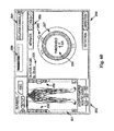
- FIGS. 59-60 are exemplary screen displays (to be shown on the display 190 ) illustrating one embodiment of the nerve direction feature of the monitoring system shown and described with reference to FIG. 57-58 . These screen displays are intended to communicate a variety of information to the surgeon in an easy-to-interpret fashion.
- This information may include, but is not necessarily limited to, a display of the function 230 (in this case “DIRECTION”), a graphical representation of a patient 231 , the myotome levels being monitored 232 , the nerve or group associated with a displayed myotome 233 , the name of the instrument being used 234 (in this case, a dilator), the size of the instrument being used 235 , the stimulation threshold current 236 , a graphical representation of the instrument being used 237 (in this case, a cross-sectional view of a dilator 8 or 9 ) to provide a reference point from which to illustrate relative direction of the instrument to the nerve, the stimulation current being applied to the stimulation electrodes 238 , instructions for the user 239 (in this case, “ADVANCE” and/or “HOLD”), and an arrow 240 indicating the direction from the instrument to a nerve.
- DIRECTION a display of the function 230
- a graphical representation of a patient 231 e.g.,
- This information may be communicated in any number of suitable fashions, including but not limited to the use of visual indicia (such as alpha-numeric characters, light-emitting elements, and/or graphics) and audio communications (such as a speaker element).
- visual indicia such as alpha-numeric characters, light-emitting elements, and/or graphics
- audio communications such as a speaker element.
- a dilating cannula such as at 234
- the present invention is deemed to include providing similar information on the display 190 during the use of any or all of the various instruments forming the surgical access system 6 of the present invention, including the dilation assembly 7 (i.e. the K-wire 42 and dilators 8 and 9 ) and/or the retractor blade 12 or the shim elements 22 , 25 .
- pressure monitoring may be performed during retraction. While not discussed, it should be appreciated that pressure monitoring may also be performed during one or more of the dilation steps prior to retraction.
- any one or more of the dilation components (including any of the sequential dilators) and/or retraction components (including the center blades 12 or 500 , blades 16 , 18 , retractor extenders 22 and/or the shim element 25 , 600 ) may be equipped with a pressure sensor to measure the amount and duration of force applied to tissue containing neural structures.
- one or more pressure sensing elements are provided on one or more of the various dilation and retraction components; (2) a communication link is established between the pressure sensing elements and a processor capable of measuring, displaying, and/or monitoring the amount and duration of force applied to the tissue; (3) the pressure on body tissues is measured as the various components are advanced towards, opened, or maintained at or near the surgical target site; and (4) the degree of dilation and/or retraction is reduced and/or periodically released as needed to minimize or avoid any resulting neurologic deficit patient due to the dilation and/or retraction.
- one or more interpolation algorithms may be employed to quantify or approximate the pressure exerted on tissues between pressure sensing elements as well.
- the processing unit for measuring pressure is integrated within the nerve monitoring system 170 .
- Display 190 may be configured to display alpha-numeric and/or graphic indicia relating to the pressure measurements obtained by pressure sensor 457 (e.g. the amount or duration of pressure applied to adjacent tissue containing neural structures). Warnings may be displayed if the pressure detected advances beyond a minimum threshold magnitude level, beyond a minimum duration, and/or beyond a minimum aggregate (e.g. combination of magnitude and time) threshold.
- a separate pressure monitoring system may be employed.
- the present invention accomplishes the goal of gaining access a surgical target site in a fashion less invasive than traditional “open” surgeries and, moreover, does so in a manner that provides the ability to access such a surgical target site regardless of the neural structures required to be passed through (or near) in order to establish an operative corridor to the surgical target site.
- the present invention furthermore provides the ability to perform neural monitoring in the tissue or regions adjacent the surgical target site during any procedures performed after the operative corridor has been established.
- the surgical access system of the present invention can be used in any of a wide variety of surgical or medical applications, above and beyond the spinal applications discussed herein.
- Such spinal applications may include any procedure wherein instruments, devices, implants and/or compounds are to be introduced into or adjacent the surgical target site, including but not limited to discectomy, fusion (including PLIF, ALIF, TLIF and any fusion effectuated via a lateral or far-lateral approach and involving, by way of example, the introduction and/or removal of bone products (such as allograft or autograft) and/or devices having ceramic, metal and/or plastic construction (such as mesh) and/or compounds such as bone morphogenic protein), total disc replacement, etc.
- discectomy including PLIF, ALIF, TLIF and any fusion effectuated via a lateral or far-lateral approach and involving, by way of example, the introduction and/or removal of bone products (such as allograft or autograft) and/or devices having ceramic, metal and/or plastic construction (such as mesh) and/or compounds such as bone morphogenic protein), total disc replacement, etc.
- fusion including PLIF, ALIF, TLIF and any fusion effectu
- the surgical access system of the present invention opens the possibility of accessing an increased number of surgical target sites in a “less invasive” fashion by eliminating or greatly reducing the threat of contacting nerves or neural structures while establishing an operative corridor through or near tissues containing such nerves or neural structures.
- the surgical access system of the present invention represents a significant advancement capable of improving patient care (via reduced pain due to “less-invasive” access and reduced or eliminated risk of neural contact before, during, and after the establishment of the operative corridor) and lowering health care costs (via reduced hospitalization based on “less-invasive” access and increased number of suitable surgical target sites based on neural monitoring).
Abstract
Description
Claims (24)
Priority Applications (1)
| Application Number | Priority Date | Filing Date | Title |
|---|---|---|---|
| US13/434,845 US9795367B1 (en) | 2003-10-17 | 2012-03-29 | Surgical access system and related methods |
Applications Claiming Priority (7)
| Application Number | Priority Date | Filing Date | Title |
|---|---|---|---|
| US51259403P | 2003-10-17 | 2003-10-17 | |
| US10/967,668 US7905840B2 (en) | 2003-10-17 | 2004-10-18 | Surgical access system and related methods |
| US75835606P | 2006-01-11 | 2006-01-11 | |
| US11/653,173 US8313430B1 (en) | 2006-01-11 | 2007-01-11 | Surgical access system and related methods |
| US12/635,869 US8303515B2 (en) | 2003-09-25 | 2009-12-11 | Surgical access system and related methods |
| US201161468854P | 2011-03-29 | 2011-03-29 | |
| US13/434,845 US9795367B1 (en) | 2003-10-17 | 2012-03-29 | Surgical access system and related methods |
Related Parent Applications (2)
| Application Number | Title | Priority Date | Filing Date |
|---|---|---|---|
| US11/653,173 Continuation-In-Part US8313430B1 (en) | 2003-10-17 | 2007-01-11 | Surgical access system and related methods |
| US12/635,869 Continuation-In-Part US8303515B2 (en) | 2003-09-25 | 2009-12-11 | Surgical access system and related methods |
Related Child Applications (1)
| Application Number | Title | Priority Date | Filing Date |
|---|---|---|---|
| US12/635,869 Continuation US8303515B2 (en) | 2003-09-25 | 2009-12-11 | Surgical access system and related methods |
Publications (1)
| Publication Number | Publication Date |
|---|---|
| US9795367B1 true US9795367B1 (en) | 2017-10-24 |
Family
ID=60082783
Family Applications (1)
| Application Number | Title | Priority Date | Filing Date |
|---|---|---|---|
| US13/434,845 Active 2027-07-16 US9795367B1 (en) | 2003-10-17 | 2012-03-29 | Surgical access system and related methods |
Country Status (1)
| Country | Link |
|---|---|
| US (1) | US9795367B1 (en) |
Cited By (34)
| Publication number | Priority date | Publication date | Assignee | Title |
|---|---|---|---|---|
| US20170333023A1 (en) * | 2016-05-20 | 2017-11-23 | Choicespine, Lp | Access Instruments To Extend A Surgical Working Channel |
| US20180000604A1 (en) * | 2009-04-16 | 2018-01-04 | Nuvasive, Inc. | Methods and Apparatus for Performing Spine Surgery |
| US20190167246A1 (en) * | 2012-09-26 | 2019-06-06 | DePuy Synthes Products, Inc. | Nir/red light for lateral neuroprotection |
| US20190183476A1 (en) * | 2016-10-04 | 2019-06-20 | Jgmg Bengochea, Llc | Retractor extension clip systems |
| US10624623B1 (en) | 2019-02-12 | 2020-04-21 | Edward Rustamzadeh | Lateral retractor system for minimizing muscle damage in spinal surgery |
| US10631842B1 (en) * | 2019-02-12 | 2020-04-28 | Edward Rustamzadeh | Lateral retraction system for minimizing muscle damage in spinal surgery |
| US20200188135A1 (en) * | 2009-12-07 | 2020-06-18 | Samy Abdou | Devices and methods for minimally invasive spinal stabilization and instrumentation |
| US10799230B2 (en) | 2019-02-12 | 2020-10-13 | Edward Rustamzadeh | Lateral retractor system for minimizing muscle damage in spinal surgery |
| US10857003B1 (en) | 2015-10-14 | 2020-12-08 | Samy Abdou | Devices and methods for vertebral stabilization |
| US20210030424A1 (en) * | 2019-07-29 | 2021-02-04 | Boston Scientific Limited | Devices and methods for treatment of hemorrhoids |
| US10925593B2 (en) | 2019-02-12 | 2021-02-23 | Edward Rustamzadeh | Lateral retractor system for minimizing muscle damage in spinal surgery |
| US10973648B1 (en) | 2016-10-25 | 2021-04-13 | Samy Abdou | Devices and methods for vertebral bone realignment |
| CN112932570A (en) * | 2021-01-30 | 2021-06-11 | 江西省人民医院 | Dilator for orthopedic surgery |
| US20210186477A1 (en) * | 2019-12-20 | 2021-06-24 | Medos International Sarl | Retractor Members, And Related Systems And Methods |
| US11058548B1 (en) | 2016-10-25 | 2021-07-13 | Samy Abdou | Devices and methods for vertebral bone realignment |
| US11096799B2 (en) | 2004-11-24 | 2021-08-24 | Samy Abdou | Devices and methods for inter-vertebral orthopedic device placement |
| US11173040B2 (en) | 2012-10-22 | 2021-11-16 | Cogent Spine, LLC | Devices and methods for spinal stabilization and instrumentation |
| US11179248B2 (en) | 2018-10-02 | 2021-11-23 | Samy Abdou | Devices and methods for spinal implantation |
| US11246582B2 (en) | 2019-02-12 | 2022-02-15 | Edward Rustamzadeh | Dual-motion rotation and retraction system for minimizing muscle damage in spinal surgery |
| US11253243B2 (en) | 2019-06-18 | 2022-02-22 | Nuvasive, Inc. | Tissue retraction system |
| US11324608B2 (en) | 2011-09-23 | 2022-05-10 | Samy Abdou | Spinal fixation devices and methods of use |
| USD956225S1 (en) | 2020-05-12 | 2022-06-28 | Innovasis, Inc. | Surgical retractor |
| USD956224S1 (en) | 2020-05-12 | 2022-06-28 | Innovasis, Inc. | Surgical retractor |
| USD956223S1 (en) | 2020-05-12 | 2022-06-28 | Innovasis, Inc. | Surgical retractor |
| EP4039196A1 (en) * | 2021-02-03 | 2022-08-10 | Warsaw Orthopedic, Inc. | Modular surgical instrument system for shank-based retraction and distraction |
| US11432810B2 (en) | 2020-05-12 | 2022-09-06 | Innovasis, Inc. | Systems and methods for surgical retraction |
| US11547395B2 (en) | 2019-06-18 | 2023-01-10 | Nuvasive, Inc. | Tissue retraction system |
| US11559336B2 (en) | 2012-08-28 | 2023-01-24 | Samy Abdou | Spinal fixation devices and methods of use |
| US11602337B2 (en) | 2019-04-24 | 2023-03-14 | Nuvasive, Inc. | Transmission assembly |
| US11744569B2 (en) | 2019-02-12 | 2023-09-05 | Edward Rustamzadeh | Lateral retractor system for minimizing muscle damage in spinal surgery |
| USD1002842S1 (en) | 2021-06-29 | 2023-10-24 | Edward Rustamzadeh | Combination surgical spinal dilator and retractor system |
| US11839413B2 (en) | 2012-02-22 | 2023-12-12 | Samy Abdou | Spinous process fixation devices and methods of use |
| US11931113B2 (en) | 2020-08-03 | 2024-03-19 | Mazor Robotics Ltd. | Systems, devices, and methods for retractor interference avoidance |
| US11944356B2 (en) | 2019-11-22 | 2024-04-02 | Medos International Sarl | Control member for adjusting access tube position, and related systems and methods |
Citations (170)
| Publication number | Priority date | Publication date | Assignee | Title |
|---|---|---|---|---|
| US1194319A (en) | 1916-08-08 | Vaginal | ||
| US2693795A (en) | 1950-09-09 | 1954-11-09 | Herman R Grieshaber | Surgical retractor |
| US2807259A (en) | 1955-02-24 | 1957-09-24 | Federico D C Guerriero | Vaginal speculum and surgical retractor |
| US3467079A (en) | 1967-04-14 | 1969-09-16 | David Charles James | Gall bladder and common duct retractor |
| US3509873A (en) | 1967-04-24 | 1970-05-05 | Jack B Karlin | Retractor |
| GB1210410A (en) | 1966-12-24 | 1970-10-28 | Heinrich Walter Peters | Improvements in or relating to frames particularly for windows |
| US3680546A (en) | 1970-10-30 | 1972-08-01 | Instrumentation For Medicine I | Illuminated surgical retractor |
| US3724449A (en) | 1970-10-19 | 1973-04-03 | W Gauthier | Retractor apparatus |
| US3888117A (en) | 1973-07-16 | 1975-06-10 | Minnesota Mining & Mfg | Pressure sensor and instrument utilizing same |
| US3998217A (en) | 1975-01-13 | 1976-12-21 | William E. Trumbull | Surgical retractor device |
| US4010741A (en) | 1976-01-22 | 1977-03-08 | William Kohlmann Gauthier | Surgical retractor |
| US4156424A (en) | 1978-05-01 | 1979-05-29 | Burgin Kermit H | Locking adjustable speculum |
| US4165746A (en) | 1977-06-30 | 1979-08-28 | Burgin Kermit H | Plastic forceps |
| CA1142826A (en) | 1978-11-08 | 1983-03-15 | Kermit H. Burgin | Locking adjustable speculum |
| US4617916A (en) | 1984-11-08 | 1986-10-21 | Minnesota Scientific, Inc. | Retractor apparatus |
| US4627421A (en) | 1984-08-03 | 1986-12-09 | Symbas Panagiotis N | Sternal retractor |
| US4726356A (en) | 1985-11-12 | 1988-02-23 | Kapp Surgical Instrument, Inc. | Cardiovascular and thoracic retractor |
| US4813401A (en) | 1986-11-26 | 1989-03-21 | Grieshaber Manufacturing Company | Retractor |
| US4945896A (en) | 1989-01-24 | 1990-08-07 | Gade George F | Surgical retractor assembly having tissue viability sensor embedded therein |
| US4955884A (en) | 1988-06-02 | 1990-09-11 | Circon Corporation | System for reducing drag on the movement of an electrode in a resectoscope |
| US5052374A (en) | 1990-08-06 | 1991-10-01 | Alvarez Jacinto Manuel | Hernia retractor |
| US5152279A (en) | 1991-11-15 | 1992-10-06 | Wilk Peter J | Retractor and associated method for use in laparoscopic surgery |
| US5195505A (en) | 1990-12-27 | 1993-03-23 | United States Surgical Corporation | Surgical retractor |
| US5199419A (en) | 1991-08-05 | 1993-04-06 | United States Surgical Corporation | Surgical retractor |
| US5231974A (en) | 1991-05-31 | 1993-08-03 | Giglio Steven R | Self retaining retractor |
| WO1993020741A1 (en) | 1992-04-08 | 1993-10-28 | Jako Geza J | Percutaneous surgical endoscopy |
| US5280782A (en) | 1991-11-15 | 1994-01-25 | Wilk Peter J | Variable length laparoscopic retractor and associated method of use |
| US5339801A (en) | 1992-03-12 | 1994-08-23 | Uresil Corporation | Surgical retractor and surgical method |
| US5375481A (en) | 1993-11-12 | 1994-12-27 | Codman & Shurtleff, Inc. | Multi-position ratchet mechanism |
| US5474056A (en) | 1991-09-18 | 1995-12-12 | Laborie Enterprises Inc. | Suspension and retraction system for endoscopic surgery and method for using same |
| US5474558A (en) * | 1992-04-30 | 1995-12-12 | Neubardt; Seth L. | Procedure and system for spinal pedicle screw insertion |
| DE4425652A1 (en) | 1994-07-20 | 1996-02-01 | Psl Plastic Surgery Licensor A | Device for holding open and spreading wound |
| US5520610A (en) | 1991-05-31 | 1996-05-28 | Giglio; Steven R. | Self retaining retractor |
| US5769781A (en) * | 1995-11-13 | 1998-06-23 | Chappuis; James L. | Protector retractor |
| US5772583A (en) | 1994-01-21 | 1998-06-30 | Wright; John T. M. | Sternal retractor with attachments for mitral & tricuspid valve repair |
| US5785647A (en) | 1996-07-31 | 1998-07-28 | United States Surgical Corporation | Surgical instruments useful for spinal surgery |
| US5807270A (en) | 1994-06-20 | 1998-09-15 | Williams; Christopher Edward | Brain damage monitor |
| US5885210A (en) | 1998-09-21 | 1999-03-23 | Cox; Victor M. | Surgical retractor |
| US5902233A (en) | 1996-12-13 | 1999-05-11 | Thompson Surgical Instruments, Inc. | Angling surgical retractor apparatus and method of retracting anatomy |
| US5931777A (en) * | 1998-03-11 | 1999-08-03 | Sava; Gerard A. | Tissue retractor and method for use |
| US5944658A (en) | 1997-09-23 | 1999-08-31 | Koros; Tibor B. | Lumbar spinal fusion retractor and distractor system |
| US5947896A (en) | 1996-04-26 | 1999-09-07 | United States Surgical Corporation | Heart stabilizer apparatus and method for use |
| US5954739A (en) * | 1990-03-02 | 1999-09-21 | General Surgical Innovations, Inc. | Method of dissecting tissue layers |
| EP0951868A1 (en) | 1998-04-27 | 1999-10-27 | Waldemar Link (GmbH & Co.) | Surgical retractor |
| US6024696A (en) | 1998-04-24 | 2000-02-15 | Hoftman; Moshe | Side wall support speculum |
| US6050996A (en) | 1997-11-12 | 2000-04-18 | Sherwood Services Ag | Bipolar electrosurgical instrument with replaceable electrodes |
| US6074343A (en) | 1999-04-16 | 2000-06-13 | Nathanson; Michael | Surgical tissue retractor |
| US6083154A (en) | 1997-10-23 | 2000-07-04 | Sofamor S.N.C. | Surgical instrumentation and method for retracting and shifting tissues |
| US6099468A (en) | 1999-01-15 | 2000-08-08 | Kapp Surgical Instrument, Inc. | Retractor for partial sternotomy |
| US6213940B1 (en) | 1996-04-26 | 2001-04-10 | United States Surgical Corporation | Surgical retractor including coil spring suture mount |
| US6224545B1 (en) | 1998-07-24 | 2001-05-01 | Core Surgical, Inc. | Surgical retractor and method for use |
| US6231506B1 (en) | 1999-05-04 | 2001-05-15 | Cardiothoracic Systems, Inc. | Method and apparatus for creating a working opening through an incision |
| US6254532B1 (en) | 1998-05-22 | 2001-07-03 | Coroneo Inc. | Surgical apparatus and method |
| US6264605B1 (en) | 1998-01-23 | 2001-07-24 | United States Surgical Corporation | Surgical instrument |
| US6273853B1 (en) | 1997-09-30 | 2001-08-14 | Coroneo Inc. | Sternum retractor for performing bypass surgery on a beating heart |
| US6283912B1 (en) | 1999-05-04 | 2001-09-04 | Cardiothoracic Systems, Inc. | Surgical retractor platform blade apparatus |
| US6322500B1 (en) | 1996-12-23 | 2001-11-27 | University Of Massachusetts | Minimally invasive surgical apparatus |
| US6340345B1 (en) | 1999-03-18 | 2002-01-22 | Automated Medical Products Corp. | Surgical retractor blade and handle for movement with two degrees of freedom |
| US20020013514A1 (en) * | 2000-04-14 | 2002-01-31 | Brau Salvador A. | Surgical retractor and related surgical approach to access the anterior lumbar region |
| US6511423B2 (en) | 2001-01-17 | 2003-01-28 | Thompson Surgical Instruments, Inc. | Cross bar for a surgical retractor system |
| US6685632B1 (en) | 1999-05-04 | 2004-02-03 | Cardiothoracic Systems, Inc. | Surgical instruments for accessing and stabilizing a localized portion of a beating heart |
| US6712795B1 (en) | 2002-06-07 | 2004-03-30 | Lester Cohen | Surgical procedure and apparatus |
| US6837851B1 (en) | 1999-10-18 | 2005-01-04 | Coroneo, Inc. | Adjustable surgical retractor |
| US6849064B2 (en) | 2002-10-25 | 2005-02-01 | James S. Hamada | Minimal access lumbar diskectomy instrumentation and method |
| US6929606B2 (en) | 2001-01-29 | 2005-08-16 | Depuy Spine, Inc. | Retractor and method for spinal pedicle screw placement |
| US6945933B2 (en) | 2002-06-26 | 2005-09-20 | Sdgi Holdings, Inc. | Instruments and methods for minimally invasive tissue retraction and surgery |
| US6951538B2 (en) | 2001-01-29 | 2005-10-04 | Depuy Spine, Inc. | Retractor and method for spinal pedicle screw placement |
| US6994669B1 (en) | 1999-04-15 | 2006-02-07 | Heartport, Inc. | Apparatus and method for cardiac surgery |
| US20060074278A1 (en) | 2004-09-02 | 2006-04-06 | Dominique Petit | Tissue retractor producing a widened operating channel |
| WO2006042241A2 (en) * | 2004-10-08 | 2006-04-20 | Nuvasive, Inc. | Surgical access system and related methods |
| US7052457B2 (en) | 2002-07-11 | 2006-05-30 | Fanous Refaat S | Self-retaining retractor |
| US20060224044A1 (en) | 2005-03-31 | 2006-10-05 | Depuy Spine, Inc. | Surgical retractors and methods of use |
| US7135020B2 (en) | 1997-11-12 | 2006-11-14 | Sherwood Services Ag | Electrosurgical instrument reducing flashover |
| US7141015B2 (en) | 2003-05-09 | 2006-11-28 | Bernard Joseph Ruane | Expandable and pivotally adjustable surgical retractor |
| WO2007002405A2 (en) | 2005-06-22 | 2007-01-04 | K2M, Inc. | Minimal incision maximal access mis spine instrumentation and method |
| US20070021682A1 (en) * | 2005-07-20 | 2007-01-25 | Nuvasive Inc. | System and methods for performing neurophysiologic assessments with pressure monitoring |
| US20070038033A1 (en) | 2005-04-25 | 2007-02-15 | Depuy Spine, Inc. | Cassette based surgical retractor |
| US7182729B2 (en) | 2003-09-18 | 2007-02-27 | Stryker Spine | Surgical retractor with removable scissor arms |
| US20070156025A1 (en) | 2006-01-04 | 2007-07-05 | Connie Marchek | Surgical retractors and methods of minimally invasive surgery |
| EP1829488A1 (en) | 2006-03-01 | 2007-09-05 | Ansabere Surgical S.L. | Improved retractor for surgical use |
| US20070208228A1 (en) | 2006-03-01 | 2007-09-06 | Nicholas Pavento | Surgical retractors and methods of minimally invasive surgery |
| US20070290369A1 (en) | 2004-06-18 | 2007-12-20 | Hitachi Chemical Co., Ltd. | Resin Paste For Die Bonding And Its Use |
| US7374534B2 (en) | 2005-03-09 | 2008-05-20 | Dalton Brian E | Retractor and method for percutaneous tissue retraction and surgery |
| US20080183044A1 (en) | 2007-01-26 | 2008-07-31 | Dennis Colleran | Flexible surgical retractor and method of use |
| US20080195102A1 (en) | 2004-09-15 | 2008-08-14 | Paul Andrew Glazer | Hand Held Integrated Pedicle Screw Placement Device |
| US20080221586A1 (en) * | 2007-02-09 | 2008-09-11 | Alphatec Spine, Inc. | Curviliner spinal access method and device |
| US20080234550A1 (en) | 2005-05-26 | 2008-09-25 | Hawkes David T | Minimally Traumatic Portal |
| US7435249B2 (en) | 1997-11-12 | 2008-10-14 | Covidien Ag | Electrosurgical instruments which reduces collateral damage to adjacent tissue |
| US7435219B2 (en) | 2004-03-25 | 2008-10-14 | Depuy Spine, Inc. | Surgical retractor positioning device |
| US20080319290A1 (en) | 2007-06-22 | 2008-12-25 | Vioptix, Inc. | Tissue Retractor Oximeter |
| US7481766B2 (en) | 2003-08-14 | 2009-01-27 | Synthes (U.S.A.) | Multiple-blade retractor |
| US20090062619A1 (en) | 2007-03-26 | 2009-03-05 | Bjork Todd M | Methods and apparatus for surgical retraction |
| US20090069635A1 (en) | 2006-01-23 | 2009-03-12 | Pioneer Surgical Technology, Inc. | Retraction Apparatus And Method Of Use |
| US20090076516A1 (en) | 2007-09-13 | 2009-03-19 | David Lowry | Device and method for tissue retraction in spinal surgery |
| US20090105547A1 (en) | 2007-04-20 | 2009-04-23 | Spotlight Surgical, Inc. | Adjustable Retractor Blade |
| US7537565B2 (en) | 2005-09-27 | 2009-05-26 | Daniel Bass | Surgical retractor with rotating blades |
| US20090143649A1 (en) | 2007-11-30 | 2009-06-04 | Physion Srl | Speculum for the electropharmacological treatment of vaginal diseases |
| US7582058B1 (en) | 2002-06-26 | 2009-09-01 | Nuvasive, Inc. | Surgical access system and related methods |
| US20090259110A1 (en) | 2006-02-14 | 2009-10-15 | Metech S.R.L. | Process and a device for surgical treatment of rectal and haemorrhoidal prolapse |
| US20090264710A1 (en) | 2006-04-29 | 2009-10-22 | Comis Orthopaedics Limited | Surgical apparatus |
| US7632269B2 (en) | 2004-01-16 | 2009-12-15 | Ethicon Endo-Surgery, Inc. | Electrosurgical instrument with replaceable cartridge |
| US7641659B2 (en) | 2003-03-13 | 2010-01-05 | Zimmer Spine, Inc. | Spinal access instrument |
| US20100010334A1 (en) | 2005-05-16 | 2010-01-14 | Bleich Jeffery L | Spinal access and neural localization |
| US7691057B2 (en) | 2003-01-16 | 2010-04-06 | Nuvasive, Inc. | Surgical access system and related methods |
| US20100160737A1 (en) * | 2008-12-23 | 2010-06-24 | Josh Shachar | Brain retractor apparatus for measuring and predicting electrophysiological parameters |
| US7819801B2 (en) | 2003-02-27 | 2010-10-26 | Nuvasive, Inc. | Surgical access system and related methods |
| WO2010121291A1 (en) | 2009-04-19 | 2010-10-28 | Kevin Seex | Assembly for spinal surgery including cannulated retractor blade |
| WO2010125598A1 (en) | 2009-04-29 | 2010-11-04 | Lrnerio Angelo Muttillo | An autostatic retractor with screw closure mechanism for neck surgery |
| WO2010136860A1 (en) | 2009-04-22 | 2010-12-02 | Smart Hospital S.R.L. | A toolkit for implanting a vertebral support |
| US20100312068A1 (en) | 2009-06-08 | 2010-12-09 | Dalton Brian E | Surgical retractor |
| US7850608B2 (en) | 2002-10-25 | 2010-12-14 | K2M, Inc. | Minimal incision maximal access MIS spine instrumentation and method |
| US7905840B2 (en) | 2003-10-17 | 2011-03-15 | Nuvasive, Inc. | Surgical access system and related methods |
| US7922657B2 (en) | 2002-05-03 | 2011-04-12 | Alan Marc Gillinov | Surgical retractors and method of operation |
| US7931589B2 (en) | 2006-11-09 | 2011-04-26 | Ebi, Llc | Surgical retractor device and related methods |
| US7931591B2 (en) | 2004-09-03 | 2011-04-26 | Mccarthy Patrick M | Surgical retractor |
| US7946982B2 (en) | 2002-10-25 | 2011-05-24 | K2M, Inc. | Minimal incision maximal access MIS spine instrumentation and method |
| US20110137130A1 (en) | 2009-12-03 | 2011-06-09 | John Thalgott | Posterior Lumbar Retractor System |
| US20110144450A1 (en) | 2009-10-19 | 2011-06-16 | Anthony Paolitto | Tissue retractor with movable blades and articulating wrist joint |
| US7976463B2 (en) | 2002-06-26 | 2011-07-12 | Warsaw Orthopedic, Inc. | Instruments and methods for minimally invasive tissue retraction and surgery |
| US20110172494A1 (en) | 2010-01-12 | 2011-07-14 | Tedan Surgical | Surgical retractor with curved rotating blades |
| US7981031B2 (en) | 2006-01-04 | 2011-07-19 | Depuy Spine, Inc. | Surgical access devices and methods of minimally invasive surgery |
| US20110224497A1 (en) | 2010-03-11 | 2011-09-15 | Mark Weiman | Tissue Retractor and Methods Of Use |
| US20110237902A1 (en) | 2008-06-25 | 2011-09-29 | Howard Steven Rosen | Examination Apparatus |
| US20110301421A1 (en) | 2010-02-24 | 2011-12-08 | Meni-Med Ltd | Surgical retractor |
| US20110301422A1 (en) | 2009-11-10 | 2011-12-08 | Troy Woolley | Method and Apparatus for Performing Spinal fusion Surgery |
| US20110301423A1 (en) | 2007-10-22 | 2011-12-08 | Tibor Koros | Surgical retractor systems |
| US8100828B2 (en) | 2002-11-23 | 2012-01-24 | George Frey | Distraction and retraction system for spinal surgery |
| US20120046527A1 (en) | 2010-03-11 | 2012-02-23 | Jason Cianfrani | Tissue Retractor and Method of Use |
| US8137284B2 (en) | 2002-10-08 | 2012-03-20 | Nuvasive, Inc. | Surgical access system and related methods |
| US20120083662A1 (en) | 2010-10-01 | 2012-04-05 | K2M, Inc. | Retractor |
| US8152720B2 (en) | 2009-08-05 | 2012-04-10 | Thomas Stuart Loftus | Retracto component system and method of using same |
| US20120130180A1 (en) | 2009-04-13 | 2012-05-24 | Physcient, Inc. | Methods and devices to decrease tissue trauma during surgery |
| US20120136392A1 (en) | 2009-03-16 | 2012-05-31 | Synthes Usa, Llc | System and Method for Stabilizing Vertebrae in Spine Surgery Through a Lateral Access Channel |
| US8206293B2 (en) | 2007-03-30 | 2012-06-26 | Exactech, Inc. | Retractor |
| WO2012093368A1 (en) | 2011-01-06 | 2012-07-12 | Dymond Ian Walter Dryden | A retractor for use in surgery |
| US8226554B2 (en) | 2008-10-30 | 2012-07-24 | Warsaw Orthopedic, Inc. | Retractor assemblies for surgery in a patient |
| US8251997B2 (en) | 1988-06-13 | 2012-08-28 | Warsaw Orthopedic, Inc. | Method for inserting an artificial implant between two adjacent vertebrae along a coronal plane |
| US8257255B2 (en) | 2009-02-24 | 2012-09-04 | Thompson Surgical Instruments, Inc. | Surgical retractor with locking blade |
| US8262570B2 (en) | 2008-05-30 | 2012-09-11 | Pioneer Surgical Technology, Inc. | Retraction apparatus and method of use |
| US8267859B2 (en) | 2005-09-28 | 2012-09-18 | Holmed Corporation | Spreader insert for a retractor system |
| US20120245431A1 (en) | 2010-09-20 | 2012-09-27 | Cyril Baudouin | Spinal Access Retractor |
| US20120245432A1 (en) | 2006-06-06 | 2012-09-27 | Edward Karpowicz | Surgical Retractor System |
| US8313430B1 (en) | 2006-01-11 | 2012-11-20 | Nuvasive, Inc. | Surgical access system and related methods |
| US20120330106A1 (en) | 2011-06-24 | 2012-12-27 | Genesee Biomedical, Inc. | Thoracic retractors and methods |
| WO2013000105A1 (en) | 2011-06-29 | 2013-01-03 | Shao Weixing | Pipe support for expanding channel pipe |
| US8360971B2 (en) | 2009-02-24 | 2013-01-29 | Thompson Surgical Instruments, Inc. | Surgical retractor angling device |
| US8376937B2 (en) * | 2010-01-28 | 2013-02-19 | Warsaw Orhtopedic, Inc. | Tissue monitoring surgical retractor system |
| US8425602B2 (en) | 2007-02-09 | 2013-04-23 | Alphatec Spine, Inc. | Curvilinear spinal access method and device |
| US20130123581A1 (en) | 2011-11-14 | 2013-05-16 | Biomet Manufacturing Corp. | Self-retaining retractor |
| US8449463B2 (en) | 2010-10-08 | 2013-05-28 | K2M, Inc. | Lateral access system and method of use |
| US20130158359A1 (en) | 2011-12-20 | 2013-06-20 | Daniel Predick | Three-Blade Spinal Retractor |
| US20130190575A1 (en) | 2011-08-31 | 2013-07-25 | Lanx, Inc. | Lateral Retractor System and Methods of Use |
| US8517935B2 (en) | 2006-01-04 | 2013-08-27 | DePuy Synthes Products, LLC | Surgical retractors and methods of minimally invasive surgery |
| US20130261401A1 (en) | 2012-03-30 | 2013-10-03 | Depuy Spine, Inc. | Methods and Devices for Tissue Retraction |
| US8562621B2 (en) | 2007-07-06 | 2013-10-22 | Luis A. Mignucci | Anterior spinal interbody fusion delivery system |
| US8568306B2 (en) | 2009-04-03 | 2013-10-29 | Mitchell A Hardenbrook | Surgical retractor system |
| JP3187929U (en) | 2006-11-09 | 2013-12-26 | イービーアイ,リミテッド ライアビリティ カンパニー | Retractor |
| US20140024900A1 (en) | 2012-07-17 | 2014-01-23 | Warsaw Orthopedic, Inc. | Surgical retractor and method of use |
| US8636655B1 (en) | 2010-01-19 | 2014-01-28 | Ronald Childs | Tissue retraction system and related methods |
| US8636656B2 (en) | 2011-08-16 | 2014-01-28 | Warsaw Orthopedic, Inc. | Retractor assemblies with blade drive mechanisms |
| US20140066718A1 (en) | 2012-09-06 | 2014-03-06 | Medacta International Sa | Surgical device for minimally invasive spinal fusion and surgical system comprising the same |
| US20140073857A1 (en) | 2011-10-05 | 2014-03-13 | Mark A. Dodson | Modular Retractor And Related Method |
| CN203506775U (en) | 2013-08-15 | 2014-04-02 | 北京瑞克斡医疗科技有限公司 | Turnover retractor |
| US8715175B2 (en) | 2010-06-09 | 2014-05-06 | Karl Storz Gmbh & Co. Kg | Thoracic retractor |
| US20140128979A1 (en) | 2011-11-15 | 2014-05-08 | Baxano Surgical, Inc. | Implants for Spinal Therapy |
| US8821394B2 (en) | 2012-03-30 | 2014-09-02 | DePuy Synthes Products, LLC | Methods and devices for tissue retraction |
| US8821396B1 (en) | 2003-09-25 | 2014-09-02 | Nuvasive, Inc. | Surgical access system and related methods |
| US8852090B2 (en) | 2012-03-13 | 2014-10-07 | Globus Medical, Inc. | System and method for retracting body tissue |
| US8876687B2 (en) | 2006-03-08 | 2014-11-04 | Zimmer Spine, Inc. | Surgical retractor and retractor assembly |
| US8882661B2 (en) | 2006-09-22 | 2014-11-11 | Alphatec Spine, Inc. | Retractor |
-
2012
- 2012-03-29 US US13/434,845 patent/US9795367B1/en active Active
Patent Citations (174)
| Publication number | Priority date | Publication date | Assignee | Title |
|---|---|---|---|---|
| US1194319A (en) | 1916-08-08 | Vaginal | ||
| US2693795A (en) | 1950-09-09 | 1954-11-09 | Herman R Grieshaber | Surgical retractor |
| US2807259A (en) | 1955-02-24 | 1957-09-24 | Federico D C Guerriero | Vaginal speculum and surgical retractor |
| GB1210410A (en) | 1966-12-24 | 1970-10-28 | Heinrich Walter Peters | Improvements in or relating to frames particularly for windows |
| US3467079A (en) | 1967-04-14 | 1969-09-16 | David Charles James | Gall bladder and common duct retractor |
| US3509873A (en) | 1967-04-24 | 1970-05-05 | Jack B Karlin | Retractor |
| US3724449A (en) | 1970-10-19 | 1973-04-03 | W Gauthier | Retractor apparatus |
| US3680546A (en) | 1970-10-30 | 1972-08-01 | Instrumentation For Medicine I | Illuminated surgical retractor |
| US3888117A (en) | 1973-07-16 | 1975-06-10 | Minnesota Mining & Mfg | Pressure sensor and instrument utilizing same |
| US3998217A (en) | 1975-01-13 | 1976-12-21 | William E. Trumbull | Surgical retractor device |
| US4010741A (en) | 1976-01-22 | 1977-03-08 | William Kohlmann Gauthier | Surgical retractor |
| US4165746A (en) | 1977-06-30 | 1979-08-28 | Burgin Kermit H | Plastic forceps |
| US4156424A (en) | 1978-05-01 | 1979-05-29 | Burgin Kermit H | Locking adjustable speculum |
| CA1142826A (en) | 1978-11-08 | 1983-03-15 | Kermit H. Burgin | Locking adjustable speculum |
| US4627421A (en) | 1984-08-03 | 1986-12-09 | Symbas Panagiotis N | Sternal retractor |
| US4617916A (en) | 1984-11-08 | 1986-10-21 | Minnesota Scientific, Inc. | Retractor apparatus |
| US4726356A (en) | 1985-11-12 | 1988-02-23 | Kapp Surgical Instrument, Inc. | Cardiovascular and thoracic retractor |
| US4813401A (en) | 1986-11-26 | 1989-03-21 | Grieshaber Manufacturing Company | Retractor |
| US4955884A (en) | 1988-06-02 | 1990-09-11 | Circon Corporation | System for reducing drag on the movement of an electrode in a resectoscope |
| US8251997B2 (en) | 1988-06-13 | 2012-08-28 | Warsaw Orthopedic, Inc. | Method for inserting an artificial implant between two adjacent vertebrae along a coronal plane |
| US4945896A (en) | 1989-01-24 | 1990-08-07 | Gade George F | Surgical retractor assembly having tissue viability sensor embedded therein |
| US5954739A (en) * | 1990-03-02 | 1999-09-21 | General Surgical Innovations, Inc. | Method of dissecting tissue layers |
| US5052374A (en) | 1990-08-06 | 1991-10-01 | Alvarez Jacinto Manuel | Hernia retractor |
| US5195505A (en) | 1990-12-27 | 1993-03-23 | United States Surgical Corporation | Surgical retractor |
| US5520610A (en) | 1991-05-31 | 1996-05-28 | Giglio; Steven R. | Self retaining retractor |
| US5231974A (en) | 1991-05-31 | 1993-08-03 | Giglio Steven R | Self retaining retractor |
| US5199419A (en) | 1991-08-05 | 1993-04-06 | United States Surgical Corporation | Surgical retractor |
| US5474056A (en) | 1991-09-18 | 1995-12-12 | Laborie Enterprises Inc. | Suspension and retraction system for endoscopic surgery and method for using same |
| US5152279A (en) | 1991-11-15 | 1992-10-06 | Wilk Peter J | Retractor and associated method for use in laparoscopic surgery |
| US5280782A (en) | 1991-11-15 | 1994-01-25 | Wilk Peter J | Variable length laparoscopic retractor and associated method of use |
| US5339801A (en) | 1992-03-12 | 1994-08-23 | Uresil Corporation | Surgical retractor and surgical method |
| WO1993020741A1 (en) | 1992-04-08 | 1993-10-28 | Jako Geza J | Percutaneous surgical endoscopy |
| US5474558A (en) * | 1992-04-30 | 1995-12-12 | Neubardt; Seth L. | Procedure and system for spinal pedicle screw insertion |
| US5375481A (en) | 1993-11-12 | 1994-12-27 | Codman & Shurtleff, Inc. | Multi-position ratchet mechanism |
| US5772583A (en) | 1994-01-21 | 1998-06-30 | Wright; John T. M. | Sternal retractor with attachments for mitral & tricuspid valve repair |
| US5807270A (en) | 1994-06-20 | 1998-09-15 | Williams; Christopher Edward | Brain damage monitor |
| DE4425652A1 (en) | 1994-07-20 | 1996-02-01 | Psl Plastic Surgery Licensor A | Device for holding open and spreading wound |
| US5769781A (en) * | 1995-11-13 | 1998-06-23 | Chappuis; James L. | Protector retractor |
| US5947896A (en) | 1996-04-26 | 1999-09-07 | United States Surgical Corporation | Heart stabilizer apparatus and method for use |
| US6213940B1 (en) | 1996-04-26 | 2001-04-10 | United States Surgical Corporation | Surgical retractor including coil spring suture mount |
| US5785647A (en) | 1996-07-31 | 1998-07-28 | United States Surgical Corporation | Surgical instruments useful for spinal surgery |
| US5902233A (en) | 1996-12-13 | 1999-05-11 | Thompson Surgical Instruments, Inc. | Angling surgical retractor apparatus and method of retracting anatomy |
| US6322500B1 (en) | 1996-12-23 | 2001-11-27 | University Of Massachusetts | Minimally invasive surgical apparatus |
| US5944658A (en) | 1997-09-23 | 1999-08-31 | Koros; Tibor B. | Lumbar spinal fusion retractor and distractor system |
| US6273853B1 (en) | 1997-09-30 | 2001-08-14 | Coroneo Inc. | Sternum retractor for performing bypass surgery on a beating heart |
| US6083154A (en) | 1997-10-23 | 2000-07-04 | Sofamor S.N.C. | Surgical instrumentation and method for retracting and shifting tissues |
| US7435249B2 (en) | 1997-11-12 | 2008-10-14 | Covidien Ag | Electrosurgical instruments which reduces collateral damage to adjacent tissue |
| US6050996A (en) | 1997-11-12 | 2000-04-18 | Sherwood Services Ag | Bipolar electrosurgical instrument with replaceable electrodes |
| US7135020B2 (en) | 1997-11-12 | 2006-11-14 | Sherwood Services Ag | Electrosurgical instrument reducing flashover |
| US7160298B2 (en) | 1997-11-12 | 2007-01-09 | Sherwood Services Ag | Electrosurgical instrument which reduces effects to adjacent tissue structures |
| US6264605B1 (en) | 1998-01-23 | 2001-07-24 | United States Surgical Corporation | Surgical instrument |
| US5931777A (en) * | 1998-03-11 | 1999-08-03 | Sava; Gerard A. | Tissue retractor and method for use |
| US6024696A (en) | 1998-04-24 | 2000-02-15 | Hoftman; Moshe | Side wall support speculum |
| EP0951868A1 (en) | 1998-04-27 | 1999-10-27 | Waldemar Link (GmbH & Co.) | Surgical retractor |
| US6254532B1 (en) | 1998-05-22 | 2001-07-03 | Coroneo Inc. | Surgical apparatus and method |
| US6224545B1 (en) | 1998-07-24 | 2001-05-01 | Core Surgical, Inc. | Surgical retractor and method for use |
| US5885210A (en) | 1998-09-21 | 1999-03-23 | Cox; Victor M. | Surgical retractor |
| US6099468A (en) | 1999-01-15 | 2000-08-08 | Kapp Surgical Instrument, Inc. | Retractor for partial sternotomy |
| US6340345B1 (en) | 1999-03-18 | 2002-01-22 | Automated Medical Products Corp. | Surgical retractor blade and handle for movement with two degrees of freedom |
| US6994669B1 (en) | 1999-04-15 | 2006-02-07 | Heartport, Inc. | Apparatus and method for cardiac surgery |
| US6074343A (en) | 1999-04-16 | 2000-06-13 | Nathanson; Michael | Surgical tissue retractor |
| US6283912B1 (en) | 1999-05-04 | 2001-09-04 | Cardiothoracic Systems, Inc. | Surgical retractor platform blade apparatus |
| US6685632B1 (en) | 1999-05-04 | 2004-02-03 | Cardiothoracic Systems, Inc. | Surgical instruments for accessing and stabilizing a localized portion of a beating heart |
| US6231506B1 (en) | 1999-05-04 | 2001-05-15 | Cardiothoracic Systems, Inc. | Method and apparatus for creating a working opening through an incision |
| US6837851B1 (en) | 1999-10-18 | 2005-01-04 | Coroneo, Inc. | Adjustable surgical retractor |
| US20020013514A1 (en) * | 2000-04-14 | 2002-01-31 | Brau Salvador A. | Surgical retractor and related surgical approach to access the anterior lumbar region |
| US6511423B2 (en) | 2001-01-17 | 2003-01-28 | Thompson Surgical Instruments, Inc. | Cross bar for a surgical retractor system |
| US6929606B2 (en) | 2001-01-29 | 2005-08-16 | Depuy Spine, Inc. | Retractor and method for spinal pedicle screw placement |
| US6951538B2 (en) | 2001-01-29 | 2005-10-04 | Depuy Spine, Inc. | Retractor and method for spinal pedicle screw placement |
| US7922657B2 (en) | 2002-05-03 | 2011-04-12 | Alan Marc Gillinov | Surgical retractors and method of operation |
| US6712795B1 (en) | 2002-06-07 | 2004-03-30 | Lester Cohen | Surgical procedure and apparatus |
| US6945933B2 (en) | 2002-06-26 | 2005-09-20 | Sdgi Holdings, Inc. | Instruments and methods for minimally invasive tissue retraction and surgery |
| US7976463B2 (en) | 2002-06-26 | 2011-07-12 | Warsaw Orthopedic, Inc. | Instruments and methods for minimally invasive tissue retraction and surgery |
| US7582058B1 (en) | 2002-06-26 | 2009-09-01 | Nuvasive, Inc. | Surgical access system and related methods |
| US7052457B2 (en) | 2002-07-11 | 2006-05-30 | Fanous Refaat S | Self-retaining retractor |
| US8137284B2 (en) | 2002-10-08 | 2012-03-20 | Nuvasive, Inc. | Surgical access system and related methods |
| US6849064B2 (en) | 2002-10-25 | 2005-02-01 | James S. Hamada | Minimal access lumbar diskectomy instrumentation and method |
| US7946982B2 (en) | 2002-10-25 | 2011-05-24 | K2M, Inc. | Minimal incision maximal access MIS spine instrumentation and method |
| US7850608B2 (en) | 2002-10-25 | 2010-12-14 | K2M, Inc. | Minimal incision maximal access MIS spine instrumentation and method |
| US8100828B2 (en) | 2002-11-23 | 2012-01-24 | George Frey | Distraction and retraction system for spinal surgery |
| US7691057B2 (en) | 2003-01-16 | 2010-04-06 | Nuvasive, Inc. | Surgical access system and related methods |
| US7819801B2 (en) | 2003-02-27 | 2010-10-26 | Nuvasive, Inc. | Surgical access system and related methods |
| US7641659B2 (en) | 2003-03-13 | 2010-01-05 | Zimmer Spine, Inc. | Spinal access instrument |
| US7141015B2 (en) | 2003-05-09 | 2006-11-28 | Bernard Joseph Ruane | Expandable and pivotally adjustable surgical retractor |
| US7481766B2 (en) | 2003-08-14 | 2009-01-27 | Synthes (U.S.A.) | Multiple-blade retractor |
| US7182729B2 (en) | 2003-09-18 | 2007-02-27 | Stryker Spine | Surgical retractor with removable scissor arms |
| US8821396B1 (en) | 2003-09-25 | 2014-09-02 | Nuvasive, Inc. | Surgical access system and related methods |
| US7905840B2 (en) | 2003-10-17 | 2011-03-15 | Nuvasive, Inc. | Surgical access system and related methods |
| US7632269B2 (en) | 2004-01-16 | 2009-12-15 | Ethicon Endo-Surgery, Inc. | Electrosurgical instrument with replaceable cartridge |
| US7435219B2 (en) | 2004-03-25 | 2008-10-14 | Depuy Spine, Inc. | Surgical retractor positioning device |
| US20070290369A1 (en) | 2004-06-18 | 2007-12-20 | Hitachi Chemical Co., Ltd. | Resin Paste For Die Bonding And Its Use |
| US20060074278A1 (en) | 2004-09-02 | 2006-04-06 | Dominique Petit | Tissue retractor producing a widened operating channel |
| US7931591B2 (en) | 2004-09-03 | 2011-04-26 | Mccarthy Patrick M | Surgical retractor |
| US20080195102A1 (en) | 2004-09-15 | 2008-08-14 | Paul Andrew Glazer | Hand Held Integrated Pedicle Screw Placement Device |
| US20090018399A1 (en) | 2004-10-08 | 2009-01-15 | Scot Martinelli | Surgical access system and related methods |
| WO2006042241A2 (en) * | 2004-10-08 | 2006-04-20 | Nuvasive, Inc. | Surgical access system and related methods |
| US7374534B2 (en) | 2005-03-09 | 2008-05-20 | Dalton Brian E | Retractor and method for percutaneous tissue retraction and surgery |
| US20060224044A1 (en) | 2005-03-31 | 2006-10-05 | Depuy Spine, Inc. | Surgical retractors and methods of use |
| US20070038033A1 (en) | 2005-04-25 | 2007-02-15 | Depuy Spine, Inc. | Cassette based surgical retractor |
| US20100010334A1 (en) | 2005-05-16 | 2010-01-14 | Bleich Jeffery L | Spinal access and neural localization |
| US20080234550A1 (en) | 2005-05-26 | 2008-09-25 | Hawkes David T | Minimally Traumatic Portal |
| WO2007002405A2 (en) | 2005-06-22 | 2007-01-04 | K2M, Inc. | Minimal incision maximal access mis spine instrumentation and method |
| US20070021682A1 (en) * | 2005-07-20 | 2007-01-25 | Nuvasive Inc. | System and methods for performing neurophysiologic assessments with pressure monitoring |
| US7537565B2 (en) | 2005-09-27 | 2009-05-26 | Daniel Bass | Surgical retractor with rotating blades |
| US8267859B2 (en) | 2005-09-28 | 2012-09-18 | Holmed Corporation | Spreader insert for a retractor system |
| US8517935B2 (en) | 2006-01-04 | 2013-08-27 | DePuy Synthes Products, LLC | Surgical retractors and methods of minimally invasive surgery |
| US7981031B2 (en) | 2006-01-04 | 2011-07-19 | Depuy Spine, Inc. | Surgical access devices and methods of minimally invasive surgery |
| US20070156025A1 (en) | 2006-01-04 | 2007-07-05 | Connie Marchek | Surgical retractors and methods of minimally invasive surgery |
| US8313430B1 (en) | 2006-01-11 | 2012-11-20 | Nuvasive, Inc. | Surgical access system and related methods |
| US20090069635A1 (en) | 2006-01-23 | 2009-03-12 | Pioneer Surgical Technology, Inc. | Retraction Apparatus And Method Of Use |
| US20090259110A1 (en) | 2006-02-14 | 2009-10-15 | Metech S.R.L. | Process and a device for surgical treatment of rectal and haemorrhoidal prolapse |
| EP1829488A1 (en) | 2006-03-01 | 2007-09-05 | Ansabere Surgical S.L. | Improved retractor for surgical use |
| US20070208228A1 (en) | 2006-03-01 | 2007-09-06 | Nicholas Pavento | Surgical retractors and methods of minimally invasive surgery |
| US8876687B2 (en) | 2006-03-08 | 2014-11-04 | Zimmer Spine, Inc. | Surgical retractor and retractor assembly |
| US20090264710A1 (en) | 2006-04-29 | 2009-10-22 | Comis Orthopaedics Limited | Surgical apparatus |
| US20120245432A1 (en) | 2006-06-06 | 2012-09-27 | Edward Karpowicz | Surgical Retractor System |
| US8882661B2 (en) | 2006-09-22 | 2014-11-11 | Alphatec Spine, Inc. | Retractor |
| US7931589B2 (en) | 2006-11-09 | 2011-04-26 | Ebi, Llc | Surgical retractor device and related methods |
| JP3187929U (en) | 2006-11-09 | 2013-12-26 | イービーアイ,リミテッド ライアビリティ カンパニー | Retractor |
| US20080183044A1 (en) | 2007-01-26 | 2008-07-31 | Dennis Colleran | Flexible surgical retractor and method of use |
| US20080221586A1 (en) * | 2007-02-09 | 2008-09-11 | Alphatec Spine, Inc. | Curviliner spinal access method and device |
| US8425602B2 (en) | 2007-02-09 | 2013-04-23 | Alphatec Spine, Inc. | Curvilinear spinal access method and device |
| US8152714B2 (en) | 2007-02-09 | 2012-04-10 | Alphatec Spine, Inc. | Curviliner spinal access method and device |
| US20090062619A1 (en) | 2007-03-26 | 2009-03-05 | Bjork Todd M | Methods and apparatus for surgical retraction |
| US8206293B2 (en) | 2007-03-30 | 2012-06-26 | Exactech, Inc. | Retractor |
| US20090105547A1 (en) | 2007-04-20 | 2009-04-23 | Spotlight Surgical, Inc. | Adjustable Retractor Blade |
| US20080319290A1 (en) | 2007-06-22 | 2008-12-25 | Vioptix, Inc. | Tissue Retractor Oximeter |
| US8562621B2 (en) | 2007-07-06 | 2013-10-22 | Luis A. Mignucci | Anterior spinal interbody fusion delivery system |
| US20090076516A1 (en) | 2007-09-13 | 2009-03-19 | David Lowry | Device and method for tissue retraction in spinal surgery |
| US20110301423A1 (en) | 2007-10-22 | 2011-12-08 | Tibor Koros | Surgical retractor systems |
| US20090143649A1 (en) | 2007-11-30 | 2009-06-04 | Physion Srl | Speculum for the electropharmacological treatment of vaginal diseases |
| US20120203070A1 (en) | 2008-04-11 | 2012-08-09 | Physcient, Inc. | Methods and devices to decrease tissue trauma during surgery |
| US8262570B2 (en) | 2008-05-30 | 2012-09-11 | Pioneer Surgical Technology, Inc. | Retraction apparatus and method of use |
| US20110237902A1 (en) | 2008-06-25 | 2011-09-29 | Howard Steven Rosen | Examination Apparatus |
| US8226554B2 (en) | 2008-10-30 | 2012-07-24 | Warsaw Orthopedic, Inc. | Retractor assemblies for surgery in a patient |
| US20100160737A1 (en) * | 2008-12-23 | 2010-06-24 | Josh Shachar | Brain retractor apparatus for measuring and predicting electrophysiological parameters |
| US8257255B2 (en) | 2009-02-24 | 2012-09-04 | Thompson Surgical Instruments, Inc. | Surgical retractor with locking blade |
| US8360971B2 (en) | 2009-02-24 | 2013-01-29 | Thompson Surgical Instruments, Inc. | Surgical retractor angling device |
| US20120136392A1 (en) | 2009-03-16 | 2012-05-31 | Synthes Usa, Llc | System and Method for Stabilizing Vertebrae in Spine Surgery Through a Lateral Access Channel |
| US8568306B2 (en) | 2009-04-03 | 2013-10-29 | Mitchell A Hardenbrook | Surgical retractor system |
| US20120130180A1 (en) | 2009-04-13 | 2012-05-24 | Physcient, Inc. | Methods and devices to decrease tissue trauma during surgery |
| WO2010121291A1 (en) | 2009-04-19 | 2010-10-28 | Kevin Seex | Assembly for spinal surgery including cannulated retractor blade |
| WO2010136860A1 (en) | 2009-04-22 | 2010-12-02 | Smart Hospital S.R.L. | A toolkit for implanting a vertebral support |
| WO2010125598A1 (en) | 2009-04-29 | 2010-11-04 | Lrnerio Angelo Muttillo | An autostatic retractor with screw closure mechanism for neck surgery |
| US20100312068A1 (en) | 2009-06-08 | 2010-12-09 | Dalton Brian E | Surgical retractor |
| US8152720B2 (en) | 2009-08-05 | 2012-04-10 | Thomas Stuart Loftus | Retracto component system and method of using same |
| US20110144450A1 (en) | 2009-10-19 | 2011-06-16 | Anthony Paolitto | Tissue retractor with movable blades and articulating wrist joint |
| US20110301422A1 (en) | 2009-11-10 | 2011-12-08 | Troy Woolley | Method and Apparatus for Performing Spinal fusion Surgery |
| US20110137130A1 (en) | 2009-12-03 | 2011-06-09 | John Thalgott | Posterior Lumbar Retractor System |
| US20110172494A1 (en) | 2010-01-12 | 2011-07-14 | Tedan Surgical | Surgical retractor with curved rotating blades |
| US8636655B1 (en) | 2010-01-19 | 2014-01-28 | Ronald Childs | Tissue retraction system and related methods |
| US8376937B2 (en) * | 2010-01-28 | 2013-02-19 | Warsaw Orhtopedic, Inc. | Tissue monitoring surgical retractor system |
| US20110301421A1 (en) | 2010-02-24 | 2011-12-08 | Meni-Med Ltd | Surgical retractor |
| US20120046527A1 (en) | 2010-03-11 | 2012-02-23 | Jason Cianfrani | Tissue Retractor and Method of Use |
| US20110224497A1 (en) | 2010-03-11 | 2011-09-15 | Mark Weiman | Tissue Retractor and Methods Of Use |
| US8715175B2 (en) | 2010-06-09 | 2014-05-06 | Karl Storz Gmbh & Co. Kg | Thoracic retractor |
| US20120245431A1 (en) | 2010-09-20 | 2012-09-27 | Cyril Baudouin | Spinal Access Retractor |
| US20120083662A1 (en) | 2010-10-01 | 2012-04-05 | K2M, Inc. | Retractor |
| US8449463B2 (en) | 2010-10-08 | 2013-05-28 | K2M, Inc. | Lateral access system and method of use |
| WO2012093368A1 (en) | 2011-01-06 | 2012-07-12 | Dymond Ian Walter Dryden | A retractor for use in surgery |
| US20120330106A1 (en) | 2011-06-24 | 2012-12-27 | Genesee Biomedical, Inc. | Thoracic retractors and methods |
| WO2013000105A1 (en) | 2011-06-29 | 2013-01-03 | Shao Weixing | Pipe support for expanding channel pipe |
| US8636656B2 (en) | 2011-08-16 | 2014-01-28 | Warsaw Orthopedic, Inc. | Retractor assemblies with blade drive mechanisms |
| US20130190575A1 (en) | 2011-08-31 | 2013-07-25 | Lanx, Inc. | Lateral Retractor System and Methods of Use |
| US20140073857A1 (en) | 2011-10-05 | 2014-03-13 | Mark A. Dodson | Modular Retractor And Related Method |
| US20130123581A1 (en) | 2011-11-14 | 2013-05-16 | Biomet Manufacturing Corp. | Self-retaining retractor |
| US20140128979A1 (en) | 2011-11-15 | 2014-05-08 | Baxano Surgical, Inc. | Implants for Spinal Therapy |
| US20130158359A1 (en) | 2011-12-20 | 2013-06-20 | Daniel Predick | Three-Blade Spinal Retractor |
| US8852090B2 (en) | 2012-03-13 | 2014-10-07 | Globus Medical, Inc. | System and method for retracting body tissue |
| US8821394B2 (en) | 2012-03-30 | 2014-09-02 | DePuy Synthes Products, LLC | Methods and devices for tissue retraction |
| US20130261401A1 (en) | 2012-03-30 | 2013-10-03 | Depuy Spine, Inc. | Methods and Devices for Tissue Retraction |
| US20140024900A1 (en) | 2012-07-17 | 2014-01-23 | Warsaw Orthopedic, Inc. | Surgical retractor and method of use |
| US20140066718A1 (en) | 2012-09-06 | 2014-03-06 | Medacta International Sa | Surgical device for minimally invasive spinal fusion and surgical system comprising the same |
| CN203506775U (en) | 2013-08-15 | 2014-04-02 | 北京瑞克斡医疗科技有限公司 | Turnover retractor |
Cited By (54)
| Publication number | Priority date | Publication date | Assignee | Title |
|---|---|---|---|---|
| US11096799B2 (en) | 2004-11-24 | 2021-08-24 | Samy Abdou | Devices and methods for inter-vertebral orthopedic device placement |
| US20180000604A1 (en) * | 2009-04-16 | 2018-01-04 | Nuvasive, Inc. | Methods and Apparatus for Performing Spine Surgery |
| US10426627B2 (en) * | 2009-04-16 | 2019-10-01 | Nuvasive, Inc. | Methods and apparatus for performing spine surgery |
| US11246713B2 (en) | 2009-04-16 | 2022-02-15 | Nuvasive, Inc. | Methods and apparatus for performing spine surgery |
| US10945861B2 (en) * | 2009-12-07 | 2021-03-16 | Samy Abdou | Devices and methods for minimally invasive spinal stabilization and instrumentation |
| US11918486B2 (en) | 2009-12-07 | 2024-03-05 | Samy Abdou | Devices and methods for minimally invasive spinal stabilization and instrumentation |
| US20200188135A1 (en) * | 2009-12-07 | 2020-06-18 | Samy Abdou | Devices and methods for minimally invasive spinal stabilization and instrumentation |
| US10857004B2 (en) | 2009-12-07 | 2020-12-08 | Samy Abdou | Devices and methods for minimally invasive spinal stabilization and instrumentation |
| US11517449B2 (en) | 2011-09-23 | 2022-12-06 | Samy Abdou | Spinal fixation devices and methods of use |
| US11324608B2 (en) | 2011-09-23 | 2022-05-10 | Samy Abdou | Spinal fixation devices and methods of use |
| US11839413B2 (en) | 2012-02-22 | 2023-12-12 | Samy Abdou | Spinous process fixation devices and methods of use |
| US11559336B2 (en) | 2012-08-28 | 2023-01-24 | Samy Abdou | Spinal fixation devices and methods of use |
| US11559295B2 (en) | 2012-09-26 | 2023-01-24 | DePuy Synthes Products, Inc. | NIR/red light for lateral neuroprotection |
| US20190167246A1 (en) * | 2012-09-26 | 2019-06-06 | DePuy Synthes Products, Inc. | Nir/red light for lateral neuroprotection |
| US11219439B2 (en) * | 2012-09-26 | 2022-01-11 | DePuy Synthes Products, Inc. | NIR/RED light for lateral neuroprotection |
| US11918483B2 (en) | 2012-10-22 | 2024-03-05 | Cogent Spine Llc | Devices and methods for spinal stabilization and instrumentation |
| US11173040B2 (en) | 2012-10-22 | 2021-11-16 | Cogent Spine, LLC | Devices and methods for spinal stabilization and instrumentation |
| US10857003B1 (en) | 2015-10-14 | 2020-12-08 | Samy Abdou | Devices and methods for vertebral stabilization |
| US11246718B2 (en) | 2015-10-14 | 2022-02-15 | Samy Abdou | Devices and methods for vertebral stabilization |
| US9867605B2 (en) * | 2016-05-20 | 2018-01-16 | Choicespine, Lp | Access instruments to extend a surgical working channel |
| US20170333023A1 (en) * | 2016-05-20 | 2017-11-23 | Choicespine, Lp | Access Instruments To Extend A Surgical Working Channel |
| US20190183476A1 (en) * | 2016-10-04 | 2019-06-20 | Jgmg Bengochea, Llc | Retractor extension clip systems |
| US10898175B2 (en) * | 2016-10-04 | 2021-01-26 | Jgmg Bengochea, Llc | Retractor extension clip systems |
| US11259935B1 (en) | 2016-10-25 | 2022-03-01 | Samy Abdou | Devices and methods for vertebral bone realignment |
| US11058548B1 (en) | 2016-10-25 | 2021-07-13 | Samy Abdou | Devices and methods for vertebral bone realignment |
| US10973648B1 (en) | 2016-10-25 | 2021-04-13 | Samy Abdou | Devices and methods for vertebral bone realignment |
| US11752008B1 (en) | 2016-10-25 | 2023-09-12 | Samy Abdou | Devices and methods for vertebral bone realignment |
| US20210137511A1 (en) * | 2017-02-21 | 2021-05-13 | Jgmg Bengochea, Llc | Retractor extension clip systems and methods |
| US11844505B2 (en) * | 2017-02-21 | 2023-12-19 | Jgmg Bengochea, Llc | Retractor extension clip systems and methods |
| US11179248B2 (en) | 2018-10-02 | 2021-11-23 | Samy Abdou | Devices and methods for spinal implantation |
| US10925593B2 (en) | 2019-02-12 | 2021-02-23 | Edward Rustamzadeh | Lateral retractor system for minimizing muscle damage in spinal surgery |
| US10631842B1 (en) * | 2019-02-12 | 2020-04-28 | Edward Rustamzadeh | Lateral retraction system for minimizing muscle damage in spinal surgery |
| US11246582B2 (en) | 2019-02-12 | 2022-02-15 | Edward Rustamzadeh | Dual-motion rotation and retraction system for minimizing muscle damage in spinal surgery |
| US11744569B2 (en) | 2019-02-12 | 2023-09-05 | Edward Rustamzadeh | Lateral retractor system for minimizing muscle damage in spinal surgery |
| US10856861B2 (en) | 2019-02-12 | 2020-12-08 | Edward Rustamzadeh | Lateral retractor system for minimizing muscle damage in spinal surgery |
| US11389149B2 (en) | 2019-02-12 | 2022-07-19 | Edward Rustamzadeh | Dual-motion rotation and retraction system for minimizing muscle damage in spinal surgery |
| US10799230B2 (en) | 2019-02-12 | 2020-10-13 | Edward Rustamzadeh | Lateral retractor system for minimizing muscle damage in spinal surgery |
| US10624623B1 (en) | 2019-02-12 | 2020-04-21 | Edward Rustamzadeh | Lateral retractor system for minimizing muscle damage in spinal surgery |
| US11602337B2 (en) | 2019-04-24 | 2023-03-14 | Nuvasive, Inc. | Transmission assembly |
| US11547395B2 (en) | 2019-06-18 | 2023-01-10 | Nuvasive, Inc. | Tissue retraction system |
| US11253243B2 (en) | 2019-06-18 | 2022-02-22 | Nuvasive, Inc. | Tissue retraction system |
| US11583292B2 (en) * | 2019-07-29 | 2023-02-21 | Boston Scientific Limited | Devices and methods for treatment of hemorrhoids |
| US20210030424A1 (en) * | 2019-07-29 | 2021-02-04 | Boston Scientific Limited | Devices and methods for treatment of hemorrhoids |
| US11944356B2 (en) | 2019-11-22 | 2024-04-02 | Medos International Sarl | Control member for adjusting access tube position, and related systems and methods |
| US11759193B2 (en) * | 2019-12-20 | 2023-09-19 | Medos International Sarl | Retractor members, and related systems and methods |
| US20210186477A1 (en) * | 2019-12-20 | 2021-06-24 | Medos International Sarl | Retractor Members, And Related Systems And Methods |
| USD956223S1 (en) | 2020-05-12 | 2022-06-28 | Innovasis, Inc. | Surgical retractor |
| USD956224S1 (en) | 2020-05-12 | 2022-06-28 | Innovasis, Inc. | Surgical retractor |
| USD956225S1 (en) | 2020-05-12 | 2022-06-28 | Innovasis, Inc. | Surgical retractor |
| US11432810B2 (en) | 2020-05-12 | 2022-09-06 | Innovasis, Inc. | Systems and methods for surgical retraction |
| US11931113B2 (en) | 2020-08-03 | 2024-03-19 | Mazor Robotics Ltd. | Systems, devices, and methods for retractor interference avoidance |
| CN112932570A (en) * | 2021-01-30 | 2021-06-11 | 江西省人民医院 | Dilator for orthopedic surgery |
| EP4039196A1 (en) * | 2021-02-03 | 2022-08-10 | Warsaw Orthopedic, Inc. | Modular surgical instrument system for shank-based retraction and distraction |
| USD1002842S1 (en) | 2021-06-29 | 2023-10-24 | Edward Rustamzadeh | Combination surgical spinal dilator and retractor system |
Similar Documents
| Publication | Publication Date | Title |
|---|---|---|
| US11457907B2 (en) | Surgical access system and related methods | |
| US9795367B1 (en) | Surgical access system and related methods | |
| US11723644B2 (en) | Surgical access system and related methods | |
| US8827900B1 (en) | Surgical access system and related methods | |
| US9351718B1 (en) | Surgical access system and related methods | |
| US9655505B1 (en) | Systems and methods for performing neurophysiologic monitoring during spine surgery | |
| AU2021202154B2 (en) | Surgical access system and related methods |
Legal Events
| Date | Code | Title | Description |
|---|---|---|---|
| AS | Assignment |
Owner name: NUVASIVE, INC., CALIFORNIA Free format text: ASSIGNMENT OF ASSIGNORS INTEREST;ASSIGNORS:LEE, JAMES COLEMAN;SCHOLL, THOMAS;GHARIB, JAMES;AND OTHERS;SIGNING DATES FROM 20120719 TO 20120720;REEL/FRAME:028651/0468 |
|
| AS | Assignment |
Owner name: BANK OF AMERICA, N.A., AS ADMINISTRATIVE AGENT, CALIFORNIA Free format text: NOTICE OF GRANT OF SECURITY INTEREST IN PATENTS;ASSIGNORS:NUVASIVE, INC.;IMPULSE MONITORING, INC.;REEL/FRAME:040634/0404 Effective date: 20160208 Owner name: BANK OF AMERICA, N.A., AS ADMINISTRATIVE AGENT, CA Free format text: NOTICE OF GRANT OF SECURITY INTEREST IN PATENTS;ASSIGNORS:NUVASIVE, INC.;IMPULSE MONITORING, INC.;REEL/FRAME:040634/0404 Effective date: 20160208 |
|
| AS | Assignment |
Owner name: BANK OF AMERICA, N.A., AS ADMINISTRATIVE AGENT, TEXAS Free format text: NOTICE OF GRANT OF SECURITY INTEREST IN PATENTS;ASSIGNORS:NUVASIVE, INC.;BIOTRONIC NATIONAL, LLC;NUVASIVE CLINICAL SERVICES MONITORING, INC.;AND OTHERS;REEL/FRAME:042490/0236 Effective date: 20170425 Owner name: BANK OF AMERICA, N.A., AS ADMINISTRATIVE AGENT, TE Free format text: NOTICE OF GRANT OF SECURITY INTEREST IN PATENTS;ASSIGNORS:NUVASIVE, INC.;BIOTRONIC NATIONAL, LLC;NUVASIVE CLINICAL SERVICES MONITORING, INC.;AND OTHERS;REEL/FRAME:042490/0236 Effective date: 20170425 |
|
| STCF | Information on status: patent grant |
Free format text: PATENTED CASE |
|
| AS | Assignment |
Owner name: BANK OF AMERICA, N.A., AS ADMINISTRATIVE AGENT, NORTH CAROLINA Free format text: SECURITY INTEREST;ASSIGNORS:NUVASIVE, INC.;NUVASIVE CLINICAL SERVICES MONITORING, INC.;NUVASIVE CLINICAL SERVICES, INC.;AND OTHERS;REEL/FRAME:052918/0595 Effective date: 20200224 |
|
| MAFP | Maintenance fee payment |
Free format text: PAYMENT OF MAINTENANCE FEE, 4TH YEAR, LARGE ENTITY (ORIGINAL EVENT CODE: M1551); ENTITY STATUS OF PATENT OWNER: LARGE ENTITY Year of fee payment: 4 |