US9797165B2 - Electric latch retraction bar - Google Patents
Electric latch retraction bar Download PDFInfo
- Publication number
- US9797165B2 US9797165B2 US14/469,915 US201414469915A US9797165B2 US 9797165 B2 US9797165 B2 US 9797165B2 US 201414469915 A US201414469915 A US 201414469915A US 9797165 B2 US9797165 B2 US 9797165B2
- Authority
- US
- United States
- Prior art keywords
- latch
- electric
- retraction device
- electric motor
- armature
- Prior art date
- Legal status (The legal status is an assumption and is not a legal conclusion. Google has not performed a legal analysis and makes no representation as to the accuracy of the status listed.)
- Active, expires
Links
Images


Classifications
-
- E—FIXED CONSTRUCTIONS
- E05—LOCKS; KEYS; WINDOW OR DOOR FITTINGS; SAFES
- E05B—LOCKS; ACCESSORIES THEREFOR; HANDCUFFS
- E05B47/00—Operating or controlling locks or other fastening devices by electric or magnetic means
- E05B47/0001—Operating or controlling locks or other fastening devices by electric or magnetic means with electric actuators; Constructional features thereof
- E05B47/0012—Operating or controlling locks or other fastening devices by electric or magnetic means with electric actuators; Constructional features thereof with rotary electromotors
-
- E—FIXED CONSTRUCTIONS
- E05—LOCKS; KEYS; WINDOW OR DOOR FITTINGS; SAFES
- E05B—LOCKS; ACCESSORIES THEREFOR; HANDCUFFS
- E05B47/00—Operating or controlling locks or other fastening devices by electric or magnetic means
- E05B47/02—Movement of the bolt by electromagnetic means; Adaptation of locks, latches, or parts thereof, for movement of the bolt by electromagnetic means
- E05B47/023—Movement of the bolt by electromagnetic means; Adaptation of locks, latches, or parts thereof, for movement of the bolt by electromagnetic means the bolt moving pivotally or rotatively
-
- E—FIXED CONSTRUCTIONS
- E05—LOCKS; KEYS; WINDOW OR DOOR FITTINGS; SAFES
- E05B—LOCKS; ACCESSORIES THEREFOR; HANDCUFFS
- E05B63/00—Locks or fastenings with special structural characteristics
- E05B63/0056—Locks with adjustable or exchangeable lock parts
-
- E—FIXED CONSTRUCTIONS
- E05—LOCKS; KEYS; WINDOW OR DOOR FITTINGS; SAFES
- E05B—LOCKS; ACCESSORIES THEREFOR; HANDCUFFS
- E05B65/00—Locks or fastenings for special use
- E05B65/10—Locks or fastenings for special use for panic or emergency doors
- E05B65/1046—Panic bars
-
- E—FIXED CONSTRUCTIONS
- E05—LOCKS; KEYS; WINDOW OR DOOR FITTINGS; SAFES
- E05B—LOCKS; ACCESSORIES THEREFOR; HANDCUFFS
- E05B65/00—Locks or fastenings for special use
- E05B65/10—Locks or fastenings for special use for panic or emergency doors
- E05B65/1046—Panic bars
- E05B65/1053—Panic bars sliding towards and away form the door
-
- E—FIXED CONSTRUCTIONS
- E05—LOCKS; KEYS; WINDOW OR DOOR FITTINGS; SAFES
- E05B—LOCKS; ACCESSORIES THEREFOR; HANDCUFFS
- E05B47/00—Operating or controlling locks or other fastening devices by electric or magnetic means
- E05B47/0001—Operating or controlling locks or other fastening devices by electric or magnetic means with electric actuators; Constructional features thereof
- E05B2047/0014—Constructional features of actuators or power transmissions therefor
- E05B2047/0015—Output elements of actuators
- E05B2047/0016—Output elements of actuators with linearly reciprocating motion
-
- E—FIXED CONSTRUCTIONS
- E05—LOCKS; KEYS; WINDOW OR DOOR FITTINGS; SAFES
- E05B—LOCKS; ACCESSORIES THEREFOR; HANDCUFFS
- E05B47/00—Operating or controlling locks or other fastening devices by electric or magnetic means
- E05B47/0001—Operating or controlling locks or other fastening devices by electric or magnetic means with electric actuators; Constructional features thereof
- E05B2047/0014—Constructional features of actuators or power transmissions therefor
- E05B2047/0018—Details of actuator transmissions
- E05B2047/0023—Nuts or nut-like elements moving along a driven threaded axle
-
- E—FIXED CONSTRUCTIONS
- E05—LOCKS; KEYS; WINDOW OR DOOR FITTINGS; SAFES
- E05B—LOCKS; ACCESSORIES THEREFOR; HANDCUFFS
- E05B47/00—Operating or controlling locks or other fastening devices by electric or magnetic means
- E05B2047/0048—Circuits, feeding, monitoring
- E05B2047/0067—Monitoring
-
- E—FIXED CONSTRUCTIONS
- E05—LOCKS; KEYS; WINDOW OR DOOR FITTINGS; SAFES
- E05B—LOCKS; ACCESSORIES THEREFOR; HANDCUFFS
- E05B63/00—Locks or fastenings with special structural characteristics
- E05B63/0065—Operating modes; Transformable to different operating modes
-
- E—FIXED CONSTRUCTIONS
- E05—LOCKS; KEYS; WINDOW OR DOOR FITTINGS; SAFES
- E05B—LOCKS; ACCESSORIES THEREFOR; HANDCUFFS
- E05B65/00—Locks or fastenings for special use
- E05B65/10—Locks or fastenings for special use for panic or emergency doors
- E05B65/1093—Dogging means for holding the actuation means, e.g. the actuating handle
-
- Y—GENERAL TAGGING OF NEW TECHNOLOGICAL DEVELOPMENTS; GENERAL TAGGING OF CROSS-SECTIONAL TECHNOLOGIES SPANNING OVER SEVERAL SECTIONS OF THE IPC; TECHNICAL SUBJECTS COVERED BY FORMER USPC CROSS-REFERENCE ART COLLECTIONS [XRACs] AND DIGESTS
- Y10—TECHNICAL SUBJECTS COVERED BY FORMER USPC
- Y10S—TECHNICAL SUBJECTS COVERED BY FORMER USPC CROSS-REFERENCE ART COLLECTIONS [XRACs] AND DIGESTS
- Y10S292/00—Closure fasteners
- Y10S292/65—Emergency or safety
-
- Y—GENERAL TAGGING OF NEW TECHNOLOGICAL DEVELOPMENTS; GENERAL TAGGING OF CROSS-SECTIONAL TECHNOLOGIES SPANNING OVER SEVERAL SECTIONS OF THE IPC; TECHNICAL SUBJECTS COVERED BY FORMER USPC CROSS-REFERENCE ART COLLECTIONS [XRACs] AND DIGESTS
- Y10—TECHNICAL SUBJECTS COVERED BY FORMER USPC
- Y10T—TECHNICAL SUBJECTS COVERED BY FORMER US CLASSIFICATION
- Y10T292/00—Closure fasteners
- Y10T292/08—Bolts
- Y10T292/0908—Emergency operating means
-
- Y—GENERAL TAGGING OF NEW TECHNOLOGICAL DEVELOPMENTS; GENERAL TAGGING OF CROSS-SECTIONAL TECHNOLOGIES SPANNING OVER SEVERAL SECTIONS OF THE IPC; TECHNICAL SUBJECTS COVERED BY FORMER USPC CROSS-REFERENCE ART COLLECTIONS [XRACs] AND DIGESTS
- Y10—TECHNICAL SUBJECTS COVERED BY FORMER USPC
- Y10T—TECHNICAL SUBJECTS COVERED BY FORMER US CLASSIFICATION
- Y10T292/00—Closure fasteners
- Y10T292/08—Bolts
- Y10T292/096—Sliding
- Y10T292/0969—Spring projected
- Y10T292/097—Operating means
-
- Y—GENERAL TAGGING OF NEW TECHNOLOGICAL DEVELOPMENTS; GENERAL TAGGING OF CROSS-SECTIONAL TECHNOLOGIES SPANNING OVER SEVERAL SECTIONS OF THE IPC; TECHNICAL SUBJECTS COVERED BY FORMER USPC CROSS-REFERENCE ART COLLECTIONS [XRACs] AND DIGESTS
- Y10—TECHNICAL SUBJECTS COVERED BY FORMER USPC
- Y10T—TECHNICAL SUBJECTS COVERED BY FORMER US CLASSIFICATION
- Y10T292/00—Closure fasteners
- Y10T292/08—Bolts
- Y10T292/096—Sliding
- Y10T292/1014—Operating means
- Y10T292/1021—Motor
-
- Y—GENERAL TAGGING OF NEW TECHNOLOGICAL DEVELOPMENTS; GENERAL TAGGING OF CROSS-SECTIONAL TECHNOLOGIES SPANNING OVER SEVERAL SECTIONS OF THE IPC; TECHNICAL SUBJECTS COVERED BY FORMER USPC CROSS-REFERENCE ART COLLECTIONS [XRACs] AND DIGESTS
- Y10—TECHNICAL SUBJECTS COVERED BY FORMER USPC
- Y10T—TECHNICAL SUBJECTS COVERED BY FORMER US CLASSIFICATION
- Y10T292/00—Closure fasteners
- Y10T292/08—Bolts
- Y10T292/1043—Swinging
- Y10T292/1075—Operating means
- Y10T292/1082—Motor
-
- Y—GENERAL TAGGING OF NEW TECHNOLOGICAL DEVELOPMENTS; GENERAL TAGGING OF CROSS-SECTIONAL TECHNOLOGIES SPANNING OVER SEVERAL SECTIONS OF THE IPC; TECHNICAL SUBJECTS COVERED BY FORMER USPC CROSS-REFERENCE ART COLLECTIONS [XRACs] AND DIGESTS
- Y10—TECHNICAL SUBJECTS COVERED BY FORMER USPC
- Y10T—TECHNICAL SUBJECTS COVERED BY FORMER US CLASSIFICATION
- Y10T292/00—Closure fasteners
- Y10T292/11—Magnetic
-
- Y—GENERAL TAGGING OF NEW TECHNOLOGICAL DEVELOPMENTS; GENERAL TAGGING OF CROSS-SECTIONAL TECHNOLOGIES SPANNING OVER SEVERAL SECTIONS OF THE IPC; TECHNICAL SUBJECTS COVERED BY FORMER USPC CROSS-REFERENCE ART COLLECTIONS [XRACs] AND DIGESTS
- Y10—TECHNICAL SUBJECTS COVERED BY FORMER USPC
- Y10T—TECHNICAL SUBJECTS COVERED BY FORMER US CLASSIFICATION
- Y10T70/00—Locks
- Y10T70/50—Special application
- Y10T70/5093—For closures
- Y10T70/5155—Door
- Y10T70/5159—Emergency exit
Definitions
- This invention relates to latch mechanisms for doors and in particular to door latch mechanisms comprising a latch retraction bar.
- Door locking mechanisms and security doors to prevent theft or vandalism have evolved over the years from simple doors with heavy duty locks to more sophisticated egress and access control devices.
- Hardware and systems for limiting and controlling egress and access through doors are generally utilized for theft-prevention or to establish a secured area into which (or from which) entry is limited.
- retail stores use such secured doors in certain departments (such as, for example, the automotive department) which may not always be manned to prevent thieves from escaping through the door with valuable merchandise.
- industrial companies also use such secured exit doors to prevent pilferage of valuable equipment and merchandise.
- exit device is a push bar or push rail (“push bar”) actuated latch retraction device installed on the inside of a door. When sufficient pressure is applied to the bar it depresses causing the door latch to retract from the door frame, allowing the door to be opened.
- push bar push bar
- These types of exit devices are typically required by fire or building codes and are used in public buildings where many people may be gathered. The devices allow for safe and quick egress from inside of the building, such as in the case of an emergency. These devices allow for this egress while keeping the door locked to those trying to enter the building from the outside.
- U.S. Pat. No. 6,116,661 describes an electric dogging mechanism for a push bar exit device consisting of slidable plate and armature which are attracted to an electric coil when the coil is energized.
- the slidable plate is connected to a push bar mechanism. After the push bar is depressed, retracting the exit device latch, the coil is energized attracting and holding the armature to the coil. This holds the push bar depressed and the latch retracted by the connection of the slidable plate to the push bar mechanism.
- Electrically operated push bar exit devices can also be used in applications where they can be operated by a card reader or keypad from outside to allow access through a door that also serves as an exit bar latch retraction device from inside. Other applications allow for these devices to allow operation with power door operators, allowing the latch to retract on command such as through a timed schedule. These timed schedules can be implemented at facilities that operate on a fixed schedule, such as schools.
- Some current implementations of these electric exit devices utilize solenoids to retract the latch bolt, which can require a relatively high operating current to reliably retract the latch bolt and overcome initial friction.
- Another current implementation uses a motor to retract the latch bolt, with the motor pulling back the bar which causes the latch bolt to retract.
- a switch can be included to detect when the bar reaches the fully retracted position, at which point the motor is turned off. In this design, the motor does not shut off until the push rail is fully retracted as sensed by the switch.
- Internal components of the exit device can bind or otherwise prevent the motor from fully retracting the latch bolt. This causes the motor to overwork and produces a continuous drive to the motor which can ultimately burn it out.
- PCT International Publication WO 2006/015769 to Dorma also discloses a means of retracting the latch through linear movement. There is no mention of how the patented mechanism would be held in the retracted position.
- the present invention provides an electric latch retraction push bar exit device that utilizes a motor to impart linear movement on the latch and to retract the latch. When the latch is retracted it is held in that position by a holding mechanism and the motor can be turned off. This allows for power saving and reduced wear on the motor and surrounding assemblies.
- a bias spring is included to return the latch to the latched condition if power is lost to the exit device or if the controller signals the holding mechanism to release the latch.
- FIG. 1 is perspective view of a door utilizing one embodiment of an electric latch retraction push bar exit device according to the present invention
- FIG. 2 is a perspective view of one embodiment of an electric latch retraction push bar exit device according to the present invention
- FIG. 3 is an exploded view of a motor and holding magnet assembly that can be utilized in one embodiment of an electric latch retraction push bar exit device according to the present invention
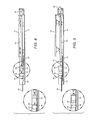
- FIG. 4 is a plan view of the latch retraction push bar exit device shown in FIG. 2 in the unlatched condition.
- FIG. 5 is a plan view of the latch retraction push bar exit device shown in FIG. 2 in the latched condition.
- the present invention provides an electric latch retraction push-bar exit device (“push-bar exit device”). SDC where the latch can be retracted through the standard pushing action on the push-bar.
- the exit devices according to the present invention can comprise secondary mechanisms for retracting the latch, such as through an electric motor.
- the motor can be internal to the device housing and can comprise a stepper motor type linear actuator to retract the latch.
- a holding magnet can be activated to hold the actuator in the unlatched position to allowing the motor to be switched off.
- Many different holding magnets can be used such as a magnetic holding coil.
- biasing springs can be used to return the latch to the locked position and in one embodiment a combination of an actuator biasing spring and a latch biasing spring can reverse the linear movement of the actuator and cause the device to return to the latched position.
- first, second, etc. may be used herein to describe various elements or components these elements and components should not be limited by these terms. These terms are only used to distinguish one element or component from another element or component. Thus, a first element or component discussed below could be termed a second element or component without departing from the teachings of the present invention.
- Embodiments of the invention are described herein with reference to certain illustrations that are schematic illustrations of idealized embodiments of the invention. As such, variations from the shapes of the illustrations as a result, for example, of manufacturing techniques and/or tolerances are expected. Embodiments of the invention should not be construed as limited to the particular shapes of the elements or components illustrated herein but are to include deviations in shapes that result, for example, from manufacturing. Thus, the regions illustrated in the figures are schematic in nature and their shapes are not intended to illustrate the precise shape of an element or component and are not intended to limit the scope of the invention.
- FIG. 1 shows one embodiment of a door 10 utilizing a push-bar exit device 12 according to the present invention.
- the push-bar exit device 12 is mounted in convention manner to the door 12 with a horizontal orientation and location that allow for the exit device's latch to engage a latch opening in the door frame 13 .
- the door 10 When engaged the door 10 is prevented from opening, when the latch is retracted from latch opening the door 10 can open.
- depressing the push-bar 14 causes the latch to retract from the latch opening to allow opening of the door 10 .
- the push-bar exit device comprises a housing 18 with the push-bar 14 movably mounted to the housing so that it can be depressed. As with most conventional push-bar exit devices, this action can retract the latch so that it is partially within the housing. As the push-bar 14 is depressed it causes a latch 20 to retract toward the housing. As discussed above, when the latch 20 is retracted the door utilizing the push-bar exit device 12 can be opened. Many different known mechanisms can be used to cause the latch 20 to retract as the push-bar 14 is depressed, and it is understood that each of these known mechanisms can be utilized in different embodiments of push-bar exit devices according to the present invention.
- push bar exit devices are arranged so that latch 20 can be retracted in a manner beyond the manual pushing of the push-bar 14 .
- These can include many different types of linear actuators.
- the latch 20 can be retracted in response to an electrical signal, and many different devices and mechanisms can be used to retract the latch 20 is response to an electrical signal.
- an electric motor 22 can be used to retract the latch, with motor 22 mounted in place within the housing 18 .
- An adjustment plate 24 can be included within the housing 18 with the motor 22 mounted to the adjustment plate 24 by a mounting block 26 .
- many different types of motors can be used with a suitable motor 22 such as a rotary or step motor.
- the motor 22 can impart linear movement on the latch 20 using many different mechanisms.
- the motor 22 can comprise an internal nut that turns when an electrical signal is applied to the motor 22 .
- the housing 18 can also have internal linkage 28 that connects at one end to the latch 20 and at the other end to the motor 22 .
- the motor end of the linkage 28 has a threaded section that mates with the motor's internal nut, and as the nut turns on the threaded section linear movement is imparted on the latch 20 through the linkage 28 .
- the motor further comprises an armature 32 that extends from the motor 22 as the latch 20 is retracted.
- a holding magnet 34 is mounted to the adjustment plate 24 by a magnet mounting block 36 , with the magnet 34 in alignment with the armature 32 .
- Many different magnets can be used, with a suitable one being an electrically actuated magnetic coil.
- An actuator switch/sensor 38 is mounted integral to the magnet 34 and as mentioned above, in the path of travel of the armature 32 to sense its position relative to the magnet 34 .
- a controller 40 can be utilized to control operation of the push-bar exit device 12 , and in different embodiments the controller 40 can be remote or local to the exit device 12 .
- the controller can communicate with the exit device using many different “hard-wire” and wireless communication links.
- the controller comprises commercially available electronics interconnected in conventional way, and in different embodiments the controller 40 can perform many different functions.
- the armature 32 engages the sensor 38 the sensor 38 signals the controller 40 to turn the motor off to allow the actuator mechanism to “coast” to the fully retracted position.
- This coasting action is designed to compensate for manufacturing tolerances in the internal components of the exit device, including but not limited to the adjustment plate 24 and linkage 28 . This allows for a “self adjusting” feature eliminating the need to readjust the device linkage as the exit device 12 wears from use.
- the controller 40 is also designed to deliver a “timed” period of motor activation. This “timed” period is set to be slightly longer than is needed to retract the latch 20 .
- the controller 40 monitors the actuator sensor 38 to determine when to remove motor power to enable the “coasting” effect and ensure a positive mating of the armature 32 against the magnet 36 .
- the power to the motor 22 can be turned off. A rest period for motor cooling is initiated and the latch retraction cycle can be attempted again. The motor 22 will not be damaged in the event of binding of the panic device due to door alignment problems or door preload.
- the armature 32 moves to the retracted position and engages the sensor 38 , the armature contacts the magnet.
- the magnet holds the armature 32 in the retracted position, allows the motor to be switched off while still keeping the device in the unlatched condition. This allows for keeping the exit device 12 in the unlatched condition while not consuming power by continued activation of the motor.
- the power needed to energize the magnet 34 is less than that consumed by the motor 22 , with this arrangement realizing significant reduction in power consumption compared to similar devices without a magnet 34 .
- a biasing spring 42 is included on the linkage 28 biasing the linkage 28 to the latch 20 to the latched condition. If power is removed from the magnet 34 , either by the controller or by loss of power to the exit device 12 , the bias spring reverses the linear motion of the motor and causes the exit device 12 to return to the latched condition.
Abstract
Description
Claims (20)
Priority Applications (2)
| Application Number | Priority Date | Filing Date | Title |
|---|---|---|---|
| US14/469,915 US9797165B2 (en) | 2008-11-17 | 2014-08-27 | Electric latch retraction bar |
| US14/538,621 US10107015B2 (en) | 2008-11-17 | 2014-11-11 | Electric latch retraction push-bar device |
Applications Claiming Priority (3)
| Application Number | Priority Date | Filing Date | Title |
|---|---|---|---|
| US19956008P | 2008-11-17 | 2008-11-17 | |
| US12/616,564 US8851530B2 (en) | 2008-11-17 | 2009-11-11 | Electric latch retraction bar |
| US14/469,915 US9797165B2 (en) | 2008-11-17 | 2014-08-27 | Electric latch retraction bar |
Related Parent Applications (1)
| Application Number | Title | Priority Date | Filing Date |
|---|---|---|---|
| US12/616,564 Continuation US8851530B2 (en) | 2008-11-17 | 2009-11-11 | Electric latch retraction bar |
Related Child Applications (1)
| Application Number | Title | Priority Date | Filing Date |
|---|---|---|---|
| US14/538,621 Continuation-In-Part US10107015B2 (en) | 2008-11-17 | 2014-11-11 | Electric latch retraction push-bar device |
Publications (2)
| Publication Number | Publication Date |
|---|---|
| US20140361550A1 US20140361550A1 (en) | 2014-12-11 |
| US9797165B2 true US9797165B2 (en) | 2017-10-24 |
Family
ID=42171405
Family Applications (2)
| Application Number | Title | Priority Date | Filing Date |
|---|---|---|---|
| US12/616,564 Active 2031-03-27 US8851530B2 (en) | 2008-11-17 | 2009-11-11 | Electric latch retraction bar |
| US14/469,915 Active 2030-03-08 US9797165B2 (en) | 2008-11-17 | 2014-08-27 | Electric latch retraction bar |
Family Applications Before (1)
| Application Number | Title | Priority Date | Filing Date |
|---|---|---|---|
| US12/616,564 Active 2031-03-27 US8851530B2 (en) | 2008-11-17 | 2009-11-11 | Electric latch retraction bar |
Country Status (1)
| Country | Link |
|---|---|
| US (2) | US8851530B2 (en) |
Cited By (1)
| Publication number | Priority date | Publication date | Assignee | Title |
|---|---|---|---|---|
| US11035150B2 (en) * | 2016-04-08 | 2021-06-15 | Hanchett Entry Systems, Inc. | Electrified exit device |
Families Citing this family (23)
| Publication number | Priority date | Publication date | Assignee | Title |
|---|---|---|---|---|
| US10107015B2 (en) * | 2008-11-17 | 2018-10-23 | Security Door Controls | Electric latch retraction push-bar device |
| US9447617B2 (en) * | 2011-07-22 | 2016-09-20 | Overhead Door Corporation | Sliding door panel hold open assembly |
| DE102011114643B4 (en) * | 2011-09-30 | 2016-03-24 | Airbus Operations Gmbh | Actuation device for opening an emergency exit flap of a cockpit door |
| EP2679750A1 (en) * | 2012-06-26 | 2014-01-01 | 9Design.be bvba | Locking device comprising a deactivation mechanism |
| CA2888623C (en) * | 2012-10-19 | 2017-10-10 | Yale Security Inc. | Apparatus and method for electromechanically retracting a door latch |
| DE102014102003A1 (en) * | 2014-02-18 | 2015-08-20 | Dorma Deutschland Gmbh | Lock with a lock nut for receiving a reducing sleeve |
| US9435142B2 (en) | 2014-02-28 | 2016-09-06 | Schlage Lock Company Llc | Method of operating an access control system |
| EP3164558B1 (en) * | 2014-10-17 | 2018-08-29 | EUCHNER GmbH + Co. KG | Device for locking or releasing a safety-relevant, movable component in a controlled manner |
| US9875586B2 (en) * | 2015-01-21 | 2018-01-23 | Texas Instruments Incorporated | Inductive coded lock system |
| US10072444B2 (en) * | 2015-05-15 | 2018-09-11 | Schlage Lock Company Llc | Exit device force adjustment mechanisms |
| GB2541023A (en) * | 2015-08-07 | 2017-02-08 | Gianni Ind Inc | Emergency fire escape door lock device |
| US9939054B2 (en) * | 2015-10-09 | 2018-04-10 | Command Access Technology, Inc. | Actuator with ball screw drive |
| WO2017079084A1 (en) * | 2015-11-04 | 2017-05-11 | Westinghouse Air Brake Technologies Corporation | Delayed emergency release unit |
| DE102016104773A1 (en) * | 2016-03-15 | 2017-09-21 | Assa Abloy Sicherheitstechnik Gmbh | Anti-panic push rod with modular drive mechanism |
| DE102016104779A1 (en) * | 2016-03-15 | 2017-09-21 | Assa Abloy Sicherheitstechnik Gmbh | Anti-panic push rod with drive device |
| TWI605184B (en) * | 2016-10-19 | 2017-11-11 | I-Tek Metal Manufacturing Co Ltd | Internal operating device for door lock |
| US10968664B2 (en) * | 2017-02-24 | 2021-04-06 | Schlage Lock Company Llc | Exit device systems and methods |
| US20220145668A1 (en) * | 2019-01-28 | 2022-05-12 | Sargent Manufacturing Company | Universal dogging and electronic latch retraction |
| US20210156170A1 (en) * | 2019-11-25 | 2021-05-27 | Schlage Lock Company Llc | Exit device assembly with integrated access control |
| US11519199B2 (en) * | 2020-04-02 | 2022-12-06 | M. Arthur Gensler, Jr. & Associates, Inc. | Bar handle with incorporated lock |
| CA3119092A1 (en) * | 2020-05-19 | 2021-11-19 | Dormakaba Usa Inc. | Assembly for exit device |
| US11629533B2 (en) * | 2021-05-25 | 2023-04-18 | The Eastern Company | Sliding latch |
| FR3139932A1 (en) * | 2022-09-21 | 2024-03-22 | Cogelec | Home support system |
Citations (66)
| Publication number | Priority date | Publication date | Assignee | Title |
|---|---|---|---|---|
| US1948217A (en) | 1932-03-14 | 1934-02-20 | Sr Charles M Goodwin | Electric lock |
| US2366613A (en) | 1943-08-11 | 1945-01-02 | H B Ives Company | Casement window operator |
| US2504408A (en) | 1945-03-29 | 1950-04-18 | Cons Car Heating Co Inc | Electric door operator with auxiliary operating means |
| US2765648A (en) | 1953-03-13 | 1956-10-09 | Curtis M Hatcher | Electro-magnetic vehicle door lock |
| US3576119A (en) | 1968-11-25 | 1971-04-27 | Archie H Harris | Electromechanical door lock system |
| US3614145A (en) | 1970-08-19 | 1971-10-19 | Von Duprin Inc | Dogging device for panic exit latch and actuator assembly |
| US3767238A (en) | 1972-05-04 | 1973-10-23 | Von Duperin Inc | Push plate panic exit device |
| US3854763A (en) | 1973-07-18 | 1974-12-17 | Von Duprin Inc | Electrical and mechanical dogging device |
| US4006471A (en) | 1975-01-31 | 1977-02-01 | Detex Corporation | Emergency exit lock system for doors |
| US4167280A (en) | 1978-07-24 | 1979-09-11 | Ingersoll-Rand Company | Panic exit mechanism |
| US4257631A (en) | 1979-06-25 | 1981-03-24 | Reliable Security Systems, Inc. | Magnetic emergency exit door lock with delayed opening |
| US4328985A (en) | 1979-08-10 | 1982-05-11 | Reliable Security Systems, Inc. | Timing apparatus for delaying opening of doors |
| US4344647A (en) | 1980-06-16 | 1982-08-17 | Reliable Security Systems, Inc. | Exterior operating arrangement for emergency exit doors with delayed opening feature |
| US4351552A (en) | 1979-03-20 | 1982-09-28 | Reliable Security Systems, Inc. | Emergency exit door latching and locking apparatus |
| US4354699A (en) | 1980-05-09 | 1982-10-19 | Reliable Security Systems, Inc. | Apparatus for delaying opening of doors |
| US4384738A (en) | 1980-10-16 | 1983-05-24 | Kidde, Inc. | Exit device with lock down mechanism |
| US4519640A (en) | 1981-10-07 | 1985-05-28 | I.C.B. France Industrie Et Componsants Du Batiment Societe Anonyme | Electronically motorized lock whose motor shaft is parallel to the longitudinal axis of the bolts |
| US4545606A (en) | 1983-01-31 | 1985-10-08 | Vodra Richard J | Door latch assembly |
| US4631528A (en) | 1984-10-02 | 1986-12-23 | Emhart Industries, Inc. | Push bar exit device with alarm |
| US4652028A (en) | 1985-02-12 | 1987-03-24 | Reliable Security Systems, Inc. | Magnetic emergency exit door lock with time delay |
| EP0233094A1 (en) | 1986-01-10 | 1987-08-19 | Brunam Contrôle Sarl | Quick-release fastener provided with a panic bar |
| US4709950A (en) | 1984-06-21 | 1987-12-01 | American Device Manufacturing Co. | Crash bar door locking device |
| US4720128A (en) | 1985-02-12 | 1988-01-19 | Reliable Security Systems, Inc. | Magnetic emergency exit door lock with time delay |
| US4784415A (en) | 1986-02-24 | 1988-11-15 | Fichet-Bauche | Locking and unlocking device |
| US4796931A (en) | 1987-08-07 | 1989-01-10 | Yale Security Inc. | Exit device having adjustable backset |
| US4801163A (en) | 1986-09-02 | 1989-01-31 | Emhart Industries Inc. | Exit device actuator and dogger |
| US4821456A (en) | 1988-05-02 | 1989-04-18 | Hisami Nogaki | Linear mechanical drive with precise end-of-travel load positioning |
| FR2622240A1 (en) | 1987-10-27 | 1989-04-28 | Chauvat Sofranq | Anti-panic closure device of the pushbar type with active barring |
| US4875722A (en) | 1986-09-02 | 1989-10-24 | Emhart Industries, Inc. | Exit device actuator and dogger |
| US4976476A (en) | 1989-06-13 | 1990-12-11 | Monarch Hardware & Manufacturing Co., Inc., Subsidiary Of Newman Tonks, Inc. | Manual and electrical mechanism for unlocking a bolt |
| FR2653480A1 (en) | 1989-10-25 | 1991-04-26 | Vincenti Henri | Electric lock with automatic spring opening |
| FR2659379A1 (en) * | 1989-10-25 | 1991-09-13 | Vincenti Henri | Electric lock with pivoting lock bolt mounted on a door capable of being opened in the event of panic despite a thrust on the door |
| US5072973A (en) | 1989-10-04 | 1991-12-17 | Motus Incorporated | Door hold open device |
| WO1992004519A1 (en) | 1990-09-05 | 1992-03-19 | Motus Incorporated | Power conserving door holder |
| EP0485248A1 (en) | 1990-11-05 | 1992-05-13 | Jpm Chauvat S.A. | Control system for anti-panic lock |
| US5169185A (en) | 1991-01-25 | 1992-12-08 | Republic Industries, Inc. | Panic exit device featuring improved bar movement and fail safe dogging |
| US5219385A (en) | 1990-12-13 | 1993-06-15 | Catwin Industrial Corporation | Lock for fire-escape door |
| US5246258A (en) | 1988-11-29 | 1993-09-21 | Sidney Kerschenbaum | Rim type door lock with interchangeable bolt assemblies and adjustable backset plate assemblies |
| US5322332A (en) | 1992-10-16 | 1994-06-21 | Thomas Industries, Inc. | Rim type latching system |
| US5340171A (en) | 1992-01-22 | 1994-08-23 | Republic Industries, Inc. | Door latch control apparatus with independent actuators |
| US5410301A (en) | 1992-11-24 | 1995-04-25 | Mas-Hamilton Group | Status monitoring system for an electronic lock |
| US5429399A (en) | 1992-10-22 | 1995-07-04 | Geringer; Arthur | Electronic delayed egress locking system |
| US5507120A (en) | 1995-05-30 | 1996-04-16 | Schlage Lock Company | Track driven power door operator |
| US5605362A (en) | 1993-11-01 | 1997-02-25 | Yale Security Inc. | Exit device having a deadbolt as its securing member |
| US5630631A (en) | 1994-02-10 | 1997-05-20 | Fuji Electric Co., Ltd. | Door locking apparatus for dispenser |
| US5823582A (en) | 1995-08-24 | 1998-10-20 | Harrow Products, Inc. | Electromagnetically-managed latching exit bar |
| JPH11107595A (en) | 1997-10-01 | 1999-04-20 | Kazumi Sonomoto | Window frame unit and automatic window unlocking device for use therefor |
| US6048000A (en) | 1998-04-28 | 2000-04-11 | Geringer; Arthur | Delayed egress panic device with internal deadlocking bolt mechanism |
| US6104594A (en) | 1999-03-10 | 2000-08-15 | Harrow Products, Inc. | Electromagnetic latch retractor for exit bar |
| EP1031688A1 (en) | 1999-02-26 | 2000-08-30 | Jpm S.A | Control system for a door with an antipanic push bar having an electrical component needing an external electrical connection |
| EP1031689A1 (en) | 1999-02-26 | 2000-08-30 | Jpm S.A | Control system for a door with an antipanic push bar of the active locking type |
| US6116661A (en) | 1999-01-29 | 2000-09-12 | Monarch Hardware And Manufacturing Company | Electric dogging mechanism for use with an exit device |
| US6189939B1 (en) | 1998-09-10 | 2001-02-20 | Raymond E. Zehrung | Electrified emergency exit device having an accessible hold off lock |
| US6324789B1 (en) | 1999-12-17 | 2001-12-04 | Westinghouse Air Brake Company | Encased overhead door operator having threadably attached mounts |
| US6386597B1 (en) | 1999-10-07 | 2002-05-14 | Harrow Products, Inc. | Dual latch retraction system for exit bar |
| US6565130B1 (en) | 2001-12-05 | 2003-05-20 | Harrow Products, Inc. | Dual action latch retractor |
| US6769723B2 (en) | 2002-08-30 | 2004-08-03 | Dor-O-Matic Inc. | Midrail mounted exit device |
| US6786519B2 (en) | 2002-01-07 | 2004-09-07 | U-Code, Inc. | Swing bolt lock with improved tamper resistance and method of operation |
| US20040189018A1 (en) | 2003-03-20 | 2004-09-30 | Security Door Controls | Push bar locking mechanism with rapid unlocking |
| US20050104381A1 (en) | 2002-09-30 | 2005-05-19 | Andrew Whitaker | Delayed egress exit device |
| WO2006015769A1 (en) * | 2004-08-04 | 2006-02-16 | Dorma Gmbh + Co. Kg | Door lock, especially comprising a panic function |
| US20060082162A1 (en) | 2004-10-12 | 2006-04-20 | Escobar Miguel A | Electromechanical door solenoid current surge booster circuit |
| US7102475B2 (en) | 2002-08-27 | 2006-09-05 | Mitsubishi Denki Kabushiki Kaisha | Magnetic actuator |
| WO2008010876A2 (en) | 2006-06-30 | 2008-01-24 | Sargent Manufacturing Company | Electronic push retraction exit device |
| US7536885B1 (en) | 2006-02-17 | 2009-05-26 | Detex Corporation | Bimodal door security system |
| US20100218569A1 (en) | 2009-03-02 | 2010-09-02 | Hunt Robert C | Electromagnetic lock having distance-sensing monitoring system |
Family Cites Families (1)
| Publication number | Priority date | Publication date | Assignee | Title |
|---|---|---|---|---|
| ATE407075T1 (en) | 2004-08-19 | 2008-09-15 | Sca Hygiene Prod Ab | ARRANGEMENT FOR REMOVAL OF AN ABSORBENT ARTICLE FROM A STACK OF ABSORBENT ARTICLES |
-
2009
- 2009-11-11 US US12/616,564 patent/US8851530B2/en active Active
-
2014
- 2014-08-27 US US14/469,915 patent/US9797165B2/en active Active
Patent Citations (75)
| Publication number | Priority date | Publication date | Assignee | Title |
|---|---|---|---|---|
| US1948217A (en) | 1932-03-14 | 1934-02-20 | Sr Charles M Goodwin | Electric lock |
| US2366613A (en) | 1943-08-11 | 1945-01-02 | H B Ives Company | Casement window operator |
| US2504408A (en) | 1945-03-29 | 1950-04-18 | Cons Car Heating Co Inc | Electric door operator with auxiliary operating means |
| US2765648A (en) | 1953-03-13 | 1956-10-09 | Curtis M Hatcher | Electro-magnetic vehicle door lock |
| US3576119A (en) | 1968-11-25 | 1971-04-27 | Archie H Harris | Electromechanical door lock system |
| US3614145A (en) | 1970-08-19 | 1971-10-19 | Von Duprin Inc | Dogging device for panic exit latch and actuator assembly |
| US3767238A (en) | 1972-05-04 | 1973-10-23 | Von Duperin Inc | Push plate panic exit device |
| US3854763A (en) | 1973-07-18 | 1974-12-17 | Von Duprin Inc | Electrical and mechanical dogging device |
| US4006471A (en) | 1975-01-31 | 1977-02-01 | Detex Corporation | Emergency exit lock system for doors |
| US4167280A (en) | 1978-07-24 | 1979-09-11 | Ingersoll-Rand Company | Panic exit mechanism |
| US4351552A (en) | 1979-03-20 | 1982-09-28 | Reliable Security Systems, Inc. | Emergency exit door latching and locking apparatus |
| US4257631A (en) | 1979-06-25 | 1981-03-24 | Reliable Security Systems, Inc. | Magnetic emergency exit door lock with delayed opening |
| US4328985A (en) | 1979-08-10 | 1982-05-11 | Reliable Security Systems, Inc. | Timing apparatus for delaying opening of doors |
| US4354699A (en) | 1980-05-09 | 1982-10-19 | Reliable Security Systems, Inc. | Apparatus for delaying opening of doors |
| US4344647A (en) | 1980-06-16 | 1982-08-17 | Reliable Security Systems, Inc. | Exterior operating arrangement for emergency exit doors with delayed opening feature |
| US4384738A (en) | 1980-10-16 | 1983-05-24 | Kidde, Inc. | Exit device with lock down mechanism |
| US4519640A (en) | 1981-10-07 | 1985-05-28 | I.C.B. France Industrie Et Componsants Du Batiment Societe Anonyme | Electronically motorized lock whose motor shaft is parallel to the longitudinal axis of the bolts |
| US4545606A (en) | 1983-01-31 | 1985-10-08 | Vodra Richard J | Door latch assembly |
| US4709950A (en) | 1984-06-21 | 1987-12-01 | American Device Manufacturing Co. | Crash bar door locking device |
| US4631528A (en) | 1984-10-02 | 1986-12-23 | Emhart Industries, Inc. | Push bar exit device with alarm |
| US4652028A (en) | 1985-02-12 | 1987-03-24 | Reliable Security Systems, Inc. | Magnetic emergency exit door lock with time delay |
| US4720128A (en) | 1985-02-12 | 1988-01-19 | Reliable Security Systems, Inc. | Magnetic emergency exit door lock with time delay |
| EP0233094A1 (en) | 1986-01-10 | 1987-08-19 | Brunam Contrôle Sarl | Quick-release fastener provided with a panic bar |
| US4784415A (en) | 1986-02-24 | 1988-11-15 | Fichet-Bauche | Locking and unlocking device |
| US4875722A (en) | 1986-09-02 | 1989-10-24 | Emhart Industries, Inc. | Exit device actuator and dogger |
| US4801163A (en) | 1986-09-02 | 1989-01-31 | Emhart Industries Inc. | Exit device actuator and dogger |
| US4796931A (en) | 1987-08-07 | 1989-01-10 | Yale Security Inc. | Exit device having adjustable backset |
| FR2622240A1 (en) | 1987-10-27 | 1989-04-28 | Chauvat Sofranq | Anti-panic closure device of the pushbar type with active barring |
| US4821456A (en) | 1988-05-02 | 1989-04-18 | Hisami Nogaki | Linear mechanical drive with precise end-of-travel load positioning |
| US5246258A (en) | 1988-11-29 | 1993-09-21 | Sidney Kerschenbaum | Rim type door lock with interchangeable bolt assemblies and adjustable backset plate assemblies |
| US4976476A (en) | 1989-06-13 | 1990-12-11 | Monarch Hardware & Manufacturing Co., Inc., Subsidiary Of Newman Tonks, Inc. | Manual and electrical mechanism for unlocking a bolt |
| US5072973A (en) | 1989-10-04 | 1991-12-17 | Motus Incorporated | Door hold open device |
| FR2653480A1 (en) | 1989-10-25 | 1991-04-26 | Vincenti Henri | Electric lock with automatic spring opening |
| FR2659379A1 (en) * | 1989-10-25 | 1991-09-13 | Vincenti Henri | Electric lock with pivoting lock bolt mounted on a door capable of being opened in the event of panic despite a thrust on the door |
| WO1992004519A1 (en) | 1990-09-05 | 1992-03-19 | Motus Incorporated | Power conserving door holder |
| EP0485248A1 (en) | 1990-11-05 | 1992-05-13 | Jpm Chauvat S.A. | Control system for anti-panic lock |
| US5219385A (en) | 1990-12-13 | 1993-06-15 | Catwin Industrial Corporation | Lock for fire-escape door |
| US5169185A (en) | 1991-01-25 | 1992-12-08 | Republic Industries, Inc. | Panic exit device featuring improved bar movement and fail safe dogging |
| US5340171A (en) | 1992-01-22 | 1994-08-23 | Republic Industries, Inc. | Door latch control apparatus with independent actuators |
| US5322332A (en) | 1992-10-16 | 1994-06-21 | Thomas Industries, Inc. | Rim type latching system |
| US5429399A (en) | 1992-10-22 | 1995-07-04 | Geringer; Arthur | Electronic delayed egress locking system |
| US5410301A (en) | 1992-11-24 | 1995-04-25 | Mas-Hamilton Group | Status monitoring system for an electronic lock |
| US5605362A (en) | 1993-11-01 | 1997-02-25 | Yale Security Inc. | Exit device having a deadbolt as its securing member |
| US5630631A (en) | 1994-02-10 | 1997-05-20 | Fuji Electric Co., Ltd. | Door locking apparatus for dispenser |
| US5507120A (en) | 1995-05-30 | 1996-04-16 | Schlage Lock Company | Track driven power door operator |
| US5823582A (en) | 1995-08-24 | 1998-10-20 | Harrow Products, Inc. | Electromagnetically-managed latching exit bar |
| US5988708A (en) | 1995-08-24 | 1999-11-23 | Harrow Products, Inc. | Electromagnetically managed latching exit bar |
| JPH11107595A (en) | 1997-10-01 | 1999-04-20 | Kazumi Sonomoto | Window frame unit and automatic window unlocking device for use therefor |
| US6048000A (en) | 1998-04-28 | 2000-04-11 | Geringer; Arthur | Delayed egress panic device with internal deadlocking bolt mechanism |
| US6189939B1 (en) | 1998-09-10 | 2001-02-20 | Raymond E. Zehrung | Electrified emergency exit device having an accessible hold off lock |
| US6394508B1 (en) | 1998-09-10 | 2002-05-28 | Raymond E. Zehrung | Electrified emergency exit device having an accessible hold off lock |
| US6116661A (en) | 1999-01-29 | 2000-09-12 | Monarch Hardware And Manufacturing Company | Electric dogging mechanism for use with an exit device |
| EP1031688A1 (en) | 1999-02-26 | 2000-08-30 | Jpm S.A | Control system for a door with an antipanic push bar having an electrical component needing an external electrical connection |
| EP1031689A1 (en) | 1999-02-26 | 2000-08-30 | Jpm S.A | Control system for a door with an antipanic push bar of the active locking type |
| US6104594A (en) | 1999-03-10 | 2000-08-15 | Harrow Products, Inc. | Electromagnetic latch retractor for exit bar |
| US6386597B1 (en) | 1999-10-07 | 2002-05-14 | Harrow Products, Inc. | Dual latch retraction system for exit bar |
| US6324789B1 (en) | 1999-12-17 | 2001-12-04 | Westinghouse Air Brake Company | Encased overhead door operator having threadably attached mounts |
| US6565130B1 (en) | 2001-12-05 | 2003-05-20 | Harrow Products, Inc. | Dual action latch retractor |
| US6786519B2 (en) | 2002-01-07 | 2004-09-07 | U-Code, Inc. | Swing bolt lock with improved tamper resistance and method of operation |
| US7102475B2 (en) | 2002-08-27 | 2006-09-05 | Mitsubishi Denki Kabushiki Kaisha | Magnetic actuator |
| US6769723B2 (en) | 2002-08-30 | 2004-08-03 | Dor-O-Matic Inc. | Midrail mounted exit device |
| US7000954B2 (en) | 2002-08-30 | 2006-02-21 | Dor-O-Matic, Inc. | Midrail mounted exit device |
| US7503597B2 (en) | 2002-08-30 | 2009-03-17 | Dor-O-Matic, Inc. | Midrail mounted exit device |
| US20050104381A1 (en) | 2002-09-30 | 2005-05-19 | Andrew Whitaker | Delayed egress exit device |
| US20040189018A1 (en) | 2003-03-20 | 2004-09-30 | Security Door Controls | Push bar locking mechanism with rapid unlocking |
| US20080295550A1 (en) | 2004-08-04 | 2008-12-04 | Dorma Gmbh & Co., Kg | Door Lock, Especially Comprising a Panic Function |
| WO2006015769A1 (en) * | 2004-08-04 | 2006-02-16 | Dorma Gmbh + Co. Kg | Door lock, especially comprising a panic function |
| US20060082162A1 (en) | 2004-10-12 | 2006-04-20 | Escobar Miguel A | Electromechanical door solenoid current surge booster circuit |
| US7862091B2 (en) | 2004-10-12 | 2011-01-04 | Command Access Technology, LLC | Electromechanical door solenoid current surge booster circuit |
| US7536885B1 (en) | 2006-02-17 | 2009-05-26 | Detex Corporation | Bimodal door security system |
| US7484777B2 (en) | 2006-06-30 | 2009-02-03 | Sargent Manufacturing Company | Electronic push retraction exit device |
| WO2008010876A2 (en) | 2006-06-30 | 2008-01-24 | Sargent Manufacturing Company | Electronic push retraction exit device |
| US20090127869A1 (en) | 2006-06-30 | 2009-05-21 | Sargent Manufacturing Company | Electronic push retraction exit device |
| US7883123B2 (en) | 2006-06-30 | 2011-02-08 | Sargent Manufacturing Company | Electronic push retraction exit device |
| US20100218569A1 (en) | 2009-03-02 | 2010-09-02 | Hunt Robert C | Electromagnetic lock having distance-sensing monitoring system |
Non-Patent Citations (1)
| Title |
|---|
| Omega Engineering. Stepper Motors, Aug. 24, 2008. |
Cited By (2)
| Publication number | Priority date | Publication date | Assignee | Title |
|---|---|---|---|---|
| US11035150B2 (en) * | 2016-04-08 | 2021-06-15 | Hanchett Entry Systems, Inc. | Electrified exit device |
| US11299914B2 (en) * | 2016-04-08 | 2022-04-12 | Hanchett Entry Systems, Inc. | Electrified exit device |
Also Published As
| Publication number | Publication date |
|---|---|
| US8851530B2 (en) | 2014-10-07 |
| US20140361550A1 (en) | 2014-12-11 |
| US20100123323A1 (en) | 2010-05-20 |
Similar Documents
| Publication | Publication Date | Title |
|---|---|---|
| US9797165B2 (en) | Electric latch retraction bar | |
| US10107015B2 (en) | Electric latch retraction push-bar device | |
| US7614669B2 (en) | Interchangeable lock operable in fail safe or fail secure modes | |
| US7540542B2 (en) | Electric strike | |
| US5876073A (en) | Electrically operable door locking apparatus and method for operating the same | |
| US7698918B2 (en) | Interchangeable lock operable in fail safe or fail secure modes | |
| US4917419A (en) | Electromechanical door lock system | |
| EP3215697B1 (en) | Cam latch | |
| EP2140086B1 (en) | Piezo actuated slide latching mechanism | |
| US6053546A (en) | Trigger system for electromagnetic lock | |
| US7963574B2 (en) | Fail safe/fail secure lock with quick change access window | |
| US6634685B2 (en) | Electronically-operable door strike with guard clip, springless solenoid and face plate | |
| US8047582B1 (en) | Electro-mechanical lock | |
| US4125008A (en) | Electrically operated lock | |
| CA2622083A1 (en) | Electronic tongue strike mechanism | |
| WO2004031517A1 (en) | Delayed egress exit device | |
| MX2011004254A (en) | Electromechanical locks and latching arrangements. | |
| CA2658343C (en) | Magnetic lock means with auxiliary mechanical locking or resistance means | |
| AU2001266260B2 (en) | Locking device for a door | |
| WO2000028176A1 (en) | An electrically controlled slidebolt lock | |
| AU2001266260A1 (en) | Locking device for a door | |
| KR20180034648A (en) | Electric strike system with keeper monitoring | |
| US6325429B1 (en) | Electrically operated door lock | |
| MXPA05004341A (en) | Electric strike assembly. | |
| US20170268256A1 (en) | Electric lock with latch retractor |
Legal Events
| Date | Code | Title | Description |
|---|---|---|---|
| AS | Assignment |
Owner name: 1 ADOLFO, LLC, CALIFORNIA Free format text: ASSIGNMENT OF ASSIGNORS INTEREST;ASSIGNORS:GERINGER, ARTHUR V.;GERINGER, DAVID A.;REEL/FRAME:033629/0569 Effective date: 20140828 |
|
| AS | Assignment |
Owner name: SECURITY DOOR CONTROLS, CALIFORNIA Free format text: ASSIGNMENT OF ASSIGNORS INTEREST;ASSIGNOR:1 ADOLFO, LLC;REEL/FRAME:043537/0867 Effective date: 20170905 |
|
| STCF | Information on status: patent grant |
Free format text: PATENTED CASE |
|
| MAFP | Maintenance fee payment |
Free format text: PAYMENT OF MAINTENANCE FEE, 4TH YR, SMALL ENTITY (ORIGINAL EVENT CODE: M2551); ENTITY STATUS OF PATENT OWNER: SMALL ENTITY Year of fee payment: 4 |