US9797721B2 - Three-axis digital compass - Google Patents
Three-axis digital compass Download PDFInfo
- Publication number
- US9797721B2 US9797721B2 US14/894,267 US201414894267A US9797721B2 US 9797721 B2 US9797721 B2 US 9797721B2 US 201414894267 A US201414894267 A US 201414894267A US 9797721 B2 US9797721 B2 US 9797721B2
- Authority
- US
- United States
- Prior art keywords
- axis
- magnetic field
- sensors
- magnetic sensors
- axis magnetic
- Prior art date
- Legal status (The legal status is an assumption and is not a legal conclusion. Google has not performed a legal analysis and makes no representation as to the accuracy of the status listed.)
- Active, expires
Links
Images


Classifications
-
- G—PHYSICS
- G01—MEASURING; TESTING
- G01C—MEASURING DISTANCES, LEVELS OR BEARINGS; SURVEYING; NAVIGATION; GYROSCOPIC INSTRUMENTS; PHOTOGRAMMETRY OR VIDEOGRAMMETRY
- G01C17/00—Compasses; Devices for ascertaining true or magnetic north for navigation or surveying purposes
- G01C17/02—Magnetic compasses
- G01C17/28—Electromagnetic compasses
-
- G—PHYSICS
- G01—MEASURING; TESTING
- G01R—MEASURING ELECTRIC VARIABLES; MEASURING MAGNETIC VARIABLES
- G01R33/00—Arrangements or instruments for measuring magnetic variables
- G01R33/0005—Geometrical arrangement of magnetic sensor elements; Apparatus combining different magnetic sensor types
-
- G—PHYSICS
- G01—MEASURING; TESTING
- G01R—MEASURING ELECTRIC VARIABLES; MEASURING MAGNETIC VARIABLES
- G01R33/00—Arrangements or instruments for measuring magnetic variables
- G01R33/0011—Arrangements or instruments for measuring magnetic variables comprising means, e.g. flux concentrators, flux guides, for guiding or concentrating the magnetic flux, e.g. to the magnetic sensor
-
- G—PHYSICS
- G01—MEASURING; TESTING
- G01R—MEASURING ELECTRIC VARIABLES; MEASURING MAGNETIC VARIABLES
- G01R33/00—Arrangements or instruments for measuring magnetic variables
- G01R33/02—Measuring direction or magnitude of magnetic fields or magnetic flux
- G01R33/06—Measuring direction or magnitude of magnetic fields or magnetic flux using galvano-magnetic devices
- G01R33/09—Magnetoresistive devices
Definitions
- the present invention relates to magnetic sensor technology, particularly to three-axis digital compasses.
- the size of the resulting three-axis magnetic field sensor is larger; this increases device size and increases complexity of the packaging process.
- the present invention discloses a three-axis digital compass, the elements of the compass can be produced on a single chip, which utilizes a flux concentrator to distort the magnetic field, where the Z-axis magnetic field component perpendicular to the plane is transformed into in-plane XY components, which can be detected by the two X and Y magnetic sensors, and as a result the X and Y magnetic sensors can be used to simultaneously compute the X, Y, Z magnetic field components, and these X, Y, Z magnetic field components can then be separated out by an algorithm, which is then transformed into a digital signal.
- the present invention proposes a three-axis magnetic field sensor, comprising
- a flux concentrator which distorts the external magnetic field such that the Z-axis component of the external magnetic field is turned into X-axis and Y-axis magnetic field components;
- each of the X-axis magnetic field sensors has a sensing direction parallel to the X axis;
- each of the Y-axis magnetic field sensors has a sensing direction parallel to the Y axis;
- a signal sampling unit which is connected to the output terminal of each of the magnetic sensors, for use in sampling the output signals of the magnetic sensors
- a signal processing unit which is connected to the output of the sampling unit, and the signal processing unit is used to calculate the corresponding X-axis, Y-axis, and Z-axis magnetic field components from the sampled signals;
- a signal output unit which sends out a digital signal representing the calculation performed by the signal processing unit.
- each of the X-axis magnetic sensors and the Y-axis magnetic sensors are deposited on the substrate surface and senses a magnetic field component parallel to the substrate surface.
- the X-axis magnetic sensors and the Y-axis magnetic sensors are composed of AMR, GMR, or TMR magnetic sensor elements.
- the X-axis magnetic sensors and the Y-axis magnetic sensors are spin-valves that have an X-axis magnetic sensing element with a pinned layer magnetization direction and a Y-axis magnetic sensing element with a pinned layer magnetization direction that are aligned in mutually orthogonal directions.
- the X-axis magnetic sensors and the Y-axis magnetic sensors each include at least a sensing element and a reference element, where the reference element is located under the flux concentrator, and the sensing elements are located along the edges of the flux concentrator.
- the X-axis component of the magnetic field correlates to the sum of the two output signals from the X-axis magnetic sensors
- the Y-axis component of the magnetic field correlates to the sum of the two output signals from the Y-axis magnetic sensors.
- the Z-axis component of the magnetic field correlates to the difference between the two output signals from the X-axis magnetic sensors, or it correlates to the difference between the two output signals from the Y-axis magnetic sensors, or it correlates to the difference between the sum of the X-axis magnetic sensor signal outputs added to the difference between the Y-axis magnetic sensor outputs.
- the flux concentrator is composed of a high permeability soft magnetic material NiFe, CoFeSiB, CoZrNb, CoFeB, FeSiB or FeSiBNbCu.
- the thickness of the flux concentrator is 1 to 20 um.
- the substrate contains CMOS, and the X-axis magnetic sensor and the Y-axis magnetic sensors are lithographically patterned on top of the substrate.
- the X-axis component of the magnetic field correlates to the sum of two output signals from the X-axis magnetic sensors
- the Y-axis component of the magnetic field correlates to the sum of two output signals from the Y-axis magnetic sensors
- the Z-axis component of the magnetic field correlates to the difference between the sum of the X-axis magnetic sensor signal outputs added to the difference between the Y-axis magnetic sensor outputs.
- the Z-axis component of the magnetic field correlates to the difference between the two output signals from the X-axis magnetic sensors, or it correlates to the difference between the two output signals from the Y-axis magnetic sensors, or it correlates to the difference between the sum of the X-axis magnetic sensor signal outputs added to the difference between the Y-axis magnetic sensor outputs.
- the present invention has small size, a simple manufacturing process, easy packaging, novel structure, simple algorithm, and high measurement precision.
- FIG. 1 is a top view of the three-axis compass of the present invention.
- FIG. 2 is a diagram showing the distortion of a Z-axis magnetic field.
- FIG. 3 is a diagram showing the distortion of an X-axis or a Y-axis magnetic field.
- FIG. 4 is a diagram illustrating the measuring principle of the three-axis digital compass with magnetic field applied along the X-axis.
- FIG. 5 is a diagram illustrating the measuring principle of the three-axis digital compass with magnetic field applied along the Y-axis.
- FIG. 6 is a diagram illustrating the measuring principle of the three-axis digital compass with magnetic field applied along the Z-axis.
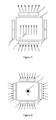
- FIG. 7 shows an illustration of a block diagram of a specific embodiment of the present invention.
- FIG. 8 shows a schematic diagram of the circuit for the X-axis and Y-axis referenced bridge magnetic sensors.
- FIG. 9 shows a cross-sectional view of a three-axis digital compass of the present invention.
- FIG. 10 shows a schematic diagram of the signal processing system used for the three-axis digital compass of the present invention.
- FIG. 1 shows a top-down view of the three-axis digital compass of the present invention.
- the three-axis digital compass includes two X-axis magnetic sensors 1 and 2 , two Y-axis magnetic sensors 3 and 4 , and a flux concentrator 5 .
- X-axis magnetic sensors 1 and 2 and Y-axis magnetic sensors 3 and 4 each include at least one sensing element and one reference element. They are deposited on the surface of the substrate, and arranged around the circumference of the flux concentrator 5 , with the X-axis magnetic sensors 1 and 2 oppositely arranged, and the Y-axis magnetic sensors 3 and 4 oppositely arranged.
- the reference elements of the magnetic sensors are located under the flux concentrator 5 , and the sensing elements are located around the edges of the flux concentrator 5 .
- the X-axis magnetic sensors only detect the X-component of the magnetic field
- the Y-axis magnetic sensors only detect the Y-component of the magnetic field.
- the two X-axis magnetic sensors 1 and 2 and the two Y-axis magnetic sensors 3 and 4 can be AMR, GMR, or TMR type magnetoresistive sensors. They may be spin-valves, and the pinned layer magnetic moment direction of the X-axis magnetic sensors 1 and 2 are set orthogonally with respect to the pinned layer magnetization direction of Y-axis magnetic sensors 3 and 4 .
- the flux concentrator 5 is composed of high permeability soft ferromagnetic material, preferably composed of an alloy such as NiFe, CoFeSiB, CoZrNb, CoFeB, FeSiB, or FeSiBNbCu.
- the flux concentrator 5 has a thickness of 1 to 20 urn.
- the surface of the substrate is parallel to the XY plane, and the Z-axis is perpendicular to the substrate plane.
- FIG. 2 shows the distribution of a Z-axis magnetic field component around flux concentrator 5 .
- the Z-component of the magnetic field in the vicinity of the flux concentrator 5 are bent thereby generating a magnetic field component in the XY plane.
- the sensing elements 7 and 8 of the X-axis and Y-axis magnetic sensors arranged about the circumference of flux concentrator 5 can respectively measure the X-axis and Y-axis magnetic field components, producing output signals, while the reference elements 9 and 10 located under the flux concentrator 5 are not exposed to an X or Y magnetic field component, the field in their vicinity is nearly vertically oriented, so they do not produce and output a signal.
- FIG. 3 shows a cross-sectional view in the X or Y plane, of the distribution of the magnetic field components around flux concentrator 5 .
- the X or Y plane magnetic field components in the vicinity of the flux concentrator 5 are bent, producing a Z-axis component, for reference elements 9 and 10 located under flux concentrator 5 , the magnetic field is perpendicular near the interior region of the flux concentrator, producing almost entirely a Z-axis component, therefore a signal response is not produced.
- an X-axis or a Y-axis oriented magnetic field will produce a response.
- the two X-axis magnetic field sensors will only produce a response to an X-axis magnetic field component, and they will not respond to a Y-axis magnetic field component.
- the two Y-axis magnetic field sensors will only produce a response to a Y-axis magnetic field component, and they will not respond to an X-axis magnetic field component.
- V ij S ij B ij +Vo ij
- S ij represents the magnetic sensor sensitivity, and it has the following range of values: S ij : O ⁇ S ij ⁇ 100 mV/V/G;
- B ij represents the magnetic field at the location of each sensor location.
- the external magnetic field along the X-axis, the Y-axis, and the Z-axis has three components B x , B y , and B z which become distorted after passing through the flux concentrator.
- the sensor's output voltage is related to a linear combination of magnetic field component B x , B y , and B 2 :
- V 1x S 1x ( ⁇ B x + ⁇ B z )+ Vo 1x
- V 2x S 2x ( ⁇ B x ⁇ B z )+ Vo 2x
- V 1y S 1y ( ⁇ B y + ⁇ B z )+ Vo 1y
- V 2y S 2y ( ⁇ B y ⁇ B z )+ Vo 2y
- ⁇ and ⁇ are the magnetic field gain coefficients of the flux concentrator 5 for the external magnetic field, and they are a function of its length (L), width (W), and thickness (t).
- ⁇ ⁇ ( L,W,t )
- ⁇ ⁇ ( L,W,t )
- B x ( V 1 ⁇ x + V 2 ⁇ x ) - ( Vo 1 ⁇ x + Vo 2 ⁇ x ) ⁇ ⁇ ( S 1 ⁇ x + S 2 ⁇ x )
- B y ( V 1 ⁇ y + V 2 ⁇ y ) - ( Vo 1 ⁇ y + Vo 2 ⁇ y ) ⁇ ⁇ ( S 1 ⁇ y + S 2 ⁇ y )
- B z ( V 2 ⁇ x - V 1 ⁇ x ) + ( V 2 ⁇ y - V 1 ⁇ y ) + ( Vo 1 ⁇ x - Vo 2 ⁇ x ) + ( Vo 1 ⁇ y - Vo 2 ⁇ y ) ⁇ ⁇ ( S 1 ⁇ x + S 2 ⁇ x + S 1 ⁇ y + S 2 ⁇ y )
- B ox V ox /S x
- B oy V oy /S y
- V 0z ( Vo 2x ⁇ Vo 1x )+( Vo 2y ⁇ Vo 1y )
- S z ⁇ ( S 1x +S 2x +S 1y +S 2y )
- B oz V oz /S z
- FIGS. 4, 5, and 6 respectively show the magnetic field distributions for external magnetic fields applied in the X, Y, Z directions.
- the output of the X is axis and the Y-axis magnetic sensors are respectively:
- V 1x S 1x ( ⁇ B x )+
- V 2x S 2x ( ⁇ B x )+
- V 1y Vo 1y
- V 2y Vo 2y
- V 1x , V 2x are related to the external magnetic field
- V 1y , V 2y are unrelated to the external magnetic field
- V 1x , V 2x have no dependence on the external magnetic field
- V 1y , V 2y depend on the external magnetic field
- V 1x , V 2x , V 1y , and V 2y are related to the external magnetic field
- FIG. 7 shows another implementation example of a specific embodiment of the three-axis digital compass invention.
- the X-axis magnetic sensors ( 1 ′, 2 ′) and Y-axis magnetic sensors ( 3 ′, 4 ′) sense XY magnetic field components in the plane parallel to the surface of the substrate, the figure shows the plane parallel to the XY plane.
- the magnetic sensors may be AMR, GMR, or TMR sensors.
- Each magnetic sensor includes two reference elements 8 ′ and 9 ′, which are located directly below the flux concentrator 5 , as well as two sensing elements 7 ′ and 10 ′, which are arranged around the outer periphery of flux concentrator 5 .
- Reference elements 8 ′ and 9 ′ are not exposed to XY magnetic field components, so there is no response to the external magnetic field, thus through the two X and Y axis magnetic sensors 7 ′ and 10 ′ the magnetic field sensor signal output is produced.
- Reference elements 8 ′ and 9 ′ may also be used as sensing elements in place of sensing elements 7 ′ and 10 ′ around the outer edge of flux concentrator 5 ′.
- Reference elements 8 ′, 9 ′ and sensing elements 7 ′, 10 ′ are connected as a full bridge as shown in FIG. 8 . In this figure, each of the elements has its pinned layer magnetization set in the same direction, such that the full bridge circuit produces the following output voltage
- FIG. 9 is a schematic diagram showing the structure of the three-axis digital compass, the X, Y axis magnetic sensors sense elements 7 and 8 are located around the outer periphery of flux concentrator 5 , reference elements 9 and 10 are located below the edge of flux concentrator 5 , reference elements 9 , 10 and sense elements 7 , 8 are lithographically patterned on the surface of CMOS substrate 15 .
- FIG. 10 shows a diagram of the three-axis digital compass's signal processing circuit.
- the result of the three dimensional magnetic field calculations is transferred to the signal output unit 19 , enabling the three-axis digital compass to output the components of the external magnetic field measurement.
- the Z-axis component of the magnetic field correlates to the difference between the two output signals from the X-axis magnetic sensors, or it correlates to the difference between the two output signals from the Y-axis magnetic sensors, or it correlates to the difference between the sum of the X-axis magnetic sensor signal outputs added to the difference between the Y-axis magnetic sensor outputs.
- the other methods can ultimately be described in a corresponding manner, but the first two methods have no substantial difference, and people skilled in the art can after seeing these implementations immediately and without the slightest doubt, conclude this from the first two methods, therefore the above detailed description of the methods will not be repeated.
Abstract
A three-axis digital compass comprising two X-axis magnetic sensors, two Y-axis magnetic sensors, a flux concentrator, a signal sampling unit, a signal processing unit, and a signal output unit is disclosed. The X-axis and Y-axis magnetic sensors are arranged along a periphery of the flux concentrator. An external magnetic field is distorted when passing through the flux concentrator. An Z axis component of the external magnetic field is converted into X-axis or Y-axis magnetic field components when passing through the flux concentrator, and the so converted components of the external magnetic field act on the X-axis and Y-axis magnetic sensitive sensors. An output signal of the X-axis and Y-axis magnetic sensitive sensors is sent to the signal processing unit through the signal sampling unit, and it is used to calculate the three orthogonal components of the external magnetic field. These calculated external magnetic field components are output in a digital format through the signal output unit. The three-axis digital compass has a novel structure and an elegant computation algorithm. The design is compatible with AMR, GMR, TMR or other magnetoresistive sensor technology.
Description
This application is a U.S. national stage application filed under 35 U.S.C. §371 from International Application Serial No. PCT/CN2014/078685, which was filed 28 May 2014, and published as WO2014/190909 on 4 Dec. 2014, and which claims priority to China Application No. 20130202801.1, filed 28 May 2013, which applications and publication are incorporated by reference as if reproduced herein and made a part hereof in their entirety, and the benefit of priority of each of which is claimed herein.
The present invention relates to magnetic sensor technology, particularly to three-axis digital compasses.
In the field of consumer electronics, for example smart phones, tablet computers, and other portable electronic devices, there is a need to use three-axis compass combined with inertial measurement devices such as a three-axis gyroscopes, and three-axis accelerometers, in order to form a complete 9-axis inertial magnetic navigation unit. These three-axis compasses can simultaneously measure three magnetic field components at the same time, and they are composed of AMR, GMR, or TMR magnetoresistive sensors. These magnetoresistive sensors detect the magnetic field in the plane of the substrate, such that two magnetic field components, X, Y, can be detected by tow orthogonal magnetoresistive sensors on the same substrate, in order to realize a two-axis XY magnetic field sensor. However, for the Z-axis magnetic field component, one solution is to use a one-axis sensor installed on an orthogonal plane. This method has the following shortcomings:
1) An XY magnetic sensor with a Z-single axis magnetic sensor cannot be accomplished in a fully integrated manufacturing process, thereby adding complexity.
2) Relative to a fully integrated manufacturing process, the assembly of individual sensors into a three-axis compass is not very accurate, which impacts the accuracy of the resulting sensor.
3) Because the one-axis Z-axis magnetic sensor has a sensing axis perpendicular to the XY two-axis magnetic sensor, the size of the resulting three-axis magnetic field sensor is larger; this increases device size and increases complexity of the packaging process.
To solve the above problems, the present invention discloses a three-axis digital compass, the elements of the compass can be produced on a single chip, which utilizes a flux concentrator to distort the magnetic field, where the Z-axis magnetic field component perpendicular to the plane is transformed into in-plane XY components, which can be detected by the two X and Y magnetic sensors, and as a result the X and Y magnetic sensors can be used to simultaneously compute the X, Y, Z magnetic field components, and these X, Y, Z magnetic field components can then be separated out by an algorithm, which is then transformed into a digital signal. The present invention proposes a three-axis magnetic field sensor, comprising
A flux concentrator, which distorts the external magnetic field such that the Z-axis component of the external magnetic field is turned into X-axis and Y-axis magnetic field components;
two X-axis magnetic sensors, where the X-axis magnetic sensors are respectively located near the edges of the flux concentrator on both sides along the X-axis direction, and each of the X-axis magnetic field sensors has a sensing direction parallel to the X axis;
two Y-axis magnetic sensors, where the Y-axis magnetic sensors are respectively located near the edges of the flux concentrator on both sides along the Y-axis direction, and each of the Y-axis magnetic field sensors has a sensing direction parallel to the Y axis;
a signal sampling unit, which is connected to the output terminal of each of the magnetic sensors, for use in sampling the output signals of the magnetic sensors;
a signal processing unit, which is connected to the output of the sampling unit, and the signal processing unit is used to calculate the corresponding X-axis, Y-axis, and Z-axis magnetic field components from the sampled signals;
a signal output unit, which sends out a digital signal representing the calculation performed by the signal processing unit.
Preferably, each of the X-axis magnetic sensors and the Y-axis magnetic sensors are deposited on the substrate surface and senses a magnetic field component parallel to the substrate surface.
Preferably, the X-axis magnetic sensors and the Y-axis magnetic sensors are composed of AMR, GMR, or TMR magnetic sensor elements.
Preferably, the X-axis magnetic sensors and the Y-axis magnetic sensors are spin-valves that have an X-axis magnetic sensing element with a pinned layer magnetization direction and a Y-axis magnetic sensing element with a pinned layer magnetization direction that are aligned in mutually orthogonal directions.
Preferably, the X-axis magnetic sensors and the Y-axis magnetic sensors each include at least a sensing element and a reference element, where the reference element is located under the flux concentrator, and the sensing elements are located along the edges of the flux concentrator.
Preferably, the X-axis component of the magnetic field correlates to the sum of the two output signals from the X-axis magnetic sensors, and the Y-axis component of the magnetic field correlates to the sum of the two output signals from the Y-axis magnetic sensors.
Preferably, the Z-axis component of the magnetic field correlates to the difference between the two output signals from the X-axis magnetic sensors, or it correlates to the difference between the two output signals from the Y-axis magnetic sensors, or it correlates to the difference between the sum of the X-axis magnetic sensor signal outputs added to the difference between the Y-axis magnetic sensor outputs.
Preferably, the flux concentrator is composed of a high permeability soft magnetic material NiFe, CoFeSiB, CoZrNb, CoFeB, FeSiB or FeSiBNbCu.
Preferably, the thickness of the flux concentrator is 1 to 20 um.
Preferably, the substrate contains CMOS, and the X-axis magnetic sensor and the Y-axis magnetic sensors are lithographically patterned on top of the substrate.
Further, the X-axis component of the magnetic field correlates to the sum of two output signals from the X-axis magnetic sensors, and the Y-axis component of the magnetic field correlates to the sum of two output signals from the Y-axis magnetic sensors, and the Z-axis component of the magnetic field correlates to the difference between the sum of the X-axis magnetic sensor signal outputs added to the difference between the Y-axis magnetic sensor outputs.
Further, the Z-axis component of the magnetic field correlates to the difference between the two output signals from the X-axis magnetic sensors, or it correlates to the difference between the two output signals from the Y-axis magnetic sensors, or it correlates to the difference between the sum of the X-axis magnetic sensor signal outputs added to the difference between the Y-axis magnetic sensor outputs.
The present invention has small size, a simple manufacturing process, easy packaging, novel structure, simple algorithm, and high measurement precision.
In order to more clearly illustrate various implementations of the proposed technical solution, the following figures and text introduce simple examples in order to provide an introduction to the technical solution, obviously, the description below does not describe all possible cases, and the average person skilled in this technology, without any additional creativity, can using the appended drawings produce additional figures.
The figures below combined with preferred embodiment examples are used to describe the invention in detail.
Assuming that in the linear range, the sensor response has the following relationship with respect to an external magnetic field:
V ij =S ij B ij +Vo ij
V ij =S ij B ij +Vo ij
Where i=1 or 2, and j=x or y. Sij represents the magnetic sensor sensitivity, and it has the following range of values:
S ij : O<S ij<100 mV/V/G;
S ij : O<S ij<100 mV/V/G;
Bij represents the magnetic field at the location of each sensor location.
The external magnetic field along the X-axis, the Y-axis, and the Z-axis has three components Bx, By, and Bz which become distorted after passing through the flux concentrator. At X1, X2, Y1, and Y2 magnetic sensors positions 1-4, the magnetic fields B1x, B2x, B1y, and B2y may be expressed:
B 1x =αB x +γB z
B 2x =αB x −γB z
B 1y =αB y +γB z
B 2y =αB y −γB z
B 1x =αB x +γB z
B 2x =αB x −γB z
B 1y =αB y +γB z
B 2y =αB y −γB z
The sensor's output voltage is related to a linear combination of magnetic field component Bx, By, and B2:
V 1x =S 1x(αB x +γB z)+Vo 1x
V 2x =S 2x(αB x −γB z)+Vo 2x
V 1y =S 1y(αB y +γB z)+Vo 1y
V 2y =S 2y(αB y −γB z)+Vo 2y
V 1x =S 1x(αB x +γB z)+Vo 1x
V 2x =S 2x(αB x −γB z)+Vo 2x
V 1y =S 1y(αB y +γB z)+Vo 1y
V 2y =S 2y(αB y −γB z)+Vo 2y
Wherein, α and γ are the magnetic field gain coefficients of the flux concentrator 5 for the external magnetic field, and they are a function of its length (L), width (W), and thickness (t).
α=α(L,W,t)
γ=γ(L,W,t)
Where,
α: 0<|α|<100
γ: 0<|γ|<100
α=α(L,W,t)
γ=γ(L,W,t)
Where,
α: 0<|α|<100
γ: 0<|γ|<100
In order to solve these Linear equations for the sensor output, we can take the four output voltage signals V1x, V2x, V1y, V2y and solve them for a unique set of magnetic field values Bx, By, Bz:
For simplicity, calibration constants can be defined:
V 0x =Vo 1x +Vo 2x
S x=α(S 1x +S 2x)
where
B ox =V ox /S x
V 0y =Vo 1y +Vo 2y
S y=α(S 1y +S 2y)
where
B oy =V oy /S y
V 0z=(Vo 2x −Vo 1x)+(Vo 2y −Vo 1y)
S z=γ(S 1x +S 2x +S 1y +S 2y)
where
B oz =V oz /S z
V 0x =Vo 1x +Vo 2x
S x=α(S 1x +S 2x)
where
B ox =V ox /S x
V 0y =Vo 1y +Vo 2y
S y=α(S 1y +S 2y)
where
B oy =V oy /S y
V 0z=(Vo 2x −Vo 1x)+(Vo 2y −Vo 1y)
S z=γ(S 1x +S 2x +S 1y +S 2y)
where
B oz =V oz /S z
Thus, by solving the following three simple equations, using 3 sensitivity and 3 offset calibration coefficients, you can obtain the three magnetic field components Bx, By, and Bz. Therefore the calibration of this three-axis compass is the same complexity as the prior art designs.
V 1x =S 1x(αB x)+Vo 1x
V 2x =S 2x(αB x)+Vo 2x
V 1y =Vo 1y
V 2y =Vo 2y
From the above four equations, it can be seen that V1x, V2x are related to the external magnetic field, and V1y, V2y are unrelated to the external magnetic field, and
V 1x =Vo 1x
V 2x =Vo 2x
V 1y =S 1y(αB y)+Vo 1y
V 2y =S 2y(αB y)+Vo 2y
From the above four equations, it can be seen that V1x, V2x have no dependence on the external magnetic field, and V1y, V2y depend on the external magnetic field, such that
V 1x =S 1x(γB z)+Vo 1x
V 2x =S 2x(−γB z)+Vo 2x
V 1y =S 1y(γB z)+Vo 1y
V 2y =S 2y(−γB z)+Vo 2y
From this it can be seen V1x, V2x, V1y, and V2y are related to the external magnetic field, and
V 1x =S 1x(αB x +γB z)+Vo 1x
V 2x =S 2x(αB x −γB z)+Vo 2x
V 1y =S 1y(αB y +γB z)+Vo 1y
V 2y =S 2y(αB y −γB z)+Vo 2y
Wherein, α and γ are the magnetic field gain coefficients of the flux concentrator 5 for the external magnetic field, and they are a function of its length (L), width (W), and thickness (t).
α=α(L,W,t)
γ=γ(L,W,t)
α=α(L,W,t)
γ=γ(L,W,t)
Then by using the following equations the voltage signals can be converted into the three magnetic field components:
The result of the three dimensional magnetic field calculations is transferred to the signal output unit 19, enabling the three-axis digital compass to output the components of the external magnetic field measurement.
The Z-axis component of the magnetic field correlates to the difference between the two output signals from the X-axis magnetic sensors, or it correlates to the difference between the two output signals from the Y-axis magnetic sensors, or it correlates to the difference between the sum of the X-axis magnetic sensor signal outputs added to the difference between the Y-axis magnetic sensor outputs. In this embodiment of the present invention, the other methods can ultimately be described in a corresponding manner, but the first two methods have no substantial difference, and people skilled in the art can after seeing these implementations immediately and without the slightest doubt, conclude this from the first two methods, therefore the above detailed description of the methods will not be repeated.
The foregoing presents preferred embodiments of the present invention, but it does not limit the invention. For technical personnel skilled in the art, the present invention can be made to have various modifications and changes. Any changes, equivalent replacements, or improvements, within spirit and principles of the present invention, should be included within the scope of the present invention.
Claims (12)
1. A three-axis digital compass, comprising:
a flux concentrator, which distorts the external magnetic field such that the Z-axis component of the external magnetic field is turned into X-axis and Y-axis magnetic field components;
two X-axis magnetic sensors, where the X-axis magnetic sensors are respectively located near the edges of the flux concentrator on both sides along the X-axis direction, and each of the X-axis magnetic field sensors has a sensing direction parallel to the X axis;
two Y-axis magnetic sensors, where the Y-axis magnetic sensors are respectively located near the edges of the flux concentrator on both sides along the Y-axis direction, and each of the Y-axis magnetic field sensors has a sensing direction parallel to the Y axis;
a signal sampling unit, which is connected to the output terminal of each of the magnetic sensors, for use in sampling the output signals of the magnetic sensors;
a signal processing unit, which is connected to the output of the sampling unit, and the signal processing unit is used to calculate the corresponding X-axis, Y-axis, and Z-axis magnetic field components from the sampled signals; and
a signal output unit, which sends out a digital signal representing the calculation performed by the signal processing unit.
2. The three-axis digital compass of claim 1 , wherein each of the X-axis magnetic sensors and the Y-axis magnetic sensors are deposited on the substrate surface and senses a magnetic field component parallel to the substrate surface.
3. The three-axis digital compass of claim 1 , wherein the X-axis magnetic sensors and the Y-axis magnetic sensors are composed of AMR, GMR, or TMR magnetic sensor elements.
4. The three-axis digital compass of claim 1 , wherein the X-axis magnetic sensors and the Y-axis magnetic sensors are spin-valves that have an X-axis magnetic sensing element with a pinned layer magnetization direction and a Y-axis magnetic sensing element with a pinned layer magnetization direction that are aligned in mutually orthogonal directions.
5. The three-axis digital compass of claim 1 , wherein the X-axis magnetic sensors and the Y-axis magnetic sensors each include at least a sensing element and a reference element, where the reference element is located under the flux concentrator, and the sensing elements are located along the edges of the flux concentrator.
6. The three-axis digital compass of claim 1 , wherein the X-axis component of the magnetic field correlates to the sum of the two output signals from the X-axis magnetic sensors, and the Y-axis component of the magnetic field correlates to the sum of the two output signals from the Y-axis magnetic sensors.
7. The three-axis digital compass of claim 1 , wherein the Z-axis component of the magnetic field correlates to the difference between the two output signals from the X-axis magnetic sensors, or it correlates to the difference between the two output signals from the Y-axis magnetic sensors, or it correlates to the difference between the sum of the X-axis magnetic sensor signal outputs added to the difference between the Y-axis magnetic sensor outputs.
8. The three-axis digital compass of claim 1 , wherein the flux concentrator is composed of a high permeability soft magnetic material NiFe, CoFeSiB, CoZrNb, CoFeB, FeSiB or FeSiBNbCu.
9. The three-axis digital compass of claim 1 , wherein the thickness of the flux concentrator is 1 to 20 mm.
10. The three-axis digital compass of claim 1 , wherein the substrate contains CMOS, and the X-axis magnetic sensor and the Y-axis magnetic sensors are lithographically patterned on top of the substrate.
11. The three-axis digital compass of claim 10 , wherein the X-axis component of the magnetic field correlates to the sum of two output signals from the X-axis magnetic sensors, and the Y-axis component of the magnetic field correlates to the sum of two output signals from the Y-axis magnetic sensors.
12. The three-axis digital compass of claim 10 , wherein the Z-axis component of the magnetic field correlates to the difference between the two output signals from the X-axis magnetic sensors, or it correlates to the difference between the two output signals from the Y-axis magnetic sensors, or it correlates to the difference between the sum of the X-axis magnetic sensor signal outputs added to the difference between the Y-axis magnetic sensor outputs.
Applications Claiming Priority (4)
| Application Number | Priority Date | Filing Date | Title |
|---|---|---|---|
| CN201310202801.1A CN103267520B (en) | 2013-05-21 | 2013-05-28 | A kind of three axle digital compasses |
| CN201310202801.1 | 2013-05-28 | ||
| CN201310202801 | 2013-05-28 | ||
| PCT/CN2014/078685 WO2014190909A1 (en) | 2013-05-28 | 2014-05-28 | Three-axis digital compass |
Publications (2)
| Publication Number | Publication Date |
|---|---|
| US20160116283A1 US20160116283A1 (en) | 2016-04-28 |
| US9797721B2 true US9797721B2 (en) | 2017-10-24 |
Family
ID=51990078
Family Applications (1)
| Application Number | Title | Priority Date | Filing Date |
|---|---|---|---|
| US14/894,267 Active 2034-10-22 US9797721B2 (en) | 2013-05-28 | 2014-05-28 | Three-axis digital compass |
Country Status (5)
| Country | Link |
|---|---|
| US (1) | US9797721B2 (en) |
| EP (1) | EP3006896B1 (en) |
| JP (1) | JP6525336B2 (en) |
| CN (1) | CN103267520B (en) |
| WO (1) | WO2014190909A1 (en) |
Cited By (2)
| Publication number | Priority date | Publication date | Assignee | Title |
|---|---|---|---|---|
| US20210293538A1 (en) * | 2020-03-19 | 2021-09-23 | Tdk Corporation | Magnetic Sensor Device, Method of Manufacturing the Sensor Device, and Rotational Operation Mechanism |
| US20220308247A1 (en) * | 2020-10-29 | 2022-09-29 | Hangzhou Moveroad Technology Co., Ltd. | Three-mode geomagnetic detector |
Families Citing this family (17)
| Publication number | Priority date | Publication date | Assignee | Title |
|---|---|---|---|---|
| CN103267520B (en) * | 2013-05-21 | 2016-09-14 | 江苏多维科技有限公司 | A kind of three axle digital compasses |
| CN103901363B (en) * | 2013-09-10 | 2017-03-15 | 江苏多维科技有限公司 | A kind of single-chip z axis magnetic resistance sensor |
| TW201518753A (en) * | 2013-11-14 | 2015-05-16 | Voltafield Technology Corp | Magnetoresistive sensing device |
| CN104656045B (en) * | 2013-11-17 | 2018-01-09 | 爱盛科技股份有限公司 | Magnetic field sensing module, measuring method and manufacturing method of magnetic field sensing module |
| CN103913709B (en) | 2014-03-28 | 2017-05-17 | 江苏多维科技有限公司 | Single-chip three-axis magnetic field sensor and manufacturing method thereof |
| CN103954920B (en) | 2014-04-17 | 2016-09-14 | 江苏多维科技有限公司 | A kind of single-chip tri-axis linear magnetic sensor and preparation method thereof |
| US9778324B2 (en) * | 2015-04-17 | 2017-10-03 | Apple Inc. | Yoke configuration to reduce high offset in X-, Y-, and Z-magnetic sensors |
| JP6701047B2 (en) * | 2016-09-29 | 2020-05-27 | 旭化成エレクトロニクス株式会社 | Magnetic sensor and method of manufacturing magnetic sensor |
| US10816615B2 (en) | 2017-05-19 | 2020-10-27 | Asahi Kasei Microdevices Corporation | Magnetic sensor |
| JP6516057B1 (en) * | 2017-12-26 | 2019-05-22 | Tdk株式会社 | Magnetic sensor |
| JP6981449B2 (en) * | 2018-03-23 | 2021-12-15 | Tdk株式会社 | Magnetic sensor |
| JP6538226B1 (en) * | 2018-03-23 | 2019-07-03 | Tdk株式会社 | Magnetic sensor |
| CN109061528B (en) * | 2018-08-02 | 2020-08-18 | 华中科技大学 | Three-axis planar magnetic sensor based on giant magneto-impedance effect |
| CN113865571A (en) * | 2021-08-20 | 2021-12-31 | 无锡宇宁智能科技有限公司 | Method and device for improving application precision of mobile phone compass and readable storage medium |
| WO2023217356A1 (en) | 2022-05-10 | 2023-11-16 | Sensitec Gmbh | Vectorial magnetic field sensor and manufacturing method of a vectorial magnetic field sensor |
| CN116224189B (en) * | 2023-05-06 | 2023-09-05 | 江苏多维科技有限公司 | Correction method for magnetic flux gathering element position error in magnetic sensor |
| CN116224190B (en) * | 2023-05-06 | 2023-09-05 | 江苏多维科技有限公司 | Magnetic sensor for eliminating manufacturing error of magnetic flux collecting element |
Citations (16)
| Publication number | Priority date | Publication date | Assignee | Title |
|---|---|---|---|---|
| US20020021124A1 (en) * | 2000-08-21 | 2002-02-21 | Christian Schott | Sensor for the detection of the direction of a magnetic field |
| US6556007B1 (en) * | 2001-02-06 | 2003-04-29 | Hitachi Metals, Ltd. | Bearing sensor having magneto resistive elements |
| US7112957B2 (en) * | 2004-06-16 | 2006-09-26 | Honeywell International Inc. | GMR sensor with flux concentrators |
| CN200958944Y (en) | 2006-10-18 | 2007-10-10 | 上海德科电子仪表有限公司 | Electronic compass for pointing vehicle direction |
| US20080052932A1 (en) * | 2006-09-01 | 2008-03-06 | Song Sheng Xue | Magnetic MEMS sensors |
| US20100251557A1 (en) * | 2009-04-07 | 2010-10-07 | Mordechay Albo | North finding device, system and method |
| US20100307015A1 (en) * | 2009-06-05 | 2010-12-09 | Apple Inc. | Accuracy indications for an electronic compass in a portable device |
| US20120206137A1 (en) | 2011-02-14 | 2012-08-16 | Memsic, Inc. | Monolithic tri-axis amr sensor and manufacturing method thereof |
| CN103116143A (en) | 2013-01-22 | 2013-05-22 | 中国人民解放军国防科学技术大学 | Integrated high-accuracy triaxial magnetic sensor |
| CN103267520A (en) | 2013-05-21 | 2013-08-28 | 江苏多维科技有限公司 | Three-axis digital compass |
| CN203337153U (en) | 2013-05-21 | 2013-12-11 | 江苏多维科技有限公司 | Triaxial digital compass |
| US20140054733A1 (en) * | 2011-04-21 | 2014-02-27 | Jiangsu Multidimensional Technology Co., Ltd. | Single-chip referenced full-bridge magnetic field sensor |
| US20140225605A1 (en) * | 2011-08-30 | 2014-08-14 | Multidimension Technology Co., Ltd | Mtj three-axis magnetic field sensor and encapsulation method thereof |
| US20150128431A1 (en) * | 2013-11-14 | 2015-05-14 | Voltafield Technology Corporation | Magnetic-Field Sensing Method |
| US20160223623A1 (en) * | 2013-09-10 | 2016-08-04 | MultiDimension Technology Co., Ltd. | Single-chip z-axis linear magnetic resistance sensor |
| US20160377428A1 (en) * | 2009-03-13 | 2016-12-29 | Otl Dynamics Llc | Leveling and positioning system and method |
Family Cites Families (14)
| Publication number | Priority date | Publication date | Assignee | Title |
|---|---|---|---|---|
| JP3928775B2 (en) * | 2001-12-07 | 2007-06-13 | 旭化成エレクトロニクス株式会社 | Integrated orientation sensor |
| DE60238951D1 (en) * | 2002-11-29 | 2011-02-24 | Yamaha Corp | MAGNETIC SENSOR AND METHOD FOR COMPENSATING TEMPERATURE-DEPENDENT PROPERTIES THEREOF |
| NL1025089C2 (en) * | 2003-12-19 | 2005-06-21 | Xensor Integration B V | Magnetic field sensor, carrier of such a magnetic field sensor and a compass, provided with such a magnetic field sensor. |
| US7126330B2 (en) * | 2004-06-03 | 2006-10-24 | Honeywell International, Inc. | Integrated three-dimensional magnetic sensing device and method to fabricate an integrated three-dimensional magnetic sensing device |
| CN2793692Y (en) * | 2004-12-09 | 2006-07-05 | 中国科学院物理研究所 | Digital compass based on GMR sensor |
| US7424826B2 (en) * | 2005-11-10 | 2008-09-16 | Memsic, Inc. | Single chip tri-axis accelerometer |
| WO2008123144A1 (en) * | 2007-03-23 | 2008-10-16 | Asahi Kasei Emd Corporation | Magnetic sensor and its sensitivity measuring method |
| DE102008041859A1 (en) * | 2008-09-08 | 2010-03-11 | Robert Bosch Gmbh | Magnetic field sensor arrangement for measuring spatial components of a magnetic field |
| US8339132B2 (en) * | 2009-03-26 | 2012-12-25 | Aichi Steel Corporation | Magnetic detection device |
| US8390283B2 (en) * | 2009-09-25 | 2013-03-05 | Everspin Technologies, Inc. | Three axis magnetic field sensor |
| US8395381B2 (en) * | 2010-07-09 | 2013-03-12 | Invensense, Inc. | Micromachined magnetic field sensors |
| CN102620724B (en) * | 2011-01-26 | 2016-03-09 | 新科实业有限公司 | Geomagnetic sensor device and digital compass |
| US9116198B2 (en) * | 2012-02-10 | 2015-08-25 | Memsic, Inc. | Planar three-axis magnetometer |
| CN102565727B (en) * | 2012-02-20 | 2016-01-20 | 江苏多维科技有限公司 | For measuring the magnetic resistance sensor in magnetic field |
-
2013
- 2013-05-28 CN CN201310202801.1A patent/CN103267520B/en active Active
-
2014
- 2014-05-28 EP EP14803821.9A patent/EP3006896B1/en active Active
- 2014-05-28 WO PCT/CN2014/078685 patent/WO2014190909A1/en active Application Filing
- 2014-05-28 JP JP2016515637A patent/JP6525336B2/en active Active
- 2014-05-28 US US14/894,267 patent/US9797721B2/en active Active
Patent Citations (17)
| Publication number | Priority date | Publication date | Assignee | Title |
|---|---|---|---|---|
| US20020021124A1 (en) * | 2000-08-21 | 2002-02-21 | Christian Schott | Sensor for the detection of the direction of a magnetic field |
| US6556007B1 (en) * | 2001-02-06 | 2003-04-29 | Hitachi Metals, Ltd. | Bearing sensor having magneto resistive elements |
| US7112957B2 (en) * | 2004-06-16 | 2006-09-26 | Honeywell International Inc. | GMR sensor with flux concentrators |
| US20080052932A1 (en) * | 2006-09-01 | 2008-03-06 | Song Sheng Xue | Magnetic MEMS sensors |
| CN200958944Y (en) | 2006-10-18 | 2007-10-10 | 上海德科电子仪表有限公司 | Electronic compass for pointing vehicle direction |
| US20160377428A1 (en) * | 2009-03-13 | 2016-12-29 | Otl Dynamics Llc | Leveling and positioning system and method |
| US20100251557A1 (en) * | 2009-04-07 | 2010-10-07 | Mordechay Albo | North finding device, system and method |
| US20100307015A1 (en) * | 2009-06-05 | 2010-12-09 | Apple Inc. | Accuracy indications for an electronic compass in a portable device |
| US20120206137A1 (en) | 2011-02-14 | 2012-08-16 | Memsic, Inc. | Monolithic tri-axis amr sensor and manufacturing method thereof |
| US20140054733A1 (en) * | 2011-04-21 | 2014-02-27 | Jiangsu Multidimensional Technology Co., Ltd. | Single-chip referenced full-bridge magnetic field sensor |
| US20140225605A1 (en) * | 2011-08-30 | 2014-08-14 | Multidimension Technology Co., Ltd | Mtj three-axis magnetic field sensor and encapsulation method thereof |
| CN103116143A (en) | 2013-01-22 | 2013-05-22 | 中国人民解放军国防科学技术大学 | Integrated high-accuracy triaxial magnetic sensor |
| CN203337153U (en) | 2013-05-21 | 2013-12-11 | 江苏多维科技有限公司 | Triaxial digital compass |
| CN103267520A (en) | 2013-05-21 | 2013-08-28 | 江苏多维科技有限公司 | Three-axis digital compass |
| WO2014190909A1 (en) | 2013-05-28 | 2014-12-04 | 江苏多维科技有限公司 | Three-axis digital compass |
| US20160223623A1 (en) * | 2013-09-10 | 2016-08-04 | MultiDimension Technology Co., Ltd. | Single-chip z-axis linear magnetic resistance sensor |
| US20150128431A1 (en) * | 2013-11-14 | 2015-05-14 | Voltafield Technology Corporation | Magnetic-Field Sensing Method |
Non-Patent Citations (1)
| Title |
|---|
| "International Application No. PCT/CN2014/078685, International Search Report dated Sep. 16, 2014", (Sep. 16, 2014), 6 pgs. |
Cited By (3)
| Publication number | Priority date | Publication date | Assignee | Title |
|---|---|---|---|---|
| US20210293538A1 (en) * | 2020-03-19 | 2021-09-23 | Tdk Corporation | Magnetic Sensor Device, Method of Manufacturing the Sensor Device, and Rotational Operation Mechanism |
| US11635296B2 (en) * | 2020-03-19 | 2023-04-25 | Tdk Corporation | Magnetic sensor device, method of manufacturing the sensor device, and rotational operation mechanism |
| US20220308247A1 (en) * | 2020-10-29 | 2022-09-29 | Hangzhou Moveroad Technology Co., Ltd. | Three-mode geomagnetic detector |
Also Published As
| Publication number | Publication date |
|---|---|
| WO2014190909A1 (en) | 2014-12-04 |
| US20160116283A1 (en) | 2016-04-28 |
| EP3006896A4 (en) | 2017-01-18 |
| JP6525336B2 (en) | 2019-06-05 |
| CN103267520A (en) | 2013-08-28 |
| CN103267520B (en) | 2016-09-14 |
| EP3006896B1 (en) | 2020-08-26 |
| EP3006896A1 (en) | 2016-04-13 |
| JP2016521845A (en) | 2016-07-25 |
Similar Documents
| Publication | Publication Date | Title |
|---|---|---|
| US9797721B2 (en) | Three-axis digital compass | |
| US9116198B2 (en) | Planar three-axis magnetometer | |
| JP5152495B2 (en) | Magnetic sensor and portable information terminal device | |
| JP6312686B2 (en) | Monolithic 3-axis magnetic field sensor | |
| US10670425B2 (en) | System for measuring angular position and method of stray field cancellation | |
| CN107076784B (en) | Current sensor | |
| CN103901363A (en) | Single-chip Z-axis linear magneto-resistive sensor | |
| US10557726B2 (en) | Systems and methods for reducing angle error for magnetic field angle sensors | |
| EP3223029B1 (en) | Magnetic sensor | |
| WO2014094526A1 (en) | Magnetic sensing device and magnetic sensing method therefor | |
| US9933462B2 (en) | Current sensor and current measuring device | |
| CN203480009U (en) | Single-chip Z-axis linear magneto-resistor sensor | |
| CN209432986U (en) | Vector closed loop compensation formula triaxial magnetic field sensor probe based on Helmholtz coil | |
| JP2016517952A (en) | Magnetic sensing device, magnetic induction method and manufacturing process thereof | |
| JP2015075465A (en) | Three-dimensional magnetic field measuring apparatus and three-dimensional magnetic field measuring method | |
| Mohamadabadi | Anisotropic Magnetoresistance Magnetometer for inertial navigation systems | |
| US8261458B2 (en) | Geomagnetic sensor device and digital compass with the same | |
| JP6321323B2 (en) | Magnetic sensor | |
| CN107643041A (en) | Displacement detector | |
| CN203337153U (en) | Triaxial digital compass | |
| JP6185298B2 (en) | Magnetic sensor | |
| JP4084036B2 (en) | Magnetic sensor and orientation detection system using the magnetic sensor | |
| JP3961265B2 (en) | Magnetic sensor | |
| CN108469594B (en) | High-precision closed-loop gradient magnetic resistance sensor | |
| JP2011174775A (en) | Current sensor |
Legal Events
| Date | Code | Title | Description |
|---|---|---|---|
| AS | Assignment |
Owner name: MULTIDIMENSION TECHNOLOGY CO., LTD., CHINA Free format text: ASSIGNMENT OF ASSIGNORS INTEREST;ASSIGNORS:DEAK, JAMES GEZA;ZHOU, ZHIMIN;LI, DAN;REEL/FRAME:037612/0102 Effective date: 20151207 |
|
| STCF | Information on status: patent grant |
Free format text: PATENTED CASE |
|
| MAFP | Maintenance fee payment |
Free format text: PAYMENT OF MAINTENANCE FEE, 4TH YR, SMALL ENTITY (ORIGINAL EVENT CODE: M2551); ENTITY STATUS OF PATENT OWNER: SMALL ENTITY Year of fee payment: 4 |