US9801547B2 - Portable monitoring devices for processing applications and processing analysis of physiological conditions of a user associated with the portable monitoring device - Google Patents
Portable monitoring devices for processing applications and processing analysis of physiological conditions of a user associated with the portable monitoring device Download PDFInfo
- Publication number
- US9801547B2 US9801547B2 US14/221,234 US201414221234A US9801547B2 US 9801547 B2 US9801547 B2 US 9801547B2 US 201414221234 A US201414221234 A US 201414221234A US 9801547 B2 US9801547 B2 US 9801547B2
- Authority
- US
- United States
- Prior art keywords
- user
- light
- housing
- data
- monitoring device
- Prior art date
- Legal status (The legal status is an assumption and is not a legal conclusion. Google has not performed a legal analysis and makes no representation as to the accuracy of the status listed.)
- Active
Links
- 238000012806 monitoring device Methods 0.000 title claims abstract description 204
- 230000004962 physiological condition Effects 0.000 title claims abstract description 25
- 238000004458 analytical method Methods 0.000 title claims description 12
- 238000012545 processing Methods 0.000 title description 23
- 230000000694 effects Effects 0.000 claims abstract description 109
- 238000000034 method Methods 0.000 claims abstract description 63
- 230000033001 locomotion Effects 0.000 claims description 92
- 230000007613 environmental effect Effects 0.000 claims description 46
- 230000007958 sleep Effects 0.000 claims description 41
- 239000000463 material Substances 0.000 claims description 32
- 238000005070 sampling Methods 0.000 claims description 27
- 238000004891 communication Methods 0.000 claims description 26
- 231100000430 skin reaction Toxicity 0.000 claims description 23
- 210000000707 wrist Anatomy 0.000 claims description 22
- 230000004044 response Effects 0.000 claims description 20
- 230000000875 corresponding effect Effects 0.000 claims description 18
- 230000000276 sedentary effect Effects 0.000 claims description 17
- 230000006870 function Effects 0.000 claims description 16
- 230000029058 respiratory gaseous exchange Effects 0.000 claims description 16
- 230000036760 body temperature Effects 0.000 claims description 6
- 238000007405 data analysis Methods 0.000 claims description 4
- 238000000576 coating method Methods 0.000 claims description 2
- 230000002596 correlated effect Effects 0.000 claims description 2
- 239000011248 coating agent Substances 0.000 claims 1
- 230000003287 optical effect Effects 0.000 description 69
- 238000001514 detection method Methods 0.000 description 32
- 238000013186 photoplethysmography Methods 0.000 description 27
- 238000005259 measurement Methods 0.000 description 18
- 238000009532 heart rate measurement Methods 0.000 description 17
- 230000003750 conditioning effect Effects 0.000 description 13
- 230000008901 benefit Effects 0.000 description 10
- 238000001228 spectrum Methods 0.000 description 10
- 239000008280 blood Substances 0.000 description 9
- 210000004369 blood Anatomy 0.000 description 9
- 230000036772 blood pressure Effects 0.000 description 9
- 238000012544 monitoring process Methods 0.000 description 9
- 230000036541 health Effects 0.000 description 8
- 230000005540 biological transmission Effects 0.000 description 7
- 239000007788 liquid Substances 0.000 description 7
- 230000009182 swimming Effects 0.000 description 7
- 238000012546 transfer Methods 0.000 description 7
- WQZGKKKJIJFFOK-GASJEMHNSA-N Glucose Natural products OC[C@H]1OC(O)[C@H](O)[C@@H](O)[C@@H]1O WQZGKKKJIJFFOK-GASJEMHNSA-N 0.000 description 6
- 230000005189 cardiac health Effects 0.000 description 6
- 239000008103 glucose Substances 0.000 description 6
- 229910052751 metal Inorganic materials 0.000 description 6
- 239000002184 metal Substances 0.000 description 6
- 239000000758 substrate Substances 0.000 description 6
- 206010037660 Pyrexia Diseases 0.000 description 5
- 238000005516 engineering process Methods 0.000 description 5
- 238000001914 filtration Methods 0.000 description 5
- 239000011521 glass Substances 0.000 description 5
- 230000007246 mechanism Effects 0.000 description 5
- 230000008569 process Effects 0.000 description 5
- 230000000284 resting effect Effects 0.000 description 5
- 230000008667 sleep stage Effects 0.000 description 5
- 229910001220 stainless steel Inorganic materials 0.000 description 5
- 239000010935 stainless steel Substances 0.000 description 5
- RYYVLZVUVIJVGH-UHFFFAOYSA-N caffeine Chemical compound CN1C(=O)N(C)C(=O)C2=C1N=CN2C RYYVLZVUVIJVGH-UHFFFAOYSA-N 0.000 description 4
- 230000008859 change Effects 0.000 description 4
- 230000000994 depressogenic effect Effects 0.000 description 4
- 238000010586 diagram Methods 0.000 description 4
- 230000002708 enhancing effect Effects 0.000 description 4
- 239000004744 fabric Substances 0.000 description 4
- 230000004907 flux Effects 0.000 description 4
- 239000004033 plastic Substances 0.000 description 4
- 229920003023 plastic Polymers 0.000 description 4
- 238000003825 pressing Methods 0.000 description 4
- 230000002829 reductive effect Effects 0.000 description 4
- 230000001360 synchronised effect Effects 0.000 description 4
- 238000012549 training Methods 0.000 description 4
- 239000004593 Epoxy Substances 0.000 description 3
- 206010041235 Snoring Diseases 0.000 description 3
- 239000013566 allergen Substances 0.000 description 3
- 210000003423 ankle Anatomy 0.000 description 3
- 238000013459 approach Methods 0.000 description 3
- 230000000903 blocking effect Effects 0.000 description 3
- 230000000747 cardiac effect Effects 0.000 description 3
- 230000008878 coupling Effects 0.000 description 3
- 238000010168 coupling process Methods 0.000 description 3
- 238000005859 coupling reaction Methods 0.000 description 3
- 235000012631 food intake Nutrition 0.000 description 3
- 230000037406 food intake Effects 0.000 description 3
- 230000001965 increasing effect Effects 0.000 description 3
- 230000010354 integration Effects 0.000 description 3
- 230000002093 peripheral effect Effects 0.000 description 3
- 238000011084 recovery Methods 0.000 description 3
- 230000009467 reduction Effects 0.000 description 3
- 230000001932 seasonal effect Effects 0.000 description 3
- 230000001960 triggered effect Effects 0.000 description 3
- XLYOFNOQVPJJNP-UHFFFAOYSA-N water Substances O XLYOFNOQVPJJNP-UHFFFAOYSA-N 0.000 description 3
- CWYNVVGOOAEACU-UHFFFAOYSA-N Fe2+ Chemical group [Fe+2] CWYNVVGOOAEACU-UHFFFAOYSA-N 0.000 description 2
- LPHGQDQBBGAPDZ-UHFFFAOYSA-N Isocaffeine Natural products CN1C(=O)N(C)C(=O)C2=C1N(C)C=N2 LPHGQDQBBGAPDZ-UHFFFAOYSA-N 0.000 description 2
- FYYHWMGAXLPEAU-UHFFFAOYSA-N Magnesium Chemical compound [Mg] FYYHWMGAXLPEAU-UHFFFAOYSA-N 0.000 description 2
- 206010062519 Poor quality sleep Diseases 0.000 description 2
- 239000004820 Pressure-sensitive adhesive Substances 0.000 description 2
- RTAQQCXQSZGOHL-UHFFFAOYSA-N Titanium Chemical compound [Ti] RTAQQCXQSZGOHL-UHFFFAOYSA-N 0.000 description 2
- 230000001133 acceleration Effects 0.000 description 2
- 230000003044 adaptive effect Effects 0.000 description 2
- 229910052782 aluminium Inorganic materials 0.000 description 2
- XAGFODPZIPBFFR-UHFFFAOYSA-N aluminium Chemical compound [Al] XAGFODPZIPBFFR-UHFFFAOYSA-N 0.000 description 2
- 238000013528 artificial neural network Methods 0.000 description 2
- QVGXLLKOCUKJST-UHFFFAOYSA-N atomic oxygen Chemical compound [O] QVGXLLKOCUKJST-UHFFFAOYSA-N 0.000 description 2
- 230000017531 blood circulation Effects 0.000 description 2
- 229960001948 caffeine Drugs 0.000 description 2
- VJEONQKOZGKCAK-UHFFFAOYSA-N caffeine Natural products CN1C(=O)N(C)C(=O)C2=C1C=CN2C VJEONQKOZGKCAK-UHFFFAOYSA-N 0.000 description 2
- 235000019577 caloric intake Nutrition 0.000 description 2
- 239000003990 capacitor Substances 0.000 description 2
- HVYWMOMLDIMFJA-DPAQBDIFSA-N cholesterol Chemical compound C1C=C2C[C@@H](O)CC[C@]2(C)[C@@H]2[C@@H]1[C@@H]1CC[C@H]([C@H](C)CCCC(C)C)[C@@]1(C)CC2 HVYWMOMLDIMFJA-DPAQBDIFSA-N 0.000 description 2
- 230000003247 decreasing effect Effects 0.000 description 2
- 201000010099 disease Diseases 0.000 description 2
- 208000037265 diseases, disorders, signs and symptoms Diseases 0.000 description 2
- 229940079593 drug Drugs 0.000 description 2
- 239000003814 drug Substances 0.000 description 2
- 229920001971 elastomer Polymers 0.000 description 2
- 235000013305 food Nutrition 0.000 description 2
- 239000003292 glue Substances 0.000 description 2
- 230000000774 hypoallergenic effect Effects 0.000 description 2
- 230000001976 improved effect Effects 0.000 description 2
- 230000001939 inductive effect Effects 0.000 description 2
- 238000002329 infrared spectrum Methods 0.000 description 2
- 238000002372 labelling Methods 0.000 description 2
- 229910052749 magnesium Inorganic materials 0.000 description 2
- 239000011777 magnesium Substances 0.000 description 2
- 239000000203 mixture Substances 0.000 description 2
- 238000012986 modification Methods 0.000 description 2
- 230000004048 modification Effects 0.000 description 2
- 230000006855 networking Effects 0.000 description 2
- -1 o-rings Substances 0.000 description 2
- 229910052760 oxygen Inorganic materials 0.000 description 2
- 239000001301 oxygen Substances 0.000 description 2
- 239000003973 paint Substances 0.000 description 2
- 229920001296 polysiloxane Polymers 0.000 description 2
- 238000013442 quality metrics Methods 0.000 description 2
- 238000010079 rubber tapping Methods 0.000 description 2
- 230000003860 sleep quality Effects 0.000 description 2
- 229910052719 titanium Inorganic materials 0.000 description 2
- 239000010936 titanium Substances 0.000 description 2
- 230000007704 transition Effects 0.000 description 2
- 230000000007 visual effect Effects 0.000 description 2
- 229920001621 AMOLED Polymers 0.000 description 1
- 241001669679 Eleotris Species 0.000 description 1
- LFQSCWFLJHTTHZ-UHFFFAOYSA-N Ethanol Chemical compound CCO LFQSCWFLJHTTHZ-UHFFFAOYSA-N 0.000 description 1
- JOYRKODLDBILNP-UHFFFAOYSA-N Ethyl urethane Chemical compound CCOC(N)=O JOYRKODLDBILNP-UHFFFAOYSA-N 0.000 description 1
- 229920000544 Gore-Tex Polymers 0.000 description 1
- 208000010496 Heart Arrest Diseases 0.000 description 1
- 206010020751 Hypersensitivity Diseases 0.000 description 1
- 238000007476 Maximum Likelihood Methods 0.000 description 1
- 206010049816 Muscle tightness Diseases 0.000 description 1
- 244000061176 Nicotiana tabacum Species 0.000 description 1
- 235000002637 Nicotiana tabacum Nutrition 0.000 description 1
- 206010057342 Onychophagia Diseases 0.000 description 1
- 208000012641 Pigmentation disease Diseases 0.000 description 1
- 208000037656 Respiratory Sounds Diseases 0.000 description 1
- 229910000831 Steel Inorganic materials 0.000 description 1
- 244000269722 Thea sinensis Species 0.000 description 1
- 238000009825 accumulation Methods 0.000 description 1
- 239000000853 adhesive Substances 0.000 description 1
- 230000001070 adhesive effect Effects 0.000 description 1
- 239000003570 air Substances 0.000 description 1
- 229960004784 allergens Drugs 0.000 description 1
- 208000026935 allergic disease Diseases 0.000 description 1
- 230000007815 allergy Effects 0.000 description 1
- 239000012080 ambient air Substances 0.000 description 1
- 206010003119 arrhythmia Diseases 0.000 description 1
- 230000002238 attenuated effect Effects 0.000 description 1
- 230000006399 behavior Effects 0.000 description 1
- 235000013361 beverage Nutrition 0.000 description 1
- 208000030303 breathing problems Diseases 0.000 description 1
- 230000001680 brushing effect Effects 0.000 description 1
- 238000004364 calculation method Methods 0.000 description 1
- 230000001413 cellular effect Effects 0.000 description 1
- 235000012000 cholesterol Nutrition 0.000 description 1
- 230000001427 coherent effect Effects 0.000 description 1
- 230000001276 controlling effect Effects 0.000 description 1
- 238000012937 correction Methods 0.000 description 1
- 230000001186 cumulative effect Effects 0.000 description 1
- 230000001351 cycling effect Effects 0.000 description 1
- 238000013480 data collection Methods 0.000 description 1
- 230000000881 depressing effect Effects 0.000 description 1
- 238000013461 design Methods 0.000 description 1
- 235000001916 dieting Nutrition 0.000 description 1
- 230000037228 dieting effect Effects 0.000 description 1
- 239000000428 dust Substances 0.000 description 1
- 230000002996 emotional effect Effects 0.000 description 1
- 235000015897 energy drink Nutrition 0.000 description 1
- 230000004927 fusion Effects 0.000 description 1
- 230000005021 gait Effects 0.000 description 1
- 239000004519 grease Substances 0.000 description 1
- 229910052736 halogen Inorganic materials 0.000 description 1
- 150000002367 halogens Chemical class 0.000 description 1
- 230000004217 heart function Effects 0.000 description 1
- 210000001624 hip Anatomy 0.000 description 1
- 230000002209 hydrophobic effect Effects 0.000 description 1
- 230000000977 initiatory effect Effects 0.000 description 1
- 230000003993 interaction Effects 0.000 description 1
- 230000002452 interceptive effect Effects 0.000 description 1
- 230000035987 intoxication Effects 0.000 description 1
- 231100000566 intoxication Toxicity 0.000 description 1
- 230000000670 limiting effect Effects 0.000 description 1
- 230000004904 long-term response Effects 0.000 description 1
- 210000004072 lung Anatomy 0.000 description 1
- 206010025482 malaise Diseases 0.000 description 1
- 230000013011 mating Effects 0.000 description 1
- 239000012528 membrane Substances 0.000 description 1
- 239000007769 metal material Substances 0.000 description 1
- 238000010295 mobile communication Methods 0.000 description 1
- 230000036651 mood Effects 0.000 description 1
- 238000000465 moulding Methods 0.000 description 1
- 210000003205 muscle Anatomy 0.000 description 1
- 239000002245 particle Substances 0.000 description 1
- 230000037081 physical activity Effects 0.000 description 1
- 238000002310 reflectometry Methods 0.000 description 1
- 238000009877 rendering Methods 0.000 description 1
- 230000004202 respiratory function Effects 0.000 description 1
- 230000002441 reversible effect Effects 0.000 description 1
- 238000005096 rolling process Methods 0.000 description 1
- 229920006395 saturated elastomer Polymers 0.000 description 1
- 239000000565 sealant Substances 0.000 description 1
- 230000004905 short-term response Effects 0.000 description 1
- 201000002859 sleep apnea Diseases 0.000 description 1
- 230000004620 sleep latency Effects 0.000 description 1
- 230000004622 sleep time Effects 0.000 description 1
- 230000003595 spectral effect Effects 0.000 description 1
- 230000006641 stabilisation Effects 0.000 description 1
- 238000011105 stabilization Methods 0.000 description 1
- 239000010959 steel Substances 0.000 description 1
- 230000035882 stress Effects 0.000 description 1
- 230000002459 sustained effect Effects 0.000 description 1
- 229920002803 thermoplastic polyurethane Polymers 0.000 description 1
- 239000012780 transparent material Substances 0.000 description 1
- 229940046536 tree pollen allergenic extract Drugs 0.000 description 1
- 238000002604 ultrasonography Methods 0.000 description 1
- 238000000825 ultraviolet detection Methods 0.000 description 1
- 238000001429 visible spectrum Methods 0.000 description 1
- 210000001260 vocal cord Anatomy 0.000 description 1
- 230000002618 waking effect Effects 0.000 description 1
- 230000003442 weekly effect Effects 0.000 description 1
Images


Classifications
-
- A—HUMAN NECESSITIES
- A61—MEDICAL OR VETERINARY SCIENCE; HYGIENE
- A61B—DIAGNOSIS; SURGERY; IDENTIFICATION
- A61B5/00—Measuring for diagnostic purposes; Identification of persons
- A61B5/0059—Measuring for diagnostic purposes; Identification of persons using light, e.g. diagnosis by transillumination, diascopy, fluorescence
-
- A—HUMAN NECESSITIES
- A61—MEDICAL OR VETERINARY SCIENCE; HYGIENE
- A61B—DIAGNOSIS; SURGERY; IDENTIFICATION
- A61B5/00—Measuring for diagnostic purposes; Identification of persons
- A61B5/0002—Remote monitoring of patients using telemetry, e.g. transmission of vital signals via a communication network
- A61B5/0015—Remote monitoring of patients using telemetry, e.g. transmission of vital signals via a communication network characterised by features of the telemetry system
- A61B5/0022—Monitoring a patient using a global network, e.g. telephone networks, internet
-
- A—HUMAN NECESSITIES
- A61—MEDICAL OR VETERINARY SCIENCE; HYGIENE
- A61B—DIAGNOSIS; SURGERY; IDENTIFICATION
- A61B5/00—Measuring for diagnostic purposes; Identification of persons
- A61B5/01—Measuring temperature of body parts ; Diagnostic temperature sensing, e.g. for malignant or inflamed tissue
-
- A—HUMAN NECESSITIES
- A61—MEDICAL OR VETERINARY SCIENCE; HYGIENE
- A61B—DIAGNOSIS; SURGERY; IDENTIFICATION
- A61B5/00—Measuring for diagnostic purposes; Identification of persons
- A61B5/02—Detecting, measuring or recording pulse, heart rate, blood pressure or blood flow; Combined pulse/heart-rate/blood pressure determination; Evaluating a cardiovascular condition not otherwise provided for, e.g. using combinations of techniques provided for in this group with electrocardiography or electroauscultation; Heart catheters for measuring blood pressure
- A61B5/0205—Simultaneously evaluating both cardiovascular conditions and different types of body conditions, e.g. heart and respiratory condition
-
- A—HUMAN NECESSITIES
- A61—MEDICAL OR VETERINARY SCIENCE; HYGIENE
- A61B—DIAGNOSIS; SURGERY; IDENTIFICATION
- A61B5/00—Measuring for diagnostic purposes; Identification of persons
- A61B5/02—Detecting, measuring or recording pulse, heart rate, blood pressure or blood flow; Combined pulse/heart-rate/blood pressure determination; Evaluating a cardiovascular condition not otherwise provided for, e.g. using combinations of techniques provided for in this group with electrocardiography or electroauscultation; Heart catheters for measuring blood pressure
- A61B5/024—Detecting, measuring or recording pulse rate or heart rate
- A61B5/02405—Determining heart rate variability
-
- A—HUMAN NECESSITIES
- A61—MEDICAL OR VETERINARY SCIENCE; HYGIENE
- A61B—DIAGNOSIS; SURGERY; IDENTIFICATION
- A61B5/00—Measuring for diagnostic purposes; Identification of persons
- A61B5/103—Detecting, measuring or recording devices for testing the shape, pattern, colour, size or movement of the body or parts thereof, for diagnostic purposes
- A61B5/11—Measuring movement of the entire body or parts thereof, e.g. head or hand tremor, mobility of a limb
- A61B5/1112—Global tracking of patients, e.g. by using GPS
-
- A—HUMAN NECESSITIES
- A61—MEDICAL OR VETERINARY SCIENCE; HYGIENE
- A61B—DIAGNOSIS; SURGERY; IDENTIFICATION
- A61B5/00—Measuring for diagnostic purposes; Identification of persons
- A61B5/103—Detecting, measuring or recording devices for testing the shape, pattern, colour, size or movement of the body or parts thereof, for diagnostic purposes
- A61B5/11—Measuring movement of the entire body or parts thereof, e.g. head or hand tremor, mobility of a limb
- A61B5/1118—Determining activity level
-
- A—HUMAN NECESSITIES
- A61—MEDICAL OR VETERINARY SCIENCE; HYGIENE
- A61B—DIAGNOSIS; SURGERY; IDENTIFICATION
- A61B5/00—Measuring for diagnostic purposes; Identification of persons
- A61B5/103—Detecting, measuring or recording devices for testing the shape, pattern, colour, size or movement of the body or parts thereof, for diagnostic purposes
- A61B5/11—Measuring movement of the entire body or parts thereof, e.g. head or hand tremor, mobility of a limb
- A61B5/112—Gait analysis
-
- A—HUMAN NECESSITIES
- A61—MEDICAL OR VETERINARY SCIENCE; HYGIENE
- A61B—DIAGNOSIS; SURGERY; IDENTIFICATION
- A61B5/00—Measuring for diagnostic purposes; Identification of persons
- A61B5/44—Detecting, measuring or recording for evaluating the integumentary system, e.g. skin, hair or nails
- A61B5/441—Skin evaluation, e.g. for skin disorder diagnosis
-
- A—HUMAN NECESSITIES
- A61—MEDICAL OR VETERINARY SCIENCE; HYGIENE
- A61B—DIAGNOSIS; SURGERY; IDENTIFICATION
- A61B5/00—Measuring for diagnostic purposes; Identification of persons
- A61B5/68—Arrangements of detecting, measuring or recording means, e.g. sensors, in relation to patient
- A61B5/6801—Arrangements of detecting, measuring or recording means, e.g. sensors, in relation to patient specially adapted to be attached to or worn on the body surface
- A61B5/6802—Sensor mounted on worn items
- A61B5/681—Wristwatch-type devices
-
- A—HUMAN NECESSITIES
- A61—MEDICAL OR VETERINARY SCIENCE; HYGIENE
- A61B—DIAGNOSIS; SURGERY; IDENTIFICATION
- A61B5/00—Measuring for diagnostic purposes; Identification of persons
- A61B5/68—Arrangements of detecting, measuring or recording means, e.g. sensors, in relation to patient
- A61B5/6801—Arrangements of detecting, measuring or recording means, e.g. sensors, in relation to patient specially adapted to be attached to or worn on the body surface
- A61B5/683—Means for maintaining contact with the body
- A61B5/6838—Clamps or clips
-
- A—HUMAN NECESSITIES
- A61—MEDICAL OR VETERINARY SCIENCE; HYGIENE
- A61B—DIAGNOSIS; SURGERY; IDENTIFICATION
- A61B2560/00—Constructional details of operational features of apparatus; Accessories for medical measuring apparatus
- A61B2560/02—Operational features
- A61B2560/0204—Operational features of power management
- A61B2560/0214—Operational features of power management of power generation or supply
-
- A—HUMAN NECESSITIES
- A61—MEDICAL OR VETERINARY SCIENCE; HYGIENE
- A61B—DIAGNOSIS; SURGERY; IDENTIFICATION
- A61B2560/00—Constructional details of operational features of apparatus; Accessories for medical measuring apparatus
- A61B2560/02—Operational features
- A61B2560/0242—Operational features adapted to measure environmental factors, e.g. temperature, pollution
-
- A—HUMAN NECESSITIES
- A61—MEDICAL OR VETERINARY SCIENCE; HYGIENE
- A61B—DIAGNOSIS; SURGERY; IDENTIFICATION
- A61B2562/00—Details of sensors; Constructional details of sensor housings or probes; Accessories for sensors
- A61B2562/02—Details of sensors specially adapted for in-vivo measurements
- A61B2562/0219—Inertial sensors, e.g. accelerometers, gyroscopes, tilt switches
-
- A—HUMAN NECESSITIES
- A61—MEDICAL OR VETERINARY SCIENCE; HYGIENE
- A61B—DIAGNOSIS; SURGERY; IDENTIFICATION
- A61B5/00—Measuring for diagnostic purposes; Identification of persons
- A61B5/02—Detecting, measuring or recording pulse, heart rate, blood pressure or blood flow; Combined pulse/heart-rate/blood pressure determination; Evaluating a cardiovascular condition not otherwise provided for, e.g. using combinations of techniques provided for in this group with electrocardiography or electroauscultation; Heart catheters for measuring blood pressure
- A61B5/0205—Simultaneously evaluating both cardiovascular conditions and different types of body conditions, e.g. heart and respiratory condition
- A61B5/02055—Simultaneously evaluating both cardiovascular condition and temperature
-
- A—HUMAN NECESSITIES
- A61—MEDICAL OR VETERINARY SCIENCE; HYGIENE
- A61B—DIAGNOSIS; SURGERY; IDENTIFICATION
- A61B5/00—Measuring for diagnostic purposes; Identification of persons
- A61B5/02—Detecting, measuring or recording pulse, heart rate, blood pressure or blood flow; Combined pulse/heart-rate/blood pressure determination; Evaluating a cardiovascular condition not otherwise provided for, e.g. using combinations of techniques provided for in this group with electrocardiography or electroauscultation; Heart catheters for measuring blood pressure
- A61B5/021—Measuring pressure in heart or blood vessels
-
- A—HUMAN NECESSITIES
- A61—MEDICAL OR VETERINARY SCIENCE; HYGIENE
- A61B—DIAGNOSIS; SURGERY; IDENTIFICATION
- A61B5/00—Measuring for diagnostic purposes; Identification of persons
- A61B5/02—Detecting, measuring or recording pulse, heart rate, blood pressure or blood flow; Combined pulse/heart-rate/blood pressure determination; Evaluating a cardiovascular condition not otherwise provided for, e.g. using combinations of techniques provided for in this group with electrocardiography or electroauscultation; Heart catheters for measuring blood pressure
- A61B5/024—Detecting, measuring or recording pulse rate or heart rate
- A61B5/02416—Detecting, measuring or recording pulse rate or heart rate using photoplethysmograph signals, e.g. generated by infrared radiation
-
- A—HUMAN NECESSITIES
- A61—MEDICAL OR VETERINARY SCIENCE; HYGIENE
- A61B—DIAGNOSIS; SURGERY; IDENTIFICATION
- A61B5/00—Measuring for diagnostic purposes; Identification of persons
- A61B5/22—Ergometry; Measuring muscular strength or the force of a muscular blow
- A61B5/221—Ergometry, e.g. by using bicycle type apparatus
- A61B5/222—Ergometry, e.g. by using bicycle type apparatus combined with detection or measurement of physiological parameters, e.g. heart rate
-
- A—HUMAN NECESSITIES
- A61—MEDICAL OR VETERINARY SCIENCE; HYGIENE
- A61B—DIAGNOSIS; SURGERY; IDENTIFICATION
- A61B5/00—Measuring for diagnostic purposes; Identification of persons
- A61B5/48—Other medical applications
- A61B5/4806—Sleep evaluation
- A61B5/4809—Sleep detection, i.e. determining whether a subject is asleep or not
-
- A—HUMAN NECESSITIES
- A61—MEDICAL OR VETERINARY SCIENCE; HYGIENE
- A61B—DIAGNOSIS; SURGERY; IDENTIFICATION
- A61B5/00—Measuring for diagnostic purposes; Identification of persons
- A61B5/48—Other medical applications
- A61B5/4806—Sleep evaluation
- A61B5/4812—Detecting sleep stages or cycles
-
- A—HUMAN NECESSITIES
- A61—MEDICAL OR VETERINARY SCIENCE; HYGIENE
- A61B—DIAGNOSIS; SURGERY; IDENTIFICATION
- A61B5/00—Measuring for diagnostic purposes; Identification of persons
- A61B5/48—Other medical applications
- A61B5/4806—Sleep evaluation
- A61B5/4815—Sleep quality
-
- A—HUMAN NECESSITIES
- A61—MEDICAL OR VETERINARY SCIENCE; HYGIENE
- A61B—DIAGNOSIS; SURGERY; IDENTIFICATION
- A61B5/00—Measuring for diagnostic purposes; Identification of persons
- A61B5/72—Signal processing specially adapted for physiological signals or for diagnostic purposes
- A61B5/7235—Details of waveform analysis
- A61B5/7264—Classification of physiological signals or data, e.g. using neural networks, statistical classifiers, expert systems or fuzzy systems
-
- A—HUMAN NECESSITIES
- A61—MEDICAL OR VETERINARY SCIENCE; HYGIENE
- A61B—DIAGNOSIS; SURGERY; IDENTIFICATION
- A61B5/00—Measuring for diagnostic purposes; Identification of persons
- A61B5/74—Details of notification to user or communication with user or patient ; user input means
- A61B5/742—Details of notification to user or communication with user or patient ; user input means using visual displays
- A61B5/743—Displaying an image simultaneously with additional graphical information, e.g. symbols, charts, function plots
-
- G—PHYSICS
- G01—MEASURING; TESTING
- G01C—MEASURING DISTANCES, LEVELS OR BEARINGS; SURVEYING; NAVIGATION; GYROSCOPIC INSTRUMENTS; PHOTOGRAMMETRY OR VIDEOGRAMMETRY
- G01C22/00—Measuring distance traversed on the ground by vehicles, persons, animals or other moving solid bodies, e.g. using odometers, using pedometers
- G01C22/006—Pedometers
-
- G06F19/3406—
-
- G06F19/3481—
-
- G—PHYSICS
- G16—INFORMATION AND COMMUNICATION TECHNOLOGY [ICT] SPECIALLY ADAPTED FOR SPECIFIC APPLICATION FIELDS
- G16H—HEALTHCARE INFORMATICS, i.e. INFORMATION AND COMMUNICATION TECHNOLOGY [ICT] SPECIALLY ADAPTED FOR THE HANDLING OR PROCESSING OF MEDICAL OR HEALTHCARE DATA
- G16H20/00—ICT specially adapted for therapies or health-improving plans, e.g. for handling prescriptions, for steering therapy or for monitoring patient compliance
- G16H20/30—ICT specially adapted for therapies or health-improving plans, e.g. for handling prescriptions, for steering therapy or for monitoring patient compliance relating to physical therapies or activities, e.g. physiotherapy, acupressure or exercising
-
- G—PHYSICS
- G16—INFORMATION AND COMMUNICATION TECHNOLOGY [ICT] SPECIALLY ADAPTED FOR SPECIFIC APPLICATION FIELDS
- G16H—HEALTHCARE INFORMATICS, i.e. INFORMATION AND COMMUNICATION TECHNOLOGY [ICT] SPECIALLY ADAPTED FOR THE HANDLING OR PROCESSING OF MEDICAL OR HEALTHCARE DATA
- G16H40/00—ICT specially adapted for the management or administration of healthcare resources or facilities; ICT specially adapted for the management or operation of medical equipment or devices
- G16H40/60—ICT specially adapted for the management or administration of healthcare resources or facilities; ICT specially adapted for the management or operation of medical equipment or devices for the operation of medical equipment or devices
- G16H40/63—ICT specially adapted for the management or administration of healthcare resources or facilities; ICT specially adapted for the management or operation of medical equipment or devices for the operation of medical equipment or devices for local operation
-
- G—PHYSICS
- G16—INFORMATION AND COMMUNICATION TECHNOLOGY [ICT] SPECIALLY ADAPTED FOR SPECIFIC APPLICATION FIELDS
- G16H—HEALTHCARE INFORMATICS, i.e. INFORMATION AND COMMUNICATION TECHNOLOGY [ICT] SPECIALLY ADAPTED FOR THE HANDLING OR PROCESSING OF MEDICAL OR HEALTHCARE DATA
- G16H40/00—ICT specially adapted for the management or administration of healthcare resources or facilities; ICT specially adapted for the management or operation of medical equipment or devices
- G16H40/60—ICT specially adapted for the management or administration of healthcare resources or facilities; ICT specially adapted for the management or operation of medical equipment or devices for the operation of medical equipment or devices
- G16H40/67—ICT specially adapted for the management or administration of healthcare resources or facilities; ICT specially adapted for the management or operation of medical equipment or devices for the operation of medical equipment or devices for remote operation
Definitions
- the present disclosure relates to systems and methods for linking communication between an activity tracking device and a client device.
- fitness trackers are used to measure activity, such as walking, motion, running, sleeping, being inactive, bicycling, exercising on an elliptical trainer, and the like.
- activity such as walking, motion, running, sleeping, being inactive, bicycling, exercising on an elliptical trainer, and the like.
- data collected by such fitness trackers can be transferred and viewed on a computing device.
- data is often provided as a basic accumulation of activity data with complicated or confusing interfaces.
- updates between a tracker and a client device usually require wired connectors and/or complex syncing schemes.
- Embodiments described in the present disclosure provide systems, apparatus, computer readable media, and methods.
- an activity monitoring device and associated methods for using and interfacing with the activity monitoring device are provided.
- the activity monitoring device includes a housing configured for attachment to a body part of a user. Also included ins a display screen attached to the housing and a sensor for capturing physiological conditions of the user. The sensor is disposed along a surface of the housing so that the sensor is proximate to the body part, the body part having at least some exposed skin.
- the activity monitoring device also includes memory for storing the captured physiological conditions, and a processor for examining the captured physiological conditions. At a particular time, the processor automatically selects an application to execute from a plurality of applications based on characteristics of the captured physiological conditions.
- an activity monitoring device in another embodiment, includes a wrist band and a display screen disposed on a housing.
- the wrist band is coupled to the housing.
- a sensor is disposed in the housing to capture data associated with a user.
- Memory is disposed in the housing for storing the captured data and for storing one or more applications.
- a processor that is in communication with the housing and the display screen. The processor is configured to execute the one or more applications to render content associated with the one or more applications on the display screen, at least one of the applications being configured to present metric regarding the captured data of the sensor.
- the captured data including one of motion data by the user, environmental data, biometric data of the user, or combinations of two or more thereof, and the processor enables a user to access the one or more applications to cause rendering of a user interface on the display screen.
- FIG. 1 illustrates an exemplary portable monitoring device which enables user interaction via a user interface
- the portable monitoring device may have a user interface, processor, biometric sensor(s), memory, environmental sensor(s) and/or a wireless transceiver which may communicate with an external device (for example, a client and/or server);
- an external device for example, a client and/or server
- FIG. 2 illustrates an exemplary portable biometric monitoring device which may be secured to the user through the use of a band; the exemplary portable biometric monitoring device may have a display, button(s), electronics package, and/or a band or an attachment band; notably, the band or attachment band is employed to secure the portable biometric monitoring device to the user, for example, an appendage of the user, for example, via hooks and loops (e.g., Velcro), a clasp, and/or a band having memory of its shape (e.g. through the use of, for example, a spring metal band, elastic band, a “rubber” band, and/or a watch-like band);
- hooks and loops e.g., Velcro
- a clasp e.g., a clasp
- a band having memory of its shape e.g. through the use of, for example, a spring metal band, elastic band, a “rubber” band, and/or a watch-like band
- FIG. 3 illustrates a view of the skin facing portion of the portable biometric monitoring device of, for example, FIG. 2 ; notably, in this embodiment, the portable monitoring device includes a sensor protrusion and recess for mating a charger and/or data transmission cable; notable, the protrusion may more firmly maintain the sensor in contact with the skin of the user (for example, predetermined or fixed relational contact with the skin of the user);
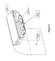
- FIG. 4 illustrates a cross-sectional view (through the electronics package) of an exemplary portable biometric monitoring device
- FIG. 5 illustrates a cross sectional view of a sensor protrusion of an exemplary portable biometric monitoring device; notably, two light sources (e.g. LED's) may be located on one or more sides of the photodetector (for example, either side or opposing sides of a photodetector) to enable photoplethysmography (PPG) sensing wherein light blocking material may be placed between the light sources and the photodetector to prevent any light from the light sources from going through the device body and being detected by the photodetector (in one embodiment, the light sources and photodetector are placed on a flexible PCB); a flexible transparent layer may be placed on the lower surface of the sensor protrusion to form a seal wherein the transparent layer may provide other functions such as preventing liquid from entering the device where the light sources or photodetectors are disposed or placed; notably, the transparent layer may be formed through in-mold labeling or “IML”;
- IML in-mold labeling
- FIG. 6 illustrates a cross sectional view of a sensor protrusion of an exemplary portable biometric monitoring device; notably, the protrusion is similar to that illustrated in the exemplary portable biometric monitoring device of FIG. 5 ; however, the light sources and photodetector are placed on a flat and/or rigid PCB;
- FIG. 7 illustrates another cross-sectional view of a PPG sensor, wherein in this embodiment, the PPG sensor does not include a protrusion; moreover, a gasket and/or a pressure sensitive adhesive may be employed to resist, inhibit and/or prevent liquid from entering the body of the device;
- FIG. 8 illustrates an exemplary geometry of a PPG light source and photodetector wherein, in this embodiment, two light sources are placed on either side of a photodetector; notably, the lights sources and photodetector may be disposed or located in a protrusion on the back of a portable biometric monitoring device which may also operate as a smart watch (the side which faces the skin of the user);
- FIG. 9 illustrates an exemplary PPG sensor having a photodetector and two LED light sources which may be disposed or located in a portable biometric monitoring device having a protrusion; notably, in this embodiment, light pipes are optically connected the LED's and photodetector to the surface of the user's skin, wherein, in operation, the light from the light sources scatters/reflects off of blood in the body, some of which reaches the photodetector via the light pipes; notably, the light pipes preferentially direct or transmit light along a predetermined path, for example, defined by the geometry and/or material of the light pipe;
- FIG. 10 illustrates an exemplary PPG detector having a protrusion with curved sides to reduce and/or minimize any discomfort to the user during operation and/or to more firmly maintain the sensor in contact with the skin of the user (for example, predetermined or fixed relational contact with the skin of the user);
- the surface of light pipes are connect the photodetector and LEDs to the user's skin and are contoured to enhance and/or maximize light flux coupling between the LEDs and photodetectors to the light pipes; notably, the end of the light pipes which face the user's skin may also contoured wherein this contour may provide focusing or defocusing to enhance and/or optimize the PPG signal (for example, the contour may focus light to a certain depth and location which coincides with an area where blood flow is likely to occur); in addition, the vertex of these foci overlap or are very close together so that the photodetector may receive, for example, the maximum possible amount of scattered/reflected light;
- FIG. 11 illustrates an exemplary portable biometric monitoring device having a band and optical sensors and light emitters disposed therein;
- FIG. 12 illustrates a portable biometric monitoring device having a display and wristband; an optical PPG (e.g. heart rate) detection sensors and/or emitters may be disposed or located on the side of the device; notably, in one embodiment, the sensors and/or emitters are disposed or located in buttons mounted on the side of the device;
- PPG e.g. heart rate
- FIG. 13 illustrates a user who is inputting a user input by pressing the side of a portable biometric monitoring device wherein, in response, the device takes a heart rate measurement from a side mounted optical heart rate detection sensor; a display of the device may thereafter display whether or not the heart rate has been detected and/or display the user's heart rate;
- FIG. 14 illustrates functionality of a portable biometric monitoring device smart alarm feature wherein, in this embodiment, the monitoring device may be able to detect or may be in communication with a device which can detect the sleep stage or state of a user (e.g. light or deep sleep); the user may set a window of time which they would like to be awoken (e.g. 6:15 am to 6:45 am); the smart alarm may be triggered by the user going into a light sleep state during the alarm window;
- a device which can detect the sleep stage or state of a user (e.g. light or deep sleep); the user may set a window of time which they would like to be awoken (e.g. 6:15 am to 6:45 am); the smart alarm may be triggered by the user going into a light sleep state during the alarm window;
- the monitoring device may be able to detect or may be in communication with a device which can detect the sleep stage or state of a user (e.g. light or deep sleep); the user may set a window of time
- FIG. 15 illustrates, in a flow diagram form, the operation of a portable biometric monitoring device which changes how the device detects a user's heart rate based on how much movement the device is experiencing; in this embodiment, there is motion detected (e.g. through the use of an accelerometer), the user may be considered active and high sampling rate heart rate detection may occur to reduce motion artifacts in the heart rate measurement; the data may be saved and/or displayed; notably, where the user is not moving, low sampling heart rate detection (which does not consume as much power) may be adequate to measure a heart rate;
- motion detected e.g. through the use of an accelerometer
- FIG. 16 illustrates an exemplary portable monitoring device which has a bicycle application (resident thereon) which may display speed and/or cadence among other metrics; the application may be activated whenever the monitoring device comes into proximity of a passive or active NFC tag, which may be attached to or disposed on the bicycle, for example, the bicycle handlebar(s), frame and/or pedal(s);
- a bicycle application resident thereon
- the application may be activated whenever the monitoring device comes into proximity of a passive or active NFC tag, which may be attached to or disposed on the bicycle, for example, the bicycle handlebar(s), frame and/or pedal(s);
- FIG. 17 illustrates an exemplary PPG sensor having a light source, light detector, ADC, processor, DAC/GPIOs, and light source intensity and on/off control;
- FIG. 18 illustrates an exemplary PPG sensor which is similar to the embodiment illustrated in FIG. 17 ; in this embodiment, however, the sensor employs a sample and hold circuit as well as analog signal conditioning;
- FIG. 19 illustrates an exemplary PPG sensor which is similar to the embodiment illustrated in FIG. 17 ; in this embodiment, however, the sensor employs a sample and hold circuit (and, in one embodiment, oversamples the signals);
- FIG. 20 illustrates an exemplary PPG sensor having multiple switchable light sources and detectors, light source intensity and on/off control, and signal conditioning circuitry
- FIG. 21 illustrates an exemplary PPG sensor which uses synchronous detection; notably, in this embodiment, a demodulator is employed to detect/recover the signal;
- FIG. 22 illustrates an exemplary PPG sensor which is similar to the embodiment illustrated in FIG. 17 ; in this embodiment, however, the sensor employs a differential amplifier in the signal detection path;
- FIG. 23 illustrates an exemplary PPG sensor having many of the features/circuitry illustrated in FIG. 17-22 ;
- FIG. 24 illustrates certain circuitry/elements of an exemplary portable biometric monitoring device having a heart rate or PPG sensor, motion sensor, display, vibromotor/vibramotor, and communication circuitry which are connected to a processor;
- FIG. 25 illustrates certain circuitry/elements of an exemplary portable biometric monitoring device having a heart rate or PPG sensor, motion sensor, display, vibromotor/vibramotor, location sensor, altitude sensor, skin conductance/wet sensor and communication circuitry which is connected to a processor;
- FIG. 26 illustrates certain circuitry/elements of an exemplary portable monitoring device having physiological sensors, environmental sensors, and/or location sensors connected to a processor;
- FIG. 27 illustrates, in block diagram form, exemplary signal flow of motion signals and optical PPG signals which are employed to measure a heart rate of the user;
- FIG. 28 illustrates, in block diagram form, exemplary signal flow of motion signals and optical PPG signals which are employed to measure a heart rate of the user;
- FIG. 29 illustrates a sensor which has an analog connection to a sensor processor which, in turn, has a digital connection to an application processor;
- FIG. 30 illustrates a sensor device which has one or multiple sensors connected to an application processor
- FIG. 31 illustrates a sensor device which has one or multiple sensors connected to sensor processors which, in turn, are connected to an application processor.
- the present inventions relate to a biometric monitoring device and methods and techniques to collect one or more types of physiological and environmental data from embedded sensors and/or external devices and communicates or relays such information to other devices or other internet-viewable sources. For example, such devices are shown in FIG. 1 . While the user is wearing or manipulating the biometric monitoring device, through one or a plurality of sensors, the device may detect one or many of physiological metrics including, but not limited to, the user's heart rate.
- the device may have a user interface directly on the device that indicates the state of one or more of the data types available and/or being tracked.
- the user interface may also be used to display data from other devices or Internet sources.
- the device may implement wireless communications so that when the user and device comes within range of a wireless base station or access point, the stored data automatically uploads to an internet viewable source such as a website.
- the device can be a computer that executes an activity tracking application (APP).
- APP activity tracking application
- the computing device can take on any form, so long as it can process information, load and execute an application, and can communicate wirelessly with the activity tracking device.
- the device can also be or work in conjunction with a computer, a tablet computer, a smart phone, a tablet, a laptop, a desktop, a watch computer, glasses computer, or any device having access to memory and processing power.
- the device is configured collect motion data, activity data, and other data, such as altitude or relative altitude data, barometric pressure data, heart rate data, temperature data, alarm data, goal data, history status data, processed data, raw data, etc.
- the computing device may usually have access to an Internet connection, every transfer between the activity tracking device and the computing device does not require Internet connection.
- the computing device can then sync data to a server.
- the server in one embodiment, can be one or more distributed servers, data centers, virtualized servers in distributed data centers, etc.
- the server in one embodiment, executes an activity management application that enables user account access to metrics associated with activity tracking devices.
- circuitry, architectures, structures, components, functions and/or elements, as well as combinations and/or permutations thereof are set forth. It should be understood that circuitry, architectures, structures, components, functions and/or elements other than those specifically described and illustrated, are contemplated and are within the scope of the present inventions, as well as combinations and/or permutations thereof.
- the biometric monitoring device of the present inventions may use one, some or all of the following sensors to acquire physiological data, including the physiological data outlined in the table below. All combinations and permutations of physiological sensors and/or physiological data are intended to fall within the scope of the present inventions.
- the biometric monitoring device of the present inventions may include but is not limited to the types one, some or all of sensors specified below to acquire the corresponding physiological data; indeed, other type(s) of sensors may be employed to acquire the corresponding physiological data, which are intended to fall within the scope of the present inventions. Additionally, the device may derive the physiological data from the corresponding sensor output data, but is not limited to the number or types of physiological data that it could derive from said sensor.
- the biometric monitoring device includes an optical sensor to detect, sense, sample and/or generate data that may be used to determine information representative of, for example, stress (or level thereof), blood pressure and/or heart rate of a user. (See, for example, FIGS. 2-7 and 17-23 ).
- the biometric monitoring device includes an optical sensor having one or more light sources (LED, laser, etc.) to emit or output light into the user's body and/or light detectors (photodiodes, phototransistors, etc.) to sample, measure and/or detect a response or reflection and provide data used to determine data which is representative of stress (or level thereof), blood pressure and/or heart rate of a user (e.g., using photoplethysmography).
- LED light sources
- laser laser
- photo detectors photodiodes, phototransistors, etc.
- a user's heart rate measurement may be triggered by criteria determined by one or more sensors (or processing circuitry connected to them). For instance, when data from the motion sensor(s) indicates a period of stillness or little motion, the biometric monitoring device may trigger, acquire and/or obtain a heart rate measurement or data. (See, for example, FIGS. 15, 24 and 25 ). In one embodiment, when the motion sensor(s) indicate user activity or motion (for example, motion that is not suitable or optimum to trigger, acquire and/or obtain desired heart rate measurement or data (for example, data used to determine a user's resting heart rate), the biometric monitoring device and/or the sensor(s) employed to acquire and/or obtain desired heart rate measurement or data may be placed or remain in a low power state. (Note that measurements taken during motion may be less reliable and may be corrupted by motion artifact.)
- the biometric monitoring device of the present inventions may employ data indicative of user activity or motion (for example, from one or more motion sensors) adjust or modify characteristics of triggering, acquiring and/or obtaining desired heart rate measurement or data (for example, to improve robustness to motion artifact).
- data indicative of user activity or motion may adjust or modify the sampling rate and/or resolution mode of sensors which acquire heart rate data (for example, where the amount of user motion exceeds a certain threshold, the biometric monitoring device may increase the sampling rate and/or increase the sampling resolution mode of sensors employed to acquire heart rate measurement or data.
- the biometric monitoring device may adjust or modify the sampling rate and/or resolution mode of the motion sensor(s) during such periods of user activity or motion (for example, periods where the amount of user motion exceeds a certain threshold). In this way, when the biometric monitoring device determines or detects such user activity or motion, the motion sensor(s) may be placed into a higher sampling rate and/or higher sampling resolution mode to, for example, enable more accurate adaptive filtering on the heart rate signal. (See, for example, FIG. 15 ).
- a motion signal may be employed to determine or establish a particular approach or technique to data acquisition or measurement (e.g., synchronous detection rather than a non-amplitude modulated approach) and/or analysis thereof. (See, for example, FIG. 21 ).
- the data which is indicative of the amount of user motion or activity establishes or adjusts the type or technique of data acquisition or measurement by the optical heart rate data acquisition sensors.
- the biometric monitoring device and technique of the present inventions may adjust and/or reduce the sampling rate of optical heart rate sampling when the motion detector circuitry detects or determines that the user's motion is below a threshold (for example, the biometric monitoring device determines the user is sedentary or asleep). (See, for example, FIG. 15 ).
- the biometric monitoring device may control its power consumption (for example, reduce power consumption by reducing the sampling rate—for instance, the biometric monitoring device may sample the heart rate (via the heart rate sensor) once every 10 minutes, or 10 seconds out of every 1 minute.
- the biometric monitoring device may, in addition thereto or in lieu thereof, control power consumption via controlling data processing circuitry analysis and/or data analysis techniques in accordance with motion detection. As such, the motion of the user may impact the heart rate data acquisition parameters and/or data analysis or processing thereof.
- the biometric monitoring device may employ the sensors to calculate heart rate variability when the device determines the user to be sedentary or asleep.
- the device may operate the sensors in a higher-rate sampling mode (relative to non-sedentary periods or periods of user activity that exceed a predetermined threshold) to calculate heart rate variability.
- the biometric monitoring device (or external device) may employ heart rate variability as an indicator of cardiac health or stress.
- the biometric monitoring device measures and/or determines the user's stress level and/or cardiac health when the user is sedentary and/or asleep (for example, as detected and/or determined by the biometric monitoring device).
- the biometric monitoring device of the present inventions may determine the user's stress level, health state (e.g., risk, onset, or progression of fever or cold) and/or cardiac health using sensor data which is indicative of the heart rate variability, galvanic skin response, skin temperature, body temperature and/or heart rate.
- processing circuitry of the biometric monitoring device may determine and/or track the user's “baseline” stress levels over time and/or cardiac “health” over time.
- the device measures a physiologic parameter of the user during one or more periods where the user is motionless (or the user's motion is below a predetermined threshold), sitting, lying down, asleep, or in a particular sleep stage (e.g., deep sleep).
- a physiologic parameter of the user may also be employed as a “baseline” for stress-related parameters, health-related parameters (e.g., risk or onset of fever or cold), cardiac health, heart rate variability, galvanic skin response, skin temperature, body temperature and/or heart rate.
- the biometric monitoring device may automatically detect or determine when the user is attempting to go to sleep, entering sleep, is asleep and/or is awoken from a period of sleep.
- the biometric monitoring device may employ physiological sensors to acquire data wherein the data processing circuitry correlates a combination of heart rate, heart rate variability, respiration rate, galvanic skin response, motion, and/or skin and/or body temperature sensing to detect or determine if the user is attempting to go to sleep, entering sleep, is asleep and/or is awoken from a period of sleep.
- the biometric monitoring device may, for example, acquire physiological data (of the type and in the manner as described herein) and/or determine physiological conditions of the user (of the type and in the manner as described herein). For example, a decrease or cessation of user motion combined with a reduction in user heart rate and/or a change in heart rate variability may indicate that the user has fallen asleep. Subsequent changes in heart rate variability and galvanic skin response may be used to determine transitions of the user's sleep state between two or more stages of sleep (for example, into lighter and/or deeper stages of sleep). Motion by the user and/or an elevated heart rate and/or a change in heart rate variability may be used to determine that the user has awoken.
- the biometric monitoring device is one component of a system for monitoring sleep, where the system comprises a secondary device capable of communicating with the biometric monitoring device and adapted to be placed near the sleeper (e.g., an alarm clock).
- the secondary device may have a shape and mechanical and/or magnetic interface to accept the biometric monitoring device for safe keeping, communication, and/or charging.
- the communication between the biometric monitoring device and the secondary device may be provided through wireless communication techniques/methods and protocols such as Bluetooth, Bluetooth 4.0, RFID, NFC, or WLAN.
- the secondary device may comprise sensors to assist in sleep or environmental monitoring such as, for example, sensors that measure ambient light, noise and/or sound (e.g., to detect snoring), temperature, humidity, and air quality (pollen, dust, CO2, etc).
- the secondary device may communicate with an external service such as www.fitbit.com or server (e.g., personal computer). Communication may be achieved through wired (e.g., Ethernet, USB) or wireless (e.g., WLAN, Bluetooth, RFID, NFC, cellular) circuitry and protocols to transfer data to and/or from the secondary device.
- the secondary device may also act as a relay to transfer data to and/or from the biometric monitoring device to an external service such as www.fitbit.com or other service (e.g., news, social network updates, email, calendar notifications), or server (e.g., personal computer, mobile phone, tablet).
- an external service such as www.fitbit.com or other service (e.g., news, social network updates, email, calendar notifications), or server (e.g., personal computer, mobile phone, tablet).
- Calculation of the user's sleep data may be executed on one or both devices or an external service (e.g., a cloud server) using data from one or both devices.
- the secondary device may be equipped with a display to display data obtained by the secondary device or data transferred to it by the biometric monitoring device, the external service, or a combination of data from the biometric monitoring device, the secondary device, and/or the external service.
- the secondary device may display data indicative of the user's heart rate, total steps for the day, activity and/or sleep goal achievement, the day's weather (measured by the secondary device or reported for a location by an external service), etc.
- the secondary device may display data related to the ranking of the user relative to other users, such as total weekly step count.
- the biometric monitoring device may be equipped with a display to display data obtained by the biometric monitoring device, the secondary device, the external service, or a combination of the three sources.
- the secondary device may act as a backup alarm (e.g., using an audio speaker).
- the secondary device may also have an interface (e.g., display and buttons or touch screen) to create, delete, modify, or enable alarms on the first and/or the secondary device.
- the biometric monitoring device may automatically detect or determine whether it is or is not attached to, disposed on and/or being worn by the user. In response to detecting or determining the biometric monitoring device is not attached to, disposed on and/or being worn by the user, the biometric monitoring device (or selected portions thereof) may implement or be placed in a low power mode of operation—for example, the optical heart rate sensor and/or circuitry may be placed in a lower power or sleep mode).
- the biometric monitoring device includes one or more light detectors (photodiodes, phototransistors, etc) wherein, if at a given light intensity setting, one or more light detectors provides a low return signal, the biometric monitoring device may interpret the data is indicative of the device not being worn.
- the device may reduce its power consumption—for example, “disable” or adjust the operating conditions of the stress and/or heart rate detection sensors and/or circuitry (for example, reduce duty cycle of or disable the light source(s) and/or detector(s), and/or disable or attenuate associated circuitry or portions thereof).
- the biometric monitoring device may periodically determine (e.g., once per second) if the operating conditions of the stress and/or heart rate detection sensors and/or associated circuitry should be restored to a normal operating condition (for example, light source(s), detector(s) and/or associated circuitry should return to a normal operating mode for heart rate detection).
- the biometric monitoring device restores the operating conditions of the stress and/or heart rate detection sensors and/or associated circuitry upon detection of a triggerable event—for example, upon detecting motion of the device (for example, based on data from one or more motion sensor(s)) and/or detecting a user input via the user interface (for example, a tap, bump or swipe).
- the biometric monitoring device may, for power saving purposes, reduce its rate of heart rate measurement collection to, for instance, one measurement per minute whilst the user is not highly active and the user may put the device into a mode of operation to generate measurements on demand or at a faster rate (e.g., once per second), for instance, by pushing a button.
- the optical sensors may be disposed on an interior or skin side of the biometric monitoring device (i.e., a side whereby the surface of the device contacts, touches and/or faces the skin of the user (hereinafter “skin side”).
- skin side a side whereby the surface of the device contacts, touches and/or faces the skin of the user
- the optical sensors may be disposed on one or more sides of the device, including the skin side and one or more sides of the device that face or are exposed to the ambient environment (environmental side).
- the data from such optical sensors may be representative of physiological data and/or environmental data.
- the optical sensors provide, acquire and/or detect information from multiple sides of the biometric monitoring device whether or not the sensors are disposed on one or more of the multiple sides.
- the optical sensors may obtain data related to the ambient light conditions of the environment.
- a light source emits light upon the skin of the user and, in response, a light detector samples, acquires and/or detects a response or reflected light from the skin (and from inside the body).
- the one or more sources and detectors may be arranged in an array or pattern that enhances or optimizes the SNR and/or reduces or minimizes power consumption by light sources and detectors.
- optical detectors sample, acquire and/or detect physiological data which may then be processed or analyzed (for example, by resident processing circuitry) to obtain data which is representative of, for example, a user's heart rate, respiration, heart rate variability, oxygen saturation (SpO2), blood volume, blood glucose, skin moisture and skin pigmentation level.
- the source(s) may emit light having one or more wavelengths which are specific or directed to a type of physiological data to be collected.
- the optical detectors may sample, measure and/or detect one or more wavelengths that are also specific or directed to a type of physiological data to be collected and physiological parameter (of the user) to be assessed or determined.
- a light source emitting light having a wavelength in the green spectrum for example, an LED that emits light having wavelengths corresponding to the green spectrum
- photodiode positioned to sample, measure and/or detect a response or reflection may provide data used to determine or detect heart rate.
- a light source emitting light having a wavelength in the red spectrum for example, an LED that emits light having wavelengths corresponding to the red spectrum
- a light source emitting light having a wavelength in the infrared spectrum for example, an LED that emits light having wavelengths corresponding to the IR spectrum
- photodiode positioned to sample, measure and/or detect a response or reflection may provide data used to determine or detect SpO2.
- the color or wavelength of the light emitted by the LED may be modified, adjusted and/or controlled in accordance with a predetermined type of physiological data being acquired or conditions of operation.
- the wavelength of the light emitted by the LED is adjusted and/or controlled to optimize and/or enhance the “quality” of the physiological data obtained and/or sampled by the detector.
- the color of the light emitted by the LED may be switched from infrared to green when the user's skin temperature or the ambient temperature is cool in order to enhance the signal corresponding to cardiac activity. (See, for example, FIG. 20 ).
- the biometric monitoring device in one embodiment, includes a window (for example, a visually opaque window) in the housing to facilitate optical transmission between the optical sensors and the user.
- the window may permit light (for example, of a selected wavelength) to be emitted by, for example, one or more LEDs, onto the skin of the user and a response or reflection to pass into the housing to be sampled, measured and/or detected by, for example, one or more photodiodes.
- the circuitry related to emitting and receiving light may be disposed in the interior of the device housing and underneath a plastic or glass layer (for example, painted with infrared ink) or an infrared lens which permits infrared light to pass but not light in the human visual spectrum. In this way, the light transmission is invisible to the human eye.
- the biometric monitoring device may employ light pipes or other light transmissive structures. (See, for example, FIGS. 8-10 ).
- light is directed from the light source to the skin of the user through light pipes or other light transmissive structures.
- Scattered light from the user's body may be directed back to the optical circuitry through the same or similar structures.
- the transmissive structures may employ a material and/or optical design to facilitate low light loss (for example, a lens) thereby improving SNR of the photo detector and/or reduce power consumption of the light source(s) (light emitters and/or light detectors).
- the light pipes or other light transmissive structures may include a material that selectively transmits light having one or more specific or predetermined wavelengths with higher efficiency than others, thereby acting as a bandpass filter.
- This bandpass filter may be tuned to improve the signal of a specific physiological data type.
- an In-Mold-Labeling or “IML” light transmissive structure may be implemented wherein the structure uses a material with predetermined or desired optical characteristics to create a specific bandpass characteristic, for example, to pass infrared light with greater efficiency than light of other wavelengths (for example, light having a wavelength in human visible spectrum).
- a biometric monitoring device may employ light transmissive structure having an optically opaque portion (including certain optical properties) and an optically transparent portion (including optical properties different from the optically opaque portion).
- a structure may be provided via a double-shot or two step molding process wherein optically opaque material is injected and optically transparent material is injected.
- a biometric monitoring device implementing such a light transmissive structure may include different transmissive property for different wavelengths depending on the direction of light travel through the structure.
- the optically opaque material may include a property of being reflective to a specific wavelength range so as to more efficiently transport light from the light emitter(s) and from the user's body back to the skin detector (which may be of a different wavelength(s) relative to the wavelength(s) of the emitted light).
- such structures may include a mask consisting of an opaque material which limits the aperture of one, some or all of the light source(s) and/or detector(s).
- the light transmissive structures selectively “define” a preferential volume of the body that light is emitted into and/or detected from.
- other mask configurations may be employed or implemented in connection with the inventions described and/or illustrated herein; all such mask configurations to, for example, improve the photoplethysmography signal, and which are implemented in connection with the inventions described and/or illustrated herein, are intended to fall within the scope of the present inventions.
- the surface of the optics or device body may include a hard coat paint, hard coat dip, or optical coatings (such as anti-reflection), scratch resistance, anti-fog, and/or wavelength band block (such as ultraviolet light blocking). Such characteristics or materials may improve the operation, accuracy and/or longevity of the biometric monitoring device.
- the biometric monitoring device includes a concave or convex shape, on the skin side of the device, to focus light towards a specific volume at a specific depth in the skin and increase the efficiency of light collected from that point into the photodetector.
- a biometric monitoring device also employs light pipes to selectively and controllably route light
- Such a configuration may improve the SNR by increasing the efficiency of light transferred from the emitter onto or into the skin of the user while decreasing “stray” light from being detected or collected by the photodetector.
- the signal sampled, measured and/or detected by the photodetector consists less of stray light and more of the user's response to such emitted light (signal or data that is representative of the response to the emitted light).
- the components of the optical sensor are positioned on the skin side of the device and arranged or positioned to reduce or minimize the distance between (i) the light source(s) and/or associated detector(s) and (ii) the skin of the user. (See, for example, FIG. 5 ). Such a configuration may improve the efficiency of light flux coupling between the components of the optical sensor and the user's body.
- the light source(s) and/or associated detector(s) are disposed on a flexible or pliable substrate which facilitates the skin side of the device to conform (for example, without additional processing) or be capable of being shaped (or compliant) to conform to the shape of the user's body part (for example, wrist, arm ankle and/or leg) to which the biometric monitoring device is coupled to attached during normal operation so that the light source(s) and/or associated detector(s) are/is close to the skin of the user (i.e., with little to no gap between the skin side of the device and the juxtaposed surface of the skin of the user. (See, FIG. 11 ).
- the light source(s) and/or associated detector(s) are disposed on a Flat Flex Cable or “FFC” or flexible PCB.
- the flexible or pliable substrate for example, FFC or flexible PCB
- the second substrate for example, PCB
- Optical components of differing heights may be mounted to different “fingers” of flexible substrate and pressed or secured to the housing surface such that the optical components are flush to the housing surface.
- the second substrate may be a relative inflexible or non-pliable substrate, fixed within the device, having other circuitry and components (passive and/or active) disposed thereon.
- the biometric monitoring device is adapted to be worn or carried on the body of a user.
- the device may be a wrist-worn or arm-mounted accessory such as a watch or bracelet.
- optical elements of the optical heart rate monitor are located on the interior or skin side of the biometric monitoring device, for example, facing the top of the wrist (i.e., the optical heart rate monitor is juxtaposed the wrist) when the device is wrist mounted. (See, for example, FIGS. 2-7 ).
- the optical heart rate monitor is located on one or more external or environmental side surfaces of the biometric monitoring device.
- the user may touch an optical window (behind which optical elements of the optical heart rate monitor are located) with a finger on the opposing hand to initiate a heart rate measurement (and/or other metrics related to heart rate such as heart rate variability) and/or collect data which may be used to determine the user's heart rate (and/or other metrics related to heart rate).
- a heart rate measurement and/or other metrics related to heart rate such as heart rate variability
- collect data which may be used to determine the user's heart rate (and/or other metrics related to heart rate).
- the biometric monitoring device may trigger or initiate the measurement(s) by detecting a (sudden) drop in incident light on the photodiode—for example, when the user's finger is placed over the optical window.
- a heart rate measurement (or other such metric) may be trigged by an IR-based proximity detector and/or capacitive touch/proximity detector (which may be separate from other detectors).
- Such IR-based proximity detector and/or capacitive touch/proximity detector may be disposed in or on and/or functionally, electrically and/or physically coupled to the optical window to detect or determine the presence of, for example, the user's finger.
- the biometric monitoring device may include a button which, when depressed, triggers or initiates heart rate measurement (and/or other metrics related to heart rate).
- the button may be disposed in close proximity of the optical window to facilitate the user pressing the button while the finger is disposed on the optical window. (See, for example, FIG. 13 ).
- the optical window may be embedded in a push button.
- the button may be given a shape and/or resistance to pressing that enhances or optimizes a pressure profile against the finger to provide high SNR during measurement or data acquisition.
- the biometric monitoring device may take the form of a clip, smooth object, pendant, anklet, belt, etc. that is adapted to be worn on the body, clipped or mounted to an article of clothing, deposited in clothing (e.g., pocket), or deposited in an accessory (e.g., handbag).
- the biometric monitoring device includes a protrusion on the skin or interior side of the device. (See, FIG. 2-11 ). When coupled to the user, the protrusion engages the skin with more force than the surrounding device body.
- an optical window or light transmissive structure may form or be incorporated in a portion of the protrusion.
- the light emitter(s) and/or detector(s) of the optical sensor may be disposed or arranged in the protrusion juxtaposed the window or light transmissive structure. (See, for example, FIGS. 3 and 11 ).
- the window portion of the protrusion of the biometric monitoring device engages the user's skin with more force than the surrounding device body—thereby providing a more secure physical connection between the user's skin and the optical window. That is, a protrusion improves sustained contact between the biometric monitoring device and the user's skin which may reduce the amount of stray light measured by the photodetector, decrease motion between the biometric monitoring device and the user, and/or provide improved local pressure to the user's skin; all of which may increase the quality of the cardiac signal of interest.
- the protrusion may contain other sensors that benefit from close proximity and/or secure contact to the user's skin.
- a heart rate sensor may be included in addition to or in lieu of a heart rate sensor and include sensors such as a skin temperature sensor (e.g., noncontact thermopile that utilizes the optical window or thermistor joined with thermal epoxy to the outer surface of the protrusion), pulse oximeter, blood pressure sensor, EMG, or galvanic skin response sensor.
- a skin temperature sensor e.g., noncontact thermopile that utilizes the optical window or thermistor joined with thermal epoxy to the outer surface of the protrusion
- pulse oximeter e.g., blood pressure sensor, EMG, or galvanic skin response sensor.
- a portion of the skin side of the biometric monitoring device may include a friction enhancing mechanism or material.
- the skin side of the biometric monitoring device may include a plurality of raised or depressed regions portions (for example, small bumps, ridges, grooves, and/or divots).
- a friction enhancing material for example, a gel-like material such as silicone
- a device back made out of gel may also provide friction while also improving user comfort and preventing stray light from entering.
- a friction enhancing mechanism or material may be used alone or in conjunction with the biometric monitoring device having a protrusion as described herein.
- the biometric monitoring device may include a plurality of raised or depressed regions portions (for example, small bumps, ridges, grooves, and/or divots) in or on the protrusion portion of the device.
- raised or depressed regions portions may be incorporated/embedded in or on a window portion of the protrusion.
- the protrusion portion may consist of or be coated with a friction enhancing material (for example, a gel-like material such as silicone).
- the use of a protrusion and/or friction may improve measurement accuracy of data acquisition corresponding to certain parameters (e.g., heart rate, heart rate variability, galvanic skin response, skin temperature, skin coloration, heat flux, blood pressure, blood glucose, etc.) by reducing motions of the sensor relative to the user's skin during operation, especially whilst the user is in motion.
- certain parameters e.g., heart rate, heart rate variability, galvanic skin response, skin temperature, skin coloration, heat flux, blood pressure, blood glucose, etc.
- the interior or skin side housing of the biometric monitoring device may also consist of a metal material (for example, steel, stainless steel, aluminum, magnesium, or titanium). Such a configuration may provide a structural rigidity. (See, for example, FIG. 3 .)
- the device body may be designed to be hypoallergenic through the use of a hypoallergenic “Nickel-Free” stainless steel.
- a type of metal that is ferrous in properties for example, a grade of stainless steel that is ferrous.
- the biometric monitoring device may interconnect with a charger using magnetic properties to secure thereto.
- biometric monitoring device may also engage a dock or dock station using such magnetic properties to facilitate data transfer.
- a housing may provide enhanced electromagnetic shielding which would enhance the integrity and reliability of the optical heart rate sensor and data acquisition process/operation.
- a skin temperature sensor may be physically and thermally coupled, for example with thermal epoxy, to the metal body to sense the temperature of the user.
- the sensor may be positioned near or in the protrusion to provide secure contact and localized thermal coupling to the user's skin.
- one or more components of the optical sensor are attached, fixed, included and/or secured to the biometric monitoring device via a liquid-tight seal (i.e., a method/mechanism that prevents liquid ingress into the body of the biometric monitoring device).
- a liquid-tight seal i.e., a method/mechanism that prevents liquid ingress into the body of the biometric monitoring device.
- a device back made out of a metal including but not limited to stainless steel, aluminum, magnesium, or titanium or a rigid plastic could provide a structure which is stiff enough to maintain the structural integrity of the device while accommodating a watertight seal for the sensor package. (See, FIGS. 3-7 ).
- a package or module of the optical sensor would be connected to the device with a pressure sensitive adhesive and a liquid gasket. (See, FIG. 7 ). Screws, rivets or the like may also be used, for example, if a stronger or more durable connection is required between the optical sensor package/module and the device body.
- the present inventions may also use watertight glues, hydrophobic membranes such as Gore-Tex, o-rings, sealant, grease, or epoxy to secure or attach the optical sensor package/module and the device body.
- the biometric monitoring device may include a material disposed on the skin or interior side which includes high reflectivity characteristic—for example, to polished stainless steel, reflective paint, and polished plastic.
- high reflectivity characteristic for example, to polished stainless steel, reflective paint, and polished plastic.
- the color of the skin or interior side of the biometric monitoring device is selected to provide certain optical characteristics (for example, reflect certain or predetermined wavelengths of light), in order to improve the signal of certain physiological data types.
- the measurements of the heart rate may be enhanced due to the preferential emission of a wavelength of the light corresponding to the green spectrum.
- the measurements of the SpO2 may be enhanced due to the emission preferential of a wavelength of the light corresponding to the red spectrum.
- the color of the skin or interior side of the biometric monitoring may be modified, adjusted and/or controlled in accordance with a predetermined type of physiological data being acquired.
- FIG. 17 depicts an exemplary schematic block diagram of an optical sensor where light is emitted from a light source toward the user's skin and the reflection is sensed by a light detector, which is subsequently digitized by an analog to digital converter (ADC).
- the intensity of the light source may be modified (e.g., through a light source intensity control module) to maintain a desirable reflected intensity signal.
- the light source intensity may be reduced to avoid saturation of the output signal from the light detector.
- the light source intensity may be increased to maintain the output signal from the light detector within a desired range of output values.
- the active control of the system may be achieved through linear or nonlinear control methods such as proportional-integral-derivative (PID) control, fixed step control, predictive control, neural networks, hysteresis, and the like, and may also employ information derived from other sensors in the device such as motion, galvanic skin response, etc.
- FIG. 17 is provided for illustration and does not limit the implementation of such a system to, for instance, an ADC integrated within a MCU, or the use of a MCU for that matter.
- Other possible implementations include the use of one or more internal or external ADCs, FPGAs, ASICs, etc.
- the system may incorporate the use of a sample and hold circuit (or equivalent) to maintain the output of the light detector while the light source is turned off or attenuated to save power.
- a sample and hold circuit or equivalent to maintain the output of the light detector while the light source is turned off or attenuated to save power.
- the sample and hold circuit may not have to maintain an accurate copy of the output of the light detector.
- the sample and hold may be reduced to, for example, a diode (e.g., Schottky diode) and capacitor.
- the output of the sample and hold may be presented to an analog signal conditioning circuit (e.g., a Sallen-Key bandpass filter, level shifter, and/or gain circuit) to condition and amplify the signal within frequency bands of interest (e.g., 0.1 Hz to 10 Hz for cardiac or respiratory function) which is then digitized by the ADC. See, for example, FIG. 18 .
- an analog signal conditioning circuit e.g., a Sallen-Key bandpass filter, level shifter, and/or gain circuit
- frequency bands of interest e.g., 0.1 Hz to 10 Hz for cardiac or respiratory function
- the embodiment may also include the analog signal conditioning circuitry (not illustrated) for variable gain settings that can be controlled to provide a suitable signal (e.g., not saturated).
- the performance characteristics e.g., slew rate and/or gain bandwidth product
- power consumption of the light source, light detector, and/or sample and hold may be significantly higher than the analog signal conditioning circuit to enable fast duty cycling of the light source.
- the power provided to the light source and light detector may be controlled separately from the power provided to the analog signal conditioning circuit to provide additional power savings.
- the output of the light detector and/or sample and hold may be sampled by an ADC in addition to or in lieu of the analog signal conditioning circuit to control the light intensity of the light source or to measure the physiologic parameters of interest when, for example, the analog signal conditioning circuit is not yet stable after a change to the light intensity setting.
- the reference voltages and/or gain of the ADC may be adjusted to enhance signal quality, or the ADC may be oversampled.
- the device may digitize the output of only the sample and hold circuit by, for example, oversampling, adjusting the reference voltages and/or gain of the ADC, or using a high resolution ADC. See, for example, FIG. 19 .
- the system may incorporate a differential amplifier to amplify the relative changes in the output of the light detector output. See, for example, FIG. 22 .
- a digital average or digital lowpass filtered signal is subtracted from the output of the light detector output and amplified before it is digitized by the ADC.
- an analog average or analog lowpass filtered signal is subtracted from the output of the light detector through, for example, the use of a sample and hold circuit and analog signal conditioning circuitry.
- the power provided to the light source, light detector, and differential amplifier may be controlled separately from the power provided to the analog signal conditioning circuit to improve power savings.
- the light detector module may incorporate a transimpedance amplifier stage with variable gain.
- a transimpedance amplifier stage with variable gain.
- the gain of the transimpedance amplifier may be automatically reduced with a variable resistor and/or multiplexed set of resistors in the negative feedback path of the transimpedance amplifier.
- the device may incorporate little to no optical shielding from ambient light by amplitude modulating the intensity of the light source and demodulating the output of the light detector (e.g., synchronous detection). See, for instance, FIG. 21 .
- the ambient light is of sufficient brightness to obtain a heart rate signal, the light source may be reduced in brightness and/or turned off completely.
- the aforementioned processing techniques may be used in combination to optically measure physiological parameters of the user. See, for example, FIG. 23 .
- This topology may allow the system to operate in a low power measurement state and circuit topology when applicable and adapt to a higher power measurement state and circuit topology as necessary.
- the system may measure the physiologic parameter (e.g., heart rate) of interest using analog signal conditioning circuitry whilst the user is immobile or sedentary to reduce power consumption, but switch to oversampled sampling of the light detector output directly whilst the user is active.
- physiologic parameter e.g., heart rate
- processing of the signal to obtain heart rate measurements may comprise filtering and/or signal conditioning such as bandpass filtering (e.g., Butterworth filter).
- bandpass filtering e.g., Butterworth filter
- nonlinear approaches may be employed such as neural networks or slew rate limiting.
- Data from the sensors on the device such as motion, galvanic skin response, skin temperature, etc., may be used to adjust the signal conditioning methods employed.
- the heart rate of the user may be measured by counting the number of signal peaks within a time window or utilizing the fundamental frequency or second harmonic of the signal (e.g., though a fast Fourier transform (FFT)).
- FFT fast Fourier transform
- FFTs may be performed on the signal and spectral peaks extracted, which are subsequently processed by a multiple target tracker which starts, continues, merges, and deletes tracks of the spectra.
- a similar set of operations are performed on the motion signal and the output is used to do activity discrimination (e.g., sedentary, walking, running, sleeping, lying down, sitting, biking, typing, elliptical, weight training) which is used to assist the multiple target tracker. For instance, it may be determined that the user was stationary and has begun to move and this information can be used to preferentially bias the track continuation toward increasing frequencies.
- the activity discriminator may determine that the user has stopped running or is running slower and this information may be used to preferentially bias the track continuation toward decreasing frequencies.
- Tracking may be achieved with single-scan or multi-scan multi-target tracker topologies such as joint probabilistic data association trackers, multiple hypothesis tracking, nearest neighbor, etc.
- Estimation and prediction in the tracker may be done through Kalman filters, spline regression, particle filters, interacting multiple model filters, etc.
- a track selector module uses the output tracks from the multiple spectra tracker and estimates the user's heart rate. The estimate may be taken as the maximum likelihood track, a weight sum of the tracks against their probabilities of being the heart rate, etc.
- the activity discriminator may furthermore influence the selection and/or fusion to get the heart rate estimate.
- a prior probability may be skewed toward heart rates in the 40-80 bpm range; whereas if the user is running, jogging, or doing other vigorous exercise, a prior probability may be skewed toward elevated heart rates in the 90-180 bpm range.
- the influence of the activity discriminator may be based on the speed of the user.
- the estimate may be shifted toward (or wholly obtained by) the fundamental frequency of the signal when the user is not moving.
- the track that corresponds to the user's heart rate may be selected based on criteria that is indicative of changes in activity; for instance, if the user begins to walk from being stationary, the track that illustrates a shift toward higher frequency may be preferentially chosen.
- the acquisition of a good heart rate signal may be indicated to the user through a display on the biometric monitoring device or another device in wired or wireless communication with the biometric monitoring device (e.g., a Bluetooth Low Energy equipped mobile phone).
- the biometric monitoring device includes a signal strength indicator which is represented by the pulsing of a LED that is viewable by the user.
- the pulsing may be timed or correlated to be coincident with the user's heart beat.
- the intensity, pulsing rate and/or color of the LED may be modified or adjusted to suggest signal strength. For example, a brighter LED intensity may represent a stronger signal or in a RGB LED configuration, a green colored LED may represent a stronger signal.
- the strength of the heart rate signal may be determined by the energy (e.g., squared cumulative sum) of the signal in a frequency band of, for instance, 0.5 Hz to 4 Hz.
- the biometric monitoring device of the present invention may have a strain gauge, pressure sensor, and/or force sensor which may be incorporated or constructed into the housing and/or in the band (in those embodiments where the biometric monitoring device is attached to or mounted with a band like a watch, bracelet, and/or armband—which may then be secured to the user).
- a signal quality metric may be calculated with these contact sensors either alone or in combination with data from the heart rate signal.
- the biometric monitoring device may monitor heart rate optically through an array of photodetectors such as a grid of photodiodes or a CCD camera. Motion of the optical device with respect to the skin may be tracked through feature tracking of the skin and/or adaptive motion correction using an accelerometer and gyroscope.
- the detector array may be in contact with the skin or offset at a small distance away from the skin.
- the detector array and its associated optics may be actively controlled (e.g., with a motor) to maintain a stabilized image of the target and acquire a heart rate signal.
- This optomechanical stabilization may be achieved using information from motion sensors (e.g., gyroscope) or image features.
- the biometric monitoring device may implement relative motion cancellation using a coherent or incoherent light source to illuminate the skin and a photodetector array with each photodetector associated with comparators for comparing the intensity between neighboring detectors—obtaining a so-called speckle pattern which may be tracked using a variety of image tracking techniques such as optical flow, template matching, edge tracking, etc.
- the light source used for motion tracking may be different than the light source used in the optical heart rate monitor.
- the biometric monitoring device may consist of a plurality of photodetectors and photoemitters distributed along the surface of the device that touches the user's skin (i.e., the skin side of the biometric monitoring device). (See, for example, FIGS. 2-11 ).
- the biometric monitoring device may consist of a plurality of photodetectors and photoemitters distributed along the surface of the device that touches the user's skin (i.e., the skin side of the biometric monitoring device).
- FIGS. 2-11 the skin side of the biometric monitoring device.
- a heart rate signal quality metric at each site may be calculated to determine the best or set of best sites for estimating the user's heart rate. Subsequently, some of the sites may be disabled or turned off to, for example, reduce power consumption.
- the device may periodically check the heart rate signal quality at some or all of the
- biometric monitoring device of the present invention may include a heart rate monitoring system including a plurality of sensors such as optical, acoustic, pressure, electrical (e.g., EKG), and motion and fuse the information from two or more of these sensors to provide an estimate of heart rate and/or mitigate noise induced from motion.
- a heart rate monitoring system including a plurality of sensors such as optical, acoustic, pressure, electrical (e.g., EKG), and motion and fuse the information from two or more of these sensors to provide an estimate of heart rate and/or mitigate noise induced from motion.
- the biometric monitoring device in one embodiment, includes optical sensors to track or detect time and duration of ultraviolet light exposure, total outdoor light exposure, the type of light source and duration and intensity of that light source (fluorescent light exposure, incandescent bulb light exposure, halogen, etc), exposure to television (based on light type and flicker rate), whether the user is indoors or outdoors, time of day and location based on light conditions.
- the ultraviolet detection sensor may consist of a reverse biased LED emitter driven as a light detector. The photocurrent produced by this detector may be characterized by, for instance, measuring the time it takes for the LED's capacitance (or alternately a parallel capacitor) to discharge.
- optical sensors could be used in conjunction with other sensors to improve detection of the data described above or be used to augment detection of other types of physiological or environmental data.
- the biometric monitoring device may contain one or more passive acoustic sensors that detect sound and pressure and which can include but not be limited to microphones, piezo film, etc.
- the acoustic sensors may be disposed on one or more sides of the device, including the side that touches or faces the skin (skin side) and the sides that face the environment (environmental sides).
- the biometric monitoring device of the present invention may also include galvanic skin response (GSR) circuitry to measure the response of the user's skin to emotional and physical stimuli or physiological changes (e.g., the transition of sleep stage).
- GSR galvanic skin response
- the invention is a wrist or arm-mounted device incorporating a band comprised of conductive rubber or fabric so that the galvanic skin response electrodes may be hidden in the band.
- the galvanic skin response circuitry may be subjected to changing temperatures and environmental conditions, it may also include circuitry to enable automatic calibration, such as two or more switchable reference resistors in parallel or series with the human skin/electrode path that allows real-time measurement of known resistors to characterize the response of the galvanic skin response circuit.
- the reference resistors may be switched into and out of the measurement path such that they are measured independently and/or simultaneously with the human skin.
- the skin side sensors would detect any type of sound transmitted through the body and the sensors could be arranged in an array or pattern that optimizes both the SNR and power consumption. These sensors could detect respiration (by listening to the lung), respiratory sounds (breathing, snoring) and problems, heart rate (listening to the heart beat), user's voice (via sound transmitted from the vocal cords throughout the body)
- the biometric monitoring device of the present inventions may use one, some or all of the following environmental sensors to, for example, acquire the environmental data, including environmental data outlined in the table below.
- the biometric monitoring device is not limited to the number or types of sensors specified below but may employ other sensors that acquire environmental data outlined in the table below. All combinations and permutations of environmental sensors and/or environmental data are intended to fall within the scope of the present inventions. Additionally, the device may derive environmental data from the corresponding sensor output data, but is not limited to the types of environmental data that it could derive from said sensor.
- biometric monitoring device of the present inventions may one or more, or all of the environmental sensors described herein and one or more, or all of the physiological sensors described herein.
- biometric monitoring device of the present inventions may acquire any or all of the environmental data and physiological data described herein using any sensor now known or later developed—all of which are intended to fall within the scope of the present inventions.
- the biometric monitoring device may include an altimeter sensor, for example, disposed or located in the interior of the device housing. (See, for example, FIGS. 25 and 26 ).
- the device housing may have a vent that allows the interior of the device to measure, detect, sample and/or experience any changes in exterior pressure.
- the vent prevents water from entering the device while facilitating measuring, detecting and/or sampling changes in pressure via the altimeter sensor.
- an exterior surface of the biometric monitoring device may include a vent type configuration or architecture (for example, a GoreTM vent) which allows ambient air to move in and out of the housing of the device (which allows the altimeter sensor to measure, detect and/or sample changes in pressure), but reduces, prevents and/or minimizes water and other liquids flow into the housing of the device.
- a vent type configuration or architecture for example, a GoreTM vent
- the altimeter sensor in one embodiment, may be filled with gel that allows the sensor to experience pressure changes outside of the gel.
- the use of a gel filled altimeter may give the device a higher level of environmental protection with or without the use of an environmentally sealed vent.
- the device may have a higher survivability rate with a gel filled altimeter in locations including but not limited to those that have high humidity, a clothes washer, a dish washer, a clothes dryer, a steam room, the shower, a pool, and any location where the device may be exposed to moisture, exposed to liquid or submerged in liquid.
- the biometric monitoring device of the present invention may use data from two or more sensors to calculate the corresponding physiological or environmental data as seen in the table below (for example, data from two or more sensors which are used in combination).
- the device may include but is not limited to the number, types, or combinations of sensors specified below. Additionally, the device may derive the included data from the corresponding sensor combinations, but is not limited to the number or types of data that could be calculated from the corresponding sensor combinations.
- the device may also include a near-field communication (NFC) receiver/transmitter to detect proximity to another device, such as a mobile phone.
- NFC near-field communication
- the device may trigger the start of new functionality on the second device (e.g., the launching of an “app” on the mobile phone and radio syncing of physiological data from the device to the second device).
- the biometric monitoring device of the present invention may implement any of the circuitry and techniques described and/or illustrated in U.S. Provisional Patent Application 61/606,559, filed Mar. 5, 2012, “Near Field Communication System, and Method of Operating Same”, inventor: James Park (the contents of which are incorporated herein by reference).
- the biometric monitoring device includes a location sensor (for example, GPS circuitry) and heart rate sensor (for example, photoplethysmography circuitry) to generate GPS or location related data and heart rate related data, respectively. (See, for example, FIGS. 25 and 26 ).
- the biometric monitoring device may then fuse, process and/or combine data from these two sensors/circuitry to, for example, determine, correlate and/or “map” geographical regions according to physiological data (for example, heart rate, stress, activity level, quantity of sleep and/or caloric intake). In this way, the biometric monitoring device may identify geographical regions that increase or decrease a measurable user metric including but not limited to heart rate, stress, activity, level, quantity of sleep and/or caloric intake.
- the biometric monitoring device may employ the GPS related data and photoplethysmography related data (notably, each of which may be considered data streams), to determine or correlate the user's heart rate according to activity levels—for example, as determined by the user's acceleration, speed, location and/or distance traveled (as measured by the GPS and/or determined from GPS related data). (See, for example, FIGS. 25 and 26 ).
- heart rate as a function of speed may be “plotted” for the user, or the data could be broken down into different levels including but not limited to sleeping, resting, sedentary, moderately active, active, and highly active.
- the biometric monitoring device may also correlate GPS related data to a database of predetermined geographic locations that have activities associated with them for a set of predetermined conditions.
- activity determination and corresponding physiological classification may include correlating a user's GPS coordinates that correspond to location(s) of exercise equipment, health club and/or gym and physiological data.
- a user's heart rate during, for example a gym workout may be automatically measured and displayed.
- many physiological classifications may be based on GPS related data including location, acceleration, altitude, distance and/or velocity.
- a database including geographic data and physiological data may be compiled, developed and/or stored on the biometric monitoring device and/or external computing device. Indeed, in one embodiment, the user may create their own location database or add to or modify the location database to better classify their activities.
- the user may simultaneously wear multiple biometric monitoring devices (having any of the features described herein).
- the devices of this embodiment may communicate with each other or a remote device using wired or wireless circuitry to calculate, for example, biometric or physiologic qualities or quantities that, for example, may be difficult or inaccurate to calculate otherwise such as pulse transit time.
- the use of multiple sensors may also improve the accuracy and/or precision of biometric measurements over the accuracy and/or precision of a single sensor. For example, having a device on the waist, wrist, and ankle could improve the detection of the user taking a step over that of a single device in only one of those locations.
- Signal processing could be performed on the devices in a distributed or centralized method to provide improved measurements over that of a single device. This signal processing could also be performed remotely and communicated back to the devices after processing.
- the biometric monitoring device may include one or more processors.
- processors See, for example, FIGURS L and M.
- an independent application processor may be used to store and execute applications that utilize sensor data acquired and processed by one or more sensor processors (processor(s) that process data from physiological, environmental and/or activity sensors). In the case where there are multiple sensors, there may also be multiple sensor processors.
- An application processor may have sensors directly connected to it as well. Sensor and application processors may exist as separate discrete chips or exist within the same packaged chip (multi-core).
- a device may have a single application processor, or an application processor and sensor processor, or a plurality of application processors and sensor processors.
- the sensor package could be placed on a daughterboard that consists of all of the analog components.
- This board may have some of the electronics typically found on the main PCB such as, but not limited to, transimpedance amplifiers, filtering circuits, level shifters, sample and hold circuits, and a microcontroller unit.
- Such a configuration may allow the daughterboard to be connected to the main PCB through the use of a digital connection rather than analog in addition to any necessary power or ground connections.
- a digital connection may have a variety of advantages over the analog daughter to main PCB connection including but not limited to a reduction in noise and a reduction in the number of necessary cables.
- the daughterboard may be connected to the main board through the use of a flex cable or set of wires.
- An application can consist of executable code and data for the application, but not limited to these.
- Data can consist of graphics or other information required to execute the application or it can be information output generated by the application.
- the executable code and data for the application can both reside on the application processor or the data for the application can be stored and retrieved from an external memory.
- External memory may include but is not limited to NAND flash, NOR flash, flash on another processor, other solid-state storage, mechanical or optical disks, RAM.
- the executable code for an application can also be stored on an external memory.
- the application processor retrieves the executable code and/or data from the external storage and executes it.
- the executable code can be temporarily or permanently stored on the memory or storage of the application processor. This allows the application to be executed more quickly on the next execution request, since the step of retrieval is eliminated.
- the application processor can retrieve all of the executable code of the application or portions of the executable code. In the latter case, only the portion of executable code required at that moment is retrieved. This allows applications that are larger than the application processor's memory or storage to be executed.
- the application processor can also have memory protection features to prevent applications from overwriting, corrupting, interrupting, blocking, or otherwise interfering with other applications, the sensor system, the application processor, or other components of the system.
- Applications can be loaded onto the application processor and any external storage via a variety of wired, wireless, optical, capacitive mechanisms including but not limited to USB, Wi-Fi, Bluetooth, Bluetooth Low Energy, NFC, RFID, Zigbee.
- Applications can be cryptographically signed with an electronic signature.
- the application processor can restrict the execution of applications to those that have the correct signature.
- the biometric monitoring device may include a housing having a size and shape that facilitates fixing the device to the user's body during normal operation wherein the device, when coupled to the user, does not measurably or appreciably impact the user's activity.
- the device may be worn in different ways depending on the specific sensor package integrated into the device and the data that the user would like to acquire.
- a user may wear one or more of the biometric monitoring devices of the present invention on their wrist or ankle (or arm or leg) with the use of a band that is flexible and thereby readily fitted to the user.
- the band may have an adjustable circumference, therefore allowing it to be fitted to the user.
- the band may be constructed from a material that shrinks when exposed to heat, therefore allowing the user to create a custom fit.
- the band may be detachable from the “electronics” portion of the biometric monitoring device and, if necessary, replaceable.
- the biometric monitoring device consists of two major components—a body (containing the “electronics”) and a band (that facilitates attaching the device to the user).
- the body may include a housing (made, for example, of a plastic or plastic-like material) and extension tabs projecting from the body (made, for example, from a metal or metal-like material). (See, for example, FIGS. 4-7 ).
- the band (made, for example, of a thermoplastic urethane) is attachable to the body mechanically or adhesively. The band may extend out a fraction of the circumference of the user's wrist.
- the distal ends of the urethane band may be connected with a Velcro, a hook and/or loop elastic fabric band that loops around a D-Ring on one side and then attaches back to itself.
- the closure mechanism would allow the user infinite band length adjustment (unlike an indexed hole and mechanical clasp closure).
- the Velcro or fabric could be attached to the band in a manner that allows it to be replaced (for example, if it is worn or otherwise undesirable to wear before the useful or end of life of the device).
- the Velcro or fabric would be attached with screws or rivets and/or glue, adhesive and/or clasp to the band.
- the biometric monitoring device of the present invention may also be integrated and worn in a necklace, chest band, bra, patch, glasses, earring, or toe band.
- the device may be built in such a way that the sensor package/portion of the biometric monitoring device is removable and can be worn in any number of ways including, but not limited to, those listed above.
- the biometric monitoring device of the present invention may be worn clipped to an article of clothing or deposited in clothing (e.g., pocket) or an accessory (e.g., handbag, backpack, wallet). Because the biometric monitoring device may not be near the user's skin, in embodiments that include heart rate measurements, the measurements may be obtained in a discrete, “on demand” context by the user manually placing the device into a specific mode (e.g., depressing a button, covering a capacitive touch sensor, etc., possibly with the heart rate sensor embedded in the button/sensor) or automatically once the user places the device against the skin (e.g., applying the finger to an optical heart rate sensor).
- a specific mode e.g., depressing a button, covering a capacitive touch sensor, etc., possibly with the heart rate sensor embedded in the button/sensor
- automatically once the user places the device against the skin (e.g., applying the finger to an optical heart rate sensor).
- the biometric monitoring device may include one or more methods of interacting with the device either locally or remotely.
- the biometric monitoring device may convey data visually through a digital display.
- the physical embodiment of this display may use any one or a plurality of display technologies including, but not limited to one or more of LED, LCD, AMOLED, E-Ink, Sharp display technology, graphical display, and other display technologies such as TN, HTN, STN, FSTN, TFT, IPS, and OLET.
- This display could show data acquired or stored locally on the device or could display data acquired remotely from other devices or Internet services.
- the device may use a sensor (for example, an Ambient Light Sensor, “ALS”) to control or adjust screen backlighting. For example, in dark lighting situations, the display may be dimmed to conserve battery life, whereas in bright lighting situations, the display may increase its brightness so that it is more easily read by the user.
- ALS Ambient Light Sensor
- the device may use single or multicolor LEDs to indicate a state of the device.
- States that the device indicate may include but are not limited to biometric states such as heart rate or application states such as an incoming message, a goal has been reached. These states may be indicated through the LED's color, being on, off, an intermediate intensity, pulsing (and/or rate thereof), and/or a pattern of light intensities from completely off to highest brightness.
- an LED may modulate its intensity and/or color with the phase and frequency of the user's heart rate.
- an E-Ink display would allow the display to remain on without the battery drain of a non-reflective display.
- This “always-on” functionality may provide a pleasant user experience in the case of, for example, a watch application where the user may simply glance at the device to see the time.
- the E-Ink display always displays content without comprising the battery life of the device, allowing the user to see the time as they would on a traditional watch.
- the device may use a light such as an LED to display the heart rate of the user by modulating the amplitude of the light emitted at the frequency of the user's heart rate.
- the device may depict heart rate zones (e.g., aerobic, anaerobic) through the color of an LED (e.g., green, red) or a sequence of LEDs that light up in accordance with changes in heart rate (e.g., a progress bar).
- the device may be integrated or incorporated into another device or structure, for example, glasses or goggles, or communicate with glasses or goggles to display this information to the user.
- the biometric monitoring device may also convey information to a user through the physical motion of the device.
- One such embodiment of a method to physically move the device is the use of a vibration inducing motor.
- the device may use this method alone, or in combination with a plurality of motion inducing technologies.
- the device may convey information to a user through audio.
- a speaker could convey information through the use of audio tones, voice, songs, or other sounds.
- a user needs to wake up at certain time That a user should wake up as they are in a certain sleep phase That a user should go to sleep as it is a certain time That a user should wake up as they are in a certain sleep phase and in a preselected time window bounded by the earliest and latest time that the user wants to wake up.
- An email was received The user has been inactive for a certain period of time. Notably, this may integrate with other applications like, for instance, a meeting calendar or sleep tracking application to block out, reduce, or adjust the behavior of the inactivity alert.
- the user has been active for a certain period of time
- the user has an appointment or calendar event
- the user has reached a certain activity metric
- the user has gone a certain distance
- the user has reached a certain mile pace
- the user has reached a certain speed
- the user has accumulated a certain elevation gain
- the user has taken a certain number of steps
- the user has had a heart rate measurement recently
- the user's heart rate has reached a certain level
- the user has a normal, active, or resting heart rate of a specific value or in a specific range
- the user's heart rate has enter or exited a certain goal range or training zone
- the user has a new heart rate “zone” goal to reach, as in the case of heart rate zone training for running, bicycling, swimming, etc.
- the user has swum a lap or completed a certain number of laps in a pool
- An external device has information that needs to be communicated to the user such as an incoming phone call or any one of the above alerts
- the user has reached a certain fatigue goal or limit.
- fatigue may be determined through a combination of heart rate, galvanic skin response, motion sensor, and/or respiration data
- the data used to determine whether or not an alert is met may be acquired from a first device and/or one or more secondary devices.
- the device itself may determine whether the criteria for an alert has been met.
- a computing device in communication with the device e.g. a server and/or a mobile phone
- the device may communicate with the user when a goal has been met.
- the criteria for meeting this goal may be based on physiological, contextual, and environmental sensors on a first device, and/or other sensor data from one or more secondary devices.
- the goal may be set by the user or may be set by the device itself and/or another computing device in communication with the device (e.g. a server).
- the device may vibrate when a biometric goal is met.
- the biometric monitoring device of the present invention may be equipped with wireless and/or wired communication circuitry to display data on a secondary device in real time.
- the invention may be able to communicate with a mobile phone via Bluetooth Low Energy in order to give real-time feedback of heart rate, heart rate variability, and/or stress to the user.
- the invention may coach or grant “points” for the user to breathe in specific ways that alleviate stress. Stress may be quantified or evaluated through heart rate, heart rate variability, skin temperature, changes in motion-activity data and/or galvanic skin response.
- the biometric monitoring device may receive input from the user through one or more local or remote input methods.
- local user input could use a sensor or set of sensors to translate a user's movement into a command to the device. Such motions could include but may not be limited to tapping, rolling the wrist, flexing one or more muscles, and swinging.
- Another user input method may be through the use of a button of type, but not limited to the types, capacitive touch button, capacitive screen, and mechanical button.
- the user interface buttons may be made of metal. In the case that the screen uses capacitive touch detection, it may always be sampling and ready to respond to any gesture or input without an intervening event such as pushing a physical button.
- the device may also take input through the use of audio commands.
- All of these input methods may be integrated into the device locally or integrated into a remote device that can communicate with the device either through a wired or wireless connection.
- the user may also be able to manipulate the device through a remote device.
- this remote device could have Internet connectivity.
- the biometric monitoring device of the present invention may act as a wrist-mounted vibrating alarm to silently wake the user from sleep.
- the biometric monitoring device may track the user's sleep quality, waking periods, sleep latency, sleep efficiency, sleep stages (e.g., deep sleep vs REM), and/or other sleep-related metrics through one or a combination of heart rate, heart rate variability, galvanic skin response, motion sensing (e.g., accelerometer, gyroscope, magnetometer), and skin temperature.
- the user may specify a desired alarm time and the invention may use one or more of the sleep metrics to determine an optimal time to wake the user.
- the user when the vibrating alarm is active, the user may cause it to hibernate or turn off by slapping or tapping the device (which is detected, for example, via motion sensor(s), a pressure/force sensor and/or capacitive touch sensor in the device).
- the device may attempt to arouse the user at an optimum point in the sleep cycle by starting a small vibration at a specific user sleep stage or time prior to the alarm setting. It may progressively increase the intensity or noticeability of the vibration as the user progresses toward wakefulness or toward the alarm setting. (See, for example, FIG. 14 ).
- the biometric monitoring device may be configured or communicated with using onboard optical sensors such as the components in an optical heart rate monitor.
- the biometric monitoring device of the present invention may include a means of wireless communication to transmit and receive information from the Internet and/or other devices.
- the wireless communication may consist of one or more means such as Bluetooth, ANT, WLAN, power-line networking, and cell phone networks. These are provided as examples and do not exclude other wireless communication methods existent or that are yet to be invented.
- the wireless connection is two ways.
- the device may transmit, communicate and/or push its data to other peripheral devices and/or the Internet.
- the device may also receive, request and/or pull data from other peripheral devices and/or the Internet.
- the biometric monitoring device may act as a relay to provide communication for other devices to each other or to the Internet.
- the device may connect to the Internet via WLAN but also be equipped with an ANT radio.
- An ANT device may communicate with the device to transmit its data to the Internet through the device's WLAN (and vice versa).
- the device may be equipped with Bluetooth. If a Bluetooth-enabled smart phone comes within reach of the device, the device may transmit data to or receive data from the Internet through the smart phone's cell phone network. Data from another device may also be transmitted to the device and stored (and vice versa) or transmitted at a later time.
- the present invention may also include streaming or transmitting web content for displaying on the biometric monitoring device.
- the following are typical examples:
- Historical graphs of heart rate and/or other data measured by the device but stored remotely 2. Historical graphs of user activity and/or foods consumed and/or sleep data that are measured by other devices and/or stored remotely (e.g., fitbit.com) 3. Historical graphs of other user-tracked data stored remotely. Examples include heart rate, blood pressure, arterial stiffness, blood glucose levels, cholesterol, duration of TV watching, duration of video game play, mood, etc. 4. Coaching and/or dieting data based on one or more of the user's heart rate, current weight, weight goals, food intake, activity, sleep, and other data. 5. User progress toward heart rate, weight, activity, sleep, and/or other goals. 6.
- Content may be delivered to the biometric monitoring device according to different contexts. For instance, in the morning, news and weather reports may be displayed along with the user's sleep data from the previous night. In the evening, a daily summary of the day's activities may be displayed.
- the invention may also include NFC, RFID, or other short-range wireless communication circuitry that may be used to initiate functionality in other devices.
- the invention may be equipped with an NFC antenna so that when a user puts it into close proximity with a mobile phone, an app is launched automatically on the mobile phone.
- the biometric monitoring device may use a wired connection to charge an internal rechargeable battery and/or transfer data to a host device such as a laptop or mobile phone.
- the device may use magnets to help the user align the device to the dock or cable.
- the magnetic field of magnets in the dock or cable and the magnets in the device itself could be strategically oriented to as to force the device to self align and provide a force that holds the device to the dock or cable.
- the magnets may also be used as conductive contacts for charging or data transmission.
- a permanent magnet is only used in the dock or cable side, not in the device itself. This may improve the performance of the biometric monitoring device where the device employs a magnetometer. With a magnet in the device, the strong field of a nearby permanent magnet may increase the difficulty for the magnetometer to accurately measure the earth's magnetic field.
- the device could contain one or more electromagnets in the device body.
- the charger or dock for charging and data transmission would also contain an electromagnet and/or a permanent magnet.
- the device could only turn on its electromagnet when it is close to the charger or dock. It could detect proximity to the dock by looking for the magnetic field signature of a permanent magnet in the charger or dock using a magnetometer. Alternatively it could detect proximity to the charger by measuring the Received Signal Strength Indication or RSSI of a wireless signal from the charger or dock.
- the electromagnet could be reversed, creating a force that repels the device from the charging cable or dock either when the device doesn't need to be charged, synced, or when it has completed syncing or charging.
- the biometric monitoring device of the present invention may include a watch-like form factor and/or bracelet, armlet, or anklet form factor and may be programmed with “apps” that launch specific functionality and/or display specific information. Apps may be launched or closed by a variety of means including but not limited to pressing a button, using a capacitive touch sensor, performing a gesture that is detected by an accelerometer, moving to a location detected by a GPS or motion sensor, compressing the device body, thereby creating a pressure signal inside the device that is detected by an altimeter, or placing the device close to an NFC tag which is associated with an app or set of apps.
- Apps may also be automatically triggered to launch or close by certain environmental or physiological conditions including but not limited to a high heart rate, the detection of water using a wet sensor (to launch a swimming application for example), a certain time of day (to launch a sleep tracking application at night for example), a change in pressure and motion characteristic of a plane taking off or landing to launch and close an “airplane” mode app. Apps may also be launched or closed by meeting multiple conditions simultaneously. For example, if an accelerometer detects that a user is running and the user presses a button it may launch a pedometer application, an altimeter data collection application and/or display. In another case where the accelerometer detects swimming and the user presses the same button, it may launch a lap counting application.
- the device could have a swim-tracking mode that may be launched by starting a swimming app.
- the device's motion sensors and/or magnetometer may be used to detect swim strokes, classify swim stroke types, detect swimming laps, and other related metrics such as stroke efficiency, lap time, speed, distance, and calorie burn.
- Directional changes indicated by the magnetometer may be used to detect a diversity of lap turn methods.
- data from a motion sensor and/or pressure sensor may be used to detect strokes.
- a bicycling app may be launched by moving the device within proximity of an NFC or RFID tag that is located on the bicycle, on a mount on the bicycle or in a location associated with a bicycle including but not limited to a bike rack or bike storage facility. (See, for example, FIG. 16 ).
- the app launched may use a different algorithm than is normally used to determine metrics including but not limited to calories burned, distance traveled, and elevation gained.
- the app may also be launched when a wireless bike sensor is detected including but not limited to a wheel sensor, GPS, cadence sensor, or power meter.
- the device may then display and/or record data from the wireless bike sensor or bike sensors.
- Additional apps include but are not limited to a programmable or customizable watch face, stop watch, music player controller (e.g., mp3 player remote control), text message and/or email display or notifier, navigational compass, bicycle computer display (when communicating with a separate or integrated GPS device, wheel sensor, or power meter), weight lifting tracker, sit-up reps tracker, pull up reps tracker, resistance training form/workout tracker, golf swing analyzer, tennis (or other racquet sport) swing/serve analyzer, tennis game swing detector, baseball swing analyzer, ball throw analyzer (e.g., football, baseball), organized sports activity intensity tracker (e.g., football, baseball, basketball, volleyball, soccer), disk throw analyzer, food bite detector, typing analyzer, tilt sensor, sleep quality tracker, alarm clock, stress meter, stress/relaxation biofeedback game (e.g., potentially in combination with a mobile phone that provides auditory and/or visual cues to train user breathing in relaxation exercises), teeth brushing tracker, eating rate track
- the apps may rely solely on the processing power and sensors of the invention.
- the apps may fuse or merely display information from an external device or set of external devices including but not limited to a heart rate strap, GPS distance tracker, body composition scale, blood pressure monitor, blood glucose monitor, watch, smart watch, mobile communication device such as a smart phone or tablet, or server.
- the device may control a music player on a secondary device.
- Aspects of the music player that may be controlled include but are not limited to the volume, selection of tracks and/or playlists, skipping forward or backward, fast forwarding or rewinding of tracks, the tempo of the track, and the music player equalizer.
- Control of the music player may be via user input or automatic based on physiological, environmental, or contextual data. For example, a user may be able to select and play a track on their smart phone by selecting the track through a user interface on the device.
- the device may automatically choose an appropriate track based on the activity level of the user (the activity level being calculated from device sensor data). This may be used to help motivate a user to maintain a certain activity level. For example, if a user goes on a run and wants to keep their heart rate in a certain range, the device may play an upbeat or higher tempo track if their heart rate is below the range which they are aiming for.
- the present invention is neither limited to any single aspect nor embodiment, nor to any combinations and/or permutations of such aspects and/or embodiments. Moreover, each of the aspects of the present invention, and/or embodiments thereof, may be employed alone or in combination with one or more of the other aspects and/or embodiments thereof. For the sake of brevity, many of those permutations and combinations will not be discussed and/or illustrated separately herein.
Abstract
Description
| TABLE | ||
| Physiological Sensors | Physiological data acquired | |
| Optical Reflectometer | Heart Rate, Heart Rate Variability | |
| Potential embodiments: | SpO2 (Saturation of Peripheral Oxygen) | |
| Light emitter and receiver | Respiration | |
| Multi or single LED and | Stress | |
| photo diode arrangement | Blood pressure | |
| Wavelength tuned for | Arterial Stiffness | |
| specific physiological signals | Blood glucose levels | |
| Synchronous detection/ | Blood volume | |
| amplitude modulation | Heart rate recovery | |
| Cardiac health | ||
| Motion Detector | Activity level detection | |
| Potential embodiments: | Sitting/standing detection | |
| Inertial, Gyro or Accelerometer | Fall detection | |
| GPS | ||
| Skin Temp | Stress | |
| EMG | Muscle tension | |
| EKG | Heart Rate, Heart Rate Variability, | |
| Potential Embodiments: | |
|
| 1 | Stress | |
| 2 lead | Cardiac health | |
| Magnetometer | Activity level based on rotation | |
| Laser Doppler | ||
| Power Meter | ||
| Ultra Sound | Blood flow | |
| Audio | Heart Rate, Heart Rate Variability, | |
| Heart Rate Recovery | ||
| Laugh detection | ||
| Respiration | ||
| Respiration type - snoring, breathing, | ||
| breathing problems | ||
| User's voice | ||
| Strain gauge | Heart Rate, Heart Rate Variability | |
| Potential embodiment: | Stress | |
| In a wrist band | ||
| Wet sensor | Stress | |
| Potential embodiment: | Swimming detection | |
| galvanic skin response | Shower detection | |
| TABLE | |
| Environmental Sensors | Environmental data acquired |
| Motion Detector | Location |
| Potential Embodiments: | |
| Inertial, Gyro or Accelerometer | |
| GPS | |
| Pressure/Altimeter sensor | Elevation |
| Ambient Temp | temperature |
| Light Sensor | Indoor vs outdoor |
| Watching TV (spectrum/flicker rate | |
| detection) | |
| Optical data transfer - initiation, QR | |
| codes, etc. | |
| ultraviolet light exposure | |
| Audio | Indoor vs Outdoor |
| Compass | Location |
| Potential Embodiments: | |
| 3 Axis Compass | |
| TABLE | |
| Data derived from signal processing of | |
| Sensor Integrations | multiple sensors |
| Skin Temp and Ambient Temp | Heat Flux |
| Heart Rate and Motion | Elevation gain |
| Motion detector and other user's motion | Users in the proximity |
| detector | |
| Motion, any heart rate sensor, galvanic skin | Sit/Standing detection |
| response | |
| Any heart rate, heart rate variability sensor, | Sleep Phase detection |
| respiration, motion | Sleep Apnea detection |
| Any heart rate sensor and/or wetness sensor, | Resting Heart rate |
| and/or motion detector | Active Heart Rate |
| Heart rate while asleep | |
| Heart rate while sedentary | |
| Any heart rate detector | Early detection of heart problems: |
| cardiac Arrhythmia | |
| Cardiac arrest | |
| Multiple heart rate detectors | Pulse transit time |
| Audio and/or strain gauge | Typing detection |
| GPS and photoplethysmography (PPG) | location- stress correlation: |
| determination of stressful regions | |
| determination of low stress regions | |
| Activity specific heart rate | |
| resting heart rate | |
| active heart rate | |
| Automatic activity classification and activity | |
| heart rate determination | |
| Heart rate, galvanic skin response, | User fatigue, for example while exercising |
| accelerometer and respiration | |
| TABLE |
| That a user needs to wake up at certain time |
| That a user should wake up as they are in a certain sleep phase |
| That a user should go to sleep as it is a certain time |
| That a user should wake up as they are in a certain sleep phase and in a |
| preselected time window bounded by the earliest and latest time that |
| the user wants to wake up. |
| An email was received |
| The user has been inactive for a certain period of time. Notably, this |
| may integrate with other applications like, for instance, a meeting |
| calendar or sleep tracking application to block out, reduce, or adjust |
| the behavior of the inactivity alert. |
| The user has been active for a certain period of time |
| The user has an appointment or calendar event |
| The user has reached a certain activity metric |
| The user has gone a certain distance |
| The user has reached a certain mile pace |
| The user has reached a certain speed |
| The user has accumulated a certain elevation gain |
| The user has taken a certain number of steps |
| The user has had a heart rate measurement recently |
| The user's heart rate has reached a certain level |
| The user has a normal, active, or resting heart rate of a specific value or |
| in a specific range |
| The user's heart rate has enter or exited a certain goal range or training |
| zone |
| The user has a new heart rate “zone” goal to reach, as in the case of |
| heart rate zone training for running, bicycling, swimming, etc. activities |
| The user has swum a lap or completed a certain number of laps in a pool |
| An external device has information that needs to be communicated to |
| the user such as an incoming phone call or any one of the above alerts |
| The user has reached a certain fatigue goal or limit. In one embodiment, |
| fatigue may be determined through a combination of heart rate, galvanic |
| skin response, motion sensor, and/or respiration data |
| TABLE | |
| 1. | Historical graphs of heart rate and/or other data measured by the |
| device but stored remotely | |
| 2. | Historical graphs of user activity and/or foods consumed and/or |
| sleep data that are measured by other devices and/or | |
| stored remotely (e.g., fitbit.com) | |
| 3. | Historical graphs of other user-tracked data stored remotely. |
| Examples include heart rate, blood pressure, arterial stiffness, | |
| blood glucose levels, cholesterol, duration of TV watching, | |
| duration of video game play, mood, etc. | |
| 4. | Coaching and/or dieting data based on one or more of the |
| user's heart rate, current weight, weight goals, food intake, | |
| activity, sleep, and other data. | |
| 5. | User progress toward heart rate, weight, activity, sleep, and/or |
| other goals. | |
| 6. | Summary statistics, graphics, badges, and/or metrics (e.g., |
| “grades”) to describe the aforementioned data | |
| 7. | The aforementioned data displayed for the user and his/her |
| “friends” with similar devices and/or tracking methods | |
| 8. | Social content such as Twitter feeds, instant messaging, and/or |
| Facebook updates | |
| 9. | Other online content such as newspaper articles, horoscopes, |
| weather reports, RSS feeds, comics, crossword puzzles, classified | |
| advertisements, stock reports, and websites | |
| 10. | Email messages and calendar schedules |
Claims (28)
Priority Applications (8)
| Application Number | Priority Date | Filing Date | Title |
|---|---|---|---|
| US14/221,234 US9801547B2 (en) | 2010-09-30 | 2014-03-20 | Portable monitoring devices for processing applications and processing analysis of physiological conditions of a user associated with the portable monitoring device |
| US15/016,712 US10004406B2 (en) | 2010-09-30 | 2016-02-05 | Portable monitoring devices for processing applications and processing analysis of physiological conditions of a user associated with the portable monitoring device |
| US15/078,981 US9728059B2 (en) | 2013-01-15 | 2016-03-23 | Sedentary period detection utilizing a wearable electronic device |
| US15/671,063 US10497246B2 (en) | 2013-01-15 | 2017-08-07 | Sedentary period detection utilizing a wearable electronic device |
| US16/017,870 US10588519B2 (en) | 2010-09-30 | 2018-06-25 | Portable monitoring devices for processing applications and processing analysis of physiological conditions of a user associated with the portable monitoring device |
| US16/700,006 US11129534B2 (en) | 2013-01-15 | 2019-12-02 | Sedentary period detection utilizing a wearable electronic device |
| US16/783,029 US11350829B2 (en) | 2010-09-30 | 2020-02-05 | Portable monitoring devices for processing applications and processing analysis of physiological conditions of a user associated with the portable monitoring device |
| US17/484,665 US20220079440A1 (en) | 2013-01-15 | 2021-09-24 | Sedentary Period Detection Using A Wearable Electronic Device |
Applications Claiming Priority (13)
| Application Number | Priority Date | Filing Date | Title |
|---|---|---|---|
| US38859510P | 2010-09-30 | 2010-09-30 | |
| US39081110P | 2010-10-07 | 2010-10-07 | |
| US13/156,304 US9167991B2 (en) | 2010-09-30 | 2011-06-08 | Portable monitoring devices and methods of operating same |
| US13/246,843 US8180591B2 (en) | 2010-09-30 | 2011-09-27 | Portable monitoring devices and methods of operating same |
| US13/469,027 US8311769B2 (en) | 2010-09-30 | 2012-05-10 | Portable monitoring devices and methods of operating same |
| US13/667,229 US8437980B2 (en) | 2010-09-30 | 2012-11-02 | Portable monitoring devices and methods of operating same |
| US13/693,334 US8548770B2 (en) | 2010-09-30 | 2012-12-04 | Portable monitoring devices and methods of operating same |
| US201361752826P | 2013-01-15 | 2013-01-15 | |
| US13/759,485 US8543351B2 (en) | 2010-09-30 | 2013-02-05 | Portable monitoring devices and methods of operating same |
| US13/959,719 US8712724B2 (en) | 2010-09-30 | 2013-08-05 | Calendar integration methods and systems for presentation of events having combined activity and location information |
| US13/959,714 US8762101B2 (en) | 2010-09-30 | 2013-08-05 | Methods and systems for identification of event data having combined activity and location information of portable monitoring devices |
| US14/156,413 US9241635B2 (en) | 2010-09-30 | 2014-01-15 | Portable monitoring devices for processing applications and processing analysis of physiological conditions of a user associated with the portable monitoring device |
| US14/221,234 US9801547B2 (en) | 2010-09-30 | 2014-03-20 | Portable monitoring devices for processing applications and processing analysis of physiological conditions of a user associated with the portable monitoring device |
Related Parent Applications (3)
| Application Number | Title | Priority Date | Filing Date |
|---|---|---|---|
| US13/959,714 Continuation-In-Part US8762101B2 (en) | 2010-09-30 | 2013-08-05 | Methods and systems for identification of event data having combined activity and location information of portable monitoring devices |
| US13/959,719 Continuation-In-Part US8712724B2 (en) | 2010-09-30 | 2013-08-05 | Calendar integration methods and systems for presentation of events having combined activity and location information |
| US14/156,413 Continuation US9241635B2 (en) | 2010-09-30 | 2014-01-15 | Portable monitoring devices for processing applications and processing analysis of physiological conditions of a user associated with the portable monitoring device |
Related Child Applications (3)
| Application Number | Title | Priority Date | Filing Date |
|---|---|---|---|
| US13/246,843 Division US8180591B2 (en) | 2010-09-30 | 2011-09-27 | Portable monitoring devices and methods of operating same |
| US15/016,712 Continuation US10004406B2 (en) | 2010-09-30 | 2016-02-05 | Portable monitoring devices for processing applications and processing analysis of physiological conditions of a user associated with the portable monitoring device |
| US15/078,981 Continuation-In-Part US9728059B2 (en) | 2013-01-15 | 2016-03-23 | Sedentary period detection utilizing a wearable electronic device |
Publications (2)
| Publication Number | Publication Date |
|---|---|
| US20140206954A1 US20140206954A1 (en) | 2014-07-24 |
| US9801547B2 true US9801547B2 (en) | 2017-10-31 |
Family
ID=50682355
Family Applications (2)
| Application Number | Title | Priority Date | Filing Date |
|---|---|---|---|
| US14/156,413 Active 2031-08-14 US9241635B2 (en) | 2010-09-30 | 2014-01-15 | Portable monitoring devices for processing applications and processing analysis of physiological conditions of a user associated with the portable monitoring device |
| US14/221,234 Active US9801547B2 (en) | 2010-09-30 | 2014-03-20 | Portable monitoring devices for processing applications and processing analysis of physiological conditions of a user associated with the portable monitoring device |
Family Applications Before (1)
| Application Number | Title | Priority Date | Filing Date |
|---|---|---|---|
| US14/156,413 Active 2031-08-14 US9241635B2 (en) | 2010-09-30 | 2014-01-15 | Portable monitoring devices for processing applications and processing analysis of physiological conditions of a user associated with the portable monitoring device |
Country Status (1)
| Country | Link |
|---|---|
| US (2) | US9241635B2 (en) |
Cited By (28)
| Publication number | Priority date | Publication date | Assignee | Title |
|---|---|---|---|---|
| US20140358473A1 (en) * | 2013-05-31 | 2014-12-04 | Nike, Inc. | Dynamic sampling |
| US20160091308A1 (en) * | 2014-09-30 | 2016-03-31 | Invensense, Inc. | Microelectromechanical systems (mems) acoustic sensor-based gesture recognition |
| US20180177459A1 (en) * | 2012-10-07 | 2018-06-28 | Rhythm Diagnostic Systems, Inc. | Health monitoring systems and methods |
| US10188890B2 (en) | 2013-12-26 | 2019-01-29 | Icon Health & Fitness, Inc. | Magnetic resistance mechanism in a cable machine |
| US10220259B2 (en) | 2012-01-05 | 2019-03-05 | Icon Health & Fitness, Inc. | System and method for controlling an exercise device |
| US10226396B2 (en) | 2014-06-20 | 2019-03-12 | Icon Health & Fitness, Inc. | Post workout massage device |
| US10244949B2 (en) | 2012-10-07 | 2019-04-02 | Rhythm Diagnostic Systems, Inc. | Health monitoring systems and methods |
| US10272317B2 (en) | 2016-03-18 | 2019-04-30 | Icon Health & Fitness, Inc. | Lighted pace feature in a treadmill |
| US10279212B2 (en) | 2013-03-14 | 2019-05-07 | Icon Health & Fitness, Inc. | Strength training apparatus with flywheel and related methods |
| USD850626S1 (en) | 2013-03-15 | 2019-06-04 | Rhythm Diagnostic Systems, Inc. | Health monitoring apparatuses |
| US10335045B2 (en) | 2016-06-24 | 2019-07-02 | Universita Degli Studi Di Trento | Self-adaptive matrix completion for heart rate estimation from face videos under realistic conditions |
| US10380866B1 (en) | 2018-09-21 | 2019-08-13 | Med Hab, LLC. | Dual case system for fall detection device |
| US10391361B2 (en) | 2015-02-27 | 2019-08-27 | Icon Health & Fitness, Inc. | Simulating real-world terrain on an exercise device |
| US10413251B2 (en) | 2012-10-07 | 2019-09-17 | Rhythm Diagnostic Systems, Inc. | Wearable cardiac monitor |
| US10426989B2 (en) | 2014-06-09 | 2019-10-01 | Icon Health & Fitness, Inc. | Cable system incorporated into a treadmill |
| US10433612B2 (en) | 2014-03-10 | 2019-10-08 | Icon Health & Fitness, Inc. | Pressure sensor to quantify work |
| USD866957S1 (en) | 2018-09-21 | 2019-11-19 | MedHab, LLC | Belt clip for fall detection device |
| US10493349B2 (en) | 2016-03-18 | 2019-12-03 | Icon Health & Fitness, Inc. | Display on exercise device |
| US10588519B2 (en) | 2010-09-30 | 2020-03-17 | Fitbit, Inc. | Portable monitoring devices for processing applications and processing analysis of physiological conditions of a user associated with the portable monitoring device |
| US10625137B2 (en) | 2016-03-18 | 2020-04-21 | Icon Health & Fitness, Inc. | Coordinated displays in an exercise device |
| US10671705B2 (en) | 2016-09-28 | 2020-06-02 | Icon Health & Fitness, Inc. | Customizing recipe recommendations |
| USD899605S1 (en) | 2018-09-21 | 2020-10-20 | MedHab, LLC | Wrist attachment band for fall detection device |
| US20210010859A1 (en) * | 2019-07-11 | 2021-01-14 | Mikro Mesa Technology Co., Ltd. | Optical measurement system and method of measuring light emitted from micro device |
| US11129534B2 (en) | 2013-01-15 | 2021-09-28 | Fitbit, Inc. | Sedentary period detection utilizing a wearable electronic device |
| US11159585B2 (en) | 2018-03-14 | 2021-10-26 | At&T Intellectual Property I, L.P. | Content delivery and consumption with affinity-based remixing |
| US20230125403A1 (en) * | 2021-10-24 | 2023-04-27 | Logicmark, Inc. | System and method for fall detection using multiple sensors, including barometric or atmospheric pressure sensors |
| US11806109B2 (en) | 2010-09-30 | 2023-11-07 | Fitbit, Inc. | Methods and systems for metrics analysis and interactive rendering, including events having combined activity and location information |
| US11903700B2 (en) | 2019-08-28 | 2024-02-20 | Rds | Vital signs monitoring systems and methods |
Families Citing this family (155)
| Publication number | Priority date | Publication date | Assignee | Title |
|---|---|---|---|---|
| US8577431B2 (en) | 2008-07-03 | 2013-11-05 | Cercacor Laboratories, Inc. | Noise shielding for a noninvasive device |
| US20100030040A1 (en) | 2008-08-04 | 2010-02-04 | Masimo Laboratories, Inc. | Multi-stream data collection system for noninvasive measurement of blood constituents |
| US9585584B2 (en) | 2010-05-21 | 2017-03-07 | Medicomp, Inc. | Physiological signal monitor with retractable wires |
| US10216893B2 (en) | 2010-09-30 | 2019-02-26 | Fitbit, Inc. | Multimode sensor devices |
| US20140340997A1 (en) * | 2013-05-20 | 2014-11-20 | Aliphcom | Media device, application, and content management using sensory input determined from a data-capable watch band |
| US20140206289A1 (en) * | 2011-06-10 | 2014-07-24 | Aliphcom | Data-capable band management in an integrated application and network communication data environment |
| US9700222B2 (en) | 2011-12-02 | 2017-07-11 | Lumiradx Uk Ltd | Health-monitor patch |
| US9123317B2 (en) * | 2012-04-06 | 2015-09-01 | Icon Health & Fitness, Inc. | Using music to motivate a user during exercise |
| US8955395B2 (en) * | 2012-05-24 | 2015-02-17 | Ronald Greggory Bjork | Magneto cyclist power sensor |
| US10772559B2 (en) | 2012-06-14 | 2020-09-15 | Medibotics Llc | Wearable food consumption monitor |
| US10314492B2 (en) | 2013-05-23 | 2019-06-11 | Medibotics Llc | Wearable spectroscopic sensor to measure food consumption based on interaction between light and the human body |
| US9582035B2 (en) | 2014-02-25 | 2017-02-28 | Medibotics Llc | Wearable computing devices and methods for the wrist and/or forearm |
| US10130277B2 (en) | 2014-01-28 | 2018-11-20 | Medibotics Llc | Willpower glasses (TM)—a wearable food consumption monitor |
| US8948832B2 (en) | 2012-06-22 | 2015-02-03 | Fitbit, Inc. | Wearable heart rate monitor |
| US9005129B2 (en) | 2012-06-22 | 2015-04-14 | Fitbit, Inc. | Wearable heart rate monitor |
| US9044149B2 (en) | 2012-06-22 | 2015-06-02 | Fitbit, Inc. | Heart rate data collection |
| JP5900632B2 (en) * | 2012-09-24 | 2016-04-06 | 株式会社村田製作所 | Biosensor and biosensor manufacturing method |
| US9039614B2 (en) | 2013-01-15 | 2015-05-26 | Fitbit, Inc. | Methods, systems and devices for measuring fingertip heart rate |
| US9753436B2 (en) | 2013-06-11 | 2017-09-05 | Apple Inc. | Rotary input mechanism for an electronic device |
| US10512407B2 (en) | 2013-06-24 | 2019-12-24 | Fitbit, Inc. | Heart rate data collection |
| US9338617B2 (en) * | 2013-06-25 | 2016-05-10 | Joel Douglas | Smart monitoring sensor system for monitoring mobility |
| KR102087349B1 (en) | 2013-08-09 | 2020-04-24 | 애플 인크. | Tactile switch for an electronic device |
| DE112014005880T5 (en) * | 2013-12-24 | 2016-09-08 | Huaqin Telecom Technology Co., Ltd | A wristwatch and a procedure for running their application programs |
| EP3013217B1 (en) | 2014-01-07 | 2017-02-22 | Opsolution GmbH | Device and method for determining a concentration in a sample |
| US20160357265A1 (en) * | 2014-02-10 | 2016-12-08 | Apple Inc. | Motion gesture input detected using optical sensors |
| US10048802B2 (en) | 2014-02-12 | 2018-08-14 | Apple Inc. | Rejection of false turns of rotary inputs for electronic devices |
| US20150223576A1 (en) * | 2014-02-12 | 2015-08-13 | Raj Vora | System and Method For Dynamic Jewelry |
| SG11201606854YA (en) * | 2014-02-19 | 2016-09-29 | Lumira Ltd | Health monitor |
| US10429888B2 (en) | 2014-02-25 | 2019-10-01 | Medibotics Llc | Wearable computer display devices for the forearm, wrist, and/or hand |
| US11030708B2 (en) | 2014-02-28 | 2021-06-08 | Christine E. Akutagawa | Method of and device for implementing contagious illness analysis and tracking |
| US9704205B2 (en) | 2014-02-28 | 2017-07-11 | Christine E. Akutagawa | Device for implementing body fluid analysis and social networking event planning |
| WO2015136879A1 (en) * | 2014-03-12 | 2015-09-17 | Seiko Epson Corporation | Biological information measuring device and method of controlling biological information measuring device |
| US20150265214A1 (en) * | 2014-03-24 | 2015-09-24 | Samsung Electronics Co., Ltd. | Adjustable sensor support structure for optimizing skin contact |
| KR20150115452A (en) * | 2014-04-04 | 2015-10-14 | 삼성전자주식회사 | Wearable type electronic device |
| JP2015205667A (en) * | 2014-04-23 | 2015-11-19 | 株式会社キャットアイ | cyclocomputer |
| US20150331447A1 (en) * | 2014-05-15 | 2015-11-19 | Kabushiki Kaisha Toshiba | Substrate device comprising a reinforcing member |
| AU2014364342B1 (en) * | 2014-05-27 | 2015-10-01 | Razer (Asia-Pacific) Pte. Ltd. | Wristbands, methods for controlling a wristband, and computer readable media |
| US9531859B2 (en) | 2014-05-27 | 2016-12-27 | Razer (Asia-Pacific) Pte. Ltd. | Wristbands, methods for controlling a wristband, and computer readable media |
| TWI580244B (en) * | 2014-05-27 | 2017-04-21 | 雷蛇(亞太)私人有限公司 | Wristbands, methods for controlling a wristband, and computer readable media |
| USD793565S1 (en) * | 2014-05-29 | 2017-08-01 | Pulseon Oy | Wrist device |
| TWI620544B (en) * | 2014-06-11 | 2018-04-11 | 廣達電腦股份有限公司 | Heart rate measurement machine and method thereof |
| USD861168S1 (en) | 2016-06-14 | 2019-09-24 | Fitbit, Inc. | Wearable fitness monitor |
| WO2015196298A1 (en) * | 2014-06-26 | 2015-12-30 | Biopeak Corporation | A multi-parameter sensor system for measuring physiological signals |
| US10178959B1 (en) * | 2014-07-10 | 2019-01-15 | Verily Life Sciences Llc | Non-invasive flow monitoring |
| US20160192218A1 (en) * | 2014-07-14 | 2016-06-30 | Under Armour, Inc. | Techniques for classifying sleep sessions |
| US9888857B2 (en) * | 2014-07-16 | 2018-02-13 | Qualcomm Incorporated | Methods and systems for reducing energy consumption of a heart rate monitor |
| US10190891B1 (en) | 2014-07-16 | 2019-01-29 | Apple Inc. | Optical encoder for detecting rotational and axial movement |
| US20160025513A1 (en) * | 2014-07-28 | 2016-01-28 | Amitabha BHATTACHARYYA | Multi-sensor pedometer |
| US9538921B2 (en) | 2014-07-30 | 2017-01-10 | Valencell, Inc. | Physiological monitoring devices with adjustable signal analysis and interrogation power and monitoring methods using same |
| KR20160015719A (en) * | 2014-07-31 | 2016-02-15 | 엘지전자 주식회사 | Mobile terminal and method for controlling the same |
| TWI592910B (en) * | 2014-08-01 | 2017-07-21 | Motion monitoring method and apparatus thereof | |
| KR20160024627A (en) * | 2014-08-26 | 2016-03-07 | 삼성전자주식회사 | Electronic apparatus and method for monitoring sleep |
| JP6476656B2 (en) * | 2014-08-27 | 2019-03-06 | セイコーエプソン株式会社 | Biological information detection device |
| DE212015000214U1 (en) | 2014-09-02 | 2017-05-12 | Apple Inc. | Wearable electronic device |
| US11918375B2 (en) | 2014-09-05 | 2024-03-05 | Beijing Zitiao Network Technology Co., Ltd. | Wearable environmental pollution monitor computer apparatus, systems, and related methods |
| US10448867B2 (en) | 2014-09-05 | 2019-10-22 | Vision Service Plan | Wearable gait monitoring apparatus, systems, and related methods |
| US10617342B2 (en) | 2014-09-05 | 2020-04-14 | Vision Service Plan | Systems, apparatus, and methods for using a wearable device to monitor operator alertness |
| US20160066841A1 (en) * | 2014-09-08 | 2016-03-10 | Aliphcom | Strap band for a wearable device |
| WO2016040253A1 (en) * | 2014-09-08 | 2016-03-17 | Braintree Analytics Llc | Blood pressure monitoring using a multi-function wrist-worn device |
| US20160066842A1 (en) * | 2014-09-09 | 2016-03-10 | Polar Electro Oy | Wrist-worn apparatus for optical heart rate measurement |
| US9818282B2 (en) * | 2014-09-12 | 2017-11-14 | Plantronics, Inc. | Wearable sends message on fall when worn |
| US9952675B2 (en) * | 2014-09-23 | 2018-04-24 | Fitbit, Inc. | Methods, systems, and apparatuses to display visibility changes responsive to user gestures |
| KR102269797B1 (en) * | 2014-10-08 | 2021-06-28 | 엘지전자 주식회사 | Wearable device |
| WO2016060461A1 (en) * | 2014-10-15 | 2016-04-21 | Jun Ho Park | Wearable device |
| US20160120445A1 (en) | 2014-11-05 | 2016-05-05 | Qardio, Inc. | Devices, systems and methods for contextualized recording of biometric measurements |
| TWI584110B (en) * | 2014-11-10 | 2017-05-21 | Asia Vital Components Co Ltd | Heat dissipation structure of wearable electronic device |
| USD760395S1 (en) | 2014-11-19 | 2016-06-28 | Empatica Srl | Wearable biosensing device |
| TWI578506B (en) * | 2014-11-27 | 2017-04-11 | 原相科技股份有限公司 | Optical detecting module with waterproofing function |
| US10004408B2 (en) | 2014-12-03 | 2018-06-26 | Rethink Medical, Inc. | Methods and systems for detecting physiology for monitoring cardiac health |
| US9776041B1 (en) * | 2015-01-02 | 2017-10-03 | Anya Manish Lachwani | User performance analysis system |
| US10215568B2 (en) | 2015-01-30 | 2019-02-26 | Vision Service Plan | Systems and methods for tracking motion, performance, and other data for an individual such as a winter sports athlete |
| US11571143B2 (en) | 2015-02-19 | 2023-02-07 | 6Degrees Ltd. | Remote controlled physical activity monitoring |
| US10388183B2 (en) * | 2015-02-27 | 2019-08-20 | Icon Health & Fitness, Inc. | Encouraging achievement of health goals |
| JP6515185B2 (en) | 2015-03-05 | 2019-05-15 | アップル インコーポレイテッドApple Inc. | Watch, wrist-worn electronic device and wearable electronic device having an optical encoder having direction dependent optical characteristics |
| KR102163612B1 (en) | 2015-03-08 | 2020-10-08 | 애플 인크. | Compressible seal for rotatable and translatable input mechanisms |
| GB2537809B (en) | 2015-03-12 | 2021-03-03 | Cambridge temperature concepts ltd | Monitoring vital signs |
| US9911326B2 (en) * | 2015-03-31 | 2018-03-06 | Here Global B.V. | Method and apparatus for detecting pedestrian mode from probe data |
| WO2016168315A2 (en) * | 2015-04-13 | 2016-10-20 | Medicomp, Inc. | Pendant physiological signal monitor and associated system and methods |
| US10018966B2 (en) | 2015-04-24 | 2018-07-10 | Apple Inc. | Cover member for an input mechanism of an electronic device |
| JP6532056B2 (en) * | 2015-04-28 | 2019-06-19 | 株式会社タニタ | Health information awakening device |
| US9392946B1 (en) | 2015-05-28 | 2016-07-19 | Fitbit, Inc. | Heart rate sensor with high-aspect-ratio photodetector element |
| US10905359B2 (en) * | 2015-06-12 | 2021-02-02 | Koninklijke Philips N.V. | Apparatus, system, method, and computer program for distinguishing between active and inactive time periods of a subject |
| CN107921207B (en) * | 2015-06-19 | 2021-04-02 | 豪夫迈·罗氏有限公司 | Control apparatus and method for controlling a medical system, portable device, apparatus and computer program product |
| EP3111842A1 (en) | 2015-06-30 | 2017-01-04 | Nokia Technologies Oy | An apparatus comprising a light detector, a light source and optics |
| US10448871B2 (en) | 2015-07-02 | 2019-10-22 | Masimo Corporation | Advanced pulse oximetry sensor |
| KR20170008043A (en) * | 2015-07-13 | 2017-01-23 | 엘지전자 주식회사 | Apparatus and method for measuring heart beat/stree of moble terminal |
| KR20170028130A (en) * | 2015-09-03 | 2017-03-13 | 박준호 | Wearable device |
| US10863935B2 (en) * | 2015-09-11 | 2020-12-15 | Happy Health, Inc. | Apparatus and method for optical tissue detection |
| US10317200B1 (en) | 2015-09-30 | 2019-06-11 | Apple Inc. | Multi-mode sensor for surface orientation |
| US9498161B1 (en) * | 2015-10-16 | 2016-11-22 | Fitbit, Inc. | Small form-factor pressure sensor passages |
| CN106339076B (en) * | 2015-10-22 | 2019-11-15 | 北京智谷睿拓技术服务有限公司 | Control method and control device based on action recognition |
| US10231668B2 (en) | 2015-11-13 | 2019-03-19 | International Business Machines Corporation | Instant messaging status reporting based on smart watch activity |
| FR3045257B1 (en) * | 2015-12-09 | 2018-03-16 | Dreem | METHOD AND SYSTEM FOR RECOVERING OPERATING DATA OF A BRAIN WAVE MEASURING DEVICE |
| US11206989B2 (en) * | 2015-12-10 | 2021-12-28 | Fitbit, Inc. | Light field management in an optical biological parameter sensor |
| US10568525B1 (en) | 2015-12-14 | 2020-02-25 | Fitbit, Inc. | Multi-wavelength pulse oximetry |
| FI127926B (en) | 2015-12-21 | 2019-05-31 | Suunto Oy | Sensor based context management |
| CN105577936A (en) * | 2016-01-11 | 2016-05-11 | 广东欧珀移动通信有限公司 | Scenario module adjustment method and device |
| JP2017127458A (en) * | 2016-01-20 | 2017-07-27 | セイコーエプソン株式会社 | Athletic performance measuring device |
| KR102635868B1 (en) * | 2016-01-26 | 2024-02-14 | 삼성전자주식회사 | Electronic device and controlling method thereof |
| JP2017136165A (en) * | 2016-02-02 | 2017-08-10 | 富士通株式会社 | Sensor information processing device, sensor unit, and sensor information processing program |
| US10537253B2 (en) | 2016-02-25 | 2020-01-21 | Samsung Electronics Company, Ltd. | Detecting live tissues using signal analysis |
| US9891651B2 (en) | 2016-02-27 | 2018-02-13 | Apple Inc. | Rotatable input mechanism having adjustable output |
| US11042916B1 (en) | 2016-02-29 | 2021-06-22 | Canary Medical Inc. | Computer-based marketplace for information |
| TWI612939B (en) * | 2016-03-22 | 2018-02-01 | Li Ren Gui | Method and device for detecting blood flow rate |
| CN109152544B (en) | 2016-04-06 | 2021-09-10 | 雷瑟联合科技有限公司 | Blood flow measurement system using adherent laser speckle contrast analysis |
| EP3442407A1 (en) * | 2016-04-15 | 2019-02-20 | Koninklijke Philips N.V. | System and method for evaluating a variation of a heart rate of a subject |
| CN109195510A (en) | 2016-04-29 | 2019-01-11 | 飞比特公司 | Multi-channel optical Power Capacity pulse wave sensor |
| US10551798B1 (en) | 2016-05-17 | 2020-02-04 | Apple Inc. | Rotatable crown for an electronic device |
| US10204637B2 (en) * | 2016-05-21 | 2019-02-12 | Stephen P Forte | Noise reduction methodology for wearable devices employing multitude of sensors |
| US9876889B1 (en) * | 2016-07-13 | 2018-01-23 | Play Impossible Corporation | Smart playable device and charging systems and methods |
| US10702211B2 (en) * | 2016-07-15 | 2020-07-07 | Apple Inc. | Sensor window with integrated isolation feature |
| US10061399B2 (en) | 2016-07-15 | 2018-08-28 | Apple Inc. | Capacitive gap sensor ring for an input device |
| US10019097B2 (en) | 2016-07-25 | 2018-07-10 | Apple Inc. | Force-detecting input structure |
| CN106175696B (en) * | 2016-09-14 | 2019-02-01 | 广州视源电子科技股份有限公司 | Sleep state monitoring method and system |
| US10455906B1 (en) | 2016-09-19 | 2019-10-29 | Apple Inc. | Consistently-tight watch band |
| US20190290146A1 (en) | 2016-09-29 | 2019-09-26 | Koninklijke Philips N.V. | Optical vital signs sensor |
| US10835205B2 (en) * | 2016-12-06 | 2020-11-17 | Gerardo Rodriquez | Stand-alone continuous cardiac doppler pulse monitoring patch with integral visual and auditory alerts, and patch-display system and method |
| US20180206774A1 (en) * | 2017-01-26 | 2018-07-26 | Intel Corporation | Wearable devices for assisting parkinson's disease patients |
| US11051706B1 (en) | 2017-04-07 | 2021-07-06 | Fitbit, Inc. | Multiple source-detector pair photoplethysmography (PPG) sensor |
| US9910298B1 (en) | 2017-04-17 | 2018-03-06 | Vision Service Plan | Systems and methods for a computerized temple for use with eyewear |
| US10699247B2 (en) | 2017-05-16 | 2020-06-30 | Under Armour, Inc. | Systems and methods for providing health task notifications |
| EP3407185B1 (en) | 2017-05-24 | 2019-10-16 | Continental Automotive GmbH | Algorithm triggered sensor data acquisition |
| US10664074B2 (en) | 2017-06-19 | 2020-05-26 | Apple Inc. | Contact-sensitive crown for an electronic watch |
| US10558278B2 (en) | 2017-07-11 | 2020-02-11 | Apple Inc. | Interacting with an electronic device through physical movement |
| US10962935B1 (en) | 2017-07-18 | 2021-03-30 | Apple Inc. | Tri-axis force sensor |
| US20190053754A1 (en) * | 2017-08-18 | 2019-02-21 | Fitbit, Inc. | Automated detection of breathing disturbances |
| US10613494B2 (en) * | 2017-09-25 | 2020-04-07 | Ademco Inc. | Systems, methods, and devices for detecting a value corresponding to an ambient condition and generating an alert responsive to the value |
| US10817594B2 (en) * | 2017-09-28 | 2020-10-27 | Apple Inc. | Wearable electronic device having a light field camera usable to perform bioauthentication from a dorsal side of a forearm near a wrist |
| CN108209874B (en) * | 2018-01-03 | 2021-01-26 | 深圳北航新兴产业技术研究院 | Automatic sleep staging method and device |
| CN108093145A (en) * | 2018-01-04 | 2018-05-29 | 董平 | A kind of function selection method and device and electronic equipment |
| US11311232B2 (en) * | 2018-01-20 | 2022-04-26 | Beacon Sleep Solutions | Systems and methods for managing sleep disorders |
| CN108107709A (en) * | 2018-01-22 | 2018-06-01 | 章锦阳 | A kind of sleep supervision planning wrist-watch |
| US20210068736A1 (en) | 2018-02-02 | 2021-03-11 | Sony Corporation | Method and device for sensing physiological stress |
| JP2019140624A (en) * | 2018-02-14 | 2019-08-22 | オムロン株式会社 | Radio communication device, sensor device, and wearable device |
| WO2019183581A2 (en) * | 2018-03-22 | 2019-09-26 | KHN Solutions, Inc. | Method and system for transdermal alcohol monitoring |
| CN108670261B (en) * | 2018-04-12 | 2021-10-15 | 深圳先进技术研究院 | Motion state detection method, wearable device and apparatus |
| US11360440B2 (en) | 2018-06-25 | 2022-06-14 | Apple Inc. | Crown for an electronic watch |
| US11666217B2 (en) * | 2018-07-01 | 2023-06-06 | Dukorp Corporation | System and method for biometric-based spatial categorization |
| EP3594963A1 (en) * | 2018-07-11 | 2020-01-15 | Koninklijke Philips N.V. | Device, system and method for determining a stress level of a user |
| US10722128B2 (en) | 2018-08-01 | 2020-07-28 | Vision Service Plan | Heart rate detection system and method |
| US11561515B2 (en) | 2018-08-02 | 2023-01-24 | Apple Inc. | Crown for an electronic watch |
| US11181863B2 (en) | 2018-08-24 | 2021-11-23 | Apple Inc. | Conductive cap for watch crown |
| CN211293787U (en) | 2018-08-24 | 2020-08-18 | 苹果公司 | Electronic watch |
| US11194298B2 (en) | 2018-08-30 | 2021-12-07 | Apple Inc. | Crown assembly for an electronic watch |
| CN209625187U (en) | 2018-08-30 | 2019-11-12 | 苹果公司 | Electronic watch and electronic equipment |
| CN109171759A (en) * | 2018-09-03 | 2019-01-11 | 惠州泓亚智慧科技有限公司 | A kind of biomedicine tester |
| CN109276253A (en) * | 2018-11-12 | 2019-01-29 | 歌尔股份有限公司 | A method of detection user's swimming exercise amount |
| US11194299B1 (en) | 2019-02-12 | 2021-12-07 | Apple Inc. | Variable frictional feedback device for a digital crown of an electronic watch |
| CN109662697A (en) * | 2019-02-19 | 2019-04-23 | 深圳市大鹏新区南澳人民医院 | A kind of intelligent monitor bracelet |
| CN110179436B (en) * | 2019-04-04 | 2021-11-19 | 深圳创达云睿智能科技有限公司 | Snore sampling method and terminal equipment |
| IT201900016142A1 (en) * | 2019-09-12 | 2021-03-12 | St Microelectronics Srl | DOUBLE VALIDATION STEP DETECTION SYSTEM AND METHOD |
| USD934430S1 (en) | 2019-11-18 | 2021-10-26 | Empatica Srl | Wearable biosensing device |
| FR3104021B1 (en) * | 2019-12-10 | 2023-04-07 | Vitalmania | Device for monitoring the state of hydration of a subject |
| US11550268B2 (en) | 2020-06-02 | 2023-01-10 | Apple Inc. | Switch module for electronic crown assembly |
| WO2023061565A1 (en) * | 2021-10-13 | 2023-04-20 | Huawei Technologies Co., Ltd. | Apparatus, system and method for determining whether a person is asleep |
Citations (436)
| Publication number | Priority date | Publication date | Assignee | Title |
|---|---|---|---|---|
| US2284849A (en) | 1941-08-29 | 1942-06-02 | Edward P Schreyer | Book end |
| US2717736A (en) | 1951-07-17 | 1955-09-13 | Robert A Schlesinger | Exercise counting apparatus |
| US2827309A (en) | 1955-06-23 | 1958-03-18 | Mark S Fred | Wrist band and insert memoranda tape combination |
| US2883255A (en) | 1954-04-28 | 1959-04-21 | Panellit Inc | Automatic process logging system |
| US3163856A (en) | 1961-11-14 | 1964-12-29 | Frederick G Kirby | Alarm device for indicating lack of motion |
| US3250270A (en) | 1962-09-19 | 1966-05-10 | Bloom Walter Lyon | Device and method for measuring the calories an individual expends |
| US3522383A (en) | 1967-06-13 | 1970-07-28 | Bell Telephone Labor Inc | Block precoding for multiple speed data transmission |
| US3918658A (en) | 1973-06-15 | 1975-11-11 | Klippan Nv | Seat belt retractor having inertial device activated by two stimuli |
| US4192000A (en) | 1977-07-14 | 1980-03-04 | Calorie Counter Limited Partnership | Electronic calorie counter |
| US4244020A (en) | 1979-01-15 | 1981-01-06 | Ratcliff Lloyd P | Caloric and/or carbohydrate calculator |
| US4281663A (en) | 1978-05-26 | 1981-08-04 | Pringle Robert D | Physical fitness indicator |
| US4284849A (en) | 1979-11-14 | 1981-08-18 | Gte Products Corporation | Monitoring and signalling system |
| US4312358A (en) | 1979-07-23 | 1982-01-26 | Texas Instruments Incorporated | Instrument for measuring and computing heart beat, body temperature and other physiological and exercise-related parameters |
| US4367752A (en) | 1980-04-30 | 1983-01-11 | Biotechnology, Inc. | Apparatus for testing physical condition of a subject |
| US4390922A (en) | 1982-02-04 | 1983-06-28 | Pelliccia Raymond A | Vibration sensor and electrical power shut off device |
| US4407295A (en) | 1980-10-16 | 1983-10-04 | Dna Medical, Inc. | Miniature physiological monitor with interchangeable sensors |
| US4425921A (en) | 1981-01-19 | 1984-01-17 | Senoh Kabushiki Kaisha | Apparatus for checking pulse and heart rates |
| US4466204A (en) | 1981-05-27 | 1984-08-21 | Chyuan Jong Wu | Electronic pace and distance counting shoe |
| US4575804A (en) | 1983-08-01 | 1986-03-11 | Ratcliff Lloyd P | Diet calculator |
| US4578769A (en) | 1983-02-09 | 1986-03-25 | Nike, Inc. | Device for determining the speed, distance traversed, elapsed time and calories expended by a person while running |
| US4617525A (en) | 1984-01-30 | 1986-10-14 | Lloyd Stephen R | Sleep posture monitor and alarm system |
| US4887249A (en) | 1988-04-19 | 1989-12-12 | Timex Corporation | Bicycle watch - dual mode circuit |
| US4930518A (en) | 1988-09-26 | 1990-06-05 | Hrushesky William J M | Sinus arrhythmia monitor |
| US4977509A (en) | 1988-12-09 | 1990-12-11 | Campsport, Inc. | Personal multi-purpose navigational apparatus and method for operation thereof |
| US5058427A (en) | 1990-09-28 | 1991-10-22 | Avocet, Inc. | Accumulating altimeter with ascent/descent accumulation thresholds |
| US5099842A (en) * | 1988-10-28 | 1992-03-31 | Nellcor Incorporated | Perinatal pulse oximetry probe |
| US5224059A (en) | 1988-06-07 | 1993-06-29 | Citizen Watch Co., Ltd. | Device for measuring altitude and barometric pressure |
| US5295085A (en) | 1992-02-25 | 1994-03-15 | Avocet, Inc. | Pressure measurement device with selective pressure threshold crossings accumulator |
| US5314389A (en) | 1991-03-12 | 1994-05-24 | Simon Dotan | Exercise monitor |
| US5323650A (en) | 1993-01-14 | 1994-06-28 | Fullen Systems, Inc. | System for continuously measuring forces applied to the foot |
| US5365930A (en) | 1991-03-18 | 1994-11-22 | Sony Corporation | Apparatus for measuring and evaluating blood circulation |
| US5446705A (en) | 1991-02-04 | 1995-08-29 | Temtec, Inc. | Time indicator having discrete adhesive |
| US5456648A (en) | 1994-03-14 | 1995-10-10 | Edinburg; Peter J. | Reward granting exercise machine |
| US5553296A (en) | 1993-05-28 | 1996-09-03 | Sun Microsystems, Inc. | Touch screen power control in a computer system |
| US5583776A (en) | 1995-03-16 | 1996-12-10 | Point Research Corporation | Dead reckoning navigational system using accelerometer to measure foot impacts |
| US5645509A (en) | 1991-07-02 | 1997-07-08 | Icon Health & Fitness, Inc. | Remote exercise control system |
| US5671162A (en) | 1995-10-23 | 1997-09-23 | Werbin; Roy Geoffrey | Device for recording descent data for skydiving |
| US5692324A (en) | 1991-12-11 | 1997-12-02 | L.A. Gear, Inc. | Athletic shoe having plug-in module |
| US5704350A (en) | 1994-03-25 | 1998-01-06 | Nutritec Corporation | Nutritional microcomputer and method |
| US5724265A (en) | 1995-12-12 | 1998-03-03 | Hutchings; Lawrence J. | System and method for measuring movement of objects |
| US5817008A (en) * | 1996-10-31 | 1998-10-06 | Spacelabs Medical, Inc. | Conformal pulse oximetry sensor and monitor |
| US5890128A (en) | 1996-03-04 | 1999-03-30 | Diaz; H. Benjamin | Personalized hand held calorie computer (ECC) |
| US5891042A (en) | 1997-09-09 | 1999-04-06 | Acumen, Inc. | Fitness monitoring device having an electronic pedometer and a wireless heart rate monitor |
| US5894454A (en) | 1993-10-25 | 1999-04-13 | Seiko Epson Corporation | Portable apparatus |
| US5899963A (en) | 1995-12-12 | 1999-05-04 | Acceleron Technologies, Llc | System and method for measuring movement of objects |
| US5941828A (en) | 1993-11-09 | 1999-08-24 | Medwave, Inc. | Hand-held non-invasive blood pressure measurement device |
| US5947868A (en) | 1997-06-27 | 1999-09-07 | Dugan; Brian M. | System and method for improving fitness equipment and exercise |
| US5955667A (en) | 1996-10-11 | 1999-09-21 | Governors Of The University Of Alberta | Motion analysis system |
| US5976083A (en) | 1997-07-30 | 1999-11-02 | Living Systems, Inc. | Portable aerobic fitness monitor for walking and running |
| JPH11347021A (en) | 1998-06-05 | 1999-12-21 | Tokico Ltd | Consumed calorie calculating device |
| US6018705A (en) | 1997-10-02 | 2000-01-25 | Personal Electronic Devices, Inc. | Measuring foot contact time and foot loft time of a person in locomotion |
| US6077193A (en) | 1998-04-03 | 2000-06-20 | Unisen, Inc. | Tracking system for promoting health fitness |
| US6078874A (en) | 1998-08-04 | 2000-06-20 | Csi Technology, Inc. | Apparatus and method for machine data collection |
| US6085248A (en) | 1997-02-11 | 2000-07-04 | Xaqtu Corporation | Media access control transmitter and parallel network management system |
| US6129686A (en) | 1996-06-12 | 2000-10-10 | Friedman; Mark B. | Patient position monitor |
| US6145389A (en) | 1996-11-12 | 2000-11-14 | Ebeling; W. H. Carl | Pedometer effective for both walking and running |
| US6183425B1 (en) | 1995-10-13 | 2001-02-06 | The United States Of America As Represented By The Administrator Of The National Aeronautics And Space Administration | Method and apparatus for monitoring of daily activity in terms of ground reaction forces |
| US6213872B1 (en) | 1997-03-10 | 2001-04-10 | Nintendo Co., Ltd. | Pedometer with game mode |
| US6241684B1 (en) | 1996-04-08 | 2001-06-05 | Seiko Epson Corporation | Exercise workout support device |
| US6287262B1 (en) | 1996-06-12 | 2001-09-11 | Seiko Epson Corporation | Device for measuring calorie expenditure and device for measuring body temperature |
| US6301964B1 (en) | 1997-10-14 | 2001-10-16 | Dyhastream Innovations Inc. | Motion analysis system |
| US6305221B1 (en) | 1995-12-12 | 2001-10-23 | Aeceleron Technologies, Llc | Rotational sensor system |
| US6309360B1 (en) | 1997-03-17 | 2001-10-30 | James R. Mault | Respiratory calorimeter |
| US20010049470A1 (en) | 2000-01-19 | 2001-12-06 | Mault James R. | Diet and activity monitoring device |
| US20010055242A1 (en) | 2000-06-02 | 2001-12-27 | Ajay Deshmukh | Continuous laminar fluid mixing in micro-electromechanical systems |
| RU2178588C1 (en) | 2000-05-03 | 2002-01-20 | Марков Валерий Николаевич | Light panel |
| US20020013717A1 (en) | 2000-12-28 | 2002-01-31 | Masahiro Ando | Exercise body monitor with functions to verify individual policy holder and wear of the same, and a business model for a discounted insurance premium for policy holder wearing the same |
| WO2002011019A1 (en) | 2000-08-01 | 2002-02-07 | First Usa Bank, N.A. | System and method for transponder-enabled account transactions |
| US20020019585A1 (en) | 1999-05-18 | 2002-02-14 | Dickinson Elisabeth N. | Electronic apparatus and method for monitoring net calorie intake |
| US20020077219A1 (en) | 2000-05-24 | 2002-06-20 | Cohen Michael Alvarez | Incentive awards for use of exercise equipment |
| US20020082144A1 (en) | 2000-12-11 | 2002-06-27 | Linda Pfeffer | Fitness triage system and nutrition gets personal |
| US20020087264A1 (en) | 2001-01-04 | 2002-07-04 | Hills Alexander A. | Position location system and method |
| US20020109600A1 (en) | 2000-10-26 | 2002-08-15 | Mault James R. | Body supported activity and condition monitor |
| US6454708B1 (en) | 1999-04-15 | 2002-09-24 | Nexan Limited | Portable remote patient telemonitoring system using a memory card or smart card |
| US6469639B2 (en) | 1998-05-15 | 2002-10-22 | System Excelerator, Inc. | Method and apparatus for low power, micro-electronic mechanical sensing and processing |
| US6478736B1 (en) | 1999-10-08 | 2002-11-12 | Healthetech, Inc. | Integrated calorie management system |
| US20020178060A1 (en) | 2001-05-25 | 2002-11-28 | Sheehan Patrick M. | System and method for providing and redeeming electronic paperless coupons |
| US20020191797A1 (en) | 2001-06-13 | 2002-12-19 | Sun Microsystems, Inc. | Secure ephemeral decryptability |
| US20020198776A1 (en) | 2001-03-05 | 2002-12-26 | Takashi Nara | Fitness tool, point-giving server, point-giving system, pointigiving method and program |
| US20030018523A1 (en) | 2001-07-20 | 2003-01-23 | Ethan Rappaport | Rewards program using electronically encoded instruments |
| US6529827B1 (en) | 1999-11-01 | 2003-03-04 | Garmin Corporation | GPS device with compass and altimeter and method for displaying navigation information |
| US6527711B1 (en) | 1999-10-18 | 2003-03-04 | Bodymedia, Inc. | Wearable human physiological data sensors and reporting system therefor |
| US20030050537A1 (en) | 2000-06-22 | 2003-03-13 | Guidance Interactive Technolgies | Interactive reward devices and methods |
| US20030065561A1 (en) | 2001-10-02 | 2003-04-03 | International Business Machines Corporation | Providing consumers with incentives for healthy eating habits |
| US6558335B1 (en) | 2000-11-22 | 2003-05-06 | Medwave, Inc | Wrist-mounted blood pressure measurement device |
| US6561951B2 (en) | 2000-12-21 | 2003-05-13 | Agere Systems, Inc. | Networked biometrically secured fitness device scheduler |
| US6571200B1 (en) | 1999-10-08 | 2003-05-27 | Healthetech, Inc. | Monitoring caloric expenditure resulting from body activity |
| US20030107575A1 (en) | 2000-07-10 | 2003-06-12 | Cardno Andrew John | Customer activity tracking system and method |
| US6583369B2 (en) | 2001-04-10 | 2003-06-24 | Sunbeam Products, Inc. | Scale with a transiently visible display |
| US6585622B1 (en) | 1999-12-03 | 2003-07-01 | Nike, Inc. | Interactive use an athletic performance monitoring and reward method, system, and computer program product |
| US20030131059A1 (en) | 2002-01-08 | 2003-07-10 | International Business Machines Corporation | Method, system, and program for providing information on scheduled events to wireless devices |
| US6607493B2 (en) | 2001-02-16 | 2003-08-19 | Hyunwon Inc. | Heart beat analysis device and method |
| US20030171189A1 (en) | 1997-06-05 | 2003-09-11 | Kaufman Arthur H. | Audible electronic exercise monitor |
| US20030208335A1 (en) | 1996-07-03 | 2003-11-06 | Hitachi, Ltd. | Method, apparatus and system for recognizing actions |
| US20030226695A1 (en) | 2000-05-25 | 2003-12-11 | Mault James R. | Weight control method using physical activity based parameters |
| US6678629B2 (en) | 2000-01-31 | 2004-01-13 | Seiko Instruments Inc. | Portable altimeter and altitude computing method |
| US20040054497A1 (en) | 2002-09-12 | 2004-03-18 | Kurtz Anthony D. | Weight monitoring computer |
| US20040061324A1 (en) | 2001-12-07 | 2004-04-01 | Delaware Capital Formation, Inc. | Combination biometric and/or magnetic sensing functionalities and/or GPS with radio frequency transponder functionality on an intelligent label |
| US20040122488A1 (en) | 2002-12-23 | 2004-06-24 | Cardiac Pacemakers, Inc. | Method and apparatus for enabling data communication between an implantable medical device and a patient management system |
| US20040117963A1 (en) | 2002-11-14 | 2004-06-24 | Schneider Robert H. | Tool for detecting the release of energy |
| US6761064B2 (en) | 2001-11-19 | 2004-07-13 | Seiko Instruments Inc. | Movement-detecting altimeter |
| US6772331B1 (en) | 1999-05-21 | 2004-08-03 | International Business Machines Corporation | Method and apparatus for exclusively pairing wireless devices |
| US20040152957A1 (en) | 2000-06-16 | 2004-08-05 | John Stivoric | Apparatus for detecting, receiving, deriving and displaying human physiological and contextual information |
| US6788200B1 (en) | 2002-10-21 | 2004-09-07 | Mitchell W Jamel | Footwear with GPS |
| US6790178B1 (en) | 1999-09-24 | 2004-09-14 | Healthetech, Inc. | Physiological monitor and associated computation, display and communication unit |
| US6808473B2 (en) | 2001-04-19 | 2004-10-26 | Omron Corporation | Exercise promotion device, and exercise promotion method employing the same |
| US6811516B1 (en) | 1999-10-29 | 2004-11-02 | Brian M. Dugan | Methods and apparatus for monitoring and encouraging health and fitness |
| US6813582B2 (en) | 2002-07-31 | 2004-11-02 | Point Research Corporation | Navigation device for personnel on foot |
| US6813931B2 (en) | 1997-10-10 | 2004-11-09 | Nanoproducts Corporation | Nanocomposite devices and related nanotechnology |
| US20040239497A1 (en) | 2001-06-04 | 2004-12-02 | Yaakov Schwartzman | Method and apparatus for two-way communications amongst a plurality of communications devices |
| US20040249299A1 (en) | 2003-06-06 | 2004-12-09 | Cobb Jeffrey Lane | Methods and systems for analysis of physiological signals |
| US20040257557A1 (en) * | 2003-06-19 | 2004-12-23 | Optix Lp | Method and apparatus for optical sampling to reduce interfering variances |
| US20050037844A1 (en) | 2002-10-30 | 2005-02-17 | Nike, Inc. | Sigils for use with apparel |
| US20050038679A1 (en) | 2003-07-11 | 2005-02-17 | Short Douglas J. | Method of promoting employee wellness and health insurance strategy for same |
| US6862575B1 (en) | 2000-08-17 | 2005-03-01 | Nokia Corporation | Electronic coupon system |
| US20050054938A1 (en) | 2003-07-29 | 2005-03-10 | Wehman Thomas C. | Method and apparatus including altimeter and accelerometers for determining work performed by an individual |
| US20050102172A1 (en) | 2003-10-31 | 2005-05-12 | Sirmans James R.Jr. | System and method for evaluating insurance member activity and pricing insurance products |
| US20050107723A1 (en) | 2003-02-15 | 2005-05-19 | Wehman Thomas C. | Methods and apparatus for determining work performed by an individual from measured physiological parameters |
| US20050163056A1 (en) | 2004-01-23 | 2005-07-28 | Ranta-Aho Karri | Method and apparatus for fast data rate ramp up in Node B scheduling of UE uplink |
| US20050171410A1 (en) | 2004-01-31 | 2005-08-04 | Nokia Corporation | System, method and computer program product for managing physiological information relating to a terminal user |
| US20050187481A1 (en) | 2003-12-05 | 2005-08-25 | Feras Hatib | Real-time measurement of ventricular stroke volume variations by continuous arterial pulse contour analysis |
| US20050186965A1 (en) | 2002-05-27 | 2005-08-25 | John Pagonis | Method of enabling a wireless information device to access location data |
| US20050195830A1 (en) | 2004-02-18 | 2005-09-08 | Interdigital Technology Corporation | User directed background transfer and data storage |
| US20050216724A1 (en) | 2004-03-05 | 2005-09-29 | Kabushiki Kaisha Toshiba | Information processing scheme for realizing contents transfer and copyright protection |
| US20050228692A1 (en) | 2004-04-08 | 2005-10-13 | Hodgdon Darren W | Incentive based health care insurance program |
| US20050228244A1 (en) | 2004-04-07 | 2005-10-13 | Triage Wireless, Inc. | Small-scale, vital-signs monitoring device, system and method |
| US20050234742A1 (en) | 2004-04-08 | 2005-10-20 | Hodgdon Darren W | Incentive based health care insurance program |
| US20050248718A1 (en) | 2003-10-09 | 2005-11-10 | Howell Thomas A | Eyeglasses with activity monitoring |
| US20050272564A1 (en) | 2004-06-02 | 2005-12-08 | Johnson Health Tech Co., Ltd. | Exercise apparatus and method for tracking number of steps |
| US20060004265A1 (en) | 2004-06-16 | 2006-01-05 | Firstbeat Technologies Oy. | System for monitoring and predicting physiological state under physical exercise |
| US6984207B1 (en) | 1999-09-14 | 2006-01-10 | Hoana Medical, Inc. | Passive physiological monitoring (P2M) system |
| US20060020177A1 (en) | 2004-07-24 | 2006-01-26 | Samsung Electronics Co., Ltd. | Apparatus and method for measuring quantity of physical exercise using acceleration sensor |
| US20060020174A1 (en) | 2004-07-21 | 2006-01-26 | Yoshihiro Matsumura | Physical activity measuring system |
| US20060025282A1 (en) | 2004-07-28 | 2006-02-02 | Redmann William G | Device and method for exercise prescription, detection of successful performance, and provision of reward therefore |
| US20060039348A1 (en) | 2004-08-20 | 2006-02-23 | Nokia Corporation | System, device and method for data transfer |
| US20060047208A1 (en) | 2004-08-30 | 2006-03-02 | Samsung Electronics Co., Ltd. | Apparatus and method for measuring quantity of exercise through film-type pressure sensor |
| US20060047447A1 (en) | 2004-08-24 | 2006-03-02 | Impact Sports Technologies, Inc. | System, method and device for monitoring an athlete |
| US20060064037A1 (en) | 2004-09-22 | 2006-03-23 | Shalon Ventures Research, Llc | Systems and methods for monitoring and modifying behavior |
| US20060064276A1 (en) | 2004-09-23 | 2006-03-23 | Inventec Appliances Corp. | Mobile phone with pedometer |
| US7020508B2 (en) | 2002-08-22 | 2006-03-28 | Bodymedia, Inc. | Apparatus for detecting human physiological and contextual information |
| US20060069619A1 (en) | 1997-10-09 | 2006-03-30 | Walker Jay S | Systems and methods for facilitating group rewards |
| US20060089542A1 (en) | 2004-10-25 | 2006-04-27 | Safe And Sound Solutions, Inc. | Mobile patient monitoring system with automatic data alerts |
| US7041032B1 (en) | 2002-03-05 | 2006-05-09 | Calvano Robert T | Wrist band workout display |
| US20060106535A1 (en) | 2004-11-15 | 2006-05-18 | Duncan Jerry R | Mapping system with improved flagging function |
| US20060111944A1 (en) | 2003-10-31 | 2006-05-25 | Sirmans James R Jr | System and method for encouraging performance of health-promoting measures |
| WO2006055125A1 (en) | 2004-11-12 | 2006-05-26 | Nike, Inc. | Article of apparel incorporating a separable electronic device |
| US7062225B2 (en) | 2004-03-05 | 2006-06-13 | Affinity Labs, Llc | Pedometer system and method of use |
| US20060129436A1 (en) | 2003-07-11 | 2006-06-15 | Short Douglas J | Method of reducing employer health related costs while promoting employee wellness and health benefit plan strategy for same |
| US20060143645A1 (en) | 2001-12-17 | 2006-06-29 | Vock Curtis A | Shoes employing monitoring devices, and associated methods |
| US20060166718A1 (en) | 2005-01-24 | 2006-07-27 | Nambirajan Seshadri | Pairing modular wireless earpiece/microphone (HEADSET) to a serviced base portion and subsequent access thereto |
| US20060189863A1 (en) | 1998-04-30 | 2006-08-24 | Abbott Diabetes Care, Inc. | Analyte monitoring device and methods of use |
| US7099237B2 (en) | 2000-09-19 | 2006-08-29 | Sardool Singh Lall | Time keeping system and watch |
| WO2006090197A1 (en) | 2005-02-24 | 2006-08-31 | Nokia Corporation | Motion-input device for a computing terminal and method of its operation |
| US20060217231A1 (en) | 2005-03-24 | 2006-09-28 | Walkstyles, Inc. | Interactive exercise device and system |
| US20060247952A1 (en) | 2005-04-28 | 2006-11-02 | Visual Telecommunications Network, Inc. | Method and apparatus of transmitting patient medical data between a client computer and a server using electronic mail |
| EP1721237A1 (en) | 2004-02-27 | 2006-11-15 | Simon Richard Daniel | Wearable modular interface strap |
| US20060277474A1 (en) | 1998-12-18 | 2006-12-07 | Tangis Corporation | Automated selection of appropriate information based on a computer user's context |
| US20060282021A1 (en) | 2005-05-03 | 2006-12-14 | Devaul Richard W | Method and system for fall detection and motion analysis |
| US20060288117A1 (en) | 2005-05-13 | 2006-12-21 | Qualcomm Incorporated | Methods and apparatus for packetization of content for transmission over a network |
| US20060287883A1 (en) | 2005-06-20 | 2006-12-21 | Turgiss Jennifer L | Interactive, internet supported health and fitness management system |
| US7162368B2 (en) | 2004-11-09 | 2007-01-09 | Honeywell International Inc. | Barometric floor level indicator |
| US20070011028A1 (en) | 2005-07-05 | 2007-01-11 | Cardiac Pacemakers, Inc. | Optimization of timing for data collection and analysis in advanced patient management system |
| US20070050715A1 (en) | 2005-07-26 | 2007-03-01 | Vivometrics, Inc. | Computer interfaces including physiologically guided avatars |
| US20070049384A1 (en) | 2005-07-27 | 2007-03-01 | Landscape Structure | Interactive activity system |
| US20070051369A1 (en) | 2005-09-08 | 2007-03-08 | Samsung Electronics Co., Ltd. | Apparatus, method, and medium calculating calorie consumption |
| US20070061593A1 (en) | 2005-09-15 | 2007-03-15 | Ufuk Celikkan | Sending secured data |
| US20070071643A1 (en) | 2005-09-29 | 2007-03-29 | Berkeley Heartlab, Inc. | Internet based system for monitoring blood test, vital sign and exercise information from a patient |
| US20070072156A1 (en) | 2005-08-05 | 2007-03-29 | Abk Ventures | Lifestyle coach behavior modification system |
| US7200517B2 (en) | 1997-10-02 | 2007-04-03 | Nike, Inc. | Monitoring activity of a user in locomotion on foot |
| US20070083602A1 (en) | 2005-10-06 | 2007-04-12 | Heggenhougen Rolv E | Method, system and software for dynamically extracting content for integration with electronic mail |
| US20070083095A1 (en) | 2005-10-07 | 2007-04-12 | Rippo Anthony J | External exercise monitor |
| US20070123391A1 (en) | 2005-11-28 | 2007-05-31 | Samsung Electronics Co., Ltd | Exercise management function providing system and method |
| US20070135264A1 (en) | 2005-12-09 | 2007-06-14 | Outland Research, Llc | Portable exercise scripting and monitoring device |
| US20070136093A1 (en) | 2005-10-11 | 2007-06-14 | Rankin Innovations, Inc. | Methods, systems, and programs for health and wellness management |
| US20070146116A1 (en) | 2005-12-22 | 2007-06-28 | Sony Ericsson Mobile Communications Ab | Wireless communications device with integrated user activity module |
| US20070155277A1 (en) | 2005-07-25 | 2007-07-05 | Avi Amitai | Mobile/portable and personal pre-recorded sound effects electronic amplifier device/gadget |
| US20070159926A1 (en) | 2003-04-17 | 2007-07-12 | Nike, Inc. | Adaptive Watch |
| US7246033B1 (en) | 2006-03-13 | 2007-07-17 | Susan Leeds Kudo | Pedometer for pets |
| US20070179761A1 (en) | 2006-01-27 | 2007-08-02 | Wren Christopher R | Hierarchical processing in scalable and portable sensor networks for activity recognition |
| US20070179356A1 (en) | 2005-12-29 | 2007-08-02 | Guidance Interactive Healthcare, Inc. | Programmable devices, systems and methods for encouraging the monitoring of medical parameters |
| US20070194066A1 (en) | 2006-02-22 | 2007-08-23 | Nike, Inc. | Article of apparel incorporating a covered electronic device |
| US20070197920A1 (en) | 2005-08-23 | 2007-08-23 | Joshua Adams | Method, system and computer program product for performance monitoring and planning |
| US7261690B2 (en) | 2000-06-16 | 2007-08-28 | Bodymedia, Inc. | Apparatus for monitoring health, wellness and fitness |
| US20070208544A1 (en) | 2006-03-03 | 2007-09-06 | Garmin Ltd. | Method and apparatus for estimating a motion parameter |
| US7272982B2 (en) | 2004-03-19 | 2007-09-25 | Arbitron Inc. | Gathering data concerning publication usage |
| US7283870B2 (en) | 2005-07-21 | 2007-10-16 | The General Electric Company | Apparatus and method for obtaining cardiac data |
| US20070276271A1 (en) | 2006-04-28 | 2007-11-29 | Idt Technology Limited | Exercise data apparatus |
| US20070288265A1 (en) | 2006-04-28 | 2007-12-13 | Thomas Quinian | Intelligent device and data network |
| US20080001735A1 (en) | 2006-06-30 | 2008-01-03 | Bao Tran | Mesh network personal emergency response appliance |
| US20080014947A1 (en) | 2004-12-17 | 2008-01-17 | Murat Carnall | Method and apparatus for recording events |
| US20080022089A1 (en) | 2006-06-26 | 2008-01-24 | Leedom Charles M | Security system for handheld wireless devices using-time variable encryption keys |
| US20080032864A1 (en) | 2006-08-04 | 2008-02-07 | Ayman Hakki | Internet Enabled Motivational Exercise System and Apparatus |
| US20080044014A1 (en) | 2006-08-18 | 2008-02-21 | Corndorf Eric D | Secure Telemetric Link |
| US20080054072A1 (en) | 2005-11-17 | 2008-03-06 | Lalitesh Katragadda | Vehicle information systems and methods |
| WO2008038141A2 (en) | 2006-09-26 | 2008-04-03 | Seth Tropper | Coupon redeemable upon completion of a predetermined threshold of physical activity |
| US20080084823A1 (en) | 2006-10-06 | 2008-04-10 | Sony Corporation | Data communication device, data communication method and program thereof |
| US20080097550A1 (en) | 2006-10-24 | 2008-04-24 | Kent Dicks | Systems and methods for remote patient monitoring and command execution |
| US20080109158A1 (en) | 2006-11-02 | 2008-05-08 | Yka Huhtala | Real time performance comparison |
| US20080114829A1 (en) | 2006-11-13 | 2008-05-15 | Microsoft Corporation | Selective communication of targeted information |
| US7373820B1 (en) | 2004-11-23 | 2008-05-20 | James Terry L | Accelerometer for data collection and communication |
| US20080125288A1 (en) | 2006-04-20 | 2008-05-29 | Nike, Inc. | Systems for activating and/or authenticating electronic devices for operation with apparel and equipment |
| US20080125959A1 (en) | 2006-11-03 | 2008-05-29 | Doherty Sean T | Method, system and computer program for detecting and monitoring human activity utilizing location data |
| US20080134102A1 (en) | 2006-12-05 | 2008-06-05 | Sony Ericsson Mobile Communications Ab | Method and system for detecting movement of an object |
| US20080129457A1 (en) | 2005-01-21 | 2008-06-05 | Swisscom Mobile Ag | Identification Method and System and Device Suitable for Said Method and System |
| US20080140338A1 (en) | 2006-12-12 | 2008-06-12 | Samsung Electronics Co., Ltd. | Mobile Device Having a Motion Detector |
| US20080139910A1 (en) | 2006-12-06 | 2008-06-12 | Metronic Minimed, Inc. | Analyte sensor and method of using the same |
| US20080140163A1 (en) | 2006-12-06 | 2008-06-12 | Keacher Jeffrey T | Telemetry device for a medical device programmer |
| US20080146892A1 (en) | 2006-12-19 | 2008-06-19 | Valencell, Inc. | Physiological and environmental monitoring systems and methods |
| US20080155077A1 (en) | 2006-12-20 | 2008-06-26 | James Terry L | Activity Monitor for Collecting, Converting, Displaying, and Communicating Data |
| US20080176655A1 (en) | 2007-01-19 | 2008-07-24 | James Terry L | System and Method for Implementing an Interactive Online Community Utilizing an Activity Monitor |
| US20080190202A1 (en) | 2006-03-03 | 2008-08-14 | Garmin Ltd. | Method and apparatus for determining the attachment position of a motion sensing apparatus |
| US20080214360A1 (en) | 2006-03-03 | 2008-09-04 | Garmin Ltd. | Method and apparatus for estimating a motion parameter |
| US20080275309A1 (en) * | 2000-06-16 | 2008-11-06 | John Stivoric | Input output device for use with body monitor |
| US20080285805A1 (en) | 2007-03-15 | 2008-11-20 | Xsens Technologies B.V. | Motion Tracking System |
| US7457724B2 (en) | 1994-11-21 | 2008-11-25 | Nike, Inc. | Shoes and garments employing one or more of accelerometers, wireless transmitters, processors, altimeters, to determine information such as speed to persons wearing the shoes or garments |
| US20080300641A1 (en) | 2007-06-01 | 2008-12-04 | Brunekreeft Willie N | Cardiac information and activity information association systems, apparatus, and methods |
| US20090012418A1 (en) | 2007-07-03 | 2009-01-08 | Frank Gerlach | Medical surgical sponge and instrument detection system and method |
| US20090018797A1 (en) | 2007-07-13 | 2009-01-15 | Fujitsu Limited | Measuring method, measuring apparatus and computer readable information recording medium |
| US20090043531A1 (en) | 2007-08-08 | 2009-02-12 | Philippe Kahn | Human activity monitoring device with distance calculation |
| US20090047645A1 (en) | 2007-08-17 | 2009-02-19 | Adidas International Marketing B.V. | Sports electronic training system, and applications thereof |
| US20090048044A1 (en) | 2007-08-17 | 2009-02-19 | Adidas International Marketing B.V. | Sports electronic training system with sport ball, and applications thereof |
| US20090054751A1 (en) | 2007-08-22 | 2009-02-26 | Bruce Babashan | Touchless Sensor for Physiological Monitor Device |
| US20090054737A1 (en) | 2007-08-24 | 2009-02-26 | Surendar Magar | Wireless physiological sensor patches and systems |
| US20090058635A1 (en) | 2007-08-31 | 2009-03-05 | Lalonde John | Medical data transport over wireless life critical network |
| US20090063293A1 (en) | 2007-09-04 | 2009-03-05 | Apple Inc. | Dynamic Presentation of Location-Specific Information |
| US7502643B2 (en) | 2003-09-12 | 2009-03-10 | Bodymedia, Inc. | Method and apparatus for measuring heart related parameters |
| US7505865B2 (en) | 2005-09-06 | 2009-03-17 | Sony Corporation | Velocity detection, position detection and navigation system |
| WO2009042965A1 (en) | 2007-09-26 | 2009-04-02 | Switch2Health Inc. | System and method for activating a device based on a record of physical activity |
| US20090088183A1 (en) | 2007-10-02 | 2009-04-02 | Piersol Kurt W | Geographically self-labeling access points |
| US20090093341A1 (en) | 2007-10-03 | 2009-04-09 | James Terry L | Music and Accelerometer Combination Device for Collecting, Converting, Displaying and Communicating Data |
| US20090098821A1 (en) | 2005-05-13 | 2009-04-16 | Vodafone K.K. | Information Delivery Apparatus and Information Delivery System |
| US7539532B2 (en) | 2006-05-12 | 2009-05-26 | Bao Tran | Cuffless blood pressure monitoring appliance |
| US20090144456A1 (en) | 2007-11-30 | 2009-06-04 | Alexander David Gelf | Interface Device for Securely Extending Computer Functionality |
| US20090144639A1 (en) | 2007-11-30 | 2009-06-04 | Nike, Inc. | Interactive Avatar for Social Network Services |
| US20090150178A1 (en) | 2007-12-05 | 2009-06-11 | Rick Douglas Sutton | Method And System For Tracking Physical Metrics In A Social Commerce System |
| US20090156172A1 (en) | 2007-12-12 | 2009-06-18 | Weng Chong Chan | Motion driven follow-up alerts for mobile electronic device |
| US20090171788A1 (en) | 2006-09-26 | 2009-07-02 | Switch2Health Inc. | System and method for activating a device based on a record of physical activity |
| US7558622B2 (en) | 2006-05-24 | 2009-07-07 | Bao Tran | Mesh network stroke monitoring appliance |
| US20090195350A1 (en) | 2008-02-01 | 2009-08-06 | Pillar Llc | Situationally Aware and Self-Configuring Electronic Data And Communication Device |
| US20090262088A1 (en) | 2008-04-16 | 2009-10-22 | Nike, Inc. | Athletic performance user interface for mobile device |
| US20090264713A1 (en) | 2006-04-04 | 2009-10-22 | Koninklijke Philips Electronics N.V. | Expressive pen |
| US7608050B2 (en) | 2006-05-25 | 2009-10-27 | Telefonaktiebolaget Lm Ericsson (Publ) | Motion detector for a mobile device |
| US20090271147A1 (en) | 2008-04-28 | 2009-10-29 | Yoshinori Sugai | Pedometer |
| US20090287921A1 (en) | 2008-05-16 | 2009-11-19 | Microsoft Corporation | Mobile device assisted secure computer network communication |
| US20090307517A1 (en) | 2008-06-06 | 2009-12-10 | Jean-Noel Fehr | Apparatus and Method for Processing Wirelessly Communicated Data and Clock Information Within an Electronic Device |
| US20090309742A1 (en) | 2008-06-11 | 2009-12-17 | Jillian Alexander | Disaster alert display (dad) emergency and natural disaster warning system that automatically detects if people are caught in an emergency or disaster, determines if they are ok, and notifies their emergency contacts |
| US20090313857A1 (en) | 2005-03-31 | 2009-12-24 | Adidas International Marketing B.V. | Shoe Housing |
| US7653508B1 (en) | 2006-12-22 | 2010-01-26 | Dp Technologies, Inc. | Human activity monitoring device |
| US20100023348A1 (en) | 2008-07-22 | 2010-01-28 | International Business Machines Corporation | Remotely taking real-time programmatic actions responsive to health metrics received from worn health monitoring devices |
| US20100043056A1 (en) | 2008-08-14 | 2010-02-18 | Microsoft Corporation | Portable device association |
| US20100058064A1 (en) | 2008-08-27 | 2010-03-04 | Microsoft Corporation | Login authentication using a trusted device |
| US20100059561A1 (en) | 2001-02-20 | 2010-03-11 | Michael Ellis | Reconfigurable personal display system and method |
| US20100069203A1 (en) | 2008-09-18 | 2010-03-18 | Omron Healthcare Co., Ltd. | Body motion discriminating apparatus and activity monitor |
| US20100079291A1 (en) | 2008-09-26 | 2010-04-01 | Muve, Inc. | Personalized Activity Monitor and Weight Management System |
| US7690556B1 (en) | 2007-01-26 | 2010-04-06 | Dp Technologies, Inc. | Step counter accounting for incline |
| US20100125729A1 (en) | 2007-11-19 | 2010-05-20 | International Business Machines Corporation | System and method of performing electronic transactions |
| US20100130873A1 (en) * | 2008-04-03 | 2010-05-27 | Kai Sensors, Inc. | Non-contact physiologic motion sensors and methods for use |
| US20100159709A1 (en) | 2004-03-02 | 2010-06-24 | Kabushiki Kaisha Toshiba | Mask pattern correcting method, mask pattern inspecting method, photo mask manufacturing method, and semiconductor device manufacturing method |
| US20100158494A1 (en) | 2008-12-07 | 2010-06-24 | Leap Devices, LLC | Radio Wireless Mesh Network System and Method for Photographic Camera Integration |
| US20100167783A1 (en) | 2008-12-31 | 2010-07-01 | Motorola, Inc. | Portable Electronic Device Having Directional Proximity Sensors Based on Device Orientation |
| US20100179411A1 (en) | 2007-06-13 | 2010-07-15 | St. Jude Medical AB a, corporation | IMPLANTABLE MEDICAL DEVICE AND A METHOD COMPRISING MEANS FOR DETECTING AND CLASSIFYING VENTRICULAR TACHYARRHYTMIAS (As Amended) |
| US20100185064A1 (en) | 2007-01-05 | 2010-07-22 | Jadran Bandic | Skin analysis methods |
| US7762952B2 (en) | 2004-10-14 | 2010-07-27 | Samsung Electronics Co., Ltd. | Method, medium, and apparatus for portably measuring calorie consumption |
| US20100191153A1 (en) | 2009-01-27 | 2010-07-29 | University Of Washington | Prosthetic limb monitoring system |
| US7771320B2 (en) | 2006-09-07 | 2010-08-10 | Nike, Inc. | Athletic performance sensing and/or tracking systems and methods |
| US7774156B2 (en) | 2007-07-12 | 2010-08-10 | Polar Electro Oy | Portable apparatus for monitoring user speed and/or distance traveled |
| US20100205541A1 (en) | 2009-02-11 | 2010-08-12 | Jeffrey A. Rapaport | social network driven indexing system for instantly clustering people with concurrent focus on same topic into on-topic chat rooms and/or for generating on-topic search results tailored to user preferences regarding topic |
| US20100217099A1 (en) * | 2009-02-25 | 2010-08-26 | Leboeuf Steven Francis | Methods and Apparatus for Assessing Physiological Conditions |
| US20100222179A1 (en) | 2009-02-27 | 2010-09-02 | Sinclair Temple | Presenting information to users during an activity, such as information from a previous or concurrent outdoor, physical activity |
| US7789802B2 (en) | 2003-06-17 | 2010-09-07 | Garmin Ltd. | Personal training device using GPS data |
| US20100261987A1 (en) | 2009-03-27 | 2010-10-14 | Dexcom, Inc. | Methods and systems for promoting glucose management |
| US20100292050A1 (en) | 2009-05-18 | 2010-11-18 | Adidas Ag | Portable Fitness Monitoring Systems, and Applications Thereof |
| US20100292600A1 (en) | 2009-05-18 | 2010-11-18 | Adidas Ag | Program Products, Methods, and Systems for Providing Fitness Monitoring Services |
| US20100295684A1 (en) | 2009-05-21 | 2010-11-25 | Silverplus, Inc. | Personal health management device |
| US20100298661A1 (en) | 2009-05-20 | 2010-11-25 | Triage Wireless, Inc. | Method for generating alarms/alerts based on a patient's posture and vital signs |
| US20100304674A1 (en) | 2009-06-01 | 2010-12-02 | Samsung Electronics Co. Ltd. | System and method for connecting bluetooth devices |
| US20100311544A1 (en) | 2008-04-02 | 2010-12-09 | Nike, Inc. | Wearable Device Assembly Having Athletic Functionality |
| US20100331145A1 (en) | 2009-04-26 | 2010-12-30 | Nike, Inc. | Athletic Watch |
| US7865140B2 (en) | 2005-06-14 | 2011-01-04 | The Invention Science Fund I, Llc | Device pairing via intermediary device |
| US20110009051A1 (en) | 2003-10-01 | 2011-01-13 | Khedouri Robert K | Audio Visual Player Apparatus and System and Method of Content Distribution Using the Same |
| US20110021143A1 (en) | 2009-07-24 | 2011-01-27 | Ash Kapur | Method and system for reducing burden on a bluetooth low power end-point device |
| US20110029241A1 (en) | 2009-07-30 | 2011-02-03 | Mine Safety Appliances Company | Personal Navigation System and Associated Methods |
| CN101978374A (en) | 2008-03-03 | 2011-02-16 | 耐克国际有限公司 | Interactive athletic equipment system |
| US20110051665A1 (en) | 2009-09-03 | 2011-03-03 | Apple Inc. | Location Histories for Location Aware Devices |
| US7907901B1 (en) | 2007-09-13 | 2011-03-15 | Dp Technologies, Inc. | Method and apparatus to enable pairing of devices |
| US20110080349A1 (en) | 2009-10-02 | 2011-04-07 | Research In Motion Limited | Method of waking up and a portable electronic device configured to perform the same |
| US7925022B2 (en) | 2005-05-23 | 2011-04-12 | The Invention Science Fund I, Llc | Device pairing via device to device contact |
| US20110087076A1 (en) | 2009-04-03 | 2011-04-14 | Intrapace, Inc. | Feedback systems and methods for communicating diagnostic and/or treatment signals to enhance obesity treatments |
| US7927253B2 (en) | 2007-08-17 | 2011-04-19 | Adidas International Marketing B.V. | Sports electronic training system with electronic gaming features, and applications thereof |
| US20110106449A1 (en) | 2009-10-30 | 2011-05-05 | Mahesh Chowdhary | Methods and applications for altitude measurement and fusion of user context detection with elevation motion for personal navigation systems |
| US7941665B2 (en) | 2003-12-05 | 2011-05-10 | Hewlett-Packard Development Company, L.P. | Device pairing |
| US20110109540A1 (en) | 2009-11-06 | 2011-05-12 | Sony Corporation | Accelerometer-based tapping user interface |
| US7942824B1 (en) * | 2005-11-04 | 2011-05-17 | Cleveland Medical Devices Inc. | Integrated sleep diagnostic and therapeutic system and method |
| US7953549B2 (en) | 2004-01-16 | 2011-05-31 | Adidas Ag | Wireless device, program products and methods of using a wireless device to deliver services |
| US20110131005A1 (en) | 2007-12-18 | 2011-06-02 | Hiromu Ueshima | Mobile recording apparatus, body movement measuring apparatus, information processing apparatus, movement pattern determining apparatus, activity amount calculating apparatus, recording method, body movement measuring method, information processing method, movement pattern determining method, activity amount calculating met |
| US20110145894A1 (en) | 2008-06-18 | 2011-06-16 | Koninklijke Philips Electronics N.V. | Personal security manager for ubiquitous patient monitoring |
| US20110153773A1 (en) | 2009-12-23 | 2011-06-23 | Apple Inc. | Efficient service advertisement and discovery in a peer-to-peer networking environment with cooperative advertisement |
| CN102111434A (en) | 2010-12-28 | 2011-06-29 | 北京邮电大学 | Wireless network-based exercise data acquisition and service method and system |
| US20110167262A1 (en) | 2010-01-04 | 2011-07-07 | Pillar Ventures, Llc | Identification and authorization of communication devices |
| US20110193704A1 (en) | 2009-08-31 | 2011-08-11 | Abbott Diabetes Care Inc. | Displays for a medical device |
| US20110197157A1 (en) | 2009-09-04 | 2011-08-11 | Nike, Inc. | Monitoring and Tracking Athletic Activity |
| US8005922B2 (en) | 2007-07-27 | 2011-08-23 | Research In Motion Limited | Remote control in a wireless communication system |
| US20110214030A1 (en) | 2008-12-07 | 2011-09-01 | Apdm, Inc | Wireless Synchronized Movement Monitoring Apparatus and System |
| US20110224508A1 (en) | 2010-03-10 | 2011-09-15 | Sotera Wireless, Inc. | Body-worn vital sign monitor |
| US20110221590A1 (en) | 2010-03-15 | 2011-09-15 | Welch Allyn, Inc. | Personal Area Network Pairing |
| US20110230729A1 (en) | 2007-08-09 | 2011-09-22 | Omron Healthcare Co., Ltd. | Blood pressure measurement device for measuring at appropriate timing |
| US8028443B2 (en) | 2005-06-27 | 2011-10-04 | Nike, Inc. | Systems for activating and/or authenticating electronic devices for operation with footwear |
| US20110275940A1 (en) | 2009-12-09 | 2011-11-10 | Nike, Inc. | Athletic performance monitoring system utilizing heart rate information |
| US8059573B2 (en) | 2007-07-30 | 2011-11-15 | Qualcomm Incorporated | Method of pairing devices |
| US8095071B2 (en) | 2008-11-13 | 2012-01-10 | Samsung Electro-Mechanics Co., Ltd. | Method for pairing wireless communication devices and apparatus for the same |
| US8099318B2 (en) | 2007-07-09 | 2012-01-17 | Velti Plc | Mobile device marketing and advertising platforms, methods, and systems |
| US20120015778A1 (en) | 2010-07-14 | 2012-01-19 | Adidas Ag | Location-Aware Fitness Monitoring Methods, Systems, and Program Products, and Applications Thereof |
| US8103247B2 (en) | 2006-10-31 | 2012-01-24 | Microsoft Corporation | Automated secure pairing for wireless devices |
| US20120035487A1 (en) | 2004-01-16 | 2012-02-09 | Adidas Ag | Methods for Receiving Information Relating to an Article of Footwear |
| US20120046113A1 (en) | 2010-08-17 | 2012-02-23 | Ballas Paul Angelos | System and method for rating intensity of video games |
| CN102377815A (en) | 2010-08-17 | 2012-03-14 | 赵珂 | Building intelligent fitness system and using method thereof |
| US20120072165A1 (en) | 2009-03-31 | 2012-03-22 | Commissariat A L'energie Atomique Et Aux Energies Alternatives | System and method for observing the swimming activity of a person |
| US20120084054A1 (en) | 2010-09-30 | 2012-04-05 | Shelten Gee Jao Yuen | Portable monitoring devices and methods of operating same |
| US20120094649A1 (en) | 2010-05-17 | 2012-04-19 | Technogym S.P.A. | System for monitoring the physical activity of a user, a portable medium and a method for monitoring |
| US20120102008A1 (en) | 2010-10-25 | 2012-04-26 | Nokia Corporation | Method and apparatus for a device identifier based solution for user identification |
| US8172761B1 (en) | 2004-09-28 | 2012-05-08 | Impact Sports Technologies, Inc. | Monitoring device with an accelerometer, method and system |
| WO2012061438A2 (en) | 2010-11-01 | 2012-05-10 | Nike International Ltd. | Wearable device assembly having athletic functionality |
| US20120116684A1 (en) | 2010-11-10 | 2012-05-10 | Apple Inc. | Supporting the monitoring of a physical activity |
| US20120119911A1 (en) | 2010-11-16 | 2012-05-17 | Jeon Younghyeog | Exercise monitoring apparatus, system and controlling method thereof |
| US8190651B2 (en) | 2009-06-15 | 2012-05-29 | Nxstage Medical, Inc. | System and method for identifying and pairing devices |
| US20120150483A1 (en) | 2000-12-15 | 2012-06-14 | Vock Curtis A | Machine Logic Airtime Sensor For Board Sports |
| US20120166257A1 (en) | 2010-12-27 | 2012-06-28 | Fujitsu Limited | Exercise management apparatus, exercise management method, and recording medium |
| US20120165684A1 (en) | 2009-05-13 | 2012-06-28 | Monitoring Information Technologies, Inc. | Systems and Methods for Heart and Activity Monitoring |
| US8213613B2 (en) | 2004-08-11 | 2012-07-03 | Thomson Licensing | Device pairing |
| US20120183939A1 (en) | 2010-11-05 | 2012-07-19 | Nike, Inc. | Method and system for automated personal training |
| US20120215328A1 (en) | 2011-02-23 | 2012-08-23 | Richard Schmelzer | Physical activity monitoring and recording system and device |
| US8260261B2 (en) | 2009-08-31 | 2012-09-04 | Qualcomm Incorporated | Securing pairing verification of devices with minimal user interfaces |
| US8271662B1 (en) | 2011-09-14 | 2012-09-18 | Google Inc. | Selective pairing of devices using short-range wireless communication |
| US20120245716A1 (en) | 2009-03-16 | 2012-09-27 | Robert Bosch Gmbh | Activity Monitoring Device and Method |
| US20120254987A1 (en) | 2011-03-30 | 2012-10-04 | Qualcomm Incorporated | Pairing and authentication process between a host device and a limited input wireless device |
| US8289162B2 (en) | 2008-12-22 | 2012-10-16 | Wimm Labs, Inc. | Gesture-based user interface for a wearable portable device |
| US20120265480A1 (en) | 2010-01-20 | 2012-10-18 | Omron Healthcare Co., Ltd. | Body movement detection device |
| US20120274508A1 (en) | 2009-04-26 | 2012-11-01 | Nike, Inc. | Athletic Watch |
| US20120283855A1 (en) | 2010-08-09 | 2012-11-08 | Nike, Inc. | Monitoring fitness using a mobile device |
| US20120290109A1 (en) | 2010-12-16 | 2012-11-15 | Nike, Inc. | Methods and Systems for Encouraging Athletic Activity |
| US20120297229A1 (en) | 2011-05-20 | 2012-11-22 | Microsoft Corporation | Auto-connect in a peer-to-peer network |
| US20120297440A1 (en) | 2011-05-20 | 2012-11-22 | Echostar Technologies L.L.C. | System and Method for Remote Device Pairing |
| US20120296400A1 (en) * | 2010-02-01 | 2012-11-22 | Rensselaer Polytechnic Institute | Method and system for facilitating adjusting a circadian pacemaker |
| WO2012171032A2 (en) | 2011-06-10 | 2012-12-13 | Aliphcom | Determinative processes for wearable devices |
| US20120316456A1 (en) | 2011-06-10 | 2012-12-13 | Aliphcom | Sensory user interface |
| WO2012170586A2 (en) | 2011-06-10 | 2012-12-13 | Aliphcom | Sleep management method and apparatus for a wellness application using data from a data-capable band |
| WO2012170924A2 (en) | 2011-06-10 | 2012-12-13 | Aliphcom | Motion profile templates and movement languages for wearable devices |
| US20120324226A1 (en) | 2010-02-26 | 2012-12-20 | International Business Machines Corporation | Transaction auditing for data security devices |
| US20130006718A1 (en) | 2011-07-01 | 2013-01-03 | Certusview Technologies, Llc | Methods, apparatus and systems for chronicling the activities of field technicians |
| US20130041590A1 (en) | 2011-03-31 | 2013-02-14 | Adidas Ag | Group Performance Monitoring System and Method |
| CN102983890A (en) | 2012-11-14 | 2013-03-20 | 北京小米科技有限责任公司 | Method and device of pairing connection of equipment |
| US20130072169A1 (en) | 2007-06-20 | 2013-03-21 | Qualcomm Incorporated | System and method for user profiling from gathering user data through interaction with a wireless communication device |
| US20130095459A1 (en) | 2006-05-12 | 2013-04-18 | Bao Tran | Health monitoring system |
| US20130094600A1 (en) | 2010-06-23 | 2013-04-18 | Gemalto Sa | Method of managing transfers of data by an interface of bluetooth type |
| US20130103847A1 (en) | 2011-10-21 | 2013-04-25 | Motorola Mobility, Inc. | Device Provisioning or Pairing Using Graphical Representation of Device Identifier |
| US20130102251A1 (en) | 2011-10-25 | 2013-04-25 | Apple Inc. | Data transfer using the bluetooth low energy standard |
| US20130106684A1 (en) | 2010-11-01 | 2013-05-02 | Nike, Inc. | Wearable Device Assembly Having Athletic Functionality |
| US20130132501A1 (en) | 2011-11-18 | 2013-05-23 | Apple Inc. | Synchronization of devices in a peer-to-peer network environment |
| US8462591B1 (en) | 2011-12-21 | 2013-06-11 | Sanaa Marhaben | Islamic prayer and pedometer watch |
| US20130151193A1 (en) | 2011-06-21 | 2013-06-13 | Garmin Switzerland Gmbh | Method and apparatus for determining motion explosiveness |
| US20130166048A1 (en) | 2011-12-22 | 2013-06-27 | Adidas Ag | Fitness Activity Monitoring Systems And Methods |
| US20130187789A1 (en) | 2012-01-19 | 2013-07-25 | Nike, Inc. | Wearable device assembly having antenna |
| US20130190903A1 (en) | 2012-01-19 | 2013-07-25 | Nike, Inc. | Action Detection and Activity Classification |
| US20130190008A1 (en) | 2012-01-19 | 2013-07-25 | University Of Southern California | Physical activity monitoring and intervention using smartphone and mobile app |
| US20130191034A1 (en) | 2012-01-19 | 2013-07-25 | Nike, Inc. | Energy expenditure |
| CN103226647A (en) | 2012-11-30 | 2013-07-31 | 天津唐虞科技发展有限公司 | Health data management system and method based on network |
| US20130203475A1 (en) | 2012-01-26 | 2013-08-08 | David H. Kil | System and method for processing motion-related sensor data with social mind-body games for health application |
| US20130209972A1 (en) | 2012-02-09 | 2013-08-15 | Abraham Carter | Providing Diet and Exercise Plans with Real Time Tracking, Modification, and Notification |
| US20130225117A1 (en) | 2012-02-29 | 2013-08-29 | Qualcomm Incorporated | Modified Present Signal Mode for Mobile Device |
| US20130228063A1 (en) | 2005-10-06 | 2013-09-05 | William D. Turner | System and method for pacing repetitive motion activities |
| US8533269B2 (en) | 2007-12-03 | 2013-09-10 | Stephen J. Brown | User-calibrated activity newsfeed on a social network |
| US20130261475A1 (en) | 2004-09-10 | 2013-10-03 | Terumo Kabushiki Kaisha | Sphygmomanometer |
| US20130268199A1 (en) | 2009-08-11 | 2013-10-10 | Certusview Technologies, Llc | Locating equipment communicatively coupled to or equipped with a mobile/portable device |
| US20130268767A1 (en) | 2012-04-09 | 2013-10-10 | Mcafee, Inc. | Wireless token authentication |
| US20130267249A1 (en) | 2012-04-10 | 2013-10-10 | Sense Networks, Inc. | User Description Based on Contexts of Location and Time |
| US20130268687A1 (en) | 2012-04-09 | 2013-10-10 | Mcafee, Inc. | Wireless token device |
| US20130274904A1 (en) | 2012-04-13 | 2013-10-17 | Adidas Ag | Wearable Athletic Activity Monitoring Methods And Systems |
| US20130281110A1 (en) | 2012-04-18 | 2013-10-24 | Google Inc. | Using peer devices to locate a mobile device |
| US20130289366A1 (en) | 2011-01-20 | 2013-10-31 | Nitto Denko Corporation | Method and apparatus for deriving a health index for determining cardiovascular health |
| US20130296672A1 (en) | 2012-05-02 | 2013-11-07 | Masimo Corporation | Noninvasive physiological sensor cover |
| US20130296666A1 (en) | 2011-01-20 | 2013-11-07 | Nitto Denko Corporation | Device and method for removal of ambient noise signal from a photoplethysmograph |
| US20130325396A1 (en) | 2010-09-30 | 2013-12-05 | Fitbit, Inc. | Methods and Systems for Metrics Analysis and Interactive Rendering, Including Events Having Combined Activity and Location Information |
| US20130331058A1 (en) | 2012-06-12 | 2013-12-12 | Help Now Technologies, Llc | Emergency alert system |
| US20130337974A1 (en) | 2012-06-19 | 2013-12-19 | EZ as a Drink Productions, Inc. | Personal wellness management platform |
| US20130345978A1 (en) | 2012-06-05 | 2013-12-26 | Nike, Inc. | Multi-Activity Platform and Interface |
| US8634796B2 (en) | 2008-03-14 | 2014-01-21 | William J. Johnson | System and method for location based exchanges of data facilitating distributed location applications |
| US8638228B2 (en) | 2007-02-02 | 2014-01-28 | Hartford Fire Insurance Company | Systems and methods for sensor-enhanced recovery evaluation |
| US20140039840A1 (en) | 2010-09-30 | 2014-02-06 | Fitbit, Inc. | Methods and Systems for Classification of Geographic Locations for Tracked Activity |
| US20140035761A1 (en) | 2010-09-30 | 2014-02-06 | Fitbit, Inc. | Methods, Systems and Devices for Generating Real-Time Activity Data Updates to Display Devices |
| US20140035764A1 (en) | 2012-08-01 | 2014-02-06 | International Business Machines Corporation | Code set conversion management optimization |
| US20140039804A1 (en) | 2010-09-30 | 2014-02-06 | Fitbit, Inc. | Methods, Systems and Devices for Activity Tracking Device Data Synchronization With Computing Devices |
| US20140039841A1 (en) | 2010-09-30 | 2014-02-06 | Fitbit, Inc. | Methods and Systems for Identification of Event Data Having Combined Activity and Location Information of Portable Monitoring Devices |
| US20140052280A1 (en) | 2010-09-30 | 2014-02-20 | Fitbit, Inc. | Methods and Systems for Interactive Goal Setting and Recommender Using Events Having Combined Activity and Location Information |
| US20140077673A1 (en) | 2012-09-17 | 2014-03-20 | Tata Consultancy Services Limited | Enclosure for Biometric Sensor |
| US20140085077A1 (en) | 2012-09-26 | 2014-03-27 | Aliphcom | Sedentary activity management method and apparatus using data from a data-capable band for managing health and wellness |
| US8684900B2 (en) | 2006-05-16 | 2014-04-01 | Bao Tran | Health monitoring appliance |
| US8690578B1 (en) | 2013-01-03 | 2014-04-08 | Mark E. Nusbaum | Mobile computing weight, diet, nutrition, and exercise tracking system with enhanced feedback and data acquisition functionality |
| US20140099614A1 (en) | 2012-10-08 | 2014-04-10 | Lark Technologies, Inc. | Method for delivering behavior change directives to a user |
| US20140121471A1 (en) | 2012-10-26 | 2014-05-01 | Nike, Inc. | Athletic Performance Monitoring System Utilizing Heart Rate Information |
| US20140125618A1 (en) | 2010-09-30 | 2014-05-08 | Fitbit, Inc. | Selection of display power mode based on sensor data |
| US20140156228A1 (en) | 2010-09-30 | 2014-06-05 | Fitbit, Inc. | Method of data synthesis |
| US20140164611A1 (en) | 2010-09-30 | 2014-06-12 | Fitbit, Inc. | Tracking user physical activity with multiple devices |
| US20140200691A1 (en) | 2013-01-17 | 2014-07-17 | Garmin Switzerland Gmbh | Fitness monitor |
| US20140207264A1 (en) | 2003-12-11 | 2014-07-24 | Q-Tec Systems Llc | Method and apparatus for exercise monitoring combining exercise monitoring and visual data with wireless wearable devices |
| US20140213858A1 (en) | 2011-09-16 | 2014-07-31 | Koninklijke Philips N.V. | Device and method for estimating the heart rate during motion |
| US20140275885A1 (en) | 2013-03-14 | 2014-09-18 | Nonin Medical, Inc. | Self-contained regional oximetry |
| US20140278229A1 (en) | 2012-06-22 | 2014-09-18 | Fitbit, Inc. | Use of gyroscopes in personal fitness tracking devices |
| US8847988B2 (en) | 2011-09-30 | 2014-09-30 | Microsoft Corporation | Exercising applications for personal audio/visual system |
| US20140316305A1 (en) | 2012-06-22 | 2014-10-23 | Fitbit, Inc. | Gps accuracy refinement using external sensors |
| US20140337621A1 (en) | 2013-05-07 | 2014-11-13 | Serguei Nakhimov | Wearable communication device, security complex and user interface |
| US20140337451A1 (en) | 2014-05-06 | 2014-11-13 | Fitbit, Inc. | Notifications Regarding Interesting or Unusual Activity Detected from an Activity Monitoring Device |
| US20150026647A1 (en) | 2013-07-22 | 2015-01-22 | Lg Electronics Inc. | Mobile terminal and control method thereof |
| US8949070B1 (en) | 2007-02-08 | 2015-02-03 | Dp Technologies, Inc. | Human activity monitoring device with activity identification |
| US8954290B2 (en) | 2010-09-30 | 2015-02-10 | Fitbit, Inc. | Motion-activated display of messages on an activity monitoring device |
| US8961414B2 (en) | 2000-06-16 | 2015-02-24 | Aliphcom | Apparatus for monitoring health, wellness and fitness |
| US20150057967A1 (en) | 2013-08-26 | 2015-02-26 | EveryFit, Inc | Power efficient system and method for measuring physical activity in resource constrained devices |
| US8968195B2 (en) | 2006-05-12 | 2015-03-03 | Bao Tran | Health monitoring appliance |
| US20150102923A1 (en) | 2010-09-30 | 2015-04-16 | Fitbit, Inc. | Alarm setting and interfacing with gesture contact interfacing controls |
| US20150120186A1 (en) | 2013-10-31 | 2015-04-30 | Garmin Switzerland Gmbh | Distance calibration by event points |
| US20150137994A1 (en) | 2013-10-27 | 2015-05-21 | Aliphcom | Data-capable band management in an autonomous advisory application and network communication data environment |
| US9047648B1 (en) | 2006-03-30 | 2015-06-02 | At&T Mobility Ii Llc | Measurement, collection, reporting and processing of health condition data |
| US20150220883A1 (en) | 2014-02-06 | 2015-08-06 | Oracle International Corporation | Employee wellness tracking and recommendations using wearable devices and human resource (hr) data |
| WO2015127067A1 (en) | 2014-02-24 | 2015-08-27 | Sony Corporation | Smart wearable devices and methods for automatically configuring capabilities with biology and environment capture sensors |
| US20150289802A1 (en) | 2014-04-11 | 2015-10-15 | Withings | Method to Determine Positions and States of an Activity Monitoring Device |
| US20150324541A1 (en) | 2011-11-28 | 2015-11-12 | Koninklijke Philips N.V. | Health monitoring system for calculating a total risk score |
| US20150374267A1 (en) | 2014-06-30 | 2015-12-31 | Garmin Switzerland Gmbh | Automatic reset of physical performance information |
| WO2016003269A1 (en) | 2014-06-30 | 2016-01-07 | Scint B.V. | Body worn measurement device |
| US20160063888A1 (en) | 2013-04-02 | 2016-03-03 | David MacCallum | Nutrition-Pedometer |
| US20160061626A1 (en) | 2010-09-30 | 2016-03-03 | Fitbit, Inc. | Methods, Systems and Devices for Generating Real-Time Activity Data Updates to Display Devices |
| US20160058372A1 (en) | 2014-09-02 | 2016-03-03 | Apple Inc. | Terrain type inference from wearable with motion sensing |
| US20160089572A1 (en) | 2014-09-25 | 2016-03-31 | Microsoft Technology Licensing, Llc | Dynamic progress-towards-goal tracker |
| US20160107646A1 (en) | 2014-10-17 | 2016-04-21 | Ford Global Technologies, Llc | Vehicle Operation Based On Activity Tracking |
| US9426769B2 (en) | 2013-11-29 | 2016-08-23 | Here Global B.V. | Method and apparatus for determining a geo-location correction-offset |
| US20160285985A1 (en) | 2010-09-30 | 2016-09-29 | Fitbit, Inc. | Tracking user physical acitvity with multiple devices |
| US20160278669A1 (en) | 2010-09-30 | 2016-09-29 | Fitbit, Inc. | Methods, Systems and Devices for Linking User Devices to Activity Tracking Devices |
| US20160323401A1 (en) | 2010-09-30 | 2016-11-03 | Fitbit, Inc. | Methods, Systems and Devices for Automatic Linking of Activity Tracking Devices To User Devices |
-
2014
- 2014-01-15 US US14/156,413 patent/US9241635B2/en active Active
- 2014-03-20 US US14/221,234 patent/US9801547B2/en active Active
Patent Citations (528)
| Publication number | Priority date | Publication date | Assignee | Title |
|---|---|---|---|---|
| US2284849A (en) | 1941-08-29 | 1942-06-02 | Edward P Schreyer | Book end |
| US2717736A (en) | 1951-07-17 | 1955-09-13 | Robert A Schlesinger | Exercise counting apparatus |
| US2883255A (en) | 1954-04-28 | 1959-04-21 | Panellit Inc | Automatic process logging system |
| US2827309A (en) | 1955-06-23 | 1958-03-18 | Mark S Fred | Wrist band and insert memoranda tape combination |
| US3163856A (en) | 1961-11-14 | 1964-12-29 | Frederick G Kirby | Alarm device for indicating lack of motion |
| US3250270A (en) | 1962-09-19 | 1966-05-10 | Bloom Walter Lyon | Device and method for measuring the calories an individual expends |
| US3522383A (en) | 1967-06-13 | 1970-07-28 | Bell Telephone Labor Inc | Block precoding for multiple speed data transmission |
| US3918658A (en) | 1973-06-15 | 1975-11-11 | Klippan Nv | Seat belt retractor having inertial device activated by two stimuli |
| US4192000A (en) | 1977-07-14 | 1980-03-04 | Calorie Counter Limited Partnership | Electronic calorie counter |
| US4281663A (en) | 1978-05-26 | 1981-08-04 | Pringle Robert D | Physical fitness indicator |
| US4244020A (en) | 1979-01-15 | 1981-01-06 | Ratcliff Lloyd P | Caloric and/or carbohydrate calculator |
| US4312358A (en) | 1979-07-23 | 1982-01-26 | Texas Instruments Incorporated | Instrument for measuring and computing heart beat, body temperature and other physiological and exercise-related parameters |
| US4284849A (en) | 1979-11-14 | 1981-08-18 | Gte Products Corporation | Monitoring and signalling system |
| US4367752A (en) | 1980-04-30 | 1983-01-11 | Biotechnology, Inc. | Apparatus for testing physical condition of a subject |
| US4407295A (en) | 1980-10-16 | 1983-10-04 | Dna Medical, Inc. | Miniature physiological monitor with interchangeable sensors |
| US4425921A (en) | 1981-01-19 | 1984-01-17 | Senoh Kabushiki Kaisha | Apparatus for checking pulse and heart rates |
| US4466204A (en) | 1981-05-27 | 1984-08-21 | Chyuan Jong Wu | Electronic pace and distance counting shoe |
| US4390922A (en) | 1982-02-04 | 1983-06-28 | Pelliccia Raymond A | Vibration sensor and electrical power shut off device |
| US4578769A (en) | 1983-02-09 | 1986-03-25 | Nike, Inc. | Device for determining the speed, distance traversed, elapsed time and calories expended by a person while running |
| US4575804A (en) | 1983-08-01 | 1986-03-11 | Ratcliff Lloyd P | Diet calculator |
| US4617525A (en) | 1984-01-30 | 1986-10-14 | Lloyd Stephen R | Sleep posture monitor and alarm system |
| US4887249A (en) | 1988-04-19 | 1989-12-12 | Timex Corporation | Bicycle watch - dual mode circuit |
| US5224059A (en) | 1988-06-07 | 1993-06-29 | Citizen Watch Co., Ltd. | Device for measuring altitude and barometric pressure |
| US4930518A (en) | 1988-09-26 | 1990-06-05 | Hrushesky William J M | Sinus arrhythmia monitor |
| US5099842A (en) * | 1988-10-28 | 1992-03-31 | Nellcor Incorporated | Perinatal pulse oximetry probe |
| US4977509A (en) | 1988-12-09 | 1990-12-11 | Campsport, Inc. | Personal multi-purpose navigational apparatus and method for operation thereof |
| US5058427A (en) | 1990-09-28 | 1991-10-22 | Avocet, Inc. | Accumulating altimeter with ascent/descent accumulation thresholds |
| US5446705A (en) | 1991-02-04 | 1995-08-29 | Temtec, Inc. | Time indicator having discrete adhesive |
| US5314389A (en) | 1991-03-12 | 1994-05-24 | Simon Dotan | Exercise monitor |
| US5365930A (en) | 1991-03-18 | 1994-11-22 | Sony Corporation | Apparatus for measuring and evaluating blood circulation |
| US5645509A (en) | 1991-07-02 | 1997-07-08 | Icon Health & Fitness, Inc. | Remote exercise control system |
| US5692324A (en) | 1991-12-11 | 1997-12-02 | L.A. Gear, Inc. | Athletic shoe having plug-in module |
| US5295085A (en) | 1992-02-25 | 1994-03-15 | Avocet, Inc. | Pressure measurement device with selective pressure threshold crossings accumulator |
| US5323650A (en) | 1993-01-14 | 1994-06-28 | Fullen Systems, Inc. | System for continuously measuring forces applied to the foot |
| US5553296A (en) | 1993-05-28 | 1996-09-03 | Sun Microsystems, Inc. | Touch screen power control in a computer system |
| US5894454A (en) | 1993-10-25 | 1999-04-13 | Seiko Epson Corporation | Portable apparatus |
| US5941828A (en) | 1993-11-09 | 1999-08-24 | Medwave, Inc. | Hand-held non-invasive blood pressure measurement device |
| US5456648A (en) | 1994-03-14 | 1995-10-10 | Edinburg; Peter J. | Reward granting exercise machine |
| US5704350A (en) | 1994-03-25 | 1998-01-06 | Nutritec Corporation | Nutritional microcomputer and method |
| US7457724B2 (en) | 1994-11-21 | 2008-11-25 | Nike, Inc. | Shoes and garments employing one or more of accelerometers, wireless transmitters, processors, altimeters, to determine information such as speed to persons wearing the shoes or garments |
| US7983876B2 (en) | 1994-11-21 | 2011-07-19 | Nike, Inc. | Shoes and garments employing one or more of accelerometers, wireless transmitters, processors altimeters, to determine information such as speed to persons wearing the shoes or garments |
| US5583776A (en) | 1995-03-16 | 1996-12-10 | Point Research Corporation | Dead reckoning navigational system using accelerometer to measure foot impacts |
| US6183425B1 (en) | 1995-10-13 | 2001-02-06 | The United States Of America As Represented By The Administrator Of The National Aeronautics And Space Administration | Method and apparatus for monitoring of daily activity in terms of ground reaction forces |
| US5671162A (en) | 1995-10-23 | 1997-09-23 | Werbin; Roy Geoffrey | Device for recording descent data for skydiving |
| US6305221B1 (en) | 1995-12-12 | 2001-10-23 | Aeceleron Technologies, Llc | Rotational sensor system |
| US5724265A (en) | 1995-12-12 | 1998-03-03 | Hutchings; Lawrence J. | System and method for measuring movement of objects |
| US5899963A (en) | 1995-12-12 | 1999-05-04 | Acceleron Technologies, Llc | System and method for measuring movement of objects |
| US5890128A (en) | 1996-03-04 | 1999-03-30 | Diaz; H. Benjamin | Personalized hand held calorie computer (ECC) |
| US6241684B1 (en) | 1996-04-08 | 2001-06-05 | Seiko Epson Corporation | Exercise workout support device |
| US6287262B1 (en) | 1996-06-12 | 2001-09-11 | Seiko Epson Corporation | Device for measuring calorie expenditure and device for measuring body temperature |
| US6129686A (en) | 1996-06-12 | 2000-10-10 | Friedman; Mark B. | Patient position monitor |
| US20030208335A1 (en) | 1996-07-03 | 2003-11-06 | Hitachi, Ltd. | Method, apparatus and system for recognizing actions |
| US5955667A (en) | 1996-10-11 | 1999-09-21 | Governors Of The University Of Alberta | Motion analysis system |
| US5817008A (en) * | 1996-10-31 | 1998-10-06 | Spacelabs Medical, Inc. | Conformal pulse oximetry sensor and monitor |
| US6145389A (en) | 1996-11-12 | 2000-11-14 | Ebeling; W. H. Carl | Pedometer effective for both walking and running |
| US6085248A (en) | 1997-02-11 | 2000-07-04 | Xaqtu Corporation | Media access control transmitter and parallel network management system |
| US6213872B1 (en) | 1997-03-10 | 2001-04-10 | Nintendo Co., Ltd. | Pedometer with game mode |
| US6309360B1 (en) | 1997-03-17 | 2001-10-30 | James R. Mault | Respiratory calorimeter |
| US20030171189A1 (en) | 1997-06-05 | 2003-09-11 | Kaufman Arthur H. | Audible electronic exercise monitor |
| US5947868A (en) | 1997-06-27 | 1999-09-07 | Dugan; Brian M. | System and method for improving fitness equipment and exercise |
| US5976083A (en) | 1997-07-30 | 1999-11-02 | Living Systems, Inc. | Portable aerobic fitness monitor for walking and running |
| US5891042A (en) | 1997-09-09 | 1999-04-06 | Acumen, Inc. | Fitness monitoring device having an electronic pedometer and a wireless heart rate monitor |
| US7200517B2 (en) | 1997-10-02 | 2007-04-03 | Nike, Inc. | Monitoring activity of a user in locomotion on foot |
| US6018705A (en) | 1997-10-02 | 2000-01-25 | Personal Electronic Devices, Inc. | Measuring foot contact time and foot loft time of a person in locomotion |
| US6302789B2 (en) | 1997-10-03 | 2001-10-16 | Nintendo Co., Ltd. | Pedometer with game mode |
| US20060069619A1 (en) | 1997-10-09 | 2006-03-30 | Walker Jay S | Systems and methods for facilitating group rewards |
| US6813931B2 (en) | 1997-10-10 | 2004-11-09 | Nanoproducts Corporation | Nanocomposite devices and related nanotechnology |
| US6301964B1 (en) | 1997-10-14 | 2001-10-16 | Dyhastream Innovations Inc. | Motion analysis system |
| US6513381B2 (en) | 1997-10-14 | 2003-02-04 | Dynastream Innovations, Inc. | Motion analysis system |
| US6077193A (en) | 1998-04-03 | 2000-06-20 | Unisen, Inc. | Tracking system for promoting health fitness |
| US20060189863A1 (en) | 1998-04-30 | 2006-08-24 | Abbott Diabetes Care, Inc. | Analyte monitoring device and methods of use |
| US6469639B2 (en) | 1998-05-15 | 2002-10-22 | System Excelerator, Inc. | Method and apparatus for low power, micro-electronic mechanical sensing and processing |
| JPH11347021A (en) | 1998-06-05 | 1999-12-21 | Tokico Ltd | Consumed calorie calculating device |
| US6078874A (en) | 1998-08-04 | 2000-06-20 | Csi Technology, Inc. | Apparatus and method for machine data collection |
| US20060277474A1 (en) | 1998-12-18 | 2006-12-07 | Tangis Corporation | Automated selection of appropriate information based on a computer user's context |
| US6454708B1 (en) | 1999-04-15 | 2002-09-24 | Nexan Limited | Portable remote patient telemonitoring system using a memory card or smart card |
| US20020019585A1 (en) | 1999-05-18 | 2002-02-14 | Dickinson Elisabeth N. | Electronic apparatus and method for monitoring net calorie intake |
| US6772331B1 (en) | 1999-05-21 | 2004-08-03 | International Business Machines Corporation | Method and apparatus for exclusively pairing wireless devices |
| US6984207B1 (en) | 1999-09-14 | 2006-01-10 | Hoana Medical, Inc. | Passive physiological monitoring (P2M) system |
| US6790178B1 (en) | 1999-09-24 | 2004-09-14 | Healthetech, Inc. | Physiological monitor and associated computation, display and communication unit |
| US6478736B1 (en) | 1999-10-08 | 2002-11-12 | Healthetech, Inc. | Integrated calorie management system |
| US6571200B1 (en) | 1999-10-08 | 2003-05-27 | Healthetech, Inc. | Monitoring caloric expenditure resulting from body activity |
| US6527711B1 (en) | 1999-10-18 | 2003-03-04 | Bodymedia, Inc. | Wearable human physiological data sensors and reporting system therefor |
| US6811516B1 (en) | 1999-10-29 | 2004-11-02 | Brian M. Dugan | Methods and apparatus for monitoring and encouraging health and fitness |
| US6529827B1 (en) | 1999-11-01 | 2003-03-04 | Garmin Corporation | GPS device with compass and altimeter and method for displaying navigation information |
| US6585622B1 (en) | 1999-12-03 | 2003-07-01 | Nike, Inc. | Interactive use an athletic performance monitoring and reward method, system, and computer program product |
| US20010049470A1 (en) | 2000-01-19 | 2001-12-06 | Mault James R. | Diet and activity monitoring device |
| US6513532B2 (en) | 2000-01-19 | 2003-02-04 | Healthetech, Inc. | Diet and activity-monitoring device |
| US6678629B2 (en) | 2000-01-31 | 2004-01-13 | Seiko Instruments Inc. | Portable altimeter and altitude computing method |
| RU2178588C1 (en) | 2000-05-03 | 2002-01-20 | Марков Валерий Николаевич | Light panel |
| US20020077219A1 (en) | 2000-05-24 | 2002-06-20 | Cohen Michael Alvarez | Incentive awards for use of exercise equipment |
| US20030226695A1 (en) | 2000-05-25 | 2003-12-11 | Mault James R. | Weight control method using physical activity based parameters |
| US20010055242A1 (en) | 2000-06-02 | 2001-12-27 | Ajay Deshmukh | Continuous laminar fluid mixing in micro-electromechanical systems |
| US20080275309A1 (en) * | 2000-06-16 | 2008-11-06 | John Stivoric | Input output device for use with body monitor |
| US20040152957A1 (en) | 2000-06-16 | 2004-08-05 | John Stivoric | Apparatus for detecting, receiving, deriving and displaying human physiological and contextual information |
| US7285090B2 (en) | 2000-06-16 | 2007-10-23 | Bodymedia, Inc. | Apparatus for detecting, receiving, deriving and displaying human physiological and contextual information |
| US7261690B2 (en) | 2000-06-16 | 2007-08-28 | Bodymedia, Inc. | Apparatus for monitoring health, wellness and fitness |
| US8961414B2 (en) | 2000-06-16 | 2015-02-24 | Aliphcom | Apparatus for monitoring health, wellness and fitness |
| US6699188B2 (en) | 2000-06-22 | 2004-03-02 | Guidance Interactive Technologies | Interactive reward devices and methods |
| US20030050537A1 (en) | 2000-06-22 | 2003-03-13 | Guidance Interactive Technolgies | Interactive reward devices and methods |
| US20030107575A1 (en) | 2000-07-10 | 2003-06-12 | Cardno Andrew John | Customer activity tracking system and method |
| WO2002011019A1 (en) | 2000-08-01 | 2002-02-07 | First Usa Bank, N.A. | System and method for transponder-enabled account transactions |
| US6862575B1 (en) | 2000-08-17 | 2005-03-01 | Nokia Corporation | Electronic coupon system |
| US7099237B2 (en) | 2000-09-19 | 2006-08-29 | Sardool Singh Lall | Time keeping system and watch |
| US20020109600A1 (en) | 2000-10-26 | 2002-08-15 | Mault James R. | Body supported activity and condition monitor |
| US6558335B1 (en) | 2000-11-22 | 2003-05-06 | Medwave, Inc | Wrist-mounted blood pressure measurement device |
| US6620078B2 (en) | 2000-12-11 | 2003-09-16 | Aerobics And Fitness Association Of America | Fitness triage system and nutrition gets personal |
| US20020082144A1 (en) | 2000-12-11 | 2002-06-27 | Linda Pfeffer | Fitness triage system and nutrition gets personal |
| US20120150483A1 (en) | 2000-12-15 | 2012-06-14 | Vock Curtis A | Machine Logic Airtime Sensor For Board Sports |
| US20120265477A1 (en) | 2000-12-15 | 2012-10-18 | Vock Curtis A | System For Determining Helmet Temperature And Events |
| US6561951B2 (en) | 2000-12-21 | 2003-05-13 | Agere Systems, Inc. | Networked biometrically secured fitness device scheduler |
| US20020013717A1 (en) | 2000-12-28 | 2002-01-31 | Masahiro Ando | Exercise body monitor with functions to verify individual policy holder and wear of the same, and a business model for a discounted insurance premium for policy holder wearing the same |
| US20020087264A1 (en) | 2001-01-04 | 2002-07-04 | Hills Alexander A. | Position location system and method |
| US6607493B2 (en) | 2001-02-16 | 2003-08-19 | Hyunwon Inc. | Heart beat analysis device and method |
| US20140094941A1 (en) | 2001-02-20 | 2014-04-03 | Adidas Ag | Physical Activity Feedback Systems and Methods |
| US20100059561A1 (en) | 2001-02-20 | 2010-03-11 | Michael Ellis | Reconfigurable personal display system and method |
| US20020198776A1 (en) | 2001-03-05 | 2002-12-26 | Takashi Nara | Fitness tool, point-giving server, point-giving system, pointigiving method and program |
| US6583369B2 (en) | 2001-04-10 | 2003-06-24 | Sunbeam Products, Inc. | Scale with a transiently visible display |
| US6808473B2 (en) | 2001-04-19 | 2004-10-26 | Omron Corporation | Exercise promotion device, and exercise promotion method employing the same |
| US20020178060A1 (en) | 2001-05-25 | 2002-11-28 | Sheehan Patrick M. | System and method for providing and redeeming electronic paperless coupons |
| US20040239497A1 (en) | 2001-06-04 | 2004-12-02 | Yaakov Schwartzman | Method and apparatus for two-way communications amongst a plurality of communications devices |
| US20020191797A1 (en) | 2001-06-13 | 2002-12-19 | Sun Microsystems, Inc. | Secure ephemeral decryptability |
| US20030018523A1 (en) | 2001-07-20 | 2003-01-23 | Ethan Rappaport | Rewards program using electronically encoded instruments |
| US20030065561A1 (en) | 2001-10-02 | 2003-04-03 | International Business Machines Corporation | Providing consumers with incentives for healthy eating habits |
| US6761064B2 (en) | 2001-11-19 | 2004-07-13 | Seiko Instruments Inc. | Movement-detecting altimeter |
| US20040061324A1 (en) | 2001-12-07 | 2004-04-01 | Delaware Capital Formation, Inc. | Combination biometric and/or magnetic sensing functionalities and/or GPS with radio frequency transponder functionality on an intelligent label |
| US20060143645A1 (en) | 2001-12-17 | 2006-06-29 | Vock Curtis A | Shoes employing monitoring devices, and associated methods |
| US7171331B2 (en) | 2001-12-17 | 2007-01-30 | Phatrat Technology, Llc | Shoes employing monitoring devices, and associated methods |
| US20030131059A1 (en) | 2002-01-08 | 2003-07-10 | International Business Machines Corporation | Method, system, and program for providing information on scheduled events to wireless devices |
| US7041032B1 (en) | 2002-03-05 | 2006-05-09 | Calvano Robert T | Wrist band workout display |
| US20050186965A1 (en) | 2002-05-27 | 2005-08-25 | John Pagonis | Method of enabling a wireless information device to access location data |
| US6813582B2 (en) | 2002-07-31 | 2004-11-02 | Point Research Corporation | Navigation device for personnel on foot |
| US7020508B2 (en) | 2002-08-22 | 2006-03-28 | Bodymedia, Inc. | Apparatus for detecting human physiological and contextual information |
| US20080287751A1 (en) | 2002-08-22 | 2008-11-20 | Stivoric John M | Apparatus for detecting human physiological and contextual information |
| US20140180022A1 (en) | 2002-08-22 | 2014-06-26 | Bodymedia, Inc. | Adhesively mounted apparatus for determining physiological and contextual status |
| US6856938B2 (en) | 2002-09-12 | 2005-02-15 | Anthony D. Kurtz | Weight monitoring computer |
| US20040054497A1 (en) | 2002-09-12 | 2004-03-18 | Kurtz Anthony D. | Weight monitoring computer |
| US6788200B1 (en) | 2002-10-21 | 2004-09-07 | Mitchell W Jamel | Footwear with GPS |
| US20050037844A1 (en) | 2002-10-30 | 2005-02-17 | Nike, Inc. | Sigils for use with apparel |
| US20040117963A1 (en) | 2002-11-14 | 2004-06-24 | Schneider Robert H. | Tool for detecting the release of energy |
| US20040122488A1 (en) | 2002-12-23 | 2004-06-24 | Cardiac Pacemakers, Inc. | Method and apparatus for enabling data communication between an implantable medical device and a patient management system |
| US20050107723A1 (en) | 2003-02-15 | 2005-05-19 | Wehman Thomas C. | Methods and apparatus for determining work performed by an individual from measured physiological parameters |
| US20070159926A1 (en) | 2003-04-17 | 2007-07-12 | Nike, Inc. | Adaptive Watch |
| US20040249299A1 (en) | 2003-06-06 | 2004-12-09 | Cobb Jeffrey Lane | Methods and systems for analysis of physiological signals |
| US7789802B2 (en) | 2003-06-17 | 2010-09-07 | Garmin Ltd. | Personal training device using GPS data |
| US20040257557A1 (en) * | 2003-06-19 | 2004-12-23 | Optix Lp | Method and apparatus for optical sampling to reduce interfering variances |
| US20050038679A1 (en) | 2003-07-11 | 2005-02-17 | Short Douglas J. | Method of promoting employee wellness and health insurance strategy for same |
| US20060129436A1 (en) | 2003-07-11 | 2006-06-15 | Short Douglas J | Method of reducing employer health related costs while promoting employee wellness and health benefit plan strategy for same |
| US20050054938A1 (en) | 2003-07-29 | 2005-03-10 | Wehman Thomas C. | Method and apparatus including altimeter and accelerometers for determining work performed by an individual |
| US7502643B2 (en) | 2003-09-12 | 2009-03-10 | Bodymedia, Inc. | Method and apparatus for measuring heart related parameters |
| US20110009051A1 (en) | 2003-10-01 | 2011-01-13 | Khedouri Robert K | Audio Visual Player Apparatus and System and Method of Content Distribution Using the Same |
| US20050248718A1 (en) | 2003-10-09 | 2005-11-10 | Howell Thomas A | Eyeglasses with activity monitoring |
| US20060111944A1 (en) | 2003-10-31 | 2006-05-25 | Sirmans James R Jr | System and method for encouraging performance of health-promoting measures |
| US20050102172A1 (en) | 2003-10-31 | 2005-05-12 | Sirmans James R.Jr. | System and method for evaluating insurance member activity and pricing insurance products |
| US7941665B2 (en) | 2003-12-05 | 2011-05-10 | Hewlett-Packard Development Company, L.P. | Device pairing |
| US20050187481A1 (en) | 2003-12-05 | 2005-08-25 | Feras Hatib | Real-time measurement of ventricular stroke volume variations by continuous arterial pulse contour analysis |
| US20140207264A1 (en) | 2003-12-11 | 2014-07-24 | Q-Tec Systems Llc | Method and apparatus for exercise monitoring combining exercise monitoring and visual data with wireless wearable devices |
| US20120035487A1 (en) | 2004-01-16 | 2012-02-09 | Adidas Ag | Methods for Receiving Information Relating to an Article of Footwear |
| US7953549B2 (en) | 2004-01-16 | 2011-05-31 | Adidas Ag | Wireless device, program products and methods of using a wireless device to deliver services |
| US20050163056A1 (en) | 2004-01-23 | 2005-07-28 | Ranta-Aho Karri | Method and apparatus for fast data rate ramp up in Node B scheduling of UE uplink |
| US7133690B2 (en) | 2004-01-23 | 2006-11-07 | Nokia Corporation | Method and apparatus for fast data rate ramp up in Node B scheduling of UE uplink |
| US20050171410A1 (en) | 2004-01-31 | 2005-08-04 | Nokia Corporation | System, method and computer program product for managing physiological information relating to a terminal user |
| US20050195830A1 (en) | 2004-02-18 | 2005-09-08 | Interdigital Technology Corporation | User directed background transfer and data storage |
| EP1721237A1 (en) | 2004-02-27 | 2006-11-15 | Simon Richard Daniel | Wearable modular interface strap |
| US20100159709A1 (en) | 2004-03-02 | 2010-06-24 | Kabushiki Kaisha Toshiba | Mask pattern correcting method, mask pattern inspecting method, photo mask manufacturing method, and semiconductor device manufacturing method |
| US20050216724A1 (en) | 2004-03-05 | 2005-09-29 | Kabushiki Kaisha Toshiba | Information processing scheme for realizing contents transfer and copyright protection |
| US7062225B2 (en) | 2004-03-05 | 2006-06-13 | Affinity Labs, Llc | Pedometer system and method of use |
| US7272982B2 (en) | 2004-03-19 | 2007-09-25 | Arbitron Inc. | Gathering data concerning publication usage |
| US7443292B2 (en) | 2004-03-19 | 2008-10-28 | Arbitron, Inc. | Gathering data concerning publication usage |
| US20050228244A1 (en) | 2004-04-07 | 2005-10-13 | Triage Wireless, Inc. | Small-scale, vital-signs monitoring device, system and method |
| US20050234742A1 (en) | 2004-04-08 | 2005-10-20 | Hodgdon Darren W | Incentive based health care insurance program |
| US20050228692A1 (en) | 2004-04-08 | 2005-10-13 | Hodgdon Darren W | Incentive based health care insurance program |
| US20050272564A1 (en) | 2004-06-02 | 2005-12-08 | Johnson Health Tech Co., Ltd. | Exercise apparatus and method for tracking number of steps |
| US20060004265A1 (en) | 2004-06-16 | 2006-01-05 | Firstbeat Technologies Oy. | System for monitoring and predicting physiological state under physical exercise |
| US20060020174A1 (en) | 2004-07-21 | 2006-01-26 | Yoshihiro Matsumura | Physical activity measuring system |
| US20060020177A1 (en) | 2004-07-24 | 2006-01-26 | Samsung Electronics Co., Ltd. | Apparatus and method for measuring quantity of physical exercise using acceleration sensor |
| US20060025282A1 (en) | 2004-07-28 | 2006-02-02 | Redmann William G | Device and method for exercise prescription, detection of successful performance, and provision of reward therefore |
| US8213613B2 (en) | 2004-08-11 | 2012-07-03 | Thomson Licensing | Device pairing |
| US20060039348A1 (en) | 2004-08-20 | 2006-02-23 | Nokia Corporation | System, device and method for data transfer |
| US20060047447A1 (en) | 2004-08-24 | 2006-03-02 | Impact Sports Technologies, Inc. | System, method and device for monitoring an athlete |
| US20060047208A1 (en) | 2004-08-30 | 2006-03-02 | Samsung Electronics Co., Ltd. | Apparatus and method for measuring quantity of exercise through film-type pressure sensor |
| US20130261475A1 (en) | 2004-09-10 | 2013-10-03 | Terumo Kabushiki Kaisha | Sphygmomanometer |
| US20060064037A1 (en) | 2004-09-22 | 2006-03-23 | Shalon Ventures Research, Llc | Systems and methods for monitoring and modifying behavior |
| US20060064276A1 (en) | 2004-09-23 | 2006-03-23 | Inventec Appliances Corp. | Mobile phone with pedometer |
| US8172761B1 (en) | 2004-09-28 | 2012-05-08 | Impact Sports Technologies, Inc. | Monitoring device with an accelerometer, method and system |
| US7762952B2 (en) | 2004-10-14 | 2010-07-27 | Samsung Electronics Co., Ltd. | Method, medium, and apparatus for portably measuring calorie consumption |
| US20060089542A1 (en) | 2004-10-25 | 2006-04-27 | Safe And Sound Solutions, Inc. | Mobile patient monitoring system with automatic data alerts |
| US7162368B2 (en) | 2004-11-09 | 2007-01-09 | Honeywell International Inc. | Barometric floor level indicator |
| WO2006055125A1 (en) | 2004-11-12 | 2006-05-26 | Nike, Inc. | Article of apparel incorporating a separable electronic device |
| US20060106535A1 (en) | 2004-11-15 | 2006-05-18 | Duncan Jerry R | Mapping system with improved flagging function |
| US7373820B1 (en) | 2004-11-23 | 2008-05-20 | James Terry L | Accelerometer for data collection and communication |
| US20080014947A1 (en) | 2004-12-17 | 2008-01-17 | Murat Carnall | Method and apparatus for recording events |
| US20080129457A1 (en) | 2005-01-21 | 2008-06-05 | Swisscom Mobile Ag | Identification Method and System and Device Suitable for Said Method and System |
| US20060166718A1 (en) | 2005-01-24 | 2006-07-27 | Nambirajan Seshadri | Pairing modular wireless earpiece/microphone (HEADSET) to a serviced base portion and subsequent access thereto |
| WO2006090197A1 (en) | 2005-02-24 | 2006-08-31 | Nokia Corporation | Motion-input device for a computing terminal and method of its operation |
| US20060217231A1 (en) | 2005-03-24 | 2006-09-28 | Walkstyles, Inc. | Interactive exercise device and system |
| US7559877B2 (en) | 2005-03-24 | 2009-07-14 | Walkstyles, Inc. | Interactive exercise device and system |
| US20090313857A1 (en) | 2005-03-31 | 2009-12-24 | Adidas International Marketing B.V. | Shoe Housing |
| US20060247952A1 (en) | 2005-04-28 | 2006-11-02 | Visual Telecommunications Network, Inc. | Method and apparatus of transmitting patient medical data between a client computer and a server using electronic mail |
| US20060282021A1 (en) | 2005-05-03 | 2006-12-14 | Devaul Richard W | Method and system for fall detection and motion analysis |
| US20060288117A1 (en) | 2005-05-13 | 2006-12-21 | Qualcomm Incorporated | Methods and apparatus for packetization of content for transmission over a network |
| US20090098821A1 (en) | 2005-05-13 | 2009-04-16 | Vodafone K.K. | Information Delivery Apparatus and Information Delivery System |
| US20110258689A1 (en) | 2005-05-23 | 2011-10-20 | Cohen Alexander J | Device pairing via device to device contact |
| US7925022B2 (en) | 2005-05-23 | 2011-04-12 | The Invention Science Fund I, Llc | Device pairing via device to device contact |
| US7865140B2 (en) | 2005-06-14 | 2011-01-04 | The Invention Science Fund I, Llc | Device pairing via intermediary device |
| US20060287883A1 (en) | 2005-06-20 | 2006-12-21 | Turgiss Jennifer L | Interactive, internet supported health and fitness management system |
| US8028443B2 (en) | 2005-06-27 | 2011-10-04 | Nike, Inc. | Systems for activating and/or authenticating electronic devices for operation with footwear |
| US20070011028A1 (en) | 2005-07-05 | 2007-01-11 | Cardiac Pacemakers, Inc. | Optimization of timing for data collection and analysis in advanced patient management system |
| US7283870B2 (en) | 2005-07-21 | 2007-10-16 | The General Electric Company | Apparatus and method for obtaining cardiac data |
| US20070155277A1 (en) | 2005-07-25 | 2007-07-05 | Avi Amitai | Mobile/portable and personal pre-recorded sound effects electronic amplifier device/gadget |
| US20070050715A1 (en) | 2005-07-26 | 2007-03-01 | Vivometrics, Inc. | Computer interfaces including physiologically guided avatars |
| US20070049384A1 (en) | 2005-07-27 | 2007-03-01 | Landscape Structure | Interactive activity system |
| US20070072156A1 (en) | 2005-08-05 | 2007-03-29 | Abk Ventures | Lifestyle coach behavior modification system |
| US20070197920A1 (en) | 2005-08-23 | 2007-08-23 | Joshua Adams | Method, system and computer program product for performance monitoring and planning |
| US7505865B2 (en) | 2005-09-06 | 2009-03-17 | Sony Corporation | Velocity detection, position detection and navigation system |
| US20070051369A1 (en) | 2005-09-08 | 2007-03-08 | Samsung Electronics Co., Ltd. | Apparatus, method, and medium calculating calorie consumption |
| US20070061593A1 (en) | 2005-09-15 | 2007-03-15 | Ufuk Celikkan | Sending secured data |
| US20070071643A1 (en) | 2005-09-29 | 2007-03-29 | Berkeley Heartlab, Inc. | Internet based system for monitoring blood test, vital sign and exercise information from a patient |
| US20070083602A1 (en) | 2005-10-06 | 2007-04-12 | Heggenhougen Rolv E | Method, system and software for dynamically extracting content for integration with electronic mail |
| US20130228063A1 (en) | 2005-10-06 | 2013-09-05 | William D. Turner | System and method for pacing repetitive motion activities |
| US20070083095A1 (en) | 2005-10-07 | 2007-04-12 | Rippo Anthony J | External exercise monitor |
| US20070136093A1 (en) | 2005-10-11 | 2007-06-14 | Rankin Innovations, Inc. | Methods, systems, and programs for health and wellness management |
| US20120092157A1 (en) | 2005-10-16 | 2012-04-19 | Bao Tran | Personal emergency response (per) system |
| US7942824B1 (en) * | 2005-11-04 | 2011-05-17 | Cleveland Medical Devices Inc. | Integrated sleep diagnostic and therapeutic system and method |
| US20080054072A1 (en) | 2005-11-17 | 2008-03-06 | Lalitesh Katragadda | Vehicle information systems and methods |
| US7713173B2 (en) | 2005-11-28 | 2010-05-11 | Samsung Electronics Co., Ltd | Exercise management function providing system and method |
| US20070123391A1 (en) | 2005-11-28 | 2007-05-31 | Samsung Electronics Co., Ltd | Exercise management function providing system and method |
| US20070135264A1 (en) | 2005-12-09 | 2007-06-14 | Outland Research, Llc | Portable exercise scripting and monitoring device |
| US20070146116A1 (en) | 2005-12-22 | 2007-06-28 | Sony Ericsson Mobile Communications Ab | Wireless communications device with integrated user activity module |
| US20070179356A1 (en) | 2005-12-29 | 2007-08-02 | Guidance Interactive Healthcare, Inc. | Programmable devices, systems and methods for encouraging the monitoring of medical parameters |
| US20070179761A1 (en) | 2006-01-27 | 2007-08-02 | Wren Christopher R | Hierarchical processing in scalable and portable sensor networks for activity recognition |
| US20070194066A1 (en) | 2006-02-22 | 2007-08-23 | Nike, Inc. | Article of apparel incorporating a covered electronic device |
| US8060337B2 (en) | 2006-03-03 | 2011-11-15 | Garmin Switzerland Gmbh | Method and apparatus for estimating a motion parameter |
| US7467060B2 (en) | 2006-03-03 | 2008-12-16 | Garmin Ltd. | Method and apparatus for estimating a motion parameter |
| US20080214360A1 (en) | 2006-03-03 | 2008-09-04 | Garmin Ltd. | Method and apparatus for estimating a motion parameter |
| US8055469B2 (en) | 2006-03-03 | 2011-11-08 | Garmin Switzerland Gmbh | Method and apparatus for determining the attachment position of a motion sensing apparatus |
| US7827000B2 (en) | 2006-03-03 | 2010-11-02 | Garmin Switzerland Gmbh | Method and apparatus for estimating a motion parameter |
| US8036850B2 (en) | 2006-03-03 | 2011-10-11 | Garmin Switzerland Gmbh | Method and apparatus for estimating a motion parameter |
| US20070208544A1 (en) | 2006-03-03 | 2007-09-06 | Garmin Ltd. | Method and apparatus for estimating a motion parameter |
| US20080190202A1 (en) | 2006-03-03 | 2008-08-14 | Garmin Ltd. | Method and apparatus for determining the attachment position of a motion sensing apparatus |
| US20090076765A1 (en) | 2006-03-03 | 2009-03-19 | Garmin Ltd. | Method and apparatus for estimating a motion parameter |
| US20110022349A1 (en) | 2006-03-03 | 2011-01-27 | Garmin Switzerland Gmbh | Method and apparatus for estimating a motion parameter |
| US7246033B1 (en) | 2006-03-13 | 2007-07-17 | Susan Leeds Kudo | Pedometer for pets |
| US9047648B1 (en) | 2006-03-30 | 2015-06-02 | At&T Mobility Ii Llc | Measurement, collection, reporting and processing of health condition data |
| US20090264713A1 (en) | 2006-04-04 | 2009-10-22 | Koninklijke Philips Electronics N.V. | Expressive pen |
| US20080125288A1 (en) | 2006-04-20 | 2008-05-29 | Nike, Inc. | Systems for activating and/or authenticating electronic devices for operation with apparel and equipment |
| US20070276271A1 (en) | 2006-04-28 | 2007-11-29 | Idt Technology Limited | Exercise data apparatus |
| US20070288265A1 (en) | 2006-04-28 | 2007-12-13 | Thomas Quinian | Intelligent device and data network |
| US8968195B2 (en) | 2006-05-12 | 2015-03-03 | Bao Tran | Health monitoring appliance |
| US7539532B2 (en) | 2006-05-12 | 2009-05-26 | Bao Tran | Cuffless blood pressure monitoring appliance |
| US20130095459A1 (en) | 2006-05-12 | 2013-04-18 | Bao Tran | Health monitoring system |
| US8684900B2 (en) | 2006-05-16 | 2014-04-01 | Bao Tran | Health monitoring appliance |
| US20120330109A1 (en) | 2006-05-24 | 2012-12-27 | Bao Tran | Health monitoring appliance |
| US8764651B2 (en) | 2006-05-24 | 2014-07-01 | Bao Tran | Fitness monitoring |
| US7558622B2 (en) | 2006-05-24 | 2009-07-07 | Bao Tran | Mesh network stroke monitoring appliance |
| US20130231574A1 (en) | 2006-05-24 | 2013-09-05 | Bao Tran | Fitness monitoring |
| US7608050B2 (en) | 2006-05-25 | 2009-10-27 | Telefonaktiebolaget Lm Ericsson (Publ) | Motion detector for a mobile device |
| US20080022089A1 (en) | 2006-06-26 | 2008-01-24 | Leedom Charles M | Security system for handheld wireless devices using-time variable encryption keys |
| US20080001735A1 (en) | 2006-06-30 | 2008-01-03 | Bao Tran | Mesh network personal emergency response appliance |
| US20080032864A1 (en) | 2006-08-04 | 2008-02-07 | Ayman Hakki | Internet Enabled Motivational Exercise System and Apparatus |
| US20080044014A1 (en) | 2006-08-18 | 2008-02-21 | Corndorf Eric D | Secure Telemetric Link |
| US20120179278A1 (en) | 2006-09-07 | 2012-07-12 | Nike, Inc. | Athletic Performance Sensing and/or Tracking Systems and Methods |
| US7771320B2 (en) | 2006-09-07 | 2010-08-10 | Nike, Inc. | Athletic performance sensing and/or tracking systems and methods |
| US8177260B2 (en) | 2006-09-26 | 2012-05-15 | Switch2Health Inc. | Coupon redeemable upon completion of a predetermined threshold of physical activity |
| WO2008038141A2 (en) | 2006-09-26 | 2008-04-03 | Seth Tropper | Coupon redeemable upon completion of a predetermined threshold of physical activity |
| US20090171788A1 (en) | 2006-09-26 | 2009-07-02 | Switch2Health Inc. | System and method for activating a device based on a record of physical activity |
| US20080093838A1 (en) | 2006-09-26 | 2008-04-24 | Tropper Seth A | Coupon Redeemable Upon Completion of a Predetermined Threshold of Physical Activity |
| US20080084823A1 (en) | 2006-10-06 | 2008-04-10 | Sony Corporation | Data communication device, data communication method and program thereof |
| US8270297B2 (en) | 2006-10-06 | 2012-09-18 | Sony Corporation | Data communication device, data communication method and program thereof |
| US20080097550A1 (en) | 2006-10-24 | 2008-04-24 | Kent Dicks | Systems and methods for remote patient monitoring and command execution |
| US8103247B2 (en) | 2006-10-31 | 2012-01-24 | Microsoft Corporation | Automated secure pairing for wireless devices |
| US20080109158A1 (en) | 2006-11-02 | 2008-05-08 | Yka Huhtala | Real time performance comparison |
| US20080125959A1 (en) | 2006-11-03 | 2008-05-29 | Doherty Sean T | Method, system and computer program for detecting and monitoring human activity utilizing location data |
| US20080114829A1 (en) | 2006-11-13 | 2008-05-15 | Microsoft Corporation | Selective communication of targeted information |
| US20080134102A1 (en) | 2006-12-05 | 2008-06-05 | Sony Ericsson Mobile Communications Ab | Method and system for detecting movement of an object |
| US20080139910A1 (en) | 2006-12-06 | 2008-06-12 | Metronic Minimed, Inc. | Analyte sensor and method of using the same |
| US20080140163A1 (en) | 2006-12-06 | 2008-06-12 | Keacher Jeffrey T | Telemetry device for a medical device programmer |
| US20120227737A1 (en) | 2006-12-06 | 2012-09-13 | Medtronic Minimed, Inc. | Analyte sensor and method of using the same |
| US20080140338A1 (en) | 2006-12-12 | 2008-06-12 | Samsung Electronics Co., Ltd. | Mobile Device Having a Motion Detector |
| US20080146892A1 (en) | 2006-12-19 | 2008-06-19 | Valencell, Inc. | Physiological and environmental monitoring systems and methods |
| US20080155077A1 (en) | 2006-12-20 | 2008-06-26 | James Terry L | Activity Monitor for Collecting, Converting, Displaying, and Communicating Data |
| US7881902B1 (en) | 2006-12-22 | 2011-02-01 | Dp Technologies, Inc. | Human activity monitoring device |
| US7653508B1 (en) | 2006-12-22 | 2010-01-26 | Dp Technologies, Inc. | Human activity monitoring device |
| US20100185064A1 (en) | 2007-01-05 | 2010-07-22 | Jadran Bandic | Skin analysis methods |
| US20080176655A1 (en) | 2007-01-19 | 2008-07-24 | James Terry L | System and Method for Implementing an Interactive Online Community Utilizing an Activity Monitor |
| US7690556B1 (en) | 2007-01-26 | 2010-04-06 | Dp Technologies, Inc. | Step counter accounting for incline |
| US8638228B2 (en) | 2007-02-02 | 2014-01-28 | Hartford Fire Insurance Company | Systems and methods for sensor-enhanced recovery evaluation |
| US8949070B1 (en) | 2007-02-08 | 2015-02-03 | Dp Technologies, Inc. | Human activity monitoring device with activity identification |
| US20080285805A1 (en) | 2007-03-15 | 2008-11-20 | Xsens Technologies B.V. | Motion Tracking System |
| US20080300641A1 (en) | 2007-06-01 | 2008-12-04 | Brunekreeft Willie N | Cardiac information and activity information association systems, apparatus, and methods |
| US20100179411A1 (en) | 2007-06-13 | 2010-07-15 | St. Jude Medical AB a, corporation | IMPLANTABLE MEDICAL DEVICE AND A METHOD COMPRISING MEANS FOR DETECTING AND CLASSIFYING VENTRICULAR TACHYARRHYTMIAS (As Amended) |
| US20130072169A1 (en) | 2007-06-20 | 2013-03-21 | Qualcomm Incorporated | System and method for user profiling from gathering user data through interaction with a wireless communication device |
| US20090012418A1 (en) | 2007-07-03 | 2009-01-08 | Frank Gerlach | Medical surgical sponge and instrument detection system and method |
| US8099318B2 (en) | 2007-07-09 | 2012-01-17 | Velti Plc | Mobile device marketing and advertising platforms, methods, and systems |
| US7774156B2 (en) | 2007-07-12 | 2010-08-10 | Polar Electro Oy | Portable apparatus for monitoring user speed and/or distance traveled |
| US20090018797A1 (en) | 2007-07-13 | 2009-01-15 | Fujitsu Limited | Measuring method, measuring apparatus and computer readable information recording medium |
| US8005922B2 (en) | 2007-07-27 | 2011-08-23 | Research In Motion Limited | Remote control in a wireless communication system |
| US8059573B2 (en) | 2007-07-30 | 2011-11-15 | Qualcomm Incorporated | Method of pairing devices |
| US20090043531A1 (en) | 2007-08-08 | 2009-02-12 | Philippe Kahn | Human activity monitoring device with distance calculation |
| US20110230729A1 (en) | 2007-08-09 | 2011-09-22 | Omron Healthcare Co., Ltd. | Blood pressure measurement device for measuring at appropriate timing |
| US7927253B2 (en) | 2007-08-17 | 2011-04-19 | Adidas International Marketing B.V. | Sports electronic training system with electronic gaming features, and applications thereof |
| US20090047645A1 (en) | 2007-08-17 | 2009-02-19 | Adidas International Marketing B.V. | Sports electronic training system, and applications thereof |
| US20090048044A1 (en) | 2007-08-17 | 2009-02-19 | Adidas International Marketing B.V. | Sports electronic training system with sport ball, and applications thereof |
| US20090054751A1 (en) | 2007-08-22 | 2009-02-26 | Bruce Babashan | Touchless Sensor for Physiological Monitor Device |
| US20090054737A1 (en) | 2007-08-24 | 2009-02-26 | Surendar Magar | Wireless physiological sensor patches and systems |
| US20090063193A1 (en) | 2007-08-31 | 2009-03-05 | Mike Barton | Dashboard diagnostics for wireless patient communicator |
| US20090058635A1 (en) | 2007-08-31 | 2009-03-05 | Lalonde John | Medical data transport over wireless life critical network |
| US20130310896A1 (en) | 2007-08-31 | 2013-11-21 | Cardiac Pacemakers, Inc. | Wireless patient communicator for use in a life critical network |
| US20090063293A1 (en) | 2007-09-04 | 2009-03-05 | Apple Inc. | Dynamic Presentation of Location-Specific Information |
| US7907901B1 (en) | 2007-09-13 | 2011-03-15 | Dp Technologies, Inc. | Method and apparatus to enable pairing of devices |
| WO2009042965A1 (en) | 2007-09-26 | 2009-04-02 | Switch2Health Inc. | System and method for activating a device based on a record of physical activity |
| US20090088183A1 (en) | 2007-10-02 | 2009-04-02 | Piersol Kurt W | Geographically self-labeling access points |
| US20090093341A1 (en) | 2007-10-03 | 2009-04-09 | James Terry L | Music and Accelerometer Combination Device for Collecting, Converting, Displaying and Communicating Data |
| US20100125729A1 (en) | 2007-11-19 | 2010-05-20 | International Business Machines Corporation | System and method of performing electronic transactions |
| US20090144456A1 (en) | 2007-11-30 | 2009-06-04 | Alexander David Gelf | Interface Device for Securely Extending Computer Functionality |
| US20090144639A1 (en) | 2007-11-30 | 2009-06-04 | Nike, Inc. | Interactive Avatar for Social Network Services |
| US8533269B2 (en) | 2007-12-03 | 2013-09-10 | Stephen J. Brown | User-calibrated activity newsfeed on a social network |
| US20090150178A1 (en) | 2007-12-05 | 2009-06-11 | Rick Douglas Sutton | Method And System For Tracking Physical Metrics In A Social Commerce System |
| US20090156172A1 (en) | 2007-12-12 | 2009-06-18 | Weng Chong Chan | Motion driven follow-up alerts for mobile electronic device |
| US20110131005A1 (en) | 2007-12-18 | 2011-06-02 | Hiromu Ueshima | Mobile recording apparatus, body movement measuring apparatus, information processing apparatus, movement pattern determining apparatus, activity amount calculating apparatus, recording method, body movement measuring method, information processing method, movement pattern determining method, activity amount calculating met |
| US20090195350A1 (en) | 2008-02-01 | 2009-08-06 | Pillar Llc | Situationally Aware and Self-Configuring Electronic Data And Communication Device |
| CN101978374A (en) | 2008-03-03 | 2011-02-16 | 耐克国际有限公司 | Interactive athletic equipment system |
| US8634796B2 (en) | 2008-03-14 | 2014-01-21 | William J. Johnson | System and method for location based exchanges of data facilitating distributed location applications |
| US20100311544A1 (en) | 2008-04-02 | 2010-12-09 | Nike, Inc. | Wearable Device Assembly Having Athletic Functionality |
| US20100130873A1 (en) * | 2008-04-03 | 2010-05-27 | Kai Sensors, Inc. | Non-contact physiologic motion sensors and methods for use |
| US20090262088A1 (en) | 2008-04-16 | 2009-10-22 | Nike, Inc. | Athletic performance user interface for mobile device |
| US20090271147A1 (en) | 2008-04-28 | 2009-10-29 | Yoshinori Sugai | Pedometer |
| US20090287921A1 (en) | 2008-05-16 | 2009-11-19 | Microsoft Corporation | Mobile device assisted secure computer network communication |
| US8132037B2 (en) | 2008-06-06 | 2012-03-06 | Roche Diagnostics International Ag | Apparatus and method for processing wirelessly communicated data and clock information within an electronic device |
| US20090307517A1 (en) | 2008-06-06 | 2009-12-10 | Jean-Noel Fehr | Apparatus and Method for Processing Wirelessly Communicated Data and Clock Information Within an Electronic Device |
| US20090309742A1 (en) | 2008-06-11 | 2009-12-17 | Jillian Alexander | Disaster alert display (dad) emergency and natural disaster warning system that automatically detects if people are caught in an emergency or disaster, determines if they are ok, and notifies their emergency contacts |
| US20110145894A1 (en) | 2008-06-18 | 2011-06-16 | Koninklijke Philips Electronics N.V. | Personal security manager for ubiquitous patient monitoring |
| US20100023348A1 (en) | 2008-07-22 | 2010-01-28 | International Business Machines Corporation | Remotely taking real-time programmatic actions responsive to health metrics received from worn health monitoring devices |
| US20100043056A1 (en) | 2008-08-14 | 2010-02-18 | Microsoft Corporation | Portable device association |
| US20100058064A1 (en) | 2008-08-27 | 2010-03-04 | Microsoft Corporation | Login authentication using a trusted device |
| US20100069203A1 (en) | 2008-09-18 | 2010-03-18 | Omron Healthcare Co., Ltd. | Body motion discriminating apparatus and activity monitor |
| US20100079291A1 (en) | 2008-09-26 | 2010-04-01 | Muve, Inc. | Personalized Activity Monitor and Weight Management System |
| US8095071B2 (en) | 2008-11-13 | 2012-01-10 | Samsung Electro-Mechanics Co., Ltd. | Method for pairing wireless communication devices and apparatus for the same |
| US20100158494A1 (en) | 2008-12-07 | 2010-06-24 | Leap Devices, LLC | Radio Wireless Mesh Network System and Method for Photographic Camera Integration |
| US20110214030A1 (en) | 2008-12-07 | 2011-09-01 | Apdm, Inc | Wireless Synchronized Movement Monitoring Apparatus and System |
| US8289162B2 (en) | 2008-12-22 | 2012-10-16 | Wimm Labs, Inc. | Gesture-based user interface for a wearable portable device |
| US20100167783A1 (en) | 2008-12-31 | 2010-07-01 | Motorola, Inc. | Portable Electronic Device Having Directional Proximity Sensors Based on Device Orientation |
| US20100191153A1 (en) | 2009-01-27 | 2010-07-29 | University Of Washington | Prosthetic limb monitoring system |
| US20100205541A1 (en) | 2009-02-11 | 2010-08-12 | Jeffrey A. Rapaport | social network driven indexing system for instantly clustering people with concurrent focus on same topic into on-topic chat rooms and/or for generating on-topic search results tailored to user preferences regarding topic |
| US20100217099A1 (en) * | 2009-02-25 | 2010-08-26 | Leboeuf Steven Francis | Methods and Apparatus for Assessing Physiological Conditions |
| US20100222179A1 (en) | 2009-02-27 | 2010-09-02 | Sinclair Temple | Presenting information to users during an activity, such as information from a previous or concurrent outdoor, physical activity |
| US20120245716A1 (en) | 2009-03-16 | 2012-09-27 | Robert Bosch Gmbh | Activity Monitoring Device and Method |
| US20100261987A1 (en) | 2009-03-27 | 2010-10-14 | Dexcom, Inc. | Methods and systems for promoting glucose management |
| US20120072165A1 (en) | 2009-03-31 | 2012-03-22 | Commissariat A L'energie Atomique Et Aux Energies Alternatives | System and method for observing the swimming activity of a person |
| US20110087076A1 (en) | 2009-04-03 | 2011-04-14 | Intrapace, Inc. | Feedback systems and methods for communicating diagnostic and/or treatment signals to enhance obesity treatments |
| US20100331145A1 (en) | 2009-04-26 | 2010-12-30 | Nike, Inc. | Athletic Watch |
| US20120274508A1 (en) | 2009-04-26 | 2012-11-01 | Nike, Inc. | Athletic Watch |
| US20110003665A1 (en) | 2009-04-26 | 2011-01-06 | Nike, Inc. | Athletic watch |
| US20110032105A1 (en) | 2009-04-26 | 2011-02-10 | Nike, Inc. | GPS Features and Functionality in an Athletic Watch System |
| US8562489B2 (en) | 2009-04-26 | 2013-10-22 | Nike, Inc. | Athletic watch |
| US20120165684A1 (en) | 2009-05-13 | 2012-06-28 | Monitoring Information Technologies, Inc. | Systems and Methods for Heart and Activity Monitoring |
| US20100292600A1 (en) | 2009-05-18 | 2010-11-18 | Adidas Ag | Program Products, Methods, and Systems for Providing Fitness Monitoring Services |
| US20100292050A1 (en) | 2009-05-18 | 2010-11-18 | Adidas Ag | Portable Fitness Monitoring Systems, and Applications Thereof |
| US20100298661A1 (en) | 2009-05-20 | 2010-11-25 | Triage Wireless, Inc. | Method for generating alarms/alerts based on a patient's posture and vital signs |
| US20100298656A1 (en) | 2009-05-20 | 2010-11-25 | Triage Wireless, Inc. | Alarm system that processes both motion and vital signs using specific heuristic rules and thresholds |
| US8487771B2 (en) | 2009-05-21 | 2013-07-16 | Silverplus, Inc. | Personal health management device |
| US20100295684A1 (en) | 2009-05-21 | 2010-11-25 | Silverplus, Inc. | Personal health management device |
| US20100304674A1 (en) | 2009-06-01 | 2010-12-02 | Samsung Electronics Co. Ltd. | System and method for connecting bluetooth devices |
| US8190651B2 (en) | 2009-06-15 | 2012-05-29 | Nxstage Medical, Inc. | System and method for identifying and pairing devices |
| US20120221634A1 (en) | 2009-06-15 | 2012-08-30 | Nxstage Medical, Inc. | System and method for identifying and pairing devices |
| US20110021143A1 (en) | 2009-07-24 | 2011-01-27 | Ash Kapur | Method and system for reducing burden on a bluetooth low power end-point device |
| US20110029241A1 (en) | 2009-07-30 | 2011-02-03 | Mine Safety Appliances Company | Personal Navigation System and Associated Methods |
| US20130268199A1 (en) | 2009-08-11 | 2013-10-10 | Certusview Technologies, Llc | Locating equipment communicatively coupled to or equipped with a mobile/portable device |
| US20110193704A1 (en) | 2009-08-31 | 2011-08-11 | Abbott Diabetes Care Inc. | Displays for a medical device |
| US8260261B2 (en) | 2009-08-31 | 2012-09-04 | Qualcomm Incorporated | Securing pairing verification of devices with minimal user interfaces |
| US20110051665A1 (en) | 2009-09-03 | 2011-03-03 | Apple Inc. | Location Histories for Location Aware Devices |
| US8533620B2 (en) | 2009-09-04 | 2013-09-10 | Nike, Inc. | Monitoring and tracking athletic activity |
| US20130238287A1 (en) | 2009-09-04 | 2013-09-12 | Nike, Inc. | Monitoring and tracking athletic activity |
| US8825445B2 (en) | 2009-09-04 | 2014-09-02 | Nike, Inc. | Monitoring and tracking athletic activity |
| US20110197157A1 (en) | 2009-09-04 | 2011-08-11 | Nike, Inc. | Monitoring and Tracking Athletic Activity |
| US20110080349A1 (en) | 2009-10-02 | 2011-04-07 | Research In Motion Limited | Method of waking up and a portable electronic device configured to perform the same |
| US20110106449A1 (en) | 2009-10-30 | 2011-05-05 | Mahesh Chowdhary | Methods and applications for altitude measurement and fusion of user context detection with elevation motion for personal navigation systems |
| US20110109540A1 (en) | 2009-11-06 | 2011-05-12 | Sony Corporation | Accelerometer-based tapping user interface |
| CN102740933A (en) | 2009-12-09 | 2012-10-17 | 耐克国际有限公司 | Athletic performance monitoring system utilizing heart rate information |
| US20110275940A1 (en) | 2009-12-09 | 2011-11-10 | Nike, Inc. | Athletic performance monitoring system utilizing heart rate information |
| US20110153773A1 (en) | 2009-12-23 | 2011-06-23 | Apple Inc. | Efficient service advertisement and discovery in a peer-to-peer networking environment with cooperative advertisement |
| US20110167262A1 (en) | 2010-01-04 | 2011-07-07 | Pillar Ventures, Llc | Identification and authorization of communication devices |
| US20120265480A1 (en) | 2010-01-20 | 2012-10-18 | Omron Healthcare Co., Ltd. | Body movement detection device |
| US20120296400A1 (en) * | 2010-02-01 | 2012-11-22 | Rensselaer Polytechnic Institute | Method and system for facilitating adjusting a circadian pacemaker |
| US20120324226A1 (en) | 2010-02-26 | 2012-12-20 | International Business Machines Corporation | Transaction auditing for data security devices |
| US20110224508A1 (en) | 2010-03-10 | 2011-09-15 | Sotera Wireless, Inc. | Body-worn vital sign monitor |
| US20110221590A1 (en) | 2010-03-15 | 2011-09-15 | Welch Allyn, Inc. | Personal Area Network Pairing |
| US20120094649A1 (en) | 2010-05-17 | 2012-04-19 | Technogym S.P.A. | System for monitoring the physical activity of a user, a portable medium and a method for monitoring |
| US20130094600A1 (en) | 2010-06-23 | 2013-04-18 | Gemalto Sa | Method of managing transfers of data by an interface of bluetooth type |
| US20120015778A1 (en) | 2010-07-14 | 2012-01-19 | Adidas Ag | Location-Aware Fitness Monitoring Methods, Systems, and Program Products, and Applications Thereof |
| US20120283855A1 (en) | 2010-08-09 | 2012-11-08 | Nike, Inc. | Monitoring fitness using a mobile device |
| CN102377815A (en) | 2010-08-17 | 2012-03-14 | 赵珂 | Building intelligent fitness system and using method thereof |
| US20120046113A1 (en) | 2010-08-17 | 2012-02-23 | Ballas Paul Angelos | System and method for rating intensity of video games |
| US20130073254A1 (en) | 2010-09-30 | 2013-03-21 | Fitbit, Inc. | Portable monitoring devices and methods of operating same |
| US20120084053A1 (en) | 2010-09-30 | 2012-04-05 | Shelten Gee Jao Yuen | Portable monitoring devices and methods of operating same |
| US8738323B2 (en) | 2010-09-30 | 2014-05-27 | Fitbit, Inc. | Methods and systems for metrics analysis and interactive rendering, including events having combined activity and location information |
| US20120226472A1 (en) | 2010-09-30 | 2012-09-06 | Shelten Gee Jao Yuen | Portable Monitoring Devices and Methods of Operating Same |
| US20160278669A1 (en) | 2010-09-30 | 2016-09-29 | Fitbit, Inc. | Methods, Systems and Devices for Linking User Devices to Activity Tracking Devices |
| US20120083715A1 (en) | 2010-09-30 | 2012-04-05 | Shelten Gee Jao Yuen | Portable Monitoring Devices and Methods of Operating Same |
| US8386008B2 (en) | 2010-09-30 | 2013-02-26 | Fitbit, Inc. | Activity monitoring systems and methods of operating same |
| US20160285985A1 (en) | 2010-09-30 | 2016-09-29 | Fitbit, Inc. | Tracking user physical acitvity with multiple devices |
| US20130073255A1 (en) | 2010-09-30 | 2013-03-21 | Fitbit, Inc. | Portable Monitoring Devices and Methods of Operating Same |
| US20120083714A1 (en) | 2010-09-30 | 2012-04-05 | Shelten Gee Jao Yuen | Activity Monitoring Systems and Methods of Operating Same |
| US20140125618A1 (en) | 2010-09-30 | 2014-05-08 | Fitbit, Inc. | Selection of display power mode based on sensor data |
| US20130080113A1 (en) | 2010-09-30 | 2013-03-28 | Shelten Gee Jao Yuen | Portable Monitoring Devices and Methods of Operating Same |
| US8738321B2 (en) | 2010-09-30 | 2014-05-27 | Fitbit, Inc. | Methods and systems for classification of geographic locations for tracked activity |
| US8744803B2 (en) | 2010-09-30 | 2014-06-03 | Fitbit, Inc. | Methods, systems and devices for activity tracking device data synchronization with computing devices |
| US20130096843A1 (en) | 2010-09-30 | 2013-04-18 | Fitbit, Inc. | Portable Monitoring Devices and Methods of Operating Same |
| US20160259426A1 (en) | 2010-09-30 | 2016-09-08 | Fitbit, Inc. | Motion-activated display of messages on an activity monitoring device |
| US9374279B2 (en) | 2010-09-30 | 2016-06-21 | Fitbit, Inc. | Motion-activated display of messages on an activity monitoring device |
| US8670953B2 (en) | 2010-09-30 | 2014-03-11 | Fitbit, Inc. | Portable monitoring devices and methods of operating same |
| US8437980B2 (en) | 2010-09-30 | 2013-05-07 | Fitbit, Inc. | Portable monitoring devices and methods of operating same |
| US20160061626A1 (en) | 2010-09-30 | 2016-03-03 | Fitbit, Inc. | Methods, Systems and Devices for Generating Real-Time Activity Data Updates to Display Devices |
| US8463577B2 (en) | 2010-09-30 | 2013-06-11 | Fitbit, Inc. | Portable monitoring devices and methods of operating same |
| US8463576B2 (en) | 2010-09-30 | 2013-06-11 | Fitbit, Inc. | Portable monitoring devices and methods of operating same |
| US9081534B2 (en) | 2010-09-30 | 2015-07-14 | Fitbit, Inc. | Methods and systems for interactive goal setting and recommender using events having combined activity and location information |
| US20130151196A1 (en) | 2010-09-30 | 2013-06-13 | Fitbit, Inc. | Portable Monitoring Devices and Methods of Operating Same |
| US20140067278A1 (en) | 2010-09-30 | 2014-03-06 | Fitbit, Inc. | Portable Monitoring Devices and Methods of Operating Same |
| US20130158369A1 (en) | 2010-09-30 | 2013-06-20 | Fitbit, Inc. | Activity Monitoring Systems and Methods of Operating Same |
| US20140052280A1 (en) | 2010-09-30 | 2014-02-20 | Fitbit, Inc. | Methods and Systems for Interactive Goal Setting and Recommender Using Events Having Combined Activity and Location Information |
| US20140039841A1 (en) | 2010-09-30 | 2014-02-06 | Fitbit, Inc. | Methods and Systems for Identification of Event Data Having Combined Activity and Location Information of Portable Monitoring Devices |
| US20150127268A1 (en) | 2010-09-30 | 2015-05-07 | Fitbit, Inc. | Methods, Systems and Devices for Activity Tracking Device Data Synchronization With Computing Devices |
| US20150102923A1 (en) | 2010-09-30 | 2015-04-16 | Fitbit, Inc. | Alarm setting and interfacing with gesture contact interfacing controls |
| US20150088457A1 (en) | 2010-09-30 | 2015-03-26 | Fitbit, Inc. | Methods And Systems For Identification Of Event Data Having Combined Activity And Location Information Of Portable Monitoring Devices |
| US20140039804A1 (en) | 2010-09-30 | 2014-02-06 | Fitbit, Inc. | Methods, Systems and Devices for Activity Tracking Device Data Synchronization With Computing Devices |
| US20140156228A1 (en) | 2010-09-30 | 2014-06-05 | Fitbit, Inc. | Method of data synthesis |
| US8954290B2 (en) | 2010-09-30 | 2015-02-10 | Fitbit, Inc. | Motion-activated display of messages on an activity monitoring device |
| US20140035761A1 (en) | 2010-09-30 | 2014-02-06 | Fitbit, Inc. | Methods, Systems and Devices for Generating Real-Time Activity Data Updates to Display Devices |
| US20140343867A1 (en) | 2010-09-30 | 2014-11-20 | Fitbit, Inc. | Portable monitoring devices and methods of operating same |
| US20140039840A1 (en) | 2010-09-30 | 2014-02-06 | Fitbit, Inc. | Methods and Systems for Classification of Geographic Locations for Tracked Activity |
| US8180592B2 (en) | 2010-09-30 | 2012-05-15 | Fitbit, Inc. | Portable monitoring devices and methods of operating same |
| US8180591B2 (en) | 2010-09-30 | 2012-05-15 | Fitbit, Inc. | Portable monitoring devices and methods of operating same |
| US20120083716A1 (en) | 2010-09-30 | 2012-04-05 | Shelten Gee Jao Yuen | Portable Monitoring Devices and Methods of Operating Same |
| US20120083705A1 (en) | 2010-09-30 | 2012-04-05 | Shelten Gee Jao Yuen | Activity Monitoring Systems and Methods of Operating Same |
| US8543185B2 (en) | 2010-09-30 | 2013-09-24 | Fitbit, Inc. | Activity monitoring systems and methods of operating same |
| US8543351B2 (en) | 2010-09-30 | 2013-09-24 | Fitbit, Inc. | Portable monitoring devices and methods of operating same |
| US8548770B2 (en) | 2010-09-30 | 2013-10-01 | Fitbit, Inc. | Portable monitoring devices and methods of operating same |
| US20140164611A1 (en) | 2010-09-30 | 2014-06-12 | Fitbit, Inc. | Tracking user physical activity with multiple devices |
| US8311770B2 (en) | 2010-09-30 | 2012-11-13 | Fitbit, Inc. | Portable monitoring devices and methods of operating same |
| US20130268236A1 (en) | 2010-09-30 | 2013-10-10 | Fitbit, Inc. | Portable Monitoring Devices and Methods of Operating Same |
| US8892401B2 (en) | 2010-09-30 | 2014-11-18 | Fitbit, Inc. | Methods and systems for metrics analysis and interactive rendering, including events having combined activity and location information |
| US8868377B2 (en) | 2010-09-30 | 2014-10-21 | Fitbit, Inc. | Portable monitoring devices and methods of operating same |
| US8311769B2 (en) | 2010-09-30 | 2012-11-13 | Fitbit, Inc. | Portable monitoring devices and methods of operating same |
| US8762101B2 (en) | 2010-09-30 | 2014-06-24 | Fitbit, Inc. | Methods and systems for identification of event data having combined activity and location information of portable monitoring devices |
| US20120226471A1 (en) | 2010-09-30 | 2012-09-06 | Shelten Gee Jao Yuen | Portable Monitoring Devices and Methods of Operating Same |
| US20140191866A1 (en) | 2010-09-30 | 2014-07-10 | Fitbit, Inc. | Methods and Systems for Metrics Analysis and Interactive Rendering, Including Events Having Combined Activity and Location Information |
| US20120084054A1 (en) | 2010-09-30 | 2012-04-05 | Shelten Gee Jao Yuen | Portable monitoring devices and methods of operating same |
| US20160323401A1 (en) | 2010-09-30 | 2016-11-03 | Fitbit, Inc. | Methods, Systems and Devices for Automatic Linking of Activity Tracking Devices To User Devices |
| US20130297220A1 (en) | 2010-09-30 | 2013-11-07 | Fitbit, Inc. | Portable Monitoring Devices and Methods of Operating Same |
| US20130325396A1 (en) | 2010-09-30 | 2013-12-05 | Fitbit, Inc. | Methods and Systems for Metrics Analysis and Interactive Rendering, Including Events Having Combined Activity and Location Information |
| US8583402B2 (en) | 2010-09-30 | 2013-11-12 | Fitbit, Inc. | Portable monitoring devices and methods of operating same |
| US20120102008A1 (en) | 2010-10-25 | 2012-04-26 | Nokia Corporation | Method and apparatus for a device identifier based solution for user identification |
| US20130106684A1 (en) | 2010-11-01 | 2013-05-02 | Nike, Inc. | Wearable Device Assembly Having Athletic Functionality |
| WO2012061438A2 (en) | 2010-11-01 | 2012-05-10 | Nike International Ltd. | Wearable device assembly having athletic functionality |
| US20120183939A1 (en) | 2010-11-05 | 2012-07-19 | Nike, Inc. | Method and system for automated personal training |
| US20120116684A1 (en) | 2010-11-10 | 2012-05-10 | Apple Inc. | Supporting the monitoring of a physical activity |
| US20120119911A1 (en) | 2010-11-16 | 2012-05-17 | Jeon Younghyeog | Exercise monitoring apparatus, system and controlling method thereof |
| US8597093B2 (en) | 2010-12-16 | 2013-12-03 | Nike, Inc. | Methods and systems for encouraging athletic activity |
| US20120290109A1 (en) | 2010-12-16 | 2012-11-15 | Nike, Inc. | Methods and Systems for Encouraging Athletic Activity |
| US20120166257A1 (en) | 2010-12-27 | 2012-06-28 | Fujitsu Limited | Exercise management apparatus, exercise management method, and recording medium |
| CN102111434A (en) | 2010-12-28 | 2011-06-29 | 北京邮电大学 | Wireless network-based exercise data acquisition and service method and system |
| US20130296673A1 (en) | 2011-01-20 | 2013-11-07 | Nitto Denko Corporation | Optical measurement device and a method for an optical measurement |
| US20130289366A1 (en) | 2011-01-20 | 2013-10-31 | Nitto Denko Corporation | Method and apparatus for deriving a health index for determining cardiovascular health |
| US20130296666A1 (en) | 2011-01-20 | 2013-11-07 | Nitto Denko Corporation | Device and method for removal of ambient noise signal from a photoplethysmograph |
| US20120215328A1 (en) | 2011-02-23 | 2012-08-23 | Richard Schmelzer | Physical activity monitoring and recording system and device |
| US20120254987A1 (en) | 2011-03-30 | 2012-10-04 | Qualcomm Incorporated | Pairing and authentication process between a host device and a limited input wireless device |
| US20130041590A1 (en) | 2011-03-31 | 2013-02-14 | Adidas Ag | Group Performance Monitoring System and Method |
| US20120297229A1 (en) | 2011-05-20 | 2012-11-22 | Microsoft Corporation | Auto-connect in a peer-to-peer network |
| US20120297440A1 (en) | 2011-05-20 | 2012-11-22 | Echostar Technologies L.L.C. | System and Method for Remote Device Pairing |
| WO2012171032A2 (en) | 2011-06-10 | 2012-12-13 | Aliphcom | Determinative processes for wearable devices |
| US20120316456A1 (en) | 2011-06-10 | 2012-12-13 | Aliphcom | Sensory user interface |
| WO2012170924A2 (en) | 2011-06-10 | 2012-12-13 | Aliphcom | Motion profile templates and movement languages for wearable devices |
| WO2012170586A2 (en) | 2011-06-10 | 2012-12-13 | Aliphcom | Sleep management method and apparatus for a wellness application using data from a data-capable band |
| US20130151193A1 (en) | 2011-06-21 | 2013-06-13 | Garmin Switzerland Gmbh | Method and apparatus for determining motion explosiveness |
| US20130006718A1 (en) | 2011-07-01 | 2013-01-03 | Certusview Technologies, Llc | Methods, apparatus and systems for chronicling the activities of field technicians |
| US8271662B1 (en) | 2011-09-14 | 2012-09-18 | Google Inc. | Selective pairing of devices using short-range wireless communication |
| US20140213858A1 (en) | 2011-09-16 | 2014-07-31 | Koninklijke Philips N.V. | Device and method for estimating the heart rate during motion |
| US8847988B2 (en) | 2011-09-30 | 2014-09-30 | Microsoft Corporation | Exercising applications for personal audio/visual system |
| US20130103847A1 (en) | 2011-10-21 | 2013-04-25 | Motorola Mobility, Inc. | Device Provisioning or Pairing Using Graphical Representation of Device Identifier |
| US20130102251A1 (en) | 2011-10-25 | 2013-04-25 | Apple Inc. | Data transfer using the bluetooth low energy standard |
| US20130132501A1 (en) | 2011-11-18 | 2013-05-23 | Apple Inc. | Synchronization of devices in a peer-to-peer network environment |
| US20150324541A1 (en) | 2011-11-28 | 2015-11-12 | Koninklijke Philips N.V. | Health monitoring system for calculating a total risk score |
| US8462591B1 (en) | 2011-12-21 | 2013-06-11 | Sanaa Marhaben | Islamic prayer and pedometer watch |
| US20130166048A1 (en) | 2011-12-22 | 2013-06-27 | Adidas Ag | Fitness Activity Monitoring Systems And Methods |
| US20130190903A1 (en) | 2012-01-19 | 2013-07-25 | Nike, Inc. | Action Detection and Activity Classification |
| US20130190008A1 (en) | 2012-01-19 | 2013-07-25 | University Of Southern California | Physical activity monitoring and intervention using smartphone and mobile app |
| US20130191034A1 (en) | 2012-01-19 | 2013-07-25 | Nike, Inc. | Energy expenditure |
| US20130187789A1 (en) | 2012-01-19 | 2013-07-25 | Nike, Inc. | Wearable device assembly having antenna |
| US20130203475A1 (en) | 2012-01-26 | 2013-08-08 | David H. Kil | System and method for processing motion-related sensor data with social mind-body games for health application |
| US20130209972A1 (en) | 2012-02-09 | 2013-08-15 | Abraham Carter | Providing Diet and Exercise Plans with Real Time Tracking, Modification, and Notification |
| US20130225117A1 (en) | 2012-02-29 | 2013-08-29 | Qualcomm Incorporated | Modified Present Signal Mode for Mobile Device |
| US20130268687A1 (en) | 2012-04-09 | 2013-10-10 | Mcafee, Inc. | Wireless token device |
| US20130268767A1 (en) | 2012-04-09 | 2013-10-10 | Mcafee, Inc. | Wireless token authentication |
| US20130267249A1 (en) | 2012-04-10 | 2013-10-10 | Sense Networks, Inc. | User Description Based on Contexts of Location and Time |
| US20130274904A1 (en) | 2012-04-13 | 2013-10-17 | Adidas Ag | Wearable Athletic Activity Monitoring Methods And Systems |
| US20130281110A1 (en) | 2012-04-18 | 2013-10-24 | Google Inc. | Using peer devices to locate a mobile device |
| US20130296672A1 (en) | 2012-05-02 | 2013-11-07 | Masimo Corporation | Noninvasive physiological sensor cover |
| US20130345978A1 (en) | 2012-06-05 | 2013-12-26 | Nike, Inc. | Multi-Activity Platform and Interface |
| US20130331058A1 (en) | 2012-06-12 | 2013-12-12 | Help Now Technologies, Llc | Emergency alert system |
| US20130337974A1 (en) | 2012-06-19 | 2013-12-19 | EZ as a Drink Productions, Inc. | Personal wellness management platform |
| US20140278229A1 (en) | 2012-06-22 | 2014-09-18 | Fitbit, Inc. | Use of gyroscopes in personal fitness tracking devices |
| US20140316305A1 (en) | 2012-06-22 | 2014-10-23 | Fitbit, Inc. | Gps accuracy refinement using external sensors |
| US20140035764A1 (en) | 2012-08-01 | 2014-02-06 | International Business Machines Corporation | Code set conversion management optimization |
| US20140077673A1 (en) | 2012-09-17 | 2014-03-20 | Tata Consultancy Services Limited | Enclosure for Biometric Sensor |
| US20140085077A1 (en) | 2012-09-26 | 2014-03-27 | Aliphcom | Sedentary activity management method and apparatus using data from a data-capable band for managing health and wellness |
| US20140099614A1 (en) | 2012-10-08 | 2014-04-10 | Lark Technologies, Inc. | Method for delivering behavior change directives to a user |
| US20140121471A1 (en) | 2012-10-26 | 2014-05-01 | Nike, Inc. | Athletic Performance Monitoring System Utilizing Heart Rate Information |
| CN102983890A (en) | 2012-11-14 | 2013-03-20 | 北京小米科技有限责任公司 | Method and device of pairing connection of equipment |
| CN103226647A (en) | 2012-11-30 | 2013-07-31 | 天津唐虞科技发展有限公司 | Health data management system and method based on network |
| US8690578B1 (en) | 2013-01-03 | 2014-04-08 | Mark E. Nusbaum | Mobile computing weight, diet, nutrition, and exercise tracking system with enhanced feedback and data acquisition functionality |
| US20140200691A1 (en) | 2013-01-17 | 2014-07-17 | Garmin Switzerland Gmbh | Fitness monitor |
| US20140275885A1 (en) | 2013-03-14 | 2014-09-18 | Nonin Medical, Inc. | Self-contained regional oximetry |
| US20160063888A1 (en) | 2013-04-02 | 2016-03-03 | David MacCallum | Nutrition-Pedometer |
| US20140337621A1 (en) | 2013-05-07 | 2014-11-13 | Serguei Nakhimov | Wearable communication device, security complex and user interface |
| US20150026647A1 (en) | 2013-07-22 | 2015-01-22 | Lg Electronics Inc. | Mobile terminal and control method thereof |
| US20150057967A1 (en) | 2013-08-26 | 2015-02-26 | EveryFit, Inc | Power efficient system and method for measuring physical activity in resource constrained devices |
| US20150137994A1 (en) | 2013-10-27 | 2015-05-21 | Aliphcom | Data-capable band management in an autonomous advisory application and network communication data environment |
| US20150120186A1 (en) | 2013-10-31 | 2015-04-30 | Garmin Switzerland Gmbh | Distance calibration by event points |
| US9426769B2 (en) | 2013-11-29 | 2016-08-23 | Here Global B.V. | Method and apparatus for determining a geo-location correction-offset |
| US20150220883A1 (en) | 2014-02-06 | 2015-08-06 | Oracle International Corporation | Employee wellness tracking and recommendations using wearable devices and human resource (hr) data |
| WO2015127067A1 (en) | 2014-02-24 | 2015-08-27 | Sony Corporation | Smart wearable devices and methods for automatically configuring capabilities with biology and environment capture sensors |
| US20150289802A1 (en) | 2014-04-11 | 2015-10-15 | Withings | Method to Determine Positions and States of an Activity Monitoring Device |
| US20140337451A1 (en) | 2014-05-06 | 2014-11-13 | Fitbit, Inc. | Notifications Regarding Interesting or Unusual Activity Detected from an Activity Monitoring Device |
| WO2016003269A1 (en) | 2014-06-30 | 2016-01-07 | Scint B.V. | Body worn measurement device |
| US20150374267A1 (en) | 2014-06-30 | 2015-12-31 | Garmin Switzerland Gmbh | Automatic reset of physical performance information |
| US20160058372A1 (en) | 2014-09-02 | 2016-03-03 | Apple Inc. | Terrain type inference from wearable with motion sensing |
| US20160089572A1 (en) | 2014-09-25 | 2016-03-31 | Microsoft Technology Licensing, Llc | Dynamic progress-towards-goal tracker |
| US20160107646A1 (en) | 2014-10-17 | 2016-04-21 | Ford Global Technologies, Llc | Vehicle Operation Based On Activity Tracking |
Non-Patent Citations (59)
| Title |
|---|
| "A Hybrid Discriminative/Generative Approach for Modeling Human Activities", Lester, et al., Proc. of the Int'l Joint Conf. Artificial Intelligence, 2005, pp. 766-772. |
| "Activator is One of the Best Cydia iPhone Hacks I Control your iPhone with Gestures," (iphone-tips-and-advice.com, [retrieved on Jul. 9, 2013 at http://www.iphone-tips-and-advice.comlactivatior.html], 10 pp. |
| "Activity Classification Using Realistic Data From Wearable Sensors", Parkka, et al, IEEE Transactions on Information Technology in Biomedicine, vol. 10, No. 1, Jan. 2006, pp. 119-128. |
| "Altimeter and Barometer System", Clifford, et al., Freescale Semiconductor Aplication Note AN1979, Rev. 3, Nov. 2006. |
| "An Intelligent Multi-Sensor system for Pedestrian Navigation", Retscher, Journal of Global Positioning Systems, vol. 5, No. 1, 2006, pp. 110-118. |
| "Automatic classification of ambulatory movements and evaluation of energy consumptions utilizing accelerometers and barometer", Ohtaki, et al, Microsystem Technologies, vol. 11, No. 8-10, Aug. 2005, pp. 1034-1040. |
| "Classification of Human Moving Patterns Using Air Pressure and Acceleration", Sagawa, et al, Proceedings of the 24th Annual Conference of the IEEE Industrial Electronics Society, vol. 2, Aug.-Sep. 1998, pp. 1214-1219. |
| "Design of a Wireless Assisted Pedestrian Dead Reckoning System-The NavMote Experience", Fang, et al, IEEE Transactions on Instrumentation and Measurement, vol. 54, No. 6, Dec. 2005, pp. 2342-2358. |
| "Direct Measurement of Human Movement by Accelerometry", Godfrey, et al., Medical Engineering & Physics, vol. 30, 2008, pp. 1364-1386. |
| "Drift-free dynamic height sensor using MEMS IMU aided by MEMS pressure sensor", Tanigawa, et al, Workshop on Positioning, Navigation and Communication, Mar. 2008, pp. 191-196. |
| "Evaluation of a New Method of Heading Estimation of Pedestrian Dead Reckoning Using Shoe Mounted Sensors", Stirling et al., Journal of Navigation, vol. 58, 2005, pp. 31-45. |
| "Foot Mounted Inertia System for Pedestrian Naviation", Godha et al., Measurement Science and Technology, vol. 19, No. 7, May 2008, pp. 1-9. |
| "Improvement of Walking Speed Prediction by Accelerometry and Altimetiy, Validated by Satellite Positioning", Perrin, et al, Medical & Biological Engineering & Computing, vol. 38, 2000, pp. 164-168. |
| "Indoor Navigation with MEMS Sensors", Lammel, et al., Proceedings of the Eurosensors XIII conference, vol. 1, No. 1, Sep. 2009, pp. 532-535. |
| "Non-restricted measurement of walking distance", Sagawa, et al, IEEE Int' 1 Conf. on Systems, Man, and Cybernetics, vol. 3, Oct. 2000, pp. 1847-1852. |
| "On Foot Navigation: When GPS alone is not Enough", Ladetto, et al, Journal of Navigation, vol. 53, No. 2, Sep. 2000, pp. 279-285. |
| "Parts of Your Band," (Product Release Date Unknown, downloaded Jul. 22, 2013) Jawbone UP Band, 1 page. |
| "SCP 1000-D01/D11 Pressure Sensor as Barometer and Altimeter", VTI Technologies Application, Jun. 2006, Note 33. |
| "Suunto LUMI User Guide", Jun. and Sep. 1997. |
| "Using MS5534 for altimeters and barometers", Intersema App., Note AN501, Jan. 2006. |
| "Validated caloric expenditure estimation using a single body-worn sensor", Lester, et al, Proc. of the Int'l Conf. on Ubiquitous Computing, 2009, pp. 225-234. |
| "Design of a Wireless Assisted Pedestrian Dead Reckoning System—The NavMote Experience", Fang, et al, IEEE Transactions on Instrumentation and Measurement, vol. 54, No. 6, Dec. 2005, pp. 2342-2358. |
| Chudnow, Alan (Dec. 3, 2012) "Basis Wristband Make Its Debut," The Wired Self, Living in a Wired World, published in Health [retrieved on Jul. 22, 2013 at http://thewiredself.com/health/basis-wrist-band-make-its-debut/], 3pp. |
| Deepak et al., Plug-and-Play, Single-Chip Photoplethysmography, 34th Annual International Conference of the IEEE EMBS, San Diego, California USA, Aug. 28-Sep. 1, 2012, 4 pages. |
| Definition of "Graphic" from Merriam-Webster Dictionary, downloaded from merriam-webster.com on Oct. 4, 2014, 3 pp. |
| Definition of "Graphical user interface" from Merriam-Webster Dictionary, downloaded from merriam-webster.com on Oct. 4, 2014, 2 pp. |
| DesMarais, Christina (posted on Sep. 3, 2013) "Which New Activity Tracker is Best for You?" Health and Home, Health & Fitness , Guides & Reviews, [Retrieved on Sep. 23, 2013 at http://www.techlicious.com/guide/which-new-activity-tracker-is-right-for-- you/] 4 pp. |
| Empson, Rip, (Sep. 22, 2011) "Basis Reveals an Awesome New Affordable Heart and Health Tracker You Can Wear on Your Wrist," [retrieved on Sep, 23, 2013 at http://techcrunch.com/2011/09/22/basis-reveals-an-awesome-new . . . ], 3 pp. |
| Fitbit Inc., "Fitbit Automatically Tracks Your Fitness and Sleep" published online at web.archive.org/web/20080910224820/http://www.fitbit.com, copyright Sep. 10, 2008, 1 page. |
| Fitbit User's Manual, Last Updated Oct. 22, 2009, 15 pages. |
| Forerunner® 10 Owner's Manual (Aug. 2012), Garmin Ltd., 10 pp. |
| Forerunner® 110 Owner's Manual, (2010) "GPS-Enabled Sport Watch," Garmin Ltd., 16 pp. |
| Forerunner® 201 personal trainer owner's manual, (Feb. 2006) Garmin Ltd., 48 pp. |
| Forerunner® 205/305 Owner's Manual, GPS-enabled trainer for runners, (2006-2008), Garmin Ltd., 80 pp. |
| Forerunner® 210 Owner's Manual, (2010) "GPS-Enabled Sport Watch," Garmin Ltd., 28 pp. |
| Forerunner® 301 personal trainer owner's manual, (Feb. 2006) Garmin Ltd., 66 pp. |
| Forerunner® 310XT Owner's Manual, Multisport GPS Training Device, (2009-2013), Garmin Ltd., 56 pp. |
| Forerunner® 405 Owner's Manual, (Mar. 2011) "GPS-Enabled Sport Watch With Wireless Sync," Garmin Ltd., 56 pp. |
| Forerunner® 405CX Owner's Manual, "GPS-Enabled Sports Watch With Wireless Sync," (Mar. 2009), Garmin Ltd., 56 pp. |
| Forerunner® 410 Owner's Manual, (Jul. 2012) "GPS-Enabled Sport Watch With Wireless Sync," Garmin Ltd., 52 pp. |
| Forerunner® 50 with ANT+Sport.TM. wireless technology, Owner's Manual, (Nov. 2007) Garmin Ltd., 44 pp. |
| Forerunner® 910XT Owner's Manual, (Jan. 2013) Garmin Ltd., 56 pp. |
| Garmin Swim.TM. Owner's Manual (Jun. 2012), 12 pp. |
| Godha et al., "Foot Mounted Inertia System for Pedestrian Naviation", Measurement Science and Technology, vol. 19, No. 7, May 2008, pp. 1-9 (10 pages). |
| International Search Report dated Aug. 15, 2008, in related application PCT/IB07/03617. |
| Ladetto et al, "On Foot Navigation: When GPS alone is not Enough", Journal of Navigation, vol. 53, No. 2, Sep. 2000, pp. 279-285 (6 pages). |
| Lark/Larkpro, User Manual, (2012) "What's in the box," Lark Technologies, 7 pp. |
| Larklife, User Manual, (2012) Lark Technologies, 7 pp. |
| Lester et al, "Validated caloric expenditure estimation using a single body-worn sensor", Proc. Of the Int'l Conf. on Ubiquitous Computing, 2009, pp. 225-234 (10 pages). |
| Minetti et al. Energy cost of walking and running at extreme uphill and downhill slopes. J Appl Physiol. 2002; 93:10-39-1046. |
| Nike+ FuelBand GPS Manual, User's Guide (Product Release Date Unknown, downloaded Jul. 22, 2013), 26 pages. |
| Nike+SportBand User's Guide, (Product Release Date Unknown, downloaded Jul. 22, 2013), 36 pages. |
| Nike+SportWatch GPS Manual, User's Guide, Powered by TOMTOM, (Product Release Date Unknown, downloaded Jul. 22, 2013), 42 pages. |
| O'Donovan et al., 2009, A context aware wireless body area network (BAN), Proc. 3rd Intl. Conf. Pervasive Computing Technologies for Healthcare, pp. 1-8. |
| Polar WearLink® + Coded Transmitter 31 Coded Transmitter W.I.N.D. User Manual, POLAR® Listen to Your Body, Manufactured by Polar Electro Oy, 11 pages. |
| Rainmaker, (Jun. 25, 2012, updated Feb. 16, 2013) "Garmin Swim watch In-Depth Review," retrieved on Sep. 9, 2013 at http://www.dcrainmaker.com/2012/06/garmin-swim-in-depth-review,html, 38 pp. |
| Sagawa et al, "Non-restricted measurement of walking distance", IEEE Intl Conf. on Systems, Man, and Cybernetics, vol. 3, Oct. 2000, pp. 1847-1852 (6 pages). |
| Specification of the Bluetooth® System, Core Package, version 4.1, Dec. 2013, vols. 0 & 1, 282 pages. |
| Thompson et al., (Jan. 1996) "Predicted and measured resting metabolic rate of male and female endurance athletes," Journal of the American Dietetic Association 96(1):30-34. |
Cited By (41)
| Publication number | Priority date | Publication date | Assignee | Title |
|---|---|---|---|---|
| US11806109B2 (en) | 2010-09-30 | 2023-11-07 | Fitbit, Inc. | Methods and systems for metrics analysis and interactive rendering, including events having combined activity and location information |
| US11350829B2 (en) | 2010-09-30 | 2022-06-07 | Fitbit, Inc. | Portable monitoring devices for processing applications and processing analysis of physiological conditions of a user associated with the portable monitoring device |
| US10588519B2 (en) | 2010-09-30 | 2020-03-17 | Fitbit, Inc. | Portable monitoring devices for processing applications and processing analysis of physiological conditions of a user associated with the portable monitoring device |
| US10220259B2 (en) | 2012-01-05 | 2019-03-05 | Icon Health & Fitness, Inc. | System and method for controlling an exercise device |
| US10993671B2 (en) | 2012-10-07 | 2021-05-04 | Rds | Health monitoring systems and methods |
| US10413251B2 (en) | 2012-10-07 | 2019-09-17 | Rhythm Diagnostic Systems, Inc. | Wearable cardiac monitor |
| US10244949B2 (en) | 2012-10-07 | 2019-04-02 | Rhythm Diagnostic Systems, Inc. | Health monitoring systems and methods |
| US10842391B2 (en) | 2012-10-07 | 2020-11-24 | Rds Sas | Health monitoring systems and methods |
| US20180177459A1 (en) * | 2012-10-07 | 2018-06-28 | Rhythm Diagnostic Systems, Inc. | Health monitoring systems and methods |
| US11786182B2 (en) | 2012-10-07 | 2023-10-17 | Rds | Health monitoring systems and methods |
| US10863947B2 (en) | 2012-10-07 | 2020-12-15 | Rds Sas | Health monitoring systems and methods |
| US11937946B2 (en) | 2012-10-07 | 2024-03-26 | Rds | Wearable cardiac monitor |
| US10980486B2 (en) | 2012-10-07 | 2021-04-20 | Rds | Health monitoring systems and methods |
| US10610159B2 (en) * | 2012-10-07 | 2020-04-07 | Rhythm Diagnostic Systems, Inc. | Health monitoring systems and methods |
| US11185291B2 (en) * | 2012-10-07 | 2021-11-30 | Rds | Health monitoring systems and methods |
| US20210100514A1 (en) * | 2012-10-07 | 2021-04-08 | Rds Sas | Health monitoring systems and methods |
| US10959678B2 (en) | 2012-10-07 | 2021-03-30 | Rds | Health monitoring systems and methods |
| US11129534B2 (en) | 2013-01-15 | 2021-09-28 | Fitbit, Inc. | Sedentary period detection utilizing a wearable electronic device |
| US10279212B2 (en) | 2013-03-14 | 2019-05-07 | Icon Health & Fitness, Inc. | Strength training apparatus with flywheel and related methods |
| USD850626S1 (en) | 2013-03-15 | 2019-06-04 | Rhythm Diagnostic Systems, Inc. | Health monitoring apparatuses |
| US10398358B2 (en) * | 2013-05-31 | 2019-09-03 | Nike, Inc. | Dynamic sampling |
| US20140358473A1 (en) * | 2013-05-31 | 2014-12-04 | Nike, Inc. | Dynamic sampling |
| US10188890B2 (en) | 2013-12-26 | 2019-01-29 | Icon Health & Fitness, Inc. | Magnetic resistance mechanism in a cable machine |
| US10433612B2 (en) | 2014-03-10 | 2019-10-08 | Icon Health & Fitness, Inc. | Pressure sensor to quantify work |
| US10426989B2 (en) | 2014-06-09 | 2019-10-01 | Icon Health & Fitness, Inc. | Cable system incorporated into a treadmill |
| US10226396B2 (en) | 2014-06-20 | 2019-03-12 | Icon Health & Fitness, Inc. | Post workout massage device |
| US20160091308A1 (en) * | 2014-09-30 | 2016-03-31 | Invensense, Inc. | Microelectromechanical systems (mems) acoustic sensor-based gesture recognition |
| US10391361B2 (en) | 2015-02-27 | 2019-08-27 | Icon Health & Fitness, Inc. | Simulating real-world terrain on an exercise device |
| US10272317B2 (en) | 2016-03-18 | 2019-04-30 | Icon Health & Fitness, Inc. | Lighted pace feature in a treadmill |
| US10625137B2 (en) | 2016-03-18 | 2020-04-21 | Icon Health & Fitness, Inc. | Coordinated displays in an exercise device |
| US10493349B2 (en) | 2016-03-18 | 2019-12-03 | Icon Health & Fitness, Inc. | Display on exercise device |
| US10335045B2 (en) | 2016-06-24 | 2019-07-02 | Universita Degli Studi Di Trento | Self-adaptive matrix completion for heart rate estimation from face videos under realistic conditions |
| US10671705B2 (en) | 2016-09-28 | 2020-06-02 | Icon Health & Fitness, Inc. | Customizing recipe recommendations |
| US11159585B2 (en) | 2018-03-14 | 2021-10-26 | At&T Intellectual Property I, L.P. | Content delivery and consumption with affinity-based remixing |
| US11412010B2 (en) | 2018-03-14 | 2022-08-09 | At&T Intellectual Property I, L.P. | Content delivery and consumption with affinity-based remixing |
| USD866957S1 (en) | 2018-09-21 | 2019-11-19 | MedHab, LLC | Belt clip for fall detection device |
| USD899605S1 (en) | 2018-09-21 | 2020-10-20 | MedHab, LLC | Wrist attachment band for fall detection device |
| US10380866B1 (en) | 2018-09-21 | 2019-08-13 | Med Hab, LLC. | Dual case system for fall detection device |
| US20210010859A1 (en) * | 2019-07-11 | 2021-01-14 | Mikro Mesa Technology Co., Ltd. | Optical measurement system and method of measuring light emitted from micro device |
| US11903700B2 (en) | 2019-08-28 | 2024-02-20 | Rds | Vital signs monitoring systems and methods |
| US20230125403A1 (en) * | 2021-10-24 | 2023-04-27 | Logicmark, Inc. | System and method for fall detection using multiple sensors, including barometric or atmospheric pressure sensors |
Also Published As
| Publication number | Publication date |
|---|---|
| US9241635B2 (en) | 2016-01-26 |
| US20140135612A1 (en) | 2014-05-15 |
| US20140206954A1 (en) | 2014-07-24 |
Similar Documents
| Publication | Publication Date | Title |
|---|---|---|
| US11350829B2 (en) | Portable monitoring devices for processing applications and processing analysis of physiological conditions of a user associated with the portable monitoring device | |
| US9801547B2 (en) | Portable monitoring devices for processing applications and processing analysis of physiological conditions of a user associated with the portable monitoring device | |
| US11684281B2 (en) | Photoplethysmography-based pulse wave analysis using a wearable device | |
| US9596990B2 (en) | Portable biometric monitoring devices and methods of operating same | |
| US10700774B2 (en) | Adaptive data transfer using bluetooth | |
| US10830904B2 (en) | GPS power conservation using environmental data | |
| US10153537B2 (en) | Hybrid radio frequency / inductive loop antenna | |
| US20190082985A1 (en) | Optical device for determining pulse rate |
Legal Events
| Date | Code | Title | Description |
|---|---|---|---|
| AS | Assignment |
Owner name: MORGAN STANLEY SENIOR FUNDING, INC., AS COLLATERAL AGENT, NEW YORK Free format text: SECURITY INTEREST;ASSIGNOR:FITBIT, INC.;REEL/FRAME:033532/0027 Effective date: 20140813 Owner name: MORGAN STANLEY SENIOR FUNDING, INC., AS COLLATERAL Free format text: SECURITY INTEREST;ASSIGNOR:FITBIT, INC.;REEL/FRAME:033532/0027 Effective date: 20140813 |
|
| AS | Assignment |
Owner name: SILICON VALLEY BANK, AS ADMINISTRATIVE AGENT, CALI Free format text: SECURITY INTEREST;ASSIGNOR:FITBIT, INC.;REEL/FRAME:033546/0670 Effective date: 20140813 Owner name: SILICON VALLEY BANK, AS ADMINISTRATIVE AGENT, CALIFORNIA Free format text: SECURITY INTEREST;ASSIGNOR:FITBIT, INC.;REEL/FRAME:033546/0670 Effective date: 20140813 |
|
| AS | Assignment |
Owner name: FITBIT, INC., CALIFORNIA Free format text: ASSIGNMENT OF ASSIGNORS INTEREST;ASSIGNORS:YUEN, SHELTEN;PARK, JAMES;FRIEDMAN, ERIC;AND OTHERS;SIGNING DATES FROM 20140303 TO 20140312;REEL/FRAME:034804/0301 |
|
| AS | Assignment |
Owner name: FITSTAR, INC., CALIFORNIA Free format text: RELEASE OF SECURITY INTEREST IN PATENTS;ASSIGNOR:MORGAN STANLEY SENIOR FUNDING, INC.;REEL/FRAME:037269/0076 Effective date: 20151210 Owner name: FITBIT, INC., CALIFORNIA Free format text: RELEASE OF SECURITY INTEREST IN PATENTS;ASSIGNOR:MORGAN STANLEY SENIOR FUNDING, INC.;REEL/FRAME:037269/0076 Effective date: 20151210 |
|
| AS | Assignment |
Owner name: FITBIT, INC., CALIFORNIA Free format text: TERMINATION AND RELEASE OF SECURITY INTEREST IN PATENTS;ASSIGNOR:SILICON VALLEY BANK, AS ADMINISTRATIVE AGENT;REEL/FRAME:037300/0497 Effective date: 20151210 Owner name: FITSTAR, INC., CALIFORNIA Free format text: TERMINATION AND RELEASE OF SECURITY INTEREST IN PATENTS;ASSIGNOR:SILICON VALLEY BANK, AS ADMINISTRATIVE AGENT;REEL/FRAME:037300/0497 Effective date: 20151210 |
|
| STCF | Information on status: patent grant |
Free format text: PATENTED CASE |
|
| AS | Assignment |
Owner name: FITBIT, INC., CALIFORNIA Free format text: ASSIGNMENT OF ASSIGNORS INTEREST;ASSIGNOR:AXLEY, ANDREW LARSEN;REEL/FRAME:051942/0334 Effective date: 20190807 |
|
| FEPP | Fee payment procedure |
Free format text: PETITION RELATED TO MAINTENANCE FEES GRANTED (ORIGINAL EVENT CODE: PTGR); ENTITY STATUS OF PATENT OWNER: LARGE ENTITY |
|
| CC | Certificate of correction | ||
| MAFP | Maintenance fee payment |
Free format text: PAYMENT OF MAINTENANCE FEE, 4TH YEAR, LARGE ENTITY (ORIGINAL EVENT CODE: M1551); ENTITY STATUS OF PATENT OWNER: LARGE ENTITY Year of fee payment: 4 |