US9803365B2 - Lightweight semi-permanent truss system - Google Patents
Lightweight semi-permanent truss system Download PDFInfo
- Publication number
- US9803365B2 US9803365B2 US15/265,661 US201615265661A US9803365B2 US 9803365 B2 US9803365 B2 US 9803365B2 US 201615265661 A US201615265661 A US 201615265661A US 9803365 B2 US9803365 B2 US 9803365B2
- Authority
- US
- United States
- Prior art keywords
- plate
- shaped
- polygonal
- section
- tubular truss
- Prior art date
- Legal status (The legal status is an assumption and is not a legal conclusion. Google has not performed a legal analysis and makes no representation as to the accuracy of the status listed.)
- Active
Links
Images


Classifications
-
- E—FIXED CONSTRUCTIONS
- E04—BUILDING
- E04C—STRUCTURAL ELEMENTS; BUILDING MATERIALS
- E04C3/00—Structural elongated elements designed for load-supporting
- E04C3/02—Joists; Girders, trusses, or trusslike structures, e.g. prefabricated; Lintels; Transoms; Braces
- E04C3/04—Joists; Girders, trusses, or trusslike structures, e.g. prefabricated; Lintels; Transoms; Braces of metal
- E04C3/08—Joists; Girders, trusses, or trusslike structures, e.g. prefabricated; Lintels; Transoms; Braces of metal with apertured web, e.g. with a web consisting of bar-like components; Honeycomb girders
- E04C3/083—Honeycomb girders; Girders with apertured solid web
-
- A—HUMAN NECESSITIES
- A47—FURNITURE; DOMESTIC ARTICLES OR APPLIANCES; COFFEE MILLS; SPICE MILLS; SUCTION CLEANERS IN GENERAL
- A47B—TABLES; DESKS; OFFICE FURNITURE; CABINETS; DRAWERS; GENERAL DETAILS OF FURNITURE
- A47B55/00—Cabinets, racks or shelf units, having essential features of rigid construction
-
- E—FIXED CONSTRUCTIONS
- E04—BUILDING
- E04C—STRUCTURAL ELEMENTS; BUILDING MATERIALS
- E04C3/00—Structural elongated elements designed for load-supporting
- E04C3/02—Joists; Girders, trusses, or trusslike structures, e.g. prefabricated; Lintels; Transoms; Braces
- E04C3/04—Joists; Girders, trusses, or trusslike structures, e.g. prefabricated; Lintels; Transoms; Braces of metal
- E04C3/08—Joists; Girders, trusses, or trusslike structures, e.g. prefabricated; Lintels; Transoms; Braces of metal with apertured web, e.g. with a web consisting of bar-like components; Honeycomb girders
- E04C3/09—Joists; Girders, trusses, or trusslike structures, e.g. prefabricated; Lintels; Transoms; Braces of metal with apertured web, e.g. with a web consisting of bar-like components; Honeycomb girders at least partly of bent or otherwise deformed strip- or sheet-like material
-
- E—FIXED CONSTRUCTIONS
- E04—BUILDING
- E04C—STRUCTURAL ELEMENTS; BUILDING MATERIALS
- E04C3/00—Structural elongated elements designed for load-supporting
- E04C3/02—Joists; Girders, trusses, or trusslike structures, e.g. prefabricated; Lintels; Transoms; Braces
- E04C3/28—Joists; Girders, trusses, or trusslike structures, e.g. prefabricated; Lintels; Transoms; Braces of materials not covered by groups E04C3/04 - E04C3/20
-
- E—FIXED CONSTRUCTIONS
- E04—BUILDING
- E04C—STRUCTURAL ELEMENTS; BUILDING MATERIALS
- E04C3/00—Structural elongated elements designed for load-supporting
- E04C3/30—Columns; Pillars; Struts
- E04C3/32—Columns; Pillars; Struts of metal
-
- E—FIXED CONSTRUCTIONS
- E04—BUILDING
- E04C—STRUCTURAL ELEMENTS; BUILDING MATERIALS
- E04C3/00—Structural elongated elements designed for load-supporting
- E04C3/30—Columns; Pillars; Struts
- E04C3/36—Columns; Pillars; Struts of materials not covered by groups E04C3/32 or E04C3/34; of a combination of two or more materials
-
- E—FIXED CONSTRUCTIONS
- E04—BUILDING
- E04C—STRUCTURAL ELEMENTS; BUILDING MATERIALS
- E04C3/00—Structural elongated elements designed for load-supporting
- E04C3/02—Joists; Girders, trusses, or trusslike structures, e.g. prefabricated; Lintels; Transoms; Braces
- E04C3/04—Joists; Girders, trusses, or trusslike structures, e.g. prefabricated; Lintels; Transoms; Braces of metal
- E04C2003/0404—Joists; Girders, trusses, or trusslike structures, e.g. prefabricated; Lintels; Transoms; Braces of metal beams, girders, or joists characterised by cross-sectional aspects
- E04C2003/0408—Joists; Girders, trusses, or trusslike structures, e.g. prefabricated; Lintels; Transoms; Braces of metal beams, girders, or joists characterised by cross-sectional aspects characterised by assembly or the cross-section
- E04C2003/0413—Joists; Girders, trusses, or trusslike structures, e.g. prefabricated; Lintels; Transoms; Braces of metal beams, girders, or joists characterised by cross-sectional aspects characterised by assembly or the cross-section being built up from several parts
-
- E—FIXED CONSTRUCTIONS
- E04—BUILDING
- E04C—STRUCTURAL ELEMENTS; BUILDING MATERIALS
- E04C3/00—Structural elongated elements designed for load-supporting
- E04C3/02—Joists; Girders, trusses, or trusslike structures, e.g. prefabricated; Lintels; Transoms; Braces
- E04C3/04—Joists; Girders, trusses, or trusslike structures, e.g. prefabricated; Lintels; Transoms; Braces of metal
- E04C2003/0404—Joists; Girders, trusses, or trusslike structures, e.g. prefabricated; Lintels; Transoms; Braces of metal beams, girders, or joists characterised by cross-sectional aspects
- E04C2003/0443—Joists; Girders, trusses, or trusslike structures, e.g. prefabricated; Lintels; Transoms; Braces of metal beams, girders, or joists characterised by cross-sectional aspects characterised by substantial shape of the cross-section
- E04C2003/0465—Joists; Girders, trusses, or trusslike structures, e.g. prefabricated; Lintels; Transoms; Braces of metal beams, girders, or joists characterised by cross-sectional aspects characterised by substantial shape of the cross-section square- or rectangular-shaped
Definitions
- This invention relates to a truss system to provide for construction of semi-permanent structures such as frameworks and the like and more particularly to a structural system which allows for attachment of truss sections at desired places and orientation along any section of an adjacent truss section.
- prior art support structures generally are comprised of solid girders or hollow tubular members. Providing a solid support structure limits the ability of personnel to access within the hollow sections to bolt segments together from within. Rather, with such structural members, sections are connected by running a bolt completely through adjoining sections, wasting valuable space within the hollow segment where additional connections could have been made.
- the present invention provides a semi-permanent structural truss system to provide a support system for creation of a load bearing assembly.
- the apparatus described includes tubular truss sections having a plurality of access slots to allow passage of hands and arms of personnel into the inner region of the truss section to ease connection between truss sections.
- a plurality of bolt holes are also provided around each access slot to permit connection of adjacent truss sections as desired.
- the truss sections further comprise end-plates having access slots and additional bolt holes. Additional bolt holes are provided on the end-plates to aid in attachment and support between end sections or to the peripheral sides of adjacent truss sections.
- the end-plates may alternatively be configured as a pivotal plate to allow truss sections to be angled in relation to one another or to compensate for uneven ground or movement of the structure. Brackets may be added to facilitate the connection of truss sections.
- the portability and ease of installation and setup of the structural truss system is particularly suitable for use in construction or other industry where temporary support structures are required. Because the sections may be configured to pivot up and down on hinges, the framework structures created by the truss sections may be attached between other sections as desired to provide support between perpendicularly attached sections. This feature further allows the truss sections to compensate due to uneven ground or added load upon the support structure.
- each truss section is formed by joining together two formed half-sections of structural plate, each being pre-formed with a flat central surface and outer ends that fold upward along a joint line to form the half-member into a channel or U-shape.
- the outer ends of each half-section are provided with a plurality of half-slots that create the access slots, preferably polygonal-shaped access slots, when the half-slots of one U-shaped half-member are placed to coincide with the U-shaped half-slots of the other U-shaped half-member.
- the adjoining half-members are welded at their intersection to create the tubular section.
- each of the truss sections of the system will be constructed from structural aluminum or structural steel plate, however other types of materials and metals might be utilized to construct the sections, including polymer materials, all depending upon the intended use of the system.
- FIG. 1 is a perspective view of the interconnected truss system of the present invention.
- FIG. 2 is side view of the interconnected truss system of FIG. 1
- FIG. 3 is a focused view of the peripheral side of the interconnected truss system of FIG. 2 .
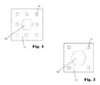
- FIG. 4 is a front view of the end-plate of the interconnected truss system.
- FIG. 5 is a front view of the slot and bolt hole pattern of the peripheral side of the interconnected truss system.
- FIG. 6 is a perspective view of the half section member component of the interconnected truss system in a flat position.
- FIG. 7 is a side view of the half section member component of the interconnected truss system in a flat position as shown in FIG. 6 .
- FIG. 8 is a perspective view of the half section member component of the interconnected truss system in a folded position.
- FIG. 9 is a side view of the half section member component of the interconnected truss system in a folded position as shown in FIG. 8 .
- FIG. 10 is a perspective view of the orientation of two half section members for formation of the interconnected truss system.
- FIG. 11 is a side view of the orientation of two half section members for formation of the interconnected truss system.
- FIG. 12 is a perspective view of the welded connection of two half section members formation of the interconnected truss system.
- FIG. 13 is a side view of the welded connection of two half section members formation of the interconnected truss system.
- FIG. 14 a is a perspective view of the bracket end-plate embodiment of the present invention.
- FIG. 14 b is a side view of the bracket end-plate embodiment of the present invention shown in FIG. 14 a.
- FIG. 15 a is a perspective view of the pivotal end-plate embodiment of the present invention.
- FIG. 15 b is a side view of the pivotal end-plate embodiment of the present invention shown in FIG. 15 a.
- FIG. 16 is a perspective view of a free standing framework assembled by the interconnected truss system.
- FIG. 17 is a side view of a free standing framework assembled by the interconnected truss system shown in FIG. 16 .
- FIG. 18 is a top view of a lattice framework assembled by the interconnected truss system.
- FIG. 19 is a top view of a branching framework assembled by the interconnected truss system.
- FIG. 20 is a perspective view of a bolt connection through the bolt holes of the present invention.
- the truss system ( 10 ) comprises a plurality of variously configured elongate tubular truss sections ( 14 ) each having first and second ends ( 12 ) and a peripheral side ( 13 ).
- the truss sections ( 14 ) are preferably elongate, hollow, rectangular tubes with end-plates ( 15 ) for attachment to other sections ( 14 ).
- Each such truss section ( 14 ) has a plurality of polygonal shaped access slots ( 16 a ) which allow for reaching within truss section ( 14 ).
- the polygonal shaped slots ( 16 a ) are spaced at equal distances along the longitudinal length of the peripheral sides ( 13 ) of truss sections ( 14 ) and are of sufficient size to allow for ease of passage of the hand and arm of personnel into the central hollow interior ( 11 ) of truss section ( 14 ) to facilitate access for fastening of bolts ( 30 ) through bolt holes ( 18 ).
- peripheral sides ( 13 ) are comprised of a plurality of a repeated patterns of slots ( 16 a ) surrounded by a number of bolt holes ( 18 ) arranged in a uniform pattern in relation to each slot ( 16 a ).
- end-plates ( 15 ) comprise a polygonal shaped access slot ( 16 b ), similar to that of slot ( 16 a ) on peripheral side ( 13 ) of truss section ( 14 ), which also have a plurality of bolt holes ( 18 ).
- the polygonal shaped access slots ( 16 b ) and bolt holes ( 18 ) on end-plates ( 15 ) allow the end-plates ( 15 ) on ends ( 12 ) of adjacent truss sections ( 14 ) to be attached together to provide a desired length of successive truss sections ( 14 ).
- the end-plate ( 15 ) of a truss section ( 14 ) may also be attached to a peripheral side ( 13 ) of an adjacent section ( 14 ) by a bolt ( 30 ) through the aligned bolt holes ( 18 ) to create intersecting truss sections ( 14 ).
- Access slots ( 16 a , 16 b ) provide access to the hollow interior area ( 11 ) of the truss section ( 14 ) to allow bolting of each truss section ( 14 ) together without the necessity of running bolt ( 30 ) through the entire section ( 14 ).
- end-plates ( 15 ) are provided with additional bolt holes ( 18 ) to allow additional attachment bolts ( 30 ) to be provided to increase the load capacity of connections where such sections ( 14 ) are linked together. Additional bolt holes ( 18 ) on the end-plates ( 15 ) allow stronger connections between adjoining end-plates ( 15 ), which tend to receive added flex stresses due to the increased length of the resulting truss member created when multiple sections ( 14 ) are joined together. This is advantageous as the additional load capacity provide by additional bolts aids in resisting structural failure due to such flexing stresses.
- each truss section ( 14 ) has four peripheral sides ( 13 ) to create the tubular shape of truss section ( 14 ) with sufficient area within the segment to allow for access, it is envisioned that each section could be created with as little as three peripheral sides or more than four peripheral sides depending upon spacial needs required for connection.
- An end-plate ( 15 ), as shown in FIG. 4 , on an end ( 12 ) of an adjacent truss section ( 14 ) may be attached to another end-plate ( 15 ) on an end ( 12 ) of an adjacent truss section ( 14 ), wherein a line of truss sections ( 14 ) may be created in an end-to-end relation.
- the additional bolt holes ( 18 ) provided on end-plates ( 15 ) will provide added hold between the individual truss sections ( 14 ).
- end-plates ( 15 ) may be attached to the bolt holes ( 18 ) along peripheral side ( 13 ), wherein a junction of truss sections ( 14 ) may be created perpendicular in relation to one another.
- Two peripheral sides ( 13 ) of adjacent sections ( 14 ) may also be attached to one another in a parallel or perpendicular running orientation, wherein the two adjacent truss sections ( 14 ) are attached to each other via the bolt holes ( 18 ) provided on peripheral sides ( 13 ) of both adjacent truss sections ( 14 ). It is envisioned that attaching adjacent sections ( 14 ) in a parallel orientation will create a stronger support member capable of retaining a greater amount of weight. Furthermore, attaching adjacent truss sections ( 14 ) in a perpendicular orientation can be done to create scaffolding legs or a traverse between additional lines of sections ( 14 ).
- FIGS. 6-13 show the creation of a truss section ( 14 ).
- Each truss section ( 14 ) is created by joining together half-sections of U-shaped plate members ( 34 ).
- each U-shaped plate member ( 34 ) is formed of a plate ( 39 ) that has a central surface ( 35 ) and outer wings ( 36 ).
- Preferably first and second fold-lines or joints ( 37 ) are provided between central surface ( 35 ) and outer wings ( 36 ).
- the joints ( 37 ) allow outer wings ( 36 ) of the plate ( 39 ) to fold upward to form a U-shaped plate member ( 34 ) having outer flanges ( 31 ) with flange ends ( 33 ).
- each U-shaped plate member ( 34 ) is provided with a plurality of the fully shaped equally spaced slots ( 16 a ) which run along its length.
- the outer wings ( 36 ) creating the flanges ( 31 ) of the U-shaped plate members ( 34 ) are provided with a plurality of equally spaced slots half-slots ( 38 ) on the flanges ( 31 ) of the U-shaped plate member which are formed to create the polygonal shaped slot ( 16 a ) when the half-slots ( 38 ) of one U-shaped plate member ( 34 ) is the placed in relation to the half-slots ( 38 ) of another U-shaped plate member ( 34 ).
- Bolt holes ( 18 ) are provided through member ( 34 ) in order to create the pattern of slots ( 16 a ) and bolt holes ( 18 ) in the completed tubular truss section ( 14 ).
- the plate ( 39 ) used to form the U-shaped plate members ( 34 ) is preferably structural aluminum or aluminum alloys though any suitable metal such as stainless steel, carbon steel, steel alloys, or other metal alloys could also be utilized.
- the bolt holes, ( 18 ), slots ( 16 a ), and half-slots ( 38 ) in each U-shaped plate member ( 34 ) are preferably laser cut but could also be formed by machining, milling, stamping, flame cutting, or water jetting.
- a truss section ( 14 ) is formed by placing two U-shaped plate members ( 34 ) together to abut their opposing flange ends ( 33 ) in an mirror arrangement to create a the hollow central interior ( 11 ).
- U-shaped placing members ( 34 ) together half-slots ( 38 ) on the outer wings ( 36 ) forming the flanges ( 31 ) and flange ends ( 33 ) of U-shaped plate members ( 34 ) are placed together to create the desired polygonal shape forming slots ( 16 a ).
- a connection may be created between two truss sections ( 14 ) by alignment of the bolt holes ( 18 ) of each adjoining truss section ( 14 ) and passage of bolt ( 30 ) through the aligned bolt holes ( 18 ).
- bolts ( 30 ) may be secured by affixing a lock nut ( 44 ). Access is readily available to secure lock nut ( 44 ) through slots ( 16 a , 16 b ).
- a series of adjacent truss sections ( 14 ) may be joined and held securely together.
- the truss section ( 14 ) may be provided with an bracket ( 50 ) fixedly attached to an end ( 12 ) as an alternate embodiment of end-plate ( 15 ).
- Bracket ( 50 ) is provided with bolt holes ( 18 ) to facilitate attachment to the bolt holes ( 18 ) of an adjacent truss section ( 14 ).
- FIG. 14 a shows that it is envisioned that any number of bolt holes ( 18 ) may be provided to facilitate attachment and support.
- FIGS. 15 a and 15 b another embodiment of the truss structural system ( 10 ) comprises providing a pivot plate ( 60 ) in place of end-plate ( 15 ).
- the pivotal mount ( 62 ) of pivotal plate ( 60 ) is connected to an end ( 12 ) of truss section ( 14 ) by means of hinge ( 64 ).
- the hinged connection of the pivot plate ( 60 ) to truss section ( 14 ) allows the pivot plates ( 60 ) to be pivoted on hinge ( 64 ) to allow for varied angular orientation and connection between adjacent sections ( 14 ).
- pivot plate ( 60 ) is also provided with a plurality of bolt holes ( 18 ) to allow for fixed attachment to an adjacent truss section ( 14 ).
- Pivotal mount ( 62 ) comprises a dual blade attachment configuration to allow sliding passage of the single blade configuration of hinge ( 64 ) on truss section ( 14 ) for alignment of pivotal bolt holes ( 66 a ) on pivotal mount ( 62 ) and hinge bolt holes ( 66 b ) on hinge ( 64 ).
- Pivotal mount ( 62 ) and binge ( 64 ) may be pivotally attached by passage of a bolt, lock-nut, pin, or other attachment structure conventional in the art through the pivotal bolt holes ( 66 a ) and hinge bolt holes ( 66 b ) of pivotal mount ( 62 ) and hinge ( 64 ), respectively, to allow for pivotal movement between pivot plate ( 60 ) and truss section ( 14 ).
- a truss structural system ( 10 ) may be modified to provide a flexible frame consisting of truss sections ( 14 ) which form a latticework pivotally attached by hinges ( 64 ). It is thought that pivotally attaching the truss sections ( 14 ) will allow a structure to be more effectively used in areas where the ground surface is uneven. Pivotally attaching the truss sections ( 14 ) will also allow for the creation of an A-frame structure comprised of interconnected truss sections ( 14 ). The angle of pivot of the truss sections ( 14 ) with respect to each other may be varied as desired.
- each truss section ( 14 ) is configured as an elongated box having sidewalls created by central surfaces ( 35 ) and the intersection of the flange ends ( 33 ) of adjoining U-shaped plate members ( 34 ).
- the tubular shape of the truss sections ( 14 ) provides for added space for access through slots ( 16 a , 16 b ) for securing bolts ( 30 ).
- the truss sections ( 14 ), including the end-plates ( 15 ), brackets ( 50 ), and pivot plates ( 60 ), are configured to support the weight of heavy equipment and structures that may be attached to or suspended from the truss sections ( 14 ).
- slots ( 16 a , 16 b ) are shown as hexagonal shaped openings running through section ( 14 ) it is thought that other polygonal shapes or circular type slot shapes could be utilized.
- FIGS. 16, 17, 18, and 19 Examples of the structural frameworks which may be created by use truss sections ( 14 ) is shown in detail in FIGS. 16, 17, 18, and 19 .
- One or more of the truss sections ( 14 ) may be configured together as desired to form a structure of desired strength and stability. Being variously configurable for attachment to one another, the truss sections ( 14 ) may be fixed to create structural bases ( FIG. 19 ), free-standing frames ( FIGS. 16 & 17 ), or a latticework ( FIG. 18 ) of interconnected truss sections ( 14 ).
- Truss sections ( 14 ) may be attached linearly in an end-to-end arrangement of adjacent sections ( 14 ) by attachment to either an end-plate ( 15 ) or bracket ( 50 ), for a fixed structural arrangement, or with pivot plates ( 60 ), for a flexible arrangement.
- a junction may also be created by attachment of an end ( 12 ) of a truss section ( 14 ) to a peripheral side ( 13 ) of an adjacent truss section ( 14 ).
- cables ( 70 ) or additional truss sections ( 14 ), pivotally attached or otherwise, may be provided for added structural support when creating a free standing structure or for allowing for suspension of equipment and personnel from the formed structure. Cables ( 70 ) may be attached via access slots ( 16 a , 16 b ) or may be attached to bolt holes ( 18 ) as necessary to provide for sufficient support.
Abstract
A truss support system is disclosed. The system is comprised of a plurality of tubular truss sections configured for attachment to each other. Each of the sections has a plurality of polygonal shaped access slots surrounded by a plurality of bolt holes along each of its peripheral sides and on end-plates at each end of the truss sections. The end-plates of the system have additional bolt holes around the access slot compared to the number of bolts surrounding the access slots on the peripheral sides to provide for increased hold between end-to-end connections of truss sections. The truss sections of the system may be hinged together to compensate for uneven ground or for increased load supported.
Description
This application claims priority to U.S. provisional application Ser. No. 62/218,402 filed Sep. 14, 2015, the entire content of which is hereby incorporated by reference.
This invention relates to a truss system to provide for construction of semi-permanent structures such as frameworks and the like and more particularly to a structural system which allows for attachment of truss sections at desired places and orientation along any section of an adjacent truss section.
In numerous industries it is necessary to erect semi-permanent structures both internally as well as externally in order to permit workers to stand at an elevation above the ground surface or to suspend structures and things above the ground. Often times these temporary structures are hollow lengths of piping or tubing erected by interconnection end to end with other hollow sections, thus limiting the area upon which other connections may be made to further build the structure or connect an object to be suspended therefrom. Such prior art structures, being mainly comprised of long solid materials which may be only attached at joints between two adjoining ends of each section require connection by extensive welding between sections or insubstantial connection by through running bolts.
Due to the requirement that the support structure provide adequate support under load, prior art support structures generally are comprised of solid girders or hollow tubular members. Providing a solid support structure limits the ability of personnel to access within the hollow sections to bolt segments together from within. Rather, with such structural members, sections are connected by running a bolt completely through adjoining sections, wasting valuable space within the hollow segment where additional connections could have been made.
Furthermore, when bolts are employed for the purpose of attaching prior art support sections in an end-to-end relationship, the teaching is to apply the same number of attachment bolts as would be applied in attaching segments in a perpendicular cross member arrangement. Support segments placed in an end-to-end arrangement are subjected to a considerable amount of flexing stress which could cause a break or shearing of the support structure if a failure should occur. In the event of a structural failure, there is a considerable risk of damage to equipment and a high risk of injury or death to personnel.
Accordingly, there is a need in the art for a semi-permanent tubular support structure which allows for a plurality of connections to be made both between each adjoining section and along the external periphery of each section, wherein each end-plate employs additional connections to resist structural failure.
The present invention provides a semi-permanent structural truss system to provide a support system for creation of a load bearing assembly. The apparatus described includes tubular truss sections having a plurality of access slots to allow passage of hands and arms of personnel into the inner region of the truss section to ease connection between truss sections. A plurality of bolt holes are also provided around each access slot to permit connection of adjacent truss sections as desired.
The truss sections further comprise end-plates having access slots and additional bolt holes. Additional bolt holes are provided on the end-plates to aid in attachment and support between end sections or to the peripheral sides of adjacent truss sections. The end-plates may alternatively be configured as a pivotal plate to allow truss sections to be angled in relation to one another or to compensate for uneven ground or movement of the structure. Brackets may be added to facilitate the connection of truss sections.
The portability and ease of installation and setup of the structural truss system is particularly suitable for use in construction or other industry where temporary support structures are required. Because the sections may be configured to pivot up and down on hinges, the framework structures created by the truss sections may be attached between other sections as desired to provide support between perpendicularly attached sections. This feature further allows the truss sections to compensate due to uneven ground or added load upon the support structure.
The tubular character of each truss section is formed by joining together two formed half-sections of structural plate, each being pre-formed with a flat central surface and outer ends that fold upward along a joint line to form the half-member into a channel or U-shape. The outer ends of each half-section are provided with a plurality of half-slots that create the access slots, preferably polygonal-shaped access slots, when the half-slots of one U-shaped half-member are placed to coincide with the U-shaped half-slots of the other U-shaped half-member. When two members are oriented upon each other the abutting half slots create the desired access slots, the adjoining half-members are welded at their intersection to create the tubular section. Because the intersection of the half-members is interrupted by the access slots created by the abutting half-members, amount of welding required to connect the plates is substantially reduced. This method of construction provides a distinct advantage when compared to the construction of similar structural members which require welding along the entire length of each member when forming a tube section.
It is thought that each of the truss sections of the system will be constructed from structural aluminum or structural steel plate, however other types of materials and metals might be utilized to construct the sections, including polymer materials, all depending upon the intended use of the system.
One embodiment of the semi-permanent truss structural system (10) is shown in a perspective view in FIG. 1 and in a side view in FIGS. 2 & 3 . The truss system (10) comprises a plurality of variously configured elongate tubular truss sections (14) each having first and second ends (12) and a peripheral side (13). The truss sections (14) are preferably elongate, hollow, rectangular tubes with end-plates (15) for attachment to other sections (14). Each such truss section (14) has a plurality of polygonal shaped access slots (16 a) which allow for reaching within truss section (14). The polygonal shaped slots (16 a) are spaced at equal distances along the longitudinal length of the peripheral sides (13) of truss sections (14) and are of sufficient size to allow for ease of passage of the hand and arm of personnel into the central hollow interior (11) of truss section (14) to facilitate access for fastening of bolts (30) through bolt holes (18).
As can be seen in FIG. 5 , showing a view of single iteration of the repeated pattern on peripheral side (13), the peripheral sides (13) are comprised of a plurality of a repeated patterns of slots (16 a) surrounded by a number of bolt holes (18) arranged in a uniform pattern in relation to each slot (16 a).
As shown in FIG. 4 , end-plates (15) comprise a polygonal shaped access slot (16 b), similar to that of slot (16 a) on peripheral side (13) of truss section (14), which also have a plurality of bolt holes (18). The polygonal shaped access slots (16 b) and bolt holes (18) on end-plates (15) allow the end-plates (15) on ends (12) of adjacent truss sections (14) to be attached together to provide a desired length of successive truss sections (14). The end-plate (15) of a truss section (14) may also be attached to a peripheral side (13) of an adjacent section (14) by a bolt (30) through the aligned bolt holes (18) to create intersecting truss sections (14). Access slots (16 a, 16 b) provide access to the hollow interior area (11) of the truss section (14) to allow bolting of each truss section (14) together without the necessity of running bolt (30) through the entire section (14).
Due to the anticipated load stresses that occur at the connection of ends (12) when attaching two truss sections (14) in an end-to-end orientation, end-plates (15) are provided with additional bolt holes (18) to allow additional attachment bolts (30) to be provided to increase the load capacity of connections where such sections (14) are linked together. Additional bolt holes (18) on the end-plates (15) allow stronger connections between adjoining end-plates (15), which tend to receive added flex stresses due to the increased length of the resulting truss member created when multiple sections (14) are joined together. This is advantageous as the additional load capacity provide by additional bolts aids in resisting structural failure due to such flexing stresses.
While preferably each truss section (14) has four peripheral sides (13) to create the tubular shape of truss section (14) with sufficient area within the segment to allow for access, it is envisioned that each section could be created with as little as three peripheral sides or more than four peripheral sides depending upon spacial needs required for connection.
An end-plate (15), as shown in FIG. 4 , on an end (12) of an adjacent truss section (14) may be attached to another end-plate (15) on an end (12) of an adjacent truss section (14), wherein a line of truss sections (14) may be created in an end-to-end relation. In such an arrangement, the additional bolt holes (18) provided on end-plates (15) will provide added hold between the individual truss sections (14). Further, end-plates (15) may be attached to the bolt holes (18) along peripheral side (13), wherein a junction of truss sections (14) may be created perpendicular in relation to one another.
Two peripheral sides (13) of adjacent sections (14) may also be attached to one another in a parallel or perpendicular running orientation, wherein the two adjacent truss sections (14) are attached to each other via the bolt holes (18) provided on peripheral sides (13) of both adjacent truss sections (14). It is envisioned that attaching adjacent sections (14) in a parallel orientation will create a stronger support member capable of retaining a greater amount of weight. Furthermore, attaching adjacent truss sections (14) in a perpendicular orientation can be done to create scaffolding legs or a traverse between additional lines of sections (14).
The plate (39) used to form the U-shaped plate members (34) is preferably structural aluminum or aluminum alloys though any suitable metal such as stainless steel, carbon steel, steel alloys, or other metal alloys could also be utilized. The U-shaped plate members (34), depending upon their anticipated uses, could also be constructed of structural polymers. The bolt holes, (18), slots (16 a), and half-slots (38) in each U-shaped plate member (34) are preferably laser cut but could also be formed by machining, milling, stamping, flame cutting, or water jetting.
Now referring to FIGS. 10-13 , a truss section (14) is formed by placing two U-shaped plate members (34) together to abut their opposing flange ends (33) in an mirror arrangement to create a the hollow central interior (11). In U-shaped placing members (34) together, half-slots (38) on the outer wings (36) forming the flanges (31) and flange ends (33) of U-shaped plate members (34) are placed together to create the desired polygonal shape forming slots (16 a).
The intersection of the opposing flange ends (33) of the U-shaped plate members (34) create a weld line (40) along the flange ends (33) of between the half-slots (38) creating slots (16 a) that reduces the welding necessary to join the two U-shaped plate members (34) together to form the tubular truss section (14). Unlike conventional methods of forming a tubular truss, where welding occurs along the entire length of the truss member, the orientation of the half-slots (38) as described creates numerous breaks along the length of the truss section (14), thus welding on weld line (40) is only required along the flange ends (33) between each half-slot (38).
Now referring to FIG. 20 , a connection may be created between two truss sections (14) by alignment of the bolt holes (18) of each adjoining truss section (14) and passage of bolt (30) through the aligned bolt holes (18). Once placed there through, bolts (30) may be secured by affixing a lock nut (44). Access is readily available to secure lock nut (44) through slots (16 a, 16 b). By orientation of the bolt holes (18) on truss sections (14) and those of end-plates (15), a series of adjacent truss sections (14) may be joined and held securely together.
Now referring to FIGS. 14a and 14b , the truss section (14) may be provided with an bracket (50) fixedly attached to an end (12) as an alternate embodiment of end-plate (15). Bracket (50) is provided with bolt holes (18) to facilitate attachment to the bolt holes (18) of an adjacent truss section (14). Though pictured in FIG. 14a as having two bolt holes (18), it is envisioned that any number of bolt holes (18) may be provided to facilitate attachment and support.
Referring now to FIGS. 15a and 15b , another embodiment of the truss structural system (10) comprises providing a pivot plate (60) in place of end-plate (15). The pivotal mount (62) of pivotal plate (60) is connected to an end (12) of truss section (14) by means of hinge (64). The hinged connection of the pivot plate (60) to truss section (14) allows the pivot plates (60) to be pivoted on hinge (64) to allow for varied angular orientation and connection between adjacent sections (14). Similar to end-plate (15), pivot plate (60) is also provided with a plurality of bolt holes (18) to allow for fixed attachment to an adjacent truss section (14).
Pivotal mount (62) comprises a dual blade attachment configuration to allow sliding passage of the single blade configuration of hinge (64) on truss section (14) for alignment of pivotal bolt holes (66 a) on pivotal mount (62) and hinge bolt holes (66 b) on hinge (64). Pivotal mount (62) and binge (64) may be pivotally attached by passage of a bolt, lock-nut, pin, or other attachment structure conventional in the art through the pivotal bolt holes (66 a) and hinge bolt holes (66 b) of pivotal mount (62) and hinge (64), respectively, to allow for pivotal movement between pivot plate (60) and truss section (14). By way of example, a truss structural system (10) may be modified to provide a flexible frame consisting of truss sections (14) which form a latticework pivotally attached by hinges (64). It is thought that pivotally attaching the truss sections (14) will allow a structure to be more effectively used in areas where the ground surface is uneven. Pivotally attaching the truss sections (14) will also allow for the creation of an A-frame structure comprised of interconnected truss sections (14). The angle of pivot of the truss sections (14) with respect to each other may be varied as desired.
As shown in the cross-sectional views, FIGS. 11 and 13 , each truss section (14) is configured as an elongated box having sidewalls created by central surfaces (35) and the intersection of the flange ends (33) of adjoining U-shaped plate members (34). The tubular shape of the truss sections (14) provides for added space for access through slots (16 a, 16 b) for securing bolts (30). The truss sections (14), including the end-plates (15), brackets (50), and pivot plates (60), are configured to support the weight of heavy equipment and structures that may be attached to or suspended from the truss sections (14). Though slots (16 a, 16 b) are shown as hexagonal shaped openings running through section (14) it is thought that other polygonal shapes or circular type slot shapes could be utilized.
Examples of the structural frameworks which may be created by use truss sections (14) is shown in detail in FIGS. 16, 17, 18, and 19 . One or more of the truss sections (14) may be configured together as desired to form a structure of desired strength and stability. Being variously configurable for attachment to one another, the truss sections (14) may be fixed to create structural bases (FIG. 19 ), free-standing frames (FIGS. 16 & 17 ), or a latticework (FIG. 18 ) of interconnected truss sections (14). Truss sections (14) may be attached linearly in an end-to-end arrangement of adjacent sections (14) by attachment to either an end-plate (15) or bracket (50), for a fixed structural arrangement, or with pivot plates (60), for a flexible arrangement. A junction may also be created by attachment of an end (12) of a truss section (14) to a peripheral side (13) of an adjacent truss section (14).
In use, cables (70) or additional truss sections (14), pivotally attached or otherwise, may be provided for added structural support when creating a free standing structure or for allowing for suspension of equipment and personnel from the formed structure. Cables (70) may be attached via access slots (16 a, 16 b) or may be attached to bolt holes (18) as necessary to provide for sufficient support.
It is thought that the truss structural system (10) and the method of the present invention and many of its attendant advantages will be understood from the foregoing description. It is also thought that one may make various changes in the form, construction and arrangement of the parts of the sections and system without sacrificing its material advantages or departing from the spirit and scope of the invention and that the form described herein is merely an exemplary embodiment of the invention.
Claims (9)
1. A method of creating a semi-permanent structural support member comprising the steps of:
a. providing:
i. first and second half-sections of plate, each said half-section of plate having a central surface and two outer wings, said central surface and said outer wings running the longitudinal length of each said half-section of plate, each said half-section of plate having a joint running between said central surface and each said outer wing;
ii. a plurality of polygonal-shaped slots along said central surface of each said half-section of plate, wherein each said polygonal-shaped slot has a plurality of surrounding bolt holes arranged in a uniform pattern;
iii. a plurality of half polygonal-shaped slots along each said outer wing of each said half-section of plate; and
iv. wherein each said half polygonal-shaped slot has a plurality of surrounding bolt holes arranged in a uniform pattern;
b. folding each said outer wing of each said half-section of plate upwardly along said joint thereby creating first and second U-shaped plate members having upwardly extending outer flanges with each said outer flange having a flange end;
c. abutting said flange ends of said outer flanges of said first U-shaped plate member against said flange ends of said outer flanges of said second U-shaped plate member, whereby said adjacent half polygonal-shaped slots of said abutting outer flanges of said first and second U-shaped plate members are oriented to form a polygonal-shaped slot and whereby abutting said flange ends of said outer flanges of said first and second U-shaped plate members form a weld line; and
d. welding along said weld line to form a tubular rectangular support member having a hollow interior, first and second ends, and peripheral sides with a plurality of said polygonal-shaped slots, wherein said bolt holes are arranged in a uniform repeated pattern in relation to each said polygonal-shaped slot created by said adjacent half polygonal-shaped slots and said abutting outer flanges of said first and second U-shaped plate members;
providing an end-plate upon said first and said second end of said formed tubular support member;
wherein each end-plate has an end-plate polygonal-shaped slot and a plurality of end-plate bolt holes in a quantity greater than said bolt holes arranged in a uniform repeated pattern in relation to each said polygonal-shaped slot on said peripheral sides of said formed tubular support member.
2. The method of creating a semi-permanent structural support member of claim 1 , further comprising the steps of providing a pivotable hinge at each said end-plate.
3. The method of creating a semi-permanent structural support member of claim 1 , wherein said end-plate is a bracket.
4. A method of constructing a semi-permanent structural support system comprising the steps of:
a. providing:
i. a plurality elongate hollow tubular truss sections having peripheral sides and first and second ends, each said tubular truss section comprised entirely of first and second U-shaped plates, said first and second U-shaped plates having a pair of extending outer flanges, each said outer flange having a flange end, said flange ends of said first and second U-shaped plates abutting against each other and welded together at said abutting flange ends;
ii. each said elongate tubular truss section having a plurality of polygonal-shaped access slots arranged along said peripheral sides of said elongate tubular truss section;
iii. wherein each said polygonal-shaped shaped access slot on said peripheral sides has an array of corresponding bolt holes arranged in a uniform pattern in relation to each said polygonal-shaped access slot; and
iv. an end-plate upon each said first end and each said second end of each said elongate hollow tubular truss section, wherein each said end-plate has an end-plate polygonal-shaped access slot and a plurality of end-plate bolt holes in a quantity greater than that of said bolt holes arrayed with each said polygonal-shaped access slot on said peripheral sides of said elongate tubular truss section;
b. selecting first and second said elongate hollow tubular truss sections from said plurality of elongate hollow tubular truss sections;
c. orienting said end-plate of said first elongate hollow tubular truss section wherein said polygonal shaped slot and said bolt holes of said end-plate of said first elongate hollow tubular truss section align with selected said polygonal shaped slot and said bolt holes of said second elongate hollow tubular truss section; and
d. fastening a bolt through each aligned said bolt hole to affix said first elongate hollow tubular truss section to said second elongate hollow tubular truss section.
5. The method of constructing a semi-permanent structural support system of claim 4 , wherein said end-plates of said first or said second ends of said first elongate hollow tubular truss section may be attached to said peripheral side or said first or second ends of said second elongate hollow tubular truss section.
6. The method of constructing a semi-permanent structural support system of claim 5 , wherein one of said peripheral sides of said first elongate hollow tubular truss section may be attached to one of said peripheral sides of said second elongate hollow tubular truss section.
7. The method of constructing a semi-permanent structural support system of claim 6 , further comprising the step of connecting cables between said first and said second elongate hollow tubular truss sections.
8. The method of constructing a semi-permanent structural support systems of claim 7 , further comprising the step of providing a hinge between said ends and said end-plates of each said elongate hollow tubular truss section.
9. The method of constructing a semi-permanent structural support system of claim 7 , wherein each said end-plate is a bracket.
Priority Applications (1)
| Application Number | Priority Date | Filing Date | Title |
|---|---|---|---|
| US15/265,661 US9803365B2 (en) | 2015-09-14 | 2016-09-14 | Lightweight semi-permanent truss system |
Applications Claiming Priority (2)
| Application Number | Priority Date | Filing Date | Title |
|---|---|---|---|
| US201562218402P | 2015-09-14 | 2015-09-14 | |
| US15/265,661 US9803365B2 (en) | 2015-09-14 | 2016-09-14 | Lightweight semi-permanent truss system |
Publications (2)
| Publication Number | Publication Date |
|---|---|
| US20170073971A1 US20170073971A1 (en) | 2017-03-16 |
| US9803365B2 true US9803365B2 (en) | 2017-10-31 |
Family
ID=58257293
Family Applications (1)
| Application Number | Title | Priority Date | Filing Date |
|---|---|---|---|
| US15/265,661 Active US9803365B2 (en) | 2015-09-14 | 2016-09-14 | Lightweight semi-permanent truss system |
Country Status (1)
| Country | Link |
|---|---|
| US (1) | US9803365B2 (en) |
Cited By (9)
| Publication number | Priority date | Publication date | Assignee | Title |
|---|---|---|---|---|
| US10006193B1 (en) * | 2017-02-07 | 2018-06-26 | Tai Yu Liu | Lightweight steel construction |
| USD831232S1 (en) * | 2017-12-18 | 2018-10-16 | Acier Profile S.B.B. Inc. | Modular tower segment |
| US10273690B2 (en) * | 2017-12-26 | 2019-04-30 | Ruhollah SAFARI | Truss composite ceiling with little amount of steel |
| USD882826S1 (en) * | 2015-03-18 | 2020-04-28 | Patrick J. Santini | Tubular beam |
| US11085472B2 (en) * | 2018-09-17 | 2021-08-10 | Sergio Cardenas | Concrete form board sleeve connector |
| USD932060S1 (en) * | 2015-03-18 | 2021-09-28 | Patrick J. Santini | Tubular beam |
| US20210381219A1 (en) * | 2020-06-09 | 2021-12-09 | Wisys Technology Foundation, Inc. | Connector System for Container-Based Structures |
| US11380227B2 (en) * | 2020-06-30 | 2022-07-05 | Christie Digital Systems Usa, Inc. | Truss system for video displays |
| US11953053B1 (en) | 2019-12-11 | 2024-04-09 | Bryan Jerome Perl | Beam with improved hole patterns |
Families Citing this family (4)
| Publication number | Priority date | Publication date | Assignee | Title |
|---|---|---|---|---|
| US10519657B1 (en) * | 2018-01-22 | 2019-12-31 | Robert M. Callahan | Systems, devices, and/or methods for managing joists |
| WO2019162534A1 (en) * | 2018-02-20 | 2019-08-29 | Torres Arenas Javier | Method for producing a tubular profile and tubular profile obtained |
| KR101974888B1 (en) * | 2018-04-05 | 2019-05-03 | (주)정인그린빌 | Frame For Modular Building |
| CN112832455A (en) * | 2019-11-25 | 2021-05-25 | 怀化市恒裕实业有限公司 | Steel structure beam |
Citations (27)
| Publication number | Priority date | Publication date | Assignee | Title |
|---|---|---|---|---|
| US1656810A (en) * | 1923-08-11 | 1928-01-17 | Zeppelin Luftschiffbau | Hollow girder for light structures |
| US2936051A (en) * | 1957-10-18 | 1960-05-10 | Alfred K Martin | Metal structural unit |
| US3063523A (en) * | 1959-08-31 | 1962-11-13 | A D Goodwin & Son Inc | Boom |
| US3104454A (en) * | 1959-09-28 | 1963-09-24 | Mc Graw Edison Co | Method of making structural members |
| US3989396A (en) * | 1972-05-30 | 1976-11-02 | Nippon Steel Corporation | Steel box-column for steel structures |
| US4593514A (en) * | 1984-09-19 | 1986-06-10 | Gte Products Corporation | Space frame |
| US4964256A (en) * | 1990-01-05 | 1990-10-23 | Economy Forms Corporation | Beam member for concrete forming system |
| US5426906A (en) * | 1992-02-06 | 1995-06-27 | Wilian Holding Company | Beam member for use in concrete forming apparatus |
| US5527625A (en) * | 1992-09-02 | 1996-06-18 | Bodnar; Ernest R. | Roll formed metal member with reinforcement indentations |
| US5551199A (en) * | 1993-11-08 | 1996-09-03 | Hayes; Jerry R. | Box truss for lights |
| US5678375A (en) * | 1992-07-07 | 1997-10-21 | Juola; Tuomo | Framework of a building |
| US20020005022A1 (en) * | 1997-06-30 | 2002-01-17 | Matthews Leroy | Sheet material attachment system |
| US20030126827A1 (en) * | 2002-01-07 | 2003-07-10 | Davis Kurt K. | Box beam and method for fabricating same |
| US20030184075A1 (en) * | 2002-03-27 | 2003-10-02 | Freeman Richard B. | Frame member having overlapping reinforcement sections |
| US20040093825A1 (en) * | 2001-02-15 | 2004-05-20 | Dae-Jun Lee | Tubular structure and modular building assembly using the same |
| US20040211149A1 (en) * | 2003-04-04 | 2004-10-28 | Andre Rioux | Modular tower structure |
| US6837446B1 (en) * | 2003-01-16 | 2005-01-04 | Sprayer Specialties, Inc. | Unitary boom structure |
| US7051488B2 (en) * | 1993-06-28 | 2006-05-30 | Nelson Thomas P | Sub-rigid fast-form barrier system |
| US20060185258A1 (en) * | 2005-02-18 | 2006-08-24 | Scene Ethique Inc. | System for assembling a load-bearing support structure, and structure assembled with such a system |
| US20060277859A1 (en) * | 2003-09-01 | 2006-12-14 | Forster Rohr Und Profiltechnik Ag | Profile and method for producing a profile |
| US20070107368A1 (en) * | 2005-11-01 | 2007-05-17 | Ruehl Phillip C | Boxed Frame Member and Method for Manufacture |
| US20080028721A1 (en) * | 2006-08-04 | 2008-02-07 | Byron James Daniels | Structural column and process for making the same |
| US20100071141A1 (en) * | 2008-09-19 | 2010-03-25 | Randall Julian Reiner | Variable length beam |
| US8418425B1 (en) * | 2010-12-29 | 2013-04-16 | Patrick J. Santini | Tubular beam for the construction of temporary structures |
| US20130167468A1 (en) * | 2011-12-30 | 2013-07-04 | Joseph Daniel Gallagher | Truss Deadweight |
| US20140250820A1 (en) * | 2011-10-14 | 2014-09-11 | Imagine Tf, Llc | Truss system with integral channels |
| US9212491B1 (en) * | 2015-05-22 | 2015-12-15 | Patrick J. Santini | Modular stairway |
-
2016
- 2016-09-14 US US15/265,661 patent/US9803365B2/en active Active
Patent Citations (34)
| Publication number | Priority date | Publication date | Assignee | Title |
|---|---|---|---|---|
| US1656810A (en) * | 1923-08-11 | 1928-01-17 | Zeppelin Luftschiffbau | Hollow girder for light structures |
| US2936051A (en) * | 1957-10-18 | 1960-05-10 | Alfred K Martin | Metal structural unit |
| US3063523A (en) * | 1959-08-31 | 1962-11-13 | A D Goodwin & Son Inc | Boom |
| US3104454A (en) * | 1959-09-28 | 1963-09-24 | Mc Graw Edison Co | Method of making structural members |
| US3989396A (en) * | 1972-05-30 | 1976-11-02 | Nippon Steel Corporation | Steel box-column for steel structures |
| US4593514A (en) * | 1984-09-19 | 1986-06-10 | Gte Products Corporation | Space frame |
| US4964256A (en) * | 1990-01-05 | 1990-10-23 | Economy Forms Corporation | Beam member for concrete forming system |
| US5426906A (en) * | 1992-02-06 | 1995-06-27 | Wilian Holding Company | Beam member for use in concrete forming apparatus |
| US5678375A (en) * | 1992-07-07 | 1997-10-21 | Juola; Tuomo | Framework of a building |
| US5527625A (en) * | 1992-09-02 | 1996-06-18 | Bodnar; Ernest R. | Roll formed metal member with reinforcement indentations |
| US7051488B2 (en) * | 1993-06-28 | 2006-05-30 | Nelson Thomas P | Sub-rigid fast-form barrier system |
| US5551199A (en) * | 1993-11-08 | 1996-09-03 | Hayes; Jerry R. | Box truss for lights |
| US5743060A (en) * | 1993-11-08 | 1998-04-28 | Hayes; Jerry R. | Box truss for lights |
| US20020005022A1 (en) * | 1997-06-30 | 2002-01-17 | Matthews Leroy | Sheet material attachment system |
| US7155874B2 (en) * | 2001-02-15 | 2007-01-02 | Dae-Jun Lee | Tubular structure and modular building assembly using the same |
| US20040093825A1 (en) * | 2001-02-15 | 2004-05-20 | Dae-Jun Lee | Tubular structure and modular building assembly using the same |
| US6802170B2 (en) * | 2002-01-07 | 2004-10-12 | Kurt K. Davis | Box beam and method for fabricating same |
| US20030126827A1 (en) * | 2002-01-07 | 2003-07-10 | Davis Kurt K. | Box beam and method for fabricating same |
| US20030184075A1 (en) * | 2002-03-27 | 2003-10-02 | Freeman Richard B. | Frame member having overlapping reinforcement sections |
| US6837446B1 (en) * | 2003-01-16 | 2005-01-04 | Sprayer Specialties, Inc. | Unitary boom structure |
| US7464513B2 (en) * | 2003-04-04 | 2008-12-16 | Tower Solutions Inc. | Modular tower structure |
| US20040211149A1 (en) * | 2003-04-04 | 2004-10-28 | Andre Rioux | Modular tower structure |
| US20060277859A1 (en) * | 2003-09-01 | 2006-12-14 | Forster Rohr Und Profiltechnik Ag | Profile and method for producing a profile |
| US20060185258A1 (en) * | 2005-02-18 | 2006-08-24 | Scene Ethique Inc. | System for assembling a load-bearing support structure, and structure assembled with such a system |
| US7707780B2 (en) * | 2005-02-18 | 2010-05-04 | Scene Ethique Inc. | System for assembling a load-bearing support structure, and structure assembled with such a system |
| US20070107368A1 (en) * | 2005-11-01 | 2007-05-17 | Ruehl Phillip C | Boxed Frame Member and Method for Manufacture |
| US8484930B2 (en) * | 2005-11-01 | 2013-07-16 | Phillip C. Ruehl | Boxed frame member and method for manufacture |
| US20080028721A1 (en) * | 2006-08-04 | 2008-02-07 | Byron James Daniels | Structural column and process for making the same |
| US20100071141A1 (en) * | 2008-09-19 | 2010-03-25 | Randall Julian Reiner | Variable length beam |
| US8418425B1 (en) * | 2010-12-29 | 2013-04-16 | Patrick J. Santini | Tubular beam for the construction of temporary structures |
| US20140250820A1 (en) * | 2011-10-14 | 2014-09-11 | Imagine Tf, Llc | Truss system with integral channels |
| US20130167468A1 (en) * | 2011-12-30 | 2013-07-04 | Joseph Daniel Gallagher | Truss Deadweight |
| US8695305B2 (en) * | 2011-12-30 | 2014-04-15 | Joseph Daniel Gallagher | Truss deadweight |
| US9212491B1 (en) * | 2015-05-22 | 2015-12-15 | Patrick J. Santini | Modular stairway |
Cited By (11)
| Publication number | Priority date | Publication date | Assignee | Title |
|---|---|---|---|---|
| USD882826S1 (en) * | 2015-03-18 | 2020-04-28 | Patrick J. Santini | Tubular beam |
| USD930856S1 (en) * | 2015-03-18 | 2021-09-14 | Patrick J. Santini | Tubular beam |
| USD932060S1 (en) * | 2015-03-18 | 2021-09-28 | Patrick J. Santini | Tubular beam |
| US10006193B1 (en) * | 2017-02-07 | 2018-06-26 | Tai Yu Liu | Lightweight steel construction |
| USD831232S1 (en) * | 2017-12-18 | 2018-10-16 | Acier Profile S.B.B. Inc. | Modular tower segment |
| US10273690B2 (en) * | 2017-12-26 | 2019-04-30 | Ruhollah SAFARI | Truss composite ceiling with little amount of steel |
| US11085472B2 (en) * | 2018-09-17 | 2021-08-10 | Sergio Cardenas | Concrete form board sleeve connector |
| US11953053B1 (en) | 2019-12-11 | 2024-04-09 | Bryan Jerome Perl | Beam with improved hole patterns |
| US20210381219A1 (en) * | 2020-06-09 | 2021-12-09 | Wisys Technology Foundation, Inc. | Connector System for Container-Based Structures |
| US11840833B2 (en) * | 2020-06-09 | 2023-12-12 | Wisys Technology Foundation, Inc. | Connector system for container-based structures |
| US11380227B2 (en) * | 2020-06-30 | 2022-07-05 | Christie Digital Systems Usa, Inc. | Truss system for video displays |
Also Published As
| Publication number | Publication date |
|---|---|
| US20170073971A1 (en) | 2017-03-16 |
Similar Documents
| Publication | Publication Date | Title |
|---|---|---|
| US9803365B2 (en) | Lightweight semi-permanent truss system | |
| US20200224435A1 (en) | Erected platform and method of erecting thereof | |
| US8978338B2 (en) | Structural trusses with monolithic connector plate members | |
| US4122646A (en) | Equilateral derrick structure | |
| EP2123834A1 (en) | Connector for space frames | |
| JP2014505190A (en) | Split gusset connection | |
| US20030177735A1 (en) | Built-up beam assembly for building structures | |
| BRPI0508754B1 (en) | work platform support system, interconnect structure, work platform support structure, work platform system, method of using an interconnect structure, and method for installing an additional platform system module | |
| US20020046534A1 (en) | Metal truss system | |
| US20170254099A1 (en) | Adjustable Platform Extension Bracket For Work Platform Systems and Related Methods | |
| US20180238042A1 (en) | Adjustable moment frame | |
| US20060076191A1 (en) | Walk-through scaffold and hoist frame | |
| US10745907B1 (en) | Rolling block restraint connector for external restraint moment connections | |
| RU178233U1 (en) | Dismountable overpass for laying communications | |
| US20050155526A1 (en) | Weldless platform assembly | |
| US8266864B2 (en) | Readily configured and reconfigured structural trusses based on tetrahedrons as modules | |
| RU220352U1 (en) | Adjustable four-post load-bearing element for overpass | |
| RU2616200C1 (en) | Connection of thin-walled steel profiles using volumetric shaped elements | |
| RU220478U1 (en) | Adjustable two-post support element | |
| US20190119945A1 (en) | Connection fittings for a transportable shelter | |
| KR102181757B1 (en) | material for temporary structure, temporary structure with the same and method of constructing thereof | |
| RU224644U1 (en) | Adjustable four-post carrier | |
| RU2136826C1 (en) | Tubular multitier scaffolding | |
| JP2004137885A (en) | Connector for long material and its connecting structure | |
| WO2007028213A1 (en) | Metal roof bracket and hip plate assembly |
Legal Events
| Date | Code | Title | Description |
|---|---|---|---|
| STCF | Information on status: patent grant |
Free format text: PATENTED CASE |
|
| FEPP | Fee payment procedure |
Free format text: MAINTENANCE FEE REMINDER MAILED (ORIGINAL EVENT CODE: REM.); ENTITY STATUS OF PATENT OWNER: MICROENTITY |
|
| FEPP | Fee payment procedure |
Free format text: SURCHARGE FOR LATE PAYMENT, MICRO ENTITY (ORIGINAL EVENT CODE: M3554); ENTITY STATUS OF PATENT OWNER: MICROENTITY |
|
| MAFP | Maintenance fee payment |
Free format text: PAYMENT OF MAINTENANCE FEE, 4TH YEAR, MICRO ENTITY (ORIGINAL EVENT CODE: M3551); ENTITY STATUS OF PATENT OWNER: MICROENTITY Year of fee payment: 4 |