US9804673B2 - Touch sensitive device - Google Patents
Touch sensitive device Download PDFInfo
- Publication number
- US9804673B2 US9804673B2 US13/201,754 US201013201754A US9804673B2 US 9804673 B2 US9804673 B2 US 9804673B2 US 201013201754 A US201013201754 A US 201013201754A US 9804673 B2 US9804673 B2 US 9804673B2
- Authority
- US
- United States
- Prior art keywords
- touch
- exciter
- data entry
- sensitive data
- screen
- Prior art date
- Legal status (The legal status is an assumption and is not a legal conclusion. Google has not performed a legal analysis and makes no representation as to the accuracy of the status listed.)
- Active
Links
Images


Classifications
-
- G—PHYSICS
- G06—COMPUTING; CALCULATING OR COUNTING
- G06F—ELECTRIC DIGITAL DATA PROCESSING
- G06F3/00—Input arrangements for transferring data to be processed into a form capable of being handled by the computer; Output arrangements for transferring data from processing unit to output unit, e.g. interface arrangements
- G06F3/01—Input arrangements or combined input and output arrangements for interaction between user and computer
- G06F3/016—Input arrangements with force or tactile feedback as computer generated output to the user
-
- Y—GENERAL TAGGING OF NEW TECHNOLOGICAL DEVELOPMENTS; GENERAL TAGGING OF CROSS-SECTIONAL TECHNOLOGIES SPANNING OVER SEVERAL SECTIONS OF THE IPC; TECHNICAL SUBJECTS COVERED BY FORMER USPC CROSS-REFERENCE ART COLLECTIONS [XRACs] AND DIGESTS
- Y10—TECHNICAL SUBJECTS COVERED BY FORMER USPC
- Y10T—TECHNICAL SUBJECTS COVERED BY FORMER US CLASSIFICATION
- Y10T29/00—Metal working
- Y10T29/49—Method of mechanical manufacture
- Y10T29/49002—Electrical device making
- Y10T29/49004—Electrical device making including measuring or testing of device or component part
Definitions
- the invention relates to touch sensitive devices including touch sensitive screens or panels.
- U.S. Pat. No. 4,885,565, U.S. Pat. No. 5,638,060, U.S. Pat. No. 5,977,867, US2002/0075135 describe touch-operated apparatus having tactile feedback for a user when touched.
- an actuator is provided for imparting motion to the CRT when the actuator is energised to provide tactile feedback.
- U.S. Pat. No. 5,638,060 a voltage is applied to a piezo-electric element which forms a switch to vibrate the element to apply a reaction force to a user's finger.
- a tactile feedback unit generates a mechanical vibration sensed by the user when the touch screen is touched with a finger or a pointer.
- the amplitude, vibration frequency and pulse length of the mechanical vibration are controlled, with the pulse width being long enough to be felt but short enough to terminate before the next key touch.
- US2002/0075135 describes the use of a second transducer to provide a pulse in the form of transient spike to simulate a button click.
- WO 2008/045694 A1 of Immersion Corporation discloses a haptic effect device including a housing and a touchscreen coupled to the housing through a suspension.
- An actuator is coupled to the touchscreen.
- the suspension is tuned so that when the actuator generates first vibrations at a first frequency, the first vibrations are substantially isolated from the housing and are applied to the touchscreen to simulate a mechanical button. Further, when the actuator generates second vibrations at a second frequency, the second vibrations are substantially passed through to the housing to create a vibratory alert.
- a method of making a touch-sensitive data entry screen of the kind arranged to provide haptic response to a user via at least one electromechanical exciter coupled to the screen comprising resiliently mounting the touch sensitive data entry screen on a suspension, analysing the mechanical and electromechanical coupled system represented by the data entry screen, suspension and the at least one exciter, and selecting values of parameters of the coupled system to provide a required displacement and acceleration of the screen at low frequency in response to human touch.
- the analysis may comprise analysing the resonance of the or each exciter. Each exciter may have the same or different resonance(s).
- the analysis may comprise analysing the resonance of the resiliently suspended screen. The coupled resonance of the resiliently mounted screen and exciter may also be included in the analysis.
- the method includes identification of the output response, in terms of acceleration and displacement of the touch surface.
- the parameters which may be included in the analysis are selected from one or more of the electrical and mechanical proprieties of the at least one exciter, the efficiency and electronic properties of the or each drive amplifier and the coding and shaping of the electrical drive signals for desired haptic output.
- the mechanical properties of the surface of the screen may also be matched by including the screen in the analysis as a whole body resonant system, where the Q factor, moving mass and compliance of the screen, are included in the mechanical matching to both the electrical and mechanical components of the exciter.
- the analysis may employ the surface supported resonance.
- the selection of values may comprise improving the electrical efficiency and/or the mechanical footprint, in particular the resulting thickness, of the coupled system.
- the selection of values may comprise selecting some or all of the screen parameters (including but not limited to size, material, weight), exciter parameters (including but not limited to size, height, internal resonance) and the parameters of any screen suspension (including but not limited to material and location on the screen).
- the screen may have a size of at least 200 mm and/or a mass of at least 200 gms.
- the screen may be suitable for use in a netbook or similar device.
- the screen may comprise a liquid crystal display (LCD) screen and a touch screen. Both the LCD screen and touch screen may be co-extensive.
- LCD liquid crystal display
- the required screen acceleration ranges from 5 to 50 m/s 2 , and may be greater than 15 m/sec perhaps of the order of 20 m/s 2 .
- the or each exciter may be coupled to the screen to excite the screen into out-of-plane movement and/or in-plane movement and/or rocking displacement.
- the screen may thus be operating pistonically (i.e. in whole body resonance).
- the or each exciter may be an inertial electromagnetic exciter.
- Such exciters are well known in the art e.g. from WO97/09859, WO98/34320 and WO99/13684, belonging to the applicant and incorporated herein by reference.
- at least one exciter may be a piezoelectric transducer, a magneto-strictive exciter or a bender or torsional transducer (e.g. of the type taught in WO 00/13464).
- a plurality of exciters (perhaps of different types) may be selected to operate in a co-ordinated fashion.
- the haptic signal may provide the sensation of a button click to a user.
- a complex haptic signal (in terms of produced displacement and/or acceleration) may be generated to provide additional information to the user.
- the haptic response signal may be associated with a user action or gesture etc.
- the haptic signal may be associated with the response of the screen in terms of display action or reaction.
- a switching amplifier may be employed to feed haptic signals to the or each exciter and may output a signal in the form of a low pass filtered waveform.
- the amplifier output waveform may at least approximate to a square waveform.
- touch screen apparatus having haptic response to a user made by the method of any preceding claim.
- the apparatus may comprise means to produce an acoustic signal, e.g. a bending wave loudspeaker, for example as shown in WO00/02417 (incorporated herein by reference) which discloses a combination loudspeaker and visual display device comprising a transparent bending wave speaker spaced from the front of a display screen by a small spacing air layer.
- an acoustic signal e.g. a bending wave loudspeaker, for example as shown in WO00/02417 (incorporated herein by reference) which discloses a combination loudspeaker and visual display device comprising a transparent bending wave speaker spaced from the front of a display screen by a small spacing air layer.
- the loudspeaker functionality may be incorporated by appropriate excitation of the touch screen itself, using the teaching of WO97/09842 (incorporated herein by reference).
- Such an acoustic signal may produce audio output which reinforce the beneficial association between haptics signal, user actions and/or apparatus responses.
- the apparatus may comprise an electronic display, e.g. LCD.
- the apparatus may comprise a switching amplifier for feeding haptic signals to the or each exciter.
- FIG. 1 a shows a plan view of touch sensitive apparatus
- FIG. 1 b shows a cross-section of the touch sensitive device of FIG. 1 a
- FIG. 2 shows the simulated amplitude of the acceleration as it varies with frequency for the screen of FIG. 1 mounted on a foamed plastic suspension having zero damping and one with some damping, respectively;
- FIG. 3 shows the simulated amplitude of the acceleration varying with frequency for the screen of FIG. 1 driven by a grounded exciter, an inertial exciter and a tuned inertial exciter, respectively;
- FIG. 4 shows the simulated amplitude of the acceleration varying with frequency for the screen of FIG. 1 and the amplitude derived from acoustic SPL measurement;
- FIG. 5 shows a block diagram of the components of the system
- FIG. 6 shows a flow chart of the method steps for selecting parameters of a device shown in FIG. 1 ;
- FIG. 7 is the circuit schematics for a simulation of the mechanical response of the system
- FIG. 8 shows the signals across various components in the circuit of FIG. 7 by plotting output against time near resonance (100 Hz);
- FIG. 9 shows the variation in the simulated mechanical response of the device with varying impulse train widths near resonance
- FIG. 10 shows the variation in the simulated mechanical response of the device with varying frequency
- FIG. 11 shows the variation in the simulated mechanical response of the device with varying damping resistors.
- FIGS. 1 a and 1 b shows a touch sensitive device suitable for Netbook and other similar sized applications.
- a Netbook is a type of laptop computer that is small and light with reduced specifications and processing power relative to larger laptops. Netbooks are generally well-suited for accessing web-based or Internet applications. However, they are often are less appropriate for running complex or resource-intensive applications. Such devices typically have a generally rectangular touch sensitive screen with a diagonal of 8 to 10 inches. Similar sized touch sensitive screens are found in other applications, e.g. photocopier screens. In these fields the device may be driven by an electromechanical exciter comprising a vibration device such as a spring loaded mass type used in mobile phones or the type with rotating shaft and eccentric weight. In other words, prior art devices typically use exciters which are small motors. Both the known types have drawbacks including insufficient acceleration, slow response times, low efficiency and an inability to properly translate more complex modulated haptics signals into tactile user sensations.
- the device comprises a touch-sensitive data entry screen 5 in the form of an LCD panel 12 adjacent a coextensive touch screen 14 .
- a user may contact the panel-form touch screen with a finger or with a stylus 9 as shown.
- the LCD screen 12 is mounted to a grounded frame 3 using a resilient foamed plastic suspension 6 which extends around the periphery of the screen 5 .
- Four low profile electrodynamic exciters 13 are mounted to the frame 3 , one at each corner, and are coupled by means of couplers 8 to the rear of the LCD screen to excite resonant bending wave excitation in the LCD screen. These exciters are thus grounded but inertial exciters (i.e.
- exciters which are not mounted to a frame may also be used or a combination of inertial and grounded exciters.
- the excitation is such as to produce a “haptic” sensation, i.e. a force feedback, to a user touching the touch sensitive device.
- the exciters 13 apply a modulated or transient spike signal to the panel when it is touched on its surface 10 by a user's finger tip, as indicated by the arrow 2 , and applies an opposing feedback force to the finger tip, as indicated by the arrow 4 , to simulate a button or key click.
- the exciters used are off-the-shelf units designed for broadband acoustic operation. It is anticipated that more powerful units could be developed given the considerably reduced bandwidth requirement of a haptic application
- An additional transducer 15 is also shown mounted to the rear or internal surface of the screen 5 to apply bending wave energy to the screen 5 to produce an acoustic output.
- This transducer is inertial and is optionally included and may be of the kind described in WO97/09842 or of the kind described in WO01/54450. Following the teaching of WO97/09842, the exciter is mounted towards the centre of the panel to optimally drive bending wave vibration in the screen.
- FIGS. 2 to 4 show some results of simulations and experimentation based on a test-bed device having a 9′′ LCD screen.
- the LCD screen mass is set as 183 g and an estimated 64 g is added for the touch screen giving a total screen mass of approximately 250 g.
- the material of the touch screen is set as 1 mm glass of the same area as the LCD screen.
- the exciter is selected to be a 4 ohm electromagnetic device with a 25 mm diameter voice coil and a low profile design (i.e. thickness ⁇ 6 mm).
- the target resonant frequency of the total screen mass resonating on the compliance of the mounting suspension is set at 100 Hz and the foam stiffness is selected to give this desired 100 Hz resonance with the 250 g screen mass. It is noted that although this stiffness was arbitrarily chosen to give the required resonance frequency, the values are within typical foam characteristics checked in the database.
- FIG. 2 shows the variation of the simulated acceleration with frequency for the screen (LCD and touch screen) in response to a 1 W (2V) sinusoidal input to the exciter.
- One simulation (line 22 ) uses a suspension with zero damping and the other (line 24 ) with a more realistic value for the damping.
- the magnet cup of the exciter is grounded, i.e. fixed, to the frame and a target acceleration of 20 m/s 2 at 100 Hz is achieved.
- FIG. 3 shows the results of a simulation investigating the effect of using the exciter in both grounded (line 32 ) and inertial mode (line 34 ) (i.e. magnet cup not grounded to the reference frame).
- line 34 i.e. magnet cup not grounded to the reference frame.
- the resonance of the magnet on the exciter's suspension occurs at a frequency of 57 Hz.
- a third line 36 plots the effect of selecting the exciter suspension so that the exciter resonance corresponds to 100 Hz.
- FIG. 2 shows that mounting the exciter in inertial configuration increases the acceleration at the screen. This is further magnified by tuning the exciter resonance to coincide with the panel resonance.
- FIG. 4 compares measured results (line 44 ) with simulated result (line 42 ) using the results of FIGS. 2 and 3 .
- a simple test-bed mock up is constructed with the LCD panel (LCD screen and touch screen) mounted to a MDF board via foam strips around the perimeter of the panel.
- the sound pressure level (SPL) produced by a rigid piston is proportional to its acceleration.
- the SPL measurement was made in a standard room (i.e. not an anechoic chamber) so there is a noise contribution predominantly below about 250 Hz. There are also interactions from room reflections and/or standing waves in the SPL measured data.
- FIG. 5 shows as blocks, the components of the system.
- Contact on the screen may be detected and/or tracked by one or more sensors 17 which feed measurements to a processor 20 to obtain information about the contact, e.g. location or other characteristics as described in International patent applications WO 01/48684, WO 03/005292 and/or WO 04/053781 to the present applicant. These International patent applications are hereincorporated by reference.
- other known methods including capacitive or resistive methods, may be used to receive and record or sense such contacts.
- a signal generator/amplifier 21 uses the contact location, a signal generator/amplifier 21 provides a signal to the exciter 13 to drive the resonance in the touch screen 14 .
- FIG. 6 summarises the method steps in selecting the system parameters which are used to make a device having a desired output.
- the desired resonant frequency which is to be excited in the panel to produce the haptic sensation is set together with the desired panel acceleration at this frequency, i.e. of the order of 20 m/s at 100 Hz in the example above.
- the mass of the panel i.e. LCD screen and touch panel as above
- an exciter to excite resonance in the panel, particularly at the selected resonant frequency is selected.
- a standard low-profile exciter is selected.
- the internal exciter resonance may be matched to the desired resonant frequency.
- the suspension parameters including material and location on the panel, are selected to achieve the desired resonance based on the knowledge of the other parameters in the system.
- the parameters of the panel, exciter and suspension are all considered to achieve the optimal solution.
- This is a complex electromechanically coupled system where the elements of the system are considered as a whole to so as optimise performance.
- Some additional parameters of the combined system which may be taken into account are the electrical efficiency of the coupled system (e.g. to increase battery life where the system is so powered) and the mechanical footprint of the coupled system.
- appropriate selection of a subset of parameters e.g. when some parameters are fixed, may achieve a useful but not necessarily optimal solution.
- FIGS. 7 to 12 illustrate the selection of the electrical parameters for one of the exciters.
- FIG. 7 shows the detailed circuit schematics for simulating the mechanical response of the system near resonance (e.g. at 100 Hz).
- the parameters of the exciter are modelled on the right hand side of the drawing and show the mass of the exciter as an inductance L 1 , and the damping of the exciter as a resistor R 2 .
- the exciter is an open drain single end exciter driver.
- the left hand part of the circuit is the amplifier which is connected to the exciter via a MosFet (T 3 ).
- the amplifier is a switching amplifier which may be turned off thus preventing conduction between source and drain and increasing electrical efficiency of the exciter.
- the circuit may also be used for auto calibration to find a drive frequency near resonance by using the driving exciter as an input device.
- the fact that the MosFet drive transistor gets turned off facilitates monitoring panel displacements. (This would also work with a push-pull H-Bridge drive as well because after applying a driving pulse one would turn off all drive MosFets.)
- the motivation for doing auto calibration is to mitigate against the large temperature drift of the mechanical properties of typical supporting foams.
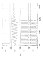
- FIG. 8 shows the different signals across various components in the circuit diagram of FIG. 7 .
- An input trigger pulse is applied to VG 1 as shown in the upper Figure. This has a duration of 10 ms and is of 5V.
- a square wave pulse train is applied to the open drain MosFet (labelled T 3 IRFZ44). This pulse train has an input pulse width of 100 ms and is approximately 4.5V.
- the output to the mechanical circuit which is the analogue of the exciter is shown in the lower figure (VM 3 ). This is a modified square wave pulse train.
- These signals result in a voltage response (VM 1 ) across capacitor C (C 1921 ) which is equivalent to the displacement provided by the exciter.
- the amplifier operates in cooperation with the moving mass (L 1 275 m), electrical resistance (R 2 ) and inductance (C 1921 ) of the moving coil exciter and the coupled mass of the driven screen.
- a near square wave type of output shown in the third figure of FIG. 8 is converted to a low pass filtered waveform or more sine wave shape, suitable for haptic sensation, as shown in the second figure of FIG. 8 .
- Class B or Class A/B linear amplifier Much higher system efficiency will be possible compared with an audio type linear amplifier
- the output has short duration 100 ms to form a pulse like signal to provide a button click sensation to a user's finger tip.
- the touch actions performed by a user's finger may include gestures such as sweeps, pinches expansions, pushes, taps etc.
- the haptics signal may match each of these touch actions.
- Such matched signals are likely to be more complex (e.g. combination of pulses, provide variations in displacement and/or acceleration) so as to provide additional information to the user.
- These more complex signals could be provided by varying the input pulse train widths, the frequency of the square wave pulse train and/or the resistance of the exciter.
- FIG. 9 shows how the output across VM 1 varies with varying input pulse train widths.
- the width of the input is set at approximately 55 ms and the lower figure (VM 1 [ 6 ]), the width of the input is set at approximately 145 ms.
- the other graphs show widths between these extremes.
- FIG. 10 shows how the output across VM 1 varies with changing frequency of the square wave pulse train.
- the frequency is set at 350 Hz and the lower figure (VM 1 [ 6 ]), the frequency is approximately 35 Hz.
- the other graphs show frequencies between these extremes.
- a frequency of 100 Hz is shown in the fourth figure (VM 1 [ 4 ]).
- FIG. 11 shows how the output across VM 1 varies if the internal resistance (R 2 in FIG. 7 ) of the exciter is changed.
- the resistance is set at 10 ohm and in the lower figure (VM 1 [ 6 ]), the resistance is set at 200 ohm.
- the other graphs show frequencies between these extremes.
Abstract
Description
Claims (24)
Priority Applications (1)
| Application Number | Priority Date | Filing Date | Title |
|---|---|---|---|
| US15/789,721 US10296094B2 (en) | 2009-02-16 | 2017-10-20 | Touch sensitive device |
Applications Claiming Priority (3)
| Application Number | Priority Date | Filing Date | Title |
|---|---|---|---|
| GB0902499.3 | 2009-02-16 | ||
| GB0902499A GB2468275A (en) | 2009-02-16 | 2009-02-16 | A method of making a touch-sensitive data entry screen with haptic feedback |
| PCT/GB2010/050230 WO2010092397A1 (en) | 2009-02-16 | 2010-02-12 | Touch sensitive device |
Related Parent Applications (1)
| Application Number | Title | Priority Date | Filing Date |
|---|---|---|---|
| PCT/GB2010/050230 A-371-Of-International WO2010092397A1 (en) | 2009-02-16 | 2010-02-12 | Touch sensitive device |
Related Child Applications (1)
| Application Number | Title | Priority Date | Filing Date |
|---|---|---|---|
| US15/789,721 Continuation US10296094B2 (en) | 2009-02-16 | 2017-10-20 | Touch sensitive device |
Publications (2)
| Publication Number | Publication Date |
|---|---|
| US20120038568A1 US20120038568A1 (en) | 2012-02-16 |
| US9804673B2 true US9804673B2 (en) | 2017-10-31 |
Family
ID=40548216
Family Applications (2)
| Application Number | Title | Priority Date | Filing Date |
|---|---|---|---|
| US13/201,754 Active US9804673B2 (en) | 2009-02-16 | 2010-02-12 | Touch sensitive device |
| US15/789,721 Active US10296094B2 (en) | 2009-02-16 | 2017-10-20 | Touch sensitive device |
Family Applications After (1)
| Application Number | Title | Priority Date | Filing Date |
|---|---|---|---|
| US15/789,721 Active US10296094B2 (en) | 2009-02-16 | 2017-10-20 | Touch sensitive device |
Country Status (9)
| Country | Link |
|---|---|
| US (2) | US9804673B2 (en) |
| EP (1) | EP2396713B1 (en) |
| JP (1) | JP2012518218A (en) |
| KR (1) | KR20110130427A (en) |
| CN (1) | CN102395943A (en) |
| BR (1) | BRPI1012345A2 (en) |
| CA (1) | CA2752687A1 (en) |
| GB (1) | GB2468275A (en) |
| WO (1) | WO2010092397A1 (en) |
Cited By (2)
| Publication number | Priority date | Publication date | Assignee | Title |
|---|---|---|---|---|
| US20170038863A1 (en) * | 2015-08-06 | 2017-02-09 | Apple Inc. | Method of tuning a haptic actuator including ferromagnetic mass change iterations and related apparatus |
| US10216231B1 (en) * | 2018-02-20 | 2019-02-26 | Nvf Tech Ltd | Moving magnet actuator for haptic alerts |
Families Citing this family (31)
| Publication number | Priority date | Publication date | Assignee | Title |
|---|---|---|---|---|
| GB2468275A (en) * | 2009-02-16 | 2010-09-08 | New Transducers Ltd | A method of making a touch-sensitive data entry screen with haptic feedback |
| GB0905692D0 (en) * | 2009-04-02 | 2009-05-20 | Tno | Touch sensitive device |
| US20110260988A1 (en) * | 2010-01-20 | 2011-10-27 | Northwestern University | Method and apparatus for increasing magnitude and frequency of forces applied to a bare finger on a haptic surface |
| US10638617B2 (en) * | 2010-10-19 | 2020-04-28 | Nokia Technologies Oy | Display apparatus |
| US20120242584A1 (en) | 2011-03-22 | 2012-09-27 | Nokia Corporation | Method and apparatus for providing sight independent activity reports responsive to a touch gesture |
| JP5928767B2 (en) * | 2011-04-18 | 2016-06-01 | 京セラ株式会社 | Portable information terminal |
| US10108288B2 (en) | 2011-05-10 | 2018-10-23 | Northwestern University | Touch interface device and method for applying controllable shear forces to a human appendage |
| WO2012154972A2 (en) | 2011-05-10 | 2012-11-15 | Northwestern University | A touch interface device having an electrostatic multitouch surface and method for controlling the device |
| US10007341B2 (en) | 2011-06-21 | 2018-06-26 | Northwestern University | Touch interface device and method for applying lateral forces on a human appendage |
| US8686839B2 (en) * | 2011-11-01 | 2014-04-01 | Texas Instruments Incorporated | Closed-loop haptic or other tactile feedback system for mobile devices, touch screen devices, and other devices |
| WO2013170099A1 (en) | 2012-05-09 | 2013-11-14 | Yknots Industries Llc | Calibration of haptic feedback systems for input devices |
| CN104412201B (en) | 2012-05-09 | 2018-09-21 | 苹果公司 | Change the output of computing device based on tracking window |
| US20150109223A1 (en) | 2012-06-12 | 2015-04-23 | Apple Inc. | Haptic electromagnetic actuator |
| US9886116B2 (en) | 2012-07-26 | 2018-02-06 | Apple Inc. | Gesture and touch input detection through force sensing |
| US9727140B2 (en) | 2012-08-31 | 2017-08-08 | Nec Corporation | Tactile force sense presentation device, information terminal, tactile force sense presentation method, and computer-readable recording medium |
| US9304587B2 (en) | 2013-02-13 | 2016-04-05 | Apple Inc. | Force sensing mouse |
| FR3015382B1 (en) * | 2013-12-19 | 2017-01-13 | Dav | CONTROL DEVICE FOR MOTOR VEHICLE AND CONTROL METHOD |
| US20150242037A1 (en) | 2014-01-13 | 2015-08-27 | Apple Inc. | Transparent force sensor with strain relief |
| US10297119B1 (en) | 2014-09-02 | 2019-05-21 | Apple Inc. | Feedback device in an electronic device |
| US9939901B2 (en) | 2014-09-30 | 2018-04-10 | Apple Inc. | Haptic feedback assembly |
| US9720500B2 (en) | 2014-11-07 | 2017-08-01 | Faurecia Interior Systems, Inc | Haptic touch panel assembly for a vehicle |
| US9910493B2 (en) | 2014-11-07 | 2018-03-06 | Faurecia Interior Systems, Inc. | Suspension component for a haptic touch panel assembly |
| US9798409B1 (en) | 2015-03-04 | 2017-10-24 | Apple Inc. | Multi-force input device |
| JP6418084B2 (en) * | 2015-07-01 | 2018-11-07 | 京セラドキュメントソリューションズ株式会社 | User interface device, image forming device |
| FI20175691A1 (en) | 2017-07-14 | 2019-01-15 | Senseg Oy | Electrostatic actuator structure |
| US10620705B2 (en) | 2018-06-01 | 2020-04-14 | Google Llc | Vibrating the surface of an electronic device to raise the perceived height at a depression in the surface |
| CN110045814B (en) * | 2018-12-30 | 2022-06-14 | 瑞声科技(新加坡)有限公司 | Excitation signal generation method and device, terminal and storage medium |
| US10850711B2 (en) * | 2019-05-03 | 2020-12-01 | Ford Global Technologies, Llc | System and methods for exterior vehicle display and panel exciters |
| FR3095875B1 (en) * | 2019-05-07 | 2021-06-04 | Commissariat Energie Atomique | TOUCH INTERFACE OFFERING A VIBROTACTILE FEEDBACK WITH IMPROVED LOCATION |
| DE102019220095A1 (en) * | 2019-12-18 | 2021-06-24 | Continental Automotive Gmbh | Haptic operating device in a motor vehicle |
| JP2023039801A (en) * | 2021-09-09 | 2023-03-22 | 京セラ株式会社 | Electrical apparatus and vibration control method |
Citations (23)
| Publication number | Priority date | Publication date | Assignee | Title |
|---|---|---|---|---|
| US20010006006A1 (en) * | 1999-12-23 | 2001-07-05 | Hill Nicholas P.R. | Contact sensitive device |
| US6680729B1 (en) * | 1999-09-30 | 2004-01-20 | Immersion Corporation | Increasing force transmissibility for tactile feedback interface devices |
| US20050017947A1 (en) | 2000-01-19 | 2005-01-27 | Shahoian Erik J. | Haptic input devices |
| US20050078093A1 (en) * | 2003-10-10 | 2005-04-14 | Peterson Richard A. | Wake-on-touch for vibration sensing touch input devices |
| US20060119589A1 (en) * | 1998-06-23 | 2006-06-08 | Immersion Corporation | Haptic feedback for touchpads and other touch controls |
| US20060181517A1 (en) * | 2005-02-11 | 2006-08-17 | Apple Computer, Inc. | Display actuator |
| US20070278033A1 (en) * | 2004-04-16 | 2007-12-06 | New Transducers Limited | Acoustic Device And Method Of Making Acoustic Device |
| US20080084384A1 (en) * | 2006-10-05 | 2008-04-10 | Immersion Corporation | Multiple Mode Haptic Feedback System |
| US20080186152A1 (en) * | 2007-02-02 | 2008-08-07 | Electronics & Telecommunications Research Institute | Haptic experience service method and system |
| US20080198139A1 (en) | 2007-02-20 | 2008-08-21 | Immersion Corporation | Haptic Feedback System with Stored Effects |
| US20080231612A1 (en) * | 2003-12-31 | 2008-09-25 | 3M Innovative Properties Company | Touch sensitive device employing bending wave vibration sensing and excitation transducers |
| US7446752B2 (en) * | 1999-09-28 | 2008-11-04 | Immersion Corporation | Controlling haptic sensations for vibrotactile feedback interface devices |
| US20090009488A1 (en) * | 2007-07-02 | 2009-01-08 | D Souza Henry M | Method and system for detecting touch events based on redundant validation |
| US7561142B2 (en) * | 1999-07-01 | 2009-07-14 | Immersion Corporation | Vibrotactile haptic feedback devices |
| US20090243997A1 (en) * | 2008-03-27 | 2009-10-01 | Immersion Corporation | Systems and Methods For Resonance Detection |
| US20100013799A1 (en) * | 2008-07-18 | 2010-01-21 | Samsung Corning Precision Glass Co., Ltd. | Touch input detecting display filter and display device having the same |
| US20100245254A1 (en) * | 2009-03-24 | 2010-09-30 | Immersion Corporation | Planar Suspension Of A Haptic Touch Screen |
| US20100282524A1 (en) * | 2007-07-09 | 2010-11-11 | Sensitive Object | Touch control system and method for localising an excitation |
| US20110074544A1 (en) * | 2009-09-29 | 2011-03-31 | Tyco Electronics Corporation | Method and apparatus for detecting simultaneous touch events on a bending-wave touchscreen |
| US20110102349A1 (en) * | 2008-08-08 | 2011-05-05 | Nissha Printing Co., Ltd. | Touch Sensitive Device |
| US8169402B2 (en) * | 1999-07-01 | 2012-05-01 | Immersion Corporation | Vibrotactile haptic feedback devices |
| US8701132B2 (en) * | 2011-02-28 | 2014-04-15 | Panasonic Corporation | Movement mechanism and optical disc apparatus |
| US8884884B2 (en) * | 2008-11-12 | 2014-11-11 | Immersion Corporation | Haptic effect generation with an eccentric rotating mass actuator |
Family Cites Families (24)
| Publication number | Priority date | Publication date | Assignee | Title |
|---|---|---|---|---|
| DE69911961T2 (en) * | 1998-07-03 | 2004-07-29 | New Transducers Ltd. | PLATE-SHAPED RESONANT SPEAKER |
| US6965678B2 (en) * | 2000-01-27 | 2005-11-15 | New Transducers Limited | Electronic article comprising loudspeaker and touch pad |
| US6911901B2 (en) * | 2000-12-20 | 2005-06-28 | New Transducers Limited | Multi-functional vibro-acoustic device |
| US7190331B2 (en) * | 2002-06-06 | 2007-03-13 | Siemens Corporate Research, Inc. | System and method for measuring the registration accuracy of an augmented reality system |
| JP3937982B2 (en) | 2002-08-29 | 2007-06-27 | ソニー株式会社 | INPUT / OUTPUT DEVICE AND ELECTRONIC DEVICE HAVING INPUT / OUTPUT DEVICE |
| US7800595B2 (en) * | 2003-12-18 | 2010-09-21 | 3M Innovative Properties Company | Piezoelectric transducer |
| US8232969B2 (en) * | 2004-10-08 | 2012-07-31 | Immersion Corporation | Haptic feedback for button and scrolling action simulation in touch input devices |
| US7499039B2 (en) * | 2005-01-10 | 2009-03-03 | 3M Innovative Properties Company | Iterative method for determining touch location |
| DE102005011633A1 (en) * | 2005-03-14 | 2006-09-21 | Siemens Ag | Touch screen with haptic feedback |
| US7683890B2 (en) * | 2005-04-28 | 2010-03-23 | 3M Innovative Properties Company | Touch location determination using bending mode sensors and multiple detection techniques |
| US7616192B2 (en) | 2005-07-28 | 2009-11-10 | Avago Technologies Ecbu Ip (Singapore) Pte. Ltd. | Touch device and method for providing tactile feedback |
| US8405618B2 (en) | 2006-03-24 | 2013-03-26 | Northwestern University | Haptic device with indirect haptic feedback |
| US20080100568A1 (en) | 2006-10-30 | 2008-05-01 | Koch Paul B | Electronic device providing tactile feedback |
| US8063888B2 (en) | 2007-02-20 | 2011-11-22 | Microsoft Corporation | Identification of devices on touch-sensitive surface |
| WO2008152457A1 (en) | 2007-06-14 | 2008-12-18 | Nokia Corporation | Screen assembly |
| GB0724149D0 (en) * | 2007-12-11 | 2008-01-23 | New Transducers Ltd | Touch-sensitive device |
| US20090181724A1 (en) | 2008-01-14 | 2009-07-16 | Sony Ericsson Mobile Communications Ab | Touch sensitive display with ultrasonic vibrations for tactile feedback |
| US8310444B2 (en) | 2008-01-29 | 2012-11-13 | Pacinian Corporation | Projected field haptic actuation |
| US8169332B2 (en) * | 2008-03-30 | 2012-05-01 | Pressure Profile Systems Corporation | Tactile device with force sensitive touch input surface |
| JP4838280B2 (en) | 2008-03-31 | 2011-12-14 | 太平洋セメント株式会社 | Touch panel type input device |
| US20090267892A1 (en) | 2008-04-24 | 2009-10-29 | Research In Motion Limited | System and method for generating energy from activation of an input device in an electronic device |
| US20100141408A1 (en) * | 2008-12-05 | 2010-06-10 | Anthony Stephen Doy | Audio amplifier apparatus to drive a panel to produce both an audio signal and haptic feedback |
| GB2468275A (en) * | 2009-02-16 | 2010-09-08 | New Transducers Ltd | A method of making a touch-sensitive data entry screen with haptic feedback |
| WO2011051722A2 (en) * | 2009-10-29 | 2011-05-05 | New Transducers Limited | Touch sensitive device |
-
2009
- 2009-02-16 GB GB0902499A patent/GB2468275A/en not_active Withdrawn
-
2010
- 2010-02-12 JP JP2011549675A patent/JP2012518218A/en active Pending
- 2010-02-12 WO PCT/GB2010/050230 patent/WO2010092397A1/en active Application Filing
- 2010-02-12 CA CA2752687A patent/CA2752687A1/en not_active Abandoned
- 2010-02-12 BR BRPI1012345A patent/BRPI1012345A2/en not_active Application Discontinuation
- 2010-02-12 US US13/201,754 patent/US9804673B2/en active Active
- 2010-02-12 EP EP10704586.6A patent/EP2396713B1/en active Active
- 2010-02-12 KR KR1020117021540A patent/KR20110130427A/en not_active Application Discontinuation
- 2010-02-12 CN CN2010800168055A patent/CN102395943A/en active Pending
-
2017
- 2017-10-20 US US15/789,721 patent/US10296094B2/en active Active
Patent Citations (24)
| Publication number | Priority date | Publication date | Assignee | Title |
|---|---|---|---|---|
| US20060119589A1 (en) * | 1998-06-23 | 2006-06-08 | Immersion Corporation | Haptic feedback for touchpads and other touch controls |
| US8169402B2 (en) * | 1999-07-01 | 2012-05-01 | Immersion Corporation | Vibrotactile haptic feedback devices |
| US7561142B2 (en) * | 1999-07-01 | 2009-07-14 | Immersion Corporation | Vibrotactile haptic feedback devices |
| US7446752B2 (en) * | 1999-09-28 | 2008-11-04 | Immersion Corporation | Controlling haptic sensations for vibrotactile feedback interface devices |
| US6680729B1 (en) * | 1999-09-30 | 2004-01-20 | Immersion Corporation | Increasing force transmissibility for tactile feedback interface devices |
| US20010006006A1 (en) * | 1999-12-23 | 2001-07-05 | Hill Nicholas P.R. | Contact sensitive device |
| US20050017947A1 (en) | 2000-01-19 | 2005-01-27 | Shahoian Erik J. | Haptic input devices |
| US20050078093A1 (en) * | 2003-10-10 | 2005-04-14 | Peterson Richard A. | Wake-on-touch for vibration sensing touch input devices |
| US20080231612A1 (en) * | 2003-12-31 | 2008-09-25 | 3M Innovative Properties Company | Touch sensitive device employing bending wave vibration sensing and excitation transducers |
| US20070278033A1 (en) * | 2004-04-16 | 2007-12-06 | New Transducers Limited | Acoustic Device And Method Of Making Acoustic Device |
| US20060181517A1 (en) * | 2005-02-11 | 2006-08-17 | Apple Computer, Inc. | Display actuator |
| WO2008045694A1 (en) | 2006-10-05 | 2008-04-17 | Immersion Corporation | Multiple mode haptic feedback system |
| US20080084384A1 (en) * | 2006-10-05 | 2008-04-10 | Immersion Corporation | Multiple Mode Haptic Feedback System |
| US20080186152A1 (en) * | 2007-02-02 | 2008-08-07 | Electronics & Telecommunications Research Institute | Haptic experience service method and system |
| US20080198139A1 (en) | 2007-02-20 | 2008-08-21 | Immersion Corporation | Haptic Feedback System with Stored Effects |
| US20090009488A1 (en) * | 2007-07-02 | 2009-01-08 | D Souza Henry M | Method and system for detecting touch events based on redundant validation |
| US20100282524A1 (en) * | 2007-07-09 | 2010-11-11 | Sensitive Object | Touch control system and method for localising an excitation |
| US20090243997A1 (en) * | 2008-03-27 | 2009-10-01 | Immersion Corporation | Systems and Methods For Resonance Detection |
| US20100013799A1 (en) * | 2008-07-18 | 2010-01-21 | Samsung Corning Precision Glass Co., Ltd. | Touch input detecting display filter and display device having the same |
| US20110102349A1 (en) * | 2008-08-08 | 2011-05-05 | Nissha Printing Co., Ltd. | Touch Sensitive Device |
| US8884884B2 (en) * | 2008-11-12 | 2014-11-11 | Immersion Corporation | Haptic effect generation with an eccentric rotating mass actuator |
| US20100245254A1 (en) * | 2009-03-24 | 2010-09-30 | Immersion Corporation | Planar Suspension Of A Haptic Touch Screen |
| US20110074544A1 (en) * | 2009-09-29 | 2011-03-31 | Tyco Electronics Corporation | Method and apparatus for detecting simultaneous touch events on a bending-wave touchscreen |
| US8701132B2 (en) * | 2011-02-28 | 2014-04-15 | Panasonic Corporation | Movement mechanism and optical disc apparatus |
Cited By (3)
| Publication number | Priority date | Publication date | Assignee | Title |
|---|---|---|---|---|
| US20170038863A1 (en) * | 2015-08-06 | 2017-02-09 | Apple Inc. | Method of tuning a haptic actuator including ferromagnetic mass change iterations and related apparatus |
| US10120448B2 (en) * | 2015-08-06 | 2018-11-06 | Apple Inc. | Method of tuning a haptic actuator including ferromagnetic mass change iterations and related apparatus |
| US10216231B1 (en) * | 2018-02-20 | 2019-02-26 | Nvf Tech Ltd | Moving magnet actuator for haptic alerts |
Also Published As
| Publication number | Publication date |
|---|---|
| GB2468275A (en) | 2010-09-08 |
| WO2010092397A1 (en) | 2010-08-19 |
| EP2396713A1 (en) | 2011-12-21 |
| US20120038568A1 (en) | 2012-02-16 |
| CA2752687A1 (en) | 2010-08-19 |
| GB0902499D0 (en) | 2009-04-01 |
| BRPI1012345A2 (en) | 2016-03-22 |
| EP2396713B1 (en) | 2018-09-26 |
| US10296094B2 (en) | 2019-05-21 |
| KR20110130427A (en) | 2011-12-05 |
| JP2012518218A (en) | 2012-08-09 |
| US20180074588A1 (en) | 2018-03-15 |
| CN102395943A (en) | 2012-03-28 |
Similar Documents
| Publication | Publication Date | Title |
|---|---|---|
| US10296094B2 (en) | Touch sensitive device | |
| US10318006B2 (en) | High definition haptic effects generation using primitives | |
| KR102290143B1 (en) | Controlling method of tactile actuator and device | |
| US20130201127A1 (en) | Input device | |
| EP3029549A1 (en) | Display device and electronic apparatus | |
| US8436825B2 (en) | Haptic interaction device | |
| KR20140109292A (en) | Haptic device with linear resonant actuator | |
| JP2013109429A (en) | Touch sensor and electronic device | |
| WO2018079339A1 (en) | Touch panel-attached display device | |
| KR20150034861A (en) | Modual and appratus and method for providing feedback | |
| WO2019003870A1 (en) | Input device | |
| US10216275B2 (en) | Touch and haptics device | |
| US8902176B2 (en) | Haptic feedback apparatus | |
| JP2019067379A (en) | Display device equipped with force sensor and method of manufacturing the same | |
| KR101164861B1 (en) | Touch screen with vibrating function | |
| WO2009117125A1 (en) | Vibrating substrate for haptic interface | |
| TWI756950B (en) | Display device and touch feedback method | |
| KR102631306B1 (en) | Apparatus and method of forming localized vibration, and method for arranging exicitors | |
| WO2019130504A1 (en) | Electronic device | |
| JP2019061443A (en) | Input device and electronic device | |
| JP2018073020A (en) | Display device with touch panel |
Legal Events
| Date | Code | Title | Description |
|---|---|---|---|
| AS | Assignment |
Owner name: NEW TRANSDUCERS LIMITED, UNITED KINGDOM Free format text: ASSIGNMENT OF ASSIGNORS INTEREST;ASSIGNORS:COLLOMS, MARTIN;WHITWELL, TIMOTHY CHRISTOPHER JOHNSON;REEL/FRAME:027093/0282 Effective date: 20111013 |
|
| AS | Assignment |
Owner name: HIWAVE TECHNOLOGIES (UK) LIMITED, UNITED KINGDOM Free format text: CHANGE OF NAME;ASSIGNOR:NEW TRANSDUCERS LIMITED;REEL/FRAME:043334/0262 Effective date: 20110304 Owner name: NVF TECH LTD., UNITED KINGDOM Free format text: CHANGE OF NAME;ASSIGNOR:HIWAVE TECHNOLOGIES (UK) LIMITED;REEL/FRAME:043334/0331 Effective date: 20130804 |
|
| STCF | Information on status: patent grant |
Free format text: PATENTED CASE |
|
| AS | Assignment |
Owner name: HIWAVE TECHNOLOGIES (UK) LIMITED, UNITED KINGDOM Free format text: CHANGE OF NAME;ASSIGNOR:NEW TRANSDUCERS LIMITED;REEL/FRAME:044802/0965 Effective date: 20110304 Owner name: NVF TECH LTD, UNITED KINGDOM Free format text: CHANGE OF NAME;ASSIGNOR:HIWAVE TECHNOLOGIES (UK) LIMITED;REEL/FRAME:044803/0079 Effective date: 20130724 |
|
| AS | Assignment |
Owner name: GOOGLE LLC, CALIFORNIA Free format text: ASSIGNMENT OF ASSIGNORS INTEREST;ASSIGNOR:NVF TECH LTD.;REEL/FRAME:050233/0949 Effective date: 20190821 |
|
| MAFP | Maintenance fee payment |
Free format text: PAYMENT OF MAINTENANCE FEE, 4TH YEAR, LARGE ENTITY (ORIGINAL EVENT CODE: M1551); ENTITY STATUS OF PATENT OWNER: LARGE ENTITY Year of fee payment: 4 |