US9815605B2 - Container carrier - Google Patents
Container carrier Download PDFInfo
- Publication number
- US9815605B2 US9815605B2 US13/509,862 US201013509862A US9815605B2 US 9815605 B2 US9815605 B2 US 9815605B2 US 201013509862 A US201013509862 A US 201013509862A US 9815605 B2 US9815605 B2 US 9815605B2
- Authority
- US
- United States
- Prior art keywords
- quadra
- plastics film
- container
- arcuate
- plastics
- Prior art date
- Legal status (The legal status is an assumption and is not a legal conclusion. Google has not performed a legal analysis and makes no representation as to the accuracy of the status listed.)
- Active, expires
Links
Images


Classifications
-
- B—PERFORMING OPERATIONS; TRANSPORTING
- B65—CONVEYING; PACKING; STORING; HANDLING THIN OR FILAMENTARY MATERIAL
- B65D—CONTAINERS FOR STORAGE OR TRANSPORT OF ARTICLES OR MATERIALS, e.g. BAGS, BARRELS, BOTTLES, BOXES, CANS, CARTONS, CRATES, DRUMS, JARS, TANKS, HOPPERS, FORWARDING CONTAINERS; ACCESSORIES, CLOSURES, OR FITTINGS THEREFOR; PACKAGING ELEMENTS; PACKAGES
- B65D71/00—Bundles of articles held together by packaging elements for convenience of storage or transport, e.g. portable segregating carrier for plural receptacles such as beer cans or pop bottles; Bales of material
- B65D71/50—Bundles of articles held together by packaging elements for convenience of storage or transport, e.g. portable segregating carrier for plural receptacles such as beer cans or pop bottles; Bales of material comprising a plurality of articles held together only partially by packaging elements formed otherwise than by folding a blank
- B65D71/504—Bundles of articles held together by packaging elements for convenience of storage or transport, e.g. portable segregating carrier for plural receptacles such as beer cans or pop bottles; Bales of material comprising a plurality of articles held together only partially by packaging elements formed otherwise than by folding a blank the element being formed from a flexible sheet provided with slits or apertures intended to be stretched over the articles and adapt to the shape of the article
-
- A—HUMAN NECESSITIES
- A47—FURNITURE; DOMESTIC ARTICLES OR APPLIANCES; COFFEE MILLS; SPICE MILLS; SUCTION CLEANERS IN GENERAL
- A47G—HOUSEHOLD OR TABLE EQUIPMENT
- A47G23/00—Other table equipment
- A47G23/02—Glass or bottle holders
- A47G23/0241—Glass or bottle holders for bottles; Decanters
-
- A—HUMAN NECESSITIES
- A47—FURNITURE; DOMESTIC ARTICLES OR APPLIANCES; COFFEE MILLS; SPICE MILLS; SUCTION CLEANERS IN GENERAL
- A47G—HOUSEHOLD OR TABLE EQUIPMENT
- A47G23/00—Other table equipment
- A47G23/02—Glass or bottle holders
- A47G23/0266—Glass or bottle holders for cans
-
- B—PERFORMING OPERATIONS; TRANSPORTING
- B65—CONVEYING; PACKING; STORING; HANDLING THIN OR FILAMENTARY MATERIAL
- B65B—MACHINES, APPARATUS OR DEVICES FOR, OR METHODS OF, PACKAGING ARTICLES OR MATERIALS; UNPACKING
- B65B17/00—Other machines, apparatus, or methods for packaging articles or materials
- B65B17/02—Joining articles, e.g. cans, directly to each other for convenience of storage, transport, or handling
- B65B17/025—Joining articles, e.g. cans, directly to each other for convenience of storage, transport, or handling the articles being joined by a top carrier element
-
- B—PERFORMING OPERATIONS; TRANSPORTING
- B65—CONVEYING; PACKING; STORING; HANDLING THIN OR FILAMENTARY MATERIAL
- B65D—CONTAINERS FOR STORAGE OR TRANSPORT OF ARTICLES OR MATERIALS, e.g. BAGS, BARRELS, BOTTLES, BOXES, CANS, CARTONS, CRATES, DRUMS, JARS, TANKS, HOPPERS, FORWARDING CONTAINERS; ACCESSORIES, CLOSURES, OR FITTINGS THEREFOR; PACKAGING ELEMENTS; PACKAGES
- B65D71/00—Bundles of articles held together by packaging elements for convenience of storage or transport, e.g. portable segregating carrier for plural receptacles such as beer cans or pop bottles; Bales of material
- B65D71/50—Bundles of articles held together by packaging elements for convenience of storage or transport, e.g. portable segregating carrier for plural receptacles such as beer cans or pop bottles; Bales of material comprising a plurality of articles held together only partially by packaging elements formed otherwise than by folding a blank
- B65D71/508—Bundles of articles held together by packaging elements for convenience of storage or transport, e.g. portable segregating carrier for plural receptacles such as beer cans or pop bottles; Bales of material comprising a plurality of articles held together only partially by packaging elements formed otherwise than by folding a blank the elements being formed by one or more films or similar, e.g. nets
-
- B—PERFORMING OPERATIONS; TRANSPORTING
- B65—CONVEYING; PACKING; STORING; HANDLING THIN OR FILAMENTARY MATERIAL
- B65D—CONTAINERS FOR STORAGE OR TRANSPORT OF ARTICLES OR MATERIALS, e.g. BAGS, BARRELS, BOTTLES, BOXES, CANS, CARTONS, CRATES, DRUMS, JARS, TANKS, HOPPERS, FORWARDING CONTAINERS; ACCESSORIES, CLOSURES, OR FITTINGS THEREFOR; PACKAGING ELEMENTS; PACKAGES
- B65D71/00—Bundles of articles held together by packaging elements for convenience of storage or transport, e.g. portable segregating carrier for plural receptacles such as beer cans or pop bottles; Bales of material
- B65D71/50—Bundles of articles held together by packaging elements for convenience of storage or transport, e.g. portable segregating carrier for plural receptacles such as beer cans or pop bottles; Bales of material comprising a plurality of articles held together only partially by packaging elements formed otherwise than by folding a blank
Definitions
- the present invention relates to a plastics container carrier and to packaging systems for containers and using the same.
- This invention also pertains to carrier stock for machine application to substantially identical containers such as beverage cans having annular chimes, cylindrical side walls, and frusto-conical walls between the chimes and the side walls.
- the present invention relates to plastic film having apertures to securely retain drinks cans, food cans, bottles and similar containers, a method of applying the film and the resultant combination.
- FIG. 1 shows an example from U.S. Pat. No. 2,874,835 (ITW) which provides a carrier 30 comprising a flat sheet of plastic material which is provided with a plurality of apertures 32 .
- the apertures are distinctly smaller (>20%) than a diameter of a can retained by the carrier.
- FIG. 1 a shows how cans, in use are retained, with the circumferential inner edge of the plastics apertures engaging with a lower edge of rim 46 . It can be seen that the plastics carrier material is substantially deformed by stretching—after considerable forces have been applied—such that the edge of the aperture is perpendicular to the plane of the plastics carrier period to placement of the cans, especially with reference to feature 40 in FIG. 1 b .
- polyethylene is a preferred plastics material, which is stamped in a press to form the apertures.
- This example taught of additional holes through which the ends of an elongate handle can subsequently be inserted.
- These plastics films commonly referred to as carrier stock—are stretched beyond their elastic limit. That is to say the size of aperture will in turn stretch into shapes which are complimentary to the shapes of the container (per U.S. Pat. No. 4,250,682 (ITW)).
- carrier stock is typically polyethylene and early examples were of a thickness of 500 ⁇ m or more, although it is typically 400 ⁇ m or more for rim applied carriers.
- the cans are of a greater diameter than the apertures and, accordingly, stretch the apertures and deform the material adjacent into a frusto-conical shape whereby the cans are aggressively retained against withdrawal in the direction opposite to that in which they have been inserted . . . .”.
- U.S. Pat. No. 2,936,070 teaches of a still further patent, the teaching of which was to address that a plastic carrier that provides a gripping section not susceptible to loss of a can through twisting and bending movements.
- resilient, flexible fingers 28 were forced upwardly (as the plastics film is placed upon a number of cans during packing), the fingers being determined by roots 30 defined partway into an inside edge portion of an aperture.
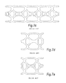
- FIGS. 3 b and 3 c show the teaching from this prior retainer in side views, where the rounded crenulations 28 are clearly visible.
- U.S. Pat. No. 2,936,070 advises, in particular, that the root diameter is less than the diameter of the cans and a considerable stretching force is, nonetheless, applied to the plastic material in the vicinity of the roots in stretching the material into the frustoconical, almost cylindrical conformation shown in FIG. 3 c .
- the description further discloses that “the carrier can be assembled with cans with considerable facility, simply by stamping the carrier down over the proper number of cans. The cans simply cam into the apertures, deflecting the fingers . . . whereby the cans are gripped aggressively with the fingers abutting beneath the can beads”. Indeed, the stamping forces would have been considerable.
- one proposal for an article carrier was formed from a tube which was alternately slit from side-to-side in a manner leaving un-slit connecting portions at subsequent alternate opposite sides whereby successive sections of the tube may be folded relative to each other generally into a common plane for receiving the articles to be carried.
- immediately adjacent articles in a package are spaced from each other at the area of contact with the carrier only by a double thickness of the relatively thin material.
- U.S. Pat. No. 3,968,621 taught of manufacturing a carrier by the formation of an extruded net, which net was subsequently flattened by the use of a roller to produce an apertured film of carrier stock, as shown in FIG. 5 .
- U.S. Pat. No. 3,317,234 teaches of a packaging system using an upper laminate and a lower laminate. As seen with reference to FIGS. 6 a and 6 b , the upper laminate comprising a first, continuous plastics layer and a second laminate comprising an apertured card layer is placed over an arrangement of bottles.
- the apertures of the card layer are arranged to fit over respective metal cap of a drinks bottle, the peripheral edges of the apertures being arranged to engage with the underside of the metal cap, whereby to retain the upper part of the bottle.
- the lower laminate being arranged to act in a similar fashion with a bottle having a characteristic waist, about which a card member of the second laminate could engage, in conjunction with a plastics layer, which enveloped a lower portion of the bottle.
- cans were retained by substantially similar first and second laminates, the card element of which engaging with a body-directed edge of the respective upper and lower rims of a double rimmed can.
- the apertures defined in such stock are generally of a triangular/D shape, primarily to assist in the mechanical placement of the stock around the rim of a can, which mechanical application necessitated the use of mechanical fingers which generally prevented the simultaneous use of such devices in any configuration other than in the provision of two-rank longitudinal rows. That is to say the cans are attached with two cans being in a side-by-side arrangement: the systems generally could not reliably operate to provide cans packed, for example in 3 ⁇ 3 or 3 ⁇ 4 or 4 ⁇ 4 etc arrangements.
- the band segments also included inner segments partly bounding the can-receiving apertures, along with transversely extending segments joining the inner segments, for finger-hold grip elements.
- Can manufacturers have in the past introduced cans having smaller chime diameters, as compared to the diameters of the side walls. Cans of this type are known as “necked-in” cans. The newest versions of these necked-in cans further and drastically reduce the ratio of the chime diameter and the side wall diameter.
- the band segments defining the can receiving apertures grip the frusto-conical walls of the cans tightly and engage the lower edges of the chimes.
- the frusto-conical wall between the chime and the side wall defines a conical angle greater than approximately 28° and in some instances as great as approximately 37°.
- the frusto-conical wall defines such a large angle relative to the can axis, it is difficult to apply carrier stock since the band segments defining the can receiving apertures have an undesirable tendency to slide up the cans and to rest on the cans above the lower edges of the chimes. This tendency is enhanced due to the jaw application system mentioned above.
- both these documents involve the use of relatively thick (greater than 400 ⁇ m) and in placement around cans are stretched beyond their elastic limit.
- These types of carrier stock have not, however, been widely adopted. This utilises a thick plastics sheeting which is stretched beyond its elastic limit.
- the present invention seeks to overcome at least one problem associated with the prior art.
- the present invention seeks to provide a process for grouping containers such as cans and bottles whereby great stretching forces are not required to enable attachment of several containers in a six-pack or similar.
- the present invention also seeks to provide a carrier film which can locate with cylindrical containers and frusto-conical containers using the elastic properties of the carrier film.
- carrier stock provided with a number of apertures for holding a number of containers together, the stock comprising a thin plastics sheet material having a number of apertures arranged in at least a first direction, wherein the apertures comprise a plurality of finger elements, separated by troughs, the apertures having a centre; wherein the peak of the finger elements lie on a first circumference relative to the centre and the bottom of the troughs lie on a second circumference relative to the centre, the second circumference being equal to or greater than the circumference of the container; wherein the peaks of the fingers are operably engageable with a beading of a container as the troughs are urged downwardly and outwardly; the troughs being operable to allow the film to elastically deform upon placement and enable the film to adopt a three dimensional structure.
- a four fingered aperture benefits in terms of packaging of product by reason of the forces from the chime, through the finger, allow upward movement of film adjacent the troughs, whereby to create a wave effect.
- the three dimensional structure adopted by the film is analogous to a vehicular monocoque structure; the strength of the shaped stock with containers is greater than that of the otherwise flexible material.
- Applicants have determined that at the point where the fingers meet with the underside of a beading of a container, such as the chime of a beverage can, the material is deflected in a downwards direction. Because the contact is discontinuous, this creates a three dimensional wave in the material which acts against the tabs or fingers and forces them to remain in contact with the containers. At the corners of the sheet (in the case of a four pack for example) opposite where the cut outs in the aperture are situated, because there are no downward forces, only lateral ones exerted by the effect of the fingers acting against the chimes, the material is forced into an apex at its furthest point from the can contributing to the wave effect. This combination of wave effect and apex further prevents the fingers from moving away from the underside of the chime and ensures the containers are held securely.
- the film is conveniently manufactured from 100-300 ⁇ m thickness plastics, which plastics can be selected from the group comprising polyethylene, polyethylene derivatives and plastics materials with similar mechanical properties.
- plastics can be selected from the group comprising polyethylene, polyethylene derivatives and plastics materials with similar mechanical properties.
- the material since it is not stretched to an extent where any occlusions or similar defects may give rise to subsequent problems, can be made from recycled plastics such as post consumer waste (PCW) plastics.
- PCW post consumer waste
- re-cycled plastics materials post consumer waste (PCW) material
- PCW post consumer waste
- the apertured material conveniently has further reduced size apertures within the material between the container receiving apertures, such further apertures assisting in the wave effect to be defined and assists in the apertures be more simply fastened about a container. Apertures may also assist in the manual handling of completed container pack, by providing finger access apertures. Additionally, it should be borne in mind that having an increased number of apertures in the film will mean that the overall cost of material supply is reduced.
- the apertured material can be dimensioned to fit around traditional cylindrical walled cans such as traditional baked-bean can.
- the apertured film can be dimensioned to fit about the necked-in cans as are typically presently produced in the beverage industry.
- the apertured film can be dimensioned to fit about the necks of bottles, wherein beading around the neck of a bottle can act in a similar fashion to the chime or beading of a can.
- the apertures can resemble a generally square-like (quadra-arcuate) aperture, with the tabs comprising slightly outwardly extending arcs. Other poly-arcuate apertures are possible, the number of tabs, however being less than ten, for containers as are commonly employed for beverages.
- the carrier stock or film of the present invention can comprise integrally joined band segments defining can receiving apertures in longitudinal rows and transverse ranks. There may be a single longitudinal row.
- the band segments include generally longitudinal outer segments with each outer segment partly bounding the can receiving apertures in an outer row.
- the carrier stock or film can be provided as a roll for use in a roll on method of applying the product, conveniently in a multi-lane format of typically but not exclusively 6 lanes wide.
- the sheet material is supplied on a roll and feeds into the application machine in a near continuous action, whereupon it is sub-divided within the machine into the required pack sizes, e.g. 4 packs, 6 packs etc.
- the method of rolling film on to the top of the container uses the downward pressure of the roller as the containers pass beneath it to gently elastically form the material through the interaction of film and container in order to achieve the aforementioned gripping action and 3 dimensional transformation of the sheet material.
- the film after application to a number of containers defines a three dimensional shape as a direct result of the various forces acting upon the material, whereby to increase the inherent strength of the resultant product.
- a reduction in the grade and thickness of the film material can be realised: costs can be reduced because less raw material is required. Further by virtue of the machinery not being required to exert tremendous forces to enable the material to engage with containers, the specification of the packaging plant can be reduced, again reducing costs.
- a still further advantage is that because the machinery is less massive and can be applied without large mechanical jaws/hands (as are presently used in the industry—which impede the function of adjacently located mechanical jaws/hands), several packing streams can be simply placed in side-by-side configuration—even enabling 12-aperture rows to be manufactured.
- the present invention takes advantage of physical properties of sheet material whereby, surprisingly, containers such as beverage cans can be retained by a sheet of a thickness much reduced to the sheet widely employed hitherto which has been placed over the rim of the container, whereby a plurality of inner edges defined along an inner circumference of the aperture abut an underside of the rim, in the free state the inside circumference being less than the circumference of the can, below the rim, the sheet material, by virtue of a discontinuous circumferential contact about said rim, whereby to conform in a three-dimensional form which offers stability and strength to a container and film combination.
- the three-dimensional form provides a strength far greater than that which would have been achievable with a standard film.
- the material of choice can be selected for price and availability rather than quality per se.
- FIGS. 1 a - c show a first example of known carrier stock
- FIGS. 2 a, b show a second example of known carrier stock
- FIG. 3 a - c show a third example of known carrier stock
- FIG. 4 shows a container carrier comprising strips of material
- FIG. 5 shows another prior art container retaining means
- FIGS. 6 a, b show card and plastics laminate container retaining means
- FIGS. 7 a - e show examples of presently commonly used carrier stock
- FIGS. 8 a - c show a first embodiment of a film and the same in use
- FIG. 9 shows a second embodiment.
- FIG. 10 shows a third embodiment
- FIG. 11 shows a still further embodiment of the invention.
- FIGS. 12-12 f detail steps in the application process
- FIGS. 13 a & b show manufacturing equipment in plan and side views
- FIGS. 14-15 show views of a application drum in accordance with another aspect of the invention.
- FIGS. 16-21 show cans unitized with a further example of the invention.
- FIGS. 8 a and 8 b show first and second perspective views of an arrangement of five beer cans retained by plastics film stock having six container apertures.
- the plastics film is shown in plan view in FIG. 8 c .
- Each aperture 80 a is of a general square shape, operably arranged to accept a circularly cylindrical part of a container therethrough, with four fingers or tabs 81 , 82 , 83 & 84 extending from indentations or troughs having a web element connecting adjacent fingers.
- the troughs lie on a radius slightly greater than the radius of the container about which the film is designed to retain.
- the nails of the fingers i.e. the portions that will abut the rim or chime of the can, are conveniently slightly curved inwardly.
- the arc corresponds to an arc of a circle of a radius corresponding to a radius of the container that lies immediately adjacent the rim or chime of the container, the shape taking into account the fact that the film will adopt an undulating shape in view of the resilience of the plastics film being utilised. It is important to note that whilst the elastic properties of the film are utilised, the elastic limit of the material is not approached.
- carrier stock provided with a number of apertures for holding a number of containers together, the stock comprising a thin plastics sheet material having a number of apertures arranged in at least a first direction.
- the apertures comprise a plurality of finger elements, separated by troughs, the apertures having a centre.
- the peak of the finger elements lie on a first circumference relative to the centre whilst the bottom of the troughs (that part of the troughs most distant from the centre) lie on a second circumference relative to the centre, the second circumference being equal to or greater than the circumference of the container.
- the peaks of the fingers engage with a beading of a container whilst the troughs, as a direct result—since they are part of the same film—are urged downwardly and outwardly.
- the troughs urge the film to elastically form upon placement and enable the film to adopt a three dimensional structure.
- the number of fingers can vary from three upwards, it has been found that a four fingered aperture (or multiple finger equivalents operable to achieve the same effect) benefits in terms of packaging of product by reason of the forces from the chime, through the finger, allow upward movement of film adjacent the troughs, whereby to create a wave effect.
- the three dimensional structure adopted by the film is in many ways analogous to the types of structures in vehicular manufacturing i.e. the structure is a monocoque structure where the overall strength of the finished film is greater than that of the inherently flexible material.
- film 80 is provided with apertures 81 , the apertures being defined by fingers 82 - 85 .
- One aperture 81 will now be discussed: the distance between the centres of oppositely facing fingers is approximately 90% of the diameter of the portion of the container about which the aperture will close upon, whilst the distance between opposite troughs corresponds to 110% of said diameter.
- the fingers 82 - 85 abut the lower part of the chime or rim of the can and the film closely follows the necked-in portion of the container.
- the film in accordance with the invention adopts a three dimensional geometrical form that enables the shape of the film to thereby provide a relatively rigid arrangement.
- the present invention can utilise recycled plastics film of a thickness of 350 ⁇ m or less. It is to be realised that whilst the weight of a single apertured film for a six-pack is of the order of a couple of grammes, globally, several thousands of tons of plastics are employed in the manufacture of container film. A reduction in the amount of plastics by 25% or more will provide a significant reduction in operating costs for any canning plant.
- it is known in the art for example EP1038791
- any buckling of a transverse web is to be minimised because of customer perception; a smooth transverse web is believed to be more aesthetically pleasing.
- the raw material for the present invention can indeed comprise re-cycled material or at least have a significant recycled material content.
- the procedure of application of the apertured film in accordance with the present invention can be conveniently formed by a number of methods.
- a presently preferred method will be described with reference to FIG. 8 c , which, for convenience shall be assumed to be receiving a can, not shown, from the right; the inside edge of finger 84 of the aperture is urged toward the under-chime (upper rim) of a can; the adjacent side fingers 81 , 83 of the aperture are then eased over the corresponding rim parts of the can until the inside edge of the aperture opposite the first engaged side of the aperture is adjacent the rim, whereupon continuing pressure enables the inside edge of the last aperture finger 82 to engage with an underside of the rim, thereby enabling the apertured film to be simply, safely and securely engaged therewith.
- a generally three fingered aperture may be provided, comprising a generally equilateral triangular configuration, and would provide a minimally fingered design with a security of retention.
- many polygonal form can be configured which operate in accordance with the inventions, although, a regular four-sided aperture is likely to be more readily generally accepted.
- Containers of other cylindrical shapes can be retained; it may be appropriate to have five, six or more fingers or tabs per aperture. Ten have been found to be a convenient limit for large domestic containers.
- FIG. 9 a portion of film 90 , with six apertures abreast, is shown, the apertures 91 being of a second regular quadrilateral shape. Further apertures or slits 92 , together with circular apertures 93 are sized and positioned to assist in the maintenance of the monocoque film shape, once containers have been retained by the film.
- the circular opening 93 may be formed of difference shapes or may be replaced by a number of smaller aperture, conveniently closely spaced together.
- the shape and position of the apertures are such that the troughs between the fingers correspond with the corners of the curved sides, the distance between opposite troughs being approximately 110% the diameter of the container at the rim.
- FIG. 10 shows a further portion of film 100 , which has generally square apertures 101 , which have fingers 102 - 105 separated by small troughs 106 - 109 .
- the troughs are more pronounced with respect to the troughs of FIGS. 9 and 11 , but may be of other shapes with regard to a requirement not to induce tears in the film. Again the distance between opposite troughs is approximately 110% the diameter of the container at the rim.
- FIG. 11 shows a still further embodiment, wherein each side of a generally square aperture comprises distinct arc sections 111 - 114 ; the troughs can be considered to exist at the centre of adjacent arcs 115 - 118 .
- FIG. 11 a shows a variant of the arcuate quadrilateral design wherein a substantially square aperture acts with tab elements having an inwardly facing arcuate tab.
- FIGS. 11 b -11 d show the variant of FIG. 11 a in use.
- a significant advantage of the present invention is that the mechanical properties of the material are only required to be strong enough to hold the cans, and not stand up to the rigours and high stretch of the standard application processes encountered in the prior art. Not only does this have significant advantages in the manufacturing processes (reduced operating forces incur less wear for application machines and thus further reduce operating costs), and also enables the use of cheaper plastics to be employed. Indeed, recycled plastics such as low grade Post Consumer Waste (e.g. low density polyethylene—LDPE) can be employed which also satisfies the perennial demands of market requirements in that the basic consumable materials are cheaper. As discussed above, in view of the materials not needing to be stretched to particular limits, the thickness of the basic product can also be reduced i.e.
- LDPE low density polyethylene
- the thickness can be 300 ⁇ m (or less): the issue of the presence of inclusions or not is of no consequence.
- a preferred thickness for such stock for prior systems in an unstressed condition has been in a range from approximately 16 mils (400 ⁇ m) to approximately 17.5 mils (445 ⁇ m).
- the present invention allows the use of raw material that can be purchased at far more favourable rates than specified high quality material.
- a preferred method of application utilises a simple roll on application method as shall be disclosed in detail hereinafter; a simple machine can be utilised in manufacturing industry; since great stretching forces are not applied, lever arm and/or hydraulic operations can be minimised and the strength of the machine need not be great, as a direct result compared to systems which stretch plastics towards and beyond their elastic limits.
- the use of simpler and cheaper machines will also enable the systems to be operated by smaller manufacturing concerns and thereby increase markets.
- FIGS. 12 a -12 f show a superposition of the edges of an un-stretched aperture upon a beading 126 of a container 122 .
- FIG. 12 a shows how, in a first application step associated with retaining a number of containers with a stock of apertured plastics sheeting in accordance with the present invention. An inside tab edge 121 of the aperture abuts against an underside edge of a bead 126 of the container.
- FIG. 12 b shows how, in relation to the apertured plastics sheet stock 100 an application roller will rotate with respect to a container passing underneath in a direction perpendicular to the roller axis. The roller is not shown, although the stock is shown having an arcuate profile and will be discussed in greater detail with respect to machinery below.
- FIGS. 12 e and 12 f show corresponding plan and side view of the application process as the edge 127 is received by the rim of the container 126 —as shown, the application roller is shown as the container passes below the axis of the roller
- FIGS. 13 a & 13 b there are shown plan and side views of an otherwise standard conveyor system 130 for the transport of containers in the form of soft-drinks cans 139 or similar.
- the cans 139 are fed along a conveyor to an accumulation position 134 (proceeding in a direction indicated by arrow 138 ).
- the containers are brought towards each other in close proximity in preparation for the application of the apertured retaining sheet, performed by roller 132 which receive sheet 110 from sheeting supply system 133 .
- Cutting apparatus controlled between the units labelled 136 enable appropriate pack sizes to be produced.
- sheeting supply mandrel 135 can co-operate with another mandrel (not shown) to provide a continuous supply of sheeting to the roller 132 .
- seamless connection of separate sheets can be performed to provide effective continuous operation, or at least almost continuous operation of the system.
- FIGS. 14 and 16 show, respectively side and detail view of the application drum and production line conveyor arrangement.
- FIGS. 17-21 show cans unitized with a further example of a carrier stock in accordance with the invention.
- the carrier stock is formed, for example by die-cutting, from a single sheet of resilient polymeric material, such as low density polyethylene.
- Known carrier stock has been formed of high quality plastics sheet, such as low density polyethylene.
Abstract
The present invention relates to a container carrier and to packaging systems for containers and using the same. This invention pertains to carrier stock for machine application to substantially identical containers such as beverage cans having annular chimes, cylindrical side walls, and frusto-conical walls between the chimes and the side walls. In particular, the present invention relates to plastic film having apertures to securely retain drinks cans, food cans, bottles and similar containers, a method of applying the film and the resultant combination.
Description
The present invention relates to a plastics container carrier and to packaging systems for containers and using the same. This invention also pertains to carrier stock for machine application to substantially identical containers such as beverage cans having annular chimes, cylindrical side walls, and frusto-conical walls between the chimes and the side walls. In particular, the present invention relates to plastic film having apertures to securely retain drinks cans, food cans, bottles and similar containers, a method of applying the film and the resultant combination.
It is common practice to package beverages such as sparkling fruit juices, cola drinks, beers and the like in cans, typically being manufactured from pressed aluminium or plated steel, the thickness being of the order of 50 μm or so. These cans are typically sold in four- or six packs. Early examples of packaging such packs utilised cardboard which enveloped the cans. In the 1950's plastic film container carriers were first promulgated. The early forms of plastics film container carrier utilised apertures which were deformed upon application of the sheet over the cans, whereby the film formed a continuous flange area about the side of the can. The films were placed about the top of the can, underneath a beaded edge formed at the junction of the lid of the can.
Such early forms of carrier film allowed the cans to be pulled through—albeit with some difficulty—but a reverse movement of the can with respect to the carrier would mean that the plastics flange would abut the bead and further movement required a considerable force to release the can.
The forces necessary to enable the plastics film to engage with the sides of a can were considerable and, of course, the large forces that were utilised to pack the containers together resulted in problems in a consumer accessing an individual tin. GB1200807 (ITW) introduced slits in apertures, but forces of application were still considerable since the apertures were “significantly smaller than the diameter of a can with which the carrier film is to be assembled” and therefore were still stretched beyond the elastic limit of the material. U.S. Pat. No. 2,997,169 taught of a solution to the problem by the inclusion of tear-off tabs 72 b; per FIGS. 2a & 2 b, where pre-stressed members associated with tab portion enabled a tear in the plastics retaining film, which was considered easier than forcing the rim of the can around the already stretched plastics film.
The cans are of a greater diameter than the apertures and, accordingly, stretch the apertures and deform the material adjacent into a frusto-conical shape whereby the cans are aggressively retained against withdrawal in the direction opposite to that in which they have been inserted . . . .”. U.S. Pat. No. 2,936,070 teaches of a still further patent, the teaching of which was to address that a plastic carrier that provides a gripping section not susceptible to loss of a can through twisting and bending movements. With reference to FIGS. 3a and 3b , resilient, flexible fingers 28 were forced upwardly (as the plastics film is placed upon a number of cans during packing), the fingers being determined by roots 30 defined partway into an inside edge portion of an aperture. FIGS. 3b and 3c show the teaching from this prior retainer in side views, where the rounded crenulations 28 are clearly visible. U.S. Pat. No. 2,936,070 advises, in particular, that the root diameter is less than the diameter of the cans and a considerable stretching force is, nonetheless, applied to the plastic material in the vicinity of the roots in stretching the material into the frustoconical, almost cylindrical conformation shown in FIG. 3c . The description further discloses that “the carrier can be assembled with cans with considerable facility, simply by stamping the carrier down over the proper number of cans. The cans simply cam into the apertures, deflecting the fingers . . . whereby the cans are gripped aggressively with the fingers abutting beneath the can beads”. Indeed, the stamping forces would have been considerable.
Further developments included various modifications: one proposal for an article carrier was formed from a tube which was alternately slit from side-to-side in a manner leaving un-slit connecting portions at subsequent alternate opposite sides whereby successive sections of the tube may be folded relative to each other generally into a common plane for receiving the articles to be carried. In order to economize on material, it is generally desirable to make the wall of the tube as thin as possible consistent with the required strength and durability. Thus, in such heretofore proposed structures, immediately adjacent articles in a package are spaced from each other at the area of contact with the carrier only by a double thickness of the relatively thin material. It was found that such spacing is, for many purposes, insufficient since, in practice, the closely adjacent articles such as bottles or cans would rub against each other so that the respective surfaces may be scratched or otherwise defaced. For example, it is common practice to apply a label or other decorative design by lithography or other means to beverage cans and such labelling would be damaged if the cans were permitted to rub together unduly such as when the package was subjected to continual motion or vibration during transport. U.S. Pat. No. 3,924,738 provided a solution to this problem by forming longitudinally extending rib means whereby to provide a separation spacing between cans, as shown in FIG. 4 .
U.S. Pat. No. 3,968,621 taught of manufacturing a carrier by the formation of an extruded net, which net was subsequently flattened by the use of a roller to produce an apertured film of carrier stock, as shown in FIG. 5 . U.S. Pat. No. 3,317,234 teaches of a packaging system using an upper laminate and a lower laminate. As seen with reference to FIGS. 6a and 6b , the upper laminate comprising a first, continuous plastics layer and a second laminate comprising an apertured card layer is placed over an arrangement of bottles. The apertures of the card layer are arranged to fit over respective metal cap of a drinks bottle, the peripheral edges of the apertures being arranged to engage with the underside of the metal cap, whereby to retain the upper part of the bottle. The lower laminate being arranged to act in a similar fashion with a bottle having a characteristic waist, about which a card member of the second laminate could engage, in conjunction with a plastics layer, which enveloped a lower portion of the bottle. In a similar fashion, cans were retained by substantially similar first and second laminates, the card element of which engaging with a body-directed edge of the respective upper and lower rims of a double rimmed can.
In the early 1980's, there was a shift in the method of applying film stock to cans and the like. Previous forms of strip stock for circularly cylindrical containers had been provided with substantially circular apertures. In contrast teachings equivalent to or derived from U.S. Pat. No. 4,219,117 (ITW), which were designed for application by dedicated jaw and drum machinery (such as described in U.S. Pat. No. 4,250,682) utilised stock that had integrally joined band segments defining can receiving apertures in longitudinal rows and transverse ranks. The band segments included generally longitudinal outer segments with each outer segment partly bounding the can receiving apertures in an outer row. The apertures defined in such stock are generally of a triangular/D shape, primarily to assist in the mechanical placement of the stock around the rim of a can, which mechanical application necessitated the use of mechanical fingers which generally prevented the simultaneous use of such devices in any configuration other than in the provision of two-rank longitudinal rows. That is to say the cans are attached with two cans being in a side-by-side arrangement: the systems generally could not reliably operate to provide cans packed, for example in 3×3 or 3×4 or 4×4 etc arrangements.
In the carrier stock illustrated and described in the U.S. Pat. No. 4,219,117, the band segments also included inner segments partly bounding the can-receiving apertures, along with transversely extending segments joining the inner segments, for finger-hold grip elements.
Can manufacturers have in the past introduced cans having smaller chime diameters, as compared to the diameters of the side walls. Cans of this type are known as “necked-in” cans. The newest versions of these necked-in cans further and drastically reduce the ratio of the chime diameter and the side wall diameter. When stock is applied by known procedures, the band segments defining the can receiving apertures grip the frusto-conical walls of the cans tightly and engage the lower edges of the chimes.
In a necked-in can of a newer type, the frusto-conical wall between the chime and the side wall defines a conical angle greater than approximately 28° and in some instances as great as approximately 37°. When the frusto-conical wall defines such a large angle relative to the can axis, it is difficult to apply carrier stock since the band segments defining the can receiving apertures have an undesirable tendency to slide up the cans and to rest on the cans above the lower edges of the chimes. This tendency is enhanced due to the jaw application system mentioned above.
A further problem of known systems, where great forces have been used to apply the carrier stock, that they can be difficult to remove—not only by accident; in use, especially by youngsters, has caused effervescent spillage to occur since the removal by force of a drinks can from a carrier strip has resulted in an unnecessary disturbance of the effervescent liquid inside, resulting in a spray or spillage upon a subsequent opening of the can. In EP0461748(ITW) and EP0621203 (ITW)—which address the provision of tear-open tabs, which extend upwardly across the chimes of straight-walled and conical cans, respectively, whereby to simplify release. The tabs in the later patent have concave lateral portions adjacent a stem of the tab “for stress relief”. Furthermore, both these documents involve the use of relatively thick (greater than 400 μm) and in placement around cans are stretched beyond their elastic limit. These types of carrier stock have not, however, been widely adopted. This utilises a thick plastics sheeting which is stretched beyond its elastic limit.
The present invention seeks to overcome at least one problem associated with the prior art. The present invention seeks to provide a process for grouping containers such as cans and bottles whereby great stretching forces are not required to enable attachment of several containers in a six-pack or similar. The present invention also seeks to provide a carrier film which can locate with cylindrical containers and frusto-conical containers using the elastic properties of the carrier film.
In accordance with a first aspect of the invention, there is provided carrier stock provided with a number of apertures for holding a number of containers together, the stock comprising a thin plastics sheet material having a number of apertures arranged in at least a first direction, wherein the apertures comprise a plurality of finger elements, separated by troughs, the apertures having a centre; wherein the peak of the finger elements lie on a first circumference relative to the centre and the bottom of the troughs lie on a second circumference relative to the centre, the second circumference being equal to or greater than the circumference of the container; wherein the peaks of the fingers are operably engageable with a beading of a container as the troughs are urged downwardly and outwardly; the troughs being operable to allow the film to elastically deform upon placement and enable the film to adopt a three dimensional structure. Whilst the present invention requires at least three fingers, it has been found that a four fingered aperture benefits in terms of packaging of product by reason of the forces from the chime, through the finger, allow upward movement of film adjacent the troughs, whereby to create a wave effect. The three dimensional structure adopted by the film is analogous to a vehicular monocoque structure; the strength of the shaped stock with containers is greater than that of the otherwise flexible material.
Applicants have determined that at the point where the fingers meet with the underside of a beading of a container, such as the chime of a beverage can, the material is deflected in a downwards direction. Because the contact is discontinuous, this creates a three dimensional wave in the material which acts against the tabs or fingers and forces them to remain in contact with the containers. At the corners of the sheet (in the case of a four pack for example) opposite where the cut outs in the aperture are situated, because there are no downward forces, only lateral ones exerted by the effect of the fingers acting against the chimes, the material is forced into an apex at its furthest point from the can contributing to the wave effect. This combination of wave effect and apex further prevents the fingers from moving away from the underside of the chime and ensures the containers are held securely.
The film is conveniently manufactured from 100-300 μm thickness plastics, which plastics can be selected from the group comprising polyethylene, polyethylene derivatives and plastics materials with similar mechanical properties. The material, since it is not stretched to an extent where any occlusions or similar defects may give rise to subsequent problems, can be made from recycled plastics such as post consumer waste (PCW) plastics. In view of the stresses that are applied both in the fitting of the stock by machines and in subsequent use and transportation, previous systems always employed good quality plastics: re-cycled plastics materials (post consumer waste (PCW) material) may have inclusions within the material whereby the integrity of the stressed plastics sheet is questionable.
The apertured material conveniently has further reduced size apertures within the material between the container receiving apertures, such further apertures assisting in the wave effect to be defined and assists in the apertures be more simply fastened about a container. Apertures may also assist in the manual handling of completed container pack, by providing finger access apertures. Additionally, it should be borne in mind that having an increased number of apertures in the film will mean that the overall cost of material supply is reduced.
The apertured material can be dimensioned to fit around traditional cylindrical walled cans such as traditional baked-bean can. The apertured film can be dimensioned to fit about the necked-in cans as are typically presently produced in the beverage industry. The apertured film can be dimensioned to fit about the necks of bottles, wherein beading around the neck of a bottle can act in a similar fashion to the chime or beading of a can. The apertures can resemble a generally square-like (quadra-arcuate) aperture, with the tabs comprising slightly outwardly extending arcs. Other poly-arcuate apertures are possible, the number of tabs, however being less than ten, for containers as are commonly employed for beverages.
The carrier stock or film of the present invention can comprise integrally joined band segments defining can receiving apertures in longitudinal rows and transverse ranks. There may be a single longitudinal row. The band segments include generally longitudinal outer segments with each outer segment partly bounding the can receiving apertures in an outer row. In application, the carrier stock or film can be provided as a roll for use in a roll on method of applying the product, conveniently in a multi-lane format of typically but not exclusively 6 lanes wide. The sheet material is supplied on a roll and feeds into the application machine in a near continuous action, whereupon it is sub-divided within the machine into the required pack sizes, e.g. 4 packs, 6 packs etc. The method of rolling film on to the top of the container uses the downward pressure of the roller as the containers pass beneath it to gently elastically form the material through the interaction of film and container in order to achieve the aforementioned gripping action and 3 dimensional transformation of the sheet material.
In particular, the film after application to a number of containers defines a three dimensional shape as a direct result of the various forces acting upon the material, whereby to increase the inherent strength of the resultant product. As a direct result of the increase in strength of the applied film (in three-dimensions), a reduction in the grade and thickness of the film material can be realised: costs can be reduced because less raw material is required. Further by virtue of the machinery not being required to exert tremendous forces to enable the material to engage with containers, the specification of the packaging plant can be reduced, again reducing costs. A still further advantage is that because the machinery is less massive and can be applied without large mechanical jaws/hands (as are presently used in the industry—which impede the function of adjacently located mechanical jaws/hands), several packing streams can be simply placed in side-by-side configuration—even enabling 12-aperture rows to be manufactured.
Thus the present invention takes advantage of physical properties of sheet material whereby, surprisingly, containers such as beverage cans can be retained by a sheet of a thickness much reduced to the sheet widely employed hitherto which has been placed over the rim of the container, whereby a plurality of inner edges defined along an inner circumference of the aperture abut an underside of the rim, in the free state the inside circumference being less than the circumference of the can, below the rim, the sheet material, by virtue of a discontinuous circumferential contact about said rim, whereby to conform in a three-dimensional form which offers stability and strength to a container and film combination. Specifically, the three-dimensional form provides a strength far greater than that which would have been achievable with a standard film. As a direct result of its increased strength, the material of choice can be selected for price and availability rather than quality per se.
The above and other advantages enable the objectives of the invention to be achieved.
Some preferred embodiments of the invention will now be described, by way of example, with reference to the accompanying drawings, of which:
There will now be described, by way of example only, the best mode contemplated by the inventor for carrying out the present invention. In the following description, numerous specific details are set out in order to provide a complete understanding to the present invention. It will be apparent to those skilled in the art, that the present invention may be put into practice with variations of the specific.
The present invention shall now be described with reference to a first embodiment as shown in FIGS. 8a-c . FIGS. 8a and 8b show first and second perspective views of an arrangement of five beer cans retained by plastics film stock having six container apertures. The plastics film is shown in plan view in FIG. 8c . Each aperture 80 a is of a general square shape, operably arranged to accept a circularly cylindrical part of a container therethrough, with four fingers or tabs 81, 82, 83 & 84 extending from indentations or troughs having a web element connecting adjacent fingers. The troughs lie on a radius slightly greater than the radius of the container about which the film is designed to retain. The nails of the fingers, i.e. the portions that will abut the rim or chime of the can, are conveniently slightly curved inwardly. Indeed, in order to most closely fit about a container, the arc corresponds to an arc of a circle of a radius corresponding to a radius of the container that lies immediately adjacent the rim or chime of the container, the shape taking into account the fact that the film will adopt an undulating shape in view of the resilience of the plastics film being utilised. It is important to note that whilst the elastic properties of the film are utilised, the elastic limit of the material is not approached.
In use, carrier stock provided with a number of apertures for holding a number of containers together, the stock comprising a thin plastics sheet material having a number of apertures arranged in at least a first direction. The apertures comprise a plurality of finger elements, separated by troughs, the apertures having a centre. The peak of the finger elements lie on a first circumference relative to the centre whilst the bottom of the troughs (that part of the troughs most distant from the centre) lie on a second circumference relative to the centre, the second circumference being equal to or greater than the circumference of the container. In use the peaks of the fingers engage with a beading of a container whilst the troughs, as a direct result—since they are part of the same film—are urged downwardly and outwardly. In so doing the troughs urge the film to elastically form upon placement and enable the film to adopt a three dimensional structure. Whilst the number of fingers can vary from three upwards, it has been found that a four fingered aperture (or multiple finger equivalents operable to achieve the same effect) benefits in terms of packaging of product by reason of the forces from the chime, through the finger, allow upward movement of film adjacent the troughs, whereby to create a wave effect. The three dimensional structure adopted by the film is in many ways analogous to the types of structures in vehicular manufacturing i.e. the structure is a monocoque structure where the overall strength of the finished film is greater than that of the inherently flexible material.
Referring in particular to FIG. 8c , film 80 is provided with apertures 81, the apertures being defined by fingers 82-85. One aperture 81 will now be discussed: the distance between the centres of oppositely facing fingers is approximately 90% of the diameter of the portion of the container about which the aperture will close upon, whilst the distance between opposite troughs corresponds to 110% of said diameter. As can be seen, with further reference to FIGS. 8a and 8b , the fingers 82-85 abut the lower part of the chime or rim of the can and the film closely follows the necked-in portion of the container. Rather than utilising the elasticity of the material to enable containers to be retained, the film in accordance with the invention adopts a three dimensional geometrical form that enables the shape of the film to thereby provide a relatively rigid arrangement. In actual fact, rather than utilise high quality virgin plastics film of a preferred thickness in the range of 400-500 μm, the present invention can utilise recycled plastics film of a thickness of 350 μm or less. It is to be realised that whilst the weight of a single apertured film for a six-pack is of the order of a couple of grammes, globally, several thousands of tons of plastics are employed in the manufacture of container film. A reduction in the amount of plastics by 25% or more will provide a significant reduction in operating costs for any canning plant. Additionally, it is known in the art (for example EP1038791), that any buckling of a transverse web is to be minimised because of customer perception; a smooth transverse web is believed to be more aesthetically pleasing.
As will be appreciated, prior systems for linking containers more closely approach the elastic deformation limit of the plastics material. Indeed, in the apparatus as shown in U.S. Pat. No. 4,250,682 a machine is shown which engages a carrier strip and assembles the carrier strip with a plurality of articles moving in close relation thereto. The apparatus in Braun has a rotary drum with carrier stretching members for engaging, stretching and positioning the carrier strip over the tops of the articles moving there-under such that the carrier material is retained under the chime of the article. Similarly, in another teaching (EP0456357) it is stated that a carrier strip engaging assembly is used to elastically deform the engaged carrier strip for assembly with articles.
Since recycled materials are more likely to have inclusions and other faults, which can compromise the strength of material that is stretched towards an elastic limit, the industry has previously not been able to accept such materials, increasing the financial burden in the packaging industry. Not only does the present invention provide a solution which uses less raw material and is according more “environmentally friendly” than prior solutions, the raw material for the present invention can indeed comprise re-cycled material or at least have a significant recycled material content.
The procedure of application of the apertured film in accordance with the present invention can be conveniently formed by a number of methods. A presently preferred method will be described with reference to FIG. 8c , which, for convenience shall be assumed to be receiving a can, not shown, from the right; the inside edge of finger 84 of the aperture is urged toward the under-chime (upper rim) of a can; the adjacent side fingers 81, 83 of the aperture are then eased over the corresponding rim parts of the can until the inside edge of the aperture opposite the first engaged side of the aperture is adjacent the rim, whereupon continuing pressure enables the inside edge of the last aperture finger 82 to engage with an underside of the rim, thereby enabling the apertured film to be simply, safely and securely engaged therewith. It will be appreciated that since significant forces would not be required to enable the apertures to be placed over containers, then the machinery need not be so massive and that three or more containers may be easily be retained by a film in accordance with the invention; previous systems cannot reliably unitize more than two containers in a process such as a fast moving production line.
Whilst the first example is a square aperture, it will be appreciated that a generally three fingered aperture may be provided, comprising a generally equilateral triangular configuration, and would provide a minimally fingered design with a security of retention. It will be appreciated that many polygonal form can be configured which operate in accordance with the inventions, although, a regular four-sided aperture is likely to be more readily generally accepted. Containers of other cylindrical shapes can be retained; it may be appropriate to have five, six or more fingers or tabs per aperture. Ten have been found to be a convenient limit for large domestic containers.
Referring now to FIG. 9 , a portion of film 90, with six apertures abreast, is shown, the apertures 91 being of a second regular quadrilateral shape. Further apertures or slits 92, together with circular apertures 93 are sized and positioned to assist in the maintenance of the monocoque film shape, once containers have been retained by the film. The circular opening 93 may be formed of difference shapes or may be replaced by a number of smaller aperture, conveniently closely spaced together. In this film the shape and position of the apertures are such that the troughs between the fingers correspond with the corners of the curved sides, the distance between opposite troughs being approximately 110% the diameter of the container at the rim.
A significant advantage of the present invention is that the mechanical properties of the material are only required to be strong enough to hold the cans, and not stand up to the rigours and high stretch of the standard application processes encountered in the prior art. Not only does this have significant advantages in the manufacturing processes (reduced operating forces incur less wear for application machines and thus further reduce operating costs), and also enables the use of cheaper plastics to be employed. Indeed, recycled plastics such as low grade Post Consumer Waste (e.g. low density polyethylene—LDPE) can be employed which also satisfies the perennial demands of market requirements in that the basic consumable materials are cheaper. As discussed above, in view of the materials not needing to be stretched to particular limits, the thickness of the basic product can also be reduced i.e. the thickness can be 300 μm (or less): the issue of the presence of inclusions or not is of no consequence. A preferred thickness for such stock for prior systems in an unstressed condition has been in a range from approximately 16 mils (400 μm) to approximately 17.5 mils (445 μm). The present invention allows the use of raw material that can be purchased at far more favourable rates than specified high quality material.
A preferred method of application utilises a simple roll on application method as shall be disclosed in detail hereinafter; a simple machine can be utilised in manufacturing industry; since great stretching forces are not applied, lever arm and/or hydraulic operations can be minimised and the strength of the machine need not be great, as a direct result compared to systems which stretch plastics towards and beyond their elastic limits. The use of simpler and cheaper machines will also enable the systems to be operated by smaller manufacturing concerns and thereby increase markets.
As the roller continues to move, with reference to FIGS. 12c & 12 d the side edges 123 & 125 of the aperture diverge elastically to surround the sides of the container beading 126. It will be appreciated that this figure is part cross-section in the plane of the beading 126 and part side-perspective view of the can 122. The application forces AF, acting from a centre of the application roller, are relatively gentle—no forces which stretch the plastics sheet material beyond its elastic limit are present.
As discussed above, in view of the reduced forces necessary to assemble containers, system power requirements would be reduced and energy consumption would be reduced. For example, by having the system applying film to containers in 6-12 rank widths, then packing stations can be made more compact and simplify distribution since larger widths of format negate a need to divert packs after application ready for tray packing process. A still further advantage in having a wider operating width is that the overall velocity of machinery can be reduced. Compared to a 2-rank packing system, the operating speed is one third to one sixth the speed of such 2-rank packing systems. This will have concomitant advantages in the lifetime, reliability (down-times are expensive) and cost in the conveyor, the motors and supporting equipment. Equally the demands on material would be reduced, also permitting the use of lower grade material.
With reference to FIGS. 13a & 13 b, there are shown plan and side views of an otherwise standard conveyor system 130 for the transport of containers in the form of soft-drinks cans 139 or similar. In particular, with reference to FIG. 13a , the cans 139 are fed along a conveyor to an accumulation position 134 (proceeding in a direction indicated by arrow 138). In the accumulation position, the containers are brought towards each other in close proximity in preparation for the application of the apertured retaining sheet, performed by roller 132 which receive sheet 110 from sheeting supply system 133. Cutting apparatus controlled between the units labelled 136 enable appropriate pack sizes to be produced. With reference to FIG. 13b , sheeting supply mandrel 135 can co-operate with another mandrel (not shown) to provide a continuous supply of sheeting to the roller 132. As is known, seamless connection of separate sheets can be performed to provide effective continuous operation, or at least almost continuous operation of the system.
It will be appreciated that, since the containers can be arranged in 6+ wide lines, then different lines may be packaged differently using known techniques, adding variability to the production line process. Additionally, it would be possible, with appropriate channelling, to have cross over with other products (brands) whereby a perceived need for other machines/systems is not necessary. The carrier stock is formed, for example by die-cutting, from a single sheet of resilient polymeric material, such as low density polyethylene. Known carrier stock has been formed of high quality plastics sheet, such as low density polyethylene.
Claims (16)
1. A plastics film comprising a thin plastics sheet material, the thin plastics sheet material comprising:
a plurality of quadra-arcuate apertures for holding a plurality of containers together, each container of the plurality of containers having a beading, the plurality of quadra-arcuate apertures extending in at least a first direction of the plastics film;
wherein each quadra-arcuate aperture of the plurality of quadra-arcuate apertures has a center and wherein edges defining each quadra-arcuate aperture has a geometry which comprises four tabs facing the center, each tab of the four tabs being defined by peaks spaced apart by troughs, each trough defining a root at a maximum point from the center;
wherein the peaks and the roots lie, respectively, on first and second circumferences relative to the center, the second circumference, when the plastics film is in unstretched form and prior to placement about a container, being equal to or greater than a beading circumference of the container;
wherein each tab of the four tabs is curved such that each tab has a curved edge facing the center, each curved edge forming an arc of a circle, the circle having a radius that is greater than a distance between the curved edge and the center of each quadra-arcuate aperture of the plurality of quadra-arcuate apertures;
wherein a configuration of each quadra-arcuate aperture of the plurality of quadra-arcuate apertures is such that, upon placement of each quadra-arcuate aperture about a container of the plurality of containers, each peak of each tab engages with said beading of the container, wherein the plastics film, at a point where the peaks of the tabs meet with an underside of the beading of the container of the plurality of containers, is deflected in a downwards direction to form a non-planar wave effect in at least the first direction of the plastics film as the thin plastics sheet material elastically forms a three dimensional structure to retain the plurality of containers together; and
wherein the plastics film can be provided as a roll.
2. The plastics film according to claim 1 , wherein each tab extends inwardly towards the center.
3. The plastics film according to claim 1 , wherein the troughs comprise rectilinear corner sections.
4. The plastics film according to claim 1 , wherein the plastics film is made from a material comprising at least one of polyethylene, polyethylene derivatives and plastics materials with similar mechanical properties.
5. The plastics film according to claim 1 , wherein the plastics film is made from recycled plastics.
6. The plastics film according to claim 5 , wherein the plastics film is made from post consumer waste (PCW) plastics.
7. The plastics film according to claim 1 , wherein the plastics film is made from 100-350 μm thickness plastics sheet.
8. The plastics film according to claim 1 , further comprising further apertures within the thin plastics sheet material between the plurality of quadra-arcuate apertures for holding containers, such further apertures enabling stress relief, whereby each quadra-arcuate aperture of the plurality of quadra-arcuate apertures may more simply be fastened about a container.
9. The plastics film according to claim 1 , wherein each quadra-arcuate aperture of the plurality of quadra-arcuate apertures is dimensioned to fit around cylindrical walled cans.
10. The plastics film according to claim 1 , wherein each quadra-arcuate aperture of the plurality of quadra-arcuate apertures is dimensioned to fit about reduced chime or necked cans.
11. The plastics film according to claim 1 , wherein each quadra-arcuate aperture of the plurality of quadra-arcuate apertures is dimensioned to fit around a neck of a bottle.
12. The plastics film according to claim 1 , wherein the plurality of quadra-arcuate apertures are arranged in a single row.
13. The plastics film according to claim 1 , wherein the plurality of quadra-arcuate apertures are arranged in more than one row.
14. The plastics film according to claim 1 , wherein the beading of the container is a chime of a beverage container.
15. The plastics film according to claim 1 , wherein the plurality of quadra-arcuate apertures can be placed over the beading circumference by deflecting the tabs and without stretching the plurality of quadra-arcuate apertures.
16. A method of unitizing containers utilizing the plastics film of claim 1 , the method comprising:
receiving a container of the plurality of containers;
urging the curved edge of a tab of one quadra-arcuate aperture of the plurality of quadra arcuate apertures toward an under-chime edge of the container;
easing adjacent side tabs of the one quadra-arcuate aperture over a corresponding rim of the container until the curved edge of the one quadra-arcuate aperture opposite a first engaged side of the one quadra-arcuate aperture is adjacent the corresponding rim of the container; and
causing the curved edge of a last tab to engage with an underside of the rim of the container, whereby to secure the plastics film with the container.
Applications Claiming Priority (3)
| Application Number | Priority Date | Filing Date | Title |
|---|---|---|---|
| GB0920396.9 | 2009-11-23 | ||
| GBGB0920396.9A GB0920396D0 (en) | 2009-11-23 | 2009-11-23 | A plastics container carrier |
| PCT/GB2010/002163 WO2011061518A1 (en) | 2009-11-23 | 2010-11-23 | A container carrier |
Publications (2)
| Publication Number | Publication Date |
|---|---|
| US20120227361A1 US20120227361A1 (en) | 2012-09-13 |
| US9815605B2 true US9815605B2 (en) | 2017-11-14 |
Family
ID=41565645
Family Applications (1)
| Application Number | Title | Priority Date | Filing Date |
|---|---|---|---|
| US13/509,862 Active 2033-01-31 US9815605B2 (en) | 2009-11-23 | 2010-11-23 | Container carrier |
Country Status (11)
| Country | Link |
|---|---|
| US (1) | US9815605B2 (en) |
| EP (1) | EP2504251B8 (en) |
| CN (1) | CN102648135B (en) |
| BR (1) | BR112012012278B1 (en) |
| CA (1) | CA2778312C (en) |
| DK (1) | DK2504251T3 (en) |
| ES (1) | ES2539838T3 (en) |
| GB (2) | GB0920396D0 (en) |
| PL (1) | PL2504251T3 (en) |
| PT (1) | PT2504251E (en) |
| WO (1) | WO2011061518A1 (en) |
Cited By (4)
| Publication number | Priority date | Publication date | Assignee | Title |
|---|---|---|---|---|
| US11247820B2 (en) * | 2018-04-05 | 2022-02-15 | British Polythene Limited | Container carriers |
| US11453516B2 (en) * | 2016-09-12 | 2022-09-27 | Westrock Packaging System, Llc | Applicator plate, apparatus and method |
| US20230101990A1 (en) * | 2021-09-24 | 2023-03-30 | Graphic Packaging International, Llc | Methods And Systems For Preparing Blanks For Forming Carriers For Containers |
| USD996227S1 (en) * | 2021-08-20 | 2023-08-22 | Fishbone Packaging Inc. | Container carrier |
Families Citing this family (23)
| Publication number | Priority date | Publication date | Assignee | Title |
|---|---|---|---|---|
| GB0920396D0 (en) | 2009-11-23 | 2010-01-06 | Dijofi Ltd | A plastics container carrier |
| GB201019848D0 (en) | 2010-11-23 | 2011-01-05 | Dijofi Ltd | A machine and system for applying container carriers to containers |
| US9957093B2 (en) * | 2012-10-18 | 2018-05-01 | Illinois Tool Works Inc. | Container package |
| USD728228S1 (en) | 2013-03-15 | 2015-05-05 | Daniel A. DeChant | Horizontal bifold cell phone wallet |
| US20160122115A1 (en) * | 2013-05-17 | 2016-05-05 | Empire Technology Development Llc | Self-cooling containers and wraps |
| CN104339715B (en) * | 2013-08-05 | 2017-03-01 | 江苏泰尔新材料股份有限公司 | A kind of paper folder and its paper folding method |
| JP2019514802A (en) * | 2016-05-02 | 2019-06-06 | ウエストロック・パッケージング・システムズ・エルエルシー | Blank for forming an article carrier |
| US10457430B2 (en) * | 2017-09-22 | 2019-10-29 | American Canning Machines, LLC | Apparatus for coupling plastic can carriers to cans |
| US11845599B2 (en) * | 2019-01-14 | 2023-12-19 | Illinois Tool Works Inc. | Container carrier |
| CA3136696A1 (en) * | 2019-04-11 | 2020-10-15 | Westrock Packaging Systems, Llc | Article top engaging device, article carrier and blank therfor |
| BE1027707B1 (en) * | 2019-07-16 | 2021-05-25 | Anheuser Busch Inbev Nv | OBJECT CARRIER |
| BE1027706B1 (en) * | 2019-07-16 | 2021-05-25 | Anheuser Busch Inbev Nv | THREE-DIMENSIONAL WEARER WITH ADAPTED LIPS |
| USD943427S1 (en) * | 2019-08-27 | 2022-02-15 | E6Pr S.A.P.I. De C.V. | Can holder |
| CN114650951A (en) * | 2019-09-20 | 2022-06-21 | E6Pr公司 | Edible can holder with flaps |
| USD982457S1 (en) | 2021-03-03 | 2023-04-04 | Fishbone Packaging Inc. | Container carrier |
| US11511895B1 (en) | 2019-11-18 | 2022-11-29 | Kevin Alan L'Heureux | Container carrier application system and method |
| US20210214537A1 (en) * | 2020-01-13 | 2021-07-15 | Illinois Tool Works Inc. | Polyolefin Elastomer In Multi-Packaging Carrier |
| US11608225B2 (en) | 2020-01-20 | 2023-03-21 | John MANNINEN | Container apparatus for storing and displaying recyclable objects |
| USD937100S1 (en) * | 2020-03-30 | 2021-11-30 | World Centric | Container carrier |
| USD941684S1 (en) * | 2020-05-11 | 2022-01-25 | E6Pr S.A.P.I. De C.V. | Edible beverage bottle holder |
| USD967715S1 (en) * | 2020-05-11 | 2022-10-25 | E6Pr S.A.P.I. De C.V. | Edible beverage can holder |
| USD996981S1 (en) * | 2020-07-17 | 2023-08-29 | Fishbone Packaging Inc. | Container carrier |
| WO2023003538A1 (en) * | 2021-07-19 | 2023-01-26 | Manninen John | Container apparatus for storing and displaying recyclable objects |
Citations (122)
| Publication number | Priority date | Publication date | Assignee | Title |
|---|---|---|---|---|
| US2032944A (en) | 1934-10-10 | 1936-03-03 | Standard Stoker Co Inc | Stoker conveyer |
| US2874835A (en) | 1958-12-01 | 1959-02-24 | Illinois Tool Works | Container carrier and package |
| US2936070A (en) * | 1958-04-15 | 1960-05-10 | Illinois Tool Works | Can carrier |
| US2997169A (en) | 1958-02-06 | 1961-08-22 | Illinois Tool Works | Container-carrier device |
| US3016259A (en) * | 1957-08-29 | 1962-01-09 | Lawrence Frank Dean | Holders for bottles and like necked containers |
| US3032944A (en) * | 1959-12-24 | 1962-05-08 | Illinois Tool Works | Container and carrier assembling machine |
| GB914202A (en) | 1959-02-03 | 1962-12-28 | Illinois Tool Works | Devices for supporting and carrying containers |
| US3137109A (en) * | 1961-05-26 | 1964-06-16 | Illinois Tool Works | Method of making a carrier for containers |
| US3156358A (en) * | 1962-02-02 | 1964-11-10 | Burton Machine Corp John | Carrier and multi-container package |
| US3281180A (en) * | 1964-03-24 | 1966-10-25 | Joseph C Spery | Container carrier |
| US3317234A (en) * | 1965-05-24 | 1967-05-02 | James C De Shazor Jr | Carrier for bottles or cans |
| US3346106A (en) | 1965-05-03 | 1967-10-10 | Ex Cell O Corp | Container carrier |
| US3355013A (en) | 1965-09-23 | 1967-11-28 | Illinois Tool Works | Container carrier package having protective top covers |
| US3387879A (en) * | 1967-05-05 | 1968-06-11 | Mead Corp | Carrier for flanged article |
| US3426501A (en) | 1966-10-24 | 1969-02-11 | Ex Cell O Corp | Clip feeding device |
| GB1145672A (en) | 1965-05-19 | 1969-03-19 | Illinois Tool Works | Assembling carriers with containers |
| GB1200807A (en) | 1967-04-27 | 1970-08-05 | Illinois Tool Works | Container carriers |
| US3627123A (en) * | 1969-08-13 | 1971-12-14 | Continental Can Co | Carrying device for groups of cans |
| US3711145A (en) * | 1971-07-09 | 1973-01-16 | Illinois Tool Works | Container carrier package |
| US3742677A (en) | 1971-07-21 | 1973-07-03 | Owens Illinois Inc | Method and apparatus for applying a carrier to a cluster of containers |
| US3778096A (en) * | 1972-03-06 | 1973-12-11 | Illinois Tool Works | Container carrier and package |
| US3785484A (en) * | 1972-04-12 | 1974-01-15 | Grip Pak Inc | Container package |
| US3816969A (en) | 1972-09-25 | 1974-06-18 | Reliance Electric Co | Fully automatic wrapping machine |
| US3816968A (en) | 1973-05-03 | 1974-06-18 | Illinois Tool Works | Drum assembly for container carrier machine |
| GB1359125A (en) | 1972-09-18 | 1974-07-10 | Illinois Tool Works | Container and carrier assembling machine |
| US3874502A (en) * | 1973-03-02 | 1975-04-01 | Illinois Tool Works | Multiple container carrier and package |
| US3924738A (en) | 1974-12-09 | 1975-12-09 | Illinois Tool Works | Multipackage device for containers and method for making same |
| US3946535A (en) * | 1973-12-28 | 1976-03-30 | Illinois Tool Works Inc. | Carrier applicating machine and method |
| US3959949A (en) * | 1975-06-02 | 1976-06-01 | Illinois Tool Works Inc. | System, machine and method for multipackaging containers |
| US3966044A (en) * | 1975-03-31 | 1976-06-29 | Grip-Pak, Inc. | Scrapless plastic sheet multi-packaging device |
| US3968621A (en) | 1972-05-05 | 1976-07-13 | Illinois Tool Works Inc. | Method of packaging using extruded net |
| US3985228A (en) * | 1975-07-14 | 1976-10-12 | Illinois Tool Works Inc. | Bottle carrier |
| US4018331A (en) * | 1975-05-29 | 1977-04-19 | Illinois Tool Works Inc. | Multipackaging devices |
| US4018027A (en) | 1975-06-02 | 1977-04-19 | Byron V. Curry et al. | Heat installed multi-pack carrier machine |
| US4033457A (en) * | 1975-01-17 | 1977-07-05 | Illinois Tool Works Inc. | Reel-windable container carrier stock |
| GB1495156A (en) | 1973-12-28 | 1977-12-14 | Illinois Tool Works | Application of carriers to containers |
| GB1518210A (en) | 1975-08-11 | 1978-07-19 | Illinois Tool Works | Carriers for packages of containers |
| US4139094A (en) * | 1977-05-06 | 1979-02-13 | Owens-Illinois, Inc. | Carrier for bottles |
| GB2031833A (en) | 1978-10-16 | 1980-04-30 | Plg Res | Device for holding a number of containers |
| US4218086A (en) * | 1978-11-16 | 1980-08-19 | Illinois Tool Works Inc. | Bottle carrier |
| US4219117A (en) * | 1979-04-18 | 1980-08-26 | Illinois Tool Works Inc. | Multipackaging device |
| US4250682A (en) * | 1979-07-19 | 1981-02-17 | Illinois Tool Works Inc. | Wheel assembly for use in an apparatus for multipackaging containers |
| US4287699A (en) | 1979-11-15 | 1981-09-08 | Dacam Corporation | Carrier applicator |
| GB2074123A (en) | 1980-04-14 | 1981-10-28 | Illinois Tool Works | Applying stretchable carrier strips to cans etc |
| US4301918A (en) * | 1980-05-19 | 1981-11-24 | Illinois Tool Works Inc. | Container carrier preform |
| US4330058A (en) * | 1980-06-13 | 1982-05-18 | Illinois Tool Works Inc. | Container carrier preform strip |
| US4448452A (en) | 1980-05-30 | 1984-05-15 | The Mead Corporation | Bottle carrier |
| US4487312A (en) | 1983-03-10 | 1984-12-11 | Owens-Illinois, Inc. | Package for carrying two multicontainer packs |
| US4505089A (en) | 1982-03-11 | 1985-03-19 | Dacam Corporation | Carrier applicator |
| US4545173A (en) | 1980-11-10 | 1985-10-08 | Hartness Thomas Signor | Apparatus for securing cartons on the top of articles carried in a case |
| US4546876A (en) | 1983-09-09 | 1985-10-15 | Owens-Illinois, Inc. | Bottle carrier |
| US4592466A (en) * | 1985-03-25 | 1986-06-03 | Illinois Tool Works Inc. | Container carrier and package |
| US4624363A (en) * | 1985-08-23 | 1986-11-25 | Illinois Tool Works Inc. | Multi-packaging devices, methods and machines |
| US4641483A (en) | 1985-09-06 | 1987-02-10 | Warren Yamauchi | Container holder fitting device |
| GB2183590A (en) | 1984-11-13 | 1987-06-10 | Owens Illinois Inc | Decorated carrier for bottles |
| US4712680A (en) | 1984-10-22 | 1987-12-15 | Owens-Illinois Plastic Products Inc. | Reinforced self-centering plastic carrier for bottles |
| US4741729A (en) | 1985-08-23 | 1988-05-03 | Illinois Tool Works Inc. | Multi-packaging devices, methods and machines |
| US4793647A (en) * | 1987-11-02 | 1988-12-27 | Marvin Claire C | Cup caddy |
| US4817361A (en) * | 1988-02-16 | 1989-04-04 | Grip-Pak, Inc. | Carrier assembling apparatus |
| US4872549A (en) * | 1984-10-22 | 1989-10-10 | Owens-Illinois Plastic Products Inc. | Carrier for bottles |
| US4911289A (en) * | 1989-04-17 | 1990-03-27 | Bird Stanford W | Carrier for beverage bottles |
| US4915217A (en) | 1989-03-07 | 1990-04-10 | Owens-Illinois Plastic Products Inc. | Container package |
| US5054257A (en) * | 1989-07-27 | 1991-10-08 | Grip-Pak, Inc. | Cut-off device for can-container packaging equipment |
| US5063111A (en) | 1990-02-05 | 1991-11-05 | Owens-Illinois Plastic Products Inc. | Degradable bottle and can carrier coated with ultraviolet absorber |
| EP0456357A1 (en) | 1990-05-07 | 1991-11-13 | Illinois Tool Works Inc. | Apparatus for applying a multi-package carrier |
| EP0461748A1 (en) | 1990-06-14 | 1991-12-18 | Illinois Tool Works Inc. | Carrier stock with tear-open tabs |
| US5088269A (en) | 1990-11-26 | 1992-02-18 | Nigrelli Systems, Inc. | Process and apparatus for producing a sanitary carrier for a plurality of containers |
| US5125506A (en) * | 1991-04-18 | 1992-06-30 | Imperial Packaging Inc. | Carriers of multiples of flanged containers |
| US5154289A (en) * | 1991-10-15 | 1992-10-13 | Illinois Tool Works, Inc. | Container package |
| US5255780A (en) * | 1992-11-17 | 1993-10-26 | Illinois Tool Works Inc. | Carrier stock with tear-open tabs |
| US5267427A (en) * | 1992-02-05 | 1993-12-07 | Peterson Kevin R | Recycling strip and dispenser for handling empty plastic bottles |
| EP0621203A1 (en) | 1993-04-21 | 1994-10-26 | Illinois Tool Works Inc. | Carrier stock for cans |
| US5413395A (en) * | 1993-04-08 | 1995-05-09 | International Omni-Pak Corporation | Carrier for bottles and like containers |
| US5456350A (en) * | 1994-08-18 | 1995-10-10 | Illinois Tool Works Inc. | Carrier stock having finger-gripping straps and strut-producing straps |
| US5485914A (en) * | 1994-11-08 | 1996-01-23 | Jefferson Smurfit Corporation | Composite article carrier |
| US5511656A (en) * | 1994-08-18 | 1996-04-30 | Illinois Tool Works Inc. | Carrier stock having finger-gripping straps curved inwardly toward each other |
| US5590776A (en) * | 1995-10-06 | 1997-01-07 | Galbierz; Richard T. | Multi-pack carrier for bottles |
| US5593026A (en) | 1995-02-21 | 1997-01-14 | Illinois Tool Works Inc. | Ring container multipack with perforated tear strip for container removal |
| US5671588A (en) | 1995-09-08 | 1997-09-30 | Owens-Illinois Labels Inc. | Method and apparatus for applying carriers to containers |
| US5695232A (en) * | 1995-11-16 | 1997-12-09 | Tipp; Raymond P. | Bottle carrier |
| US5735562A (en) | 1997-02-18 | 1998-04-07 | Oregon Precision Industries, Inc. | Multi-container carrier |
| US5791464A (en) * | 1997-03-17 | 1998-08-11 | Galbierz; Jerome Joseph | Cover for containers in multipack carriers |
| US5813193A (en) | 1997-03-24 | 1998-09-29 | Owens-Illinois Labels Inc. | Method and apparatus for applying carriers to containers |
| US5845776A (en) * | 1997-07-16 | 1998-12-08 | Eco-Pak Products, Inc. | Multi-pack carrier for bottles |
| EP0890523A1 (en) | 1997-07-11 | 1999-01-13 | Marina Alminana Caballero | Support for cans of drink |
| US6039181A (en) * | 1995-05-02 | 2000-03-21 | Whiteside; G. Michael | Transit packaging having reduced content |
| US6050399A (en) | 1997-11-14 | 2000-04-18 | Owens-Illinois Labels Inc. | Plastic container carrier with wide skirt for obscuring container UPC indicia |
| US6055791A (en) | 1999-02-05 | 2000-05-02 | Maston Corporation | Apparatus for installing a carrier on beverage cans and the like |
| US6059099A (en) * | 1998-09-18 | 2000-05-09 | Eco-Pak Products, Inc. | Multi-pack carrier |
| US6122893A (en) * | 1998-12-22 | 2000-09-26 | Illinois Tool Works Inc. | System and apparatus for packaging a uniform group of container having a range of diameters |
| EP1038791A1 (en) | 1999-03-16 | 2000-09-27 | Illinois Tool Works Inc. | Container carrier |
| US6168012B1 (en) * | 1999-06-03 | 2001-01-02 | Eco-Pak Products, Inc. | Bottle carrier |
| US6170225B1 (en) * | 1997-04-10 | 2001-01-09 | Illinois Tool Works Inc. | Low speed container package forming machine |
| US6170652B1 (en) * | 1999-08-18 | 2001-01-09 | Illinois Tool Works Inc. | Label panel container carrier |
| US6230880B1 (en) * | 1999-08-18 | 2001-05-15 | Illinois Tool Works Inc. | Label panel container carrier |
| US20020011423A1 (en) * | 1998-09-25 | 2002-01-31 | Weaver William N. | Multiple property container carrier |
| US20030080004A1 (en) | 2001-10-31 | 2003-05-01 | Robert Olsen | Label panel container carrier with integral handle |
| US6588173B1 (en) | 2002-02-21 | 2003-07-08 | Illinois Tool Works Inc. | Machine for packaging containers |
| US6658815B1 (en) | 2002-02-08 | 2003-12-09 | Jose F. Gaspar | Bottle carrier system |
| US20040046406A1 (en) | 2002-09-09 | 2004-03-11 | Borg James C. | Three bottle carrier |
| US20040134799A1 (en) * | 2003-01-10 | 2004-07-15 | Mattson Larry J. | Container carrier |
| US6814905B1 (en) * | 1999-12-02 | 2004-11-09 | Associated Packaging Enterprises, Inc. | Continuous process and apparatus for making thermoformed articles |
| US20040256250A1 (en) | 2003-06-23 | 2004-12-23 | Borg Zakary J. | Balanced multiple container carrier |
| US20050112322A1 (en) * | 2003-11-20 | 2005-05-26 | Weaver William N. | Flexible carrier having regions of higher and lower energy treatment |
| US20050234213A1 (en) * | 2004-04-19 | 2005-10-20 | Keith Salsman | Polymer manufacturing process |
| WO2006009570A1 (en) | 2004-06-21 | 2006-01-26 | Illinois Tool Works, Inc. | Three pack container carrier |
| WO2006061782A2 (en) | 2004-12-08 | 2006-06-15 | Illinois Tool Works Inc. | Flexible carrier |
| US7108128B2 (en) | 2003-06-23 | 2006-09-19 | Oregon Precision Industries, Inc. | Balanced multiple container carrier |
| US20070039836A1 (en) | 2005-08-19 | 2007-02-22 | Oregon Precision Industries, Inc. | Multiple container carrier |
| US7195809B2 (en) * | 2003-01-24 | 2007-03-27 | Illinois Tool Works Inc. | Flexible carrier |
| US20070296231A1 (en) | 2006-06-27 | 2007-12-27 | Oregon Precision Industries, Inc. | Multiple container carrier |
| WO2008001971A1 (en) | 2006-06-28 | 2008-01-03 | Young Hyun Kim | Apparatus for holding up bottle |
| US20080203204A1 (en) * | 2007-02-22 | 2008-08-28 | Olsen Robert C | Cup carrier |
| US20080236443A1 (en) * | 2007-03-29 | 2008-10-02 | Robert Keith Salsman | Polymer Manufacturing Process |
| US20080245680A1 (en) * | 2007-04-06 | 2008-10-09 | Olsen Robert C | Container carrier |
| WO2009023822A1 (en) | 2007-08-15 | 2009-02-19 | Meadwestvaco Packaging Systems, Llc | Carton and carton blank |
| EP2028126A1 (en) | 2007-07-24 | 2009-02-25 | Mirco I. Richardson | Carrier with handle |
| US20090090085A1 (en) * | 2007-10-05 | 2009-04-09 | Marco Leslie S | Flexible carrier and system for application to a plurality of containers |
| WO2009046240A2 (en) | 2007-10-05 | 2009-04-09 | Illinois Tool Works Inc. | Applicating machine |
| US20100140121A1 (en) * | 2008-12-04 | 2010-06-10 | Illinois Tool Works Inc. | Container carrier string |
| GB2475622A (en) | 2009-11-23 | 2011-05-25 | Dijofi Ltd | Can or Bottle Carrier and Method of Application |
| US20130263557A1 (en) | 2010-11-23 | 2013-10-10 | British Polythene Limited | Machine and system for applying container carriers to containers |
Family Cites Families (1)
| Publication number | Priority date | Publication date | Assignee | Title |
|---|---|---|---|---|
| MX2011008741A (en) * | 2009-02-24 | 2011-09-06 | Graphic Packaging Int Inc | Package for containers. |
-
2009
- 2009-11-23 GB GBGB0920396.9A patent/GB0920396D0/en not_active Ceased
-
2010
- 2010-11-23 CN CN201080051886.2A patent/CN102648135B/en active Active
- 2010-11-23 CA CA2778312A patent/CA2778312C/en active Active
- 2010-11-23 PL PL10801191T patent/PL2504251T3/en unknown
- 2010-11-23 EP EP10801191.7A patent/EP2504251B8/en active Active
- 2010-11-23 PT PT108011917T patent/PT2504251E/en unknown
- 2010-11-23 DK DK10801191.7T patent/DK2504251T3/en active
- 2010-11-23 WO PCT/GB2010/002163 patent/WO2011061518A1/en active Application Filing
- 2010-11-23 US US13/509,862 patent/US9815605B2/en active Active
- 2010-11-23 ES ES10801191.7T patent/ES2539838T3/en active Active
- 2010-11-23 GB GB1019846.3A patent/GB2475622B/en active Active
- 2010-11-23 BR BR112012012278-9A patent/BR112012012278B1/en active IP Right Grant
Patent Citations (135)
| Publication number | Priority date | Publication date | Assignee | Title |
|---|---|---|---|---|
| US2032944A (en) | 1934-10-10 | 1936-03-03 | Standard Stoker Co Inc | Stoker conveyer |
| US3016259A (en) * | 1957-08-29 | 1962-01-09 | Lawrence Frank Dean | Holders for bottles and like necked containers |
| US2997169A (en) | 1958-02-06 | 1961-08-22 | Illinois Tool Works | Container-carrier device |
| US2936070A (en) * | 1958-04-15 | 1960-05-10 | Illinois Tool Works | Can carrier |
| US2874835A (en) | 1958-12-01 | 1959-02-24 | Illinois Tool Works | Container carrier and package |
| GB914202A (en) | 1959-02-03 | 1962-12-28 | Illinois Tool Works | Devices for supporting and carrying containers |
| US3032944A (en) * | 1959-12-24 | 1962-05-08 | Illinois Tool Works | Container and carrier assembling machine |
| GB974619A (en) | 1959-12-24 | 1964-11-04 | Illinois Tool Works | Machines for assembling carriers with cans or other containers |
| US3137109A (en) * | 1961-05-26 | 1964-06-16 | Illinois Tool Works | Method of making a carrier for containers |
| US3156358A (en) * | 1962-02-02 | 1964-11-10 | Burton Machine Corp John | Carrier and multi-container package |
| US3281180A (en) * | 1964-03-24 | 1966-10-25 | Joseph C Spery | Container carrier |
| US3346106A (en) | 1965-05-03 | 1967-10-10 | Ex Cell O Corp | Container carrier |
| GB1145672A (en) | 1965-05-19 | 1969-03-19 | Illinois Tool Works | Assembling carriers with containers |
| US3317234A (en) * | 1965-05-24 | 1967-05-02 | James C De Shazor Jr | Carrier for bottles or cans |
| US3355013A (en) | 1965-09-23 | 1967-11-28 | Illinois Tool Works | Container carrier package having protective top covers |
| US3426501A (en) | 1966-10-24 | 1969-02-11 | Ex Cell O Corp | Clip feeding device |
| GB1200807A (en) | 1967-04-27 | 1970-08-05 | Illinois Tool Works | Container carriers |
| US3387879A (en) * | 1967-05-05 | 1968-06-11 | Mead Corp | Carrier for flanged article |
| US3627123A (en) * | 1969-08-13 | 1971-12-14 | Continental Can Co | Carrying device for groups of cans |
| US3711145A (en) * | 1971-07-09 | 1973-01-16 | Illinois Tool Works | Container carrier package |
| US3742677A (en) | 1971-07-21 | 1973-07-03 | Owens Illinois Inc | Method and apparatus for applying a carrier to a cluster of containers |
| US3778096A (en) * | 1972-03-06 | 1973-12-11 | Illinois Tool Works | Container carrier and package |
| US3785484A (en) * | 1972-04-12 | 1974-01-15 | Grip Pak Inc | Container package |
| US3968621A (en) | 1972-05-05 | 1976-07-13 | Illinois Tool Works Inc. | Method of packaging using extruded net |
| GB1359125A (en) | 1972-09-18 | 1974-07-10 | Illinois Tool Works | Container and carrier assembling machine |
| US3816969A (en) | 1972-09-25 | 1974-06-18 | Reliance Electric Co | Fully automatic wrapping machine |
| US3874502A (en) * | 1973-03-02 | 1975-04-01 | Illinois Tool Works | Multiple container carrier and package |
| GB1463898A (en) | 1973-05-03 | 1977-02-09 | Illinois Tool Works | Machines cor applying carrier stock to containers |
| US3816968A (en) | 1973-05-03 | 1974-06-18 | Illinois Tool Works | Drum assembly for container carrier machine |
| GB1495156A (en) | 1973-12-28 | 1977-12-14 | Illinois Tool Works | Application of carriers to containers |
| US3946535A (en) * | 1973-12-28 | 1976-03-30 | Illinois Tool Works Inc. | Carrier applicating machine and method |
| US3924738A (en) | 1974-12-09 | 1975-12-09 | Illinois Tool Works | Multipackage device for containers and method for making same |
| US4033457A (en) * | 1975-01-17 | 1977-07-05 | Illinois Tool Works Inc. | Reel-windable container carrier stock |
| US3966044A (en) * | 1975-03-31 | 1976-06-29 | Grip-Pak, Inc. | Scrapless plastic sheet multi-packaging device |
| US4018331A (en) * | 1975-05-29 | 1977-04-19 | Illinois Tool Works Inc. | Multipackaging devices |
| US3959949A (en) * | 1975-06-02 | 1976-06-01 | Illinois Tool Works Inc. | System, machine and method for multipackaging containers |
| US4018027A (en) | 1975-06-02 | 1977-04-19 | Byron V. Curry et al. | Heat installed multi-pack carrier machine |
| US3985228A (en) * | 1975-07-14 | 1976-10-12 | Illinois Tool Works Inc. | Bottle carrier |
| GB1518210A (en) | 1975-08-11 | 1978-07-19 | Illinois Tool Works | Carriers for packages of containers |
| US4139094A (en) * | 1977-05-06 | 1979-02-13 | Owens-Illinois, Inc. | Carrier for bottles |
| GB2031833A (en) | 1978-10-16 | 1980-04-30 | Plg Res | Device for holding a number of containers |
| US4218086A (en) * | 1978-11-16 | 1980-08-19 | Illinois Tool Works Inc. | Bottle carrier |
| US4219117A (en) * | 1979-04-18 | 1980-08-26 | Illinois Tool Works Inc. | Multipackaging device |
| US4250682A (en) * | 1979-07-19 | 1981-02-17 | Illinois Tool Works Inc. | Wheel assembly for use in an apparatus for multipackaging containers |
| US4287699A (en) | 1979-11-15 | 1981-09-08 | Dacam Corporation | Carrier applicator |
| GB2074123A (en) | 1980-04-14 | 1981-10-28 | Illinois Tool Works | Applying stretchable carrier strips to cans etc |
| US4301918A (en) * | 1980-05-19 | 1981-11-24 | Illinois Tool Works Inc. | Container carrier preform |
| US4448452A (en) | 1980-05-30 | 1984-05-15 | The Mead Corporation | Bottle carrier |
| US4330058A (en) * | 1980-06-13 | 1982-05-18 | Illinois Tool Works Inc. | Container carrier preform strip |
| US4545173A (en) | 1980-11-10 | 1985-10-08 | Hartness Thomas Signor | Apparatus for securing cartons on the top of articles carried in a case |
| US4505089A (en) | 1982-03-11 | 1985-03-19 | Dacam Corporation | Carrier applicator |
| US4487312A (en) | 1983-03-10 | 1984-12-11 | Owens-Illinois, Inc. | Package for carrying two multicontainer packs |
| US4546876A (en) | 1983-09-09 | 1985-10-15 | Owens-Illinois, Inc. | Bottle carrier |
| US4712680A (en) | 1984-10-22 | 1987-12-15 | Owens-Illinois Plastic Products Inc. | Reinforced self-centering plastic carrier for bottles |
| US4872549A (en) * | 1984-10-22 | 1989-10-10 | Owens-Illinois Plastic Products Inc. | Carrier for bottles |
| GB2183590A (en) | 1984-11-13 | 1987-06-10 | Owens Illinois Inc | Decorated carrier for bottles |
| US4592466A (en) * | 1985-03-25 | 1986-06-03 | Illinois Tool Works Inc. | Container carrier and package |
| EP0196181A2 (en) | 1985-03-25 | 1986-10-01 | Illinois Tool Works Inc. | Container carrier and package |
| US4624363A (en) * | 1985-08-23 | 1986-11-25 | Illinois Tool Works Inc. | Multi-packaging devices, methods and machines |
| US4741729A (en) | 1985-08-23 | 1988-05-03 | Illinois Tool Works Inc. | Multi-packaging devices, methods and machines |
| US4641483A (en) | 1985-09-06 | 1987-02-10 | Warren Yamauchi | Container holder fitting device |
| US4793647A (en) * | 1987-11-02 | 1988-12-27 | Marvin Claire C | Cup caddy |
| US4817361A (en) * | 1988-02-16 | 1989-04-04 | Grip-Pak, Inc. | Carrier assembling apparatus |
| US4915217A (en) | 1989-03-07 | 1990-04-10 | Owens-Illinois Plastic Products Inc. | Container package |
| US4911289A (en) * | 1989-04-17 | 1990-03-27 | Bird Stanford W | Carrier for beverage bottles |
| US5054257A (en) * | 1989-07-27 | 1991-10-08 | Grip-Pak, Inc. | Cut-off device for can-container packaging equipment |
| US5063111A (en) | 1990-02-05 | 1991-11-05 | Owens-Illinois Plastic Products Inc. | Degradable bottle and can carrier coated with ultraviolet absorber |
| US5117609A (en) * | 1990-05-07 | 1992-06-02 | Illinois Tool Works, Inc. | Apparqus and method for applying a multi-package carrier |
| EP0456357A1 (en) | 1990-05-07 | 1991-11-13 | Illinois Tool Works Inc. | Apparatus for applying a multi-package carrier |
| EP0461748A1 (en) | 1990-06-14 | 1991-12-18 | Illinois Tool Works Inc. | Carrier stock with tear-open tabs |
| US5088269A (en) | 1990-11-26 | 1992-02-18 | Nigrelli Systems, Inc. | Process and apparatus for producing a sanitary carrier for a plurality of containers |
| US5125506A (en) * | 1991-04-18 | 1992-06-30 | Imperial Packaging Inc. | Carriers of multiples of flanged containers |
| US5154289A (en) * | 1991-10-15 | 1992-10-13 | Illinois Tool Works, Inc. | Container package |
| US5267427A (en) * | 1992-02-05 | 1993-12-07 | Peterson Kevin R | Recycling strip and dispenser for handling empty plastic bottles |
| US5255780A (en) * | 1992-11-17 | 1993-10-26 | Illinois Tool Works Inc. | Carrier stock with tear-open tabs |
| US5413395A (en) * | 1993-04-08 | 1995-05-09 | International Omni-Pak Corporation | Carrier for bottles and like containers |
| EP0621203A1 (en) | 1993-04-21 | 1994-10-26 | Illinois Tool Works Inc. | Carrier stock for cans |
| US5456350A (en) * | 1994-08-18 | 1995-10-10 | Illinois Tool Works Inc. | Carrier stock having finger-gripping straps and strut-producing straps |
| US5511656A (en) * | 1994-08-18 | 1996-04-30 | Illinois Tool Works Inc. | Carrier stock having finger-gripping straps curved inwardly toward each other |
| US5485914A (en) * | 1994-11-08 | 1996-01-23 | Jefferson Smurfit Corporation | Composite article carrier |
| US5593026A (en) | 1995-02-21 | 1997-01-14 | Illinois Tool Works Inc. | Ring container multipack with perforated tear strip for container removal |
| US6039181A (en) * | 1995-05-02 | 2000-03-21 | Whiteside; G. Michael | Transit packaging having reduced content |
| US5671588A (en) | 1995-09-08 | 1997-09-30 | Owens-Illinois Labels Inc. | Method and apparatus for applying carriers to containers |
| US5590776A (en) * | 1995-10-06 | 1997-01-07 | Galbierz; Richard T. | Multi-pack carrier for bottles |
| US5695232A (en) * | 1995-11-16 | 1997-12-09 | Tipp; Raymond P. | Bottle carrier |
| US5735562A (en) | 1997-02-18 | 1998-04-07 | Oregon Precision Industries, Inc. | Multi-container carrier |
| US5791464A (en) * | 1997-03-17 | 1998-08-11 | Galbierz; Jerome Joseph | Cover for containers in multipack carriers |
| US5813193A (en) | 1997-03-24 | 1998-09-29 | Owens-Illinois Labels Inc. | Method and apparatus for applying carriers to containers |
| US6170225B1 (en) * | 1997-04-10 | 2001-01-09 | Illinois Tool Works Inc. | Low speed container package forming machine |
| EP0890523A1 (en) | 1997-07-11 | 1999-01-13 | Marina Alminana Caballero | Support for cans of drink |
| US5845776A (en) * | 1997-07-16 | 1998-12-08 | Eco-Pak Products, Inc. | Multi-pack carrier for bottles |
| US6050399A (en) | 1997-11-14 | 2000-04-18 | Owens-Illinois Labels Inc. | Plastic container carrier with wide skirt for obscuring container UPC indicia |
| US6059099A (en) * | 1998-09-18 | 2000-05-09 | Eco-Pak Products, Inc. | Multi-pack carrier |
| US20020011423A1 (en) * | 1998-09-25 | 2002-01-31 | Weaver William N. | Multiple property container carrier |
| US6122893A (en) * | 1998-12-22 | 2000-09-26 | Illinois Tool Works Inc. | System and apparatus for packaging a uniform group of container having a range of diameters |
| US6055791A (en) | 1999-02-05 | 2000-05-02 | Maston Corporation | Apparatus for installing a carrier on beverage cans and the like |
| EP1038791A1 (en) | 1999-03-16 | 2000-09-27 | Illinois Tool Works Inc. | Container carrier |
| US6168012B1 (en) * | 1999-06-03 | 2001-01-02 | Eco-Pak Products, Inc. | Bottle carrier |
| US6170652B1 (en) * | 1999-08-18 | 2001-01-09 | Illinois Tool Works Inc. | Label panel container carrier |
| EP1077185A2 (en) | 1999-08-18 | 2001-02-21 | Illinois Tool Works Inc. | Carrier and package |
| US6230880B1 (en) * | 1999-08-18 | 2001-05-15 | Illinois Tool Works Inc. | Label panel container carrier |
| US6814905B1 (en) * | 1999-12-02 | 2004-11-09 | Associated Packaging Enterprises, Inc. | Continuous process and apparatus for making thermoformed articles |
| US20030080004A1 (en) | 2001-10-31 | 2003-05-01 | Robert Olsen | Label panel container carrier with integral handle |
| US6658815B1 (en) | 2002-02-08 | 2003-12-09 | Jose F. Gaspar | Bottle carrier system |
| US6588173B1 (en) | 2002-02-21 | 2003-07-08 | Illinois Tool Works Inc. | Machine for packaging containers |
| US20040046406A1 (en) | 2002-09-09 | 2004-03-11 | Borg James C. | Three bottle carrier |
| US6715810B2 (en) | 2002-09-09 | 2004-04-06 | Oregon Precision Industries, Inc. | Three bottle carrier |
| US6874620B2 (en) | 2003-01-10 | 2005-04-05 | Roberts Polypro | Container carrier |
| US20040134799A1 (en) * | 2003-01-10 | 2004-07-15 | Mattson Larry J. | Container carrier |
| US7195809B2 (en) * | 2003-01-24 | 2007-03-27 | Illinois Tool Works Inc. | Flexible carrier |
| US20040256250A1 (en) | 2003-06-23 | 2004-12-23 | Borg Zakary J. | Balanced multiple container carrier |
| US7108128B2 (en) | 2003-06-23 | 2006-09-19 | Oregon Precision Industries, Inc. | Balanced multiple container carrier |
| US20050112322A1 (en) * | 2003-11-20 | 2005-05-26 | Weaver William N. | Flexible carrier having regions of higher and lower energy treatment |
| US20050234213A1 (en) * | 2004-04-19 | 2005-10-20 | Keith Salsman | Polymer manufacturing process |
| EP1758799A1 (en) | 2004-06-21 | 2007-03-07 | Illinois Tool Works Inc. | Three pack container carrier |
| WO2006009570A1 (en) | 2004-06-21 | 2006-01-26 | Illinois Tool Works, Inc. | Three pack container carrier |
| EP1828007A2 (en) | 2004-12-08 | 2007-09-05 | Illinois Tool Works, Inc. | Flexible carrier |
| WO2006061782A2 (en) | 2004-12-08 | 2006-06-15 | Illinois Tool Works Inc. | Flexible carrier |
| EP1710171A1 (en) | 2005-04-08 | 2006-10-11 | Oregon Precision Industries, Inc. | Balanced multiple container carrier |
| US20070039836A1 (en) | 2005-08-19 | 2007-02-22 | Oregon Precision Industries, Inc. | Multiple container carrier |
| US7377382B2 (en) | 2005-08-19 | 2008-05-27 | Oregon Precision Industries, Inc. | Multiple container carrier |
| US20070296231A1 (en) | 2006-06-27 | 2007-12-27 | Oregon Precision Industries, Inc. | Multiple container carrier |
| WO2008001971A1 (en) | 2006-06-28 | 2008-01-03 | Young Hyun Kim | Apparatus for holding up bottle |
| US20080203204A1 (en) * | 2007-02-22 | 2008-08-28 | Olsen Robert C | Cup carrier |
| US20080236443A1 (en) * | 2007-03-29 | 2008-10-02 | Robert Keith Salsman | Polymer Manufacturing Process |
| US20080245680A1 (en) * | 2007-04-06 | 2008-10-09 | Olsen Robert C | Container carrier |
| EP2028126A1 (en) | 2007-07-24 | 2009-02-25 | Mirco I. Richardson | Carrier with handle |
| WO2009023822A1 (en) | 2007-08-15 | 2009-02-19 | Meadwestvaco Packaging Systems, Llc | Carton and carton blank |
| US20090090085A1 (en) * | 2007-10-05 | 2009-04-09 | Marco Leslie S | Flexible carrier and system for application to a plurality of containers |
| WO2009046240A2 (en) | 2007-10-05 | 2009-04-09 | Illinois Tool Works Inc. | Applicating machine |
| US20090094938A1 (en) | 2007-10-05 | 2009-04-16 | Biernat Krzysztof P | Applicating machine |
| US20100140121A1 (en) * | 2008-12-04 | 2010-06-10 | Illinois Tool Works Inc. | Container carrier string |
| GB2475622A (en) | 2009-11-23 | 2011-05-25 | Dijofi Ltd | Can or Bottle Carrier and Method of Application |
| WO2011061518A1 (en) | 2009-11-23 | 2011-05-26 | Dijofi Limited | A container carrier |
| US20130263557A1 (en) | 2010-11-23 | 2013-10-10 | British Polythene Limited | Machine and system for applying container carriers to containers |
Non-Patent Citations (2)
| Title |
|---|
| Leijten, René, "International Search Report" for PCT/GB2010/002163, dated May 2, 2011, 4 pages. |
| Ungureanu, M., "International Search Report" for PCT/GB2011/052306 dated Feb. 20, 2012, 3 pages. |
Cited By (5)
| Publication number | Priority date | Publication date | Assignee | Title |
|---|---|---|---|---|
| US11453516B2 (en) * | 2016-09-12 | 2022-09-27 | Westrock Packaging System, Llc | Applicator plate, apparatus and method |
| US20230121478A1 (en) * | 2016-09-12 | 2023-04-20 | Westrock Packaging Systems, Llc | Applicator plate, apparatus and method |
| US11247820B2 (en) * | 2018-04-05 | 2022-02-15 | British Polythene Limited | Container carriers |
| USD996227S1 (en) * | 2021-08-20 | 2023-08-22 | Fishbone Packaging Inc. | Container carrier |
| US20230101990A1 (en) * | 2021-09-24 | 2023-03-30 | Graphic Packaging International, Llc | Methods And Systems For Preparing Blanks For Forming Carriers For Containers |
Also Published As
| Publication number | Publication date |
|---|---|
| CN102648135A (en) | 2012-08-22 |
| US20120227361A1 (en) | 2012-09-13 |
| CA2778312C (en) | 2019-04-16 |
| EP2504251A1 (en) | 2012-10-03 |
| GB201019846D0 (en) | 2011-01-05 |
| CN102648135B (en) | 2015-03-04 |
| PL2504251T3 (en) | 2015-08-31 |
| PT2504251E (en) | 2015-08-26 |
| GB0920396D0 (en) | 2010-01-06 |
| ES2539838T3 (en) | 2015-07-06 |
| EP2504251B1 (en) | 2015-04-08 |
| WO2011061518A1 (en) | 2011-05-26 |
| DK2504251T3 (en) | 2015-06-15 |
| BR112012012278A2 (en) | 2018-04-17 |
| GB2475622A (en) | 2011-05-25 |
| CA2778312A1 (en) | 2011-05-26 |
| EP2504251B8 (en) | 2015-06-10 |
| GB2475622B (en) | 2012-02-29 |
| BR112012012278B1 (en) | 2019-11-19 |
Similar Documents
| Publication | Publication Date | Title |
|---|---|---|
| US9815605B2 (en) | Container carrier | |
| EP2643221B1 (en) | A machine and system for applying container carriers to containers | |
| US20170190488A1 (en) | A container carrier | |
| US3653503A (en) | Carrier package | |
| CN105764627B (en) | Manufacture the device and related methods of pull-tab Crown shape bottle cap | |
| US7574843B2 (en) | Method of manufacturing and stacking packaging units with increased stability | |
| KR20180120725A (en) | Re-sealable container lids and methods of manufacture including methods of use and methods of use | |
| EP2546163B1 (en) | Tag operating as a handle for application to a capped container | |
| US4544194A (en) | Plural bottle carrier | |
| GB2051723A (en) | Bottle packages | |
| EP4061737B1 (en) | A cluster of cans and method for producing such clusters of cans | |
| EP3124392B1 (en) | Overcap having means which facilitate the opening of a container and the subsequent direct consumption of the content thereof | |
| US11926458B1 (en) | Container carrier | |
| US20090114551A1 (en) | Reusable package billboard | |
| WO2016074996A1 (en) | Closures with an annular removal element |
Legal Events
| Date | Code | Title | Description |
|---|---|---|---|
| AS | Assignment |
Owner name: BRITISH POLYTHENE LIMITED, UNITED KINGDOM Free format text: ASSIGNMENT OF ASSIGNORS INTEREST;ASSIGNOR:BATES, STEPHEN;REEL/FRAME:028223/0214 Effective date: 20120511 |
|
| STCF | Information on status: patent grant |
Free format text: PATENTED CASE |
|
| MAFP | Maintenance fee payment |
Free format text: PAYMENT OF MAINTENANCE FEE, 4TH YEAR, LARGE ENTITY (ORIGINAL EVENT CODE: M1551); ENTITY STATUS OF PATENT OWNER: LARGE ENTITY Year of fee payment: 4 |