US9816294B2 - Device and methods for preventing unwanted access to a locked enclosure - Google Patents
Device and methods for preventing unwanted access to a locked enclosure Download PDFInfo
- Publication number
- US9816294B2 US9816294B2 US14/739,376 US201514739376A US9816294B2 US 9816294 B2 US9816294 B2 US 9816294B2 US 201514739376 A US201514739376 A US 201514739376A US 9816294 B2 US9816294 B2 US 9816294B2
- Authority
- US
- United States
- Prior art keywords
- lock
- electricity
- display
- self
- lever arm
- Prior art date
- Legal status (The legal status is an assumption and is not a legal conclusion. Google has not performed a legal analysis and makes no representation as to the accuracy of the status listed.)
- Active, expires
Links
Images


Classifications
-
- E—FIXED CONSTRUCTIONS
- E05—LOCKS; KEYS; WINDOW OR DOOR FITTINGS; SAFES
- E05B—LOCKS; ACCESSORIES THEREFOR; HANDCUFFS
- E05B47/00—Operating or controlling locks or other fastening devices by electric or magnetic means
- E05B47/0001—Operating or controlling locks or other fastening devices by electric or magnetic means with electric actuators; Constructional features thereof
- E05B47/0012—Operating or controlling locks or other fastening devices by electric or magnetic means with electric actuators; Constructional features thereof with rotary electromotors
-
- E—FIXED CONSTRUCTIONS
- E05—LOCKS; KEYS; WINDOW OR DOOR FITTINGS; SAFES
- E05B—LOCKS; ACCESSORIES THEREFOR; HANDCUFFS
- E05B15/00—Other details of locks; Parts for engagement by bolts of fastening devices
-
- E—FIXED CONSTRUCTIONS
- E05—LOCKS; KEYS; WINDOW OR DOOR FITTINGS; SAFES
- E05B—LOCKS; ACCESSORIES THEREFOR; HANDCUFFS
- E05B17/00—Accessories in connection with locks
- E05B17/10—Illuminating devices on or for locks or keys; Transparent or translucent lock parts; Indicator lights
-
- E—FIXED CONSTRUCTIONS
- E05—LOCKS; KEYS; WINDOW OR DOOR FITTINGS; SAFES
- E05B—LOCKS; ACCESSORIES THEREFOR; HANDCUFFS
- E05B17/00—Accessories in connection with locks
- E05B17/22—Means for operating or controlling lock or fastening device accessories, i.e. other than the fastening members, e.g. switches, indicators
- E05B17/226—Displays on locks, e.g. LED or LCD screens
-
- E—FIXED CONSTRUCTIONS
- E05—LOCKS; KEYS; WINDOW OR DOOR FITTINGS; SAFES
- E05B—LOCKS; ACCESSORIES THEREFOR; HANDCUFFS
- E05B37/00—Permutation or combination locks; Puzzle locks
-
- E—FIXED CONSTRUCTIONS
- E05—LOCKS; KEYS; WINDOW OR DOOR FITTINGS; SAFES
- E05B—LOCKS; ACCESSORIES THEREFOR; HANDCUFFS
- E05B47/00—Operating or controlling locks or other fastening devices by electric or magnetic means
- E05B47/06—Controlling mechanically-operated bolts by electro-magnetically-operated detents
- E05B47/0676—Controlling mechanically-operated bolts by electro-magnetically-operated detents by disconnecting the handle
- E05B47/0684—Controlling mechanically-operated bolts by electro-magnetically-operated detents by disconnecting the handle radially
- E05B47/0688—Controlling mechanically-operated bolts by electro-magnetically-operated detents by disconnecting the handle radially with a pivotally moveable coupling element
-
- E—FIXED CONSTRUCTIONS
- E05—LOCKS; KEYS; WINDOW OR DOOR FITTINGS; SAFES
- E05B—LOCKS; ACCESSORIES THEREFOR; HANDCUFFS
- E05B49/00—Electric permutation locks; Circuits therefor ; Mechanical aspects of electronic locks; Mechanical keys therefor
-
- E—FIXED CONSTRUCTIONS
- E05—LOCKS; KEYS; WINDOW OR DOOR FITTINGS; SAFES
- E05B—LOCKS; ACCESSORIES THEREFOR; HANDCUFFS
- E05B65/00—Locks or fastenings for special use
- E05B65/0075—Locks or fastenings for special use for safes, strongrooms, vaults, fire-resisting cabinets or the like
-
- E—FIXED CONSTRUCTIONS
- E05—LOCKS; KEYS; WINDOW OR DOOR FITTINGS; SAFES
- E05B—LOCKS; ACCESSORIES THEREFOR; HANDCUFFS
- E05B65/00—Locks or fastenings for special use
- E05B65/0075—Locks or fastenings for special use for safes, strongrooms, vaults, fire-resisting cabinets or the like
- E05B65/0082—Locks or fastenings for special use for safes, strongrooms, vaults, fire-resisting cabinets or the like with additional locking responsive to attack, e.g. to heat, explosion
-
- E—FIXED CONSTRUCTIONS
- E05—LOCKS; KEYS; WINDOW OR DOOR FITTINGS; SAFES
- E05C—BOLTS OR FASTENING DEVICES FOR WINGS, SPECIALLY FOR DOORS OR WINDOWS
- E05C1/00—Fastening devices with bolts moving rectilinearly
- E05C1/02—Fastening devices with bolts moving rectilinearly without latching action
-
- G—PHYSICS
- G07—CHECKING-DEVICES
- G07C—TIME OR ATTENDANCE REGISTERS; REGISTERING OR INDICATING THE WORKING OF MACHINES; GENERATING RANDOM NUMBERS; VOTING OR LOTTERY APPARATUS; ARRANGEMENTS, SYSTEMS OR APPARATUS FOR CHECKING NOT PROVIDED FOR ELSEWHERE
- G07C9/00—Individual registration on entry or exit
- G07C9/00174—Electronically operated locks; Circuits therefor; Nonmechanical keys therefor, e.g. passive or active electrical keys or other data carriers without mechanical keys
- G07C9/00658—Electronically operated locks; Circuits therefor; Nonmechanical keys therefor, e.g. passive or active electrical keys or other data carriers without mechanical keys operated by passive electrical keys
- G07C9/00666—Electronically operated locks; Circuits therefor; Nonmechanical keys therefor, e.g. passive or active electrical keys or other data carriers without mechanical keys operated by passive electrical keys with dials
-
- E—FIXED CONSTRUCTIONS
- E05—LOCKS; KEYS; WINDOW OR DOOR FITTINGS; SAFES
- E05B—LOCKS; ACCESSORIES THEREFOR; HANDCUFFS
- E05B47/00—Operating or controlling locks or other fastening devices by electric or magnetic means
- E05B47/0001—Operating or controlling locks or other fastening devices by electric or magnetic means with electric actuators; Constructional features thereof
- E05B2047/0014—Constructional features of actuators or power transmissions therefor
- E05B2047/0018—Details of actuator transmissions
- E05B2047/002—Geared transmissions
- E05B2047/0021—Geared sectors or fan-shaped gears
-
- E—FIXED CONSTRUCTIONS
- E05—LOCKS; KEYS; WINDOW OR DOOR FITTINGS; SAFES
- E05B—LOCKS; ACCESSORIES THEREFOR; HANDCUFFS
- E05B47/00—Operating or controlling locks or other fastening devices by electric or magnetic means
- E05B47/0001—Operating or controlling locks or other fastening devices by electric or magnetic means with electric actuators; Constructional features thereof
- E05B2047/0014—Constructional features of actuators or power transmissions therefor
- E05B2047/0018—Details of actuator transmissions
- E05B2047/0026—Clutches, couplings or braking arrangements
- E05B2047/0031—Clutches, couplings or braking arrangements of the elastic type
-
- E—FIXED CONSTRUCTIONS
- E05—LOCKS; KEYS; WINDOW OR DOOR FITTINGS; SAFES
- E05B—LOCKS; ACCESSORIES THEREFOR; HANDCUFFS
- E05B47/00—Operating or controlling locks or other fastening devices by electric or magnetic means
- E05B2047/0048—Circuits, feeding, monitoring
- E05B2047/0057—Feeding
- E05B2047/0062—Feeding by generator
-
- E—FIXED CONSTRUCTIONS
- E05—LOCKS; KEYS; WINDOW OR DOOR FITTINGS; SAFES
- E05B—LOCKS; ACCESSORIES THEREFOR; HANDCUFFS
- E05B47/00—Operating or controlling locks or other fastening devices by electric or magnetic means
- E05B2047/0048—Circuits, feeding, monitoring
- E05B2047/0067—Monitoring
- E05B2047/0069—Monitoring bolt position
-
- Y—GENERAL TAGGING OF NEW TECHNOLOGICAL DEVELOPMENTS; GENERAL TAGGING OF CROSS-SECTIONAL TECHNOLOGIES SPANNING OVER SEVERAL SECTIONS OF THE IPC; TECHNICAL SUBJECTS COVERED BY FORMER USPC CROSS-REFERENCE ART COLLECTIONS [XRACs] AND DIGESTS
- Y10—TECHNICAL SUBJECTS COVERED BY FORMER USPC
- Y10T—TECHNICAL SUBJECTS COVERED BY FORMER US CLASSIFICATION
- Y10T70/00—Locks
- Y10T70/70—Operating mechanism
- Y10T70/7051—Using a powered device [e.g., motor]
- Y10T70/7062—Electrical type [e.g., solenoid]
- Y10T70/7068—Actuated after correct combination recognized [e.g., numerical, alphabetical, or magnet[s] pattern]
- Y10T70/7085—Using a dial having indicia or pointer and indicia
-
- Y—GENERAL TAGGING OF NEW TECHNOLOGICAL DEVELOPMENTS; GENERAL TAGGING OF CROSS-SECTIONAL TECHNOLOGIES SPANNING OVER SEVERAL SECTIONS OF THE IPC; TECHNICAL SUBJECTS COVERED BY FORMER USPC CROSS-REFERENCE ART COLLECTIONS [XRACs] AND DIGESTS
- Y10—TECHNICAL SUBJECTS COVERED BY FORMER USPC
- Y10T—TECHNICAL SUBJECTS COVERED BY FORMER US CLASSIFICATION
- Y10T70/00—Locks
- Y10T70/70—Operating mechanism
- Y10T70/7051—Using a powered device [e.g., motor]
- Y10T70/7062—Electrical type [e.g., solenoid]
- Y10T70/7107—And alternately mechanically actuated by a key, dial, etc.
-
- Y—GENERAL TAGGING OF NEW TECHNOLOGICAL DEVELOPMENTS; GENERAL TAGGING OF CROSS-SECTIONAL TECHNOLOGIES SPANNING OVER SEVERAL SECTIONS OF THE IPC; TECHNICAL SUBJECTS COVERED BY FORMER USPC CROSS-REFERENCE ART COLLECTIONS [XRACs] AND DIGESTS
- Y10—TECHNICAL SUBJECTS COVERED BY FORMER USPC
- Y10T—TECHNICAL SUBJECTS COVERED BY FORMER US CLASSIFICATION
- Y10T70/00—Locks
- Y10T70/70—Operating mechanism
- Y10T70/7051—Using a powered device [e.g., motor]
- Y10T70/7062—Electrical type [e.g., solenoid]
- Y10T70/7113—Projected and retracted electrically
Definitions
- the present invention relates generally to locks, and more specifically, to high security locks adapted for use in safes and other security structures or areas.
- a further exemplary embodiment of the self-powered lock according to the present invention includes a lock operable by a motor and a display device operable to display information regarding the lock to a user.
- the lock also includes a manually operable electricity generator generating electricity upon manual actuation by the user.
- the electricity generator is electrically connected to the display device and the motor to supply electricity thereto for operating the lock and the display device.
- a further exemplary embodiment of the invention provides a method of powering a lock having a manually operable electricity generator electrically connected to a motor and a display device.
- the method provides generating electricity upon manual actuation of the electricity generator and supplying electricity generated by the electricity generator to the motor for operating the lock.
- the method also provides supplying electricity generated by the electricity generator to the display device for displaying information regarding the lock to a user.
- FIG. 1 is a perspective view of an exemplary device having a generally rectangular casing according to the invention.
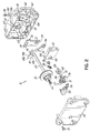
- FIG. 3 is an exploded perspective view of the device of FIG. 1 as viewed from a location behind a casing of the device showing the interaction of various elements.
- the downward movement of the lever arm 40 urges the sliding member 32 downwardly.
- the downward movement of the sliding member 32 is limited by the rotational position of the blocker member 58 .
- the interaction between the rotary element 30 , sliding member 32 , lever arm 40 and the blocker member 58 is described in more detail below.
- FIGS. 6A-6D show the functionality of the device 10 from a front side view. Descriptions of directions such as clockwise and counterclockwise with respect to these FIGS. 6A-6D should be understood to be relative from this front view.
- the lever arm 40 is in the disengaged position and unable to engage with the mechanical detent or recess 66 (shown in hidden lines) of the rotary element 30 .
- the lock bolt 22 is in the locked position and is extending at least partially out of the casing 18 .
- the face gear 56 is in the first position and the blocker member 58 (shown in phantom lines) is in a locking position.
- the first leg 82 biases the first arm 78 in a counterclockwise direction and the second leg 84 biases the second arm 80 in a clockwise direction.
- the counterclockwise bias on the first arm 78 due to the engagement of the first leg 82 , biases the face gear 56 in the counterclockwise direction.
- a first end tooth 57 a of face gear 56 is biased against the worm gear 54 to maintain a mesh therebetween.
- the configuration of the components described in a directional manner may be configured in a manner such that the component moves in an opposite direction as described.
- the worm gear 54 and face gear 56 may be configured such that the face gear 56 rotates in a clockwise direction to rotate from the first to the second positions and in a counterclockwise direction to rotate from the second to the first position.
- a spring clutch (not shown) is utilized. Specifically, the spring clutch is operatively coupled to the face gear 56 and the blocker member 58 in order to rotate the blocker member 58 in the similar or same manner as the torsion spring 60 .
- FIG. 8 shows an exploded diagram of the motor 52 , worm gear 54 , face gear 56 , and blocker member 58 .
- Extending from the rear side of the face gear 56 is a shaft 96 .
- the torsion spring 60 is situated on the shaft 96 and is located between two spring clips 98 a and 98 b that engage with recesses 100 a , 100 b on the shaft 96 .
- the torsion spring 60 is allowed to freely rotate about the shaft 96 with respect to an axis extending along the center of the shaft 96 .
- the blocker member 58 is situated on the shaft 96 .
- the blocker member 58 is allowed to freely rotate about the shaft 96 with respect to the axis extending along the center of the shaft 96 .
- a voltage limiting diode (not shown) is traditionally used to ground excess charge within the primary capacitor bank 226 when the auxiliary capacitor bank 232 is not in use.
- the device 10 will effectively precharge the auxiliary capacitor bank 232 rather than ground excess charge from the primary capacitor bank 226 . More particularly, the device 10 retains energy in the auxiliary capacitor bank 232 by isolating the excess power with the first pass transistor 230 . The excess electricity being generated is sensed by the microcontroller 216 . In this way, the user experience is again enhanced by conserving energy and requiring less rotation of the lock dial 16 to charge the device 10 , especially when activating the electric motor 228 with both the primary and auxiliary capacitor banks 226 , 232 .
- the device 10 may also include “LCD over-modulation” as an added security benefit.
- the display 14 when the display 14 is LCD, the display 14 communicates with an LCD driver module 235 operatively connected to the microcontroller 216 .
- the microcontroller 216 directs the LCD driver module 235 to operate particular LCD segments shown on the LCD display 14 . These LCD segments are “flickered” in rapid succession in order to prevent damage to the LCD display 14 .
Abstract
A device for preventing unwanted opening of a locked enclosure includes a lock bolt moveable between a locked position and an unlocked position. A face gear is meshable with and rotatable by the worm gear between locking and unlocking positions when the worm gear is driven in the first and second directions, respectively. A blocker member is rotatable between first and second positions. A biasing member is operatively coupled to the face gear and the blocker member to bias the blocker member in a biasing direction. A sliding member selectively disengages the blocker member to allow the blocker member to rotate in the biasing direction. A lever arm is operatively coupled to the sliding member such that the lever arm is in the disengaged and engageable positions when the sliding member engages the blocker member in the first and second positions, respectively.
Description
This application is a divisional of application Ser. No. 14/132,117, filed Dec. 18, 2013 (pending) which claims the priority of application Ser. No. 61/739,437 filed Dec. 19, 2012 (expired), the disclosures of which are hereby incorporated by reference herein.
The present invention relates generally to locks, and more specifically, to high security locks adapted for use in safes and other security structures or areas.
Items of extremely sensitive nature or very high proprietary value often must be stored securely in a safe or other containment device, with access to the items restricted to selected individuals given a predetermined combination code necessary to enable authorized unlocking thereof. It is essential to ensure against unauthorized unlocking of such safe containers by persons employing conventional safe-cracking techniques or sophisticated equipment for applying electrical or magnetic fields, high mechanical forces, or accelerations intended to manipulate elements of the locking mechanism to thereby open it.
Numerous locking mechanisms are known which employ various combinations of mechanical, electrical and magnetic elements both to ensure against unauthorized operation and to effect cooperative movements among the elements for authorized locking and unlocking operations.
The present invention, as more fully disclosed hereinbelow, meets these perceived needs at reasonable cost with a geometrically compact, electrically autonomous, locking mechanism.
In accordance with an exemplary embodiment of the present invention, a device for preventing unwanted opening of a locked enclosure is provided. The device includes a lock bolt mounted for movement between a locked position and an unlocked position. A lever arm moveable between disengaged and engageable positions is included and is operatively coupled to the lock bolt to move the lock bolt between the locked and unlocked positions. A rotary element is included and is engageable with the lever arm in the engageable position thereof, wherein rotation of the rotary element when the rotary element is engaged with the lever arm moves the lock bolt between the locked and unlocked positions. A worm gear driven by a motor in first and second directions is also provided. The device also includes a face gear meshable with and rotatable by the worm gear between first and second positions when the worm gear is driven in the first and second directions, respectively. A blocker member is included and is rotatable between locking and unlocking positions. A biasing member is also included and is operatively coupled to the face gear and the blocker member. As such, when the face gear rotates between the first and second position, the biasing member biases the blocker member in a biasing direction. Specifically, the biasing direction is a direction of rotation of the face gear. A sliding member is provided that selectively engages and disengages the blocker member. The sliding member selectively disengages the blocker member to allow the blocker member to rotate in the biasing direction. The lever arm is operatively coupled to the sliding member such that the lever arm is in the disengaged and engageable positions when the sliding member engages with the blocker member in the locking and unlocking positions, respectively.
In an aspect of the invention, a first arm protrudes transversely from a rear side of the face gear and a second arm protrudes transversely from a front side of the blocker member in a direction opposite the first arm. The first and second arms interact with the biasing member to rotate the blocker member.
According to another exemplary embodiment of the present invention, a self-powered lock is provided. The self-powered lock includes a lock operable by a motor. The self-powered lock also provides a manually operable electricity generator generating electricity upon manual actuation by a user, the electricity being used to supply power input to a controller. An electricity storage device storing electricity generated by the electricity generator is provided. The controller determines a required amount of electricity to operate the motor and supplies electricity to the motor from the electricity storage device according to the required amount.
Another exemplary embodiment of the present invention is a self-powered lock including a lock operable by a motor. Also provided is a manually operable electricity generator generating electricity upon manual actuation by a user, the electricity being used to supply power input to a controller. An electricity storage device storing electricity generated by the electricity generator is provided. At least a portion of the electricity stored by the electricity storage device is used when the lock is operated. The electricity storage device is configured to store an unused portion of electricity after the lock is operated. The unused portion of electricity is usable for a subsequent lock operation to supply power input to the controller.
In accordance with the present invention, yet another exemplary embodiment of a self-powered lock includes a lock operable by a motor. A controller operative to supply electricity to the motor is provided. Also provided is a manually operable electricity generator operative to generate electricity upon manual actuation by a user. The electricity is used to supply power input to the controller. An electricity storage device operatively coupled to the electricity generator is provided. A rotatable lock dial coupled with the electricity generator to generate electricity upon rotation of the lock dial is also provided. In addition, a sensor sensing a rate of rotation of the lock dial is operatively coupled with the controller. The controller determines whether the lock dial is being rotated with an automated device. When the controller determines that the lock dial is being rotated with an automated device, the controller maintains the lock in a locked position regardless of whether a correct lock combination is input.
A further exemplary embodiment of the self-powered lock according to the present invention includes a lock operable by a motor and a display device operable to display information regarding the lock to a user. The lock also includes a manually operable electricity generator generating electricity upon manual actuation by the user. The electricity generator is electrically connected to the display device and the motor to supply electricity thereto for operating the lock and the display device.
A method of moving a lock bolt between locked and unlocked positions is provided in accordance with the present invention. The lock bolt is coupled to a lever arm moveable between engageable and disengageable positions. The lever arm is operatively coupled to a sliding member. The method includes driving a worm gear with a motor in a first direction, thereby rotating a face gear from a locking to an unlocking position. The method further includes biasing a blocker member with a biasing member in a biasing direction, the biasing direction being the direction of rotation of the face gear. As such, the biasing member interacts with the face gear and the blocker member. The method further provides preventing the rotation of the blocker member between locking and unlocking positions by a selective engagement between the blocker member and a sliding member, wherein the lever arm is in the disengaged and engageable positions when the sliding member engages the blocker member in the locking and unlocking positions, respectively. The method further provides releasing the selective engagement by an upward movement of the sliding member to rotate the blocker member in the biasing direction to the second position. As such, a user rotates a rotary element to cause upward movement by the lever arm interacting with the rotary element. Furthermore, the method provides that the rotary element is further rotated by the user to cause an engagement between the lever arm and the rotary element and downwardly move the sliding member, thereby reengaging the selective engagement. Further rotation of the rotary element after the engagement moves the lock bolt into the unlocked position.
In an aspect of the invention, the method provides driving the worm gear with the motor in a second direction, thereby rotating the face gear from the unlocking to the locking position. The method also provides biasing the blocker member with the biasing member in the biasing direction. Furthermore, the method provides moving the lock bolt to the locking position when the user rotates the rotary element in a direction opposite the direction of rotation to move the lock bolt to the unlocking position, thereby moving the lever arm to the disengaged position. The lever arm moving to the disengaged position releases the selective engagement, thereby rotating the blocker member in the biasing direction back to the first position. The method also provides reengaging the selective engagement when the blocker member is in the first position.
A method of providing sufficient electricity to a motor operating a lock is also provided according to an exemplary embodiment of the invention. The method provides generating electricity upon manual actuation of a manually operable electricity generator by a user and storing the generated electricity with a first electricity storage device. Furthermore, the method provides determining a required amount of electricity to operate the motor via a controller and supplying electricity to the motor from the first electricity storage device according to the required amount.
A method of preventing an automated device from inputting a correct lock combination of a lock is provided in accordance with another exemplary embodiment of the invention. The method provides sensing the rotation of a lock dial with a sensor and communicating sensed rotation from the sensor to a controller. Furthermore, the method provides determining whether the lock dial is being rotated with the automated device via the controller. Accordingly, when the controller determines that the lock dial is being rotated with the automated device, the controller maintains the lock in a locked position regardless of inputting the correct lock combination.
A further exemplary embodiment of the invention provides a method of powering a lock having a manually operable electricity generator electrically connected to a motor and a display device. The method provides generating electricity upon manual actuation of the electricity generator and supplying electricity generated by the electricity generator to the motor for operating the lock. The method also provides supplying electricity generated by the electricity generator to the display device for displaying information regarding the lock to a user.
Various additional objectives, advantages, and features of the invention will be appreciated from a review of the following detailed description of the illustrative embodiments taken in conjunction with the accompanying drawings.
The accompanying drawings, which are incorporated in and constitute a part of this specification, illustrate embodiments of the invention and, together with a general description of the invention given above, and the detailed description given below, serve to explain the invention.
As best seen in FIG. 1 , a device 10 for preventing unwanted opening of a locked enclosure according to a preferred embodiment of this invention has an external user-accessible hub 12 conveniently provided with a display 14 and a manually rotatable combination input knob or dial 16. Hub 12 is attached to the casing 18 in any known manner. Alternatively, there may be an access apparatus such as a door disposed between the hub 12 and a casing 18.
An aperture 24 extends through the entire thickness of casing 18 to closely accommodate therein shaft 26 extending from combination-input knob 16 (see FIG. 1 ) into a space 28 defined inside casing 18. In casing 18, there is provided an annular journal bearing 25 to closely receive and rotatably support shaft 26 via rotary element 30 projecting therethrough and into space 28.
A sliding member 32 is provided which has a cam notch 34 at a superior portion, and a flat bottom portion 94 at the bottom end. The sliding member 32 includes an elongate aperture 33. The elongate aperture 33 provides clearance for a case stud 36 which is affixed to the casing 18 and coupled to an extension spring 38. The spring 38 couples to a lever arm 40 at a lever stud 42 by case stud 36. As discussed below in more detail, lever arm 40 includes a lateral pin 44 (see FIGS. 5A-5F ) that travels within cam notch 34 of sliding member 32. The lever arm 40 includes a circular aperture 46 at one end and a hook 47 at the other end. The hook 47 has contiguous portions 47 a, 47 b and 47 c. The lock bolt 22 has a pin (not shown) which receives the end of the lever arm 40 having the circular aperture 46 whereat the lever arm 40 is pivotably fixed such that the circular aperture 46 is situated concentrically relative to a pivot mounting aperture 48 of the lock bolt 22. The lever arm 40 is pivotable to engage with a mechanical detent or recess 66 (see FIGS. 5A-5F ) of the rotary element 30, as explained below in further detail.
As seen in FIGS. 3-4 , a shaft 26, rotatable by knob 16 (see FIG. 1 ), extends into casing 18. The lock bolt 22 is slidably supported by casing 18 to be projected outwardly into a locking position, or to be retracted substantially within casing 18 to an unlocking position, upon appropriate manual operation of combination-input knob 16 (see FIG. 1 ) by a user. Casing 18 is provided with a detachable back wall 50, fixed to the remaining portion of casing 18 by fasteners 51, which also serve to provide support to various components of the device 10 according to this invention.
A motor 52 and a worm gear 54 are provided. The worm gear 54 is meshable with and rotates a face gear 56. A blocker member 58 is operatively coupled to the face gear 56 by a torsion spring 60, the interaction of which is explained in more detail below with respect to FIGS. 7A-7G . As further shown in FIGS. 3-4 , shroud 72 envelops the motor 52, worm gear 54 and face gear 56 (see FIG. 3 ). Fastener 31 engages with aperture 53 in a shaft 96 in order to fix the shroud 72 relative to the shaft 96 and thereby the casing 18. Shroud 72 assists in maintaining the position of motor 52 and also provides protection against access to the motor 52 and worm gear 54 through the back wall 50.
As shown in FIG. 3 , an end portion of shaft 26 which extends into casing 18, preferably has a square cross-section, to which is mounted the rotary element 30 via the matchingly shaped and sized central fitting aperture 24 (see FIG. 2 ). Accordingly, when the user of the safe manually applies a torque to the combination-input knob 16 (see FIG. 1 ), torque transmits to shaft 26 to thereby forcibly rotate rotary element 30. Fastener 29 fixes the rotary element 30 relative to the shaft 26. A split ring (not shown), for example, may be utilized to retain the rotary element 30 to shaft 26 in a known manner. Other known techniques or structures for retaining the rotary element 30 may be used. By this arrangement there is readily available, through rotary element 30, a manually provided torque at a point inside space 28 of casing 18, i.e., within the secure containment space 28 inside a locked enclosure.
As shown in FIG. 5A , the lever arm 40 is in the disengaged position, unable to move downwardly to thereby engage with the mechanical detent 66 provided on rotary element 30. When the blocker member 58 is in the second position, the sliding member 32 has the freedom to move further down. In addition, because of the manner of coupling with lever arm 40, the hook 47 of lever arm 40 is allowed to move under the load from extension spring 38 into the engageable position with recess 66 of rotary element 30. As the rotary element 30 is rotated clockwise (as viewed from a back view as shown in FIGS. 5A-5F ) when the lever arm 40 is in the disengaged position as shown in FIG. 5C , the hook 47 of the lever arm 40, under loading from extension spring 38, interacts with a cam surface 45 of rotary element 30. In turn, the lever arm 40 raises and the sliding member 32 moves in an upwards direction as indicated by arrow 68. This allows the blocker member 58 to rotate to an unlocking position. When the lever arm 40 moves to the engageable position (see FIG. 5D ), the hook 47 of the lever arm 40 interacts with cammed surface 45 of the rotary element 30 in a cammed relationship until the user rotates the rotary element 30 to the point where the hook 47 may engage the mechanical detent 66 of the rotary element 30, as shown in FIG. 5D . The movement of the lever arm 40 into the engageable position depends on the position of the sliding member 32 relative to the blocker member 58.
Specifically, cam notch 34 at the upper distal end of sliding member 32 engages with lateral pin 44 of lever arm 40. As shown in FIGS. 5A-5D extension spring 38 keeps a biasing force on the lever arm 40 in the downward direction. The coupling described above between lever arm 40 and sliding member 32 ensures that sliding member 32 follows the vertical movement of lever arm 40 but, due to the interaction between sliding member 32 and blocker member 58, that range of motion is restricted when the blocker member 58 is in the locking position. Because of the limited range of motion of lever arm 40 when the blocker member 58 is in the locking position, the hook 47 of lever arm 40 will only make contact with a portion of the cam surface 45 of rotary element 30. This is done in order to raise the sliding member 32 and release pressure off the blocker member 58, thereby allowing the blocker member 58 to move under any biasing load caused by the torsion spring 60 and the particular orientation of the face gear 56. Once the blocker member 58 is in the unlocking position, the hook 47 of lever arm 40 is free to follow all portions of cam surface 45. When the hook 47 reaches the recess 66, from external input rotation of the rotary element 30, it will positively engage with the recess 66 as shown in FIG. 5D .
More specifically, force transmitting through the sliding member 32, the fixed cam portion 64, the outside edge portions 47 a, 47 b, 47 c of lever arm 40, and the hook 47 with mechanical detent 66 leads to a manually-provided force being transmitted to forcibly draw lock bolt 22 into casing 18 in the direction of arrows 70 as shown in FIG. 5E . Ultimately, lock bolt 22 becomes substantially drawn into casing 18 to its unlocked position. As shown in FIG. 5F , when the user desires to move the lock bolt 22 back to the locked position from the unlocked position, the user may rotate the lock dial 16 (see FIG. 1 ) to rotate the rotary element 30 in the counterclockwise direction. The counterclockwise rotation causes the lever arm 40 to move in the direction as indicated by arrows 71 and to eventually disengage from the recess 66 of the rotary element 30. This movement of the lever arm 40 moves the lock bolt 22 back to the locked position, wherein the lock bolt 22 is extending at least partially out of the casing 18. Depending on the rotational position of the rotary element 30 relative to the hook 47, after the user rotates the lock dial 16 (see FIG. 1 ) in the counterclockwise direction to move the lock bolt 22 to the locked position, the lever arm 40 and sliding member 32 will essentially be configured as shown in FIGS. 5A-5B .
Referring to FIG. 6C , the face gear 56 remains in the second position. As rotary element 30 has been even further rotated in the counterclockwise direction, hook 47 of lever arm 40 engages with the recess 66 of the rotary element 30. This engagement is caused by the biasing load of extension spring 38, and the downward movement of both the lever arm 40 and the sliding member 32 is allowed because the blocker member 58 is in the second position as described above with respect to FIGS. 5A-5E . However, the downward movement of the sliding member 32 is limited by the position of the blocker member 58, as described below with respect to FIGS. 7A-7G .
As shown in FIG. 6D , when the user desires to move the lock bolt 22 back to the locked position from the unlocked position, the user may rotate the lock dial 16 (see FIG. 1 ) and, in turn, rotate the rotary element 30 in the clockwise direction. The clockwise rotation causes the lever arm 40 to move in the direction as indicated by the arrows 77 and to eventually disengage from the recess 66 of the rotary element 30. This movement of the lever arm 40 moves the lock bolt 22 back to the locked position, wherein the lock bolt 22 is extending at least partially out of the casing 18. Depending on the rotational position of the rotary element 30 relative to the hook 47, after the user rotates the lock dial 16 (see FIG. 1 ) in the clockwise direction to move the lock bolt 22 to the locked position, the lever arm 40 and sliding member 32 will essentially be configured as shown in FIGS. 6A-6B .
In the configuration as shown in FIG. 7A , the first leg 82 biases the first arm 78 in a counterclockwise direction and the second leg 84 biases the second arm 80 in a clockwise direction. The counterclockwise bias on the first arm 78, due to the engagement of the first leg 82, biases the face gear 56 in the counterclockwise direction. Specifically, in the first position, a first end tooth 57 a of face gear 56 is biased against the worm gear 54 to maintain a mesh therebetween. Because the face gear 56 is a sector gear containing a plurality of teeth 57 along only a portion of the circumference thereof, the bias in the counterclockwise direction assists in maintaining a mesh between the worm gear 54 and the face gear 56 when the face gear 56 is in the locking position. Specifically, when the worm gear 54 threads have run off either end of the first end tooth 57 a or a second end tooth 57 b of the face gear 56, the mesh has been exited. The bias from torsion spring 60 is to promote the maintenance of mesh by a reentry or reengaging of the mesh between worm gear 54 and teeth 57 of face gear 56 when the motor 52 rotates the worm gear 54 in the appropriate direction. This configuration is particularly advantageous because it allows the motor 52 to overrun multiple rotations without a stall condition since, in a preferred embodiment, power is applied to the motor 52 during a fixed time interval. The configuration of first and second end teeth 57 a, 57 b relative to the torsion spring 60 is such that the amount of bias on the blocker member 58 when the blocker member 58 is in the locking and unlocking positions is controlled. The configurations of the sliding member 32, lever arm 40 and rotary element 30 that correspond with the positions of the worm gear 54, blocker member 58 and torsion spring 60 as shown in FIG. 7A are shown in FIGS. 5A and 6A .
With reference to FIG. 7C , after the face gear 56 has rotated to the second position, due to the engagement of the second leg 84 and first arm 78, the second leg 84 creates a bias on the first arm 78 to rotate the face gear 56 in the clockwise direction. The clockwise bias on the face gear 56 assists in maintaining a mesh between the face gear 56 and worm gear 54 when the face gear 56 is in the second position. Specifically, in this configuration, second end tooth 57 b of face gear 56 is biased against the worm gear 54 thereby maintaining a bias therebetween. More specifically, the spring bias from torsion spring 60 maintains a mesh between the second end tooth 57 b and worm gear 54 by reengaging the mesh therebetween after a disengagement of mesh.
As shown in FIG. 7D , due to the counterclockwise bias from the first leg 82 on the second arm 80 and thus the blocker member 58, when the sliding member 32 disengages from the blocker member 58, the blocker member 58 rotates counterclockwise to reach an unlocking position. The rotation of the blocker member 58 to the unlocking position is limited due to the engagement between a protrusion 86 on the blocker member 58 and a second stop 90 of the casing 18. This engagement prevents the blocker member 58 from rotating further in the counterclockwise direction. As discussed above, the lever arm 40 follows the cammed surface 45 of rotary element 30 in a cammed relationship, but, before the hook 47 engages the mechanical detent or recess 66, the sliding member 32 is prevented from moving downward. As such, the sliding member 32 is prevented from re-engaging the blocker member 58. After the hook 47 of the lever arm 40 engages the mechanical detent or recess 66 of the rotary element 30, sliding member 32 is able to move in a downward direction relative to and towards the blocker member 58. Further rotation of the rotary element 30 by rotation of the lock dial 16 (see FIG. 1 ) moves the lock bolt 22 from the locked to the unlocked position, where the lock bolt 22 is retracted into the casing 18 in the unlocked position. The sliding member 32 includes the bottom portion 94 preferably having a shape complementary to a flat cam portion 92 of the blocker member 58. The engagement of the bottom portion 94 of the sliding member 32 and the flat cam portion 92 of the blocker member 58 causes the blocker member 58 to rotate in the clockwise direction a distance, indicated by the letter “D,” away from the unlocking position, as shown in FIGS. 7E-7F .
After a predetermined period of time, electricity is provided to the motor 52 to thereby rotate the worm gear 54 in the second direction, thereby rotating the face gear 56 in the clockwise direction back to the first position as shown in FIG. 7F . Alternatively, a sensor (not shown) is provided to detect the position of the lock bolt 22 and communicate with the motor 52 through a controller, such as a microcontroller 216 (see FIG. 12 ), to thereby drive the worm gear 54 based on the position of the lock bolt 22. By way of example, the sensor may sense whether the user has driven the lock bolt 22 into the unlocked position as described above. Upon sensing that the lock bolt 22 is in the unlocked position, the sensor may communicate with the controller to thereby supply power to the motor 52, thereby driving the worm gear 54 in a second direction, the second direction being opposite to the first direction and thereby rotating the face gear 56 from the second to the first position.
As the face gear 56 rotates from the second position to the first position, the first arm 78 engages with the first leg 82, thereby rotating the first leg 82 therewith. The rotation of the first leg 82 causes the second leg 84 to rotate in the clockwise direction, whereby the second leg 84 engages with the second arm 80. Further rotation of the second leg 84 is prevented due to the engagement with the second arm 80, which prevents further rotation in the clockwise direction due to the engagement of the bottom portion 94 of the sliding member 32 with the flat cam portion 92 of the blocker member 58. In this configuration, due to the relative movement and position between the first and second legs 82, 84 of the torsion spring 60, the first leg 82 biases the first arm 78 in a counterclockwise direction and the second leg 84 biases the second arm 80 in a clockwise direction.
As discussed above with respect to FIGS. 5A-5F and 6A-6D and as further shown in FIG. 7 , the user rotates the lock dial 16 (see FIG. 1 ) in a clockwise direction to rotate the rotary element 30 and the lock bolt 22 moves from the unlocked position to the locked position. Accordingly, the hook 47 disengages in an upward direction from the mechanical detent or recess 66 of the rotary element 30. Further rotation of the rotary element 30 causes the hook 47 to again interact with the cammed surface 45 of the rotary element 30 in a cammed relationship. The upward movement of the lever arm 40 causes the sliding member 32 to move in an upward direction due to the coupled relationship between the lever arm 40 and the sliding member 32. The upward motion of the sliding member 32 disengages the sliding member 32 from the blocker member 58. Due to the bias on the second arm 80 by the second leg 84 in the clockwise direction, the disengagement of the sliding member 32 from the blocker member 58 allows the blocker member 58 to rotate in the clockwise direction to the locking position. The rotation to the locking position in the clockwise direction is limited by the engagement of the protrusion 86 of the blocker member 58 with the first stop 88. As discussed previously with respect to FIG. 7A , when the face gear 56 is in the first position and the blocker member 58 is in the locking position, the first leg 82 biases the first arm 78 in a counterclockwise direction and the second leg 84 biases the second arm 80 in a clockwise direction.
Many of the movements of components have been described directionally, for example, to move in a counterclockwise or clockwise direction. Persons skilled in the art will appreciate that the configuration of the components described in a directional manner may be configured in a manner such that the component moves in an opposite direction as described. By way of example, in an alternative embodiment, the worm gear 54 and face gear 56 may be configured such that the face gear 56 rotates in a clockwise direction to rotate from the first to the second positions and in a counterclockwise direction to rotate from the second to the first position.
In an alternative embodiment, rather than utilizing the torsion spring 60 as the biasing member, a spring clutch (not shown) is utilized. Specifically, the spring clutch is operatively coupled to the face gear 56 and the blocker member 58 in order to rotate the blocker member 58 in the similar or same manner as the torsion spring 60.
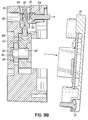
Referring to FIGS. 9A and 9B , the lock further includes a relock mechanism 102 which prevents movement of the lock bolt 22 from the locked to the unlocked position when the lock is tampered with or compromised in any manner. The relock mechanism 102 comprises a first pin 104 coupled to the back wall 50 of the casing 18. The first pin 104 is coupled to a spring-biased second pin 106 in a configuration that prevents a movement of the second pin 106 in the direction of the spring bias. The second pin 106 is situated above an aperture 108 in a superior portion of the lock bolt 22. In a preferred embodiment, the second pin 106 contains a recess 110 for accepting the free end 112 of the first pin 104. The free end 112 of the first pin 104 is preferably shaped according to the shape of the recess 110 in order to provide a complimentary fit between the first and second pins 104, 106. Different shapes of the recess 110 of the second pin 106 and free end 112 of the first pin 104 are contemplated in order to provide alternative coupling configurations between the first and second pins 104, 106. The first and second pins 104, 106, before the back wall 50 of casing 18 have been tampered with, are preferably situated essentially perpendicular to one another, whereby the first pin 104 prevents a movement of the second pin 106 that is perpendicular to the first pin 104.
When the back wall 50 is tampered with, such, when the back wall 50 is at least partially removed, the first pin 104 decouples from the second pin 106. Due to the spring bias on the second pin 106 by a spring 114, the second pin 106 moves in the direction of the spring bias. Preferably, the second pin 106 is biased downwards towards the aperture 108 of the lock bolt 22 and in a direction perpendicular to the movement of the lock bolt 22 and enters the aperture 108 of the lock bolt 22 after being decoupled from the first pin 104. Alternatively, the second pin 106 could be suspended elsewhere within the casing 18 with respect to the lock bolt 22. For example, the second pin 106 may be suspended on a wall other than the back wall 50. As such, the aperture 108 in the lock bolt 22 would be situated to thereby allow the second pin 106 to enter the aperture 108 when the casing 18 is tampered with. The second pin 106 is manufactured with material properties that would enable it to resist the movement of the lock bolt 22 from the locked to the unlocked position.
Referring to FIG. 11 , an alternative embodiment of a device 10′ includes the lock dial 16 and a display 14′. In this embodiment, the display 14′ is front facing. The display 14′ is configured to be facing frontwards for ease of use reasons. For example, the front facing display 14′ is advantageous in situations such as where the lock is disposed on a safe that is in an elevated position. Some users may not be tall enough to see the upwardly facing display in such a situation. Therefore, it is advantageous to provide the front facing display 14′ for such a situation.
Furthermore, the generator 224 is operatively connected to the LCD display 14 having an LED backlight. The circuit 200 further includes an interface PCB & LED backlight drive circuit 201. The generator 224 provides electricity to the LED backlight of the LCD display 14 as well as the microcontroller 216, which provides LCD control signals to an LCD driver module 235. As such, the LCD driver module 235 provides LCD drive signals to the LCD display 14. However, the LCD drive signals and the LED backlight drive are powered independently from each other via the generator 224.
More specifically, according to FIG. 12 and FIGS. 13A-13D , rotation of the lock dial 16 in either the clockwise (CW) or counterclockwise (CCW) direction generates power for storage in the primary capacitor bank 226 via the generator 224. For reference, the rotation CW or CCW with respect to FIGS. 13A-13D is in relation to the user viewing the front of the lock dial 16. On initial power up, the primary and auxiliary capacitor banks 226, 232 are discharged. As the user turns the lock dial 16, generated AC power is rectified into DC pulses. The DC pulses charge the primary capacitor bank 226. The DC pulses are detected by the generator pulse detector 236, which turns on the second pass transistor 237 with each DC pulse. The voltage of the primary capacitor bank 226 is communicated to the voltage detector 238. Generally, the initial voltage charge will not exceed a threshold voltage limit of the voltage detector 238 until the user turns the lock dial 16 to generate sufficient voltage. Once the voltage exceeds the threshold voltage limit, the third pass transistor 239 is turned on. Accordingly, the primary capacitor bank 226 directs stored charge to the voltage regulator 240 and powers on the microcontroller 216. The microcontroller 216 then turns on the third pass transistor 239 for directing power to the microcontroller 216 even if rotation of the lock dial 16 ceases for some period of time. As rotation of the lock dial 16 continues, the microcontroller 216 monitors the voltage of the primary capacitor bank 226 in order to display user prompts and continue operation as described below. In addition, the primary capacitor bank 226 is electrically connected to the microcontroller 216 and the electric motor 228. However, the auxiliary capacitor bank 232 is also electrically connected to the electric motor 228 via the first pass transistor 230 for providing additional power in cold temperature conditions, such as below 32° F., the purpose of which will be described below in more detail.
The lock dial 16 is rotated until a minimum voltage is detected by the microcontroller 216. According to the exemplary embodiment, an analog-to-digital converter (not shown) is manufactured into the microcontroller 216 to detect, or otherwise sense, voltage. However, it will be appreciated that any device or method of detecting voltage may similarly be used. In any case, once the minimum voltage, such as 5 volts, is detected from the primary capacitor bank 226, the display 14 indicates for the user to dial left, i.e., CCW. Should the user dial CCW, the user may input a combination as described below. However, should the user dial right, i.e., CW, the display 14 indicates an audit count. The user may repeat dialing right to indicate both the firmware level and repeat again for the firmware date on the display 14.
Once the user initiates the CCW rotation of the lock dial 16, the microcontroller 216 obtains the value of P from memory. If P has a value of 3 or greater, the display 14 indicates this value. At this point, the device 10 initiates detection of the ambient temperature via a temperature sensor 231 operatively connected to the microcontroller 216. The microcontroller 216 compares the measured ambient temperature to a predetermined temperature at which the effects of ESR diminish the ability of the primary capacitor bank 226 to operate the electric motor 228, otherwise referred to herein as the ESR threshold temperature. Regardless of whether or not the ambient temperature is above the ESR threshold temperature, the generator 224 electrically charges the primary capacitor bank 226.
In the event that the measured ambient temperature is below the ESR threshold temperature, the microcontroller 216 operates the first pass transistor 230 and charges both the primary and auxiliary capacitor banks 226, 232. The microcontroller 216 then senses the voltage stored in the available capacitor banks. In other words, depending on the ambient temperature, the generator 224 charges the primary capacitor bank 226 or both primary and auxiliary capacitor banks 226, 232, in anticipation of operating the device 10. In addition, the microcontroller 216 continues to sense the voltage charge in the available capacitor banks throughout the operation of the device 10. Should the detected voltage drop below the predetermined charge value for the ambient temperature, the display 14 will indicate for the user to either dial right or dial left, depending on the status of the operation. In this way, the device 10 will remain charged throughout the operation of the device 10 shown in FIGS. 13A-13D .
Once the microcontroller 216 detects the ambient temperature and accommodates for any effect of ESR as directed above, the microcontroller 216 initializes a loop timer and obtains X, Y, and Z values from memory. After verifying the detected voltage and detecting that CCW rotation has stopped and CW rotation has begun, then the microcontroller 216 stores the entered dial value at the stop as X1. This process is repeated to obtain values for Y1 and Z1. Next, the microcontroller 216 verifies if the entered values X1, Y1, Z1 match the proper combination values X, Y, Z. If the values match, the operation will proceed as described below. If the values do not match or the entire combination was entered in less than ten seconds, the display 14 will indicate a lightning bolt, P will be increased, and the lock will power off. This may be generally referred to as an entry error. In addition, the device will shutdown, or otherwise timeout, without error if the user's time between inputting the combination values X1, Y1, Z1 exceeds 40 seconds. However, if the user's total time to input the combination is greater than 180 seconds, the entry will again be treated as an entry error.
With the entries correct and the device 10 charged, the microcontroller 216 again senses the ambient temperature to determine whether cold temperature conditions are present. If the ambient temperature is above the ESR threshold temperature, the primary capacitor bank 226 is operatively connected to the electric motor 228. The microcontroller 216 then verifies the amount of charge in the primary capacitor bank 226 before finally discharging the primary capacitor bank 226 and activating the electric motor 228. If the ambient temperature is below the ESR threshold temperature, both the primary capacitor bank 226 and the auxiliary capacitor bank 232 are operatively connected to the electric motor 228 via the first pass transistor 230. The microcontroller 216 then verifies the amount of charge in the available capacitor banks before finally discharging each of the available capacitor banks and activating the electric motor 228. Finally, the display 14 indicates for the user to open to the right so that the lock bolt 22 (see FIG. 3 ) may be retracted by the user.
Furthermore, the device 10 also conserves power while powered off. Specifically, the microcontroller 216 will turn off the third pass transistor 239. This deprives the voltage regulator 240 of power, which, consequently, turns off the microcontroller 216. Given that the third pass transistor 239 is biased to be turned off, minimal current flows from either of the primary and auxiliary capacitor banks 226, 232. Thus, the primary and auxiliary capacitor banks 226, 232 retain charge for longer periods of time. On subsequent power up, energy is more likely to be retained in the primary and auxiliary capacitor banks 226, 232 depending on the elapsed time since the previous operation of the device 10. For instance, the device 10 may power on in as little as one rotation of the lock dial 16. In any case, this enhances the user experience by conserving energy and requiring less rotation of the lock dial 16 to charge the device 10 than would otherwise be necessary.
With regard to conserving excess charge produced by the generator 224, a voltage limiting diode (not shown) is traditionally used to ground excess charge within the primary capacitor bank 226 when the auxiliary capacitor bank 232 is not in use. However, the device 10 will effectively precharge the auxiliary capacitor bank 232 rather than ground excess charge from the primary capacitor bank 226. More particularly, the device 10 retains energy in the auxiliary capacitor bank 232 by isolating the excess power with the first pass transistor 230. The excess electricity being generated is sensed by the microcontroller 216. In this way, the user experience is again enhanced by conserving energy and requiring less rotation of the lock dial 16 to charge the device 10, especially when activating the electric motor 228 with both the primary and auxiliary capacitor banks 226, 232.
For instance, when the ambient temperature is above the ESR threshold temperature, the microcontroller 216 will pulse the first pass transistor 230 both on and off in order to precharge the auxiliary capacitor bank 232. Specifically, when the first pass transistor 230 is off, the generator 224 does not charge the auxiliary capacitor bank 232. When the first pass transistor 230 is on, the generator 224 charges the auxiliary capacitor bank 232. The first pass transistor 230 is pulsed on when the primary capacitor bank 226 is above a predetermined charge and pulsed off when the primary capacitor bank 226 is below the predetermined charge. For example, the predetermined minimum charge may be 9 volts. However, when both the primary and auxiliary capacitor banks 226, 232 are equal to the predetermined charge, the voltage limiting diode (not shown) grounds the excess charge.
The device 10 may also include “LCD over-modulation” as an added security benefit. Specifically, when the display 14 is LCD, the display 14 communicates with an LCD driver module 235 operatively connected to the microcontroller 216. Traditionally, the microcontroller 216 directs the LCD driver module 235 to operate particular LCD segments shown on the LCD display 14. These LCD segments are “flickered” in rapid succession in order to prevent damage to the LCD display 14. However, the rate of this rapid flicker is traditionally determined by the clock signal of the microcontroller 216, which, according to an exemplary embodiment, may vary between 125 kHz and 899 kHz. For example, the number N=25 may always display at a clock signal frequency of 250 kHz for a traditional display. However, according to an exemplary embodiment of the device 10, the LCD driver module 235 is configured to receive the data from the microcontroller 216 and convert the clock signal to a unique clock signal representative of the intended number. Going further, the LCD driver module 235 randomizes the unique clock signal for any given number. For example, the number “25” may display once at 862 kHz and another time at 125 kHz. In this way, any attempts to detect the frequency of the LCD display 14 will result in a wide array of detected frequencies; thus, making it more difficult to tie a particular frequency to a particular number.
Finally, the above operation of the device 10 uses a traditional three-number entry sequence. It will be appreciated that the device 10 may also be operated according to a dual combination mode or a supervisor/subordinate mode. Furthermore, while the present invention has been illustrated by the description of one or more embodiments thereof, and while the embodiments have been described in considerable detail, they are not intended to restrict or in any way limit the scope of the appended claims to such detail. The various features shown and described herein may be used alone or in any combination. Additional advantages and modifications will readily appear to those skilled in the art. The invention in its broader aspects is therefore not limited to the specific details, representative apparatus and method and illustrative examples shown and described. Accordingly, departures may be from such details without departing from the scope of the general inventive concept.
Claims (14)
1. A self-powered lock, comprising;
a lock operable by a motor;
a display device operable to display information regarding the lock to a user;
a manually operable electricity generator generating electricity upon manual actuation by the user, the electricity generator electrically connected to the display device and the motor to supply electricity thereto for operating the lock and the display device;
a lock bolt mounted for movement between a locked position and an unlocked position;
a lever arm moveable between disengaged and engageable positions and operatively coupled to the lock bolt to move the lock bolt between the locked and unlocked positions;
a rotary element engageable with the lever arm in the engageable position thereof, wherein rotation of the rotary element when the rotary element is engaged with the lever arm moves the lock bolt between the locked and unlocked positions;
a worm gear driven by the motor in a first direction and a second direction;
a face gear meshable with and rotatable by the worm gear between first and second positions when the worm gear is driven in the first and second directions, respectively;
a blocker member rotatable between a locking position and an unlocking position;
a biasing member operatively coupled to the face gear and the blocker member, wherein when the face gear rotates between the first and second positions, the biasing member biases the blocker member in an biasing direction, the biasing direction being a direction of rotation of the face gear; and
a sliding member selectively engaging and disengaging the blocker member, wherein the sliding member selectively disengaging the blocker member allows the blocker member to rotate in the biasing direction, and the lever arm is operatively coupled to the sliding member such that the lever arm is in the disengaged and engageable positions when the sliding member engages with the blocker member in the locking and unlocking positions, respectively.
2. The self-powered lock of claim 1 , wherein the display device further includes a display and a backlight, the display operable to display the information and the backlight operable to direct light on the display, and the electricity generator is electrically connected to the backlight.
3. The self-powered lock of claim 2 , further comprising:
a filtering device covering at least a portion of the display, the filtering device adapted to prevent a viewing of the display from a plurality of angles.
4. The self-powered lock of claim 2 , wherein the electricity generator is electrically connected to the display.
5. The self-powered lock of claim 2 , wherein the display is a liquid crystal display and the backlight is a light emitting diode.
6. The self-powered lock of claim 5 , wherein the light emitting diode and the liquid crystal display are embedded in an at least semitransparent medium.
7. The self-powered lock of claim 6 , wherein the at least semitransparent medium is epoxy.
8. The self-powered lock of claim 1 , wherein the information displayed is at least one of a dialing combination, a dialing direction, and an operational menu.
9. The self-powered lock of claim 1 further comprising:
an electricity storage device electrically connected between the electricity generator and the display device and between the electricity generator and the motor, the electricity storage device configured to store electricity received from the electricity generator and selectively and simultaneously supply electricity to the display device and the motor.
10. The self-powered lock of claim 9 , wherein the electricity storage device is configured to regulate the electricity supplied to the display device such that at least a portion of the display device remains operational for a period of time after power generation stops.
11. The self-powered lock of claim 1 , further comprising:
a controller electrically connected between the electricity generator and the display device, the controller configured to supply a randomized clock signal to the display device.
12. The self-powered lock of claim 1 , further comprising:
a controller; and
a first electricity storage device storing electricity generated by the electricity generator,
wherein the controller determines a required amount of electricity to operate the motor and supplies electricity to the motor from the first electricity storage device according to a required amount.
13. The self-powered lock of claim 1 , further comprising:
a controller; and
an electricity storage device storing electricity generated by the electricity generator,
wherein at least a portion of the electricity stored by the electricity storage device is used when the lock is operated,
wherein the electricity storage device is configured to store an unused portion of electricity after the lock is operated, the unused portion of electricity usable for a subsequent lock operation to supply power input to the controller.
14. The self-powered lock of claim 1 , further comprising:
a controller operative to supply electricity to the motor;
an electricity storage device operatively coupled to the electricity generator;
a rotatable lock dial coupled with the electricity generator to generate electricity upon rotation of the lock dial; and
a sensor sensing a rate of rotation of the lock dial and operatively coupled with the controller,
wherein the controller determines whether the lock dial is being rotated with an automated device,
wherein when the controller determines that the lock dial is being rotated with the automated device, the controller maintains the lock in a locked position regardless of whether a correct lock combination is input.
Priority Applications (7)
| Application Number | Priority Date | Filing Date | Title |
|---|---|---|---|
| US14/739,376 US9816294B2 (en) | 2012-12-19 | 2015-06-15 | Device and methods for preventing unwanted access to a locked enclosure |
| US15/212,618 US10190335B2 (en) | 2012-12-19 | 2016-07-18 | Methods for preventing unwanted access to a locked enclosure |
| US15/798,985 US10550604B2 (en) | 2012-12-19 | 2017-10-31 | Device and methods for preventing unwanted access to a locked enclosure |
| US15/798,974 US10557285B2 (en) | 2012-12-19 | 2017-10-31 | Device and methods for preventing unwanted access to a locked enclosure |
| US16/697,001 US11499342B2 (en) | 2012-12-19 | 2019-11-26 | Device and methods for preventing unwanted access to a locked enclosure |
| US16/697,006 US11613911B2 (en) | 2012-12-19 | 2019-11-26 | Device and methods for preventing unwanted access to a locked enclosure |
| US18/117,856 US11913255B2 (en) | 2012-12-19 | 2023-03-06 | Device and methods for preventing unwanted access to a locked enclosure |
Applications Claiming Priority (3)
| Application Number | Priority Date | Filing Date | Title |
|---|---|---|---|
| US201261739437P | 2012-12-19 | 2012-12-19 | |
| US14/132,117 US9080349B2 (en) | 2012-12-19 | 2013-12-18 | Device and methods for preventing unwanted access to a locked enclosure |
| US14/739,376 US9816294B2 (en) | 2012-12-19 | 2015-06-15 | Device and methods for preventing unwanted access to a locked enclosure |
Related Parent Applications (1)
| Application Number | Title | Priority Date | Filing Date |
|---|---|---|---|
| US14/132,117 Division US9080349B2 (en) | 2012-12-19 | 2013-12-18 | Device and methods for preventing unwanted access to a locked enclosure |
Related Child Applications (3)
| Application Number | Title | Priority Date | Filing Date |
|---|---|---|---|
| US15/212,618 Division US10190335B2 (en) | 2012-12-19 | 2016-07-18 | Methods for preventing unwanted access to a locked enclosure |
| US15/798,985 Division US10550604B2 (en) | 2012-12-19 | 2017-10-31 | Device and methods for preventing unwanted access to a locked enclosure |
| US15/798,974 Division US10557285B2 (en) | 2012-12-19 | 2017-10-31 | Device and methods for preventing unwanted access to a locked enclosure |
Publications (2)
| Publication Number | Publication Date |
|---|---|
| US20150275550A1 US20150275550A1 (en) | 2015-10-01 |
| US9816294B2 true US9816294B2 (en) | 2017-11-14 |
Family
ID=50929365
Family Applications (8)
| Application Number | Title | Priority Date | Filing Date |
|---|---|---|---|
| US14/132,117 Active US9080349B2 (en) | 2012-12-19 | 2013-12-18 | Device and methods for preventing unwanted access to a locked enclosure |
| US14/739,376 Active 2034-08-08 US9816294B2 (en) | 2012-12-19 | 2015-06-15 | Device and methods for preventing unwanted access to a locked enclosure |
| US15/212,618 Active 2034-05-13 US10190335B2 (en) | 2012-12-19 | 2016-07-18 | Methods for preventing unwanted access to a locked enclosure |
| US15/798,974 Active US10557285B2 (en) | 2012-12-19 | 2017-10-31 | Device and methods for preventing unwanted access to a locked enclosure |
| US15/798,985 Active 2034-04-06 US10550604B2 (en) | 2012-12-19 | 2017-10-31 | Device and methods for preventing unwanted access to a locked enclosure |
| US16/697,001 Active 2034-11-10 US11499342B2 (en) | 2012-12-19 | 2019-11-26 | Device and methods for preventing unwanted access to a locked enclosure |
| US16/697,006 Active 2035-02-03 US11613911B2 (en) | 2012-12-19 | 2019-11-26 | Device and methods for preventing unwanted access to a locked enclosure |
| US18/117,856 Active US11913255B2 (en) | 2012-12-19 | 2023-03-06 | Device and methods for preventing unwanted access to a locked enclosure |
Family Applications Before (1)
| Application Number | Title | Priority Date | Filing Date |
|---|---|---|---|
| US14/132,117 Active US9080349B2 (en) | 2012-12-19 | 2013-12-18 | Device and methods for preventing unwanted access to a locked enclosure |
Family Applications After (6)
| Application Number | Title | Priority Date | Filing Date |
|---|---|---|---|
| US15/212,618 Active 2034-05-13 US10190335B2 (en) | 2012-12-19 | 2016-07-18 | Methods for preventing unwanted access to a locked enclosure |
| US15/798,974 Active US10557285B2 (en) | 2012-12-19 | 2017-10-31 | Device and methods for preventing unwanted access to a locked enclosure |
| US15/798,985 Active 2034-04-06 US10550604B2 (en) | 2012-12-19 | 2017-10-31 | Device and methods for preventing unwanted access to a locked enclosure |
| US16/697,001 Active 2034-11-10 US11499342B2 (en) | 2012-12-19 | 2019-11-26 | Device and methods for preventing unwanted access to a locked enclosure |
| US16/697,006 Active 2035-02-03 US11613911B2 (en) | 2012-12-19 | 2019-11-26 | Device and methods for preventing unwanted access to a locked enclosure |
| US18/117,856 Active US11913255B2 (en) | 2012-12-19 | 2023-03-06 | Device and methods for preventing unwanted access to a locked enclosure |
Country Status (5)
| Country | Link |
|---|---|
| US (8) | US9080349B2 (en) |
| EP (4) | EP3666997A1 (en) |
| JP (3) | JP6370308B2 (en) |
| CA (2) | CA2891799C (en) |
| WO (1) | WO2014100115A2 (en) |
Cited By (4)
| Publication number | Priority date | Publication date | Assignee | Title |
|---|---|---|---|---|
| US20180051482A1 (en) * | 2012-12-19 | 2018-02-22 | Lock Ii, Llc | Device and methods for preventing unwanted access to a locked enclosure |
| US10190337B2 (en) * | 2014-04-29 | 2019-01-29 | Nanjing Easthouse Electrical Co., Ltd. | Methods and systems of electronic and mechanical dual combination locks |
| WO2019113058A1 (en) * | 2017-12-04 | 2019-06-13 | Lock Ii, Llc | Electro-mechanical lock and installation method having integrated electrical conductor |
| US10704295B2 (en) | 2017-12-04 | 2020-07-07 | Lock Ii, Llc | Electro-mechanical lock and installation method having integrated electrical conductor |
Families Citing this family (34)
| Publication number | Priority date | Publication date | Assignee | Title |
|---|---|---|---|---|
| USD287889S (en) * | 1984-09-06 | 1987-01-20 | Paul Goldstein | Collapsible lampshade |
| NZ607522A (en) * | 2010-08-05 | 2015-05-29 | Sargent & Greenleaf | High security lock |
| CA2781985C (en) * | 2011-06-30 | 2019-12-03 | Kaba Ilco Corp. | Self-powered lock system with passive id detection |
| US9758990B2 (en) * | 2013-05-30 | 2017-09-12 | Spectrum Brands, Inc. | Deadbolt with status indicator light |
| EP2910715A1 (en) * | 2014-02-19 | 2015-08-26 | Assa Abloy Ab | Lock device and associated method, computer program and computer program product |
| DE102014005656A1 (en) * | 2014-04-17 | 2015-10-22 | Kiekert Aktiengesellschaft | Drive unit for securing a rotational axis distance of gear elements |
| CN103993786B (en) * | 2014-04-29 | 2016-05-18 | 南京东屋电气有限公司 | A kind of electronic-mechanical double controlled lock |
| ES2567927B1 (en) * | 2014-09-26 | 2017-01-31 | Ojmar, S.A. | LOCK WITH IMPROVED LOOP SYSTEM |
| WO2016089806A2 (en) * | 2014-12-03 | 2016-06-09 | Illinois Tool Works Inc. | Door lock |
| US10533343B2 (en) * | 2015-02-09 | 2020-01-14 | Mg Tech Center Bv H.O.D.N. Lock Technology | Electronic and mechanical combination lock |
| DE102015117039A1 (en) | 2015-10-07 | 2017-04-13 | Schulte-Schlagbaum Aktiengesellschaft | Motor operated cabinet lock |
| JP6455387B2 (en) * | 2015-10-09 | 2019-01-23 | アイシン精機株式会社 | Gear transmission |
| US10044710B2 (en) | 2016-02-22 | 2018-08-07 | Bpip Limited Liability Company | Device and method for validating a user using an intelligent voice print |
| US9803390B1 (en) * | 2016-07-11 | 2017-10-31 | Anna Marie Bowling | Apparatus and method for assisting a user in actuating a locking mechanism associated with a storage device |
| DE102016117076A1 (en) | 2016-09-12 | 2018-03-15 | Schulte-Schlagbaum Aktiengesellschaft | Cabinet door lock with radio module |
| MX2019014363A (en) | 2017-06-02 | 2020-07-27 | Lock Ii L L C | Device and methods for providing a lock for preventing unwanted access to a locked enclosure. |
| CN107945345A (en) * | 2017-12-06 | 2018-04-20 | 四川住易物联科技有限公司 | A kind of cell intelligent access control system |
| TWI649488B (en) * | 2018-03-07 | 2019-02-01 | 東洋建蒼電機股份有限公司 | Switching device that can be unlocked by way of detection |
| CN108765652A (en) * | 2018-05-16 | 2018-11-06 | 芜湖众梦电子科技有限公司 | A kind of energy-saving dialing control intelligent access control system of computer based |
| USD887815S1 (en) * | 2018-05-18 | 2020-06-23 | Nanjing Easthouse Electrical Co., Ltd | Lock |
| TWI702017B (en) * | 2018-07-10 | 2020-08-21 | 川湖科技股份有限公司 | Lock mechanism for objects movable to each other |
| CN109025496B (en) * | 2018-08-03 | 2020-10-27 | 太仓市大烨建筑工程有限公司 | Door lock with back locking structure and working method thereof |
| CN108716315B (en) * | 2018-08-23 | 2024-03-01 | 杨立凡 | Inner disc of cipher disc of mechanical digital lock |
| CN110295793A (en) * | 2019-06-20 | 2019-10-01 | 珠海格力电器股份有限公司 | A kind of intelligent door lock and intelligent door lock data display method |
| SE544107C2 (en) * | 2019-06-27 | 2021-12-28 | Assa Abloy Ab | Arrangement for electronic locking system with energy harvesting and feedback, and electronic locking system |
| WO2021023278A1 (en) | 2019-08-06 | 2021-02-11 | 云丁网络技术(北京)有限公司 | Intelligent safeguard system |
| CN111021840A (en) * | 2019-12-20 | 2020-04-17 | 歌尔股份有限公司 | Intelligent lock |
| IT202000000940A1 (en) * | 2020-01-20 | 2021-07-20 | Bitron Spa | Door lock device to lock the door of an appliance. |
| SE545664C2 (en) * | 2020-01-23 | 2023-11-28 | Assa Abloy Ab | Actuating device with electromechanical coupling device including blocker, holder and manually actuated release mechanism, and lock device |
| US20210372164A1 (en) * | 2020-05-29 | 2021-12-02 | Klaus W. Gartner | Electromechanical lock |
| CN111719947B (en) * | 2020-06-02 | 2021-07-06 | 南京天普机电产品制造有限公司 | Self-locking door lock for toilet on high-speed rail |
| WO2022026556A1 (en) * | 2020-07-28 | 2022-02-03 | Lock Ii, Llc | Electromechanical locks and related methods |
| CN113622762B (en) * | 2021-08-16 | 2022-06-14 | 斯科智能五金(绍兴)有限公司 | Waterproof shockproof electronic intelligent motor home lock |
| WO2023136912A1 (en) * | 2022-01-14 | 2023-07-20 | Lock Ii, Llc | Electromechanical locks and related methods |
Citations (75)
| Publication number | Priority date | Publication date | Assignee | Title |
|---|---|---|---|---|
| US686073A (en) | 1901-03-20 | 1901-11-05 | William H Hollar | Electrically-controlled combination-lock. |
| US1084764A (en) | 1911-05-25 | 1914-01-20 | John Storr Jr | Combination-lock. |
| US2399906A (en) | 1943-09-01 | 1946-05-07 | Arrow Hart & Hegeman Electric | Indexing means for multiposition electric switches |
| US2807954A (en) | 1954-07-06 | 1957-10-01 | Harry C Miller | Combination lock |
| DE1065871B (en) | 1959-09-24 | Siemens-Schuckert werke Aktiengesellschaft, Berlin und Erlangen | Device for locking rotatable organs | |
| US3024452A (en) | 1958-08-22 | 1962-03-06 | Itt | Multi-digit electrical door lock |
| US3097327A (en) | 1958-02-08 | 1963-07-09 | Atomic Energy Authority Uk | Actuator for electrically operable device |
| US3320490A (en) | 1964-09-15 | 1967-05-16 | Hugo M Beck | Electronic combination lock |
| FR1543004A (en) | 1966-10-21 | 1968-10-18 | Improvements to electric combination locks | |
| US3468143A (en) | 1966-10-21 | 1969-09-23 | Bambino Electronics Ltd | Random selection electrical combination locks |
| US3633167A (en) | 1970-05-25 | 1972-01-04 | Phinizy R B | Security system |
| US3718764A (en) | 1970-03-11 | 1973-02-27 | Data Coard Corp | Terminal unit for credit account maintenance system |
| US3733861A (en) | 1972-01-19 | 1973-05-22 | Recognition Devices | Electronic recognition door lock |
| US3796889A (en) | 1972-09-18 | 1974-03-12 | N Fradkin | Coded electrical locking device |
| US3812403A (en) | 1972-06-29 | 1974-05-21 | K Gartner | Electronic combination lock including sequential signal generator and signal display |
| US3958231A (en) | 1974-07-01 | 1976-05-18 | Hoffman Ronald J | Sequential time-base lock system |
| US3978376A (en) | 1973-09-05 | 1976-08-31 | Wilson Larry E | Electronic lock |
| US4095239A (en) | 1975-05-19 | 1978-06-13 | Gerry Martin E | Digital combination lock and means for remotely presetting combination therein |
| US4106316A (en) | 1976-03-11 | 1978-08-15 | Chubb & Son's Lock And Safe Company Limited | Keyless combination locks |
| US4114147A (en) | 1977-03-24 | 1978-09-12 | Hile John R | Code combination property alarm system |
| US4232354A (en) | 1979-01-02 | 1980-11-04 | Mueller Rand W | Electrically actuated lock for a door or similar access means |
| WO1980002710A1 (en) | 1979-05-30 | 1980-12-11 | Thelin Handel Id Select | Electronic lock |
| EP0021670A1 (en) | 1979-06-07 | 1981-01-07 | Bjoern Lyng | Code type lock especially for safes |
| US4379245A (en) | 1980-03-20 | 1983-04-05 | Dynascan Corporation | Manually operable rotary pulse generating apparatus for pulse counting and similar applications |
| US4416127A (en) | 1980-06-09 | 1983-11-22 | Gomez Olea Naveda Mariano | Magneto-electronic locks |
| US4433355A (en) | 1980-03-04 | 1984-02-21 | Yale Security Products Ltd. | Electronic locks for doors |
| US4438962A (en) | 1981-10-02 | 1984-03-27 | Emhart Industries, Inc. | Alternate manually and electrically actuated bolt |
| US4457148A (en) | 1978-07-17 | 1984-07-03 | Johansson Fritz H | Electronic digital combination lock |
| US4502048A (en) | 1980-02-15 | 1985-02-26 | Rehm Werner J | Security means |
| US4625848A (en) | 1983-03-24 | 1986-12-02 | Pierre Meyers | Lock device |
| US4631940A (en) | 1985-03-29 | 1986-12-30 | Sargent & Greenleaf, Inc. | Digital readout combination lock dial assembly |
| US4664430A (en) | 1985-09-05 | 1987-05-12 | Compagnie Industrielle De Mecanismes En Abrege C.I.M. | Electrically opened and closed latch for automobile vehicle doors |
| US4671087A (en) | 1984-08-01 | 1987-06-09 | Wso Cpu-System Ab | Door lock including electrically actuable coupling arrangement |
| US4684945A (en) | 1985-05-14 | 1987-08-04 | Ddrs, Inc. | Electronic lock with secure backdoor access |
| EP0260860A1 (en) | 1986-09-13 | 1988-03-23 | Chubb & Son's Lock and Safe Company Limited | Locking mechanisms |
| US4745784A (en) | 1986-04-21 | 1988-05-24 | Alan Uyeda | Electronic dial combination lock |
| US4754625A (en) | 1987-03-16 | 1988-07-05 | Mcgourty Thomas K | Electrically controlled lock |
| US4759062A (en) | 1986-10-06 | 1988-07-19 | International Electronics Technology Corporation | Arrangement for and method of protecting private security codes from unauthorized disclosure |
| US4766746A (en) | 1986-02-21 | 1988-08-30 | Supra Products, Inc. | Electronic real estate lockbox system |
| GB2202577A (en) | 1987-03-20 | 1988-09-28 | Gen Electric Plc | Combination locks |
| US4833465A (en) | 1986-02-28 | 1989-05-23 | Aug. Winkhaus Gmbh & Co. Kg | Electronic door lock |
| US4832385A (en) | 1985-12-11 | 1989-05-23 | Oscar Llort | Lock with electrically controlled setting by means of an electromagnet |
| DE3817696C1 (en) | 1988-05-25 | 1989-11-30 | Pierre Dipl.-Ing. 8012 Ottobrunn De Meyers | Coupling system with driving plate, drop-in lever and detent element |
| WO1989012154A1 (en) | 1988-06-10 | 1989-12-14 | Gartner Klaus W | Electronic lock with manual combination override |
| US4912460A (en) | 1987-07-16 | 1990-03-27 | John Chu | Electrostatically activated gating mechanism |
| EP0361881A2 (en) | 1988-09-29 | 1990-04-04 | C & M TECHNOLOGY, INC. | Commputerized combination lock |
| US4977765A (en) | 1990-06-04 | 1990-12-18 | Claude Legault | Delay action electronic timer lock with automatic cancellation cam |
| US5021776A (en) | 1988-07-11 | 1991-06-04 | Yale Security Inc. | Electronic combination of lock with changeable entry codes, lock-out and programming code |
| US5184064A (en) * | 1991-03-25 | 1993-02-02 | Stewart & Stevenson Services, Inc. | Encapsulated meter with optical programmer |
| US5265452A (en) | 1991-09-20 | 1993-11-30 | Mas-Hamilton Group | Bolt lock bolt retractor mechanism |
| US5299436A (en) | 1990-03-13 | 1994-04-05 | Mardesich Enterprises, Inc. | Fast access electronic locking system |
| US5307656A (en) | 1990-12-17 | 1994-05-03 | La Gard, Inc. | High security electronic dial combination lock |
| US5473920A (en) | 1994-06-10 | 1995-12-12 | Ilco Unican, Inc. | Manipulation proof combination lock |
| US5487290A (en) | 1992-01-13 | 1996-01-30 | C & M Technology, Inc. | High security lock mechanism |
| US5517184A (en) * | 1991-06-21 | 1996-05-14 | C & M Technology, Inc. | Electronic combination lock with high security features |
| US5592838A (en) | 1992-02-20 | 1997-01-14 | Mas-Hamilton Group | Anti-attack interlocks for a combination lock mechanism |
| US5647235A (en) | 1993-10-29 | 1997-07-15 | Sargent & Greenleaf, Inc. | Tamper-evident electronic combination lock having integral bearing/retaining member |
| US5862692A (en) | 1996-10-11 | 1999-01-26 | C.L. Industries, Inc. | Safe door lock with servo motor operated cam |
| US5893283A (en) | 1997-05-07 | 1999-04-13 | Mas-Hamilton Group | Solenoid controlled bolt control for an electronic lock |
| US5896026A (en) | 1998-03-20 | 1999-04-20 | Mas-Hamilton Group | Power conservation and management system for a self-powered electronic lock |
| US6006561A (en) | 1997-05-07 | 1999-12-28 | Mas-Hamilton Group, Inc. | Electronic reset for solenoid activated control in an electronic lock |
| US6098433A (en) | 1998-04-02 | 2000-08-08 | American Security Products Company | Lock for safes and other security devices |
| US6302455B1 (en) | 1999-09-27 | 2001-10-16 | Chao-Lin Huang | Electric safeguard door lock |
| JP2001344864A (en) | 2000-05-30 | 2001-12-14 | Nidec Copal Corp | Locking mechanism |
| US20020056300A1 (en) | 1999-05-06 | 2002-05-16 | Ilco Unican Inc. | Electromechanical lock |
| US20040068935A1 (en) * | 2002-09-19 | 2004-04-15 | Kabushiki Kaisha Tokai Rika Denki Seisakusho | Door opening and closing apparatus |
| US20060005592A1 (en) | 2004-07-07 | 2006-01-12 | Moon Charles W | Manipulation-resistant combination lock |
| US7140213B2 (en) | 2004-02-21 | 2006-11-28 | Strattec Security Corporation | Steering column lock apparatus and method |
| US20070030240A1 (en) * | 2005-08-05 | 2007-02-08 | Nec Corporation | Display device, method, and terminal device having switchable viewing angle |
| US20090007612A1 (en) | 2004-11-05 | 2009-01-08 | Valeo Sicherheitssysteme Gmbh | Safe Gear Box for Electrical Steering Column Lock |
| US20090178449A1 (en) | 2006-05-02 | 2009-07-16 | Abloy Oy | Lock body |
| US20100251787A1 (en) | 2008-03-24 | 2010-10-07 | Vemus Endustriyel Elektronik Sanayi Ve Ticaret Limited Sirketi | Micro Motor Locking System |
| US8093986B2 (en) | 2009-01-20 | 2012-01-10 | Lock II, L.L.C. | Self-powered electronic lock |
| US8490445B2 (en) | 2009-08-13 | 2013-07-23 | Tong Lung Metal Industry Co., Ltd. | Electric door lock |
| US20130245833A1 (en) | 2012-01-30 | 2013-09-19 | Schlage Lock Company Llc | Lock devices, systems and methods |
Family Cites Families (29)
| Publication number | Priority date | Publication date | Assignee | Title |
|---|---|---|---|---|
| JPS5992193A (en) | 1982-11-16 | 1984-05-28 | Mitsubishi Electric Corp | Backing plate for laser working |
| US4622574A (en) | 1985-07-29 | 1986-11-11 | The Perkin-Elmer Corporation | Semiconductor chip with recessed bond pads |
| JPH0621861B2 (en) | 1987-09-28 | 1994-03-23 | 株式会社日立製作所 | Photoacoustic spectroscopy |
| JP2913309B2 (en) * | 1989-10-23 | 1999-06-28 | 国際技術開発株式会社 | Electric lock |
| CA2105597A1 (en) * | 1992-11-24 | 1994-05-25 | Gerald L. Dawson | Electronic combination lock with time delay feature to control opening |
| US5493279A (en) | 1993-03-24 | 1996-02-20 | Mas-Hamilton Group | Electronic combination lock with covert entry detection feature and method of covert entry detection |
| US5684457A (en) * | 1995-06-01 | 1997-11-04 | C&M Technology, Inc. | Tamper indication system for combination locks |
| US5870914A (en) * | 1996-06-12 | 1999-02-16 | Mas-Hamilton Group | Electronic combination lock with self-contained power generation |
| JPH10184133A (en) | 1996-12-27 | 1998-07-14 | Itoki Crebio Corp | Utensil with dial lock |
| CA2236986A1 (en) | 1997-05-07 | 1998-11-07 | Mas-Hamilton Group | Electronic combination lock and capacitor charging circuit |
| WO1999029987A1 (en) * | 1997-12-12 | 1999-06-17 | Mas-Hamilton Group, Inc. | A drive and control system for power generation and pulse generation in an electronic lock |
| AU7051300A (en) * | 1999-08-13 | 2001-03-13 | Mas-Hamilton Group, Inc. | Electronic lock and method for preventing the unauthorized opening thereof |
| DE102005022930A1 (en) * | 2005-05-15 | 2006-11-16 | Gunter Kries | Locking/unlocking system for plants, machines and buildings has electrically controlled locking component supplied from manually operated generator and which is operated depending upon state of at least one electrical contact |
| ATE463811T1 (en) | 2005-12-16 | 2010-04-15 | Iloq Oy | ELECTROMECHANICAL LOCK AND ASSOCIATED METHOD OF OPERATION |
| KR100706436B1 (en) * | 2006-01-05 | 2007-04-10 | 엘에스전선 주식회사 | Digital doorlock having ultra capacitor |
| CN101324163B (en) * | 2007-06-11 | 2013-03-27 | 上海伙伴科技发展有限公司 | Cam lock and electrodynamic device thereof |
| ES2641268T3 (en) * | 2007-07-18 | 2017-11-08 | Iloq Oy | Electromechanical lock |
| CA3023141C (en) * | 2008-09-05 | 2020-12-29 | Lock II, L.L.C. | High security lock |
| EP2354389B1 (en) * | 2010-01-15 | 2012-09-19 | iLoq Oy | Electromechanical lock |
| US9437058B2 (en) * | 2011-07-26 | 2016-09-06 | Gogoro Inc. | Dynamically limiting vehicle operation for best effort economy |
| US8996212B2 (en) * | 2011-07-26 | 2015-03-31 | Gogoro Inc. | Apparatus, method and article for providing vehicle diagnostic data |
| EP2737601B1 (en) * | 2011-07-26 | 2020-04-08 | Gogoro Inc. | Apparatus, method and article for collection, charging and distributing power storage devices, such as batteries |
| US9080349B2 (en) * | 2012-12-19 | 2015-07-14 | Lock II, L.L.C. | Device and methods for preventing unwanted access to a locked enclosure |
| JP6229155B2 (en) | 2013-10-03 | 2017-11-15 | パナソニックIpマネジメント株式会社 | Manufacturing method of three-dimensional shaped object |
| CN103993786B (en) * | 2014-04-29 | 2016-05-18 | 南京东屋电气有限公司 | A kind of electronic-mechanical double controlled lock |
| DE102014112319A1 (en) * | 2014-08-27 | 2016-03-03 | Mitteldeutsche Tresorbau Gmbh | Compact operating unit for a safe lock |
| JP6507918B2 (en) * | 2015-08-04 | 2019-05-08 | アイシン精機株式会社 | Operation input detection device |
| CN106088849B (en) * | 2016-08-18 | 2018-05-22 | 东莞市锁之道科技有限公司 | A kind of cam lock |
| MX2019014363A (en) * | 2017-06-02 | 2020-07-27 | Lock Ii L L C | Device and methods for providing a lock for preventing unwanted access to a locked enclosure. |
-
2013
- 2013-12-18 US US14/132,117 patent/US9080349B2/en active Active
- 2013-12-18 EP EP19219013.0A patent/EP3666997A1/en active Pending
- 2013-12-18 JP JP2015549605A patent/JP6370308B2/en not_active Expired - Fee Related
- 2013-12-18 WO PCT/US2013/075998 patent/WO2014100115A2/en active Application Filing
- 2013-12-18 EP EP19219120.3A patent/EP3663489A1/en active Pending
- 2013-12-18 CA CA2891799A patent/CA2891799C/en active Active
- 2013-12-18 CA CA3060159A patent/CA3060159C/en active Active
- 2013-12-18 EP EP19173291.6A patent/EP3561202A1/en active Pending
- 2013-12-18 EP EP13864463.8A patent/EP2935732B1/en active Active
-
2015
- 2015-06-15 US US14/739,376 patent/US9816294B2/en active Active
-
2016
- 2016-07-18 US US15/212,618 patent/US10190335B2/en active Active
-
2017
- 2017-10-31 US US15/798,974 patent/US10557285B2/en active Active
- 2017-10-31 US US15/798,985 patent/US10550604B2/en active Active
-
2018
- 2018-01-04 JP JP2018000103A patent/JP6545837B2/en active Active
- 2018-12-19 JP JP2018237244A patent/JP6756808B2/en active Active
-
2019
- 2019-11-26 US US16/697,001 patent/US11499342B2/en active Active
- 2019-11-26 US US16/697,006 patent/US11613911B2/en active Active
-
2023
- 2023-03-06 US US18/117,856 patent/US11913255B2/en active Active
Patent Citations (91)
| Publication number | Priority date | Publication date | Assignee | Title |
|---|---|---|---|---|
| DE1065871B (en) | 1959-09-24 | Siemens-Schuckert werke Aktiengesellschaft, Berlin und Erlangen | Device for locking rotatable organs | |
| US686073A (en) | 1901-03-20 | 1901-11-05 | William H Hollar | Electrically-controlled combination-lock. |
| US1084764A (en) | 1911-05-25 | 1914-01-20 | John Storr Jr | Combination-lock. |
| US2399906A (en) | 1943-09-01 | 1946-05-07 | Arrow Hart & Hegeman Electric | Indexing means for multiposition electric switches |
| US2807954A (en) | 1954-07-06 | 1957-10-01 | Harry C Miller | Combination lock |
| US3097327A (en) | 1958-02-08 | 1963-07-09 | Atomic Energy Authority Uk | Actuator for electrically operable device |
| US3024452A (en) | 1958-08-22 | 1962-03-06 | Itt | Multi-digit electrical door lock |
| US3320490A (en) | 1964-09-15 | 1967-05-16 | Hugo M Beck | Electronic combination lock |
| FR1543004A (en) | 1966-10-21 | 1968-10-18 | Improvements to electric combination locks | |
| US3468143A (en) | 1966-10-21 | 1969-09-23 | Bambino Electronics Ltd | Random selection electrical combination locks |
| US3718764A (en) | 1970-03-11 | 1973-02-27 | Data Coard Corp | Terminal unit for credit account maintenance system |
| US3633167A (en) | 1970-05-25 | 1972-01-04 | Phinizy R B | Security system |
| US3733861A (en) | 1972-01-19 | 1973-05-22 | Recognition Devices | Electronic recognition door lock |
| US3812403A (en) | 1972-06-29 | 1974-05-21 | K Gartner | Electronic combination lock including sequential signal generator and signal display |
| US3796889A (en) | 1972-09-18 | 1974-03-12 | N Fradkin | Coded electrical locking device |
| US3978376A (en) | 1973-09-05 | 1976-08-31 | Wilson Larry E | Electronic lock |
| US3958231A (en) | 1974-07-01 | 1976-05-18 | Hoffman Ronald J | Sequential time-base lock system |
| US4095239A (en) | 1975-05-19 | 1978-06-13 | Gerry Martin E | Digital combination lock and means for remotely presetting combination therein |
| US4106316A (en) | 1976-03-11 | 1978-08-15 | Chubb & Son's Lock And Safe Company Limited | Keyless combination locks |
| US4114147A (en) | 1977-03-24 | 1978-09-12 | Hile John R | Code combination property alarm system |
| US4457148A (en) | 1978-07-17 | 1984-07-03 | Johansson Fritz H | Electronic digital combination lock |
| US4232354A (en) | 1979-01-02 | 1980-11-04 | Mueller Rand W | Electrically actuated lock for a door or similar access means |
| WO1980002710A1 (en) | 1979-05-30 | 1980-12-11 | Thelin Handel Id Select | Electronic lock |
| EP0021670A1 (en) | 1979-06-07 | 1981-01-07 | Bjoern Lyng | Code type lock especially for safes |
| US4502048A (en) | 1980-02-15 | 1985-02-26 | Rehm Werner J | Security means |
| US4433355A (en) | 1980-03-04 | 1984-02-21 | Yale Security Products Ltd. | Electronic locks for doors |
| US4379245A (en) | 1980-03-20 | 1983-04-05 | Dynascan Corporation | Manually operable rotary pulse generating apparatus for pulse counting and similar applications |
| US4416127A (en) | 1980-06-09 | 1983-11-22 | Gomez Olea Naveda Mariano | Magneto-electronic locks |
| US4438962A (en) | 1981-10-02 | 1984-03-27 | Emhart Industries, Inc. | Alternate manually and electrically actuated bolt |
| US4625848A (en) | 1983-03-24 | 1986-12-02 | Pierre Meyers | Lock device |
| US4671087A (en) | 1984-08-01 | 1987-06-09 | Wso Cpu-System Ab | Door lock including electrically actuable coupling arrangement |
| US4631940A (en) | 1985-03-29 | 1986-12-30 | Sargent & Greenleaf, Inc. | Digital readout combination lock dial assembly |
| US4684945A (en) | 1985-05-14 | 1987-08-04 | Ddrs, Inc. | Electronic lock with secure backdoor access |
| US4664430A (en) | 1985-09-05 | 1987-05-12 | Compagnie Industrielle De Mecanismes En Abrege C.I.M. | Electrically opened and closed latch for automobile vehicle doors |
| US4832385A (en) | 1985-12-11 | 1989-05-23 | Oscar Llort | Lock with electrically controlled setting by means of an electromagnet |
| US4766746A (en) | 1986-02-21 | 1988-08-30 | Supra Products, Inc. | Electronic real estate lockbox system |
| US4833465A (en) | 1986-02-28 | 1989-05-23 | Aug. Winkhaus Gmbh & Co. Kg | Electronic door lock |
| US4745784A (en) | 1986-04-21 | 1988-05-24 | Alan Uyeda | Electronic dial combination lock |
| EP0260860A1 (en) | 1986-09-13 | 1988-03-23 | Chubb & Son's Lock and Safe Company Limited | Locking mechanisms |
| US4759062A (en) | 1986-10-06 | 1988-07-19 | International Electronics Technology Corporation | Arrangement for and method of protecting private security codes from unauthorized disclosure |
| US4754625A (en) | 1987-03-16 | 1988-07-05 | Mcgourty Thomas K | Electrically controlled lock |
| GB2202577A (en) | 1987-03-20 | 1988-09-28 | Gen Electric Plc | Combination locks |
| US4912460A (en) | 1987-07-16 | 1990-03-27 | John Chu | Electrostatically activated gating mechanism |
| DE3817696C1 (en) | 1988-05-25 | 1989-11-30 | Pierre Dipl.-Ing. 8012 Ottobrunn De Meyers | Coupling system with driving plate, drop-in lever and detent element |
| WO1989012154A1 (en) | 1988-06-10 | 1989-12-14 | Gartner Klaus W | Electronic lock with manual combination override |
| US5021776A (en) | 1988-07-11 | 1991-06-04 | Yale Security Inc. | Electronic combination of lock with changeable entry codes, lock-out and programming code |
| US5061923A (en) | 1988-09-29 | 1991-10-29 | C & M Technology, Inc. | Computerized combination lock |
| EP0361881A2 (en) | 1988-09-29 | 1990-04-04 | C & M TECHNOLOGY, INC. | Commputerized combination lock |
| US6420958B1 (en) | 1988-09-29 | 2002-07-16 | C&M Technology, Inc. | Electronic combination lock with high security features |
| US6052063A (en) | 1988-09-29 | 2000-04-18 | C&M Technology, Inc. | Electronic combination lock with high security features |
| US5299436A (en) | 1990-03-13 | 1994-04-05 | Mardesich Enterprises, Inc. | Fast access electronic locking system |
| US4977765A (en) | 1990-06-04 | 1990-12-18 | Claude Legault | Delay action electronic timer lock with automatic cancellation cam |
| US5307656A (en) | 1990-12-17 | 1994-05-03 | La Gard, Inc. | High security electronic dial combination lock |
| US5184064A (en) * | 1991-03-25 | 1993-02-02 | Stewart & Stevenson Services, Inc. | Encapsulated meter with optical programmer |
| US6034616A (en) | 1991-06-21 | 2000-03-07 | C&M Technology, Inc. | Electronic combination lock with high security features |
| US5517184A (en) * | 1991-06-21 | 1996-05-14 | C & M Technology, Inc. | Electronic combination lock with high security features |
| US5265452A (en) | 1991-09-20 | 1993-11-30 | Mas-Hamilton Group | Bolt lock bolt retractor mechanism |
| US6813917B2 (en) | 1992-01-13 | 2004-11-09 | C&M Technology, Inc. | High security lock mechanism |
| US6314773B1 (en) | 1992-01-13 | 2001-11-13 | C&M Technology, Inc. | High security lock mechanism |
| US5715716A (en) | 1992-01-13 | 1998-02-10 | C & M Technology, Inc. | High security lock mechanism |
| US5720194A (en) | 1992-01-13 | 1998-02-24 | C & M Technology, Inc. | High security lock mechanism |
| US7263865B2 (en) | 1992-01-13 | 2007-09-04 | C&M Technology, Inc. | High security lock mechanism |
| US20060174668A1 (en) | 1992-01-13 | 2006-08-10 | C&M Technology, Inc. | High security lock mechanism |
| US6546769B2 (en) | 1992-01-13 | 2003-04-15 | C&M Technology, Inc. | High security lock mechanism |
| US5960655A (en) | 1992-01-13 | 1999-10-05 | C&M Technology, Inc. | High security lock mechanism |
| US6502438B1 (en) | 1992-01-13 | 2003-01-07 | C&M Technology, Inc. | Electronic combination lock having anti-tampering features |
| US5653135A (en) | 1992-01-13 | 1997-08-05 | C & M Technology, Inc. | High security lock mechanism |
| US5487290A (en) | 1992-01-13 | 1996-01-30 | C & M Technology, Inc. | High security lock mechanism |
| US5592838A (en) | 1992-02-20 | 1997-01-14 | Mas-Hamilton Group | Anti-attack interlocks for a combination lock mechanism |
| US5647235A (en) | 1993-10-29 | 1997-07-15 | Sargent & Greenleaf, Inc. | Tamper-evident electronic combination lock having integral bearing/retaining member |
| US5473920A (en) | 1994-06-10 | 1995-12-12 | Ilco Unican, Inc. | Manipulation proof combination lock |
| US5862692A (en) | 1996-10-11 | 1999-01-26 | C.L. Industries, Inc. | Safe door lock with servo motor operated cam |
| US5893283A (en) | 1997-05-07 | 1999-04-13 | Mas-Hamilton Group | Solenoid controlled bolt control for an electronic lock |
| US6006561A (en) | 1997-05-07 | 1999-12-28 | Mas-Hamilton Group, Inc. | Electronic reset for solenoid activated control in an electronic lock |
| US6178791B1 (en) | 1997-05-07 | 2001-01-30 | Mas-Hamilton Group, Inc. | Electronic reset for solenoid activated control in an electronic lock |
| US5896026A (en) | 1998-03-20 | 1999-04-20 | Mas-Hamilton Group | Power conservation and management system for a self-powered electronic lock |
| US6098433A (en) | 1998-04-02 | 2000-08-08 | American Security Products Company | Lock for safes and other security devices |
| US20020056300A1 (en) | 1999-05-06 | 2002-05-16 | Ilco Unican Inc. | Electromechanical lock |
| US6302455B1 (en) | 1999-09-27 | 2001-10-16 | Chao-Lin Huang | Electric safeguard door lock |
| JP2001344864A (en) | 2000-05-30 | 2001-12-14 | Nidec Copal Corp | Locking mechanism |
| US20040068935A1 (en) * | 2002-09-19 | 2004-04-15 | Kabushiki Kaisha Tokai Rika Denki Seisakusho | Door opening and closing apparatus |
| US7140213B2 (en) | 2004-02-21 | 2006-11-28 | Strattec Security Corporation | Steering column lock apparatus and method |
| US20060005592A1 (en) | 2004-07-07 | 2006-01-12 | Moon Charles W | Manipulation-resistant combination lock |
| US20090007612A1 (en) | 2004-11-05 | 2009-01-08 | Valeo Sicherheitssysteme Gmbh | Safe Gear Box for Electrical Steering Column Lock |
| US7856858B2 (en) | 2004-11-05 | 2010-12-28 | Valeo Sicherheitssysteme Gmbh | Safe gear box for electrical steering column lock |
| US20070030240A1 (en) * | 2005-08-05 | 2007-02-08 | Nec Corporation | Display device, method, and terminal device having switchable viewing angle |
| US20090178449A1 (en) | 2006-05-02 | 2009-07-16 | Abloy Oy | Lock body |
| US20100251787A1 (en) | 2008-03-24 | 2010-10-07 | Vemus Endustriyel Elektronik Sanayi Ve Ticaret Limited Sirketi | Micro Motor Locking System |
| US8093986B2 (en) | 2009-01-20 | 2012-01-10 | Lock II, L.L.C. | Self-powered electronic lock |
| US8490445B2 (en) | 2009-08-13 | 2013-07-23 | Tong Lung Metal Industry Co., Ltd. | Electric door lock |
| US20130245833A1 (en) | 2012-01-30 | 2013-09-19 | Schlage Lock Company Llc | Lock devices, systems and methods |
Non-Patent Citations (6)
| Title |
|---|
| European Patent Office, European Search Report from corresponding EP Application 02003032, dated Mar. 1, 2006. |
| European Patent Office, Supplementary European Search Report in EP Application 13864463, dated Sep. 28, 2016. |
| Locksmith Ledger International, X-07: A Safe Lock That Operates Electronically, No. 9, Jul. 1991. |
| U.S. Patent and Trademark Office, International Preliminary Report on Patentability in PCT Serial No. PCT/US13/75998, dated Dec. 24, 2014. |
| U.S. Patent and Trademark Office, International Search Report and Written Opinion in PCT Serial No. PCT/US13/75998, dated Jul. 8, 2014. |
| U.S. Patent and Trademark Office, Invitation to Pay Additional Fees in PCT Application Serial No. PCT/US13/075998, dated Apr. 25, 2014. |
Cited By (10)
| Publication number | Priority date | Publication date | Assignee | Title |
|---|---|---|---|---|
| US20180051482A1 (en) * | 2012-12-19 | 2018-02-22 | Lock Ii, Llc | Device and methods for preventing unwanted access to a locked enclosure |
| US10190335B2 (en) * | 2012-12-19 | 2019-01-29 | Lock Ii, Llc | Methods for preventing unwanted access to a locked enclosure |
| US10550604B2 (en) * | 2012-12-19 | 2020-02-04 | Lock Ii, Llc | Device and methods for preventing unwanted access to a locked enclosure |
| US10557285B2 (en) * | 2012-12-19 | 2020-02-11 | Lock Ii, Llc | Device and methods for preventing unwanted access to a locked enclosure |
| US11499342B2 (en) | 2012-12-19 | 2022-11-15 | Lock Ii, Llc | Device and methods for preventing unwanted access to a locked enclosure |
| US11613911B2 (en) | 2012-12-19 | 2023-03-28 | Lock Ii, Llc | Device and methods for preventing unwanted access to a locked enclosure |
| US10190337B2 (en) * | 2014-04-29 | 2019-01-29 | Nanjing Easthouse Electrical Co., Ltd. | Methods and systems of electronic and mechanical dual combination locks |
| WO2019113058A1 (en) * | 2017-12-04 | 2019-06-13 | Lock Ii, Llc | Electro-mechanical lock and installation method having integrated electrical conductor |
| US10704295B2 (en) | 2017-12-04 | 2020-07-07 | Lock Ii, Llc | Electro-mechanical lock and installation method having integrated electrical conductor |
| US11447978B2 (en) | 2017-12-04 | 2022-09-20 | Lock Ii, Llc | Electro-mechanical lock and installation method having integrated electrical conductor |
Also Published As
Similar Documents
| Publication | Publication Date | Title |
|---|---|---|
| US11913255B2 (en) | Device and methods for preventing unwanted access to a locked enclosure | |
| JP2688429B2 (en) | Motor lock safe | |
| US5887467A (en) | Pawl & solenoid locking mechanism | |
| EP1032742B1 (en) | Electronic padlock and method for operating its motor | |
| KR20130047740A (en) | Padlock | |
| JP3557400B2 (en) | Remote-controlled auxiliary lock | |
| CN210003066U (en) | handle type electronic lock body | |
| JP3307040B2 (en) | Emergency unlocking device for electronic lock | |
| CN112282570A (en) | Door lock mechanism of safe | |
| CN110847709B (en) | Lock structure and coin box | |
| CN215255364U (en) | Lockset and storage cabinet | |
| CN103790444A (en) | Electronic lock mechanism capable of automatically recording micro-unlocking with keys | |
| JP2006233658A (en) | Locking device for game machine | |
| JP2963857B2 (en) | False alarm prevention device | |
| JP2004353318A (en) | Remote controlled lock |
Legal Events
| Date | Code | Title | Description |
|---|---|---|---|
| STCF | Information on status: patent grant |
Free format text: PATENTED CASE |
|
| MAFP | Maintenance fee payment |
Free format text: PAYMENT OF MAINTENANCE FEE, 4TH YEAR, LARGE ENTITY (ORIGINAL EVENT CODE: M1551); ENTITY STATUS OF PATENT OWNER: LARGE ENTITY Year of fee payment: 4 |