USRE42057E1 - Weather station - Google Patents
Weather station Download PDFInfo
- Publication number
- USRE42057E1 USRE42057E1 US11/485,648 US48564806A USRE42057E US RE42057 E1 USRE42057 E1 US RE42057E1 US 48564806 A US48564806 A US 48564806A US RE42057 E USRE42057 E US RE42057E
- Authority
- US
- United States
- Prior art keywords
- light
- wind
- screen
- axis
- weather station
- Prior art date
- Legal status (The legal status is an assumption and is not a legal conclusion. Google has not performed a legal analysis and makes no representation as to the accuracy of the status listed.)
- Expired - Lifetime
Links
- 238000000034 method Methods 0.000 claims description 2
- 230000001939 inductive effect Effects 0.000 claims 1
- 230000004913 activation Effects 0.000 description 2
- 230000004888 barrier function Effects 0.000 description 2
- 230000008901 benefit Effects 0.000 description 2
- 235000014676 Phragmites communis Nutrition 0.000 description 1
- 230000001419 dependent effect Effects 0.000 description 1
- 230000000694 effects Effects 0.000 description 1
- 230000007246 mechanism Effects 0.000 description 1
- 238000012986 modification Methods 0.000 description 1
- 230000004048 modification Effects 0.000 description 1
- 238000001208 nuclear magnetic resonance pulse sequence Methods 0.000 description 1
- 230000008569 process Effects 0.000 description 1
- 230000035945 sensitivity Effects 0.000 description 1
Images


Classifications
-
- G—PHYSICS
- G01—MEASURING; TESTING
- G01P—MEASURING LINEAR OR ANGULAR SPEED, ACCELERATION, DECELERATION, OR SHOCK; INDICATING PRESENCE, ABSENCE, OR DIRECTION, OF MOVEMENT
- G01P5/00—Measuring speed of fluids, e.g. of air stream; Measuring speed of bodies relative to fluids, e.g. of ship, of aircraft
- G01P5/02—Measuring speed of fluids, e.g. of air stream; Measuring speed of bodies relative to fluids, e.g. of ship, of aircraft by measuring forces exerted by the fluid on solid bodies, e.g. anemometer
- G01P5/06—Measuring speed of fluids, e.g. of air stream; Measuring speed of bodies relative to fluids, e.g. of ship, of aircraft by measuring forces exerted by the fluid on solid bodies, e.g. anemometer using rotation of vanes
- G01P5/07—Measuring speed of fluids, e.g. of air stream; Measuring speed of bodies relative to fluids, e.g. of ship, of aircraft by measuring forces exerted by the fluid on solid bodies, e.g. anemometer using rotation of vanes with electrical coupling to the indicating device
-
- G—PHYSICS
- G01—MEASURING; TESTING
- G01D—MEASURING NOT SPECIALLY ADAPTED FOR A SPECIFIC VARIABLE; ARRANGEMENTS FOR MEASURING TWO OR MORE VARIABLES NOT COVERED IN A SINGLE OTHER SUBCLASS; TARIFF METERING APPARATUS; MEASURING OR TESTING NOT OTHERWISE PROVIDED FOR
- G01D5/00—Mechanical means for transferring the output of a sensing member; Means for converting the output of a sensing member to another variable where the form or nature of the sensing member does not constrain the means for converting; Transducers not specially adapted for a specific variable
- G01D5/26—Mechanical means for transferring the output of a sensing member; Means for converting the output of a sensing member to another variable where the form or nature of the sensing member does not constrain the means for converting; Transducers not specially adapted for a specific variable characterised by optical transfer means, i.e. using infrared, visible, or ultraviolet light
- G01D5/32—Mechanical means for transferring the output of a sensing member; Means for converting the output of a sensing member to another variable where the form or nature of the sensing member does not constrain the means for converting; Transducers not specially adapted for a specific variable characterised by optical transfer means, i.e. using infrared, visible, or ultraviolet light with attenuation or whole or partial obturation of beams of light
- G01D5/34—Mechanical means for transferring the output of a sensing member; Means for converting the output of a sensing member to another variable where the form or nature of the sensing member does not constrain the means for converting; Transducers not specially adapted for a specific variable characterised by optical transfer means, i.e. using infrared, visible, or ultraviolet light with attenuation or whole or partial obturation of beams of light the beams of light being detected by photocells
- G01D5/347—Mechanical means for transferring the output of a sensing member; Means for converting the output of a sensing member to another variable where the form or nature of the sensing member does not constrain the means for converting; Transducers not specially adapted for a specific variable characterised by optical transfer means, i.e. using infrared, visible, or ultraviolet light with attenuation or whole or partial obturation of beams of light the beams of light being detected by photocells using displacement encoding scales
- G01D5/3473—Circular or rotary encoders
-
- G—PHYSICS
- G01—MEASURING; TESTING
- G01D—MEASURING NOT SPECIALLY ADAPTED FOR A SPECIFIC VARIABLE; ARRANGEMENTS FOR MEASURING TWO OR MORE VARIABLES NOT COVERED IN A SINGLE OTHER SUBCLASS; TARIFF METERING APPARATUS; MEASURING OR TESTING NOT OTHERWISE PROVIDED FOR
- G01D5/00—Mechanical means for transferring the output of a sensing member; Means for converting the output of a sensing member to another variable where the form or nature of the sensing member does not constrain the means for converting; Transducers not specially adapted for a specific variable
- G01D5/26—Mechanical means for transferring the output of a sensing member; Means for converting the output of a sensing member to another variable where the form or nature of the sensing member does not constrain the means for converting; Transducers not specially adapted for a specific variable characterised by optical transfer means, i.e. using infrared, visible, or ultraviolet light
- G01D5/32—Mechanical means for transferring the output of a sensing member; Means for converting the output of a sensing member to another variable where the form or nature of the sensing member does not constrain the means for converting; Transducers not specially adapted for a specific variable characterised by optical transfer means, i.e. using infrared, visible, or ultraviolet light with attenuation or whole or partial obturation of beams of light
- G01D5/34—Mechanical means for transferring the output of a sensing member; Means for converting the output of a sensing member to another variable where the form or nature of the sensing member does not constrain the means for converting; Transducers not specially adapted for a specific variable characterised by optical transfer means, i.e. using infrared, visible, or ultraviolet light with attenuation or whole or partial obturation of beams of light the beams of light being detected by photocells
- G01D5/347—Mechanical means for transferring the output of a sensing member; Means for converting the output of a sensing member to another variable where the form or nature of the sensing member does not constrain the means for converting; Transducers not specially adapted for a specific variable characterised by optical transfer means, i.e. using infrared, visible, or ultraviolet light with attenuation or whole or partial obturation of beams of light the beams of light being detected by photocells using displacement encoding scales
- G01D5/34776—Absolute encoders with analogue or digital scales
-
- G—PHYSICS
- G01—MEASURING; TESTING
- G01P—MEASURING LINEAR OR ANGULAR SPEED, ACCELERATION, DECELERATION, OR SHOCK; INDICATING PRESENCE, ABSENCE, OR DIRECTION, OF MOVEMENT
- G01P13/00—Indicating or recording presence, absence, or direction, of movement
- G01P13/02—Indicating direction only, e.g. by weather vane
-
- G—PHYSICS
- G01—MEASURING; TESTING
- G01W—METEOROLOGY
- G01W1/00—Meteorology
Definitions
- the invention relates to a weather station, in particular, to a weather station that is also suitable for private use.
- the station has at least one element mounted on bearings on a housing, or rack, on a vertical axis for alignment with the direction of the wind and with a measuring device, which depending on the angle position of the element aligning in the direction of the wind, provides an electrical signal.
- Weather stations especially for private use, are known.
- such weather stations are also known that can be used to measure wind direction and wind force, whereby the wind direction is measured by means of a wind vane, the angle position of which is converted to an electric signal, by means of a potentiometer, the slider of which is connected with the wind vane as a driving mechanism.
- the signal corresponding to the wind direction and the signal corresponding to the wind force derived from a wind wheel, or impeller wheel is input to an electronic analysis and control unit, which then sends digital data corresponding to these signals by means of a transmitter of the electronic analysis and control unit to a spatially distant display station.
- the object of the present invention is to improve a weather station to the effect of achieving a simplified design, in particular, of the measuring device for generating the signal corresponding to the wind direction with improved sensitivity.
- a weather station with at least one element mounted on bearings on a housing or rack on a vertical axis for alignment with the direction of the wind and with a measuring device, which depending on the angle position of the element aligning in the direction of the wind provides an electrical signal
- the measuring device is an opto electric measuring device with at least two light paths.
- Each of the at least two light paths has its own light-emitting element and which have a common light detector and form a light path configuration, each light path is used to scan a group of markings, which are located around an axis of at least one screen in such a manner that the markings provide a code when scanning that defines the angle area of the position of the element aligning with the direction of the wind.
- the at least one screen and the light path configuration corresponding to the position of the element aligning with the direction of the wind can be swivelled relative to each other around the axis of the screen, and an electronic control and analysis unit is provided that individually activates the light-emitting elements during a measuring or analysis phase and hereby determines the angle position of the element aligning with the direction of the wind.
- the wind is measured in angle steps or in angle areas, for example in a total of 16 angle areas with the use of a total of four groups of optically scannable markings and accordingly of four light paths, each of which scans the markings of one group.
- the wind direction is measured in this process fully without contact, so that an accurate display is possible even at low wind forces.
- a further special feature of the invention is that the light paths, of which at least one is allocated to one group of optically scannable markings, each has its own light-emitting elements, which can economically be realized in the form of light-emitting diodes, but only one common light detector or receiver for all light paths.
- the single groups of markings are then scanned successively in time by corresponding activation of its allocated light-emitting element and/or the scanning of the individual groups takes place by pulsed activation of the allocated light-emitting element each with a different pulse frequency, so that the presence of a marking of a particular group can be determined based on the frequency of the received light signal or conversely that the absence of a marking of a particular group can be determined based on the absence of a particular frequency in the received light signal. Also by triggering the light-emitting elements of the various light paths with different pulse frequencies these elements can be activated preferably for a limited time and/or successively in time.
- FIG. 1 shows a simplified representation in cross section of a weather station according to the present invention.
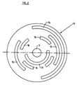
- FIG. 2 shows a slice of an angle transmitter of the weather station in FIG. 1 .
- the weather station generally designated 1 in the drawings which is suitable especially for private use, makes it possible to measure the wind speed and the wind direction and transfers the measured data by means of a radio signal to a spatially separate display device 2 .
- the weather station 1 for this purpose consists essentially of a closed housing 3 , which can be fastened to the facade of a building or a wall or another suitable base by means of an arm 4 that extends radially from the housing.
- a shaft 4 mounted on bearings on a vertical axis.
- An upper end of the shaft 4 extends beyond the top of the housing and a lower end of the shaft extends beyond the bottom of the housing 3 .
- a wind vane 6 is fastened to the top end of the shaft 5 and a device 7 for measuring the wind force is fastened to the lower end of the shaft.
- the wind vane 6 is designed so that it aligns with the direction of the wind with the rotation of the shaft 5 , hereby aligning the device 7 in such a manner that it is positioned ideally to the wind direction.
- the device 7 includes an outer frame 8 designed as a ring, in which a small impeller wheel 9 can rotate freely on bearings on an axis radial to the axis of the shaft 5 .
- the impeller wheel 9 which is designed in the manner of an airplane propeller with slanted blades, is provided with a permanent magnet that works together with a sensor 10 that activates a magnetic field, for example with a reed contact, in such a manner that this sensor 10 provides a pulse sequence proportionate to the number of revolutions.
- the signal provided by the sensor 10 is therefore proportional to the wind force.
- the sensor 10 is for example integrated in a spoke-like brace of the frame 8 , on which the impeller wheel 9 can also rotate freely on bearings.
- the signal of the sensor 10 is transferred by means of a sliding contact 11 to an electronic analysis and control unit 11 accommodated in the housing 3 , for example operated by battery and containing a microprocessor.
- the device 7 described here offers the advantage that the forces that act on the impeller wheel 9 are very small, that an inexpensive sliding bearing can be used for the bearings of the impeller wheel 9 and with low friction, so that even at low wind speeds, for example wind speeds as low as 0.5 m/sec, a display is possible.
- the housing also contains an angle transmitter or a measuring device 12 , which has, inter alia, a screen or orifice plate 13 that is on the same axis as the shaft and is connected with the shaft so that it turns with the shaft.
- a screen or orifice plate 13 that is on the same axis as the shaft and is connected with the shaft so that it turns with the shaft.
- this plate 13 on several, i.e.
- optically scannable markings in the form of slit-shaped openings, on the outermost imaginary circle one circular arc opening extending over an angle area of 180°, on the adjacent, further inward imaginary circle two circular arc openings 15 offset in relation to each other by 180° each of which extends over an angle area of 90°, on the adjacent, further inward imaginary circle four circular arc openings 16 offset in relation to each other by 90°, which extend over an angle area of 45°, and on the innermost imaginary circle a slit-shaped opening 17 , that also extends over an angle area of 180°.
- the circular arc slits or openings 14 - 17 therefore form four groups of optically scannable markings and are offset from group to group such that sixteen angle areas of 22.5° each are distributed on the axis of the orifice plate 13 and are uniquely defined by the fact that each angle area has an opening with a typical pattern formed by the openings 14 - 17 that differs from the other angle areas.
- the openings 14 - 17 form groups with a different radial distance from the axis of the orifice plate 13 , this results in a total of sixteen uniquely defined angle areas, of which one is designated WB in the drawing.
- the measuring device 12 has four light diodes 18 - 21 , which are located on one side of the orifice plate 13 , in the depicted embodiment above the orifice plate 13 , in a stationary manner, i.e. not rotating with the orifice plate, in a row extending radially to the orifice plate, in such a manner that each light diode 18 - 21 is allocated to a group of openings 14 - 17 , i.e. is located on the movement path of the corresponding group of openings.
- a light guide 22 which is optically connected with a light detector 23 and by means of which the light of the light diodes 18 - 21 is transferred to the light sensor 23 , which for example consists of a phototransistor.
- the light diodes 18 - 21 therefore form four light paths for scanning the openings 14 - 17 with the common light sensor 23 .
- the latter provides a sensor signal to the electronic analysis and control unit 11 dependent on the presence or absence of a light signal striking the light sensor.
- the light diodes 18 - 21 are activated periodically in time intervals, in such a manner that in a measuring cycle there the light diodes 18 - 21 are activated alternately in time for a limited time at least once during each time interval, so that during this measuring cycle the groups of openings are scanned serially for the presence or absence of an opening, from which the respective angle area of the wind direction is determined.
- the light barrier unit 24 with the alternately activated light diodes 18 - 21 and the common light sensor represents a particularly reliable, but also economical solution for the measuring device 12 .
- a further advantage of this measuring device 12 is that it enables the contactless and zero force or zero moment determination of the angle position. This also contributes to the fact that even very low wind speeds, for example as low as 0.5 m/sec, can be displayed.
- the data measured by the electronic analysis and control unit 11 (wind speed and wind direction) is fed to a transmitter module 25 , which is also accommodated in the housing 3 , for transfer to the display 2 .
- each of the individual diodes 18 - 21 with a different pulsed frequency, likewise preferably successively in time, so that due to the different frequency of the signal supplied by the light detector 23 , this signal can be allocated to the respective light diode 18 - 21 or to the respective group of openings, therefore making it possible to determine the presence or absence of an opening in the groups of openings of the angle areas.
Abstract
Description
- 1 weather station
- 2 display device
- 3 housing
- 4 fastening arm
- 5 shaft
- 6 weather vane
- 7 device for measuring wind speed
- 8 frame
- 9 impeller wheel
- 10 sensor
- 11 electronic analysis and control unit
- 12 angle measuring device
- 13 screen or orifice plate
- 14-17 circular arc slit
- 18-21 light-emitting element, for example light-emitting diode
- 22 light guide
- 23 light sensor
- 24 light barrier unit
- 25 transmitter module
Claims (45)
Priority Applications (1)
| Application Number | Priority Date | Filing Date | Title |
|---|---|---|---|
| US11/485,648 USRE42057E1 (en) | 2002-02-21 | 2006-07-13 | Weather station |
Applications Claiming Priority (4)
| Application Number | Priority Date | Filing Date | Title |
|---|---|---|---|
| DE10207423 | 2002-02-21 | ||
| DE10207423A DE10207423B4 (en) | 2002-02-21 | 2002-02-21 | Weather station |
| US10/358,388 US6761065B2 (en) | 2002-02-21 | 2003-02-05 | Weather station |
| US11/485,648 USRE42057E1 (en) | 2002-02-21 | 2006-07-13 | Weather station |
Related Parent Applications (1)
| Application Number | Title | Priority Date | Filing Date |
|---|---|---|---|
| US10/358,388 Reissue US6761065B2 (en) | 2002-02-21 | 2003-02-05 | Weather station |
Publications (1)
| Publication Number | Publication Date |
|---|---|
| USRE42057E1 true USRE42057E1 (en) | 2011-01-25 |
Family
ID=27674828
Family Applications (2)
| Application Number | Title | Priority Date | Filing Date |
|---|---|---|---|
| US10/358,388 Ceased US6761065B2 (en) | 2002-02-21 | 2003-02-05 | Weather station |
| US11/485,648 Expired - Lifetime USRE42057E1 (en) | 2002-02-21 | 2006-07-13 | Weather station |
Family Applications Before (1)
| Application Number | Title | Priority Date | Filing Date |
|---|---|---|---|
| US10/358,388 Ceased US6761065B2 (en) | 2002-02-21 | 2003-02-05 | Weather station |
Country Status (2)
| Country | Link |
|---|---|
| US (2) | US6761065B2 (en) |
| DE (1) | DE10207423B4 (en) |
Families Citing this family (5)
| Publication number | Priority date | Publication date | Assignee | Title |
|---|---|---|---|---|
| US20050216128A1 (en) * | 2004-03-26 | 2005-09-29 | Clark James J | Water irrigation system with elevated sensing unit and method of controlling irrigation |
| DE102005046577B4 (en) * | 2005-09-28 | 2007-05-16 | Andreas Grasl | Wind direction sensor of a building smoke extraction system |
| US7310047B2 (en) * | 2005-12-14 | 2007-12-18 | Saudi Arabian Oil Company | Gas alarm system with wind direction indicator |
| US20080011821A1 (en) * | 2006-07-10 | 2008-01-17 | Daniel Measurement And Control, Inc. | Method and System of Determining Orifice Plate Parameters |
| CN106841677B (en) * | 2017-03-23 | 2019-04-23 | 山东省科学院海洋仪器仪表研究所 | A kind of cursor type photoelectricity wind direction coder |
Citations (9)
| Publication number | Priority date | Publication date | Assignee | Title |
|---|---|---|---|---|
| DE3434437A1 (en) | 1984-09-19 | 1986-03-20 | Karl-Heinz 8000 München Güntner | Wind measurement apparatus |
| US4891642A (en) * | 1988-01-11 | 1990-01-02 | Sundstrand Data Control, Inc. | Wind shear detection system |
| US5127358A (en) * | 1991-05-29 | 1992-07-07 | Peter Galloway | Apparent wind direction indicator |
| US5355724A (en) * | 1993-08-23 | 1994-10-18 | The United States Of America As Represented By The Administrator Of The National Aeronautics And Space Administration | Optically broadcasting wind direction indicator |
| US5448161A (en) * | 1992-07-24 | 1995-09-05 | Lightning Protection Technology | Transformer-coupled photodiode circuit for lightning and other light pulse detection |
| US6202023B1 (en) | 1996-08-22 | 2001-03-13 | Go2 Systems, Inc. | Internet based geographic location referencing system and method |
| US6380535B1 (en) * | 1999-08-06 | 2002-04-30 | Lockheed Martin Corporation | Optical tuft for flow separation detection |
| US6672152B2 (en) * | 2001-12-21 | 2004-01-06 | Honeywell International Inc. | Flush surface air data sensor |
| US6679112B2 (en) * | 1999-12-17 | 2004-01-20 | Thales Avionics S.A. | Total pressure determination with multifunction probe for aircraft |
Family Cites Families (2)
| Publication number | Priority date | Publication date | Assignee | Title |
|---|---|---|---|---|
| DE2041832B2 (en) * | 1970-08-22 | 1973-10-04 | Licentia Patent-Verwaltungs-Gmbh, 6000 Frankfurt | Arrangement for scanning a coded grid scale |
| JPS60207065A (en) * | 1984-03-30 | 1985-10-18 | Sumitomo Electric Ind Ltd | Optical fiber transmitting type anemoscope |
-
2002
- 2002-02-21 DE DE10207423A patent/DE10207423B4/en not_active Expired - Fee Related
-
2003
- 2003-02-05 US US10/358,388 patent/US6761065B2/en not_active Ceased
-
2006
- 2006-07-13 US US11/485,648 patent/USRE42057E1/en not_active Expired - Lifetime
Patent Citations (9)
| Publication number | Priority date | Publication date | Assignee | Title |
|---|---|---|---|---|
| DE3434437A1 (en) | 1984-09-19 | 1986-03-20 | Karl-Heinz 8000 München Güntner | Wind measurement apparatus |
| US4891642A (en) * | 1988-01-11 | 1990-01-02 | Sundstrand Data Control, Inc. | Wind shear detection system |
| US5127358A (en) * | 1991-05-29 | 1992-07-07 | Peter Galloway | Apparent wind direction indicator |
| US5448161A (en) * | 1992-07-24 | 1995-09-05 | Lightning Protection Technology | Transformer-coupled photodiode circuit for lightning and other light pulse detection |
| US5355724A (en) * | 1993-08-23 | 1994-10-18 | The United States Of America As Represented By The Administrator Of The National Aeronautics And Space Administration | Optically broadcasting wind direction indicator |
| US6202023B1 (en) | 1996-08-22 | 2001-03-13 | Go2 Systems, Inc. | Internet based geographic location referencing system and method |
| US6380535B1 (en) * | 1999-08-06 | 2002-04-30 | Lockheed Martin Corporation | Optical tuft for flow separation detection |
| US6679112B2 (en) * | 1999-12-17 | 2004-01-20 | Thales Avionics S.A. | Total pressure determination with multifunction probe for aircraft |
| US6672152B2 (en) * | 2001-12-21 | 2004-01-06 | Honeywell International Inc. | Flush surface air data sensor |
Also Published As
| Publication number | Publication date |
|---|---|
| DE10207423B4 (en) | 2006-02-09 |
| US6761065B2 (en) | 2004-07-13 |
| US20030154780A1 (en) | 2003-08-21 |
| DE10207423A1 (en) | 2003-09-11 |
Similar Documents
| Publication | Publication Date | Title |
|---|---|---|
| USRE42057E1 (en) | Weather station | |
| US3963918A (en) | Identification device for machine moulded products | |
| US4827123A (en) | Direction sensitive optical shaft encoder | |
| EP0443514B1 (en) | Apparatus for monitoring a bearing | |
| US4875379A (en) | Apparatus for measuring the torque of an operating shaft | |
| AU2264595A (en) | A detection system | |
| US4631940A (en) | Digital readout combination lock dial assembly | |
| US5272402A (en) | Electrical machine with device for detecting rotor position and rotational speed | |
| US7201124B2 (en) | Phase displacement device | |
| US6360449B1 (en) | Incremental encoder having absolute reference marks | |
| US3420101A (en) | Flow velocity and direction sensor | |
| EP0979390A1 (en) | Pulse generator | |
| EP0054661B1 (en) | A capacitive transducer for sensing a home position | |
| US4677291A (en) | Analysis of rotational eccentricity | |
| US6102165A (en) | Antifriction bearing with signal generator and method for using same | |
| US6427614B1 (en) | Sewing machine with a ventilation wheel and a rotation speed sensor attached to an electric motor | |
| US20160290834A1 (en) | Distance measuring device and method thereof for seeking distance measuring starting point | |
| GB2189663A (en) | Direction indicators | |
| NO145321B (en) | DEVICE FOR DIGITAL CODING OF THE ANGLE POSITION OF A FIRST SHAFT IN RELATION TO A REFERENCE POSITION | |
| CN1387031A (en) | Centrifugal separator | |
| US4262908A (en) | Light ray target apparatus | |
| JPS5515047A (en) | Moving point detection method | |
| KR200247869Y1 (en) | Hitting Power Measurement Device | |
| JP2578464Y2 (en) | Gas meter flow rate detector | |
| US6677863B2 (en) | Absolute encoder |
Legal Events
| Date | Code | Title | Description |
|---|---|---|---|
| AS | Assignment |
Owner name: RICHMOND IP HOLDINGS, LLC, VIRGINIA Free format text: ASSIGNMENT OF ASSIGNORS INTEREST;ASSIGNORS:HAUPT, ROLF WILHEIM;SCHEFFEL, FRITZ;SIGNING DATES FROM 20060125 TO 20060215;REEL/FRAME:022216/0861 |
|
| FPAY | Fee payment |
Year of fee payment: 8 |
|
| AS | Assignment |
Owner name: LA CROSSE TECHNOLOGY IP HOLDINGS, LLC, WISCONSIN Free format text: ASSIGNMENT OF ASSIGNORS INTEREST;ASSIGNOR:RICHMOND IP HOLDINGS, LLC;REEL/FRAME:031019/0710 Effective date: 20130708 |
|
| AS | Assignment |
Owner name: LA CROSSE TECHNOLOGY IP HOLDINGS, LLC, WISCONSIN Free format text: ASSIGNMENT OF ASSIGNORS INTEREST;ASSIGNOR:RICHMOND IP HOLDINGS, LLC;REEL/FRAME:031054/0355 Effective date: 20130708 |
|
| FEPP | Fee payment procedure |
Free format text: PAYER NUMBER DE-ASSIGNED (ORIGINAL EVENT CODE: RMPN); ENTITY STATUS OF PATENT OWNER: SMALL ENTITY Free format text: PAYOR NUMBER ASSIGNED (ORIGINAL EVENT CODE: ASPN); ENTITY STATUS OF PATENT OWNER: SMALL ENTITY |
|
| FPAY | Fee payment |
Year of fee payment: 12 |