USRE44262E1 - Optical coupler comprising multimode fibers and method of making the same - Google Patents
Optical coupler comprising multimode fibers and method of making the same Download PDFInfo
- Publication number
- USRE44262E1 USRE44262E1 US12/153,189 US15318908A USRE44262E US RE44262 E1 USRE44262 E1 US RE44262E1 US 15318908 A US15318908 A US 15318908A US RE44262 E USRE44262 E US RE44262E
- Authority
- US
- United States
- Prior art keywords
- fiber
- mode
- few
- bundle
- core
- Prior art date
- Legal status (The legal status is an assumption and is not a legal conclusion. Google has not performed a legal analysis and makes no representation as to the accuracy of the status listed.)
- Active, expires
Links
Images


Classifications
-
- G—PHYSICS
- G02—OPTICS
- G02B—OPTICAL ELEMENTS, SYSTEMS OR APPARATUS
- G02B6/00—Light guides; Structural details of arrangements comprising light guides and other optical elements, e.g. couplings
- G02B6/02—Optical fibres with cladding with or without a coating
- G02B6/02004—Optical fibres with cladding with or without a coating characterised by the core effective area or mode field radius
- G02B6/02009—Large effective area or mode field radius, e.g. to reduce nonlinear effects in single mode fibres
-
- G—PHYSICS
- G02—OPTICS
- G02B—OPTICAL ELEMENTS, SYSTEMS OR APPARATUS
- G02B6/00—Light guides; Structural details of arrangements comprising light guides and other optical elements, e.g. couplings
- G02B6/02—Optical fibres with cladding with or without a coating
- G02B6/036—Optical fibres with cladding with or without a coating core or cladding comprising multiple layers
- G02B6/03616—Optical fibres characterised both by the number of different refractive index layers around the central core segment, i.e. around the innermost high index core layer, and their relative refractive index difference
- G02B6/03622—Optical fibres characterised both by the number of different refractive index layers around the central core segment, i.e. around the innermost high index core layer, and their relative refractive index difference having 2 layers only
-
- G—PHYSICS
- G02—OPTICS
- G02B—OPTICAL ELEMENTS, SYSTEMS OR APPARATUS
- G02B6/00—Light guides; Structural details of arrangements comprising light guides and other optical elements, e.g. couplings
- G02B6/10—Light guides; Structural details of arrangements comprising light guides and other optical elements, e.g. couplings of the optical waveguide type
- G02B6/14—Mode converters
-
- G—PHYSICS
- G02—OPTICS
- G02B—OPTICAL ELEMENTS, SYSTEMS OR APPARATUS
- G02B6/00—Light guides; Structural details of arrangements comprising light guides and other optical elements, e.g. couplings
- G02B6/24—Coupling light guides
- G02B6/26—Optical coupling means
- G02B6/28—Optical coupling means having data bus means, i.e. plural waveguides interconnected and providing an inherently bidirectional system by mixing and splitting signals
- G02B6/2804—Optical coupling means having data bus means, i.e. plural waveguides interconnected and providing an inherently bidirectional system by mixing and splitting signals forming multipart couplers without wavelength selective elements, e.g. "T" couplers, star couplers
- G02B6/2821—Optical coupling means having data bus means, i.e. plural waveguides interconnected and providing an inherently bidirectional system by mixing and splitting signals forming multipart couplers without wavelength selective elements, e.g. "T" couplers, star couplers using lateral coupling between contiguous fibres to split or combine optical signals
Definitions
- This invention relates generally to optical fiber couplers. More particularly, the invention pertains to optical fiber couplers for coupling a bundle of multimode fibers, containing a few-mode fiber in their centre, to a large core area double clad fiber. The invention also provides a method for making such coupler.
- Multimode optical fibers are used in a large number of applications, such as communications networks, sensors systems, avionic and aerospace industry, medical instruments, fiber bundles, and fiber amplifiers and lasers.
- One of the basic components in most of these applications is the multimode fiber coupler, that can take several different forms, such as the power splitter, the tap coupler, the star coupler or the power combiner. All these components essentially take several multimode fibers and bundle them together by either mechanically holding them or twisting them together, and the structure is fused and/or tapered in order to induce coupling between the fibers from the input to the output.
- the basic description of this coupling is given in U.S. Pat. No. 4,291,940 of Kawasaki et al. It discloses that if two multimode fibers are placed side by side and then fused together using a heat source, there is some optical power transfer from one fiber to the other. Such transfer can be increased as the structure is pulled and tapered.
- 4,550,974 describes a process presently known in the art as the “cut and fuse” process where a fused tapered multimode fiber bundle is cut and then fused together again to produce a better mode scrambling effect and thus better uniformity. From this process, it quickly became apparent that one did not need to fuse the same two coupler halves together, but one could put together two different coupler halves, thereby creating another way of making M ⁇ N couplers.
- the double clad fiber amplifiers or lasers use a type of fiber, the double clad fiber (DCF), that has a single-mode core doped with rare-earth ions, such as ytterbium, erbium or neodinium, that is surrounded by an optical cladding of far larger diameter.
- This cladding is a highly multimode waveguide and it is surrounded by another optical cladding having a lower refractive index, which may be a polymer cladding.
- This pump optical power can be injected in the core in the same manner as in single-mode fiber amplifiers, but the purpose of the double clad is that the pump power can be injected into the inner cladding which surrounds the core. Because some of the cladding modes travel through the core, they provide energy to the rare-earth ions and enable the amplification of the signal to occur. Moreover, because the inner cladding is far larger than the core, it is possible to input a greater number of pump laser light and spatially multiplex the same in the cladding, rather than wavelength or polarization multiplex the pump laser in the core. Thus, a much greater amount of pump power is available in DCF for the amplification than in single-mode fiber amplifiers.
- the coupling is achieved by bulk optics, coupling the pump power through lens and mirrors into the double cladding.
- U.S. Pat. No. 5,864,644 describes how this can be done with a multimode taper bundle using a similar approach as the “cut and fuse” technique, where the second coupler half is replaced by a DCF.
- the patent also describes how it is possible to include in the bundle s single-mode fiber, that will connect to the single-mode core of the DCF, thus allowing a signal to go through the coupler and be amplified or reversely, if the coupler is used in a counter pump configuration (i.e. the pump power and the signal go in the opposite direction), to let the signal out of the amplifier with minimum loss.
- a modification to this structure is disclosed in U.S. Pat. No. 6,434,302, where it is stated that for better performance, the tapered bundle and DCF structure must be tapered further than the diameter of the DCF to improve mode distribution for improved gain efficiency.
- Another object of the present invention is to provide an input end fused fiber periphery or fiber bundle transverse geometry that would preserve the modal content of the few-mode core in such coupler.
- a still further object of the present invention is to provide a method of making a coupler with the above mentioned properties, including alignment and splicing of the fiber bundle to the LACDCF.
- a single-mode fiber normally has a mode field diameter of up to 9 ⁇ m, whereas a few-mode fiber usually has a mode field diameter of 30–50 ⁇ m, while multimode fibers generally have a core mode field diameter above 50 ⁇ m. Also, in the LACDCFs the core has a mode field diameter which is similar to that of the core of the few-mode fiber.
- the basic difference in connecting the LACDCF to a bundle with a few-mode fiber is that the signal transmitting the few-mode fiber cannot simply be tapered to achieve the connection (as in the case of single-mode fibers), and must be made to match the modal content of the LACDCF.
- an optical coupler which comprises:
- the multimode fibers of the bundle end portion may also be tapered before being fused in order to fit within the circumference of the inner cladding of the input end of the LACDCF.
- the method of the present invention essentially comprises:
- the multimode fibers at the output end of the bundle may also be tapered prior to being fused, so as to fit within the circumference of the inner cladding of the input end of the LACDCF.
- FIG. 1 is a schematic side view representation of a coupler arrangement in accordance with the present invention in which a bundle of three fibers comprising two multimode fibers and a few-mode fiber in the centre is connected to the LACDCF;
- FIG. 2 is a section view of the splicing region of FIG. 1 along line A—A;
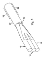
- FIG. 3 is a perspective view of the coupler shown in FIG. 1 ;
- FIG. 4 is a schematic side view representation of a coupler in accordance with the present invention in which a bundle of more than two multimode fibers with a few-mode fiber in the centre is connected to the LACDCF;
- FIG. 5 is a schematic side view representation of an embodiment of the present invention where the core of a single-mode fiber has been expanded and connected to a core of a few-mode fiber before splicing with the LACDCF;
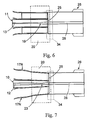
- FIG. 6 is a schematic side view representation of another embodiment in which the core of a single-mode fiber has been expanded to a few-mode fiber level just before splicing with the LACDCF;
- FIG. 7 is a schematic side view representation of an embodiment where the core of the few-mode fiber has been expanded prior to bundling and then fused and tapered within the bundle fusion region to the appropriate mode size before splicing with the LACDCF;
- FIGS. 8A to 8L represent a schematic view of different fiber bundle configurations that may be used within the scope of the present invention.
- a few-mode fiber 10 is provided, having a core 12 of 50 ⁇ m diameter and a cladding 14 of 125 ⁇ m diameter.
- This few-mode fiber 10 is bundled with two multimode fibers 16 , 18 and the bundle is fused in the fusion region 20 .
- the multi-mode fibers 16 , 18 each have a core 22 of 105 ⁇ m diameter and a cladding 24 of 125 ⁇ m diameter.
- the three fibers total 375 ⁇ m in their longitudinal periphery before fusion and 350 ⁇ m after fusion.
- the fused end of this structure was then cleaved, aligned and spliced to the end 25 of the LACDCF 26 having a large area core 28 of 50 ⁇ m diameter and an inner cladding 30 of 350 ⁇ m diameter.
- the second outer polymer cladding 32 was stripped from the end portion 27 of the LACDCF prior to splicing in the splicing region 34 .
- the polymer cladding is stripped so that it would not burn during splicing. However, if a non-polymeric outer cladding is used, it does not need to be stripped from the inner cladding near the splicing region.
- FIG. 2 illustrates a transverse section view of the coupler arrangement of FIG. 1 along line A—A, namely essentially at the splicing position.
- the few-mode fiber 10 having its core 12 bundled and fused with multimode fibers 16 and 18 , is aligned and spliced with the LACDCF 26 having a large area core 28 (shown in FIG. 1 ) that corresponds to core 12 in its modal content.
- the periphery of the bundle is adapted to fit within the circumference of the inner cladding 30 of the LACDCF and, if necessary, should be tapered to achieve such size.
- This periphery does not need to cover the entire surface of end 25 of the inner cladding 30 of the LACDCF, but what is important is that the bundle and the few-mode fiber be so aligned with the LACDCF as to preserve the fundamental mode transmission from the few-mode fiber to the LACDCF. Essentially, this means that the core 12 should be precisely modally aligned with the large area core 28 . This can be done by launching the fundamental mode of the few-mode fiber and monitoring the modal content at the input of the LACDCF with a near-field measurement device, such as a camera that images the fiber endface through an appropriate lens. One then aligns the bundle and the LACDCF until a Gaussian mode field is obtained.
- a near-field measurement device such as a camera that images the fiber endface through an appropriate lens.
- the splice is then made and the modal field is checked again to verify that the modal content does not change. If the modal content has changed or was lost because of the splice, this may be due to stresses in the splice.
- the splice then needs to be reheated and reworked to optimize the modal content.
- the LACDCF fiber should be straight or under a small amount of tension to prevent mode coupling that would effect the measurement. Such measurement should also be done at the wavelength of the operation or at a wavelength very close to it in order to produce best results.
- FIG. 3 which represents a perspective view of the coupler of the present invention, shows that the few-mode fiber 10 is positioned in the middle between multi-mode fibers 16 and 18 and is fused and spliced at the splicing end 25 with the LACDCF fiber 26 .
- the polymer outer cladding 32 has been removed, so that the splicing is done within the circumference of the inner cladding of the LACDCF 26 .
- the splicing would still be done within the circumference of the inner cladding of the LACDCF 26 , even if a non-polymeric outer cladding were used, however, such outer cladding need not be removed from the end portion 27 .
- multi-mode fibers 16 , 18 . . . N bundled around the few-mode fiber 10 .
- multimode fibers 16 , 18 . . . N bundled around the few-mode fiber 10 .
- These fibers would be fused within the fusion region 20 to fit within the circumference of the inner cladding 30 of the LACDCF, and spliced within the splicing region 34 at end 25 to the LACDCF fiber 26 while preserving fundamental mode transmission from the few-mode fiber 10 to the LACDCF 26 . As already described previously, this is achieved with proper modal alignment of the cores 12 and 28 .
- the fibers 17 N are tapered to 125 ⁇ m diameter before fusing them in the fusion region 20 . They are then spliced to the LACDCF fiber 26 in the splicing region 34 at end 25 of the LACDCF, after alignment to preserve the modal content of the feed-trough.
- ⁇ o is the final diameter of the multimode fiber
- ⁇ i is the initial diameter of the multimode fiber
- NA MM is the numerical aperture of the multimode fiber
- NA DCF is the numerical aperture of the LACDCF inner cladding waveguide.
- FIGS. 5 , 6 and 7 relate to the adjustment of the mode field diameter of the signal fiber to the large area core of the double clad fiber.
- the invention provides an adjustment of the mode field diameter of the signal fiber 11 , which is a single-mode fiber having a 6 ⁇ m core 13 , to the LACDCF fiber 26 having a 50 ⁇ m core 28 .
- This is done by providing a mode converter to increase the size of the core as shown at 15 and splice it to a length of a few mode fiber at 21 so as to connect it with the 50 ⁇ m core 12 of the few-mode fiber provided within the fusion region 20 .
- the few-mode fiber is fused in the fusion region 20 with the multimode fibers 16 , 18 and spliced with the LACDCF 26 in the splicing region 34 as already described previously, so that cores 12 and 28 are coupled to preserve the fundamental mode transmission from the few mode fiber to the LACDCF.
- the core 13 is diffused at 19 to become a 50 ⁇ m core that can be aligned and spliced with core 28 of the LACDCF 26 as described previously.
- This configuration is similar to that shown in FIG. 5 , except there is no transitional few-mode fiber provided in the bundle.
- FIG. 7 provides for an expansion of the core 12 of the few-mode fiber 10 that has been narrowed while tapering the fibers 17 N around it, as disclosed with reference to FIG. 4 .
- This may happen in some cases due to a particular design of the bundle where one must taper the few-mode fiber because the diameter of the fused bundle is larger than the diameter of the internal cladding of the LACDCF, and one could not taper the outer multi-mode fibers more because of the relation of the numerical apertures as expressed in the ratio R above.
- the mode converter mentioned above with reference to FIGS. 5 , 6 and 7 is usually produced by heating the fiber to a high temperature such that the germanium, which is present as a dopant in the fiber core, diffuses into the cladding, thereby increasing the size of the core and thus of the mode.
- the mode field diameter of the expanded core becomes equal to that of the large area core of the DCF and at this point the heating is stopped and the mode conversion is completed.
- FIGS. 8A to 8L illustrate different fiber configurations that can be used in accordance with the present invention within bundles to be coupled with LACDCF. It should be noted that these configurations are not limitative.
- FIG. 8A shows a configuration of 3 ⁇ 1 or (2+1) ⁇ 1, such as already described with reference to FIGS. 1 , 2 and 3 , namely where three fibers are coupled with one LACDCF.
- the middle signal fiber FMF is a few-mode fiber and the two outer pump fibers MMF are multimode fibers.
- FIG. 8B illustrates a 4 ⁇ 1 or (3+1) ⁇ 1 configuration, again with the FMF in the middle and three MMF surrounding it in symmetrical manner.
- FIGS. 8C and 8D illustrate two symmetrical configurations of 5 ⁇ 1 or (4+1) ⁇ 1 bundles that can be used in accordance with this invention.
- the FMF is located in the middle and is symmetrically surrounded by MMF fibers.
- FIGS. 8E and 8F show two 6 ⁇ 1 or (5+1) ⁇ 1 configurations.
- the FMF is surrounded by 5 MMF fibers of same diameter and in FIG. 8F the central FMF is surrounded by 5 larger MMF pump fibers.
- FIG. 8G shows a 7 ⁇ 1 or (6+1) ⁇ 1 configuration where the central FMF is surrounded by 6 MMF pump fibers of same size.
- FIG. 8H illustrates a (9+1) ⁇ 1 configuration where the central FMF is significantly larger than the 9 surrounding MMF pump fibers.
- FIG. 8I shows a configuration of (18+1) ⁇ 1 where the central FMF is larger than the 18 surrounding MMF pump fibers.
- MMF fibers only a few of the surrounding fibers have been identified as MMF fibers, but all of them can be MMF fibers, although if not all ports are needed, some of them can be replaced by dummy fibers, namely pure silica coreless fibers.
- FIG. 8J illustrates a 19 ⁇ 1 or (18+1) ⁇ 1 configuration where the central FMF is surrounded by 18 MMF fibers of same size. Again, if some of the MMF ports are not needed, they can be replaced by dummy fibers and this applies to all configurations.
- FIG. 8K shows a 19 ⁇ 1 or (18+1) ⁇ 1 configuration where a large diameter FMF is surrounded by 18 MMF pump fibers.
- FIG. 8L illustrates a 37 ⁇ 1 or (36+1) ⁇ 1 configuration where a central FMF is surrounded by 36 MMF pump fibers of same diameter.
- the pump fibers are 220 ⁇ m in diameter with 0.22 numerical aperture, one can reduce them to 125 ⁇ m diameter and bundle them around a 125 ⁇ m central signal fiber.
- This can produce configurations where all fibers are of equal size as illustrated in FIGS. 8A , 8 B, 8 C, 8 D, 8 E, 8 G, 8 J and 8 L.
- the configurations of 7 ⁇ 1 shown in FIG. 8G , 19 ⁇ 1 shown in FIG. 8J and 37 ⁇ 1 shown in FIG. 8L are close-pack configurations, meaning that there is essentially no space left between the fibers.
Abstract
An optical coupler is provided. It has a bundle of multimode fibers with a few-mode fiber in its centre. Such bundle is fused at one end which is the output end for the signal that is transmitted by the few-mode fiber. To make the coupler, this output end of the bundle is aligned and spliced with a large area core double clad fiber while preserving the modal content of the feed-through. A method for making such optical coupler is also provided. It includes the steps of bundling a central few-mode fiber with a plurality of multimode fibers and then fusing one end of such bundle and aligning it and splicing with a large core double clad fiber, while preserving fundamental mode transmission from one to the other.
Description
This invention relates generally to optical fiber couplers. More particularly, the invention pertains to optical fiber couplers for coupling a bundle of multimode fibers, containing a few-mode fiber in their centre, to a large core area double clad fiber. The invention also provides a method for making such coupler.
Multimode optical fibers are used in a large number of applications, such as communications networks, sensors systems, avionic and aerospace industry, medical instruments, fiber bundles, and fiber amplifiers and lasers. One of the basic components in most of these applications is the multimode fiber coupler, that can take several different forms, such as the power splitter, the tap coupler, the star coupler or the power combiner. All these components essentially take several multimode fibers and bundle them together by either mechanically holding them or twisting them together, and the structure is fused and/or tapered in order to induce coupling between the fibers from the input to the output. The basic description of this coupling is given in U.S. Pat. No. 4,291,940 of Kawasaki et al. It discloses that if two multimode fibers are placed side by side and then fused together using a heat source, there is some optical power transfer from one fiber to the other. Such transfer can be increased as the structure is pulled and tapered.
This basic fused-tapered concept was used in several subsequent patents such as U.S. Pat. Nos. 4,392,712 and 4,330,170 where it became apparent that this procedure could also be used for more than two fibers, thus creating M×N fused taper bundles, where M is the input number of fibers and N is the output number of fibers. Moreover, the fuse and taper process received some further improvements such as described in U.S. Pat. Nos. 4,426,215 and 4,550,974 where several techniques are disclosed to improve the uniformity of the power distribution in the fused-tapered multimode fiber bundles. In particular, U.S. Pat. No. 4,550,974 describes a process presently known in the art as the “cut and fuse” process where a fused tapered multimode fiber bundle is cut and then fused together again to produce a better mode scrambling effect and thus better uniformity. From this process, it quickly became apparent that one did not need to fuse the same two coupler halves together, but one could put together two different coupler halves, thereby creating another way of making M×N couplers.
As applications of multimode fiber evolved, there came another application that can benefit from this process. The double clad fiber amplifiers or lasers use a type of fiber, the double clad fiber (DCF), that has a single-mode core doped with rare-earth ions, such as ytterbium, erbium or neodinium, that is surrounded by an optical cladding of far larger diameter. This cladding is a highly multimode waveguide and it is surrounded by another optical cladding having a lower refractive index, which may be a polymer cladding. To amplify an optical signal propagating through the DCF core, one needs to optically pump the rare-earth ions. This pump optical power can be injected in the core in the same manner as in single-mode fiber amplifiers, but the purpose of the double clad is that the pump power can be injected into the inner cladding which surrounds the core. Because some of the cladding modes travel through the core, they provide energy to the rare-earth ions and enable the amplification of the signal to occur. Moreover, because the inner cladding is far larger than the core, it is possible to input a greater number of pump laser light and spatially multiplex the same in the cladding, rather than wavelength or polarization multiplex the pump laser in the core. Thus, a much greater amount of pump power is available in DCF for the amplification than in single-mode fiber amplifiers.
In some DCF amplifiers or lasers, the coupling is achieved by bulk optics, coupling the pump power through lens and mirrors into the double cladding. U.S. Pat. No. 5,864,644 describes how this can be done with a multimode taper bundle using a similar approach as the “cut and fuse” technique, where the second coupler half is replaced by a DCF. The patent also describes how it is possible to include in the bundle s single-mode fiber, that will connect to the single-mode core of the DCF, thus allowing a signal to go through the coupler and be amplified or reversely, if the coupler is used in a counter pump configuration (i.e. the pump power and the signal go in the opposite direction), to let the signal out of the amplifier with minimum loss. A modification to this structure is disclosed in U.S. Pat. No. 6,434,302, where it is stated that for better performance, the tapered bundle and DCF structure must be tapered further than the diameter of the DCF to improve mode distribution for improved gain efficiency.
In high power amplifiers and lasers, as the power available for pump is greater, the power output of the amplifier or laser is also larger, to the point where the light intensity in the doped glass becomes large enough to damage the glass or to produce undesirable non-linear effects, such as Raman or Brilloin scattering. Thus, a new generation of DCF fibers has been developed to address these high power situations. These fibers have a large core area so that, even if the power is high, the intensity in the core remains reasonable. Even if one decreases the index step of the core waveguide, the large core is not necessarily single-mode at the laser wavelength. The fiber core is few-moded. One must carefully excite the core fundamental mode to have the amplification in that mode, that will produce the best output beam. This problem is not addressed in U.S. Pat. Nos. 5,864,644 and 6,434,302 which deal only with a single-mode connection. A single-mode connection is simple because one cannot excite anything other than the fundamental mode in the connection, even if the splice between the tapered fiber bundle and the DCF is bad. In the few-mode case, this connection is crucial to the proper functioning of the amplifier.
Thus, there is a need for a coupler that provides a connection of a bundle of multimode pump fibers that have a few-mode signal fiber in their centre, to a large area core double clad fiber (LACDCF).
It is an object of the present invention to provide an optical coupler with a fused fiber bundle of multimode fibers having a few-mode fiber in their centre, to be connected to LACDCF.
Another object of the present invention is to provide an input end fused fiber periphery or fiber bundle transverse geometry that would preserve the modal content of the few-mode core in such coupler.
A still further object of the present invention is to provide a method of making a coupler with the above mentioned properties, including alignment and splicing of the fiber bundle to the LACDCF.
Other objects and advantages of the invention will become apparent from the following description thereof.
As is known, a single-mode fiber normally has a mode field diameter of up to 9 μm, whereas a few-mode fiber usually has a mode field diameter of 30–50 μm, while multimode fibers generally have a core mode field diameter above 50 μm. Also, in the LACDCFs the core has a mode field diameter which is similar to that of the core of the few-mode fiber.
In a single-mode connection, one deals with two cores that have the same mode field diameter, because at one point in the tapering process, the mode field diameter increases rather than decreasing. One can thus, by tapering a bundle of fibers that include a single-mode fiber, match the mode field of the single-mode core of the tapered bundle to the mode of the DCF single-mode core, as disclosed, for instance, in U.S. Pat. No. 6,434,302. This, however, is not possible to achieve with a few-mode fiber, unless one tapers the bundle to the point where the two fiber core becomes single-mode. Thus, the basic difference in connecting the LACDCF to a bundle with a few-mode fiber is that the signal transmitting the few-mode fiber cannot simply be tapered to achieve the connection (as in the case of single-mode fibers), and must be made to match the modal content of the LACDCF.
Thus, in essence, according to the present invention, there is provided an optical coupler which comprises:
-
- (a) a bundle of a plurality of multimode fibers having a few-mode fiber in the centre, said few-mode fiber being a signal fiber through which an optical signal is transmitted;
- (b) a large area core double clad fiber (LACDCF) having an inner cladding and an outer cladding with a lower refractive index, which outer cladding may be made of a polymer, said LACDCF having an end portion from which the outer cladding is removed if it is made of a polymer, said end portion terminating with an input end the inner cladding of which has a predetermined circumference, into which input end of the LACDCF the optical signal is to be transmitted;
- (c) said bundle having a fused end portion with an output end having a periphery that fits within the circumference of the inner cladding of the input end of the LACDCF; and
- (d) said output end of the bundle being aligned and spliced with the input end of the LACDCF in such a way as to preserve fundamental mode transmission from the few-mode fiber to the LACDCF.
The multimode fibers of the bundle end portion may also be tapered before being fused in order to fit within the circumference of the inner cladding of the input end of the LACDCF.
The method of the present invention essentially comprises:
-
- (a) bundling a central few-mode fiber with a plurality of surrounding multimode fibers so that the surrounding multimode fibers are placed generally symmetrically around the central few-mode fiber, thereby forming a bundle of said fibers having an output end;
- (b) providing a large area core double clad fiber (LACDCF) and if it has an outer polymer cladding, removing said outer polymer cladding from an end portion thereof, said end portion terminating with an input end of the LACDCF having an inner cladding of a given circumference;
- (c) fusing the output end of the bundle so that its periphery fits within the circumference of the inner cladding of the input end of the LACDCF; and
- (d) splicing the fused output end of the bundle to the input end of the LACDCF in such a manner that the core of the few-mode fiber is precisely modally aligned with the core of the LACDCF so as to preserve fundamental mode transmission from the few-mode fiber to the LACDCF.
The multimode fibers at the output end of the bundle may also be tapered prior to being fused, so as to fit within the circumference of the inner cladding of the input end of the LACDCF.
The invention will now be described with reference to the appended drawings, in which:
Preferred embodiments of the invention will now be described with reference to the appended drawings in which the same parts are designated by the same reference numbers.
In the embodiment shown in FIG. 1 , a few-mode fiber 10 is provided, having a core 12 of 50 μm diameter and a cladding 14 of 125 μm diameter. This few-mode fiber 10 is bundled with two multimode fibers 16, 18 and the bundle is fused in the fusion region 20. The multi-mode fibers 16, 18 each have a core 22 of 105 μm diameter and a cladding 24 of 125 μm diameter. The three fibers total 375 μm in their longitudinal periphery before fusion and 350 μm after fusion. The fused end of this structure was then cleaved, aligned and spliced to the end 25 of the LACDCF 26 having a large area core 28 of 50 μm diameter and an inner cladding 30 of 350 μm diameter. The second outer polymer cladding 32 was stripped from the end portion 27 of the LACDCF prior to splicing in the splicing region 34. The polymer cladding is stripped so that it would not burn during splicing. However, if a non-polymeric outer cladding is used, it does not need to be stripped from the inner cladding near the splicing region. Once the coupler is thus made, it is normally packaged by bonding it to a suitable substrate to preserve the alignment of the components.
It is also possible to use any suitable number of multi-mode fibers 16, 18 . . . N, bundled around the few-mode fiber 10. Thus, for example, one can place six multimode fibers having a diameter of 125 μm around a few mode fiber 10 also having a diameter of 125 μm. These fibers would be fused within the fusion region 20 to fit within the circumference of the inner cladding 30 of the LACDCF, and spliced within the splicing region 34 at end 25 to the LACDCF fiber 26 while preserving fundamental mode transmission from the few-mode fiber 10 to the LACDCF 26. As already described previously, this is achieved with proper modal alignment of the cores 12 and 28.
In another embodiment, illustrated in FIG. 4 , one can use, for example, seven multimode fibers 17N having a diameter of 220 μm, bundled around a 125 μm few-mode fiber 10. The fibers 17N are tapered to 125 μm diameter before fusing them in the fusion region 20. They are then spliced to the LACDCF fiber 26 in the splicing region 34 at end 25 of the LACDCF, after alignment to preserve the modal content of the feed-trough.
In general, when tapering the outer multimode fibers, one should not taper them more than the ratio:
R=ρo/ρi=NAMM/NADCF
where R is the maximum taper radio
R=ρo/ρi=NAMM/NADCF
where R is the maximum taper radio
ρo is the final diameter of the multimode fiber
ρi is the initial diameter of the multimode fiber
NAMM is the numerical aperture of the multimode fiber
NADCF is the numerical aperture of the LACDCF inner cladding waveguide.
When tapering the outer multimode fibers, one can have any suitable number of such fibers bundled and then fused around a few-mode fiber, provided the above taper ratio is maintained. Some such bundle configurations are shown in FIGS. 8A to 8L discussed below.
Further embodiments of the invention as illustrated in FIGS. 5 , 6 and 7 relate to the adjustment of the mode field diameter of the signal fiber to the large area core of the double clad fiber.
Thus, in FIG. 5 the invention provides an adjustment of the mode field diameter of the signal fiber 11, which is a single-mode fiber having a 6 μm core 13, to the LACDCF fiber 26 having a 50 μm core 28. This is done by providing a mode converter to increase the size of the core as shown at 15 and splice it to a length of a few mode fiber at 21 so as to connect it with the 50 μm core 12 of the few-mode fiber provided within the fusion region 20. Then, the few-mode fiber is fused in the fusion region 20 with the multimode fibers 16, 18 and spliced with the LACDCF 26 in the splicing region 34 as already described previously, so that cores 12 and 28 are coupled to preserve the fundamental mode transmission from the few mode fiber to the LACDCF.
In another embodiment illustrated in FIG. 6 , rather than using a mode converter to expand and splice a single-mode fiber to a length of a few-mode fiber, one can provide a mode converter to diffuse the core 13 of a single mode fiber 11 at 19 so that the core 13 is diffused within the fusion region 20 near the splicing surface 25, whereby the fiber 11 becomes few-moded over a few centimeters leading to the splicing region 34, where the fiber is aligned and spliced with the LACDCF 26. The core 13 is diffused at 19 to become a 50 μm core that can be aligned and spliced with core 28 of the LACDCF 26 as described previously. This configuration is similar to that shown in FIG. 5 , except there is no transitional few-mode fiber provided in the bundle.
The embodiment illustrated in FIG. 7 provides for an expansion of the core 12 of the few-mode fiber 10 that has been narrowed while tapering the fibers 17N around it, as disclosed with reference to FIG. 4 . This may happen in some cases due to a particular design of the bundle where one must taper the few-mode fiber because the diameter of the fused bundle is larger than the diameter of the internal cladding of the LACDCF, and one could not taper the outer multi-mode fibers more because of the relation of the numerical apertures as expressed in the ratio R above. In such as case, one can expand the core 12 of the few-mode fiber 10 using the mode converter referred to above, for example at location 23 within the fusion region 20, and leading to the splicing region 34. This expansion is done so that the core of the few-mode fiber at the splicing surface 25 will match core 28 of the LACDCF 26 and produce the required modal content of the feed-through. It is important to note that when additional tapering is done, the total tapering of the pump fibers should not exceed the R ratio referred to above. Any tapering in excess of that ratio will cause extra loss.
The mode converter mentioned above with reference to FIGS. 5 , 6 and 7 is usually produced by heating the fiber to a high temperature such that the germanium, which is present as a dopant in the fiber core, diffuses into the cladding, thereby increasing the size of the core and thus of the mode. At one point of such diffusion process, the mode field diameter of the expanded core becomes equal to that of the large area core of the DCF and at this point the heating is stopped and the mode conversion is completed.
In the various bundles and particularly in the tapered bundles, it is important to respect the symmetry around the few-mode fiber as much as possible, so that the fusion process does not asymmetrically deform the core of the few-mode fiber, which would make it difficult to produce a good splice. However, if the number of fibers is large, for example greater than 19, one does not need to be too careful in preserving the symmetry of the structure so long as the signal fiber remains essentially in the center of the fiber bundle. The deformation of the core will be negligible, even with high fusion and tapering of the outer multimode fibers.
Thus, FIG. 8A shows a configuration of 3×1 or (2+1)×1, such as already described with reference to FIGS. 1 , 2 and 3, namely where three fibers are coupled with one LACDCF. In this case, the middle signal fiber FMF is a few-mode fiber and the two outer pump fibers MMF are multimode fibers.
Finally, FIG. 8L illustrates a 37×1 or (36+1)×1 configuration where a central FMF is surrounded by 36 MMF pump fibers of same diameter.
By way of example, for a reduction of the pump fibers by a factor of 2, namely reducing 125 μm diameter pump fibers to 65 μm, one can place 9 fibers around the 125 μm signal fiber as illustrated in FIG. 8H . One can also add another layer of the pump fibers to form a configuration of 18 pump fibers around one signal fiber as shown in FIG. 8I . One can further add an additional layer of pump fibers to produce 27 pump fibers surrounding a signal fiber as shown in FIG. 8K . With 27 pump fibers, the configuration fits within a 400 μm diameter LACDCF.
In a further example, if the pump fibers are 220 μm in diameter with 0.22 numerical aperture, one can reduce them to 125 μm diameter and bundle them around a 125 μm central signal fiber. This can produce configurations where all fibers are of equal size as illustrated in FIGS. 8A , 8B, 8C, 8D, 8E, 8G, 8J and 8L. The configurations of 7×1 shown in FIG. 8G , 19×1 shown in FIG. 8J and 37×1 shown in FIG. 8L are close-pack configurations, meaning that there is essentially no space left between the fibers.
It should be noted that the invention is not limited to the specific embodiments described above, but that various modifications obvious to those skilled in the art may be made without departing from the invention and the scope of the following claims.
Claims (35)
1. An optical coupler which comprises:
(a) a bundle of a plurality of multimode fibers having a few-mode fiber in the center, said few-mode fiber being a signal fiber through which an optical signal is transmitted;
(b) a large area core double clad fiber (LACDCF) having an inner cladding and an outer cladding with a lower refractive index, and having an end portion terminating with an input end the inner cladding of which has a predetermined circumference, into said input end of the LACDCF the optical signal is to be transmitted from said few-mode fiber;
(c) said bundle having a fused end portion with an output end having a periphery that fits within the circumference of the inner cladding of the input end of the LACDCF; and
(d) said output end of the bundle being aligned and spliced with the input end of the LACDCF in such a way as to preserve fundamental mode transmission from the few-mode fiber to the LACDCF.
2. An optical coupler according to claim 1 , in which the outer cladding of the LACDCF is a polymer cladding and said polymer outer cladding is removed from the end portion of the LACDCF.
3. An optical coupler according to claim 1 , in which the multimode fibers are tapered before being fused at the output end, in order to fit within the circumference of the inner cladding of the input end of the LACDCF.
4. An optical coupler according to claim 3 , in which the multimode fibers are tapered and fused in such a way as not to affect the fundamental mode transmission in the core of the few-mode fiber.
5. An optical coupler according to claim 3 , in which the tapering of the multimode fibers reduces the core of the few-mode fiber to the fundamental mode size near the output end of the bundle, when said core bad been expanded prior to bundling.
6. An optical coupler according to claim 1 , in which the few-mode fiber at the output end is a fiber with a core expanded from a single mode fiber.
7. An optical coupler according to claim 1 , in which the plurality of multimode fibers is placed essentially symmetrically around the few-mode fiber within the bundle.
8. An optical coupler according to claim 1 , in which at least one of the plurality of multimode fibers in the bundle is replaced by a dummy fiber.
9. A method of forming an optical coupler, which comprises;
(a) bundling a central few-mode fiber with a plurality of surrounding multimode fibers so that the surrounding multimode fibers are positioned essentially symmetrically around the central few-mode fiber, thereby forming a bundle of said fibers having an output end;
(b) providing a large area core double clad fiber (LACDCF) having an inner cladding and an outer cladding with a lower refractive index, and having an end portion terminating with an input end where the inner cladding of the LACDCF has a given circumference;
(c) fusing the output end of the bundle so that its periphery fits within the circumference of the inner cladding of the input end of the LACDCF; and
(d) splicing the fused output end of the bundle to the input end of the LACDCF in such a manner that the core of the few-mode fiber is precisely modally aligned with the core of the LACDCF so as to preserve fundamental mode transmission from the few-mode fiber to the LACDCF.
10. Method according to claim 9 , in which the outer cladding of the LACDCF is a polymer cladding and the method includes removing said polymer outer cladding from the end portion of the LACDCF prior to splicing.
11. Method according to claim 9 , in which the multimode fibers at the output end of the bundle are tapered prior to being fused.
12. Method according to claim 11 , in which the tapering is done according to the following maximum taper ratio:
R=ρo/ρi=NAMM/NADCF
R=ρo/ρi=NAMM/NADCF
where R is the maximum taper radio
ρo is the final diameter of the multimode fiber
ρi is the initial diameter of the multimode fiber
NAMM is the numerical aperture of the multimode fiber
NADCF is the numerical aperture of the LACDCF inner cladding waveguide.
13. Method according to claim 11 , in which the tapering of the multimode fibers followed by fusing of the bundle in done so as not to affect the modal size of the core of the few-mode fiber.
14. Method according to claim 11 , in which the tapering of the multimode fibers followed by fusing of the bundle decreases the modal size of the core of the few-mode fiber, when said core had been expanded prior to bundling.
15. Method according to claim 9 , in which the few-mode fiber has a core near the output end of the bundle, which is expanded from an initial single-mode fiber core.
16. Method according to claim 15 , in which the expansion is done by means of a mode converter to increase the size of the core.
17. Method according to claim 15 , in which the expansion is done by beating to a high temperature such that germanium present in the core diffuses into the cladding, thereby increasing the size of the core and of the mode.
18. Method according to claim 9 , in which the cores of the few-mode fiber and of the LACDCF are precisely modally aligned by launching the fundamental mode of the few-mode fiber while monitoring the modal content at the input end of the LACDCF by means of a near field measurement device and aligning the output end of the bundle and the input end of the LACDCF unit a Gaussian mode field is obtained.
19. Method according to claim 18 , in which the LACDCF is kept straight or under a small tension, when monitoring the modes by the near field measurement device, and the measurement is done at or near operational wavelength.
20. Method according to claim 19 , in which the coupler is packaged by bonding it to a suitable substrate to preserve the alignment of the components.
21. An optical fiber coupler device comprising:
a) a double-clad fiber comprising a large area central core, an inner cladding having a first refractive index, and an outer cladding having a second refractive index lower than said first refractive index;
b) a fiber bundle comprising a plurality of multimode fibers coupled to said inner cladding of said double-clad fiber, and a central fiber having a few-mode central core, said central fiber being coupled to said double-clad fiber such that said few-mode central core is coupled to said large area central core and such as to preserve fundamental mode transmission between said few-mode central core of said central fiber and said large area central core of said double-clad fiber;
wherein said fiber bundle is being tapered to a reduced cross sectional area prior to being coupled to the double-clad fiber such that said tapered fiber bundle fits within a circumference of said inner cladding of said double-clad fiber.
22. An optical fiber assembly comprising:
a) a fiber bundle comprising a plurality of multimode pump fibers and a central few-mode fiber, said few-mode fiber comprising a few-mode central core, said bundle having an outer diameter; and
b) a double-clad fiber comprising a large area central core, an inner cladding, and an outer cladding, said inner cladding having an outer diameter that is at least equal to said outer diameter of said fiber bundle;
wherein said fiber bundle is spliced to said double-clad fiber such that said few-mode central core and said large area central core are optically coupled such as to preserve fundamental mode transmission between said central cores, and such that optical power in said multimode pump fibers of said fiber bundle is coupled into said inner cladding of said double-clad fiber.
23. An optical fiber coupler device comprising:
a) a double-clad fiber comprising a large area central core, an inner cladding, and an outer cladding;
b) a plurality of multimode fibers optically coupled to said inner cladding of said double-clad fiber; and
c) a few-mode fiber comprising a few-mode central core, said few-mode fiber being coupled to said double-clad fiber such that the few-mode central core is coupled to said large area central core of said double-clad fiber and such as to preserve fundamental mode transmission between said few-mode central core of said few-mode fiber and said large area central core of said double-clad fiber;
wherein said plurality of multimode fibers and said few-mode fiber are bundled together into a fiber bundle, wherein said few-mode fiber is located at the center of said fiber bundle, and wherein said fiber bundle is being tapered to a reduced cross sectional area prior to being coupled to said double-clad fiber such that said tapered fiber bundle fits within a circumference of said inner cladding of said double-clad fiber.
24. An optical fiber assembly comprising:
a) a fiber bundle comprising a plurality of multimode pump fibers, and a central fiber comprising a few-mode central core, said fiber bundle having an outer diameter; and
b) a double-clad fiber comprising a large area central core, an inner cladding, and an outer cladding, said inner cladding having an outer diameter that is at least equal to said outer diameter of said fiber bundle,
wherein said fiber bundle is spliced to said double-clad fiber such that said central cores are optically coupled such as to preserve fundamental mode transmission between said central cores, and such that optical power in said multimode pump fibers is coupled into said inner cladding of said double-clad fiber.
25. The optical fiber assembly according to claim 24, wherein said fiber bundle is tapered and spliced to said double-clad fiber so as to not affect fundamental mode transmission from between said central cores.
26. The optical fiber assembly according to claim 25, wherein said few-mode central core is narrowed in a first region where said fiber bundle is tapered, and wherein said few-mode central core is expanded in a second region where said fiber bundle is spliced to said double-clad fiber.
27. The optical fiber assembly according to claim 26, further comprising core expanding means for expanding said few-mode central core in said second region.
28. An optical fiber assembly comprising:
a) a fiber bundle comprising a plurality of multimode pump fibers, and a central single-mode fiber comprising a single-mode central core, said fiber bundle having an outer diameter; and
b) a double-clad fiber comprising a large area core, an inner cladding, and an outer cladding, said inner cladding having an outer diameter that is at least equal to said outer diameter of said fiber bundle,
wherein said fiber bundle is spliced to said double-clad fiber such that said central cores are optically coupled such as to preserve fundamental mode transmission between said central cores, and such that optical power in said multimode pump fibers of said fiber bundle is coupled into said inner cladding of said double-clad fiber; and
wherein said fiber bundle comprises a mode converter coupled to said single-mode fiber for increasing a size of said single-mode central core of said single-mode fiber to be compatible with said large area central core of said double-clad fiber.
29. The optical fiber assembly according to claim 28, wherein said mode converter comprises a fiber having a few-mode central core.
30. The optical fiber assembly according to claim 28, wherein said mode converter comprises diffusion means for diffusing said single-mode central core to thereby cause said single-mode central core to become few-moded in a region adjacent to where said fiber bundle is spliced to said double-clad fiber.
31. An optical fiber assembly comprising:
a) a fiber bundle comprising a plurality of multimode pump fiber, and a central few-mode fiber comprising a few-mode central core, said fiber bundle having an outer diameter; and
b) a double-clad fiber comprising a large area central core, an inner cladding, and an outer cladding, said inner cladding having an outer diameter that is at least equal to said outer diameter of said fiber bundle;
wherein said fiber bundle is spliced to said double-clad fiber such that said few-mode central core of said few-mode fiber is optically coupled to said large area central core of said double-clad fiber such as to preserve fundamental mode transmission between said central cores, and such that optical power in said multimode pump fibers of said fiber bundle is coupled into said inner cladding of said double-clad fiber.
32. An optical fiber assembly comprising:
a) a fiber bundle comprising a plurality of multimode pump fiber, and a central fiber comprising a few-mode central core, said fiber bundle having an outer diameter; and
b) a double-clad fiber comprising a large area central core, an inner cladding, and an outer cladding, said inner cladding having an outer diameter that is at least equal to said outer diameter of said fiber bundle;
wherein said fiber bundle is spliced to said double-clad fiber such that said few-mode central core of said central fiber is optically coupled to said large area central core of said double-clad fiber such as to preserve fundamental mode transmission between said central cores, and such that optical power in said multimode pump fibers of said fiber bundle is coupled into said inner cladding.
33. An optical coupler according to claim 1, in which the bundle is tapered before being fused at the output end in order to fit within the circumference of the inner cladding of the input end of the LACDCF.
34. An optical coupler according to claim 33, in which the bundle is tapered and fused in such a way as not to affect the fundamental mode transmission in the core of the few-mode fiber.
35. An optical coupler according to claim 33, in which the tapering of the bundle reduces the core of the few-mode fiber to the fundamental mode size near the output end of the bundle, when said core had been expanded prior to bundling.
Priority Applications (1)
| Application Number | Priority Date | Filing Date | Title |
|---|---|---|---|
| US12/153,189 USRE44262E1 (en) | 2003-10-29 | 2008-05-14 | Optical coupler comprising multimode fibers and method of making the same |
Applications Claiming Priority (2)
| Application Number | Priority Date | Filing Date | Title |
|---|---|---|---|
| US10/694,717 US7046875B2 (en) | 2003-10-29 | 2003-10-29 | Optical coupler comprising multimode fibers and method of making the same |
| US12/153,189 USRE44262E1 (en) | 2003-10-29 | 2008-05-14 | Optical coupler comprising multimode fibers and method of making the same |
Related Parent Applications (1)
| Application Number | Title | Priority Date | Filing Date |
|---|---|---|---|
| US10/694,717 Reissue US7046875B2 (en) | 2003-10-29 | 2003-10-29 | Optical coupler comprising multimode fibers and method of making the same |
Publications (1)
| Publication Number | Publication Date |
|---|---|
| USRE44262E1 true USRE44262E1 (en) | 2013-06-04 |
Family
ID=34549937
Family Applications (2)
| Application Number | Title | Priority Date | Filing Date |
|---|---|---|---|
| US10/694,717 Ceased US7046875B2 (en) | 2003-10-29 | 2003-10-29 | Optical coupler comprising multimode fibers and method of making the same |
| US12/153,189 Active 2024-07-16 USRE44262E1 (en) | 2003-10-29 | 2008-05-14 | Optical coupler comprising multimode fibers and method of making the same |
Family Applications Before (1)
| Application Number | Title | Priority Date | Filing Date |
|---|---|---|---|
| US10/694,717 Ceased US7046875B2 (en) | 2003-10-29 | 2003-10-29 | Optical coupler comprising multimode fibers and method of making the same |
Country Status (1)
| Country | Link |
|---|---|
| US (2) | US7046875B2 (en) |
Cited By (8)
| Publication number | Priority date | Publication date | Assignee | Title |
|---|---|---|---|---|
| US20140185132A1 (en) * | 2012-12-31 | 2014-07-03 | Nlight Photonics Corporation | All fiber low dynamic pointing high power lma fiber amplifier |
| US9158070B2 (en) | 2008-08-21 | 2015-10-13 | Nlight Photonics Corporation | Active tapers with reduced nonlinearity |
| US9285541B2 (en) | 2008-08-21 | 2016-03-15 | Nlight Photonics Corporation | UV-green converting fiber laser using active tapers |
| US9484707B2 (en) | 2012-12-31 | 2016-11-01 | Nlight, Inc. | Spatially stable high brightness fiber |
| US9484706B1 (en) | 2012-06-12 | 2016-11-01 | Nlight, Inc. | Tapered core fiber manufacturing methods |
| US9494738B1 (en) | 2009-05-28 | 2016-11-15 | Nlight, Inc. | Single mode fiber combiners |
| US9535217B1 (en) | 2008-06-30 | 2017-01-03 | Nlight, Inc. | Multimode fiber combiners |
| US11005230B2 (en) * | 2017-05-11 | 2021-05-11 | Fujikura Ltd. | Combiner, fiber laser device, and method for manufacturing combiner |
Families Citing this family (53)
| Publication number | Priority date | Publication date | Assignee | Title |
|---|---|---|---|---|
| US7016573B2 (en) * | 2003-11-13 | 2006-03-21 | Imra America, Inc. | Optical fiber pump multiplexer |
| US7248767B2 (en) * | 2004-03-13 | 2007-07-24 | Optiworks, Inc. | Multimode optical fiber coupler and fabrication method |
| US20060165358A1 (en) * | 2005-01-21 | 2006-07-27 | Ceramoptec Industries, Inc. | Compact bundles of light guides with sections having reduced interstitial area |
| US7412135B2 (en) * | 2005-01-21 | 2008-08-12 | Nufern | Fiber optic coupler, optical fiber useful with the coupler and/or a pump light source, and methods of coupling light |
| US7280723B2 (en) * | 2005-05-06 | 2007-10-09 | Schott Corporation | Illumination assembly including a rigid light-guiding element incorporating a numerical-aperture alteration taper |
| CA2523930A1 (en) * | 2005-10-19 | 2007-04-19 | Itf Technologies Optiques Inc./Itf Optical Technologies Inc. | Method of making fiber optic couplers with precise positioning of fibers |
| JP2007133239A (en) * | 2005-11-11 | 2007-05-31 | Nippon Sheet Glass Co Ltd | Collimator and optical filter device using the same |
| CA2533674A1 (en) | 2006-01-23 | 2007-07-23 | Itf Technologies Optiques Inc./Itf Optical Technologies Inc. | Optical fiber component package for high power dissipation |
| CA2535472C (en) * | 2006-02-07 | 2014-04-22 | Itf Technologies Optiques Inc./Itf Optical Technologies Inc. | Multimode fiber outer cladding coupler for multi-clad fibers |
| US7532792B2 (en) * | 2006-08-28 | 2009-05-12 | Crystal Fibre A/S | Optical coupler, a method of its fabrication and use |
| CN100427979C (en) * | 2007-01-05 | 2008-10-22 | 烽火通信科技股份有限公司 | Laser power integrated device and its implement method |
| US7539377B2 (en) * | 2007-01-11 | 2009-05-26 | Gonthier Francois | Method and device for optically coupling optical fibres |
| US7437046B2 (en) * | 2007-02-12 | 2008-10-14 | Furukawa Electric North America, Inc. | Optical fiber configuration for dissipating stray light |
| US7455460B2 (en) * | 2007-03-08 | 2008-11-25 | Panduit Corp. | Fiber optic connector with double-clad stub fiber |
| US20080267560A1 (en) * | 2007-04-30 | 2008-10-30 | Digiovanni David John | Mode-field resizing in optical fibers |
| WO2009080039A1 (en) * | 2007-12-20 | 2009-07-02 | Crystal Fibre A/S | Optical combiner and method of producing the same |
| US9857536B2 (en) * | 2008-07-14 | 2018-01-02 | Chiral Photonics, Inc. | Optical component assembly for use with an optical device |
| US8873134B2 (en) | 2008-08-21 | 2014-10-28 | Nlight Photonics Corporation | Hybrid laser amplifier system including active taper |
| US8818151B1 (en) * | 2009-08-03 | 2014-08-26 | United States Of America As Represented By The Secretary Of The Air Force | Fiber Pump Signal Combiner |
| CA2787699A1 (en) | 2010-01-22 | 2011-07-28 | Francois Gonthier | Method and device for optically coupling optical fibres |
| EP2372420A1 (en) * | 2010-04-01 | 2011-10-05 | Alcatel-Lucent Deutschland AG | Optical mode splitter for MIMO transmission over multimode fiber |
| US8953648B2 (en) | 2010-07-30 | 2015-02-10 | Ben-Gurion University Of The Negev Research & Development Authority | Fiber laser pumping configuration and method |
| US8351113B2 (en) | 2010-09-02 | 2013-01-08 | Textron Systems Corporation | High power fiber laser system |
| US20120213472A1 (en) * | 2011-02-17 | 2012-08-23 | Violante Louis D | Fiber bundle based passive bi-directional off-axis forj with center bore |
| KR20120095694A (en) * | 2011-02-21 | 2012-08-29 | 한국전자통신연구원 | Optic coupler and active optical module using the same |
| US20120275753A1 (en) * | 2011-04-28 | 2012-11-01 | Reinhardt Sherrh C | Fiber assembly with tray feature |
| US9097853B2 (en) * | 2012-01-20 | 2015-08-04 | Laser Zentrum Hannover E.V. | Coupling arrangement for non-axial transfer of electromagnetic radiation |
| WO2013126924A1 (en) | 2012-02-26 | 2013-08-29 | Soreq Nuclear Research Center | Fiber beam combiner |
| CN103048737A (en) * | 2012-12-28 | 2013-04-17 | 清华大学 | Optical fiber beam splitter |
| GB2510370A (en) * | 2013-01-31 | 2014-08-06 | Gsi Group Ltd | Fibre Optical Laser Combiner |
| US10838155B2 (en) | 2013-06-14 | 2020-11-17 | Chiral Photonics, Inc. | Multichannel optical coupler |
| US10126494B2 (en) * | 2013-06-14 | 2018-11-13 | Chiral Photonics, Inc. | Configurable polarization mode coupler |
| US9817191B2 (en) * | 2013-06-14 | 2017-11-14 | Chiral Photonics, Inc. | Multichannel optical coupler array |
| US11156781B2 (en) * | 2013-06-14 | 2021-10-26 | Chiral Photonics, Inc. | Passive aligning optical coupler array |
| US11966091B2 (en) * | 2013-06-14 | 2024-04-23 | Chiral Photonics, Inc. | Multichannel optical coupler array |
| US10101536B2 (en) * | 2013-06-14 | 2018-10-16 | Chiral Photonics, Inc. | Multichannel optical coupler array |
| US10914891B2 (en) * | 2013-06-14 | 2021-02-09 | Chiral Photonics, Inc. | Multichannel optical coupler |
| US10564348B2 (en) * | 2013-06-14 | 2020-02-18 | Chiral Photonics, Inc. | Passive aligning optical coupler array |
| JP5814314B2 (en) * | 2013-08-09 | 2015-11-17 | 株式会社フジクラ | Optical combiner, laser device using the same, and optical combiner manufacturing method |
| US20150085352A1 (en) * | 2013-09-20 | 2015-03-26 | Alcatel-Lucent Usa Inc. | Optical amplifier for space-division multiplexing |
| CN103698843B (en) * | 2013-12-18 | 2016-09-14 | 江苏大学 | A kind of Low-degeneracy few-mode fiber |
| EP3117254B1 (en) | 2014-03-14 | 2023-08-16 | Soreq Nuclear Research Center | Brightess preserving fiber beam combiner for reduced nonlinearities and intense radiation damage durability |
| HUE056149T2 (en) * | 2015-06-09 | 2022-01-28 | Corelase Oy | Laser processing apparatus and method and an optical component therefor |
| CN107870391A (en) * | 2016-09-27 | 2018-04-03 | 福州高意光学有限公司 | A kind of method that femto-second laser auxiliary prepares fiber coupler |
| US10969611B2 (en) * | 2017-07-14 | 2021-04-06 | The Government Of The United States Of America, As Represented By The Secretary Of The Navy | Devices for transmitting a modulated optical signal using a few-mode fiber |
| US11850679B2 (en) | 2017-12-29 | 2023-12-26 | Corelase Oy | Laser processing apparatus and method |
| CN109061801B (en) * | 2018-10-12 | 2024-02-20 | 广东国志激光技术有限公司 | High-power signal beam combiner and manufacturing method thereof |
| CN110308516A (en) * | 2019-07-30 | 2019-10-08 | 南京邮电大学 | A kind of mode conversion and application based on less fundamental mode optical fibre coupler |
| JP6869298B2 (en) * | 2019-08-09 | 2021-05-12 | 株式会社フジクラ | Optical combiner, laser device, and manufacturing method of optical combiner |
| US11061188B1 (en) * | 2020-03-02 | 2021-07-13 | Ad Value Photonics, Inc. | Fiber coupler and method for fabrication of the same |
| CN113189847B (en) * | 2021-04-21 | 2024-04-12 | 之江实验室 | Multichannel parallel super-resolution direct-writing lithography system based on optical fiber mode-selection coupler |
| CN113281845B (en) * | 2021-05-12 | 2022-10-11 | 天津大学 | OAM photon lantern based on spiral tapered fiber bundle and manufacturing and application thereof |
| CN113466993B (en) * | 2021-07-07 | 2022-12-02 | 天津大学 | Polarization-maintaining mode group selection type photon lantern and manufacturing and application thereof |
Citations (39)
| Publication number | Priority date | Publication date | Assignee | Title |
|---|---|---|---|---|
| US4205901A (en) | 1975-07-17 | 1980-06-03 | International Standard Electric Corporation | Limited mode optical fiber |
| US4291940A (en) | 1977-06-13 | 1981-09-29 | Canadian Patents & Development Ltd. | Low loss access coupler for multimode optical fiber distribution systems |
| US4330170A (en) | 1979-11-26 | 1982-05-18 | Canadian Patents & Development Limited | Low-loss star couplers for optical fiber systems |
| US4392712A (en) * | 1977-03-23 | 1983-07-12 | Tokyo Shibaura Electric Co., Ltd. | Light distributor |
| US4426215A (en) | 1981-10-07 | 1984-01-17 | International Telephone And Telegraph Corporation | Method of fabricating a low loss fused biconical taper fiber optic coupler |
| US4550974A (en) | 1981-10-07 | 1985-11-05 | International Telephone And Telegraph Corporation | Low loss fused biconical taper optic coupler |
| US4606020A (en) | 1984-02-03 | 1986-08-12 | The United States Of America As Represented By The Secretary Of The Army | Efficient design technique for wavelength division multiplexing |
| US4815079A (en) | 1987-12-17 | 1989-03-21 | Polaroid Corporation | Optical fiber lasers and amplifiers |
| US4877300A (en) * | 1988-10-24 | 1989-10-31 | Corning Incorporated | Non-adiabatically-tapered connector |
| US4877304A (en) * | 1987-09-09 | 1989-10-31 | Corning Incorporated | Few-mode/single-mode fiber |
| US5129021A (en) | 1988-07-12 | 1992-07-07 | British Telecommunications Public Limited Company | Optical star couplers |
| US5355426A (en) * | 1992-09-02 | 1994-10-11 | Gould Electronics Inc. | Broadband MXN optical fiber couplers and method of making |
| US5381503A (en) | 1992-08-19 | 1995-01-10 | Sumitomo Electric Industries, Ltd. | Mode field diameter conversion fiber |
| US5479546A (en) * | 1994-05-16 | 1995-12-26 | Litton Systems, Inc. | Optimized non-linear effect tapered optical fiber interferometer/switch device |
| US5664037A (en) * | 1995-09-28 | 1997-09-02 | Corning Incorporated | Multi-neckdown fiber optic coupler |
| US5751873A (en) | 1993-11-10 | 1998-05-12 | Aofr Pty. Limited | Fibre optic couplers |
| US5761234A (en) * | 1996-07-09 | 1998-06-02 | Sdl, Inc. | High power, reliable optical fiber pumping system with high redundancy for use in lightwave communication systems |
| US5809189A (en) | 1993-08-12 | 1998-09-15 | Virginia Tech Intellectual Properties, Inc. | Controlled dopant diffusion for fiber optic coupler |
| US5858865A (en) | 1995-12-07 | 1999-01-12 | Micron Technology, Inc. | Method of forming contact plugs |
| US5864644A (en) * | 1997-07-21 | 1999-01-26 | Lucent Technologies Inc. | Tapered fiber bundles for coupling light into and out of cladding-pumped fiber devices |
| US5999673A (en) | 1994-12-28 | 1999-12-07 | Italtel Spa | Coupling arrangement between a multi-mode light source and an optical fiber through an intermediate optical fiber length |
| US6219480B1 (en) | 1999-01-29 | 2001-04-17 | Fiberstars Incorporated | Optical coupler for coupling light between one and a plurality of light ports |
| US6397636B1 (en) * | 1999-05-20 | 2002-06-04 | Lucent Technologies Inc. | Method of applying a precursor to an assembled fiber bundle and fusing the bundle together |
| US6414262B1 (en) | 1999-11-03 | 2002-07-02 | Nanyang Technological University | Method and apparatus for laser splicing of optical fibers |
| US6434302B1 (en) | 1998-03-04 | 2002-08-13 | Jds Uniphase Corporation | Optical couplers for multimode fibers |
| US6434295B1 (en) * | 1999-01-14 | 2002-08-13 | Jds Uniphase Corporation | Side coupled pumping of double clad fiber gain media |
| US20020172478A1 (en) | 2001-05-21 | 2002-11-21 | Sahlin Jennifer Joyce | Light transmission techniques |
| US6529657B2 (en) | 2001-02-23 | 2003-03-04 | Keopsys, Inc. | Angle selective side-pumping of fiber amplifiers and lasers |
| US20030128723A1 (en) * | 2002-01-03 | 2003-07-10 | Alcatel | Optical coupler for a multimode pump |
| US20030202547A1 (en) * | 1998-11-25 | 2003-10-30 | Fermann Martin E. | Multi-mode fiber amplifier |
| US20040091219A1 (en) * | 2002-11-12 | 2004-05-13 | Fitel Usa Corp. | Systems and methods for reducing splice loss in optical fibers |
| US20040197062A1 (en) * | 2003-04-04 | 2004-10-07 | White Ian A. | Optical fiber for single-mode operation |
| US20040196537A1 (en) * | 2003-02-11 | 2004-10-07 | Andrei Starodoumov | Optical fiber coupling arrangement |
| US6816652B1 (en) | 2000-03-20 | 2004-11-09 | Calmar Optcom, Inc. | Pump fiber bundle coupler for double-clad fiber devices |
| US6823117B2 (en) | 2001-12-07 | 2004-11-23 | Coherent, Inc. | Mode multiplexing optical coupling device |
| US20040247271A1 (en) * | 2001-10-09 | 2004-12-09 | Skovgaard Peter M. W. | Hermetically sealed optical fibre with voids or holes, method of its production, and its use |
| US20040252946A1 (en) * | 2003-06-13 | 2004-12-16 | Digiovanni David J. | Cladding pumped optical fiber gain devices |
| US6840687B2 (en) * | 2001-02-07 | 2005-01-11 | Fitel Usa Corp. | Systems and methods for low-loss splicing of optical fibers |
| US7016573B2 (en) | 2003-11-13 | 2006-03-21 | Imra America, Inc. | Optical fiber pump multiplexer |
-
2003
- 2003-10-29 US US10/694,717 patent/US7046875B2/en not_active Ceased
-
2008
- 2008-05-14 US US12/153,189 patent/USRE44262E1/en active Active
Patent Citations (41)
| Publication number | Priority date | Publication date | Assignee | Title |
|---|---|---|---|---|
| US4205901A (en) | 1975-07-17 | 1980-06-03 | International Standard Electric Corporation | Limited mode optical fiber |
| US4392712A (en) * | 1977-03-23 | 1983-07-12 | Tokyo Shibaura Electric Co., Ltd. | Light distributor |
| US4291940A (en) | 1977-06-13 | 1981-09-29 | Canadian Patents & Development Ltd. | Low loss access coupler for multimode optical fiber distribution systems |
| US4330170A (en) | 1979-11-26 | 1982-05-18 | Canadian Patents & Development Limited | Low-loss star couplers for optical fiber systems |
| US4426215A (en) | 1981-10-07 | 1984-01-17 | International Telephone And Telegraph Corporation | Method of fabricating a low loss fused biconical taper fiber optic coupler |
| US4550974A (en) | 1981-10-07 | 1985-11-05 | International Telephone And Telegraph Corporation | Low loss fused biconical taper optic coupler |
| US4606020A (en) | 1984-02-03 | 1986-08-12 | The United States Of America As Represented By The Secretary Of The Army | Efficient design technique for wavelength division multiplexing |
| US4877304A (en) * | 1987-09-09 | 1989-10-31 | Corning Incorporated | Few-mode/single-mode fiber |
| US4815079A (en) | 1987-12-17 | 1989-03-21 | Polaroid Corporation | Optical fiber lasers and amplifiers |
| US5129021A (en) | 1988-07-12 | 1992-07-07 | British Telecommunications Public Limited Company | Optical star couplers |
| US4877300A (en) * | 1988-10-24 | 1989-10-31 | Corning Incorporated | Non-adiabatically-tapered connector |
| US5381503A (en) | 1992-08-19 | 1995-01-10 | Sumitomo Electric Industries, Ltd. | Mode field diameter conversion fiber |
| US5355426A (en) * | 1992-09-02 | 1994-10-11 | Gould Electronics Inc. | Broadband MXN optical fiber couplers and method of making |
| US5809189A (en) | 1993-08-12 | 1998-09-15 | Virginia Tech Intellectual Properties, Inc. | Controlled dopant diffusion for fiber optic coupler |
| US5751873A (en) | 1993-11-10 | 1998-05-12 | Aofr Pty. Limited | Fibre optic couplers |
| US5479546A (en) * | 1994-05-16 | 1995-12-26 | Litton Systems, Inc. | Optimized non-linear effect tapered optical fiber interferometer/switch device |
| US5999673A (en) | 1994-12-28 | 1999-12-07 | Italtel Spa | Coupling arrangement between a multi-mode light source and an optical fiber through an intermediate optical fiber length |
| US5664037A (en) * | 1995-09-28 | 1997-09-02 | Corning Incorporated | Multi-neckdown fiber optic coupler |
| US5858865A (en) | 1995-12-07 | 1999-01-12 | Micron Technology, Inc. | Method of forming contact plugs |
| US5761234A (en) * | 1996-07-09 | 1998-06-02 | Sdl, Inc. | High power, reliable optical fiber pumping system with high redundancy for use in lightwave communication systems |
| US6167075A (en) * | 1996-07-09 | 2000-12-26 | Sdl, Inc. | High power, reliable optical fiber pumping system with high redundancy for use in lightwave communication systems |
| US5864644A (en) * | 1997-07-21 | 1999-01-26 | Lucent Technologies Inc. | Tapered fiber bundles for coupling light into and out of cladding-pumped fiber devices |
| US6434302B1 (en) | 1998-03-04 | 2002-08-13 | Jds Uniphase Corporation | Optical couplers for multimode fibers |
| US20030202547A1 (en) * | 1998-11-25 | 2003-10-30 | Fermann Martin E. | Multi-mode fiber amplifier |
| US6434295B1 (en) * | 1999-01-14 | 2002-08-13 | Jds Uniphase Corporation | Side coupled pumping of double clad fiber gain media |
| US6219480B1 (en) | 1999-01-29 | 2001-04-17 | Fiberstars Incorporated | Optical coupler for coupling light between one and a plurality of light ports |
| US6397636B1 (en) * | 1999-05-20 | 2002-06-04 | Lucent Technologies Inc. | Method of applying a precursor to an assembled fiber bundle and fusing the bundle together |
| US6414262B1 (en) | 1999-11-03 | 2002-07-02 | Nanyang Technological University | Method and apparatus for laser splicing of optical fibers |
| US6816652B1 (en) | 2000-03-20 | 2004-11-09 | Calmar Optcom, Inc. | Pump fiber bundle coupler for double-clad fiber devices |
| US6840687B2 (en) * | 2001-02-07 | 2005-01-11 | Fitel Usa Corp. | Systems and methods for low-loss splicing of optical fibers |
| US6529657B2 (en) | 2001-02-23 | 2003-03-04 | Keopsys, Inc. | Angle selective side-pumping of fiber amplifiers and lasers |
| US20020172478A1 (en) | 2001-05-21 | 2002-11-21 | Sahlin Jennifer Joyce | Light transmission techniques |
| US20040247271A1 (en) * | 2001-10-09 | 2004-12-09 | Skovgaard Peter M. W. | Hermetically sealed optical fibre with voids or holes, method of its production, and its use |
| US6823117B2 (en) | 2001-12-07 | 2004-11-23 | Coherent, Inc. | Mode multiplexing optical coupling device |
| US20030128723A1 (en) * | 2002-01-03 | 2003-07-10 | Alcatel | Optical coupler for a multimode pump |
| US20040091219A1 (en) * | 2002-11-12 | 2004-05-13 | Fitel Usa Corp. | Systems and methods for reducing splice loss in optical fibers |
| US20040196537A1 (en) * | 2003-02-11 | 2004-10-07 | Andrei Starodoumov | Optical fiber coupling arrangement |
| US20040197062A1 (en) * | 2003-04-04 | 2004-10-07 | White Ian A. | Optical fiber for single-mode operation |
| US20040252946A1 (en) * | 2003-06-13 | 2004-12-16 | Digiovanni David J. | Cladding pumped optical fiber gain devices |
| US6970624B2 (en) | 2003-06-13 | 2005-11-29 | Furukawa Electric North America | Cladding pumped optical fiber gain devices |
| US7016573B2 (en) | 2003-11-13 | 2006-03-21 | Imra America, Inc. | Optical fiber pump multiplexer |
Non-Patent Citations (2)
| Title |
|---|
| Applications Note No. M105 (Oxford Electronics Ltd.) Jun. 1, 1999. |
| The Photonics Design and Applications Handbook 2002 Fiber Optics: Understanding the Basics (Lucent Technologies). |
Cited By (10)
| Publication number | Priority date | Publication date | Assignee | Title |
|---|---|---|---|---|
| US9535217B1 (en) | 2008-06-30 | 2017-01-03 | Nlight, Inc. | Multimode fiber combiners |
| US9158070B2 (en) | 2008-08-21 | 2015-10-13 | Nlight Photonics Corporation | Active tapers with reduced nonlinearity |
| US9285541B2 (en) | 2008-08-21 | 2016-03-15 | Nlight Photonics Corporation | UV-green converting fiber laser using active tapers |
| US9494738B1 (en) | 2009-05-28 | 2016-11-15 | Nlight, Inc. | Single mode fiber combiners |
| US9484706B1 (en) | 2012-06-12 | 2016-11-01 | Nlight, Inc. | Tapered core fiber manufacturing methods |
| US9815731B1 (en) | 2012-06-12 | 2017-11-14 | Nlight, Inc. | Tapered core fiber manufacturing methods |
| US20140185132A1 (en) * | 2012-12-31 | 2014-07-03 | Nlight Photonics Corporation | All fiber low dynamic pointing high power lma fiber amplifier |
| US9356418B2 (en) * | 2012-12-31 | 2016-05-31 | Nlight, Inc. | All fiber low dynamic pointing high power LMA fiber amplifier |
| US9484707B2 (en) | 2012-12-31 | 2016-11-01 | Nlight, Inc. | Spatially stable high brightness fiber |
| US11005230B2 (en) * | 2017-05-11 | 2021-05-11 | Fujikura Ltd. | Combiner, fiber laser device, and method for manufacturing combiner |
Also Published As
| Publication number | Publication date |
|---|---|
| US7046875B2 (en) | 2006-05-16 |
| US20050094952A1 (en) | 2005-05-05 |
Similar Documents
| Publication | Publication Date | Title |
|---|---|---|
| USRE44262E1 (en) | Optical coupler comprising multimode fibers and method of making the same | |
| EP1060423B1 (en) | Optical couplers for multimode fibers | |
| CA2441918C (en) | Optical coupler comprising multimode fibers and method of making the same | |
| US7720340B2 (en) | Device for coupling radiation into or out of an optical fibre | |
| US7933479B2 (en) | Multimode fiber outer cladding coupler for multi-clad fibers | |
| EP2721438B1 (en) | Techniques and devices for low-loss coupling to a multicore fiber | |
| US6321006B2 (en) | Optical fiber having an expanded mode field diameter and method of expanding the mode field diameter of an optical fiber | |
| US20080267560A1 (en) | Mode-field resizing in optical fibers | |
| Gan et al. | Ultra-low crosstalk fused taper type fan-in/fan-out devices for multicore fibers | |
| CN110071415B (en) | Aiming beam fiber side coupling | |
| Zhao et al. | Fabrication of high-efficiency pump and signal combiner based on a thermally expanded core technique | |
| WO2022202768A1 (en) | Laser device and processing device | |
| US11061188B1 (en) | Fiber coupler and method for fabrication of the same | |
| US11808982B2 (en) | Optical combiner, laser device, and method for manufacturing optical combiner | |
| WO2002052318A1 (en) | Method for making splices between two optical fibres which are different from each other | |
| JPH08304661A (en) | Optical fiber cable and its production |
Legal Events
| Date | Code | Title | Description |
|---|---|---|---|
| FPAY | Fee payment |
Year of fee payment: 8 |
|
| MAFP | Maintenance fee payment |
Free format text: PAYMENT OF MAINTENANCE FEE, 12TH YEAR, LARGE ENTITY (ORIGINAL EVENT CODE: M1553) Year of fee payment: 12 |