USRE45951E1 - Cable enclosure assemblies and methods for using the same - Google Patents
Cable enclosure assemblies and methods for using the same Download PDFInfo
- Publication number
- USRE45951E1 USRE45951E1 US13/272,849 US201113272849A USRE45951E US RE45951 E1 USRE45951 E1 US RE45951E1 US 201113272849 A US201113272849 A US 201113272849A US RE45951 E USRE45951 E US RE45951E
- Authority
- US
- United States
- Prior art keywords
- cable
- strength member
- strain relief
- slot
- enclosure
- Prior art date
- Legal status (The legal status is an assumption and is not a legal conclusion. Google has not performed a legal analysis and makes no representation as to the accuracy of the status listed.)
- Active, expires
Links
Images


Classifications
-
- G—PHYSICS
- G02—OPTICS
- G02B—OPTICAL ELEMENTS, SYSTEMS OR APPARATUS
- G02B6/00—Light guides; Structural details of arrangements comprising light guides and other optical elements, e.g. couplings
- G02B6/44—Mechanical structures for providing tensile strength and external protection for fibres, e.g. optical transmission cables
- G02B6/4439—Auxiliary devices
- G02B6/4471—Terminating devices ; Cable clamps
- G02B6/4477—Terminating devices ; Cable clamps with means for strain-relieving to interior strengths element
-
- H—ELECTRICITY
- H02—GENERATION; CONVERSION OR DISTRIBUTION OF ELECTRIC POWER
- H02G—INSTALLATION OF ELECTRIC CABLES OR LINES, OR OF COMBINED OPTICAL AND ELECTRIC CABLES OR LINES
- H02G15/00—Cable fittings
- H02G15/013—Sealing means for cable inlets
-
- H—ELECTRICITY
- H02—GENERATION; CONVERSION OR DISTRIBUTION OF ELECTRIC POWER
- H02G—INSTALLATION OF ELECTRIC CABLES OR LINES, OR OF COMBINED OPTICAL AND ELECTRIC CABLES OR LINES
- H02G15/00—Cable fittings
- H02G15/08—Cable junctions
- H02G15/10—Cable junctions protected by boxes, e.g. by distribution, connection or junction boxes
- H02G15/115—Boxes split perpendicularly to main cable direction
-
- G—PHYSICS
- G02—OPTICS
- G02B—OPTICAL ELEMENTS, SYSTEMS OR APPARATUS
- G02B6/00—Light guides; Structural details of arrangements comprising light guides and other optical elements, e.g. couplings
- G02B6/44—Mechanical structures for providing tensile strength and external protection for fibres, e.g. optical transmission cables
- G02B6/4439—Auxiliary devices
- G02B6/444—Systems or boxes with surplus lengths
- G02B6/4453—Cassettes
- G02B6/4454—Cassettes with splices
Definitions
- the present invention relates to cable enclosures and, more particularly, to cable enclosure assemblies and methods for using the same.
- Fiber optic drop cables typically include one or more strength members, one or more optical fibers, a protective buffer tube surrounding the optical fiber(s), and an outer jacket surrounding the strength member(s) and the buffer tube.
- Known environmental splice enclosures typically secure each cable using clamps, bolts or the like to prevent the cable from pulling out or pushing into the enclosure.
- a cable enclosure for use with a cable having a lengthwise cable axis, an outer jacket and a transmission media within the outer jacket, includes a housing assembly and a strain relief structure on the housing assembly.
- the housing assembly defines a chamber and a cable port.
- the housing assembly is configured to receive the cable.
- the strain relief structure includes a pair of opposed engagement structures defining a cable slot therebetween. At least one of the engagement structures includes a blade edge flanking the cable slot.
- the cable enclosure is configured to receive the cable such that the cable extends through the cable port and into the chamber and a portion of the cable is received in the cable slot such that the at least one blade edge cuts into the outer jacket to resist withdrawal of the cable from the chamber through the cable port.
- a method for securing a cable in a cable enclosure includes providing a cable enclosure including: a housing assembly defining a chamber and a cable port, wherein the housing assembly is configured to receive the cable; and a strain relief structure on the housing assembly, the strain relief structure including a pair of opposed engagement structures defining a cable slot therebetween, at least one of the engagement structures including a blade edge flanking the cable slot.
- the method further includes installing the cable in the cable enclosure such that the cable extends through the cable port and into the chamber, including inserting a portion of the cable in the cable slot such that the at least one blade edge cuts into the outer jacket to resist withdrawal of the cable from the chamber through the cable port.
- a strain relief device for use with a flat drop cable having a cable width, a cable height greater than the cable width, a lengthwise cable axis, an outer jacket and a transmission media within the outer jacket, includes a body, and a strain relief structure on the body.
- the strain relief structure includes a pair of opposed engagement structures defining a cable slot therebetween. At least one of the engagement structures includes a blade edge flanking the cable slot.
- the strain relief structure is configured to receive the flat drop cable such that a portion of the flat drop cable is received in the cable slot such that at least one blade edge cuts into the outer jacket to resist withdrawal of the flat drop cable from the strain relief structure.
- the cable slot has a slot width that is less than the cable width.
- a method for securing a flat drop cable the flat drop cable having a cable width, a cable height greater than the cable width, a lengthwise cable axis, an outer jacket and a transmission media within the outer jacket, includes providing a strain relief device including: a body; and a strain relief structure on the body, the strain relief structure including a pair of opposed engagement structures defining a cable slot therebetween, at least one of the engagement structures including a blade edge flanking the cable slot.
- the method further includes installing the flat drop cable in the strain relief structure, including inserting a portion of the flat drop cable in the cable slot such that at least one blade edge cuts into the outer jacket to resist withdrawal of the flat drop cable from the strain relief structure.
- a cable enclosure for use with a cable having a lengthwise cable axis, an outer jacket and a transmission media and a strength member within the outer jacket, the outer jacket and the strength member each having a terminal end, includes a housing assembly and at least one strength member pocket wall on the housing assembly.
- the housing assembly defines a chamber and a cable port.
- the housing assembly is configured to receive the cable.
- the at least one strength member pocket wall defines a strength member pocket.
- the cable enclosure is configured to receive the cable such that the cable extends through the cable port, the transmission media extends into the chamber, and the terminal end of the strength member is contained in the strength member pocket to limit intrusion of the jacket and intrusion of the strength member into the housing assembly through the cable port.
- a method for securing a cable in cable enclosure, the cable having a lengthwise cable axis, an outer jacket and a transmission media and a strength member within the outer jacket, the outer jacket and the strength member each having a terminal end.
- the method includes providing a cable enclosure including: a housing assembly defining a chamber and a cable port, wherein the housing assembly is configured to receive the cable; and at least one strength member pocket wall on the housing assembly defining a strength member pocket.
- the method further includes installing the cable in the cable enclosure such that the cable extends through the cable port, the transmission media extends into the chamber, and the terminal end of the strength member is contained in the strength member pocket to limit intrusion of the jacket and intrusion of the strength member into the housing assembly through the cable port.
- FIG. 1 is a rear perspective view of a splice connection assembly including a cable enclosure assembly according to embodiments of the present invention, wherein the cable enclosure assembly is in an open position.
- FIG. 2 is a front perspective view of the splice connection assembly of FIG. 1 , wherein the cable enclosure assembly is in a closed position.
- FIG. 3 is a perspective view of a bottom housing part of the cable enclosure assembly of FIG. 1 with cables mounted therein.
- FIG. 4 is an enlarged, fragmentary, perspective view of the cable enclosure assembly of FIG. 1 with a cable mounted therein, wherein a sealant forming a part of the cable enclosure assembly is omitted for the purpose of explanation.
- FIG. 5 is an enlarged, fragmentary, cross-sectional view of the cable enclosure assembly of FIG. 1 taken along the line 5 - 5 of FIG. 4 , wherein the sealant is omitted for the purpose of explanation.
- FIG. 6 is an enlarged, fragmentary, cross-sectional view of the cable enclosure assembly of FIG. 1 taken along the line 6 - 6 of FIG. 5 , wherein the sealant is omitted for the purpose of explanation.
- FIG. 7 is an enlarged, fragmentary, top plan view of the cable enclosure assembly of FIG. 1 prior to installation of the cable and wherein the sealant thereof is omitted for the purpose of explanation.
- FIG. 8 is an enlarged, fragmentary, rear perspective view of the cable enclosure assembly of FIG. 1 wherein the cable is installed in the bottom housing part and a top housing part of the cable enclosure assembly has not yet been moved to the closed position.
- FIG. 9 is an enlarged, fragmentary, cross-sectional view of a compression feature of the cable enclosure assembly of FIG. 1 .
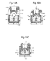
- FIGS. 10A, 10B and 10C are enlarged, fragmentary, cross-sectional views of the cable enclosure assembly of FIG. 1 with the compression feature of the cable enclosure assembly is in various positions.
- FIG. 11 is an enlarged, fragmentary, cross-sectional view of the splice connection assembly of FIG. 1 taken along the line 11 - 11 of FIG. 10C .
- FIG. 12 is an enlarged, fragmentary, cross-sectional view of an alternative embodiment of the cable enclosure assembly wherein a triple point filler feature is not provided.
- spatially relative terms such as “under”, “below”, “lower”, “over”, “upper” and the like, may be used herein for ease of description to describe one element or feature's relationship to another element(s) or feature(s) as illustrated in the figures. It will be understood that the spatially relative terms are intended to encompass different orientations of the device in use or operation in addition to the orientation depicted in the figures. For example, if the device in the figures is turned over, elements described as “under” or “beneath” other elements or features would then be oriented “over” the other elements or features. Thus, the exemplary term “under” can encompass both an orientation of over and under. The device may be otherwise oriented (rotated 90 degrees or at other orientations) and the spatially relative descriptors used herein interpreted accordingly.
- Embodiments of the present invention provide cable enclosure assemblies for securing and/or environmentally protecting cable terminations or splices. More particularly, according to some embodiments, a cable enclosure assembly includes a cable sealant and a mechanism to displace the cable sealant about a circumference of the cable to effect improved or complete coverage of the sealant about the cable. According to some embodiments, a mechanism is provided to close or fill a sealant triple point void to prevent the formation of an unsealed passageway. Still further embodiments provide mechanisms for resisting pull out of the cable from the enclosure and/or for resisting push in or intrusion of the cable into the enclosure without requiring the use of bolts, clamps, or the like.
- the cable enclosure assembly 100 includes a first housing part 110 (referred to herein as the “top housing part”), a second housing part 130 (referred to herein as the “bottom housing part”), a strain relief member 160 , two masses of flowable cable sealant 50 and flowable perimeter sealant 56 .
- the assembly 100 includes a hinge mechanism 102 ( FIG. 2 ) so that the housing parts 110 , 130 are relatively pivotable between an open position as shown in FIG. 1 and a closed position as shown in FIG. 2 . In the closed position, the assembly 100 defines a chamber 106 ( FIG. 1 ).
- the assembly 100 may be referred to as a clamshell cable enclosure. Cable ports 104 ( FIG. 2 ) communicate with the chamber 106 and the exterior of the assembly 100 .
- the assembly 100 may be used with cables 20 to form a splice connection assembly 5 ( FIGS. 1 and 2 ), for example.
- the cables 20 are each optical fiber flat drop cables including an optical fiber 28 , an inner jacket or buffer tube 26 surrounding the optical fiber 28 , a pair of strength members 24 , and an outer jacket 22 surrounding the components 24 , 26 , 28 .
- the jacket 22 and the buffer tube 26 may be formed of any suitable material, such as a polymeric material.
- the jacket 22 may be extruded over the strength members 24 and the buffer tube 26 . According to some embodiments, the jacket 22 tightly covers and conforms to the strength members 24 and the buffer tube 26 .
- the optical fiber 28 may be loosely contained in the buffer tube 26 .
- a gel or other sealant may be placed in the buffer tube 26 .
- the strength members 24 may be formed of any suitable material, including a relatively stiff, hard material.
- Suitable materials for the strength members may include steel or fiberglass.
- the optical fiber 28 may be formed of glass, for example. While a single optical fiber 28 is shown in each cable 20 , one or both of the cables 20 may include multiple optical fibers (e.g., twelve each) bundled in a common buffer tube 26 , for example.
- Each cable 20 has a longitudinal or lengthwise cable axis A-A ( FIG. 5 ), a cross-sectional width dimension D ( FIG. 6 ), and a cross-sectional height dimension C ( FIG. 6 ) that is greater than the width dimension D.
- the top housing part 110 includes a body 112 , hinge structures 114 , latch structures 115 , a perimeter sealing flange 116 , locator structures 118 , 119 , and a compression feature or projection 120 .
- the bottom housing part 130 includes a body 132 , hinge structures 134 ( FIG. 2 ), latch structures 135 , a perimeter sealant channel 136 ( FIG. 3 ), a pair of containment wall structures 140 ( FIGS. 3, 4 and 8 ), and a pair of strength member pocket wall structures 150 ( FIGS. 3-5, 7 and 8 ).
- the hinge structures 134 mate with the hinge structures 114 to form the hinge mechanism 102 ( FIG. 2 ).
- the latch structures 135 mate with the latch structures 115 to lock the assembly 100 in the closed position ( FIG. 2 ).
- the perimeter sealant 56 is disposed in the perimeter channel 136 .
- each wall structure 140 defines a cable passage 142 communicating with a respective one of the cable ports 104 ( FIG. 2 ).
- the wall structure 140 further defines a rear slot 144 , a sealant cavity 146 and a strain relief member holding slot 148 .
- a mass of cable sealant 50 ( FIG. 8 ) is disposed in each sealant cavity 146 .
- each strength member pocket wall structure 150 includes an inner wall 150 A, an end wall 150 B, and an outer wall 150 C collectively defining a strength member pocket or cavity 152 ( FIG. 7 ) and a sideward opening 154 ( FIG. 7 ) communicating with the strength member pocket 152 .
- the housing parts 110 , 130 may each be formed of any suitable material. According to some embodiments, the housing parts 110 , 130 are formed of a polymeric material. Suitable polymeric materials may include, polypropylene and its derivatives, or polycarbonate, for example.
- the strain relief member 160 includes a base strip 162 , a pair of upstanding opposed side posts 164 , and a pair of opposed engagement tabs 166 .
- Each engagement tab 166 has a fixed end 166 A adjoining a respective one of the posts 164 so that the engagement tab 166 is flexibly cantilevered from the post 164 .
- Each engagement tab 166 also has a knife edge 166 B opposite its fixed end 166 A. The knife edges 166 B and the base strip 162 together to find a general U-shaped cable slot 168 therebetween and a top opening 169 communicating with the top end of the cable slot 168 .
- the strain relief member 160 is securely mounted in the slot 148 of the bottom housing part 130 .
- the base strip 162 and the side posts 164 are press fit into the slot 148 .
- the slot 148 is shaped to permit the blade tabs 166 to deflect inwardly (i.e., away from the cable port 104 ) up to a prescribed deflection distance.
- the cable slot 168 defines a passthrough axis B-B ( FIG. 7 ) extending lengthwise through the cable slot 168 .
- the knife edges 166 B also define a blade axis G-G ( FIG. 6 ) transverse (according to some embodiments and as shown, perpendicular) to the passthrough axis B-B.
- the fixed ends 166 A define a primary strain relief member plane P-P ( FIGS. 5 and 7 ) and the blade tabs 166 are angled out of the plane P-P and taper radially inwardly with respect to the pass through axis B-B in a direction away from the port 104 .
- a slot plane N-N ( FIGS. 5 and 7 ) defined by the blade edges 166 B is substantially orthogonal to the passthrough axis B-B.
- the blade tabs 166 are each disposed at an angle of between about 10 and 20 degrees with respect to the plane P-P.
- the cable slot 168 has a nominal width F and a height E ( FIG. 6 ). According to some embodiments, the width F is less than the nominal outer diameter D of the smallest cable 20 intended for use with the assembly 100 . According to some embodiments, the width F is at least 0.6 inch less than the nominal outer diameter of the smallest cable 20 intended for use with the assembly 100 .
- the compression feature 120 may be integrally molded with the body 112 of the top housing part 110 .
- the compression feature 120 includes an inner engagement surface 122 having opposed side surfaces 122 A, 122 B.
- the surface 122 is generally arcuate and concave (according to some embodiments, generally cup-shaped) in cross-section so that the channel defined thereby is truncated cylindrical (e.g., semi-cylindrical) overall.
- each side surface 122 A, 122 B forms an angle K ( FIG. 9 ) of between about 25 and 45 degrees with respect to the blade axis G-G.
- the compression feature 120 may define opposed prongs 126 extending toward the sealant cavity 146 when the assembly 100 is closed.
- a triple point filler feature 128 extends downwardly from the engagement surface 122 .
- the triple point filler feature 128 may take the form of a lengthwise extending ridge.
- the triple point filler feature 128 is generally arcuate and convex in cross-section so that it is truncated cylindrical (e.g., semi-cylindrical) overall.
- a plurality of clips 108 may be mounted in the bottom housing part 130 and used to manage the optical fibers 28 as discussed below.
- One or more splice holders 109 may be mounted in the bottom housing part 130 and used to hold one or more splices as discussed below.
- the sealants 50 , 56 may be any suitable sealants. According to some embodiments, the sealant 50 is a gel sealant. According to some embodiments, the sealant 56 is a gel sealant. According to some embodiments, both of the sealants 50 , 56 are gel sealants.
- gel refers to the category of materials which are solids extended by a fluid extender. The gel may be a substantially dilute system that exhibits no steady state flow. As discussed in Ferry, “Viscoelastic Properties of Polymers,” 3 rd ed. P. 529 (J. Wiley & Sons, New York 1980), a polymer gel may be a cross-linked solution whether linked by chemical bonds or crystallites or some other kind of junction.
- the absence of the steady state flow may be considered to be the definition of the solid-like properties while the substantial dilution may be necessary to give the relatively low modulus of gels.
- the solid nature may be achieved by a continuous network structure formed in the material generally through crosslinking the polymer chains through some kind of junction or the creation of domains of associated substituents of various branch chains of the polymer.
- the crosslinking can be either physical or chemical as long as the crosslink sites may be sustained at the use conditions of the gel.
- Gels for use in this invention may be silicone (organopolysiloxane) gels, such as the fluid-extended systems taught in U.S. Pat. No. 4,634,207 to Debbaut (hereinafter “Debbaut '207”); U.S. Pat. No. 4,680,233 to Camin et al.; U.S. Pat. No. 4,777,063 to Dubrow et al.; and U.S. Pat. No. 5,079,300 to Dubrow et al. (hereinafter “Dubrow '300”), the disclosures of each of which are hereby incorporated herein by reference.
- silicone organopolysiloxane
- silicone gels may be created with non-reactive fluid extenders as in the previously recited patents or with an excess of a reactive liquid, e.g., a vinyl-rich silicone fluid, such that it acts like an extender, as exemplified by the Sylgarde 200 product commercially available from Dow-Corning of Midland, Mich. or as disclosed in U.S. Pat. No. 3,020,260 to Nelson. Because curing is generally involved in the preparation of these gels, they are sometimes referred to as thermosetting gels.
- a reactive liquid e.g., a vinyl-rich silicone fluid
- the gel may be a silicone gel produced from a mixture of divinyl terminated polydimethylsiloxane, tetrakis (dimethylsiloxy)silane, a platinum divinyltetramethyldisiloxane complex, commercially available from United Chemical Technologies, Inc. of Bristol, Pa., polydimethylsiloxane, and 1,3,5,7-tetravinyltetra-methylcyclotetrasiloxane (reaction inhibitor for providing adequate pot life).
- Gels may be used, for example, polyurethane gels as taught in the aforementioned Debbaut '261 and U.S. Pat. No. 5,140,476 to Debbaut (hereinafter “Debbaut '476”) and gels based on styrene-ethylene butylenestyrene (SEBS) or styrene-ethylene propylene-styrene (SEPSS) extended with an extender oil of naphthenic or nonaromatic or low aramatic content hydrocarbon oil, as described in U.S. Pat. No. 4,369,284 to Chen; U.S. Pat. No. 4,716,183 to Gamarra et al.; and U.S. Pat. No.
- SEBS styrene-ethylene butylenestyrene
- SEPSS styrene-ethylene propylene-styrene
- the SEBS and SEPS gels comprise glassy styrenic microphases interconnected by a fluid-extended elastomeric phase.
- the microphase-separated styrenic domains serve as the junction points in the systems.
- the SEBS and SEPS gels are examples of thermoplastic systems.
- EPDM rubber-based gels as described in U.S. Pat. No. 5,177,143 to Chang et al.
- Yet another class of gels which may be used are based on anhydride-containing polymers, as disclosed in WO 96/23007. These gels reportedly have good thermal resistance.
- the gel may include a variety of additives, including stabilizers and antioxidants such as hindered phenols (e.g., IrganoxTM 1076, commercially available from Ciba-Geigy Corp. of Tarrytown, N.Y.), phosphites (e.g, IrgafosTM 168, commercially available from Ciba-Geigy Corp. of Tarrytown, N.Y.), metal deactivators (e.g., IrganoxTM D1024 from Ciba-Geigy Corp. of Tarrytown, N.Y.), and sulfides (e.g., Cyanox LTDP, commercially available from American Cyanamid Co.
- stabilizers and antioxidants such as hindered phenols (e.g., IrganoxTM 1076, commercially available from Ciba-Geigy Corp. of Tarrytown, N.Y.), phosphites (e.g, Irgafos
- halogenated paraffins e.g., Bromoklor 50, commercially available from Ferro Corp. of Hammond, Ind.
- phosphorous containing organic compounds e.g., Fyrol PCF and Phosflex 390, both commercially available from Akzo Nobel Chemicals Inc. of Dobbs Ferry, N.Y.
- acid scavengers e.g., DHT-4A, commercially available from Kyowa Chemical Industry Co. Ltd through Mitsui & Co. of Cleveland, Ohio, and hydrotalcite.
- suitable additives include colorants, biocides, tackifiers and the like described in “Additives for Plastics, Edition 1” published by D.A.T.A., Inc. and The International Plastics Selector, Inc., San Diego, Calif.
- the hardness, stress relaxation, and tack may be measured using a Texture Technologies Texture Analyzer TA-XT2 commercially available from Texture Technologies Corp. of Scarsdale, N.Y., or like machines, having a five kilogram load cell to measure force, a 5 gram trigger, and 1 ⁇ 4 inch (6.35 mm) stainless steel ball probe as described in Dubrow '300, the disclosure of which is incorporated herein by reference in its entirety.
- TA-XT2 commercially available from Texture Technologies Corp. of Scarsdale, N.Y.
- a 60 mL glass vial with about 20 grams of gel, or alternately a stack of nine 2 inch ⁇ 2 inch ⁇ 1 ⁇ 8′′ thick slabs of gel is placed in the Texture Technologies Texture Analyzer and the probe is forced into the gel at the speed of 0.2 mm/sec to a penetration distance of 4.0 mm.
- the hardness of the gel is the force in grams, as recorded by a computer, required to force the probe at that speed to penetrate or deform the surface of the gel specified for 4.0 mm. Higher numbers signify harder gels.
- the data from the Texture Analyzer TA-XT2 may be analyzed on an IBM PC or like computer, running Microsystems Ltd, XT.RA Dimension Version 2.3 software.
- the tack and stress relaxation are read from the stress curve generated when the XT.RA Dimension version 2.3 software automatically traces the force versus time curve experienced by the load cell when the penetration speed is 2.0 mm/second and the probe is forced into the gel a penetration distance of about 4.0 mm. The probe is held at 4.0 mm penetration for 1 minute and withdrawn at a speed of 2.00 mm/second.
- the stress relaxation is the ratio of the initial force (F i ) resisting the probe at the pre-set penetration depth minus the force resisting the probe (F f ) after 1 min divided by the initial force F i , expressed as a percentage. That is, percent stress relaxation is equal to
- the stress relaxation is the ratio of the initial force minus the force after 1 minute over the initial force. It may be considered to be a measure of the ability of the gel to relax any induced compression placed on the gel.
- the tack may be considered to be the amount of force in grams resistance on the probe as it is pulled out of the gel when the probe is withdrawn at a speed of 2.0 mm/second from the preset penetration depth.
- Cone penetration (“CP”) values may range from about 70 (10 ⁇ 1 mm) to about 400 (10 ⁇ 1 mm).
- Harder gels may generally have CP values from about 70 (10 ⁇ 1 mm) to about 120 (10 ⁇ 1 mm).
- Softer gels may generally have CP values from about 200 (10 ⁇ 1 mm) to about 400 (10 ⁇ 1 mm), with particularly preferred range of from about 250 (10 ⁇ 1 mm) to about 375 (10 ⁇ 1 mm).
- CP values from about 200 (10 ⁇ 1 mm) to about 400 (10 ⁇ 1 mm)
- particularly preferred range of from about 250 (10 ⁇ 1 mm) to about 375 (10 ⁇ 1 mm).
- a relationship between CP and Voland gram hardness can be developed as proposed in U.S. Pat. No. 4,852,646 to Dittmer et al.
- the gel has a Voland hardness, as measured by a texture analyzer, of between about 5 and 100 grams force.
- the gel may have an elongation, as measured by ASTM D-638, of at least 55%. According to some embodiments, the elongation is of at least 100%.
- the gel may have a stress relaxation of less than 80%.
- the gel may have a tack greater than about 1 gram.
- Suitable gel materials include POWERGEL sealant gel available from Tyco Electronics Energy Division of Fuquay-Varina, N.C. under the RAYCHEM brand.
- sealants 50 , 56 are gels as described above, other types of sealants may be employed.
- the sealants 50 , 56 may be silicone grease or hydrocarbon-based grease.
- the sealants 50 , 56 are initially provided only in the bottom housing part 130 .
- the assembly 100 as manufactured may include sealant only in the bottom housing part 130 with the top housing part 110 being free of sealant.
- the assembly 100 may be used in the following manner to form a splice connection assembly 5 , for example.
- Each cable 20 is prepared. More particularly, the outer jacket 22 , the strength members 24 , the buffer tube 26 and the optical fiber 29 are trimmed to provide an outer jacket terminal end 22 A, respective strength member terminal ends 24 A extending beyond the jacket terminal end 22 A, and a buffer tube terminal end 26 A extending beyond the strength member terminal ends 24 A, with the optical fiber 28 extending beyond the buffer tube terminal end 26 A.
- Each of the cables 20 is aligned with one of the cable passages 142 and its associated cable port 104 .
- the cable 20 is then pressed downwardly so that the jacket 22 slides into the passage 142 , the cable slot 168 of the strain relief member 160 , and the cable sealant 50 .
- the cable 20 displaces the cable sealant 50 so that the portion of the cable 20 in the sealant cavity 146 becomes at least partially surrounded by the cable sealant 50 .
- the cable 20 may form a sealant void or trough 52 in the cable sealant 50 .
- the cable enters the cable slot 168 through the top opening 169 .
- the relative shapes of the cable 20 and the slot 168 ensure that the cable 20 slides into the cable slot 168 along the blade axis G-G and is properly oriented during insertion and once seated.
- the blade tabs 166 may deflect or flare inwardly (i.e., away from the port 104 ) to expand to accommodate the cable width D.
- the cable axis A-A extends substantially orthogonal to the slot plane N-N.
- the knife edges 166 B of the blade tabs 166 cut radially into the outer jacket 22 of the cable 20 a distance M ( FIG. 6 ).
- the cut depth M is at least about 0.005 inch.
- the cut depth M is between about 0.005 and 0.025 inch.
- the knife edges 166 B cut into the outer jacket 22 but do not cut into the buffer tube 26 .
- the alignment of the strength members 24 along the blade axis G-G ensures that, in the event the knife edges 166 B cut more deeply through the outer jacket 22 (for example, as a result of vibration or tensioning of the cable 20 ), the knife edges 166 B will engage the strength members 24 before engaging the buffer tube 26 , thereby inhibiting or preventing the knife edges 166 B from cutting through the buffer tube 26 .
- the strength member 24 is routed or laid into the strength member pocket 152 such that the strength member terminal ends 24 A are positioned adjacent the end wall 150 B as shown in FIGS. 4 and 5 .
- the gap defined between the terminal ends 24 A and the end wall 150 B is in the range of from about zero to 0.15 inch.
- the buffer tube 26 is routed out of the cable passage 142 through the side opening 154 , around the wall structure 140 , and into the main chamber 106 of the bottom housing part 130 as shown in FIGS. 3 and 4 .
- the optical fiber 28 may be wound about the chamber 106 and retained by the clips 108 and ultimately spliced (e.g., by splice fusing) to the fiber 28 of the other cable 20 .
- the splice may be mounted in the splice holder 109 .
- the top housing part 110 is then mounted on the bottom housing part 130 .
- the hinge structures 114 are interlocked with the hinge structures 134 to form the hinge mechanism 102 as shown in FIG. 1 .
- the housing parts 110 , 130 may be pre-coupled by the hinge mechanism 102 or another suitable releasable or permanent hinge mechanism.
- the housing parts 110 , 130 are pivoted with respect to one another about the hinge mechanism 102 to close the assembly 100 until the latch structures 115 , 135 interlock to secure the assembly in its closed position.
- the closure of the assembly 100 also effectuates a perimeter environmental seal and environmental seals about each of the cables 20 .
- the perimeter seal is created by the sealant channel 136 , the perimeter sealant 56 and the perimeter flange 116 .
- the flange 116 enters the channel 136 and displaces the sealant 56 .
- This perimeter seal may be maintained so long as the latch structures 115 , 136 remain interlocked.
- Each cable seal is provided by the respective cable sealant 50 , wall structure 140 , and compression feature 120 .
- lateral insertion of the cable 20 into the cable sealant 50 will result in unreliable, incomplete or inadequate coverage of the cable 20 with sealant.
- insertion of the cable 20 into the cable sealant 50 may form a sealant trough 52 .
- the compression feature 120 serves to displace the cable sealant 50 in a manner that ensures proper ultimate positioning of the cable sealant 50 .
- FIGS. 10A-10C and 11 show a closure sequence of the assembly 100 .
- the compression feature 120 is moved in an installation direction V ( FIG. 10A ) toward the sealant cavity 146 .
- the cable 20 is installed in the strain relief member 160 and the top housing part 110 is still spaced apart from the bottom housing part 130 in a ready position such that the compression member 120 does not yet engage the cable sealant 50 .
- the top housing part 110 is partially closed onto the bottom housing part 130 .
- the cable sealant 50 is partially displaced by the compression feature 120 .
- FIGS. 10C and 11 the assembly 100 is fully closed and the cable sealant 50 is fully displaced by the compression member 120 , which is in an installed position.
- the compression member 120 is seated in the sealant cavity 146 .
- the compression member 120 (and, more particularly, the engagement surfaces 122 A, 122 B ( FIG. 9 )) is shaped such that it forces the cable sealant 50 to flow about the cable 20 in opposed inward directions Q and R ( FIG. 10B ) transverse (e.g, perpendicular) or generally radial to the cable axis A-A ( FIG. 3 ) and transverse to the installation direction V to circumferentially surround the portion of the cable 20 in the sealant cavity 146 .
- the engagement surfaces 122 A, 122 B apply a compressive load to the cable sealant 50 in each of the sideward directions Q, R and a downward direction T ( FIG.
- a sealant trough 52 may initially be present in the cable sealant 50 .
- the compression member 120 may be configured to force the cable sealant 50 to flow about the cable 20 to fill the trough 52 with sealant 50 when the compression member 120 is moved into the closed position.
- a buffer region 60 ( FIG. 10C ) is defined between the cable 20 and the compression feature 120 .
- the compression feature 120 forces the cable sealant 50 to flow into and fill, at least in part, the buffer region 60 .
- the locator features 118 , 119 serve to ensure that the cable 20 is properly spaced apart from the compression member 120 to maintain the buffer region 60 .
- the locator features 118 , 119 also serve to properly position the cable 20 in the cable slot 168 of the strain relief member 160 .
- the triple point filler feature 128 may serve to fill a triple point channel 54 in the cable sealant 50 when the assembly 100 is closed.
- a compression feature 120 ′ having no triple point filler feature 128 is provided.
- sealants such as gels, mastics and viscous materials are compressed around an object, they may meet at a triple point 54 .
- a triple point is an intersection of three sealing surfaces where a roughly triangular leak path is created. Typically, this leak path should be sealed off. In many cases, extraordinarily high pressures must be applied to the sealant in order to reduce this triangular leak path to zero and create a perfect or satisfactory seal. As the triangular space becomes smaller and smaller, more and more pressure is required to eliminate the space or leak path.
- the triple point filler feature 128 fills the triple point channel 54 so that it is not necessary to eliminate the triple point channel 54 by further displacing the sealant 50 .
- the triple point filler feature 128 may greatly reduce the amount of compression required to force the cable sealant 50 to completely seal about the portion of the cable 20 without permitting remaining leak paths.
- the strain relief member 160 and the protrusion pocket wall structure 150 may reliably and satisfactorily secure each cable 20 in the assembly 100 without requiring the use of bolts, clamps, or the like to secure the strength members 24 .
- the cable 20 is strain relieved and pull out is limited or prevented by the strain relief member 160 .
- the blade tabs 166 may function like barbs and grip the cable 20 more tightly when the cable 20 is pulled away from the assembly 100 , thereby tenaciously preventing axial withdrawal of the cable 20 from the assembly 100 .
- the strain relief member 160 and the pocket wall structure 150 may separate the functions of limiting or resisting withdrawal of the cable 20 from the assembly 100 and limiting or resisting insertion or protrusion of the cable into the assembly 100 .
- the slot 168 of the strain relief member 160 may have a width F that is much less than the width D of the cable 20 so that the cable 20 can only be inserted into the slot 168 in one orientation, namely, such that its height dimension C (i.e., the greater cross-sectional dimension) is parallel to or substantially coincident with the slot depthwise axis or blade axis G-G.
- This may ensure that the symmetrical axis G-G of the slot 168 passes through the center of each strength member 24 and the buffer tube 26 containing the fiber 28 .
- this configuration may ensure that the knife edges 166 B contact the strength members 24 before contacting the buffer tube 26 , thereby preventing damage to the fiber 28 itself.
- the strength member pocket wall structure 150 may serve to limit or prevent axial sliding of the cable 20 or the strength members 24 into the enclosure 100 .
- the terminal ends 24 A of the strength member 24 will abut the end wall 150 B to resist cable intrusion that may damage the fiber 28 .
- Strength member protrusion is a known phenomenon wherein cable strength members extend and retract in length as a result of thermal expansion and contraction.
- the pocket wall structure 150 defines the strength member pocket 152 within which the strength members 24 will be contained in the event the strength members protrude inwardly (i.e., generally in an intrusion direction H ( FIG. 7 )), thereby preventing the strength members 24 from progressing further inwardly and damaging the fiber 28 .
- the width I and the contained depth J ( FIG. 7 ) of the pocket 152 are selected to be sufficiently narrow and short that the strength members 24 cannot buckle under columnar loading in the even the strength members 24 protrude in and bottom out in the pocket 152 .
- the strength members 24 are trimmed and installed in the pocket 152 such that the initial spacing W ( FIG. 5 ) between the terminal ends 24 A of the strength members 24 and the wall 150 B is in the range of from about zero to 0.15 inch.
- the side opening 154 ( FIG. 7 ) is sized and positioned to allow the buffer tube 26 to pass around the wall structure 150 without excessively bending the fiber 28 in the buffer tube 26 .
- the cable sealing system can provide an effective, reliable and convenient environmental seal about a cable.
- the cable sealing system may be particularly well-suited for small diameter fiber optic cables (e.g., from about 0.1 to 0.3 inch in diameter).
- the sealing system may be employed with flat drop fiber optic cables having an approximately oval cross-section.
- the cable sealing system may allow the use of a two-piece or two-sided housing assembly having sealant in only one piece or side of the housing assembly.
- the piston (i.e., compression feature 120 ) and bore (i.e., cable sealant cavity 146 defined by the wall structure 140 ) configuration of the cable sealing system may enable relatively high compression loading of the sealant 50 while also limiting egress of the sealant 50 from the sealant cavity 146 or the assembly 100 .
- the compression feature 120 is located adjacent the hinge mechanism 102 and distal from the opposed, free ends of the housing parts 110 , 130 , the assembly may provide improved mechanical leverage advantage so that substantial compression loading can be imparted to the sealant 50 by manually closing the assembly 100 .
- the assembly 100 may provide a reliable (and, in at least some embodiments, moisture-tight) seal between the assembly 100 and the cables 20 .
- the sealant 50 may accommodate cables of different sizes within a prescribed range.
- the compression feature 120 applies a compressive force to the sealant 50 .
- the gel is thereby elongated and is generally deformed and substantially conforms to the outer surface of the cable 20 and to the inner surfaces of the assembly 100 . Some shearing of the gel may occur as well.
- at least some of the gel deformation is elastic. The restoring force in the gel resulting from this elastic deformation causes the gel to operate as a spring exerting an outward force between the assembly 100 and the cable 20 .
- each sealant 50 , 56 is a self-healing or self-amalgamating gel.
- cables 20 having optical fibers 28 as transmission media have been disclosed herein, according to further embodiments, cables having other types of transmission media (e.g., electrical conductors formed of copper or other metal) may be used.
Abstract
Description
Claims (45)
Priority Applications (1)
| Application Number | Priority Date | Filing Date | Title |
|---|---|---|---|
| US13/272,849 USRE45951E1 (en) | 2007-01-16 | 2011-10-13 | Cable enclosure assemblies and methods for using the same |
Applications Claiming Priority (3)
| Application Number | Priority Date | Filing Date | Title |
|---|---|---|---|
| US88508107P | 2007-01-16 | 2007-01-16 | |
| US11/980,284 US7603018B2 (en) | 2007-01-16 | 2007-10-30 | Cable enclosure assemblies and methods for using the same |
| US13/272,849 USRE45951E1 (en) | 2007-01-16 | 2011-10-13 | Cable enclosure assemblies and methods for using the same |
Related Parent Applications (1)
| Application Number | Title | Priority Date | Filing Date |
|---|---|---|---|
| US11/980,284 Reissue US7603018B2 (en) | 2007-01-16 | 2007-10-30 | Cable enclosure assemblies and methods for using the same |
Publications (1)
| Publication Number | Publication Date |
|---|---|
| USRE45951E1 true USRE45951E1 (en) | 2016-03-29 |
Family
ID=39616888
Family Applications (4)
| Application Number | Title | Priority Date | Filing Date |
|---|---|---|---|
| US11/980,284 Ceased US7603018B2 (en) | 2007-01-16 | 2007-10-30 | Cable enclosure assemblies and methods for using the same |
| US11/978,780 Ceased US7477826B2 (en) | 2007-01-16 | 2007-10-30 | Cable enclosure assemblies and methods for using the same |
| US12/930,789 Active USRE46547E1 (en) | 2007-01-16 | 2011-01-13 | Cable enclosure assemblies and methods for using the same |
| US13/272,849 Active 2028-05-08 USRE45951E1 (en) | 2007-01-16 | 2011-10-13 | Cable enclosure assemblies and methods for using the same |
Family Applications Before (3)
| Application Number | Title | Priority Date | Filing Date |
|---|---|---|---|
| US11/980,284 Ceased US7603018B2 (en) | 2007-01-16 | 2007-10-30 | Cable enclosure assemblies and methods for using the same |
| US11/978,780 Ceased US7477826B2 (en) | 2007-01-16 | 2007-10-30 | Cable enclosure assemblies and methods for using the same |
| US12/930,789 Active USRE46547E1 (en) | 2007-01-16 | 2011-01-13 | Cable enclosure assemblies and methods for using the same |
Country Status (1)
| Country | Link |
|---|---|
| US (4) | US7603018B2 (en) |
Cited By (4)
| Publication number | Priority date | Publication date | Assignee | Title |
|---|---|---|---|---|
| US10306793B2 (en) * | 2015-09-14 | 2019-05-28 | CommScope Connectivity Belgium BVBA | Longitudinal radial seal |
| US20220334337A1 (en) * | 2017-04-25 | 2022-10-20 | CommScope Connectivity Belgium BVBA | Connection module for cable seal gel block |
| US20220357521A1 (en) * | 2021-05-06 | 2022-11-10 | Odu Gmbh & Co. Kg | Connector device, connector and connection cable |
| US11515696B2 (en) * | 2019-12-17 | 2022-11-29 | Te Connectivity Solutions Gmbh | Electrical component enclosure with injected seal and method |
Families Citing this family (113)
| Publication number | Priority date | Publication date | Assignee | Title |
|---|---|---|---|---|
| CN101170247B (en) * | 2006-10-27 | 2010-05-19 | 3M新设资产公司 | Re-accessible connector enclosing cover |
| US7603018B2 (en) | 2007-01-16 | 2009-10-13 | Tyco Electronics Corporation | Cable enclosure assemblies and methods for using the same |
| US7822310B2 (en) * | 2007-02-28 | 2010-10-26 | Corning Cable Systems Llc | Fiber optic splice trays |
| US7799995B2 (en) * | 2007-08-27 | 2010-09-21 | Tyco Electronics Corporation | Sealing assemblies for elongate members and methods for using the same |
| NZ584265A (en) * | 2007-08-27 | 2011-10-28 | Tyco Electronics Corp | Enclosure assembly with control clip for a fiber optic cable |
| US8798427B2 (en) | 2007-09-05 | 2014-08-05 | Corning Cable Systems Llc | Fiber optic terminal assembly |
| EP2238493A2 (en) * | 2008-01-09 | 2010-10-13 | ADC Telecommunications, Inc. | Wall box adapted to be mounted at a mid-span access location of a telecommunications cable |
| US7970249B2 (en) * | 2008-02-15 | 2011-06-28 | Adc Telecommunications, Inc. | Fiber optic splice enclosure |
| US7889961B2 (en) | 2008-03-27 | 2011-02-15 | Corning Cable Systems Llc | Compact, high-density adapter module, housing assembly and frame assembly for optical fiber telecommunications |
| US8718434B2 (en) * | 2008-07-01 | 2014-05-06 | Adc Telecommunications, Inc. | Cable enclosure with sealed cable entry port |
| US8452148B2 (en) | 2008-08-29 | 2013-05-28 | Corning Cable Systems Llc | Independently translatable modules and fiber optic equipment trays in fiber optic equipment |
| US11294135B2 (en) | 2008-08-29 | 2022-04-05 | Corning Optical Communications LLC | High density and bandwidth fiber optic apparatuses and related equipment and methods |
| EP2344915A4 (en) | 2008-10-09 | 2015-01-21 | Corning Cable Sys Llc | Fiber optic terminal having adapter panel supporting both input and output fibers from an optical splitter |
| US8879882B2 (en) | 2008-10-27 | 2014-11-04 | Corning Cable Systems Llc | Variably configurable and modular local convergence point |
| ES2735999T3 (en) * | 2008-12-09 | 2019-12-23 | Prysmian Spa | Optical cable with dry core and dry protection tubes |
| CN102365572A (en) * | 2009-01-28 | 2012-02-29 | Adc电信公司 | Fiber optic enclosure |
| US8170391B2 (en) * | 2009-02-11 | 2012-05-01 | Adc Telecommunications, Inc. | Fiber optic strain relief assembly |
| US8554042B2 (en) * | 2009-02-18 | 2013-10-08 | Commscope, Inc. | Optical fiber management shelf including door with push-push fastener |
| CN102326406B (en) * | 2009-02-18 | 2014-12-24 | 北卡罗来纳康姆斯科普公司 | Fiber management shelf having removable door, push-push fastening elements, stackable side retainer rings and reduced profile front retainer rings |
| ATE534049T1 (en) | 2009-02-24 | 2011-12-15 | Ccs Technology Inc | CABLE HOLDING DEVICE OR ARRANGEMENT FOR USE WITH A CABLE |
| US20100220967A1 (en) * | 2009-02-27 | 2010-09-02 | Cooke Terry L | Hinged Fiber Optic Module Housing and Module |
| EP2237091A1 (en) | 2009-03-31 | 2010-10-06 | Corning Cable Systems LLC | Removably mountable fiber optic terminal |
| US8699838B2 (en) | 2009-05-14 | 2014-04-15 | Ccs Technology, Inc. | Fiber optic furcation module |
| US8538226B2 (en) * | 2009-05-21 | 2013-09-17 | Corning Cable Systems Llc | Fiber optic equipment guides and rails configured with stopping position(s), and related equipment and methods |
| US9075216B2 (en) | 2009-05-21 | 2015-07-07 | Corning Cable Systems Llc | Fiber optic housings configured to accommodate fiber optic modules/cassettes and fiber optic panels, and related components and methods |
| US8712206B2 (en) | 2009-06-19 | 2014-04-29 | Corning Cable Systems Llc | High-density fiber optic modules and module housings and related equipment |
| ES2793952T3 (en) | 2009-06-19 | 2020-11-17 | Corning Optical Communications LLC | High Density and Bandwidth Fiber Optic Apparatus |
| JP2012530943A (en) | 2009-06-19 | 2012-12-06 | コーニング ケーブル システムズ リミテッド ライアビリティ カンパニー | High fiber optic cable packaging density equipment |
| WO2011009060A2 (en) * | 2009-07-16 | 2011-01-20 | Adc Telecommunications, Inc. | Fiber optic enclosure with adapter bulkhead positioned beneath pivotal splice tray |
| US8467651B2 (en) * | 2009-09-30 | 2013-06-18 | Ccs Technology Inc. | Fiber optic terminals configured to dispose a fiber optic connection panel(s) within an optical fiber perimeter and related methods |
| US8625950B2 (en) | 2009-12-18 | 2014-01-07 | Corning Cable Systems Llc | Rotary locking apparatus for fiber optic equipment trays and related methods |
| US8992099B2 (en) | 2010-02-04 | 2015-03-31 | Corning Cable Systems Llc | Optical interface cards, assemblies, and related methods, suited for installation and use in antenna system equipment |
| US9547144B2 (en) | 2010-03-16 | 2017-01-17 | Corning Optical Communications LLC | Fiber optic distribution network for multiple dwelling units |
| US8913866B2 (en) | 2010-03-26 | 2014-12-16 | Corning Cable Systems Llc | Movable adapter panel |
| US8792767B2 (en) | 2010-04-16 | 2014-07-29 | Ccs Technology, Inc. | Distribution device |
| EP2558895B1 (en) | 2010-04-16 | 2019-04-17 | Corning Optical Communications LLC | Sealing and strain relief device for data cables |
| EP2381284B1 (en) | 2010-04-23 | 2014-12-31 | CCS Technology Inc. | Under floor fiber optic distribution device |
| US9075217B2 (en) | 2010-04-30 | 2015-07-07 | Corning Cable Systems Llc | Apparatuses and related components and methods for expanding capacity of fiber optic housings |
| US8879881B2 (en) | 2010-04-30 | 2014-11-04 | Corning Cable Systems Llc | Rotatable routing guide and assembly |
| US9632270B2 (en) | 2010-04-30 | 2017-04-25 | Corning Optical Communications LLC | Fiber optic housings configured for tool-less assembly, and related components and methods |
| US9519118B2 (en) | 2010-04-30 | 2016-12-13 | Corning Optical Communications LLC | Removable fiber management sections for fiber optic housings, and related components and methods |
| US8660397B2 (en) | 2010-04-30 | 2014-02-25 | Corning Cable Systems Llc | Multi-layer module |
| US9720195B2 (en) | 2010-04-30 | 2017-08-01 | Corning Optical Communications LLC | Apparatuses and related components and methods for attachment and release of fiber optic housings to and from an equipment rack |
| US8705926B2 (en) | 2010-04-30 | 2014-04-22 | Corning Optical Communications LLC | Fiber optic housings having a removable top, and related components and methods |
| WO2011162926A2 (en) | 2010-06-21 | 2011-12-29 | 3M Innovative Properties Company | Sealing member for an enclosure |
| US8718436B2 (en) | 2010-08-30 | 2014-05-06 | Corning Cable Systems Llc | Methods, apparatuses for providing secure fiber optic connections |
| WO2012044290A1 (en) * | 2010-09-29 | 2012-04-05 | Ipg Photonics Corporation | Method and system for encapsulating optical components |
| JP5963759B2 (en) | 2010-10-19 | 2016-08-03 | スリーエム イノベイティブ プロパティズ カンパニー | Enclosure for cable connection |
| CN103430072B (en) | 2010-10-19 | 2018-08-10 | 康宁光缆系统有限责任公司 | For the transformation box in the fiber distribution network of multitenant unit |
| EP2633356A4 (en) | 2010-10-26 | 2014-04-09 | Adc Telecommunications Inc | System and method for anchoring fiber optic cables to provide strain relief |
| US9279951B2 (en) | 2010-10-27 | 2016-03-08 | Corning Cable Systems Llc | Fiber optic module for limited space applications having a partially sealed module sub-assembly |
| US9116324B2 (en) | 2010-10-29 | 2015-08-25 | Corning Cable Systems Llc | Stacked fiber optic modules and fiber optic equipment configured to support stacked fiber optic modules |
| US8662760B2 (en) | 2010-10-29 | 2014-03-04 | Corning Cable Systems Llc | Fiber optic connector employing optical fiber guide member |
| CN203759315U (en) | 2010-11-30 | 2014-08-06 | 康宁光缆系统有限责任公司 | Optical fiber device |
| WO2012106510A2 (en) | 2011-02-02 | 2012-08-09 | Corning Cable Systems Llc | Dense fiber optic connector assemblies and related connectors and cables suitable for establishing optical connections for optical backplanes in equipment racks |
| RU2595645C2 (en) * | 2011-03-07 | 2016-08-27 | Тайко Электроникс Корпорейшн | Device for cable clamp with unloading cable tension and methods for use thereof |
| EP2503370A1 (en) * | 2011-03-25 | 2012-09-26 | CCS Technology Inc. | Indoor fiber optic distribution device and indoor fiber optic installation system |
| NL2006501C2 (en) * | 2011-03-31 | 2012-10-02 | Attema B V | Cassette for containing a splice element. |
| US8774585B2 (en) | 2011-04-12 | 2014-07-08 | Adc Telecommunications, Inc. | Strain-relief bracket for fiber optic closure |
| US9008485B2 (en) | 2011-05-09 | 2015-04-14 | Corning Cable Systems Llc | Attachment mechanisms employed to attach a rear housing section to a fiber optic housing, and related assemblies and methods |
| US9556336B2 (en) * | 2011-06-20 | 2017-01-31 | CommScope Connectivity Belgium BVBA | Dry silicone gels and their methods of making |
| US8642891B2 (en) | 2011-06-20 | 2014-02-04 | Tyco Electronics Amp Gmbh | Closure and interconnect systems and methods of using dry silicone gels in closure and interconnect systems |
| CN103649805B (en) | 2011-06-30 | 2017-03-15 | 康宁光电通信有限责任公司 | Fiber plant assembly of shell using non-U-width size and associated method |
| US8953924B2 (en) | 2011-09-02 | 2015-02-10 | Corning Cable Systems Llc | Removable strain relief brackets for securing fiber optic cables and/or optical fibers to fiber optic equipment, and related assemblies and methods |
| US8890050B2 (en) | 2011-11-21 | 2014-11-18 | Tyco Electronics Corporation | Photosensor circuits including a regulated power supply comprising a power circuit configured to provide a regulated power signal to a comparator of a pulse-width modulator |
| EP2597501A1 (en) * | 2011-11-22 | 2013-05-29 | Tyco Electronics Raychem BVBA | Cable build-up device and cable closure system |
| US9038832B2 (en) | 2011-11-30 | 2015-05-26 | Corning Cable Systems Llc | Adapter panel support assembly |
| US9219546B2 (en) | 2011-12-12 | 2015-12-22 | Corning Optical Communications LLC | Extremely high frequency (EHF) distributed antenna systems, and related components and methods |
| AU2011384239B2 (en) * | 2011-12-22 | 2016-02-11 | Prysmian S.P.A. | Retention assembly for flexible strength members of an optical cable |
| US10110307B2 (en) | 2012-03-02 | 2018-10-23 | Corning Optical Communications LLC | Optical network units (ONUs) for high bandwidth connectivity, and related components and methods |
| EP2837204A4 (en) | 2012-04-10 | 2015-12-23 | Tyco Electronics Corp | Extruded seal carrier and method of use |
| US9004778B2 (en) | 2012-06-29 | 2015-04-14 | Corning Cable Systems Llc | Indexable optical fiber connectors and optical fiber connector arrays |
| US9250409B2 (en) | 2012-07-02 | 2016-02-02 | Corning Cable Systems Llc | Fiber-optic-module trays and drawers for fiber-optic equipment |
| US9049500B2 (en) | 2012-08-31 | 2015-06-02 | Corning Cable Systems Llc | Fiber optic terminals, systems, and methods for network service management |
| US9042702B2 (en) | 2012-09-18 | 2015-05-26 | Corning Cable Systems Llc | Platforms and systems for fiber optic cable attachment |
| US8909019B2 (en) | 2012-10-11 | 2014-12-09 | Ccs Technology, Inc. | System comprising a plurality of distribution devices and distribution device |
| EP2725397B1 (en) | 2012-10-26 | 2015-07-29 | CCS Technology, Inc. | Fiber optic management unit and fiber optic distribution device |
| EP3722854B1 (en) | 2013-01-29 | 2023-05-24 | CommScope Connectivity Belgium BVBA | Optical fiber distribution system |
| RU2015139897A (en) | 2013-02-19 | 2017-03-27 | Тайко Электроникс Райхем Бвба | SEALED JOINT JOINT FOR COMMUNICATION EQUIPMENT |
| US8985862B2 (en) | 2013-02-28 | 2015-03-24 | Corning Cable Systems Llc | High-density multi-fiber adapter housings |
| CN105393151B (en) | 2013-04-24 | 2018-09-18 | 泰科电子瑞侃有限公司 | optical fiber distribution system |
| ES2735635T3 (en) | 2013-04-24 | 2019-12-19 | CommScope Connectivity Belgium BVBA | Universal mounting mechanism for mounting a telecommunications chassis in a telecommunications accessory |
| US9790051B2 (en) * | 2013-06-18 | 2017-10-17 | Commscope Technologies Llc | Conductor spool and optical fiber / electrical composite cable with conductor spool assembly |
| WO2015028619A2 (en) * | 2013-08-30 | 2015-03-05 | Tyco Electronics Raychem Bvba | Cable fixation device and method |
| WO2015106075A1 (en) | 2014-01-10 | 2015-07-16 | Tyco Electronics Raychem Bvba | Thermoplastic gel compositions and their methods of making |
| JP6445769B2 (en) | 2014-03-05 | 2018-12-26 | コーニング リサーチ アンド ディヴェロップメント コーポレイション | Cable gripping structure and optical fiber connector |
| CN105093442B (en) * | 2014-04-15 | 2018-08-24 | 泰科电子(上海)有限公司 | Cable connection protective device and its installation method |
| CN105093443B (en) | 2014-04-15 | 2018-02-16 | 泰科电子(上海)有限公司 | Cable connection protection device and its installation method |
| CN105093444B (en) | 2014-04-15 | 2018-06-26 | 泰科电子(上海)有限公司 | Cable connection protective device and its installation method |
| US9753239B2 (en) * | 2014-06-26 | 2017-09-05 | Commscope Technologies Llc | Fiber optic cable retention |
| AU2016239875C1 (en) | 2015-04-03 | 2021-06-24 | CommScope Connectivity Belgium BVBA | Telecommunications distribution elements |
| US9629954B2 (en) * | 2015-05-05 | 2017-04-25 | beteSTRONGCASES, LLC | Tube passage sealing system |
| EP3311210B1 (en) | 2015-06-19 | 2022-10-12 | Commscope Technologies LLC | Optical termination enclosure |
| ES2903246T3 (en) | 2015-09-14 | 2022-03-31 | CommScope Connectivity Belgium BVBA | Closing system for an enclosure |
| WO2017046063A1 (en) * | 2015-09-14 | 2017-03-23 | CommScope Connectivity Belgium BVBA | Sealing block arrangements for enclosures |
| AU2017266732A1 (en) * | 2016-05-18 | 2018-10-25 | CommScope Connectivity Belgium BVBA | Cable slack storage device |
| MX2019001248A (en) | 2016-09-07 | 2019-04-25 | Commscope Technologies Llc | Anisotropic cable sealing gels; and methods for fabricating cable sealing gels. |
| PT110213B (en) * | 2017-07-21 | 2020-09-29 | C3T Technologies, Sa | MULTI-LEVEL OPTICAL POINT FOR MOORING, CONNECTION, ACCOMMODATION AND DERIVATION OF EXTERNAL FIBER OPTIC CABLES ON A SUPPORT |
| EP3669221A4 (en) | 2017-08-18 | 2021-07-21 | Commscope Technologies LLC | Mst expansion closures; and methods |
| US11320617B2 (en) * | 2017-11-23 | 2022-05-03 | Prysmian S.P.A. | Connection box and method for connecting optical cables |
| US11422327B2 (en) * | 2018-02-13 | 2022-08-23 | Commscope Technologies Llc | Cable sealant arrangement for a sealed closure |
| EP3759535A4 (en) | 2018-02-28 | 2021-11-10 | CommScope Technologies LLC | Packaging assembly for telecommunications equipment |
| EP3762753A4 (en) | 2018-03-09 | 2021-11-10 | CommScope Technologies LLC | Cable seals with reinforcements |
| EP3781973A1 (en) | 2018-04-17 | 2021-02-24 | CommScope Connectivity Belgium BVBA | Telecommunications distribution elements |
| IT201800005665A1 (en) * | 2018-05-24 | 2019-11-24 | CONNECTION BOX, IN PARTICULAR FOR THE SEALING AND INSULATION OF ELECTRICAL AND SIMILAR CONNECTIONS | |
| DK3844972T3 (en) | 2018-08-31 | 2022-10-17 | CommScope Connectivity Belgium BVBA | FRAME ASSEMBLIES FOR OPTICAL FIBER DISTRIBUTION ELEMENTS |
| EP3844973A1 (en) | 2018-08-31 | 2021-07-07 | CommScope Connectivity Belgium BVBA | Frame assemblies for optical fiber distribution elements |
| WO2020043909A1 (en) | 2018-08-31 | 2020-03-05 | CommScope Connectivity Belgium BVBA | Frame assemblies for optical fiber distribution elements |
| EP3845044B1 (en) | 2018-08-31 | 2023-02-15 | CommScope Connectivity Belgium BVBA | Frame assemblies for optical fiber distribution elements |
| WO2020152347A1 (en) | 2019-01-25 | 2020-07-30 | CommScope Connectivity Belgium BVBA | Frame assemblies for optical fiber distribution elements |
| WO2020185882A1 (en) * | 2019-03-13 | 2020-09-17 | Commscope Technologies Llc | Re-enterable enclosure with environmental sealing |
| WO2020205313A1 (en) * | 2019-03-29 | 2020-10-08 | Commscope Technologies Llc | Fiber management components for telecommunications closures |
| EP4041359A1 (en) * | 2019-11-26 | 2022-08-17 | Boston Scientific Scimed, Inc. | Medical device packaging system |
Citations (27)
| Publication number | Priority date | Publication date | Assignee | Title |
|---|---|---|---|---|
| JPS6389809A (en) | 1986-10-03 | 1988-04-20 | Nippon Telegr & Teleph Corp <Ntt> | Half-divided type branching connection case |
| US4849580A (en) | 1988-02-11 | 1989-07-18 | Minnesota Mining And Manufacturing Company | Environmental protection closure for wire splices; and method |
| US4954098A (en) | 1989-11-01 | 1990-09-04 | Minnesota Mining And Manufacturing Company | Sealed insulation displacement connector |
| US4986625A (en) * | 1985-12-26 | 1991-01-22 | Amp Incorporated | Optical fiber connector with retainer |
| US5030136A (en) | 1989-04-14 | 1991-07-09 | Minnesota Mining And Manufacturing Company | Connector for cables |
| US5044719A (en) * | 1989-08-11 | 1991-09-03 | Amp Incorporated | Cable connector |
| JPH05315020A (en) | 1992-05-12 | 1993-11-26 | Nitto Denko Corp | Cover for waterproofing electric wire connecting portion |
| US5347084A (en) | 1991-06-07 | 1994-09-13 | Raychem Corporation | Hinged gel-filled security and environmental protection device |
| US5397859A (en) | 1993-12-10 | 1995-03-14 | The Whitaker Corporation | Enclosure with sealant for spliced coaxial cables |
| US5410105A (en) | 1992-09-21 | 1995-04-25 | Nitto Denko Corporation | Method for waterproofing junction of main and branch wires and cover therefor |
| DE29605927U1 (en) | 1996-04-02 | 1996-07-04 | Lohmeier Schaltschranksysteme | switch cabinet |
| US5569882A (en) | 1993-11-10 | 1996-10-29 | Yazaki Corporation | Waterproof protective cover |
| US5674089A (en) | 1994-06-01 | 1997-10-07 | Raychem Corporation | Environmental protection device manually operated latch mechanism |
| US5758004A (en) * | 1995-03-31 | 1998-05-26 | Minnesota Mining And Manufacturing Company | Closure with cable strain relief |
| US5763835A (en) | 1995-11-01 | 1998-06-09 | Raychem Corporation | Gel-filled closure |
| US5796041A (en) | 1995-05-29 | 1998-08-18 | Yazaki Corporation | Waterproof protective cover |
| US6111201A (en) * | 1997-05-22 | 2000-08-29 | Thomas & Betts International, Inc. | Cable splice closure |
| US6303865B1 (en) | 1993-05-24 | 2001-10-16 | Yazaki Corporation | Waterproof structure for wire harness |
| US6333463B1 (en) | 2000-11-17 | 2001-12-25 | Tyco Electronics Corporation | Wire separators having sealant material reservoirs and cable splice closures employing such separators |
| US6416348B2 (en) | 2000-04-24 | 2002-07-09 | Sumitomo Wiring Systems, Ltd. | Insulation-displacement terminal fitting |
| US6572399B2 (en) | 2000-10-11 | 2003-06-03 | Channell Limited | Electrical connector |
| US6652312B2 (en) | 2000-06-02 | 2003-11-25 | Robert Bosch Gmbh | Encapsulated electrical device |
| US6721483B2 (en) | 2000-10-17 | 2004-04-13 | Preformed Line Products Company | Cable closure and assembly |
| US20060153516A1 (en) * | 2005-01-13 | 2006-07-13 | Napiorkowski John J | Network interface device having integral slack storage compartment |
| US7477826B2 (en) * | 2007-01-16 | 2009-01-13 | Tyco Electronics Corporation | Cable enclosure assemblies and methods for using the same |
| EP1907897B1 (en) | 2005-07-27 | 2009-07-01 | Corning Cable Systems LLC | Sealing and retaining cable attachment for telecommunications closures |
| US20100166377A1 (en) | 2008-12-31 | 2010-07-01 | Nair K R Suresh | Compact high density central office fiber distribution system |
Family Cites Families (9)
| Publication number | Priority date | Publication date | Assignee | Title |
|---|---|---|---|---|
| US5696351A (en) * | 1995-03-10 | 1997-12-09 | Ericsson Raynet | Cable retention and sealing device |
| US5606150A (en) * | 1995-07-25 | 1997-02-25 | The Whitaker Corporation | Enclosure for spliced cable |
| GB9617591D0 (en) * | 1996-08-22 | 1996-10-02 | Raychem Sa Nv | Optical fibre splice closure |
| US5844171A (en) * | 1997-04-22 | 1998-12-01 | Mev Corporation | Environmentally enclosed cable splice |
| US5862290A (en) * | 1997-05-01 | 1999-01-19 | Lucent Technologies Inc. | Optical fiber cable splice closure |
| WO2000003275A1 (en) * | 1998-07-02 | 2000-01-20 | Preformed Line Products Company | Optical fiber splice case with integral cable clamp, buffer cable storage area and metered air valve |
| US7214735B2 (en) * | 2004-02-02 | 2007-05-08 | 3M Innovative Properties Company | Microsphere-filled sealant materials |
| US20050276562A1 (en) * | 2004-06-09 | 2005-12-15 | Battey Jennifer A | Fiber optic closure with integral cable management and sealing features |
| CA2531263C (en) * | 2004-12-22 | 2015-11-03 | Tyco Electronics Corporation | Optical fiber termination apparatus, entry sealing members and methods for using the same |
-
2007
- 2007-10-30 US US11/980,284 patent/US7603018B2/en not_active Ceased
- 2007-10-30 US US11/978,780 patent/US7477826B2/en not_active Ceased
-
2011
- 2011-01-13 US US12/930,789 patent/USRE46547E1/en active Active
- 2011-10-13 US US13/272,849 patent/USRE45951E1/en active Active
Patent Citations (29)
| Publication number | Priority date | Publication date | Assignee | Title |
|---|---|---|---|---|
| US4986625A (en) * | 1985-12-26 | 1991-01-22 | Amp Incorporated | Optical fiber connector with retainer |
| JPS6389809A (en) | 1986-10-03 | 1988-04-20 | Nippon Telegr & Teleph Corp <Ntt> | Half-divided type branching connection case |
| US4849580A (en) | 1988-02-11 | 1989-07-18 | Minnesota Mining And Manufacturing Company | Environmental protection closure for wire splices; and method |
| US5030136A (en) | 1989-04-14 | 1991-07-09 | Minnesota Mining And Manufacturing Company | Connector for cables |
| US5044719A (en) * | 1989-08-11 | 1991-09-03 | Amp Incorporated | Cable connector |
| US4954098A (en) | 1989-11-01 | 1990-09-04 | Minnesota Mining And Manufacturing Company | Sealed insulation displacement connector |
| US5347084A (en) | 1991-06-07 | 1994-09-13 | Raychem Corporation | Hinged gel-filled security and environmental protection device |
| JPH05315020A (en) | 1992-05-12 | 1993-11-26 | Nitto Denko Corp | Cover for waterproofing electric wire connecting portion |
| US5410105A (en) | 1992-09-21 | 1995-04-25 | Nitto Denko Corporation | Method for waterproofing junction of main and branch wires and cover therefor |
| US6303865B1 (en) | 1993-05-24 | 2001-10-16 | Yazaki Corporation | Waterproof structure for wire harness |
| US5569882A (en) | 1993-11-10 | 1996-10-29 | Yazaki Corporation | Waterproof protective cover |
| US5397859A (en) | 1993-12-10 | 1995-03-14 | The Whitaker Corporation | Enclosure with sealant for spliced coaxial cables |
| US5561269A (en) | 1993-12-10 | 1996-10-01 | The Whitaker Corporation | Enclosure for spliced coaxial cables |
| US5674089A (en) | 1994-06-01 | 1997-10-07 | Raychem Corporation | Environmental protection device manually operated latch mechanism |
| US5758004A (en) * | 1995-03-31 | 1998-05-26 | Minnesota Mining And Manufacturing Company | Closure with cable strain relief |
| US5796041A (en) | 1995-05-29 | 1998-08-18 | Yazaki Corporation | Waterproof protective cover |
| US5763835A (en) | 1995-11-01 | 1998-06-09 | Raychem Corporation | Gel-filled closure |
| US5828005A (en) | 1995-11-01 | 1998-10-27 | Raychem Corporation | Gel-filled closure |
| DE29605927U1 (en) | 1996-04-02 | 1996-07-04 | Lohmeier Schaltschranksysteme | switch cabinet |
| US6111201A (en) * | 1997-05-22 | 2000-08-29 | Thomas & Betts International, Inc. | Cable splice closure |
| US6416348B2 (en) | 2000-04-24 | 2002-07-09 | Sumitomo Wiring Systems, Ltd. | Insulation-displacement terminal fitting |
| US6652312B2 (en) | 2000-06-02 | 2003-11-25 | Robert Bosch Gmbh | Encapsulated electrical device |
| US6572399B2 (en) | 2000-10-11 | 2003-06-03 | Channell Limited | Electrical connector |
| US6721483B2 (en) | 2000-10-17 | 2004-04-13 | Preformed Line Products Company | Cable closure and assembly |
| US6333463B1 (en) | 2000-11-17 | 2001-12-25 | Tyco Electronics Corporation | Wire separators having sealant material reservoirs and cable splice closures employing such separators |
| US20060153516A1 (en) * | 2005-01-13 | 2006-07-13 | Napiorkowski John J | Network interface device having integral slack storage compartment |
| EP1907897B1 (en) | 2005-07-27 | 2009-07-01 | Corning Cable Systems LLC | Sealing and retaining cable attachment for telecommunications closures |
| US7477826B2 (en) * | 2007-01-16 | 2009-01-13 | Tyco Electronics Corporation | Cable enclosure assemblies and methods for using the same |
| US20100166377A1 (en) | 2008-12-31 | 2010-07-01 | Nair K R Suresh | Compact high density central office fiber distribution system |
Non-Patent Citations (3)
| Title |
|---|
| Tyco Electronics Corporation, FOSC 450 D Closure Installation Instruction: Fiber Optic Splice Closure, 2003, 26 Pages. |
| Tyco Electronics Corporation, FOSC 450, Fiber Optic Gel Splice Closures, 2001, 2 Pages. |
| Tyco Electronics Corporation, FOSC 450, Fiber Optics Splice Closure Ordering Guide, 2004, 26 Pages. |
Cited By (5)
| Publication number | Priority date | Publication date | Assignee | Title |
|---|---|---|---|---|
| US10306793B2 (en) * | 2015-09-14 | 2019-05-28 | CommScope Connectivity Belgium BVBA | Longitudinal radial seal |
| US20220334337A1 (en) * | 2017-04-25 | 2022-10-20 | CommScope Connectivity Belgium BVBA | Connection module for cable seal gel block |
| US11860436B2 (en) * | 2017-04-25 | 2024-01-02 | CommScope Connectivity Belgium BVBA | Connection module for cable seal gel block |
| US11515696B2 (en) * | 2019-12-17 | 2022-11-29 | Te Connectivity Solutions Gmbh | Electrical component enclosure with injected seal and method |
| US20220357521A1 (en) * | 2021-05-06 | 2022-11-10 | Odu Gmbh & Co. Kg | Connector device, connector and connection cable |
Also Published As
| Publication number | Publication date |
|---|---|
| USRE46547E1 (en) | 2017-09-12 |
| US7603018B2 (en) | 2009-10-13 |
| US7477826B2 (en) | 2009-01-13 |
| US20080169116A1 (en) | 2008-07-17 |
| US20080170832A1 (en) | 2008-07-17 |
Similar Documents
| Publication | Publication Date | Title |
|---|---|---|
| USRE45951E1 (en) | Cable enclosure assemblies and methods for using the same | |
| US7799995B2 (en) | Sealing assemblies for elongate members and methods for using the same | |
| US8227696B2 (en) | Sealant-filled enclosures and methods for environmentally protecting a connection | |
| US5763835A (en) | Gel-filled closure | |
| US6730847B1 (en) | Electrical connection protector kit and method for using the same | |
| US7378593B2 (en) | Electrical connection protector kits, insert assemblies and methods for using the same | |
| US8178783B2 (en) | Sealant-filled enclosures and methods for environmentally protecting a connection | |
| WO2006026145A1 (en) | Sealing member for enclosures | |
| US20020039858A1 (en) | Electrical connection protector kit and method for using the same | |
| EP1207608B1 (en) | Wire separators having sealant material reservoirs and cable splice closures emlploying such separators | |
| US8748741B2 (en) | Corrosion resistant multiple tap connectors | |
| CA2616735C (en) | Electrical connection protector kits, insert assemblies and methods for using the same | |
| CA2400029C (en) | Electrical connection protector kit and method for using the same |
Legal Events
| Date | Code | Title | Description |
|---|---|---|---|
| AS | Assignment |
Owner name: ADC TELECOMMUNICATIONS, INC., PENNSYLVANIA Free format text: ASSIGNMENT OF ASSIGNORS INTEREST;ASSIGNOR:TYCO ELECTRONICS CORPORATION;REEL/FRAME:036907/0571 Effective date: 20150824 |
|
| AS | Assignment |
Owner name: TYCO ELECTRONICS SERVICES GMBH, SWITZERLAND Free format text: ASSIGNMENT OF ASSIGNORS INTEREST;ASSIGNORS:ADC TELECOMMUNICATIONS, INC.;TE CONNECTIVITY SOLUTIONS GMBH;REEL/FRAME:036908/0443 Effective date: 20150825 |
|
| AS | Assignment |
Owner name: COMMSCOPE EMEA LIMITED, IRELAND Free format text: ASSIGNMENT OF ASSIGNORS INTEREST;ASSIGNOR:TYCO ELECTRONICS SERVICES GMBH;REEL/FRAME:036956/0001 Effective date: 20150828 |
|
| AS | Assignment |
Owner name: COMMSCOPE TECHNOLOGIES LLC, NORTH CAROLINA Free format text: ASSIGNMENT OF ASSIGNORS INTEREST;ASSIGNOR:COMMSCOPE EMEA LIMITED;REEL/FRAME:037012/0001 Effective date: 20150828 |
|
| AS | Assignment |
Owner name: JPMORGAN CHASE BANK, N.A., AS COLLATERAL AGENT, ILLINOIS Free format text: PATENT SECURITY AGREEMENT (TERM);ASSIGNOR:COMMSCOPE TECHNOLOGIES LLC;REEL/FRAME:037513/0709 Effective date: 20151220 Owner name: JPMORGAN CHASE BANK, N.A., AS COLLATERAL AGENT, ILLINOIS Free format text: PATENT SECURITY AGREEMENT (ABL);ASSIGNOR:COMMSCOPE TECHNOLOGIES LLC;REEL/FRAME:037514/0196 Effective date: 20151220 Owner name: JPMORGAN CHASE BANK, N.A., AS COLLATERAL AGENT, IL Free format text: PATENT SECURITY AGREEMENT (ABL);ASSIGNOR:COMMSCOPE TECHNOLOGIES LLC;REEL/FRAME:037514/0196 Effective date: 20151220 Owner name: JPMORGAN CHASE BANK, N.A., AS COLLATERAL AGENT, IL Free format text: PATENT SECURITY AGREEMENT (TERM);ASSIGNOR:COMMSCOPE TECHNOLOGIES LLC;REEL/FRAME:037513/0709 Effective date: 20151220 |
|
| FPAY | Fee payment |
Year of fee payment: 8 |
|
| AS | Assignment |
Owner name: ANDREW LLC, NORTH CAROLINA Free format text: RELEASE BY SECURED PARTY;ASSIGNOR:JPMORGAN CHASE BANK, N.A.;REEL/FRAME:048840/0001 Effective date: 20190404 Owner name: REDWOOD SYSTEMS, INC., NORTH CAROLINA Free format text: RELEASE BY SECURED PARTY;ASSIGNOR:JPMORGAN CHASE BANK, N.A.;REEL/FRAME:048840/0001 Effective date: 20190404 Owner name: COMMSCOPE TECHNOLOGIES LLC, NORTH CAROLINA Free format text: RELEASE BY SECURED PARTY;ASSIGNOR:JPMORGAN CHASE BANK, N.A.;REEL/FRAME:048840/0001 Effective date: 20190404 Owner name: COMMSCOPE, INC. OF NORTH CAROLINA, NORTH CAROLINA Free format text: RELEASE BY SECURED PARTY;ASSIGNOR:JPMORGAN CHASE BANK, N.A.;REEL/FRAME:048840/0001 Effective date: 20190404 Owner name: ALLEN TELECOM LLC, ILLINOIS Free format text: RELEASE BY SECURED PARTY;ASSIGNOR:JPMORGAN CHASE BANK, N.A.;REEL/FRAME:048840/0001 Effective date: 20190404 Owner name: COMMSCOPE TECHNOLOGIES LLC, NORTH CAROLINA Free format text: RELEASE BY SECURED PARTY;ASSIGNOR:JPMORGAN CHASE BANK, N.A.;REEL/FRAME:049260/0001 Effective date: 20190404 Owner name: COMMSCOPE, INC. OF NORTH CAROLINA, NORTH CAROLINA Free format text: RELEASE BY SECURED PARTY;ASSIGNOR:JPMORGAN CHASE BANK, N.A.;REEL/FRAME:049260/0001 Effective date: 20190404 Owner name: ALLEN TELECOM LLC, ILLINOIS Free format text: RELEASE BY SECURED PARTY;ASSIGNOR:JPMORGAN CHASE BANK, N.A.;REEL/FRAME:049260/0001 Effective date: 20190404 Owner name: REDWOOD SYSTEMS, INC., NORTH CAROLINA Free format text: RELEASE BY SECURED PARTY;ASSIGNOR:JPMORGAN CHASE BANK, N.A.;REEL/FRAME:049260/0001 Effective date: 20190404 Owner name: ANDREW LLC, NORTH CAROLINA Free format text: RELEASE BY SECURED PARTY;ASSIGNOR:JPMORGAN CHASE BANK, N.A.;REEL/FRAME:049260/0001 Effective date: 20190404 |
|
| AS | Assignment |
Owner name: JPMORGAN CHASE BANK, N.A., NEW YORK Free format text: TERM LOAN SECURITY AGREEMENT;ASSIGNORS:COMMSCOPE, INC. OF NORTH CAROLINA;COMMSCOPE TECHNOLOGIES LLC;ARRIS ENTERPRISES LLC;AND OTHERS;REEL/FRAME:049905/0504 Effective date: 20190404 Owner name: WILMINGTON TRUST, NATIONAL ASSOCIATION, AS COLLATE Free format text: PATENT SECURITY AGREEMENT;ASSIGNOR:COMMSCOPE TECHNOLOGIES LLC;REEL/FRAME:049892/0051 Effective date: 20190404 Owner name: JPMORGAN CHASE BANK, N.A., NEW YORK Free format text: ABL SECURITY AGREEMENT;ASSIGNORS:COMMSCOPE, INC. OF NORTH CAROLINA;COMMSCOPE TECHNOLOGIES LLC;ARRIS ENTERPRISES LLC;AND OTHERS;REEL/FRAME:049892/0396 Effective date: 20190404 Owner name: WILMINGTON TRUST, NATIONAL ASSOCIATION, AS COLLATERAL AGENT, CONNECTICUT Free format text: PATENT SECURITY AGREEMENT;ASSIGNOR:COMMSCOPE TECHNOLOGIES LLC;REEL/FRAME:049892/0051 Effective date: 20190404 |
|
| MAFP | Maintenance fee payment |
Free format text: PAYMENT OF MAINTENANCE FEE, 12TH YEAR, LARGE ENTITY (ORIGINAL EVENT CODE: M1553); ENTITY STATUS OF PATENT OWNER: LARGE ENTITY Year of fee payment: 12 |
|
| AS | Assignment |
Owner name: WILMINGTON TRUST, DELAWARE Free format text: SECURITY INTEREST;ASSIGNORS:ARRIS SOLUTIONS, INC.;ARRIS ENTERPRISES LLC;COMMSCOPE TECHNOLOGIES LLC;AND OTHERS;REEL/FRAME:060752/0001 Effective date: 20211115 |