WO1989010256A1 - Cad/cam stereolithographic data conversion - Google Patents
Cad/cam stereolithographic data conversion Download PDFInfo
- Publication number
- WO1989010256A1 WO1989010256A1 PCT/US1989/001561 US8901561W WO8910256A1 WO 1989010256 A1 WO1989010256 A1 WO 1989010256A1 US 8901561 W US8901561 W US 8901561W WO 8910256 A1 WO8910256 A1 WO 8910256A1
- Authority
- WO
- WIPO (PCT)
- Prior art keywords
- vectors
- data
- layer
- vector
- hatch
- Prior art date
Links
- 238000006243 chemical reaction Methods 0.000 title abstract description 45
- 238000000034 method Methods 0.000 claims abstract description 1149
- 230000008569 process Effects 0.000 claims abstract description 328
- 239000012530 fluid Substances 0.000 claims abstract description 30
- 230000000638 stimulation Effects 0.000 claims abstract description 12
- 230000002195 synergetic effect Effects 0.000 claims abstract description 8
- 239000013598 vector Substances 0.000 claims description 1505
- 239000007788 liquid Substances 0.000 claims description 154
- 239000007787 solid Substances 0.000 claims description 118
- 238000012545 processing Methods 0.000 claims description 77
- 230000033001 locomotion Effects 0.000 claims description 68
- 229920000642 polymer Polymers 0.000 claims description 62
- 238000012805 post-processing Methods 0.000 claims description 26
- 238000007711 solidification Methods 0.000 claims description 5
- 230000008023 solidification Effects 0.000 claims description 5
- 230000000977 initiatory effect Effects 0.000 claims 1
- 230000004044 response Effects 0.000 abstract description 38
- 230000005855 radiation Effects 0.000 abstract description 12
- 239000002245 particle Substances 0.000 abstract description 3
- 239000010410 layer Substances 0.000 description 1371
- 230000006870 function Effects 0.000 description 515
- 238000011960 computer-aided design Methods 0.000 description 350
- 239000000463 material Substances 0.000 description 189
- 229920005989 resin Polymers 0.000 description 178
- 239000011347 resin Substances 0.000 description 178
- 241000238876 Acari Species 0.000 description 112
- 230000008859 change Effects 0.000 description 106
- 238000004422 calculation algorithm Methods 0.000 description 98
- 238000013461 design Methods 0.000 description 98
- 238000012360 testing method Methods 0.000 description 97
- 239000011800 void material Substances 0.000 description 97
- 239000004033 plastic Substances 0.000 description 86
- 229920003023 plastic Polymers 0.000 description 86
- 230000003068 static effect Effects 0.000 description 80
- 238000012937 correction Methods 0.000 description 69
- 230000012447 hatching Effects 0.000 description 59
- 238000001723 curing Methods 0.000 description 57
- 229920005994 diacetyl cellulose Polymers 0.000 description 57
- 238000003860 storage Methods 0.000 description 48
- 238000004519 manufacturing process Methods 0.000 description 45
- 239000002699 waste material Substances 0.000 description 45
- 230000009471 action Effects 0.000 description 42
- 238000005516 engineering process Methods 0.000 description 41
- 238000007598 dipping method Methods 0.000 description 40
- 238000012546 transfer Methods 0.000 description 39
- OKKJLVBELUTLKV-UHFFFAOYSA-N Methanol Chemical compound OC OKKJLVBELUTLKV-UHFFFAOYSA-N 0.000 description 36
- 230000003287 optical effect Effects 0.000 description 35
- 230000000694 effects Effects 0.000 description 31
- 238000013459 approach Methods 0.000 description 29
- 238000012423 maintenance Methods 0.000 description 29
- 229910052727 yttrium Inorganic materials 0.000 description 29
- 238000004458 analytical method Methods 0.000 description 28
- 238000010586 diagram Methods 0.000 description 27
- 240000007320 Pinus strobus Species 0.000 description 26
- 239000000126 substance Substances 0.000 description 26
- 230000008901 benefit Effects 0.000 description 21
- 238000011161 development Methods 0.000 description 21
- 230000018109 developmental process Effects 0.000 description 21
- 238000006116 polymerization reaction Methods 0.000 description 21
- 238000003825 pressing Methods 0.000 description 21
- 238000011049 filling Methods 0.000 description 20
- 238000012986 modification Methods 0.000 description 20
- 230000004048 modification Effects 0.000 description 20
- 230000002829 reductive effect Effects 0.000 description 18
- 230000001419 dependent effect Effects 0.000 description 17
- 238000005259 measurement Methods 0.000 description 17
- 238000011417 postcuring Methods 0.000 description 17
- 239000011343 solid material Substances 0.000 description 17
- 238000004140 cleaning Methods 0.000 description 16
- 238000007667 floating Methods 0.000 description 15
- 238000013024 troubleshooting Methods 0.000 description 15
- 230000007704 transition Effects 0.000 description 14
- 229920000742 Cotton Polymers 0.000 description 12
- PWPJGUXAGUPAHP-UHFFFAOYSA-N lufenuron Chemical compound C1=C(Cl)C(OC(F)(F)C(C(F)(F)F)F)=CC(Cl)=C1NC(=O)NC(=O)C1=C(F)C=CC=C1F PWPJGUXAGUPAHP-UHFFFAOYSA-N 0.000 description 12
- 230000001681 protective effect Effects 0.000 description 12
- 239000000243 solution Substances 0.000 description 12
- 101100505008 Dictyostelium discoideum grxA gene Proteins 0.000 description 11
- 238000004891 communication Methods 0.000 description 11
- 230000002441 reversible effect Effects 0.000 description 11
- 238000012549 training Methods 0.000 description 11
- 240000000136 Scabiosa atropurpurea Species 0.000 description 10
- 230000001133 acceleration Effects 0.000 description 10
- 239000008186 active pharmaceutical agent Substances 0.000 description 10
- 238000004364 calculation method Methods 0.000 description 10
- 230000001934 delay Effects 0.000 description 10
- 238000009826 distribution Methods 0.000 description 10
- 239000000047 product Substances 0.000 description 10
- XLYOFNOQVPJJNP-UHFFFAOYSA-N water Substances O XLYOFNOQVPJJNP-UHFFFAOYSA-N 0.000 description 10
- 241000538562 Banjos Species 0.000 description 9
- 101100328886 Caenorhabditis elegans col-2 gene Proteins 0.000 description 9
- UIZLQMLDSWKZGC-UHFFFAOYSA-N cadmium helium Chemical compound [He].[Cd] UIZLQMLDSWKZGC-UHFFFAOYSA-N 0.000 description 9
- 238000001514 detection method Methods 0.000 description 9
- 230000009191 jumping Effects 0.000 description 9
- 230000001343 mnemonic effect Effects 0.000 description 9
- 150000003254 radicals Chemical class 0.000 description 9
- 230000009467 reduction Effects 0.000 description 9
- 238000012163 sequencing technique Methods 0.000 description 9
- 101000767160 Saccharomyces cerevisiae (strain ATCC 204508 / S288c) Intracellular protein transport protein USO1 Proteins 0.000 description 8
- 238000003491 array Methods 0.000 description 8
- BDOSMKKIYDKNTQ-UHFFFAOYSA-N cadmium atom Chemical compound [Cd] BDOSMKKIYDKNTQ-UHFFFAOYSA-N 0.000 description 8
- 238000005755 formation reaction Methods 0.000 description 8
- IXHBTMCLRNMKHZ-LBPRGKRZSA-N levobunolol Chemical compound O=C1CCCC2=C1C=CC=C2OC[C@@H](O)CNC(C)(C)C IXHBTMCLRNMKHZ-LBPRGKRZSA-N 0.000 description 8
- 229910052751 metal Inorganic materials 0.000 description 8
- 239000002184 metal Substances 0.000 description 8
- 239000000178 monomer Substances 0.000 description 8
- 230000002040 relaxant effect Effects 0.000 description 8
- 238000012552 review Methods 0.000 description 8
- 101000689199 Homo sapiens Src-like-adapter Proteins 0.000 description 7
- 102100024519 Src-like-adapter Human genes 0.000 description 7
- 238000003848 UV Light-Curing Methods 0.000 description 7
- 230000001070 adhesive effect Effects 0.000 description 7
- 230000015572 biosynthetic process Effects 0.000 description 7
- 238000000576 coating method Methods 0.000 description 7
- 230000007423 decrease Effects 0.000 description 7
- 230000008030 elimination Effects 0.000 description 7
- 238000003379 elimination reaction Methods 0.000 description 7
- 238000002360 preparation method Methods 0.000 description 7
- VYPSYNLAJGMNEJ-UHFFFAOYSA-N silicon dioxide Inorganic materials O=[Si]=O VYPSYNLAJGMNEJ-UHFFFAOYSA-N 0.000 description 7
- 101100446506 Mus musculus Fgf3 gene Proteins 0.000 description 6
- 229910052793 cadmium Inorganic materials 0.000 description 6
- 239000011521 glass Substances 0.000 description 6
- 210000004247 hand Anatomy 0.000 description 6
- 230000006872 improvement Effects 0.000 description 6
- 238000001746 injection moulding Methods 0.000 description 6
- 238000009434 installation Methods 0.000 description 6
- YOBAEOGBNPPUQV-UHFFFAOYSA-N iron;trihydrate Chemical compound O.O.O.[Fe].[Fe] YOBAEOGBNPPUQV-UHFFFAOYSA-N 0.000 description 6
- 230000000670 limiting effect Effects 0.000 description 6
- 238000011068 loading method Methods 0.000 description 6
- 231100000647 material safety data sheet Toxicity 0.000 description 6
- 230000007246 mechanism Effects 0.000 description 6
- 238000013508 migration Methods 0.000 description 6
- 230000005012 migration Effects 0.000 description 6
- 230000029058 respiratory gaseous exchange Effects 0.000 description 6
- 239000005336 safety glass Substances 0.000 description 6
- 239000000344 soap Substances 0.000 description 6
- 239000010409 thin film Substances 0.000 description 6
- 238000010146 3D printing Methods 0.000 description 5
- 206010070834 Sensitisation Diseases 0.000 description 5
- 238000010521 absorption reaction Methods 0.000 description 5
- DGOBMKYRQHEFGQ-UHFFFAOYSA-L acid green 5 Chemical compound [Na+].[Na+].C=1C=C(C(=C2C=CC(C=C2)=[N+](CC)CC=2C=C(C=CC=2)S([O-])(=O)=O)C=2C=CC(=CC=2)S([O-])(=O)=O)C=CC=1N(CC)CC1=CC=CC(S([O-])(=O)=O)=C1 DGOBMKYRQHEFGQ-UHFFFAOYSA-L 0.000 description 5
- 230000001154 acute effect Effects 0.000 description 5
- 230000000903 blocking effect Effects 0.000 description 5
- 238000010276 construction Methods 0.000 description 5
- 230000003247 decreasing effect Effects 0.000 description 5
- 230000002950 deficient Effects 0.000 description 5
- 238000006073 displacement reaction Methods 0.000 description 5
- 239000000428 dust Substances 0.000 description 5
- 239000000976 ink Substances 0.000 description 5
- 238000007726 management method Methods 0.000 description 5
- 238000013507 mapping Methods 0.000 description 5
- 230000008313 sensitization Effects 0.000 description 5
- 239000002356 single layer Substances 0.000 description 5
- 229910052720 vanadium Inorganic materials 0.000 description 5
- ZWEHNKRNPOVVGH-UHFFFAOYSA-N 2-Butanone Chemical compound CCC(C)=O ZWEHNKRNPOVVGH-UHFFFAOYSA-N 0.000 description 4
- 238000012935 Averaging Methods 0.000 description 4
- CURLTUGMZLYLDI-UHFFFAOYSA-N Carbon dioxide Chemical compound O=C=O CURLTUGMZLYLDI-UHFFFAOYSA-N 0.000 description 4
- KFZMGEQAYNKOFK-UHFFFAOYSA-N Isopropanol Chemical compound CC(C)O KFZMGEQAYNKOFK-UHFFFAOYSA-N 0.000 description 4
- 239000003153 chemical reaction reagent Substances 0.000 description 4
- 238000005520 cutting process Methods 0.000 description 4
- 238000010894 electron beam technology Methods 0.000 description 4
- 239000010408 film Substances 0.000 description 4
- 231100001261 hazardous Toxicity 0.000 description 4
- 230000036541 health Effects 0.000 description 4
- 238000013007 heat curing Methods 0.000 description 4
- 239000002874 hemostatic agent Substances 0.000 description 4
- 230000002452 interceptive effect Effects 0.000 description 4
- 230000014759 maintenance of location Effects 0.000 description 4
- 239000003550 marker Substances 0.000 description 4
- 239000011159 matrix material Substances 0.000 description 4
- COCAUCFPFHUGAA-MGNBDDOMSA-N n-[3-[(1s,7s)-5-amino-4-thia-6-azabicyclo[5.1.0]oct-5-en-7-yl]-4-fluorophenyl]-5-chloropyridine-2-carboxamide Chemical compound C=1C=C(F)C([C@@]23N=C(SCC[C@@H]2C3)N)=CC=1NC(=O)C1=CC=C(Cl)C=N1 COCAUCFPFHUGAA-MGNBDDOMSA-N 0.000 description 4
- 230000036961 partial effect Effects 0.000 description 4
- -1 poly(2,3-dichloro-1-propyl acrylate) Polymers 0.000 description 4
- 238000007639 printing Methods 0.000 description 4
- 239000010453 quartz Substances 0.000 description 4
- 229910000679 solder Inorganic materials 0.000 description 4
- 241000894007 species Species 0.000 description 4
- 239000000758 substrate Substances 0.000 description 4
- 229910052717 sulfur Inorganic materials 0.000 description 4
- 238000010408 sweeping Methods 0.000 description 4
- 238000009423 ventilation Methods 0.000 description 4
- LYCAIKOWRPUZTN-UHFFFAOYSA-N Ethylene glycol Chemical compound OCCO LYCAIKOWRPUZTN-UHFFFAOYSA-N 0.000 description 3
- 101001034845 Mus musculus Interferon-induced transmembrane protein 3 Proteins 0.000 description 3
- NIXOWILDQLNWCW-UHFFFAOYSA-N acrylic acid group Chemical group C(C=C)(=O)O NIXOWILDQLNWCW-UHFFFAOYSA-N 0.000 description 3
- 229910052782 aluminium Inorganic materials 0.000 description 3
- XAGFODPZIPBFFR-UHFFFAOYSA-N aluminium Chemical compound [Al] XAGFODPZIPBFFR-UHFFFAOYSA-N 0.000 description 3
- 230000000712 assembly Effects 0.000 description 3
- 238000000429 assembly Methods 0.000 description 3
- 235000008429 bread Nutrition 0.000 description 3
- 238000009795 derivation Methods 0.000 description 3
- 238000001704 evaporation Methods 0.000 description 3
- 230000008020 evaporation Effects 0.000 description 3
- 230000005281 excited state Effects 0.000 description 3
- 210000003811 finger Anatomy 0.000 description 3
- 239000003292 glue Substances 0.000 description 3
- 238000001459 lithography Methods 0.000 description 3
- 238000003801 milling Methods 0.000 description 3
- 238000011022 operating instruction Methods 0.000 description 3
- 230000000149 penetrating effect Effects 0.000 description 3
- 230000002093 peripheral effect Effects 0.000 description 3
- 230000002035 prolonged effect Effects 0.000 description 3
- 238000000926 separation method Methods 0.000 description 3
- 231100000075 skin burn Toxicity 0.000 description 3
- 230000036555 skin type Effects 0.000 description 3
- HTRJZMPLPYYXIN-UHFFFAOYSA-N 2-acetamido-3-[[4-[(2-acetamido-2-carboxyethyl)sulfanylcarbothioylamino]phenyl]carbamothioylsulfanyl]propanoic acid Chemical compound CC(=O)NC(C(O)=O)CSC(=S)NC1=CC=C(NC(=S)SCC(NC(C)=O)C(O)=O)C=C1 HTRJZMPLPYYXIN-UHFFFAOYSA-N 0.000 description 2
- OKTJSMMVPCPJKN-UHFFFAOYSA-N Carbon Chemical compound [C] OKTJSMMVPCPJKN-UHFFFAOYSA-N 0.000 description 2
- 241000282326 Felis catus Species 0.000 description 2
- 241001251094 Formica Species 0.000 description 2
- 241000283899 Gazella Species 0.000 description 2
- 241001235534 Graphis <ascomycete fungus> Species 0.000 description 2
- XLYOFNOQVPJJNP-ZSJDYOACSA-N Heavy water Chemical compound [2H]O[2H] XLYOFNOQVPJJNP-ZSJDYOACSA-N 0.000 description 2
- 101000973510 Homo sapiens Melanoma-derived growth regulatory protein Proteins 0.000 description 2
- 101001034843 Mus musculus Interferon-induced transmembrane protein 1 Proteins 0.000 description 2
- 244000046052 Phaseolus vulgaris Species 0.000 description 2
- 235000010627 Phaseolus vulgaris Nutrition 0.000 description 2
- 238000012356 Product development Methods 0.000 description 2
- 206010000210 abortion Diseases 0.000 description 2
- 239000000853 adhesive Substances 0.000 description 2
- 239000000443 aerosol Substances 0.000 description 2
- 208000026935 allergic disease Diseases 0.000 description 2
- 238000004873 anchoring Methods 0.000 description 2
- QVGXLLKOCUKJST-UHFFFAOYSA-N atomic oxygen Chemical compound [O] QVGXLLKOCUKJST-UHFFFAOYSA-N 0.000 description 2
- 230000033228 biological regulation Effects 0.000 description 2
- 239000001569 carbon dioxide Substances 0.000 description 2
- 229910002092 carbon dioxide Inorganic materials 0.000 description 2
- 238000002680 cardiopulmonary resuscitation Methods 0.000 description 2
- 239000011248 coating agent Substances 0.000 description 2
- 230000002301 combined effect Effects 0.000 description 2
- 230000001143 conditioned effect Effects 0.000 description 2
- 238000013523 data management Methods 0.000 description 2
- 230000009977 dual effect Effects 0.000 description 2
- 230000005684 electric field Effects 0.000 description 2
- 238000011156 evaluation Methods 0.000 description 2
- 230000003203 everyday effect Effects 0.000 description 2
- 238000002474 experimental method Methods 0.000 description 2
- 239000006260 foam Substances 0.000 description 2
- 239000012634 fragment Substances 0.000 description 2
- 239000007789 gas Substances 0.000 description 2
- 230000005484 gravity Effects 0.000 description 2
- 238000009499 grossing Methods 0.000 description 2
- 239000000383 hazardous chemical Substances 0.000 description 2
- 239000002920 hazardous waste Substances 0.000 description 2
- 238000010438 heat treatment Methods 0.000 description 2
- 239000001307 helium Substances 0.000 description 2
- 229910052734 helium Inorganic materials 0.000 description 2
- SWQJXJOGLNCZEY-UHFFFAOYSA-N helium atom Chemical compound [He] SWQJXJOGLNCZEY-UHFFFAOYSA-N 0.000 description 2
- 239000003595 mist Substances 0.000 description 2
- 239000000203 mixture Substances 0.000 description 2
- VZUGBLTVBZJZOE-KRWDZBQOSA-N n-[3-[(4s)-2-amino-1,4-dimethyl-6-oxo-5h-pyrimidin-4-yl]phenyl]-5-chloropyrimidine-2-carboxamide Chemical compound N1=C(N)N(C)C(=O)C[C@@]1(C)C1=CC=CC(NC(=O)C=2N=CC(Cl)=CN=2)=C1 VZUGBLTVBZJZOE-KRWDZBQOSA-N 0.000 description 2
- 230000008520 organization Effects 0.000 description 2
- 229910052760 oxygen Inorganic materials 0.000 description 2
- 239000001301 oxygen Substances 0.000 description 2
- 238000010422 painting Methods 0.000 description 2
- 230000000704 physical effect Effects 0.000 description 2
- 230000002028 premature Effects 0.000 description 2
- 239000003380 propellant Substances 0.000 description 2
- 238000011084 recovery Methods 0.000 description 2
- 238000011160 research Methods 0.000 description 2
- 230000000717 retained effect Effects 0.000 description 2
- 239000004576 sand Substances 0.000 description 2
- 230000011664 signaling Effects 0.000 description 2
- 230000000391 smoking effect Effects 0.000 description 2
- 239000002904 solvent Substances 0.000 description 2
- 239000007921 spray Substances 0.000 description 2
- 238000005507 spraying Methods 0.000 description 2
- 230000009466 transformation Effects 0.000 description 2
- 238000005406 washing Methods 0.000 description 2
- XFMDETLOLBGJAX-UHFFFAOYSA-N 2-methylideneicosanoic acid Chemical compound CCCCCCCCCCCCCCCCCCC(=C)C(O)=O XFMDETLOLBGJAX-UHFFFAOYSA-N 0.000 description 1
- GNFTZDOKVXKIBK-UHFFFAOYSA-N 3-(2-methoxyethoxy)benzohydrazide Chemical compound COCCOC1=CC=CC(C(=O)NN)=C1 GNFTZDOKVXKIBK-UHFFFAOYSA-N 0.000 description 1
- KOAWAWHSMVKCON-UHFFFAOYSA-N 6-[difluoro-(6-pyridin-4-yl-[1,2,4]triazolo[4,3-b]pyridazin-3-yl)methyl]quinoline Chemical compound C=1C=C2N=CC=CC2=CC=1C(F)(F)C(N1N=2)=NN=C1C=CC=2C1=CC=NC=C1 KOAWAWHSMVKCON-UHFFFAOYSA-N 0.000 description 1
- 229930091051 Arenine Natural products 0.000 description 1
- 101100162210 Aspergillus parasiticus (strain ATCC 56775 / NRRL 5862 / SRRC 143 / SU-1) aflM gene Proteins 0.000 description 1
- FGUUSXIOTUKUDN-IBGZPJMESA-N C1(=CC=CC=C1)N1C2=C(NC([C@H](C1)NC=1OC(=NN=1)C1=CC=CC=C1)=O)C=CC=C2 Chemical compound C1(=CC=CC=C1)N1C2=C(NC([C@H](C1)NC=1OC(=NN=1)C1=CC=CC=C1)=O)C=CC=C2 FGUUSXIOTUKUDN-IBGZPJMESA-N 0.000 description 1
- 101100115215 Caenorhabditis elegans cul-2 gene Proteins 0.000 description 1
- 101100328884 Caenorhabditis elegans sqt-3 gene Proteins 0.000 description 1
- 101100102500 Caenorhabditis elegans ver-1 gene Proteins 0.000 description 1
- 241000581364 Clinitrachus argentatus Species 0.000 description 1
- 101150066718 FMOD gene Proteins 0.000 description 1
- 108010014173 Factor X Proteins 0.000 description 1
- 101100446352 Fusarium pseudograminearum (strain CS3096) FDB1 gene Proteins 0.000 description 1
- 101000701876 Homo sapiens Serpin A9 Proteins 0.000 description 1
- 239000005909 Kieselgur Substances 0.000 description 1
- CBENFWSGALASAD-UHFFFAOYSA-N Ozone Chemical compound [O-][O+]=O CBENFWSGALASAD-UHFFFAOYSA-N 0.000 description 1
- 102100037658 STING ER exit protein Human genes 0.000 description 1
- 101710198240 STING ER exit protein Proteins 0.000 description 1
- 241000656145 Thyrsites atun Species 0.000 description 1
- 241001203089 Trogium pulsatorium Species 0.000 description 1
- 230000002745 absorbent Effects 0.000 description 1
- 239000002250 absorbent Substances 0.000 description 1
- 239000011358 absorbing material Substances 0.000 description 1
- 150000001252 acrylic acid derivatives Chemical class 0.000 description 1
- 229920006397 acrylic thermoplastic Polymers 0.000 description 1
- 238000004026 adhesive bonding Methods 0.000 description 1
- 230000002411 adverse Effects 0.000 description 1
- 238000004378 air conditioning Methods 0.000 description 1
- 101150091027 ale1 gene Proteins 0.000 description 1
- 230000004075 alteration Effects 0.000 description 1
- 230000001668 ameliorated effect Effects 0.000 description 1
- 230000002547 anomalous effect Effects 0.000 description 1
- 230000003466 anti-cipated effect Effects 0.000 description 1
- 230000001174 ascending effect Effects 0.000 description 1
- 230000002238 attenuated effect Effects 0.000 description 1
- 230000004888 barrier function Effects 0.000 description 1
- 238000005452 bending Methods 0.000 description 1
- 230000009286 beneficial effect Effects 0.000 description 1
- 239000000227 bioadhesive Substances 0.000 description 1
- 230000005540 biological transmission Effects 0.000 description 1
- 239000004566 building material Substances 0.000 description 1
- 239000003610 charcoal Substances 0.000 description 1
- 239000013626 chemical specie Substances 0.000 description 1
- 239000004927 clay Substances 0.000 description 1
- 230000001427 coherent effect Effects 0.000 description 1
- 239000003086 colorant Substances 0.000 description 1
- 150000001875 compounds Chemical class 0.000 description 1
- 239000004020 conductor Substances 0.000 description 1
- 238000011109 contamination Methods 0.000 description 1
- 238000001816 cooling Methods 0.000 description 1
- 230000001186 cumulative effect Effects 0.000 description 1
- 238000013479 data entry Methods 0.000 description 1
- 230000007547 defect Effects 0.000 description 1
- 238000012217 deletion Methods 0.000 description 1
- 230000037430 deletion Effects 0.000 description 1
- 239000010432 diamond Substances 0.000 description 1
- 238000009792 diffusion process Methods 0.000 description 1
- 239000006185 dispersion Substances 0.000 description 1
- 239000012769 display material Substances 0.000 description 1
- 238000011143 downstream manufacturing Methods 0.000 description 1
- 230000005672 electromagnetic field Effects 0.000 description 1
- 229920006335 epoxy glue Polymers 0.000 description 1
- 230000007717 exclusion Effects 0.000 description 1
- 239000012632 extractable Substances 0.000 description 1
- 238000000605 extraction Methods 0.000 description 1
- 238000001125 extrusion Methods 0.000 description 1
- 235000013305 food Nutrition 0.000 description 1
- 239000003574 free electron Substances 0.000 description 1
- 239000003517 fume Substances 0.000 description 1
- 239000008246 gaseous mixture Substances 0.000 description 1
- 238000000227 grinding Methods 0.000 description 1
- 210000004209 hair Anatomy 0.000 description 1
- 102000050111 human SERPINA9 Human genes 0.000 description 1
- 238000002347 injection Methods 0.000 description 1
- 239000007924 injection Substances 0.000 description 1
- 238000003780 insertion Methods 0.000 description 1
- 230000037431 insertion Effects 0.000 description 1
- 239000011810 insulating material Substances 0.000 description 1
- 230000010354 integration Effects 0.000 description 1
- 230000003993 interaction Effects 0.000 description 1
- 150000002500 ions Chemical class 0.000 description 1
- 230000001788 irregular Effects 0.000 description 1
- 230000002427 irreversible effect Effects 0.000 description 1
- 230000000622 irritating effect Effects 0.000 description 1
- 238000011031 large-scale manufacturing process Methods 0.000 description 1
- 230000013016 learning Effects 0.000 description 1
- 239000010985 leather Substances 0.000 description 1
- 239000011344 liquid material Substances 0.000 description 1
- 229910052748 manganese Inorganic materials 0.000 description 1
- 229910001507 metal halide Inorganic materials 0.000 description 1
- 150000005309 metal halides Chemical class 0.000 description 1
- 238000004377 microelectronic Methods 0.000 description 1
- 238000001393 microlithography Methods 0.000 description 1
- 238000002156 mixing Methods 0.000 description 1
- 238000012544 monitoring process Methods 0.000 description 1
- 239000010852 non-hazardous waste Substances 0.000 description 1
- 231100000252 nontoxic Toxicity 0.000 description 1
- 230000003000 nontoxic effect Effects 0.000 description 1
- 230000001473 noxious effect Effects 0.000 description 1
- 230000001151 other effect Effects 0.000 description 1
- 239000003973 paint Substances 0.000 description 1
- 230000000737 periodic effect Effects 0.000 description 1
- 238000000016 photochemical curing Methods 0.000 description 1
- 229920003229 poly(methyl methacrylate) Polymers 0.000 description 1
- 238000002310 reflectometry Methods 0.000 description 1
- 230000000246 remedial effect Effects 0.000 description 1
- 230000008439 repair process Effects 0.000 description 1
- 230000000241 respiratory effect Effects 0.000 description 1
- 230000000284 resting effect Effects 0.000 description 1
- 238000007665 sagging Methods 0.000 description 1
- 238000005488 sandblasting Methods 0.000 description 1
- 229920006395 saturated elastomer Polymers 0.000 description 1
- 230000035945 sensitivity Effects 0.000 description 1
- 230000035939 shock Effects 0.000 description 1
- 238000006467 substitution reaction Methods 0.000 description 1
- 239000013589 supplement Substances 0.000 description 1
- 239000000725 suspension Substances 0.000 description 1
- ISXSCDLOGDJUNJ-UHFFFAOYSA-N tert-butyl prop-2-enoate Chemical compound CC(C)(C)OC(=O)C=C ISXSCDLOGDJUNJ-UHFFFAOYSA-N 0.000 description 1
- 238000001029 thermal curing Methods 0.000 description 1
- 229920001187 thermosetting polymer Polymers 0.000 description 1
- 210000003813 thumb Anatomy 0.000 description 1
- 230000001131 transforming effect Effects 0.000 description 1
- 238000013519 translation Methods 0.000 description 1
- VLCQZHSMCYCDJL-UHFFFAOYSA-N tribenuron methyl Chemical compound COC(=O)C1=CC=CC=C1S(=O)(=O)NC(=O)N(C)C1=NC(C)=NC(OC)=N1 VLCQZHSMCYCDJL-UHFFFAOYSA-N 0.000 description 1
- 238000007666 vacuum forming Methods 0.000 description 1
- 239000002966 varnish Substances 0.000 description 1
- 230000000007 visual effect Effects 0.000 description 1
- 230000003313 weakening effect Effects 0.000 description 1
- 238000009736 wetting Methods 0.000 description 1
Classifications
-
- G—PHYSICS
- G06—COMPUTING; CALCULATING OR COUNTING
- G06T—IMAGE DATA PROCESSING OR GENERATION, IN GENERAL
- G06T17/00—Three dimensional [3D] modelling, e.g. data description of 3D objects
- G06T17/20—Finite element generation, e.g. wire-frame surface description, tesselation
-
- B—PERFORMING OPERATIONS; TRANSPORTING
- B29—WORKING OF PLASTICS; WORKING OF SUBSTANCES IN A PLASTIC STATE IN GENERAL
- B29C—SHAPING OR JOINING OF PLASTICS; SHAPING OF MATERIAL IN A PLASTIC STATE, NOT OTHERWISE PROVIDED FOR; AFTER-TREATMENT OF THE SHAPED PRODUCTS, e.g. REPAIRING
- B29C64/00—Additive manufacturing, i.e. manufacturing of three-dimensional [3D] objects by additive deposition, additive agglomeration or additive layering, e.g. by 3D printing, stereolithography or selective laser sintering
- B29C64/10—Processes of additive manufacturing
- B29C64/106—Processes of additive manufacturing using only liquids or viscous materials, e.g. depositing a continuous bead of viscous material
- B29C64/124—Processes of additive manufacturing using only liquids or viscous materials, e.g. depositing a continuous bead of viscous material using layers of liquid which are selectively solidified
- B29C64/129—Processes of additive manufacturing using only liquids or viscous materials, e.g. depositing a continuous bead of viscous material using layers of liquid which are selectively solidified characterised by the energy source therefor, e.g. by global irradiation combined with a mask
- B29C64/135—Processes of additive manufacturing using only liquids or viscous materials, e.g. depositing a continuous bead of viscous material using layers of liquid which are selectively solidified characterised by the energy source therefor, e.g. by global irradiation combined with a mask the energy source being concentrated, e.g. scanning lasers or focused light sources
-
- B—PERFORMING OPERATIONS; TRANSPORTING
- B29—WORKING OF PLASTICS; WORKING OF SUBSTANCES IN A PLASTIC STATE IN GENERAL
- B29C—SHAPING OR JOINING OF PLASTICS; SHAPING OF MATERIAL IN A PLASTIC STATE, NOT OTHERWISE PROVIDED FOR; AFTER-TREATMENT OF THE SHAPED PRODUCTS, e.g. REPAIRING
- B29C64/00—Additive manufacturing, i.e. manufacturing of three-dimensional [3D] objects by additive deposition, additive agglomeration or additive layering, e.g. by 3D printing, stereolithography or selective laser sintering
- B29C64/30—Auxiliary operations or equipment
- B29C64/386—Data acquisition or data processing for additive manufacturing
- B29C64/393—Data acquisition or data processing for additive manufacturing for controlling or regulating additive manufacturing processes
-
- B—PERFORMING OPERATIONS; TRANSPORTING
- B29—WORKING OF PLASTICS; WORKING OF SUBSTANCES IN A PLASTIC STATE IN GENERAL
- B29C—SHAPING OR JOINING OF PLASTICS; SHAPING OF MATERIAL IN A PLASTIC STATE, NOT OTHERWISE PROVIDED FOR; AFTER-TREATMENT OF THE SHAPED PRODUCTS, e.g. REPAIRING
- B29C64/00—Additive manufacturing, i.e. manufacturing of three-dimensional [3D] objects by additive deposition, additive agglomeration or additive layering, e.g. by 3D printing, stereolithography or selective laser sintering
- B29C64/40—Structures for supporting 3D objects during manufacture and intended to be sacrificed after completion thereof
-
- B—PERFORMING OPERATIONS; TRANSPORTING
- B33—ADDITIVE MANUFACTURING TECHNOLOGY
- B33Y—ADDITIVE MANUFACTURING, i.e. MANUFACTURING OF THREE-DIMENSIONAL [3-D] OBJECTS BY ADDITIVE DEPOSITION, ADDITIVE AGGLOMERATION OR ADDITIVE LAYERING, e.g. BY 3-D PRINTING, STEREOLITHOGRAPHY OR SELECTIVE LASER SINTERING
- B33Y10/00—Processes of additive manufacturing
-
- B—PERFORMING OPERATIONS; TRANSPORTING
- B33—ADDITIVE MANUFACTURING TECHNOLOGY
- B33Y—ADDITIVE MANUFACTURING, i.e. MANUFACTURING OF THREE-DIMENSIONAL [3-D] OBJECTS BY ADDITIVE DEPOSITION, ADDITIVE AGGLOMERATION OR ADDITIVE LAYERING, e.g. BY 3-D PRINTING, STEREOLITHOGRAPHY OR SELECTIVE LASER SINTERING
- B33Y50/00—Data acquisition or data processing for additive manufacturing
- B33Y50/02—Data acquisition or data processing for additive manufacturing for controlling or regulating additive manufacturing processes
-
- G—PHYSICS
- G01—MEASURING; TESTING
- G01J—MEASUREMENT OF INTENSITY, VELOCITY, SPECTRAL CONTENT, POLARISATION, PHASE OR PULSE CHARACTERISTICS OF INFRARED, VISIBLE OR ULTRAVIOLET LIGHT; COLORIMETRY; RADIATION PYROMETRY
- G01J1/00—Photometry, e.g. photographic exposure meter
- G01J1/42—Photometry, e.g. photographic exposure meter using electric radiation detectors
- G01J1/4257—Photometry, e.g. photographic exposure meter using electric radiation detectors applied to monitoring the characteristics of a beam, e.g. laser beam, headlamp beam
-
- G—PHYSICS
- G03—PHOTOGRAPHY; CINEMATOGRAPHY; ANALOGOUS TECHNIQUES USING WAVES OTHER THAN OPTICAL WAVES; ELECTROGRAPHY; HOLOGRAPHY
- G03F—PHOTOMECHANICAL PRODUCTION OF TEXTURED OR PATTERNED SURFACES, e.g. FOR PRINTING, FOR PROCESSING OF SEMICONDUCTOR DEVICES; MATERIALS THEREFOR; ORIGINALS THEREFOR; APPARATUS SPECIALLY ADAPTED THEREFOR
- G03F7/00—Photomechanical, e.g. photolithographic, production of textured or patterned surfaces, e.g. printing surfaces; Materials therefor, e.g. comprising photoresists; Apparatus specially adapted therefor
- G03F7/0037—Production of three-dimensional images
-
- G—PHYSICS
- G03—PHOTOGRAPHY; CINEMATOGRAPHY; ANALOGOUS TECHNIQUES USING WAVES OTHER THAN OPTICAL WAVES; ELECTROGRAPHY; HOLOGRAPHY
- G03F—PHOTOMECHANICAL PRODUCTION OF TEXTURED OR PATTERNED SURFACES, e.g. FOR PRINTING, FOR PROCESSING OF SEMICONDUCTOR DEVICES; MATERIALS THEREFOR; ORIGINALS THEREFOR; APPARATUS SPECIALLY ADAPTED THEREFOR
- G03F7/00—Photomechanical, e.g. photolithographic, production of textured or patterned surfaces, e.g. printing surfaces; Materials therefor, e.g. comprising photoresists; Apparatus specially adapted therefor
- G03F7/70—Microphotolithographic exposure; Apparatus therefor
- G03F7/70416—2.5D lithography
-
- G—PHYSICS
- G06—COMPUTING; CALCULATING OR COUNTING
- G06T—IMAGE DATA PROCESSING OR GENERATION, IN GENERAL
- G06T17/00—Three dimensional [3D] modelling, e.g. data description of 3D objects
-
- G—PHYSICS
- G06—COMPUTING; CALCULATING OR COUNTING
- G06T—IMAGE DATA PROCESSING OR GENERATION, IN GENERAL
- G06T17/00—Three dimensional [3D] modelling, e.g. data description of 3D objects
- G06T17/10—Constructive solid geometry [CSG] using solid primitives, e.g. cylinders, cubes
-
- B—PERFORMING OPERATIONS; TRANSPORTING
- B29—WORKING OF PLASTICS; WORKING OF SUBSTANCES IN A PLASTIC STATE IN GENERAL
- B29K—INDEXING SCHEME ASSOCIATED WITH SUBCLASSES B29B, B29C OR B29D, RELATING TO MOULDING MATERIALS OR TO MATERIALS FOR MOULDS, REINFORCEMENTS, FILLERS OR PREFORMED PARTS, e.g. INSERTS
- B29K2995/00—Properties of moulding materials, reinforcements, fillers, preformed parts or moulds
- B29K2995/0037—Other properties
- B29K2995/0072—Roughness, e.g. anti-slip
- B29K2995/0073—Roughness, e.g. anti-slip smooth
-
- G—PHYSICS
- G05—CONTROLLING; REGULATING
- G05B—CONTROL OR REGULATING SYSTEMS IN GENERAL; FUNCTIONAL ELEMENTS OF SUCH SYSTEMS; MONITORING OR TESTING ARRANGEMENTS FOR SUCH SYSTEMS OR ELEMENTS
- G05B2219/00—Program-control systems
- G05B2219/30—Nc systems
- G05B2219/49—Nc machine tool, till multiple
- G05B2219/49013—Deposit layers, cured by scanning laser, stereo lithography SLA, prototyping
Definitions
- Appendix E Non-3D Systems Software Vendors as of
- Appendix F Software Listing, Version 3.03 Appendix I: Technical Papers, 3D Systems, Inc.,
- Appendix J Program Listing - Quarter Cylinder Appendix K: Software Listing, Version 3.20
- This invention relates generally to improvements in methods and apparatus for forming three-dimensional objects from a fluid medium and, more particularly, to a new and improved stereolithography system involving the application of enhanced data manipulation and lithographic techniques to production of three-dimensional objects, whereby such objects can be formed more rapidly, reliably, accurately and economically.
- this invention relates to the conversion of CAD/CAM data into stereolithographic data.
- stereolithography is a method for automatically building complex plastic parts by successively printing cross-sections of photopolymer or the like (such as liquid plastic) on top of each other until all of the thin layers are joined together to form a whole part.
- photopolymer or the like such as liquid plastic
- Photocurable polymers change from liquid to solid in the presence of light and their photospeed with ultraviolet light (UV) is fast enough to make them practical model building materials.
- the material that is not polymerized when a part is made is still usable and remains in the vat as successive parts are made.
- An ultraviolet laser generates a small intense spot of UV. This spot is moved across the liquid surface with a galvanometer mirror X-Y scanner. The scanner is driven by computer generated vectors or the like. Precise complex patterns can be rapidly produced with this technique.
- SLA stereolithography apparatus
- Stereolithography represents an unprecedented way to quickly make complex or simple parts without tooling. Since this technology depends on using a computer to generate its cross sectional patterns, there is a natural data link to CAD/CAM. However, such systems have encountered difficulties relating to structural stress, shrinkage, curl and other distortions, as well as resolution, speed, accuracy and difficulties in producing certain object shapes.
- This problem of holes was approached by deciding to create skin fill in the offset region between layers when the triangles forming that portion of a layer had a slope less than a specified amount from the horizontal plane.
- This skin fill is known as near-horizontal or near-flat skin.
- This technique worked well for completing the creation of solid parts.
- a version of this technique also completed the work necessary for solving the transition problem.
- the same version of this technique that solved the transition problem also yielded the best vertical feature accuracy of objects.
- the present invention provides a new and improved stereolithography system for generating a three-dimensional object by forming successive sive, adjacent, cross-sectional laminae of that object at the face of a fluid medium capable of altering its physical state in response to appropriate synergistic stimulation, information defining the object being specially processed to reduce stress, curl and distortion, and increase resolution, strength, accuracy, speed and economy of reproduction, even for rather difficult object shapes, the successive laminae being automatically integrated as they are formed to define the desired three ⁇ dimensional object.
- the present invention harnesses the principles of computer generated graphics in combination with stereolithography, i.e., the application of lithographic techniques to the production of three-dimensional objects, to simultaneously execute computer aided design (CAD) and computer aided manufacturing (CAM) in producing three-dimensional objects directly from computer instructions.
- CAD computer aided design
- CAM computer aided manufacturing
- the invention can be applied for the purposes of sculpturing models and prototypes in a design phase of product development, or as a manufacturing system, or even as a pure art form.
- Stepolithography is a method and apparatus for making solid objects by successively “printing” thin layers of a curable material, e.g., a UV curable material, one on top of the other.
- a programmed movable spot beam of UV light shining on a surface or layer of UV curable liquid is used to form a solid cross-section of the object at the surface of the liquid.
- the object is then moved, in a programmed manner, away from the liquid surface by the thickness of one layer, and the next cross-section is then formed and adhered to the immediately preceding layer defining the object. This process is continued until the entire object is formed.
- Essentially all types of object forms can be created with the technique of the present invention. Complex forms are more easily created by using the functions of a computer to help generate the programmed commands and to then send the program signals to the stereolithographic object forming subsystem.
- a body of a fluid medium capable of solidification in response to prescribed stimulation is first appropriately contained in any suitable vessel to define a designated working surface of the fluid medium at which successive cross-sectional laminae can be generated.
- an appropriate form of synergistic stimulation such as a spot of UV light or the like, is applied as a graphic pattern at the specified working surface of the fluid medium to form thin, solid, individual layers at the surface, each layer representing an adjacent cross ⁇ section of the three-dimensional object to be produced.
- information defining the object is specially processed to reduce curl and distortion, and increase resolution, strength, accuracy, speed and economy of reproduction.
- Superposition of successive adjacent layers on each other is automatically accomplished, as they are formed, to integrate the layers and define the desired three ⁇ dimensional object.
- a suitable platform to which the first lamina is secured is moved away from the working surface in a programmed manner by any appropriate actuator, typically all under the control of a micro-computer of the like. In this way, the solid material that was initially formed at the working surface is moved away from that surface and new liquid flows into the working surface position.
- this new liquid is, in turn, converted to solid material by the programmed UV light spot to define a new lamina, and this new lamina adhesively connects to the material adjacent to it, i.e., the immediately preceding lamina. This process continues until the entire three-dimensional object has been formed. The formed object is then removed from the container and the apparatus is ready to produce another object, either identical to the first object or an entirely new object generated by a computer or the like.
- the data base of a CAD system can take several forms.
- One form consists of representing the surface of an object as a mesh of polygons, typically triangles. These triangles completely form the inner and outer surfaces of the object.
- This CAD representation also includes a unit length normal vector for each triangle. The normal points away from the solid which the triangle is bounding and indicate slope.
- This invention provides a means of processing CAD data, which may be provided as "PHIGS" or the like, into layer-by-layer vector data that can be used for forming models through stereolithography. Such information may ultimately be converted to raster scan output data or the like, without in any way departing from the spirit and scope of the invention.
- stereolithography is a three-dimensional printing process which uses a moving laser beam to build parts by solidifying successive layers of liquid plastic. This method enables a designer to create a design on a CAD system and build an accurate plastic model in a few hours.
- a stereolithographic process in accordance with the invention may include the following steps.
- the solid model is designed in the normal way on the CAD system, without specific reference to the stereolithographic process.
- Model preparation for stereolithography involves selecting the optimum orientation, adding supports, and selecting the operating parameters of the stereolithography system.
- the optimum orientation will (1) enable the object to drain, (2) have the least number of unsupported surfaces, (3) optimize important surfaces, and (4) enable the object to fit in the resin vat. Supports must be added to secure unattached sections and for other purposes, and a CAD library of supports can be prepared for this purpose.
- the stereolithography operating parameters include selection of the model scale and layer (slice) thickness.
- the surface of the solid model is then divided into triangles, typically "PHIGS".
- a triangle is the least complex polygon for vector calculations. The more triangles formed, the better the surface resolution and hence, the more accurate the formed object with respect to the CAD design.
- Data points representing the triangle coordinates and normals thereto are then transmitted typically as PHIGS, to the stereolithographic system via appropriate network communication such as ETHERNET.
- the software of the stereolithographic system then slices the triangular sections horizontally (X-Y plane) at the selected layer thickness.
- the stereolithographic unit next calculates the section boundary, hatch, and horizontal surface (skin) vectors.
- Hatch vectors consist of cross-hatching between the boundary vectors. Several "styles" or slicing formats are available. Skin vectors, which are traced at high speed and with a large overlap, form the outside horizontal surfaces of the object. Interior horizontal areas, those within top and bottom skins, are not filled in other than by cross-hatch vectors.
- the SLA then forms the object one horizontal layer at a time by moving the ultraviolet beam of a helium-cadmium laser or the like across the surface of a photocurable resin and solidifying the liquid where it strikes. Absorption in the resin prevents the laser light from penetrating deeply and allows a thin layer to be formed.
- Each layer is comprised of vectors which are typically drawn in the following order: border, hatch, and surface.
- the first layer that is drawn by the SLA adheres to a horizontal platform located just below the liquid surface.
- This platform is attached to an elevator which then lowers the elevator under computer control.
- the platform dips a short distance, such as several millimeters into the liquid to coat the previous cured layer with fresh liquid, then rises up a smaller distance leaving a thin film of liquid from which the second layer will be formed.
- the next layer is drawn. Since the resin has adhesive properties, the second layer becomes firmly attached to the first. This process is repeated until all the layers have been drawn and the entire three-dimensional object is formed. Normally, the bottom 0.25 inch or so of the object is a support structure on which the desired part is built. Resin that has not been exposed to light remains in the vat to be used for the next part. There is very little waste of material.
- Post processing typically involves draining the formed object to remove excess resin, ultraviolet or heat curing to complete polymerization, and removing supports. Additional processing, including sanding and assembly into working models, may also be performed.
- the new and improved stereolithographic system of the present invention has many advantages over currently used apparatus for producing plastic objects.
- the methods and apparatus of the present invention avoid the need of producing design layouts and drawings, and of producing tooling drawings and tooling.
- the designer can work directly with the computer and a stereolithographic device, and when he is satisfied with the design as displayed on the output screen of the computer, he can fabricate a part for direct examination. If the design has to be modified, it can be easily done through the computer, and then another part can be made to verify that the change was correct. If the design calls for several parts with interacting design parameters, the method of the invention becomes even more useful because of all of the part designs can be quickly changed and made again so that the total assembly can be made and examined, repeatedly if necessary.
- the data manipulation techniques of the present invention enable production of objects with reduced stress, curl and distortion, and increased resolution, strength, accuracy, speed and economy of production, even for difficult and complex object shapes.
- stereolithography is particularly useful for short run production because the need for tooling is eliminated and production set-up time is minimal. Likewise, design changes and custom parts are easily provided using the technique. Because of the ease of making parts, stereolithography can allow plastic parts to be used in many places where metal or other material parts are now used. Moreover, it allows plastic models of objects to be quickly and economically provided, prior to the decision to make more expensive metal or other material parts.
- the new and improved stereolithographic methods and apparatus of the present invention satisfy a long existing need for an improved CAD and CAM system capable of rapidly, reliably, accurately and economically designing and fabricating three-dimensional parts and the like.
- FIG. 1 is a overall block diagram of a stereolithography system for the practice of the present invention
- FIGS. 2 and 3 are flow charts illustrating the basic concepts employed in practicing the method of stereolithography of the present invention.
- FIG. 4 is a combined block diagram, schematic and elevational sectional view of a system suitable for practicing the invention
- FIG. 5 is an elevational sectional view of a second embodiment of a stereolithography system for the practice of the invention
- FIGS. 6 and 7a-7b are exploded, perspective views of the major component groups in a suitable stereolithography system
- FIG. 8 is a block diagram of a suitable stereolithography system
- FIG. 9 is a perspective view of the laser and optical system in a stereolithography system which may utilize the present invention.
- FIG. 10 is an overall block diagram of the software in a suitable stereolithography system
- FIGS. 11 and 12 are symbolic flowcharts of a suitable stereolithographic process
- FIGS. 13 and 14 illustrate a sample CAD designed object
- FIG. 15 shows typical slicing of a CAD object
- FIGS. 16, 17 and 18 show slice (layer) data forming the object
- FIG. 19a shows a faceted sketch of a solid cube
- FIG. 19b shows a faceted sketch of a hollow cube
- FIG. 19c shows a faceted sketch of a solid octagon shaped cylinder
- FIG. 20a shows a faceted CAD designed object in gridded space
- FIGS. 20b-20d show a faceted CAD designed object after rounding of triangles - Scale 2 - Scale 4 - Scale 10;
- FIGS. 20e-20f shows a faceted CAD designed object after rounding of triangles in which triangle overlap occurs;
- FIG. 21a illustrates a faceted CAD designed object after rounding of triangles based on scale factor
- FIG. 21b shows a faceted CAD designed object after rounding of triangles in the vertical to slicing layers layer thickness 20 mils
- FIG. 21c shows a faceted CAD designed object after rounding of triangles in the vertical to slicing layers layer thickness 5 mils;
- FIG. 22a shows a faceted CAD designed object to be sliced
- FIG. 22b shows a faceted CAD designed object sliced at 20 mil layers
- FIG. 22c illustrates a faceted CAD designed object sliced at variable layer thickness of 5 mil and 20 mil;
- FIG. 23a shows a side view of the intersection of triangles with a layer and vectors that are created at this intersection;
- FIG. 23b shows a side view of a faceted section of an object, the slicing layer, the offset, the vectors created, including a point vector;
- FIG. 23c illustrates a side view of a CAD designed object with internal features (windows) after rounding has occurred
- FIG. 23d shows a side view of the same object after being built from obtaining boundary vectors at the slicing layer
- FIG. 23e is a side view of the same object after being built from obtaining boundary vectors at one bit above the slicing layer;
- FIG. 24 is a top view of a cross-section of an object showing how hatch paths are determined;
- FIG. 24a is a top view of an object filled by X hatch
- FIG. 24b is a top view of an object filled by Y hatch
- FIG. 24c is a top view of an object filled by 60/120 hatch
- FIG. 24d is a top view of a layer of an object completely filled in its solid regions
- FIG. 24e is a top view of a layer of an object properly filled in by cross-hatch (X & Y)
- FIG. 24f is a top view of a layer of boundary vectors along with hatch vectors generated by a first algorithm (X & Y);
- FIG. 24g is a top view of boundary vectors along with hatch vectors generated by a second algorithm (X & Y);
- FIG. 24h is a top view of a layer of boundary vectors along with hatch vectors generated by still another algorithm (X & Y);
- FIGS. 24i and 24j are top views of cross-sections of an object hatched using various MIAs
- FIG. 24k is a schematic boundary diagram
- FIG. 25a illustrates vertices of a flat triangle
- FIG. 25b shows a flat boundary derived from flat triangles
- FIG. 25c illustrates flat boundaries with pairs of duplicate vectors removed
- FIG. 25d shows a flat triangle with boundary vectors and two-dimensional normals
- FIG. 25e shows a flat triangle with vector list
- FIG. 25f is a top view of a flat skin surface and the triangles forming the surface
- FIG. 25g is a top view of the flat skin surface with duplicate pairs of vectors removed, along with one edge triangle flipping over, and how its normal points in the opposite direction to the other segment normals forming the boundary;
- FIG. 25h is a top view of flat triangles forming a single double surface before flipping, after flipping, with segment normals, after cancellation of duplicate pairs, after splitting of vectors, and after loop determination (two);
- FIGS. 26a and 26b are side views illustrating boundaries on two consecutive layers and the associated variables for determination of the MSA;
- FIG. 26c shows a part requiring near-flat skin;
- FIG. 26d shows near-flat triangles intersecting two layers and the first two boundary vectors being formed (three cases);
- FIG. 26e is a top view of near-flat boundary vectors for a trapezoid and a triangle being completed;
- FIG. 26f is a top view of a trapezoid showing relationships between segment normals, boundaries, and inner and outer portions of the trapezoid;
- FIG. 26g is a top view of near-flat skin triangle boundaries before removal of pairs of duplicate vectors
- FIG. 26h is a top view of a near-flat skin boundary after removal of duplicate vectors
- FIG. 27a is a top view of one order for drawing boundary vectors when they are not ordered
- FIG. 27b is a top view of an order of drawing boundary vectors after they have been ordered
- FIG. 27c is a top view of boundaries and hatch showing spacing so that the endpoint of one vector is closest to the beginning point of its neighboring vector
- FIG. 27d is a top view of boundaries and hatch showing an endpoint of a vector closer to a beginning point on a vector across a hollow instead of to its neighbor;
- FIG. 27e is a top view of boundary and hatch showing an order of drawing of hatch
- FIG. 28a is a side view of a CAD designed object
- FIG. 28b is a side view of the same CAD designed object built using slicing STYLE 1 or 2, with the perimeter of the CAD object drawn around it;
- FIG. 28c is a side view of the same CAD designed object built using slicing STYLE 3 or 4, with the perimeter of the CAD object drawn around it;
- FIG. 29a is a side view of a CAD designed object showing slice layers and planes one bit above the layers where boundary vector will be obtained;
- FIG. 29b is a side view of a CAD designed object showing boundary vectors
- FIG. 29c is a side view of a CAD designed object showing boundary vectors after they have been given a full cure
- FIG. 29d is a side view of a CAD designed object depicting flat skin boundaries after they have been moved to the layers on which they will be built;
- FIG. 29e is a side view of a CAD designed object showing near flat skin frames at the locations where they were created;
- FIG. 29f is a side view of a CAD designed object showing near flat skin boundaries after they have been given full cure;
- FIG. 29g is a side view of a CAD designed object showing superposition of layer boundaries and near-flat boundaries after being cured;
- FIGS. 29h and 29i are side views of a CAD designed object along with superposition of all vectors
- FIG. 30a is a side view of a CAD designed object showing positions of slice layers and planes one bit down for creation of layer boundary vectors;
- FIG. 30b is a side view of a CAD designed object showing the layer boundary vectors at the positions where they were created;
- FIG. 30c is a side view of a CAD designed object along with fully cured layer boundaries
- FIG. 30d is a side view of a CAD designed object along with near-flat skin boundaries
- FIG. 30e is a side view of a CAD designed object along with near-flat skin boundaries after being moved to the layers on which they will be built;
- FIG. 3Of is a side view of a CAD designed object along with near-flat skin boundaries being given a full cure and indicates where these boundaries overlap already cured layer boundaries;
- FIG. 30g is a side view of a CAD designed object showing superposition of layer boundaries and near-flat skin boundaries;
- FIG. 30h is a side view of a CAD designed object along with flat skin boundaries;
- FIG. 30i is a side view of a CAD designed object along with flat skin boundaries being moved to the layers on which they will be built;
- FIG. 30j is a side view of a CAD designed object showing superposition of all vectors, with down facing skins being drawn at the bottom of their layers;
- FIG. 31a is a side view of a CAD designed object showing positions of slice layers and location of layer boundaries;
- FIG. 31b is a side view of a CAD designed object with layer boundaries being given a full layer cure depth
- FIG. 31c is a side view of a CAD designed object showing positions where down-facing, near-flat boundaries are obtained;
- FIG. 3Id is a side view of a CAD designed object showing down-facing near-flat boundaries on which they will be built (up on layer);
- FIG. 31e is a side view of a CAD designed object showing positions where up-facing, near-flat boundaries are obtained;
- FIG. 3If is a side view of a CAD designed object showing up-facing near-flat boundaries after they are moved to the layers on which they will be built (down one layer);
- FIG. 31g is a side view of a CAD designed object showing the positions where up-facing flat skin boundaries are obtained;
- FIG. 31h is a side view of a CAD designed object showing up-facing flat boundaries after they are moved to the layers on which they will be built (down one layer);
- FIG. 31i is a side view of a CAD designed object showing the positions where down-facing flat skin boundaries are obtained (built on same layer as obtained);
- FIG. 31j is a side view of CAD designed object with all vectors superimposed and drawn to the proper cure depth;
- FIG. 31k is a side view of a CAD designed object showing positions of slice layers and location of layer boundaries;
- FIG. 31l is a side view of a CAD designed object with layer boundaries being given a full layer cure depth
- FIG. 31m is a side view of a CAD designed object showing positions where down-facing, near-flat boundaries are obtained;
- FIG. 3In is a side view of a CAD designed object showing down-facing, near-flat boundaries after they are moved to the layers on which they will be built (up two layers);
- FIG. 31o is a side view of a CAD designed object showing positions where up-facing near-flat boundaries are obtained;
- FIG. 31p is a side view of a CAD designed object showing the positions where up-facing flat skin boundaries are obtained (built on the same layer derived);
- FIG. 31q is a side view of a CAD designed object showing the positions where down-facing, flat skin boundaries are obtained;
- FIG. 31r is a side view of a CAD designed object showing down-facing, flat boundaries after they are moved to the layers on which they will be built (up one layer);
- FIG. 31s is a side view of CAD designed object with all vectors superimposed and drawn to the proper cure depth
- FIG. 31t are side views of straight but slanted beams showing that objects can be built with particular layer thickness but not with others;
- FIGS. 31u-31v are side views of an object similar to that used in describing STYLES 3 and 4 but with a wider window and varying layer thicknesses;
- FIGS. 32a and 32b are top views of the cross-section of a CAD designed object depicting desired boundaries and boundaries after curing;
- FIG. 33 is a software architecture flowchart depicting in greater detail the overall data flow, data manipulation and data management in a stereolithography system incorporating the features of the invention
- FIGS. 34a, 34b and 34c are top views of vectors that can crossover if not handled properly;
- FIGS. 34d through 341 are further schematic diagrams illustrating vector order;
- FIGS. 35a-35c are APL programs for such a model
- FIGS. 36a through 36m are graphs relevant to cure compensation; and FIGS. 37a, 37b and 37c illustrate the mathematical basis and derivations for cure compensation.
- FIG. 38 is a diagram showing the right hand rule relationship between border vectors and the triangle normal
- FIGS. 39a-39b is the format of the Object. STL file
- FIG. 40 is a diagram showing the difference between an interior cross-section and a top cross-section of an object
- FIG. 41 is a diagram showing the boundary, skin, and hatch vectors for an interior cross-section and a top cross-section of an object
- FIG. 42 illustrates an up-facing near-flat skin area and a down-facing flat skin area
- FIG. 43a illustrates the boundary and skin vectors for a flat down-facing skin area
- FIG. 43b illustrates the boundary and skin vectors for a near-flat up-facing skin area
- FIG. 44a illustrates the input parameters which can be keyed in at the SLICE user interface
- FIG. 44b illustrates the format of the Object. SLI file
- FIG. 45 illustrates the format of the Object.V file
- FIG. 46 illustrates a banjotop
- FIG. 47 illustrates a working curve
- FIG. 48 illustrates the relationship between radial mirror movement and linear movement along a flat surface
- FIG. 49 illustrates the overlapping of bullets
- FIG. 50a illustrates a screen format for the PREPARE program
- FIG. 50b illustrates the format of MATERIAL.MAT
- FIG. 50c is a report from PREPARE interpreting the contents of the Object.R file
- FIG. 50d illustrates the format of the Object. L file
- FIGS. 51a-51b illustrates the format of the BUILD.PRM file
- FIG. 52a illustrates an X-Y grid representing movement of the laser beam with no geometrical correction
- FIG. 52b illustrates the pincushion effect
- FIG. 53 illustrates a calibration plate
- FIG. 54a illustrates that correcting only vector endpoints will not solve the pincushion effect
- FIG. 54b illustrates breaking up and correcting the endpoints of microvectors
- FIG. 55 illustrates sweeping a laser beam past a pinhole
- FIG. 56 illustrates the pinholes used for drift calibration
- FIG. 57a illustrates a plot of a beam profile from the program BEAM
- FIG. 57b illustrates a plot of beam width in the X and Y directions from the program BEAM
- FIG. 58 is a flowchart of the SLICE STYLE algorithm
- FIG. 59a illustrates the difference between steep, near-flat, and flat triangles
- FIG. 59b illustrates the derivation of a layer boundary segment normal from the triangle normal of a steep triangle
- FIG. 60a illustrates two objects that are spaced from each other by a small amount on the order of 1 mil;
- FIG. 60b illustrates the objects moving next to each other due to rounding error;
- FIG. 60c illustrates the intersection of the slicing layer (and the X-Y plane 1 bit above the slicing layer) with two objects;
- FIG. 60d illustrates the layer boundary vectors that result from the intersection shown in Fig. 60c;
- FIG. 60e illustrates the layer boundary vectors after removal of the duplicate boundary vectors which are common to the two objects
- FIG. 61a illustrates the flipping of a triangle due to rounding error
- FIG. 61b illustrates the overlaying of the triangles after flipping
- FIG. 61c illustrates the overlapping layer boundary vectors that result from slicing at the overlapping areas illustrated in Fig. 61b;
- FIG. 62a illustrates boundary vectors and their segment normals conforming to the left hand rule
- FIG. 62b illustrates the flipping of a triangle, and the resultant flipping of a segment normal
- FIG. 63a illustrates the "net summation" hatch vector generation algorithm
- FIG. 63b illustrates the performance of the "net summation" hatch generation algorithm in the case of flipping triangles
- FIG. 64a illustrates a flat up-facing triangle
- FIG. 64b illustrates the segment normals for the vector 5 spanning the triangle
- FIG. 64c illustrates the removal of duplicate vectors forming common sides to adjacent flat up-facing triangles
- FIG. 65a illustrates the flipping of a triangle
- FIG. 65b illustrates the segment normals after the flipping has occurred
- FIG. 66a illustrates the removal of duplicate boundary vectors and the flipping of segment normals
- FIG. 66b illustrates reversing the segment normals
- FIG. 67 illustrates the movement of flat up-facing skin from layer n+1 to layer n as per STYLE 1;
- FIG. 68 illustrates the generation of a trapezoid from a near-flat down-facing triangle
- FIG. 69 illustrates the segment normals associated with the trapezoid
- FIG. 70 illustrates the placement of skin fill at the top or bottom of a layer
- the FIG. 71 illustrates generation of a trapezoid from a near-flat up-facing triangle
- FIG. 72 is a flowchart of the SLICE STYLE 2 algorithm
- FIG. 73 illustrates the difference in cure depth which results if over-curing by 6 mils to adhere to an adjacent layer
- FIG. 74a illustrates four slicing layers of an object, highlighting the FDB vectors
- FIGS. 74b-74c illustrate reversing segment normals for LB vectors to stop hatching in an area
- FIG. 75a illustrates that obtaining LB vectors 1 bit above the slicing layer means that FUB vectors will not duplicate LB vectors
- FIG. 75b illustrates the determination of the area required by STYLE 3
- FIG. 76a illustrates distortion at a sharp point caused by beam width compensation
- FIG. 76b illustrates a way of solving for the distortion
- FIG. 77a illustrates Type 2 distortion caused by beam width compensation
- FIG. 77b illustrates the apparent flipping of segment normals at the point of distortion illustrated in FIG. 77a
- FIG. 77c illustrates an aggravated form of the distortion illustrated in FIG. 77a
- FIG. 78a illustrates beam width compensation at a sharp vertex
- FIG. 78b illustrates the passage of the laser beam along the sharp vertex of FIG. 78a;
- FIG. 78c illustrates Type 1 crossover of offset layer boundary vectors caused by beam width compensation
- FIG. 78d illustrates the passage of the laser beam along with the crossover layer boundary vectors of FIG. 78c;
- FIG. 78e illustrates backing off the offsetting of the endpoints of certain layer boundary vectors to avoid the crossover of FIG. 78c;
- FIG. 79 illustrates the false correction of a crossover
- FIG. 80a illustrates offsetting a first endpoint for beam width compensation at a sharp vertex
- FIG. 80b illustrates offsetting a second endpoint for beam width compensation at a sharp vertex
- FIG. 80c illustrates offsetting a third endpoint for beam width compensation, and the detection of a crossover
- FIG. 81a illustrates the crossed-over portion of the layer boundary vectors at a sharp vertex after beam width compensation
- FIG. 81b illustrates eliminating the crossed-over portion of FIG. 81a as a method of avoiding crossover
- FIG. 81c illustrates eliminating the crossed-over potion of FIG. 81a by replacing it with a single vector
- FIG. 82a illustrates offsetting a first endpoint for beam width compensation in a Type 2 situation
- FIG. 82b illustrates offsetting a second endpoint for beam width compensation in the example of FIG. 82a
- FIG. 82c illustrates offsetting a third endpoint for beam width compensation in the example of FIG. 82a;
- FIG. 82d illustrates offsetting a fourth endpoint for beam width compensation in the example of FIG. 82a
- FIG. 82e illustrates offsetting a fifth endpoint for beam width compensation in the example of FIG. 82a and the deletion of a crossover
- FIG. 83a illustrates the crossed-over portions of the layer boundary vectors in the example of FIG. 82a;
- FIG. 83b illustrates handling the crossover by eliminating the portion of the layer boundary vectors of FIG. 83a;
- FIG. 83c illustrates the presence of crossover after beginning the offsetting of endpoints from a different endpoint than in FIG. 82a;
- FIG. 83d illustrates backing up the endpoints to eliminate the crossover detected in FIG. 83c;
- FIGS. 84a-84f illustrate a SLICE 3.20 STYLE 1 flowchart with beam width compensation added
- FIG. 85 is a flowchart illustrating the beam width compensation substeps;
- FIG. 86 illustrates the SLA-1 control panel switches and indicators;
- FIG. 87 illustrates a sample part log
- FIG. 88 illustrates a sample working curve
- FIGS. 89a-89e illustrates a recommended optics cleaning technique
- FIG. 90 illustrates air filter replacement
- FIGS. 91a-91b illustrates electronic cabinet components
- FIGS. 93a-93c illustrates optics components
- FIG. 94 illustrates chamber components
- FIGS. 95a-95b illustrate laser resonator alignment
- FIGS. 95a-96b illustrates optics alignment
- FIG. 97 illustrates chamber alignment
- FIG. 98 illustrates the stereolithography system
- FIGS. 99a-99b illustrates the electronic cabinet assembly
- FIG. 100 illustrates the optics assembly
- FIGS. 101a-101b illustrates the chamber assembly
- FIG. 102 illustrates the wiring diagram
- FIGS. 103a-103f illustrates the geometric model of a generic American automobile SLICE would get as input
- FIGS. 104a-104c illustrates an exploded view of the geometric model
- FIGS. 105a-105b illustrates how SLICE orders the triangles by type and height
- FIG. 106 illustrates how SLICE orders scan triangles by their lowest corner
- FIGS. 107a-107b illustrate how SLICE slices the car and stacks the slices
- FIG. 108 illustrates how an individual slice is formed
- FIGS. 109a-109b illustrates how SLICE makes trapezoids for the near-flat triangles
- FIG. 110a illustrates the cross hatching and skin filling of flat triangles
- FIG. 110b illustrates the generation of borders from scan triangles
- FIGS, 111a-111b illustrates the SLA-1 and Post Curing Apparatus
- FIG. 112 illustrates the major components of the SLAl
- FIG. 113 illustrates the Post Curing Apparatus
- FIG. 114 illustrates the locations of laser warning and safety information labels
- FIG. 115 illustrates a sample part
- FIG. 116 illustrates supports anchoring layer borders in place until cross hatch vectors are drawn
- FIG. 117 illustrates supports preventing deformation and cure of cantilevered beams and similar structures
- FIG. 118 illustrates supports anchoring unattached layer sections
- FIG. 119 illustrates cross web supports preventing layer skewing
- FIG. 120 illustrates diagonal supports not extending into interior corners;
- FIG. 121 illustrates how curved surfaces require many triangles to approximate;
- FIG. 122 illustrates how any CAD object can be completely described by flat, near flat, and steep triangles;
- FIG. 123 illustrates how SLICE cross-sections threedimensional stereolithography (.STL) files and generates Slice (.SLI) files;
- FIG. 124 illustrates how the type of triangle sliced determined whether the area between the layer borders is cross hatched or skin filled
- FIG. 125 illustrates how the angle at which a triangle classification changes from near-flat to steep is defined by the SLICE parameter MSA;
- FIG. 126 illustrates the SLA-1 menu system
- FIG. 127 illustrates NETWORK transferring files via Ethernet between the Control and Slice Computers
- FIG. 128 illustrates TERMINAL UTILITY enabling users to remotely operate SLICE from the Control Computer
- FIG. 129 illustrates MERGE combining all the files for a part (support and object files) and generating Layer (.L), Vector (.V), and Range (.R) files;
- FIG. 130 illustrates VIEW displaying StereoLithography (.STL) and Slice (.SLI) files on the Control Computer screen;
- FIG. 131 illustrates the graphing of an .STL file
- FIG. 132 illustrates the graphing of an .SLI file
- FIGS. 133-134 illustrate BUILD status screens
- FIGS. 135a-135c illustrates the PCA at different steps of operation
- FIG. 136 illustrates a simplified schematic of the SLA-1 He-Cd laser
- FIG. 137 illustrates the releasing of short-lived, high energy species to a lower energy excited state
- FIG. 138 illustrates how a small change in temperature causes a large change in viscosity
- FIG. 139 illustrates an intensity profile showing a maximum near the center of the beam
- FIG. 140 illustrates how the change in the refractive index of the resin as it transforms from liquid to solid enhances the bullet shape
- FIG. 141 illustrates how step period values determine the overall dimensions of bullets and also affect bullet shape
- FIG. 142 illustrates a working curve showing lineheight and linewidth as a function of Step Period
- FIG. 143 illustrates an overview of the procedure necessary to produce a part with the SLA
- FIGS. 144a-144b illustrates how the faceted representation of an object follows the PHIGS graphics standard
- FIG. 145 illustrates the binary floating point format compatible with the Intel 80287 math coprocessor
- FIG. 146 illustrates the box represented by the TEST0017.STL file.
- FIGS. 147a-147b illustrate a test part specification.
- a CAD generator 2 and appropriate interface 3 provide a data description of the object to be formed, typically in PHIGS format, via network communication such as ETHERNET or the like to an interface computer 4 where the object data is manipulated to optimize the data and provide output vectors which reduce stress, curl and distortion, and increase resolution, strength, accuracy, speed and economy of reproduction, even for rather difficult and complex object shapes.
- the interface computer 4 generates layer data by slicing the CAD data, varying layer thickness, rounding polygon vertices, filling, generating flat skins, near-flat skins, up-facing and down-facing skins, scaling, cross-hatching, offsetting vectors and ordering vectors.
- the vector data and parameters from the computer 4 are directed to a controller subsystem 5 for operating the system stereolithography laser, mirrors, elevator and the like.
- FIGS. 2 and 3 are flow charts illustrating the basic system of the present invention for generating three ⁇ dimensional objects by means of stereolithography.
- UV curable chemicals are known which can be induced to change to solid state polymer plastic by irradiation with ultraviolet light (UV) or other forms of synergistic stimulation such as electron beams, visible or invisible light, reactive chemicals applied by ink jet or via a suitable mask.
- UV curable chemicals are currently used as ink for high speed printing, in processes of coating or paper and other materials, as adhesives, and in other specialty areas.
- Lithography is the art of reproducing graphic objects, using various techniques. Modern examples include photographic reproduction, xerography, and microlithography, as is used in the production of microelectronics. Computer generated graphics displayed on a plotter or a cathode ray tube are also forms of lithography, where the image is a picture of a computer coded object.
- Computer aided design (CAD) and computer aided manufacturing (CAM) are techniques that apply the abilities of computers to the processes of designing and manufacturing.
- a typical example of CAD is in the area of electronic printed circuit design, where a computer and plotter draw the design of a printed circuit board, given the design parameters as computer data input.
- a typical example of CAM is a numerically controlled milling machine, where a computer and a milling machine produce metal parts, given the proper programming instructions. Both CAD and CAM are important and are rapidly growing technologies.
- a prime object of the present invention is to harness the principles of computer generated graphics, combined with UV curable plastic and the like, to simultaneously execute CAD and CAM, and to produce three-dimensional objects directly from computer instructions.
- This inven tion referred to as stereolithography, can be used to sculpture models and prototypes in a design phase of product development, or as a manufacturing device, or even as an art form.
- the present invention enhances the developments in stereolithography set forth in U.S. Patent No. 4,575,330, issued March 11, 1986, to Charles W. Hull, one of the inventors herein.
- Step 8 calls for generation of CAD or other data, typically in digital form, representing a three ⁇ dimensional object to be formed by the system.
- This CAD data usually defines surfaces in polygon format, triangles and normals perpendicular to the planes of those triangles, e.g., for slope indications, being presently preferred, and in a presently preferred embodiment of the invention conforms to the Programmer's Hierarchial Interactive Graphics System (PHIGS) now adapted as an ANSI standard.
- PHIGS Hierarchial Interactive Graphics System
- Step 9 the PHIGS data or its equivalent is converted, in accordance with the invention, by a unique conversion system to a modified data base for driving the stereolithography output system in forming three ⁇ dimensional objects.
- information defining the object is specially processed to reduce stress, curl and distortion, and increase resolution, strength and accuracy of reproduction.
- Step 10 in Figure 2 calls for the generation of individual solid laminae representing cross-sections of a three-dimensional object to be formed.
- Step 11 combines the successively formed adjacent laminae to form the desired three-dimensional object which has been programmed into the system for selective curing.
- the stereolithographic system of the present invention generates three-dimensional objects by creating a cross-sectional pattern of the object to be formed at a selected surface of a fluid medium, e.g., a UV curable liquid or the like, capable of altering its physical state in response to appropriate synergistic stimulation such as impinging radiation, electron beam or other particle bombardment, or applied chemicals (as by ink jet or spraying over a mask adjacent the fluid surface), successive adjacent laminae, representing corresponding successive adjacent cross-sections of the object, being automatically formed and integrated together to provide a step-wise laminar or thin layer buildup of the object, whereby a three-dimensional object is formed and drawn from a substantially planar or sheet-like surface of the fluid medium during the forming process.
- a fluid medium e.g., a UV curable liquid or the like
- Step 8 calls for generation of CAD or other data, typically in digital form, representing a three ⁇ dimensional object to be formed by the system.
- the PHIGS data is converted by a unique conversion system to a modified data base for driving the stereolithography output system in forming three-dimensional objects.
- Step 12 calls for containing a fluid medium capable of solidification in response to prescribed reactive stimulation.
- Step 13 calls for application of that stimulation as a graphic pattern, in response to data output from the computer 4 in Fig. 1, at a designated fluid surface to form thin, solid, individual layers at that surface, each layer representing an adjacent cross ⁇ section of a three-dimensional object to be produced.
- each lamina will be a thin lamina, but thick enough to be adequately cohesive in forming the cross-section and adhering to the adjacent laminae defining other cross-sections of the object being formed.
- Step 14 in Figure 3 calls for superimposing successive adjacent layers or laminae on each other as they are formed, to integrate the various layers and define the desired three-dimensional object.
- FIGS. 4-5 of the drawings illustrate various apparatus suitable for implementing the stereolithographic methods illustrated and described by the systems and flow charts of FIGS. 1-3.
- Stepolithography is a method and apparatus for making solid objects by successively “printing” thin layers of a curable material, e.g., a UV curable material, one on top of the other.
- a curable material e.g., a UV curable material
- a programmable movable spot beam of UV light shining on a surface or layer of UV curable liquid is used to form a solid cross-section of the object at the surface of the liquid.
- the object is then moved, in a programmed manner, away from the liquid surface by the thickness of one layer and the next cross-section is then formed and adhered to the immediately preceding layer defining the object. This process is continued until the entire object is formed.
- the data base of a CAD system can take several forms.
- One form as previously indicated, consists of representing the surface of an object as a mesh of triangles (PHIGS). These triangles completely form the inner and outer surfaces of the object.
- This CAD representation also includes a unit length normal vector for each triangle. The normal points away from the solid which the triangle is bounding.
- This invention provides a means of processing such CAD data into the layer-by-layer vector data that is necessary for forming objects through stereolithography. For stereolithography to successfully work, there must be good adhesion from one layer to the next. Hence, plastic from one layer must overlay plastic that was formed when the previous layer was built.
- a presently preferred embodiment of a new and improved stereolithographic system is shown in elevational cross-section in Figure 4.
- a container 21 is filled with a UV curable liquid 22 or the like, to provide a designated working surface 23.
- a programmable source of ultraviolet light 26 or the like produces a spot of ultraviolet light 27 in the plane of surface 23.
- the spot 27 is movable across the surface 23 by the motion of mirrors or other optical or mechanical elements (not shown in FIG. 4) used with the light source 26.
- the position of the spot 27 on surface 23 is controlled by a computer control system 28.
- the system 28 may be under control of CAD data produced by a generator 20 in a CAD design system or the like and directed in PHIGS format or its equivalent to a computerized conversion system 25 where information defining the object is specially processed to reduce stress, curl and distortion, and increase resolution, strength and accuracy of reproduction.
- a movable elevator platform 29 inside container 21 can be moved up and down selectively, the position of the platform being controlled by the system 28. As the device operates, it produces a three-dimensional object 30 by step-wise buildup of integrated laminae such as 30a, 30b, 30c.
- the surface of the UV curable liquid 22 is maintained at a constant level in the container 21, and the spot of UV light 27, or other suitable form of reactive stimulation, of sufficient intensity to cure the liquid and convert it to a solid material is moved across the working surface 23 in a programmed manner.
- the elevator platform 29 that was initially just below surface 23 is moved down from the surface in a programmed manner by any suitable actuator. In this way, the solid material that was initially formed is taken below surface 23 and new liquid 22 flows across the surface 23. A portion of this new liquid is, in turn, converted to solid material by the programmed UV light spot 27, and the new material adhesively connects to the material below it. This process is continued until the entire three-dimensional object 30 is formed.
- the object 30 is then removed from the container 21, and the apparatus is ready to produce another object. Another object can then be produced, or some new object can be made by changing the program in the computer 28.
- the curable liquid 22, e.g., UV curable liquid, must have several important properties: (A) It must cure fast enough with the available UV light source to allow practical object formation times. (B) It must be adhesive, so that successive layers will adhere to each other. (C) Its viscosity must be low enough so that fresh liquid material will quickly flow across the surface when the elevator moves the object. (D) It should absorb UV so that the film formed will be reasonably thin. (E) It must be reasonably insoluble in that same solvent in the solid state, so that the object can be washed free of the UV cure liquid and partially cured liquid after the object has been formed. (F) It should be as non-toxic and non ⁇ irritating as possible.
- the cured material must also have desirable properties once it is in the solid state. These properties depend on the application involved, as in the conventional use of other plastic materials. Such parameters as color, texture, strength, electrical properties, flammability, and flexibility are among the properties to be considered. In addition, the cost of the material will be important in many cases.
- the UV curable material used in the presently preferred embodiment of a working stereolithograph is DeSoto SLR 800 stereolithography resin, made by DeSoto, Inc. of Des Plains, Illinois.
- the light source 26 produces the spot 27 of UV light small enough to allow the desired object detail to be formed, and intense enough to cure the UV curable liquid being used quickly enough to be practical.
- the source 26 is arranged so it can be programmed to be turned off and on, and to move, such that the focused spot 27 moves across the surface 23 of the liquid 22.
- the spot 27 moves, it cures the liquid 22 into a solid, and "draws" a solid pattern on the surface in much the same way a chart recorder or plotter uses a pen to draw a pattern on paper.
- the light source 26 for the presently preferred embodiment of a stereolithography is typically a heliumcadmium ultraviolet laser such as the Model 4240-N HeCd Multimode Laser, made by Liconix of Sunnyvale, California.
- means may be provided to keep the surface 23 at a constant level and to replenish this material after an object has been removed, so that the focus spot 27 will remain sharply in focus on a fixed focus plane, thus insuring maximum resolution in forming a high layer along the working surface.
- the elevator platform 29 is used to support and hold the object 30 being formed, and to move it up and down as required. Typically, after a layer is formed, the object 30 is moved beyond the level of the next layer to allow the liquid 22 to flow into the momentary void at surface 23 left where the solid was formed, and then it is moved back to the correct level for the next layer.
- the requirements for the elevator platform 29 are that it can be moved in a programmed fashion at appropriate speeds, with adequate precision, and that it is powerful enough to handle the weight of the object 30 being formed. In addition, a manual fine adjustment of the elevator platform position is useful during the set-up phase and when the object is being removed.
- the elevator platform 29 can be mechanical, pneumatic, hydraulic, or electrical and may also be optical or electronic feedback to precisely control its position.
- the elevator platform 29 is typically fabricated of either glass or aluminum, but any material to which the cured plastic material will adhere is suitable.
- a computer controlled pump (not shown) may be used to maintain a constant level of the liquid 22 at the working surface 23.
- Appropriate level detection system and feedback networks can be used to drive a fluid pump or a liquid displacement device, such as a solid rod (not shown) which is moved out of the fluid medium as the elevator platform is moved further into the fluid medium, to offset changes in fluid volume and maintain constant fluid level at the surface 23.
- the source 26 can be moved relative to the sensed level 23 and automatically maintain sharp focus at the working surface 23. All of these alternatives can be readily achieved by appropriate data operating in conjunction with the computer control system 28.
- SLICE portion of the processing referred to as "SLICE” takes in the object that is to be built, together with any scaffolding or supports that are necessary to make it more buildable. These supports are typically generated by the user's CAD. The first thing SLICE does is to find the outlines of the object and its supports.
- SLICE defines each microsection or layer one at a time under certain specified controlling styles. SLICE produces a boundary to the solid portion of the object. If, for instance, the object is hollow, there will be an outside surface and an inside one. This outline then is the primary information. The SLICE program then takes that outline or series of outlines and, considering that the building of an outside skin and an inside skin won't join to one another, since there will be liquid between them and it will collapse, SLICE turns this into a real product, a real part by putting in cross-hatching between the surfaces, or solidifying everything in between or adding skins where it's so gentle a slope that one layer wouldn't join on top of the next, remembering past history or slope of the triangles (PHIGS) .
- SLICE does all those things and other programs then use some lookup tables of the chemical characteristics of the photopolymer, how powerful the laser is, and related parameters to indicate how long to expose each of the output vectors used to operate the system.
- Those output vectors can be divided into identifiable groups. One group consists of the boundaries or outlines. Another group consists of cross ⁇ hatches.
- a third group consists of skins and there are subgroups of those, such as upward facing skins, and downward facing skins which have to be treated slightly differently. These subgroups are all tracked differently because they may get slightly different treatment; in the process, the output data is then appropriately managed to form the desired object and supports.
- the elevator platform 29 is raised and the object is removed from the platform for post processing.
- each container 21 there may be several containers 21 used in the practice of the invention, each container having a different type of curable material that can be automatically selected by the stereolithographic system.
- the various materials might provide plastics of different colors, or have both insulating and conducting material available for the various layers of electronic products.
- the UV light source 26 in Figure 5 focuses the spot 27 at the interface between the liquid 22 and the non ⁇ miscible intermediate liquid layer 32, the UV radiation passing through a suitable UV transparent window 33, of quartz or the like, supported at the bottom of the container 21.
- the curable liquid 22 is provided in a very thin layer over the non-miscible layer 32 and thereby has the advantage of limiting layer thickness directly rather than relying solely upon absorption and the like to limit the depth of curing since ideally an ultrathin lamina is to be provided. Hence, the region of formation will be more sharply defined and some surfaces will be formed smoother with the system of Figure 5 than with that of Figure 4. In addition a smaller volume of UV curable liquid 22 is required, and the substitution of one curable material for another is easier.
- a commercial stereolithography system will have additional components and subsystems besides those previously shown in connection with the schematically depicted systems of FIGS. 1-5.
- the commercial system would also have a frame and housing, and a control panel. It should have means to shield the operator from excess UV and visible light, and it may also have means to allow viewing of the object 30 while it is being formed.
- Commercial units will provide safety means for controlling ozone and noxious fumes, as well as conventional high voltage safety protection and interlocks. Such commercial units will also have means to effectively shield the sensitive electronics from electronic noise sources.
- an electron source, a visible light source, or an x-ray source or other radiation source could be substituted for the UV light source 26, along with appropriate fluid media which are cured in response to these particular forms of reactive stimulation.
- alphaoctadecylacrylic acid that has been slightly prepolymerized with UV light can be polymerized with an electron beam.
- poly(2,3-dichloro-1-propyl acrylate) can be polymerized with an x-ray beam.
- the commercialized SLA is a self-contained system that interfaces directly with the user's CAD system. The SLA, as shown in FIGS.
- the slice computer terminal includes the process computer (disc drive), keyboard, monitor, power supplies, ac power distribution panel and control panel.
- the computer assembly includes plug-in circuit boards for control of the terminal, high-speed scanner mirrors, and vertical (Z-stage) elevator. Power supplies for the laser, dynamic mirrors, and elevator motor are mounted in the lower portion of the cabinet.
- the control panel includes a power on switch/-indicator, a chamber light switch/indicator, a laser on indicator, and a shutter open indicator.
- Operation and maintenance parameters are also typically displayed on the monitor. Operation is controlled by keyboard entries. Work surfaces around the key-board and disc drive are covered with formica or the like for easy cleaning and long wear.
- the helium cadmium (HeCd) laser and optical components are mounted on top of the electronic cabinet and chamber assembly. The laser and optics plate may be accessed for service by removing separate covers. For safety reasons, a special tool is required to unlock the cover fasteners and interlock switches are activated when the covers are removed. The interlocks activate a solenoid-controlled shutter to block the laser beam when either cover is removed.
- the shutter assembly As shown in Figure 9, the shutter assembly, two ninety degree beam-turning mirrors, a beam expander, an X-Y scanning mirror assembly, and precision optical window are mounted on the optics plate.
- the rotary solenoidactuated shutters are installed at the laser output and rotate to block the beam when a safety interlock is opened.
- the ninety degree beam-turning mirrors reflect the laser beam to the next optical component.
- the beam expander enlarges and focuses the laser beam on the liquid surface.
- the high speed scanning mirrors direct the laser beam to trace vectors on the resin surface.
- a quartz window between the optics enclosure and reaction chamber allows the laser beam to pass into the reaction chamber, but otherwise isolates the two regions.
- the chamber assembly contains an environmentally ⁇ controlled chamber, which houses a platform, reaction vat, elevator, and beam profiler.
- the chamber in which the object is formed is designed for operator safety and to ensure uniform operating conditions.
- the chamber may be heated to approximately 40° C (104° F) and the air is circulated and filtered.
- An overhead light illuminates the reaction vat and work surfaces.
- An interlock on the glass access door activates a shutter to block the laser beam when opened.
- the reaction vat is designed to minimize handling of the resin. It is typically installed in the chamber on guides which align it with the elevator and platform.
- the object is formed on a platform attached to the vertical axis elevator, or Z-stage.
- the platform is immersed in the resin vat and it is adjusted incrementally downward while the object is being formed. To remove the formed part, it is raised to a position above the vat. The platform is then disconnected from the elevator and removed from the chamber for post processing. Handling trays are usually provided to catch dripping resin.
- the beam profilers are mounted at the sides of the reaction vat at the focal length of the laser.
- the scanning mirror is periodically commanded to direct the laser beam onto the beam profiler, which measures the beam intensity profile.
- the data may be displayed on the terminal, either as a profile with intensity contour lines or as a single number representing the overall (integrated) beam intensity. This information is used to determine whether the mirrors should be cleaned and aligned, whether the laser should be serviced, and what parameter values will yield vectors of the desired thickness and width.
- a software diagram of the SLA is shown in Figure 10.
- a CAD system can be used to design a part in three-dimensional space. This is identified as the object file.
- supports In order to generate the part, supports must be added to prevent distortion. This is accomplished by adding the necessary supports to the CAD part design and creating a CAD support file.
- the resultant two or more CAD generated files are then physically inserted into the slice computer through ETHERNET.
- the stereolithography apparatus builds the part one layer at a time starting with the bottom layer.
- the SLICE computer breaks down the CAD part into individual horizon tal slices.
- the SLICE computer also calculates where hatch vectors will be created.
- the SLICE computer may be a separate computer with its own keyboard and monitor. However, the SLICE computer may share a common keyboard and monitor with the PROCESS computer. The operator can vary the thickness of each slice and change other parameters of each slice with a User Interface program.
- the SLICE computer may use the XENIX or UNIX operating system and is connected to the SLA PROCESS computer by an ETHERNET network data bus or the like.
- the sliced files are then transferred to the PROCESS computer through ETHERNET.
- the PROCESS computer merges the sliced object and support files into a layer control file and a vector file.
- the operator then inserts the necessary controls needed to drive the stereolithography apparatus in the layer control and a default parameter file.
- the vector file is not usually edited.
- the operator can strengthen a particular volume of the part by inserting rivets. This is accomplished by inserting the necessary parameters to a critical volume file prior to merging of the sliced files.
- the MERGE program integrates the object, support, and critical volume files and inserts the resultant data in the layer control file.
- the operator can edit the layer control file and change the default parameter file.
- the default parameter file contains the controls needed to operate the stereolithography apparatus to build the part.
- the PROCESS computer uses the MSDOS operating system and is directly connected to the stereolithography apparatus.
- Stereolithography is a three-dimensional printing process which uses a moving laser beam to build parts by solidifying successive layers of liquid plastic. This method enables a designer to create a design on a CAD system and build an accurate plastic model in a few hours.
- the stereolithographic process may comprise of the following steps. First ' , the solid model is designed in the normal way on the CAD system, without specific reference to the stereolithographic process.
- Model preparation for stereolithography involves selecting the optimum orientation, adding supports, and selecting the operating parameters of the stereolithography system.
- the optimum orientation will (1) enable the object to drain, (2) have the least number of unsupported surfaces, (3) optimize important surfaces, and (4) enable the object to fit in the resin vat. Supports must be added to secure unattached sections and for other purposes; a CAD library of supports can be prepared for this purpose.
- the stereolithography operating parameters include selection of the model scale and layer (slice) thickness.
- the surface of the solid model is then divided into triangles, typically "PHIGS". A triangle is the least complex polygon for vector calculations. The more triangles formed, the better the surface resolution and hence the more accurate the formed object with respect to the CAD design
- Data points representing the triangle coordinates are then transmitted to the stereolithographic system via appropriate network communications.
- the software of the stereolithographic system then slices the triangular sections horizontally (X-Y plane) at the selected layer thickness.
- the stereolithographic unit next calculates the section boundary, hatch, and horizontal surface (skin) vectors.
- Hatch vectors consist of cross-hatching between the boundary vectors.
- Skin vectors which are traced at high speed and with a large overlap, form the outside horizontal surfaces of the object.
- Interior horizontal areas, those within top and bottom skins, are not filled in other than by cross-hatch vectors.
- the SLA then forms the object one horizontal layer at a time by moving the ultraviolet beam of a helium-cadmium laser across the surface of a photocurable resin and solidifying the liquid where it strikes. Absorption in the resin prevents the laser light from penetrating deeply and allows a thin layer to be formed.
- Each layer is comprised of vectors which are drawn in he following order: border, hatch, and surface.
- the first layer that is drawn by the SLA adheres to a horizontal platform located just below the liquid surface.
- This platform is attached to an elevator which then lowers its vertically under computer control.
- the platform dips several millimeters into the liquid to coat the previous cured layer with fresh liquid, then rises up a smaller distance leaving a thin film of liquid from which the second layer will be formed.
- the next layer is drawn. Since the resin has adhesive properties, the second layer becomes firmly attached to the first. This process is repeated until all the layers have been drawn and the entire three ⁇ dimensional object is formed. Normally, the bottom 0.25 inch or so of the object is a support structure on which the desired part is built.
- the stereolithographic method and apparatus has many advantages over currently used methods for producing plastic objects. The method avoids the need of producing design layouts and drawings, and of producing tooling drawings and tooling. The designer can work directly with the computer and a stereolithographic device, and when he is satisfied with the design as displayed on the output screen of the computer, he can fabricate a part for direct examination.
- the design has to be modified, it can be easily done through the computer, and then another part can be made to verify that the change was correct. If the design calls for several parts with interacting design parameters, the method becomes even more useful because all of the part designs can be quickly changed and made again so that the total assembly can be made and examined, repeatedly if necessary.
- part production can begin immediately, so that the weeks and months between design and production are avoided. Ultimate production rates and parts costs should be similar to current injection molding costs for short run production, with even lower labor costs than those associated with injection molding. Injection molding is economical only when large numbers of identical parts are required. Stereolithography is useful for short run production because the need for tooling is eliminated and production set-up time is minimal. Likewise, design changes and custom parts are easily provided using the technique. Because of the ease of making parts, stereolithography can allow plastic parts to be used in many places where metal or other material parts are now used. Moreover, it allows plastic models of objects to be quickly and economically provided, prior to the decision to make more expensive metal or other material parts.
- Stereolithography embodies the concept of taking three-dimensional computer data describing an object and creating a three-dimensional plastic replica of the object. Construction of an object is based on converting the three-dimensional computer data into two-dimensional data representing horizontal layers and building the object layer by layer.
- the software that takes us from the three-dimensional data defining the object to vector data is called "SLICE".
- FIGS. 13 and 14 illustrate a sample CAD designed object. Figure 15 shows typical slicing of CAD object.
- FIGS. 16, 17 and 18 show slice (layer) data forming the object.
- CAD data files are referred to as STL files. These STL files divide the surface area of an object into triangular facets. The simpler the object the fewer the triangles needed to describe it, and the more complex the object or the more accuracy used to represent its curvatures the more triangles required to describe it. These triangles encompass both inner and outer surfaces.
- Figure 33 is a software architecture flowchart depicting in greater detail the overall data flow, data manipulation and data management in a stereolithography system incorporating the features of the invention.
- triangles are represented by four sets of three numbers each. Each of the first three sets of numbers represents a vertex of the triangle in three-dimensional space.
- the fourth set represents the coordinates of the normal vector perpendicular to the plane of the triangle. This normal is considered to start at the origin and point to the coordinates specified in the STL file. By convention this normal vector is also of unit length (i.e., one CAD unit).
- the normal vector can point in either of two directions, but by convention, the direction we have chosen points from solid to hollow (away from the solid interior of the object that the triangle is bounding).
- attribute designation is also associated with each triangle.
- Figure 19a shows a faceted sketch of a solid cube.
- Figure 19b shows a faceted sketch of a hollow cube.
- Figure 19c shows a faceted sketch of a solid octagon shaped cylinder.
- Scaling of an STL file involves a consideration of SLICE, the slicing program that converts the threedimensional data into two-dimensional vectors, which is based on processing integers.
- the CAD units in which an object is dimensioned, and therefore the STL file are arbitrary.
- a scale factor is used to divide the CAD units into bits (1 bit is approximately .3 mil), so that slicing can be done based on bits instead of on the units of design. This provides the ability to maximize the resolution with which an object will be built regardless of what the original design units were. For example, a part designed in inches has the maximum resolution of one inch but if it is multiplied by a scale factor of 1000 or maybe 10000 the resolution is increased to 0.001 inches (mils) or to 0.0001 inches (1/10th of a mil).
- Figure 20a shows a faceted CAD designed object in gridded space (two-dimensional).
- Figures 20b-20d show a faceted CAD designed object after rounding of triangles Scale 1 - Scale 4 - Scale 10.
- Figures 20e-20f show a faceted CAD designed object after rounding of triangles in which triangle overlap occurs.
- Rounding of triangle vertices provides several advantages over allowing them to remain at the locations that they were originally at in the STL file. If vertices are rounded then all horizontal triangles are moved to slicing layers. Thus, when flat skin is created (derived from horizontal triangles) the skin will have excellent fit within the boundaries at a particular layer. In addition, the cross-hatching between the walls of objects will have more accurate placement. Cross hatching is based on hatch paths intersecting boundaries and then determining whether to turn hatching on and off. If a hatch path should strike a vertex point it would be difficult to make an accurate decision whether to turn hatch on or off. By rounding vertices, SLICE knows exactly where they are (in the vertical dimension) and can therefore avoid them when creating boundaries (which are used in the process of generating hatch).
- Rounding of vertices to slicing layers is more likely to cause overlap of triangles than is rounding to the nearest scale bit.
- certain slicing styles require creating vectors 1 bit off the slicing layers so that the part comes out with the best vertical dimension. These styles are discussed in more detail farther on in this application.
- the problems associated with rounding of vertices to slicing layers cannot be solved by using arbitrarily small slicing layers or by limiting the minimum size of triangles.
- One possible way of minimizing the problem is to put a limit on the maximum dimension of triangles to slightly over one layer thickness. This could be used to reduce the number of overlapping surfaces.
- Figure 21a illustrates a faceted CAD designed object after rounding of triangles based on scale factor.
- Figure 21b shows a faceted CAD designed object after rounding of triangles in the vertical to slicing layers - layer thickness 20 mils.
- Figure 21c shows a faceted CAD designed object after rounding of triangles in the vertical to slicing layers - layer thickness 5 mils.
- the vertical distance between layers can be varied depending on the vertical resolution needed in different areas.
- the selection of layer thickness is based on three distinct considerations: 1) desired resolution, 2) structural strength required of the layer, and 3) time allowed for building the object. Each of these factors is affected by layer thickness.
- Item 1 resolution, is the most obvious item that is affected.
- the resolution of vertical features is inversely proportional to layer thickness.
- Item 2 structural strength, is proportional to cure thickness, and cure thickness is generally based on layer thickness plus a constant or a percentage of layer thickness.
- Another way of minimizing this problem is to design parts as separate objects that can be sliced separately using different layer thicknesses. So item 2 is sometimes a problem with regard to decreasing layer thickness but not necessarily.
- Item 3 may or may not represent a problem when layer thickness is decreased.
- the time required to build a given part is based on three tasks: laser scanning time, liquid settling time, and number of layers per given thickness. As the layer thickness decreases, the liquid settling time increases, number of layers per unit thickness increases, and the drawing time decreases. On the other hand, with increasing layer thickness, the settling time decreases, number of layers per unit thickness decreases, and the drawing time increases.
- Figure 22a shows a faceted CAD designed object to be sliced.
- Figure 22b shows a faceted CAD designed object sliced at 20 mil layers.
- Figure 22c illustrates a faceted CAD designed object sliced at variable layer thickness of 5 mil and 20 mil.
- boundaries that can be used to form the edges of layers and features when building parts. These boundaries include the layer boundary, down facing flat skin boundary, up facing flat skin boundary, down facing near-flat skin boundary, and up facing near-flat skin boundary.
- Triangles are categorized into three main groups after they are rounded to both scale bits and to layers: scan triangles, near-flat triangles, and flat triangles.
- Flat triangles are those which have all three vertices all lying on the same layer.
- Near-flat triangles are those having normal vectors within some minimum angle from the vertical. All remaining triangles are scan triangles, i.e., those having normals outside the minimum angle from the vertical.
- Layer boundaries are created at the line of intersection of scan and near-flat triangles with a horizontal plane intersecting the object at a vertical level slightly offset from the slicing layer.
- Each scan and near-flat triangle that is present at this slight vertical offset from a given layer will be used to create one vector that will form part of the layer boundary.
- Each triangle will have two points that cross a given layer and one of these points will be used as a starting point for a vector and the other point will be used as the ending point of the vector. Since triangles form complete surfaces around the object to be formed, both inside and outside, there will be vectors formed that will make a complete boundary around the layer. After creation of layer boundary vectors, all degenerate vectors should be removed. These point vectors were not created from intersecting triangle vertices.
- Figure 23a shows a side view of the intersection of triangles with a layer, and vectors that are created at this intersection.
- Figure 23b shows a side view of a faceted section of an object, the slicing layer, the offset, and the vectors created including a point vector.
- boundary vectors should be created right at the intersection of the triangles with the slicing layer but this creates several problems that can be readily solved by creating the boundary vectors from the intersection of triangles with a horizontal plane that is just slightly above or below the slicing layer.
- This concept of creating boundary vectors which are slightly offset from the slicing layer introduces some minor problems but they an be made negligible by making the offset arbitrarily small.
- a preferred offset is one scale bit off the actual layer level. For discussion's sake, an offset one bit above the slicing layer will be considered by way of example (STYLE 1). The table below is illustrative.
- Part design units inches Slice scale factor: 1000 Layer spacing: 20
- the vertical offset for obtaining boundary vectors creates one potential problem: If the part has a near horizontal boundary at a particular layer then if SLICE obtains the boundary vectors from one bit above the layer, they may be considerably different from the vectors that would have been formed if the boundaries were obtained from the exact slicing level. This problem can be minimized by making the one bit offset extremely small compared to the part dimensions. This is why the one bit offset is preferred.
- the offset described above avoids several potential difficulties: The first is that the object's vertical dimensions would be otherwise distorted. These distortions can take several forms: the overall height of the part would be one layer too tall, the bottom of all vertical openings would be placed one layer too high relative to the bottom of the part, and all these openings would be one layer shorter than desired. All of these distortions can be summarized by stating that all up facing features will be one layer too high relative to all down facing features.
- the second problem deals with misplaced cross-hatch vectors (generated using one of SLICE'S hatching algorithms).
- Figure 23c illustrates a side view of a CAD designed object with internal features (windows) after rounding has occurred.
- Figure 23d shows a side view of the same object after being built from obtaining boundary vectors at the slicing layer.
- Figure 23e is a side view of the same object after being built from obtaining boundary vectors at one bit above the slicing layer.
- the first algorithm is based on an on-off switching of cross-hatch as layer border vectors are encountered.
- the second algorithm is based on knowing where the solid portion of the object is and, therefore, where cross-hatching should be placed based on the direction that normal vectors point.
- the types of hatch are 1) hatch that runs parallel to the Xaxis, 2) hatch that runs parallel to the Y-axis, and 3) hatch that runs at 60 degrees and 120 degrees to the Xaxis.
- the spacing between the hatch vectors is based on the number of bits specified in a slice command line for the parameters -Hx, -Hy, -Ha, MIA, which parameters are defined below:
- the methods of implementing the hatch vectors are 1) implement all generated hatch or 2) implement only those hatch vectors that intersect both boundaries at angles greater than that specified with the slice command - MIA.
- MIA option allows one to generate near-radial (nearly perpendicular to the boundaries) cross-hatch which can be an advantage in the case of objects that are prone to curl.
- Another feature added to the algorithm to minimize misplacement or nonplacement of hatch vectors involves a determination of the slope (in the XY plane) of each of the boundary vectors that was used in the determination of an intersection point. If an intersection point is listed more than once, the slopes associated with it are used to determine how to interpret the point. If a point is derived from two vectors with the same sign (+ or -) of slope, the point is considered a boundary. If the slopes have the opposite sign the point is ignored.
- the second process is based on using the normal vectors which are supplied with each triangle in the STL file. When layer borders are created, each vector created is derived from a triangle that intersects a horizontal plane one bit above the slicing layer.
- Each boundary vector is stored as a beginning point (x,y) and an ending point (x,y) and associated with each vector are six attributes. These attributes describe the orientation of the normal vector that is associated with the triangle from which the vector was obtained. These six attributes are 1) did the normal point along the positive x axis? (true or false), 2) did the normal point along the -x axis?, 3) did the normal vector point along the +y axis?, 4) did the normal vector point along the -y axis?, 5) did the normal vector point along the +z axis?, 6) did the normal vector point along the -z axis.
- SLICE determines where to place hatch vectors
- SLICE still uses the intersection of a hatch path with boundary vectors to trigger a need to make a decision, but SLICE now bases whether or not to turn on or off the hatching based on whether the normals indicate SLICE is going into or out of solid. What actually happens is that SLICE determines the point at which each boundary vector intersects the hatching line, and puts this point in a list along with its normal information. This is done with each boundary vector for each hatch path. Each point is evaluated as to whether it indicates that hatch should be turned on or off or continued in the same state.
- the present algorithm involves turning on the hatch if a boundary is intersected that contains a normal indicating that the hatching line is intersecting solid, whether or not other normals at the same point indicate that one is entering hollow. After hatching is on, it stays on until a boundary point is intersected that contains only normals that indicate the entering of hollow. So the present algorithm favors hatch staying on when a boundary that contains conflicting information is intersected.
- This algorithm can be improved by the recalculation of normal vectors after rounding, as mentioned earlier, and by taking the algebraic sum of the signs of the directions indicated by the normals when a point is listed more than once.
- the hatching turns on or continues on; if the sum is greater than zero the hatching turns off or continues off; and if the sum is zero the hatching continues on the same state whether on or off. It must be remembered that evaluation of points for hatching occurs starting with the smallest point and working toward the larger points along a given hatch path.
- the second algorithm can cause the misplacement or non-placement of hatch vectors if separate objects that overlap in space are combined in the same STL file. Since these situations represent physically impossible objects, the CAD designer should be able to avoid them when creating STL files. If, for design convenience, an overlapping of objects would be convenient, the objects should be placed into separate STL files and sliced separately.
- the present as well as the proposed algorithm can cause the misplacement of vectors if dimensions of features or hollows in CAD space cause them to collapse in some manner (due to chosen scale or layer thickness), thereby forming a double skin in some regions of an object. The formation of misplaced hatch vectors has a different source for these two algorithms.
- the present algorithm can misplace hatch the entire distance along the collapsed region except at the starting and ending points of boundary vectors. At these points, it will make the right decision some of the time. However, the alternative algorithm will make the proper decision at every point along the collapsed region except at the starting and ending points of boundary vectors. At these points, it will make the right decision a portion of the time. Therefore, it is not advisable to design parts that have regions where a collapse can occur, but if this is not possible, the alternative algorithm will at least reduce the likelihood of stray vectors (from the above mentioned source).
- the present algorithm can misplace hatch vectors when a hatch line intersects a boundary at a junction point where two or more boundary vectors meet. However, the improved algorithm will not misplace vectors in this situation.
- Figure 24 is a top view of a cross-section of an object showing how hatch paths are determined.
- Figure 24a is a top view of an object filled by X hatch.
- Figure 24b is a top view of an object filled by Y hatch.
- Figure 24c is a top view of an object filled by 60/120 hatch.
- Figure 24d is a top view of a layer of an object completely filled in its solid regions.
- Figure 24e is a top view of a layer of an object properly filled in by cross-hatch (X & Y).
- Figure 24f is a top view of a layer of boundary vectors along with hatch vectors generated by the first algorithm (X & Y).
- Figure 24g is a top view of boundary vectors along with hatch vectors generated by the second algorithm (X & Y).
- Figure 24h is a top view of a layer of boundary vectors along with hatch vectors generated by the proposed algorithm (X & Y) .
- FIGS. 24i and 24j are top views of cross-sections of an object hatched using various MIAs.
- FIGS. 24k is a schematic boundary diagram.
- Problems to be considered include: 1) how to specify in CAD or otherwise which triangles are regular and which are not, 2) how to insure triangles that form closed loops are of one type only, 3) how would tangent following be implemented (vector offsetting to account for line width a/k/a beam width compensation, discussed in more detail later), 4) would hatch associated with near-flat and flat boundaries still be used, etc.
- Flat skin is generated from completely horizontal triangles.
- a horizontal triangle is one which has all three vertices at the same layer. Rounding of triangle vertices may produce flat triangles from triangles that were not originally horizontal.
- the first step in forming flat skins is to separate them into two groups, one consisting of up-facing triangles (up-pointing normals) and the other consisting of down-facing triangles.
- the triangles in each group are then ordered according to the layers which they belong to.
- the edges of each triangle which belong to a particular layer are interpreted as boundary vectors for flat up or down-facing skin. These boundary vectors continue to tessellate an area of skin into a group of triangles.
- SLICE next removes all pairs of duplicate boundary vectors.
- the filling of the flat skin boundaries is based on the same algorithms as mentioned for cross-hatching above. Therefore, the intersection of a fill line with a boundary triggers the need for a decision to be made as to whether to turn on fill, turn off fill, or continue as is.
- the decision on what to do is again based on either an oddeven turn on/turn off condition or on the consideration of the direction of the normal vectors associated with each boundary segment (vector).
- vectors are created by SLICE, and are associated with the boundary vectors, unlike the normals discussed earlier, which are created by the CAD system and are associated with the triangles.
- the normal associated with each vector is derived from the triangle it was obtained from, whereas the normal associated with each flat triangle points only in the vertical direction and therefore cannot be used to determine any characteristics designating the inside or outside of the triangle.
- the technique used to determine the normals for a flat skin boundary is based on the analysis of the three vectors that make up the boundary of a triangle as a group. The technique is to compare the coordinates of the vertices making up a vector to those of the third point of the triangle to determine which way is outside the triangle (relative to the vector). This information, along with the slope of the boundary vector, is sufficient to determine the proper normal direction. This same procedure is done for each of the segments that form the boundaries of a triangle.
- the normal is then reduced to designate which quadrant it points in, and that information is saved with the boundary segment data (beginning and endpoints). This procedure is repeated for all flat triangles. Then all pairs of duplicate boundary vectors are removed for a given skin type on a given layer. The fill vectors can then be calculated using the same algorithm previously described for hatch vectors.
- Figure 25a illustrates vertices of a flat triangles.
- Figure 25b is a flat boundary derived from flat triangles.
- Figure 25c is a flat boundaries with pairs of duplicate vectors removed.
- Figure 25d is a flat triangle with boundary vectors and two-dimensional normals.
- Figure 25e is a flat triangle with its associated vector list.
- a further improved technique of generating skins is based on the original direction of the vertical component of the triangle normals as supplied in the STL file. Problems may occur when flat triangles on the edge of a flat surface flip over after rounding to vertices. These problems might occur because the segment normals associated with skin boundary vectors (from flipped triangles) may end up pointing toward the area requiring skin instead of away from it. This, in turn, can cause the misplacement of hatch or fill vectors.
- Figure 25f is a top view of a flat skin surface and the triangles forming the surface.
- Figure 25g is a top view of the flat skin surface with duplicate pairs of vectors removed, along with one edge triangle flipping over, and how its normal points in the opposite direction to the other segment normals forming the boundary.
- the first solution is based on considerations similar to those used to develop the normal-sign summation hatching process.
- Six situations can develop when flat triangles flip over: 1) the flipped triangle forms a single flat surface, 2) the flipped triangle forms a single and a double flat surface, 3) the flipped triangle forms a double surface only, 4) the flipped triangle forms a double and a triple surface, 5) the flipped triangle forms a triple surface only, and 6) other situations that can develop between flat triangles involving features collapsing to single layers, yielding flat up and downfacing triangles covering the same area on a single layer. These situations are very similar to those used to develop the normal-sign summation hatching process.
- the summation technique used for layer hatching computes the net boundary at the intersection of boundaries with hatch paths
- the technique for skinning is based on determining net normals for areas based on addition of areas with like normals and subtraction of areas with opposite normals (up-facing, and down-facing). Then, the determination as to whether an area receives up-facing skin, down-facing skin, or no skin is based on whether the net normal of the areas points up, down, or does not exist.
- the directions of the normals must be determined after distortion of the triangles.
- This process yields skin boundaries and fill perfectly matched to features (distorted) requiring particular types of skin (up or down). This process is based on the assumption that no area on a single layer (layer of creation not layer of drawing) can require both up and down skin. This implies that a feature that is originally less than one layer in thickness might be lost.
- the second solution is based on computing computer segment normals a second time after duplicate pairs of boundary vectors are removed.
- This recomputation would be based on the consideration that the majority of the segment normals on any closed boundary loop were correct the first time they were created (from their triangles) but that a minority of them are wrong, or better yet, on the assumption that the segment normal from a non-flipped triangle is correct and all other segment normals can be made to match it.
- This method of recomputation is based on the vector ordering procedure described subsequently herein in greater detail. Once the vectors are ordered, the cross product of all boundary vectors (forming a given loop) with their segment normals should be consistently up or down for a given closed loop. With this knowledge, a comparison between cross products is made, and then any unusual segment normals reversed.
- FIG. 25h is a top view of flat triangles forming single/double surfaces before flipping, after flipping, with segment normals, after cancellation of duplicate pairs, after splitting of vectors, and after loop determination (two).
- SLICE In building objects, SLICE generally considers the objects to have solid portions and hollow portions. Walls wider than two cure widths are created by boundary vectors forming side surfaces and filling in between the boundaries with cross-hatch. If the vertical slope of a wall is over one cure width wide for each layer thickness, then a gap will be formed between the boundary vectors on the two layers. This gap can cause the drainage of liquid from between wall surfaces.
- the problems of gaps between boundaries is solved by the concept of near-flat skin. Near-flat skin also solves the problem of making the transition from vertical to horizontal features.
- This method of filling in the area between the boundaries of consecutive layers can be implemented in several ways.
- One of the simpler ways of generating fill vectors is based on the realization that areas that require near horizontal skin will be represented by triangles whose normals are within a certain angle of the vertical. This angle (MSA - minimum surface angle) is presently defined by the operator and is based on the angle at which two boundary vectors drawn on consecutive layers would no longer overlap. This is further based on the cure width of the segments forming the boundaries and the layer thickness.
- FIGS. 26a and 26b are side views of boundaries on two consecutive layers and the associated variables for determination of the MSA.
- Figure 26c is a part requiring near-flat skin (the test box).
- SLICE can process these specific triangles to yield boundary vectors for this skin. It would be difficult to base the development of near-flat skin on differences between layer borders from one layer to the next. Also, to consistently determine the proper near-flat fill, this fill must be generated from the intersection of near-flat triangles right at the slicing layers, not one bit up or down. As with all fill and hatch vectors, SLICE must first determine the boundaries between which it wants to fill. Once these boundaries are determined, the fill will be based on the same algorithms on which layer hatch and flat skin fill are based.
- SLICE By having the triangle vertices land on slicing layers, SLICE insures that if a triangle affects the fill between two layers, it will have components that either land on each layer or at least intersect each layer. A situation cannot develop in which a triangle will affect the region between two layers and only cross one of them. Since a triangle crosses both layers, SLICE can generate two vectors from the intersection of the triangle with the two layers. These two vectors form two opposing sides of a trapezoid, or of a degenerate trapezoid (triangle).
- Figure 26d is a near-flat triangle intersecting two layers and forming two boundary vectors.
- the remaining two sides of the trapezoid are formed by producing straight non-intersecting lines from the endpoints of the first segment to the endpoints of the second segment. Now that SLICE has formed a twodimensional boundary (in a plane) from a particular nearflat triangle, that can be filled with skin and/or hatch.
- the next step is to determine the segment normal vectors associated with each of these boundary vectors to clarify what is inside and what is outside of the trapezoid. This determination is very similar to that which was done for flat skin boundaries.
- the vertical component of the normal of the near-flat triangle, which generated the trapezoid is used to determine whether the trapezoid belongs to up-facing or down-facing near-flat skin.
- the segment normals for each trapezoid boundary are calculated by noting that the slope of the segment normal vector is the negative reciprocal of the segment slope and its direction is away from the remaining two points of the trapezoid.
- the information for the segment normal is only stored (after calculation) as 6 bits, indicating whether it has components along the positive or negative directions of the three axes. Normals are determined for each of the sides of the trapezoid. This procedure is then repeated for each of the layers that each near-flat triangle intersect.
- Figure 26e is a top view of near-flat boundary vectors for a trapezoid and a triangle being completed.
- Figure 26f is a top view of the trapezoid showing relationships between segment normals, boundaries, and inner and outer portions of the trapezoid.
- Figure 26g is a top view of near-flat skin trapezoid boundaries before removal of pairs of duplicate vectors.
- Figure 26h is a top view of near-flat skin boundary after removal of duplicate vectors.
- Boundary vectors are created from processing triangles that intersect a given layer. This processing of triangles can occur in any order and can therefore produce boundary vectors in any order.
- the movement of the laser across the liquid surface takes a finite time. During this finite time two things happen: 1) slight curing of the liquid occurs even if it does not produce measurable solid material, and 2) by the time the laser beam has reached a point which it is supposed to cure, it may have already received commands to move to a new point, or at minimum it will not sit at this first point for the proper length of time to give it proper cure. Taking these two points into consideration, the laser beam should not be jumping any more than it has to. When jumping cannot be avoided, it is better to jump over a region of solid than a region of hollow.
- Figure 27a is a top view of a possible order to drawing boundary vectors when they are not ordered.
- Figure 27b is a top view of drawing boundary vectors after they have been ordered.
- Hatch and fill vectors are created from making decisions at the intersection points of hatch and fill paths with boundaries. After creation of hatch or fill vectors, they need to be ordered in a way to give optimum part building conditions (as with boundary vectors). When drawing hatch vectors, the number and lengths of the jumps of the laser beam should be minimized. Jumps over hollow areas need to be minimized, whereas jumps over solid areas can be considered less critical. Also, hatch types (X, Y, 60/120) should be drawn as groups to insure that stresses on a layer are developed in such a manner to minimize them on the layer as a whole, and to spread them uniformly over all areas so that there are no local area build ups. SLICE needs to consider ways of drawing blocks of hatch and fill vectors to minimize jumping. One method is based on a technique of minimizing jumping distance regardless of whether that distance is over solid or hollow. The steps for this method are as follows:
- Figure 27c is a top view of boundaries and hatch showing spacing so that the endpoint of 1 vector is closest to the beginning point of its neighboring vector.
- Figure 27d is a top view of boundaries and hatch showing an endpoint of a vector placed closer to a beginning point on a vector across a hollow instead of to its neighbor.
- STYLES 1 though 4 Four methods have been analyzed regarding placement of skins. These methods have been designated as STYLES 1 though 4.
- the first two styles (STYLE 1 and 2) have characteristics that allow the building of any general part; therefore, they have the characteristics of always having solid material on a previous layer which is available to attach to the solid material which is being formed on the following layer.
- STYLES 3 and 4 on the other hand, cannot be used to build general parts due to inconsistency in the availability of solid material from the previous layer on which to attach solid material from the present layer. This inconsistency disappears for parts that fit specific requirements, so STYLES 3 and 4 can be useful for some classes of parts.
- STYLES 1 and 2 build parts whose solid areas are slightly oversized in the X and Y dimensions and whose hollow areas are slightly undersized in the X and Y dimensions.
- the amount to which these solid features are oversized is based on the vertical angles of the normals of the triangles that form the features. If a triangle's normal makes a large angle with the vertical, it will cause the features to be only slightly oversized; whereas if a triangle's normal makes a small angle with the vertical, it will produce a larger amount of oversizing.
- STYLES 3 and 4 build parts whose solid features are slightly undersized in the X and Y dimensions and whose hollow features are slightly oversized in the X and Y dimensions.
- the amount to which these solid features are undersized is based on the vertical angles of the normals of the triangles that form the features. If a triangle's normal makes a large angle with the vertical, it will cause the features to be only slightly undersized; whereas if a triangle's normal makes a small angle with the vertical the features will be undersized by a larger amount.
- the amount of undersizing along with the horizontal separation of features will determine under what conditions STYLES 3 and 4 can no longer build real parts and, therefore, under what CAD design criteria STYLES 3 and 4 can effectively be used.
- Figure 28a is a side view of a CAD designed object.
- Figure 28b is a side view of the same CAD designed object built using STYLE 1 or 2, with a perimeter of the CAD object drawn around it.
- Figure 28c is a side view of the same CAD designed object built using STYLE 3 or 4, with a perimeter of the CAD object drawn around it.
- Layer boundary vectors are obtained from the intersection of scan and near-flat triangles with a horizontal plane 1 scale bit above the slice layer. Normals for these vectors are obtained from the triangles they are derived from, if appropriate for later hatching between boundaries. This 1 bit up obtainment of vectors gives the right vertical displacement between down facing and up facing features. This also gives the ability to consistently deal with flat up-facing, flat down-facing, nearflat up-facing, and near-flat down-facing skin based solely on the type of skin not on geometrical relations of features.
- Figure 29a is a side view of a CAD designed object showing slice layers and planes one bit above the layers where boundary vector will be obtained.
- Figure 29b is a side view of a CAD designed object showing boundary vectors.
- Figure 29c is a side view of a CAD designed object showing boundary vectors after they have been given a full cure.
- Layer hatch vectors are obtained from hatch lines intersecting layer boundaries.
- Flat skin boundary vectors are separated into two categories: 1) up-facing, and 2) down-facing.
- Flat skin boundaries are obtained from the edges of horizontal triangles. Normal vectors to these boundary vectors are obtained by considering inside and outside areas of the triangles if appropriate to later filling or hatching. Duplicate boundary vectors are removed. Therefore, boundaries are converted from triangle boundaries to boundaries enclosing skin fill areas.
- Flat skin hatch vectors are obtained from hatch lines intersecting flat skin boundaries.
- Flat skin hatch is not currently being used because it is basically redundant to layer hatch, after skins are put on the right layer, but it is available if it is needed.
- Flat skin fill vectors are obtained from fill lines intersecting flat skin boundaries.
- Vectors associated with flat up-facing skin are moved down 1 layer from the layer on which they were derived. This is due to the layer boundary and hatch being obtained from one bit above the slicing layer, causing there to be no layer boundary or hatch under these skins. Actually, this movement of skin is not due to the location of boundaries, but this movement of the skin is required for building parts with the right vertical dimensions, so SLICE picks the location at which to derive layer boundaries that would allow it to make this movement of skin in a consistent manner.
- Figure 29d is a side view of a CAD designed object depicting flat skin boundaries after they have been moved to the layers on which they will be built.
- Near-flat skin boundaries are created from the intersection of near-flat triangles with horizontal planes at the slice layers.
- Near-flat triangles are those defined by their normals being at smaller angles to the vertical than some specified angle. This angle is based on the point at which boundaries generated from this triangle on consecutive layers would no longer overlap given a particular cure width of the boundary and a particular thickness between the layers. Because triangle vertices are rounded, SLICE is assured that if there is a requirement for near-flat skin between two layers, that each triangle surfacing the object in that region will intersect a horizontal plane at each layer.
- intersections are used to create boundary vector segments for near-flat skins.
- the additional two segments required are obtained by connecting the ends of these first two. Normals to each segment are generated if appropriate for later filling or hatching.
- These boundaries are divided into two types: 1) up facing, and 2) down facing. Duplicate near-flat boundary vectors are then removed along with point vectors.
- Near-flat skin hatch vectors are obtained from hatch lines intersecting near-flat skin boundaries. Near-flat skin hatch is currently being used for down facing skin but not for up facing skin. Up facing skin hatch is basically redundant, to layer hatch, while down facing skin hatch isn't redundant because it is used to create full layer thickness sections of an obj ect .
- Figure 29e is a side view of a CAD designed obj ect showing near flat skin frames at the locations where they were created.
- Near-flat skin fill vectors are obtained from fill paths intersecting near-flat skin boundaries.
- FIG. 29g is a side view of a CAD designed object showing near flat skin boundaries after they have been given full cure.
- Figure 29g is a side view of a CAD designed object showing superposition of layer boundaries and near-flat boundaries after being cured.
- the technique used for generation and placement of near-flat skins provides a means of making a gradual transition from vertical to horizontal features while always insuring that solid material on previous layers is available to attach the current layer to.
- FIG. 29j is a side view of a CAD designed object along with superposition of all vectors.
- STYLE 2 achieves the same end result as STYLE 1.
- the part is slightly oversized on its X and Y dimensions, while maintaining a placement of vertical features (Z dimension) which yields the best duplication of the CAD designed object possible, while building it with finite layer thickness.
- the approach of STYLE 2 is opposite to that of STYLE 1. This causes differences in how vectors are being obtained and implemented to build the correct sized part.
- Layer boundary vectors are obtained from the intersection of scan and near-flat triangles with a horizontal plane 1 scale bit below the slice layer. This implies that down-facing features (skin) will have no layer boundary or layer hatch to build on, while up-facing features (skin) will have both layer hatch and boundaries available to build upon. Normals for these boundary vectors are obtained from the triangles that give rise to the vectors, if appropriate for later hatching between the boundaries. Obtainment of boundaries 1 bit below the slice layers allows the correct vertical displacement between down-facing and up-facing features. It also permits SLICE to deal with all 4 skin types in a consistent manner, based solely on the type of skin not on geometrical relations of features.
- Layer hatch vectors are obtained from hatch lines intersecting layer boundaries.
- Flat skin boundary vectors are separated into two categories: 1) up-facing, and 2) down-facing.
- Flat-skin boundaries are obtained from the edges of horizontal triangles. Normal vectors to the created boundary vectors are obtained by considering inside and outside areas of the triangles, if appropriate to later filling or hatching. Duplicate pairs of boundary vectors are removed, therefore converting from triangle boundaries to boundaries enclosing skin fill areas.
- Flat skin hatch vectors are obtained from hatch lines intersecting flat skin boundaries.
- Flat skin hatch is currently considered unnecessary because it duplicates layer hatch which is available once skins are moved to the layers on which SLICE wants to build them, but it is available if needed.
- Flat skin fill vectors are obtained from fill paths intersecting flat skin boundaries.
- Vectors associated with flat, down-facing skin are moved up from the layer on which they were derived. This movement is due to the requirement of maintaining the best vertical duplication of the CAD designed object. Associated with this movement was the reason for obtaining layer boundaries 1 bit below the slice layer. In other words, by obtaining layer boundaries one bit below the slice layer, SLICE insures that flat down-facing skins won't have any hatch under them, and therefore they could be moved up. This also, insures that up-facing, flat skins would always have hatch available to build on. Near-flat skin boundaries are created in exactly the same way they are created for STYLE 1.
- Near-flat skin hatch vectors are obtained from hatch lines intersecting near-flat skin boundaries. Near-flat skin hatch is required for up-facing skin, but not for down-facing skin. Down-facing hatch appears to duplicate layer hatch whereas up-facing hatch doesn't because it is used to create a full layer thickness of solid in a new area.
- Figure 30a is a side view of a CAD designed object showing positions of slice layers and planes one bit down for creation of layer boundary vectors.
- Figure 30b is a side view of a CAD designed object showing the layer boundary vectors at the positions where they were created.
- Figure 30c is a side view of a CAD designed object along with fully cured layer boundaries.
- Near-flat skin fill vectors are obtained from fill lines intersecting near-flat skin boundaries.
- SLICE compares the current layer to the layer above (as stated earlier, this comparison is made exactly on the slice layers and not above or below). This means that near-flat, up-facing and near-flat, down-facing skin vectors have nothing to build on so they can be moved up or down to find support, or they can be moved to or stay on layers that don't already contain support if SLICE uses near-flat boundaries and hatch to build full a layer thickness of material (for support).
- the requirement of maintaining an object of consistent size and shape relative to the CAD design demands that near-flat up-facing skin vectors be moved up one layer and that the associated boundaries and hatch be given a full layer cure.
- Figure 30d is a side view of a CAD designed object along with near-flat skin boundaries.
- Figure 30e is a side view of a CAD designed object along with near-flat skin boundaries after being moved to the layers that they will be built on.
- Figure 3Of is a side view of a CAD designed object along with near-flat skin boundaries being given a full cure. Also indications as to where these boundaries overlap already cured layer boundaries are provided.
- Figure 30g is a side view of a CAD designed object showing superposition of layer boundaries and nearflat skin boundaries.
- STYLE 2 The STYLE 2 method of deriving vectors and their associated placement provides the same important result that STYLE 1 did: SLICE can make a gradual transition from vertical to horizontal structures while always insuring that it will have solid material below on previous layers to attach the current layer to. All four types of skin fill are to be drawn as relatively thin films (i.e. shallow) at the top of the layers they are placed on, but eventually before drawing down-facing skins, the part will probably be lifted out of the liquid slightly (less than 1 layer) thereby allowing the skin to fill the bottom of the layer to minimize ripple between fill and hatch.
- Figure 3Oh is a side view of a CAD designed object along with flat skin boundaries.
- Figure 30i is a side view of a CAD designed object along with flat skin boundaries being moved to the layers they will be built on.
- Figure 30j is a side view of a CAD designed object showing superposition of all vectors (with down facing skins being drawn at the bottom of their layers.
- STYLE 3 and STYLE 4 STYLES 3 and 4 are very different from STYLES 1 and 2; STYLES 1 and 2 are used to build objects that are slightly oversized in the X and Y dimensions, whereas STYLES 3 and 4 are used to build objects that are slightly undersized in the X and Y dimensions. STYLES 1 and 2 can build any general object; whereas STYLES 3 and 4 can have problems when attempting to build parts that include thin walled sections at small angles to the horizontal. The circumstances under which problems can occur are based on relationships between layer thickness, layer levels, and geometric relationships between features. The conditions under which STYLES 3 and 4 can be used to successfully build objects will be discussed in more detail after discussing the methods of generating vectors.
- STYLES 3 and 4 derive their vectors from a combination of vector types used in STYLES 1 and 2, respectively.
- Layer boundaries for STYLE 3 (layer n) surround the areas enclosed by the layer boundaries of STYLE 1 (layer n) minus the intersection of areas enclosed by the layer boundaries from STYLE 1 (layer n) with the areas enclosed by up-facing, near-flat boundaries from STYLE 1 (layer n).
- Figure 31a is a side view of a CAD designed object showing positions of slice layers and obtainment of layer boundaries.
- Figure 31b is a side view of a CAD designed object with layer boundaries being given a full layer cure depth. Layer hatch vectors are obtained from hatch paths intersecting layer boundaries.
- Near-flat, down-facing boundaries for STYLE 3 surround areas enclosed by the intersection of areas enclosed by down-facing near-flat boundaries from STYLE 1 (layer n) with areas enclosed by the layer boundaries of STYLE 1 from (layer n+1).
- Figure 31c is a side view of a CAD designed object showing positions where down-facing near-flat boundaries are obtained.
- Figure 3Id is a side view of a CAD designed object showing down-facing near-flat boundaries on which they will be built (up one layer).
- Near-flat, down-facing hatch and fill are obtained from hatch and fill paths intersecting near-flat, downfacing boundaries.
- Near-flat, down-facing hatch duplicates layer hatch and is therefore not generally needed.
- Near-flat, down-facing vectors are moved up one layer to be built (layer n+1).
- Up-facing, near-flat boundaries for STYLE 3 surround the areas enclosed by the intersection of areas enclosed by up-facing, near-flat boundaries from STYLE 1 (layer n) with the areas enclosed by layer boundaries of STYLE 1 (layer n-1).
- Figure 31e is a side view of a CAD designed object showing positions where up-facing near-flat boundaries are obtained.
- Figure 3If is a side view of a CAD designed object showing up-facing near-flat boundaries after they are moved to the layers on which they will be built (down one layer).
- Near-flat, up-facing hatch and fill are obtained from hatch and fill paths intersecting near-flat up-facing boundaries.
- Near-flat, up-facing hatch duplicates layer hatch and is therefore not generally needed.
- Near-flat, up-facing vectors are moved down to the previous layer (layer n-1).
- FIG. 31g is a side view of a CAD designed object showing the positions where up-facing flat skin boundaries are obtained.
- Figure 31h is a side view of a CAD designed object showing up-facing flat boundaries after they are moved to the layers on which they will be built (down one layer).
- Flat, up-facing hatch and fill are generated from hatch and fill paths intersecting flat up-facing boundaries.
- Flat, up-facing hatch duplicates layer hatch and is, therefore, not generally needed.
- Vectors associated with flat, up-facing skin (layer n) are moved down to the previous layer to be built (layer n-1).
- Flat, down-facing boundaries for STYLE 3 (layer n) surround the areas enclosed by flat down-facing boundaries from STYLE 1 (layer n) minus the intersection of areas enclosed by flat, down-facing boundaries from STYLE 1 (layer n) with the areas enclosed by near-flat, up-facing boundaries from STYLE 1 (layer n).
- Figure 31i is a side view of a CAD designed object showing the positions where down-facing flat skin boundaries are obtained (built on same layer as obtained).
- FIG. 31j is a side view of CAD designed object with all vectors superimposed and drawn to the proper cure depth (remembering that hatch and fill always are created from boundaries).
- STYLE 4 Layer boundaries for STYLE 4 (layer n) surround the areas enclosed by the layer boundaries of STYLE 2 (layer n) minus the intersection of the areas enclosed by layer boundaries from STYLE 2 (layer n) with the areas enclosed by down-facing, near-flat boundaries from STYLE 2 (layer n-1).
- Figure 31k is a side view of a CAD designed object showing positions of slice layers and obtainment of layer boundaries.
- Figure 311 is a side view of a CAD designed object with layer boundaries being given a full layer cure depth.
- Layer hatch vector are obtained from hatch paths intersecting layer boundaries.
- Near-flat, down-facing boundaries for STYLE 4 surround areas enclosed by the intersection of the areas enclosed by down-facing near-flat boundaries from STYLE 2 (layer n) with the areas enclosed by layer boundaries from STYLE 2 (layer n+2).
- Near-flat, down-facing hatch and fill are obtained from hatch and fill paths intersecting near-flat downfacing boundaries.
- Near-flat, down-facing hatch duplicates layer hatch and is therefore not generally needed.
- Near-flat, down-facing vectors are moved up two layers to be built (layer n+2).
- Figure 31m is a side view of a CAD designed object showing positions where down-facing near-flat boundaries are obtained.
- Figure 3In is a side view of a CAD designed object showing down-facing near-flat boundaries after they are moved to the layers on which they will be built (up two layers).
- Near-flat, up-facing boundaries for STYLE 4 surround areas enclosed by the intersection of the areas enclosed by near-flat, up-facing boundaries from STYLE 2 (layer n) with the areas surrounded by the layer boundaries from STYLE 2 (layer n).
- Near-flat, up-facing hatch and fill are obtained from hatch and fill paths intersecting near-flat up-facing boundaries.
- Near-flat, up-facing hatch duplicates layer hatch and is, therefore, not generally needed.
- Near-flat, up-facing vectors are not moved, but remain on the layer from which they were derived when they are built (layer n).
- Flat, up-facing skin boundaries for STYLE 4 surround the areas enclosed by the flat, up-facing skin boundaries of STYLE 2 (layer n) minus the intersection of areas enclosed by flat, up-facing boundaries from STYLE 2 (layer n) with the areas enclosed by near-flat, down-facing boundaries from STYLE 2 (layer n-1).
- Figure 31o is a side view of a CAD designed object showing positions where up-facing near-flat boundaries are obtained.
- Figure 31p is a side view of a CAD designed object showing the positions where up-facing flat skin boundaries are obtained (built on the same layer as derived).
- Flat, up-facing hatch and fill are generated from hatch and fill paths intersecting flat, up-facing boundaries.
- Flat, up-facing hatch duplicates layer hatch and is, therefore, not generally needed.
- Vectors associated with flat, up-facing skin (layer n) stay on the layer from which they were created when they were built.
- FIG. 31q is a side view of a CAD designed object showing the positions where down-facing flat skin boundaries are obtained.
- Figure 31r is a side view of a CAD designed object showing down-facing flat boundaries after they are moved to the layers on which they will be built (up one layer).
- FIG. 31s is a side view of a CAD designed object with all vectors superimposed and drawn to the proper cure depth (remembering that hatch and fill always are created from boundaries).
- STYLES 3 and 4 cannot be used to build general objects, but can be useful for building objects that meet particular requirements.
- the object should be inspected using the following criteria: l) using the appropriate layer thickness, determine where each slice layer will be, 2) image the object being built completely within the envelope of its (rounded) CAD designed skin, 3) determine if there are any critical areas on each layer that will not adhere to the layer below; if such areas exist, the object cannot be built using the chosen parameters (layer thickness and/or slice layer levels). If such areas do not exist, the object can be built.
- Figure 3It are side views of straight but slanted beams showing that objects can be built with particular layer thicknesses but not with others.
- Figures 31u-3lv are side views of an object similar to that used in describing STYLES 3 and 4 but with a wider window and varying layer thicknesses.
- boundary vectors When boundary vectors are drawn, they cure a desired depth of material but they also cure a finite width of material. Since the boundary vectors are created at the exact edges of objects, these edges are displaced by 1/2 of a cure width into the area that is supposed to be hollow. Since any object has two edges per feature, this expansion will cause an increase of 1 cure width in crosssection of each feature.
- One cure width can range from 10 mils to 30 mils. This amount of over cure causes distortions outside of the desired tolerance of +/- 5 mils for any feature.
- the solution to this size problem can be implemented in the original CAD design, or preferably can be implemented in SLICE by an offset of all boundary vectors 1/2 a cure width into the solid region of the object.
- the CAD implementation is functional but trivial; therefore, the following will discuss a SLICE implementation of boundary vector offsetting.
- FIGS. 32a and 32b are top views of the cross-section of a CAD designed object depicting desired boundaries after curing.
- the major steps required in the offsetting procedure are as follows:
- A) Produce boundary vectors. For each boundary vector, store the starting point (Xs, Ys), the ending point (Xe, Ye), the complete unit length normal information (in the plane), and the equation for the vector.
- the overlapping vectors are to be considered as two vectors that have opposite pointing normals. These two vectors are to be removed from further processing. This leaves SLICE with boundaries formed by non-overlapping vectors. 3) Using the vectors from step 2 maximize the lengths of the vectors by combining any that join end to end and have the same equation. This will minimize the number of vectors.
- the next step is to offset the boundary loops half a cure width into solid regions (opposite direction to boundary normals).
- the offsetting of vectors can be done by modifying the vector beginning and ending points by use of the following equations: 1) Variable definitions
- Xbo X coordinate beginning point after offsetting
- Ybo Y coordinate beginning point after offsetting
- each of the vectors must be checked to see if it is still pointing in the same direction. If it is, SLICE goes on to the next pair. If not, SLICE removes the vector that changed direction (180 degree flip), along with the calculated intersection point, and proceeds to recalculate a new intersection point based on the good vector from the first pair and the next vector in the list. This procedure is continued until the new intersection points for all boundary vectors are obtained. Note this procedure is based on the assumption that no feature will collapse when the offset occurs.
- Ordering of vectors as presently implemented begins with picking any boundary vector, and defining the tail to head orientation of the vector to keep its normal pointing towards the left, while proceeding in a direction from head to tail along the vector.
- SLICE searches the remaining vectors for one that adjoins to the head of this first vector that will have its normal pointing in the proper direction when this adjoining point is defined as the tail of this second vector. This process is continued until a closed loop is formed, and then the loop is set aside and processing continues until all vectors are used. Note, cure compensation is done only to boundary vectors; hatch and fill are determined after compensation is completed on the boundary vectors.
- the first difficulty can be resolved by a technique of breaking off loops when they form. For example, if 10 vectors are ordered, and then another vector is ordered, vectors 5 through 11 may form a closed loop. If this occurs, SLICE can set vectors 5 thru 11 aside, and start with vector 4 again and look for an adjoining vector.
- FIGS. 34a, b, and c are top views of vectors that can crossover if not handled properly. Another portion of the implemented process is that, on acute angles, the length of the offsetting vector is limited to a maximum of 2 laser beam widths so that complete loss of narrow features does not occur.
- FIGS. 34d-k give a complete overview of the above described technique of cure compensation.
- Figure 341 depicts the removal of vectors that change direction after being cure compensated.
- the SLICE program accepts input data in the form of three dimensional triangles and creates output data consisting of line segments (vectors) to be beamed upon the surface of a photopolymerizing compound in a layer by layer manner. It is a goal of this process that it be accurate to within several thousandths of an inch (mils). Clearly, to achieve such accuracy to the true dimensions of the part being made, factors such as the radius of the laser beam must be taken into account.
- cure compensation is to correct for the radius of the laser beam when either inner or outer borders of a layer are traced.
- This problem is akin to those common in numerically controlled milling (NC), except that here, the distances are much smaller. Note that while the original part is defined in three dimensions, SLICE has reduced the problem to a two dimensional one. The corrections for the third dimension, the vertical or Z direction, are taken into account by the processing logic in SLICE.
- the compensation is essentially a path reduction by a factor related to the laser beam radius.
- the path the laser beam travels must be expanded.
- FIGS. 35a-35c are APL programs for such a model. Some of the various compensation cases that can arise are shown in the attached graphs FIGS. 36a through 36m. Note that it is assumed that the conversion from input triangles to endpoint-sorted vectors has already been performed satisfactorily. In fact, this conversion is not always straight forward. The endpoint sort algorithm process will subsequently be discussed in greater detail. For an overview of the entire conversion process from input triangles to layered segments, reference is made to the previous discussion and to Figure 33.
- FIGS. 36a-36m illustrate specific cure compensation cases. Due to the pitch of the dot matrix printer, the graphs are not in a 1 to 1 aspect ratio, although they do appear at 1 to 1 on the computer monitor. The Figures are plotted in nonspecific units. The origin is shown in the lower left of each graph, in which the X axis is horizontal, and the Y axis is vertical. In order to exaggerate the effects of cure compensation, the laser beam radius (0.4) is quite large compared to the perimeters. One distortion that is clearly visible in all cases of the photopolymerization process is that sharp corners are rounded, because the laser beam spot is round itself.
- the circles represent laser beam spots at the vertices of the compensated perimeter.
- the lines connecting the centers of the circles indicates the beam path of the laser.
- FIG. 36a An outer perimeter in the shape of a right triangle is considered in Fig. 36a. Its coordinates are plotted; and they are (1,1) (4,1) (4,4).
- Cure compensation is applied to these coordinates and they are moved inward; i.e. the outer perimeter is reduced in size.
- the amount of reduction can be visualized geometrically by inscribing a circle (the laser beam) at each vertex of the perimeter. The centers of these circles thus gives the new vertices of the compensated perimeter. It can be seen that each such inscribed circle will be tangent to the two vectors sharing a common point; that point is the vertex to be compensated in the perimeter. Since the relationship is bitangential, it will cause the compensation to vary as the angle between the two vectors varies.
- Fig. 36c in which is shown an acute angle at vertex (5,1). Note the significant displacement of the circle that is required to maintain the required bitangential condition. Thus, it is seen that for acute angles, there will be considerable compensation resulting in a foreshortening distortion of the perimeter.
- the acute angle distortion should not necessarily be regarded as undesirable because 1) the distortion is relative to laser beam radius which is quite small to begin with, and 2) the feature that would have existed without the compensation may have been structurally weak, or 3) the uncompensated feature itself would be a distortion of the outer perimeter. This distortion is an outcome of the bitangential effect of inscribing the laser beam wholly within the original outer perimeter, and could be ameliorated by relaxing this condition, i.e. allowing a portion of the laser beam to exceed the actual outer perimeter.
- An oblique angle does not induce a significant distortion.
- An example of this case is shown in FIG. 36d at vertex (1,1,). Note that the inscribed circle near (1,1) does not touch point (1,1). Rather, it is tangent to the vectors sharing that vertex.
- a vertex is collinear when the angle between the vectors is 180 degrees. In this case, the vertex is not a significant feature and can be dealt with by deleting it from the vertex list forming the perimeter.
- the collinear vertex is shown in FIG. 36f.
- Two vertices that are coincident are also redundant. One of them is deleted from the vertex list of the perimeter. The angle is indeterminate until there is only one vertex at that coordinate. The coincident point is shown in FIG. 36g at vertex (4,1).
- inside angle and the circle must be inscribed along the projections of the vectors.
- An angle that is additionally greater than 270 degrees is termed an “invasive angle” because it cuts into the perimeter.
- the complex perimeter will likely contain an assortment of the above enumerated cases.
- Inner perimeters are encountered as the boundaries of holes, or as the insides of walls. Inner perimeters must be compensated by expansion, as shown in FIG. 36j.
- inner and outer perimeters can be made in several ways. In this particular model, the convention is adopted that outer perimeters shall have their vertices ordered in a clockwise manner, and inner perimeters counterclockwise. Another mathematically sound method is to use a negative beam radius for inner perimeters. The type of a perimeter can additionally be determined by comparing the vector normals to a known orientation at the start; this is the method used in SLICE cure compensation.
- Cure compensation may have some structural effects on a part.
- the key structural point is that the triangles abut each other.
- the triangles are reduced, since they are each outer perimeters, so that they no longer touch one another. This will affect the three dimensional structural qualities of the part.
- FIGS. 37a and 37b illustrate the mathematical basis and derivations for cure compensation.
- vectors When parts are built using stereolithography, resin is cured by exposing its surface with a laser that traces the appropriate pattern by use of many straight variable length line segments (vectors). These vectors serve different purposes: some are used to create skin, some to create boundaries, some to create internal structure (cross-hatch), etc.
- the vectors that can occur on a particular layer are divided into 14 types, called blocks. These fourteen blocks are significant for part building when using STYLE 1; if another style is used, the number of blocks and their types will probably change. The fourteen types are:
- Each of the 5 boundaries could have corresponding hatch and fill vectors.
- the reason some of these hatch and fill blocks are not included in some styles are because they are redundant or at least unnecessary when the above blocks are used. All these vector blocks, along with the ones that aren't included, are discussed in more detail in the sections above that discuss part building styles.
- To build good parts it is not only required that the above vectors be drawn with certain curing requirements, but also that they be drawn in a particular order.
- the required drawing order is actually the order of the blocks in the list above. This drawing order is required to minimize curl, and/or to minimize birdnesting, and/or to insure that vectors that are drawn do not affect the curing of vectors that will be drawn afterwards, etc.
- SLICE will include layer header information for the missing layers in the output file.
- the layer header information is supplied for all layers. It is included as a fifteenth block which is labelled "L" followed by a number indicating the scale bit spacing in the vertical dimension from which the vector blocks were derived.
- Appendix A is a users manual and a systems manual describing the overall system for an early Model SLA-1 Beta Site Stereolithography System, including installation and operation.
- Appendix B is the first draft of the SLA-1 Software Manual together with a manual addendum for use with this earlier system.
- Appendix C is a listing of software version 2.62 for running an earlier stereolithography system.
- Appendix D is a Training Manual for a more recent version of the Model SLA-1 Stereolithography System
- Appendix E is a list of non-3D Systems software vendors for a more recent version of the Model SLA-1 Stereolithography System
- Appendix F is a listing of software version 3.03 for running a more recent stereolithography system
- FIGS. 58a58f is a "Slice" Flow Chart Implementing STYLE 1
- 72a-72f is a "Slice" Flow Chart Implementing STYLE 2
- Appendix I is a Stereolithography CAD/CAM Interface Specification for enabling a suitable interface between CAD/CAM equipment and the Model SLA-1 Stereolithography System
- Appendix J is a program listing for producing a quarter cylinder
- Appendix K is a listing of software version 3.20 for running an even more recent version of the stereolithography system.
- the major feature of this embodiment is that the program used to convert the CAD/CAM data into vectors, which is known as SLICE, has been updated.
- the version of SLICE described is version 3.03.
- the version of SLICE is version 3.20.
- a software listing of SLICE version 3.20 has been added to the subject application as Appendix K, and, as indicated at the outset, is incorporated by reference as though set forth in full herein.
- Version 3.20 differs from version 3.03 primarily in the area of beam width compensation, which is a technique for making adjustments to the positioning of the vectors to account for the size of the beam width, which can range from 7-20 mils.
- Version 3.03 does provide for beam width compensation, but version 3.20 provides several improvements in this area such as improvements in ordering vectors, recalculating segment normals, and combining overlapping vectors in such a way to improve the beam width compensation process.
- Another feature, not present even in SLICE version 3.20, but to be added in future versions of SLICE is the ability to create border vectors directly on the slicing layers as opposed to 1 bit above as required by STYLE 1. This will have the benefit of simplifying the STYLE 3 and STYLE 4 algorithms (to make undersized parts). At present, these algorithms have not been implemented in SLICE version 3.20, but creating border vectors on the slicing layers will simplify the STYLE 3 and 4 algorithms to the extent that they can be much more easily implemented. This feature will be discussed in greater detail further on.
- stereolithography is the process of creating a three-dimensional representation of an object by successively curing two-dimensional cross-sections (but with some finite thickness on the order of mils) on the surface of a liquid photopolymer, such that the cross-sections adhere to one another in a laminar buildup to reproduce the object.
- a block diagram of the embodiment described herein is set forth in Figure 8. As indicated in the figure, the major components of the system include laser 1 optics, 2, dynamic mirrors 3, Z-stage elevator 4, SLICE computer 5, PROCESS computer 6, vat 7, elevator driver 8, and dynamic mirror driver 9.
- the SLICE computer is electrically coupled to the PROCESS computer, which in turn is electrically coupled to the Z-stage elevator and the dynamic mirror through the elevator driver and dynamic mirror driver, respectively.
- the laser is continuously on and emitting a laser light beam.
- the laser beam is directed through the optics, which first expands and then focuses the beam, and also directs the beam to the dynamic mirrors, which in turn, direct the beam to a specific location on the surface of a liquid photopolymer resin placed in the vat.
- the SLICE computer is electrically coupled to a CAD/CAM system (not shown).
- CAD/CAM data descriptive of a three-dimensional object is created on the CAD/CAM system, and then transferred to the SLICE computer.
- the SLICE computer converts the CAD/CAM data into a database of vectors, which are used to direct the movement of the laser beam on the surface of the photopolymer in the vat.
- a vector consists of 2 endpoints and a direction, and the directed laser beam will move from one endpoint to another on the surface of the photopolymer in the direction indicted by the vector.
- the PROCESS computer is electrically coupled to the SLICE computer. After the SLICE computer has converted the CAD/CAM data into vectors, the SLICE computer transfers the vectors to the PROCESS computer, after which the PROCESS computer can manipulate the data and then begin the photopolymerization process.
- The. PROCESS computer is electrically coupled to the Z-stage elevator and to the dynamic mirrors, and controls the two simultaneously by means of the vector data. More specifically, for each two-dimensional cross-section, the PROCESS computer, by means of the dynamic mirrors, will direct the laser beam to move across the surface of the photopolymer according to the vectors associated with that two-dimensional cross-section. As a result, the surface of the photopolymer will cure to form a two-dimensional cross-section (of finite thickness relating to the layer thickness desired).
- the laser beam will not move across the surface in a continuous fashion however. Instead, it will be directed to successively step a certain distance, and then wait a certain amount, which distance and amount are programmable, and hence controllable by a user.
- These values will be used by the PROCESS computer in controlling the dynamic mirrors. Specifically, the PROCESS computer will cause the dynamic mirrors to rotate by a particular angular increment so that the beam sweeps out the predetermined step size on the surface of the photopolymer. Then, the PROCESS computer will wait the predetermined amount before causing the dynamic mirrors to once again change position.
- the PROCESS computer directs the Z-stage elevator to dip a certain amount into the vat of photopolymer so that liquid photopolymer will spread over the surface of the cured cross-section in preparation for the curing of the next cross-section.
- the thickness of a cured layer is controllable by the user, and in general, the PROCESS computer will direct the elevator to lower itself sufficiently in the vat so that enough liquid polymer to form a cured layer at the desired layer thickness will move over the already-cured layers.
- optics 2 comprises 90-degree mirrors 201 and 203, which direct the laser beam through beam expander 202, and to the dynamic mirrors 3.
- the beam expander first expands and then focuses the laser beam. The expanding step is necessary to enable the beam to be focused to a smaller diameter during the focusing step than would otherwise be the case if the beam were left unexpanded.
- the dynamic mirrors comprise an X-mirror, and a separate Y-mirror.
- the X-mirror is rotatable about an axis for directing the laser beam to span the surface of the liquid polymer in the X-direction.
- the Y-mirror is rotatable about an orthogonal axis for directing the laser beam to span the surface of the liquid polymer in the Y ⁇ direction. The degree of rotation of these mirrors is controlled by the PROCESS computer.
- the laser is advantageously a Liconix (Sunnyvale, California) Model 4240N, HeCd multimode laser coupled to a Model 4240PS power supply, which laser has an average power of 10 mW continuous wave, a beam diameter of 1-2 millimeters, a wavelength of 325 nm, and a power consumption of approximately 7 amps at 120 VAC.
- the laser is an Omnichrome (Chino, California) Model 356XM HeCd laser coupled to a Model 100 power supply.
- the dynamic mirrors are advantageously P/N E00-Z2173
- the mirror driver is advantageously an I/O board manufactured by Tarnz Technologies (Los Angeles, California).
- the Z-stage elevator advantageously comprises P/N 008-0324-3, a 14 inch linear table with 5 pitch, manufactured by Daedal (Harrison City, Pennsylvania) and available through Pacific Technical Products (Sylmar, California).
- the elevator driver also advantageously comprises P/N MC5000-20, a motor control and motor drive for the linear table, and a standard computer I/0 board to interface between computer operated software and the motor control and drive.
- the PROCESS computer is advantageously a Wyse 286, Model 2200, manufactured by Wyse Technology, San Jose, California, including a 40 MByte hard disc, and "AT" style keyboard, a monitor, graphics card, math co-processor, and an Ethernet card, which card is manufactured by Excelan or Micom.
- the Wyse 286 is similar to an IBM AT, and is a 16 bit, 10 MHZ computer on which the MS-DOS operating system, version 3.21 (or earlier versions) from Wyse Technology is run. For file management assistance, Q-DOS II, version 2.00 from Gazelle Systems, Provo, Utah, is used.
- Additional software which is advantageously available on the PROCESS computer includes FTP Software, FTP Software PC/TCP File Transfer Program Version 1.16, or FTP Software PC/TCP Telnet Version 1.16, both available from MICOMInterlan, Inc., Boxborough, Massachusetts. Additional software includes Ethernet Software from Exelan.
- the SLICE computer is advantageously the NEC Powermate 386 computer, a 32 bit microprocessor, manufactured by NEC Information Systems, Inc., Boxborough, Massachusetts, and available from Peripheral Systems, Inc., Van Nuys, California.
- the particular operating system is the 386/ix operating system, UNIX System V Release 1.0.4 80386.
- Additional software includes TCP Ethernet Support, Micom version. Both the UNIX operating system and the Ethernet support software are available from Interactive Systems Corporation, Santa Monica, California.
- the SLICE computer also contains an 85 megabyte hard disk.
- a diagram of the software architecture of the stereolithography system is shown in Figure 33. The figure includes some of the components shown in Figure 8 , and the identifying numerals for these components have been kept the same.
- the software is distributed between the SLICE computer and the PROCESS computer. Additional software is resident on, and executed by, the z-stage elevator driver 8 (labelled as “z-stage” in Fig. 33), and by the mirror driver 9 (labelled as "DX” in Fig. 33). Also shown in the figure is software which is resident on and executed by the CAD/CAM system, which system is external to the stereolithography system. This software is only described here for the purpose of providing a complete software overview, and is the responsibility of the CAD/CAM system.
- the software architecture comprises the following software programs, which programs are listed below along with their identifying numerals, and the computer on which the software is resident:
- CAD/SLA Interface Program 100 CAD Computer SLICE 3.03 (3.20 in the second SLICE COMPUTER embodiment) 101 SLICE (UI) 102 SLICE Computer MERGE 103 PROCESS Computer
- This program is resident on a CAD/CAM computer.
- the CAD system database embodies a CAD/CAM modelling capability, enabling a user to specify or define a threedimensional object.
- this program outputs the Object.STL data file, containing data descriptive of the surface of a threedimensional object.
- the Object. STL file must be placed in a certain format in order for it to conform to the requirements of the software of the stereolithography system resident on the SLICE and PROCESS computers.
- the responsibility of placing the Object.STL file in the correct format lies outside the stereolithography system, and is in fact, the responsibility of the CAD system.
- the surface of any threedimensional object can be divided up into a series of triangles.
- the stereolithography system requires that the surface be defined in terms of triangles which meet two requirements: 1) the triangles must completely and singly span the surface; and 2) that the vertex of a triangles only meet adjacent triangles at their vertices, and not at the line segments connecting the vertices. These requirements result in computational efficiency.
- the resolution with which the triangular description of the surface matches the actual surface depends on the number of triangles used to define the surface. The greater the number of triangles used, the finer the resolution. At present, the system allows a surface to be defined with up to 14,000 triangles.
- the triangle of a surface can be defined in terms of vectors.
- a vector is a line segment having two endpoints and a direction. One endpoint is the tail, the other is the head, and the direction is from the tail endpoint to the head endpoint.
- FIG. 38 it requires three vectors to define the perimeter of a triangle.
- the three vectors required to define the triangle of FIG. 38 are denoted as vectors 300, 301, and 302, respectively.
- the tail points of vectors 300-302 are denoted as 304, 305, and 306 respectively, and the heads are denoted as 305, 306 and 304, respectively.
- a surface triangle has a particular orientation with respect to the surface it is bounding, and a fourth vector known as the triangle normal vector is required to indicate this orientation. As illustrated in FIG. 38, the triangle normal is always directed away from the solid which the triangle bounds.
- the triangle normal of the triangle of FIG. 38 is denoted as 303.
- a requirement of the Object.STL file is that the vectors of the triangle obey a certain relationship with respect to each other known as the right hand rule.
- This rule requires that the three vectors making up the surface of the triangle, 301-302, be oriented so that the head of one vector ends at the tail of another.
- the rule requires that when the vectors are oriented to define a counter-clockwise loop, that the triangle normal be pointed in the direction which the thumb of the right hand would point if the fingers of the right hand were curled in the counter-clockwise direction. This relationship is satisfied by the triangle of FIG. 38.
- FIGS. 39a-39b the particular format chose for the Object.
- STL file is illustrated in FIGS. 39a-39b.
- the endpoints at the head of the four vectors are provided, first the endpoint of the triangle normal, followed by the endpoints of the vectors which span the perimeter.
- the endpoints of the heads are sufficient since the vectors are assumed to be lined up end to end, and the tail endpoints of one vector will be the head endpoint of another.
- This program converts the Object.STL file into a series of vectors for directing the movement of the laser beam across the surface of the photopolymer.
- a rasterbased sweep of the laser across the surface of the photopolymer is also possible, but a vector-based approach is preferable. This is because, in a raster-based approach, the laser beam is required to sweep the entire area of the surface of the polymer, causing in some instances partial curing of unwanted areas.
- a vector-based approach provides better control.
- a raster-based approach is possible but it requires a rapid ability to keep the beam from curing unwanted areas, and also requires the ability to provide a high enough intensity image at the liquid surface.
- SLICE a user first executes the related program SLICE (UI), which is a user interface program, for obtaining values of certain parameters to use in executing SLICE.
- UI a user interface program
- SLICE will interact with the user to obtain values for these parameters, and output the values to the file Object.UII, indicated as 202 in Figure 33.
- Figure 44 lists the parameters which SLICE (UI) prompts the user for.
- SLICE takes the Object. STL file, and uses it to create vectors for each two-dimensional cross-section of the object which will be formed at the surface of the photopolymer.
- STYLE 1 is a particular method of processing 3 dimensional triangle surface data into 2 dimensional vector data so that when a part is built it will approximate the original CAD design in a consistent and accurate manner irregardless of the specific part geometry. STYLE 1 consistently oversizes the XY dimensions of a part in as accurate a manner as possible when layering of a finite thickness is used to construct a part. STYLE 1 is discussed more deeply at another point in this disclosure.
- boundary vectors define the exterior boundaries of the cross-section, while the skin or hatch vectors define the interior part of the cross-section.
- the interior portion of a cross-section can either be a skin or a cross-hatch or both.
- the interior portion will contain skin if the cross-section represents an outer surface of the three-dimensional object, and will only contain hatch if the cross-section represents only an interior section of the object.
- Figure 40 illustrates a skinned cross-section representing the top of a cylinder (later hatch and later boundary also present but not shown), and a hatched cross-section representing an interior section of the cylinder.
- crosssection 307 representing the top of the cylinder is represented by a series of parallel lines. These are called skin vectors.
- the interior of cross-section 308 is represented by a series of criss-crossing parallel lines. These are called hatch vectors.
- each vector has a direction and a length associated with it.
- Each vector represents the movement of the laser beam across the surface of the photopolymer which will cause curing of the photopolymer at the vector location.
- Skin vectors are spaced close to one another so that there will be no gaps between the cured lines which will result after the laser has traversed the vector. Gaps between the lines represent uncured polymer, which would drain from a cured crosssection. As a result, if the vectors had large spaces between them, the cured cross-section would not be a good representation of the top of the cylinder. As a result, skin vectors are generally placed close to one another.
- Cross-hatch vectors can be spaced apart from one another. This is because these vectors are used to create interior cross-sections to a part, and it does not matter whether liquid polymer can drain through gaps in the cured lines, since it will be trapped by the skinned areas anyway. It is only necessary to have close enough spacing to provide structural support inside the object. Note that liquid polymer will remain inside of an object after all the cross-sections have been formed if skin fill is chosen appropriately. This liquid resin will be cured during the post-curing steps described in U.S. Patent Application Serial Nos. 183,016, 183,014, and 183,012, which were filed on April 18, 1988, and in their CIPS, respectively, Serial Nos.
- Cross-section 307 is comprised of border vectors 309 and skin vectors 310.
- Cross-hatch vectors 312 represent vectors which are parallel to the Y direction
- cross-hatch vectors 313 represent vectors which are parallel to the X direction.
- vectors 311 are layer boundary (LB) vectors
- vectors 312 and 313 are layer Crosshatch (LH) vectors
- vectors 309 are flat up-facing skin boundary (FUB) vectors
- vectors 310 are flat upfacing skin fill (FUF) vectors.
- cross-section 307 also contains LB and LH vectors to provide structural support, but those have been omitted for the sake of clarity in this discussion.
- cross-section 309 is the bottom section of the object that is illustrated in the Figure, while cross-section 310 is the top-most portion of the object.
- Cross-section 309 is illustrated in more detail in Figure 43a.
- the cross-section comprises flat downfacing skin boundary (FDB) vectors 311, and flat downfacing skill fill (FDF) vectors 312.
- FDB flat downfacing skin boundary
- FDF flat downfacing skill fill
- Cross-section 310 is illustrated in more detail in Figure 43b.
- cross-section 310 represents a slanted portion of the object of Figure 42.
- the problem with representing a slanted surface is that it cannot be represented by one cross-section, but must, instead, be represented by a series of cross-sections which stacked together approximate the slanted surface.
- Figure 42 shows cross-section 310 as really being made up of cross-sections 310(A), 310(B), 310(C), 310(D), and 310(E).
- cross-section 310(A) is comprised of near-flat up-facing skin boundary (NFUB) vectors 313(A), and near-flat up-facing skin fill (NFUF) vectors 314(A).
- NFUB near-flat up-facing skin boundary
- NFUF near-flat up-facing skin fill
- the rest of the cross-sections 310(B), 310(C), 310(D), and 310(E), are made up of the same vector types (the crosssections also contain LB and LH vectors, but this is being de-emphasized for the purposes of explanation).
- the vectors for each of the cross-sections 310 (A) -310(E) will not be drawn at the same time. This is because these vectors will be associated with different cross-sections. Instead, the vectors will be drawn in the following order: 310(E), 310(D), 310(C), 310(B), and 310(A).
- NFDB Near-flat down-facing skin boundary
- NFDF nearflat down-facing skin fill
- the skin vectors are in the usual instance, cured to a much lower depth, typically 5-20 mils. This is because the laser head is directed to move much faster over the areas represented by the skin vectors. As a result, there will be less cure depth. Different cure depths are possible because, cure depth is based on a quantity of light being absorbed and therefore the beam being attenuated as the light penetrates deeper into the resin. At some point the quantity of light becomes too low to initiate sufficient polymerization to convert the resin from its liquid state to a state of gelled plastic. This quantity of light is considered the critical exposure. Below the level of critical exposure, solid material is not formed thereby limiting the cure depth obtained from a given exposure of light.
- Exposure is proportional to the intensity of the beam and is inversely proportional to the velocity of travel of the beam. The reason skin vectors are given much lower exposure than hatch and boundary is because skin vectors (and therefore plastic created by them) are not required for adhering layers together.
- Near-flat down-facing areas are represented by border vectors which surround skin vectors.
- Near-flat downfacing hatch vectors (NFDH) span near-flat down-facing skin boundaries analogous to LB and LH.
- Use of STYLE 1 requires creation of near-flat down-facing cross-hatch vectors, because near-flat down-facing fill is the only type that does not have any layer hatch to support it. Since skin is made relatively weak, it requires support to give it strength. NFDH is also required to give the nearflat down-facing skin area the proper depth (and uniformity) thereby securing proper dimensioning of the part.
- SLICE enables a user to specify the parameters indicated in Figure 44a. As indicated, the following parameters can be varied: Resolution Layer thickness X hatch spacing
- MSA Minimum surface angle
- MIA Minimum intersect angle
- the resolution is used to translate between the units used by the user on the CAD computer, in which units the Object.STL file is defined, and the units used by the SLICE and PROCESS computers to create the vector data.
- the specified resolution of 1000 indicates that 1000 SLICE units corresponds to one CAD unit. In other words, the SLICE unit is 1 mil.
- the layer thickness is the thickness between successive cross-sections in the created part. This parameter is used to lower the elevator appropriately at successive stages of the curing process.
- the cure depth need not correspond to the layer thickness.
- the cure depth can be 26 mils with a layer thickness of 20 mil, and a layer overlap of 6 mils.
- the layer thickness need not be the same for an entire part but can vary from layer to layer.
- hatch vectors can be oriented in the X-direction, the Ydirection, or both, and along lines at 60° to the X-axis and along lines at 120° to the X-axis (60/120 degree).
- the X hatch spacing, the Y hatch spacing, and the 60/120 degree hatch spacing specify the spacing between these vectors.
- the X, Y, and 60/120 degree hatch spacing respectively is 40, 40 and 0 mils, indicating that X and Y hatching is turned on, while 60/120 degree hatching is turned off.
- SLICE first creates the border vectors for a particular cross-section, and then generates the hatch or skin vectors to define the interior of the crosssection.
- the border vectors are created from the surface triangles used to define the surface of the object and their intersection with the particular cross-section being analyzed by SLICE.
- the hatch vectors are then created, one row at a time, which rows begin and end at a border vector spanning a cross-section.
- the hatch spacing values are used by SLICE in the process of generating the hatch vectors to successively space one row of hatch vectors from an adjacent row.
- Skin vectors can be created in either the X or the Y direction.
- Simultaneous X and Y skin vectors, and 60/120 degree skin vectors are not generally used because of the distortion which results.
- a major source of distortion is due to the shrink that occurs when a vector is being drawn (fresh plastic being formed) which at the same time is attaching to already partially polymerized plastic. This is an especially dominant mode of distortion when long vectors are created adjacent to or on top of already existing long lines of plastic.
- the amount of shrink is proportional to the amount of polymerization, so at this stage, the greater the amount of polymerization that occurs on a layer the greater the shrink and the greater the likelihood of distortion.
- the entire second pass is bonding newly created plastic to previously created plastic which can result in a great deal of distortion.
- the second skin type is generally not needed because the first skin entirely surfaces the part anyway.
- the X and Y skin fill spacing defines the spacing between the X and Y vectors respectively. As with the hatch vectors, these parameters are used by SLICE to generate the skin vectors from the border vectors.
- the MSA parameter is read by SLICE to detect the presence of a near-flat area
- the MIA parameter is also used by SLICE to generate hatch vectors which are as close as possible to being perpendicular to the border vectors, a requirement in some cases for lower distortion.
- the correct MSA depends on the layer thickness chosen.
- the correct MSA for different layer thicknesses is as follows:
- the MSA values versus later thickness in the above table are only general recommendations.
- the above table gives reasonable values for MSA based on the need to entirely surface the object as it is being created, along with assumptions about beam focus. In this sense, the required MSA is machine dependent (being based on beam cure depth to cure width comparisons).
- MSA is not considered in this table. Down-facing near-flat skin vectors are required to create not only good surfaces but also to form a portion of the parts superstructure. When this superstructure consideration is made, the MSA for all later thicknesses approaches 90° irregardless of beam cure properties.
- the output of SLICE 3.20 is placed in the Object.SLI file.
- the Object. SLI file will consist of data describing the vectors associated with each cross-section. As indicated earlier, there are 11 different vector types, so that for each cross-section, there can in general be 11 different groups of data which correspond to the different vector types.
- Figure 44b illustrates the format of the Object.SLI file. As indicated, the file is organized by a value of "L", which value represents a particular cross section. For each cross section, and for each vector type, the file contains the endpoints of vectors of that vector type. An example from Figure 44 is shown below: L 740
- the laser beam will be directed to draw a box.
- the output of SLICE is a file containing vectors for use in directing the laser beam to traverse the surface of a liquid polymer to cure a cross-section of an object, and the vectors in the output file are organized according to the cross-sections to which they pertain.
- the MERGE program merges Object.SLI files from one or more objects.
- This program enables different Object. STL files to be converted to vector data (i.e., "SLICED") independently of one another, and then merged before the laser is directed to traverse the vectors on the surface of the photopolymer.
- SLICED vector data
- This enables the different .STL files to be converted using different parameters for each.
- it may be necessary to divide up a single object into many different subsections, convert each independently, and then merge them to recreate the single part.
- a user may wish to create .STL files for objects that overlap in space, such as a teacup, and the handle of the teacup, which handle is partially embedded in the surface of the teacup. If the files were merged before SLICE, a fundamental requirement for .STL files will be broken: this is the requirement that the triangle of an .STL file completely surface an object. If this file were merged, some of the triangles would be inside the object.
- MERGE creates the Object.V file, which contains the vectors from all the merged OBJECT.SLI files.
- Object.V is first organized by cross-section, and within a cross-section, the file is organized by object, and within an object, the file is organized by vector type. For each cross-section, object, and vector type combination, the file lists the endpoints of all the vectors of that type.
- the format of Object.V is illustrated in Figure 45.
- This file only contains the vectors for a single object. As indicated, the format is identical as that in Figure 44, except that the vector types have a "1" appended to them indicating they correspond to the first (and only) object. If other objects were involved, the file would contain a listing of all the vector types by cross-section associated with the second object, which vector types will be placed after all the vector types associated with the first object.
- MERGE also creates the Object.L and Object .R files, which are used to control, for each cross section, the speed with which the vectors are drawn, and manner in which the elevator dips the cross-sections into the liquid photopolymer after it has been cured in preparation for curing the next cross-section.
- the Object.L file enables a user to specify different curing parameters for each object, cross-section, vector type combination on a cross-section by cross-section basis.
- a user can specify different dipping parameters for a particular cross-section. Therefore, by way of example, for a merged file of 4 objects, with 11 vector types, the Object.L file enables a user to specify 44 different cure parameters for a given cross-section, and different dipping parameters for each cross-section.
- Object.L provides layer by layer control of the curing process.
- the Object.R file is designed for those applications where the flexibility allowed by Object.L is not needed.
- Object.R instead of providing layer by layer control, provides control on a range by range basis, where a range is defined as any number of cross-sections. (A crosssection is the same as a layer.)
- the primary dipping parameters which can be specified in the Object.L file or (other parameters can exist for specialized equipment the Object.R file is are follows: Parameter Interpretation ZA Acceleration ZV Maximum velocity
- ZW Wait ZD Distance These parameters are used to control the elevator after a particular cross-section is cured.
- ZA is the amount by which the PROCESS computer causes the elevator to accelerate
- ZV is the maximum velocity which the elevator will be allowed to achieve, It will maintain this velocity until the software determines that it is time to begin deceleration resulting in the elevator coming to rest at the desired position.
- ZA is specified in terms of rev/sec 2
- ZD is specified in millimeters, and specifies the distance the elevator is caused to initially dip into the photopolymer. This value will be much greater than the layer thickness, which is typically specified in terms of mils. After the initial dipping, the elevator will be directed to move back up. so that the surface of the cured photopolymer on the elevator will be 1 layer thickness below the surface of the photopolymer.
- the value ZW is specified in seconds, and is the amount by which the PROCESS computer waits (including the time required to dip down and up) before beginning the curing process for the those layer.
- the value should be chosen to be sufficient to allow excess liquid photopolymer to run off through a process known as gravity leveling.
- the value of SP will be defined in units of 10 microseconds, and is the amount of time the PROCESS computer causes the laser beam to wait after it has traversed a certain step size.
- the value of SS is in terms of angular movement of the dynamic mirrors, and represents the smallest increment of radial movement of the dynamic mirrors, and hence the smallest step increment of the laser beam on the surface of the photopolymer.
- the unit of radial movement of the mirrors is defined in terms of bits, where 3556 bits represents movement of 1 inch. As a result, 1 bit represents approximately .3 mils of movement (near the center of the drawing field).
- the dynamic mirrors are each capable of movement up to 64K bits, so that together, the mirrors can cause the laser beam to traverse a two-dimensional area of 64K x 64K bits, which corresponds to a 40° angular displacement along each axis.
- the value of SP represents the time it takes for the laser to first traverse the step defined by SS, plus the time the beam is directed to wait after traversing the step. In general, the travel time is very small, and the wait time will dominate.
- JD represents the amount by which the laser beam is directed to remain at the tail of a vector it has just jumped to.
- PREPARE is a user interface which helps a user specify the cure and dipping parameters for the Object.R file.
- a standard word processor type line editor is used to specify parameters in the Object.L file.
- PREPARE takes as input the MATERIAL. LST, MATERIAL.MAT, POWER.LST, PREPARE. PRM, BUILD. PRM Object. L, and Object.R files.
- a material file (indicated as MATERIAL.MAT in Figure 33) is a file that, for a given photopolymer, contains sample data relating the laser power and cure depth (and cure width) to various SS and SP values. It is a crucial file used in translating desired cure depth values into SP and SS values.
- the MATERIAL.LST file specifies the last material file used.
- the material file, MATERIAL.MAT contains data obtained from measurements of a cured polymer structure known as a banjotop. The banjotop is both machine and resin dependent. Eventually the material file will contain only information about a particular resin, whereas the machine dependent variable values will be obtained from beam profile measurements.
- the banjotop is a 1 layer thick plastic part with 5 lines of different exposures running across a support frame, as illustrated in Figure 46.
- banjotop 321 has 5 lines, 322(A)-(E), running across its face.
- Each line represents cured polymer obtained by running the laser over the face of the banjotop at a given velocity (which is proportional to exposure). Moving from right to left, each line is given double the exposure of the previous line.
- the purpose of the banjotop is to provide empirical measurements of the relationship between exposure and cure depth. Because the liquid photopolymer must absorb ultraviolet light during the curing process, cure depth will be logarithmical related to exposure. That is, if the exposure is multiplied by the factor X, the cure depth will increase by much less than a factor of X. Instead, the cure depth will increase logarithmical.
- each line is obtained by doubling the exposure given to the previous line.
- the cure depth should increase additionally by the same incremental value from layer to layer. In other words, the increment in cure depth from one successive line to the next should be the same.
- banjotop 321 has five strings 322 drawn across it at different exposures.
- the exposure applied to string 322(B) is twice that applied to string 322(A)
- the exposure applied to string 322(C) is twice that applied to string 322(B)
- the exposure applied to string 322(D) is twice that applied to string 322(C)
- the exposure applied to string 322(E) is twice that applied to string 322(D).
- the cure depth between strings 322 does not maintain the same relationship as the exposure between strings. Instead, the cure depth varies by approximately four to six mils from one string to the next.
- the change in cure depth of string 322(B) compared to string 322(A), of string 322(C) compared to string 322(B), of string 322(D) compared to 322(C), of string 322(E) compared with string 322(D) are all approximately four to six mils.
- the relationship is logarithmic, and a plot of log (exposure) vs. cure depth should yield a straight line. This is illustrated by curve 323 in Figure 47.
- cure width can be plotted as a function of log (exposure) and a useful relationship observed, as illustrated by curve 324 in Figure 47. However this relationship can be misleading since it is not based on exponential attenuation of the beam as is true with cure depth. Cure width is primarily based on beam profile.
- PREPARE The purpose of PREPARE is to enable a user to specify values of SS and SP that can be used in order to achieve a particular cure depth when building a part.
- Laser exposure is related to SS and SP as follows: for a given stereolithography machine and beam focus laser exposure is proportional to the following value: laser power (mW) x SP SS
- the degree of proportionality may change.
- SS is an angular movement of the dynamic mirrors.
- the relationship between SS and the movement of the laser beam across the surface of the liquid photopolymer is illustrated in Figure 48.
- dynamic mirrors 3 direct laser beam 326 to move to the position indicated as 329. It is assumed that the laser beam at position 326 is perpendicular to the surface of the photopolymer.
- the radial movement of the mirrors, indicated at 325 in the figure, is measured in terms of bits, and is the SS referenced to above.
- the radial movement of the laser beam causes the location at which the beam strikes the surface of photopolymer 328 to change.
- the beam originally strikes location 330 on the surface of the photopolymer, and is caused to move to location 331 by the radial movement of the mirrors.
- the distance travelled by the laser beam, indicated as 327 in the figure is related to the radial distance 325 as follows: distance 327 is approximately equal to radial distance 325 (measured in radians) multiplied by distance 326. The relationship is however only approximate.
- distance 326 multiplied by angular distance 325 actually measures the angular distance 332 which is travelled by the laser beam, not the linear distance 327. It turns out, however, that the two distances will be approximately the same when the perpendicular distance 326 between the dynamic mirrors and the surface of the photopolymer is large. In the particular embodiment described herein, the value of distance 326 is 27 inches.
- the value of SS for either the X or the Y dynamic mirrors can range from 0 to 64K bits. This also represents an angular movement of 0 to 40 degrees.
- the working curve provides the ability for a user to determine what value of laser exposure will achieve a given cure depth or width.
- the other purpose of PREPARE is to provide the ability for the user to translate between the value of laser exposure required to achieve a certain cure depth and values of SS and SP, which values will be placed into the Object.R file.
- the working curve described above, and the relationship between laser exposure and SS and SP is highly dependent on a particular machine, and beam focus.
- the relationship and working curve may change, and it may be necessary to obtain another working curve from a banjotop cured using the new machine or beam focus.
- measurements from the new banjotop will be placed in another MATERIAL.MAT file, and the MATERIAL.LST file updated if appropriate with the name of the new MATERIAL.MAT file.
- the working curve is also highly dependent on the particular beam focus, beam profile, and machine.
- the beam focus is determinative of the beam spot size, and depends on the optics 2 used (see Figure 8). In general, the optics focus the beam to a width of between 7-20 mil at 1/e 2 power level.
- the beam profile is highly dependent on the particular modes produced by the laser 1.
- the TEM 00 mode is relatively gaussian, having no nodes or zeroes across its face, while other nodes, such as the TEM 10 mode, will have nodes or zeroes running across their face.
- the laser is multi-mode, since it will be too wasteful of input power to try to discriminate between modes. If the optics or the laser is changed, however, the working curve may have to be recalculated.
- the working curve is highly dependent on the particular photopolymer used. If this changes, the working curve will have to be recalculated.
- the value of SS for hatch and boundary vectors is advantageously 2, (approximately .6 mil) and for fill vectors, the value of SS is advantageously 16 (approximately 4.8 mil).
- a value of 2 for SS corresponds to a step size of approximately .6 mil.
- the pattern of curing of the photopolymer will resemble a series, of partially overlapping bullets. This is indicated in Figure 49. Since the beam diameter is approximately 7-20 mils, there will be a substantial overlap in the bullets formed during the curing process. In general, the larger the value of SS, the less overlap, and the more lumpy a cured line will appear. If a less lumpy line is desired, a smaller value of SS should be chosen.
- the working curve will be used to translate between the desired cure depth and the value of SP.
- the embodiment described herein allows a value of SP between 10 and approximately 4,000.
- the banjotop Since SP is the most important parameter to be determined by the working curve, it is advantageous to use the banjotop to create a working curve that directly translates between SP and cure depth. This is the approach adopted in the particular embodiment described herein. Two banjotops are created, each having an SS of 2, and each having 5 lines associated with different values of SP. One banjotop is typically made with values of SP of 2560, 1280, 640, 320, and 160, and the second with values of SP of 160, 80, 40, 20, and 10. After the banjotops are created, the cure depths are measured, and the resulting data placed into a MATERIAL.MAT file. If the beam focus or shape, or material, or laser power, or stereolithography machine is changed, new banjotops must be created, and new working curves defined.
- PREPARE also makes use of the POWER.
- a HeCd laser is advantageously used in the embodiment described herein, which is specified as having an average 20 mW output power with a 2000 hours life.
- the output power may drop 1 mW per week, until after several months, the laser is at 10 mW, where it may remain for a time. After a time, the laser power will start to drop again. In many cases, the laser power can drop rapidly at first, i.e., from 25 to 20 mW in a couple of weeks.
- the working curves will depend on the particular laser output power of the laser used to create the banjotops, and they must be recalibrated if the laser power changes.
- One way to recalibrate the working curves is to build a new banjotop every time a new part is to be made. This is inconvenient, and it has been found that it will be acceptable to simply measure the laser power every time a part is to be created, compare this with the laser power used to create the working curve, and then based on this comparison, recalibrate the working curve for any drop in laser power. This recalibration will be successful as long as the focus of the laser beam has not been changed.
- working curves are not recalibrated because they define legitimate relationships between cure depth and exposure, but the parameters to maintain a given exposure level are recalibrated due to a drop in laser power.
- the POWER. LST file contains the last laser power value used.
- PREPARE When a part is to be built, a new laser power is entered into PREPARE. This new laser power updates POWER. LST, and it is used along with a specific MATERIAL.MAT file to make determinations about required SPs for particular cure depths.
- PREPARE. PRM and BUILD. PRM contain a number of default parameters. The main default parameters obtain a presently from PREPARE. PRM are the SS values for the hatch and boundary vectors on the one hand, and the ss values for the skin vectors on the other. PREPARE will obtain default values for various other parameters from the PREPARE.PRM file also.
- BUILD.PRM contains a large number of default parameters used in the process of building parts. These parameters include a scaling factor to convert an object from SLICE units to mirror units that will allow the part to be produced with the desired size, offsetting parameters that will allow the object to be shifted from its original slice position to a mirror bit position, which will allow it to be built at a desired location on the elevator platform.
- BUILD.PRM can conceptually be looked at as being made up of 2 parameter files for the latest versions of software (3.2 and newer). The first file is still called BUILD.PRM with the second file taking on the name of the object to built (OBJECT.PRM).
- PREPARE reads in the Object.PRM file if it exists), if not, it will read in the BUILD.PRM file, when changes are made they are made to the Object.PRM file. Older versions of prepare read and write to the BUILD.PRM file.
- PREPARE is capable of assisting the user in modifying the several parameters in BUILD.PRM mentioned above, along with a few others. Additional parameters in BUILD.PRM include laser control parameters for each vector block type and for each object along with a single set of dipping parameters for the part. But these values cannot be changed by PREPARE but instead by a standard word processor type or line type editor.
- PREPARE enables a user to specify various cure and dipping parameters, will help compute the associated SS and SP values used to achieve a particular curing depth and width, range by range, will use new laser power A-D working curves to compute the new cure parameter and then write the curing parameters into appropriate parts of the Object.R file, and also allows editing of the Object.R file to change defaults and dipping parameters.
- Figure 50a is a report produced by PREPARE showing the use of PREPARE to specify different curing parameters, i.e. cure depth or SP, etc. for each block type Wmin and Wmax on different cure sections. As indicated, two ranges are present. Range 1 consists of two 20 mil crosssections, and Range 2 consists of thirteen 20 mil crosssections. The curing parameters that can be specified for each range are cure depth or Sp. Wmin and Wmax as seen in the Figure are respectively the width at 6 mils from the bottom of the a string with the displayed cure depth and the width at the top of a string with the displayed cure depth. Wmin and Wmax are shown for convenience only, specific editing capabilities for these parameters do not exist.
- Cure widths are also important to specify in ranges and layers having skinned surfaces. This is because the spacing between skin vectors is advantageously 1-4 mils (while the spacing between hatch vectors is advantageously 30-100 mils), and depending on the beam width, there will be a substantial bit of overlap between adjacent skin vectors, which will affect the cure depth. With a cure width of 8 mils, for example, and a spacing of 4 mils, the laser will cure a given area twice. In other words, cure depth will be dependent on cure width in areas of closely spaced skin vectors. The cure depths and related SPS displayed in PREPARE do not consider overlap of vectors or changes in SS but these things can be dealt with manually as long as access to the needed information is displayed by PREPARE.
- Figure 50b shows the contents of a MATERIAL.MAT file, as interpreted and displayed by PREPARE.
- the file contains 5 data pairs corresponding to the 5 strings on a banjotop, with each pair consisting of a value of SP, and a value of LH (which stands for line height , and which is the same as cure depth).
- LH which stands for line height , and which is the same as cure depth.
- SLOPE SLOPE
- LH Y-intercept
- closeness of fit data derived from a least squares fit of the data to the equation.
- Figure 50c shows the contents of Object.R after it has been written into by PREPARE with various curing parameters. As indicated, all LB and LH vectors in the first range are to be drawn with an SS of 2, and an SP of 212. All LB and LH vectors in the second range are to be drawn with an SS of 2, and an SP of 58. The cure depth associated with these values of SP are respectively 35 mils and 26 mils, which can be determined by the use of the data specified in the displayed MATERIAL.MAT file, and the current laser power. Finally, for the sake of completeness, Figure 50(D) shows the format of a portion of the Object.L file.
- the Object.L file is similar to the Object.R file, but it provides layer by layer control instead of range by range control. For each layer, object, and vector type combination. Object.L enables a user to specify different curing parameters. Therefore, for each such combination, Object.L provides for the entry of curing parameters for that combination.
- BUILD The function of BUILD is primarily to take the vectors and control file and to check to see if any additional parameters necessary to build a part are required to be added and then it send out the commands at appropriate times in order to build a part.
- BUILD will add the necessary parameters from a default file of parameters.
- BUILD combines data from the BUILD.PRM, Object.L or Object.R and Object.V files.
- BUILD will check for necessary building parameters (such as curing parameters) in first the Object.R or Object. L files, and if not present, in the BUILD.PRM file. The last check will be in Object.PRM then BUILD.PRM if BUILD version 3.20 or above.
- PRM enables a user to set default values for dipping parameters, part offset parameters, and part scaling parameters, along with part cure parameters.
- the dipping parameters, ZA, ZV, ZD, and ZW, have already been explained.
- the scaling parameters are as follows.
- the vectors in Object.V are defined in SLICE units, which depend on the CAD units and the desired resolution. For a CAD unit of one inch, and a resolution of 1000 for example, a SLICE unit will be 0.001 inches or 1 mil.
- BUILD must convert the vectors into radial units for use in directing the dynamic mirrors to rotate a particular radial distance.
- the BUILD must also develop commands from the abovedescribed files for use in controlling the Z-stage elevator.
- the Z-stage elevator commands must be expressed in terms of revolutions of a pitch screw. This is because the elevator is caused to move up or down a certain amount by means of revolutions of the pitch screw.
- the elevator pitch parameter is simply a relationship between moving the elevator a particular distance along with the motor and the screw pitch characteristics.
- BUILD also allows default exposure, i.e. SS and SP, values to be specified for each object and vector type combination.
- BUILD also enables the user to specify certain offset values (defined in bits) which will be added to the X and Y coordinates of the endpoints of each vector. These offsets can be used to position the part center so it matches the center of the elevator platform, for example.
- BUILD contains default values for the area (defined in bits) within the scan range of the mirrors, which is the outline of the vat containing the photopolymer, which outline can be less than the mirror range. As indicated earlier, the mirrors may range from 0 to 64K in either the X or the Y direction, while the vat containing the photopolymer may extend only from 16,384 to 49,152 bits.
- BUILD also enables the user to control riveting and multiply pass capabilities. Riveting is a technique whereby layer to layer adhesion is not required of cross hatch and boundary vectors. Layer to layer adhesion is achieved by means of curing the boundary and hatch to slightly less than layer thickness, i.e. 18 or 19 mils for a 20 mil layer, then giving extra cure to portions of cross hatch allowing these portions to bond the layers together. These portions of the hatch that are cured to the point of bonding are called rivets.
- adhesion doesn't need to be made between layers until the 2nd, 3rd or even 7th pass of the laser. This allows a large percentage of polymerization to occur before attachment to the previous layer thereby reducing distortion. This technique is called redraw and allows different exposure parameters on each pass and variable length of drawing before Redraw starts the next pass.
- BUILD.PRM The format of BUILD.PRM is shown in Figures 51a-51b. As indicated, the file maintains default values for the elevator pitch parameter, for scaling between millimeters and revolutions, the scale factor for scaling between SLICE units and mirror bits, the location and dimensions of the vat area in bits, and variable for controlling the riveting process, variables for controlling the redraw process, and standard cure parameters on a block by block, object by object basis.
- STEREO performs a geometrical correction to the vector data in order to correct for an effect known as the pincushion.
- STEREO also makes corrections for other errors such as drift, mirrors not orthogonal, mirror rotation not at surface, etc.
- the pincushion effect can be explained with reference to Figure 48.
- SLICE units and bits radial units used to drive the mirrors
- a linear relationship was assumed. In other words, assuming a SLICE unit equals one mil, and assuming 3556 bits/inch all vector data is multiplied by the scale factor 3.556 by BUILD.
- the calibration plate is shown in Figure 53. It consists of a metal plate with pinholes spread in a grid, which pinholes are spaced 1/4" from one another.
- the calibration plate is placed below the laser beam at the exact location that the surface of the photopolymer would be at during curing.
- the beam is initially directed to shine straight down, and perpendicularly strike the surface of the calibration plate, and the calibration plate is placed so that the laser beam strikes and passes through the center pinhole on the surface of the calibration plate, indicated as 333 in Figure 53.
- each mirror has a range of to 64K bits, so that the central location within the range for each mirror will be 32767 bits.
- sensing means for sensing the passage of laser light through a particular pinhole.
- the plate is also oriented so that the rows and columns of pinholes line up along the X and Y axes, as close as possible.
- CALIBRATION operates as follows: After the passage of the laser light through pinhole 333 is detected, the beam is directed to move to the location indicated as 334 in Figure 53. Since this is 1/4" from location 333, which is 889 bits, the mirrors are directed to rotate 889 bits. However, as discussed earlier, the linear distance on the surface of the calibration plate will require less than 889 bits, of movement maybe 880 bits. Therefore, the laser light may not pass through the pinhole, and the calibration program causes the beam to move around in a spiral search pattern as indicated by 335 until the sensing means detects the passage of the laser light. The divergence between the expected and actual distance in bits at location 334 is then stored.
- microvectors are advantageously spaced at 512 bit increments (representing 256 steps of 2 mil increments) which represents spacing of approximately 1/8 inch.
- LASER is the program that directly controls the dynamic mirrors by means of the mirror driver, indicated as DX in Figure 33.
- BASIC is a programming language. But here, we are concerned with running a BASIC program that generates vectors directly from equations describing the surface of an object, i.e. a cylinder, along with controlling the part building procedures as the BUILD program does. It creates a file called Object.DAT, which is a file of vectors that is sent out to be drawn.
- Object.DAT is a file of vectors that is sent out to be drawn.
- CLIFF takes the Object.DAT file and puts it in the same format as BUILD puts the Object.V file.
- BEAM BEAM is a program to measure the profile of the laser beam as it crosses a pinhole.
- the pinhole is much smaller in diameter than the beam diameter, and BEAM causes the laser beam to sweep incrementally over the pinhole to build up the profile of the beam shape.
- beam 341 is caused to sweep over the pinhole 340 initially in the X-direction.
- the intensity (power) of the beam is measured.
- the beam is stepped one increment in the Y-direction, and then re-incremented across the pinhole in the Xdirection, and the intensity measured at each increment. This is repeated until the beam has been completely incremented in the Y-direction.
- BEAM is an important program used to create the X-Y matrix used for geometrical correction by STEREO. There are two pinhole sensors located diagonally across the vat.
- BEAM will sweep the beam across the pinholes on either side of the vat to obtain an accurate location of pinholes this data consisting of Intensity values and associated X, Y coordinates. BEAM then takes the weighted average of the X and Y positions, weighted by the intensity numbers, to compute a weighted average beam location value, which precisely measures the location of the center of the beam. This precise measurement is necessary to produce a precise X-Y table for drift correction.
- Figure 57a shows the beam profile obtained by sweeping the laser beam across a pinhole. As indicated in the Figure, an incremental intensity value is obtained for each X and Y location of the beam as it sweeps across the pinhole. These numbers are plotted in Figure 57a.
- Figure 57b is another report produced by BEAM. It shows the beam profile first along the X direction and then along the Y direction. This report is used to verify reasonable symmetry of the beam, and to show the beam width along the X and Y axis. This feature is very useful for bringing the beam to a good focus at the liquid/sensor level.
- the plates shown in Figure 57b are obtained from the data shown in Figure 57a. Two adjacent rows or columns of data in Figure 57a are used to produce one of the values plotted in Figure 57b. For example, the data indicated by 346 in Figure 57a is used to compute the value indicated by 348 in Figure 57b, and the data indicated by 347 in Figure 57a, is used to compute the value indicated by 349 in Figure 57b.
- BEAM also periodically directs the laser beam to sweep across both pinholes which are placed in known and fixed locations. The sweeping of these pinholes is performed even during the photo curing process to correct for drift correction, an error that occurs over time through drift in the mirrors. Since 'the location of the pinholes are fixed and known, the laser beam is directed to this location by the dynamic methods. If the passage of light through the pinhole is not detected, a spiral search for the hole is performed until the hole is found. The actual coordinates of the beam are then compared with the estimated components to compute a value which is used to correct for drift.
- the data obtained by BEAM sweeping across the calibration plate and the two fixed pinholes is stored in the CALIB.DAT file.
- BEAM also makes use of the BEAM.PRM file.
- the BEAM.PRM file is a parameter file which contains the last known positions of the two sensors and contains intensity calibration factors. Note that if left uncorrected, the above sources of error can result in as much as 33 mils of error, with the corrections discussed above in place, it has been found that- only about 4 mils of error due to the mirrors remain.
- This program simply takes the X, Y correction data created by BEAM during the sweep of the calibration plate, reformats it, and places it in the STEREO.GEO file for use by STEREO as a lookup table in making geometrical corrections.
- FIG. 58a-58f A detailed flow chart of SLICE version 3.20 is included in Figures 58a-58f. As indicated, the first step is to specify certain input parameters required to drive the execution of SLICE version 3.20. This is indicated by step 400 in Figure 58a. The following input parameters should be specified:
- MSA Minimum surface angle
- MIA Minimum intersect angle
- the scale is the desired resolution, and will be used to translate the CAD data, which is expressed in terms of CAD units, into vector data, which is expressed in terms of SLICE units.
- the system is presently capable of a maximum resolution in the X or Y directions of 3556 bits per inch, where each bit represents approximately .3 mil. If the CAD units are inches, then a scale value is 3556 provides maximum resolution for building parts. Higher scale values may be useful for other purposes such as ease of interpreting data. In this instance, scale can be any value of 3556 or larger.
- the fixed or variable Z spacing enables a user to specify the slicing up of the CAD/CAM data into crosssections of varying thickness. This is an important design parameter of the system, for it enables a user to specify a finer vertical (Z-direction) resolution in those regions of the object having the most detail, and less resolution in those regions where the finer detail is not needed.
- the layer thickness can range from 5 to 30 mils, with an average of 20 mils. A layer thickness of 5 mils is also common.
- 5 mil layers are typically weak and susceptible to distortion because of curling.
- a 20 mil layer is much stronger and less susceptible to distortion, but is capable of less resolution.
- the curing time can increase to the point that it dominates the reduction of time gained by with the curing of a lesser number of cross-sections. of an object being covered simultaneously by more than one triangle, and will also result in the triangle normal vector flipping direction to point into the solid rather than away from the solid.
- the flipping of triangles causes two of the fundamental format rules for the .STL file to be broken. As will be seen, this will create many problems which must be detected and corrected in the remaining portions of SLICE 3.20.
- the collapsed triangles are removed from the .STL database.
- the purpose of removing collapsed triangles is that their presence will be problematic downstream during the generation of hatch and skin vectors.
- the collapsed triangles will not be necessary for the complete representation of the surface of the object.
- hatch and skin vectors are generated between border vectors
- border vectors are created at or near the slicing layer, they are generated at the intersection of an XY plane with the triangles spanning the surface of an object. If a collapsed triangle lies at the point of intersection, it will result in the generation of a redundant border vector which can confuse the generation of hatch and skin vectors.
- the removal of collapsed triangles can result in a triangle vertex touching an adjacent triangle at other than a vertex.
- step 405 the triangle normal vectors, which indicate the orientation of the triangles with respect to the surface they span, are recomputed to take account of any change in direction that may have occurred through the rounding process.
- step 401 wherein the triangle vertices of the .STL file, which are represented in CAD units, are multiplied by the scale value to convert to SLICE units, i.e. inches to mils.
- Step 402 calls for integerizing or rounding the triangle vertices in the X, Y, and Z directions to take account of the physical limitations of the system. This step, although not strictly necessary, is performed to achieve computational efficiency. This aids computional efficiency because intergers can be manipulated much faster than floating point numbers.
- the highest resolution of the system is, as discussed earlier, 1 bit, which is approximately .3 mils. Therefore, the X and Y components of the triangle vertices are rounded to the nearest bit.
- maximum X and Y resolution is 3556 bits/inch indicating that a scale factor of 3556 fits/inch or higher will yield best resolution. So generally, a scale or resolution factor of 5000 is used, if full resolution is desired. If full resolution is not necessary a scale factor of 1000 bits/inch is used.
- the physical limitations of the system are defined by the chosen layer thickness. Therefore, the Z-components of each triangle vertex are rounded to the nearest cross-section as defined by the chosen layer thickness.
- the rounding of the triangle vertices will introduce several distortions which will cause problems in the downstream portions of SLICE 3.20.
- the major problems are the collapsing of certain triangle to single points or lines, or the flipping of certain triangles.
- the flipping of certain triangles will result in a portion of the surface only the magnitude of the Z-component is updated for use in comparing with the MSA to detect near-flat up or downfacing triangles.
- the direction of the Z-component is taken from the original .STL file data before rounding.
- the Zcomponent of the triangle normals is not used in any downstream processing other than in the detection of nearflat triangles up- or down-facing categories for processing and flat triangles, while the X and Y components are used for the generation of hatch and fill vectors.
- the triangle normals are only used to create a directional vector (to be discussed later) for boundary vectors called a segment normal which points in the X and Y plane only.
- the magnitude of the Z-component must be recalculated because of the use of the triangle normal in detecting the presence of near-flat skins, but the original sign of the Z-component is used to divide triangles into up-facing or down-facing categories.
- step 406 begins the process of categorizing the triangles as either up or down-facing near-flat triangles.
- triangles can be categorized as near-flat triangles, steep triangles, and flat triangles.
- Steep triangles are triangles whose normals form angles with the vertical axis which are greater than the specified value for MSA, while it is the exact opposite for near-flat triangles, and flat triangles are triangles having normals which point in the Z-direction.
- One importance of classifying triangles is that it allows the detection of near-flat areas which trigger the generation of near-flat skin vectors. If these vectors were not created, slanted areas of an object, which would be reproduced as a staircase of stacked cross-sections, would show exposed areas of cross-hatching. These areas should be covered by cured polymer, which polymer will result from the generation of near-flat skin vectors.
- the direction of these near-flat areas is performed by comparing the angle that the triangle normal makes with respect to the vertical axis, and if the difference is less than or equal to the MSA, classifies the triangle as a nearflat triangle. This comparison is discussed earlier in the body of the application (see Figures 26a and 26b, and associated discussion).
- the process begins with the generation of layer boundary vectors, which is performed in step 408.
- the layer boundary vectors for a particular layer are created at the intersection of a horizontal slice with step and near-flat triangles, which intersection is 1 bit above a particular layer.
- the lines representing the points of intersection become the layer boundary vectors.
- the layer boundary vectors are created 1 bit above the slicing layer, since otherwise, the representation of the object would be distorted (see Figure 29a and associated discussion in the body of the application). Specifically, slicing 1 bit above the layer produces a part having the right vertical height between up-facing and down-facing areas.
- SLICE 3.20 will simply indicate the present orabsence of X and y components only. It will not keep track of the Z-components, since by definition, all segment normals for the boundary vectors will be in the X-Y plane. SLICE 3.20 will extract the information about the X and Y components from the triangle normal, and use this to create attributes for the segment normal.
- Steps 409 and 410 are designed to clean up the border vectors in preparation for the generation of skin and hatch vectors.
- step 409 duplicate pairs of boundary vectors are eliminated.
- Duplicate boundary vectors can occur for several reasons. This step has little meaning for layer boundaries as it is currently implemented. As implemented only a portion of appropriate vectors will be removed. Presently, for duplicate vectors to be removed they must have matching endpoints, either head to head matching and tail to tail matching or head to tail and tail to head matching. Several situations can occur that result in duplicate pairs of boundaries, but for efficient removal a couple of extra steps need to be added to the present implementation. These steps include removal of sections of duplicate vectors that only overlap along part of their lengths, along with only one being removed if the overlapping vectors have similar segment normals, or if they have opposite normals both are removed.
- Figure 60a depicts a narrow slit (505) additional detail regarding the generation of border vectors.
- Step 408 also includes the substep of creating segment normals for the boundary vectors.
- Segment normals are related to boundary vectors in the same way that triangle normals are related to the surface triangles: the segment normals are simply meant to show the orientation of a boundary vector with respect to the interior part of the cross-section that it is spanning. In the embodiment described herein, segment normals always point away from the solid part of the cross-section that the boundary vectors are spanning
- the surface triangle also has triangle normal 502 which indicates the orientation of the triangle with respect to the surface it is spanning.
- the border vector has a segment normal 503, which indicates the orientation of the border vector with respect to the interior of the triangle, and hence the solid part of the cross-section of the solid it is spanning.
- segment normals for the boundary vectors will be created from the triangle normals of the surface triangles from which the boundary vectors are derived. In fact, this is the approach taken by SLICE 3.20.
- SLICE version 3.20 does not keep track of all information about a segment normal, but only enough to be able to determine which quadrant the segment normal points toward. It turns out that the only information that is required is whether or not the segment normal has a positive or negative X-component, Y-component, and Z-component (for determining category of skin, i.e. up or between two boxes 506, as designed on a CAD system.
- Figure 60b depicts the two boxes and the collapsed slit after scaling the CAD designed part for slicing.
- Figure 60c depicts two planes intersecting the part one at a slice later and the other 1 bit above that.
- Figure 60d depicts the boundaries and their segment normals as derived from the slice.
- Boundary 505a is actually two boundaries overlapping but with opposite normals. Proper elimination results in the boundaries shown in Figure 60E. Present implementation may or may not remove the vector depending whether or not endpoints matched.
- Duplicate or redundant boundary vectors can also result from the flipping of triangles, which can occur during the rounding and integerizing process of step 402.
- a surface triangle flips there can be a portion of the object which will be covered by more than one surface triangle at the same time.
- the step of generating boundary vectors if this portion of the surface intersects an X-Y plane 1 bit above a slicing layer, then up to three or more overlapping boundary vectors can be generated.
- the redundant vectors can be eliminated. Using the present implementation this elimination is unlikely to be successful.
- Figure 61a shows triangle 511 adjacent to triangle 512, which in turn is adjacent to triangles 513 and 514. Because of a rounding error, triangle 512 is caused to flip, and overlap triangle 511. Note that the overlapping of triangle 512 will also distort triangles 513 and 514, which are required to and will continue to abut triangle 512, even after it has flipped.
- the boundary vectors are indicated as having a particular direction.
- the particular direction will be defined in terms of the segment normals of the boundary vectors.
- the particular convention chosen is the "left hand rule," which means simply that the direction of a boundary vector will be such that when moving from the tail to the head of the vector, the segment normal will point off to the left.
- the segment normals will be obtained from the triangle normals for the boundary vectors.
- vector 516 points to the left consistent with its segment normal pointing out of the plane of the paper.
- Vector 517 points to the right since its segment normal points into the paper.
- step 409 redundant vectors such as vectors 518 and 519 along with redundant portions of 517 can be eliminated but they do not necessarily need to be eliminated since the matching algorithm used can properly interpret where hatch should be placed. On the other hand it would be nice if duplicate vectors are removed so that a double or triple exposure of boundaries won't be applied.
- step 410 point vectors will be eliminated. As discussed in the body of this application, point layer boundary vectors will not occur due to triangle vertices, since, as discussed in the body of this application, triangle vertices have been rounded to the slicing layer, and will never be 1 bit above it. There may be situations, however, when the X-Y plane will intersect a narrow portion of a surface triangle, which portion is so narrow, that the resultant border vector will be rounded to a single point. These point vectors will be eliminated in step 410.
- the border vectors will be ordered in such a way as to eliminate or minimize jumping of the laser beam especially across uncured liquid photopolymer.
- the border vectors will be created in no particular order, and in fact will be created in the order in which the surface triangles are processed. This is illustrated in Figure 27a, which shows the boundary vectors ordered in the sequence in which they were created. Note that if the boundary vectors are left in this order, the laser beam will be caused to jump across areas of uncured polymer, which can cause unwanted curing. To get around this problem, the border vectors will be reordered as indicted in Figure 27b, which shows the border vectors ordered according to how they will be drawn.
- Step 412 merely signifies the completion of the generation of the layer boundaries, which comprise boundary vectors placed end to end which span across-section at the layer.
- each boundary vector has an associated segment normal, and together, the boundary vectors and segment normals that span a layer should obey a convention known as the "left hand rule.” According to this convention, if the vectors are placed end to end so that the tail of one abuts the head of the next vector, the vectors will form a clockwise loop if they are outer boundaries and a counter-clockwise loop if they are inner boundaries, and in travelling around the loop in the direction of the vectors, the segment normals should all point to the left. Outer boundaries enclose solid areas, while inner boundaries enclose hollow areas. This is indicted in Figure 62a.
- step 413 the boundary vectors minus the segment normals are stored for output to the .SLI file for layer n.
- the segment normals are not eliminated in this step, but are kept for further processing. They are simply not written out to the .SLI file since they are only used for processing internal to SLICE 3.20.
- step 419 the generation of hatch vectors takes place. As indicated in Figure 58, this step takes as input the HA, HY, HX, and MIA parameters, which together define the desired spacing and type of hatch vectors which will be generated. HA, HY, HX are explained in the body of the application. If one of these values is zero, the associated hatch vector type will not be generated.
- MIA is used to generate hatch vectors which are as close as possible to a radial hatch. This is illustrated in Figures 24i and 24j and described in the associated text in the body of the application.
- a radial hatch is not presently allowed since it may result in hatch vectors on adjacent layers not being directly above one another.
- the benefit of having hatch vectors on adjacent layers above one another is that the cured polymer on the layers corresponding to the hatch vectors will adhere to one another if the hatch vectors are placed directly above each other, which will contribute to the strength of the cured part. With radial hatching, there is no guarantee that hatch vectors on adjacent layers will be above one another.
- the use of MIA results in achieving as close to a radial hatch as possible on a general part, while at the same time ensuring the hatch vectors on adjacent layers are above one another.
- the first method operates by detecting the presence of a boundary vector along a hatch path, and if hatch vectors are currently being generated, stops their generation. If they are not currently being generated, this first method begins their generation.
- the problem with the first method is that it gets easily confused if it encounters an area along a hatch path where more than one border vector intersect or meet. This may occur if a hatch path simply goes through an area where the head of one border vector touches the tail of another border vector, or an area having duplicate or redundant overlapping border vectors. This occurs when a triangle segment common to two triangles has landed on a slicing layer, or because a triangle has flipped. This problem will manifest itself in the generation of spurious hatch vectors in areas meant to be hollow, or the absence of hatch vectors through areas meant to be solid.
- the second method analyzes the boundary vectors and their segment normals to make the decision whether or not to turn on or off the generation of hatch vectors.
- the segment normals of the boundary vectors should point in the direction away from the solid which the border vectors span (although, as indicted earlier, this relationship may not hold if a triangle has flipped), and the "primary on” method will always begin the generation of hatch vectors when it encounters a border vector having a segment normal indicating that the hatch path is about to travel through a solid region. If an area along a hatch path is encountered where more than one boundary vector intersects or overlaps, the method will continue or begin to generate hatch vectors if any segment normal from any of the boundary vectors indicates entry into a solid. As a result, the generation of hatch vectors will cease only when a boundary vector or vectors is or are encountered where there is no possibility of confusion, no segment normal indicates the entry into a solid.
- the signs of segment normals for all the boundary vectors are summed, and a decision to either begin, or turn off, or continue as is the generation of hatch vectors is made based on the net summation.
- the method works by comparing the direction of each segment normal with the direction of the hatching path to determine a sign for that normal "+” if the normal is in the same direction as the hatching direction, and "-" if the normal is in the opposite direction. Then, the signs for all the segment normals are summed. If the net sum is "+,” hatch vector generation is turned off; if the net sum is "-,” hatch generation is turned on; if the net sum is "0,” hatch generation will continue as is.
- layer boundary 520 spans a cross-section of an object, which layer boundary is comprised of layer boundary vectors and their associated segment normals. Also indicated are hatching paths 521 (A) -521(C). As indicated, hatching path 521(A) intersects point "1" of the boundary, indicated as 522(A), which is the intersection point of two boundary vectors. As indicated at 522(B), the net direction of the segment normals with respect to the hatching path direction is determined. Since the net direction is "0,” hatch generation, initially off, will continue off. This is the proper decision as indicated.
- Hatching path 521(B) intersects point "2" of the boundary, indicated as 523(A), which is the intersection point of two boundary vectors.
- the net direction of the segment normals with respect to the hatch path direction is negative, indicating that hatching should be turned on.
- the hatch path also intersects point "3" of the layer boundary, indicated as 524(A).
- the net direction of the segment normals is positive, indicated that hatch vector generation should be turned off. As illustrated, these are correct decisions.
- Hatching path 521(C) intersects point "5,” which is indicated as 525(A). As indicted at 525(B), the net direction of the segment normals at this point is "0,” indicating that hatch generation should continue as is, which is to continue on. This is a correct decision.
- the "net summation" method is also advantageous for dealing with the problem of flipping triangles.
- flipping triangles two situations will be encountered: situations where an area will be surfaced by three tri angles, and situations where an area will be surfaced by two triangles.
- the surfacing of an area by three triangles is indicated by 526 in Figure 63b, which corresponds to area 528 also shown in that Figure.
- the surfacing of an area by two triangles is indicated by 527 in Figure 63b, which corresponds to 529, which shows the flipping of a triangle at the corner of a solid.
- the point of overlap in 526 is indicted by 530. As indicated, if the hatching path direction is into the solid, the net summation of the direction of the segment normals will always be negative, signalling the turning on of hatch generation. If the hatching path direction is away from the solid into space, the net summation will be positive, signalling the turning off of hatch vector generation.
- the point of overlap in 527 is illustrated by 531.
- the point of overlap will be in an area of free space, and regardless of the incident direction of the hatching path at the point of overlap, the net direction of the segment noirmals will always be "0,” and hatch generation will always continue as is, i.e. off, through the area of overlap.
- the hatch vectors will be ordered with the objective of minimizing the amount of time the laser beam will pass over uncured polymer, i.e. hollow areas, and maximizing the amount of time the laser beam is directed to pass over cured polymer, i.e. solid areas.
- the ordering of hatch vectors is illustrated in Figures 27c-27e, and discussed in the associated text in the body of the application.
- step 416 the hatch vectors are labelled held for output as LH vectors for layer n into the .SLI file.
- Step 417 continues the generation of boundary vectors, this time from down-facing flat triangles.
- FDB flat down-facing boundary vectors
- step 417 continues the generation of boundary vectors, this time from down-facing flat triangles.
- a flat down-facing triangle will fit entirely within the plane of a slicing layer as indicated in Figure 64a, which shows flat down-facing triangle 533 within slicing layer 532.
- the FDB vectors will in fact be the triangle segments indicted as 534(A), 534(B) and 534(C) in the Figure.
- the segment normals for the FDB vectors are derived. Unlike the case with the LB vectors, however, the segment normals are not derived from the triangle normals, but will in fact be derived from the relative locations of the triangle vertices, which will be determinative of the direction of the segment normals.
- segment normal for segment 534(A) is determined by comparing its endpoints, 535(A) and 535(C), with the vertex 535(B). This comparison will indicate the orientation of the segment with respect to the interior of the triangle it is bordering, and will be used to generate a segment normal pointing away from the interior. A similar comparison will take place for segments 534(B) and 534(C), by comparing endpoints 535(B) and 535(C) with 535(A), and by comparing endpoints 535(A) and 535(B) with 535(C), respectively.
- FIG. 64b shows segment normals 535(A), 535(B), and 535(C), corresponding to boundary vectors 534(A), 534(B), and 534(C), respectively.
- the boundary vectors are also assigned a direction to conform to the left hand rule, i.e. according to which the segment normal always points off to the left as the vector is traversed from its tail to its head.
- step 419 duplicate FDB vectors are removed. This is a relatively simple process, and requires analyzing all of the down-facing flat triangles on a slicing layer, and eliminating all boundary vectors derived from segments that are common to two triangles. This is illustrated in Figure 64c, which shows triangles 536 and 537 sharing a common segment, which is two FDB vectors, one for triangle 536, the other for triangle 537. Both of these boundary vectors will be eliminated in step 419.
- step 420 all point vectors will be removed. Point vectors can result from collapsing of triangles due to rounding on the slicing layers.
- step 421 the FDB vectors are reordered to minimize the passage of the laser beam over uncured photopolymer.
- step 422 the direction of segment normals can be recalculated to take account of triangles that may have flipped due to rounding distortions on the X-Y plane. As indicated earlier, this can occur when all vertices are rounded to the nearest bit.
- step 422 involves recalculating the direction of the segment normals based on detection of flipped triangles and reversal of these segments and normals if necessary, or simply majority of vectors in any loop are considered to have correct normals so minority of segment normals are reversed or by a other more sophisticated techniques. If this correction is made to Figure 66a, the situation in Figure 66b results.
- Step 423 signals the completion of the generation of flat down-facing skin borders, which are comprised of a series of FDB vectors placed end to end, and conforming to the left hand rule.
- Step 424 involves removing the segment normals, and saving the vectors for storage in the .SLI file with the FDB label.
- step 425 flat down-facing skin vectors are created from the FDB vectors in a manner closely analogous to the way hatch vectors are created from the LB vectors. The only differences are that the spacing between skin vectors is typically much less, and skin vectors are generally only created in the X or the Y direction, not both, and not at 60/120 degrees, as with hatch vectors.
- step 426 the skin vectors are ordered using the same algorithms as used to order the layer hatch vectors, the purpose of the algorithm being to minimize the passage of the beam over uncured polymer.
- step 427 the skin vectors are labelled with FDF, stored for output in the .SLI file as FDF vectors for layer n.
- hatch vectors are not generated from the FDB vectors. This is because these vectors are redundant which to layer hatch vectors will already be created as from layer border vectors.
- step 429 flat up-facing triangles are analyzed, and used to generate flat up-facing skin boundaries.
- the process of generating flat up-facing skin boundary vectors is entirely analogous to that for obtaining flat downfacing boundary vectors, except that the vectors for layer n are derived from triangles on layer n + 1.
- STYLE 1 which is the style that is used to generate oversized parts, and which is the style which is currently implemented on SLICE version 3.20
- STYLE 1 generates layer border and layer hatch vectors 1 bit above a slicing layer, and 1 bit above an up-facing skin triangle will by definition be in open space.
- all flat up-facing boundary vectors will generate cured polymer which will be fully floating unless it is moved down 1 layer since it will not have any cured polymer from layer hatch or layer boundary vectors on which it can be supported.
- FIG. 67 This situation is illustrated in Figure 67.
- layers n + 1, n and n-1 are respectively indicated as 543(A), 544(A), and 545(A).
- the corresponding cured polymer that will result for each layer is shown in Figure 67.
- layer n + 1 will result in the generation of flat up-facing boundary and skin vectors, which when cured, yield the cured polymer indicated by 543(B).
- Layer n + 1 will not result in the generation of layer hatch and boundary vectors since those vectors will be obtained by slicing 1 bit above the layer, which is free space.
- Layers n and n-1 will result in the generation of layer hatch and border vectors, which will result in cured polymer 544(B) and 545(B), respectively.
- Steps 430-436 pertaining to flat up-facing fill are exactly analogous to steps 418-427, respectively, and will not be discussed further. The only differences are that in step 436, the boundary vectors are labelled as FUB vectors before outputting to the .SLI file, and in step
- the skin fill vectors are labelled as FUF vectors before outputting to the .SLI file. Also, as indicated in
- hatch vectors (FUH vectors) will not be generated from the FUB vectors, since they will be redundant to LH vectors, which will already have been generated at layer n from the LB vectors.
- step 417 and its progeny will be invoked, if the net normal is "0" then no skin will be created in that area.
- the present implementation is to not recalibrate the Z-components of normals after rounding and then deal with mis-directed segments and segment normals as necessary.
- step 441 near-flat down-facing trapezoid boundaries for layer n are formed from the intersection of near-flat down-facing triangles with slicing layers at levels n and n + 1.
- FIG. 68 shows a near-flat down-facing triangle intersecting slicing layers n and n + 1 at segments 546 and 547 respectively.
- segment 547 is moved down to layer n to form segment 548 as indicated.
- Segments 546 and 548 are used to form the first two boundary vectors of the trapezoid.
- the next two boundary vectors which span the trapezoid, 549 and 550, respectively, are formed by simply connecting the end parts of segments 549 and 550.
- step 442 the segment normals for the segments surrounding the trapezoid are computed.
- the direction of the segment normals are computed based on the relative position of the vertices of the trapezoid in a manner entirely analogous to the determination of the direction of segment normals associated with flat up or down-facing triangles.
- the positions of the endpoints of a segment are compared with the other vertices of the trapezoid, and the comparison used to determine the direction of the segment normals.
- Figure 69 which illustrates the segment normals and the associated trapezoid segments.
- duplicate vectors are removed.
- Duplicate vectors are defined as those vectors which form a common boundary between two adjacent trapezoids which have been generated from near-flat down-facing triangles. These will be removed for the same reasons as removal for duplicate boundaries from flat skin areas.
- point vectors will be removed. As before, these will be generated by a triangle vertex landing on a slicing layer, or by the collapse of short trapezoid boundaries when endpoints intergized, and will be removed to eliminate problems in the generation of hatch and fill vectors from the near-flat border vectors.
- the vectors will be reordered to minimize the passage of the laser beam over uncured polymer.
- step 446 the segment normals associated with the trapezoid segments will be recalculated to correct for the problem of flipping triangles, which can occur with nearflat triangles as with any other triangle.
- the problem will manifest itself by trapezoid segment normals pointing to the interior of the near-flat skin areas rather than the exterior.
- the segment normals can be recalculated in a similar manner to that for flat skin boundaries.
- Step 447 signals the completion of the generation of near-flat down-facing borders which comprise a series of near-flat down-facing border vectors and their associated segment normals, which border vectors are placed end to end, and which border vectors obey the left hand rule with respect to their segment normals.
- step 448 the segment normals are removed, and the border vectors are labelled as NFDB vectors and stored for output to the .SLI file.
- step 449 the generation of near-flat down-facing skin fill vectors is performed. This process is performed using the near-flat down-facing skin border vectors from the skin/hatch vector generation algorithms discussed above.
- step 450 the skin vectors are ordered to minimize the passage over the uncured photopolymer using the algorithms described in the body of the application (which apply to the generation of the hatch and skin-vectors), and in step 451, the skin vectors are labelled as NFDF vectors, and stored for output to the .SLI file.
- near-flat down-facing hatch vectors are generated. It may seem anomalous that near-flat downfacing hatch vectors must be generated when in analogous situations discussed earlier, i.e. flat-up and down-facing skin vectors, flat-up and down-facing hatch vectors were not generated. Near-flat down-facing skin vectors are different since they will always generate cured polymer which will be unsupported until supported by cured polymer generated by near-flat down-facing hatch vectors. Ever other type of skin vector, i.e. flat up- or down-facing skin vectors or even near-flat up-facing skin vectors, will generate cured photopolymer which will be supported by polymer cured from layer hatch and boundary vectors.
- step 452 the hatch vectors required to support the near-flat down-facing skin vectors are formed from the near-flat down-facing boundary vectors.
- the algorithms used are as discussed earlier.
- step 453 the hatch vectors are ordered to minimize the passage of the laser beam over uncured photopolymer, and in step 454, the hatch vectors are labelled as NFDH vectors, and stored for output to the .SLI file.
- ear-flat up-facing boundary vectors are formed. These vectors are formed from one triangle at a time by first forming a trapezoid from the intersection of a near-flat up-facing triangles with slicing layers n + 1 and n. Then the segmented from the layer n + 1 intersec tion is moved down to layer n, and in conjunction with the other segments formed at the intersection with layer n is used to form a trapezoid on layer n.
- FIG. 71 shows a nearflat up-facing triangle intersecting layer n + 1 at segment 555, and layer n at segment 556. Segment 555 is then moved down to layer n, and the end parts of segments 557 and 556 are connected to form a trapezoid, along with two additional segments, 558 and 559, which together span the trapezoid.
- step 456 the segment normals are determined as before by comparing the relative positions of the endpoints of the segments, and in step 457, duplicate vectors forming a common side to adjacent trapezoids are eliminated.
- step 458 point vectors due to triangle vertices, or collapsing of tiny border vectors due to rounding errors, are eliminated, and in step 459, the border vectors are limited to minimize the passage of the laser beam over uncured polymer.
- the segment normals for the trapezoids are recalculated to correct for the problem of flipping triangles and the attendant problem of segment normals, and in step 461, the completion of the generation of a near-flat up-facing border is signalled.
- a near-flat up-facing border comprises a series of near-flat up-facing border vectors which are placed end to end, and which, in conjunction with their segment normals, satisfy the left hand rule.
- step 462 the segment normals are removed, the vectors are labelled as NFUB vectors, and then stored for output to the .SLI file.
- step 463 near-flat up-facing skin fill vectors are formed using the algorithms already discussed in conjunction with the NFUB vectors, and in step 464, the vectors are ordered for the reasons already discussed.
- step 465 the skin fill vectors are labelled as NFUF vectors, and stored for output to the .SLI file.
- step 466 duplicate vectors are removed. Between block types, since all boundary hatch vectors are usually drawn with the same cure, and since a vector only needs to be drawn once to cure the proper amount of polymer, duplicates to vectors can be eliminated as being redundant. For example, the vectors of type LB will be drawn first, followed by type LH boundary followed by type NFDB followed by the remaining 8 blocks this order of drawing the vector types was listed earlier in this application.
- Layer boundaries are placed in the .SLI file then before placing LH vectors into the .SLI file the LH vectors are compared to the LB vectors so that duplicates can be removed, then the remaining LH vectors are put into the .SLI file. Next NFDB vectors are compared to LB vectors, and LH vectors so that duplicates can be removed, then the remaining NFDB vectors are placed in the .SLI file. This procedure continues until all boundary and hatch vectors have been compared. Since skin fill vectors are usually given less cure than boundary and hatch they do not need to be drawn where they duplicate other skin vectors, boundary, or hatch vectors. So this elimination of vectors continues until all block types have been processed.
- step 467 all data stored for output is stored in the .SLI file. Then, SLICE 3.20 moves back to step 407 to repeat the above-described process for the next layer. This will continue until all layers have been handled.
- Figures 58a-58f represent the process called STYLE 1 presently used by SLICE version 3.20 for building parts.
- Figures 72a-72f represent another process called STYLE 2 for building oversized parts, not currently implemented in SLICE version 3.20, but which will be implemented in future versions of SLICE.
- This process is illustrated in Figures 30a-30j and discussed extensively in the associated text in the body of the application. However, its main differences with STYLE 1 will now be noted.
- step 560 of Figure 72a layer hatch and boundary vectors are formed at 1 bit below a slicing layer as opposed to 1 bit above.
- step 561 down-facing flat triangles from layer n-1 are used to determine down-facing skin boundary and fill vectors for layer n. This is analogous to the creation of up-facing skin boundary and fill vectors at layer n+1 for layer n. Also, as indicated in step 562, the up-facing skin boundary and fill vectors for layer n in STYLE 2 are created at layer n.
- near-flat down-facing border and skin fill vectors for layer n are created from the intersection of near-flat down-facing triangles with slicing layers n and n-1. This is in contrast to the situation in STYLE 1, where near-flat down-facing border and skin fill vectors were created from the intersection of near-flat down-facing triangles with slicing layers n and n+1. Another difference is that near-flat down-facing hatch vectors are not created in STYLE 2, while they were created in STYLE 1 to provide the necessary structural support for near-flat down-facing skin fill.
- near-flat up-facing skin boundary and fill vectors for layer n are created from near-flat up-facing triangles intersecting layers n and n-1. This is in contrast to the creation of such vectors in STYLE 1 from near-flat up-facing triangles intersecting slicing layers n and n+1.
- near-flat up-facing hatch vectors will be generated from the near-flat up-facing border vectors. This is because in STYLE 2, unlike the situation in STYLE 1, the cured polymer from the near-flat up-facing skin boundary and fill vectors will be free floating unless
- hatch vectors are generated to provide structure. This is analogous to the situation in STYLE 1, where the polymer from the near-flat down-facing skin boundary and fill vectors would be left free floating unless hatch vectors were generated to provide structure.
- STYLES 3 and 4 Two additional styles, STYLES 3 and 4, are extensively discussed in the body of the application, and are also illustrated in Figures 31a-31j (STYLE 3), and in Figures 31k-31s (STYLE 4). These styles are useful for generating undersized parts, which must be filled in and cured with additional polymer in a subsequent processing step.
- STYLES 3 and 4 are not yet implemented in version 3.20 of SLICE, but are expected to be implemented in future versions. Additional styles which are expected to be implemented in later versions of SLICE include the curing of a part having dimensions which are the average of the dimensions of an oversized part, as developed according to STYLES 1 and 2, and an undersized part, as developed according to styles 3 and 4.
- the part By taking the average, the part will be close in resolution to the object, and will require fewer if any post-processing sanding or filling steps. Moreover, any type of average can be taken, including but not limited to the geometric average, or arithmetic average. Parts produced according to this approach will be useful for certain high speed applications, where the time to perform the filling or sanding post-processing steps is not available, and where high precision is not important.
- Another style which is expected to be available in future versions of SLICE is the use of a topological average to produce a part. In this approach, the purpose is to ensure that certain topological features of an object, i.e.
- a new layer border and hatch generation algorithm is expected to be implemented in future versions of SLICE.
- a key aspect of the algorithm is that layer boundary and hatch vectors will be generated exactly at the slicing layer, not 1 bit above as in STYLE 1, or 1 bit below, as in STYLE 2.
- the major advantage of this algorithm is that it will significantly ease the computational burden now required to implement STYLES 3 and 4, which burden is due to the requirement of taking intersections of areas encompassed by boundary vectors.
- Another benefit of this algorithm is that it will enable the detection of downfacing skin fill areas, so that full curing to 6 mil beyond the layer thickness, e.g. 26 mil, can be suppressed in these areas, and curing only to the layer thickness, e.g. 20 mil is allowed. In this instance, 6 mils of error will be eliminated.
- a significant benefit of generating layer border and hatch vectors at the slicing layer instead of 1 bit above or below is that it will enable flat down-facing skin fill to be generated at the correct cure thickness, e.g. 20 mil, instead of a cure thickness which is 6 mil beyond the desired cure thickness.
- This problem will occur because LB and LH vectors will be generated in flat down-facing skin areas, as well as areas without down-facing features.
- One reason why is that the LB vectors will be generated 1 bit above the slicing layer, while the FDB vectors will be generated right at the slicing layer, with the result that the LB and FDB vectors may not have the same endpoints.
- the LB vectors are indicated as 569(A), while the FDB vectors are indicated as 569(B). Since the LB and FDB vectors are generated at the same slice layer and completely duplicate one another, the LB vectors can be easily eliminated.
- the LB vectors are indicated as 570(A), while the FDB vectors are indicated as 570(B).
- the LB vectors and the FDB vectors will only be duplicated at segment 570(C), and the LB vectors for this segment can be eliminated.
- the FDB vectors and their segment normals for the other 3 sides, 570 (D) -570 (F), will be copied to create new LB vectors for these three segments as indicated by 571 in Figure 74(B).
- the LB vectors are created in order to stop the generation of LH vectors in hollow region 573 in Figure 74(B).
- the segment normals since the segment normals are pointed into the solid region instead of out of the solid region, LH vectors will still be generated inside hollow area 573. Therefore, to get around this problem, the segment normals will be reversed as indicated by 572 in Figure 74(C). With this change in place, the generation of LH vectors inside region 573 will be suppressed.
- the LB vectors are indicated by 574(A), while the FDB vectors are indicated by 574(B).
- the LB vectors associated with segments 574(C) and 574(F) will be removed the segments associated with 574(D) and 574(E) will be copied into new LB vectors for these two segments.
- segment normals associated with these two segments will be reversed, so that the generation of LH vectors in the flat down-facing area will be suppressed in a similar way to the suspension of those vectors in layer 3.
- Another benefit of this algorithm is that it will significantly improve the computational efficiency of the STYLE 3 and 4 algorithms, and should facilitate their implementation, with the result that undersized parts can be more easily obtained.
- the generation of undetsized parts as per STYLES 3 and 4 in conjunction with the generation of oversized parts as per STYLES 1 and 2 will enable the implementation of the averaging STYLES mentioned earlier.
- STYLE 3 indicates that the layer boundaries for STYLE 3 (layer n) will surround the areas enclosed by the layer boundaries of STYLE 1 (layer n) minus the intersection of the areas enclosed by the layer boundaries of STYLE 1 (layer n) with the areas endorsed by up-facing near-flat boundaries from STYLE 1 (layer n).
- the layer boundary associated with layer n is indicated as 576, which is 1 bit above the slicing layer.
- the upfacing near-flat boundaries are indicated as 575 and 577.
- the layer boundaries for STYLE 3, as called for by the above description, are the border vectors (577) for the area 579 but to obtain this from the three boundary loops requires a 2 dimensional area analysis to obtain the desired boundaries which is somewhat complex. If the layer boundary vectors and near-flat up-facing skin boundary vectors are generated at the same layer, 575 and 576 will be duplicates, and area 578 and 578(A) in Figure 75b will disappear.
- Beam width compensation will now be described. Beam width compensation had been implemented in previous versions of SLICE, but several improvements in the algorithm for beam width compensation are available in SLICE version 3.20.
- the basic concept of beam width compensation is to adjust the border vectors of a solid inward to the solid by 1/2 of the beam width so that the final cured part will more closely resemble the original. If no compensation were made for beam width, the final cured part could be off by as much as a full beam width, i.e. 7-20 mils.
- the first problem is the vertex problem, which will be illustrated with reference to Figure 76a.
- Beam width compensation begins by moving vertex point 585 along axis 586 to 587 until the distance 581 and the distance 582 are approximately 1/2 beam width each.
- a problem with this approach is that the distance 580 may be several inches, which will give rise to a large distortion in the part.
- FIG. 77a A second problem is illustrated in Figure 77a.
- the dotted line represents the change made to the boundary (solid line) for beam width compensation.
- this will result, in some instances, in a distortion around the point of a vertex.
- Figure 77(B) another problem is indicated in Figure 77(B), where the segment normal vectors associated with the area at the vertex have apparently reversed.
- Figure 77a although initially all the segment normals on the border 593 point outwards, once the borders have been compensated, a situation can arise, as indicated in 591, where the segment normals vertex inward. Therefore, besides the distortion of the point, another problem is that the pointing of the segment normals will cause mis-generation of hatch vectors in the area surrounding 594. This is because the segment normals erroneously indicate that solid surrounds area 594.
- the first major problem that occurs with beam width compensation is the extension of a hollow or the removal of solid at sharp points.
- a second major problem with beam width compensation is the crossover problem; whereby vectors crossover each other forming sections of inside/out boundaries which can give trouble when attempting to hatch or fill between boundaries, but an additional problem exists that is whenever a crossover occurs it indicates the feature is too small to accurately draw, but in an attempt to still be as accurate as possible we should draw the boundaries with no gap between (either a gap from crossing over, or a gap from not offsetting far enough is less than the best possible representation) even to the extent of exposing it on one boundary.
- type 1 shows a flipping of a vector (violation of left hand rule for vectors) whenever a crossover takes place
- type 2 crosses over but does not give a warning that a problem has occurred.
- Figures 78a-78d Figures 78a-78d.
- Figures 78a-b illustrate the situation where beam width compensation works correctly.
- 598 represents the layer boundary surrounding the solid of a part which has not been compensated for beam width
- 599 represents the layer boundary compensated for beam width.
- 600 represents the passage of the laser beam along layer boundary 599, and as indicated, the compensation has yielded no distortion of the part.
- endpoint 608 will be moved 1/2 of the beam width along path 607 to form endpoint 601; next, endpoint 612 will be moved 1/2 beam width along path 605 to form endpoint 604; next, endpoint 611 will be moved 1/2 beam width along path 603 to form endpoint 602; and endpoint 610 is moved 1/2 beam width along path 609 to form endpoint 606.
- the offset for layer boundary consists of the layer border vectors 601 to 604, 604 to 602, and 602 to 606.
- border vectors 601604, and 602-606 cross over at 613.
- segment normals along the offset layer boundary no longer are consistent with the left hand rule. This is evident when considering that portion of the layer boundary which spans the area 614. As indicated, in moving clockwise around this area, (which was the original rotation of boundaries) the segment normals point into the area, and do not obey the left hand rule.
- the crossover manifests itself as distortion in the final cured part.
- 615 represents the passage of the laser beam.
- the difference between the crossover problem illustrated in Figures 77 and 78 is that Figure 77 represents the crossover of type 2 vectors, while Figure 78 represents the crossover of type 1 vectors.
- Figure 78 illustrates the flipping of segment directions while Figure 77 does not. If all crossovers flipped segment directions it would be a relatively easy task to identify and correct.
- the crossover in Figure 78 can be detected as follows. First, any two vectors if extended far enough will intersect at some point. With reference to Figure 78c, the intersection between vector 601-604, of vector 602606, is determined by extending the 77 vectors if necessary. In this particular example, the vectors do not have to be extended, since they in fact already intersect at 613. Next, since the endpoints of each vector are known, the coordinates of the intersection point are compared with the endpoints of the vectors to determine whether the intersection point is situated between the endpoints of the vectors. If so, it is assumed that a crossover has occurred.
- One solution is to block the migration of point 612 along with bisecting line 605, and to block the migration of point 611 along bisecting line 603 in Figure 78c to prevent a crossover. This can be accomplished by locating the midpoint of bisecting line 605, and preventing point 612 from moving beyond the midpoint. In addition, the midpoint of bisecting line 603 is determined, and point 611 will be prevented from moving beyond that midpoint.
- beam width compensation begins by first moving endpoint 626 1/2 beam width along path 627 to point 623.
- the algorithm attempts to move endpoint 624 along path 625 to point 621, where it is simultaneously 1/2 bean width from the local portion of the layer boundary.
- the above algorithm will prevent point 622 from moving beyond the midpoint of line segment 624-621, and this point ends up at 622.
- this point is less than 1/2 the beam width from boundary vector 624-626, and so significant distortion along this path will be introduced. This in spite of the fact that the point could have been left at 621 with no crossover occurring.
- a third problem is that the algorithm of blocking migration of the endpoints to the extent it is effective, is only effective in correcting for the crossover of type 1 vectors. It does not deal with the problem of crossover of type 2 vectors which is illustrated in Figures 77a-77c.
- the algorithm proceeds by sequentially offsetting the endpoints of each boundary vector that forms a loop, one endpoint at a time. After each endpoint is offset, the algorithm checks for crossover, and if present, the algorithm modifies the endpoints appropriately without adherence to a fixed rule based on blocking migration of the endpoints along a bisecting line.
- the algorithm solves the problem of false positive detection of crossovers problem mentioned above with respect to Figure 79 since it is invoked only if an actual crossover is detected. In addition, as will be seen, the algorithm works even for type 2 crossed-over vectors.
- the algorithm backs off on the migration of an endpoint to the extent necessary to prevent crossover.
- the algorithm is not limited to backing up an endpoint to the midway point at a bisecting line, as discussed above.
- endpoint 608 of boundary vector 608-612 is offset by 1/2 beam width to point 601 and a crossover checked for. Since no crossover is present, the boundary vectors are now considered to be the vectors 601-612, 612-611, and 611-610.
- endpoint 612 of vector 601-612 is now offset 1/2 beam width to point 604, and a crossover checked for. Since no crossover is detected, the boundary vectors are now considered to the vectors 601-604, 604-611, and 611-610.
- endpoint 611 is next offset 1/2 beam width to point 602, and a crossover checked for. At this point, the boundary vectors are tentatively considered to be 601604, 604-602, and 602-610.
- a crossover will be detected by computing the point of intersection on a pairwise basis between all boundary vectors in a loop, and then checking to see whether this point is an internal point, i.e. between the endpoints, for the vectors under consideration.
- the following two pairwise comparisons of the vectors will be made: 601-604 with 604602, and 601-604 with 602-610.
- the algorithm will detect a crossover during the latter pairwise comparison.
- the next stage of processing is to decide to what extent to back off the movement of the vector endpoints in order to avoid the crossover.
- One approach, illustrated in Figure 81a is simply to delete the portions of the vectors indicated by 614 to arrive at the boundary vector illustrated in Figure 81b.
- the area indicated by 614 could be collapsed into a single vector as indicated by 615 in Figure 81c.
- Other approaches to backing off endpoints to avoid crossover are possible.
- endpoint 617 is offset 1/2 beam width to 619, and crossover checked for.
- a pairwise comparison and crossover check of all the boundary vectors in a loop will be performed. Since none is detected, the algorithm proceeds.
- endpoint 618 is moved to 621, and a pairwise crossover check performed. Since none is detected, the algorithm proceeds.
- endpoint 620 is moved to 623, and a pairwise crossover check is performed. Since none is detected, the algorithm proceeds.
- endpoint 622 is moved to 624, and a pairwise crossover check performed. Since none is detected, the algorithm proceeds.
- endpoint 625 is moved to 626, and a pairwise crossover check performed. At this point, crossovers between vectors 624-626 and 619-621, and between vectors 626-627 and 619-621, are detected.
- the next step in the algorithm is to determine how to back off the endpoints to prevent crossover.
- one approach is to simply cut off the vectors in the circled area indicated by 628 in order to arrive at the boundary vectors indicated by Figure 83b.
- An aspect of the algorithm is that the detection and correction of crossovers will depend on which endpoint of which vector is used to begin the sequence of offsetting steps.
- the endpoint indicated by 629 was used to begin the offsetting process, and assuming the sequencing of endpoints proceeds counterclockwise, a crossover was detected when endpoint 630 is moved to 631.
- one approach to backing off would consist of moving endpoint 631 closer to 630, and also moving endpoint 633 closer to 632 so that the situation illustrated in Figure 83d results.
- Another approach to backing off which will be independent of the endpoint where offsetting begins, is to complete offsetting even after a crossover has been detected until all endpoints of all boundary vectors in the loop have been offset, and to then make a decision as to the optimal way to back off.
- beam width compensation is implemented using beam width measurements taken from the banjotops. These measurements are input by a user, and used to determine the offsets of the boundary vectors. Required offset is manually specified as a parameter to SLICE.
- An alternative implementation which will be available in future versions of the system, is to estimate the appropriate offset adjustment by combining beam profile information with known and measured properties of the resin. This is known as automatic beam width compensation.
- the appropriate offset adjustment will be derived from a prediction of the profile of a cured trace which prediction is obtained from beam intensity profile measurements and known properties of the resin. This is described in a related patent application, pertaining to a method and apparatus for beam profiling; S.N. 268,816, which, as indicated at the outset, is herein incorporated by reference as though set forth in full herein.
- the beam width adjustment can still be determined from the banjotop measurements, with the banjotop measurements recalibrated using changes in the beam intensity profile since the banjotops were last run.
- the beam width compensation substeps for each border vector type will be the same, which substeps are flowcharted in Figure 85.
- the segment normals for the boundary vectors are recomputed if not already done so in previous processing steps.
- the recalibration of segment normals is presently being performed for all but the boundary layer vectors.
- segment normals are used in the offsetting substep (substep 641 in Figure 85) to determine in what direction the offset should be. Since the segment normals should point away from a solid, the offset is performed in the opposite direction to the segment normal. Therefore, it is now necessary to recompute segment normals for layer border vectors.
- this substep indicated as optional in the Figures 58 and 72 flowcharts, is mandatory in Figures 84 and 85. As discussed earlier, segment normals may get reversed because of the flipping of triangles due to rounding. In this substep, they are corrected for by using the left hand rule, and by checking against the segment normals of other border vectors in the loop.
- substep 640 overlapping border vectors are combined, and point vectors are removed.
- This substep is performed because it allows small vectors to be attached to longer vectors thereby removing some of the improper offsetting that results from limiting endpoint offsetting when the only fear of crossover exists instead of basing offset limiting what this step really does is attempt to line up vectors that changed directions due to integration.
- this substep represents a significant departure of SLICE version 3.20 from past versions of SLICE. Since it lays the ground work for implementing the improved offsetting algorithm based on crossover detect.
- Substeps 641-644 have already been discussed extensively. In substep 641, an endpoint of a boundary vector is offset in the direction opposite its segment normal, and the boundary vectors tentatively recomputed.
- substep 642 a precise comparison of the boundary vectors in the loop is performed to detect a crossover. If a crossover is not detected, in substep 643, the changes to the boundary vectors are made permanent, and the process repeats with the next endpoint in the loop. If a crossover is detected, in substep 644, the endpoint last offset is backed up until the crossover is eliminated, the border vectors recomputed and the changes made permanent, and the process is repeated with the next endpoint in the loop.
- Web supports are described in related co-pending U. S. Patent Application S.N. 182,801, which, as indicated at the outset, is herein incorporated by reference as though set forth in full herein. In addition, web supports are described in the Training Manual attached as Appendix D.
- Web supports are presently being used to support a part while it is being created and possibly post-cured. Their primary advantage is that they provide good structural support parallel to the axis of the support, which is the axis along which the web is formed.
- web supports are their ease of creation.
- there are two ways to create web supports 1) in the CAD/CAM system, wherein the web supports are defined each as individual miniature boxes, i.e. tall, long and narrow, and 2) by creating a box with internal cross-hatching below the part being cured.
- the already implemented SLICE algorithms for generating hatch vectors could be used to generate the web supports.
- the box could be created in a separate .STL file, placed into its own .SLI file, then merged with the Object. SLI file after slicing.
- a straight web could be created by hatching in the X or Y directions (not both).
- a criss-crossed web support could be implemented by hatching in the X and Y directions.
- a triangular web support could be implemented by hatching at 60/120 degrees and in either the X or the Y directions.
- the hatch spacing should be chosen to be 1/4" to 1" depending on the support needed.
- a third benefit is that the platform of the z-stage elevator typically has holes in it, and web supports will not fal3 into the holes, unlike other types of supports, which can.
- a fourth benefit is that web supports will be built on the platform at the time when the part is being built.
- Each layer of the part is cured by first curing its border vectors, followed by its hatch or skin fill vectors. In curing the polymer at the border, a problem called birdnesting may arise. Birdnesting is a distortion that occurs when cured polymer representing a border of a layer is cured and left free-floating in the resin. The distortion results through the delay in the drawing of hatch and skin fill vectors, which will provide structure to the border.
- the new and improved stereolithographic method and apparatus has many advantages over currently used methods for producing plastic objects.
- the method avoids the need of producing tooling drawings and tooling.
- the designer can work directly with the computer and a stereolithographic device, and when he is satisfied with the design as displayed on the output screen of the computer, he can fabricate a part for direct examination information defining the object being specially processed to reduce cure and distortion, and increase resolution, strength and accuracy of reproduction. If the design has to be modified, it can be easily done through the computer, and then another part can be made to verify that the change was correct. If the design calls for several parts with interacting design parameters, the method becomes even more useful because all of the part designs can be quickly changed and made again so that the total assembly can be made and examined, repeatedly if necessary.
- the data manipulation techniques of the present invention enable production of objects with reduced stress, curl and distortion, and increased resolution, strength accuracy, speed and economy of production, even for difficult and complex object shapes.
- part production can begin immediately, so that the weeks and months between design and production are avoided. Ultimate production rates and parts costs should be similar to current injection molding costs for short run production, with even lower labor costs than those associated with injection molding. Injection molding is economical only when large numbers of identical parts are required. Stereolithography is particularly useful for short run production because the need for tooling is eliminated and production set-up time is minimal. Likewise, design changes and custom parts are easily provided using the technique. Because of the ease of making parts, stereolithography can allow plastic parts to be used in many places where metal or other material parts are now used. Moreover, it allows plastic models of objects to be quickly and economically provided, prior to the decision to make more expensive metal or other material parts.
- This manual contains operation and maintenance procedures and information for the SLA-1 Beta Site Stereolithography
- the maintenance procedures are limited in scope to routine maintenance to be performed by the SLA-1 operator, such as filter replacement. Service and repairs not covered in this manual shall be performed by qualified technicians in accordance with the SLA-1 Service Manual.
- Warning Pages Following the title page you will find a summary of critical warnings. You may be seriously injured if these warnings are not explicitly followed. Carefully read all warnings and first aid instructions prior to operation or maintenance of the SLA-1.
- the SLA-1 Stereolithography System produces three-dimensional parts directly from a CAD system.
- the formed objects up to nine inches in any dimension, are made of photocurable plastic. They can be used in a wide variety of applications, including:
- Stereolithography is a three-dimensional printing process which uses a moving laser beam to build parts by solidifying successive layers of liquid plastic. This method enables a designer to create a design on a CAD system and build an accurate plastic model in a few hours.
- the stereolithographic process is composed of the following eight steps, as shown in Figure 11.
- Design solid model • Prepare model for stereolithography • Section model into triangles and reduce data for transmission • Transmit data file to SLA-1 slice computer • Slice triangle files horizontally • Calculate vectors and add hatch and fill • Form object • Post processing The solid model is designed in the normal way on the CAD system, without specific reference to the stereolithographic process. A copy of the model is made for stereolithographic processing. 2.
- Model preparation for stereolithography involves selecting the optimum orientation, adding supports, and selecting SLA-1 operating parameters.
- the optimum orientation will (1) enable the object to drain, (2) have the least number of unsupported surfaces, (3) optimize important surfaces, and (4) enable the object to fit in the resin vat. Supports must be added to secure unattached sections and for other purposes; a CAD library of supports can be prepared for this purpose.
- SLA-1 operating parameters include selection of the model scale and layer (slice) thickness. 3.
- the surface of the solid model is then divided into triangles. A triangle is the least complex polygon for vector calculations.
- the Beta SLA-1 capability is approaching 200,000 triangles, with further improvements planned for the production SLA-1. The more triangles formed, the better the surface resolution and hence the more accurate the formed object with .respect to the CAD design.
- Data points representing the triangle coordinates are then transmitted to the SLA-1 via Ethernet communication.
- the SLA-1 software slices the triangular sections horizontally (X-Y plane) at the selected layer thickness.
- the SLA-1 next calculates the section boundary, hatch, and horizontal surface (skin) vectors.
- Hatch vectors consist of cross-hatching between the boundary vectors. Several styles are available. Skin vectors, which are traced at high speed and with a large overlap, form the outside horizontal surfaces of the object. Interior horizontal areas, those within top and bottom skins, are not filled in other than by cross-hatch vectors.
- the SLA-1 forms the object one horizontal layer at a time by moving the ultraviolet beam of a heliumadmium lasher across the surface of a photocurable resin and solidifying the liquid where it strikes. Absorption in the resin prevents the laser light from penetrating deeply and allows a thin layer to be formed.
- Each layer is comprised of vectors which are drawn in the following order: border, hatch, and surface. 7.
- the first layer that is drawn adheres to a horizontal platform located just below the liquid surface. This platform is attached to an elevator which then lowers it vertically under computer control. After drawing a layer, the platform dips several millimeters into the liquid to coat the previous cured layer with fresh liquid, then rises up a smaller distance leaving a thin film of liquid from which the second layer will be formed. After a pause to allow the liquid surface to flatten out, the next layer is drawn. Since the resin has adhesive properties, the second layer becomes firmly attached to the first. This process is repeated until all the layers have been drawn and the entire three-dimensional object is formed. Normally, the bottom 0.25 inch or so of the object is a support structure on which the desired part is built. Resin that has not been exposed to light remains in the vat to be used for the next part. There is very little waste of material.
- Post processing involves heating the formed object to remove excess resin, ultraviolet or heat curing to complete polymerization, and removing supports. Additional processing, including sanding and assembly into working models, may also be performed.
- the SLA-1 is a self-contained system that interfaces directly with the user's CAD system.
- the SLA-1 as shown in Figures 6-7, consists of four major component groups: the slice computer terminal, the electronic cabinet assembly, the optics assembly, and the chamber assembly.
- a block diagram of the SLA-1 is shown in Figure 8.
- the electronic cabinet assembly includes the process computer (disc drive), keyboard, monitor, power supplies, ac power distribution panel, and control panel.
- the computer assembly includes plug-in circuit boards for control of the terminal, high-speed scanner mirrors, and vertical (Z-stage) elevator. Power supplies for the laser, dynamic mirrors, and elevator motor are mounted in the lower portion of the cabinet.
- the control panel includes a power on switch/indicator, a chamber light switch/indicator, a laser on indicator, and a shutter open indicator.
- Operation and maintenance parameters including fault diagnostics and laser performance information, are displayed on the monitor. Operation is controlled by keyboard entries. Work surfaces around the keyboard and disc drive are covered with formica for easy cleaning and long wear.
- the helium cadmium (HeCd) laser and optical components are mounted on top of the electronic cabinet and chamber assembly.
- the laser and optics plate may be accessed for service by removing separate covers.
- a special tool is required to unlock the cover fasteners and interlock switches are activated when the covers are removed.
- the interlocks activate a solenoid-controlled shutter to block the laser beam when either cover is removed.
- An optics cleaning kit and interlock shorting tool are located under the optics cover.
- the cleaning kit includes cotton swabs, special cleaning tissues, and materials for cleaning the beam-turning mirrors and beam expander lenses.
- the interlock shorting tool is used to defeat the interlocks during servicing. This is necessary to enable optics alignment and servicing procedures which require operation of the laser with the optics and laser covers removed.
- the shutter assembly two 90° beam-turning mirrors, beam expander, scanning mirror assembly, and optical window are mounted on the optics plate.
- the rotary solenoid-actuated shutters are installed at the laser output and rotate to block the beam when a safety interlock is opened.
- the 90° beam-turning mirrors reflect the laser beam to the next optical component.
- the beam expander enlarges and focuses the laser beam on the liquid surface.
- the high speed scanning mirrors direct the laser beam to trace vectors on the resin surface.
- a quartz window between the optics enclosure and reaction chamber allows the laser beam to pass into the reaction chamber, but otherwise isolates the two regions.
- the chamber assembly contains an environmentally-controlled chamber, which houses a platform, reaction vat, elevator, and beam profiler.
- the chamber in which the object is formed is designed for operator safety and to ensure uniform operating conditions.
- the chamber may be heated to approximately 40°C (104°F) and the air is circulated and filtered.
- An overhead light illuminates the reaction vat and work surfaces.
- An interlock on the glass access door activates a shutter to block the laser beam when opened.
- the reaction vat is designed to minimize handling of the resin. It is installed in the chamber on guides which align it with the elevator and platform.
- the part is formed on a platform attached to the vertical axis elevator, or Z-stage.
- the platform is immersed in the resin vat and is adjusted incrementally downward while the object is being formed. To remove the formed part, it is raised to a position above the vat. The platform is then disconnected from the elevator and removed from the chamber for post processing. Handling trays are provided to catch dripping resin.
- the beam profiler is mounted to one side of the reaction vat at the focal length of the laser.
- the scanning mirror is periodically commanded to direct the laser beam onto the beam profiler, which measures the beam intensity profile.
- the data may be displayed on the terminal either as a profile with intensity contour lines or as a single number representing the overall (integrated) beam intensity. This information is used to determine whether the mirrors should be cleaned and aligned, whether the laser should be serviced, and what parameter values will yield vectors of the desired thickness and width.
- a software diagram of the SLA-1 is shown in Figure 10.
- supports In order to generate the part, supports must be added to prevent distortion. This is accomplished by adding the necessary supports to the CAD part design and creating a CAD support file. The resultant two or more CAD generated files are then physically inserted into the slice computer through Ethernet.
- the stereolithography apparatus builds the part one layer at a time starting with the bottom layer.
- the slice computer breaks down the CAD part into individual horizontal slices.
- the slice computer also calculates where hatch vectors will be created. This is done to achieve maximum strength as each layer is constructed.
- the slice computer at the Beta Sites is a separate computer with its own keyboard and monitor. It is anticipated that in production models, the slice computer will be in the SLA-1 electronic cabinet and will share a common keyboard and monitor with the process computer. The operator can vary the thickness of each slice and change other parameters of each slice with the User Interface program.
- the slice computer uses the Xenix machine language and is connected to the SLA-1 process computer by an Ethernet data bus.
- the sliced files are then transferred to the process computer through Ethernet.
- the process computer merges the sliced object and support files into a layer control file and a vector file.
- the operator then inserts the necessary controls needed to drive the stereolithography apparatus in the layer and parameter file. (The vector file is not usually edited.)
- the operator can strengthen a particular volume of the part by inserting rivets. This is accomplished by inserting the necessary parameters to the critical volume file prior to merging of the sliced files.
- the merge program integrates the object, support, and critical volume files and inserts the resultant data in the layer control file.
- the operator can edit the layer control file and change the default parameter file.
- the default parameter file contains the controls needed to operate the stereolithography apparatus to build the part.
- the process computer uses the MSDOS machine language and is directly connected to he stereolithography apparatus.
- Beta SLA-1 performance specifications are listed in Table 1-1 for quick reference.
- Control panel switches and status indicators are illustrated and described in Figures 86a-86b.
- This section contains complete operating instructions for design and construction of model parts. Included are instructions for design of parts and supports on the CAD system, slicing of parts on the slice computer, and operation and control of the SLA-1 system to build parts. Also included are instructions for file transfer, insertion of critical volumes, merging of sliced files, editing of part control files, preparing default parameter files, running supervisor to build parts, post processing of parts, and use of working curves.
- Supporting structures consist of bases, posts, and webs which are needed to properly support the part and prevent the part from being distorted during construction on the SLA-1 system.
- the supports should be designed on the CAD system in a separate support file.
- the operator should create the CAD support file as follows: a. Design a structure at the bottom of the CAD part which will rest on the elevator panel. This platform must have several horizontal legs which are at least 0.65 inch long (more than twice the diameter of the 1/4 inch holes in the platform). b. Design supports to intersect every outside corner of a part, as these are major stress areas. c. Arrange supports so that every unsupported down-facing border falls on a previously created support. d. Space supports at a minimum distance apart for best stress resistance. e. Design supports to have at least two layers of vertical overlap into the part for a strong attachment.
- the slice computer (Wyse PC 386) automatically breaks down the object and support files into individual slices under user control. The user must choose the thickness of each slice and determine the shape and method of cross-hatching.
- This procedure shows how to operate the slice computer to use the User Interface program to insert slice parameters and run the Slice program.
- This procedure assumes that the CAD file has been installed in the slice computer.
- An asterisk (*) in front of a step indicates that this is an optional step that only needs to be performed if a common keyboard is being used to operate the slice computer and process computer.
- a. Press ENTER - MAIN MENU is displayed.
- *b. Select Data Transfer (Slice) and press ENTER - Data Transfer menu is displayed.
- Select option 7 (X Skin fill for near flat surfaces).
- t. SELECT option 8 (Y Skin fill for near flat surfaces).
- ENTER. ad In response to Slice Version to use (Default XY)? prompt, press ENTER. (The program now slices the files using the inserted slice parameters.) ae. After slicing is completed, DATA TRANSFER MENU is displayed, af. Press Q (Quit) and ENTER. (The sliced files are now ready to be transferred to the process computer.)
- the SHUTTER OPEN and LASER ON indicators will illuminate during operation.
- the SHUTTER OPEN indicator will illuminate when the laser shutter is open and the LASER ON indicator will illuminate when the laser is operating.
- the MAIN MENU will be displayed on the monitor as the process computer boots up. Select "Power on sequence' and press ENTER.
- the POWER SEQUENCE menu will be displayed.
- Other functions can be performed during laser warm-up.
- type GET and press ENTER In response to (ftp) prompt, type GET and press ENTER. i. In response to (remote-file) prompt, type name of desired file usually followed by .sli (example test.sli) and press ENTER. j. In response to (local-file test.sli is default) prompt, press ENTER (unless you want to change name). (The FTP routine will now transfer the file to the process computer. It will prompt when the transfer is complete.) k. To exit from FTP, in response to ftp) prompt, type BYE and press ENTER. (The sliced files have now been transferred to the SLA-1 process computer.) 1. MAIN MENU is displayed after transfer is completed.
- ⁇ type> is "XV" to rivet cross-hatches in the enclosed area or "XI”, to ignore cross-hatches
- ⁇ base> is the base of the box relative to the slice scale
- ⁇ height> is the height of the box
- ⁇ xl, y1> is the first coordinate of the box
- ⁇ x2, y2> is the second coordinate ⁇ x3, y3> is the third coordinate
- ⁇ x4, y4> is the fourth coordinate i. Press Esc (escape) key. j. Use arrow key to select File and press ENTER, k. Use arrow key to select Save and press ENTER. 1. Use arrow key to select Quit and press ENTER. (The new ⁇ part> .box file has now been created to identify a critical volume.) 3.3.4 How to Merge Sliced Files. This procedure shows how to combine (merge) the object and support files into vector and layer control files. a. Press ENTER - MAIN MENU is displayed. b. Select option 2 (MERGE) and press ENTER. c. In response to Slice File Names prompt, type names of files to be merged (include .SLI as part of the names) and press ENTER.
Abstract
An improved stereolithography system for generating a three-dimensional object (30) by creating a cross-sectional pattern of the object to be formed at a selected surface (23) of a fluid medium (22) capable of altering its physical state in response to appropriate synergistic stimulation by impinging radiation, particle bombardment or chemical reaction, information defining the object being specially processed to reduce curl and distortion, and increase resolution, strength, accuracy, speed and economy of reproduction even for rather difficult object shapes, the successive adjacent laminae (30a, 30b, 30c), representing corresponding successive adjacent cross-sections of the object, being automatically formed and integrated together to provide a stepwise laminar buildup of the desired object, whereby a three-dimensional object is formed and drawn from a substantially planar surface of the fluid medium during the forming process. The conversion of CAD/CAM data descriptive of the object into stereolithographic data used to trace cross-sections of the object is described.
Description
CAD/CAM Stereolithographic Data Conversion
Related Applications:
1. Cross-Reference to Related Applications
This application is related to U.S. Patent Application Serial Nos. 182,823; 182,830; 183,015; 182,801; 183,016; 183,014; and 183,012; filed April 18, 1988, all of which are hereby fully incorporated by reference into this disclosure as though set forth in full herein. Continuations-in-part of U.S. Patent Application Serial Nos. 182,830; 183,016; 183,014; and 183,012; were filed on November 8, 1988, all of which are hereby fully incorporated by reference into this disclosure as though set forth in full herein. The Serial Nos. for the above¬mentioned continuations-in-part are, respectively, 269,801; 268,816; 268,337; 268,907 (all for Serial No. 182,830); 268,429 (for Serial No. 183,016); 268,408 (for Serial No. 183,014); and 268,428 (for Serial No. 183,012). A continuation application to S.N. 269,801 was filed on March 31, 1989, which is hereby fully incorporated by reference into this disclosure as though set forth in full herein. The Lyon & Lyon Dkt. No. for the above-mentioned continuation application is 186/195.
2. Cross-Reference To Attached Appendices
Attached are the following appendices, which are all hereby fully incorporated by reference into this disclosure as though set forth in full herein:
Appendix A: 3D Systems, Inc., SLA-1 Beta Site
Stereolithography System Users Manual and Service Manual, November, 1987 Appendix B: 3D Systems, Inc., SLA-1 Software Manual, Beta Release, First Draft,
October, 1987
Appendix C: Software Listing, Version 2.62 Appendix D: 3D Systems, Inc., SLA-1, Training
Manual, Revision 3.0, April 1988
Appendix E: Non-3D Systems Software Vendors as of
April 13, 1988
Appendix F: Software Listing, Version 3.03 Appendix I: Technical Papers, 3D Systems, Inc.,
Stereolithography CAD/CAM Interface
Specification, December 1, 1987
Appendix J: Program Listing - Quarter Cylinder Appendix K: Software Listing, Version 3.20
3. Field of the Invention
This invention relates generally to improvements in methods and apparatus for forming three-dimensional objects from a fluid medium and, more particularly, to a new and improved stereolithography system involving the application of enhanced data manipulation and lithographic techniques to production of three-dimensional objects, whereby such objects can be formed more rapidly, reliably, accurately and economically. Specifically, this invention relates to the conversion of CAD/CAM data into stereolithographic data.
4. Background of the Invention
It is common practice in the production of plastic parts and the like to first design such a part and then painstakingly produce a prototype of the part, all involving considerable time, effort and expense. The design is then reviewed and, oftentimes, the laborious process is again and again repeated until the design has been optimized. After design optimitization, the next step is production. Most production plastic parts are injection
molded. Since the design time and tooling costs are very high, plastic parts are usually only practical in high volume production. While other processes are available for the production of plastic parts, including direct machine work, vacuum-forming and direct forming, such methods are typically only cost effective for short run production, and the parts produced are usually inferior in quality to molded parts.
Very sophisticated techniques have been developed in the past for generating three-dimensional objects within a fluid medium which is selectively cured by beams of radiation brought to selective focus at prescribed intersection points within the three-dimensional volume of the fluid medium. Typical of such three-dimensional systems are those described in U.S. Pat. Nos. 4,041,476; 4,078,229; 4,238,840 and 4,288,861. All of these systems rely upon the buildup of synergistic energization at selected points deep within the fluid volume, to the exclusion of all other points in the fluid volume. Unfortunately, however, such three-dimensional forming systems face a number of problems with regard to resolution and exposure control. The loss of radiation intensity and image forming resolution of the focused spots as the intersections move deeper into the fluid medium create rather obvious complex control situations. Absorption, diffusion, dispersion and diffraction all contribute to the difficulties of working deep within the fluid medium on an economical and reliable basis.
In recent years, "stereolithography" systems, such as those described in U.S. Pat. No. 4,575,330 entitled "Apparatus For Production Of Three-Dimensional Objects By Stereolithography", which is hereby fully incorporated by reference into this disclosure as though set forth in full herein, have come into use. Basically, stereolithography is a method for automatically building complex plastic parts by successively printing cross-sections of photopolymer or the like (such as liquid plastic) on top of
each other until all of the thin layers are joined together to form a whole part. With this technology, the parts are literally grown in a vat of liquid plastic. This method of fabrication is extremely powerful for quickly reducing design ideas to physical form and for making prototypes.
Photocurable polymers change from liquid to solid in the presence of light and their photospeed with ultraviolet light (UV) is fast enough to make them practical model building materials. The material that is not polymerized when a part is made is still usable and remains in the vat as successive parts are made. An ultraviolet laser generates a small intense spot of UV. This spot is moved across the liquid surface with a galvanometer mirror X-Y scanner. The scanner is driven by computer generated vectors or the like. Precise complex patterns can be rapidly produced with this technique.
The laser scanner, the photopolymer vat and the elevator, along with a controlling computer, combine together to form a stereolithography apparatus, referred to as an "SLA". An SLA is programmed to automatically make a plastic part by drawing one cross section at a time, and building it up layer by layer.
Stereolithography represents an unprecedented way to quickly make complex or simple parts without tooling. Since this technology depends on using a computer to generate its cross sectional patterns, there is a natural data link to CAD/CAM. However, such systems have encountered difficulties relating to structural stress, shrinkage, curl and other distortions, as well as resolution, speed, accuracy and difficulties in producing certain object shapes.
The following background discussion sets forth some of the history in the development of the system of the present invention, including problems encountered and solutions developed, in the course of providing an enhanced SLA incorporating the features of the invention.
The original stereolithography process approach to building parts was based on building walls that were one line width thick, a line width being the width of plastic formed after a single pass was made with a beam of ultraviolet light. This revealed two primary problems: 1) relatively weak structural strength, along with 2) layer to layer adhesion problems when making the transition from vertical to horizontal features. This technique was based on building parts using the Basic Programming Language to control the motion of a U.V. laser light beam.
Another approach to solving the transition problem was to build parts with a solid wall thickness based on completely solidifying the material between two surface boundaries. This procedure experienced problems with distortion of parts and with relatively long exposure times required. This procedure provided good structural strength and produced better results in connection with the transition from vertical to horizontal features.
Another approach was based on using inner and outer walls as boundaries for a section of an object, as all real objects have, but the area between these boundaries was not to be completely solidified, but rather crisscrossed by a grid structure known as cross-hatching. This technique provides good structural strength and resolved much of the transition problem. It also reduced the exposure time and distortion problem. However it now created a new potential problem in that, what had originally been a solid object, was now an object with walls but missing top and bottom surfaces. The "hollowness" problem was then solved by filling in all horizontal sections with closely-spaced vectors thereby forming a top and bottom skin. This approach had all the advantages of the previous one, but still had problems of its own. As one made the transition from vertical to horizontal features, one would find holes in the part where the boundary lines of successive layers were offset by greater than one line width between layers.
The original version of this approach also had skins that did not always fit as well as desired, but this was later solved by rounding the triangle boundaries to slicing layers. This rounding technique also solved another problem which could cause misdirected cross-hatching.
This problem of holes was approached by deciding to create skin fill in the offset region between layers when the triangles forming that portion of a layer had a slope less than a specified amount from the horizontal plane. This skin fill is known as near-horizontal or near-flat skin. This technique worked well for completing the creation of solid parts. A version of this technique also completed the work necessary for solving the transition problem. The same version of this technique that solved the transition problem also yielded the best vertical feature accuracy of objects.
There continues to be a long existing need in the design and production arts for the capability of rapidly and reliably moving from the design stage to the prototype stage and to ultimate production, particularly moving directly from the computer designs for such plastic parts to virtually immediate prototypes and the facility for large scale production on an economical and automatic basis. Accordingly, those concerned with the development and production of three-dimensional plastic objects and the like have long recognized the desirability for further improvement in more rapid, reliable, accurate, economical and automatic means which would facilitate quickly moving from a design stage to the prototype stage and to production. The present invention clearly fulfills all of these needs.
Summary of the Invention
Briefly, and in general terms, the present invention provides a new and improved stereolithography system for generating a three-dimensional object by forming succes
sive, adjacent, cross-sectional laminae of that object at the face of a fluid medium capable of altering its physical state in response to appropriate synergistic stimulation, information defining the object being specially processed to reduce stress, curl and distortion, and increase resolution, strength, accuracy, speed and economy of reproduction, even for rather difficult object shapes, the successive laminae being automatically integrated as they are formed to define the desired three¬dimensional object.
In a presently preferred embodiment, by way of example and not necessarily by way of limitation, the present invention harnesses the principles of computer generated graphics in combination with stereolithography, i.e., the application of lithographic techniques to the production of three-dimensional objects, to simultaneously execute computer aided design (CAD) and computer aided manufacturing (CAM) in producing three-dimensional objects directly from computer instructions. The invention can be applied for the purposes of sculpturing models and prototypes in a design phase of product development, or as a manufacturing system, or even as a pure art form.
"Stereolithography" is a method and apparatus for making solid objects by successively "printing" thin layers of a curable material, e.g., a UV curable material, one on top of the other. A programmed movable spot beam of UV light shining on a surface or layer of UV curable liquid is used to form a solid cross-section of the object at the surface of the liquid. The object is then moved, in a programmed manner, away from the liquid surface by the thickness of one layer, and the next cross-section is then formed and adhered to the immediately preceding layer defining the object. This process is continued until the entire object is formed. Essentially all types of object forms can be created with the technique of the present invention. Complex forms are more easily created by using the functions of a
computer to help generate the programmed commands and to then send the program signals to the stereolithographic object forming subsystem.
Of course, it will be appreciated that other forms of appropriate synergistic stimulation for a curable fluid medium, such as particle bombardment (electron beams and the like), chemical reactions by spraying materials through a mask or by ink jets, or impinging radiation other than ultraviolet light, may be used in the practice of the invention without departing from the spirit and scope of the invention.
By way of example, in the practice of the present invention, a body of a fluid medium capable of solidification in response to prescribed stimulation is first appropriately contained in any suitable vessel to define a designated working surface of the fluid medium at which successive cross-sectional laminae can be generated. Thereafter, an appropriate form of synergistic stimulation, such as a spot of UV light or the like, is applied as a graphic pattern at the specified working surface of the fluid medium to form thin, solid, individual layers at the surface, each layer representing an adjacent cross¬section of the three-dimensional object to be produced. In accordance with the invention, information defining the object is specially processed to reduce curl and distortion, and increase resolution, strength, accuracy, speed and economy of reproduction.
Superposition of successive adjacent layers on each other is automatically accomplished, as they are formed, to integrate the layers and define the desired three¬dimensional object. In this regard, as the fluid medium cures and solid material forms as a thin lamina at the working surface, a suitable platform to which the first lamina is secured is moved away from the working surface in a programmed manner by any appropriate actuator, typically all under the control of a micro-computer of the like. In this way, the solid material that was initially
formed at the working surface is moved away from that surface and new liquid flows into the working surface position. A portion of this new liquid is, in turn, converted to solid material by the programmed UV light spot to define a new lamina, and this new lamina adhesively connects to the material adjacent to it, i.e., the immediately preceding lamina. This process continues until the entire three-dimensional object has been formed. The formed object is then removed from the container and the apparatus is ready to produce another object, either identical to the first object or an entirely new object generated by a computer or the like.
The data base of a CAD system can take several forms. One form consists of representing the surface of an object as a mesh of polygons, typically triangles. These triangles completely form the inner and outer surfaces of the object. This CAD representation also includes a unit length normal vector for each triangle. The normal points away from the solid which the triangle is bounding and indicate slope. This invention provides a means of processing CAD data, which may be provided as "PHIGS" or the like, into layer-by-layer vector data that can be used for forming models through stereolithography. Such information may ultimately be converted to raster scan output data or the like, without in any way departing from the spirit and scope of the invention.
For stereolithography to successfully work, there must be good adhesion from one cross-sectional layer to the next. Hence, plastic from one layer must overlay plastic that was formed when the previous layer was built. In building models that are made of vertical segments, plastic that is formed on one layer will fall exactly on previously formed plastic from the preceding layer and, therefore, good adhesion is achieved. As one starts to make a transition from vertical to horizontal features using finite jumps in layer thickness, a point is eventually reached where the plastic formed on one layer does
not make contact with the plastic formed on the previous layer, and this can result in severe adhesion problems. Horizontal surfaces themselves do not present adhesion problems since, by being horizontal, the whole section is built on one layer with side-to-side adhesion maintaining structural integrity. This invention provides a general means of insuring adequate adhesion between layers when making transitions from vertical to horizontal or horizontal to vertical sections, as well as providing a means for completely bounding a surface and reducing stress and strain in formed objects.
As previously indicated, stereolithography is a three-dimensional printing process which uses a moving laser beam to build parts by solidifying successive layers of liquid plastic. This method enables a designer to create a design on a CAD system and build an accurate plastic model in a few hours. By way of example and not necessarily by way of limitation, a stereolithographic process in accordance with the invention may include the following steps.
First, the solid model is designed in the normal way on the CAD system, without specific reference to the stereolithographic process.
Model preparation for stereolithography involves selecting the optimum orientation, adding supports, and selecting the operating parameters of the stereolithography system. The optimum orientation will (1) enable the object to drain, (2) have the least number of unsupported surfaces, (3) optimize important surfaces, and (4) enable the object to fit in the resin vat. Supports must be added to secure unattached sections and for other purposes, and a CAD library of supports can be prepared for this purpose. The stereolithography operating parameters include selection of the model scale and layer (slice) thickness.
The surface of the solid model is then divided into triangles, typically "PHIGS". A triangle is the least
complex polygon for vector calculations. The more triangles formed, the better the surface resolution and hence, the more accurate the formed object with respect to the CAD design. Data points representing the triangle coordinates and normals thereto are then transmitted typically as PHIGS, to the stereolithographic system via appropriate network communication such as ETHERNET. The software of the stereolithographic system then slices the triangular sections horizontally (X-Y plane) at the selected layer thickness.
The stereolithographic unit (SLA) next calculates the section boundary, hatch, and horizontal surface (skin) vectors. Hatch vectors consist of cross-hatching between the boundary vectors. Several "styles" or slicing formats are available. Skin vectors, which are traced at high speed and with a large overlap, form the outside horizontal surfaces of the object. Interior horizontal areas, those within top and bottom skins, are not filled in other than by cross-hatch vectors.
The SLA then forms the object one horizontal layer at a time by moving the ultraviolet beam of a helium-cadmium laser or the like across the surface of a photocurable resin and solidifying the liquid where it strikes. Absorption in the resin prevents the laser light from penetrating deeply and allows a thin layer to be formed.
Each layer is comprised of vectors which are typically drawn in the following order: border, hatch, and surface.
The first layer that is drawn by the SLA adheres to a horizontal platform located just below the liquid surface. This platform is attached to an elevator which then lowers the elevator under computer control. After drawing a layer, the platform dips a short distance, such as several millimeters into the liquid to coat the previous cured layer with fresh liquid, then rises up a smaller distance leaving a thin film of liquid from which the second layer will be formed. After a pause to allow
the liquid surface to flatten out, the next layer is drawn. Since the resin has adhesive properties, the second layer becomes firmly attached to the first. This process is repeated until all the layers have been drawn and the entire three-dimensional object is formed. Normally, the bottom 0.25 inch or so of the object is a support structure on which the desired part is built. Resin that has not been exposed to light remains in the vat to be used for the next part. There is very little waste of material.
Post processing typically involves draining the formed object to remove excess resin, ultraviolet or heat curing to complete polymerization, and removing supports. Additional processing, including sanding and assembly into working models, may also be performed.
The new and improved stereolithographic system of the present invention has many advantages over currently used apparatus for producing plastic objects. The methods and apparatus of the present invention avoid the need of producing design layouts and drawings, and of producing tooling drawings and tooling. The designer can work directly with the computer and a stereolithographic device, and when he is satisfied with the design as displayed on the output screen of the computer, he can fabricate a part for direct examination. If the design has to be modified, it can be easily done through the computer, and then another part can be made to verify that the change was correct. If the design calls for several parts with interacting design parameters, the method of the invention becomes even more useful because of all of the part designs can be quickly changed and made again so that the total assembly can be made and examined, repeatedly if necessary. Moreover, the data manipulation techniques of the present invention enable production of objects with reduced stress, curl and distortion, and increased resolution, strength, accuracy, speed and
economy of production, even for difficult and complex object shapes.
After the design is complete, part production can begin immediately, so that the weeks and months between design and production are avoided. Stereolithography is particularly useful for short run production because the need for tooling is eliminated and production set-up time is minimal. Likewise, design changes and custom parts are easily provided using the technique. Because of the ease of making parts, stereolithography can allow plastic parts to be used in many places where metal or other material parts are now used. Moreover, it allows plastic models of objects to be quickly and economically provided, prior to the decision to make more expensive metal or other material parts.
Hence, the new and improved stereolithographic methods and apparatus of the present invention satisfy a long existing need for an improved CAD and CAM system capable of rapidly, reliably, accurately and economically designing and fabricating three-dimensional parts and the like.
The above and other objects and advantages of this invention will be apparent from the following more detailed description when taken in conjunction with the accompanying drawings of illustrative embodiments.
Brief Description of the Drawings
FIG. 1 is a overall block diagram of a stereolithography system for the practice of the present invention;
FIGS. 2 and 3 are flow charts illustrating the basic concepts employed in practicing the method of stereolithography of the present invention;
FIG. 4 is a combined block diagram, schematic and elevational sectional view of a system suitable for practicing the invention;
FIG. 5 is an elevational sectional view of a second embodiment of a stereolithography system for the practice of the invention;
FIGS. 6 and 7a-7b are exploded, perspective views of the major component groups in a suitable stereolithography system;
FIG. 8 is a block diagram of a suitable stereolithography system;
FIG. 9 is a perspective view of the laser and optical system in a stereolithography system which may utilize the present invention;
FIG. 10 is an overall block diagram of the software in a suitable stereolithography system;
FIGS. 11 and 12 are symbolic flowcharts of a suitable stereolithographic process;
FIGS. 13 and 14 illustrate a sample CAD designed object;
FIG. 15 shows typical slicing of a CAD object; FIGS. 16, 17 and 18 show slice (layer) data forming the object;
FIG. 19a shows a faceted sketch of a solid cube; FIG. 19b shows a faceted sketch of a hollow cube; FIG. 19c shows a faceted sketch of a solid octagon shaped cylinder; FIG. 20a shows a faceted CAD designed object in gridded space;
FIGS. 20b-20d show a faceted CAD designed object after rounding of triangles - Scale 2 - Scale 4 - Scale 10; FIGS. 20e-20f shows a faceted CAD designed object after rounding of triangles in which triangle overlap occurs;
FIG. 21a illustrates a faceted CAD designed object after rounding of triangles based on scale factor; FIG. 21b shows a faceted CAD designed object after rounding of triangles in the vertical to slicing layers layer thickness 20 mils;
FIG. 21c shows a faceted CAD designed object after rounding of triangles in the vertical to slicing layers layer thickness 5 mils;
FIG. 22a shows a faceted CAD designed object to be sliced;
FIG. 22b shows a faceted CAD designed object sliced at 20 mil layers;
FIG. 22c illustrates a faceted CAD designed object sliced at variable layer thickness of 5 mil and 20 mil; FIG. 23a shows a side view of the intersection of triangles with a layer and vectors that are created at this intersection;
FIG. 23b shows a side view of a faceted section of an object, the slicing layer, the offset, the vectors created, including a point vector;
FIG. 23c illustrates a side view of a CAD designed object with internal features (windows) after rounding has occurred;
FIG. 23d shows a side view of the same object after being built from obtaining boundary vectors at the slicing layer;
FIG. 23e is a side view of the same object after being built from obtaining boundary vectors at one bit above the slicing layer; FIG. 24 is a top view of a cross-section of an object showing how hatch paths are determined;
FIG. 24a is a top view of an object filled by X hatch;
FIG. 24b is a top view of an object filled by Y hatch;
FIG. 24c is a top view of an object filled by 60/120 hatch;
FIG. 24d is a top view of a layer of an object completely filled in its solid regions; FIG. 24e is a top view of a layer of an object properly filled in by cross-hatch (X & Y);
FIG. 24f is a top view of a layer of boundary vectors along with hatch vectors generated by a first algorithm (X & Y);
FIG. 24g is a top view of boundary vectors along with hatch vectors generated by a second algorithm (X & Y);
FIG. 24h is a top view of a layer of boundary vectors along with hatch vectors generated by still another algorithm (X & Y);
FIGS. 24i and 24j are top views of cross-sections of an object hatched using various MIAs;
FIG. 24k is a schematic boundary diagram;
FIG. 25a illustrates vertices of a flat triangle;
FIG. 25b shows a flat boundary derived from flat triangles; FIG. 25c illustrates flat boundaries with pairs of duplicate vectors removed;
FIG. 25d shows a flat triangle with boundary vectors and two-dimensional normals;
FIG. 25e shows a flat triangle with vector list; FIG. 25f is a top view of a flat skin surface and the triangles forming the surface;
FIG. 25g is a top view of the flat skin surface with duplicate pairs of vectors removed, along with one edge triangle flipping over, and how its normal points in the opposite direction to the other segment normals forming the boundary;
FIG. 25h is a top view of flat triangles forming a single double surface before flipping, after flipping, with segment normals, after cancellation of duplicate pairs, after splitting of vectors, and after loop determination (two);
FIGS. 26a and 26b are side views illustrating boundaries on two consecutive layers and the associated variables for determination of the MSA; FIG. 26c shows a part requiring near-flat skin;
FIG. 26d shows near-flat triangles intersecting two layers and the first two boundary vectors being formed (three cases);
FIG. 26e is a top view of near-flat boundary vectors for a trapezoid and a triangle being completed;
FIG. 26f is a top view of a trapezoid showing relationships between segment normals, boundaries, and inner and outer portions of the trapezoid;
FIG. 26g is a top view of near-flat skin triangle boundaries before removal of pairs of duplicate vectors;
FIG. 26h is a top view of a near-flat skin boundary after removal of duplicate vectors;
FIG. 27a is a top view of one order for drawing boundary vectors when they are not ordered; FIG. 27b is a top view of an order of drawing boundary vectors after they have been ordered;
FIG. 27c is a top view of boundaries and hatch showing spacing so that the endpoint of one vector is closest to the beginning point of its neighboring vector; FIG. 27d is a top view of boundaries and hatch showing an endpoint of a vector closer to a beginning point on a vector across a hollow instead of to its neighbor;
FIG. 27e is a top view of boundary and hatch showing an order of drawing of hatch;
FIG. 28a is a side view of a CAD designed object;
FIG. 28b is a side view of the same CAD designed object built using slicing STYLE 1 or 2, with the perimeter of the CAD object drawn around it; FIG. 28c is a side view of the same CAD designed object built using slicing STYLE 3 or 4, with the perimeter of the CAD object drawn around it;
FIG. 29a is a side view of a CAD designed object showing slice layers and planes one bit above the layers where boundary vector will be obtained;
FIG. 29b is a side view of a CAD designed object showing boundary vectors;
FIG. 29c is a side view of a CAD designed object showing boundary vectors after they have been given a full cure;
FIG. 29d is a side view of a CAD designed object depicting flat skin boundaries after they have been moved to the layers on which they will be built;
FIG. 29e is a side view of a CAD designed object showing near flat skin frames at the locations where they were created; FIG. 29f is a side view of a CAD designed object showing near flat skin boundaries after they have been given full cure;
FIG. 29g is a side view of a CAD designed object showing superposition of layer boundaries and near-flat boundaries after being cured;
FIGS. 29h and 29i are side views of a CAD designed object along with superposition of all vectors;
FIG. 30a is a side view of a CAD designed object showing positions of slice layers and planes one bit down for creation of layer boundary vectors;
FIG. 30b is a side view of a CAD designed object showing the layer boundary vectors at the positions where they were created;
FIG. 30c is a side view of a CAD designed object along with fully cured layer boundaries;
FIG. 30d is a side view of a CAD designed object along with near-flat skin boundaries;
FIG. 30e is a side view of a CAD designed object along with near-flat skin boundaries after being moved to the layers on which they will be built;
FIG. 3Of is a side view of a CAD designed object along with near-flat skin boundaries being given a full cure and indicates where these boundaries overlap already cured layer boundaries; FIG. 30g is a side view of a CAD designed object showing superposition of layer boundaries and near-flat skin boundaries;
FIG. 30h is a side view of a CAD designed object along with flat skin boundaries;
FIG. 30i is a side view of a CAD designed object along with flat skin boundaries being moved to the layers on which they will be built;
FIG. 30j is a side view of a CAD designed object showing superposition of all vectors, with down facing skins being drawn at the bottom of their layers;
FIG. 31a is a side view of a CAD designed object showing positions of slice layers and location of layer boundaries;
FIG. 31b is a side view of a CAD designed object with layer boundaries being given a full layer cure depth;
FIG. 31c is a side view of a CAD designed object showing positions where down-facing, near-flat boundaries are obtained;
FIG. 3Id is a side view of a CAD designed object showing down-facing near-flat boundaries on which they will be built (up on layer); FIG. 31e is a side view of a CAD designed object showing positions where up-facing, near-flat boundaries are obtained;
FIG. 3If is a side view of a CAD designed object showing up-facing near-flat boundaries after they are moved to the layers on which they will be built (down one layer);
FIG. 31g is a side view of a CAD designed object showing the positions where up-facing flat skin boundaries are obtained; FIG. 31h is a side view of a CAD designed object showing up-facing flat boundaries after they are moved to the layers on which they will be built (down one layer);
FIG. 31i is a side view of a CAD designed object showing the positions where down-facing flat skin boundaries are obtained (built on same layer as obtained);
FIG. 31j is a side view of CAD designed object with all vectors superimposed and drawn to the proper cure depth;
FIG. 31k is a side view of a CAD designed object showing positions of slice layers and location of layer boundaries;
FIG. 31l is a side view of a CAD designed object with layer boundaries being given a full layer cure depth;
FIG. 31m is a side view of a CAD designed object showing positions where down-facing, near-flat boundaries are obtained;
FIG. 3In is a side view of a CAD designed object showing down-facing, near-flat boundaries after they are moved to the layers on which they will be built (up two layers);
FIG. 31o is a side view of a CAD designed object showing positions where up-facing near-flat boundaries are obtained;
FIG. 31p is a side view of a CAD designed object showing the positions where up-facing flat skin boundaries are obtained (built on the same layer derived);
FIG. 31q is a side view of a CAD designed object showing the positions where down-facing, flat skin boundaries are obtained; FIG. 31r is a side view of a CAD designed object showing down-facing, flat boundaries after they are moved to the layers on which they will be built (up one layer);
FIG. 31s is a side view of CAD designed object with all vectors superimposed and drawn to the proper cure depth;
FIG. 31t are side views of straight but slanted beams showing that objects can be built with particular layer thickness but not with others;
FIGS. 31u-31v are side views of an object similar to that used in describing STYLES 3 and 4 but with a wider window and varying layer thicknesses;
FIGS. 32a and 32b are top views of the cross-section of a CAD designed object depicting desired boundaries and boundaries after curing;
FIG. 33 is a software architecture flowchart depicting in greater detail the overall data flow, data manipulation and data management in a stereolithography system incorporating the features of the invention;
FIGS. 34a, 34b and 34c are top views of vectors that can crossover if not handled properly; FIGS. 34d through 341 are further schematic diagrams illustrating vector order;
FIGS. 35a-35c are APL programs for such a model;
FIGS. 36a through 36m are graphs relevant to cure compensation; and FIGS. 37a, 37b and 37c illustrate the mathematical basis and derivations for cure compensation.
FIG. 38 is a diagram showing the right hand rule relationship between border vectors and the triangle normal; FIGS. 39a-39b is the format of the Object. STL file;
FIG. 40 is a diagram showing the difference between an interior cross-section and a top cross-section of an object;
FIG. 41 is a diagram showing the boundary, skin, and hatch vectors for an interior cross-section and a top cross-section of an object;
FIG. 42 illustrates an up-facing near-flat skin area and a down-facing flat skin area;
FIG. 43a illustrates the boundary and skin vectors for a flat down-facing skin area;
FIG. 43b illustrates the boundary and skin vectors for a near-flat up-facing skin area;
FIG. 44a illustrates the input parameters which can be keyed in at the SLICE user interface; FIG. 44b illustrates the format of the Object. SLI file;
FIG. 45 illustrates the format of the Object.V file;
FIG. 46 illustrates a banjotop;
FIG. 47 illustrates a working curve;
FIG. 48 illustrates the relationship between radial mirror movement and linear movement along a flat surface; FIG. 49 illustrates the overlapping of bullets;
FIG. 50a illustrates a screen format for the PREPARE program;
FIG. 50b illustrates the format of MATERIAL.MAT;
FIG. 50c is a report from PREPARE interpreting the contents of the Object.R file;
FIG. 50d illustrates the format of the Object. L file;
FIGS. 51a-51b illustrates the format of the BUILD.PRM file;
FIG. 52a illustrates an X-Y grid representing movement of the laser beam with no geometrical correction;
FIG. 52b illustrates the pincushion effect;
FIG. 53 illustrates a calibration plate;
FIG. 54a illustrates that correcting only vector endpoints will not solve the pincushion effect; FIG. 54b illustrates breaking up and correcting the endpoints of microvectors;
FIG. 55 illustrates sweeping a laser beam past a pinhole;
FIG. 56 illustrates the pinholes used for drift calibration;
FIG. 57a illustrates a plot of a beam profile from the program BEAM;
FIG. 57b illustrates a plot of beam width in the X and Y directions from the program BEAM; FIG. 58 is a flowchart of the SLICE STYLE algorithm;
FIG. 59a illustrates the difference between steep, near-flat, and flat triangles;
FIG. 59b illustrates the derivation of a layer boundary segment normal from the triangle normal of a steep triangle;
FIG. 60a illustrates two objects that are spaced from each other by a small amount on the order of 1 mil;
FIG. 60b illustrates the objects moving next to each other due to rounding error;
FIG. 60c illustrates the intersection of the slicing layer (and the X-Y plane 1 bit above the slicing layer) with two objects;
FIG. 60d illustrates the layer boundary vectors that result from the intersection shown in Fig. 60c;
FIG. 60e illustrates the layer boundary vectors after removal of the duplicate boundary vectors which are common to the two objects;
FIG. 61a illustrates the flipping of a triangle due to rounding error;
FIG. 61b illustrates the overlaying of the triangles after flipping; FIG. 61c illustrates the overlapping layer boundary vectors that result from slicing at the overlapping areas illustrated in Fig. 61b;
FIG. 62a illustrates boundary vectors and their segment normals conforming to the left hand rule; FIG. 62b illustrates the flipping of a triangle, and the resultant flipping of a segment normal;
FIG. 63a illustrates the "net summation" hatch vector generation algorithm;
FIG. 63b illustrates the performance of the "net summation" hatch generation algorithm in the case of flipping triangles;
FIG. 64a illustrates a flat up-facing triangle;
FIG. 64b illustrates the segment normals for the vector 5 spanning the triangle; FIG. 64c illustrates the removal of duplicate vectors forming common sides to adjacent flat up-facing triangles;
FIG. 65a illustrates the flipping of a triangle;
FIG. 65b illustrates the segment normals after the flipping has occurred; FIG. 66a illustrates the removal of duplicate boundary vectors and the flipping of segment normals;
FIG. 66b illustrates reversing the segment normals;
FIG. 67 illustrates the movement of flat up-facing skin from layer n+1 to layer n as per STYLE 1;
FIG. 68 illustrates the generation of a trapezoid from a near-flat down-facing triangle; FIG. 69 illustrates the segment normals associated with the trapezoid;
FIG. 70 illustrates the placement of skin fill at the top or bottom of a layer; the FIG. 71 illustrates generation of a trapezoid from a near-flat up-facing triangle;
FIG. 72 is a flowchart of the SLICE STYLE 2 algorithm;
FIG. 73 illustrates the difference in cure depth which results if over-curing by 6 mils to adhere to an adjacent layer;
FIG. 74a illustrates four slicing layers of an object, highlighting the FDB vectors;
FIGS. 74b-74c illustrate reversing segment normals for LB vectors to stop hatching in an area; FIG. 75a illustrates that obtaining LB vectors 1 bit above the slicing layer means that FUB vectors will not duplicate LB vectors;
FIG. 75b illustrates the determination of the area required by STYLE 3; FIG. 76a illustrates distortion at a sharp point caused by beam width compensation;
FIG. 76b illustrates a way of solving for the distortion;
FIG. 77a illustrates Type 2 distortion caused by beam width compensation;
FIG. 77b illustrates the apparent flipping of segment normals at the point of distortion illustrated in FIG. 77a;
FIG. 77c illustrates an aggravated form of the distortion illustrated in FIG. 77a;
FIG. 78a illustrates beam width compensation at a sharp vertex;
FIG. 78b illustrates the passage of the laser beam along the sharp vertex of FIG. 78a;
FIG. 78c illustrates Type 1 crossover of offset layer boundary vectors caused by beam width compensation; FIG. 78d illustrates the passage of the laser beam along with the crossover layer boundary vectors of FIG. 78c;
FIG. 78e illustrates backing off the offsetting of the endpoints of certain layer boundary vectors to avoid the crossover of FIG. 78c;
FIG. 79 illustrates the false correction of a crossover;
FIG. 80a illustrates offsetting a first endpoint for beam width compensation at a sharp vertex; FIG. 80b illustrates offsetting a second endpoint for beam width compensation at a sharp vertex;
FIG. 80c illustrates offsetting a third endpoint for beam width compensation, and the detection of a crossover;
FIG. 81a illustrates the crossed-over portion of the layer boundary vectors at a sharp vertex after beam width compensation;
FIG. 81b illustrates eliminating the crossed-over portion of FIG. 81a as a method of avoiding crossover;
FIG. 81c illustrates eliminating the crossed-over potion of FIG. 81a by replacing it with a single vector;
FIG. 82a illustrates offsetting a first endpoint for beam width compensation in a Type 2 situation;
FIG. 82b illustrates offsetting a second endpoint for beam width compensation in the example of FIG. 82a; FIG. 82c illustrates offsetting a third endpoint for beam width compensation in the example of FIG. 82a;
FIG. 82d illustrates offsetting a fourth endpoint for beam width compensation in the example of FIG. 82a;
FIG. 82e illustrates offsetting a fifth endpoint for beam width compensation in the example of FIG. 82a and the deletion of a crossover;
FIG. 83a illustrates the crossed-over portions of the layer boundary vectors in the example of FIG. 82a;
FIG. 83b illustrates handling the crossover by eliminating the portion of the layer boundary vectors of FIG. 83a;
FIG. 83c illustrates the presence of crossover after beginning the offsetting of endpoints from a different endpoint than in FIG. 82a;
FIG. 83d illustrates backing up the endpoints to eliminate the crossover detected in FIG. 83c;
FIGS. 84a-84f illustrate a SLICE 3.20 STYLE 1 flowchart with beam width compensation added;
FIG. 85 is a flowchart illustrating the beam width compensation substeps; FIG. 86 illustrates the SLA-1 control panel switches and indicators;
FIG. 87 illustrates a sample part log;
FIG. 88 illustrates a sample working curve;
FIGS. 89a-89e illustrates a recommended optics cleaning technique;
FIG. 90 illustrates air filter replacement;
FIGS. 91a-91b illustrates electronic cabinet components;
FIGS. 93a-93c illustrates optics components; FIG. 94 illustrates chamber components;
FIGS. 95a-95b illustrate laser resonator alignment;
FIGS. 95a-96b illustrates optics alignment;
FIG. 97 illustrates chamber alignment;
FIG. 98 illustrates the stereolithography system; FIGS. 99a-99b illustrates the electronic cabinet assembly;
FIG. 100 illustrates the optics assembly;
FIGS. 101a-101b illustrates the chamber assembly;
FIG. 102 illustrates the wiring diagram; FIGS. 103a-103f illustrates the geometric model of a generic American automobile SLICE would get as input;
FIGS. 104a-104c illustrates an exploded view of the geometric model;
FIGS. 105a-105b illustrates how SLICE orders the triangles by type and height; FIG. 106 illustrates how SLICE orders scan triangles by their lowest corner;
FIGS. 107a-107b illustrate how SLICE slices the car and stacks the slices;
FIG. 108 illustrates how an individual slice is formed;
FIGS. 109a-109b illustrates how SLICE makes trapezoids for the near-flat triangles;
FIG. 110a illustrates the cross hatching and skin filling of flat triangles; FIG. 110b illustrates the generation of borders from scan triangles;
FIGS, 111a-111b illustrates the SLA-1 and Post Curing Apparatus;
FIG. 112 illustrates the major components of the SLAl;
FIG. 113 illustrates the Post Curing Apparatus; FIG. 114 illustrates the locations of laser warning and safety information labels;
FIG. 115 illustrates a sample part; FIG. 116 illustrates supports anchoring layer borders in place until cross hatch vectors are drawn;
FIG. 117 illustrates supports preventing deformation and cure of cantilevered beams and similar structures; FIG. 118 illustrates supports anchoring unattached layer sections;
FIG. 119 illustrates cross web supports preventing layer skewing;
FIG. 120 illustrates diagonal supports not extending into interior corners; FIG. 121 illustrates how curved surfaces require many triangles to approximate;
FIG. 122 illustrates how any CAD object can be completely described by flat, near flat, and steep triangles;
FIG. 123 illustrates how SLICE cross-sections threedimensional stereolithography (.STL) files and generates Slice (.SLI) files;
FIG. 124 illustrates how the type of triangle sliced determined whether the area between the layer borders is cross hatched or skin filled; FIG. 125 illustrates how the angle at which a triangle classification changes from near-flat to steep is defined by the SLICE parameter MSA;
FIG. 126 illustrates the SLA-1 menu system;
FIG. 127 illustrates NETWORK transferring files via Ethernet between the Control and Slice Computers;
FIG. 128 illustrates TERMINAL UTILITY enabling users to remotely operate SLICE from the Control Computer;
FIG. 129 illustrates MERGE combining all the files for a part (support and object files) and generating Layer (.L), Vector (.V), and Range (.R) files;
FIG. 130 illustrates VIEW displaying StereoLithography (.STL) and Slice (.SLI) files on the Control Computer screen;
FIG. 131 illustrates the graphing of an .STL file; FIG. 132 illustrates the graphing of an .SLI file;
FIGS. 133-134 illustrate BUILD status screens;
FIGS. 135a-135c illustrates the PCA at different steps of operation;
FIG. 136 illustrates a simplified schematic of the SLA-1 He-Cd laser;
FIG. 137 illustrates the releasing of short-lived, high energy species to a lower energy excited state;
FIG. 138 illustrates how a small change in temperature causes a large change in viscosity; FIG. 139 illustrates an intensity profile showing a maximum near the center of the beam;
FIG. 140 illustrates how the change in the refractive index of the resin as it transforms from liquid to solid enhances the bullet shape;
FIG. 141 illustrates how step period values determine the overall dimensions of bullets and also affect bullet shape;
FIG. 142 illustrates a working curve showing lineheight and linewidth as a function of Step Period;
FIG. 143 illustrates an overview of the procedure necessary to produce a part with the SLA;
FIGS. 144a-144b illustrates how the faceted representation of an object follows the PHIGS graphics standard;
FIG. 145 illustrates the binary floating point format compatible with the Intel 80287 math coprocessor;
FIG. 146 illustrates the box represented by the TEST0017.STL file; and
FIGS. 147a-147b illustrate a test part specification.
Description of the Preferred Embodiment Referring now to the drawings, and particularly to Figure 1 thereof, there is shown a block diagram of an overall stereolithography system suitable for practicing the present invention. A CAD generator 2 and appropriate interface 3 provide a data description of the object to be formed, typically in PHIGS format, via network communication such as ETHERNET or the like to an interface computer 4 where the object data is manipulated to optimize the data and provide output vectors which reduce stress, curl and distortion, and increase resolution, strength, accuracy, speed and economy of reproduction, even for rather difficult and complex object shapes. The interface computer 4 generates layer data by slicing the CAD data, varying layer thickness, rounding polygon vertices, filling, generating flat skins, near-flat skins, up-facing and down-facing skins, scaling, cross-hatching, offsetting vectors and ordering vectors.
The vector data and parameters from the computer 4 are directed to a controller subsystem 5 for operating the system stereolithography laser, mirrors, elevator and the like.
FIGS. 2 and 3 are flow charts illustrating the basic system of the present invention for generating three¬dimensional objects by means of stereolithography.
Many liquid state chemicals are known which can be induced to change to solid state polymer plastic by irradiation with ultraviolet light (UV) or other forms of synergistic stimulation such as electron beams, visible or invisible light, reactive chemicals applied by ink jet or via a suitable mask. UV curable chemicals are currently used as ink for high speed printing, in processes of coating or paper and other materials, as adhesives, and in other specialty areas.
Lithography is the art of reproducing graphic objects, using various techniques. Modern examples include photographic reproduction, xerography, and microlithography, as is used in the production of microelectronics. Computer generated graphics displayed on a plotter or a cathode ray tube are also forms of lithography, where the image is a picture of a computer coded object.
Computer aided design (CAD) and computer aided manufacturing (CAM) are techniques that apply the abilities of computers to the processes of designing and manufacturing. A typical example of CAD is in the area of electronic printed circuit design, where a computer and plotter draw the design of a printed circuit board, given the design parameters as computer data input. A typical example of CAM is a numerically controlled milling machine, where a computer and a milling machine produce metal parts, given the proper programming instructions. Both CAD and CAM are important and are rapidly growing technologies.
A prime object of the present invention is to harness the principles of computer generated graphics, combined with UV curable plastic and the like, to simultaneously execute CAD and CAM, and to produce three-dimensional objects directly from computer instructions. This inven
tion, referred to as stereolithography, can be used to sculpture models and prototypes in a design phase of product development, or as a manufacturing device, or even as an art form. The present invention enhances the developments in stereolithography set forth in U.S. Patent No. 4,575,330, issued March 11, 1986, to Charles W. Hull, one of the inventors herein.
Referring now more specifically to Figure 2 of the drawing, the stereolithographic method is broadly outlined. Step 8 calls for generation of CAD or other data, typically in digital form, representing a three¬dimensional object to be formed by the system. This CAD data usually defines surfaces in polygon format, triangles and normals perpendicular to the planes of those triangles, e.g., for slope indications, being presently preferred, and in a presently preferred embodiment of the invention conforms to the Programmer's Hierarchial Interactive Graphics System (PHIGS) now adapted as an ANSI standard. This standard is described, by way of example in the publication "Understanding PHIGS", published by Template, Megatek Corp., San Diego, California, which is hereby fully incorporated by reference into this disclosure as though set forth in full herein.
In Step 9, the PHIGS data or its equivalent is converted, in accordance with the invention, by a unique conversion system to a modified data base for driving the stereolithography output system in forming three¬dimensional objects. In this regard, information defining the object is specially processed to reduce stress, curl and distortion, and increase resolution, strength and accuracy of reproduction.
Step 10 in Figure 2 calls for the generation of individual solid laminae representing cross-sections of a three-dimensional object to be formed. Step 11 combines the successively formed adjacent laminae to form the desired three-dimensional object which has been programmed into the system for selective curing.
Hence, the stereolithographic system of the present invention generates three-dimensional objects by creating a cross-sectional pattern of the object to be formed at a selected surface of a fluid medium, e.g., a UV curable liquid or the like, capable of altering its physical state in response to appropriate synergistic stimulation such as impinging radiation, electron beam or other particle bombardment, or applied chemicals (as by ink jet or spraying over a mask adjacent the fluid surface), successive adjacent laminae, representing corresponding successive adjacent cross-sections of the object, being automatically formed and integrated together to provide a step-wise laminar or thin layer buildup of the object, whereby a three-dimensional object is formed and drawn from a substantially planar or sheet-like surface of the fluid medium during the forming process.
The aforedescribed technique illustrated in Fig. 2 is more specifically outlined in the flowchart of Figure 3, where again Step 8 calls for generation of CAD or other data, typically in digital form, representing a three¬dimensional object to be formed by the system. Again, in Step 9, the PHIGS data is converted by a unique conversion system to a modified data base for driving the stereolithography output system in forming three-dimensional objects. Step 12 calls for containing a fluid medium capable of solidification in response to prescribed reactive stimulation. Step 13 calls for application of that stimulation as a graphic pattern, in response to data output from the computer 4 in Fig. 1, at a designated fluid surface to form thin, solid, individual layers at that surface, each layer representing an adjacent cross¬section of a three-dimensional object to be produced. In the practical application of the invention, each lamina will be a thin lamina, but thick enough to be adequately cohesive in forming the cross-section and adhering to the adjacent laminae defining other cross-sections of the object being formed.
Step 14 in Figure 3 calls for superimposing successive adjacent layers or laminae on each other as they are formed, to integrate the various layers and define the desired three-dimensional object. In the normal practice for the invention, as the fluid medium cures and solid material forms to define one lamina, that lamina is moved away from the working surface of the fluid medium and the next lamina is formed in the new liquid which replaces the previously formed lamina, so that each successive lamina is superimposed and integral with (by virtue of the natural adhesive properties of the cured fluid medium) all of the other cross-sectional laminae. Of course, as previously indicated, the present invention also deals with the problems posed in transitioning between vertical and horizontal features.
The process of producing such cross-sectional laminae is repeated over and over again until the entire three¬dimensional object has been formed. The object is then removed and the system is ready to produce another object which may be identical to the previous object or may be an entirely new object formed by changing the program controlling the stereolithographic system.
FIGS. 4-5 of the drawings illustrate various apparatus suitable for implementing the stereolithographic methods illustrated and described by the systems and flow charts of FIGS. 1-3.
As previously indicated, "Stereolithography" is a method and apparatus for making solid objects by successively "printing" thin layers of a curable material, e.g., a UV curable material, one on top of the other. A programmable movable spot beam of UV light shining on a surface or layer of UV curable liquid is used to form a solid cross-section of the object at the surface of the liquid. The object is then moved, in a programmed manner, away from the liquid surface by the thickness of one layer and the next cross-section is then formed and adhered to
the immediately preceding layer defining the object. This process is continued until the entire object is formed.
Essentially all types of object forms can be created with the technique of the present invention. Complex forms are more easily created by using the functions of a computer to help generate the programmed commands and to then send the program signals to the stereolithographic object forming subsystem.
The data base of a CAD system can take several forms. One form, as previously indicated, consists of representing the surface of an object as a mesh of triangles (PHIGS). These triangles completely form the inner and outer surfaces of the object. This CAD representation also includes a unit length normal vector for each triangle. The normal points away from the solid which the triangle is bounding. This invention provides a means of processing such CAD data into the layer-by-layer vector data that is necessary for forming objects through stereolithography. For stereolithography to successfully work, there must be good adhesion from one layer to the next. Hence, plastic from one layer must overlay plastic that was formed when the previous layer was built. In building models that are made of vertical segments, plastic that is formed on one layer will fall exactly on previously formed plastic from the preceding layer, and thereby provide good adhesion. As one starts to make a transition from vertical to horizontal features, using finite jumps in layer thickness, a point will eventually be reached where the plastic formed on one layer does not make contact with the plastic formed on the previous layer, and this causes severe adhesion problems. Horizontal surfaces themselves do not present adhesion problems because by being horizontal the whole section is built on one layer with side¬to-side adhesion maintaining structural integrity. This invention provides a general means of insuring adhesion between layers when making transitions from vertical to
horizontal or horizontal to vertical sections, as well as providing a way to completely bound a surface, and ways to reduce or eliminate stress and strain in formed parts. A presently preferred embodiment of a new and improved stereolithographic system is shown in elevational cross-section in Figure 4. A container 21 is filled with a UV curable liquid 22 or the like, to provide a designated working surface 23. A programmable source of ultraviolet light 26 or the like produces a spot of ultraviolet light 27 in the plane of surface 23. The spot 27 is movable across the surface 23 by the motion of mirrors or other optical or mechanical elements (not shown in FIG. 4) used with the light source 26. The position of the spot 27 on surface 23 is controlled by a computer control system 28. As previously indicated, the system 28 may be under control of CAD data produced by a generator 20 in a CAD design system or the like and directed in PHIGS format or its equivalent to a computerized conversion system 25 where information defining the object is specially processed to reduce stress, curl and distortion, and increase resolution, strength and accuracy of reproduction.
A movable elevator platform 29 inside container 21 can be moved up and down selectively, the position of the platform being controlled by the system 28. As the device operates, it produces a three-dimensional object 30 by step-wise buildup of integrated laminae such as 30a, 30b, 30c.
The surface of the UV curable liquid 22 is maintained at a constant level in the container 21, and the spot of UV light 27, or other suitable form of reactive stimulation, of sufficient intensity to cure the liquid and convert it to a solid material is moved across the working surface 23 in a programmed manner. As the liquid 22 cures and solid material forms, the elevator platform 29 that was initially just below surface 23 is moved down from the surface in a programmed manner by any suitable actuator.
In this way, the solid material that was initially formed is taken below surface 23 and new liquid 22 flows across the surface 23. A portion of this new liquid is, in turn, converted to solid material by the programmed UV light spot 27, and the new material adhesively connects to the material below it. This process is continued until the entire three-dimensional object 30 is formed. The object 30 is then removed from the container 21, and the apparatus is ready to produce another object. Another object can then be produced, or some new object can be made by changing the program in the computer 28.
The curable liquid 22, e.g., UV curable liquid, must have several important properties: (A) It must cure fast enough with the available UV light source to allow practical object formation times. (B) It must be adhesive, so that successive layers will adhere to each other. (C) Its viscosity must be low enough so that fresh liquid material will quickly flow across the surface when the elevator moves the object. (D) It should absorb UV so that the film formed will be reasonably thin. (E) It must be reasonably insoluble in that same solvent in the solid state, so that the object can be washed free of the UV cure liquid and partially cured liquid after the object has been formed. (F) It should be as non-toxic and non¬irritating as possible.
The cured material must also have desirable properties once it is in the solid state. These properties depend on the application involved, as in the conventional use of other plastic materials. Such parameters as color, texture, strength, electrical properties, flammability, and flexibility are among the properties to be considered. In addition, the cost of the material will be important in many cases.
The UV curable material used in the presently preferred embodiment of a working stereolithograph (e.g., Figure 3) is DeSoto SLR 800 stereolithography resin, made by DeSoto, Inc. of Des Plains, Illinois.
The light source 26 produces the spot 27 of UV light small enough to allow the desired object detail to be formed, and intense enough to cure the UV curable liquid being used quickly enough to be practical. The source 26 is arranged so it can be programmed to be turned off and on, and to move, such that the focused spot 27 moves across the surface 23 of the liquid 22. Thus, as the spot 27 moves, it cures the liquid 22 into a solid, and "draws" a solid pattern on the surface in much the same way a chart recorder or plotter uses a pen to draw a pattern on paper.
The light source 26 for the presently preferred embodiment of a stereolithography is typically a heliumcadmium ultraviolet laser such as the Model 4240-N HeCd Multimode Laser, made by Liconix of Sunnyvale, California.
In the system of Figure 4, means may be provided to keep the surface 23 at a constant level and to replenish this material after an object has been removed, so that the focus spot 27 will remain sharply in focus on a fixed focus plane, thus insuring maximum resolution in forming a high layer along the working surface. In this regard, it is desired to shape the focal point to provide a region of high intensity right at the working surface 23, rapidly diverging to low intensity and thereby limiting the depth of the curing process to provide the thinnest appropriate cross-sectional laminae for the object being formed.
The elevator platform 29 is used to support and hold the object 30 being formed, and to move it up and down as required. Typically, after a layer is formed, the object 30 is moved beyond the level of the next layer to allow the liquid 22 to flow into the momentary void at surface 23 left where the solid was formed, and then it is moved back to the correct level for the next layer. The requirements for the elevator platform 29 are that it can be moved in a programmed fashion at appropriate speeds, with adequate precision, and that it is powerful enough to handle the weight of the object 30 being formed. In
addition, a manual fine adjustment of the elevator platform position is useful during the set-up phase and when the object is being removed.
The elevator platform 29 can be mechanical, pneumatic, hydraulic, or electrical and may also be optical or electronic feedback to precisely control its position. The elevator platform 29 is typically fabricated of either glass or aluminum, but any material to which the cured plastic material will adhere is suitable. A computer controlled pump (not shown) may be used to maintain a constant level of the liquid 22 at the working surface 23. Appropriate level detection system and feedback networks, well known in the art, can be used to drive a fluid pump or a liquid displacement device, such as a solid rod (not shown) which is moved out of the fluid medium as the elevator platform is moved further into the fluid medium, to offset changes in fluid volume and maintain constant fluid level at the surface 23. Alternatively, the source 26 can be moved relative to the sensed level 23 and automatically maintain sharp focus at the working surface 23. All of these alternatives can be readily achieved by appropriate data operating in conjunction with the computer control system 28.
As an overview, the portion of the processing referred to as "SLICE" takes in the object that is to be built, together with any scaffolding or supports that are necessary to make it more buildable. These supports are typically generated by the user's CAD. The first thing SLICE does is to find the outlines of the object and its supports.
SLICE defines each microsection or layer one at a time under certain specified controlling styles. SLICE produces a boundary to the solid portion of the object. If, for instance, the object is hollow, there will be an outside surface and an inside one. This outline then is the primary information. The SLICE program then takes that outline or series of outlines and, considering that
the building of an outside skin and an inside skin won't join to one another, since there will be liquid between them and it will collapse, SLICE turns this into a real product, a real part by putting in cross-hatching between the surfaces, or solidifying everything in between or adding skins where it's so gentle a slope that one layer wouldn't join on top of the next, remembering past history or slope of the triangles (PHIGS) . SLICE does all those things and other programs then use some lookup tables of the chemical characteristics of the photopolymer, how powerful the laser is, and related parameters to indicate how long to expose each of the output vectors used to operate the system. Those output vectors can be divided into identifiable groups. One group consists of the boundaries or outlines. Another group consists of cross¬hatches. A third group consists of skins and there are subgroups of those, such as upward facing skins, and downward facing skins which have to be treated slightly differently. These subgroups are all tracked differently because they may get slightly different treatment; in the process, the output data is then appropriately managed to form the desired object and supports.
After the three-dimensional object 30 has been formed, the elevator platform 29 is raised and the object is removed from the platform for post processing.
In addition, there may be several containers 21 used in the practice of the invention, each container having a different type of curable material that can be automatically selected by the stereolithographic system. In this regard, the various materials might provide plastics of different colors, or have both insulating and conducting material available for the various layers of electronic products.
Referring now more particularly to the remaining drawings, in connection with various alternative embodiments of the invention, like reference numerals throughout
the various figures of the drawings denote like or corresponding parts as those previously discussed in connection with the preferred embodiment of the invention shown in Figure 4. As will be apparent from Figure 5 of the drawings, there is shown an alternate configuration of a stereolithograph wherein the UV curable liquid 22 or the like floats on a heavier UV transparent liquid 32 which is nonmiscible and non-wetting with the curable liquid 22. By way of example, ethylene glycol or heavy water are suitable for the intermediate liquid layer 32. In the system of Figure 4 , the three-dimensional obj ect 30 is pulled up from the liquid 22, rather than down and further into the liquid medium, as shown in the system of Figure 3. The UV light source 26 in Figure 5 focuses the spot 27 at the interface between the liquid 22 and the non¬miscible intermediate liquid layer 32, the UV radiation passing through a suitable UV transparent window 33, of quartz or the like, supported at the bottom of the container 21. The curable liquid 22 is provided in a very thin layer over the non-miscible layer 32 and thereby has the advantage of limiting layer thickness directly rather than relying solely upon absorption and the like to limit the depth of curing since ideally an ultrathin lamina is to be provided. Hence, the region of formation will be more sharply defined and some surfaces will be formed smoother with the system of Figure 5 than with that of Figure 4. In addition a smaller volume of UV curable liquid 22 is required, and the substitution of one curable material for another is easier.
A commercial stereolithography system will have additional components and subsystems besides those previously shown in connection with the schematically depicted systems of FIGS. 1-5. For example, the commercial system would also have a frame and housing, and a control panel. It should have means to shield the operator from excess UV and visible light, and it may also have means to allow
viewing of the object 30 while it is being formed. Commercial units will provide safety means for controlling ozone and noxious fumes, as well as conventional high voltage safety protection and interlocks. Such commercial units will also have means to effectively shield the sensitive electronics from electronic noise sources.
As previously mentioned, a number of other possible apparatus may be utilized to practice the stereolithographic method. For example, an electron source, a visible light source, or an x-ray source or other radiation source could be substituted for the UV light source 26, along with appropriate fluid media which are cured in response to these particular forms of reactive stimulation. For example, alphaoctadecylacrylic acid that has been slightly prepolymerized with UV light can be polymerized with an electron beam. Similarly, poly(2,3-dichloro-1-propyl acrylate) can be polymerized with an x-ray beam. The commercialized SLA is a self-contained system that interfaces directly with the user's CAD system. The SLA, as shown in FIGS. 6 and 7a-7b, consists of four major component groups: the slice computer terminal, the electronic cabinet assembly, the optics assembly, and the chamber assembly. A block diagram of the SLA is shown in Figure 8. The electronic cabinet assembly includes the process computer (disc drive), keyboard, monitor, power supplies, ac power distribution panel and control panel. The computer assembly includes plug-in circuit boards for control of the terminal, high-speed scanner mirrors, and vertical (Z-stage) elevator. Power supplies for the laser, dynamic mirrors, and elevator motor are mounted in the lower portion of the cabinet.
The control panel includes a power on switch/-indicator, a chamber light switch/indicator, a laser on indicator, and a shutter open indicator.
Operation and maintenance parameters, including fault diagnostics and laser performance information, are also
typically displayed on the monitor. Operation is controlled by keyboard entries. Work surfaces around the key-board and disc drive are covered with formica or the like for easy cleaning and long wear. The helium cadmium (HeCd) laser and optical components are mounted on top of the electronic cabinet and chamber assembly. The laser and optics plate may be accessed for service by removing separate covers. For safety reasons, a special tool is required to unlock the cover fasteners and interlock switches are activated when the covers are removed. The interlocks activate a solenoid-controlled shutter to block the laser beam when either cover is removed.
As shown in Figure 9, the shutter assembly, two ninety degree beam-turning mirrors, a beam expander, an X-Y scanning mirror assembly, and precision optical window are mounted on the optics plate. The rotary solenoidactuated shutters are installed at the laser output and rotate to block the beam when a safety interlock is opened. The ninety degree beam-turning mirrors reflect the laser beam to the next optical component. The beam expander enlarges and focuses the laser beam on the liquid surface. The high speed scanning mirrors direct the laser beam to trace vectors on the resin surface. A quartz window between the optics enclosure and reaction chamber allows the laser beam to pass into the reaction chamber, but otherwise isolates the two regions.
The chamber assembly contains an environmentally¬controlled chamber, which houses a platform, reaction vat, elevator, and beam profiler.
The chamber in which the object is formed is designed for operator safety and to ensure uniform operating conditions. The chamber may be heated to approximately 40° C (104° F) and the air is circulated and filtered. An overhead light illuminates the reaction vat and work surfaces. An interlock on the glass access door activates a shutter to block the laser beam when opened.
The reaction vat is designed to minimize handling of the resin. It is typically installed in the chamber on guides which align it with the elevator and platform.
The object is formed on a platform attached to the vertical axis elevator, or Z-stage. The platform is immersed in the resin vat and it is adjusted incrementally downward while the object is being formed. To remove the formed part, it is raised to a position above the vat. The platform is then disconnected from the elevator and removed from the chamber for post processing. Handling trays are usually provided to catch dripping resin.
The beam profilers are mounted at the sides of the reaction vat at the focal length of the laser. The scanning mirror is periodically commanded to direct the laser beam onto the beam profiler, which measures the beam intensity profile. The data may be displayed on the terminal, either as a profile with intensity contour lines or as a single number representing the overall (integrated) beam intensity. This information is used to determine whether the mirrors should be cleaned and aligned, whether the laser should be serviced, and what parameter values will yield vectors of the desired thickness and width.
A software diagram of the SLA is shown in Figure 10. There are three computers needed to control the stereolithographic apparatus, a CAD system, a SLICE computer, and a PROCESS computer. Any CAD system can be used to design a part in three-dimensional space. This is identified as the object file. In order to generate the part, supports must be added to prevent distortion. This is accomplished by adding the necessary supports to the CAD part design and creating a CAD support file. The resultant two or more CAD generated files are then physically inserted into the slice computer through ETHERNET. The stereolithography apparatus builds the part one layer at a time starting with the bottom layer. The SLICE computer breaks down the CAD part into individual horizon
tal slices. The SLICE computer also calculates where hatch vectors will be created. This is done to achieve maximum strength as each layer is constructed. The SLICE computer may be a separate computer with its own keyboard and monitor. However, the SLICE computer may share a common keyboard and monitor with the PROCESS computer. The operator can vary the thickness of each slice and change other parameters of each slice with a User Interface program. The SLICE computer may use the XENIX or UNIX operating system and is connected to the SLA PROCESS computer by an ETHERNET network data bus or the like.
The sliced files are then transferred to the PROCESS computer through ETHERNET. The PROCESS computer merges the sliced object and support files into a layer control file and a vector file. The operator then inserts the necessary controls needed to drive the stereolithography apparatus in the layer control and a default parameter file. (The vector file is not usually edited.) The operator can strengthen a particular volume of the part by inserting rivets. This is accomplished by inserting the necessary parameters to a critical volume file prior to merging of the sliced files. The MERGE program integrates the object, support, and critical volume files and inserts the resultant data in the layer control file. The operator can edit the layer control file and change the default parameter file. The default parameter file contains the controls needed to operate the stereolithography apparatus to build the part. The PROCESS computer uses the MSDOS operating system and is directly connected to the stereolithography apparatus.
The stereolithographic process is broadly illustrated by the symbolic flowcharts of FIGS. 11 and 12.
Stereolithography is a three-dimensional printing process which uses a moving laser beam to build parts by solidifying successive layers of liquid plastic. This method enables a designer to create a design on a CAD
system and build an accurate plastic model in a few hours. In a presently preferred embodiment, by way of example and not necessarily by way of limitation, the stereolithographic process may comprise of the following steps. First', the solid model is designed in the normal way on the CAD system, without specific reference to the stereolithographic process.
Model preparation for stereolithography involves selecting the optimum orientation, adding supports, and selecting the operating parameters of the stereolithography system. The optimum orientation will (1) enable the object to drain, (2) have the least number of unsupported surfaces, (3) optimize important surfaces, and (4) enable the object to fit in the resin vat. Supports must be added to secure unattached sections and for other purposes; a CAD library of supports can be prepared for this purpose. The stereolithography operating parameters include selection of the model scale and layer (slice) thickness. The surface of the solid model is then divided into triangles, typically "PHIGS". A triangle is the least complex polygon for vector calculations. The more triangles formed, the better the surface resolution and hence the more accurate the formed object with respect to the CAD design
Data points representing the triangle coordinates are then transmitted to the stereolithographic system via appropriate network communications. The software of the stereolithographic system then slices the triangular sections horizontally (X-Y plane) at the selected layer thickness.
The stereolithographic unit (SLA) next calculates the section boundary, hatch, and horizontal surface (skin) vectors. Hatch vectors consist of cross-hatching between the boundary vectors. Several slicing styles are available. Skin vectors, which are traced at high speed and with a large overlap, form the outside horizontal surfaces
of the object. Interior horizontal areas, those within top and bottom skins, are not filled in other than by cross-hatch vectors.
The SLA then forms the object one horizontal layer at a time by moving the ultraviolet beam of a helium-cadmium laser across the surface of a photocurable resin and solidifying the liquid where it strikes. Absorption in the resin prevents the laser light from penetrating deeply and allows a thin layer to be formed. Each layer is comprised of vectors which are drawn in he following order: border, hatch, and surface.
The first layer that is drawn by the SLA adheres to a horizontal platform located just below the liquid surface. This platform is attached to an elevator which then lowers its vertically under computer control. After drawing a layer, the platform dips several millimeters into the liquid to coat the previous cured layer with fresh liquid, then rises up a smaller distance leaving a thin film of liquid from which the second layer will be formed. After a pause to allow the liquid surface to flatten out, the next layer is drawn. Since the resin has adhesive properties, the second layer becomes firmly attached to the first. This process is repeated until all the layers have been drawn and the entire three¬dimensional object is formed. Normally, the bottom 0.25 inch or so of the object is a support structure on which the desired part is built. Resin that has not been exposed to light remains in the vat to be used for the next part. There is very little waste of material. Post processing involves draining the formed object to remove excess resin, ultraviolet or heat curing to complete polymerization, and removing supports. Additional processing, including sanding and assembly into working models, may also be performed. The stereolithographic method and apparatus has many advantages over currently used methods for producing plastic objects. The method avoids the need of producing
design layouts and drawings, and of producing tooling drawings and tooling. The designer can work directly with the computer and a stereolithographic device, and when he is satisfied with the design as displayed on the output screen of the computer, he can fabricate a part for direct examination. If the design has to be modified, it can be easily done through the computer, and then another part can be made to verify that the change was correct. If the design calls for several parts with interacting design parameters, the method becomes even more useful because all of the part designs can be quickly changed and made again so that the total assembly can be made and examined, repeatedly if necessary.
After the design is complete, part production can begin immediately, so that the weeks and months between design and production are avoided. Ultimate production rates and parts costs should be similar to current injection molding costs for short run production, with even lower labor costs than those associated with injection molding. Injection molding is economical only when large numbers of identical parts are required. Stereolithography is useful for short run production because the need for tooling is eliminated and production set-up time is minimal. Likewise, design changes and custom parts are easily provided using the technique. Because of the ease of making parts, stereolithography can allow plastic parts to be used in many places where metal or other material parts are now used. Moreover, it allows plastic models of objects to be quickly and economically provided, prior to the decision to make more expensive metal or other material parts.
Stereolithography embodies the concept of taking three-dimensional computer data describing an object and creating a three-dimensional plastic replica of the object. Construction of an object is based on converting the three-dimensional computer data into two-dimensional data representing horizontal layers and building the
object layer by layer. The software that takes us from the three-dimensional data defining the object to vector data is called "SLICE". FIGS. 13 and 14 illustrate a sample CAD designed object. Figure 15 shows typical slicing of CAD object. FIGS. 16, 17 and 18 show slice (layer) data forming the object.
CAD data files are referred to as STL files. These STL files divide the surface area of an object into triangular facets. The simpler the object the fewer the triangles needed to describe it, and the more complex the object or the more accuracy used to represent its curvatures the more triangles required to describe it. These triangles encompass both inner and outer surfaces.
In this representation all triangles are required to have their vertices intersect the vertices of other triangles; therefore, no triangle may have a vertex coincide with the edge (between vertices) of another. This insures that when triangle vertices are rounded (at a later stage) that no holes in the surface (represented by the triangles) are inadvertently created.
Figure 33 is a software architecture flowchart depicting in greater detail the overall data flow, data manipulation and data management in a stereolithography system incorporating the features of the invention; In the CAD data file, triangles are represented by four sets of three numbers each. Each of the first three sets of numbers represents a vertex of the triangle in three-dimensional space. The fourth set represents the coordinates of the normal vector perpendicular to the plane of the triangle. This normal is considered to start at the origin and point to the coordinates specified in the STL file. By convention this normal vector is also of unit length (i.e., one CAD unit). The normal vector can point in either of two directions, but by convention, the direction we have chosen points from solid to hollow (away from the solid interior of the object that the triangle is
bounding). Also associated with each triangle is an attribute designation.
Figure 19a shows a faceted sketch of a solid cube. Figure 19b shows a faceted sketch of a hollow cube. Figure 19c shows a faceted sketch of a solid octagon shaped cylinder.
Scaling of an STL file involves a consideration of SLICE, the slicing program that converts the threedimensional data into two-dimensional vectors, which is based on processing integers. The CAD units in which an object is dimensioned, and therefore the STL file, are arbitrary. A scale factor is used to divide the CAD units into bits (1 bit is approximately .3 mil), so that slicing can be done based on bits instead of on the units of design. This provides the ability to maximize the resolution with which an object will be built regardless of what the original design units were. For example, a part designed in inches has the maximum resolution of one inch but if it is multiplied by a scale factor of 1000 or maybe 10000 the resolution is increased to 0.001 inches (mils) or to 0.0001 inches (1/10th of a mil).
All vertices of triangles are rounded to the nearest bit in all three dimensions; therefore, the object's dimensions are quantized. This means a part designed in inches with a scale factor of 1000 will have its triangle vertices rounded to the nearest mil.
If there are triangles surfacing the object that collapse to a single point or a line because their dimensions and orientation are such that the vertices are not resolved as individual bits, they are ignored in subsequent processing. Collapsed triangles can not produce discontinuities (i.e. holes) in the triangle faceted surface of the object, and they do not cause overlapping of any triangles that are distorted when filling in the area of a collapsed triangle. Rounding of triangle vertices which does not produce collapsed triangles cannot produce discontinuities (holes) in the surface of the
object, but can cause overlapping of sections of triangles and can cause triangle normals to change their directions to new quadrants (up to 180 degree changes in direction). This does not necessarily cause a problem, but does need to be considered in later processing, in particular when creating boundary and cross-hatch vectors. Overlapping of triangles can also occur if wall thickness or hollows are thinner than 1 bit. These problems can be prevented by either using an arbitrarily small bit size or by requiring that all triangles exceed certain minimum dimensions.
Figure 20a shows a faceted CAD designed object in gridded space (two-dimensional). Figures 20b-20d show a faceted CAD designed object after rounding of triangles Scale 1 - Scale 4 - Scale 10. Figures 20e-20f show a faceted CAD designed object after rounding of triangles in which triangle overlap occurs.
There is a second rounding of triangle vertices which occurs, involving rounding the triangle vertices in the vertical direction to the nearest slicing layer. This rounding process causes a vertical distortion in the part and may cause the collapse or expansion of small features. This may not necessarily be serious since the maximum resolution in the vertical dimensions is one layer thickness. Regions containing critical features can be sliced into thinner layers to minimize distortion.
Rounding of triangle vertices provides several advantages over allowing them to remain at the locations that they were originally at in the STL file. If vertices are rounded then all horizontal triangles are moved to slicing layers. Thus, when flat skin is created (derived from horizontal triangles) the skin will have excellent fit within the boundaries at a particular layer. In addition, the cross-hatching between the walls of objects will have more accurate placement. Cross hatching is based on hatch paths intersecting boundaries and then determining whether to turn hatching on and off. If a hatch path should strike a vertex point it would be
difficult to make an accurate decision whether to turn hatch on or off. By rounding vertices, SLICE knows exactly where they are (in the vertical dimension) and can therefore avoid them when creating boundaries (which are used in the process of generating hatch).
Rounding of vertices to slicing layers is more likely to cause overlap of triangles than is rounding to the nearest scale bit. In addition, certain slicing styles require creating vectors 1 bit off the slicing layers so that the part comes out with the best vertical dimension. These styles are discussed in more detail farther on in this application. Unlike the rounding due to slicing scale, the problems associated with rounding of vertices to slicing layers cannot be solved by using arbitrarily small slicing layers or by limiting the minimum size of triangles. One possible way of minimizing the problem is to put a limit on the maximum dimension of triangles to slightly over one layer thickness. This could be used to reduce the number of overlapping surfaces. The proposed hatching algorithm will enable the handling of regions of overlapping triangles in a consistent and reliable manner. Figure 21a illustrates a faceted CAD designed object after rounding of triangles based on scale factor. Figure 21b shows a faceted CAD designed object after rounding of triangles in the vertical to slicing layers - layer thickness 20 mils. Figure 21c shows a faceted CAD designed object after rounding of triangles in the vertical to slicing layers - layer thickness 5 mils.
When an object is sliced into layers, the vertical distance between layers can be varied depending on the vertical resolution needed in different areas. The selection of layer thickness is based on three distinct considerations: 1) desired resolution, 2) structural strength required of the layer, and 3) time allowed for building the object. Each of these factors is affected by layer thickness.
Item 1, resolution, is the most obvious item that is affected. The resolution of vertical features is inversely proportional to layer thickness. Item 2, structural strength, is proportional to cure thickness, and cure thickness is generally based on layer thickness plus a constant or a percentage of layer thickness.
As layers get thinner, a problem with structural strength of layers may develop even though layer-to-layer adhesion is satisfactory. An approach to solving this strength problem is based on giving layers more cure depth than required for good adhesion. This works well in many cases, but a few cases still exist where these thicker cure depths may cause undesired structural differences between the part as designed and the part as actually built.
Another way of minimizing this problem is to design parts as separate objects that can be sliced separately using different layer thicknesses. So item 2 is sometimes a problem with regard to decreasing layer thickness but not necessarily.
Item 3 may or may not represent a problem when layer thickness is decreased. The time required to build a given part is based on three tasks: laser scanning time, liquid settling time, and number of layers per given thickness. As the layer thickness decreases, the liquid settling time increases, number of layers per unit thickness increases, and the drawing time decreases. On the other hand, with increasing layer thickness, the settling time decreases, number of layers per unit thickness decreases, and the drawing time increases.
These three tasks balance each other to give long part building times for thick layers, long part building times for thin layers, and shorter part building time for intermediate layer thickness. Figure 22a shows a faceted CAD designed object to be sliced. Figure 22b shows a faceted CAD designed object sliced at 20 mil layers. Figure 22c illustrates a faceted
CAD designed object sliced at variable layer thickness of 5 mil and 20 mil.
There are several types of boundaries that can be used to form the edges of layers and features when building parts. These boundaries include the layer boundary, down facing flat skin boundary, up facing flat skin boundary, down facing near-flat skin boundary, and up facing near-flat skin boundary. At this point in the description of the invention, we will concern ourselves with only the creation of layer boundaries, leaving the other boundary types for subsequent discussion.
Triangles are categorized into three main groups after they are rounded to both scale bits and to layers: scan triangles, near-flat triangles, and flat triangles. Flat triangles are those which have all three vertices all lying on the same layer. Near-flat triangles are those having normal vectors within some minimum angle from the vertical. All remaining triangles are scan triangles, i.e., those having normals outside the minimum angle from the vertical.
Layer boundaries are created at the line of intersection of scan and near-flat triangles with a horizontal plane intersecting the object at a vertical level slightly offset from the slicing layer. Each scan and near-flat triangle that is present at this slight vertical offset from a given layer will be used to create one vector that will form part of the layer boundary. Each triangle will have two points that cross a given layer and one of these points will be used as a starting point for a vector and the other point will be used as the ending point of the vector. Since triangles form complete surfaces around the object to be formed, both inside and outside, there will be vectors formed that will make a complete boundary around the layer. After creation of layer boundary vectors, all degenerate vectors should be removed. These point vectors were not created from intersecting triangle vertices.
since vertices are right on the slicing layer. But these point vectors can be created from triangles that are relatively narrow at the vertical level at which the vectors were derived, so narrow that the beginning and endpoints of the vector rounded to the same point. It should be noted that in some circumstances, vectors can overlap at more than their endpoints. This may present problems in later processing if not handled properly.
Figure 23a shows a side view of the intersection of triangles with a layer, and vectors that are created at this intersection. Figure 23b shows a side view of a faceted section of an object, the slicing layer, the offset, and the vectors created including a point vector.
It may seem that boundary vectors should be created right at the intersection of the triangles with the slicing layer but this creates several problems that can be readily solved by creating the boundary vectors from the intersection of triangles with a horizontal plane that is just slightly above or below the slicing layer. This concept of creating boundary vectors which are slightly offset from the slicing layer introduces some minor problems but they an be made negligible by making the offset arbitrarily small. A preferred offset is one scale bit off the actual layer level. For discussion's sake, an offset one bit above the slicing layer will be considered by way of example (STYLE 1). The table below is illustrative.
Part design units: inches Slice scale factor: 1000 Layer spacing: 20
Vertical location of part in CAD space:
1.000 to 1.100 inches Location of layers in scaled units:
1000, 1020, 1040, 1060, 1080, 1100
Locations of intersecting plane for determining boundary vectors in scaled units:
1001, 1021, 1041, 1061, 1081, 1101 Layer designations associated with boundary vectors : 1000, 1020, 1040
1060, 1080 Note: The original object was 100 mils tall. If SLICE would have obtained boundary vectors right at the slicing layer, it would have had six layers (to be built at 20 mils each) forming a 120 mil object, but since it sliced 1 bit above the slicing layer, it ends up with only five layers (to be built at 20 mils each) forming a 100 mil object.
The vertical offset for obtaining boundary vectors creates one potential problem: If the part has a near horizontal boundary at a particular layer then if SLICE obtains the boundary vectors from one bit above the layer, they may be considerably different from the vectors that would have been formed if the boundaries were obtained from the exact slicing level. This problem can be minimized by making the one bit offset extremely small compared to the part dimensions. This is why the one bit offset is preferred.
The offset described above avoids several potential difficulties: The first is that the object's vertical dimensions would be otherwise distorted. These distortions can take several forms: the overall height of the part would be one layer too tall, the bottom of all vertical openings would be placed one layer too high relative to the bottom of the part, and all these openings would be one layer shorter than desired. All of these distortions can be summarized by stating that all up facing features will be one layer too high relative to all down facing features. The second problem deals with misplaced cross-hatch vectors (generated using one of SLICE'S hatching algorithms). This is manifested in two ways: one is lack
of consistency in generating cross-hatch for supporting up facing flat skin, the second way is the drawing of stray cross-hatch vectors running through hollow places within the object and/or cross-hatching missing from within the walls of the object.
Figure 23c illustrates a side view of a CAD designed object with internal features (windows) after rounding has occurred. Figure 23d shows a side view of the same object after being built from obtaining boundary vectors at the slicing layer. Figure 23e is a side view of the same object after being built from obtaining boundary vectors at one bit above the slicing layer.
Two data manipulation process algorithms for generation of cross-hatch have proven particularly useful in the practice of the present invention. The first algorithm is based on an on-off switching of cross-hatch as layer border vectors are encountered. The second algorithm is based on knowing where the solid portion of the object is and, therefore, where cross-hatching should be placed based on the direction that normal vectors point.
At this point, three types of cross-hatch will be defined along with two options of implementing them. The types of hatch are 1) hatch that runs parallel to the Xaxis, 2) hatch that runs parallel to the Y-axis, and 3) hatch that runs at 60 degrees and 120 degrees to the Xaxis.
Given a slice scale factor, the spacing between the hatch vectors is based on the number of bits specified in a slice command line for the parameters -Hx, -Hy, -Ha, MIA, which parameters are defined below:
Spacing between hatch vectors that run parallel to the "X" axis - option - -Hx (number).
Spacing between hatch vectors that run parallel to the "Y" axis - option = -Hy (number). Spacing between hatch vectors that run parallel to lines 60 degrees to the "X" axis, and vectors that run
parallel to lines 120 degrees to the "X" axis - option = -Ha (number).
Allowed minimum intersect angle between cross-hatch and any boundary vectors that it would contact - option = -MIA (number).
The methods of implementing the hatch vectors are 1) implement all generated hatch or 2) implement only those hatch vectors that intersect both boundaries at angles greater than that specified with the slice command - MIA. Using the MIA option allows one to generate near-radial (nearly perpendicular to the boundaries) cross-hatch which can be an advantage in the case of objects that are prone to curl.
The locations of hatch paths are fixed in scaled CAD space. For this to be true, one hatch path for each orientation must be fixed with the other hatch paths being separated from the first by the number of bits specified in the "H" options. These fixed hatch paths are the paths parallel to the hatch directions that goes through the origin. This implies that all hatch vectors lay over hatch paths from previous layers; therefore, it does not matter where a part is designed in CAD space, hatch will be built above hatch. This is especially important for near-radial cross-hatch. By definition, near-radial cross-hatch is lacking a considerable amount of perpendicular hatch that could otherwise be used as support for hatch on upper layers.
The aforedescribed process works well, but may encounter difficulty in deciding where to put hatching when the hatch path intersects a boundary at the junction of two vectors. This problem manifests itself by sometimes not hatching in areas where it should (causing weakening of the part) and by sometimes hatching in areas of hollow where there should be none (known as stray vectors). In order to minimize the misplacement of hatch, a possible feature to add to the algorithm would allow only the drawing of hatch when an even number of boundary
intersection points are encountered on a hatching path, whereas now, the algorithm just ignores the last intersection point if it is odd (so that hatch will not turn on and run until it runs out of space). Another feature added to the algorithm to minimize misplacement or nonplacement of hatch vectors involves a determination of the slope (in the XY plane) of each of the boundary vectors that was used in the determination of an intersection point. If an intersection point is listed more than once, the slopes associated with it are used to determine how to interpret the point. If a point is derived from two vectors with the same sign (+ or -) of slope, the point is considered a boundary. If the slopes have the opposite sign the point is ignored. The second process is based on using the normal vectors which are supplied with each triangle in the STL file. When layer borders are created, each vector created is derived from a triangle that intersects a horizontal plane one bit above the slicing layer. Each boundary vector is stored as a beginning point (x,y) and an ending point (x,y) and associated with each vector are six attributes. These attributes describe the orientation of the normal vector that is associated with the triangle from which the vector was obtained. These six attributes are 1) did the normal point along the positive x axis? (true or false), 2) did the normal point along the -x axis?, 3) did the normal vector point along the +y axis?, 4) did the normal vector point along the -y axis?, 5) did the normal vector point along the +z axis?, 6) did the normal vector point along the -z axis. When SLICE determines where to place hatch vectors, SLICE still uses the intersection of a hatch path with boundary vectors to trigger a need to make a decision, but SLICE now bases whether or not to turn on or off the hatching based on whether the normals indicate SLICE is going into or out of solid. What actually happens is that SLICE determines the point at which each boundary vector
intersects the hatching line, and puts this point in a list along with its normal information. This is done with each boundary vector for each hatch path. Each point is evaluated as to whether it indicates that hatch should be turned on or off or continued in the same state. The present utilization of this algorithm is based on original normals supplied by the STL file and not on normals recalculated after rounding of triangles to scale bits and slicing layers has occurred. Of course, during rounding, some triangle normals may change quadrants even to the extreme of flipping 180 degrees. Therefore, an improved algorithm will involve a recalculation of normals after rounding. Actually, cross¬hatch uses only the X and Y components of the normal, so for the sake of proper placement of cross-hatch, SLICE need only recalculate the horizontal components, and not the vertical components of the normal vectors. Recalculation of the vertical components must be based on how the recalculation will affect the vector types that use it. Also the present algorithm involves turning on the hatch if a boundary is intersected that contains a normal indicating that the hatching line is intersecting solid, whether or not other normals at the same point indicate that one is entering hollow. After hatching is on, it stays on until a boundary point is intersected that contains only normals that indicate the entering of hollow. So the present algorithm favors hatch staying on when a boundary that contains conflicting information is intersected. This algorithm can be improved by the recalculation of normal vectors after rounding, as mentioned earlier, and by taking the algebraic sum of the signs of the directions indicated by the normals when a point is listed more than once. If the sum is less than zero, the hatching turns on or continues on; if the sum is greater than zero the hatching turns off or continues off; and if the sum is zero the hatching continues on the same state whether on or off. It must be remembered that
evaluation of points for hatching occurs starting with the smallest point and working toward the larger points along a given hatch path.
The second algorithm, as well as its proposed alternative, can cause the misplacement or non-placement of hatch vectors if separate objects that overlap in space are combined in the same STL file. Since these situations represent physically impossible objects, the CAD designer should be able to avoid them when creating STL files. If, for design convenience, an overlapping of objects would be convenient, the objects should be placed into separate STL files and sliced separately. The present as well as the proposed algorithm can cause the misplacement of vectors if dimensions of features or hollows in CAD space cause them to collapse in some manner (due to chosen scale or layer thickness), thereby forming a double skin in some regions of an object. The formation of misplaced hatch vectors has a different source for these two algorithms.
The present algorithm can misplace hatch the entire distance along the collapsed region except at the starting and ending points of boundary vectors. At these points, it will make the right decision some of the time. However, the alternative algorithm will make the proper decision at every point along the collapsed region except at the starting and ending points of boundary vectors. At these points, it will make the right decision a portion of the time. Therefore, it is not advisable to design parts that have regions where a collapse can occur, but if this is not possible, the alternative algorithm will at least reduce the likelihood of stray vectors (from the above mentioned source). The present algorithm can misplace hatch vectors when a hatch line intersects a boundary at a junction point where two or more boundary vectors meet. However, the improved algorithm will not misplace vectors in this situation.
All three algorithms implement cross-hatch along the X-axis only. To derive hatch parallel to the Y-axis the
part is rotated 90°, hatched along the new X-axis and then rotated back. To derive 60 and 120° hatch, the object is rotated 60 and 120°, respectively, hatched along the new X-axis, then rotated back into place. Figure 24 is a top view of a cross-section of an object showing how hatch paths are determined. Figure 24a is a top view of an object filled by X hatch. Figure 24b is a top view of an object filled by Y hatch. Figure 24c is a top view of an object filled by 60/120 hatch. Figure 24d is a top view of a layer of an object completely filled in its solid regions.
Figure 24e is a top view of a layer of an object properly filled in by cross-hatch (X & Y). Figure 24f is a top view of a layer of boundary vectors along with hatch vectors generated by the first algorithm (X & Y). Figure 24g is a top view of boundary vectors along with hatch vectors generated by the second algorithm (X & Y). Figure 24h is a top view of a layer of boundary vectors along with hatch vectors generated by the proposed algorithm (X & Y) . FIGS. 24i and 24j are top views of cross-sections of an object hatched using various MIAs. FIGS. 24k is a schematic boundary diagram.
It is also possible to use a special normal vector to indicate that a boundary should not be considered when determining cross-hatch. This might be a normal vector of zero length (0,0,0). This normal would indicate that a particular triangle has no preferred orientation with regard to one side bounding solid and the other bounding empty space. This could be useful in building many objects, but certain problems must be considered in deciding how and when to implement it. Problems to be considered include: 1) how to specify in CAD or otherwise which triangles are regular and which are not, 2) how to insure triangles that form closed loops are of one type only, 3) how would tangent following be implemented (vector offsetting to account for line width a/k/a beam width compensation, discussed in more detail later), 4)
would hatch associated with near-flat and flat boundaries still be used, etc.
Flat skin is generated from completely horizontal triangles. A horizontal triangle is one which has all three vertices at the same layer. Rounding of triangle vertices may produce flat triangles from triangles that were not originally horizontal. The first step in forming flat skins is to separate them into two groups, one consisting of up-facing triangles (up-pointing normals) and the other consisting of down-facing triangles. The triangles in each group are then ordered according to the layers which they belong to. Next, the edges of each triangle which belong to a particular layer are interpreted as boundary vectors for flat up or down-facing skin. These boundary vectors continue to tessellate an area of skin into a group of triangles. SLICE next removes all pairs of duplicate boundary vectors. This leaves flat skin boundaries that form a closed loop around an area of skin. These boundary vectors are then filled with very finely spaced cross-hatch (fill) vectors being separated perpendicularly by the number of bits specified by the -Hfx or -Hfy options of slice. This procedure of creating boundaries and fill for flat skins is repeated for both up-facing and down-facing horizontal triangles for each layer of the object.
The filling of the flat skin boundaries is based on the same algorithms as mentioned for cross-hatching above. Therefore, the intersection of a fill line with a boundary triggers the need for a decision to be made as to whether to turn on fill, turn off fill, or continue as is. The decision on what to do is again based on either an oddeven turn on/turn off condition or on the consideration of the direction of the normal vectors associated with each boundary segment (vector). These normals are created by SLICE, and are associated with the boundary vectors, unlike the normals discussed earlier, which are created by the CAD system and are associated with the triangles.
For layer hatching, the normal associated with each vector is derived from the triangle it was obtained from, whereas the normal associated with each flat triangle points only in the vertical direction and therefore cannot be used to determine any characteristics designating the inside or outside of the triangle. The technique used to determine the normals for a flat skin boundary is based on the analysis of the three vectors that make up the boundary of a triangle as a group. The technique is to compare the coordinates of the vertices making up a vector to those of the third point of the triangle to determine which way is outside the triangle (relative to the vector). This information, along with the slope of the boundary vector, is sufficient to determine the proper normal direction. This same procedure is done for each of the segments that form the boundaries of a triangle. The normal is then reduced to designate which quadrant it points in, and that information is saved with the boundary segment data (beginning and endpoints). This procedure is repeated for all flat triangles. Then all pairs of duplicate boundary vectors are removed for a given skin type on a given layer. The fill vectors can then be calculated using the same algorithm previously described for hatch vectors.
Skin fill always runs parallel to the X or Y axis so it sufficient to know what quadrant a normal points to determine whether it indicates the entering of hollow or solid. This argument is true for hatch as well, since the algorithms are the same. But when SLICE considers 60/120 hatch, knowing the quadrant in which a normal points is not sufficient to determine accurately whether SLICE is entering or leaving solid. When hatching is done along the 60° or 120° line, SLICE can consider the part to be rotated counterclockwise 60 to 120 degrees. SLICE can consider the axis to be rotated clockwise 60 or 120 degrees so that it can still use X and Y normal indicators to determine whether or not solid or hollow is being entered. But, in doing this rotation, SLICE must not
forget to recalculate the new quadrants in which the normals point.
Just as fill is determined for flat-skin, SLICE could determine cross-hatch if needed. Figure 25a illustrates vertices of a flat triangles. Figure 25b is a flat boundary derived from flat triangles. Figure 25c is a flat boundaries with pairs of duplicate vectors removed. Figure 25d is a flat triangle with boundary vectors and two-dimensional normals. Figure 25e is a flat triangle with its associated vector list.
A further improved technique of generating skins is based on the original direction of the vertical component of the triangle normals as supplied in the STL file. Problems may occur when flat triangles on the edge of a flat surface flip over after rounding to vertices. These problems might occur because the segment normals associated with skin boundary vectors (from flipped triangles) may end up pointing toward the area requiring skin instead of away from it. This, in turn, can cause the misplacement of hatch or fill vectors.
Figure 25f is a top view of a flat skin surface and the triangles forming the surface. Figure 25g is a top view of the flat skin surface with duplicate pairs of vectors removed, along with one edge triangle flipping over, and how its normal points in the opposite direction to the other segment normals forming the boundary.
Two known possible solutions to this problem exist. The first solution is based on considerations similar to those used to develop the normal-sign summation hatching process. Six situations can develop when flat triangles flip over: 1) the flipped triangle forms a single flat surface, 2) the flipped triangle forms a single and a double flat surface, 3) the flipped triangle forms a double surface only, 4) the flipped triangle forms a double and a triple surface, 5) the flipped triangle forms a triple surface only, and 6) other situations that can develop between flat triangles involving features
collapsing to single layers, yielding flat up and downfacing triangles covering the same area on a single layer. These situations are very similar to those used to develop the normal-sign summation hatching process. The only difference is that overlapping boundaries are one dimensional whereas the areas covered by overlapping triangles are two dimensional. In essence, the summation technique used for layer hatching computes the net boundary at the intersection of boundaries with hatch paths, whereas, the technique for skinning is based on determining net normals for areas based on addition of areas with like normals and subtraction of areas with opposite normals (up-facing, and down-facing). Then, the determination as to whether an area receives up-facing skin, down-facing skin, or no skin is based on whether the net normal of the areas points up, down, or does not exist. For this to work, the directions of the normals must be determined after distortion of the triangles.
This process yields skin boundaries and fill perfectly matched to features (distorted) requiring particular types of skin (up or down). This process is based on the assumption that no area on a single layer (layer of creation not layer of drawing) can require both up and down skin. This implies that a feature that is originally less than one layer in thickness might be lost.
The second solution is based on computing computer segment normals a second time after duplicate pairs of boundary vectors are removed. This recomputation would be based on the consideration that the majority of the segment normals on any closed boundary loop were correct the first time they were created (from their triangles) but that a minority of them are wrong, or better yet, on the assumption that the segment normal from a non-flipped triangle is correct and all other segment normals can be made to match it. This method of recomputation is based on the vector ordering procedure described subsequently herein in greater detail. Once the vectors are ordered,
the cross product of all boundary vectors (forming a given loop) with their segment normals should be consistently up or down for a given closed loop. With this knowledge, a comparison between cross products is made, and then any unusual segment normals reversed.
Some of the above assumptions might be inapplicable if boundaries are not closed, or two closed boundaries join. A list of possible skin configurations is shown below with a statement as to how this algorithm will form that skin: double surface - area properly skinned, single surface - area skinned properly, single/double - possibly one or both areas improperly skinned along with the possibility of skinning missing other areas also, triple surface - area skinned properly, and double/triple - area skinned properly. Therefore, this second technique has only one problem: single/double surfaces. The possibility of forming a single/double surface is very small, because the formation of a double/single surface implies that only two triangles are involved in the situation and that the one that did not flip is narrower than the one that did.
There is an algorithmic process for reducing the remaining problem further. The problem with single/double surfaces is that after elimination of duplicates, SLICE has only two crossed triangular shaped single surfaces left, but those single surfaces share two vectors and two vectors need one normal for one triangle and the opposite normal for the other. Whenever boundary vectors cross, SLICE needs one segment normal on one side of the cross and the opposite normal on the other side. The solution is based on the detection of crossing boundaries, then dividing the vectors that cross into vectors that end at the intersection point, and then reordering, the new vectors. In this reordering, special care must be taken in order to insure that boundary lines are not crossed and therefore insuring that ' the new loops are traversed properly. This is also true for two boundary loops that
touch at a vertex point. Intersection and touching can be determined by the same algorithmic process. Then loops can be formed by requiring that at the intersection point, the loop not be formed by crossing boundaries but by proceeding to the boundary vector that forms the smallest angle with the last vector, and breaking off loops when they are completed. Figure 25h is a top view of flat triangles forming single/double surfaces before flipping, after flipping, with segment normals, after cancellation of duplicate pairs, after splitting of vectors, and after loop determination (two).
In building objects, SLICE generally considers the objects to have solid portions and hollow portions. Walls wider than two cure widths are created by boundary vectors forming side surfaces and filling in between the boundaries with cross-hatch. If the vertical slope of a wall is over one cure width wide for each layer thickness, then a gap will be formed between the boundary vectors on the two layers. This gap can cause the drainage of liquid from between wall surfaces. The problems of gaps between boundaries is solved by the concept of near-flat skin. Near-flat skin also solves the problem of making the transition from vertical to horizontal features.
This method of filling in the area between the boundaries of consecutive layers can be implemented in several ways. One of the simpler ways of generating fill vectors is based on the realization that areas that require near horizontal skin will be represented by triangles whose normals are within a certain angle of the vertical. This angle (MSA - minimum surface angle) is presently defined by the operator and is based on the angle at which two boundary vectors drawn on consecutive layers would no longer overlap. This is further based on the cure width of the segments forming the boundaries and the layer thickness.
FIGS. 26a and 26b are side views of boundaries on two consecutive layers and the associated variables for
determination of the MSA. Figure 26c is a part requiring near-flat skin (the test box).
Since individual triangles can be analyzed to determine the need for near-flat skin, SLICE can process these specific triangles to yield boundary vectors for this skin. It would be difficult to base the development of near-flat skin on differences between layer borders from one layer to the next. Also, to consistently determine the proper near-flat fill, this fill must be generated from the intersection of near-flat triangles right at the slicing layers, not one bit up or down. As with all fill and hatch vectors, SLICE must first determine the boundaries between which it wants to fill. Once these boundaries are determined, the fill will be based on the same algorithms on which layer hatch and flat skin fill are based.
By having the triangle vertices land on slicing layers, SLICE insures that if a triangle affects the fill between two layers, it will have components that either land on each layer or at least intersect each layer. A situation cannot develop in which a triangle will affect the region between two layers and only cross one of them. Since a triangle crosses both layers, SLICE can generate two vectors from the intersection of the triangle with the two layers. These two vectors form two opposing sides of a trapezoid, or of a degenerate trapezoid (triangle).
Figure 26d is a near-flat triangle intersecting two layers and forming two boundary vectors.
The remaining two sides of the trapezoid are formed by producing straight non-intersecting lines from the endpoints of the first segment to the endpoints of the second segment. Now that SLICE has formed a twodimensional boundary (in a plane) from a particular nearflat triangle, that can be filled with skin and/or hatch. The next step is to determine the segment normal vectors associated with each of these boundary vectors to clarify what is inside and what is outside of the trapezoid. This
determination is very similar to that which was done for flat skin boundaries.
First, the vertical component of the normal of the near-flat triangle, which generated the trapezoid, is used to determine whether the trapezoid belongs to up-facing or down-facing near-flat skin. The segment normals for each trapezoid boundary are calculated by noting that the slope of the segment normal vector is the negative reciprocal of the segment slope and its direction is away from the remaining two points of the trapezoid. Remember that the information for the segment normal is only stored (after calculation) as 6 bits, indicating whether it has components along the positive or negative directions of the three axes. Normals are determined for each of the sides of the trapezoid. This procedure is then repeated for each of the layers that each near-flat triangle intersect.
At this time, all degenerate boundary vectors (the point vectors that turned some trapezoids into triangles) are removed. Following this, all pairs of duplicate boundary vectors of each type of each layer are removed. After removal of duplicate vectors, SLICE is left with complete boundaries of near-flat skin with associated segment normals indicating inside and outside of the boundaries. These boundaries can now be filled using either of the hatching algorithms. Near-flat hatch vectors generated will have the same characteristics as those of layer hatch and the near-flat skin fill vectors will have the same characteristics of flat skin fill. The concept of where to place near-flat skin after it has been created will be discussed in the next section.
Figure 26e is a top view of near-flat boundary vectors for a trapezoid and a triangle being completed. Figure 26f is a top view of the trapezoid showing relationships between segment normals, boundaries, and inner and outer portions of the trapezoid. Figure 26g is a top view of near-flat skin trapezoid boundaries before removal
of pairs of duplicate vectors. Figure 26h is a top view of near-flat skin boundary after removal of duplicate vectors.
The same comments made regarding recalculating flatskin boundary segment normals applies to near-flat boundary segment normals as well.
However, as with flat skin, there are situations in which near-flat skin fill and hatch can be misplaced. These situations come about from the same circumstances described in the comments relating to flat skin previously described. The solutions described in connection with flat skin also can be applied here. However, it should be noted that near-flat skin is much less likely to have problems than flat skin because it is much less likely to have flipped over triangles overlapping other triangles.
Boundary vectors are created from processing triangles that intersect a given layer. This processing of triangles can occur in any order and can therefore produce boundary vectors in any order. When objects are built, the movement of the laser across the liquid surface takes a finite time. During this finite time two things happen: 1) slight curing of the liquid occurs even if it does not produce measurable solid material, and 2) by the time the laser beam has reached a point which it is supposed to cure, it may have already received commands to move to a new point, or at minimum it will not sit at this first point for the proper length of time to give it proper cure. Taking these two points into consideration, the laser beam should not be jumping any more than it has to. When jumping cannot be avoided, it is better to jump over a region of solid than a region of hollow.
It must be remembered that the boundaries form closed loops of vectors; therefore, the location of the head of one vector will always correspond to the tail of another. If SLICE considers boundary vectors to be drawn from tail to head, it can minimize the jumps when drawing boundaries by ordering the vectors so that the first vector is
followed by a second vector whose tail is at the same point as the head of the first, and the tail of the third vector is at the same point as the head of the second. This is continued for a given closed loop. The only time the beam needs to jump is when it begins drawing the boundary, when it starts drawing a new loop, and when it finishes the boundary. These statements apply to the ordering used for all types of boundaries.
Figure 27a is a top view of a possible order to drawing boundary vectors when they are not ordered. Figure 27b is a top view of drawing boundary vectors after they have been ordered.
Hatch and fill vectors are created from making decisions at the intersection points of hatch and fill paths with boundaries. After creation of hatch or fill vectors, they need to be ordered in a way to give optimum part building conditions (as with boundary vectors). When drawing hatch vectors, the number and lengths of the jumps of the laser beam should be minimized. Jumps over hollow areas need to be minimized, whereas jumps over solid areas can be considered less critical. Also, hatch types (X, Y, 60/120) should be drawn as groups to insure that stresses on a layer are developed in such a manner to minimize them on the layer as a whole, and to spread them uniformly over all areas so that there are no local area build ups. SLICE needs to consider ways of drawing blocks of hatch and fill vectors to minimize jumping. One method is based on a technique of minimizing jumping distance regardless of whether that distance is over solid or hollow. The steps for this method are as follows:
1) Start with any one hatch vector and define its tail and head and define it to be drawn from tail to head.
2) Search the remaining hatch vectors for the one that has a point closest to the head of the first vector. 3) Define this closest point as the tail of vector 2 (vector 2 to be drawn tail to head).
4) Search the remaining vectors for the one that has a point closest to the head of vector 2.
5) Define this closest point as the tail of vector 3. 6) Continue this process until all vectors are ordered.
This procedure will minimize the jumping distance (number of jumps is constant).
This is a reasonable method to minimize the jumping distance but is probably a relatively slow way of ordering the vectors. This algorithmic process does not distinguish between jumping over solid or hollow areas and will only minimize the jumps over hollow areas when the gap of the hollow is greater than the distance from the endpoint of one vector to the starting point of its neighboring vector (see Figure below).
Figure 27c is a top view of boundaries and hatch showing spacing so that the endpoint of 1 vector is closest to the beginning point of its neighboring vector. Figure 27d is a top view of boundaries and hatch showing an endpoint of a vector placed closer to a beginning point on a vector across a hollow instead of to its neighbor.
The way hatch and fill vectors are presently ordered in SLICE is based on a completely different algorithm than the one described. The present algorithm is based on drawing the first vector derived from the first hatch or fill path followed by the first vector derived from the second hatch or fill path. This process continues until all the paths are covered. Then the algorithm is repeated, this time looking for the second vector on each path, and then the third, until all vectors have been covered. Every other vector is drawn in reverse order so as to minimize the jumping distance. This algorithm keeps the jumps to a minimum and the jumps that do occur are generally over solid as opposed to hollow areas.
Figure 27e is a top view of boundary and hatch showing order of drawing of hatch.
There are several other algorithms that could be used to order the hatch and fill, but comments will only be provided for one more. This last algorithm is very similar to the first, but it has one difference. It uses a very small hatch spacing for calculating the drawing order but actually only outputs a portion of the vectors. This portion would be based on the desired spacing and on skipping an even number of dummy vectors so that the drawing order will be proper.
Four methods have been analyzed regarding placement of skins. These methods have been designated as STYLES 1 though 4. The first two styles (STYLE 1 and 2) have characteristics that allow the building of any general part; therefore, they have the characteristics of always having solid material on a previous layer which is available to attach to the solid material which is being formed on the following layer. STYLES 3 and 4, on the other hand, cannot be used to build general parts due to inconsistency in the availability of solid material from the previous layer on which to attach solid material from the present layer. This inconsistency disappears for parts that fit specific requirements, so STYLES 3 and 4 can be useful for some classes of parts.
STYLES 1 and 2 build parts whose solid areas are slightly oversized in the X and Y dimensions and whose hollow areas are slightly undersized in the X and Y dimensions. The amount to which these solid features are oversized is based on the vertical angles of the normals of the triangles that form the features. If a triangle's normal makes a large angle with the vertical, it will cause the features to be only slightly oversized; whereas if a triangle's normal makes a small angle with the vertical, it will produce a larger amount of oversizing.
STYLES 3 and 4, on the other hand, build parts whose solid features are slightly undersized in the X and Y
dimensions and whose hollow features are slightly oversized in the X and Y dimensions. The amount to which these solid features are undersized is based on the vertical angles of the normals of the triangles that form the features. If a triangle's normal makes a large angle with the vertical, it will cause the features to be only slightly undersized; whereas if a triangle's normal makes a small angle with the vertical the features will be undersized by a larger amount. The amount of undersizing along with the horizontal separation of features will determine under what conditions STYLES 3 and 4 can no longer build real parts and, therefore, under what CAD design criteria STYLES 3 and 4 can effectively be used.
Figure 28a is a side view of a CAD designed object. Figure 28b is a side view of the same CAD designed object built using STYLE 1 or 2, with a perimeter of the CAD object drawn around it. Figure 28c is a side view of the same CAD designed object built using STYLE 3 or 4, with a perimeter of the CAD object drawn around it. Layer boundary vectors are obtained from the intersection of scan and near-flat triangles with a horizontal plane 1 scale bit above the slice layer. Normals for these vectors are obtained from the triangles they are derived from, if appropriate for later hatching between boundaries. This 1 bit up obtainment of vectors gives the right vertical displacement between down facing and up facing features. This also gives the ability to consistently deal with flat up-facing, flat down-facing, nearflat up-facing, and near-flat down-facing skin based solely on the type of skin not on geometrical relations of features.
Figure 29a is a side view of a CAD designed object showing slice layers and planes one bit above the layers where boundary vector will be obtained. Figure 29b is a side view of a CAD designed object showing boundary vectors. Figure 29c is a side view of a CAD designed
object showing boundary vectors after they have been given a full cure.
Layer hatch vectors are obtained from hatch lines intersecting layer boundaries. Flat skin boundary vectors are separated into two categories: 1) up-facing, and 2) down-facing. Flat skin boundaries are obtained from the edges of horizontal triangles. Normal vectors to these boundary vectors are obtained by considering inside and outside areas of the triangles if appropriate to later filling or hatching. Duplicate boundary vectors are removed. Therefore, boundaries are converted from triangle boundaries to boundaries enclosing skin fill areas.
Flat skin hatch vectors are obtained from hatch lines intersecting flat skin boundaries. Flat skin hatch is not currently being used because it is basically redundant to layer hatch, after skins are put on the right layer, but it is available if it is needed.
Flat skin fill vectors are obtained from fill lines intersecting flat skin boundaries.
Vectors associated with flat up-facing skin are moved down 1 layer from the layer on which they were derived. This is due to the layer boundary and hatch being obtained from one bit above the slicing layer, causing there to be no layer boundary or hatch under these skins. Actually, this movement of skin is not due to the location of boundaries, but this movement of the skin is required for building parts with the right vertical dimensions, so SLICE picks the location at which to derive layer boundaries that would allow it to make this movement of skin in a consistent manner.
Figure 29d is a side view of a CAD designed object depicting flat skin boundaries after they have been moved to the layers on which they will be built. Near-flat skin boundaries are created from the intersection of near-flat triangles with horizontal planes at the slice layers. Near-flat triangles are those
defined by their normals being at smaller angles to the vertical than some specified angle. This angle is based on the point at which boundaries generated from this triangle on consecutive layers would no longer overlap given a particular cure width of the boundary and a particular thickness between the layers. Because triangle vertices are rounded, SLICE is assured that if there is a requirement for near-flat skin between two layers, that each triangle surfacing the object in that region will intersect a horizontal plane at each layer. These intersections are used to create boundary vector segments for near-flat skins. The additional two segments required are obtained by connecting the ends of these first two. Normals to each segment are generated if appropriate for later filling or hatching. These boundaries are divided into two types: 1) up facing, and 2) down facing. Duplicate near-flat boundary vectors are then removed along with point vectors.
Near-flat skin hatch vectors are obtained from hatch lines intersecting near-flat skin boundaries. Near-flat skin hatch is currently being used for down facing skin but not for up facing skin. Up facing skin hatch is basically redundant, to layer hatch, while down facing skin hatch isn't redundant because it is used to create full layer thickness sections of an obj ect .
Figure 29e is a side view of a CAD designed obj ect showing near flat skin frames at the locations where they were created.
Near-flat skin fill vectors are obtained from fill paths intersecting near-flat skin boundaries.
When creating near-flat skin for a layer, whether it be up-facing or down-facing, SLICE compares the current layer to the layer above. This means that near-flat, upfacing skin will always have hatch vectors and partial boundary vectors on which to be built, from layer boundary and hatch. But since down-facing, near-flat skin will have nothing to build on, full down-facing, near-flat
boundaries and hatch will be required to support the skin. Also more important, giving near-flat, down-facing skin boundaries and hatch a full layer cure will give the part a consistent, slightly oversize X and Y dimension (perfect for smoothing by sanding to yield the right sized part). Figure 29g is a side view of a CAD designed object showing near flat skin boundaries after they have been given full cure. Figure 29g is a side view of a CAD designed object showing superposition of layer boundaries and near-flat boundaries after being cured.
The technique used for generation and placement of near-flat skins provides a means of making a gradual transition from vertical to horizontal features while always insuring that solid material on previous layers is available to attach the current layer to.
Both down-facing flat and near-flat skin fill are to be drawn as relatively thin films at the top of their layers but eventually, before drawing of down-facing skin fill, there will probably be an up dip of the part in the liquid to allow the drawing of the fill to be at the bottom of the layer, instead of the top, thereby minimizing ripple between fill and hatch on down-facing features. FIG. 29j is a side view of a CAD designed object along with superposition of all vectors. STYLE 2 achieves the same end result as STYLE 1. The part is slightly oversized on its X and Y dimensions, while maintaining a placement of vertical features (Z dimension) which yields the best duplication of the CAD designed object possible, while building it with finite layer thickness. The approach of STYLE 2 is opposite to that of STYLE 1. This causes differences in how vectors are being obtained and implemented to build the correct sized part.
Layer boundary vectors are obtained from the intersection of scan and near-flat triangles with a horizontal plane 1 scale bit below the slice layer. This implies that down-facing features (skin) will have no layer
boundary or layer hatch to build on, while up-facing features (skin) will have both layer hatch and boundaries available to build upon. Normals for these boundary vectors are obtained from the triangles that give rise to the vectors, if appropriate for later hatching between the boundaries. Obtainment of boundaries 1 bit below the slice layers allows the correct vertical displacement between down-facing and up-facing features. It also permits SLICE to deal with all 4 skin types in a consistent manner, based solely on the type of skin not on geometrical relations of features.
Layer hatch vectors are obtained from hatch lines intersecting layer boundaries.
Flat skin boundary vectors are separated into two categories: 1) up-facing, and 2) down-facing. Flat-skin boundaries are obtained from the edges of horizontal triangles. Normal vectors to the created boundary vectors are obtained by considering inside and outside areas of the triangles, if appropriate to later filling or hatching. Duplicate pairs of boundary vectors are removed, therefore converting from triangle boundaries to boundaries enclosing skin fill areas.
Flat skin hatch vectors are obtained from hatch lines intersecting flat skin boundaries. Flat skin hatch is currently considered unnecessary because it duplicates layer hatch which is available once skins are moved to the layers on which SLICE wants to build them, but it is available if needed.
Flat skin fill vectors are obtained from fill paths intersecting flat skin boundaries.
Vectors associated with flat, down-facing skin are moved up from the layer on which they were derived. This movement is due to the requirement of maintaining the best vertical duplication of the CAD designed object. Associated with this movement was the reason for obtaining layer boundaries 1 bit below the slice layer. In other words, by obtaining layer boundaries one bit below the slice
layer, SLICE insures that flat down-facing skins won't have any hatch under them, and therefore they could be moved up. This also, insures that up-facing, flat skins would always have hatch available to build on. Near-flat skin boundaries are created in exactly the same way they are created for STYLE 1.
Near-flat skin hatch vectors are obtained from hatch lines intersecting near-flat skin boundaries. Near-flat skin hatch is required for up-facing skin, but not for down-facing skin. Down-facing hatch appears to duplicate layer hatch whereas up-facing hatch doesn't because it is used to create a full layer thickness of solid in a new area.
Figure 30a is a side view of a CAD designed object showing positions of slice layers and planes one bit down for creation of layer boundary vectors. Figure 30b is a side view of a CAD designed object showing the layer boundary vectors at the positions where they were created. Figure 30c is a side view of a CAD designed object along with fully cured layer boundaries.
Near-flat skin fill vectors are obtained from fill lines intersecting near-flat skin boundaries.
When creating near-flat skin for a layer, whether it be up-facing or down-facing, SLICE compares the current layer to the layer above (as stated earlier, this comparison is made exactly on the slice layers and not above or below). This means that near-flat, up-facing and near-flat, down-facing skin vectors have nothing to build on so they can be moved up or down to find support, or they can be moved to or stay on layers that don't already contain support if SLICE uses near-flat boundaries and hatch to build full a layer thickness of material (for support). The requirement of maintaining an object of consistent size and shape relative to the CAD design demands that near-flat up-facing skin vectors be moved up one layer and that the associated boundaries and hatch be given a full layer cure. Additionally, near-flat, down
facing vectors must be moved up a layer, therefore, making hatch unnecessary, because of the presence of layer hatch. Figure 30d is a side view of a CAD designed object along with near-flat skin boundaries. Figure 30e is a side view of a CAD designed object along with near-flat skin boundaries after being moved to the layers that they will be built on. Figure 3Of is a side view of a CAD designed object along with near-flat skin boundaries being given a full cure. Also indications as to where these boundaries overlap already cured layer boundaries are provided. Figure 30g is a side view of a CAD designed object showing superposition of layer boundaries and nearflat skin boundaries.
The STYLE 2 method of deriving vectors and their associated placement provides the same important result that STYLE 1 did: SLICE can make a gradual transition from vertical to horizontal structures while always insuring that it will have solid material below on previous layers to attach the current layer to. All four types of skin fill are to be drawn as relatively thin films (i.e. shallow) at the top of the layers they are placed on, but eventually before drawing down-facing skins, the part will probably be lifted out of the liquid slightly (less than 1 layer) thereby allowing the skin to fill the bottom of the layer to minimize ripple between fill and hatch.
Figure 3Oh is a side view of a CAD designed object along with flat skin boundaries. Figure 30i is a side view of a CAD designed object along with flat skin boundaries being moved to the layers they will be built on. Figure 30j is a side view of a CAD designed object showing superposition of all vectors (with down facing skins being drawn at the bottom of their layers.
STYLE 3 and STYLE 4 STYLES 3 and 4 are very different from STYLES 1 and 2; STYLES 1 and 2 are used to build objects that are
slightly oversized in the X and Y dimensions, whereas STYLES 3 and 4 are used to build objects that are slightly undersized in the X and Y dimensions. STYLES 1 and 2 can build any general object; whereas STYLES 3 and 4 can have problems when attempting to build parts that include thin walled sections at small angles to the horizontal. The circumstances under which problems can occur are based on relationships between layer thickness, layer levels, and geometric relationships between features. The conditions under which STYLES 3 and 4 can be used to successfully build objects will be discussed in more detail after discussing the methods of generating vectors. STYLES 3 and 4 derive their vectors from a combination of vector types used in STYLES 1 and 2, respectively. Note: The statements below that reference vector types from STYLES 1 and 2 refer to the layers from which those vector types were derived (they do not indicate the layer on which the vectors are moved to before they are drawn, which can be different). Layer boundaries for STYLE 3 (layer n) surround the areas enclosed by the layer boundaries of STYLE 1 (layer n) minus the intersection of areas enclosed by the layer boundaries from STYLE 1 (layer n) with the areas enclosed by up-facing, near-flat boundaries from STYLE 1 (layer n). Figure 31a is a side view of a CAD designed object showing positions of slice layers and obtainment of layer boundaries. Figure 31b is a side view of a CAD designed object with layer boundaries being given a full layer cure depth. Layer hatch vectors are obtained from hatch paths intersecting layer boundaries.
Near-flat, down-facing boundaries for STYLE 3 (layer n) surround areas enclosed by the intersection of areas enclosed by down-facing near-flat boundaries from STYLE 1 (layer n) with areas enclosed by the layer boundaries of STYLE 1 from (layer n+1).
Figure 31c is a side view of a CAD designed object showing positions where down-facing near-flat boundaries are obtained. Figure 3Id is a side view of a CAD designed object showing down-facing near-flat boundaries on which they will be built (up one layer).
Near-flat, down-facing hatch and fill are obtained from hatch and fill paths intersecting near-flat, downfacing boundaries. Near-flat, down-facing hatch duplicates layer hatch and is therefore not generally needed. Near-flat, down-facing vectors are moved up one layer to be built (layer n+1).
Up-facing, near-flat boundaries for STYLE 3 surround the areas enclosed by the intersection of areas enclosed by up-facing, near-flat boundaries from STYLE 1 (layer n) with the areas enclosed by layer boundaries of STYLE 1 (layer n-1).
Figure 31e is a side view of a CAD designed object showing positions where up-facing near-flat boundaries are obtained. Figure 3If is a side view of a CAD designed object showing up-facing near-flat boundaries after they are moved to the layers on which they will be built (down one layer).
Near-flat, up-facing hatch and fill are obtained from hatch and fill paths intersecting near-flat up-facing boundaries. Near-flat, up-facing hatch duplicates layer hatch and is therefore not generally needed. Near-flat, up-facing vectors are moved down to the previous layer (layer n-1).
Flat, up-facing skin boundaries for STYLE 3 surround the areas enclosed by flat-up facing skin boundaries from STYLE 1 (layer n) minus the intersection of areas enclosed by flat up-facing boundaries from STYLE 1 (layer n) with the areas enclosed by near-flat, down-facing boundaries from STYLE 1 (layer n-1). Figure 31g is a side view of a CAD designed object showing the positions where up-facing flat skin boundaries are obtained. Figure 31h is a side view of a CAD designed
object showing up-facing flat boundaries after they are moved to the layers on which they will be built (down one layer).
Flat, up-facing hatch and fill are generated from hatch and fill paths intersecting flat up-facing boundaries. Flat, up-facing hatch duplicates layer hatch and is, therefore, not generally needed. Vectors associated with flat, up-facing skin (layer n) are moved down to the previous layer to be built (layer n-1). Flat, down-facing boundaries for STYLE 3 (layer n) surround the areas enclosed by flat down-facing boundaries from STYLE 1 (layer n) minus the intersection of areas enclosed by flat, down-facing boundaries from STYLE 1 (layer n) with the areas enclosed by near-flat, up-facing boundaries from STYLE 1 (layer n).
Figure 31i is a side view of a CAD designed object showing the positions where down-facing flat skin boundaries are obtained (built on same layer as obtained).
Flat, down-facing hatch and fill are obtained from hatch and fill paths intersecting flat down-facing boundaries. Flat, down-facing hatch duplicates layer hatch and is therefore not generally needed. Flat, downfacing skin vectors stay on the same layer on which they were found (layer n). Figure 31j is a side view of CAD designed object with all vectors superimposed and drawn to the proper cure depth (remembering that hatch and fill always are created from boundaries).
STYLE 4 Layer boundaries for STYLE 4 (layer n) surround the areas enclosed by the layer boundaries of STYLE 2 (layer n) minus the intersection of the areas enclosed by layer boundaries from STYLE 2 (layer n) with the areas enclosed by down-facing, near-flat boundaries from STYLE 2 (layer n-1).
Figure 31k is a side view of a CAD designed object showing positions of slice layers and obtainment of layer boundaries. Figure 311 is a side view of a CAD designed object with layer boundaries being given a full layer cure depth.
Layer hatch vector are obtained from hatch paths intersecting layer boundaries.
Near-flat, down-facing boundaries for STYLE 4 surround areas enclosed by the intersection of the areas enclosed by down-facing near-flat boundaries from STYLE 2 (layer n) with the areas enclosed by layer boundaries from STYLE 2 (layer n+2).
Near-flat, down-facing hatch and fill are obtained from hatch and fill paths intersecting near-flat downfacing boundaries. Near-flat, down-facing hatch duplicates layer hatch and is therefore not generally needed. Near-flat, down-facing vectors are moved up two layers to be built (layer n+2).
Figure 31m is a side view of a CAD designed object showing positions where down-facing near-flat boundaries are obtained. Figure 3In is a side view of a CAD designed object showing down-facing near-flat boundaries after they are moved to the layers on which they will be built (up two layers). Near-flat, up-facing boundaries for STYLE 4 surround areas enclosed by the intersection of the areas enclosed by near-flat, up-facing boundaries from STYLE 2 (layer n) with the areas surrounded by the layer boundaries from STYLE 2 (layer n). Near-flat, up-facing hatch and fill are obtained from hatch and fill paths intersecting near-flat up-facing boundaries. Near-flat, up-facing hatch duplicates layer hatch and is, therefore, not generally needed. Near-flat, up-facing vectors are not moved, but remain on the layer from which they were derived when they are built (layer n).
Flat, up-facing skin boundaries for STYLE 4 surround the areas enclosed by the flat, up-facing skin boundaries of STYLE 2 (layer n) minus the intersection of areas enclosed by flat, up-facing boundaries from STYLE 2 (layer n) with the areas enclosed by near-flat, down-facing boundaries from STYLE 2 (layer n-1).
Figure 31o is a side view of a CAD designed object showing positions where up-facing near-flat boundaries are obtained. Figure 31p is a side view of a CAD designed object showing the positions where up-facing flat skin boundaries are obtained (built on the same layer as derived).
Flat, up-facing hatch and fill are generated from hatch and fill paths intersecting flat, up-facing boundaries. Flat, up-facing hatch duplicates layer hatch and is, therefore, not generally needed. Vectors associated with flat, up-facing skin (layer n) stay on the layer from which they were created when they were built.
Flat, down-facing boundaries for STYLE 4 (layer n) surround the areas enclosed by flat, down-facing boundaries from STYLE 2 (layer n) minus the intersection of areas enclosed by flat, down-facing boundaries from STYLE 2 (layer n) with areas enclosed by near-flat, up-facing boundaries from STYLE 2 (layer n). Figure 31q is a side view of a CAD designed object showing the positions where down-facing flat skin boundaries are obtained. Figure 31r is a side view of a CAD designed object showing down-facing flat boundaries after they are moved to the layers on which they will be built (up one layer).
Flat, down-facing hatch and fill are obtained from hatch and fill paths intersecting flat down-facing boundaries. Flat, down-facing hatch duplicates layer hatch and is, therefore, not generally needed. Flat, downfacing skin vectors move up one layer relative to where they were found (layer n+1).
Figure 31s is a side view of a CAD designed object with all vectors superimposed and drawn to the proper cure depth (remembering that hatch and fill always are created from boundaries). As stated earlier, STYLES 3 and 4 cannot be used to build general objects, but can be useful for building objects that meet particular requirements. To insure that STYLES 3 and 4 will build a particular object properly, the object should be inspected using the following criteria: l) using the appropriate layer thickness, determine where each slice layer will be, 2) image the object being built completely within the envelope of its (rounded) CAD designed skin, 3) determine if there are any critical areas on each layer that will not adhere to the layer below; if such areas exist, the object cannot be built using the chosen parameters (layer thickness and/or slice layer levels). If such areas do not exist, the object can be built.
Figure 3It are side views of straight but slanted beams showing that objects can be built with particular layer thicknesses but not with others. Figures 31u-3lv are side views of an object similar to that used in describing STYLES 3 and 4 but with a wider window and varying layer thicknesses.
OFFSETTING OF VECTORS
When boundary vectors are drawn, they cure a desired depth of material but they also cure a finite width of material. Since the boundary vectors are created at the exact edges of objects, these edges are displaced by 1/2 of a cure width into the area that is supposed to be hollow. Since any object has two edges per feature, this expansion will cause an increase of 1 cure width in crosssection of each feature. One cure width can range from 10 mils to 30 mils. This amount of over cure causes distortions outside of the desired tolerance of +/- 5 mils for any feature. The solution to this size problem can be
implemented in the original CAD design, or preferably can be implemented in SLICE by an offset of all boundary vectors 1/2 a cure width into the solid region of the object. The CAD implementation is functional but trivial; therefore, the following will discuss a SLICE implementation of boundary vector offsetting.
FIGS. 32a and 32b are top views of the cross-section of a CAD designed object depicting desired boundaries after curing. The major steps required in the offsetting procedure are as follows:
A) Produce boundary vectors. For each boundary vector, store the starting point (Xs, Ys), the ending point (Xe, Ye), the complete unit length normal information (in the plane), and the equation for the vector. The equation of the line should be specified in the form aX + bY = c.
B) Group vectors with same equations (whether normals are opposite or not). 1) Determine whether any vectors with the same equation overlap in space.
2) If any do, divide the vectors into separate vectors, ones that completely overlap with other vectors, and ones that do not overlap anywhere. This increases the number of vectors. Next, process the vectors that overlap to determine whether any of them can be reduced to a single non-overlapping vector. Vectors that overlap are processed by determining the net normal for the area covered by the vectors. The determination of the net normal yields a net normal of 0, or a normal of unit length pointing in one of two possible directions. If a non-zero net normal is determined, the overlapping vectors are to be considered as only one vector whose normal points in the net direction. This vector is to be placed in with the other non-overlapping vectors for further processing. If a zero net normal is determined, the overlapping vectors are to be considered as two vectors
that have opposite pointing normals. These two vectors are to be removed from further processing. This leaves SLICE with boundaries formed by non-overlapping vectors. 3) Using the vectors from step 2 maximize the lengths of the vectors by combining any that join end to end and have the same equation. This will minimize the number of vectors.
C) Order the resulting vectors from the previous step, so that the head of one vector ends at the tail of the next, and continue until a closed loop is formed. After this loop is closed, take the next unused vector and continue to order the remaining vectors to form additional loops. If everything has been processed properly to this point, SLICE should only have closed loops formed. Also, these closed loops should have consistent normal directions.
D) The next step is to offset the boundary loops half a cure width into solid regions (opposite direction to boundary normals). The offsetting of vectors can be done by modifying the vector beginning and ending points by use of the following equations: 1) Variable definitions
Xbo = X coordinate beginning point after offsetting Ybo = Y coordinate beginning point after offsetting
Xeo = X coordinate ending point after offsetting
Yeo = Y coordinate ending point after offsetting
Xb = X coordinate beginning point before offsetting
Yb = Y coordinate beginning point before offsetting
Xe = X coordinate ending point before offsetting Ye = Y coordinate ending point before offsetting
Xn = X component of unit length boundary normal
Yn = Y component of unit length boundary normal Equations:
Xbo = Xb - Xn Xeo = Xe - Xn Ybo = Yb - Yn Yeo = Ye = Yn E) The next step is to recalculate the intersection points between boundary vectors. Since SLICE ordered vectors in an earlier step, it now knows which vectors should meet (consecutive vectors meet head to tail). The line equations for each pair of vectors are used to determine the new intersection point of the two vectors (head of the first vector and tail of the second).
Mathematically, it is simple to find the intersection of two lines but another check must be performed at the same time: each of the vectors must be checked to see if it is still pointing in the same direction. If it is, SLICE goes on to the next pair. If not, SLICE removes the vector that changed direction (180 degree flip), along with the calculated intersection point, and proceeds to recalculate a new intersection point based on the good vector from the first pair and the next vector in the list. This procedure is continued until the new intersection points for all boundary vectors are obtained. Note this procedure is based on the assumption that no feature will collapse when the offset occurs. The previous section described a method of implementing cure compensation based on determining a reliable vector ordering procedure, then offsetting all vectors 1/2 a line width in the direction opposite to the direction in which the normal pointed, and then finally recalculating the intersection points between consecutive vectors along with removal of vectors that changed directions. In this section, a description of another method of implementing cure compensation is provided based on determining another reliable vector ordering procedure and then offsetting vector beginning and end points. By offsetting beginning and end points, SLICE does not need to recalculate intersections of vectors after the compensation as it
needed to do previously, but it still needs to insure that vectors don't cross each other (change direction). There are subtle differences between these two approaches with each having some disadvantages and advantages compared to the other. Some appropriate mixing of the techniques will probably yield an even better cure compensation process.
Ordering of vectors as presently implemented begins with picking any boundary vector, and defining the tail to head orientation of the vector to keep its normal pointing towards the left, while proceeding in a direction from head to tail along the vector. Next, SLICE searches the remaining vectors for one that adjoins to the head of this first vector that will have its normal pointing in the proper direction when this adjoining point is defined as the tail of this second vector. This process is continued until a closed loop is formed, and then the loop is set aside and processing continues until all vectors are used. Note, cure compensation is done only to boundary vectors; hatch and fill are determined after compensation is completed on the boundary vectors.
Two difficulties can arise when ordering vectors: 1) Several vectors can meet at one point, so that going along the wrong path can lead to inappropriate formation of loops, and 2) Sometimes, due to flipping of triangles, normals can point in the wrong direction so formation of loops is not possible when requiring that vectors have the proper normal.
The first difficulty can be resolved by a technique of breaking off loops when they form. For example, if 10 vectors are ordered, and then another vector is ordered, vectors 5 through 11 may form a closed loop. If this occurs, SLICE can set vectors 5 thru 11 aside, and start with vector 4 again and look for an adjoining vector.
The second problem is not really solved by this process. Closed boundary loops may not always be possible, so SLICE doesn't require them in this implementation. It just produces an output that warns
that a hatching or filling problem might result because this situation has occurred. Note, a combination of the various ordering algorithms described can produce a more reliable ordering, especially by combining loop removal of the section with ordering previously described in the immediately prior section.
The actual method of compensating for cure width now that the vectors are ordered, is next described. Part of the process is used to minimize the possibility of the compensation causing crossovers of vectors. Crossovers can occur when vectors are short compared to the required compensation, and also when the angles between several consecutive vectors cause a crossover. The vector which offsets the vertex (offsetting vector) drops a line from its endpoint to each of the vectors that formed it. These lines are perpendicular to each of the forming vectors and their intersection points are required to be less than 1/2 the distance from the vertex to the end of each vector. If this is not the case, then the offsetting vector is shortened until the 1/2 point limit is not exceeded.
FIGS. 34a, b, and c are top views of vectors that can crossover if not handled properly. Another portion of the implemented process is that, on acute angles, the length of the offsetting vector is limited to a maximum of 2 laser beam widths so that complete loss of narrow features does not occur.
FIGS. 34d-k give a complete overview of the above described technique of cure compensation.
Figure 341 depicts the removal of vectors that change direction after being cure compensated.
The SLICE program accepts input data in the form of three dimensional triangles and creates output data consisting of line segments (vectors) to be beamed upon the surface of a photopolymerizing compound in a layer by layer manner. It is a goal of this process that it be accurate to within several thousandths of an inch (mils). Clearly, to achieve such accuracy to the true dimensions
of the part being made, factors such as the radius of the laser beam must be taken into account.
Thus the purpose of cure compensation (previously termed "tangent following") is to correct for the radius of the laser beam when either inner or outer borders of a layer are traced. This problem is akin to those common in numerically controlled milling (NC), except that here, the distances are much smaller. Note that while the original part is defined in three dimensions, SLICE has reduced the problem to a two dimensional one. The corrections for the third dimension, the vertical or Z direction, are taken into account by the processing logic in SLICE.
It originally appeared that a scaling operation might be the solution—SLICE could simply shrink the outline (in the case of outer perimeter). But scaling will not be uniform on layers that do not have radial symmetry, and requires calculating a "center of inertia" for each outline. To many irregular outlines, scaling would induce a distortion that is much different than the desired cure compensation. Therefore an approach that adjusts each vertex would have to be taken.
For outer perimeters (borders), the compensation is essentially a path reduction by a factor related to the laser beam radius. For inner perimeters (holes, and inner surfaces of walls), the path the laser beam travels must be expanded.
The final algorithmic process developed is based upon vector algebra and trigonometry. Realizing that each pair of line segments comprising the border can be thought of as two vectors (rays) emanating from a common point (local origin), a model was developed using APL under MS-DOS.
FIGS. 35a-35c are APL programs for such a model. Some of the various compensation cases that can arise are shown in the attached graphs FIGS. 36a through 36m. Note that it is assumed that the conversion from input triangles to endpoint-sorted vectors has already been performed satisfactorily.
In fact, this conversion is not always straight forward. The endpoint sort algorithm process will subsequently be discussed in greater detail. For an overview of the entire conversion process from input triangles to layered segments, reference is made to the previous discussion and to Figure 33.
The following discussion refers to FIGS. 36a-36m, which illustrate specific cure compensation cases. Due to the pitch of the dot matrix printer, the graphs are not in a 1 to 1 aspect ratio, although they do appear at 1 to 1 on the computer monitor. The Figures are plotted in nonspecific units. The origin is shown in the lower left of each graph, in which the X axis is horizontal, and the Y axis is vertical. In order to exaggerate the effects of cure compensation, the laser beam radius (0.4) is quite large compared to the perimeters. One distortion that is clearly visible in all cases of the photopolymerization process is that sharp corners are rounded, because the laser beam spot is round itself.
In each graph, the circles represent laser beam spots at the vertices of the compensated perimeter. The lines connecting the centers of the circles indicates the beam path of the laser.
BASIC CURE COMPENSATION
An outer perimeter in the shape of a right triangle is considered in Fig. 36a. Its coordinates are plotted; and they are (1,1) (4,1) (4,4).
Cure compensation is applied to these coordinates and they are moved inward; i.e. the outer perimeter is reduced in size. The amount of reduction can be visualized geometrically by inscribing a circle (the laser beam) at each vertex of the perimeter. The centers of these circles thus gives the new vertices of the compensated perimeter.
It can be seen that each such inscribed circle will be tangent to the two vectors sharing a common point; that point is the vertex to be compensated in the perimeter. Since the relationship is bitangential, it will cause the compensation to vary as the angle between the two vectors varies.
ACUTE ANGLE CASE
To illustrate this point, consider Fig. 36c in which is shown an acute angle at vertex (5,1). Note the significant displacement of the circle that is required to maintain the required bitangential condition. Thus, it is seen that for acute angles, there will be considerable compensation resulting in a foreshortening distortion of the perimeter. The acute angle distortion should not necessarily be regarded as undesirable because 1) the distortion is relative to laser beam radius which is quite small to begin with, and 2) the feature that would have existed without the compensation may have been structurally weak, or 3) the uncompensated feature itself would be a distortion of the outer perimeter. This distortion is an outcome of the bitangential effect of inscribing the laser beam wholly within the original outer perimeter, and could be ameliorated by relaxing this condition, i.e. allowing a portion of the laser beam to exceed the actual outer perimeter.
OBLIQUE ANGLE CASE
An oblique angle does not induce a significant distortion. An example of this case is shown in FIG. 36d at vertex (1,1,). Note that the inscribed circle near (1,1) does not touch point (1,1). Rather, it is tangent to the vectors sharing that vertex.
INSIDE ANGLE CASE
The same effect of oblique angle compensation is even more pronounced in the case of the "inside angles", i.e.
angles greater than 180 degrees. In this case, the inscribed circle is tangent to the infinite projections of the two vectors. This angle is shown in Fig. 36e at vertex (3,3).
COLLINEAR VERTEX CASE
A vertex is collinear when the angle between the vectors is 180 degrees. In this case, the vertex is not a significant feature and can be dealt with by deleting it from the vertex list forming the perimeter. The collinear vertex is shown in FIG. 36f.
COINCIDENT POINT CASE
Two vertices that are coincident are also redundant. One of them is deleted from the vertex list of the perimeter. The angle is indeterminate until there is only one vertex at that coordinate. The coincident point is shown in FIG. 36g at vertex (4,1).
INVASIVE ANGLE CASE
When the angle is greater than 180 degrees, it is an
"inside angle" and the circle must be inscribed along the projections of the vectors. An angle that is additionally greater than 270 degrees is termed an "invasive angle" because it cuts into the perimeter.
There is no significant distortion induced by this feature. However, the laser beam will overlap itself to an increasing degree as the angle approachs 360 degrees.
At the boundary case of 0 degrees, the laser beam will trace inward and outward, with no effect on the perimeter at all. The invasive vertex is shown on FIG. 36h vertex
(4,2).
COMPLEX POLYGON CASE
The complex perimeter will likely contain an assortment of the above enumerated cases. An additional possibility exists that cure compensation will move a
perimeter segment to cross over an adjacent segment. Such is very nearly the case in FIG. 36i near vertex (1,1).
Such a case must be regarded as an ill defined part, but could be dealt with using more advanced techniques beyond the scope of the algorithm presented in this application.
WALLS
So far, only outer perimeters which are reduced have been considered. Inner perimeters are encountered as the boundaries of holes, or as the insides of walls. Inner perimeters must be compensated by expansion, as shown in FIG. 36j.
The distinction between inner and outer perimeters can be made in several ways. In this particular model, the convention is adopted that outer perimeters shall have their vertices ordered in a clockwise manner, and inner perimeters counterclockwise. Another mathematically sound method is to use a negative beam radius for inner perimeters. The type of a perimeter can additionally be determined by comparing the vector normals to a known orientation at the start; this is the method used in SLICE cure compensation.
ADJOINING OUTER PERIMETERS
Cure compensation may have some structural effects on a part. Consider a layer in a part in which there are three adjacent triangles that form a hole in the center as shown in FIG. 36k and 36e. The key structural point is that the triangles abut each other. After cure compensation, the triangles are reduced, since they are each outer perimeters, so that they no longer touch one another. This will affect the three dimensional structural qualities of the part.
It is not possible for a two-dimensional compensation algorithm such as that presented here to correct for these types of structural cases. This may be a topic for future
research. Currently, these types of cases will require user intervention.
FIGS. 37a and 37b illustrate the mathematical basis and derivations for cure compensation.
When parts are built using stereolithography, resin is cured by exposing its surface with a laser that traces the appropriate pattern by use of many straight variable length line segments (vectors). These vectors serve different purposes: some are used to create skin, some to create boundaries, some to create internal structure (cross-hatch), etc. The vectors that can occur on a particular layer are divided into 14 types, called blocks. These fourteen blocks are significant for part building when using STYLE 1; if another style is used, the number of blocks and their types will probably change. The fourteen types are:


The easiest way to insure that vectors are drawn in the right order is to have SLICE output the blocks in the proper order. The above order is used for the SLICE output file with regard to each layer. The ordering of layers in the output file is done from lowest to highest. If a given object is not continuous in the vertical direction (the gaps will be filled in by other objects that will be built at the same time), SLICE will include layer header information for the missing layers in the output file. The layer header information is supplied for all layers. It is included as a fifteenth block which is labelled "L" followed by a number indicating the scale bit spacing in the vertical dimension from which the vector blocks were derived.
An example of one embodiment of a commercial system, provided by 3D Systems, Inc. of Valencia, California, embodying the present invention, is illustrated and described by the enclosed appendices, wherein Appendix A is a users manual and a systems manual describing the overall system for an early Model SLA-1 Beta Site Stereolithography System, including installation and operation. Appendix B is the first draft of the SLA-1 Software Manual together with a manual addendum for use with this earlier system. Appendix C is a listing of software version 2.62 for running an earlier stereolithography system. Appendix D is a Training Manual for a more recent version of the Model SLA-1 Stereolithography System, Appendix E is a list of non-3D Systems software vendors for a more recent version of the Model SLA-1 Stereolithography System, Appendix F is a listing of software version 3.03 for running a more recent stereolithography system, FIGS. 58a58f is a "Slice" Flow Chart Implementing STYLE 1, FIGS. 72a-72f is a "Slice" Flow Chart Implementing STYLE 2, Appendix I is a Stereolithography CAD/CAM Interface Specification for enabling a suitable interface between CAD/CAM equipment and the Model SLA-1 Stereolithography System, Appendix J is a program listing for producing a quarter cylinder, and Appendix K is a listing of software version 3.20 for running an even more recent version of the stereolithography system.
A second working embodiment of a commercial stereolithography system provided by 3D Systems, Inc. will now be described. This embodiment is similar to the first embodiment described above.
The major feature of this embodiment is that the program used to convert the CAD/CAM data into vectors, which is known as SLICE, has been updated. In the first embodiment described above, the version of SLICE described is version 3.03. In the second commercial working embodiment, to be described in more detail below, the version of SLICE is version 3.20. For completeness, a software
listing of SLICE version 3.20 has been added to the subject application as Appendix K, and, as indicated at the outset, is incorporated by reference as though set forth in full herein. Version 3.20 differs from version 3.03 primarily in the area of beam width compensation, which is a technique for making adjustments to the positioning of the vectors to account for the size of the beam width, which can range from 7-20 mils. If the width of the beam is not accounted for, the final cured part will be distorted from the original by as much as 1 full beam width, i.e. 7-20 mils. Version 3.03 does provide for beam width compensation, but version 3.20 provides several improvements in this area such as improvements in ordering vectors, recalculating segment normals, and combining overlapping vectors in such a way to improve the beam width compensation process.
Another feature, not present even in SLICE version 3.20, but to be added in future versions of SLICE is the ability to create border vectors directly on the slicing layers as opposed to 1 bit above as required by STYLE 1. This will have the benefit of simplifying the STYLE 3 and STYLE 4 algorithms (to make undersized parts). At present, these algorithms have not been implemented in SLICE version 3.20, but creating border vectors on the slicing layers will simplify the STYLE 3 and 4 algorithms to the extent that they can be much more easily implemented. This feature will be discussed in greater detail further on.
As discussed more fully in the body of this application, stereolithography is the process of creating a three-dimensional representation of an object by successively curing two-dimensional cross-sections (but with some finite thickness on the order of mils) on the surface of a liquid photopolymer, such that the cross-sections adhere to one another in a laminar buildup to reproduce the object.
A block diagram of the embodiment described herein is set forth in Figure 8. As indicated in the figure, the major components of the system include laser 1 optics, 2, dynamic mirrors 3, Z-stage elevator 4, SLICE computer 5, PROCESS computer 6, vat 7, elevator driver 8, and dynamic mirror driver 9. As indicated in the figure, the SLICE computer is electrically coupled to the PROCESS computer, which in turn is electrically coupled to the Z-stage elevator and the dynamic mirror through the elevator driver and dynamic mirror driver, respectively. When the system is in operation, the laser is continuously on and emitting a laser light beam. As indicated, the laser beam is directed through the optics, which first expands and then focuses the beam, and also directs the beam to the dynamic mirrors, which in turn, direct the beam to a specific location on the surface of a liquid photopolymer resin placed in the vat.
The SLICE computer is electrically coupled to a CAD/CAM system (not shown). CAD/CAM data descriptive of a three-dimensional object is created on the CAD/CAM system, and then transferred to the SLICE computer. The SLICE computer converts the CAD/CAM data into a database of vectors, which are used to direct the movement of the laser beam on the surface of the photopolymer in the vat. A vector consists of 2 endpoints and a direction, and the directed laser beam will move from one endpoint to another on the surface of the photopolymer in the direction indicted by the vector.
The PROCESS computer is electrically coupled to the SLICE computer. After the SLICE computer has converted the CAD/CAM data into vectors, the SLICE computer transfers the vectors to the PROCESS computer, after which the PROCESS computer can manipulate the data and then begin the photopolymerization process. The. PROCESS computer is electrically coupled to the Z-stage elevator and to the dynamic mirrors, and controls the two simultaneously by means of the vector data. More
specifically, for each two-dimensional cross-section, the PROCESS computer, by means of the dynamic mirrors, will direct the laser beam to move across the surface of the photopolymer according to the vectors associated with that two-dimensional cross-section. As a result, the surface of the photopolymer will cure to form a two-dimensional cross-section (of finite thickness relating to the layer thickness desired).
The laser beam will not move across the surface in a continuous fashion however. Instead, it will be directed to successively step a certain distance, and then wait a certain amount, which distance and amount are programmable, and hence controllable by a user. These values will be used by the PROCESS computer in controlling the dynamic mirrors. Specifically, the PROCESS computer will cause the dynamic mirrors to rotate by a particular angular increment so that the beam sweeps out the predetermined step size on the surface of the photopolymer. Then, the PROCESS computer will wait the predetermined amount before causing the dynamic mirrors to once again change position.
After a particular cross-section is created, the PROCESS computer directs the Z-stage elevator to dip a certain amount into the vat of photopolymer so that liquid photopolymer will spread over the surface of the cured cross-section in preparation for the curing of the next cross-section.
The thickness of a cured layer is controllable by the user, and in general, the PROCESS computer will direct the elevator to lower itself sufficiently in the vat so that enough liquid polymer to form a cured layer at the desired layer thickness will move over the already-cured layers.
However, because the photopolymers are, in general, of moderate viscosity, the elevator will initially generally dip the previously created layer below the surface of the photopolymer at greater than the layer thickness so that the polymer will flow over the part at a fast rate.
Then, the part will be raised to the desired level so that the excess liquid polymer will flow off the part, and so that the remaining polymer will have the desired layer thickness. A more detailed diagram of the optics 2 and dynamic mirrors 3 is shown in Figure 9. As indicated, optics 2 comprises 90-degree mirrors 201 and 203, which direct the laser beam through beam expander 202, and to the dynamic mirrors 3. The beam expander first expands and then focuses the laser beam. The expanding step is necessary to enable the beam to be focused to a smaller diameter during the focusing step than would otherwise be the case if the beam were left unexpanded.
The dynamic mirrors comprise an X-mirror, and a separate Y-mirror. The X-mirror is rotatable about an axis for directing the laser beam to span the surface of the liquid polymer in the X-direction. The Y-mirror is rotatable about an orthogonal axis for directing the laser beam to span the surface of the liquid polymer in the Y¬direction. The degree of rotation of these mirrors is controlled by the PROCESS computer.
As set forth in Appendix E, the laser is advantageously a Liconix (Sunnyvale, California) Model 4240N, HeCd multimode laser coupled to a Model 4240PS power supply, which laser has an average power of 10 mW continuous wave, a beam diameter of 1-2 millimeters, a wavelength of 325 nm, and a power consumption of approximately 7 amps at 120 VAC. Alternatively, the laser is an Omnichrome (Chino, California) Model 356XM HeCd laser coupled to a Model 100 power supply.
The dynamic mirrors are advantageously P/N E00-Z2173
XY0507 scanning mirrors manufactured by General Scanning,
Inc. (Watertown, Massachusetts) coupled to a P/N E00DX2005 controller for the XY0507 scanning mirrors. The mirror driver is advantageously an I/O board manufactured by Tarnz Technologies (Los Angeles, California).
The Z-stage elevator advantageously comprises P/N 008-0324-3, a 14 inch linear table with 5 pitch, manufactured by Daedal (Harrison City, Pennsylvania) and available through Pacific Technical Products (Sylmar, California). The elevator driver also advantageously comprises P/N MC5000-20, a motor control and motor drive for the linear table, and a standard computer I/0 board to interface between computer operated software and the motor control and drive. The PROCESS computer is advantageously a Wyse 286, Model 2200, manufactured by Wyse Technology, San Jose, California, including a 40 MByte hard disc, and "AT" style keyboard, a monitor, graphics card, math co-processor, and an Ethernet card, which card is manufactured by Excelan or Micom. The Wyse 286 is similar to an IBM AT, and is a 16 bit, 10 MHZ computer on which the MS-DOS operating system, version 3.21 (or earlier versions) from Wyse Technology is run. For file management assistance, Q-DOS II, version 2.00 from Gazelle Systems, Provo, Utah, is used. Additional software which is advantageously available on the PROCESS computer includes FTP Software, FTP Software PC/TCP File Transfer Program Version 1.16, or FTP Software PC/TCP Telnet Version 1.16, both available from MICOMInterlan, Inc., Boxborough, Massachusetts. Additional software includes Ethernet Software from Exelan.
The SLICE computer is advantageously the NEC Powermate 386 computer, a 32 bit microprocessor, manufactured by NEC Information Systems, Inc., Boxborough, Massachusetts, and available from Peripheral Systems, Inc., Van Nuys, California. The particular operating system is the 386/ix operating system, UNIX System V Release 1.0.4 80386. Additional software includes TCP Ethernet Support, Micom version. Both the UNIX operating system and the Ethernet support software are available from Interactive Systems Corporation, Santa Monica, California. Advantageously, the SLICE computer also contains an 85 megabyte hard disk.
A diagram of the software architecture of the stereolithography system is shown in Figure 33. The figure includes some of the components shown in Figure 8 , and the identifying numerals for these components have been kept the same. As illustrated, the software is distributed between the SLICE computer and the PROCESS computer. Additional software is resident on, and executed by, the z-stage elevator driver 8 (labelled as "z-stage" in Fig. 33), and by the mirror driver 9 (labelled as "DX" in Fig. 33). Also shown in the figure is software which is resident on and executed by the CAD/CAM system, which system is external to the stereolithography system. This software is only described here for the purpose of providing a complete software overview, and is the responsibility of the CAD/CAM system.
As indicated, the software architecture comprises the following software programs, which programs are listed below along with their identifying numerals, and the computer on which the software is resident: Program Resident Computer
CAD/SLA Interface Program 100 CAD Computer SLICE 3.03 (3.20 in the second SLICE COMPUTER embodiment) 101 SLICE (UI) 102 SLICE Computer MERGE 103 PROCESS Computer
MATERIAL 104 PROCESS Computer
PREPARE 105 PROCESS Computer
BEAM 106 PROCESS Computer
CALOUT 107 PROCESS Computer BUILD 108 PROCESS Computer
STEREO 109 PROCESS Computer
LASER 110 PROCESS Computer
BASIC 111 PROCESS Computer
CLIFF 112 PROCESS Computer As indicated in the figure, each of the above programs executes in conjunction with one or more data bases
or files. A summary of the functions performed by each of these programs will be provided below:
CAD/SLA INTERFACE PROGRAM
This program is resident on a CAD/CAM computer. The CAD system database, embodies a CAD/CAM modelling capability, enabling a user to specify or define a threedimensional object. Once the design of the object is completed, this program outputs the Object.STL data file, containing data descriptive of the surface of a threedimensional object.
The Object. STL file must be placed in a certain format in order for it to conform to the requirements of the software of the stereolithography system resident on the SLICE and PROCESS computers. The responsibility of placing the Object.STL file in the correct format lies outside the stereolithography system, and is in fact, the responsibility of the CAD system.
Although other representations are possible, as illustrated in FIG. 11, the surface of any threedimensional object can be divided up into a series of triangles. The stereolithography system requires that the surface be defined in terms of triangles which meet two requirements: 1) the triangles must completely and singly span the surface; and 2) that the vertex of a triangles only meet adjacent triangles at their vertices, and not at the line segments connecting the vertices. These requirements result in computational efficiency.
The resolution with which the triangular description of the surface matches the actual surface depends on the number of triangles used to define the surface. The greater the number of triangles used, the finer the resolution. At present, the system allows a surface to be defined with up to 14,000 triangles.
In general, the triangle of a surface can be defined in terms of vectors. As discussed earlier in the application, a vector is a line segment having two endpoints and
a direction. One endpoint is the tail, the other is the head, and the direction is from the tail endpoint to the head endpoint. As illustrated in FIG. 38, it requires three vectors to define the perimeter of a triangle. The three vectors required to define the triangle of FIG. 38 are denoted as vectors 300, 301, and 302, respectively. The tail points of vectors 300-302 are denoted as 304, 305, and 306 respectively, and the heads are denoted as 305, 306 and 304, respectively. However, a surface triangle has a particular orientation with respect to the surface it is bounding, and a fourth vector known as the triangle normal vector is required to indicate this orientation. As illustrated in FIG. 38, the triangle normal is always directed away from the solid which the triangle bounds. The triangle normal of the triangle of FIG. 38 is denoted as 303.
A requirement of the Object.STL file is that the vectors of the triangle obey a certain relationship with respect to each other known as the right hand rule. This rule requires that the three vectors making up the surface of the triangle, 301-302, be oriented so that the head of one vector ends at the tail of another. In addition, the rule requires that when the vectors are oriented to define a counter-clockwise loop, that the triangle normal be pointed in the direction which the thumb of the right hand would point if the fingers of the right hand were curled in the counter-clockwise direction. This relationship is satisfied by the triangle of FIG. 38.
In this embodiment of the subject invention, the particular format chose for the Object. STL file is illustrated in FIGS. 39a-39b. As illustrated, only the endpoints at the head of the four vectors are provided, first the endpoint of the triangle normal, followed by the endpoints of the vectors which span the perimeter. The endpoints of the heads are sufficient since the vectors are assumed to be lined up end to end, and the tail endpoints of one vector will be the head endpoint of
another. In addition,
the endpoints are assumed to be ordered according to the right hand rule previously described. Finally, only the endpoint of the triangle normal, which is assumed to have a unity length, is provided since it will alone contain enough information to define the orientation of the triangle with respect to the solid.
SLICE 3.03 (SLICE 3.20)
This program converts the Object.STL file into a series of vectors for directing the movement of the laser beam across the surface of the photopolymer. A rasterbased sweep of the laser across the surface of the photopolymer is also possible, but a vector-based approach is preferable. This is because, in a raster-based approach, the laser beam is required to sweep the entire area of the surface of the polymer, causing in some instances partial curing of unwanted areas. A vector-based approach provides better control. A raster-based approach is possible but it requires a rapid ability to keep the beam from curing unwanted areas, and also requires the ability to provide a high enough intensity image at the liquid surface.
To execute SLICE, a user first executes the related program SLICE (UI), which is a user interface program, for obtaining values of certain parameters to use in executing SLICE. SLICE (UI) will interact with the user to obtain values for these parameters, and output the values to the file Object.UII, indicated as 202 in Figure 33.
Figure 44 lists the parameters which SLICE (UI) prompts the user for. As discussed in the body of this application, SLICE takes the Object. STL file, and uses it to create vectors for each two-dimensional cross-section of the object which will be formed at the surface of the photopolymer.
At present, for each layer, SLICE creates 11 different types of vectors to define that cross section. These 11 vector types along with their method of creation
and placement define what is known as STYLE 1. STYLE 1 is a particular method of processing 3 dimensional triangle surface data into 2 dimensional vector data so that when a part is built it will approximate the original CAD design in a consistent and accurate manner irregardless of the specific part geometry. STYLE 1 consistently oversizes the XY dimensions of a part in as accurate a manner as possible when layering of a finite thickness is used to construct a part. STYLE 1 is discussed more deeply at another point in this disclosure. These vector types are listed below:

At present, the interior portion of a cross-section can either be a skin or a cross-hatch or both. The interior portion will contain skin if the cross-section represents an outer surface of the three-dimensional object, and will only contain hatch if the cross-section represents only an interior section of the object. These principles are illustrated in Figure 40, which illustrates a skinned cross-section representing the top of a cylinder (later hatch and later boundary also present but not
shown), and a hatched cross-section representing an interior section of the cylinder.
As illustrated in the Figure, the interior of crosssection 307 representing the top of the cylinder is represented by a series of parallel lines. These are called skin vectors. The interior of cross-section 308 is represented by a series of criss-crossing parallel lines. These are called hatch vectors.
As discussed earlier, each vector has a direction and a length associated with it. Each vector represents the movement of the laser beam across the surface of the photopolymer which will cause curing of the photopolymer at the vector location. Skin vectors are spaced close to one another so that there will be no gaps between the cured lines which will result after the laser has traversed the vector. Gaps between the lines represent uncured polymer, which would drain from a cured crosssection. As a result, if the vectors had large spaces between them, the cured cross-section would not be a good representation of the top of the cylinder. As a result, skin vectors are generally placed close to one another.
Cross-hatch vectors, on the other hand, can be spaced apart from one another. This is because these vectors are used to create interior cross-sections to a part, and it does not matter whether liquid polymer can drain through gaps in the cured lines, since it will be trapped by the skinned areas anyway. It is only necessary to have close enough spacing to provide structural support inside the object. Note that liquid polymer will remain inside of an object after all the cross-sections have been formed if skin fill is chosen appropriately. This liquid resin will be cured during the post-curing steps described in U.S. Patent Application Serial Nos. 183,016, 183,014, and 183,012, which were filed on April 18, 1988, and in their CIPS, respectively, Serial Nos. 268,429; 268,408; and
264,428, filed on November 28, 1988. This cured resin will provide additional structural support for the object. Cross-sections 307 and 308 are shown in more detail in Figure 41, which makes the vector directions more clear. Note that the boundaries of each of these crosssections will be defined in terms of vectors also, and this as well is indicated in the Figure.
Cross-section 307, for example, is comprised of border vectors 309 and skin vectors 310. Cross-section 308, on the other hand, is comprised of border vectors 311, and cross-hatch vectors 312 and 313. Cross-hatch vectors 312 represent vectors which are parallel to the Y direction, while cross-hatch vectors 313 represent vectors which are parallel to the X direction. In the terminology of the 11 vector-types listed above, vectors 311 are layer boundary (LB) vectors, vectors 312 and 313 are layer Crosshatch (LH) vectors, vectors 309 are flat up-facing skin boundary (FUB) vectors, and vectors 310 are flat upfacing skin fill (FUF) vectors. (Strictly speaking, cross-section 307 also contains LB and LH vectors to provide structural support, but those have been omitted for the sake of clarity in this discussion.)
The rest of the vector types will be explained with reference to Figure 42. As illustrated, cross-section 309 is the bottom section of the object that is illustrated in the Figure, while cross-section 310 is the top-most portion of the object.
Cross-section 309 is illustrated in more detail in Figure 43a. In the terminology of the 11 vector types discussed above, the cross-section comprises flat downfacing skin boundary (FDB) vectors 311, and flat downfacing skill fill (FDF) vectors 312.
Cross-section 310 is illustrated in more detail in Figure 43b. Note that cross-section 310 represents a slanted portion of the object of Figure 42. The problem with representing a slanted surface is that it cannot be represented by one cross-section, but must, instead, be
represented by a series of cross-sections which stacked together approximate the slanted surface. This is illustrated in Figure 42, which shows cross-section 310 as really being made up of cross-sections 310(A), 310(B), 310(C), 310(D), and 310(E).
The vector representation of these cross-sections is shown in Figure 43b. In the terminology of the 11 vector types, cross-section 310(A), for example, is comprised of near-flat up-facing skin boundary (NFUB) vectors 313(A), and near-flat up-facing skin fill (NFUF) vectors 314(A). The rest of the cross-sections 310(B), 310(C), 310(D), and 310(E), are made up of the same vector types (the crosssections also contain LB and LH vectors, but this is being de-emphasized for the purposes of explanation). It should be emphasized that the vectors for each of the cross-sections 310 (A) -310(E) will not be drawn at the same time. This is because these vectors will be associated with different cross-sections. Instead, the vectors will be drawn in the following order: 310(E), 310(D), 310(C), 310(B), and 310(A).
Near-flat down-facing skin boundary (NFDB) and nearflat down-facing skin fill (NFDF) vectors are analogous to NFUB and NFUF vectors, respectively, except that they pertain to down-facing areas instead of up-facing areas. It turns out that skin vectors, besides their close spacing, have another difference with the hatch and boundary vectors. In the usual instance, the laser beam will expose the area of a hatch or boundary area sufficiently to create a cure depth of approximately 26 mil. This corresponds to dividing up an object into 20 mil cross-sections, and curing the layers so that they cure 6 mils into each other. The 6 mil curing results in the cross-sections being adhered to one another, and the vectors at which this adherence occurs are the hatch and boundary vectors from adjacent cross-sections.
The skin vectors, however, are in the usual instance, cured to a much lower depth, typically 5-20 mils. This is
because the laser head is directed to move much faster over the areas represented by the skin vectors. As a result, there will be less cure depth. Different cure depths are possible because, cure depth is based on a quantity of light being absorbed and therefore the beam being attenuated as the light penetrates deeper into the resin. At some point the quantity of light becomes too low to initiate sufficient polymerization to convert the resin from its liquid state to a state of gelled plastic. This quantity of light is considered the critical exposure. Below the level of critical exposure, solid material is not formed thereby limiting the cure depth obtained from a given exposure of light. Exposure is proportional to the intensity of the beam and is inversely proportional to the velocity of travel of the beam. The reason skin vectors are given much lower exposure than hatch and boundary is because skin vectors (and therefore plastic created by them) are not required for adhering layers together. Near-flat down-facing areas are represented by border vectors which surround skin vectors. Near-flat downfacing hatch vectors (NFDH) span near-flat down-facing skin boundaries analogous to LB and LH. Use of STYLE 1 requires creation of near-flat down-facing cross-hatch vectors, because near-flat down-facing fill is the only type that does not have any layer hatch to support it. Since skin is made relatively weak, it requires support to give it strength. NFDH is also required to give the nearflat down-facing skin area the proper depth (and uniformity) thereby securing proper dimensioning of the part.
The above completes the description of the various vector types in the current embodiment of the system. Other vectors types are, however, possible.
SLICE (UI) enables a user to specify the parameters indicated in Figure 44a. As indicated, the following parameters can be varied: Resolution
Layer thickness X hatch spacing
Y hatch spacing
60/120 degree hatch spacing X skin fill spacing
Y skin fill spacing Minimum surface angle (MSA) Minimum intersect angle (MIA)
Other parameters can also be specified but are not shown in the interface menu. The most important of these parameters are 1) the specification of which axis is to be considered the SLICE axis, in other words the vertical axis for part building, -X, -Y, -Z are the options with Z being the default axis. The other two axes form the layers XY, XZ, YZ, and 2) the specification as to what the effective beam width is and therefore what the 1/2 beam width is for beam width compensation.
The resolution is used to translate between the units used by the user on the CAD computer, in which units the Object.STL file is defined, and the units used by the SLICE and PROCESS computers to create the vector data. In Figure 40, for example, assuming the unit of measurement on the CAD system is inches, the specified resolution of 1000 indicates that 1000 SLICE units corresponds to one CAD unit. In other words, the SLICE unit is 1 mil.
The layer thickness is the thickness between successive cross-sections in the created part. This parameter is used to lower the elevator appropriately at successive stages of the curing process. Note that the cure depth need not correspond to the layer thickness. In fact, as indicated earlier, the cure depth can be 26 mils with a layer thickness of 20 mil, and a layer overlap of 6 mils. The layer thickness need not be the same for an entire part but can vary from layer to layer. As indicated in the body of the application, hatch vectors can be oriented in the X-direction, the Ydirection, or both, and along lines at 60° to the X-axis
and along lines at 120° to the X-axis (60/120 degree). The X hatch spacing, the Y hatch spacing, and the 60/120 degree hatch spacing specify the spacing between these vectors. In the example of Figure 40, the X, Y, and 60/120 degree hatch spacing respectively is 40, 40 and 0 mils, indicating that X and Y hatching is turned on, while 60/120 degree hatching is turned off.
Note that SLICE first creates the border vectors for a particular cross-section, and then generates the hatch or skin vectors to define the interior of the crosssection. The border vectors are created from the surface triangles used to define the surface of the object and their intersection with the particular cross-section being analyzed by SLICE. The hatch vectors are then created, one row at a time, which rows begin and end at a border vector spanning a cross-section. The hatch spacing values are used by SLICE in the process of generating the hatch vectors to successively space one row of hatch vectors from an adjacent row. Skin vectors can be created in either the X or the Y direction. Simultaneous X and Y skin vectors, and 60/120 degree skin vectors are not generally used because of the distortion which results. A major source of distortion is due to the shrink that occurs when a vector is being drawn (fresh plastic being formed) which at the same time is attaching to already partially polymerized plastic. This is an especially dominant mode of distortion when long vectors are created adjacent to or on top of already existing long lines of plastic. The amount of shrink is proportional to the amount of polymerization, so at this stage, the greater the amount of polymerization that occurs on a layer the greater the shrink and the greater the likelihood of distortion. Therefore, if an entire layer is skinned by one type of vector then passed over again a second time for additional curing, the entire second pass is bonding newly created plastic to previously created plastic which can result in a great deal of
distortion. However, it should also be noted that proper application of multiple passes on a single level whose net result is the desired cure depth can lead to less distortion under appropriate circumstances. Additionally the second skin type is generally not needed because the first skin entirely surfaces the part anyway. The X and Y skin fill spacing defines the spacing between the X and Y vectors respectively. As with the hatch vectors, these parameters are used by SLICE to generate the skin vectors from the border vectors.
As described in the body of the application, the MSA parameter is read by SLICE to detect the presence of a near-flat area, and the MIA parameter is also used by SLICE to generate hatch vectors which are as close as possible to being perpendicular to the border vectors, a requirement in some cases for lower distortion.
As indicated on p. 3.5-16 of the Training Manual attached as Appendix D, the correct MSA depends on the layer thickness chosen. The correct MSA for different layer thicknesses is as follows:
Layer thickness MSA
5 mils 40
10 mils 50
15 mils 55
20 mils 60
The MSA values versus later thickness in the above table are only general recommendations. The above table gives reasonable values for MSA based on the need to entirely surface the object as it is being created, along with assumptions about beam focus. In this sense, the required MSA is machine dependent (being based on beam cure depth to cure width comparisons). There is an additional consideration in selecting MSA that is not considered in this table. Down-facing near-flat skin vectors are required to create not only good surfaces but also to form a portion of the parts superstructure. When this superstructure consideration is made, the MSA for all
later thicknesses approaches 90° irregardless of beam cure properties.
The output of SLICE 3.20 is placed in the Object.SLI file. The Object. SLI file will consist of data describing the vectors associated with each cross-section. As indicated earlier, there are 11 different vector types, so that for each cross-section, there can in general be 11 different groups of data which correspond to the different vector types. Figure 44b illustrates the format of the Object.SLI file. As indicated, the file is organized by a value of "L", which value represents a particular cross section. For each cross section, and for each vector type, the file contains the endpoints of vectors of that vector type. An example from Figure 44 is shown below: L 740
LB 250 8750 8750 8750
8750 8750 8750 250
8750 250 250 250 250 250 250 250
This example indicates that for a cross section 740 mils above an origin, the laser beam will draw 4 layer border vectors having the following endpoints: (250,250) → (8750,8750) (8750,8750) → (8750,250)
(8750,250) → (250,250) (250,250) → (250,8750) In other words, the laser beam will be directed to draw a box. In summary, the output of SLICE is a file containing vectors for use in directing the laser beam to traverse the surface of a liquid polymer to cure a cross-section of an object, and the vectors in the output file are organized according to the cross-sections to which they pertain.
MERGE
The MERGE program merges Object.SLI files from one or more objects. This program enables different Object. STL files to be converted to vector data (i.e., "SLICED") independently of one another, and then merged before the laser is directed to traverse the vectors on the surface of the photopolymer. This enables the different .STL files to be converted using different parameters for each. In addition, because of limitations in the CAD system, it may be necessary to divide up a single object into many different subsections, convert each independently, and then merge them to recreate the single part.
Finally, a user may wish to create .STL files for objects that overlap in space, such as a teacup, and the handle of the teacup, which handle is partially embedded in the surface of the teacup. If the files were merged before SLICE, a fundamental requirement for .STL files will be broken: this is the requirement that the triangle of an .STL file completely surface an object. If this file were merged, some of the triangles would be inside the object.
MERGE creates the Object.V file, which contains the vectors from all the merged OBJECT.SLI files.
Object.V is first organized by cross-section, and within a cross-section, the file is organized by object, and within an object, the file is organized by vector type. For each cross-section, object, and vector type combination, the file lists the endpoints of all the vectors of that type. The format of Object.V is illustrated in Figure 45.
This file only contains the vectors for a single object. As indicated, the format is identical as that in Figure 44, except that the vector types have a "1" appended to them indicating they correspond to the first (and only) object. If other objects were involved, the file would contain a listing of all the vector types by cross-section associated with the second object, which vector types will
be placed after all the vector types associated with the first object.
MERGE also creates the Object.L and Object .R files, which are used to control, for each cross section, the speed with which the vectors are drawn, and manner in which the elevator dips the cross-sections into the liquid photopolymer after it has been cured in preparation for curing the next cross-section. Either the Object.L file, or the Object.R file, but not both, can be used to control these parameters.
The Object.L file enables a user to specify different curing parameters for each object, cross-section, vector type combination on a cross-section by cross-section basis. In addition, a user can specify different dipping parameters for a particular cross-section. Therefore, by way of example, for a merged file of 4 objects, with 11 vector types, the Object.L file enables a user to specify 44 different cure parameters for a given cross-section, and different dipping parameters for each cross-section. In other words. Object.L provides layer by layer control of the curing process.
The Object.R file is designed for those applications where the flexibility allowed by Object.L is not needed. Object.R, instead of providing layer by layer control, provides control on a range by range basis, where a range is defined as any number of cross-sections. (A crosssection is the same as a layer.)
The primary dipping parameters which can be specified in the Object.L file or (other parameters can exist for specialized equipment the Object.R file is are follows: Parameter Interpretation ZA Acceleration ZV Maximum velocity
ZW Wait ZD Distance These parameters are used to control the elevator after a particular cross-section is cured. ZA is the
amount by which the PROCESS computer causes the elevator to accelerate, and ZV is the maximum velocity which the elevator will be allowed to achieve, It will maintain this velocity until the software determines that it is time to begin deceleration resulting in the elevator coming to rest at the desired position. ZA is specified in terms of rev/sec2, and ZV is specified in terms of rev/sec. Since a 5 pitch elevator is used, and 5 revolutions = 1 inch, these numbers can be converted to more traditional values of inch/sec2 or inches/sec. These values are sent by the PROCESS computer to the stepper motor which controls the elevator.
ZD is specified in millimeters, and specifies the distance the elevator is caused to initially dip into the photopolymer. This value will be much greater than the layer thickness, which is typically specified in terms of mils. After the initial dipping, the elevator will be directed to move back up. so that the surface of the cured photopolymer on the elevator will be 1 layer thickness below the surface of the photopolymer.
The value ZW is specified in seconds, and is the amount by which the PROCESS computer waits (including the time required to dip down and up) before beginning the curing process for the those layer. The value should be chosen to be sufficient to allow excess liquid photopolymer to run off through a process known as gravity leveling.
The most important curing parameters are as follows:
Parameter Interpretation
SP Step period
SS Step size
JD Jump delay
The value of SP will be defined in units of 10 microseconds, and is the amount of time the PROCESS computer causes the laser beam to wait after it has traversed a certain step size. The value of SS is in terms of angular movement of the dynamic mirrors, and
represents the smallest increment of radial movement of the dynamic mirrors, and hence the smallest step increment of the laser beam on the surface of the photopolymer.
The unit of radial movement of the mirrors is defined in terms of bits, where 3556 bits represents movement of 1 inch. As a result, 1 bit represents approximately .3 mils of movement (near the center of the drawing field). In addition, the dynamic mirrors are each capable of movement up to 64K bits, so that together, the mirrors can cause the laser beam to traverse a two-dimensional area of 64K x 64K bits, which corresponds to a 40° angular displacement along each axis.
The value of SP represents the time it takes for the laser to first traverse the step defined by SS, plus the time the beam is directed to wait after traversing the step. In general, the travel time is very small, and the wait time will dominate.
The value of JD represents the amount by which the laser beam is directed to remain at the tail of a vector it has just jumped to.
Object.L and Object.R will be discussed further following a description of the program PREPARE.
PREPARE
PREPARE is a user interface which helps a user specify the cure and dipping parameters for the Object.R file. To specify parameters in the Object.L file, a standard word processor type line editor is used.
As indicated in FIG. 33, PREPARE takes as input the MATERIAL. LST, MATERIAL.MAT, POWER.LST, PREPARE. PRM, BUILD. PRM Object. L, and Object.R files.
A material file (indicated as MATERIAL.MAT in Figure 33) is a file that, for a given photopolymer, contains sample data relating the laser power and cure depth (and cure width) to various SS and SP values. It is a crucial file used in translating desired cure depth values into SP and SS values.
The MATERIAL.LST file specifies the last material file used. The material file, MATERIAL.MAT, contains data obtained from measurements of a cured polymer structure known as a banjotop. The banjotop is both machine and resin dependent. Eventually the material file will contain only information about a particular resin, whereas the machine dependent variable values will be obtained from beam profile measurements.
The banjotop is a 1 layer thick plastic part with 5 lines of different exposures running across a support frame, as illustrated in Figure 46. As indicated in the figure, banjotop 321 has 5 lines, 322(A)-(E), running across its face. Each line represents cured polymer obtained by running the laser over the face of the banjotop at a given velocity (which is proportional to exposure). Moving from right to left, each line is given double the exposure of the previous line.
The purpose of the banjotop is to provide empirical measurements of the relationship between exposure and cure depth. Because the liquid photopolymer must absorb ultraviolet light during the curing process, cure depth will be logarithmical related to exposure. That is, if the exposure is multiplied by the factor X, the cure depth will increase by much less than a factor of X. Instead, the cure depth will increase logarithmical.
With the banjotop, each line is obtained by doubling the exposure given to the previous line. According to the logarithmic relationship, however, the cure depth should increase additionally by the same incremental value from layer to layer. In other words, the increment in cure depth from one successive line to the next should be the same.
In Figure 46, for example, banjotop 321 has five strings 322 drawn across it at different exposures. The exposure applied to string 322(B) is twice that applied to string 322(A), the exposure applied to string 322(C) is twice that applied to string 322(B), the exposure applied
to string 322(D) is twice that applied to string 322(C), and the exposure applied to string 322(E) is twice that applied to string 322(D).
It turns out, however, that the cure depth between strings 322 does not maintain the same relationship as the exposure between strings. Instead, the cure depth varies by approximately four to six mils from one string to the next. In other words, the change in cure depth of string 322(B) compared to string 322(A), of string 322(C) compared to string 322(B), of string 322(D) compared to 322(C), of string 322(E) compared with string 322(D) are all approximately four to six mils. As mentioned earlier, the relationship is logarithmic, and a plot of log (exposure) vs. cure depth should yield a straight line. This is illustrated by curve 323 in Figure 47.
For convenience in some circumstances, cure width can be plotted as a function of log (exposure) and a useful relationship observed, as illustrated by curve 324 in Figure 47. However this relationship can be misleading since it is not based on exponential attenuation of the beam as is true with cure depth. Cure width is primarily based on beam profile.
The purpose of PREPARE is to enable a user to specify values of SS and SP that can be used in order to achieve a particular cure depth when building a part. Laser exposure is related to SS and SP as follows: for a given stereolithography machine and beam focus laser exposure is proportional to the following value: laser power (mW) x SP SS
For a different machine or beam focus, the degree of proportionality may change.
As indicated earlier, SS is an angular movement of the dynamic mirrors. The relationship between SS and the movement of the laser beam across the surface of the liquid photopolymer is illustrated in Figure 48. As shown in the Figure, dynamic mirrors 3 direct laser beam 326 to
move to the position indicated as 329. It is assumed that the laser beam at position 326 is perpendicular to the surface of the photopolymer. The radial movement of the mirrors, indicated at 325 in the figure, is measured in terms of bits, and is the SS referenced to above. The radial movement of the laser beam causes the location at which the beam strikes the surface of photopolymer 328 to change. In the Figure, the beam originally strikes location 330 on the surface of the photopolymer, and is caused to move to location 331 by the radial movement of the mirrors. The distance travelled by the laser beam, indicated as 327 in the figure is related to the radial distance 325 as follows: distance 327 is approximately equal to radial distance 325 (measured in radians) multiplied by distance 326. The relationship is however only approximate.
This is because distance 326 multiplied by angular distance 325 actually measures the angular distance 332 which is travelled by the laser beam, not the linear distance 327. It turns out, however, that the two distances will be approximately the same when the perpendicular distance 326 between the dynamic mirrors and the surface of the photopolymer is large. In the particular embodiment described herein, the value of distance 326 is 27 inches.
As mentioned earlier, the value of SS for either the X or the Y dynamic mirrors can range from 0 to 64K bits. This also represents an angular movement of 0 to 40 degrees. As mentioned earlier, the working curve provides the ability for a user to determine what value of laser exposure will achieve a given cure depth or width. The other purpose of PREPARE is to provide the ability for the user to translate between the value of laser exposure required to achieve a certain cure depth and values of SS and SP, which values will be placed into the Object.R file.
The working curve described above, and the relationship between laser exposure and SS and SP is highly dependent on a particular machine, and beam focus. If either one of these changes, the relationship and working curve may change, and it may be necessary to obtain another working curve from a banjotop cured using the new machine or beam focus. In this instance, measurements from the new banjotop will be placed in another MATERIAL.MAT file, and the MATERIAL.LST file updated if appropriate with the name of the new MATERIAL.MAT file.
The working curve is also highly dependent on the particular beam focus, beam profile, and machine. The beam focus is determinative of the beam spot size, and depends on the optics 2 used (see Figure 8). In general, the optics focus the beam to a width of between 7-20 mil at 1/e2 power level. The beam profile is highly dependent on the particular modes produced by the laser 1. As is known, the TEM00 mode is relatively gaussian, having no nodes or zeroes across its face, while other nodes, such as the TEM10 mode, will have nodes or zeroes running across their face. Advantageously, the laser is multi-mode, since it will be too wasteful of input power to try to discriminate between modes. If the optics or the laser is changed, however, the working curve may have to be recalculated.
Finally, the working curve is highly dependent on the particular photopolymer used. If this changes, the working curve will have to be recalculated.
In the particular embodiment described herein, the value of SS for hatch and boundary vectors is advantageously 2, (approximately .6 mil) and for fill vectors, the value of SS is advantageously 16 (approximately 4.8 mil).
A value of 2 for SS corresponds to a step size of approximately .6 mil. As discussed earlier, the pattern of curing of the photopolymer will resemble a series, of partially overlapping bullets. This is indicated in Figure 49. Since the beam diameter is approximately 7-20
mils, there will be a substantial overlap in the bullets formed during the curing process. In general, the larger the value of SS, the less overlap, and the more lumpy a cured line will appear. If a less lumpy line is desired, a smaller value of SS should be chosen.
Therefore, with the value of SS determined primarily by the vector type, the working curve will be used to translate between the desired cure depth and the value of SP. The embodiment described herein allows a value of SP between 10 and approximately 4,000.
Since SP is the most important parameter to be determined by the working curve, it is advantageous to use the banjotop to create a working curve that directly translates between SP and cure depth. This is the approach adopted in the particular embodiment described herein. Two banjotops are created, each having an SS of 2, and each having 5 lines associated with different values of SP. One banjotop is typically made with values of SP of 2560, 1280, 640, 320, and 160, and the second with values of SP of 160, 80, 40, 20, and 10. After the banjotops are created, the cure depths are measured, and the resulting data placed into a MATERIAL.MAT file. If the beam focus or shape, or material, or laser power, or stereolithography machine is changed, new banjotops must be created, and new working curves defined.
PREPARE also makes use of the POWER. LST file, indicated as 205 in Figure 33, which is used by PREPARE as the default laser power, since it was the last laser power used to recalibrate the working curves if a change in the laser output power associated with the stereolithography system is detected.
A HeCd laser is advantageously used in the embodiment described herein, which is specified as having an average 20 mW output power with a 2000 hours life. In practice, the output power may drop 1 mW per week, until after several months, the laser is at 10 mW, where it may remain for a time. After a time, the laser power will start to
drop again. In many cases, the laser power can drop rapidly at first, i.e., from 25 to 20 mW in a couple of weeks.
The working curves will depend on the particular laser output power of the laser used to create the banjotops, and they must be recalibrated if the laser power changes. One way to recalibrate the working curves is to build a new banjotop every time a new part is to be made. This is inconvenient, and it has been found that it will be acceptable to simply measure the laser power every time a part is to be created, compare this with the laser power used to create the working curve, and then based on this comparison, recalibrate the working curve for any drop in laser power. This recalibration will be successful as long as the focus of the laser beam has not been changed. In practice, working curves are not recalibrated because they define legitimate relationships between cure depth and exposure, but the parameters to maintain a given exposure level are recalibrated due to a drop in laser power.
One problem that may occur is that the modes of the laser may change as it drops in power. In practice, however, it has been found that the recalibration based solely on laser power will still be reasonably successful as long as the laser power has been the only parameter changed. This will be the case even if the laser modes have changed. The POWER. LST file contains the last laser power value used. When a part is to be built, a new laser power is entered into PREPARE. This new laser power updates POWER. LST, and it is used along with a specific MATERIAL.MAT file to make determinations about required SPs for particular cure depths.
PREPARE. PRM and BUILD. PRM contain a number of default parameters. The main default parameters obtain a presently from PREPARE. PRM are the SS values for the hatch and boundary vectors on the one hand, and the ss values for the skin vectors on the other. PREPARE will obtain
default values for various other parameters from the PREPARE.PRM file also.
BUILD.PRM contains a large number of default parameters used in the process of building parts. These parameters include a scaling factor to convert an object from SLICE units to mirror units that will allow the part to be produced with the desired size, offsetting parameters that will allow the object to be shifted from its original slice position to a mirror bit position, which will allow it to be built at a desired location on the elevator platform. BUILD.PRM can conceptually be looked at as being made up of 2 parameter files for the latest versions of software (3.2 and newer). The first file is still called BUILD.PRM with the second file taking on the name of the object to built (OBJECT.PRM). The latest version of PREPARE (reads in the Object.PRM file if it exists), if not, it will read in the BUILD.PRM file, when changes are made they are made to the Object.PRM file. Older versions of prepare read and write to the BUILD.PRM file. PREPARE is capable of assisting the user in modifying the several parameters in BUILD.PRM mentioned above, along with a few others. Additional parameters in BUILD.PRM include laser control parameters for each vector block type and for each object along with a single set of dipping parameters for the part. But these values cannot be changed by PREPARE but instead by a standard word processor type or line type editor.
In summary, PREPARE enables a user to specify various cure and dipping parameters, will help compute the associated SS and SP values used to achieve a particular curing depth and width, range by range, will use new laser power A-D working curves to compute the new cure parameter and then write the curing parameters into appropriate parts of the Object.R file, and also allows editing of the Object.R file to change defaults and dipping parameters.
Figure 50a is a report produced by PREPARE showing the use of PREPARE to specify different curing parameters,
i.e. cure depth or SP, etc. for each block type Wmin and Wmax on different cure sections. As indicated, two ranges are present. Range 1 consists of two 20 mil crosssections, and Range 2 consists of thirteen 20 mil crosssections. The curing parameters that can be specified for each range are cure depth or Sp. Wmin and Wmax as seen in the Figure are respectively the width at 6 mils from the bottom of the a string with the displayed cure depth and the width at the top of a string with the displayed cure depth. Wmin and Wmax are shown for convenience only, specific editing capabilities for these parameters do not exist. It will be important for a user to specify values of Wmax and Wmin in those ranges or layers having near flat surfaces, since, as indicated in Figure 26(b), the calculation of the MSA used to detect the presence of near-flat surfaces depends on Wmin and Wmax. PREPARE does not assist one in determining MSA other than acting as a display for Wmin and Wmax. It must be remembered that specification of MSA is done before slicing but the information in PREPARE can be useful for future slices.
Cure widths are also important to specify in ranges and layers having skinned surfaces. This is because the spacing between skin vectors is advantageously 1-4 mils (while the spacing between hatch vectors is advantageously 30-100 mils), and depending on the beam width, there will be a substantial bit of overlap between adjacent skin vectors, which will affect the cure depth. With a cure width of 8 mils, for example, and a spacing of 4 mils, the laser will cure a given area twice. In other words, cure depth will be dependent on cure width in areas of closely spaced skin vectors. The cure depths and related SPS displayed in PREPARE do not consider overlap of vectors or changes in SS but these things can be dealt with manually as long as access to the needed information is displayed by PREPARE.
Figure 50b shows the contents of a MATERIAL.MAT file, as interpreted and displayed by PREPARE. As indicated,
the file contains 5 data pairs corresponding to the 5 strings on a banjotop, with each pair consisting of a value of SP, and a value of LH (which stands for line height , and which is the same as cure depth). Also indicated is SLOPE, Y-intercept (LH), and closeness of fit data derived from a least squares fit of the data to the equation.
LH = SLOPE * LOG10 (Exposure) + (Intercept) where exposure = (SP) Figure 50c shows the contents of Object.R after it has been written into by PREPARE with various curing parameters. As indicated, all LB and LH vectors in the first range are to be drawn with an SS of 2, and an SP of 212. All LB and LH vectors in the second range are to be drawn with an SS of 2, and an SP of 58. The cure depth associated with these values of SP are respectively 35 mils and 26 mils, which can be determined by the use of the data specified in the displayed MATERIAL.MAT file, and the current laser power. Finally, for the sake of completeness, Figure 50(D) shows the format of a portion of the Object.L file. The Object.L file is similar to the Object.R file, but it provides layer by layer control instead of range by range control. For each layer, object, and vector type combination. Object.L enables a user to specify different curing parameters. Therefore, for each such combination, Object.L provides for the entry of curing parameters for that combination.
BUILD The function of BUILD is primarily to take the vectors and control file and to check to see if any additional parameters necessary to build a part are required to be added and then it send out the commands at appropriate times in order to build a part. BUILD will add the necessary parameters from a default file of parameters.
As indicated in Figure 33, BUILD combines data from the BUILD.PRM, Object.L or Object.R and Object.V files. For a given layer object, vector type combination, BUILD will check for necessary building parameters (such as curing parameters) in first the Object.R or Object. L files, and if not present, in the BUILD.PRM file. The last check will be in Object.PRM then BUILD.PRM if BUILD version 3.20 or above.
In general, BUILD. PRM enables a user to set default values for dipping parameters, part offset parameters, and part scaling parameters, along with part cure parameters. The dipping parameters, ZA, ZV, ZD, and ZW, have already been explained.
The scaling parameters are as follows. The vectors in Object.V are defined in SLICE units, which depend on the CAD units and the desired resolution. For a CAD unit of one inch, and a resolution of 1000 for example, a SLICE unit will be 0.001 inches or 1 mil.
BUILD must convert the vectors into radial units for use in directing the dynamic mirrors to rotate a particular radial distance. As indicated earlier, the radial units used to control the dynamic mirrors are bits, where 3556 bits represent one inch of linear movement. Therefore, to make the conversion, BUILD must scale (that is multiply) all vectors by the scaling factor 3556/1000 = 3.556. It should be noted that slight errors in the scale factor (for a particular mirror to liquid distance) are automatically compensated for by geometric correction if the same scale factor is specified when building parts as was used when the system was calibrated.
BUILD must also develop commands from the abovedescribed files for use in controlling the Z-stage elevator. The Z-stage elevator commands must be expressed in terms of revolutions of a pitch screw. This is because the elevator is caused to move up or down a certain amount by means of revolutions of the pitch screw. For a fivepitch elevator as used in the embodiment described herein,
five revolutions of the pitch screw is equal to one inch of movement of the elevator in the z-direction. The elevator pitch parameter is simply a relationship between moving the elevator a particular distance along with the motor and the screw pitch characteristics.
BUILD also allows default exposure, i.e. SS and SP, values to be specified for each object and vector type combination.
BUILD also enables the user to specify certain offset values (defined in bits) which will be added to the X and Y coordinates of the endpoints of each vector. These offsets can be used to position the part center so it matches the center of the elevator platform, for example. In addition, BUILD contains default values for the area (defined in bits) within the scan range of the mirrors, which is the outline of the vat containing the photopolymer, which outline can be less than the mirror range. As indicated earlier, the mirrors may range from 0 to 64K in either the X or the Y direction, while the vat containing the photopolymer may extend only from 16,384 to 49,152 bits.
BUILD also enables the user to control riveting and multiply pass capabilities. Riveting is a technique whereby layer to layer adhesion is not required of cross hatch and boundary vectors. Layer to layer adhesion is achieved by means of curing the boundary and hatch to slightly less than layer thickness, i.e. 18 or 19 mils for a 20 mil layer, then giving extra cure to portions of cross hatch allowing these portions to bond the layers together. These portions of the hatch that are cured to the point of bonding are called rivets. Several commands exist to affect how rivets will be made. Additionally BUILD has commands that allow drawing of vectors and adhesion to be made by multiple passes over the same vector with the laser. This enables up to 7 passes to be made in order to achieve adhesion and final cure depth. Therefore adhesion doesn't need to be made between layers
until the 2nd, 3rd or even 7th pass of the laser. This allows a large percentage of polymerization to occur before attachment to the previous layer thereby reducing distortion. This technique is called redraw and allows different exposure parameters on each pass and variable length of drawing before Redraw starts the next pass.
The format of BUILD.PRM is shown in Figures 51a-51b. As indicated, the file maintains default values for the elevator pitch parameter, for scaling between millimeters and revolutions, the scale factor for scaling between SLICE units and mirror bits, the location and dimensions of the vat area in bits, and variable for controlling the riveting process, variables for controlling the redraw process, and standard cure parameters on a block by block, object by object basis.
STEREO
STEREO performs a geometrical correction to the vector data in order to correct for an effect known as the pincushion. STEREO also makes corrections for other errors such as drift, mirrors not orthogonal, mirror rotation not at surface, etc. The pincushion effect can be explained with reference to Figure 48. In correcting between SLICE units and bits (radial units used to drive the mirrors), a linear relationship was assumed. In other words, assuming a SLICE unit equals one mil, and assuming 3556 bits/inch all vector data is multiplied by the scale factor 3.556 by BUILD.
However, with reference to Figure 48, the relationship between the mirror's radial movement, indicated by
325 in the Figure, and linear beam movement, indicated as 327 in the Figure, will not be linear, and will in fact be more and more nonlinear the more the laser beam is directed away from its perpendicular position indicated by 326 in the Figure.
The assumed linear relationship will introduce a distortion into the curing of a cross-section called the pin cushion effect, which is illustrated in Figure 52. If the mirrors are commanded to direct the laser beam to draw the pattern shown in Figure 52a, in reality, the laser beam, as it traverses the surface of the photopolymer, will traverse the pattern shown in Figure 52b.
STEREO provides a means for correcting for the pin cushion effect through the use of a calibration plate. The calibration plate is shown in Figure 53. It consists of a metal plate with pinholes spread in a grid, which pinholes are spaced 1/4" from one another.
During a set up step, before a part is built, the calibration plate is placed below the laser beam at the exact location that the surface of the photopolymer would be at during curing. In addition, the beam is initially directed to shine straight down, and perpendicularly strike the surface of the calibration plate, and the calibration plate is placed so that the laser beam strikes and passes through the center pinhole on the surface of the calibration plate, indicated as 333 in Figure 53. As indicated earlier, each mirror has a range of to 64K bits, so that the central location within the range for each mirror will be 32767 bits. Placed behind the calibration plate are sensing means for sensing the passage of laser light through a particular pinhole. The plate is also oriented so that the rows and columns of pinholes line up along the X and Y axes, as close as possible.
CALIBRATION operates as follows: After the passage of the laser light through pinhole 333 is detected, the beam is directed to move to the location indicated as 334 in Figure 53. Since this is 1/4" from location 333, which is 889 bits, the mirrors are directed to rotate 889 bits. However, as discussed earlier, the linear distance on the surface of the calibration plate will require less than 889 bits, of movement maybe 880 bits. Therefore, the laser light may not pass through the pinhole, and the
calibration program causes the beam to move around in a spiral search pattern as indicated by 335 until the sensing means detects the passage of the laser light. The divergence between the expected and actual distance in bits at location 334 is then stored.
This process is then repeated for each of the pinholes on the calibration plate, to result in a table of divergences in both the X and Y directions associated with each of the pinholes. These values are then used by STEREO to make geometrical corrections to the vectors to correct for the pincushion effect. For example, a 1/4" vector pointing from 333 to 334 in Figure 53 would be corrected by subtracting 19 bits from the X value associated with the endpoint at 334, thereby changing a 1/4" length from 889 bits to only 880 bits.
In general, to exactly correct for geometrical errors would require that every point besides just the endpoints on a vector be corrected. If only the endpoints on a vector are corrected, some geometrical distortion will remain.
This can be illustrated with respect to Figure 54a. As indicated in the Figure, when vector 336 is drawn by the system, it will actually be drawn as 337 on the surface of the polymer. If only the endpoints of the vector were corrected, the resulting vector would appear as 338. As indicated, this vector will still be distorted.
However, to geometrically correct for every point in the interior of a vector would be time-consuming and probably unnecessary. It has been found, however, that a good compromise is to divide up each vector into small units called microvectors, and then geometrically correct the endpoints of each microvector. This is indicated in Figure 54b, which shows vector 336 divided up into microvectors indicated as 339 (A) -339 (G). The endpoints of each microvector are geometrically corrected, so that the placement of the corrected microvectors, as indicated
in the Figure, will be a good approximation to the original vector. In the embodiment described herein, the microvectors are advantageously spaced at 512 bit increments (representing 256 steps of 2 mil increments) which represents spacing of approximately 1/8 inch.
Note that STEREO will incidentally correct for a number of other sources of distortion. These include distortion induced because the axis of rotation of the X and Y and mirrors are not directly at the surface of the mirrors, because the X and Y mirrors are not aligned exactly orthogonally to each other, and because of inherent absolute distortion in the mirrors. This last source of error can be explained with reference to Figure 48. The error is that even though the mirrors are directed to move a certain radial distance, indicated by 325 in the figure, they will in reality move radically more or less than this amount. Other sources of error will be present and corrected by the data, obtained from calibration plate, an aspect of the calibration plate is that the source of the error is irrelevant.
LASER
LASER is the program that directly controls the dynamic mirrors by means of the mirror driver, indicated as DX in Figure 33.
BASIC
In general, BASIC is a programming language. But here, we are concerned with running a BASIC program that generates vectors directly from equations describing the surface of an object, i.e. a cylinder, along with controlling the part building procedures as the BUILD program does. It creates a file called Object.DAT, which is a file of vectors that is sent out to be drawn.
CLIFF
CLIFF takes the Object.DAT file and puts it in the same format as BUILD puts the Object.V file.
BEAM BEAM is a program to measure the profile of the laser beam as it crosses a pinhole. In general, the pinhole is much smaller in diameter than the beam diameter, and BEAM causes the laser beam to sweep incrementally over the pinhole to build up the profile of the beam shape. As indicated in Figure 55, beam 341 is caused to sweep over the pinhole 340 initially in the X-direction. At each increment, the intensity (power) of the beam is measured. After incrementing completely through the Xrange the beam is stepped one increment in the Y-direction, and then re-incremented across the pinhole in the Xdirection, and the intensity measured at each increment. This is repeated until the beam has been completely incremented in the Y-direction.
BEAM is an important program used to create the X-Y matrix used for geometrical correction by STEREO. There are two pinhole sensors located diagonally across the vat.
BEAM will sweep the beam across the pinholes on either side of the vat to obtain an accurate location of pinholes this data consisting of Intensity values and associated X, Y coordinates. BEAM then takes the weighted average of the X and Y positions, weighted by the intensity numbers, to compute a weighted average beam location value, which precisely measures the location of the center of the beam. This precise measurement is necessary to produce a precise X-Y table for drift correction.
Figure 57a shows the beam profile obtained by sweeping the laser beam across a pinhole. As indicated in the Figure, an incremental intensity value is obtained for each X and Y location of the beam as it sweeps across the pinhole. These numbers are plotted in Figure 57a.
Figure 57b is another report produced by BEAM. It shows the beam profile first along the X direction and then along the Y direction. This report is used to verify reasonable symmetry of the beam, and to show the beam width along the X and Y axis. This feature is very useful for bringing the beam to a good focus at the liquid/sensor level. One adjusts the beam expander (focusing device) until the most desireable focus is found by allowing the width display to update and indicate changes in focus at various beam expander positions, The plates shown in Figure 57b are obtained from the data shown in Figure 57a. Two adjacent rows or columns of data in Figure 57a are used to produce one of the values plotted in Figure 57b. For example, the data indicated by 346 in Figure 57a is used to compute the value indicated by 348 in Figure 57b, and the data indicated by 347 in Figure 57a, is used to compute the value indicated by 349 in Figure 57b.
BEAM also periodically directs the laser beam to sweep across both pinholes which are placed in known and fixed locations. The sweeping of these pinholes is performed even during the photo curing process to correct for drift correction, an error that occurs over time through drift in the mirrors. Since 'the location of the pinholes are fixed and known, the laser beam is directed to this location by the dynamic methods. If the passage of light through the pinhole is not detected, a spiral search for the hole is performed until the hole is found. The actual coordinates of the beam are then compared with the estimated components to compute a value which is used to correct for drift.
The data obtained by BEAM sweeping across the calibration plate and the two fixed pinholes is stored in the CALIB.DAT file. Note that BEAM also makes use of the BEAM.PRM file. The BEAM.PRM file is a parameter file which contains the last known positions of the two sensors and contains intensity calibration factors.
Note that if left uncorrected, the above sources of error can result in as much as 33 mils of error, with the corrections discussed above in place, it has been found that- only about 4 mils of error due to the mirrors remain.
CALOUT
This program simply takes the X, Y correction data created by BEAM during the sweep of the calibration plate, reformats it, and places it in the STEREO.GEO file for use by STEREO as a lookup table in making geometrical corrections.
The above completes the description of the software architecture of the embodiment described herein. Next, the function of SLICE version 3.20, the program used to convert CAD/CAM data into vector data, will be described in detail.
DETAILED DESCRIPTION OF SLICE VERSION 3.20
A detailed flow chart of SLICE version 3.20 is included in Figures 58a-58f. As indicated, the first step is to specify certain input parameters required to drive the execution of SLICE version 3.20. This is indicated by step 400 in Figure 58a. The following input parameters should be specified:
.STL file to be sliced Scale (Res) Fixed or variable z-spacing (Zs)
Hatch spacing in the X-direction (Hx) Hatch spacing in the Y-direction (Hy) Hatch spacing at 60/120 degrees (Ha) Skin fill spacing in the X-direction (HFx) Skin fill spacing in the Y-direction (HFy)
Minimum surface angle (MSA) Minimum intersect angle (MIA) Name of SLI file for output vectors Most of these parameters are self-explanatory or are described in the body of the application. The scale is
the desired resolution, and will be used to translate the CAD data, which is expressed in terms of CAD units, into vector data, which is expressed in terms of SLICE units. As discussed above, the system is presently capable of a maximum resolution in the X or Y directions of 3556 bits per inch, where each bit represents approximately .3 mil. If the CAD units are inches, then a scale value is 3556 provides maximum resolution for building parts. Higher scale values may be useful for other purposes such as ease of interpreting data. In this instance, scale can be any value of 3556 or larger.
The fixed or variable Z spacing enables a user to specify the slicing up of the CAD/CAM data into crosssections of varying thickness. This is an important design parameter of the system, for it enables a user to specify a finer vertical (Z-direction) resolution in those regions of the object having the most detail, and less resolution in those regions where the finer detail is not needed. In general, the layer thickness can range from 5 to 30 mils, with an average of 20 mils. A layer thickness of 5 mils is also common.
Although a 5 mil layer thickness will enable finer resolution, 5 mil layers are typically weak and susceptible to distortion because of curling. A 20 mil layer is much stronger and less susceptible to distortion, but is capable of less resolution.
These (5 mil) layers suffer from the additional problem that the dipping time for a particular thickness will increase with a decrease in layer thickness. This is because at finer layer thicknesses, it will take more time for excess polymer to gravity level.
On the other hand, when the layer thickness is very thick, the curing time can increase to the point that it dominates the reduction of time gained by with the curing of a lesser number of cross-sections.
of an object being covered simultaneously by more than one triangle, and will also result in the triangle normal vector flipping direction to point into the solid rather than away from the solid. In other words, the flipping of triangles causes two of the fundamental format rules for the .STL file to be broken. As will be seen, this will create many problems which must be detected and corrected in the remaining portions of SLICE 3.20.
In step 403, the collapsed triangles are removed from the .STL database. The purpose of removing collapsed triangles is that their presence will be problematic downstream during the generation of hatch and skin vectors. In addition, the collapsed triangles will not be necessary for the complete representation of the surface of the object. As will be seen, hatch and skin vectors are generated between border vectors, border vectors are created at or near the slicing layer, they are generated at the intersection of an XY plane with the triangles spanning the surface of an object. If a collapsed triangle lies at the point of intersection, it will result in the generation of a redundant border vector which can confuse the generation of hatch and skin vectors. The removal of collapsed triangles can result in a triangle vertex touching an adjacent triangle at other than a vertex. This will not be a problem, however, as the vertex rule was only required before the rounding step to insure that no holes would be created in the surface during rounding, as could occur if the vertex rule were not obeyed. After the rounding step, there is no requirement that the rule be obeyed.
In step 405, the triangle normal vectors, which indicate the orientation of the triangles with respect to the surface they span, are recomputed to take account of any change in direction that may have occurred through the rounding process.
In the embodiment described herein, only the X and Y components of the triangle normals are recomputed, while
In sum, total curing time will be large at the extremes, i.e. at both high and low layer thicknesses. It has been found, in general, that a layer thickness of 10 mil will give the optimal building time. The next step indicated in Figure 58 is step 401, wherein the triangle vertices of the .STL file, which are represented in CAD units, are multiplied by the scale value to convert to SLICE units, i.e. inches to mils.
Step 402 calls for integerizing or rounding the triangle vertices in the X, Y, and Z directions to take account of the physical limitations of the system. This step, although not strictly necessary, is performed to achieve computational efficiency. This aids computional efficiency because intergers can be manipulated much faster than floating point numbers.
In the X and Y directions, the highest resolution of the system is, as discussed earlier, 1 bit, which is approximately .3 mils. Therefore, the X and Y components of the triangle vertices are rounded to the nearest bit. This implies maximum X and Y resolution is 3556 bits/inch indicating that a scale factor of 3556 fits/inch or higher will yield best resolution. So generally, a scale or resolution factor of 5000 is used, if full resolution is desired. If full resolution is not necessary a scale factor of 1000 bits/inch is used.
In the Z-direction, the physical limitations of the system are defined by the chosen layer thickness. Therefore, the Z-components of each triangle vertex are rounded to the nearest cross-section as defined by the chosen layer thickness.
The rounding of the triangle vertices will introduce several distortions which will cause problems in the downstream portions of SLICE 3.20. As discussed in the body of the application, the major problems are the collapsing of certain triangle to single points or lines, or the flipping of certain triangles. The flipping of certain triangles will result in a portion of the surface
only the magnitude of the Z-component is updated for use in comparing with the MSA to detect near-flat up or downfacing triangles. The direction of the Z-component is taken from the original .STL file data before rounding. The reason why this occurs is that at present, the Zcomponent of the triangle normals is not used in any downstream processing other than in the detection of nearflat triangles up- or down-facing categories for processing and flat triangles, while the X and Y components are used for the generation of hatch and fill vectors. In the current embodiment, the triangle normals are only used to create a directional vector (to be discussed later) for boundary vectors called a segment normal which points in the X and Y plane only. The magnitude of the Z-component must be recalculated because of the use of the triangle normal in detecting the presence of near-flat skins, but the original sign of the Z-component is used to divide triangles into up-facing or down-facing categories.
The next step, step 406, begins the process of categorizing the triangles as either up or down-facing near-flat triangles. As indicated in the body of the application, and as illustrated in Figure 59, which is reproduced from page 3.3-2 of the Training Manual attached as Appendix D, triangles can be categorized as near-flat triangles, steep triangles, and flat triangles. Steep triangles are triangles whose normals form angles with the vertical axis which are greater than the specified value for MSA, while it is the exact opposite for near-flat triangles, and flat triangles are triangles having normals which point in the Z-direction.
One importance of classifying triangles is that it allows the detection of near-flat areas which trigger the generation of near-flat skin vectors. If these vectors were not created, slanted areas of an object, which would be reproduced as a staircase of stacked cross-sections, would show exposed areas of cross-hatching. These areas should be covered by cured polymer, which polymer will
result from the generation of near-flat skin vectors. The direction of these near-flat areas is performed by comparing the angle that the triangle normal makes with respect to the vertical axis, and if the difference is less than or equal to the MSA, classifies the triangle as a nearflat triangle. This comparison is discussed earlier in the body of the application (see Figures 26a and 26b, and associated discussion).
With the rounding of the triangle vertices SLICE 3.20 is ready to begin the generation of vectors from the triangles. This is indicted by step 407.
The process begins with the generation of layer boundary vectors, which is performed in step 408. As discussed earlier, the layer boundary vectors for a particular layer are created at the intersection of a horizontal slice with step and near-flat triangles, which intersection is 1 bit above a particular layer. The lines representing the points of intersection become the layer boundary vectors. As discussed in the body of the application, the layer boundary vectors are created 1 bit above the slicing layer, since otherwise, the representation of the object would be distorted (see Figure 29a and associated discussion in the body of the application). Specifically, slicing 1 bit above the layer produces a part having the right vertical height between up-facing and down-facing areas. Another benefit of slicing 1 bit above the layer is that all triangle vertices (which have all been rounded to layers) will be avoided. As will be discussed further on, this will avoid certain problems in the generation of hatch or skin vectors, which would otherwise occur if the triangle vertices were on the slicing layer. Briefly, the problem would occur since the triangle vertices would confuse SLICE 3.20 regarding the presence of boundary vectors, which in turn, would confuse it regarding when to begin or stop the generation of hatch or skin vectors. Figures 23a and 23b and the related discussion provide
down-facing). In other words, only six pieces of data are needed.
To create the segment normals for the boundary vectors, SLICE 3.20 will simply indicate the present orabsence of X and y components only. It will not keep track of the Z-components, since by definition, all segment normals for the boundary vectors will be in the X-Y plane. SLICE 3.20 will extract the information about the X and Y components from the triangle normal, and use this to create attributes for the segment normal.
Steps 409 and 410 are designed to clean up the border vectors in preparation for the generation of skin and hatch vectors.
As indicated, in step 409, duplicate pairs of boundary vectors are eliminated. Duplicate boundary vectors can occur for several reasons. This step has little meaning for layer boundaries as it is currently implemented. As implemented only a portion of appropriate vectors will be removed. Presently, for duplicate vectors to be removed they must have matching endpoints, either head to head matching and tail to tail matching or head to tail and tail to head matching. Several situations can occur that result in duplicate pairs of boundaries, but for efficient removal a couple of extra steps need to be added to the present implementation. These steps include removal of sections of duplicate vectors that only overlap along part of their lengths, along with only one being removed if the overlapping vectors have similar segment normals, or if they have opposite normals both are removed. One way for duplicate boundaries to occur is when small features collapse creating a double surfaced region of triangles with opposite normals. This is a difficult situation to deal with, because a decision needs to be made as to whether boundaries should be retained or eliminated. Our preferred embodiment is that both boundaries should be removed. This situation is illustrated in Figure 60a. Figure 60a depicts a narrow slit (505)
additional detail regarding the generation of border vectors.
Step 408 also includes the substep of creating segment normals for the boundary vectors. Segment normals are related to boundary vectors in the same way that triangle normals are related to the surface triangles: the segment normals are simply meant to show the orientation of a boundary vector with respect to the interior part of the cross-section that it is spanning. In the embodiment described herein, segment normals always point away from the solid part of the cross-section that the boundary vectors are spanning
These principals are illustrated in Figure 59(b). As indicted, surface triangle 500 (which happens to be a steep triangle — it could also have been a near-flat triangle) is sliced by plane 504, which is 1 bit above the slicing layer. The intersection results in the generation of boundary vector 503.
The surface triangle also has triangle normal 502 which indicates the orientation of the triangle with respect to the surface it is spanning. Similarly, the border vector has a segment normal 503, which indicates the orientation of the border vector with respect to the interior of the triangle, and hence the solid part of the cross-section of the solid it is spanning.
Note that the segment normals for the boundary vectors will be created from the triangle normals of the surface triangles from which the boundary vectors are derived. In fact, this is the approach taken by SLICE 3.20.
At present, SLICE version 3.20 does not keep track of all information about a segment normal, but only enough to be able to determine which quadrant the segment normal points toward. It turns out that the only information that is required is whether or not the segment normal has a positive or negative X-component, Y-component, and Z-component (for determining category of skin, i.e. up or
between two boxes 506, as designed on a CAD system. Figure 60b depicts the two boxes and the collapsed slit after scaling the CAD designed part for slicing. Figure 60c depicts two planes intersecting the part one at a slice later and the other 1 bit above that. Figure 60d depicts the boundaries and their segment normals as derived from the slice. Boundary 505a is actually two boundaries overlapping but with opposite normals. Proper elimination results in the boundaries shown in Figure 60E. Present implementation may or may not remove the vector depending whether or not endpoints matched.
Duplicate or redundant boundary vectors can also result from the flipping of triangles, which can occur during the rounding and integerizing process of step 402. When a surface triangle flips, there can be a portion of the object which will be covered by more than one surface triangle at the same time. During the step of generating boundary vectors, if this portion of the surface intersects an X-Y plane 1 bit above a slicing layer, then up to three or more overlapping boundary vectors can be generated. In step 408, the redundant vectors can be eliminated. Using the present implementation this elimination is unlikely to be successful.
This problem is illustrated in Figure 61. Figure 61a shows triangle 511 adjacent to triangle 512, which in turn is adjacent to triangles 513 and 514. Because of a rounding error, triangle 512 is caused to flip, and overlap triangle 511. Note that the overlapping of triangle 512 will also distort triangles 513 and 514, which are required to and will continue to abut triangle 512, even after it has flipped.
After flipping, the situation is as indicted in Figure 61b. If it is assumed that plane 515 represents an X-Y plane 1 bit above a slicing layer, then the generation of redundant boundary vectors will result.
The duplication of redundancy of boundary vectors is illustrated in Figure 61c. Vector 516 resulted from the
intersection of plane 515 with triangle 511; vector 517 resulted from the intersection of plane 515 with triangle 512; vector 518 resulted from the intersection of plane 515 with triangle 513; and vector 519 resulted from the intersection of plane 515 with triangle 514.
Note that in Figure 61c, the boundary vectors are indicated as having a particular direction. In the embodiment described herein, the particular direction will be defined in terms of the segment normals of the boundary vectors. The particular convention chosen is the "left hand rule," which means simply that the direction of a boundary vector will be such that when moving from the tail to the head of the vector, the segment normal will point off to the left. As mentioned earlier, the segment normals will be obtained from the triangle normals for the boundary vectors. In Figure 61c, for example, vector 516 points to the left consistent with its segment normal pointing out of the plane of the paper. Vector 517, on the other hand, points to the right since its segment normal points into the paper. The segment normal points into the paper since it is derived from the triangle normal of triangle 512, which because of the flipping of the triangle, has also flipped direction. Vectors 518 and 519 continue to point to the left since, even though triangles 513 and 514 have become distorted, they have not flipped.
In step 409, redundant vectors such as vectors 518 and 519 along with redundant portions of 517 can be eliminated but they do not necessarily need to be eliminated since the matching algorithm used can properly interpret where hatch should be placed. On the other hand it would be nice if duplicate vectors are removed so that a double or triple exposure of boundaries won't be applied. In step 410, point vectors will be eliminated. As discussed in the body of this application, point layer boundary vectors will not occur due to triangle vertices,
since, as discussed in the body of this application, triangle vertices have been rounded to the slicing layer, and will never be 1 bit above it. There may be situations, however, when the X-Y plane will intersect a narrow portion of a surface triangle, which portion is so narrow, that the resultant border vector will be rounded to a single point. These point vectors will be eliminated in step 410.
In step 411, the border vectors will be ordered in such a way as to eliminate or minimize jumping of the laser beam especially across uncured liquid photopolymer.
The border vectors will be created in no particular order, and in fact will be created in the order in which the surface triangles are processed. This is illustrated in Figure 27a, which shows the boundary vectors ordered in the sequence in which they were created. Note that if the boundary vectors are left in this order, the laser beam will be caused to jump across areas of uncured polymer, which can cause unwanted curing. To get around this problem, the border vectors will be reordered as indicted in Figure 27b, which shows the border vectors ordered according to how they will be drawn.
Step 412 merely signifies the completion of the generation of the layer boundaries, which comprise boundary vectors placed end to end which span across-section at the layer.
In addition, each boundary vector has an associated segment normal, and together, the boundary vectors and segment normals that span a layer should obey a convention known as the "left hand rule." According to this convention, if the vectors are placed end to end so that the tail of one abuts the head of the next vector, the vectors will form a clockwise loop if they are outer boundaries and a counter-clockwise loop if they are inner boundaries, and in travelling around the loop in the direction of the vectors, the segment normals should all point to the left.
Outer boundaries enclose solid areas, while inner boundaries enclose hollow areas. This is indicted in Figure 62a.
Because of the flipping of triangles, however, there may be situations where a boundary vector and its associated segment normal point in the wrong direction. This is indicted in Figure 62b. In all instances, this problem would be eliminated in step 409 if properly applied. In these instances, the mis-directed boundary vectors and associated segment normals should not cause problems during the generation of hatch vectors. If however these considerations are applied to the various skin boundaries problems can occur.
In step 413, the boundary vectors minus the segment normals are stored for output to the .SLI file for layer n. The segment normals are not eliminated in this step, but are kept for further processing. They are simply not written out to the .SLI file since they are only used for processing internal to SLICE 3.20. In step 419, the generation of hatch vectors takes place. As indicated in Figure 58, this step takes as input the HA, HY, HX, and MIA parameters, which together define the desired spacing and type of hatch vectors which will be generated. HA, HY, HX are explained in the body of the application. If one of these values is zero, the associated hatch vector type will not be generated. MIA is used to generate hatch vectors which are as close as possible to a radial hatch. This is illustrated in Figures 24i and 24j and described in the associated text in the body of the application. A radial hatch is not presently allowed since it may result in hatch vectors on adjacent layers not being directly above one another. The benefit of having hatch vectors on adjacent layers above one another is that the cured polymer on the layers corresponding to the hatch vectors will adhere to one another if the hatch vectors are placed directly above each other, which will
contribute to the strength of the cured part. With radial hatching, there is no guarantee that hatch vectors on adjacent layers will be above one another. The use of MIA results in achieving as close to a radial hatch as possible on a general part, while at the same time ensuring the hatch vectors on adjacent layers are above one another.
As indicated in the body of the application, the starting and stopping of the generation of hatch vectors will be done by detecting the presence or absence of boundary vectors along parallel hatch paths as illustrated in Figure 24.
Three methods have been considered for the generation of hatch vectors. These are discussed extensively in the body of the application. The first method, the "on/off" method, operates by detecting the presence of a boundary vector along a hatch path, and if hatch vectors are currently being generated, stops their generation. If they are not currently being generated, this first method begins their generation.
The problem with the first method is that it gets easily confused if it encounters an area along a hatch path where more than one border vector intersect or meet. This may occur if a hatch path simply goes through an area where the head of one border vector touches the tail of another border vector, or an area having duplicate or redundant overlapping border vectors. This occurs when a triangle segment common to two triangles has landed on a slicing layer, or because a triangle has flipped. This problem will manifest itself in the generation of spurious hatch vectors in areas meant to be hollow, or the absence of hatch vectors through areas meant to be solid.
The second method, the "priority on" method, analyzes the boundary vectors and their segment normals to make the decision whether or not to turn on or off the generation of hatch vectors. The segment normals of the boundary vectors should point in the direction away from the solid
which the border vectors span (although, as indicted earlier, this relationship may not hold if a triangle has flipped), and the "primary on" method will always begin the generation of hatch vectors when it encounters a border vector having a segment normal indicating that the hatch path is about to travel through a solid region. If an area along a hatch path is encountered where more than one boundary vector intersects or overlaps, the method will continue or begin to generate hatch vectors if any segment normal from any of the boundary vectors indicates entry into a solid. As a result, the generation of hatch vectors will cease only when a boundary vector or vectors is or are encountered where there is no possibility of confusion, no segment normal indicates the entry into a solid.
This method still suffers from the generation of spurious hatch vectors. As a result, a third method, the "net summation" method has been developed.
According to this method, when points along a hatch patch are encountered, where one or more boundary vectors meet or intersect, the signs of segment normals for all the boundary vectors are summed, and a decision to either begin, or turn off, or continue as is the generation of hatch vectors is made based on the net summation. The method works by comparing the direction of each segment normal with the direction of the hatching path to determine a sign for that normal "+" if the normal is in the same direction as the hatching direction, and "-" if the normal is in the opposite direction. Then, the signs for all the segment normals are summed. If the net sum is "+," hatch vector generation is turned off; if the net sum is "-," hatch generation is turned on; if the net sum is "0," hatch generation will continue as is.
A comparison of these three methods is provided in the body of the application as Figures 24a-24h, and the associated narrative. It has been found that the third method, the "net summation" method, is best for dealing
with the intersection points of border vectors, and for dealing with duplicate or redundant border vectors caused by flipping triangles.
The operation of the third method will be explained with reference to Figure 63a. As indicted, layer boundary 520 spans a cross-section of an object, which layer boundary is comprised of layer boundary vectors and their associated segment normals. Also indicated are hatching paths 521 (A) -521(C). As indicated, hatching path 521(A) intersects point "1" of the boundary, indicated as 522(A), which is the intersection point of two boundary vectors. As indicated at 522(B), the net direction of the segment normals with respect to the hatching path direction is determined. Since the net direction is "0," hatch generation, initially off, will continue off. This is the proper decision as indicated.
Hatching path 521(B) intersects point "2" of the boundary, indicated as 523(A), which is the intersection point of two boundary vectors. As indicated at 523(B), the net direction of the segment normals with respect to the hatch path direction is negative, indicating that hatching should be turned on. The hatch path also intersects point "3" of the layer boundary, indicated as 524(A). As indicated at 524(B), the net direction of the segment normals is positive, indicated that hatch vector generation should be turned off. As illustrated, these are correct decisions.
Hatching path 521(C) intersects point "5," which is indicated as 525(A). As indicted at 525(B), the net direction of the segment normals at this point is "0," indicating that hatch generation should continue as is, which is to continue on. This is a correct decision.
The "net summation" method is also advantageous for dealing with the problem of flipping triangles. With flipping triangles, two situations will be encountered: situations where an area will be surfaced by three tri
angles, and situations where an area will be surfaced by two triangles. The surfacing of an area by three triangles is indicated by 526 in Figure 63b, which corresponds to area 528 also shown in that Figure. The surfacing of an area by two triangles is indicated by 527 in Figure 63b, which corresponds to 529, which shows the flipping of a triangle at the corner of a solid.
The point of overlap in 526 is indicted by 530. As indicated, if the hatching path direction is into the solid, the net summation of the direction of the segment normals will always be negative, signalling the turning on of hatch generation. If the hatching path direction is away from the solid into space, the net summation will be positive, signalling the turning off of hatch vector generation.
The point of overlap in 527 is illustrated by 531. As indicated, the point of overlap will be in an area of free space, and regardless of the incident direction of the hatching path at the point of overlap, the net direction of the segment noirmals will always be "0," and hatch generation will always continue as is, i.e. off, through the area of overlap.
In step 415, the hatch vectors will be ordered with the objective of minimizing the amount of time the laser beam will pass over uncured polymer, i.e. hollow areas, and maximizing the amount of time the laser beam is directed to pass over cured polymer, i.e. solid areas. The ordering of hatch vectors is illustrated in Figures 27c-27e, and discussed in the associated text in the body of the application.
In step 416, the hatch vectors are labelled held for output as LH vectors for layer n into the .SLI file.
Step 417 continues the generation of boundary vectors, this time from down-facing flat triangles. These are known as flat down-facing boundary vectors (FDB) unlike the case with layer boundary vectors, however, which were determined at 1 bit above the slicing layer,
flat down-facing boundary vectors are determined right at the slicing level since flat triangles are only found right on a SLICE layer due to rounding of vertices.
A flat down-facing triangle will fit entirely within the plane of a slicing layer as indicated in Figure 64a, which shows flat down-facing triangle 533 within slicing layer 532. As a result, the FDB vectors will in fact be the triangle segments indicted as 534(A), 534(B) and 534(C) in the Figure. In step 418, the segment normals for the FDB vectors are derived. Unlike the case with the LB vectors, however, the segment normals are not derived from the triangle normals, but will in fact be derived from the relative locations of the triangle vertices, which will be determinative of the direction of the segment normals. With reference to Figure 64a for example, the segment normal for segment 534(A) is determined by comparing its endpoints, 535(A) and 535(C), with the vertex 535(B). This comparison will indicate the orientation of the segment with respect to the interior of the triangle it is bordering, and will be used to generate a segment normal pointing away from the interior. A similar comparison will take place for segments 534(B) and 534(C), by comparing endpoints 535(B) and 535(C) with 535(A), and by comparing endpoints 535(A) and 535(B) with 535(C), respectively. The segment normals which form these comparisons are shown in Figure 64b, which shows segment normals 535(A), 535(B), and 535(C), corresponding to boundary vectors 534(A), 534(B), and 534(C), respectively. Note that the boundary vectors are also assigned a direction to conform to the left hand rule, i.e. according to which the segment normal always points off to the left as the vector is traversed from its tail to its head.
In step 419, duplicate FDB vectors are removed. This is a relatively simple process, and requires analyzing all of the down-facing flat triangles on a slicing layer, and eliminating all boundary vectors derived from segments
that are common to two triangles. This is illustrated in Figure 64c, which shows triangles 536 and 537 sharing a common segment, which is two FDB vectors, one for triangle 536, the other for triangle 537. Both of these boundary vectors will be eliminated in step 419.
The remaining area enclosed by the remaining four FDB boundary vectors is indicated by 538 in Figure 64c. Note that duplicate boundary vectors are eliminated to simplify calculation of skin fill vectors, and reducing the number of skin vectors considerably since one hatch or fill vector is created each time a boundary is crossed even if the boundary indicates "continue as is."
In step 420, all point vectors will be removed. Point vectors can result from collapsing of triangles due to rounding on the slicing layers.
In step 421, the FDB vectors are reordered to minimize the passage of the laser beam over uncured photopolymer.
In step 422, the direction of segment normals can be recalculated to take account of triangles that may have flipped due to rounding distortions on the X-Y plane. As indicated earlier, this can occur when all vertices are rounded to the nearest bit.
The problem is illustrated in Figure 66. As indicated in Figure 65a, triangle 539 is caused to flip over into triangle 540 due to a rounding distortion. Both triangles are flat down-facing triangles, and the FDB vectors which will be generated will coincide with the triangle segments. In addition, the segment normals are as indicated.
In Figure 65b, the duplicate boundary vectors associated with segment 541 will be removed, and the situation indicted in Figure 66a will result. The direction of the boundary vectors which remain after the elimination of the duplicate boundary vectors is indicated.
As can be seen, there is a fundamental flaw in these boundary loops. The loop can not be traversed without encountering vectors that point in the wrong direction and normals that point the wrong way. The correction to this problem can be implemented in various ways ranging from simple checks that detect and solve the problem some of the time to more complex methods that solve the problem most of the time to more sophisticated methods that solve the problem all the time. The situation has the potential for causing problems in the generation of skin vectors since skin fill is derived by the same algorithm as hatch vectors and therefore depends on segment normals to properly indicate solid regions, and also has the potential of causing problems with beam width compensation (this will be discussed later). Therefore, step 422 involves recalculating the direction of the segment normals based on detection of flipped triangles and reversal of these segments and normals if necessary, or simply majority of vectors in any loop are considered to have correct normals so minority of segment normals are reversed or by a other more sophisticated techniques. If this correction is made to Figure 66a, the situation in Figure 66b results.
Step 423 signals the completion of the generation of flat down-facing skin borders, which are comprised of a series of FDB vectors placed end to end, and conforming to the left hand rule.
Step 424 involves removing the segment normals, and saving the vectors for storage in the .SLI file with the FDB label.
In step 425, flat down-facing skin vectors are created from the FDB vectors in a manner closely analogous to the way hatch vectors are created from the LB vectors. The only differences are that the spacing between skin vectors is typically much less, and skin vectors are generally only created in the X or the Y direction, not both, and not at 60/120 degrees, as with hatch vectors.
In step 426, the skin vectors are ordered using the same algorithms as used to order the layer hatch vectors, the purpose of the algorithm being to minimize the passage of the beam over uncured polymer. In step 427, the skin vectors are labelled with FDF, stored for output in the .SLI file as FDF vectors for layer n.
As indicated in step 428, hatch vectors are not generated from the FDB vectors. This is because these vectors are redundant which to layer hatch vectors will already be created as from layer border vectors.
In step 429, flat up-facing triangles are analyzed, and used to generate flat up-facing skin boundaries. The process of generating flat up-facing skin boundary vectors is entirely analogous to that for obtaining flat downfacing boundary vectors, except that the vectors for layer n are derived from triangles on layer n + 1. The reasons for this are that STYLE 1 (which is the style that is used to generate oversized parts, and which is the style which is currently implemented on SLICE version 3.20) generates layer border and layer hatch vectors 1 bit above a slicing layer, and 1 bit above an up-facing skin triangle will by definition be in open space. Thus, all flat up-facing boundary vectors will generate cured polymer which will be fully floating unless it is moved down 1 layer since it will not have any cured polymer from layer hatch or layer boundary vectors on which it can be supported.
This situation is illustrated in Figure 67. As indicated, layers n + 1, n and n-1, are respectively indicated as 543(A), 544(A), and 545(A). The corresponding cured polymer that will result for each layer is shown in Figure 67. As indicated, layer n + 1 will result in the generation of flat up-facing boundary and skin vectors, which when cured, yield the cured polymer indicated by 543(B). Layer n + 1 will not result in the generation of layer hatch and boundary vectors since those vectors will be obtained by slicing 1 bit above the layer,
which is free space. Layers n and n-1, however, will result in the generation of layer hatch and border vectors, which will result in cured polymer 544(B) and 545(B), respectively. Since skin fill vectors are cured at a shorter depth than the layer hatch and boundary vectors, the cured polymer resulting from those vectors, 543(B) in Figure 67, will be free floating unless the cured polymer is placed on layer n. This is accomplished by associating the skin boundary and fill vectors generated by slicing layer n+ 1 with layer n.
Steps 430-436 pertaining to flat up-facing fill are exactly analogous to steps 418-427, respectively, and will not be discussed further. The only differences are that in step 436, the boundary vectors are labelled as FUB vectors before outputting to the .SLI file, and in step
439, the skin fill vectors are labelled as FUF vectors before outputting to the .SLI file. Also, as indicated in
440, hatch vectors (FUH vectors) will not be generated from the FUB vectors, since they will be redundant to LH vectors, which will already have been generated at layer n from the LB vectors.
In the above discussion, it has been tacitly assumed that the difference between flat up-facing and down-facing triangles is easily determined. This is normally a simple process, and is based on looking at the direction of the triangle normal: if it is pointing up in the Z-direction, a flat up-facing triangle is present, while if it is pointing down in the Z-direction, a flat down-facing triangle is present.
However, this process will become complicated in those situations where flipped triangles are present. This is because in these instances, a particular area on the surface of an object may be covered by up to three or more triangles, each having a triangle normal, and the process of detecting the presence of an up or down-facing skin will be more ambiguous than if a single triangle
normal were involved. In this instance, as described in the body of the application, an algorithm analogous to the "net summation" algorithm can be used to compute the net direction of the triangle normals in the overlapping areas of the flipped triangle. If the net direction is upfacing, an up-facing flat triangle will be assumed, and step 429 and its progeny will be invoked. If the net direction is down-facing, a down-facing flat triangle is assumed, and step 417 and its progeny will be invoked, if the net normal is "0" then no skin will be created in that area. The present implementation is to not recalibrate the Z-components of normals after rounding and then deal with mis-directed segments and segment normals as necessary. In step 441, near-flat down-facing trapezoid boundaries for layer n are formed from the intersection of near-flat down-facing triangles with slicing layers at levels n and n + 1.
This situation is illustrated in Figure 68, which shows a near-flat down-facing triangle intersecting slicing layers n and n + 1 at segments 546 and 547 respectively. Next, segment 547 is moved down to layer n to form segment 548 as indicated. Segments 546 and 548 are used to form the first two boundary vectors of the trapezoid. The next two boundary vectors which span the trapezoid, 549 and 550, respectively, are formed by simply connecting the end parts of segments 549 and 550.
In step 442, the segment normals for the segments surrounding the trapezoid are computed. As indicated in the body of the application, the direction of the segment normals are computed based on the relative position of the vertices of the trapezoid in a manner entirely analogous to the determination of the direction of segment normals associated with flat up or down-facing triangles. In other words, the positions of the endpoints of a segment are compared with the other vertices of the trapezoid, and the comparison used to determine the direction of the
segment normals. The end result is displayed in Figure 69, which illustrates the segment normals and the associated trapezoid segments.
In step 443, duplicate vectors are removed. Duplicate vectors are defined as those vectors which form a common boundary between two adjacent trapezoids which have been generated from near-flat down-facing triangles. These will be removed for the same reasons as removal for duplicate boundaries from flat skin areas. In step 444, point vectors will be removed. As before, these will be generated by a triangle vertex landing on a slicing layer, or by the collapse of short trapezoid boundaries when endpoints intergized, and will be removed to eliminate problems in the generation of hatch and fill vectors from the near-flat border vectors. In step 445, the vectors will be reordered to minimize the passage of the laser beam over uncured polymer.
In step 446, the segment normals associated with the trapezoid segments will be recalculated to correct for the problem of flipping triangles, which can occur with nearflat triangles as with any other triangle. The problem will manifest itself by trapezoid segment normals pointing to the interior of the near-flat skin areas rather than the exterior. The segment normals can be recalculated in a similar manner to that for flat skin boundaries.
Step 447 signals the completion of the generation of near-flat down-facing borders which comprise a series of near-flat down-facing border vectors and their associated segment normals, which border vectors are placed end to end, and which border vectors obey the left hand rule with respect to their segment normals.
In step 448, the segment normals are removed, and the border vectors are labelled as NFDB vectors and stored for output to the .SLI file. In step 449, the generation of near-flat down-facing skin fill vectors is performed. This process is performed using the near-flat down-facing skin border vectors from
the skin/hatch vector generation algorithms discussed above.
In step 450, the skin vectors are ordered to minimize the passage over the uncured photopolymer using the algorithms described in the body of the application (which apply to the generation of the hatch and skin-vectors), and in step 451, the skin vectors are labelled as NFDF vectors, and stored for output to the .SLI file.
In step 452, near-flat down-facing hatch vectors are generated. It may seem anomalous that near-flat downfacing hatch vectors must be generated when in analogous situations discussed earlier, i.e. flat-up and down-facing skin vectors, flat-up and down-facing hatch vectors were not generated. Near-flat down-facing skin vectors are different since they will always generate cured polymer which will be unsupported until supported by cured polymer generated by near-flat down-facing hatch vectors. Ever other type of skin vector, i.e. flat up- or down-facing skin vectors or even near-flat up-facing skin vectors, will generate cured photopolymer which will be supported by polymer cured from layer hatch and boundary vectors. This is illustrated in Figures 29f and 29g, and the associated text, in the body of the application. Therefore, in step 452, the hatch vectors required to support the near-flat down-facing skin vectors are formed from the near-flat down-facing boundary vectors. The algorithms used are as discussed earlier.
In step 453, the hatch vectors are ordered to minimize the passage of the laser beam over uncured photopolymer, and in step 454, the hatch vectors are labelled as NFDH vectors, and stored for output to the .SLI file.
In step 455, ear-flat up-facing boundary vectors are formed. These vectors are formed from one triangle at a time by first forming a trapezoid from the intersection of a near-flat up-facing triangles with slicing layers n + 1 and n. Then the segmented from the layer n + 1 intersec
tion is moved down to layer n, and in conjunction with the other segments formed at the intersection with layer n is used to form a trapezoid on layer n.
This is illustrated in Figure 71, which shows a nearflat up-facing triangle intersecting layer n + 1 at segment 555, and layer n at segment 556. Segment 555 is then moved down to layer n, and the end parts of segments 557 and 556 are connected to form a trapezoid, along with two additional segments, 558 and 559, which together span the trapezoid.
In step 456, the segment normals are determined as before by comparing the relative positions of the endpoints of the segments, and in step 457, duplicate vectors forming a common side to adjacent trapezoids are eliminated. In step 458, point vectors due to triangle vertices, or collapsing of tiny border vectors due to rounding errors, are eliminated, and in step 459, the border vectors are limited to minimize the passage of the laser beam over uncured polymer. In step 460, the segment normals for the trapezoids are recalculated to correct for the problem of flipping triangles and the attendant problem of segment normals, and in step 461, the completion of the generation of a near-flat up-facing border is signalled. A near-flat up-facing border comprises a series of near-flat up-facing border vectors which are placed end to end, and which, in conjunction with their segment normals, satisfy the left hand rule.
In step 462, the segment normals are removed, the vectors are labelled as NFUB vectors, and then stored for output to the .SLI file.
In step 463, near-flat up-facing skin fill vectors are formed using the algorithms already discussed in conjunction with the NFUB vectors, and in step 464, the vectors are ordered for the reasons already discussed. In step 465, the skin fill vectors are labelled as NFUF vectors, and stored for output to the .SLI file.
In step 466, duplicate vectors are removed. Between block types, since all boundary hatch vectors are usually drawn with the same cure, and since a vector only needs to be drawn once to cure the proper amount of polymer, duplicates to vectors can be eliminated as being redundant. For example, the vectors of type LB will be drawn first, followed by type LH boundary followed by type NFDB followed by the remaining 8 blocks this order of drawing the vector types was listed earlier in this application. Layer boundaries are placed in the .SLI file then before placing LH vectors into the .SLI file the LH vectors are compared to the LB vectors so that duplicates can be removed, then the remaining LH vectors are put into the .SLI file. Next NFDB vectors are compared to LB vectors, and LH vectors so that duplicates can be removed, then the remaining NFDB vectors are placed in the .SLI file. This procedure continues until all boundary and hatch vectors have been compared. Since skin fill vectors are usually given less cure than boundary and hatch they do not need to be drawn where they duplicate other skin vectors, boundary, or hatch vectors. So this elimination of vectors continues until all block types have been processed. With the final result being what goes into the .SLI file, in the right order of course, and in step 467, all data stored for output is stored in the .SLI file. Then, SLICE 3.20 moves back to step 407 to repeat the above-described process for the next layer. This will continue until all layers have been handled.
Figures 58a-58f represent the process called STYLE 1 presently used by SLICE version 3.20 for building parts. The characteristic of this process, as described in the body of the application, and as illustrated in Figures 29h and 29i, is that it will build oversized parts, which can be sanded down to yield an accurate replica of the object. Figures 72a-72f represent another process called STYLE 2 for building oversized parts, not currently implemented in SLICE version 3.20, but which will be
implemented in future versions of SLICE. This process is illustrated in Figures 30a-30j and discussed extensively in the associated text in the body of the application. However, its main differences with STYLE 1 will now be noted.
The first difference is that, as indicated in step 560 of Figure 72a, layer hatch and boundary vectors are formed at 1 bit below a slicing layer as opposed to 1 bit above. The next difference is that, as indicated in step 561, down-facing flat triangles from layer n-1 are used to determine down-facing skin boundary and fill vectors for layer n. This is analogous to the creation of up-facing skin boundary and fill vectors at layer n+1 for layer n. Also, as indicated in step 562, the up-facing skin boundary and fill vectors for layer n in STYLE 2 are created at layer n.
Next, as indicted in step 563, near-flat down-facing border and skin fill vectors for layer n are created from the intersection of near-flat down-facing triangles with slicing layers n and n-1. This is in contrast to the situation in STYLE 1, where near-flat down-facing border and skin fill vectors were created from the intersection of near-flat down-facing triangles with slicing layers n and n+1. Another difference is that near-flat down-facing hatch vectors are not created in STYLE 2, while they were created in STYLE 1 to provide the necessary structural support for near-flat down-facing skin fill.
Also, as indicated in step 564, near-flat up-facing skin boundary and fill vectors for layer n are created from near-flat up-facing triangles intersecting layers n and n-1. This is in contrast to the creation of such vectors in STYLE 1 from near-flat up-facing triangles intersecting slicing layers n and n+1. Finally, as indicated in 565, near-flat up-facing hatch vectors will be generated from the near-flat up-facing border vectors. This is because in STYLE 2, unlike the situation in STYLE 1, the cured polymer from the near-flat up-facing skin
boundary and fill vectors will be free floating unless
hatch vectors are generated to provide structure. This is analogous to the situation in STYLE 1, where the polymer from the near-flat down-facing skin boundary and fill vectors would be left free floating unless hatch vectors were generated to provide structure.
Two additional styles, STYLES 3 and 4, are extensively discussed in the body of the application, and are also illustrated in Figures 31a-31j (STYLE 3), and in Figures 31k-31s (STYLE 4). These styles are useful for generating undersized parts, which must be filled in and cured with additional polymer in a subsequent processing step. STYLES 3 and 4 are not yet implemented in version 3.20 of SLICE, but are expected to be implemented in future versions. Additional styles which are expected to be implemented in later versions of SLICE include the curing of a part having dimensions which are the average of the dimensions of an oversized part, as developed according to STYLES 1 and 2, and an undersized part, as developed according to styles 3 and 4. By taking the average, the part will be close in resolution to the object, and will require fewer if any post-processing sanding or filling steps. Moreover, any type of average can be taken, including but not limited to the geometric average, or arithmetic average. Parts produced according to this approach will be useful for certain high speed applications, where the time to perform the filling or sanding post-processing steps is not available, and where high precision is not important. Another style which is expected to be available in future versions of SLICE is the use of a topological average to produce a part. In this approach, the purpose is to ensure that certain topological features of an object, i.e. a 1 mil gap between 2 blocks, or a 1 mil flagpole extending out of an object, are not lost, since such features might otherwise disappear during the stereolithography process due to rounding distortions. In those
instances where certain of these topological features are necessary to reproduce in a part, this style contemplates a user being able to flag those features which must be reproduced in the final part. A new layer border and hatch generation algorithm is expected to be implemented in future versions of SLICE. A key aspect of the algorithm is that layer boundary and hatch vectors will be generated exactly at the slicing layer, not 1 bit above as in STYLE 1, or 1 bit below, as in STYLE 2. The major advantage of this algorithm is that it will significantly ease the computational burden now required to implement STYLES 3 and 4, which burden is due to the requirement of taking intersections of areas encompassed by boundary vectors. Another benefit of this algorithm is that it will enable the detection of downfacing skin fill areas, so that full curing to 6 mil beyond the layer thickness, e.g. 26 mil, can be suppressed in these areas, and curing only to the layer thickness, e.g. 20 mil is allowed. In this instance, 6 mils of error will be eliminated.
As mentioned above, a significant benefit of generating layer border and hatch vectors at the slicing layer instead of 1 bit above or below is that it will enable flat down-facing skin fill to be generated at the correct cure thickness, e.g. 20 mil, instead of a cure thickness which is 6 mil beyond the desired cure thickness. This problem will occur because LB and LH vectors will be generated in flat down-facing skin areas, as well as areas without down-facing features. One reason why is that the LB vectors will be generated 1 bit above the slicing layer, while the FDB vectors will be generated right at the slicing layer, with the result that the LB and FDB vectors may not have the same endpoints. If they had the same endpoints, they could be recognized as duplicate vectors, and could be eliminated. The reason why the LB and LH vectors yield a cure depth of 6 mils beyond the layer thickness is that they are used to adhere adjacent
cross-sections to one another, for which purpose 6 mils of extra cure depth is added. This problem is illustrated in Figure 73, which illustrates a flat down-facing area representing the bottom of a part. As indicated, the layer thickness should be 20 mil. However, cured polymer 567 results from undesired and inadequate LB (and hence LH) vectors which cause curing 6 mils beyond the 20 mil desired thickness. The elimination of the undersized LB (and LH) vectors would enable the proper cure depth, i.e. 20 mil, to be obtained as indicated at 568. STYLE 1 will generate FDH vectors for flat down-facing areas, but these vectors could be programmed to yield a 20 mil cure depth, so that eliminating the LB and LH vectors would have a beneficial impact. The elimination of duplicate LB (and LH) vectors in flat down-facing areas can be illustrated using Figure 74, which illustrates the LB vectors, and the FDB vectors, associated with four different slicing layers of a part.
Regarding the first layer, the LB vectors are indicated as 569(A), while the FDB vectors are indicated as 569(B). Since the LB and FDB vectors are generated at the same slice layer and completely duplicate one another, the LB vectors can be easily eliminated.
Regarding the second layer, there is no flat downfacing area to worry about.
Regarding the third layer, the LB vectors are indicated as 570(A), while the FDB vectors are indicated as 570(B). As can be seen, the LB vectors and the FDB vectors will only be duplicated at segment 570(C), and the LB vectors for this segment can be eliminated.
In addition, the FDB vectors and their segment normals for the other 3 sides, 570 (D) -570 (F), will be copied to create new LB vectors for these three segments as indicated by 571 in Figure 74(B). The LB vectors are created in order to stop the generation of LH vectors in hollow region 573 in Figure 74(B). However, assuming the "net summation" hatching algorithm is in place for gener
ating hatch vectors, since the segment normals are pointed into the solid region instead of out of the solid region, LH vectors will still be generated inside hollow area 573. Therefore, to get around this problem, the segment normals will be reversed as indicated by 572 in Figure 74(C). With this change in place, the generation of LH vectors inside region 573 will be suppressed.
With regards to layer 4, the LB vectors are indicated by 574(A), while the FDB vectors are indicated by 574(B). The LB vectors associated with segments 574(C) and 574(F) will be removed the segments associated with 574(D) and 574(E) will be copied into new LB vectors for these two segments. In addition, the segment normals associated with these two segments will be reversed, so that the generation of LH vectors in the flat down-facing area will be suppressed in a similar way to the suspension of those vectors in layer 3.
Another benefit of this algorithm is that it will significantly improve the computational efficiency of the STYLE 3 and 4 algorithms, and should facilitate their implementation, with the result that undersized parts can be more easily obtained. In addition, the generation of undetsized parts as per STYLES 3 and 4 in conjunction with the generation of oversized parts as per STYLES 1 and 2 will enable the implementation of the averaging STYLES mentioned earlier.
STYLE 3 indicates that the layer boundaries for STYLE 3 (layer n) will surround the areas enclosed by the layer boundaries of STYLE 1 (layer n) minus the intersection of the areas enclosed by the layer boundaries of STYLE 1 (layer n) with the areas endorsed by up-facing near-flat boundaries from STYLE 1 (layer n).
Therefore, with respect to Figures 75a and 75b, the layer boundary associated with layer n is indicated as 576, which is 1 bit above the slicing layer. The upfacing near-flat boundaries are indicated as 575 and 577. The layer boundaries for STYLE 3, as called for by the
above description, are the border vectors (577) for the area 579 but to obtain this from the three boundary loops requires a 2 dimensional area analysis to obtain the desired boundaries which is somewhat complex. If the layer boundary vectors and near-flat up-facing skin boundary vectors are generated at the same layer, 575 and 576 will be duplicates, and area 578 and 578(A) in Figure 75b will disappear. If duplicate vectors are removed this leaves only the area 579 and boundaries 577 remaining which are exactly the layer boundaries desired (with segment normals reversed). This will tremendously ease the computational burden required to implement STYLE 3 since the computation of the intersection called for by STYLE 3 can be implemented through simple vector addition and subtraction. Now, as indicated in Figure 75b, the intersection requires keeping track of more than one twodimensional area, and cannot be computed using simple vector addition and subtraction.
BEAM WIDTH COMPENSATION Beam width compensation will now be described. Beam width compensation had been implemented in previous versions of SLICE, but several improvements in the algorithm for beam width compensation are available in SLICE version 3.20. The basic concept of beam width compensation is to adjust the border vectors of a solid inward to the solid by 1/2 of the beam width so that the final cured part will more closely resemble the original. If no compensation were made for beam width, the final cured part could be off by as much as a full beam width, i.e. 7-20 mils.
A simple adjustment of the boundary vectors by 1/2 of the beam width will, however, cause several other distortions. This section discusses several of these distortions, and the method of getting around them which have been adopted.
The first problem is the vertex problem, which will be illustrated with reference to Figure 76a.
As indicated in the Figure, the contour of an object, indicated at 583 in the Figure, forms a sharp vertex. Beam width compensation begins by moving vertex point 585 along axis 586 to 587 until the distance 581 and the distance 582 are approximately 1/2 beam width each. A problem with this approach is that the distance 580 may be several inches, which will give rise to a large distortion in the part.
One solution is to simply move the vertex closer to point 585, but this will result in distortion along the entire length of segments 583 and 584, this is the present implementation where we limit the distance 580 to less than or equal to two beam widths.
Another solution is illustrated in Figure 76b. This situation is simply to move the beam and cure the polymer from points 587 to 588 (and also to move the beam along path 589, and along path 590). This yields a much more accurate part, and is planned for implementation in the future.
A second problem is illustrated in Figure 77a. As indicated, the dotted line represents the change made to the boundary (solid line) for beam width compensation. As indicated by 591, this will result, in some instances, in a distortion around the point of a vertex. Besides the distortion, another problem is indicated in Figure 77(B), where the segment normal vectors associated with the area at the vertex have apparently reversed. As indicated in Figure 77a, although initially all the segment normals on the border 593 point outwards, once the borders have been compensated, a situation can arise, as indicated in 591, where the segment normals vertex inward. Therefore, besides the distortion of the point, another problem is that the pointing of the segment normals will cause mis-generation of hatch vectors in the
area surrounding 594. This is because the segment normals erroneously indicate that solid surrounds area 594.
In sum, the first major problem that occurs with beam width compensation is the extension of a hollow or the removal of solid at sharp points.
A second major problem with beam width compensation is the crossover problem; whereby vectors crossover each other forming sections of inside/out boundaries which can give trouble when attempting to hatch or fill between boundaries, but an additional problem exists that is whenever a crossover occurs it indicates the feature is too small to accurately draw, but in an attempt to still be as accurate as possible we should draw the boundaries with no gap between (either a gap from crossing over, or a gap from not offsetting far enough is less than the best possible representation) even to the extent of exposing it on one boundary. There have been two distinct types of crossover problems observed, type 1 shows a flipping of a vector (violation of left hand rule for vectors) whenever a crossover takes place, whereas type 2 crosses over but does not give a warning that a problem has occurred.
The type 2 vector crossover problem is illustrated in Figure 77c, whereby vector 595 is caused to crossover vector 597, and whereby vector 596 is also caused to crossover vector 597. As indicated in Figure 77b, the problem arises because compensation causes the area 594 to be formed with segment normals apparently reversed. Note that this occurred even though no flipping of segment normals took place. The type 1 vector crossover problem is illustrated in
Figures 78a-78d. Figures 78a-b illustrate the situation where beam width compensation works correctly. With respect to Figure 78a, 598 represents the layer boundary surrounding the solid of a part which has not been compensated for beam width, while 599 represents the layer boundary compensated for beam width. With respect to Figure 78b, 600 represents the passage of the laser beam
along layer boundary 599, and as indicated, the compensation has yielded no distortion of the part.
In Figure 78c, on the other hand, a problem known as the crossover problem has occurred. As indicated in the Figure, 598 represents the layer boundary not yet offset, while 599 represents the offset layer boundary. Note that compensated for layer boundary 599 will be formed on a point by point basis.
First, it is assumed that the segments between endpoints 608 and 612, 612 and 611, and 611 and 610, all represent layer boundary vectors.
These vectors will be offset on an endpoint by endpoint basis. First, endpoint 608 will be moved 1/2 of the beam width along path 607 to form endpoint 601; next, endpoint 612 will be moved 1/2 beam width along path 605 to form endpoint 604; next, endpoint 611 will be moved 1/2 beam width along path 603 to form endpoint 602; and endpoint 610 is moved 1/2 beam width along path 609 to form endpoint 606. Thus, the offset for layer boundary consists of the layer border vectors 601 to 604, 604 to 602, and 602 to 606.
As a result of the compensation, border vectors 601604, and 602-606 cross over at 613. In addition, the segment normals along the offset layer boundary no longer are consistent with the left hand rule. This is evident when considering that portion of the layer boundary which spans the area 614. As indicated, in moving clockwise around this area, (which was the original rotation of boundaries) the segment normals point into the area, and do not obey the left hand rule.
The crossover manifests itself as distortion in the final cured part. As indicated in Figure 78d, 615 represents the passage of the laser beam. As indicated, there will be significant distortion at the areas indicated by 616(A) and 616(B). This distortion is due to boundaries, if crosshatching was attempted chances are the situation would be worse.
The difference between the crossover problem illustrated in Figures 77 and 78 is that Figure 77 represents the crossover of type 2 vectors, while Figure 78 represents the crossover of type 1 vectors. In other words, Figure 78 illustrates the flipping of segment directions while Figure 77 does not. If all crossovers flipped segment directions it would be a relatively easy task to identify and correct.
The crossover in Figure 78 can be detected as follows. First, any two vectors if extended far enough will intersect at some point. With reference to Figure 78c, the intersection between vector 601-604, of vector 602606, is determined by extending the 77 vectors if necessary. In this particular example, the vectors do not have to be extended, since they in fact already intersect at 613. Next, since the endpoints of each vector are known, the coordinates of the intersection point are compared with the endpoints of the vectors to determine whether the intersection point is situated between the endpoints of the vectors. If so, it is assumed that a crossover has occurred.
Once the crossover has been detected, there are several possible solutions. One solution is to block the migration of point 612 along with bisecting line 605, and to block the migration of point 611 along bisecting line 603 in Figure 78c to prevent a crossover. This can be accomplished by locating the midpoint of bisecting line 605, and preventing point 612 from moving beyond the midpoint. In addition, the midpoint of bisecting line 603 is determined, and point 611 will be prevented from moving beyond that midpoint.
The end result is indicated in Figure 78e. The problem that occurs with this solution is that there may be significant distortion along the lengths of boundary vectors 608-612, and 610-611. This is because the distance between these boundary vectors and the offset boundary vectors will no longer be 1/2 the beam width
along the entire length of the boundary vectors. With respect to Figure 78e, although the distance between the points 601 and 608, and between 606 and 610, as by indicated 617 and 619 respectively, is still 1/2 the beam width, the distances 618 and 620 may be substantially less than 1/2 the beam width .
Another problem that may occur with this approach is that the proper migration of vector endpoints may be blocked even if there would have been no crossover. This situation is illustrated with respect to Figure 79.
As indicated in the Figure, beam width compensation begins by first moving endpoint 626 1/2 beam width along path 627 to point 623. Next, the algorithm attempts to move endpoint 624 along path 625 to point 621, where it is simultaneously 1/2 bean width from the local portion of the layer boundary. However, as indicated earlier, the above algorithm will prevent point 622 from moving beyond the midpoint of line segment 624-621, and this point ends up at 622. Moreover, this point is less than 1/2 the beam width from boundary vector 624-626, and so significant distortion along this path will be introduced. This in spite of the fact that the point could have been left at 621 with no crossover occurring.
A third problem is that the algorithm of blocking migration of the endpoints to the extent it is effective, is only effective in correcting for the crossover of type 1 vectors. It does not deal with the problem of crossover of type 2 vectors which is illustrated in Figures 77a-77c.
A suggested algorithm for handling the aforementioned problems will now be described.
The algorithm proceeds by sequentially offsetting the endpoints of each boundary vector that forms a loop, one endpoint at a time. After each endpoint is offset, the algorithm checks for crossover, and if present, the algorithm modifies the endpoints appropriately without
adherence to a fixed rule based on blocking migration of the endpoints along a bisecting line.
The algorithm solves the problem of false positive detection of crossovers problem mentioned above with respect to Figure 79 since it is invoked only if an actual crossover is detected. In addition, as will be seen, the algorithm works even for type 2 crossed-over vectors.
As mentioned above, once a crossover is detected, the algorithm backs off on the migration of an endpoint to the extent necessary to prevent crossover. The algorithm is not limited to backing up an endpoint to the midway point at a bisecting line, as discussed above.
The operation of the algorithm can be explained with reference to Figure 80. With reference to Figure 80a, endpoint 608 of boundary vector 608-612 is offset by 1/2 beam width to point 601 and a crossover checked for. Since no crossover is present, the boundary vectors are now considered to be the vectors 601-612, 612-611, and 611-610. With reference to Figure 80b, endpoint 612 of vector 601-612 is now offset 1/2 beam width to point 604, and a crossover checked for. Since no crossover is detected, the boundary vectors are now considered to the vectors 601-604, 604-611, and 611-610. With reference to Figure 80c, endpoint 611 is next offset 1/2 beam width to point 602, and a crossover checked for. At this point, the boundary vectors are tentatively considered to be 601604, 604-602, and 602-610.
As before, a crossover will be detected by computing the point of intersection on a pairwise basis between all boundary vectors in a loop, and then checking to see whether this point is an internal point, i.e. between the endpoints, for the vectors under consideration. In the example of Figure 80c, the following two pairwise comparisons of the vectors will be made: 601-604 with 604602, and 601-604 with 602-610. At this stage of processing, the algorithm will detect a crossover during the latter pairwise comparison.
The next stage of processing is to decide to what extent to back off the movement of the vector endpoints in order to avoid the crossover. One approach, illustrated in Figure 81a, is simply to delete the portions of the vectors indicated by 614 to arrive at the boundary vector illustrated in Figure 81b. Alternatively, the area indicated by 614 could be collapsed into a single vector as indicated by 615 in Figure 81c. Other approaches to backing off endpoints to avoid crossover are possible. The above illustrated the use of the algorithm in detecting and correcting the crossover of adjoining vectors. Next, the operation of the algorithm in detecting and correcting for crossover of type 2 vectors will be described. With reference to Figure 82a, endpoint 617 is offset 1/2 beam width to 619, and crossover checked for. As before, a pairwise comparison and crossover check of all the boundary vectors in a loop will be performed. Since none is detected, the algorithm proceeds. Then, with reference to Figure 82b, endpoint 618 is moved to 621, and a pairwise crossover check performed. Since none is detected, the algorithm proceeds. Next, with reference to Figure 82c, endpoint 620 is moved to 623, and a pairwise crossover check is performed. Since none is detected, the algorithm proceeds.
With reference to Figure 82d, endpoint 622 is moved to 624, and a pairwise crossover check performed. Since none is detected, the algorithm proceeds.
With reference to Figure 82e endpoint 625 is moved to 626, and a pairwise crossover check performed. At this point, crossovers between vectors 624-626 and 619-621, and between vectors 626-627 and 619-621, are detected.
The next step in the algorithm is to determine how to back off the endpoints to prevent crossover. With reference to Figure 83a, one approach is to simply cut off the vectors in the circled area indicated by 628 in order to arrive at the boundary vectors indicated by Figure 83b.
An aspect of the algorithm is that the detection and correction of crossovers will depend on which endpoint of which vector is used to begin the sequence of offsetting steps. In Figure 83c, for example, the endpoint indicated by 629 was used to begin the offsetting process, and assuming the sequencing of endpoints proceeds counterclockwise, a crossover was detected when endpoint 630 is moved to 631. At this point, one approach to backing off would consist of moving endpoint 631 closer to 630, and also moving endpoint 633 closer to 632 so that the situation illustrated in Figure 83d results.
Another approach to backing off, which will be independent of the endpoint where offsetting begins, is to complete offsetting even after a crossover has been detected until all endpoints of all boundary vectors in the loop have been offset, and to then make a decision as to the optimal way to back off.
IMPLEMENTATION OF BEAM-WIDTH COMPENSATION
At present, beam width compensation is implemented using beam width measurements taken from the banjotops. These measurements are input by a user, and used to determine the offsets of the boundary vectors. Required offset is manually specified as a parameter to SLICE.
An alternative implementation, which will be available in future versions of the system, is to estimate the appropriate offset adjustment by combining beam profile information with known and measured properties of the resin. This is known as automatic beam width compensation. The appropriate offset adjustment will be derived from a prediction of the profile of a cured trace which prediction is obtained from beam intensity profile measurements and known properties of the resin. This is described in a related patent application, pertaining to a method and apparatus for beam profiling; S.N. 268,816,
which, as indicated at the outset, is herein incorporated by reference as though set forth in full herein.
Alternatively, the beam width adjustment can still be determined from the banjotop measurements, with the banjotop measurements recalibrated using changes in the beam intensity profile since the banjotops were last run.
Beam width compensation is presently implemented in
SLICE version 3.20. Several steps have been added to
SLICE version 3.20 for beam width compensation, which steps are not reflected in Figures 58 and 72. These steps will now be described.
With reference to Figure 84a-84f, which is the STYLE 1 flowchart of SLICE, the step of performing beam width compensation will be performed on all the border vector types before the vector data is written out to the .SLI file, and before hatch and skin fill vectors are generated from the border vector data. Therefore, as indicated in Figures 84a-84f, beam width compensation steps 634-638 will be respectively added for layer boundary vectors, flat down-facing border vectors, flat up-facing border vectors, near-flat down-facing border vectors, and nearflat up-facing border vectors.
The beam width compensation substeps for each border vector type will be the same, which substeps are flowcharted in Figure 85. As indicated, in substep 639, the segment normals for the boundary vectors are recomputed if not already done so in previous processing steps. As indicated in Figures 84a-84f, the recalibration of segment normals is presently being performed for all but the boundary layer vectors. In the absence of beam width compensation, it is not necessary to recompute the segment normals for these vectors, since they are only being used to generate hatch and skin fill vectors, and any flips of segments normals will be corrected for by the "net summation" hatch or skin fill vector generation algorithm.
With beam width compensation, however, the segment normals are used in the offsetting substep (substep 641 in
Figure 85) to determine in what direction the offset should be. Since the segment normals should point away from a solid, the offset is performed in the opposite direction to the segment normal. Therefore, it is now necessary to recompute segment normals for layer border vectors. For the other border vector types, this substep, indicated as optional in the Figures 58 and 72 flowcharts, is mandatory in Figures 84 and 85. As discussed earlier, segment normals may get reversed because of the flipping of triangles due to rounding. In this substep, they are corrected for by using the left hand rule, and by checking against the segment normals of other border vectors in the loop.
In substep 640, overlapping border vectors are combined, and point vectors are removed. This substep is performed because it allows small vectors to be attached to longer vectors thereby removing some of the improper offsetting that results from limiting endpoint offsetting when the only fear of crossover exists instead of basing offset limiting what this step really does is attempt to line up vectors that changed directions due to integration. In addition, this substep represents a significant departure of SLICE version 3.20 from past versions of SLICE. Since it lays the ground work for implementing the improved offsetting algorithm based on crossover detect. Substeps 641-644 have already been discussed extensively. In substep 641, an endpoint of a boundary vector is offset in the direction opposite its segment normal, and the boundary vectors tentatively recomputed. In substep 642, a precise comparison of the boundary vectors in the loop is performed to detect a crossover. If a crossover is not detected, in substep 643, the changes to the boundary vectors are made permanent, and the process repeats with the next endpoint in the loop. If a crossover is detected, in substep 644, the endpoint last offset is backed up until the crossover is eliminated, the border
vectors recomputed and the changes made permanent, and the process is repeated with the next endpoint in the loop.
WET SUPPORTS
Web supports are described in related co-pending U. S. Patent Application S.N. 182,801, which, as indicated at the outset, is herein incorporated by reference as though set forth in full herein. In addition, web supports are described in the Training Manual attached as Appendix D.
Web supports are presently being used to support a part while it is being created and possibly post-cured. Their primary advantage is that they provide good structural support parallel to the axis of the support, which is the axis along which the web is formed.
Another benefit of web supports is their ease of creation. At present, there are two ways to create web supports: 1) in the CAD/CAM system, wherein the web supports are defined each as individual miniature boxes, i.e. tall, long and narrow, and 2) by creating a box with internal cross-hatching below the part being cured. In this latter approach, the already implemented SLICE algorithms for generating hatch vectors could be used to generate the web supports. The box could be created in a separate .STL file, placed into its own .SLI file, then merged with the Object. SLI file after slicing. Specifically, a straight web could be created by hatching in the X or Y directions (not both). A criss-crossed web support could be implemented by hatching in the X and Y directions. A triangular web support could be implemented by hatching at 60/120 degrees and in either the X or the Y directions. In addition, the hatch spacing should be chosen to be 1/4" to 1" depending on the support needed.
A third benefit is that the platform of the z-stage elevator typically has holes in it, and web supports will not fal3 into the holes, unlike other types of supports, which can.
A fourth benefit is that web supports will be built on the platform at the time when the part is being built. Each layer of the part is cured by first curing its border vectors, followed by its hatch or skin fill vectors. In curing the polymer at the border, a problem called birdnesting may arise. Birdnesting is a distortion that occurs when cured polymer representing a border of a layer is cured and left free-floating in the resin. The distortion results through the delay in the drawing of hatch and skin fill vectors, which will provide structure to the border. By the time the hatch or skin fill vectors are drawn, the border may have moved due to movement of the liquid polymer in which it is floating. Birdnesting is discussed in more detail in related co-pending U. S. Patent Application S.N. 183,015, which, as indicated at the outset, is herein incorporated by reference as though set forth in full herein.
By drawing web supports before part boundaries they help solve the birdnesting problem since they provide a support that the polymer created by drawing the border vectors can adhere to before the hatch and skin fill vectors are drawn. With other types of supports, i.e. post supports, the polymer drawn from the border vectors will typically surround and not adhere to the posts, so that birdnesting still will be a problem.
The new and improved stereolithographic method and apparatus has many advantages over currently used methods for producing plastic objects. The method avoids the need of producing tooling drawings and tooling. The designer can work directly with the computer and a stereolithographic device, and when he is satisfied with the design as displayed on the output screen of the computer, he can fabricate a part for direct examination information defining the object being specially processed to reduce cure and distortion, and increase resolution, strength and accuracy of reproduction. If the design has to be modified, it can be easily done through the computer, and then
another part can be made to verify that the change was correct. If the design calls for several parts with interacting design parameters, the method becomes even more useful because all of the part designs can be quickly changed and made again so that the total assembly can be made and examined, repeatedly if necessary. Moreover, the data manipulation techniques of the present invention enable production of objects with reduced stress, curl and distortion, and increased resolution, strength accuracy, speed and economy of production, even for difficult and complex object shapes.
After the design is complete, part production can begin immediately, so that the weeks and months between design and production are avoided. Ultimate production rates and parts costs should be similar to current injection molding costs for short run production, with even lower labor costs than those associated with injection molding. Injection molding is economical only when large numbers of identical parts are required. Stereolithography is particularly useful for short run production because the need for tooling is eliminated and production set-up time is minimal. Likewise, design changes and custom parts are easily provided using the technique. Because of the ease of making parts, stereolithography can allow plastic parts to be used in many places where metal or other material parts are now used. Moreover, it allows plastic models of objects to be quickly and economically provided, prior to the decision to make more expensive metal or other material parts. While a variety of stereolithographic systems have been disclosed for the practice of the present invention, they all have in common the concept of drawing upon a substantially two-dimensional surface and extracting a three-dimensional object from that surface. The present invention satisfies a long existing need in the art for a CAD/CAM-interfaceable system capable of rapidly, reliably, accurately and economically designing
and fabricating three-dimensional plastic parts and the like.
It will be apparent from the foregoing that, while particular forms of the invention have been illustrated and described, various modifications can be made without departing from the spirit and scope of the invention. Accordingly, it is not intended that the invention be limited, except as by the appended claims.
A P P E N D I X
©1989 3D SYSTEMS, INC. ALL RIGHTS RESERVED
SLA-1
BETA SITE
STEROLITHOGRAPHY
SYSTEM
CONFIDENTIAL LEGENDS ON THIS APPENDIX ARE TO BE CONSIDERED DELETED,
3D Systems Incorporated 12847 Arroyo Street Sylmar, California 91342 (818) 898-1533 · FAX (818) 361-5484
NOVEMBER 1987

3D Systems Incorporated
12847 Arroyo Street
Sylmar, California 91342
(818) 898-1533 FAX (818) 361-5484
NOVEMBER 1987


INTRODUCTION
SCOPE
This manual contains operation and maintenance procedures and information for the SLA-1 Beta Site Stereolithography
System.
The maintenance procedures are limited in scope to routine maintenance to be performed by the SLA-1 operator, such as filter replacement. Service and repairs not covered in this manual shall be performed by qualified technicians in accordance with the SLA-1 Service Manual.
ORGANIZATION
This manual is divided into five sections, as follows:
SECTION I. DESCRIPTION AND GENERAL INFORMATIONPhysical and functional descriptions of the SLA-1 and a list of performance specifications.
SECTION II. CONTROLS AND INDICATORS - Description of each operator control and indicator.
SECTION III . OPERATING INSTRUCTIONS O p e r a t i n g procedures and information .
SECTION IV. TROUBLESHOOTING - Diagnostic and correction procedures.
SECTION V. OPERATOR MAINTENANCE INSTRUCTIONS Procedures for routine maintenance.
OTHER FEATURES OF INTEREST
Title Page Index. On the right side of the title page you will find a section index. The black markers printed to the right of the text are keyed to similar markers on the
first page of each referenced section. To locate a section, flip through the manual until you find a marker printed in the same location as the title page marker.
Warning Pages. Following the title page you will find a summary of critical warnings. You may be seriously injured if these warnings are not explicitly followed. Carefully read all warnings and first aid instructions prior to operation or maintenance of the SLA-1.
REPORTING ERRORS AND RECOMMENDING IMPROVEMENTS This manual was prepared for use by Beta Site users and maintenance personnel. It will be revised to incorporate recommended content and format changes. If you find any mistakes or if you have any recommendations for improving the procedures, please let us know by sending a copy of the marked-up page(s) to:
Attn: Chick Lewis
3D Systems Inc.
12847 Arroyo St.
Sylmar, California 91342 (818) 898-1533 · FAX (818) 361-5484
SECTION I DESCRIPTION AND GENERAL INFORMATION
1.1 PURPOSE
The SLA-1 Stereolithography System produces three-dimensional parts directly from a CAD system. The formed objects, up to nine inches in any dimension, are made of photocurable plastic. They can be used in a wide variety of applications, including:
Industrial Engineering
Design Engineering
Architectural Design
Medical
Scientific
1.2 DESCRIPTION
1.2.1 Stereolithography Process. Stereolithography is a three-dimensional printing process which uses a moving laser beam to build parts by solidifying successive layers of liquid plastic. This method enables a designer to create a design on a CAD system and build an accurate plastic model in a few hours. The stereolithographic process is composed of the following eight steps, as shown in Figure 11. • Design solid model • Prepare model for stereolithography • Section model into triangles and reduce data for transmission • Transmit data file to SLA-1 slice computer • Slice triangle files horizontally • Calculate vectors and add hatch and fill • Form object • Post processing The solid model is designed in the normal way on the CAD system, without specific reference to the
stereolithographic process. A copy of the model is made for stereolithographic processing. 2. Model preparation for stereolithography involves selecting the optimum orientation, adding supports, and selecting SLA-1 operating parameters. The optimum orientation will (1) enable the object to drain, (2) have the least number of unsupported surfaces, (3) optimize important surfaces, and (4) enable the object to fit in the resin vat. Supports must be added to secure unattached sections and for other purposes; a CAD library of supports can be prepared for this purpose. SLA-1 operating parameters include selection of the model scale and layer (slice) thickness. 3. The surface of the solid model is then divided into triangles. A triangle is the least complex polygon for vector calculations. The Beta SLA-1 capability is approaching 200,000 triangles, with further improvements planned for the production SLA-1. The more triangles formed, the better the surface resolution and hence the more accurate the formed object with .respect to the CAD design.
4. Data points representing the triangle coordinates are then transmitted to the SLA-1 via Ethernet communication. The SLA-1 software slices the triangular sections horizontally (X-Y plane) at the selected layer thickness.
5. The SLA-1 next calculates the section boundary, hatch, and horizontal surface (skin) vectors. Hatch vectors consist of cross-hatching between the boundary vectors. Several styles are available. Skin vectors, which are traced at high speed and with a large overlap, form the outside horizontal surfaces of the object. Interior horizontal areas, those within top and bottom skins, are not filled in other than by cross-hatch vectors.
6. The SLA-1 forms the object one horizontal layer at a time by moving the ultraviolet beam of a heliumadmium lasher across the surface of a photocurable resin and solidifying the liquid where it strikes. Absorption in the resin prevents the laser light from penetrating deeply and allows a thin layer to be formed. Each layer is comprised of vectors which are drawn in the following order: border, hatch, and surface. 7. The first layer that is drawn adheres to a horizontal platform located just below the liquid surface. This platform is attached to an elevator which then lowers it vertically under computer control. After drawing a layer, the platform dips several millimeters into the liquid to coat the previous cured layer with fresh liquid, then rises up a smaller distance leaving a thin film of liquid from which the second layer will be formed. After a pause to allow the liquid surface to flatten out, the next layer is drawn. Since the resin has adhesive properties, the second layer becomes firmly attached to the first. This process is repeated until all the layers have been drawn and the entire three-dimensional object is formed. Normally, the bottom 0.25 inch or so of the object is a support structure on which the desired part is built. Resin that has not been exposed to light remains in the vat to be used for the next part. There is very little waste of material.
8. Post processing involves heating the formed object to remove excess resin, ultraviolet or heat curing to complete polymerization, and removing supports. Additional processing, including sanding and assembly into working models, may also be performed.
1.2.2 Stereolithography System. The SLA-1 is a self-contained system that interfaces directly with the user's CAD system. The SLA-1, as shown in Figures 6-7,
consists of four major component groups: the slice computer terminal, the electronic cabinet assembly, the optics assembly, and the chamber assembly. A block diagram of the SLA-1 is shown in Figure 8.
1.2.2.1 Electronic Cabinet Assembly. The electronic cabinet assembly includes the process computer (disc drive), keyboard, monitor, power supplies, ac power distribution panel, and control panel. The computer assembly includes plug-in circuit boards for control of the terminal, high-speed scanner mirrors, and vertical (Z-stage) elevator. Power supplies for the laser, dynamic mirrors, and elevator motor are mounted in the lower portion of the cabinet.
The control panel includes a power on switch/indicator, a chamber light switch/indicator, a laser on indicator, and a shutter open indicator.
Operation and maintenance parameters, including fault diagnostics and laser performance information, are displayed on the monitor. Operation is controlled by keyboard entries. Work surfaces around the keyboard and disc drive are covered with formica for easy cleaning and long wear.
1.2.2.2 Optics Assembly. The helium cadmium (HeCd) laser and optical components are mounted on top of the electronic cabinet and chamber assembly. The laser and optics plate may be accessed for service by removing separate covers. For safety reasons, a special tool is required to unlock the cover fasteners and interlock switches are activated when the covers are removed. The interlocks activate a solenoid-controlled shutter to block the laser beam when either cover is removed.
An optics cleaning kit and interlock shorting tool are located under the optics cover. The cleaning kit includes cotton swabs, special cleaning tissues, and materials for cleaning the beam-turning mirrors and beam
expander lenses. The interlock shorting tool is used to defeat the interlocks during servicing. This is necessary to enable optics alignment and servicing procedures which require operation of the laser with the optics and laser covers removed.
The shutter assembly, two 90° beam-turning mirrors, beam expander, scanning mirror assembly, and optical window are mounted on the optics plate. The rotary solenoid-actuated shutters are installed at the laser output and rotate to block the beam when a safety interlock is opened. The 90° beam-turning mirrors reflect the laser beam to the next optical component. The beam expander enlarges and focuses the laser beam on the liquid surface. The high speed scanning mirrors direct the laser beam to trace vectors on the resin surface. A quartz window between the optics enclosure and reaction chamber allows the laser beam to pass into the reaction chamber, but otherwise isolates the two regions.
1.2.2.3 Chamber Assembly. The chamber assembly contains an environmentally-controlled chamber, which houses a platform, reaction vat, elevator, and beam profiler.
The chamber in which the object is formed is designed for operator safety and to ensure uniform operating conditions. The chamber may be heated to approximately 40°C (104°F) and the air is circulated and filtered. An overhead light illuminates the reaction vat and work surfaces. An interlock on the glass access door activates a shutter to block the laser beam when opened.
The reaction vat is designed to minimize handling of the resin. It is installed in the chamber on guides which align it with the elevator and platform.
The part is formed on a platform attached to the vertical axis elevator, or Z-stage. The platform is immersed in the resin vat and is adjusted incrementally downward while the object is being formed. To remove the formed part, it is raised to a position above the vat.
The platform is then disconnected from the elevator and removed from the chamber for post processing. Handling trays are provided to catch dripping resin.
The beam profiler is mounted to one side of the reaction vat at the focal length of the laser. The scanning mirror is periodically commanded to direct the laser beam onto the beam profiler, which measures the beam intensity profile. The data may be displayed on the terminal either as a profile with intensity contour lines or as a single number representing the overall (integrated) beam intensity. This information is used to determine whether the mirrors should be cleaned and aligned, whether the laser should be serviced, and what parameter values will yield vectors of the desired thickness and width.
1.2.3 Software. A software diagram of the SLA-1 is shown in Figure 10. There are three computers needed to control the stereolithographic apparatus, a CAD system, a slice computer, and a process computer. Any CAD system can be used to design a part in three-dimensional space. This is identified as the object file. In order to generate the part, supports must be added to prevent distortion. This is accomplished by adding the necessary supports to the CAD part design and creating a CAD support file. The resultant two or more CAD generated files are then physically inserted into the slice computer through Ethernet.
The stereolithography apparatus builds the part one layer at a time starting with the bottom layer. The slice computer breaks down the CAD part into individual horizontal slices. The slice computer also calculates where hatch vectors will be created. This is done to achieve maximum strength as each layer is constructed. The slice computer at the Beta Sites is a separate computer with its own keyboard and monitor. It is anticipated that in production models, the slice computer
will be in the SLA-1 electronic cabinet and will share a common keyboard and monitor with the process computer. The operator can vary the thickness of each slice and change other parameters of each slice with the User Interface program. The slice computer uses the Xenix machine language and is connected to the SLA-1 process computer by an Ethernet data bus.
The sliced files are then transferred to the process computer through Ethernet. The process computer merges the sliced object and support files into a layer control file and a vector file. The operator then inserts the necessary controls needed to drive the stereolithography apparatus in the layer and parameter file. (The vector file is not usually edited.) The operator can strengthen a particular volume of the part by inserting rivets. This is accomplished by inserting the necessary parameters to the critical volume file prior to merging of the sliced files. The merge program integrates the object, support, and critical volume files and inserts the resultant data in the layer control file. The operator can edit the layer control file and change the default parameter file. The default parameter file contains the controls needed to operate the stereolithography apparatus to build the part. The process computer uses the MSDOS machine language and is directly connected to he stereolithography apparatus.
1.3 PERFORMANCE SPECIFICATIONS
Beta SLA-1 performance specifications are listed in Table 1-1 for quick reference.

 SECTION II CONTROLS AND INDICATORS
2.1 INTRODUCTION
This section describes the function of each SLA-1 operating control and indicator.
2.2 CONTROL PANEL
Control panel switches and status indicators are illustrated and described in Figures 86a-86b.
SECTION III OPERATING INSTRUCTIONS
3.1 INTRODUCTION
This section contains complete operating instructions for design and construction of model parts. Included are instructions for design of parts and supports on the CAD system, slicing of parts on the slice computer, and operation and control of the SLA-1 system to build parts. Also included are instructions for file transfer, insertion of critical volumes, merging of sliced files, editing of part control files, preparing default parameter files, running supervisor to build parts, post processing of parts, and use of working curves.
3.2 MATERIALS AND EQUIPMENT Materials and equipment that would enhance the operation of the SLA-1 system are listed in Table 3-1. Equivalent items may used.

3.3 CAD DESIGN FOR SLA-1 PARTS
3.3.1 How to Design CAD Parts for SLA-1. A part must initially be designed on a CAD system before it can be built on the SLA-1 system. This manual assumes that the
operator knows how to design parts using a CAD system. In order to make the CAD design compatible with the SLA-1 system, the operator usually prepares two or more files on the CAD system, object files and support files. The object file is simply the CAD part. The support file is needed to add supporting structures to enable the part to keep its shape during construction on the SLA-1 system.
3.3.2 Rules for Design of Parts. In order to prepare the CAD design for the SLA-1 system, the operator should modify the CAD object file as follows: a. Wall thicknesses should ideally be 0.020 to 0.150 inch. b. Rotate CAD parts into an orientation which will: 1. Minimize trapped volumes as the part builds. 2. Take advantage of nice up-facing skin surfaces.
3. Minimize visibility of down-facing skin surfaces.
4. Make support design easy and optimum.
5. Make parts stable and strong as they are created. c. Design parts so that horizontal gaps and holes are larger than desired by one laser linewidth. d. All solid parts must completely enclose a volume. Single surfaces will confuse the Crosshatch algorithms.
3.3.3 How to Design Support Files for SLA-1. Supporting structures consist of bases, posts, and webs which are needed to properly support the part and prevent the part from being distorted during construction on the SLA-1 system. The supports should be designed on the CAD system in a separate support file.
3.3.4 Rules for Design of Supports. The operator should create the CAD support file as follows:
a. Design a structure at the bottom of the CAD part which will rest on the elevator panel. This platform must have several horizontal legs which are at least 0.65 inch long (more than twice the diameter of the 1/4 inch holes in the platform). b. Design supports to intersect every outside corner of a part, as these are major stress areas. c. Arrange supports so that every unsupported down-facing border falls on a previously created support. d. Space supports at a minimum distance apart for best stress resistance. e. Design supports to have at least two layers of vertical overlap into the part for a strong attachment.
3.4 SLICE OPERATION
3.4.1 How to Slice Files. The slice computer (Wyse PC 386) automatically breaks down the object and support files into individual slices under user control. The user must choose the thickness of each slice and determine the shape and method of cross-hatching.
3.4.2 Rules for Slicing. The operator should slice the CAD object and support files as follows: a. Up-facing skin surfaces should only be in one dimension (X or Y) and should have a 0.002 inch offset (high overlap). Exposure must be low. b. Cross hatch should usually be as nearly perpendicular to part border as possible. Cross hatches parallel to part borders increase production time and may increase stress. c. Slice support files without creating skin.
3.4.3 How to Run User Interface. This procedure shows how to operate the slice computer to use the User
Interface program to insert slice parameters and run the Slice program. This procedure assumes that the CAD file has been installed in the slice computer. An asterisk (*) in front of a step indicates that this is an optional step that only needs to be performed if a common keyboard is being used to operate the slice computer and process computer. a. Press ENTER - MAIN MENU is displayed. *b. Select Data Transfer (Slice) and press ENTER - Data Transfer menu is displayed.
*c. Select TELNET, Terminal Utility and press ENTER. d. In response to $ prompt, type UI (user interface) and press ENTER - SLICE USER INTERFACE Menu is displayed. e. Select option 1 (DATABASE File Name). f. In response to Enter Data File Name: prompt, type data file name followed by .stl (example - test.stl) and press ENTER. g. In response to Type File Binary or ASCII (B,A): prompt, type b (binary) or a (ASCII) as applicable and press ENTER. h. Select option 2 (Scale). i. In response to Enter Scale Value: prompt, type (scale value per CAD dimension unit) and press ENTER. (If 1000 is selected, 1000.000 is inserted in the Value column, which is 1/1000 of one CAD dimension unit.) (Example - for a part CAD designed in inches, a scale of 1000 makes each slice scale unit 1 mil.) j. Select option 3 (Z Spacing). k. In response to Enter Fixed or Variable Spacing (F, V, or Q) value: prompt, type F (fixed) and press ENTER. Then type thickness in slice scale units (from option 2) (example - 20) and press ENTER. (To select variable thicknesses, refer to software manual.) 1. Select option 4 (X hatch spacing). m. In response to Enter Hatch Spacing (hx) value: prompt, type X hatch spacing in slice scale units (example - 200 (5 hatches/inch)) and press ENTER.
NOTE Do not use option 5 (Y hatch spacing) if option 6 (60/120 degree hatch spacing) is to be used, n. Select option 5 (Y hatch spacing). o. In response to Enter Hatch Spacing (hy) value: prompt, type Y hatch spacing in slice scale units (example - 200) and press ENTER. p. Select option 6 (60/120 degree hatch spacing). q. In response to Enter Hatch Spacing (60/120) value: prompt, type 60/120 hatch spacing in slice scale units (example - 20) and press ENTER, r. Select option 7 (X Skin fill for near flat surfaces). s. In response to Enter Skin fill for near flat surfaces (hfx) value: prompt, type X skin fill offset in slice scale units (example - 2) and press ENTER. t. SELECT option 8 (Y Skin fill for near flat surfaces).
NOTE If x skin fill is used, Y should not be used, and vice versa. u. In response to Enter Skin fill for near flat surfaces (hfy) value: prompt, type Y skin fill in mils (example - 2) and press ENTER. v. Select option 9 (minimum Surface Angle for scanned facets). w. In response to Enter a Minimum Surface Angle prompt, type desired angle in degrees from vertical (example - 60) and press ENTER. x. Select option 10 (Minimum Hatch Intersect Angle). y. In response to Enter a Minimum Intersect Angle value: prompt, type intersect angle in degrees (example 20) and press ENTER. z. Select option 11 (Segment Output File Name). aa. In response to Enter Segment File Name: prompt, type desired output file name followed by .sli (slice) (example - test. sli) and press ENTER.
ab. After all slice parameters have been selected, select s (Save) and press ENTER. (This will save the parameters for future use and reference.) ac. In response to "Press (Enter) to Continue" prompt, press ENTER. Then select d (DoSlice) and press
ENTER. ad. In response to Slice Version to use (Default XY)? prompt, press ENTER. (The program now slices the files using the inserted slice parameters.) ae. After slicing is completed, DATA TRANSFER MENU is displayed, af. Press Q (Quit) and ENTER. (The sliced files are now ready to be transferred to the process computer.)
3.5 SLA-1 OPERATION
3.5.1 Turn-On Procedure. a. Set POWER ON switch to on (up). Verify that POWER ON indicator illuminates. b. Set OVEN LIGHT switch to on (up). Verify that OVEN LIGHT indicator illuminates and that overhead light in reaction chamber illuminates.
NOTE The SHUTTER OPEN and LASER ON indicators will illuminate during operation. The SHUTTER OPEN indicator will illuminate when the laser shutter is open and the LASER ON indicator will illuminate when the laser is operating. c. The MAIN MENU will be displayed on the monitor as the process computer boots up. Select "Power on sequence' and press ENTER. d. The POWER SEQUENCE menu will be displayed.
Sequentially press function keys 1, 2, and 3 to power up the laser, mirror, and elevator drivers, and to open the laser shutters. e. Wait at least 15 minutes for the laser to stabilize in power before beginning to create a part. Other
functions (file preparation, data transfer, etc.) can be performed during laser warm-up.
3.5.2 How to Transfer Files from Slice Computer to Process Computer. This procedure shows how to transfer the sliced object and support files from the slice computer to the process computer (Wyse PC 286) in the SLA-1. a. Press ENTER - MAIN MENU is displayed. b. Select option 1 (Data Transfer). c. In response to (data transfer) prompt, type 2 (FTP) (file transfer program) and press ENTER. d. In response to (ftp) prompt, type OPEN and press ENTER. e. In response to (to) prompt, type address of slice computer and press ENTER. f. In response to Remote user prompt, type the name of your directory and press ENTER. g. In response to Password prompt, type your password and press ENTER, h. In response to (ftp) prompt, type GET and press ENTER. i. In response to (remote-file) prompt, type name of desired file usually followed by .sli (example test.sli) and press ENTER. j. In response to (local-file test.sli is default) prompt, press ENTER (unless you want to change name). (The FTP routine will now transfer the file to the process computer. It will prompt when the transfer is complete.) k. To exit from FTP, in response to ftp) prompt, type BYE and press ENTER. (The sliced files have now been transferred to the SLA-1 process computer.) 1. MAIN MENU is displayed after transfer is completed.
35.3 How to Insert Critical Volumes. This procedure shows how to set up critical volumes. These critical volumes can be used to insert rivets, which are multiple
passes of the laser beam over Crosshatch vectors to increase strength, or for other special treatment (This procedure can be skipped if the CAD part contains no critical volumes.) a. On CAD computer, call up CAD display of the part. b. Identify x, Y, and Z coordinates in CAD space for the four bottom corners of the rectangular solid (critical volume). c. On process computer, select option 5 (Edit System Files) and press ENTER. d. Select option to create a new file - Turbo Basic is displayed. e. Use arrow keys to select Write to and press ENTER. f. In response to New Name prompt, enter name of critical volume followed by .box (example - test.box) and press ENTER. g. Use arrow keys to select Edit and press ENTER. h. In response to C: Test .Box enter: prompt, insert the following: <type>, <base>, <height>, <xl>, <y1>, <x2>, <y2>,
<x3>, <y3>, <x4>, <y4> (Be sure to insert commas between each item. Proper syntax is critical.) where:
<type> is "XV" to rivet cross-hatches in the enclosed area or "XI", to ignore cross-hatches
<base> is the base of the box relative to the slice scale <height> is the height of the box
<xl, y1> is the first coordinate of the box
<x2, y2> is the second coordinate <x3, y3> is the third coordinate
<x4, y4> is the fourth coordinate i. Press Esc (escape) key. j. Use arrow key to select File and press ENTER, k. Use arrow key to select Save and press ENTER. 1. Use arrow key to select Quit and press ENTER. (The new <part> .box file has now been created to identify a critical volume.)
3.3.4 How to Merge Sliced Files. This procedure shows how to combine (merge) the object and support files into vector and layer control files. a. Press ENTER - MAIN MENU is displayed. b. Select option 2 (MERGE) and press ENTER. c. In response to Slice File Names prompt, type names of files to be merged (include .SLI as part of the names) and press ENTER. (Be sure to include critical volume file, if applicable.) d. In response to Output File Name prompt, type desired name of output file and press ENTER. (No ".XXX" ending is necessary.) e. Press ENTER and wait for process computer to merge files (one slice at a time). (The program will prompt when it has completed the merge.)
3.5.5 How to Operate SLA-1 to Build Parts. These procedures show how to use the process computer to actually build a part in the reaction vat. Included are procedures for setting up the reaction vat, modifying the merged vector and control files, preparing the default parameter files, and running the part making (supervisor) program.
3.5.5.1. Rules for Building SLA-1 Parts. In order to prepare the SLA-1 to build a part, the operator must perform the operator's checklist, edit the layer control (.L) file (SUPER .PRM), prepare the default parameter files, and run the supervisor programs as follows: a. Set speed of first support layer three times slower than normal layer drawing speed. This overcures first layer to enable it to adhere firmly to elevator platform. b. Set dip speeds low to avoid undue stresses to part in progress. c. Use longer dip delays for:
1. Fragile layers.
2. Lowest layers of supports near platform.
3. After layers with large area skins.
4. In areas with large trapped volumes of resin. 5. For shallow dip depths (thin layer thicknesses). d. Use single passes and choose exposure speeds from working curves which provide a 0.006 to 0.008 inch overcure into previously created layers. e. Record important parameters and comments in a Part Log (example in figure 87). (The user is encouraged to create his own custom Part Log to his special requirements.) If a printer is available, print out important parameters for a permanent record.
3.5.5.2 How to Prepare Default Parameter Files. This procedure shows how to prepare the default parameter (.PRM) files to control the part building access: a. Press ENTER - MAIN MENU is displayed. b. Select option 5 (Edit System Files) and press ENTER. c. In response to Load File Name prompt, enter file names (insert SUPER. PRM only) and press ENTER. d. .Move arrow to Edit block and press ENTER. Values can now be inserted in default parameter (SUPER.PRM) files. (Refer to software manual for definitions of codes.) e. To quit editing files:
1. Press Esc key.
2. Use arrow key to select File and press ENTER.
3. Use arrow key to select Save and press ENTER.
4. Press Q key - MAIN MENU is displayed.
3.5.5.3 How to Edit Layer Control Files, This procedure shows how to modify the layer (.L) files to fine tune the part building process: a. Press ENTER MAIN MENU is displayed. b. Select option 5 (Edit System Files) and press ENTER.
c. In response to Load File Name prompt, enter file names (insert .L files only; .V files are not usually edited) and press ENTER. d. Move arrow to Edit block and press ENTER. Values can now be changed on layer (.L) files. (Refer to software manual for definition of codes.) e. To quit editing files:
1. Press Esc key.
2. Use arrow key to select File and press ENTER. 3. Use arrow key to select Save and press ENTER.
4. Press Q key - MAIN MENU is displayed.
3.5.5.4 Operator's Checklist Before Starting a Part. This procedure shows how to set up the reaction vat, laser, and elevator, and how to monitor the part during construction. a. Is correct resin in the vat? If not, insert proper resin in vat:
1. Open chamber door.
2. Drain out resin. 3. Clean vat thoroughly.
.4. Fill vat with correct resin.
5. Close chamber door.
6. Wait 1/2 hour for resin level to stabilize. b. Is resin level adequate? If not, add resin in vat: 1. Open vat door.
2. Add resin as required.
3. Close vat door.
4. Wait 1/2 hour for resin level to stabilize. c. Is elevator level correct? If not, set level as follows:
1. On process computer, press ENTER - main menu is displayed.
2. Select Utilities menu and press ENTER.
3. Select Z-Stage Mover and press ENTER. 4. To move elevator up, press ↑ (up) arrow and press any key to stop movement.
5. To move elevator down, press 4, (down) arrow and press any key to stop movement.
CAUTION Do not allow elevator to hit top bracket or side of vat. Mechanical damage can result.
6. Toggle up T arrow until liquid resin level is just below holes in the elevator platform.
7. Toggle I arrow until liquid resin is level with holes (dimples in surface visible). d. (Optional) Is laser power properly adjusted? Check laser power as follows:
1. On process computer, press ENTER - main menu is displayed.
2. Select Utilities menu and press ENTER. 3. Select Beam/Profiler option and press ENTER.
4. The prompt Compute the Beam Profile and Measure its Intensity will be displayed while the laser is being focused on the beam profiler in the chamber. 5. The prompt Display Power will be displayed when the laser beam power has been computed and the laser is returned to its normal position. e. Are all necessary files in the active directory? Check directory for correctly named vector, layer, and default parameter files as follows:
1. Type DIR, space, part name, and .*, and press ENTER to display vector (.V) and layer (.L) files.
2. Type DIR, space, *.prm, and press ENTER to display default parameter (.PRM) files. f. Are all the values inserted in the vector, layer, and default parameter files correct and with proper syntax? Refer to software manual for definitions of codes and syntax. g. Is the elevator driving subroutine initialized? Initialize elevator drive subroutine as follows:
1. On process computer, press ENTER - main menu is displayed.
2. Select Utilities menu and press ENTER.
3. Select Power On Sequence and press ENTER. 4. Function keys 1, 2, and 3 can be used to power the laser, driving electronics, and open the shutters.
3.5.5.5 How to Run Supervisor to Make a Part. Now that all of the preparatory work has been done, this procedure shows how to actually build a part. a. On process computer, press ENTER - MAIN MENU is displayed. b. Select option 4 (Supervisor) and press ENTER. c. In response to Part Prefix prompt:, type name of part files and press ENTER. This causes on the laser to start tracing the first layer. Verify that SHUTTER OPEN and LASER ON indicators on operator control panel are illuminated. d. Watch the first layers form. 1. Is the part centered on the elevator platform?
2. Do the first layers stick to the platform?
3. If not, abort the run and correct the problem.
3.5.5.6 Post Processing of SLA-1 Parts. This procedure shows how to remove the finished part from the vat, drain the part, cure and dry the part, and remove supports, a. Updip and Preliminary Draining.
1. On process computer, press ENTER - main menu is displayed.
2. Select Utilities menu and press ENTER. 3. Select Z-Stage Mover and press ENTER.
4. Very slowly toggle t arrow until elevator is raised to 1 inch above edge of reaction vat level. Do not raise part quickly or distortion could occur.
5. Wait approximately 15 minutes to allow excess resin to drip from part. b. Part/Platform Removal.
1. Place a pad of absorptive material on the special drain tray.
2. Slip the drain tray under the elevator platform and rest it on the shelves on either side of the vat.
3. Toggle ↓ arrow on keyboard to lower the elevator platform until it is about 1/4 inch above the absorptive pad.
4. Twist one of the elevator shaft knobs one turn ccw. This will unscrew a threaded rod inside the elevator shaft from a threaded hole in one side of the elevator platform and partially release the platform.
5. Repeat step (d) with the opposite elevator shaft knob.
6. Repeat steps (d) and (e) alternately until the platform drops free from the shafts and falls a fraction of an inch to rest on the absorptive pad.
7. Raise the elevator shafts, if necessary, with the ↑ arrow on keyboard. 8. Remove the drain tray, platform, and attached part from the vat chamber. Keep the platform horizontal if possible to avoid putting side stresses on the green (uncured) part. c. Oven Draining. 1. Place elevator platform and part in an oven.
2. Set temperature to 80 to 90°C and wait 1 hour.
3. Carefully wipe off excess liquid resin which adheres to up and down-facing surfaces with cotton swabs. d. Post Curing.
1. Place elevator platform and part in an ultraviolet flood oven.
2. Flood the part with ultraviolet light until it is dry and no longer tacky.
3. Use a fine-tooth saw and remove the part from the elevator platform by sawing through the bottom supports that attach the part to the platform. Protect the part from stresses and inertial shocks during this procedure.
4. Clean all "sawdust" and fragments of support from the part before continuing. 5. Turn part upside don (or rest part on its side if this is not possible) and repeat steps 1 and 2. e. Platform Replacement.
1. Scrape away any dry resin that is still sticking to elevator platform after removal of part. If may be necessary to tap out the threaded holes in the platform with a #10-32 tap.
2. Place the empty platform on the drain tray.
3. Place the drain tray in the SLA-1 vat chamber resting on the shelves and centered as well as possible over the vat. 4. Very slowly toggle ↓ arrow on keyboard to lower the elevator shafts until the threaded rods are very close to the platform. Avoid running the shafts into the platform or tray as this can ruin the threads on the shaft.
5. Adjust the tray and platform so that the threaded holes in the platform are exactly aligned beneath the threaded rods. 6. Slowly toggle 4. arrow on keyboard until the threaded rods contact the threaded holes gently.
7. Twist one of the elevator shaft knobs one turn cw. This will rotate the threaded rod inside the elevator shaft and cause it to engage the threaded hole in the panel.
8. Repeat step 7 with the opposite elevator shaft knob.
9. Repeats steps 7 and 8 alternately until the platform is lifted off of the drain tray and is in firm contact with the bottom of the elevator shafts. 10. Snug up the elevator shaft knobs to secure the panel to the shafts. Do not overtighten as this can fracture the interior threaded rod. 11. Toggle the ↑ arrow on keyboard to raise the elevator. 12. Remove the drain tray. f. Removing Supports and Finishing.
1. Carefully cut away supports with side cutting pliers.
2. Carefully smooth off rough surfaces with appropriate files.
3. Surface finish as required.
3.5.5.7 Shutdown Procedures. a. Set OVEN LIGHT switch to off (down). Verify that OVEN LIGHT indicator extinguishes. b. Set POWER ON switch to off (down). Verify that POWER ON and other indicators extinguish.
3.5.5.8 How to Create and Use Working Curves. The degree to which liquid plastic can be solidified is determined by three factors: (1) the type of resin used, (2) laser power, and (3) degree of laser focus. By creating a working curve, the operator can adjust the laser drawing speed to compensate for variations in these three factors. Therefore, a new working curve must be prepare each time a new batch of resin is used or there is a significant loss of laser power as shown on the Part Log. The working curve is then used to change the step period (laser drawing speed) and step size in the default parameter and layer control files. a. Toggle 4 arrow on keyboard to lower elevator platform to 1 inch below resin surface. The banjo part used
to create working curves will be prepared free floating on the resin surface, b. On process computer, press ENTER - main menu is displayed. c. Select Utilities menu an press ENTER. d. Select Banjo and press ENTER. Follow the menu to input the largest step period (SP) to be used. The SLA-1 will prepare the banjo part in the vat. e. After banjo part is completed, drain and cure it (subparagraph 3.5.5.6). f. Use a microscope and measure horizontal width of each string. g. Cut banjo part sideways and use microscope to measure thickness (depth) of each string. h. Plot height and width values on a working curve (sample in Figure 88) at the step periods chosen (example - 40, 80, 160, 320, and 640). The lowest step period will create the thinnest banjo string and the highest step period will create the thickest banjo string. i. Another banjo can be created with different step periods to extend the range of the working curve, j. Connect the five or more points to form both working curves. k. The working curve can now be used to select the step period and step size for each slice. 1. Insert the chosen step period and step size into the default parameter files (paragraph 3.5.5.2).
SECTION IV Troubleshooting
4.1 INTRODUCTION
This section contains troubleshooting procedures to identify and correct operation errors and selected hardware failures. Fault conditions not covered in this section shall be corrected by qualified maintenance technicians using the SLA-1 Service Manual.
4.2 TROUBLESHOOTING PROCEDURES Beta SLA-1 troubleshooting procedures are listed in Table 4-1.

5.1 INTRODUCTION
This section contains procedures for routine maintenance to be performed by the SLA-1 operator. Included are procedures to clean up resin spills, add resin to vat, replace vat, replace air filter, and clean optical components. Maintenance requirements not covered in this section shall be performed by qualified technicians in accordance with SLA-1 Service Manual.
5.2 MATERIALS AND EQUIPMENT
Recommended maintenance materials and equipment are listed in Table 5-1. Equivalent items may be used.


5.3 RESIN CLEANING/REPLENISHMENT PROCEDURES
5.3.1 Cleanup of Small Resin Spills.

UV CURABLE RESINS MAY CAUSE EYE AND SKIN BURNS. REPEATED OR PROLONGED SKIN CONTACT MAY CAUSE SENSITIZATION. VAPOR MAY BE HARMFUL. a. Read the safety precautions and first aid instructions at the front of this manual. b. Put on chemically resistant gloves and safety glasses. c. Remove the spilled resin using disposable towels. d. Seal contaminated towels and other contaminated articles in a marked container suitable for the disposal of hazardous materials.
NOTE Fully cured resins present no safety or health related hazards. An alter-native means of disposing lightly contaminated articles is to ultraviolet or heat-cure the affected areas and dispose of as nonhazardous waste. e. Clean the spill area with isopropanol followed by a thorough washing with soap and water.
f. Remove gloves and seal in disposal container. Dispose of container in accordance with applicable hazardous waste laws and regulations. g. Wash hands thoroughly with soap and water.
5.3.2 Cleanup of Large Resin Spills.

UV CURABLE RESINS MAY CAUSE EYE AND SKIN BURNS. REPEATED OR PROLONGED SKIN CONTACT MAY CAUSE SENSITIZATION. VAPOR MAY BE HARMFUL. a. Immediately isolate the spill area. b. Read the safety precautions and first aid instructions at the front of this manual. c. Put on protective clothing, chemically resistant gloves and safety glasses. If the spill area is not well ventilated, wear NIOSH/MSHA approved respiratory equipment. d. Cover the spill with absorbing material such as sawdust, clay, diatomaceous earth, or activated charcoal. e. When the absorbent is saturated, seal it in a marked container suitable for the disposal of hazardous materials. f. Clean the spill area with isopropanol followed by a thorough washing with soap and water. g. Wipe resin off protective clothing with clean disposable towels. h. Remove protective clothing in the following order: boots, gloves and suit. After removing gloves, use disposable cloths to protect hands. i. Place contaminated articles in the disposal container. Dispose of container in accordance with applicable hazardous waste laws and regulations. j. Shower with soap and cool water.
5.3.3 Vat Replenishment. The reaction vat contains spillways on both sides to handle resin overflow. The overflowed resin then flows through the overflow tubes, through the drain valve, and settles in the collections bottle. Do not reuse resin after an overflow. If resin level in vat is low, replenish as follows: a. Open chamber door. b. Slowly pour new resin into vat. Make sure that new resin is the same type as the resin in the vat. The part will not build properly if different resins are mixed in the vat. c. Wait 1/2 hour for resin level to settle before resuming operation. d. Close chamber door.
5.4 OPTICS CLEANING (Figures 89a-89e)
The SLA-1 optics must be cleaned when there is obvious contamination (fingerprints, dust, haze) of the optical surfaces, or when the laser power measured at the resin surface is less than the power measured at the laser by more than a few milliwatts. If laser power loss is present, the optical alignment should be checked. If the system is aligned as well as possible and still there is a significant difference in power from the laser to the resin surface, optics cleaning is required.
5.4.1 Equipment Required. a. A source of clean, compressed air designed for optics cleaning. b. A small amount of clean reagent-grade methanol in a glass (not plastic) bottle. c. A supply of clean lens tissue. (Conventional face tissues leave lint on optical surfaces and are not recommended. Industrial wiping tissues are designed to be abrasive, and should be strictly avoided.) d. A hemostat or pair of clamping tweezers.
e. A supply of special cotton swabs designed for optics cleaning. (These have a wooden stick with the cotton heads attached without glue. Plastic "sticks" and glue can be dissolved by the methanol and their residue contaminates the optical surfaces.) f. Freshly scrubbed, clean, dry hands.
5.4.2 Care and Handling of Optics. All of the optics in the SLA-1 are coated with precise dielectric coatings, either to avoid unwanted reflections from the surfaces of the transmissive optics or to achieve efficient reflections from the mirrors. These coatings are fragile and easy to damage. Even faint fingerprints will damage the coatings, so extreme care must be taken to never touch the optical surfaces with fingers or with anything except carefully handled lens tissue or special cotton swabs. The optics must be handled only by the edges of any of the optics, or by the uncoated backs of the reflective optics.
5.4.3 Laser Brewster Windows. Refer to HeCd Laser Service Manual to clean laser brewster windows.
5.4.4 Laser Resonator Mirrors. Refer to HeCd Laser Service Manual to clean laser resonator mirrors.
5.4.5 90 Degree Beam-Turning Mirrors. (Figure 89b) The beam-turning mirrors can be removed and cleaned after their protective covers/shields have been removed. Turn the thumbscrew locking the mirror mount post into the post-holder ccw and gently lift the post and mirror mount of the post-holder. If desired, the mirrors and their immediate black-anodized holders can be separated from the mount by loosening the thumbscrew which retains the mirror holder to the mirror mount. a. carefully remove dust and lint from the mirror surface using clean compressed air. If using an aerosol "duster," be certain that the can is always
held upright or aerosol propellant will be sprayed onto and contaminate the optical surface. b. Wash hands thoroughly and fold a new sheet of lens tissue in halves repeatedly to achieve a "pad" of lens tissue about 1-inch square, and several thicknesses of tissue thick. Grasp this pad along one edge with a hemostat or locking tweezers. c. Apply a few drops of reagent-grade methanol to the pad and shake off any excess. d. Apply the side of the pad to one edge of the surface of the mirror. Carefully draw the pad across the surface one time only using some pressure on the hemostat. Allow the "tail" of the pad to follow the leading edge of the pad and drag across the optical surface. Immediately discard this piece of lens tissue, e. Allow the small film of methanol remaining on the optic to evaporate naturally. Do not wipe or blow on the optic to assist evaporation. f. Carefully examine the optic by looking at a glancing reflection of a bright area. If the optic still is not clean, choose a new sheet of lens tissue and repeat steps b through f until satisfactory results are achieved. g. If it is desired to clean the beam expander lenses as well, do not replace the 90 degree beam-turning mirrors and mounts until the lenses have been cleaned as explained below.
5.4.6 Beam Expander Lenses. (Figure 89c) Do not remove the lenses from the beam expander mount. The mount is difficult to realign and should not be removed. a. In order to clean the beam expander optics in place, the 90 degree beam-turning mirrors and mounts should be removed as explained above and carefully set aside.
b. Apply a few drops of reagent grade methanol to an unused special cotton swab and shake or flick off any excess. c. To clean the input expanding (small) lens: 1. Carefully insert the soft tip of the swab into the input aperture until the surface of the lens is encountered. Use slight pressure and rotate the swab as it contacts the lens. Remove the swab and immediately discard it. 2. Repeat steps b and c.1 with a new, much "drier" swab from which almost all of the methanol has been shaken out. 3. Repeat step c.1 with a new, completely dry cotton swab. d. To clean the output converging (large) lens:
1. Apply a few drops of reagent grade methanol to an unused special cotton swab and shake or flick off any excess.
2. Use soft pressure with the soft tip of the swab and begin in the center of the lens. Wipe the lens with an expanding spiral pattern until the outer edge is wiped once. Immediately discard the swab.
3. Repeat step d.2 with a new, much "drier" swab from which almost all of the methanol has been shaken out.
4. Repeat step d.1 with a new, completely dry cotton swab.
5. Now carefully examine the lens by looking at a reflection of a bright area. If the lens still is not clean, choose a new special cotton swab and repeat steps d.1 through d.5 until satisfactory results are achieved. e. Check the cleaning Job by viewing the expanded beam. 1. Replace the input 90 degree beam turning mirror.
2. Put on UV blocking glasses or goggles.
3. Defeat the interlock shutter by using the interlock- defeat jumper and realign the turning mirror so that the laser beam passes directly through the center of the beam expander. 4. Place a fluorescing piece of paper in front of the output lens and watch the expanded beam image carefully while adjusting the input turning mirror slightly to move the beam around through the beam expander. Any discontinuities in the beam pattern which do not move with the beam as it moves are likely to be caused by blemishes on the beam expander optics. If any are observed, repeat paragraph 5.3.5.6 entirely. f. Replace the output beam-turning mirror and mount it in the post holder.
5.4.7 Galvanometer-Driven Dynamic Mirrors. (Figure 89d)
CAUTION The galvanometer-driven dynamic mirrors are very light, thin, carefully balanced, and fragile. Breaking a dynamic mirror is easy to do and will involve a major replacement of the dynamic mirror system, and realignment of the SLA-1 optics. Therefore, be especially careful and gentle when cleaning the dynamic mirrors. a. Remove the protective cover from the dynamic mirrors by loosening the two machine screws which attach it to the dynamic mirror bracket. Be certain not to confuse them with the machine screws which mount the entire dynamic mirror bracket. Do not remove the dynamic mirror bracket from its mount, nor the mount from the optical plate. Detaching and remounting the dynamic mirrors could necessitate a major optical realignment, and is not recommended. b. Apply a few drops of reagent grade methanol to an unused special cotton swab and shake or flick off any excess.
c. Hold the stick of the swab between the fingers and carefully bring the side of the swab into contact with one end of the front surface of one of the dynamic mirrors. d. Use gentle pressure and wipe the swab along the long axis of the mirror once while rotating the swab in the opposite direction. Immediately discard the swab. e. Allow the small film of methanol remaining on the optic to evaporate naturally. Do not wipe or blow on the optic to assist evaporation. f. Repeat steps c through e for the other dynamic mirror. g. Now carefully examine the optics by looking at a glancing reflection of a bright area. If the optics still are not clean, choose a new cotton swab, and repeat steps c through g until satisfactory results are achieved.
5.4.8 Laser Chamber Window. (Figure 89e) a. Open chamber door. b. Remove two screws from inside chamber and remove window mount. c. Remove two screws and remove plastic retaining ring from window mount. d. Wash hands thoroughly, touch only the edges of the window, and remove the window from the mount. e. Carefully remove dust and lint from the surface using clean compressed air. If using an aerosol "duster," be certain that the can is always held upright or aerosol propellant will be sprayed onto and contaminate the optical surface. f. Fold a new sheet of lens tissue in halves repeatedly to achieve a pad" of lens tissue about 1-inch square, and several thicknesses of tissue thick. Grasp this pad along one edge with the hemostat or locking tweezers.
g. Apply a few drops of reagent grade methanol to the pad and shake off any excess, h. Now apply the side of the pad to new edge of the surface of the window as shown in. Carefully draw the pad across the surface one time only using some pressure on the thermostat. Allow the "tail" of the pad to follow the leading edge of the pad and drag across the optical surface. This will clean one section of the surface of the large window. immediately discard this piece of lens tissue. i. Use a new pile of lens tissue each time and repeat steps d through f until the entire surface has been cleaned, j. Allow the small film of methanol remaining on the window to evaporate naturally. Do not wipe or blow on the window to assist evaporation, k. Carefully examine the window by looking at a glancing reflection of a bright area. If the window still is not clean, choose a new sheet of lens tissue and repeat steps d through i until satisfactory results are achieved. 1. Repeat steps d through i to clean the other side of the window, m. Carefully replace the window in the mount. n. Install plastic retaining ring on window mount and secure with two screws, o. Install window mount in chamber window aperture and secure with two screws, p. Close chamber door.
5.5 REPLACEMENT PROCEDURES
5.5.1 Air Filter Replacement. (Figure 90) Replace the air filter every 6 months. a. Open chamber door. b. Place lit on vat.
c. Remove two screws and pull air filter with clamp attached straight out from chamber. d. Install new air filter in chamber and secure with two screws. e. Remove lid from vat. f. Close chamber.
5.5.2 Chamber Lamp. a. Set OVEN LAMP switch to off. b. Open chamber door. c. Grasp chamber lamp at both ends and pull straight down to disengage lamp. d. Install new lamp by pushing both ends to engage the prongs. e. Close chamber door. f. Set OVEN LAMP switch to on. Verify that chamber lamp is illuminated.
5.5.3 Control Panel Lamps. a. Place a small flat blade screwdriver on bottom of plastic lens and push up to disengage lens. b. Grasp plastic tab with screwdriver and pry lamp forward to remove. c. Install new lamp in plastic tab. d. Install plastic lens. Verify that lamp illuminates during normal operating sequence.
GLOSSARY The following terms are used in the stereolithography process:
60/120 ANGLE HATCH This is a type of crosshatching pattern which supplements the standard X and Y hatching. See software manual.
BANJO This is a part which when built and measured provides line height and line width data for the working curve. BASES (SUPPORTS) These are the structures generated by the CAD which provide structural support to the actual part when being built. (See webs).
BEAM PROFILE This is the spatial distribution of laser beam energy.
BORDER (BOUNDARY) The border is a block of vectors defining the walls of a sliced layer of a part.
CAD Computer aided design. CENTERING This is a SLICE routine which automatically centers the part in space. This can only be done if the part is defined by only one STL file. See software manual. CLIFF This is a software program which is used primarily in BASIC programming. It can also be used to move mirrors using direct commands from the DOS shell by transmitting data to STEREO. CRITICAL AREA This is an area within the part which has coordinates defined in a text file prior to merging. The area can have special attri
butes such as riveting. See software manual.
CROSSHATCH This is a general interior vector type providing structural integrity to walls. The pattern used is defined during slicing. See software manual.
CURL This is an effect sometimes encountered during part creation which can cause part inaccuracy.
DIP ACCELERATION This is a part-building variable which defines the speed of elevator dipping. It can be modified on a layer by layer basis if needed.
DIP DELAY This is a part-building variable defining the delay between the start of a dip routine and the start of next layer calculations (and laser movement). It can be modified on a layer by layer basis.
DIP DEPTH This a part-building variable which defines the distance the elevator moves downward during a dipping sequence.
DIP SPEED This is a part-building variable which defines the maximum speed that the elevator attains. DRAWING SPEED Laser drawing speed is defined by the Supervisor variables Step Period and Step Size. It is varied depending on layer thickness, type of resin, and laser power. The drawing speed to be used is typically generated by use of the working curve.
DYNAMIC MIRRORS These are the galvanometer vector scanning mirrors which are controlled by SLA-1 software. Laser beam movement is defined by the rotation of these mirrors.
ELEVATOR The elevator is the vertically moving device to which the elevator platform and part are attached. ETHERNET This is file transfer software system. It allows for easy movement of large files.
FOOTPRINT This is the bottom of the supports which adheres directly to the elevator platform.
GREEN PART This is the laser cured part which has not undergone final post curing.
HATCH SPACING This is the distance between crosshatching which is defined during slicing (see Crosshatch).
HeCd Helium Cadmium. L FILE This is a merge generated control file which contains all the layer by layer vector block identification information. Individual layer parameters can be modified in the L file.
LASER This is the laser controller software. If is also a device which provides the light energy required to polymerize the liquid photopolymer.
LAYER THICKNESS This is the layer to layer dipping distance. It can be either one value for the whole part or changed many times throughout the
part (see variable layer thickness).
LEVELING This is the time and temperaturedependent process where the resin settles to a flat surface after being distributed by dipping. The time allowed for leveling is defined by the dip delay variable. LINE HEIGHT This the vertical thickness of a laser cured plastic line. It is variable depending on drawing speed and laser power/focus.
LINE WIDTH This is the width of a laser cured plastic line. It is variable depending on drawing speed and laser power/focus.
MERGE This is a software program which takes the individual sliced files for a part and combines them. It generates the L and V files which Supervisor uses to make the part.
MIA This is the minimum intersect angle and is used during slicing to delete hatch vectors which run parallel to layer boundaries. See software manual.
MODULUS This is a physical attribute of a material which defines it's overall toughness.
MONOMER This is a chemical species which is generally low in molecular weight and is used as a building block for preparing polymers. MSA This is the minimum surface angle and is used during slicing. See software manual.
MSHA Mine Safety and Health Administration.
NIOSH National Institute for Occupational Safety and Health.
PHIGS FORMAT This is the software program that defines the CAD surfaces by using triangles.
PHOTOINITIATOR This is a chemical which transforms the laser energy into chemical energy and initiates the polymerization process.
PHOTOPOLYMER This is a polymer which is formed using light as the energy source.
POST CURE This is the process used to cure a green part. The post cure can be either ultraviolet light induced or thermal induced.
POT LIFE This is the useful life expectancy of a pot of chemical and depends on the chemical stability and other factors.
PRIMARY RADICAL This is the initial radical species formed when laser light is absorbed by the photoinitiator. The primary radicals initiate the polymerization process.
RADIAL CROSSHATCH This is a specific type of crosshatch which generally provides the best overall strength and support (see Crosshatch).
RADIOMETER This is a device which allows for the measurement of the laser output power. RESIN This is the liquid photopolymer. RIVET This is a part making process which can be used in critical
areas which may be prone to stress related inaccuracies.
SCALE FACTOR This is a Supervisor variable which can be used to scale the xy space either larger or smaller. It does not affect the vertical dimension.
SENSITIZATION This is an allergic response that some individual may obtain after repeated skin contract with a given chemical.
SKIN (SKIN Fill) This is the coating of a horizontal (flat) or near horizontal (flat) area of the part. SLA Stereolithography Apparatus
SLICE This is the software that transforms the three-dimensional CAD designed part into a series of two-dimensional layers (slices). SMALLEY This is a stress relieving (decoupling) structure designed on the CAD.
STEP PERIOD This is a Supervisor variable which helps to define the laser drawing speed. Increasing the step period slows the speed (increases the plastic line height and width).
STEREO This is a memory resident portion of the laser controller software.
STL FILE This is the PHIGS format CAD file used as input for slicing.
SUPERVISOR This is the software which supervises all the passing of variables and data to drive the mirrors and move the Z stage up and down during part building.
TENSILE STRENGTH This is an attribute of a material which defines the energy required to stretch it.
TRAPPED VOLUMES These are areas of the part from which resin cannot drain during dipping.
USER INTERFACE This is the menu driven software which is used to control and run slicing programs.
.V FILE This is a merge generated file which contains all the layer by layer vector information. See software manual.
VARIABLE LAYER THICKNESS This is the process tool which allows use of differing dipping depths and layer thicknesses in order to achieve improved strength or accuracy. It is controlled within Slice. WEB This is a type of support structure designed by the CAD designer which can provide additional strength or support as needed.
WORKING CURVE This is the plotted line height and line width data provided from Banjotop. It is used in with laser power to obtain drawing speed information.
NOT TO BE DISCLOSED

3D Systems Incorporated
12847 Arroyo Street
Sylmar, California 91342
(818) 898-1533 FAX (818) 361-5484
NOVEMBER 1987
 Observe the following safety precautions when cleaning spilled resin or handling resin containers.
Keep away from heat, sparks and flame. Protect from sunlight and fluorescent light. Closed containers may rupture/explode when exposed to extreme heat. Use National Fire Protection Association Class B extinguishers (carbon dioxide, dry chemical or foam). Use only with adequate ventilation. Avoid breathing vapors or spray mist.
Wear safety glasses.
Wear chemically resistant gloves and protective clothing. Wash thoroughly after handling and before eating, smoking or using toilet facilities.
Wear an NIOSH/MSHA approved respirator or ensure adequate ventilation when sanding or cutting cured objects.
FIRST AID FOR CHEMICAL ACCIDENTS Skin Contact. Wash thoroughly with soap and vater. Remove contaminated clothing and shoes immediately. If skin is irritated, get medical attention. Wash clothing before reuse and discard contaminated shoes. Eye Contact. Flush immediately with large amounts of water for 15 minutes and avoid sunlight, fluorescent light, or other ultraviolet light. Get medical attention. Inhalation. Remove victim to fresh air. Give artificial respiration or cardio-pulmonary resuscitation if required. If breathing is difficult, give oxygen. Get medical attention.

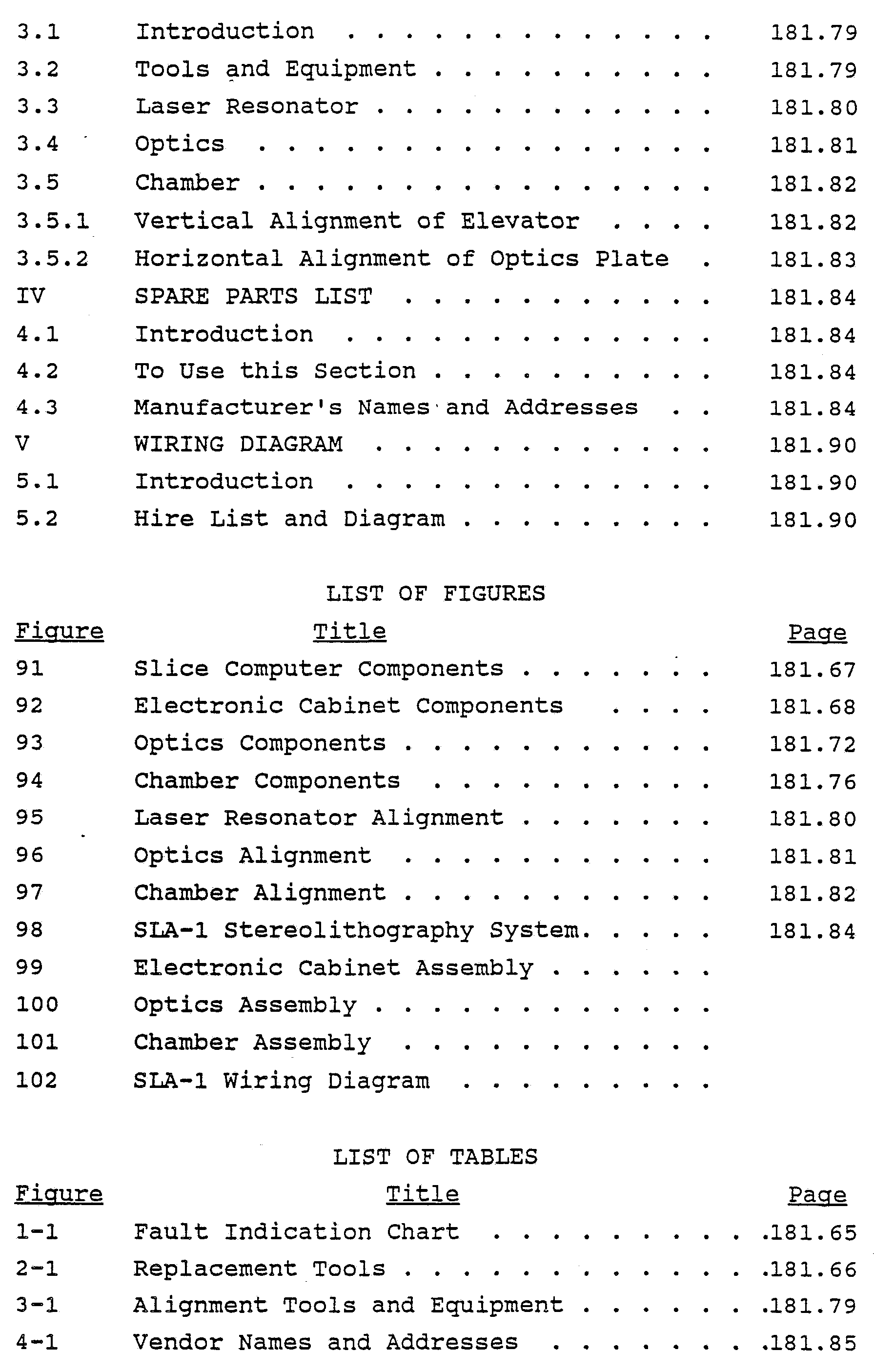 INTRODUCTION
SCOPE
This manual contains service and corrective maintenance procedures for the SLA-1 Beta Site Stereolithography System. This manual is to be used by qualified maintenance technicians to identify and replace defective components. Refer to the SLA-1 User's Manual for operation and routine maintenance procedures.
ORGANIZATION This manual is divided into five sections, as follows:
SECTION I. TROUBLESHOOTING - Diagnostic and corrective procedures. SECTION II. COMPONENT REPLACEMENT - Component removal and installation procedures. SECTION III. ALIGNMENT - Alignment of laser, optics, and chamber. SECTION IV. SPARE PARTS LISTS - Exploded view illustrations and lists of authorized spare parts. SECTION V. WIRING DIAGRAM - Wiring diagram to aid in troubleshooting and continuity tests.
OTHER FEATURES OF INTEREST
Title Page Index. On the right side of the title page you will find a section index. The black markers printed to the right of the text are keyed to similar markers on the first page of each referenced section. To locate a section, flip through the manual until you find a marker printed in the same location as the title page marker.
Warning Pages. Following the title page you will find a summary of critical warnings. You may be seriously injured if these warnings are not explicitly followed. Carefully read all warnings and first aid instructions
prior to performance of operation or maintenance instructions.
REPORTING ERRORS AND RECOMMENDING IMPROVEMENTS This manual was prepared for use by Beta Site maintenance personnel. It will be revised to incorporate recommended content and format changes. If you find any mistakes, or if you have any recommendations for improving the procedures, please let us know by sending a copy of the marked-up page(s) to: Attn: Chick Lewis
3D Systems Inc. 12847 Arroyo St. Sylmar, California 91342 (818) 898-1533 · FAX (818) 361-5484
SECTION I TROUBLESHOOTING
1.1 INTRODUCTION
This section contains troubleshooting procedures to identify and correct selected hardware failures. Troubleshooting procedures for operation errors are covered in the SLA-1 User's Manual.
1.2 HOW TO USE THIS SECTION a. Perform the appropriate troubleshooting procedure referenced in Table 1-1 in accordance with the following special instructions.

HAZARDOUS VOLTAGES ARE ACCESSIBLE WITH MAINTENANCE PANELS REMOVED. FOLLOW SAFE WORK PRACTICES.
1. The troubleshooting procedures are presented in flow diagram format. Use of the diagrams is described in Figure 1-1.
2. Test point illustrations are provided following the flow diagrams (paragraph 1.3).
Repeat the test portion of the flow diagrams after any part is replaced.

2.1 INTRODUCTION
This section contains procedures to replace defective components. Each procedure is self-contained and is supported by an illustration keyed to the procedure in sequence of disassembly. Use the troubleshooting procedures in Section I to determine which components are defective.

HAZARDOUS VOLTAGES ARE ACCESSIBLE WITH MAINTENANCE PANELS REMOVED. FOLLOW SAFE WORK PRACTICES.
2.2 TOOLS Recommended replacement tools are listed in
Table 2-1. Equivalent items may be used.

2.3.1 Monitor. a. Set power switch (1) on rear of monitor (2) to off. b. Disconnect power cable (3) from monitor. c. Use a small flat blade screwdriver to remove two connector screws and disconnect signal cable (4) from monitor. d. Remove monitor. e. Install new monitor. f. Connect signal cable (4) to monitor and use a small flat blade screwdriver and install two connector screws. g. Connect power cable (3) to monitor. h. Set power switch (1) on rear of monitor to on.
2.3.2 Keyboard. a. Set keyboard lockout keylock switch (5) on slice computer (6) to off. b. Disconnect signal cable (7) from keyboard (8). The cable is terminated with a telephone jack. c. Remove keyboard. d. Install new keyboard. e. Connect signal cable (7) to keyboard. f. Set keyboard lockout keylock switch (5) on slice computer (6) to on.
2.3.3 Slice Computer.
CAUTION Store the diskette in a safe place for protection. a. Remove diskette (9) (if present) from disk drive (10). b. Set keyboard lockout keylock switch (5) to off. c Set power switch (11) on rear panel to off. d. Disconnect two power cables (12) (monitor power and ac input power) from rear panel.
e. Disconnect signal cable (7) (keyboard) from front panel. f. Disconnect one signal cable (13) (monitor) and one coaxial cable (14) (Ethernet) from rear panel. g. Remove slice computer (6). h. Install new slice computer, i. Connect signal cable (7) to front panel, j. Connect one signal cable (13) and one coaxial cable
(14) to rear panel. k. Connect two power cables (12) to rear panel. 1. Set power switch (11) on rear panel to on. m. Set keyboard lockout keylock switch (5) to on. n. Install diskette (9) (if required) into disk drive
(10).
2.4 ELECTRONIC CABINET ASSEMBLY (Figures 92a-92b)
2.4.1 Monitor. a. Remove two screws (1) and remove cable access panel (2). b. Set power switch (3) on rear of monitor (4) to off. c. .Disconnect power cable (5) from monitor. d. Use a small flat blade screwdriver to remove two connector screws and disconnect signal cable (6) from monitor. e. Remove monitor. f. Install new monitor. g. Connect signal cable (6) to monitor and use a small flat blade screwdriver to install two connector screws. h. Connect power cable (5) to monitor. i. Set power switch (3) on rear of monitor to on. j. Install cable access panel (2) and secure with two screws (1).
2.4.2 Keyboard. a. Set keyboard lockout keylock switch (7) on process computer (8) to off. b. Disconnect signal cable (9) from keyboard (10). The cable is terminated with a telephone jack. c. Remove keyboard. d. Install new keyboard. e. Connect signal cable (9) to keyboard. f. Set keyboard lockout keylock switch (7) on process computer (8) to on.
2.4.3 Process Computer. a. Remove four screws (11) and remove access panel (12) from rear of electronic cabinet assembly. b. Set keyboard lockout keylock switch (7) to off. c. Set power switch (13) on rear panel to off. d. Disconnect two power cables (14) (monitor power and ac input power) from rear panel. e. Disconnect three signal cables (15) (keyboard, elevator driver, and dynamic mirrors driver) and one coaxial cable (16) (Ethernet) from rear panel. f. Push process computer (8) out through front panel and remove. g. Push new process computer through front panel. h. Connect three signal cables (15) and one coaxial cable (16) to rear panel. i Connect two power cables (14) to rear panel. j. Set power switch (12) on rear panel to on. k. Set keyboard lockout keylock switch (7) to on.
1. Install access panel (12) on rear of cabinet and secure with two screws (11).
2.4.4 Laser Power Supply.

IF THE HIGH VOLTAGE CONNECTORS ARE DISCONNECTED BEFORE POWER SWITCH IS TURNED OFF, HIGH-VOLTAGE ARCING WILL RESULT. a. Remove four screws (11) and remove access panel (12) from rear of electronic cabinet assembly. b. Set keylock POWER switch (17) on laser power supply (18) to off. Verify that POWER ON and two DISCHARGE ON indicators are extinguished. c. Disconnect three cables (19) from unit. d. Grasp laser power supply by two handles and slide out of cabinet just enough to gain access to two cables (20) on rear of unit. e. Disconnect two cables (20) from rear of unit. f. Remove laser power supply from cabinet. g. Install new laser power supply (18) into cabinet just far enough to connect cables. h. Connect two cables (20) to rear of unit. i. Push laser power supply completely into cabinet. j. Connect three cables (19) to unit. k. Set keylock POWER switch (17) to on. Verify that POWER ON and two DISCHARGE ON indicators are illuminated. 1. Install access panel (12) on rear of cabinet and secure with four screws (11).
2.4.5 Elevator Driver. a. Remove four screws (11) and remove access panel (12) from rear of electronic cabinet assembly. b. Set power switch (21) on elevator driver (22) to OFF. c. Loosen two screws from each connector and disconnect two cables (23) from unit. d. Slide elevator driver out of cabinet just enough to gain access to cable (24) on rear of unit.
e. Disconnect cable (24) from rear of unit. f. Remove elevator driver from cabinet. g. Install new elevator driver (22) into cabinet just enough to connect cable. h. Connect cable (24) to rear of unit. i. Push elevator driver completely into cabinet. j. Connect two cables (23) to unit and secure with two screws at each connector, k. Set power switch (21) to on. 1. Install access panel (12) on rear of cabinet and secure with four screws (11).
2.4.6 AC Power Distribution Panel. a. Turn off main circuit breaker (25) on bottom rear of electronic cabinet assembly. b. Remove four screws (11) and remove access panel (12) from rear of electronic cabinet assembly. c Disconnect power cables (26) from connectors J1 through J6 on ac power distribution panel (27). Four to six cables will be present. d. Disconnect cables (28) from Molex connectors J7 through J10 on unit. e. Remove four screws (29) and remove terminal board access cover (30). f. Disconnect wires from terminal strip (31) nearest rear of cabinet. Wires are marked and must be disconnected from terminals 1, 2, 3, 6, 9, 10, 11, and 12. g. Remove four screws (32) (two top and two bottom) and remove ac power distribution panel from cabinet. h. Install new ac power distribution panel (27) in cabinet and secure with four screws (32). i. Remove four screws (29) and remove terminal board access cover (30). j. Connect wires to terminal strip (31) nearest rear of cabinet. Connect wires to terminals 1, 2, 3, 6, 9, 10, 11, and 12 as marked.
k. Install terminal board access cover (30) and secure with four screws (29). 1. Connect cables (28) to Molex connectors J7 through
J10. m. Connect power cables (26) to connectors J1 through J6 as required, n. Install access panel (12) on rear of cabinet and secure with four screws (11). o. Turn on main circuit breaker (25).
2.4.7 Dynamic Mirrors Driver. a. Remove ac power distribution panel (paragraph 2.4.6, steps a through g). b. Remove six screws (33) (two top and four bottom) from dynamic mirrors driver (34) and tilt unit down to gain access to cables, c Remove four cables (35). d. Remove dynamic mirrors driver from cabinet. e. Install new dynamic mirrors driver (34) in cabinet. f. Tilt unit downward and install four cables (35). g. Place unit flush against cabinet and install six screws (33) (two top and four bottom). h. Set power switch (36) to on. i. Install ac power distribution panel (paragraph 2.4.6, steps h through o).
2.5 OPTICS ASSEMBLY (Figures 93a-93c)
2.5.1 Laser. a. Set keylock POWER switch (17) on laser power supply
(18) to off. Verify that POWER ON and two DISCHARGE
ON indicators are extinguished. b. Turn two alien screws (1) ccw to release (one on each end) and remove laser cover (2). c. Remove four screws (11, Fig. 92b) and remove access panel (12) from rear of electronic cabinet assembly. d. Disconnect three cables (19) from laser power supply.
e. Remove two screws (1) and remove cable access panel (2). f. Pull three cables up through cable access hole. g. Remove four cap screws (3, Fig. 93a) from laser (4) (two front and two back). h. Loosen alien screw (5) and remove interlock switch
(6) from rear of laser, i. Lift laser and remove from cabinet. j. Install new laser (4) on cabinet and secure with four cap screws (3). k. Install interlock switch (6) on rear of laser and tighten alien screw (5). 1. Push three cables (19, Fig. 92b) through cable access hole to laser power supply (18). m. Install cable access panel (2) on cabinet and secure with two screws (1). n. Connect three cables (19) to laser power supply, o. Set keylock POWER switch (17) on laser power supply to on. verify that POWER ON and two DISCHARGE ON indicators are illuminated. p. Install access panel (12) on rear of cabinet and secure with four screws (11). q. Align laser mirrors (paragraph 3.3). r. Install laser cover (2, Fig. 93a) and turn two alien screws (1) cw to latch.
2.5.2 Shutters. a. Turn two alien screws (7) ccw to release (one on each end) and remove optics cover (8). c. Tag and unsolder wires from shutters (9). d. Remove two alien screws (10) and remove shutters. e. Solder wires to new shutters (9). f. Install shutters and secure with two alien screws (10). g. Install optics cover (8) and turn two alien screws (7) cw to latch.
2.5.3 Beam-Turning Mirrors. a. Turn two alien screws (7) ccw to release (one on each end) and remove optics cover (8). b. Loosen thumbscrew (11) and lift beam-turning mirror (12) straight up. c. Install new beam-turning mirror (12) and tighten thumbscrew (11). d. Align beam-turning mirrors (paragraph 3.4). e. Install optics cover (8) and turn two alien screws (7) cw to latch.
2.5.4 Beam-Expander. a. Turn two alien screws (7) ccw to release (one on each end) and remove optics cover (8). b. Remove four alien screws (13) and lift beam expander (14) straight up. c Install new beam expander (14) and secure with four alien screws (13). d. Install optics cover (8) and turn two alien screws
(7) cw to latch.
2.5.5 Dynamic Mirrors. a. Turn two alien screws (7) ccw to release (one at each end) and remove optics cover (8). b. Remove four screws (11, Fig. 92) and remove access panel (12) from rear of electronic cabinet assembly. c. Set power switch (35) on dynamic mirrors driver (33) to off. d. Disconnect two outer cables (34) from dynamic mirrors driver. e. Remove two screws (1) and remove cable access panel (2). f. Pull two cables (34) up through cable access hole. g. Remove two alien screws (15, Fig. 93c) and lift dynamic mirrors (16) straight up from cabinet. h. Install new dynamic mirrors (16) on cabinet and secure with two alien screws (15).
i. Push two cables (34, Fig. 92b) through cable access hole to dynamic mirrors driver (33). j. Install cable access panel (2) on cabinet and secure with two screws (1). k. Connect two cables to dynamic mirrors driver. l. Set power switch (35) on dynamic mirrors driver to on. m. Install access panel (12) on rear of cabinet and secure with four screws (11). n. Align beam-turning mirrors (paragraph 3.4). o. Install optics cover (8, Fig. 93a) and turn two alien screws (7) cw to latch.
2.5.6 Interlock Switches.
2.5.6.1 Laser Cover. a. Turn two alien screws (1) ccw to release (one at each end) and remove laser cover (2). b. Loosen one alien screw (5) and lift interlock switch (6) from rear of laser (4). c. Tag and unsolder wires from switch. d. Loosen two alien screws (17) and lift dual interlock switch (18) from cabinet. e. Tag and unsolder wires from switch. f. Solder wires to new interlock switch (6). g. Install switch on rear of laser (4) and tighten one alien screw (5). h. Solder wires to new dual interlock switch (18). i. Install switch on cabinet and tighten two alien screws (17). j. Install laser cover (2) and turn two allen screws (l) cw to latch.
2.5.6.2 Optics Cover. a. Turn two alien screws (7) ccw to release (one at each end) and remove optics cover (8).
b. Loosen two alien screws (19) (one for each switch) and lift interlock switch (20) from cabinet. c Tag and unsolder wires from switches. d. Solder wires to new interlock switches (20). e. Install switches on cabinet and tighten two alien screws (19) (one for each switch). f. Install optics cover (8) and turn two alien screws (7) cw to latch.
2.6 CHAMBER ASSEMBLY (Figure 94)
2.6.1 Heater/Fan. a. Open chamber door (1). b. Remove air filter (paragraph 2.6.1, steps a and b). c. Set main circuit breaker on bottom rear of electronic cabinet assembly to off. d. Remove four screws (2) and remove bottom cover (3) on heater/fan (4). e. Disconnect three wires from terminal strip (5). The wires are marked. f. Remove four screws (6) and remove heater/fan (4) from chamber. h. Install new heater/fan (4) in chamber and secure with four screws (6). g. Remove four screws (2) and remove bottom cover (3) from new heater/fan. i. Connect three wires as marked to terminal strip (5). j. Install bottom cover (3) on heater/fan and secure with four screws (2). k. Set main circuit breaker on electronic cabinet assembly to on. l. Install air filter (paragraph 2.6.1, steps c and d). m. Close chamber door (1). Verify that fan is turning.
2.6.2 Reaction Vat. a. Open chamber door (1).
b. Remove two side shelves (7) by lifting shelves to disengage from attaching screws. c. Unscrew two knobs (8) to disengage platform rods (9) from vat (10). d. Install lid (11) on vat and secure four latches (12). e. Turn off drain valve (13) and remove collection bottle (14). f. Grasp vat by two side handles (15) and slide out of chamber. g. Clean resin from platform rods (9) (refer to User's Manual). h. Slide new vat (10) into chamber. i. Remove lid (11) from vat by releasing four snap fasteners. j. Screw two knobs (8) to engage platform rods (9) to vat. k. Place collection bottle (14) under valve (13) and turn on drain valve. l. Fill vat with resin (refer to User's Manual). m. Install two side shelves (7). n. Close chamber door (1).
2.6.3 Platform. a. Open chamber door (1). b. Remove two screws (16). c. Unscrew two knobs (8) to disengage platform rods (9) from vat (10) and lift platform (17) straight out of chamber. d. Install new platform (17) in chamber and screw two knobs (8) to engage platform rods (9) to vat (10). e. Install two screws (16). f. Close chamber door (2).
2.6.4 Elevator. a. Open chamber door (1). b. Disconnect cable (18) from left side of chamber. c. Remove one screw (19) and remove cable clamp (20).
Remove platform (paragraph 2.6.3, steps a through c).
Remove four allen screws (21) and pull elevator (22) and cable straight out of chamber.
Install new elevator (22) in chamber and secure with four alien screws (21).
Install platform (paragraph 2.6.3, steps d through f).
Install cable clamp (20) on cable (18) and secure to cable and clamp to chamber with one screw (19). i Connect elevator cable (18) to chamber cable (23). j Close chamber door (1).
2.6.6 Beam Profiler. It is extremely difficult to remove the beam profiler in the Beta Site systems. Therefore, it is recommended that this unit not be removed. The SLA-1 can still operate even though the beam profiler is defective.
SECTION III ALIGNMENT
3.1 INTRODUCTION
This section contains procedures to align the laser, optics, and chamber. These procedures must be performed when the optics or laser is replaced, or when these items become misaligned through normal wear.
3.2 TOOLS AND EQUIPMENT
Recommended alignment tools and equipment are listed in Table 3-1. Equivalent items may be used.

This is a very touchy alignment which should only be performed when laser power or beam shape has deteriorated. Two alien ball drivers (5/64 inch) and a laser power meter are required to perform this procedure. a. Remove optics cover and laser cover. b. Remove two screws and remove shutter assembly. c. Place laser power meter to interrupt laser beam. d. Insert one ball driver in upper rear laser adjustment hole and second ball driver in upper front laser adjustment hole. e. Observe laser power meter and detune (turn 1/10 turn ccw) rear laser mirror adjustment. f. Tune front laser mirror adjustment to maximize power. Adjust in small increments only. g. Detune rear laser mirror (turn 1/10 turn cw) adjustment and repeat step f. h. Repeat steps e and f several times until maximum power is obtained. i. Place a card in front of the laser power meter and note shape of laser beam. The beam should be relatively round. If not, repeat steps e through h several times for a round beam shape at maximum power. j. Carefully remove both ball drivers and remove card, k. Insert one ball driver in lower rear laser adjustment hole and second ball driver in lower front laser adjustment hole. l. Repeat steps e through i several times until a round beam shape at maximum power is obtained. m. Repeat upper and lower laser mirror adjustment several times to optimize laser power and beam shape, n. Carefully remove both ball drivers and remove card. o. Remove laser power meter. p. Install shutter assembly and secure with two screws. q. Install optics cover and laser cover.
3.4 OPTICS (Figure 96a-96b)

UV LASER RADIATION MAY DAMAGE EYE TISSUE. AVOID DIRECT EXPOSURE TO LASER BEAM. WEAR SAFETY GLASSES.
CAUTION Fingerprints may damage optics coatings. Clean hands thoroughly and strictly avoid touching optical surfaces. a. Remove optics cover. b. Loosen two adjustment screws (front and rear) and slide beam expander out and remove. c. Adjust two each adjustment screws on two beam-turning mirrors and adjust mirrors so that laser beam strikes center of both mirrors and center window of dynamic window. d. Use a T-square to check that beam path between second beam turning mirror and dynamic mirror is exactly 3.25 inch above optic plate along entire beam path. Use a set of calipers to take measurements. e. Adjust two adjustment screws on second beam turning mirror to achieve correct value. f. Use a 12-inch set of calipers to check that beam path between second beam-turning mirror and dynamic mirror is exactly 11.74 inch from beam path to front edge of optic plate along entire beam path. g. Adjust two adjustment screws on second beam-turning mirror to achieve correct value. h. Repeat steps d through g several times for optimum vertical and horizontal alignment. i. Put transparent scotch tape over input and exit apertures of beam expander. Make sure that tape does not contact lenses, j. Install beam expander.
k. Adjust beam expander adjustment screws so that laser beam is centered as close as possible at input and exit apertures. Do not adjust any mirrors, only the beam expander. The position of the beam as it strikes the second beam-turning mirror and dynamic mirror should not change after installation of beam expander. l. Tighten lock nuts on beam expender adjustment screws. m. Remove scotch tape from beam expander apertures. n. Install optics cover.
3.5 CHAMBER (Figure 97)
3.5.1 Vertical Alignment of Elevator. The perfect alignment of the elevator axis with the Vertical is critical for building of accurate stereolithographic parts. Any off vertical alignment of components will result in a vertical skew of every part built with the SLA-1. a. Remove reaction vat and platform (Section II). b. On bottom of cabinet, raise up floor adjustment foot number 4 to balance cabinet on three feet. c. Remove two allen screws and remove optic cover. d. Open chamber door. e. Remove two inside screws and lower optic window mount from inside chamber. f. Suspend a plumb bob from center of optic window aperture. g. Adjust height of string until top of plumb bob exactly touches floor of chamber, h. Place a sheet of paper on bottom of chamber and mark plumb bob position exactly. i. Install vertical alignment tool and place string against vertical string groove, j. Run elevator up and don while observing plumb bob for lateral movement.
If plumb bob moves off from spot marked in step g, adjust chamber floor adjustment cabinet feet (1, 2, and 3) for best vertical alignment.
Place string against horizontal string groove and mark plumb bob position.
Repeat steps j and k.
Repeat steps i through m several times until optimum leveling is achieved.
Lower foot number 4 to floor level. (Be careful not to upset leveling.)
P Remove vertical alignment tool and plumb bob. q Install optic window mount by installing two screws inside chamber. r Close chamber door. s Install platform and reaction vat (Section II).
3.5.2 Horizontal Alignment of Optics Plate. Do not use the adjustable feet of the SLA-1 for horizontal alignment. This will upset the vertical alignment of the elevator. a. Loosen four tiedown bolts on optic plate. b. Place a precision level on optics plate. c. Adjust four levelling bolts for optimum horizontal level at all points of the optics plate. d. Tighten tiedown bolts.
SECTION IV SPARE PARTS LISTS
4.1 INTRODUCTION
This section contains an exploded view illustration and listing of each authorized spare part.
4.2 HOW TO USE THIS SECTION a. Locate the defective part or assembly in which the part is located in Figure 98. Note the index number.
NOTE The SLA-1 is arranged into three major assemblies or component groups: the electronic cabinet assembly, the optics assembly, and the chamber assembly. These assemblies and components are illustrated and listed in Figure 98. Subassemblies and detail parts are listed in parts lists 99 through 101. b. Locate the index number in the parts list for Figure 4-1 and note the part number, nomenclature and source for replaceable parts, or the figure number in which the replaceable parts are listed. Assemblies containing replaceable parts are listed for reference purposes only and are identified by the abbreviation REF in the Units Per Assy column. c. Repeat steps a and b to locate subassemblies and detail parts in the referenced parts list, d. Order replacement parts from the listed manufacturer in accordance with the instructions in paragraph 4.3.
4.3 MANUFACTURER'S NAMES AND ADDRESSES SLA component manufacturers are listed in Table
4-1. When ordering spare parts, specify the part number, nomenclature, and quantity required. Always inform your 3-D Systems project engineer first if problems arise. He will usually be able to arrange to acquire the necessary
parts. The manufacturers of SLA-1 components and subassemblies are listed for convenience.


5.1 INTRODUCTION
This section contains a wiring diagram to aid in troubleshooting and continuity tests.
5.2 WIRE LIST AND DIAGRAM
All SLA-1 cables and interconnections between components and subassemblies are shown in the wiring diagram (Figure 102).
A P P E N D I X B
©1989 3D SYSTEMS, INC. ALL RIGHTS RESERVED
3D Systems , Inc .
SLA-1 Software Manual
Beta Release, First Draft
October, 1987
3D Systems, Inc.
12847 Arroyo Street
Sylmar, CA 91342
(818) 898 - 1533 (818) 361 - 5484 FAX
3D Systems SLA-1 Software Manual Beta Release, First Draft October, 1987
TABLE OF CONTENTS 1. 0 Introduction . .. .. . . . . .. . . . . . . . . . . . . . . .. .. . . . . . . . .
1.1 System Overview . .. .. . . . . .. . . . . . . . . . . . . . . .. .. . .. . .
1.2 Major Part-Making Components . .. .. . . . . .. . . . . . . . . . .
1.3 Utilities . .. .. . . . . .. . . . . . . . . . . . . . . .. .. .. . . . . . . . . .
2.0 Getting Started . . . . .. . . . . . . . . . . . . . . .. .. .. . . . . . . . . . 2.1 Getting Around on the Slice Computer.
2.1.1 Making a User Account . . . . . . . . . . .. .. .. . . . . . . . . . .
2.1.2 Disk Usage Maintenance . . . . . . . . . . .. .. .. . . . . . . . . .
2.2 Getting Around on the Process Computer . . . . . . . . . .
2.2.1 Disk Usage Maintenance . . . . . . . . . . .. .. .. . . . . . . . . 3.0 SLICE and the User Interface . . . . . . .. .. .. . . . . . . . .
3.1 The TELNET Communications Program . .. .. .. . . . . . . . .
3.2 SLICE Overview . .. .. . . . . .. . . . . . . . . . . . . . . .. .. .. . . .
3.3 SLICE Features and Capabilities . . . . . . .. .. .. . . . . .
3.4 SLICE Command Line Parameters . . . . . . .. .. .. . . . . . . . 3.5 The SLICE User Interface . . . . . . . . . . . . . . . .. .. .. . . .
3.5.1 UI Overview . .. .. . . . . .. . . . . . . . . . . . . . . .. .. .. . . . .
3.5.2 UI Main Command Menu . . . . . . . . . . . . . . .. .. .. . . . . . .
3.5.3 UI Alter Options Menu . . . . . . . . . . . . . . .. .. .. . . . . .
3.5.4 UI Extra Parameters Screen . . . . . . . . . . . . . . .. .. .. 4.0 The Parser . .. .. . . . . .. . . . . . . . . . . . . . . .. .. .. . . . .. . .
4.1 The FTP File-Transfer Program . . . . . . .. .. .. . . . .. . .
4.2 Operating The Parser . . . . . . . . . . . . . . .. .. .. . . . .. . . .
4.3 The Parser's Options . . . . . . . . . . . . . . .. .. .. . . . .. . . .
4.4 Critical Areas . . . . . . . . . . . . . . .. .. .. . . . .. . . . . . . . . . 5.0 The Supervisor . . . . . . . . . . . . . . .. .. .. . . . .. . . . . . . . . .
5.1 The Steps To Take Before Running the Supervisor.
5.1.1 Getting the Step Periods .. .. .. . . . .. . . . . . . . . . . .
5.1.2 Editing the Supervisors Default Parameters
File . . . . . . . . . . . . . . .. .. .. . . . .. . . . . . . . . . . . . . . . 5.1.3 Editing the Layer Control File . . . . . . . . . . . . . . . .
5.2 Operating the Supervisor . . . . . . . . . . . . . . . . . . . . . . . .
5.3 The Supervisor's Options ........................
5.4 The Supervisor's Keyboard Commands..............
5.5 Using Rivets ....................................
6.0 Other Programs .................................. 6.1 FRONT, Simple Front End to Laser Controller .....
6.2 CLIFF, Control Laser Instrument From File .......
6.3 STEREO, The Stereolithography Device Driver .....
6.3.1 STEREO Command Set............................
6.3.2 STEREO Options................................ 7.0 File Formats ....................................
7.1 SLICE'S Input File (*.STL) Format ...............
7.2 SLICE'S Output File (*.SLI) Format ..............
7.3 The Parser's Output File (*.P and *.L) Format...
7.4 Critical Area File (*.BOX) Format............... 7.5 Supervisor Default Parameters File (SUPER. PRM)
Format..........................................
7.6 The STEREO.DEF Driver Default File Format .......
7.7 The STEREO.GEO Geometric Correction File Format. Appendix A - SLA-1 Software System Chart ............. Appendix B - The STEREO Command Set ..................
Appendix C - Stereolithography Software Glossary .....
Appendix D - Editor Commands .........................
1.0 Introduction
Welcome to the world of Stereolithography. By now, you know what Stereolithography is all about, and you have seen an SLA=1 machine. The job of this manual is to introduce you to the software that makes a SLA machine work.
First, lets quickly review the Stereolithography process. A three-dimensional part is designed on a CAD system, and transferred to a Slice Computer where the part is transformed into a series of two-dimensional layers. From that computer, the two-dimensional part is moved over to the
Process Computer in the SLA machine. It is the job of that computer to make the part. This manual follows the Stereolithography process. First, you will receive a brief introduction to all the important software programs. Then you will be shown how the Slice Computer works, how the Process Computer Works, and how to pass files to them.
1.1 System Overview By System, we mean the Stereolithography Software System. And it is a system. It encompasses two operating systems - MSDOS and XENIX - and over a dozen programs, each important to some aspect of the Stereolithography process. At last count, we figure there are nine levels of software. Each level can be viewed as a black box and having a unique task:


The responsibilities of providing these services are spread out amongst three computers — one that you already use for CAD work, our 80386-based Slice Computer, and our 80286-based Part-Making Computer:

The Slice Computer
The 80386-based Slice Computer contains XENIX, a full-bore multitasking Operating System which allows many users to simultaneously sign-on, transfer CAD files, and slice them. On this computer you will be introduced to some system management programs and some stereolithography software. The Slice Computer contains the Slice Program (SLICE) and its convenient User Interface Program (UI). SLICE is the program that takes a 3-D database and transforms it into a 2-D one suitable for part-making. Since SLICE conforms to the Unix philosophy of how programs work (which by the way is not so intuitive), we have developed UI which is an convenient menu- driven front-end to SLICE.
You will use UI to input the parameters you want SLICE to see and then run SLICE through UI. Generally, unless you need to do some disk or system maintenance, you will not need to leave UI until you sign-off.

The Process Computer
The Process Computer has many programs. Rather than instruct you how to call up each program from DOS, we instead have developed a menu program which you can use instead. The menu program leads you to each of the major part-making programs, the utility programs, and provides some disk management functions.
The SLA machine operator will tap into the Slice Computer and pull out the 2-dimensional database of the part he next wishes to make. This is accomplished using Ethernet software programs TELNET and FTP. TELNET temporarily makes the Process Computer into a computer terminal so that you can sign-into the Slice computer and run the User Interface program. You can then use FTP to transfer the 2-D databases (okay, we'll start calling them sliced files) files over to the Process Computer. Once a sliced file is on the Process Computer, it may need to be combined with other sliced files, such as those containing a base for the part. The Parser, PARSE, does this job and also makes a special layer control file which you can edit to fine-tune the part-making process. After running the Parser, you will proceed to the Supervisor, SUPER, which is the one program in charge of making a part. The Supervisor controls the motion of the laser beam and the Z-stage elevator, dipping and pausing for each layer. Actually, The Supervisor's job is to "pass along" laser movement information to some rather sophisticated memoryresident software. The Supervisor talks to STEREO, a special Stereolithography Device Driver we created that knows about such SLA-specific things as special ways to draw and geometric correction which causes the laser beam to map linearly onto the vat's surface. STEREO, in turn, talks to LASER, the low-level - laser controller, which is constantly running, moving the laser beam one discrete step every so often. We told you a bit more than you probably needed to know, but we want you to get a good understanding of the system. The STEREO Device Driver has a set of commands that control how the laser moves on any given layer. Sometimes you want the laser to behave differently at some point during the part-making process. So, we gave the Supervisor the capability of passing along to STEREO commands that you have placed in certain files.
We want you to be aware that you are learning the commands of a common device driver, a driver that many different programs can use. Once you learn the STEREO Command Set, you will be in pretty good shape to quickly adapt to other programs.

1.3 Utilities
In addition to the major components, there are a variety of utility programs that aid the part-making process.
There is the power on-off sequencer (POWER) that enables you to safely turn on and off various elements of the SLA machine with appropriate directions.
And there is the Calibrator (CALIB) that is run not-sooften to calibrate the Vat Surface (the "Field") to make the SLA machine geometrically correct. Special hardware is necessary in order to use this program.
The Profiler (PROFILE) that analyzes the laser beam, and it is run often, perhaps once a day. It makes note of the current shape and intensity of the beam. The results of
its analysis is retained in a special file that other programs can read.
The Get Step Periods program (GETSP) is one such program. It eliminates the need for you to be a chemist by reading the Profiler's data and enabling you to determine an appropriate Step Period (laser speed) for making a particular part. It knows the working curves for different materials, and it will select an appropriate Step Period for your forthcoming part-making sessions. ZSTAGE gives you control over the Z-Stage, the vertical elevator that the part sits on. ZSTAGE is used to set the elevator just before a part is make, and it is also used to bring a part up out of the vat.

Utility Programs
2.0 Getting Started
In this chapter, we assume you have installed your Slice and Process Computer Systems according the Installation Manual and have verified their proper operation. This chapter takes you at that point to help you get started using these two computer for the part-making process.
2.1 Getting Around on the Slice Computer Each person performing slicing should have his or her own XENIX account on the Slice Computer. Once an account has been created, the owner can sign on.
2.1.1 Making a User Account
Sign onto the sysadm account by typing 'sysadm' at the login prompt and press Enter. Enter the password, which
is '3dsys'. Note that the password isn't displayed as its typed in. And the case of the letters is important; type them in lower case.
The sysadm account is a special Xenix account that automatically takes you to a menu-driven system administration program. From this menu you can create and remove user accounts, and perform a variety of other system tasks. If you want to know more information about the sysadm function than what is presented here, please refer to the appropriate Xenix documentation.
Take a few moments to look over the screen. Select the User Maintenance options by pressing 'U'. Do not press Enter. Select MakeUser by pressing 'M'. Do not press Enter. Answer 'y' (and Enter) to 'detailed instructions?'. Next time you can answer 'n' because you will be familiar with the make-user process.
Enter the new user's login name. This should be short and in all lower case letters. We simply use people's first names and an occasional first letter of their last name. Make up your own rule, but be consistent. It will make system management easier.
Answer 'y' to 'Do you wish to use the next available user id?' query. Let the system assign the id number. You will rarely have to refer to it.
Answer 'y' to 'Do you want to use the default group?' query. This will assign the standard group 'group'. Assign a password that is at least 5 characters in length. You will have to enter it again as a safety precaution against typos. If you don't care about security, just make the password the same for all users. This way, you can hop around the various user accounts and pick up the sliced file. Select the Standard (Bourne) Shell, item 1. Enter a comment if you want. Generally, you will enter the user's full name (with upper and lower case letters) here.
Review the account information. If you are satisfied, answer 'n' to 'Do you want to change anything?' prompt. The computer will take a few moments to create the user. You have finished adding a user to the Slice Computer. That user can now sign-in and do slicing.
If you want to remove a user, you can select the Remove User option. You will have to delete all of the user's files before you can delete him from the computer system. Play around with the sysadm menu system. Don't do anything that looks irreversible or serious until you have read up on it.
2.1.2 Disk Usage Maintenance
Depending on the size of your part files, you will need to take time to make periodic maintenance. This means you should erase or archive old part files to make way for new ones.
When you sign-in, the computer will tell you how much disk space is taken up by your files. The number shown is the number of 512 byte blocks (1/2 K). Check this number to make sure you aren't taking up more disk space than you thought. Make sure your disk usage doesn't get out of hand.
If you are in the User Interface, use option 6 to quit and return to Xenix. There you can use the rm command to remove files: rm sli0045.stl will erase the single file sli0045.stl rm gbox03* will erase all files whose name begin with
'gbox03'
You can also use cp to copy and mv to move files around. Refer to the Xenix Documentation for more information.
If you feel you need more information about the Xenix Operating System, we recommend the following books: * Understanding XENIX: A Conceptual Guide Que Corporation * Working with XENIX Systems
Scott, Foresman, and Company
* XENIX at Work
Microsoft Press
* Inside XENIX
The Waite Group * XENIX Tutor
XENIX Training on DOS PCs SCO, our Xenix supplier sell these books to end-users. Contact them at (408) 425 - 7222.
2.2 Getting Around on the Process computer The Process Computer is your typical AT-compatible MSDOS Computer System. If you don't know the first thing about MSDOS, don't worry. All you have to do is turn the computer on; it does the rest. You will enter a Menu Program from which you can get to all the essential part-making programs.
2.2.1 Disk Usage Maintenance
As with the Slice Computer, you will need to watch your disk usage on the Process Computer. The Process Computer contains 40 Megabytes, of which about 2 Megabytes are taken up by MSDOS and the Stereolithography Software.
Unless you have created your own directories for the sliced files, you will be in the \WORK directory. Periodically, go to the DOS Menu and select item 1 to get the disk usage stats. You will see something like: 21344256 bytes total disk space 49152 bytes in 2 hidden files 45056 bytes in 22 directories 6254592 bytes in 391 user files 20480 bytes in bad sectors 14974976 bytes available on disk 555360 bytes total memory 598128 bytes free Watch the 'bytes available on disk'. This system has more than 14 Megabytes (14,000,000) left so there is no immediate danger of running our of disk space. Depending on the
sizes of the part files, you should get concerned when this number drops below a few Megabytes.
Once you realize that you need to some housecleaning, or "disk cleaning" in this case, select item 3 in the DOS Menu. This will take you to a program called QuickDos II (QD2) where you can do such disk-related things as copying files, moving files, and deleting files.
To delete files, use the arrow keys to move up and down the directory listing shown. Press the Space Bar to tag a file. A white arrow should appear at the left of the file name. Keep doing this until all the files you want to delete have been tagged. To untag a file, move back to the file and press the Space Bar again. The white arrow should disappear. Press 'E' (no Enter) to erase. QuickDos will show you the file you have selected on a different screen. Press Alt-E (hold the Alt key down while pressing 'E') to begin the erase procedure. If you see something you don't like, press Esc to abort. QD2 performs a variety of other useful disk management tasks. Refer to its documentation for more information.
3.0 SLICE and the User Interface
To use SLICE and the User Interface, you can sign-on to the Slice Computer either directly via its keyboard, or from the Process Computer over the Ethernet communications link. Section 3.1 describes how to use the Ethernet TELNET terminal program.
Once you are signed-in, there are two ways to tell SLICE what you want done. One is to work directly from the Xenix Operating System where you must specify all the options on one line. The other is to use UI, the Slice User Interface Program, where you can specify the options through a set of menus. Both techniques are described below. We have found most people prefer using the User Interface.
3.1 The TELNET Communications Program
The TELNET Program allows you to connect up to the Slice Computer from the Process Computer and run the User Interface and SLICE programs. From the Process Computer Main Menu, select item 1, Data Transfer. You will be placed in the XFER program are presented with the following options:
1. TELNET, Terminal Utility
2. FTP, File Transfer Program Q. Quit
If you don't what to communicate just yet, press Q to quit and return to the main menu. Otherwise, select item 1, TELNET. TELNET should run and connect the computer you are currently on (the Process Computer) up to the Slice Computer. If both computers are functioning and are properly linked together, you should see the Xenix Login message appear. At this point the Process Computer is like the Slice Computer s main console. You can now sign-in and run SLICE or the User Interface.
Eventually, you will have to sign-off. Get out of whatever program you may be in (the DEL key may do that) and type: exit You should then be logged off the Slice Computer and returned to the Process Computer's main menu.
3.2 SLICE Overview
This quick overview will give you a brief description of
SLICE methodology. SLICE'S mission is to read in a solid model whose surfaces were tessellated into triangular facets, and then to calculate output that is suitable for the laser control system to polymerize the model in layers, working from the bottom up. While we are discussing SLICE , it is important to realize that these next questions touch upon deep topics. The
areas of numerical analysis, analytical geometry, computer graphics, and computer architecture, are among those that are relevant to SLICE. The discussion below is by no means a thorough treatment of these topics, but rather a starting point to provoke thought. Why use layers?
The UV catalyzed polymerization process usually takes place at or near the monomer-substrate surface, so an approach akin to assembling a loaf of bread by gluing the slices back together is taken by the laser process. SLICE "slices" the original model mathematically which the laser then puts back together.
The laser must trace the outline of each slice and sweep across ("hatching") the interior of each slice. In addition, the end-slices of the bread loaf, and the near flat ones are traced more finely, called "filling" in SLICE parlance.
Therefore the object to be produced must be reduced to cross-sections. This is the heart of the problem—to do the cross-sectioning and hatching/filling efficiently and correctly. Why use triangles?
There are many ways to represent solids, such as constructive-solid-geometry, parametric representation (based upon a variety of fundamental curves such as bicubic patches), and boundary representation (called b-rep in the literature). B-rep is the most popular and often the most efficient for a general class of objects (e.g. not wings or boat hulls). The boundary representation method generally involves describing a solid model in terms of its surfaces which are approximated by polygons. The smaller the polygons the better the b-rep model represents the actual object. Some solid model analysis problems (such as tolerance checking) originate right here-because we stray away from reality once we take the first step of interpolating
polygons. We can discuss this further in a future section.
How the model is actually produced, whether by volumes of revolution, extrusion, projection, cross-sectioning (in reverse of SLICE), etc., does not (at present) concern us here. But the end result is a model that must have integrity. Polygons must be planar, and adjacent polygons must indeed abut one another, for example. The triangle is a very nice surface b-rep polygon to work with for several reasons: non-degenerate triangles always define a single plane in 3-space, (as two points define a line in 2-space, and 4 points define a hypercube in 4-space, etc.). A degenerate triangle is one in which one or more of the points have the same coordinates. Triangles are also the simplest entity with which to perform computations, as compared to trapezoids, hence they proliferate in many popular CAD and solid modelling systems. Why have variable z-spacing? Let us use our food example again. If we are slicing a loaf of bread that is geometrically uninteresting, say a loaf of Roman Meal, it is wasteful to slice at every millimeter; centimeters will do. If we are slicing a dome shaped French baguette, for example, but want a reasonably accurate model, some slices should be thinner than others. Those slices that have more detail and that have smaller slope should be smaller. This is a little like the resulting problem above, but now we will vary the grid size DYNAMICALLY as we move through the model. Secondly, this approximation corrects for limitations in the laser process, not for a mathematical loss of accuracy as in the integer problem.
The limitation in the laser process is caused by the fact that beam shoots at approximately a normal angle to the substrate surface. Angled surfaces are therefore built up in a stair stepping method. The side of each step is a slice, and its angle is given by the angle of the laser beam relative to the substrate liquid surface.
The second limitation is that areas that are nearly flat must be treated as if they were completely flat. Completely flat regions are skin-filled, which is essentially a very fine cross-hatching. Near flat regions must be skin-filled lest gaps and/or warpage occur in the completed part. Additional structural features may have to be built in order to compensate for properties inherent in the polymer. There are other effects relevant to the part-making process, but they are not covered here. There is for example, a correction necessary for the spherical projection of the laser beam onto the flat surface of the substrate liquid, which is done in a post-SLICE laser output phase. The thickness of slices must vary then to: 1) obtain a sufficient level of detail, and 2) provide sufficient polymerization/ structural strength in areas that have small slope. Why are triangles classified? Recall that the input consists only of triangles. Each slice will intersect some of the triangles. Triangles are classified by their slope relative to the x-y plane in SLICE: flat (slope=0), near-flat (slope< human-determined subjective criteria), and "scan" triangles (slope is large).
The line segments that are calculated by slicing through triangles are treated differently depending on the triangle they came from. These resulting intersections of slices with triangles form outlines of slices, called "borders", and provide information needed to do the cross-hatching and skin-filling. Why have output blocks?
Output blocks in Slice's output files identify the type of two-point vectors which follow. Special action can then be taken by the Supervisor on some of these blocks to strengthen the part and prevent warpage.
3.3 SLICE Blocks
SLICE takes the 3-D object database and classifies the facets as flat, near-flat, or scanned. When SLICE gets around to producing 2-D output, it organizes the layer vectors into various block.
SLICE block identifiers follow the following mnemonic rule. Not all combinations are valid.


The above list is shown in kind of a triangle-type order which is different from the order SLICE outputs the data. SLICE outputs the way the part is to be built:
* borders first
* then hatches
* then down fills
* then up fills SLICE outputs the blocks in the following order:

The L block isn't one really. It is followed by the internal Z-layer number, must like the old Z block. However, unlike the old Z which has the complete boundary for that layer, the L has no vectors.
3.4 SLICE Command Line Parameters
To activate SLICE the hard way, you will need to type out a XENIX command line with the form:
SLICE < input_file <options> where SLICE is the current SLICE program (e.g. 'slice20b') input_file is the name of the STL input file
<options> represent any combination of the following SLICE program options:
-scale <scale_yalue>
Used to specify a real number scale value that will be used to scale the input file coordinates. The default scale value is 1.
-sf <segment output file>
Used to specify an output file for z plane intersection segments. The default is to not generate a segment output file.
-zs <Z spacing value>
Used to indicate the constant z spacing of the output cross-sections.
-hy <hatch spacing value> Used to set spacing of hatch lines parallel to the Y-axis.
-hx <hatch spacing value>
Used to set spacing of hatch lines parallel to the X-axis.
-ha <hatch spacing value>
Used to set spacing of 60 degree angle hatch lines.
-hfy <hatch spacing value> Sets spacing of hatch lines parallel to the Y-axis on flat surfaces.
-hfx <hatch spacing value>
Sets spacing of hatch lines parallel to the X-axis on flat surfaces. -zsf <Z spacing control file>
Used to specify the file containing variable Z-spacing information.
-c Centering option.
Centers object coordinates around 32768, 32768. -nsc No section codes option.
Suppresses section codes in the output file.
-msa Minimum surface angle option.
Indicates minimum surface angle for scanned facets. Legal values are between 0 and 90 degrees. -mia Minimum intersect angle option.
Indicates minimum intersect angle for hatch lines. Legal values are between 0 and 90 degrees.
-b Binary input option.
Indicates that the input file is in binary format. -d Display option.
Causes the program to display cross-sections on the screen as they are generated.
-h Help option.
Causes the program to print a help similar to this list of options and then stop.
-b Binary input option.
Indicates that the input file is in binary attributed format.
-aries ARIES attributed binary input option. Use when binary file is ARIES and attributed.
-disk Disk option.
Causes the program save intermediate information on disk rather than in memory. -x or -y Slice Axis option.
Use the x-axis or y-axis as the slice axis, not the standard z-axis.
SLICE can be executed directly as a standard Xenix program. However, we have a developed a special User-Interface program for SLICE, described below.
3.5 The SLICE User Interface We have developed a special User Interface program to SLICE that runs under XENIX. It is a much easier way to run SLICE compared to typing command lines. UI, as the User Interface is called, can be run remotely through Ethernet. UI, the SLICE User Interface, presents menus and allows the user to easily select and define the various SLICE options for a particular STL Slice Input File. The options for different STL files are remembered in special setup files with the same file name prefix, but with the extension ".UII" (UI Information).
UI also allows the user to define a special variable Z-spacing file (with the extension ".UIZ") that is used by SLICE to generate different-spaced layers for different sections of a part.
3.5.1 UI Overview
The complex nature of using SLICE especially on a Unix-based system prompted the development of the User Interface (UI) program. It is a simple easy-to-use front end for the Stereolithographer where, by selecting 'items off a menu, he can enter the Slice options for his latest part . A key feature of UI it that it supports variable Z-spacing, a difficult feature of SLICE to use outside of UI.
UI allows a SLICE user to change options and invoke the SLICE program. - SLICE then slices the specified 3D object into 2D layers using the UI options.
UI can be invoked from any process Unix or Xenix account. It is assumed that such a system has already been created with the necessary software. It is recommended that each individual needing to use UI and SLICE be given their own account. The command syntax for the UI command is: ui <option_file_name> where <option_file_name> is the name you wish to refer to the new set of options. If you wish, it can be related somehow to the part name. If <option_file_name> is omitted, the last option file name will be used and its option file loaded.
3.5.2 UI Main Command Menu
The User Interface's Main Command Menu is shown below:
- SLICE USER INTERFACE - Version 2.10
Current Object: test Database File Name: test.stl
Extra Parameters: -aries -x Alter - Alter standard options Extra - Set extra parameters
Load - Load a different object's options Save - Save current object's options Write - Save current option's under different object name Copy - Copy another object's options into current object DoSlice - Do slicing with current options Quit - Exit UI (Use SAVE to save options first) Which Command? _
The UI commands behave as follows:
Alter - Go to the Options Menu so that the Slice Options can be changed. Extra - Go to the Extra Parameters Screen so that non-standard Slice options can be specified. Load - Loads a different set of options into UI. The previous objects options (if any) are not automatically saved. Using Load is equivalent to quitting UI and rerunning it with the new object's name. Save - Saves the current option data into the current object file. Stays in the main menu.
Write - Same as Save, but allows you to specify a different file in which to store the option data. The new name becomes your current object file name.
Copy - Copies the options of a different object into the current object's options. The Copy command saves having to reenter options where options for a new object are being defined but the options are similar to those for some past object. By Copying those old options in and making minor adjustments, you are off and running SLICE quickly.
DoSlice - Go Do Slicing with the current options. DoSlice allows you to specify what version of Slice you wish to use.
Quit - quits UI. Does not Save. Returns to back to the Unix or Xenix command level.
3.5.3 UI Alter Options Menu All the numbered options in the UI program are parameters to the SLICE program. All the lettered options are used for UI control. Most of the SLICE options are selfexplanatory.

(1) DATABASE File name sets the name of the file that contains the three-dimensional CAD database for the object. An extension of ".stl" is assumed.
(11) Segment Output File Name is the name of the file that SLICE will output to. An extension of ".sli" is assumed. (3) Z Spacing is one of two types, Variable or Fixed. Fixed is where just one value for all spacing, while Variable allows many. When Fixed is selected, UI just asks for the one Z spacing value. When Variable is selected, UI displays a new screen and allows you to edit the Variable Z-Spacing Table. While adding and deleting values to and from the variable Z- spacing table, you will use the following commands:
A level setting Add new level and spacing value to table D level Delete level from table
S Save table, return to main menu Q Quit, return to main menu, don't save table H print a Help message similar to this
A adds a new level and spacing value. Both of these numbers will be multiplied by scale as they are sent out to SLICE. In other words, they are in the original CAD units — inches, feet, whatever. Also, the indicated spacing begins at the indicated level. The first entry goes from that level to just before the level indicated by the second entry, and so on. The new spacing and hence the new dip depth will be used after the vectors for the indicated layer are drawn.
D deletes a level. S saves the table and returns you back to UI's main menu. Q skips the save, just returning you to the main menu. Any entries you made will be lost. H prints out a convenient help message.
If after you create a Variable Z-spacing table, you go back to Fixed spacing, then return to Variable spacing, the original Z- Spacing Table is restored. The Save command in the Variable Z-spacing section does not save the table to disk. You must also use the Save or Write command in the main menu to make any changes permanent.
3.5.4 UI Extra Parameters Screen
Supplying Extra Parameters is a convenient way for us to support non-standard Slice commands without having to create confusing menus. You may never need to enter any extra parameters. This is a just-in-case feature. Below is a copy of the Extra Parameters screen:
Extra Parameters allows you to specify non-standard slice options for inclusion in the slice command line. What parameters are valid is based on the version of Slice you will use.
The following parameters have been known to exist:
-x part's height is in the x-axis
-y part's height is in the y-axis
-aries use the non-standard Aries CAD System input file format
Current Extra Parameters are:
-aries -x
Enter new Extra Parameters or just press Enter to keep old:
4.0 The Parser
The Parser takes sliced files and prepares them for the Supervisor. PARSE'S name comes from the fact that it parses out the slice block identifiers and stores them is a special layer control file. This file you can later edit to fine tune the part-making process. PARSE also combines multiple slice files together, such as a part and an appropriate base, and generates just one large vector file for the Supervisor.
4.1 The FTP File-Transfer Program
You can use the FTP File Transfer Program to move a sliced file over from the Slice Computer to the Process Computer.
Go to the XFER program by selecting item 1 in the Main
Menu. There, select item 2, for FTP. FTP will prompt you for the Remote User Name. Type in the name of your user account. Then it will prompt you for your password. Type than it. If FTP can sign onto the
Slice Computer, I will display the prompt: FTP>
At this point, there are a variety of commands you can use. We will focus on just five of them here — mdir, ldir, get, put, and bye.
You can use 'mdir' to get a directory listing of the Slice Computer, and 'ldir' to get a directory listing of the
Process Computer.
Use 'mdir' to see the contents of your Slice Computer directory. Is the file you want to send over there? If it is, make sure you are going to store it in the right place on the Process Computer by using 'ldir'.
If everything looks right, use 'get' to move over the file: get <filename> where <filename> is the name of the file you want to copy over. The original file on the Slice Computer will not be disturbed. Use 'ldir' again to make sure the file came over.
In a similar manner, you can use 'put' to copy a file from the Process Computer over to the Slice Computer. That's it. Use 'bye' to end FTP. FTP will sign-on the
Slice Computer and return you back to the Process
Computer's main menu.
4.2 Operating The Parser
When PARSE is brought up, it display the following heading:
PARSE, Slice Files Combine and Parse Program 3D Systems Laser Stereolithography System Version 2.30 by 3D Systems October 1987
Slice File Names :- At this point, type in all the names of the SLICE files
(no more than 10 at a time), separated by spaces, to combine into a single part. The output files generated will be used by SUPER, the Supervisor, to build a part on the stereolithography apparatus.
After pressing Enter, PARSE will prompt with:
Output File Name: Here, just give the prefix; do not add any extensions (like *.DAT). PARSE will make two output files <part>.L and <part>.P, where <part> is the name you input here. <part>.L will be a short file contain layer information, and <part>.P will be the combined vector file of all the SLICE input files.
Then, PARSE will ask for three numbers: Slice scale factor?_
Slice -zs layer spacing?_
Layer thickness in mm (20 mil = 0.508mm)? _ In the near future, PARSE will obtain this information directly from SLICE, but for now, you have to repeat it. Please do not delight too much in being able to "fudge" the part by inputting different numbers from what SLICE was told as this capability will soon vanish.. PARSE will pass this information along to SUPER. PARSE then begins it run: Starting parsing ... Hit Ctrl-Break to abort.
7800: L1 LB1 LH1 NFDB1 NFDH1 FDF1 NFDF1 L2 LB2
7810: L1 LB1 LH1 L2 LB2 NFUB2 NFUF2 FUF2 : : :
If you press Ctrl-Break at any point before PARSE has finished, you will abort the parse procedure. Incomplete
<part>.L and <part>.P files will be left on your disk so that you can look at the intermediate results. If you don't want these files, delete them to conserve disk space. The '7800', '7810' numbers shown above are references to the L blocks being read in from the SLI file. The number itself is from after the line in the SLI file that begins with an L. The letter-number combinations that follow show the block-type and input file number that PARSE is currently working on —NFUB2 means that PARSE is working on the Near-Flat Up Facing Skin Border for the indicated layer from the second input file.
When PARSE is done, it returns control back to Menu program, at which point you can either edit its files or run the Supervisor.
PARSE maintains increasing layer numbers. It will automatically resolve the condition where the input files may start and stop on different layers by juggling the input from the various input files. PARSE can handle up to 10 input files per run. For a given input file name in the 'Slice File Names' prompt, one can add one or more of the following options: /Z<offset> - offset Z-layer numbers
/N<set of ZXYISABJHVCFGKCD> - no, don't use blocks indicated /O<set of ZXYISABJHVCFGKCD> - only use blocks indicated
/Z allows you to offset the Z-layer values for that input file. This is useful when you need to align two previously non-aligned CAD objects such as posts and the major part. /Z-100 will reduce the apparent Z-layer values for that file by 100. The actual physical shift is related to the SLICE scale factor.
/N and /O allow you to select which blocks to exclude or include, respectively. /N LH,NFDH will eliminate all section cross hatching, and /O LB, NFDB,NFUB will only allow the border blocks through. "N" stands for "No" and "0" stands for "Only". By the way, it isn't wise to use both /N and /0 together since they are mutually exclusive. No matter what you type, PARSE will always include the L-block.
4.3 The Parser's Options
PARSE accepts a command line whose format mimics the input queries discussed above. This allows PARSE to be run from a *.BAT batch file without user intervention. The format is: PARSE <file1> <file2> ... /OUTFILE<output file prefix>
/SCALE<scale>/ZSPC<Z-spacing>/THICK><thickness
/OUTFILE specifies the output file prefix, /SCALE and /ZSPC the SLICE scale and Z-layer spacing, and /THICK the layer thickness. You cannot use these options from the Menu program. As indicated before, specifying the scale, Z-spacing, and the thickness is temporary and will soon be eliminated. If the Command Line is incomplete, PARSE will prompt for the missing information.
4.4 Critical Areas PARSE supports critical areas, where the Supervisor can be instructed to perform or not to perform something within the confines of a box. For a given part with a file name prefix of <part>, PARSE attempts to read the <part>.BOX file. If it doesn't see the file, it simply prints out a warning message and continues. Otherwise, it reads in the file and analyzes it while parsing. Two types of critical areas are supported: Cross-Hatching with Rivets (XV) and Ignore Cross-Hatching (XI) . That is, all the cross-hatch vectors within the critical area confines will either become rivets (multi-pass draws for strength) or be ignored.
See Section 7.4 for the format of the *.BOX file. See Section 5.5 for a discussion on rivets.
5.0 The Supervisor The Supervisor supervises the part-making process. It reads the vectors from a file, sending them to the laser controller, modifying them according to the layer control file.
The Supervisor runs for as long as it takes to make a part. It sends the packets of vectors to the STEREO driver, and it controls the Z-Stage, moving it down and back up for a dip after each layer.
The Supervisor reads three files. SUPER. PRM contains the default laser controller parameters for each block. The <filename>.L part layer control file contains your
override laser controller parameters. The <filename>.P part file contains all the vectors from all the files combined together by the Parser.
The Supervisor knows about each type of block and which number PARSE File it came from. For any block from any file, you can tell the Supervisor to alter certain laser controller parameters such as step size, and step period.
5.1 The Steps To Take Before Running the Supervisor Run the Beam Profiler and the GetSP programs if necessary. Adjust the Z-Stage using the Z-Stage Controller program. (More)
5.1.1 Getting the Step Periods
You should run the GETSP program each time you use a new material or after you have run the Beam Profiler. GETSP will ask you for the desired line height (in mils) and make an estimate of what Step Period you should use for your next part.
GETSP will ask you if it should update the SUPER. PRM Default Parameters File for you. If you answer 'y', then the next part will be made with the calculated step period. You can still override the new step period in the *.L Layer Control File for certain block if you desire.
5.1.2 Editing the Supervisor's Default Parameters File Here's an example of the new SUPER. PRM file: ! ! Supervisor Parameter File ! Version 2.21 ! ! last altered: 9/28/87 ! reason: to test new SUPER Default Option line ! in this file ! ! Default SUPER Options !
! place options together inside of quotes; use " " if no ! options /NEG2 required for some prototype units ! " /NEG2" ! ! General Parameters !
800 Elevator board base address
50 Elevator pitch parm, 100 for alphas, 50 for betas
1.0 XY-only scale factor; does not affect Z-axis
0 x-coordinate offset
0 Y-coordinate offset
750 Max number of vectors to send to Stereo ! - Block defaults - ! ! Each time the Supervisor starts a block, the ! respective default string below is sent to the ! Stereo driver. Z,X... are the block types ! (Z-Boundary, X-Cross-Hatch, etc.) and they are ! followed by the parse input file number (e g. 1 ! may be for post vectors and 2 for object vectors). ! Although only defaults for 2 Slice files are set ! for here, up to 10 files are supported. !
#TOP,"BX 8500;BY 34300" ! laser beam begin (home) position
LB1,"RD 1;RS 300; RC 1; ! redraw delay, size, count
SP 25; ! step period JP 0; ! jump delay
SS 2" ! step size
NFDB1,"RP 1;RS 300;RC 1;SP 25;JD 0;SS 2" LH1,"RC 1;SP 25;JD 0;SS 2;
VC 5; ! rivet count VR 99; ! rivet reduction amount
VP 11 ,12,13,14,15" ! rivet step periods
NFDH1,"RC 1;SP 25;JD 0; SS 2;VC 5;VR 99;VP 11,12,13,14,15" FDF1,"RC 1;SP 25;JD 0;SS 16" NFDF1, RC 1:SP 25;JD 0;SS 16" NFUF1, "RC 1:SP 50;JD 0;SS 16" FUF1,"RC 1;SP 10;JD 0;SS 16"
LB2,"RD 1;RS 300;RC 1;SP 25;JD 0;SS 2"
NFDB2, RD 1;RS 300;RC 1;SP 25;JD 0:SS 2"
LH2,"RC 1;SP 25;JD 0;SS 2;VC 5;VR 99;VP 11,12,13,14,15"
NFDH2, "RC 1;SP 25;JD 0; SS 2;VC 5;VR 99;VP 11,12,13,14,15"
FDF2,"RC 1;SP 25;JP 0;SS 16" NFDF2, RC 1;SP 25;JD 0;SS 16" NFUF2, RC 1;SP 50;JD 0;SS 16" FUF2, "RC 1;SP 10;JD 0;SS 16" #BTM,"ZW 10; ! Z-axis wait time in seconds
ZD 5; ! Z-axis dip depth in mm
ZV 0.8; ! Z-axis velocity parameter
ZA 0.1" ! Z-axis acceleration parameter
Blank lines and lines starting with ! are ignored. Text after a ! is also ignored. The first few lines contain fixed Supervisor parameters that can only be affected by changing the numbers here. The rest of the file contains the default settings for the various blocks. The L1 line contains the default laser control commands sent to STEREO laser driver whenever a L block from (PARSE input) file is encountered.
These default command strings are by no-means fixed. Feel free to change them any way you like, even just to experiment. You can even eliminate all the defaults if they confuse you and start defining them over again.
5.1.3 Editing the Layer Control File To edit a file, select item 5 from the Main Menu and tell the Editor what file you want to edit. Layer Control Files always have a ".L" extension. The *.L file (* means any set of file name characters) can contain overrides for any block. Say that we have a FDF1
5.2 Operating the Supervisor
SUPER is the name of the Version 2 Part-Making Supervisor.
Version 1's Supervisor was called SUPV and should no longer be used.
When SUPER is brought up, it displays the title:
SUPER, Part Making Supervisor
3D Systems Laser Stereolithography System
Version 2.30 by 3D Systems October 1987
Part Prefix: -Enter the prefix of the part's file name. SUPER will automatically assume the Layer Control File is the prefix plus ".L" and the vector file is the prefix plus ".P" SUPER runs much like PARSE in that it display the current Z-layer number and the block name as it runs:
7800: L1 LB1 LH1 NFDB1 NFDH1 FDF1 NFDF1 L2 LB2 Waiting... Dipping... Relaxing...0 7810: L1 LB1 LH1 L2 LB2 NFUB2 NFUF2 FUF2 Waiting... Dipping... Relaxing...19
SUPER tells you when its waiting for the laser controller to idle, when its dipping the elevator, and when its relaxing (delaying). The time to the next layer is displayed after "Relaxing". Z-stage control
Through the Layer Control File (*.L) and its own SUPER.PRM file, SUPER allows the Stereolithographer to pass along commands to STEREO to control such items as laser beam home position, draw speeds and step size. SUPER has the most flexibility because it doesn't look at the STEREO commands. It just passes the "strings" along to STEREO at the appropriate time. That control over the XY-laser motion has now been extended to the Z-stage. Four new commands have been added that allow the Stereolithography to vary various Z-stage parameters:
5.1.3 Editing-the Layer Control File
To edit a file, select item 5 from the Main Menu and tell the Editor what file you want to edit. Layer Control
Files always have a ".L" extension. The *.L file (* means any set of file name characters) can contain overrides for any block. Say that we have a FDF1
(Flat Down-Skin Fill from file 1) block. The Supervisor first sends the FDF1 line from its SUPER.PRM file to
STEREO: RC 1;SP 25;JD 0:SS 2
Then, the FDF1 override line from the *.L is sent to
STEREO:
SP 10;JD 10
Because the later commands override the earlier ones, the combined effect is:
RC1;SS 2;SP 10:JD 10
SUPER gives you two levels of control, one in SUPER.PRM, and one in the part's control file. You may want to make special directories for different classes of parts that use different SUPER.PRM files.
NOTE: Future releases of the Supervisor may require alterations to the SUPER.PRM files. Whenever possible, a
SUPER.PRM convert file will be supplied.
We recommend modifying only the *.L Layer Control files and leaving the *.P vector files alone. Use the PARSE /Z,
/N and /O options to shift layers and exclude certain blocks.
Since both PARSE and SUPER ignore lines that begin with an exclamation point, you can insert comments in the data files:
! temporarily reduce step period to test material XQ45 7800,FUF1,"SP5"
(Flat Down-Skin Fill from file 1) block. The Supervisor first sends the FDF1 line from its SUPER.PRM file to STEREO:
RC 1;SP 25;JD 0;SS 2 Then, the FDF1 override line from the *.L is sent to STEREO:
SP 10;JD 10 Because the later commands override the earlier ones, the combined effect is: RC1;SS 2;SP 10;JD 10
NFDF1,"RC 1;SP 25;JD 0;SS 16" NFUF1,"RC 1;SP 50;JD 0;SS 16" FUF1,"RC 1;SP 10;JD 0;SS 16" LB2,"RD 1;RS 300;RC 1;SP 25;JD 0;SS 2" NFDB2,"RD 1;RS 300;RC 1:SP 25;JD 0;SS 2"
LH2,"RC 1;SP 25;JD 0;SS 2 ;VC 5;VR 99;VP 11,12,13,14,15" NFDH2,"RC 1;SP 25;JD 0; SS 2;VC 5;VR 99;VP 11,12,13,14,15" FDF2, RC 1;SP 25;JD 0:SS 16" NFDF2,"RC 1;SP 25;JD 0;SS 16" NFUF2,"RC 1;SP 50;JD 0;SS 16" FUF2,"RC 1;SP 10;JP 0;SS 16"
#BTM,"ZW 10; ! Z-axis wait time in seconds ZD 5; ! Z-axis dip depth in mm ZV 0.8; ! Z-axis velocity parameter ZA 0.1" ! Z-axis acceleration parameter
Blank lines and lines starting with ! are ignored. Text after a ! is also ignored. The first few lines contain fixed Supervisor parameters that can only be affected by changing the numbers here. The rest of the file contains the default settings for the various blocks.
The L1 line contains the default laser control commands sent to STEREO laser driver whenever a L block from (PARSE input) file 1 is encountered. These default command strings are by no-means fixed. Feel free to change them any way you like, even just to experiment. You can even eliminate all the defaults if they confuse you and start defining them over again.
ZW delay set the Z-stage wait time (after dipping) ZD depth set the Z-stage dip depth (in mm) ZV velocity set the Z-stage velocity parameter ZA accel set the Z-stage acceleration parameter These commands can be intermixed with STEREO commands in any way, as in:
1800, FUF, "SP 10,10;RC 2;ZW 10;ZD 5;RV 250" This Control Layer File entry sets a new Z-stage wait time and dip depth in the midst of setting new Redraw parameters. The SP and RC commands are passed to STEREO, SUPER analyzes itself the ZW and ZD commands, then the RV command is passed to STEREO. Note that quotes are still required around the whole command string.
5.3 The Supervisor's Options
Like PARSE, SUPER has run-time options that can be appended to the part file name: /S - show stuff /LOFF - laser off /ZOFF - Z-table off
Running SUPER with the /S option will show all the commands SUPER sends to both the Laser Controller (STEREO) and the Z-Table Controller. /LOFF suppresses laser control and /ZOFF suppresses Z-table elevator control. Neither /LOFF or /ZOFF affects the output of commands caused by /S. /LOFF and /ZOFF should be used when running the Supervisor without the appropriate control boards installed in the computer. Negative Z-stage control has also been added to SUPER. "Negative Z-Stage" refers to when the Z-stage works backwards from the default. All the old Beta will require Negative Z-stage control, since positive Z-stage control is defined as proper operation for the new Production Betas. Following "SUPER" or the input file name with "/NEGZ" will cause the Supervisor the use Negative Z-stage control.
5.5 Using Rivets
The laser controller supports the "rivets", where the middle section of certain vectors are redrawn to help strengthen the plastic part being made. Rivets are a special implementation utilizing the laser controller's redraw mode. Rivets work as follows:
The redraw pass count is set to 1 using the RC command. The number of redraw passes for the rivets is set with the VC command, and the rivet reduction amount (the amount to chop off of both ends of the rivet vector) is set with the VR command. Then the various step periods for the passes are set using the SP command. The STEREO Driver processes JX,JY and NX,NY commands as before. (Section 6.3 discusses the STEREO Command Set.) When it encounters a VX,VY sequence, it constructs a rivet on this vector. Internally, this works as follows: 1. STEREO sets the step periods to the VPO (riVet Period #0) value. 2. STEREO sets up the full vector to be drawn.
3. STEREO sets the redraw pass count to the VC value, the multi-pass step period to VP1, VP2, etc., then sets the reduced vector to be drawn and redrawn.
4. STEREO then restores the original redraw count and the ordinary step periods.
5. STEREO continues processing...
The most consistent laser motion occurs with the standard redraw pass count set to 1. The standard redraw mode could be on while rivets are being processed; the standard redraw pass count could be, say, 2, while the rivet redraw pass count could be, say, 6. However, the rivet redraw will truncate the distance of redraw sections just before the rivet, and that may have an effect on rivet performance. Rivet Implementation
Several STEREO commands support rivets. These commands all begin with 'V (not 'R', as it is already used for
Two more Z-stage related options have been added to SUPER. /START defines, at what layer to begin processing, and /STOP - defines at what layer to end processing. SUPER will skid past all the beginning layers to the one indicated by /START and end processing just after the layer indicated by /STOP. The layer numbers that follow /START and /STOP are the internal SLICE Z- layer numbers. The following set of options will cause the Supervisor to only process layers 1200 to 1450: box0035/START 1200/STOP 1450
The following set of options will cause the Supervisor to start processing layers beginning at 2000:
SUPER bθX0038/START 2000 The spaces after /START and /STOP are not necessary, nor is the case of the letters significant.
5.4 The Supervisor's Keyboard Commands
While the Supervisor is relaxing and counting down the wait period, you can now take one of four actions.
1. You can wait for the wait period to expire, at which point SUPER will begin processing the next layer.
2. You can press P to pause. When the wait period expires, SUPER will wait for a keystroke before continuing. The countdown continues, but the time left is followed by "-P". You can press P again to cancel the pause.
3. You can press C to continue. The rest of the current wait period is skipped, and SUPER begins processing the next layer immediately.
4. You can press S to skip. SUPER aborts the current wait period and asks you what layer you which to skip to.
Enter the internal Z layer number and press Enter. SUPER will scan for and resume processing on that layer. If it doesn't find that layer, SUPER will end.
"Redraw"). The code that is responsible for "making rivets" uses a combination of vector moves, jumps, and vector redraws.
VC 1-10 riVet pass Count (# passes) VP 5-6553,.. riVet step Periods (10 us) VR 0-65535 riVet Reduction amount (distance) VX 0-65535 riVet end X position (position) VY 0-65535 riVet end Y position (position) where: 10 us is the # of 10s of microseconds resolution = 0.84 us (from 1.19 MHz clock) position is the absolute position in the field distance is the absolute distance in step size units
# passes is the number of redraw passes Like the SP command, the VP command has multiple arguments. Each of up to ten passes of rivet redraw can have its own step period. The VP command can have 1 to 10 arguments, each a step period for a pass: VP vp0,vp1,vp2,vp3... where vp0 is the step period for rivet redraw pass 0 (the full vector draw), vpl is the step period for redraw pass 1 (the first pass of the rivet), and so on. The VP command is stuffed into - the Background Command Queue FOR EACH RIVET, so try to limit the number of rivet redraw passes.
6.0 Other Programs
This chapter discusses some ancillary programs that yόu may never use. We feel that we should document them anyway just-in-case.
FRONT, CLIFF, and STEREO are documented in this chapter.
FRONT is a FRONT end interface to the low-level laser controller, CLIFF is a program that reads STEREO commands from either the keyboard or a file and sends them to
STEREO. STEREO is the Stereolithography Device Driver
mentioned many times before; its full command set is documented here.
6.1 FRONT, Simple Front End to Laser Controller FRONT is primarily a debugging tool used in developing the low-level laser controller.
To run FRONT, just type "FRONT" at a DOS prompt. FRONT doesn't care if the laser controller has been loaded or not.
FRONT displays a menu screen that looks like this: 3D Systems Laser Controller Simple Front End
Version 2.30 by Tarnz Technologies October, 1987 A. Laser Installed Check 50. Get Software
Interrupt Number
0. Open Laser Channel 51. Get Background Interval Time
1. Close Laser Channel 52. Get Laser Control
Word 20. Add Vector to Command 61. Set Background Queue Interval Time 21. Add Open Shutter Command 62. Set Laser Control
Word
22. Add Close Shutter Command 70. Execute
23. Add Change Time Base Cmmnd 71. Execute and Clear
24. Add Pause Command 72. Clear 3. Reset Command Queue X. Exit
4. Get Command Queue Size For the most part, FRONT is self-explanatory. You simply enter the number of the option that interests you at the "FRONT>" prompt and press Enter. FRONT will then ask you for any arguments the option might have. In the case of status options, FRONT will print out the status in a suitable format. If any errors are returned by the lowlevel laser controller, FRONT will print them out.
6.2 CLIFF, Control Laser Instrument From File CLIFF stands for "Control Laser Instrument From File" and that is exactly what it does. It reads commands from a text file or optionally from the keyboard and sends them to STEREO Driver.
3D Systems personnel have found it useful to write simple BASIC programs and use CLIFF from the middle of them using the SHELL statement. Their approach to developing laser controlling programs is similar to this procedure: 1. Understand what it is to be accomplished
2. Develop the Basic algorithms and write the code, temporarily displaying intermediate results to the screen for debugging purposes 3. Make a text file filled with STEREO commands 4. Invoke CLIFF by using Basic's SHELL statement
5. See if an error was generated - if the file CLIFF.ERR exists, it contains the error description
6. Dip object being built and process next layer Somewhere in the BASIC program, the Basic statement
SHELL "CLIFF <data file with commands>/T/W" can be found. This is the statement that temporarily suspends execution of the Basic program, executes the string as though it were an MSDOS command, then returns control back to the Basic program at the next statement. Ordinarily when CLIFF is run, it will display a title, identifying itself and informing you about its version number. The /T option makes CLIFF transparent and forces CLIFF to not output anything to the video screen. This allows the controlling Basic program to assume complete control over the screen.
Ordinarily, CLIFF will end when it translate the last command from the data file. The /W option forces CLIFF, after reading and translating the commands in the text file, to wait until the background task idles before quitting and returning to the BASIC program. The DOS command line syntax for CLIFF is:
CLIFF <datafile>/options where <datafile> is the name of the data file containing the laser control information, and /options are any number of user-selectable options: /S - show laser control information /W - wait for laser idle at end /T - transparency mode (no CLIFF text) CLIFF can perform the wait-for-idle function (/W option) without having any data file or commands to execute. CLIFF /W and CLIFF /W/T (transparent) will make CLIFF wait for the background task to idle.
<datafile> can be replaced by a sequence of direct commands by preceding the commands with a ' , " , or @ character. A semicolon can be used to separate commands. As many commands as will fit on one line can be specified. In the following example, the block mode is turned on and the laser beam moved:
CLIFF 'MD BL + ; JX 1000; JY 2000; NX 4000; NY 5000; EC If CLIFF is called up with no arguments, it will prompt with
Enter file name_: at which point the operator should enter the name of the data file containing CLIFF-compatible commands. Direct commands can be entered here if preceded by a special character as described above.
When CLIFF is executed, it erases the CLIFF.ERR file in the currently directory if it exists. Any errors encountered during the processing of the data file will be stored in the CLIFF.ERR file as well as displayed on the screen. This feature allows for the operator to review more that a screen full of error messages, and it allows programs that called CLIFF to see what errors occurred. CLIFF reads a file, line by line, and sends the output to the STEREO device driver. Any errors indicated by STEREO are reported.
6.3 The Stereolithography Device Driver
STEREO is a memory-resident driver specially designed for
Stereolithography. Its command set is intended to be somewhat compatible with General Scanning's PG Series
Electronic Packages for Laser Control.
STEREO installs itself in the computer's memory when the
Process Computer powers up and stays there. Any program can come along and call on STEREO to provide laser controller services.


10 us is the # of 10s of microseconds resolution = 0.84 us (from 1.19 MHz clock) position is the absolute position in the field range in 0 to 65535 distance is the absolute distance in step size units rel incr is the relative # of position increments # passes is the number of redraw passes step periods is the time to cover that # of steps programmed by SP command tick counts) delay delay value in milliseconds (may be faster on faster computers) In the above list, following each two-character command is the range of numbers allowed as arguments to the command. All numbers are in unsigned decimal. BX and BY set the laser beam's home position. This is the position in the field that the laser beam will be place at when there is no part-making activity.
JX and JY move the laser beam to a new location quickly. No polymerization takes place.
The Jump is conditioned by JS and LD. JS defines the Jump Size, the number of field units to jump at one time. This is usually a large number, like 10000. JD sets the number of step period delays once the jump movement have been completed. This lets the mechanical mirrors settle.
NX and NY move the laser beam to a new location slowly.
Polymerization-does take place.
The slow laser beam movement is controlled by SS, SP, and
SD. SP defines the Step Period, the time for each discrete laser step. SS defines the Step Size, the number of units in the field to move each step period. SD is the delay once the laser beam reaches its destination.
LO and LF set the Laser On and Laser Off delays going into and out of the idle mode. These are delays for the homing and unhomeing of the laser beam.
NS and AB are accepted but not acted upon. They are provided simply for General Scanning compatibility.
On the SLA-1, we usually use MD AS -, MD BL +, and MD PA
MD BL + turns on the block mode, where laser controller commands are queue up and then let go with the -EX or EC command. This technique prevents unnecessary idle times.
EX causes then lase set of commands to be executed.
Another EX will cause the same set of commands to be executed again. EC executes, but then clears out the commands. CL clears out the command without executing.
With.the block mode on, nNo commands will be interpreted unless EX or EC is used.
SR and HR reset the low-level laser controller. HR is the most useful since it stops all current activity and empties out all the previous commands. HR can be used at the beginning of programs.
RC, RD, and RS control the Redraw parameters. Redraw is where the laser controller makes multiple passes over the same vectors. RC defines the pass count, RD the delay before starting a pass, and RS the size of the redraw.
Every RS potion of the vectors will be redrawn if RC is greater than 1.
VC, VP, VR, VX, and VY control the Rivet feature. Discussed in more detail in Section 5.5, rivets are where the interiors of a vectors are redrawn. VC defines the number of redraw passes, VP the multiple step periods, one
for each pass, and VR the amount to chop off of both end of the vector. Zero and negative length vectors are not redrawn. To tell STEREO a vector is a rivet, use VX and VY instead of NX and NY. WI waits for idle. WI's parameter is some delay so that the low- level laser controller will have time to synchronize with STEREO. Typically, WI 1000 will work just fine.
The SP (and VP) command has multiple arguments. Each of up to ten passes of redraw can have its own step period. The SP command can have 1 to 10 arguments, each a step period for a pass:
SP sp0,sp1,spi,sp3... where sp0 is the step period for redraw pass 0 (the original vector move), spl is the step period for redraw pass 1, and so on.
The command line with invokes STEREO and causes it to be installed in memory takes the form: STEREO [/options] where /options are any number of user-selectable options: /NV - no constant vector velocity /NG - no geometric correction /NC - no version check at install time STEREO can only be installed once after the computer has been powered up. If different options are required, the computer system will have to be completely rebooted. Geometric correction is automatically invoked. If geometric correction is not desired, the option /NG should be specified in the command line. Geometric correction occurs on the endpoints of any vector STEREO passes to the low-level laser controller.
6.3.2 STEREO Options
LASER and STEREO are installed automatically when the
Process Computer starts up. LASER contains the low-level laser controller and has no options. STEREO, on the other hand, has options. For the most part, these options are
of little interest, but are documented for the sake of completeness.
Axes Control
Because we have SLA units with axes going in different directions, we installed Axes Control into the STEREO driver. When STEREO is brought up, either by the user typing or from an AUTOEXEC.BAT file, the following options can be use to set the axes:
/X+ X-axis is positive. This is the current default.
/X- X-axis is negative. Using this flips the direction of the X-axis. /Y+ Y-axis is positive. This is the current default. /Y- Y-axis is negative. Using this flips the direction of the Y-axis. /SWAPXY swaps the X and Y coordinates BEFORE any other axis or geometric correction operation. Swapping is not ordinarily done.
Here's a sample DOS command line that installs STEREO with the X-axis direction changed. Note that STEREO must not have already been installed.
STEREO/X_ STEREO reports to you the axes orientation it is going to use when it installs itself. Check this and make sure you got what you asked for.
Geometric Correction
Geometric Correction has been installed in STEREO. Geometric Correction now not only corrects for the pincushion distortion, but also for the imprecisions of each individual SLA unit.
We call the current correction technique TableInterpolation Geometric Correction because the correction is done after performing look-ups in a special table.
This table maps the linear XY coordinate system in a distorted one that ends up cancelling the real SLA unit's distortion. The look-up table is stored in a file generated by CALIB, the SLA machine calibration program. STEREO'S /NG option will cancel Geometric Correction.
The look-up table has 65 by 65 entries, one entry for each 1024 steps across the X and Y axes plus the end. Remember each axis has a resolution of 65536 steps. The table is stored in the ASCII file STEREO.GEO (see Section 6.7), which is read when STEREO installs itself. If STEREO can't find STEREO.GEO or if it detects some problem with it, it will display an appropriate message. Each SLA machine will have a different STEREO.GEO based on the results of its calibration. One machine's Geometric Correction will not be the same as that for any other in maintaining the desired mil_accuracy. (The other machine will still run; the parts it makes may seem strange, however.) Think about, recalibrating if you move around STEREO.GEO files.
7.0 File Formats
This chapter describes the various Stereolithography file formats. Of these, the ones you will become the most familiar with are the Layer Control File (*.L) and the SUPER.PRM Default Parameters File.
7.1 SLICE'S Input File (*.STL) Format
A CAD program must be able to produce a file with the specific format described below. Usually this file is quite large is size (several hundred thousand bytes) and is transferred over a high speed data link such as Ethernet to the 386-based Stereolithography Computer. Transfers of smaller-size files using RS-232 and floppy diskettes are also possible but not recommended. The SLICE Input Format loosely follows a graphics standard called PHIGS (Programmers Hierarchical Interactive Graphics Standard), and improves on it in several ways.
First, all the numeric data can be compressed into binary form, greatly reducing the size of storage files and reducing the data transfer time to the Stereolithography Computer. Second, support of special part building attributes allow certain features to be "attached" to facets and passed all the way down the pike to the Part-Making Supervisor.
Files being submitted to SLICE should has the extension ".STL", that is, the names of the files should end in ".STL". When SLICE is run and no extension is supplied, SLICE will automatically assumes a ".STL" extension. Older files that has a "DAT" extension in their file name should either be renamed or have their file names specified completely in SLICE'S command line (see Section 2.1). The files can be stored in either ASCII or Binary. We recommend using the ASCII format while developing STL-file-making software and then switching to the binary format for release. Older versions of SLICE, pre-SLICE17 do not support the binary format. An example of an ASCII STL file follows. It defines a simple tetrahedron.


endsolid Solid_Tetra.2 The important structure for an ASCII STL file is its use of words to identify the type of numeric data. The facet normal and vertex information can be in floating point numbers like 43.332382912 and 1.3045E+3 are acceptable. The vertices should follow the right-hand rule. The normal vector should have a magnitude of 1. We assume a word is 16 bits and is equal to two bytes. The precise format for a Binary STL file is: (top of file) 80 bytes - general information contains part names, comments, etc. 2 words - number of facet records each facet record defines one triangle
First facet record:

This word should be set to zero : : :
The STL Binary Format is similar in structure to the ASCII format. One facet record follows another, and each facet record defines a normal, three triangle vertices, and optionally some attributes. Since we don't as yet support attributes, the attribute count word should be set to zero. The binary format for the number of facet records and for each number of attributes is just an unsigned integer. The normal and triangle vertices are in four-byte 8087 real format, with a 3 byte mantissa and a 1 byte exponent.
7.2 SLICE'S Output File (*.SLI) Format
SLICE produces one output file for each input file. By default, each output file has the extension ".SLI". The current format for the output file is as follows: !
! optional comments ! L <layer1> L-block (mandatory)
LB non-L blocks are only present when
<X1> <Y1> <X2> <Y2> they have vectors
<X1> <Y1> <X2> <Y2>
<X1> <Y1> <X2> <Y2> LB - Layer Border <X1> <Y1> <X2> <Y2> : :
LH LH - Layer Hatch
<X1> <Y1> <X2> <Y2> : : NFDB NFDB - Near-Flat Down-skin
Border
<X1> <Y1> <X2> <Y2> : :
NFDH NFDH - Near-Flat Down-skin Hatch <X1> <Y1> <X2> <Y2> : :
NFUB NFUB - Near-Flat Up-skin Border
<X1> <Y1> <X2> <Y2> : :
FDF FUF - Flat Down-skin Fill
<X1> <Y1> <X2> <Y2> : :
NFDF NFDF - Near-Flat Down-skin Fill <X1> <Y1> <X2> <Y2> : :
NFUF NFUF - Near-Flat Up-skin Fill
<X1> <Y1> <X2> <Y2> : : FUF FUF - Flat Up-skin Fill
<X1> <Y1> <X2> <Y2> : :
L <layer2> second Z-layer of file
: : (format repeats) where <X1> <Y1> <X2> <Y2> are the two coordinates of a vector in
X-Y space, four ASCII numbers <X1> <Y1> is the start of the vector <X2> <Y2> is the end of the vector
7.3 The Parser's Output File (*.P and *.L) Format
For a given set of input files, PARSE will produce one *.L file (* represents any set of DOS filename characters) and one *.P file. The *.L file is small and contains layer information, and the *.P file contains the combined vectors.
The *.P file is similar in appearance to the original *.SLI files but differs in three ways.
First, the *.P file is the result of combining all the input files together to form a single vector file for the Supervisor. PARSE had juggled the input files so that all the layers are in ascending order - just the way the Supervisor expects them.
Second, if told to do so, PARSE has selectively included or excluded certain types of blocks, so the vectors for the excluded blocks will not appear in the *.P file.
Third, PARSE has tacked on a file and layer identifier to each block header in the *.P file. Whereas the input line was just:
LH PARSE may output to the *.P file:
LH2,7800 indicating that the block came from the second input file and belongs on layer 7800.
The *.P files can get quite long, so editing them might require a editor that can go beyond 64K of characters. Smaller files of course can be easily edited by virtually any editor.
The *.L files are the most interesting. For each block output to the *.P file, a corresponding single-line entry was made to the *.L file. In addition, a #TOP and a #BTM line-entry wad made for each layer - the #T0P just above and the #BTM just below the layer's other block entries. Here's a sample:
7800: L1 LB1 LH1 NFDB1 NFDH1 FDF1 NFDF1 L2 LB2 Waiting... Dipping... Relaxing...0
7810: L1 LB1 LH1 L2 LB2 NFUB2 NFUF2 FUF2 * 1000,50,.508 7800, #TOP 7800,L1 7800,LB1 7800,LH1 7800,NFDB1,"SP 3;RC 1"
7800,NFDH1
7800,FDF1
7800,NFDF1
7800,L2 7800,LB2
7800,#BTM
7810,#TOP
7810,L1
7810,LB1 7810,LH1
7810,L2
7810,LB2
7810,NFUB2
7810,NFUF2 7810,FUF2
7810,#BTM
The first line contains the scale, Z-spacing, and layer thickness as told to PARSE. These values are picked up later by the Supervisor.
Note that each line starts with the layer number, followed by the block type. Any line can be followed by:
,"<override commands>" which contains override commands. The override command is the last STEREO command string sent to the STEREO device driver before drawing the block's vectors, and it can override previously set laser control defaults. Line 7800,NFDB1 above contains such a line. PARSE does not ever make any override commands - only the operator can do that. The override feature is discussed in more detail in Section 5.1.
7.4 Critical Area File (*.B0X) Format
Version 2.04 supports critical areas, where the Supervisor can be instructed to perform or not to perform something within the confines of a box. For a given part with a file name prefix of <part>, PARSE attempts to read the
<part> BOX file. If it doesn't see the file, it simply prints out a warning message and continues. Otherwise, it reads in the file and analyzes it while parsing. The Format for the *.BOX file is: <type>, <base>, <height>, <x1>, <y1>, <x2>, <y2>, <x3>, <y3>, <x4 >, <y4> : : : : where: <type> is XV' to rivet cross-hatches in the enclosed area or 'XI' to ignore cross-hatches <base> is the base of the box relative to the scale <height> is the height of the box <x1>,<y1> is the first coordinate of the box <x2>,<y2> is the second coordinate <x3>,<y3> is the third coordinate <x4>,<y4> is the fourth coordinate If the CAD image was drawn in mils (1000ths of inches) and the scale factor is 1000, then:
XV, 8.0,0.3,1,1,1,-1,-1,-1-1,1 -XI, 7.90,0.2,2,2,2,-0.5,-3,-2,-1,3.1 defines two boxes, one 3/10 and one 2/10 inches high. The first box tells where cross-hatching with rivets will occur, and the second box tells where no cross-hatching will occur. All the coordinates are expressed in inches. The current box algorithm supports only lines on the X and Y-axes. Only rectangles can be specified. Don't specify diamonds or near-triangles. If you need to isolate a precise area, use a set of rectangles that nearly approximate it.
7.5 Supervisor Default Parameters File (SUPER.PRM) Format
Blank lines and lines starting with 1 are ignored. The first few lines contain fixed Supervisor parameters that can only be affected by changing the numbers there. The
rest of the file contains the default settings for the various blocks. ! ! Supervisor Parameter File ! Version 2.30 ! ! last altered: 9/28/87 ! reason: to test new SUPER Default Option line ! in this file ! ! Default SUPER Options ! ! place options together inside of quotes; use " " ! if no options ! /NEG2 required for some prototype units ! "" ! ! General Parameters !
800 Elevator board base address 50 Elevator pitch parm, 100 for alphas, 50 for betas
1.0 XY-only scale factor; does not affect Z-axis 0 X-coordinate offset 0 Y-coordinate offset 750 Max number of vectors to send to Stereo ! ! - Block defaults - ! ! Each time the Supervisor starts a block, the ! respective default string below is sent to the Stereo ! driver. Z,X... are the block types (Z-Boundary, ! X-Cross-Hatch, etc) and they are followed by the ! parse input file number (e.g. 1 may be for ! post vectors and 2 for object vectors). Although
! only defaults for 2 Slice files are set for here, up ! to 10 files are supported. !
#TOP,"BX 8500; BY 34300" ! laser beam begin (home) position
LB1,"RD 1; RS 300;RC 1: redraw delay, size, count SP 25; step period JD 0; jump delay SS 2" step size NFDB1,"RD 1;RS 300;RC 1;SP 25,JD 0;SS 2"
LH1,"RC 1;SP 25;JD 0;SS 2;
VC 5; ! rivet count
VR 99; ! rivet reduction amount
VP 11,12,13,14,15" ! rivet step periods NFDH1,"RC 1;SP 25;JD 0; SS 2;VC 5;VR 99;VP 11,12,13,14,15"
FDF1,"RC 1,SP 25;JD 0;SS 16"
NFDF1,"RC 1;SP 50;JD 0;SS 16"
NFUF1,"RC 1;SP 10;JD 0;SS 16
FUF1, "RC 1;SP 50;JD 0;SS 16" LB2,"RD 1;RS 300;RC 1;SP 25;JD 0;SS 2"
NFDB2,"RD 1;RS 300;RC 1;SP 25;JD 0;SS 2"
LH2,"RC 1;SP 25;JD 0:SS 2 ;VC 5;VR 99;VP 11,12,13,14,15"
NFDH2,"RC 1;SP 25;JD 0; SS 2;VC 5;VR 99;VP 11,12,13,14,15"
FDF2,"RC 1;SP 25;JD 0;SS 16" NFDF2,"RC 1;SP 25;JD 0:SS 16"
NFUF2,"RC 1;SP 50;JD 0;SS 16"
FUF2,"RC 1;SP 10;JD 0;SS 16"
#BTM,"ZW 10 ! Z-axis wait time in seconds
ZD 5 ! Z-axis dip depth in mm ZV 0.8 ! Z-axis velocity parameter ZA 0.1" ! Z-axis acceleration parameter The file lets the STEREO commands be intermixed with the special Supervisor Z-stage commands. Command strings can be broken up into several lines, and comments (beginning with an !) can be at the end of any line.
7.6 The STEREO.DEF Driver Default File Format Below is a copy of the STEREO.DEF file supplied with the system. These are the default values loaded by STEREO when it is installed. You may never need to change any of these values in this file. In fact, the Supervisor always resets these parameters using the appropriate lines from the SUPER.PRM and *.L files. !
I STEREO Device Driver Initial Set-up !
2 [SS] Step Size
1190 [SP] Step Periods
64 [SD] Scan Delay
65535 [JS] Jump Size 100 [JD] Jump Delay
0 [LO] Laser On Delay
0 [LF] Laser Off Delay
1 [RC] Redraw Pass Count
0 [RD] Redraw Delay 200 [RS] Redraw Size
2 [VC] Rivet Pass Count
1190. [VP] Rivet Step Periods
100 [VR] Rivet Reduction Amount
7.7 The STEREO.GEO Geometric Correction File Format The geometric correction look-up table has 65 by 65 entries, one entry for each 1024 steps across the x and Y axes plus the end. Remember each axis has a resolution of 65536 steps. The table is stored in the ASCII file STEREO.GEO in the \3DSYS directory, which is read when STEREO installs itself. If STEREO can't find STEREO.GEO or if it detects some problem with it, it will display an appropriate message. So, the format for the look-up table is as follows: ! ! Comment Lines (optional) !
65,65,2 ! 65 by 65 by 2 coordinates 102.34,134.56 ! correction for (0,0) 101.23,123.45 ! correction for (0,1024) : : : 102.41,144.33 ! correction for (0,65536) 98.767,102.22 ! correction for (1024,0) 96.352,100.034 ! correction for (1024,1024) : : :
Note that even though we are mapping onto an integersystem, the correction table can have floating-pointing numbers. The first non-comment line must contain "65,65,2" as that is the only geometric correction format currently supported by STEREO.
Each SLA machine will have a different STEREO.GEO based on the results of its calibration. One machine's Geometric Correction will not be the same as that for any other in maintaining the desired mil-accuracy. DO NOT COPY STEREO.GEO FILES FROM ONE SLA MACHINE TO ANOTHER.
Appendix A - SLA-1 Software System Chart- Process-Computer - - Slice Computer Start-Up Installation MSDOS XENIX
TCP TCP
LASER STEREO
Menu Programs MENU
System Functions CHKDSK SYSAPM
DIR DOS QP2
Slicing Programs
UI
SLICE Part-Making Programs PARSE SUPER GRAPH
Utility Programs POWER GETSP ZSTAGE CALIB PROFILE
Communication-Programs TELNET TELNET
FTP FTP
Appendix B - The STEREO Command Set STEREO Command Set is intended to be somewhat compatible with General Scanning's DC Series Electronic Packages for Laser Control.


10 us is the # of 10s of microseconds resolution = 0.84 us (from 1.19 MHz clock) position is the absolute position in the field range in 0 to 65535 distance is the absolute # distance in step size units rel incr is the relative of position increments # passes is the number of redraw passes step periods is the time to cover that # of steps programmed by SP command (-tick counts) delay delay value in milliseconds (may be faster on faster computers) Section 6.3.1 discusses these commands in more detail.
Appendix C - Stereolithography Software Glossary Below, we present a software glossary of terms you may have encountered in this documentation or may hear in the future. Please take a few minutes to review these terms. 80286 - the 16-bit microprocessor in the Process Computer. 80386 - the 32-bit microprocessor in the Slice Computer, block - a set of vectors in a file critical area - an area where vectors will be treated special cross-hatching - supporting cross-vectors between the inside and outside walls of a part Ethernet - a high-speed intra-computer communications system jointly developed by Digital, Intel and Xerox field - the surface of the vat that the laser beam can reach filling - the process by which part surfaces are made geometric correction - adjusting the laser beam for the pincushion effect home position - the field location that the beam jumps to when there is no part-making activity laser controller - the software "underneath" the
Supervisor that controls the laser's motion jump - the quick, non-polymerization moving of the laser beam jump delay - the delay after a jump allowing the mirrors to settle mirrors - those which rotate to position the laser beam anywhere in the field MSDOS - the standard Disk Operating System for the
Process Computer multi-tasking - where many people can use the same computer simultaneously
pincushion effect - the inherent distortion of a pin-point source being directed onto a flat surface process - the act of making a part Process Computer - the computer in the SLA machine that is used to make parts; MSDOS-based redrawing - making multiple passes of the laser beam over the same vector to induce strength rivets - an intelligent method of redrawing where the extra passes are made over a smaller area segment - two-coordinate, four-point describing a line shutters - barriers of the laser beam slicing - the act of preparing a 3D part for Stereolithography by transforming it into 2D layers
Slice Computer - the computer away from the SLA machine that is use to slice parts; XENIX-based step - a discrete movement of the laser beam step period - the period during which one step is made step size - the number of field units for a step unix- - an advanced multi-tasking operating system developed at Bell Labs in the 70's XENIX - a unix-like Operating System provided on the Slice Computer
Z-stage - the vertical elevator parts rest on
Appendix D - Editor Commands
The Editor Commands are similar to those of Word-Star, a popular Word Processing System, and to those found in the Borland International family of products. Basic Cursor Movement Commands character left Ctrl-S or Left character right Ctrl-P or Right word left Ctrl-A word right Ctrl-F line up Ctrl-E or Up line down Ctrl-X or Down scroll up Ctrl-W scroll down Ctrl-Z page up Ctrl-R or PgUp page down Ctrl-C or PgDn Quick Cursor Movement Commands beginning of line Ctrl-Q S or Home end of line Ctrl-Q D or End top of window Ctrl-Q E bottom of window Ctrl-Q X top of file Ctrl-Q R bottom of file Ctrl-Q C beginning of block Ctrl-Q B end of block Ctrl-Q K last cursor position Ctrl-Q P Insert and Delete Commands insert mode on/off Ctrl-V or Ins insert line Ctrl-N delete line Ctrl-Y delete to end of line Ctrl-Q Y delete character to left of cursor Ctrl-H or
Backspace delete character under cursor Ctrl-G or Del delete word right of cursor Ctrl-T Block Commands mark block-begin Ctrl-K B mark block-end Ctrl-K K
mark single word Ctrl-K T copy block Ctrl-K C delete block Ctrl-K Y hide/display block Ctrl-K H move block Ctrl-K V read block from disk Ctrl-K R write block to disk Ctrl-K W Miscellaneous Commands find Ctrl-Q F find and replace Ctrl-Q A repeat last find Ctrl-L abort operation Ctrl-U restore line Ctrl-Q L quit edit Ctrl-K P
3D SYSTEMS SOFTWARE MANUAL ADDENDUM #1
SLICE REVEALED TO EVERYBODY
See FIGS. 103a-103f, 104a-104c, 105a-105b, 106, 107a-107b,
108, 109a-109b, 110a-110b
A P P E N D I X
©1989 3D SYSTEMS, INC. ALL RIGHTS RESERVED
VERSION 2 . 62 =====================================================
3D Systems Stereolithography System Software ===================================================== BEAM BAS
SLA-1 Beam Profile and Calibration Software - - - - - - - - - - - - - - - - - - - - - - - - - - - - - - - - - - - - - - - - - - - - - - - - - - - - -
Warning: Compile with TB (Unmodified), not TBM if SoundOn% = 1 (uses Sound) - - - - - - - - - - - - - - - - - - - - - - - - - - - - - - - - - - - - - - - - - - - - - - - - - - - - -
©1989 3D SYSTEMS, INC. ALL RIGHTS RESERVED
'Rationalize the TotalWeight/TW/XYweight variables usage 'Use a ShortDelay(us) function for us delays using usec, '?LongDelay (ms) 'Read usec
' - - - - - - - - - - - - - - - - - - - - - - - - - - - - - - - - - - - - - - - - - - - - - - - - - - - - - - -
Version$ = "2.62" FALSE = 0 TRUE = -1
'Global Vars:
'XRest#,YRest# - Rest Position of laser from PRM file 'Power#(s) - Last power in mW for sensor s
' XSensorPos# (s) , YSensorPos# ( s) - Sensor position from
PRM file
' XSP# (s) , YSP (s) - Actual position from FindHoles
'Resources:
'Files:
'#1=Disk File (in calibr8)? same for parameter file? '#2=LPT1 - Used by option in Position Check
DIM Beam%(30,30),oldBeam%(30,30)
DIM (1) RowWeight# ( 30) , oldRowWt# ( 30 ) , Colweight# ( 30 ) , oldColWt#(30) DIM Resist# (100), Temp# (100), LastField% (4) '
'Initialize Vars and Screen '
SoundOn% = 0 ParamFile$ = "BEAM.PRM" Blank$ = String$(79," ") timeouts = 30000 ColMax%=22 ' I%=X=across screen:
RowMax%=ColMax% 'ColMax%/RowMax% can differ IF we redraw row/col screen usec = 1/4 '4 usec per loop of 2-byte integers calib$(1)=" 1 " change to "1 - 3" when calibrating calib$(2)="1 or 2" calib$(3)="1 - 3 " NumSensors% = 13 Discrete Beam%=10 lamda# = 5.9 OPTION BASE 0 SCREEN 0,0,0,0 GOTO DisplayTitle '
'check for BEAM Program Options '
CheckForOptions:
CmdLine$ + UCASE$(CmdLine$) I% = INSTR(CmdLine$,"/TEXT")
IF I%>0 THEN 'check for /TEXT text operation flag
TextDisplay% = TRUE
CmdLine$ = LEFT$(CmdLine$,I%-1)+MID$ (CmdLine$,I%+2) END IF RETURN '
'Display Title while Initializing '
DisplayTitle:
GOSUB PrintTitle Open and Read Parameters File
CALL Center ( " - - - Reading Parameters File - - - " , 25 )
FileName$ = ParamFile$ ON ERROR GOTO TryHome OPEN ParamFile$ FOR INPUT AS #1 GOTO ReadParams TryHome:
ON ERROR GOTO CantOpen
OPEN "C:\3DSYS\"+ParamFile$ FOR INPUT AS #1 RESUME ReadParams ReadParams: ON ERROR GOTO BadFormat A$ = FN GetFileLine$(1)
IF LEFT$(A$,1)=CHR$(34) THEN 'handle quoted options line
I% - INSTR(2,A$,CHR$(34)) IF I% > 0 THEN A$=LEFT$ (A$, I%) CmdLine$ = FN NoQuotes$ (A$) GOSUB CheckForOptions A$ = FN GetFileLine$(1) END IF XRest# = VAL(A$)
YRest# = VAL(MID$(A$,INSTR(A$,",")+1)) SensorNum% = VAL(FN GetFileLine$(1)) FOR Sensor%=1 TO SensorNum%
SensorChannel%(Sensor%) = VAL(FN GetFileLine$(1)) A$ = FN GetFileLine$(1)
XSensorPos#(Sensor%) = VAL(A$)
YSensorPos#(Sensor%) = VAL(MID$(A$,INSTR(A$,",")+1))
FOR Pinhole%=1 TO 4
SensorCalib#(Sensor%,Pinhole%) = VAL(FN GetFileLine $(1)) NEXT Pinhole% NEXT Sensor%
TempChannel% = VAL(FN GetFileLine$(1)) 'assume only one thermometer at first TempCalPts% = VAL(FN GetFileLine$(1)) FOR I%=1 TO TempCalPts% ' Resist# (i%) , Temp# ( i% ) may not be integers A$ = FN GetFileLine$(1) Resist# (I%) = VAL(A$)
Temp#(I%) = VAL(MID$(A$,INSTR(A$,",")+1)) + 273.15 abs temp NEXT I% CLOSE #1
Resist# (0) = 2*Resist#(1) - Resist# (2) Temp#(0) = 2*Temp#(1) - Temp# (2) ON ERROR GOTO 0 '
'handle command line options '
CmdLine$ = COMMAND$ GOSUB CheckForOptions '
'Reset JB Board and Z-table/s '
GOSUB IOSetup '
'Find Sensors 1 and 2 ' GOSUB Search7 '
'Set Initial Sensor #3 '
XSP#(3) = XSensorPos#(3) YSP#(3) = YSensorPos#(3)
'Main Program Loop
Menu:
X#=YRest# 'Move beam to rest position Y#YRest# GOSUB MoveBeam
GOSUB SetMenu 'Display Menu GOSUB Selection 'Get Selection
CLS
IF Selection%=9 THEN END
ON Selection% GOSUB Display1,History2,
Position3, Power4,_
Focus5 , Move6 ,_
Search7, Calibr8 'GOTO Menu '
'Display Main Menu SetMenu:
KEY OFF
GOSUB PrintTitle
Indent$ = STRING$ (25," ")
LOCATE 6,1,0
PRINT Indent$; "1. Display Profile"
PRINT Indent$; "2. Beam Power/Profile History"
PRINT Indent$; "3. Position Check"
PRINT Indent$; "4. Beam Power"
PRINT Indent$; "5. Beam Focus"
PRINT Indent$; "6. Move Beam"
PRINT Indent$; "7. Find Pinholes"
PRINT Indent$; "8. Calibrate System"
PRINT Indent$; "T. Toggle between Screen Modes"
PRINT Indent$; "X. Exit - Return to Main Menu"
LOCATE 18,29,0
IF TextDisplay% THEN
PRINT " Text Display Mode "
ELSE
PRINT "Graphics Display Mode"
END IF
LOCATE 20,14,0
PRINT "Sensor # Default Location Current Power
FOR i% = 1 TO 3
LOCATE 20+i%,17,0
PRINT i%;
LOCATE 20+i%,25,0
CALL PrintXY (XSensorPos# ( i%) , YSensorPos# ( i% ) )
LOCATE 20+i%,43,0 CALL PrintXY(XSP#(i%), YSP#(i%)) LOCATE 20+i%,59,0 PRINT USING "###.#";Power# (i%); NEXT i% RETURN '
'Print Option line and get Selection ' Selection:
GOSUB ReadTemp
LOCATE 25,1,0
PRINT "MENU: SELECT OPTION ";
LOCATE 25,66,0 PRINT "Temp:";
PRINT USING "###.#";Temp#;
PRINT " C"; SetMainKey:
K$=UCASE$ (INKEY$) IF K$="" THEN GetMainKey
IF K$="T" THEN TextDisplay% = NOT TextDisplay%
IF K$="X" THEN Selection% = 9 ELSE Selection% - VAL(K$)
RETURN
'***************************** '* Option 1: Display Profile * '*****************************
Display1: Sensor% = 1 Display%=1 'numbers, graphic characters, contours st%=4 '1.4 mil Mn%=1 '>1 for averaging Display1a:
IF TextDisplay% THEN SCREEN 0,0,0,0 'stay in text mode ELSE
SCREEN 10,0,0 'enter graphics mode END IF CLS
LOCATE 25,1,0 PRINT "(1) DISPLAY PROFILE: Press ";calib$ (NumSensors%); "to select sensor##, Q t Display1b:
GOSUB GoodRead IF TotWtAvg#=0 THEN t$ =" ERROR: Sensor #"+Str$ (Sensor%)+" 'was not found: Try (6) Move or (7) Searc CALL Center(t$,24) CALL WaitKey RETURN END IF
XSP# (Sensor%) = Xaverage# YSP#(Sensor%)= Yaverage# 'GOSUB Printlnfo '*** bring in contours later? 'and log(beam-slice) contours k$=InKey$
IF (Val(k$)>0) AND (Val (k$) <=NumSensors%) THEN sensor%=Val (k$) GOTO Display1a ELSE
IF k$<>"" THEN RETURN END IF GOTO Display1b
' ********************* '* Option 2: History * '*********************
History2:
LOCATE 24,1,0 PRINT "(2) History of Beam Power & Profile";
CALL Center ( "History File Not Yet Installed", 4)
CALL Center("will track beam power vs. time", 5) CALL Center("also compare profiles, XY gain & drift", 6)
CALL WaitKey RETURN
' * * * * * * * * * * * * * * * * * * * * * * * * * * * *
' * Option 3 : Position Check * ' * * * * * * * * * * * * * * * * * * * * * * * * * * * *
Position3 : FOR i% = 1 TO 4 'Set up initial Fields for Ranger LastField%(i%) = 32767 NEXT i% st%=4 1.4 mil Mn%=1 for averaging display%=0 don't display
'& have XSP#(sensor%), Y-, Position3a:
LOCATE 25,1 'Scroll Screen PRINT LOCATE 21,1,0 PRINT Blank$;
PRINT " X Offset X Gain Y Offset Y Gain"; PRINT Blank$; PRINT Blank$; FOR sensor% = 1 TO 2
LOCATE 22+sensor%,20,0 PRINT "Sensor #";sensor%; PRINT USING"###.#";Power#(sensor%); PRINT" mW, "; 'or for other pinholes PRINT "Center:";
CALL PrintXY(XSP#(Sensor%), YSP#(Sensor%)) NEXT sensor% CALL Center("(3) POSITION CHECK: Press P for printout, Q to Quit", 25)
FOR sensor% = 1 TO 2
GOSUB GoodRead
XSP#(sensor%)= Xaverage# 'update centers
YSP#(sensor%)= Yaverage# NEXT sensor%
Xoffs#=( XSP#(1)+XSP#(2)-XSensorPos#(1)-XSensorPos#(2)
)/( 2*3,556 ) 'mils Yoffs#=( YSP#(1)+YSP#(2)-YSensorPos#(1)-YSensorPos#(2)
)/( 2*3,556 ) Xgain#=((XSP#(1)-XSP#(2))/(XsensorPos#(1)-XSensorPos#
(2)) -1*10000 'mils per 10" Ygain#=((YSP#(1)-YSP#(2))/(YSensorPos#(1)-YSensorPos#
(2))-1*10000
CALL Ranger(1,Xoffs#, "X") CALL Ranger(2,Xgain#, "x")
CALL Ranger(3,Yoffs#, "Y")
CALL Ranger(4,Ygain#, "y")
sensor%=1 'leave it set
k$=UCase$(InKey$) IF k$="" THEN Position3a IF k$="P" then LOCATE 1,1,0
CALL Center("Do you want a printout (y/n) ?",25) waitprint: DO k$-UCase$(InKey$) LOOP UNTIL (k$ = "Y") or (k$ = "N") IF k$="Y" AND printout% = 0 THEN printout%=1 OPEN "0",#2,"LPT1"
WIDTH "LPT1:",255 'no end of line CR/LF added automatically PRINT#2,"X is offset, x is length change of 10";_ chr$(34);" part, both .3 mils / div
PRINT#2,SPC(85);time$
PRINT#2,CHR$(27); "A";CHR$(1);CHR$(15) '1/180 LPI,17 pitch ELSE IF k$ + "N" THEN GOSUB PrinterOff END IF
GOTO Position3a END IF PrinterOff: IF printout% = 1 THEN PRINT #2, time$ restore 1/6 line spacing, non-condensed PRINT #2, CHR$ (27); "A";CHR$ (12);CHR$ (18); PRINT #2,chr$ (12); CLOSE #2 printout%=0 END IF RETURN
SUB Ranger ( ffield% , position# , character$) ' field 1-4 LOCAL PPos%, ch$, CurrField%
SHARED printout%,LastField% ( )
CurrField% = Int(3*position#/19) '3 character positions per .001" PPos% = Int(3*position#)-19*CurrField% ch$ = character$
IF LastField%(ffield%) < 32767 THEN 'Always display first one
IF CurrField% < LastField%(ffield%) THEN 'See if in new field ch$ = "/" ELSE
IF CurrField% > LastField%(ffield%) THEN ch$ = "/"
END IF END IF
LastField% ( ffield% ) = CurrField%
PPos%=PPos%+1+20* (Ffield%-1) LOCATE 21,PPos%,0 PRINT ch$;
LOCATE 21,20*Ffield%,0 PRINT "j";
IF printout% THEN
PRINT#2,SPC(PPos%);ch$;chr$(13);SPC(20*Ffield%);
"¦";chr$(13); IF Ffield%=4 THEN PRINT#2,"" END IF END SUB
'
' * * * * * * * * * * * * * * * * * * * * * * * *
' * Option 4 : Beam Power * ' * * * * * * * * * * * * * * * * * * * * * * * *
'Power 4:
'as fast as possible, sound output 'have dropped tests for 65535,0 on X#,Y# 'rework sounds, can speed with pre-calculation LOCATE 25,1,0
PRINT "(4) POWER: Press " ;calib$(NumSensors%);" to select sensor #, Q to Quit"; Sensor%=1 Power 4a: Repeats%=0
PowerAvg# (sensor%) =0 SC%=SensorChannel% (Sensor%) st%=4 '1.4 mil = matches that used for calib st#=st% xcorner#=XSP#(Sensor%)-((ColMax%+1)/2.0)*st% ycorner#=YSP#(Sensor%)-((RowMax%+1)/2.0)*st% CALL ClearLine(24) Power4b:
TotalWeight%=0 FOR I%=1 TO ColMax%
X#= xcorner# + l%*st%
Y#= ycorner# 'extra delay on first
GOSUB MoveBeam
FOR J%=1 TO RowMax% scream . . . Y#= Y#+st# hi%=Int(y#/256.0) OUT &H301,hi%
OUT &H300 ,int(y#-256.0*hi%)
OUT &H302,inp(&H302) and not &Ho2 2 for strobe OUT &H302,inp(&H302) or &Ho2 ' ************ ReadJBBoard MACROed ******************* counts = timeouts OUT &H30C,SC% FOR qq% = 1 TO 15*usec
NEXT qq% 'must wait 10us for EOS to go LO (286 @ 4us/next%)
DO 'then appx 110us for conversion with signal D7 HI DECR counts LOOP UNTIL (INP(&H310)>127) or (count&=0) qi%=INP(SH30C)
IF counts = 0 THEN JBError
IF 0.0 + TotalWeight% + qi% > 32768 THEN Call Center("Sensor #"+Str#(sensor%)+" Saturation", 24) GOTO Power4c END IF
TotalWeight% = TotalWeight% + qi% 'only overflow @ 22*22*60 NEXT J% X#=xcorner#
GOSUB MoveBeam Y#=ycorner#
GOSUB MoveBeam 'scan around the corners .... NEXT I% TotalWeight%=TotalWeight%-Background# (sensor%) LOCATE 24,26,0
Repeats %=Repeats%+1 IF Repeats% >100 THEN Repeats%= 100 PowerAvg# (sensor%) = (PowerAvg# (sensor%)*(Repeats%- 1)+TotalWeight%)/Repeats% LOCATE 20+sensor%,5,0
PRINT "Sensor #";sensor%;
PRINT USING "###.##";PowerAvg# (sensor%)*SensorCalib#
(sensor%,3); ?" mW Averaged Reading; ("; PRINT USING "###,##"; TotalWeight%*SensorCalib#
(sensor%,3); ?" mW Unfiltered Reading)" IF TotalWeight%<1 THEN TotalWeight%=1 protect log function IF SoundOn% THEN
SOUND 1000,0
SOUND int(30*log(TotalWeight%)+37),.5 END IF
' 'If 10 * round then recheck centers with goodread & 'XSP# ()=XAvg# 'range, duration, need time
'
Power 4c: k$=inkey$
IF k$="" THEN Power4b
IF (Val(k$) > 0) AND (Val(k$) <= NumSensors%) THEN sensor%=val(k$) : goto Power 4a RETURN
' * * * * * * * * * * * * * * * * * * * * * * * *
'* Option 5: Beam Focus * ' * * * * * * * * * * * * * * * * * * * * * * * *
'Focus5:
sensor%=1 'starting
'assumes 22x22 array (for now)
'l/e^2 but actring on area-integrated power IF TextDisplay% THEN
SCREEN 0,0,0,0 ELSE SCREEN 10,0,0,0 END IF Focus5a: LOCATE 25,1,0
PRINT "(5) Focus Parameters: Press "calib$ (NumSensors%)" for sensor #, S to search Xaverage#=0 Yaverage#=0 st%=4 '1.4 mil st#=st% Mn%=1 'for averaging HiPoints%=0
FOR i% = 1 TO ColMax%:ColWeight#(i%)=0:NEXT i% FOR j% = 1 TO RowMax%:RowWeight#(j%)=0:NEXT j%
bk#=Bk#(sensor%) FOR Try% = 1 TO Mn% smoothing TotalWeight#=0 Xweight#=0.0 Yweight#=0.0 xcorner#=XSP# (Sensor%) - ((ColMax%+1)/2.0)*st% ycorner#=YSP# (Sensor%) - ((RowMax%+1)/2.0)*st% FOR I%=1 TO ColMax% 'not step 2
'and not zig-zag until we study timing X# = xcorner# + I%*st% Y# = ycorner# 'only needed 1st time GOSUB MoveBeam
FOR J%=1 TO RowMax% Y#= Y# + st#
GOSUB YAxisOnly 'indistinguishable from when 4ms added pre-read TotalWeight# = TotalWeight# + qi% 'do not remove background
If qi%>bk# THEN HiPoints%=HiPoints%+1 Xweight# = Xweight# + X#*qi% Yweight# = Yweight# + Y#*qi% ColWeight#(i%) = ColWeight# (i%) + qi% RowWeight#(j%) = RowWeight# (j%) + qi% NEXT J% X#=Xcorner# GOSUB MoveBeam Y#=YCorner# GOSUB MoveBeam 'scan around the corners .... NEXT I% 'need re-centering, not just speed IF TotalWeight# <> 0 THEN
Xaverage# = Xaverage# + Xweight#/TotalWeight# Yaverage# = Yaverage# + Yweight#/TotalWeight# END IF NEXT Try%
Xaverage# = Xaverage#/Mn% Yaverage# = Yaverage#/Mn% XSP# (Sensor%) =Xaverage# YSP# (Sensor%) =Yaverage#
'
'Now assume only ColMax%=RowMax%(=22)
' tw#=totalWeight#-Background#(sensor%) IF tw#<=0 then tw#=1
CALL Center("BEAM NOT FOUND" ,24) CALL WaitKey
GOSUB FindHoles 'scans for 2-mil hole for that sensor
IF terminate% = 1 THEN GOTO FocusCleanUp end if
CLS
LocRowMax%=ColMax%: if RowMax%>ColMax% THEN LocRowMax%= RowMax% cwmax#=0
IF TextDisplay% THEN stp%=2 else stp%=1 LOCATE 1,79 PRINT "X";
FOR i% = 1 TO LocRowMax% STEP stp% 'larger of the i,j: display zeros for smal cw#=colweight# (i%) cw#=cw#-Background# (sensor%)/ColMax%
IF cw#<1 THEN cw# = .5 cw#=6*(log(cw#/tw#)+8) 'from 2 to 39 .5/(22*22*220) to 1
IF cwmax#<cw# THEN cwmax#=cw# colweight# (i%)=cw#
IF CW%<1 THEN cw%=l IF CW%>79*8 THEN CW%=79*8 rw%=rw%+40*i
IF rw%>79*8 THEN rw%=79*8 i2% = i%*7
IF TextDisplay% THEN
LOCATE int(i%/stp%)+1,1 PRINT STRING$ (cw%/8+1, "-") ;"*"; ELSE
CIRCLE (3+CW%,i2%),2
LINE (0,i2%)-(CW%,i2%),3,,&HCCCC END IF NEXT i%
cwmax#=cwmax#-6 'to find l/e^2 of beam x% = Int(cwmax#*16) IF x% < 1 THEN x% = 1 IF x% > 79*8 THEN X% = 79*8 IF TextDisplay% THEN
LOCATE 12,X%/8
PRINT "^"; ELSE
LINE (X%,0)-(X%,160)
END IF
LOCATE 13,79 PRINT "Y"; rwmax#=0 FOR i% = 1 TO LocRowMax% step stp% 'larger of the i,j display zeros for small rw#=RowWeight# (i%) rw#=rw#-Background# (sensor%)/RowMax% IF rw#<1 THEN rw# = .5 rw#=6*(log(rw#/tw#)+8 'tw# really not wanted here, want absolute IF rwmax#<rw# THEN rwmax#=rw# RowWeight# (i%) =rw# rw%=rw#*16 '*1.02*lamda# ? IF rw%<1 then rw%=1
IF rw%>79*8 THEN rw%=79*8 i2% = 155+i%*7+7
IF TextDisplay% THEN
LOCATE 12+int(i%/stp%),1 PRINT STRING$ (rw%/8+1, "-");"*"; ELSE
CIRCLE (3+rw%,i2%),2 LINE (0,i2%)-(rw%,i2%),3,,&HCCC END IF NEXT i% rwmax#=rwmax#-6 x% = Int(rwmax#*16) IF x% < 1 THEN x% = 1 IF X% > 79*8 THEN x% = 79*8 IF TextDisplay% THEN LOCATE 23,X%/8 PRINT "^"; ELSE
LINE (x%,165)-(x%,320) END IF
FOR i%=1 TO LocRowMax%-1
IF colweight#(i%+1)>cwmax# and colweight# (i%) <cw, ax# then_ cplo=i%+(cwmax#-colweight#(i%))/colweight#(i%+1)- colweight#(i%))
IF colweight#(i%+1)<cwmax# and colweight#(i%)>cwmax# then_ cphi=i%+(cwmax#-colweight#(i%))/(colweight#(i%+1)- colweight#(i%)) IF rowweight#(i%+1)>rwmax# and rowweight# (i%)<rwmax# then_ rphi=i%+(rwmax#-rowweight#(i%))/(rowweight#(i%+1)- rowweight#(i%)) NEXT i% LOCATE 24,1,0 PRINT blank$; LOCATE 24,15,0
PRINT "Sensor #"Sensor%" Average Width"; PRINT INT((cphi-cplo+rphi-rplo)*4/(2*3.556)*10)/10: PRINT "mils X/Y =";int((cphi-cplo)/(rphirplo)*100)/100;
k$=UCase$ (InKey$) IF k$="S" then
XSP#(Sensor%)= X# YSP#(Sensor%)= Y#
GOSUB FindHOles2 'searches around new center ELSEIF (Val(k$) > 0) AND (Val(k$) <=NumSensors%) THEN sensor%=val (k$) ELSEIF k$<>"" THEN GOTO FocusCleanUp END IF GOTO Focus5a
FocusCleanUp: SCREEN 0,0,0,0 RETURN
' * * * * * * * * * * * * * * * * * * * * * * *
'* Option 6 : Move Beam * ' * * * * * * * * * * * * * * * * * * * * * * *
Move6 :
X# = XRest#
Y# = YRest# sensor%=1 Move6a: SCREEN 0,0,0,0
CLS
LOCATE 25,1,0
PRINT "(6) MOVE BEAM:"; indent$ = String$ (23," ") LOCATE 1,1
PRINT indent$;"Sensor Default Last Found"
PRINT indent$;" Position Position"
PRINT indent$;" "
LOCATE 5+NumSensors%, 1 PRINT indent$; "Beam Rest Position: "; CALL PrintXY (XRest# , YRest# ) CALL Center("KeyPress Action ",17)
CALL Center(" ",18)
CALL Center(" "+calib$(NumSensor%)+" Change sensor #
CALL Center(" X Reposition X coord, of beam ",20) CALL Center(" Y Reposition Y coord, of beam ",21) CALL Center(" S Search for hole of sensor from current position ",22) CALL Center(" Q Quit Move Beam function ",23) CALL Center("************************************",11) CALL Center("* *",12)
CALL Center("* *",13)
CALL Center("************************************",14) FOR i% = 1 TO NumSensors% LOCATE 3+i%,26 PRINT i%; " ";
CALL PrintXY (XSensorPos#(i%), YSensorPos#(i%)) PRINT " ";
CALL PrintXY (XSP# (i%), YSP#(i%)) NEXT i% Move6b:
CALL ClearLine(15) GOSUB MoveBeam Move6c:
CALL Pause CALL ReadJBBoard(SensorChannel%(Sensor%)) LOCATE 12,29
PRINT "Sensor #";Sensor%; " Power: "; PRINT using "###";qi%; LOCATE 13,22 PRINT "Current Beam Position: "; CALL PrintXY(X#,Y#)
IF SoundOn% AND (qi%>bk# (sensor%)) THEN SOUND 1000,0 SOUND int(30*qi%+37),.1 END IF
SELECT CASE (ch$) CASE ""
GOTO Move6c 'ch$ from Pause Command CASE "X" LOCATE 15,30,0
PRINT "New X Position ="; INPUT a$
IF a$<>"" THEN X#=Val(a$) GOTO Move6b CASE "Y"
LOCATE 15,30,0 PRINT "New Y Position =" ; INPUT a$
IF a$<>"" THEN Y#=Val(a$) GOTO Move6b CASE "S"
XSP#(Sensor%)= X#
YSP#(Sensor%)= Y# CLS
GOSUB FindHoles2 'start again at this new center X# = XSP#(Sensor%) Y# = YSP#(Sensor%) if terminate% = 0 THEN CALL WaitKey GOTO Move6a CASE ELSE IF (Val(ch$) > 0) AND (Val(ch$) <= NumSensors%) THEN sensor%=val (ch$) GOTO Move6b END IF END SELECT
IF SoundOn% THEN SOUND 1000,0 RETURN
' * * * * * * * * * * * * * * * * * * * * * * * * * * *
' * Option 7 : Find Pinholes * ' * * * * * * * * * * * * * * * * * * * * * * * * * * *
Search7 :
CLS sensor%=1
GOSUB FindHoles 'scans for 2-mil hole around original center
IF terminate% = 0 THEN CALL Pause
CLS sensor%=2
GOSUB FindHoles IF terminate% = 0 THEN CALL Pause
RETURN
' * * * * * * * * * * * * * * * * * * * * * * * * * * * * * *
'* Option 8: Calibrate System * ' * * * * * * * * * * * * * * * * * * * * * * * * * * * * * * Calibr8 : '
'start with 2nd menu
'WARNING : changing laser, focus etc
'will invalidate geometric calibration
' '1 calibrate power readings (& update file) sensor 1/2 ' 2 calibrate temperature readings (& update file) '3 update sensor location file sensor 1/2
'4 update beam rest position (& update file) '5 Calibrate geometric corrections
'warning : requires calibrator 'a) X-Y precision table 'b) 3D Systems precision grid
(set flag to use either) '? here restart history file 'even calibrate usec delay for file 'remind of need to center table, align etc NumSensors% = 3 from now on, use 3 sensors ... may revise CALL Center("Beam Calibration Function", 1) LOCATE 12,1,0
PRINT "WARNING: Beam Calibration requires that the X-Y Calibration System with"
PRINT " the 3rd Sensor is setup. If calibration is attempted without" PRINT " the system in place, Z Table damage may result" CALL Center("Is the X-Y Calibration System in place (Y or N)?",25) DO k$ = UCase$(InKey$) LOOP UNTIL (k$ = "Y") or (k$ = "N") IF k$="N" THEN
CALL Center("**** Aborting Beam Calibration ****",24)
CALL WaitKey RETURN END IF CLS
CALL Center ("Beam Calibration Function",1) XTablePosOld#=0 YTablePosOld#=0 XTablePos#=0 YTablePos#=0 GOSUB MoveTable
GOSUB BacktoCenter 'eliminates backlash by - & + .025"
Sensor%=3 X#=32767 Y#=32767 GOSUB movebeam
CALL Center("Press a key when Sensor #3 is centered", 13)
LOCATE 12,28,0
PRINT "Sensor #3 reading is "; adjust:
CALL ReadJBBoard(SensorChannel% (Sensor%)) LOCATE 12,48,0 PRINT qi%;
IF SoundOn% AND (qi%>7) THEN SOUND 1000,0
SOUND INT(30*qi%+37),.11 END IF
FOR i%=1 TO 30
FOR ii% = 1 TO 10000*usec NEXT ii% NEXT i% IF InKey$="" THEN ADJUST
CALL ClearLine(12) CALL ClearLine(13)
GOSUB FindHoles
IF terminate% = 1 THEN AbortCalib
'FOR sensor% = 1 TO 2 'could also use Position3 routine
'GOSUB CalibFind 'have the background readings 'IF terminate% = 1 THEN AbortCalib 'NEXT sensor%
CALL Center("Do you want to run a Full or Partial
Calibration (F/P?",24) DO k$ =UCase$(InKey$) LOOP UNTIL (k$="F") OR (k$="P") IF k$="F" THEN FullPart# = .25 ELSE FullPart#=10 FOR sensor% = 1 TO 2
GOSUB SlowCalibFind
IF terminate%=1 THEN AbortCalib NEXT sensor%
FOR tableX#=5 TO -5 step -FullPart# 'convert the axes here sensor%=3
XSP# (Sensor%) =32767.0-(.9539)*3556.0*TableX# YSP# (Sensor%) 32767.0+(.9760)*3556.0*(-5) TableY# 'here adjust for geometry = or we'll miss holes 'must set parameters before findholes X#=XSP# (sensor%) best 'guess, improve with precalib
Y#=YSP# (sensor%) GOSUB MoveBeam
FOR ii = 1 to 10000 'allow mirror coil temperature to stabilize NEXT ii
FOR tableY#=-5 TO 5 step FullPart #.25 or .5 sensor%=3
XSP# (Sensor%) =32767.0-(.9539)*3556.0*TableX# YSP# (Sensor%) =32767.0+(.9760)*3556.0*TableY#
Adjust for Geometry
XTablePos#=100000.0*TableX# YTablePos#=100000.0*TableY# GOSUB MoveTable
CALL Center("X Table ="+Str$(tableX#)+" Y Table ="Str$ (TableY#),23) GOSUB CalibFind
IF terminate% = 1 THEN AbortCalib ** needs revision NEXT TableY# FOR sensor% = 1 TO 2 could also use Position3 routine
GOSUB SlowCalibFind
IF terminate% = 1 THEN AbortCalib ** needs revision NEXT sensor% NEXT TableX#
CALL Center("Beam Calibration complete at "+date$+" "+time$,24)
BackToCenter: XTablePos#=0
YTablePos#=0
GOSUB MoveTable
CALL WaitKey RETURN
AbortCalib:
CALL Center("**** Aborting Beam Calibration ****",24) GOTO BackToCenter 'Later, may want to stop table instead of centering
' * * * * * * * * * * * * * * * * * * * * * * * * * * * * * * * * * * * * * * * * * * * * * * * * * * * * * * * * ' UTILITIES ' * * * * * * * * * * * * * * * * * * * * * * * * * * * * * * * * * * * * * * * * * * * * * * * * * * * * * * * * ' ' ' Z-Table(s) ' ' ' * * * * * * * * * * * * * ' * MoveTable * ' * * * * * * * * * * * * *
MoveTable: cmd$=" 01 " GOSUB SendTableText XMove&= XTablePos#-XtablePosold# Sign$="" IF XMove&<0 THEN Sign$="-" '????? need to wait after
00,17? Move$=str$ (xmove&) cmd$=" D"+sign$+right$ (move$, len(move$)-1)+" G " 'a,v already set GOSUB SendTableText XtablePosOld# = XTablePos#
cmd$=" 00 " GOSUB SendTableText
Ymove& = YTablePos#-YtablePosold#
Sign$=""
IF YMove&<0 THEN Sign$="-"
Move$=str$ (Ymove&) cmd$=" D" +sign$+right$ (move$ , len (move$ ) -1) + " G " ' a , v already set
GOSUB SendTableText
YtablePosOld# = YTablePos#
cmd$=" 01 "
GOSUB SendTableText cmd$=" D-2500 G " 'Backlash routine moves -0.025"
THEN +0.025" X,Y GOSUB SendTableText cmd$=" D2500 G " 'Backlash routine moves -0.025"
THEN +0.025" X,Y GOSUB SendTableText cmd$=" 00 " GOSUB SendTableText cmd$=" D-2500 G " 'Backlash routine moves -0.025" THEN +0.025" X,Y GOSUB SendTableText cmd$=" D2500 G " 'Backlash routine moves =0.025" THEN +0.025" X,Y GOSUB SendTableText RETURN '
* * * * * * * * * * * * * * * * * '
* SendTableText * '
* * * * * * * * * * * * * * * * * ' ' ' The following is a handshake subroutine allowing ' data to be transferred from the IBM BUS to the PC21. 'Command string data is sent to the PC21 one character at 'a time. '
SendTableText:
RAH: Do we need delay?
FOR qq = 1 TO 10 FOR qq% = 1 TO 1000*usec NEXT qq% NEXT qq
FOR IO = 1 TO LEN( CMD$ ) CHAR$ = MID$( CMD$, 10, 1) GOSUB SendTableByte
NEXT 10
CHAR$ = CHR$ (13):GOSUB 'SendTableByte
GOSUB InputTableByte wait for completion
RETURN
SendTableByte: counts = timeouts DO
BYTE = INP( TableAddr%+1 ) DECR counts LOOP WHILE (IDBREADY AND NOT BYTE) AND (count&>0) IF counts = 0 THEN JBError OUT TableAddr%, ASC( CHAR$ ) OUT TableAddr%+1, ( CONTROL OR IDBREADY ) counts = timeouts DO
BYTE = INP( TableAddr%+1 ) DECR counts LOOP WHILE (IDBREADY AND BYTE) AND (count&>0) IF count&= 0 THEN JBError OUT TableAddr%+1, ( CONTROL AND NOT IDBREADY ) RETURN
'
' The following is a handshake subroutine allowing data 'to be transferred from the PC21 to the IBM BUS. This 'data is sent one character at a time.
'
InputTableByte: counts = timeouts DO BYTE = INP( TableAddr%+1 ) DECR counts LOOP UNTIL (BYTE = 22) OR (count&=0) IF counts = 0 THEN JBError RETURN
' ' ' SCANNING ROUTINES ' ' ' * * * * * * * * * * * * * ' * FindHoles * ' * * * * * * * * * * * * *
Updates hole position Needs to confirm that we have 2 mil hole.
FindHoles:
CALL FlushKey
CALL Center("Searching for Sensor #"+Str$ (sensor%) +" press any key to abort" ,25 X#=XRest# ' first get background reading - - - - - - - - - - - --
Y#=YRest#
GOSUB MoveBeam 'make sure to move beam away Bk#=0
FOR i%=1 TO ColMax% FOR j%=1 TO RowMax% ' ********** ReadJBBoard MACROed ****************
counts = timeouts
OUT &H30C,SensorChannel% (Sensor%)
FOR qq% = 1 TO 15&usec
NEXT qq% 'must wait 10us for EOS to go LO (286 @
'4us/next%) DO 'then appx 110us for conversion with
'signal
'D7 HI DECR counts LOOP UNTIL (INP(&H310)>127) or (count&=0) qi%=INP(&H30C)
IF counts = 0 THEN JBError
Bk#=Bk#+qi% NEXT j% NEXT i% Background# (sensor%) =bk# bk# (sensor%) =3+2*Background#(sensor%)/(ColMax%*RowMax%
) remove noise for centeri XSP# (Sensor%) = XSensorPos#(Sensor%) will be best starting point YSP# (Sensor%) = YSensorPos#(Sensor%) ******* ? or not check ******
FindHoles2:
'When we want to use new starting point 'updates hole position ' display%=1 calibrate%=0
ExtraTries%=0 'repeats of finest centering routine
GOSUB FastFine ' - - - - - - background, spiral , zero_in '** here need to search for other 3 pinholes: radius 'known, try angles
'or know approx position from assembly
'details ' (sensor 3 different). 'must modify IF 2 mil hole saturates, or is 'too small.. RETURN
SlowCalibFind:
X# = XSP# (Sensor%) Y# = YSP# (Sensor%) GOSUB MoveBeam FOR ii%=1 TO 15 15 sec
CALL Center("Waiting ... "+str$ (16-ii%)+" ",24)
FOR jj% = 1 TO 20000*usec NEXT jj% NEXT ii%
CALL ClearLine(24) CalibFind:
Display%=1
ExtraTries%=3 'repeats of finest centering routine Calibrate%=1 FastFind: terminate%=0 'looks for requests to terminate CantFind%=0 Spiral:
SpiralSideMax%=100 '100*4.5 mil to start search st#=16 '.0045" per steep is fine for seeing our beams bk#=bk# (sensor%) Spiral2:
X# = XSP# (Sensor%) Y# = YSP# (Sensor%) GOSUB MoveBeam 'gets us to best starting position FOR qq%=1 TO 2000*usec NEXT qq% CALL FlushKey
CALL Center("Searching for Sensor #"+Str$ (sensor%)+": press any key to abort",2
'Now spiral to search for 2 mil holes
FOR spiralside% = -5 TO SpiralSideMax% FOR i%= 1 TO spiralside% GOSUB MoveBeam IF qi% > bk# THEN foundit 'found IF 2 * background +3
X# = X# + St# NEXT i%
FOR j%=1 TO spiralside% GOSUB MoveBeam
IF qi% > bk# THEN foundit 'found IF 2 * background +3 Y # = Y# + St# NEXT j% st# = -st# 'reverse directions after each 2 sides
IF inkey$<>"" THEN CALL Abort
IF terminate% = 1 THEN RETURN END IF
Next spiralside%
CALL Center("Cannot find Sensor #"+Str$ (Sensor%) +": is beam blocked?" ,24)
St#=st#/1.5 SpiralSideMax%=SpiralSideMax%*3 bk#=bk#-.5
CantFind%= CantFind% +1
IF CantFind% < 5 THEN spiral2
CALL Center("Could not find Sensor #"+str$ (Sensor%),24) CALL WaitKey
RETURN 'couldn't find it
Foundit:
IF TextDisplay% THEN
SCREEN 0,0,0,0 ELSE
SCREEN 10,0,0,0 END IF IF display% THEN
LOCATE 1,70,0 PRINT "Sensor #"Sensor%;
CALL Center("Found Sensor #"+str$ (Sensor%),25) END IF
XSP# (Sensor%) = X# 'new best starting point YSP# (Sensor%) = Y# st#=4 st%=st# 'scan step in bits
XSPav#=0 YSPav#=0
FOR retry%= 1 TO 1 + ExtraTries% 'discard the first IF display% THEN CALL ClearCol(22) XYweight#=0 Xweight#=0 Yweight#=0
TW#=0 'for power, not removing noise till end SaturationCount%=0 xcorner#=XSP# (Sensor%) - ((ColMax%+1)/2.0)*st% ycorner#=YSP# (Sensor%) - ((RowMax%+1)/2.0)*st% MaxVal% = 0
FOR I%=1 TO ColMax% 'prefer to return around edges after line. IF display% THEN CALL ClearCol(ColMax%-l%) X#= xcorner# + I%*st% Y#= ycorner# GOSUB MoveBeam FOR J%=1 TO RowMax% Y#= Y# + st#
GOSUB YaxisOnly
'************* ReadJBBoard MACROed ****************** count& = timeouts OUT &H30C,SensorChannel% (Sensor%) FOR qq% = 1 TO 15*usec
NEXT qq% 'must wait 10us for EOS to go LO (286 @
'4us/next%) DO 'then appx 110us for conversion with signal D7 'HI DECR counts
LOOP UNTIL (INP(&H310)>127) or (count&=0) qi%=INP(&H30C)
IF MaxVal% < qi% THEN MaxVal% = qi%
IF counts = 0 THEN JBError
TW#=TW#+qi%
IF qi%<bk# (sensor%) THEN Qi% = 0 'note this affect totalweight IF qi%>210 THEN SaturationCount% = SaturationCount% + 1
XYweight# = XYweight# + qi% IF display% THEN gx% = (3*(ColMax%-I%)+1*8 gy% = (RowMax%-J%+1)*14 q% = qi%/DiscreteBeam%+1
IF q% > 20 THEN q% = 20 IF TextDisplay% THEN
LOCATE RowMax%-J%+1,3* (ColMax%-I%) +1 IF NOT qi% THEN PRINT " +"; ELSE PRINT USING "###" ;qi%;
ELSE
FOR cc%=1 TO q% CIRCLE (gx%,gy%), cc% NEXT cc% END IF
END IF if inkey$<>"" then return
Xweight# = Xweight# + X#*qi% 'want floating point numbers here Yweight# = Yweight# + Y#*qi% NEXT J% X#= xcorner# GOSUB MoveBeam Y#= ycorner# GOSUB MoveBeam NEXT I% IF XYweight#=0 THEN
CantFind%= CantFind% +1 IF CantFind% < 5 THEN spiral t$ ="ERROR: Sensor #"+Str$ (sensor%) +" not found: Try (6) Move" CALL Center(t$, 24)
CALL WaitKey
RETURN couldn't find it END IF
IF SaturationCount% > 0 THEN LOCATE 24,1,0 t$ = "WARNING: "+str$ (SaturationCount%) +" sensor readings near saturation" CALL Center(t$,24) FOR I=1 TO 25000 delay NEXT i END IF
'
'Later select sensor hole size automatically
' XSP#(Sensor%) = Xweight#/(XYweight#) 'protected against missing beams YSP#(Sensor%) = Yweight#/(XYweight#) Power# (sensor%) = (TW# -Background# (sensor%) ) * (SensorCalib# (Sensor%, 3)) IF retry% > 1 THEN display% = 0 faster without XSPav#=XSPav#+XSP#(sensor%) YSPav#=YSPav#+YSP#(sensor%) END IF NEXT retry% 'use average outside subroutine, or terminate to here XSPav#=XSPav#/(ExtraTries%+(ExtraTries%=0)) YSPav#=YSPav#/(ExtraTries%+(ExtraTries%=0)) IF calibrate% THEN OPEN "A" ,#1, "calibr8.dat" '?use spaces or comma delimiters? PRINT #1,USING"######.##;XSPav#;YSPav#;Power#
(sensor%);Temp#; PRINT #1, time$ CLOSE #1 END IF
GOSUB Printlnfo RETURN
ReadTemp:
'SUBROUTINE: READ voltage of thermistor on JB Board 'use 1/T, LOG(R) function TO linearize the interpolation
CALL ReadJBBoard(TempChannel%) resist#=20000.0*(255-qi%)/(255+qi%) from 20K resistor on JB Board IF qi%>214 THEN
PRINT "Temperature > 70 C" Temp#=71 BEEP RETURN END IF calctemp:
FOR It%=1 TO TempCalPts% IF Resist# (It%) >Resist# THEN NEXT It% IF Resist# (It%) =Resist# THEN Temp#=Temp#(It%) ELSE B# = (1/Temp#(It%-1)-1/Temp#(It%) / (LOG(Resist# (It%-1))-LOG(Resist#(It%)))
Temp# = 1/(1/Temp#(It%-1) - B# * ( LOG(Resist# (It%-1))-LOG(Resist# ))) END IF
Temp#=Temp#-273.15 RETURN ' ' BEAM CONTROL ' ' ' * * * * * * * * * * * * ' * MoveBeam * ' * * * * * * * * * * * * '
'Routine to move mirrors to X,Y directly 'Note: X,Y can be any kind of variable, we change 'to integers
'and get qi% (for speed: later fixed addrs 'routines for each)
'
MoveBeam:
IF x#>65534 THEN x#=65534 ELSEIF X#<0 THEN x#=0 'faster than math expression x#=x#+(x#- 65534) *(x#>65534)+(x END IF hi%=int(x#/256.0) OUT &H301,hi%
OUT &H300,INT(x#-256.0*hi%)
OUT &H302,INP(&H302) AND NOT &HO1 1 for strobe x
OUT &H302,INP(&H302) OR &O1
IF y#>65534 THEN y#=65534
ELSEIF y#<0 THEN y#=0
END IF
YAxisOnly: '- - - - - - - - - - - - - - - - - - - - - - - - - - - - - - - - - hi%=int(y#/256.0) OUT &H301,hi%
OUT &H300,INT(y#-256.0*hi%)
OUT &H302,INP($H302) AND NOT SH02 '2 for strobe y OUT &H302,INP($H302) OR &HO2
************** ReadJBBoard MACROed ******************** count& = timeouts OUT &H30C, SensorChannel% (Sensor%) FOR qq% = 1 TO 15*usec
NEXT qq% 'must wait 10us for EOS to go LO (286 @
'4 us/next%) DO 'then appx 110us for conversion with
'signal 'D7 HI DECR counts LOOP UNTIL (INP(&H310)>127) or (count&=0) qi%=INP(&H30C) IF count& = 0 THEN JBError
RETURN
* * * * * * * * * * * *
* GoodRead *
* * * * * * * * * * * *
'Enter with ColMax%, j-, sensor%,XSP# ( ) ,y-, Bk# ( ), 'Backgr.., Mn%,St%
GoodRead:
IF display% THEN LOCATE 1,70
PRINT "Sensor #"Sensor%; END IF
FOR i% = 1 TO ColMax% Colweight# (i%)=0 NEXT i%
FOR j% = 1 TO RowMax%
RowWeight# (j%)=0 NEXT j% Xaverage# = 0 Yaverage# = 0 TotWtAvg# = 0 FOR Try% = 1 TO Mn%
IF display% THEN CALL ClearCol(22) TotalWeight#=0 XYweight#=0
Xweight#=0 Yweight#=0 xcorner#=XSP# (Sensor%) - ((ColMax%+1)/2.0) *st% ycorner#=YSP# (Sensor%) - ((RowMax%+1)/2.0) *st% MaxVal% = 0
FOR I%=1 TO ColMax%
IF display% THEN CALL ClearCol (ColMax%-I%) X#= xcorner# + I%*st% Y#= ycorner# GOSUB MoveBeam
FOR J%=1 TO RowMax% Y#= Y# + st% GOSUB YAxisOnly
' ************* ReadJBBoard MACROed ****************** count& = timeouts
OUT &H30C,SensorChannel% (Sensor%) FOR qq% = 1 TO 15*usec
NEXT qq% 'must wait 10us for EOS to go LO (286 @ '4us/next%) DO 'then appx 110us for conversion with signal 'D7 HI DECR counts LOOP UNTIL (INP(&H310)>127) or (count&=0) qi%=INP(&H30C) IF MaxVal% < qi% THEN MaxVal% = qi% IF count& = 0 THEN JBError
Beam%(i%,j%) = qi% 'full array TotalWeight# = TotalWeight# + qi% 'true totals Colweight# (i%) = Colweight# (i%) + qi% Rowweight# (j%) = Rowweight# (j%) + qi%
IF display% THEN gx% = (3*(ColMax%-I%)+1)*8 gy% = (RowMax%-J%+1)*14 q% = (qi%-(bk#(sensor%)-3)/2)/DiscreteBeam%+1
IF 9% > 20 THEN 9% = 20 IF TextDisplay% THEN
LOCATE RowMax%-J%+1,3*(ColMax%-I%)+1 IF lnt(qi%)=0 THEN PRINT " +"; ELSE PRINT USING "###" ;INT(qi%)
ELSE FOR cc%=1 TO q%
CIRCLE (gx%,gy%), cc% NEXT cc% END IF
END IF
IF qi% >+ Bk# (sensor%) THEN 'no background for centering
XYweight# = XYweight# + qi% Yweight# = Xweight# + X#*qi%
Yweight# = Yweight# + Y#*qi% END IF
'IF qi% = 0 THEN qi% = .5 row/col? ' PRINT #1 , mid$ ( " . io%θ#@********** " , int (2+log(qi%)),1);
'or contours NEXT J% X#=xcorner# GOSUB MoveBeam Y#=ycorner#
GOSUB MoveBeam 'scan around the corners .... NEXT I% IF XYweight# <> 0 THEN
Xaverage# = Xaverage# + Xweight#/XYweight# Yaverage# = Yaverage# + Yweight#/XYweight# END IF
TotWtAvg# = TotWtAvg# + TotalWeight# - Background# (sensor%)
NEXT Try% Xaverage# = Xaverage#/Mn% Yaverage# = Yaverage#/Mn%
TotWtAvg# = TotWtAvg#/Mn%
Power# (sensor%) =TotWtAvg#*SensorCalib# (Sensor%, 3)
RETURN * * * * * * * * * * * * * * * * * * * * * * * * * * * * * * * * * * * * * * * * * * * * * * * * * * * * * * * ' ' MISCELLANEOUS FUNCTIONS ' * * * * * * * * * * * * * * * * * * * * * * * * * * * * * * * * * * * * * * * * * * * * * * * * * * * * * * * '- - - - - - - - - - - - - - - - - - - - - - - - - - - - - - - - - - - - - - - - - - - - - - - - - - - - - - - - ' HARDWARE ROUTINES '- - - - - - - - - - - - - - - - - - - - - - - - - - - - - - - - - - - - - - - - - - - - - - - - - - - - - - - -
* * * * * * * * * * * ' ' * IOSetup * * * * * * * * * * * * '
IOSetup:
CALL Center ( " - - - Resetting Hardware " .25) OUT &H303,&H88 'control byte of XY JB Board; A,B out, 'C 1/2 in 1/2 out & Thermistor
X#=XRest# Y#=YRest# GOSUB MoveBeam GOSUB MoveBeam TableAddr%=800
CONTROL = 96' = 64+32 is the normal state of the Control Byte CRASH = 4' bit 2 mask for Control Byte
INTACK = 8' bit 3 mask for Control Byte
IDBREADY = 16' bit 4 mask for Control Byte
FAULT = 32' bit 5 mask for Control Byte
ZINTERRUPT = 64' bit 6 mask for Control Byte RECEIVED = 128' bit 7 mask for Control Byte
STOPPED = 2' mask for Status Bit 1
LOADRDY = 4' mask for Status Bit 2
MESSAGE = 8 mask for Status Bit 3
OUT TableAddr%+1, ( CONTROL OR CRASH ) Control Bit 2 high OUT TableAddr%+1, ( CONTROL AND NOT CRASH ) Control Bit 2 low '
'RAH: Do we need delay?
'
FOR qq = 1 TO 500
FOR qq% = 1 TO 1000*usec 'wait for BMA ?how long NEXT qq% NEXT qq OUT TableAddr%+1, ( CONTROL AND NOT FAULT ) Control
Bit 5 low OUT TableAddr%+1, ( CONTROL OR FAULT ) Control Bit 5 high
'
' RAH: Do we need delay?
'
FOR qq = 1 TO 500 FOR qq% = 1 TO 1000*usec
NEXT qq% NEXT qq cmd$="E 01 MN A.3 V1 " 'defines acceleration & velocity throughout GOSUB SendTableText cmd$="E 00 MN A.3 V1.5 " 'defines acceleration & velocity throughout GOSUB SendTableText RETURN
SUB ReadJBBoard (channel%) '- - - - - -and return value qi% of Intensity¬
SHARED usec,qi% count& = timeouts
OUT &H30C, channel% 'automatic strobe ? FOR qq% = 1 TO 15*usec
NEXT qq% 'must wait 10us for EOS to go LO (286 @
'4us/next%) DO 'then appx 110us for conversion with
'signal 'D7 HI
DECR counts LOOP UNTIL (INP(&H310)>127) or (count&=0) qi%=INP(&H30C) IF count& = 0 THEN JBError END SUB ' '- - - - - - - - - - - - - - - - - - - - - - - - - - - - - - - - - - - - - - - - - - - - - - - - - - - - - - - -
' SCREEN AND KEYBOARD ROUTINES
'- - - - - - - - - - - - - - - - - - - - - - - - - - - - - - - - - - - - - - - - - - - - - - - - - - - - - - - -
PrintPowerPos:
CALL ClearLine(23)
LOCATE 23,10,0
PRINT (Sensor #";sensor%; "Power";
PRINT USING"###.#";Power# (sensor%); PRINT" mW, "; 'or for other pinholes
PRINT "Center";
CALL PrintXY (XSP# (Sensor%),YSP# (Sensor%)) RETURN
Printlnfo: LOCATE 3,71
PRINT "Power";
LOCATE 4,69
PRINT USING "###.# mW" ;Power# (sensor%);
LOCATE 6,71 PRINT "Center";
LOCATE 7,68
CALL PrintXY (XSP# (Sensor%),YSP# (Sensor%))
LOCATE 18,71
PRINT "Maximum"; LOCATE 19,72
PRINT MaxVal%; RETURN
PrintTitle: SCREEN 0,0,0 CLS
CALL Center("BEAM, V"+Version$,1)
CALL Center("3D SYSTEMS SLA-1 STEREOLITHOGRAPHY
SOFTWARE", 2) RETURN
SUB PrintXY (x#,y#) LOCAL s$,i$ s$ = "("+Mid$(Str$(Int(x#)),2)+","+Mid$(Str$(Int(y#)),
2)+")" IF Len(s$)<12 THEN i$ = String$ (6-Int(Len(s$)/2)," ") PRINT Left$ (i$+s$+" ",13); END SUB
SUB ClearLine(i%) SHARED blank$ LOCATE i%,1 PRINT blank$; END SUB
SUB Center(t$,num%)
SHARED Blank$
LOCATE num%,1,0 PRINT Blank$;
LOCATE num%,40-Len(t$)/2
PRINT t$; END SUB
SUB WaitKey SHARED Blank$
CALL Center("<Hit any key to continue>",25) DO
LOOP UNTIL InKey$ <> "" LOCATE 25,1,0 PRINT Blank$; END SUB
SUB Pause
SHARED usec,ch$ LOCAL i& i& = 30000*usec DO Deer is ch$ = UCase$ (InKey$) LOOP UNTIL (i&=0) OR (ch$<>"") END SUB
SUB FlushKey WHILE InKey$<>"" WEND END SUB
SUB ClearCol(col%) SHARED TextDisplay% IF (col% > 0) and (TextDisplay% = 0) THEN col2% = (col%-1)*24-4 IF col2%<0 THEN col2% = 0 LINE (col2%,0)-(col2%+23,330),0,BF END IF END SUB
'- - - - - - - - - - - - - - - - - - - - - - - - - - - - - - - - - - - - - - - - - - - - - - - - - - - - - - - - ' FILE ROUTINES
'- - - - - - - - - - - - - - - - - - - - - - - - - - - - - - - - - - - - - - - - - - - - - - - - - - - - - - - -
DEF FN GetFileLine$(FileNum%) LOCAL Temp$ TryAnotherLine:
IF EOF(FileNum%) THEN BadFormat
LINE INPUT #FileNum%,Temp$ IF LEN(Temp$)=0 OR LEFT$ (Temp$, 1)=" 1 " THEN
TryAnotherLine FN GetFileLine$=Temp$ END DEF
'- - - - - - - - - - - - - - - - - - - - - - - - - - - - - - - - - - - - - - - - - - - - - - - - - - - - - - - -
' ERROR ROUTINES
'- - - - - - - - - - - - - - - - - - - - - - - - - - - - - - - - - - - - - - - - - - - - - - - - - - - - - - - -
SUB Abort SHARED terminate%, Blank$
LOCAL ch$
CALL Center("Do you really want to abort (Y or N)?",25)
DO ch$ = UCase$(InKey$)
LOOP UNTIL (ch$="Y") OR (ch$="N")
IF ch$ = "Y" THEN terminate% = 1
LOCATE 25,1,0
PRINT Blank$; END SUB
CantOpen:
CALL SystemError("Can't open "+FileName$+" file!") END
BadFormat: CALL SystemError$ ( "Invalid format for "+FileName$+" file!") END
JBError:
CALL Center("JB Board I/O Timeout Error, Aborting Beam Program",24) CALL WaitKey CLS
END '
'Remove excess quote marks around string ' DEF FN NoQuotes$(Text$) LOCAL S,E S = 1
IF LEFT$ (Text$,1)=CHR$ (34) THEN S=S+1 E = LEN(Text$) +1 IF RIGHT$ (Text$,1)= CHR$ (34) THEN E=E-1 FN NoQuotes$ = MID$ (Text$,S,E-S)
END DEF
SUB SystemError(Text$)
PRINT Text$ OPEN "C:\SYSTEM.ERR" FOR OUTPUT AS #9
PRINT #9, "BEAM: ";Text$
CLOSE #9 END SUB
' * * * * * * * * * * * * * * * * * * * * * * * * * * * * * * * * * * * * * * * * * * * * * * * * * * * * * * * ' END OF BEAM.BAS
' * * * * * * * * * * * * * * * * * * * * * * * * * * * * * * * * * * * * * * * * * * * * * * * * * * * * * * *
=======================================================
CLIFF, Control Laser Instrument From File for 3D Systems Sterolithography System Version 2.60 by Tarnz Technologies =======================================================
CLIFF reads simple (X,Y) laser position commands from a file and controls the laser mirrors using the LASER background process. Please see the MRCLIFF program for details on the commands and their arguments.
The command line for cliff takes the form:
CLIFF <datafile> [/options]
where <datafile> is the name of the data file containing the laser control information, and /options are any number of user-selectable options:
/S - show laser control information /W - wait for laser idle at end /T - transparency mode (no CLIFF text)
CLIFF can perform the wait-for-idle function (/W option) without having any data file or commands to execute. CLIFF /W and CLIFF /W/T (transparent) will make CLIFF wait for the background task to idle.
<datafile> can be replaced by a sequence of direct commands by preceding the commands with a ' , " , or @ character. A semicolon can be used to separate commands. As many commands as will fit on one line can be specified. In the following example, the block mode is turned on and the laser beam moved:
CLIFF MD BL +; JX 1000; JY 2000; NX 4000; NY 5000; EC
If CLIFF is called up with no arguments, it will prompt with
Enter file name: _
at which point the operator should enter the name of the data file containing CLIFF-compatible commands. Direct commands can be entered here if preceded by a special character as described above.
=======================================================
} {Recent History:
8/18/87 Ver 2.02 CLIFF Version 2.00 released interfaces with memory resident
STEREO device driver
8/22/87 Ver 2.03 /NVC changed to /NC for no version check
8/25/87 Ver 2.04 only updated version number
9/23/87 Ver 2.12 added MinSystemVersion check
9/30/87 Ver 2.25 only updated version number
11/12/87 Ver 2.30 first Beta software release
12/09/87 Ver 2.40 upgraded to Turbo Pascal Version 4.0 different STEREO-installed check
1/25/88 Ver 2.60 version update only
} uses Dos,Crt;
type str16 = string[16]; str80 = string[80]; str255 = string[255];
var ch,key: Char;
Line,temp, cmd: str255;
StereoVersion: str16;
count, i , remline , Er, OpNum, code : Integer; Format, LineCount, IOerr: Integer ErrorFile, InputFile: text;
VersionCheckFlag, TransparentFlag, WaitForIdleFlag : Boolean;
ShowData, ErrorOpen, Abort: Boolean ; regs: Registers;
const
ThisCliffVersion = '2.60'; MinSystemVersion = '2.40'; CtrlC = #3; sp40 =
_LASERVECTOR = $64; _STEREOVECTOR = $65;
label ExitProgram;
function upper(text: str255) : str255; var i: Integer; temp: str255; begin temp := text; for i := 1 to length (temp) do temp[i] := upcase
(temp[i]; upper := temp; end;
function many(Ch: Char;num: Integer) : str255; var temp: str255; i: Integer; begin temp := ' '; for i:=1 to num do temp := temp+Ch; many := temp;
end;
procedure ReadCommandLine (var line: string); var i: Integer; begin line := ParamStr(1); for i:=2 to ParamCount do line := line + ' ' + ParamStr(i); end;
procedure print(text: str255); begin if not TransparentFlag then write (text); end;
procedure println(text: str255); begin if not TransparentFlag then writeln(text); end;
function IntStr(num: Integer): str16; var temp: str16; begin if num>=0 then Str(num,temp) else Str(num+$8000,temp); IntStr := temp; end;
function _LaserOk: Boolean; type
CopyType = array[1..20] of char; var CopyPtr: ^CopyType; CopyStr: string[20]; begin
with regs do begin
AX := ($35 shl 8) or _LASERVECTOR; Intr($21,regs); CopyPtr := Ptr(ES,BX-19); end; move(CopyPtr^[1], CopyStr[1],18); CopyStr[0] := #18; _LaserOk := (CopyStr = Tarnz Technologies ); end;
function _LaserPresent: Boolean; begin if _LaserOk then _LaserPresent := true else begin _LaserPresent := false; writeln('LASER system not installed.'); end; end;
function _StereoOk: Boolean; type CopyType = array[1..20] of char; var
CopyPtr: ^CopyType; CopyStr: string[20]; begin with regs do begin
AX := ($35 shl 8) or _STEREOVECTOR; Intr($21,regs); CopyPtr := Ptr(ES,57); end; move(CopyPtr^ [1], CopyStr[1],18); CopyStr[0] := #18; if CopyStr = 'Tarnz Technologies' then begin _StereoOk := true; with regs do CopyPtr := Ptr(ES,30);
move(CopyPtr^ [1],StereoVersion[1],4); StereoVersion[0] := #4; end else begin _StereoOk := false; StereoVersion := '?.??'; end; end; function _StereoPresent: Boolean; begin if _StereoOk then _StereoPresent := true else begin _StereoPresent := false; writeln ('STEREO driver not installed.'); end; end;
procedure Error(text: str255); begin if whereX > 1 then println(' '); if LineCount=0 then println('*** '+text) else println('*** '+text+' in line '+IntStr (LineCount)); if not ErrorOpen then begin rewrite (ErrorFile); ErrorOpen := true; end; writeln(ErrorFile,text); end;
procedure DescribeError(Er: Integer); begin case Er of 0: ;
1: Error( '1. Laser interface card not found'); 2: Error( '2. Laser channel not open'); 3: Error( '3. Background Command Queue full timeout');
4: Error( '4. Invalid interrupt time');
5 : Error( '5. Not in block mode');
6: Error( '6. Exec Queue limit timeout');
127: Error( '127. Bad SIH command parameter');
128: Error( '128. Unrecognized STEREO command');
255: Error( '255. Internal error (please report)'); else Error(IntStr(Er)+'. Unrecognized SIH error'); end: end;
{ - - - - - - - - - - - - - - - - - - - - - - - - - - -
Pass Command on to Memory Resident Portion - - - - - - - - - - - - - - - - - - - - - - - - - - - - }
procedure StereoCommand(line: str255); begin if (length(line) >0) and (line[1]<>'!') then with regs do begin line := line + chr(0); { end-of-line } AX := $00; { for future expansion } BX := Ofs(line) +1; { pass pointer to string } ES := Seg(line); Intr(_STEREOVECTOR,regs); end; if regs.AL>0 then DescribeError(regs.AL); end;
procedure ProcessFile; begin if not ShowData then begin println(''); print ('0 lines'); end; while not eof(InputFile) and not Abort do begin readln (InputFile,Line); if ShowData then println(Line);
LineCount := LineCount+1;
StereoCommand(Line); if not TransparentFlag then if not ShowData then if LineCount mod 25=0 then begin gotoxy(1,whereY); print (IntStr(LineCount)); end; if keypressed then begin key := ReadKey; if key in [CtrlC, 'A', 'a' ] then Abort := true; end; end; (not eof) if not (TransparentFlag and ShowData) then begin gotoxy(1,whereY); println(IntStr(LineCount)); end; if Abort then begin
Error( 'Control Process Aborted'); while keypressed do key := ReadKey; end; {if Abort} end;
procedure CheckForOptions (var str: str255); var i: Integer; begin while (length(str) >1 and (str[1]=' ') do delete
(str, 1,1); i := pos( '/S',upper(str)); { show input file lines } if i>0 then begin
ShowData := true; delete(str, i, 2); end; i := pos( '/W',upper(str)); { set wait for idle flag } if i>0 then begin
WaitForldleFlag := true; delete(str,i,2); end; i := pos( '/T',upper(str)); { set transparency flag } if i>0 then begin
Transparentflag := true; delete (str, i, 2); end; i := pos( '/NC',upper(str)); { no version check } if i>0 then begin
VersionCheckFlag := false; delete (str, i, 3); end; end;
procedure CliffHeader; begin writeln; writeln(#213,many(#205,52),#184); writeln (#179, ' CLIFF, Control Laser Instrument From File Program ',#179); writeln (#179, ' 3D Systems Laser Sterolithography
System ' ,#179); writeln(#179, ' Version ',ThisCliffVersion,' by Tarnz Technologies November 19 writeln(#212,many(#205,52),#190); writeln; end;
begin ReadCommandLine(cmd);
LineCount := 0;
Abort := false;
WaitForldleFlag := false;
TransparentFlag := false; ErrorOpen := false;
ShowData := false; VersionCheckFlag := true; { ***** check for memory resident STEREO device driver }
Assign(ErrorFile, 'CLIFF.ERR'); {$I-} { erase error file if it exists } Erase (ErrorFile);
($I+)
IOerr := IOresult; { clear I/O result }
CheckForOptions(cmd);
if not TransparentFlag then CliffHeader; if not (_LaserPresent and_StereoPresent) then goto
ExitProgram; if VersionCheckFlag then if SteveoVersion < MinSystemVersion then begin writeln( 'Obsolete STEREO in use.'); goto ExitProgram; end; if length(cmd)=0 then begin write ('Enter file name: '); readln(cmd);
CheckForOptions(cmd); end; if (length(cmd)>1 and (cmd[1] in ['@','"','''']) then begin { handle direct commands} cmd := copy(cmd,2,199); StereoCommand(cmd); end else begin
{ handle commands from a file } if length(cmd)>0 then begin if pos( '.' ,cmd)=0 then cmd := cmd + '.DAT': assign(InputFile.cmd);
{$%-} reset (InputFile);
IOerr := IOresult;
{$%+} if IOerr <> 0 then
Error('I/O Error '+IntStr(IOerr)+' opening file '+cmd) else begin ProcessFile; close (InputFile); end; end; end; if WaitForldleFlag then StereoCommand ( 'WI 1000');
ExitProgram:
{$I-} close (InputFile); close(ErrorFile);
{$I+} end. { = = = = = = = = = = = = = = = = = = = = = = = = = = = = = = = = = = = = = = = = = = = = = = = = = = = = = = = FRONT; Simple Front End Program
for 3D Systemss Laser Controller Software
Version 2.60 by Tarnz Technologies = = = = = = = = = = = = = = = = = = = = = = = = = = = = = = = = = = = = = = = = = = = = = = = = = = = = = = =
This program, FRONT, is primarily a debugging tool used by Tarnz Technologies in developing the machine language laser controller and software interface. Along with LASER. INC, the laser controller library, this program serves as an example for interfacing the laser control with a high-level language. The machine language routines were written language-independent BASIC and C programs can be written to perform the same tasks embodied here. Turbo Pascal was chosen for development because of its compile speed.
This program allows the user access to all the software interface routines. Of course, any consumeroriented program would only use those software interrupt routines it needs and would certainly work on a more general basis.
= = = = = = = = = = = = = = = = = = = = = = = = = = = = = = = = = = = = = = = = = = = = = = = = = = = = = = =} {
History: 8/18/87 Ver 2.02 FRONT released very similar to versions 1.20 on
8/22/87 Ver 2.03 version number updated only
8/25/86 Ver 2.04 version number updated only
9/23/87 Ver 2.12 added MinSystemVersion (nop)
9/30/87 Ver 2.25 only updated version number
11/12/87 Ver 2.30 first Beta software release
12/09/87 Ver 2.40 upgraded to Turbo Pascal Version4.0
12/23/87 Ver 2.41 show control word fixed 1/25/88 Ver 2.60 version update only }
uses Dos,Crt;
{$i laser. inc} { include laser interface library }
type str16 = string[16]; str80 = string[80];
BitArray = array[0..15] of Word;
var ch,key: Char; done: Boolean;
Line,temp: str80; i,num.remline,Er,OpNum, code: Integer;
const
ThisFrontVersion = '2.60'; MinSystemVersion = '2.30'; HexDigits: str16 = '012345689ABCDEF'; sp40 =
Indent1 = 4; Indent2 = 41; AllBits = $FFFF; BitValue: BitArray = ($0001, $0002, $0004, $0008, $0010, $0020, $0040, $0080, $0100, $0200, $0400, $0800, $1000, $2000, $4000, $8000);
function many(Ch: Char;num: Integer): String; var temp: String; i: Integer; begin temp := ' '; for i:=1 to num do temp := temp+Ch; many := temp; end;
procedure beep; begin sound(1000); delay(500); NoSound; end;
procedure centerln(text: str80); begin gotoxy((80-length(text)) div 2,whereY); writeln (text); end;
procedure DrawBox(x1,y1,x2,y2: Integer)r
var i: Integer: begin gotoxy(x1,y1); write (#218); for i:=x1+1 to x2-1 do write(#196); write (#191); for i:=y1+1 to y2-1 do begin gotoxy(x1,i); write(#179); gotoxy(x2,i); write(#179); end; gotoxy(x1,y2); write(#192); for i:=x1+1 to x2-1 do write(#196); write(#217); end;
procedure LaserOk; begin if _LaserOk then writeln( 'Lasersystem installed.') else writeln ( 'Laser system not installed.'); end;
procedure OpenLaser; var
Ticks: Word; begin write('Ticks:'); readln(Line); val(Line,Ticks, code); if code=0 then Er := _OpenLaser(Ticks); end;
procedure CloseLaser; begin
Er := _CloseLaser; end;
procedure parse(var num: Real); begin val (temp,num, code); temp "= copy(temp,code+1,99); end;
procedure DoBox; var iter, step: Word; begin write('Enter step rate: '); readln(temp); val (temp, step, code); iter := trunc(65536.0 / step -1); step := step * 256; writeln(step,' ', iter);
{ Er := _AddVector (0, 0, step. step, iter);} repeat Er := _AddVector (0, 0, step, 0, iter); until Er=0; repeat
Er := _AddVector (65535, 0,0, step, iter); until Er=0; repeat
Er := _AddVector ( 65535, -step, -step, 0, iter); until Er=0; repeat
Er := _AddVector(0, 65535, 0, -step, iter); until Er=0: end;
procedure AddVector; var startX, startY, deltaX, deltaY, incr: Real;
begin writeln( 'Enter startX, startY, deltaX, deltaY, # of steps:'); readln(temp); if (length(temp) >0) and (upcase(temp[1]='B') then DoBox else begin parse(startX); parse(startY); parse(deltaX); parse(deltaY); parse(incr);
Er := _AddVector(trunc (startX), trunc (startY), trunc (deltaX*256) , trunc (deltaY*256) , trunc(incr)); writeln('(',trunc(startX) , ' , ' ,trunc(startY) ,') [',
trunc(deltaX*256) , ' , ' ,trunc(deltaY*256) ,']', trunc (incr)); end; end;
procedure AddOpenShutter; begin
Er :=_AddOpenShutter; end;
procedure AddCloseShutter; begin
Er := _AddCloseShutter; end;
procedure AddChangeTimebase; begin write( 'Enter new Time Base: '); readln(Line); val (Line , num, code) ;
if code=0 then Er := AddChangeTimebase(num); end;
procedure AddPause; begin write ('Enter # of ticks to pause: '); readln(Line); val (Line,num,code); if code=0 then Er :=AddPause(num); end;
procedure ResetCmdQueue; begin
Er := _ReserCmdQueue; end;
procedure GetCmdQueueSize; var size: Word; begin
Er := _GetCmdQueueSize (size); write ('CommandQueue Size =',size,' bytes (',#126); size := size div _PACKET_SIZE; write(size, ' '); if size<>i then write ( 'entries' ) else write( 'entry' ); writeln (')'); end;
procedure GetlntNum: var num: Word; begin Er := _GetlntNum (num) : writeln ( ' Software Interrupt Number is ' , num) ; end;
procedure GetBkgndTime; var time: Word; begin Er := _GetBkgndTime(time); writeln('Background Interval Time is ',time,' (',trunc (time/1.19), 'us)'); end;
procedure GetControlWord; var bit: Integer; ctrl : Word; begin
Er := _GetControlWord(ctrl); write ( 'Control word is ' ); bit := 15; repeat if (ctrl and BitValue[bit])=0 then write('0) else write( '1' ); if bit=8 then write (' '); bit := bit-1; until bit<0; writeln; end;
procedure SetlnNum; begin write ('Enter new Software Interrupt Number:'); readln(Line); val (Line,num,code); if code=0 then Er := _SetlnNum(num); end;
procedure SetBkgndTime; begin write ('Enter new Background Interval time:');
readln(Line); val (Line,num, code); if code=0 then Er := _SetBkgndTime(num); end;
procedure SetControlWord; var bit: Word; begin write( 'Set/Clear which bit?'); readln(Line); if length(Line) >0 then begin val(copy(Line,2,99),bit,code);
Er := _AlterControlWordBit(Line[1],bit); end; end;
procedure Execute; begin
Er := _Execute; end;
procedure ExecuteClear; begin
Er := _ExecuteClear; end;
procedure Clear; begin
Er := _Clear; end;
procedure AskExit; begin write("Are you sure (Y/N)?'); readln(Line); if upcase(Line[1]='Y' then done := true;
end;
procedure Command; begin ClrScr; done := false; repeat Er := 0; if _LaserOk then if _GetBkgndldleStatus then write('-') else write( '*' ); write ( 'FRONT>' ); readln(Line); if length(Line) >0 then case upcase(Line[1] of A : LaserOk; 'E','Q','X': AskExit; else begin val (Line,OpNum, code); case OpNum of
0 Open Laser; 1 CloseLaser; 20 AddVector; 21 AddOpenShutter; 22 AddCloseShutter; 23 AddChangeTimebase; 24 AddPause; 3 ResetCmdQueue; 4 GetCmdQueueSize; 50 GetlntNum; 51 GetBkgndTime; 52 GetControlWord; 60 SetlntNum; 61 SetBkgndTime; 62 SetControlWord; 70 Execute; 71 ExecuteClear; 72 Clear;
end: {case OpNum} end; {begin} end; {case Line[1]} if Er>0 then begin beep; writeln( 'Error - ',Er); end; until done; end;
procedure menuln(indent: Integer;text: str80); begin gotoxy(indent,whereY); writeln(text); end;
begin
ClrScr; centerln('3D Systems Laser Controller Simple Front
End'); centerln('Version '+ThisFrontVersion+' by Tarnz Technologies December 1987'); writeln; centerln(many (#196,12)); writeln; remline := whereY; menuln(Indent1, ' A. Laser Installed Check'); menuln(Indent1, ' 0. Open Laser Channel'); menuln(Indent1, ' 1. Closer Laser Channel')' menuln(Indent1, '20. Add Vector to Command Queue'); menuln(Indent1, ' 21. Add Open Shutter Command '); menuln(Indent1, '22. Add Closer Shutter Command'); menuln(Indent1, ' 23. Add Change Time Base Command') menuln(Indent1, '24. Add Pause Command'); menuln(Indent1, ' 3. Reset Command Queue'); menuln(Indent1, ' 4. Get Command Queue Size'); gotoxy(Indent2,remline);
menuln ( Indent2 , ' 50. Get Software Interrupt Number ' ) ; menuln (Indent2 , ' 51. Get Background Interval Time ' ) ; menuln (Indent2, '52. Get Laser Control Word'); menuln (Indent2, ' 61. Set Background Interval Time'); menuln (Indent2 , ' 62. Set Laser Control Word ' ) ; menuln (Indent2, '70. Execute'); menuln (Indent2, '71. Execute and Clear'); menuln (Indent2 , ' 72. Clear ' ) ; menuln (Indent2, ' X. Exit'); writeln;
DrawBox(1,18,80,24); window(3,19,78,23); Command; window(1,1,80,25); ClrScr; end.
= = = = = = = = = = = = = = = = = = = = = = = = = = = = = = = = = = = = = = = = = = = = = = = = = = = = = = = =
LASER. INC
StereoLithography Laser Controller Software Interrupt Interface Routines for 3D Systems, Inc. Version 2.60 by Tarnz Technologies = = = = = = = = = = = = = = = = = = = = = = = = = = = = = = = = = = = = = = = = = = = = = = = = = = = = = = = =
The purpose of these routines is to interface generalpurpose Turbo Pascal programs with the memory resident laser controller software. The machine language-based laser controller software the routines below interface to can be used with other languages like Basic, C, and 8086 Assembly Language.
Turbo Pascal was chosen because of its development environment and low source-to-executable-object code turnaround time. As development progresses and there is no longer a great need for a fast development environment, these routines should be adapted to C to
maintain project software consistency. Turbo C and Microsoft C are the leading choices for C languages.
Below is a list of the routines in this include file. Most of the functions relate directly to specific software interrupt calls. The Code is the related interrupt's AX (AH,AL) value. Some of the interrupt functions require arguments to be passed in other registers, and some will return results. See the actual routines for more details on the interface protocol.


} const _LASERVECTOR = $64; { Interrupt vector alternative
{ values: $60 through $67.
_PACKET_SIZE = 13; { length of vector packet
OK 0; { Errors returned by Level Zero }
_INTERNAL_ERROR = 255;
_MINIMUM_TICKS = 59; { don't go below 50 us }
_LASER_QUEUE_MAX = 60000.0 { Laser Queue size }
_ALLBITS = $FFFF;
_BITVALUE: array[0] ..15] of Word = ($0001, $0002, $0004, $0008, $0010, $0020, $0040, $0080, $0100, $0200, $0400, $0800, $1000, $2000, $4000, $8000);
type _Str16 = string[16]; _Str255 = string[255]; _VectorType = record fractX: Byte; { start coordinates
startX: Word; fractY: Byte ; { fractional portion - 1 byte, should be set to 0 } startY: Word; { integer portion - 2 bytes } deltaX: Integer; { +/- change values in 1/256 units } deltaY: Integer; incr: Word { # of increments within vector count } end; _StepPeriodsType = record num : Byte; periods: array[0..9] of Word; end;
var _IntReg: Registers;
LaserVersion: Str16;
{ - - - - - - - - - - - - - - - - - - - - - - - - - - - - - - - - - - - - - - - - - - - - - - - - - - - - - -
_LaserO_ function check to see if laser controller code has been installed. returns; false if code not installed true if code is installed
LaserVersion contains laser controller version number
{- - - - - - - - - - - - - - - - - - - - - - - - - - - - - - - - - - - - - - - - - - - - - - - - - - - - -
}
function _LaserOk: Boolean; type
CopyType = array[1..20] of char; var
CopyPtr: ^CopyType; CopyStr: string[20]; begin with _IntReg do begin AX := ($35 shl 8) or _LASERVECTOR;
Intr($21,_IntReg);
CopyPtr :=Ptr(Es,BX-19); end; move(CopyPtr^ [1], CopyStr[1],18); CopyStr[0] := #18; if CopyStr = 'Tarnz Technologies' then begin _LaserOk := true; with _IntReg do
CopyPtr := Ptr(Es,BX-46); move (CopyPtr^[1],LaserVersion[1],18); LaserVersion[0] := #4; end else begin _LaserOk := false;
LaserVersion := '?.??'; end; end; { - - - - - - - - - - - - - - - - - - - - - - - - - -- - - - - - - - - - - - - - - - - - - - - - - - - - -
_LaserPresent function same as LaserOk but also prints a message if laser system is not installed.
returns: false if code not installed true if code is installed
- - - - - - - - - - - - - - - - - - - - - - - - - -- - - - - - - - - - - - - - - - - - - - - - - - - - - }
function _LaserPresent: Boolean; begin
if _LaserOk then _LaserPresent := true else begin _LaserPresent := false; writeln ('LASER system not installed.'); end; end; { - - - - - - - - - - - - - - - - - - - - - - - - - -- - - - - - - - - - - - - - - - - - - - - - - - - _OpenLaser(Ticks) function open up laser DAC channel with the background server interrupting every Ticks timer 0 ticks.
Input for timer 0 is a 1.19 MHz clock signal, so if Ticks = 119, the background task would activate once per 100 us; with Ticks = 1190, once per ms; etc.
returns error code
- - - - - - - - - - - - - - - - - - - - - - - - - -- - - - - - - - - - - - - - - - - - - - - - - - - - -
}
function _OpenLaser (ticks: Word) : Integer; begin { Min Time CHeck bypassed — BE CAREFUL!!!!! } { if ticks<119 then ticks := 119; } with _IntReg do begin
AX : = $0000;
BX := ticks ; (* trunc(Period*1.19 {MHz}); *) Intr(_LASERVECTOR,_IntReg); _OpenLaser :=AL; end; end;
{ - - - - - - - - - - - - - - - - - - - - - - - - - -- - - - - - - - - - - - - - - - - - - - - - - - - -
_CloserLaser function close off laser DAC channel after the background command queue empties. If laser needs to be stopped immediately, ResetVectorPool should be called before this routine.
returns error code
- - - - - - - - - - - - - - - - - - - - - - - - - -- - - - - - - - - - - - - - - - - - - - - - - - - - -
}
function _CloseLaser: Integer; begin with _IntReg do begin
AX := $0100;
Intr(_LASERVECTOR, _IntReg); _CloseLaser := AL; end; end;
{ - - - - - - - - - - - - - - - - - - - - - - - - - -- - - - - - - - - - - - - - - - - - - - - - - - - -
_AddVector ( startX, startY, deltaX, deltaY , incr) function add the vector to the background command queue. Vector start coordinates are (startX, startY) and their change value is (deltaX,deltaY). The number of incremental steps in the vector is incr. deltaX and deltaY are in a special format (high byte is +/- integer portion; low byte is 1/256 units) conducive to high-speed DAC updating. See the 3DPC protocol specification for more information.
returns error code
- - - - - - - - - - - - - - - - - - - - - - - - - -- - - - - - - - - - - - - - - - - - - - - - - - - - - }
function _AddVector (startX, startY:
Word;deltaX, deltaY: Integer; incr: Word): Integer; var VectorPacket: _VectorType; begin if incr>0 then begin
VectorPacket.fractX := 0; { set up vector packet } VectorPacket.startX := startX; VectorPacket.fractY := 0;
VectorPacket.startY := startY; VectorPacket.deltaX := deltaX; VectorPacket.deltaY := deltaY; VectorPacket.incr := incr; with _IntReg do begin
AX := $0200;
ES := Seg(VectorPacket): { point ES:BX to vector packet } BX := Ofs (VectorPacket); Intr(_LASERVECTOR,_IntReg); _AddVector := AL; end; end else _AddVector := 0; end; { - - - - - - - - - - - - - - - - - - - - - - - - - - - - - - - - - - - - - - - - - - - - - - - - - - - - -
_AddOpenShutter function add the open shutter command to the background command queue. The shutter will be opened by the background task when it gets to this command in the command queue.
returns error code
- - - - - - - - - - - - - - - - - - - - - - - - - - - - - - - - - - - - - - - - - - - - - - - - - - - - -}
function _AddOpenShutter: Integer; begin with _IntReg do begin
AX := $0201;
Intr(_LASERVECTOR, IntReg); _AddOpenShutter := AL; end; end;
{ - - - - - - - - - - - - - - - - - - - - - - - - - - - - - - - - - - - - - - - - - - - - - - - - - - - - }
_AddCloseShutter function add the close shutter command to the background command queue. The shutter will be closed by the background task when it gets to this command in the command queue.
returns error code
- - - - - - - - - - - - - - - - - - - - - - - - - - - - - - - - - - - - - - - - - - - - - - - - - - - - -
}
function _AddCloseShutter: Integer; begin with _IntReg do begin
AX := $0202;
Intr(_LASERVECTOR, IntReg); _AddCloseShutter := AL; end; end; { - - - - - - - - - - - - - - - - - - - - - - - - - - - - - - - - - - - - - - - - - - - - - - - - - - - - -
_AddChangeTimebase(Newticks) function add the change time base command to the background command queue.
The timer that awakens the background task will be reloaded with the count of Newticks by the background task when it gets to this command in the command queue.
returns error code
- - - - - - - - - - - - - - - - - - - - - - - - - - - - - - - - - - - - - - - - - - - - - - - - - - - - -
}
function _AddChangeTimebase(NewTicks: Word) : Integer; begin with _IntReg do begin
AX := $0203; BX := NewTicks;
Intr(_LASERVECTOR,_IntReg); _AddChangeTimebase := AL; end; end;
{ - - - - - - - - - - - - - - - - - - - - - - - - - - - - - - - - - - - - - - - - - - - - - - - - - - -
_AddPause (DelayTicks) function add the pause command to the background command queue. When the background task gets to this command, it will pause for DelayTicks number of time ticks. If the Background Interrupt Time is 119 (100 us), then a pause of 1 ms will ensue if DelayTicks is 10. Afterwards, background activity resumes.
returns error code
- - - - - - - - - - - - - - - - - - - - - - - - - - - - - - - - - - - - - - - - - - - - - - - - - - - -}
function _AddPause (DelayTicks: Word) : Integer;
begin with _IntRegdo begin
AX := $0204;
BX := DelayTicks;
Intr(_LASERVECTOR,_IntReg); _AddPause := AL; end; end;
{ - - - - - - - - - - - - - - - - - - - - - - - - - - - - - - - - - - - - - - - - - - - - - - - - - - -
_ResetCmdQueue function clear out the background command queue. Usually used as part of an abort procedure. Best when used just before a _CloseLaser call.
returns error code
- - - - - - - - - - - - - - - - - - - - - - - - - - - - - - - - - - - - - - - - - - - - - - - - - - - -
}
function _ResetCmdQueue: Integer; begin with _IntReg do begin AX := $0300;
Intr(_LASERVECTOR,_IntReg); _ResetCmdQueue := AL; end; end;
{ - - - - - - - - - - - - - - - - - - - - - - - - - - - - - - - - - - - - - - - - - - - - - - - - - - -
_GetCmdQueueSize function get the background command queue's size in actual number of bytes. Number of vectors is variable but can be estimated by the number returned by this routine / 13.
returns error code
- - - - - - - - - - - - - - - - - - - - - - - - - - - - - - - - - - - - - - - - - - - - - - - - - - - -
}
function _GetCmdQueueSize(var size: Word): Integer; begin with _IntReg do begin
AX := $0400;
Intr(_LASERVECTOR,_IntReg); size := BX; if size<0 then size := size + 65536; _GetCmdQueueSize := AL; end; end; { - - - - - - - - - - - - - - - - - - - - - - - - - - - - - - - - - - - - - - - - - - - - - - - - - - -
_GetIntNum(num) function place in num the software interrupt number. Not really important unless we have a software interrupt conflict.
returns error code
- - - - - - - - - - - - - - - - - - - - - - - - - - - - - - - - - - - - - - - - - - - - - - - - - - - -
}
function _GetlntNum(var num: Word) : Integer; begin with _IntReg do begin AX := $0500;
Intr(_LASERVECTOR,_IntReg); num := BL; _GetlntNum := AL; end; end;
{ - - - - - - - - - - - - - - - - - - - - - - - - - - - - - - - - - - - - - - - - - - - - - - - - - - -
_GetBkgndTime(ticks) function place in time the background task interrupt interval time in actual 1.19 MHz tick counts. (119 is 100 us, 1190 is 1 ms, etc.)
returns error code
}
function _GetBkgndTime(var ticks: Word) : Integer; begin with _IntReg do begin
AX := $0501;
Intr(_LASERVECTOR,_IntReg); ticks := BX; _GetBkgndTime := AL; end; end;
{ - - - - - - - - - - - - - - - - - - - - - - - - - - - - - - - - - - - - - - - - - - - - - - - - - - - -
_GetControlWord(ctrl) function place in ctrl the Laser Control Word showing the status of various hardware and software mechanisms.
word bit description - - - - - - - - - - - - - - - - - - - - - - - - - - - - - - - - - - - - - - - - - - - - 0 Auto-Shuuter Mode
1 Position-Acknowledge Mode
2 Block Mode 3
0 shutter control, 0=open/1=closed
returns error code
- - - - - - - - - - - - - - - - - - - - - - - - - - - - - - - - - - - - - - - - - - - - - - - - - - - -
}
function _GetControl Word(var ctrl: Word) : Integer; begin with _IntReg do begin
AX := $0502;
Intr(_LASERVECTOR,_IntReg); ctrl := BX; GetControlWord := AL; end; end;
{ - - - - - - - - - - - - - - - - - - - - - - - - - - - - - - - - - - - - - - - - - - - - - - - - - - - -
_AutoShutterModeOn function returns the status of the Auto Shutter Mode (true for on).
- - - - - - - - - - - - - - - - - - - - - - - - - - - - - - - - - - - - - - - - - - - - - - - - - - - - }
function _AutoShutterModeOn: Boolean; var
Er: Integer; ctrl : Word; begin
Er :=_GetControlWord(ctrl); _AutoShutterModeOn := (ctrl and _BITVALUE[0] > 0; end;
{ - - - - - - - - - - - - - - - - - - - - - - - - - - - - - - - - - - - - - - - - - - - - - - - - - - - - _PosAckModeOn function returns the status of the Position Acknowledge Mode (true for on).
- - - - - - - - - - - - - - - - - - - - - - - - - - - - - - - - - - - - - - - - - - - - - - - - - - - -
}
function _PosAckModeOn: Boolean; var Er: Integer; ctrl : Word; begin
Er := _GetControlWord(ctrl); _PosAckModeOn := (ctrl and _BITVALUE[1] > 0; end;
{ - - - - - - - - - - - - - - - - - - - - - - - - - - - - - - - - - - - - - - - - - - - - - - - - - - - -
_BlockModeOn function returns the status of the Block Mode (true for on).
- - - - - - - - - - - - - - - - - - - - - - - - - - - - - - - - - - - - - - - - - - - - - - - - - - - -
}
function _BlockModeOn: Boolean: var
Er: Integer; ctrl : Word; begin
Er := _GetControlWord(ctrl); _BlockModeOn := (ctrl and _BITVALUE[2] > 0; end;
{ - - - - - - - - - - - - - - - - - - - - - - - - - - - - - - - - - - - - - - - - - - - - - - - - - - - - _GetStatus (status1, status2) function place in statusl and status2 the Laser system's stati of various non-programmable hardware and software mechanisms.
word bit description - - - - - - - - - - - - - - - - - - - - - - - - - - - - - - - - - - - - - - - - - - - - - statusl.0 laser system channel open status statusl.1 laser system software interrupt established (sic) statusl.2 laser system background task in idle state statusl.3-15 status2.0 bit 0 of Port C1, X and Y-axis position acknowledge status2.1 bit 1 of Port C1, Z-axis position acknowledge status2.2 bit 2 of Port C1 status2.3 bit 3 of Port C1 status2.4-15
returns error code
- - - - - - - - - - - - - - - - - - - - - - - - - - - - - - - - - - - - - - - - - - - - - - - - - - - -
}
function _GetStatus (var status1, status2: Word) Integer; begin with_IntReg do begin
AX := $0503;
Intr(_LASERVECTOR,_IntReg); status1 :- BX; status2 := CX; _GetStatus := AL; end; end;
{ - - - - - - - - - - - - - - - - - - - - - - - - - - - - - - - - - - - - - - - - - - - - - - - - - - - -
_GetOpenStatus function tells whether or not the laser system communications channel has been opened and the time tick trap installed. The function returns a boolean value of TRUE if the channel is open.
returns boolean value
- - - - - - - - - - - - - - - - - - - - - - - - - - - - - - - - - - - - - - - - - - - - - - - - - - - -
}
function _GetOpenStatus: Boolean; var
Er: Integer; stat1, stat2: Word; begin Er := _GetStatus (stat1, stat2); if Er=0 then _GetOpen Status := (stat1 and _BITVALUE[0] > 0 else _GetOpenStatus := false; end;
{ - - - - - - - - - - - - - - - - - - - - - - - - - - - - - - - - - - - - - - - - - - - - - - - - - - - -
_GetBkgndldleStatus function tells whether or not the laser system background task is currently in the idle state where no more laser activity can be performed without some more foreground-sourced commands. The function returns a boolean value of TRUE if the background task is idle.
returns boolean value
- - - - - - - - - - - - - - - - - - - - - - - - - - - - - - - - - - - - - - - - - - - - - - - - - - - -
}
function _GetBkgndldleStatus: Boolean; var Er: Integer; stat1, stat2 : Word; begin
Er := _GetStatus (stat1, stat2); if Er=0 then_GetBkgndldleStatus := (stat1 and _BITVALUE[2] > 0 else _GetBkgndldleStatus := false; end;
{ - - - - - - - - - - - - - - - - - - - - - - - - - - - - - - - - - - - - - - - - - - - - - - - - - - - -
_GetTurnOffDelay (ticks) function get the idle state's laser turn-off delay in interrupt tick counts.
returns error code
- - - - - - - - - - - - - - - - - - - - - - - - - - - - - - - - - - - - - - - - - - - - - - - - - - - -
}
function _GetTurnOffDelay(var ticks: Word) : Integer; begin with _IntReg do begin
AX := $0504;
Intr(_LASERVECTOR, IntReg); ticks := BX; _GetTurnOffDelay := AL; end; end;
{ - - - - - - - - - - - - - - - - - - - - - - - - - - - - - - - - - - - - - - - - - - - - - - - - - - - -
_GetTurnOnDelay(ticks) function get the idle state's laser turn-on delay in interrupt tick counts.
returns error code
- - - - - - - - - - - - - - - - - - - - - - - - - - - - - - - - - - - - - - - - - - - - - - - - - - - -
}
function _GetTurnOnDelay (var ticks: Word) : Integer; begin with _IntReg do begin
AX := $0505;
Int(_LASERVECTOR, IntReg); tricks := BX; _GetTurnOnDelay := AL; end; end;
{ - - - - - - - - - - - - - - - - - - - - - - - - - - - - - - - - - - - - - - - - - - - - - - - - - - - -
_GetHomePosition(X, Y) function get the idle state's laser home position.
returns error code
- - - - - - - - - - - - - - - - - - - - - - - - - - - - - - - - - - - - - - - - - - - - - - - - - - - -
}
function _GetHomePosition(var X,Y: Word): Integer; begin with _IntReg do begin
AX := $0506;
Intr(_LASERVECTOR,_IntReg);
X := BX;
Y := CX; _GetHomePosition := AL; end; end; { - - - - - - - - - - - - - - - - - - - - - - - - - - - - - - - - - - - - - - - - - - - - - - - - - - - -
_SetIntNum(num) function set the software interrupt number to num. All software interrupt call after this point must use this new interrupt number. The interrupt vector for the old number is restored.
returns error code
- - - - - - - - - - - - - - - - - - - - - - - - - - - - - - - - - - - - - - - - - - - - - - - - - - - -
}
function _SetIntNum(num: Word) : Integer; begin with _IntReg do begin
AX := $0600; BL := num;
Intr(_LASERVECTOR, _IntReg); _SetlntNum := AL; end; end;
{ - - - - - - - - - - - - - - - - - - - - - - - - - - - - - - - - - - - - - - - - - - - - - - - - - - -
_SetBkgndTime (ticks) function set the background task interrupt interval to ticks which has the actual number of 1.19 MHz tick countgs. (119 is 100 us, etc.)
returns error code
- - - - - - - - - - - - - - - - - - - - - - - - - - - - - - - - - - - - - - - - - - - - - - - - - - - -
}
function _SetBkgndTime(ticks: Word) : Integer; begin if ticks<_MINIMUM_TICKS then ticks := _MINIMUM_TICKS; with _IntReg do begin
AX := $0601; BX := ticks; Intr(_LASERVECTOR, _IntReg); _SetBkgndTime := AL; end; end;
{ - - - - - - - - - - - - - - - - - - - - - - - - - - - - - - - - - - - - - - - - - - - - - - - - - - -
_SetControlWord(ctrl) function set the Laser Control Word to ctrl. It is recommended that most software programs use the _AlterControlWordBit and the specific mode set routines which follow.
word bit description - - - - - - - - - - - - - - - - - - - - - - - - - - - - - - - - - - - - - - - - - - - - - -
0 Auto-Shutter Mode
1 Position-Acknowledge Mode
2 Block Mode 3 -
4 shutter control, 0=open/1=closed
returns error code
- - - - - - - - - - - - - - - - - - - - - - - - - - - - - - - - - - - - - - - - - - - - - - - - - - - - }
function _SetControlWord(ctrl: Word) : Integer;
begin with _IntReg do begin
AX := $0602; BX := ctrl;
Intr(_LASERVECTOR,_IntReg); _SetControlWord := AL; end; end; { - - - - - - - - - - - - - - - - - - - - - - - - - - - - - - - - - - - - - - - - - - - - - - - - - - -
_AlterControlWordBit (op,bit) function alter the state of the indicated Control Word bit. If op is ' S ' or '+', the bit is set; if op is 'C' or '-', the bit is cleared.
returns error code
- - - - - - - - - - - - - - - - - - - - - - - - - - - - - - - - - - - - - - - - - - - - - - - - - - - -
}
function _AlterControlWordBit (op: Char;bit: Word) :
Integer; var Er: Integer; ctrl : Word; begin
Er := _GetControlWord(ctrl); if Er=0 then begin if upcase(op) in ['S','+'] then ctrl := or _BITVALUE[bit] else if upcase(op) in ['C','-'] then ctrl := ctrl and ( ALLBITS- BITVALUE[bit] );
Er := _SetControlWord(ctrl);o end; _AlterControlWordBit := Er; end;
{ - - - - - - - - - - - - - - - - - - - - - - - - - - - - - - - - - - - - - - - - - - - - - - - - - - -
_SetAutoShutterMode (state) function set the state ('S'or '+' to set, 'C or '-' to clear) of the Auto-Shutter Mode.
returns error code
- - - - - - - - - - - - - - - - - - - - - - - - - - - - - - - - - - - - - - - - - - - - - - - - - - - -
}
function _SetAutoShutterMode (op: Char): Integer; begin _SetAutoShutterMode := _AlterControlWordBit (op, 0): end;
{ - - - - - - - - - - - - - - - - - - - - - - - - - - - - - - - - - - - - - - - - - - - - - - - - - - -
_SetPosAckMode (state) function set the state ('S' or '+' to set, 'C or '-' to clear) of the Position-Acknowledge Mode.
returns error code
- - - - - - - - - - - - - - - - - - - - - - - - - - - - - - - - - - - - - - - - - - - - - - - - - - - -
}
function _SetPosAckMode(op: Char): Integer; begin _SetPosAckMode := _AlterControlWordBit(op, 1); end;
{ - - - - - - - - - - - - - - - - - - - - - - - - - - - - - - - - - - - - - - - - - - - - - - - - - - -
_SetBlockMode (state) function set the state ('S' or '+' to set, 'C' or '-' to clear) of the Block Mode where the 07 commands (below are active.
returns error code
- - - - - - - - - - - - - - - - - - - - - - - - - - - - - - - - - - - - - - - - - - - - - - - - - - - -
}
function _SetBlockMode (op: Char): Integer; begin _SetBlockMode := _AlterControlWordBit (op, 2); end;
{ - - - - - - - - - - - - - - - - - - - - - - - - - - - - - - - - - - - - - - - - - - - - - - - - - - -
_SetTurnOffDelay (ticks) function sets the idle state's laser turn-off delay to ticks interrupt counts. returns error code
- - - - - - - - - - - - - - - - - - - - - - - - - - - - - - - - - - - - - - - - - - - - - - - - - - - -
}
function _SetTurnOffrDelay(ticks: Word) : Integer; begin with _IntReg do begin
AX := $0604; BX := ticks; Intr(_LASERVECTOR, _IntReg); _SetTurnOffDelay := AL; end; end;
{ - - - - - - - - - - - - - - - - - - - - - - - - - - - - - - - - - - - - - - - - - - - - - - - - - - -
_SetTurnOnDelay(ticks) function sets the idle state's laser turn-on delay to ticks interrupt counts.
returns error code
- - - - - - - - - - - - - - - - - - - - - - - - - - - - - - - - - - - - - - - - - - - - - - - - - - - -
}
function _SetTurnOnDelay(ticks: Word) : Integer; begin with _IntReg do begin
AX := $0605; BX: = ticks;
Inter(_LASERVECTOR, _IntReg); _SetTurnOnDelay := AL; end; end;
{ - - - - - - - - - - - - - - - - - - - - - - - - - - - - - - - - - - - - - - - - - - - - - - - - - - -
_SetHomePosition(X,Y) function sets the idle state's laser home position.
returns error code
- - - - - - - - - - - - - - - - - - - - - - - - - - - - - - - - - - - - - - - - - - - - - - - - - - - -
}
function _SetHomePosition(X, Y: Word) : Integer: begin with _IntReg do begin
AX := $0606; BX := X; CX := Y;
Intr(_LASERVECTOR, _IntReg); _SetHomePosition := AL; end; end;
{ - - - - - - - - - - - - - - - - - - - - - - - - - - - - - - - - - - - - - - - - - - - - - - - - - - -
_Execute function set the background task running. The background task will process those commands added to the command queue from the last Clear Operation up to this _Execute call. For the first _Execute, then background task will start at the beginning of the queue. New commands can be added to the command queue while the background task is running.
When the background task is finished processing the current command block, it will automatically shut down, placing the laser beam at the present home position. To make programs written for earlier versions (where the background task free-ran) compatible, _Execute, _ExecuteClear, and _Clear calls (see below) should be used wherever appropriate.
returns error code
- - - - - - - - - - - - - - - - - - - - - - - - - - - - - - - - - - - - - - - - - - - - - - - - - - - - }
function _Execute: Integer; begin with _IntReg do begin
AX := $0700; Intr(_LASERVECTOR, _IntReg); _Execute := AL;
end; end ;
{ - - - - - - - - - - - - - - - - - - - - - - - - - - - - - - - - - - - - - - - - - - - - - - - - - - -
_ExecuteClear function perform the equivalent of the _Execute function
(see above) and a _Clear function (see below) function. The _ExecuteClear function provides a convenient shorthand for:
Er := _Execute; Er := -Clear;
returns error code
- - - - - - - - - - - - - - - - - - - - - - - - - - - - - - - - - - - - - - - - - - - - - - - - - - - -}
function _ExecuteClear: Integer; begin with _IntReg do begin
AX := $0701;
Intr(_LASERVECTOR, _IntReg); _ExecuteClear := AL; end; end; { - - - - - - - - - - - - - - - - - - - - - - - - - - - - - - - - - - - - - - - - - - - - - - - - - - -
_Clear function clear the command queue. Future Execute and _ExecuteClear calls will start the background task processing command queue entries added after the call to this routine. An Execute Operation asked for immediately after a Clear Operation has no effect.
If _Clear is not called between consecutive
Execute Operations, then background task will reprocess the command queue entries for the first Execute Operation. Sometimes this is desired, and sometimes it isn't.
returns error code
- - - - - - - - - - - - - - - - - - - - - - - - - - - - - - - - - - - - - - - - - - - - - - - - - - - -
}
function _Clear: Integer; begin with _IntReg do begin
AX := $0702;
Intr(_LASERVECTOR, _IntReg); _Clear := AL; end; end;
{ - - - - - - - - - - - - - - - - - - - - - - - - - - - - - - - - - - - - - - - - - - - - - - - - - - - _SetStepPeriods function set the step periods for the multiple passes. Array contains number of step periods to define (1 to 10) and the step period values in 0.82 us (1.19 Mhz) units.
returns error code
- - - - - - - - - - - - - - - - - - - - - - - - - - - - - - - - - - - - - - - - - - - - - - - - - - - - }
function _SetStepPeriods (var sp_array:
_StepPeriodsType) : Integer; begin with _IntReg do begin AX := $0800;
ES := Seg(sp_array); { point ES:BX to step period array } BX := Ofs(sp_array);
Intr(_LASERVECTOR, _IntReg); _SetStepPeriods := AL; end; end;
{ - - - - - - - - - - - - - - - - - - - - - - - - - - - - - - - - - - - - - - - - - - - - - - - - - - -
_SetRedrawCount function set the number of passes for the background task's redraw (1-8).
returns error code
- - - - - - - - - - - - - - - - - - - - - - - - - - - - - - - - - - - - - - - - - - - - - - - - - - - -
}
function _SetRedraw Count(count: Word) : Integer; begin with _IntReg do begin
AX := $0801; if count<1 then count := 1 else if count>10 then count := 10; BX := count;
Intr(_LASERVECTOR, _IntReg); _SetRedrawCount := AL; end; end;
{ - - - - - - - - - - - - - - - - - - - - - - - - - - - - - - - - - - - - - - - - - - - - - - - - - - -
_SetRedrawDelay function set the number of timer ticks the background task should delay before starting a redraw pass.
returns error code
- - - - - - - - - - - - - - - - - - - - - - - - - - - - - - - - - - - - - - - - - - - - - - - - - - - -
}
function _SetRedrawDelay(delay: Word) : Integer; begin with _IntReg do begin
AX := $0802; BX := delay;
Intr(_LASERVECTOR, _IntReg); _SetRedrawDelay := AL; end; end;
{ - - - - - - - - - - - - - - - - - - - - - - - - - - - - - - - - - - - - - - - - - - - - - - - - - - -
_Mark function marks the current position as the start of the next redraw. Usually only necessary at the beginning of a block.
returns error code
- - - - - - - - - - - - - - - - - - - - - - - - - - - - - - - - - - - - - - - - - - - - - - - - - - - - }
function _Mark: Integer; begin with _IntReg do begin
AX := $0803; Intr(_LASERVECTOR, _IntReg) _Mark := AL; end; end;
{ - - - - - - - - - - - - - - - - - - - - - - - - - - - - - - - - - - - - - - - - - - - - - - - - - - -
_Redraw function causes the background task to perform a multi-pass redraw operation when it is encountered in the Background Command Queue. _Redraw also marks so as to minimize use of commands.
returns error code
- - - - - - - - - - - - - - - - - - - - - - - - - - - - - - - - - - - - - - - - - - - - - - - - - - - }
function _Redraw: Integer; begin with _IntReg do begin
AX := $0804;
Intr(_LASERVECTOR, _IntReg); _Redraw := AL; end; end;
{ end of LASER, INC } Program SLAGRAPH;
{ 3D Systems SLA Graphics Software
Change Log:
2/16/88 - Original Release
}
{$V-} uses
Crt, Dos,Graph;
const
VERSION : String = 'Test260a'; MAX_WORD : Word = 65535;
MAX_REAL : Real = 1.7E37; MIN_REAL : Real = -1.7E37; ZERO_DEF = 1E-5; ESC : Char = #27; CR : Char = #13; LF : Char = #10; BUF_SIZE = 4095; Spaces : String = MAX_PTR_ARRAY = 16382;
{ Slice Constants }
MAX_LAYERS = 16382;
LAYER_SIZE = 16;
MAX_SECTIONS = 5;
SliceBlocks : Array [0..4] of String[3] =
('L', 'FU', 'FD', 'NFU', 'NFD'); L_SECTIONS = $0007; L_SECTION = $8000; LB_SECTION = $0001; LH_SECTION = $0002; FU_SECTIONS = $0038; FD_SECTIONS = $01C0; NFU_SECTIONS = $0E00; NFD_SECTIONS = $7000; F_SECTIONS = $01F8; NF_SECTIONS = $7E00;
{ Triangle Constants }
MAX_TRIANGLES = 10921;
TRIANGLE_SIZE = 10;
ASC_FILE = 1; { File Type Constants }
BINARY_FILE = 2;
ARIES_FILE = 3;
COOR_CHAR : Array [1..3 ] of Char = ( 'X', 'Y', 'Z' );
type
DynamicSLWordArray = Array [0..16382] of Word;
DynamicSLLonglntArray = Array [0..16382] of Longlnt; DynamicTRILongIntArray= Array [0..10921] of Longlnt; DynamicTRIRealArray = Array [0..6552] of Real; PointerStruct = Array [0..255] of Byte; PointerType = ^PointerStruct;
var
ExitSave Pointer;
HeapTop Pointer;
InBuffer Array [0..BUF_SIZE] of Char;
InBufStr String;
InBufEnd Integer;
InBufPtr Integer;
CurrFilePos Longlnt;
StartLinePos Longlnt;
EndOfFile Boolean;
FileError Boolean;
ErrLine String; ch Char; rc Integer; iw,jw Word;
Templnt Integer;
TempByte Byte;
TempWord Word;
TempBoolean Boolean;
TempReal Real;
TempLong Longlnt;
TempStr String;
TempChar Char;
InputLine String;
MonoDisplay Boolean;
GraphDriver, GraphMode Integer;
SizeX,SizeY Integer;
AspectRatio Real
GraphScale Real;
GraphCenterX, GraphCenterY Word;
GrOffsetX, GrOffsetY,GrOffsetz Real;
{ Triangle File Global Vars }
TriangleFile : File; TriangleFilename : String; { Filename of Triangle
File }
TriangleFilename : Byte { File Type of Input File
} TrianglePtr : ^DynamicTRILonglntArray;
{ Pointers to Tria
TriangleAxisValue : ^DynamicTRIRealArray; { Z values of each
TriangleNormal Array [1..3] of Real;
TriangleVertex Array [1..3,1..3] of Real;
TriangleAttrib Word;
TriangleTotal Longlnt;
TriangleFileMin Array [1..3] of Real;
TriangleFileMax Array [1..3] of Real;
TriangleSelected Longlnt;
TriangleSelectStart Real;
TriangleSelectEnd Real;
TriangleSelectMin Array [1..3] of Real;
TriangleSelectMax Array [1..3] of Real;
TriangleWindowingFile Boolean;
TriangleAngle Array [1..3] of Byte;
TriangleAxis Byte;
Gr3DMat Array [0..2,0..2] of Real;
Total_Triangles Longlnt;
{ Slice File Global Vars }
SliceFile : File;
SliceFilename : String; { Filename of Slice
File } SliceFileXMin,SliceFileXMax : Word; { File Max and Min values } SliceFileYMin,SliceFileYMax : Word; SliceLastLayer : Integer; { Pointer to last layer }
SliceLayerValue : ^DynamicSLWordArray; { Layer
Values } SliceLayerPtr : ^DynamicSLLongIntArray; {
Pointer to Layer
SliceLayerBlocks : ^DynamicSLWordArray; { Layer
Blocks }
SliceLayerXMin, SliceLayerXMax : ^DynamicSLWordArray; { Layer
Max and Min SliceLayerYMin,SliceLayerYMax : ^DynamicSLWordArray; SliceLayer : Word; { Current Layer }
SliceWindowingFile : Boolean; SliceOutputBlocks : Word; Total_Layers : Longlnt;
{$F+} procedure MainExit: {$F-} begin
{$I-} Close(SliceFile); Close (TriangleFile); {$I+} RestoreCrtMode; TextBackground (Black); TextColor(White); ClrScr;
ExitProc:=ExitSave; end;
procedure ProgramError(ErrorLine : String); { Print Program Error and exits program } begin
RestoreCrtMode;
TextBackground(Black);
TextColor(White);
ClrScr; writeln('*** SLAGRAPH ERROR: ',ErrorLine, ' ***'); ch:=ReadKey;
Halt(1); end;
procedure Reallocate (ch : Char;Alloc : Longlnt); { Allocates the array space to suggested number } var
MemoryAvail : Longlnt; begin
{ Free Heap }
Release (HeapTop);
SliceFilename := ' ';
TriangleFilename:= ' ';
MemoryAvail := MemAvail - 32768;
if ch='S' then begin
{ Don't allow more than machine can handle } if Alloc>MAX_LAYERS then Total_Layers: =MAX_LAYERS else Total_Layers:=Alloc;
{ Make sure you can allocate that many alone. If not, set maximum } if Total_Layers*LAYER_SIZE>MemoryAvail then
Total_Layers :=Round(Memory Avail/L { Given number of Layers, fill rest of memory with
Triangles } Total_Triangles :=Round( (MemoryAvail-Total_
Layers*LAYER_SIZE)/TRIANGLE_SIZE); if Total_Triangles>MAX_TRIANGLES then Total_
Triangles:=MAX_TRIANGLES; end else begin
{ Don't allow more than machine can handle} if Alloc>MAX_TRIANGLES then Total_
Triangles:=MAX_TRIANGLES else Total_Triangles:=Alloc; { Make sure you can allocate that many alone. If not, set maximum } if Total_Triangles*TRIANGLE_SIZE>MemoryAvail then
Total_Triangles:=Round(Memo { Given number of Triangles, fill rest of memory with Layers }
Total_Layers:=Round((MemoryAvail-Total_Triangles*
TRIANGLE_SIZE)/LAYER_SIZE; if Total_Layers>MAX_LAYERS then Total_Layers:= MAX_LAYERS ; end;
GetMem(SliceLayerValue,Total_Layers*2); GetMem(SliceLayerPtr,Total_Layers*4); GetMem(SliceLayerBlocks,Total_Layers*2); GetMem(SliceLayerXMin,Total_Layers*2); GetMem(SliceLayerXMax,Total_Layers*2); GetMem(SliceLayerYMin,Total_Layers*2); GetMem(SliceLayerYMax,Total_Layers*2); GetMem(TrianglePtr,Total_Triangles*4); GetMem(TriangleAxisValue,Total_Triangles*6); Dec(Total_Triangles); Dec(Total_Layers); end; procedure OutTextLn (aline:String); { "writeln" for graphics } begin
OutText(aline); MoveTo(1, GetY+TextHeight(' ')+2); end;
procedure GrTextXY(aline:String;x,y : Byte); { writes text at XY char on graphic screen } begin
OutTextXY ((x-1) * (TextWidth(' ')+2), (y1)*(TextHeight(' ')+2),aline); end;
procedure ConvertStoR(s,r : PointerType);
{ Converts a Single type (4 byte) number to a Real (6 byte) } begin r^[0] :=(( (s^[3] shl 8) + s^[2] shr 7) and $FF; r^[1] :=0;
r^[2 ] :=0 ; r^[3] :=s^[0] r^[4] :=s^[1]; r^[5] :=(s^[3] and $80) or (s^[2] and $7F); if r^[0]<>0 then Inc(r^[0] ,2) ; { e offset } end;
procedure ConvertRtoS (r, s : PointerType);
{ Converts a Real type (6 byte) number to a Single (4 byte) } var e : Byte; begin e:=r^[0]; if e<>0 then Dec(e,2); { e offset } s^[3] :=(r^[5] and $80) or ((e shr 1) and $7F); s^[2]:=((e shl 7) or (r^[5] and $7F) ) and $FF; s^[1] :=r^[4]; s^[0] :=r^[3]; end;
procedure ToUpper(var aline : String); { Converts a string to upper case } var i : Integer; begin for i:=1 to Length(aline) do aline[i] := UpCase (aline[i]); end;
procedure Center(str : String;linenum : Byte); { Centers text on screen line } begin
GotoXY (1,linenum);
ClrEol; if Length(str)>79 then GotoXY(1, linenum) else GotoXY (40- (Length(str) div 2), linenum);
write(str) ; end;
procedure WaitKey;
{ Waits for a key press while prompting } var ch : Char; begin
Center('<Press any key to continue>' ,25); ch:=ReadKey; end;
procedure SelectTxtColor(select : Integer);
{ Sets text color requested or White for non-color displays } begin if MonoDisplay then TextColor (White) else TextColor(select); end;
procedure SelectGraphColor(select : Integer);
{ Sets graphic color. If black and white, uses dashed lines, etc. } var
LineType : Integer; begin if MonoDisplay then begin
SetColor(White) case select of
1 : LineType:=SolidLn;
2 : LineType:=CenterLn; 4 : begin
LineType:=CenterLn; SetColor(LightGray); end; 9 : begin
LineType:=SolidLn;
SetColor(LightGray); end; 10 : LineType:=DashedLn; 12 : begin
LineType:=DashedLn; SetColor(LightGray); end; ELSE LineType:=CenterLn; end;
SetLineStyle (LineType, 0,NormWidth); end else SetColor(select); end;
procedure PrintHeader;
{ Prints general 3D header at top of screen } begin
TextColor(White); if Not MonoDisplay then TextBackground(Blue) else TextBackground (Black);
ClrScr;
Center('3D Systems Graphis Display Program (Version '+VERSION+')',1);
Center(' Copyright (C) 1988 3D Systems Inc', 2);
SelectTxtColor(LightGreen); end;
procedure PrintSliceHeader;
{ Print Slice Screens header } begin
PrintHeader;
SelectTxtColor(LightRed); Center( 'Slice File Control Functions', 3); TextColor(White); end; procedure PrintTriHeader;
{ Print Triangle Screens header }
begin
PrintHeader;
SelectTxtColor(LightRed);
Center('Triangle File Control Functions', 3);
TextColor(White); end;
function GetFilename(var FileName : String; sel : Integer) : Boolean;
{ Displays file with SLI or STL extensions and allows user to select a file to use. } var
DirRec : SearchRec;
CurrFileName : String;
Extn : String; row, col : Integer; count : Integer; begin if sel = 1 then begin
Extn := '.STL';
PrintTriHeader;
GotoXY (1,6); write( 'Triangle' ); end else begin
Extn := '.SLI';
PrintSliceHeader;
GotoXY (1,6); write( 'Slice' ); end;
{ Display the entries } write (' Files in current directory:'); row := 0; col := 0; count := 0;
FindFirst( '*'+Extn,AnyFile,DirRec); while (DosError = 0) and (count < 75) do begin
GotoXY(3+col*15.8+row); write (Copy (DirRec.name,1,Pos)'.'.DirRec.name)-1)); col := col + 1; if col = 5 then begin col := 0; row := row + 1; end;
FindNext(DirRec); end;
{ Read the filename } repeat
GotoXY (1,24); ClrEol; write ('Enter File Name: '); Readln (CurrFilename); ToUpper(CurrFilename); if CurrFilename <> ' ' then begin { Find in directory } if Pos('.', CurrFilename) = 0 then CurrFilename :=
CurrFilename + Extn; if Pos( '*', CurrFilename) =0 then begin FindFirst ( CurrFilename , AnyFile , DirRec) ; if DosError <> 0 then Center('****
"'+CurrFilename+'" File Not Found **** end else begin DosError:=1;
Center('*** No Wild cards allowed ***',25); end; end; until (CurrFilename = '') or (DosError = 0); if CurrFilename = ' ' then GetFilename:=FALSE else begin
FileName := CurrFilename; GetFilename:=TRUE; end; end;
procedure ASCError(FileName : String); { Prints ASC file error } begin
Str(StartLinePos.TempStr);
Center('Error found in Text file " '+FileName+' " at position'+TempStr, 23); Center ( 'Line: '+ErrLine,24); WaitKey; end;
procedure CheckBuffer(var InFile : File);
{ Makes sure the input buffer has enough data in it.
If not, it reads more in. } var
NumRead : Word; begin if InBufPtr > InBufEnd-160 then begin { Reload Buffer } if InBufPtr > InBufEnd then InBufEnd := 0 { Buffer
Empty } else begin
{ Buffer almost empty } InBufEnd := InBufEnd - InBufPtr + 1; Move(InBuffer[InBufPtr], InBuffer[0], InBufEnd); end;
{ Fill rest of buffer } if Not Eof (InFile) then BlockRead(InFile,InBuffer
[InBufEnd], BUF_SIZE-InBufEnd else NumRead:=0; { Set buffer pointers } if InBufEnd+NumRead=0 then EndOfFile:=TRUE else Inc(InBufEnd,NumRead - 1); InBufPtr := 0; end; end; procedure ResetFile(var InFile : File); { Resets input file to top of file }
begin
Reset(InFile, 1);
Seek(InFile, 0);
CurrFilePos:=0;
InBufPtr := BUF_SIZE+1;
InBufEnd := BUF_SIZE;
EndOfFile:=FALSE;
FileError;=FALSE; end;
procedure PositionFile(var InFile : File;charnum : Longlnt); { Positions input buffer to specific character of file. If not in buffer reads from file } begin if (charnum>=CurrFilePos-InBufPtr) AND (charnum<= CurrFilePos-InBufPtr+InBufEnd) InBufPtr:=InBufPtr4-charnum-CurrFilePos else begin
Seek(InFile,charnum); InBufPtr := BUF_SIZE+1; InBufEnd := BUF_SIZE; EndOfFile:=FALSE; end;
CurrFilePos:=charnum; CheckBuffer(InFile); end;
procedure ReadLine(var InFile : File);
{ Reads a line from input file into a string } var
CRPos,i : Integer; begin
InputLine:=''; if (NotFileError) AND (Not EndOfFile) then repeat CheckBuffer(InFile); { Search for CR }
if Not EndOfFile then begin i := InBufEnd-InBufPtr+1; if 1 > 255 then i := 255; InputLine[0] := Char (i); Move (InBuffer[InBufPtr], InputLine[1], i); CRPos := Pos(CR,InputLine)-1; if CRPos < 0 then CRPos := length(InputLine); InputLine[0] := Char (CRPos); StartLinePos:=CurrFilePos; PositionFile (InFile, CurrFilePos+CRPos+1); if InBuffer[InBufPtr] = LF then PositionFile (InFile, CurrFilePos+1); end else InputLine := ' '; until EndOfFile OR (InputLine <> ''); ToUpper(InputLine); ErrLine:=InputLine; end;
function ParseLine (var aline : String) : String;
{ Parses first word from string and truncs off from original string } var parsed : String; i,j : Integer; begin i:=1; while (i<=Length(aline)) AND (aline[i]=' ') do Inc(i); if i>Length(aline) then begin aline:=''; parsed:=''; end else begin j:=i; while (j<=Length(aline)) AND (aline[j]<>' ') do
Inc(j ) ; Move (aline [ i] , Parsed[1] , j-i) ; parsed[ 0] : =Char (j -i)
if j>=Length(aline) then aline:='' else begin
Move(aline[j+1], aline[l], Length(aline)-j; aline[0] :=Char (Length (aline)-j); end; end;
ParseLine:=parsed; end;
procedure SetMinMax(var num,min,max : Word); { Updates Min and Max values with given data } begin if num>max then max:=num; if num<min then min:=num; end;
procedure SetGraph;
{ Finds what type of video hardware is installed and picks best graphics screen. Sets screen definition information. } var aspectx,aspecty : Word; begin
DetectGraph(GraphDriver, GraphMode); if GraphDriver < 0 then ProgramError (' Graphics '+GraphErrorMsg(Graph Driver));
GetModeRange(GraphDriver,Templnt,GraphMode); if GraphMode>3 then GraphMode:=3; { for CGA }
InitGraph(GraphDriver, GraphMode, 'c:\tp'); rc := GraphResult; if rc <> GrOk then ProgramError (' Graphics '+GraphErrorMsg(rc)); if (GraphDriver <5) or (GraphDriver=8) then MonoDisplay:=FALSE else MonoDisplay:=TRUE;
GetAspectRatio (aspectx, aspecty);
AspectRatio := aspectx/aspecty;
SizeX := GetMaxX + 1; SizeY := GetMaxY + 1; GraphCenterX:= Round(SizeX/2) ; GraphCenterY:= Round(SizeY/2); end;
procedure SetupGraphicW(MinX,MaxX,MinY,MaxY : Word); { Sets up graphic vars using Integer(Word) proposed ranges } var scalex : Real; begin
GraphScale:=(SizeX-4)/((MaxX-MinX)/AspectRatio); if Integer (MaxY-MinY) *GraphScale>SizeY then GraphScale:=(SizeY-4)/Integer (Max
GrOffsetX:=MinX+Round((MaxX-MinX)/2);
GrOffsetY:=MinY+Round((MaxY-MinY)/2);
SetGraphMode(GraphMode);
SetColor(White);
SetBkColor(Black);
SetLineStyle(SolidLn,O,NormWidth); end;
procedure SetupGraphicR(MinX,MaxX,MinY,MaxY,MinZ,MaxZ : Real); { Sets up graphic vars using Real values and assuming rotations } var
RangeX,RangeY,RangeZ : Real; begin
RangeX:=(MaxX-MinX)*1.42; { 1.42 = 1/Sin(45deg) = worst expansion diag } RangeY:=(MaxY-MinY)*1.42; RangeZ:=(MaxZ-MinZ)*1.42; GraphScale:=SizeY/RangeX; if RangeY*GraphScale>SizeY then GraphScale:= SizeY/RangeY;
if RangeZ*GraphScale>SizeY then GraphScale:=
SizeY/RangeZ; GrOffsetX:=MinX+ (MaxX-MinX)/2 ; GrOffsetY:=MinY+ (MaxY-MinY)/2 ; GrOffsetZ:MinZ+ (MaxZ-MinZ)/2; SetGraphMode (GraphMode); SetColor(White); SetBkColor(Black); SetLineStyle(SolidLn,O,NormWidth); end;
procedure DrawLine(x1,y1,x2,y2 : Word);
{ Draws a line on graphics screen (no rotation) } begin x1:=GraphCenterX+Round(Round(x1-GrOffsetX)*
GraphScale/AspectRatio); x2 :=GraphCenterX+Round(Round(x2-GrOffsetX)*
GraphScale/AspectRatio); y1:=GraphCenterY-Round(Round(y1-GrOffsetY)*
GraphScale); y2 :=GraphCenterY-Round(Round(y2-GrOffsetY)*
GraphScale); Line(x1,y1,x2,y2); end;
procedure Compute3D(x,y, z : Real;var new_x,new_z : Integer);
{ Maps a 3D point into 2D graphics screen } begin x:=x-GrOffsetX; y:=y-GrOffsetY; z:=z-GrOffsetZ; new_x := GraphCenterX + Round (GraphScale*(x*Gr3DMat [0,0]+y*Gr3DMat[1,0]+z *Gr3DM
{ Have Y mapping just for reference.
new_y := GraphCenterY - Round(GraphScale*(x*Gr3DMat [0,1]+y*Gr3DMat[1,1]+z *Gr3DM
} new_z := GraphCenterY - Round(GraphScale* (x*Gr3DMat [0,2]+y*Gr3DMat[1,2]+z *Gr3DM end;
procedure Draw3D(x1,y1, z1, x2,y2, z2 : Real);
{ Takes 2 3D points and draws line between them } var coorx1,coory1,coorx2,coory2 : Integer; begin
Compute3D(x1,y1,z1,coorx1,coory1);
Compute3D(x2,y2, z3,coorx2, coory2);
Line(coorx1, coory1, coorx2, coory2); end;
procedure Init3D;
{ Sets up 3D transformation matrix for mapping 3D to 2D } var txy,txz,tyz : Real; begin txy := TriangleAngle[3]*0.0175; { Z Axis } txz := TriangleAngle[2]*0.0175; { Y Axis } tyz := TriangleAngle[1]*0.0175; { X Axis }
Gr3DMat[0,0] := Cos(txz)*Cos(txy);
Gr3DMat[1,0] := Cos(tyz)*Sin(txy)-Sin(tyz)*Sin(txz)*
Cos(txy); Gr3DMat[2,0] := Sin(tyx)*Sin(txy)-Cos(tyz)*Sin(txz)*
Cos(txy); Gr3DMat[0,1] := Cos(txz)*Sin(txy); Gr3DMat[1,1]:= Cos(tyz)*Cos(txy)+Sin(tyz)*Sin(txz)*
Sin(txy);
Gr3DMat[2,1]:= Sin(tyz)*Cos(txy)+Cos(tyz)*Sin(txz)*
Sin(txy); Gr3DMat[0,2] := Sin(txz); Gr3DMat[l,2]:= Sin(tyz)*Cos(txz); Gr3DMat[2,2]:= Cos(tyz)*Cos(txz); end; { - - - - - - - - - - - - - - - - - - - - - - - - - - - - - - - - - - - - - - - - - - - - - - - - - - - - -
Start of Main Triangle Routines - - - - - - - - - - - - - - - - - - - - - - - - - - - - - - - - - - - - - - - - - - - - - - - - - - - - - - - }
function FindTriangleLevel (value : Real;highlo : Byte) : Word; { Binary search for value and then file lowest or highest common index } var low,mid,high, index : Word; begin low:=0; high:=TriangleTotal; index:=MAX_WORD; repeat mid:=(low+high) div 2; if value<TriangleAxisValue^[mid] then high:=mid else if value>TriangleAxisValue^[mid] then low:=mid else index:=mid; until (high-low=1) or (index<MAX_WORD); if highlo=1 then begin if index=MAX_WORD then index:=high; while (index>0) and (TriangleAxisValue^[index-1]= TriangleAxisValue^[index]) d end else begin if index=MAX_WORD then index:=low; while (index<TriangleTotal) and (TriangleAxisValue ^[index+1]=TriangleAxisValue end;
FindTriangleLevel:=index; end;
function ReadTriangle : Boolean;
{ Read in one triangles data from input files current location } var
ParsingLine : String; i,j : Word; begin if TriangleFiletype=ASC_FILE then begin TriangleAttrib:=0;
ReadLine(TriangleFile); { FACET NORMAL i j k } TempStr:=ParseLine(InputLine); if TempStr='END' then begin if ParseLine(InputLine)<>'SOLID' then
FileError:= TRUE; EndOfFile:=TRUE; end else begin if (TempStr<> 'FACET') OR (ParseLine (InputLine) <>
'NORMAL') then FileError:=T if Not FileError then for i:= 1 to 3 do begin
Val (ParseLine (InputLine),TriangleNormal[i], rc); if rc<>0 then FileError:=TRUE; end;
ReadLine(TriangleFile); { OUTER LOOP } if (ParseLine (InputLine)<>'OUTER') OR (ParseLine (InputLine) <> 'LOOP') then
ReadLine(TriangleFile); { VERTEX } if ParseLine(InputLine)<>'VERTEX' then
FileError :=TRUE else for j:= 1 to 3 do begin
Val(ParseLine(InputLine),TriangleVertex[i,j] , rc); if rc<>0 then FileError:=TRUE;
end; end; end;
ReadTriangle:=Not (FileError or EndOfFile); end else begin { A Binary File } for i:=0 to 2 do begin
ConvertStoR(@InBuffer[InBufPtr+i*4], @Triangle Normal [i+1]); end; for i:=0 to 2 do for j:=0 to 2 do ConvertStoR@InBuffer[InBufPtr+ 12+i*12+j*4], @TriangleVerte ReadTriangle:=Not EndOfFile; end; end;
procedure GraphTriangles;
{ Graph the selected triangles to screen } var index : Longlnt; min,max : Real; begin min:=MAX_REAL; max:=MIN_REAL; if TriangleWindowingFile then
SetupGraphicR(TriangleFileMin[1],TriangleFileMax[1], TriangleFileMin[2],TriangleFileMax[2], TriangleFileMin[3],TriangleFileMax[3], else
SetupGraphicR(TriangleSelectMin[1], TriangleSelect Max[1],
TriangleSelectMin[2],TriangleSelectMax[2], TriangleSelectMin[3],TriangleSelectMax[3], Init3D;
GrTextXY ( ' Triangle Filename : ' +TriangleFilename,
1 , 1) ;
Str(TriangleSelected,TempStr);
GrTextXY('Triangles Displayed : '+TempStr,1,2); index:=0 repeat if (TriangleAxisValue^[index]>TriangleSelectStart) and (TriangleAxisValue^[index]<=TriangleSelectEnd) then begin PositionFile(TriangleFile,TrianglePtr^[index]); TempBoolean:=ReadTriangle; if abs(TriangleNormal[TriangleAxis])>1-ZERO_DEF then if TriangleNormal[TriangleAxis]>0 then
SelectGraphColor(LightGreen) {FU} else SelectGraphColor(LightBlue) {FD} else if TriangleNormal[TriangleAxis].0 then SelectGraphColor (Green) {U} else SelectGraphColor(Blue); {D}
Draw3D(TriangleVertex[1,1],TriangleVertex[1,2],
TriangleVertex[1,3], TriangleVertex[2,1],TriangleVertex[2,2],
TriangleVertex[2,3]; Draw3D(TriangleVertex[2,1],TriangleVertex[2,2],
TriangleVertex[2,3], TriangleVertex[3,1],TriangleVertex[3,2],
TriangleVertex[3,3]; Draw3D(TriangleVertex[3,1],TriangleVertex[3,2],
TriangleVertex[3,3], TriangleVertex[1,1],TriangleVertex[1,2],
TriangleVertex[1,3]); end; if Not KeyPressed then Inc(Index) else Index:=TriangleTotal+1; until Index>TriangleTotal;
SetColor(LightGray); if KeyPressed then begin
TempChar:=ReadKey;
GrTextXY('Drawing ABORTED',1,3); end else GrTextXY ('Drawing Complete',1,3); end;
procedure PrintRealRange(Str1,Str2 : String;min,max Real);
{ Prints Range values on line for parameters } begin
GotoXY (3,WhereY);
TextColor(LightGray); write (Copy(Str1+' ',1,12),': ');
TextColor(White); write (min: 16 : 8);
GotoXY (42,WhereY);
TextColor(LightGray); write (Copy(Str2+' ',1,12),': ');
TextColor(White); write(max: 16: 8); end;
procedure PrintTriangleMenu;
{ Print out Triangle Main Menu } var i : Word; begin
PrintTriHeader;
GotoXY (3,5);
TextColor(LightGray); write ('Triangle Filename : ');
TextColor(White); write(TriangleFilename);
GotoXY (3,WhereY+1);
TextColor(LightGray); write ('Total Triangles: ');
TextColor(White); writeln(TriangleTotal+1); for i:= 1 to 3 do begin
GotoXY(1,WhereY+1);
PrintRealRange('File '+COOR_CHAR[i]+' Min', 'File '+COOR_CHAR[i]+' Max', Triang end;
GotoXY (3,WhereY+2); TextColor(LightGray); write('Total Selected : '); TextColor(White); writeln(TriangleSelected); PrintRealRange('Selected Min','Selected Max';
TriangleSelectStart,TriangleSelectEnd); for i:= 1 to 3 do begin
GotoXY(1,WhereY+1);
PrintRealRange('Sel. '+COOR_CHAR[i]+' Min', 'Sel. '+COOR_CHAR[i]+' Max',
TriangleSelectMin[i],TriangleSelectMax[i]; end;
TextColor(LightGray); GotoXY (3,WhereY+2); for i:=1 to 3 do write (COOR_CHAR[i], ' '); write ('Axis Rotation: '); TextColor(White); for i:= 1 to 3 do write(TriangleAngle[i], ' '); GotoXY(60,WhereY); TextColor(LightGray); write('Windowing by '); TextColor(White); if TriangleWindowingFile then write ('File') else write('Range'); GotoXY(3,WhereY+2); TextColor(LightGray); write ('Slice Axis is '); TextColor(White); write(COOR_CHAR[TriangleAxis]);
GetXY(1,24); TextColor(White); write('Commands: (New file. Select range. Windowing, Rotation, Axis, Graph):'); end;
procedure Switch(var First : Word ; var Second : Word) ; begin
TempReal := TriangleAxisValue^[First];
TriangleAxisValue^[First] :=TriangleAxisValue^[Second];
TriangleAxisValue^[Second] :=TempReal;
TempLong := TrianglePtr^[First];
TrianglePtr^[First] :=TrianglePtr^[Second];
TrianglePtr^[Second] :=TempLong; end;
procedure Quicksort (Left,Right : Word); var
LeftIndex,RightIndex : Word; KeyValue : Real; begin if Left < Right then begin LeftIndex := Left ; Rightlndex := Right + 1 ; KeyValue := TriangleAxisValue^[Left] ; repeat repeat Inc(Leftlndex) until TriangleAxisValue^[LeftIndex] >= KeyValue; repeat Dec (Rightlndex); until TriangleAxisValue^[Rightlndex] <= KeyValue; if Leftlndex < Rightlndex then Switch(Leftlndex, Right Index); until Leftlndex >= Rightlndex; Switch(Left, Rightlndex); QuickSort(Left,Rightlndex - 1);
QuickSort(Rightlndex + 1 , Right); end; end;
procedure GetTrianglelnfo;
{ Read in Triangle Database } var
FacetCount : Longlnt; i,j : Word; begin
Center('<Scanning Triangle File>',25);
{ Open triangle file }
Assign(TriangleFile,TriangleFilename);
ResetFile(Trianglefile);
TriangleTotal :=0; for i:= 1 to 3 do begin
TriangleFileMin[i] :=MAX_REAL; TriangleFileMax[i] :=MIN_REAL; TriangleSelectMin[i] :=MAX_REAL; TriangleSelectMax[i] :=MIN_REAL; end; repeat
{ Skip over file header } if TriangleFiletype=ASC_FILE then begin RealLine(TriangleFile); if ParseLine(InputLine) <>'SOLID'then FileError:= TRUE; end else PositionFile (TriangleFile,CurrFilePos+80);
{ Read in the triangles } if Not FileError then repeat
TrianglePtr^[TriangleTotal]:=CurrFilePos; { Currently pointing to first tri if ReadTriangle then begin
if (TriangleNormal[1]<>0) or
(TriangleNormal[2]<>0) or (Triangle
Normal [3]
TriangleAxisValue^[TriangleTotal]:=MAX_REAL;
{ Set Axis Value to smalle { Set Min and Max Values } for i:= 1 to 3 do begin if TriangleVertex[i,TriangleAxis]
<TriangleAxisValue^[Triangle Total] t TriangleAxisValue^[TriangleTotal] := TriangleVertex[i, TriangleAxis]; for j:=1 to 3 do begin if TriangleVertex[i,j]<TriangleFileMin[j] then TriangleFile Min[j]:= if TriangleVertex[i,j]>TriangleFileMax[j] then TriangleFile Max[j]:= if
TriangleVertex[i,j]<TriangleSelectMin[j] then Triangle SelectMin[ if
TriangleVertex[i,j]>TriangleSelectMax[j] then Triangle SelectMax[ end; end;
Inc(TriangleTotal); end;
{ Move to next triangle } if TriangleFiletype=ASC_FILE then begin ReadLine(TriangleFile); if ParseLine(InputLine)<>'ENDLOOP' then
FileErro:=TRUE; ReadLine(TriangleFile); if ParseLine(InputLine)<>'ENDFACET' then FileError:=TRUE; end else begin
Move (InBuffer[InBufPtr+48],TriangleAttrib.2);
PositionFile(TriangleFile, CurrFilePos+ TriangleAttrib+50); end; end; until (TriangleTotal>Total_Triangles) or FileError or EndOfFile; until (TriangleTotal>Total_Triangles) or FileError or
EndOfFile; if TriangleTotal>Total_Triangles then begin Str(TriangleTotal,TempStr); Center('*** Warning: Maximum of '+TempStr+' triangles read in. Ignoring rest. WaitKey;
FileError:=False; end; if Not FileError then begin
TriangleSelected:=TriangleTotal; Dec(TriangleTotal); { Quicksort(0,TriangleTotal); }
TriangleSelectStart:=TriangleFileMin[TriangleAxis]; TriangleSelectEnd:=TriangleFileMax[TriangleAxis]; end; end;
procedure DoTriangle;
{ User selected Triangle option of Main Menu } var ch : Char;
TempReall : Real; i, j, k : Word; begin ch := ' ' ; FileError:=FALSE; repeat if TriangleFilename = ' ' then ch := 'N' else begin
ResetFile(TriangleFile);
PrintTriangleMenu; if ch=' ' then repeat ch:= UpCase(ReadKey); until (ch = ESC) or (Pos(ch, 'NWSRAG') > 0); TextColor(White); end; case ch of 'N' : begin if GetFilename(TriangleFilename,1) then begin
GotoXY (1,24); write( 'File " ',TriangleFilename, ' " selected.
File type ASCII, Bin repeat
TriangleFiletype:=Pos (UpCase (ReadKey), 'ABR') ; until TriangleFiletype>0;
TriangleAxis:=2; { Assume Y }
GetTrianglelnfo;
TriangleWindowingFile:=TRUE; for i:= 1 to 3 do TriangleAngle[i] :=0; end; ch:=' '; end; 'W' : begin
TriangleWindowingFile:=Not TriangleWindowing File; ch:=' '; end; 'S' : begin
GotoXY (1,24);
ClrEol; write ( 'Select Range Start:' ); readln(TempStr);
ToUpper(TempStr); if TempStr='RESET' then begin
TriangleSelectStart := TriangleFileMin
[TriangleAxis]; TriangleSelectEnd := TriangleFileMax
[TriangleAxis]; end else begin Val(TempStr,TempReal,rc); if rc=0 then begin
GotoXY(1,24);
ClrEol; write('Select Range End: '); readln(TempStr);
Val (TempStr,TempReall,rc); if rc=0 then begin if TempReal<TempReal1 then begin TriangleSelectStart:=TempReal; TriangleSelectEnd:=TempReal1; end else begin
TriangleSelectStart:=TempReal1; TriangleSelectEnd:=TempReal; end; end; end; for i:=1 to 3 do begin
TriangleSelectMin[i] :=MAX_REAL;
TriangleSelectMax[i] :=MIN_REAL; end;
TriangleSelected:=0; for i:=0 to TriangleTotal do begin if (TriangleAxisValue^[i]>=TriangleSelect
Start) and
(TriangleAxisValue^[i]<=TriangleSelectEnd) then begin PositionFile(TriangleFile,TrianglePtr^[i]); TempBoolean:=ReadTriangle; TempBoolean:=FALSE; for j :=1 to 3 do for k:= 1 to 3 do begin
if TriangleVertex[j,k]<TriangleSelect
Min[k] then Triangle if TriangleVertex[j,k]>TriangleSelect Max[k] then Triangle end;
Inc(TriangleSelected); end; end; end; ch:=' '; end; 'R' : begin
GotoXY(1,24);
ClrEol; for i:=1 to 3 do write (COOR_CHAR[i], ' '); write('Axis Rotation: '); readln(TempStr); for i:=1 to 3 do begin
Val (ParseLine (TempStr),TempReal, rc); if (rc<>0) or (TempRead<>0) or (TempReal>180) then TriangleAngle[i else TriangleAngle[i] :=Round(TempReal); end; ch:=' '; end; 'A' : begin
GotoXY(1,24);
ClrEol; write('New Axis:' ); repeat
TempByte:=Pos (UpCase(ReadKey), 'XYZ'); until TempByte>0; if TempByte<>TriangleAxis then begin
TriangleAxis:=TempByte;
Close (TriangleFile);
GetTrianglelnfo; end;
ch:=' '; end;
'G' : begin repeat
GraphTriangles; ch:=UpCase(ReadKey); until ch<>'G'; RestoreCrtMode; end; ELSE if ch<>ESC then ch:=' '; end; until FileError OR (ch = ESC) OR (TriangleFilename=''); if FileError then begin
ASCError(TriangleFilename); TriangleFilename:=''; end; end;
{ - - - - - - - - - - - - - - - - - - - - - - - - - - - - - - - - - - - - - - - - - - - - - - - - - - - - - -
Start of Main Slice Routines - - - - - - - - - - - - - - - - - - - - - - - - - - - - - - - - - - - - - - - - - - - - - - - - - - - - - - -}
function FindZLayer(value : Word) : Word; { Binary search for Z Value } var low,mid,high, index : Word: begin low:=0; high:=SliceLastLayer; index:=MAX_WORD if (value>=SliceLayerValue^[low]) AND (value<=
SliceLayerValue^[high]) then while (low<=high) AND (index=MAX_WORD) do begin mid:=(low+high) div 2; if value<SliceLayerValue^[mid] then high:=mid-1
else if value>SliceLayerValue^[mid] then low:=mid+1 else index:=mid; end; if index=MAX_WORD then FindZLayer:=high else FindZLayer:=index; end;
function BlockType (var line : String) : Word; { Returns Block Type of String in Word bits

L(level) = 15
Not Found = None
} var bitword : Word; i : Word; begin if Copy(line,1,2)='L ' then bitword := L_SECTION else begin i:=0; while (i<MAX_SECTIONS) AND
(Copy(line,1, Length(SliceBlocks[i])) <> SliceBlocks[i] do Inc(i); if (i=MAX_SECTIONS) OR (Length(line)=Length (SliceBlocks[i])) then bitword := $0000 else case (line[Length (SIiceBlocks[i]+1]) of 'B' : bitword:=1 shl (i*3); 'H' : bitword:=1 shl (i*3+1);
'F' : bitword:=1 shl (i*3+2); else bitword:=$0000; end; end;
BlockType:=bitword; end;
function BitOn(num : Word; bit : Byte) : Boolean; { Tells if a bit is on in number } begin if ((1 shl bit) and num)>0 then BitOn:=True else BitOn:=FALSE; end;
procedure PrintWordRange(Str1,Str2 : String;min,max : Word;control : Longlnt);
{ Prints Range values on line for parameters } begin
GotoXY(3,WhereY);
TextColor(LightGray);
Write(Copy(Str1+' ',1,12),'; ');
TextColor(White); if control < 0 then write ('Undetermined') else write (min);
GotoXY(53,WhereY);
TextColor(LightGray); write(Copy(Str2+' ',1,12),': ');
TextColor(White); if control < 0 then write('Undetermined') else write(max); end;
procedure PrintBlockTable(section : Word);
{ Prints the Block table for menu from section value at current location } var
XPos,YPos : Byte;
i,j : Word; begin
XPos:=WhereX; YPos:=WhereY; for i:= 0 to 4 do begin
GotoXY(XPos,YPos+i);
TextColor(LightGray); write(SliceBlocks[i]);
GotoXY (XPOS+4,WhereY); for j:= 0 to 2 do begin if BitOn(section,i*3+j) then TextColor(White) else if Not MonoDisplay then TextColor(Blue) else TextColor(Black); if ((i <> 0) or (j <> 2)) then case j of
0 : write( ' B' );
1 : write( ' H' );
2 : write( ' F' ); end; end; end;
TextColor(White); end;
procedure PrintSliceMenu:
{ Prints Slice Menu Screen with all information } begin
PrintSliceHeader; GotoXY(1,5); TextColor(LightGray); write('Slice Filename : '); TextColor(White); write(SliceFilename); GotoXY(1,6);
PrintWordRange( 'Layer Start', 'Layer End', SliceLayerValue^[0],SliceLayerValue^[S GotoXY(1,7);
PrintWordRange( 'File X Min', 'File X Max',
SliceFileXMin,SliceFileXMax,1); GotoXY(1,8); PrintWordRange('File Y Min','File Y Max',
SliceFileYMin,SliceFileYMax,1); GotoXY(1,10); TextColor(LightGray); write('Selected Layer : ' ); TextColor(White); if SIiceLayer=MAX_WORD then write('None') else begin write(SliceLayerValue^[SliceLayer]);
GotoXY(1,11);
PrintWordRange('Layer X Min', 'File X Max',
SliceLayerXMin^[SliceLayer],SliceLa GotoXY (1,12);
PrintWordRange('Layer Y Min', 'File Y Max', SliceLayerYMin^[SliceLayer],SliceLa end;
GotoXY(1,14); TextColor(LightGray); write( 'Windowing by '); TextColor(White); if SliceWindowingFile then write( 'File' ) else write( 'Layer' ); TextColor(LightGray); GotoXY(1,16); write ( 'Layer Blocks: ' ); GotoXY(53,16); write( 'Display Blocks: ' ); if SliceLayer<MAX_WORD then begin GotoXY(2,17);
PrintBlockTable(SliceLayerBlocks^[SliceLayer] ); GotoXY(54,17);
PrintBlockTable (SliceOutputBlocks); end; GotoXY(1,24);
TextColor(White); write('Commands: (New file, Layer select. Blocks, Windowing, Graph) : ' ); end;
function ParseSegment(line : String;var x1,y1,x2,y2 Word) : Boolean; { Parses out a line that should contain 4 segment coords. } var trv : Integer; num : Word; good : Boolean; code : Word; oldlen : Char j : Word; begin good:=TRUE; try:=1; repeat if line[0]=#0 then good:=FALSE else begin if line [1]=' ' then line[1] :='0'; j :=Pos( ' ', line); if J+0 then j :=Length(line)+1; oldlen := line[0]; line[0] := Char (j-1);
Val (line,num, code); line[0] := oldlen; if code>0 then good:=FALSE else case (try) of
1 : x1:=num;
2 : y1:=num;
3 : x2 :=num;
4 : y2:=num; end; if j>=Length (line) then line:= ' '
else begin line[0] := Char (Length(line)-j); Move(line[j+1],line[1], Integer (line[0])); end; end;
Inc(try); until (Not good) OR (try>4); ParseSegment := good; end;
procedure GetSlicelnfo;
{ Reads a Slice File and sets up Range and Layer information } var sectype : Word; x1,y1,x2,y2 : Word; begin
SliceFileXMin := MAX_W0RD; SliceFileXMax := 0; SliceFileYMin := MAX_W0RD; SliceFileYMax := 0; SliceLayer := MAX_W0RD; SliceLastLayer := -1; Assign(SliceFile,SliceFilename); Reset(SliceFile,1); ResetFile(SliceFile); ReadLine(SliceFile); repeat if (Not EndOfFile) AND (InputLine[1]<>'!' ) then begin sectype := BlockType(InputLine); if sectype = 0 then if (Not ParseSegment ( InputLine, x1 , y1 , x2 , y2 ) ) or (SliceLastLayer<0) then else begin
{ A Segment }
SetMinMax(x1,SliceLayerXMin^[SliceLastLayer]
, SliceLayerXMax^[SliceLas SetMinMax(x2,SIiceLayerXMin^
[SliceLastLayer], SliceLayerXMax^[SliceLas SetMinMax(y1,SIiceLayerYMin^
[SliceLastLayer], SliceLayerYMax^[SliceLas SetMinMax(y2,SliceLayerYMin^
[SliceLastLayer], SliceLayerYMax^[SliceLas end else
{ A Block line } if sectype=L_SECTION then begin if SliceLastLayer>=0 then begin if SliceLayerXMin^[SliceLastLayer]<
SliceFileXMin then SliceFileXMin if SliceLayerXMax^[SliceLastLayer> SliceFileXMax then SliceFileXMax if SliceLayerYMin^[SliceLastLayer]<
SliceFileYMin then SliceFileYMin if SliceLayerYMax^[SliceLastLayer]> SliceFileYMax then SliceFileYMax end;
Inc(SliceLastLayer); if SliceLastLayer>Total_Layers then begin Str(SliceLastLayer,TempStr); Center( 'Warning - Maximum number of '+TempStr+' Slice layers read', WaitKey; end else begin
Val (Copy(InputLine, 3, 255),TempWord,rc); if rc<>o then FileError:=TRUE else begin
SIiceLayerValue^[SliceLastLayer] :=TempWord;
SliceLayerBlocks^[SliceLastLayer] :=$0000;
SliceLayerPtr^[SliceLastLayer] :=CurrFilePos;
SliceLayerXMin^[SliceLastLayer] :=MAX_WORD; SIiceLayerXMax^[SliceLastLayer] :=0; SliceLayerYMin^[SliceLastLayer] :=MAX_WORD; SIiceLayerYMax^[SliceLastLayer] :=0; end; end; end else SliceLayerBlocks^[SliceLastLayer]:= SliceLayerBlocks^[SliceLast end;
ReadLine (SliceFile); until FileError OR EndOfFile OR (SliceLastLayer>
Total_Layers); if Not FileError then begin if SliceLastLayer>Total_Layers then SliceLastLayer:=
Total_Layers; if SliceLayerXMin^[SliceLastLayer]<SliceFileXMin then SliceFileXMin:=SliceL if SliceLayerXMax^[SliceLastLayer]>SliceFileXMax then SliceFileXMax:=SliceL if SliceLayerYMin^[SliceLastLayer]<SliceFileYMin then SliceFileYMin:=SliceL if SliceLayerYMax^[SliceLastLayer]>SliceFileYMax then SliceFileYMax:=SliceL end; end;
procedure GrphSliceLayer; var sectype, currentsection : Word; x1,y1,x2,y2 : Word; begin if SliceWindowingFile then
SetupGraphicW(SliceFileXMin,SliceFileXMax, SliceFileYMin,SliceFileYMax) else
SetupGraphicW(SIiceLayerXMin^[SliceLayer], SliceLayer
XMax^ [SliceLayer],SliceLayerYMin^[SliceLayer], SliceLayerYMax^[SliceLayer]); OutTextLn( 'Filename: '+SliceFilename); Str(SliceLayerValue^[SliceLayer],TempStr); OutTextLn( 'Layer : '+TempStr);
PositionFile(SliceFile,SIiceLayerPtr^[SliceLayer]); repeat
ReadLine(SliceFile); if (Not EndOfFile) AND (InputLine[1]<>'!') then begin sectype := BlockType(InputLine); if sectype=0 then begin { A Segment } if (currentsection>0) AND
ParseSegment ( InputLine, x1 , y1 , x2 , y2 ) then DrawLi end else begin { A Block line } currentsection:=sectype AND SliceOutputBlocks; if currentsection>0 then if currentsection=LB_SECTION then
SelectGraphColor(Blue) else if currentsection=LH_SECTION then
SelectGraphColor(LightBlue) else if (currentsection and NFD_SECTIONS)>0 then SelectGraphColor(Red) else if (currentsection and NFU_SECTIONS)>0 then SelectGraphColor(Green) else if (currentsection and FD_SECTIONS) >0 then SelectGraphColor(Light else if (currentsection and FU_SECTIONS) >0 then SelectGraphColor(Light else SelectGraphColor(White); end; end; until (sectype=L_SECTION) OR EndOfFile; end;
procedure DoSlice;
{ User selected Slice option of Main Menu } var ch : Char; i,j : Word; index : Integer ; begin ch := ' '; repeat if SliceFilename = ' ' then ch := 'N' else begin
ResetFile(SliceFile);
PrintSliceMenu; if ch=' ' then repeat ch:= UpCase(ReadKey); until (ch = ESC) or (Pos(ch, 'NLBWG' ) > 0); TextColor(White); end; case ch of 'N' : begin if GetFilename(SliceFilename,2) then begin Center('<Scanning Slice File>',25); GetSlicelnfo; SliceWindowingFile:=TRUE; SliceLayer:=0
SliceOutputBlocks:=SliceLayerBlocks ^[Slice Layer]; end; ch:=' '; end; 'L' : begin index:=0; Templnt:=1; repeat if Templnt<>index then begin
ClrScr;
Center('Slice Layer Select', 1);
for j:=0 to 15 do if j+indez<= SliceLastLayer then begin GotoXY(1+(j mod 4)*20,2+(j div 4)*5); write (SliceLayerValue^[j+index]: 5, ' ' );
PrintBlockTable(SliceLayerBlocks^[j+index]); end;
GotoXY(1,24); write ('+ or - to move forward or back. ENTER to select Level' ); Templnt:=index; end; ch:=ReadKey; if (ch='+') and (index+16<=SliceLastLayer) then Inc(index,16); if (ch='-' and (index-16>=0) then Dec (index, 16); until ch=CR; GotoXY (1,24); ClrEol; write ( 'Enter Layer Number: ' ); readln(TempStr); if TempStr<>'' then begin Val(TempStr,iw,rc); jw:=FindZLayer(iw); if (rc<>o) OR (jw=MAX_WORD) then begin Center( 'Layer " '+TempStr+ '" Not Found',24); WaitKey; end else begin SliceLayer:=jw SliceOutputBlocks:=SliceLayerBlocks ^[Slice
Layer]; end; end; ch:=' '; end; 'B' : begin
GotoXY(1,24);
ClrEol; write('Enter Block Type to Toggle: '); readln(TempStr);
ToUpper(TempStr);
SliceOutputBlocks:=SliceOutputBlocks xor Block
Type(TempStr); ch:=' '; end; 'W' : begin
SliceWindowingFile := not SliceWindowingFile; ch:=' '; end; 'G' : if SliceLayer<MAX_WORD then begin repeat
GraphSliceLayer; ch:=UpCase(ReadKey); until ch<> 'G'; RestoreCRTMode; end else ch:=' '; ELSE if ch<>ESC then ch:=' '; end; until (ch = ESC) OR (SliceFilename=''); end;
{ - - - - - - - - - - - - - - - - - - - - - - - - - - - - - - - - - - - - - - - - - - - - - - - - - - - - - -
Start of Main Program - - - - - - - - - - - - - - - - - - - - - - - - - - - - - - - - - - - - - - - - - - - - - - - - - - - - - - - } begin
{ Setup Exit routine } ExitSave:=ExitProc; ExitProc:=@MainExit;
{ Determine graphics screen to use } GraphDriver := Detect; SetGraph;
RestoreCrtMode;
{ Use this heap location as top of heap for rest of program } Mark(HeapTop);
{ Allocate Memory for arrays }
ReAllocate ( 'S', 16382); if Total_Triangles<5000 then ReAllocate ( 'T', 5000);
repeat
PrintHeader; GotoXY (31,WhereY+2); write( 'Graphic Card: '); Case GraphDriver of
1 : write( 'CGA');
2 : write( 'MCGA');
3 : write( 'EGA');
4 : write( 'EGA 64');
5 : write( 'EGA Mono');
6 : write( 'Reserved');
7 : write( 'Hercules Mono');
8 : write( 'ATT400');
9 : write( 'VGA');
10 : write( 'PC3270'); else write('Unknown Type ',GraphDriver); end;
GotoXY(28,WhereY+1); write('Graphics Mode: ',GraphMode,' (',SizeX,',', SizeY,')');
GotoXY (1,25); write ('Maximum Triangles: ',Total_Triangles+1);
GotoXY(57,25); write ('Maximum Layers: ',Total_Layers+1);
GotoXY(29,10); write('1. Triangle File Display');
GotoXY (29,WhereY+2); write('2. Slice File Display');
GotoXY(29,WhereY+2); write('3. Reallocate # Layers');
GotoXY(29,WhereY+2); write( 'Q. Quit' );
GotoXY(28,WhereY+3); write('Enter Selection: '); repeat ch := UpCase (ReadKey); until Pos(ch, '123Q')>0; Case ch of
'1' : if Total_Triangles>=0 then DoTriangle; ' 2 ' : if Total_Layers>=0 then DoSlice; '3' : begin
ClrScr;
GotoXY(1,24); write ('Enter number of Slice Layers desired: ' ); readln(TempStr); if TempStr<> ' ' then begin Val(TempStr,TempReal,rc); TempLong:=Round(TempReal); if (rc=0) and (TempLong>=0) then ReAllocate ( 'S',TempLong); end; end; end; until (ch = 'Q'); TextBAckground(Black); TextColor(White); ClrScr; end.
Page 60,132 Title 3D Systems Laser Driver Package ; = = = = = = = = = = = = = = = = = = = = = = = = = = = = = = = = = = = = = = = = = = = = = = = = = = = = = = = ; ; LASER 3D Systems Laser Controller Driver Package ; Version 2.60 ; ; This code constitutes levels 1 and 2, the ; lowest software levels, of the Laser ; Controller System. ; ; Copyright (C) Tarnz Technologies, 1987 ; ; ; = = = = = = = = = = = = = = = = = = = = = = = = = = = = = = = = = = = = = = = = = = = = = = = = = = = = = = = ; ; History: ; ; 8/17/87 Ver 2.02 LASER released ; new identifcation schemes ; 8/22/87 Ver 2.03 version number updated only ; 8/25/87 Ver 2.04 version number updated only ; 11/12/87 Ver 2.30 first Beta software release, version update only ; 1/25/88 Ver 2.60 version update only ; ; System Equates ; current_version equ 0200h ;current software version debug equ 0 ;debug flag ; = = = = = = = = = = = = = = = = = = = = = = = = = = = = = = = = = = = = = = = = = = = = = = = = = = = = = = = ; ; Public And External Declarations ;
; ; public code references
; public laser_entry ;only callable entry point to this pkg public enddata ;segment ends for residency size calc public endqueue public endbkgtask public endcode
; ; public variable references ; public laser_int, old_tv, old_tv,current_status public sys_int_count, sint_counter,bkgnd_int_time
; ; external references ; extrn bkg_ins: far ;install background task extrn bkg_ins1: far ;change timebase extrn bkg_rmv: far ;remove background task
subttl Operating System Equates page ; = = = = = = = = = = = = = = = = = = = = = = = = = = = = = = = = = = = = = = = = = = = = = = = = = = = = = = = ; ; IBM PC and Compatible Operating System Equates ;
; ; Equates defining 8259 (Programmable Interrupt ; Controller) and 8253 (Programmable Interval Timer) ; ports and constants.
inta00 equ 20h ;8259 PORT inta01 equ 21h ;YET ANOTHER 8259 PORT time_cmd_reg equ 43h ;8253 command register
tim_ch2 equ 42h ;8253 channel two ppi_port-A equ 60h ;8255 port A ppi_port_B equ 61h ;8255 port B ext_bkg equ 4 ;ext background intr signal ppi_port_C equ 62h ;8255 port C
subttl Laser I/O Card Equates page ;======================================================= ; ; Laser I/O Card Equates ;
; ; using John Bell Engineering Card ; "Universal I/O" 83-064 ; laserlO equ 300h portA1 equ laserlO ;DAC value low byte portB1 equ laserIO+1 ;DAC value high byte portC1 equ laserIO+2
; outputs strobeX = 1 ;X-axis DAC strobe (falling edge) strobeY = 2 ;Y-axis DAC strobe (falling edge) strobeZ = 4 ;Z-axis DAC strobe (falling edge) shutter_ctrl = 8 ;laser shutter control (open/ closed)
: inputs posackXY = 16 ;X and Y-axis position acknowledge posackZ = 32 ;Z-axis position acknowledge ctrl1 eeqquu laserIO+3 ;control #1 byte (write only!)
portA2 equ laserIO+4 portB2 equ laserIO+5 portC2 equ laserIO+6 ctrl12 equ laserIO+7 portA3 equ laserIO+8 portB3 equ laserIO+9 portC3 equ laserIO+10 ctrl3 equ laserIO+11
; ; Miscellaneous ;
ExtSigs segment at OF600h ;for debugging
IntBeg db ?
IntEnd db ?
ExtSigs ends
subttl Miscellaneous Other Equates And Structures page ; = = = = = = = = = = = = = = = = = = = = = = = = = = = = = = = = = = = = = = = = = = = = = = = = = = = = = = = ; ; Error codes ; err_none equ 0 ;no error err_no_card equ 1 ;no laser interface card found err_not_open equ 2 ;laser channgel not open err_queue_full equ 3 ;background command queue is full err_bad_time equ 4 ;invalid interrupt time err_not_block equ 5 ;not in block mode err_exec_limit equ 6 ;exec limit (# EC & EX's) reached err_bad_param equ 127 ;some other bad parameter err_bad_code equ 255 ; internal code error all equ OFFFFh ;for turning flags off (allflag)
subttl Structures page ; = = = = = = = = = = = = = = = = = = = = = = = = = = = = = = = = = = = = = = = = = = = = = = = = = = = = = = = ; ; The stack frame defines the locations of the parameters on the stack ; stack_frame struc
P_bp dw 0 p_dx dw 0 p_cx dw 0 p_bx dw 0 p_ax dw 0 p_ds dw 0 p_si dw 0 p_di dw 0 p_es dw 0 p_flags dw 0
P_ip dw 0 p_cs dw 0 stack_framd ends
subttl LASER code segment page
if1
%out - Starting pass 1 endif if2
%out - Starting pass 2 endif
subttl Data Segments page
LaserData segment public 'DATA'
;
; Block Variables ; ; Execute Queue (must be first item in segment) ; - 10 entries of StarPtr [2 bytes], EndPtr [2 bytes] ; exec_queue_sιze = 200 ;max # of blocks awaiting processing exec_entry_len = 4 exeσ_queue_limit = exeC_queue_size*exec_entry_len exec_queue db exec_queue_limit dup (?) ;queue space
exec_queue_start dw 0 exec_queue_end dw 0
; ; Background Command Queue Variables ; bcmd_queue_start dw 0 ;command queue's "hard" limits bcmd_queue_end dw 0 ;real start and end of queue
Execution Block Variables
queue_start dw 0 ;command queue's "soft" limits queue_end dw 0 ;start and end of current block
rem_queue_start dw 0 ;redraw storage of the queue_start rem_queue_end dw 0 ; and queue_end pointers
; ; Background Task Variables ; _static = 0 ;in static state _off_delay = 2 ;in laser turn-off state _idle = 4 ;in laser system fully idle state
_pos_ack = 6 ;in position acknowledge state
_on_delay = 8 ;in laser turn-on state _moving = 10 ;in moving state _pausing = 12 ;in pausing state _redraw_pausing = 14 ;redrawing pause state bkgnd_mode dw _static ;execution mode bkgnd_intr_time dw 1190 ;interrupt interval time sys_int_count dw 10 ;sys int routine tick count sint_counter dw 10 ;sys int down-counter clear_pointer dw 0 ;start of command queue block delay dw 0 ;general delay downcounter off_delay_count dw 0 ;laser turn-off delay count value on_delay_count dw 0 ;laser turn-on delay count value
HomeXpos dw ;laser beam (X,Y) home position
HomeYpos dw 0
RemXpos dw 0 ;remember beam (X,Y) position here
RemYpos dw 0
XposFract db 0 ;current vector's variables
Xpos dw 0
YposFract db 0
Ypos dw 0 deltaX dw 0 deltaY dw 0 steps dw 0 signX db 0 ;sign-extends signY db 0 dummy dw 0 ut_steps dw 0 ;utility downcounting steps
redraw count dw 1 ;redraw pass count
redraw_delay dw 0 ;redraw delay step_periods dw 10 dup ;multi-pass Step Periods array (1190) mark_position dw 0 ;redraw mark position pass dw 0 ;redraw pass number
; ; Software Interrupt Variables ; swi_int dw 0 ; interrupt vector number swi_ofs dw 0 ;old SWI vector swi_seg dw 0
return_code db 0 ;function return code
ls_open = 1 ;laser system initialized ls_interrupt = 2 ;software interrupt vector set bkgnd_idle = 4 ;background in idle state flag redrawing = 8 ;doing redraw operation need_to_pause = 16 ;need to pause flag (redraw) current_status dw 0 ;general status register autoshut_mode = 1 ;automaticallyopen/close shutter on idle posack_mode = 2 ;wait for X-Y mirrors position acknowledge block_mode = 4 ;execution block mode (EX/EC/CL active) shutter = 16 ;open/closed shutter flag laser control dw shutter ;laser control word
enddata label far LaserData ends
LaserQueue segment public 'DATA'
; ; Background Command Queue ; 60K workspace can hold approximately 3750 move entries ; bcmd_queue_size = 60000 ;vector circular, queue size bcmd_queue_limit = bcmd_queue_size-32 bcmd_queue db bcmd_queue_size+16 dup (?) move_size = 13 ;background command sizes open_shutter_size = 1 close_shutter_size = 1 change_timebase_size = 3 pause_size = 3 setjperiods_size = 2 ; + 2 * num set_redraw_count_size = 3 set_redraw_delay_size = 3 mark_size = 1 redraw size = 1
endqueue label far LaserQueue ends
subttl Laser Background Task page ; = = = = = = = = = = = = = = = = = = = = = = = = = = = = = = = = = = = = = = = = = = = = = = = = = = = = = = = ; ; Laser Control Background Task ; ; responsible for: ; ; - updating x-axis & y-axis DACs every 100 us
(typ.) ; - moving of laser beam ; - geometric correction ; - shutter control ; - idling system while command queue is empty
; ; = = = = = = = = = = = = = = = = = = = = = = = = = = = = = = = = = = = = = = = = = = = = = = = = = = = = = = =
LaserGroup group LaserBackground, LaserCode
LaserBackground segment public 'CODE' assume cs:LaserBackground,ds:LaserData
; ; high-speed timer 0 interrupt ; ; typically 100 us, settable via software interrupt; laser_int proc far assume cs: LaserBackground,ds:LaserData, es: LaserData
; ; set for interrupt service ; push ax ; in al,ppi_port_B signal start of background interrupt ; and al,all-ext_bkg ; out ppi_port B,al push ds push bx push ex push dx push es push di push si
; ; background task interrupt service ; mov ax, LaserData ;point to laser system variables
mov ds,ax mov ax,LaserQueue ;point to laser command queue mov es,ax eld ;for block moves moc bx,bkgnd_mode jmp word ptr sc: [bx + offset bkgnd_states]
; ; Background State Address Table ; bkgnd_states label word dw static dw off_delay dw idle dw pos_ack dw on_delay dw moving dw pausing dw redraw_pausing
; ; old system timer interrupt vector ; must be in CS for indirect intersegment jump to
BIOS ; old_tv dd ? ;called every sys_int_count ticks
; ; static state - determine processing ; static: test laser_control,block_mode jnz block
;
; STREAM MODE
; laser commands executed as they are added to table for best throughout ; and easiest control ;
stream: mov si,bcmd_queue_start ;any entries in queue? cmp si,bcmd_queue_end jz prep_idle jmp read_queue ;yes, go execute command
; ; BLOCK MODE ; laser commands executed in blocks to prevent intermediate idles ; multi-pass redraw of small sets of vectors supported
block: mov ax,queue_start ;finished processing block? cmp ax,queue_end j z block1 jmp read_queue blockl: test current_status, redrawing ;redrawing? jnz go_redraw mov si,exec_queue_start ;no, something in exec queue? cmp si, exec_queue_end jz prep_idle ;no, idle jmp block_proc ;yes, go process next block
go_redraw: jmp redraw_pass ;multiple passes
; ; prepare to idle
prep_idle: test laser_control,autoshut_mode ;if autoshutter mode, close shutter jz home or laser_control, shutter call set_ctrl_port jmp laser_off home: mov ax,Xpos else remember current position mov RemXpos, ax mov ax, Ypos mov RemYpos, ax mov ax,HomeXpos and home laser beam mov Xpos, ax mov ax,HomeYpos mov Ypos, ax call update_DACs
laser_off: mov ax,off_delay_count ;observe laser turnoff delay cmp ax,0 je set_idle ;if 0, don't delay at all mov delay, ax mov bkgnd_mode,_off_delay sdone:jmp int_fini
; ; laser turn-off delay state ; off_delay: dec delay jnz sdone
set_idle: mov bkgnd_mode,_idle ; set idle state
; ; laser system fully idle state ; idle: test laser_control,block_mode j z idle_stream
idle_block: mov si,exec_queue_start ;wait for something in exec queue cmp si, exec_queue_end jnz out_of_idle
idle_set: or current_status,bkgnd_idle ;make sure idle flag is on jmp int_fini
idle_stream: mov si,bcmd_queue_start ;wait for something in command queue cmp si,bcmd_queue_end jz idle_set
out_of_idle and current_status,all-bkgnd_idle ;turn off idle flag test laser_control,autoshut_mode ;if autoshut mode, open shutter jz repos and laser control, all-shutter call set_ctrl_port jmp laser_on
repos: mov ax,RemXpos ; else reposition laser beam mov Xpos,ax mov ax,RemYpos mov Ypos, ax call update_DACs
test laser_control,posack_mode jz laser_on mov dx,portCl ;wait for position acknowledgement in al,dx and dx,posackXY jz laser_on mov bkgnd_mode,_pos_ack
; ; position acknowledge state ; pos_ack: mov dx,portC1 in al,dx and dx,posackXY jnz sdone mov bkgnd_mode,_static
laser_on: mov ax, on_delay_count ;observe laser turn-on delay cmp ax, 0 je set_proc ;if 0, don't delay mov delay, ax mov bkgnd_mode,_on_delay jmp int_fini
;
; laser turn-on delay state ; on_delay: dec delay jz set_proc jmp int_fini
set_proc: mov bkgnd_mode,_static ;set for normal processing test laser_control ,block_mode jz read_queue ;start processing commands immediately
; ; setup for block mode processing ; block_proc: mov si, exec_queue_start mov ax, [si] ;get start index mov bcmd_queue_start,ax ;update command queue's hard start mov queue_start,ax ;set exec block start add si, 2 mov ax, [si] ;get end index mov queue_end,ax ;set exec block end add si, 2 cmp si, exec_queue_limit ;next index jb block_proc1 mov si,0 block_procl: mov exec_queue_start,si jmp block ;catch O-length blocks
;
; begin processing background command from command queue
; read_ queue: test laser_control,block_mode jz read_stream read_ block: mov si,queue_start ;use right pointer jmp read_queue1 read_stream: mov si,bcmd_queue_start read_queue1 : mov al,es: [si] ;read next background command inc si ;point to command parameters inc al ; + 1 so that FF becomes 0 xor ah, ah ;computer jump table offset shl ax,1 cmp ax.bkgnd_ops_end ;don't use to increase throughout jae ski_bad_token mov bx,ax jmp word ptr cs: [bx + offset bkgnd_ops_tbl]
skip_bad_token: mov bx,1 ;skip past bad token jmp end_read_queue ; hope we resync on next byte
bkgnd_ops_tbl label word dw reset_queue ;FF dw move ;0 dw open_shutter ;1 dw close_shutter ;2 dw change_timebase ;3 dw pause ;4 dw set_periods ;5
dw set_redraw_count ; 6 dw set_redraw_de1ay ;7 dw mark ;8 dw redraw ;9 bkgnd_ops_end equ $-bkgnd_ops_tbl
; - - - - - - - - - - - - - - - - - - - - - - - - - - - - - - - - - - - - - - - - - - - - - - - - - - ; ; reset to beginning of command queue ; Background Command FF (Internal) ; - - - - - - - - - - - - - - - - - - - - - - - - - - - - - - - - - - - - - - - - - - - - - - - - - - reset_queue: mov queue_start, 0 ;zero start pointer jmp static ;go process next command, if any
; - - - - - - - - - - - - - - - - - - - - - - - - - - - - - - - - - - - - - - - - - - - - - - - - - - - ; ; move/draw vector ; Background Command 0 ; ; - - - - - - - - - - - - - - - - - - - - - - - - - - - - - - - - - - - - - - - - - - - - - - - - - - - move: mov bx,dx ;swap DS &ES temporarily for movsw mov ax, es mov ds, ax mov es, bx mov di, offset XposFract mov ex, (move_size+1)/2 ;copy packet from queue to workarea rep movsw mov bx, ds ;swap segments back mov ax, es mov ds, ax mov es, bx mov al, byte ptr deltaX+1 ;computer sign-extends
cbw mov signX,ah mov al,byte ptr deltaY+1 cbw mov signY,ah test current_status,need_to_paus jz movel jmp redraw_pause movel: mov bkgnd_mode,_moving mov bx,move size
; ; end of reading queue ; end_read_queue: text laser_control,block_mode jz end_stream
end_block: mov ax,queue_start add ax,bx cmp ax,bcmd_queue_size ;next start index jb end_read_queuel mov ax,0 ;wraparound command queue (soft) end_read_queuel: mov queue_start, ax jmp set_DACs
end_stream: mov ax,bcmd_queue_start add ax,bx cmp ax,bcmd_queue_size ;next start index jb end_read_queue2 mov ax,0 ;wraparound command queue
(hard)
end_read_queue2 : mov bcmd_queue_start,ax jmp set DACs
; ; moving state - vector processing ; moving: mov ax,word ptr XposFraet ;compute new X position add ax,deltaX ;add fract & 1st byte of integer mov word ptr XposFraet, ax mov al,byte ptr Xpos+1 ;add carry to 2nd byte of integer adc al,signX mov byte ptr Xpos+1,al
mov ax,word ptr YposFract ;compute new Y position add ax,deltaY mov word ptr YposFract, ax mov al,byte ptr Ypos+1 adc al,signY ;0 for + deltas, FFh for deltas mov byte ptr Ypos+1,al
dec steps ;count down # steps jnz set_DACs mov bkgnd_mode,_static ;static state next tick
; ; set laser mirror DACs to appropriate values ; set_DACs: call update_DACs
; ; return from interrupt ; int_fini : dec sint_counter ;call system timer interrupt routine mov ax,sint_counter ; every (sys_int_count) # ticks cmp ax,0 je sys_fini pop si ;normal, non-sys interrupt return pop di pop es pop dx pop ex pop bx pop ds mov al,20h acknowledge interrupt out 020h,al sti pop ax iret
sys_fini: mov ax,sys_int_count ;reload downcounter mov sint_counter, ax pop si pop di pop es pop dx pop ex pop bx pop ds mov al,20h ;reset interrupt to allow laser out 020h,al ;interrupts during BIOS operation
sti pop ax jmp old tv ;continue timer interrupt in
VIOS
bkgnd_local_sbrs proc near page ; ; Set Output Control Port shutter control ; set_ctrl_port: mov dx,portC1 in al,dx ;read existing port
C1 bits test laser_control,shutter ;update for shutter jnz shut_closed shut_open: and al, all-shutter_ctrl imp shut_str shut_closed: ;shutter closed if shutter not 0 or al, shutter_ctrl shut_str: out dx,al ret
; ; Update laser beam X and Y Digital to Analog Converters ; update_DACs:
set_XDAC: mov ax,Xpos ;output X-pos to laser X- asix DAC mov dx,portA1 out dx,al inc dx
mov al,ah out dx,al inc dx ;port C1 has strobe lines in al-dx and al,all-strobeX ;falling edge out dx,al or al,strobeX out dx,al
set_YDAC: mov ax,Ypos ;output Y-pos to laser Y-axis=
DAC mov dx,portA1 out dx,al inc dx mov al,ah out dx,al inc dx ;port C1 has strobe lines in al,dx and al,all-strobeY ;falling edge out dx,al or al,strobeY out dx,al
mov ax,OFFh mov dx,portAl out dx,al inc dx out dx,al ret
pkgnd_local_sbrs endp page ; - - - - - - - - - - - - - - - - - - - - - - - - - - - - - - - - - - - - - - - - - - - - - - ; ; open laser beam shutter ; Background Command 1
; ; - - - - - - - - - - - - - - - - - - - - - - - - - - - - - - - - - - - - - - - - - - - - - - open_shutter: and laser_control,all-shutter call far ptr set_ctrl mov bx , open_shutter_size jmp end_read_queue ; - - - - - - - - - - - - - - - - - - - - - - - - - - - - - - - - - - - - - - - - - - - - - - ; ; close laser beam shutter ; Background Command 2 ; ; - - - - - - - - - - - - - - - - - - - - - - - - - - - - - - - - - - - - - - - - - - - - - - - close_shutter: or laset_control,shutter call far ptr set_ctrl mov bx,close_shutter_size jmp end_read_queue
; - - - - - - - - - - - - - - - - - - - - - - - - - - - - - - - - - - - - - - - - - - - - - - - ; ; change interrupt time base ; Background Command 3 ; ; - - - - - - - - - - - - - - - - - - - - - - - - - - - - - - - - - - - - - - - - - - - - - - - change_timebase: mov bx,es: [si] mov step_periods,bx ;just alter first step period call bkg_ins1 ;change time base now mov bx,change_timebase_size jmp end_read_queue
; - - - - - - - - - - - - - - - - - - - - - - - - - - - - - - - - - - - - - - - - - - - - - - - ; ; pause queue processing
; Background Command 4 ; ; - - - - - - - - - - - - - - - - - - - - - - - - - - - - - - - - - - - - - - - - - - - - - - pause: mov ax,es: [si] mov ut_steps,ax mov bkgnd_mode,_pausing set for pausing state mov bx,pause_size jmp end_read_queue
pausing: dec ut_steps ;count down # steps jnz pausingl mov bkgnd_mode,_static ;static state next tick pausingl: jmp int_fini
; - - - - - - - - - - - - - - - - - - - - - - - - - - - - - - - - - - - - - - - - - - - - - - ; ; set_periods ; Background Command 5 ; ; - - - - - - - - - - - - - - - - - - - - - - - - - - - - - - - - - - - - - - - - - - - - - - set_periods : mov cl,es:[si] ;get sp count [1 byte] inc si mov ch,0 ;set high byte to 0 push cx cmp paa,0 ;read sp only on redraw/pass 0 jnz set_periods_skip mov di,offset step_periods mov bx,ex:[si] ;get sp0 mov [di],bx push es call bkg_ins1 ;set new timer interrupt pop es jmp set_periods_next
set_periods_loop: mov ax,es: [si] ;copy spl, sp2... mov [di],ax ; to step_periods array set_periods_next: add si,2 add di,2 dec cl jnz set_periods_loop set_periods_ski: pop bx ;calc size of sp command shl bx,1 add bx,set_periods_size jmp end_read_queue
; - - - - - - - - - - - - - - - - - - - - - - - - - - - - - - - - - - - - - - - - - - - - - - - ; ; set_redraw_count ; Background Command 6 ; ; - - - - - - - - - - - - - - - - - - - - - - - - - - - - - - - - - - - - - - - - - - - - - - - set_redraw_count: mov ax,es: [si] mov redraw_count,ax mov bx, set_redraw_count_size jmp end_read_queue
; - - - - - - - - - - - - - - - - - - - - - - - - - - - - - - - - - - - - - - - - - - - - - - - ; ; set_redraw_delay ; Background Command 7 ; ; - - - - - - - - - - - - - - - - - - - - - - - - - - - - - - - - - - - - - - - - - - - - - - - set_redraw_delay: mov ax,es: [si] mov redraw_delay, ax mov bx,set_redraw_delay_size jmp end_read_queue
; - - - - - - - - - - - - - - - - - - - - - - - - - - - - - - - - - - - - - - - - - - - - - - ; ; mark ; Background Command 8 ; ; - - - - - - - - - - - - - - - - - - - - - - - - - - - - - - - - - - - - - - - - - - - - - - mark: mov ax, queue_start ;remember current queue position mov mark_position,ax mov bx,mar_size jmp end_read_que
; - - - - - - - - - - - - - - - - - - - - - - - - - - - - - - - - - - - - - - - - - - - - - - ; ; redraw ; Background Command 9 ; ; - - - - - - - - - - - - - - - - - - - - - - - - - - - - - - - - - - - - - - - - - - - - - -
; ; set up for redraw ; redraw test last_control ,block_mode jz no_redraw ;make sure task in block mode mov ax,queue_start mov rem_queue_start, ax ;remember current queue start / end mov ax,queue_end mov rem_queue_end,ax or current_status, redrawing ;turn on redrawing flag
; ; start a redraw pass
; redraw pass :
inc pass ;next pass number mov di,pass cmp di-redraw_count ;all passes done? jae finish_redraw shl di,1 ; x 2 mov bx,step_periods[di] ;no, change step period
(1..) call bkg_ins1 cmp redraw_delay,0 ;if redraw_delay > 0, je redraw_passl or current_status,need_to_pause ;pause on next vector pos redraw_pass1: mov ax,mark_position ;set redraw start / end mov queue_start, ax mov ax, rem_queue_start mov queue_end,ax mov bx,mark_size ;skip mark or last redraw instruction jmp end_read_queue
; ; finish up redraw ; finish_redraw: mov ax,rem_queue_start ;restore queue start / end mov queue_start,ax mov mark_position,ax ;update mark position mov ax,rem_queue_end mov queue_end,ax mov current_status, all-redrawing-need_to_pause ;turn off flags
mov pass,0 ;set redraw pass to 0 mov bx,step_periods ;set step period 0 call bkg_ins1
no_redraw: mov bx,redraw_size ;skip redraw instruction jmp end_read_queue
redraw_pause: mov ax,redraw_delay ;delay this number of timer ticks mov ut_steps, ax mov bkgnd_mode,_redraw_pausing jmp set_DACs ;update DACs with first move position
redraw_pausing: dec ut_steps ;count down # steps jz redraw_pausing1 jmp int_fini
redraw_pausing1: and current_status,all-need_to_pause ;turn off need-topause flag jmp move1 ;now, go do vector move
laser_int endp
endbkgtask label far
LaserBackground ends
subttl Copyright Notice page
LaserCode segment public 'CODE' assume cs: LaserCode,ds:Laser Data
; = = = = = = = = = = = = = = = = = = = = = = = = = = = = = = = = = = = = = = = = = = = = = = = = = = = = = = = = ; ; LASER SYSTEM INFORMATION AREA ; dw current_version dw LaserData ;memory-resident segments dw LaserQueue dw LaserBackground dw LaserCode db 16 dup (0)
; = = = = = = = = = = = = = = = = = = = = = = = = = = = = = = = = = = = = = = = = = = = = = = = = = = = = = = == ; ; COPYRIGHT NOTICE ; db 'LASER Controller Version 2.60 Copyright (C) 1988 by Tarnz Technolo subttle Software Interrupt Service page ; = = = = = = = = = = = = = = = = = = = = = = = = = = = = = = = = = = = = = = = = = = = = = = = = = = = = = = = = ; ; Laser Software Interrupt Functions ; ; These functions can be called from any high-level ; language having software interrupt capability. ; ; AH AL ; 00 — open laser DAC channel and initialize ; 01 — close laser DAC channel and restore system ; 02 xx add command to background command queue ; 02 00 move/draw vector ; 02 01 shutter open ; 02 02 shutter closed ; 02 03 change time base ; 02 04 pause ; 03 — reset background command queue
; 04 — get background command queue size ; 05 xx get_option ; 05 00 get software interrupt vector number ; 05 01 get background task interval time ; 05 02 get laser control word ; 05 03 get laser status ; 05 04 get laser turn-off (active to idle) delay ; 05 05 get laser turn-on (idle to active) delay ; 05 06 get laser home position ; 06 xx set_option ; 06 00 set software interrupt vector number ; 06 01 set background task interval time ; 06 02 set laser control word ; 06 03 ; 06 04 set laser turn-off delay ; 06 05 set laser turn-on delay ; 06 06 set lase home position ; 07 xx background task execution control ; 07 00 execute command queue to current point and stop ; 07 01 execute command queue to current point, stop, and clear ; 07 02 clear command queue (reset queue's start pointer) ; 08 xx background task redraw control ; 08 00 set multi-pass step periods ; 08 01 set redraw pass count ; 08 02 set redraw delay ; 08 03 mark position ; 08 04 perform multi-pass redraw ; ; = = = = = = = = = = = = = = = = = = = = = = = = = = = = = = = = = = = = = = = = = = = = = = = = = = = = = = = = page ; = = = = = = = = = = = = = = = = = = = = = = = = = = = = = = = = = = = = = = = = = = = = = = = = = = = = = = = = ; ; Laser Controller Software Interface ; Interrupt Handler
; ; All calls have the following format: ; ; ah = function code ; al = sub-function code if applicable ; ; bx..dx are call dependent ; ; On return, the following is always true: ; ; al = error code: 0 - operation was successful ; 255 - internal error, please report ; ; = = = = = = = = = = = = = = = = = = = = = = = = = = = = = = = = = = = = = = = = = = = = = = = = = = = = = = = = ; ; software interrupt entry point ; laser_swi: call far ptr laser_entry iret
laser_entry proc far ;
; save the working registers on the user's stack for
; the moment until we can switch to the internal stack ; pushf push es push di push si push ds push ax push bx push cx
push dx push bp mov bp,sp
mov ax, LaserData ;point to laser system variables mov ds,ax mov ax, LaserQueue ;point to laser system queue mov es,ax
; ; decode the function call and dispatch it ; mov ax, [bp].p_ax mov return_code,err_none
; ; convert AH into an index into the function table ; mov al,ah ;computer jump table offset xor ah,ah shl ax,1 cmp ax,funct_tbl_end jc entry_1 mov return_code,err_bad_param ;invalid function code jmp entry_2
; ; call the appropriate procedure ; entry_1: mov bx,ax call word ptr sc: [bx + offset funct_tbl] ; ; return to caller with return code ;
entry_2 : mov ax,[bp].p_ax mov al,return_code mov [bp].p_ax,ax mov sp,bp pop bp pop dx pop cx pop bx pop ax pop ds pop si pop di
Pop es popf ret
laser_entry endp
funct_tbl label word dw open_laser_and_init dw close_laser_and_reset dw add_to_bcmd_queue dw reset_bcmd_queue dw get_bcmd_queue_size dw get_option dw set_option dw bkgnd_exec_ctrl dw redraw_ctrl funct_tbl_end equ $-funct_tbl
subttle setinterrupt page ; = = = = = = = = = = = = = = = = = = = = = = = = = = = = = = = = = = = = = = = = = = = = = = = = = = = = = = = = ; ; Set an interrupt vector. The register programming is:
;
; BX:AX = CS:IP for the Interrupt Service Routine ; DX = interrupt type (number) ; Upon return, BX:AX contains the previous interrupt ; vector ; = = = = = = = = = = = = = = = = = = = = = = = = = = = = = = = = = = = = = = = = = = = = = = = = = = = = = = = = setinterrupt proc near push ds push es push cx push dx push bx push ax mov ax,dx ;first return old vector mov ah,35h ;it will be in ES:BX int 21h mov cx,bx ;save BX mov ax,dx ;now set the new vector mov ah,25h pop dx ;pop AX into DX and so that pop bx ;DS:DX is the desired value mov ds,bx push es ;save ES and CX push cx int 21h pop ax ;restore ES:CX as BX:AX and pop bx ;return pop dx pop cx pop es pop ds ret
setinterrupt endp
subttle Software Interrupt Functions
page
soft_fns proc near
; - - - - - - - - - - - - - - - - - - - - - - - - - - - - - - - - - - - - - - - - - - - - - - - - - - - - - - - ; ; AH = OO: open_laser_and_init ; ; Install background task and initialize variables. ; ; if BX > 0 then use BX to set new background ; interrupt interval else use previously defined time ; interval value ; ; - - - - - - - - - - - - - - - - - - - - - - - - - - - - - - - - - - - - - - - - - - - - - - - - - - - - - - - - open_laser_and_init: call reset_bcmd_queue mov bx,[bp].p_bx or bx,bx jnz open_1 mov bx,bkgnd_intr_time open_1: call set_ports call set_ctrl call set_bkgnd_time ret
; ; set up 8255 ports on John Bell I/O Card ; ; A1(0-7) output mode 0 ; B1(0-7) output mode 0 ; C1(0-3) output mode 0 ; C1(4-7) input mode 0 ; set_ports
mov dx,ctrll mov al,10001000b ;output control1 byte out dx,al ;doing so reset ports ; mov dx,portAl ;init ports ; mov al,00h ; out dx,al ;port A1, DAC value of 0 ; inc dx ; out dx,al ;port B1 inc dx mov dx,portCl mov al,OFFh out dx,al ;port C1, strobes high ret
page
; - - - - - - - - - - - - - - - - - - - - - - - - - - - - - - - - - - - - - - - - - - - - - - - - - - - - - - - - ; ; AH = 01: close_laser_and_reset ; ; Stop background task and clean-up system as much as possible. ; ; - - - - - - - - - - - - - - - - - - - - - - - - - - - - - - - - - - - - - - - - - - - - - - - - - - - - - - - - close_laser_and_reset: call bkg_rmy mov bkgnd_mode,_static ;static state ret
page
; - - - - - - - - - - - - - - - - - - - - - - - - - - - - - - - - - - - - - - - - - - - - - - - - - - - - - - - - ; ; AH = 02: add command to background task's queue ; ; AL COMMAND TYPE ADDED ; OO vector move/draw
; 01 shutter open ; 02 shutter closed ; 03 change time base ; 04 pause ; ; - - - - - - - - - - - - - - - - - - - - - - - - - - - - - - - - - - - - - - - - - - - - - - - - - - - - - - - - addbcmd_tbl label word dw add_vector dw add_shutter_open dw add_shutter_close dw add_change_timebase dw add_pause addbcmd_tbl_end equ $-addbcmd_tbl
add_to_bcmd_ queue: test current_status,ls_open ;only add vector if channel open jnz add_bcmd1 mov return_code,err_not_open ret add_bcmd1: call get_size ;check for near-full background queue cmp ax,bcmd_queue_limit jb add_bcmd2 mov return_code,err_queue_full ret add_bcmd2: mov ax,[bp].p_ax mov di,bcmd_queue_end mov es:[di],al ;store command type inc di xor ah,ah shl ax,1 cmp ax,addbcmd_tbl_end jc add_bcmd3
mov return_code, err_bad_param ; invalid function ret ; ; call appropriate function ; add bcmd3 : mov bx,ax call word ptr cs: [bx + offset addbcmd_tbl] ret
; ; AX = 0200: add_vector ; ; Add vector to background command queue. ; ; ES:BX points to vector packet: ; byte 0 - startX fractional (start coordinates) ; 1,2 - startX integer ; 3 - startY fractional ; 4,5 - startY integer ; 6,7 - deltaX tract/int (change coordinates); 8,9 - deltaY fract/int ; 10,11 - incr (# of steps) ; add_vector: push ds mov ds,[bp].p_es ;ES:BX point to vector packet mov si,[bp].p_bx cld mov cx,(move_size+1)/2 rep movsw pop ds mov bx,move_size jmp end_store
; ; AX = 0201: background shutter open ; ; Open laser beam shutter in-line with background ; sequencing. ; add_shutter_open: mov bx,open_shutter_size jmp end_store
; ; AX - 0202: background shutter closed ; ; Close laser beam shutter in-line with background ; sequencing. add_shutter_close: mov bx,close_shutter_size jmp end_store
; ; AX = 0203: background change time base ; ; Change interrupt time base in-line with background ; sequencing. add_change_timebase: mov bx,[bp].p_bx mov es:[di],bx mov bx,change_timebase_size jmp end_store
; ; AX = 0204: temporarily pause background task; ; Pause background processing in-line with background ; sequencing. add_pause:
mov bx,[bp].p_bx mov es:[di],bx mov bx,pause_size
; ; finishing off storing to background queue ; end_store: mov ax,bcmd_queue_end ;next end index add ax,bx cmp ax,bcmd_queue_limit ;next start index jb end_storel mov di,ax ;store queue max token mov es:[di],byte ptr OFFh mov ax,0 ;wraparound queue end_storel: mov bcmd_queue_end,ax ret page
; --------------------------------------------------------- ; ; AH = 03: reset_bcmd_queue ; ; Throw away all commands currently in background command queue. ; Current background task operations are suspended. ; ;--------------------------------------------------------- reset_bcmd_queue: pushf ;will stop current operation cli mov ax,exec_queue_end mov exec_queue_start,ax mov ax,bcmd_queue_end ; force queues to zero length
mov bcmd_queue_start,ax ;and make background routine idle mov clear_pointer,ax mov ax,queue_end mov queue_start,ax and current_status,all-redrawing-need_to_pause
;no redraw mov pass,0 mov bkgnd_mode,_static ;will enter idle state popf ret
page
; - - - - - - - - - - - - - - - - - - - - - - - - - - - - - - - - - - - - - - - - - - - - - - - - - - - - - - - - - ; ; AH = 04: (jet_bcmd_queue_size ;
; Return the number of bytes currently used by
; background command queue in BX. ; ; - - - - - - - - - - - - - - - - - - - - - - - - - - - - - - - - - - - - - - - - - - - - - - - - - - - - - - - - - get_bcmd_queue_size: call get_size mov [bp].p_bx,ax ret
get_size: pushf cli mov ax,bcmd_queue_end ;try end-start sub ax,bcmd_queue_start jnc get_sizel ;
; add in background command queue size for negative numbers ; won't be perfectly accurate on queue wraparound
; add ax,bcmd_queue_size get_sizel: popf ret
page
; - - - - - - - - - - - - - - - - - - - - - - - - - - - - - - - - - - - - - - - - - - - - - - - - - - - - - - - - - ; ; AH = 05: get_option ; ; Return laser control option: ; ; AL OPTION RETURNED ; 00 Software interrupt vector number ; 01 background task interval time ; 02 laser control word ; 03 laser status ; 04 laser turn-off delay tick count ; 05 laser turn-on delay tick count ; 06 laser beam home position ; ; - - - - - - - - - - - - - - - - - - - - - - - - - - - - - - - - - - - - - - - - - - - - - - - - - - - - - - - - - goptn_tbl label word dw get_int_vector dw get_bkgnd_time dw get_laser_ctrl dw get_status dw get_off_count dw get_on_count dw get_home_pos goptn_tbl_end equ $-goptn_tbl
get_option: mov ax,[bp]..p_ax xor ah,ah
shl ax,1 cmp ax,goptn_tbl_end jc go_1 mov return_code, err_bad_param ;invalid function ret
go_1: ; ; call appropriate function ; mov bx,ax call word ptr cs: [bx + offset goptn_tbl] ret
; ; AX - 0500: get software interrupt vector number ; ; BL gets interrupt vector number ; get_int_vector: mov ax,swi_int mov bx,[bp].p_bx mov bl,al mov [bp].p_bx,bx ret
; ; AX - 0501: get background task interrupt interval time ; ; BX gets timer parameter: ; intr freq = BX / 1.19 MHz (e.g. if BX = 119, freq is 100 us) ; ; get_bkgnd_time: mov bx,bkgnd_intr_time
mov [bp] .p_bx, bx ret
; ; AX = 0502: get laser control word ; get_laser_ctrl: mov bx,laser_control mov [bp].p_bx,bx ret ; ; AX = 0503 : get laser status ; get_status: mov ax,current status ;return current status in
BX mov [bp].p_bx,ax mov dx,portC1 ;return Port C1 inputs in Cx in al,dx shl al,1 shl al,1 shl al,1 shl al,1 mov ah,0 mov [bp].p_cx,ax ret
; ; AX = 0504: get laser turn-off delay count ; get_off_count: mov bx,off_delay_count ; return off tick count mov [bp].p_bx,bx ret ;
; AX = 0505: get laser turn-on delay count
; get_on_count: mov bx,on_delay_count ;return on tick count mov [bp].p_bx,bx ret
; ; AX = 0506: get laser home position ; get_home_pos : mov bx,HomeXpos mov [bp].p_bx,bx ;home X-position in BX mov cx,HomeYpos mov [bp].p_cx,cx ;home Y-position in CX ret page ; - - - - - - - - - - - - - - - - - - - - - - - - - - - - - - - - - - - - - - - - - - - - - - - - - - - - - - - - - ; AH = 06 : set_option ;
; Change laser control option: ; ; AL OPTION CHANGED ; 00 software interrupt vector number ; 01 background task interval time ; 02 laser control word ; 03 -
; 04 laser turn-off delay tick count ; 05 laser turn-on delay tick count ; 06 laser beam home position ; ; - - - - - - - - - - - - - - - - - - - - - - - - - - - - - - - - - - - - - - - - - - - - - - - - - - - - - - - - - soptn_tbl label word dw set_int_vector dw set_bkgnd_time dw set_laser_ctrl dw no_so
dw set_off_count dw set_on_count dw set_home_pos soptn_tbl_end equ $-soptn_tbl
set_option: mov ax,[bp].p_ax xor ah,ah shl ax,1 cmp ax,soptn_tbl_end jc so_1 mov return_code, err_bad_param ;invalid function ret
so 1: ; ; call appropriate function ; mov bx,ax call word ptr cs: [bx + offset soptn_tbl] no so: ret
; ; AX = 0600: set software interrupt vector number ; ; if BL = 0, ; then if vector previously set, then restore old vector ; else do nothing ; else use BL to set software interrupt vector number ; set_int_vector: mov bx,[bp].p_bx or bl,bl jz set_int_1
xor bh,bh mov swi_int,bx mov dx,bx mov ax,offset laser_swi mov bx,cs call setinterrupt or current_status,ls_interrupt mov swi_seg,bx mov swi_ofs,ax ret
set int 1: ; ; restore old interrupt vector ; test current_status,ls_interrupt jnz set_int_2 ret
set_int_2 : mov bx,swi_sεg mov ax,swi_ofs mov dx,swi_int call setinterrupt and current_status,all-ls_interrupt ret ; ; AX = 0601: set background task interrupt interval time ; activate background task if not already running ; ; BX has timer parameter: ; intr freq = BX / 1.19 MHz
(e.g. if BX = 119, freq is 100 us) ;
; set_bkgnd_time: mov bx,[bp].p_bx mov step_periods,bx call bkg_ins ret
; ; AX = 0602: set laser control word ; set_laser_ctrl : mov bx,[bp].p_bx mov laser_control,bx
; ; set control bits ; set ctrl mov dx,portC1 in al,dx ; read existing port C1 bits test laser_control,shutter ;update for shutter jnz shutter_closed shutter_open: and al,all-shutter_ctrl
Ump shutter_str shutter_closed: ;shutter closed if shutter not 0 or al,shutter_ctrl shutter_str: out dx,al ret
; ; AX = 0604: set laser turn-off delay count ;
set_off_count: mov bx,[bp].p_bx ;set off tick count mov off_delay_count,bx ret
; ; AX = 0605: set laser turn-on delay count ; set_on_count: mov bx,[bp].p_bx ;set on tick count mov on_delay_count,bx ret
; ; AX = 0606: set laser home position ; set_home_pos : mov bx,[bp].p_bx ;home X-position in
BX mov HomeXpos,bx mov ex,[bp].p_cx ;home Y-position in
CX mov HomeYpos,cx ret page
; - - - - - - - - - - - - - - - - - - - - - - - - - - - - - - - - - - - - - - - - - - - - - - - - - - - - - - - - - ; ; AH = 07: control background task's execution ; ; only functional when Block Mode is on (laser_control bit 2) ; ; AL EXECUTION CONTROL ESTABLISHED ; 00 execute command block ; 01 execute and clear command block
; 02 clear command block ; ; - - - - - - - - - - - - - - - - - - - - - - - - - - - - - - - - - - - - - - - - - - - - - - - - - - - - - - - - - exec_ctrl_tbl label word dw exec dw exec_clear dw clear exec_ctrl_tbl_end equ $-exec_ctrl_tbl
bkgnd_exec_ctrl : test current_status,ls_open ;continue only if channel open jnz exec_ctrl1 mov return_code, err_not_open ret exec_ctrll: test laser_control,block_mode ; and in block mode jnz exec_ctrl2 mov return_code, err_not_block exec_ctrl2 : mov ax,[bp].p_ax mov di,bcmd_queue_end xor ah,ah shl ax,1 cmp ax,exec_ctrl_tbl_end jc exec_call mov return_code,err_bad_param ;invalid function ret ; ; call appropriate function ; exec_call: mov bx,ax call word ptr cs:[bx + offset exec_ctrl_tbl] ret
; ; AX = 0700: execute command block ; ; Execute command queue entries from last Clear Operation to the last command entered. ; exec: mov bx,exec_queue_end ;check for full exec queue mov si,bx add bx,exec_entry_len cmp bx,exec_queue_limit jb exec1 mov bx,0 ;wraparound execl : cmp bx,exec_queue_start; full if indexes are equal jne exec2 mov return_code,err_exec_limit ret exec2 : mov ax,clear_pointer mov [si],ax ;establish block to execute: add si,2 ; from clear_pointer (set by clear mov ax,bcmd_queue_end ;routine) to current end of mov [si],ax ; command queue mov exec_queue_end,bx ; ret
; ; AX = 0701: execute and clear command block ; ; Execute command queue entries from last Clear
; Operation and then Clear. ; exec_clear: call exec ;set up exec block cmp return_code,0 je clear ;fall into clear if no error ret
; ; AX = 0702: clear command block ; ; Reset the start of the command block for future Execute Operations. ; clear: mov ax,bcmd_queue_end ;set clear pointer to current end mov clear_pointer,ax ; of command queue ret page
; - - - - - - - - - - - - - - - - - - - - - - - - - - - - - - - - - - - - - - - - - - - - - - - - - - - - - - - - - ; ; AH = 08: background task's redraw control ; ; AL REDRAW CONTROL ESTABLISHED ; 00 set multi-pass step periods ; 01 set redraw count ; 02 set redraw delay ; 03 mark position ; 04 perform multi-pass redraw ; ; - - - - - - - - - - - - - - - - - - - - - - - - - - - - - - - - - - - - - - - - - - - - - - - - - - - - - - - - - redraw_ctrl_tbl label word dw add_set_periods dw add_set_redraw_count
dw add_set_redraw_delay dw add_mark_position dw add_redraw redraw_ctrl_tbl_end equ $-redraw_ctrl_tbl
redraw_ctrl : test current_status,ls_open ;continue only if channel open jnz redraw_ctrl1 mov return_code,err_not_open ret redraw_ctrl1 test laser_control,block_mode ;and in block mode jnz redraw_ctrl2 mov return_code,err_not_block redraw_ctrl2 call get_size ;check for near-full queue cmp ax,bcmd_queue_limit jb redraw_ctrl3 mov return_code,err_queue_full ret redraw_ctrl3 mov ax,[bp].p_ax add al,5 ;token val = subcmd # + 5 mov di,bcmd_queue_end mov es:[di],al ;store token inc di mov ax,[bp].p_ax xor ah,ah shl ax,1 cmp ax,redraw_ctrl_tbl_end jc redraw_call mov return_code,err_bad_param ;invalid function ret ;
; call appropriate function ; redraw_call: mov bx,ax call word ptr cs:[bx + offset redraw_ctrl_tbl] ret
; ; AX = 0800: add set multi-pass step periods to command queue ; ; Add the set multi-pass step periods token and the variable size argument to the Background Command Queue ; ; ES:BX points to step periods array: ; byte 0 - number of step periods (byte) ; 1,2 - step period pass 0 (word) ; 3,4 - step period pass 1 (word) ; etc. ; add_set_periods: push ds mov ds,[bp].p_es ;ES:BX points to step periods array mov si,[bp].p_bx eld ;for movsw, DS:SI+ ->
ES enmov cl,ds:[si] ;get # step periods, word count mov ch,0 mov es:[di],cl inc si inc di cmp ex,10 ;max of 10 passes jbe add_set_periods1 mov ex,10
add_set_periods1: mov bx,cx shl bx,1 ;compute laser command size add bx,set_periods_size rep movsw pop ds jmp end_store
; ; AX = 0801: add set redraw count to command queue ;
; Add the set redraw count token and argument to the
; Background Command Queue ; add_set_redraw_count: mov bx,[bp].p_bx mov es:[di],bx mov bx,set_redraw_count_size jmp end_store
; ; AX = 0802: add set redraw delay to command queue ; ; Add the set redraw delay token and argument to the
; Background Command Queue ; add_set_redraw_delay: mov bx,[bp].p_bx mov es:[di],bx mov bx,set_redraw_delay_size jmp end_store
; ; AX = 0803: add mark position to command queue ; ; Add the mark position token to the Background Command Queue ; add_mark_position: mov bx,mark_size jmp end_store
; ; AX = 0804: add redraw to command queue ; ; Add the redraw token to the Background Command Queue ; add_redraw: mov bx,redraw_size jmp end_store
soft_fns endp
endcode label far
LaserCode ends
end
DISKOFF.ASM
Page 60,132
Title DISKOFF Turn Floppy Disk's Motor Off ; = = = = = = = = = = = = = = = = = = = = = = = = = = = = = = = = = = = = = = = = = = = = = = = = = = = = = = = = ;
DISKOFF Turn Floppy Disk's Motor Off
This program turns off the floppy disk drive's motor which isn't automatically turned off by the OS. By installing the variable-speed sterolithography laser controller code, we have trapped out the system clock which would have automatically time-out the floppy disk drive (s).
Version 1.00 (c) Copyright Tarnz Technologies, 1987
; = = = = = = = = = = = = = = = = = = = = = = = = = = = = = = = = = = = = = = = = = = = = = = = = = = = = = = = = name diskoff
; ; System Data ; sysdata segment at 40h org 03Fh motor_status db ? motor_count db ? sysdata ends
subttl DiskOff Code page ; = = = = = = = = = = = = = = = = = = = = = = = = = = = = = = = = = = = = = = = = = = = = = = = = = = = = = = = = ; ; DiskOff Code ; ; = = = = = = = = = = = = = = = = = = = = = = = = = = = = = = = = = = = = = = = = = = = = = = = = = = = = = = = =
DiskOffCode segment public 'CODE' assume cd:DiskOffCode,ds: sysdata, ss: stack
nomotor proc far mov ax,sysdata mov ds,ax mov motor_count,0 and motor_status,OFOh ;turn off motor running bits mov al,OCh mov dx,03f2h ;FDC control port out dx,al ;turn off the motor
mov ax,4DOoh ;exit back to DOS int 21h ret
nomotor endp DiskOffCode ends
stack segment para stack 'STACK' db 32 dup (O) stack ends
end nomotor
' = = = = = = = = = = = = = = = = = = = = = = = = = = = = = = = = = = = = = = = = = = = = = = = = = = = = = = = = ' 3D Systems Stereolithography System Software ' = = = = = = = = = = = = = = = = = = = = = = = = = = = = = = = = = = = = = = = = = = = = = = = = = = = = = = = = '
MATERIAL.BAS ' ' SLA-1 Material Manager Software ' ' - - - - - - - - - - - - - - - - - - - - - - - - - - - - - - - - - - - - - - - - - - - - - - - - - - - - - - - ' ' History: ' 12/01/87 Ver 2.30 first release
' 12/14/87 Ver 2.40 handles line widths min and max, computes MSA ' 12/17/87 Ver 2.41 FN zero conditions handled
(divide,
LOG) ' 1/08/88 Ver 2.50 relabeled Calc MSA due to MSA concept problems ' 1/25/88 Ver 2.60 version update only ' ' - - - - - - - - - - - - - - - - - - - - - - - - - - - - - - - - - - - - - - - - - - - - - - - - - - - - - - - -
DIM SP [20 ] , LH [ 20 ] , WMIN [ 20 ] , WMAX [ 20 ]
Versionld$ = "2.60" TRUE = -1 FALSE = 0 ScanFlag% = FALSE
SingleBar$ = STRING$ (45,196) PowerFile$ = "POWER.LST" LastMaterialFile$ = "MATERIAL.LST"
COLOR 15 MatAsk: CLS
PRINT SingleBar$
PRINT " MATERIAL, Material Manager" PRINT " 3D Systems Laser Stereolithography System" PRINT " Version "+VersionId$+" 3D Systems, Inc." PRINT SingleBar$ PRINT
IF LEN(MaterialFile$)>0 THEN PRINT " Material File:
";MaterialFile
$ PRINT
PRINT " 1. Load Material Data" PRINT " 2. View Material Data"
PRINT " 3. Input New Material Data" PRINT " 4. Layer Thickness Information" PRINT " Q. Quit" PRINT
PRINT " Option: "; MatAskLoop:
A$ = UCASE$ (INKEY$)
IF LEN(A$)=0 THEN MatAskLoop
PRINT A$;
IF A$="1" THEN LoadMaterial
IF A$="2" THEN ViewMaterial
IF A$="3" THEN InputMaterial
IF A$="4" THEN Layerlnfo
IF A$="Q" THEN END
- - - - - - - - - - - - - - - - - - - - - - - - - - - - - - - - - - - - - - - - - - - - - - - - - - - - - - - -
LoadMaterial:
CLS
PRINT "Available Material Files:"
PRINT
ON ERROR GOTO NoMaterialFiles
FILES "*.MAT"
GOTO GetMaterialAsk NoMaterialFiles:
PRINT "- no material files in working directory -"
RESUME GetMaterialAsk GetMaterialAsk:
PRINT
INPUT "Name of data file to read: ",MaterialFile$
IF LEN(MaterialFile$)=0 THEN MatAsk
MaterialFile$ = UCASE$(MaterialFile$)
IF INSTR(MaterialFile$,".")=0 THEN MaterialFile$ = MaterialFile$ + ".MAT"
ON ERROR GOTO CantReadMaterialFile
GOSUB GetMaterialFileData
OPEN LastMaterialFile$ FOR OUTPUT AS #9
PRINT #9,MaterialFile$ CLOSE #9 GOTO MatAsk
GetMaterialFileData:
OPEN MaterialFile$ FOR INPUT AS #7
ON ERROR GOTO 0
INPUT #7,MaterialLaserPower
INPUT #7,NumberOfPairs%
FOR I% = 1 TO NumberOfPairs%
INPUT #7,SP(I%)
INPUT #7,LH(I%)
INPUT #7,WMIN(I%)
INPUT #7,WMAX(I%)
SP(I%) = LOG(SP(I%))/LOG(10) NEXT I% CLOSE #7
CALL Regression(LH(),LHSlope,LHYint,LHRval) CALL Regression(WMIN(),WMINSlope,WMINYint,WMINRval) CALL Regression(WMAX(),WMAXSlope,WMAXYint,WMAXRval) RETURN
CantReadMaterialFile:
PRINT "Can't read material file ";MaterialFile$
CLOSE #7
RESUME GetMaterialAsk
' - - - - - - - - - - - - - - - - - - - - - - - - - - - - - - - - - - - - - - - - - - - - - - - - - - - - - - - - -
InputMaterial: CLS
PRINT "INPUT MATERIAL DATA" PRINT PRINT
INPUT "Name of Material Data File: ",MaterialFile$ MaterialFile$ = UCASE$ (MaterialFile$)
IF LEN(MaterialFile$)=0 THEN MatAsk
IF INSTR(MaterialFile$,".")=0 THEN MaterialFile$ =
MaterialFile$ + ".MAT"
PRINT
INPUT "Enter Material Test Laser Power Reading (mW) :
",MaterialLaserPower INPUT "How many Step Period/Line Height data pairs?
",NumberOfPairs% PRINT
ON ERROR GOTO 0 FOR 1% = 1 TO NumberOfPairs% PRINT "Data pair #";I%;": ";
INPUT "SP = ",SP(I%)
LOCATE CSRLIN-1,30
INPUT " LH = ",LH(I%)
IF SP(I%)=0 OR LH(I%)=0 THEN MatAsk ' abort
SP(I%)=LOG(SP(I%))/LOG(10) ' convert to log(sp)
LOCATE CSRLIN-1,45
INPUT "WMIN = ",WMIN(I%)
LOCATE CSRLIN-1,60
INPUT "WMAX = ",WMAX(I%) NEXT 1%
OPEN MaterialFile$ FOR OUTPUT AS #7 PRINT #7,MaterialLaserPower PRINT #7,NumberOfPairs% FOR I% = 1 TO NumberOfPairs%
PRINT #7,10^SP(I%)
PRINT #7,LH(I%)
PRINT #7,WMIN(I%)
PRINT #7,WMAX(I%) NEXT 1% CLOSE #7
OPEN LastMaterialFile$ FOR OUTPUT AS #9 PRINT #9,MaterialFile$ CLOSE #9
CALL Regression (LH(),LHSlope,LHYint,LHRval) CALL Regression(WMIN(),WMINSlope,WMINYint,WMINRval)
CALL Regression(WMAX() ,WMAXSlope,WMAXYint,WMAXRval) GOTO MatAsk
' --------------------------------------------------------
ViewMaterial: CLS
PRINT "Data from Material File: ";MaterialFile$ PRINT PRINT
PRINT "Material Test Laser Power Reading: "; PRINT USING "###.##";MaterialLaserPower PRINT
PRINT NumberOfPairs%;"Material Data Pairs:" PRINT FOR 1% = 1 TO NumberOfPairs%
PRINT USING "##. ";I%;
PRINT USING " SP = ####.##";10^SP(I%);
LOCATE ,20
PRINT USING " LH = ####.##";LH(I%);
LOCATE ,35
PRINT USING " WMIN = ####.##";WMIN(I%);
LOCATE ,52
PRINT USING " WMAX = ####.##";WMAX(I%) NEXT 1% PRINT
PRINT " LH: Slope =";
PRINT USING "#####.##";INT(LHSlope*1000)/1000; PRINT " Y-Intercept =";
PRINT USING "#####.##";INT(LHYint*100)/100; PRINT " R-Value =";
PRINT USING "#####.##";INT(LHRval*1000)/1000 PRINT "WMIN: Slope =";
PRINT USING "#####.##";INT(WMINSlope*1000)/1000; PRINT " Y-Intercept =";
PRINT USING "#####.##";INT(WMINYint*100)/100; PRINT " R-Value =";
PRINT USING "#####.##";INT(WMINRval*1000)/1000
PRINT "WMAX: Slope =";
PRINT USING "#####.##";INT(WMAXSlope*1000)/1000;
PRINT " Y-Intercept =";
PRINT USING "#####.##";INT(WMAXYint*100)/100;
PRINT " R-Value =";
PRINT USING "#####.##";INT(WMAXRval*1000)/1000
PRINT
INPUT "Press Enter to continue... ",A$
GOTO MatAsk
- - - - - - - - - - - - - - - - - - - - - - - - - - - - - - - - - - - - - - - - - - - - - - - - - - - - - - - - -
Layerlnfo:
CLS
PRINT "LAYER THICKNESS INFORMATION"
PRINT
PRINT
INPUT "Desired max layer thickness (mils): ",T$
T = VAL(T$) ' to simulate cure depth
IF T=0 THEN GOTO MatAsk
PRINT
PRINT
WMIN = FN GetLog(T+6,WMINSlope,WMINYint)
WMAX = FN GetLog(T+6,WMINSlope,WMINYint) ' MSA = 180/3.1415926535*(2*T/(WMIN+WMAX)) ' wrong ' IF MSA<0 THEN MSA=0 ' IF MSA>89.999 THEN MSA=90
PRINT USING "WMIN = ####.##";WMIN;
PRINT USING " WMAX = ####.##";WMAX ' PRINT USING " MSA = ###.##";MSA don't show yet
PRINT
INPUT "Press Enter to continue... ",A$
GOTO MatAsk
' - - - - - - - - - - - - - - - - - - - - - - - - - - - - - - - - - - - - - - - - - - - - - - - - - - - - - - - -
SUB Regression(Array(1),Slope,Yint,Rval) SHARED NumberOfPairs%,SP() XY = 0 SUMX = 0 SUMY = 0 SUMY2 = 0 XSQUARED = 0 IF NumberOfPairs%<1 THEN
Slope = 0
Yint = 0
Rval = 0
GOTO EndRegSub END IF FOR 1% = 1 TO NumberOfPairs%
XY = XY + SP(I%) * Array(I%)
SUMX = SUMX + SP(I%)
SUMY = SUMY + Array(I%)
SUMY2 = SUMY2 + Array(I%)^2
XSQUARED = XSQUARED + SP(I%)^2 NEXT 1%
Denom = XSQUARED - (SUMX^2) / NumberOfPairs% IF Denom < 1E-5 THEN Slope = 0_
ELSE Slope = (XY - (SUMX*SUMY)/NumberOfPairs%) / Denom Yint = SUMY/NumberOfPairs% - Slope * SUMX/NumberOfPairs%
Denom = SUMY2 - SUMY^2 / NumberOfPairs%
IF Denom < 1E-5 THEN Rval = 0_
ELSE Rval = SQR(((Yint * SUMY + Slope * XY) - SUMY^2/NumberOfPairs%) / Denom) EndRegSub: END SUB
DEF FN GetLog(DataPoint,Slope,Yint) IF DataPoint > 0 THEN
FN GetLog = Slope * LOG10(DataPoint) + Yint ELSE
FN GetLog = 0
END IF END DEF
' = = = = = = = = = = = = = = = = = = = = = = = = = = = = = = = = = = = = = = = = = = = = = = = = = = = = = = = ' ' UTILITY FUNCTIONS AND PROCEDURES ' ' - - - - - - - - - - - - - - - - - - - - - - - - - - - - - - - - - - - - - - - - - - - - - - - - - - - - - - - ' ' Removes all double spaces in CmdLine$ '
RemoveDoubleSpaces:
WHILE INSTR(CmdLine$," ")>0
I = INSTR(CmdLine$," ")
CmdLine$ = left$ (CmdLine$,I) + mid$ (CmdLine$,I+2,99) WEND RETURN
'
' Find any char of Char$ in Main$ starting at index
Start
' Returns LEN(Main$)+1 if no character of Char$ in
Main$ '
DEF FN FindStr(Start%,Main$,Char$) LOCAL I%,J%,MIN% MIN% = LEN(Main$) + 1 FOR I%=1 to LEN (Char$)
J% = INSTR(Start%,Main$,MID$(Char$, I%,1)) IF (J% > 0) AND (J% < MIN%) THEN MIN% = J% NEXT 1%
FN FindStr = MIN% END DEF
' ' Make a string from a number without a leading space '
DEF FN StrNoSp$ (Num)
LOCAL A$
A$=STR$(Num)
IF LEFT$ (A$ ,1)=" " THEN A$=RIGHT$ (A$,LEN(A$)-1)
FN StrNoSp$ = A$ END DEF
'
' Pick out a number from a string
' starting at Index and going to the next space or comma or end-of-string '
SUB UnitVallnt (Storages,Text$,Index%) Storages = VAL(MID$(Text$,Index%)) Index% = FN FindStr(Index%,Text$," ,") + 1
END SUB
SUB UnitVal (Storage,Text$,Index%) Storage = VAL(MID$(Text$,Index%)) Index% = FN FindStr (Index%,Text$," ,") + 1
END SUB
'
' Pick out text from a string ' starting at Index and going to the next comma or end-of-string '
SUB UnitStr(Storage$,Text$,Index%)
LOCAL I%
1% = FN FindStr(Index%,Text$," ,")
Storage$ = MID$ (Text$,Index%,I%-Index%)
Index% = I% + 1 END SUB
' ' Remove excess spaces around string '
DEF FN NoSp$(Text$) 'LOCAL S%,E% IF LEN(Text$) >0 THEN S% = 1 WHILE MID$(Text$,S%,1)=" "
INCR S% WEND
E% = LEN(Text$) WHILE E%>S%+1 AND MID$(Text$,E%,1) =" "
DECR E% WEND
FN NoSp$ = MID$ (Text$,S%,E%-S%+1) ELSE
FN NoSp$ = "" END IF END DEF
'
' Can't open file. Report this to operator. '
CantOpen:
CALL SystemError("Can't open file "+FileName$) END
' - - - - - - - - - - - - - - - - - - - - - - - - - - - - - - - - - - - - - - - - - - - - - - - - - - - - - - - '
' Show error and store it on disk '
SUB SystemError(Text$)
PRINT Text$
OPEN "C:\SYSTEM.ERR" FOR OUTPUT AS #9
PRINT #9, "PREPARE: ";Text$
CLOSE #9 END SUB
{ = = = = = = = = = = = = = = = = = = = = = = = = = = = = = = = = = = = = = = = = = = = = = = = = = = = = = = =
3D Systems Stereolithography System Software
= = = = = = = = = = = = = = = = = = = = = = = = = = = = = = = = = = = = = = = = = = = = = = = = = = = = = = = =
MERGE.PAS
SLA-1 Merge Sliced Files Software
- - - - - - - - - - - - - - - - - - - - - - - - - - - - - - - - - - - - - - - - - - - - - - - - - - - - - - - - -
Compile with Turbo Pascal Version 4.0
File name line syntax:
<file name>/Z<offset>/N<blocks/0<blocks> <file name>...
/OUTFILE<outfile>/RES<resolution>/ZSPC<z-spacing> /THICK<thickness>
where <file name> is a Slice input file
<offset> is a + or - Z-axis offset for that input file
<blocks> contains the identifiers for the blocks to skip for that input file separated by commas <outfile> follows all input file specs and is the name of the part output file to store the parsed data
Up to 10 Slice data files can be combined.
- - - - - - - - - - - - - - - - - - - - - - - - - - - - - - - - - - - - - - - - - - - - - - - - - - - - - - - - -
Merge *.V vector output file format: (file #2)
L1,<layer A>
<x1> <y1> <x2> <y2>
<another block, <layer A>
[L2,<layer A>
<x1> <y1> <x2> <y2>
<another block>,<layer A>
: : ] L1,<layer B>
(EOF)
---------------------------------------------------------
Critical Area Codes:
XV = draw section cross-hatch vectors in box as rivets XI = ignore section cross-hatch vectors in box SV = draw up/down skin cross-hatch vectors in box as rivets SI = ignore up/down skin cross-hatch vectors in box
--------------------------------------------------------
Recent History:
9/ 1/87 Ver 2.04 Version 2 released
9/ 3/87 Ver 2.07 Compiled by TBM (Modified
Turbo Basic)
9/ 4/87 Ver 2.08 added SV, SI critical areas
9/17/87 Ver 2.10 only updated version number
9/25/87 Ver 2.20 new SLICE 19 block format supported
9/28/87 Ver 2.21 added NFUB support
9/30/87 Ver 2.25 only updated version number
10/26/87 Ver 2.27 Parse name changed to Merge *.P files now *.V files error file support
11/12/87 Ver 2.30 first Beta software release 11/20/87 Ver 2.31 added directory listing of *.SLI files
Ver 2.32
12/04/87 Ver 2.33 slice20 FUB FDB blocks
BLOCK. ID file support 12/14/87 Ver 2.40 input file names in *.L output file pass along ! comment lines in slice files
12/21/87 Ver 2.41 second !MERGE line contains start, end, # of layers BOX file noted when found, not if not found scans ! SLICE comments for
Res, ZSpacing, Thick
1/11/88 Ver 2.50 BLOCK.ID looked for in \3DSYS too 1/22/88 Ver 2.54 makes Range instead of Layer
Control File as default Layer
Control File made if /LAYERCTRL option used
1/25/88 Ver 2.60 generates both Layer and Range
Files (.L and .R) 1/27/88 thickness input is in mils, not millimeters 1/27/88 thickness defaults to Z-Spacing value 2/10/88 converted from Turbo Basic to
Turbo Pascal 4.0 merge operation runs 2.5 times faster than before merge status box with layer and range information /O only and /N no block selections improved
2/12/88 Ver 2.61 EndLayer variable now Longlnt layer numeric output is type word, not integer
- - - - - - - - - - - - - - - - - - - - - - - - - - - - - - - - - - - - - - - - - - - - - - - - - - - - - - - -}
uses Crt, Dos ;
const Versionld = '2.61'; sp80 = '
ErrorFileName = 'C:\SYSTEM.ERR'; BlockldFileName = 'BLOCK.ID'; HomeDirectory = 'C:\3DSYS\'; Cr = ^M; StatusBoxLeft = 42; StatusBoxRight = 79; StatusBoxTop = 10; StatusBoxBottom = 22;
type str6 = string[6]; str16 = string[16];
var
FirstVar: Byte; { must be first variable defined }
X1,Y1,X2,Y2,X3,Y3,X4,Y4: array [1..100] of Longlnt; ZBaseBox,ZHeightBox: array [1..100] of Longlnt;
BoxType: array [1..100] of str6:
CurrentZ,ZOffset: array [1..10] of Longlnt;
OnlyBlocks,NoBlocks: array [1..10] of String;
BlockMnemonics: array [1..32] of str6; Blocks: array [1..100] of str6;
ErrorFile: Text;
InputFiles: array[1..10] of Text; code,NumPartFiles,InFile,NumCritVols: Integer;
BlockMnemonicsCount,ZSpace,BlockCount,Layers : Integer; CmdLine,MergeLine,FirstFileName,Line,OutFileName: String;
SingleBar,LayerFileName,RangeFileName,VectorFileName:
String;
Resolution,ZSpacing,Thickness: Real; CurrentLayer,LastLayer,ZStart,ZEnd,ZVal: Longlnt; StartLayer,EndLayer,MergeLayer: Longlnt; LayerFile,RangeFile,VectorTextFile: Text; UpdateFile: File of Char; Updatelndex: Longlnt; HeaderType: Char; FileNum,Cmd,Blk: str6;
FirstRange,NewRange,SkipBlock,NeedStep: Boolean; RangeLayerCount,RangeCount,UpdX,UpdY: Integer;
LastVar: Byte; { should be last variable defined }
{ - - - - - - - - - - - - - - - - - - - - - - - - - - - - - - - - - - - - - - - - - - - - - - - - - - - - - - -
Utility Routines
- - - - - - - - - - - - - - - - - - - - - - - - - - - - - - - - - - - - - - - - - - - - - - - - - - - - - - - - }
function upper(text: string) : string; var i: Integer; temp: string; begin temp := text; for i := 1 to length (temp) do temp[i] := upcase(temp[i]); upper := temp; end;
function many(Ch: Char;num: Integer) : string; var temp : string; i: Integer; begin temp := ' '; for i:=1 to num do temp := temp+Ch; many := temp;
end;
procedure centerln(text: String); begin gotoxy((79-length(text)) div 2,whereY); writeln (text); end;
function IntStr(num: Integer): str16; var temp: str16; begin if num>=0 then Str(num,temp) else Str(num+$8000, temp); IntStr := temp; end;
function WordStr(num: Word): str16; var temp: str16; begin
Str(num,temp); WordStr := temp; end;
function LongStr(num: Longlnt): str16; var temp: str16; begin Str(num,temp);
LongStr := temp; end;
function RealStr(num: Real;AfterDecimal: Integer): String; var i: Integer; temp: String;
begin
Str(num: 10:AfterDecimal,temp); i := 1; while (i<length(temp)) and (temp[i]=' ') do inc(i); RealStr := copy(temp,i,99); end;
function spc(len: Integer): string; begin spc := copy(sp80+sp80,1,len); end;
procedure ReadCommandLine (var line: string); var i: Integer; begin line := ParamStr(1); for i:=2 to ParamCount do line := line + ' ' + ParamStr(i); end;
{ Remove excess quote marks around string
} function NoQuotes(Text: String): String; const
Quote = '"'; var s, e: Integer; begin s := 1; if (length(Text)>1) and (Text[1]=Quote) then inc(s); e := length(Text); if Text[e]=Quote then dec(e);
NoQuotes := copy (Text, s,e-s+1); end;
{
Removes all double spaces in text string
} procedure RemoveDoubleSpaces (var text: string); begin while pos(' ',text)>0 do delete (text,pos(' ',text),1); end;
{ Find any char of Chars in Main starting at index Start
Returns length(Main)+1 if no character of Chars in
Main
} function FindStr(Start: Integer;Main: string;Chars: str16): Integer; var i,j,min: Integer; temp: String; begin min := length(Main)+1; temp := copy(Main,Start,199); for i:=1 to length(Chars) do begin j := Start + pos(Chars[i],temp) - 1; if (j >= Start) and (j < min) then min := j; end;
FindStr := min; end;
{ better val routines } function IntVal(line: String;var code: Integer):
Integer; var code2: Integer; num: Integer;
begin val (line,num,code); if code<>o then val (copy(line,1,code-1),num,code2); IntVal := num; end;
function LongVal(line: String;var code: Integer): Longlnt; var code2 : Integer; num: Longlnt; begin val (line,num,code); if code<>0 then val (copy(line,1,code-1),num,code2); LongVal := num; end;
function RealVal(line: String;var code: Integer): Real; var ofs,code2: Integer; num: Real; begin ofs := 0; if line[1]='.' then begin line := '0' + line; ofs := -1; end; val (line,num,code); if code<>0 then val (copy(line,1,code-1),num,code2); if code<>0 then inc(code,ofs);
RealVal := num; end;
{
Pick out a number from a string starting at Index and going to the next space or comma or end-of-string
} procedure UnitValShortlnt(var Storage: Integer;Text:
String;var Index: Integer); var i: Integer; begin
Storage := IntVal(copy(Text,Index,99),i); if i=0 then Index := length(Text) +1 else inc(Index,i); end;
procedure UnitVallnt(var Storage: Longlnt;Text:
String;var Index: Integer); var i: Integer; begin
Storage := LongVal(copy(Text,Index,99),i); if i=0 then Index := length(Text)+1 else inc(Index,i); end;
procedure UnitVal (var Storage: Real;Text: String;var Index: Integer); var i: Integer; begin Storage := RealVal(copy(Text,Index,99),i); if i=0 then Index := length(Text)+1 else inc(Index,i); end;
{ Pick out text from a string starting at Index and going to the next comma or end-of-string
} procedure UnitStr(var Storage,Text: String;var
Index: Integer); var i: Integer; begin i := FindStr(Index,Text, ' , ');
Storage := copy(Text,Index,i-Index); Index := i + 1; end;
{ Show error and store it on disk
} procedure QuietSystemError(TextLine: string); begin assign (ErrorFile,ErrorFileName); rewrite (ErrorFile); writeln(ErrorFile, 'MERGE: ',TextLine); close(ErrorFile); end;
procedure SystemError(TextLine: string); begin writeln (TextLine);
QuietSystemError(TextLine); end;
Can't open file. Report this to operator.
} procedure CantOpen(FileName: string); begin
SystemError('Can''t open file '+FileName); end;
{ Harry's ultimate Draw-A-Box on the text screen routine }
procedure DrawBox(x1,y1,x2,y2: integer;BoxType: integer); type
BoxMode = array[1..4] of Char; {
Box Types:
1: Single Line all around 2: Double Line all around
3: Single Line horizontal. Double Line vertical 4: Double Line horizontal, Single Line vertical} const
{ Type } UpperLeftCorner : BoxMode = (#218, #201, #214, #213) UpperRightCorner : BoxMode = ( #191 , #187 , #183 , #184 ) LowerLeftCorner : BoxMode = (#192, #200, #211, #212) LowerRightCorner : BoxMode = (#217, #188, #189, #190) HorzBar : BoxMode = (#196, #205, #196, #205) VertBar : BoxMode = (#179, #186, #186, #179) var i: integer; FullHorzBar: String; begin gotoxy(x1,y1); if x1<x2 then begin if y1=y2 then FullHorzBar
:= Many(HorzBar[BoxType],x2-x1+1) else FullHorzBar := Many(HorzBar[BoxType],x2-x1-1); end else FullHorzBar := ' '; if y1<>y2 then begin if x1<>x2 then write(UpperLeftCorner[BoxType]); write(FullHorzBar); if x1<>x2 then write(UpperRightCorner[BoxType]); end; for i:=y1+1 to y2-1 do begin
gotoxy (x1, i); write(VertBar[BoxType]); gotoxy(x2,i); write(VertBar[BoxType]); end; gotoxy(x1,y2); if y1 = y2 then write(FullHorzBar) else begin if x1<>x2 then write(LowerLeftCorner[BoxType]); write (FullHorzBar); if x1<>x2 then write (LowerRightCorner[BoxType]); end; end;
procedure SetUpStatusBox; begin
DrawBox(StatusBoxLeft,StatusBoxTop,StatusBoxRight, StatusBoxBottom, 1);
DrawBox(StatusBoxLeft+1,StatusBoxTop+2,StatusBoxRight-1,
StatusBoxTop+2,1); DrawBox(StatusBoxLeft+1,StatusBoxBottom-2,
StatusBoxRight-1,StatusBoxBottom-2,1); end;
{$F+} procedure ExitMerge; {$F-} begin window(1,1,80,25); gotoxy(1,22); end;
{ = = = = = = = = = = = = = = = = = = = = = = = = = = = = = = = = = = = = = = = = = = = = = = = = = = = = = =}
procedure ReadBoxFile; var
BoxFile: Text; BoxFileLine: String; index,BoxLineCount: Integer; TempBoxType: str6; TempZBaseBox,TempZHeightBox: Real;
TempXl1TempY1,TempX2,TempY2,TempX3,TempX4,TempY4: Real; begin
NumCritVols : = 0; assign (BoxFile,OutFileName + '.BOX');
{$I-} reset(BoxFile);
{$I+} if IOresult = 0 then begin writeln; writeln(. Critical Area box file found (' ,OutFileName, '.BOX)'); BoxLineCount := 0; while not eof (BoxFile) do begin readln(BoxFile, BoxFileLine); inc(BoxLinecount); if (BoxFileLine<>'') and (BoxFileLine[1]<>'!') then begin index := 1;
UnitStr (TempBoxType, BoxFileLine , index) ; UnitVal (TempZBaseBox,BoxFileLine,index); UnitVal (TempZHeightBox,BoxFileLine,index); UnitVal (TempX1,BoxFileLine,index) UnitVal (TempY1,BoxFileLine,index)
UnitVal (TempX2,BoxFileLine,index) UnitVal (TempY2,BoxFileLine,index) UnitVal (TempX3,BoxFileLine,index) UnitVal (TempY3,BoxFileLine,index) UnitVal (TempX4,BoxFileLine,index) if index > length(BoxFileLine) then writeln ('Box line ',BoxLineCount,' too
short'); UnitVal (TempY4,BoxFileLine,index); if index <= length(BoxFileLine) then writeln('Box line ',BoxLineCount,' too long'); inc(NumCritVols);
BoxType[NumCritVols] := upper(TempBoxType); ZBaseBox[NumCritVols] := round(TempZBaseBox *
Resolution); ZHeightBox[NumCritVols] := round (TempZHeightBox * Resolution);
X1 [NumCritVols] = round(TempX1 * Resolution) Y1 [NumCritVols] = round(TempY1 * Resolution) X2 [NumCritVols] = round(TempX2 * Resolution) Y2 [NumCritVols] = round(TempY2 * Resolution) X3 [NumCritVols] = round(TempX3 * Resolution) Y3 [NumCritVols] = round(TempY3 * Resolution) X4 [NumCritVols] = round(TempX4 * Resolution) Y4 [NumCritVols] = round(TempY4 * Resolution) end; end; close (BoxFile); end; end;
procedure FindFirstLayers; var i, dummy: Integer; GoodLine: Boolean; begin
{ determine first layer number for each slice file } MergeLayer := 99999; for InFile := 1 to NumPartFiles do begin if not eof (InputFiles[InFile]) then begin GoodLine := false; repeat readln(InputFiles[InFile],Line);
if (Line = '') or (Line[1] in [*!','*']) then begin writeln(LayerFile,Line); writeln(RangeFile,Line); if copy(Line,1,6) = '!SLICE' then begin i := pos ('-RES ',Line); if (i>0) and (Resolution<=0) then Resolution := RealVal
(copy(Line,i+5,99), dummy); i := pos('-ZS ',Line); if (i>0) and (ZSpacing<=0) then
ZSpacing := RealVal (copy (Line,i+4,99), dummy); i := pos ('-THICK ',Line); if (i>0) and (Thickness<=0) then
Thickness := RealVal
(copy(Line,i+7,99),dummy); end; end else GoodLine := true; until GoodLine or eof (InputFiles[InFile]);
HeaderType := Line[1];
Zval := LongVal (copy(Line,3,99),dummy) + ZOffset[InFile]; CurrentZ[InFile] := Zval; if Zval < MergeLayer THEN MergeLayer := Zval; end; end;
StartLayer := MergeLayer; end;
procedure GetParameters; var
MmFlag: Boolean; dummy: Integer;
DefaultThickness: Real; temp: String; begin
writeln; if Resolution <= 0 then repeat write ('Slice -res resolution value? '); readln(Line); Resolution := RealVal (Line,dummy); end; if ZSpacing <= 0 then begin write ('Slice -zs layer spacing? '); readln(Line); ZSpacing := RealVal (Line,dummy); end;
MmFlag := false; if Thickness <= 0 then begin
DefaultThickness := int(ZSpacing * 1000 / Resolution); write ('Layer thickness in mils
[',RealStr(DefaultThickness,0),']? '); readln(Line); if Line = ' ' then Thickness := DefaultThickness else begin if pos ('MM',upper(Line))>0 then MmFlag := true; Thickness := RealVal (Line,dummy); end; end; if not MmFlag then Thickness := Thickness * 0.0254; { convert to mm } temp := '* ' + RealStr(Resolution, 3) + ',' + RealStr(ZSpacing,3) + ',' + RealStr(Thickness,3); writeln(LayerFile,temp); writeln(RangeFile,temp); end;
{ - - - - - - - - - - - - - - - - - - - - - - - - - - - - - - - - - - - - - - - - - - - - - - - - - - - - - - -}
procedure AddBlock; var
i: Integer; begin i := 1; while (i <= BlockCount) and (Blocks[i] <> Blk) do inc(i); if i > BlockCount then begin inc(BlockCount); Blocks[BlockCount] := Blk; end; end;
procedure OutputRange; var i: Integer; begin gotoxy(UpdX,UpdY); write(LastLayer:5, ' ',RangeLayerCount:5); NewRange := true; writeln(RangeFile,ZStart, ', ', LastLayer, ',', ZSpace, ', ',ZSpace); for i:=1 to BlockCount do writeln (RangeFile,Blocks[i]); inc(RangeCount); end;
procedure StartNewRange; begin
ZStart := MergeLayer;
BlockCount := 0;
NeedStep := true; end;
procedure MakeControl; var
LayerDiff: Longlnt; begin writeln(LayerFile,MergeLayer,',',Blk);
if Layers=1 then begin ZStart := MergeLayer; CurrentLayer := MergeLayer; NeedStep := true; AddBlock; end else begin if CurrentLayer = MergeLayer then AddBlock else begin
CurrentLayer := MergeLayer; if NeedStep then begin NeedStep := false; ZSpace := MergeLayer - LastLayer; AddBlock; end else begin LayerDiff := MergeLayer - LastLayer; if LayerDiff <> ZSpace then begin OutputRange; StartNewRange; AddBlock; end else AddBlock; end; end; end; end;
{ - - - - - - - - - - - - - - - - - - - - - - - - - - - - - - - - - - - - - - - - - - - - - - - - - - - - - - -}
procedure NewLayer; var i: Integer; begin inc (Layers);
EndLayer := MergeLayer; if NewRange then begin if FirstRange then begin LastLayer := MergeLayer; FirstRange := false;
end; writeln; write (Cr,RangeCount+1:2,'. ', LastLayer: 5, ' - ' );
UpdX := whereX; UpdY := whereY; write (LastLayer: 5,' 1 layers' );
NewRange := false;
RangeLayerCount := 1; end else begin gotoxy(UpdX,UpdY); inc (RangeLayerCount); write(LastLayer: 5,' ',RangeLayerCount:5); end;
Blk := '#TOP'; MakeControl;
{ write out critical areas for layer } for i := 1 to NumCritVols do if (ZBaseBox[i] <= MergeLayer) and
(MergeLayer <= ZBaseBox[i] + ZHeightBox[i]) then writeln (LayerFile,MergeLayer,',#CA ',BoxType [i],
',',X1[i],',',Y1[i],',',X2[i],',',Y2,',',X3[i],',',
Y3[i],',',X4[i],',',Y4[i]); end;
{ - - - - - - - - - - - - - - - - - - - - - - - - - - - - - - - - - - - - - - - - - - - - - - - - - - - - - - -} procedure PrintHeaders; begin
(* write (Cmd,FileNum,' '); *0 { update vector file } writeln(VectorFile,Cmd,FileNum, ', ',MergLayer); { update layer and range files } Blk := Cmd + FileNum; MakeControl; end;
{ - - - - - - - - - - - - - - - - - - - - - - - - - - - - - - - - - - - - - - - - - - - - - - - - - - - - - - }
procedure ReadSlices; var i,j,c: Integer; select,temp: String; begin
FirstRange := true; NewRange := true; repeat
NewLayer; for InFile := 1 to NumPartFiles do begin FileNum := IntStr(InFile); { process rest of Z block & other blocks } SkipBlock := false; if not (eof(InputFiles[InFile])) and (CurrentZ [InFile]=MergeLayer) then begin
Cmd := HeaderType; PrintHeaders; end; while not(eof(InputFiles[InFile])) and (CurrentZ [InFile]=MergeLayer) do begin repeat readln(InputFiles[InFile],Line); Line[length(Line) + 1] := #0; if copy(Line,1,1) = '!' then begin writeln(LayerFile,Line); writeln(Rangefile,Line); end; until copy(Line,1,1)<>'!;;
{process slice block } i := 0; temp := copy(Line,1,2); if (temp = 'Z') or (temp = 'L') then i := 1 else if length(temp) =1 then i := pos (temp, 'ZXYISHVABJCDEFGK'); if i=0 then begin
i := 1; while (i <= BlockNmemonicsCount) and
((copy(Line,1,length(BlockMnemonics[i])) <> BlockMnemonics [i]) or not (Line[length(BlockMnemonics[i])+1] in [#0, ' '])) do inc(i); if i > BlockMnemonicsCount then i := 0; end; if i > 0 then begin
SkipBlock := false; c := FindStr(1, Line, ' '); Cmd := copy(Line,1,c-1); if i=1 then begin { handle Z block special } Zval := LongVal (copy(Line,c+1,9),code)
+ ZOffset[InFile]; CurrentZ[InFile] := Zval; end else begin select := ' , ' + cmd + ','; if (pos (select,NoBlocks[InFile]) > 0) or
((length(OnlyBlocks[InFile]) > 0) or (pos(select,OnlyBlocks[InFile])=0)) then begin SkipBlock := true; end else PrintHeaders; end; end else if not SkipBlock then writeln (Vectorfile,Line); end; {while} end; {for}
Blk := #BTM'; MakeControl;
LastLayer := Mergelayer; MergeLayer := 00000; for InFile := 1 to NumPartfiles do if not eof (InputFiles[InFiles]) then if CurrentZ[InFile] < MergeLayer then MergeLayer
:= CurrentZ[InFile]; until MergeLayer = 99999; and;
procedure Update(FileName: String); var i: Interger;
St: String; begin assign(UpdateFile,FileName); reset(UpdateFile);
Seek(UpdateFile,UpdateIndex);
St := WordStr(StartLayer);
St := St + spc(5-length(St)); for i:=1 to 5 do write(UpdateFile,St[i]); Seek(UpdateFile,UpdateIndex + 16);
St := WordStr(EndLayer);
St := St + spc(5-length(St)); for i:=1 to 5 do write (UpdateFile, St[i]);
Seek(UpdateFile,UpdateIndex + 16 + 17); St := Wordstr(Layers);
St := St + spc(5-length(St)); for i:=1 to 5 do write(UpdateFile,St[i]); close(UpdateFile); end; { - - - - - - - - - - - - - - - - - - - - - - - - - - - - - - - - - - - - - - - - - - - - - - - - - - - - - -}
procedure MergeFiles; begin
{ determine output file prefix } if OutFileName = ' ' then begin write ('Output file Name Prefix [', FirstFileName,]:
'); readln(OutFileName); if OutFileName = ' ' then OutFileName := FirstFileName; OutFileName := upper(OutFileName);
end;
{ open up output files, existing files are overwritten }
LayerFileName := OutFileName + '.L'; RangeFileName := OutFileName + '.R'; VectorFileName := OutFileName + '.V; assign(LayerFile, LayerFileName); rewrite (LayerFile); writeln (LayerFile, ' !MERGE: -FILES ',MergeLine); writeln (LayerFile, ' !MERGE: -STARTLAYER XXXXX -ENDLAYER XXXXX -NUMLAYERS XXXXX'); Updatelndex := length(MergeLine) + 17 + 20; { points to StartLayer value }
assign(RangeFile,RangeFileName); rewrite(RangeFile); writeln(RangeFile, ' !MERGE: -FILES ' ,Mergeline); writeln(RangeFile, ' !MERGE: -STARTLAYER XXXXX -ENDLAYER XXXXX -NUMLAYERS XXXXX');
assign(VectorFile,VectorFileName); rewrite(VectorFile); Layers := 0; FindFirstLayers; GetParameters; ReadBoxFile;
window(StatusBoxLeft+1,StatusBoxTop+1,StatusBoxRight¬
1,
StatusBoxBottom-1); ClrScr; window(1,1,80,25); SetUpStatusBox; gotoxy(StatusBoxLeft+2,StatusBoxTop+1); write ( 'Different Z-Spacing Ranges:';
window( StatusBoxLeft +2, StatusBoxTop+3, StatusBoxRight- 2,
StatusBoxBottom-3); Readslices;
close(VectorFile);
OutputRange; close(LayerFile); close(RangeFile);
Update(LayerFileName); Update(RangeFileName); window(1,1,80,24); gotoxy(StatusBoxLeft+2,StatusBoxBottom-1); write(RangeCount,' range'); if RangeCount>1 then write('s'); write(', ',Layers,' layer'); if Layers>1 then write('s'); write(' processed. '); end;
{ - - - - - - - - - - - - - - - - - - - - - - - - - - - - - - - - - - - - - - - - - - - - - - - - - - - - - -}
procedure CheckForOptions; var i,oi,j: Integer;
FileName: String; begin FirstFileName := '';
CmdLine := upper(cmdLine);
RemoveDoubleSpaces (CmdLine); i := pos ('/OUTFILE',CmdLine); if i>0 then begin oi := i; inc(i,8); while (i<length(CmdLine)) and (CmdLine[i]=' ') do inc(i); j := FindStr(i,CmdLine,' /');
OutFileName := copy(CmdLine, i , j -i) ; delete (CmdLine , oi , j -oi) ; end; i := pos ('/RES',CmdLine); if i>0 then begin oi := i; inc (i, 4); while (i<length(CmdLine)) and (CmdLine[i]=' ') do inc(i); j := FindStr(i,CmdLine,' /'); val (copy(CmdLine,i,j-i),Resolution,code) delete(CmdLine,oi,j-oi); e,d; i := pos('/ZPC' ,CmdLine); if i>0 then begin oi :- i; inc (i,5); while (i<length(CmdLine)) and (CmdLine[i]=' ') do inc(i); j := FindStr(i,CmdLine,' /'); val(copyCmdLine,i,j-i),ZSpacing,code); delete(CmdLine,oi,j-oi); end; i := pos ( '/THICK', CmdLine); if i>0 then begin oi : - i; inc(i,6); while (i<length(CmdLine)) and (CmdLine[i]=' ') do inc(i); j := FindStr(i, CmdLine,' /'); val(copy(CmdLine,i,j-i),ZSpacing,code); delete (CmdLine,oi,j-oi); end; i := pos ('/THICK',CmdLine); if i>0 then begin oi := i; inc(i,6);
while (i<length(CmdLine)) and (CmdLine[i]=' ') do inc(i); j := FindStr(i, CmdLine, ' /'); val (copy(CmdLine, i, j-i) ,Thickness, Code) ; delete (CmdLine, oi,j-oi); end;
Remove DoubleSpaces (CmdLine); MergeLine := CmdLine;
{ pick out slice file names and open them up } while CmdLine<> ' ' do begin i := pos (' ', CmdLine); if i=0 then begin
FileName :- CmdLine; CmdLine := ' '; and else begin
FileName := copy(CmdLine,1,i-1); CmdLine := copy(CmdLine,i+1,255); end; inc(NumPartfiles); i := pos ('/Z',FileName); if i=0 then i := pos ( '/L',FileName); if i>0 then begin oi := i; inc(i,2); while (i<length(FileName)) and (FileName[i]=' ') do inc(i); j := FindStr(i,Filename,' /'); val (copy(FileName,i,j-i),ZOffset[NumPartFiles],code); delete (FileName,oi,j-oi); end; i := pos ('/N',FileName); if i>0 then begin oi := i; inc (i, 2) while (i<length(FileName)) and (FileName[i]=' ') do inc(i);
j := FindStr(i,FileName,'/'); NoBlocks[NumPartFiles] := ',' +copy(FileName,i,ji)+','; delete(FileName,oi,j-oi); end; i := pos ('/O',FileName); if i>0 then begin oi := i; inc (i,2); while (i<length(FileName)) and (FileName[i]=' ') do inc(i); j := FindStr(i,Filename,'/'); OnlyBlocks[NumPartFiles] := ',' +copy(FileName, i,j-i)+','; delete (FileName,oi,j-oi); end; if FirstFileName = ' ' then FirstFileName := FileName; i := pos ( ' . ' , FileName); if i=0 then FileName := FileName + '.SLI'; assign (InputFiles[NumpartFiles],FileName);
{$I-} reset(inputFiles[NumPartFiles]); if IOresult<>0 then begin writeln('Can't open file ', FileName); halt(1); end; end; {while} if NumPartFiles = 0 then halt(0); end;
procedure ShowFiles(FileSpec: String); var
Filecount: integer; Dirlnfo: SearchRec; begin FileCount := 0;
FindFirst(FileSpec,AnyFile,DirInfo);
if Dos Error <>0 then writeln( ' - none - ') else begin while Dos Error=0 do begin if FileCount >0 then write (spc(11- ((whereX-1) mod 10+1))); inc(Filecount); write (copy(DirInfo.Name,1,pos('.',Dirlnfo.Name)- 1));
FindNext(Dirlnfo); end; writeln; end; end;
procedure ProcessCommandLine; begin
ReadCommandLine(CmdLine); if CmdLine = ' ' then begin writeln(' Directory Listing of Sliced Files:'); writeln; ShowFiles('*.SLI'); writeln; write( 'Slice File Names: '); readln(CmdLine); writeln; end;
NumPartfiles := 0; CheckForOptions; end;
procedure ReadBlockldFile; var
BlockldFile: text;
BlockldLine: string; index,Group: Integer;
Block: String; begin
BlockMnemonicsCount := 0;
{$I-} assign(BlockIdFile,BlockIdFileName); reset (BlockldFile); if IOresult<>O then begin writeln('Can't find Block Id file.'); halt (2); end; end; {$I+} while not eof (BlockldFile) do begin readln(BlockldFile,BlockldLine); if (length(BlockIdLine)>0) and (BlockldLine[1]<>'!' then begin index := 1;
UnitValShortlnt(Group,BlockldLine,index); UnitStr(Block,BlockldLine,index); if Group=0 then begin inc(BlockMnemonicsCount); BlockMnemonics[BlockMnemonicsCount] := upper(Block); end; end; end; close(BlockldFile; end;
{ - - - - - - - - - - - - - - - - - - - - MAIN PROGRAM - - - - - - - - - - - - - - - - - - }
begin
ExitProc := @ExitMerge; CheckBreak := true;
FillChar(FirstVar,ofs(LastVar)-Ofs(FirstVar),#0);
{ clear variables } ClrScr;
SingleBar := many (#196,26); centerln ('MERGE, Sliced Files Merger');
centerln('3D Systems Laser Stereolithography System'); centerln( 'Version '+VersionId+' 3D Systems, Inc.'); centerln(SingleBar);
writeln; writeln;
OutFileName := ' '; ReadBlockldFile; ProcessCommandLine; MergeFiles; QuietSystemError('Success.'); end.
{ =======================================================
3D Systems Stereolithography System Software
========================================================
MENU. PAS
SLA-1 Menu Software
---------------------------------------------------------
History:
11/12/87 Ver 2.30 first Beta software release
11/20/87 Ver 2.31 ENTER for Exit option fix
11/23/87 Ver 2.32 pauses for Turbo Basic error messages
11/24/87 Ver 2.33 converted from Turbo Basic to
Turbo Pascal SHELL's no longer eat up 64K or main memory
Consolidated Profiler &
Calibrator Added Materials
Manager to Utility Menu
Added Change Directory to Dos
Menu - Alt-F9 View Option
History added
12/02/87 Ver 2.34 fixed date format
12/06/87 Ver 2.35 Using BEAM instead of CALIB and
PROFILE
12/12/87 Ver 2.40 resets Text Mode when returning from Shell
12/16/87 Ver 2.41 clearing of screen for pause fixed prevent double pause (esp for directory)
12/17/87 Ver 2.42 revitalize cursor before running
Shells
12/24/87 Ver 2.43 better cursor on/off routines
'X' input at ExitSystem verify ignored
1/08/88 Ver 2.50 TESTPART program access added 1/25/88 Ver 2.60 version update only 2/12/88 Ver 2.61 1900 + year in resetting system date
--------------------------------------------------------}
{ $R-, S+, I+, D+,T-, F-,V+, B-,N-, L+ } {$M 4096,0,0 }
program MenuProgram; uses Crt,Dos;
type str10 = string[10]; str16 = string[16]; str40 = string[40]; str80 = string[80]; str100 = string[100]; str255 = string[255]; HistoryType = record Menu, Option: Byte; mon, day,hour,min: Byte; end;
var Fnkey,CmdChr,key,key2: Char;
IOerr,CmdVal,ordkey: Integer;
Row,Menu,Indent: Integer;
Mon,Day,Year,Hour,Minu,Sec,WeekDay: Integer; code,i: Integer; PausedFlag,IntervalLock,ErrorFlag,NoInterval: Boolean;
Line,CurrentDate,CurrentTime: str80;
SingleBar,DoubleBar: str100;
CurrentDir: str40; cmd: str16; regs: Registers; SystemFile,ErrorFile: text; MenuPos: array[1..3] of Integer;
OptionHistory: array[1..19] of HistoryType; StartHistory,EndHistory: Integer;
const
MSDOS = $21; Versionld = '2.61';
ComSpec = 'C:\COMMAND.COM'; SystemFileName = 'C:\SLA1.SYS'; ErrorFileName = 'C:\SYSTEM.ERR'; sp80 = ' DayOfWeek: String[21] = 'SunMonTueWedThuFriSat'; Zel: array[1..12] of Integer = (1,4,3,6,1,4,6,2,
5,0,3,5); MainExecs: array[1..8] of str10 = ('XFER', 'MERGE', 'GRAPH', 'PREPARE', 'SUPER','','',''); UtilityExecs: array[1..8] of str10 =
("POWER', 'GOBEAM', 'ZSTAGE', 'MATERIAL', 'EDIT', 'TESTPART ', '', ''); DosExecs: array[1..8] of str10 =
('CHKDSK', ' ', 'DIR/W','QD2 ', ", '', ", ''); MenuMax: array[1..3] of Integer = (8,7,6);
MenuColor: array[1..3] of Integer = (12,11,10); MaxHistory = 19; Cr = ^M;
procedure CursorOff; begin with regs do begin AH := 3; BH := 0; Intr($10,regs); AH := 1;
CH := CH or $20 ; Intr ( $10 , regs) ; end; end;
procedure CursorOn; begin with regs do begin AH := 3; BH := 0; Intr($10,regs); AH := 1;
CH := CH and $DF; Intr($10,regs); end; end;
procedure Resetscreen; begin
TextMode(C80); CursorOff; end;
function upper(text: str255) : str255; var i: Integer; temp: str255; begin temp := text; for i := 1 to length(temp) do temp[i] := upcase(temp[i]); upper := temp; end;
function many(Ch: Char;num: Integer) : str80; var temp: str80;
i: Integer; begin temp := ' ' ; for i:=1 to num do temp := temp+Ch; many := temp; end;
function spc(len: Integer): str255; begin spc := copy(sp80,1,len); end;
procedure beep; begin sound(1000); delay(100); NoSound; end;
function IntStr(num: Integer): str10; var temp: str10; begin if num>=0 then Str(num,temp) else Str(num+$8000,temp);
IntStr := temp; end;
procedure ReadCommandLine(var line: str80); var i: Integer; begin line := ParamStr(1); for i:=2 to ParamCount do line := line + ' ' + ParamStr(i); end;
{
Pad time element with left space if necessary
} function PadSp(num: Integer): str10; var temp: str10; begin temp := IntStr(num); if num<10 then PadSp := ' ' + temp else PadSp := temp; end;
{
Pad time element with left zero if necessary
} function LZero(num: Integer): str10; var temp: str10; begin temp := IntStr(num); if num<10 then LZero := '0' + temp else LZero := temp; end;
{
Compute day-of-week using Harry's modified Zeller Algorithm } function Zeller(month,day,year: Integer): Integer; begin if month<3 then dec(year);
Zeller := (Zel[month] + day + year + (year shr 2)) mod 7; end;
{
Read time directly from clock chip
works only on ATs, 286s, 386s; does not work on standard
PCs, XTs
} procedure GetTime; var good: Boolean; begin good := false; while not good do begin port[$70] := $0A; { wait for update to finish (then there's 244 us) } if (port[$71] and $80)=0 then begin port[$70] := $00; { get seconds } Sec := port[$71]; port[$70] := $0A; if (port[$71] and $80)=0 then begin port[$70] := $02; { get minutes } Minu := port[$71]; port[$70] := $0A; if (port[$71] and $80) =0 then begin port[$70] := $04; { get hours } Hour := port[$71]; port[$70] := $0A; if (port[$71] and $80)=0 then begin port[$70] := $07; { get day } Day := port[$71]; port[$70] := $0A; if (port[$71] and $80) =0 then begin port[$70] := $08; { get month }
Mon := port[$71]; port[$70] := $0A; if (port[$71] and $80)=0 then begin port[$70] := $09; { get year } Year := port[$71]; port[$70] := $0A;
if (port[$71] and $80)=0 then good := true; end; end; end; end; end; end; end;
Sec := (Sec shr 4) * 10 + (Sec and $0F); { convert from BCD }
Minu = (Minu shr 4) * 10 + (Minu and $0F); Hour = (Hour shr 4) * 10 + (Hour and $0F); Day = (Day shr 4) * 10 + (Day and $0F); Mon = (Mon shr 4) * 10 + (Mon and $0F); Year = (Year shr 4) * 10 + (Year and $0F); WeekDay = Zeller(Mon,Day,Year); end;
{ Get a time stamp consisting of the relative day and the current time
} procedure GetTimeStamp; var tdow,tday,tmon,tyear,tsec,tminu,thour: str4; AmPm: Char; begin
GetTime; tmon = PadSp(Mon); tday = LZero(Day); tyear = LZero(Year); tdow = copy(DayOfWeek,Zeller(Mon,Day,Year)*3+1,3); CurrentDate := tdow+ ' '+tmon+'/'+tday+'/'+tyear; tsec := LZero(Sec); tminu := LZero(Minu);
if Hour=0 then begin thour := '12';
AmPm := 'A'; end else if Hour<12 then begin thour := PadSp(Hour);
AmPm := 'A'; end else if Hour=12 then begin thour := '12';
AmPm : = 'P'; end else begin thour := PadSp (Hour-12);
AmPm := 'P' end;
CurrentTime : = thour+':'+tminu+' '+AmPm+'M'; end;
{
Reset Computer System's Date and Time from Hardware Clock
} procedure SetSystemDateTime; begin
GetTime;
SetDate(1900+Year,Mon,Day); SetTime(Hour,Minu,Sec,0); end;
{
Remove excess quote marks around string
} function NoQuotes(Text: str80) : str80; var s,e: Integer; begin s := 1; if (length(Text)>1) and (Text[1]=chr(34)) then s:=s+1; e := length(Text);
if (Text[e]=chr(34)) and (e>s) then e:=e-1; NoQuotes := copy(Text,s,e-s+1); end;
function InChildProcess: Boolean; begin
InChildProcess := (Mem[0:99 shl 2] and $80)>0; end;
procedure SetChildProcess; begin Mem[0:99 shl 2] := $80; end;
procedure ClearChildProcess; begin
Mem[0:99 shl 2] := $00; end;
procedure CheckForOptions (var line: str80); var i: Integer; begin line := upper(line); i := pos('/NOINTERVAL',line); { check for /NOINTERVAL
} if i>0 then begin Nolnterval := true; delete(line,i,11); end; end;
procedure Pause; begin if not PausedFlag then begin gotoxy(1,25); write('Press Enter to Continue... ');
readln(Input); PausedFlag := true; end; end;
function Desc(menu, line: Integer): str80; var index: Integer; begin index := menu * 10 + line; case index of
11: Desc := 'Transfer Files Between this Computer and
Another over Ethernet'; 12: Desc := 'Merge Separately-Sliced Object Files Together';
13: Desc := 'Graph an Object in either Faceted or
Sliced form'; 14: Desc := 'Prepare to Make a Part and Set Up Various Parameters'; 15: Desc := 'Run the Part-making Supervisor Program';
16: Desc := 'Go to the Utility Menu'; 17: Desc := 'Go to the Disk Operating System Menu'; 18: Desc := 'Exit Stereolithography System
Completely'; 21: Desc := 'Control the Power-Up or Down Sequence
of Laser Equipment';
22: Desc := 'Laser Beam Profile and Calibration
Operations';
23: Desc := 'Move the Z-stage Elevator Up and Down';
24: Desc := 'View, Alter, and Add Data for Vat Materials';
25: Desc := 'Enter the Editor to Modify the Contents of a File';
26: Desc := 'Run the Test Part Utility Program'; 27: Desc := 'Return to the Main Menu';
31: Desc := 'Show Hard Disk Statistics, including
Free Space Remaining';
32: Desc := 'Change to a Different File Directory'; 33: Desc := 'Show the Directory for the Current Directory';
34: Desc := 'Enter the Quick-DOS Utility to Move Files and Change Directories';
35: Desc := 'Enter a DOS Shell, Allowing You to Run
Other Programs';
36: Desc := 'Return to the Main Menu'; else Desc := ''; end; end;
{ - - - - - - - - - - - - - - - - - - - - - - - - - - - - - - - - - - - - - - - - - - - - - - - - - - - - - - -}
procedure DrawMain; begin writeln(' MAIN MENU'); TextColor(White); writeln; gotoxy(20,whereY); writeln(copy(SingleBar,1,40)); writeln; gotoxy(Indent,whereY); writeln('1. Data Transfer'); gotoxy(Indent,whereY); writeln('2. Merger'); gotoxy(Indent,whereY); writeln('3. Graher');
gotoxy(Indent,whereY); writeln('4. Prepare'); gotoxy(Indent,whereY); writeln('5. Supervisor'); gotoxy(Indent,whereY); writeln('6. Utility Menu'); gotoxy(Indent,whereY); writeln('7. DOS Menu'); gotoxy(Indent,whereY); writeln('X. Exit'); end;
procedure DrawUtility; begin writeln(' UTILITY MENU'); TextColor(White); writeln; gotoxy(20,whereY); writeln(copy(SingleBar,1,40)); writeln; gotoxy(Indent,whereY); writeln('1. Power Sequencer'); gotoxy(Indent,whereY); writeln('2. Beam Analysis'); gotoxy(Indent,whereY); writeln('3. Z-Stage Mover'); gotoxy(Indent,whereY); writeln('4. Material Manager'); gotoxy(Indent,whereY); writeln ('5. Edit a File'); gotoxy(Indent,whereY); writeln('6. Make Test Parts'); gotoxy(Indent,whereY); writeln ('X. Return to Main Menu'); end;
procedure DrawDos;
begin writeln(' DOS MENU' ) ;
TextColor(White); writeln; gotoxy(20,whereY); writeln(copy(SingleBar,1,40)); writeln; gotoxy(Indent,whereY); writeln('1. Disk Usage Stats'); gotoxy(Indent,whereY); writeln('2. Change Directory'); gotoxy(Indent,whereY); writeln('3. Directory Listing'); gotoxy(Indent,whereY); writeln('4. Quick DOS Utility'); gotoxy(Indent,whereY); writeln('5. DOS Shell'); gotoxy(Indent,whereY); writeln('X. Return to Main Menu'); end;
procedure DrawMenuScreen; begin
SetSystemDateTime; ClrScr; TextColor(White); writeln(DoubleBar); writeln(' SLA-1 3D SYSTEMS STEREOLITHOGRAPHY SYSTEM + Versionld); writeln(DoubleBar); writeln;
TextColor(MenuColor[Menu]); case Menu of 1: DrawMain; 2 : DrawUtility; 3 : DrawDos;
end; writeln; gotoxy(20,whereY); writeln(copy(SingleBar,1,40)); Row := whereY; writeln; writeln(' Select an Option either by Using the Arrows and Pressing Enter'); write (' or by Pressing the Corresponding Number'); end;
function ErrorOnScreen: Boolean; var
BaseAddr: Word; ScanError: Boolean; i: Integer; begin if LastMode=7 then BaseAddr := $B000 else BaseAddr := $B800; i := 0;
ScanError := true; while (i<4000) and ScanError do begin if upcase(chr(Mem[BaseAddr:i]))='E' then if (upcase(chr(Mem[BaseAddr:i+2]))='R') and (upcase(chr(Mem[BaseAddr:i+4]))='R') then
ScanError := false; inc(i,2); end;
ErrorOnScreen := not ScanError; end;
{
SHELL program, check for existence of error If error, pause and wait for Enter before returning to menu }
procedure Shell (Prog,Options: str80); begin
PausedFlag := false;
SetSystemDateTime; CursorOn;
Exec(Prog,Options);
CursorOff;
{$I-} assign(ErrorFile,ErrorFileName); reset(ErrorFile);
{$I+}
ErrorFlag := (IOresult=0); if ErrorFlag then begin close (ErrorFile); Pause;
{$I-} erase (ErrorFile);
{$I+} end else if ErrorOnScreen then Pause; end; { - - - - - - - - - - - - - - - - - - - - - - - - - - - - - - - - - - - - - - - - - - - - - - - - - - - - - - - } {
Option History routines
} procedure AddHistory(text: str10); begin
OptionHistory[EndHistory] .Menu := Menu;
OptionHistory[EndHistory] .Option := CmdVal;
OptionHistory[EndHistory] .mon := Mon; OptionHistory[EndHistory] .day := Day;
OptionHistory[EndHistory] .hour := Hour;
OptionHistory[EndHistory] .min := Minu; inc (EndHistory); if EndHistory > MaxHistory then EndHistory = 1; if StartHistory = EndHistory then begin
inc (StartHistory); if StartHistory > MaxHistory then StartHistory := 1; end; end;
procedure ShowHistory; begin ClrScr; writeln('Menu System Recent Option History:'); writeln; writeln('Menu Option Name Date Time'); writeln(' - - - - - - - - - - - - - - - - - - - - - - - - - - - - - - - - - -'); i := StartHistory; while i<>EndHistory do with OptionHistory[i] do begin write (' ',Menu,' ',Option,' '); case Menu of
1: cmd := MainExecs[Option]; 2: cmd := UtilityExecs[Option]; 3: cmd := DosExecs[Option]; end; write(cmd,spc(16-length(cmd))); writeln(PadSp(mon), '/' ,LZero(day),' ',
PadSp(hour), ':' ,LZero(min)); inc(i); if i > MaxHistory then i := 1; end; writeln; write('Press any key to continue... '); key := ReadKey;
DrawMenuScreen; end;
{
Show Menu Item Description
} procedure ShowDescription; begin
gotoxy(Indent-2,8+MenuPos[Menu]); TextColor(Yellow); write(chr(16)); gotoxy(1,24); write(spc(79)); gotoxy((78-length(Desc(Menu,MenuPos[Menu]))) div 2,24);
TextColor(Black); TextBackground(MenuColor[Menu]); write(' ',Desc(Menu,MenuPos[Menu]),' '); TextColor(White); TextBackground(Black); end;
{ Execute INTERVAL Program
} procedure Dolnterval; begin if IntervalLock = false then begin IntervalLock := true;
Shell(ComSpec, '/C INTERVAL'); DrawMenuScreen; ShowDescription; end; end;
{
Get Input for Menu, handle scrolling
} procedure HelpAsk; var
LineChange, Leave: Boolean; begin
Leave := false; LineChange := true; repeat
if LineChange then ShowDescription; repeat
GetTimeStamp; GetDir(0,CurrentDir); gotoxy(2,4); write(CurrentDir); gotoxy(67,4); write(CurrentDate); gotoxy(71,5); write(CurrentTime); if IntervalHour = -1 then begin if IntervalMin = Minu then Dolnterval { handle xx:mm interval } else IntervalLock := false; { free interval lock } end else begin if IntervalHour = Hour then begin { handle hh:mm interval } if (IntervalMin = -1) or (IntervalMin = Minu) then Dolnterval else IntervalLock := false; end; end; until keypressed; LineChange := false;
CmdChr := upcase (ReadKey); if CmdChr = chr(0) then FnKey := ReadKey else FnKey := chr(0); if CmdChr in [ #0 , ' 1 ' . . ' 9 ' , ' X ' , Cr] then begin LineChange := true; gotoxy(Indent-2,8+MenuPos[Menu]); write(' '); if (CmdChr=Cr) and (MenuPos[Menu]<MenuMax[Menu]) then CmdChr := chr(ord('0')+MenuPos[Menu]); if (CmdChr='X') or ((CmdChr=Cr) and (MenuPos[Menu]=
MenuMax[Menu])) then
CmdChr := chr(ord('0')+MenuMax[Menu]); case FnKey of
'P': if MenuPos[Menu] >= MenuMax[Menu] then MenuPos[Menu] := 1 else inc(MenuPos[Menu]); 'H': if MenuPos[Menu] <= 1 then MenuPos[Menu] := MenuMax[Menu] else dec(MenuPos[Menu]); 'p': ShowHistory; end; val (CmdChr,CmdVal,code); if (CmdVal>0) and (CmdVal<=MenuMax[Menu]) then begin Leave := true;
MenuPos[Menu] := CmdVal; end; end; until Leave; case Menu of
1: cmd := MainExecs[CmdVal]; 2: cmd := UtilityExecs[CmdVal]; 3 : cmd := DosExecs[CmdVal]; end; if length(cmd)>0 then AddHistory(cmd); end;
{ - - - - - - - - - - - - - - - - - - UTILITY STUFF - - - - - - - - - - - - - }
procedure UtilityMenu; begin repeat
Menu := 2 ; DrawMenuScreen; HelpAsk; ClrScr; if CmdVal<7 then begin
Shell(ComSpec, '/C '+UtilityExecs[CmdVal] ); ResetScreen; end; until CmdVal = MenuMax[2]; end;
{ - - - - - - - - - - - - - - - - - - - DOS STUFF - - - - - - - - - - - - - - - - - - - - - - - }
procedure DiskUsage; begin writeln(' DISK USAGE STATISTICS'); writeln(copy(SingleBar,1,34)); writeln;
Shell(ComSpee, '/C '+DosExecs[1]);
Pause; end;
procedure DirList; begin
Shell(ComSpec, '/C '+DosExecs[3]);
Pause; end;
procedure ChangeDir; var
NewDir: str40; begin
CursorOn; ClrScr; writeln('Current directory is ',CurrentDir); writeln; writeln; writeln('You can specify a new directory using the following rules:'); writeln; writeln('If you wish to move to a subdirectory, just type
in the'); writeln( 'subdirectory''s name. '); writeln; writeln('If you want to move up a directory level, just enter .. (two periods) .'); writeln; writeln('If you are going to specify a completely new directory path, start'); writeln('your entry with a \ (backslash).'); writeln; writeln; write('Enter new directory specification: '); readln(NewDir); {$I-}
ChDir(NewDir); if IOresult<>0 then begin writeln; writeln( 'Can''t find directory. '); writeln; write ('Press any key to continue... '); key := ReadKey; end;
{$I+} CursorOff; end;
procedure QDos; begin
Shell (ComSpec, '/C '+DosExecs [4]); end;
procedure DosShell; begin
CursorOn;
ClrScr; SetChildProcess;
writeln('To return to the Dos Menu, use the EXIT command. '); writeln(copy(SingleBar,1,48)); Exec(ComSpec,''); ResetScreen;
ClearChildProcess; end;
procedure DosMenu; begin repeat
Menu := 3; DrawMenuScreen; HelpAsk; ClrScr; case CmdVal of 1: DiskUsage; 2: ChangeDir; 3: DirList; 4: QDos; 5: DosShell; end; until CmdVal = MenuMax[3]; end;
{ - - - - - - - - - - - - - - - - - - - MAXN STUFF - - - - - - - - - - - - - - - - - - - }
procedure ExitSystem; begin
CursorOn;
ClrScr; writeln('Dos Menu Option 5 allows you to issue DOS commands and run other'); writeln('programs, then return to the Menu System using the EXIT command. '); writeln; writeln('This option will cause you to leave the
Stereolithography System'); write ('completely. Are you sure you want to do this? '); repeat key := upcase(ReadKey); until key<>'X'; writeln(key); if key='Y' then begin SetSystemDateTime; Halt(0); end;
CursorOff; end;
procedure MainMenu; begin
ResetScreen; repeat
Menu := 1; DrawMenuScreen; HelpAsk; ClrScr; if CmdVal=MenuMax[1] then ExitSystem else if CmdVal<6 then begin
Shell (ComSpec, '/C '+MainExecs[CmdVal]); ResetScreen; end else if CmdVal=6 then UtilityMenu else if CmdVal=7 then DosMenu; until 0=1; { forever } end;
{ - - - - - - - - - -}
label
NoMoreSystemFile;
begin
CheckBreak := false; if InChildProcess then begin writeln('You are currently in a DOS Shell . '); writeln('Please use EXIT to return to the Menu System.'); halt(2); end;
Indent := (80-20) div 2; Nolnterval := false; IntervalHour := -1; IntervalMin := -1; for i:=1 to 3 do
MenuPos [i] := 1; StartHistory := 1; EndHistory := 1;
SingleBar := many(#196,79); DoubleBar := many(#205,79);
SetSystemDateTime;
{$I-} assign(ErrorFile,ErrorFileName); erase(ErrorFile); IOerr := IOresult; {$I+}
{ read SLA-1 System File
}
{$I-} assign(SystemFile,SystemFileName); reset(SystemFile); {$I+} if 10 result<>O then begin writeln('No system file. Stopping.'); halt(1);
end; repeat readln(SystemFile,Line); until eof(SystemFile) or ((length(Line) >0) and (Line[1]<>'!')); if not eof(SystemFile) then begin Line := NoQuotes(Line); CheckForOptions (Line); i := 1; while (i<2) and not eof(SystemFile) do begin Line := ' ' ; while (length(Line)=0) or (Line[1]='!') do begin if eof (SystemFile) then goto NoMoreSystemFile; readln(SystemFile,Line); end;
Line := upper(Line); writeln( 'line=',line); case i of 1: begin h := copy(Line,1,2); m := copy(line,4,2); if h[1]='X' then IntervalHour := -1 else val (h, IntervalHour,code); if m[1]='X' then IntervalMin := -1 else val (m,IntervalMin,code); end; end; inc(i); end; end;
No MoreSystemFile: close(SystemFile); ReadCommandine(Line); CheckForOption(Line); MainMenu; end.
ReadSystemFile;
ReadChronoFile; ReadCommandLine(Line); CheckForOptions(Line); MainMenu; end.
' = = = = = = = = = = = = = = = = = = = = = = = = = = = = = = = = = = = = = = = = = = = = = = = = = = = = = = = ' 3D Systems Stereolithography System Software ' = = = = = = = = = = = = = = = = = = = = = = = = = = = = = = = = = = = = = = = = = = = = = = = = = = = = = = = ' ' PREPARE.BAS ' SLA-1 Prepare for Part-Making Software ' ' - - - - - - - - - - - - - - - - - - - - - - - - - - - - - - - - - - - - - - - - - - - - - - - - - - - - - - - ' ' History: ' 11/12/87 Ver 2.30 first Beta software release ' 11/13/87 Ver 2.31 new material data input fix ' range manager and CalcSp fixes ' 12/02/87 Ver 2.32 removed Material Input capability ' 12/04/87 Ver 2.33 programmable block updating ' BLOCK.ID file support ' 12/14/87 Ver 2.40 Material linewidths (min & max) ' support ' 12/17/87 Ver 2.41 no last material file condition ' handled ' 12/22/87 Ver 2.43 no blanking scan before report ' 1/06/88 Ver 2.50 update depth when changing step ' period value ' no overflow on step period input ' 1/11/88 Ver 2.51 BLOCK. ID looked for in \3DSYS too ' 1/20/88 Ver 2.54 paging occurs for more than 10 ' blocks support of new *.R Range ' Control File added /SCAN option to ' force block scan ' 1/25/88 Ver 2.60 Calc SP placed under Range
Manager ' new Vector Manager (old Layer Edit) ' Range File and Layer File command ' update separated out ' PREPARE.PRM support
' different SS (Step Size) support ' for skins ' part file statistics ' 2/03/88 - old range files identified ' operator may proceed to build new ' range file ' 2/08/88 - different layer block cmds bug ' removed ' 2/12/88 Ver 2.61 Comments array indexing starts at ' 1 not 0 added Block Scan will wipe out ' commands warning query ' 2/26/88 Ver 2.62 default UpdateCmds group is not 1 ' instead of 0 '
DIM ZStart&[100], ZEnd&[100], ZSpace%[100], CureDepth%[100] DIM BlockStart%[100], BlockEnd%[100] DIM BlockType$[3000], BlockCmd$[3000] DIM TBType$[30], TBCmd$[30] DIM SP[20], LH[20], WMIN[20], WMAX[20] DIM BlockGroupCount%[10], BlockGroupId$[10,40] DIM Comments$ [100]
Maxlnt = 32768 MaxUInt = 65535
TRUE = -1
FALSE = 0
ScanFlag% = FALSE
Versionld$ = "2.62" Title$ = "Prepare V" + Versionld$
HomeDir$ = "C:\3DSYS\"
ParamFile$ = "PREPARE.PRM"
ON ERROR GOTO TryHome
OPEN ParamFileName$ FOR INPUT AS #1
GOTO ReadParams TryHome:
RESUME TryHome2 TryHome2: ON ERROR GOTO NoParams
OPEN HomeDir$ + ParamFileName$ FOR INPUT AS #1
GOTO ReadParams NoParams:
NormStepSize$ = "SS 2" FillStepSize$ = "SS 16"
RESUME Preparelnit
'
' read PREPARE 's parameter file ' ReadParams:
LINE INPUT #1,A$
IF LEN(A$)=0 OR LEFT$ (A$,1) ="!" THEN ReadParams 1% = INSTR(2,A$,CHR$(34)) IF I% > 0 THEN A$ = LEFT$ (A$,I%) CmdLine$ = FN NoQuotes$(A$) GOSUB CheckForOptions
FOR I%=1 TO 2 ' change this when altering PREPARE.PRM format ReadNextLine: LINE INPUT #1,A$
IF LEN(A$)=0 OR LEFT$ (A$,1)="!" THEN ReadNextLine V=VAL(A$) V$ = LEFT$(A$,1) IF V$=CHR$(34) THEN V% = INSTR(MID$(A$,2), CHR$(34)) + 1 S$ = MID$(A$,2,V%-2) ELSE
S$ = "" END IF IF I%=1 THEN NormStepSize$ = S$_ ELSE IF I%=2 THEN FillStepSize$ = S$
NEXT I% CLOSE #1
Preparelnit:
SingleBar$ = STRING$ (45, 196) RangeBar$ = "" FOR I%=1 TO 8 READ S%
IF I%>1 THEN RangeBar$ = RangeBar$ + CHR$ (249) RangeBar$ = RangeBar$ + STRING$ (S%, 196) NEXT I%
DATA 7,9,7,9,11,11,11,7 BlockBar$ = "" FOR I%=1 TO 3 READ S% IF I%>1 THEN BlockBar$ = BlockBar$ + CHR$ (249) BlockBar$ = BlockBar$ + STRING$ (S%, 196) NEXT I% DATA 8,10,50 LayerBar$ = "" FOR I%=1 TO 5 READ S%
IF I%>1 THEN LayerBar$ = LayerBar$ + CHR$ (249) LayerBar$ = LayerBar$ + STRING$ (S%, 196) NEXT I% DATA 7,9,7,9,7 SpBar$ = " FOR I%=1 TO 8 READ S%
IF I%>1 THEN SpBar$ = SpBar$ + CHR$ (249) SpBar$ = SpBar$ + STRING$ (S%, 196) NEXT 1%
DATA 7,9,7,9,7,8,7,7 LayerTempFileName$ = "LAYER.TMP" PowerFile$ = "POWER.LST" LastMaterialFile$ = "MATERIAL.LST" BlockldFileName$ = "BLOCK.ID"
MinSp& = 8 MaxSp& = 4000
COLOR 15 Restart: CLS
PRINT SingleBar$
PRINT " PREPARE, Part-Making Preparer" PRINT " 3D Systems Laser Stereolithography System" PRINT " Version ";Versionld$ 3D Systems, Inc." PRINT Single Bar$ PRINT PRINT
BlockGroups% = 0
ON ERROR GOTO TryHome3 OPEN BlockldFileName$ FOR INPUT AS #1
GOTO ReadBlockld TryHome3:
ON ERROR GOTO NoBlockldFile
OPEN "C:\3DSYS\"+BlockIdFileName$ FOR INPUT AS #1 RESUME ReadBlockld ReadBlockld:
ON ERROR GOTO 0
IF EOF(1) THEN ProcessCmdLine
LINE INPUT #1,A$ IF LEN(A$)=0 OR LEFT$ (A$,1) ="!" THEN ReadBlockld lndex% = 1
CALL UnitValShortlnt (Group%,A$,Index%)
CALL UnitStr(Block$,A$,Index%)
IF Group%<0 OR Group%>10 THEN CALL SystemError("Invalid block group number in Block Id File "_ +BlockIdFileName$) END
END IF
IF Group% > BlockGroups% THEN BlockGroups% = Group%
BlockGroupId$[Group%,BlockGroupCount%[Group%]]
UCASE$(Block$)
INCR BlockGroupCount%[Group%]
GOTO ReadBlockld
ProcessCmdLine: CLOSE #1
CmdLine$ = UCASE$ (Command$) GOSUB CheckForOptions IF LEN(CmdLine$) =0 THEN PRINT "Part files in this directory:" ON ERROR GOTO NoPartFiles FILES "*.V" GOTO AskForPartFile NoPartFiles: PRINT "- none -"
RESUME AskForPartFile AskForPartFile: PRINT
INPUT "Part Name: ", CmdLine$ PRINT END IF
CmdLine$ = UCASE$(CmdLine$) GOSUB CheckForOptions 1% = INSTR(CmdLine$,".") IF I%>0 THEN
PartName$ = LEFT$ (CmdLine$, I%-1) ELSE
PartName$ = CmdLine$ END IF IF LEN(PartName$)=0 THEN END GOTO StartPrepare
CheckForOptions:
I% = INSTR(CmdLine$, "/SCAN") IF I%>0 THEN ForcedScan% = TRUE
CmdLine$ = LEFT$ (CmdLine$,I%-1)+MID$ (CmdLine$,I%+5) END IF RETURN
' - - - - - - - - - - - - - - - - - - - - - - - - - - - - - - - - - - - - - - - - - - - - - - - - - - - - - - -
StartPrepare:
PartRangeFileName$ = PartName$ + ".R"
PartLayerFileName$ = PartName$ + ".L"
BackupFileName$ = PartName$ + ".BAK"
ON ERROR GOTO NewPart OPEN PartRangeFileName$ FOR INPUT AS #10
ON ERROR GOTO 0
1% = 0 CheckOld:
IF EOF(10) THEN HaveOldRangeFile LINE INPUT #10,L$
LI$ = UCASE$ (LEFT$ (L$,1))
IF L1$="" OR Ll$="!" OR Ll$="*" THEN CheckOld
IF L1$ >= "A" AND LI$ <= "Z" THEN HaveNewRangeFile
INCR I% IF I% < 30 THEN CheckOld
HaveOldRangeFile: PRINT
PRINT "File ";PartRangeFileName$;" is an older Range File with a"; PRINT " different format."
PRINT "Do you wish to continue and build a new Range File from the Layer"
PRINT "File ";PartLayerFileName$;"? "; INPUT "",Q$ IF UCASE$ (LEFT$ (Q$,1))="Y" THEN PRINT
GOTO BuildRangeTable ELSE STOP
END IF
HaveNewRangeFile: CLOSE #10
OPEN PartRangeFileName$ FOR INPUT AS #10 1% = 0
GotBlocksFromRangeFile% = FALSE CommentCount% = 0 RangeRead:
ON ERROR GOTO 0 LINE INPUT #10,L$
R$=UCASE$ (LEFT$ (L$,1)) IF R$="*" THEN Index% = 2
WHILE MID$(L$,Index%,1)=" " Index% = Index% + 1 WEND
CALL UnitVal (SIiceRes,L$,Index%) CALL UnitVal (ZSpacing,L$,Index%) CALL UnitVal (Thickness,L$,Index%) GOTO RangeRead END IF
IF LEN(L$)=0 OR R$="!" THEN IF CommentCount% <= 100 THEN INCR CommentCount% Comments$[CommentCount%] = L$ END IF
GOTO RangeRead END IF
Rangelndex% = 1 IF R$>="0" AND R$<="9" THEN INCR I%
CALL UnitValInt(ZStart&[I%],L$,Rangelndex%) CALL UnitValInt(ZEnd& [I%],L$,Rangelndex%) CALL UnitValShortlnt(ZSpace%[I%], L$,Rangelndex%) CALL UnitValShortlnt(CureDepth%[I%],L$,RangeIndex%) BlockStart%[I%] = BlockEnd%
ELSE
GotBlocksFromRangeFile% = TRUE
CALL UnitStr(BlockType$[BlockEnd%],L$,Rangelndex%) T$ = FN NoSp$(MID$(L$,RangeIndex%)) J%=INSTR(T$,"!")
IF J%=0 THEN J%=LEN(T$)+1
BlockCmd$[BlockEnd%] = FN NoSp$ (LEFT$ (T$,J%-1)) BlockEnd%[I%] = BlockEnd% INCR BlockEnd% END IF
IF NOT EOF(10) THEN RangeRead RangeCount% = 1% CLOSE #10 ' backwards (pre V2.55) compatibility IF ForcedScan% OR NOT GotBlocksFromRangeFile% THEN GOSUB BlockScan GOTO MainMenu
NewPart:
RESUME BuildRangeTable
BuildRangeTable:
ON ERROR GOTO NoLayerFile
OPEN PartLayerFileName$ FOR INPUT AS #3
ON ERROR GOTO 0
PRINT "Reading ";PartLayerFileName$;"..."
GetToControlTop: IF EOF(3) THEN
CALL SystemError("Error: "+PartLayerFileName$+" empty.")
END END IF
LINE INPUT #3, CONTROL$ C$=LEFT$ (CONTROL$, 1) IF C$="!" THEN GetToControlTop IF C$="*" THEN
Index% = 2
WHILE MID$ (CONTROL$,Index%,1)=" "
Index% = Index% + 1 WEND CALL UnitVal (SliceRes,CONTROL$,Index%) CALL UnitVal (ZSpacing,CONTROL$,Index%) CALL UnitVal (Thickness,CONTROL$,Index%) GOTO GetToControlTop END IF
RangeCount% = 0
BlockIndex% = 0
TBIndex% = 0
First% = TRUE
Last% = FALSE GOTO AlreadyHaveBlock
ReadBlocks:
IF EOF(3) THEN Last% = TRUE GOTO CompareLayer END IF
LINE INPUT #3, CONTROL$ AlreadyHaveBlock:
IF LEN(CONTROL$) =0 OR LEFT$ (CONTROL$,1) ="!" THEN ReadBlocks ' ' parse out layer number, name, command, and comment '
ControlIndex% = 1
CALL UnitVallnt(ControlLayer&,CONTROL$,ControlIndex%) CALL UnitStr(ControlType$,CONTROL$,ControlIndex%) T$ = FN NoSp$(MID$(CONTROL$,ControlIndex%)) I%=INSTR(T$,"!") IF I%=0 THEN I%=LEN(T$)+1 ControlCmd$ = FN NoSp$ (LEFT$ (T$, I%-1))
'
' store blocks in temporary array, loop until different layer ' StoreBlocks:
IF ControlType$="#CA" THEN ReadBlocks ' skip critical areas
IF First% THEN ' handle first layer First% = FALSE RangeStep% = ZSpacing Layers = ControlLayerS GOSUB StartNewRange GOTO StoreBlock END IF IF ControlLayer& <> Layer& THEN EvaluateLayer StoreBlock:
TBType$[TBIndex%] = ControlType$ TBCmd$[TBIndex%] = ControlCmd$ INCR TBIndex% GOTO ReadBlocks
'
' start a new layer range if the Z-spacing changes '
EvaluateLayer: IF NeedStep% THEN
NeedStep% = FALSE
RangeStep% = ControlLayer& - Layers ZSpace%[RangeCount%] = RangeStep% END IF TwoLayersBack& = OldLayer& OldLayer& = Layer& Layer& = ControlLayer& CD% = ControlLayer& - OldLayer& IF CD%<>RangeStep% THEN GOSUB StartNewRange GOTO UpdateRange
END IF
'
' compare current layer's block commands against those of current range ' if there are two different commands for a particular layer, ' a new layer range must be started
'
CompareLayer: FOR I%=0 TO TBIndex%-1 ' check each block of current layer
FOR J%=BlockStart%[RangeCount%] TO BlockEnd%[RangeCount%]
IF TBType$[I%]=BlockType$[J%] THEN IF TBCmd$[I%]θBlockCmd$[J%] THEN
GOSUB StartNewRange
ZEnd& [RangeCount%-1] = TwoLayersBack& ZStart&[RangeCount%] = OldLayer& ZEnd& [RangeCount%] = OldLayer& GOTO UpdateRange
ELSE
GOTO NextCurrentBlock END IF END IF NEXT J%
NextCurrentBlock: NEXT 1% '
' layer checks out, add it to current range '
UpdateRange:
ZEnd&[RangeCount%] = ControlLayer& '
' add any new blocks to current range's block table '
FOR I%=0 TO TBIndex%-1 ' check each block of current layer
FOR J%=BlockStart%[RangeCount%] TO BlockEnd%[RangeCount%]
IF TBType$[I%]=BlockType$[J%] THEN NextCurrentBlock2 NEXT J%
BlockType$[BlockIndex%] = TBType$[I%] BlockCmd$[BlockIndex%] = TBCmd$[I%] INCR BlockIndex% NextCurrentBlock2 : NEXT 1%
BlockEnd%[RangeCount%] = BlockIndex%-1 '
' set up the new layer ' TBIndex% = 0
IF Last% THEN LayerCleanUp GOTO StoreBlock
' ' start a new range of layers '
StartNewRange:
NeedStep% = TRUE
INCR RangeCount%
ZStart& [RangeCount%] = ControlLayer& ZEnd& [RangeCount%] = ControlLayer&
RangeStep% = ControlLayer& - Layer&
BlockStart%[RangeCount%] = BlockIndex%
BlockEnd% [RangeCount%] = BlockIndex%
TBIndex% = 0 RETURN
LayerCleanUp: CLOSE #3 FOR I%=1 TO RangeCount%
CureDepth%[I%] = ZSpace%[I%] NEXT I%
GOTO MainMenu
NoBlockldFile:
CALL SystemError("Can't open Block Id File "+BlockIdFileName$) END
BadBlockldFile:
CALL SystemError("Bad format for Block Id File
"+BlockIdFileName$)
END
NoLayerFile:
CALL SystemError("Can't open Layer Control File
"+PartLayerFileName$)
END
NoRangeFile: CALL SystemError("Can't open Range File "4-PartRangeFileName$) END
RangeFileProb:
CALL SystemError("Problem with Range File "+PartRangeFileName$) END
NoVectorFile:
CALL SystemError("Can't open Vector File "+PartVectorFileName$)
NoBackupFile:
CALL SystemError("Can't open Backup File
"+BackupFileName$)
END
NoTempFile:
CALL SystemError ( "Can 't open Temporary File
"4-LayerTempFileName? )
END
' - - - - - - - - - - - - - - - - - - - - - - - - - - - - - - - - - - - - - - - - - - - - - - - - - - - - - -
'
' show PREPARE 's Main Menu '
MainMenu:
CLS I$ = STRING$ (29," ")
MainBar$=STRING$(25,CHR$(196))
T$ = "MAIN MENU"
GOSUB CenterLine
T$ = Title$ GOSUB CenterLine
T$ = "working on part "+PartName$
GOSUB CenterLine
PRINT
PRINT T$ = MainBar$
GOSUB CenterLine
PRINT
PRINT
PRINT I$ "1. Parameters Manager" PRINT I$ "2. Range Manager"
PRINT I$ "3. Layer Manager"
PRINT I$ "4. Vector Manager"
PRINT I$ "5. Statistics"
PRINT I$ "X. Exit" PRINT
PRINT
T$ = MainBar$
GOSUB CenterLine
PRINT PRINT
PRINT I$; "Which option? ";
LoopMain:
C$ = UCASE$ (INKEY$)
IF LEN(C$)=0 THEN LoopMain
IF C$="X" THEN END
IF C$="l" ' THEN ParamsManager
IF C$="2" THEN RangeManager
IF C$="3" ' THEN LayerManager
IF C$="4" ' THEN Vector Manager
IF C$="5" ' THEN Statistics
GOTO LoopMain
' ===================================================== ' ' Parameters Manager: ' '
ParamsManager: CLS IF RangeCount% = 0 THEN
PRINT "No layer ranges!" ELSE
T$ = "PARAMETERS MANAGER"
GOSUB CenterLine
T$ = Title$
GOSUB CenterLine
T$ = "working on part "+PartName$
GOSUB CenterLine
PRINT END IF INPUT I$ GOTO MainMenu
'===================================================== ' ' Range Manager: ' ' show layer range table
' a layer range is conditioned on the following: ' all layers must have the same z-spacing from the last ' layer ' they must have the same command strings for each type ' of block ' allow comments (stored in first layer only) ' RangeManager: CLS IF RangeCount% = 0 THEN
PRINT "No layer ranges!" ELSE T$ = "RANGE MANAGER"
GOSUB CenterLine
T$ = Title$
GOSUB CenterLine
T$ = "working on file "+PartRangeFileName$ GOSUB CenterLine
PRINT
PRINT RangeBar$
PRINT " Range Z-Start Z-End Z-Space
CAD-Start CAD-End CAD-Space PRINT RangeBar$
FOR I%=1 TO RangeCount%
PRINT USING ### ";I%; PRINT USING ##### ";ZStart&[I%]; PRINT USING #####";ZEnd&[I%]; PRINT USING ##### ";ZSpace%[I%]; PRINT USING #####.###";ZStart&[I%]/SliceRes; PRINT USING #####.###";ZEnd&[I%]/SliceRes; PRINT USING #####.###";ZSpace%[I%]/SliceRes; IF ZSpace%[I%]>0 THEN Z% = (ZEnd&[I%]-ZStart&[I%])/ZSpace%[I%] ELSE Z% = 0
END IF PRINT USING " #####";Z%+1 NEXT I%
PRINT RangeBar$ END IF PRINT
PRINT " Press:"
PRINT " A to add range D to delete range E to edit range"
PRINT " V to verify blocks R to make a report C to calc SP's"
PRINT " X to exit Q to quit program U to update disk" LoopRange:
C$=UCASE$ (INKEY$)
IF LEN(C$)=0 THEN LoopRange
IF C$= 'A'' THEN AddRange
IF C$= 'D'' THEN DeleteRange
IF C$= "E" THEN EditRange
IF C$= "S' ' THEN ScanBlocks
IF C$= 'R' ' THEN MakeReport
IF C$= "C " THEN CalcSp
IF C$= 'U'' THEN UpdateRangeFile
IF C$= 'X' ' THEN MainMenu
IF C$= "Q'' THEN END
GOTO LoopRange
'- - - - - - - - - - - - - - - - - - - - - - - - - - - - - - - - - - - - - - - - - - - - - - - - - - - - - - -
AddRange: PRINT PRINT
PRINT "Adding Range"
PRINT "Press Z to Enter Z-Layer or C to enter CAD Number: "; LoopAdd: C$=UCASE$ (INKEY$)
IF LEN(C$)=0 THEN LoopAdd PRINT C$
PRINT "Enter break point, in ";
IF C$="C" THEN PRINT "CAD"; ELSE PRINT "Z-Layer"; INPUT " units: ",RangeBreak
IF LEN(C$)=0 THEN RangeManager IF C$="C" THEN
RangeBreak& = RangeBreak*SliceRes ELSE RangeBreak& = RangeBreak END IF
IF RangeBreak& <= ZStart&[l] OR RangeBreak& > ZEnd&[RangeCount%]_ THEN RangeManager FOR I%=1 TO RangeCount%
IF RangeBreak&=ZStart&[I%] THEN RangeManager IF RangeBreak&<ZStart&[I%] THEN StartFound NEXT I% StartFound: DECR I%
ZNew& = ZStart&[I%] DO ' calc new range end OldZNew& = ZNew& ZNew& = ZNew& + ZSpace%[I%] LOOP UNTIL ZNew&>=RangeBreak&
IF ZNew&<>RangeBreak& THEN RangeManager ' invalid layer
FOR J%=RangeCount% TO I% STEP -1
ZStart& [J%+1] = ZStart& [J%] ZEnd& [J%+1] = ZEnd& [J%] ZSpace% [J%+1] = ZSpace% [J%] CureDepth% [J%+1] = CureDepth% [J%] BlockStart% [J%+ 1 ] = BlockStart% [J% ] BlockEnd% [J%+1] = BlockEnd% [J%] NEXT J%
INCR RangeCount%
ZStart& [I%+1] = RangeBreak&
ZNew& = ZStart& [1%3
DO ' calc new range end
OldZNew& = ZNew&
ZNew& = ZNew& + ZSpace%[I%] LOOP UNTIL ZNew&>=RangeBreak& ZEnd& [I%] = OldZNew& BlockStart%[I%] = BlockIndex% FOR J%=BlockStart%[I%+1] TO BlockEnd%[I%+1]
BlockType$ [BlockIndex%] = BlockType$ [J%] BlockCmd$ [BlockIndex%] = BlockCmd$ [J%]
INCR BlockIndex% NEXT J%
BlockEnd% [I%] = BlockIndex%-1 GOTO RangeManager
' - - - - - - - - - - - - - - - - - - - - - - - - - - - - - - - - - - - - - - - - - - - - - - - - - - - - - - -
DeleteRange: PRINT PRINT
INPUT "Delete what range: ",Range% IF Range%<2 OR Range%>RangeCount%-1 THEN RangeManager IF ZSpace%[Range%] = ZSpace%[Range%-1] AND _ ZSpace%[Range%] = ZSpace%[Range%+1] THEN PRINT "Consolidate with range #";FN NoSp$ (STR$ (Range%-1)); PRINT " or #";FN NoSp$ (STR$ (Range%+1));": "; INPUT "",C$
IF LEFT$(C$,1)="#" THEN C$=MID$ (C$, 2) C% = VAL(C$)
IF C% = Range%-1 THEN C$="U"_ ELSE IF C%=Range%+1 THEN C$="D"_ ELSE RangeManager ELSE
IF ZSpace%[Range%] = ZSpace%[Range%-1] THEN C$="U" ELSE C$="D"
END IF
1% = Range%
OldStart& = ZStart&[I%]
OldEnd& = ZEnd&[I%] FOR J%=BlockStart%[I%] TO BlockEnd%[I%]
BlockType$[BlockIndex%] = "***" ' deleted
NEXT J%
FOR J%=I% TO RangeCount%
ZStart& [J%] = ZStart& [J%+1] ZEnd& [J%] = ZEnd& [J%+1] ZSpace% [J%] = ZSpace% [J%+1] CureDepth% [J%] = CureDepth% [J%+1] BlockStart% [J%] = BlockStart% [J%+1] BlockEnd% [J%] = BlockEnd% [J%+1] NEXT J%
DECR RangeCount%
IF C$="D" THEN
ZStart& [I%] = OldStart&
ELSE ZEnd&[I%-1] = OldEnd&
END IF
GOTO RangeManager
' - - - - - - - - - - - - - - - - - - - - - - - - - - - - - - - - - - - - - - - - - - - - - - - - - - - - - - -
EditRange: PRINT
PRINT
INPUT "Edit what range? ",Range%
IF Range%<1 OR Range%>RangeCount% THEN RangeManager
BlockBase% = BlockStart%[Range%] BlockCount% = BlockEnd%[Range%] - BlockStart%[Range%] + 1 ShowBlocks:
CLS
T$ = "Layer Range Blocks" GOSUB CenterLine
T$ = "working on file "+PartLayerFileName$ GOSUB CenterLine PRINT
PRINT " Range #";Range% PRINT " Z-Levels: ";
PRINT USING "FROM ##### TO ##### BY
#####";_
ZStart&[Range%], ZEnd&[Range%], ZSpace%[Range%] PRINT " CAD Units: "; PRINT USING "FROM #####.### TO #####.### BY
#####.###";_
ZStart&[Range%]/SliceRes,ZEnd&[Range%]/SliceRes,_ ZSpace%[Range%]/SliceRes PRINT PRINT " Block# Block Id Block Command" PRINT " ";BlockBar$ IF BlockBase%+9 < BlockEnd%[Range%] THEN
BlockTo% = BlockBase%+9 ELSE BlockTo% = BlockEnd%[Range%] END IF FOR I%=BlockBase% TO BlockTo%
PRINT USING " ## " ;I%-BlockStart% [Range%]+1; PRINT " ";BlockType$[I%];SPC(12-LEN(BlockType$[I%])); PRINT BlockCmd$ [I%] NEXT I%
PRINT " ";BlockBar$ IF BlockBase%+9 < BlockEnd%[Range%] THEN PRINT " MORE BLOCKS - - - "
IF BlockBase% > BlockStart%[Range%] THEN PRINT " Enter B to go back.";
IF BlockBase%+9 < BlockEnd%[Range%] THEN PRINT " Enter F to go forward."; PRINT
PRINT " Enter number of block to edit, just Return to stop: ";
V% = CSRLIN h% = POS BlockAsk:
LOCATE v%,h% PRINT " ";
LOCATE V%,h% INPUT "",Block$ B$ = UCASE$ (LEFT$ (Block$,1)) IF B$="B" THEN DECR BlockBase%,10
IF BlockBase% < BlockStart%[Range%] THEN BlockBase% = BlockStart%[Range%] GOTO ShowBlocks END IF IF B$="F" THEN
IF BlockBase%+10 <= BlockEnd%[Range%] THEN INCR BlockBase%,10 GOTO ShowBlocks END IF IF LEN(Block$)=0 THEN RangeManager Block% = VAL(Block$)
IF Block%<1 OR Block%>BlockCount% THEN PRINT " Invalid block number "; GOTO BlockAsk END IF
Index% = BlockStart%[Range%]+Block%-1 PRINT " Enter commands for ";BlockType$[Index%]; LINE INPUT ": ",Cmd$ IF LEN(FN NoSp$ (Cmd$) )=0 THEN Cmd$ = ''" ELSE
IF LEFT$ (Cmd$,1)<>CHR$(34) THEN Cmd$=CHR$(34)+Cmd$ IF RIGHT$ (Cmd$,1)<>CHR$(34) THEN Cmd$=CMD$+CHR$(34) END IF BlockCmd$ [Index%] = UCASE$ (Cmd$) GOTO ShowBlocks
'- - - - - - - - - - - - - - - - - - - - - - - - - - - - - - - - - - - - - - - - - - - - - - - - - - - - - - -
ScanBlocks: PRINT PRINT PRINT "Rescanning will wipe out any existing commands. Continue? "; INPUT "",A$
IF UCASE$ (LEFT$ (A$, 1))="Y" THEN GOSUB BlockScan GOTO RangeManager
BlockScan:
ON ERROR GOTO NoLayerFile OPEN PartLayerFileName$ FOR INPUT AS #3 ON ERROR GOTO 0
PRINT "Scanning " ;PartLayerFileName$;"..." BlockIndex% = 0
IF RangeCount%>0 THEN
R%=1
BlockStart%[R%] = BlockIndex%
BlockEnd%[R%] = BlockIndex%-1
ScanReadBlocks:
IF EOF(3) THEN ScanStartNewRange
LINE INPUT #3, CONTROL$ ScanAlreadyHaveBlock:
T$ = LEFT$ (CONTROL$,1) IF LEN(CONTROL$) =0 OR T$="!" OR T$="*" THEN
ScanReadBlocks '
' parse out layer number, block name ' ControlIndex% = 1 CALL UnitVallnt(ControlLayer&,CONTROL$,ControlIndex%)
CALL UnitStr(ControlType$,CONTROL$,ControlIndex%) T$ = FN NoSp$(MID$(CONTROL$,ControlIndex%))
1% = INSTR(T$,"!")
IF I%=0 THEN I%=LEN(T$)+1
ControlCmd$ = FN NoSp$(LEFT$(T$,I%-1))
IF ControlType$="#CA" THEN ScanReadBlocks ' skip critical areas
IF ControlLayer& < ZStart& [R%] THEN ScanReadBlocks IF ControlLayer& > ZEnd& [R%] THEN ScanstartNewRange '
' add unique blocks to current range's block table '
FOR J%=BlockStart%[R%] TO BlockEnd%[R%]
IF ControlType$=BlockType$[J%3 THEN ScanReadBlocks NEXT J%
BlockType$[BlockIndex%] = ControlType$ BlockCmd$[BlockIndex%] = ControlCmd$ BlockEnd%[R%] = BlockIndex% INCR BlockIndex% GOTO ScanReadBlocks ' ' set up the new layer '
ScanstartNewRange: INCR R%
IF R%<=RangeCount% THEN BlockStart%[R%] = BlockIndex% BlockEnd%[R%] = BlockIndex%-1 GOTO ScanAlreadyHaveBlock END IF END IF CLOSE #3 RETURN
' - - - - - - - - - - - - - - - - - - - - - - - - - - - - - - - - - - - - - - - - - - - - - - - - - - - - - - -
MakeReport: PRINT
PRINT
PRINT "Press V to view report on screen, or P to print on printer: "; LoopReport: C$=UCASE$ (INKEY$)
IF LEN(C$)=0 THEN LoopReport IF C$="V" THEN ViewReport IF C$="P" THEN PrintReport GOTO RangeManager
ViewReport: CLS
T$ = " PREPARE Report for "+PartLayerFileName$ T$ = T$ + STRING$ (59-LEN(T$)," ") + DATE$+" "+TIME$ FOR I%=1% TO RangeCount% CLS
PRINT T$
PRINT
PRINT " Range Z-Start Z-End Z-Space
CAD-Start CAD-End CAD-Space PRINT USING ### ";I%; PRINT USING ##### ";ZStart&[I%]; PRINT USING #####";ZEnd&[I%]; PRINT USING ##### ";ZSpace%[I%]; PRINT USING #####.###";ZStart&[I%]/SliceRes; PRINT USING #####.###";ZEnd&[I%]/SliceRes; PRINT USING #####.###";ZSpace%[I%]/SliceRes; PRINT USING #####"; (ZEnd&[I%]-ZStart&[I%])/ZSpace% [I%]+1
PRINT " - - - - - - - - - - - - - - - - - - - - - - - - - - - - - - - - - - - - - - - - - BlockCount% = 1
FOR J%=BlockStart%[I%] TO BlockEnd%[I%] PRINT " Block" ;BlockCount%;
PRINT " Type " ;BlockType$ [J%];SPC (6-LEN (BlockType$ [J%])); IF LEN(BlockCmd$ [J%]) THEN PRINT " Commands ";BlockCmd$ [J%];
PRINT
INCR BlockCount% NEXT J%
PRINT "- - - - - - - - - - - - - - - - - - - - - - - - - - - - - - - - - - - - - - - - - - - - -
PRINT
INPUT "Press Enter to continue...",A$
NEXT 1%
GOTO RangeManager
PrintReport: ON ERROR GOTO PrinterNotReady LPRINT LPRINT
T$ = " PREPARE Report for "+PartLayerFileName$ LPRINT T$ + STRING$(59-LEN(T$)," ") + DATE$;' ";TIME$ LPRINT
LPRINT " Range Z-Start Z-End Z-Space CAD-Start CAD-End CAD-Space FOR I%=1% TO RangeCount% LPRINT USING " ### ";I%; LPRINT USING " ##### ";ZStart&[I%]; LPRINT USING " #####";ZEnd&[I%]; LPRINT USING " ##### ";ZSpace%[I%]; LPRINT USING " #####.###";ZStart&[I%]/SliceRes; LPRINT USING " #####.###'';ZEnd&[I%]/SliceRes; LPRINT USING " #####.###";ZSpace%[I%]/SliceRes; LPRINT USING " #####";(ZEnd&[I%]-ZStart&[I%])/ ZSpace%[I%]+1 LPRINT " - - - - - - - - - - - - - - - - - - - - - - - - - - - - - - - - "
BlockCount% = 1 FOR J%=BlockStart%[I%] TO BlockEnd%[I%]
LPRINT " Block";BlockCount%;
LPRINT " Type ";BlockType$[J%];SPC(6-LEN
(BlockType$[J%]));
IF LEN(BlockCmd$[J%]) THEN LPRINT " Commands: ";BlockCmd$[J%];
LPRINT
INCR BlockCount% NEXT J%
LPRINT "- - - - - - - - - - - - - - - - - - - - - - - - - - - - - - - - - - - - - - - - - NEXT I%
LPRINT CHR$ (12); GOTO RangeManager
PrinterNotReady: PRINT PRINT "Printer not ready. Press P to try again, or Q to quit: "; PrintNRLoop: DO
C$ = UCASE$ (INKEY$) LOOP UNTIL LEN(C$)>0 IF C$="P" THEN RESUME IF c$="Q" THEN RESUME RangeManager GOTO PrintNRLoop
'- - - - - - - - - - - - - - - - - - - - - - - - - - - - - - - - - - - - - - - - - - - - - - - - - - - - - - -
UpdateRangeFile: PRINT PRINT
ON ERROR GOTO RangeFileProb OPEN PartRangeFileName$ FOR OUTPUT AS #10 PRINT "Updating ";PartRangeFileName$;"..." FOR I%=1 TO CommentCount%
PRINT #10,Comments$ [I%] NEXT I%
PRINT #10,"* "; WRITE #10,SliceRes,ZSpacing,Thickness FOR I%=1% TO RangeCount%
WRITE #10,ZStart& [1%],ZEnd&[I%],ZSpace%[I%],
CureDepth%[I%]
FOR J%=BlockStart%[I%3 TO BlockEnd%[I%3 PRINT #10, BlockType$ [J%] ; IF LEN(BlθCkCmd$[J%])>0 THEN PRINT #10, " , " ;Quote$ ;BlockCmd$ [J%] ;Quote$ ; PRINT #10,"" NEXT J% NEXT 1% CLOSE #10 GOTO RangeManager
'=====================================================
' ' Layer Manager ' - allows editing of individual layers ' listing of layers having specified blocks ' '
LayerManager: CLS
IF RangeCount% = 0 THEN PRINT "No layer ranges!" ELSE
T$ = "LAYER MANAGER" GOSUB CenterLine T$ = Title$ GOSUB CenterLine
T$ = "working on file "+PartLayerFileName$ GOSUB CenterLine Indent$ = STRING$ (18," ") PRINT PRINT Indent$;LayerBar$
PRINT Indent$;" Range Z-Start Z-End Z-Space Count"
PRINT Indent$;LayerBar$ FOR I%=1 TO RangeCount% PRINT Indent$;
PRINT USING " ### ";I%; PRINT USING " ##### ";ZStart&[I%]; PRINT USING " #####";ZEnd&[I%]; PRINT USING " ##### ";ZSpace%[I%]; IF ZSpace%[I%]>0 THEN
Z% = (ZEnd&[I%]-ZStart&[I%])/ZSpace%[I%] ELSE
Z% = 0 END IF PRINT USING " #####";Z%+1 NEXT I%
PRINT Indent$;LayerBar$ END IF PRINT PRINT " Press:"
PRINT " F to find blocks E to edit layer file U to update disk"
PRINT " X to exit Q to quit program" LoopLayer: C$=UCASE$ (INKEY$)
IF LEN(C$)=0 THEN LoopLayer IF C$="F" THEN FindBlocks IF C$="E" THEN EditLayer IF C$="U" THEN UpdateLayerFile IF C$="X" THEN MainMenu IF C$="Q" THEN END GOTO LoopLayer
' - - - - - - - - - - - - - - - - - - - - - - - - - - - - - - - - - - - - - - - - - - - - - - - - - - - - - - -
FindBlocks: PRINT
PRINT
INPUT "Find what blocks (separate by spaces)? ",B$
IF LEN(B$)=0 THEN LayerManager
TBIndex% = 0 WHILE LEN(B$)>0
I% = INSTR(B$," ") IF I%=0 THEN I%=LEN(B$)+1
TBType$[TBIndex%] = UCASE$ (LEFT$ (B$, I%-1)) INCR TBIndex% B$ = MID$(B$,I%+1) WEND
PRINT "Look through what range of layers? Enter ALL, or enter number of the single" PRINT "range, or enter Z-Layer start, stop: "; LINE INPUT "",Z$
IF LEN(Z$)=0 THEN LayerManager IF LEFT$ (UCASE$ (Z$),1)="A" THEN MinLayer& = 0 MaxLayer& = 99999 ELSE
I% = INSTR(Z$,",") IF I% THEN
MinLayer& = VAL(LEFT$(Z$,I%-1)) MaxLayer& = VAL(MID$(Z$,I%+1)) ELSE
IF LEFT$(Z$,1)="#" THEN Z$=MID$(Z$,2) J% = VAL(Z$) MinLayer& = ZStart&[J%] MaxLayer& = ZEnd&[J%] END IF END IF
FindStart:
ON ERROR GOTO NoLayerFile OPEN PartLayerFileName$ FOR INPUT AS #3 ON ERROR GOTO 0
PRINT "Searching ";PartLayerFileName$;"..."
FindLoop:
IF EOF(3) THEN FindDone LINE INPUT #3, CONTROL$ L$ = LEFT$ (CONTROL$,%)
IF LEN(CONTROL$)=0 OR L$="*" OR L$="!" THEN FindLoop ControlIndex% = 1
CALL UnitVallnt(ControlLayer&,CONTROL$,ControlIndex%) CALL UnitStr(ControlType$,CONTROL$,ControlIndex%) IF ControlLayer& < MinLayer& OR ControlLayer& > MaxLayer& THEN FindLoop FOR I%=0 TO TBIndex%-1
IF ControlType$=TBType$[I%] THEN PRINT TBType$[I%];" block found on layer";ControlLayer& GOTO FindLoop END IF NEXT I% GOTO FindLoop
FindDone: CLOSE #3 PRINT
INPUT "Press Enter to continue... ",A$ GOTO LayerManager
' - - - - - - - - - - - - - - - - - - - - - - - - - - - - - - - - - - - - - - - - - - - - - - - - - - - - - - -
EditLayer:
SHELL "EDIT "+PartLayerFileName$ GOTO LayerManager
' - - - - - - - - - - - - - - - - - - - - - - - - - - - - - - - - - - - - - - - - - - - - - - - - - - - - - - -
UpdateLayerFile:
PRINT
PRINT
PRINT "About to update Layer File " ;PartLayerFileName$; INPUT " Okay? ",A$
IF A$="" OR UCASE$ (LEFT$ (A$, 1))<>"Y" THEN LayerManager
ON ERROR GOTO NoBackup
KILL BackupFileName$ GOTO UpdateStart NoBackup:
RESUME UpdateStart
RenameError:
PRINT "Error trying to rename ";PartLayerFileName$ GotWarning% = TRUE NoLayerControl: RESUME UpdateDone
UpdateStart:
ON ERROR GOTO NoLayerControl
NAME PartLayerFileName$ AS BackupFileName$
ON ERROR GOTO NoBackupFile
OPEN BackupFileName$ FOR INPUT AS #3 ON ERROR GOTO NoLayerFile
OPEN PartLayerFileName$ FOR OUTPUT AS #4
ON ERROR GOTO 0
PRINT "Updating ";PartLayerFileName$;"..."
GotWarning% = FALSE
UpdateLoop:
IF EOF(3) THEN UpdateDone
LINE INPUT #3,CONTROL$
L$ = LEFT$ (CONTROL$,1)
IF LEN(CONTROL$)=0 OR L$="*" OR L$="!" THEN PRINT #4,CONTROL$ GOTO UpdateLoop
END IF
ControlIndex% = 1
CALL UnitVallnt(ControlLayer&,CONTROL$,ControlIndex%) CALL UnitStr(ControlType$,CONTROL$,ControlIndex%)
T$ = FN NoSp$(MID$(CONTROL$,ControlIndex%))
I%=INSTR(T$,"!")
IF I%=0 THEN I%=LEN(T$)+1
ControlCmd$ = FN NoSp$(LEFT$(T$,I%-1))
ControlComment$ = MID$(T$,I%)
UpdateBlock:
IF ControlType$="#CA" THEN PRINT #4,CONTROL$ GOTO UpdateLoop END IF FOR I%=1 TO RangeCount%
IF ControlLayer& < ZStart&[I%] THEN UpdLayer NEXT I% IF ControlLayer& <= ZEnd&[I%-1] THEN UpdLayer
PRINT "Warning: Layer";ControlLayer&;"not accounted for in table." BadUpdate:
GotWarning% = TRUE PRINT #4,CONTROL$ GOTO UpdateLoop
UpdLayer: DECR I%
FOR J%=BlockStart%[I%] TO BlockEnd%[I%] IF BlockType$ [J%]=ControlType$ THEN UpdBlock NEXT J%
PRINT "Warning: Layer";ControlLayer&;"Block ";ControlType$;_
" not accounted for in table." GOTO BadUpdate
UpdBlock:
PRINT #4,FN NoSp$(STR$(ControlLayer&));",";ControlType$;
IF LEN(BlockCmd$[J%3)>0 THEN PRINT #4,",";BlockCmd$[J%];
IF LEN(ControlComment$) THEN PRINT #4,"
";ControlComment$;
PRINT #4 , ""
GOTO UpdateLoop
UpdateDone:
ON ERROR GOTO 0
CLOSE #3
CLOSE #4
IF GotWarning% THEN
INPUT "Press Enter to continue... ",A$ END IF GOTO LayerManager
'===================================================== '
' Vector Manager
- allows editing of individual vectors
Vector Manager: CLS IF RangeCount% = 0 THEN
PRINT "No layer ranges!" ELSE
T$ = "VECTOR MANAGER" GOSUB CenterLine T$ = Title$
GOSUB CenterLine
T$ = "working on file "+PartVectorFileName$ GOSUB CenterLine Indent$ = STRING$ (18, " ") PRINT
PRINT Indent$;LayerBar$
PRINT Indent$;" Range Z-Start Z-End Z-Space Count"
PRINT Indent$;LayerBar$ FOR I%=1 TO RangeCount% PRINT Indent$; PRINT USING " ### ";i%; PRINT USING " ##### ";ZStart%[I%]; PRINT USING " #####";ZEnd&[I%]; PRINT USING " ##### ";ZSpace%[I%];
IF ZSpace%[I%]>0 THEN
Z% = (ZEnd&[I%]-ZStart&[I%])/ZSpace%[I%] ELSE Z% = 0 END IF
PRINT USING " #####";Z%+1 NEXT 1%
PRINT Indent$;LayerBar$ END IF PRINT
PRINT " Press:" PRINT " E to edit Vector File PRINT " X to exit Q to quit program" LoopVector: C$=UCASE$ (INKEY$)
IF LEN(C$)=0 THEN LoopVector IF C$="E" THEN EditVector IF C$="X" THEN MainMenu IF C$="Q" THEN END GOTO LoopVector
' - - - - - - - - - - - - - - - - - - - - - - - - - - - - - - - - - - - - - - - - - - - - - - - - - - - - - - -
EditVector:
PRINT
PRINT INPUT "Edit starting at what Z-layer? ",L$
L$ = FN NoSp$(L$)
IF LEN(L$)=0 THEN VectorManager
PRINT "Reading file, please wait...";
ON ERROR GOTO NoVectorFile OPEN PartVectorFileName$ FOR INPUT AS #4
ON ERROR GOTO NoBackupFile
OPEN LayerTempFileName$ FOR OUTPUT AS #5
StartLineCount& = 0 ' ' Search for layer
'
EditVectorSearch:
IF EOF(4) THEN EditVectorNotFound LINE INPUT #4,A$ INCR StartLineCount&
IF LEFT$(A$,1)="L" THEN Tl$ = LEFT$ (A$,1) T2$ = MID$ (A$,2,1) T40N$ = MID$ (A$,4,9) IF T1$="L" AND (T2$>="0") AND (T2$<="9") THEN IF T40N$=L$ THEN EditVectorSetup IF VAL(T40N$)>VAL(1$) THEN EditVectorNotFound END IF END IF GOTO EditVectorSearch '
' setup for edit, max file size is 50K '
EditVectorSetup: PRINT #5,A$
CharCount& = LEN(A$) +2 EndLineCount& = StartLineCount& WHILE CharCount&<50000 AND NOT EOF (4) LINE INPUT #4, A$ INCR EndLineCountS PRINT #5,A$
INCR CharCount$,LEN(A$)+2 WEND CLOSE #4 CLOSE #5
SHELL "EDIT "+LayerTempFileName$ CLS
LOCATE 12,1
PRINT "Update ";PartVectorFileName$;" file? "; EditVectorLoop:
C$ = UCASE$ (INKEY$)
IF LEN(C$)=0 THEN EditVectorLoop
PRINT C$;
IF C$<>"Y" THEN VectorManager
' begin vector file update '
ON ERROR GOTO NoBackup2 ' remove backup file
KILL BackupFileName$ GOTO UpdateVectors NoBackup2 : RESUME Update Vectors
UpdateVectors:
ON ERROR GOTO Rename Error
NAME PartVectorFileName$ AS BackupFileName$ ' juggle file names around ON ERROR GOTO NoBackupFile
OPEN BackupFileName$ FOR INPUT AS #4 ON ERROR GOTO NoVectorFile OPEN PartVectorFileName$ FOR OUTPUT AS #6 ON ERROR GOTO 0 FOR IS=1 TO StartLineCount&-1 ' copy part prior LINE INPUT #4,A$ PRINT #6,A$ NEXT I&
FOR I&=StartLineCount& TO EndLineCount& ' throw away original
LINE INPUT #4,A$ NEXT I&
ON ERROR GOTO NoTempFile OPEN LayerTempFileName$ FOR INPUT AS #5 ON ERROR GOTO 0
WHILE NOT EOF(5) ' replace with edited
LINE INPUT #5,A$ PRINT #6,A$ WEND CLOSE #5
WHILE NOT EOF(4) ' copy part after
LINE INPUT #4,A$
PRINT #6,A$ WEND CLOSE #4 CLOSE #6 GOTO VectorManager
EditVectorNotFound: PRINT INPUT "Can't find indicated layer. Press Enter to continue... " ,A$ GOTO VectorManager
'====================================================== ' ' Calculate part's step period(s) '
CalcSp:
ON ERROR GOTO NoPowerFile OPEN PowerFile$ FOR INPUT AS #8 INPUT #8,LaserPower CLOSE #8
GOTO CalcReadMaterialData NoPowerFile: LaserPower = 0 RESUME CalcReadMaterialData
CalcReadMaterialData:
ON ERROR GOTO NoLastMaterialFile OPEN LastMaterialFile$ FOR INPUT AS #9 LINE INPUT #9,MaterialFile$ CLOSE #9
GOSUB GetMaterialFileData GOTO ShowSp NoLastMaterialFile:
MaterialFile$ = "- none -"
FOR I%=1 TO RangeCount% EstSpS[I%] = 0 SP(I%) = 0 : LH(I%) = 0 : WMIN(I%) = 0 : WMAX(I%)
LHSlope = 0 LHYInt = 0 LHRval = 0 WMINSlope = 0 WMINYint = 0 WMINRval = 0 WMAXSlope = 0 WMAXYint = 0 WMAXRval = 0
NEXT I%
RESUME ShowSp
ShowSp: CLS
ON ERROR GOTO 0 IF RangeCount% = 0 THEN
PRINT "No layer ranges!" ELSE
T$ = "RANGE - CALC SP"
GOSUB CenterLine
T$ = Title$
GOSUB CenterLine T$ = "working on file "+PartRangeFileName$
GOSUB CenterLine
Indent$ = STRING$ (6," ")
PRINT
T$ = "Laser Power Reading: "+STR$(INT(LaserPower*100)/ 100)+" mW"
GOSUB CenterLine
T$ = "using working curve data from material file:
"+MaterialFile$
GOSUB CenterLine PRINT Indent$;SpBar$
PRINT Indent$;" Range Z-Start Z-End Z-Space
Depth Est SP W Min W Max"
PRINT Indent$;SpBar$
FOR I%=1 TO RangeCount% WMIN = FN GetLog(EstSp&[I%],WMINSlope,WMINYint) IF WMIN>999 THEN WMIN=999
IF WMIN<0 THEN WMIN=0
WMAX = FN GetLog(EstSp&[I%],WMAXSlope,WMAXYint)
IF WMAX>999 THEN WMAX=999
IF WMAX<0 THEN WMAX=0
PRINT Indent$;
PRINT USING ### ";i%; PRINT USING ##### ";ZStart&[I%]; PRINT USING #####";ZEnd&[I%]; PRINT USING ##### ";ZSpace%[I%]; PRINT USING #####";CureDepth%[I%]; PRINT USING #####";EstSpS[I%]; PRINT USING ###.#'';WMIN; PRINT USING ###.#";WMAX NEXT I%
PRINT Indent$;SpBar$ END IF PRINT
PRINT " Press:" PRINT " R to read material data U to update range commands" PRINT " C to change power rating E to edit cure depth/ step period" PRINT " V to view material data"
PRINT " X to exit Q to quit program"
LoopSp:
C$=UCASE$ (INKEY$)
IF LEN (C$) =0 THEN LoopSp
IF C$="R" THEN ReadMaterial IF C$="C THEN ChangeSp IF C$="U" THEN UpdateCmds IF C$="V" THEN ViewMaterial IF C$="E" THEN EditSpParams IF C$="X" THEN RangeManager IF C$="Q" THEN END
GOTO LoopSp
'- - - - - - - - - - - - - - - - - - - - - - - - - - - - - - - - - - - - - - - - - - - - - - - - - - - - - - -
ReadMaterial :
CLS
PRINT "Available Material Files:"
PRINT ON ERROR GOTO NoMaterialFiles
FILES "*.MAT"
GOTO GetMaterialAsk NoMaterialFiles:
PRINT "- no material files in working directory -" RESUME GetMaterialAsk GetMaterialAsk:
PRINT
INPUT "Name of data file to read: ",MaterialFile$
IF LEN(MaterialFile$)=0 THEN ShowSp MaterialFile$ = UCASE$ (MaterialFile$)
IF INSTR(MaterialFile$,".")=0 THEN MaterialFile$ =
MaterialFile$ + ".MAT"
ON ERROR GOTO CantReadMaterialFile
GOSUB GetMaterialFileData OPEN LastMaterialFile$ FOR OUTPUT AS #9
PRINT #9,MaterialFile$
CLOSE #9
GOTO ShowSp
GetMaterialFileData: OPEN MaterialFile$ FOR INPUT AS #7 ON ERROR GOTO 0 INPUT #7,MaterialLaserPower INPUT #7,NumberOfPairs% FOR I% = 1 TO NumberOfPairs% INPUT #7,SP(I%) INPUT #7,LH(I%) SP(I%) = LOG(SP(I%))/LOG(10) INPUT #7,WMIN(I%) INPUT #7,WMAX(I%) NEXT I% CLOSE #7
CALL Regression(LH(), LHSlope, LHYint, LHRval) CALL Regression (WMIN ( ) , WMINSlope,WMINYint ,WMINRval) CALL Regression (WMAX ( ) , WMAXSlope,WMAXYint,WMAXRval) GOSUB DoCalculation RETURN
CantReadMaterialFile:
PRINT "Can't read material file ";MaterialFile$
CLOSE #7
RESUME GetMaterialAsk
' - - - - - - - - - - - - - - - - - - - - - - - - - - - - - - - - - - - - - - - - - - - - - - - - - - - - - - -
ChangeSp:
PRINT
INPUT "Enter new laser power reading (mW) ",LaserPower OPEN PowerFile$ FOR OUTPUT AS #8
PRINT #8,LaserPower
CLOSE #8
GOSUB DoCalculation
GOTO ShowSp
'- - - - - - - - - - - - - - - - - - - - - - - - - - - - - - - - - - - - - - - - - - - - - - - - - - - - - - -
UpdateCmds: CLS
PRINT "Update Range Commands" PRINT PRINT "Block Groups:" PRINT FOR I%=0 TO BlockGroups%
PRINT FN StrNoSp$(I%);". ", FOR J%=0 TO BlockGroupCount%[I%]-1 IF POS(0)>75 THEN PRINT PRINT " ";
END IF
PRINT BlockGroupId$[I%,J%];SPC(6-LEN(BlockGroupId$ [I%,J%])); NEXT J% PRINT NEXT I% PRINT
INPUT "Use which block group [l]? ",A$ IF LEN(A$)=0 THEN Group% = 1 ELSE Group% = VAL(A$) PRINT
INPUT "Update which merge-sets [all]? ",Upd$ Upd$ = UCASE$ (Upd$)
IF LEN(Upd$)=0 OR LEFT$ (Upd$, 1)="A" THEN Upd$="A" FOR I%=1 TO RangeCount% NewSp$ = "SP " + FN NoSp$ (STR$ (EstSp& [I%])) FOR J%=BlockStart%[I%] TO BlockEnd%[I%] B$ = BlockType$ [J%] F$ = ""
WHILE RIGHT$ (B$, 1) <"A" F$ = F$+RIGHT$(B$,1)
B$ = LEFT$ (B$,LEN(B$)-1) WEND
IF B$="L" OR (Upd$<>"A" AND INSTR(Upd$,F$) =0) THEN NoUpdateCmdBlock K%=0
WHILE K% < BlockGroupCount%[Group%] IF B$=BlockGroupId$[Group%,K%] THEN UpdateCmdBlock INCR K% WEND
GOTO NoUpdateCmdBlock UpdateCmdBlock:
IF RIGHT$ (B$,1)="F" THEN NewSs$ = FillStepSize$ ELSE
NewSs$ = NormStepSize$ END IF
IF NewSs$<>"" THEN CALL UpdateBlockCommands
(J%,B$,NewSs$)
IF NewSp$<>"" THEN CALL UpdateBlockCommands
(J%,B$,NewSp$)
NoUpdateCmdBlock: NEXT J% NEXT I% PRINT
PRINT "Range commands updated in memory. Use Range Manager Update Disk Command"
INPUT "to update the Range File out on disk...",A$ GOTO ShowSp
SUB UpdateBlockCommands (Index%,Block$,Newltem$) LOCAL T$, Itemld$,I%,J%,K%,CmdLeft$,CmdRight$ SHARED BlockCmd$ []
1% = INSTR(Newltem$," ") ' get text up to first space (or end)
IF I%=0 THEN I%=LEN(NewItem$)+1 Itemld$ = LEFT$(NewItem$,I%-1) T$ = FN NoQuotes$(BlockCmd$[Index%]) IF LEN(T$)=0 THEN
T$ = Newltem$ ELSE
J% = INSTR(T$,Itemld$) IF J% THEN
K% = INSTR(J%,T$,";") IF K%=0 THEN K% = LEN(T$) CmdLeft$ = LEFT$(T$,J%-1) CmdRight$ = MID$(T$,K%+1,99) IF LEN(CmdRight$)=0 AND RIGHT$(CmdLeft$,1)=";" THEN_
CmdLeft$ = LEFT$(CmdLeft$,LEN(CmdLeft$)-1) T$ = CmdLeft$+CmdRight$ END IF IF LEN(T$) THEN
T$ = Newltem$ + ";" + T$ ELSE
T$ = Newltem$ END IF END IF
IF LEN(T$) THEN T$ = CHR$(34) + T$ + CHR$(34) BlockCmd$[Index%] = T$ UpdateBlocksEnd: END SUB
' - - - - - - - - - - - - - - - - - - - - - - - - - - - - - - - - - - - - - - - - - - - - - - - - - - - - - - -
ViewMaterial: CLS
PRINT "Data from Material File: ";MaterialFile$ PRINT PRINT
PRINT "Material Test Laser Power Reading: "; PRINT USING "###.##";MaterialLaserPower PRINT
PRINT NumberOfPairs%; "Material Data Pairs:" PRINT
FOR I% = 1 TO NumberOfPairs% PRINT USING "##. ";I%;
PRINT USING " SP = ####.##";10^SP(I%); LOCATE ,20 PRINT USING " LH = ####.##'';LH(I%); LOCATE ,35
PRINT USING " WMIN = ####.##'';WMIN(I%); LOCATE ,52
PRINT USING " WMAX = ####.##";WMAX(I%) NEXT I% PRINT
PRINT " LH: Slope =";
PRINT USING "##### . ##" ; INT (LHSlope*1000) /1000 ; PRINT " Y-Intercept =" ; PRINT USING "##### . ##" ; INT (LHYint*100) /100 ;
PRINT " R-Value =";
PRINT USING "#####.##";INT(LHRval*1000)/1000
PRINT "WMIN: Slope =";
PRINT USING "#####.##";INT(WMINSlope*1000)/1000; PRINT " Y-Intercept =";
PRINT USING "#####.##";INT(WMINYint*100)/100;
PRINT '' R-Value =";
PRINT USING "#####.##";INT(WMINRval*1000)/1000
PRINT "WMAX: Slope ="; PRINT USING "#####.##";INT(WMAXSlope*1000)/1000;
PRINT " Y-Intercept =";
PRINT USING "#####.##";INT(WMAXYint*100)/100;
PRINT " R-Value =";
PRINT USING "#####.##";INT(WMAXRval*1000)/1000 PRINT
INPUT "Press Enter to continue... ",A$
GOTO ShowSp
'- - - - - - - - - - - - - - - - - - - - - - - - - - - - - - - - - - - - - - - - - - - - - - - - - - - - - - - -
EditSpParams: PRINT
PRINT "Enter C followed by range #,new cure depth PRINT " or S followed by range #,new step period: "; LINE INPUT "",A$ C$ = UCASE$ (LEFT$ (A$,1)) IF C$="S" THEN
ModingSp% = TRUE GOTO EditCont ELSEIF C$="C" THEN ModingSp% = FALSE GOTO EditCont END IF GOTO ShowSp EditCont:
A$ = MID$ (A$,2,99) IF INSTR(A$,",")=0 THEN ShowSp
1% = INSTR(A$,",") Range% = VAL(LEFT$(A$,I%-1))
IF Range%<1 OR Range%>RangeCount% THEN ShowSp Value# = VAL(MID$(A$,I%+1)) IF Value# <= Maxlnt THEN Value% = Value# IF ModingSp% THEN
EstSp&[Range%] = Value%
CureDepth%[Range%] = FN GetLog(Value%,LHSlope, LHYint) ELSE
CureDepth%[Range%] = Value%
EstSp&[Range%] = FN GetExp(Value%,LHSlope,LHYint) END IF IF EstSp&[Range%] < MinSp& THEN EstSp&[Range%] = MinSp&
IF EstSP&[Range%] > MaxSp& THEN EstSp&[Range%] = MaxSp& END IF GOTO ShowSp
DoCalculation:
FOR I%=1 TO RangeCount%
IF LaserPower < 1 THEN EstSp&[I%] = MinSp&_ ELSE EstSp&[I%] = FN GetExp(CureDepth%[I%],LHSlope, LHYint)
IF EstSpS [I%] < MinSpS THEN EstSp&[I%] = MinSp& IF EstSPS[I%] > MaxSpS THEN EstSp&[I%] = MaxSp& NEXT I% RETURN
'- - - - - - - - - - - - - - - - - - - - - - - - - - - - - - - - - - - - - - - - - - - - - - - - - - - - - - - -
SUB Regression (Array(1),Slope,Yint,Rval) SHARED NumberOfPairs%, SP() XY = 0 SUMX = 0
SUMY = 0 SUMY2 = 0 XSQUARED = 0
IF NumberOfPairs%<1 THEN Slope = 0 Yint = 0 Rval = 0 GOTO EndRegSub END IF FOR I% = 1 TO NumberOfPairs%
XY = XY + SP(I%) * Array (1%) SUMX = SUMX + SP(I%) SUMY = SUMY + Array(I%) SUMY2 = SUMY2 + Array(I%)^2 XSQUARED = XSQUARED + SP(I%)^2 NEXT I%
Denom = XSQUARED - (SUMX^2) / NumberOfPairs% IF Denom < 1E-5 THEN Slope = 0_
ELSE Slope = (XY - (SUMX*SUMY) /NumberOfPairs%) / Denom Yint = SUMY/NumberOfPairs% - Slope * SUMX/NumberOfPairs%
Denom = SUMY2 - SUMY^2 / NumberOfPairs% IF Denom < 1E-5 THEN Rval = 0_ ELSE Rval = SQR(((Yint * SUMY + Slope * XY) - SUMY^2/NumberOfPairs%) / Denom) EndRegSub: END SUB
DEF FN GetExp (DataPoint,Slope,Yint) IF (LaserPower>0) AND (Slope>0) THEN temp# = 10 ^ ((DataPoint - Yint) / Slope) * MaterialLaserPower / LaserPower
IF temp# <= MaxUInt THEN FN GetExp = tempi ELSE FN GetExp = MaxUInt ELSE FN GetExp = 0 END IF
END DEF
DEF FN GetLog(DataPoint,Slope,Yint)
IF (DataPoint>0) AND (MaterialLaserPower>0) AND (LaserPower>0) THEN FN GetLog = Slope * LOG10 (DataPoint/
(MaterialLaserPower / LaserPower)) + Yint ELSE
FN GetLog = 0 END IF END DEF
'======================================================= ' ' Statistics: ' show full directory of all files involved with part '
Statistics: CLS
PRINT "Statistics for part ";PartName$;":" SHELL "DIR "+PartName$+".*" LOCATE 23,1
INPUT "Press Enter to continue: ",A$ GOTO MainMenu
'======================================================= ' ' UTILITY FUNCTIONS AND PROCEDURES ' ' - - - - - - - - - - - - - - - - - - - - - - - - - - - - - - - - - - - - - - - - - - - - - - - - - - - - - - - ' ' Removes all double spaces in CmdLine$ '
RemoveDoubleSpaces:
WHILE INSTR(CmdLine$," ")>0 I = INSTR(CmdLine$," ")
CmdLine$ = left$ (CmdLine$,I) + mid$ (CmdLine$,I+2,99) WEND RETURN
' ' Find any char of Char$ in Main$ starting at index Start
' Returns LEN(Main$)+1 if no character of Char$ in Main$ ' DEF FN FindStr(Start%,Main$,Char$) LOCAL I%,J%,MIN% MIN% = LEN(Main$) + 1 FOR I%=1 to LEN(Char$)
~% = INSTR(Start%,Main$,MID$(Char$,I%,1)) IF (J% > 0) AND (J% < MIN%) THEN MIN% = J% NEXT I%
FN FindStr = MIN% END DEF
' ' Make a string from a number without a leading space '
DEF FN StrNoSp$ (Num)
LOCAL A$
A$=STR$ (Num) IF LEFT$ (A$,1)=" " THEN A$=RIGHT$ (A$,LEN(A$)-1)
FN StrNoSp$ = A$ END DEF
'
' Pick out a number from a string ' starting at Index and going to the next space or comma or end-of-string
'
SUB UnitValShortlnt (Storage%,Text$,Index%) Storage% = VAL(MID$(Text$,Index%))
Index% = FN FindStr(Index%,Text$," ,") + 1 END SUB
SUB UnitVallnt(Storage&,Text$,Index%) Storages = VAL(MID$(Text$,Index%)) Index% = FN FindStr(Index%,Text$," ,") + 1 END SUB
SUB UnitVal (Storage,Text$,Index%) Storage = VAL(MID$(Text$,Index%)) Index% = FN FindStr(Index%,Text$," ,") + 1 END SUB
'
' Pick out text from a string
' starting at Index and going to the next comma or end-of-string '
SUB UnitStr(Storage$,Text$,Index%) LOCAL I%
I% = FN FindStr(Index%,Text$," ,") Storage$ = MID$ (Text$,Index%,I%-Index%) Index% = I% + 1 END SUB
'
' Remove excess quote marks around string
' DEF FN NoQuotes$ (Text$)
LOCAL S%,E%
S% = 1
IF LEFT$ (Text$,1)=CHR$(34) THEN INCR S%
E% = LEN(Text$)+1 IF RIGHT$ (Text$,1)=CHR$(34) THEN DECR E%
FN NoQuotes$ = MID$(Text$,S%,E%-S%) END DEF
'
' Remove excess spaces around string '
DEF FN NoSp$(Text$) LOCAL S%,E%
IF LEN(Text$)>0 THEN S% = 1
WHILE MID$ (Text$,S%,1)=" " INCR S% WEND
E% = LEN(Text$)
WHILE E%>S%+1 AND MID$ (Text$,E%,1)=" "
DECR E% WEND FN NoSp$ = MID$ (Text$,S%,E%-S%+1) ELSE
FN NoSp$ = "" END IF END DEF
'
' Can't open file. Report this to operator. '
CantOpen:
CALL SystemError("Can't open file "+FileName$) END
' - - - - - - - - - - - - - - - - - - - - - - - - - - - - - - - - - - - - - - - - - - - - - - - - - - - - - - - -
'
' Show error and store it on disk
' SUB SystemError(Text$)
PRINT Text$
OPEN "C:\SYSTEM.ERR" FOR OUTPUT AS #9
PRINT #9, "PREPARE: ";Text$
CLOSE #9 END SUB
CenterLine:
LOCATE , (79-LEN(T$))/2
PRINT T$
RETURN
{=======================================================
3D Systems Stereolithography System Software ========================================================
POWER.PAS
SLA-1 Power Control Program
--------------------------------------------------------
Recent History: 11/12/87 Ver 2.30 first Beta software release 1/08/88 Ver 2.50 retitled program 1/25/88 Ver 2.60 better messages 2/08/88 - converted from Turbo Basic to
Turbo Pascal Version 4.0 better Laser Board I/O power status line display support of toggling-Laser power
2/26/88 Ver 2.62 fix for toggling Laser power 3/09/88 Ver 2.80 added copyright notice 4/04/88 Ver 3.00 change menus
--------------------------------------------------------}
uses Crt,Dos;
const
Versionld = '2.62'; LaserBoardAddress = $300;
PowerPort = $304;
_INIT_OUT = $01; { outputs }
_ZSTAGE_OUT = $02;
_SHUTTER_OUT = $04;
_LASER_OUT = $08;
_INIT_IN = $10; { inputs }
_DOOR_IN = $20;
_SHUTTER_IN = $40;
_LASER_IN = $80; Indent = 22; LASERVECTOR = $64; STEREOVECTOR = $65; HomeDirectory = 'C:\3DSYS\'; FixFileName = 'FIX.DAT'; ParamFileName = 'POWER.PRM'; ErrorFileName = 'C:\SYSTEM.ERR'; CtrlC = ^C;
type str4 = string[4]; str16 = string[16]; LaserPowerType = (_Unknown,_Level,_Toggle); OnOffType = (On,Off);
var key: Char; regs: Registers; LaserVersion,StereoVersion: str4;
ParamFile,ErrorFile,FixFile: Text; temp,IndentStr,FixFileLine,ParamFileLine: String;
LaserOff,ShowStuff: Boolean;
QSize: Longlnt; i,IOerr: Integer;
LaserPower: LaserPowerType;
{
Cursor on / off routines
}
procedure CursorOff; begin with regs do begin AH := 3;
BH := 0; Intr($10,regs); AH := 1; CH := CH or $20; Intr($10,regs) ; end; end;
procedure CursorOn; begin with regs do begin AH := 3; BH := 0; Intr($10,regs); AH := 1; CH := CH and $DF; Intr($10,regs); end; end;
procedure beep; begin sound(1000); delay(500);
NoSound; end;
{
Show error and store it on disk
) procedure SystemError(Text: string); begin writeln('ERROR: '+Text); beep; assign(ErrorFile,ErrorFileName); rewrite(ErrorFile); writeln(ErrorFile, 'POWER: ',Text);
close(ErrorFile); end;
{
Describe Error to Operator } procedure PrintError(Text: String); begin if whereX>1 then writeln; writeln('*** ',Text); end;
function upper(text: string): string; var i: Integer; temp: string; begin temp := text; for i := 1 to length(temp) do temp[i] := upcase (temp[i]); upper := temp; end;
function many(Ch: Char;num: Integer): string; var temp: string; i: Integer; begin temp := ' ' ; for i:=1 to num do temp := temp+Ch; many := temp; end;
function IntStr(num: Integer): str16; var temp: str16; begin
if num>=0 then Str(num,temp) else Str(num+$8000, temp); IntStr := temp; end;
procedure Abort; var key: Char; begin while keypressed do key := ReadKey; CursorOn; halt(127); end;
procedure HandleKeyboardRequest; begin while keypressed do begin key := ReadKey; if key = CtrlC then Abort; if (key = #0) and keypressed then key := ReadKey; end; end;
procedure DrawBox(x1,y1,x2,y2: integer;BoxType: integer); type
BoxMode = array[1..4] of Char; {
Box Types:
1: Single Line all around 2: Double Line all around
3: Single Line horizontal. Double Line vertical 4: Double Line horizontal. Single Line vertical
} const
{ Type 1 2 3 4 }
UpperLeftCorner : BoxMode = (#218, #201, #214, #213) UpperRightCorner : BoxMode = (#191, #187, #183, #184) LowerLeftCorner : BoxMode = (#192, #200, #211, #212) LowerRightCorner : BoxMode = (#217, #188, #189, #190) HorzBar : BoxMode = (#196, #205, #196, #205) VertBar : BoxMode = (#179, #186, #186, #179) var i: integer; FullHorzBar: String; begin gotoxy(x1,y1); if x1<x2 then FullHorzBar
:= Many(HorzBar[BoxType],x2-x1-1) else FullHorzBar := ''; if x1<>x2 then write (UpperLeftCorner[BoxType]); write (FullHorzBar); if x1<>x2 then write (UpperRightCorner[BoxType]); for i:=y1+1 to y2-1 do begin gotoxy(x1,i) ; write(VertBar[BoxType]); gotoxy(x2,i); write(VertBar[BoxType]); end; gotoxy(x1,y2); if x1<>x2 then write(LowerLeftCorner[BoxType]); write(FullHorzBar); if x1<>x2 then write(LowerRightCorner[BoxType]); end;
($i lctrl.inc}
procedure ShowPowerStatus; begin gotoxy(12,24); case LaserPower of
_Unknown: write('U'); _Level : write('L');
_Toggle : write('T'); end; write ('-Laser '); if port[PowerPort + 2] and _LASER_IN = 0 then write ('On') else write (Off); write (' Shutter '); if port[PowerPort + 2] and _SHUTTER_IN = 0 then write ('Open ') else write ('Closed'); write (' Door '); if port[PowerPort + 2] and _DOOR_IN = 0 then write ('Open ') else write('Closed'); write (' Z-Stage '); if port[PowerPort + 2] and _ZSTAGE_OUT = 0 then write (Off) else write ('On '); end;
procedure SendLaserCommand(cmd: String); begin
ShowError(STEREO(cmd)); end;
procedure PowerControl (bit: Integer;Op: OnOffType); begin if Op = On then port[PowerPort + 2] := port[PowerPort + 2] or bit else port[PowerPort + 2] := port[PowerPort + 2] and ($FF-bit); end;
procedure ToggleLaserPowerOn; var loop1: Longlnt;
begin
PowerControl (_LASER_OUT,On); loop1 := 0; repeat inc (loop1); until (port[PowerPort + 2] and _LASER_IN = 0) or (loop1 > 100000); PowerControl (_LASER_OUT,Off); if (loop1 > 100000) then PrintError('Can''t detect laser toggle feedback.'); end;
procedure ToggleLaserPowerOff; var loop1: Longlnt; begin
PowerControl (_LASER_OUT,On); loop1 := 0; repeat inc(loop1); until (port[PowerPort + 2] and _LASER_IN > 0) or (loop1 > 100000); PowerControl(_LASER_OUT,Off); if (loop1 > 100000) then
PrintError('Can''t detect laser toggle feedback.'); end;
procedure TurnOnLaser; var loop: Longlnt; begin if LaserPower = _Toggle then begin if port[PowerPort + 2] and _LASER_IN > 0 then ToggleLaserPowerOn; end else PowerControl (_LASER_OUT,On); if LaserPresent and StereoPresent then begin SendLaserCommand ('HR;CL;MD BL +');
assign (FixFile,FixFileName);
{$I-} reset(FixFile); IOerr := IOresult; if IOerr <> 0 then begin assign(FixFile,HomeDirectory + FixFileName); reset(FixFile); IOerr := IOresult; end; ($I+) if IOerr = 0 then begin while not eof (FixFile) do begin readln (FixFile,FixFileLine); if (FixFileLine <> '') and (FixFileLine[1] <> '!') then
SendLaserCommand(FixFileLine); end; close(FixFile); end; end; end;
procedure TurnOnElevator; begin
PowerControl(_ZSTAGE_OUT,On); end;
procedure OpenShutter; begin
PowerControl(_SHUTTER_OUT,On); end;
procedure TurnOffLaser; begin gotoxy(18,17); write ( ' - - - WARNING - - -' ) ; gotoxy (18,18);
write('The laser may take half an hour to restart!'); gotoxy(18,19); write ('Are you sure you want to turn the laser off?
'); repeat
ShowPowerStatus; until keypressed; HandleKeyboardRequest; if upcase(key)='Y' then if LaserPower = _Toggle then begin if port[PowerPort + 2] and _LASER_IN = 0 then ToggleLaserPowerOff; end else PowerControl (_LASER_OUT,Off); end;
procedure TurnOffElevator; begin
PowerControl (_ZSTAGE_OUT,Off); end;
procedure CloseShutter; begin
PowerControl (_SHUTTER_OUT,Off); end;
procedure GetSelection; begin repeat repeat
ShowPowerStatus; until keypressed; HandleKeyboardRequest; key := upcase(key); if key in ['1' .. '6', 'X'] then exit; until false; end;
procedure ShowPowerMenu; begin window(1,1,80,21);
ClrScr; writeln(IndentStr,' SLA-1 POWER CONTROL'); writeln (IndentStr,' Version '+VersionId); for i:=1 to 5 do writeln;
DrawBox(Indent-1,7,80-Indent,15,1); window(Indent,8,80-Indent-1,14); ClrScr; writeln(' 1. Turn Laser and Mirror Drive On'); writeln(' 2. Turn Elevator On'); writeln(' 3. Open Shutter'); writeln(' 4. Turn Laser and Mirror Drive Off'); writeln(' 5. Turn Elevator Off'); writeln(' 6. Close Shutter'); write(' X. Exit'); window(1,1,80,25); gotoxy(28,19); write ( ' Please make a selection.'); DrawBox(10,23,69,25,1); end;
procedure HardReset; begin port[PowerPort + 33 := $98; { init 8255 chip } port[PowerPort + 3] := $98; end;
procedure InitPowerPort; begin PowerControl(1,Off); if port[PowerPort + 2] and _INIT_IN > 0 then HardReset else begin
PowerControl (1,On); if port[PowerPort + 2] and _INIT_IN = 0 then HardReset;
end ; end;
procedure ReadParams; begin assign(ParamFile,ParamFileName);
{$I-} reset(ParamFile); IOerr := IOresult; if IOerr <> 0 then begin assign(ParamFile,HomeDirectory + ParamFileName); reset(ParamFile);
IOerr := IOresult; end;
{$I+} LaserPower := _Unknown; if IOerr = 0 then begin while not eof(ParamFile) do begin readln(ParamFile,ParamFileLine); ParamFileLine := upper(ParamFileLine); if (ParamFileLine <> '') and (ParamFileLine [1] <> '!' ) then begin if copy(ParamFileLine,1,15) = 'LASERPOWERTYPE= ' then begin temp := copy(ParamFileLine,16,3); if temp = 'LEV' then LaserPower := _Level else if temp = 'TOG' then LaserPower := _Toggle; end; end; end; close(ParamFile); end; end;
begin CheckBreak := false;
ShowStuff := false; LaserOff := false; ClrScr;
InitPowerPort; IndentStr := many(' ', Indent); ReadParams; CursorOff; repeat
ShowPowerMenu; GetSelection; gotoxy(1,22); ClrEol; case key of
'1' : TurnOnLaser; '2': TurnOnElevator; '3' : OpenShutter; '4' : TurnOffLaser; '5' : TurnOffElevator; '6' : CloseShutter; 'X': Abort; end; until false; end.
========================================================
3D Systems Stereolithography System Software ========================================================
SERVICE. PAS
SLA-1 Special Services Provider
- - - - - - - - - - - - - - - - - - - - - - - - - - - - - - - - - - - - - - - - - - - - - - - - - - - - - - - -
Compile with TBM - Modified Turbo Basic - not TB!
Recent History: 11/20/87 Ver 2.30 under development 12/06/87 Ver 2.31 Error output shows SERVICE, not
MERGE
/I in command line causes all errors to be ignored
/T in command line for transparent operation
1/25/88 Ver 2.60 version update only 2/24/88 Ver 2.61 converted to Turbo Pascal
Version 4.0 added program title header added invalid command error
- - - - - - - - - - - - - - - - - - - - - - - - - - - - - - - - - - - - - - - - - - - - - - - - - - - - - - - }
uses Dos;
const
Versionld = '2 .61';
MSDOS = $21; { interrupt vectors } LASERVECTOR = $64;
ErrorFileName = 'C:\SYSTEM.ERR';
type str4 = string[4]; str16 = string[16];
var i: Integer;
ErrorFile: Text; regs: Registers; LaserVersion: str4; SingleBar,CmdLine,cmd: String; ShowErrors,NoText: Boolean;
function upper(text: string): string; var i: Integer; temp: string; begin temp := text; for i := 1 to length(temp) do temp[i] := upcase(temp[i]); upper := temp; end;
function many(Ch: Char;num: Integer): string; var temp: string; i: Integer; begin temp := ' ' ; for i:=1 to num do temp := temp+Ch; many := temp; end;
function CleanUpSpaces(Text: String): String; var
Temp: String; i: Integer;
HaveSpace: Boolean; begin i := 1; while (i < length(Text)) and (copy(Text,1,1)=' ') do inc(i);
HaveSpace := false;
Temp := ' '; while i <= length(Text) do begin if Text[i]=' ' then HaveSpace := true else begin if HaveSpace then begin
Temp := Temp + ' ' + Text[i]; HaveSpace := false; end else Temp := Temp + Text[i]; end; inc(i); end; {while i} CleanUpSpaces := Temp; end;
{ convert integer to a string
} function IntStr(num: Integer): str16; var temp: str16; begin if num>=0 then Str(num, temp) else Str(num+$8000,temp);
IntStr := temp; end;
{
Tell user if not transparent
} procedure Tell (Text: String); begin if not NoText then writeln (Text);
end;
{ read DOS command line
} procedure ReadCommandLine (var line: string); var i: Integer; begin line : = ParamStr(1); for i:=2 to ParamCount do line := line + ' ' + ParamStr(i); end;
{
Show error and store it on disk } procedure SystemError(Text: string); begin writeln(Text); assign(ErrorFile,ErrorFileName); rewrite(ErrorFile); writeln(ErrorFile,'SERVICE: ',Text); close(ErrorFile); end;
{ - - - - - - - - - - - - - - - - - - - - - - - - - - - - - - - - - - - - - - - - - - - - - - - - - - - - - - - - - -
Laser Controller Routines
- - - - - - - - - - - - - - - - - - - - - - - - - - - - - - - - - - - - - - - - - - - - - - - - - - - - - - - - - - - }
{
Check for Memory-Resident Laser Controller System
} function LaserOk: Boolean; type
CopyType = array[1..20] of char; var
CopyPtr: ^CopyType; CopyStr: string[20]; begin with regs do begin
AX := ($35 shl 8) or LASERVECTOR; Intr($21,regs); CopyPtr := Ptr(ES,BX-19); end; move(CopyPtr^[1],CopyStr[1],18); CopyStr[0] := #18; if CopyStr = 'Tarnz Technologies' then begin LaserOk := true; with regs do
CopyPtr := Ptr(ES,BX-46); move(CopyPtr^[1],LaserVersion[1],4); LaserVersion[0] := #4; end else begin LaserOk := false;
LaserVersion := '?.??'; end; end;
function LaserPresent: Boolean; begin if LaserOk then LaserPresent := true else begin
LaserPresent := false;
SystemError('LASER system not installed.'); end; end;
{- - - - - - - - - - - - - - - - - - - - - - - - - - - - - - - - - - - - - - - - - - - - - - - - - - - - - -}
procedure TurnLaserControllerOff; var
Er: Integer; begin with regs do begin AX := $0100; Intr(LASERVECTOR,regs); Er := AL; if ShowErrors then begin if Er=0 then Tell ('Laser Controller turned off.') else Tell ('Error'+IntStr(Er)+' attempting to turn laser off.'); end; end; end;
procedure TurnLaserControllerOn; var
Er: Integer; begin with regs do begin AX := $0000;
BX := 1190; { 1 ms step period } Intr(LASERVECTOR,regs); Er := AL; if ShowErrors then begin if Er=0 then Tell ('Laser Controller turned on.') else Tell('Error'+IntStr(Er)+' attempting to turn laser on. '); end; end; end;
procedure ShowHeader; begin
SingleBar := many(chr(196),45); writeln; writeln(SingleBar); writeln(' SERVICE, SLA Resource Utility'); writeln(' 3D Systems Laser Stereolithography System'); writeln(' Version ',VersionId,' 3D Systems, Inc.'); writeln(SingleBar); writeln; end;
{ - - - M A I N P R O G R A M - - }
begin
ShowErrors := true; NoText := false; ReadCommandLine(CmdLine); cmd := CleanUpSpaces(upper(CmdLine)); i := pos('/I',cmd); if i>0 then begin ShowErrors := false; delete (cmd,i,2); end; i := pos('/T',cmd); if i>0 then begin NoText := true; delete (cmd,i,2); end; if not NoText then ShowHeader; if not LaserPresent then halt(1); if length(cmd)>0 then begin if copy(cmd,1,5)='LASER' then begin if copy(cmd,7,2)='ON' then TurnLaserControllerOn else if copy(cmd,7,3)='OFF' then
TurnLaserControllerOff else Tell('Invalid LASER request.');
end else Tell ( 'Unrecognized command.'); end; halt(0); end.
/****************************************************** /
/* */
/*PFP */
/* */
/*PFP Main module */
/* */ /* MODIFICATION LOG */
/*- - - - - - - - - - - - - - - - - - - - - - - - - - - - - - - - - - - - - - - - - - - - - - - - - - - - */
/*date who what */
/*- - - - - - - - - - - - - - - - - - - - - - - - - - - - - - - - - - - - - - - - - - - - - - - - - - - - -*/
/* ¦P. Stinebaugh ¦original code V18 */ /* */
/******************************************************/
#include <stdio.h>
#include <time.h>
#include "pfp.h" #include "pfptri.h"
#include "pfphi.h"
#include "pfpseg.h"
#include "pfputl.h"
#define VERSION "2.60"
#define BANNER "3D Systems Slice Program"
/*
Version 18a - corrected border/skin alignment
18b - implemented 120 degree hatching
18c - corrected memory usage reporting I8d - corrected up/down facets on binary input slice 1 unit above level 18e - modified Z spacing table logic for greater number of slice levels
18f - corrected skin border 18g - filtered output segments
(Point Segments, Duplicate Segments) modified output of '.' to numbers (layer count)
19 - implemented Style I processing changed output block mnemonics 19a - Style IA implemented, having the NFUB block 19b - Implemented segment file post processing
Allowed Z to range up to 65535 with 16384 layers
Added Attributed binary input option 19c - Added holding layer in memory.
Allow upper or lower case for ASCII files 19d - Add -ARIES -X -Y -C options Delete -NC option Redo intra-layer vector processing
20 - Implement Normal Code new version number scheme - V20 also known as V2.30 20a - Modify to work with Unix
232 - Standardize Version number
Implement Style 1B Correct Var Z Spacing Table Setup Add check for Z table ranges Correct Sorting of Hatch and Fill Segments
Correct ASCII input routines to handle '\r's
233 - Allow broken parts in the slice axis
234 - Optional internal triangle database output
Eliminate collapsed line triangles
Align border segments so they will be eliminated 240 - output slice command line to slice output file second major software release
250 - Implement Cross Hatch endpoint counting
Recompute normal vectors of deformed triangles Eliminate triangle counting
251 - Experimental (No version released) 260 - Recognize Ctrl-Z as EOF in ASCII file input Change "read" references (was "scaled") Error check output to SLI file
(I/O, disk full ...) Only recompute X & Y normal information
INPUT_TRI_STRUC *tri_bucket_array [MAX_Z_INDEX] OUT_SEG_STRUC *FU_seg_bucket_array [MAX_Z_INDEX] OUT_SEG_STRUC *FD_seg_bucket_array [MAX_Z_INDEX] OUT_SEG_STRUC *NFU_seg_bucket_array [MAX_Z_INDEX] OUT_SEG_STRUC *NFD_seg_bucket_array [MAX_Z_INDEX] OUT_SEG_STRUC *post_LB_seg_list = NULL_SEG OUT_SEG_STRUC *post_LH_seg_list = NULL_SEG OUT_SEG_STRUC *post_NFDB_seg_list = NULL_SEG OUT_SEG_STRUC *post_NFDH_seg_list = NULL_SEG OUT_SEG_STRUC *post_NFDF_seg_list = NULL_SEG OUT_SEG_STRUC *post_NFUB_seg_list = NULL_SEG OUT_SEG_STRUC *post_NFUH_seg_list = NULL_SEG OUT_SEG_STRUC *post_NFUF_seg_list = NULL_SEG OUT_SEG_STRUC *post_FUB_seg_list = NULL_SEG OUT_SEG_STRUC *post_FUH_seg_list = NULL_SEG OUT_SEG_STRUC *post_FUF_seg_list = NULL_SEG OUT_SEG_STRUC *post_FDB_seg_list = NULL_SEG
OUT_SEG_STRUC *post_FDH_seg_list = NULL_SEG; OUT_SEG_STRUC *post_FDF_seg_list = NULL SEG;
UINT16 z_control_table[MAX_Z_INDEX]; unsigned long post_z_level = 0;
UINT16 all_min_z, all_max_z, all_min_z_index, all_max_z_index;
UINT16 post_file_number;
FILE *post_process_seg_file[2];
STRING *post_process_filename[2];
long max_mem_alloc = 0; long total_mem_alloc = 0; long curr_mem_alloc = 0;
unsigned long temp_count = 0;
extern INT16 slice_count;
/******************************************************* local procedure
print_user_info
*******************************************************/
static void print_user_info (outfile, user_info)
FILE *outfile;
USER_INFO_STRUC *user_info; { fprintf (outfile, "\n resolution value . . . . . . . . % f" ,
user_info-> res_value); fprintf (outfile, "\n x hatch spacing %u", user_info-> x_hatch_spacing); fprintf (outfile, "\n y hatch spacing %u", user_info-> y_hatch_spacing); fprintf (outfile, "\n flat x fill spacing %u", user_info-> x_flat_fill_spacing); fprintf (outfile, "\n flat y fill spacing %u", user_info-> y_flat_fill_spacing); fprintf (outfile, "\n 60/120 degree angle hatch spacing .. %u", user_info-> angle_hatch_spacing); fprintf (outfile, "\n min surface angle %u", user_info-> min_surface_angle); fprintf (outfile, "\n min intersect angle %u", user_info-> min_intersect_angle); fprintf (outfile, "\n input file format %s", user_info-> binary_input ? "binary" : "ascii"); fprintf (outfile, "\n centering ................ %s", user_info-> centering_off ? "off" : "on"); fprintf (outfile, "\n output file section codes..%s", user_info-> section_codes_off ? "off" : "on"); fprintf (outfile, "\n segment output file %s", ((*(user_info-> segfile_name) == '\0') ? "- not used -"
: user_info-> segfile_name)); if (*(user_info-> internal_filename) > '\0') fprintf (outfile, "\n internal triangles output file ..... %s", user_info-> internal_filename); if (*(user_info-> z_space_filename) == '\0')
fprintf (outfile, "\n z spacing .......... %u\n", user_info-> z_spacing);
else
fprintf (outfile, "\n z spacing control file ............ %s\n", user_info-> z_space_filename)
} /* print_user_info */
/******************************************************* local procedure
get_space_line
*******************************************************/
static void get_space_line (z_space_file, z_change, new_z_spacing, eof, z)
FILE *z_space_file;
UINT16 *z_change;
UINT16 *new_z_spacing; BOOLEAN *eof;
UINT16 z;
{ short read_status; short read_count = 2; unsigned int temp1,temp2;
read_status = fscanf (z_space_file, "%u %u", Stemp1, Stemp2);
*z_change = (INT16) temp1;
*new_z_spacing = ( INT16) temp2 ;
if (read_status != read_count)
{ if (read_status == EOF) *eof = TRUE; else
{ fprintf (stderr, "\n error - invalid format in z spacing file\n"); exit (SYS_FAILURE);
} } else if ((z != MAX_Z_VAL) && (*z_change <= z))
{ fprintf (stderr,
"\n error - z value (%u) in spacing file is out of sequence \n", *z_change); exit (SYS_FAILURE); } else if ((*z_change < 0) ¦¦ (*new_z_spacing < 0))
{ fprintf (stderr, "\n error - invalid value in z spacing file"); exit (SYS_FAILURE);
}
} /* get_space_line */
/****************************************************** local procedure
get_space_file_data
*******************************************************/
static void get_space_file_data (z_space_file)
FILE *z_space_file;
{
UINT16 new_z_spacing, z_change, z_count = 0, z;
BOOLEAN eof = FALSE; unsigned long zi;
UINT16 last_z_change, last_new_z_spacing;
get_space_line (z_space_file, &z_change, &new_z_spacing,
&eof, MAX_Z_VAL); while ((!eof) && (z_count < MAX_Z_INDEX)) { last_z_change = z_change; last_new_z_spacing = new_z_spacing; z = z_change; get_space_line (z_space_file, &z_change,
&new_z_spacing, &eof, z); zi = last_z_change; while (zi < z_change) { z_control_table [z_count++] = zi; zi += last_new_z_spacing; } } while ((zi < MAX_Z_VAL) && (z_count < MAX_Z_INDEX)) { z_control_table [z_count++] = zi; zi += last_new_z_spacing;
} while (z_count < MAX_Z_INDEX) z_control_table [ z_count++] = MAX_Z_VAL;
} /* get_space_file_data */
static build_constant_spacing (user_info)
USER_INFO_STRUC *user_info;
{ UINT16 z_count=0; long zi = 0;
while ((zi < MAX_Z_VAL) && (z_count < MAX_Z_INDEX)) { z_control_table [z_count++] = zi; zi += user_info-> z_spacing; } while (z_count < MAX_Z_INDEX) z_control_table [z_count++] = MAX_Z_VAL;
} /* build_constant_spacing */
/****************************************************** local procedure
set_z_spacing
*******************************************************/
static void set_z_spacing (user_info)
USER_INFO_STRUC *user_info;
{
FILE *z_space_file;
if (*(user_info-> z_space_filename) != '\0') {
openfile (user_info-> z_space_filename,
&z_space_file, "r"); get_space_file_data (z_space_file);
} else { build_constant_spacing(user_info); }
} /* set_z_spacing */
/*******************************************************
local procedure
get_min_max_z
*******************************************************/
static void single_min_max_z (a_seg_bucket_array) OUT_SEG_STRUC *a_seg_bucket_array[]; {
INT16 i,j;
for (i = 0; i < MAX_Z_INDEX; i++) { j = z_control_table [i]; if (a_seg_bucket_array [i] != NULL_SEG) { if (j > all_max_z) { all_max_z_index = i; all_max_z = j;
}; if (j < all_min_z) { all_min_z_index = i; all_min_z = j; }
} } } /* single_min_max_z */
static void get_min_max_z () {
INT16 i,j;
all_min_z_index = MAX_Z_INDEX-1; all_min_z = z_control_table [MAX_Z_INDEX-1];
for (i = 0; i < MAX_Z_INDEX; i-++) { j = z_control_table [i]; if (tri_bucket_array [i] != NULL_INPUT_TRI) { all_max_z_index = i; all_max_z = j; if (j < all_min_z) { all_min_z_index = i; all_min_z = j; } } } single_min_max_z (FU_seg_bucket_array); single_min_max_z (FD_seg_bucket_array); single_min_max_z (NFU_seg_bucket_array); single_min_max_z (NFD_seg_bucket_array); }
/*****************************************************
procedure
comb_list
Combines segment list into one big list. Save the type
of list in segment structure for later extraction. Does not add point or duplicate segments
******************************************************/ void comb_list(main_list,new_list,list_code)
OUT_SEG_STRUC **main_list;
OUT_SEG_STRUC **new_list;
UINT16 list_code;
{
OUT_SEG_STRUC *new_ptr, *scan_ptr, *end_ptr;
BOOLEAN delete_seg;
new_ptr = *new_list; *new_list = NULL_SEG;
while (new_ptr != NULL_SEG) { if ((new_ptr-> x_1 == new_ptr-> x_2) && (new_ptr-> y_1 == new_ptr-> y_2)) delete_seg = TRUE; else { scan_ptr = *main_list; end_ptr = NULL_SEG; while ((scan_ptr != NULL_SEG) &&
! ((new_ptr->x_1 == scan_ptr->x_1) &&
(new_ptr->y_1 == scan_ptr->y_1) &&
(new_ptr->x_2 == scan_ptr->x_2) &&
(new_ptr->y_2 == scan_ptr->y_2)) && ! ((new_ptr->x_1 == scan_ptr->x_2) &&
(new_ptr->y_1 == scan_ptr->y_2 ) && (new_ptr->x_2 == scan_ptr->x_1) && (new_ptr->y_2 == scan_ptr->y_1) ) ) { end_ptr = scan_ptr; scan_ptr = scan _ptr-> next_seg;
} if (scan_ptr ! = NULL_SEG) delete_seg = TRUE ; else delete_seg = FALSE ; }
scan_ptr = new_ptr-> next_seg; if (delete_seg) mem_free(new_ptr,sizeof
(OUT_SEG_STRUC)); else { if (*new_list == NULL_SEG) { *new_list = new_ptr; if (*main_list == NULL_SEG) *main_list =new_ptr;
} if (end_ptr != NULL_SEG) end_ptr-> next_seg = new_ptr;
/* Use "normal_info" to store list type */ new_ptr-> normal_info = list_code; new_ptr-> next_seg = NULL_SEG;
} new_ptr = scan_ptr;
}
};
/****************************************************** procedure
write_post
Writes a segment list to a temp file for disk processing. Save type of list in Segment structure.
*******************************************************/ void write_post (seg_ptr,out_file,type_code) OUT_SEG_STRUC *seg_ptr; FILE *out_file;
UINT16 type_code;
{ OUT_SEG_STRUC *temp_ptr;
while (seg_ptr != NULL_SEG) {
/* Use "normal_info" to store list type */
seg_ptr-> normal_info = type_code; fwrite(seg_ptr,sizeof (OUT_SEG_STRUC),1,out_file); temp_ptr = seg_ptr; seg_ptr = seg_ptr-> next_seg; mem_free(temp_ptr,sizeof(OUT_SEG_STRUC));
};
};
/******************************************************* procedure
read_post
Read all segment list from prev. layer into post segment lists.
*******************************************************/ void read_post(in_file) FILE *in_file; {
OUT_SEG_STRUC *seg_ptr; OUT_SEG_STRUC *end_LB_seg_list = NULL_SEG; OUT_SEG_STRUC *end_LH_seg_list = NULL_SEG; OUT_SEG_STRUC *end_NFDB_seg_list = NULL_SEG; OUT_SEG_STRUC *end_NFDH_seg_list = NULL_SEG; OUT_SEG_STRUC *end_NFDF_seg_list = NULL_SEG; OUT_SEG_STRUC *end_NFUB_seg_list = NULL_SEG; OUT_SEG_STRUC *end_NFUH_seg_list = NULL_SEG; OUT_SEG_STRUC *end_NFUF_seg_list = NULL_SEG; OUT_SEG_STRUC *end_FDB_seg_list = NULL_SEG; OUT_SEG_STRUC *end_FDH_seg_list = NULL_SEG; OUT_SEG_STRUC *end_FDF_seg_list = NULL_SEG; OUT_SEG_STRUC *end_FUB_seg_list = NULL_SEG; OUT_SEG_STRUC *end_FUH_seg_list = NULL_SEG; OUT_SEG_STRUC *end_FUF_seg_list = NULL_SEG; post_LB_seg_list = NULL_SEG; post_LH_seg_list = NULL_SEG;
post_NFDB_seg_list = NULL_SEG post_NFDH_seg_list = NULL_SEG post_NFDF_seg_list = NULL_SEG post_NFUB_seg_list = NULL_SEG post_NFUH_seg_list = NULL_SEG post_NFUF_seg_list = NULL_SEG post_FDB_seg_list = NULL_SEG post_FDH_seg_list = NULL_SEG post_FDF_seg_list = NULL_SEG post_FUB_seg_list = NULL_SEG post_FUH_seg_list = NULL_SEG post_FUF_seg_list = NULL_SEG
if (in_file != (FILE *) NULL) { seg_ptr = (OUT_SEG_STRUC *) mem_alloc (sizeof(OUT_SEG_STRUC)); while ((fread(seg_ptr,sizeof(OUT_SEG_STRUC), 1,in_file) == 1) &&
(feof(in_file) == 0)) { seg_ptr-> next_seg = NULL_SEG; switch (seg_ptr-> normal_info) { /* "normal_info" has list type */ case LB_CODE : if (end_LB_seg_list != NULL_SEG) end_LB_seg_list-> next_seg = seg_ptr; else post_LB_seg_list = seg_ptr; end_LB_seg_list = seg_ptr; break; case LH_CODE : if (end_LH_seg_list != NULL_SEG) end_LH_seg_list-> next_seg = seg_ptr; else post_LH_seg_list = seg_ptr; end_LH_seg_list = seg_ptr; break; case NFDB_CODE : if (end_NFDB_seg_list != NULL_SEG) end_NFDB_seg_list-> next_seg = seg_ptr;
else post_NFDB_seg_list = seg_ptr; end_NFDB_seg_list = seg_ptr; break; case NFDH_CODE : if (end_NFDH_seg_list != NULL_SEG) end_NFDH_seg_list-> next_seg = seg_ptr; else post_NFDH_seg_list = seg_ptr; end_NFDH_seg_list = seg_ptr; break; case NFDF_CODE : if (end_NFDF_seg_list != NULL_SEG) end_NFDF_seg_list-> next_seg = seg_ptr; else post_NFDF_seg_list = seg_ptr; end_NFDF_seg_list = seg_ptr; break; case NFUB_CODE : if (end_NFUB_seg_list != NULL_SEG) end_NFUB_seg_list-> next_seg = seg_ptr; else post_NFUB_seg_list = seg_ptr; end_NFUB_seg_list = seg_ptr; break; case NFUH_CODE : if (end_NFUH_seg_list != NULL_SEG) end_NFUH_seg_list-> next_seg = seg_ptr; else post_NFUH_seg_list = seg_ptr; end_NFUH_seg_list = seg_ptr; break; case NFUF_CODE : if (end_NFUF_seg_list != NULL_SEG) end_NFUF_seg_list-> next_seg = seg_ptr; else post_NFUF_seg_list = seg_ptr; end_NFUF_seg_list = seg_ptr; break; case FDB_CODE : if (end_FDB_seg_list != NULL_SEG) end_FDB_seg_list-> next_seg = seg_ptr; else post_FDB_seg_list = seg_ptr;
end_FDB_seg_list = seg_ptr; break; case FDH_CODE : if (end_FDH_seg_list != NULL_SEG) end_FDH_seg_list-> next_seg = seg_ptr; else post_FDH_seg_list = seg_ptr; end_FDH_seg_list = seg_ptr; break; case FDF_CODE : if (end_FDF_seg_list != NULL_SEG) end_FDF_seg_list-> next_seg = seg_ptr; else post_FDF_seg_list = seg_ptr; end_FDF_seg_list = seg_ptr; break; case FUB_CODE : if (end_FUB_seg_list != NULL_SEG) end_FUB_seg_list-> next_seg = seg_ptr; else post_FUB_seg_list = seg_ptr; end_FUB_seg_list = seg_ptr; break; case FUH_CODE : if (end_FUH_seg_list != NULL_SEG) end_FUH_seg_list-> next_seg = seg_ptr; else post_FUH_seg_list = seg_ptr; end_FUH_seg_list = seg_ptr; break; case FUF_CODE : if (end_FUF_seg_list != NULL_SEG) end_FUF_seg_list-> next_seg = seg_ptr; else post_FUF_seg_list = seg_ptr; end_FUF_seg_list = seg_ptr; break; default : fprintf(stderr, "Unknow Section Code (read_post)
%u\n",seg_ptr->normal_info); exit(1);
break;
}; seg_ptr = (OUT_SEG_STRUC *) mem_alloc(sizeof(OUT_SEG_STRUC));
}; mem_free (seg_ptr,sizeof(OUT_SEG_STRUC));
};
};
/******************************************************* local procedure
process_output_section
*******************************************************/
static void process_output_section (LB_seg_list, z_index. z, user_info, main_seg_file)
OUT_SEG_STRUC **LB_seg_list;
UINT16 z_index,z;
USER_INFO_STRUC *user_info;
FILE *main_seg_file;
OUT_SEG_STRUC *master_seg_list = NULL_SEG; OUT_SEG_STRUC *LH_seg_list = NULL_SEG; OUT_SEG_STRUC *NFUH_seg_list = NULL_SEG; OUT_SEG_STRUC *NFUF_seg_list = NULL_SEG; OUT_SEG_STRUC *NFDH_seg_list = NULL SEG;
OUT_SEG_STRUC *NFDF_seg_list = NULL_SEG; OUT_SEG_STRUC *FDH_seg_list = NULL_SEG; OUT_SEG_STRUC *FDF_seg_list = NULL_SEG; OUT_SEG_STRUC *FUH_seg_list = NULL_SEG; OUT_SEG_STRUC *FUF_seg_list = NULL_SEG;
OUT_SEG_STRUC *temp_ptr;
INT16 loop_count = 0;
BOOLEAN do_hatch_flag,do_fill_flag;
UINT16 last_z_level;
if (post_z_level > (unsigned long) MAX_Z_VAL) { pfp_delete_seg_list(LB_seg_list); pfp_delete_seg_list(&post_LB_seg_list); pfp_delete_seg_list(&post_LH_seg_list); pfp_delete_seg_list(&post_NFDB_seg_list) pfp_delete_seg_list(&post_NFDH_seg_list) pfp_delete_seg_list(&post_NFDF_seg_list) pfp_delete_seg_list(&post_NFUB_seg_list) pfp_delete_seg_list(&post_NFUH_seg_list) pfp_delete_seg_list(&post_NFUF_seg_list) pfp_delete_seg_list(&post_FDB_seg_list) pfp_delete_seg_list(&post_FDH_seg_list) pfp_delete_seg_list(&post_FDF_seg_list) pfp_delete_seg_list(&post_FUB_seg_list) pfp_delete_seg_list(&post_FUH_seg_list) pfp_delete_seg_list(&post_FUF_seg_list)
} else { last_z_level = (UINT16) post_z_level; do_hatch_flag = (user_info-> y_hatch_spacing) ¦ ¦ (user_info-> x_hatch_spacing) ¦ ¦ (user_info-> angle_hatch_spacing);
do_fill_flag = (user_info-> y_flat_fill_spacing) ¦¦
(user_info-> x_flat_fill_spacing);
if ( ! do_hatch_flag && !do_fill_flag) { pfp_delete_seg_list(&FU_seg_bucket_array[z_index]); pfp_delete_seg_list(&FD_seg_bucket_array[z_index]);
pfp_delete_seg_list(&NFU_seg_bucket_array[z_index]);
pfp_delete_seg_list(&NFD_seg_bucket_array[z_index]); } else { pfp_remove_duplicate_edges(&FU_seg_bucket_ array[z_index]); Pfp_remove_duplicate_edges(&FD_seg_bucket _array[z_index]); pfp_remove_duplicate_edges(&NFU_seg_bucket
_array[z_index]); pfp_remove_duplicate_edges(&NFD_seg_bucket _array[z_index]); }; pfp_remove_duplicate_edges(LB_seg_list);
pfp_sort_seg_list (LB_seg_list, &loop_count); pfp_sort_seg_list (&FU_seg_bucket_array[z_index], &loop_count); pfp_sort_seg_list (&FD_seg_bucket_array[z_index], &loop_count); pfp_sort_seg_list (&NFU_seg_bucket_array[z_index],
&loop_count); pfp_sort_seg_list (&NFD_seg_bucket_array[z_index], &loop_count);
/* if (user_info->cure) { cure_compensate(LB_seg_list); cure_compensate(&FU_seg_bucket_array[z_index]);
cure_compensate(&FD_seg_bucket_array[z_index]); cure_compensate(&NFU_seg_bucket_array[z_index]); cure_compensate(&NFD_seg_bucket_array[z_index]);
};
if (do_hatch_flag) { pfp_get_hatch_lines (*LB_seg_list, &LH_seg_list, user_info-> x_hatch_spacing, user_info-> y_hatch_spacing, user_info-> angle_hatch_spacing, user_info-> min_intersect_angle,
FALSE); pfp_get_hatch_lines (NFD_seg_bucket_array[z_index],
&NFDH_seg_list, user_info-> x_hatch_spacing, user_info-> y_hatch_spacing, user_info-> angle_hatch_spacing, user_info-> min_intersect_angle,
TRUE);
}; if (do_fill_flag) { pfp_get_hatch_lines (FU_seg_bucket_array[z_index], &FUF_seg_list, user_info-> x_flat_fill_spacing, user_info-> y_flat_fill_spacing, 0, 0, TRUE); pfp_get_hatch_lines (FD_seg_bucket_array[z_index], &FDF_seg_list, user_info-> x_flat_fill_spacing, user_info-> y_flat_fill_spacing, 0, 0, TRUE); pfp_get_hatch_lines (NFU_seg_bucket_array[z_index],
&NFUF_seg_list, user_info-> x_flat_fill_spacing, user_info-> y_flat_fill_spacing, 0, 0, TRUE); pfp_get_hatch_lines (NFD_seg_bucket_array[z_index], &NFDF_seg_list, user_info-> x_flat_fill_spacing, user_info-> y_flat_fill_spacing, 0, 0, TRUE); };
if (main_seg_file != (FILE *) NULL) { if (!user_info-> in_mem) { post_process_seg_file [post_file_number] = fopen(post_process_filename[post_file_ number], "wb"); write_post (*LB_seg_list, post_process seg_file[post_file_number], LB_CODE); write_post(LH_seg_list, post_process_seg _file[post_file_number], LH_CODE); write_post(NFD_seg_bucket_array[z_index], post_process_seg_file [post_file_number], NFDB_CODE); write_post (NFDH_seg_list, post_process_seg file[post_file_number],NFDH_CODE); write_post (NFDF_seg_list, post_process
_seg_file[post_file_number],NFDF_CODE); write_post (NFU_seg_bucket_array[z_index], post_process_seg_file[post_file_number], NFUB_CODE); write_post(NFUH_seg_list, post_process.
_seg_file[post_file_number],NFUH_CODE); write_post(NFUF_seg_list, post_process _seg_file[post_file_number],NFUF_CODE); /*
write_post(FD_seg_bucket_array[z_index], post_process_seg_file[post_file_number], FDB_CODE); write_post(FDH_seg_list, post_process_seg_file [post_file_number],FDH_CODE);
*/ write_post(FDF_seg_list, post_process_seg_file [post_file_number],FDF_CODE); /* write_post(FU_seg_bucket_array[z_index], post_process_seg_file[post_file number],FUB_CODE); write_post(FUH_seg_list, post_process
_seg_file[post_file_number],FUH_CODE); write_post(FUF_seg_list, post_process
_seg_file[post_file_number],FUF_CODE);
* / fclose (post_process_seg_file[post_file_number])
post_file_number = (++post_file_number)%2; post_process_seg_file[post_file_number] = fopen(post_process_filename [post_file_number], "rb");
read_post(post_process_seg_file[post_file_number]); fclose(post_process_seg_file[post_file_number]); }
comb_list(&master_seg_list,&post_LB_seg_list,
LB_CODE) ; comb_list(&master_seg_list,&post_LH_seg_list, LH_CODE); comb_list(&master_seg_list,&post_NFDB_seg_list,
NFDB_CODE); comb_list(&master_seg_list,&post_NFDH_seg_list,
NFDH_CODE);
comb_list(&maste(_seg_list,&post_NFDF_seg_list,
NFDF_CODE); comb_list(&master_seg_list,&post_NFUB_seg_list,
NFUB_CODE); comb_list(&master_seg_list,&post_NFUF_seg_list,
NFUF_CODE); comb_list(&master_seg_list,&post_FDB_seg_list,
FDB_CODE); comb_list(&master_seg_list,&post_FDF_seg_list, FDF_CODE); comb_list(&master_seg_list,&FU_seg_bucket_array
[z_index],FUB_CODE); comb_list(&master_seg_list,&FUF_seg_list,
FUF_CODE);
if (master_seg_list != NULL_SEG) {
pfp_print_seg_list(&post_LB_seg_list,last_z_level, main_seg_file,LB_CODE,user_info);
pfp_print_seg_list(&post_LH_seg_list,last_z_level, main_seg_file,LH_CODE,user_info);
pfp_print_seg_list(&post_NFDB_seg_list,last_z_level, main_seg_file,NFDB_CODE,user_info);
pfp_print_seg_list(&post_NFDH_seg_list,last_z_level, main_seg_file,NFDH_CODE,user_info);
pfp_print_seg_list(&post_NFUB_seg_list,last_z_level, main_seg_file,NFUB_CODE,user_info);
pfp _print_seg_list ( &post_FDB_seg_list, last_z_ievel , main_seg_file, FDB_CODE, user_info) ;
pfp_print_seg_list ( &post_FDF_seg_list, last_z_level , main_seg_file , FDF_CODE ,user_info) ;
pfp_print_seg_list(&post_NFDF_seg_list,last_z_level, main_seg_file,NFDF_CODE,user_info);
pfp_print_seg_list(&post_NFUF_seg_list,last_z_level, main_seg_file,NFUF_CODE,user_info); pfp_print_seg_list(&FU_seg_bucket_array[z_index], last_z_level, main_seg_file, FUB_CODE, user_info); pfp_print_seg_list(SFUF_seg_list, last_z_level, main_seg_file, FUF_CODE, user_info); fflush(main_seg_file); }
post_z_level = (unsigned long) z;
if (user_info-> in_mem) { post_LB_seg_list = *LB_seg_list; post_LH_seg_list = LH_seg_list; post_NFDB_seg_list = NFD_seg_bucket_array[z_index]; post_NFDH_seg_list = NFDH_seg_list; post_NFUB_seg_list = NFU_seg_bucket_array[z_index]; post_FDB_seg_list = FD_seg_bucket_array[z_index]; post_FDF_seg_list = FDF_seg_list; post_NFDF_seg_list = NFDF_seg_list; post_NFUF_seg_list = NFUF_seg_list; } } FD_seg_bucket_array [ z_index] = NULL_SEG ;
FU_seg_bucket_array [ z_index] = NULL_SEG ; NFD_seg_bucket_array [ z_index] = NULL_SEG ; NFU_seg_bucket_array [ z_index] = NULL_SEG ;
} ; } /* process_output_section */
/****************************************************** local procedure
generate_cross_sections
******************************************************** */
static void generate_cross_sections (seg_file, user_info)
FILE *seg_file;
USER_INFO_STRUC *user_info;
{
INPUT_TRI_STRUC **tri_bucket_ptr; OUT_SEG_STRUC *border_seg_list; VECT_TRI_STRUC *z_active_list; UINT16 zi, zon, section count = 0;
z_active_list = NULL_VECT_TRI;
get_min_max_z (); /* sets all_'s */ zi = all_min_z_index; do { zon = z_control_table [zi]; section_count++; if ( !user_info-> display_on)
fprintf(stderr," generating cross section %u level
%u\r",section_count,zon); tri_bucket_ptr = &tri_bucket_array [zi]; border_seg_list = NULL_SEG; pfp_update_z_active_list (tri_bucket_ptr,
&border_seg_list, &z_active_list); pfp_process_z_active_list (&z_active_list, zon, &border_seg_list);
process_output_section (&border_seg_list, zi, zon, user_info, seg_file); zi++; } while ((zi <= all_max_z_index) ¦¦ (z_active_list != NULL_VECT_TRI));
fprintf (stderr,"\n");
} /* generate_cross_sections */
/****************************************************** local procedure
init_slice_output_file
******************************************************* /
static void init_slice_output_file (user_info, seg_file)
USER_INFO_STRUC *user_info ; FILE *seg_file;
fprintf(seg_file,"!3DSYS SLA-1 SLICE FILE\n"); fprintf(seg_file,"!SLICE= -VER %s",VERSION); fprintf(seg_file," %s %f",RES_OPTION,user_info-> res_value); fprintf(seg_file," %s %u",X_HATCH_SPACE_OPTION, user_info-> x_hatch_spacing); fprintf(seg_file," %s %u",Y_HATCH_SPACE_OPTION, user_info-> y_hatch_spacing); fprintf(seg_file," %s %u",XF_HATCH_SPACE_OPTION, user_info-> x_flat_fill_spacing); fprintf(seg_file," %s %u",YF_HATCH_SPACE_OPTION, user_info-> y_flat_fill_spacing); fprintf(seg_file," %s %u",ANGLE_HATCH_SPACE_OPTION, user_info-> angle_hatch_spacing); fprintf(seg_file," %s %u",MIN_SURFACE_ANGLE_OPTION, user_info-> min_surface_angle); fprintf(seg_file," %s %u",MIN_INTERSECT_ANGLE_OPTION, user_info-> min_intersect_angle); if (*(user_info-> z_space_filename) > '\0') fprintf(seg_file," %s %s",Z_SPACE_FILE_OPTION, user_info-> z_space_filename); else fprintf(seg_file," %s %u",Z_SPACE_OPTION, user_info-> z_spacing); if (*(user_info-> internal_filename) > '\0') fprintf(seg_file," %s %s",INTERNAL_OPTION, user_info-> internal_filename); if (user_info-> axis == 1) fprintf(seg_file," %s", X_AXIS_OPTION); if (user_info-> axis == 2) fprintf(seg_file , " %s", Y_AXIS_OPTION); if (user_info-> binary_input) fprintf(seg_file, " %s" ,BINARY_INPUT_OPTION); if (user_info-> centering_off == FALSE) fprintf(seg_file, " %s", CENTER_OPTION); if (user_info-> section_codes_off == FALSE)
fprintf(seg_file, " %s" , SECTION_CODES_OFF_OPTION); if (user_info-> in_mem == FALSE) fprintf(seg_file," %s",DISK_OPTION); if (user_info-> attrib == FALSE) fprintf(seg_file," %s",ARIES_OPTION); fprintf(seg_file,"\n"); } /* init_slice_output_file */
/*******************************************************
Main procedure for PFP
*******************************************************/
main (argc, argv)
INT16 argc; STRING *argv[ ];
{
USER_INFO_STRUC user_info;
FILE *seg_file;
STRING start_time [100],end_time[100];
STRING line[80],file_str0[16],file_strl[16]; INT16 i;
OUT_SEG_STRUC *dummy_seg;
get_timestamp (start_time);
fprintf (stderr, "\n %s Version %s %s",
BANNER, VERSION, start_time);
post_file_number = 0; temp_count = 0;
pfp_get_user_info (argc, argv, &user_info); print_user_info (stderr, &user_info); set_z_spacing (&user_info); if (*(user_info.segfile_name) != '\0') openfile (user_info .segfile_name, &seg_file, "w"); else seg_file = stdout; init_slice_output_file (&user_info,seg_file);
pfp_get_input_database (stdin, &user_info);
if (user_info .display_on) init_graphics ();
post_process_filename[0] = file_str0; post_process_filename[1] = file_str1; if (!user_info.in_mem) for (i=0; i<2 ; i++) { strcpy(post_process_filename[i], "SLICEXXXXXX"); mktemp(post_process_filename[i]); post_process_seg_file[i] = fopen(post_process _filename[i], "wb"); fclose (post_process_seg_file[i]); }
generate_cross_sections (seg_file, &user_info);
if (user_info .display_on) end_graphics ();
post_z_level += ((unsigned long) MAX_Z_VAL + 1); dummy_seg = NULL_SEG; process_output_section(&dummy_seg,1,0,&user_info, seg_file); if (!user_info.in_mem) for (i=0; i<2; i++) {
strcpy(line, "rm "); strcat(line,post_process_filename[i]); system(line);
};
fprintf (stderr, "\n max memory allocation : %ld bytes\n", max_mem_alloc); fprintf (stderr, " total memory allocation
: %ld bytes\n", total_mem_alloc); if (curr_mem_alloc != 0) fprintf (stderr," warning: %ld bytes not freed\n",curr_mem_alloc); get_timestamp (end_time); fprintf (stderr, "\n"); fprintf (stderr, " Start Time: %s",start_time); fprintf (stderr, " End Time: %s",end_time); exit(SYS_SUCCESS);
/*****************************************************/
/* */
/* PFP.H */
/* */
/* */
/* MODIFICATION LOG */ /*- - - - - - - - - - - - - - - - - - - - - - - - - - - - - - - - - - - - - - - - - - - - - - - - - - - -*/
/* date who what */ /*- - - - - - - - - - - - - - - - - - - - - - - - - - - - - - - - - - - - - - - - - - - - - - - - - - - -*/
/* ¦P. Stinebaugh ¦ original code */
/* ¦ ¦ */ /*****************************************************/
typedef unsigned long UINT32; typedef unsigned short UINT16; typedef short INT16; typedef unsigned char BOOLEAN; typedef unsigned char UINT8 ; typedef char STRING;
#define SYS_SUCCESS 0 #define SYS_FAILURE 1
#define DISPLAY_OFF 0 #define DISPLAY_ON 1
#define LB_CODE 1 #define LH_CODE 2 #define NFUB_CODE 3 #define NFUH_CODE 4 #define NFUF_CODE 5 #define NFDB_CODE 6 #define NFDH_CODE 7 #define NFDF_CODE 8 #define FDB_CODE 9 #define FDH_CODE 10 #define FDF_CODE 11
#define FUB_CODE 12
#define FUH_CODE 13
#define FUF_CODE 14
#define TRUE 1
#define FALSE 0
#define MAX_POINTER_INDEX 16383
#define MAX_Z_VAL 65535 #define MAX_Z_INDEX 16383 #define MAX_X_VAL 65535 #define MAX_Y_VAL 65535
#define MAX_DBL 1E4-38
#define MAX_UINT 65535
#define ZERO_DEF 1E-5
#define RADIANS_PER_DEGREE 0.01745329266666666666
/******************************************************/
/* V
/* PFPCHL.C */
/* V
/* PFP Cross-Hatch Line Module */
/* */ /* MODIFICATION LOG */
/* - - - - - - - - - - - - - - - - - - - - - - - - - - - - - - - - - - - - - - - - - - - - - - - - - - - - - */
/* date who what */
*- - - - - - - - - - - - - - - - - - - - - - - - - - - - - - - - - - - - - - - - - - - - - - - - - - - - -*/ /* ¦P. Stinebaugh ¦ original code */ /* ¦R. Harlow ¦ new code */
/* ¦ ¦ */
/******************************************************/
#include <stdio.h> #include <math.h>
#include "pfp.h"
#include "pfpseg.h" #include "pfpchl.h" #include "pfputl.h"
#define IN_FLAG 1 #define OUT_FLAG 2
double hatch_angle; double hatch_m; double hatch_b_value; double hatch_b_spacing; double hatch_bottom; UINT16 hatch_max_index; BOOLEAN elim_flat_tri; INT16 incount;
static HATCH_POINT_STRUC *hatch_point_table [MAX_POINTER
_INDEX]; static BOOLEAN hatch_clear = FALSE;
static HATCH_POINT_STRUC *scan_x(point) HATCH_POINT_STRUC **point;
{
HATCH_POINT_STRUC *back_ptr = NULL_HATCH_POINT;
UINT16 min_angle, curr_x;
UINT8 flag;
if (*point != NULL_HATCH_POINT) { incount = 0; min_angle = MAX_UINT; curr_x = (*point)->x_val; do { if ((*point)->enter_flag&IN_FLAG) incount++; else incount—; if ((*point)->angle < min_angle) min_angle
= (*point)->angle; back_ptr = *point; *point = (*point)->next_point;
} while ((*point != NULL_HATCH_POINT) && (curr_x
== (*point) ->x_val)); back_ptr->angle = min_angle;
}; return(back_ptr);
};
/****************************************************** local procedure
locate_segment_points
Returns two hatch line endpoints from hatch point table
of a valid hatch line. Looks for one "in" and one "out" point to make segment. Uses in/out area count to evaluate critical points.
******************************************************/ static void locate_segment_points (hatch_index,point1, point2)
UINT16 hatch_index;
HATCH_POINT_STRUC **point1; HATCH_POINT_STRUC **point2; {
HATCH_POINT_STRUC *scan_ptr, *back_ptr;
scan_ptr = hatch_point_table [hatch_index];
/* Find first IN point */ do *point1 = scan_x(Sscan_ptr); while ((*point1 != NULL_HATCH_POINT) && (incount <= 0));
/* Look for next X where only OUT points exist */ if (*point1 != NULL_HATCH_POINT) { *point2 = NULL_HATCH_POINT; while ((scan_ptr != NULL_HATCH_POINT) && (*point2 == NULL_HATCH_POINT)) { *point2 = scan_x(&scan_ptr); if (incount >= 0) *point2 = NULL_HATCH_POINT; };
};
if ((*point1 == NULL_HATCH_POINT) ¦¦ (*point2 == NULL_HATCH_POINT)) { *point1 = NULL_HATCH_POINT; *point2 = NULL_HATCH_POINT; while (hatch_point_table[hatch_index] != NULL _HATCH_POINT) {
back_ptr = hatch_point_table[hatch_index]; hatch_point_table[hatch_index] = back
_ptr->next_point; mem_free (back_ptr,sizeof(HATCH_POINT_STRUC)); };
} else while (hatch_point_table[hatch_index] != (*point2)->next_point) { back_ptr = hatch_point_table[hatch_index]; hatch_point_table[hatch_index] = back_ptr-> next_point; if ((back_ptr != *point1) && (back_ptr != *point2)) mem_free (back_ptr,sizeof(HATCH_POINT_STRUC));
};
}; /* locate_segment_points */
/*******************************************************
exchange_xy_normal_info
Exchanges the X and Y normal information in a normal_info byte. Used for 90 degree rotation (swapping X & Y values)
*******************************************************/ static void exchange_xy_normal_info(normal_info)
UINT8 *normal_info ;
{
UINT8 new_norm;
new_norm = *normal_info&(255 - NORMAL_X_NEGATIVE - NORMAL_X_POSITIVE
- NORMAL_Y_NEGATIVE
- NORMAL_Y_POSITIVE); if (*normal_info&NORMAL_X_POSITIVE) new_norm
¦= NORMAL_Y_POSITIVE; if (*normal_info&NORMAL_X_NEGATIVE) new_norm ¦= NORMAL_Y_NEGATIVE; if (*normal_info&NORMAL_Y_POSITIVE) new_norm
¦= NORMAL_X_POSITIVE; if (*normal_info&NORMAL_Y_NEGATIVE) new_norm
¦= NORMAL_X_NEGATIVE; *normal_info = new_norm;
};
/ ******************************************************
compute_b_value
Finds B intersect of hatch line on or below a point
******************************************************/ static double compute_b_value(x,y) UINT16 x,y; {
return((double) (y - hatch_m * x)); };
/ ******************************************************
compute_b_index
Returns the index value in the hatch point table for the hatch B value.
******************************************************
static UINT16 compute_b_index(b) double b;
{ double round_dbl();
return((UINT16) round_dbl((b-hatch_bottom) /hatch_b_spacing));
};*/
/*******************************************************
compute_low_b_index
Returns the index value in the hatch point table on or below for the hatch B value.
******************************************************** static UINT16 compute_low_b_index(b) double b; { double round_dbl();
return ((UINT16) floor((b-hatch_bottom)/hatch_b_spacing));
};*/
/******************************************************
get_segment
Goes threw hatch point list (locate_seg_points) and adds a hatch line to segment list if one is found.
******************************************************/ static void get_segment (hatch_index, hatch_list, min_intersect_angle,
hatch_line_found)
UINT16 hatch_index;
OUT_SEG_STRUC **hatch_list;
UINT16 min_intersect_angle; BOOLEAN *hatch_line_found;
{
OUT_SEG__STRUC *seg_ptr;
HATCH_POINT_STRUC *pointl_ptr, *point2_ptr;
*hatch_line_found = FALSE;
locate_segment_points (hatch_index, Spoint1_ptr, Spoint2_ptr);
if ((point1_ptr != NULL_HATCH_POINT) &&
(point1_ptr-> angle >= min_intersect_angle) && (point2_ptr-> angle >= min_intersect_angle)) { seg_ptr = (OUT_SEG_STRUC *) mem_alloc (sizeof (OUT_SEG_STRUC)); seg_ptr-> x_1 = point1_ptr-> x_val; seg_ptr-> x_2 = point2_ptr-> x_val; seg_ptr-> y_1 = point1_ptr-> y_val; seg_ptr-> y_2 = point2_ptr-> y_val; seg_ptr-> next_seg = *hatch_list; *hatch_list = seg_ptr; *hatch_line_found = TRUE; }
if (point1_ptr != NULL_HATCH_POINT) { mem_free (point1_ptr,sizeof(HATCH_POINT_STRUC)); mem_free (point2_ptr,sizeof(HATCH_POINT_STRUC));
};
} /* get_segment */
/****************************************************** local procedure
add_point_to_table
Adds a hatch point to hatch point table
******************************************************/ static void add_point_to_table (x,y,new_angle, new_enter_flag) UINT16 x,y;
INT16 new_angle; UINT8 new_enter_flag;
{
HATCH_POINT_STRUC *front_ptr, *back_ptr, *new_point_ptr;
UINT16 hatch_index; BOOLEAN add_flag;
hatch_index = floor( (hatch_b_value - hatch_bottom + hatch_b_spacing/2)
/hatch_b_spacing);
if (hatch_index >= MAX_POINTER_INDEX) { fprintf (stderr, "\n error - number of hatch lines exceeds limit of %u\n", (UINT16) MAX_POINTER_INDEX); exit (SYS_FAILURE);
} ;
front_ptr = hatch_point_table [hatch_index] ; back_ptr = NULL_HATCH_POINT ;
/* Search List for X value */ while ( ( front_ptr ! = NULL_HATCH_POINT) && ( front_ptr-> x_val < x) ) {
back_ptr = front_ptr; front_ptr = front_ptr-> next_point;
};
new_point_ptr = (HATCH_POINT_STRUC *) mem_alloc (sizeof (HATCH_POINT_STRUC)); if (back_ptr == NULL_HATCH_POINT) { new_point_ptr->next_point = hatch_point_table
[hatch_index]; hatch_point_table[hatch_index] = new_point_ptr; } else { new_point_ptr->next_point = front_ptr; back_ptr->next_point = new_point_ptr;
} ; new_point_ptr-> x_val = x; new_point_ptr-> y_val = y; new_jpoint_ptr-> angle = new_angle; new_point_ptr-> enter_flag = new_enter_flag; if (hatch_index > hatch_max_index) hatch_max_index = hatch_index;
}; /* add_point_to_table */
/******************************************************
compute_line
Compute M and B for line between two points
*******************************************************/ static void compute_line(x1,y1,x2,y2,m,b)
UINT16 x1,y1;
UINT16 X2,y2; double *m; double *b;
{
if (X1 == X2 ) {
*m = (double) MAX_DBL; *b = (double) x1 ;
} else {
*m = ( (double) y2 - y1) / ( (double) x2 - x1) ; *b = (double) y1 - ( *m) * (double) x1 ;
} ; } ;
/ *******************************************************
get_hatch_bottom
Finds lowest b a segment point and a hatch line will generate so we know what to start point array at.
******************************************************** **/ static get_hatch_bottom(seg_list,swap_xy) OUT_SEG_STRUC *seg_list; BOOLEAN swap_xy;
{ double b;
hatch_bottom = MAX_DBL;
while (seg_list != NULL_SEG) { if (swap_xy) b = compute_b_value (seg_list->y_1,seg_list->x_1); else b = compute_b_value(seg_list->x_1,seg_list->y_1); if (b < hatch_bottom) hatch_bottom = b; if (swap_xy) b = compute_b_value(seg_list->y_2, seg_list->x_2);
else b = compute_b_value(seg_list->x_2,seg_list->y_2); if (b < hatch_bottom) hatch_bottom = b; seg_list = seg_list-> next_seg;
} hatch_bottom = ceil(hatch_bottom/hatch_b_spacing) * hatch_b_spacing;
};
/******************************************************
compute_intersect
Finds intersect point of hatch line and passed line.
******************************************************/ static BOOLEAN compute_intersect(m,b,min_max_info,x,y) double m,b; MIN_MAX_STRUC *min_max_info; UINT16 *x,*y;
{ double dx,dy; double round_dbl();
if (m != hatch_m) { if (m == MAX_DBL) dx = b; else dx = (b-hatch_b_value)/(hatch_m-m); dy = round_dbl(hatch_m*dx + hatch_b_value); dx = round_dbl(dx); if ((dx >= min_max_info->min_x) &&
(dx <= min_max_info->max_x) && (dy >= min_max_info->min_y) && (dy <= min_max_info->max_y)) { *x = (UINT16) (dx); *y = (UINT16) (dy);
return(TRUE); }
}; return (FALSE);
};
/******************************************************
get_hatch_points
Gets hatch intersect points for border segment and stores into hatch level
******************************************************/ static void get_hatch_points(seg_ptr,swap_xy) OUT_SEG_STRUC *seg_ptr;
BOOLEAN swap_xy;
{ UINT16 x1,y1,x2,y2;
UINT16 hatch_x,hatch_y; double seg_m,seg_b;
INT16 angle;
UINT16 start_b_index,end_b_index; double b_val_1,b_val_2;
UINT8 enter_flag;
MIN_MAX_STRUC min_max_info; double temp_dbl;
enter_flag = seg_ptr->normal_info ; if (!swap_xy) { x1 = seg_ptr->x_1; y1 = seg_ptr->y_1; x2 = seg_ptr->x_2; y2 = seg_ptr->y_2;
} else { x1 = seg_ptr->y_1; y1 = seg_ptr->x_1; x2 = seg_ptr->y_2; y2 = seg_ptr->x_2; exchange_xy_normal_info(&enter_flag);
};
b_val_1 = compute_b_value(x1,y1); b_val_2 = compute_b_value(x2,y2); if (b_val_1 < b_val_2) { start_b_index = ceil ((b_val_1-hatch_bottom)
/hatch_b_spacing); end_b_index = floor ( (b_val_2-hatch_bottom) /hatch_b_spacing);
} else { start_b_index = ceil ((b_val_2-hatch_bottom) /hatch_b_spacing); end_b_index = floor( (b_val_1-hatch_bottom) /hatch_b_spacing);
); if (end_b_index > MAX_POINTER_INDEX) end_b_index = 0;
compute_line (x1,y1,x2,y2,&seg_m,&seg_b); if (x1<x2) { min_max_info.min_x = x1; min_max_info.max_x = x2;
} else { min_max_info.min_x = x2; min_max_info.max_x = x1;
}; if (y1<y2) { min_max_info.min_y = y1; min_max_info.max_y = y2;
} else { min_max_info.min_y = y2; min_max_info.max_y = y1; };
angle = fabs ((hatch_angle - atan(seg_m))
/RADIANS_PER_DEGREE); if (angle > 90) angle = 180-angle;
if (seg_m == 0.0) { enter_flag &= NORMAL_Y_POSITIVE; if (hatch_m < 0.0) enter_flag ^= NORMAL_Y_POSITIVE;
} else { enter_flag &= NORMAL_X_POSITIVE; temp_dbl = fabs (hatch_m); /* For Microport Bug */ if ((sign(hatch_m) == sign(seg_m)) && (temp_dbl > fabs(seg_m))) enter_flag ^= NORMAL_X_POSITIVE; }; if (enter_flag) enter_flag = OUT_FLAG; else enter_flag = IN_FLAG; enter_flag ¦= (seg_ptr->normal_info& (FLAT_TRI+NEAR_FLAT_TRI));
while (start_b_index <= end_b_index) { hatch_b_value = start_b_index * hatch_b_spacing + hatch_bottom; if (((fabs(seg_m-hatch_m) > ZERO_DEF) ¦¦
(fabs(seg_b-hatch_b_value) > ZERO_DEF)) && compute_intersect(seg_m,seg_b,&min_max_info, &hatch_x,&hatch_y)) add_point_to_table(hatch_x,hatch_y,angle, enter_flag); start_b_index++;
}; };
/******************************************************* *
get_hatch_pattern
Takes border list and generates hatch segments
******************************************************* /
static void get_hatch_pattern(border_seg_list,hatch_list,spacing, mia,rot_angle)
OUT_SEG_STRUC *border_seg_list; OUT_SEG_STRUC **hatch_list; UINT16 spacing; UINT16 mia; UINT16 rot_angle;
{
UINT16 i,temp_uint; int loop_start,loop_end,pointer,direction;
BOOLEAN hatch_found,swap_xy,reverse; OUT_SEG_STRUC *hatch_ptr;
if (rot_angle == 90) { swap_xy = TRUE; rot_angle = 0;
} else swap_xy = FALSE;
hatch_angle = (double) rot_angle * RADIANS_PER_DEGREE; hatch_m = tan(hatch_angle); hatch_b_spacing = spacing/cos (hatch_angle);
if (hatch_b_spacing < 0) hatch_b_spacing = -hatch_b_spacing;
get_hatch_bottom(border_seg_list,swap_xy); hatch_max_index = 0; while (border_seg_list != NULL_SEG) { get_hatch_points(border_seg_list,swap_xy); border_seg_list = border_seg_list-> next_seg;
};
reverse = FALSE; loop_start = 0; loop_end = hatch_max_index;. pointer = loop_start; direction = 1; do { do { get_segment(pointer,hatch_list,mia,&hatch_found); if (hatch_found) { hatch_ptr = *hatch_list; if (swap_xy) { temp_uint = hatch_ptr->x_1; hatch_ptr->x_1 = hatch_ptr->y_1; hatch_ptr->y_1 = temp_uint; temp_uint = hatch_ptr->x_2; hatch_ptr->x_2 = hatch_ptr->y_2; hatch_ptr->y_2 = temp_uint;
}; if (reverse) { temp_uint = hatch_ptr->x_1 ; hatch_ptr->x_1 = hatch_ptr->x_2 ; hatch_ptr->x_2 = temp_uint ; temp_uint = hatch_ptr->y_1 ; hatch_ptr->y_1 = hatch_ptr->y_2 ; hatch_ptr->y_2 = temp_uint ;
} ; reverse = ! reverse ;
}; pointer += direction;
} while ((pointer >= loop_start) && (pointer <= loop_end));
while ((hatch_point_table[loop_start] == NULL _HATCH_POINT) &&
(loop_start != loop_end)) loop_start++; while ((hatch_point_table[loop_end] == NULL _HATCH_POINT) &&
(loop_end != loop_start)) loop_end—;
if (pointer < loop_start) { pointer = loop_start; direction = 1;
} else { pointer = loop_end; direction = -1; };
} while (hatch_point_table[loop_start] != NULL HATCH_POINT);
} ;
/******************************************************* exported procedure
pfp_get_hatch_lines
*******************************************************/ void pfp_get_hatch_lines (border_seg_list, hatch_list, horiz_spacing, vert_spacing, angle_spacing, min_intersect angle,elim_flat_tri_flag)
OUT_SEG_STRUC *border_seg_list; OUT_SEG_STRUC **hatch_list; UINT16 horiz_spacing; UINT16 vert_spacing; UINT16 angle_spacing;
UINT16 min_intersect_angle; BOOLEAN elim_flat_tri_flag;
{
UINT16 i;
if (border_seg_list != NULL_SEG) {
elim_flat_tri = elim_flat_tri_flag;
if (!hatch_clear) { for (i=0; i < MAX_POINTER_INDEX;i++) hatch_point _table[i] = NULL_HATCH_POINT; hatch_clear = TRUE;
};
if (horiz_spacing) { get_hatch_pattern (border_seg_list, hatch_list, horiz_spacing, min_intersect _angle,0);
} if (vert_spacing) { get_hatch_pattern (border_seg_list, hatch_list, vert_spacing, min_intersect _angle,90);
} if (angle_spacing) { get_hatch_pattern (border_seg_list, hatch_list, angle_spacing, min_intersect _angle,60); get_hatch_pattern (border_seg_list, hatch_list, angle_spacing, min_intersect _angle,120);
}
}
} /* pfp_get_hatch_lines */
/*****************************************************/ /* */
/* PFPCHL. H */
/* */ /* PFP Cross-Hatch Line Header */
/* */
/*****************************************************/
struct hatch_point {
UINT16 x_val; UINT16 y_val;
UINT16 angle;
UINT8 enter_flag;
UINT16 triangle_number; struct hatch_point *next_point; }; typedef struct hatch_point HATCH_POINT_STRUC;
struct min_max_type {
UINT16 min_x;
UINT16 max_x; UINT16 min_y;
UINT16 max_y;
};
typedef struct min_max_type MIN_MAX_STRUC;
#define NULL_HATCH_POINT (HATCH_POINT_STRUC *) NULL
/*******************************************************
*/
/*
*/ /* PFPGRAF.C
*/ /* */
/* PFP graphics module */ /* */
/* MODIFICATION LOG
*/ /*
*/
/* date who what
*/
/*- - - - - - - - - - - - - - - - - - - - - - - - - - - - - - - - - - - - - - - - - - - - - - - - - - - - - - - -*/
/* ¦P. Stinebaugh ¦ original code
*/
/* ¦ ¦
/* ¦ ¦
*/ /******************************************************* */
#include "pfp.h"
#define Z_LABEL_Z_POSITION 5500
#define Z_LABEL_X_POSITION MAX_X_VAL + 3000
#define Z_VAL_Z_POSITION 50
#define Z_VAL_X_POSITION MAX_X_VAL + 2000
#define LOOP_VAL_Z_POSITION 50000
#define LOOP_VAL_X_POSITION MAX_X_VAL + 4000
#define HORIZ_MARGIN 17000
#define LEFT_EDGE_COORD 0. 0 - HORIZ_MARGIN
#define RIGHT_EDGE_COORD MAX_X_VAL + HORIZ_MARGIN
void init_graphics ()
{ /* pBegin ("ibm_cga"); */ /* ?? pBegin ("hgc") ; pSetActivePage (0); pSetDisplayPage (0); pDefineWmdow ( (double) LEFT_EDGE_COORD , (double) 0 , (double) RIGHT_EDGE_COORD, (double)
MAX_Y_VAL) ; pDefineViewPort ((double) 0, (double) 0, (double) 1.0, (double) 1.0); pAllowMappingDistortion (1); pEnableWindowClipping (0); pSetColor (1); pSetCharSize (1, 2);
?? */
} /* init_graphics */
void pfp_display_section_code (section_code)
UINT8 section_code;
STRING code_string [10];
/* ?? sprintf (code_string, "%c", section_code);
pMove ((double) LOOP_VAL_X_POSITION, (double)
LOOP_VAL_Z_POSITION); pString (code_string); ?? */
} /* pfp_display_section_code */
void setup_screen (z_val, loop_count)
INT16 z_val; INT16 loop_count;
{
STRING string_buf [100];
/* if (debug_mode) pPause (1); */
/* ?? pSetColor (1); pDrawRectangle ((double) 0.0, (double) 0.0, (double) MAX_X_VAL, (double) MAX_Y_VAL); pMove ( (double) Z_LABEL_X_POSITION, (double) Z_LABEL_Z_POSITION) ;
pstring ("Z"); pMove ((double) Z_VAL_X_POSITION, (double)
Z_VAL_Z_POSITION); sprintf (string_buf, "%d", z_val); pString (string_buf);
pMove ((double) LOOP_VAL_X_POSITION, (double)
LOOP_VAL_Z_POSITION); sprintf (string_buf, "%d", loop_count); pString (string_buf); ?? */
} /* setup_screen */
void draw_line (x1, z1, x2, z2)
UINT16 x1, zl, x2, z2;
{
/* ?? pMove ((double) (UINT16) x1, (double) (UINT16) z1); pDrawLine ((double) (UINT16) x2, (double) (UINT16) z2); ??? */
} /* draw_line */
void set_display_mode (display_mode)
INT16 display_mode;
{ /* ?? pSetColor (display_mode); ?? */
} /* set_display_mode */
void end_graphics ()
{
/* ?? pEnd (); ?? */
} /* end_graphics */
/*****************************************************/ /* */
/* PFPHI.C */
/* */ /* PFP human interface module */
/* */
/* MODIFICATION LOG */
/*- - - - - - - - - - - - - - - - - - - - - - - - - - - - - - - - - - - - - - - - - - - - - - - - - - - -*/
/* date who what */ /*- - - - - - - - - - - - - - - - - - - - - - - - - - - - - - - - - - - - - - - - - - - - - - - - - - - -*/
/* ¦ P. Stinebaugh ¦ original code */
/* ¦ ¦ */
/*****************************************************/
/******************************************************
PFPHI.C contains the following routines:
get_arg_code . . . . . . . . . . . . converts command line arg string to code not_a_number . . . . . . . . . . . . checks a string for a legal numeric value get_float_arg . . . . . . . . . . . processes a command line arg float parameter get_int_arg . . . . . . . . . . . .. processes a command line arg integer parameter get_filename_arg . . . . . . . . processes an arg that has a filename parameter get_user_info_cmd_line . . gets all user info from the command line init_user_info . . . . . . . . . . initializes user_info structure to standard defaults print_cmd_line_help . . . . . prints command line help text to the screen
check_user_info . . . . . . . . . retrieves and processes user option input get_user_info . . . . . . . . . . . retrieves and processes user option input
******************************************************** */
#include <stdio.h>
#include "pfp.h" #include "pfphi.h"
/******************************************************* ** local procedure
get_arg_code
Takes a command line arg and returns the code value of the arg or an unknown arg code value.
******************************************************* /
static void get_arg_code (input_arg, arg_code)
STRING *input_arg; INT16 *arg_code;
STRING arg[100]; INT16 i;
strcpy (arg, input_arg);
for (i = 0; i < strlen (arg); i++) arg [i] = toupper (arg [i]);
if (!strcmp (arg, RES_OPTION)) *arg_code = RES_OPTION_CODE;
else if (!strcmp (arg, HELP_OPTION)) *arg_code = HELP_OPTION_CODE;
else if (!strcmp (arg, SEGFILE_OPTION)) *arg_code = SEGFILE_OPTION_CODE;
else if (!strcmp (arg, DISPLAY_OPTION)) *arg_code = DISPLAY_OPTION_CODE;
else if (!strcmp (arg, Z_SPACE_OPTION)) *arg_code = Z_SPACE_OPTION_CODE;
else if (!strcmp (arg, Z_SPACE_FILE_OPTION)) *arg_code = Z_SPACE_FILE_OPTION_CODE;
else if (!strcmp (arg, XF_HATCH_SPACE_OPTION)) *arg_code = XF_HATCH_SPACE_OPTION_CODE;
else if (!strcmp (arg, YF_HATCH_SPACE_OPTION)) *arg_code = YF_HATCH_SPACE_OPTION_CODE;
else if (!strcmp (arg, Y_HATCH_SPACE_OPTION)) *arg_code = Y_HATCH_SPACE_OPTION_CODE;
else if (!strcmp (arg, X_HATCH_SPACE_OPTION)) *arg_code = X_HATCH_SPACE_OPTION_CODE;
else if (!strcmp (arg, ANGLE_HATCH_SPACE_OPTION)) *arg_code = ANGLE_HATCH_SPACE_OPTION_CODE;
else if (!strcmp (arg, CENTER_OPTION)) *arg_code = CENTER_OPTION_CODE;
else if (!strcmp (arg, SECTION_CODES_OFF_OPTION)) *arg_code = SECTION_CODES_OFF_OPTION_CODE;
else if (!strcmp (arg, MIN_SURFACE_ANGLE_OPTION)) *arg_Cθde = MIN_SURFACE_ANGLE_OPTION_CODE;
else if (!strcmp (arg, MIN_INTERSECT_ANGLE_OPTION)) *arg_code = MIN_INTERSECT_ANGLE_OPTION_CODE;
else if (!strcmp (arg, X_AXIS_OPTION)) *arg_code = X_AXIS_OPTION_CODE;
else if (!strcmp (arg, Y_AXIS_OPTION)) *arg_code = Y_AXIS_OPTION_CODE;
else if (!strcmp (arg, BINARY_INPUT_OPTION)) *arg_code = BINARY_INPUT_OPTION_CODE;
else if (!strcmp (arg, DEBUG_OPTION)) *arg_code = DEBUG_OPTION_CODE;
else if (!strcmp (arg, DISK_OPTION)) *arg_code = DISK_OPTION_CODE;
else if (!strcmp (arg, ARIES_OPTION)) *arg_code = ARIES_OPTION_CODE;
else if (!strcmp (arg, INTERNAL_OPTION)) *arg_code = INTERNAL_OPTION_CODE;
else
*arg_code = UNKNOWN_OPTION_CODE;
} /* get_arg_code */
/***************************************************** local function
not_a_number
Takes a character string and determines if it represents a legal integer or real value. A legal number contains only the chars '0' through '9' with at most one decimal point and possibly a '-' sign at the beginning of the string.
******************************************************** */
static INT16 not_a_number (number_string)
STRING *number_string;
{ BOOLEAN decimal_point_found = FALSE; BOOLEAN not a num = FALSE;
short number_length;
short i = 0 ;
number_length = strlen (number_string);
if (number_length == 0) not_a_num = TRUE;
else if ((number_string[i] == '-') ¦¦ (number_string[i] == '. ')) { i++; not_a_num = (i == number_length);
}
while ((i < number_length) && !not_a_num)
{ if (number_string[i] == '.')
{ not_a_num = decimal_point_found; decimal_point_found = TRUE;
} else not_a_num = ((number_string[i] < '0') ¦¦ (number_string[i] > '9')); i++;
}
return ((short) not_a_num);
} /* not_a_number */
/****************************************************** local procedure
get_float_arg
Gets the float parameter of the command line option identified by option_name and arg_index. Checks for error. Increments arg_index if appropriate. '
******************************************************/
static void get_float_arg (float_val, argc, argv, arg_index, option_name, error)
float *float_val;
INT16 argc;
STRING *argv[ ];
INT16 *arg_index;
STRING *option_name;
BOOLEAN *error;
short arg_code;
if ((*arg_index + 1) == argc)
{ *error = TRUE; fprintf (stderr, "\n error - missing parameter for
%s option \n", option_name);
} else
{ if (not_a_number (argv [*arg_index + 1]))
{ *error = TRUE; get_arg_code (argv [*arg_index + 1], &arg code);
if (arg_code == UNKNOWN_OPTION_CODE)
{ fprintf (stderr, "\n error - invalid parameter for %s option \n", option_name);
(*arg_index) ++ ;
} else fprintf (stderr, "\n error - missing parameter for %s option \n", option_name);
} else
{ if (strlen (argv [*arg_index + 1]) >
MAX_FLOAT_LENGTH)
{ *error = TRUE; fprintf (stderr, " \n error - real number
length exceeds limit"); fprintf (stderr, " for %s option \n", option_name);
} else sscanf (argv [*arg_index + 1], "%f", float_val);
(*arg_index) ++ ;
} } } /* get_float_arg */
/****************************************************** local procedure
get_int_arg
Gets the int parameter of the command line option identified by option_name and arg_index. Checks for error. Increments arg_index if appropriate.
****************************************************** /
static void get_int_arg (int_val, argc, argv, arg_index, option_name, error)
INT16 *int_val;
INT16 argc;
STRING *argv[ ];
INT16 *arg_index;
STRING *option_name;
BOOLEAN *error;
short arg_code;
if ((*arg_index + 1) == argc) {
*error = TRUE; fprintf (stderr, "\n error - missing parameter for %s option \n", option_name);
} else
{
if (not_a_number (argv [*arg_index + 1]))
{ *error = TRUE; get_arg_code (argv [*arg_index + 1], &arg_code); if (arg_code == UNKNOWN_OPTION_CODE)
{ fprintf (stderr, "\n error - invalid parameter for %s option \n", option_name);
(*arg_index)++ ;
} else fprintf (stderr, "\n error - missing parameter for %s option \n", option_name);
} else
{ if (strlen (argv [*arg_index + 1]) >
MAX_INT_LENGTH)
{ *error = TRUE; fprintf (stderr, " \n error - number length exceeds limit"); fprintf (stderr, " for %s option \n", option_name);
} else sscanf (argv [*arg_index + 1], "%d", int_val); (*arg_index)++ ;
}
} /* get_int_arg */
/******************************************************* local procedure
get_filename_arg
Gets the filename parameter of the command line option identified by option_name and arg_index and copies it to the filename parameter. Checks for error. Increments arg_index if appropriate.
******************************************************/
static void get_filename_arg (filename, argc, argv, arg_index, option_name, error)
STRING *filename;
INT16 argc; STRING *argv[ ]; short *arg_index;
STRING *option_name;
BOOLEAN *error;
{ short arg_code;
if ((*arg_index + 1) == argc)
{
*error = TRUE; printf ("\n error - missing filename parameter for %s option \n", option_name);
}
else
{ get_arg_code (argv [*arg_index + 1], &arg_code);
if (arg_code != UNKNOWN_OPTION_CODE) {
*error = TRUE; printf ("\n error - missing filename parameter for %s option \n", option_name); }
else
{ strcpy (filename, argv [*arg_index + 1]);
(*arg_index)++ ; } }
} /* get_filename_arg */
/****************************************************** local procedure
get_user_info_cmd_line
Reads the command line information and stores the data into the structure user_info. Checks for error.
******************************************************/
static void get_user_info_cmd_line (user_info, argc, argv, cmd_line_help_needed, cmd_line_help_requested)
USER_INFO_STRUC *user_info; INT16 argc;
STRING *argv[ ];
BOOLEAN *cmd_line_help_needed;
BOOLEAN *cmd_line_help_requested;
{ float float_arg;
INT16 int_arg;
STRING filename_arg [100];
INT16 arg_index,arg_code;
*cmd_line_help_needed = FALSE; *cmd_line_help_requested = FALSE;
arg_index = 1;
while (arg_index < argc)
{ get_arg_code (argv[arg_index], &arg_code);
switch (arg_code)
{ case RES_OPTION_CODE : get_float_arg (&float_arg, argc, argv, &arg_index, RES_OPTION, cmd_line help_needed); user_info-> res_value = float_arg; if (user_info->res_value <= 0.0) { fprintf (stderr, "\n error - res
value out of range - %-1.3f \n", user_info->res_value); exit(SYS_FAILURE);
} break;
case Z_SPACE_OPTION_CODE : get_int_arg (&int_arg, argc, argv, &arg_index, Z_SPACE_OPTION, cmd_line_help_needed); user_info->z_spacing = int_arg; if (user_info->z_spacing <= 0) { fprintf (stderr, "\n error - z spacing value out of range - %u \n", user_info->z_spacing); exit(SYS_FAILURE);
} break;
case YF_HATCH_SPACE_OPTION_CODE : get_int_arg (&int_arg, argc, argv,
&arg_index, YF_HATCH_SPACE_OPTION, cmd_line_help_needed); user_info-> y_flat_fill_spacing = int_arg; break;
case XF_HATCH_SPACE_OPTION_CODE : get_int_arg (&int_arg, argc, argv, &arg_index, XF_HATCH_SPACE_OPTION, cmd_line_help_needed); user_info-> x_flat_fill_spacing = int_arg; break;
case Y_HATCH_SPACE_OPTION_CODE : get_int_arg (&int_arg, argc, argv, &arg_index, Y_HATCH_SPACE_OPTION,
cmd_line_help_needed); user_info-> Y_hatch_spacing = int_arg; break;
case X_HATCH_SPACE_OPTION_CODE : get_int_arg (&int_arg, argc, argv,
&arg_index, X_HATCH_SPACE_OPTION, cmd_line_help_needed); user_info-> x_hatch_spacing = int_arg; break;
case ANGLE_HATCH_SPACE_OPTION_CODE : get_int_arg (&int_arg, argc, argv,
&arg_index, ANGLE_HATCH_SPACE_OPTION, cmd_line_help_needed); user_info-> angle_hatch_spacing = int_arg; break;
case MIN_SURFACE_ANGLE_OPTION_CODE : get_int_arg (&int_arg, argc, argv,
&arg_index, MIN_SURFACE_ANGLE_OPTION, cmd_line_help_needed); user_info-> min_surface_angle = int_arg; break;
case MIN_INTERSECT_ANGLE_OPTION_CODE : get_int_arg (&int_arg, argc, argv,
&arg_index, MIN_INTERSECT_ANGLE_OPTION, cmd_line_help_needed); user_info-> min_intersect_angle = int_arg; break;
case X_AXIS_OPTION_CODE : user_info-> axis = 1; break;
case Y_AXIS_OPTION_CODE :
user_info-> axis = 2; break;
case BINARY_INPUT_OPTION_CODE : user_info-> binary_input = TRUE; break;
case SEGFILE_OPTION_CODE : get_filename_arg (filename_arg, argc, argv,
&arg_index, SEGFILE_OPTION, cmd_line _help_needed); strcpy (user_info-> segfile_name, filename_arg); break;
case Z_SPACE_FILE_OPTION_CODE : get_filename_arg (filename_arg, argc, argv, &arg_index, Z_SPACE_OPTION, cmd_line_help_needed); strcpy (user_info-> z_space_filename, filename_arg); break;
case HELP_OPTION_CODE :
*cmd_line_help_requested = TRUE; break;
case DEBUG_OPTION_CODE : user_info-> debug_mode = TRUE; break;
case CENTER_OPTION_CODE : user_info-> centering_off = FALSE; break;
case SECTION CODES OFF OPTION CODE :
user_info-> section_codes_off = TRUE; break;
case DISPLAY_OPTION_CODE : user_info-> display_on = TRUE; break;
case DISK_OPTION_CODE : user_info-> in_mem = FALSE; break;
case ARIES_OPTION_CODE : user_info-> binary_input = TRUE; user_info-> attrib = FALSE; break;
case INTERNAL_OPTION_CODE : get_filename_arg (filename_arg, argc, argv /
&arg_index, INTERNAL_OPTION, cmd_line help_needed); strcpy (user_info-> internal_filename, filename_arg); break;
case UNKNOWN_OPTION_CODE :
{ *cmd_line_help_needed = TRUE; fprintf (stderr,
"\n error - unknown option - %s \n", argv [arg_index]); } } arg_index++ ;
}
} /* get_user_info_cmd_line */
/******************************************************* local procedure
init_user_info
Initializes user_info structure to default values.
******************************************************** /
static void init_user_info (user_info)
USER_INFO_STRUC *user_info;
{ user_info-> res_value = DEFAULT_RES_VALUE; strcpy (user_info-> segfile_name, DEFAULT_SEGFILE_NAME); user_info-> debug_mode = FALSE; user_info-> display_on = FALSE; user_info-> centering_off = TRUE; user_info-> section_codes_off = FALSE; user_info-> axis = 0; user_info-> binary_input = FALSE; user_info-> attrib = TRUE; user_info-> in_mem = TRUE; user_info-> z_spacing = 1; user_info-> y_flat_fill_spacing = 0; user_info-> x_flat_fill_spacing = 0; user_info-> y_hatch_spacing = 0;
user_info-> x_hatch_spacing = 0; user_info-> angle_hatch_spacing = 0; user_info-> min_surface_angle = 0; user_info-> min_intersect_angle = 0; * (user_info-> z_space_filename) = '\0'; * (user_info-> internal_filename) ='\0';
} /* init_user_info */
/****************************************************** local procedure
print_cmd_line_help
Prints command line help message explaining command line syntax.
****************************************************** /
static void print_cmd_line_help ()
{ fprintf (stderr, "\n PFP Command Line Syntax: \n"); fprintf (stderr, "\n PFP < input_file <options>
\n"); fprintf (stderr, "\n where <options> indicates any of the following: \n"); fprintf (stderr, "\n -res <res_value>"); fprintf (stderr, "\n Used to specify a real number resolution value that");
fprintf stderr, \n will be used to scale the input file coordinates."); fprintf stderr, \n The default resolution value is
%f\n", DEFAULT_RES_VALUE); fprintf stderr, \n -sf <segment output file>"); fprintf stderr, \n Used to specify an output file for"); fprintf stderr, z plane intersection segments."); fprintf stderr, \n The default is to not generate a segment"); fprintf stderr, output file\n"); fprintf stderr, \n -zs <z spacing value>"); fprintf stderr, \n Used to indicate the constant z spacing of the"); fprintf stderr, output cross-sections. \n"); fprintf stderr, \n -hy <hatch spacing value>"); fprintf stderr, \n Used to set spacing of hatch lines parallel"); fprintf stderr, to the y axis.\n"); fprintf stderr, \n -hx <hatch spacing value>"); fprintf stderr, \n Used to set spacing of hatch lines parallel"); fprintf stderr, to the x axis.\n"); fprintf stderr, \n -ha <hatch spacing value>"); fprintf stderr, \n Used to set spacing of 60 degree angle"); fprintf stderr, hatch lines. \n"); fprintf stderr, \n -hfy <hatch spacing value>"); fprintf stderr, \n Sets spacing of hatch lines parallel"); fprintf stderr, to the y axis on flat surfaces. \n"); fprintf stderr, \n -hfx <hatch spacing value>"); fprintf stderr, \n Sets spacing of hatch lines parallel"); fprintf stderr, to the x axis on flat surfaces. \n"); fprintf stderr, \n -zsf <z spacing control file>");
fprintf (stderr, "\n Used to specify the file containing variable"); fprintf (stderr, " z spacing information. \n"); fprintf (stderr, "\n -c"); fprintf (stderr, "\n Centering option."); fprintf (stderr, "\n Center object coordinates\n"); fprintf (stderr, "\n -nsc"); fprintf (stderr, "\n No section codes option."); fprintf (stderr, "\n Suppresses section codes in the output file\n"); fprintf (stderr, "\n -msa"); fprintf (stderr, "\n Minimum surface angle option."); fprintf (stderr, "\n Indicates minimum surface angle for scanned");
fprintf (stderr, "\n facets. Legal values are between 0 and 90"); fprintf (stderr, " degrees. \n"); fprintf (stderr, "\n -mia"); fprintf (stderr, "\n Minimum intersect angle option."); fprintf (stderr, "\n Indicates minimum intersect angle for hatch"); fprintf (stderr, "\n lines. Legal values are between 0 and 90"); fprintf (stderr, " degrees. \n"); fprintf (stderr, "\n -b"); fprintf (stderr, "\n Binary input option."); fprintf (stderr, "\n Indicates that the input file is in binary"); fprintf (stderr, " attributed format."); fprintf (stderr, "\n -aries"); fprintf (stderr, "\n ARIES attributed binary input option."); fprintf (stderr, "\n Used when binary file is ARIES and attributed. \n"); fprintf (stderr, "\n -d"); fprintf (stderr, "\n Display option."); fprintf (stderr, "\n Causes the program to display cross-sections"); on the screen as they are generated. \n"); fprintf (stderr, "\n -h"); fprintf (stderr, "\n Help option."); fprintf (stderr, "\n Causes the program to print this help"); fprintf (stderr, " message and then stop.\n"); fprintf (stderr, "\n -disk");
fprintf (stderr, "\n Disk option."); fprintf (stderr, "\n Causes the program save layers on disk rather"); than in memory.
Use for large files. \n"); fprintf (stderr, "\n -x or -y"); fprintf (stderr, "\n Slice Axis option."); fprintf (stderr, "\n Changes the Slice axis from the
Z to X or Y\n"); fprintf (stderr, "\n -internal <triangle analysis file>"); fprintf (stderr, "\n Generates a special binary file consisting of"); Slice's own internal representation of triangles, "); fprintf (stderr, "\n useful for analysis purposes\n"); fprintf (stderr, "\n");
} /* print_cmd_line_help */
/******************************************************* local procedure
check_user_info
Checks user_info structure for legal values. Sets display_on option if not set and no segment file was specified.
*******************************************************/
static void check_user_info (user_info, cmd_line _help_needed)
USER_INFO_STRUC *user_info; BOOLEAN *cmd_line_help_needed;
{ if (!user_info-> display_on && (*(user_info-> segfile_name) == '\0'))
user_info-> display_on = TRUE;
if ((user_info-> min_surface_angle < 0) ¦¦
(user_info-> min_surface_angle > MAX_ANGLE))
{ fprintf (stderr,
"\n error - minimum surface angle (%d) must be between 0 and %d \n", user_info-> min_surface_angle, MAX_ANGLE); *cmd_line_help_needed = TRUE;
} if ((user_info-> min_intersect_angle < 0) ¦¦ (user_info-> min_intersect_angle > MAX_ANGLE))
{ fprintf (stderr,
"\n error - minimum intersect angle (%d) must be between 0 and %d \n", user_info-> min _intersect_angle, MAX_ANGLE); *cmd_line_help_needed = TRUE; }
} /* check_user_info */
/******************************************************* *** exported procedure
pfp_get_user_info
Gets user input from the command line.
Returns user input in the structure user_info.
******************************************************** **/
void pfp_get_user_info (argc, argv, user_info)
INT16 argc;
STRING *argv[ ];
USER_INFO_STRUC *user_info;
{
BOOLEAN cmd_line_help_needed, cmd_line_help_requested;
init_user_info (user_info);
get_user_info_cmd_line (user_info, argc, argv, &cmd_line_help_needed, &cmd_line _help_requested);
check_user_info (user_info, &cmd_line_help_needed);
if (cmd_line_help_requested)
{ print_cmd_line_help ( ) ; exit (SYS_FAILURE) ;
} else if (cmd_line_help_needed)
{ fprintf (stderr, "\n — for command line help try the %s option \n", HELP_OPTION); exit (SYS_FAILURE); }
} /* pfp_get_user_info */
/******************************************************* */
/* */ /* PFPHI.H */ /* */
/* PFP Human Interface header file */ /* */
/* MODIFICATION LOG
*/ /*- - - - - - - - - - - - - - - - - - - - - - - - - - - - - - - - - - - - - - - - - - - - - - - - - - - - - - - -*/
/* date who what
*/
/*- - - - - - - - - - - - - - - - - - - - - - - - - - - - - - - - - - - - - - - - - - - - - - - - - - - - - - -*/
/* ¦P. Stinebaugh ¦ original code
*/
/* ¦ ¦
*/ /******************************************************* */
#define FILE_NAME_LENGTH 100
typedef struct
{ float res_value;
UINT16 y_flat_fill_spacing;
UINT16 x_flat_fill_spacing;
UINT16 y_hatch_spacing;
UINT16 x_hatch_spacing;
UINT16 angle_hatch_spacing;
UINT16 z_spacing;
UINT16 min_surface_angle;
UINT16 min_intersect_angle;
UINT16 axis;
STRING z_space_filename [FILE_NAME_LENGTH];
STRING internal_filename[FILE_NAME_LENGTH];
STRING segfile_name [FILE_NAME_LENGTH];
BOOLEAN binary_input;
BOOLEAN debug_mode;
BOOLEAN display_on;
BOOLEAN centering_off;
BOOLEAN section_codes_off;
BOOLEAN attrib;
BOOLEAN in_mem;
} USER_INFO_STRUC;
#define RES_OPTION "-RES" #define SEGFILE_OPTION "-SF" #define HATCH_FILE_OPTION "-HF" #define Y_HATCH_SPACE_OPTION "-HY" #define X_HATCH_SPACE_OPTION "-HX" #define ANGLE_HATCH_SPACE_OPTION "-HA" #define YF_HATCH_SPACE_OPTION "-HFY" #define XF_HATCH_SPACE_OPTION "-HFX" #define HELP_OPTION "-H"
#define DISPLAY_OPTION "-D" #define Z_SPACE_OPTION "-ZS" #define Z_SPACE_FILE_OPTION "-ZSF" #define CENTER_OPTION "-C" #define SECTION_CODES_OFF_OPTION "-NSC" #define MIN_SURFACE_ANGLE_OPTION "-MSA" #define MIN_INTERSECT_ANGLE_OPTION "-MIA" #define X_AXIS_OPTION "-X" #define Y_AXIS_OPTION "-Y"
#define BINARY_INPUT_OPTION "-B" #define DEBUG_OPTION "-DEBUG" #define DISK_OPTION "-DISK" #define ARIES_OPTION "-ARIES" #define INTERNAL_OPTION "-INTERNAL"
#define RES_OPTION_CODE 1
#define SEGFILE_OPTION_CODE 2
#define Y_HATCH_SPACE_OPTION_CODE 3
#define X_HATCH_SPACE_OPTION_CODE 4 #define ANGLE_HATCH_SPACE_OPTION_CODE 5
#define YF_HATCH_SPACE_OPTION_CODE 6
#define XF_HATCH_SPACE_OPTION_CODE 7
#define HELP_OPTION_CODE 8
#define DEBUG_OPTION_CODE 9 #define DISPLAY_OPTION_CODE 10
#define Z_SPACE_OPTION_CODE 11
#define Z_SPACE_FILE_OPTION_CODE 12
#define CENTER_OPTION_CODE 13 #define SECTION_CODES_OFF_OPTION_CODE 14 #define MIN_SURFACE_ANGLE_OPTION_CODE 15 #define MIN_INTERSECT_ANGLE_OPTION_CODE 16
#define X_AXIS_OPTION_CODE 17
#define Y_AXIS_OPTION_CODE 18
#define BINARY_INPUT_OPTION_CODE 19 #define DISK_OPTION_CODE 20
#define ARIES_OPTION_CODE 21
#define INTERNAL_OPTION_CODE 22
#define UNKNOWN_OPTION_CODE 23
#define DEFAULT_RES_VALUE 1.0 #define DEFAULT_SEGFILE_NAME ""
#define MAX_FLOAT_LENGTH 9 #define MAX_INT_LENGTH 5 #define MAX_ANGLE 90
{ - - - - - - - - - - - - - - - - - - - - - - - - - - - - - - - - - - - - - - - - - - - - - - - - - - - - - - -
_Redraw function causes the background task to perform a multi-pass redraw operation when it is encountered in the Background Command Queue. _Redraw also marks so as to minimize use of commands.
returns error code
- - - - - - - - - - - - - - - - - - - - - - - - - - - - - - - - - - - - - - - - - - - - - - - - - - - - - - - }
function _Redraw: Integer; begin with _IntReg do begin
AX := $0804; Intr(_LASERVECTOR, _IntReg); _Redraw := AL; end; end;
{ end of LASER, INC } Program SLAGRAPH;
{ 3D Systems SLA Graphics Software
Change Log:
2/16/88 - Original Release
} {$V-} uses
Crt,Dos,Graph;
const
VERSION : String = 'Test260a'; MAX_WORD : Word = 65535; MAX_REAL : Real = 1.7E37; MIN_REAL : Real = -1.7E37; ZERO_DEF = 1E-5; ESC : Char = #27; CR : Char = #13; LF : Char = #10; BUF_SIZE = 4095; Spaces : String =
MAX_PTR_ARRAY = 16382;
{ Slice Constants }
MAX_LAYERS = 16382;
LAYER_SIZE = 16; MAX_SECTIONS = 5;
SliceBlocks : Array [0..4] of String[3] = ('L', 'FU', 'FD', 'NFU', 'NFD');
L_SECTIONS = $0007;
L_SECTION = $8000; LB_SECTION = $0001;
LH_SECTION = $0002;
FU_SECTIONS = $0038;
FD_SECTIONS = $01C0;
NFU_SECTIONS = $0E00; NFD_SECTIONS = $7000;
F_SECTIONS = $01F8;
NF_SECTIONS = $7E00;
{ Triangle Constants } MAX_TRIANGLES = 10921; TRIANGLE_SIZE = 10;
ASC_FILE = 1; { File Type Constants }
BINARY_FILE = 2;
ARIES_FILE = 3;
COOR_CHAR : Array [ 1. .3 ] of Char = ( ' X ' , ' Y ' , ' Z ' ) ;
type
DynamicSLWordArray = Array [0..16382] of Word;
DynamicsLLonglntArray = Array [0..16382] of Longlnt;
DynamicTRILongIntArray = Array [ 0. . 10921 ] of Longlnt ;
DynamicTRIRealArray = Array [0..6552] of Real;
PointerStruct = Array [0..255] of Byte; PointerType = ^PointerStruct;
var
ExitSave : Pointer; HeapTop : Pointer;
InBuffer : Array [0..BUF_SIZE] of Char;
InBufStr : String;
InBufEnd : Integer;
InBufPtr : Integer; CurrFilePos : Longlnt;
StartLinePos : Longlnt;
EndOfFile : Boolean;
FileError : Boolean;
ErrLine : String; ch : Char; rc : Integer; iw,jw : Word;
Templnt : Integer;
TempByte : Byte; TempWord : Word;
TempBoolean : Boolean;
TempReal : Real;
TempLong : Longlnt;
TempStr : String; TempChar : Char;
InputLine : String;
MonoDisplay : Boolean; GraphDriver, GraphMode: Integer;
SizeX,SizeY : Integer; AspectRatio : Real
GraphScale : Real;
GraphCenterX,GraphCenterY : Word; GrOffsetX,GrOffsetY,GrOffsetz : Real;
{ Triangle File Global Vars }
TriangleFile : File; TriangleFilename : String; { Filename of Triangle
File }
TriangleFilename : Byte { File Type of Input File
} TrianglePtr : ^DynamicTRILonglntArray;
{ Pointers to Tria
TriangleAxisValue : ^DynamicTRIRealArray; { Z values of each
TriangleNormal : Array [1..3] of Real; TriangleVertex : Array [1..3,1..3] of Real; TriangleAttrib : Word; TriangleTotal : Longlnt; TriangleFileMin : Array [1..3] of Real; TriangleFileMax : Array [1..3] of Real; TriangleSelected : Longlnt; TriangleSelectStart : Real; TriangleSelectEnd : Real; TriangleSelectMin : Array [1..3] of Real; TriangleSelectMax : Array [1..3] of Real; TriangleWindowingFile : Boolean; TriangleAngle : Array [1..3] of Byte; TriangleAxis : Byte; Gr3DMat : Array [0..2,0..2] of Real; Total_Triangles : Longlnt;
{ Slice File Global Vars } SliceFile : File;
SliceFilename : String; { Filename of Slice
File } SliceFileXMin,SliceFileXMax : Word; { File Max and Min values } SliceFileYMin,SliceFileYMax : Word;
SliceLastLayer : Integer; { Pointer to last layer } SliceLayerValue : ^DynamicSLWordArray; { Layer
Values } SliceLayerPtr : ^DynamicSLLongIntArray; {
Pointer to Layer
SliceLayerBlocks : ^DynamicSLWordArray; { Layer
Blocks } SliceLayerXMin, SliceLayerXMax : ^DynamicSLWordArray; { Layer
Max and Min SliceLayerYMin,SliceLayerYMax : ^DynamicSLWordArray; SliceLayer : Word; { Current Layer }
SliceWindowingFile : Boolean; SliceOutputBlocks : Word; Total_Layers : Longlnt;
{$F+} procedure MainExit: {$F-} begin
{$I-} Close(SliceFile); Close(TriangleFile); {$I+} RestoreCrtMode; TextBackground(Black); TextColor(White); ClrScr;
ExitProc:=ExitSave; end;
procedure ProgramError(ErrorLine : String); { Print Program Error and exits program } begin
RestoreCrtMode; TextBackground(Black); TextColor(White); ClrScr; writeln('*** SLAGRAPH ERROR: * ,ErrorLine, ' ***'); ch:=ReadKey;
Halt(1); end;
procedure Reallocate (ch : Char;Alloc : Longlnt); { Allocates the array space to suggested number } var
MemoryAvail : Longlnt; begin
{ Free Heap } Release (HeapTop); SliceFilename := ' ';
TriangleFilename:= ' '; MemoryAvail := MemAvail - 32768;
if ch='S' then begin
{ Don't allow more than machine can handle } if Alloc>MAX_LAYERS then Total_Layers :=MAX_LAYERS else Total_Layers:=Alloc; { Make sure you can allocate that many alone. If not, set maximum } if Total_Layers*LAYER_SIZE>MemoryAvail then Total_Layers:=Round(Memory Avail/L
{ Given number of Layers, fill rest of memory with
Triangles } Total_Triangles:=Round((MemoryAvail-Total_ Layers*LAYER_SIZE)/TRIANGLE_SIZE); if Total_Triangles>MAX_TRIANGLES then Total_ Triangles:=MAX_TRIANGLES; end else begin
{ Don't allow more than machine can handle} if Alloc>MAX_TRIANGLES then Total_ Triangles:=MAX_TRIANGLES else Total_Triangles:=Alloc;
{ Make sure you can allocate that many alone. If not, set maximum } if Total_Triangles*TRIANGLE_SIZE>MemoryAvail then Total_Triangles:=Round(Memo
{ Given number of Triangles, fill rest of memory with Layers } Total_Layers:=Round((MemoryAvail-Total_Triangles* TRIANGLE_SIZE)/LAYER_SIZE; if Total_Layers>MAX_LAYERS then Total_Layers:= MAX_LAYERS; end;
GetMem(SIiceLayerValue,Total_Layers*2); GetMem(SliceLayerPtr,Total_Layers*4); GetMem(SliceLayerBlocks,Total_Layers*2); GetMem(SIiceLayerXMin,Total_Layers*2); GetMem(SliceLayerXMax,Total_Layers*2); GetMem(SIiceLayerYMin,Total_Layers*2); GetMem(SliceLayerYMax,Total_Layers*2); GetMem(TrianglePtr,Total_Triangles*4);
GetMem(TriangleAxisValue,Total_Triangles*6); Dec(Total_Triangles); Dec(Total_Layers); end; procedure OutTextLn(aline:String); { "writeln" for graphics } begin
OutText(aline);
MoveTo(1,GetY+TextHeight(' ') +2); end;
procedure GrTextXY (aline: String;x,y : Byte); { writes text at XY char on graphic screen } begin
OutTextXY((x-1)*(TextWidth(' ')+2), (y- 1)*(TextHeight(' ')+2),aline); end;
procedure ConvertstoR(s,r : PointerType);
{ Converts a Single type (4 byte) number to a Real (6 byte) } begin
r^[0] :==(((s^[3] shl 8) + s^[2] shr 7) and $FF; r^[1] :=0; r^[2] :=0; r^[3] :=s^[0] r^[4] :=s^[1]; r^[5] :=(s^[3] and $80) or (s^[2] and $7F); if r^[0]<>0 then Inc(r^[0],2); { e offset } end;
procedure ConvertRtoS(r,s : PointerType); { Converts a Real type (6 byte) number to a Single (4 byte) } var e : Byte; begin e:=r^[0]; if e<>0 then Dec(e,2); { e offset } s^[3]:=(r^[5] and $80) or ((e shr 1) and $7F); s^[2]:=((e shl 7) or (r^[5] and $7F)) and $FF; s^[1]:=r^[4]; s^[0]:=r^[3]; end;
procedure ToUpper(var aline : String); { Converts a string to upper case } var i : Integer; begin for i:=1 to Length(aline) do aline[i] := UpCase(aline[i]); end;
procedure Center(str : String;linenum Byte); { Centers text on screen line } begin
GotoXY(1,linenum); ClrEol;
if Length(str)>79 then GotoXY(1,linenum) else GotoXY(40-(Length(str) div 2), linenum); write(str); end;
procedure WaitKey;
{ Waits for a key press while prompting } var ch : Char; begin Center('<Press any key to continue>' ,25); ch:=ReadKey; end;
procedure SelectTxtColor(select : Integer);
{ Sets text color requested or White for non-color displays } begin if MonoDisplay then TextColor (White) else TextColor(select); end;
procedure SelectGraphColor(select : Integer);
{ Sets graphic color. If black and white, uses dashed lines, etc. } var
LineType : Integer; begin if MonoDisplay then begin SetColor(White) case select of
1 : LineType:=SolidLn; 2 : LineType:=CenterLn; 4 : begin
LineType:=CenterLn; SetColor(LightGray);
end;
9 : begin
LineType:=SolidLn; SetColor(LightGray); end;
10 : LineType:=DashedLn; 12 : begin
LineType:=DashedLn; SetColor(LightGray); end;
ELSE LineType:=CenterLn; end;
SetLineStyle(LineType,0,NormWidth); end else SetColor(select); end;
procedure PrintHeader;
{ Prints general 3D header at top of screen } begin
TextColor(White); if Not MonoDisplay then TextBackground(Blue) else TextBackground(Black); ClrScr;
Center('3D Systems Graphis Display Program (Version '+VERSION+')',1); Center('Copyright (C) 1988 3D Systems Inc',2); SelectTxtColor(LightGreen); end;
procedure PrintsliceHeader;
{ Print Slice Screens header } begin
PrintHeader;
SelectTxtColor(LightRed); Center( 'Slice File Control Functions', 3); TextColor(White); end;
procedure PrintTriHeader;
{ Print Triangle Screens header } begin
PrintHeader; SelectTxtColor(LightRed);
Center('Triangle File Control Functions', 3); TextColor(White); end;
function GetFilename (var FileName : String; sel : Integer) : Boolean;
{ Displays file with SLI or STL extensions and allows user to select a file to use. } var
DirRec : SearchRec; CurrFileName : String; Extn : String; row,col : Integer; count : Integer; begin if sel = 1 then begin Extn := '.STL'; PrintTriHeader; GotoXY(1,6); write('Triangle'); end else begin
Extn := '.SLI'; PrintSliceHeader; GotoXY(1,6); write('Slice'); end;
{ Display the entries } write(' Files in current directory:'); row := 0; col := 0; count := 0;
FindFirst ('*'+Extn,AnyFile,DirRec); while (DosError = 0) and (count < 75) do begin GotoXY (3+col*15.8+row); write(Copy(DirRec.name,1,Pos) '.'.DirRec.name)-1)); col := col + 1; if col = 5 then begin col := 0; row := row + 1; end; FindNext(DirRec); end;
{ Read the filename } repeat
GotoXY(1,24); ClrEol; write('Enter File Name: '); Readln(CurrFilename); ToUpper(CurrFilename); if CurrFilename <> ' ' then begin { Find in directory } if Pos('.',CurrFilename) = 0 then CurrFilename :=
CurrFilename + Extn; if Pos('*',CurrFilename) =0 then begin FindFirst(CurrFilename,AnyFile,DirRec); if DosError <> 0 then Center('****
"'+CurrFilename+'" File Not Found **** end else begin DosError:=1;
Center('*** No Wild cards allowed ***',25); end; end; until (CurrFilename = '') or (DosError = 0); if CurrFilename = '' then GetFilename:=FALSE else begin FileName := CurrFilename; GetFilename:=TRUE; end;
end ;
procedure ASCError(FileName : String); { Prints ASC file error } begin Str(StartLinePos.TempStr);
Center('Error found in Text file "'+FileName+'" at position'+TempStr,23); Center( 'Line: '+ErrLine,24); WaitKey; end;
procedure CheckBuffer(var InFile : File);
{ Makes sure the input buffer has enough data in it.
If not, it reads more in. } var NumRead : Word; begin if InBufPtr > InBufEnd-160 then begin { Reload Buffer } if InBufPtr > InBufEnd then InBufEnd := 0 { Buffer Empty } else begin
{ Buffer almost empty } InBufEnd := InBufEnd - InBufPtr + 1; Move(InBuffer[InBufPtr],InBuffer[0],InBufEnd); end;
{ Fill rest of buffer } if Not Eof (InFile) then BlockRead(InFile,InBuffer
[InBufEnd],BUF_SIZE-InBufEnd else NumRead:=0; { Set buffer pointers } if InBufEnd+NumRead=0 then EndOfFile:=TRUE else Inc (InBufEnd,NumRead - 1); InBufPtr := 0; end; end;
procedure ResetFile(var InFile : File); { Resets input file to top of file } begin
Reset (InFile, 1); Seek(InFile,0); CurrFilePos:=0; InBufPtr := BUF_SIZE+1; InBufEnd := BUF_SIZE; EndOfFile:=FALSE; FileError;=FALSE; end;
procedure PositionFile (var InFile : File;charnum : Longlnt);
{ Positions input buffer to specific character of file. If not in buffer reads from file } begin if (charnum>=CurrFilePos-InBufPtr) AND (charnum<= CurrFilePos-InBufPtr+InBufEnd) InBufPtr:=InBufPtr+charnum-CurrFilePos else begin
Seek(InFile,charnum); InBufPtr := BUF_SIZE+1; InBufEnd := BUF_SIZE; EndOfFile:=FALSE; end;
CurrFilePos:=charnum; CheckBuffer(InFile); end;
procedure ReadLine(var InFile : File); { Reads a line from input file into a string } var
CRPos,i : Integer; begin
InputLine:=''; if (NotFileError) AND (Not EndOfFile) then repeat
CheckBuffer(InFile); { Search for CR } if Not EndOfFile then begin i := InBufEnd-InBufPtr+1; if 1 > 255 then i := 255; InputLine[0] := Char (i); Move(InBuffer[InBufPtr],InputLine[1],i); CRPos := Pos(CR,InputLine)-1; if CRPos < 0 then CRPos := length(InputLine); InputLine[0] := Char (CRPos); StartLinePos:=CurrFilePos; PositionFile(InFile,CurrFilePos+CRPos+1); if InBuffer[InBufPtr] = LF then PositionFile (InFile,CurrFilePos+1); end else InputLine := ' '; until EndOfFile OR (InputLine <> ''); ToUpper(InputLine); ErrLine:=InputLine; end;
function ParseLine (var aline : String) : String;
{ Parses first word from string and truncs off from original string } var parsed : String; i,j : Integer; begin i:=1; while (i<=Length(aline)) AND (aline[i]=' ') do Inc(i); if i>Length(aline) then begin aline:=''; parsed:=''; end else begin j:=i; while (j<=Length(aline)) AND (aline[j]<>' ') do Inc(j);
Move(aline[i],Parsed[l],j-i); parsed[0] :=Char (j-i); if j>=Length(aline) then aline:='' else begin Move(aline[j+1],aline[l],Length(aline)-j; aline[0] :=Char (Length(aline)-j); end; end;
ParseLine:=parsed; end;
procedure SetMinMax(var num,min,max : Word); { Updates Min and Max values with given data } begin if num>max then max:=num; if num<min then min:=num; end;
procedure SetGraph;
{ Finds what type of video hardware is installed and picks best graphics screen. Sets screen definition information. } var aspectx,aspecty : Word; begin
DetectGraph(GraphDriver,GraphMode); if GraphDriver < 0 then ProgramError('Graphics - '+GraphErrorMsg(Graph Driver)); GetModeRange(GraphDriver,Templnt,GraphMode); if GraphMode>3 then GraphMode:=3; { for CGA } InitGraph(GraphDriver, GraphMode, 'c:\tp'); rc := GraphResult; if rc <> GrOk then ProgramError('Graphics - '+GraphErrorMsg(rc)); if (GraphDriver <5) or (GraphDriver=8) then MonoDisplay:=FALSE else MonoDisplay:=TRUE;
GetAspectRatio(aspectx,aspecty); AspectRatio := aspectx/aspecty; SizeX := GetMaxX + 1; SizeY := GetMaxY + 1; GraphCenterX:= Round(SizeX/2); GraphCenterY:= Round(SizeY/2); end;
procedure SetupGraphicW(MinX,MaxX,MinY,MaxY : Word); { Sets up graphic vars using Integer(Word) proposed ranges } var scalex : Real; begin
GraphScale:=(SizeX-4)/((MaxX-MinX)/AspectRatio); if Integer (MaxY-MinY)*GraphScale>SizeY then GraphScale:=(SizeY-4)/Integer (Max GrOffsetX:=MinX+Round((MaxX-MinX)/2); GrOffsetY:=MinY+Round((MaxY-MinY)/2); SetGraphMode(GraphMode); SetColor(White);
SetBkColor(Black); SetLineStyle(SolidLn,0,NormWidth); end;
procedure SetupGraphicR(MinX,MaxX,MinY,MaxY,MinZ,MaxZ : Real);
{ Sets up graphic vars using Real values and assuming rotations } var
RangeX,RangeY,RangeZ : Real; begin
RangeX:=(MaxX-MinX)*1.42; { 1.42 = 1/Sin(45deg) = worst expansion diag } RangeY:=(MaxY-MinY) *1.42; RangeZ:=(MaxZ-MinZ) *1.42; GraphScale:=SizeY/RangeX;
if RangeY*GraphScale>SizeY then GraphScale:=
SizeY/RangeY; if RangeZ*GraphScale>SizeY then GraphScale:= SizeY/RangeZ; GrOffsetX:=MinX+(MaxX-MinX)/2; GrOffsetY:=MinY+(MaxY-MinY)/2; GrOffsetz:MinZ+(MaxZ-MinZ)/2; SetGraphMode(GraphMode); SetColor(White); SetBkColor(Black);
SetLineStyle(SolidLn,0,NormWidth); end;
procedure DrawLine(x1,y1,x2,y2 : Word);
{ Draws a line on graphics screen (no rotation) } begin x1:=GraphCenterX+Round(Round(xl-GrOffsetX)*
GraphScale/AspectRatio); x2 :=GraphCenterX+Round(Round(x2-GrOffsetX)* GraphScale/AspectRatio); y1:=GraphCenterY-Round(Round(y1-GrOffsetY)* GraphScale); y2 :=GraphCenterY-Round(Round(y2-GrOffsetY)*
GraphScale); Line(x1,y1,x2,y2); end;
procedure Compute3D(x,y,z : Real;var new_x,new_z : Integer);
{ Maps a 3D point into 2D graphics screen } begin x:=x-GrOffsetX; y:=y-GrOffsetY; z:=z-GrOffsetz; new_x := GraphCenterX + Round(GraphScale*(x*Gr3DMat [0,0]+y*Gr3DMat[1,0]+z *Gr3DM
{ Have Y mapping just for reference. new_y := GraphCenterY - Round(GraphScale*(x*Gr3DMat [0,1]-fy*Gr3DMat[1,1]+z *Gr3DM } new_z := GraphCenterY - Round(GraphScale* (x*Gr3DMat [0,2]+y*Gr3DMat[1,2]+z *Gr3DM end;
procedure Draw3D(x1,y1,z1,x2,y2,z2 : Real);
{ Takes 2 3D points and draws line between them } var coorx1,coory1,coorx2,coory2 : Integer; begin Compute3D(x1,y1,z1,coorx1,coory1); Compute3D(x2,y2,z3,coorx2,coory2); Line(coorx1,coory1,coorx2,coory2); end;
procedure Init3D; { Sets up 3D transformation matrix for mapping 3D to 2D } var txy,txz,tyz : Real; begin txy := TriangleAngle[3]*0.0175; { Z Axis } txz := TriangleAngle[2]*0.0175; { Y Axis } tyz := TriangleAngle[1]*0.0175; { X Axis }
Gr3DMat[0,0] := Cos(txz)*Cos(txy);
Gr3DMat[1,0]:= Cos(tyz)*Sin(txy)-Sin(tyz)*Sin(txz)* Cos (txy);
Gr3DMat[2,0] := Sin(tyx)*Sin(txy)-Cos(tyz)*Sin(txz)*
Cos (txy); Gr3DMat[0,1] := Cos(txz)*Sin(txy);
Gr3DMat[1,1]: = Cos(tyz)*Cos(txy)+sin(tyz)*Sin(txz)*
Sin(txy); Gr3DMat[2,1] := Sin(tyz)*Cos(txy)+Cos(tyz)*Sin(txz)* Sin(txy); Gr3DMat[0,2]: = Sin(txz);
Gr3DMat[1,2] := Sin(tyz)*Cos(txz); Gr3DMat[2,2] := Cos(tyz)*Cos(txz); end;
{ - - - - - - - - - - - - - - - - - - - - - - - - - - - - - - - - - - - - - - - - - - - - - - - - - - - - - - Start of Main Triangle Routines - - - - - - - - - - - - - - - - - - - - - - - - - - - - - - - - - - - - - - - - - - - - - - - - - - - - - - -
}
function FindTriangleLevel (value : Real;highlo : Byte) Word; { Binary search for value and then file lowest or highest common index } var low,mid,high,index : Word; begin low:=0; high:=TriangleTotal; index:=MAX_WORD; repeat mid:=(low-fhigh) div 2; if value<TriangleAxisValue^[mid] then high:=mid else if value>TriangleAxisValue^[mid] then low:=mid else index:=mid; until (high-low=1) or (index<MAX_WORD); if highlo=1 then begin if index=MAX_WORD then index:=high; while (index>0) and (TriangleAxisValue^[index-1]= TriangleAxisValue^ [index]) d end else begin if index=MAX_WORD then index:=low;
while (index<TriangleTotal) and (TriangleAxisValue ^[index+1]=TriangleAxisValue end;
FindTriangleLevel:=index; end;
function ReadTriangle : Boolean;
{ Read in one triangles data from input files current location } var ParsingLine : String; i,j : Word; begin if TriangleFiletype=ASC_FILE then begin TriangleAttrib:=0; ReadLine(TriangleFile); { FACET NORMAL i j k } TempStr:=ParseLine(InputLine); if TempStr='END' then begin if ParseLine (InputLine) <>' SOLID' then FileError:= TRUE; EndOfFile:=TRUE; end else begin if (TempStr<> 'FACET') OR (ParseLine(InputLine)<>
'NORMAL') then FileError:=T if Not FileError then for i:= 1 to 3 do begin
Val (ParseLine(InputLine),TriangleNormal[i],rc); if rc<>o then FileError:=TRUE; end;
ReadLine(TriangleFile) ; { OUTER LOOP } if (ParseLine(InputLine) <>'OUTER') OR (ParseLine (InputLine)<>'LOOP') then
ReadLine(TriangleFile); { VERTEX } if ParseLine(InputLine)<>'VERTEX' then FileError :=TRUE else for j:= 1 to 3 do begin
Val(ParseLine(InputLine),TriangleVertex[i,j]
, rc); if rc<>O then FileError:=TRUE; end; end; end;
ReadTriangle:=Not (FileError or EndOfFile); end else begin
{ A Binary File } for i:=0 to 2 do begin
ConvertStoR(@InBuffer[InBufPtr+i*4],@Triangle Normal [i+1]); end; for i:=0 to 2 do for j:=0 to 2 do ConvertStoR@InBuffer[InBufPtr+ 12+i*i2+j*4], @TriangleVerte ReadTriangle:=Not EndOfFile; end; end;
procedure GraphTriangles;
{ Graph the selected triangles to screen } var index : Longlnt; min,max : Real; begin min:=MAX_REAL; max:=MIN_REAL; if TriangleWindowingFile then
SetupGraphicR(TriangleFileMin[1],TriangleFileMax[1], TriangleFileMin[2],TriangleFileMax[2],
TriangleFileMin[3],TriangleFileMax[3], else
SetupGraphicR(TriangleSelectMin[1], TriangleSelect Max[1], TriangleSelectMin[2],TriangleSelectMax[2],
TriangleSelectMin [ 3 ] , TriangleSelectMax [ 3 ] , Init3D ; GrTextXY ( ' Triangle Filename : ' + TriangleFilename ,
1 , 1) ; Str(TriangleSelected,TempStr);
GrTextXY('Triangles Displayed : '+TempStr,1,2); index:=0 repeat if (TriangleAxisValue^[index]>TriangleSelectStart) and
(TriangleAxisValue^[index]<=TriangleSelectEnd) then begin PositionFile(TriangleFile,TrianglePtr^[index]); TempBoolean:=ReadTriangle; if abs (TriangleNormal[TriangleAxis])>1-ZERO_DEF then if TriangleNormal[TriangleAxis]>0 then
SelectGraphColor(LightGreen) {FU} else SelectGraphColor(LightBlue) {FD} else if TriangleNormal[TriangleAxis] .0 then
SelectGraphColor (Green) {U} else SelectGraphColor(Blue); {D}
Draw3D(TriangleVertex[1,1],TriangleVertex[1,2], TriangleVertex[1,3],
TriangleVertex[2,1],TriangleVertex[2,2],
TriangleVertex[2,3]; Draw3D(TriangleVertex[2,1],TriangleVertex[2,2], TriangleVertex[2,3], TriangleVertex[3,1],TriangleVertex[3,2], TriangleVertex[3,3]; Draw3D(TriangleVertex[3,1],TriangleVertex[3,2],
TriangleVertex[3,3], TriangleVertex[1,1],TriangleVertex[1,2], TriangleVertex[1,3]); end; if Not KeyPressed then Inc (Index)
else Index:=TriangleTotal+i; until Index>TriangleTotal; SetColor(LightGray); if KeyPressed then begin TempChar:=ReadKey;
GrTextXY('Drawing ABORTED',1,3); end else GrTextXY (' Drawing Complete', 1, 3); end;
procedure PrintRealRange (Str1,Str2 : String;min,max : Real);
{ Prints Range values on line for parameters } begin
GotoXY(3,WhereY); TextColor(LightGray); write (Copy(Str1+' ',1,12),': '); TextColor(White); write(min:16:8); GotoXY(42,WhereY); TextColor(LightGray); write(Copy(Str2+' ',1,12),': '); TextColor(White); write(max:16:8); end;
procedure PrintTriangleMenu; { Print out Triangle Main Menu } var i : Word; begin
PrintTriHeader; GotoXY(3,5);
TextColor(LightGray); write('Triangle Filename : '); TextColor(White); write(TriangleFilename); GotoXY(3,WhereY+1);
TextColor(LightGray); write('Total Triangles: '); TextColor(White); writeln(TriangleTotal+1); for i:= 1 to 3 do begin GotoXY(1,WhereY+1);
PrintRealRange('File '+COOR_CHAR[i]+' Min', 'File '+COOR_CHAR[i]+' Max', Triang end; GotoXY(3,WhereY+2);
TextColor(LightGray); write('Total Selected : '); TextColor(White); writeln(TriangleSelected); PrintRealRange ('Selected Min', 'Selected Max'; TriangleSelectStart,TriangleSelectEnd); for i:= 1 to 3 do begin GotoXY(1,WhereY+1);
PrintRealRange('Sel. '+COOR_CHAR[i]+' Min' , 'Sel. '+COOR_CHAR[i]+' Max',
TriangleSelectMin[i],TriangleSelectMax[i]; end;
TextColor(LightGray); GotoXY(3,WhereY+2); for i:=l to 3 do write (COOR_CHAR[i],' '); write('Axis Rotation: '); TextColor(White); for i:= 1 to 3 do write (TriangleAngle[i],' '); GotoXY(60,WhereY); TextColor(LightGray); write('Windowing by '); TextColor(White); if TriangleWindowingFile then write ('File') else write ('Range'); GotoXY(3,WhereY+2);
TextColor(LightGray); write ('Slice Axis is ');
TextColor(White); write (COOR_CHAR[TriangleAxis]); GetXY(1,24); TextColor(White); write ('Commands: (New file. Select range. Windowing, Rotation, Axis, Graph):'); end;
procedure Switch(var First : Word ; var Second : Word) ; begin TempReal := TriangleAxisValue^[First];
TriangleAxisValue^[First] :=TriangleAxisValue^[Second]; TriangleAxisValue^[Second] :=TempReal; TempLong := TrianglePtr^[First]; TrianglePtr^[First] :=TrianglePtr^[Second]; TrianglePtr^[Second] :=TempLong; end;
procedure Quicksort (Left,Right : Word); var
Leftlndex,Rightlndex : Word; KeyValue : Real; begin if Left < Right then begin Leftlndex := Left ; Rightlndex := Right + 1 ; KeyValue := TriangleAxisValue^[Left] ; repeat repeat Inc(Leftlndex) until TriangleAxisValue^[Leftlndex] >= KeyValue; repeat Dec(Rightlndex); until TriangleAxisValue^[Rightlndex] <= KeyValue; if Leftlndex < Rightlndex then Switch(Leftlndex, Right Index); until Leftlndex >= Rightlndex;
Switch(Left, Rightlndex); Quicksort(Left,Rightlndex - 1); Quicksort(Rightlndex + 1 , Right); end; end;
procedure GetTrianglelnfo;
{ Read in Triangle Database } var
FacetCount : Longlnt; i,j : Word; begin
Center('<Scanning Triangle File>',25); { Open triangle file } Assign(TriangleFile,TriangleFilename); ResetFile(Trianglefile); TriangleTotal :=0; for i:= 1 to 3 do begin
TriangleFileMin[i] :=MAX_REAL; TriangleFileMax[i] :=MIN_REAL; TriangleSelectMin[i] :=MAX_REAL; TriangleSelectMax[i] :=MIN_REAL; end; repeat
{ Skip over file header } if TriangleFiletype=ASC_FILE then begin RealLine (TriangleFile); if ParseLine(InputLine)<>'SOLID' then FileError:= TRUE; end else PositionFile(TriangleFile,CurrFilePos+80);
{ Read in the triangles } if Not FileError then repeat
TrianglePtr^[TriangleTotal] :=CurrFilePos; { Currently pointing to first tri if ReadTriangle then begin
if (TriangleNormal[1]<>0) or
(TriangleNormal[23<>0) or (Triangle Normal[3]
TriangleAxisValue^[TriangleTotal] :=MAX_REAL; { Set Axis Value to smalle
{ Set Min and Max Values } for i:= 1 to 3 do begin if TriangleVertex[i,TriangleAxis]
<TriangleAxisValue^[Triangle Total] t TriangleAxisValue^[TriangleTotal] :=
TriangleVertex[i, TriangleAxis]; for j :=1 to 3 do begin if TriangleVertex[i,j]<TriangleFileMin[j] then TriangleFile Min[j]:= if TriangleVertex[i,j]>TriangleFileMax[j] then TriangleFile Max[j]:= if
TriangleVertex[i,j]<TriangleSelectMin[j] then Triangle SelectMin[ if
TriangleVertex[i,j]>TriangleSelectMax[j] then Triangle SelectMax[ end; end; Inc (TriangleTotal); end;
{ Move to next triangle } if TriangleFiletype=ASC_FILE then begin ReadLine(TriangleFile); if ParseLine(InputLine)<>'ENDLOOP' then
FileErro:=TRUE; ReadLine(TriangleFile); if ParseLine(InputLine)<>'ENDFACET' then FileError:=TRUE; end else begin
Move(InBuffer[InBufPtr+48],TriangleAttrib.2);
PositionFile(TriangleFile,CurrFilePos+ TriangleAttrib+50); end; end; until (TriangleTotal>Total_Triangles) or FileError or EndOfFile; until (TriangleTotal>Total_Triangles) or FileError or
EndOfFile; if TriangleTotal>Total_Triangles then begin Str(TriangleTotal,TempStr);
Center('*** Warning: Maximum of '+TempStr+' triangles read in. Ignoring rest. WaitKey;
FileError:=False; end; if Not FileError then begin
TriangleSelected:=TriangleTotal; Dec(TriangleTotal); { Quicksort(0,TriangleTotal); } TriangleSelectStart:=TriangleFileMin[TriangleAxis]; TriangleSelectEnd:=TriangleFileMax[TriangleAxis]; end; end;
procedure DoTriangle; { User selected Triangle option of Main Menu } var ch : Char; TempReal1 : Real; i, j, k : Word; begin ch := ' '; FileError:=FALSE; repeat if TriangleFilename = " then ch := 'N' else begin
ResetFile(TriangleFile);
PrintTriangleMenu; if ch=' ' then repeat ch:= UpCase(ReadKey); until (ch = ESC) or (Pos(ch, 'NWSRAG' ) > 0); TextColor(White); end; case ch of 'N' : begin if GetFilename(TriangleFilename,1) then begin
GotoXY(1,24); write('File " ',TriangleFilename, ' " selected.
File type ASCII, Bin repeat TriangleFiletype:=Pos (UpCase(ReadKey), 'ABR')
until TriangleFiletype>0;
TriangleAxis:=2; { Assume Y }
GetTrianglelnfo; TriangleWindowingFile:=TRUE; for i:= 1 to 3 do TriangleAngle[i]:=0; end; ch:=' '; end; 'W' : begin
TriangleWindowingFile:=Not TriangleWindowing File; ch:=' '; end; 'S' : begin
GotoXY(1,24);
ClrEol; write('Select Range Start:'); readln(TempStr); Toϋpper(TempStr); if TempStr='RESET' then begin
TriangleSelectStart := TriangleFileMin
[TriangleAxis]; TriangleSelectEnd := TriangleFileMax [TriangleAxis]; end else begin
Val (TempStr,TempReal,rc); if rc=0 then begin GotoXY(1,24); ClrEol; write ('Select Range End:'); readln(TempStr); Val (TempStr,TempReall,rc); if rc=0 then begin if TempReal<TempReal1 then begin TriangleSelectStart:=TempReal;
TriangleSelectEnd:=TempReall; end else begin
TriangleSelectStart:=TempReall; TriangleSelectEnd:=TempReal; end; end; end; for i:=1 to 3 do begin
TriangleSelectMin[i]:=MAX_REAL; TriangleSelectMax[i]:=MIN_REAL; end;
TriangleSelected:=0; for i:=0 to TriangleTotal do begin if (TriangleAxisValue^[i]>=TriangleSelect Start) and
(TriangleAxisValue^[i]<=TriangleSelectEnd) then begin PositionFile(TriangleFile,TrianglePtr^[i]); TempBoolean: =ReadTriangle; TempBoolean: =FALSE; for j :=1 to 3 do for k:= 1 to 3 do begin
if TriangleVertex[j,k]<TriangleSelect
Min[k] then Triangle if TriangleVertex[j,k]>TriangleSelect Max[k] then Triangle end;
Inc(TriangleSelected); end; end; end; ch:=' '; end; 'R' : begin
GotoXY(1,24); ClrEol; for i:=1 to 3 do write (COOR_CHAR[i],' '); write ('Axis Rotation: '); readln (TempStr); for i:=1 to 3 do begin
Val (ParseLine(TempStr),TempReal,rc); if (rc<>0) or (TempRead<>0) or (TempReal>180) then TriangleAngle[i else TriangleAngle[i] :=Round(TempReal); end; ch:= ' '; end;
'A' : begin
GotoXY(1,24); ClrEol; write('New Axis:'); repeat
TempByte:=Pos (UpCase (ReadKey), 'XYZ'); until TempByte>0; if TempByte<>TriangleAxis then begin TriangleAxis:=TempByte; Close(TriangleFile);
GetTrianglelnfo; end;
ch:=' '; end; 'G' : begin repeat GraphTriangles; ch:=UpCase(ReadKey); until ch<> 'G'; RestoreCrtMode; end; ELSE if ch<>ESC then ch:= ' '; end; until FileError OR (ch = ESC) OR (TriangleFilename=''); if FileError then begin ASCError(TriangleFilename); TriangleFilename:=''; end; end;
{ - - - - - - - - - - - - - - - - - - - - - - - - - - - - - - - - - - - - - - - - - - - - - - - - - - - - - - Start of Main Slice Routines - - - - - - - - - - - - - - - - - - - - - - - - - - - - - - - - - - - - - - - - - - - - - - - - - - - - - - -
}
function FindZLayer (value : Word) : Word; { Binary search for Z Value } var low,mid,high,index : Word: begin low:=0; high:=SliceLastLayer; index:=MAX_WORD if (value>=SliceLayerValue^[low]) AND (value<=
SIiceLayerValue^[high]) then while (low<=high) AND (index=MAX_WORD) do begin mid:=(low+high) div 2; if value<SliceLayerValue^[mid] then high:=mid-1
else if value>SliceLayerValue^[mid] then low:=mid+1 else index:=mid; end; if index=MAX_WORD then FindZLayer:=high else FindZLayer:=index; end;
function BlockType (var line : String) : Word; { Returns Block Type of String in Word bits B H F - - - - - - - - -
L 0 1 2 (Bits Set)
FU 3 4 5
FD 6 7 8 NFU 9 10 11
MFD 12 13 14
L(level) = 15
Not Found = None
} var bitword : Word; i : Word; begin if Copy(line,1,2)='L ' then bitword := L_SECTION else begin i:=0; While (i<MAX_SECTIONS) AND
(Copy(line,1,Length(SliceBlocks[i])) <> SliceBlocks[i] do Inc(i); if (i=MAX_SECTIONS) OR (Length(line) =Length (SliceBlocks[i])) then bitword := $0000 else case (line[Length(SliceBlocks[i]+1]) of 'B' : bitword:=1 shl (i*3);
'H' : bitword:=1 shl (i*3+1);
'F' : bitword:=1 shl (i*3+2); else bitword:=$0000; end; end;
BlockType:=bitword; end;
function BitOn(num : Word; bit : Byte) : Boolean; { Tells if a bit is on in number } begin if ((1 shl bit) and num) >0 then BitOn:=True else BitOn:=FALSE; end;
procedure PrintWordRange(Str1,Str2 : String;min,max : Word;control : Longlnt); { Prints Range values on line for parameters } begin
GotoXY(3,WhereY); TextColor(LightGray); Write(Copy(Str1+' ',1,12),'; '); TextColor(White); if control < 0 then write ('Undetermined') else write (min); GotoXY(53,WhereY); TextColor(LightGray); write (Copy(Str2+' ',1,12),': '); TextColor(White); if control < 0 then write ('Undetermined') else write(max); end;
procedure PrintBlockTable(section : Word);
{ Prints the Block table for menu from section value at current location } var
XPos,YPos : Byte;
i,j : Word; begin
XPos:=WhereX; YPos:=WhereY; for i:= 0 to 4 do begin GotoXY(XPos,YPos+i); TextColor(LightGray); write(SIiceBlocks[i]); GotoXY(XPOS+4,WhereY); for j:= 0 to 2 do begin if BitOn(section,i*3+j) then TextColor(White) else if Not MonoDisplay then TextColor(Blue) else TextColor(Black); if ((i <> 0) or (j <> 2)) then case j of 0 : write(' B')
1 : write(' H')
2 : write(' F') end; end; end;
TextColor(White); end;
procedure PrintsliceMenu:
{ Prints Slice Menu Screen with all information } begin
PrintsliceHeader; GotoXY(1,5); TextColor(LightGray); write('Slice Filename : '); TextColor(White); write(SliceFilename); GotoXY(1,6);
PrintWordRange ( 'Layer Start', 'Layer End', SliceLayerValue^[0],SliceLayerValue^[S GotoXY(1,7);
PrintWordRange ('File X Min', 'File X Max',
SliceFileXMin,SliceFileXMax,1); GotoXY(1,8);
PrintWordRange ( 'File Y Min', 'File Y Max', SliceFileYMin,SliceFileYMax,1); GotoXY(1,10); TextColor(LightGray); write('Selected Layer : '); TextColor(White); if SliceLayer=MAX_WORD then write ('None') else begin write (SliceLayerValue^[SliceLayer]); GotoXY(1,11);
PrintWordRange ('Layer X Min', 'File X Max', SIiceLayerXMin^[SliceLayer],SliceLa
GotoXY(1,12);
PrintWordRange ('Layer Y Min', 'File Y Max', SliceLayerYMin^[SliceLayer],SliceLa end; GotoXY(1,14);
TextColor(LightGray); write ('Windowing by '); TextColor(White); if SliceWindowingFile then write('File') else write ('Layer'); TextColor(LightGray); GotoXY(1,16); write('Layer Blocks:'); GotoXY(53,16); write ('Display Blocks:'); if SliceLayer<MAX_WORD then begin GotoXY(2,17);
PrintBlockTable(SliceLayerBlocks^[SliceLayer]); GotoXY(54,17); PrintBlockTable(SliceOutputBlocks); end; GotoXY(1,24);
TextColor(White); write('Commands: (New file. Layer select. Blocks, Windowing, Graph):'); end;
function ParseSegment (line : String;var x1,y1,x2,y2 Word) : Boolean; { Parses out a line that should contain 4 segment coords. } var trv : Integer; num : Word; good : Boolean; code : Word; oldlen : Char j : Word; begin good:=TRUE; try:=1; repeat if line[0]=#0 then good:=FALSE else begin if line [1]=' ' then line[1] :='0'; j :=Pos(' ',line); if j+0 then j :=Length(line)+1; oldlen := line[0]; line[0] := Char (j-1); Val(line,num,code); line[0] := oldlen; if code>0 then good:=FALSE else case (try) of
1 : x1:=num;
2 : y1:=num;
3 : x2:=num;
4 : y2:=num; end; if j>=Length (line) then line: = ' '
else begin line[0] := Char (Length(line)-j); Move(line[j+1],line[1],Integer (line[0])); end; end;
Inc(try); until (Not good) OR (try>4); ParseSegment := good; end;
procedure GetSlicelnfo;
{ Reads a Slice File and sets up Range and Layer information } var sectype : Word; x1,y1,x2,y2 : Word; begin
SliceFileXMin := MAX_WORD; SliceFileXMax := 0; SliceFileYMin := MAX_W0RD; SliceFileYMax := 0;
SliceLayer := MAX_WORD; SliceLastLayer := -1; Assign(SliceFile,SliceFilename); Reset(SliceFile,1); ResetFile(SliceFile); ReadLine(SliceFile); repeat if (Not EndOfFile) AND (InputLine[1]<>'!') then begin sectype := BlockType(InputLine); if sectype = 0 then if (Not ParseSegment (InputLine,x1,y1,x2,y2)) or (SliceLastLayer<0) then else begin { A Segment }
SetMinMax(x1,SliceLayerXMin^[SliceLastLayer]
, SliceLayerXMax^[SliceLas SetMinMax(x2,SliceLayerXMin^
[SliceLastLayer], SliceLayerXMax^[SliceLas SetMinMax(y1,SliceLayerYMin^
[SliceLastLayer], SliceLayerYMax^[SliceLas SetMinMax(y2,SliceLayerYMin^
[SliceLastLayer], SIiceLayerYMax^[SliceLas end else
{ A Block line } if sectype=L_SECTION then begin if SliceLastLayer>=0 then begin if SliceLayerXMin^[SliceLastLayer]< SliceFileXMin then SliceFileXMin if SΪiceLayerXMax^[SliceLastLayer> SliceFileXMax then SliceFileXMax if SIiceLayerYMin^[SIiceLastLayer]< SliceFileYMin then SliceFileYMin if SliceLayerYMax^[SliceLastLayer]>
SliceFileYMax then SliceFileYMax end;
Inc (SliceLastLayer); if SliceLastLayer>Total_Layers then begin Str(SliceLastLayer,TempStr);
Center('Warning - Maximum number of '+TempStr+' Slice layers read', WaitKey; end else begin Val(Copy(InputLine,3,255),TempWord,rc); if rc<>o then FileError:=TRUE else begin
SliceLayerValue^[SliceLastLayer]:=TempWord; SliceLayerBlocks^[SliceLastLayer] :=$0000;
SliceLayerPtr^[SliceLastLayer] :=CurrFilePos;
SliceLayerXMin^[SliceLastLayer] :=MAX_WORD; SliceLayerXMax^[SliceLastLayer] :=0; SIiceLayerYMin^[SliceLastLayer] :=MAX_WORD; SliceLayerYMax^[SliceLastLayer] :=0; end; end; end else SliceLayerBlocks^[SliceLastLayer]:= SliceLayerBlocks^[SliceLast end; ReadLine(SliceFile); until FileError OR EndOfFile OR (SliceLastLayer>
Total_Layers); if Not FileError then begin if SliceLastLayer>Total_Layers then SliceLastLayer:= Total_Layers; if SIiceLayerXMin^[SliceLastLayer]<SliceFileXMin then SliceFileXMin:=SliceL if SliceLayerXMax^[SliceLastLayer]>SliceFileXMax then SliceFileXMax:=SliceL if SIiceLayerYMin^[SliceLastLayer]<SliceFileYMin then SliceFileYMin:=SliceL if SliceLayerYMax^[SliceLastLayer]>SliceFileYMax then SliceFileYMax:=SliceL end; end;
procedure GrphSliceLayer; var sectype,currentsection : Word; x1,y1,x2,y2 : Word; begin if SliceWindowingFile then
SetupGraphicW(SliceFileXMin,SliceFileXMax, SliceFileYMin,SliceFileYMax) else SetupGraphicW(SliceLayerXMin^[SliceLayer], SliceLayer
XMax^[SliceLayer],SliceLayerYMin^[SliceLayer], SIiceLayerYMax^[SliceLayer]); OutTextLn('Filename: '+SliceFilename); Str(SliceLayerValue^[SliceLayer],TempStr); OutTextLn('Layer : '+TempStr);
PositionFile(SliceFile,SliceLayerPtr^[SliceLayer]); repeat
ReadLine(SliceFile); if (Not EndOfFile) AND (InputLine[1]<> '!') then begin sectype := BlockType(InputLine); if sectype=0 then begin { A Segment } if (currentsection>0) AND ParseSegment(InputLine, x1,y1,x2,y2) then
DrawLi end else begin { A Block line } currentsection:=sectype AND SliceOutputBlocks; if currentsection>0 then if currentsection=LB_SECTION then
SelectGraphColor(Blue) else if currentsection=LH_SECTION then SelectGraphColor(LightBlue) else if (currentsection and NFD_SECTIONS)>0 then SelectGraphColor(Red) else if (currentsection and NFU_SECTIONS)>0 then SelectGraphColor(Green) else if (currentsection and FD_SECTIONS)>0 then SelectGraphColor(Light else if (currentsection and FU_SECTIONS)>0 then SelectGraphColor(Light else SelectGraphColor(White); end; end; until (sectype=L_SECTION) OR EndOfFile; end;
procedure DoSlice;
{ User selected Slice option of Main Menu } var ch : Char; i,j : Word; index : Integer; begin ch := ' '; repeat if SliceFilename = '' then ch := 'N' else begin
ResetFile(SliceFile); PrintSliceMenu; if ch=' ' then repeat ch:= UpCase(ReadKey); until (ch = ESC) or (Pos(ch, 'NLBWG') > 0); TextColor(White); end; case ch of 'N' : begin if GetFilename(SliceFilename,2) then begin Center('<Scanning Slice File>',25); GetSlicelnfo; SliceWindowingFile:=TRUE; SliceLayer:=0
SliceOutputBlocks:=SliceLayerBlocks ^[Slice Layer]; end; ch:=' '; end;
'L' : begin index:=0; Templnt:=1; repeat if Templnt<>index then begin
ClrScr; Center('Slice Layer Select',1);
for j:=0 to 15 do if j+indez<= SliceLastLayer then begin GotoXY(1+(j mod 4)*20,2+(j div 4)*5); write(SIiceLayerValue^[j+index]:5,' ');
PrintBlockTable(SliceLayerBlocks^[j+index]); end;
GotoXY(1,24); write('+ or - to move forward or back. ENTER to select Level');
Templnt:=index; end; ch:=ReadKey; if (ch='+') and (index+16<=SliceLastLayer) then Inc (index, 16); if (ch='-' and (index-16>=0) then Dec(index,16); until ch=CR; GotoXY(1,24); ClrEol; write( 'Enter Layer Number: '); readln (TempStr); if TempStr<>' ' then begin Val(TempStr,iw,rc); jw:=FindZLayer(iw); if (rc<>0) OR (jw=MAX_WORD) then begin Center('Layer " '+TempStr+'" Not Found', 24); WaitKey; end else begin SIiceLayer:=jw
SliceOutputBlocks:=SliceLayerBlocks ^[Slice
Layer]; end; end; ch:=' '; end; 'B' : begin
GotoXY(1,24); ClrEol; write ('Enter Block Type to Toggle: '); readln(TempStr); ToUpper(TempStr);
SliceOutputBlocks:=SliceOutputBlocks xor Block
Type(TempStr); ch:=' '; end; 'W' : begin
SliceWindowingFile := not SliceWindowingFile; ch:=' '; end; 'G' : if SliceLayer<MAX_WORD then begin repeat
GraphSliceLayer; ch:=UpCase(ReadKey); until ch<> 'G'; RestoreCRTMode; end else ch:=' ';
ELSE if ch<>ESC then ch:= ' '; end; until (ch = ESC) OR (SliceFilename=''); end;
{ - - - - - - - - - - - - - - - - - - - - - - - - - - - - - - - - - - - - - - - - - - - - - - - - - - - - - - -
Start of Main Program - - - - - - - - - - - - - - - - - - - - - - - - - - - - - - - - - - - - - - - - - - - - - - - - - - - - - - - -
} begin
{ Setup Exit routine } ExitSave:=ExitProc; ExitProc:=@MainExit;
{ Determine graphics screen to use } GraphDriver := Detect;
SetGraph; RestoreCrtMode;
{ Use this heap location as top of heap for rest of program } Mark(HeapTop);
{ Allocate Memory for arrays } ReAllocate ('S',16382); if Total_Triangles<5000 then ReAllocate ( 'T',5000);
repeat
PrintHeader; GotoXY (31,WhereY+2); write('Graphic Card: '); Case GraphDriver of
1 write('CGA'); 2 write('MCGA'); 3 write('EGA'); 4 write('EGA 64'); 5 write('EGA Mono'); 6 write('Reserved'); 7 write('Hercules Mono'); 8 write('ATT400'); 9 : write('VGA'); 10: write('PC3270'); else write ('Unknown Type ',GraphDriver); end; GotoXY(28,WhereY+1); write ('Graphics Mode: ',GraphMode,' (',SizeX,',', SizeY,')');
GotoXY(1,25); write ('Maximum Triangles: ',Total_Triangles+1); GotoXY(57,25); write ('Maximum Layers: ',Total_Layers+1);
GotoXY (29 , 10) ; write('1. Triangle File Display'); GotoXY(29,WhereY+2); write('2. Slice File Display'); GotoXY(29,WhereY+2); write('3. Reallocate # Layers ' ) ; GotoXY(29,WhereY+2); write ('Q. Quit' );
GotoXY(28,WhereY+3); write('Enter Selection: '); repeat ch := UpCase(ReadKey); until Pos(ch, '123Q')>0; Case ch of '1' : if Total_Triangles>=0 then DoTriangle; ' 2' : if Total_Layers>=0 then DoSlice; '3' : begin
ClrScr; GotoXY(1,24); write( 'Enter number of Slice Layers desired:'); readln(TempStr); if TempStr<> ' ' then begin Val(TempStr,TempReal,rc); TempLong:=Round(TempReal); if (rc=0) and (TempLong>=0) then ReAllocate ( 'S',TempLong); end; end; end; until (ch = 'Q'); TextBAckground(Black); TextColor(White); ClrScr; end.
Page 60,132
Title 3D Systems Laser Driver Package ;======================================================== ; ; LASER 3D Systems Laser Controller Driver Package ; Version 2.60 ; ; This code constitutes levels 1 and 2, the ; lowest software levels, of the Laser ; Controller System. ; ; Copyright (C) Tarnz Technologies, 1987 ; ; ;======================================================== ; ; History: ; ; 8/17/87 Ver 2.02 LASER released ; new identifcation schemes ; 8/22/87 Ver 2.03 version number updated only ; 8/25/87 Ver 2.04 version number updated only ; 11/12/87 Ver 2.30 first Beta software release, version update only ; 1/25/88 Ver 2.60 version update only ; ; System Equates ; current_version equ 0200h ;current software version debug equ 0 ;debug flag ;======================================================== ; ; Public And External Declarations ;
;
; public code references
; public laser_entry ;only callable entry point this pkg public enddata ;segment ends for resident calc public endqueue public endbkgtask public endcode
; ; public variable references ; public laser_int, old_tv, old_tv,current_status public sys_int_count, sint_counter,bkgnd_int_
; ; external references ; extrn bkg_ins : far ; install background extrn bkg_insl: far ;change timebase extrn bkg_rmv: far ;remove background
subttl Operating System Equates page ;======================================================== ; ; IBM PC and Compatible Operating System Equal ;
; ; Equates defining 8259 (Programmable Interrupt ; Controller) and 8253 (Programmable Interval
 ; ports and constants.
intaOO equ 20h ;8259 PORT intaOl equ 21h ;YET ANOTHER 8259 time_cmd_reg equ 43h ;8253 command register
tim_ch2 equ 42h ;8253 channel two ppi_port-A equ 60h ;8255 port A ppi_port_B equ 61h ;8255 port B ext_bkg equ 4 ;ext background intr signal ppi_port_C equ 62h ;8255 port C
subttl Laser I/O Card Equates page ;======================================================== ; ; Laser I/O Card Equates ;
; ; using John Bell Engineering Card ; "Universal I/O" 83-064 ; laserlO equ 300h portA1 equ laserlO ;DAC value low byte portB1 equ laserIO+1 ;DAC value high byte portC1 equ laserIO+2 ; outputs strobeX = ;X-axis DAC strobe (falling edge) strobeY = ;Y-axis DAC strobe (falling edge) strobeZ = ;Z-axis DAC strobe (falling edge) shutter_ctrl = ;laser shutter control (open/ closed)
: inputs posackXY = 16 ;X and Y-axis position acknowledge posackZ = 32 ;Z-axis position acknowledge ctrl1 equ laserIO+3 ;control #1 byte (write only!)
portA2 equ laserIO+4 portB2 equ laserIO+5 portC2 equ laserIO+6 ctrl12 equ laserIO+7 portA3 equ laserIO+8 portB3 equ laserIO+9 portC3 equ laserIO+10 ctrl3 equ laserIO+11
; ; Miscellaneous ;
ExtSigs segment at OF600h ;for debugging IntBeg db ? IntEnd db ? ExtSigs ends
subttl Miscellaneous Other Equates And Structures page ;======================================================== ;
; Error codes ; err_none equ 0 ;no error err_no_card equ 1 ;no laser interface card found err_not_open equ 2 ;laser channgel not open err_queue_full equ 3 ;background command queue is full err_bad_time equ 4 ; invalid interrupt time err_not_block equ 5 ;not in block mode err_exec_limit equ 6 ;exec limit (# EC & EX's) reached err_bad_param equ 127 ;some other bad parameter err_bad_code equ 255 ; internal code error all equ OFFFFh ;for turning flags off (allflag)
subttl Structures page ;======================================================== ; ; The stack frame defines the locations of the parameters on the stack ; stack_frame strut p_fap dw 0
P_dx dw 0 p_cx dw 0 p_bx dw 0 p_ax dw 0 p_ds dw 0 p_si dw 0 p_di dw 0 p_es dw 0 p_flags dw 0
P_ip dw 0 p_cs dw 0 stack_framd ends
subttl LASER code segment page
ifl
%out - Starting pass 1 - endif if2
%out - Starting pass 2 - endif
subttl Data Segments page LaserData segment public 'DATA'
; Block Variables ; ; Execute Queue (must be first item in segment) ; - 10 entries of StarPtr [2 bytes], EndPtr [2 bytes] ; exec_queue_sιze 200 ;max # of blocks awaiting processing exec_entry_len 4 exec_queue_limit = exec_queue_size*exec_entry_len exec_queue db exec_queue_limit dup (?) ;queue space
exec_queue_start dw 0 exec_queue_end dw 0
; ; Background Command Queue Variables ; bcmd_queue_start dw 0 ;command queue's "hard" limits bcmd_queue_end dw 0 ;real start and end of queue ; ; Execution Block Variables ; queue_start dw 0 ;command queue's "soft" limits queue_end dw 0 ;start and end of current block
rem_queue_start dw 0 ;redraw storage of the queue_start rem_queue_end dw 0 ; and queue_end pointers
; ; Background Task Variables ; static = 0 ;in static state off_delay = 2 ;in laser turn-off state idle = 4 ;in laser system fully idle state
_pos_ack = 6 ;in position acknowledge state
_on_delay = 8 ;in laser turn-on state
_moving = 10 ;in moving state
_pausing = 12 ;in pausing state
_redraw_pausing = 14 ;redrawing pause state bkgnd_mode dw _static ;execution mode bkgnd_intr_time dw 1190 ;interrupt interval time sys_int_count dw 10 ;sys int routine tick count sint_counter dw 10 ;sys int down-counter clear_pointer dw 0 ;start of command queue block delay dw 0 ;general delay downcounter off_delay_count dw 0 ;laser turn-off delay count value on_delay_count dw ;laser turn-on delay count value
HomeXpos dw 0 ;laser beam (X,Y) home position
HomeYpos dw 0
RemXpos dw 0 ;remember beam (X,Y) position here
RemYpos dw 0
XposFraet db 0 ;current vector's variables
Xpos dw 0
YposFract db 0
Ypos dw 0 deltaX dw 0 deltaY dw 0 steps dw 0 signX db 0 ;sign-extends signY db 0 dummy dw 0 ut_steps dw 0 ;utility downcounting steps
redraw_count dw 1 ;redraw pass count
redraw_delay dw 0 ;redraw delay step_periods dw 10 dup ;multi-pass Step Periods array (1190) mark_position dw 0 ;redraw mark position pass dw 0 ;redraw pass number
; ; Software Interrupt Variables ; swi_int dw 0 ;interrupt vector number swi_ofs dw 0 ;old SWI vector swi_seg dw 0
return_code db 0 ;function return code
ls_open = 1 ;laser system initialized ls_interrupt = 2 ;software interrupt vector set bkgnd_idle = 4 ;background in idle state flag redrawing = 8 ;doing redraw operation need_to_pause = 16 ;need to pause flag (redraw) current_status dw 0 ;general status register autoshut_mode = 1 ;automaticallyopen/close shutter on idle posack_mode = 2 ;wait for X-Y mirrors position acknowledge block_mode = 4 ;execution block mode (EX/EC/CL active) shutter = 16 ;open/closed shutter flag laser_control dw sshhutter ;laser control word
enddata label far LaserData ends
LaserQueue segment public 'DATA'
; ; Background Command Queue ; 60K workspace can hold approximately 3750 move entries ; bcmd_queue_sιze 60000 ;vector circular queue size bcmd_queue_limit = bcmd_queue_size-32 bcmd_queue db bcmd_queue_size+16 dup (?) move_size = 13 ;background command sizes open_shutter_size = 1 close_shutter_size = 1 change_timebase_size = 3 pause_size = 3 set_periods_size = 2 ; + 2 * num set_redraw_count_size = 3 set_redraw_delay_size = 3 mark_size = 1 redraw size = 1
endqueue label far LaserQueue ends
subttl Laser Background Task page ;======================================================== ; ; Laser Control Background Task ; ; responsible for: ; ; - updating x-axis & y-axis DACs every 100 us
(typ.) ; - moving of laser beam ; - geometric correction ; - shutter control ; - idling system while command queue is empty
; ;========================================================
LaserGroup group LaserBackground,LaserCode
LaserBackground segment public 'CODE' assume cs: LaserBackground,ds: LaserData
; ; high-speed timer 0 interrupt ; ; typically 100 us, settable via software interrupt ; laser_int proc far assume cs : LaserBackground,ds: LaserData, es:LaserData
; ; set for interrupt service ; push ax ; in al,ppi_port_B signal start of background interrupt ; and al,all-ext_bkg ; out ppi_port B,al push ds push bx push ex push dx push es push di push si
; ; background task interrupt service ; mov ax, LaserData ;point to laser system variables
mov ds, ax mov ax, LaserQueue ;point to laser command queue mov es, ax eld ;for block moves moc bx,bkgnd_mode jmp word ptr sc: [bx + offset bkgnd_states]
; ; Background State Address Table ; bkgnd_states label word dw static dw off_delay dw idle dw pos_ack dw on_delay dw moving dw pausing dw redraw_pausing
; ; old system timer interrupt vector ; must be in CS for indirect intersegment jump to
BIOS ; old_tv dd ;called every sys_int_count ticks
; ; static state - determine processing ; static: test laser_control,block_mode jnz block
;
; STREAM MODE
; laser commands executed as they are added to table for best throughout ; and easiest control ;
stream: mov si,bcmd_queue_start ;any entries in queue? cmp si,bcmd_queue_end jz prep_idle jmp read_queue ;yes, go execute command
; ; BLOCK MODE ; laser commands executed in blocks to prevent intermediate idles ; multi-pass redraw of small sets of vectors supported
block: mov ax,queue_start ;finished processing block? cmp ax,queue_end jz block1 jmp read_queue blockl: test current_status, redrawing ;redrawing? jnz go_redraw mov si,exec_queue_start ;no, something in exec queue? cmp si,exec_queue_end jz prep_idle ;no, idle jmp block_proc ;yes , go process next block
go_redraw: jmp redraw_pass ;multiple passes
; ; prepare to idle
; prep_idle: test laser_control,autoshut_mode ;if autoshutter mode, close shutter jz home or laser_control, shutter call set_ctrl_port jmp laser_off home: mov ax,Xpos else remember current position mov RemXpos,ax mov ax,Ypos mov RemYpos,ax mov ax,HomeXpos and home laser beam mov Xpos,ax mov ax,HomeYpos mov Ypos,ax call update_DACs
laser_off mov ax,off_delay_count ;observe laser turnoff delay cmp ax,0 je set_idle ;if 0, don't delay at all mov delay,ax mov bkgnd_mode,_off_delay sdone:jmp int_fini
; ; laser turn-off delay state ; off_delay: dec delay jnz sdone
set_idle: mov bkgnd_mode,_idle ; set idle state
;
; laser system fully idle state ; idle: test laser_control,block_mode jz idle_stream
idle_block: mov si,exec_queue_start ;wait for something in exec queue cmp si,exec_queue_end jnz out_of_idle
idle_set: or current_status,bkgnd_idle ;make sure idle flag is on jmp int_fini
idle_stream: mov si,bcmd_queue_start ;wait for something in command queue cmp si,bcmd_queue_end jz idle_set
out_of_idle and current_status,all-bkgnd_idle ;turn off idle flag test laser_control,autoshut_mode ;if autoshut mode, open shutter jz repos and laser control, all-shutter call set_ctrl_port jmp laser_on
repos: mov ax,RemXpos ; else reposition laser beam mov Xpos,ax mov ax,RemYpos mov Ypos,ax call update_DACs
test laser_control,posack_mode jz laser_on mov dx,portC1 ;wait for position acknowledgement in al,dx and dx,posackXY jz laser_on mov bkgnd_mode,_pos_ack
; ; position acknowledge state ; pos_ack: mov dx,portCl in al,dx and dx,posackXY jnz sdone mov bkgnd_mode,_static
laser_on: mov ax,on_delay_count ;observe laser turn-on delay cmp ax,0 je set_proc ;if 0, don't delay mov delay,ax mov bkgnd_mode,_on_delay jmp int_fini
; laser turn-on delay state ; on_delay: dec delay jz set_proc jmp int_fini
set_proc: mov bkgnd_mode,_static ;set for normal processing test laser_control,block_mode jz read_queue ; start processing commands immediately
; ; setup for block mode processing ; block_proc: mov si,exec_queue_start mov ax,[si] ;get start index mov bcmd_queue_start,ax ;update command queue's hard start mov queue_start, ax ;set exec block start add si,2 mov ax,[si] ;get end index mov queue_end,ax ;set exec block end add si,2 cmp si,exec_queue_limit ;next index jb block_proc1 mov si,0 block_procl: mov exec_queue_start,si jmp block ;catch 0-length blocks
;
; begin processing background command from command queue
; read_queue: test laser_control,block_mode jz read_stream read_block: mov si,queue_start ;use right pointer jmp read_queuel read_stream: mov si,bcmd_queue_start read_queuel: mov al,es: [si] ;read next background command inc si ;point to command parameters inc al ; + 1 so that FF becomes 0 xor ah,ah ;computer jump table offset shl ax,l cmp ax.bkgnd_ops_end ;don't use to increase throughout jae ski_bad_token mov bx,ax jmp word ptr cs:[bx + offset bkgnd_ops_tbl]
skip_bad_token: mov bx,1 ;skip past bad token jmp end_read_queue ; hope we resync on next byte
bkgnd_ops_tbl label word dw reset_queue ;FF dw move ;0 dw open_shutter ;1 dw close_shutter ;2 dw change_timebase ;3 dw pause ;4 dw set_periods ;5
dw set_redraw_count ; 6 dw set_redraw_delay ;7 dw mark ;8 dw redraw ;9 bkgnd_ops_end equ $-bkgnd_ops_tbl
; - - - - - - - - - - - - - - - - - - - - - - - - - - - - - - - - - - - - - - - - - - - - - - - - - ; ; reset to beginning of command queue ; Background Command FF (Internal) ; - - - - - - - - - - - - - - - - - - - - - - - - - - - - - - - - - - - - - - - - - - - - - - - - - reset_queue: mov queue_start, 0 ;zero start pointer jmp static ;go process next command, if any
; - - - - - - - - - - - - - - - - - - - - - - - - - - - - - - - - - - - - - - - - - - - - - - - - - - ; ; move/draw vector ; Background Command 0 ; ; - - - - - - - - - - - - - - - - - - - - - - - - - - - - - - - - - - - - - - - - - - - - - - - - - - move: mov bx,dx ;swap DS SES temporarily for movsw mov ax,es mov ds,ax mov es,bx mov di,offset XposFraet mov cx,(move_size+1)/2 ;copy packet from queue to workarea rep movsw mov bx,ds ;swap segments back mov ax,es mov ds,ax mov es,bx mov al,byte ptr deltaX+1 ;computer sign-extends
mov signX,ah mov al,byte ptr deltaY+1 cbw mov signY,ah test current_status,need_to_paus jz movel jmp redraw_pause movel: mov bkgnd_mode,_moving mov bx,move_size
; ; end of reading queue ; end_read_queue: text laser_control,block_mode jz end_stream
end_block: mov ax,queue_start add ax,bx cmp ax,bcmd_queue_size ;next start index jb end_read_queuel mov ax,0 ;wraparound command queue (soft) end_read_queuel: mov queue_start, ax jmp set_DACs
end_stream: mov ax,bcmd_queue_start add ax,bx cmp ax,bcmd_queue_size ;next start index jb end_read_queue2 mov ax,0 ;wraparound command queue (hard)
end_read_queue2: mov bcmd_queue_start, ax jmp set_DACs
; ; moving state - vector processing ; moving mov ax,word ptr XposFract ;compute new X position add ax,deltaX ;add fract & 1st byte of integer mov word ptr XposFraet, ax mov al,byte ptr Xpos+1 ;add carry to 2nd byte of integer adc al,signX mov byte ptr Xpos+1,al
mov ax,word ptr YposFract ;compute new Y position add ax,deltaY mov word ptr YposFract, ax mov al,byte ptr Ypos+1 adc al,signY ;0 for + deltas, FFh for deltas mov byte ptr Ypos+1, al
dec steps ;count down # steps jnz set_DACs mov bkgnd_mode,_static ;static state next tick
; ; set laser mirror DACs to appropriate values ; set_DACs: call update_DACs
; ; return from interrupt ; int_fini: dec sint_counter ;call system timer interrupt routine mov ax,sint_counter ; every (sys_int_count) # ticks cmp ax,0 je sys_fin pop si ;normal, non-sys interrupt return pop di pop es pop dx pop cx pop bx pop ds mov al,20h ;acknowledge interrupt out 020h,al sti pop ax iret
sys_fini: mov ax, sys_int_count ;reload downcounter mov sint_counter,ax pop si pop di pop es pop dx pop cx pop bx pop ds mov al,20h ;reset interrupt to allow laser out 020h,al ; int(errupts during BIOS operation
sti pop ax jmp old_tv ;continue timer interrupt in
VIOS
bkgnd_local_sbrs proc near page ;
; Set Output Control Port - shutter control ; set_ctrl_port: mov dx,portC1 in al,dx ;read existing port
C1 bits test laser_control,shutter ;update for shutter jnz shut_closed shut_open: and al,all-shutter_ctrl imp shut_str shut_closed: ;shutter closed if shutter not 0 or al,shutter_ctrl shut_str: out dx,al ret
; ; Update laser beam X and Y Digital to Analog Converters ; update_DACs:
set_XDAC: mov ax,Xpos ;output X-pos to laser X- asix DAC mov dx,portA1 out dx,al inc dx
mov al,ah out dx,al inc dx ;port Cl has strobe lines in al-dx and al,all-strobeX ;falling edge out dx,al or al,strobeX out dx,al
set_YDAC: mov ax,Ypos ;output Y-pos to laser Y-axis=
DAC mov dx,portA1 out dx,al inc dx mov al,ah out dx,al inc dx ;port Cl has strobe lines in al,dx and al,all-strobeY ; falling edge out dx,al or al,strobeY out dx,al
mov ax,OFFh mov dx,portA1 out dx,al inc dx out dx,al ret
pkgnd_local_sbrs endp page ; - - - - - - - - - - - - - - - - - - - - - - - - - - - - - - - - - - - - - - - - - - - - - - - ; ; open laser beam shutter ; Background Command 1
; ; - - - - - - - - - - - - - - - - - - - - - - - - - - - - - - - - - - - - - - - - - - - - - - open_shutter: and laser_control, all-shutter call far ptr set_ctrl mov bx,open_shutter_size jmp end_read_queue
; ; ; close laser beam shutter ; Background Command 2 ; ; - - - - - - - - - - - - - - - - - - - - - - - - - - - - - - - - - - - - - - - - - - - - - - close_shutter: or laset_control, shutter call far ptr set_ctrl mov bx,close_shutter_size jmp end_read_queue
; - - - - - - - - - - - - - - - - - - - - - - - - - - - - - - - - - - - - - - - - - - - - - - ; ; change interrupt time base ; Background Command 3 ; ; - - - - - - - - - - - - - - - - - - - - - - - - - - - - - - - - - - - - - - - - - - - - - - change_timebase: mov bx,es:[si] mov step_periods,bx ;just alter first step period call bkg_ins1 ;change time base now mov bx,change_timebase_size jmp end_read_queue
; - - - - - - - - - - - - - - - - - - - - - - - - - - - - - - - - - - - - - - - - - - - - - - ; ; pause queue processing
; Background Command 4 ; ; - - - - - - - - - - - - - - - - - - - - - - - - - - - - - - - - - - - - - - - - - - - - - - pause: mov ax,es:[si] mov ut_steps,ax mov bkgnd_mode,_pausing ;set for pausing state mov bx,pause_size jmp end_read_queue
pausing: dec ut_steps ;count down # steps jnz pausing1 mov bkgnd_mode,_static ;static state next tick pausingl: jmp int_fini
; - - - - - - - - - - - - - - - - - - - - - - - - - - - - - - - - - - - - - - - - - - - - - - ; ; set_periods ; Background Command 5 ; ; - - - - - - - - - - - - - - - - - - - - - - - - - - - - - - - - - - - - - - - - - - - - - - set_periods: mov cl,es:[si] ;get sp count [1 byte] inc si mov ch,0 ;set high byte to 0 push ex cmp paa,0 ;read sp only on redraw/pass 0 jnz set_periods_skip mov di,offset step_periods mov bx,ex:[si] ;get sp0 mov [di],bx push es call bkg_ins1 ;set new timer interrupt pop es jmp set_periods_next
set_periods_loop: mov ax,es: [si] ;copy sp1, sp2... mov [di],ax ; to step_periods array set_periods_next: add si,2 add di,2 dec cl jnz set_periods_loop set_periods_ski : pop bx ;calc size of sp command shl bx,1 add bx,set_periods_size jmp end_read_queue
; - - - - - - - - - - - - - - - - - - - - - - - - - - - - - - - - - - - - - - - - - - - - - - ; ; set_redraw_count ; Background Command 6 ; ; - - - - - - - - - - - - - - - - - - - - - - - - - - - - - - - - - - - - - - - - - - - - - - set_redraw_count: mov ax,es:[si] mov redraw_count,ax mov bx,set_redraw_count_size jmp end_read_queue
; - - - - - - - - - - - - - - - - - - - - - - - - - - - - - - - - - - - - - - - - - - - - - - ; ; set_redraw_delay ; Background Command 7 ; ; - - - - - - - - - - - - - - - - - - - - - - - - - - - - - - - - - - - - - - - - - - - - - - set_redraw_delay: mov ax,es:[si] mov redraw_delay,ax mov bx,set_redraw_delay_size jmp end_read_queue
; - - - - - - - - - - - - - - - - - - - - - - - - - - - - - - - - - - - - - - - - - - - - - - ; ; mark ; Background Command 8 ; ; - - - - - - - - - - - - - - - - - - - - - - - - - - - - - - - - - - - - - - - - - - - - - - mark: mov ax,queue_start ;remember current queue position mov mark_position,ax mov bx,mar_size jmp end_read_que
; - - - - - - - - - - - - - - - - - - - - - - - - - - - - - - - - - - - - - - - - - - - - - - ; ; redraw ; Background Command 9 ; ; - - - - - - - - - - - - - - - - - - - - - - - - - - - - - - - - - - - - - - - - - - - - - -
; ; set up for redraw ; redraw test last_control ,block_mode jz no_redraw ;make sure task in block mode mov ax,queue_start mov rem_queue_start, ax ;remember current queue start / end mov ax,queue_end mov rem_queue_end,ax or current_status, redrawing ;turn on redrawing flag
;
; start a redraw pass
; redraw pass:
inc pass ;next pass number mov di,pass cmp di-redraw_count ;all passes done? jae finish_redraw shl di,1 ; x 2 mov bx,step_periods[di] ;no, change step period
(1..) call bkg_ins1 cmp redraw_delay,0 ;if redraw_delay > 0, je redraw_pass1 or current_status,need_to_pause ;pause on next vector pos redraw_pass1: mov ax,mark_position ;set redraw start / end mov queue_start,ax mov ax,rem_queue_start mov queue_end,ax mov bx,mark_size ;skip mark or last redraw instruction jmp end_read_queue
; ; finish up redraw ; finish_redraw: mov ax,rem_queue_start ;restore queue start / end mov queue_start, ax mov mark_position,ax ;update mark position mov ax,rem_queue_end mov queue_end,ax mov current_status, all-redrawing-need_to_pause ;turn off flags
mov pass, 0 ;set redraw pass to 0 mov bx,step_periods ;set step period 0 call bkg_insl
no_redraw: mov bx,redraw_size ;skip redraw instruction jmp end_read_queue
redraw_pause: mov ax,redraw_delay ;delay this number of timer ticks mov ut_steps,ax mov bkgnd_mode,_redraw_pausing jmp set_DACs ;update DACs with first move position
redraw_pausing: dec ut_steps ;count down # steps jz redraw_pausing1 jmp int_fini
redraw_pausing1: and current_status,all-need_to_pause ;turn off need-topause flag jmp move1 ;now, go do vector move
laser_int endp
endbkgtask label far
LaserBackground ends
subttl Copyright Notice page
LaserCode segment public 'CODE' assume cs: LaserCode,ds: Laser Data
;======================================================== ; ; LASER SYSTEM INFORMATION AREA ; dw current_version ;current version number dw LaserData ;memory-resident segments dw LaserQueue dw LaserBackground dw LaserCode db 16 dup (0)
;======================================================== ; ; COPYRIGHT NOTICE ; db 'LASER Controller Version 2.60 Copyright (C) 1988 by Tarnz Technolo subttle Software Interrupt Service page ;======================================================== ; ; Laser Software Interrupt Functions ; ; These functions can be called from any high-level ; language having software interrupt capability. ; ; AH AL ; 00 — open laser DAC channel and initialize ; 01 — close laser DAC channel and restore system ; 02 xx add command to background command queue ; 02 00 move/draw vector ; 02 01 shutter open ; 02 02 shutter closed ; 02 03 change time base ; 02 04 pause ; 03 — reset background command queue
; 04 — get background command queue size ; 05 xx get_option ; 05 00 get software interrupt vector number ; 05 01 get background task interval time ; 05 02 get laser control word ; 05 03 get laser status ; 05 04 get laser turn-off (active to idle) delay ; 05 05 get laser turn-on (idle to active) delay ; 05 06 get laser home position ; 06 xx set_option ; 06 00 set software interrupt vector number ; 06 01 set background task interval time ; 06 02 set laser control word ; 06 03 - ; 06 04 set laser turn-off delay ; 06 05 set laser turn-on delay ; 06 06 set lase home position ; 07 xx background task execution control ; 07 00 execute command queue to current point and stop
; 07 01 execute command queue to current point, stop, and clear ; 07 02 clear command queue (reset queue's start pointer) ; 08 xx background task redraw control ; 08 00 set multi-pass step periods ; 08 01 set redraw pass count ; 08 02 set redraw delay ; 08 03 mark position ; 08 04 perform multi-pass redraw ; ;======================================================== page ;======================================================== ; ; Laser Controller Software Interface ; Interrupt Handler
; ; All calls have the following format: ; ; ah = function code ; al = sub-function code if applicable ; ; bx..dx are call dependent ; ; On return, the following is always true: ; ; al = error code: 0 - operation was successful ; 255 - internal error, please report ; ;======================================================== ; ; software interrupt entry point ; laser_swi: call far ptr laser_entry iret
laser_entry proc far ;
; save the working registers on the user's stack for
; the moment until we can switch to the internal stack ; pushf push es push di push si push ds push ax push bx push cx
push dx push bp mov bp,sp
mov ax,LaserData ;point to laser system variables mov ds,ax mov ax,LaserQueue ;point to laser system queue mov es,ax
; ; decode the function call and dispatch it ; mov ax,[bp].p_ax mov return_code,err_none
; ; convert AH into an index into the function table ; mov al,ah ;computer jump table offset xor ah,ah shl ax,1 cmp ax,funct_tbl_end jc entry_1 mov return_code,err_bad_param ;invalid function code jmp entry_2
; ; call the appropriate procedure ; entry_1: mov bx,ax call word ptr sc: [bx + offset funct_tbl] ; ; return to caller with return code ;
entry_2 : mov ax,[bp].p_ax mov al,return_code mov [bp].p_ax,ax mov sp,bp pop bp pop dx pop cx pop bx pop ax pop ds pop si pop di pop es popf ret
laser_entry endp
funct tbl label word dw open_laser_and_init ;0 dw close_laser_and_reset ;1 dw add_to_bcmd_queue ;2 dw reset_bcmd_queue ;3 dw get_bcmd_queue_size ;4 dw get_option ;5 dw set_option ;6 dw bkgnd_exec_ctrl ;7 dw redraw_ctrl ;8 funct_tbl_end equ $-funct_tbl
subttle setinterrupt page ;======================================================== ; ; Set an interrupt vector. The register programming is:
;
; BX:AX = CS:IP for the Interrupt Service Routine ; DX = interrupt type (number) ; Upon return, BX:AX contains the previous interrupt ; vector ;======================================================== setinterrupt proe near push ds push es push cx push dx push bx push ax mov ax,dx ; first return old vector mov ah,35h ;it will be in ES:BX int 21h mov cx,bx ;save BX mov ax,dx ;now set the new vector mov ah,25h pop dx ;pop AX into DX and so that pop bx ;DS:DX is the desired value mov ds,bx push es ;save ES and CX push cx int 21h pop ax ;restore ES:CX as BX:AX and pop bx ;return pop dx pop cx pop es pop ds ret
setinterrupt endp
subttle Software Interrupt Functions
page
soft_fns proe near
; - - - - - - - - - - - - - - - - - - - - - - - - - - - - - - - - - - - - - - - - - - - - - - - - - - - - - - - - ; ; AH = 00: open_laser_and_init ; ; Install background task and initialize variables. ; ; if BX > 0 then use BX to set new background ; interrupt interval else use previously defined time ; interval value ; ; - - - - - - - - - - - - - - - - - - - - - - - - - - - - - - - - - - - - - - - - - - - - - - - - - - - - - - - - open_laser_and_init: call reset_bcmd_queue mov bx,[bp].p_bx or bx,bx jnz open_1 mov bx,bkgnd_intr_time open_1: call set_ports call set_ctrl call set_bkgnd_time ret
; ; set up 8255 ports on John Bell I/0 Card ; ; A1(0-7) output mode 0 ; B1(0-7) output mode 0 ; C1(0-3) output mode 0 ; C1(4-7) input mode 0 ; set_ports
mov dx,ctrl1 mov al,10001000b ;output controll byte out dx,al ;doing so reset ports ; mov dx,portA1 ;init ports ; mov al,00h ; out dx,al ;port A1, DAC value of 0 ; inc dx ; out dx,al ;port B1 inc dx mov dx,portCl mov al,OFFh out dx,al ;port C1, strobes high ret
page
; - - - - - - - - - - - - - - - - - - - - - - - - - - - - - - - - - - - - - - - - - - - - - - - - - - - - - - - - ; ; AH = 01: close_laser_and_reset ; ; Stop background task and clean-up system as much as possible. ; ; - - - - - - - - - - - - - - - - - - - - - - - - - - - - - - - - - - - - - - - - - - - - - - - - - - - - - - - - close_laser_and_reset: call bkg_rmy mov bkgnd_mode,_static ;static state ret
page
; - - - - - - - - - - - - - - - - - - - - - - - - - - - - - - - - - - - - - - - - - - - - - - - - - - - - - - - - ; ; AH = 02: add command to background task's queue ; ; AL COMMAND TYPE ADDED ; 00 vector move/draw
; 01 shutter open ; 02 shutter closed ; 03 change time base ; 04 pause ; ; - - - - - - - - - - - - - - - - - - - - - - - - - - - - - - - - - - - - - - - - - - - - addbcmd tbl label word dw add_vector dw add_shutter_open dw add_shutter_close dw add_change_timebase dw add_pause addbcmd_tbl_end equ $-addbcmd_tbl
add_to_bcmd_ queue: test current_status,ls_open ;only add channel open jnz add_bcmd1 mov return_code,err_not_open ret add_bcmdl: call get_size ;check for near-full
 queue cmp ax,bcmd_queue_limit jb add_bcmd2 mov return_code,err_queue_full ret add_bcmd2 : mov ax,[bp].p_ax mov di,bcmd_queue_end mov es:[di],al ;store command inc di xor ah,ah shl ax,1 cmp ax,addbcmd_tbl_end jc add_bcmd3
mov return_code,err_bad_param ;invalid function ret ; ; call appropriate function ; add bcmd3: mov bx,ax call word ptr cs: [bx + offset addbcmd_tbl] ret
queue cmp ax,bcmd_queue_limit jb add_bcmd2 mov return_code,err_queue_full ret add_bcmd2 : mov ax,[bp].p_ax mov di,bcmd_queue_end mov es:[di],al ;store command inc di xor ah,ah shl ax,1 cmp ax,addbcmd_tbl_end jc add_bcmd3
mov return_code,err_bad_param ;invalid function ret ; ; call appropriate function ; add bcmd3: mov bx,ax call word ptr cs: [bx + offset addbcmd_tbl] ret
; ; AX = 0200: add_vector ; ; Add vector to background command queue. ; ; ES:BX points to vector packet: ; byte 0 - startX fractional (start coordinates) ; 1,2 - startX integer ; 3 - startY fractional ; 4,5 - startY integer ; 6,7 - deltaX tract/int (change coordinates) ; 8,9 - deltaY fract/int ; 10,11 - incr (# of steps) ; add_vector: push ds mov ds,[bp].p_es ;ES:BX point to vector packet mov si,[bp].p_bx eld mov ex,(move_size+1)/2 rep movsw pop ds mov bx,move_size jmp end_store
; ; AX = 0201: background shutter open ; ; Open laser beam shutter in-line with background ; sequencing. ; add_shutter_open: mov bx,open_shutter_size jmp end_store
; ; AX - 0202: background shutter closed ; ; Close laser beam shutter in-line with background ; sequencing. add_shutter_close: mov bx,close_shutter_size jmp end_store
; ; AX = 0203: background change time base ; ; Change interrupt time base in-line with background ; sequencing. add_change_timebase: mov bx,[bp].p_bx mov es:[di],bx mov bx,change_timebase_size jmp end_store
; ; AX = 0204: temporarily pause background task ; ; Pause background processing in-line with background ; sequencing. add_pause:
mov bx,[bp].p_bx mov es:[di],bx mov bx,pause_size
; ; finishing off storing to background queue ; end_store: mov ax,bcmd_queue_end ;next end index add ax,bx cmp ax,bcmd_queue_limit ;next start index jb end_storel mov di,ax ;store queue max token mov es:[di],byte ptr OFFh mov ax,0 ;wraparound queue end_storel: mov bcmd_queue_end,ax ret page
; - - - - - - - - - - - - - - - - - - - - - - - - - - - - - - - - - - - - - - - - - - - - - - - - - - - - - - - - ; ; AH = 03 : reset_bcmd_queue ; ; Throw away all commands currently in background command queue. ; Current background task operations are suspended. ; ; - - - - - - - - - - - - - - - - - - - - - - - - - - - - - - - - - - - - - - - - - - - - - - - - - - - - - - - - reset_bcmd_queue: pushf ;will stop current operation cli mov ax,exec_queue_end mov exec_queue_start,ax mov ax,bcmd_queue_end ;force queues to zero length
mov bcmd_queue_start,ax ;and make background routine idle mov clearjpointer, ax mov ax,queue_end mov queue_start, ax and current_status,all-redrawing-need_to_pause
;no redraw mov pass,0 mov bkgnd_mode,_static ;will enter idle state popf ret
page
; - - - - - - - - - - - - - - - - - - - - - - - - - - - - - - - - - - - - - - - - - - - - - - - - - - - - - - - - ; ; AH = 04: get_bcmd_queue_size ; ; Return the number of bytes currently used by ; background command queue in BX. ; ; - - - - - - - - - - - - - - - - - - - - - - - - - - - - - - - - - - - - - - - - - - - - - - - - - - - - - - - - get_bcmd_queue_size: call get_size mov [bp].p_bx,ax ret
get_size: pushf cli mov ax,bcmd_queue_end ;try end-start sub ax,bcmd_queue_start jnc get_sizel ;
; add in background command queue size for negative numbers ; won't be perfectly accurate on queue wraparound
; add ax,bcmd_queue_size get_sizel: popf ret
page
; - - - - - - - - - - - - - - - - - - - - - - - - - - - - - - - - - - - - - - - - - - - - - - - - - - - - - - - - ; ; AH = 05 : get_option ;
; Return laser control option: ; ; AL OPTION RETURNED ; 00 Software interrupt vector number ; 01 background task interval time ; 02 laser control word ; 03 laser status ; 04 laser turn-off delay tick count ; 05 laser turn-on delay tick count ; 06 laser beam home position ; ; - - - - - - - - - - - - - - - - - - - - - - - - - - - - - - - - - - - - - - - - - - - - - - - - - - - - - - - - goptn_tbl label word dw get_int_vector dw get_bkgnd_time dw get_laser_ctr1 dw get_status dw get_off_count dw get_on_count dw get_home_pos goptn_tbl_end equ $-goptn_tbl
get_option: mov ax,[bp].p_ax xor ah,ah
shl ax,1 cmp ax,goptn_tbl_end jc go_1 mov return_code,err_bad_param ;invalid function ret
go_1: ; ; call appropriate function ; mov bx,ax call word ptr cs:[bx + offset goptn_tbl] ret
; ; AX - 0500: get software interrupt vector number ; ; BL gets interrupt vector number ; get_int_vector: mov ax,swi_int mov bx,[bp].p_bx mov bl,al mov [bp].p_bx,bx ret
; ; AX - 0501: get background task interrupt interval time ; ; BX gets timer parameter: ; intr freq = BX / 1.19 MHz (e.g. if BX = 119, freq is 100 us) ; ; get_bkgnd_time: mov bx,bkgnd_intr_time
mov [bp].p_bx,bx ret
; ; AX = 0502 : get laser control word ; get_laser_ctrl: mov bx,laser_control mov [bp].p_bx,bx ret ; ; AX = 0503: get laser status ; get_status : mov ax,current_status ;return current_status in BX mov [bp].p_bx,ax mov dx,portC1 ;return Port Cl inputs in Cx in al,dx shl al,1 shl al,1 shl al,1 shl al,1 mov ah,0 mov [bp].p_cx,ax ret
; ; AX = 0504: get laser turn-off delay count ; get_off_count: mov bx,off_delay_count ; return off tick count mov [bp].p_bx,bx ret ; ; AX = 0505: get laser turn-on delay count
; get_on_count: mov bx,on_delay_count ;return on tick count mov [bp].p_bx,bx ret
; ; AX = 0506: get laser home position ; get_home_pos: mov bx,HomeXpos mov [bp].p_bx,bx ;home X-position in BX mov ex,HomeYpos mov [bp].p_cx,cx ;home Y-position in CX ret page ; - - - - - - - - - - - - - - - - - - - - - - - - - - - - - - - - - - - - - - - - - - - - - - - - - - - - - - - - ; AH = 06: set_option ; ; Change laser control option: ; ; AL OPTION CHANGED ; 00 software interrupt vector number ; 01 background task interval time ; 02 laser control word ; 03 ; 04 laser turn-off delay tick count ; 05 laser turn-on delay tick count ; 06 laser beam home position ; ; - - - - - - - - - - - - - - - - - - - - - - - - - - - - - - - - - - - - - - - - - - - - - - - - - - - - - - - - soptn_tbl label word dw set_int_vector dw set_bkgnd_time dw set_laser_ctrl dw no_so
dw set_off_count dw set_on_count dw set_home_pos soptn_tbl_end equ $-soptn_tbl
set_option: mov ax,[bp].p_ax xor ah,ah shl ax,1 cmp ax,soptn_tbl_end jc so_1 mov return_code,err_bad_param ;invalid function ret
so 1: ; ; call appropriate function ; mov bx,ax call word ptr cs: [bx + offset soptn_tbl] no_so: ret
; ; AX = 0600: set software interrupt vector number ; ; if BL = 0, ; then if vector previously set, then restore old vector ; else do nothing ; else use BL to set software interrupt vector number ; set_int_vector: mov bx,[bp].p_bx or bl,bl jz set_int_1
xor bh,bh mov swi_int,bx mov dx,bx mov ax,offset laser_swi mov bx,cs call setinterrupt or current_status, ls_interrupt mov swi_seg,bx mov swi_ofs,ax ret
set int 1: ; ; restore old interrupt vector ; test current_status, ls_interrupt jnz set_int_2 ret
set_int_2 : mov bx,swi_seg mov ax,swi_ofs mov dx,swi_int call setinterrupt and current_status, all-ls_interrupt ret
; ; AX = 0601: set background task interrupt interval time ; activate background task if not already running ; ; BX has timer parameter: ; intr freq = BX / 1.19 MHz
(e.g. if BX = 119, freq is 100 us) ;
; set_bkgnd_time: mov bx,[bp].p_bx mov step_periods,bx call bkg_ins ret
; ; AX = 0602: set laser control word ; set_laser_ctrl : mov bx,[bp].p_bx mov laser_control,bx
; ; set control bits ; set ctrl: mov dx,portC1 in al,dx ; read existing port Cl bits test laser_control, shutter ;update for shutter jnz shutter_closed shutter_open: and al,all-shutter_ctrl jmp shutter_str shutter_closed: ;shutter closed if shutter not 0 or al,shutter_ctrl shutter_str: out dx,al ret
; ; AX = 0604: set laser turn-off delay count ;
set_off_count: mov bx,[bp].p_ :ff tick count mov off delav ret
; ; AX = 0605: set I~ ay count ; set_on_count: mov bx, [bp] . p_": set on tick count mov on_delay_ ret
; ; AX = 0606: set la_ ; set_home_pos: mov bx, [bp] .p_": ■__.-_ion xn BX mov HomeXpos ,b: mov ex, [bp] .-._•. Y-position in
CX mov HomeYpos , c: ret page
; ----------------------------------------------------- --- ; ; AH = 07: control b s execution ; ; only functional when Bl (laser_control bit 2) ; ; AL EXECUTION C ;HED ; 00 execute co:r.r ; 01 execute and block
; 02 clear command block ; ; - - - - - - - - - - - - - - - - - - - - - - - - - - - - - - - - - - - - - - - - - - - - - - - - - - - - - - - - exec_ctrl_tbl label word dw exec dw exec_clear dw clear exec_ctrl_tbl_end equ $-exec_ctrl_tbl
bkgnd_exec_ctrl: test current_status,ls_open ;continue only if channel open jnz exec_ctrl1 mov return_code,err_not_open ret exec_ctrl1: test laser_control,block_mode ; and in block mode jnz exec_ctrl2 mov return_code,err_not_block exec_ctrl2 : mov ax,[bp].p_ax mov di,bcmd_queue_end xor ah,ah shl ax,1 cmp ax,exec_ctrl_tbl_end jc exec_call mov return_code,err_bad_param ;invalid function ret ; ; call appropriate function ; exec_call: mov bx,ax call word ptr cs:[bx + offset exec_ctrl_tbl] ret
; ; AX = 0700: execute command block ; ; Execute command queue entries from last Clear Operation to the last command entered. ; exec: mov bx,exec_queue_end ;check for full exec queue mov si,bx add bx,exec_entry_len cmp bx,exec_queue_limit jb exec1 mov bx,0 ;wraparound execl: cmp bx,exec_queue_start; full if indexes are equal jne exec2 mov return_code,err_exec_limit ret exec2 mov ax,clear_pointer mov [si],ax ;establish block to execute: add si,2 ; from clear_pointer (set by clear mov ax,bcmd_queue_end ;routine) to current end of mov [si],ax ; command queue mov exec_queue_end,bx ; ret
; ; AX = 0701: execute and clear command block ; ; Execute command queue entries from last Clear
; Operation and then Clear. ; exec_clear: call exec ;set up exec block cmp return_code, 0 je clear ;fall into clear if no error ret
; ; AX = 0702: clear command block ; ; Reset the start of the command block for future Execute Operations. ; clear: mov ax,bcmd_queue_end ;set clear pointer to current end mov clear_pointer,ax ; of command queue ret page
; - - - - - - - - - - - - - - - - - - - - - - - - - - - - - - - - - - - - - - - - - - - - - - - - - - - - - - - - ; ; AH = 08: background task's redraw control ; ; AL REDRAW CONTROL ESTABLISHED ; 00 set multi-pass step periods ; 01 set redraw count ; 02 set redraw delay ; 03 mark position ; 04 perform multi-pass redraw ; ; - - - - - - - - - - - - - - - - - - - - - - - - - - - - - - - - - - - - - - - - - - - - - - - - - - - - - - - - redraw_ctrl_tbl label word dw add_set_periods dw add_set_redraw_count
dw add_set_redraw_delay dw add_mark_position dw add_redraw redraw_ctrl_tbl_end equ $-redraw_ctrl_tbl
redraw_ ctrl : test current_status,ls_open ;continue only if channel open jnz redraw_ctrl1 mov return_code,err_not_open ret redraw_ctrll: test laser_control,block_mode ;and in block mode jnz redraw_ctrl2 mov return_code,err_not_block redraw_ ctrl2 : call get_size ;check for near-full queue cmp ax,bcmd_queue_limit jb redraw_ctrl3 mov return_code,err_queue_full ret redraw_ctrl3 : mov ax,[bp].p_ax add al,5 ;token val = subcmd # + 5 mov di,bcmd_queue_end mov es:[di],al ;store token inc di mov ax,[bp].p_ax xor ah,ah shl ax,1 cmp ax,redraw_ctrl_tbl_end jc redraw_call mov return_code,err_bad_param ;invalid function ret ;
; call appropriate function ; redraw_call : mov bx,ax call word ptr cs:[bx + offset redraw_ctrl_tbl] ret
; ; AX = 0800: add set multi-pass step periods to command queue ; ; Add the set multi-pass step periods token and the variable size argument to the Background Command Queue ; ; ES:BX points to step periods array: ; byte 0 - number of step periods (byte) ; 1,2 - step period pass 0 (word) ; 3,4 - step period pass 1 (word) ; etc. ; add_set_periods: push ds mov ds,[bp].p_es ;ES:BX points to step periods array mov si,[bp].p_bx eld ;for movsw, DS:SI+ ->
ES : DI4mov cl,ds:[si] ;get # step periods, word count mov ch,0 mov es:[di],c1 inc si inc di cmp cx,10 ;max of 10 passes jbe add_set_periodsl mov cx,10
add_set_periodsl: mov bx,cx shl bx,1 ;compute laser command size add bx,set_periods_size rep movsw pop ds jmp end_store
; ; AX = 0801: add set redraw count to command queue
Add the set redraw count token and argument to the ; Background Command Queue ; add_set_redraw_count: mov bx,[bp] . p_bx mov es :[di],bx mov bx,set_redraw_count_size jmp end_store
;
; AX = 0802: add set redraw delay to command queue ;
; Add the set redraw delay token and argument to the
; Background Command Queue ; add_set_redraw_delay: mov bx,[bp].p_bx mov es:[di],bx mov bx,set_redraw_delay_size jmp end_store
; ; AX = 0803: add mark position to command queue ; ; Add the mark position token to the Background Command Queue ; add_mark_position: mov bx,mark_size jmp end_store
; ; AX = 0804: add redraw to command queue ; ; Add the redraw token to the Background Command Queue ; add_redraw: mov bx,redraw_size jmp end_store
soft_fns endp
endcode label far
LaserCode ends
end
DISKOFF.ASM
Page 60,132
Title DISKOFF Turn Floppy Disk's Motor Off ;======================================================== ;
DISKOFF Turn Floppy Disk's Motor Off
This program turns off the floppy disk drive's motor which isn't automatically turned off by the OS. By installing the variable-speed sterolithography laser controller code, we have trapped out the system clock which would have automatically time-out the floppy disk drive(s).
Version 1.00 (c) Copyright Tarnz Technologies, 1987
;======================================================== name diskoff
; ; System Data ; sysdata segment at 40h org 03Fh motor_status db ? motor_count db ? sysdata ends
subttl DiskOff Code page ;======================================================== ; ; DiskOff Code ; ;========================================================
DiskOffCode segment public 'CODE' assume cd:DiskOffCode,ds: sysdata,ss: stack
nomotor proc far mov ax,sysdata mov ds,ax mov motor_count, 0 and motor_status,OFOh ;turn off motor running bits mov al,OCh mov dx,03f2h ;FDC control port out dx,al ;turn off the motor
mov ax,4DOoh ;exit back to DOS int 21h ret
nomotor endp
DiskOffCode ends
stack segment para stack 'STACK' db 32 dup (0) stack ends
end nomotor
'======================================================== ' 3D Systems Stereolithography System Software '======================================================== ' ' MATERIAL.BAS ' SLA-1 Material Manager Software ' ' - - - - - - - - - - - - - - - - - - - - - - - - - - - - - - - - - - - - - - - - - - - - - - - - - - - - - - - - ' ' History:
12/01/87 Ver 2.30 first release '
' 12/14/87 Ver 2.40 handles line widths min and max, computes MSA ' 12/17/87 Ver 2.41 FN zero conditions handled
(divide, LOG)
' 1/08/88 Ver 2.50 relabeled Calc MSA due to MSA concept problems ' 1/25/88 Ver 2.60 version update only ' ' - - - - - - - - - - - - - - - - - - - - - - - - - - - - - - - - - - - - - - - - - - - - - - - - - - - - - - - -
DIM SP[20],LH[20],WMIN[20],WMAX[20]
VersionId$ = "2.60" TRUE = -1 FALSE = 0 ScanFlag% = FALSE
SingleBar$ = STRING$(45,196) PowerFile$ = "POWER.LST" LastMaterialFile$ = "MATERIAL.LST"
COLOR 15 MatAsk:
CLS
PRINT SingleBar$
PRINT " MATERIAL, Material Manager"
PRINT " 3D Systems Laser Stereolithography System" PRINT " Version "+VersionId$+" 3D Systems, Inc."
PRINT SingleBar$
PRINT
IF LEN(MaterialFile$)>0 THEN PRINT " Material File:
";MaterialFile $
PRINT
PRINT " 1. Load Material Data"
PRINT " 2. View Material Data"
PRINT " 3. Input New Material Data" PRINT " 4. Layer Thickness Information" PRINT " Q. Quit" PRINT PRINT " Option: "; MatAskLoop:
A$ = UCASE$(INKEY$) IF LEN(A$)=0 THEN MatAskLoop PRINT A$; IF A$="1" THEN LoadMaterial IF A$="2" THEN ViewMaterial IF A$="3 " THEN InputMaterial IF A$="4" THEN Layerlnfo IF A$="Q" THEN END
- - - - - - - - - - - - - - - - - - - - - - - - - - - - - - - - - - - - - - - - - - - - - - - - - - - - - - - - -
LoadMaterial:
CLS
PRINT "Available Material Files:"
PRINT ON ERROR GOTO NoMaterialFiles
FILES "*.MAT"
GOTO GetMaterialAsk NoMaterialFiles:
PRINT "- no material files in working directory -" RESUME GetMaterialAsk GetMaterialAsk:
PRINT
INPUT "Name of data file to read: ",MaterialFile$
IF LEN(MaterialFile$)=0 THEN MatAsk MaterialFile$ = UCASE$(MaterialFile$)
IF INSTR(MaterialFile$,".")=0 THEN MaterialFile$ = MaterialFile$ + ".MAT"
ON ERROR GOTO CantReadMaterialFile
GOSUB GetMaterialFileData OPEN LastMaterialFile$ FOR OUTPUT AS #9
PRINT #9,MaterialFile$ CLOSE #9 GOTO MatAsk
GetMaterialFileData: OPEN MaterialFile$ FOR INPUT AS #7 ON ERROR GOTO 0 INPUT #7,MaterialLaserPower INPUT #7,NumberOfPairs% FOR I% = 1 TO NumberOfPairs% INPUT #7,SP(I%) INPUT #7,LH(I%) INPUT #7,WMIN(I%) INPUT #7,WMAX(I%) SP(I%) = LOG(SP(I%))/LOG(10) NEXT I% CLOSE #7
CALL Regression(LH(),LHSlope,LHYint,LHRval) CALL Regression(WMIN(),WMINSlope,WMINYint,WMINRval) CALL Regression(WMAX(),WMAXSlope,WMAXYint,WMAXRval) RETURN
CantReadMaterialFile:
PRINT "Can't read material file ";MaterialFile$
CLOSE #7
RESUME GetMaterialAsk
' - - - - - - - - - - - - - - - - - - - - - - - - - - - - - - - - - - - - - - - - - - - - - - - - - - - - - - - -
InputMaterial: CLS
PRINT "INPUT MATERIAL DATA" PRINT PRINT
INPUT "Name of Material Data File: ",MaterialFile$ MaterialFile$ = UCASE$(MaterialFile$)
IF LEN(MaterialFile$)=0 THEN MatAsk IF INSTR(MaterialFile$,".")=0 THEN MaterialFile$ = MaterialFile$ + ".MAT" PRINT INPUT "Enter Material Test Laser Power Reading (mW) :
",MaterialLaserPower INPUT "How many Step Period/Line Height data pairs?
",NumberOfPairs% PRINT ON ERROR GOTO 0
FOR I% = 1 TO NumberOfPairs% PRINT "Data pair #";I%;": ";
INPUT "SP = ",SP(I%)
LOCATE CSRLIN-1,30 INPUT " LH = ",LH(I%)
IF SP(I%)=0 OR LH(I%)=0 THEN MatAsk ' abort
SP(I%)=LOG(SP(I%))/LOG(10) ' convert to log(sp)
LOCATE CSRLIN-1,45
INPUT "WMIN = ",WMIN(I%) LOCATE CSRLIN-1,60
INPUT "WMAX = ",WMAX(I%) NEXT I%
OPEN MaterialFile$ FOR OUTPUT AS #7 PRINT #7,MaterialLaserPower PRINT #7,NumberOfPairs%
FOR I% = 1 TO NumberOfPairs%
PRINT #7,10^SP(I%)
PRINT #7,LH(I%)
PRINT #7,WMIN(I%) PRINT #7,WMAX(I%) NEXT 1% CLOSE #7
OPEN LastMaterialFile$ FOR OUTPUT AS #9 PRINT #9,MaterialFile$ CLOSE #9
CALL Regression(LH(),LHSlope,LHYint,LHRval)
CALL Regression(WMIN(),WMINSlope,WMINYint,WMINRval)
CALL Regression (WMAX(),WMAXSlope,WMAXYint,WMAXRval) GOTO MatAsk
' - - - - - - - - - - - - - - - - - - - - - - - - - - - - - - - - - - - - - - - - - - - - - - - - - - - - - - - -
ViewMaterial: CLS
PRINT "Data from Material File: ";MaterialFile$ PRINT PRINT
PRINT "Material Test Laser Power Reading: "; PRINT USING ''###.##";MaterialLaserPower PRINT
PRINT NumberOfPairs%;"Material Data Pairs:" PRINT
FOR I% = 1 TO NumberOfPairs% PRINT USING "##. ";I%;
PRINT USING " SP = ####.##";10^SP(I%); LOCATE ,20
PRINT USING " LH = ####.##";LH(I%); LOCATE ,35 PRINT USING " WMIN = ####.##";WMIN(I%); LOCATE ,52
PRINT USING " WMAX = ####.##";WMAX(I%) NEXT I% PRINT PRINT " LH: Slope =";
PRINT USING "#####.##";INT(LHSlope*1000)/1000; PRINT " Y-Intercept =";
PRINT USING "#####.##";INT(LHYint*100)/100; PRINT " R-Value ="; PRINT USING "#####.##";INT(LHRval*1000)/1000 PRINT "WMIN: Slope =";
PRINT USING "#####.##";INT(WMINSlope*1000)/1000; PRINT " Y-Intercept =";
PRINT USING "#####.##";INT(WMINYint*100)/100; PRINT " R-Value =";
PRINT USING "#####.##";INT(WMINRval*1000)/1000 PRINT "WMAX: Slope =";
PRINT USING "#####.##";INT(WMAXSlope*1000)/1000; PRINT " Y-Intercept ="; PRINT USING "#####.##";INT(WMAXYint*100)/100; PRINT " R-Value =";
PRINT USING "#####.##";INT(WMAXRval*1000)/1000 PRINT
INPUT "Press Enter to continue... ",A$ GOTO MatAsk
- - - - - - - - - - - - - - - - - - - - - - - - - - - - - - - - - - - - - - - - - - - - - - - - - - - - - - - - -
Layerlnfo:
CLS
PRINT "LAYER THICKNESS INFORMATION" PRINT
PRINT
INPUT "Desired max layer thickness (mils): ",T$
T = VAL(T$) ' to simulate cure depth
IF T=0 THEN GOTO MatAsk PRINT
PRINT
WMIN = FN GetLog(T+6,WMINSlope,WMINYint)
WMAX = FN GetLog(T+6,WMINSlope,WMINYint) ' MSA = 180/3.1415926535* (2*T/ (WMIN+WMAX)) ' wrong ' IF MSA<0 THEN MSA=0
' IF MSA>89.999 THEN MSA=90
PRINT USING "WMIN = ####.##";WMIN;
PRINT USING " WMAX - ####.##";WMAX ' PRINT USING " MSA = ###.##";MSA don't show yet PRINT
INPUT "Press Enter to continue . .. " , A$
GOTO MatAsk
' - - - - - - - - - - - - - - - - - - - - - - - - - - - - - - - - - - - - - - - - - - - - - - - - - - - - - - - -
SUB Regression(Array(1),Slope,Yint,Rval) SHARED NumberOfPairs%,SP() XY = 0 SUMX = 0 SUMY = 0 SUMY2 = 0 XSQUARED = 0 IF NumberOfPairs%<1 THEN Slope = 0 Yint = 0 Rval = 0 GOTO EndRegSub END IF
FOR 1% = 1 TO NumberOfPairs% XY = XY + SP(I%) * Array(I%) SUMX = SUMX + SP(I%) SUMY = SUMY + Array(1%) SUMY2 = SUMY2 + Array(I%)^2 XSQUARED = XSQUARED + SP(I%)^2 NEXT I%
Denom = XSQUARED - (SUMX^2) / NumberOfPairs% IF Denom < 1E-5 THEN Slope = 0_
ELSE Slope = (XY - (SUMX*SUMY)/NumberOfPairs%) / Denom Yint = SUMY/NumberOfPairs% - Slope * SUMX/NumberOfPairs%
Denom = SUMY2 - SUMY^2 / NumberOfPairs% IF Denom < 1E-5 THEN Rval = 0_
ELSE Rval = SQR(((Yint * SUMY + Slope * XY) - SUMY^2/NumberOfPairs%) / Denom) EndRegSub: END SUB
DEF FN GetLog(DataPoint,Slope,Yint) IF DataPoint > 0 THEN
FN GetLog = Slope * LOG10 (DataPoint) + Yint ELSE
FN GetLog = 0
END IF END DEF
'======================================================== ' ' UTILITY FUNCTIONS AND PROCEDURES ' ' - - - - - - - - - - - - - - - - - - - - - - - - - - - - - - - - - - - - - - - - - - - - - - - - - - - - - - - - ' ' Removes all double spaces in CmdLine$ '
RemoveDoubleSpaces:
WHILE INSTR(CmdLine$," ")>0 I = INSTR(CmdLine$," ")
CmdLine$ = left$(CmdLine$,I) + mid$(CmdLine$,I+2,99) WEND
RETURN
'
' Find any char of Char$ in Main$ starting at index Start ' Returns LEN(Main$)+1 if no character of Char$ in Main$ '
DEF FN FindStr(Start%,Main$,Char$) LOCAL I%,J%,MIN% MIN% = LEN(Main$) + 1 FOR I%=1 to LEN(Char$)
J% = INSTR(Start%,Main$,MID$(Char$,I%,1)) IF (J% > 0) AND (J% < MIN%) THEN MIN% = J% NEXT 1% FN FindStr = MIN% END DEF
' ' Make a string from a number without a leading space '
DEF FN StrNoSp$(Num)
LOCAL A$
A$=STR$(Num)
IF LEFT$(A$,1)=" " THEN A$=RIGHT$(A$,LEN(A$)-1)
FN StrNoSp$ = A$ END DEF
'
' Pick out a number from a string
' starting at Index and going to the next space or comma or end-of-string '
SUB UnitValInt(Storages,Text$,Index%) Storage& = VAL(MID$(Text$,Index%)) Index% = FN FindStr(Index%,Text$, " ,") + 1 END SUB
SUB UnitVal(Storage,Text$,Index%) Storage = VAL(MID$(Text$,Index%)) Index% = FN FindStr(Index%,Text$, " ,") + 1
END SUB
'
' Pick out text from a string
' starting at Index and going to the next comma or end-of-string ' SUB UnitStr(Storage$,Text$,Index%)
LOCAL I%
1% = FN FindStr(Index%,Text$," ,")
Storage$ = MID$(Text$,Index%,I%-Index%)
Index% = I% + 1 END SUB
'
' Remove excess spaces around string '
DEF FN NoSp$(Text$) 'LOCAL S%,E% IF LEN(Text$)>0 THEN S% = 1 WHILE MID$(Text$,S%,1)=" " INCR S% WEND
E% = LEN(Text$)
WHILE E%>S%+1 AND MID$ (Text$,E%, 1) =" " DECR E% WEND
FN NoSp$ = MID$(Text$,S%,E%-S%+1) ELSE
FN NoSp$ = "" END IF END DEF
'
' Can't open file. Report this to operator. ' CantOpen:
CALL SystemError("Can't open file "+FileName$) END
' - - - - - - - - - - - - - - - - - - - - - - - - - - - - - - - - - - - - - - - - - - - - - - - - - - - - - - - ' ' Show error and store it on disk '
SUB SystemError(Text$)
PRINT Text$
OPEN "C:\SYSTEM.ERR" FOR OUTPUT AS #9 PRINT #9, "PREPARE: ";Text$
CLOSE #9 END SUB
/******************************************************* */
/* */ /* PFPIDB.C
*/ /*
*/
/* PFP Input Database Module
*/
/* */
/* MODIFICATION LOG
*/
/* - - - - - - - - - - - - - - - - - - - - - - - - - - - - - - - - - - - - - - - - - - - - - - - - - - - - - - -*/ /* date who what
*/
/* - - - - - - - - - - - - - - - - - - - - - - - - - - - - - - - - - - - - - - - - - - - - - - - - - - - - - -
*/
/* ¦ P. Stinebaugh ¦ original code */
/*
/ ¦ ¦
*/ /*******************************************************
*/
#include <stdio.h> #include <math.h> #include <malloc.h>
#include "pfp.h" #include "pfphi.h" #include "pfptri.h" #include "pfpseg.h" #include "pfputl.h"
extern TNPUT_TRI_STRUC *tri_bucket_array[ ]; extern OUT_SEG_STRUC *FD_seg_bucket_array[ ]; extern OUT_SEG_STRUC *FU_seg_bucket_array[ ]; extern OUT_SEG_STRUC *NFU_seg_bucket_array[ ]; extern OUT_SEG_STRUC *NFD_seg_bucket_array[ ]; extern UINT16 z_control_table[ ]; extern UINT16 all_min_z, all_max_z, all_min_z_index, all_max_z_index;
/***************************************************** general procedure
find_z_binarily - binary search of z_control_table for layer z
*******************************************************/
UINT16 get_z_binarily(z)
UINT16 z;
{
UINT16 low = 0, mid, high = MAX_Z_INDEX-1;
while (low <= high) { mid = (low + high) / 2; if (z < z_control_table [mid]) high = mid - 1; else if (z > z_control_table [mid]) low = mid + 1; else return(mid);
} if (z_control_table [low] > z) return(low);
else return (high) ;
} /* get_z_binarily */
/******************************************************* * local procedure
get_offsets
******************************************************** */
static void get_offsets (min_x, min_y, min_z, max_x, max_y, max_z, res_value, x_offset, y_offset, z_offset)
float min_x, min_y, min_z, max_x, max_y, max_z, res_value; float *x_offset, *y_offset, *z_offset;
{
BOOLEAN res_error1, res_error2; float x_range, y_range, z_range; float round_flt();
x_range - (max_x - min_x) * res_value; y_range = (max_y - min_y) * res_value; z_range = (max_z - min_z) * res_value;
res_error1 = ((x_range > MAX_X_VAL) ¦¦ (y_range > MAX_Y_VAL) ¦¦ (z_range > MAX_Z_VAL));
res_error2 = (z_range > z_control_table [MAX_Z_INDEX-1] );
if (res_error1 ¦¦ res_error2) { if (res_error1) { fprintf (stderr, "\n error - resolution value too large for this"); fprintf (stderr, " part\n");
} if (res_error2) { fprintf (stderr, "\n error - z-value would require more than"); fprintf (stderr, " %u layers.\n",MAX_Z_INDEX);
} fprintf (stderr,
" min x = %f max x = %f min y = %f max y = %f min z = %f max z = %f\n", min_x, max_x, min_y, max_y, min_z, max_z); exit (SYS_FAILURE); }
*x_offset = round_fIt(((MAX_X_VAL - x_range) / 2.0)
- (min_x * res_value));
*y_offset = round_fIt(((MAX_Y_VAL - y_range) / 2.0)
- (min_y * res_value)); *z_offset = round_flt(((z_control_table [MAX_Z_INDEX-1]
- z_range) / 2.0) - (min_z * res_value));
} /* get_offsets */
/ ******************************************************
local procedure
check_tri_dimensions
****************************************************** /
static void check_tri_dimensions (tri_ptr)
INPUT_TRI_STRUC *tri_ptr;
if ((tri_ptr-> x1 > MAX_X_VAL) (tri_ptr-> x1 < 0.0) ¦¦
(tri_ptr-> x2 > MAX_X_VAL) (tri_ptr-> x2
< 0.0) ¦¦ (tri_ptr-> X3 > MAX_X_VAL) (tri_ptr-> x3
< 0.0) ¦¦
(trijptr-> y1 > MAX_Y_VAL) (tri_ptr-> y1
< 0.0) ¦¦ (tri_ptr-> y2 > MAX_Y_VAL) (tri_ptr-> y2
< 0.0) ¦¦ (tri_ptr-> y3 > MAX_Y_VAL) (tri_ptr-> y3
< 0-0) ¦¦ (tri_ptr-> z1 > z_control_table [MAX_Z_INDEX-1])
¦¦ (tri_ptr-> zl < 0.0) ¦¦
(tri_ptr-> z2 > z_control_table [MAX_Z_INDEX-1])
¦¦ (tri_ptr-> z2 < 0.0) ¦¦
(tri_ptr-> z3 > z_control_table [MAX_Z_INDEX-1])
¦¦ (tri_ptr-> z3 < 0.0))
{ fprintf (stderr, "\n error - dimensions of uncentered object"); fprintf (stderr, " exceed limits. Check Resolution value. \n"); exit (SYS_FAILURE);
}
} /* check_tri_dimensions */
/****************************************************** local procedure
res_triangles
******************************************************/
static void res_triangles (tri_list, x_offset, y_offset, z_offset,res_value, centering_off)
INPUT_TRI_STRUC *tri_list; float x_offset, y_offset, z_offset, res_value;
BOOLEAN centering_off;
{
INPUT_TRI_STRUC *tri_ptr; float round_fIt();
tri_ptr = tri_list;
if (centering_off) while (tri_ptr != NULL_INPUT_TRI) { tri_ptr-> x1 = round_flt(tri_ptr-> x1 *
res_value); tri_ptr-> x2 = round_flt(tri_ptr-> x2 * res_value); tri_ptr-> x3 = round_flt(tri_ptr-> x3 * res_value);
trijptr-> y1 = round_flt(tri_ptr-> y1 * res_value); tri_ptr-> y2 = round_flt(tri_ptr-> y2 * res_value); tri_ptr-> y3 = round_flt(tri_ptr-> y3 * res_value);
tri_ptr-> z1 = round_flt(tri_jptr-> z1 * res_value); tri_ptr-> z2 = round_flt(tri_ptr-> z2 * res_value); tri_ptr-> z3 = round_flt(tri_ptr-> z3 * res_value);
check_tri_dimensions (tri_ptr); tri_ptr = tri_ptr-> next_input_tri; } else while (tri_ptr != NULL_INPUT_TRI)
{ tri_ptr-> x1 = round_flt((tri_jptr-> x1 * res_value) + x_offset); tri_ptr-> x2 = round_flt((tri_ptr-> x2 * res_value) + x_offset); tri_ptr-> x3 = round_flt((tri_ptr-> x3 * res_value) + x_offset);
tri_ptr-> y1 = round_flt((tri_ptr-> y1 * res_value) + y_offset); tri_ptr-> y2 = round_flt((tri_ptr-> y2 * res_value) + y_offset);
tri_ptr-> y3 = round_flt((tri_ptr-> y3 * res_value) + y_offset);
tri_ptr-> z1 = round_flt((tri_ptr-> z1 * res_value) + z_offset); tri_ptr-> z2 = round_flt((tri_ptr-> z2 * res_value) + z_offset); tri_ptr-> z3 = round_flt((tri_ptr-> z3 * res_value) + z_offset); tri_ptr = tri_ptr-> next_input_tri; }
} /* res_triangles */
/******************************************************* * local procedure
remove_collapsed_triangles
********************************************************
*/
static void remove_collapsed_triangles (tri_list)
INPUT_TRI_STRUC **tri_list;
{
INPUT_TRI_STRUC *tri_ptr, *back_ptr; INPUT_TRI_STRUC head_rec; float Ax,Ay,Az; float Bx,By,Bz;
float Cx,Cy,Cz; unsigned long point_count = 0,line_count = 0;
BOOLEAN delete_tri;
tri_ptr = *tri_list; head_rec .next_input_tri = tri_ptr; back_ptr = &head_rec;
while (tri_ptr != NULL_INPUT_TRI) { delete_tri = FALSE; if ((tri_ptr->xl == tri_ptr->x2) && (tri_ptr->x2 = tri_ptr->x3) &&
(tri_ptr->y1 == tri_ptr->y2) && (tri_ptr->y2 = tri_ptr->y3) && (tri_ptr->z1 == tri_ptr->z2) && (tri_ptr->z2 = tri_ptr->z3)) { delete_tri = TRUE; point_count++;
} else {
Ax = tri_ptr-> x2 - tri_ptr-> x1; Ay = tri_ptr-> y2 - tri_ptr-> y1;
Az = tri_ptr-> z2 - tri_ptr-> z1;
Bx = tri_ptr-> x3 - tri_ptr-> x1;
By = tri_ptr-> y3 - tri_ptr-> y1;
Bz = tri_ptr-> z3 - tri_ptr-> z1; Cx = fabs(Ay*Bz-Az*By);
Cy = fabs(Az*Bx-Ax*Bz);
Cz = fabs(Ax*By-Ay*Bx); if ((CX < ZERO_DEF) && (Cy < ZERO_DEF) && (Cz < ZERO_DEF)) { delete_tri = TRUE; line_count++;
}; }; if (delete_tri) {
back_ptr-> next_input_tri = tri_ptr-> next input_tri; mem_free (tri_ptr,sizeof(INPUT_TRI_STRUC)); tri_ptr = back_ptr-> next_input_tri; } else { tri_ptr = tri_ptr-> next_input_tri; back_ptr = back_ptr-> next_input_tri;
}; };
*tri_list = head_rec .next_input_tri;
if (point_count > 0) fprintf (stderr, "\n warning - %lu collapsed point triangles removed \n", point_count); if (line_count > 0)
fprintf (stderr, "\n warning - %lu collapsed line triangles removed \n", line_count);
} /* remove_collapsed_triangles */
/****************************************************** local procedure
get_z_output_coord
******************************************************** /
static UINT16 get_z_output_coord (z)
UINT16 z;
{
UINT16 i, greater_z, lesser_z;
i = get_z_binarily(z); greater_z = z_control_table [i]; if (z == z_control_table [i]) lesser_z = z_control_table [i]; else lesser_z = z_control_table [i-1]; /* printf("get_z_output_coord: z=%u i=%u lesser_z=%u greater_z=%u\n",z,i,lesser_z,greater_z); */
if ((lesser_z == 0) ¦ ¦ (((greater_z - z) <= (z -
lesser_z)) && (greater_z != z_control_table [MAX_Z_INDEX-1])))
return (greater_z); else return (lesser_z);
} /* get_z_output_coord */
/****************************************************** local procedure
adjust_z_coords
*******************************************************/
static void adjust_z_coords (tri_list, z_spacing)
INPUT_TRI_STRUC *tri_list; UINT16 z_spacing;
{ INPUT_TRI_STRUC *tri_ptr; float round_flt();
UINT16 get_z_coord();
if (z_spacing != 1)
{ tri_ptr = tri_list; while (tri_ptr != NULL_INPUT_TRI) {
tri_ptr-> z1 = round_flt((float) tri_ptr-> z1 / z_spacing) * z_spacing; tri_ptr-> z2 = round_flt((float) tri_ptr-> z2 / z_spacing) * z_spacing; tri_ptr-> z3 = round_flt((float) tri_ptr-> z3 / z_spacing) * z_spacing; tri_ptr = tri_ptr-> next_input_tri;
}
} else
{ tri_ptr = tri_list; while (tri_ptr != NULL_INPUT_TRI)
{ tri_ptr-> z1 = get_z_output_coord ((UINT16) tri_ptr-> z1); tri_ptr-> z2 = get_z_output_coord ((UINT16) tri_ptr-> z2); tri_ptr-> z3 = get_z_output_coord ((UINT16) tri_ptr-> z3); tri_ptr = tri_ptr-> next_input_tri;
} }
} /* adjust_z_coords */
/******************************************************* local procedure
output_internal_triangles
*******************************************************/
static void output_internal_triangles (user_info,tri_list)
USER_INFO_STRUC *user_info; INPUT_TRI_STRUC **tri_list;
{
FILE *InternalFile; INPUT_TRI_STRUC *tri_ptr; UINT32 count,tri_count; float zero,i,j,k;
zero = 0; tri_ptr = *tri_list; tri_count = 0; while (tri_ptr != NULL_INPUT_TRI) { tri_count++; tri_ptr = tri_ptr-> next_input_tri;
} if (tri_count>0) { fprintf(stderr, " writing internal triangles output file ...\n");
InternalFile = fopen(user_info-> internal _filename,"wb");
fprintf (InternalFile, "Slice Internal Triangle File"); count = 28; whila (count<80) { /* should write out copy of org header */ fprintf (InternalFile," "); count++; } fwrite(&tri_count,4,1,InternalFile); /* write out
# of triangle facets */ tri_ptr = *tri_list; while (tri_ptr i= NULL_INPUT_TRI) { count = 3; if (tri_ptr->normal_info&NORMAL_X_POSITIVE) i =
1; else if (tri_ptr->normal_info&NORMAL_X_NEGATIVE) i = -1; else { i = 0; count—;
}; if (tri_ptr->normal_info&NORMAL_Y_POSITIVE) j = 1; else if (tri_ptr->normal_info&NORMAL_Y_NEGATIVE) j = -1; else { j = 0; count—;
}; if (tri_ptr->normal_info&NORMAL_Z_POSITIVE) k= 1; else if
(tri_ptr->normal_info&NORMAL_Z_NEGATIVE) k = -1; else ( k = 0; count—;
}; switch (count) { case 2 : i *= 0.707106781; j *= 0.707106781; k *= 0.707106781; break; case 3 : i *= 0.577350269;
j *= 0.577350269; k *= 0.577350269; break;
}; fwrite(&i,4,1,InternalFile); fwrite(&j,4,1,InternalFile); fwrite(&k,4,1,InternalFile);
fwrite (tri_ptr,36,1,InternalFile); /* write out triangle vertices */ fwrite(&zero,2,1,InternalFile);
/* attribute data (none) */ tri_ptr = tri_ptr-> next_input_tri;
} fclose(InternalFile); } }
/****************************************************** local function
flat_tri
****************************************************** /
static flat_tri (tri_ptr)
INPUT_TRI_STRUC *tri_ptr;
{ return
((tri_ptr-> z1 == tri_ptr-> z2) && (tri_ptr-> z2 == tri_ptr-> z3));
} /* flat_tri */
/******************************************************* local function
near_flat_tri
*******************************************************/
static near_flat_tri (tri_ptr, min_angle)
INPUT_TRI_STRUC *tri_ptr; INT16 min_angle;
{ double dx1, dy1, dz1, dx2, dy2, dz2, dx, dy, dz, d, angle;
if (!min_angle) return (FALSE); else
{ dx1 = tri_ptr-> x1 - tri_ptr-> x2; dy1 = tri_ptr-> y1 - tri_ptr-> y2; dz1 = tri_ptr-> z1 - tri_ptr-> z2;
dx2 = tri_ptr-> x1 - tri_ptr-> x3; dy2 = tri_ptr-> y1 - tri_ptr-> y3; dz2 = tri_ptr-> z1 - tri_ptr-> z3;
dx = dy1 * dz2 - dz1 * dy2; dy = dzl * dx2 - dx1 * dz2; dz = dxl * dy2 - dy1 * dx2;
d = sqrt (dx * dx + dy * dy);
if (d == 0) angle = 0; else angle = 90.0 - fabs (atan (dz / d) / RADIANS_PER_DEGREE);
return (angle < (double) min_angle); }
} /* near_flat_tri */
/******************************************************* ** recompute_normals
Recomputes the normals of the triangles after they have been deformed by adjusting the Z coords.
Version 252 - Only recompute X and Y
*******************************************************/
static recompute_normals (tri_list, axis) INPUT_TRI_STRUC *tri_list; INT16 axis ;
{
UINT8 flag; double a1,a2,a3; double b1,b2,b3; double i,j,k; double temp;
/*
Vector A - Vertex 2 to Vertex 3 of input Vector B - Vertex 2 to Vertex 1 of input Normal i,j,k - AxB = (a2*b3 - a3*b2)i + (a3*b1 - a1*b3)j + (a1*b2 - a2*b1)k
Note: Vectors change if axis is not inputs (-x -y) Must adjust for these cases. */ fprintf(stderr, " recomputing normals ...\n"); while (tri_list != NULL_INPUT_TRI) { switch (axis) { case 0 : al = tri_list->x3 - tri_list->x2; /* No axis swap */ a2 = tri_list->y3 - tri_list->y2; a3 = tri_list->z3 - tri_list->z2; b1 = tri_list->x1 - tri_list->x2; b2 = tri_list->y1 - tri_list->y2; b3 = tri_list->z1 - tri_list->z2; break; case 1 : a3 = tri_list->x3 - tri_list->x2;
/* X and Z axis swapped */ a2 = tri_list->y3 - tri_list->y2; a1 = tri_list->z3 - tri_list->z2; b3 = tri_list->x1 - tri_list->x2; b2 = tri_list->y1 - tri_list->y2; b1 = tri_list->z1 - tri_list->z2; break; case 2 : a1 = tri_list->x3 - tri_list->x2; /* Y and Z axis swapped */
a3 = tri_list->y3 - tri_list->y2; a2 = tri_list->z3 - tri_list->z2; b1 = tri_list->x1 - tri_list->x2; b3 = tri_list->y1 - tri_list->y2; b2 = tri_list->z1 - tri_list->z2; break;
};
i = a2*b3 - a3*b2; j = a3*b1 - a1*b3; k = a1*b2 - a2*b1;
switch (axis) { /* reswap flag info */ case 1: temp = k; k = i; i = temp; break; case 2: temp = k; k = j; j = temp; break;
};
flag = tri_list->normal_info & (NORMAL_Z_POSITIVE+ NORMAL_Z_NEGATIVE);
if (fabs(i) > ZERO_DEF) { if (i < 0) flag ¦= NORMAL_X_NEGATIVE; else flag ¦= NORMAL_X_POSITIVE;
};
if (fabs(j) > ZERO_DEF) { if (j < 0) flag ¦= NORMAL_Y_NEGATIVE; else flag ¦= NORMAL_Y_POSITIVE;
};
if (fabs(k) > ZERO_DEF) { if (k < 0) flag ¦= NORMAL_Z_NEGATIVE; else flag ¦= NORMAL_Z_POSITIVE;
};
*/
tri_list->normal_info = flag; tri_list = tri_list->next_input_tri;
}; };
/****************************************************** local procedure
******************************************************** /
static void get_tri_lists (in_file, user_info, res_value, min_angle, centering_off, z_spacing, scan_tri_list, flat_tri_list, near_flat_tri_list)
FILE *in_file;
USER_INFO_STRUC *user_info; float res_value;
INT16 min_angle;
BOOLEAN centering_off;
UINT16 z_spacing;
INPUT_TRI_STRUC **scan_tri_list; INPUT_TRI_STRUC **flat_tri_list;
INPUT TRI STRUC **near flat tri list;
{
INPUT_TRI_STRUC *input_tri_list, *tri_ptr, *temp_ptr; unsigned long up_scan_tri_count = 0,
dn_scan_tri_count = 0; unsigned long up_flat_tri_count = 0, dn_flat_tri_count = 0; unsigned long up_near_flat_tri_count = 0, dn_near_flat_tri_count = 0; float min_x, min_y, min_z, max_x, max_y, max_z; float x_offset, y_offset, z_offset; long resoluted_min_z,resoluted_max_z;
min_x = MAX_X_VAL; min_y = MAX_Y_VAL; min_z = z_control_table [MAX_Z_INDEX-1];
max_X = 0.0 - MAX_X_VAL; max_y = 0.0 - MAX_Y_VAL; max_z = 0.0 - z_control_table [MAX_Z_INDEX-1];
/* printf ("\n get_tri_lists - begin \n"); */ fprintf (stderr, "\n loading input database ...\n");
if (user_info-> binary_input) pfp_get_input_tri_list_bin (in_file, Sinput_tri_list,
&min_x, &min_y, &min_z, &max_x, &max_y, &max_z, user_info); else pfp_get_input_tri_list (in_file, &input_tri_list, &min_x, &min_y, &min_z, &max_x, &max_y, &max_z,user_info);
resoluted_min_z = round_fIt (min_z * res_value); resoluted_max_z = round_fIt (max_z * res_value); if (resoluted_min_z < z_control_table[0]) { if (*(user_info-> z_space_filename) != '\0')
fprintf(stderr, "\nError - Part begins below Variable Z Spacing Table\n"); else fprintf(stderr,"\nError - Part begins below minimum Z value\n"); fprintf (stderr," Z Spacing Table: %u Part:
%ld\n",z_control_table[0],resoluted_min_z); exit (SYS_FAILURE);
}; if (resoluted_max_z > z_control_table[MAX_Z_INDEX-1])
{ if (*(user_info-> z_space_filename) != '\0') fprintf(stderr, "\nError - Part extends past the Variable Z Spacing Table of %u layers\n", (MAX_Z_INDEX-1)); else fprintf (stderr, "\nError - Part extends past the maximum Z value of %u layers\n", (MAX_Z_INDEX-1)); fprintf(stderr," Z Spacing Table: %u Part: %u\n",z_control_table[MAX_Z_INDEX-1], resoluted_max_z); exit (SYS_FAILURE);
};
get_offsets (min_x, min_y, min_z, max_x, max_y, max_z, res_value, &x_offset, &y_offset, &z_offset);
res_triangles (input_tri_list, x_offset, y_offset, z_offset, res_value, centering_off);
adjust_z_coords (input_tri_list, z_spacing);
remove_collapsed_triangles (&input_tri_list);
recompute_normals(input_tri_list,user_info->axis);
if (*(user_info-> internal_filename) > '\0') output_internal_triangles (user_info, &input_tri_list);
while (input_tri_list != NULL_INPUT_TRI) { tri_ptr = input_tri_list; input_tri_list = input_tri_list-> next_input_tri;
if (flat_tri (tri_ptr))
{ tri_ptr->normal_info = (tri_ptr->normal_info
&(255-NORMAL_X_NEGATIVE-NORMAL_X_POSITIVE -NORMAL_Y_NEGATIVE-NORMAL_Y_POSITIVE))
¦ FLAT_TRI; tri_ptr-> next_input_tri = *flat_tri_list; *flat_tri_list = tri_ptr; if (tri_ptr-> normal_info & NORMAL_Z_POSITIVE) up_flat_tri_count++; else dn_flat_tri_count++;
} else if (near_flat_tri (tri_ptr, min_angle))
{ tri_ptr->normal_info ¦= NEAR_FLAT_TRI; temp_ptr = (INPUT_TRI_STRUC *) mem_alloc
(sizeof (INPUT_TRI_STRUC)); copy (tri_ptr, temp_ptr, sizeof
(INPUT_TRI_STRUC)); temp_ptr-> next_input_tri = *scan_tri_list; *scan_tri_list = temp_ptr; tri_ptr-> next_input_tri = *near_flat_tri_list;
*near_flat_tri_list = tri_ptr;
if (tri_ptr-> normal_info & NORMAL_Z_POSITIVE) up_near_flat_tri_count++; else dn_near_flat_tri_count++;
} else
{ tri_ptr-> next_input_tri = *scan_tri_list; *scan_tri_list = tri_ptr; if (tri_ptr-> normal_info & NORMAL_Z_POSITIVE) up_scan_tri_count++; else dn_scan_tri_count++;
} }
fprintf (stderr, "\n %5lu scan triangles loaded
(%5lu up facing, %51u down facing) \n", up_scan_tri_count + dn_scan _tri_count, up_scan_tri_count, dn_scan _tri_count); fprintf (stderr, " %5lu near flat triangles loaded
(%51u up facing, %5lu down facing) \n", up_near_flat _tri_count + dn_near_flat_tri_count, up_near_flat_tri_count, dn_near_flat _tri_count); fprintf (stderr, " %5lu flat triangles loaded
(%5lu up facing, %5lu down
facing) \n\n", up_flat_tri_count + dn_flat_tri_count, up_flat tri_count, dn_flat_tri_count);
/* printf ("\n get_tri_lists - end \n"); */
} /* get_tri_lists */
/******************************************************* ** local procedure
insert_tri
********************************************************
**/
static void insert_tri (input_tri, z_bucket_array)
INPUT_TRI_STRUC *input_tri; INPUT_TRI_STRUC **z_bucket_array;
{ float min_z ; UINT16 min_z_value;
UINT16 i;
pfp_get_min_z (input_tri, &min_z); min_z_value = (UINT16) min_z;
i = get_z_binarily (min_z_value);
input_tri-> next_input_tri = z_bucket_array [i]; z_bucket_array [i] = input_tri;
} /* insert_tri */
void tri_bucket_sort (tri_list, a_tri_bucket_array)
INPUT_TRI_STRUC **tri_list; INPUT_TRI_STRUC **a_tri_bucket_array;
{ INPUT_TRI_STRUC *tri_ptr, **bucket_ptr; INT16 i;
/* printf ("\n tri_bucket_sort - begin \n"); */ bucket_ptr = a_tri_bucket_array;
for (i = 0; i < MAX_Z_INDEX; i++, bucket_ptr++) *bucket_ptr = NULL_INPUT_TRI;
while (*tri_list != NULL_INPUT_TRI)
{ tri_ptr = (*tri_list)-> next_input_tri; insert_tri (*tri_list, a_tri_bucket_array);
*tri_list = tri_ptr; }
*tri_list = NULL_INPUT_TRI;
/* printf ("\n tri_bucket_sort - end \n"); */
} /* tri_bucket_sort */
void pfp_get_input_database (in_file, user_info)
FILE *in_file;
USER_INFO_STRUC *user_info;
{
INPUT_TRI_STRUC *scan_tri_list; INPUT_TRI_STRUC *flat_tri_list;
INPUT_TRI_STRUC *near_flat_tri_list; UINT16 z;
scan_tri_list = NULL_INPUT_TRI; flat_tri_list = NULL_INPUT_TRI; near_flat_tri_list = NULL_INPUT_TRI;
get_tri_lists (in_file, user_info, user_info-> res_value, user_info-> min_surface_angle, user_info-> centering_off, user_info-> z_spacing, &scan_tri_list, &flat_tri_list,
&near_flat_tri_list);
for (z = 0; z < MAX_Z_INDEX; Z++)
{
FU_seg_bucket_array[z] = NULL_SEG; FD_seg_bucket_array[z] = NULL_SEG; NFU_seg_bucket_array[z] = NULL_SEG; NFD_seg_bucket_array[z] = NULL_SEG;
}
if (scan_tri_list != NULL_INPUT_TRI) tri_bucket_sort (&scan_tri_list, tri_bucket_array);
if (flat_tri_list != NULL_INPUT_TRI) process_flat_tri_list (flat_tri_list);
if (near_flat_tri_list != NULL_INPUT_TRI) process_near_flat_tri_list (near_flat_tri_list);
} /* pfp_get_input_database */
/******************************************************/
/* */
/* PFPRIE.C */
/* */
/* PFP Remove Internal Edges Module */
/* */ /* MODIFICATION LOG */
/* - - - - - - - - - - - - - - - - - - - - - - - - - - - - - - - - - - - - - - - - - - - - - - - - - - - */
/* date who what */
/* - - - - - - - - - - - - - - - - - - - - - - - - - - - - - - - - - - - - - - - - - - - - - - - - - - -*/
/* ¦P. Stinebaugh ¦ original code */ /* ¦ ¦ */
/******************************************************/
#include <stdio.h> #include <math.h> #include "pfp.h" #include "pfpseg.h" #include "pfputl.h"
#define MAX_HASH_INDEX 1501
static OUT_SEG_STRUC *hash_table [MAX_HASH_INDEX]; static OUT_SEG_STRUC *end_hash_table [MAX_HASH_INDEX]; static BOOLEAN hash_table_initialized = FALSE;
/******************************************************* local procedure
order_seg_points
******************************************************* /
static void order_seg_points (seg_ptr) OUT_SEG_STRUC *seg_ptr; {
UINT16 temp;
if ((seg_ptr-> x_1 > seg_ptr-> x_2) ¦ ¦
((seg_ptr->x_1 == seg_ptr->x_2) && (seg_ptr-> y_1 > seg_ptr->y_2))) {
temp = seg_ptr-> x_1; seg_ptr-> x_1 = segjptr-> x_2; seg_ptr-> x_2 = temp; temp = seg_ptr-> y_1; seg_ptr-> y_1 = seg_ptr-> y_2; seg_ptr-> y_2 = temp;
};
} /* order_seg_points */
/******************************************************* local procedure
insert_segment
******************************************************* /
static void insert_segment (seg_ptr) OUT_SEG_STRUC *seg_ptr;
{ OUT_SEG_STRUC *scan_ptr, *back_ptr; double hash_key; UINT16 hash_index;
hash_key = (double) MAX_Y_VAL * seg_ptr-> x_1
+ seg_ptr-> y_1 ;
hash_index = (UINT16) fmod(hash_key, (double) MAX_HASH_INDEX);
scan_ptr = hash_table [hash_index];
while ((scan_ptr != NULL_SEG) &&
!((scan_ptr-> x_1 == seg_ptr-> x_1) && (scan_ptr-> y_1 == seg_ptr-> y_1) && (scan_ptr-> x_2 == seg_ptr-> x_2) && (scan_ptr-> y_2 == seg_ptr-> y_2))) { back_ptr = scan_ptr; scan_ptr = scan_ptr-> next_seg;
};
if (scan_ptr == NULL_SEG) { if (hash_table[hash_index] == NULL) hash_table [hash_index] = seg_ptr; else end_hash_table[hash_index] ->next_seg
= seg_ptr; seg_ptr->next_seg = NULL_SEG; end_hash_table[hash_index] = seg_ptr; } else { if ( ! ( ( seg_ptr->normal_info^scan_ptr->normal_info) & (FLAT_TRI+NEAR_FLAT_TRI) ) ) { if (hash_table [hash_index] == scan_ ptr) hash_table [hash_index] = scan_ptr->next_seg; else { back_ptr->next_seg = scan_ptr->next_seg; if (end_hash_table[hash_index] == scan_ptr) end_hash_table[hash_index] = back_ptr; }; mem_free (scan_ptr,sizeof(OUT_SEG_STRUC));
}; mem_free (seg_ptr,sizeof(OUT_SEG_STRUC));
};
} ; /* insert_segment */
/******************************************************* exported procedure
pfp_remove_duplicate_edges
******************************************************* /
void pfp_remove_duplicate_edges (seg_list) OUT_SEG_STRUC **seg_list;
{ OUT_SEG_STRUC *seg_ptr; UINT16 i;
if ( !hash_table_initialized) { for (i = 0; i < MAX_HASH_INDEX; i++) hash_table [i] = NULL_SEG; hash_table_initialized = TRUE;
>;
while (*seg_list != NULL_SEG) { seg_ptr = *seg_list; *seg_list = seg_ptr->next_seg; if ((seg_ptr->x_1 == seg_ptr->x_2) && (seg_ptr->y_1 == seg_ptr->y_2)) { mem_free(seg_ptr, sizeof (OUT_SEG_STRUC));
} else { order_seg_points (seg_ptr);
insert_segment (seg_ptr);
}; };
for (i = 0; i < MAX_HASH_INDEX; i++) if (hash_table[i] != NULL_SEG) { end_hash_table[i]->next_seg = *seg_list; *seg_list = hash_table[i]; hash_table [i] = NULL_SEG;
} ;
} /* pfp_remove_duplicate_edges */
/*****************************************************/ /* */
/* PFPRIF.C */
/* */
/* PFP Read Input File Module */
/* */ /* MODIFICATION LOG */
/* - - - - - - - - - - - - - - - - - - - - - - - - - - - - - - - - - - - - - - - - - - - - - - - - - -*/
/* date who what */
/* - - - - - - - - - - - - - - - - - - - - - - - - - - - - - - - - - - - - - - - - - - - - - - - - - -*/
/* ¦P. Stinebaugh ¦ original code */ /* ¦ ¦ */
/*****************************************************/
#include <stdio.h> #include "pfp.h" #include "pfphi.h" #include "pfptri.h" #include "pfpseg.h" #include "pfputl.h"
#define NORMAL_FLAG_CHAR 'f' #define NORMAL_MIN 1E-05
static UINT16 tri_count = 0;
/****************************************************** local function
is_legal_char
Returns a value that indicates if the char parameter is within the legal character set.
******************************************************/
static BOOLEAN is_legal_char (ch)
STRING ch;
return ((ch >= ' ') && (ch <= '~'));
/* the next line of code stops the '+' and '-' illegal char messages but causes other problems: run #1: got memory parity error, system halted run #2: got 'invalid input file format' after several minutes and program stopped, no other information then commented out line and recompiled to make it like it was before */
} /* is_legal_char */
/****************************************************** local procedure
get_line
Reads characters from the input file into a line buffer up to the next newline char. Checks for error. Indicates if the file is eof.
****************************************************** /
static void get_line (input_file, line_buf, error, eof)
FILE *input_file; STRING *line_buf; BOOLEAN *error; BOOLEAN *eof;
{ short status; BOOLEAN eoln; BOOLEAN char_error = FALSE;
BOOLEAN leading_blanks_skipped = FALSE;
do { do { status = fscanf (input_file, "%c", line_buf); } while ( ! leading_blanks_skipped && (*line_buf
== ' ') && (status == 1)); leading_blanks_skipped = TRUE; *eof = (status != 1) ¦¦ (*line_buf == 26); eoln = (*line_buf == '\n') ¦¦ (*line_buf == '\r') ¦¦ (*eof); if (!(eoln ¦¦ *eof) && ( ! is_legal_char (*line_buf)))
{ char_error = TRUE; fprintf (stderr, " Error - Illegal char found in triangle %u: %02X (Hex)\n", tri_count, (unsigned char) *line_buf);
} line_buf++;
} while ( ! *eof && !eoln); *—line_buf = '\0';
*error = *error ¦ ¦ char_error; } /* get_line */
/******************************************************* local procedure
swap_vert
*******************************************************/
void swap_vert(x,y,z,user_info) float *x; float *y; float *z;
USER_INFO_STRUC *user_info; { float temp;
if (user_info-> axis == 1) { temp = *z; *z = *x; *x = temp;
} else if (user_info-> axis == 2) { temp = *z;
*z = *y; *y = temp; }
};
/****************************************************** local procedure
get_input_tri_asc
****************************************************** /
static void get_input_tri_asc (in_file, tri_ptr, user_info, error)
FILE *in_file; INPUT_TRI_STRUC *tri_ptr; USER_INFO_STRUC *user_info; BOOLEAN *error;
{
UINT16 items_read;
tri_ptr-> next_input_tri = NULL_INPUT_TRI;
fscanf (in_file, "%*s %f %f %f", &tri_ptr->x1, &tri_ptr->y1, &tri_ptr->z1); swap_vert (&tri_ptr->x1, &tri_ptr->y1,&tri_ptr->zl,user_info);
fscanf (in_file, "%*s %f %f %f", &tri_ptr->x2, &tri_ptr->y2, &tri_ptr->z2); swap_vert(&tri_ptr->x2, &tri_ptr->y2, &tri_ptr->z2,user_info);
items_read = fscanf (in_file, "%*s %f %f %f", &tri_ptr->x3, &tri_ptr->y3, &tri_ptr->z3); swap_vert(&tri_ptr->x3, &tri_ptr-> y3, &tri_ptr->z3,user_info);
*error = (items_read != 3);
if (*error) if (feof(in_file)) fprintf (stderr, "\n Error - Premature end of input file at triangle %u\n",tri_count); else fprintf (stderr, "\n Error - I/O error in reading input file at triangle %u\n",tri_count);
} /* get_input_tri_asc */
/****************************************************** local procedure
update_min_max_values
*******************************************************/
void update_min_max_values (tri_ptr, min_x, min_y, min_z, max_x, max_y, max_z)
INPUT_TRI_STRUC *tri_ptr; float *min_x, *min_y, *min_z, *max_x, *max_y, *max_z;
{ if (tri_ptr-> x1 < *min_x)
*min_x = tri_ptr-> x1; if (tri_ptr-> x2 < *min_x) *min_x = tri_ptr-> x2; if (tri_ptr-> x3 < *min_x) *min_x = tri_ptr-> x3;
if (tri_ptr-> y1 < *min_y)
*min_y = tri_ptr-> y1; if (tri_ptr-> y2 < *min_y)
*min_y = tri_ptr-> y2; if (tri_ptr-> y3 < *min_y)
*min_y = tri_ptr-> y3;
if (tri_ptr-> z1 < *min_z) *min_z = tri_ptr-> z1; if (tri_ptr-> z2 < *min_z) *min_z = tri_ptr-> z2;
if (tri_ptr-> z3 < *min_z *min_z = tri_ptr-> z3;
if (tri_ptr-> x1 > *max_x *max_x = tri_ptr-> x1; if (tri_ptr-> x2 > *max_x *max_x = tri_ptr-> x2 ; if (tri_ptr-> x3 > *max_x *max_x = tri_ptr-> x3 ;
if (tri_ptr-> y1 > *max_y *max_y = tri_ptr-> y1; if (tri__ptr-> y2 > *max_y *max_y = tri_ptr-> y2; if (tri_ptr-> y3 > *max_y *max_y = tri_ptr-> y3;
if (tri_ptr-> z1 > *max_z *max_z = tri_ptr-> z1; if (tri_ptr-> z2 > *max_z *max_z = tri_ptr-> z2; if (tri_ptr-> z3 > *max_z *max_z = tri_ptr-> z3;
} /* update_min_max_values */
static void check_normal(i,j,k) float i, j ,k;
{ float len;
len = i*i+j*j+k*k;
if ((len != 0) && ((len < .9) ¦¦ (len > 1.1))) { fprintf (stderr, "\n Error reading normal for triangle %u. \n" ,tri_count); fprintf (stderr, " Normal %g %g %g not a unit
normal. \n",i,j,k); exit(SYS_FAILURE);
}; };
static void set_normal_info(i,j,k,normal_info) float i,j,k; UINT8 *normal_info;
{ if ((i > -NORMAL_MIN) && (i < NORMAL_MIN) ) i = 0.0; if ((j > -NORMAL_MIN) && (j < NORMAL_MIN) ) j = 0.0; if ((k > -NORMAL_MIN) && (k < NORMAL_MIN) ) k = 0.0;
*normal_info = 0;
if (i > 0.0) *normal_info ¦= NORMAL_X_POSITIVE; else if (i < 0.0) *normal_info ¦= NORMAL_X_NEGATIVE;
if (j > 0.0) *normal_info ¦= NORMAL_Y_POSITIVE; else if (j < 0.0) *normal_info ¦= NORMAL_Y_NEGATIVE;
if (k > 0.0) *normal_info ¦= NORMAL_Z_POSITIVE; else if (k < 0.0) *normal_info ¦= NORMAL_Z_NEGATIVE;
};
static void get_normal_asc(line_buff,normal_info,user_info)
STRING *line_buff;
UINT8 *normal_info;
USER_INFO_STRUC *user_info; {
INT16 items_read;
INT16 items_expected = 3;
float normal_i,normal_j,normal_k;
items_read = sscanf(line_buff, "%*s %*s %f %f
%f", &normal_i, &normal_j, &normal_k); check_normal(normal_i,normal_j,normal_k);
swap_vert(&normal_i, &normal_j, &normal_k,user_info);
if (items_read != items_expected) { fprintf(stderr, "\n Error - I/O error trying to read normal in triangle %u\n",tri_count); exit(SYS_FAILURE); }
set_normal_info(normal_i,normal_j,normal_k,normal_info);
/****************************************************** exported procedure
pfp_get_input_tri_list
****************************************************** /
void pfp_get_input_tri_list (in_file, tri_list, min_x, min_y, min_z, max_x, max_y, max_z, user_info)
FILE *in_file;
INPUT_TRI_STRUC **tri_list; float *min_x, *min_y, *min_z, *max_x,
*max_y, *max_z;
USER_INFO_STRUC *user_info;
STRING line_buf[200]; BOOLEAN error = FALSE; BOOLEAN eof = FALSE; UINT8 normal_info; INPUT_TRI_STRUC *tri_ptr, *back_ptr;
*tri_list = (INPUT_TRI_STRUC *) mem_alloc (sizeof (INPUT_TRI_STRUC)); tri_ptr = *tri_list; get_line (in_file, line_buf, &error, &eof); while (!eof && ! error)
{ while (!eof && ! error && (tolower(*line_buf) != NORMAL_FLAG_CHAR)) get_line (stdin, line_buf, &error, &eof);
if (leof && "error)
{ tri_count++; get_normal_asc(line_buf,&normal_info,user_info); get_line(stdin,line_buf,&error,&eof); get_input_tri_asc (stdin, tri_ptr, user_info, &error); tri_ptr-> normal_info = normal_info; if (!error)
{ update_min_max_values (tri_ptr, min_x, min_y, min_z, max_x, max_y, max_z); tri_ptr-> next_input_tri = (INPUT_TRI STRUC *) mem_alloc (sizeof
(INPUT_TRI_STRUC) ) ; back_ptr = tri_ptr; tri_ptr = tri_ ptr-> next_input_tri;
get_line (stdin, line_buf, &error, &eof); } } }
if (error) exit (SYS_FAILURE);
if (tri_count > 0)
{ back_ptr-> next_input_tri = NULL_INPUT_TRI; mem_free (tri_ptr, sizeof(INPUT_TRI_STRUC));
} else
{ fprintf (stderr, "\n Error - No triangles found in input file"); exit (SYS_FAILURE); )
} /* pfp_get_input_tri_list */
/***************************************************** local procedure get_normal_bin
****************************************************** /
get_normal_bin ( in_file , tri_ptr, user_info) FILE *in_file ; INPUT_TRI_STRUC *tri_ptr ;
USER_INFO_STRUC *user_info ; {
float normal_i,normal_j,normal_k;
fread (&normal_i, sizeof(float), 1, in_file); fread (&normal_j, sizeof(float), 1, in_file); fread (&normal_k, sizeof(float), 1, in_file); check_normal(normal_i,normal_j,normal_k); swap_vert(&normal_i,&normal_j,&normal_k,user_info);
set_normal_info(normal_i,normal_j,normal_k,&tri _ptr->normal_info);
return (normal_i != 0.0 ¦¦ normal_j 1= 0.0 ¦¦ normal_k 1= 0.0);
}/* get_normal_bin */
/******************************************************* local procedure
get_input_tri_bin
******************************************************/
void get_input_tri_bin (in_file, tri_ptr, user_info, error)
FILE *in_file; INPUT_TRI_STRUC *tri_ptr; USER_INFO_STRUC *user_info; BOOLEAN *error;
{
INT16 items_read;
tri_ptr-> next_input_tri = NULL_INPUT_TRI;
items_read = fread (tri_ptr, sizeof(float), 9,in_file); swap_vert(&tri_ptr->x1, &tri_ptr->y1, &tri_ptr->z1, user_info); swap_vert (&tri_ptr->x2, &tri_ptr->y2, &tri_ptr->z2, user_info); swap_vert(&tri_ptr->x3, &tri_ptr->y3, &tri_ptr->z3, user_info);
*error = (items_read != 9);
if (*error) { if (feof(in_file)) fprintf (stderr, "\n Error - Premature end of input file at triangle %u\n",tri_count); else fprintf (stderr, "\n Error - I/O error reading verticies in triangle %uinvalid format in binary input file\n"); exit (SYS_FAILURE); }
} /* get_input_tri_bin */
/****************************************************** exported procedure
pfp_get_input_tri_list_bin
****************************************************** /
void pfp_get_input_tri_list_bin (in_file, tri_list, min_x, min_y, min_z, max_x, max_y, max_z, user_info)
FILE *in_file; INPUT_TRI_STRUC **tri_list; float *min_x, *min_y, *min_z, *max_x, *max_y,
*max_z; USER_INFO_STRUC *user_info;
{
BOOLEAN error = FALSE; INPUT_TRI_STRUC *tri_ptr, *back_ptr; STRING record[81]; unsigned long facet_records; UINT16 attrib_size;
*tri_list = (INPUT_TRI_STRUC *) mem_alloc (sizeof (INPUT_TRI_STRUC));
tri_ptr = *tri_list; record[80] = '\0'; while (!error && (fread(record,80,1,in_file) > 0)) if (user_info->attrib) { fread(&facet_records,4,1,in_file); while (!error && (facet_records != 0)) { tri_count++; facet_records—; get_normal_bin (in_file,tri_ptr,user_info); get_input_tri_bin (in_file, tri_ptr, user_info, &error); if (!error) { fread(&attrib_size,2,1,in_file); while (attrib_size i= 0) { attrib_size—; fread(record,1,1,in_file);
} update_min_max_values (tri_ptr, min_x, min_y,
min_z, max_x, max_y, max_z); tri_ptr-> next_input_tri = (INPUT_TRI_STRUC *) mem_alloc (sizeof (INPUT_TRI_STRUC)); back_ptr = tri_ptr; tri_ptr = tri_ptr-> next_input_tri;
} } } else while (!error && get_normal_bin (in_file, tri_ptr, user_info)) { tri_count++; get_input_tri_bin (in_file, tri_ptr, user_info,
&error); if (!error) { fread(&attrib_size,2,1,in_file); while (attrib_size > 0) { fread(record,1,1,in_file); attrib_size—;
) update_min_max_values (tri_ptr, min_x, min_y, min_z, max_x, max_y, max_z); tri_ptr-> next_input_tri = (INPUT_TRI_STRUC *) mem_alloc (sizeof (INPUT_TRI_STRUC)); back_ptr = tri_ptr; tri_ptr = tri_ptr-> next_input_tri; } } if (error) exit (SYS_FAILURE);
if (tri_count > 0) { back_ptr-> next_input_tri = NULL_INPUT_TRI; mem_free (tri_ptr, sizeof (INPUT_TRI_STRUC));
} else { fprintf (stderr, "\n Error - No triangles found in
input file"); exit (SYS_FAILURE);
} } /* pfp_get_input_tri_list_bin */
/*****************************************************/ /* */
/* PFPSEG.C */
/* */
/* PFP Segment utility module */
/* */ /* */
/* MODIFICATION LOG */
/*--- ---- ------- --------- -------------------------- */
/* date who what */
/*--- ---- ------- --------- -------------------------- -*/ /* ¦P. Stinebaugh ¦ original code */
/* ¦ ¦ */
/*****************************************************/
#include <stdio.h> #include "pfp.h" #include "pfphi.h" #include "pfptri.h" #include "pfpseg.h"
/****************************************************** exported procedure
Output_Error
*******************************************************/
void Output_Error()
{ fprintf (stderr,"\n*** I/O Error in Slice output file ***\n"); exit(SYS_FAILURE); };
/****************************************************** exported procedure
pfp_print_seg_list
*******************************************************/
void pfp_print_seg_list (seg_list, z, seg_file, section_type, user_info)
OUT_SEG_STRUC **seg_list; UINT16 z; FILE *seg_file; UINT16 section_type; USER_INFO_STRUC *user_info;
{
OUT_SEG_STRUC *seg_ptr, *temp_ptr;
if (section_type == LB_CODE) { if (fprintf (seg_file, "%s %u\n", L_TEXT, z) !=0) Output_Error; if (*seg_list != NULL_SEG) if (fprintf(seg_file, "%s\n", LB_TEXT) !=0) Output_Error; }
if ((*seg_list != NULL_SEG) &&
((*seg_list) -> normal_info == section_type)) { ( !user_info-> section_codes_off) switch (section_type)
{ case (LH_CODE) : if (fprintf(seg_file, "%s\n", LH_TEXT) !=0) Output_Error; break; case (NFDB_CODE) : if (fprintf(seg_file, "%s\n", NFDB_TEXT) !=0) Output_Error; break; case (NFDH_CODE) : if (fprintf(seg_file, "%s\n", NFDH_TEXT) !=0) Output_Error; break; case (NFDF_CODE) : if (fprintf(seg_file, "%s\n", NFDF_TEXT) !=0) Output_Error; break; case (NFUB_CODE) : if (fprintf(seg_file, "%s\n", NFUB_TEXT) !=0) Output_Error; break; case (NFUH_CODE) : if (fprintf(seg_file, "%s\n", NFUH_TEXT) !=0) Output_Error; break; case (NFUF_CODE) : if (fprintf(seg_file, "%s\n", NFUF_TEXT) !=0) Output_Error; break; case (FUB_CODE) : if (fprintf(seg_file, "%s\n", FUB_TEXT) !=0) Output_Error; break; case (FUH_CODE) : if (fprintf(seg_file, "%s\n", FUH_TEXT) !=0) Output_Error; break; case (FUF_CODE) : if (fprintf(seg_file, "%s\n", FUF_TEXT) !=0) Output_Error; break; case (FDB_CODE) :
if (fprintf(seg_file, "%s\n", FDB_TEXT) !=0) Output_Error; break; case (FDH_CODE) : if (fprintf(seg_file, "%s\n", FDH_TEXT) !=0) Output_Error; break; case (FDF_CODE) : if (fprintf(seg_file, "%s\n", FDF_TEXT) !=0) Output_Error; break; }
seg_ptr = *seg_list;
while ((seg_ptr != NULL_SEG) &&
(seg_ptr-> normal_info == section_type)) { if (fprintf(seg_file, " %u %u %u %u\n", seg_ptr-> x_1, seg_ptr-> y_1, seg_ptr-> x_2, seg_ptr-> y_2)!=0) Output_Error; temp_ptr = seg_ptr; seg_ptr = seg_ptr-> next_seg; mem_free(temp_ptr,sizeof (OUT_SEG_STRUC)); }
*seg_list = NULL_SEG; }
} /* pfp_print_seg_list */
/****************************************************** exported procedure
pfp_display_seg_list
******************************************************* /
void pfp_display_seg_list (seg_list, display_mode)
OUT_SEG_STRUC *seg_list; INT16 display_mode;
{
OUT_SEG_STRUC *seg_ptr;
set_display_mode (display_mode);
seg_ptr = seg_list;
while (seg_ptr != NULL_SEG) { draw_line (seg_ptr-> x_1, seg_ptr-> y_1, seg_ptr-> x_2, seg_ptr-> y_2); seg_ptr = seg_ptr-> next_seg; }
} /* pfp_display_seg_list */
/****************************************************** exported procedure
pfp_delete_seg_list
*******************************************************/
void pfp_delete_seg_list (seg_list)
OUT_SEG_STRUC **seg_list;
{ OUT_SEG_STRUC *next_ptr, *seg_ptr;
seg_ptr = *seg_list;
while (seg_ptr != NULL_SEG)
{ next_ptr = seg_ptr-> next_seg; mem_free (seg_ptr, sizeof(OUT_SEG_STRUC)); seg_ptr = next_ptr; )
*seg_list = seg_ptr;
} /* pfp_delete_seg_list */
/****************************************************** local procedure
swap_points
*******************************************************/
static void swap_points (seg_ptr)
OUT_SEG_STRUC *seg_ptr;
{
UINT16 temp;
temp = seg_ptr-> x_1; seg_ptr-> x_1 = seg_ptr-> x_2; seg_ptr-> x_2 = temp;
temp = seg_ptr-> y_1; seg_ptr-> y_1 = seg_ptr-> y_2; seg_ptr-> y_2 = temp;
} /* swap_points */
/****************************************************** local procedure
get_next_seg
*******************************************************/
static void get_next_seg (seg_ptr, seg_list, next_seg_ptr)
OUT_SEG_STRUC *seg_ptr;
OUT_SEG_STRUC **seg_list; OUT_SEG_STRUC **next_seg_ptr;
OUT_SEG_STRUC *list_ptr, *back_ptr; OUT_SEG_STRUC head_rec;
BOOLEAN seg_found = FALSE;
*next_seg_ptr = NULL_SEG; back_ptr = &head_rec; head_rec .next_seg = *seg_list; list_ptr = *seg_list;
while ((list_ptr != NULL_SEG) && !seg_found)
{ seg_found = (((seg_ptr-> x_1 == list_ptr-> x_2) && (seg_ptr-> y_1 == list_ptr-> y_2)) ¦¦ ((seg_ptr-> x_1 == list_ptr-> x_1) &&
(seg_ptr-> y_1 == list_ptr-> y_1)));
if ( ! seg_found)
{ back_ptr = list_ptr; list_ptr = list_ptr-> next_seg; } }
if (seg_found) { if ( ! ((seg_ptr-> x_1 == list_ptr-> x_2) && (seg_ptr-> y_1 == list_ptr-> y_2))) swap_points (list_ptr);
back_ptr-> next_seg = list_ptr-> next_seg; *next_seg_ptr = list_ptr;
}
*seg_list = head_rec . next_seg;
} /* get_next_seg */
/****************************************************** exported procedure
pfp_sort_seg_list
*******************************************************/
void pfp_sort_seg_list (list_1_ptr, loop_count)
OUT_SEG_STRUC **list_1_ptr; INT16 *loop_count;
{
OUT_SEG_STRUC *list_2_ptr, *seg_ptr, *next_seg_ptr;
seg_ptr = NULL_SEG; next_seg_ptr = NULL_SEG; list_2_ptr = NULL_SEG;
*loop_count = 0;
while ( *list_1__ptr ! = NULL_SEG)
{ ( *loop_count) ++ ;
seg_ptr = *list_1_ptr;
*list_1_ptr = (*list_1_ptr)-> next_seg; seg_ptr-> next_seg = list_2_ptr; list_2_ptr = seg_ptr; do
{ get_next_seg (seg_ptr, list_1_ptr,
&next_seg_ptr); if (next_seg_ptr != NULL_SEG) { next_seg_ptr-> next_seg = list_2_ptr; list_2_ptr = next_seg_ptr; seg_ptr = next_seg_ptr;
} } while (next_seg_ptr != NULL_SEG);
}
*list_1_ptr = list_2_ptr;
} /* pfp_sort_seg_list */
/****************************************************** procedure
append_seg_list
*******************************************************/
void append_seg_list (list1, list2)
OUT_SEG_STRUC **list1; OUT SEG STRUC **list2;
{
OUT_SEG_STRUC *list1_ptr;
if (*list1 == NULL_SEG) *list1 = *list2; else
{ listl_ptr = *list1; while (list1_ptr-> next_seg != NULL_SEG) list1_ptr = list1_ptr-> next_seg; list1_ptr-> next_seg = *list2;
} *list2 = NULL_SEG;
} /* append_seg_list */
/******************************************************/ /* */
/* PFPSEG.H */
/* */
/* PFP segment header file */
/* */ /* MODIFICATION LOG */
/*--- ---- ------- --------- -------------------------- --*/
/* date who what */
/*--- ---- ------- --------- -------------------------- --*/
/* ¦ ¦ */ /* ¦ ¦ */
/******************************************************/
#define NORMAL_X_POSITIVE 1
#define NORMAL_X_NEGATIVE 2
#define NORMAL_Y_POSITIVE 4 #define NORMAL_Y_NEGATIVE 8
#define NORMAL_Z_POSITIVE 16
#define NORMAL_Z_NEGATIVE 32
#define FLAT_TRI 64
#define NEAR_FLAT_TRI 128
struct out_seg
{
UINT16 x_1;
UINT16 y_1;
UINT16 x_2; UINT16 y_2;
UINT8 normal_info; struct out_seg *next_seg;
};
typedef struct out_seg OUT_SEG_STRUC;
#define NULL_SEG (OUT_SEG_STRUC *) NULL
#define L_TEXT 'L" /* Layer Header */ #define LB_TEXT 'LB" /* border */ #define LH_TEXT 'LH" /* border hatching */ #define NFDB_TEXT 'NFDB" /* Near-Flat Down skin
Border */
#define NFDH_TEXT 'NFDH" /* Near-Flat Down skin
Hatch */
#define NFDF_TEXT 'NFDF" /* Near-Flat Down skin Fill */ #define NFUB_TEXT 'NFUB" /* Near-Flat Up skin Border */ #define NFUH_TEXT 'NFUH" /* Near-Flat Up skin Border */ #define NFUF_TEXT 'NFUF" /* Near-Flat Up skin Fill */ #define FDB_TEXT 'FDB" /* Flat Down skin Fill */ #define FDH_TEXT FDH" /* Flat Down skin Fill */ #define FDF_TEXT FDF" /* Flat Down skin Fill */ #define FUB_TEXT FUB" /* Flat Down skin Fill */ #define FUH_TEXT FUH" /* Flat Down skin Fill */ #define FUF_TEXT FUF" /* Flat Down skin Fill */
/*****************************************************/ /* */
/* PFPTRI.C */
/* */
/* PFP Process Triangles Section */
/* */ /* MODIFICATION LOG */
/*- - - - - - - - - - - - - - - - - - - - - - - - - - - - - - - - - - - - - - - - - - - - - - - - - - - */
/* date who what */
/* - - - - - - - - - - - - - - - - - - - - - - - - - - - - - - - - - - - - - - - - - - - - - - - - - - - */
/* ¦ ¦ */ /*****************************************************/
#include <stdio.h> #include <math.h>
#include "pfp.h" #include "pfphi.h" #include "pfptri.h" #include "pfpseg.h" #include "pfputl.h"
extern INPUT_TRI_STRUC *tri_bucket_array[ ]; extern OUT_SEG_STRUC *FD_seg_bucket_array[ ]; extern OUT_SEG_STRUC *FU_seg_bucket_array[ ]; extern OUT_SEG_STRUC *NFU_seg_bucket_array[ ]; extern OUT_SEG_STRUC *NFD_seg_bucket_array[ ]; extern UINT16 z_control_table[ ];
/****************************************************
local procedure
add_near_flat_segment
Adds a segment list
*****************************************************/
static void add_near_flat_segment (segment, zi) OUT_SEG_STRUC **segment; UINT16 zi;
{
OUT_SEG_STRUC *seg_ptr;
seg_ptr = *segment; *segment = NULL_SEG;
if (seg_ptr->normal_info&NORMAL_Z_POSITIVE) { seg_ptr->next_seg = NFU_seg_bucket_array[zi]; NFU_seg_bucket_array[zi] = seg_ptr;
} else { seg_ptr->next_seg = NFD_seg_bucket_array[zi]; NFD_seg_bucket_array[zi] = seg_ptr;
}; };
/******************************************************
procedure
process_flat_tri_list
Takes each flat triangle and generates segments for z level and adds to FU or FD segment lists
*******************************************************/
void process_flat_tri_list(flat_tri_list)
INPUT_TRI_STRUC *flat_tri_list;
{
OUT_SEG_STRUC *seg_list; INPUT_TRI_STRUC *temp_tri_ptr; UINT16 flat_tri_count = 0;
UINT16 zi;
while (flat_tri_list 1= NULL_INPUT_TRI) { flat_tri_count++; if (flat_tri_count%10 == 0) fprintf (stderr," processing flat triangles (%u) \r", flat_tri_count);
seg_list = NULL_SEG; pfp_convert_tri_to_segs(flat_tri_list,&seg_list); zi = get_z_binarily((UINT16) flat_tri_list->z1);
if (flat_tri_list->normal_info&NORMAL_Z_POSITIVE) {
append_seg_list(&seg_list,&FU_seg_bucket_array[zi]); FU_seg_bucket_array[zi] = seg_list;
} else {
append_seg_list(&seg_list,&FD_seg_bucket_array[zi]); FD_seg_bucket_array[zi] = seg_list; }?
temp_tri_ptr = flat_tri_list; flat_tri_list = flat_tri_list->next_input_tri; mem_free(temp_tri_ptr,sizeof(INPUT_TRI_STRUC));
}; fprintf(stderr," processing flat triangles (%u)\n", flat_tri_count);
};
/****************************************************
procedure
process_near_flat_tri_list
Takes each near flat triangle and breaks into polygon for each z level and adds to NFU or NFD segment lists
*******************************************************/ void process_near_flat_tri_list(near_flat_tri_list) INPUT_TRI_STRUC *near_flat_tri_list; {
OUT_SEG_STRUC *side1_seg, *side2_seg, *top_seg, *bot_seg; INPUT_TRI_STRUC *temp_tri_ptr; VECT_TRI_STRUC vect_tri; UINT16 - near_tri_count = 0; UINT16 zi;
top_seg = NULL_SEG; bot_seg = NULL_SEG;
while (near_flat_tri_list != NULL_INPUT_TRI) { near_tri_count++; if (near_tri_count%10 == 0) fprintf(stderr," processing near flat triangles (%u) \r", near_tri_count);
pfp_convert_tri_to_vect(near_flat_tri_list,&vect _tri); zi = get_z_binarily((UINT16) vect_tri.vert1_z);
while (z_control_table[zi+1] <= vect_tri.vert3_z) { pfp_get_intersection_segment(&vect_tri,z_control table[zi], &bot_seg); pfp_get_intersection_segment(&vect_tri,z_control
table[zi+1], &top_seg); side1_seg = (OUT_SEG_STRUC *) mem_alloc (sizeof
(OUT_SEG_STRUC)); side1_seg->x_1 = bot_seg->x_1; side1_seg->y_1 = bot_seg->y_1; side1_seg->x_2 = top_seg->x_1; side1_seg->y_2 = top_seg->y_1; side2_seg = (OUT_SEG_STRUC *) mem_alloc (sizeof (OUT_SEG_STRUC)); side2_seg->x_1 = bot_seg->x_2; side2_seg->y_1 = bot_seg->y_2; side2_seg->x_2 = top_seg->x_2; side2_seg->y_2 = top_seg->y_2; side1_seg->normal_info = bot_seg->normal_info; side2_seg->normal_info = bot_seg->normal_info;
/* Check for point segments in Top and Bottom. If so, at a vertex */ if ((bot_seg->x_1 == bot_seg->x_2) && (bot_seg->y_1 == bot_seg->y_2)) { pfp_get_xy_normal_info
((float) side1_seg->x_1, (float) side1_seg->y_1,
(float) side1_seg->x_2, (float) side1_seg->y_2, (float) top_seg->x_2, (float) top_seg->y_2,
&side1_seg->normal_info); pfp_get_xy_normal_info
((float) side2_seg->x_1, (float) side2_seg->y_1, (float) side2_seg->x_2, (float) side2_seg->y_2,
(float) top_seg->x_1, (float) top_seg->y_1, &side2_seg->normal_info); pfp_get_xy_normal_info
((float) top_seg->x_1, (float) top_seg->y_1, (float) top_seg->x_2, (float) top_seg->y_2,
(float) bot_seg->x_1, (float) bot_seg->y_1, &top_seg->normal_info);
add_near_flat_segment(&top_seg,zi);
} else { pfp_get_xy_normal_info ((float) side1_seg->x_1, (float) side1_seg->y_1,
(float) side1_seg->x_2, (float) side1_seg->y_2, (float) bot_seg->x_2, (float) bot_seg->y_2, &side1_seg->normal_info) ; pfp_get_xy_normal_info
((float) side2_seg->x_1, (float) side2_seg->y_1,
(float) side2_seg->x_2, (float) side2_seg->y_2, (float) bot_seg->x_1, (float) bot_seg->y_1, &side2_seg->normal_info); pfp_get_xy_normal_info
((float) bot_seg->x_1, (float) bot_seg->y_1, (float) bot_seg->x_2, (float) bot_seg->y_2, (float) top_seg->x_1, (float) top_seg->y_1, &bot_seg->normal_info); if ((top_seg->x_1 != top_seg->x_2) ¦¦ (top_seg->y_1 != top_seg->y_2)) { pfp_get_xy_normal_info
((float) top_seg->x_1, (float) top_seg->y_1, (float) top_seg->x_2, (float) top_seg->y_2,
(float) bot_seg->x_1, (float) bot_seg->y_1, &top_seg->normal_info); add_near_flat_segment(&top_seg, zi);
}; add_near_flat_segment(&bot_seg, zi);
}; add_near_flat_segment (&side1_seg, zi); add_near_flat_segment (&side2_seg, zi); zi++; };
temp_tri_ptr = near_flat_tri_list; near_flat_tri_list = near_flat_tri list->next_input_tri; mem_free(temp_tri_ptr, sizeof(INPUT_TRI_STRUC)) );
if (top_seg != NULL_SEG) mem_free (top_seg, sizeof(OUT_SEG_STRUC)); if (bot_seg != NULL_SEG) mem_free(bot_seg,sizeof(OUT_SEG_STRUC));
fprintf (stderr," processing near flat triangles (%u) \n",near_tri_count); };
/*****************************************************/ /* */
/* PFPTRI.H */
/* */
/* PFP triangle definition header file */
/* */ /* MODIFICATION LOG */
/* - - - - - - - - - - - - - - - - - - - - - - - - - - - - - - - - - - - - - - - - - - - - - - - - - - - */
/* date who what */
/* - - - - - - - - - - - - - - - - - - - - - - - - - - - - - - - - - - - - - - - - - - - - - - - - - - -*/
/* ¦P. Stinebaugh ¦ original code */ /* ¦ ¦ */
/*****************************************************/
struct in_tri
{ float x1; float y1; float z1; float x2; float y2; float z2; float x3; float y3; float z3;
UINT8 normal info; struct in_tri *next_input_tri; };
typedef struct in_tri INPUT_TRI_STRUC;
struct vector
{ float x; float y;
float x_incr; float y_incr;
};
struct vect_tri { struct vector vector_1; struct vector vector_2; struct vector vector_3; float vert1_z; float vert2_z; float vert3_z; UINT8 normal_info; struct vect_tri *next_tri;
};
typedef struct vect_tri VECT_TRI_STRUC;
#define NULL_INPUT_TRI (INPUT_TRI_STRUC *) NULL #define NULL_VECT_TRI (VECT_TRI_STRUC *) NULL
/******************************************************/ /* */
/* PFPTUTL.C */
/* */
/* PFP Triangle Utilities module */
/* */
/* MODIFICATION LOG */
/* - - - - - - - - - - - - - - - - - - - - - - - - - - - - - - - - - - - - - - - - - - - - - - - - - - - - */
/* date who what */ /* - - - - - - - - - - - - - - - - - - - - - - - - - - - - - - - - - - - - - - - - - - - - - - - - - - - - -*/
/* ¦P. Stinebaugh ¦ original code */
/* ¦ ¦ */
/******************************************************/
#include <stdio.h> #include "pfp.h" #include "pfptri.h" #include "pfpseg.h" #include "pfputl.h"
extern UINT16 z_control_table [ ];
/******************************************************* exported procedure
pfp_get_min_z
******************************************************/
void pfp_get_min_z (tri, min_z)
INPUT_TRI_STRUC *tri; float *min_z;
{
*min_z = (float) (MAX_Z_VAL+1);
if (tri-> z1 < *min_z) *min_z = tri-> z1;
if (tri-> z2 < *min_z) *min_z = tri-> z2;
if (tri-> z3 < *min_z) *min_z = tri-> z3;
} /* pfp_get_min_z */
/****************************************************** local procedure
get_max_z
******************************************************/
void get_max_z (tri, max_z)
INPUT_TRI_STRUC *tri; float *max_z;
*max_z = 0.0;
if (tri-> z1 > *max_z) *max_z = tri-> z1;
if (tri-> z2 > *max_z) *max_z = tri-> z2;
if (tri-> z3 > *max_z) *max_z = tri-> z3;
} /* get_max_z */
/****************************************************** local procedure
order_points
*******************************************************/
void order_points (input_tri)
INPUT_TRI_STRUC *input_tri;
{
INPUT_TRI_STRUC *temp_tri; float min_z; float max_z;
temp_tri = (INPUT_TRI_STRUC *) mem_alloc (sizeof (INPUT_TRI_STRUC));
pfp_get_min_z (input_tri, &min_z);
get_max_z (input_tri, &max_z);
if ((input_tri-> z1 == max_z) && (input_tri-> z2 == min_z))
{ temp_tri-> x1 = input_tri-> x2; temp_tri-> y1 = input_tri-> y2; temp_tri-> z1 = input_tri-> z2;
temp_tri-> x2 = input_tri-> x3; temp_tri-> y2 = input_tri-> y3; temp_tri-> z2 = input_tri-> z3;
temp_tri-> x3 = input_tri-> x1; temp_tri-> y3 = input_tri-> y1; temp_tri-> z3 = input_tri-> z1; }
else if ((input_tri-> z1 == max_z) && (input_tri-> z3 == min_z))
{ temp_tri-> x1 = input_tri-> x3; temp_tri-> y1 = input_tri-> y3; temp_tri-> z1 = input_tri-> z3;
temp_tri-> x2 = input_tri-> x2; temp_tri-> y2 = input_tri-> y2; temp_tri-> z2 = input_tri-> z2;
temp_tri-> x3 = input_tri-> x1; temp_tri-> y3 = input_tri-> y1; temp_tri-> z3 = input_tri-> z1;
} else if ((input_tri-> z2 == max_z) && (input_tri-> z3 == min_z))
{ temp_tri-> x1 = input_tri-> x3; temp_tri-> y1 = input_tri-> y3; temp_tri-> z1 = input_tri-> z3;
temp_tri-> x2 = input_tri-> x1; temp_tri-> y2 = input_tri-> y1; temp_tri-> z2 = input_tri-> z1;
temp_tri-> x3 = input_tri-> x2; temp_tri-> y3 = input_tri-> y2; temp_tri-> z3 = input_tri-> z2; }
else if ((input_tri-> z2 == max_z) && (input_tri-> z1 == min_z))
{ temp_tri-> x1 = input_tri-> x1; temp_tri-> y1 = input_tri-> y1; temp_tri-> z1 = input_tri-> z1;
temp_tri-> x2 = input_tri-> x3; temp_tri-> y2 = input_tri-> y3; temp_tri-> z2 = input_tri-> z3;
temp_tri-> x3 = input_tri-> x2; temp_tri-> y3 = input_tri-> y2; temp_tri-> z3 = input_tri-> z2;
}
else if ((input_tri-> z3 == max_z) && (input_tri-> z1 == min_z))
{ temp_tri-> x1 = input_tri-> x1;
temp_tri-> y1 = input_tri-> y1; temp_tri-> z1 = input_tri-> z1; temp_tri-> x2 = input_tri-> x2; temp_tri-> y2 = input_tri-> y2; temp_tri-> z2 = input_tri-> z2;
temp_tri-> x3 = input_tri-> x3; temp_tri-> y3 = input_tri-> y3; temp_tri-> z3 = input_tri-> z3; }
else
{ temp_tri-> x1 = input_tri-> x2; temp_tri-> y1 = input_tri-> y2; temp_tri-> z1 = input_tri-> z2;
temp_tri-> x2 = input_tri-> x1; temp_tri-> y2 = input_tri-> y1; temp_tri-> z2 = input_tri-> z1;
temp_tri-> x3 = input_tri-> x3; temp_tri-> y3 = input_tri-> y3; temp_tri-> z3 = input_tri-> z3; }
temp_tri-> normal_info = input_tri-> normal_info; temp_tri-> next_input_tri = input_tri-> next_input_tri; copy(temp_tri, input_tri, sizeof (INPUT_TRI_STRUC)); mem_free(temp_tri,sizeof(INPUT_TRI_STRUC));
} /* order_points */
/****************************************************** local procedure
get_vector
******************************************************/
void get_vector (vector_ptr, start_x, start_y, start_z, end_x, end_y, end_z)
struct vector *vector_ptr; float start_x; float start_y; float start_z; float end_x; float end_y; float end_z;
{ double delta_x, delta_y, delta_z;
vector_ptr-> x = start_x; vector_ptr-> y = start_y;
delta_z = end_z - start_z;
if (delta_z > 0.0)
{ delta_x = end_x - start_x; delta_y = end_y - start_y; vector_ptr-> x_incr = delta_x / delta_z; vector_ptr-> y_incr = delta_y / delta_z;
} else
{
vector_ptr-> x_incr = 0; vector_ptr-> y_incr = 0;
}
} /* get_vector */
/ ****************************************************** exported procedure
pfp_get_intersection_segment
******************************************************* / void pfp_get_intersection_segment (vect_ptr, z_value, seg_ptr)
VECT_TRI_STRUC *vect_ptr; UINT16 z_value; OUT_SEG_STRUC **seg_ptr;
OUT_SEG_STRUC *segment;
if (*seg_ptr == NULL_SEG)
*seg_ptr = (OUT_SEG_STRUC *) mem_alloc (sizeof(OUT_SEG_STRUC)); segment = *seg_ptr;
segment-> normal_info = vect_ptr-> normal_info; segment-> x_1 = round_flt(vect_ptr-> vector_1 .x + vect_ptr-> vector_1.x_incr * (z_value - vect_ptr->vert1_z));
segment-> y_1 = round_flt(vect_ptr-> vector_1 .y + vect_ptr-> vector_1.y_incr * (z_value - vect_ptr->vert1_z));
if (vect_ptr-> vert2_z > z_value)
{ segment-> x_2 = round_fIt (vect_ptr-> vector_2 .x
+ vect_ptr-> vector_2.x_incr * (z_value - vect_ptr->vert1_z)); segment-> y_2 = round_fIt (vect_ptr-> vector_2 .y + vect_ptr-> vector_2.y_incr * (z_value - vect_ptr->vert1_z));
} else
{ segment-> x_2 = round_fIt (vect_ptr-> vector_3 .x + vect_ptr-> vector_3.x_incr * (z_value - vect_ptr->vert2_z)); segment-> y_2 = round_fIt (vect_ptr-> vector_3 .y
+ vect_ptr-> vector_3.y_incr * (z_value - vect_ptr->vert2_z));
}
} /* pfp_get_intersection_segment */
/****************************************************** exported procedure
****************************************************** /
void pfp_convert_tri_to_vect(input_tri, vect_tri)
INPUT_TRI_STRUC *input_tri; VECT_TRI_STRUC *vect_tri;
{ struct vector *vector_ptr;
order_points (input_tri) ;
vector_ptr = (struct vector *) vect_tri;
get_vector (vector_ptr++, input_tri-> x1, input_tri-> y1, input_tri-> z1, input_tri-> x3, input_tri-> y3, input_tri-> z3);
get_vector (vector_ptr++, input_tri-> x1, input_tri-> y1, input_tri-> z1, input_tri-> x2, input_tri-> y2, input_tri-> z2);
get_vector (vector_ptr, input_tri-> x2, input_tri-> y2, input_tri-> z2, input_tri-> x3, input_tri-> y3, input_tri-> z3);
vect_tri-> vert1_z = input_tri->z1; vect_tri-> vert2_z = input_tri->z2; vect_tri-> vert3_z = input_tri->z3; vect_tri-> normal_info = input_tri-> normal_info; vect_tri-> next_tri = NULL_VECT_TRI;
} /* pfp_convert_tri_to_vect */
/****************************************************** procedure
******************************************************/
void pfp_convert_tri_to_segs (tri_ptr, seg_list)
INPUT_TRI_STRUC *tri_ptr; OUT_SEG_STRUC **seg_list;
OUT_SEG_STRUC *seg_ptr;
segjptr = (OUT_SEG_STRUC *) mem_alloc (sizeof (OUT_SEG STRUC)); seg_ptr-> x_1 = tri_ptr-> x1; seg_ptr-> y_1 = tri_ptr-> y1; seg_ptr-> x_2 = tri_ptr-> x2; seg_ptr-> y_2 = tri_ptr-> y2; seg_ptr->normal_info = tri_ptr->normal_info; pfp_get_xy_normal_info (tri_ptr-> x1, tri_ptr-> y1, tri_ptr-> x2, tri_ptr-> y2, tri_ptr-> x3, tri_ptr-> y3,
Sseg_ptr->normal_info); seg_ptr-> next_seg = *seg_list;
*seg_list = seg_ptr;
seg_ptr = (OUT_SEG_STRUC *) mem_alloc (sizeof (OUT_SEG
_STRUC)); seg_ptr-> x_1 = tri_ptr-> x2; seg_ptr-> y_1 = tri_ptr-> y2; seg_ptr-> x_2 = tri_ptr-> x3; seg_ptr-> y_2 = tri_ptr-> y3; seg_ptr->normal_info = tri_ptr->normal_info;
pfp_get_xy_normal_info (tri_ptr-> x2, tri_ptr-> y2, tri_ptr-> x3, tri_ptr-> y3, tri_ptr-> x1, tri_ptr-> y1,
&seg_ptr->normal_info); seg_ptr-> next_seg = *seg_list;
*seg_list = seg_ptr;
seg_ptr = (OUT_SEG_STRUC *) mem_alloc (sizeof (OUT_SEG
_STRUC)); seg_ptr-> x_1 = tri_ptr-> x3; seg_ptr-> y_1 = tri_ptr-> y3; seg_ptr-> x_2 = tri_ptr-> x1; seg_ptr-> y_2 = tri_ptr-> y1; seg_ptr->normal_info = tri_ptr->normal_info; pfp_get_xy_normal_info (tri_ptr-> x3, tri_ptr-> y3, tri_ptr-> x1, tri_ptr-> y1, tri_ptr-> x2, tri_ptr-> y2,
&seg_ptr->normal_info); seg_ptr-> next_seg = *seg_list; *seg_list = seg_ptr;
/* pfp_convert_tri_to_segs */
/******************************************************/
/* */
/* PFPUTL.C */
/* */
/* PFP Utilities module */
/* */ /* MODIFICATION LOG */
/* - - - - - - - - - - - - - - - - - - - - - - - - - - - - - - - - - - - - - - - - - - - - - - - - - - - - -*/
/* date who what */
/* - - - - - - - - - - - - - - - - - - - - - - - - - - - - - - - - - - - - - - - - - - - - - - - - - - - - -*/
/* ¦P. Stinebaugh ¦ original code */ /* ¦ ¦ */
/******************************************************/
#include <stdio.h> #include <time.h> #include <malloc.h> #include <math.h> #include "pfp.h" #include "pfptri.h" #include "pfpseg.h" #include "pfputl.h"
static long last_time;
extern long max_mem_alloc; extern long total_mem_alloc; extern long curr_mem_alloc;
float round_fIt (float_val) float float_val;
{ long int_val;
int_val = float_val;
if (((float) int_val+0.5) <= float_val) int_val++; return (int_val);
} /* round_float */
double round_dbl(dbl_val) double dbl_val;
{ if (dbl_val < 0.0) dbl_val = ceil (0.5+dbl_val); else dbl_val = floor ( 0.54-dbl_val) ; return (dbl_val);
} /* round_dbl */
INT16 sign(d) double d;
{ if (d < 0.0) return(-1); else return (1);
};
STRING *mem_alloc (size)
UINT16 size;
{ STRING *ptr;
ptr = (STRING *) malloc (size);
curr_mem_alloc += size; total_mem_alloc += size;
if (curr_mem_alloc > max_mem_alloc) max_mem_alloc = curr_mem_alloc;
if (ptr == (STRING *) NULL)
( fprintf (stderr, "\n error - memory allocation failed\n"); fprintf (stderr, "\n current allocation = %ld\n", curr_mem_alloc); exit (SYS_FAILURE); >
return (ptr);
} /* mem_alloc */
void mem_free (ptr,num_bytes)
STRING *ptr; UINT16 num_bytes;
if (ptr != (STRING *) NULL)
{ curr_mem_alloc -= num_bytes; free (ptr);
} else
{ fprintf (stderr, "\n error - null pointer freed \n"); exit (SYS_FAILURE); }
} /* mem_free */
void get_timestamp (timestamp)
STRING *timestamp;
{ long time_buf;
time (&time_buf); strcpy (timestamp, ctime (&time_buf));
} /* get_timestamp */
void openfile (filename, file_ptr, open_mode)
STRING *filename; FILE **file_ptr; STRING *open_mode;
if (*filename == '\0')
*file_ptr = (FILE *) NULL; else
{ *file_ptr = fopen (filename, open_mode); if (*file_ptr == (FILE *) NULL)
{ fprintf (stderr, "\n error - unable to open
%s\n", filename); exit (SYS_FAILURE); } }
} /* openfile */
void copy (source_ptr, dest_ptr, byte_count)
STRING *source_ptr; STRING *dest_ptr; INT16 byte_count;
{
INT16 i;
for (i = 0; i < byte_count; i++)
{ *dest_ptr = *source_ptr; dest_ptr++; source_ptr++; }
} /* copy */
void pfp_get_xy_normal_info
(x1,y1,x2,y2,x3,y3,normal_info) float x1; float y1; float x2; float y2; float x3; float y3;
UINT8 *normal_info;
{ double slope, offset;
*normal_info &= (255-NORMAL_X_NEGATIVE-NORMAL_X
_POSITIVE-NORMAL_Y_NEGATIVE-NORMAL_Y_POSITIVE);
if ((x2 - x1) != 0.0) slope = (y2 - y1) / (x2 - x1); else slope = 0.0;
offset = y1 - slope*x1;
if (slope == 0.0) { if (y1 == y2) { if (y3 < y2) *normal_info ¦= NORMAL_Y_POSITIVE; else *normal_info ¦= NORMAL_Y_NEGATIVE;
}; if (X1 == X2) { if (x3 < x2) *normal_info ¦= NORMAL_X_POSITIVE; else *normal_info ¦= NORMAL_X_NEGATIVE;
}; } else { if (((Y3 " offset)/slope) >= x3) *normal_info j= NORMAL_X_POSITIVE; else *normal_info [= NORMAL_X_NEGATIVE; if ((slope*x3 + offset) >= y3) *normal_info J= NORMAL_Y_POSITIVE; else *normal_info ¦= NORMAL_Y_NEGATIVE;
/*****************************************************/ /* */
/* PFPUTL.H */
/* */
/* PFP Utility Prototypes */
/* */ /*****************************************************/
double round_dbl(); float round_flt(); STRING *mem_alloc(); INT16 sign();
/*****************************************************/ /* */
/* PFPZACT.C */
/* */
/* PFP Z Active list module */
/* */ /* MODIFICATION LOG */
/* - - - - - - - - - - - - - - - - - - - - - - - - - - - - - - - - - - - - - - - - - - - - - - - - - - - -*/
/* date who what *//* - - - - - - - - - - - - - - - - - - - - - - - - - - - - - - - - - - - - - - - - - - - - - - - - - - - -*/
/* ¦P. Stinebaugh ¦ original code */ /* ¦ ¦ */
/*****************************************************/
#include <stdio.h> #include "pfp.h" #include "pfptri.h" #include "pfpseg.h" #include "pfputl.h"
/******************************************************* exported procedure
pfp_update_z_active_list
*******************************************************/
void pfp_update_z_active_list (z_bucket_ptr, seg_list, z_active_list)
INPUT_TRI_STRUC **z_bucket_ptr; OUT_SEG_STRUC **seg_list; VECT_TRI_STRUC **z_active_list;
{
VECT_TRI_STRUC *new_vect_tri;
INPUT_TRI_STRUC *z_bucket_back_ptr, **list_head;
list_head = z_bucket_ptr; while (*z_bucket_ptr != NULL_INPUT_TRI) { new_vect_tri = (VECT_TRI_STRUC *) mem_alloc
(sizeof (VECT_TRI_STRUC)); pfp_convert_tri_to_vect (*z_bucket_ptr, new_vect_tri); new_vect_tri-> next_tri = *z_active_list; *z_active_list = new_vect_tri; z_bucket_back_ptr = *z_bucket_ptr; *z_bucket_ptr = (*z_bucket_ptr) -> next_input_tri; mem_free (z_bucket_back_ptr,sizeof(INPUT_TRI_STRUC));
};
*list_head = NULL_INPUT_TRI;
} /* pfp_update_z_active_list */
/******************************************************* exported procedure
pfp_process_z_active_list
*******************************************************/
void pfp_process_z_active_list (z_active_list, z_value, seg_list)
VECT_TRI_STRUC **z_active_list; UINT16 z_value;
OUT_SEG_STRUC **seg_list;
{ VECT_TRI_STRUC *tri_back_ptr, *tri_list_ptr;
OUT_SEG_STRUC *seg_ptr; VECT_TRI_STRUC list_head;
z_value++;
list_head .next_tri = *z_active_list; tri_list_ptr = *z_active_list; tri_back_ptr = &list_head;
while (tri_list_ptr != NULL_VECT_TRI)
{ if (tri_list_ptr-> vert3_z <= z_value)
{ tri_back_ptr-> next_tri = tri_list_ptr-> next_tri; mem_free (tri_list_ptr, sizeof(VECT
_TRI_STRUC)); tri_list_ptr = tri_back_ptr-> next_tri;
} else
{ seg_ptr = (OUT_SEG_STRUC *) mem_alloc (sizeof (OUT_SEG_STRUC)); pfp_get_intersection_segment (tri_list_ptr, z_value, &seg_ptr);
seg_ptr->normal_info &= (255-FLAT_TRI-NEAR
_FLAT_TRI); seg_ptr-> next_seg = *seg_list; *seg_list = seg_ptr; tri_list_ptr = tri_list_ptr-> next_tri; tri_back_ptr = tri_back_ptr-> next_tri; } }
*z_active_list = list_head .next_tri;
} /* pfp_process_z_active_list */
/*****************************************************/ /* */
/* PRTUTL.C - Debugging Print Routines */
/* */
/* MODIFICATION LOG */
/* - - - - - - - - - - - - - - - - - - - - - - - - - - - - - - - - - - - - - - - - - - - - - - - - - - - -*/ /* date who what */
/* - - - - - - - - - - - - - - - - - - - - - - - - - - - - - - - - - - - - - - - - - - - - - - - - - - - -*/
/* ¦ ¦ */
/* ¦ ¦ */
/*****************************************************/
#include <stdio.h> #include "pfp.h" #include "pfptri.h" #include "pfpseg.h" #include "pfpchl.h"
void print_hatch_point(out_file,point) FILE *out_file;
HATCH_POINT_STRUC *point;
{ if (point == NULL_HATCH_POINT) fprintf(out_file, "\nHatch Point NULL\n"); else { fprintf (out_file, "\nHatch Point %u %u\n",point¬
>x_val,point->y_val); fprintf(out_file," angle %d enter_flag %d triangle number %u\n",point->angle,point-> enter_flag,point->triangle_number); fprintf(out_file," next_point %lu\n",point-> next_point); }; };
void print_hatch_list(out_file,point_ptr) FILE *out_file;
HATCH_POINT_STRUC *point_ptr;
{ fprintf (out_file," - - - - - - - - - - BEGIN HATCH POINT
LIST - - - - - - - - - -\n"); while (point_ptr != (HATCH_POINT_STRUC *) NULL) { print_hatch_point(out_file,point_ptr); point_ptr = point_ptr->next_point; }; fprintf(out_file," - - - - - - - - - - - END HATCH POINT
LIST - - - - - - - - - - -\n");
};
void print_normal_info(out_file,norm) FILE *out_file;
UINT8 norm;
{ fprintf(out_file, "Segment Triangle Type: "); if (norm&FLAT_TRI) fprintf (out_file, "FLAT"); else if (norm&NEAR_FLAT_TRI) fprintf (out_file, "NEAR FLAT"); else fprintf (out_file, "SCAN"); fprintf (out_file, "\n"); fprintf (out_file, "NORMAL_X_POSITIVE = %s ", norm & NORMAL_X_POSITIVE ? "True " :
"False"); fprintf (out_file, "NORMAL_X_NEGATIVE = %s\n", norm & NORMAL_X_NEGATIVE ? "True " : "False"); fprintf (out_file, "NORMAL_Y_POSITIVE = %s ", norm & NORMAL_Y_POSITIVE ? "True " : "False"); fprintf (out_file, "NORMAL_Y_NEGATIVE = %s\n", norm & NORMAL_Y_NEGATIVE ? "True " : "False");
fprintf (out_file, "NORMAL_Z_POSITIVE = %s ", norm & NORMAL_Z_POSITIVE ? "True " : "False"); fprintf (out_file, "NORMAL_Z_NEGATIVE = %s\n", norm & NORMAL_Z_NEGATIVE ? "True " :
"False"); fprintf (out_file, "\n");
);
void print_segment (out_file, seg)
FILE *out_file; OUT_SEG_STRUC *seg;
{ fprintf (out_file, "\n Segment\n"); fprintf (out_file, " x1 = %u y1 = %u \n", seg-> x_1, seg-> y_1); fprintf (out_file, " x2 = %u y2 = %u \n", seg-> x_2, seg-> y_2); print_normal_info(out_file,seg->normal_info);
fprintf (out_file, " next ptr = %lu \n", seg-> next_seg);
} /* print_segment */
void print_seg_list (out_file, seg_list)
FILE *out_file; OUT_SEG_STRUC *seg_list;
{
OUT_SEG_STRUC *seg_ptr; UINT16 list_length = 0;
seg_ptr = seg_list; while (seg_ptr != NULL_SEG)
{ list_length++; seg_ptr = seg_ptr-> next_seg; }
fprintf (out_file, "\nprinting segment list \n"); fprintf (out_file, "list length = %u ", list_length); fprintf (out_file, "list = \n");
seg_ptr = seg_list;
while (seg_ptr != NULL_SEG)
( print_segment (out_file, seg_ptr); seg_ptr = seg_ptr-> next_seg;
} } /* print_seg_list */
void print_seg_bucket_array (out_file, seg_bucket_array)
FILE *out_file; OUT_SEG_STRUC **seg_bucket_array;
(
OUT_SEG_STRUC *seg_ptr; UINT16 i;
fprintf (out_file, "\n Z Segment Bucket Structure: \n");
for (i = 0; i < MAX_Z_INDEX; i++) { seg_ptr = seg_bucket_array [i];
if (seg_ptr != NULL_SEG) fprintf (out_file, "\n\n Z Bucket Index %d \n", i); while (seg_ptr != NULL_SEG) { print_segment (out_file, seg_ptr); seg_ptr = seg_ptr-> next_seg; } }
} /* print_seg_bucket_array */
void print_input_tri (out_file, tri)
FILE *out_file;
INPUT_TRI_STRUC *tri;
{ fprintf (out_file, " (x,y,z) = %f %f %f \n", tri-> x1, tri-> y1, tri-> z1); fprintf (out_file, " (x,y,z) = %f %f %f \n", tri-> x2, tri-> y2, tri-> z2); fprintf (out_file, " (x,y,z) = %f %f %f \n", tri-> x3, tri-> y3, tri-> z3); print_normal_info(out_file,tri->normal_info);
} /* print_input_tri */
in_box (tri_ptr)
INPUT_TRI_STRUC *tri_ptr;
{ if ((tri_ptr-> z1 <= 3000) ¦¦ (tri_ptr-> z2 <= 3000) ¦¦
(tri_ptr-> z3 <= 3000))
{ if ((tri_ptr-> z1 >= 3000) ¦¦ (tri_ptr-> z2 >= 3000) ¦¦ (tri_ptr-> z3 >= 3000))
( if ((tri_ptr-> x1 < 20000) && (tri_ptr-> x1 > 13000)) ¦¦
((tri_ptr-> x2 < 20000) && (tri_ptr-> x2 >
13000)) ¦¦ ((tri_ptr-> x3 < 20000) && (tri_ptr-> x3 > 13000)) )
{ if (
((tri_ptr-> y1 < 55000) && (tri_ptr-> y1 >
48000)) ¦¦ ((tri_ptr-> y2 < 55000) && (tri_ptr-> y2 >
48000)) ¦¦ ((tri_ptr-> y3 < 55000) && (tri_ptr-> y3 >
48000))
) return (1);
} } } return (0);
} /* in_box */
void print_tri_list (out_file,tri_list)
FILE *out_file;
INPUT_TRI_STRUC *tri_list;
{
INPUT_TRI_STRUC *tri_ptr; UINT16 list_length = 0;
tri_ptr = tri_list; while (tri_ptr != NULL_INPUT_TRI)
( list_length++; tri_ptr = tri_ptr-> next_input_tri; }
fprintf (out_file, "\n list length = %u ", list_length); fprintf (out_file, "\n list = \n");
tri_ptr = tri_list; while (tri_ptr != NULL_INPUT_TRI) { /*if (in_box (tri_ptr)) */ print_input_tri (out_file, tri_ptr); tri_ptr = tri_ptr-> next_input_tri; }
} /* print_tri_list */
void print_tri_bucket_array (out_file, z_bucket_array)
FILE *out_file; INPUT_TRI_STRUC **z_bucket_array; {
INPUT_TRI_STRUC *tri_ptr; INT16 i;
fprintf (out_file, "\n Tri Bucket Structure: \n" );
for (i = 0; i < MAX_Z_INDEX; i++) ( tri_ptr = z_bucket_array [i]; if (tri_ptr != NULL_INPUT_TRI) fprintf (out_file, "\n\n Z Bucket Index = %d \n", i); while (tri_ptr != NULL_INPUT_TRI)
{ print_input_tri (out_file, tri_ptr); tri_ptr = tri_ptr-> next_input_tri;
} }
} /* print_tri_bucket_array */
void print_vect_tri (out_file, vect_tri)
FILE *out_file; VECT_TRI_STRUC *vect_tri;
{ fprintf (out_file, " vector 1:\n"); fprintf (out_file, " x = %f y = %f x_incr = %f y_incr = %f\n", vect_tri-> vector_1 .x, vect_tri-> vector_1 .y, vect_tri-> vector_1 .x_incr, vect_tri-> vector_1 .y_incr);
fprintf (out_file, " vector 2:\n"); fprintf (out_file, " x = %f y = %f x_incr = %f y_incr = %f\n", vect_tri-> vector_2 .x, vect_tri-> vector_2 .y, vect_tri-> vector_2 .x_incr, vect_tri-> vector_2 .y_incr);
fprintf (out_file, " vector 3:\n"); fprintf (out_file, " x = %f y = %f x_incr = %f y_incr = %f\n", vect_tri-> vector_3 .x, vect_tri-> vector_3 .y, vect_tri-> vector_3 .x_incr, vect_tri-> vector_3 .y_incr);
fprintf (out_file, "Vertex 1 Z = %f\n",vect_tri-> vert1_z); fprintf (out_file, "Vertex 2 Z = %f\n",vect_tri-> vert2_z); fprintf (out_file, "Vertex 3 Z = %f\n",vect_tri-> vert3_z); print_normal_info(out_file,vect_tri->normal_info);
} /* print_vect_tri */
void print_z_active_list (out_file, z_active_list)
FILE *out_file; VECT_TRI_STRUC *z_active_list;
{ while (z_active_list != NULL_VECT_TRI)
{
print_vect_tri (out_file, z_active_list); z_active_list = z_active_list-> next_tri;
} fflush (out_file);
} /* print_z_active_list */
{$R-,S-,I-,D+,T-,F-,V-,B-,N-,L+} ($M 4096,1,65536}
{=======================================================
STEREO, Sterolithography Device Driver
for 3D Systems' Sterolithography System
Version 2.60 by Tarnz Technologies
STEREO is a memory-resident laser controller device driver. It interfaces between the Background Task's Software Interrupt Handler and a program wanting to control the laser apparatus using easy text-based commands.
STEREO receives and processes simple (X,Y) laser position commands passed to it by some other program using a software interrupt vector. The CLIFF Turbo Pascal program is just such a program; it can read commands from either the computer's keyboard or from disk files and then pass them along to this program.
STEREO, like an MSDOS driver, can be called by programs written in any language, including assembly and BASIC. The interface will usually be a special subroutine that invokes the STERO software interrupt. Unlike an MSDOS driver, STEREO cannot be referenced directly by a filename.
STEREO'S device driver format is simpler, faster, and more clean than an MSDOS device driver. STEREO processed a complete text string (a line) at a time, as
opposed to one character at a time for an MSDOS device driver. If desired, an official MSDOS device driver (STL:, LSR: or whatever) could be added in later.
STEREO understands the following commands:
BX 0-65535 Beginning X position (position)
BY 0-65535 Beginning Y position (position)
JX 0-65535 Jump to new X position (position)
JY 0-65535 Jump to new Y position (position)
NX 0-65535 Next X position (position)
NY 0-65535 Next Y position (position)
SS 1-65535 Step Size (rel incr)
! SP 5-6553,.. multi-pass Step Periods (10 us)
SD 0-65535 Scanning Delay (step periods)
JS 1-65535 Jump Size (rel incr)
JD 0-65535 Jump Delay (step periods)
LO 0-65535 Laser On delay (10 us)
LF 0-65535 Laser Off delay (10 us)
+ NS eNter Sequence mode -
+ AB Enter Absolute mode -
EX Execute -
EC Execute and Clear -
CL Clear table -
! MD AS +/- set Auto-Shutter mode (on/off)
! MD BL +/- set BLock mode (on/off)
! MD PA +/- set Pos Ack mode (on/off)
! SR Soft Reset
! HR Hard Reset
! RC 1-10 Redraw pass Count (# passes)
! RD 0-65535 Redraw Delay (step periods)
! RS 0-65535 Redraw Size (distance)
! VC 1-10 riVet pass Count (# passes)
! VP 5-6553,.. riVet step Periods (10 us)
! VR 0-65535 riVet Reduction amount (distance)
! VX 0-65535 riVet end X position (position)
! VY 0-65535 riVet end Y position (position)
! WI 0-32767 Wait for Idle (delay)
where:
10 us is the # of 10s of microseconds resolution = 0.84 us (from 1.19 MHz clock) position is the absolute position in the field distance is the absolute distance in step size units rel incr is the relative # of position increments
# passes is the number of redraw passes step periods is the time to cover that # of steps programmed by SP command (= tick counts) delay delay value in milliseconds (may be faster on faster computers)
In the above list, following each two-character command is the range of numbers allowed as arguments to the command. Each command must be on a separate line, ending with a CR or CR/LF sequence. All spaces are ignored. All numbers are in unsigned decimal.
The Control Instruction Set is intended to be compatible with General Scanning's DG Series Electronic Packages for Laser Control. Only the Vector Mode is supported. The Raster Mode is not supported. The step and delta functions of the Vector Mode are also unsupported. No Z-axis control is supported yet. Commands marked with an '*' are not fully implemented as per the DG specification for
functional reasons. Commands marked with '+' are included only for the sake of complete command compatibility. '!' denotes new commands not available on the DG devices.
DG Version 2.6 Vector Mode Commands not supported:
ST enter STep mode
RE REset to top of stack in step mode
DL enter DeLta mode
Q1 Query IB 1 Q2 Query IB 2
The command line with invokes STEREO and causes it to be installed in memory takes the form:
STEREO [/options]
where /options are any number of user-selectable options:
/D - debug mode, display vector information
/NV - no constant vector velocity
/NG - no geometric correction
/NC - no version check at install time
STEREO can only be installed once after the computer has been powered up. If different options are required, the computer system will have to be completely rebooted.
The SP (and VP) command has multiple arguments. Each of up to ten passes of redraw can have its own step period. The SP command can have 1 to 10 arguments, each a step period for a pass:
SP sp0,sp1,sp2,sp3...
where sp0 is the step period for redraw pass 0 (the original vector move), sp1 is the step period for redraw pass 1, and so on. /V121 option is not longer supported.
Geometric correction is automatically invoked. If geometric correction is not desired, the option /NG or /GEO NO should be specified on the command line. Geometric correction occurs on the endpoints of any vector STEREO passes to the software interrupt handler.
STEREO code came from Version 1.40 of CLIFF, which originally performed the command translation. This memory-resident STEREO device driver was formed to speed up 3D Systems' supervisory programs, written in GWBASIC and Turbo BASIC. With the Geo Correct Table, STEREO takes up approximately 80K of memory, increasing to about 150K the amount of main memory used by the complete laser controller system and its data structures.
Axes Control Options: DEFAULT
/X +/- select X-axis direction +
/Y +/- select Y-axis direction +
/SWAPXY swap X and Y coordinates no
/GEO XY¦YX¦NO select geo correct sequence YX (used for old style)
/AXESBEGIN to axes-control begin pos no
========================================================
Recent History: 8/18/87 Ver 2.02 STEREO released memory resident portion of Ver 1.x
CLIFF process WI Wait for Idle command added
8/22/87 Ver 2.03 Stuart's new Geometric Correction
Y is the first, X is the second mirror /NC no version check flag jump vectors of 0 steps skipped
Cvtlnt now works for 32768 ($8000)
Step Periods supported for stream
(non-block) mode
8/25/87 Ver 2.04 Geometric Correction delta bugs fixed
9/23/87 Ver 2.12 STEREO Axes Control added new options /X, /Y, /SWAPXY, /GEO
9/30/87 Ver 2.25 Table-Interpolation Geometric
Correction installed
10/26/87 Ver 2.26 Wait for Idle argument is 100 minimum
/NG prevents loading of STEREO.GEO
10/28/87 Ver 2.27 improved Geometric Correction formula
11/12/87 Ver 2.30 first Beta software release 11/18/87 Ver 2.31 allow axes control independent of geo correction
/AXESBEGIN option added to axes-control BX,BY
GeoCorrectTable size made programmable (70 elements/axis) added TableDivisor for
GeoCorrectTable
12/11/87 Ver 2.40 STEREO upgraded to Turbo Pascal
Version 4.0
STEREO always returns with Queue
Size
Change in CX
GeoCorrectTable storage allocated on heap dynamically max GeoCorrectTable size increased to 90 by 90
Some variables changed to Word or
Longlnt type
12/16/87 Ver 2.41 GeoCorrect overwrite / memory alloc debugged
QueueCount substituted for
QueueSize calculation
12/21/87 Ver 2.43 Check for Break turned off improved keyboard and Ctrl-Break
Abort service
1/06/88 Ver 2.50 zero-length vectors ignored
Ctrl-Break check looks at scan code now
1/27/88 Ver 2.60 better STEREO.GEO processing blanks allowed around commas separating numbers check for too few or too many entries in STEREO.GEO no mark and redraw around executes when redraw count is 1
OkayForRedrawCommand flag added to limit redundant mark and redraw commands }
uses Dos,Crt;
type str16 = string[16]; str80 = string[80]; BitArray = array[0..15] of Word;
GeoCorrectTableType = array[0..10000] of Longlnt; GeoCorrectTablePtr = ^GeoCorrectTableType;
var
FirstVar: Byte; { must be first variable defined } ch,key: Char; temp,cmd,TextCommand,OperationMnemonics,Operand: String;
StereoVersion: str16; count,i,j,remline,Er,OpNum,code,code2: Integer; IOerr: Integer;
GeoFile,DefaultFile: text; tempX,tempY,X1,Y1,X2,Y2,oldX2,oldY2: Real; arg,beginXpos,beginYpos,Xpos,Ypos,oldX,oldY: Real;
FirstX,NegX,NegY,SwapXY,SwapBegin: Boolean; first,VelocityFlag,DebugMode,Redrawing,done: Boolean;
OkayForRedrawCommand: Boolean;
_Step_Size,_Step_Period,_Scan_Delay,_Jump_Delay: Word;
_Jump_Size,_Rivet_Reduction: Real;
_Laser_On_Delay,_Laser_Off_Delay: Word; _Redraw_Count,_Redraw_Delay,_Redraw_Size: Word;
KeyAbort,VersionCheckFlag,GeoCorrectFlag,DoingRivet: Boolean; changeX,changeY,ChangeV,BrokenX,BrokenY: Real; deltaX,deltaY,steps,GeoDeltaX,GeoDeltaY: Real; Distance,IntDeltaX,IntDeltaY: Integer;
IntSteps,TotalSteps,TempSteps: Word;
RivetMainPeriod,CurrentRedrawCount,_Rivet_Count: Word;
StoreCount,QueueCount: Word;
FieldX,FieldY,StartX,StartY,EndX,EndY,GeoEndX,GeoEndY, Xcoord,Ycoord: Real;
DiscreteX,DiscreteY,DiscreteSteps: Word; regs: Registers;
XC,YC,XCount,YCount,CoordCount,TableDivisor: Word;
StereoSize: Longlnt; StrOfs,StrSeg: Word; data,Rturn: Byte;
xGeoCorrectTable,YGeoCorrectTable: GeoCorrectTablePtr;
LastVar: Byte; { must be last variable defined }
const ThisStereoVersion = '2.60'; MinSystemVersion = '2.30'; CtrlBreak = #0;
HexDigits: str16 = '0123456789ABCDEF'; sp40 = ' '; Indent1 = 4; Indent2 = 41; AllBits = $FFFF; BitValue: BitArray =
($0001, $0002, $0004, $0008, $0010, $0020, $0040, $0080, $0100, $0200, $0400, $0800, $1000, $2000, $4000, $8000); Shutter = 0; { control word bit 0 - shutter open/closed } _BIOSVECTOR = $16; _STEREOVECTOR = $65;
MaxGeo = 100; { maximum GeoCorrectTable Index } GeoMult = 4096; { GeoCorrectTable Longlnt multiplier ) StepRound = 0.02; { rounding value for # of laser steps }
label ExitProgram;
function StartOfProgramCode: String; begin
StartOfProgramCode :=
'STEREO Device Driver Version 2.60 Copyright (C) 1988 by Tarnz Technologies '; end;
($i laser.inc} { include laser interface library }
var
StepPeriodsArray,RivetPeriodsArray: _StepPeriodsType;
function _StereoOk: Boolean; type CopyType = array[1..20] of char; var
CopyPtr: ^CopyType; CopyStr: string[20]; begin with regs do begin
AX := ($35 shl 8) or _STEREOVECTOR; MsDos(regs); CopyPtr := Ptr(ES,57); end; move(CopyPtr^[1], CopyStr[1],18); CopyStr[0] := #18; if CopyStr = 'Tarnz Technologies' then begin StereoOk := true; with regs do CopyPtr := Ptr(ES,30); move(CopyPtr^[1],StereoVersion[1],4); StereoVersion[0] := #4; end else begin StereoOk := false; StereoVersion := '?.??'; end; end;
function upper(text: String) : String; var i: Integer; temp: String; begin temp := text; for i := 1 to length(temp) do temp[i] := upcase(temp[i]);
upper : = temp ; end ;
function many(Ch: Char;num: Integer) : String; var temp: String; i: Integer; begin temp := ' '; for i:=1 to num do temp := temp+Ch; many := temp; end;
procedure ReadCommandLine(var line: string); var i: Integer; begin line := ParamStr(1); for i:=2 to ParamCount do line := line + ' ' + ParamStr(i); end;
function CvtDelta(num: Real) : Word; begin num := num * 256; if num < 32768.0 then CvtDelta := trunc(num) else if num > 32768.0 then CvtDelta := trunc(num) else CvtDelta := $8000; end;
function sgn(num: Real) : Integer; begin if num<0 then sgn := -1 else if num>0 then sgn := 1 else sgn := 0; end;
function CvtTicks(time: Real): Word; begin
CvtTicks := trunc(time * 119.0 / 10.0); end;
procedure SkipToNum(var str: String); var i: Integer; begin i := 1; while (i <= length(str)) and not(str[i] in [ '0' .. '9','.']) do inc(i); if i>1 then str := copy(str,i,99); end;
procedure RealParse(var RealNum: Real); begin val (temp,RealNum,code); if code<>0 then val (copy(temp,1,code-1),RealNum,code2); temp := copy(temp,code+1,99); end;
procedure IntParse(var IntNum: Word); var num: Real; begin if length(temp) =0 then IntNum := 0 else begin val (temp,num,code); if code<>0 then val (copy(temp,1,code-1),num,code2); IntNum := trunc(num); if code=0 then temp := '' else temp := copy(temp,code+1,99); end; end;
function IntStr(num: Integer): str16; var temp: str16; begin if num>=0 then Str(num,temp) else Str(num-f-$8000,temp); IntStr := temp; end;
function RealStr(num: Real) : str16; var temp: str16; begin if num<0 then Str(65536.0+num: 6:0,temp) else Str(num: 6:0,temp); while temp[1]=' ' do temp := copy(temp,2,6); RealStr := temp; end;
function spc(len: Integer): str80; begin spc := copy(sp40+sp40+sp40,1,len); end;
procedure msg(text: String); begin
(* return text to calling program *) end;
procedure msgln(text: String); begin
(* return text + Cr to calling program *) end;
function MemAbs(pt: Pointer): Longlnt; begin
MemAbs := Longlnt (seg(pt^)) shl 4 + ofs(pt^); end;
function PtrAdd (point: Pointer;offset: Longlnt):
Pointer; var
NewAddr: Longlnt; begin
NewAddr := MemAbs (point) +offset;
PtrAdd := Ptr(NewAddr div 16,NewAddr mod 16); end;
function StatusKey: Char; begin with regs do begin AX := $0100; Intr(_BIOSVECTOR, regs);
StatusKey := chr (AH); { return scan code } end; end;
procedure SIHerror; begin
Return := Er; end;
function TryCommand: Boolean; begin if Er=3 (queue full} then TryCommand := true else TryCommand := false; if keypressed {abort} then begin if StatusKey = CtrlBreak then begin TryCommand := false; KeyAbort := true; end; end; end;
function TryBlockCommand: Boolean; begin
if (Er=3) {command queue full} or (Er=6) {exec queue full} then TryBlockCommand := true else TryBlockCommand := false; if keypressed {abort} then begin if StatusKey = CtrlBreak then begin TryBlockCommand := false; KeyAbort := true; end; end; end;
procedure newX(num: Real); begin oldX := Xpos; Xpos := num; end;
procedure newY(num: Real); begin oldY := Ypos; Ypos := num; end;
{
AxesControl — adjust axes
} procedure AxesControl (oldX,oldY: Real;var retX,retY: Real); begin if SwapXY then begin retY := oldX; retX := oldY; end else begin retX := oldX; retY := oldY; end;
if NegX then retX := 65535.0 - retX; if NegY then retY := 65535.0 - retY; end;
procedure SetRedrawCount(RedrawCount: Integer); begin if RedrawCount<>CurrentRedrawCount then begin CurrentRedrawCount := RedrawCount; Er := 3; while TryCommand do Er := _SetRedrawCount(CurrentRedrawCount); inc (QueueCount, 3); SIHerror; end; end;
{
Laser Motion Routines:
* ResetRedraw - just mark for beginning of block
* PerformRedraw - redraw and mark last section
* MoveLaser - new move alg using redraw & vector slicing
* JumpLaser - controlled breakup of jump motion to limit overshoot }
procedure ResetRedraw; begin if OkayForRedrawCommand and _BlockModeOn then begin if DebugMode then msgln('Mark '+IntStr(_Redraw_Size)); Er := 3; while TryCommand do
Er := _Mark; inc(QueueCount);
SIHerror; end;
Distance := 0; Redrawing := false; OkayForRedrawCommand := false; end;
procedure PerformRedraw; begin if OkayForRedrawCommand and _BlockModeOn then begin if DebugMode then msgln('Redraw '+IntStr (_Redraw_Size)); Er := 3; while TryCommand do
Er := _Redraw; inc (QueueCount); SIHerror; end;
Distance := 0; Redrawing := false; OkayForRedrawCommand := false; end;
{
GeoCorrect — geometric correct coordinate pair
} procedure GeoCorrect (oldX, oldY: Real;var newX,newY: Real) ; var
GX11,GX12,GX21,GX22,GY11,GY12,GY21,GY22: Real; Xf,Yf,XfYf: Real; XIndex,YIndex,Lookup: Word; begin if GeoCorrectFlag then begin
XIndex := trunc (oldX / TableDivisor); if XIndex >= XCount then XIndex := XCount-1; YIndex := trunc (oldY / TableDivisor);
if YIndex >= YCount then YIndex := YCount-1; Lookup := XIndex * YCount + YIndex;
GX11 = XGeoCorrectTable^[Lookup]; GX12 = XGeoCorrectTable^[Lookup+1]; GX21 = XGeoCorrectTable^[Lookup+YCount]; GX22 = XGeoCorrectTable^[Lookup+YCount+1]; GY11 = YGeoCorrectTable^[Lookup]; GY12 = YGeoCorrectTable^[Lookup+1]; GY21 = YGeoCorrectTable^[Lookup+YCount]; GY22 = YGeoCorrectTable^[Lookup+YCount+1]; Xf := (oldX - TableDivisor * 1.0 * XIndex) /
TableDivisor; Yf := (oldY - TableDivisor * 1.0 * YIndex) / TableDivisor; XfYf := Xf * Yf; newX := (GX11 + Xf * (GX21 - GX11) + Yf * (GX12 - GX11) + XfYf * (GX22 + GX11 - GX12 - GX21)) / GeoMult; newY := (GY11 + Xf * (GY21 - GY11) + Yf * (GY12 - GY11) + XfYf * (GY22 + GY11 - GY12 - GY21)) / GeoMult; end else begin newX := oldX; newY := oldY; end; if DebugMode then begin writeln ( 'GX11=',GX11/GeoMult: 7 : 2,' GX12=',GX12/ GeoMult: 7 : 2, ' GX21=',GX21/GeoMult:7:2,' GX22=',GX22/ GeoMult: 7: 2); writeln ('GY11=',GY11/GeoMult: 7 : 2,' GY12=', GY12/ GeoMult:7:2,
' GY21=',GY21/GeoMult:7:2,' GY22=',GY22/ GeoMult: 7:2); writeln('oldX=', oldX:7:2,' oldY=',oldY:7:2,' newX=', newX:7:2,' newY=', newY:7:2); writeln;
end; end ;
procedure JumpLaser; begin AxesControl(Xpos,Ypos,EndX,EndY);
AxesControl(oldX,oldY,StartX,StartY); changeX := EndX-StartX; changeY := EndY-StartY; if VelocityFlag then changeV := sqrt (sqr(changeX) +sqr(changeY)) else if abs(changeX) < abs(changeY) then ChangeV := abs(changeY) else ChangeV := abs(changeX); steps := ChangeV / _Jump_Size; if steps>0 then begin deltaX := changeX / steps; deltaY := changeY / steps; IntSteps := trunc(steps+StepRound) + 1; TotalSteps := 1; repeat
BrokenX := StartX + deltaX*TotalSteps; BrokenY := StartY + deltaY*TotalSteps; TotalSteps := TotalSteps + 1; if TotalSteps >= IntSteps then begin BrokenX := EndX;
BrokenY := EndY; end;
GeoCorrect(BrokenX,BrokenY,FieldX,FieldY); Er := 3; { add discrete jump } while TryCommand do begin
Er := _AddVector(trunc(FieldX),trunc(FieldY),
0,0,1); { incl a 1 tick pause
} OkayForRedrawCommand := true; end;
inc (QueueCount,13); SIHerror; until TotalSteps >= IntSteps; end; end;
procedure MoveLaser; begin
AxesControl(Xpos,Ypos,EndX,EndY); AxesControl(oldX,oldY,StartX,StartY); changeX := EndX - StartX; changeY := EndY - StartY; if VelocityFlag then changeV := sqrt(sqr(changeX) + sqr(changeY)) else if abs(changeX) < abs(changeY) then ChangeV := abs(changeY) else ChangeV := abs(changeX); steps := ChangeV / _Step_Size; if steps>=1 then begin deltaX := changeX / steps; deltaY := changeY / steps;
IntSteps := trunc(steps+StepRound); IntDeltaX := CvtDelta(deltaX); IntDeltaY := CvtDelta(deltaY); TotalSteps := 0; repeat
BrokenX := StartX + deltaX * TotalSteps; BrokenY := StartY + deltaY * TotalSteps; TempSteps := IntSteps - TotalSteps; if TempSteps>256 then TempSteps := 256; if (CurrentRedrawCount > 1) and (_Redraw_Size>0) then if Distance+TempSteps >= _Redraw_Size then begin TempSteps := _Redraw_Size - Distance; Redrawing := true; end;
TotalSteps := TotalSteps + TempSteps;
Distance := Distance + TempSteps; GeoCorrect(BrokenX,BrokenY,FieldX,FieldY);
{ Geometric Correction addition } if GeoCorrectFlag then begin GeoCorrect(BrokenX+TempSteps*DeltaX,BrokenY+TempSteps *DeltaY,
GeoEndX,GeoEndY); changeX := GeoEndX - FieldX; changeY := GeoEndY - FieldY; ChangeV := sqrt(sqr(changeX) + sqr(changeY)); steps := ChangeV / _Step_Size; GeoDeltaX := ChangeX / steps; GeoDeltaY := ChangeY / steps; DiscreteX := CvtDelta(GeoDeltaX); DiscreteY := CvtDelta(GeoDeltaY);
DiscreteSteps := trunc(steps+StepRound); end else begin
DiscreteX := IntDeltaX; DiscreteY := IntDeltaY; DiscreteSteps := TempSteps; end;
Er := 3; { send out move command } while TryCommand do begin
Er := _AddVector(trunc(FieldX),trunc(FieldY), DiscreteX,DiscreteY,DiscreteSteps);
OkayForRedrawCommand := true; end; inc(QueueCount, 13); SIHerror; if Redrawing then PerformRedraw; until TotalSteps = IntSteps; end; end;
- - - - -
}
procedure BeginX; begin beginXpos := PositionArgument; end;
procedure BeginY; var
X1,Y1,X2,Y2: Real; begin beginYpos := arg; if SwapBegin then AxesControl(beginXpos,beginYpos,X1,Y1) else begin X1 := beginXpos; Y1 := beginYpos; end; GeoCorrect(X1,Y1,X2,Y2);
Er := _SetHomePosition(trunc(X2),trunc(Y2)); SIHerror; end;
procedure JumpX; begin newX(arg); end;
procedure JumpY; begin newY(arg); if _Jump_Delay<>0 then begin JumpLaser; Er := 3; while TryCommand do
Er := _AddPause(_Jump_Delay);
inc(QueueCount,3); SIHerror; end; end;
procedure NextX; begin newX(arg); end;
procedure NextY; begin newY(arg);
MoveLaser; end;
procedure Stepsize; begin
_Step_Size := trunc(arg); end;
procedure StepPeriods; var i: Integer; begin
PerformRedraw; count := 0; while (length(temp) > 0) and (count < 10) do begin val(temp,arg,code); if code<>0 than val(copy(temp,1,code- 1),arg,code2); if code=0 them temp :=' ' else temp := copy(temp,code+1,99); count := count +1
StepPeriodsArray.num := count; if count>0 then begin (* if DebugMode then begin
msg('New step periods array: '); for i:=0 to count-1 do msg(StepPeriods
Array.periods [i], ' '); msgln(''); end; *) Er := 3; if _BlockModeOn then begin while TryCommand do
Er := _SetStepPeriods(StepPeriodsArray); inc (QueueCount,count*2+2); end else begin while TryCommand do
Er := _AddChangeTimebase(StepPeriods
Array.periods[0]); inc(QueueCount,3); end;
SIHerror; end; PerformRedraw; end;
procedure ScanDelay; begin
_Scan_Delay := WordArgument; end;
procedure Jumpsize; begin
_Jump_Size := arg; if _Jump_Size < 50 then _Jump_Size := 50; { limit } end;
procedure JumpDelay; begin
_Jump_Delay := WordArgument; end;
procedure LaserOn; begin
_Laser_On_Delay : = CvtTicks (arg)
Er : = _SetTurnOnDelay (_Laser_On_Delay) ; SIHerror; end ;
procedure LaserOff; begin
_Laser_Off_Delay := CvtTicks(arg); Er := _SetTurnOffDelay(_Laser_Off_Delay);
SIHerror; end;
procedure SequenceMode; begin { no-operation } end;
procedure AbsoluteMode; begin
{ no-operation } end;
procedure Execute; begin
PerformRedraw; Er := 3; while TryBlockCommand do
Er := _Execute;
SIHerror; ResetRedraw; end;
procedure ExecuteClear; begin
PerformRedraw;
Er := 3; while TryBlockCommand do
Er := _ExecuteClear;
QueueCount := 0; SIHerror;
ResetRedraw; end;
procedure ClearTable; begin Er := _Clear;
QueueCount := 0; if Er<>5 then SIHerror; { not in block mode okay }
ResetRedraw; end;
procedure SetMode; begin if length(cmd) =5 then case cmd[3] of
'A': Er := _SetAutoShutterMode(cmd[5]);
'B': Er := _SetBlockMode(cmd[5]); 'P': Er := _SetPosAckMode(cmd[5]); end;
SIHerror; end;
procedure SoftReset; begin
Er := _SetAutoShutterMode('-'); { off }
SIHerror;
Er := _SetBlockMode('-'); { off }
SIHerror; Er := _SetPosAckMode('-'); { off }
SIHerror;
QueueCount := 0; end;
procedure HardReset; begin
SoftReset;
Er := _ResetCmdQueue; SIHerror; end;
procedure RedrawCount; begin
_Redraw_Count := trunc(arg); if _Redraw_Count < 1 then _Redraw_Count := 1 else if _Redraw_Count > 10 then _Redraw_Count := 10; SetRedrawCount(_Redraw_Count); PerformRedraw; Er := 3; while TryCommand do
Er := _SetRedrawCount(_Redraw_Count); inc(QueueCount,3); SIHerror; end;
procedure RedrawDelay; begin
_Redraw_Delay := trunc(arg);
Er := 3; while TryCommand do Er := _SetRedrawDelay(_Redraw_Delay); inc(QueueCount,3); SIHerror; end;
procedure Redrawsize; begin
_Redraw_Size := trunc(arg); end;
procedure RivetCount;
begin
_Rivet_Count := trunc(arg); if _Rivet_Count < 1 then _Rivet_Count := 1 else if _Rivet_Count > 10 then _Rivet_Count := 10; _Rivet_Count := _Rivet_Count - 1; end;
procedure RivetPeriods; var i: Integer; begin val(temp,arg,code); if code<> then val(copy(temp,1,code-1),arg,code2); RivetMainPeriod := CvtTicks(arg); if code = 0 then temp := ' ' else temp := copy (temp,code+1,99); count := 0; while (length(temp) >0 and (count<10) do begin val(temp,arg,code); if code,.0 then val(copy(temp,1,code-1),arg,code2); if code=0 then temp := ' ' else temp := copy(temp,code+1,99); RivetPeriodsArray.periods[count] := CvtTicks(arg); count := count + 1; end RivetPeriodsArray.num := count; (* if DebugMode then begin msg('New rivet periods array: '); msg( ' Main=',RivetMainPeriod); for i:=0 to count-1 do msg(' ', RivetPeriodsArray.periods[i]); msgln(''); end; *) end;
procedure RivetReduction; begin
_Rivet_Reduction := arg; end;
procedure ResetFromRivets; begin if RivetPeriodsArray.num>0 then begin { set standard step periods } Er := 3 ; while TryCommand do
Er := _SetStepPeriods(StepPeriodsArray); inc (QueueCount,StepPeriodsArray.num*2+2); SIHerror; end; end;
procedure RivetX; begin newX(arg); end;
procedure RivetY; var StartX,StartY,EndX,EndY: Real;
ReducedStartX,ReducedStartY,ReducedEndX,ReducedEndY:
Real;
ReductionX,ReductionY: Real ;
DirX,DirY,ReducedDirX,ReducedDirY: Integer; begin
StartX := oldX;
StartY := Ypos;
EndX := Xpos;
EndY := arg; { set rivet step periods }
Er := 3; while TryCommand do
Er := _AddChangeTimeBase(RivetMainPeriod); inc(QueueCount,3);
SIHerror;
{ draw complete vector }
NextY;
DirX := sgn(EndX - StartX);
DirY := sgn(EndY - StartY);
ReductionX := _Rivet_Reduction * deltaX;
ReductionY := _Rivet_Reduction * deltaY;
ReducedStartX = StartX + ReductionX; ReducedStartY = StartY + ReductionY; ReducedEndX = EndX - ReductionX; ReducedEndY = EndY - ReductionY; ReducedDirX := sgn (ReducedEndX - ReducedStartX); ReducedDirY : = sgn (ReducedEndY - ReducedStartY) ; DoingRivet := true; { do rivet if reduced vector size is greater than 0 units } if ((ReducedDirX = DirX) and (ReducedDirY = DirY)) and (_Rivet_Count > 0) then begin { end standard redraw if any } PerformRedraw; if RivetPeriodsArray.num>0 then begin { set rivet step periods } Er := 3; while TryCommand do Er := _SetStepPeriods(RivetPeriodsArray); inc(QueueCount,RivetPeriodsArray.num*2+2); SIHerror; end;
{ set rivet pass count } SetRedrawCount(_Rivet_Count);
{ draw reduced vector - the rivet } arg := ReducedStartX; JumpX; arg := ReducedStartY; JumpY; arg := ReducedEndX; NextX;
arg := ReducedEndY;
NextY;
{ end rivet redraw }
PerformRedraw; { restore original redraw pass count }
SetRedrawCount(_Redraw_Count);
{ jump to end of full vector } arg := EndX;
JumpX; arg := EndY;
JumpY; end;
{ reset standard step periods } Er := 3; while TryCommand do
Er := _SetStepPeriods(StepPeriodsArray); inc(QueueCount,StepPeriodsArray.num*2-+2);
SIHerror;
DoingRivet := false; end;
procedure Waitldle; var time: Integer; begin time := trunc(arg); if time < 100 then time := 100; { set minimum delay time } delay(time); { delay long enough for background task to see EX } repeat until _GetBkgndldleStatus or keypressed; if keypressed then if StatusKey = CtrlBreak then KeyAbort := true; end;
{ - - - - - - - - - - - - - - - - - - - - - - - - - -- -
STEREO Command Parser
- - - - - - - - - - - - - - - - - - - - - - - - - - - -}
procedure ParseCommand; begin temp : = copy (cmd, 3 , 99 ) ; val(temp,arg,code); if code<>0 then val (copy(temp,1,code-1),arg,code2); op := copy(cmd,1,2); i := pos(op,
' *BX*BY*JX*JY*NX*NY*SS*SP*SD*JS*JD*LO*LF*NS*AB' + ' *EX*EC*CL*MD*SR*HR*RC*RD*RS*VC*VP*VR*VX*VY*WI'); if (length(op)>1) and (i>0 then case i div 3 of case
OpNum of
0: BeginX; { BX }
1: BeginY; { BY }
2: JumpX; { JX }
3- JumpY; { JY }
4: NextX; { NX }
5. NextY; { NY }
6: Stepsize; { SS }
7: StepPeriods; { SP }
8: ScanDelay; { SD }
9 JumpSize; { JS }
10: JumpDelay; { JD }
11 LaserOn; { LO )
12 LaserOff; { LF }
13 : SequenceMode; { NS }
14 AbsoluteMode; { AB }
15 : Execute; { EX }
16 ExecuteClear; { EC }
17 . ClearTable; { CL }
18 SetMode; { MD }
19 : SoftReset; { SR }
20 : HardReset; { HR }
21 : RedrawCount; { RC }
22 : RedrawDelay; { RD }
23: RedrawSize; { RS }
24: RivetCount; { VC }
25 : RivetPeriods; { VP }
26: RivetReduction; { VR }
27: RivetX; { VX }
28: RivetY; { VY }
29: Waitldle; { WI } end else Return : 128 { unrecognized command } end;
{ - - - - - - - - - - - - - - - - - - - - - - - - - - -
Process STEREO Commands coming through the Software Interrupt
- Software Interrupt $65 (101) Handler -
ES:BX points to first character of string. String should end with a character value of 0, 10 (LF), or 13 (CR). An error code will be returned in AL with 0 meaning no error occurred.
- - - - - - - - - - - - - - - - - - - - - - - - - - - }
procedure
ReceiveCommand(Flags,CS,IP,AX,BX,CX,DX,SI,DI,DS, ES,BP: Word); interrupt; begin
KeyAbort := false; strOfs := BX;
StrSeg := ES;
INLINE ($FB); { STI ;allow interrupts }
{ build a compatible command string }
cmd := ' ' done := false; Return := 0; QueueCount := 0; while (not KeyAbort) and (not done) and (Return=0) do begin
Ch := ehr(Mem[StrSeg:StrOfs]); done := Ch < ' '; if done or (Ch=';') then begin StrOfs := StrOfs + 1; ParseCommand; cmd := ' '; end else begin if Ch In ['!'..'~'] then cmd := cmd + upcase(Ch); StrOfs := StrOfs +1; end; end; { write (' Stereo Debug ', keypressed); } CX := QueueCount; AX := Return; BX := StrOfs; end; { - - - - - - - - - - - - - - - - - - - - - - - - - - -
Memory Resident Routines
After the following routines install the memory-resident routines above, they are thrown away and not used again.
- - - - - - - - - - - - - - - - - - - - - - - - - - - }
procedure ResidentTermination; begin with regs do begin
AH := $31; AL := 1;
DX := trunc(StereoSize) shr 4; MsDos(regs); end; end;
procedure InitMemoryResidency; begin
SetIntVec(_STEREOVECTOR,@ReceiveCommand); end;
{ - - - - - }
function WhiteSpace (var str: String; loc: Integer): Integer; begin while (loc <= length(str)) and (str[loc] in [#9, ' ']) do loc := loc + 1;
WhiteSpace := loc; end;
procedure CheckForOptions (var str: String); var i: Integer; begin str := upper(str); while (length(str) > 1) and (str[1] = ' ' ) do delete (str,1,1); i := pos('/D',str); { set debug mode } if i>0 then begin DebugMode := true; delete(str,i,2); end; i := pos('/NV',str); { not constant vector velocity } if i>0 then begin { larger of X and Y axes } VelocityFlag := false;
delete(str,i,3); end; i := pos('/NG',str); { no geometric correction } if i>0 then begin GeoCorrectFlag := false; delete (str,i,3); end; i := pos('/NC,str); { no version check } if i>0 then begin VersionCheckFlag := false; delete(str,i,3); end; i := pos('/SWAPXY',str); { swap X & Y coordinates } if i>0 then begin SwapXY := true; delete(str,i,7); end; i := pos('/AXESBEGIN',str); { axes-control begin (home) coordinates } if i>0 then begin
SwapBegin := true; delete(str,i,10); end; i := pos ('/GEO',str); { geo-correct axes order } if i>0 then begin j := WhiteSpace(str,i+4); case str[j] of
'X' : FirstX := true; 'Y' : FirstX := false; 'N': GeoCorrectFlag := false; end; delete(str,i,j+2-i); end; i := pos('/X',str); { X-axis orientation } if i>0 then begin
NegX := (str[i+2]='-'); delete(str,i,3);
end; i := pos('/Y -,str); { Y-axis orientation } if i>0 then begin
NegY := (str[i+2]='-'); delete(str,i,3); end; end;
procedure ShowAxis(Neg: Boolean;AxCh: Char); begin if Neg then write('-') else write ('+'}; write(AxCh,' axis'); end;
procedure ShowGeometry; begin write ('Geometry is '); if SwapXY then write ('XY Swapped, '); if SwapBegin then write('Begin Swapped, '); if FirstX then begin ShowAxis (NegX, 'X'); write(' first, then '); ShowAxis (NegY, 'Y'); end else begin
ShowAxis (NegY, 'Y'); write(' first, then '); ShowAxis(NegX, 'X'); end; writeln('.'); if GeoCorrectFlag then writeln('Geometric Correction active.'); end;
{ - - - M A I N P R O G R A M - - - } begin
CheckBreak := false;
FillChar(FirstVar,ofs(LastVar)-ofs(FirstVar),#0);
{ clear variables }
VelocityFlag := true; { default to constant vector velocity } GeoCorrectFlag := true; { default to geometric correction }
DriftCorrectionFlag := true; { perform drift correction }
VersionCheckFlag := true; writeln; writeln(#213,many(#205,53),#184); writeln(#179,' STEREO, Stereolithography Device Driver
,#179); writeln(#179,' 3D Systems Laser Stereolithography System ' ,#179); writeln(#212,many(#205,53),#190); writeln; cmd := StartOfProgramCode;
ReadCommandLine(cmd); if not _LaserPresent then goto ExitProgram; if _StereoOk then begin writeln ('STEREO Device Driver Version ',StereoVersion,
' already installed.'); goto ExitProgram; end;
CheckForOptions(cmd); if VersionCheckFlag then if LaserVersion < MinSystemVersion then begin writeln('Obsolete LASER system in use.'); goto ExitProgram; end;
Xpos := 32767;
Ypos := 32767; DoingRivet := false;
RivetMainPeriod := 1190;
StepPeriodsArray.num := 0;
RivetPeriodsArray.num := 0;
{ read and/or set defaults }
Assign(DefaultFile, 'STEREO.DEF» ) ;
{$I-} reset(DefaultFile);
{$I+} if IOresult<>0 then begin writeln('Can''t find STEREO.DEF default file!');
_Step_Sιze = 32; _Step_Period = 119; _Scan_Delay = 64; _Jump_Size = 65535.0; _Jump_Delay = 100; _Laser_On_Delay = 0; _Laser_Off_Delay = 0; _Redraw_Count = 1; _Redraw_Delay = 0; _Redraw_Size = 200; _Rivet_Count = 1; _Rivet_Reduction = 100; end else begin { read default file } i := 1; while (i<=14) and not eof(DefaultFile) do begin readln(DefaultFile,temp); if not ((length(temp) =0) or (temp[1]='!')) then begin case i of
1: IntParse(_Step_Size); 2 : begin count := 0; while (length(temp)>0) and (count<10) do begin
IntParse(StepPeriodsArray.periods[count]); count := count+1; end;
StepPeriodsArray.num := count; _Step_Period := StepPeriodsArray.periods[0]; end; 3 : IntParse(_Scan_Delay);
4: RealParse(_Jump_Size); 5: IntParse(_Jump_Delay); 6: IntParse(_Laser_On_Delay); 7: IntParse(_Laser_Off_Delay); 8: IntParse(_Redraw_Count);
9: IntParse(_Redraw_Delay); 10: IntParse(_Redraw_Size); 11: IntParse(_Rivet_Count); 12 : begin count := 0; while (length(temp) >0) and (count<10) do begin
IntParse(RivetPeriodsArray.periods [count]); count := count+1; end;
RivetPeriodsArray.num := count; end; 13: RealParse(_Rivet_Reduction); end; i := i+1; end; {if not} end; {while i<} close(DefaultFile); end;
CurrentRedrawCount := _Redraw_Count;
XGeoCorrectTable := HeapPtr; if GeoCorrectFlag then begin { read Geometric Correction Table } Assign(GeoFile, 'STEREO.GEO');
{$I-}
reset(GeoFile);
{$I-} if IOresult<>O then begin writeln('Can''t find STEREO.GEO Geometric Correction File!');
GeoCorrectFlag := false; end else begin { read geometric correction table from file } repeat readln(GeoFile,temp); until ((length(temp)>0) and (temp[1]<>'!')) or eof(GeoFile);
SkipToNum(temp);
IntParse(XCount); SkipToNum(temp);
IntParse(YCount);
YGeoCorrectTable :=
PtrAdd(XGeoCorrectTable,Longlnt (XCount*YCount) shl 2); SkipToNum(temp);
IntParse(CoordCount); SkipToNum(temp); IntParse(TableDivisor);
If TableDivisor < 1 then TableDivisor := 1024; { for V2.30 compatibility } if (XCount<>YCount) or (CoordCount<>2) or (XCount>MaxGeo) or (YCount>MaxGeo) then begin writeln('Illegal format for STEREO.GEO file.'); halt(1); end;
XC := 0; YC := 0;
StoreCount := 0; while (XC<XCount) and not eof(GeoFile) do begin while (YC<YCount) and not eof(GeoFile) do begin repeat readln(GeoFile,temp);
until ((length(temp) >0) and (temp[1]<>'!')) or eof(GeoFile); SkipToNum(temp); RealParse(Xcoord); SkipToNum(temp);
RealParse(Ycoord);
XGeoCorrectTable^[StoreCount] := trunc(Xcoord* GeoMult);
YGeoCorrectTable^[StoreCount] := trunc(Ycoord* GeoMult); inc(StoreCount); inc(YC); end; {while YC} inc(XC); YC := 0; end; {while XC} if XC < XCount then begin writeln('Not enough entries in STEREO.GEO file. '); halt(2); end; while not eof(GeoFile) do begin readln(GeoFile,temp); if (length(temp)>0) and (temp[1]<>'!') then begin
SkipToNum(temp); if temp [ 1] in [ ' 0 ' . . ' 9 ' , ' . ' ] then begin writeln ( 'Too many entries in STEREO.GEO file.'); halt(3); end; end; end; close(GeoFile); end; end;
StereoSize := MemAbs(XGeoCorrectTable) + (Longlnt(XCount* YCount) shl 3) - (Longlnt(PrefixSeg) shl 4) + 1024;
StereoSize := ((StereoSize shr 4)+1) shl 4; (* writeln('MemAbs XGeo=',MemAbs(XGeoCorrectTable)); writeln('MemAbs YGeo=',MemAbs(YGeoCorrectTable)); writeln('X*Y shl 2=',Longlnt(XCount*YCount) shl 2); writeln('PrefixSeg=',Longlnt(PrefixSeg)); writeln('StereoSize=',StereoSize);
*) writeln ('STEREO Device Driver installed using ',
RealStr(StereoSize/1024), 'K bytes. '); ShowGeometry;
InitMemoryResidency; ResidentTermination;
ExitProgram: end.
{======================================================
StereoLithography Laser Controller Software Interrupt Interface Routines for 3D Systems, Inc.
Version 2.60 by Tarnz Technologies =======================================================
The purpose of these routines is to interface generalpurpose Turbo Pascal programs with the memory resident laser controller software. The machine language-based laser controller software the routines below interface to can be used with other languages like Basic, C, and 8086 Assembly Language.
Turbo Pascal was chosen because of its development environment and low source-to-executable-object code turnaround time. As development progresses and there is no longer a great need for a fast development environment, these routines should be adapted to C to maintain project software consistency. Turbo C and Microsoft C are the leading choices for C languages.
Below is a list of the routines in this include file. Most of the functions relate directly to specific software interrupt calls. The Code is the related interrupt's AX (AH,AL) value. Some of the interrupt functions require arguments to be passed in other registers, and some will return results. See the actual routines for more details on the interface protocol.
Pascal Function Code Description - - - - - - - - - - - - - - - - - - - - - - - - - - - - - - - - - - - - - - - - - - - - - - - - _LaserOk see if laser software is installed _LaserPresent tell if laser software not installed
_OpenLaser 00 — open laser DAC channel and initialize _CloseLaser 01 — close laser DAC channel and restore system
02 XX add command to background command queue _AddVector 02 00 add vector command _AddOpenShutter 02 01 add open shutter command _AddCloseShutter 02 02 add close shutter command _AddChangeTimebase 02 03 add change time base command _AddPause 02 04 add pause command _ResetCmdQueue 03 — reset background command queue _GetCmdQueueSize 04 — get background command queue size
05 xx get option
_GetIntNum 05 00 get software interrupt vector number
_GetBkgndTime 05 01 get background task interval time _GetControlWord 05 02 get laser control word _AutoShutterModeOn 05 02 get status of auto shutter mode _PosAckModeOn 05 02 get status of position acknowledge mode _BlockModeOn 05 02 get status of block mode _GetStatus 05 03 get laser status _GetOpenStatus 05 03 get laser channel open status _GetBkgndldleStatus 05 03 get background idle status _GetTurnOffDelay 05 04 get laser turn-off delay _GetTurnOnDelay 05 05 get laser turn-on delay _GetHomePosition 05 06 get laser home position
06 xx set option
_SetlntNum 06 00 set software interrupt vector number _SetBkgndTime 06 01 set background task interval time _SetControlWord 06 02 set laser control word
(general) _SetAutoShutMode 06 02 set laser control word, bit 0 _SetPosAckMode 06 02 set laser control word, bit 1 _SetBlockMode 06 02 set laser control word, bit 2 06 03 - _SetTurnOffDelay 06 04 set laser turn-off delay _SetTurnOnDelay 06 05 set laser turn-on delay _SetHomePosition 06 06 set laser home position
07 xx background task execution control _Execute 07 00 execute command queue to current point and stop _ExecuteClear 07 01 execute command queue to current point, stop, and clear _Clear 07 02 clear command queue (reset queue's start pointer)
08 xx background task redraw control _SetStepPeriods 08 00 set multi-pass step periods _SetRedrawCount 08 01 set redraw pass count _SetRedrawDelay 08 02 set redraw delay _Mark 08 03 mark redraw start position _Redraw 08 04 perform multi-pass redraw
===================================================== }
const
_LASERVECTOR = $64; { Interrupt vector alternative
}
{ values: $60 through $67. }
_PACKET_SIZE = 13; { length of vector packet }
_OK = 0; { Errors returned by Level
Zero} _INTERNAL_ERROR = 255;
_MINIMUM_TICKS = 59; { don't go below 50 us
}
_LASER_QUEUE_MAX= 60000.0; { Laser Queue size }
_ALLBITS = $FFFF; _BITVALUE: array[0..15] of Word =
($0001, $0002, $0004, $0008, $0010, $0020, $0040, $0080, $0100, $0200, $0400, $0800, $1000, $2000, $4000, $8000);
type
_Str16 = string[16]; _Str255 = string[255]; _VectorType = record fractX: Byte; { start coordinates startX: Word; fractY: Byte; { fractional portion - 1 byte, should be set to 0 } startY: Word; { integer portion - 2 bytes
} deltaX: Integer; { +/- change values in 1/256 units} deltaY: Integer;
incr: Word; { # of increments within vector count} end; _StepPeriodsType = record num : Byte; periods: array[0..9] of Word; end;
var _IntReg: Registers; LaserVersion: _Strl6;
{ - - - - - - - - - - - - - - - - - - - - - - - - - - - - - - - - - - - - - - - - - - - - - - - - - - - _LaserOk function check to see if laser controller code has been installed.
returns: false if code not installed true if code is installed
LaserVersion contains laser controller version number
- - - - - - - - - - - - - - - - - - - - - - - - - - - - - - - - - - - - - - - - - - - - - - - - - - -} }
function _LaserOk: Boolean; type
CopyType = array[1..20] of char; var CopyPtr: ^CopyType; CopyStr: string[20]; begin with _IntReg do begin
AX := ($35 shl 8) or _LASERVECTOR; Intr($21,_IntReg);
CopyPtr := Ptr(Es,BX-19); end;
move(CopyPtr^[1],CopyStr[1],18);
CopyStr[0] := #18; if CopyStr = 'Tarnz Technologies' then begin _LaserOk := true; with IntReg do
CopyPtr := Ptr(Es,BX-46); move(CopyPtr^[1],LaserVersion[1],18); LaserVersion[0] := #4; end else begin _LaserOk := false;
LaserVersion := '?.??'; end; end;
{ - - - - - - - - - - - - - - - - - - - - - - - - - - - - - - - - - - - - - - - - - - - - - - - - - - -
_LaserPresent function same as LaserOk but also prints a message if laser system is not installed.
returns: false if code not installed true if code is installed - - - - - - - - - - - - - - - - - - - - - - - - - - - - - - - - - - - - - - - - - - - - - - - - - - -} }
function _LaserPresent: Boolean; begin if _LaserOk then _LaserPresent := true else begin _LaserPresent := false; writeln('LASER system not installed.'); end; end;
{ - - - - - - - - - - - - - - - - - - - - - - - - - - - - - - - - - - - - - - - - - - - - - - - - - - -
_OpenLaser(Ticks) function
open up laser DAC channel with the background server interrupting every Ticks timer 0 ticks. Input for timer 0 is a 1.19 MHz clock signal, so if Ticks = 119, the background task would activate once per 100 us; with Ticks = 1190, once per ms; etc.
returns error code
- - - - - - - - - - - - - - - - - - - - - - - - - - - - - - - - - - - - - - - - - - - - - - - - - - - -}
function _OpenLaser (ticks: Word): Integer; begin { Min Time CHeck bypassed — BE CAREFUL! ! ! ! ! } { if ticks<119 then ticks := 119; } with _IntReg do begin
AX := $0000;
BX := ticks ; (* trunc (Period*1.19 {MHz}); *) Intr(_LASERVECTOR,_IntReg); _OpenLaser := AL; end; end;
{ - - - - - - - - - - - - - - - - - - - - - - - - - - - - - - - - - - - - - - - - - - - - - - - - - - - -
_CloseLaser function close off laser DAC channel after the background command queue empties. If laser needs to be stopped immediately, _ResetVectorPool should be called before this routine.
returns error code
- - - - - - - - - - - - - - - - - - - - - - - - - - - - - - - - - - - - - - - - - - - - - - - - - - - -}
function _CloseLaser: Integer; begin with _IntReg do begin
AX := $0100;
Intr(_LASERVECTOR,_IntReg); _CloseLaser := AL; end; end;
{ - - - - - - - - - - - - - - - - - - - - - - - - - - - - - - - - - - - - - - - - - - - - - - - - - - - -
_AddVector(startX,startY,deltaX,deltaY,incr) function add the vector to the background command queue. Vector start coordinates are (startX,startY) and their change value is
(deltaX,deltaY). The number of incremental steps in the vector is incr. deltaX and deltaY are in a special format (high byte is +/- integer portion; low byte is 1/256 units) conducive to high-speed DAC updating. See the 3DPC protocol specification for more information.
returns error code
- - - - - - - - - - - - - - - - - - - - - - - - - - - - - - - - - - - - - - - - - - - - - - - - - - - -}
function _AddVector(startX,startY: Word;deltaX,deltaY: Integer; incr: Word) : Integer; var
VectorPacket: _VectorType; begin if incr>0 then begin VectorPacket.fractX := 0; { set up vector packet } VectorPacket.startX := startX; VectorPacket.fractY := 0; VectorPacket.startY := startY; VectorPacket.deltaX := deltaX; VectorPacket.deltaY := deltaY;
VectorPacket.incr := incr; with _IntReg do begin
AX := $0200;
ES := Seg(VectorPacket); { point ES:BX to vector packet } BX := Ofs(VectorPacket);
Intr(_LASERVECTOR,_IntReg); _AddVector := AL; end; end else _AddVector := 0; end;
{ - - - - - - - - - - - - - - - - - - - - - - - - - - - - - - - - - - - - - - - - - - - - - - - - - - - -
_AddOpenShutter function add the open shutter command to the background command queue. The shutter will be opened by the background task when it gets to this command in the command queue.
returns error code
- - - - - - - - - - - - - - - - - - - - - - - - - - - - - - - - - - - - - - - - - - - - - - - - - - - - }
function _AddOpenShutter: Integer; begin with _IntReg do begin
AX := $0201;
Intr(_LASERVECTOR,_IntReg); _AddOpenShutter := AL; end; end;
{ - - - - - - - - - - - - - - - - - - - - - - - - - - - - - - - - - - - - - - - - - - - - - - - - - - -
_AddCloseShutter function add the close shutter command to the background command queue. The shutter will be closed by the
background task when it gets to this command in the command queue.
returns error code
- - - - - - - - - - - - - - - - - - - - - - - - - - - - - - - - - - - - - - - - - - - - - - - - - - - - }
function _AddCloseShutter: Integer; begin with _IntReg do begin
AX := $0202; Intr(_LASERVECTOR,_IntReg); _AddCloseShutter := AL; end; end;
{ - - - - - - - - - - - - - - - - - - - - - - - - - - - - - - - - - - - - - - - - - - - - - - - - - - - -
_AddChangeTimebase (NewTicks) function add the change time base command to the background command queue. The timer that awakens the background task will be reloaded with the count of NewTicks by the background task when it gets to this command in the command queue.
returns error code
- - - - - - - - - - - - - - - - - - - - - - - - - - - - - - - - - - - - - - - - - - - - - - - - - - - -}
function _AddChangeTimebase(NewTicks: Word) : Integer; begin with _IntReg do begin
AX := $0203; BX := NewTicks;
Intr(_LASERVECTOR,_IntReg); _AddChangeTimebase := AL;
end ; end ;
{ - - - - - - - - - - - - - - - - - - - - - - - - - - - - - - - - - - - - - - - - - - - - - - - - - - - -
_AddPause(DelayTicks) function add the pause command to the background command queue. When the background task gets to this command, it will pause for DelayTicks number of timer ticks. If the Background Interrupt Time is 119 (100 us), then a pause of 1 ms will ensue if DelayTicks is 10. Afterwards, background activity resumes.
returns error code
- - - - - - - - - - - - - - - - - - - - - - - - - - - - - - - - - - - - - - - - - - - - - - - - - - - -}
function _AddPause(DelayTicks: Word) : Integer; begin with _IntReg do begin
AX := $0204;
BX := DelayTicks;
Intr(_LASERVECTOR,_IntReg); _AddPause := AL; end; end;
{ - - - - - - - - - - - - - - - - - - - - - - - - - - - - - - - - - - - - - - - - - - - - - - - - - - - -
_ResetCmdQueue function clear out the background command queue. Usually used as part of an abort procedure. Best when used just before a _CloseLaser call.
returns error code
- - - - - - - - - - - - - - - - - - - - - - - - - - - - - - - - - - - - - - - - - - - - - - - - - - - - }
function _ResetCmdQueue: Integer; begin with _IntReg do begin
AX := $0300;
Intr(_LASERVECTOR,_IntReg); _ResetCmdQueue := AL; end; end;
{ - - - - - - - - - - - - - - - - - - - - - - - - - - - - - - - - - - - - - - - - - - - - - - - - - - - -
_GetCmdQueueSize function get the background command queue's size in actual number of bytes. Number of vectors is variable but can be estimated by the number returned by this routine / 13.
returns error code
- - - - - - - - - - - - - - - - - - - - - - - - - - - - - - - - - - - - - - - - - - - - - - - - - - - - }
function_GetCmdQueueSize(var size: Word) : Integer; begin with _IntReg do begin
AX := $0400;
Intr(_LASERVECTOR,_IntReg); size := BX; if size<0 then size := size + 65536; _GetCmdQueueSize := AL; end; end;
{ - - - - - - - - - - - - - - - - - - - - - - - - - - - - - - - - - - - - - - - - - - - - - - - - - - - -
_GetlntNum(num) function place in num the software interrupt number. Not really important unless we have a software interrupt conflict.
returns error code
- - - - - - - - - - - - - - - - - - - - - - - - - - - - - - - - - - - - - - - - - - - - - - - - - - - -}
function _GetlntNum(var num: Word) : Integer; begin with _IntReg do begin
AX := $0500;
Intr(_LASERVECTOR,_IntReg); num := BL; _GetlntNum := AL;
end; end;
{ - - - - - - - - - - - - - - - - - - - - - - - - - - - - - - - - - - - - - - - - - - - - - - - - - - - -
_GetBkgndTime(ticks) function place in time the background task interrupt interval time in actual 1.19 MHz tick counts, (119 is 100 us, 1190 is 1 ms, etc.)
returns error code
- - - - - - - - - - - - - - - - - - - - - - - - - - - - - - - - - - - - - - - - - - - - - - - - - - - - }
function _GetBkgndTime(var ticks: Word) : Integer; begin with _IntReg do begin
AX := $0501;
Intr(_LASERVECTOR,_IntReg); ticks := BX; _GetBkgndTime := AL; end; end;
{ - - - - - - - - - - - - - - - - - - - - - - - - - - - - - - - - - - - - - - - - - - - - - - - - - - - -
_GetControlWord(ctrl) function place in ctrl the Laser Control Word showing the status of various hardware and software mechanisms.
word bit description - - - - - - - - - - - - - - - - - - - - - - - - - - - - - - - - - - - - - - -
0 Auto-Shutter Mode
1 Position-Acknowledge Mode 2 Block Mode
3 -
0 shutter control, 0=open/1=closed
returns error code
- - - - - - - - - - - - - - - - - - - - - - - - - - - - - - - - - - - - - - - - - - - - - - - - - - - -}
function _GetControlWord(var ctrl: Word): Integer; begin with _IntReg do begin
AX := $0502;
Intr(_LASERVECTOR,_IntReg); ctrl := BX; _GetControlWord := AL; end; end;
{ - - - - - - - - - - - - - - - - - - - - - - - - - - - - - - - - - - - - - - - - - - - - - - - - - - - -
_AutoShutterModeOn function returns the status of the Auto Shutter Mode (true for on).
- - - - - - - - - - - - - - - - - - - - - - - - - - - - - - - - - - - - - - - - - - - - - - - - - - - - }
function _AutoShutterModeOn: Boolean; var
Er: Integer; ctrl : Word; begin
Er := _GetControlWord(ctrl); _AutoShutterModeOn := (ctrl and BITVALUE[0]) > 0; end;
{ - - - - - - - - - - - - - - - - - - - - - - - - - - - - - - - - - - - - - - - - - - - - - - - - - - - - -
_PosAckModeOn function returns the status of the Position Acknowledge
Mode (true for on).
- - - - - - - - - - - - - - - - - - - - - - - - - - - - - - - - - - - - - - - - - - - - - - - - - - - - }
function _PosAckModeOn: Boolean; var
Er: Integer; Ctrl : Word; begin Er := _GetControlWord(ctrl); _PosAckModeOn := (ctrl and _BITVALUE[1]) > 0; end;
{ - - - - - - - - - - - - - - - - - - - - - - - - - - - - - - - - - - - - - - - - - - - - - - - - - - - -
_BlockModeOn function returns the status of the Block Mode (true for on).
- - - - - - - - - - - - - - - - - - - - - - - - - - - - - - - - - - - - - - - - - - - - - - - - - - - - }
function _BlockModeOn: Boolean; var
Er: Integer; ctrl : Word; begin
Er := _GetControlWord(ctrl); _BlockModeOn := (Ctrl and_BITVALUE[2]) > 0; end;
{ - - - - - - - - - - - - - - - - - - - - - - - - - - - - - - - - - - - - - - - - - - - - - - - - - - - -
_GetStatus(status1,status2) function place in statusl and status2 the Laser system's stati of various non-programmable hardware and software mechanisms.
word bit description - - - - - - - - - - - - - - - - - - - - - - - - - - - - - - - - - - - - - - - - - - - status1.0 laser system channel open status status1.1 laser system software interrupt established (sic) status1.2 laser system background task in idle state status1.3-15 - status2.0 bit 0 of Port C1, X and Y-axis position acknowledge status2.1 bit 1 of Port C1,, Z-axis position acknowledge status2.2 bit 2 of Port C1
status2.3 bit 3 of Port C1 status2.4-15 -
returns error code
- - - - - - - - - - - - - - - - - - - - - - - - - - - - - - - - - - - - - - - - - - - - - - - - - - - -}
function _GetStatus (var status1,status2: Word):
Integer; begin with _IntReg do begin
AX := $0503; Intr(_LASERVECTOR,_IntReg); status1 := BX; status2 := CX; _GetStatus := AL; end; end;
{ - - - - - - - - - - - - - - - - - - - - - - - - - - - - - - - - - - - - - - - - - - - - - - - - - - - -
_GetOpenStatus function tells whether or not the laser system communications channel has been opened and the timer tick trap installed. The function returns a boolean value of TRUE if the channel is open.
returns boolean value
- - - - - - - - - - - - - - - - - - - - - - - - - - - - - - - - - - - - - - - - - - - - - - - - - - - - }
function _GetOpenStatus: Boolean; var
Er: Integer; stat1,stat2 : Word; begin
Er := _GetStatus(stat1,stat2);
if Er=0 then _GetOpenStatus := (stat1 and _BITVALUE[0]) > 0 else _GetOpenStatus := false; end;
{ - - - - - - - - - - - - - - - - - - - - - - - - - - - - - - - - - - - - - - - - - - - - - - - - - - - -
_GetBkgndIdleStatus function tells whether or not the laser system background task is currently in the idle state where no more laser activity can be performed without some more foreground-sourced commands. The function returns a boolean value of TRUE if the background task is idle.
returns boolean value
- - - - - - - - - - - - - - - - - - - - - - - - - - - - - - - - - - - - - - - - - - - - - - - - - - - - }
function _GetBkgndldleStatus: Boolean; var
Er: Integer; stat1,stat2 : Word; begin Er := _GetStatus(stat1,stat2); if Er=0 then _GetBkgndldleStatus := (stat1 and BITVALUE[2]) > 0 else _GetBkgndIdleStatus := false; end;
{ - - - - - - - - - - - - - - - - - - - - - - - - - - - - - - - - - - - - - - - - - - - - - - - - - - - -
_GetTurnOffDelay(ticks) function get the idle state's laser turn-off delay in interrupt tick counts.
returns error code
- - - - - - - - - - - - - - - - - - - - - - - - - - - - - - - - - - - - - - - - - - - - - - - - - - - -}
function _GetTurnOffDelay(var ticks: Word) : Integer; begin with _IntReg do begin AX := $0504;
Intr(_LASERVECTOR,_IntReg); ticks := BX; _GetTurnOffDelay := AL; end; end;
{ - - - - - - - - - - - - - - - - - - - - - - - - - - - - - - - - - - - - - - - - - - - - - - - - - - - -
_GetTurnOnDelay(ticks) function get the idle state's laser turn-on delay in interrupt tick counts.
returns error code
- - - - - - - - - - - - - - - - - - - - - - - - - - - - - - - - - - - - - - - - - - - - - - - - - - - - }
function _GetTurnOnDelay(var ticks: Word) : Integer; begin with _IntReg do begin AX := $0505;
Intr(_LASERVECTOR,_IntReg); ticks := BX; _GetTurnOnDelay := AL; end; end;
{ - - - - - - - - - - - - - - - - - - - - - - - - - - - - - - - - - - - - - - - - - - - - - - - - - - - -
_GetHomePosition(X,Y) function get the idle state's laser home position.
returns error code
- - - - - - - - - - - - - - - - - - - - - - - - - - - - - - - - - - - - - - - - - - - - - - - - - - - -}
function _GetHomePosition(var X,Y: Word) : Integer; begin with _IntReg do begin
AX := $0506;
Intr(_LASERVECTOR,_IntReg);
X := BX; Y := CX; _GetHomePosition := AL; end; end;
{ - - - - - - - - - - - - - - - - - - - - - - - - - - - - - - - - - - - - - - - - - - - - - - - - - - - -
_SetlntNum(num) function set the software interrupt number to num. All software interrupt call after this point must use this new interrupt number. The interrupt vector for the old number is restored.
returns error code
- - - - - - - - - - - - - - - - - - - - - - - - - - - - - - - - - - - - - - - - - - - - - - - - - - - - }
function _SetIntNum(num: Word) : Integer; begin with _IntReg do begin
AX := $0600; BL := num;
Intr(_LASERVECTOR, _IntReg); _SetlntNum := AL; end; end;
{ - - - - - - - - - - - - - - - - - - - - - - - - - - - - - - - - - - - - - - - - - - - - - - - - - - - -
_SetBkgndTime(ticks) function set the background task interrupt interval to ticks which has the actual number of 1.19 MHz tick counts. (119 is 100 us, etc.)
returns error code
- - - - - - - - - - - - - - - - - - - - - - - - - - - - - - - - - - - - - - - - - - - - - - - - - - - - }
function _SetBkgndTime(ticks: Word) : Integer; begin if ticks<_MINIMUM_TICKS then ticks := _MINIMUM_TICKS ; with _IntReg do begin
AX := $0601; BX := ticks; Intr(_LASERVECTOR,_IntReg); _SetBkgndTime := AL; end; end;
{ - - - - - - - - - - - - - - - - - - - - - - - - - - - - - - - - - - - - - - - - - - - - - - - - - - - -
_SetControlWord(ctrl) function set the Laser Control Word to ctrl. It is recommended that most software programs use the _AlterControlWordBit and the specific mode set routines which follow.
word bit description - - - - - - - - - - - - - - - - - - - - - - - - - - - - - - - - - - - - - - - -
0 Auto-Shut0ter Mode
1 Position-Acknowledge Mode
2 Block Mode
3 -
4 shutter control, 0=open/1=closed
returns error code
- - - - - - - - - - - - - - - - - - - - - - - - - - - - - - - - - - - - - - - - - - - - - - - - - - - - }
function _SetControlWord(ctrl: Word) : Integer; begin with _IntReg do begin
AX := $0602; BX := ctrl; Intr(_LASERVECTOR, _IntReg); _SetControlWord := AL; end; end;
{ - - - - - - - - - - - - - - - - - - - - - - - - - - - - - - - - - - - - - - - - - - - - - - - - - - - -
_AlterControlWordBit(op,bit) function alter the state of the indicated Control Word bit. If op is 'S' or '+', the bit is set; if op is ' C ' or '-', the bit is cleared.
returns error code
- - - - - - - - - - - - - - - - - - - - - - - - - - - - - - - - - - - - - - - - - - - - - - - - - - - -}
function _AlterControlWordBit(op: Char;bit: Word):
Integer; var
Er: Integer; ctrl: Word; begin
Er := _GetControlWord(ctrl); if Er=0 then begin
if upcase(op) in ['S','+'] then ctrl := ctrl or _BITVALUE[bit] else if upcase(op) in ['C','-'] then ctrl := ctrl and (_ALLBITS-_BITVALUE[bit]);
Er := _SetControlWord(ctrl); end; _AlterControlWordBit := Er; end;
{ - - - - - - - - - - - - - - - - - - - - - - - - - - - - - - - - - - - - - - - - - - - - - - - - - - - -
_SetAutoShutterMode(state) function set the state ('S'or '+' to set, 'C' or '-' to clear) of the Auto-Shutter Mode.
returns error code
- - - - - - - - - - - - - - - - - - - - - - - - - - - - - - - - - - - - - - - - - - - - - - - - - - - -}
function _SetAutoShutterMode(op: Char): Integer; begin _SetAutoShutterMode := _AlterControlWordBit (op, 0); end;
{ - - - - - - - - - - - - - - - - - - - - - - - - - - - - - - - - - - - - - - - - - - - - - - - - - - - -
_SetPosAckMode(state) function set the state ('S' or '+' to set, 'C' or '-' to clear) of the Position-Acknowledge Mode.
returns error code
- - - - - - - - - - - - - - - - - - - - - - - - - - - - - - - - - - - - - - - - - - - - - - - - - - - - }
function _SetPosAckMode(op: Char): Integer; begin _SetPosAckMode := _AlterControlWordBit(op,1);
end ;
{ - - - - - - - - - - - - - - - - - - - - - - - - - - - - - - - - - - - - - - - - - - - - - - - - - - - -
_SetBlockMode(state) function set the state ('S' or '+' to set, 'C' or '-' to clear) of the Block Mode where the 07 commands (below) are active.
returns error code
- - - - - - - - - - - - - - - - - - - - - - - - - - - - - - - - - - - - - - - - - - - - - - - - - - - -}
function _SetBlockMode(op: Char) : Integer; begin _SetBlockMode := _AlterControlWordBit(op,2); end;
{ - - - - - - - - - - - - - - - - - - - - - - - - - - - - - - - - - - - - - - - - - - - - - - - - - - - -
_SetTurnOffDelay(ticks) function sets the idle state's laser turn-off delay to ticks interrupt counts.
returns error code
- - - - - - - - - - - - - - - - - - - - - - - - - - - - - - - - - - - - - - - - - - - - - - - - - - - -}
function _SetTurnOffDelay(ticks: Word): Integer; begin with _IntReg do begin
AX := $0604; BX := ticks;
Intr(_LASERVECTOR,_IntReg); _SetTurnOffDelay := AL; end; end;
{ - - - - - - - - - - - - - - - - - - - - - - - - - - - - - - - - - - - - - - - - - - - - - - - - - - - -
_SetTurnOnDelay(ticks) function sets the idle state's laser turn-on delay to ticks interrupt counts.
returns error code
- - - - - - - - - - - - - - - - - - - - - - - - - - - - - - - - - - - - - - - - - - - - - - - - - - - - }
function _SetTurnOnDelay(ticks: Word) : Integer; begin with _IntReg do begin AX := $0605; BX := ticks;
Intr(_LASERVECTOR,_IntReg); _SetTurnOnDelay := AL; end; end;
{ - - - - - - - - - - - - - - - - - - - - - - - - - - - - - - - - - - - - - - - - - - - - - - - - - - - -
_SetHomePosition(X,Y) function sets the idle state's laser home position.
returns error code
- - - - - - - - - - - - - - - - - - - - - - - - - - - - - - - - - - - - - - - - - - - - - - - - - - - - }
function _SetHomePosition(X,Y: Word) : Integer; begin with _IntReg do begin
AX := $0606; BX := X; CX := Y;
Intr(_LASERVECTOR, _IntReg); _SetHomePosition := AL;
end; end ; { - - - - - - - - - - - - - - - - - - - - - - - - - - - - - - - - - - - - - - - - - - - - - - - - - - - -
_Execute function set the background task running. The background task will process those commands added to the command queue from the last Clear Operation up to this _Execute call. For the first _Execute, then background task will start at the beginning of the queue. New commands can be added to the command queue while the background task is running.
When the background task is finished processing the current command block, it will automatically shut down, placing the laser beam at the preset home position.
To make programs written for earlier versions (where the background task free-ran) compatible, _Execute, _ExecuteClear, and _Clear calls (see below) should be used wherever appropriate.
returns error code
- - - - - - - - - - - - - - - - - - - - - - - - - - - - - - - - - - - - - - - - - - - - - - - - - - - - }
function _Execute: Integer; begin with _IntReg do begin AX := $0700;
Intr(_LASERVECTOR,_IntReg); _Execute := AL; end; end;
{ - - - - - - - - - - - - - - - - - - - - - - - - - - - - - - - - - - - - - - - - - - - - - - - - - - - -
_ExecuteClear function perform the equivalent of the _Execute function
(see above) and a _Clear function (see below) function. The _ExecuteClear function provides a convenient shorthand for:
Er := _Execute;
Er := _Clear;
returns error code
- - - - - - - - - - - - - - - - - - - - - - - - - - - - - - - - - - - - - - - - - - - - - - - - - - - -}
function _ExecuteClear: Integer; begin with _IntReg do begin
AX := $0701; Intr(_LASERVECTOR, _IntReg); _ExecuteClear := AL; end; end;
{ - - - - - - - - - - - - - - - - - - - - - - - - - - - - - - - - - - - - - - - - - - - - - - - - - - - -
_Clear function clear the command queue. Future _Execute and _ExecuteClear calls will start the background task processing command queue entries added after the call to this routine. An Execute Operation asked for immediately after a Clear Operation has no effect.
If _Clear is not called between consecutive
Execute Operations, then background task will reprocess the command queue entries for the first
Execute Operation. Sometimes this is desired, and sometimes it isn't.
returns error code
- - - - - - - - - - - - - - - - - - - - - - - - - - - - - - - - - - - - - - - - - - - - - - - - - - - -}
function _Clear: Integer; begin with _IntReg do begin
AX := $0702;
Intr(_LASERVECTOR, _IntReg); _Clear := AL; end; end;
{ - - - - - - - - - - - - - - - - - - - - - - - - - - - - - - - - - - - - - - - - - - - - - - - - - - - -
_SetStepPeriods function set the step periods for the multiple passes. array contains number of step periods to define (1 to 10) and the step period values in 0.82 us (1.19 Mhz) units.
returns error code
- - - - - - - - - - - - - - - - - - - - - - - - - - - - - - - - - - - - - - - - - - - - - - - - - - - - }
function _SetStepPeriods(var sp_array:
_StepPeriodsType) : Integer; begin with _IntReg do begin AX := $0800;
ES := Seg(sp_array); { point ES:BX to step periods array } BX := Ofs(sp_array).; Intr(_LASERVECTOR, _IntReg);
_SetStepPeriods := AL; end; end;
{ - - - - - - - - - - - - - - - - - - - - - - - - - - - - - - - - - - - - - - - - - - - - - - - - - - - -
_SetRedrawCount function set the number of passes for the background task's redraw (1-8).
returns error code
- - - - - - - - - - - - - - - - - - - - - - - - - - - - - - - - - - - - - - - - - - - - - - - - - - - - }
function _SetRedrawCount(count: Word): Integer; begin with _IntReg do begin
AX := $0801; if count<1 then count := 1 else if count>10 then count := 10; BX := count;
Intr(_LASERVECTOR, _IntReg); _SetRedrawCount := AL; end; end;
{ - - - - - - - - - - - - - - - - - - - - - - - - - - - - - - - - - - - - - - - - - - - - - - - - - - - -
_SetRedrawDelay function set the number of timer ticks the background task should delay before starting a redraw pass.
returns error code
- - - - - - - - - - - - - - - - - - - - - - - - - - - - - - - - - - - - - - - - - - - - - - - - - - - - }
function _SetRedrawDelay(delay: Word) : Integer; begin with _IntReg do begin AX := $0802; BX := delay;
Intr(_LASERVECTOR, _IntReg); _SetRedrawDelay := AL; end; end;
{ - - - - - - - - - - - - - - - - - - - - - - - - - - - - - - - - - - - - - - - - - - - - - - - - - - - -
_Mark function marks the current position as the start of the next redraw. Usually only necessary at the beginning of a block.
returns error code
- - - - - - - - - - - - - - - - - - - - - - - - - - - - - - - - - - - - - - - - - - - - - - - - - - - - }
function _Mark: Integer; begin with _IntReg do begin
AX := $0803;
Intr(_LASERVECTOR, _IntReg); _Mark := AL; end; end;
{ - - - - - - - - - - - - - - - - - - - - - - - - - - - - - - - - - - - - - - - - - - - - - - - - - - - -
_Redraw function causes the background task to perform a multi-pass redraw operation when it is encountered in the
Background Command Queue. Redraw also marks so as to minimize use of commands.
returns error code
- - - - - - - - - - - - - - - - - - - - - - - - - - - - - - - - - - - - - - - - - - - - - - - - - - - - }
function _Redraw: Integer; begin with _IntReg do begin
AX := $0804;
Intr(_LASERVECTOR, _IntReg); _Redraw := AL; end; end;
{ end of LASER.INC }
{$R-,S+,I+,D+,T-,F-,V-B-,N-,L+} {$M 16384,0,655360} {=====================================================
3D Systems Stereolithography System Software ======================================================
SUPER.PAS
SLA-1 Part-Making Graphics Supervisor ---- ---- ---- ---- ---- ---- ---- ---- ---- ---- ---- ---- -----
SUPER-specific Commands:
ZW secs set Z-axis Wait time in seconds ZD distance set Z-axis dip Depth in millimeters ZV velocity set Z-axis Velocity parameter ZA accel set Z-axis Acceleration parameter
Recent History: 9/ 1/87 Ver 2.04 Version 2 released 9/ 2/87 Ver 2.06 Variable dip logic corrected 9/ 3/87 Ver 2.07 compiled by TBM (Modified Turbo
Basic) double parse of options EX &
CL before double EC to suppress glitch
9/ 4/87 Ver 2.08 added SV, SI critical areas 9/17/87 Ver 2.10 PRM numbers less than 0.1 supported selectable range of Z layers with /START, /STOP options keyboard pause / continue / skip to layer control
9/22/87 Ver 2.11 fixed incorrect day of week read
9/23/87 Ver 2.12 new SUPER commands ZW, ZD, ZV, and
ZA structural changes to SUPER.PRM
9/25/87 Ver 2.20 new SLICE 19 block format supported
9/28/87 Ver 2.21 /NEGZ Z-stage is negative flag default option line in SUPER.PRM added NFUB support added lower
case SUPER command support
9/30/87 Ver 2.25 no execute for empty blocks
(primarily for L block)
10/20/87 Ver 2.26 /DEMO out-of-vat-delay option for
AutoFact '87
10/26/87 Ver 2.27 *.P files now *.L file error file support
11/03/87 Ver 2.28 special demo screen read from file
SUPER. DMO
11/04/87 Ver 2.29 demo action descriptions with good timing
11/12/87 Ver 2.30 first Beta software release 11/15/87 Ver 2.31 added directory of *.L files 11/20/87 Ver 2.32 multiple part-making capability added
12/04/87 Ver 2.33 slice20 FUB FDB blocks Menu System forced pause at end of part-making run BLOCK.ID file supported
12/16/87 Ver 2.40 SUPER converted from Turbo Basic to Turbo Pascal faster file transveral, laser buffer filling no special demo screen support
12/18/87 Ver 2.41 fixed Z-Table dip routine (inf board output) 12/21/87 Ver 2.50 graphics support added start-up and part-making information displays laser vectors shown on screen
12/23/87 Ver 2.51 Block File read speed up skipping to new layers sped up 150 times 12/28/87 Ver 2.52 skip to new layer fixed Layer
Control File command processing fixed added ability to flip between the two graphic screens
1/06/88 Ver 2.53 break abort allowed during skip action negative offsets shown as such wait action F1/F2 support added graphics display of error messages
axes orientation arrows for view window better file directory display
1/22/88 Ver 2.54 control of min/max vat viewport coords via SUPER. PRM ShowFiles based on *.V instead of *.L case no longer important on SUPER.PRM option line better nonexistent input files recovery
1/25/88 Ver 2.60 Graphics Supervisor no longer classified as Experimental support of *.R Range Control Files (as well as *.L) correct layer count derived from Range Control File
2/06/88 - /DEMO option made functional rivet processing made functional
- - - - - - - - - - - - - - - - - - - - - - - - - - - - - - - - - - - - - - - - - - - - - - - - - - - - - uses Dos, Crt, Graph, { library of graphics routines } Drivers, { all the BGI drivers } Fonts; { all the BGI fonts }
type str4 = string[4]; str6 = string[6]; str10 = string[10]; str16 = string[16]; str40 = string[40]; str80 = string[80];
OpModeType = (TextOp,GraphicsOp);
var
FirstVar: Byte; { must be first variable defined }
Ch,key: Char; index,dummy,code,i,j,k: Integer;
WeekDay,Hour,Minu,Sec,Mon,Day,Year: Integer;
temp,cmd,SingleBar: str80;
ShowStuff,ZTableOff,LaserOff,DipFlag,NegZStage,Demo: Boolean;
FirstLayer,SameBlock,MoveOnFlag,SkipFlag,PauseFlag: Boolean;
QSize,Layer,VPosition,StartZ,EndZ,NumLayers, LayersToBuild: Longlnt;
XYScale,ZPitch,PartHeight: Real;
CurrentDate,CurrentTime: str16; ParamOptions,ControlLine,BlockLine,PartName: str80;
StartTimeStamp,EndTimeStamp: str40;
BlockMnemonicsCount,OutOfVatDelay,BoxCount, x1,y1,x2,y2: Word;
BlockFileLoc,MaxBlockSize,BlockSize: Longlnt; regs: Registers;
ControlFile,ErrorFile: Text;
BlockFile: file; {untyped}
XOffset,YOffset,ZAddress: Longlnt;
ParBlockType: array[0..100] of str10; ParStereoDef: array[0..100] of str80;
BoxType: array[1..10] of str4;
MinX,MaxX,MinY,MaxY: array[1..10] of Word;
BoxX1, BoxY1, BoxX2, BoxY2, BoxX3, BoxY3, BoxX4, BoxY4: array[1..10] of Word; Member: array[1..4] of Word;
BlockMnemonics: array[1..20] of str10;
Offsets: array[0..50,1..22] of Longlnt;
LayerCount,NumXOffsets,NmYOffsets,NumOffsets: Word;
ParCount,RelexationTime: Word; LaserVersion,StereoVersion: str4; check1,check2: Boolean;
BlockNumRead,BufIndex,Controllndex,Blocklndex: Integer;
SaveSec,NewSec,DeltaSecs,OldDeltaSecs,ControlLayer, BlockLayer: Longlnt;
GrDeltaX,GrDeltaY: Longlnt;
ControlType,BlockType; strlo;
DipDepth,ZTableVeloc,ZTableAccel: Real; SliceRes,ZSpacing,Thickness:Real; Onscreen,GraphDriver,GraphMode,Error: Integer; Viewport: ViewPortType; OpMode: OpModeType;
LayerCtrl,SwapXY,NegX,NegY: Boolean; GrMinX,GrMinY,GrMaxX,GrMaxY: Longlnt; RangeCount,BlockCount: Integer; RangeZStart,RangeZEnd: Longlnt; Boxlndex,RangeZSpace,RangeCureDepth: Integer; ZStart,ZEnd: array[1..100] of Longlnt;
{ all the ranges } ZSpace,CureDepth: array [1..100] of Ineger;
{ ) BlockTypes: array[1..100] of str6;
{ just for one range } BlockCmds: array[1..100] of str80; LastVar: Byte; { must be last variable-to-be-zeroed defined }
BlockBuf: array[1..4100] of Char;
const
Versionld = '2.60';
MSDOS = $21;
LASERVECTOR = $64; STEREOVECTOR = $65;
Blockldentifiers = 'ZXYISHVABJCDEFGK';
ErrorFileName = 'C:\SYSTEM.ERR';
SystemFileName = 'C:\SLA1.SYS';
HomeDirectory = 'C:\3DSYS'; BlockldFileName = 'BLOCK.ID';
ParamFileName = 'SUPER.PRM';
SuperCommandsCount = 4;
SuperCommands: array[1..4] of str4 = ('ZW', 'ZD', 'ZV', 'ZA'); CtrlC = ^C;
Bs = ^H; Tab = ^I; Lf = ^J; Cr = ^M; CtrlS = ^S; Fl = 59; F2 = 60; sp80 =
DayOfWeek: String[21] = 'SunMonTueWedThuFriSat'; Z e l : array [ 1. . 12 ] o f I nt eger
(1,4,3,6,1,4,6,2,5,0,3,5); BlockRecordSize = 4096;
{ - - - - - - - - - - - - - - - - - - - - - - - - - - - - - - - - - - - - - - - - - - - - - - - - - - - - }
procedure OverText(Text: String;len: Integer); forward;
{
Describe Error to Operator
} procedure PrintError(Text: String); begin if OpMode = TextOp then begin if whereX>1 then writeln; writeln('*** ',Text); end else begin
MoveTo(3*8,24*14-2); OverText('*** ' +Text,50) end; end;
{ - - - - - - - - - - - - - - - - - - - - - - - - - - - - - - - - - - - - - - - - - - - - - - - - - - - - }
{ include various files }
{$i utility,inc} { miscellaneous routines }
{$i keybrd.inc} { keyboard routines }
{$i graph.inc} { screen graphics routines }
{$i time.inc} { date and time routines }
{$i zstage.inc} { Z-stage elevator routines }
($i lctrl.inc} { laser control routines }
- - - - - - - - - - - - - - - - - - - - - - - - - - - - - - - - - - - - - - - - - - - - - - - - - - - - -
function EofBlockFile: Boolean; begin EofBlockFile:= eof(BlockFile) and (BufIndex>=BlockNumRead); end;
procedure OpenFiles; label EasyLayer; begin
{ look for either a .R or .L control file } If LayerCtrl then goto EasyLayer; assign(ControlFile,PartName+'.R');
{$I-} reset(ControlFile); if IOresult=0 then begin if eof(ControlFile) then begin
SystemError('Error: Control File ' +PartName+'.R empty.'); halt(6); end; end else begin EasyLayer; assign(ControlFile,PartName+'.L'); reset(ControlFile); if IOresult<>0 then begin
SystemError('No Control File for part '+PartName); halt(5);
end else begin if eof(ControlFile) then begin SystemError('Error: Control File '+PartName+ '.L empty.'); halt (7); end else LayerCtrl := true; end end;
{ look for the vector file } assign(BlockFile,PartName+'.V); reset (BlockFile, 1); if IOresult<>O then begin CantOpen(PartName+'.V); halt(8); end; if EofBlockFile then begin
SystemError('Error: '+PartName+ '.V empty.'); halt(9) end; {$I+} end;
procedure ParseControlLineComments; begin if (length(ControlLine) >0) and copy(ControlLine, 1,6)=' !MERGE') then begin i := pos ( ' -STARTLAYER ', ControlLine); if (i>0) and (StartZ=0) then StartZ := LongVal(copy(ControlLine, i+12,5),dummy); i := pos('-ENDLAYER ',ControlLine); if (i>0) and (EndZ=65535) then EndZ := LongVal(copy(ControlLine, i+10,5),dummy); i := pos ('-NUMLAYERS ',ControlLine); if (i>0) and (NumLayers=65535) then NumLayers :=LongVal (copy
(ControlLine,i+11,S),dummy); end end;
procedure GetLayerControlLine; begin repeat if eof(ControlFile) then begin ControlLine : = ''; SameBlock := false; exit; end; readin(ControlFile,ControlLine); ParseControlLineComments; until (length)ControlLine)>0) and (ControlLine[1]<>'!'); Controllndex := 1; UnitVallnt(ControlLayer,
ControlLine,ControlIndex); UnitStr(ControlType,ControlLine, Controllndex);
SameBlock := (BlockLayer = ControlLayer) and (BlockType = ControlType); { writeln(SameBlock,' CLayer=', ControlLayer,' CType=' ,ControlType,' (Line=', Contro and;
procedure GetRangeControlLine; begin repeat if eof(ControlFile) then begin ControlLine :=''; exit; end; readln(ControlFile,ControlLine); ParseControlLineComments; until (length(ControlLine)>0) and
(ControlLine[1]<>'!'); end;
procedure ReadRange; var Index,p: Integer; AtEnd: Boolean; begin
Index := 1;
UnitVallnt (RangeZStart, ControlLine, Index); UnitVallnt (RangeZEnd, ControlLine, Index); UnitValShortlnt (RangeZSpace, ControlLine, Index); UnitValShortlnt (RangeCureDepth, ControlLine, Index); AtEnd := false; BlockCount := 0; repeat
GetRangeControlLine; if (ControlLine='') or (ControlLine[1] in [ '0'..'9']) then AtEnd := true else begin inc(BlockCount); p := pos(',',ControlLine); if p=0 then p := length(ControlLine) +1; BlockTypes[BlockCount] := copy(ControlLine,1,p-1); BlockCmds [BlockCount] :=
NoQuotes(copy(ControlLine,p+1,255)); end; until AtEnd; end;
procedure ReSeekBlockFile; begin if BlockFileLoc > FileSize(BlockFile) then BlockFileLoc := FileSize(BlockFile); { force eof condition } Seek(BlockFile,BlockFileLoc);
BlockRead(BlockFile,BlockBuf,BlockRecordSize,
BlockNumRead); BufIndex := 1; end;
function GetBlockCh: Char; begin if not EofBlockFile then begin GetBlockCh := BlockBuf[BufIndex]; inc(BufIndex); inc(BlockFileLoc); if BufIndex>BlockNumRead then begin
BufIndex := 1; BlockRead(BlockFile,BlockBuf,BlockRecordSize, BlockNumRead); end; end; end;
procedure GetBlockLine; var Ch: Char; store: Integer; begin repeat
BlockLine := ''; if EofBlockFile then begin SameBlock := false; exit; end;
Ch := GetBlockCh; BlockLine[1] := Ch; store := 2; while (not EofBlockFile) and (Ch<>Cr) do begin Ch := GetBlockCh; BlockLine[store] := Ch; inc(store);
end;
BlockLine[0] := chr(store); { throw away line-feed } if not EofBlockFile then Ch :=GetBlockCh; if BlockLine[1] in ['A'..'Z'] then begin Blocklndex := 1;
UnitStr(BlockType,BlockLine,Blocklndex); UnitVallnt(BlockLayer,BlockLine,Blocklndex); end; until (length(BlockLine) >0) and (BlockLine[1]<>'!'); SameBlock := (BlockLayer = ControlLayer) and (BlockType = ControlType) { writeln (SameBlock,' BLayer=',BlockLayer,' B Type=', BlockType,; BLine=',BlockLine) end;
procedure BlockSkip; var
Ch: Char; i,NumRead: Integer; Match: str10; SkipBuf: String; begin
Match := Lf+'L'; while (BlockLayer < StartZ) and not EofBlockFile do begin Seek(BlockFile,BlockFileLoc); BlockRead(BlockFile,SkipBuf[1],255,NumRead); i := pos (Match,SkipBuf); SkipBuf[0] := chr(255); while (i=0) and not (eof(BlockFile) or keypressed) do begin inc(BlockFileLoc,NumRead); move(SkipBuf[236],SkipBuf[1],20); BlockRead(BlockFile,SkipBuf[20],235,NumRead); if keypressed then HandleKeyboardRequest;
i = pos (Match,SkipBuf); if >0 then dec (i,19); end; if i>0 then inc (BlockFileLoc,i) else BlockFileLoc := FileSize(BlockFile); ReSeekBlockFile; GetBlockLine; if keypressed then HandleKeyboard Request; end; end;
{ - - - - - - - - - - - - - - - - - - - - - - - - - - - - - - - - - - - - - - - - - - - - - - - - - - - -
Send Supervisor execute command to the Stereo driver
} procecure LaserExecute; begin
ShowError (STEREO('EX;CL;EC;EC'))
BlockSize := 0; end;
{ - - - - - - - - - - - - - - - - - - - - - - - - - - - - - - - - - - - - - - - - - - - - - - - - - - - -
Send Supervisor laser control command to the Stereo driver
} procecure SendLaserCommand(cmd: String); begin ShowError(STEREO(cmd));
BlockSize := BlockSize + QSize; if BlockSize > MaxBlockSize then LaserExecute; end;
{ - - - - - - - - - - - - - - - - - - - - - - - - - - - - - - - - - - - - - - - - - - - - - - - - - - - -
Pick Out and Execute SUPER-specific Command }
procedure PickOutSuperCommand(var cmd: String); var op: str4; k,index: Integer; arg: Real; begin repeat op := upper(copy(cmd,1,2)); index := 1; while (index<SuperCommandsCount) and (pos(SuperCommands[index],op)=0) do inc(index); if index<=SuperCommandsCount then begin k: = 3; while (k<length(cmd)) and (cmd[k]<>';' do inc(k); inc(k); arg := RealVal(copy(cmd,3,k-3),code); case index of
1: {ZWait} Relaxation Time = trunc(arg); 2: {ZDepth} DipDepth = arg; 3: {ZVeloc} ZTableVeloc = arg; 4: {ZAccel} ZTableAccel = arg; end; cmd := copy(cmd,k,199); end; until index > SuperCommandsCount; end;
{ - - - - - - - - - - - - - - - - - - - - - - - - - - - - - - - - - - - - - - - - - - - - - - - - - - - -
Process both SUPER and STEREO commands
SUPER and STEREO commands are broken apart and executed in the proper sequence, but by the two different programs. }
procedure ProcessCommands(cmd: String); var
OrgCmd: String; i,j,Superlndex: Integer; begin cmd := upper(cmd); repeat
OrgCmd := cmd; i := length(OrgCmd) + 1; for j:=l to SuperCommandsCount do begin
Superlndex := pos(SuperCommands[j],OrgCmd); if (Superlndex > 0) and (Superlndex < i) then i := Superlndex; end; cmd := copy(OrgCmd,1,i-1); if length(cmd) >0 then SendLaserCommand(cmd); cmd := copy (OrgCmd, i, 255); if length(cmd) >0 then PickOutSuperCommand(cmd); until length(cmd) =0; end;
{ - - - - - - - - - - - - - - - - - - - - - - - - - - - - - - - - - - - - - - - - - - - - - - - - - - - -
Sort four numbers in Member array for ReadLayerBox, PointInBox routines
} procedure QuadSort; var temp: Word;
QuadSortFlag: Boolean; QuadSortl: Integer; begin
QuadSortFlag := true; while QuadSortFlag do begin QuadSortFlag := false; for QuadSortl := 1 to 3 do begin { quit if no swaps
if Member[QuadSortl] > Member[QuadSortl+1] then begin temp := Member[QuadSortl]; { swap two values } Member[QuadSortl] := Member[Quad Sort I+1]; Member[QuadSortI+1] := temp; QuadSortFlag : = true; end; end; end; end;
{ - - - - - - - - - - - - - - - - - - - - - - - - - - - - - - - - - - - - - - - - - - - - - - - - - - - -
See if a point is in critical area box
} function PointInBox(index: Integer;XA,YA: Word); Boolean; begin if (XA >= MinX[index]) and (XA <= MaxX[index]) and (YA > = Miny[ index]) AND (YA <= MaxY[index] then PointlnBox := true else PointlnBox := false; end;
{ - - - - - - - - - - - - - - - - - - - - - - - - - - - - - - - - - - - - - - - - - - - - - - - - - - - -
See if both points are in a critical area box
} function QualifyRivet: Boolean; begin
QualifyRivet := false; for Boxlndex:=1 to BoxCount do if PointlnBox(Boxlndex,x 1,y1) and PointlnBox (Boxlndex,x2,y2) then begin QualifyRivet := true; exit; end; end;
Read critical area box for layer
} procedure ReadLayerBox; var i: Integer;
Box_X1, Box_Y1, Box_X2,Box_Y2, Box_X3, Box_Y3, Box_ X4, Box_Y4: Real; begin inc(BoxCount); i := 4; if ControlType[i]=' ' then inc(i);
UnitStr(BoxType[BoxCount],ControlLine,Controllndex);
UnitVal(Box_X1)ControlLine,Controllndex) UnitVal(Box_Y1)ControlLine,Controllndex)
UnitVal(Box_X2)ControlLine,Controllndex)
UnitVal(Box_Y2)ControlLine,Controllndex)
UnitVal(Box_X3)ControlLine,Controllndex)
UnitVal(Box_Y3)ControlLine,Controllndex) UnitVal(Box_X4)ControlLine,Controllndex)
UnitVal(Box_Y4)ControlLine,Controllndex) i := BoxCount: if XYScale<>1;000 then begin
BoxX1[i] = trunc(Box _X1 * XYScale) BoxY1[i] = trunc(Box _Y1 * XYScale) BoxX2[i] = trunc(Box _X2 * XYScale) BoxY2[i] = trunc(Box _Y2 * XYScale) BOXX3[i] = trunc(Box _X3 * XYScale) BOXY3[i] = trunc(Box _Y3 * XYScale) BoxX4[i] = trunc(Box _X4 * XYScale) BoxY4[i] = trunc(Box _Y4 * XYScale) end else begin
BoxX1[i] = trunc(Box _X1) BoxY1[i] = trunc(Box _Y1) BoxX2[i] = trunc(Box _X2) BoxY2[i] = truncnBox _Y2) BoxX3[i] = trunc(Box _X3)
BoxY3[i] = trunc(Box _Y3); BoxX4[i] = trunc(Box _X4); BoxY4[i] = trunc(Box _Y4); end;
Member[1] := BoxX1[i]; { need box X-axis min and max
Member[2] = BoxX2[i]; Member[3] = BoxX3[i]; Member[4] = BoxX4[i]; QuadSort; MinX[2] := Member[1] MaxX[2] := Member[4];
Member[1] := BoxY1[i]; { need box Y-axis min and max
} Member[2] = BoxY2[i]; Member[3] = BoxY3[i]; Member[4] = BoxY4[i]; QuadSort; MinY[i] := Member[1] MaxY[i] := Member[4]; end;
{ - - - - - - - - - - - - - - - - - - - - - - - - - - - - - - - - - - - - - - - - - - - - - - - - - - - -} -
Find Block Type in ParBlockType array. If there, send the corresponding ParStereoDef default string to Stereo.
} procedure SetBlockDefaults; begin i := 1; while (ParBlockType[i]<>ControlType) and (i<=ParCount) do inc(i); if i<=ParCount then
ProcessCommands(ParStereoDef[i]; end;
{ - - - - - - - - - - - - - - - - - - - - - - - - - - - - - - - - - - - - - - - - - - - - - - - - - - - - }
procedure GraphVector; var grx1,grx2,gry1,gry2,temp: Word; begin if NegX then begin grx1:= round((65535-x1-XOffset-GrMinX)/GrDeltaX*
(77-45)*8); grx2:= round((65535-x2-XOffset-GrMinX)/GrDeltaX* (77-45)*8); end else begin grx1 := round((x1+XOffset-GrMinX)/GrDeltaX*
(77-45)*8); grx2 := round((x2-t-XOffset-GrMinX)/GrDeltaX* (77-45)*8); end: if NegY then begin gry1 := round((65535-y2-YOffset-GrMinY)/GrDeltaY* (22-9)*14); gry2 := round((65535-y1-YOffset-GrMinY)/GrDeltaY* (22-9)*14); end else begin gry1 := round((y1+YOffset-GrMinY)/GrDeltaY* (22-9)*14); gry2 := round((y2+YOffset-GrMinY)/GrDeltaY* (22-9)*14); end; if SwapXY then begin temp := grx1; grx1 := grx1; gry1 := temp; temp := grx2; grx2 := gry1; gry2 := temp; end;
SetViewPort(45*8+4,9*14+4,77*8+4,22*14+4,true);
Line(grx1,gry1,grx2,gry2); SetViewPort(0,0,GetMaxX,GetMaxY,true); end;
procedure DrawVector; begin
SendLaserCommand('JX'+WordStr(xl+XOffset)+';
JY'+WordStr(y1+YOffset)+';NX'-+WordStr(x2+XOffset) +';NY'+WordStr(y2+YOffset)); if OpMode=GraphicsOp then GraphVector; end;
{ - - - - - - - - - - - - - - - - - - - - - - - - - - - - - - - - - - - - - - - - - - - - - - - - - - - - }
procedure DrawsectionRivet; begin if QuallifyRivet then begin { Box type I skips } if BoxType[Boxlndex]=*XI' then exit; { Skip hatch } if BoxType[Boxlndex]=*XV' then begin SendLaserCommand('JX'+WordStr(x1+XOffset)+';
JY'+WordStr(y1+YOffset)+';VX'+WordStr(x2+XOffset) +';VY'+WordStr(y2+YOffset)); if OpMode=GraphicsOp then GraphVector; end; end else DrawVector; end;
{ - - - - - - - - - - - - - - - - - - - - - - - - - - - - - - - - - - - - - - - - - - - - - - - - - - - - }
procedure DrawSkinRivet; begin if QualifyRivet then begin { Box Type I skips } if BoxType[i]='SI' then exit; { Skip hatch } if BoxType[i]='SV' then begin
SendLaserCommand('JX'+WordStr(x1+XOffset)+';
JY'+WordStr(y1+YOffset) +';VX'+WordStr (x2+XOffset)+';VY'+WordStr(y2+YOffset)); if OpMode=GraphicsOp then GraphVector; end; end else DrawVector; end;
{======================================================
BLOCK PROCESSING ROUTINES: SLICE
ZBlock: Section Border V1 XBlock: Section X Hatching V1
YBlock: Section Y Hatching V1
IBlock: Section Angle Hatching V18 8/26/87
SBlock: Up Facing Skin Border V17 8/25/87
HBlock: Up Facing Skin X Fill V17 VBlock: Up Facing Skin Y Fill V17
ABlock: Up Facing Skin X Hatch V17
BBlock: Up Facing Skin Y Hatch V17
JBlock: Up Facing Skin Angle Hatch V18
CBlock: Down Facing Skin Border V17 DBlock: Down Facing Skin X Fill V17
EBlock: Down Facing Skin Y Fill V17
FBlock: Down Facing Skin X Hatch V17
GBlock: Down Facing Skin Y Hatch V17
KBlock: Down Facing Skin Angle Hatch V18
- New Mnemonic Set -
BlockL Layer id (no vectors) V19 9/25/87 BlockLB Layer Border V19 BlockLH Layer Hatch VI9 BlockFUF Flat Up skin Fill V19 BlockNFUB Near-Flat Up skin Border V19a 9/28/87 BlockNFUF Near-Flat Up skin Fill V19 BlockFDF Flat Down skin Fill V19
BlockNFBD Near-Flat Down skin Border V19 BlockNFDH Near-Flat Down skin Hatch V19 BlOCkNFDF Near-Flat Down skin Fill V19 BlockFUB Near-Flat Down skin Fill V20 12/4/87 BlockFDB Near-Flat Down skin Fill V20
{ - - - - - - - - - - - - - - - - - - - - - - - - - - - - - - - - - - - - - - - - - - - - - - - - - - - -
procedure HandleBlockVector(Blockype: Integer); begin case Block Type of
1: DrawVector; {ZBlock}
2: DrawSectionRivet; {XBlock}
3: DrawSectionRivet; {YBlock}
4: DrawSectionRivet; {IBlock}
5: DrawVector; {SBlock}
6: DrawVector; {HBlock}
7: DrawVector; {VBlock}
8: DrawSkinRivet; {ABlock}
9: DrawSkinRivet; {BBlock}
10: DrawSkinRivet; {JBlock}
11: DrawVector {CBlock}
12: DrawVector {DBlock}
13: DrawVector {EBlock}
14: DrawSkinRivet; {FBlock}
15: DrawSkinRivet; {GBlock}
16: DrawSkinRivet; {KBlock}
20: ; {BlockL}
21: DrawVector {BlockLB}
22: DrawSectionRivet; {JBlockLH}
23: DrawSkinRivet; {JBlockFUF}
24: Draw Vector {JBlockNFUB}
25: DrawSkinRivet; {JBlockNFUF}
26: DrawSkinRivet; {JBlockFDF}
27: DrawVector {JBlockNFDB}
28: DrawSkinRivet; {JBlockNFDH}
29: DrawSkinRivet; {JBlockNFDF}
30: DrawVector {JBlockFUB} 31: DrawVector {JBlockFDB} end; end;
{ - - - - - - - - - - - - - - - - - - - - - - - - - - - - - - - - - - - - - - - - - - - - - - - - - - - -
{
Break apart input line into two coordinates (x1,y1) and (x2,y2)
} procedure GetCoords; var x_1,y_1,x_2,y_2 : Real; begin
Blocklndex := 1;
UnitVal (x_1,BlockLine,Blocklndex);
UnitVal (y_1,BlockLine,Blocklndex);
UnitVal (x_2,BlockLine,Blocklndex);
UnitVal (y_2,BlockLine,Blocklndex); if XYScaleoi . 000 then begin x1 = trunc(x_1 * XYScale); y1 = trunc(y_1 * XYScale); X2 = trunc(x-2 * XYScale); y2 = tranc(y_2 * XYScale); end else begin x1 trunc(x_1); y1 trunc(y_1);
X2 trunc(x_2); y2 tranc(y_2); end; end;
{
Process block entries until a new layer block header appears }procedure ProcessBlockByLayer; var
n,ProcI,Ofs: Integer; Ctrl: str10;
OrgSameBlock,BlockHadVectorsFlag: Boolean; OrgBlockLayer: Word; OrgBlockType: str10; begin
{ will return at end of block } n := 2; while (n<length(ControlType)) and not (ControlType[n] in ['0'..'9']) do inc(n); Prod : = 0; if n=2 then ProcI:=pos(ControlType[1],BlockIdentifiers); if Proe 1=0 then begin Ctrl := copy(ControlType,1,n-1); for j:=1 to BlockMnemonicsCount do if Ctrl = BlockMnemonics[j] then Prod := 19+j; { start at 20 } end if Procl>0 then begin if OpMode=TextOp then write (ControlType, ' ') else begin
MoveTo(28*8,13*14); OverText(ControlType,5); end;
SetBlockDefaults;
ProcessCommands(NoQuotes(copy(ControlLine, Controllndex,199);))) VPosition := BlockFileLoc; OrgSameBlock := SameBlock;
OrgBlockLayer := BlockLayer; OrgBlockType := BlockType; for Ofs:=1 to NumOfsets do begin if Ofs>1 then begin BlockFileLoc := VPosition; ReSeekBlockFile; end;
XOffset := Offsets[Ofs-1,1] YOffset := Offsets[Ofs-1,2] SameBlock := OrgSameBlock; BlockLayer := OrgBlockLayer; BlockType := OrgBlockType;
BlockHadVectorsFlag : = false; while SameBlock do begin GetBlockLine; if SameBlock then begin BlockHadVectorsFlag : = true;
GetCoords;
HandleBlockVector(ProcI); end; end; if BlockHadVectorsFlag then LaserExecute; end; end else
Message('Unrecognized block type '+BlockType+' in layer '+WordStr(Layer)); end;
procedure ScanAndSendCommands (block: str6); var i,len: Integer; begin len := 0; i := 1; while (ParBlockType[i]<>block) and (i<=ParCount) do inc(i); if i<=ParCount then begin
ProcessCommands(ParStereoDef[i]); inc(len,length(ParStereoDef[i])); end; i := 1; while (BlockTypes[i]<>block) and (i<=BlockCount) do inc(i);
if i<=BlockCount then begin ProcessCommands(BlockCmds[i]); inc(len,length(BlockCmds[i])); end; if len > 0 then LaserExecute; end;
{
Process block entries until a new block entry appears procedure ProcessBlockByRange; var n,Prod,Ofs: Integer; Ctrl: str10;
OrgSameBlock,BlockHadVectorsFlag: Boolean; OrgBlockLayer: Word; OrgBlockType: str10; begin
{ will return at end of vector block } n := 2; while (n<length(BlockType)) and not(BlockType[n] in ['0'..'9']) do inc(n); Prod := 0; if n=2 then ProcI:=pos(BlockType[1],BlockIdentifiers); if Procl=0 then begin
Ctrl := copy(BlockType,1,n-1); for j:=1 to BlockMnemonicsCount do if Ctrl = BlockMnemonics[j] then Prod := 19+j; { start at 20 } end; if Procl>0 then begin if OpMode=TextOp then write(BlockType,' ') else begin
MoveTo(28*8,13*14); OverText(BlockType,5); end; ScanAndSendCommands(Blocktype); VPosition := BlockFileLoc;
ControlType := Block Type;
OrgSameBlock := (BlockLayer = ControlLayer) and
(BlockType = ControlType); OrgBlockLayer := Blocklayer; OrgBlockType := Block Type; for Ofs :=1 to NumOffsets do begin if Ofs>l then begin
BlockFileLoc := VPosition; ReseekBlockFile; end;
XOffset := Offsets[Ofs-1,1]; YOffset := 0ffsets[Ofs-1,2]; SameBlock := OrgSameBlock; BlockLayer := OrgBlockLayer; BlockType := OrgBlockType;
BlockHadVectorsFlag := false; while SameBlock and not EofBlockFile do begin GetBlockLine; if SameBlock then begin BlockHadVectorsFlag := true;
GetCoords;
HandleBlockVector(ProcI); end; end; if BlockHadVectorsFlag then LaserExecute; end; end else
Message('Unexpected block type '+BlockType+' in layer '+WordStr(Layer)); end;
{ - - - - - - - - - - - - - - - - - - - - - - - - - - - - - - - - - - - - - - - - - - - - - - - - - - - -
Supervisor dip Z-table routines
} procedure DelayControl(DelayTime: Integer);
var key: Char;
ScreenH: Integer; line: String;
NewZ : Word; begin
Screen H := whereX;
DeltaSecs := 0;
GetTime;
SaveSec := Sec + 60*Minu +3600*Hour;
MoveOnFlag := false;
SkipFlag := false;
PauseFlag := false; while (DeltaSecs < Dealy Time) and not MoveOnFlag do begin WaitTest; if keypressed then begin key := upcase(ReadKey) case key of #0: begin key := ReadKey; if OpMode = GraphicsOp then begin if ord(key) = F1 then SetVisualPage(0) else if ord(key) = F2 then SetVisualPage(1) end; end;
CtrlS: key := ReadKey;
CtrlC: Abort;
'P': PauseFlag:= not PauseFlag; 'C ' : begin
MoveOnFlag := true; { force exit }
PauseFlag := false; end;
'S' : begin
MoveOnFlag := true;
SkipFlag := true;
PauseFlag := false; end; end; end; if DeltaSecs <> OldDeltaSecs then begin OldDeltaSecs := DeltaSecs; temp := IntStr(DelayTime-DeltaSecs); if PauseFlag then temp := temp + '-P' else temp := temp + ' '; if OpMode=TextOp then begin gotoxy(ScreenH,whereY); write(temp); end else begin
MoveTo(73*8,7*14); OverText(temp,5); end; end; end; {while} gotoxy(ScrrenH,whereY); if PauseFlag then temp := '0-P ' else temp := '0 ' if OpMode=TextOp then begin gotoxy(ScreenH,whereY); write(temp); end else begin MoveTo(73*8,7*14); OverText(temp,5); end; if PauseFlag then begin { handle pause } Action('PAUSED') if OpMode=GraphicsOp then begin MoveTo(3*8,24*14-2);
OutText('Supervisor paused. Press any key to continue...'); end; key := ReadKey;
PauseFlag := false; if OpMode=GraphicsOp then begin
MoveTo(3*8,24*14-2); OverText('',50); end; end; if (OpMode=TextOp) and (whereX>1) then writeln; if SkipFlag then begin { handle layer skip } if OpMode=TextOp then begin write ( 'Skip to what Z layer? '); readln(line); end else begin
MoveTo(3*8,24*14-2) OutText ( 'Skip to what Z layer? '); line := Getlnput(8); MoveTo(3*7,24*14-2); OverText('',30);
Action('SKIPPING') end; if length(line) >0 then begin NewZ := LongVal(line,code); if NewZ>0 then StartZ := NewZ; end; end; end;
procedure DipAndWait; var clean: Boolean; begin if whereX>1 then writein; Action('WAITING'); clean := false;
{ Textmode(c80); } repeat
SendLaserCommand ('WI 1000'); { wait for background laser control to idle } { write ( ' kp= ' , keypressed) ; } if keypressed then HandleKeyboardRequest
else clean := true; { write(' c=',clean); } until clean; { write(exited...'); key := readkey; } ZMove('MN H+ V' + RealStr(int(ZTableVeloc*10000)/ 10000,3) + ' A' + RealStr(int(ZTableAccel*10000.0)/1000,3)); if Demo then begin Action('SURFACING'); FormatZCommand(-PartHeight); DelayControl(OutofCatDelay); if SkipFlag then exit; FoirmatZCommand(PartHeight); delay(100); WaitForldleZStage; { wait for Z-stage to stop moving}
end; Action ('DIPPING'); FormatZCommand(DipDepth); if Demo then FormatZCommand(-DipDepth) else begin if FirstLayer then begin
FormatZCommand(Thickness-DipDepth); FirstLayer := false; end else if ZSpacing <> 0 then FormatZCommand((ControlLayer-Layer)/ ZSpacing * Thickness - DipDepth; end;
Action('RELAXING'); if OpMode=GraphicsUp then begin MoveTo(67*8,7*14);
OutText('TIME: '+WordStr(RelaxationTime)); DelayControl(RelaxationTime); MoveTo(66*8,7*14); OverText('',10); end else DelayControl(RelaxationTime);
and
{ - - - - - - - - - - - - - - - - - - - - - - - - - - - - - - - - - - - - - - - - - - - - - - - - - - - - }
procedure HandleHeader(Line: String); var Index: Integer; begin
Index :=2; while (Index<length(Line)) and (Line[Index]=' ') do inc(Index); UnitVal(SliceRes,Line,Index); UnitVal(ZSpacing,Line,Index); UnitVal(Thickness,Line,Index); end;
procedure DetermineNumLayers; var i: Integer; range: Longlnt; begin i := 1; range = ZStart[1]; LayersToBuild :=0; while (i <= RangeCount) and (range <=EndZ) do begin if range >= StartZ then inc(LayersToBuild); if ZSpace[i]>0 ten inc(range,ZSpace[i]) else inc(range); if range > ZEnd[i] then begin inc(i); range := ZStart[i]; end; end; end;
procedure DriveByLayers; begin
{ determines the next block to execute can skip blocks on specific layers handles dipping, setting of critical areas, screen updates
} while (ControlLine <> ' ') and (ControlLayer <= EndZ) do begin if ControlLayer < StartZ then begin BlockSkip;
GetLayerControlLine; end else if ControlType=' #T0P' then begin if DipFlag then begin DipAndWait; DipFlag := false; end; if not SkipFlag then begin Layer := ControlLayer; if OpMode=TextOp then write(Layer, ': ') else begin
MoveTo(14*8,13*14); OverText(WordStr(Layer),5); SetViewPort(45*8+4,9*14+4,22*8+4+14,true); ClearViewPort; SetViewPort(0.0,GetMaxX,GetMaxY,true);
MoveTo(7*8,7*14); inc(LayerCount); if LayersToBuild < 65535 then OverText(WordStr(LayerCount)+' OF '+ OF '+WordStr(LayersToBuild),13) else OverText(WordStr(LayerCount),13); end;
Action('DRAWING'); SetBlockDefaults; cmd := NoQuotes(copy(ControlLine, ControlIndex,199)); if length(cmd) >0 then begin
ProcessCommands(cmd); LaserExecute; end;
BoxCount : = 0; { no layer boxes } end;
SkipFlag := false; GetLayerControlLine; end else if ControlType='#BTM' then begin SetBlockDefaults; cmd :=NoQuotes(copy(ControlLine,Controllndex,199)); if length(cmd) >0 then begin ProcessCommands(cmd); LaserExecute; end; DipFlag : = true;
GetLayerControlLine; end else if copy (ControlType,1,3)='#CA' then begin ReadLayerBox: GetLayerControlLine; { will skip blocks for those *.L block entries edited out} end else begin if SameBlock then begin ProcessBlockByLayer; GetLayerControlLine; end else GetBlockLine; end; end; end;
procedure DriveByRanges; begin
{ utilizes range information can't skip blocks on specific layers doesn't support critical areas handles dipping, screen updates }
while (not EofBlockFile) and (BlockLayer <= EndZ) do begin if BlockLayer > RangeZEnd then ReadRange; if BlockLayer; < StartZ then begin BlockSkip;
DetermineNumLayers; { adjust layer m of n values} inc(LayersToBuild,LayerCount); end else begin
ControlLayer := BlockLayer; { dip based on ControlLayer - Layer } if DipFlag then begin DipAndWait; DipFlag := false; end; if BlockLayer >= StartZ then begin Layer := ControlLayer; if OpMode=TextOp then write (Layer, ':') else begin
MoveTo(14*8,13*14); OverText(WordStr(Layer),5);
SetViewPort(45*8+4,9*14+4,77*8+4,22*14+4,true); ClearViewPort;
SetViewPort(0,0,&&&&&MaxX,GetMaxY,true); MoveTo(7*8,7*14); inc(LayerCount); if LayersToBuild < 65535 then
OverText(WordStr(LayerCount)+' OF ' +WordStr(LayersToBuild),13) else OverText(WordStr(Layer Count),13); end;
Action('DRAWING'); ScanAndSendCommands('#TOP'); while (ControlLayer = BlockLayer) and not EofBlockFile do ProcessBlockByRange;
ScanAndSendCommands('#BTM'); DipFlag := true;
end; end; end; end;
procedure PartMake; var cmd: String; begin if NumOffsets > 1 then writeln(IntStr(NumOffsets), ' multiples being made at once. '); writein;
SendLaserCommand('HR;MD BL +'); FirstLayer :=true; repeat
LayerCount :=0; SendLaserCommand ('CL;EC'); BlockSize :=0;
{ read table headers
} if LayerCtrl then begin repeat
GetLayerControlLine; if ControlLine[1]='*' then
HandleHeader(ControlLine); until ControlLine[1] <>'*'; LayersToBuild := NumLayers; end else begin RangeCount :=0
ControlLine :='BEGIN'; while ControlLine<>'' do begin { read all ranges in} GetRangeControlLine; i f C o n t r o l L i n e [ 1 ] = ' * ' t h e n HandleHeader(ControlLine); if ControlLine[1] in [0'..9'] then begin
inc(RangeCount); Index := 1;
UnitVallnt (ZStart [RangeCount], ControlLine, Index); UnitVallnt (ZEnd) [RangeCount],
ControlLine, Index); UnitValShortlnt (ZSpace [RangeCount],
ControlLine, Index); UnitValShortlnt (CureDepth [RangeCount], ControlLine, Index); end; end; Close(ControlFile);
DetermineNumLayers; { determine # of layers from range data } reset(ControlFile); repeat
GetRangeControlLine; until (ControlLine='') or (ControlLine[1]<>'*'); ReadRange; { load in block data for first range } Layer := ZStart[1]; end;
BufIndex := 1; BlockFileLoc := 0; BlockRead(BlockFile,BlockBuf,BlockRecordSize, BlockNumRead); repeat
GetBlockLine; if BlockLine[1]='*' then HandleHeader(BlockLine); until BlockLine[1]<>'*'; Layer := -1;
{ update Action Screen
}
if OpMode=GraphicsOp then begin MoveTo(1*8,7*14); if LayersToBuild<65535 then OutText ('LAYER 1 OF '+WordStr(LayersToBuild)) else OutText('LAYER 1'); MoveTo(14*8,12*14);
OutText(WordStr(StartZ)); MoveTo(14*8,14*14); OutText(WordStr(EndZ)); end;
if LayerCtrl then DriveByLayers { decide on control routine } else DriveByRanges;
close(ControlFile); close(BlockFile); if Demo then OpenFiles; until not Demo; end;
{ - - - - - - - - - - - - - - - - - - - - - - - - - - - - - - - - - - - - - - - - - - - - - - - - - - - -} }
procedure CheckForOptions(var cmd: string); var i,oi,j: Integer; begin cmd := upper(cmd); i := pos ('/TEXT', cmd); { check for /TEXT text operation} if i>0 then begin
OpMode := TextOp; delete(cmd,i,5); end; i:= pos ('/START', cmd); { check for /START Z-layer start } if i>0 then begin oi := i; inc(i,6);
while (i<length(cmd)) and (cmd[i]=' ') do inc(i); j := FindStr(i,cmd,' /'); val(copy(cmd,i,j-i),StartZ,code); delete(cmd,oi,j-oi); end; i := POS('/STOP' ,cmd); {check for /END Z-layer end } if i>0 then begin oi := i; inc(i,5); while (i<length(cmd)) and (cmd[i]=' ') do inc(i); j := FindStr(i,cmd,' /'); val(copy(cmd,i,j-i),EndZ,code); delete(cmd,oi,j-oi); end; i := pos('/SWAPXY', cmd); { swap X & Y coordinates } if i>0 then begin
SwapXY := true; delete(cmd,1,7); end; i := pos('/X' ,cmd); {X-axis orientation } if i>0 then begin
NegX := (cmd[i+2]='_'); delete(cmd,i,3); end; i := pos('/Y' ,cmd); { Y-axis orientation } if i>0 then begin
NegY := (cmd[i+2]='-'); delete(cmd),i,3); end; i := pos('/S' ,cmd); if i>0 then begin { check for /S Show Stuff flag }
ShowStuff := true; delete(cmd,i,2); end; i : = pos ('/ZOFF', cmd); { check for /ZOFF
No Z-Control flag } if i>0 then begin
ZTableOff := true; delete(cmd,i,5); end; i := pos ('/LOFF' ,cmd); { check for /LOFF No Laser flag } if i>0 then begin
LaserOff := true; delete(cmd,i,5); end; i := pos('/NEGZ' .cmd); { check for /NEGZ
Neg-Z Stage flag } if i>0 then begin
NegZStage := true; delete(cmd,i,5); end; i := pos('/HEIGHT', cmd) ; { check for /HEIGHT flag } if i>0 then begin oi := i; inc(i,7); while (i<length(cmd)) and (cmd[i]=' ') do inc(i); j := FindStr(i,cmd,' /'); val(copy(cmd,i,j-i),PartHeight,code); delete(cmd,oi,j-oi); end; i = pos ('/DEMO', cmd); { check for /DEMO flag } if i>0 then begin
Demo := true; oi := i; inc(i,5); while (i<length(cmd)) and (cmd[i]=' ') do inc(i); j := FindStr(i,cmd,' /'); val(copy(cmd,i,j-i),OutOfVatDelay,code); delete(cmd,oi,j-oi); end; i : = pos ( ' /LC , cmd) ; { check for Layer Control option } if i>0 then begin
LayerCtrl := true;
delete (cmd, i, 10) ; end; end;
procedure ReadBlockldFile; var
BlockldFile: text; BlockldLine: string; Group: Integer; Block: String; begin
BlockMnemonicsCount := 0;
{$I-} assign(BlockldFile,BlockldFileName); reset(BlockldFile); if IOresult<>0 then begin assign(BlockIdFile,HomeDirectory+'\'+BlockIdFileName); reset(BlockldFile); if IOresult<> then begin writeln('Can''t find Block Id file.'); half(2); end; end;
{$I+} while not eof(BlockldFile) do begin readln(BlockldFile,BlockldLine); if (length(BlockldLine)>0) and (BlockldLine[l]<>'!') then begin index := 1;
UnitValShortlnt(Group,BlockldLine,index); UnitStr(Block,BlockldLine,index); if Group=0 then begin inc(BlockMnemonicsCount); BlockMnemonics[BlockMnemonicsCount] := upper(Block); end; end;
end; close(BlockldFile); end;
procedure GetXOffsets(line: string); begin
NumXOffsets := 0; repeat
Offsets[NumXOffsets,1] : = LongVal(line,code); inc(NumXOffsets); j := FindStr(1,line,', '); if (j=length(line)+1) or (line[j]=' ') then exit; line := copy(line,j+1,199); until NumXOffsets>50; end;
procedure GetYOffsets (line: string); begin
NumYOffsets := 0; repeat
Offsets[NumOffsets,2] := LongVal(line,code); inc(NumYOffsets); j := FindStr(1,line,', '); if (j=length(line)+1) or (line[j]=' ') then exit; line := copy(line,j+1,199); until NumYOffsets>50; end;
procedure GetXY(line: String;var Xvar,Yvar:ongInt); begin
Xvar := LongVal(line,code);
Yvar := LongVal(copy(line,code+1,255),code); end;
procedure ReadSuperParamsFile; var
ParamFile: text;
count: Integer; cmd,ParamLine: String; begin
{$I-} assign(ParamFile,ParamFileName); reset(ParamFile); if IOresult<>0 then begin assign(ParamFile,'C:\3DSYS\'+ParamFileName); reset(ParamFile); if IOresult<>0 then begin writeln('Can''t find Supervisor Parameter file.'); halt(3); end; end; {$I+} count := 0; while (not eof (ParamFile)) and (count<=8) do begin readln(ParamFile,ParamLine); if (length(ParamLine)>0) and (ParamLine[1]<>'!') then begin case count of 0 : begin
ParamOptions := upper(NoQuotes(ParamLine)); if length(ParamOptions)=0 then ParamOptions := 'NONE';
CheckForOptions(ParamLine); end; 1: ZAddress := IntVal(ParamLine,code); 2: ZPitch := RealVal(ParamLine,code); 3: XYScale := RealVal(ParamLine,code); 4: GetXOffsets(ParamLine); 5: GetYOffsets(ParamLine); 6: MaxBlockSize := IntVal(ParamLine,code); 7 : GetXY(ParamLine,GrMinX,GrMinY); 8 : GetXY(ParamLine,GrMaxX,GrMaxY); end; inc(count);
end; end;
NumOffsets := NumXOffsets; if NumOffsets > NumYOffsets then NumOffsets := NumYOffsets; ParCount := 0; while not eof(ParamFile) do begin cmd := ''; repeat repeat if eof(ParamFile) then begin
SystemError('Error - Unexpected end of
SUPER.PRM file!'); halt(4); end; readln(ParamFile,ParamLine); i := 1; { clean up input, zap some white space } while (i<length(ParamLine)) and (ParamLine[i] in [Tab,' ']) do inc(i); delete(ParamLine,1,i-1); until (length(ParamLine)>0) and (ParamLine[1]<>'!'); j := pos('!',ParamLine); if j>0 then begin dec(j); while (j>0) and (ParamLine[j] in [Tab,' '] do dec(j); delete(ParamLine,j+1,199); end; cmd := cmd + ParamLine; until cmd[length(cmd)]<>';'' inc(ParCount); i := FindStr(1,cmd,',');
ParBlockType[ParCount] := copy(cmd,1,i-1); ParStereoDef[ParCount] :=NoQuotes(copy(cmd,i+1,199)); end; close(ParamFile); end;
procedure ShowFiles(FileSpec: string); var
FileCount: Integer; Dirlnfo: SearchRec; begin
FileCount := 0;
FindFirst(FileSpec,AnyFile,Dirlnfo); ifDosError<>0 then writein('- none -') else begin while DosError=0 do begin if FileCount>0 then write(spc(11-((whereX-1) mod 10+1))) inc(FileCount); write(copy(Dirlnfo.Name,1,pos('.',Dirlnfo.Name)-1)); FindNext(Dirlnfo); end; writeln; end; end;
procedure GetPartFileNameText; begin if length(PartName) =0 then begin writeln('Director Listing of Part Files:'); writeln; ShowFiles('*.V); writeln; write('Part Prefix: '); readln(PartName); end; PartName := upper(PartName); CheckForOptions(PartName); end;
procedure GetPartFileNameGr; var
FileCount: Integer; Dirlnfo: SearchRec; name: str16; begin if length(PartName) =0 then begin FileCount := 0; MoveTo(1*8,11*14);
OutText('Parts Directory Listing:'); FindFirst('*.V,AnyFile,Dirlnfo); MoveTo(1*8,12*14); if DosError<>0 then OutText('- NONE -') else begin while (DosError = 0) and (GetY < 23*14) do begin inc(FileCount); name:=copy(Dirlnfo.Name,1,pos('.',Dirlnfo.Name) i); name := name + spc(12-length(name)); OutText (name); if GetX>8*60 then MoveTo(1*8,GetY+14);
FindNext(Dirlnfo); end; writeln; end; MoveTo(1*8,22*14); SetColor(2);
OutText('Part Filename: '); SetColor(3);
PartName := upper(GetInput(50)); CheckForOptions(PartName); end; end;
procedure MakeTitle; begin ClearViewPort; SetColor(3);
DrawBorder;
MoveTo(10,5);
SetColor(3);
DrawBorder; MoveTo(10,5);
SetTextStyle(TriplexFont,HorizDir,4);
OutText('3D Systems');
MoveTo(13,40);
SetTextStyle(SmallFont,HorizDir,6); OutText('Sylmar, California');
MoveTo(250,15);
SetTextStyle(SansSerifFont,HorizDir,4);
OutText('SUPERVISOR');
SetTextStyle(DefaultFont,HorizDir,1); MoveTo(64#8,1*14+7);
OutText('SLA-1');
MoveTo(64*8,2*14+7);
OutText('Version '+VersionId);
SetLineStyle(SolidLn,0,ThickWidth); Line(0,65,639,65);
SetLineStyle(SolidLn,0,NoιrmWidth); end; procedure MakeParamScreen; var i: Integer; begin
MakeTitle;
Line (0,6*14+4,639,6*14+4);
SetTextStyle(DefaultFont,HorizDir.1); MoveTo(1*8,7*14);
OutText('Options: '+ParamOptions);
Line(0,8*14+4,639,8*14+4);
MoveTo(1*8,9*14);
OutText('XY-Scale: '+RealStr(XYScale,4)); MoveTo(55*8,9*14);
OutText('# Parts: X Y');
Line(0,10*14+4,639,10*14+4);
Line(68*8-4,8*14+4,68*8-4,23*14+4); Line(74*8-4,8*14+4,74*8-4,23*14+4); Line(54*8-4,8*14+4,54*8-4,10*14+4); Line(0,21,*14+4,68*8-4,21*14+4); Line(0,23,*14+4,639,23*14+4); MoveTo(64*8,9*14); OutText(WordStr(NumOffsets)); i := 0; while (i<12) nd (i<NumOffsets) do begin MoveTo(68*8,(11+i)*14);
OutText(LongStr(Offsets[i,1])); MoveTo(74*8,(11+i)*14); OutText(LongStr(Offsets[i,2])); inc(i); end; end;
procedure MakeAction Screen; var
H,V: Char; NegHorz,NegVert: Boolean; begin
MakeTitle;
Line(0,6*14+4,639,6*14+4);
SetTextStyle(DefaultFont,HorizDir,1); MoveTo(1*8,7*14);
OutText('Options: '+ParamOptions);
Line(0,8*14+4,39,8*14+4);
MoveTo(1*8,9*14);
OutText('XY-Scale: '+RealStr(XYScale,4)); MoveTo(55*8,9*14);
OutText('# Parts: X Y');
Line(0,10*14+4,639,10*14+4);
Line(68*8-4,8*14+4,68*8-4,23*14+4);
Line(74*8-4,8*14+4,74*8-4,23*14+4); Line(54*8-4,8*14+4,54*8-4,10*14+4);
Line(0,21*14+4,68*8-4,21*14+4);
Line(0,23*14+4,639,23*14+4); MoveTo(64*8,9*14); OutText(WordStr(NumOffsets)); i := 0; while (i<12) and (i<NumOffsets) do begin MoveTo(68*8,(11+i)*14); OutText(LongStr(Offsets[i,1])); MoveTo(74*8,(11+i)*14); OutText(LongStr(Offsets[i,2])); inc(i); end; end;
procedure MakeActionScreen; var H,V: Char;
NegHorz,NegVert: Boolean; begin
MakeTitle;
Line(0,6*14+4,639,6*14+4); SetTextStyle(DefaultFont,HorizDir,1);
MoveTo(1*8,7*14);
OutText('ACTION: ');
SetColor(2);
OutText('INITIALIZING'); SetColor(3);
Line(0,8*14+4,639,8*14+4);
MoveTo(1*8,5*14+3);
OutText('PART ' +PartName);
MoveTo(64*8,5*14+3); OutText('CONTROL: '); if LayerCtrl then OutText ('LAYER'); else OutText ('RANGE');
MoveTo(1*8,9*14);
OutText ( ' START TIME : ' +StartTimeStamp) ; MoveTo ( 3*8 , 10*14 ) ;
OutText ( ' END TIME : ' +EndTimeStamp) ;
Line(0,11*14+4,35*8+4,11*14+4); MoveTo(1*8,12*14); OutText('START LAYER:'); MoveTo(4*8,13*14); OutText('ON LAYER: '); MoveTo(3*8,14*14); OutText('END LAYER:'); Line(0,15*14+4,35*8+4,15*14+4); MoveTo(28*8,12*14); OutText('BLOCK');
Line(35*8+4,8*14+4,35*8+4,15*14+4); Line(24*8+4,11*14+4,24*8+4,15*14+4); Rectangle(45*8+4-1,9*14+4-1,77*8+4+1,22*14+4+1); Line(0,23*14+4,639,23*14+4); { draw axes orientation arrows } NegVert := NegY; NegHorz := NegX; V := 'Y'; H := 'X'; if SwapXY then begin NegVert := NegX; NegHorz := NegY; V := 'X'; H := 'Y'; end; case NegVert of false: case NegHorz of false: begin
Line(38*8+4,10*14+4,38*8+4,12*14+4); Line(38*8+4,10*14+4,42*8+4,10*14+4);
MoveTo(43*8,10*14); OutText(H); MoveTo(38*8,13*14-4); OutText(V); end; true: begin
Line(42*8+4,10*14+4,42*8+4,12*14+4);
Line(38*8+4,12*14+4,42*8+4,10*14+4); MoveTo(42*8,13*14-4); OutText(V); MoveTo(37*8,10*14); OutText(H); end; end; true: case NegHorz of false: begin Line(38*8+4,10*14+4,38*8+4,12*14+4);
Line(38*8+4,12*14+4,42*8+4,12*14+4); MoveTo(38*8,9*14+4); OutText(V); MoveTo(43*8,12*14); OutText(H); end; true: begin
Line(42*8+4,10*14+4,42*8+4,12*14+4); Line(38*8+4,12*14+4,42*8+4,12*14+4); MoveTo(37*8,12*14);
OutText(H); MoveTo(42*8,9*14+4); OutText(V); end; end; end; end;
{ - - - M A I N - - -}
begin CheckBreak := false;
FillChar(FirstVar,ofs(LastVar)-Ofs(FirstVar),#0;
{ clear variables } SingleBar := many(chr(196),45); writeln; writeln(SingleBar);
writeln(' SUPER, Part-Making Supervisor'); writeln(' 3D Systems Laser Sterolithography System'); writeln(' Version ',Versionld,' 3D Systems, Inc.'); writeln(SingleBar); writeln;
OpMode := TextOp;
check1:= LaserPresent; check2 := StereoPresent; if not (check1 and check2) then halt(1); OpMode := GraphicsOp;
StartZ := 0;
EndZ := 65535;
NumLayers := 65535;
ReadBlockldFile; ReadSuperParamsFile;
ReadCommandLine(cmd); { process overriding command line } i := pos('/', cmd); if i=0 then i : length(cmd) +1; PartName := upper (copy(cmd,1,i-1)); cmd := upper(copy(cmd,i,255));
CheckForOptions(cmd);
GrDeltaX := GrMaxX-GrMinX; if GrDeltaX < 10 then GrDeltaX := 10; GrDeltaY := GrMaxY-GrMinY; if GrDeltaY < 10 then GrDeltaY := 10;
if OpMode=TextOp then begin
GetPartFileNameText; if (NumOffsets<1) or (length(PartName)=0) then halt(0); writeln;
OpenFiles; writeln ('Starting part-making process...');
GetTimeStamp; StartTimeStamp := CurrentDate+' '+CurrentTime;
InitZTable;
PartMake; writeln;
SystemError( 'Part completed.'); writeln; writeln(' Start Time: ',StartTimeStamp);
GetTimeStamp; writeln( ' End Time: ',CurrentDate+' '+CurrentTime); end else begin
InstallGraphics;
Buildlmage;
MakeParamScreen;
Showlmage; GetPartFileNameGr; if (NumOffsets<1) or length(PartName) =0) then begin TextMode(C80); halt(0); end; OpenFiles;
Buildlmage;
GetTimeStamp;
StartTimeStamp := CurrentDate+ ' '+CurrentTime;
MakeActionScreen; Showlmage;
InitZTable;
PartMake; writeln;
GetTimeStamp; EndTimeStamp := CurrentDate+ ' '+CurrentTime;
MoveTo(13*8,10*14);
OutText(EndTimeStamp);
Action('PART COMPLETED'); repeat Ch := ReadKey; if (Ch = #0) and keypressed then begin key := ReadKey; { don't overwrite Ch }
if OpMode = GraphicsOp then begin if ord(key) = F1 then SetVisualPage(0) else if ord(key) = F2 then SetVisualPage(1); end; until Ch<>#0; CloseGraph; end; Quit; end.
{======================================================
3D Systems Stereolithography System Software ======================================================
XFER.PAS
SLA-1 File Transfer Utility Software - - - - - - - - - - - - - - - - - - - - - - - - - - - - - - - - - - - - - - - - - - - - - - - - - - - - -
History: 11/12/87 Ver 2.30 first Beta software release 12/02/87 Ver 2.31 reactivates tcp for Turbo Pascal
V4.0 Menu
12/17/87 Ver 2.40 telnet/ftp host is 'SliceComputer'
(not 'process')
1/11/88 Ver 2.50 support of different Ethernet types based on SLAl.SYS file
1/20/88 Ver 2.51 upper case X for exit 1/25/88 Ver 2.60 version update only - - - - - - - - - - - - - - - - - - - - - - - - - - - - - - - - - - - - - - - - - - - - - - - - - - - - }
{$R-,S+,I+,D+,T-,F-,V-,B-,N-,L+ } {$M 16384,0,16384 }
uses Crt,Dos;
type
EthernetSupport = (_NoEthernet,_Excelan,_Micom, _Unknown);
var Ch: Char;
Line,SingleBar: String; Ethernet: EthernetSupport; SystemFile,ErrorFile: Text;
const Versionld = '2.60';
ComSpee = 'C:\COMMAND.COM';
SystemFileName = 'C:\SIAl.SYS'; ErrorFileName = 'C:\SYSTEM.ERR';
{
Show error and store it on disk } procedure SystemError(Text: string); begin writeln(Text); assign(ErrorFile,ErrorFileName); rewrite(ErrorFile); writeln(ErrorFile, 'XFER: ',Text); close(ErrorFile); end;
function upper(text: string): string; var i: Integer; temp: string; begin temp := text; for i := 1 to length(temp) do temp[i] := upcase (temp[i]); upper := temp; end;
function many(Ch: Char;num: Integer) : String; var temp: String; i: Integer; begin temp := ' '; for i:=l to num do temp := temp+Ch; many := temp; end;
procedure DetermineEthernetSupport;
begin
Ethernet := _NoEthernet; assign(SystemFile,SystemFileName);
($I-} reset(SystemFile);
{$I+} if IOresult=0 then begin while not eof(SystemFile) do begin readln(SystemFile,Line); Line := upper(Line); if copy(Line,1,9)='ETHERNET=' then begin case Line[10] of
'N' : Ethernet := _NoEthernet; 'E' : Ethernet := _Excelan; 'M' : Ethernet := _Micom;
'U' : Ethernet := _Unknown; end; end; end; end; end;
begin
DetermineEthernetSupport; SingleBar := many(#196,45); if Ethernet = _Excelan then Exec(ComSpec, '/C REX'); repeat ClrScr; writeln(SingleBar); writeln ('XFER, Ethernet File Transfer'); writeln ('3D Systems Laser Stereolithography System'); writeln('Version '+VersionId+' 3D Systems, Inc.'); writeln(SingleBar); writeln; writeln; writeln;
if Ethernet = _NoEthernet then begin
SystemError('No Ethernet Communications Support'); halt(1); end else begin case Ethernet of
_Excelan: writeln(' using Excelan Ethernet support');
_Micom : writeln ('using Micom Interlan support'); else writeln (' using unknown support'); end; writeln; writeln; writeln(' 1- TELNET, Terminal Utility '); writeln(' 2. FTP, File Transfer Program'); writeln(' X. Exit Program '); writeln; writeln; write(' Which action? '); Ch := upcase(ReadKey); if Ch in ['1', '2', 'X'] then begin writeln; writeln; case upcase (Ch) of '1': begin
Exec(ComSpec, '/C TELNET SliceComputer') ; halt(0); end; '2': begin
Exec(ComSpec, '/C FTP SliceComputer'); halt(0); end; 'X': halt(0); end; end; end;
until 0=1; end.
- - - - - - - - - - - - - - - - - - - - - - - - - - - - - - - - - - - - - - - - - - - - - - - - - - - -
Utility Routines - - - - - - - - - - - - - - - - - - - - - - - - - - - - - - - - - - - - - - - - - - - - - - - - - - - -
function sgn(num: Real): Real; begin if num<0 then sgn := -1 else if num>0 then sgn := 1 else sgn := 0; end;
function upper (text: string) : string; var i : Integer; temp: string; begin temp := text; for i := 1 to length (temp) do temp[i] := upcase (temp[i]); upper := temp; end;
function many(Ch: Char:num: Integer) : string; var temp: string; i: Integer; begin temp := ' '; for i:=1 to num do temp := temp+Ch; many := temp; end;
function min(int1,int2: Integer): Integer; begin if int1<int2 then min := int1 else min := int2; end;
function max(int1,int2: Integer): Integer; begin if int1>int2 then max := int1 else max := int2; end;
function IntStr(num: Integer); str16; var temp: str16; begin if num>=0 then Str(num,temp) else Str(num+$8000,temp);
IntStr := temp; end;
function WordStr(num: Word) : str16; var temp: str16; begin
Str(num,temp); WortStr := temp; end; var temp; str16; begin
Str(num,temp); LongStr := temp; end;
function RealStr(num: Real;AfterDecimal: Integer): str80; var i: Integer; temp: str80; begin
Str(num:10:AfterDecimal,temp); i := 1; while (i<length(temp)) and (temp[i]= ' ') do inc(i);
RealStr := copy(temp,i,99); end;
function spc(len: Integer): string; begin spc := copy(sp80+sp80,1,len); end;
procedure ReadCommandLine (var line: string); var i: Integer; begin line := ParamStr(1); for i:=2 to ParamCount do line := line + ' ' + ParamStr(i); end; {
Remove excess quote marks around string
} function NoQuotes (Text: str80): str80; const Quote = '"'; var s,e: Integer; begin s := 1; if (length(Text)>1) and (Text[1]=Quote) then inc(s); e := length(Text); if Text[e]=Quote then dec(e);
NoQuotes := copy(Text,s,e-s+1); end;
{
Removes all double spaces in text string
} procedure RemoveDoubleSpaces (var text: string); begin
while pos(' ',text)>0 do delete(text,pos(' 'text),1); end;
{ Find any char of Chars in Main starting at index Start
Returns length(Main) +1 if no character of Chars in
Main
} function FindStr(Start: Integer;Main: string;Chars: str10) : Integer; var i,j,min: Integer; temp: String; begin min := length(Main)+1; temp := copy(Main,Str*****99); for i:=1 to length(Chars) do begin j := Start + pos (Chars[i],temp) - 1; if (j >= Start) and (j < min) then min := j; end;
FindStr := min end;
{ better val routines } function IntVal (line: String;var code: Integer):
Integer; var code2 : Integer; num; Integer; begin val(line,num,code); if code<>0 then val (copy(line,1,code-1),num,code2);
IntVal := num; end;
function LongVal(line: String;var code: Integer):
Longlnt; var code2 : Integer; num: Longlnt; begin val(line,num,code); if code<>0 then val (copy(line,1,code-1),num,code2); LongVal := num; end;
function RealVal(line: String:var code: Integer): Real; var code2 : Integer; num: Real; begin if line[1]='.' then line := '0' + line; val(line,num,code); if code<>0 then val (copy(line,1,code-1),num,code2);
RealVal := num; end;
{
Pick out a number from a string starting at Index and going to the next space or comma or end-of-string } procedure UnitValShortlnt(var Storage: Integer;Text:
String;var Index: Integer); var i: Integer; begin
Storage := IntVal(copy(Text,Index,99),i); if i=0 then Index := length(Text)+1 else Index := Index + i; end;
procedure UnitVallnt(var Storage: Longlnt;Text: String;var Index: Integer);
var i: Integer; begin
Storage := LongVal(copy(Text,Index,99),i); if i=0 then Index := length(Text)+1 else Index := Index + i; end; var i: Integer; begin
Storage := RealVal(copy(Text,Index,99),i); if i=0 then Index := length(Text)+1 else Index := Index + i; end;
{
Pick out text from a string starting at Index and going to the next comma or end-of-string
} procedure UnitStr(var Storage,Text: String;var Index:
Integer); var i: Integer; begin i := FindStr(Index,Text, ',');
Storage := copy(Text,Index,i-Index);
Index := i + i; end;
{
Show error and store it on disk
} procedure SystemError(Text: string); begin
if OpMode = TextOp then writeln(Text) else begin
MoveTo(3*8,24*14-2); OverText(Text,50); Ch := ReadKey; TextMode(C80); end; assign(ErrorFile,ErrorFileName); rewrite(ErrorFile); writeln (ErrorFile, 'SUPER: ',Text); close(ErrorFile); end;
{
Can't open file. Report this to operator. } procedure CantOpen(FileName: string); begin
SystemError('Can''t open file '+FileName);\ end;
{ - - - - - - - - - - - - - - - - - - - - - - - - - - - - - - - - - - - - - - - - - - - - - - - - - - -
Keyboard Routines - - - - - - - - - - - - - - - - - - - - - - - - - - - - - - - - - - - - - - - - - - - - - - - - - - - - }
procedure Abort; var key: Char; begin if OpMode=GraphicsOp then TextMode(CBO); while keypressed do key := ReadKey; halt(127); end;
function STEREO(LaserCommand: String): Integer; forward; procedure ShowError(Error: Integer); forward;
procedure Quit; var key: Char; begin
ShowError(STEREO ('SP 100;EC;EC')); if OpMode=GraphicsOp then TextMode(C80); halt(0); end;
procedure HandleKeyboardRequest; var key: Char; begin while keypressed do begin key := ReadKey; if key = CtrlS then key := ReadKey; if key = CtrlC then Abort; if (key = #0) and keypressed then begin key := ReadKey; if OpMode = GraphicsOp then begin if ord(key) = F1 then SetVisualPage(0)
else if ord(key) = F2 then SetVisualPage(1); end; end; end; end;
{ - - - - - - - - - - - - - - - - - - - - - - - - - - - - - - - - - - - - - - - - - - - - - - - - - - -
GRAPH Include File - - - - - - - - - - - - - - - - - - - - - - - - - - - - - - - - - - - - - - - - - - - - - - - - - - - - }
{$F+} procedure MainExit; {$F-} begin {$I-} Close (SliceFile); Close(TriangleFile); {$I+} RestoreCrtMode; TextBackground(Black); TextColor(White); ClrScr; ExitProc:=ExitSave; end;
procedure CursorOff; begin with regs do begin AH := 3; BH := 0; Intr($10,regs); AH := 1;
CH := CH or $20; Intr($10,regs); end; end;
procedure CursorOn; begin with regs do begin AH := 3; BH := 0; Intr($10,regs); AH := 1; CH := CH and $DF; Intr($10,regs); end; end;
{******************************************************* procedure ConvertRtoS (r,s : PointerType);
{ Converts a Real type (6 byte) number to a Single (4 byte) var e : Byte; begin e:=r^[0]; if e<>0 then Dec(e,2); s^[3] :=(r^[5] and $80) or ((e shr 1) and $7F); s^[2]:=((e shl 7) or (r^[5] and $7F)) and $FF; s^[1] :=r^[4]; s^[0] :=r^[3]; end;
*******************************************************\
procedure ProgramError(ErrorLine : String); { Print Program Error and exits program } begin
RestoreCrtMode; TextBackground(Black);
TextColor(White); ClrScr; writeln('*** SLAGRAPH ERROR: ',ErrorLine,' ***'); ch:=ReadKey; Halt(1); end;
procedure ReAllocate (ch : Char;Alloc : Longlnt); { Allocates the array space to sugessted number } var MemoryAvail : Longlnt; begin
{ Free Heap } Release(HeapTop); SliceFilename := ' ';
TriangleFilename:= ' '; MemoryAvail := MemAvail - 32768;
if ch='S' then begin
{ Don't allow more than machine can handle } if Alloc>MAX_LAYERS then Total_Layers:=MAX_LAYERS else Total_Layers:=Alloc;
{ Make sure you can allocate that many alone. If not, set maximum } if Total_Layers*LAYER_SIZE>MemoryAvail then Total_Layers:=Round(MemoryAvail/LAYER_SIZE);
{ Given number of Layers, fill rest of memory with Triangles }
Total_Triangles:=Round((MemoryAvail-Total_Layers*LAYER_S IZE)/TRIANGLE_SIZE); if Total_Triangles>MAX_TRIANGLES then Total_Triangles :=MAX_TRIANGLES; end else begin
{ Don't allow more than machine can handle } if Alloc>MAX_TRIANGLES then Total_Triangles:=MAX_TRIANGLES else Total_Triangles:=Alloc;
{ Make sure you can allocate that many alone. If not, set maximum } if Total_Triangles*TRIANGLE_SIZE>MemoryAvail then Total_Triangles:=Round(MemoryAvail/TRIANGLE_SIZE);
{ Given number of Triangles, fill rest of memory with Layers }
Total_Layers:=Round ((MemoryAvail-Total_Triangles*TRIANGL E_SIZE)/LAYER_SIZE); if Total_Layers>MAX_LAYERS then Total_Layers:=MAX_LAYERS; end;
GetMem(SIiceLayerValue,Total_Layers*2);
GetMem(SliceLayerPtr,Total_Layers*4);
GetMem(SliceLayerBlocks,Total_Layers*2); GetMem(SliceLayerXMin,Total_Layers*2) GetMem(SIiceLayerXMax,Total_Layers*2) GetMem(SliceLayerYMin,Total_Layers*2) GetMem(SliceLayerYMax,Total_Layers*2) GetMem(TrianglePtr,Total_Triangles*4) GetMem(TriangleAxisValue,Total_Triangles*6); Dec(Total_Triangles); Dec(Total_Layers); end;
procedure OutTextLn (aline: String); { "writeln" for graphics } begin
OutText(aline);
MoveTo(1,GetY+TextHeight(' ')+2); end;
procedure GrTextXY(aline:String;x,y : Byte);
{ writes text at XY char on graphic screen } begin
OutTextXY((x-1)*(TextWidth(' ')+2),(y-1)*(TextHeight(' ')+2),aline); end;
procedure ConvertStoR(s,r : PointerType);
{ Converts a Single type (4 byte) number to a Real (6 byte) } begin r^[0] :=(((s^[3] shl 8) + s^[2]) shr 7) and $FF; r^[1] :=0; r^[2] :=0; r^[3] :=s^[0]; r^[4] :=s^[1]; r^[5] :=(s^[3] and $80) or (s^[2] and $7F); if r^[0]<>0 then Inc(r^[0],2); { e offset } end;
procedure ToUpper(var aline : String); { Converts a string to upper case } var i : Integer; begin for i:=1 to Length(aline) do aline[i] := UpCase(aline[i]); end;
procedure Center(str : String;linenum : Byte); { Centers text on screen line } begin
GotoXY(1,linenum); ClrEol; if Length(str)>79 then GotoXY(1,linenum) else GotoXY(40-(Length(str) div 2),linenum); write(str); end;
procedure WaitKey;
{ Waits for a key press while prompting } var ch : Char; begin
Center('<Press any key to continue>' ,25); ch:=ReadKey; end;
procedure PrintHeader;
{ Prints general 3D header at top of screen } begin
TextColor(White); if Not MonoDisplay then TextBackground(Blue) else TextBackground(Black); ClrScr;
Center('3D Systems Graphics Display Program (Version '+VERSION+')',1);
Cente({'Copyright (C) 1988 3D Systems Inc' ,2); SelectTxtColor(LightGreen); end;
procedure PrintsliceHeader; { Print Slice Screens header } begin
PrintHeader;
SelectTxtColor(LightRed); Center('Slice File Control Functions' ,3); TextColor(White); end;
procedure PrintTriHeader;
{ Print Triangle Screens header } begin PrintHeader;
SelectTxtColor(LightRed);
Center('Triangle File Control Functions' ,3); TextColor(White); end;
function GetFilename (var FileName : String; sel : Integer) : Boolean;
{ Displays file with SLI or STL extentions and allows user to select a file to use. } var
DirRec : SearchRec;
CurrFileName : String;
Extn : String; row,col : Integer; count : Integer; begin
DisplayMode := 'W';
FileSorted := false;
FileError:=FALSE;
if sel = 1 then begin Extn := '.STL'; PrintTriHeader; GotoXY(3,6) ; write('Triangle'); end else begin Extn := '.SLI'; PrintSliceHeader; GotoXY(3,6); write('Slice'); end;
{ Display the entries } write(' Files in current directory:'); row := 0; col := 0; count := 0;
FindFirst('*'+Extn,AnyFile,DirRec); while (DosError = 0) and (count < 75) do begin GotoXY(3+col*15,8+row); write(Copy(DirRec.name,1,Pos('.',DirRec.name)-1)); col := col + 1; if col = 5 then begin col := 0; row := row + 1; end;
FindNext(DirRec); end;
{ Read the filename } repeat GotoXY(1,24); ClrEol; write(' Enter File Name: '); Readln(CurrFilename); ToUpper(CurrFilename); DosError:=0; if CurrFilename <> ' ' then begin { Find in directory }
if Pos('.', CurrFilename) = 0 then CurrFilename
:= CurrFilename + Extn; if Pos ('*', CurrFilename) =0 then begin FindFirst(CurrFilename,AnyFile,DirRec); if DosError <> 0 then Center('****
" '+CurrFilename+'" File Not Found ****', 25); end else begin DosError:=1;
Center('*** No Wild cards allowed ***',25); end; if DosError<>0 then CurrFilename: = ''; end; until (DosError = 0); if CurrFilename = ' ' then GetFilename:=FALSE else begin
FileName := CurrFilename; GetFilename:=TRUE; end; end;
procedure ASCError(FileName : String); { Prints ASC file error } begin
Str(StartLinePos,TempStr);
Center ('Error found in Text file "'+FileName+ '" at byte offset '+TempStr, 23);
Center('Line: '+Copy(ErrLine,1,73),24); WaitKey; end;
procedure ASCErrorLn(FileName : String); { Prints ASC file error } begin
Str(CurrLinePos,TempStr);
Center('Error found in Text file " '+FileName+'" at line '+TempStr,23); Center('Line: '+Copy(ErrLine,1,73),24);
WaitKey ; end ;
procedure CheckBuffer(var InFile : File);
{ Makes sure the input buffer has enogh data in it. If not, it reads more in. } var
NumRead : Word; begin if InBufPtr > InBufEnd-160 then begin { Reload Buffer } if InBufPtr > InBufEnd then InBufEnd := 0 {
Buffer Empty } else begin
{ Buffer almost empty } InBufEnd := InBufEnd - InBufPtr + 1;
Move(InBuffer[InBufPtr],InBuffer[0],InBufEnd); end;
{ Fill rest of buffer } if Not Eof(InFile) thenBlockRead(InFile,InBuffer [InBufEnd],BUF_SIZE-InBufEnd,NumRead) else NumRead:=0; { Set buffer pointers } if InBufEnd+NumRead=0 then EndOfFile:=TRUE else Inc(InBufEnd,NumRead - 1); InBufPtr := 0; end; end;
procedure ResetFile(var InFile : File); { Resets input file to top of file } begin
Reset(InFile,1); Seek(InFile,0); CurrFilePos:=0; CurrLinePos:=0; InBufPtr := BUF SIZE+1;
InBufEnd := BUF_SIZE; EndOfFile:=FALSE; FileError:=FALSE; end;
procedure PositionFile(var InFile : File;charnum : Longlnt);
{ Positions input buffer to specific character of file. If not in buffer reads from file } begin if (charnum>=CurrFilePos-InBufPtr) AND (charnum<=CurrFilePos-InBufPtr+InBufEnd) then InBufPtr:=InBufPtr+charnum-CurrFilePos else begin Seek(InFile,charnum);
InBufPtr := BUF_SIZE+1; InBufEnd := BUF_SIZE; EndOfFile:=FALSE; end; CurrFilePos :=charnum; CheckBuffer(InFile); end;
procedure ReadLine (var InFile : File);
{ Reads a line from input file into a string } var
EOFPos,CRPos,i : Integer; begin
InputLine:=' '; if Not (FileError or EndOfFile) then repeat CheckBuffer(InFile); { Search for CR } if Not EndOfFile then begin if InBufEnd=0 then i:=0 else i := InBufEnd-InBufPtr+1; if i > 255 then i := 255;
InputLine[0] := Char (i); Move(InBuffer[InBufPtr],InputLine[1],i); CRPos := Pos(CR,InputLine)-1; if CRPos < 0 then CRPos := i; InputLine[0] := Char (CRPos);
EOFPos := Pos(EOF_CHAR,InputLine)-1; if EOFPos>0 then InputLine[0] := Char (EOFPos); StartLinePos:=CurrFilePos; PositionFile(InFile,CurrFilePos+CRPos+1); if InBuffer[InBufPtr] = LF then
PositionFile(InFile,CurrFilePos+1); Inc(CurrLinePos); ToUpper(InputLine); ErrLine:=InputLine; end else InputLine := ''; until EndOfFile OR (InputLine <> ''); EndOfFile := EndOfFile and (InputLine=' '); end;
function ParseLine (var aline : String) : String; { Parses first word from string and truncs off from original string } var parsed : String; i,j : Integer; begin i :=1; while (i<=Length(aline)) AND (aline[i]=' ') do Inc(i); if i>Length(aline) then begin aline:=''; parsed:=''; end else begin j:=i; while (j<=Length(aline)) AND (aline[j]<>' ') do Inc(j);
Move(aline[i],Parsed[l],j-i);
parsed[0] :=Chr (j-i); if j>=Length(aline) then aline:=' ' else begin
Move(aline[j+1],aline[1],Length(aline)-j); aline[0] :=Char (Length(aline)-j); end; end;
ParseLine:=parsed; end;
{ - - - - - - - - - - - - - - - - - - - - - - - - - - - - - - - - - - - - - - - - - - - - - - - - - - - -
Time/Date Routine - - - - - - - - - - - - - - - - - - - - - - - - - - - - - - - - - - - - - - - - - - - - - - - - - - - - }
{
Pad time element with left space if necessary } function PadSp(num: Integer): str10; var temp: strt10; begin temp := IntStr(num); if num<10 then PadSp := ' ' + temp else PadSp := temp; end;
{ Pad time element with left zero if necessary
} function LZero (num: Integer): str10; var temp: str10; begin temp := IntStr(num); if num<10 then LZero := '0' + temp else LZero := temp; end;
{
Compute day-of-week using Harry's modified Zeller Algorithm
} function Zeller(month,day,year: Integer): Integer; begin if month<3 then dec(year);
Zeller := (Zel[month] + day + year + (year shr 2)) mod 7;
end;
{
Read time directly from clock chip works only on ATs, 286s, 386s; does not work on standard PCs, XTs
} procedure GetTime; var good; Boolean; begin good := false; while not good do begin port[$70] := $0A; { wait for update to finish (then there's 244 us) } if (port[$71] and $80) =0 then begin port[$70] := $00; { get seconds } Sec := port[$71]; port[$70] := $0A; if (port[$71] and $80) =0 then begin port[$70] := $02; { get minutes }
Minu := port[$71]; port[$70] := $0A if (port[$71] and $80) =0 then begin port[$70] := $04; { get hours } Hour := port[$71]; port[$70] := $0A if (port[$71] and $80) =0 then begin port[$70] := $04; { get day } Day := port[$71]; port[$70] := $0A if (port[$71] and $80) =0 then begin port[$70] := $08; { get month } Mon := port[$71]; port[$70] := $0A if (port[$71] and $80) =0 then begin port[$70] := $09; { get year } Year := port[$71];
port[$70] := $0A if (port[$71] and $80) =0 then good := true; end; end; end; end; end; end; end;
Sec := (Sec shr 4) * 10 + (Sec and $0F); { convert from BCD } Minu := (Minu shr 4) * 10 + (Minu and $0F)
Hour := (Hour shr 4) * 10 + (Hour and $0F)
Day := (Day shr 4) * 10 + (Day and $0F)
Mon := (Mon shr 4) * 10 + (Mon and $0F)
Year := (Year shr 4) * 10 + (Year and $0F)
WeekDay := Zeller(Mon,Day,Year); end;
{
Get a time stamp consisting of the relative day and the current time
} procedure GetTimeStamp; var tdow,tday,tmon,tyear,tsec,tminu,thour: str10; AmPm: Char; begin
GetTime; tmon := PadSp(Mon); tday := LZero(Day); tyear := LZero(Year); tdow := copy(DayOfWeek,Zeller(Mon,Day,Year)*3+1,3); CurrentDate := tdow+' '+tmon+'/'+day+'/'+tyear; tsec := LZero(Sec); tminu := LZero(Minu);
if Hour=0 then begin thour := '12';
AmPm := 'A'; end else if Hour<12 then begin thour := PadSp(Hour);
AmPm := 'A'; end else if Hour=12 then begin thour := '12';
AmPm := 'P'; end else begin thour := PadSp(Hour-12);
AmPm := 'P' end;
CurrentTime := thour+':'+tminu+' '+AmPm+'M'; end;
{
Compute difference in seconds for a calling wait routine
} procedure WaitTest; begin
GetTime:
NewSecs := Sec + 60*Min*****3600*Hour; DeltaSecs := NewSec - SureSec; if DeltaSecs < 0 then DeltaSecs := DeltaSecs + 86400; end;
{ - - - - - - - - - - - - - - - - - - - - - - - - - - - - - - - - - - - - - - - - - - - - - - - - - - -
Z-Stage Elevator Routines - - - - - - - - - - - - - - - - - - - - - - - - - - - - - - - - - - - - - - - - - - - - - - - - - - - - } procedur InitZTable; begin port[ZAddress+1] := $64; port[ZAddress+1] := $60; delay(100); port[ZAddress+1] := $40; port[ZAddress+1] := $60; delay(100); end;
procedure ZTable(Ch: Char); var b: Integer; begin repeat b := port[ZAdress+1]; until (b and $10) >0; port[ZAddress] := ord(Ch); port[ZAddress+1] := $70; repeat
B:=port[ZAddress+1]; until (b and $10) =0; port[ZAddress+1] := $60; and;
{
Send command to Z-axis stepper controller
} procedure ZMove(Cmd: string); begin if ShowStuff then begin if whereX>1 then writeln; writeln(' ZTable>' ,Cmd); end;
if not ZTableOff then begin
Cmd := Cmd + Cr; for i:=1 to length(Cmd) do ZTable(Cmd[i]); end; end;
procedure FormatZCommand(Distance: Real); begin
Distance := sgn(Distance) * int(abs(Distance) * ZPitch * 1000 / 25.4); if NegZStage then Distance := -Distance; ZMove(;'+RealStr(Distance,0)+' G'); end;
procedure WaitForldleZStage; var b: Word; begin repeat b := port[ZAddress+l]; until keypressed or (b and 2>0); end;
{ - - - - - - - - - - - - - - - - - - - - - - - - - - - - - - - - - - - - - - - - - - - - - - - - - -
Laser Controller Routines - - - - - - - - - - - - - - - - - - - - - - - - - - - - - - - - - - - - - - - - - - - - - - - - - - - - }
{
Check for Memory-Resident Laser Controller System } function LaserOk: Boolean; type
CopyType = array[1..20] of char; var CopyPtr: ^CopyType; CopyStr: string[20]; begin with regs do begin
AX := ($35 shl 8) or LASERVECTOR; Intr($21,regs);
CopyPtr := Ptr(ES,BX-19); end; move(CopyPtr^[1],CopyStr[1],18); CopyStr[0] := #18; if CopyStr = 'Tarnz Technologies' then begin LaserOk := true; with regs do
CopyPtr := Ptr(ES,BX-46); move(CopyPtr^[1],LaserVersion[1],4); LaserVersion[0] := #4; end else begin
LaserOk := false; LaserVersion := '?.??'; end; end;
function LaserPresent: Boolean; begin if LaserOk then LaserPresent := true else begin
LaserPresent := false;
SystemError('LASER system not installed.'); end; end;
{
Check for Memory-Resident STEREO Stereolithography Device Driver
) function StereoOk: Boolean; type
CopyType = array[1..20] of char; var
CopyPtr: ^CopyType; CopyStr: string[20]; begin with regs do begin
AX := ($35 shl 8) or STEREOVECTOR; Intr($21,regs); CopyPtr := Ptr(ES,57); end; move(CopyPtr^[1],CopyStr[1],18); CopyStr[0] := #18; if CopyStr = 'Tarnz Technologies' then begin StereoOk := true; with regs do
CopyPtr := Ptr(ES,30); move(CopyPtr^[1],StereoVersion[1],4); StereoVersion[0] := #4; end else begin StereoOk := false;
StereoVersion := '?.??'; end; end;
function StereoPresent: Boolean; begin
if StereoOk then StereoPresent := true else begin
StereoPresent := false;
SystemError('STEREO driver not installed.'); end; end;
procedure ShowError(Error: Integer); begin case Error of 0: ;
1: PrintError('1. Laser interface card not found'); 2: PrintError('2. Laser channel not open'); 3: PrintError('3. Background Command Queue full timeout'); 4: PrintError('4. Invalid interrupt time'); 5: PrintError('5. Not in block mode'); 6: PrintError('6. Exec Queue limit timeout'); 7: PrintError('127. Bad SIH command parameter'); 8: PrintError('128. Unrecognized STEREO command'); 255: PrintError('255. Internal error (please report)'); else PrintError(IntStr(Error)+'. Unrecognized SIH error'); end; end;
{ - - - - - - - - - - - - - - - - - - - - - - - - - - - - - - - - - - - - - - - - - - - - - - - - - -
Pass Command on to Memory Resident STEREO Device Driver - - - - - - - - - - - - - - - - - - - - - - - - - - - - - - - - - - - - - - - - - - - - - - - - - - }
function STEREO(LaserCommand: String) : Integer; begin
STEREO := 0; if length(LaserCommand)>0 then begin if Showstuff then begin if whereX>1 then writeln;
writeln (' Laser>', LaserCommand); end; if not LaserOff then begin if LaserCommand[1]<>'!' then with regs do begin laserCommand := LaserCommand + chr(0); AX := $00;
BX := Ofs(LaserCommand)+1; { pass pointer to string }
ES := Seg(LaserCommand); Intr (STEREOVECTOR,regs); STEREO := AX and $FF; QSize := CX; end; end; end; if keypressed then HandleKeyboardRequest; end;
======================================================
3D Systems Stereolithography System Software ======================================================
TESTPART.BAS
SLA-1 Test Part Utility Software
- - - - - - - - - - - - - - - - - - - - - - - - - - - - - - - - - - - - - - - - - - - - - - - - - - -
Compile with TBM - Modified Turbo Basic - not TB! - - - - - - - - - - - - - - - - - - - - - - - - - - - - - - - - - - - - - - - - - - - - - - - - - - -
Recent History:
1/11/88 Ver 2.50 first release 1/25/88 Ver 2.60 version update only
VersionId$ = "2.60"
SingleBar$ = STRING$(45,196)
CLS
PRINT SingleBar$
PRINT " TESTPART, Test Part Utility" PRINT " 3D Systems Laser Stereolithography System"
PRINT " Version "+VersionId$+ 3D Systems, Inc."
PRINT SingleBar$
PRINT
PRINT PRINT " 1. BanjoTop, Determine Working Curves"
PRINT " X. Exit Program"
PRINT
PRINT KeyLoop: K$ = UCASE$(INKEY$)
IF K$ = "1" THEN StartBanjo
IF K$ = "X" THEN END
GOTO KeyLoop
********************************************************
BANJOTOP turbobasic version 11/19/87 wav ********************************************************
StartBanjo: CLS
PRINT
LOCATE 1,36 PRINT "BANJOTOP" PRINT INPUT "INPUT BIGGEST SP VALUE OF 5 TO BE DRAWN
(160 minimum) :",sp$ t$ = ucase$(left$(sp$,1)) if t$="Q" or t$="X" then end sp = VAL(sp$) IF sp/16 < 10 THEN
PRINT PRINT
PRINT " ERROR ERROR ERROR ERROR" PRINT " THE SMALLEST SP MUST NOT BE LESS THAN 10"
PRINT PRINT "THUS, USE SP 160 FOR FASTEST LASER
DRAWING !" LOCATE 20,30 PRINT "ANY KEY TO TRY AGAIN ..."; GOSUB strobe GOTO StartBanjo END IF PRINT "THE FOLLOWING STRING SP'S WILL BE GENERATED."
PRINT
FOR I = 1 TO 5
PRINT "SP ";sp sp = sp/2 NEXT I
PRINT
PRINT "OK ? (Y/N)" gosub strobe
IF ans$ <>"Y" AND ans$<> "y" THEN StartBanjo
CLS
SP = 32*SP
STRINGSP = SP
PRINT "PLEASE WAIT..." SHELL "CLIFF ΗR/W/T"
mainprogram:
GOSUB setup
GOSUB mainmenu
GOSUB openfile
GOSUB writeparameters
GOSUB writebase
GOSUB writestrings
LOCATE 18,27
PRINT "making base and strings.
GOSUB movemirrors
LOCATE 22,35
PRINT " done !!":
END
END
writebase:
M$ = "J"
X = xside/2
Y = yside/2 + yinc
GOSUB writexytofile
M$ = "N"
X = xside/2
Y = -yside/2 GOSUB writexytofile
X = -xside/2
Y = -yside/2 GOSUB writexytofile X = -xside/2 Y = yside/2
GOSUB writexytofile X = xside/2 + yinc
Y = yside/2 GOSUB writexytofile RETURN
writestrings:
sp = stringsp * 2
FOR x = -3*xside/8 TO xside/8 STEP 6*xside/(12*4) sp = sp/2
PRINT#2, "SP";sp M$="J"
Y= -yside/2 - yinc GOSUB writexytofile M$="N"
Y= yside/2 + yinc GOSUB writexytofile NEXT X RETURN
writexytofile:
PRINT#2, M$;"X";cx+x PRINT#2, M$;"Y";cy+y RETURN
writeparameters:
PRINT#2, "MD BL+" PRINT#2, "CL" PRINT#2, "SS2" PRINT#2, "SP";sp PRINT#2, "JD0" PRINT#2, "BX32000" PRINT#2, "BY62000" RETURN
movemirrors:
PRINT#2, "EX"
CLOSE
SHELL "CLIFF LASER.DAT/W/T"
ON ERROR GOTO chkerror
OPEN "CLIFF.ERR" FOR INPUT AS #3
CLOSE #3
PRINT "CLIFF process aborted."
END
END chkerror:
CLOSE #3 RESUME chkdone
chkdone:
ON ERROR GOTO 0 RETURN
openfile:
OPEN "LASER.DAT" FOR OUTPUT AS #2 RETURN
mainmenu:
CLS
FOR 1=1 TO 79 LOCATE 1,I,0 PRINT "*"; NEXT LOCATE 2,35,0
PRINT "* SLA1 *" LOCATE 3,33,0 PRINT "PROGRAM: BANJOTOP" FOR I=1 TO 79 LOCATE 4,1,0
PRINT "*"; NEXT FOR I = 1 TO 5
LOCATE 10 + i,30 PRINT "SP ";STRINGSP
STRINGSP = STRINGSP / 2 NEXT I STRINGSP = 32 * STRINGSP LOCATE 23,25 PRINT "ANY KEY TO CONTINUE..."; GOSUB strobe
FOR I=25 TO 55 LOCATE 23,I,0 PRINT " "; NEXT
RETURN
setup:
cx = 32000 approx center of pot cy = 32000 scale = 140 bits/mm xside = 25 1 x 1/2 inch xside = xside * scale yside = xside / 2 sp = 500 base step period yinc = yside / 4 overlap
RETURN
strobe: ans$ = INKEY$
IF LEN(ans$) = 0 then strobe return
/****************************************************** *
* 3D System's Unix Slice User Interface Program *
*
* Version 2.40 Second Beta Release * *******************************************************/
#include <stdio.h> #include<string.h> #include <math.h>
#include <sys/types.h> #include<sys/times.h> struct tms timestamp1,timestamp2; unsigned long time_val1,time_val2; unsigned long system_time;
#include "ui.h"
#define UI_FILE_EXT ".UII" #define Z_SPACE_EXT ".UIZ"
#define SLICE_INPUT_EXT ".stl" #define SLICE_OUTPUT_EXT ".sli" #define LAST_FILE "LAST.UIN"
#define PARA_NO 11 #define FUNC_NO 24
#define FLUSH_IN fflush(stdin)
#define CLRSCR system("tput clear")
#define SLICE_PGM "slice" #define SLICE_VER "260" #define VERSION 2.60
#define log_file_name "LOG.UI" FILE *log_file_ptr;
/******************************************************/
typedef struct { int z_layer; int z_VALUE; } 1_RECORD:
/******************************************************/
unsigned scaled(user_info,num) USER_INFO_STRUC *user_info; float num;
{ return(unsigned) (user_info->resolution*num+0.5)); };
/******************************************************/
char exact(user_info,num)
USER INFO_STRUC *user_info; float num; { if (fabs(user_info->resolution * num - scaled(user_info, num)) < 1E-3) return (' ');
};
*******************************************************/
wait_key()
char line[2];
printf ("\n Press <Enter> to continue "); getline (line, 1);
/******************************************************/
unsigned read_int()
char line[7]; int i; float temp;
do { getline (line, 6); i=0; parse_number(line,&i.&temp); if (temp < 0.0) temp = -temp; if (temp > 65535.0) printf ("Number Ragne Error (065535) .Retype: ");
*******************************************************/
float read_float(check) BOOLEAN check;
char line[13]; int i; float temp;
do { getline(line,12); i=0 parse_number(line,&i,Stemp); if (temp < 0.0) temp = -temp; temp = (unsigned long) (temp*1000_0.0005) / (float) (1000); if (check && (temp > 65535.0)) printf ("Number Range Error (0-65535). Retype: ")
} while (check && (temp > 65535.0)); return(temp); }
/******************************************************/
openfile (filename,file_ptr,open_mode) char filename[ ]; FILE **file_ptr; char *open_mode;
{ if ((*file_ptr = fopen (filename, open_mode)) == NULL)
{ fprintf (stderr, "\n ERROR - unable to open %s\n", filename); exit (1); }
} /*openfile */
/******************************************************/
pet_object_name (argc,argy,object_name) int argc; char *argy[ ]; char object_name[ ];
{
FILE *file_ptr;
if (argc > 1) { strcpy (object_name,argy[1]); if (strchr(object_name,'.') != NULL)
{ fprintf (stderr, "\n*** Object name cannot contain periods. ");
fprintf (stderr, "Object name is not the file name ***\n"); exit (1);
} } else
{ if (! file_exist (LAST_FILE))
{ fprintf (stderr, "\n*** Cannot find %s. Please use ",LAST_FILE); fprintf (stderr, "%s command with object name ***\n", argy[0]); exit (1); } openfile (LAST_FILE.&file_ptr, "r"); fscantf (file_ptr, "%s", object_name); fclose (file_ptr);
} } /* get_object_name */
/******************************************************/
file_exist (file_name) char (file_name[ ];
{ FILE *file_ptr;
if ((file_ptr + fopen (file_name, "r" )) != NULL)
{ fclose(file_ptr); return(TRUE); } else return (FALSE); } /* file exist */
/******************************************************/
update_last_UI (object_name) char object_name[ ];
{
FILE *file_ptr;
openfile (LAST_FILE, &file_ptr, "w"); fprintf (file_ptr, "%s\n", object_name); fclose(file_ptr); }; /* update_last_UI */
/******************************************************/ nid read_UI_file(filename, user_info) char filename[ ]; USER_INFO_STRUC *user_info;
FILE *file_ptr; char option[STR_LEN],temp_str[STR_LEN]; unsigned int i;
openfile(filename, &file_ptr, "r");
while (fscanf(file_ptr, "%s", option) == 1) { if (strcmp(option,VERSION_TXT) == 0) fscanf(file_ptr, "%f", &user_info->version); if (strcmp(option, IN_FILE_TXT) == 0) fscanf(file_ptr, "%s",user_info->input_filename); if (strcmp(option, EXTRA_PARAMS_TXT) == 0) { fgets(user_info- >extra_parameters,STR_LEN,file_ptr); user_info->extra_parameters[strlen(user_info- >extra_ parameters)-1 = '\0';
} if (strcmp(option,OUT_FILE_TXT) == 0) fscanf(file_ptr, "%s",user_info->segfile_name);
if (strcmp(option,SCALE_TXT) == 0) fscanf(file_ptr, "%f", &user_info->resolution); if (strcmp(option,RES_TXT) == 0) fscanf(file_ptr, "%f", &user_info-.resolution); if (strcmp(option,Z_SPACE_TXT) == 0) fscanf(file_ptr, "%f", &user_info->z_spacing); if (strcmp(option,X_FLAT_TXT) == 0) fscanf(file_ptr, "%f", &user_info->x_flat_fill_ spacing); if (strcmp(option, Y_FLAT_FILL_TXT) == 0) fscanf(file_ptr, "%f", &user_info->y_flat_fill_ spacing); if (strcmp(option, X_HATCH_TXT) == 0) fscanf(file_ptr, "%f", &user_info->x_hatch_spacing); if (strcmp(option, Y_HATCH_TXT) == 0) fscanf(file_ptr, "%f", &user_info->y-hatch_spacing); if (strcmpt(optin, ANGLE_HATCH_TXT) == 0) fscanf(file_ptr, "%f", &user_info->angle_hatch_ spacing); if (strcmp (option, MSA_TXT) == 0) fscanf(file_ptr, "%u", &user_info- >min_surface_angle); if (strcmp(option,oIA_TXT) == 0) fscanf(file_ptr, "%u", &user_info->min_intersect_ angle); if (strcmp(option, FILETYPE_TXT) == 0) fscanf(file_ptr, "%u", &user_info->file_type); if (strcmp(option,CENTERING_TXT) == 0) fscanf ( file_ptr , "%u" , &user_info->centering) ; if (strcmp(option,VAR_Z_SPACE_TXT) == 0) { i = 0; fscanf(file_ptr, "%s", temp_str); while (temp_str[0] != '*') { fscanf(file_ptr, "%f %f %s", &user_info- >z_level[i],
&user_info->z_level spacing[i],
temp_str); i++; } } } fclose(file_ptr); if (user_info->version < 2.339) { user_info->z_spacing /= user_info->resolution; user_info->x_flat_fill_spacing /= user_info- >resolution; user_info->y_flat_fill_spacing /= user_info- >resolution; user_info->x_hatch_spacing /= user_info->resolution; user_info->y_hatch_spacing /= user_info->resolution; user_info->angle_hatch_spacing /= user_info- >resolution;
/******************************************************/
pet_user_info_from_file (user_info,object_name) USER_INFO_STRUC *user_info; char object_name[ ];
char filename[STR_LEN];
strcpy(filename,object_name); strcat(filename,UI_FILE_EXT); init_user_info(user_info,object_name); if (file_exist(filename))read_UI_file(filename,user_ info);
/* get_user_info_from_file */
/******************************************************/
void save_UI_data_file(user_info,object_name) USER INFO STRUC *user_info;
char object_name[ ];
{
FILE *file_ptr; char filename[STR_LEN]; unsigned int i;
strcpy(filename,object_name); strcat(filename,UI_FILE_EXT); openfile (filename, &file_ptr, "w");
fprintf(file_ptr, "%s %f\n",VERSION_TXT,VERSION); fprintf(file_ptr, "%s %s\n", IN_FILE_TXT,user_info- >input_ filename); fprintf(file_ptr, "%s %s\n",EXTRA_PARAMS_TXT,user_info- > extra_parameters); fprintf(file_ptr, "%s %s\n",OUT_FILE_TXT,user_info-> segfile_name); fprintf ( file_ptr, "%s %f\n" , RES_TXT , user_info-> resolution); fprintf(file_ptr, "%s %f\n", Z_SPACE_TXT,user_info->z_ spacing); fprintf(file_ptr, "%s %f\n", X_FLAT_FILL_TXT,user_info- >x_ flat_fill_spacing); fprintf ( file_ptr, "%s %f\n" , Y-FLAT_FILL_TXT, user_info-
>y_ flat_fill_spacing); fprintf(file_ptr, "%s %f\n", X_HATCH_TXT,user_info- >x_hatch _spacing); fprintf(file_ptr, "%s %f\n", Y_HATCH_TXT,user_info- >y_hatch -spacing); fprintf(file_ptr, "%s %f\n",ANGLE_HATCH_TXT,user_info-> angle_hatch_spacing;
fprintf(file_ptr, "%s %u\n",MSA_TXT,user_info- >min_surface _angle); fprintf(file_ptr, "%s %u\n" ,MIA_TXT,user_info->min_ intersect_angle); fprintf(file_ptr, "%s %u\n", FILETYPE_TXT,user_info- >file_ type); fprintf(file_ptr, "%s %u\n",CENTERING_TXT,user_info-> centering); fprintf(file_ptr, "%s\n",VAR_Z_SPACE_TXT); i = 0; while (user_info->z_level[i] >= 0) { fprintf(file_ptr," > %f %f\n",user_info->z_level[i], user_info->z_level_spacing[ i++;
} fprintf(file_ptr," *\n"); fclose(file_ptr); printf("User Interface Options for %s Saved\n", object_ name); wait_key(); } /* save_UI_data_file */
/******************************************************/
show_main_menu(user_info,object_name) USER_INFO_STRUC *user_info; char object_name[ ];
} char filename [STR_LEN]; unsigned int i; CLRSCR; printf (" - SLICE USER INTERFACE - \n"); printf (" Version %-1.2f\n\n\n",
VERSION): printf (" Current Object: %s\n", object_name); printf ("Database File Name: %s",user_info->input_ filename); switch (user_info->file_type) { case 0: print (", ASCII format"); break; case 1: printf (", Binary format"); break;
} printf("\n"); printf ( " Extra Parameters : %s\n" , user_info->extra_ parameters); printf( \n"); printf ( " Alter - Alter standard options\n"); printf ( " Extra - Set extra parameters\n"); printf ( "\n"); printf (" Load - Load a different object's options\n"); printf ( " Save - Save current object's options\n"); printf (" Write - Save current option's under different object name\n"); printf ("Copy - Copy another object's options into current object\n"); printf ( "\n"): printf ( " DoSlice - Do slicing with current options\n"); printf ( " Quit - Exit UI (Use SAVE to save options first)\n"); printf (("\n"); }; /* show_main_menu */
/ ****************************************************** /
process_UI_main (user_info,str_comm.object_name)
USER_INFO_STRUC *user_info; char str_comm[ ]; char object_name[ ];
unsigned int option_val,temp; char option_str[3], option_chr; float temp_float;
do { show_main_menu(user_info,object_name); printf ("Which Command? "); getline(option_str,2); option_chr = toupper(option_str[0]); process_command (option_chr,user_info, str_comm, object_name);
} while (option_chr != 'Q'); } /* process_UI_main */
/******************************************************/
process_command
(option_chr,user_info,str_comm,object_name) char option_chr; USER_INFO_STRUC *user_info; char str_comm[ ]; char object_name[ ];
{ char temp_name [STR_LEN] ;
switch (option_chr)
{ case 'A': process_UI_option(user_info,str_comm,object _name); break; case 'E': set_extra_parameters(user_info); break:
case 'L': load_UI_data_file(user_info,object_name); break; case 'S': save_UI_data)file(user)info,object_name); break; case 'W': printf ("New object name to save under?
"); getline(temp_name,STR_LEN); save_UI_data_file(user_info,temp_name); break; case 'C': copy_UI_data_file(user_info); break; case 'D': slice_UI_data_file(user_info,str_comm, object_name); break;
}
/* process_command */
/******************************************************/
parse_number(line,ptr_passed,num) char line[ ]; int *ptr_passed; float *num;
{ int sign,ptr; float base, fraction_base; BOOLEAN good_num;
ptr = *ptr_passed;
while (line[ptr] == ' ') ptr++; if (line[ptr] == '-') sign = -1; else sign = 1; if (strchr("+-",line[ptr] != NULL) ptr++;
base = 0; fraction_base + 0; good_num = FALSE; while ((LINE[ptr] == '.' !! ((line[ptr] >= '0') && (line
[ptr] <= '9')))
{ if (line[ptr] i= '.') { good_num = TRUE; if (fraction_base == 0.0) { base = base * 10 + (line[ptr++] - '0'); } else { base = base + ((float) (line[ptr++] - '0') * fraction_base); fraction_base = fraction_base / 10.0;
} } else { fraction_base + 0.1; ptr++; } }
*ptr_passed = ptr; *num = sign * base; if (((line[ptr] != ' ') && (line [ptr] != ',') && (line
[ptr] != '\0')) !! !good_nu
{
*num = 0; return(FALSE); } else {
*ptr_passed++; return(TRUE); } }
*ptr_passed = ptr;
*num = sign * base; if (((line[ptr] != ' ') && (line[ptr] != ',') && (line[ptr] != '\0')) !! !good_nu
{ *num = 0: return(FALSE); } else {
*ptr_passed++; return(TRUE); } }
/******************************************************/ getline(s,lim) char s[ ]; unsigned int lim;
{ int c,i;
FLUSH_IN; i = 0; c = getchar(); while ((i<lim) && (c != EOF) && (c!='\n') && (c!=LF))
{ s[i] = c; i++; c = getchar();
} s[i] - '\0'; FLUSH_IN; return(i); }
/****************************************************** /
find_z_level(user_info,level,index) USER INFO STRUC *user info;
float level; unsigned *index;
( unsigned i;
i=0 ; while (user_info-> z_level[i] < level) && (user_info-> z_level[i] >=0) && (i < MAX_Z_TABLE) ) i++; *index = i; }
/******************************************************/
insert_z_table(user)_info,level,spacing,message) USER_INFO_STRUC *user_info; float level, spacing; char message[ ];
{ unsigned i,j;
if ((user_info-> z_level[MAX_Z_TABLE-1] >=0.0) && (user_info-> z_level[MAX_Z_TABLE-1] != level)) { strcpy(message,"**** Table Fulle. Cannot Add New Level ****"); } else { find_z_level(user_info,level,&i); if ((user_info-> z_level[i] != level) && (user_info- > z_level[i] >= 0))
{ for (j=MAX_Z_TABLE-1; (j > i); j—)
{ user_info-> z_level[j] = user_info-> z_level[ji]; usor_info-> z_level_spacing[j] = user_info-> z_ level_spacing[j-1];
} user_info-> z_level[i] = level; user_info-> z_level_spacing[i] = spacing;
}
/******************************************************* /delete_z_level(user_info,level,message)
USER_INFO_STRUC *user_info; float level; char message[ ];
unsigned i,j;
find_z_level(user_info,level,&i); if ((user_info-> z_level[i] != level) !! (i == MAX_Z_ TABLE))
{ strcpy(message, "**** Level does not exist ****" ) ; } else { for (j=i; j<MAX_Z_TABLE-1); j++) { user_info-> z_level[j] = user_info-> z_level[j+1]; user_info-> z_level_spacing[j] = user_info-> z_level_ spacing[j+1]; } user_info-> z_level[MAX_Z_TABLE-1] = -1;
} }
/******************************************************/
show_z_table(user_info,linenum) USER_INFO_STRUC *user_info; float level;
char message[ ];
unsigned i,j;
find_z_level(user_info,level,&i); if ((user_info-> z_level[i] i= level) !! (i == MAX_Z_ TABLE))
{ strcpy(message, "**** Level does not exist ****");
} else { for (j=i; j<MAX_Z_TABLE-1); j++) { user_info-> z_level[j] = user_info-> z_level[j+1]; user_info-> z_level_spacing[j] = user_info-> z_level_ spacing{j+1]; } user_info-> z_level[MAX_Z_TABLE-1] = -1; } }
/******************************************************/
show_z_table(user_info,linenum) USER_INFO_STRUC *user_info; uinsigned int *linenum;
{ unsigned int i,next_line;
CLRSCR; printf(" Z Level"); printf(" "); printf("Spacing\n"); printf ( " - - - - - - - - - " ) ; printf(" "); printf ( " - - - - - - - - - - - \n" ) ; next line = 3;
for (i=0; (user_info->z_level[i] >= 0) && (i < MAX_Z_ TABLE); i++)
{ printf(" %9.3f ",user_info->z_level[i]; printf(" . . . . . . . . . . . . . . . . . . . . "); printf(" %9.3f\n" ,user_info->_level_spacing[i]); next_line++;
} *linenum = next_line;
}
/******************************************************/
void input_z_spacing (user_info_perm) USER _INFO_STRUC *user_info_perm; {
USER_INFO_STRUC user_info; char cmd,line[STR_LEN],message[STR_LEN]; unsigned int i,leninum; float float_value, float_value_2;
CLRSCR; printf ("\n\nZ-Spacing Input\n"); printf ("============\n\n"); do { printf("Fixed or Variable Z-Spacing (F, V or Q)? "); getline(line,1); cmd = toupper(line[0]); } while (strchr("FVQ",cmd) == NULL); switch (cmd) { case 'F': do { printf("\nFixed Z-Spacing Value? "); getline(line,STR_LEN-1); i = 0; parse_number(line,&i,&float_value);
} while ((float_yalue <= 0) ¦¦ (float_value
>=65535.0)); user_info_perm-> z_spacing = float_value; break; case 'V': strcpy(message, " "); memcpy(&user_info,user_info_perm,sizeof(USER_INFO_
STRUC)); user_info.z_spacing = 0.0; do { do { show_z_table(&user_info,&linenum); while (linenum < 23)
{ printf("\n¦); linenum++;
} printf("%s\n",message); printf("Command (A,D,S,Q,Help) ? ")" getline(line,STR_LEN-1): cmd = toupper(line[0]); if (cmd == '0' ¦¦ strchr("ADSQH".cmd) == NULL) strcpy(message,"**** Enter Valid Command ****"); } while (cmd == '\0' ¦¦ strchr(ADSQH".cmd) == NULL); strcpy(message, " "); switch (cmd) { case 'H': printf("\nZ-Spacing Help Commands: \n\n"); printf(" A-level spacing Add new level and spacing value to table\n printf(" D-level
Delete level from table\n"); printf(" S
Save table, return to options menu\n"); printf(" Q
Quit, return to options menu, don't save t printf(" H
print this Help message\n"); printf ("\n Note: All Values are in CAD Units\n"); wait_key(); break; case 'A': i = l; if ( !parse_number(line.&i,&float_value)) strcpy(message,"**** Invalid Numeric input for
level ****"); else { if (float_value < 0.0) strcpy(message, "**** Level must be a positive number ****"); else { if (!parse_number(line,&i,&float_value_2)) strcpy(message, "**** Invalid Numeric input for spacing ****"); else { if (float_value_2 <= 0.0 strcpy(message, "**** Spacing must be greater than zero ****"); else { insert_z_table(&user_info, float_value, float_value_2,message)
} }
} } break; case 'D': i = 1; if ('parse_number(line,&i,&float_value)) strcpy(message, "**** Invalid Numeric input for level ****");
else { if (float_value < 0.0) strcpy(message, "**** Level must be a positive number ****"); else { delete_z_level(&user_info, float_value,message); } } break; case 'S':
memcpy(user_info_perm,&user_info,sizeof(USER_INFO_ STRUC)); printf ("=== Variable Z-Spacing Information Saved ===\n"); wait_key(); break; } /* ADSQH */ } while (strchr("SQ",cmd) == NULL); break; /* V */ } /* VFQ */ /* input_z_spacing */
/******************************************************/
copy_UI_data_file (user_info) USER_INFO_STRUC *user info;
FILE *file_ptr; char object_name[STR_LEN],filename[STR_LEN],temp1
[STR_LEN,temp2[STR_LEN]; unsigned int file_type;
printf ("Object name to copy? "); getline(object_name,STR_LEN); strcpy(filename,object_name);
strcat (filename,UI_FILE_EXT); if ( ! file_exist (filename))
{ printf ("**** Cannot find User Interface data file for
%s *****\n",object_name); } else { strcpy*temp1.user_info-> input_filename); file_type = user_info->file_type; strcpy(temp2,user_info-> segfile_name); get_user_info_from_file(user_info,object_name); strcpy(user_info-> input_filename,temp1); user_info-> file_type = file_type; strcpy(user_info-> segfile_name.temp2); printf ("User Interface Options for %s Copied\n", object_name);
} wait key(); } /* copy_UI_data_file */
/******************************************************/
set_extra_parameters (user_info) USER_INFO_STRUC *user_info;
char temp[STR_LEN];
CLRSCR; printf("\n"); printf("Extra Parameters allows you to specify nonstandard slice options\n"); printf ("for inclusion in the slice command line. What parameters are valid\n"); printf ("is based on the version of Slice you will use.\n\n"); printf ("The following parameters have been known to exist:\n\n";
printf (" -x part's height is in the x-axis\n"); printf(" -y part's height is in the y-axis\n"); printf(" -aries use the non-standard Aries CAD System input file format\n"); printf("\n\n"); printf("Current Extra Parameters are;\n"); printf("%s\n\n".user info->extra parameters): printf("Enter new Extra Parameters or just press Enter to keep old:\n"); getline(temp, STR_LEN-1); if (strlen(temp) >0 { if (strcmp(temp, " ")==0) strcpy(user_info->extra_ parameters, "") ; else strcpy(user_info->extra_parameters,temp);
} }
/******************************************************/
load_UI_data__file (user_info,object_name) USER_INFO_STRUC_ *user_info; char object_name[ ]; [
FILE *file_ptr; char filename[STR_LEN];
printf ("Object name to load? "); getline(object_name,STR_LEN); strcpy(filename,object_name); strcat (filename,UI_FILE_EXT); if (!file_exist(filename)) {
printf ("==== Cannot find User Interface data file for
%s\n" , object_name); printf ("==== Setting options to User Interface dafaults
\n"); init_user_info(user_info,object_name); } else { get_user_info_from_file(user_info,object_name); printf("User Interface Options for %s Loaded \n". object_name);
} wait_key(); } /* load_UI_data_file */
/******************************************************/
slice_YU_data_file (user_info.str_com,object_name) USER INFO STRUC *user info; char str_comm[ ]; char object_name[ ]; { char z_space_file[STR_LEN].slice_version[5];
strcpy(z_space_file,object_name); strcat(z_space_file,Z_SPACE_EXT); printf ("Slice Version to use (Default %s) ? ",SLICE_VER); getline(slice_version,4); if (slice_version[0] == '\0') strcpy(slice_version,
SLICE_VER); set_command__line (user_info,object_name,str_comm,z_space_ file,slice_version); run_slice (user_info, str_comm,z_space_file); } /* slice_UI_data_file */
/****************************************************** /
show_option_menu(user_info,object_name) USER_INFO_STRUC *user_info; char object_name[ ]; { char filename [STR_LEN]; unsigned ini i;
CLRSCR; printf (" - SLICE USER INTERFACE -\n" printf (" Version %-
1.2f\n\n\n",VERSION); printf (" Current Object: %s\n\n",object_name; printf ("Option Description Value
Inte printf ( "- - - - - - - - - - - - - - - - - - - printf (" (1) DATABASE File Name %s ",user_info>inpu switch (user_info->file_type) { case 0: printf ("(ASCII)"); break; case 1: printf ("(Binary)"); break; } printf ("\n");
printf (" (2) Resolution %-8.3f\n" ,user_info-
printf (" (3) Z-Spacing "); if (user_info->z_spacing != 0.0) { printf ("%-8.3f Fixed %c%u\n", user_info- >z_spacing, exact(user_info,user_info scaled(user_info,user_
info->z_spacing)); } else } printf ("Variable\n");
}
printf (" (4) x hatch spacing %-8.3f %c%u\n user_info->x_hatch_spacing, exact(user_info,user_ info-> x_hatch_spacing),scaled(user_info,user_info->x_ hatch_spacing)); printf (" (5) y hatch spacing %-8.3f %c%u\n user_info->y_hatch_spacing,exact(user_info,user_ info-> y_hatch_spacing),scaled(user_info,user_info->y_ hatch_spacing)); printf (" (6) 60/120 degree hatch spacing %-8.3f %c%u\n user_info->angle_hatch_spacing,exact(user_info, user_info->angle_hatch_spacing),scaled(user_info, user_info->angle_hatch_spacing)); printf (" (7) x skin fill spacing %-8.3f %c%u\n user_info->x_flat_fill_spacing,exact(user_info, user_info->x_flat_fill_spacing),scaled(user_info, user_info->x_flat_fill_spacing)); printf (" (8) y skin fill spacing %-8.3f %c%u\n user_info->y_flat_fill_spacing,exact(user_info, user_info->y_flat_fill_spacing),scaled(user_info, user_info->y_flat_fill_spacing)); printf (" (9) Minimum Surface Angle for scanned facets
%u\n",user_info->min_ printf (" (10) Minimum Hatch Intersect Angle %u\n",user_info->min_ printf (" (11) Segment Output File Name
%s\n",user_info->segf printf (" (Q) Quit, return to Main Menu\n:); printf ("\n"); } ; /* show_option_menu */
%u\n",user_info->min_
/******************************************************/
process_UI_option (user_info,str_comm,object_name) USER_INFO_STRUC *user_info; char str_comm[ ]; char object_name[ ];
[ unsigned int option_val,temp; char option_str[3], option_chr; float temp_float;
do { show_option_menu(user_info,object_nane); printf ("After which Option? "); getline(option_str,2); option_chr = toupper(option_str[0]; option_val = 0; temp = 0; parse_number(option_str,&temp,&temp_float); option_val = temp_float; process_option (option_val,user_info); } while (option_chr i= 'Q'); } /* process_UI_option */
/**.*************************************************** /
process_option (option_val,user_info) int option_val; USER INFO STRUC "user_info;
{ int temp;
switch (option_val)
{ case 1 : input_filename (user_info); break; case 2 : printf ("Enter resolution value " "); user_info->resolution = read_float (FALSE); if (user_info->resolution == 0) user_info-> resolution = 1.0; break; case 3 : input_z_spacing (user_info) break; case 4 : input_hx_ (user_info); break; case 5 : input_hy_ (user_info); break; case 6 input_ahs_ (user_info); break; case 7 : input_hfx_ (user_info); break; case 8 : input_hfy_ (user_info); break; case 9 : input_msa_ (user_info); break; case 10: input_mia_ (user_info); break; case 11: printf ("Enter segment file name : "); getline(user_info->segfile_name.STR_LEN-1); if (strchr(user_info->segfile_name, ' . ' ) ==
NULL strcat(user_info->segfile_name,SLICE_ OUTPUT_EXT); break; }
} /* process_option */
/****************************************************** /
input_filename (user info)
USER_INFO_STRUC *user_info;
{ char line[2];
printf ("Object Data File Name? "); getline(user_info->input_filename,STR_LEN-1; if (strchr(user_info->input_filename,'.') == NULL) strcat(user_info->input_file,SLICE_INPUT_EXT); do { printf ("File Type Binary or ASCII (B,A)? "); getline(line,1); line[0] = toupper(line[0]); } while ((line[0] != 'A') && (line[0] != 'B')); if (line[0] == *A') user_info->file_type = 0; else user_info->file_type = 0; } /* input_filename */
/******************************************************/
input hfy (user_info) USER_INFO_STRUC *user_info;
printf ("Enter Y skin fill spacing value (hfy) : "); user_info->y_flat_fill_spacing = read_float (TRUE); /* input_hfy */
/******************************************************/
input hfx (user_info)
USER_INFO_STRUC *user_info ;
printf ( "Enter X skin fill spacing value (hfx) : " ) ; user_info->x_flat_fill_spacing = read_float (TRUE) ;
/* input_hfx */
/******************************************************/
input hy (user_info)
USER_INFO_STRUC *user_info;
printf ("Enter Y hatch spacing value (hy) : "); user_info->y_hatch_spacing = read_float(TRUE); /* input_hy */
/******************************************************/
input hx (user_info) USER_INFO_STRUC *user_info;
printf ("Enter X hatch spacing value (hx): "); user_info->x_hatch_spacing = read_float(TRUE);
/ .* input_hx */
/******************************************************/
input_ahs (user_info)
USER_INFO_STRUC *user_info;
printf ("Enter a value for 60-120 angle hatch spacing
"); user_info->angle_hatch_spacing = read_float(TRUE); /* input_ahs */
/****************************************************** /
input_mia (user_info)
USER_INFO_STRUC *user_info ; [
printf ("Enter Minimum Intersect Angle value (mia):
"); user_info->min_intersect_angle = read_int();
} /* input_mia */ /******************************************************/
input_msa (user_info)
USER_INFO_STRUC *user_info
[ printf ("Enter a Minimum Surface Angle value (msa): "); user_info->min_surface_angle = read_int(); } /* input msa */
/******************************************************/
select centering (user_info) USER_INFO_STRUC *user_info
[ char ans printf ("Enter Y for centering, N for not centering :
"); ans = getchar(); if (toupper(ans) == 'Y') user_info->centering = TRUE; else user_info->centering = FALSE; /* select_centering */
/******************************************************/
init_user_info (user_info,object_name) USER_INFO_STRUC *user_info; char object_name[ ];
[ unsigned i;
user_info-> version = VERSION; strcpy (user_info->input_filename, object_name) ;
strcat(user_info->input_filename, SLICE_INPUT_EXT); user_info->file_type = 2; user_info->resolution = 1.0; user_info->z_spacing = 10.0; user_info->z_flat_fill_spacing = 0.0; user_info->x_flat_fill_spacing = 0.0; user_info->y_hatch_spacing = 0.0; user_info->x_hatch_spacing = 0.0; user_info->angle_hatch_spacing = 0.0; user_info->min_surface_angle = 0; user_info->min_intersect_angle = 0;
strcpy (user_info->extra_parameters, "-ARIES -Y"); strcpy (user_info->segfile_name,object_name); strcat (user_info->segfile_name, SLICE_OUTPUT_EXT); user_info->centering = FALSE;
for (i=0; i < MAX_Z_TABLE; i++) user_info-> z_level[i] = -1; } /* init_user_info */
/******************************************************/
set_command_line
(user_info,objeσt_name,str_comm,z_space_ file,slice_version)
USER_INFO_STRUC *user_info; char object_name[ ]; char str_comm[ ]; char z_space_file[ ],slice_version[ ];
{ char ch[STR_LEN]; int i; FILE *file ptr;
strcpy (str_comm, SLICE_PGM); strcat (str_comm, slice_version); strcat (str_comm, " <"); strcat (str_comm, user_info->input_filename); strcat (str_comm, " ");
switch (user_info->file_type) { case 1: strcat (str_comm, BINARY_TXT); strcat (str_comm, " "); break; }
if (strcmp(slice_version, "240)") < 0) strcat(str_comm, SCALE_TXT);
else strcat (str_comm, RES_TXT); sprintf (ch, " %1.3f ", user_info->resolution); strcat (str_comm,ch);
if (user_info->z_spacing !- 0.0)
{ strcat (str_comm, Z_SPACE_TXT); sprintf (ch, " %u ", scaled(user_info,user_info-> z_ spacing)); strcat (str_comm, ch); } else { strcat (str_comm, VAR_Z_SPACE_TXT); strcat (str_comm, " "); strcat (str_comm, z_space_file); strcat (str_comm, " ");
openfile (z_space_file, &file_ptr, "w"); for (i=0; ((i < MAX_Z_TABLE) && user_info- >z_level[i]
>= 0)); i++) fpritnf(file_ptr, "%u %u\n",
scaled(user_info,user_info->z_level[i], scaled(user_info,user_info- >z_level_spacing[i])); fclosef(file_ptr); } if (user_info->x_flat_fill_spacing != 0)
{ strcat (str_comm, X_FLAT_FILL_TXT); sprint(ch, "%u ", scaled(user_info,user_info- >x_flat_ fill_spacing)); strcat (str_comm, ch);
} if (user_info->y_flat_fill_spacing != 0) { strcat (str_comm, Y_FLAT_FILL_TXT); sprintf(ch, " %u ", scaled(user_info,user_ info->y_flat_fill_spacing)); strcat (str_comm, ch); }
if (user_info->x_hatch_spacing != 0)
{ strcat (str_comm, X_HATCH_TXT); sprintf(ch, " %u ", scaled(user_info,user_ info->x_hatch_spacing)); strcat (str_comm, ch);
} if (user_info->y_hatch_spacing != 0)
{ strcat (str_comm, Y_HATCH_TXT); sprintf (ch, " %u ", scaled(user_info,user_ info->y_hatch_spacing)); strcat (str_comm, ch);
} if (user_info->angle_hatch_spacing != 0)
{
strcat (str_comm, ANGLE_HATCH_TXT); sprintf(ch, " %u ", scaled(user_info,user_info>angle_ hatch_spacing)); strcat (str_comm, ch); >
if (user_info->min_surface_angle != 0)
( strcat (str_comm, MSA_TXT); sprintf (ch, " %u ", user_info->min_surface_angle; strcat (str_comm, ch);
} if (user_info->min_intersect_angle != 0)
{ strcat (str_comm, MIA_TXT); sprintf (ch, " %u ", user_info->min_intersect_angle); strcat (str_comm, ch);
} if (user_info->centering) { strcat (str_comm, CENTERING_TXT); strcat (str_comm, " ")
} strcat (str_comm, OUT_FILE_TXT) ; strcat (str_comm, " " ) ; strcat (str_σomm, user_info->segfile_name) ;
if ( strlen(user_info->extra_parameters) >0) { strcat (str_comm, " ") ; strcat (str_comm, user_info->extra_parameters) ; }
/* set_command_line */
/****************************************************** /
run_slice (user_info,str_comm,z_space_file) USER_INFO_STRUC *user_info; char str_σomm[ ]; char z_space_file[ ];
{ int rc.i = 0,j = 0; char temp[STR_LEN];
printf ("Slice Command Line:\n"); while (str_comm[i] != '\0') { if ((j > 65) && (str_comm[i] == ' ')) { j = 7 printf("\n ");
} printf ("%c", str_cmm[i++]); j++;
} printf("\n\n"); fflush(stdout);
* timestamp and execute slice command */ time(&system_time); time_vall = times(×tampl); rc = system (str_comm); time_val2 = times(×tamp2);
/* record slice activity in log file
*/ openfile (log_file_name, &log_file_ptr, "a"); fprintf(log_file_ptr, "%s\n", str_comm); fprintf(log_file_ptr, "%s CODE=%d REAL=%lu CPU=%lu\n", ctime(&system_time), rc,time_val2-time_val1,
timestamp2.tms_cutime + timestamp2.tms_cstime - timestamp1.tms_cutime - timestamp1.tms_cstime); fclose(log_file_ptr);
if (file_exist(z_space_file)) { strcpy(temp, "rm "); strcat(temp, z_space_file); system(temp);
} if (rc !=0)
{ printf ("\n*\n") ; printf ("* WARNING: SLICE ERROR DETECTED RC = %d\n", rc); printf ("*\n");
} else printf (" SLICE COMPLETED\n");
wait_key();
/* run_slice */
/******************************************************/
main(argc,argv) int argc; char *argv[ ];
USER_INFO_STRUC user_info; char object_name[STR_LEN]; char str_comm[200], ans[STR_LEN],ans2[STR_LEN];
strcpy (ans, " "); get_object_name (argc,argv,object_name); get_user_info_from_file (&user_info, object_name);
process_UT_main (&user_info,str_comm,object_name);
update_last_UI (object_name); printf("\n"); exit(0);
#define LF 10
#define MAX_Z_TABLE 20
#define STR_LEN 81
#define BOOLEAN short int #define TRUE 1
#define FALSE 0
#define VERSION_TXT "version"
#define IN_FILE_TXT "datafile"
#define FILETYPE_TXT "filetype" #define EXTRA_PARAME _TXT "extra"
#define OUT_FILE_TXT "-sf"
#define Z_SPACE_TXT "-zs"
#define SCALE_TXT "-scale"
#define RES_TXT "-res" #define X_FLAT_FILL_ TXT "-hfx"
#define Y_FLAT_FILL_ TXT "-hfy"
#define X_HATCH_TXT "-hx"
#define Y_HATCH_TXT "-hy"
#define ANGLE_HATCH_ TXT "-ha" #define MSA_TXT "-msa"
#define MIA_TXT "-mia"
#define BINARY_TXT "-b"
#define CENTERING_TXT "-c"
#define VAR_Z_SPACE_TXT "-zsf"
typedef struct /* NOTE: Not the same as in SLICE */
{ float version ; char input_filename [STR_LEN] ; unsigned file_type ; char segfile_name [STR_LEN] ; float resolution ; float z_spacing; float x_flat_fill_spacing ; float y_flat_fill_spacing ;
float x_hatch_spacing; float y_hatch_spacing; float angle_hatch_spacing; unsigned min_surface_angle; unsigned min_intersect_angle; unsigned centering; char extra_parameters[STR_LEN]; float z_level[MAX_Z_TABLE],z_level_spacing [MAX_Z_TABLE]; } USER_INFO_STRUC;
{=======================================================
VIEW, Pop-Up Laser Controller Status View Program
for 3D Systems' sterolithography System
Version 2.60 by Tarnz Technologies
========================================================
VIEW is a memory-resident pop-up utility that shows the status of the Tarnz Technologies' laser controller. It can be called up from within any foreground program with just with a press of ALT-S. The foreground program will be temporarily suspended until VIEW is cancelled.
VIEW installs itself in the path of the keyboard key service routines and watches for an ALT-S. When it see it, it "pops-up" with a status display of what the laser controller is doing, showing the size of both the Background Command and the Exec Command Queues and some other miscellaneous information. When ALT-S is pressed again, VIEW "un-pops" and lets the previous foreground program continue.
As long as VIEW is active, it shows the real-time status. Any changes the laser controller background task makes will be immediately reflected in VIEW's display.
======================================================= }
{
Recent History: 8/22/87 Ver 2.03 VIEW in development, not released memory-resident laser controller status view program nothing being reported
8/25/87 Ver 2.04 version number updated only
9/23/87 Ver 2.12 added MinSystemVersion check
9/30/87 Ver 2.25 only updated version number
11/12/87 Ver 2.30 first Beta software release
1/25/88 Ver 2.60 version update only
}
{$C-,U-,K-}
type str16 = string[16]; str80 = string[80]; str255 = string[255]; BitArray = array[0..15] of Word; _Regpack = record case integer of 1: (_AX,_BX,_CX,_DX,_BP,_SI,_DI,_DS,_ES,_Flags:
Integer);
2 : (_AL,_AH,_BL,_BH,_CL,_CH,_DL,_DH: Byte); end; ScreenType = array[1..25,1..80,1..2] of char; XYType = record
Xpos,Ypos: Byte; end; DisplayType = (Mono,CGA);
var ch,key,key2: Char; temp,cmd,op: str255; count,i,remline,Er,OpNum,code: Integer;. ordkey,data,Viewsize,IOerr: Integer;
LaserVersion,ViewVersion: str16; BiosRegs,regs: _RegPack; Savescreen,PopUpScreen: ScreenType; done,reshow,VersionCheckFlag,LargeScreenChange: Boolean;
SaveCursorPosition: XYType;
CursorMode,ImageRow,ImageCol: Integer;
Xstart,Ystart: Integer;
LastVar: Byte; { must be last variable defined }
MonoVideoScreen: ScreenType absolute $B000:$0000; CGAVideoScreen: ScreenType absolute $B800:$0000;
const
ThisViewVersion = '2.60'; MinSystemVersion = '2.30'; _LASERVECTOR = $64; _VIEWVECTOR = $09; Display: DisplayType = Mono;
Esc = 27;
AltS = 27031;
F1 = 27059;
F2 = 27060;
F3 = 27061;
F4 = 27062;
F5 = 27063;
F6 = 27064;
F7 = 27065;
F8 = 27066;
F9 = 27067;
F10 = 27068;
ShftF1 = 27084;
ShftF2 = 27085;
ShftF3 = 27086;
ShftF4 = 27087;
ShftF5 = 27088;
ShftF6 = 27089;
ShftF7 = 27090;
ShftF8 = 27091;
ShftF9 = 27092;
ShftF10 = 27093;
CtrlF1 = 27094
CtrlF2 = 27095;
CtrlF3 = 27096;
CtrlF4 = 27097;
CtrlF5 = 27098;
CtrlF6 = 27099;
CtrlF7 = 27100;
CtrlF8 = 27101;
CtrlF9 = 27102;
CtrlF10 = 27103;
LeftArrow = 27075; RightArrow = 27077;
UpArrow = 27072;
DownArrow = 27080;
Home = 27071;
EndKey = 27079;
Ins = 27082;
Del = 27083;
CtrlC = #3;
HexDigits: str16 = '0123456789ABCDEF'; sp40 = ' ';
AllBits = $FFFF;
BitValue: BitArray =
($0001, $0002, $0004, $0008, $0010, $0020, $0040, $0080, $0100, $0200, $0400, $0800, $1000, $2000, $4000, $8000); Shutter = 0; { control word bit 0 - shutter open/closed }
SaveDSeg Integer = 0;
Active Integer = 0;
OrgKeylntr Integer = 0; { really a 2-word pointer }
OrgKeyIntr2: Integer = 0; BIOS = $10;
label ExitProgram;
procedure ScreenRoutines; external 'SCREEN.EXE'; procedure FullScreenUpdate(var image: ScreenType); external; ScreenRoutines[$200]; procedure ScreenUpdate(ch,Position: Integer); external; ScreenRoutines[$203];
function _LaserOk: Boolean; type
CopyType = array[1..20] of char; var
CopyPtr: ^CopyType; CopyStr: string[20]; begin with regs do begin _AX := ($35 shl 8) or _LASERVECTOR; Intr($21,regs); CopyPtr := Ptr(_Es,_BX-19); end; move(CopyPtr^[1],CopyStr[1],18); CopyStr[0] := #18; if CopyStr = 'Tarnz Technologies' then begin _LaserOk := true; with regs do
CopyPtr := Ptr(_Es,_BX-46); move(CopyPtr^[1],LaserVersion[1],18); LaserVersion[0] := #4; end else begin _LaserOk := false;
LaserVersion := '?.??'; end; end;
function _LaserPresent: Boolean; begin if _LaserOk then _LaserPresent := true
else begin _LaserPresent := false; writeln('LASER not installed.'); end; end;
function _ViewOk: Boolean; type
CopyType = array[1..20] of char; var CopyPtr: ^CopyType; CopyStr: string[20]; begin with regs do begin
_AX := ($35 shl 8) or _VIEWVECTOR; Intr($21,regs);
CopyPtr := Ptr(_Es,_BX-38); end; move(CopyPtr^[1],CopyStr[1],18); CopyStr[0] := #18; if CopyStr = 'Tarnz Technologies' then begin _ViewOk := true; with regs do
CopyPtr := Ptr(_Es,_BX-65); move(CopyPtr^[1],ViewVersion[1],4); ViewVersion[0] := #4; end else begin _ViewOk := false;
ViewVersion := '?.??'; end; end;
function upper(text: str255): str255; var i: Integer; temp: str255; begin
temp := text; for i := 1 to length (temp) do temp[i] := upcase (temp[i]); upper := temp; end;
function many(Ch: Char;num: Integer): str255; var temp: str255; i: Integer; begin temp := ' '; for i:=1 to num do temp := temp+Ch; many := temp; end;
procedure ReadCommandLine(var line: str255); var CL: str80 absolute Cseg:$80; begin line := CL; end;
function Cvtlnt(num: Real) : Integer; begin if num < 0 then Cvtlnt := 0 else if num > 65535.0 then Cvtlnt := $FFFF else if num < 32768.0 then Cvtlnt := trunc(num) else if num > 32768.0 then Cvtlnt := trunc(num-65536.0) else num := $8000; end;
function sgn(num: Real): Integer; begin if num<0 then sgn := -1 else if num>0 then sgn := 1 else sgn := 0;
end;
function CvtTicks(time: Real): Integer; begin
CvtTiσks := Cvtlnt(time * 119.0 / 10.0); end;
procedure RealParse(var RealNum: Real); begin val(temp,RealNum,code); temp := copy(temp,code+1,99); end;
procedure IntParse(var IntNum: Integer); var num: Real; begin val(temp,num,code);
IntNum := Cvtlnt(num); temp := copy(temp,code+1,99); end;
function IntStr(num: Integer): str16; var temp: str16; begin if num>=0 then Str(num,temp) else Str(num+$8000,temp); IntStr := temp; end;
function RealStr(num: Real): str16; var temp: str16; begin if num<0 then Str(65536.0+num:6:0,temp) else Str(num:6:0,temp);
while temp[1]=' ' do temp := copy(temp,2,6); RealStr := temp; end;
function rpt(ch: Char;len: Integer): str80; var i: Integer; temp: str80; begin temp := ' '; for i := 1 to len do temp := temp+ch; rpt := temp; end;
function spc(len: Integer): str80; begin spc := copy(sp40+sp40+sp40,1,len); end;
procedure beep; begin sound(1000); delay(250); NoSound; end;
procedure SetTextColor(atr: Byte); begin TextColor(atr and $0F);
TextBackground(atr shr 4); end;
procedure ClearEol(atr: Byte); var oldX: Integer; begin
SetTextColor(atr);
ClrEol; { write (' '); while whereX>1 do write(' '); } end;
procedure ClearScreen(atr: Byte); var oldY: Integer; begin
SetTextColor(atr); ClrScr;
{ gotoxy(1,1); oldY := 0; while oldY<>whereY do begin oldY := whereY; ClearEol(atr); end; gotoxy(1,1); } end;
procedure GetScreen(var image: ScreenType); begin port[$3D8] := 33; { Video off } case Display of
Mono: image := MonoVideoScreen; CGA : image := CGAVideoScreen; end; port[$3D8] := 41; { Video back on } end;
procedure SetScreen(var image: ScreenType); begin if (Display=Mono) or LargeScreenChange then begin port[$3D8] := 33; case Display of
Mono: MonoVideoScreen := image; CGA : CGAVideoScreen := image;
end; port[$3D8] := 41; LargeScreenChange := false; end else FullScreenUpdate(image); end;
procedure ClearImage (var image: ScreenType); begin
FillChar(Image,4000,0); ImageRow := 1; ImageCol := 1; end;
procedure ImageNewLine; begin
ImageCol := 1; if ImageRow <25 then ImageRow := ImageRow + 1; end;
procedure GotoImage(col,row: Integer); begin
ImageRow := row; ImageCol := col; end;
procedure ImageWriteCh(var image: ScreenType;ch: Char; atr: Byte); begin image[ImageRow,ImageCol,1] := ch; image[ImageRow,ImageCol,2] := chr(atr); ImageCol := ImageCol + 1; end;
procedure ImageWrite (var image: ScreenType ;text : str80;atr: Byte); var i: Integer;
begin for i := 1 to length(text) do ImageWriteCh
(image,text[i],atr); end;
procedure ImageWriteln(var image: ScreenType;text: str80;atr: Byte); begin
ImageWrite(image,text,atr); ImageNewLine; end;
procedure ImageLineWrite (var image: ScreenType;text: str80;atr: Byte;max: Integer); begin
ImageWrite(image,text,atr); while ImageCol<=max do
ImageWrite(image, ' ',atr); ImageNewLine; end;
procedure DrawBox(var image: ScreenType;x1,y1,x2,y2: Integer;BoxType: Integer;atr: Byte); type
BoxMode = array[1..4] of Char;
{
Box Types: 1: Single Line all around 2: Double Line all around
3: Single Line horizontal. Double Line vertical 4: Double Line horizontal. Single Line vertical
} const
{ Type 1 2 3 4
UpperLeftCorner : BoxMode = (#218, #201, #214, #213);
UpperRightCorner : BoxMode = ( #191 , #187 , #183 , #184 ) ;
LowerLeftCorner : BoxMode = (#192, #200, #211, #212);
LowerRightCorner: BoxMode = (#217, #188, #189, #190); HorzBar : BoxMode = (#196, f205, #196, #205); VertBar : BoxMode = (f179, #186, #186, #179); var i: Integer;
FullHorzBar: str80; begin
GotoImage(x1,y1);
FullHorzBar := many(HorzBar[BoxType],x2-x1-1); ImageWriteCh(image,UpperLeftCorner[BoxType],atr); ImageWrite(image,FullHorzBar,atr); ImageWriteCh(image,UpperRightCorner[BoxType],atr); for i:=y1+1 to y2-1 do begin Gotolmage(x1,i); ImageWriteCh(image,VertBar[BoxType],atr); Gotolmage(x2,i);
ImageWriteCh(image,VertBar[BoxType],atr); end;
Gotolmage(x1,y2); ImageWriteCh(image,LowerLeftCorner[BoxType],atr); ImageWrite(image,FullHorzBar,atr); ImageWriteCh(image,LowerRightCorner[BoxType],atr); end;
procedure BlankLine(var image: ScreenType;maxcol: Integer;atr: Byte); begin while ImageCol<=maxcol do ImageWriteCh(image,' ',atr);
ImageNewLine; end;
procedure CursorOff; begin with BiosRegs do begin _AH := $03; Intr(BIOS,BiosRegs);
if (_CX and $6000)<>$2000 then begin CursorMode := _CX; _AH := $01; _CH := $20; Intr(BIOS,BiosRegs); end; end; end;
procedure CursorOn; begin with BiosRegs do begin _AH := $01; _CX := CursorMode; Intr(BIOS,BiosRegs); end; end;
procedure RemXY(var XYvar: XYType); begin
XYvar.Xpos := whereX; XYvar.Ypos := whereY; end;
procedure SetXY(XYvar: XYType); begin gotoxy(XYvar.Xpos, XYvar.Ypos); end;
procedure BuildPopUpScreen; var i: Integer; begin PopUpScreen := SaveScreen;
DrawBox(PopUpScreen,Xstart,Ystart,Xstart+38,
Ystart+13,2,$07); for i:=Ystart+1 to Ystart+12 do begin
Gotolmage(Xstart+1,i);
BlankLine(PopUpScreen,Xstart+37,$20); end;
Gotolmage(Xstart+10,Ystart); ImageWrite(PopUpScreen,' 3D SYSTEMS VIEW ',$17);
Gotolmage(Xstart+3,Ystart+2);
ImageWrite(PopUpScreen,' MODES', $27);
Gotolmage(Xstart+3,Ystart+3);
ImageWrite(PopUpScreen,' Exec Queue Size: 0 BL+',$27);
Gotolmage(Xstart+3,Ystart+4);
ImageWrite(PopUpScreen,' Command Queue Size: 0
PA-',$27);
Gotolmage(Xstart+3,Ystart+5); ImageWrite(PopUpScreen, ' AS-', $27);
Gotolmage(Xstart+3,Ystart+6);
ImageWrite(PopUpScreen, 'Background State: IDLE',$27);
Gotolmage(Xstart+3,Ystart+7); ImageWrite(PopUpScreen,' Timer Interval: 1190 us',$27);
Gotolmage(Xstart+3,Ystart+9);
ImageWrite (PopUpScreen, ' Trace : 4 2 2 3 2 6 2 2 2 1 2
2 2',$27); Gotolmage(Xstart+3,Ystart+10);
ImageWrite(PopUpScreen, 'Error: . . . . . 5 . . . . .
. . ',$27] ;
Gotolmage(Xstart+1,Ystart+12); ImageWrite(PopUpScreen,' - Press ESC to exit - ',$47); end;
procedure _readkey(var ch: Char); begin read(kbd,ch); ch := upper(ch); end;
procedure ReadKey; var gotkey: Boolean; begin gotkey := false; while not gotkey do begin _readkey(key); ordkey := ord(key); if (key=#27) and keypressed then begin _readkey(key2); ordkey := ord(key2) +27000; end; gotkey := true; reshow := false; case ordkey of
LeftArrow : if Xstart > 1 then begin Xstart := Xstart - 1; reshow := true; end; RightArrow: if Xstart < 42 then begin
Xstart := Xstart + 1; reshow := true; end; UpArrow : if Ystart > 1 then begin Ystart := Ystart - 1; reshow : - true; end; DownArrow : if Ystart < 12 then begin Ystart := Ystart + 1; reshow := true; end; end; if reshow then begin BuildPopUpScreen; SetScreen(PopUpScreen); gotkey := false; end;
if (ordkey=AltS) or (ordkey=Esc) then done := true; end; end;
function ViewExternalIdentifier: str255; begin
ViewExternalldentifier := 'VIEW Utility Version 2.80 Copyright (C) 1988 by Tarnz Technologies '; end;
{ - - - - - - - - - - - - - - - - - - - - - - - - - - -
Process VIEW Keyboard Interrupt
- Interrupt 9 Handler ¬
- - - - - - - - - - - - - - - - - - - - - - - - - - - }
procedure KeyboardHandler;
INLINE (
$5D/ { POP BP ;undo 2nd BP push }
$FB/ { STI ; }
$50/ { PUSH AX ; }
$E5/$60/ { IN AX,60h ; ]
$3C/$1F/ { CMP AL,31 ; 'S' scan code? }
$75/$25/ { JNE KEY1 ; }
$B4/$02/ { MOV AH,2 ; }
$CD/$16/ { INT 16H ; }
$A8/$08/ { TEST AL,8 ;Alt key? }
$74/$lD/ { JZ KEY1 ; }
$E4/$61/ { IN AL,61h ;yes, reset keyboard}}
$8A/$E0/ { MOV AH,AL ; }
$0C/$80/ { OR AL,80h ; }
$E6/$61/ { OUT 61h,AL ; }
$8A/$C4/ { MOV AL,AH ; }
$E6/$61/ { OUT 61h,AL ; }
$FA/ { CLI ;enable interrupts}
$B0/$20/ { MOV AL,20h ; }
$E6/$20/ { OUT 20h,AL ; }
$FB/ { STI ;enable interrupts}
$58/ { POP AX ; }
$2E/$80/$3E/Active/$00/ { CMP CS : [Active],0 ;bring up VIEW }
$74/$09/ { JE KINTR ;if not already active}
$5D/ { POP BP ;undo TURBO } $CF/ { IRET ; }
{KEY1: ; }
$58/ { POP AX ;handle ordinary key}
$5D/ { POP BP ; }
$2E/$FF/$2E/θrgKeyIntr/ { JMP CS: [OrgKeylntr] ; }
{KINTR: ; }
$50/ { PUSH AX ;save registers }
$53/ { PUSH BX ; }
$51/ { PUSH CX ; }
$52/ { PUSH DX ; }
$56/ { PUSH SI ; }
$57/ { PUSH DI ; }
$1E/ { PUSH DS ; }
$06/ { PUSH ES ; }
$2E/$8E/$lE/SaveDSeg) { MOV DS,CS:[SaveDSeg] ;set Data Seg }
LargeScreenChange := true;
GetScreen(SaveScreen);
RemXY(SaveCursorPosition);
BuildPopUpScreen;
SetScreen(PopUpScreen);
Active := 1;
CursorOff;
done := false; repeat
ReadKey; write(key); until done;
LargeScreenChange := true; SetScreen(SaveScreen); CursorOn;
SetXY(SaveCursorPosition); Active := 0;
INLINE (
$07/ { POP ES ;restore registers}
$1F/ { POP DS ; }
$5F/ { POP DI ; }
$5E/ { POP SI ; }
$5A/ { POP DX ; }
$59/ { POP CX ; }
$5B/ { POP BX ; }
$58/ { POP AX ; }
$8B/$E5/ { MOV SP,BP ;undo TURBO }
$5D/ { POP BP ; }
$CF); { IRET ; } end;
{ - - - - - - - - - - - - - - - - - - - - - - - - - - -
Memory Resident Routines
After the following routines install the memoryresident routines above, they are thrown away and not used again.
- - - - - - - - - - - - - - - - - - - - - - - - - - -}
procedure InstallVector; begin
with regs do begin
_AH := $35; { save old keyboard vector
}
_AL := _VIEWVECTOR; MsDos(regs);
OrgKeylntr := _BX; OrgKeyIntr2 := _ES;
_AH := $25; { install VIEW keyboard vector }
_AL := _VIEWVECTOR; _DS := CSeg;
_DX := Ofs(KeyboardHandler); MsDos(regs); end; end;
procedure ResidentTermination; begin with regs do begin _AH := $31; _AL := 1; _DX := ViewSize; MsDos(regs); end; end;
procedure InitMemoryResidency; begin
SaveDSeg := Dseg; InstallVector; end;
( - - - - - }
procedure CheckForOptions (var str: str255); var i: Integer;
begin while (length(str)>1) and (str[1]=' ') do delete (str,1,1); i := pos('/NC,str) ; { no version check } if i>0 then begin
VersionCheckFlag := false; delete (str,i,3); end; end;
{ - - - M A I N P R O G RA M - - - }
begin writeln; writeln(#213,many(#205,54),#184); writeln(#179,' VIEW, Pop-Up Laser Controller Status View Utility ',#179); writeln(#179,' 3D Systems Laser Stereolithography System ',#179); writeln(#179,' Version '+ThisViewVersion+' by Tarnz Technologies November 1987 writeln(#212,many(#205,54),#190); writeln; ReadCommandLine(cmd); if not _LaserPresent then goto ExitProgram; if _ViewOk then begin writeln('VIEW Utility Version ',ViewVersion,' already installed. '); goto ExitProgram; end;
CheckForOptions(cmd); if VersionCheckFlag then if LaserVersion < MinSystemVersion then begin writeln ('Wrong LASER version number.'); goto ExitProgram; end;
ViewSize := (ofs(InstallVector) + ofs(LastVar)) div 16 + $200; Xstart := 40; Ystart := 2;
writeln('VIEW memory-resident utility installed using
' '
RealStr(ViewSize*16.0),' bytes.');
InitMemoryResidency; ResidentTermination;
ExitProgram: end.
========================================================
3D Systems Stereolithography System Software ========================================================
ZSTAGE.BAS
SLA-1 Z-Stage Control Program - - - - - - - - - - - - - - - - - - - - - - - - - - - - - - - - - - - - - - - - - - - - - - - - - - - - - -
Recent History: 11/12/87 Ver 2.30 first Beta software release 11/15/87 Ver 2.31 fixed motor controller timing eliminated need for NUM LOCK
1/22/88 Ver 2.50 added motion status can move specified distances (inches) supports ZSTAGE.PRM file
1/25/88 Ver 2.60 version update only 2/24/88 Ver 2.61 Home Directory search for ZSTAGE.PRM fix displays source Of ZSTAGE.PRM File - - - - - - - - - - - - - - - - - - - - - - - - - - - - - - - - - - - - - - - - - - - - - - - - - - - - -
SCREEN 0,1 CLS
KEY OFF
MOTION = 0
VersionId$ ="2.61"
ParamFileName$ = "ZSTAGE.PRM" HomeDir$ = "C:\3DSYS\"
TIMEOUT = 0
TRUE = -1
FALSE = 0
ON ERROR GOTO TryHome OpenedParamFileName$ = ""
OPEN ParamFileName$ FOR INPUT AS #1
OpenedParamFileName$ =ParamFileName$
GOTO ReadParams TryHome: RESUME TryHome2
TryHome2:
ON ERROR GOTO CantReadParams
OPEN HomeDir$ = ParamFileName$ FOR INPUT AS #1 OpenedParamFileName$ = HomeDir$ = ParamFileName$ GOTO ReadParmas
CantReadParams:
Address = 800 assume these values
Accel$ = ".5"
Veloc$ = "1" BigDist$ = "2000000"
MicroSteps = 100000
TimeoutValue = 2000 RESUME PrepareMenu
CheckForOptions: I% = INSTR(CmdLine$, "/S")
IF I%>0 THEN check for /S Show Stuff flag
ShowStuff = TRUE
CmdLine$ = LEFT$(CMDLine$,I%-1)+MID$(CMDLine$,I%+2) END IF I% = INSTR(CmdLine$. "/NEGZ") check for /NEGZ Neg-Z
Stage flag IF I%>0 THEN
NeoZStage = TRUE
CmdLine$ = LEFT$(CmdLine$.I%-1)+MID$(CmdLine$,I%+5) END IF RETURN
ReadParams:
ON ERROR GOTO 0 LINE INPUT #1,A$ IF LEN(A$)=0 OR LEFT$ (A$,1)="!" THEN ReadParams I% = INSTR(2,A$,CHR$(34)) IF I% > 0 THEN A$=LEFT$(A$,I%) CmdLine$ - FN NoQuotes$(A$)
GOSUB CheckForOptions FOR I%=1 TO 6 ReadNextLine:
LINE INPUT #1,A$
IF LEN(A$)=0 OR LEFT$(A$,1)=" ! " THEN ReadNextLine V=VAL(A$)
V$ = LEFT$ (A$.INSTR(A$," ")-1) IF I%=1 THEN Address = V_ ELSE IF I%=2 THEN Accel$ = V$_ ELSE IF I%=3 THEN Veloc$ = V$_
ELSE IF I%=4 THEN BigDist$ = V$_
ELSE IF I%=5 THEN Microsteps = V_
ELSE IF I%=6 THEN TimeoutValue = V
NEXT I% CLOSE #1
PrepareMenu:
CmdLine$ = COMMAND$ GOSUB CheckForOptions
ShowMenu: ON ERROR GOTO 0
CLS
Index$ = STRING$(22," ")
PRINT lndent$; "ZSTAGE, Z-Stage Elevator Controller"
PRINT Indent$; "3D Systems Stereolithography System" PRINT Indent$; "Version "+VersionId$+" 3D Systems, Inc."
LOCATE 6.33
IF TIMEOUT THEN PRINT "NO ELEVATOR"_
ELSE PRINT "ELEVATOR STOP" Indent$ - STRING$(19," ")
PRINT
PRINT
PRINT Indent$;" UP ARROWS for moving elevator up"
PRINT PRINT Indent$; "DOWN ARROWS for moving elevator down"
PRINT
PRINT Indent$;" SPACE BAR to stop elevator motion"
PRINT
PRINT Indent$;" D move a specified distance"
PRINT
PRINT Indent$;" Q or X to exit program"
PRINT
Row = CSRLIN
LOCATE 21,1
IF OpenedParamFileName$ = "" THEN
L$ = "Not using any Parameter File:"
ELSE
L$ = "Using "+OpenedParamFileName$+" Parameter File:"
END IF
GOSUB CenterLine
PRINT
L$ = "Address ="+STR$(Address) +" Accel = "+Accel$+" Veloc = "+Veloc$
IF NegZStage THEN L$ = L$ + " /NEGZ"
GOSUB CenterLine
PRINT
!$ = "Big Dist + "+BigDist$+" Microsteps
="+STR$(MicroSteps)+_ " Timeout Value ="+STR$(TimeoutValue)
GOSUB CenterLine
LOCATE Row,1
GOSUB Control KeyLoop:
A$=UCASE$(INKEY$) :IF A$="" THEN KeyLoop
IF A$="8" OR MID$(A$,2,1)="H" THEN EvelUp IF A$="2' OR MID$(A$,2,1)="P" THEN EvelDown IF A$="D' THEN MoveDistance IF A$="Q' OR A$="X" THEN Quit IF A$=" " THEN GOSUB Control
GOTO KeyLoop
EvelUp:
IF NegZStage THEN Dir$="+" ELSE Dir$ = "-"
LOCATE 6,33
PRINT "ELEVATOR UP " GOTO MoveEvel EvelDown:
IF NegZStage THEN Dir$="-" ELSE Dir$ = "+"
LOCATE 6,33
PRINT "ELEVATOR DOWN"
MoveEve1:
CMD$=" E MN A"+Accel$+" V"+Veloc$+" D"+Dir$+BigDist$+" G"
GOSUB SendZStageCmd
GOSUB RequestStatus GOTO ShowMenu
SendZStageCmd:
IF ShowStuff THEN LOCATE 25,1 PRINT SPC(79); LOCATE 25,1
PRINT "ZSTAGE OUTPUT" ";CMD$; END IF
IF RIGHT$(CMD$,1)<>CHR$(13) THEN CMD$=CMD$+CHR$(13) FOR I=1 TO LEN(CMD$) X$=MID$(CMD$,I.1) TIMEOUT = 0 GOSUB SendChar IF TIMEOUT THEN RETURN NEXT I X$=CHR$(13) TIMEOUT = 0 GOSUB SendChar IF TIMEOUT THEN RETURN
GetResponse:
C$="" GetResponsel:
B=INP(Address+l) IF (B AND &H8)=0 THEN RETURN D=INP(Address)
OUT Address+1,&HEO TC = 0 GetResponse2: TC = TC + 1 IF TC > TimeoutValue THEN TIMEOUT = -1 RETURN ELSE
B=INP(Address+1) IF B AND &H8 THEN GetResponse2 END IF
OUT Address+1,&H60 C$=C$+CHR$(D)
IF D<> &HD THEN GetResponsel RETURN
SendChar: TC = 0 CharLoop1: TC = TC + 1 IF TC > TimeoutValue THEN TIMEOUT = -1 RETURN ELSE
B=INP(Address+1) IF (B AND &H10)=0 THEN CharLoop1 END IF
OUT Address,ASC(X$) OUT Address+1,&H70 TC = 0 CharLoop2:
TC = TC + 1
IF TC > TimeoutValue THEN
TIMEOUT = -1
RETURN ELSE B=INP(Address+1)
IF B AND &H10 THEN CharLoop2 END IF
OUT Address+1,&H60 RETURN
Control:
OUT Address+1, &H64
FOR Y + 1 TO 20 : NEXT delays
OUT Address+1, &H60
FOR Y = 1 TO 1000 : NEXT OUT Address+1, &H40
FOR Y = 1 TO 10 : NEXT
OUT Address+1, &H60
FOR 1=1 TO 500 : NEXT
RETURN
RequestStatus:
CMD$="R"
GOSUB SendZStageCMD
IF TIMEOUT OR ((INSTR(C$, "*S")<>0) + (INSTR(C$,"*@")<>0)) THEN RETURN
ZZ$=INKEY$
IF ZZ$="" THEN RequestStatus
CMD$="S"
GOSUB SendZStageCmd RETURN
MoveDistance: LOCATE Row,1
INPUT "Move how far (in inches)? ",F$ IF F$="" THEN ShowMenu
F = INT(VAL(F$) * MicroSteps) convert to step units IF F < 0 THEN
IF NegZStage THEN Dir$ = "+" ELSE Dir$= "-"
F = -F ELSE
IF NegZStage THEN Dir$ = "-" ELSE Dir$ = "+" END IF
Dist$ = STR$(F)
IF LEFT$(Dist$,1) = " " THEN Dist$ = MID$(Dist$,2) CMD$=" E MN A"+Accel$+" V"+Veloc$+" D"+Dir$+Dist$+" G
II
GOSUB SendZStageCmd GOSUB RequestStatus GOTO ShowMenu
Quit:
GOSUB Control
CLS
END
CenterLine: LOCATE , (79-LEN(L$))/2 PRINT L$; RETURN
Remove excess quote marks around string
DEF FN NoQuotes$(Text$) LOCAL S,E S = 1
IF LEFT$(Text$,1)=CHR$(34) THEN S=S+1 E = LEN(Text$)+1 IF RIGHT$(Text$,1)=CHR$(34) THEN E=E-1 FN NoQuotes$ = MID$(Text$,S,E-S) END DEF
CALOUT.BAS ver 2.60 2/12/88 to convert sensor readings to calibration table specifies directory for STEREO.GEO, accepts .CAL input
readings are every 889 bits = 0.2500" nearest above 65536 = 74 x 889 = 65786 = 65535 + 251 therefore our table goes from 0 to 74 tlo%=0 thi%=74
DIM x3#(tlo%:thi%,tlo%:thi%),y3#(tlo%:thi%,tlo%:thi%) 'X & Y calibration tables
DIM x1f(tlo%:thi%+1),y1f(tlo%:thi%+1),x2#(tlo%:thi%+1), y2#(tlo%:thi%+1) 'sensors # 1,2
CLS ? reread:
INPUT "Exact name of calibration file to be adjusted ";nm$
InputFile$= nm$ '#1 - rename when saving i%= INSTR(1,nm$,".") IF i%>0 THEN nm$=LEFT$ (nm$, i%-1)
OutputFile$= nm$+" . GEO" ' #2
DriftFile$= nm$+".DRF" '#2
'nearest to center is 37 x 889 = 32893 =
32767 + 126 (.0354") 'and our readings (-5" to + 5") are from array locations 17 to 57 ' (NOTE X Axis is reversed: this was corrected by reading X from 5 to -5)
clo%=17 chi%=57 inc#=889
CLS
KEY OFF
LOCATE 5,1,1
?"Program to convert data from Beam Profiler Calibration Run" ?
INPUT "Customer Name and/or SLA-1 Serial # ",nm$ ?
INPUT "DX Serial # ",dx$ ?
INPUT "Date of Calibration ",dt$
CLS
LOCATE 5,1,0
?"Filling Uncorrected Table" '- - - - - - - - - - - - - - - - - - - - - - - - FOR i% = tlo% TO thi% x3f=inc#*i% IF X3#<5 THEN X3#=5 IF X3#>65530 THEN X3#=65530 FOR j% = tlo% TO thi% X3# (i%,j%)=x3# NEXT j% NEXT i%
FOR j% = tlo% TO thi% y3#=inc#*j% IF y3#<5 THEN y3#=5
IF y3#>65530 THEN y3#=65530 FOR i% = tlo% TO thi% y3# (i%,j%)=y3# NEXT i% NEXT j%
Reading:
CLS
LOCATE 5,1,0
?"Reading Measured Values" ' - - - - - - - - - - - - - - - - - - - - - - - - - - - - - - - ' may later have text in .CAL file which should be saved
SUB ReadLine (x3#,y3#) 'later use temperature to check for drift
LOCAL a$, i% ReadLine: LINE INPUT #1,a$
IF LEFT$(a$,1)="!" THEN ReadLine x3#=VAL(a$) y3#=VAL(MID$(a$,10,10)) 'could parse to the commas? END SUB
OPEN INPUTFILE$ FOR INPUT AS #1
'Should save the 32767,32767 readings at beginning & end 'to check for relative movement, or uncompensated drift.
FOR i% = clo% TO chi%
CALL ReadLine(x1#(i%)),y1#(i%)) CALL ReadLine(x2#(i%)),y2#(i)) FOR j% = clo% TO chi%
CALL ReadLine(x3#(i%,j%),y3#(i%,j%)) IF X3#(i%,j%)<10000 OR X3#(i%,j%)>55000 OR y3#(i%,j%)<10000 OR y3#(i%,j%)>55000 THEN ?""WARNING: check files for possible wrong entries"
END IF NEXT j% NEXT I% i%=chi%+1 'just in case BASIC changes
CALL ReadLine(x1#(i%),y1#(i%)) 'extra reading bracketing calibration points
CALL ReadLine(x2#(i%),y2#(i%))
' may add 32767,32767 at beginning & end
CLOSE #1
CLS
LOCATE 5,1,0
?"Finding Mirror Drift"
FOR I%=clo% TO chi%+1 xltot#=xltot#+x1#(i%)/(chi%+1-clo%+1) 'could use arrays, but much easier to make errors! x2tot#=x2tot#+x2#(i%)/(chi%+1-clo%+1) y1tot#=y1tot#+y1#(i%)/(chi%+1-clo%+1) y2tot#=y2tot#+y2#(i%)/(chi%+1-clo%+1) NEXT I%
FOR I%=clo% TO chi%+1 xd#=x1tot#-x1#(i%) if xdmax#<xd# then xdmax#=xd# if xdmin#>xd# then xdmin#=xd# x1dev#=x1dev#+xd#*xd#/(chi%+1-clo%+1) xd#=x2tot#-x2#(i%) if xdmax#<xd# then xdmax#=xd# if xdmin#>xd# then xdmin#=xd# x2dev#=x2dev#+xd#*xd#/(chi%+1-clo%+1) yd#=y1tot#-y1#(i%) if ydmax#<yd# then ydmax#=yd# if ydmin#>yd# then ydminf=yd# y1dev#=y1dev#+yd#*yd#/(chi%+1-clo%+1) yd#=y2tot#-y2#(i%) if ydmax#<yd# then ydmax#=yd# if ydmin#>yd# then ydmin#=yd# y2dev#=y2dev#+yd#*yd#/(chi%+1-clo%+1) NEXT I%
OPEN DriftFile$ FOR OUTPUT AS #2
PRINT #2," xltot# x2tot# y1tot# y2tot# (bits) " PRINT #2, USING "######.##";x1tot#,x2tot#,y1tot#), y2tot#) PRINT #2," xldev# x2dev# y1dev# y2dev# (bits
RMS)" PRINT #2, USING "######.##";SQR(x1dev#),SQR(x2dev#),
SQR(y1dev#),SQR(y2dev#) PRINT #2,"" PRINT #2," x1#(i%) x2#(i%) y1#(i%) y2#(i%) (bits)
FOR i%=clo% TO chi%+1
PRINT #2, USING "######.##";x1#(i%)-x1tot#; x2#(i%)-x2tot#;_y1#(i%)-y1tot#;y2#(i%)-y2tot# NEXT i% CLOSE #2
FOR I%=clo% TO chi%+1 're-work the drift information - - - - - - - - - - - - - - - - - - - xof#=((x1#(i%)+x2#(i%))-(x1tot#+x2tot#))/2 'bits yof#=((y1f(i%)+y2#(i%))-(y1tot#+y2tot#))/2 'bits xgn#=(x1#(i%)-x2#(i%))/(x1tot#-x2tot#)
'approximately = 1 ygn#=(y1#(i%)-y2#(i%))/(y1tot#-y2tot#) 'approximately = 1 're-use the x1#() etc. arrays x1#(i%)=xof# x2#(i%)=xgn# y1#(i%)=yof# y2f (i%)=ygn# NEXT i%
OPEN DriftFile$ FOR APPEND AS #2 PRINT #2,""
PRINT #2," X offset X gain Y offset Y gain (bits, bits/10";CHR$(34);")" PRINT #2,""
FOR i%=clo% TO chi%+1
PRINT #2, USING "#######.#";x1#(i%);(x2#(i%)-1)*35560_ y1#(i%);(y2#(i%)-1)*35560 NEXT i% CLOSE #2
'needs to show temp, drift & ask whether to correct or use un-corrected * * * if ydmax#<yd# then ydmax#=yd# if ydmin#>yd# then ydmin#=yd# xd#=xdmax#-xdmin# 'both started from zero, must be + & - yd#=ydmax#-ydmin#
IF xd#<yd# THEN xd#=yd# 'select larger PRINT PRINT "From measuring the apparent position of the beam profile sensors" PRINT "during calibration, we find total effective mirror drift" PRINT USING "####";xd#/3.556; PRINT " mils " PRINT
FOR i = 1 to 10000 NEXT i
IF Xd#>500 THEN
PRINT "Program found wrong profiler pinholes, " PRINT ""
PRINT "File will be written without attempting to correct for drift" GOTO writeout END IF IF xd#>35 THEN
PRINT "Excessive drift, you may want to run again " PRINT " ?temperature drift
PRINT " ?air conditioning direct air currents
PRINT " ?insufficient warmup" PRINT IF xdf>100 THEN
PRINT "File will be written without attempting to correct for drift" GOTO writeout END IF PRINT "DO YOU WANT TO USE THE TEMPERATURE CORRECTION
OF CALIBRATION POINTS (Y/N) ?" PRINT "you may want to run this program again after studying the ";
PRINT LEFT$(outputfile$,LEN(outputfile$)-4);
".DRF file" DO
K$=UCASE$(INKEY$) LOOP UNTIL K$="Y" OR K$="N" IF k$="N" THEN writeout END IF
'GOTO writeout ***** use when temperature drift file did not work CLS
LOCATE 5,1,0
?"Adjusting Measured Values" ' - - - - - - - - - - - - - - - - - - - - -- - - - - - - - - - - - - - - - - - - - - - - - - - - - - - -
'NOTE: we will assume 32767 is at center of range, to 1st order
' so we can use offset & gain (of & gn) independently
'
' First calculate offset & gain for each set of readings.
' then take proportionate part of the ones for beginning & end ' of the Y Axis (j%) table movement; ' —assume drift evenly distributed over time intervals between ' readings, remember that profile measurements take time too. Xnew = ( Xold - 32767 ) / Xgn + 32767 - Xof ' (how nice if numbers were centered on Zero!)
FOR i% = clo% TO chi%
' need the range of corrections from beginning & end of Column xof#=x1#(i%) 'start xofd#=(x1#(i%+1)-x1#(i%))/(chi%-clo%+2) 'delta yof#=y1#(i%) 'start yofd#=(y1#(i%+1)-y1#(i%))/(chi%-clo%+2) 'delta xgn#=x2#(i%) 'start xgnd#=(x2#(i%+1)-x2#(i%))/(chi%-clo%+2) 'delta ygn#=y2f(i%) 'start ygnd#=(y2#(i%+1)-y2#(i%))/(chi%-clo%+2) 'delta
FOR j% = clo% TO chi% x3#(i%,j%)=(x3#(i%,j%)-32767)/(xgn#+xgnd#*
(j%-clo%+1))_+32767 - xof#-xofd#*(j%-clo%+1) y3#(i%,j%)=(y3#(i%,j%)-32767)/(ygn#+ygnd#*
(j%-clo%+1))_+32767 - yof#-yofd#*(j%-clo%+1) NEXT j% NEXT I%
'CLS 'LOCATE 5,1,0
'?"Adjusting Extrapolated Values"
'- - - - - - - - - - - - - - - - - - - - -- - - - - - - - - - - - - - - - - - - - - - - - - - - - - - -
'do we really need to ? - yes for 12" pot at
same level . . . 'but should be calibrating 12" by then: SO - DON'T
'
CLS
LOCATE 5,1,0
?"Writing Corrected File" '- - - - - - - - - - - - - - - - - - - - -- - - - - - - - - - - - - - - - - - - - - - - - - - - - - - -
writeout:
OPEN outputFile$ FOR OUTPUT AS #2
PRINT #2,"!SLA-1 ";nm$;", DX serial # ";dx$;" on ";dt$
PRINT #2,"! Position values used for calibration, &
RMS deviations (bits) " PRINT #2,"!Sensor1 "; PRINT #2, USING "######.##";x1tot#,y1tot#,SQR(x1dev#),
SQR(y1dev#) PRINT #2,"!Sensor2 "; PRINT #2, USING "######.##";x2tot#,y2tot#,SQR(x2dev#),
SQR(y2dev#)
WRITE #2,thi%+1,thi%+1,2,inc#
FOR i% = tlo% TO thi% FOR j% = tlo% TO thi%
A$ = STR$(INT(x3#(i%,j%)*10+0.5)/10) PRINT #2,MID$(A$,2); PRINT #2,",";
A$ = STR$(INT(y3#(i%,j%)*10+0.5)/10) PRINT #2,MID$(A$,2) NEXT j% NEXT i% CLOSE #2
CLS ?
?"Calibration correction complete ? ?"We have created two files, " ;driftfile$;" and
";outputfile$ ?
?driftfile$;" has the profiler positions measured after each column of the grid" ?
?outputfile$;" has the calibration data which will become STEREO.GEO" ?
?"Rename it C:\3DSYS\STEREO.GEO when loading in calibrated machine" END
OutNoSp:
A$ = STR$(INT(A*10+0.5)/10) PRINT #2,MID$(A$,2); RETURN
A P P E N D I X D
©1989 3D SYSTEMS, INC. ALL RIGHTS RESERVED
3D SYSTEMS , INC.
TRAINING MANUAL
SLA-1
REVISION 3.0 APRIL 1988
TABLE OF CONTENTS
INTRODUCTION . . . . . . . . . . . . . . . . . . 1074
TRAINING PROGRAM SCHEDULE . . . . . . . . . . . 1075
1.0 OVERVIEW . . . . . . . . . . . . . . . . . . . . 1077 1.1 The StereoLithographic Process . . . . . .1078
1.2 StereoLithographic Systems . . . . . . . . . 1080
2.0 SAFETY . . . . . . . . . . . . . . . . . . . . . 1083
2.1 Laser Safety . . . . . . . . . . . . . . . .1083
2.2 Chemical Safety . . . . . . . . . . . . . . 1085 3.0 STEREOLITHOGRAPHY — FROM START TO FINISH . . . 1087
3.1 CAD Design . . . . . . . . . . . . . . . . . 1088
3.2 Orient & Support . . . . . . . . . . . . . . 1089
3.3 CAD Interface . . . . . . . . . . . . . . . .1094
3.4 Slice Computer . . . . . . . . . . . . . . . 1095 3.5 Slice. . . . . . . . . . . . . . . . . . . . 1098
3.6 Control Computer . . . . . . . . . . . . . . 1114
3.7 Utilities . . . . . . . . . . . . . . . . 1118
3.8 Network . . . . . . . . . . . . . . . . . . .1129
3.9 Merge . . . . . . . . . . . . . . . . . . . 1134 3.10 View . . . . . . . . . . . . . . . . . . . 1137
3.11 Prepare . . . . . . . . . . . . . . . . . .1145
3.12 Build . . . . . . . . . . . . . . . . . . . 1168
3.13 Post Process . . . . . . . . . . . . . . .1173
3.14 Checklist . . . . . . . . . . . . . . . . .1179 4.0 PROBLEM SOLVING TECHNIQUES . . . . . . . . . . . 1181
4.1 Limitations of StereoLithography . . . . . 1181
4.2 Part Building Problems and Remedies. . . . . 1183 5.0 ADDITIONAL READING . . . . . . . . . . . . . . . 1190
5.1 Laser Theory . . . . . . . . . . . . . . . . 1190 5.2 The Chemistry of StereoLithography . . . . . 1192
5.3 Bullets, Banjotops and Working Curves . . . 1195 Glossary . . . . . . . . . . . . . . . . . . . . 1203
INTRODUCTION
Purpose and Scope
This training manual presents information needed to build StereoLithographic parts. It is divided into five sections, each describing a different aspect of StereoLithography.
Section 1.0 Provides an overview description of the StereoLithographic process and hardware and software systems. Section 2.0 Discusses laser and chemical safety.
Section 3.0 Provides detailed part building information and procedures in thirteen subsections arranged in the same order that parts are built. The subsections are further divided into basic and intermediate chapters, where applicable. Section 4.0 Discusses the limitations of StereoLithography and provides remedies for common part building problems. Section 5.0 Provides background laser, chemistry and working curve information. A training schedule and glossary of StereoLithographic terms are also provided. These sections are printed on colored paper for quick reference. The SLA-1 Training Program is a five day course. The first two days intersperse classroom discussion of basic part building procedures with operation of the SLA-1 to build a simple part. The next three days cover intermediate topics, including use of the SLA-1 to build progressively more complex parts. By the end of the week, you should be able to operate the SLA-1 to build a wide variety of parts directly from CAD data. Abbreviations
CAD Computer Aided Design CFM Cubic Feet per Minute DOS Disk Operating System MIA Minimum hatch Intersect Angle
MSA Minimum Surface Angle for scanned facets
MSDS Material Safety Data Sheet
NIOSH National Institute for Occupational Safety and
Health
PCA Post Curing Apparatus
RHR Right-Hand Rule
SEA StereoLithography Apparatus
UV Ultraviolet
Symbols ^ Space enter key

control/break keys File Type Extensions
.BAT Batch File .R Range File .EXE Executable File .SLI Slice File
.L Layer File .STL CAD StereoLithography File .MAT Material File .U11 Slice Options File .PRM Parameter File .V Vector File Terms Part combined object and supports
Object CAD model (may be a group of detail parts) Support supporting structure on which the object is built
TRAINING PROGRAM SCHEDULE Day One Class Introduction Training Schedule Overview Safety
Lab 1 - Building Part l StereoLithography — From Start to Finish CAD Design Orient & Support CAD Interface Slice Computer Slice - Basic
Lab 2 - Slice
Day Two StereoLithography — From Start to Finish (Cont'd) Control Computer Utilities - Basic Lab 2 - Utilities Network - Basic Lab 2 - Network Merge Lab 2 - Merge
Prepare - Basic Lab 2 - Prepare Build - Basic Lab 2 - Build Post Process
Lab 2 - Post Process Checklist Day Three StereoLithography — From Start to Finish (Cont'd) Slice - Intermediate Lab 3 - Slice Utilities - Intermediate Lab 3 - Utilities Network Lab 3 - Network View
Lab 3 - View Prepare - Intermediate Lab 3 - Prepare Build - Intermediate Lab 3 - Build Day Four Bullets, Banjotops & Working Curves Material Files Lab 4 - Building Part 4 Group Discussion
Day Five Problem Solving Techniques Part Building Problems & Remedies
Student Part Discussion Installation Customer Support Class Evaluation Closing Remarks
SECTION 1.0
OVERVIEW
StereoLithography is a three-dimensional printing process which produces accurate copies of CAD solid or surface models directly from CAD data. The process uses a moving laser beam, directed by computer, to print or draw cross-sections of the model onto the surface of photo-curable liquid plastic. A cross-section is drawn, lowered by an elevator one layer deep into a vat of the liquid plastic, and another cross-section is drawn directly on top of the first. Because of the nature of the liquid plastic, each layer adheres to the last. This process is repeated, layer by layer, to form the threedimensional StereoLithographic part from the bottom up. StereoLithography produces models in much less time than conventional tooling methods. Parts that take days, weeks or months to prototype with present methods can be made in a matter of hours with StereoLithography.
StereoLithography can be used in a wide variety of applications, including:
• Design Engineering
Automotive Aerospace Commercial Medical
• Manufacturing Engineering
• Architectural Design
• Scientific Uses
1.1 THE STEREOLITHOGRAPHIC PROCESS
The StereoLithographic Process is composed of nine major steps performed on three hardware systems (See FIG. 12).
 Apparatus
1. CAD Design 4. Slice 9. Post Process
2. Orient & Support 5. Network
3. CAD Interface 6. Merge
7. Prepare 8. Build
CAD System
CAD Design (Step 1)
The part is designed as a solid or surface model on the CAD system without specific reference to StereoLithography.
Orient & Support (Step 2)
The CAD model is oriented in 3D space (within the CAD system) for StereoLithography. A base, or support, is designed to attach and support the part while it is being built.
CAD Interface (Step 3)
The CAD model is processed through an interface to generate files formatted for StereoLithography. These .STL files are generic representations of all surfaces in the CAD design. The interfaces are supplied by CAD vendors. StereoLithography Apparatus Slice (Step 4) The StereoLithography (.STL) files representing three-dimensional objects are cross-sectioned on the Slice Computer to create layers of user defined thickness.
Network (Step 5)
The sliced files are transmitted from the Slice Computer to the Control Computer via Ethernet or floppy disk. Merge (Step 6) The sliced files for a part (i.e., all files for the supports and the part itself) are combined and reformatted to drive the SLA-1. Prepare (Step 7) Part-building parameters are specified by the user as required by the part's geometry and end use. Build (Step 8)
The part is built one layer at a time by moving a focused laser beam across the surface of photo-curable resin, solidifying the liquid where it strikes. The first (lowest) layer adheres to a horizontal platform located just below the surface of the resin. The platform is attached to an elevator which then lowers it under computer control. After drawing a layer, the platform dips into the liquid, leaving a thin film from which the second layer will be formed. The next layer is drawn after a pause to allow the liquid surface to level. Since the resin has adhesive properties, the second layer becomes firmly attached to the first. This process is repeated until all layers have been drawn to form the three-dimensional object. Resin that has not been exposed to the laser beam remains in the vat to be used for the next part. There is very little waste of material. Post Curing Apparatus Post Process (Step 9)
The part is drained to remove excess resin, ultraviolet cured to complete the polymerization process, and supports are removed. Optional finishing, such as sanding, assembly into working models and painting, may also be performed.
1.2 STEREOLITHOGRAPHIC SYSTEMS (See FIG. 111a-111b)
• StereoLithography Apparatus
• Post Curing Apparatus StereoLithography Apparatus The major components of the SLA-1 are (See FIG. 112):
• Control Computer
• Laser and Optical System
• Process Chamber
• Control Panel • Slice Computer
Control Computer
All StereoLithography process steps from Network through Build are run on the Control Computer. Programs and operating parameters are selected from menus for ease of operation.
• MSDOS based 286 Computer (single-user, single task)
• Monochrome Terminal
• 40 Megabyte Hard Disk • 36 to 38 Megabytes Available Disk Space
• Ethernet Interface Laser and Optical System
The SLA-1 laser and optical system is mounted directly over the process chamber. These components generate and direct the laser beam under computer control onto the surface of the liquid resin.
The SLA-1 uses a helium-cadmium (HeCd), multimode ultraviolet laser. The laser beam power varies, and is nominally 15 milliwatts at a wavelength of 325 nanometers. As shown in FIG. 9, the SLA-1 optical system is composed of a shutter assembly, two 90-degree beam-turning mirrors, a beam expander, and X-Y dynamic mirrors mounted on an optics plate. A 2-inch diameter precision optical window allows the laser beam to enter the process chamber while isolating optical components from the chamber environment.
The solenoid-actuated shutter operates to block the laser beam when an interlock switch is activated.
Interlock switches monitor removal of the laser and optics covers and opening of the process chamber door.
The 90-degree beam-turning mirrors are specially coated for high reflectivity at 325 nanometers while transmitting most other wavelengths. The first turning mirror reflects the beam from the laser to the inlet aperture of the beam expander. The second mirror reflects the laser beam from the outlet beam expander aperture to the dynamic mirrors. Unmodified laser beams diverge slightly over distance. A highly focused beam is desired for StereoLithography because it has higher power density and can therefore cure plastic at a greater depth or at a faster rate. The beam expander expands the divergent laser beam to four times its inlet diameter, then focuses it so that the beam converges to a small spot on the surface of the resin.
The high-speed dynamic mirrors deflect the laser beam under computer control to trace vectors on the surface of the resin. Like the beam-turning mirrors, the dynamic mirrors are highly reflective at 325 nanometers and transmit most other wavelengths. Process Chamber
The environmentally-controlled process chamber houses an elevator and platform, resin vat and beam profilers. This is where StereoLithographic parts are created. The chamber is designed for operator safety and to ensure uniform operating conditions. Air is circulated and filtered through active charcoal. An overhead light illuminates the resin vat and work surfaces. An interlock on the access door activates a shutter to block the laser beam when the door is opened. The clear acrylic door blocks ultraviolet light for safe viewing by operators.
The elevator raises and lowers the part under computer control. The platform supports the part while it is being built. The resin vat is 9 inches in every dimension. It is installed in the chamber on guides which align it with the elevator and platform. An overflow system channels excess
resin to a removable container to maintain a constant liquid level.
Two beam profilers are mounted in the process chamber, one on either side of the resin vat. The beam profilers measure laser power and intensity under computer control. Control Panel
The SLA-1 control panel includes:
POWER ON switch switches primary power to the laser, power supplies, process chamber and control computer.
OVEN LIGHT switch turns the overhead light in the process chamber on and off. LASER ON indicator indicates that the laser is on when lit. SHUTTER ON indicator indicates that the shutter is open when lit. Slice Computer
The Slice Computer is used to cross-section .STL files to create .SLI files. • UNIX based 386 Computer (multi-user, multi-task)
• Monochrome Terminal
• 70 Megabyte Hard Disk
• Megabyte Available Disk Space
• Ethernet Interface
POST CURING APPARATUS (See FIG. 113)
The Post Curing Apparatus (PCA) is used to cure parts produced by the SLA-1. This is done by exposing parts to ultraviolet radiation in an enclosed, vented chamber. The PCA can hold parts measuring 12 inches in every dimension. Its major components include:
• three 400 Watt metal-halide UV lamps, with reflectors, which can be positioned in the chamber for optimum curing. The lamps have a rated service life of 750 hours. • a one revolution per minute turntable which rotates the part for uniform curing.
• two doors, one at the front and one at the top, for loading and unloading parts. Both doors are interlocked to turn off the UV lamps and turntable when they are opened, and have UV blocking windows to allow safe viewing of the parts.
• a 240 CFM (Cubic Feet per Minute) cooling and vent fan.
• a control panel with power switch and timer.
SECTION 2.0 SAFETY
2.1 LASER SAFETY Safety Features
The SLA-1 is designed as a Class 1 Laser Device, which means that in normal operation the laser beam is completely confined. Other SLA-1 laser safety features include:
• Interlocks on the laser and optics covers and process chamber door which actuate a shutter to block the laser beam when the interlock circuit is activated.
• Control panel lamps which indicate whether the laser is on and whether or not an interlock circuit is activated.
Warning and Safety Information Labels The following laser safety labels are affixed to the SLA-1. Their locations are shown in the FIG. 114.

Two ID/certification labels certify conformance to CFR laser safety requirements and provide power and identification data.
Interlocked Protective Cover Labels
DANGER
Invisible laser radiation when open and interlock defeated. AVOID DIRECT EXPOSURE TO BEAM
Three interlocked protective cover labels are affixed near the three interlock switches. The labels conform to the requirements for Defeatable Interlocks, Class Illb. Non-Interlocked Protective Cover Label
DANGER
Invisible laser radiation when open.
AVOID DIRECT EXPOSURE TO BEAM
One non-interlocked protective cover label is affixed to the shutter protective housing so as to be visible when the laser cover is removed. The label conforms to the requirements for Non-Interlocked, Class Illb. Safety Precautions
WARNING LASER SAFETY PRECAUTIONS
USE OF CONTROLS OR ADJUSTMENTS, OR
PERFORMANCE OF PROCEDURES OTHER THAN THOSE SPECIFIED HEREIN, MAY RESULT IN HAZARDOUS INVISIBLE LASER RADIATION EXPOSURE.
DURING NORMAL USE AND MAINTENANCE OF THE SLA-1, NO LASER RADIATION IS ACCESSIBLE TO
THE USER. HOWEVER, IF THE INTERLOCKS ARE DEFEATED FOR ANY REASON (INCLUDING PERFORMANCE OF SERVICE PROCEDURES COVERED IN THE SLA-1 SERVICE MANUAL), HELIUM CADMIUM LASER POWER UP TO 100 mW AT 325 nm
COULD BE ACCESSIBLE.
IF THE INTERLOCKS ARE DEFEATED FOR PERFORMANCE OF SERVICE PROCEDURES EXPLAINED IN THE SLA-1 SERVICE MANUAL, WEAR UV BLOCKING SAFETY GLASSES AND AVOID
DIRECT EXPOSURE TO THE LASER BEAM.
NEVER STARE DIRECTLY INTO THE LASER BEAM OR INTO A REFLECTION FROM A MIRROR-LIKE SURFACE.
2.2 CHEMICAL SAFETY Safety Guidelines
The photopolymers used in StereoLithography may contain multi-functional acrylates which can be hazardous if handled improperly. Personnel working with chemicals
should obtain and consult guidelines in the MSDS (Material Safety Data Sheet). Safety guidelines for the Desolite SLR 800 resin are summarized below.
WARNING
CHEMICAL HAZARDS
UV CURABLE RESINS MAY CAUSE EYE AND SKIN BURNS. REPEATED OR PROLONGED SKIN CONTACT MAY CAUSE SENSITIZATION. RESIN VAPOR MAY BE HARMFUL. • Wear safety glasses with side shields when handling resins.
• Wear chemically resistant gloves and protective clothing when handling resins. Wash thoroughly after handling and before eating, smoking or using toilet facilities.
• Use only with adequate ventilation. Avoid breathing vapors or spray mist.
• Keep away from heat, sparks and flame. Protect from sunlight and fluorescent light. Closed containers may rupture or explode when exposed to extreme heat. Use National Fire Protection Association Class B Extinguishers (carbon dioxide, dry chemical or foam). • Wear an NIOSH approved respirator or ensure adequate ventilation when sanding and cutting cured parts.
• Dispose of chemicals properly. Do not reuse empty containers. First Aid Guidelines
Skin Contact Wash thoroughly with soap and water. Remove contaminated clothing and shoes immediately.
If skin is irritated, get medical attention.
Wash clothing before reuse. Discard contaminated leather shoes or other apparel.
Eye contact Flush immediately with large amounts of water for 15 minutes and avoid sunlight, fluorescent light and other UV light. Get medical attention. Inhalation Remove victim to fresh air. Give artificial respiration or CPR as required. If breathing is difficult, give oxygen. Get medical attention.
SECTION 3.0 STEREOLITHOGRAPHY — FROM START TO FINISH
This section is divided into thirteen subsections covering in detail the process for making a StereoLithographic part (See FIG. 115). Each subsection includes a basic chapter introducing beginning commands
and procedures and, in some subsections, an intermediate chapter with procedures for building more complex parts.
3.1 CAD Design 3.8 Network
3.2 Orient & Support 3.9 Merge 3.3 CAD Interface 3.10 View
3.4 Slice Computer 3.11 Prepare
3.5 Slice 3.12 Build
3.6 Control Computer 3.13 Post Process
3.7 Utilities The same part is used as an example in the basic chapters of each subsection. Students will build this part, shown below, during the first two days of training, and then study the intermediate topics and build more complex parts. A checklist for making parts is provided at the back of this section.
3.1 CAD DESIGN Surfaces
The object must be represented as closed surfaces which unambiguously define an enclosed volume. That is, model data must specify what is inside the solid material of the object and what is not. This is required so that all horizontal cross-sections consist of closed curves which completely separate the inside and outside of the object. CAD Resolution
When generating objects with curved surfaces (e.g., spheres, cylinders), keep in mind that curved surfaces are approximated by a large number of polygons or facets. The larger the number, the more closely the surface is approximated, resulting in a smoother curve on the finished part. However, a larger number of polygons or facets also increases the slicing time and resultant file size. As a rule, use the lowest acceptable resolution.
Wall Thickness
The minimum recommended wall thickness for curved objects is 0.020 inch. Walls thinner than 0.020 inch are achievable only under special circumstances. The absolute minimum wall thickness is twice the width of the laser beam.
3.2 ORIENT & SUPPORT
Orienting CAD Models
A CAD part must reside entirely in the positive X Y Z quadrant for StereoLithography. It should then be oriented to:
• minimize the distance between the part and the CAD origin.
• minimize the height of the support structure. The part should be at least 0.25 inch above the platform for efficient draining. However, supports that are too tall take longer to build and may distort as the weight of the part increases while it is being built. • minimize the height of the object. This reduces the number of layers to be built, thereby reducing the run time.
• optimize part draining.
• minimize the number of slanted or sloping surfaces. These surfaces are constructed of overlapping layers so that the surface has a "stair-step" appearance, with the thickness of each layer being the height of the step.
• ensure that smooth or aesthetically important surfaces are either oriented vertically or upward-facing and horizontal. (Vertical and upward-facing horizontal surfaces are smoother than downward-facing surfaces.)
• minimize the volume of liquid entrapped as the part is built. Entrapped liquid slows the part building process by requiring more time for the liquid resin
to settle and level to a uniform height after the part is dipped.
• Ensure that important circular cross-sections are drawn in the X-Y plane. Higher resolution can be achieved in the X-Y plane.
• Ensure that the part fits in the resin vat. If the part is too large, it may be sectioned, built in several runs, then reassembled during post processing. The importance of each of these factors is determined by your objectives in making the part.
Supports
StereoLithographic objects are built on supports rather than directly on the elevator platform. The main reasons for using supports are to:
• separate the object from the platform. This ensures that:
— they are easily separated during post processing.
— the first object layer is of uniform thickness, even if the platform is warped or improperly installed.
— resin can drain quickly through the platform. This reduces the time required to build the part, since the surface of the resin levels faster after the part is dipped. Additionally, excess resin drains faster from the completed part to reduce post processing time.
• anchor the part firmly to the platform or other part sections. • prevent curling or damage during dipping. Common Types of Supports
Straight Webs are very thin rectangles or fins, generally less than 0.002 inch thick. Straight web supports must be defined by a volume, not single surfaces.
Cross Webs are made from two straight webs which intersect at right angles. Cross web
supports are stronger than straight webs. Circular Webs are hollow tubes strongly bonded to the object. Circular webs can support more weight than straight and cross web supports. However, they require more triangles, and thus use more memory. Triangular Webs are composed of three straight webs to form a triangle. These supports may be used in conjunction with straight webs which intersect the vertices. Triangular web supports are stronger than all other types of web supports. Example 1 (See FIG. 116) Near the bottom of the solid sphere, layer border vectors consist of circles whose diameters increase rapidly with each successive layer. Until other vectors are drawn, many of the layer borders would float freely on the surface of the liquid. Air currents or convection currents in the liquid could cause them to drift out of position.
Adding supports which extend to the equator of the sphere, as shown, would solve this problem. Note that above the equator the layer borders are formed directly on the Crosshatch vectors of the previous layer, and as such are firmly anchored without the need for further support.
Example 2 (See FIG. 117)
The first layer of the cantilevered beam may be permanently deformed by static resistance of the liquid when the part is dipped. In addition, the layer could curl upward when the next layer is formed. Both of these problems are solved by adding supports.
Example 3 (See FIG. 118) The first layer of the teacup handle would be completely unattached when formed and would drift when the part is
dipped. The support provides a surface, anchored to the elevator platform or to the body of the teacup, on which the handle can be built.
Building Supports NOTES:
• Supports must be completely contained in positive CAD space.
• Bottom supports should overlap the bottom layers of the object by approximately 0.040 to 0.060 inch (typically 2 to 3 layers). This ensures a strong bond between the supports and object.
• Side supports should also overlap the object to provide a stronger support structure.
Generally, supports are designed together as a single CAD file separate from the object file. They are positioned relative to the object after it is designed and oriented for StereoLithography. (The object and support files are merged and drawn as a single file later in the StereoLithographic process.) A library of supports resident on the CAD system could reduce the need for designing unique supports for each object. In any case, supports should be designed and attached to the object in accordance with the following guidelines.
Placement Supports should be located as needed to provide a rigid foundation on which the object can be built. This includes supporting corners and edges. Supports should also be added to anchor or strengthen other surfaces, as discussed in the preceding examples.
If possible, avoid placing supports on surfaces that for aesthetic or functional reasons need to be smooth. After the part is post-cured and the supports are removed, ridges will normally remain on the surface of the part. (The ridges can, however, be
cut and sanded or ground away.) Supports can be attached to a strong section of the object, as well as to the elevator platform.
Spacing Supports typically are spaced 0.1 to 0.8 inch apart. In general terms, space supports at sufficiently close intervals so that no appreciable sag or curl occurs; however, drawing too many supports will slow the part building process. Orientation Use cross web supports to prevent layer skewing (see FIG. 119). If straight web supports for a part are aligned parallel to one another, as shown below, the weight of the part could cause the webs to sag sideways while the part is being built.
Subsequent layers would then be offset slightly (skewed) with respect to the previous layers. Height Hold parts at least 0.25 inch above the elevator platform to ensure optimum liquid draining and leveling. To inhibit bending or sagging and to minimize drawing time, supports should be no taller than required. If a tall support is needed, a cross, circular or triangular web should be used for additional strength. Width Supports must be at least 0.65 inch wide where they contact the platform or they may droop or fall through the platform drain holes. However, to minimize drawing time, supports should be only as wide as necessary. Diagonal supports beginning and ending on the part should be designed as buttresses, as shown in FIG. 120, and should not extend into the corner of the part where they will be hard to remove.
Thickness Supports should be designed with minimum thickness (web supports should be 1 mil thick). Since the thickness of lines drawn with the laser is usually 10 to 20 mils, the actual support will be considerably thicker than the CAD design. Supports designed as single surfaces with no CAD volume are not allowed.
Attachment To ensure that the object attaches securely to the supports, design supports to overlap the object vertically by 0.040 to 0.060 inch (typically 2 to 3 layers).
3.3 CAD INTERFACE Tessellation Theory Many CAD and solid modeling systems represent surfaces of parts as a set of triangles. Triangles are the simplest polygon for computations and, if enough are used, can closely approximate all surfaces.
The easiest geometric shape to represent, other than a triangle, is a rectangle. The most difficult is a curve. As shown in FIG. 121, a rectangle can be created by two back-to-back triangles. Curved surfaces, on the other hand, can be closely approximated only by a large number of triangles. The SLA-1 can process up to 14,000 triangles per StereoLithography (.STL) file to produce very accurate circles and other curved surfaces.
Classifying Triangles
As shown in FIG. 122, CAD triangles are classified for StereoLithography as flat (horizontal), near-flat and steep (vertical or near-vertical). The roof of the simplified automobile is composed of flat triangles. The hood and trunk are made up of near-flat triangles. The front, sides and back are steep triangles.
The .STL Format File
The .STL file required as input to SLICE is composed of triangular facets with outward facing (away from solid) unit normals. This format specifies the X, Y and Z coordinates of each vertex and the unit normal for each triangle. Interfaces used to generate .STL files are supplied by CAD vendors.
The .STL file can be in either ASCII or binary format. Binary is preferred for space and performance considerations. ASCII is used at times because it allows easy debugging of interfaces.
3.4 SLICE COMPUTER Overview
StereoLithographic files are input to the Slice Computer and cross-sectioned using the program SLICE. The sliced files are then moved to the Control Computer for further processing. All files are transferred between the computers either via Ethernet or floppy disk. using UNIX UNIX is a multi-task, multi-user operating system. All commands are entered in lowercase letters. The Slice
Computer runs a Bourne shell. Getting Started
Login Enter your user ID at the login prompt. login:train

Password Enter your password. It will not print on the screen. Password:

UNIX Prompt At the UNIX prompt, enter UNIX commands or run SLICE.
Welcome to the UNIX Operating System
$ dosget Use dosget to copy files from a DOS formatted floppy disk to the working directory. Specify -a for ASCII files or -b for binary files.
$dosget^-a^a: filename^,
 NOTE: The Slice Computer does not prompt for file type (ASCII or binary). The default is ASCII. Copying Files and Logoff dosput Use dosput to copy files from the working directory to a DOS formatted floppy disk. $dosput^-a^filename^a:

Logoff Logoff UNIX $exit

Abort
Use the
 or Del keys to abort SLICE UNIX Commands
UNIX is a powerful operating system with many commands and command options. However, most functions required in everyday operation can be accomplished using only the commands listed here. Consult your UNIX documentation for more information. cat Use cat to print files to the screen. For example, to print a file newfile.ext, enter:
$cat^newfile.ext
 cd Use cd (change directory) to move from one directory to another. For example, to move from the home directory to another called newdir enter: $cd^newdir

To return to the home directory: $cd
 cp Use cp (copy) to make a copy of a file. For example, to create a file called newfile that is an exact duplicate of existing file oldfile in your current directory, enter: $cp^oldfile^newfile
 df Displays the number of free disk blocks. $df
 du Summarizes disk usage. $du

Is Use Is (list) to list in alphabetical order the files and subdirectories in a directory. If the directory is empty, UNIX will redisplay the $ prompt. $ls

Is accepts a filename or directory name as an argument. If you use a filename, the file will be listed if it is in the directory. $ls^filename

If you specify a directory, all files in the directory will be listed. Several options are available for use with the Is command. The most useful is: $ls^-l Lists the mode, number of links, owner, group, size and time of last modification for each file in the directory. mv Use mv (move) when you would like to change the name of a file or directory without making a copy of its contents. For example, to rename newfile to oldfile, enter: $mv^newfile^oldfile
 pwd Use pwd to print the contents of the current working directory to the screen. $pwd
 rm Use rm (remove) to delete a file from a directory. For example, to remove newfile from the current directory, enter: $rm^newfile
 who am i Use who am i to list the current user's name. $who^am^i
 3.5 SLICE overview (See FIG. 123)
SLICE cross-sections three-dimensional StereoLithography (.STL) files and generates Slice (.SLI) files consisting of cross-sections in the X-Y plane layered one on top of another to create a three-dimensional object. General Information
Logon UNIX directly at the Slice Computer or remotely at the Control Computer via REMOTE USER. Execute SLICE at the UNIX prompt ($).
The next step is to alter standard options and enter extra parameters, as needed. These options control slicing and have a strong impact on part building later in the StereoLithographic process. They can be saved to disk in an options file (.UII) to be used for later runs of the same or similar parts.
The final step is to slice the .STL file, in accordance with the Slice options, to create a Slice (.SLI) file. Layer Borders, Crosshatches and Skin Fill (See FIG. 124)
Layer Borders Layer border vectors define surface boundaries. Crosshatches Crosshatch vectors are created internally by SLICE to partially solidify and strengthen the liquid area between layer borders (walls). The spacing between crosshatches and the type used are selected prior to running SLICE.
Skin Fill Horizontal (top and bottom) surfaces are covered a series of closely spaced parallel vectors which form a type of skin. The layers between the skins are generally cross-hatched for added strength.
Layer Thickness
Layer thickness is a SLICE parameter which allows users to choose and vary layer thicknesses, thus determining the vertical resolution of the part.
Use thinner layers is to improve accuracy and resolution in the vertical (Z) axis. Vertical dimension accuracy and resolution are limited to one layer thickness.
Sloping (near-flat) surfaces are approximated with smaller horizontal and vertical surfaces which appear as stair-steps. The chosen layer thickness determines the height of each step. Gaps between layer borders are skin filled. Other areas may be crosshatched, if necessary. Decreasing the layer thickness in near-flat regions results in smoother surfaces, since the height of each step is reduced.
Thicker layers can be used to strengthen parts and in some cases reduce the time required to build parts. However, the laser must trace at a slower rate over the resin surface to draw thicker layers, so the time saved by drawing thicker and thus fewer layers is partially offset by the reduced drawing speed. Vector Blocks
SLICE creates vector blocks for a variety of two-point vectors. The block identifiers follow the mnemonic rule shown below.

Block Mnemonic Description LB Layer Border LH Layer Hatch FUB Flat Up Border
FUF Flat Up skin Fill
FDB Flat Down Border
FDF Flat Down skin Fill
NFUB Near-Flat Up skin Border
NFUF Near-Flat Up skin Fill
NFDB Near-Flat Down skin Border
NFDH Near-Flat Down skin Hatch
NFDF Near-Flat Down skin Fill Slice Resolution Slice resolution translates .STL files from CAD space to Slice space by specifying the number of slice units contained in each CAD unit.
Slice Resolution = # of slice units/CAD unit
Slice Main Menu
SLICE MAIN MENU
Current Object: cam_part
Database File Name: cam_part.stl, binary format
Extra Parameters:
Alter — Alter Standard Options Extra — Set extra parameters
Load — Load a different object's option
Save — Save current object's option
Write ~ Save current object's options under different name Copy — Copy another object's options into current object
DoSlice— Do slicing with current options
Quit — Exit (use SAVE to save options first)
Which Command?
Alter Alters standard slicing parameters.
Extra Selects extra parameters not listed on the Alter
Menu. These extra parameters currently specify the vertical axis for part building.
(default) slice part along Z-axis
-X slice part along X-axis
-Y slice part along Y-axis
Save Saves the options displayed on the screen, variable layer thickness table and extra parameters in the current options file.
DoSlice Runs SLICE using the current options. Quit Quits SLICE. QUIT does not save the options file (use SAVE first).

Resolution Divides the CAD unit into smaller slice units, in essence creating a three-dimensional grid. Thus, if the CAD model was designed in inches, and slice resolution was set to 1000, each inch of the part would be divided into 1000 slice units, each 0.001 inch long. NOTES:
• Larger resolution values distort triangles less and reduce the possibility of crosshatching errors.
• All files comprising a single part (all support and object files) should be sliced with the same resolution.
• The largest X, Y or Z coordinate of the CAD model determines the maximum acceptable value for slice resolution.
(highest coordinate) * slice res.< 65,535
• Use round numbers (i.e., 1000, 2000, 5000 etc.). Layer Thickness Defines the vertical slice thickness in CAD units. (Layer thickness is displayed later in both CAD units and slice units, but is entered in CAD units.)
Layer thickness may be fixed for an entire file (i.e., all layers assigned the same layer thickness) or varied
(groups of layers having different layer thicknesses). Typical values range from 0.002 inch to 0.030 inch.
Type Thickness Fine 0.005 inch Medium 0.010 inch Coarse 0.020 inch For example. if you want a part designed in inches to be built of layers 0.01 inch thick, enter .01. The layer thickness in slice units will be displayed on the screen automatically under the SLICE UNITS heading.
The maximum number of layers which can be used is 16384 (this corresponds to 0.0005 inch thick layers on an 8.0 inch part).
Hatch Spacing Options (4), (5) and (6) specify the perpendicular distance, in CAD units, between adjacent hatch vectors drawn parallel to the X axis, parallel to the Y axis, or 60 and 120 degrees from the X axis, respectively. NOTES:
• Typical hatch spacing values are 0.05 to 0.10 inch.
• Use zero for web supports. (Web supports are designed as two back-to-back vertical surfaces and thus do not need crosshatches.) A zero means no crosshatches are generated.
• X and Y crosshatches are commonly used together to form a grid of squares.
• X and 60/120 crosshatches are most often used since they produce a more rigid structure than X and Y crosshatches alone. Fill Spacing Options (7) and (8) specify the perpendicular distance, in CAD units, between skin vectors drawn parallel to the X or Y axis, respectively. NOTES:
• Typical fill spacing values are 0.001 to 0.004 inch.
• Never use both X and Y fill at the same time as this tends to stress and deform surfaces.
• Use zero for supports.
Output Filename Is the filename that will be assigned to the slice output file.
Quit Returns control to the Slice Main
Menu.
Procedures (Lab 2 - Slice) Before You Start
• Transfer .STL files to the Slice Computer
• Logon UNIX
Step 1) At the UNIX prompt, execute SLICE and enter the object filename. $slice^cam_part

Step 2)
SLICE MAIN MENU
Current Object: cam part
Database File Name: cam part. sti, binary format
Extra Parameters?
Alter — Alter Standard Options
Extra — Set extra parameters
Load — Load a different object's options
Save — Save current object's options
Write — Save current option's options under different name Copy — Copy another object's options into current object DoSlice— Do slicing with current options Quit — Exit (use SAVE to save options first)
Which Command?
At the Slice Main Menu, press A to alter standard options.

At the Alter Menu, update or verify the following options.
(1) DATABASE Filename cam_part ascii
(2) Resolution 5000 (3) Layer thickness fixed
.010
(4) X hatch spacing .050
(6) 60/120 degree hatch spacing .050
(7) X skin fill spacing .003 (9) Minimum Surface Angle 50 for scanned facets Press Q to return to Slice Main Menu. Step 4) Press E to set extra parameters and enter -y.
Step 5) Press S to save options file as cam part.UII, Step 6)
SLICE MAIN MENU
Current Object: cam_part
Database File Name: cam_part.stl, ascii format
Extra Parameters: -Y
Alter — Alter Standard Options
Extra — Set extra parameters
Load — Load a different object's options
Save — Save current object's options
Write — Save current option's options under different name Copy -- Copy another object's options into current object DoSlice— Do slicing with current options Quit — Exit (use SAVE to save options first)
Which Command?
At the Slice Main Menu, press D to slice the cam_part file.
Step 7)
3D SYSTEMS SLICE PROGRAM
Resolution value................. 5000.000
X hatch spacing.................. 250
Y hatch spacing.................. 0
Flat X fill spacing.............. 15
Flat Y fill spacing .............. 0
60/120 degree angle hatch spacing 250
Min Surface Angle................ 50
Min Intersect Angle.............. 0
Input file format................ ascii centering ........................ off segment output file.............. cam part.sli layer thickness.................. 50
Start Time: Tue Mar 22 07:59:59 1988 End Time: Tue Mar 22 08:01:26 1988 SLICE COMPLETED
Press <Enter> to continue...
When SLICE is finished, press to return to
 the Slice Main Menu.
Step 8) At the Slice Main Menu, press A to alter standard options for the supports file (cam_base). Step 9) At the Alter Menu, update the following options. (1) DATABASE Filename camjbase, ascii
(2) Resolution 5000 (3) Layer Thickness fixed,
.010
Set hatch, skin fill and MSA values (options 4 thru 9) to zero.
Step 10) Press E and set extra parameters to -y. Step 11) Press S to save options file as cam_base.UII. Step 12) At the Slice Main Menu, press D to slice cam_base file. Step 13) At the Slice Main Menu, press Q to quit SLICE. This will return you to the UNIX prompt.
INTERMEDIATE TOPICS
Slice Main Menu
SLICE MAIN MENU
Current Object: cam_part
Database File Name: cam_part. sti, ascii format
Extra Parameters:
Alter — Alter Standard Options Extra — Set extra parameters
Load — Load a different object's options Save — Save current object's options Write — Save current option's options under different name Copy — Copy another object's options into current object DoSlice— Do slicing with current options Quit — Exit (use SAVE to save options first)
Which Command?
Load Loads another file. The options previously listed on the screen are not automatically saved
(you must use the SAVE command). Using LOAD is equivalent to quitting SLICE and re-entering a new file to Slice.
Write Writes the options into another object's options file.
Copy Copies options from a previously saved object's options file into the current options file. COPY saves having to re-enter options which are similar to those entered during an earlier run.
Alter Menu

Variable layer thickness allows sets of layers (ranges) in the file to be created in which layer thickness can be individually specified.
Thinner layers are commonly used to:
• minimize the star-step appearance of sloping surfaces
• improve accuracy of critical vertical dimensions and details
Thicker layers are occasionally used to strengthen unsupported regions or to produce stronger, rigid layers.
Layer Thickness Commands
Z Level Spacing
Command (A, D, S, Q, Help)?
Adds a new Z Level to the table. The Z Level specifies the vertical dimension to begin slicing at the specified thickness. The starting dimension and thickness are both entered in CAD units. Slicing will continue at this spacing until another Z Level is defined.
The first (lowest) Z Level must start at or lower than the bottom of the object to be sliced.
Deletes a Z Level from the table.
Saves the table and returns control to the Alter
Menu.
Returns to the Alter Menu without saving the table.
H Prints a help message similar to this listing.
MSA
SLICE parameter MSA (Minimum Surface Angle for scanned facets) defines the angle at which a triangle classification changes from near-flat to steep. As shown in FIG. 125, near-flat triangles are at an angle greater than zero (horizontal), but less than or equal to the MSA. Steep triangles are at an angle greater than the MSA, but less than or equal to 90 degrees.
NOTES: • Triangles inclined at less than the MSA are classified as near-flat. For these triangles, SLICE generates near-flat skin to fill gaps between layer borders on adjacent layers. Too large an MSA will cause SLICE to generate more skin vectors than necessary, increasing the run time and file size. Too small an MSA will cause gaps in the finished part resulting in liquid draining out of the object's walls.
• The correct MSA depends on the layer thickness used. Recommended values are:
Layer Thickness MSA
0.005 40
0.010 50
0.015 55 0.020 60
• Use zero for web supports. MIA
Allows removal of specific hatch vectors which may cause part building problems. This is an advanced option — consult a 3D Systems Applications Engineer.
Procedures (Lab 3-Slice)
Variable Layer Thickness Step 1)

At the Alter Menu, press 3 to select LAYER THICKNESS.
Step 2)
Z Level Spacing
Command (A, D, S, Q, Help)?
Press V to select variable thickness. Step 3) Add or delete Z Levels as needed.
Command? A^1.00^.010

Command? A^2.60^.005

NOTE: The first Z Level must start at or below the bottom of the part.
Step 4)
Z Level Spacing
1.000 . . . . .. . . . . . .010
2 .600 . . . . . .. . . . . . 005
Command (A, D, S, Q, Help)?
Press S to save Layer Thickness table.
Step 5) Press Q to return to Alter Menu.
Step 6) Alter other standard options, as required.
(4) X hatch spacing .050 (9) MSA 55
Step 7) Press E and set extra parameters to
-y.
Step 8) Press S to save options file as spike_p.UII. Step 9) At the Slice Main Menu, press D to slice spike_p file. Step 10) Repeat to set parameters and slice spike_b file. 3.6 CONTROL COMPUTER Overview
All StereoLithographic process steps from MERGE through BUILD are run on the Control Computer. This encompasses all functions from transmitting and
merging slice files, through controlling the elevator and dynamic mirrors to build the part.
Programs and operating parameters are selected from menus for ease of operation. The top-down hierarchy begins at the Main Menu, and continues through submenus, data entry screens, and status/ information screens. Select options from menus by pressing the option number on the keyboard, or use the up and down arrow keys on the numeric keypad to position the pointer, then press
 I I
I I
The SLA-1 menu hierarchy is illustrated in FIG. 126 and the following figure. Note that each menu includes an exit or quit option to return to a next-higher menu. The exit option from the Main Menu takes you out of the SLA-1 operating system and into MSDOS.

The Control Computer operates under the single-user, single-task MSDOS operating system. The MSDOS prompt is based on the default disk drive. Filenames are limited to eight characters with a maximum of three characters for the extension (e.g., .SLI).
MSDOS is a powerful operating system, with many commands to choose from. However, most functions required in everyday operation of the SLA-1 can be accomplished using the few commands summarized below. Cd changes directories cd^directory
 Copy copies files.
The following example copies one file to another file in the same directory on the same disk, but with a different filename. Both files then contain the same data, but have different names. copy^test1.ext^test2.ext
 You can also copy the file to a floppy disk. For example, to copy TEST1.EXT from the current directory to disk drive A: copy^testl.ext^a:
 Delete deletes files. The following example deletes file
TEST1.EXT from the current directory. del^test1.ext

To delete several files with either a common filename or filename extension, type the command with an asterisk (*) for the common name. For example, the command del^test1.*
 deletes all files with the filename TEST1, followed by any extension, in the current directory. The command del^*.ext
 deletes all files with the extension EXT. Use these global commands with care. Directory lists files and subdirectories in a directory.
The following example lists all files in the current directory dir

The next example lists all files named F1LE1, regardless of extension, in the current directory. dir^file1.*

The next example lists all files with extension .EXT, regardless of filename. dir^.ext
 Help displays a list of the available MSDOS commands, or the complete syntax and a short description of a specific command. This command may not be available on all systems. To list all commands help

To print the complete syntax and a short description of COPY to the screen. help^copy
 Rename Renames a file.
For example, the following command renames file TESTl with the name TEST. rename^test1^test

After renaming, a file named TEST1 is no longer in the directory, but the same file exists under the name TEST.
3.7 UTILITIES Overview
Utility menu options are used throughout the part-building process. Their functions include: • Turning on and off SLA-1 hardware
• Measuring laser beam intensity and focus
• Moving the elevator platform before and after building a part
• Entering cure depth and linewidth data measured from banjotops
• Editing text files
• Making test parts Utility Menu
3D SYSTEMS STEREOLITHOGRAPHY SYSTEM
UTILITY MENU
1. Power Sequencer
2. Beam Analysis
3. Elevator Mover
4. Material Manager
5. Edit A File
6. Make Test Parts
X. Return to Main Menu
Power Sequencer
POWER SEQUENCER MENU
1. Turn Laser and Mirror Driver On
2. Turn Elevator On
3. Open Shutter
4. Turn Laser and Mirror Driver Off
5. Turn Elevator Off 6. Close Shutter
X. Exit
Please Make a Selection
Laser on Shutter Open Door Closed Elevator On
Turns on and off the laser, dynamic mirrors and elevator drivers, and opens and closes the laser shutter, directly from the Control Computer keyboard. The current status of each component is listed at the bottom of the screen.
Beam Analysis
BEAM ANALYSIS MENU
1. Display Profile
2. Beam Power/Profile History
3. Position Check
4. Beam Power
5. Beam Focus
6. Move Beam
7. Find Pinholes
8. Calibrate System
T. Toggle Between Screen Modes
X. Exit - Return to Main Menu
Measures laser beam intensity and focus, and enables Field Engineers to maintain and calibrate the laser. Beam Power points the laser beam at two beam profilers mounted in the Process Chamber and then calculates the average laser power. The current laser power is needed when Prepare Menu option MATERIAL MANAGER is run to calculate cure depths.
Elevator Mover
ELEVATOR STOP
UP ARROW move elevator up
DOWN ARROW move elevator down
SPACE BAR stop elevator motion
D move a specified distance
T toggle parameter display
Q or X exit to utility menu
Elevator Mover enables positioning of the elevator platform using up and down arrow keys on the Control Computer numeric keypad. Press the space bar to stop elevator motion.
D moves the elevator platform a specified distance in inches. Positive values move the platform downward, negative up.
T toggles parameter information displayed at the bottom of the screen on and off.
Procedures (Lab 2 - Utilities) Power Sequencer Step 1)
UTILITY MENU
1. Power Sequencer
2. Beam Analysis
3. Elevator Mover
4. Material Manager
5. Edit A File
6. Make Test Parts X. Return to Main Menu
At the Utility Menu, press 1 to select POWER SEQUENCER.
Step 2)
POWER SEQUENCER MENU
1. Turn Laser and Mirror Driver On
2. Turn Elevator On
3. Open Shutter
4. Turn Laser and Mirror Driver Off
5. Turn Elevator Off
6. Close . Shutter
X. Exit
Please Make a Selection
Laser on Shutter Open Door Closed Elevator On
At the Power Sequencer Menu, press the appropriate number key. The status display at the bottom of the screen will automatically update.
Beam Analysis Step 1)
UTILITY MENU
1. Power Sequencer
2. Beam Analysis
3. Elevator Mover
4. Material Manager
5. Edit A File
6. Make Test Parts
X. Return to Main Menu
At the Utility Menu, press 2 to select BEAM ANALYSIS.
Step 2)
BEAM ANALYSIS MENU
1. Display Profile
2. Beam Power/Profile History
3. Position Check
4. Beam Power
5. Beam Focus
6. Move Beam
7. Find Pinholes
8. Calibrate System
T. Toggle Between Screen Modes
X. Exit - Return to Main Menu
At the Beam Analysis Menu, press 1 to select DISPLAY PROFILE or 4 to select BEAM POWER. Step 3)
Display Profile
Review profile then press to
 return to Beam Analysis
Menu.
Beam Power
Sensor #1 8.08 mW Averaged Reading (7.99 mW Unfiltered) Sensor #2 7.73 mW Averaged Reading (7.65 mW Unfiltered) Press 1 - 3 to select sensor #, Q to Quit
After power readings settle, write down average and press Q to return to Beam Analysis Menu.
Elevator Mover Step 1)
UTILITY MENU
1. Power Sequencer
2. Beam Analysis
3. Elevator Mover
4. Material Manager
5. Edit A File
6. Make Test Parts
X. Return to Main Menu
At the Utility Menu, press 3 to select ELEVATOR MOVER. Step 2)
ELEVATOR STOP
UP ARROW move elevator up
DOWN ARROW move elevator down
SPACE BAR stop elevator motion
D move a specified distance
T toggle parameter display
Q or Xexit to utility menu
Press the up and down arrow keys on the numeric keypad to raise and lower the elevator platform and Press the space bar to stop elevator motion, or Press D to specify a distance (in inches) for the elevator to move (positive values lower the elevator).
INTERMEDIATE TOPICS General Information Edit a File
EDIT A FILE is used to edit text files. Make Test Parts
MAKE TEST PARTS is used to build banjotops. Material Manager
MATERIAL MANAGER
1. Load Material Data
2. View Material Data
3. Input New Material Data
4. Layer Thickness Information
Q. Quit
Option:
Load Material Data lists material (.MAT) files and prompts for the file to be loaded. View Material Data displays material data on the screen. Input New Material Data inputs material data measured from banjotops. These data include:
• Step Period (SP) values
• The lineheight of each banjotop string
• The minimum and maximum linewidth measurement from each banjotop string INPUT NEW MATERIAL DATA then calculates a working curve and displays the slope and Y-intercept of the curve on the screen.
NOTE:
Refer to subsection 5.3 for further discussion of banjotops, working curves and related topics.
Procedures (Lab 3 - Utilities) Material Manager Step 1)
UTILITY MENU
1. Power Sequencer
2. Beam Analysis
3. Elevator Mover
4. Material Manager
5. Edit A File
6. Make Test Parts
X. Return to Main Menu
At the Utility Menu, press 4 to select MATERIAL MANAGER. Step 2)
MATERIAL MANAGER
1. Load Material Data
2. View Material Data
3. Input New Material Data
4. Layer Thickness Information Q. Quit
Option:
At the Material Manager Menu, press the appropriate option number.
step 3)
Load Material Data
Available Material Files:
TEST.MAT
31498240 Bytes free
Name of data file to be read:
Enter the material (.MAT) filename. Name of data file to read: test.mat

Data from Material File: test.mat Material Test Laser Power Reading: 10.50 3 Material Data Pairs
1 SP= LH= WMIN= WMAX=
2 SP= LH= WMIN= WMAX=
3 SP= LH= WMIN= WMAX= LH: Slope= Y-Intercept= R-Value= WMIN: Slope= Y-Intercept= R-Value= WMAX: Slope= Y-Intercept= R-Value= Press Enter to Continue ...
Review material data then press

Input New Material Data
INPUT MATERIAL DATA
Name of Material Data File:
NOTE: Run Utility Menu option MAKE TEST PARTS to create banjotops, then measure the banjotop strings to generate data for the material file.
Enter material data filename. Include .MAT suffix.
Name of Material Data File: test.mat

INPUT MATERIAL DATA
Name of Material Data File: test.mat Enter Material Test Laser Power Reading (mW)
Enter average laser power reading from BEAM POWER.
Enter Mat'l Test Laser Power Reading (mW) :

INPUT MATERIAL DATA
Name of Material Data File: test.mat
Enter Material Test Laser Power Reading (mW)
How Many Step Period/Line Height Data Pairs?
Enter number of data pairs measured from banjotop.
How Many Step Period/Line Height Data Pairs? 3
 INPUT MATERIAL DATA Name of Material Data File: test.mat Enter Material Test Laser Power Reading (mW) : _ How Many Step Period/Line Height Data Pairs? 3 Data Pair 1 SP = LH = WMIN = WMAX = Data Pair 2 SP = LH = WMIN = WMAX = Data Pair 3 SP = LH = WMIN = WMAX =
Enter Step Period (SP), Line Height (LH) and minimum and maximum linewidth (WMIN, WMAX) data measured from banjotops. If WMIN and WMAX data were not measured, enter zeroes.
Data from Material File: TEST.MAT
Material Test Laser Power Reading:
3 Material Data Pairs
1 SP= LH= WMIN= WMAX=
2 SP= LH= WMIN= WMAX=
3 SP= LH= WMIN= WMAX=
LH: Slope = Y-Intercept = R-Value =
WMIN: Slope = Y-Intercept = R-Value =
WMAX: Slope = Y-Intercept = R-Value =
Press > Enter to Continue ...
Review data for accuracy, then press

3.8 NETWORK (see FIG. 127) Overview
NETWORK transfers files via Ethernet between the Control and Slice Computers, and enables remote operation of the Slice Computer from the Control Computer keyboard.
Network Menu
3D SYSTEMS STEREOLITHOGRAPHY SYSTEM NETWORK PROGRAM MENU
1. Telnet, Terminal Utility
2. FTP, File Transfer Program X. Exit Program
Which Action?
File Transfer Program Copies a file in the Slice Computer directory and moves it into the Control Computer working directory, or vice versa. FTP is generally used to transfer .SLI files to the Control Computer. Several commands are available. The prompt is: FTP>
File Transfer Commands get moves a copy of a file from the Slice Computer to the working directory in the Control
Computer. The file is copied, and thus remains in the Slice Computer directory after the transfer is completed. mget similar to get, except multiple files can be transferred at the same time. put moves a copy of a file from the working directory in the Control Computer to the Slice
Computer. The file is copied, and thus remains in the Control Computer directory after the transfer is completed, mput similar to put, except multiple files can be transferred at the same time. dir lists all files in the Slice Computer directory. Press CNTRL-S to pause the listing and CNTRL-Q to restart the listing. ldir lists all files in the Control Computer working directory. bye exits FTP and returns to the Main Menu.
help lists and describes all available commands. Procedures (Lab 2 - Network) Step 1)
3D SYSTEMS STEREOLITHOGRAPHY SYSTEM
MAIN MENU
► 1. Network
2. Merge
3. View
4. Prepare
5. Build
6. Utilities
7. DOS Menu
X. Exit
Select an Option either by Using the Arrows and
Pressing Enter or by Pressing the Corresponding
Number
At the Main Menu, select NETWORK. 1 or locate pointer
 Step 2)
3D SYSTEMS NETWORK PROGRAM
1. Telnet, Terminal Utility 2. FTP, File Transfer Program X. Exit Program
Which Action?
At the Network Menu, press 2 to select FTP, Step 3) At the prompt, enter your remote user name.
Remote User Name: train

Step 4) At the prompt, enter your password. It will not be displayed on the screen
Remote Password:
Step 5) At the ftp> prompt, enter the appropriate command.
ftp>ascii

ftp>get^cam_part.sli

ftp>mget^campart.sli^cam_base.sli
 ftp>dir

ftp>ldir

ftp>bye

NOTES: You must specify the format of file to be transferred (ASCII or binary). Slice files are in ASCII format, .STL files in ASCII or binary. The default is ASCII.
Files transferred from UNIX (Slice Computer) to MSDOS (Control Computer) must comply with DOS filename rules. That is, the filename is limited in length to eight characters, and the extension is limited to three characters.
INTERMEDIATE TOPICS Terminal Utility (see FIG. 128)
TERMINAL UTILITY enables users to logon the Slice Computer from the Control Computer keyboard and remotely operate SLICE and other programs. This option is infrequently used, since the Control Computer is generally being used to build parts.
Procedures (Lab 3 - Network) Step 1)
3D SYSTEMS STEREOLITHOGRAPHY SYSTEM
MAIN MENU
► 1. Network
2. Merge
3. View
4. Prepare
5. Build
6. Utilities
7. DOS Menu
X. Exit
Select an Option either by Using the Arrows and
Pressing Enter or by Pressing the Corresponding
Number
At the Main Menu, select NETWORK.
1 or locate pointer

Step 2)
3D SYSTEMS NETWORK PROGRAM
1. Telnet, Terminal Utility
2 . FTP, File Transfer Program X. Exit Program
Which Action?
At the Network Menu, press 1 to select TELNET.
Step 3) At the prompt, enter your remote user name.
Login: train

Step 4) At the prompt, enter your password, It will not be displayed on the screen.
Password:

Step 5) At the UNIX prompt, enter commands as needed.
UNIX System V Release 1.0.4 80386
$
Step 6} When finished, exit TELNET.
$exit

3.9 MERGE
Overview (see FIG. 129) MERGE combines all Slice files for a part (support and object files) and generates Layer (.L), Vector (.V) and Range (.R) files.
Layer (file.L) File defines the types of vector blocks in each layer, Vector (file.V) File contains vector data used by BUILD to draw each layer, Range (file.R) File specifies range, drawing parameters and dipping parameters for BUILD. It is this file which may be modified using Prepare options to add part building parameters
Merge Information Screen
3D SYSTEMS STEREOLITHOGRAPHY SYSTEM
SLICED FILES MERGER Directory Listing of Sliced Files: CAM_PART CAM_BASE
Slice File Names: cam_part cam_base Output File Name Prefix [CAM_PART]: cam Layer Thickness in mils [10]?
Different Z-Spacing Ranges:
1. 3650 — 6850 65 layers
1 range, 65 layers processed
The MERGE information screen is used to enter file information. It displays the following status information as MERGE is running.
• Starting and ending Z Level values for each layer thickness range.
• The Z Level currently being merged.
• At completion of the run, the total number of ranges processed and the number of merged layers in each range.
Procedures (Lab 2 - Merge) Before you Start
Run Network Menu option FTP to transfer all required Slice files to the Control Computer working directory.
Step 1)
3D SYSTEMS STEREOLITHOGRAPHY SYSTEM
MAIN MENU
1. Network
► 2. Merge
3. View
4. Prepare
5. Build
6. Utilities
7. DOS Menu
X. Exit
Select an Option either by Using the Arrows and
Pressing Enter or by Pressing the Corresponding
Number
At the Main Menu, select MERGE.
2 or locate pointer

Step 2) Enter the files to be merged.
Slice File Names: cam_part^cam_base
Step 3) Enter a filename for the layer, vector and range files, or press
 to select the default filename. Output File Name Prefix [CAM_PART]: cam
Step 4) At the prompt, press
 to select the default layer thickness
Layer thickness in mils [10]?
 Step 5)
Directory Listing of Sliced Files:
CAM_PART CAM_BASE Slice File Names: cam-part cam_base Output File Name Prefix [CAM_PART]:cam Layer Thickness in mils [10]?
Different Z-Spacing Ranges:
1. 3650 — 6850 65 layers 1 range, 65 layers processed
Watch the screen to determine when MERGE is completed.
NOTE: Slice files with revisions earlier than 3.0 may prompt for Z-spacing.
INTERMEDIATE TOPICS
Merge Options
/Z adjusts the vertical position of one file relative to another. This option is used to align objects vertically. Enter the offset in slice units following the file to be adjusted.
Slice File Names: cam_part^cam_base/z100 /X adjusts the X direction position of one file relative to another. /Y adjusts the Y direction position of one file relative to another.
3.10 VIEW
Overview (see FIG. 136)
VIEW displays StereoLithography (.STL) and Slice (.SLI) files on the Control Computer screen. It is used primarily to:
• evaluate the need for variable layer thicknesses
• determine whether all vector blocks are needed
• study layers and part features
check slice files
View Menu
3D SYSTEMS STEREOLITHOGRAPHY SYSTEM
GRAPHICS DISPLAY PROGRAM
1. Graph Triangles (.STL file)
2. Graph Sliced Layers (.SLI file)
3. Change Screen Mode Q. Quit Program
Enter Selection: Maximum Triangles: 5341 Maximum Layers: 16382
Graph Triangles New File specifies a new file to be graphed. The .STL files in the working directory are listed when the GRAPH TRIANGLES option is selected,
Graph graphs the file. Rotation specifies the number of degrees rotation for the X, Y and Z axes following the Right-Hand Rule (RHR) convention. For example, to show an isometric view of the part, rotate the X axis 30 degrees, the Y axis 15 degrees, and the 2 axis 0 degrees,
Axis specifies the axis to be oriented vertically when the file is graphed.
ESC (ESC key) escapes the GRAPH TRIANGLES function back to the View Menu.
Window Mode Advanced Topic. Select Range Advanced Topic.
Graph Sliced Layers
New File specifies a new file to be graphed. The .SLI files in the working directory are listed when the GRAPH SLICED LAYERS option is selected.
Layer Select lists the vector blocks in each layer in the file. This parameter is used to select slice layers which have vectors of interest. The minimum and maximum X and Y coordinates for the selected layer, in slice units, and the mnemonics for all vector blocks in the layer, are displayed when a layer is selected,
Blocks specifies vector blocks to be displayed when the part is graphed. Using the toggle feature, selected blocks may be omitted from the next graph of the file,
Graph graphs the file.
ESC (ESC key) escapes the slice file display function back to the View Menu.
Windowing Advanced Topic.
change Screen Mode
Allocates available disk space between StereoLithography and Slice Files. In most cases, the defaults will not have to be changed. However, if a very large .STL file is to be graphed, increase the triangles allocation (to a maximum of 10,921). If a very large .SLI file is to be graphed, increase the layers allocation (to a maximum of 16,382). If both types of files are being graphed, apportion disk space appropriately.
Procedures (Lab 3 - View) Before You Start
To display an .STL file: • Generate the file in either ASCII or binary format.
• Transfer the file to the Control Computer working directory using a floppy disk or DATA TRANSFER. To display an .SLI file:
• Run SLICE if the file has not been generated.
• Transfer the .SLI file to the Control Computer working directory using a floppy disk or DATA TRANSFER.
Change Screen Mode Step 1)
3D SYSTEMS STEREOLITHOGRAPHY SYSTEM
MAIN MENU
1. Network
2. Merge
3. View
4. Prepare
5. Build
6. Utilities
7. DOS Menu
X. Exit
Select an Option either by Using the Arrows and Pressing Enter or by Pressing the Corresponding Number
At the Main Menu, select VIEW. 3 or locate pointer

Step 2)
3D SYSTEMS GRAPHICS DISPLAY PROGRAM
1. Graph Triangles (.STL file) 2. Graph Sliced Layers (.SLI file)
3. Change Screen Mode Q. Quit Program
Enter selection:
Maximum Triangles: 5341 Maximum Layers: 16382
Review the disk space allocation shown at the bottom of the screen to determine if memory must be reallocated between the files. In most cases, the defaults will not have to be changed.
Step 3) If you need to change the allocation, press 3 to select CHANGE SCREEN MODE, then enter the appropriate number of slice layers at the prompt. Viewing StereoLithography Files
Step 1) At the Main Menu, select VIEW.
3 or locate pointer

Step 2) At the View Menu, press l to select GRAPH TRIANGLES. Step 3) At the prompt, enter the StereoLithography filename. Enter File Name: cam part

Step 4) At the prompt, enter the file type (ASCII or binary). File "CAM.PART.STL" selected.
Type ASCII or Binary (A,B)
?A

step 5)
TRIANGLE FILE CONTROL FUNCTIONS
Triangle Filename: CAM.PART.STL Triangle Filetype: ASCII Total Triangles: 484 File X Min: 3.61324143 File X Max: 5.26136637 File Y Min: 0.96399999 File Y Max: 1.37500000 File Z Min: 3.66136622 File Z Max: 5.38452482 Total Selected: 484 Selected Min: 3.66136622 Selected Max: 5.38452482 Sel. X Min: 3.61324143 Sel. X Max: 5.26136637 Sel. Y Min: 0.96399999 Sel. Y Max: 1.37500000 Sel. Z Min: 3.66136622 Sel. Z Max: 5.38452482 X Y Z Axis Rotation: 0 0 0 Windowing by File Slice Axis is Z
Select: N new file W windowing mode S select range A slice axis R rotate G graph
Step 6) To rotate the display axes, press R then enter the number of degrees rotation for the X, Y and Z axes at the prompt.
X Y Z Axis Rotation:
15^10^0

The screen will automatically update to show the selected rotation of each axis. Step 7) To toggle between display modes, press W« Step 8) To change the display axis, press A then enter the display axis at the prompt. New Axis: X

The screen will automatically rescan the file and update the screen to show the selected display axis.
Step 9) To specify a new file to be graphed, press N then enter the filename at the prompt. Enter File Name: cam_part

Step 10) To graph the file, press G. (See FIG. 131)
Viewing Sliced Files
Step 1) At the Main Menu, select VIEW.
3 or locate pointer

Step 2) At the View Menu, press 2 to select GRAPH SLICED FILES. Step 3) At the prompt, enter the Slice filename. Enter File Name: cam part
 Step 4)
SLICE FILE CONTROL FUNCTIONS
Slice Filename: CAM_PART.SLI
Layer Start: 4800 Layer End: 6850
File X Min: 18066 File X Max: 26,307
File Y Min: 18307 File Y Max: 26923
Selected Layer: 4800
Layer X Min: 21250 Layer X Max: 23750
Layer Y Min: 21250 Layer Y Max: 23750
Windowing by File
Layer Blocks: Display Blocks:
L B H L B H
FU B H F FU B H F
FD B H F FD B H F
NFU B H F NFU B H F
NFD B H F NFD B H F
Select: N new file L layer select G graph
W Windowing mode B block select
Step 5) To select a specific layer to be graphed, press L and enter the layer number at the prompt. Press PgDn to move forward through the list and PgUp to move backward.
Enter Layer Number: 5000

The screen will automatically update to show the vector block mnemonics and minimum and maximum dimensions of the layer in slice units. Step 6) To select a vector block in the layer to be "toggled" on or off, press B then enter the block type at the prompt. Enter Block Type to Toggle: fun

The selected vector block will be toggled on and off until a new layer is selected or a new file is loaded.
Step 7) To toggle between display modes, press W Step 8) To graph the slice file, press G. (see FIG. 132)
PREPARE Overview
Prepare Menu options are used to specify part building parameters such as laser drawing speed and elevator dipping times, as well as to edit the Range (.R) file.
Part Building Guidelines
Layer Overlap
Good adhesion between layers is normally attained by giving each layer a 0.006 inch overcure (i.e., the cure depth used for 0.020 inch thick layers is 0.026 inch).
Dip Delay
The amount of time required for the surface of the resin to level and settle after a part is dipped is dependent on the geometry of the part and many other factors.
Common Part Building Parameters
SS (Step Size) The SLA-1 only appears to draw vectors in continuous motion. The dynamic mirrors actually move the beam in discrete steps followed by short delays. Step size is the size of the move in mirror bits. In general, step size for borders and crosshatches is set to 2 (the minimum allowable). Step size for skin fill vectors is typically set to 16.
SP (Step Period) is the length of the delay following each laser step. The larger the
SP, the slower the laser drawing speed, and thus the greater the depth of cured plastic.
ZW specifies the leveling time for the resin surface to settle and level after dipping.
Generally, ZW is set to between 30 and 60 seconds for supports. Set ZW to 45 to 180 seconds for normal part building.
Ranges
A range is a group of one or more horizontal slice layers defined by lower and upper dimensions entered in CAD units or slice units. A range is created whenever a part building parameter value needs to be specified for a group of layers.
For example, if a dip delay of 30 seconds is required for support layers, and 60 seconds will be used for all remaining layers, two ranges have to be defined. The first would contain the layers of the part with a ZW of 30, the second all layers with a delay of 60.
Another example where ranges are often used is in varying layer cure depths. A range comprised of the first few support layers would be created with larger cure depths than those specified for the rest of the layers.
Prepare Menu options are used to create the necessary ranges. Prepare Main Menu
3D SYSTEMS STEREOLITHOGRAPHY SYSTEM
PREPARE MAIN MENU
1. Parameters Manager
2. Range Manager
3. Layer Manager
4. Statistics X. Exit
Which Option?
Parameters Manager Menu
Parameters Manager is used to add or modify part building parameters.
1. Z-Pitch . . . . . . . . . . . . . . 100 2. XY-only Scale . . . . . . . . . . . 3.556 3. Maximum Vector Count . . . . . . . 5000
4. Minimum Viewport Coordinates. . . . (15000, 15000)
5. Maximum Viewport Coordinates. . . . (45000, 45000)
6. Multiple Part Positioning . . . . . (15520, 15000)
7. Build Options Line: /X-/Y-
U. Update BUILD parameters on disk
X. Exit
Z-Pitch
This parameter controls scaling of the part in the vertical dimension. XY- Only Scale Factor XY-only scale factor converts a distance in slice units into movement of the laser beam on the surface of the resin.
A characteristic of the dynamic mirrors is that the laser beam will move 1 inch on the resin surface for every 3556 mirror bits sent to the mirror drivers (or 140 bits for every mm). Since 3556 is an inconvenient number to use for slice resolution, a conversion factor is used. For example, if you slice a CAD file designed in inches with a resolution of 1000, every inch of the object will be represented by 1000 slice units, instead of 3556. Therefore, every vector in the .V file will be too short, by a factor 1000/3556 = .3556, and if it were used without modification, the final part would be too small. BUILD multiplies all vector coordinates in the .V file by the XY- only scale factor. Therefore, this parameter should be set to 3556/1000 = 3.556 to rescale the vectors to their proper lengths. In general, the formula is: XY-Only Scale = 3556 mirror bits/# slice units per inch
Note that you can also resize your part using XY-only scale factor. For example, to increase the horizontal dimensions of the part described above by 10 percent, use a scale factor of 3.556* 1.10 = 3.912 To reduce the horizontal dimensions by 50 percent, use
3.556* 0.50 = 1.778
Maximum Vector Count
This parameter specifies the maximum number of vectors to be loaded into the dynamic mirrors buffer before they begin moving to build the part. Minimum/Maximum Viewport Coordinates
BUILD viewport coordinates specify the minimum and maximum coordinates (in mirror bits) of the window display of the vat shown on the BUILD status screen. The coordinate limits are (0,0) and (65535,65535). For example, if you would like to view the cam while it is being built, use viewport coordinates: NOTE: The cam is approximately 1 inch in diameter. (Xmin,Ymin) = vat center - 1/2 part width = 32767- 0.5 * 3556 = 30989
(Xmax, Ymax) = vat center + 1/2 part width = 32767 + 0.5 * 3556 = 34545 Note that since the coordinates calculated for the X-Y offsets are for the center of the part, you must subtract enough mirror bits from the offsets to display the entire part. You must add a similar number, at least equal to one-half the part width, to the maximum offsets. To show the entire 9 inch by 9 inch working surface, enter: (Xmin,Ymin) = 32767 - 4.5 * 3556
= 16765 (Xmax,Ymax) = 32767 + 4.5 * 3556 = 48769
Multiple Part Positioning
These parameters are used to both position the part on the elevator platform and to make multiple parts in the same BUILD run. To calculate the coordinates needed to position a part in the center of the resin vat, you need to know:
• The coordinates of the center of the part in CAD space.
• The coordinates of the center of the vat, which are about (32767,32767). If necessary, exact coordinates can be obtained.
For example, if the part X-Y center is (2.3 inch, 4.1 inch), and the center of the vat is (32767, 32767), then
X-offset = vat center - (CAD center * 3556) = 32767 - (2.3 * 3556)
= 24588 Y-offset = vat center - (CAD center * 3556) = 32767 - (4.1 * 3556) = 18187 Multiple part positioning coordinates can also be used to make multiple copies of the part in the same run. For example, if you want to make four copies of the part used in the above example, you would calculate four sets of coordinates (X1/Y1, X2/Y2, X3/Y3 and X4/Y4) representing the center of each of the four parts.
If you want all four copies of the part clustered about the center of the resin vat and separated from each other by two inches in both the X and Y directions, calculate the coordinates for the vat center first, as in the previous example, then add and subtract mirror bits equal to half the distance desired between each part.
Separation = 2 inches/2 = 3556 bits X1 = Xc + 3556 = 24588 + 3556 = 28144
Y1 = Yc + 3556 = 18187 + 3556 = 21743 X2 = Xc - 3556 = 21032 Y2 = Yc - 3556 = 14631 X3 = Xc + 3556 = 28144 Y3 = Yc - 3556 = 14631
X4 = Xc - 3556 = 21032 Y4 = Yc + 3556 = 21743
Build Options Line
These parameters define the orientation of the BUILD viewport.
Update Build Parameters On Disk
This command saves all other PARAMETERS MANAGER entries to disk in the build.prm file.
Range Manager Menu
RANGE MANAGER
Prepare working on file CAM.R
CAD CAD- CAD-
Range Z-Start Z-End Z-Space Start End Space Count
1 3650 6850 50 0.730 1.370 0.010 65
Press:
A add range D delete range E edit range
V verify blocks R make a report C calc SPs
X exit S save changes on disk
RANGE MANAGER is used to:
• add or delete ranges
• calculate step periods (laser drawing speed)
• edit ranges to modify dip delays
• save the Range (.R) file The RANGE MANAGER Menu lists:
• The Range (.R) filename
• Range numbers assigned when ranges are added.
• Starting and ending range dimensions in both CAD units and slice units. In the screen shown, the slice resolution is 5000, so CAD dimensions 0.73 inch (bottom of the part) and 1.37 inches (top of the part) correspond to slice units 3650 and 6850.
• Layer thickness in both CAD units and slice units.
• Total number of layers in each range.
• Commands used to modify and save the .R file. Range Manager Commands
A adds a range to a temporary range file; the .R file is. not changed until the SAVE command is used. The starting range layer can be entered in either slice units or CAD units. The break point is the first layer of the range. D deletes a range from the screen. If there is more than one range left, the range will be combined into the next higher range if one exists (for example, data from deleted range 2 will be incorporated into range 3; if there is no range 3, the data will be incorporated into range 1). E lists (for editing) each vector block in a specified range. This command is primarily used to add dipping parameters to ranges.
Layer Range Blocks working on file CAM.R RANGE #1
Z-LEVELS: FROM 3650 TO 6850 BY 50 CAD Units: FROM 0.730 TO 1.370 BY 0.010
Blocks# Block ID Block Command
1 #TOP
2 L2
3 LB2
4 #BTM
5 L1
- - - MORE BLOCKS - - -
Enter F to go forward.
Enter number of block to edit, just Return to stop: verifies through the Layer (.L) file that only the vector blocks contained in each range are listed for editing in the temporary .R file. It is these blocks which are edited to control step periods, step sizes and other part building parameters. The vector blocks and ranges are not written to the .R file on disk until the file is saved using the S command, displays the vector blocks in each range on the screen or prints a hard-copy via the optional printer port.
PREPARE Report for CAM.R
CAD CAD- CAD-
Range Z-Start Z-End Z-Soace Start End Space Count
1 2 650 6850 50 0.730 1.370 0.010 65 - - - - - - - - - - - - - - - - - - - - - - - - - - - - - - - - - - - - - - - - -
Block 1 Type #TOP
Block 2 Type L2
Block 3 Type LB2
Block 4 Type #BTM
Block 5 Type L1
Block 6 Type LB1
Block 7 Type LH1
Block 8 Type FDB1
Block 9 Type FDF1
Press Enter to continue .. .
X exits RANGE MANAGER and returns to the Prepare Main
Menu. The .R file is not saved using this command. S saves the .R file permanently on disk, including all information entered using RANGE MANAGER. C calculates step periods and enters cure depth/step period information into the temporary range file.
CALC SP commands are:
RANGE — CAL SP
Prepare working on file CAM.R
Laser Power Reading: 12mW using working curve data from material file: TEXT.MAT
Range 2-Start Z-End Z -Space Depth Est Sp W Min W Max
1 3650 6850 50 50 4000 0.0 0.0
Press:
R read material data S Save new range commands
P change power rating E edit cure depth/step
V view material data Q quit program
X exit
R to read lineheight and width data from a material data (.MAT) file. The .MAT files in the working directory are listed on the screen for convenience. P to change the laser power reading shown on the screen to the latest reading measured by utility
BEAM ANALYSIS.
E to edit the cure depth and estimated step period values shown on the screen. V to display material data from a material data
(.MAT) file.
Q to quit the CALC SP function and return to the Main Menu. No changes entered using Prepare Menu options are saved. S adds SP and SS laser drawing parameters to appropriate vector blocks in the temporary range file. The parameters can be added to all vector blocks in the file, to only border and hatch blocks, or only to fill blocks. In addition, you can choose to update only specific merge-sets. (A merge-set is comprised of vector blocks from only one of the Slice files input to MERGE. Merge-sets are delineated by the number appended to each vector block (i.e., LB2)). Note that this update command does not update the .R file, only the temporary range file. Use the Range Manager Menu
SAVE command to save the .R file to disk.
Update Range Commands
Block Groups:
0. L LB LH FUF NFUB NFUF FDF NFDB NFDH NFDF FUB FDB
1. LB LH NFDB NFDH NFUB FUB FDB
2. FUF NFUF FDF NFDF
Use which block group [1]?
Update which merge-sets [all]?
X exits CALC SP to the Range Manager Menu.
Procedures (Lab 2 - Prepare) Parameters Manager
Step 1) At the Main Menu, press 4 to select PREPARE. Step 2) At the prompt, enter the part file name prefix. Part Prefix: cam

Step 3)
PREPARE MAIN MENU
1. Parameters Manager
2. Range Manager
3. Layer Manager
4. Statistics X. Exit
Which Option?
At the Prepare Main Menu, press 1 to select PARAMETERS MANAGER. Step 4) Set XY-only scale factor to .7112
(3556/5000). Step 5) Set X offset to 17000 (32767 - (4.5
* 3556)). Step 6) Set Y offset to 17000. Step 7) (Optional) To make two parts, set
(X1, Y1) to (15000, 15000) and
(X2, Y2) to (15000, 25000).
Step 8) Set viewport coordinates to: Xmin, Ymin = 5000, 5000
Xmax, Ymax = 35000, 35000.
Step 9) Press U to update file to disk.
Range Manager
Before You Start
Run utility BEAM ANALYSIS to measure current laser power. Record average of sensor 1 and 2 readings. Step 1)
PREPARE MAIN MENU
1. Parameters Manager
2. Range Manager
3. Layer Manager
4. Statistics X. Exit
Which Option?
At the Prepare Main Menu, press 2 to select RANGE MANAGER. Adding Ranges Step 1)
RANGE MANAGER
Prepare working on file CAM.R
CAD CAD- CAD-
Range Z-Start Z-End Z-Space Start End Space Count
1 3650 6850 50 0.730 1.370 0.010 65
Press:
A add range D delete range E edit range
V verify blocks R make a report C calc SPs
X exit S save changes on disk
At the Range Manager Menu, press A to add range. Step 2) Press Z to add range dimensions in slice units, or C to enter dimensions in CAD units.
Adding Range
Press Z to enter Z-Layer . .. Number: Z

Step 3) Enter start of range in slice units. Enter break point, in Z-Layer units: 3750

Step 4)
RANGE MANAGER
Prepare working on file CAM .R
CAD CAD- CAD-
Range Z-Start Z-End Z-Space Start End Space Count
1 3650 3700 50 0.730 0.740 0.010 2
2 3750 6850 50 0.750 1.370 0.010 63
Press:
A add range D delete range E edit range
V verify blocks R make a report C calc SPs
X exit S save changes on disk
Check screen to verify that range was added properly.
Step 5) Add another range starting at 4950. Step 6) Add a fourth range starting at 6000.
Deleting Ranges Step 1)
Verifying Ranges Step 1)
RANGE MANAGER
Prepare working on file CAM.R
CAD CAD- CAD-
Range Z-Start Z-End Z-Space Start End Space Count
1 3650 3700 50 0.730 0.740 0.010 2
2 3750 4900 50 0.750 0.980 0.010 24
3 4950 6850 50 0.990 1.370 0.010 39
Press:
A add range D delete range E edit range
V verify blocks R make a report C calc SPs
X exit S save changes on disk
At the Range Manager Menu, press V to verify blocks. Step 2) Enter y at the caution message.
Verifying will . . . . commands. Continue? y

Reporting Step 1)
RANGE MANAGER
Prepare working on file CAM.R
CAD CAD- CAD-
Range Z-Start Z-End Z-Space Start End Space Count
1 3650 3700 50 0.730 0.740 0.010 2
2 3750 4900 50 0.750 0.980 0.010 24
3 4950 6850 50 0.990 1.370 0.010 39
Press:
A add range D delete range E edit range
V verify blocks R make a report C calc SPs
X exit S save changes on disk
RANGE MANAGER
Prepare working on file CAM.R
CAD CAD- CAD-
Range Z-Start Z-End Z-Space Start End Space Count
1 3650 3700 50 0.730 0.740 0.010 2
2 3750 4900 50 0.750 0.980 0.010 24
3 4950 5950 50 0.990 1.190 0.010 21
4 6000 6850 50 1.200 1.370 0.010 18
Press:
A add range D delete range E edit range
V verify blocks R make a report C calc SPs
X exit S save changes on disk
At the Range Manager Menu, press D to delete range. Step 2) Enter the range number to be deleted.
Delete what range: 3
 Step 3)
RANGE MANAGER
Prepare working on file CAM.R
CAD CAD- CAD-
Range Z-Start Z-End Z-Space Start End Space Count
1 3650 3700 50 0.730 0.740 0.010 2
2 3750 4900 50 0.750 0.980 0.010 24
3 4950 6850 50 0.990 1.370 0.010 39
Press:
A add range D delete range E edit range
V verify blocks R make a report C calc SPs
X exit S save changes on disk
Check screen to ensure that range was deleted.
At the Range Manager Menu, press R for report.
Step 2) Press V to view report on screen, or P to print report on printer. The report will not be shown on the screen if the printer option is selected.
Step 3)
PREPARE Report for CAM.R
CAD CAD- CAD- Range Z-Start Z-End Z-Space Start End Space Count
1 3650 3700 50 0.730 0.740 0.010 2
Block 1 Type #TOP Block 2 Type L2 Block 3 Type LB2 Block 4 Type #BTM - - - - - - - - - - - - - - - - - - - - - - - - - - - - - - - - - - - - - - - -
Press Enter to continue .. .
Press to continue.

Calculating Step Periods Step 1)
RANGE MANAGER
Prepare working on file CAM.R
CAD CAD- CAD-
Range Z-Start Z-End Z-Space Start End Space Count
1 3650 3700 50 0.730 0.740 0.010 2
2 3750 4900 50 0.750 0.980 0.010 24
3 4950 6850 50 0.990 1.370 0.010 39
Press:
A add range D delete range E edit range
V verify blocks R make a report C calc SPs
X exit S save changes on disk
At the Range Manager Menu, press C to calculate step periods.
step 2)
RANGE -- CALC SP Prepare working on file CAM.R Laser Power Reading: 12mW using working curve data from material file: TEST.MAT
Range Z-Start Z-End Z-Space Depth Est Sp W Min W Max
1 3650 3700 50 50 4000 0.0 0.0
2 3750 4900 50 50 4000 0.0 0.0
3 4950 6850 50 50 4000 0.0 0.0
Press:
R read material data S Save new range commands
P change power rating E edit cure depth/step
V view material data Q quit program
X exit
At the CALC SP Menu, press P to change laser power reading.
Step 3) Enter average laser power from BEAM ANALYSIS. Enter new laser power reading (mW) :

Step 4) At the CALC SP Menu, press E to edit cure depth/step period data. Step 5) Enter the cure depth necessary to adhere "roast" the first range (containing the first two layers of the supports) to the platform by entering C followed by the range number and new cure depth. c1,35
 NOTE: The cure depth selected should be at least 6 mils greater than the layer thickness for adequate bonding between layers. The cure depth for the first few layers of supports should be deeper for strong bonding to the platform. In
this case, the required cure depth is 35 mils. Step 6) Enter cure depths of 16 for all layer borders and hatches in ranges 2 and 3. C2,16
NOTE: The cure depth selected should be at least 6 mils greater than the layer thickness for adequate bonding between layers. The cure depth for the first few layers of supports should be deeper for strong bonding to the platform. In
this case, the required cure depth is 35 mils. Step 6) Enter cure depths of 16 for all layer borders and hatches in ranges 2 and 3. C2,16
C3,16

Step 7)
RANGE — CALC SP Prepare working on file CAM.R
Laser Power Reading: 12mW using working curve data from material file: TEST.MAT
Range Z-Start Z-End Z-Space Depth Est Sp W Min W Max
1 3650 3700 50 35 640 15.7 0.0
2 3750 4900 50 16 20 10.8 0.0
3 4950 6850 50 16 20 10.8 0.0
Press:
R read material data S Save new range commands P change power rating E edit cure depth/step V view material data Q quit program X exit
At the CALC SP Menu, verify the changes. Step 8) At the CALC SP Menu, press S to save ranges, Step 9)
Update Range Commands Block Groups:
0. L LB LH FUF NFUB NFUF FDF NFDB NFDH NFDF FUB FDB
1. LB LH NFDB NFDH NFUB FUB FDB
2. FUF NFUF FDF NFDF
Use which block group [1]? Update which merge-sets [all]?
Specify which vector block group to update, or press to select the default group shown
 in the brackets.
Use which block group [1]?
Step 10) Specify the merge set(s) to be updated, or press
 to select the default shown in the brackets.
Update which merge-sets [all]?

Step 11) Begin editing skin cure depths by pressing
E then entering a cure depth of 26 mils
(this is 6 mils greater than the selected
20 mil layer thickness).
C2,26

Step 12) Divide the resultant step period (90) in half, then press E and enter that value for the skin fill SP in ranges 2 and 3.
S2,45
S3,45

Step 13) Press S to save the file. Step 14) At the prompt, specify update of skin fill blocks (block group 2).
Use which block group [1]?

Step 15) At the prompt, press
 to update all merge sets.
Update which merge sets [all]? ENTER-*¬
Step 16) At the CALC SP Menu, press X to exit the
CALC SP function. Step 17) At the Range Manager Menu, press E to edit a range to add dip delays. Step 18) At the prompt, enter 1 to edit range 1.
Edit what range? 1
 Step 19) At the prompt, add a dip delay of 30 seconds to the #BTM record.
Enter commands for #BTM: ZW^30

Step 20) Edit range 2 to add a 30 second dip delay. Step 21) Edit range 3 to add a 120 second dip delay.
Step 22}
RANGE MANAGER
Prepare working on file CAM.R
CAD CAD- CAD-
Range Z-Start Z-End Z-Space Start End Space Count
1 3650 3700 50 0.730 0.740 0.010 2
2 3750 4900 50 0.750 0.980 0.010 24
3 4950 6850 50 0.990 1.370 0.010 39
Press:
A add range D delete range E edit range
V verify blocks R make a report C calc SPs
X exit S save changes on disk
At the Range Manager Menu, press S to save the .R file to disk.
INTERMEDIATE TOPICS
Layer Manager Menu
LAYER MANAGER
Prepare working on file CAM.L
Range Z-Start Z-End Z-Space Count
1 3650 3700 50 2
2 3750 4900 50 24
3 4950 6850 50 39
Press:
F find blocks E edit layer file U update disk
X exit Q quit program
LAYER MANAGER is used primarily to find specific vector blocks in the .L file. Its other capabilities, edit and update, are advanced features.
The LAYER MANAGER screen shown above lists:
• The .L filename
• The number of ranges specified in the .R file.
• Starting and ending range dimensions in slice units.
• Layer thickness in slice units.
• The total number of layers in the range.
• Operating commands. Layer Manager Commands F finds specific vector blocks in the .L file and lists the layer numbers.
For example, if you would like to determine where merge-set 3 starts in Z space, press F to find blocks then enter L3 and ALL at the prompts. LAYER MANAGER will list all slice layers containing vector block L3 on the screen. This is fast and convenient, when compared to exiting the Prepare Menu and running VIEW to locate particular vector blocks. Statistics
Statistics for part CAM:
Directory of C:\WORK
CAM L 5043 2-16-88 4:52P
CAM R 677 2-16-88 4:54P
CAM V 480980 2-16-88 4:52P
3 FILES 8667136 bytes free
Press Enter to Continue:
STATISTICS lists layer, range and vector file information, including: • file sizes in bytes
• Date and time files were created
• free disk space
Procedures (Lab 3 Prepare) Statistics Step 1)
PREPARE MAIN MENU
1. Parameters Manager
2. Range Manager
3. Layer Manager
4. Statistics X. Exit
Which Option?
At the Prepare Main Menu, press 4 to select STATISTICS. Step 2)
Statistics for part CAM:
Directory of C: \WORK
CAM L 5043 2-16- -88 4:52P
CAM R 677 2-16- -88 4:54P
CAM V 480980 2-16- -88 4:52P
3 FILES 8667136 bytes free
Press Enter to Continue:
Press to continue.

3.12 BUILD Overview
BUILD supervises the part-making process by reading the Vector (.V) and Range (.R) files and sending appropriate commands and parameters to the dynamic mirrors and elevator driver. This includes:
• deflecting the laser beam to trace vectors on the surface of the resin vat • controlling the speed of the laser pass to ensure appropriate cure depths
• controlling the dipping sequence between layers (dip, raise, and level)

This screen is used to enter the part filename and to display part building information.
Options see Intermediate Topics or Prepare Menu option PARAMETERS MANAGER XY-Scale lists the XY-only scale factor
#Parts shows the number of duplicate parts to be built X,Y lists the multiple part positioning coordinates Parts Directory Listing lists the files in the working directory Part Filename specifies the part to be built
BUILD Status Screen (See FIG. 133)
This screen displays current status information while the part is being built.
Part shows the name of the part being built Control specifies range control (default) Action lists the current BUILD action
Loading if data for laser beam positioning are being loaded into the buffer.
Leveling if BUILD is dipping or waiting for resin to settle and level following dipping.
Drawing if vectors are being traced on the surface of the resin vat.
Analysing if BUILD is analyzing or correcting laser mirror drift. Time lists the number of seconds remaining in the dip delay. Start/End Times lists BUILD starting and ending times and dates. Start/On/End Layer lists starting and ending part layer numbers, and the layer currently being drawn. Block lists the mnemonic of the vector block currently being processed. Viewport shows a top view of the resin vat and part cross-section. Vectors are traced on the screen as they are drawn on the surface of the resin.
PROCEDURES (LAB 2 - BUILD) BEFORE YOU START • Position the elevator platform slightly below the surface of the resin using ELEVATOR MOVER.
• Open the resin spillway valve on the front of the vat to allow resin displaced by the platform support rods to flow into the overflow container. • Raise the elevator until the top surface of the platform is slightly above the resin level.
• Close the door to the process chamber.
• Verify that the LASER ON and SHUTTER OPEN indicators are on. Use POWER SEQUENCER to turn on the laser or close the shutter, as required.
Step 1)
3D SYSTEMS STEREOLITHOGRAPHY SYSTEM
MAIN MENU
1. Network
2. Merge
3. View
4. Prepare
► 5. Build
6. Utilities
7. DOS Menu
X. Exit
Select an Option either by Using the Arrows and
Pressing Enter or by Pressing the Corresponding
Number
At the Main Menu, select BUILD.
5 or locate pointer


Enter the part filename from the files listed.
Part Filename: cam
 Step 3) (See FIG.134)
Check the status screen and part periodically to verify:
• That the first few layers adhere to the elevator platform
• That the part is centered in the resin vat
• That layers with different layer thickness values adhere to one another
Abort BUILD, by pressing if there are part making problems. This will return you to the Main Menu.
INTERMEDIATE TOPICS KEYBOARD COMMANDS
During the leveling action, BUILD accepts three keyboard commands.
P pauses BUILD until any other key is pressed. The leveling time will continue to count down to zero. A pause message is displayed in the command line at the bottom of the screen. C continues the part building process by overriding the remaining leveling time period and immediately starting the next layer. S skips to a specified Z level. The first layer at or above that Z level will be drawn. This command works only in the direction from lower to higher Z levels. COMMAND LINE OPTIONS
/LOFF turns off the dynamic mirrors driver. This option is used in conjunction with /ZOFF to run BUILD without making a part.
/ZOFF turns off the elevator driver. This option is used in conjunction with /LOFF to run BUILD without making a part.
/START specifies a starting Z level for part building. All lower layers are skipped. Use /START to start building in the middle of a part.
For example, to start building the sample part at Z level 5000, enter: Part Filename: cam/start^5000
 /STOP specifies an ending 2 level for part building. All upper layers are skipped. Use this option, in conjunction with /START, to build a crosssection of the part. For example, to build all layers between Z levels 5000 and 5500, enter: Part Filename: cam/start^5000/stop^5500

The elevator will not dip after the last layer is drawn. The /LOFF and /ZOFF commands are commonly used with /START and /STOP to check if the part fits in the viewport. For example, enter:
Part Filename: cam/zoff/loff/start^5000/stop^5050
 J The mirrors will not draw the layer and the elevator will not move. If the part is displayed on the viewport properly, restart BUILD with no command line options to build the part. Otherwise, edit the viewport coordinates using PARAMETERS MANAGER.
3.13 POST PROCESS OVERVIEW Post process involves curing and finishing green StereoLithographic parts. Green parts are composed of semi-hard plastic and liquid with the exact composition dependent on several factors, including the resin being used and the type of crosshatching selected. The major post process steps are:
• Draining excess resin into the resin vat.
• Wieking to remove resin from corners and other part details.
• UV curing to solidify uncured portions of the part.
• Removing supports
• Optional finishing: sanding, sandblasting, painting.
GENERAL INFORMATION Draining Drains liquid resin from the part back into the resin vat. Draining times generally range from 30 minutes to 24 hours. Note, however, that longer exposure to air will weaken the part structure and may inhibit UV curing. Thermal ovens do speed up the process, but may adversely affect the dimensional accuracy of the part. Use care when tilting and otherwise handling green parts. Layers can peel or deform readily before UV curing. Wicking Removes excess liquid trapped in corners and around small details of the part. UV curing
Finishes the polymerization process to produce a hard plastic part. Test for surface tackiness to ensure complete curing.
The general procedure is to cure all exposed surfaces while the part is attached to the platform, then remove the platform and cure all remaining surfaces. In Air This is the most common curing method. Cure parts within 12 hours of exposure to air to maintain structural soundness. The disadvantages to air curing are that parts may yellow and distort due to excess heating. In Water
Curing times can be reduced dramatically by immersing parts in .water, since water does not absorb UV light and acts as a "heat sink" to cool the part and minimize heat distortion. Remove all air bubbles, since they may cause blistering. Short, rapid curing sessions (i.e., 5 minutes) work best.
Removing supports
Remove supports from the part by clipping or sanding.
PROCEDURES (LAB 2 - POST PROCESS) DRAINING Step 1)
3D SYSTEMS STEREOLITHOGRAPHY SYSTEM
MAIN MENU
1. Network
2. Merge
3. View
4. Prepare
5. Build
► 6. Utilities
7. DOS Menu
X. Exit
Select an Option either by Using the Arrows and
Pressing Enter or by Pressing the Corresponding
Number
At the Main Menu, select UTILITIES. 6 or locate pointer

Step 2)
3D SYSTEMS STEREOLITHOGRAPHY SYSTEM
UTILITY MENU
1. Power Sequencer
2. Beam Analysis
3. Elevator Mover
4. Material Manager
5. Edit A File
6. Make Test Parts
X. Exit
At the Utility Menu, press 3 to select ELEVATOR MOVER.
Step 3) Using the up arrow key on the numeric keyboard, slowly raise the elevator 3 inches.
(Go slow to avoid distorting the part.) Step 4) Wait about 30 minutes for excess resin to drain into resin vat. PART AND PLATFORM REMOVAL FROM CHAMBER Step 1) Place a drain pad in the drain tray.
Step 2) Place the drain tray on top of the resin vat and below the elevator platform. CAUTION: DO NOT RUN THE ELEVATOR INTO THE DRAIN TRAY WHEN REMOVING THE PLATFORM FROM THE ELEVATOR RODS. THIS MAY DAMAGE THE ELEVATOR.
Step 3) Toggle the down arrow key to lower the elevator platform until it is about \ inch above the drain pad.
Step 4) Alternately turn the elevator shaft knobs one turn CCW. This will unscrew the threaded end of the shafts from the platform. Repeat this step until the platform drops free from the shafts onto the drain pad.
Step 5) Toggle the up arrow key to raise the elevator shafts, as necessary for removal of the drain tray arid platform. Step 6) Remove the drain tray and elevator platform with attached part from the process chamber.
Hold the platform level to avoid damaging the part.
WICKING Step 1) Place the drain tray and elevator platform with attached part on a work surface.
Step 2) Using swabs, gently remove excess resin from corners, details and other areas that did not drain fully. Wait and repeat as necessary.
POST CURING WARNING: Wear gloves at all times. Step 1) Place the drain tray and elevator platform with attached part in the PCA.
WARNING: Do not put drain pads or any other flammable material in the PCA. Step 2) Post cure the part until all surfaces exposed to the UV lamps are no longer tacky. Use short cure periods (5 to 10 minutes). Step 3) Using a fine tooth saw, carefully cut the supports near where they attach to the platform. Step 4) Clean the part to remove sawdust and fragments before continuing. Properly dispose of residue. Step 5) Turn the part upside down (or rest it on its side) as needed to expose uncured surfaces to the UV lamps in the PCA. Step 6) Post cure the part until all surfaces are no longer tacky. This may take several separate runs.
PLATFORM REPLACEMENT
Step 1) Scrape resin residue from the platform. Tap out threaded holes in platform with a #10-32 tap. Step 2) Hold the platform under the elevator rods so that threaded holes in the platform line up with the threaded ends of the rods. Step 3) Alternately turn the shaft knobs CW one turn. Repeat this step until the platform is securely installed on the elevator shafts.
REMOVING SUPPORTS AND FINISHING
Step 1) Carefully cut away supports with files, grinding tools, side cutting pliers or other appropriate tools. Step 2) Smooth surfaces using files.
Step 3) Sand, sandblast and paint part as required. OPERATING THE PCA
Step 1) (See FIG. 135a) Place part, still attached to platform, in center of oven. Orient lamps for even exposure (as close to 90 degrees as possible) of the greatest number of surfaces. Step 2) Set timer to 10 to 20 minutes. Step 3) After time expires, set MAIN POWER switch to
OFF. Step 4) Remove part and platform from oven and separate part from platform. Use care to avoid distorting uncured surfaces. step 5) (See FIG.135b) Reorient part on turntable to expose most of the remaining surfaces. Step 6) Repeat steps 2 and 3.
Step 7) (See FIG. 135c) Reorient part and lamps to best position to cure all remaining surfaces. This may take several runs.
3.14 PART BUILDING CHECKLIST SCOPE
This checklist is a step-by-step guide to building StereoLithographic parts. The starting point is a CAD design made without reference to StereoLithography. All required hardware and software systems are assumed to be installed and operational.
CHECKLIST
1. CAD DESIGN Verify that objects define enclosed volume Select required CAD resolution
2. ORIENT PART Position part entirely in positive CAD space, as close to origin as possible Optimize orientation to:
Enable part to fit in resin vat
Minimize number of unsupported surfaces
Maximize vertical and up facing horizontal surfaces Minimize slanted or sloping surfaces
Optimize draining
Minimize volume of entrapped liquid
3. DESIGN AND ORIENT SUPPORTS Design Supports Placement
Spacing
Orientation
Height
Width Thickness Overlap Supports 2 to 3 Layers into Object
4. CAD INTERFACE Create StereoLithography files Transfer .STL files to Slice Computer 5. SLICE Alter standard options DATABASE Filename
Resolution
Layer Thickness
Hatch Spacing
Skin Fill Spacing Minimum Surface Angle for Scanned Facets
Minimum Hatch Intersect Angle
Output File Name Specify extra parameters Save options file DoSlice to slice file Repeat to slice all object and support files
6. TRANSFER SLICE FILES TO CONTROL COMPUTER Select NETWORK From Main Menu Run FTP GET or MGET Files Check Control Computer working directory to verify transfer
7. MERGE Select MERGE from Main Menu Enter input and output filenames Record filenames and sequence entered Check MERGE screen to verify complete Run
8. MEASURE LASER POWER
Select UTILITIES from Main Menu Run BEAM ANALYSIS Record average power from both sensor readings
9. PARAMETERS MANAGER Calculate and enter X-Y only scale factor Calculate and enter minimum/maximum viewport coordinates Calculate and enter multiple part positioning coordinates
10. PREPARE RANGE FILE Add ranges Verify blocks Edit cure depths to calculate step periods
Edit dipping parameters Save range file
11. CHECK SYSTEM Top off vat with resin Open overflow valve Check indicators for laser and shutter status Position elevator platform using ELEVATOR MOVER
12. BUILD PART Select BUILD from Main Menu Check first few layers for adherence to platform and proper location in vat
13. POST PROCESS Raise part and drain excess resin into vat Remove remaining resin by wicking UV cure part on platform Finish curing and separate part from platform Remove supports from part (Optional) refinishing Clean and reinstall platform 14. (OPTIONAL) VIEW STEREOLITHOGRAPHY AND SLICE FILES If viewing .STL File, transfer file using FTP. Select VIEW from Main Menu Input filenames and specify viewing parameters
SECTION 4.0 PROBLEM SOLVING TECHNIQUES
4.1 LIMITATIONS OF STEREOLITHOGRAPHY FILE SIZE
• The maximum StereoLithography (.STL) file size is limited to approximately 14,000 triangles. • The total size for all MERGE input files is limited to about one-half the available space on the Control Computer hard disk. Use DOS Menu option DISK USAGE STATS to display available hard disk space.
• The maximum size of BUILD working files — Vector (.V), Range (.R), Layer (.L) and BUILD.PRM — is
limited by available space on the Control Computer hard disk. PART BUILDING LIMITATIONS
• The formed part (object and supports) is limited to 9 inches in any dimension. You can, however, build sections of a large part in several runs, then reassemble it during post processing.
• Parts must be attached to the platform (they cannot be built in free space). Potential free floating sections must also be supported to hold them in place when the part is dipped.
• The maximum (recommended) cure depth is 0.036 inch. This is because working curves used to equate cure depth to step period do not extend past 36 mils. This in effect limits the maximum layer thickness to 0.030 inch.
• Vertical and up-facing horizontal skins are smoother than down-facing skins. You can minimize the impact of this limitation by orienting the part so that aesthetically important surfaces are oriented vertically or upward facing.
• Vertical resolution is limited to one layer thickness. This limitation can be minimized by using variable layer thickness to specify thinner surfaces in areas where vertical resolution and dimensions are important. You can also orient the part to change the vertical dimension (e.g., from Z to X or Y).
• The maximum theoretical slice resolution is 65,535 bits.
• The laser beam positioning accuracy is limited to 2 mils anywhere in the working field.
• The maximum number of files that can be merged and built in one run is 10. • with standard defaults, the Step Period (SP) parameter cannot be less than 10. The default value
can, however, be modified using Prepare Menu options.
• The resolution achievable on the final part is limited by the resolution of the CAD model used to create the .STL file.
• The (Desolite SLR 800) resin is brittle after post curing.
4.2 PART BUILDING PROBLEMS AND REMEDIES
Common part building problems are summarized in the following table along with remedial actions. This list does not include hardware and software faults covered by troubleshooting procedures in the SLA-1 Users Manual.
PROCESS STEP PROBLEM REMEDY CAD Design CAD model not an Redesign the model enclosed volume. so that horizontal StereoLithography cross-sections file will not consist of closed slice. curves which completely separate the inside and outside of the part.
PROCESS STEP PROBLEM REMEDY
Orient & All Objects not Translate object Support in positive CAD into positive XYZ space. Stereospace. Position Lithography file as close to origin will not slice. as possible.
Liquid resin Reorient part so entrapped when that it drains as part is built. it is built. If This slows part this is not building. possible, section the part, build the sections separately, then reassemble it during post processing. Another alternative is to add drain "chimney" holes in surfaces as necessary.
Supports droop or Redesign supports fall through the to be at least holes in the 0.65 inch wide platform. where they contact the platform.
PROCESS STEP PROBLEM REMEDY
The object did Redesign the not attach supports so they adequately to the overlap the part supports. vertically by two to three layer thickness (typically 40 to 60 mils). The object and support layers in this overlap region must have the same or evenly divisible layer thickness.
Layers skew so Add cross, that the part is circular or built with a triangular web vertical slant. supports.
Part layers sag Add more supports, or curl. The supports are generally spaced 0.1 to 0.8 inch apart.
Sections of the Add supports to part drift when anchor drifting the part is sections. dipped.
PROCESS STEP PROBLEM REMEDY
Slice File sliced along Rerun slice and wrong axis. change the slice Object is built vertical axis directly on (extra parameter) platform. to match the vertical CAD axis.
Wrong units used Rerun SLICE with for layer thickcorrect layer ness (inches thickness. instead of mils).
Slice resolution Rerun SLICE with too low. Trihigher resolution. angles collapse resulting in part deformation.
Neat-flat Rerun SLICE with surfaces are too thinner layers in rough ("stairnear-flat regions step" or sand finished appearance). part.
PROCESS STEP PROBLEM REMEDY
The part has gaps Rerun SLICE and in near-flat increase the MSA surfaces. (minimum surface angle for scanned facets). Too large an MSA will, however, cause SLICE to generate more skin vectors than necessary, thereby increasing the run time and file size.
Network & Merge Insufficient disk Delete or archive space. obsolete/old files.
PROCESS STEP PROBLEM REMEDY
Prepare Layers separate Check first to see or curl due to whether the inadequate intercurrent laser layer bonding. power was used when CALC SP was run. If not, run Utility BEAM ANALYSIS to measure the laser power, then rerun RANGE MANAGER option CALC SPS to recalculate step periods. If the current laser power was used, rerun CALC SPS to ensure a 6 mil excess cure depth.
The first layer Increase its step of supports did period to three not adhere to the times the value platform. recommended using RANGE MANAGER option CALC SPs, and/or adjust the starting elevator platform height.
PROCESS STEP PROBLEM REMEDY
Horizontal Increase the dip surfaces bulge delay (parameter upward ZW) using RANGE MANAGER, or increase the height of the supports so that the part is suspended at least 0.25 inch above the platform. Surfaces tend to bulge when new layers are built on excess resin that has not had enough time to flow over the edges of the part.
The final part is Correct the XY- not the same size only scale factor as the CAD model. using PARAMETERS MANAGER, then rerun BUILD.
The part is not Enter new viewport shown, or is only coordinates using partially shown, PARAMETERS on the BUILD MANAGER, then viewport. rerun BUILD.
SECTION 5.0 ADDITIONAL READING
5.1 Laser Theory
5.2 The Chemistry of StereoLithography 5.3 Bullets, Banjotops and Working Curves
5.1 LASER THEORY
The SLA-1 Laser
The SLA-1 uses a helium-cadmium, multimode ultraviolet laser to draw vectors on photo-curable resin, thereby forming hard plastic parts. The laser beam power varies and is nominally 15 milliwatts at a wavelength of 325 nanometers.
Ultraviolet light is invisible to the human eye, but almost everything, including the resin, fluoresces when struck by UV light of the intensity supplied by the SLA-1 laser. Thus, it is easy to see the laser beam where it strikes a surface. This is especially useful when aligning the optics, and also enables you to watch the laser draw on the surface of the resin. As shown below, the in FIG. 136 laser consists of a U-shaped glass plasma discharge tube with an electrode at both ends and an optical window at either end of the straight section. The plasma tube is filled with helium gas at low pressure and has an attached reservoir of solid cadmium.
The cadmium reservoir is heated to vaporize cadmium which mixes with the helium gas. A high voltage potential applied across the plasma tube electrodes ionizes this gaseous mixture to create an electric field. Free electrons, accelerated by the electric field, strike and transfer energy to the cadmium atoms. This energy causes the cadmium atoms to enter an unstable, excited energy state.
The excited atoms spontaneously give up their excess energy and return to an unexited, stable state. The excess energy is often emitted in the form of photons
(discrete units of light energy), at precise wavelengths characteristic of cadmium.
The device described thus far is a weak plasma discharge lamp, not a laser. To make a laser, we add special, perfectly aligned parallel mirrors to either end of the plasma tube. These mirrors define an "optical resonator" and are designed to reflect photons at one of the characteristic wavelengths of cadmium (325 nanometers), while transmitting all others. The resonator mirrors reflect the small percentage of photons which are travelling parallel to the axis of the resonator back through the plasma tube. When one of the reflected photons strikes an already excited cadmium atom, it stimulates the atom to release its excess energy in the form of another photon — a photon that is identical to the reflected photon in wavelength, phase and direction of travel.
Since the first photon is not used up by this interaction, both of the identical photons will now travel through the plasma tube, reflecting back and forth between the mirrors, creating even more identical photons.
The resonator mirror located at the output end of the laser transmits a few percent of these "coherent" photons while reflecting the rest. It is these transmitted photons which the SLA-1 uses to cure StereoLithography resins. LASER MODES
The SLA-1 laser lases simultaneously in a number of distinct Transverse Electromagnetic Modes (TEMs). TEMs are the product of the electromagnetic field in the plasma discharge tube. The field forms various standing wave patterns dependent on the precise alignment of the optical resonator mirrors and the physical dimensions of the plasma tube. If the optical resonator is properly aligned, the laser will lase simultaneously in any or all of the wave patterns to create the TEMs.
TEMs are classified by the number of dark lines (nodes) evident in a cross-section of the laser beam. For example, a beam cross-section with no dark lines is classified as mode TEM00. A beam with one vertical line is a TEM01, and a beam with three horizontal and two vertical lines is a TEM32. To achieve maximum power intensity, the resonator mirrors must be aligned to enable the laser to lase in many modes at once. In this case, the mode pattern would be a combination of the patterns of each individual TEM.
The mode pattern generally drifts as the laser and optics age, resulting in a power drop and asymmetric beam shape. Adjustment of the resonator mirrors can, in many cases, improve the mode structure to increase laser intensity. At some point, however, the maximum laser power attainable will not enable the drawing of StereoLithography parts in a timely manner (the lower the laser intensity the slower the process), and the laser will have to be replaced. 2 THE CHEMISTRY OF STEREOLITHOGRAPHY INTRODUCTION
StereoLithography is made possible by a process called photopolymerization in which a liquid resin monomer is converted to a solid polymer upon exposure to ultraviolet light. The degree to which polymerization occurs, and thus the solidity of the material, is dependent on the total light energy absorbed.
The polymerization of liquid resins is not a new technology, having been used in such applications as ultraviolet inks, coatings, varnishes, and printed circuits for more than twenty years. The use of lasers as the light energy source is, however, a more recent innovation that has been used to date primarily in basic academic research programs. The StereoLithography process developed by 3D Systems, Inc. is an entirely new application.
PHOTOPOLYMERS
The photopolymers used in StereoLithography are composed of two basic materials. The first is a photoinitiator which absorbs the laser energy and forms reactive radical species which initiate the polymerization process. The photopolymers also contain acrylic functionalized monomers and oligomers which polymerize upon exposure to a free radical source.
Certain polymers contain thermoset materials which are sensitive to heat, and thus allow thermal curing of the finished part. Totally UV curable polymers do not appreciably polymerize when heated after being cured by the laser, but in the liquid form can polymerize uncontrollably when overheated. The preceding discussion of photopolymers, and the following discussion of the photopolymerization process, provide only a basic overview as needed to better understand StereoLithography. Detailed information on both topics can be found in the following reference: UV curing, Volumes 1 and II: Editor S. Peter Pappas, Science and Technology Marketing Corp., Norwalk Connecticut (1980). THE PHOTOPOLYMERIZATION PROCESS The sequence of events in the photopolymerization process is as follows.
PHOTOINITIATORS
Photoinitiator molecules (PI) absorb UV light from the laser and are converted to an excited state (the singlet state 1P1*). This short-lived, high energy species quickly relaxes to a lower energy excited state (the triplet state 3P1*). (See FIG. 137) PRIMARY RADICALS
The excited 3P1* molecules catalyze formation of one or more (generally one) species called primary radicals (R●), with the formation reaction and number dependent on the photoinitiator used. 3P1*- - - - - - - - - - >R●
POLYMER CHAIN
The primary radical reacts with an acrylic monomer (M) to form a new radical species (RM●). This starts a chain propagation process (polymerization) in which the reaction is repeated over and over again to form a polymer chain.
M M
R●- - - - - - - - >RM●- - - - - - - - - - >RMM●- - » »- - >Polymer
SOLIDIFICATION The polymer quickly increases in molecular weight until it is evident as a solid. The reaction will immediately stop if the light energy is removed. The reaction will slow down and eventually stop as the available monomer concentration decreases. The overall dimensions of the solid polymer formed when a UV laser is focused on the surface of a photopolymer are controlled by the intensity of the laser beam and the period of exposure. A longer exposure or increased laser energy will increase the depth and width of the solid region.
PHYSICAL PROPERTIES OF PHOTOPOLYMERS
The physical properties of Desolite SLR 800, both as a liquid and as a solid, are summarized below.
LIQUID PROPERTIES Viscosity (Brookfield cps at 25°C) 1350 centipoise Solids (Reactive Material) > 99 percent Volatility Low
SOLID (POST CURE) PROPERTIES Extractables (using MEK solvent) <5 percent Tensile Modulus 140 kpsi Tensile Strength 6.7 kpsi Tensile Elongation at Break - 7 percent Plastic parts prepared using SLR 800 resin tend to be somewhat brittle after UV post curing. Even so, post cured parts can be sanded, sandblasted and drilled using sufficient care.
Surfaces of completed parts can be smoothed to a glass-like finish by sanding followed by application and UV curing of a thin layer of diluted resin (a 1:1 mixture of resin and MEK — Methyl Ethyl Ketone). Defects in parts (e.g., cracks, chips and holes) can usually be eliminated by using a similar resin/UV curing technique.
Finished parts have shown adhesion properties typical of acrylics, thus allowing the use of standard epoxy glues to join parts together. One of the best glues found thus far is the resin itself, with curing by UV. VISCOSITY
As shown in FIG. 138, a relatively small change in temperature will cause a large change in the viscosity of the liquid resin, with the viscosity decreasing as the temperature increases and vice versa. Higher temperatures, and thus reduced viscosity, will result in a thinner liquid that would settle faster during dipping and drain faster during post processing. This seems like an attractive option, except that higher process temperatures may decrease the structural integrity of the part while it is being built and may cause uncontrolled polymerization of the liquid resin. 5.3 BULLETS, BANJOTOPS AND WORKING CURVES Bullets
An ultraviolet laser beam focused on the surface of a photopolymer will solidify or cure a small , bullet-shaped volume of liquid. This characteristic can be explained as follows. The intensity profile of a laser beam, as shown in FIG. 139 below where the larger values indicate higher intensity, varies from point to point with a maximum near the center of the beam. The liquid can be thought of as consisting of very thin horizontal sheets, each of which will absorb a fraction (for example — 1/2) of the laser, light and transmit the rest to the next lower sheet. If the laser beam strikes the liquid vertically
for one second, and during this time X units of light strike the top sheet, then X/2 units will be absorbed by that sheet and the remaining X/2 transmitted to a point in the second sheet, X/4 to a point in the third, and so on. Since the more light absorbed the more polymerization, the top sheet will be the most solid, the second one less so, and so on until a sheet has absorbed so little energy that it is no more solid than the surrounding liquid. If the solid plastic is pulled from the liquid, this last sheet will remain behind, since its bonding force to the solid plastic is no greater than that to the liquid below.
The depth of the cured plastic will vary as X is increased or decreased, and will also vary across the width of the laser beam since the beam front is not uniform (as shown by the intensity profile). Thus, the center of the beam will cure to the greatest depth because it is the area of highest intensity, and the surrounding areas will cure to lesser depths. The maximum solid depth achieved (after post-curing) is known as the cure depth.
A second factor also plays a role in the development of the bullet shape. Since the refractive index of solid plastic is slightly higher than that of the liquid, the laser light will be refracted inward to varying degrees as the liquid changes to solid. At certain angles, light may be reflected as well from the interface. This characteristic, illustrated in FIG. 140, tends to give the bullet a narrower shape than if beam intensity was the only consideration. STEP PERIODS
Bullets are the building blocks of StereoLithography, for the overlap of successive bullets forms lines and the overlap of lines forms surfaces. As discussed earlier, the shape of the bullets is determined largely by the beam profile and optical effects. It follows that their overall dimensions should be determined by
how much laser energy enters the liquid; this quantity is known as exposure. Exposure is proportional to the product of laser intensity and step period, an operating parameter that specifies the number of 10-microsecond increments between movements of the laser when forming a line. Thus, step period is a measure of the time the laser is focused on a particular location and the brief transit time required to move to the next location. In practice, the laser intensity is not adjusted, and exposure is controlled by choice of step period value.
Measurements taken of actual bullets produced by the SLA-1 show that in addition to varying the dimensions of the bullets, large step period values (a range of 5 to 4000 is available) will also affect the shape of the bullets. Sample bullet shapes and relative dimensions at various step period values are shown in FIG. 141. STEP SIZE
As shown in FIG. 49, bullets overlap to form lines. The distance that the laser moves between forming bullets is a parameter known as step size. If the step size is less than or equal to the maximum diameter of the bullets
(i.e., measured across the top of the bullet), the bullets will overlap and a continuous line will be formed.
Depending on the step size selected, many points in the liquid along the path of the drawn line will be exposed for more than one step period. These points, as shown in the lower figure, will be more heavily cured than surrounding points. BONDING AND OVERLAP The thickness of a line is the cumulative cure depth of the bullets from which it is formed. When lines in successive layers are intended to adhere or bond to one another, the thickness of the upper line must be greater than the separation (slice thickness) between the layers, so that the layers overlap vertically.
Layer-to-layer bonding occurs because while the top layer is being formed, the lower layer is near enough to the surface to absorb light and cure further. Thus, chemical bonds are formed between the lower layer and the freshly-formed top layer.
Strong layer-to-layer bonding and therefore sufficient overlap are needed to build strong parts. Equally important, too large an overlap may cause a layer to curl. An overlap of 6 to 8 mils typically gives good results with layer thicknesses between 5 and 30 mils. WORKING CURVES
To obtain an appropriate overlap, you will need to know which step period values will produce which cure depths. You will also need to know the width of lines produced at different step period values, especially when building a thin vertical wall or when trying to determine the angle at which a sloping (near-flat) surface will need skin fill in order to avoid gaps. Working curves provide this information. WORKING CURVES DEFINED
A working curve is a graph that shows lineheight (cure depth) and linewidth as functions of the step period value. As shown in FIG. 142, these relationships are not linear, but logarithmic. That is, if the step period is multiplied by a value X, the resulting lineheight or width is not X times as large, but considerably less.
The working curve demonstrates that when the logarithm of the step period is plotted versus lineheight or width, the points will fall more or less on a straight line. Therefore, a line can be fit to the points to obtain a linear equation which approximately relates lineheight or width to the step period value. VARIABLES THAT AFFECT WORKING CURVES Several variables affect the slope and intersect points of working curves. Different resins have different sensitivities to the ultraviolet light of the laser. Laser
power also varies from one SLA to another, and even from day-to-day in the same SLA. Finally, the degree to which the laser is focused on the liquid surface (i.e., whether the optics are properly aligned and if they are clean) can affect working curves.
OBTAINING DATA FOR WORKING CURVES
Lineheight and width data at various step period values, for the specific resin and laser in use, are obtained by creating and measuring a small, single-layer part known as a banjotop. Banjotops are created on the surface of the liquid and do not attach to the elevator platform. As shown in the FIG. 46, a banjotop has five strings (lines) formed using different step periods and a fixed step size of 2.
After the banjotop is drained and post-cured, the string heights and widths are measured. Two banjotops are generally made, with one common step period, in order to evaluate a wide range of step periods. The SLA-1 allows step periods from 5 to 4000. One banjotop is typically made with step periods of 2560, 1280, 640, 320 and 160, and the second with step periods of 160, 80, 40, 20 and 10.
MEASURING BANJO TOP STRINGS
Draw banjotops using Utility Menu option MAKE TEST PART.
Measuring banjotop string height and width as follows. Step 1) Place the banjotop with top surface facing upward on the stage of a measuring microscope or other non-contact measuring device.
Step 2) Orient the first string to be measured perpendicular to the axis of stage movement and
with the center of the string near the center of the visual field. Step 3) Move the stage to center the cross hairs along one edge of the string. Note that the stage should always be moved to the position where measurements are taken from one direction only in order to minimize the effect of backlash in the positioning screw. Step 4) Zero the counter that measures stage movement or record the stage position.
Step 5) Move the stage until the cross-hairs are centered on the opposite edge of the string and record the value. If the Stage is moved too far, reverse it past the correct position and try again.
Step 6) Repeat steps 2 through 5 to measure the width of the remaining strings. Compile all linewidth data in a table relative to step period value.
Step 7) Clamp the first banjotop short edge up and repeat steps 2 through 5 to measure the line height. Cut away each string after it is measured to reveal the next string.
Step 8) Repeat step 7 for each remaining string.
Compile all lineheight data in a table relative to step period value.
SAMPLE WORKING CURVE CALCULATIONS
Data measured from banjotops are entered using the Utility Menu MATERIAL MANAGER. It will then fit a line to the data points using the method of least squares and calculate the slope and Y-intercept of each line.
Equations can be written in terms of lineheight or width relative to step period using the slope and Y-intercept from the working curve. These equations are: (1) Height = slope log SP + Y intercept or
SP = 10 ((height - Y intercept)/slope)
(2) Width = slope log SP + Y intercept or - Y intercept)/slope) SP = 10 ((width
As an example of how such equations are used by MATERIAL MANAGER, let us find the correct step period for a layer thickness of 20 mils. Keep in mind that a cure depth of 26 mils is required to ensure adequate adhesion between layers. We'll use a slope for the height curve of 13.76 and a Y-intercept of -6.50. Using the second form of equation (1), the proper step period is:
SP = 10 ((26.00 6.50)113.76)
= 10 2.36
= 230 We can calculate the linewidth at a step period of 230 using the first form of equation (2). Assuming a slope for the width curve of 6.52 and Y-intercept 2.91, the linewidth is:
Width = 6.52 log 230 + 2.91 = 6.52(2.36) + 2.91 = 18.3 mils
Linewidths are of particular interest when designing near-flat surfaces, where you need to know the surface angle at which skin will be needed to fill gaps between the layer borders. Another situation in which linewidths are of particular interest is when step periods are calculated for skin vectors. Skin vectors are spaced 1 to 4 mils apart and overlap a great deal. (For example, if a skin fill spacing of 2 mils is used, within the width of an 8 mil wide line there would be four overlapping exposures. ) Thus, if the desired skin thickness is to be obtained, the step period value that would be used for a single line of this thickness must be reduced by the ratio of the linewidth to fill vector spacing. In our example, this would be 8/2 = 4 for a 2 mil spacing.
RE-CALIBRATING WORKING CURVES
Normally, a working curve is made only once to characterize the laser and optics with the resin type. However, variations in laser power require that the current power be measured before a part is made. Prepare Menu option RANGE MANAGER is used to update the step period values in the .R Range file when the laser power has changed.
GLOSSARY
TERM DEFINITION REFERENCE
60/120 Hatch Crosshatch vectors drawn 60 and 3.5 Vector 120 degrees from the X axis .
BANJOTOP A floating, single-layer part 5.3 with five strings (lines), each drawn at a different step period value. Banjotops provide cure depth and linewidth data for working curves.
BEAM ANALYSIS A Utilities Menu option which 3.7 focuses the laser beam on beam profilers mounted in the process chamber to measure laser power and intensity.
BEAM EXPANDER The lens assembly mounted on 1.2 the optics plate which expands the laser beam, enabling it to be focused so that the beam converges to a small, high energy spot on the surface of the resin.
BEAM PROFILE A pattern of numbers or dots 1.2 representing the spatial distribution of laser beam energy. Beam profiles are used to determine whether the laser should be adjusted or replaced, or whether the optics should be cleaned.
TERM DEFINITION REFERENCE
BEAM PROFILER A device (radio-meter) which 1.2 measures laser power and intensity. Two beam profilers are mounted on either side of the vat in the process chamber.
BEAM-TURNING Specially-coated mirrors 1.2 MIRRORS mounted on the optics plate which reflect 325 nm ultraviolet light and transmit all other wave-lengths. Beamturning mirrors reflect the laser beam from the laser outlet to the inlet aperture of the beam expander, and then from the beam expander outlet aperture to the dynamic mirrors.
BUILD A Main Menu option which super3.12 vises the building of StereoLithographic parts and controls the dynamic mirrors and elevator.
BULLET The characteristic shape of the 5.3 solid plastic created by a stationary laser beam on the surface of photo-curable resin.
CAD Computer-Aided Design
CAD RESOLUTION The internal approximation of 3.1 surfaces within a CAD system.
TERM DEFINITION REFERENCE
CIRCULAR WEB A hollow tube structure which 3 .2 SUPPORT can support large, heavy parts.
C O N T R O L The computer mounted in the 1.2 COMPUTER SLA-1 cabinet which controls t h e b u i l d i n g o f StereoLithographic parts .
CROSS WEB Two straight web supports which 3.2 SUPPORT intersect at right angles.
CROSSHATCH A vector created during slicing 3.5 which is drawn between layer borders to strengthen part surfaces. The Crosshatch type and spacing are user specified.
CURE DEPTH The thickness or depth of a 5.3 cured line of resin. The cure depth of any line is determined by the step period and step size values used to draw the line.
CURL A characteristic type of 3.2 deformation (curling of layers).
DIP DELAY A part-building parameter which 3.11 defines the time between the start of a dip and the first laser movement to draw the next layer. The dip delay allows the resin surface to level.
TERM DEFINITION REFERENCE
DRAWING SPEED The speed at which the laser 5.3 traces over the surface of the resin to form solid plastic lines and surfaces. The laser drawing speed varies depending on the layer thickness specified and laser power.
D Y N A M I C Galvanometer-controlled 1.2 MIRRORS scanning mirrors which direct the laser beam to any point on the surface of the resin.
EDIT A FILE A Utility Menu option used to 3.7 modify text files.
ELEVATOR The hardware component that 1.2 raises and lowers the platform and part in the vertical (Z) axis.
ELEVATOR MOVER A Utilities Menu option used to 3.7 position the elevator platform using the up and down arrow keys on the Control Computer numeric keypad.
ELEVATOR The perforated aluminum base 1.2 PLATFORM which attaches to the elevator and supports parts being built by the SLA-1.
TERM DEFINITION REFERENCE
ENTRAPPED A volume in the part from which 3.2 VOLUME the liquid resin cannot drain during dipping.
ETHERNET A high-speed, inter-computer 1.2 communications system jointly developed by Digital, Intel and Xerox. Ethernet is used to transfer files between the Slice and Control Computers.
EXPOSURE The product of laser intensity 5.3 and step period.
FILL Overlapping parallel vectors 3.5 which comprise the horizontal surfaces (skins) of StereoLithographic parts.
FLAT TRIANGLE A horizontal StereoLithography 3 . 3 (.STL) file triangle.
F T P ( F I L E A Network Menu option which 3.8
T R A N S F E R moves files between the Slice PROGRAM) and Control Computers .
GREEN PART A StereoLithography part prior 3.13 to UV postcuring.
HATCH SPACING A SLICE parameter which speci3 . 5 fies the perpendicular spacing, in CAD units, between crosshatches.
TERM DEFINITION REFERENCE
LASER The device which generates the 5.1 light energy required to polymerize photocurable resin. The SLA-1 Helium-Cadmium laser has a nominal power of 15 mW at a wavelength of 325 nanometers.
LAYER (.L) A MERGE output file which 3.9 FILE defines the types of vector blocks in each layer of the part.
LAYER BORDER A vector which defines the 3.5 (LB) VECTOR perimeter of a layer. Crosshatch and fill vectors are drawn between layer borders where needed.
LAYER MANAGER A Prepare Menu option used to 3.11 find vector blocks in a particular range or in the entire Layer (.L) file.
L A Y E R The depth of a cured layer of 3.5 THICKNESS plastic and the SLICE parameter used to specify fixed or variable layer thickness. Layer thickness may be varied for one layer or a group of layers, or set at one value for the entire part.
TERM DEFINITION REFERENCE
LEVELING The process whereby the surface 3.12 of the resin settles and levels after a part is dipped. The time allowed for leveling is defined by the ZW (dip delay) part building parameter.
LINE A line of cured plastic gener5.3 ated by overlapping bullets.
LINEHEIGHT The depth of a laser-cured 5.3 resin line. Lineheight is a variable dependent on exposure and is controlled by selection of step period.
LINEWIDTH The horizontal width of a 5.3 laser-cured resin line. Linewidth is a variable dependent on exposure.
MAT ERIAL A file containing cure depth 3.7 (.MAT) FILE and linewidth data measured from banjotops.
MAKE TEST A Utilities Menu option used to 3.7 PARTS create banjotops.
MAT ERIAL A Utilities Menu option used to 3.7 MANAGER input new material data from banjotops.
TERM DEFINITION REFERENCE
MERGE A Main Menu option which 3 . 9 combines all object and support Slice (.SLI) files to create Layer (.L), Range (.R) and Vector (.V) files.
MIA (MINIMUM A SLICE parameter which defines 3.5 H A T C H the minimum angle allowed I N T E R S E C T between a Crosshatch and a ANGLE) layer border vector.
MONOMER A low molecular weight chemical 5.2 species which is a building block of polymers.
MSA (MINIMUM A SLICE parameter which defines 3.5 SURFACE ANGLE) the angle from the horizontal below which a triangle is classified as near-flat rather than steep. Near-flat triangles may have skin fill but steep triangles cannot.
MSDS Material Safety Data Sheet 2.1
MSDOS The operating system used in 3.6 the Control Computer (Microsoft Disk Operating System).
MULTIPLE PART Build parameters used to posi3.11 POSITIONING tion the part on the platform
COORDINATES and/or to make multiple parts in the same BUILD run.
TERM DEFINITION REFERENCE
NEAR-FLAT A StereoLithography (.STL) file 3.5 TRIANGLE triangle at an angle greater than zero and less than or equal to the MSA.
OPTICAL WINDOW The quartz window just below 1.2 the dynamic mirrors which allows laser light to enter the process chamber while isolating the optics plate from the chamber environment.
OPTICS PLATE The aluminum plate above the 1.2 process chamber which supports the laser and optical components in precise alignment.
PARAMETERS A Prepare Menu option used to 3.11 MANAGER edit the .R file to add part building parameters.
PCA Post Curing Apparatus 1.2
PHOTOINITIATOR A chemical in photopolymers 5.2 which transforms the laser energy into chemical energy and initiates the photopolymerization (solidification) process.
PHOTOPOLYMER A chemical substance composed 5. 2 of photoinitiators, monomers and oligomers which polymerizes when exposed to light energy.
TERM DEFINITION REFERENCE
PHOTOPOLYMERIThe process whereby light 5.2 ZATION energy converts a monomer or oligomer substance into a polymer.
POST CURING An ultraviolet device used to 1.2 APPARATUS cure green StereoLithographic parts.
POST PROCESS The process to cure and finish 3.13 StereoLithographic parts.
P O W E R A Utilities Menu option which 3 .7 SEQUENCER is used to turn SLA-1 hardware on and off directly from the Control Computer keyboard.
PREPARE A Main Menu option used to 3 . 11 specify part building parameters and to edit the Range (.R) file.
P R O C E S S The chamber in which the resin 1.2 CHAMBER vat, elevator and beam profilers are mounted.
RANGE A set of one or more horizontal 3.11 slice layers defined by upper and lower dimensions either in CAD units or slice units. A new range must be created any time a part building parameter value changes.
TERM DEFINITION REFERENCE
RANGE (.R) A MERGE output file which is 3.9 FILE used to specify part building parameters by range.
RANGE MANAGER A Prepare Menu option which is 3.11 used to add or delete ranges, calculate step periods, edit ranges to modify dip delays, and update the Range (.R) file.
REMOTE USER A Network Menu option used to 3.8 remotely operate the Slice Computer from the Control Computer keyboard.
RESIN Another name for the photopolymer chemical used in StereoLithography.
RESIN VAT The container of resin in which 1.2 the object is formed.
SENSITIZATION An allergic response to the 2.2 photo-curable resins generally resulting from repeated skin contact.
SHUTTERS Solenoid-actuated vanes which 1.2 block the laser beam when an interlock switch is activated.
SKIN (SKIN Thin, overlapping lines drawn 3.5 FILL) to fill in or create horizontal surfaces.
TERM DEFINITION REFERENCE
SLA StereoLithography Apparatus
SLICE A program run on the Slice 3.5 Computer which cross-sections the StereoLithography ( . STL) file and generates vector data.
SLICE (.SLI) The SLICE output file which 3.5 FILE contains vector data used to build the part.
SLICE COMPUTER The computer used to run SLICE. 3.4 The Slice Computer operates under UNIX and is linked to the Control Computer via Ethernet.
S L I C E A SLICE parameter which 3.5 RESOLUTION specifies the number of slice units assigned to each CAD unit of measure.
STEEP TRIANGLE A vertical or near-vertical 3.3
StereoLithography ( . STL) file triangle.
STEP PERIOD A part building parameter which 3.11 defines the length of the delay following each laser step.
STEP SIZE A part building parameter which 3.11 defines the size of the step, in mirror bits, that the laser makes between forming bullets of cured plastic.
TERM DEFINITION REFERENCE
STEREOLITHOA three-dimensional printing or GRAPHY drawing process that forms plastic objects by solidifying successive layers of photocurable resin.
STEREOLITHOThe tessellated CAD file input 3.3
GRAPHY (.STL) to SLICE.
FILE
STRAIGHT WEB A thin rectangle or fin 3.2 SUPPORT structure defined by a minimum of six surfaces.
SUPPORTS Structures designed on the CAD 3.2 system to support the object above the elevator platform, provide a rigid foundation on which the part may be built, and attach and support layer sections. Supports may be processed in a separate file until combined with the object files by MERGE.
TEM Transverse Electromagnetic Mode 5.1
TESSELLATE The representation of CAD 3.3 surfaces by triangles or other polygons.
TRIANGULAR WEB A triangular shaped support 3.2 SUPPORT structure.
TERM DEFINITION REFERENCE
UNIX A multi-tasking, multi-user 3.4 operating system used in Slice Computer.
VECTOR A directed line segment repre3.5 sented by starting and ending coordinates.
VECTOR (.V) A MERGE output file which 3.9 FILE contains layer-by-layer vector data for all merged files.
VECTOR BLOCK A set of like vectors (i.e., 3.5 layer borders, crosshatches or fill).
VIEW A Main Menu option used to 3.10 display StereoLithography (.STL) and Slice (.SLI) files on the Control Computer screen.
VI EWPORT Minimum and maximum coordinates 3.11 COORDINATES which define, in mirror bits, the dimensions of the viewport in the BUILD status screen.
WEB A style of support recommended 3.2 for use in StereoLithography because of its ease of creation and removal.
TERM DEFINITION REFERENCE
WORKING CURVE A plot (of lineheight and 5.3 linewidth versus step period at a particular laser power) which characterizes the SLA-1 laser and optics with a particular resin to define part building parameters. The data used to make working curves are taken from banjotops.
XY-ONLY SCALE A part-building parameter which 3.11 FACTOR converts vector data from slice units to mirror bits. The X-Y only scale factor can be used to cross-section the part smaller or larger in the X and
Y dimensions. It does not affect the vertical (Z) dimension.
A P P E N D I X E
Non-3D Systems Software Status as of 4/13/88 Slice Computer (NEC386)
TM 386/1x Operation System UNIX; System V Release 1.0.4 80386 TCP Ethernet Support, MICOM Version
INTERACTIVE Systems Corporation
2401 Colorado Avenue, 3rd Floor
Santa Monica, California 90404 Process Computer (WYSE 286) MS-DOS 3.21
Wyse Technology
3571 N. First Street
San Jose, CA 95134 Q-DOS II Version 2.00
Gazelle Systems
42 North University Avenue, Suite 10
Provo, Utah 84601 FTP Software PC/TCP File Transfer Program Version 1.16 FTP Software PC/TCP Telnet Version 1.16
MICOM-Interlan, Inc.
155 Swanson Rd.,
Boxborough, MA 01719 April 13, 1988 Major parts list for SLA1 Laser:
1) Liconix
1390 Borregas Avenue Sunnyvale, CA 94089 A) Model 4240H HeCd Multimode Laser B) Model 4240PS Power Supply
2 ) Omnichrome 13620 Fifth Street Chino, CA 91710 A) Model 356XM HeCd Laser B) Model 100 Power Supply
Scanning mirrors:
1) General Scanning, Inc. 500 Arsonal Street Watertown, MA 02172 A) P/N E00-Z2173 XY0507 Scanning Mirrors
B) P/N E00-DX2005 Controller for XY0507 Scanning
Mirrors Z-axis (Vertical) Elevator: 1) Daedal P.O. Box G
Harrison City, PA 15836 (Purchased Via Rep.) Pacific Technical Products 15901 Foothill Blvd. Sylmar, CA 91342
A) P/N 008-0324-3 14" Linear Table with 5 Pitch
B) P/N MC5000-20 Motor Control with Motor Drive SLA1 Process Computer:
1) Wyse Technology 3571 N. First Street
San Jose, CA 95134
(Purchased Via Rep.)
Peripheral Systems, Inc.
8107 Orion Avenue Van Nuys, CA 91406
A) Wyse 286, Model 2200, includes
1. 40 MByte Hard Disc
2. "AT" Keyboard
3. Monitor 4. Graphic Card
5. Math Coprocessor
2) Tarnz Technologies 6025 Sepulveda Blvd Van Nuys, CA 91411 A) I/O board
SLA1 Slice Computer:
1) NEC Information Systems, Inc. 1414 Massachusetts Avenue Boxborough, MA 01719 (purchased Via Rep.)
Peripheral Systems, Inc. 8107 Orion Avenue Van Nuys, CA 91406 A) NEC Powermate 386 Computer Beam Expander:
1) Optomeo Design Co. 901 18th St., Suite 203 Los Alamos, N.M. 67544 A) Model # D10493 (4X) Bean Expander
A P P E N D I X F
VERSION 3 . 03
======================================================= 3D Systems Stereolithography System Software =======================================================
BEAM.PAS SLA-1 Beam Profile and Calibration Software
SLA Software Release 3.0 4/15/88
Program File Name(s)
BEAM BEAM.PAS
BEAMGR.INC
BEAMIO.INC
BEAMSCAN.INC
BEAMUTIL.INC
BLDMON.INC
BUILD BUILD.PAS LASER.INC LCTRL.INC GRAPH.INC KEYBRD.INC TIME.INC UTILITY.INC ZSTAGE.IND
CALOUT CALOUT.BAS
CLIFF CLIFF.PAS
LASER LASER.ASM
MATERIAL MATERIAL.BAS
MENU MENU.PAS
MERGE MERGE.PAS
MONITOR MONITOR.PAS
SLICE300 PFP.H
PFPCHL.H
PFPCURE.H
PFPHI.H
PFPIDB.C
PFPRIE.C
PFPRIF.C
PFPSEG.C
PFPSEG.H
PEPTRI.C
PEPTRI.H
PFPTUTL.C
PFPUTL.C
PFPUTL.H
PFPZACT.C
PRTUTL.C
POWER POWER.PAS
PREPARE PREPARE.BAS
SERVICE SERVICE.PAS
SLICE SLICE.C SLICE.H
STEREO STEREO.PAS STERCMDS.INC.
TESTPART TESTPART.BAS
XFER XFER.PAS
ZSTAGE ZSTAGE.PAS COMBINE.INC.
program Beam;
uses Crt, Dos, Graph, Drivers
type str6 = string[6]; str10 = string[10]; str16 = string [16];
OpModeType = (TextOp,GraphicsOp)
BeamProfileVarSensorType = record
Xpos : Longlnt; { inputs }
Ypos : Longlnt;
ScanStep : Integer;
BkgndThreshold : Integer;
InitialDelay : Integer;
RowToRowDelay : Integer;
ColToColDelay : Integer;
XYweight : Longlnt; { outputs }
Xweight : Longlnt;
Yweight : Longlnt;
TotalWeight : Longlnt;
HiPoints : Word;
SaturationCount : Integer;
MaxSensorReading : Interger;
BeamMap : array[0..30.0..30] of Integer;
RowWeight : array[0..30] of Word;
Colweight : array[0..30] of Word; end;
BeamProfileVarType = array[1..3] of BeamProfileVar
SensorType; FindBeamVarSensorType = record
Xval : Longlnt; { inputs & updated }
Yval : Longlnt;
SpiralDelay : Word; { inputs }
SpiralsideMax : Integer;
SpiralTries : Integer;
ScanStep : Integer;
BkgndThreshold : Integer; NumCenterPasses : Integer;
Xavg : Real; { outputs }
Yavg : Real; end;
FindBeamVarType = array[1..3] of FindBeamVarSensorType;
FindMethodType = (none,NormalFind,Verify2MilHole); PCM_Mode = (no_PCM,GainDrift,StraightXY); PMM_Mode = (no_PMM,Fast,Slow);
const Versionld = '3.03';
SoundOn = false;
ParamFileName = 'BEAM.PRM';
ErrorFileName = 'C:\SYSTEM.ERR';
HomeDirectory = 'C:\3DSYS\'; CalibFileName = CALIB.DAT';
Blank = '
ColMax = 22;
RowMax = 22;
PowerMvAvg = 10;
CtrlC = ^C; Bs = ^H; Cr= ^M;
CalibSelect: array[1..3] of str6 = (' 1 ', '1 or 2', '1 - 3 '); LaserAddr = $300; NumSensors = 3; DiscreteBeam = 5; Timeout = 60000; lambda = 5.9;
var
FirstVar: Byte; { must be first variable defined }
{ beam arrays }
Resistance,Temperature: array{0..100] of Real; { sensor arrays }
SensorChannel, SensorBkgnd: array [1..3] of Word;
XSensorPos,YSensorPos : array [1..3] of Real;
Power,Bk: array[1..3] of Real;
Xsp,Ysp: araray[1..3] of Real; SensorCalib: array[1..3,1..4] of Real;
LastField: array[1..4] of Integer;
{ miscellaneous } key: Char;
PrintDev,CalOutFile,ErrorFile,ParamFile: Text; ZTableOff,LaserOff,ShowStuff,DemoMode: Boolean;
Grlnstalled,Debug,AbortFlag,Printout,Display, Calibrate: Boolean;
BeamFound: Boolean;
OutFileName,SingleBar,CmdLine: String; XRest,YRest: Word;
TempChannel,TempCalPts: Word;
PeakReading,Sensor,Select,SensorNum,PosChkSpeed: Integer;
Xpos,Ypos: Longlnt; Xaverage,Yaverage,TotWtAvg: Real;
GraphDriver,GraphMode,Error: Integer;
Viewport: ViewPortType;
OpMode: OpModelType;
OldExitProc: Pointer; BeamProfileVariables: BeamProfileVarType;
FindBeamVariables: FindBeamVarType;
DisplaylSensor,Focus5Sensor,GoodCount: Integer;
CurrentDate,CurrentTime: String;
Sec,Minu,Hour,Day,WeekDay,Mon,Year: Integer; CalibDelays: array[1..3,1..3] of Longlnt;
PositionCheckMode: PCM_Mode;
PositionMethodMode: PMMJMode;
LastVar: Byte; { should be last variable defined }
procedure Abort; forward;
{ - - - - - - - - - - - - - - - - - - - - - - - - - - - - - - - - - - - - - - - - - - - - - - - - - - - - - -
}
{$R-,S-,I+=,F-,V-, B-} {$M 16384,0,655360 } {$i beamutil.inc} {$ beamgr.inc.} {$i beamio.inc.} {$i beamscan.inc}
{ - - - - - - - - - - - - - - - - - - - - - - - - - - - - - - - - - - - - - - - - - - - - - - - - - - - - - -
}
{ check for BEAM Program Options
} procedure CheckForOptions (var CmdLine: String); var i: Integer begin
CmdLine := upper (CmdLine); i := pos ( ' /DEBUG', CmdLine); if i>0 then begin Debug:= true; delete{CmdLine,i,6); end; i := pos ('/TEXT' ,CmdLine); if i>0 then begin OpMode := TextOp; delete(CmdLine,i,5); end;
i := pos ( ' /DEMO' , CmdLine); if i>0 then begin DemoMode := true; delete(CmdLine,i,5); end; i := pos ( '/S' ,CmdLine); if i>0 then begin { check for /S Show Stuff flag } ShowStuff := true; delete(CmdLine,i,2); end; i := pos ( '/LOFF' ,cMDlINE); {check for/LOFF No Laser flag} if i>0 then begin LaserOff := true; delete(CmdLine,i,5); end; end;
{
Read BEAM.PRM parameters file } procedure ReadBeamParamsFile; var
ParamFile: text; i,count,code,codel,code2,Sensor,Pinhole: Integer; cmd,ParamLine: String;
procedure GetParamFileLine; begin if eof (ParamFile) then ParamLine := '' else repeat readln(ParamFile,ParamLine); until eof (ParamFile) or ((ParamLine <> '') and (ParamLine[1] <> '!')); end;
begin
Center ( ' - - - Reading Parameters File - - - ' , 23 ) ;
{$I-} assign(ParamFile,ParamFileName); reset(ParamFile); if IOresult<>0 then begin assign(ParamFile,HomeDirectory+ParamFileName); reset(ParamFile); if IOresult<>0 then begin
Center ('Can''t find Beam Parameter file. ',24); WaitKey; halt(3) end; end;
{$I+} GetParamFileLine; if copy(ParamLine,1,1) = chr(34)) then begin { handle quoted options line } i := pos(chr(34),copy(ParamLine,2,255)); if i>0 then ParamLine[0] :=chr(i); ParamLine := NoQuotes(ParamLine); CheckForOptions(ParamLine); GetParamFileLine; end;
XRest := WordVal(ParamLine,code); YRest := WordVal(copy(ParamLine,code+1,255),code); GetParamFileLine;
SensorNum := WordVal(ParamLine,code); for Sensor:=1 to SensorNum do begin GetParamFileLine; SensorChannel[Sensor] := WordVal(ParamLine,code); GetParamFileLine;
XSensorPos[Sensor] := WordVal (ParamLine,code); YSensorPos[Sensor] := WordVal (copy (ParamLine,code+1,255),code); for Pinhole:=1 to 4 do begin GetParamFileLine; SensorCalib[Sensor,Pinhole] := RealVal
(ParamLine,code); end; end; {for Sensor} GetParamFileLine; TempChannel : = WordVal(ParamLine,code) ; { assume only one thermometer at fir Get ParamFileLine;
TempCalPts := WordVal(ParamLine,code); for i:=l to TempCalPts do begin { Resistance[i], Temperature[i] may not be integers
}
GetParamFileLine;
Resistance [i] := RealVal(ParamLine,code); Temperature[i] := RealVal(copy(ParamLine,code+1,255),code) + 273.15; end; for i:=1 to 3 do begin {read in Fast, Medium, & Slow Calib Delay values } GetParamFileLine; CalibDelays[i,1] := LongVal(ParamLine,code1); CalibDelays[i,2] := trunc(RealVal(copy(ParamLine,code1 +1,255),code2)*10+0.5) CalibDelays[1,3] := trunc(RealVal(copy(Paramline,code2+code1+1, 1,255), code) *10 end; close(ParamFile);
Resistance [0] := Resistance[1] * 2 - Resistance[2]; Temperature [0] := Tempeature[1] *2 - Temperature[2] end;
{
****************************
* Option 1: Display Profile* ****************************
} procedure Display1; var key: Char; v,code: Integer;
Leave,NewSensor: Boolean; begin
Sensor := DisplaylSensor; Display := true; Leave := false repeat
SetScreen: gotoxy(1,25); write('(1) DISPLAY PROFILE: Press ' ,CalibSelect [NumSensors]', to select sensor #, Q to Quit'); NewSensor := false repeat
Display := true;
BeamProfileVariables[Sensor].ScanStep := 4; GoodRead(1); if TotWtAvg=0 then begin
Center ('ERROR: Sensor #'+IntStr (Sensor) + ' was not found: Try (6) Move or (7) Search' ,24); Waitkey; exit end; if GoodCount > 0 then begin Xsp[Sensor] := Xaverage; Ysp[Sensor] := Yaverage; end;
PrintInfo(Sensor); if keypressed then begin key := ReadKey; v := IntVal(key,code); if (v > 0) and (v <=NumSensors) then begin Sensor := v;
MoveBeam(trunc(Xsp[Sensor], trunc(Ysp[Sensor)); delay(200); NewSensor := true; end else Leave := true; end; until NewSensor or Leave; until Leave;
DisplaylSensor := Sensor; end;
{
*********************
* Option 2: History * ********************* } procedure History2; begin gotoxy(1,24); writeln ( ' (2) History of Beam Power & Profile ' ) ; Center ('History File Not Yet Installed', 4); Center ('will track beam power vs. time', 5); Center ('also compare profiles, XY gain & drift' ,6); WaitKey; end;
{
****************************
* Option 3 : Position Check * ****************************
} procedure Ranger (ffield: Integer; position: Real; fch: Char)); { field 1-4 } var ch : Char;
CurrField, PPos: Integer; begin
CurrField := trunc(3*(position+80000.0)/19;
{ 3 character positions per .00 PPos := trunc(3*(position+80000.0)-CurrField*19.0); ch := fch; if LastField[ffield] < 32767 then begin { always display first one } if CurrField < LastField[ffield] then { see if in new field } ch := '/' else if CurrField > LastField[ffield] then ch := \'; end;
LastField[ffield] := CurrField; PPos := PPos+1+20*(ffield-1); gotoxy(PPos,20); write(ch);
gotoxy(20*ffield,20); write(':'); if Printout then begin write(PrintDev,spc(PPos),ch.chr(13),spc(20*ffield), ':',chr(13); if ffield=4 then writeln(PrintDev); end; end;
procedure Position3; var i,x,y,step,dir: Integer; temp: String; Xoffs,Yoffs,Xgain,Ygain: Real;
procedure PrinterOff; begin if printout then begin writeln(PrintDev,Timestamp); { restore 1/6 line spacing, non-condensed } write(PrintDev,chr(27), 'A',chr(12),chr(18) ;
write(PrintDev,chr(12)'); close(PrintDev); Printout := false; end; end;
begin for i:=l to 4 do { set up initial fields for Ranger }
LastField[i] := 32767; Display := false; repeat repeat gotoxy(1,21); if PositionCheckMode = GainDrift then writeln(' X Offset X Gain Y Offset else writeln(' X1 Y1 X2 if PositionCheckMode = GainDrift then temp := 'Gain/Drift Mode' else temp := 'Straight X/Y Mode'; if PositionMethodMode = Fast then temp := temp + ' Fast Method' else temp :== temp + ' Slow Method'; Center(temp,22); writeln; write(Blank); for Sensor:=1 to 2 do begin gotoxy(20,22+Sensor); write('Sensor # ', Sensor,Power[Sensor]: 5:1, 'mW, Center: '); PrintXY(Xsp[Sensor],Ysp[Sensor]); write (' '); end; {Sensor}
Center ('(3) POSITION CHECK: P-Printout 0.9 Speed Q-Quit', 25);
for Sensor:=1 to 2 do begin
(*
MoveBeam(32767,32767); { for Stuart's testing delay(50); *) if PositionMethodMode = Fast then begin MoveBeam(trunc(Xsp{Sensor]), trunc(Ysp[Sensor]); delay(250); end else begin x := trunc(Xsp[3-Sensor]); y := trunc(Ysp[3-Sensor]); step := 64; dir := trunc(Xsp[Sensor]) - x; if dir > 0 then begin while x < Xsp[Sensor] do begin
MoveBeam(x,y); inc(x,step); end; dec(x,step); end else begin while x > Xsp[Sensor] do begin MoveBeam(x,y); dec(x,step); end; inc(x,step); end; dir := trunc(Ysp[Sensor]) - y; if dir > 0 then begin while y < Ysp[Sensor] do begin MoveBeam(x,y); inc(y,step); end; dec(y,step); end else begin while y > Xsp[Sensor] do begin
MoveBeam(x,y); dec(y,step);
end; inc(y,step); end;
MoveBeam(trunc(Xsp[Sensor]), trunc(Ysp[Sensor])); end;
Display := false;
BeamProfileVariables[Sensor].ScanStep := 4; GoodRead(1); if GoodCount > 0 then begin
Xsp[Sensor] := Xaverage; { update centers } Ysp[Sensor] := Yaverage; end; end; {Sensor} Xoffs := ( Xsp[1]+Xsp[2]-XSensorPos[1]- XSensorPos[2] )/2*3.556); {mils} Yoffs := ( Ysp[1]+Ysp[2]-YSensorPos[1]- YSensorPos[2] )/2*3.556); Xgain := ((Xsp[1]+Xsp[2]/(XSensorPos[1]- XSensorPos[2]-1)/*10000; {mils pe
Ygain := ((Ysp[1]+Ysp[2]/(YSensorPos[1]- YSensorPos[2]-1)/*10000;
window(1,1,80,20); gotoxy(1,20); writeln; window(1,1,80,25); if PositionCheckMode = GainDrift then begin
Ranger(1,Xoffs, 'X');
Ranger(2,Xgain, 'x'); Ranger(3,Yoffs, 'Y');
Ranger(4,Ygain, 'y'); end else begin
Ranger(1,Xsp[1], 'X');
Ranger(2,Ysp[1], 'Y'); Ranger(3,Xsp[2], 'x');
Ranger(4,Ysp[2], 'y');
end; if not keypressed then delay(PosChkSpeed); until keypressed;
key := upcase(Readkey); case key of 'P' : begin gotoxy(1,1);
Center('Do you want a printout (y/n) ?' 25); if (upcase(ReadKey) = 'Y') and not Printout then begin
Printout := true; assign(PrintDev, 'PRN'); rewrite(PrintDev); writeln(PrintDev, 'X is offset, x is length change of 10',
"' part, both .3 mils / div'); writeln(PrintDev,spc(85),Timestamp); writeln(PrintDev), writeln(PrintDev,chr(27), 'A' ,chr(1), chr(15)); { 1/180 LPI, 17 p end else PrinterOff; end ' 0' . . ' 9 ' : PosChkSpeed := (ord(key)-ord('0')) * 1000 {ms}; 'M' : if PositionMethodMode = Slow then PostionMethodMode := Fast else PositionMethodMode := Slow; 'T': if PositionCheckMode = GainDrift then PositionCheckMode := StraightXY else PositionCheckMode := GainDrift; 'Q', '.X': begin PrinterOff; exit; end; end; until false; { loop indefinitely }
end;
{
************************
* Option 4: Beam Power * ************************
} procedure Power 4;
{ as fast as possible, sound output have dropped tests for 65535,0 on X#, Y# rework sounds, can speed with pre-calculation
} var code,ordkey,ADC,col,row,ScanStep,waste: Integer; PowerSum : rray[1..3] of Longlnt;
XCorner,Ycorner,TotalWeight: Longlnt; AvgArray : Array [1..PowerMvAvg] of Longlnt; AvgIndex,AvgCount : Byte; label Power4a,Power4b,Power4c; begin gotoxy(1,25); write('(4) POWER: Press ',CalibSelect[NumSensors], 'to select sensor #, Q to Quit'); Sensor := 1; Power4a:
AvgCount:=0; Avglndex : = 0; PowerSum[Sensor] : = 0; ScanStep := 4; { 1.4 mil = matches that used for calib }
Xcorner := trunc(Xsp[Sensor] - ((ColMax+1)/2.0)
* ScanStep); Ycorner := trunc(Ysp[Sensor] - ((RowMax+1)/2.0) * ScanStep);
SetupBeamProfile(BeamProfileVariables,Sensor,-1,-1,¬
1,-1);
ClearLine(24); Power4b: TotalWeight := 0; for col:=l to ColMax do begin
Xpos := Xcorner + col * ScanStep; Ypos := Ycorner; { extra delay on first } MoveBeam(Xpos,Ypos); waste:=0 while waste < BeamProfileVariables[Sensor].
ColToColDelay do Inc(waste); for row:=1 to RowMax do begin { scream . . . } inc(Ypos,ScanStep); AxisMove(Ypos,2); { move laser beam } waste:=0 while waste < BeamProfileVariables[Sensor] .
RowToRowDelay do Inc. (waste) ; ADC := ReadLaserBoard(SensorChannel[Sensor]); if TotalWeight + ADC > 32768 then begin Center ('Sensor #'+IntStr(Sensor)+ in Saturation' ,24); goto Power4c; end;
TotalWeight := TotalWeight + ADC; { only overflow @22*22*60 } end; {for row} Xpos := Xcorner; Ypos := Ycorner; MoveBeam(Xpos,Ypos); end; {for col}
Total Weight := TotalWeight - SensorBkgnd[Sensor]; if AvgIndex=PowerMvAvg then Avglndex:=1 else Inc(Avglndex); if AvgCount<PowerMvAvg then Inc(AvgCount) else Dec(PowerSum[Sensor],AvgArray[AvgIndex]); AvgArray[AvgTndex] :=TotalWeight; Inc(PowerSum[Sensor],TotalWeight);
gotoxy(5,20+Sensor); write ('Sensor # ' ,Sensor,(PowerSum[Sensor]/AvgCount)
*SensorCalib[Sensor,3]:6:2,
' mW Averaged Reading; (',TotalWeight*SensorCalib [Sensor,3]:6:2,
' mW Unfiltered Reading)'); if SoundOn then begin
Sound(1000); delay (80); if TotalWeight<1 then Sound(37) else Sound(trunc(30*ln(TotalWeight)+37)); delay(200); end;
{ If 10 * round then recheck centers with goodread & Xsp[]=XAvg range, duration, need time }
Power4c: if not keypressed then goto Power 4b else begin ordkey := IntVal(ReadKey,code); if (ordkey > 0) and (ordkey <= NumSensors) then begin Sensor := ordkey; goto Power4a; end; end; end;
{ ************************
*Option 5: Beam Focus * ************************
} procedure Focus5; var
code,ordkey,x,i,i2,stp: Integer;
LocRowMax,cwi,rwi,HiPoints,col,row,Try,ADC: Integer; cwmax,rwmax,ratio,Xaverage,Yaverage: Real; tw,cw,rw,cplo,cphi,rplo,rphi: Real; TotalWeight,Xcorner,Ycorner: Longlnt;
FocusColWeight,FocusRowWeight: array[1..30] of Real; label
Focus5a; begin Sensor := Focus5Sensor;
{ assumes 22x22 array for now
1/e^2 but acting on area-integrated power
} Setscreen; Focusδa: gotoxy (1,25); write('(5) Focus Parameters: Press' ,CalibSelect [NumSensors], 'for sensor #, S to search, Q to Quit'); with BeamProfileVariables[Sensor]do begin
SetupBeamProfile(BeamProfil(Variables,Sensor, Xsp[Sensor],Ysp[Sensor], 4{ScanStep},trunc(Bk[Sensor] + 0.5)); GetBeamProfile(BeamProfileVariables,Sensor); if TotalWeight <> 0 then begin
Xaverage :=Xweight / TotalWeight; Yaverage :=Yweight / TotalWeight; Xsp[Sensor] := Xaverage; Ysp[Sensor] := Yaverage; end;
{
Now assume only ColMax=RowMax (=22)
} tv := TotalWeight - SensorBkgnd[Sensor]; if tw <= 0 then begin tw := 1;
Center ( 'BEAM NOT FOUND ', 24);
WaitKey;
Display := true;
BeamFound := FindHoles(Sensor); { scans for 2-mil hole for that sensor } if AbortFlag then exit; end; delay (1000); SetScreen; LocRowMax; := ColMax; if RowMax > ColMax then LocRowMax := RowMax;
cwmax := 0; if OpMode = TextOp then stp := 2 else stp := 1; gotoxy (79,1); write ('X'); for i:=1 to LocRowMax do begin cw := Colweight[i]; cw := cw - SensorBkgnd[Sensor]/ColMax; if cw < 1 then cw := 0.5; cw := 6*(ln(cw/tw)+8); { from 2 to 39 .5/(22*22*220) to 1 } if cwmax < cw then cwmax := cw; FocusColWeight[i] := cw; cwi := trunc(cw*16); { *1.02*lamda# ? } if cwi < 1 then cwi := 1 else if cwi > 79*8 then cwi := 79*8; i2 := i*7; if i mod stp = 0 then begin if OpMode = TextOp then begin gotoxy(1,i div stp+1); write(many('-',cwi div 8+1), '*'); end else begin
Circle(3+cwi,i2,2); SetLineStyle(DottedLn,0,NormWidth); Line(0,i2,cwi,i2); end;
end; end; {for i}
cwmax := cwmax -6; { to find l/e^2 of beam } x := trunc(cwmax * 16); if x < 1 then x := i; if x > 79*8 then x := 79*8; if OpMode = TextOp then begin gotoxy(X div 8,12); write ('^'); end else Line (x,0,x,160);
gotoxy (79,13); write ('Y'); rwmax := 0; for i:= 1 to LocRowMax do begin rw := Rowweight[i]; rw := rw - SensorBkgnd[Sensor]/RowMax; if rw < 1 then rw := 0.5; rw := 6*(ln(rw/tw)+8; { tw# really not wanted here, want absolute } if rwmax < rw then rwmax := rw; FocusRowWeight[i] := rw; rwi := trunc(rw*16); {*1.02*lamda# ? ) if rw < 1 then rw := 1; if rw > 79*8 then rw := 79*8; i2 := 155+i*7+7; if i mod stp = 0 then begin if OpMode = TextOp then begin gottoxy(1,12+i div stp); write (many('-',rwi div 8+1), -' end else begin
Circle(3+rwi,i2,2); Line (0,i2,rwi,i2); end; end; end; {for i}
rwmax := rwmax - 6; x := trunc (rwmax * 16); if x < 1 then x := 1; if x > 79*8 then x := 79*8; if OpMode = TextOp then begin gotoxy(x div 8,23); write ('^'); end else Line (x,165,x,320); for i:=l to LocRowMax-1 do begin if (FocusColWeight[i+1] > cwmax) and (FocusColWeight[i] < cwmax) then cplo := i + (cwmax - FocusColWeight[i]) / (FocusColWeight[i+1] - FocusColWeight[i]); if (FocusColWeight[i+1] < cwmax) and (FocusColWeight[i] > cwmax) then cphi := i + (cwmax - FocusColWeight[i] / (FocusColWeight[i+1] - FocusColWeight[i]); if (FocusRowWeight[i+1] > rwmax and (FocusRowWeight[i] < rwmax) then rplo := i + (rwmax - FocusRowWeight[i] /
(FocusRowWeight[i+1] - FocusRowWeight[i]); if (FocusRowWeight[i+1] < rwmax) and (FocusRowWeight[i] > rumax) then rphi := i + (rwmax - FocusRowWeight[i]) / (FocusRowWeight [i+1] - FocusRowWeight[i]); end; gotoxy (1,24); write (Blank); gotoxy (15,24); write ('Sensor # ',Sensor, ' Average Width '); write ((cphi-cplo+rphi-rplo)*4/ (2*3.556) :4:1); if abs(rphi-rplo)<1E-5 then ratio := 0 else ratio := (cphi-cplo/ (rphi-rplo); write (' mils X/Y =',ratio:4:2);
if not keypressed then goto Focus5a else begin key := upcase(ReadKey); if key='S' then begin Xsp[Sensor] := Xpos; Ysp[Sensor] := Ypos; Display := true; if FindHoles2(Sensor) then begin; { search around new center } Xsp[Sensor] := FindBeamVariables[Sensor].Xval; Ysp[Sensor] :=- FindBeamVariables[Sensor].Yval; Xpos := trunc(Xsp[Sensor]); Ypos := trunc(Ysp[Sensor]); end; goto Focus5a end else begin ordkey := IntVal(key,code); if (ordkey > 0) and (ordkey <= NumSensors) then begin Sensor := ordkey;
MoveBeam(trunc(Xsp[Sensor]),trunc(Ysp
[Sensor])); delay (200); goto Focus5a end; end; end; end;
Focus5Sensor := Sensor; end;
{
************************
*Option 6: Move Beam * ************************ } procedure Move6;
var
KeyVal,code,i,ADC: Integer; InputLine,indent: String; label Move6a,Move6b,Move6c; begin
Xpos := XRest; Ypos := YRest; Sensor := 1; Moveδa:
TextMode (C80); gotoxy(1,25); write('(6) MOVE BEAM:'); indent := many ( ' ', 19); gotoxy(1,1);
writeln(indent, 'Sensor Default Last Found Power'); writeln(indent, Position Position (mW)'); writeln(indent, ) gotoxy(1,5+NumSensors); write(indent, 'Beam Rest Position: ');
PrintXY (XRest,YRest);
Center('KeyPress Action ',17);
Center(' ',18);
Center(' '+CalibSelect[NumSensors] + ' Change sensor # ' , 19) ;
Center (' X Reposition X coord, of beam ',20);
Center (' Y Reposition Y coord, of beam ',21);
Center (' S Search for hole of sensor from current position ',22); Center (' Q Quit move Beam function ',23);
Center (' ***************************** ',11);
Center (' * *',12);
Center (' * *',13);
Center (' *****************************',14); for i:=1 to NumSensors do begin gotoxy(23,3+;);
write(i, ' ');
PrintXY(XSensorPos[i],YSensorPos[i]); write(' '); PrintXY(Xsp[i],Ysp[i]; write (' ' ) ; write(Power[i]:5:1); end; Move6b:
Clearline(15); MoveBeam (Xpos,Ypos); Move6c:
Pause (30000);
ADC := ReadLaserBoard(SensorChannel[Sensor]); gotoxy (28,12); write ('Sensor #' , Sensor, 'Power: ',ADC':3); gotoxy(21,13); write('Current Beam Position: '); PrintXY (Xpos,Ypos); if SoundOn and (ADC > Bk[Sensor]) then begin Sound(1000); delay(10); Sound(30*ADC+37); delay(20); end; case upcase (key) of ' ': goto Move6c; 'Q': exit; 'X' : begin gotoxy(30,15); write('New X Position =*); readln(InputLine); if InputLine<>'' then Xpos := WordVal(InputLine, code); goto Move6b; end;
'Y' : begin gotoxy(30,15);
write('New Y Position ='); readln(InputLine) ; if InputLine<> ' 'then Ypos := WordVal(InputLine, code); goto Move6b; end; ' S * : begin
Xsp[Sensor] := Xpos; Ysp[Sensor] := Ypos; SetScreen;
Display := true;
If FindHoles2(Sensor) then begin {start again at this new center }
Xsp[Sensor] := FindBeamVariables[Sensor].Xval; Ysp[Sensor] := FindBeamVariables[Sensor].Yval; Xpos := trunc (Xsp[Sensor]); Ypos := trunc (Ysp[Sensor]); end; if AbortFlag then Waitkey; goto Move6a; emd; else begin
KeyVal := IntVal (key,code); if (KeyVal > 0) and KeyVal <= NumSensors) then begin Sensor := KeyVal; go to Move66; end; end; end; goto Move6c; end;;
{
*************************
*Option 7: Find Pinholes* ************************* } procedure Search7; begin
SetScreen; Sensor := 1; Display := true;
BeamFound := FindHoles(Sensor); {scans for 2-mil hole around original center} if not AbortFlag then Pause(20000); Sensor := 2; BeamFound := FindHoles(Sensor); if not AbortFlag then Pause(20000); end;
{
***************************** *Option 8: Calibrate System * *****************************
} procedure Calibr8; const CalibHoleSeparation = 890; var
Calibkey: Char;
ADC,i,code,CalibAttempts: Integer; tableX,tableY,FullPart: Real; RowStartXsp,RowStartYsp,oldXsp,oldYsp: Real; row,col,Xcount,Ycόunt: Integer; CalibCoords: array[1..50,1..50,1..2] of Real; CalibTimeout,GoodRow,GoodCol: Boolean; SpiralDelay: Word; { in milliseconds } BetweenRowsDelay,BetweenColsDelay: Word; {in tenths of seconds }
temp,Indent: String; label
AbortCalib;
procedure CalibrationDelay(time{in 1/10 sees}: Longlnt); var sec,TotalSec: Longlnt; begin if time > 0 then begin ClearLine(24); gotoxy(33,24) sec := 1; TotalSec := time div 10; if TotalSec > 0 then write('Waiting '); while (sec <= TotalSec) and no keypressed do begin gotoxy(45,24); write(TotalSec + 1 - sec,' '); delay(999); inc(sec); end; delay(100 * time mod 10); while keypressed do key := ReadKey; ClearLine(24); end; end;
function StartCalibFile: Boolean; begin
StartCalibFile := true; assign(CalOutFile,CalibFileName); {$I-} rewrite(CalOutFile); if IOresult<>0 then begin
Center('Cannot write to Calibration File ',24); WaitKey; StartCalibFile := false;
exit; end;
{$I+} writeln(CalOutFile, '! Calibration File V' + Versionld + ', started ',Timestamp; close(CalOutFile); end;
function UpdateCalibFileRow: Boolean; var i: Integer;
FoundBeaml,FoundBeam2 : Boolean; SensorPosX,SensorPosY: array[1..6] of Real; begin
UpdateCalibFileRow := true; assign(CalOutFile,CalibFileName);
{$I-} append(CalOutFile); if IOresult<>0 then begin
Center ('Error writing to Calibration File' ,24); WaitKey;
UpdateCalibFileRow := false; exit; end; {$I+} MoveBeam(trunc(Xsp[1]),trunc(Ysp[1])); CalibrationDelay(BetweenRowsDelay);
SetupFindBeam(FindBeamVariables,1{Sensor},-1{Xsp[1]},- 1{Ysp[1]},40{SpiralSideMax}, 1{SpiralTries},4{ScanStep},trunc(Bk[1]+0.5) {BkgndThreshold},
20{SpiralDelay}, 1{NumCenterPasses}); FoundBeam1 := FindBeam(FindBeamVariables,1,NormalFind); SensorPosX[1] := FindBeamVariables[1].Xavg; SensorPosY[1] := FindBeamVariables[1].Yavg; MoveBeam(trunc(Xsp[2]),trunc(Ysp[2]));
CalibrationDelay(BetweenRowsDelay);
SetupFindBeam(FindBeamVariables,2{Sensor},-1{Xsp[2]},- 1{Ysp[2]},40{SpiralSideMax}, 1{SpiralTries},4{ScanStep},trunc(Bk[1]+0.5) {BkgndThreshold},
20{SpiralDelay}, 1{NumCenterPasses}); FoundBeam2 := FindBeam(FindBeamVariables,2,NormalFind); SensorPosX[2] := FindBeamVariables[2].Xavg; SensorPosY[2] := FindBeamVariables[2].Yavg; for i:=3 to 6 do begin SensorPosX[i] := 0; SensorPosY[i] := 0; end; if not (FoundBeaml and FoundBeam2) then write(CalOutFile, 'T '); for i:=l to 6 do begin if i > 1 then write (CalOutFile, ' , '); write(CalOutFile,RealStr(SensorPosX[i],2) , ', ', RealStr(SensorPosY[i],2)); end; writeln(CalOutFile); close(CalOutFile); end;
function UpdateCalibFileCol: Boolean; var
Resist,Temper: Real; begin
UpdateCalibFileCol := true; ReadTemperature(Resist,Temper); assign(CalOutFile,CalibFileName);
{$I-} append(CalOutfile); if IOresult<>0 then begin Center ('Error writing to Calibration File ',24); WaitKey;
UpdateCalibFileCol := false; exit; end;
{$I+} GetTimeStamp; if CalibTimeout then write(CalOutFile, 'T '); writeln(CalOutFile,RealStr(Xsp[Sensor],2) ,' ,',RealStr
(Ysp[Sensor],2), ', ',RealStr(Power[Sensor],2) ,', ',Real Str (Temper,2) ,', ',CurrentTime); close(CalOutFile);
CalibTimeout := false; end;
function QuickCalibSearch: Boolean; begin SetupFindBeam(FindBeamVariables,Sensor,Xsp[Sensor], Ysp[Sensor],40{SpiralSideMax},1{SpiralTries},16 {ScanStep}, trunc(Bk[Sensor]+0.5), SpiralDelay, 3{NumCenterPasses}); if SpiralSearchForHole(FindBeamVariables,Sensor) then begin
QuickCalibSearch := true;
Xsp[Sensor] := FindBeamVariables[Sensor].Xval; Ysp[Sensor] := FindBeamVariables[Sensor].Yval; end else QuickCalibSearch := false; end;
function CalibFind: Boolean; begin
SetupFindBeam(FindBeamVariables,Sensor,Xsp[Sensor], Ysp[Sensor],40{SpiralSideMax},1{SpiralTries}, 16{ScanStep},trunc(Bk[Sensor]+0.5),SpiralDelay, 2{NumCenterPasses}); if FindBeam(FindBeamVariables,Sensor,NormalFind) then begin CalibFind := true;
Xsp[Sensor] := FindBeamVariables[Sensor].Xavg; Ysp[Sensor] := FindBeamVariables[Sensor].Yavg; end else CalibFind := false; end;
begin
Calibrate := true;
Center ('Beam Calibration Function' ,1); gotoxy(1,8); Indent := many(' ',16); writeln(Indent, 'Type Fast Medium Slow'); writeln (Indent , ' - - - - - - - - - - - - - - - - - - - - - - - - - ' ) ; writeln(Indent, 'Spiral ', CalibDelays[1,1]:4, ';
CalibDelays[2,1]:4,' ',CalibDelays[3,1] : 4, ' ms'); writeln(Indent, 'Between Points ',CalibDelays[1,2]/ 10:5:1,' '; CalibDelays[2,2]/10:5:1, ' ',CalibDelays[3,2]/10:5:1, ' secs'); writeln(Indent, 'BetweenRows', CalibDelays[1,3]/10:5:1, CalibDelays[2,3]/10:5:1,' ',CalibDelays[3,3]'/' 10:5: 1, ' secs';); writeln(Indent, ' '); writeln(Indent, 'TOTAL ',
(2.5*10*49*49+CalibDelays[1,2]*49*49+CalibDelays [1,3] *49*3)/36000:5:1,'
(2.5*10*49*49+CalibDelays[2,2]*49*49+CalibDelays
[2,3] *49*3)/36000:5:1,' (2.5*10*49*49+CalibDelays[3,2]*49*49+CalibDelays [3,3] *49*3)/36000:5:1,' hou writeln;
Center ( 'Fast, Medium, Slow or Different Calibration?',
18); CalibKey := upcase(ReadKey); case CalibKey of 'F': begin
SpiralDelay := CalibDelays[1,1]; { in
milliseconds } BetweenColsDelay:= CalibDelays[1,2]; { in tenths of seconds } BetweenRowsDelay:= CalibDelays[1,3]; end; 'M' : begin
SpiralDelay := CalibDelays[2,1]; BetweenColsDelay:= CalibDelays[2,2]; BetweenRowsDelay:= CalibDelays[2,3]; end; 'S' : begin
SpiralDelay := CalibDelays[3,1]; BetweenColsDelay:= CalibDelays[3,2]; BetweenRowsDelay:= CalibDelays[3,3]; end;
'D' : begin writeln; writeln; write('Enter Spiral Delay (in ms): '); readln(temp); if temp=' ' then exit else SpiralDelay := LongVal(temp,code); write ('Enter Between Points Delay (in secs): '); readln(temp); if temp = ' ' then exit else BetweenColsDelay := trunc(RealVal(temp,code) *10+0.5); write('Enter Between Rows Delay (in secs): '); readln(temp); if temp = ' ' then exit else BetweenRowsDelay := trunc(RealVal(temp,code) *10+0.5); end; else exit; end;
SetScreen; case CalibKey of
'F': Center('Fast Beam Calibration, started '+TimeStamp,1); 'M': Center('Medium Beam Calibration, started '+TimeStamp,1); 'S': Center('Slow Beam Calibration, started '+TimeStamp,1); 'D': Center('Different Beam Calibration, started '+TimeStamp,1); end;
Search for corner of calibration box:
1. move out Y-axis until edge is reached edge is qualified by two consecutive hole scans that fail
2. move out X-axis until edge is reached this places laser beam as close as possible to (0,0)
If a hole is found on the same axis after one has not been found, alg assumes beam was somehow blocked over the first hole and aborts. If two consecutive holes are blocked, the alg will think it has found the edge of the box and start calibrating.
Display := false; Sensor := 3;
SetupFindBeam(FindBeamVariables,Sensor,32767,32767, 75{SpiralSideMax},1{SpiralTries},16{ScanStep}, trunc(Bk[Sensor]+0.5),SpiralDelay,0{NumCenterPasses} ); if not FindBeam(FindBeamVariables,Sensor,NormalFind) then begin beep;
Center('Can''t detect calibration plate! ',24);
WaitKey; exit; end; Xsp[Sensor] := FindBeamVariables[Sensor].Xval; Ysp[Sensor] := FindBeamVariables[Sensor].Yval; Ycount := -1; repeat inc(Ycount); oldXsp := Xsp[Sensor]; oldYsp := Ysp[Sensor];
Ysp[Sensor] := Ysp[Sensor] - CalibHoleSeparation; until not QuickCalibSearch; if AbortFlag then exit; Xsp[Sensor] := oldXsp;
Ysp[Sensor] := oldYsp - 2 * CalibHoleSeparation; if QuickCalibSearch then begin beep;
Center( 'Blocked hole while scanning for edge. Aborting. ',24);
WaitKey; exit; end; if AbortFlag then exit; Xsp[Sensor] := oldXsp; Ysp[Sensor] := oldYsp; Xcount := -1; repeat inc(Xcount); oldXsp := Xsp[Sensor]; oldYsp := Ysp[Sensor];
Xsp[Sensor] := Xsp[Sensor] - CalibHoleSeparation; until not QuickCalibSearch; if AbortFlag then exit; Xsp[Sensor] := oldXsp - 2 * CalibHoleSeparation; Ysp[Sensor] := oldYsp; if QuickCalibSearch then begin
beep;
Center ( 'Blocked hole while scanning for edge.
Aborting. ',24); WaitKey; exit; end; if AbortFlag then exit; Xsp[Sensor] := oldXsp; Ysp[Sensor] := oldYsp; MoveBeam(trunc(oldXsp),trunc(oldYsp));
{
Calibration
Alg moves out each row (Y-axis), then out each column (X-axis) looking for a hole. The current alg looks for a set of 49 x 49 holes. For each position, whether it finds a hole or not, it makes an entry in the CALIB.DAT file. Entries in this file for holes for which the laser beam wasn't found after 10 attempts are preceded by a 'T'. } if not StartCalibFile then exit; CalibTimeout := false; for row := 1 to 49 do begin GoodRow := CalibFind; if not UpdateCalibFileRow then exit;
MoveBeam(trunc(Xsp[Sensor]),trunc(Ysp[Sensor])); CalibrationDelay(BetweenRowsDelay); for col := 1 to 49 do begin if AbortFlag then exit; oldXsp := Xsp[Sensor]; oldYsp := Ysp[Sensor]; CalibAttempts := 0; repeat
GoodCol := CalibFind; if AbortFlag then exit;
if not GoodCol then begin inc(CalibAttempts); beep;
Center('Calibration hole ('+IntStr(row)+','+ IntStr(col)+') not found. Dust? ',24); if CalibAttempts < 10 then GoodCol := false else begin
GoodCol := true;{ go on after 10 attempts } CalibTimeout := true; { set calibration timeout flag } end; Xsp[Sensor] := oldXsp; Ysp[Sensor] := oldYsp; end; if GoodCol then begin if col = 1 then begin
RowStartXsp := Xsp[Sensor]; RowStartYsp := Ysp[Sensor]; end; Ysp[Sensor] := Ysp[Sensor] +
CalibHoleSeparation; end; until GoodCol; if not UpdateCalibFileCol then exit; Center('Calibration hole ('+IntStr(row)+','+IntStr( col),24); if col < 49 then begin
MoveBeam(trunc(Xsp[Sensor]),trunc(Ysp[Sensor])); CalibrationDelay(BetweenColsDelay); end; end; {col}
Xsp[Sensor] := RowStartXsp; if row < 49 then begin oldXsp := Xsp[Sensor]; oldYsp := Ysp[Sensor]; CalibAttempts := 0; repeat
Xsp[Sensor] := Xsp[Sensor] + CalibHoleSeparation;
Ysp[Sensor] := RowStartYsp; GoodRow := CalibFind; if AbortFlag then exit; if not GoodRow then begin inc(CalibAttempts); beep;
Center('Can''t locate row '+IntStr(row)+'. Dust?' ,24); if CalibAttempts < 10 then GoodCol := false else begin
GoodRow := true;{ go on after 10 attempts } CalibTimeout := true; { set calibration timeout flag } end; Xsp[Sensor] := oldXsp; Ysp[Sensor] := oldYsp; end; until GoodRow; end; end; {row} if not UpdateCalibFileRow then exit; Center ('Calibration completed.', 24); WaitKey; exit;
{* - - - OLD CALIBRATION ROUTINE - - - never tested after converted to Pascal need revision if its to be used
MoveBeam(Xpos,Ypos);
Center ('Press a key when Sensor #3 is centered' ,24); gotoxy(28,25); write('Sensor #3 reading is'); repeat
ADC := ReadLaserBoard(SensorChannel[Sensor]); gotoxy(49,25); write(ADC); if SoundOn and (ADC > 7) then begin Sound(1000); delay(10); Sound(30*ADC+37); delay(20); NoSound; end; delay(300); until keypressed; while keypressed do key := ReadKey; ClearLine(24); ClearLine(25);
if AbortFlag then goto AbortCalib;
Center ('Do you want to run a Full or Partial
Calibration (F/P)?',24); key := upcase(ReadKey); if key='F' then FullPart := 0.25 else FullPart := 10; for Sensor:=1 to 2 do begin
{ SlowCalibFind(Sensor); } if AbortFlag then goto AbortCalib; end;
tableX := 5; repeat
Sensor := 3;
Xsp[Sensor] := 32767.0-(0.9539)*3556.0*TableX; Ysp[Sensor] := 32767.0+(0.9760)*3556.0*(-5); { TableY }
{ here adjust for geometry = or we'll miss holes must set parameters before findholes } Xpos := trunc(Xsp[Sensor]); { best guess, improve with pre-calib }
Ypos := trunc(Ysp[Sensor]); MoveBeam(Xpos,Ypos); CalibrationDelay(20); Xpos := 32767; Ypos := 32767;
{ FindHole(Sensor); } tableY := -5; repeat
Sensor := 3; Xsp[Sensor] := 32767.0 - 0.9539 * 3556.0 * tableX; Ysp[Sensor] := 32767.0 + 0.9760 * 3556.0 * tableY; { Adjust for Geometry } XTablePos := trunc(100000*tableX); YTablePos := trunc(100000*tableY); MoveTable;
Center ('X Table = '+RealStr(tableX,5)+' Y Table =
'+RealStr(tableY,5),23) { CalibFind(Sensor); } Printlnfo(Sensor); if AbortFlag then goto AbortCalib; { needs revision? } tableY := tableY + FullPart; { .25 or .5 } until tableY > 5; for Sensor:=1 to 2 do begin { could also use Position3 routine }
{ SlowCalibFind(Sensor); } if AbortFlag then goto AbortCalib; { needs revision? } end; tableX := tableX - FullPart; until tableX < -5;
Center('Beam Calibration complete at '+TimeStamp,24); XTablePos := 0; YTablePos := 0; MoveTable; WaitKey; exit;
- - - END OF OLD CALIBRATION ROUTINE - - -
*) AbortCalib:
Center('**** Aborting Beam Calibration ****',24); WaitKey; end;
{
}
procedure ShowTitle; begin
TextMode(C80);
SingleBar := many(#196,26); centerln('BEAM, Laser Beam Analysis Program'); centerln('Version '+VersionId); centerIn('Copyright (C) 1988 by 3D Systems, Inc.'); centerln('3D Systems Laser Stereolithography System'); centerln(SingleBar); end;
{ Display Beam's Main Menu
} procedure DisplayMenu; var i: Integer; begin
Calibrate := false; ShowTitle; window(25,7,80,18); gotoxy(1,1); writeln(' 1. Display Profile'); writeln(' 2. Beam Power/Profile History'); writeln(' 3. Position Check'); writeln(' 4. Beam Power');
writeln('5. Beam Focus'); writeln('6. Move Beam'); writeln('7. Find Pinholes'); writeln('8. Calibrate System'); writeln('T. Toggle between Screen Modes'); writeln('X. Exit - Return to Main Menu'); window(l,l,80,25) ; gotoxy(29,18) ; if OpMode = TextOp then write ( ' Text Display Mode ') else write('Graphics Display Mode'); gotoxy(14,20); write('Sensor # Default Location Current Power(mW)'); for i:=1 to 3 do begin gotoxy(17,20+i); write(i); gotoxy(25,20+i);
PrintXY(XSensorPos[i],YSensorPos[i]); gotoxy(43,20+i); PrintXY(Xsp[i],Ysp[i]); gotoxy(59,20+i); write(Power[i]:5:1); end; end;
{ print option line and get selection
} procedure GetSelection; var SelectionMade: Boolean;
Resist,Temper: Real; code: Integer; begin
ReadTemperature(Resist,Temper); gotoxy(1,25); write ('MENU: SELECT OPTION');
gotoxy(66,25); write('Temp: '); if Temper > 70 then begin write (' > 70 C'); beep; end else write (Temper: 5: 1, 'C' ); SelectionMade := false; repeat key := upcase(ReadKey); if key in [ '1' .. '9 ', 'T', 'X'] then begin SelectionMade := true; if key='T' then if OpMode = TextOp then OpMode GraphicsOp else OpMode := TextOp; if key='X' then Select := 9 else Select := IntVal(key,code); end; until SelectionMade; end;
procedure BeamAnalysis; var i: Integer; begin
IOSetup; for i:=1 to 3 do begin
Xsp[i] := XSensorPos[i]; Ysp[i] := YSensorPos[i]; end;
{ Main Program Loop
} repeat
Xpos := XRest; { Move beam to rest position'} Ypos := YRest; MoveBeam(Xpos,Ypos); DisplayMenu;
GetSelection; ClrScr; case Select of 1: Displayl; 2 : History2; 3 : Position3; 4 : Power4; 5: Focus5; 6 : Move6; 7: Search7; 8 : Calibr8; 9: halt(0); end; until false; end;
{ - - - - M A I N P R O G R A M - - - -
}
begin { Beam }
FillChar(FirstVar,ofs(LastVar)-Ofs(FirstVar),#0); { clear variables }
OldExitProc := ExitProc;
ExitProc := @ExitBeam;
CheckBreak := true;
ShowTitle; OpMode := GraphicsOp;
Display1Sensor := 1;
Focus5Sensor := 1;
PositionCheckMode := GainDrift;
PositionMethodMode := Slow;
writeln; writeln;
OutFileName := ''; ReadBeamParamsFile;
ReadCommandLine(CmdLine); CheckForOptions(CmdLine); BeamAnalysis;
QuietSystemError( 'Success. '); end.
BEAMGR.PCT
{ - - - - - - - - - - - - - - - - - - - - - - - - - - - - - - - - - - - - - - - - - - - - - - - - - - - - -
General Graphics Routines - - - - - - - - - - - - - - - - - - - - - - - - - - - - - - - - - - - - - - - - - - - - - - - - - - - - - - } procedure DrawBorder;
{ Draw a border around the current view port } begin
SetLineStyle(SolidLn, 0, ThickWidth); GetViewSettings(Viewport); with Viewport do
Rectangle(0, 0, x2-x1, y2-y1); end;
procedure OverText (Text: String;len: Integer); var x,y,color: Integer; begin x := GetX; y := GetY; color := GetColor;
SetFillStyle(EmptyFill,0);
Bar(x,y,x+TextWidth(Text),y+TextHeight(Text)); SetColor(color);
OutTextXY(x,y,Text); end;
function Getlnput(maxlen: Integer): String; var key: Char; temp: String; input: Boolean; baseX,baseY,index: Integer; begin temp := ' '; index := 0; baseX := getX; baseY := getY;
key := chr(0); while key<>Cr do begin
MoveTo(baseX+index*8,baseY); SetColor(3); OutText(chr(219)); key := ReadKey; if key = CtrlC then Abort; MoveTo(baseX+index*8,baseY); SetColor(0); OutText(chr(219));
MoveTo(baseX+index*8,baseY); SetColor(3); if key in [Bs,Cr,' '.. '~'] then begin if key=Bs then begin if index>0 then dec(index); end else if key in[ ' '..'~'] then begin OutText (key) ; if index<maxlen then inc(index); temp[index] := key; end; end; end; temp[0] := chr(index); Getlnput := temp; SetColor(3); end;
procedure GrAbort(Msg: string); begin
Writeln(Msg,': ',GraphErrorMsg(GraphResult)); Halt(1); end;
procedure InstallGraphics; begin
{ Register all the drivers } if RegisterBGIdriver(@EGAVGADriverProc) < 0 then
GrAbort ('EGA/VGA');
GraphDriver := Detect; { autodetect the hardware } InitGraph(GraphDriver,GraphMode, ''); { activate graphics } if GraphResult<>grOk then { any errors? } begin Writeln('Graphics init error: ', GraphErrorMsg (GraphDriver)); Halt(1); end; - SetVisualPage(0); SetActivePage(0); ClearDevice; end;
procedure SetScreen; begin if OpMode = GraphicsOp then begin if not Grlnstalled then begin InstallGraphics;
Grlnstalled := true; end else SetGraphMode(GraphMode); SetTextStyle(DefaultFont,HorizDir,1); SetColor(White); SetActivePage(0); SetVisualPage(0); DirectVideo := false; end else begin TextMode(C80); DirectVideo := true; end; end;
{
Print action information
} procedure Action(Text: String); var i: Integer; begin if OpMode=TextOp then write(Text,' ') else begin
MoveTo(40*8,7*14); SetColor(2); OverText(Text,20); SetColor(3); end; end;
procedure Message(Text: String); begin
MoveTo(3*8,24*14-2);
OverText(Text,length(Text)+5); end; ^Z
BEAMIO.INC
{ - - - - - - - - - - - - - - - - - - - - - - - - - - - - - - - - - - - - - - - - - - - - - - - - - - - - -
BUILD Miscellaneous I/O Routines - - - - - - - - - - - - - - - - - - - - - - - - - - - - - - - - - - - - - - - - - - - - - - - - - - - - - - }
procedure Abort; var ch: Char; begin
TextMode(C80); ExitBeam; end;
function FnAbort: Boolean; var ch: Char; begin
AbortFlag := false; if keypressed then begin
Center( 'Do you really want to abort (Y or N)?',25); repeat ch := upcase(ReadKey); until ch in ['Y', 'N']; if ch = 'Y' then AbortFlag := true else AbortFlag := false; gotoxy(1,25); write(Blank); end;
FnAbort := AbortFlag; end;
procedure JbError; begin
Center('JB Board I/O Timeout Error. Aborting
Beam Program' ,24); WaitKey;
ClrScr; end;
procedure SetScreen; begin if OpMode = GraphicsOp then begin if not Grlnstalled then begin InstallGraphics; Grlnstalled := true; end else SetGraphMode(Graph Mode), Set TextStyle (DefaultFont, HorizDir,1);
Set Color(White); Set ActivePage(0); Set VisualPage(0); DirectVideo := false; end else begin
TextMode (c80); DirectVideo := true; end; end; {
Pad time element with left space if necessary
} function PadSp(nu(: Integer) : str10; var temp: str10; begin temp := IntStr(num); if num<10 then PadSp := ' ' + temp else PadSp := temp; end;
{
Pad time element with left zero if necessary
} function LZero(num: Integer): str10;
var temp: str10; begin temp := IntStr(num); if num<10 then LZero := '0' + temp else LZero := temp; end;
{
Read time directly from clock chip works only on ATs, 286s, 386s; does not work on standard PCs, XTs
} procedure GetTime; var good: Boolean; begin good := false; while not good do begin port[$70] := $0A; { wait for update to finish (then there's 244 us) } if (port[$71] and $80) =0 then begin port[$70] := $00; { get seconds } Sec := port[$71]; port[$70] := $0A; if (port[$71] and $80) =0 then begin port[$70] := $02; { get minutes } Minu := port[$71]; port[$70] := $0A; if (port[$71] and $80) =0 then begin port [ $70 ] : = $04; { get hours }
Hour := port[$71]; port[$70] := $0A; if (port[$71] and $80)=0 then begin port[$70] := $07; { get day } Day := port[$71]; port[$70] := $0A;
if (port[$71] and $80) =0 then begin port[$70] := $08; { get month } Mon := port[$71]; port[$70] := $0A; if (port[$71] and $80)=0 then begin port[$70] := $09; { get year }
Year := port[$71]; port[$70] := $0A; if (port[$71] and $80) =0 then good true; end; end; end; end; end; end; end;
Sec := (Sec shr 4) * 10 + (Sec and $0F); { convert from BCD } Minu = (Minu shr 4) * 10 + (Minu and $0F)
Hour = (Hour shr 4) * 10 + (Hour and $0F) Day = (Day shr 4) * 10 + (Day and $0F) Mon = (Mon shr 4) * 10 + (Mon and $0F) Year = (Year shr 4) * 10 + (Year and $0F) end;
Get a time stamp consisting of the relative day and the current time
} procedure GetTimeStamp; var tday,tmon,tyear,tsec,tminu,thour: str10; AmPm: Char; begin GetTime; tmon := PadSp(Mon);
tday := LZero(Day); tyear := LZero(Year);
CurrentDate := tmon+'/'+tday+'/'+tyear; tsec := LZero(Sec); tminu := LZero(Minu); if Hour=0 then begin thour := '12';
AmPm := 'A'; end else if Hour<12 then begin thour := PadSp(Hour);
AmPm := 'A'; end else if Hour=12 then begin thour := '12';
AmPm := 'P'; end else begin thour := PadSp(Hour-12);
AmPm := 'P' end; CurrentTime := thour+':'+tminu+' '+AmPm+'M'; end;
function Timestamp: String; begin
GetTimeStamp;
Timestamp := CurrentDate + ' ' + CurrentTime; end;
function ReadLaserBoard(Channel: Integer) : Integer; var count: Longlnt;
ADC,i: Integer; begin count := Timeout; port[LaserAddr+12] := Channel;
{ must wait 10 us for EOS to go LO (286 @ 4us/loop) } i := 1; while i < 10 do inc(i);
repeat { then approx 110 us for conversion with signal D7 HI } dec(count) ; until (port[LaserAddr+16] > 127) or (count = 0); ADC := port[LaserAddr+12]; if PeakReading < ADC then PeakReading := ADC; if count = 0 then JbError; ReadLaserBoard := ADC; end; procedure ReadTemperature(var Resist,Temper: Real); var temp: Real; It,ADC: Integer; begin {
SUBROUTINE: READ voltage of thermistor on JB Board use 1/T, LOG(R) function TO linearize the interpolation
} ADC := ReadLaserBoard(TempChannel);
Resist := 20000.0 * (255-ADC) / (255+ADC); { from 20K resistor on JB Board } if ADC>214 then begin Temper := 71; exit; end;
It := 0; while (It <= TempCalPts) and (Resistance[It] > Resist) do inc(It); if Resistance[It] = Resist then Temper := Temperature[It] else begin temp := (1/Temperature[It-1] - 1/Temperature[It]) / (In(Resistance[It-1]) - In(Resistance[It])); Temper := 1/ (1/Temperature[It-1] - temp * (In(Resistance[It-1]) - ln(Resist)));
end;
Temper := Temper - 273.15; end;^Z
BEAMSCAN.INC { - - - - - - - - - - - - - - - - - - - - - - - - - - - - - - - - - - - - - - - - - - - - - - - - - - - - - -
BEAM Scanning Routines - - - - - - - - - - - - - - - - - - - - - - - - - - - - - - - - - - - - - - - - - - - - - - - - - - - - - -
************ * MoveBeam *
************
Routine to move mirrors to X,Y directly
Note: X,Y can be any kind of variable, we change to integers and get ADC% (for speed: later fixed addrs routines for each)
} procedure AxisMove (pos: Longlnt;Strobe: Byte); begin if pos > 65534 then pos := 65534 else if pos < 0 then pos := 0; portW[LaserAddr] := pos; port[LaserAddr+2] := port[LaserAddr+2] and not Strobe; { x is bit 0, y is bit 1 } port[LaserAddr+2] := port[LaserAddr+2] or Strobe; end;
procedure MoveInXAxis(x: Longlnt); begin
AxisMove(x,1); end;
procedure MoveInYAxis(y: Longlnt); begin
AxisMove(x,1); end;
begin if debug then writeln ( 'MoveBeam: moving beam to
' , x ' , ' , y) ;
MovelnXAxis(x); MovelnYAxis(y); end;
{ ******************
* GetBeamProfile * ******************
} procedure SetupBeamProfile(var BeamProfileVars: BeamProfileVarType;
Sensor: Integer;X,Y: Real;_ScanStep,_BkgndThreshold: Integer); begin with BeamProfileVars[Sensor] do begin if X >= 0 then Xpos := trunc(X); if Y >= 0 then Ypos := trunc(Y); if _ScanStep >= 0 then ScanStep := _ScanStep; if _BkgndThreshold >= 0 then BkgndThreshold := _BkgndThreshold;
InitialDelay = 2500; RowToRowDelay = 200; ColToColDelay = 2000; end; end;
procedure GetBeamProfile(var BeamProfileVars: BeamProfileVarType; Sensor: Integer); var
Pass,row,col,ADC,delay,waste: Integer; Xcorner,Ycorner: Longlnt; begin with BeamProfileVars[Sensor] do begin
XYweight := 0;
Xweight := 0;
Yweight := 0;
TotalWeight := 0; { for power, not removing noise till end }
SaturationCount := 0;
HiPoints : = 0;
BeamFound : = false; for col:=1 to ColMax do ColWeight[col] := 0; for row:=1 to RowMax do RowWeight[row] := 0;
Xcorner := Xpos - (ColMax + 1) * ScanStep div 2; Ycorner := Ypos - (RowMax + 1) * ScanStep div 2; MoveBeam(Xcorner,Ycorner); waste := 0; while waste < InitialDelay do inc(waste); PeakReading := 0; for col:=1 to ColMax do begin { prefer to return around edges after line } Xpos := Xcorner + col * ScanStep; Ypos := Ycorner;
MoveBeam(Xpos,Ypos); waste := 0; while waste < ColToColDelay do inc(waste); for row:=1 to RowMax do begin inc(Ypos,ScanStep); MovelnYAxis(Ypos); waste := 0; while waste < RowToRowDelay do inc(waste); ADC := ReadLaserBoard(SensorChannel[Sensor]); if ADC < BkgndThreshold then ADC := 0 else begin inc(HiPoints); BeamFound := true; end; if ADC > 210 then inc(SaturationCount); inc(TotalWeight,ADC); inc(ColWeight[col],ADC);
inc(RowWeight[row],ADC); BeamMap[row,col] := ADC; inc(XYweight,ADC); inc(Xweight,Xpos * ADC); { want floating point numbers here } inc(Yweight,Ypos * ADC); end; {for row} end; {for col}
MaxSensorReading := PeakReading; end; end;
{
**********************
* DisplayBeamProfile * **********************
} procedure DisplayBeamProfile(var BeamProfileVars: BeamProfileVarType; Sensor: Integer); var row,col,gx,gy,a,ADC,cc,cd: Integer; begin if Display then begin gotoxy(70,1); write('Sensor #',Sensor); if BeamFound then begin
Center ('Found Sensor #' +IntStr(Sensor), 25); ClearCol(ColMax); for col:=1 to ColMax do begin { prefer to return around edges after line }
ClearCol(ColMax-col); for row:=1 to RowMax do begin gx := ((ColMax - col) * 3 + 1) * 8; gy := (RowMax - row + 1) * 14; ADC :=
BeamProfileVars[Sensor].BeamMap[row,col];
a := (ADC - trunc(Bk[Sensor]-3)) div
DiscreteBeam + 1; if a > 15 then a := 15; if OpMode = TextOp then begin gotoxy((ColMax - col) * 3 + 1,RowMax - row
+ 1); if ADC < 1 then write (' +' ) else write(ADC: 3); end else begin if a < 2 then PutPixel(gx,gy,3) else Circle(gx,gy,a); end; if keypressed then exit; end; {for row} end; {for col} end else Center (' Sensor #'+IntStr(Sensor) +' not found' ,25); end; {if Display} end;
************
* GoodRead * ************
procedure GoodRead(iter: Integer); var
Try: Integer; begin with BeamProfileVariables[Sensor] do begin
Xaverage := 0;
Yaverage := 0;
TotWtAvg := 0;
GoodCount : = 0; for Try := 1 to iter do begin
SetupBeamProfile(BeamProfileVariables,Sensor, Xsp[Sensor], Ysp[Sensor],-1{ScanStep},-1{BkgndThreshold}); GetBeamProfile(BeamProfileVariables,Sensor); if Display then
DisplayBeamProfile(BeamProfileVariables,Sensor); if XYweight > 0 then begin
Xaverage := Xweight / XYweight + Xaverage; Yaverage := Yweight / XYweight + Yaverage; TotWtAvg := TotWtAvg + TotalWeight SensorBkgnd[Sensor]; inc(GoodCount); end; end; {for Try} if GoodCount > 0 then begin
Xaverage := Xaverage / GoodCount; Yaverage := Yaverage / GoodCount; TotWtAvg := TotWtAvg / GoodCount; end; Power[Sensor] := TotWtAvg * SensorCalib[Sensor,3]; end; end;
{ - - - - - - - - - - - - - - - - - - - - - - - - - - - - - - - - - - - - - - - - - - - - - - - - - - - - - - - - ***********
* IOSetup * ***********
} procedure IOSetup; begin
Center ( ' - - - Hardware Reset - - - ' , 23 ) ;
{ control byte of Laser Board; A,B out, C 1/2 in 1/2 out and Thermistor Board same } port[LaserAddr+3] := $88; Xpos := XRest; Ypos := YRest;
MoveBeam(Xpos,Ypos); end;
{
************
* FindBeam * ************
procedure SetupFindBeam(var FindBeamVars: FindBeamVarType;
Sensor: Integer;X,Y: Real;_SpiralSideMax,_SpiralTries,_ScanStep,
_BkgndThreshold,_SpiralDelay,_NumCenterPasses: Integer); begin with FindBeamVars[Sensor] do begin if X >= 0 then Xval trunc(X); if Y >= 0 then Yval trunc(Y); if _SpiralSideMax >= 0 then SpiralSideMax
_SpiralSideMax; if _SpiralTries >= 0 then SpiralTries _SpiralTries; if _ScanStep >= 0 then ScanStep _ScanStep; if _SpiralDelay >= 0 then SpiralDelay _SpiralDelay; if _BkgndThreshold >= 0 then BkgndThreshold _BkgndThreshold; if _NumCenterPasses >= 0 then NumCenterPasses _NumCenterPasses; end; end;
function SpiralSearchForHole(var FindBeamVars: FindBeamVarType;
Sensor: Integer) : Boolean; var i,ADC,SpiralSide,waste: Integer; X,Y: Longlnt; begin with FindBeamVars[Sensor] do begin X := trunc(Xval); Y := trunc(Yval); MoveBeam(X,Y); delay(SpiralDelay); BeamFound := false; SpiralSide := 1; while (SpiralSide <= SpiralSideMax) and not BeamFound do begin i := 1; while (i <= SpiralSide) and not BeamFound do begin MovelnXAxis (X); waste := 0; while (waste < SpiralDelay) do inc(waste); ADC := ReadLaserBoard(SensorChannel[Sensor]); if ADC > BkgndThreshold then BeamFound := true else inc(X,ScanStep); inc(i); end; i := 1; while (i <= SpiralSide) and not BeamFound do begin MovelnYAxis(Y); waste := 0; while (waste < SpiralDelay) do inc(waste); ADC := ReadLaserBoard(SensorChannel[Sensor]); if ADC > BkgndThreshold then BeamFound := true else inc(Y,ScanStep); inc(i); end; if FnAbort then exit;
{ reverse directions after each 2 sides } if not BeamFound then ScanStep := -ScanStep; inc(SpiralSide); end; {while SpiralSide} if BeamFound then begin Xval := X; Yval := Y; end;
SpiralSearchForHole := BeamFound; end; end;
function FindBeam(var FindBeamVars: FindBeamVarType;Sensor: Integer;
FindMethod: FindMethodType) : Boolean; const
HoleSeparation = 600; var
DisplayFlag: Boolean; i,ADC,pass,CantFind,SpiralSide: Integer; XspAv,YspAv: Real;
X,Y,GoodX,GoodY: Longlnt; BeamFound: Boolean; begin
FindBeam := true; DisplayFlag := Display; with FindBeamVars[Sensor] do begin CantFind := 0; repeat
X := trunc(Xval); Y := trunc(Yval);
MoveBeam(X,Y); { gets us to best starting position }
FlushKey;
Center(' Searching for Sensor #'+IntStr(Sensor)+' press any key to abort' ,25);
{
now spiral to search for holes }
SetupFindBeam(FindBeamVariables,Sensor,X,Y,-1{SpiralSide Max},
-1{SpiralTries}, -1{ScanStep}, -1{BkgndThreshold}, -1{Spira IDelay},
-1{NumCenterPasses}); BeamFound :=
SpiralSearchForHole(FindBeamVariables,Sensor); if AbortFlag then exit; if not BeamFound then begin
Center ('Can''t find Sensor #'+IntStr(Sensor)+'. Is beam blocked?' ,24);
SetupFindBeam(FindBeamVariables,Sensor,X,Y,SpiralSideMax * 2,
-1{SpiralTries}, -1{ScanStep},BkgndThreshold -1,-1{SpiralDelay},
-1{NumCenterPasses}); inc(CantFind); end; until (CantFind >= SpiralTries) or BeamFound; if CantFind >= SpiralTries then begin MoveBeam(Xval,Yval); beep;
Center ('Could not find Sensor #'+IntStr(Sensor),24); if not Calibrate then WaitKey; FindBeam := false; exit; end;
X := Xval; Y := Yval;
{
Verify that we have 2 mil hole...
1/2 mil 1 mil ) left rear 2 mil 4 mil ) right front
) of vat ) of vat 4 mil 2 mil ) 1 mil 1/2 mil )
Sensor #1 Sensor #2
We have the position of one of the four holes: 1/2, 1, 2, or 4 mils. We want to find the 2 mil hole closest to the vat. Note that the orientation of the holes is different for Sensors 1 and 2.
Hole Size Check Procedure:
1. We may have the position for the 1/2 or 1 mil hole. Move towards the vat in the X-axis and search for the 1 or 2 mil hole. If the beam is seen, adopt the new coordinates.
2. Now we may have the position for the 4 mil hole. Move towards the vat in the Y-axis and search for the 2 mil hole. If the beam is seen, use the new coordinates.
} if (Sensor < 3) and (FindMethod = Verify2MilHole) then begin GoodX := X; GoodY := Y; if X < 32767 then inc(X,HoleSeparation) else dec(X,HoleSeparation);
SetupFindBeam(FindBeamVariables,Sensor,X,Y,SpiralSideMax div 2,
-1{SpiralTries},-1{ScanStep}, -1{BkgndThreshold}, -1{Spira lDelay},
-1{NumCenterPasses}); if SpiralSearchForHole(FindBeamVariables, Sensor) then begin
GoodX := Xval; GoodY := Yval; end; X := GoodX; Y := GoodY; if AbortFlag then exit; if Y < 32767 then inc(Y,HoleSeparation) else dec(Y,HoleSeparation);
SetupFindBeam(FindBeamVariables,Sensor,X,Y, -1{SpiralSide Max},
-1{SpiralTries}, -1{ScanStep}, -1{BkgndThreshold}, -1{Spira IDelay},
-1{NumCenterPasses}); if SpiralSearchForHole(FindBeamVariables,Sensor) then begin
GoodX := Xval; GoodY := Yval; end;
X := GoodX; Y := GoodY; if AbortFlag then exit; end;
if DisplayFlag then begin SetScreen; gotoxy(70,1); write('Sensor #', Sensor); if BeamFound then Center('Found Sensor #'+IntStr(Sensor) ,25) else Center('Sensor #'+IntStr(Sensor)+' not found',25); end;
XspAv := 0; YspAv := 0; if BeamFound then begin for pass:=1 to NumCenterPasses do with BeamProfileVariables [Sensor] do begin CantFind := 0; { discard the first }
SetupBeamProfile(BeamProfileVariables,Sensor,X,Y, 4{ScanStep},trunc(Bk[Sensor] + 0.5)); repeat
GetBeamProfile(BeamProfileVariables,Sensor); if XYweight = 0 then inc(CantFind); until (XYweight > 0) or (CantFind > 3); if CantFind > 3 then begin beep;
Center('Can''t profile Sensor #'+IntStr(Sensor)+'. Try (6) Move', 24); if not Calibrate then WaitKey; FindBeam := false; exit; end; if SaturationCount > 0 then begin gotoxy(1,24); Center('WARNING: '+IntStr(SaturationCount)
+ ' sensor readings near saturation' ,24); delay(1000); end;
{ Later select sensor hole size automatically
}
X := trunc (Xweight / XYweight); { better coordinates }
Y := trunc(Yweight / XYweight); Power[Sensor] := (TotalWeight SensorBkgnd[Sensor])
* (SensorCalib[Sensor,3]);
XspAv := XspAv + Xweight / XYweight; YspAv := YspAv + Yweight / XYweight; end; {for pass} if NumCenterPasses > 1 then begin XspAv := XspAv / NumCenterPasses; YspAv := YspAv / NumCenterPasses; end; end; {if BeamFound}
Xval := X; { update integer coordinates } Yval := Y;
Xavg := XspAv; { update average coordinates }
Yavg := YspAv; if DisplayFlag then begin
DisplayBeamProfile(BeamProfileVariables,Sensor); Printlnfo(Sensor); end; end; end;
function CoarseFindBeam(Sensor: Integer) : Boolean; var
OldDisplay: Boolean; begin
OldDisplay := Display; Display := false;
SetupFindBeam(FindBeamVariables,Sensor,Xsp[Sensor],Ysp[S ensor],
50{SpiralSideMax}, 3{SpiralTries}, 16{ScanStep}, trunc(Bk[Sensor] + 0.5) {BkgndThreshold},1{SpiralDelay}, 1{NumCenterPasses}); if FindBeam(FindBeamVariables, Sensor,NormalFind) then begin
Xsp[Sensor] := FindBeamVariables[Sensor].Xval; Ysp[Sensor] := FindBeamVariables[Sensor].Yval; end;
Display := OldDisplay; CoarseFindBeam := BeamFound; end;
function FineFindBeam(Sensor: Integer) : Boolean; begin
SetupFindBeam(FindBeamVariables,Sensor,Xsp[Sensor],Ysp[S ensor],
50{SpiralSideMax}, 3{SpiralTries}, 16{ScanStep}, trunc(Bk[Sensor] +
0.5) {BkgndThreshold}, 100{SpiralDelay}, 2{NumCenterPasses}); if FindBeam(FindBeamVariables,Sensor,Verify2MilHole) then begin Xsp[Sensor] := FindBeamVariables[Sensor].Xval; Ysp[Sensor] := FindBeamVariables[Sensor].Yval; end;
FineFindBeam := BeamFound; end;
function FindLaserBeam(Sensor: Integer) : Boolean; begin if CoarseFindBeam(Sensor) and not AbortFlag then
BeamFound := FineFindBeam(Sensor); FindLaserBeam := BeamFound; end;
function FindHoles2 (Sensor: Integer): Boolean;
{
When we want to use new starting point updates hole position } begin
FindHoles2 := FindLaserBeam(Sensor); end;
function FindHoles (Sensor: Integer) : Boolean;
{
Updates hole position
Needs to confirm that we have 2 mil hole } var
BkRead: Longlnt; ADC,row,col: Integer; begin FlushKey;
Center ('Searching for Sensor #'+IntStr(Sensor)+': press any key to abort' ,25); Xpos := XRest; Ypos := YRest; MoveBeam(Xpos,Ypos); BkRead := 0; for col:=1 to ColMax do begin for row:=1 to RowMax do begin
ADC := ReadLaserBoard(SensorChannel[Sensor]); inc(BkRead,ADC); end; end;
SensorBkgnd[Sensor] := BkRead; { remove noise for centering } Bk[Sensor] := (2.0 * BkRead) / (ColMax * RowMax) + 3; FindHoles := FindHoles2(Sensor); end; ^Z
{ - - - - - - - - - - - - - - - - - - - - - - - - - - - - - - - - - - - - - - - - - - - - - - - - - - - - - -
BEAM Utility Routines - - - - - - - - - - - - - - - - - - - - - - - - - - - - - - - - - - - - - - - - - - - - - - - - - - - - - - }
procedure beep; begin
Sound(1000); delay(300); NoSound; end;
function upper(text: string) : string; var i: Integer; temp: string; begin temp := text; for i := 1 to length(temp) do temp[i] upcase(temp[i]); upper := temp; end;
function many(Ch: Char;num: Integer) : string; var temp: string; i: Integer; begin temp := ' '; for i:=1 to num do temp := temp+Ch; many := temp; end;
procedure centerln(text: String); begin gotoxy((79-length(text)) div 2,whereY); writeln(text); end;
function IntStr(num: Integer) : str16; var temp: str16; begin if num>=0 then Str(num,temp) else Str(num+$8000,temp);
IntStr := temp; end;
function WordStr(num: Word): strl6; var temp: str16; begin
Str(num,temp);
WordStr := temp; end;
function LongStr (num: Longlnt) : str16; var temp: str16; begin
Str(num,temp); LongStr := temp; end;
function RealStr (num: Real;AfterDecimal: Integer): String; var i: Integer; temp: String; begin
Str (num:10:AfterDecimal,temp); i := 1; while (i<length(temp)) and (temp[i]=' ') do inc(i); RealStr := copy(temp,i,99); end;
function spc(len: Integer) : string; begin
spc := copy(blank, 1, len) ; end;
procedure ReadCommandLine(var line: string); var i: Integer; begin line := ParamStr(1); for i:=2 to ParamCount do line := line + ' ' + ParamStr(i); end;
i
Remove excess quote marks around string
} function NoQuotes (Text: String): String; const
Quote = '"'; var s, e: Integer; begin s := 1; if (length(Text)>1) and (Text[1]=Quote) then inc(s); e := length(Text); if Text[e]=Quote then dec(e); NoQuotes := copy(Text,s,e-s+1); end;
{
Removes all double spaces in text string
} procedure RemoveDoubleSpaces (var text: string); begin while pos(' ',text)>0 do delete(text,pos(' ',text),1); end;
{
Find any char of Chars in Main starting at index Start Returns length(Main) +1 if no character of Chars in Main
} function FindStr (Start: Integer;Main: string;Chars: str16) : Integer; var i,j,min: Integer; temp: String; begin min := length(Main)+1; temp := copy(Main,Start,199); for i:=1 to length(Chars) do begin j := Start + pos (Chars[i],temp) - 1; if (j >= Start) and (j < min) then min := j; end;
FindStr := min; end;
{ better val routines
} function IntVal (line: String;var code: Integer): Integer; var code2 : Integer; num: Integer; begin val(line,num,code); if code<>0 then val(copy(line,1,code-1),num,code2); IntVal := num; end;
function WordVal(line: String;var code: Integer): Word; var code2 : Integer; num: Word; begin
val(line,num,code); if code<>0 then val (copy(line,1,code-1),num,code2); WordVal := num; end;
function LongVal (line: String;var code: Integer):
Longlnt; var code2 : Integer; num: Longlnt; begin val(line,num,code); if code<>o then val(copy(line,1,code-1),num,code2);
LongVal := num; end;
function RealVal (line: String;var code: Integer) : Real ; var ofs,code2 : Integer; num: Real; begin ofs := 0; if line[1]='.' then begin line := '0' + line; ofs := -1; end; val(line,num,code); if code<>0 then val(copy(line,1,code-1),num,code2); if code<>0 then inc(code,ofs); RealVal := num; end;
{
Pick out a number from a string starting at Index and going to the next space or comma or end-of-string }
procedure UnitValShortlnt (var Storage: Integer;Text:
String;var Index: Integer); var i: Integer; begin
Storage := IntVal(copy(Text,Index,99),i); if i=0 then Index := length(Text)+1 else inc(Index,i); end;
procedure UnitVallnt (var Storage: Longlnt;Text: String;var Index: Integer); var i: Integer; begin Storage := LongVal(copy(Text,Index,99),i); if i=0 then Index := length(Text)+1 else inc(Index,i); end;
procedure UnitVal (var Storage: Real;Text: String;var Index: Integer); var i: Integer; begin
Storage := RealVal(copy(Text,Index,99),i); if i=0 then Index := length(Text)+1 else inc (Index, i); end;
{
Pick out text from a string starting at Index and going to the next comma or end-of-string
} procedure UnitStr(var Storage,Text: String;var Index:
Integer); var
i: Integer; begin i := FindStr(Index,Text,',');
Storage := copy(Text,Index,i-Index); Index := i + 1; end;
{
Show error and store it on disk
} procedure QuietSystemError(TextLine: string); begin assign(ErrorFile,ErrorFileName); rewrite(ErrorFile); writeln(ErrorFile, 'BEAM: ',TextLine); close(ErrorFile); end;
procedure SystemError(TextLine: string); begin writeln(TextLine); QuietSystemError(TextLine); end;
{
Can't open file. Report this to operator.
} procedure CantOpen(FileName: string); begin
SystemError('Can''t open file '+FileName); end;
{ Harry's ultimate Draw-A-Box on the text screen routine } procedure DrawBox(x1,y1,x2,y2: integer;BoxType: integer); type
BoxMode = array[1..4] of Char;
Box Types:
1: Single Line all around
2: Double Line all around
3: Single Line horizontal. Double Line vertical
4: Double Line horizontal. Single Line vertical
} const
{ Type 1 2 3 4 } UpperLeftCorner : BoxMode = (#218, #201, #214, #213)
UpperRightCorner: BoxMode = (#191, #187, #183, #184)
LowerLeftCorner : BoxMode = (#192, #200, #211, #212)
LowerRightCorner: BoxMode = (#217, #188, #189, #190)
HorzBar : BoxMode = (#196, #205, #196, #205) VertBar : BoxMode = (#179, #186, #186, #179) var i: integer; FullHorzBar: String; begin gotoxy(x1,y1); if x1<x2 then begin if y1=y2 then FullHorzBar : =
Many(HorzBar[BoxType],x2-x1+1) else FullHorzBar := Many(HorzBar[BoxType],x2-x1-1); end else FullHorzBar := ''; if y1<>y2 then begin if x1<>x2 then write (UpperLeftCorner[BoxType]); write(FullHorzBar); if x1<>x2 then write (UpperRightCorner[BoxType]); end; for i:=y1+1 to y2-1 do begin gotoxy(x1,i); write(VertBar[BoxType]); gotoxy(x2,i); write(VertBar[BoxType]); end; gotoxy(x1,y2);
if y1 = y2 then write(FullHorzBar) else begin if x1<>x2 then write(LowerLeftCorner[BoxType]); write(FullHorzBar); if x1<>x2 then write(LowerRightCorner[BoxType]); end; end;
{$F+} procedure ExitBeam; {$F-} begin
TextMode(C80); if (ExitCode > 0) and (ExitCode <> 255) then begin write('exit code ', ExitCode,' at addr ',Ofs(ErrorAddr)); key := ReadKey; end;
ExitProc := OldExitProc; end;
procedure ClearLine (row: Integer); begin gotoxy(1,row); write(blank); end;
procedure Center(Text: String;Line: Integer); begin gotoxy(1,Line); write(Blank); gotoxy((79-length(Text)) div 2,Line); write(Text); end;
procedure PrintXY(x,y: Real); var
s: String; begin if x < 0 then x := 0; if x > 65535 then x := 65535; if y < 0 then y := 0; if y > 65535 then y := 65535; s := '(' + WordStr(trunc(x)) + ',' + WordStr(trunc(y)) + ')'; if length(s)<13 then s := spc((13-length(s)) div2) +s; write(s,spc(13-length(s))); end;
procedure PrintPowerPos (Sensor: Integer); begin
ClearLine(23); gotoxy(10,23); write('Sensor #', Sensor, 'Power' ,Power[Sensor]:5:1,' mW, Center');
PrintXY(Xsp[Sensor],Ysp[Sensor]); end;
procedure PrintInfo(Sensor: Integer); begin gotoxy(71,3); write('Power'); gotoxy(69,4); write(Power[Sensor]:5:1,' mW'); gotoxy(71,6); write('Center'); gotoxy(68,7);
PrintXY(Xsp[Sensor],Ysp[Sensor]); gotoxy(71,18); write('Maximum'); gotoxy(73,19); write(BeamProfileVariables[Sensor].MaxSensorReading); end;
procedure WaitKey; begin
Center('<Hit any key to continue>' ,25); repeat until keypressed; gotoxy(25,1); write(blank); end;
procedure Pause (usec: Longlnt); var i,msec: Longlnt; begin i := 1; key := ' '; msec := trunc(round(usec / 1000)); while (i < msec) and not keypressed do begin delay(1); inc(i); end; if keypressed then key := ReadKey; end;
procedure FlushKey; begin while keypressed do key := ReadKey; end;
procedure ClearCol (col: Integer); var co12: Integer; begin if (col > 0) and (OpMode = GraphicsOp) then begin col2 := (col-1)*24-4; if col2<0 then col2 := 0; SetFillStyle(EmptyFill,0); Bar(col2,0,col2+23,330);
end; end; ^Z
{
Beam Profiler monitoring routines
}
function ReadLaserBoard(Channel: Integer) : Integer; var count: Longlnt; ADC,i: Integer; begin count := Timeout; port[LaserAddr+12] := Channel;
{ must wait 10 us for EOS to go LO (286 @ 4us/loop) } i := i; while i < 10 do inc(i); repeat { then approx 110 us for conversion with signal D7 HI } dec (count); until (port[LaserAddr+16] > 127) or (count = 0); ADC := port[LaserAddr+12]; if PeakReading < ADC then PeakReading := ADC; if count = 0 then ReadLaserBoard := -1 else ReadLaserBoard := ADC; end;
procedure ReadTemperature(var Resist,Temper: Real); var temp: Real;
It,ADC: Integer; begin
{
SUBROUTINE: READ voltage of thermistor on JB Board use 1/T, LOG(R) function TQ linearize the interpolation }
ADC := ReadLaserBoard(TempChannel);
Resist := 20000.0 * (255-ADC) / (255+ADC); { from 20K resistor on JB Board } if ADC > 214 then begin Temper := 71; exit; end;
It := 0; while (It <= TempCalPts) and (Resistance[It] > Resist) do inc(It); if Resistance[It] = Resist then
Temper := Temperature[It] else begin temp := (1/Temperature[It-1] - 1/Temperature[It]) / (In(Resistance[It-1]) - In (Resistance[It])); Temper := 1/ (l/Temperature[It-1] - temp * (In(Resistance[It-1]) - ln(Resist))); end;
Temper := Temper - 273.15; end;
procedure println(text: String); begin if not transparent then writeln(text); end;
{ - - - - - - - - - - - - - - - - - - - - - - - - - - - - - - - - - - - - - - - - - - - - - - - - - - - - - -- BEAM SCANNING ROUTINES - - - - - - - - - - - - - - - - - - - - - - - - - - - - - - - - - - - - - - - - - - - - - - - - - - - - - - -
*************
* MOVE BEAM * *************
Routine to move mirrors to X,Y directly
Note: X,Y can be any kind of variable, we change to integers and get ADC% (for speed: later fixed addrs routines for each) }
procedure AxisMove(pos: Longlnt;Strobe: Byte); begin if pos > 65534 then pos := 65534 else if pos < 0 then pos := 0; portW[LaserAddr] := pos; port[LaserAddr+2] := port[LaserAddr+2] and not Strobe;
{ x is bit 0, y is bi port[LaserAddr+2] := port[LaserAddr+2] or Strobe; end;
procedure MoveInXAxis(x: Longlnt); begin
AxisMove(x,1); end;
procedure MoveInYAxis(y: Longlnt); begin
AxisMove(y, 2); end;
procedure MoveBeam(x,y6: Longlnt); begin MovelnXAxis(x); MovelnYAxis(y); end;
{
****************** * GetBeamProfile *
******************
}
procedure SetupBeamProfile(var BeamProfileVars: BeamProfileVarType; Sensor: Integer;X,t: Real;_ScanStep,_BkgndThreshold: Integer); begin
with BeamProfileVars[Sensor] do begin if X >= 0 then Xpos := trunc(X); if Y >= 0 then Ypos := trunc(Y); if _ScanStep >= 0 then ScanStep := _ScanStep; if _BkgndThreshold >= 0 then BkgndThreshold := _BkgndThreshold; InitialDelay := 2500; RowToRowDelay := 200; ColToColDelay := 2000; end; end; procedure GetBeamProfile (var BeamProfileVars: BeamProfileVarType; Sensor: Integer); var
Pass,row,col,ADC,delay,waste: Integer; Xcorner,Ycorner: Longlnt; begin with BeamProfileVars[Sensor] do begin XYweight :=0; Xweight :=0; Yweight :=0; TotalWeight :=0; {for power, not removing raise till end} :=0; SaturationCount :=0; HiPoints :=0; BeamFound := false; for col:=1 to ColMax do ColWeight[col] := 0; for row:=1 to RowMax do RowWeight[row] := 0; Xcorner := Xpos - (ColMax + 1) * ScanStep div 2; Ycorner := Ypos - (RowMax + 1) * ScanStep div 2; MoveBeam(Xcorner,Ycorner); waste := 0; while waste < Initial Delay do inc(waste); Peak Reading :=0;
for Col:=1 to ColMax do begin {prefer to return around edges after line} X pos := Xcorner + col * ScanStep; X pos := Ycorner; MoveBeam(Xpos,Ypos); waste := 0; while waste < Col to Col Delay do inc(waste); for row:-1 to RowMax do begin inc (Ypos,ScanStep); MovelnYAxis(Ypos); waste := 0; while waste < RowToRowDelay do inc(waste); ADC := ReadLaserBoard(SensorChannel[Sensor]); if ADC < BkgndThreshold then ADC := 0 else begin inc(HiPoints); BeamFound := true; end; if ADC > 210 then inc(SaturationCount); inc(TotalWeight,ADC); inc(ColWeight[col],ADC); inc(Rowweight[row],ADC); BeamMap[row,col] := ADC; inc(XYweight,ADC); inc(Xweight,Xpos * ADC); {want floating point numbers here} inc(Yweight, Ypos * ADC); end; {for row} end; {for col} MaxSensorReading := PeakReading; end; end;
************ * GoodRead *
************
}
procedure GoodRead(Sensor, iter: Integer); var
Try: Integer; begin with BeamProfileVariables[Sensor] do begin
Xaverage := 0;
Yaverage := 0;
TotWtAvg := 0; GoodCount := 0; for Try := 1 to iter do begin
SetupBeamProfile(BeamProfileVariables,Sensor,Xsp [Sensor],Ysp[Sensor], -1{ScanStep}, -1{BkgndThreshold}); GetBeamProfile(BeamProfileVariables,Sensor); if XYweight > 0 then begin
Xaverage := Xweight / XYweight + Xaverage Yaverage := Yweight / XYweight + Yaverage TotWtAvg := TotWtAvg + TotalWeight SensorBkgnd[Sensor]; inc(GoodCount); end; end; {for Try} if GoodCount > 0 then begin Xaverage := Xaverage / GoodCount; Yaverage := Yaverage / GoodCount; TotWtAvg := TotWtAvg / GoodCount; end;
Power[Sensor] := TotWtAvg * SensorCalib[Sensor,3]; end; end;
{ - - - - - - - - - - - - - - - - - - - - - - - - - - - - - - - - - - - - - - - - - - - - - - - - - - - - -
HARDWARE ROUTINES - - - - - - - - - - - - - - - - - - - - - - - - - - - - - - - - - - - - - - - - - - - - - - - - - - - - - - }
procedure IOSetup; begin port[LaserAddr+3] := $88;
Xpos := XRest; Ypos := YRest;
MoveBeam(Xpos,Ypos); end;
{
************ * FindBeam *
************
}
procedure SetupFindBeam(var FindBeamVars: FindBeamVarType; Sensor: Integer;X,Y: Real;_SpiralSideMax,_SpiralTries, _ScanStep,_BkgndThreshold,_SpiralDelay,_NumCenterPas ses: Integer); begin with FindBeamVars[Sensor] do begin if X >= 0 then Xval := trunc(X); if Y >= 0 then Yval := trunc(Y); if _SpiralSideMax >= 0 then SpiralSideMax := _SpiralSideMax; if _SpiralTries >= 0 then SpiralTries := _SpiralTries; if _ScanStep >= 0 then ScanStep := _ScanStep if _SpiralDelay >= 0 then SpiralDelay := _SpiralDelay; if _BkgndThreshold >= 0 then BkgndThreshold := _BkgndThreshold; if _NumCenterPasses >= 0 then NumCenterPassses := _NumCenterPasses;
end; end;
function SpiralSearchForHole (var FindBeamVars: FindBeamVarType; Sensor: Integer) : Boolean; var i,ADC, SpiralSide,waste: Integer; X,Y: Longlnt; begin with FindBeamVars[Sensor] do begin X := trunc(Xval); Y := trunc(Yval); MoveBeam(X,Y); delay(SpiralDelay); BeamFound := false; SpiralSide := 1; while (SpiralSide <= SpiralSideMax) and not BeamFound do begin i := 1; while (i <= SpiralSide) and not BeamFound do begin MovelnXAxis(X); waste := 0; while (waste < SpiralDelay) do inc(waste); ADC := ReadLaserBoard(SensorChannel[Sensor]); if ADC > BkgndThreshold then BeamFound := true else inc(X,ScanStep); inc(i); end; i := 1; while (i <= SpiralSide) and not BeamFound do begin MovelnYAxis(Y); waste := 0; while (waste < SpiralDelay) do inc(waste); ADC := ReadLaserBoard(SensorChannel[Sensor]); if ADC > BkgndThreshold then BeamFound := true else inc(Y,ScanStep); inc(i);
end;
{ reverse directions after each 2 sides } if not BeamFound then ScanStep := -ScanStep; inc(SpiralSide); end; {while SpiralSide} if BeamFound then begin Xval := X; Yval := Y; end; SpiralSearchForHole := Beam Found; end; end;
function FindBeam(var FindBeamVars:
FindBeamVarType;Sensor: Integer; FindMethod: FindMethodType) : Boolean; const
HoleSeparation = 600; var i,ADC,pass,CantFind,SpiralSide: Integer; XspAv,YspAv: Real;
X,Y,GoodX,GoodY: Longlnt; BeamFound: Boolean; begin
FindBeam := true; with FindBeamVars[Sensor] do begin CantFind := 0; repeat
X := trunc(Xval); Y := trunc(Yval); MoveBeam(X,Y); { gets us to best starting position }
{ now spiral to search for holes
} SetupFindBeam(FindBeamVariables,Sensor,X,Y,-1
{SpiralSideMax}, -1{SpiralTries}, -1{ScanStep},
-1{BkgndThreshold}, -1{SpiralDelay}, -1 {NumCenterPasses}); BeamFound :=
SpiralSearchForHole(FindBeamVariables, Sensor); if not BeamFound then begin
SetupFindBeam(FindBeamVariables,Sensor,X,Y, SpiralSideMax * 2, -1{SpiralTries},- 1{ScanStep}, BkgndThreshold -1,- 1{SpiralDelay}, -1{NumCenterPasses}); inc(Can(Find); end; until (CantFind >= SpiralTries) or BeamFound; if CantFind >= SpiralTries then begin MoveBeam(Xval,Yval); FindBeam := false; exit; end;
X := Xval; Y := Yval; {
Verify that we have 2 mil hole..
\ mil 1 mil ) left rear 2 mil 4 mil ) right front
) of vat ) of vat 4 mil 2 mil ) 1 mil \ mil )
Sensor #1 Sensor #2
We have the position of one of the four holes: ½ , 1, 2, or 4 mils. We want to find the 2 mil hole closest to the vat. Note that the orientation of the holes is different for Sensors 1 and 2.
Hole Size Check Procedure:
1. We may have the position for the ½ or 1 mil hole. Move towards the vat in the X-axis and search for the 1 or 2 mil hole. If the beam is seen, adopt the new coordinates.
2. Now we may have the position for the 4 mil hole. Move towards the vat in the Y-axis and search for the 2 mil hole. If the beam is seen, use the new coordinates.
} if (Sensor < 3) and (FindMethod = Verify2MilHole) then begin
GoodX := X; GoodY := Y; if X < 32767 then inc(X,HoleSeparation) else dec(X,HoleSeparation);
SetupFindBeam(FindBeamVariables,Sensor,X,Y,SpiralSid eMax div 2, -1{SpiralTries}, -1{ScanStep},- 1{BkgndThreshold}, -1{SpiralDelay},- 1{NumCenterPasses}); if SpiralSearchForHole(FindBeamVariables,Sensor) then begin GoodX := Xval; GoodY := Yval; end; X := GoodX; Y := GoodY; if Y < 32767 then inc(Y,HoleSeparation) else dec(Y,HoleSeparation); SetupFindBeam(FindBeamVariables,Sensor,X,Y,- 1{SpiralSideMax}, -1{SpiralTries}, -1{ScanStep},- 1{BkgndThreshold}, -1{SpiralDelay},- 1{NumCenterPasses}); if SpiralSearchForHole(FindBeamVariables,Sensor) then begin GoodX := Xval; GoodY := Yval;
end;
X := GoodX; Y := GoodY; end;
XspAv := 0; YspAv := 0; if BeamFound then begin for pass:=1 to NumCenterPasses do with BeamProfileVariables[Sensor] do begin CantFind := 0
{ discard the first }
SetupBeamProfile(BeamProfileVariables,Sensor,X,Y,4
(ScanStep),trunc(Bk[Sensor] + 0.5)); repeat GetBeamProfile(BeamProfileVariables,Sensor); if XYweight = 0 then inc(CantFind); until (XYweight > 0) or (Cantfind > 3); if CantFind > 3 then begin FindBeam := false; exit; end;
{
Later select sensor hole size automatically
} X := trunc(Xweight / XYweight); { better coordinates }
Y := trunc(Yweight / XYweight); Power[Sensor] := (TotalWeight -SensorBkgnd[Sensor]) * (SensorCalib[Sensor,3]);
XspAv := XspAv + Xweight / XYweight; YspAv := YspAv + Yweight / XYweight; end; {for pass} if NumCenterPasses > 1 then begin XspAv := XspAv / NumCenterPasses; YspAv := YspAv / NumCenterPasses;
end; end; {if BeamFound}
Xval := X; { update integer coordinates } Yval := Y; Xavg := XspAv; { update average coordinates } Yavg := YspAv; end; end;
function CoarseFindBeam(Sensor: Integer) : Boolean; begin
SetupFindBeam(FindBeamVariables,Sensor,Xsp[Sensor], Ysp[Sensor],50{SpiralSideMax}, 3{SpiralTries}, 16{Scan Step}, trunc(Bk[Sensor] + 0.5) {BkgndThreshold}, 1{SpiralDelay}, 1{NumCenterPasses}); if FindBeam(FindBeamVariables, Sensor,NormalFind) then begin
Xsp[Sensor] := FindBeamVariables[Sensor].Xval; Ysp[Sensor] := FindBeamVariables[Sensor].Yval; end;
CoarseFindBeam := BeamFound; end;
function FineFindBeam(Sensor: Integer) : Boolean; begin SetupFindBeam(FindBeamVariables,Sensor,Xsp[Sensor],
Ysp[Sensor], 50{SpiralSideMax}, 3{SpiralTries}, 16{Scan Step} ,trunc(Bk[Sensor] + 0.5) {BkgndThreshold}, 100{SpiralDelay}, 3{NumCenterPasses}); if FindBeam(FindBeamVariables,Sensor,Verify2MilHole) then begin Xsp[Sensor] := FindBeamVariables[Sensor].Xval; Ysp[Sensor] := FindBeamVariables[Sensor].Yval; end; FineFindBeam := BeamFound;
end;
function FindLaserBeam(Sensor: Integer) : Boolean; begin if CoarseFindBeam(Sensor) then BeamFound := FineFindBeam(Sensor)
FindLaserBeam := BeamFound; end;
{ - - - - - }
function FindHoles2(Sensor: Integer): Boolean; {
When we want to use new starting point update hole position
} begin FindHoles2 := FindLaserBeam(Sensor); end;
function FindHoles (Sensor: Integer): Boolean;
{
Updates hole position Needs to confirm that we have 2 mil hole
} var
BkRead: Longlnt; ADC,row,col: Integer; begin
Xpos := XRest; Ypos := YRest; MoveBeam(Xpos,Ypos); BkRead := 0; for col := 1 to ColMax do begin for row := 1 to RowMax do begin
ADC := ReadLaserBoard(SensorChannel[Sensor]); inc(BkRead,ADC);
end; end;
SensorBkgnd[Sensor] := BkRead; '{ remove noise for centering } Bk[Sensor] := (2.0 * BkRead) / (ColMax * RowMax) + 3; FindHoles := FindHoles2 (Sensor) ; end;
{======================================================}
{ Read BEAM.PRM parameters file
} procedure ReadBeamParamsFile; var
ParamFile: text; 1,count,code,codel,code2,Sensor,Pinhole: Integer; cmd,ParamLine: String;
procedure GetParamFileLine; begin if eof(ParamFile) then ParamLine := '' else repeat readin(ParamFile,ParamLine); until eof (ParamFile) or ((ParamLine <> '') and (ParamLine[1] <> '!')); end;
begin
{$I-} assign(ParamFile,BeamParamFileName); reset(ParamFile); if IOresult<>0 then begin assign(ParamFile,HomeDirectory+BeamParamFileName); reset(ParamFile); if IOresult<>0 then halt(10); end;
{$I+} GetParamFileLine; if copy(ParamLine,1,1) = chr(34) then begin { handle quoted options line } i := pos(chr(34),copy(ParamLine,2,255)); if i>0 then ParamLine[0] := chr(i); ParamLine := NoQuotes(ParamLine); GetParamFileLine; end; XRest := WordVal(ParamLine,code);
YRest := WordVal(copy(ParamLine,code+1,255),code; GetParamFileLine;
SensorNum := WordVal(ParamLine,code); for Sensor := 1 to SensorNum do begin GetParamFileLine;
SensorChannel[Sensor] := WordVal(ParamLine,code); GetParamFileLine;
XSensorPos[Sensor] := WordVal(ParamLine,code); YSensorPos[Sensor] := WordVal(copy(ParamLine,code+1,255), code); for Pinhole:=1 to 4 do begin GetParamFileLine; SensorCalib[Sensor,Pinhole] := RealVal(ParamLine,code); end; end; {for Sensor} GetParamFileLine;
TempChannel := WordVal(ParamLine,code); { assume only one thermometer at fir GetParamFileLine;
TempCalPts := WordVal (ParamLine,code); for i:=1 to TempCalPts do begin
{ Resistance[i],Temperature[i] may not be integers
} GetParamFileLine;
Resistance [i] := RealVal(ParamLine,code);
Temperature[i] :=
RealVal(copy(ParamLine,code+1,255), code) + 273.15; end; for i:=1 to 3 do begin { read in Fast, Medium, & Slow Calib Delay values } GetParamFileLine;
CalibDelays[i,1] := LongVal(ParamLine,code1); CalibDelays[i,2] := trunc(RealVal(copy(ParamLine,code1+1, 255),code2)*10+0.5) CalibDelays[i,3] := trunc(RealVal(copy(ParamLine,code2+ code1 +1,255),code)*10 + 0.5) end; close(ParamFile);
Resistance [0] := Resistance [1] * 2 - Resistance [2];
Temperature [0] := Temperature[1] * 2 -Temperature[2]; end;
{ - - - - - - - - - - - - - - - - - - - - - - - - - - - - - - - - - - - - - - - - - - - - - - - - - - - - - - }
procedure SetupMonitoring; begin port[LaserAddr+3] := $88; for i:=1 to 2 do begin Xsp[i] := XSensorPos[i]; Ysp[i] := YSensorPos[i]; end; end;
procedure CantLocateSensor(num: Integer); begin
PrintError('Couldn''t locate Profiler Sensor #' + IntStr(num) + ' on layer ' + IntStr(ControlLayer));
end;
procedure MonitorLaserBeamDrift; type
BufType = array[1..19] of Byte; const
CmdBufMask: BufType = (STEREO_D1,0,0,0,0,0,0,0,0,
STEREO_D2 ,0,0,0,0,0,0,0,0,0); var
CmdBuf: BufType; i: Integer; begin if not (NoDriftFlag or LaserOff) then begin Action('ANALYZING'); CmdBuf := CmdBufMask; if FindHoles (1) then begin with FindBeamVariables[1] do begin
Xsp[1] := Xavg; { fast locate next time } Ysp[1] := Yavg;
ConvertRtoS (@Xavg, @CmdBuf[2]); ConvertRtoS (@Yavg, @CmdBuf[6]); end; if FindHoles (2) then begin with FindBeamVariables[2] do begin Xsp[2] := Xavg; Ysp[2] := Yavg;
ConvertRtoS (@Xavg, @CmdBuf[11]); ConvertRtoS (@Yavg, @CmdBuf[15]); end;
ShowError(BinarySTEREO(@CmdBuf)); end else CantLocateSensor(2); end else CantLocateSensor(1); end; end;
BUILD.PAS
{$R-,S+,I+,D+,T-,F-V-,B-,N-,L+} {$M 16384,0,655360}
{======================================================
3D Systems Stereolithography System Software =======================================================
BUILD.PAS
SLA-1 Stereolithography Part-Builder - ---- ---- ---- ---- ---- ---- ---- ---- ---- ---- ---- ---- ---- - -
BUILD-specific Commands:
ZW sees - set Z-axis Wait time in seconds
ZD distance - set Z-axis dip Depth in millimeters
ZV velocity - set Z-axis Velocity parameter
ZA accel - set Z-axis Acceleration parameter - ---- ---- ---- ---- ---- ---- ---- ---- ---- ---- ---- ---- ---- - -
Recent History:
9/ 1/87 Ver 2.04 Version 2 released 9/ 2/87 Ver 2.06 variable dip logic corrected 9/ 3/87 Ver 2.07 compiled by TBM (Modified Turbo Basic) double parse of options
EX & CL before double EC to suppress glitch 9/ 4/87 Ver 2.08 added SV, SI critical areas 9/17/87 Ver 2.10 PRM numbers less than 0.1 supported selectable range of Z layers with /START, /STOP options keyboard pause / continue / skip to layer control 9/22/87 Ver 2.11 fixed incorrect day of week read 9/23/87 Ver 2.12 new SUPER commands ZW, ZD, ZV and
ZA structural changes to SUPER.PRM
9/25/87 Ver 2.20 new SLICE 19 block format supported 9/28/87 Ver 2.21 /NEGZ Z-stage is negative flag default option line in SUPER.PRM added NFUB support added lower-case SUPER command support 9/30/87 Ver 2.25 no execute for empty blocks
(primarily for L block) 10/20/87 Ver 2.26 /DEMO out-of-vat-delay option for
AutoFact '87 10/26/87 Ver 2.27 *.P files now *.L file error file support 11/03/87 Ver 2.28 special demo screen read from file SUPER.DMO
11/04/87 Ver 2.29 demo action descriptions with good timing 11/12/87 Ver 2.30 first Beta software release 11/15/87 Ver 2.31 added directory of *.L files 11/20/87 Ver 2.32 multiple part-making capability added 12/04/87 Ver 2.33 slice20 FUB FDB blocks
Menu System forced pause at end of part-making run BLOCK.ID file supported
12/16/87 Ver 2.40 SUPER converted from Turbo Basic to Turbo Pascal faster file transveral, laser buffer filling no special demo screen support
12/18/87 Ver 2.41 fixed Z-Table dip routine (inf board output) 12/21/87 Ver 2.50 graphics support added start-up and part-making information displays laser vectors shown on screen
2/23/87 Ver 2.51 Block File read speed up skipping to new layers sped up 150 times 2/28/87 Ver 2.52 skip to new layer fixed Layer Control File command processing fixed added ability to flip between the two graphic screens 1/06/88 Ver 2.53 break abort allowed during skip action negative offsets shown as such wait action F1/F2 support added graphics display of error messages axes orientation arrows for view window better file directory display 1/22/88 Ver 2.54 control of min/max vat viewport coords via SUPER.PRM ShowFiles based on *.V instead of *.L case no longer important on SUPER.PRM option line better non-existent input files recovery 1/25/88 Ver 2.60 Graphics Supervisor no longer classified as Experimental support of *.R Range Control Files (as well as *.L) correct layer count derived from Range Control File
2/06/88 - /DEMO option made functional rivet processing made functional 3/08/88 Ver 2.80 added copyright notice installed gain and offset drift correction implemented binary STEREO support 4/04/88 Ver 3.00 change messages and menus
4/08/88 Ver 3.01 added binary Vector File support removed Critical Area feature SUPER renamed to BUILD
4/11/88 Ver 3.02 fixed EofVectorFile routine 4/13/88 Ver 3.03 fixed skipped-to layer block command default problem
4/15/88 Ver 3.04 added layer number to profiling error messages default part name input from last part PREPARED still remaining to do...
part start and completion time logged to history file support of part-specific build parameters warning message if laser not on or shutters closed set up of laseroff control through Menu program (not for /LOFF)
- - - - - - - - - - - - - - - - - - - - - - - - - - - - - - - - - - - - - - - - - - - - - - - - - - - - - -}
uses Dos, Crt,
Graph, { library of graphics routines } Drivers, { all the BGI drivers } Fonts; { all the BGI fonts }
type str4 = string[4]; str6 = string[6]; str10 = string[10]; str16 = string[16]; str40 = string[40]; str80 = string[80]; OpModeType = (textOp,GraphicsOp); FpPointerStruct = array[0..255] of Byte;
FpPointerType = ^FpPointerStruct; BeamProfileVarSensorType = record
Xpos Longlnt; { inputs }
Ypos Longlnt;
ScanStep Integer;
BkgndThreshold Integer;
InitialDelay Integer;
RowToRowDelay Integer;
ColToColDelay Integer;
XYweight Longlnt; { outputs }
Xweight Longlnt;
Yweight Longlnt;
TotalWeight Longlnt;
HiPoints Word;
SaturationCount Integer;
MaxSensorReading Integer;
BeamMap array[0..30,0..30] of Integer;
RowWeight array[0..30] of Word;
ColWeight array[0..30] of Word; end;
BeamProfileVarType = array [1..3] of BeamProfileVarSensorType; FindBeamVarSensorType = record
Xval Longlnt; { inputs & updated }
Yval Longlnt;
SpiralDelay Word; { inputs }
SpiralSideMax Integer;
SpiralTries Integer;
ScanStep Integer;
BkgndThreshold Integer;
NumCenterPasses Integer;
Xavg Real; { outputs }
Yavg Real; end;
FmdBeamVarType = array[ 1. .3 ] of FmdBeamVarSensorType; FindMethodType = (none, NormalFind,Verify2MilHole) ;
var
FirstVar: Byte; { must be first variable defined } Ch,key: Char; index,dummy,code,i,j,k: Integer; WeekDay,Hour,Minu,Sec,Mon,Day,Year: Integer; temp,cmd,SingleBar: str80;
ShowStuff,ZTableOff,DipFlag,NegZStage,Demo: Boolean; FirstLayer,SameBlock,MoveOnFlag,SkipFlag,PauseFlag: Boolean; VectorFilelsBinary,NoDriftFlag: Boolean
QSize,Layer,VPosition,StartZ,EndZ,NumLayers,LayersTo Build: Long nt; PauseAfterLayer: Longlnt; XYScale,ZPitch,PartHeight: Real; CurrentDate,CurrentTime: str16;
ParamOptions,ControlLine,VectorLine,PartName,DefaultPart Name: str80; StartTimeStamp,EndTimeStamp: str40; BlockMnemonicsCount,OutOfVatDelay,x1,y1,x2,y2: Word;
VectorFileLoc,MaxLaserQueueBlockSize,LaserQueueBlockSize :
Longlnt;
Binary_X1,Binary_Y1,Binary_X2,Binary_Y2 : Word; regs: Registers; LastPartFile,ControlFile,ErrorFile: Text;
VectorFile: File; {untyped}
XOffset,YOffset,ZAddress: Longlnt;
ParVectorType: array[0..100] of str10;
ParStereoDef: array[0..100] of str80; BlockMnemonics: array[1..20] of str10;
Offsets: array[0..50,1..2] of Longlnt;
LayerCount,NumXOffsets,NumYOffsets,NumOffsets: Word;
ParCount,RelaxationTime: Word;
LaserVersion,StereoVersion: str4; check1,check2: Boolean;
VectorNumRead,BufIndex,Controllndex,Blocklndex: Integer;
SaveSec,NewSec,DeltaSecs,OldDeltaSecs,ControlLayer, VectorLayer: Longlnt; GrDeltaX,GrDeltaY: Longlnt;
ControlType,VectorType: str10; DipDepth,ZTableVeloc,ZTableAccel: Real; SliceRes,ZSpacing,Thickness: Real; Onscreen,GraphDriver,GraphMode,Error: Integer; Viewport: ViewPortType; OpMode: OpModeType;
LayerCtrl,SwapXY,NegX,NegY: Boolean; GrMinX,GrMinY,GrMaxX,GrMaxY: Longlnt; RangeCount,BlockCount: Integer; BlockVectorCount,RangeZStart,RangeZEnd: Longlnt; RangeZSpace,RangeCureDepth: Integer; ZStart,ZEnd: array[1..100] of Longlnt;
{ all the ranges } ZSpace,CureDepth: array [1..100] of Integer; { }
VectorTypes: array[1..100] of str6; { just for one range } BlockCmds: array[1..100] of str80; { }
{ - PROFILING VARIABLES - }
{ beam arrays}
Resistance,Temperature: array[0..100] of Real;
{ sensor arrays }
SensorChannel,XSensorPos,YSensorPos,SensorBkgnd: array[1..3] of Word;
Power,Bk: array[1..3] of Real;
Xsp,Ysp: array[1..3] of Real;
SensorCalib: array[1..3,1..4] of Real;
LastField: array[1..4] of Integer; { miscellaneous }
Transparent,BeamFound: Boolean;
XRest,YRest,TempChannel,TempCalPts: Word; GoodCount,PeakReading,Sensor,Select,SensorNum: Integer;
Xpos,Ypos: Longlnt; Xaverage,Yaverage,TotWtAvg: Real; OldExitProc: Pointer;
BeamProfileVariables: BeamProfileVarType; FindBeamVariables: FindBeamVarType; CalibDelays: array[1..3,1..3] of Longlnt; LastVar: Byte; { must be last varialbe-to-be-zeroed defined }
VectorBuf: array[1..4100] of Char;
const
Versionld = '3.04';
MSDOS = $21;
LASERVECTOR = $64;
STEREOVECTOR = $65;
Blockldentifiers = 'ZXYISHVABJCKEFGK';
ErrorFileName = 'C:\SYSTEM.ERR';
SystemFileName = 'C:\SLA1.SYS';
HomeDirectory = 'C:\3DSYSV;
BlockldFileName = 'BLOCK.ID';
ParamFileName = 'BUILD.PRM';
BeamParamFileName = 'BEAM.PRM'; LastpartFileName = 'PART.LST'; BuildCommandCount = 4; BuildCommands: array[1..4] of str4= ('ZW', 'ZD',
'ZV', 'ZA');
CtrlC = ^C;
Bs ^H;
Tab ^i;
Lf ^J;
Cr ^M;
CtrlS = ^S;
F1 59;
F2 = 60; sp80 = '
DayOfWeek: String[21] = 'SunMonTueWedThuFriSat';
Zel: array-1..12] of Integer =
(1,4,3,6,1,4,6,2,5,0,3,5); VectorRecordSize = 4096; PowerHistoryFileName 'C:\HISTORY\POWER.MON';
ProfileHistoryFileName 'C:\HISTORY\PROFILE.MON'; Blank = ' ColMax = 22; RowMax = 22; LaserAddr = $300 NumSensors = 2; Timeout = 60000;
{ - - - - - - - - - - - - - - - - - - - - - - - - - - - - - - - - - - - - - - - - - - - - - - - - - - - - - - }
procedure OverText(Text: String; len: Integer); forward; procedure PrintError(Text: String); forward;
{ include various files }
{$i utility.inc} { miscellaneous routines } {$i keybrd.inc} { keyboard routines } {$i graph.inc} { screen graphics routines } {$i time.inc} { date and time routines } {$i zstage.inc} { Z-stage elevator routines } {$i lctrl.inc.} { laser control routines } {$i stercmds.inc} { STEREO binary command equates } {$i bldmon.inc} { profile monitor routines }
{ - - - - - - - - - - - - - - - - - - - - - - - - - - - - - - - - - - - - - - - - - - - - - - - - - - - - - -}
{
Describe Error to Operator } procedure PrintError(Text: String);
begin beep; if OpMode = TextOp then begin if whereX>1 then writeln; writeln('***',Text); end else begin
MoveTo(3*8,24*14-2); OverText ('***' + Text, 55); end; end;
function EofVectorFile: Boolean; begin
EofVectorFile := eof(VectorFile) and (BufIndex > VectorNumRead); end;
procedure OpenFiles; var
FirstChar: Char; label EasyLayer; begin
{ look for either a .R or .L control file } if LayerCtrl then goto EasyLayer; assign(ControlFile,PartName+'.R');
{$I-} reset(ControlFile); if IOresult = 0 then begin if eof(ControlFile) then begin
SystemError('Error:Control File '+ PartName+' .R empty.'); halt(6); end; end else begin EasyLayer: assign(ControlFile, PartName + '.L'); reset(ControlFile);
if IOresult<>O then begin
SystemError('No Control File for part '+ PartName); halt(5); end else begin if eof(ControlFile) then begin
SystemError('Error:Control File ' + PartName + ' .L empty.'); halt(7); end else LayerCtrl := true; end; end;
{ look for the vector file } assign(VectorFile,PartName + '.V'); reset(VectorFile,1); if IOresult<>O then begin
CantOpen(PartName + '.V); halt(8); end; if EofVectorFile then begin SystemError('Error:' + PartName + '.V empty.'); halt(9); end;
{$I-}
BlockRead(VectorFile,FirstChar,1,VectorNumRead); if FirstChar = #0 then VectorFilelsBinary := true else begin
VectorFilelsBinary := false; close(VectorFile); reset(VectorFile,1); end; end;
procedure ParseControlLineComments; begin if (length(ControlLine)>0) and (copy(ControlLine,1,6)=' !MERGE') then begin
i := pos ('-STARTLAYER ',ControlLine); if (i>0) and (StartZ=0) then StartZ := LongVal(copy(ControlLine,i+12,5),dummy); i := pos ('-ENDLAYER ',ControlLine); if (i>0) and (End=65535) then EndZ := LongVal(copy(ControlLine,i+10,5), dummy); i := pos('-NUMLAYERS ',ControlLine); if (i>0) and (NumLayers=65535) then NumLayers := LongVal(copy(ControlLine, i+11,5), dummy); end; end;
procedure GetLayerControlLine; begin repeat if eof(ControlFile) then begin ControlLine := ''; SameBlock := false; exit; end; readln(ControlFile,ControlLine); ParseControlLineComments; until (length(ControlLine)>0) and (ControlLine[1]<>'!'); Controllndex := 1;
UnitVallnt(ControlLayer,ControlLine,Controllndex); UnitStr(ControlType,ControlLine,Controllndex); SameBlock := (VectorLayer = ControlLayer) and (VectorType = ControlType); { writeln(SameBlock,' CLayer=',ControlLayer,' CType=', ControlType,' CLine=', ControlLine} end; procedure GetRangeControlLine;
begin repeat if eof(ControlFile) then begin ControlLine := ' '; exit; end; readln(ControlFile, ControlLine); ParseControlLineComments; until (length(ControlLine)>0) and (ControlLine[1]<>'!'); end;
procedure RedRange; var
Index,p: Integer; AtEnd: Boolean; begin
Index := 1;
UnitVallnt (RangeZStart, ControlLine,Index); UnitVallnt (RangeZEnd, ControlLine,Index); UnitValShortlnt (RangeZSpace, ControlLine,Index);
UnitValShortlnt (RangeCureDepth, ControlLine,Index); AtEnd :=false; BlockCount := 0; repeat GetRangeControlLine; if (ControlLine=' ') or (ControlLine[1] in ['0'..'9']) then
AtEnd := true else begin inc(BlockCount); p := pos ( ' , ' ,ControlLine); if p=0 the p := length(ControlLine) +1; VectorTypes[BlockCount] := copy(ControlLine,1,p-1); BlockCmds [BlockCount] := NoQuotes(copy (ControlLine,p+1,255));
end until AtEnd; end;
procedure ReSeekVectorFile; begin if VectorFileLoc > FileSize(VectorFile) then VectorFileLoc := FileSize(VectorFile); { force eof condition} Seek(VectorFile,VectorFileLoc); BlockRead(VectorFile,VectorBuf,VectorRecordSize, VectorNumRead); BufIndex := 1; BlockVectorCount :=0; function GetVectorCh: Char; begin if not EofVector File then begin
GetVectorCh :=,VectorBuf[BufIndex]; inc(BufIndex); inc(VectorFileLoc); if BufIndex := 1;
BlockRead(VectorFile,VectorBuf,VectorRecordSize, VectorNumRead); end; end; end;
function GetVectorByte: Byte; begin if not EofVectorFile then GetVectorByte := ord(GetVectorCh) else GetVectorByte :=0; end;
function GetVectorWord: Word; var
WordValue: Word;
var
WordValue: Word; begin
WordValue := GetVectorByte; GetVectorWord := WordValue + GetVectorByte shl 8; end;
function GetVectorLonglnt: Longlnt; var
LonglntValue: Longlnt; begin
LonglntValue := GetVectorWord;
GetVectorLonglnt := LonglntValue + GetVectorWord shl 16; end;
procedure GetVectorEntryAscii; var
Ch: Char; store: Integer; begin repeat
VectorLine := ' '; if EofVectorFile then begin SameBlock := false; exit; end;
Ch := GetVectorCh; VectorLine[1] := Ch; store :=2; while (not EofVectorFile) and (Ch<>Cr) do begin Ch := GetVectorCh;
VectorLine[store] := Ch; inc(store); end;
VectorLine[0] := chr(store); { throw away line-feed }
if not EofVectorFile then Ch :=GetVectorCh; if VectorLine[l] in ['A'..'Z'] then begin Blocklndex := 1;
UnitStr(VectorType,VectorLine,Blocklndex); UnitVallnt(VectorLayer,VectorLine,Blocklndex); end; until (length(VectorLine) >0) and (VectorLine[1]<>'!'); SameBlock := (VectorLayer = ControlLayer) and (VectorType = ControlType);
{ writeln(SameBlock,' BLayer=' ,VectorLayer,' BType=',
VectorType,' BLine=',Vectc } end;
procedure GetVectorEntryBinary; begin if BlockVectorCount > 0 then begin Binary _X1 := GetVectorWord; Binary _Y1 := GetVectorWord; Binary _X2 := GetVectorWord; Binary _Y2 := GetVectorWord; dec(BlockVectorCount); end else begin
VectorType := BlockMnemonics[GetVectorByte] + chr(ord('0') + GetVectorByte); VectorLayer := GetVectorWord;
BlockVectorCount := GetVectorLonglnt; end;
SameBlock := (VectorLayer = ControlLayer) and (VectorType = ControlType); end; procedure GetVectorEntry; begin if VectorFilelsBinary then GetVectorEntryBinary else GetVectorEntryAscii; end;
{ - - - - - - - - - - - - - - - - - - - - - - - - - - - - - - - - - - - - - - - - - - - - - - - - - - - - - - }
procedure BlockSkipAscii; var
Ch: Char; i,NumRead: Integer; Mmatch: str10; SkipBuf: String; begin
Match := Lf+'L«; while (VectorLayer < StartZ) and not EofVectorFile do begin
Seek(VectorFile,VectorFileLoc); BlockRead(VectorFile,SkipBuf[1],255,NumRead); i := pos(Match,SkipBuf); SkipBuf[0] := chr (255); while (i=0) and not(eof(VectorFile) or keypressed) do begin inc(VectorFileLoc,NumRead); move(SkipBuf[236],SkipBuf[1],20);
Blockread(VectorFile,SkipBuf[20],235,NumRead); if keypressed then HandleKeyboardRequest; i := pos(Match,SkipBuf); if i>0 then dec (i, 19); end; if i>0 then inc(VectorFileLoc,i) else VectorFileLoc := FileSize(VectorFile); ReSeekVectorFile; GetVectorEntry; if keypressed then HandleKeyboardRequest; end; end;
procedure BlockSkipBinary; type VectorBlockEntryType = record
Block : Byte; MergeSet : Byte; Layer : Word; VectorCount : Longlnt; end; var
NumRead: Integer; VectorBlockEntry: VectorBlockEntryType; begin Seek(VectorFile,VectorFileLoc); while (VectorLayer < StartZ) and not eof (VectorFile) do begin
BlockRead(VectorFile,VectorBlockEntry,SizeOf(VectorBlock Entry),NumRead); if VectorBlockEntry.Layer < StartZ then begin inc(VectorFileLoc,8 + VectorBlockEntry. VectorCount * 8);
Seek(VectorFile,VectorFileLoc); end else VectorLayer := VectorBlockEntry.Layer; if keypressed then HandleKeyboardRequest; end;
ReSeekVectorFile; GetVectorEntry; end;
procedure BlockSkip; begin if VectorFilelsBinary then BlockSkipBinary else BlockSkipAscii; end;
{ - - - - - - - - - - - - - - - - - - - - - - - - - - - - - - - - - - - - - - - - - - - - - - - - - - - - - -}
Send execute command to the Stereo driver
}
procedure LaserExecute; const
BinaryCommand: array[1..5] of Byte =
(STEREO_EX,STEREO_CL,STEREO_EC,STEREO_EC,0); begin
ShowError(BinarySTEREO(@BinaryCommand)); LaserQueueBloekSize := 0; end;
{ - - - - - - - - - - - - - - - - - - - - - - - - - - - - - - - - - - - - - - - - - - - - - - - - - - - - - - }
Send laser control command(s) to the Stereo driver
} procedure SendLaserCommand(cmd: String); begin
ShowError(STEREO(cmd)); LaserQueueBlockSize := LaserQueueBlockSize + QSize; if LaserQueueBlockSize > MaxLaserQueueBlockSize then LaserExecute; end;
procedure SendBinaryLaserCommand(BufPtr: Pointer); begin
ShowError(BinarySTEREO(BufPtr));
LaserQueueBloekSize := LaserQueueBloekSize + QSize; if LaserQueueBloekSize > MaxLaserQueueBlockSize then LaserExecute; end;
- - - - - - - - - - - - - - - - - - - - - - - - - - - - - - - - - - - - - - - - - - - - - - - - - - - - - - -
Pick Out and Execute BUILD-specific Command
} procedure PickOutBuildCommand(var cmd: String); var op: str4;
k, index: Integer; arg: Real; begin repeat op := upper(copy(cmd,1,2)); index := 1; while (index<=BuildCommandCount) and (pos (BuildCommands [index],op) =0) do inc(index); if index<=BuildCommandsCount then begin k := 3; while (k<length(cmd)) and (cmd[k]<>';') do inc(k); inc(k); arg := RealVal(copy(cmd,3,k-3),code); case index of
1: {ZWait} RelaxationTime = trunc(arg); 2: {ZDepth} DipDepth = arg; 3: {ZVeloc} ZTableVeloc = arg; 4: {ZAccel} ZTableAccel = arg; end; cmd := copy(cmd,k,199); end; until index > BuildCommandsCount; end;
- - - - - - - - - - - - - - - - - - - - - - - - - - - - - - - - - - - - - - - - - - - - - - - - - - - - - - -
Process both BUILD and STEREO commands
BUILD and STEREO commands are broken apart and executed in the proper sequence, but by the two different programs. } procedure ProcessCommands(cmd: String); var
OrgCmd: String; i,j,BuildIndex: Integer;
begin cmd := upper (cmd); repeat
OrgCmd := cmd; i := length(OrgCmd) + 1; for j:=1 to BuildCommandsCount do begin
Buildlndex := pos(BuildCommands[j],OrgCmd); if (Buildlndex > 0) and (Buildlndex < i) then i :=
Buildlndex; end; cmd := copy(OrgCmd,1,i-1); if length(cmd) >0 then SendLaserCommand(cmd); cmd := copy(OrgCmd,i,255); if length(cmd) >0 then PickOutBuildCommand(cmd); until length(cmd) =0; end;
} - - - - - - - - - - - - - - - - - - - - - - - - - - - - - - - - - - - - - - - - - - - - - - - - - - - - - - }
{
Find Block Type in ParVectorType array. If there, send the corresponding ParStereoDef default string to Stereo.
} procedure SetBlockDefaults; begin i := 1; while (ParVectorType[i]<>ControlType) and (i<=ParCount) do inc(i); if i<=ParCount then ProcessCommands(ParStereoDef[i]); end;
{ - - - - - - - - - - - - - - - - - - - - - - - - - - - - - - - - - - - - - - - - - - - - - - - - - - - - - } }
procedure GraphVector; var grx1,grx2,gry1,gry2,temp: Word; begin if NegX then begin grxl := round((65535-x1-XOffset-GrMinX)/GrDeltaX*
(77-45)*8); grx2 := round((65535-x2-XOffset-GrMinX)/GrDeltaX* (77-45)*8); end else begin grxl := round((x1+YOffset-GrMinX)/GrDeltaX*(77¬
45)*8); grx2 := round((x2+YOffset-GrMinX)/GrDeltaX*(7745)*8); end; if NegY then begin gry1 := round((65535-y1-XOffset-GrMinY)/GrDeltaY*
(22-9)*14); gry2 := round((65535-y2-XOffset-GrMinY)/GrDeltaY* (22-9)*14); end else begin gry1:=round((y1+YOffset-GrMinY)/GrDeltaY*(22-9)*14); gry2 :=round((y2+YOffset-GrMinY)/GrDeltaY*(22-9)*14); end; if SwapXY then begin temp := grx1; grx1 := gry1; gry1 := temp; temp := grx2; grx2 := gry2; gry2 := temp; end;
SetViewPort(45*8+4,9*14+4,77*8+4,22*14+4,true); Line(grx1,gry1,grx2,gry2); SetViewPort(0,0,GetMaxX,GetMaxY,true); end;
procedure SendVector (DrawMethod: Word); type
BinaryCommandType = array[1..11] of Byte; const BinaryCommandMask: BinaryCommandType = (STEREO_JP,0,0,0,0,1,0,0,0,0,0,0); var wd: Word;
BinaryCommand: BinaryCommandType; begin
BinaryCommand := BinaryCommandMask; BinaryCommand[6] := DrawMethod; wd := trunc(x1 + XOffset); BinaryCommand[2] := lo(wd); BinaryCommand[3] := hi(wd); wd := trunc(y1 + YOffset); BinaryCommand[4] := lo(wd); BinaryCommand[5] := hi(wd); wd := trunc(x2 + XOffset); BiπaryCommand[7] := lo(wd); BinaryCommand[8] := hi(wd); wd := trunc(y2 + YOffset); BinaryCommand[9] := lo(wd); BinaryCommand[10] := hi(wd); SendBiaryLaserCommand(@BinaryCommand); if OpMode=GraphicsOp then GraphVector; end;
procedure DrawVector; begin SendVector(STEREO_MV); end;
{ - - - - - - - - - - - - - - - - - - - - - - - - - - - - - - - - - - - - - - - - - - - - - - - - - - - - - }
procedure DrawSectionRivet; begin
if true {always} then DrawVector else SendVector(STEREO_RV); if OpMode=GraphicsOp then GraphVector; end;
{ - - - - - - - - - - - - - - - - - - - - - - - - - - - - - - - - - - - - - - - - - - - - - - - - - - - - - }
procedure DrawSkinRivet; begin if true {always} then DrawVector else SendVector(STEREO_RV); if OpMode=GraphicsOp then GraphVector; end; {======================================================
BLOCK PROCESSING ROUTINES: SLICE
ZBlock: Section Border VI XBlock: Section X Hatching VI
YBlock: Section Y Hatching VI
IBlock: Section Angle Hacthing V18 8/27/87
SBlock: Up Facing Skin Border V17
HBlock: Up Facing Skin X Fill V17 VBlock: Up Facing Skin Y Fill V17
ABlock: Up Facing Skin X Hatch V17
BBlock: Up Facing Skin Y Hatch V17
JBlock: Up Facing Skin Angle Hatch V18
CBlock: Down Facing Skin Border V17 DBlock: Down Facing Skin X Fill V17
EBlock: Down Facing Skin Y Fill V17
FBlock: Down Facing Skin X Hatch V17
GBlock: Down Facing Skin Y Hatch V17
KBlock: Down Facing Skin Angle Hatch V18
- New Mnemonic Set -
BlockL - Layer id (no vectors) V19 9/25/87
BlockLB - Layer Border V19
BlockLH - Layer Hatch V19 BlockFUF - Flat Up skin Fill V19
BlockNFUB - Near-Flat Up skin Border V19a 9/28/87
BlockNFUF - Near-Flat Up skin Fill V19
BlockFDF - Flat Down skin Fill V19
BlockNFDB - Near-Flat Down skin Border V19 BlockNFDH - Near-Flat Down skin Hatch V19
BlockNFDF - Near-Flat Down skin Fill V19
BlockFUB - Near-Flat Down skin Fill V20 12/4/87
BlockFDB - Near-Flat Down skin Fill V20
- - - - - - - - - - - - - - - - - - - - - - - - - - - - - - - - - - - - - - - - - - - - - - - - - - - - - - - }
procedure HandleBlockVector(VectorType: Integer); begin case VectorType of
1: DrawVector; {ZBlock} 2: DrawSectionRivet; {XBlock}
3: DrawSectionRivet; {YBlock}
4: DrawSectionRivet; {IBlock}
5: DrawVector; {SBlock}
6: DrawVector; {HBlock} 7: DrawVector; {VBlock}
8: DrawSkinRivet; {ABlock}
9: DrawSkinRivet; {BBlock}
10: DrawSkinRivet; {JBlock}
11: DrawVector; {CBlock} 12: DrawVector; {DBlock}
13: DrawVector; {EBlock}
14: DrawSkinRivet; {FBlock}
15: DrawSkinRivet; {GBlock}
16: DrawSkinRivet; {KBlock}
20: ; {BlockL} 21: DrawVector; {BlockLB} 22: DrawSectionRivet; {BlockLH} 23: DrawSkinRivet; {BlockFUF} 24: DrawVector; {BlockNFUB} 25: DrawSkinRivet; {BlockNFUF} 26: DrawSkinRivet; {BlockFDF} 27: DrawVector; {BlockNFDB} 28: DrawSkinRivet; {BlockNFDH} 29: DrawSkinRivet; {BlockNFDF} 30: DrawVector; {BlockFUB} 31: DrawVector; {BlockFDB} end; end;
{ - - - - - - - - - - - - - - - - - - - - - - - - - - - - - - - - - - - - - - - - - - - - - - - - - - - - - }
{
Break apart input line into two coordinate - (x1,y1) and
(x2,y2) } procedure GetCoords; var x_1,y_1,x_2,y_2 : Real; begin if VectorFilelsBinary then begin if XYScale <>1.000 then begin x1 := trunc(Binary_X1 * XYScale); y1 := trunc(Binary_Yl * XYScale); x2 := trunc(Binary_X2 * XYScale); y2 := trunc(Binary_Y2 * XYScale); end else begin x1 := trunc(Binary_X1); y1 := trunc(Binary_Y1); x2 := trunc(Binary_X2); y2 := trunc(Binary_Y2); end;
end else begin { ASCII file } Blocklndex := 1;
UnitVal(x_1,VectorLine,Blocklndex); UnitVal(y_1,VectorLine,Blocklndex); UnitVal(x_2,VectorLine,Blocklndex); UnitVal(y_2,VectorLine,Blocklndex); if XYScale<>i.000 then begin x1 := trunc(x_1 * XYScale); y1 := trunc(y_1 * XYScale); x2 := trunc(x_2 * XYScale); y2 := trunc(y_2 * XYScale); end else begin x1 := trunc(x_1); y1 := trunc(y_1); x2 := trunc(x_2); y2 := trunc(y_2); end; end; end;
{
Process block entries until a new layer block header appears
I procedure ProcessBlockByLayer; var n,Procl,Ofs: Integer; Ctrl: str10;
OrgSameBlock,BlockHadVectorsFlag: Boolean; OrgVectorLayer: Word; OrgVectorType: str10; begin
{ will return at end of block } n := 2; while (n<length(ControlType)) and not(ControlType[n] in
['0'..'9'])
do inc(n); Procl := 0; if n=2 then Procl:=pos(ControlType[1],BlockIdentifiers); if Procl=0 then begin
Ctrl := copy(ControlType,1,n-1); for j:=1 to BlockMnemonicsCount do if Ctrl = BlockMnemonics[j] then Procl := 19+j; {start at 20} end; if Procl>0 then begin if OpMode=TextOp then write(ControlType, ' ') else begin
MoveTo(28*8,13*14); OverText(ControlType,5); end; SetBlockDefaults'
ProcessCommands 'NoQuotes (copy(Control Line, Controllndex, 199))); VPosition = VectorFileLoc;
OrgSameBlock = SameBlock; OrgVectorLayer = VectorLayer; OrgVectorType = VectorType; for Ofs:=1 to NumOffsets do begin if Ofs>1 then begin
VectorFileLoc := VPosition; ReSeekVectorFile; end; XOffset Offsets[Ofs-1,1]; YOffset Offsets[Ofs-1,2];
SameBlock OrgSameBlock; VectorLayer OrgVectorLayer; VectorType OrgVectorType; BlockHadVectorsFlag := false; while SameBlock do begin GetVectorEntry; if SameBlock then begin
BlockHadVectorFlag := true; GetCoords;
HandleBlockVector(Procl); end; end; if BlockHadVectorsFlag then LaserExecute; end; end else
Message ('Unrecognized block type '+VectorType+' in layer
'+WordStr(Layer)); end;
procedure ScanAndSendCommands (block: str6); var i,len: Integer; begin len := o; i := 1; while (ParVectorType[i]<>block) and (i<=ParCount) do inc(i) ; if i<=ParCount then begin
ProcessCommands (ParStereoDef[i]); inc (len,length(ParStereoDef[i])); end; i := 1; while (VectorTypes[i]<>block) and (i<=BlockCount) do inc(i); if i<=BlockCount then begin
ProcessCommands (BlockCmds[i]); inc(len,length(BlockCmds[i])); end; if len > O then LaserExecute; end;
{ Process block entries until a new block entry appears
} procedure ProcessBlockByRange; var n,Procl,Ofs: Integer; Ctrl: str10;
OrgSameBlock,BlockHadVectorsFlag: Boolean; OrgVectorLayer: Word; OrgVectorType: str10; begin { will return at end of vector block } n := 2; while (n<length(VectorType)) and not(VectorType[n] in ['0'..'9']) do inc(n); Procl := O; if n=2 then Procl :=pos(VectorType[1],Blockldentifiers); if Procl=0 then begin
Ctrl := copy (VectorType,1,n-1); for j :=1 to BlockMnemonicsCount do if Ctrl = BlockMnemonics[j] then Procl := 19+j; { start at 20 } end; if Procl>0 then begin if OpMode=TextOp then write(VectorType, ' ') else begin
MoveTo(28*8,13*14); OverText(VectorType,5); end; ScanAndSendCommands(VectorType);
VPosition = VectorFileLoc;
ControlType = VectorType;
OrgSameBlock = (VectorLayer = ControlLayer) and
(VectorType = ControlType); OrgVectorLayer := VectorLayer; OrgVectorType := VectorType; for Ofs:=1 to NumOffsets do begin
if Ofs>1 then begin
VectorFileLoc :=VPosition; ReSeekVectorfile; end; XOffset := Offsets[Ofs-1,1]; YOffset := Offsets[Ofs-1,2]; SameBlock := OrgSameBlock; VectorLayer := OrgVectorLayer; VectorType := OrgVectorType; BlockHadVectorsFlag := false; while SameBlock and not EofVectorFile do begin GetVectorEntry; if SameBlock then begin
BlockHadVectorsFlag := true; GetCoords;
HandleBlockVector (Procl); end; end; if BlockHadVectorsFlag then LaserExecute; end; end else
Message('Unexpected block type '+VectorType+' in layer
'+WordStr(Layer) ); end;
{ - - - - - - - - - - - - - - - - - - - - - - - - - - - - - - - - - - - - - - - - - - - - - - - - - - - - - -
Build Z-table dip routines
} procedure DelayControl (DelayTime: Integer); var key: Char; ScreenH: Integer; line: String; NewZ: Word; begin
ScreenH := whereX; DeltaSecs := 0;
GetTime;
SaveSec := sec + 60*Minu + 3600*Hour; MoveOnFlag := false; SkipFlag := false; if Layer >= PauseAfterLayer then begin PauseFlag := true; PauseAfterLayer := 65535; and else PauseFlag := false; while (DeltaSecs < DelayTime) and not MoveOnFlag do begin
WaitTest; if keypressed then begin key := upcase(ReadKey); case key of #O: begin key := ReadKey; if OpMode = GraphicsOp then begin if ord(key) = F1 then SetVisualPage(0) else if ord(key) = F2 then SetVisualPage (1); end; end; CtrlS: key := ReadKey; CtrlC: Abort; 'P': PauseFlag := not PauseFlag;
'C' : begin
MoveOnFlag := true; { force exit } PauseFlag := false; end; 'S' : begin
MoveOnFlag = true; SkipFlag = true; PauseFlag = false; end; end; end; if DeltaSecs <> OldDeltaSecs then begin
OldDeltaSecs := DeltaSecs; temp := IntStr(DelayTime-DeltaSecs); if PauseFlag then temp := temp + '-P' else temp := temp + ' '; if OpMode=TextOp then begin gotoxy(ScreenH,whereY); write(temp); end else begin
MoveTo(73*8,7*14); OverText(temp,5); end; end; end; {while} gotoxy(ScreenH,whereY); if PauseFlag then temp := 'O-P ' else temp := '0 '; if OpMode=TextOp then begin gotoxy(ScreenH,whereY); write(temp); end else begin MoveTo(73*8,7*14); OverText(temp,5); end; if PauseFlag then begin { handle pause } Action ('PAUSED'); if OpMode=GraphicsOp then begin MoveTo(3*8,24*14-2);
OutText ('Building paused. Press any key to continue . . . '); end; key := ReadKey; PauseFlag := false; if OpMode=GraphicsOp then begin
MoveTo(3*8,24*14-2); OverText('',50); end; end; if (OpMode=TextOp) and (whreX>1) then writeln; if SkipFlag then begin { handle layer skip }
if OpMode=TextOp then begin write ('Skip to what Z layer? '); readln(line); end else begin MoveTo(3*8,24*14-2);
OutText('Skip to what Z layer? '); line := Getlnput(8); MoveTo(3*7,24*(14-2); OverText('',30); Action ('SKIPPING'); end; if length(line)>0 then begin NewZ := LongVal(line,code); if NewZ>0 then StartZ := NewZ; end; end; end;
procedure DipAndWait; var clean: Boolean; begin if whereX>1 then writeln; Action('DRAWING'); clean := false; repeat
SendLaserCommand('WI 1000'); { wait for background laser control to idle } if keypressed then HandleKeyboardRequest else clean := true; until clean;
ZMove( 'MN H+ V + RealStr(int(ZTableVeloc*(10000.0)/10000,3)
+ ' A' + RealStr(int(ZTableAccel*10000.0)/10000,3));
if Demo then begin Action ('SURFACING');
FormatZCommand(-PartHeight); DelayControl(OutOfVatDelay);
if SkipFlag then exit;
FormatZCommand(PartHeight); delay(100);
WaitForldleZStage; { wait for Z-stage to stop moving } end;
Action('DIPPING'); FormatZCommand(DipDepth); if Demo then FormatZCommand(-DipDepth) else begin if FirstLayer then begin
FormatZCommand(Thickness-DipDepth); FirstLayer := false; end else if ZSpacing <> 0 then
FormatZCommand((ControlLayer-Layer)/ZSpacing * Thickness - DipDepth); end
Action('LEVELING'); if OpMode=GraphicsOp then begin MoveTo(67*8,7*14);
OutText ('TIME: '+WordStr(RelaxationTime)); DelayControl(RelaxationTime); MoveTo(66*8,7*14); OverText(' ',10); end else DelayControl (RelaxationTime); end;
{ - - - - - - - - - - - - - - - - - - - - - - - - - - - - - - - - - - - - - - - - - - - - - - - - - - - - - -}
procedure HandleHeader (Line: String); var
Index: Integer; begin
Index := 2;
while (Index<length(Line)) and (Line[Index]=' ') do inc(Index); UnitVal(SliceRes,Line,Index); UnitVal(ZSpacing,Line,Index); UnitVal(Thickness,Line,Index); end;
procedure DetermineNumLayers; var i: Integer; range: Longlnt; begin i := 1; range := ZStart[1]; LayersToBuild := 0; while (i <=RangeCount) and (range <=EndZ) do begin if range >=StartZ then inc(LayersToBuild); if ZSpace[i]>0 then inc(range,ZSpace[i]) else inc(range); if range > ZEnd[i] then begin inc(i); range := ZStart[i]; end; end; end;
procedure DriveByLayers;
begin
determines the next block to execute can skip blocks on specific layers handles dipping, screen updates
} while (ControlLine <> '') and (ControlLayer <= EndZ) do begin
if ControlLayer < StartZ then begin BlockSkip;
GetLayerControlLine; end else if ControlType='#TOP' then begin if DipFlag then begin DipAndWait; DipFlag := false; end;
MonitorLaserBeamDrift; if not SkipFlag then begin Layer :=*- ControlLayer; if OpMode=TextOp then write (Layer, ':') else begin
MoveTo(14*8,13*14); OverText(WordStr(Layer),5);
SetViewPort(45*8+4,9*14+4,77*8+4,22*14+4,true); ClearViewPort;
SetViewPort(0,0,GetMaxX,GetMaxY,true); MoveTo(7*8,7*14); inc(LayerCount); if LayersToBuild < 65535 then
OverText (WordStr(LayerCount)+' OF '+WordStr(LayersToBuild),13) else OverText(WordStr(LayerCount),13);
end;
Action('DRAWING'); SetBlockDefaults; cmd := NoQuotes(copy(ControlLine,Controllndex,199)); if length(cmd) >0 then begin
Process Commands(cmd); LaserExecute; end; end; SkipFlag := false;
GetLayerControlLine; end else if ControlType='#BTM' then begin SetBlockDefaults; cmd := NoQuotes(copy(ControlLine,Controllndex,199)); if length(cmd) >0 then begin ProcessCommands(cmd); LaserExecute; end; DipFlag := true;
GetLayerControlLine; { will skip blocks for those *.L block entries edited out } end else begin if SameBlock then begin ProcessBlockByLayer; GetLayerControlLine; end else GetVectorEntry; end; end; end;
procedure DriveByRanges; begin
{ utilizes range information can't skip blocks on specific layers doesn't support critical areas handles dipping, screen updates
} while (not EofVectorFile) and (VectorLayer <= EndZ) do begin while VectorLayer > RangeZEnd do Read Range; if Vectorlayer < StartZ then begin BlockSkip; DetermineNumLayers; { adjust layer m of n values } inc(LayersToBuild,LayerCount);
end else begin
ControlLayer := VectorLayer; { dip based on
Control Layer - Layer } if DipFlag then begin DipAndWait;
DipFlag := false; end;
MonitorLaserBeamDrift; if VectorLayer >= StartZ then begin Layer := ControlLayer; if OpMode=TextOp then write (Layer, ':') else begin
MoveTo (14*8,13*14); OverText(WordStr(Layer),5);
SetViewPort(45*8+4,9*14+4,77*8+4,22*14+4,true); ClearViewPort;
SetViewPort(0,0,GetMaxX,GetMaxY,true); MoveTo(7*8,7*14); inc(LayerCount); if LayersToBuild< 65535 then
OverText(WordStr(LayerCount)+' OF '+WordStr(LayersToBuild), 13 ) else OverText(WordStr(LayerCount),13); end; Action('LOADING');
ScanAndSendCommands ('#TOP'); while (ControlLayer = VectorLayer) and not
EofVectorFile do Process Block By Range; ScanAndSendCommands ('#BTM');
DipFlag := true; end; end; end; end;
procedure PartMake; var cmd: String; begin assign(LastPartFile,LastPartFileName);
{$I-} rewrite(LastPartFile);
{$I-} if IOresult = 0 then begin writeln(LastPartFile,PartName); close(LastPartFile); end; if (NumOffsets > 1) and (OpMode = TextOp) then begin writeln(IntStr(NumOffsets),' multipls being made at once.'); writeln; end;
SendLaserCommand('HR;MD BL +'); FirstLayer := true; repeat
LayerCount : = 0; SendLaserCommand('CL;EC'); LaserQueueBloekSize := 0;
{ read table headers
} if LayerCtrl then begin repeat
GetLayerControlLine; ifControlLine[1]='*' then
HandleHeader(ControlLine); until ControlLine[1]<>'*'; LayersToBuild := NumLayers; end else begin RangeCount := 0;
ControlLine := 'BEGIN';
while ControlLine <>' ' do begin { read all ranges in
}
GetRangeControlLine; if ControlLine[1]='*' then HandleHeader(ControlLine); if ControlLine[1] in ['0' .. '9'] then begin inc(RangeCount); Index := 1; UnitVallnt (ZStart [RangeCount],ControlLine,Index); UnitVallnt (ZEnd [RangeCount],ControlLine,Index); UnitValShortlnt (ZSpace [RangeCount],ControlLine, Index);
UnitValShortlnt (CureDepth[RangeCount], ControlLine,Index); end; end; close(ControlFile);
DetermineNumLayers; {determine # of layers from range data } reset(ControlFile); repeat GetRangeControlLine; until (ControlLine=' ') or (ControlLine[1]<>'*'); ReadRange; { load in block data for first range } Layer := ZStart[1]; end;
BufIndex := 1; if VectorFilelsBinary then VectorFileLoc := 1 else VectorFileLoc := 0;
BlockVectorCount := 0;
BlockRead (VectorFile, VectorBuf , VectorRecordSize, VectorNumRead); repeat
GetVectorEntry; if VectorLine[1]='*' then HandleHeader(VectorLine); until VectorLine[1]<>'*'; Layer := -1;
update Action Screen
} if OpMode=GraphicsOp then begin MoveTo(1*8,7*14); if LayersToBuild<65535 then OutText ('LAYER 1 OF '+WordStr(LayersToBuiId)) else OutText('LAYER 1'); MoveTo(14*8,12*14); OutText(WordStr(StartZ)); MoveTo(14*8,14*14);
OutText(WordStr(EndZ)); end;
if LayerCtrl then DriveByLayers {decide on control routine } else DriveByRanges;
close(ControlFile); close(VectorFile); if Demo then OpenFiles; until not Demo; end;
{ - - - - - - - - - - - - - - - - - - - - - - - - - - - - - - - - - - - - - - - - - - - - - - - - - - - - - -}
procedure CheckForOptions (var cmd: string); var i,oi,j: Integer; begin cmd := upper(cmd);
i := pos('/TEXT', cmd); { check for /TEXT text operation } if i>0 then begin OpMode := TextOp; delete(cmd,i8,5); end; i := pos('/START', cmd); {check for /START Z-layer start } if i>0 then begin oi := i; inc(i,6); while (i<length(cmd)) and (cmd[i]=' ') do inc(i); j := FileStr(i,cmd,' /'); val(copy(cmd,i,j-i),StartZ,code); delete(cmd,oi,j-oi); end; i := pos('/STOP', cmd); { check for /END Z-layer end } if i>0 then begin oi := i; inc(i,5); while (i<length(cmd)) and (cmd[i]= ' ') do inc(i); j := FindStr(i,cmd,' /'); val(copy)cmd,i,j-i),EndZ,code); delete(cmd,oi,j-oi); end; i := pos ( ' /PAUSE ' , cmd) ; { check for /PAUSE option} if i>0 then begin oi := i; inc(i,6); while (i<length(cmd)) and (cmd[i]= ' ') do inc(i); j := FindStr(i,cmd, ' /'); val(copy(cmd,i,j-i),PauseAfterLayer,code); delete(cmd,oi,j-oi); end; i := pos(' /SWAPXY', cmd); {swap X & Y coordinates } if i>0 then begin SwapXY := true;
delete(cmd,i,7); end; i := pos(' /X',cmd); { X-axis orientation } if i>0 then begin NegX := (cmd[i+2]='-'); delete(cmd, i, 3); end; i := pos(' /Y',cmd); { Y-axis orientation } if i>0 then begin NegY := (cmd[i+2]='-'); delete(cmd, i, 3); end; i := pos('/S', cmd); if i>0 then begin { check for /S Show Stuff flag } ShowStuff := true; delete(cmd,i,2); end; i := pos('/ZOFF', cmd) ; { check for /ZOFF No ZControl flag } if i>0 then begin ZTableOff := true; delete(cmd,i,5); end; i := pos ( ' /LOFF ' , cmd) ; { check for /LOFF No Laser flag } if i>0 then begin LaserOff := true; delete(cmd,i,5); end; i := pos('/NEGZ', cmd); { check for /NEGZ Neg-Z
Stage flag } if i>0 then begin NegZStage := true; delete(cmd,i,5); end; i : = pos ( '/HEIGHT ' , cmd) ; { check for /HEIGHT flag }
if i>0 then begin oi := i; inc(i,7); while (i<length(cmd)) and (cmd[i]=' ') do inc(i); j := FindStr(i, cmd, '/ '); val(copy(cmd,i,j-i),PartHeight,code); delete(cmd,oi,j-oi); end; i := pos ( '/DEMO' ,cmd); { check for /DEMO flag. } if i>0 then begin Demo := true; oi := i; inc(i,5); while (i<length(cmd)) and (cmd[i]=' ') do inc(i); j := FindStr(i,cmd,' /'); val(copy(cmd,i,j-i),OutOfVatDelay,code); delete(cmd,oi,j-oi); end; i := pos ( ' LC' , cmd) ; { check for Layer Control option } if i>0 then begin LayerCtrl := true; delete(cmd,i,3); end; i : = pos ( /NODRIFT ' , cmd) ; { check for no drift correction option } if i>0 then begin
NoDriftFlag := true; delete(cmd,i,8); end; end;
procedure ReadBlockldFile; var
BlockldFile: text; BlockldLine: string;
Group: Integer;
Block: String; begin
BlockMnemonicsCount := 0;
{$I-} assign(BlockldFile,BlockIdFileName); reset(BlockldFile); if IOresult<>0 then begin assign(BlockldFile,HomeDirectory+Blockld FileName); reset (BlockldFile); if IOresult<>0 then begin writeln('Can' 't find Block Id file.'); halt(2); end; end;
{$I-} while not eof(BlockldFile) do begin readln(BlockldFile,BlockldLine); if (length(BlockldLine)>0) and (BlockldLine[1]<>'!')
then begin index := 1;
UnitValShortlnt(Group,BlockldLine,index); UnitStr(Block,BlockldLine,index); if Group=0 then begin inc(BlockNmemonicsCount);
BlockMnemonics[BlockMnemonicsCount] := upper(Block); end; end; end; close(BlockldFile); end;
procedure GetXOffsets(line: string); begin NumXOffsets := 0;
repeat
Offsets[NumXOffsets,1] := LongVal(line,code); inc(NumXOffsets); j := FindStr(1,line,', '); if (j=length(line)+1) or (line[j]=' ') then exit; line := copy(line,j+1, 199); until NumXOffsets>50; end;
procedure GetYOffsets (line,string); begin
NumYOffsets := 0; repeat
Offsets[NumYOffsets,2] := LongVal(line,code); inc(NumYOffsets); j := FindStr(1,line,', '); if (j=length(line)+1) or (line[j]=' ') then exit; line := copy(line,j+1,199); until NumYOffsets>50; end; procedure GetXY (line: String;var Xvar,Yvar: Longlnt); begin
Xvar := LongVal(line,code);
Yvar := LongVal(copy(line,code+1,255),code); end;
procedure ReadBuildParamsFile; var
ParamFile: text; count: Integer; cmd,ParamLine: String; begin
{$I-} assign(ParamFile,ParamFileName); reset(ParamFile); if IOresult<>0 then begin assign(ParamFile, 'C:\3DSYS\'+ParamFileName);
reset(ParamFile); if IOresult <>0 then begin writeln('Can''t find Build Parameter file.'); halt (3); end; end; {$J+} count := 0; while (not eof(ParamFile)) and (count<=8 do begin readln(ParamFile, paramLine); if (length(ParamLine) >0) and (ParamLine[1]<>'!') then begin case count of 0: begin ParamOptions := upper(NoQuotes(ParamLine)); if length(ParamOptions)=0 then ParamOptions
:= 'NONE'; CheckForOptions(ParamLine); end; 1: ZAddress := IntVal(ParamLine,code); 2: ZPitch := RealVal(ParamLine,code); 3: XYScale := RealVal(ParamLine,code); 4: GetXOffsets(ParamLine); 5: GetYOffsets(ParamLine); 6: MaxLaserQueueBlockSize := IntVal(ParamLine,code);
7 : GetXY(ParamLine,GrMinX,GrMinY); 8 : GetXY(ParamLine,GrMaxX,GrMaxY); end; inc(count); end; end;
NumOffsets := NumXOffsets; if NumOffsets >NumYOffsets then NumOffsets := NumYOffsets; ParCount := 0; while not eof(ParaFile) do begin
cmd := ' '; repeat repeat if eof(ParamFile) then begin SystemError('Error - Unexpected end of BUILD.PRM file!'); halt(4); end; readln(ParamFile,ParamLine); i := 1; { clean up input, zap some white space
} while (i<length(ParamLine)) and (ParamLine[i] in
[Tab, ' ']) do inc(i); delete(ParamLine,1,i-1); until (length(ParamLine)>0) and (ParamLine [1]<>
'i'); j := pos ('!',ParamLine); if j>0 then begin dec(j); while (j>0) and (ParamLine[j] in [Tab, ' ']) do dec(j); delete(ParamLine,j+1,199); end; cmd := cmd + ParamLine; until cmd[length(cmd)]<>';'; inc(ParCount); i := FindStr(1,cmd,',');
ParVectorType[ParCount] := copy(cmd,1,i-1); ParStereoDef[ParCount] := NoQuotes(copy(cmd,i+1,199)); end; close(ParamFile); end;
procedure ReadLastPartFile; begin
DefaultPartName := ' '; assign(LastpartFile,LastPartFileName);
{$I-} reset(LastPartFile) ;
{$I-} if IOresult <> 0 then exit; readln(LastPartFile,DefaultPartName); DefaultPartName := upper(copy(DefaultPartName,1,50)); close(LastPartFile); end;
procedure ShowFiles(FileSpec: string); var
FileCount: Integer; Dirlnfo: SearchRed; begin
FileCount := 0;
FindFirst(FileSpec,AnyFile,DirInfo); if DosError<>0 then writeln('- none -') else begin while DosError=0 do begin if FileCount>0 then write(spc(11-((whereX-1) mod 10+1))); inc (FileCount); write(copy(DirInfo.Name,1,pos('.',Dirlnfo.Name) 1));
FindNext(Dirlnfo); end; writeln; end; end;
procedure GetPartFileNameText; var remX : Integer; begin
if PartName = ' ' then begin writeln('Directory Listing of Part Files;'); writeln;
ShowFiles('*.V); writeln; write('Part Name: '); remX := whereX; write(DefaultPartName); gotoxy(remX,whereY); readln(PartName); if PartName = ' ' then PartName :+ DefaultPartName; end;
PartName := upper(PartName); CheckForOptions(PartName); end;
procedure GetPartFileNameGr; var name: str16; DirInfo: SearchRec; FileCount,remX: Integer; begin if length(PartName) =0 then begin Filecount := 0; MoveTo(1*8,11,*14); OutText('Parts Directory Listing:'); FindFirst('*.V,AnyFile,Dirlnfo); MoveTo(1*8,12*14); if DosError<>0 then OutText('- NONE -') else begin while (DosError = 0) and (GetY < 23*14) do begin inc(FileCount); name := copy(DirInfo.Name,1,pos('.',Dirlnfo.Name)-1; name := name + spc(12-length(name)); OutText (name); if GetX >8*60 then MoveTo(1*8,GetY+14;
FindNext(Dirlnfo); end; writeln; end; MoveTo(1*8,22*14); SetColor(2); OutText('Part Name: '); SetColor(3); remX := GetX; OutText(DefaultPartName); MoveTo(remX,GetY); PartName := upper(Getlnput(5)); if PartName = ' ' then PartName := DefaultPartName; CheckForOptions(PartName); end; end;
procedure MakeTitle; begin
ClearViewPort; SetColor(3);
DrawBorder;
MoveT(SolidLo(10,5);
SetTextStyle(TriplexFont,HorizDir,4);
OutText('3D Systems'); MoveTo(13,40);
SetTextStyle(SmallFont,HorizDir,6);
OutText('Sylmar, California');
MoveTo (295,9);
SetTextStyle({SansSerifFont}TriplexFont,HorizDir,4); OutText('BUILD");
SetTextStyle(DefaultFont,HorizDir,1);
MoveTo (265,45);
OutText('Copyright (C) 1988');
MoveTo(64*8,1*14+7); OutText('SLA-1');
MoveTo(64*8,2*14+7);
OutText('Version '+VersionId); SetLineStyle(SolidLn,0.ThickWidth); Line(0,65,639,65); SetLineStyle(SolidLn,0,NormWidth); end;
procedure MakeParamScreen; var i: Integer; begin MakeTitle;
Line(0,6*14+4,639,6*14+4); SetTextStyle(DefaultFont,HorizDir,l); MoveTo(1*8,7*14); OutText('Options: '+ParamOptions); Line(0,8*14+4,639,8*14+4); MoveTo(1*8,9*14);
OutText('XY-Scale: '+RealStr(XYScale,4)); MoveTo(55*8,9*14); OutText('# Parts: X Y'); Line(0,10*14+4,630,10*14+4);
Line(68*8-4,8*14+4,68*8-4,23*14+4); Line(74*8-4,8*14+4,74*8-4,23*14+4); Line(54*8-4,8*14+4,54*8-4,10*14+4); Line(0,21*14+4,68*8-4,21*14+4); Line(0,23*14+4,639,23*14+4); MoveTo(64*8,9*14); OutText(WordStr(NumOffsets)); i := 0: while (i<12) and (i<NumOffsets) do begin MoveTo(68*8,(11+i)*14);
OutText(LongStr(Offsets[i,1])); MoveTo(74*8,(11+i)*14); OutText(LongStr(Offsets[i,2])); inc(i); end; end;
procedure MakeAction Screen; var
H,V: Char;
NegHorz,NegVert: Boolean; begin
MakeTitle;
Line(0,6*14+4,639,6*14+4);
SetTextStyle(DefaultFont,HorizDir,1);
MoveTo(32*8,7*14); OutText('ACTION: ');
SetColor(2);
OutText('INITIALIZING');
SetColor(3);
Line(0,8*14+4,639,8*14+4); MoveTo(1*8,5*14+3);
OutText ('PART '+PartName);
MoveTo(64*8,5*14+3);
OutText('CONTROL: '); if LayerCtrl then OutText('LAYER') else OutText ('RANGE');
MoveTo(1*8,9*14);
OutText('START TIME: '+StartTimeStamp);
MoveTo(3*8,10*14);
OutText('END TIME: '+EndTimeStamp); Line(0,11*14+4,35*8+4,11*14+4);
MoveTo(1*8,12*14);
OutText('START LAYER:');
MoveTo(4*8,13*14);
OutText('ON LAYER:'); MoveTo(3*8,14*14);
OutText('END LAYER:');
Line(0,15*14+4,35*8+4,15*14+4);
MoveTo(28*8,12*14);
OutText('BLOCK'); Line(35*8+4,8*14+4,35*8+4,15*14+4);
Line(24*8+4,11*14+4,24*8+4,15*14+4);
Rectangle(45*8+4-1,9*14+4-1,77*8+4+1,22*14+4+1);
Line(0,23*14+4,639,23*14+4); { draw axes orientation arrows } NegVert := NegY; NegHorz := NegX; V := 'Y' H := 'X' if SwapXY then begin
NegVert := NegX;
NegHorz := NegY; V := 'X'
H := 'Y' end; case NegVert of false: case NegHorz of false: begin
Line(38*8+4,10*14+4,38*8+4,12*14+4);
Line(38*8+4,10*14+4,42*8+4,10*14+4);
MoveTo(43*8,10*14); OutText(H); MoveTo(38*8,13*14-4);
OutText(V); end; true : begin
Line(42*8+4,10*14+4,42*8+4,12*14+4);
Line(38*8+4,10*14+4,42*8+4,10*14+4);
MoveTo(42*8,13*14-4); OutText(V); MoveTo(37*8,10*14); OutText(H); end; end; true : case NegHorz of false: begin
Line(38*8+4,10*14+4,38*8+4,12*14+4);
Line(38*8+4,12*14+4,42*8+4,12*14+4);
MoveTo(38*8,9*14+14); OutText(V); MoveTo(43*8,12*14);
OutText(H); end; true : begin
Line(42*8+4,10*14+4,42*8+4,12*14+4);
Line(38*8+4,12*14+4,42*8+4,12*14+4);
MoveTo(37*8,12*14); OutText(H); MoveTo(42*8,9*14+4); OutText(V); end; end; end; end;
{ - - - MA I N - - - }
begin
CheckBreak := false;
FillChar(FirstVar,ofs(LastVar)-Ofs(FirstVar),#0); { clear variables }
SingleBar := many(chr(196),45); writeln; writeln(SingleBar); writeln(' BUILD, Stereolithography Part-Builder'); writeln(' Version ', Versionld); writeln(' Copyright (c) 1988 by 3D Systems, Inc.'); writeln(' 3D Systems Laser Stereolithography System'); writeln(SingleBar);
writeln;
OpMode := TextOp;
cheek1 := LaserPresent; check2 := StereoPresent: if not (cheek1 and check2) then halt(1);
OpMode := GraphicsOp;
StartZ := 0;
EndZ := 65535;
NumLayers := 65535; PauseAfterLayer := 65535;
ReadBlockldFile;
ReadBuildParamsFile;
ReadBeamParamsFile;
ReadLastPartFile; SetupMonitoring;
ReadCommandLine(cmd); { process overriding command line } i := pos('/',cmd); if i=0 then i := length (cmd)+1; PartName := upper(copy(cmd,1,i-1)); cmd := upper(copy(cmd,i,255));
CheckForOptions(cmd);
GrDeltaX := GrMaxX-GrMinX; if GrDeltaX < 10 then GrDeltaX := 10; GrDeltaY := GrMaxY-GrMinY; if GrDeltaY < 10 then GrDeltaY := 10;
if OpMode=TextOp then begin GetPartFileNameText; if (NumOffsets < 1) or (PartName = '') then halt (0); writeln;
OpenFiles writeln ( ' Starting part-making process . . . ' ) ;
GetTimeStamp;
StartTimeStamp := CurrentDate+ ' '+CurrentTime;
InitZTable;
PartMake; writeln; SystemError('Part completed.'); writeln; writeln('Start Time: ',StartTimeStamp);
GetTimeStamp; writeln(' End Time: ',CurrentDate + ' ' + CurrentTime); end else begin
InstallGraphics;
Buildlmage;
MakeParamScreen; Showlmage;
GetPartFileNameGr; if (NumOffsets < 1) or (PartName = '') then begin TextMode(C80); halt(0); end;
OpenFiles;
Buildlmage;
GetTimeStamp;
StartTimeStamp := CurrentDate + ' ' + CurrentTime; MakeActionScreen;
Showlmage;
InitZTable;
PartMake; writeln; GetTimeStamp;
EndTimeStamp := CurrentDate + ' ' ' + CurrentTime;
MoveTo(13*8,10*14);
OutText(EndTimeStamp);
Action('PART COMPLETED'); repeat
Ch := ReadKey; if (Ch = #0) and keypressed then begin
key := ReadKey; { don't overwrite Ch } if OpMode = GraphicOp then begin if ord(key) = F1 then SetVisualPage(0) else if ord(key) = F2 then SetVisuallPage(1); end; end; until Ch<>#0; CloseGraph; end; Quit; end.
{ ====================================================
LASER. INC
StereoLithography Laser Controller Software Interrupt Interface Routines for 3D Systems, Inc.
Version 2.80 by Tarnz Technologies =====================================================
The purpose of these routines is to interface general-purpose Turbo Pascal programs with the memory resident laser controller software.
The machine language-based laser controller software the routines below interface to can be used with other languages like Basic, C, and 8086 Assembly Language.
Turbo Pascal was chosen because of its development environment and low source-to-executable-object code turnaround time. As development progresses and there is no longer a great need for a fast development evironment, these routines should be adapted to C to maintain project software consistency. Turbo C and Microsoft C are the leading choices for C languages.
Below is a list of the routines in this include file. Most of the functions relate directly to specific software interrupt calls. The Code is the related interrupt's AX (AH,AL) value. Some of the interrupt functions require arguments to be passed in other registers, and some will return results. See the actual routines for more details on the interface protocol.
Pascal Function Code Description - - - - - - - - - - - - - - - - - - - - - - - - - - - - - - - - - - - - - - - - - - - - - - - - - - - - - _LaserOk see if laser software is installed
_LaserPresent tell if laser software not installed _OpenLaser 00 — open laser DAC channel and initialize _CloseLaser 01 — close laser DAC channel and restore system
02 XX add command to background command queue _AddVector 02 00 add vector command _AddOpenShutter 02 01 add open shutter command _AddCloseShutter 02 02 add close shutter command _AddChangeTimebase 02 03 add change time base command _AddPause 02 04 add pause command _ResetCmdQueue 03 — reset background command queue _GetCmdQueueSize 04 — get background command queue size
05 XX get option _GetlntNum 05 00 get software interrupt vector number _GetBkgndTime 05 01 get background task interval time _GetControlWord 05 02 get laser control word _AutoShutterModeOn 05 02 get status of auto shutter mode _PosAckModeOn 05 02 get status of position acknowledge mode _BlockModeOn 05 02 get status of block mode _GetStatus 05 03 get laser status _GetOpenStatus 05 03 get laser channel open status _GetBkgndldleStatus 05 03 get background idle status _GetTurnOffDelay 05 04 get laser turn-off delay _GetTurnOnDelay 05 05 get laser turn-on delay _GetHomePosition 05 06 get laser home position
06 xx set option
_SetlntNum 06 00 set software interrupt vector number
_SetBkgndTime 06 01 set background task interval time _SetControlWord 06 02 set laser control word
(general)
_SetAutoShutMode 06 02 set laser control word, bito _SetPosAckMode 06 02 set laser control word, bit1 _SetBlockMode 06 02 set laser control word, bit2 06 03 _SetTurnOffDelay 06 04 set laser turn-off delay _SetTurnOnDelay 06 05 set laser turn-on delay _SetHomePosition 06 06 set laser home position
07 XX background task execution control _Execute 07 00 execute command queue to current point and stop _ExecuteClear 07 01 execute command queue to current point, stop, and clear _Clear 07 02 clear command queue (reset queue's start pointer)
08 XX background task redraw control _SetStepPeriods 08 00 set multi-pass step periods _SetRedrawCount 08 01 set redraw pass count _SetRedrawDelay 08 02 set redraw delay _Mark 08 03 mark redraw start position _Redraw 08 04 perform multi-pass redraw ===================================================== }
const _LASERVECTOR = $64; { Interrupt vector alternative
{ values: $60 through $67. }
_PACKET_SIZE = 13; { length of vector packet
}
_OK = 0; { Errors returned by Level Zero
} _INTERNAL_ERROR = 255;
_MINIMUM_TICKS = 59; { don't go below 50 us } _LASER_QUEUE_MAX = 60000.0; { Laser Queue size } _ALLBITS = $FFFF; _BITVALUE: array[0..15] of Word = ($0001, $0002, $0004, $0008, $0010, $0020, $0040, $0080,
$0100, $0200, $0400, $0800, $1000, $2000, $4000,
$8000);
type _Str16 = string[16]; _Str255 = string[255]; _VectorType = record fractX: Byte; { start coordinates
} startX: Word; fractY: Byte; { fractional portion - 1 byte, should be set to 0 } startY: Word; { integer portion - 2 bytes } deltaX: Integer; { +/- change values in 1/256 units} deltaY: Integer; incr: Word; { # of increments within vector count} end; _StepPeriodsType = record num : Byte; periods: array[0..9] of Word; end;
var _IntReg: Registers; LaserVersion: _Str16;
{ - - - - - - - - - - - - - - - - - - - - - - - - - - - - - - - - - - - - - - - - - - - - - - - - - - - - - -
_LaserOk function check to see if laser controller code has been installed.
returns: false if code not installed true if code is installed
LaserVersion contains laser controller version number
- - - - - - - - - - - - - - - - - - - - - - - - - - - - - - - - - - - - - - - - - - - - - - - - - - - }
function _LaserOk: Boolean; type
CopyType = array[1..20] of char; var CopyPtr: ^CopyType; CopyStr: string[20]; begin with _IntReg do begin
AX := ($35 shl 8) or _LASERVECTOR; Intr($21, _IntReg);
CopyPtr := Ptr(Es,BX-19); end; move(CopyPtr^[1],CopyStr[1],18); CopyStr[0] := #18; if CopyStr = 'Tarnz Technologies' then begin _LaserOk := true; with _IntReg do
CopyPtr := Ptr(Es,BX-46); move(CopyPtr^[1],LaserVersion[1],18); LaserVersion[0] := #4; end else begin _LaserOk := false;
LaserVersion := '?.??';
end; end;
{ - - - - - - - - - - - - - - - - - - - - - - - - - - - - - - - - - - - - - - - - - - - - - - - - - - - - -
_LaserPresent function same as LaserOk but also prints a message if laser system is not installed.
returns: false if code not installed true if code is installed
- - - - - - - - - - - - - - - - - - - - - - - - - - - - - - - - - - - - - - - - - - - - - - - - - - - }
function _LaserPresent: Boolean; begin if _LaserOk then _LaserPresent := true else begin _LaserPresent := false; writeln('LASER system not installed.'); end; end;
{ - - - - - - - - - - - - - - - - - - - - - - - - - - - - - - - - - - - - - - - - - - - - - - - - - - - - - -
_OpenLaser (Ticks) function open up laser DAC channel with the background server interrupting every Ticks timer 0 ticks. Input for timer 0 is a 1.19 MHz clock signal, so if Ticks = 119, the background task would activate once per 100 us; with Ticks = 1190, once per ms; etc.
returns error code
- - - - - - - - - - - - - - - - - - - - - - - - - - - - - - - - - - - - - - - - - - - - - - - - - - - - }
function _OpenLaser(ticks: Word) : Integer; begin { Min Time CHeck bypassed — BE CAREFUL!!!! ! } { if ticks<119 then ticks := 119; } with _IntReg do begin
AX := $0000;
BX := ticks ; (* trunc(Period*1.19 {MHz}); *)
Intr(_LASERVECTOR, _IntReg); _OpenLaser := AL; end; end;
{ - - - - - - - - - - - - - - - - - - - - - - - - - - - - - - - - - - - - - - - - - - - - - - - - - - - - -
_CloseLaser function close off laser DAC channel after the background command queue empties. If laser needs to be stopped immediately, _ResetVectorPool should be called before this routine.
returns error code
- - - - - - - - - - - - - - - - - - - - - - - - - - - - - - - - - - - - - - - - - - - - - - - - - - - - }
function _CloseLaser: Integer; begin with _IntReg do begin
AX := $0100;
Intr(_LASERVECTOR, _IntReg); _CloseLaser := AL; end; end;
{ - - - - - - - - - - - - - - - - - - - - - - - - - - - - - - - - - - - - - - - - - - - - - - - - - - - - -
_AddVector(startX,startY,deltaX,deltaY,incr) function
add the vector to the background command queue. Vector start coordinates are (startX,startY) and their change value is (deltaX,deltaY). The number of incremental steps in the vector is incr. deltaX and deltaY are in a special format (high byte is +/- integer portion; low byte is 1/256 units) conducive to high-speed DAC updating. See the
3DPC protocol specification for more information, returns error code
- - - - - - - - - - - - - - - - - - - - - - - - - - - - - - - - - - - - - - - - - - - - - - - - - - }
function _AddVector(startX,startY: Word;deltaX,deltaY: Integer; incr: Word) : Integer; var
VectorPacket: _VectorType; begin if incr>0 then begin
VectorPacket.fractX := 0; { set up vector packet }
VectorPacket.startX := startX; VectorPacket.fractY := 0; VectorPacket.startY := startY; VectorPacket.deltaX := deltaX; VectorPacket.deltaY := deltaY; VectorPacket. incr := incr; with _IntReg do begin
AX := $0200;
ES := Seg(VectorPacket); { point ES:BX to vector packet }
BX := Ofs(VectorPacket);
Intr(_LASERVECTOR, _IntReg); _AddVector := AL; end;
end else _AddVector := 0; end;
{ - - - - - - - - - - - - - - - - - - - - - - - - - - - - - - - - - - - - - - - - - - - - - - - - - - - - - -
_AddOpenShutter function add the open shutter command to the background command queue. The shutter will be opened by the background task when it gets to this command in the command queue.
returns error code
- - - - - - - - - - - - - - - - - - - - - - - - - - - - - - - - - - - - - - - - - - - - - - - - - - }
function _AddOpenShutter: Integer; begin with _IntReg do begin AX := $0201;
Intr(_LASERVECTOR, _IntReg); _AddOpenShutter := AL; end; end;
{ - - - - - - - - - - - - - - - - - - - - - - - - - - - - - - - - - - - - - - - - - - - - - - - - - -
_AddCloseShutter function add the close shutter command to the background command queue. The shutter will be closed by the background task when it gets to this command in the command queue.
returns error code
- - - - - - - - - - - - - - - - - - - - - - - - - - - - - - - - - - - - - - - - - - - - - - - - - - }
function _AddCloseShutter: Integer; begin with _IntReg do begin
AX := $0202;
Intr(_LASERVECTOR, _IntReg); _AddCloseShutter := AL; end; end;
{ - - - - - - - - - - - - - - - - - - - - - - - - - - - - - - - - - - - - - - - - - - - - - - - - - -
_AddChangeTimebase(NewTicks) function add the change time base command to the background command queue.
The timer that awakens the badckground task will be reloaded with the count of NewTicks by the background task when it gets to this command in the command queue.
returns error code
- - - - - - - - - - - - - - - - - - - - - - - - - - - - - - - - - - - - - - - - - - - - - - - - - }
function _AddChangeTimebase(NewTicks: Word) : Integer; begin with _IntReg do begin AX := $0203;
BX := NewTicks;
Intr(_LASERVECTOR, _IntReg); _AddChangeTimebase := AL; end; end;
{ - - - - - - - - - - - - - - - - - - - - - - - - - - - - - - - - - - - - - - - - - - - - - - - - - - - - - -
_AddPause (DelayTicks) function add the pause command to the background command queue. When the background task gets to this command.
it will pause for DelayTicks number of timer ticks. If the Background Interrupt Time is 119
(100 us), then a pause of 1 ms will ensue if DelayTicks is 10. Afterwards, background activity resumes.
returns error code
- - - - - - - - - - - - - - - - - - - - - - - - - - - - - - - - - - - - - - - - - - - - - - - - - - }
function _AddPause(DelayTicks: Word) : Integer; begin with _IntReg do begin
AX := $0204;
BX := DelayTicks;
Intr(_LASERVECTOR, _IntReg); _AddPause := AL; end; end;
{ - - - - - - - - - - - - - - - - - - - - - - - - - - - - - - - - - - - - - - - - - - - - - - - - - - - - - -
_ResetCmdQueue function clear out the background command queue. Usually used as part of an abort procedure. Best when used just before a _CloseLaser call.
returns error code
- - - - - - - - - - - - - - - - - - - - - - - - - - - - - - - - - - - - - - - - - - - - - - - - - - }
function _ResetCmdQueue: Integer; begin with _IntReg do begin
AX := $0300; Intr(_LASERVECTOR, _IntReg);
_ResetCmdQueue := AL; end; end;
{ - - - - - - - - - - - - - - - - - - - - - - - - - - - - - - - - - - - - - - - - - - - - - - - - - - - - - -
_GetCmdQueueSize function get the background command queue's size in actual number of bytes.
Number of vectors is variable but can be estimated by the number returned by this routine / 13.
returns error code
- - - - - - - - - - - - - - - - - - - - - - - - - - - - - - - - - - - - - - - - - - - - - - - - - - }
function _GetCmdQueueSize(var size: Word) : Integer; begin with _IntReg do begin
AX := $0400;
Intr (_LASERVECTOR, _IntReg) ; size := BX; if size<0 then size := size + 65536; _GetCmdQueueSize := AL; end; end;
{ - - - - - - - - - - - - - - - - - - - - - - - - - - - - - - - - - - - - - - - - - - - - - - - - - - - - - -
_GetlntNum(num) function place in num the software interrupt number. Not really important unless we have a software interrupt conflict.
returns error code
- - - - - - - - - - - - - - - - - - - - - - - - - - - - - - - - - - - - - - - - - - - - - - - - - - - }
function _GetlntNum(var num: Word) : Integer; begin with _IntReg do begin AX := $0500;
Intr(_LASERVECTOR, _IntReg); num := BL; _GetlntNum := AL; end; end;
{ - - - - - - - - - - - - - - - - - - - - - - - - - - - - - - - - - - - - - - - - - - - - - - - - - - - - - -
_GetBkgndTime(ticks) function place in time the background task interrupt interval time in actual 1.19 MHz tick counts. (119 is 100 us, 1190 is 1 ms, etc.)
returns error code
- - - - - - - - - - - - - - - - - - - - - - - - - - - - - - - - - - - - - - - - - - - - - - - - - - }
function _GetBkgndTime(var ticks: Word) : Integer; begin with _IntReg do begin
AX := $0501;
Intr(_LASERVECTOR, _IntReg); ticks := BX; _GetBkgndTime := AL; end; end;
{ - - - - - - - - - - - - - - - - - - - - - - - - - - - - - - - - - - - - - - - - - - - - - - - - - - - - - -
_GetControlWord(ctrL) funccion
place in ctrl the Laser Control Word showing the status of various hardware and software mechanisms.
word bit description - - - - - - - - - - - - - - - - - - - - - - - - - - - - - - - - - - - - - - - - - -
0 Auto-Shutter Mode
1 Position-Acknowledge Mode
2 Block Mode 3
0 shutter control, 0=open/1=closed
returns error code
- - - - - - - - - - - - - - - - - - - - - - - - - - - - - - - - - - - - - - - - - - - - - - - - - - - }
function _GetControlWord(var ctrl: Word) : Integer; begin with _IntReg do begin AX := $0502;
Intr(_LASERVECTOR, _IntReg); ctrl := BX; _GetControlWord := AL; end; end;
{ - - - - - - - - - - - - - - - - - - - - - - - - - - - - - - - - - - - - - - - - - - - - - - - - - - - - - -
_AutoShutterModeOn function returns the status of the Auto Shutter Mode (true for on).
- - - - - - - - - - - - - - - - - - - - - - - - - - - - - - - - - - - - - - - - - - - - - - - - - - - }
function _AutoShutterModeOn: Boolean; var
Er: Integer; ctrl: Word;
begin
Er := _GetControlWord(ctrl); _AutoShutterModeOn := (ctrl and _BITVALUE[0]) > 0; end;
{ - - - - - - - - - - - - - - - - - - - - - - - - - - - - - - - - - - - - - - - - - - - - - - - - - - - - - -
_PosAckModeOn function returns the status of the Position Acknowledge Mode (true for on).
- - - - - - - - - - - - - - - - - - - - - - - - - - - - - - - - - - - - - - - - - - - - - - - - - - - }
function _PosAckModeOn: Boolean; var
Er: Integer; ctrl: Word; begin Er := _GetControlWord(ctrl); _PosAckModeOn := (ctrl and _BITVALUE[1]) > 0; end;
{ - - - - - - - - - - - - - - - - - - - - - - - - - - - - - - - - - - - - - - - - - - - - - - - - - - - - - -
_BlockModeOn function returns the status of the Block Mode (true for on).
- - - - - - - - - - - - - - - - - - - - - - - - - - - - - - - - - - - - - - - - - - - - - - - - - }
function _BlockModeOn: Boolean; var Er: Integer; Ctrl: Word; begin
Er := _GetControlWord(ctrl); _BlockModeOn := (Ctrl and _BITVALUE[2]) > 0;
end;
{ - - - - - - - - - - - - - - - - - - - - - - - - - - - - - - - - - - - - - - - - - - - - - - - - - - - - -
_GetStatus (status1,status2) function place in status1 and status2 the Laser system's stati of various non-programmable hardware and software mechanisms.
word bit description - - - - - - - - - - - - - - - - - - - - - - - - - - - - - - - - - - - - - - - - - status1.0 laser system channel open status status1.1 laser system software interrupt established (sic) status1.2 laser system background task in idle state status1.3-15 status2.0 bit 0 of Port C1, X and Y-axis position acknowledge status2.1 bit 1 of Port C1, Z-axis position acknowledge status2.2 bit 2 of Port C1 status2.3 bit 3 of Port C1 status2.4-15
returns error code
- - - - - - - - - - - - - - - - - - - - - - - - - - - - - - - - - - - - - - - - - - - - - - - - - - }
function _GetStatus (var status1,status2: Word): Integer; begin with _IntReg do begin
AX := $0503;
Intr(_LASERVECTOR, _IntReg); status1 := BX; status2 := CX;
_GetStatus : = AL; end; end;
{ - - - - - - - - - - - - - - - - - - - - - - - - - - - - - - - - - - - - - - - - - - - - - - - - - - - - - -
_GetOpenStatus function tells whether or not the laser system communications channel has been opened and the timer tick trap installed. The function returns a boolean value of TRUE if the channel is open.
returns boolean value
- - - - - - - - - - - - - - - - - - - - - - - - - - - - - - - - - - - - - - - - - - - - - - - - - - - - }
function _GetOpenStatus: Boolean; var
Er: Integer; stat1,stat2: Word; begin
Er := _GetStatus(stat1,stat2); if Er=0 then _GetOpenStatus := (stat1 and _BITVALUE[0]) > 0 else _GetOpenStatus := false; end;
{ - - - - - - - - - - - - - - - - - - - - - - - - - - - - - - - - - - - - - - - - - - - - - - - - -
_GetBkgndidleStatus function tells whether or not the laser system background task is currently in the idle state where no more laser activity can be performed without some more foreground-sourced commands. The function returns a boolean value of TRUE if the background task is idle.
returns boolean value
- - - - - - - - - - - - - - - - - - - - - - - - - - - - - - - - - - - - - - - - - - - - - - - - - - - }
function _GetBkgndldleStatus: Boolean; var
Er: Integer; stat1,stat2: Word; begin
Er := _GetStatus(stat1,stat2); if Er=0 then _GetBkgndldleStatus := (stat1 and _BITVALUE[2]) > 0 else _GetBkgndldleStatus := false; end;
{ - - - - - - - - - - - - - - - - - - - - - - - - - - - - - - - - - - - - - - - - - - - - - - - - - - - - _GetTurnOffDelay(ticks) function get the idle state's laser turn-off delay in interrupt tick counts.
returns error code
- - - - - - - - - - - - - - - - - - - - - - - - - - - - - - - - - - - - - - - - - - - - - - - - - - - }
function _GetTurnOffDelay(var ticks: Word) : Integer; begin with _IntReg do begin
AX := $0504;
Intr(_LASERVECTOR, _IntReg); ticks := BX; _GetTurnOffDelay := AL; end; end;
{ - - - - - - - - - - - - - - - - - - - - - - - - - - - - - - - - - - - - - - - - - - - - - - - - - - - -
_GetTurnOnDelay (ticks) function get the idle state ' s laser turn-on delay in interrupt tick counts .
returns error code
- - - - - - - - - - - - - - - - - - - - - - - - - - - - - - - - - - - - - - - - - - - - - - - - - - - }
function _GetTurnOnDelay(var ticks: Word) : Integer; begin with _IntReg do begin
AX := $0505;
Intr(_LASERVECTOR, _IntReg); ticks := BX; _GetTurnOnDelay := AL; end; end;
{ - - - - - - - - - - - - - - - - - - - - - - - - - - - - - - - - - - - - - - - - - - - - - - - - - - - - -
_GetHomePosition(X,Y) function get the idle state's laser home position.
returns error code
- - - - - - - - - - - - - - - - - - - - - - - - - - - - - - - - - - - - - - - - - - - - - - - - - - - - }
function _GetHomePosition(var X,Y: Word) : Integer; begin with _IntReg do begin
AX := $0506;
Intr(_LASERVECTOR, _IntReg);
X := BX; Y := CX; _GetHomePosition := AL; end; end;
{ - - - - - - - - - - - - - - - - - - - - - - - - - - - - - - - - - - - - - - - - - - - - - - - - - - - - - -
_SetlntNum(num) function set the software interrupt number to num. All software interrupt call after this point must use this new interrupt number. The interrupt vector for the old number is restored.
returns error code
- - - - - - - - - - - - - - - - - - - - - - - - - - - - - - - - - - - - - - - - - - - - - - - - - - - - - }
function _SetlntNum(num: Word) : Integer; begin with _IntReg do begin
AX := $0600; BL := num;
Intr (_LASERVECTOR, _IntReg) ; _SetlntNum := AL; end; end;
{ - - - - - - - - - - - - - - - - - - - - - - - - - - - - - - - - - - - - - - - - - - - - - - - - - - - - -
_SetBkgndTime(ticks) function set the background task interrupt interval to ticks which has the actual number of 1.19 MHz tick counts. (119 is 100 us, etc.)
returns error code
- - - - - - - - - - - - - - - - - - - - - - - - - - - - - - - - - - - - - - - - - - - - - - - - - - - - - }
function _SetBkgndTime(ticks: Word) : Integer; begin
if ticks<_MINIMUM_TICKS then ticks := _MINIMUM_TICKS; with _IntReg do begin
AX := $0601; BX := ticks;
Intr(_LASERVECTOR,_IntReg); _SetBkgndTime := AL; end; end;
{ - - - - - - - - - - - - - - - - - - - - - - - - - - - - - - - - - - - - - - - - - - - - - - - - - - - - -
_SetControlWord(ctrl) function set the Laser Control Word to ctrl. It is recommended that most software programs use the _AlterControlWordBit and the specific mode set routines which follow.
word bit description - - - - - - - - - - - - - - - - - - - - - - - - - - - - - - - - - - - - - - - - -
0 Auto-Shutter Mode
1 Position-Acknowledge Mode 2 Block Mode
3 -
4 shutter control, 0=open/1=closed
returns error code
- - - - - - - - - - - - - - - - - - - - - - - - - - - - - - - - - - - - - - - - - - - - - - - - - - - - - - }
function _SetControlWord(ctrl: Word) : Integer; begin with _IntReg do begin
AX := $0602; BX := ctrl;
Intr(_LASERVECTOR, _IntReg); _SetControlWord := AL;
end; end;
{ - - - - - - - - - - - - - - - - - - - - - - - - - - - - - - - - - - - - - - - - - - - - - - - - - - - - - -
_AlterControlWordBit(op,bit) function alter the state of the indicated Control Word bit. If op is 'S' or
'+', the bit is set; if op is 'C' or '-', the bit is cleared.
returns error code
- - - - - - - - - - - - - - - - - - - - - - - - - - - - - - - - - - - - - - - - - - - - - - - - - - - - - }
function _AlterControlWordBit(op: Char;bit: Word):
Integer; var Er: Integer; ctrl: Word; begin
Er := _GetControlWord(ctrl); if Er=0 then begin if upcase(op) in ['S','+'] then ctrl := ctrl or _BITVALUE[bit] else if upcase (op) in ['C','-'] then ctrl := Ctrl and (_ALLBITS-_BITVALUE[bit]);
Er := _SetControlWord(ctrl); end; _AlterControlWordBit := Er; end;
{ - - - - - - - - - - - - - - - - - - - - - - - - - - - - - - - - - - - - - - - - - - - - - - - - - - - - - -
_SetAutoShutterMode(state) function set the state ('S' or '+' to set, 'C' or '-' to clear) of the Auto-Shutter Mode.
returns error code
- - - - - - - - - - - - - - - - - - - - - - - - - - - - - - - - - - - - - - - - - - - - - - - - - - - - - -
function _SetAutoShutterMode(op: Char) : Integer; begin _SetAutoShutterMode := _AlterControlWordBit(op,0); end;
{ - - - - - - - - - - - - - - - - - - - - - - - - - - - - - - - - - - - - - - - - - - - - - - - - - - - - - -
_SetPosAckMode(state) function set the state ('S' or '+' to set, 'C' or '-' to clear) of the
Position-Acknowledge Mode.
returns error code
- - - - - - - - - - - - - - - - - - - - - - - - - - - - - - - - - - - - - - - - - - - - - - - - - - - - - }
function _SetPosAckMode(op: Char) : Integer; begin _SetPosAckMode := _AlterControlWordBit(op,1); end;
{ - - - - - - - - - - - - - - - - - - - - - - - - - - - - - - - - - - - - - - - - - - - - - - - - - - - - - -
_SetBlockMode(state) function set the state ('S' or '+' to set, ' C' or '-' to clear) of the Block Mode where the 07 commands (below) are active.
returns error code
- - - - - - - - - - - - - - - - - - - - - - - - - - - - - - - - - - - - - - - - - - - - - - - - - - - - - }
function _SetBlockMode(op: Char) : Integer; begin _SetBlockMode := _AlterControlWordBit(op,2); end;
{ - - - - - - - - - - - - - - - - - - - - - - - - - - - - - - - - - - - - - - - - - - - - - - - - - - - - -
_SetTurnOffDelay(ticks) function sets the idle state's laser turn-off delay to ticks interrupt counts.
returns error code
- - - - - - - - - - - - - - - - - - - - - - - - - - - - - - - - - - - - - - - - - - - - - - - - - - - - - }
function _SetTurnOffDelay(ticks: Word) : Integer; begin with _IntReg do begin
AX := $0604; BX := ticks;
Intr(_LASERVECTOR,_IntReg); _SetTurnOffDelay := AL; end;
end;
{ - - - - - - - - - - - - - - - - - - - - - - - - - - - - - - - - - - - - - - - - - - - - - - - - - - - - - -
_SetTurnOnDelay(ticks) function sets the idle state's laser turn-on delay to ticks interrupt counts.
returns error code
- - - - - - - - - - - - - - - - - - - - - - - - - - - - - - - - - - - - - - - - - - - - - - - - - - - - - - }
function _SetTurnOnDelay(ticks: Word) : Integer; begin with _IntReg do begin
AX := $0605; BX := ticks;
Intr(_LASERVECTOR,_IntReg); _SetTurnOnDelay := AL; end; end;
{ - - - - - - - - - - - - - - - - - - - - - - - - - - - - - - - - - - - - - - - - - - - - - - - - - - - - - -
_SetHomePosition(X,Y) function sets the idle state's laser home position.
returns error code
- - - - - - - - - - - - - - - - - - - - - - - - - - - - - - - - - - - - - - - - - - - - - - - - - - - - - - }
function _SetHomePosition(X,Y: Word) : Integer; begin with _IntReg do begin
AX := $0606;
BX := X; CX := Y;
Intr(_LASERVECTOR, _IntReg); _SetHomePosition := AL; end; end;
{ - - - - - - - - - - - - - - - - - - - - - - - - - - - - - - - - - - - - - - - - - - - - - - - - - - - - - -
_Execute function set the background task running. The background task will process those commands added to the command queue from the last Clear Operation up to this _Execute call. For the first _Execute, then background task will start at the beginning of the queue. New commands can be added to the command queue while the background task is running.
When the background task is finished processing the current command block, it will automatically shut down, placing the laser beam at the preset home position.
To make programs written for earlier versions (where the background task free-ran) compatible, _Execute, _ExecuteClear, and _Clear calls (see below) should be used wherever appropriate.
returns error code
- - - - - - - - - - - - - - - - - - - - - - - - - - - - - - - - - - - - - - - - - - - - - - - - - - - - - }
function _Execute: Integer; begin with _IntReg do begin AX := $0700;
Intr (_LASERVECTOR, _IntReg) ; _Execute := AL; end; end;
{ - - - - - - - - - - - - - - - - - - - - - - - - - - - - - - - - - - - - - - - - - - - - - - - - - - - - -
_ExecuteClear function perform the equivalent of the _Execute function
(see above) and a _Clear function (see below) function. The _ExecuteClear function provides a convenient shorthand for:
Er := _Execute;
Er := _Clear;
returns error code
- - - - - - - - - - - - - - - - - - - - - - - - - - - - - - - - - - - - - - - - - - - - - - - - - - - - - }
function _ExecuteClear: Integer; begin with _IntReg do begin AX := $0701;
Intr(_LASERVECTOR,_IntReg); _ExecuteClear := AL; end; end;
{ - - - - - - - - - - - - - - - - - - - - - - - - - - - - - - - - - - - - - - - - - - - - - - - - - - - - - -
_Clear function clear the command queue. Future _Execute and _ExecuteClear calls
will start the background task processing command queue entries added after the call to this routine. An Execute Operation asked for immediately after a Clear Operation has no effect.
If _Clear is not called between consecutive
Execute Operations, then background task will reprocess the command queue entries for the first Execute Operation. Sometimes this is desired, and sometimes it isn't.
returns error code
- - - - - - - - - - - - - - - - - - - - - - - - - - - - - - - - - - - - - - - - - - - - - - - - - - - - - }
function _Clear: Integer; begin with _IntReg do begin
AX := $0702;
Intr(_LASERVECTOR, _IntReg); _Clear := AL; end; end;
{ - - - - - - - - - - - - - - - - - - - - - - - - - - - - - - - - - - - - - - - - - - - - - - - - - - - - - -
_SetStepPeriods function set the step periods for the multiple passes, array contains number of step periods to define (1 to 10) and the step period values in 0.82 us (1.19 Mhz) units.
returns error code
- - - - - - - - - - - - - - - - - - - - - - - - - - - - - - - - - - - - - - - - - - - - - - - - - - - - }
function _SetStepPeriods(var sp_array:
_StepPeriodsType) : Integer; begin with _IntReg do begin AX := $0800;
ES := Seg(sp_array); { point ES:BX to step periods array }
BX := Ofs(sp_array);
Intr(_LASERVECTOR, _IntReg); _SetStepPeriods := AL; end; end;
{ - - - - - - - - - - - - - - - - - - - - - - - - - - - - - - - - - - - - - - - - - - - - - - - - - - - - - -
_SetRedrawCount function set the number of passes for the background task's redraw (1-8).
returns error code
- - - - - - - - - - - - - - - - - - - - - - - - - - - - - - - - - - - - - - - - - - - - - - - - - - - - - }
function _SetRedrawCount(count: Word) : Integer; begin with _IntReg do begin
AX := $0801; if count<1 then count := 1 else if count>10 then count := 10; BX := count;
Intr(_LASERVECTOR, _IntReg); _SetRedrawCount := AL; end; end;
{ - - - - - - - - - - - - - - - - - - - - - - - - - - - - - - - - - - - - - - - - - - - - - - - - - - - - - -
_SetRedrawDelay function set the number of timer ticks the background task should delay before starting a redraw pass.
returns error code
- - - - - - - - - - - - - - - - - - - - - - - - - - - - - - - - - - - - - - - - - - - - - - - - - - - - - - }
function _SetRedrawDelay(delay: Word) : Integer; begin with _IntReg do begin AX := $0802; BX := delay;
Intr(_LASERVECTOR,_IntReg); _SetRedrawDelay := AL; end; end;
{ - - - - - - - - - - - - - - - - - - - - - - - - - - - - - - - - - - - - - - - - - - - - - - - - - - - - - -
_Mark function marks the current position as the start of the next redraw. Usually only necessary at the beginning of a block.
returns error code
- - - - - - - - - - - - - - - - - - - - - - - - - - - - - - - - - - - - - - - - - - - - - - - - - - - - - }
function _Mark: Integer; begin with _IntReg do begin
AX := $0803;
Intr (_LASERVECTOR, _IntReg) ; _Mark := AL; end; end;
{ - - - - - - - - - - - - - - - - - - - - - - - - - - - - - - - - - - - - - - - - - - - - - - - - - - - - - -
_Redraw function causes the background task to perform a multi-pass redraw operation when it is encountered in the
Background Command Queue. _Redraw also marks so as to minimize use of commands.
returns error code
- - - - - - - - - - - - - - - - - - - - - - - - - - - - - - - - - - - - - - - - - - - - - - - - - - - - - - }
function _Redraw: Integer; begin with _IntReg do begin
AX := $0804;
Intr(_LASERVECTOR, _IntReg); _Redraw := AL; end; end;
{ end of LASER.INC }^Z{ =====================================================
StereoLithography Laser Controller Software Interrupt Interface Routines for 3D Systems, Inc.
Version 2.80 by Tarnz Technologies =====================================================
The purpose of these routines is to interface general-purpose Turbo Pascal programs with the memory resident laser controller software.
The machine language-based laser controller software the routines below interface to can be used with other languages like Basic, C, and 8086 Assembly Language.
Turbo Pascal was chosen because of its development environment and low source-to-executable-object code turnaround time. As development progresses and there is no longer a great need for a fast development evironment, these routines should be adapted to C to maintain project software consistency. Turbo C and Microsoft C are the leading choices for C languages.
Below is a list of the routines in this include file. Most of the functions relate directly to specific software interrupt calls. The Code is the related interrupt's AX (AH,AL) value. Some of the interrupt functions require arguments to be passed in other registers, and some will return results. See the actual routines for more details on the interface protocol.
Pascal Function Code Description - - - - - - - - - - - - - - - - - - - - - - - - - - - - - - - - - - - - - - - - - - - - - - - - - - - - - _LaserOk see if laser software is installed _LaserPresent tell if laser software not installed _OpenLaser 00 — open laser DAC channel and initialize _CloseLaser 01 — close laser DAC channel and restore system
02 xx add command to background command queue _AddVector 02 00 add vector command
_AddOpenShutter 02 01 add open shutter command _AddCloseShutter 02 02 add close shutter command _AddChangeTimebase 02 03 add change time base command _AddPause 02 04 add pause command _ResetCmdQueue 03 — reset background command queue _GetCmdQueueSize 04 — get background command queue size
05 xx get option _GetlntNum 05 00 get software interrupt vector number _GetBkgndTime 05 01 get background task interval time _GetControlWord 05 02 get laser control word _AutoShutterModeOn 05 02 get status of auto shutter mode _PosAckModeOn 05 02 get status of position acknowledge mode _BlockModeOn 05 02 get status of block mode _GetStatus 05 03 get laser status _GetOpenStatus 05 03 get laser channel open status _GetBkgndldleStatus 05 03 get background idle status _GetTurnOffDelay 05 04 get laser turn-off delay _GetTurnOnDelay 05 05 get laser turn-on delay _GetHomePosition 05 06 get laser home position
06 xx set option _SetlntNum 06 00 set software interrupt vector number _SetBkgndTime 06 01 set background task interval time
_SetControlWord 06 02 set laser control word
(general) _SetAutoShutMode 06 02 set laser control word, bit 0 _SetPosAckMode 06 02 set laser control word, bit 1 _SetBlockMode 06 02 set laser control word, bit 2
06 03 _SetTurnOffDelay 06 04 set laser turn-off delay _SetTurnOnDelay 06 05 set laser turn-on delay _SetHomePosition 06 06 set laser home position
07 XX background task execution control _Execute 07 00 execute command queue to current point and stop _ExecuteClear 07 01 execute command queue to current point, stop, and clear _Clear 07 02 clear command queue (reset queue's start pointer)
08 XX background task redraw control _SetStepPeriods 08 00 set multi-pass step periods _SetRedrawCount 08 01 set redraw pass count _SetRedrawDelay 08 02 set redraw delay _Mark 08 03 mark redraw start position _Redraw 08 04 perform multi-pass redraw ==================================================== }
const
_LASERVECTOR = $64; { Interrupt vector alternative
}
{ values: $60 through $67.
} _PACKET_SIZE 13; { length of vector packet
}
_OK = 0; { Errors returned by Level Zero
}
_INTERNAL_ERROR = 255;
_MINIMUM_TICKS = 59; { don't go below 50 us } _LASER_QUEUE_MAX = 60000.0; { Laser Queue size } _ALLBITS = $FFFF; _BITVALUE: array[0..15] of Word =
($0001, $0002, $0004, $0008, $0010, $0020, $0040, $0080, $0100, $0200, $0400, $0800, $1000, $2000, $4000, $8000);
type
_Str16 = string[16]; _Str255 = string[255]; _VectorType = record fractX: Byte; { start coordinates
} startX: Word; fractY: Byte; { fractional portion - 1 byte, should be set to 0 } startY: Word; { integer portion - 2 bytes } deltaX: Integer; { +/- change values in 1/256 units} deltaY: Integer; incr: Word; { # of increments within vector count} end; _StepPeriodsType = record num : Byte; periods: array[0..9] of Word; end;
var _IntReg: Registers;
LaserVersion: _Str16; { - - - - - - - - - - - - - - - - - - - - - - - - - - - - - - - - - - - - - - - - - - - - - - - - - - - - -
_LaserOk function check to see if laser controller code has been installed.
returns: false if code not installed true if code is installed
LaserVersion contains laser controller version number
- - - - - - - - - - - - - - - - - - - - - - - - - - - - - - - - - - - - - - - - - - - - - - - - - - - - }
function _LaserOk: Boolean; type
CopyType = array[1..20] of char; var CopyPtr: ^CopyType; CopyStr: string[20]; begin with _IntReg do begin
AX := ($35 shl 8) or _LASERVECTOR; Intr($21, _IntReg);
CopyPtr := Ptr(Es,BX-19); end; move(CopyPtr^[1],CopyStr[1],18); CopyStr[0] := #18; if CopyStr = 'Tarnz Technologies' then begin _LaserOk := true; with _IntReg do
CopyPtr := Ptr(Es,BX-46); move(CopyPtr^[1],LaserVersion[1],18); LaserVersion[0] := #4; end else begin _LaserOk := false;
LaserVersion := '?.??';
end; end; { - - - - - - - - - - - - - - - - - - - - - - - - - - - - - - - - - - - - - - - - - - - - - - - - - - - - - -
_LaserPresent function same as LaserOk but also prints a message if laser system is not installed.
returns: false if code not installed true if code is installed
- - - - - - - - - - - - - - - - - - - - - - - - - - - - - - - - - - - - - - - - - - - - - - - - - - - }
function _LaserPresent: Boolean; begin if _LaserOk then _LaserPresent := true else begin _LaserPresent := false; writeln('LASER system not installed.'); end; end;
{ - - - - - - - - - - - - - - - - - - - - - - - - - - - - - - - - - - - - - - - - - - - - - - - - - - - -
_OpenLaser(Ticks) function open up laser DAC channel with the background server interrupting every Ticks timer 0 ticks. Input for timer 0 is a 1.19 MHz clock signal, so if Ticks = 119, the background task would activate once per 100 us; with Ticks = 1190, once per ms; etc.
returns error code
- - - - - - - - - - - - - - - - - - - - - - - - - - - - - - - - - - - - - - - - - - - - - - - - - - - }
function _OpenLaser(ticks: Word): Integer; begin { Min Time CHeck bypassed — BE CAREFUL!!!!! } { if ticks<119 then ticks := 119; } with _IntReg do begin
AX := $0000;
BX := ticks ; (* trunc (Period*1.19 {MHz}); *)
Intr(_LASERVECTOR, _IntReg); _OpenLaser := AL; end; end;
{ - - - - - - - - - - - - - - - - - - - - - - - - - - - - - - - - - - - - - - - - - - - - - - - - - - - - -
_CloseLaser function close off laser DAC channel after the background command queue empties. If laser needs to be stopped immediately, _ResetVectorPool should be called before this routine.
returns error code
- - - - - - - - - - - - - - - - - - - - - - - - - - - - - - - - - - - - - - - - - - - - - - - - - - }
function _CloseLaser: Integer; begin with _IntReg do begin
AX := $0100;
Intr(_LASERVECTOR,_IntReg); _CloseLaser := AL; end; end;
{ - - - - - - - - - - - - - - - - - - - - - - - - - - - - - - - - - - - - - - - - - - - - - - - - - - - -
_AddVector(startX,startY,deltaX,deltaY,incr) function add the vector to the background command queue. Vector start coordinates are (startX, startY) and their change value is (deltaX,deltaY). The number of incremental steps in the vector is incr. deltaX and deltaY are in a special format (high byte is +/- integer portion; low byte is 1/256 units) conducive to high-speed DAC updating. See the
3DPC protocol specification for more information, returns error code
- - - - - - - - - - - - - - - - - - - - - - - - - - - - - - - - - - - - - - - - - - - - - - - - - - - }
function _AddVector(startX,startY: Word;deltaX,deltaY: Integer; incr: Word) : Integer; var
VectorPacket: _VectorType; begin if incr>0 then begin
VectorPacket.fractX := 0; { set up vector packet }
VectorPacket.startX := startX; VectorPacket.fractY := 0; VectorPacket.startY := startY; VectorPacket.deltaX := deltaX; VectorPacket.deltaY := deltaY; VectorPacket. incr := incr; with _IntReg do begin
AX := $0200;
ES := Seg(VectorPacket); { point ES:BX to vector packet }
BX := Ofs(VectorPacket); Intr(_LASERVECTOR, _IntReg);
_AddVector := AL; end; end else _AddVector := 0; end;
{ - - - - - - - - - - - - - - - - - - - - - - - - - - - - - - - - - - - - - - - - - - - - - - - - - - - -
_AddOpenShutter function add the open shutter command to the background command queue. The shutter will be opened by the background task when it gets to this command in the command queue.
returns error code
- - - - - - - - - - - - - - - - - - - - - - - - - - - - - - - - - - - - - - - - - - - - - - - - - }
function _AddOpenShutter: Integer; begin with _IntReg do begin
AX := $0201;
Intr(_LASERVECTOR,_IntReg); _AddOpenShutter := AL; end; end;
{ - - - - - - - - - - - - - - - - - - - - - - - - - - - - - - - - - - - - - - - - - - - - - - - - - -
_AddCloseShutter function add the close shutter command to the background command queue. The shutter will be closed by the background task when it gets to this command in the command queue.
returns error code
- - - - - - - - - - - - - - - - - - - - - - - - - - - - - - - - - - - - - - - - - - - - - - - - - }
function _AddCloseShutter: Integer; begin with _IntReg do begin
AX := $0202;
Intr(_LASERVECTOR,_IntReg); _AddCloseShutter := AL; end; end;
{ - - - - - - - - - - - - - - - - - - - - - - - - - - - - - - - - - - - - - - - - - - - - - - - - - - -
_AddChangeTimebase(NewTicks) function add the change time base command to the background command queue.
The timer that awakens the badckground task will be reloaded with the count of NewTicks by the background task when it gets to this command in the command queue.
returns error code
- - - - - - - - - - - - - - - - - - - - - - - - - - - - - - - - - - - - - - - - - - - - - - - - - - }
function _AddChangeTimebase(NewTicks: Word) : Integer; begin with _IntReg do begin AX := $0203;
BX := NewTicks;
Intr(_LASERVECTOR, _IntReg); _AddChangeTimebase := AL; end; end;
{ - - - - - - - - - - - - - - - - - - - - - - - - - - - - - - - - - - - - - - - - - - - - - - - - - - - - -
_AddPause(DelayTicks) function add the pause command to the background command queue. When the background task gets to this command, it will pause for DelayTicks number of timer ticks. If the Background Interrupt Time is 119
(100 us), then a pause of 1 ms will ensue if DelayTicks is 10.
Afterwards, background activity resumes.
returns error code
- - - - - - - - - - - - - - - - - - - - - - - - - - - - - - - - - - - - - - - - - - - - - - - - - - }
function _AddPause(DelayTicks: Word) : Integer; begin with _IntReg do begin
AX := $0204; BX := DelayTicks;
Intr(_LASERVECTOR, _IntReg); _AddPause := AL; end; end;
{ - - - - - - - - - - - - - - - - - - - - - - - - - - - - - - - - - - - - - - - - - - - - - - - - - - - -
_ResetCmdQueue function clear out the background command queue. Usually used as part of an abort procedure. Best when used just before a _CloseLaser call.
returns error code
- - - - - - - - - - - - - - - - - - - - - - - - - - - - - - - - - - - - - - - - - - - - - - - - - - - }
function _ResetCmdQueue: Integer; begin with _IntReg do begin
AX := $0300;
Intr(_LASERVECTOR, _IntReg); _ResetCmdQueue := AL; end; end;
{ - - - - - - - - - - - - - - - - - - - - - - - - - - - - - - - - - - - - - - - - - - - - - - - - - - - -
_GetCmdQueueSize function get the background command queue's size in actual number of bytes. Number of vectors is variable but can be estimated by the number returned by this routine / 13.
returns error code
- - - - - - - - - - - - - - - - - - - - - - - - - - - - - - - - - - - - - - - - - - - - - - - - - - - }
function _GetCmdQueueSize(var size: Word) : Integer; begin with _IntReg do begin
AX := $0400;
Intr(_LASERVECTOR, _IntReg); size := BX; if size<0 then size := size + 65536; _GetCmdQueueSize := AL; end; end;
{ - - - - - - - - - - - - - - - - - - - - - - - - - - - - - - - - - - - - - - - - - - - - - - - - - - - -
_GetIntNum(num) function place in num the software interrupt number. Not really important unless we have a software interrupt conflict.
returns error code
- - - - - - - - - - - - - - - - - - - - - - - - - - - - - - - - - - - - - - - - - - - - - - - - - - - -
}
function _GetlntNum(var num: Word) : Integer; begin with _IntReg do begin
AX := $0500;
Intr(_LASERVECTOR, _IntReg); num := BL; _GetlntNum := AL; end; end;
{ - - - - - - - - - - - - - - - - - - - - - - - - - - - - - - - - - - - - - - - - - - - - - - - - - - - - _GetBkgndTime(ticks) function place in time the background task interrupt interval time in actual 1.19 MHz tick counts. (119 is 100 us, 1190 is 1 ms, etc.)
returns error code
- - - - - - - - - - - - - - - - - - - - - - - - - - - - - - - - - - - - - - - - - - - - - - - - - - - }
function _GetBkgndTime (var ticks: Word) : Integer; begin with _IntReg do begin
AX := $0501;
Intr(_LASERVECTOR, _IntReg); ticks := BX; _GetBkgndTime := AL; end; end;
{ - - - - - - - - - - - - - - - - - - - - - - - - - - - - - - - - - - - - - - - - - - - - - - - - - - - -
_GetControlWord(ctrl) function place in Ctrl the Laser Control Word showing the status of various hardware and software mechanisms.
word bit description - - - - - - - - - - - - - - - - - - - - - - - - - - - - - - - - - - - - - - - - -
0 Auto-Shutter Mode
1 Position-Acknowledge Mode
2 Block Mode 3 0 shutter control, 0=open/1=closed
returns error code
- - - - - - - - - - - - - - - - - - - - - - - - - - - - - - - - - - - - - - - - - - - - - - - - - - - }
function _GetControlWord(var ctrl: Word) : Integer; begin with _IntReg do begin
AX := $0502;
Intr(_LASERVECTOR, _IntReg); ctrl := BX; _GetControlWord := AL; end; end;
{ - - - - - - - - - - - - - - - - - - - - - - - - - - - - - - - - - - - - - - - - - - - - - - - - - - - -
_AutoShutterModeOn function returns the status of the Auto Shutter Mode (true for on).
- - - - - - - - - - - - - - - - - - - - - - - - - - - - - - - - - - - - - - - - - - - - - - - - - - }
function _AutoShutterModeOn: Boolean; var
Er : Integer;
ctrl: Word; begin
Er := _GetControlWord(ctrl); _AutoShutterModeOn := (ctrl and _BITVALUE[0]) > 0; end;
{ - - - - - - - - - - - - - - - - - - - - - - - - - - - - - - - - - - - - - - - - - - - - - - - - - - - -
_PosAckModeOn function returns the status of the Position Acknowledge Mode (true for on).
- - - - - - - - - - - - - - - - - - - - - - - - - - - - - - - - - - - - - - - - - - - - - - - - - - }
function _PosAckModeOn: Boolean; var
Er: Integer; ctrl: Word; begin
Er := _GetControlWord(ctrl); _PosAckModeOn := (ctrl and _BITVALUE[1]) > 0; end;
{ - - - - - - - - - - - - - - - - - - - - - - - - - - - - - - - - - - - - - - - - - - - - - - - - - - - -
_BlockModeOn function returns the status of the Block Mode (true for on).
- - - - - - - - - - - - - - - - - - - - - - - - - - - - - - - - - - - - - - - - - - - - - - - - - - }
function _BlockModeOn: Boolean; var
Er: Integer; ctrl : Word; begin
Er := _GetControlWord (ctrl) ;
_BlockModeOn := (ctrl and _BITVALUE[2]) > 0; end;
{ - - - - - - - - - - - - - - - - - - - - - - - - - - - - - - - - - - - - - - - - - - - - - - - - - - - - -
_GetStatus(status1,status2) function place in status1 and status2 the Laser system's stati of various non-programmable hardware and software mechanisms.
word bit description - - - - - - - - - - - - - - - - - - - - - - - - - - - - - - - - - - - - - - - - - status1.0 laser system channel open status status1.1 laser system software interrupt established (sic) status1.2 laser system background task in idle state status1.3-15 status2.0 bit 0 of Port C1, X and Y-axis position acknowledge status2.1 bit 1 of Port C1, Z-axis position acknowledge status2.2 bit 2 of Port C1 status2.3 bit 3 of Port C1 status2.4-15
returns error code
- - - - - - - - - - - - - - - - - - - - - - - - - - - - - - - - - - - - - - - - - - - - - - - - - - - }
function _GetStatus (var status1,status2: Word):
Integer; begin with _IntReg do begin
AX := $0503; Intr (_LASERVECTOR, _IntReg); status1 := BX;
status2 := CX; _GetStatus := AL; end; end;
{ - - - - - - - - - - - - - - - - - - - - - - - - - - - - - - - - - - - - - - - - - - - - - - - - - - - -
_GetOpenStatus function tells whether or not the laser system communications channel has been opened and the timer tick trap installed. The function returns a boolean value of TRUE if the channel is open.
returns boolean value
- - - - - - - - - - - - - - - - - - - - - - - - - - - - - - - - - - - - - - - - - - - - - - - - - - - - }
function _GetOpenStatus: Boolean; var Er: Integer; stat1, stat2 : Word; begin
Er := _GetStatus (stat1, stat2); if Er=0 then _GetOpenStatus := (stat1 and _BITVALUE[0]) > 0 else _GetOpenStatus := false; end;
{ - - - - - - - - - - - - - - - - - - - - - - - - - - - - - - - - - - - - - - - - - - - - - - - - -
_GetBkgndldleStatus function tells whether or not the laser system background task is currently in the idle state where no more laser activity can be performed without some more foreground-sourced commands. The function returns a boolean value of TRUE if the background task is idle.
returns boolean value
- - - - - - - - - - - - - - - - - - - - - - - - - - - - - - - - - - - - - - - - - - - - - - - - - - - - }
function _GetBkgndIdleStatus: Boolean; var Er: Integer; stat1,stat2 : Word; begin
Er := _GetStatus (stat1,stat2); if Er=0 then _GetBkgndldleStatus := (stat1 and BITVALUE[2]) > 0 else _GetBkgndldleStatus := false; end;
{ - - - - - - - - - - - - - - - - - - - - - - - - - - - - - - - - - - - - - - - - - - - - - - - - - - - - - _GetTurnOffDelay(ticks) function get the idle state's laser turn-off delay in interrupt tick counts.
returns error code
- - - - - - - - - - - - - - - - - - - - - - - - - - - - - - - - - - - - - - - - - - - - - - - - - - - - }
function _GetTurnOffDelay(var ticks: Word) : Integer; begin with _IntReg do begin
AX .:= $0504;
Intr(_LASERVECTOR, _IntReg); ticks := BX; _GetTurnOffDelay := AL; end; end;
{ - - - - - - - - - - - - - - - - - - - - - - - - - - - - - - - - - - - - - - - - - - - - - - - - - - - -
_GetTurnOnDelay(ticks) function get the idle state's laser turn-on delay in interrupt tick counts.
returns error code
- - - - - - - - - - - - - - - - - - - - - - - - - - - - - - - - - - - - - - - - - - - - - - - - - - - }
function _GetTurnOnDelay(var ticks: Word) : Integer; begin with _IntReg do begin AX := $0505;
Intr(_LASERVECTOR, _IntReg); ticks := BX; _GetTurnOnDelay := AL; end; end;
{ - - - - - - - - - - - - - - - - - - - - - - - - - - - - - - - - - - - - - - - - - - - - - - - - - - - -
_GetHomePosition(X,Y) function get the idle state's laser home position.
returns error code
- - - - - - - - - - - - - - - - - - - - - - - - - - - - - - - - - - - - - - - - - - - - - - - - - - - - }
function _GetHomePosition (var X,Y: Word) : Integer; begin with _IntReg do begin AX := $0506;
Intr(_LASERVECTOR, _IntReg);
X := BX; Y := CX;
_GetHomePosition := AL; end; end;
{ - - - - - - - - - - - - - - - - - - - - - - - - - - - - - - - - - - - - - - - - - - - - - - - - - - - - - -
_SetIntNum(num) function set the software interrupt number to num. All software interrupt call after this point must use this new interrupt number . The interrupt vector for the old number is restored.
returns error code
- - - - - - - - - - - - - - - - - - - - - - - - - - - - - - - - - - - - - - - - - - - - - - - - - - - - }
function _SetlntNum(num: Word) : Integer; begin with _IntReg do begin
AX := $0600; BL := num;
Intr(_LASERVECTOR, _IntReg); _SetlntNum := AL; end; end;
{ - - - - - - - - - - - - - - - - - - - - - - - - - - - - - - - - - - - - - - - - - - - - - - - - - - - -
_SetBkgndTime(ticks) function set the background task interrupt interval to ticks which has the actual number of 1.19 MHz tick counts. (119 is 100 us, etc.)
returns error code
- - - - - - - - - - - - - - - - - - - - - - - - - - - - - - - - - - - - - - - - - - - - - - - - - - - - - }
function _SetBkgndTime(ticks: Word) : Integer; begin if ticks<_MINIMUM_TICKS then ticks := _MINIMUM_TICKS; with _IntReg do begin
AX := $0601; BX := ticks; Intr (_LASERVECTOR, _IntReg); _SetBkgndTime := AL; end; end;
{ - - - - - - - - - - - - - - - - - - - - - - - - - - - - - - - - - - - - - - - - - - - - - - - - - - - -
_SetControlWord(ctrl) function set the Laser Control Word to ctrl. It is recommended that most software programs use the _AlterControlWordBit and the specific mode set routines which follow.
word bit description - - - - - - - - - - - - - - - - - - - - - - - - - - - - - - - - - - - - - - - - -
0 Auto-Shutter Mode
1 Position-Acknowledge Mode
2 Block Mode 3 -
4 shutter control, 0=open/1=closed
returns error code
- - - - - - - - - - - - - - - - - - - - - - - - - - - - - - - - - - - - - - - - - - - - - - - - - - - - - }
function _SetControlWord(ctrl: Word) : Integer; begin
with _IntReg do begin
AX := $0602;
BX := ctrl;
Intr(_LASERVECTOR, _IntReg); _SetControlWord := AL; end; end;
{ - - - - - - - - - - - - - - - - - - - - - - - - - - - - - - - - - - - - - - - - - - - - - - - - - - - - - -
_AlterControlWordBit(op,bit) function alter the state of the indicated Control Word bit. If op is 'S' or '+', the bit is set; if op is 'C' or '-', the bit is cleared.
returns error code
- - - - - - - - - - - - - - - - - - - - - - - - - - - - - - - - - - - - - - - - - - - - - - - - - - - - - }
function _AlterControlWordBit(op: Char;bit: Word):
Integer; var Er: Integer; ctrl: Word; begin
Er := _GetControlWord(ctrl); if Er=0 then begin if upcase(op) in ['S','+'] then ctrl := ctrl or _BITVALUE[bit] else if upcase(op) in ['C','-'] then
Ctrl := Ctrl and (_ALLBITS-_BITVALUE[bit]);
Er := _SetControlWord(ctrl); end; _AlterControlWordBit := Er; end;
{ - - - - - - - - - - - - - - - - - - - - - - - - - - - - - - - - - - - - - - - - - - - - - - - - - - - - -
_SetAutoShutterMode(state) function set the state ('S'or '+' to set, 'C ' or '-' to clear) of the Auto-Shutter Mode.
returns error code
- - - - - - - - - - - - - - - - - - - - - - - - - - - - - - - - - - - - - - - - - - - - - - - - - - - - -
function _SetAutoShutterMode(op: Char) : Integer; begin _SetAutoShutterMode := _AlterControlWordBit(op,0); end;
{ - - - - - - - - - - - - - - - - - - - - - - - - - - - - - - - - - - - - - - - - - - - - - - - - - - - - -
_SetPosAckMode(state) function set the state ('S' or '+' to set, 'C' or '-' to clear) of the
Position-Acknowledge Mode.
returns error code
- - - - - - - - - - - - - - - - - - - - - - - - - - - - - - - - - - - - - - - - - - - - - - - - - - - - - }
function _SetPosAckMode(op: Char) : Integer; begin _SetPosAckMode := _AlterControlWordBit(op,1); end;
{ - - - - - - - - - - - - - - - - - - - - - - - - - - - - - - - - - - - - - - - - - - - - - - - - - - - - -
_SetBlockMode(state) function set the state ('S' or '+' to set, 'C' or '-' to clear) of the
Block Mode where the 07 commands (below) are active.
returns error code
- - - - - - - - - - - - - - - - - - - - - - - - - - - - - - - - - - - - - - - - - - - - - - - - - - - - }
function _SetBlockMode(op: Char): Integer; begin _SetBlockMode := _AlterControlWordBit(op,2); end;
{ - - - - - - - - - - - - - - - - - - - - - - - - - - - - - - - - - - - - - - - - - - - - - - - - - - - - -
_SetTurnOffDelay(ticks) function sets the idle state's laser turn-off delay to ticks interrupt counts.
returns error code
- - - - - - - - - - - - - - - - - - - - - - - - - - - - - - - - - - - - - - - - - - - - - - - - - - - - }
function _SetTurnOffDelay(ticks: Word) : Integer; begin with _IntReg do begin
AX := $0604; BX := ticks; Intr(_LASERVECTOR,_IntReg); _SetTurnOffDelay := AL; end; end;
{ - - - - - - - - - - - - - - - - - - - - - - - - - - - - - - - - - - - - - - - - - - - - - - - - - - - - -
_SetTurnOnDelay(ticks) function sets the idle state's laser turn-on delay to ticks interrupt counts.
returns error code
- - - - - - - - - - - - - - - - - - - - - - - - - - - - - - - - - - - - - - - - - - - - - - - - - - - - }
function _SetTurnOnDelay(ticks: Word) : Integer; begin with _IntReg do begin
AX := $0605; BX := ticks;
Intr(_LASERVECTOR, _IntReg); _SetTurnOnDelay := AL; end; end;
{ - - - - - - - - - - - - - - - - - - - - - - - - - - - - - - - - - - - - - - - - - - - - - - - - - - - - -
_SetHomePosition(X,Y) function sets the idle state's laser home position.
returns error code
- - - - - - - - - - - - - - - - - - - - - - - - - - - - - - - - - - - - - - - - - - - - - - - - - - - - }
function _SetHomePosition(X,Y: Word) : Integer; begin with _IntReg do begin
AX : = $0606 ; BX := X; CX : = Y ;
Intr(_LASERVECTOR, _IntReg); _SetHomePosition := AL; end; end;
{ - - - - - - - - - - - - - - - - - - - - - - - - - - - - - - - - - - - - - - - - - - - - - - - - - - - - - -
_Execute function set the background task running. The background task will process those commands added to the command queue from the last Clear Operation up to this _Execute call. For the first _Execute, then background task will start at the beginning of the queue. New commands can be added to the command queue while the background task is running.
When the background task is finished processing the current command block, it will automatically shut down, placing the laser beam at the preset home position.
To make programs written for earlier versions (where the background task free-ran) compatible, _Execute, _ExecuteClear, and _Clear calls (see below) should be used wherever appropriate.
returns error code
- - - - - - - - - - - - - - - - - - - - - - - - - - - - - - - - - - - - - - - - - - - - - - - - - - - - }
function _Execute: Integer; begin with _IntReg do begin
AX := $0700;
Intr(_LASERVECTOR, _IntReg); _Execute := AL;
end; end;
{ - - - - - - - - - - - - - - - - - - - - - - - - - - - - - - - - - - - - - - - - - - - - - - - - - - - -
_ExecuteClear function perform the equivalent of the Execute function
(see above) and a _Clear function (see below) function. The _ExecuteClear function provides a convenient shorthand for:
Er := _Execute;
Er := _Clear;
returns error code
- - - - - - - - - - - - - - - - - - - - - - - - - - - - - - - - - - - - - - - - - - - - - - - - - - - - }
function _ExecuteClear: Integer; begin with _IntReg do begin
AX := $0701;
Intr(_LASERVECTOR,_IntReg); _ExecuteClear := AL; end; end;
{ - - - - - - - - - - - - - - - - - - - - - - - - - - - - - - - - - - - - - - - - - - - - - - - - - - - - -
_Clear function clear the command queue. Future _Execute and _ExecuteClear calls will start the background task processing command queue entries added after the call to this routine. An
Execute Operation asked for immediately after a Clear Operation has no effect.
If _Clear is not called between consecutive
Execute Operations, then background task will reprocess the command queue entries for the first Execute
Operation. Sometimes this is desired, and sometimes it isn't.
returns error code
- - - - - - - - - - - - - - - - - - - - - - - - - - - - - - - - - - - - - - - - - - - - - - - - - - - - }
function _Clear: Integer; begin with _IntReg do begin
AX := $0702; Intr(_LASERVECTOR, _IntReg); _Clear := AL; end; end;
{ - - - - - - - - - - - - - - - - - - - - - - - - - - - - - - - - - - - - - - - - - - - - - - - - - - - - - -
_SetStepPeriods function set the step periods for the multiple passes, array contains number of step periods to define (1 to 10) and the step period values in 0.82 us (1.19 Mhz) units.
returns error code
- - - - - - - - - - - - - - - - - - - - - - - - - - - - - - - - - - - - - - - - - - - - - - - - - - - - - }
function _SetStepPeriods (var sp_array:
_StepPeriodsType) : Integer; begin with _IntReg do begin AX := $0800;
ES := Seg(sp_array); { point ES:BX to step periods array }
BX := Ofs(sp_array);
Intr(_LASERVECTOR, _IntReg); _SetStepPeriods := AL; end; end;
{- ---- ---- ---- ---- ---- ---- ---- ---- ---- ---- ---- ---- --- -
_SetRedrawCount function set the number of passes for the background task's redraw (1-8).
returns error code
- ---- ---- ---- ---- ---- ---- ---- ---- ---- ---- ---- ---- --- - }
function _SetRedrawCount(count: Word) : Integer; begin with _IntReg do begin
AX := $0801; if count<1 then count := 1 else if count>10 then count := 10;
BX := count;
Intr(_LASERVECTOR, _IntReg); _SetRedrawCount := AL; end; end;
{ - ---- ---- ---- ---- ---- ---- ---- ---- ---- ---- ---- ---- ---- -
_SetRedrawDelay function set the number of timer ticks the background task should delay before starting a redraw pass.
returns error code
- - - - - - - - - - - - - - - - - - - - - - - - - - - - - - - - - - - - - - - - - - - - - - - - - - - - } function _SetRedrawDelay(delay: word): Integer; begin with _IntReg do begin
AX := $0802;
BX := delay;
Intr(_LASERVECTOR,_IntReg); _SetRedrawDelay := AL; end; end;
{ - - - - - - - - - - - - - - - - - - - - - - - - - - - - - - - - - - - - - - - - - - - - - - - - - - - - -
_Mark function marks the current position as the start of the next redraw. Usually only necessary at the beginning of a block.
returns error code
- - - - - - - - - - - - - - - - - - - - - - - - - - - - - - - - - - - - - - - - - - - - - - - - - - - - }
function _Mark: Integer; begin with _IntReg do begin
AX := $0803;
Intr(_LASERVECTOR, _IntReg); _Mark := AL; end; end;
{ - - - - - - - - - - - - - - - - - - - - - - - - - - - - - - - - - - - - - - - - - - - - - - - - - - - - -
_Redraw function causes the background task to perform a multi-pass redraw operation when it is encountered in the
Background Command Queue. _Redraw also marks so as to minimize use of commands.
returns error code
- - - - - - - - - - - - - - - - - - - - - - - - - - - - - - - - - - - - - - - - - - - - - - - - - - - - }
function _Redraw: Integer; begin with _IntReg do begin
AX := $0804;
Intr(_LASERVECTOR, _IntReg); _Redraw := AL; end; end;
{ end of LASER. INC } ^Z
{ - - - - - - - - - - - - - - - - - - - - - - - - - - - - - - - - - - - - - - - - - - - - - - - - - - -
LCTRL. INC.
Laser Controller Routines - - - - - - - - - - - - - - - - - - - - - - - - - - - - - - - - - - - - - - - - - - - - - - - - - - - - }
{
Check for Memory-Resident Laser Controller System
} function LaserOk: Boolean; type CopyType = array[1..20] of char; var
CopyPtr: ^CopyType; CopyStr: string[20]; begin with regs do begin
AX := ($35 shl 8) or LASERVECTOR; Intr($21,regs); CopyPtr := Ptr(ES,BX-19); end; move(CopyPtr^[1],CopyStr[1],18); CopyStr[0] := #18; if CopyStr = 'Tarnz Technologies' then begin LaserOk := true; with regs do CopyPtr := Ptr(ES,BX-46); move(CopyPtr^[1],LaserVersion[1],4); LaserVersion[0] := #4; end else begin
LaserOk := false; LaserVersion := '?.??'; end; end;
function LaserPresent: Boolean; begin if LaserOk then LaserPresent := true
else begin
LaserPresent := false;
SystemError('LASER system not installed.'); end; end;
{
Check for Memory-Resident STEREO Stereolithography Device Driver
} function StereoOk: Boolean; type
CopyType = array[1..20] of char; var
CopyPtr: ^CopyType; CopyStr: string[20]; begin with regs do begin
AX := ($35 Shl 8) or STEREOVECTOR; Intr($21,regs); CopyPtr := Ptr(ES,57); end; move(CopyPtr^[1],CopyStr[1],18); CopyStr[0] := #18; if CopyStr = 'Tarnz Technologies' then begin StereoOk := true; with regs do
CopyPtr := Ptr(ES,30); move(CopyPtr^[1],StereoVersion[1],4); StereoVersion[0] := #4; end else begin
StereoOk := false; StereoVersion := '?.??'; end; end;
function StereoPresent: Boolean;
begin if StereoOk then StereoPresent := true else begin
StereoPresent := false; SystemError('STEREO driver not installed.'); end; end;
procedure ShowError(Error: Integer); begin case Error of 0: ;
1: PrintError('1. Laser interface card not found'); 2 : PrintError('2. Laser channel not open'); 3: PrintError('3. Background Command Queue full timeout');
4 : PrintError('4. Invalid interrupt time'); 5 : PrintError('5. Not in block mode'); 6: PrintError('6. Exec Queue limit timeout'); 7: PrintError('127. Bad SIH command parameter'); 8: PrintError ('128. Unrecognized STEREO command'); 255: PrintError('255. Internal error (please report)'); else PrintError(IntStr(Error)+'. Unrecognized SIH error'); end; end;
{ - - - - - - - - - - - - - - - - - - - - - - - - - - - - - - - - - - - - - - - - - - - - - - - - - - - - -
Pass Command on to Memory Resident STEREO Device Driver
- - - - - - - - - - - - - - - - - - - - - - - - - - - - - - - - - - - - - - - - - - - - - - - - - - - - }
function STEREO(LaserCommand: String) : Integer; begin
STEREO : = 0 ;
if length(LaserCommand) >0 then begin if ShowStuff then begin if whereX>1 then writeln; writeln(' Laser>' ,LaserCommand); end; if not LaserOff then begin if LaserCommand[1]<>'!' then with regs do begin LaserCommand := LaserCommand + chr(0); AX := $00; { ASCII text format } BX := Ofs(LaserCommand)+1; { pass pointer to string } ES := Seg(LaserCommand); Intr(STEREOVECTOR,regs); STEREO := AX and $FF; QSize := CX; end; end; end; if keypressed then HandleKeyboardRequest; end;
function BinarySTEREO(CommandBuffer: Pointer) : Integer; var
BufSeg,BufOfs: Word; begin BinarySTEREO := 0;
BufSeg := seg(CommandBuffer"); BufOfs := ofs(CommandBuffer"); if Mem[BufSeg:BufOfs] > 0 then begin if ShowStuff then begin if whereX>1 then writeln; write(' BinaryLaser>'); for i:=0 to 11 do write(HexByte(Mem[BufSeg:BufOfs+i]),' '); writeln; end; if not LaserOff then begin
with regs do begin
AX := $01; { binary format }
BX := BufOfs; { pass pointer to binary command } ES := BufSeg; Intr(STEREOVECTOR,regs);
BinarySTEREO := AX and $FF; QSize := CX; end; end; end; if keypressed then HandleKeyboardRequest; end;
{ - - - - - - - - - - - - - - - - - - - - - - - - - - - - - - - - - - - - - - - - - - - - - - - - - - - - -
GRAPH. INC
General Graphics Routines - - - - - - - - - - - - - - - - - - - - - - - - - - - - - - - - - - - - - - - - - - - - - - - - - - - - - }
procedure DrawBorder;
{ Draw a border around the current view port } begin
SetLineStyle(SolidLn,0,ThickWidth); GetViewSettings(Viewport); with Viewport do
Rectangle(0, 0, x2-x1, y2-y1); end;
procedure Buildlmage; begin OnScreen := 1-OnScreen; SetActivePage(Onscreen); end;
procedure OverText (Text: String; len: Integer); var x,y,color: Integer; begin x := GetX; y := GetY; color := GetColor; SetFillStyle(EmptyFill,0);
Bar(x,y,x + len * TextWidth('A'),y + TextHeight(Text)
+ 1);
SetColor(color) OutTextXY(x,y,Text); end;
procedure Showlmage; begin
SetVisualPage(OnScreen);
end;
function Getlnput(maxlen: Integer): String; var key: Char; temp: String;
First: Boolean; baseX,baseY,index: Integer; begin temp := ''; index := 0; baseX := getX; baseY := getY; key := chr(0); SetVisualPage(OnScreen); First := true; while key <> Cr do begin
MoveTo(baseX+index*8,baseY); SetColor(2); if not First then OverText('_',51-index) { show cursor } else begin
OutText('_'); First := false; end; SetColor(3); key := ReadKey; if key = #0 then begin if keypressed then key := ReadKey; key := #0; end; if key = CtrlC then Abort; MoveTo(baseX+index*8,baseY); if key in [Bs,Cr,* '..'~'] then begin if key = Bs then begin if index > 0 then dec(index); end else if key in[' '..'~'] then begin
OverText(key,1); if index < maxlen then inc(index); temp[index] := key; end; end; end;
MoveTo(baseX+index*8,baseY); SetColor(0);
OutText('_'); { turn off cursor } SetColor(3); temp[0] := chr(index); Getlnput := temp; SetColor(3); end;
procedure GrAbort(Msg: string); begin writeln(Msg,': ',GraphErrorMsg(GraphResult)); halt(1); end;
procedure InstallGraphics; begin
{ Register all the drivers } if RegisterBGIdriver(@CGADriverProc) < 0 then GrAbort('CGA'); if RegisterBGIdriver(@EGAVGADriverProc) < 0 then GrAbort('EGA/VGA');
{ Register all the fonts } if RegisterBGIfont(@SansSerifFontProc) < 0 then
GrAbort('SansSerif'); if RegisterBGIfont (@SmallFontProc) < 0 then
GrAbort('Small'); if RegisterBGIfont(@TriplexFontProc) < 0 then
GrAbort('Triplex');
GraphDriver := Detect; { autodetect the hardware } InitGraph(GraphDriver,GraphMode,''0; activate graphics } if GraphResult<>grOk then { any errors? } begin Writeln('Graphics init error: ', GraphErrorMsg (GraphDriver)); Halt(1); end;
SetVisualPage(1); ClearDevice;
OnScreen := 1; { start with Screen 0 } end;
{
Print action information } procedure Action(Text: String); var i: Integer; begin if OpMode=TextOp then write (Text, ' ') else begin
MoveTo(40*8,7*14); SetColor(2); OverText(Text,20); SetColor(3); end; end;
procedure Message(Text: String); begin MoveTo(3*8,24*14-2);
OverText(Text,length(Text)+5; end;
{ - - - - - - - - - - - - - - - - - - - - - - - - - - - - - - - - - - - - - - - - - - - - - - - - - - - - -
KEYBRD. INC
Keyboard Routines - - - - - - - - - - - - - - - - - - - - - - - - - - - - - - - - - - - - - - - - - - - - - - - - - - - - - }
procedure Abort; var key: Char; begin if OpMode=GraphicsOp then TextMode(C80); while keypressed do key := ReadKey; halt(127); end;
function STEREO(LaserCommand: String) : Integer; forward; procedure ShowError(Error: Integer); forward;
procedure Quit; var key: Char; begin
ShowError(STEREO('SP 100;EC;EC')); if OpMode=GraphicsOp then TextMode(C80); halt(0); end;
procedure HandleKeyboardRequest; var key: Char; begin while keypressed do begin key := ReadKey; if key = CtrlS then key := ReadKey; if key = CtrlC then Abort; if (key = #0) and keypressed then begin key := ReadKey; if OpMode = GraphicsOp then begin
if ord(key) = F1 then SetVisualPage(0) else if ord(key) = F2 then SetVisualPage(1); end; end; end; end;
{ - - - - - - - - - - - - - - - - - - - - - - - - - - - - - - - - - - - - - - - - - - - - - - - - - - - -
TIME. INC
Time/Date Routines - - - - - - - - - - - - - - - - - - - - - - - - - - - - - - - - - - - - - - - - - - - - - - - - - - - - - }
{
Pad time element with left space if necessary
} function PadSp(num: Integer) : str10; var temp: str10; begin temp := IntStr(num); if num<10 then PadSp := ' ' + temp else PadSp := temp; end;
{
Pad time element with left zero if necessary
} function LZero(num: Integer) : str10; var temp: str10; begin temp := IntStr(num); if num<10 then LZero := '0' + temp else LZero := temp; end;
{
Compute day-of-week using Harry's modified Zeller
Algorithm } function Zeller (month,day,year: Integer) : Integer; begin if month<3 then dec(year);
Zeller := (Zel[month] + day + year + (year shr 2)) mod 7; end;
{ Read time directly from clock chip works only on ATs, 286s, 386s; does not work on standard PCs, XTs
} procedure GetTime; var good: Boolean; begin good := false; while not good do begin port[$70] := $0A; { wait for update to finish (then there's 244 us) } if (port[$71] and $80)=0 then begin port[$70] := $00; { get seconds } Sec := port[$71]; port[$70] := $0A; if (port[$71] and $80) =0 then begin port[$70] := $02; { get minutes } Minu := port[$71]; port[$70] := $0A; if (port[$71] and $80)=0 then begin port[$70] := $04; { get hours } Hour := port[$71]; port[$70] := $0A; if (port[$71] and $80) =0 then begin port[$70] := $07; { get day } Day := port[$71]; port[$70] := $0A; if (port[$71] and $80) =0 then begin port[$70] := $08; { get month }
Mon := port[$71];
port[$70] := $0A; if (port[$71] and $80)=0 then begin port[$70] := $09; { get year }
Year := port[$71]; port[$70] := $0A; if (port[$71] and $80) =0 then good true; end; end; end; end; end; end; end;
Sec := (Sec shr 4) 10 + (Sec and $0F); { convert from BCD }
Minu := (Minu shr 4) * 10 + (Minu and $0F);
Hour := (Hour shr 4) * 10 + (Hour and $0F);
Day := (Day shr 4) * 10 + (Day and $0F);
Mon := (Mon shr 4) * 10 + (Mon and $0F);
Year := (Year shr 4) * 10 + (Year and $0F);
WeekDay := Zeller(Mon,Day,Year); end;
{ Get a time stamp consisting of the relative day and the current time
} procedure GetTimeStamp; var tdow,tday,tmon,tyear,tsec,tminu,thour: str10;
AmPm: Char; begin
GetTime; tmon = PadSp(Mon); tday = LZero(Day); tyear = LZero(Year);
tdow := copy(DayOfWeek,Zeller(Mon,Day,Year)*3+1,3); CurrentDate := tdow+' '+tmon+' / '+tday+' / '+tyear; tsec := LZero(Sec); tminu := LZero(Minu); if Hour=0 then begin thour := '12'; AmPm := 'A'; end else if Hour<12 then begin thour := PadSp (Hour);
AmPm := 'A'; end else if Hour=12 then begin thour := '12'; AmPm := 'P'; end else begin thour := PadSp(Hour-12); AmPm := 'P' end;
CurrentTime := thour+': '+tminu+' '+AmPmt'M'; end;
{
Compute difference in seconds for a calling wait routine
} procedure WaitTest; begin
GetTime;
NewSec := Sec + 60*Minu + 3600*Hour; DeltaSecs := NewSec - SaveSec; if DeltaSecs < 0 then DeltaSecs := DeltaSecs + 86400; end;
{ - - - - - - - - - - - - - - - - - - - - - - - - - - - - - - - - - - - - - - - - - - - - - - - - - - - - -
UTILITY
Utility Routines - - - - - - - - - - - - - - - - - - - - - - - - - - - - - - - - - - - - - - - - - - - - - - - - - - - - - }
procedure beep; begin
Sound(1000); delay(300); NoSound; end;
function sgn(num: Real) : Real; begin if num<0 then sgn := -1 else if num>0 then sgn := 1 else sgn := 0; end;
function upper (text: string): string; var i: Integer; temp: string; begin temp := text; for i := 1 to length(temp) do temp[i] := upcase(temp[i]); upper := temp; end;
function many(Ch: Char;num: Integer) : string; var temp: string; i: Integer; begin temp := ' ' ; for i:=1 to num do temp := temp+Ch;
many : = temp; end;
function min(int1,int2: Integer): Integer; begin if int1<int2 then min := int1 else min := int2; end;
function max(int1,int2: Integer): Integer; begin if int1>int2 then max := intl else max := int2; end;
function IntStr(num: Integer): str16; var temp: str16; begin if num>=0 then Str (num,temp) else Str(num+$8000,temp); IntStr := temp; end; function WordStr (num: Word): str16; var temp: str16; begin
Str(num,temp); WordStr := temp; end;
function LongStr (num: Longlnt): str16; var temp: str16; begin
Str(num,temp);
LongStr := temp; end;
function RealStr(num: Real;AfterDecimal: Integer): str80; var i: Integer; temp: str80; begin
Str(num:10:AfterDecimal,temp); i := 1; while (i<length(temp)) and (temp[i]=' ') do inc(i); RealStr := copy(temp,i,99); end;
function spc(len: Integer) : string; begin spc := copy(sp80+sp80,1,len); end;
{ convert number to hex byte string
} function HexByte(num: Byte): str4; const
HexChars: str16 = '0123456789ABCDEF'; begin
HexByte := HexChars [num shr 4 + 1] + HexChars[num and $0F + 1]; end;
{ read the DOS command line
} procedure ReadCommandLine (var line: string); var i: Integer; begin line := ParamStr(1); for i:=2 to ParamCount do
line := line + ' ' + ParamStr(i); end;
{
Remove excess quote marks around string } function NoQuotes (Text: str80) : str80; const
Quote = ' " '; var s,e: Integer; begin s := 1; if (length(Text)>1) and (Text[1]=Quote) then inc(s); e := length(Text); if Text[e]=Quote then dec(e);
NoQuotes := copy(Text,s,e-s+1); end;
{
Remove all double spaces in text string } procedure RemoveDoubleSpaces (var text: string); begin while pos(' ',text)>0 do delete(text,pos(' ',text),1); end;
{
Find any char of Chars in Main starting at index Start Returns length (Main) +1 if no character of Chars in Main } function FindStr (Start: Integer;Main: string;Chars: str10) : Integer; var i,j,min: Integer;
temp: String; begin min := length(Main)+1; temp := copy(Main,Start,199); for i := 1 to length(Chars) do begin j := Start + pos(Chars[i],temp) - 1; if (j >= Start) and (j < min) then min := j; end;
FindStr := min; end;
{ better val routines
} function IntVal (line: String;var code: Integer): Integer; var code2 : Integer; num: Integer; begin val(line,num,code); if code<>0 then val (copy(line,1,code-1),num,code2);
IntVal := num; end;
function WordVal (line: String;var code: Integer) : Word; var code2 : Integer; num: Word; begin val(line,num,code); if code <>0 then val (copy(line,1,code-1),num,code2); WordVal := num; end; function LongVal (line: String;var code: Integer): Longlnt; var
code2: Integer; num: Longlnt; begin val(line,num,code); if code<>0 then val(copy(line,1,code-1),num,code2);
LongVal := num; end;
function RealVal (line: String;var code: Integer): Real; var code2: Integer; num: Real; begin if line[1]='.' then line := '0' + line; val(line,num,code); if code <>0 then val(copy(line,1,code-1),num,code2);
RealVal := num; end;
{
Pick out a number from a string starting at Index and going to the next space or comma or end-of-string
} procedure UnitValShortlnt(var Storage: Integer;Text:
String;var Index: Integer); var i: Integer; begin
Storage := IntVal(copy(Text,Index,99),i); if i=0 then Index := length(Text)+1 else Index := Index + i; end;
procedure UnitVal (var Storage: LongInt;Text: String;var
Index: Integer); var i: Integer;
begin
Storage := RealVal(copy(Text,Index,99),i); if i=0 then Index := length(Text)+1 else Index := Index + i; end;
{
Pick out text from a string starting at Index and going to the next comma or end-of-string } procedure UnitStr (var Storage,Text: String;var Index:
Integer); var i: Integer; begin i := FindStr(Index,Text,','); Storage := copy(Text,Index,i-Index); Index := i + 1; end;
{
Show error and store it on disk
} procedure SystemError (Text: string); begin if OpMode = TextOp then writeln(Text) else begin
MoveTo(3*8,24*14-2); OverText(Text,50); Ch := ReadKey; TextMode(C80); end; assign(ErrorFile,ErrorFileName); rewrite(ErrorFile); writeln(ErrorFile, 'SUPER: ',Text); close(ErrorFile);
end;
{
Can't open file. Report this to operator.
} procedure CantOpen(FileName: string); begin
SystemError ('Can''t open file '+FileName); end;
{ IEEE / Turbo Pascal floating point number conversions
} procedure ConvertRtoS(r,S_: FpPointerType);
{ Converts a Real type (6 byte) number to a Single (4 byte) } var e: Byte; begin e:=r"[0]; if e<>0 then Dec(e,2); s^[3]:=(r^[5] and $80) or ((e shr 1) and $7F); s^[2]:=((e shl 7) or (r^[5] and $7F) ) and $FF; s^[1]:=r^[4]; s^[0]:=r^[3]; end;
procedure ConvertStoR(S,r: FpPointerType);
{ Converts a Single type (4 byte) number to a Real (6 byte) } begin r^[0]:=(((s^[3] shl 8) + s^[2]) shr 7) and $FF; r^[1]:=0; r^[2]:=0; r^[3]:=s^[0]; r^[4]:=s^[1]; r^[5]:=(s^[3] and $80) or (s^[2] and $7F);
if r^[0]<>0 then lnc(r^[0],2); { e offset } end;
{ - - - - - - - - - - - - - - - - - - - - - - - - - - - - - - - - - - - - - - - - - - - - - - - - - - - -
ZSTAGE.INC
Z-Stage Elevator Routines - - - - - - - - - - - - - - - - - - - - - - - - - - - - - - - - - - - - - - - - - - - - - - - - - - - - - }
procedure InitZTable; begin port[ZAddress+1] := $64; port[ZAddress+1] := $60; delay(100); port[ZAddress+1] := $40; port[ZAddress+1] := $60; delay(100); end;
procedure ZTable(Ch: Char); var b: Integer; begin repeat b := port[ZAddress+1]; until (b and $10) >0; port[ZAddress] := ord(Ch); port[ZAddress+1] := $70; repeat
B:=port[ZAddress+1]; until (b and $10)=0; port[ZAddress+1] := $60; end;
{
Send command to Z-axis stepper controller } procedure ZMove(Cmd: string); begin if ShowStuff then begin if whereX>1 then writeln;
writeln(' ZTable>' ,Cmd); end; if not ZTableOff then begin Cmd := Cmd + Cr; for i:=1 to length(Cmd) do ZTable(Cmd[i]); end; end;
procedure FormatZCommand(Distance: Real); begin Distance := sgn(Distance) * int(abs(Distance) * ZPitch * 1000 / 25.4); if NegZStage then Distance := -Distance; ZMove('D'+RealStr(Distance,0)+' G'); end;
procedure WaitForldleZStage; var b: Word; begin repeat b := port[ZAddress+1]; until keypressed or (b and 2>0); end; ^Z
CALOUT.BAS 'CALOUT.BAS 3/28/88 ver$ = "ver 3.00" 'to convert sensor readings to calibration table 'specifies directory for STEREO.GEO, accepts .CAL input
'readings are every 889 bits = 0.2500" 'nearest above 65536 = 74 x 889 = 65786 = 65535 +
251
'therefore our table goes from 0 to 74 RangeError = 0 tlo%=0 thi%=74
DIM x3#(tlo%:thi%,tlo%:thi%), y3#(tlo%:thi%,tlo%:thi%) 'X & Y calibration tables DIM x1#(tlo%:thi%+1), y1#(tlo%:thi%+1), x2#(tlo%:thi%+1), y2# (tlo%:thi%+1) 'sensors # 1,2
CLS ? ?" CALOUT ";ver$ ? reread:
INPUT "Exact name of calibration file to be adjusted ";nm$ InputFile$= nm$ '#1 - rename when saving i%= INSTR(1,nm$,".") IF i%>0 THEN nm$=LEFT$(nm$,i%-1) OutputFile$=nm$+".GEO" '#2 DriftFile$= nm$+".DRF" '#2
'nearest to center is 37 x 889 = 32893 = 32767 + 126 (.0354") 'and our readings (-6" to + 6") are from array locations 13 to 61
' (NOTE X Axis is reversed: this was corrected by reading X from 6 to -6)
clo%=13 chi%=61 inc#=889
CLS
KEY OFF
LOCATE 5,1,1
?"Program to convert data from Beam Profiler Calibration Run" ?
INPUT "Customer Name and/or SLA-1 Serial # ",nm$ ?
INPUT "DX Serial # ",dx$ ?
INPUT "Date of Calibration ",dt$
CLS
LOCATE 5,1,0
?"Filling Uncorrected Table" ' - - - - - - - - - - - - - - - - - - - - - - - - - -
FOR i% = tlo% TO thi% x3#=inc#*i% IF X3#<5 THEN X3#=5 IF X3#>65530 THEN x3#=65530 FOR j% = tlo% TO thi% X3#(i%,j%)=x3# NEXT j% NEXT i%
FOR j% = tlo% TO thi% y3#=inc#*j%
IF y3#<5 THEN y3#=5 IF y3#>65530 THEN y3#=65530 FOR i% = tlo% TO thi% y3#(i%,j%)=y3#
NEXT i% NEXT j %
Reading: CLS LOCATE 5,1,0
?"Reading Measured Values"
' - - - - - - - - - - - - - - -- - - - - -- - - - - - - ' may later have text in .CAL file which should be saved
SUB ReadLine (x3#,y3#) 'later use temperature to check for drift LOCAL a$, i% ReadLine: LINE INPUT #1,a$
IF LEFT$(a$,1)="!" THEN ReadLine i%=INSTR(a$,",") 'find first comma x3#=VAL(LEFT$(a$,i%)) 'pick up x value a$=RIGHT$(a$,LEN(a$)-i%) 'remove used portion of a$ i%=INSTR(a$,",") 'get next comma y3#=VAL(LEFT$(a$,i%)) 'pickup up y value
END SUB
SUB ReadFour(x3#,y3#,x4#,y4#) LOCAL a$, i% ReadBack:
LINE INPUT #l,a$
IF LEFT$(a$,1)="!" THEN ReadBack
i%=INSTR(a$,",") 'find first comma χ3#=VAL(LEFT$(a$,i%)) 'pick up x value
a$=RIGHT$(a$,LEN(a$)-i%) 'remove used portion
of a$ i%=INSTR(a$,",") 'get next comma y3#=VAL(LEFT$(a$,i%)) 'pickup up y value
a$=RIGHT$(a$,LEN(a$)-i%) 'remove used portion of a$ i%=INSTR(a$,",") 'find next comma x4#=VAL(LEFT$(a$,i%)) 'pick up x value
a$=RIGHT$(a$,LEN(a$)-i%) 'remove used portion of a$ i%=INSTR(a$,",") 'get next comma y4#=VAL(LEFT$(a$,i%)) 'pickup up y value
END SUB
OPEN INPUTFILE$ FOR INPUT AS #1
'Should save the 32767,32767 readings at beginning & end 'to check for relative movement, or uncompensated drift.
FOR i% = clo% TO chi%
CALL ReadFour(x1#(i%),y1#(i%), x2#(i%),y2#(i%)) FOR j% = clo% TO chi%
CALL ReadLine(x3#(i%,j%),y3#(i%,j%)) IF X3#(i%,j%)<10000 OR X3#(i%,j%)>55000 THEN PRINT "WARNING X Value Out of Range. X = ", X3#(i%,j%) RangeError = -1 END IF
IF y3#(i%,j%)<10000 OR y3#(i%,j%)>55000 THEN PRINT "WARNING Y Value Out of Range. Y = ", x3#(i%,j%) RangeError = -1 END IF
NEXT j% NEXT I% i%=chi%+1 'just in case BASIC changes
CALL ReadFour (x1# (i%) , y1# (i%) , x2# (i%) , y2# (i%) ) ' may add 32767,32767 at beginning & end CLOSE
#1
IF RangeError <> 0 Then
PRINT "Pres Enter to Continue...";
Input Temp$ END IF CLS
LOCATE 5,1,0 ?"Finding Mirror Drift" ' - - - - - - - - - - - - - - - - - - - - - - - - - - - - - - - - - - - - - - - - - - - - - - - - - - -
' *** NOTE we have re-grouped x1,x2 y1,y2 here, we read in x1,y1 x2,y2
FOR I%=clo% TO chi%+1 x1tot#=x1tot#+x1# (i%) /(chi%+1-clo%+1) 'could use arrays, but much easier to make errors! x2tot#=x2tot#+x2# (i%) /(chi%+1-clo%+1) y1tot#=y1tot#+y1# (i%) /(chi%+1-clo%+1) y2tot#=y2tot#+y2# (i%) /(chi%+1-clo%+1) NEXT I%
FOR I%=clo% TO Chi%+1 xd#=x1tot#-x1# (i%) if xdmax#<xd# then xdmax#=xd# if xdmin#>xd# then xdmin#=xd# x1dev#=x1dev#+xd#*xd#/ (chi%+1-clo%+1) xd#=x2tot#-x2#(i%) if xdmax#<xd# then xdmax#=xd# if xdmin#>xd# then xdmin#=xd# x2dev#=x2dev#+xd#*xd#/ (chi%+1-clo%+1)
yd#=y1tot#-y1# (i%) if ydmax#<yd# then ydmax#=yd# if ydmin#>yd# then ydmin#=yd# y1dev#=y1dev#+yd#*yd#/ (chi%+1-clo%+1) yd#=y2tot#-y2# (i%) if ydmax#<yd# then ydmax#=yd# if ydmin#>yd# then ydmin#=yd# y2dev#=y2dev#+yd#*yd#/ (chi%+1-clo%+1) NEXT I%
OPEN DriftFile$ FOR OUTPUT AS #2
PRINT #2,"!CALOUT ";ver$;" Drift Report File"
PRINT #2,"!SLA-1 ";nm$;", DX serial # ";dx$;" on ";dt$
PRINT #2,"!Position values used for calibration, & RMS deviations (bits)" PRINT #2,"!Sensor1 ";
PRINT #2, USING
"######.##"; x1tot#,y1tot#, SQR(x1dev#), SQR(y1dev#)
PRINT #2,"!Sensor2 ";
PRINT #2, USING "######.##"; x2tot#, y2tot#, SQR(x2dev#), SQR(y2dev#)
PRINT #2," x1tot# x2tot# y1tot# y2tot# (bits)"
PRINT #2, USING "######.##"; x1tot#, x2tot#, y1tot#, y2tot#
PRINT #2," x1dev# x2dev# y1dev# y2dev# (bits
RMS)" PRINT #2, USING
"######.##"; SQR(x1dev#), SQR(x2dev#), SQR(y1dev#), SQR (y2dev#)
PRINT #2,""
PRINT #2," x1#(i%) x2#(i%) y1#(i%) y2#(i%) (bits)" FOR i%=clo% TO chi%+1 PRINT #2, USING
"######.##"; x1#(i%)-x1tot#;x2#(i%)-x2tot#;_
y1#(i%)-y1tot#;y2#(i%) -y2tot# NEXT i% CLOSE #2
FOR I%=clo% TO chi%+1 're-work the drift information - - - - - - - - - - - - - - - - - - - xof#=((x1#(i%)+x2#(i%))-(x1tot#+x2tot#))/2 'bits yof#=((y1#(i%)+y2#(i%))-(y1tot#+y2tot#))/2 'bits xgn#=(x1#(i%)-x2#(i%))/(x1tot#-x2tot#) 'approximately = 1 ygn#=(y1#(i%)-y2#(i%))/(y1tot#-y2tot#) 'approximately = 1 're-use the x1#() etc. arrays x1#(i%)=xof# x2#(i%)=xgn# y1#(i%)=yof# y2#(i%)=ygn# NEXT i%
OPEN DriftFile$ FOR APPEND AS #2 PRINT #2,"" PRINT #2," X offset X gain Y offset Y gain (bits, bits/10";CHR$(34);")" PRINT #2,"" FOR i%=clo% TO chi%+1 PRINT #2, USING "####### . #" ; x1# ( i%) ; (x2# ( i%) -1) *35560_ y1#(i%); (y2#(i%)-1)*35560 NEXT i% CLOSE #2
'needs to show temp, drift & ask whether to correct or use un-corrected * * * if ydmax#<yd# then ydmax#=yd# if ydmin#>yd# then ydmin#=yd# xd#=xdmax#-xdmin# 'both started from zero, must be + & -
yd#=ydmax#-ydmin#
IF xd#<yd# THEN xd#=yd# 'select larger PRINT
PRINT "From measuring the apparent position of the beam profile sensors"
PRINT "during calibration, we find total effective mirror drift" PRINT USING "####" ;xd#/3.556; PRINT " mils " PRINT
FOR i = 1 to 10000 NEXT i
IF xd#>500 THEN
PRINT "Program found wrong profiler pinholes, " PRINT ""
PRINT "File will be written without attempting to correct for drift" GOTO writeout END IF IF Xd#>35 THEN
PRINT "Excessive drift, you may want to run again "
PRINT " ?temperature drift
PRINT " ?air conditioning direct air currents PRINT " ?insufficient warmup"
PRINT
IF xd#>100 THEN PRINT "File will be written without attempting to correct for drift" GOTO writeout END IF
PRINT "DO YOU WANT TO USE THE TEMPERATURE CORRECTION
OF CALIBRATION POINTS (Y/N) ?"
PRINT "you may want to run this program again after studying the "; PRINT LEFT$ (outputfile$,LEN(outputfile$)-4);" .DRF file" DO
K$=UCASE$(INKEY$) LOOP UNTIL K$="Y" OR K$="N" IF k$="N" THEN writeout END IF
'GOTO writeout ***** use when temperature drift file did not work CLS
LOCATE 5,1,0 ?"Adjusting Measured Values" ' - - - - - - - - - - - - - - - - - - - - - -
'NOTE: we will assume 32767 is at center of range, to 1st order so we can use offset & gain (of & gn) independently '
' First calculate offset & gain for each set of readings,
' then take proportionate part of the ones for beginning & end of the Y Axis (j%) table movement; ' —assume drift evenly distributed over time intervals between readings, remember that profile measurements take time too. ' Xnew = ( Xold - 32767 ) / Xgn + 32767 - Xof ' (how nice if numbers were centered on Zero!)
FOR i% = clo% TO chi% ' need the range of corrections from beginning & end of Column xof#=x1#(i%) 'start xofd#=(x1#(i%+1)-xl#(i%))/(chi%-clo%+2) 'delta yof#=y1#(i%) 'start
yofd#=(y1#(i%+1)-y1#(i%))/(chi%-clo%+2) 'delta xgn#=x2#(i%) 'start xgnd#=(x2#(i%+1)-x2#(i%))/(chi%-clo%+2) 'delta ygn#=y2#(i%) 'start ygnd#=(y2#(i%+1)-y2#(i%))/(chi%-clo%+2) 'delta
FOR j% = clo% TO chi%
x3#(i%,j%)=(x3#(i%,j%)-32767)/(xgn#+xgnd#*(j%-clo%+1))
+32767 - xof#-xofd#*(j%-clo%+1)
y3#(i%,j%)=(y3#(i%,j%)-32767)/(ygn#+ygnd#*(j%-clo%+1))
+32767 - yof#-yofd#*(j%-clo%+1) NEXT j% NEXT I%
'CLS 'LOCATE 5,1,0
'?"Adjusting Extrapolated Values" ' - - - - - - - - - - - - - - - - - - -
'do we really need to ? - yes for 12" pot at same level . . . 'but should be calibrating 12" by then: SO - DON'T '
CLS
LOCATE 5,1,0
?"Writing Corrected File" ' - - - - - - - - - - - - - - - - - - - - - -
writeout:
OPEN outputFile$ FOR OUTPUT AS #2
PRINT #2,"!SLA-1 ";nm$;", DX serial # ";dx$;" on ";dt$
PRINT #2, "!Position values used for calibration, & RMS deviations (bits) " PRINT #2,"! Sensor1 ";
PRINT #2, USING
"######. ##" ; x1tot#, y1tot# , SQR(x1dev#) , SQR(y1dev#) PRINT #2,"!Sensor2 "; PRINT #2, USING "######. ##" ; x2tot# , y2tot#, SQR(x2dev#) , SQR(y2dev#)
WRITE #2,thi%+1,thi%+1,2,inc#
FOR i% = tlo% TO thi%
FOR j% = tlo% TO thi%
A$ = STR$(INT(x3#(i%,j%)*10+0.5)/10) PRINT #2,MID$(A$,2); PRINT #2,",";
A$ = STR$(INT(y3#(i%,j%)*10+0.5)/10) PRINT #2,MID$(A$,2) NEXT j% NEXT i% CLOSE #2
CLS ?
?"Calibration correction complete ?
?"We have created two files, " ;driftfile$;" and
";outputfile$ ?
?driftfile$;" has the profiler positions measured after each column of the grid" ?
?outputfile$;" has the calibration data which will become
STEREO.GEO" ?
?"Rename it C:\3DSYS\STEREO.GEO when loading in calibrated machine" END
OutNoSp:
A$ = STR$(INT(A*10+0.5)/10) PRINT #2,MID$(A$,2); RETURN^Z
{======================================================
CLI FF.PAS
CLIFF, Control Laser Instrument From File for 3D Systems' Sterolithography System
Version 2.80 by Tarnz Technologies ======================================================
CLIFF reads simple (X,Y) laser position commands from a file and controls the laser mirrors using the LASER background process. Please see the MRCLIFF program for details on the commands and their arguments.
The command line for cliff takes the form:
CLIFF <datafile> [/options]
where <datafile> is the name of the data file containing the laser control information, and /options are any number of user-selectable options:
/S - show laser control information
/W - wait for laser idle at end
/T - transparency mode (no CLIFF text)
CLIFF can perform the wait-for-idle function (/W option) without having any data file or commands to execute. CLIFF /W and CLIFF /W/T (transparent) will make CLIFF wait for the background task to idle.
<datafile> can be replaced by a sequence of direct commands by preceding the commands with a ', ", or @ character. A semicolon can be used to separate commands. As many commands as will fit on one line can be specified. In the following example, the block mode is turned on and the laser beam moved:
CLIFF 'MD BL +; JX 1000; JY 2000; NX 4000; NY 5000; EC
If CLIFF is called up with no arguments, it will prompt with
Enter file name: _
at which point the operator should enter the name of the data file containing CLIFF-compatible commands. Direct commands can be entered here if preceded by a special character as described above.
====================================================== }
{
Recent History: 8/18/87 Ver 2.02 CLIFF Version 2.00 released interfaces with memory resident STEREO device driver 8/22/87 Ver 2.03 /NVC changed to /NC for no version check 8/25/87 Ver 2.04 only updated version number 9/23/87 Ver 2.12 added MinSystemVersion check 9/30/87 Ver 2.25 only updated version number 11/12/87 Ver 2.30 first Beta software release 12/09/87 Ver 2.40 upgraded to Turbo Pascal Version 4.0 different STEREO-installed check
1/25/88 Ver 2.60 version update only 3/09/88 Ver 2.80 added copyright notice 4/09/88 Ver 3.00 production release
uses Dos,Crt;
type str16 = string[16]; str80 = string[80]; str255 = string[255];
var ch,key: Char;
Line,temp,cmd: str255;
StereoVersion: str16; count,i,remline,Er,OpNum,code: Integer;
Format,LineCount,IOerr: Integer;
ErrorFile,InputFile: text;
VersionCheckFlag,TransparentFlag,WaitForldleFlag: Boolean; ShowData,ErrorOpen,Abort: Boolean; regs: Registers;
const
ThisCliffVersion = '3.00'; MinSystemVersion = '2.40'; CtrlC = #3; Sp40 = '
_LASERVECTOR = $64; _STEREOVECTOR = $65;
label ExitProgram;
function upper(text: str255) : str255; var i: Integer; temp: str255; begin temp := text; for i := 1 to length(temp) do temp[i] := upcase(temp[i]);
upper : = temp ; end;
function many(Ch: Char;num: Integer) : str255; var temp: str255; i: Integer; begin temp := ' ' ; for i:=1 to num do temp := temp+Ch; many := temp; end;
procedure ReadCommandLine (var line: string); var i: Integer; begin line := ParamStr(1); for i:=2 to ParamCount do line := line + ' ' + ParamStr(i); end;
procedure print(text: str255); begin if not TransparentFlag then write(text); end;
procedure println(text: str255); begin if not TransparentFlag then writeln(text); end;
function IntStr(num: Integer): str16; var temp: str16; begin
if num>=0 then Str(num,temp) else Str(num+$8000,temp); IntStr := temp; end;
function _LaserOk: Boolean; type
CopyType = array[1..20] of char; var
CopyPtr: "CopyType; CopyStr: string[20]; begin with regs do begin
AX := ($35 shl 8) or _LASERVECTOR; Intr($21,regs); CopyPtr := Ptr(ES,BX-19); end; move(CopyPtr^[1],CopyStr[1],18); CopyStr[0] := #18; LaserOk := (CopyStr = 'Tarnz Technologies'); end;
function LaserPresent: Boolean; begin if LaserOk then LaserPresent := true else begin LaserPresent := false; writeln('LASER system not installed.'); end; end;
function StereoOk: Boolean; type
CopyType = array[1..20] of char; var
CopyPtr: ^CopyType; CopyStr: string[20];
begin with regs do begin
AX := ($35 shl 8) or _STEREOVECTOR; Intr($21,regs); CopyPtr := Ptr(ES,57); end; move(CopyPtr^[1],CopyStr[1],18); CopyStr[0] := #18; if CopyStr = 'Tarnz Technologies' then begin _StereoOk := true; with regs do
CopyPtr := Ptr(ES,30); move(CopyPtr^[1],StereoVersion[1],4); StereoVersion[0] := #4; end else begin _StereoOk := false;
StereoVersion := '?.??'; end; end;
function _StereoPresent: Boolean; begin if _StereoOk then _StereoPresent := true else begin _StereoPresent := false; writeln('STEREO driver not installed.'); end; end;
procedure Error (text: str255); begin if whereX > 1 then println(''); if LineCount=0 then println('*** '+text) else println('*** '+text+' in line '+IntStr(LineCount)); if not ErrorOpen then begin rewrite(ErrorFile);
ErrorOpen := true; end; writeln(ErrorFile,text); end;
procedure DescribeError(Er: Integer); begin case Er of
0: ;
1: Error('1. Laser interface card not found'); 2: Error('2. Laser channel not open');
3 : Error('3. Background Command Queue full timeout');
4 : Error('4. Invalid interrupt time');
5 : Error('5. Not in block mode'); 6: Error('6. Exec Queue limit timeout');
127: Error('127. Bad SIH command parameter');
128 : Error('128. Unrecognized STEREO command');
255: Error('255. Internal error (please report)'); else Error (IntStr(Er)+'. Unrecognized SIH error'); end; end;
{ - - - - - - - - - - - - - - - - - - - - - - - - - - -
Pass Command on to Memory Resident Portion
- - - - - - - - - - - - - - - - - - - - - - - - - - - - }
procedure StereoCommand(line: str255); begin if (length(line)>0) and (line[1]<>'!') then with regs do begin line := line + chr(0); { end-of-line }
AX := $00; { for future expansion }
BX := Ofs(line)+1; { pass pointer to string } ES := Seg(line); Intr(_STEREOVECTOR,regs); end; if regs.AL>0 then DescribeError(regs.AL); end;
procedure ProcessFile; begin if not ShowData then begin println(''); print ( ' 0 lines ' ); end; while not eof(InputFile) and not Abort do begin readln(InputFile,Line); if ShowData then println(Line); LineCount := LineCount+1; StereoCommand(Line); if not TransparentFlag then if not ShowData then if LineCount mod 25=0 then begin gotoxy(1,whereY); print(IntStr(LineCount)); end; if keypressed then begin key := ReadKey; if key in [CtrlC, 'A' , 'a' ] then Abort := true; end; end; {not eof} if not (TransparentFlag and ShowData) then begin gotoxy(1,whereY); println(IntStr(LineCount)); end; if Abort then begin
Error ('Control Process Aborted'); while keypressed do key := ReadKey; end; {if Abort}
end;
procedure CheckForOptions (var str: str255); var i: Integer; begin while (length(str)>1) and (str[1]=' ') do delete(str,1,1); i := pos ( '/S',upper(str)); { show input file lines
} if i>0 then begin
ShowData := true; delete(str,i,2); end; i := pos ( '/W',upper(str)); { set wait for idle flag } if i>0 then begin
WaitForldleFlag := true; delete(str,i,2); end; i := pos ('/T',upper(str)); { set transparency flag
} if i>0 then begin
TransparentFlag := true; delete(str,i,2); end; i := pos('/NC,upper(str)); { no version check } if i>0 then begin
VersionCheckFlag := false; delete(str,i,3); end; end;
procedure CliffHeader; begin writeln; writeln(#213,many(#205,53), #184);
writeln(#179,' CLIFF, Control Laser Instrument From
File Program ',#179); writeln(#179,' Version ',ThisCliffVersion+' ',#179); writeln(#179,' Copyright (C) 1988 by Tarnz Technologies ',#179); writeln(#179,' 3D Systems Laser Sterolithography
System ',#179); writeln(#212,many(#205,53), #190); writeln; end;
begin
ReadCommandLine(cmd);
LineCount = 0; Abort = false;
WaitForldleFlag = false;
TransparentFlag = false;
ErrorOpen = false;
ShowData = false; VersionCheckFlag = true;
{ ***** check for memory resident STEREO device driver }
Assign (ErrorFile, 'CLIFF.ERR'); {$I-} { erase error file if it exists } Erase(ErrorFile);
{$I-}
IOerr := IOresult; { clear I/O result } CheckForOptions(cmd);
if not TransparentFlag then CliffHeader; if not (_LaserPresent and _StereoPresent) then goto ExitProgram; if VersionCheckFlag then if StereoVersion < MinSystemVersion then begin writeln ('Obsolete STEREO in use.');
goto ExitProgram; end; if length(cmd)=0 then begin write('Enter file name: '); readln(cmd);
CheckForOptions(cmd); end; if (length(cmd)>1) and (cmd[1] in ['@','"','''']) then begin { handle direct commands } cmd := copy(cmd,2,199); StereoCommand(cmd); end else begin
{ handle commands from a file } if length(cmd)>0 then begin if pos('.',cmd) =0 then cmd := cmd + '.DAT'; assign(InputFile,cmd);
{$I-} reset(InputFile); IOerr := IOresult;
{$I-} if IOerr <> 0 then
Error ('I/O Error '+IntStr(IOerr) +' opening file '+cmd) else begin
ProcessFile; close(InputFile); end; end; end; if WaitForldleFlag then StereoCommand('WI 1000');
ExitProgram:
{$I-} close(InputFile); close(ErrorFile); {$%+}
end. ^Z
LASER.ASH
Page 60 , 132
Title 3D Systems Laser Driver Package ; ====================================================== ; ; ; LASER 3D Systems Laser Controller Driver Package ; Version 3.00 ; ; This code constitutes levels 1 and 2, the lowest ; software levels, of the Laser Controller System. ; ; Copyright (C) Tarnz Technologies, 1987 ; ; ; ======================================================
; ; History: ; ; 8/17/87 Ver 2.02 LASER released ; new identifcation schemes ; 8/22/87 Ver 2.03 version number updated only ; 8/25/87 Ver 2.04 version number updated only ; 11/12/87 Ver 2.30 first Beta software release, version update only
; 1/25/88 Ver 2.60 version update only ; 4/13/88 Ver 3.00 version update only ;
; ; System Equates ; current_version equ 0200h ;current software version debug equ 0 ;debug flag
; ====================================================== ; ; Public And External Declarations ;
; ; public code references ; public laser_entry ;only callable entry point to this pkg public enddata ;segment ends for residency size calc public endqueue public endbkgtask public endcode
; ; public variable references ; public laser_int, old_tv, old_tv, current_status public sys_int_count, sint_counter,bkgnd_intr_time
; ; external references ; extrn bkg_ins:far ;install background task extrn bkg_insl:far ;change timebase extrn bkg_rmv:far ;remove background task
subttl Operating System Equates page ; ===================================================== ; ; IBM PC and Compatible Operating System Equates ;
;
; Equates defining 8259 (Programmable Interrupt
Controller) and 8253 ; (Programmable Interval Timer) ports and constants. ; inta00 equ 20h ;8259 PORT inta01 equ 21h ;YET ANOTHER 8259 PORT tim_cmd_reg equ 43h ;8253 command register tim_ch2 equ 42h ;8253 channel two ppi_port_A equ 60h ;8255 port A ppi_port_B equ 61h ;8255 port B ext_bkg equ 4 ;ext background intr signal ppi_port_C equ 62h ;8255 port C
subttl Laser I/O Card Equates page ; ===================================================== ; ; Laser I/O Card Equates ;
; ; using John Bell Engineering Card ; "Universal I/O" 83-064 ; laserlO equ 300h portAl equ laserlO ;DAC value low byte portBl equ laserlO+1 ;DAC value high byte portCl equ laserIO+2
; outputs strobeX = 1 ;X-axis DAC strobe
(falling edge) strobeY = 2 ;Y-axis DAC strobe
(falling edge) strobeZ = 4 ; Z-axis DAC strobe
(falling edge)
shutter_ctrl = 8 ;laser shutter control
(open/closed)
; inputs posackXY = 16 ;X and Y-axis position acknowledge posackZ = 32 ; Z-axis position acknowledge ctrl1 equ laserIO+3 ;control #1 byte (write only! ) portA2 equ laserIO+4 portB2 equ laserIO+5 portC2 equ laserIO+6 ctrl2 equ laserIO+7 portA3 equ laserIO+8 portB3 equ laserIO+9 portC3 equ laserIO+10 ctrl3 equ laserIO+11
; ; Miscellaneous ;
ExtSigs segment at 0F600h ;for debugging IntBeg db ? IntEnd db ? ExtSigs ends
subttl Miscelaneous Other Equates And Structures page ; ====================================================== ; ; Error codes ; err_none equ 0 ;no error
err_no_card equ 1 ;no laser interface card found err_not_open equ 2 ;laser channel not open err_queue_full equ 3 ;background command queue is full err_bad_time equ 4 ;invalid interrupt time err_not_block equ 5 ;not in block mode err_exec_limit equ 6 ;exec limit (# EC &
EX's) reached err_bad_param equ 127 ;some other bad parameter err_bad_code equ 255 ;internal code error
all equ OFFFFh ;for turning flags off
(all-flag)
subttl Structures page ; ====================================================== ; ; The stack frame defines the locations of the parameters on the stack ; stack_frame struc p_bp dw 0 p_dx dw 0 p_cx dw 0 p_bx dw 0
P_ax dw 0 p_ds dw 0 p_si dw 0 p_di dw 0 p_es dw 0
p_flags dw 0
P_ip dw 0 p_cs dw 0 stack_frame ends
subttl LASER code segment page
if1
%out - Starting pass 1 -endif if2
%out - Starting pass 2 -endif
subttl Data Segments page LaserData segment public 'DATA'
; ; Block Variables ; ; Execute Queue (must be first item in segment) ; - 10 entries of StartPtr [2 bytes], EndPtr [2 bytes] ; exec_queue_size = 200 ;max # of blocks awaiting processing exec_entry_len = 4 exec_queue_limit = exec_queue_size*exec_entry_len exec_queue db exec_queue_limit dup (?) ;queue space
exec_queue_start dw 0 exec_queue_end dw 0
Background Command Queue Variables
bcmd_queue_start dw 0 ;command queue's "hard" limits bcmd_queue_end dw 0 ;real start and end of queue
Execution Block Variables
queue_start dw 0 ;command queue's "soft" limits queue_end dw 0 ;start and end of current block
rem_queue_start dw 0 ;redraw storage of the queue_start rem_queue_end dw 0 ;and queue_end pointers
Background Task Variables
_static = 0 ;in static state _off_delay = 2 ;in laser turn-off state _idle = 4 ;in laser system fully idle state
_pos_ack = 6 ;in position acknowledge state
_on_delay = 8 ;in laser turn-on state
_moving = 10 ;in moving state
_pausing = 12 ;in pausing state
_redraw_pausing = 14 ;redrawing pause state bkgnd_mode dw _static ;execution mode bkgnd_intr_time dw 1190 ;interrupt interval time sys_int_count dw 10 ;sys int routine tick count sint_counter dw 10 ;sys int down-counter clear_pointer dw 0 ;start of command queue block delay dw 0 ;general delay downcounter off_delay_count dw 0 ;laser turn-off delay count value on_delay_count dw 0 ;laser turn-on delay count value
HomeXpos dw 0 ; laser beam
(X,Y) home position
HomeYpos dw 0
RemXpos dw 0 ;remember beam (X,Y) position here
RemYpos dw 0
XposFract db 0 ;current vector's variables
Xpos dw 0
YposFract db 0
Ypos dw 0 deltaX dw 0 deltaY dw 0 steps dw 0 signX db 0 ;sign-extends signY db 0 dummy dw 0 ut_steps dw 0 ;utility downcounting steps
redraw_count dw 1 ;redraw pass count redraw_delay dw 0 ;redraw delay step_periods dw 10 dup (1190) ;multi-pass Step
Periods array mark_position dw 0 ;redraw mark position pass dw 0 ;redraw pass number
; ; Software Interrupt Variables ; swi_int dw 0 ;interrupt vector number swi_ofs dw 0 ;old SWI vector swi_seg dw 0
return_code db 0 ;function return code
ls_open = 1 ;laser system initialized
ls_interrupt = 2 ;software interrupt vector set bkgnd_idle = 4 ;background in idle state flag redrawing = 8 ;doing redraw operation need_to_pause = 16 ;need to pause flag (redraw) current_status dw 0 ;general status register autoshut_mode = 1 ;automatically open/close shutter on idle posack_mode = 2 ;wait for X-Y mirrors position acknowledge block_mode = 4 ;execution block mode (EX/EC/CL active) shutter = 16 ;open/closed shutter flag laser_control dw shutter ;laser control word
enddata label far LaserData ends
LaserQueue segment public 'DATA' ; ; Background Command Queue ; 60K workspace can hold approximately 3750 move entries ; bcmd_queue_size 60000 ;vector circular queue size
bcmd_queue_limit = bcmd _queue_size-32 bcmd_queue db bcmd_queue_size+16 du
(?) move_size = 13 ;background command sizes open_shutter_size = 1 close_shutter_size = 1 change_timebase_size = 3 pause_size = 3 set_periods_size = 2 ; + 2 * num set_redraw_count_size = 3 set_redraw_delay_size = 3 mark_size = 1 redraw_size = 1
endqueue label far LaserQueue ends
subttl Laser Background Task page ; ; ; Laser Control Background Task ; ; responsible for: ; ; - updating x-axis & y-axis DACs every 100 us (typ.) ; - moving of laser beam ; - geometric correction ; - shutter control ; - idling system while command queue is empty ; ; ======================================================
LaserGroup group LaserBackground,LaserCode
LaserBackground segment public 'CODE' assume cs:LaserBackground,ds:LaserData
; ; high-speed timer 0 interrupt ; ; typically 100 us, settable via software interrupt ; laser_int proc far assume cs:LaserBackground,ds:LaserData,es:LaserData
; ; set for interrupt service ; push ax
; in al,ppi_port_B ;signal start of background interrupt
; and al,all-ext_bkg
; out ppi_port_B,al push ds push bx push cx push dx push es push di push si
; ; background task interrupt service ; mov ax,LaserData ;point to laser system variables mov ds,ax mov ax,LaserQueue ;point to laser command queue mov es,ax cld ;for block moves mov bx,bkgnd_mode jmp word ptr cs:[bx + offset bkgnd_states]
; ; Background State Address Table ;' bkgnd_states label word dw static dw off_delay dw idle dw pos_ack dw on_delay dw moving dw pausing dw redraw_pausing
; ; old system timer interrupt vector ; must be in CS for indirect intersegment jump to
BIOS ; old_tv dd ? ;called every sys_int_count ticks
; ; static state - determine processing ; static: test laser_control,block_mode jnz block
; ; STREAM MODE ; laser commands executed as they are added to table for best throughput ; and easiest control ;
stream:
mov si,bcmd_queue_start ;any entries in queue? cmp si,bcmd_queue_end jz prep_idle jmp read_queue ;yes, go execute command
; ; BLOCK MODE ; laser commands executed in blocks to prevent intermediate idles ; multi-pass redraw of small sets of vectors supported
block: mov ax,queue_start ;finished processing block? cmp ax,queue_end jz block1 jmp read_queue blockl: test current_status,redrawing ;redrawing? jnz go_redraw mov si,exec_queue start ;no, something in exec queue? cmp si,exec_queue_end jz prep_idle ;no, idle jmp block_proc ;yes, go process next block
go_redraw: jmp redraw_pass ;multiple passes
;
; prepare to idle ; prep_idle: test laser_control,autoshut_mode ;if autoshutter mode, close shutter
jz home or laser_control,shutter call set_ctrl_port jmp laser_off home: mov ax,Xpos ; else remember current position mov RemXpos,ax mov ax,Ypos mov RemYpos,ax mov ax,HomeXpos ; and home laser beam mov Xpos,ax mov ax,HomeYpos mov Ypos,ax call update_DACs
laser_off:
Mov ax,off_delay_count ;observe laser turn-off delay cmp ax,0 je set_idle ;if 0, don't delay at all mov delay,ax mov bkgnd_mode,_off_delay sdone: jmp int_fini
; ; laser turn-off delay state ; off_delay: dec delay jnz sdone
set_idle: mov bkgnd_mode,_idle ;set idle state
;
; laser system fully idle state ; idle: test laser_control,block_mode jz idle_stream
idle_block: mov si,exec_queue_start ;wait for something in exec queue cmp si,exec_queue_end jnz out_of idle
idle_set: or current_status,bkgnd_idle ;make sure idle flag is on jmp int_fini
idle_stream: mov si,bcmd_queue_start ;wait for something in command queue cmp si,bcmd_queue_end jz idle set
out_of_idle: and current_status,all-bkgnd_idle ;turn off idle flag test laser_control,autoshut_mode ;if autoshut mode, open shutter
DZ repos and laser_control,all-shutter call set_ctrl_port jmp laser_on repos: mov ax,RemXpos else reposition laser beam mov Xpos,ax mov ax,RemYpos
mov Ypos,ax call update_DACs
test laser_control,posack_mode laser_on mov dx,portC1 ;wait for position acknowledgement in al,dx and dx,posackXY jz laser_on mov bkgnd_mode,_pos_ack
; ; position acknowledge state ; pos_ack: mov dx,portC1 in al,dx and dx,posackXY jnz sdone mov bkgnd_mode,_static
laser on: mov ax,on_delay_count ;observe laser turn-on delay cmp ax,0 je set_proc if 0, don't delay mov delay,ax mov bkgnd_mode,_on_delay jmp int_fini
; ; laser turn-on delay state ; on_delay: dec delay jz set proc
jmp int_fini set_proc: mov bkgnd_mode,_static ;set for normal processing test laser_control,block_mode jz read_queue ;start processing commands immediately
;
; setup for block mode processing ; block_proc: mov si,exec_queue start mov ax,[si] ;get start index mov bcmd_queue_start,ax ;update command queue's hard start mov queue_start,ax ;set exec block start add si,2 mov ax,[si] ;get end index mov queue_end,ax ;set exec block end add si,2 cmp si,exec_queue_limit ;next index jb block_proc1 mov si,0 block_procl: mov exec_queue_start,si jmp block ;catch 0-length blocks
;
; begin processing background command from command queue ; read_queue: test laser_control,block_mode jz read_stream read block:
mov si,queue_start ;use right pointer jmp read_queue1 read_stream: mov si,bcmd_queue_start read_queuel: mov al,es:[si] ;read next background command inc si ;point to command parameters inc al ; + 1 so that FF becomes 0 xor ah,ah ;compute jump tableoffset shl ax,1 cmp ax,bkgnd_ops_end ;don't use to increase throughput jae skip_bad_token mov bx,ax jmp word ptr cs:[bx + offset bkgnd_ops_tbl]
skip_bad_token: mov bx,1 ;skip past bad token jmp end_read_queue ; hope we resync on next byte
bkgnd_ops_tbl label word dw reset_queue ;FF dw move ;0 dw open_shutter ;1 dw close_shutter ;2 dw change_timebase ;3 dw pause ;4 dw set_periods ;5 dw set_redraw_count ;6 dw set_redraw_delay ; 7 dw mark ;8 dw redraw ;9 bkgnd_ops_end equ $-bkgnd_ops_tbl
; - - - - - - - - - - - - - - - - - - - - - - - - - - - - - - - - - - - - - - - - - - - - - - - - ; ; reset to beginning of command queue ; Background Command FF (Internal) ; ; - - - - - - - - - - - - - - - - - - - - - - - - - - - - - - - - - - - - - - - - - - - - - - - - reset_queue: mov queue_start,0 ;zero start pointer jmp static ;go process next command, if any
; - - - - - - - - - - - - - - - - - - - - - - - - - - - - - - - - - - - - - - - - - - - - - - - - ; ; move/draw vector ; Background Command 0 ; ; - - - - - - - - - - - - - - - - - - - - - - - - - - - - - - - - - - - - - - - - - - - - - - - - move: mov bx,ds ;swap DS & ES temporarily for movsw mov ax,es mov ds,ax mov es,bx mov di,offset XposFraet mov cx,(move_size+1)/2 ;copy packet from queue to workarea rep movsw mov bx,ds ;swap segments back mov ax,es mov ds,ax mov es,bx mov al,byte ptr deltaX+1 ;compute sign-extends cbw mov signX,ah mov al,byte ptr deltaY+1
mov signY,ah test current_status,need_to_pause jz movel jmp redraw_pause movel: mov bkgnd_mode,_moving mov bx,move_size
; ; end of reading queue ; end_read_queue: test laser_control,block_mode jz end_stream
end_block: mov ax,queue_start add ax,bx cmp ax,bcmd_queue_size ;next start index jb end_read_queuel mov ax,0 ;wraparound command queue (soft) end_read_queue1: mov queue_start, ax jmp set_DACs
end_stream: mov ax,bcmd_queue_start add ax,bx cmp ax,bcmd_queue_size ;next start index jb end_read_queue2 mov ax,0 ;wraparound command queue (hard) end_read_queue2: mov bcmd_queue_start,ax jmp set_DACs
; ; moving state - vector processing ; moving: mov ax,word ptr XposFraet ;compute new X position add ax,deltaX ;add fract & 1st byte of integer mov word ptr XposFraet, ax mov al,byte ptr Xpos+1 ;add carry to 2nd byte of integer adc al,signX mov byte ptr Xpos+1,al
mov ax,word ptr YposFract ;compute new Y position add ax,deltaY mov word ptr YposFract,ax mov al,byte ptr Ypos+1 adc al,signY ;0 for + deltas, FFh for - deltas mov byte ptr Ypos+1,al
dec steps ;count down # steps jnz set_DACs mov bkgnd_mode,_static ;static state next tick
; ; set laser mirror DACs to appropriate values ; set_DACs: call update_DACs
; ; return from interrupt ;
int_fini: dec sint_counter ;call system timer interrupt routine mov ax,sint_counter ; every (sys_int_count)
# ticks cmp ax,0 je sys_fini pop si ;normal, non-sys interrupt return pop di pop es pop dx pop cx pop bx pop ds mov al,20h ;acknowledge interrupt out 020h,al sti pop ax iret
sys_fini: mov ax,sys_int_ count ;reload downcounter mov sint_counter, ax pop si pop di pop es pop dx pop cx pop bx pop ds mov al,20h ;reset interrupt to allow laser out 020h,al ; interrupts during BIOS operation sti pop ax
jmp old_tv ;continue timer interrupt in BIOS
bkgnd_local_sbrs proc near page ; ; Set Output Control Port ; - shutter control ; set_ctrl_port: mov dx,portCl in al,dx ;read existing port C1 bits test laser_control,shutter ;update for shutter jnz shut_closed shut_open: and al,all-shutter_ctrl jmp shut_str shut_closed: ;shutter closed if shutter not 0 or al,shutter_ctrl shut_str: out dx,al ret
;
; Update laser beam X and Y Digital to Analog Converters ; update DACs:
set_XDAC: mov ax,Xpos ;output X-pos to laser X-axis
DAC mov dx,portAl out dx,al inc dx mov al,ah out dx,al
inc dx ;port C1 has strobe lines in al,dx and al,all-strobeX ;falling edge out dx,al or al,strobeX out dx,al
set_YDAC: mov ax,Ypos ;output Y-pos to laser
Y-axis DAC mov dx,portAl out dx,al inc dx mov al,ah out dx,al inc dx ;port C1 has strobe lines in al,dx and al,all-strobeY ;falling edge out dx,al or al,strobeY out dx,al
mov ax,0FFh mov dx,portAl out dx,al inc dx out dx,al ret
bkgnd_local_sbrs endp page ; - - - - - - - - - - - - - - - - - - - - - - - - - - - - - - - - - - - - - - - - - - - - - - - - ; ; open laser beam shutter ; Background Command 1
; ; - - - - - - - - - - - - - - - - - - - - - - - - - - - - - - - - - - - - - - - - - - - - - - - - open_shutter: and laser_control,all-shutter call far ptr set_ctrl mov bx,open_shutter_size jmp end_read_queue
; - - - - - - - - - - - - - - - - - - - - - - - - - - - - - - - - - - - - - - - - - - - - - - - - ; ; close laser beam shutter ; Background Command 2 ; ; - - - - - - - - - - - - - - - - - - - - - - - - - - - - - - - - - - - - - - - - - - - - - - - - close_shutter: or laser_control, shutter call far ptr set_ctrl mov bx,close_shutter_size jmp end_read_queue ; - - - - - - - - - - - - - - - - - - - - - - - - - - - - - - - - - - - - - - - - - - - - - - - - - ; ; change interrupt time base ; Background Command 3 ; ; - - - - - - - - - - - - - - - - - - - - - - - - - - - - - - - - - - - - - - - - - - - - - - - - change_timebase: mov bx,es: [si] mov step_periods,bx ;just alter first step period call bkg_ins1 ;change time base now mov bx,change_timebase_size jmp end_read_queue
; - - - - - - - - - - - - - - - - - - - - - - - - - - - - - - - - - - - - - - - - - - - - - - - - ; ; pause queue processing ; Background Command 4
; ; - - - - - - - - - - - - - - - - - - - - - - - - - - - - - - - - - - - - - - - - - - - - - - - - pause: mov ax,es: [si] mov ut_steps,ax mov bkgnd_mode,_pausing ;set for pausing state mov bx,pause_size jmp end_read_queue
pausing: dec ut_steps ;count down # steps jnz pausing1 mov bkgnd_mode,_static ;static state next tick pausingl: jmp int_fini
; - - - - - - - - - - - - - - - - - - - - - - - - - - - - - - - - - - - - - - - - - - - - - - - - ; ; set_periods ; Background Command 5 ; ; - - - - - - - - - - - - - - - - - - - - - - - - - - - - - - - - - - - - - - - - - - - - - - - - set_periods: mov cl,es: [si] ;get sp count [1 byte] inc si mov ch,0 ;set high byte to 0 push cx cmp pass,0 ;read sp only on redraw jnz set_periods_skip mov di, offset step_periods mov bx,es: [si] ;get sp0 mov [di],bx push es call bkg_ins1 ;set new timer interrupt pop es
jmp set_periods_next set_periods_loop: mov ax,es:[si] ;copy sp1, sp2... mov [di],ax ; to step_periods array set_periods_next: add si,2 add di,2 dec cl jnz set_periods_loop set_periods_skip: pop bx ;calc size of sp command shl bx,1 add bx,set_periods_size jmp end_read_queue
; - - - - - - - - - - - - - - - - - - - - - - - - - - - - - - - - - - - - - - - - - - - - - - - - ; ; set_redraw_count ; Background Command 6 ; ; - - - - - - - - - - - - - - - - - - - - - - - - - - - - - - - - - - - - - - - - - - - - - - - - set_redraw_count: mov ax,es: [si] mov redraw_count,ax mov bx,set_redraw_count_size jmp end_read_queue
; - - - - - - - - - - - - - - - - - - - - - - - - - - - - - - - - - - - - - - - - - - - - - - - - ; ; set_redraw_delay ; Background Command 7 ; ; - - - - - - - - - - - - - - - - - - - - - - - - - - - - - - - - - - - - - - - - - - - - - - - - set_redraw_delay: mov ax,es: [si]
mov redraw_delay,ax mov bx,set_redraw_delay_size jmp end_read_queue
; - - - - - - - - - - - - - - - - - - - - - - - - - - - - - - - - - - - - - - - - - - - - - - - - ; ; mark ; Background Command 8 ; ; - - - - - - - - - - - - - - - - - - - - - - - - - - - - - - - - - - - - - - - - - - - - - - - - mark: mov ax,queue_start ;remember current queue position mov mark_position,ax mov bx,mark_size jmp end_read_queue
; - - - - - - - - - - - - - - - - - - - - - - - - - - - - - - - - - - - - - - - - - - - - - - - - ; ; redraw ; Background Command 9 ; ; - - - - - - - - - - - - - - - - - - - - - - - - - - - - - - - - - - - - - - - - - - - - - - - -
; ; set up for redraw ; redraw: test laser_control,block_mode jz no_redraw ;make sure task in block mode mov ax,queue_start mov rem_queue_start,ax ;remember current queue start / end mov ax,queue_end mov rem_queue_end,ax or current_status,redrawing ;turn on redrawing flag
; ; start a redraw pass ; redraw_ pass: inc pass ;next pass numbe: mov di,pass cmp di,redraw_count ;all passes done jae finish_redraw shl di,1 ; x 2 mov bx,step_periods[di] ;no, change step period
(1..) call bkg_ins1 cmp redraw_delay,0 ;if redraw_delay > 0, je redraw_pass1 or current_status,need_to_pause pause on next vector pos redraw_ passl: mov ax,mark_position ;set redraw start / end mov queue_start,ax mov ax,rem_queue_start mov queue_end,ax mov bx,mark_size ;skip mark or last redraw instruction jmp end_read_queue
; ; finish up redraw ; finish_redraw: mov ax,rem_queue_start ;restore queue start / end mov queue_start,ax mov mark_position,ax ;update mark position mov ax,rem_queue_end
mov queue_end,ax and current_status,all-redrawing-need_to_pause
;turn off flags mov pass,0 ;set redraw pass to 0 mov bx,step_periods ;set step period 0 call bkg_ins1 no_redraw: mov bx,redraw_size ;skip redraw instruction jmp end_read_queue
redraw_pause: mov ax,redraw_delay ;delay this number of timer ticks mov ut_steps,ax mov bkgnd_mode,_redraw_pausing jmp set_DACs ;update DACs with first move position
redraw_pausing: dec ut_steps ;count down # steps jz redraw_pausing1 jmp int_fini redraw_pausingl: and current_status,all-need_to_pause ;turn off need-to-pause flag jmp move1 ;now, go do vector move
laser_int endp
endbkgtask label far
LaserBackground ends
subttl Copyright Notice page
LaserCode segment public 'CODE'
assume cs:LaserCode,ds:LaserData
; ====================================================== ; ; LASER SYSTEM INFORMATION AREA ; dw current_version ;current version number dw LaserData ;memory-resident segments dw LaserQueue dw LaserBackground dw LaserCode db 16 dup (0)
; ====================================================== ; ; COPYRIGHT NOTICE ; db 'LASER Controller Version 3.00 Copyright (C) 1988 by
Tarnz Technologies '
subttl Software Interrupt Service page ; ====================================================== ; ; Laser Software Interrupt Functions ; ; These functions can be called from any high-level language having ; software interrupt capability. ; ; AH AL ; 00 — open laser DAC channel and initialize ; 01 — close laser DAC channel and restore system ; 02 XX add command to background command queue ; 02 00 move/draw vector
; 02 01 shutter open ; 02 02 shutter closed ; 02 03 change time base ; 02 04 pause ; 03 — reset background command queue ; 04 — get background command queue size ; 05 xx get_option ; 05 00 get software interrupt vector number ; 05 01 get background task interval time ; 05 02 get laser control word ; 05 03 get laser status ; 05 04 get laser turn-off (active to idle) delay ; 05 05 get laser turn-on (idle to active) delay ; 05 06 get laser home position ; 06 xx set_option ; 06 00 set software interrupt vector number ; 06 01 set background task interval time ; 06 02 set laser control word ; 06 03 - ; 06 04 set laser turn-off delay ; 06 05 set laser turn-on delay ; 06 06 set lase home position ; 07 xx background task execution control ; 07 00 execute command queue to current point and stop
; 07 01 execute command queue to current point, stop, and clear
; 07 02 clear command queue (reset queue's start pointer) ; 08 xx background task redraw control ; 08 00 set multi-pass step periods ; 08 01 set redraw pass count ; 08 02 set redraw delay ; 08 03 mark position ; 08 04 perform multi-pass redraw
; ====================================================== page ; ====================================================== ; ; Laser Controller Software Interface ; Interrupt Handler ; ; All calls have the following format: ; ; ah = function code ; al = sub-function code if applicable ; ; bx..dx are call dependent ; ; On return, the following is always true: ; ; al = error code: 0 - operation was successful ; 255 - internal error, please report ; ; =====================================================
; ; software interrupt entry point ; laser_swi: call far ptr laser_entry iret
laser_entry proc far ; ; save the working registers on the user's stack for ; the moment until we can switch to the internal stack ; pushf push es push di
push si push ds push ax push bx push ex push dx push bp mov bp,sp
mov ax,LaserData ;point to laser system variables mov ds,ax mov ax,LaserQueue ;point to laser system queue mov es,ax
; ; decode the function call and dispatch it ; mov ax,[bp].p_ax mov return_code,err_none
; ; convert AH into an index into the function table ; mov al,ah ;compute jump table offset xor ah,ah shl ax,1 cmp ax,funct_tbl_end jc entry_1 mov return_code,err_bad_param ; invalid function code jmp entry_2
; ; call the appropriate procedure ; entry_1: mov bx,ax
call word ptr cs:[bx + offset funct_tbl]
; ; return to caller with return code ; ιtry_2 : mov ax,[bp].p_ax mov al,return_code mov [bp].p_ax,ax mov sp,bp pop bp pop dx pop ex pop bx pop ax pop ds pop si pop di pop es popf ret
laser_entry endp
funct_tbl label word dw open_laser_and_init dw close_laser_and_reset dw add_to_bcmd_queue dw reset_bcmd_queue dw get_bcmd_queue_size dw get_option dw set_option dw bkgnd_exec_ctrl dw redraw_ctrl funct_tbl_end equ $-funct_tbl
subttl setinterrupt
page ; ====================================================== ; ; Set an interrupt vector. The register programming is; ; ; BX:AX = CS:IP for the Interrupt Service Routine ; DX = interrupt type (number) ; Upon return, BX:AX contains the previous interrupt vector ; ; ===================================================== setinterrupt proc near push ds push es push ex push dx push bx push ax mov ax,dx ;first return old vector mov ah,35h ;it will be in ES:BX int 21h mov cx,bx ;save BX mov ax,dx ;now set the new vector mov ah,25h pop dx ;pop AX into DX and so that pop bx ; DS:DX is the desired value mov ds,bx push es ;save ES and CX push cx int 2lh pop ax ;restore ES:CX as BX:AX and pop bx ; return pop dx pop cx pop es
pop ds ret
setinterrupt endp
subttl Software Interrupt Functions page
soft_fns proc near
; - - - - - - - - - - - - - - - - - - - - - - - - - - - - - - - - - - - - - - - - - - - - - - - - - - - - - - ; ; AH = 00: open laser and init ; ; Install background task and initialize variables. ; ; if BX > 0 then use BX to set new background interrupt interval ; else use previously defined time interval value ; ; - - - - - - - - - - - - - - - - - - - - - - - - - - - - - - - - - - - - - - - - - - - - - - - - - - - - - - open_laser_and_init: call reset_bcmd_queue mov bx,[bp].p_bx or bx,bx jnz open_1 mov bx,bkgnd_intr_time open_l: call set_ports call set_ctrl call set_bkgnd_time ret
; ; set up 8255 ports on John Bell I/O Card ; ; A1(0-7) output mode 0
; B1(0-7) output mode 0 ; C1(0-3) output mode 0 ; C1(4-7) input mode 0 ; set_ports: mov dx,ctrl1 mov al,10001000b ;output controll byte out dx, al ; doing so reset ports
; mov dx,portAl ;init ports
; mov al,00h
; out dx,al ;port A1, DAC value of 0
; inc dx
; out dx,al ;port B1 inc dx mov dx,portC1 mov al,0FFh out dx,al ;port C1, strobes high ret page
; - - - - - - - - - - - - - - - - - - - - - - - - - - - - - - - - - - - - - - - - - - - - - - - - - - - - - ; ; AH = 01: close_laser_and_reset ; ; Stop background task and clean-up system as much as possible. ; ; - - - - - - - - - - - - - - - - - - - - - - - - - - - - - - - - - - - - - - - - - - - - - - - - - - - - - close_laser_and_reset: call bkg_rmv mov bkgnd_mode,_static ;static state ret page
; - - - - - - - - - - - - - - - - - - - - - - - - - - - - - - - - - - - - - - - - - - - - - - - - - - - - - ;
; AH = 02: add command to background task's queue ; ; AL COMMAND TYPE ADDED ; 00 vector move/draw ; 01 shutter open ; 02 shutter closed ; 03 change time base ; 04 pause ; ; - - - - - - - - - - - - - - - - - - - - - - - - - - - - - - - - - - - - - - - - - - - - - - - - - - - - - addbcmd_tbl label word dw add_vector dw add_shutter_open dw add_shutter_close dw add_change_timebase dw add pause addbcmd_tbl_end equ $-addbcmd_tbl
add_to_bcmd_queue: test current_status,ls_open ;only add vector if channel open jnz add_bcmd1 mov return_code,err_not_open ret add_bcmd1: call get_size ;check for near-full background queue cmp ax,bcmd_queue_limit jb add_bcmd2 mov return_code,err_queue_full ret add_bcmd2: mov ax,[bp].p_ax mov di,bcmd_queue_end mov es:[di],al ;store command type inc di xor ah,ah
shl ax,1 cmp ax,addbcmd_tbl_end jc add_bcmd3 mov return_code,err_bad_param ;invalid function ret ;
; call appropriate function ; add_bcmd3 : mov bx,ax call word ptr cs:[bx + offset addbcmd_tbl] ret
; ; AX = 0200: add_vector ; ; Add vector to background command queue. ; ; ES:BX points to vector packet: ; byte 0 - startX fractional (start coordinates) ; 1,2 - startX integer ; 3 - startY fractional ; 4,5 - startY integer ; 6,7 - deltaX fract/int (change coordinates) ; 8,9 - deltaY fract/int ; 10,11 - incr (# of steps) ; add_vector: push ds mov ds,[bp].p_es ;ES:BX point to vector packet mov si,[bp].p_bx eld mov cx,(move_size+1)/2 rep movsw pop ds mov bx,move_size
jmp end_store
; ; AX = 0201: background shutter open ; ; Open laser beam shutter in-line with background sequencing. ; add_shutter_open: mov bx,open_shutter_size jmp end_store
; ; AX = 0202: background shutter closed ; ; Close laser beam shutter in-line with background sequencing. ; add_shutter_close: mov bx,close_shutter_size jmp end_store
; ; AX = 0203: background change time base ; ; Change interrupt time base in-line with background sequencing. ; add_change_timebase: mov bx,[bp].p_bx mov es:[di],bx mov bx,change_timebase_size jmp end_store
; ; AX = 0204 : temporarily pause background task ;
; Pause background processing in-line with background sequencing. ; add_pause: mov bx,[bp].p_bx mov es:[di],bx mov bx,pause_size
; ; finish off storing to background queue ; end_store: mov ax,bcmd_queue_end ;next end index add ax,bx cmp ax,bcmd_queue_limit ;next start index jb end_store1 mov di,ax ;store queue max token mov es:[di],byte ptr OFFh mov ax,0 ;wraparound queue end_storel: mov bcmd_queue_end,ax ret page
; - - - - - - - - - - - - - - - - - - - - - - - - - - - - - - - - - - - - - - - - - - - - - - - - - - - - - ; ; AH = 03 : reset_bcmd_queue ; ; Throw away all commands currently in background command queue. ; Current background task operations are suspended. ; ; - - - - - - - - - - - - - - - - - - - - - - - - - - - - - - - - - - - - - - - - - - - - - - - - - - - - - reset_bcmd_queue: pushf ;will stop current operation cli
mov ax,exec_queue_end mov exec_queue_start,ax mov ax,bcmd_queue_end ;force queues to zero length mov bcmd_queue_start,ax ; and make background routine idle mov clear_pointer,ax mov ax,queue_end mov queue_start,ax and current_status,all-redrawing-need_to_pause ;no redraw mov pass,0 mov bkgnd_mode,_static ;will enter idle state popf ret page
; ; ; AH = 04 : get_bcmd_queue_size ; ; Return the number of bytes currently used by background command ; queue in BX. ; ; - - - - - - - - - - - - - - - - - - - - - - - - - - - - - - - - - - - - - - - - - - - - - - - - - - - - - get_bcmd_queue_size: call get_size mov [bp].p_bx,ax ret
get_size: pushf cli mov ax,bcmd_queue_end ;try end-start
sub ax,bcmd_queue_start jnc get_size1 ;
; add in background command queue size for negative numbers
; won't be perfectly accurate on queue wraparound ; add ax,bcmd_queue_size get_sizel: popf ret page
; - - - - - - - - - - - - - - - - - - - - - - - - - - - - - - - - - - - - - - - - - - - - - - - - - - - - - ; ; AH = 05: get_option ; ; Return laser control option: ; ; AL OPTION RETURNED ; 00 software interrupt vector number ; 01 background task interval time ; 02 laser control word ; 03 laser status ; 04 laser turn-off delay tick count ; 05 laser turn-on delay tick count ; 06 laser beam home position ; ; - - - - - - - - - - - - - - - - - - - - - - - - - - - - - - - - - - - - - - - - - - - - - - - - - - - - - goptn_ tbl label word dw get_int_vector dw get_bkgnd_time dw get_laser_ctrl dw get_status dw get_off_count dw get_on_count dw get_home_pos
goptn_tbl_end equ $-goptn_tbl
get_option: mov ax,[bp].p_ax xor ah,ah shl ax,1 cmp ax,goptn_tbl_end jc go_1 mov return_code,err_bad_param ;invalid function ret
go_1: ;
; call appropriate function ; mov bx,ax call word ptr cs: [bx + offset goptn_tbl] ret
; ; AX = 0500: get software interrupt vector number ; ; BL gets interrupt vector number ; get_int_vector: mov ax,swi_int mov bx,[bp].p_bx mov bl,al mov [bp].p_bx,bx ret
;
; AX = 0501: get background task interrupt interval time ; ; BX gets timer parameter: ; intr freq = BX / 1.19 MHz (e.g. if BX = 119, freq is 100 us)
; ; get_bkgnd_time: mov bx,bkgnd_intr_time mov [bp].p_bx,bx ret
; ; AX = 0502: get laser control word ; get_laser_ctrl: mov bx,laser_control mov [bp].p_bx,bx ret
; ; AX = 0503: get laser status ; get status: mov ax,current_status ;return current_status in
BX mov [bp].p_bx,ax mov dx,portC1 ;return Port C1 inputs in CX in al,dx shl al,1 shl al,1 shl al,1 shl al,1 mov ah,0 mov [bp].p_cx,ax ret
; ; AX = 0504 : get laser turn-off delay count ; get_off_count: mov bx,off_delay_count ;return off tick count
mov [bp] . p_bx, bx ret
; ; AX = 0505: get laser turn-on delay count ; get_on_count: mov bx,on_delay_count ;return on tick count mov [bp].p_bx,bx ret
; ; AX = 0506: get laser home position ; get_home_pos: mov bx,HomeXpos mov [bp].p_bx,bx ;home X-position in BX mov cx,HomeYpos mov [bp].p_cx,cx ;home Y-position in CX ret page
; - - - - - - - - - - - - - - - - - - - - - - - - - - - - - - - - - - - - - - - - - - - - - - - - - - - - - ;
; AH = 06: set_option ;
; Change laser control option: ;
; AL OPTION CHANGED
; 00 software interrupt vector number
; 01 background task interval time
; 02 laser control word
; 03 -
; 04 laser turn-off delay tick count
; 05 laser turn-on delay tick count
; 06 laser beam home position ;
; - - - - - - - - - - - - - - - - - - - - - - - - - - - - - - - - - - - - - - - - - - - - - - - - - - - - - soptn_tbl label word dw set_int_vector dw set_bkgnd_time dw set_laser_ctrl dw no_so dw set_off_count dw set_on_count dw set_home_pos soptn_tbl_end equ $-soptn_tbl
set_option: mov ax,[bp].p_ax xor ah,ah shl ax,1 cmp ax,soptn_tbl_end jc so_1 mov return_code,err_bad_param ;invalid function ret
so_1: ; ; call appropriate function ; mov bx,ax call word ptr cs: [bx + offset soptn_tbl] no_so: ret
; ; AX = 0600: set software interrupt vector number ; ; if BL = 0, ; then if vector previously set, then restore old vector ; else do nothing ; else use BL to set software interrupt vector number ; set_int_vector:
mov bx,[bp].p_bx or bl,bl jz set_int_1 xor bh,bh mov swi_int,bx mov dx,bx mov ax,offset laser_swi mov bx,cs call setinterrupt or current_status,ls_interrupt mov swi_seg,bx mov swi_ofs,ax ret
set_int_1: ; ; restore old interrupt vector ; test current_status,ls_interrupt jnz set_int_2 ret
set_int_2 mov bx,swi_seg mov ax,swi_ofs mov dx,swi_int call setinterrupt and current_status,all-ls_interrupt ret
;
; AX = 0601: set background task interrupt interval time ; activate background task if not already running ; ; BX has timer parameter:
; intr freq = BX / 1.19 MHz (e.g. if BX = 119, freq is 100 us) ; ; set_bkgnd_time: mov bx,[bp].p_bx mov step_periods,bx call bkg_ins ret
; ; AX = 0602: set laser control word ; set_laser_ctrl: mov bx,[bp].p_bx mov laser_control,bx
; ; set control bits ; set_ctrl: mov dx,portC1 in al,dx ;read existing port C1 bits test laser_control,shutter ;update for shutter jnz shutter_closed shutter_open: and al,all-shutter_ctrl jmp shutter_str shutter_closed: ;shutter closed if shutter not 0 or al,shutter_ctrl shutter_str: out dx,al ret
; ; AX = 0604: set laser turn-off delay count ;
set_off_count: mov bx,[bp].p_bx ;set off tick count mov off_delay_count,bx ret
; ; AX = 0605: set laser turn-on delay count ; set_on_count: mov bx,[bp].p_bx ;set on tick count mov on_delay_count,bx ret
; ; AX = 0606: set laser home position ; set_home_pos: mov bx,[bp].p_bx ;home X-position in BX mov HomeXpos,bx mov ex,[bp]-p_cx ;home Y-position in CX mov HomeYpos,cx ret page
; - - - - - - - - - - - - - - - - - - - - - - - - - - - - - - - - - - - - - - - - - - - - - - - - - - - - - ; ; AH = 07: control background task's execution ; ; only functional when Block Mode is on (laser_control bit 2) ; ; AL EXECUTION CONTROL ESTABLISHED ; 00 execute command block ; 01 execute and clear command block ; 02 clear command block ; ; - - - - - - - - - - - - - - - - - - - - - - - - - - - - - - - - - - - - - - - - - - - - - - - - - - - - -
exec_ctrl_tbl label word dw exec dw exec_clear dw clear exec_ctrl_tbl_end equ $-exec_ctrl_tbl
bkgnd_exec_ctrl: test current_status,ls_open ;continue only if channel open jnz exec_ctrl1 mov return_code,err_not_open ret exec_ctrl1: test laser_control,block_mode and in block mode jnz exec_ctrl2 mov return_code,err_not_block exec_ctrl2: mov ax,[bp].p_ax mov di,bcmd_queue_end xor ah,ah shl ax,1 cmp ax,exec_ctrl_tbl_end jc exec_call mov return_code,err_bad_param ;invalid function ret ; ; call appropriate function ; exec_call: mov bx,ax call word ptr cs: [bx + offset exec_ctrl_tbl] ret
; ; AX = 0700: execute command block ;
; Execute command queue entries from last Clear
Operation
; to the last command entered. ; exec: mov bx,exec_queue_end ;check for full exec queue mov si,bx add bx,exec_entry_len cmp bx,exec_queue_limit jb exec1 mov bx,0 ;wraparound execl: cmp bx,exec_queue_start ;full if indexes are equal jne exec2 mov return_code,err_exec_limit ret exec2 : mov ax,clear_pointer mov [si],ax ;establish block to execute: add si,2 ; from clear_pointer (set by clear mov ax,bcmd_queue_end ; routine) to current end of mov [si],ax ; command queue mov exec_queue_end,bx ; ret
; ; AX = 0701: execute and clear command block ; ; Execute command queue entries from last Clear Operation ; and then Clear. ; exec_clear: call exec ;set up exec block cmp return_code,0
je clear ;fall into clear if no error ret
; ; AX = 0702: clear command block ; ; Reset the start of the command block for future Execute
Operations. ; clear: mov ax,bcmd_queue_end ;set clear pointer to current end mov clear_pointer,ax ; of command queue ret page
; - - - - - - - - - - - - - - - - - - - - - - - - - - - - - - - - - - - - - - - - - - - - - - - - - - - - - ; ; AH = 08: background task's redraw control ; ; AL REDRAW CONTROL ESTABLISHED ; 00 set multi-pass step periods ; 01 set redraw count ; 02 set redraw delay ; 03 mark position ; 04 perform multi-pass redraw ; ; - - - - - - - - - - - - - - - - - - - - - - - - - - - - - - - - - - - - - - - - - - - - - - - - - - - - - redraw_ctrl_tbl label word dw add_set_periods dw add_set_redraw_count dw add_set_redraw_delay dw add_mark_position dw add_redraw redraw_ctrl_tbl_end equ $-redraw_ctrl_tbl
redraw_ctrl: test current_status,ls_open ;continue only if channel open jnz redraw_ctrl1 mov return_code,err_not_open ret redraw_ctrl1: test laser_control,block_mode ; and in block mod jnz redraw_ctrl2 mov return_code,err_not_block redraw_ctrl2: call get_size ;check for near-full queue cmp ax,bcmd_queue_limit jb redraw_ctrl3 mov return_code,err_queue_full ret redraw_ctrl3 : mov ax,[bp].p_ax add al,5 ;token val = subcmd # + 5 mov di,bcmd_queue_end mov es:[di],al ;store token inc di mov ax,[bp].p_ax xor ah, ah shl ax,1 cmp ax,redraw_ctrl_tbl_end jc redraw_call mov return_code,err_bad_param ;invalid function ret ; ; call appropriate function ; redraw_call: mov bx,ax call word ptr cs:[bx + offset redraw_ctrl_tbl] ret
;
; AX = 0800: add set multi-pass step periods to command queue ; ; Add the set multi-pass step periods token and the variable ; size argument to the Background Command Queue ; ; ES:BX points to step periods array: ; byte 0 - number of step periods (byte) ; 1,2 - step period pass 0 (word) ; 3,4 - step period pass 1 (word) ; etc. ; add_set_periods: push ds mov ds,[bp].p_es ;ES:BX points to step periods array mov si,[bp].p_bx eld ;for movsw, DS:SI+ -> ES:DI+ mov cl,ds:[si] ;,ggeett # step periods, word count mov ch,0 mov es:[di],cl inc si inc di cmp cx,10 ;max of 10 passes jbe add_set_periods1 mov ex, 10 add_set periodsl: mov bx1cx shl bx,l ;compute laser command size add bx,set_periods_size rep movsw pop ds jmp end_store
; ; AX = 0801: add set redraw count to command queue ; ; Add the set redraw count token and argument to the ; Background Command Queue ; add_set_redraw_count: mov bx,[bp].p_bx mov es:[di],bx mov bx,set_redraw_count_size jmp end_store
; ; AX = 0802: add set redraw delay to command queue ; ; Add the set redraw delay token and argument to the ; Background Command Queue ; add_set_redraw_delay: mov bx,[bp].p_bx mov es:[di],bx mov bx,set_redraw_delay_size jmp end_store
; ; AX = 0803: add mark position to command queue ; ; Add the mark position token to the Background Command Queue ; add_mark_position: mov bx,mark_size jmp end_store
; ; AX = 0804: add redraw to command queue ;
; Add the redraw token to the Background Command Queue ; add_redraw: mov bx,redraw_size jmp end_store
soft_fns endp
endcode label far
LaserCode ends
end ^Z
' ======================================================
MATERIAL.BAS ' 3D Systems Stereolithography System Software ' ====================================================== ' ' MATERIAL.BAS
SLA-1 Material Manager Software ' ' ' - - - - - - - - - - - - - - - - - - - - - - - - - - - - - - - - - - - - - - - - - - - - - - - - - - - - - - ' ' History: ' 12/01/87 Ver 2.30 first release ' 12/14/87 Ver 2.40 handles line widths min and max, computes MSA ' 12/17/87 Ver 2.41 FN zero conditions handled (divide, LOG) ' 1/08/88 Ver 2.50 relabeled Calc MSA due to MSA concept problems ' 1/25/88 Ver 2.60 version update only ' 3/09/88 Ver 2.80 added copyright notice ' 4/09/88 Ver 3.00 production release ' ' - - - - - - - - - - - - - - - - - - - - - - - - - - - - - - - - - - - - - - - - - - - - - - - - - - - - - -
DIM SP[20],LH[20],WMIN[20],WMAX[20]
VersionId$ = "3.00" TRUE = -1 FALSE = 0 ScanFlag% = FALSE
SingleBar$ = STRING$(45,196) PowerFile$ = "POWER.LST" LastMaterialFile$ = "MATERIAL.LST"
COLOR 15 MatAsk:
CLS
PRINT SingleBar$ PRINT " MATERIAL, Material Manager"
PRINT " Version "+VersionId$
PRINT " Copyright (C) 1988 by 3D Systems, Inc."
PRINT " 3D Systems Laser Stereolithography System"
PRINT SingleBar$ PRINT
IF LEN(MaterialFile$)>0 THEN PRINT " Material File: " ;MaterialFile$
PRINT
PRINT " 1. Load Material Data" PRINT " 2. View Material Data"
PRINT " 3. Input New Material Data"
PRINT " 4. Layer Thickness Information"
PRINT " Q. Quit"
PRINT PRINT " option: "; MatAskLoop:
A$ = UCASE$(INKEY$)
IF LEN(A$)=0 THEN MatAskLoop
PRINT A$; IF A$="1" THEN LoadMaterial
IF A$="2" THEN ViewMaterial
IF A$="3" THEN InputMaterial
IF A$="4" THEN LayerInfo
IF A$="Q" THEN END
' - - - - - - - - - - - - - - - - - - - - - - - - - - - - - - - - - - - - - - - - - - - - - - - - - - - - - -
LoadMaterial: CLS
PRINT "Available Material Files:" PRINT ON ERROR GOTO NoMaterialFiles
FILES "*.MAT" GOTO GetMaterialAsk NoMaterialFiles:
PRINT "- no material files in working directory -" RESUME GetMaterialAsk GetMaterialAsk: PRINT
INPUT "Name of data file to read: ",MaterialFile$ IF LEN(MaterialFile$)=0 THEN MatAsk MaterialFile$ = UCASE$(MaterialFile$)
IF INSTR(MaterialFile$,".")=0 THEN MaterialFile$ = MaterialFile$ + ".MAT"
ON ERROR GOTO CantReadMaterialFile GOSUB GetMaterialFileData OPEN LastMaterialFile$ FOR OUTPUT AS #9 PRINT #9,MaterialFile$ CLOSE #9 GOTO MatAsk
GetMaterialFileData: OPEN MaterialFile$ FOR INPUT AS #7 ON ERROR GOTO 0 INPUT #7,MaterialLaserPower INPUT #7,NumberOfPairs% FOR 1% = 1 TO NumberOfPairs% INPUT #7,SP(I%) INPUT #7,LH(I%) INPUT #7,WMIN(I%) INPUT #7,WMAX(I%) SP(I%) = LOG(SP(I%))/LOG(10) NEXT I% CLOSE #7
CALL Regression(LH(),LHSlope,LHYint,LHRval) CALL Regression(WMIN(),WMINSlope,WMINYint,WMINRval) CALL Regression(WMAX(),WMAXSlope,WMAXYint,WMAXRval) RETURN
CantReadMaterialFile:
PRINT "Can't read material file ";MaterialFile$
CLOSE #7
RESUME GetMaterialAsk
' - - - - - - - - - - - - - - - - - - - - - - - - - - - - - - - - - - - - - - - - - - - - - - - - - - - - - -
InputMaterial: CLS
PRINT "INPUT MATERIAL DATA" PRINT PRINT
INPUT "Name of Material Data File: ",MaterialFile$ MaterialFile$ = UCASE$(MaterialFile$) IF LEN(MaterialFile$)=0 THEN MatAsk IF INSTR(MaterialFile$,".")=0 THEN MaterialFile$ = MaterialFile$ + ".MAT" PRINT INPUT "Enter Material Test Laser Power Reading (mW) :
",MaterialLaserPower INPUT "How many Step Period/Line Height data pairs? ",NumberOfPairs% PRINT
ON ERROR GOTO 0 FOR 1% = 1 TO NumberOfPairs% PRINT "Data pair #";I%;": "; INPUT "SP = ",SP(I%) LOCATE CSRLIN-1,30 INPUT " LH = ",LH(I%)
IF SP(I%)=0 OR LH(I%)=0 THEN MatAsk ' abort SP(I%)=LOG(SP(I%))/LOG(10) ' convert to log(sp)
LOCATE CSRLIN-1,45 INPUT "WMIN = ",WMIN(I%) LOCATE CSRLIN-1,60 INPUT "WMAX = ",WMAX(I%) NEXT I%
OPEN MaterialFile$ FOR OUTPUT AS #7
PRINT #7,MaterialLaserPower
PRINT #7 ,NumberOfPairs%
FOR 1% = 1 TO NumberOfPairs%
PRINT #7,10"SP(I%) PRINT #7,LH(I%)
PRINT #7,WMIN(I%)
PRINT #7,WMAX(I%) NEXT 1% CLOSE #7 OPEN LastMaterialFile$ FOR OUTPUT AS #9 PRINT #9,MaterialFile$ CLOSE #9
CALL Regression(LH(),LHSlope,LHYint,LHRval) CALL Regression(WMIN(),WMINSlope,WMINYint,WMINRval) CALL Regression(WMAX(),WMAXSlope,WMAXYint,WMAXRval) GOTO MatAsk
' - - - - - - - - - - - - - - - - - - - - - - - - - - - - - - - - - - - - - - - - - - - - - - - - - - - - -
ViewMaterial: CLS PRINT "Data from Material File: " ;MaterialFile$ PRINT PRINT
PRINT "Material Test Laser Power Reading: "; PRINT USING "###.##" ;MaterialLaserPower PRINT
PRINT NumberOfPairs%; "Material Data Pairs:" PRINT
FOR I% = 1 TO NumberOfPairs% PRINT USING "##. ";I%; PRINT USING " SP = ####.##" ;10^SP(I%); LOCATE ,20
PRINT USING " LH = ####.##" ;LH(I%); LOCATE ,35
PRINT USING " WMIN = ####.##" ;WMIN(I%); LOCATE ,52
PRINT USING " WMAX = ####.##";WMAX(I%)
NEXT 1%
PRINT
PRINT " LH: Slope ="; PRINT USING "#####.##";INT(LHSlope*1000)/1000;
PRINT " Y-Intercept =";
PRINT USING "#####. ##";INT(LHYint*100)/100;
PRINT " R-Value =";
PRINT USING "#####.##";INT(LHRval*1000)/1000 PRINT "WMIN: Slope =";
PRINT USING "#####.##";INT(WMINSlope*1000)/1000;
PRINT " Y-Intercept =";
PRINT USING "#####.##";INT(WMINYint*100)/100;
PRINT " R-Value ="; PRINT USING "#####.##";INT(WMINRval*1000)/1000
PRINT "WMAX: Slope =";
PRINT USING "#####.##";INT(WMAXSlope*1000)/1000;
PRINT " Y-Intercept =";
PRINT USING "#####.##";INT(WMAXYint*100)/100; PRINT " R-Value =";
PRINT USING "#####.##";INT(WMAXRval*1000)/1000
PRINT
INPUT "Press Enter to continue... ",A$
GOTO MatAsk
' - - - - - - - - - - - - - - - - - - - - - - - - - - - - - - - - - - - - - - - - - - - - - - - - - - - - -
Layerlnfo:
CLS
PRINT "LAYER THICKNESS INFORMATION"
PRINT PRINT
INPUT "Desired max layer thickness (mils): ",T$
T = VAL(T$) ' to simulate cure depth
IF T=0 THEN GOTO MatAsk
PRINT PRINT
WMIN = FN GetLog(T+6,WMINSlope,WMINYint)
WMAX = FN GetLog(T+6,WMINSlope,WMINYint) ' MSA = 180/3.1415926535*(2*T/(WMIN+WMAX)) ' wrong ' IF MSA<0 THEN MSA=0 ' IF MSA>89.999 THEN MSA=90
PRINT USING "WMIN = ####.##";WMIN;
PRINT USING " WMAX = ####.##";WMAX ' PRINT USING " MSA = ###.##";MSA don't show yet
PRINT INPUT "Press Enter to continue... ",A$
GOTO MatAsk
' - - - - - - - - - - - - - - - - - - - - - - - - - - - - - - - - - - - - - - - - - - - - - - - - - - - -
SUB Regression (Array ( 1) , Slope , Yint , Rval) SHARED NumberOfPairs%, SP() XY = 0 SUMX = 0 SUMY = 0 SUMY2 = 0 XSQUARED = 0 IF NumberOfPairs%<1 THEN Slope = 0 Yint = 0 Rval = 0 GOTO EndRegSub END IF
FOR I% = 1 TO NumberOfPairs% XY = XY + SP(I%) * Array(I%) SUMX = SUMX + SP(I%) SUMY = SUMY + Array(I%) SUMY2 = SUMY2 + Array(I%)^2
XSQUARED = XSQUARED + SP(I%)^2 NEXT I%
Denom = XSQUARED - (SUMX^2) / NumberOfPairs% IF Denom < 1E-5 THEN Slope = 0_ ELSE Slope = (XY - (SUMX*SUMY) /NumberOfPairs%) / Denom
Yint = SUMY/NumberOfPairs% - Slope * SUMX/NumberOfPairs%
Denom = SUMY2 - SUMY^2 / NumberOfPairs% IF Denom < 1E-5 THEN Rval = 0_ ELSE Rval = SQR(((Yint * SUMY + Slope * XY) - SUMY^2/ NumberOfPairs%) / Denom) EndRegSub: END SUB
DEF FN GetLog (DataPoint, Slope, Yint) IF DataPoint > 0 THEN
FN GetLog = Slope * LOG10(DataPoint) + Yint ELSE
FN GetLog = 0 END IF END DEF
' ====================================================== ' ' UTILITY FUNCTIONS AND PROCEDURES ' ' - - - - - - - - - - - - - - - - - - - - - - - - - - - - - - - - - - - - - - - - - - - - - - - - - - - - - - ' ' Removes all double spaces in CmdLine$ '
RemoveDoubleSpaces: WHILE INSTR(CmdLine$," ")>0 I = INSTR(CmdLine$," ")
CmdLine$ = left$(CmdLine$,I) + mid$(CmdLine$,I+2,99) WEND RETURN
'
' Find any char of Char$ in Main$ starting at index
Start
' Returns LEN(Main$)+1 if no character of Char$ in
Main$
'
DEF FN FindStr(Start%,Main$,Char$) LOCAL I%,J%,MIN% MIN% = LEN(Main$) + 1 FOR I%=1 to LEN(Char$)
J% = INSTR(Start%,Main$,MID$(Char$,I%,1)) IF (J% > 0) AND (J% < MIN%) THEN MIN% = J% NEXT 1%
FN FindStr = MIN% END DEF
'
' Make a string from a number without a leading space '
DEF FN StrNoSp$(Num) LOCAL A$
A$=STR$ (Num)
IF LEFT$(A$,1)=" " THEN A$=RIGHT$(A$,LEN(A$)-1) FN StrNoSp$ = A$ END DEF
'
' Pick out a number from a string
' starting at Index and going to the next space or comma or end-of-string
'
SUB UnitVallnt (Storages,Text$,Index%) Storages = VAL(MID$(Text$,Index%)) Index% = FN FindStr(Index%,Text$," ,") + 1
END SUB
SUB UnitVal(Storage,Text$,Index%)
Storage = VAL(MID$(Text$,Index%)) Index% = FN FindStr(Index%,Text$," ,") + 1 END SUB
'
' Pick out text from a string
' starting at Index and going to the next comma or end-of-string '
SUB UnitStr(Storage$,Text$,Index%) LOCAL I%
1% = FN FindStr(Index%,Text$," ,") Storage$ = MID$(Text$,Index%,I%-Index%) Index% = I% + 1 END SUB
'
' Remove excess spaces around string ' DEF FN NoSp$(Text$) LOCAL S%,E% IF LEN(Text$)>0 THEN S% = 1
WHILE MID$(Text$,S%,1)=" " INCR S% WEND
E% = LEN(Text$)
WHILE E%>S%+1 AND MID$(Text$,E%,1)=" " DECR E% WEND
FN NoSp$ = MID$(Text$,S%,E%-S%+1) ELSE
FN NoSp$ = "" END IF END DEF
'
' Can't open file. Report this to operator. '
CantOpen: CALL SystemError ("Can't open file "+FileName$)
END
' - - - - - - - - - - - - - - - - - - - - - - - - - - - - - - - - - - - - - - - - - - - - - - - - - - - - - - ' ' Show error and store it on disk '
SUB SystemError(Text$) PRINT Text$
OPEN "C:\SYSTEM.ERR" FOR OUTPUT AS #9 PRINT #9, "PREPARE: ";Text$ CLOSE #9 END SUB ^Z
{ ======================================================
MENU.PAS
3D Systems Stereolithography System Software ======================================================
MENU.PAS
SLA-1 Menu Software
- - - - - - - - - - - - - - - - - - - - - - - - - - - - - - - - - - - - - - - - - - - - - - - - - - - - - -
History:
11/12/87 Ver 2.30 first Beta software release 11/20/87 Ver 2.31 ENTER for Exit option fix
11/23/87 Ver 2.32 pauses for Turbo Basic error messages 11/24/87 Ver 2.33 converted from Turbo Basic to Turbo Pascal SHELL'S no longer eat up
64K or main memory Consolidated Profiler S Calibrator Added Materials Manager to Utility
Menu Added Change Directory to Dos
Menu Alt-F9 View Option History added 12/02/87 Ver 2.34 fixed date format
12/06/87 Ver 2.35 Using BEAM instead of CALIB and
PROFILE 12/12/87 Ver 2.40 resets Text Mode when returning from Shell 12/16/87 Ver 2.41 clearing of screen for pause fixed prevent double pause (esp for directory) 12/17/87 Ver 2.42 revitalize cursor before running Shells
12/24/87 Ver 2.43 better cursor on/off routines 'X' input at ExitSystem verify ignored 1/08/88 Ver 2.50 TESTPART program access added 1/25/88 Ver 2.60 version update only
2/12/88 Ver 2.61 1900 + year in resetting system date 3/09/88 Ver 2.80 added copyright notice installed new chronometer system 4/04/88 Ver 3.00 added menu changes
4/08/88 Ver 3.01 SUPER renamed to BUILD
- - - - - - - - - - - - - - - - - - - - - - - - - - - - - - - - - - - - - - - - - - - - - - - - - - - - - - }
{$R-,S+,I+,D+,T-,F-,V+,B-,N-,L+ } {$M 4096,0,0 }
program MenuProgram; uses Crt,Dos;
type str4 = string[4]; str10 = string[10] str16 = string[16] str40 = string[40] str80 = string[80] str100 = string[100]; HistoryType = record Menu,Option: Byte; mon,day,hour,min: Byte; end;
DateType = record year : Word; month : Word; day : Word; end;
TimeStampType = record year : Word; month : Word; day : Word; hour : Word; minu : Word; sec : Word; end; YearType = (NotLeapYear,LeapYear);
var
Fnkey,CmdChr,key,key2: Char;
IOerr,CmdVal,ordkey: Integer;
Row,Menu,Indent: Integer;
Mon,Day,Year,Hour,Minu,Sec,WeekDay: Integer; WhenToExecute,ChronoOffset: array[1..32] of Longlnt;
WhatToExecute: array[1..32] of str40; code,i,ChronoPtr: Integer;
PausedFlag,ErrorFlag,Nolnterval: Boolean;
Line,CurrentDate,CurrentTime: str80; temp,SingleBar,DoubleBar: str100;
CurrentDir: str40; cmd: str16; regs: Registers;
SystemFile,ChronoFile,ErrorFile: Text; MenuPos: array[1..3] of Integer;
OptionHistory: array[1..19] of HistoryType;
StartHistory,EndHistory: Integer;
MinTimeStamp: TimeStampType;
CurrentMinutes: Longlnt; UpdateFile: File of Char;
const
MSDOS = $21; Versionld = '3.01'; ComSpec = 'C:\COMMAND.COM'; SystemFileName = 'C:\SLA1.SYS';
ErrorFileName = 'C:\SYSTEM.ERR'; ChronoFileName = 'C:\CHRONO.SYS'; sp80 = '
' ; DayOfWeek: String[21] = ' SunMonTueWedThuFriSat'; Zel: array[1..12] of Integer = (1,4,3,6,1,4,6,2,5,0,3,5); MainExecs: array[1..8] of str10 =
('XFER', 'MERGE', 'GRAPH', 'PREPARE', 'BUILD', '', '', ''); UtilityExecs: array[1..8] of str10 =
('POWER', 'GOBEAM', 'ZSTAGE', 'MATERIAL', 'EDIT', 'TESTPART',
' ', ' ') ;
DosExecs: array[1..8] of str10 = ('CHKDSK', '', 'DIR/W', 'QD2', '', '', '', ''); MenuMax: array[1..3] of Integer = (8,7,6); MenuColor: array[1..3] of Integer = (12,11,10); MaxHistory = 19; Cr = "M; DaysInMonth: array[NotLeapYear..LeapYear,1..12] of Word
= ((31,28,31,30,31,30,31,31,30,31,30,31), (31,29,31,30,31,30,31,31,30,31,30,31)); DayTable: array[NotLeapYear..LeapYear,1..13] of Word = ((0,31,59,90,120,151,181,212,243,273,304,334,365),
(0,31,60,91,121,152,182,213,244,274,305,335,366));
procedure CursorOff; begin with regs do begin AH := 3; BH := 0; Intr($10,regs); AH := 1; CH := CH or $20; Intr($10,regs);
end; end;
procedure CursorOn; begin with regs do begin AH := 3; BH := 0; Intr($10,regs); AH := 1; CH := CH and $DF; Intr($10,regs); end; end;
procedure ResetScreen; begin
TextColor(White); TextBackground(Black); TextMode(C80); CursorOff; end;
function upper(text: String) : String; var i: Integer; temp: String; begin temp := text; for i := 1 to length(temp) do temp[i] := upcase(temp[i]); upper := temp; end;
function many(Ch: Char;num: Integer) : str80; var temp: str80;
i: Integer; begin temp := ' '; for i:=l to num do temp := temp+Ch; many := temp; end;
function spc(len: Integer): String; begin spc := copy(sp80,1,len); end;
procedure beep; begin sound(1000); delay(100); NoSound; end;
function IntStr (num: Integer): strlO; var temp: str10; begin if num>=0 then Str(num,temp) else Str(num+$8000,temp);
IntStr := temp; end;
procedure ReadCommandLine(var line: str80); var i: Integer; begin line := ParamStr(1); for i:=2 to ParamCount do line := line + ' ' + ParamStr(i); end;
Pad time element with left space if necessary
} function PadSp (num: Integer): str10; var temp: str10; begin temp := IntStr(num); if num<10 then PadSp := ' ' + temp else PadSp := temp; end;
{
Pad time element with left zero if necessary
} function LZero (num: Integer): str10; var temp: str10; begin temp := IntStr(num); if num<10 then LZero := '0' + temp else LZero := temp; end;
{
Compute day-of-week using Harry's modified Zeller Algorithm } function Zeller(month,day,year: Integer) : Integer; begin if month<3 then dec(year);
Zeller := (Zel[month] + day + year + (year shr 2)) mod 7; end;
{
Read time directly from clock chip
works only on ATs, 286s, 386s; does not work on standard PCs, XTs
} procedure GetTime; var good: Boolean; begin good := false; while not good do begin port[$70] := $0A; { wait for update to finish (then there's 244 us) } if (port[$71] and $δ0)=0 then begin port[$70] := $00; { get seconds } Sec := port[$71]; port[$70] := $0A; if (port[$71] and $80)=0 then begin port[$70] := $02; { get minutes } Minu := port[$71]; port[$70] := $0A; if (port[$71] and $δ0)=0 then begin port[$70] := $04; { get hours } Hour := port[$71]; port[$70] := $0A; if (port[$71] and $80)=0 then begin port[$70] := $07; { get day } Day := port[$71]; port[$70] := $0A; if (port[$71] and $80)=0 then begin port[$70] := $0δ; { get month } Mon := port[$71]; port[$70] := $0A; if (port[$71] and $80)=0 then begin port[$70] := $09; { get year }
Year := port[$71]; port[$70] := $0A;
if (port[$71] and $80)=0 then good := true; end; end; end; end; end; end; end; Sec := (Sec shr 4) * 10 + (Sec and $0F); { convert from BCD } Minu := (Minu shr 4) * 10 + (Minu and $0F)
Hour := (Hour shr 4) * 10 + (Hour and $0F)
Day := (Day shr 4) * 10 + (Day and $0F)
Mon := (Mon shr 4) * 10 + (Mon and $0F)
Year := (Year shr 4) * 10 + (Year and $0F)
WeekDay := Zeller(Mon,Day,Year); end;
{ Get a time stamp consisting of the relative day and the current time
} procedure GetTimeStamp; var tdow,tday,tmon,tyear,tsec,tminu,thour: str4; AmPm: Char; begin
GetTime; tmon PadSp(Mon); tday := LZero(Day); tyear := LZero(Year); tdow := copy(DayOfWeek,Zeller(Mon,Day,Year)*3+1,3); CurrentDate := tdow+' ' +tmon+' / '+tday+' / '+tyear; tsec := LZero(Sec); tminu := LZero(Minu);
if Hour=0 then begin thour := '12';
AmPm := 'A'; end else if Hour<12 then begin thour := PadSp (Hour);
AmPm := 'A'; end else if Hour=12 then begin thour := '12';
AmPm := 'P'; end else begin thour := PadSp(Hour-12);
AmPm := 'P' end;
CurrentTime := thour+ ' : '+tminu+ ' '+AmPm+'M'; end;
{
Reset Computer System's Date and Time from Hardware
Clock
} procedure SetSystemDateTime; begin GetTime;
SetDate(1900+Year,Mon,Day); SetTime(Hour,Minu,Sec,0); end;
{
Julian-Cummulative-Minute algorithms
} function Julian(date: DateType) : Word; var
YearLookup: YearType; begin with date do begin if (year mod 4) = 0 then YearLookup := LeapYear else YearLookup := NotLeapYear;
Julian := 365*(year-1900) + DayTable[YearLookup,month] + day + ((year-1901) div 4) - 32142 {1/1/88}; end; end;
procedure UnJulian(JulNum: Word;var date: DateType); var
YearLookup: YearType; offset,j,lastj : Longlnt; begin with date do begin inc(JulNum,32142); {1/1/88} year := 1900; j := 0; lastj := 0; while j <= JulNum do begin lastj := j; if year mod 4 = 0 then inc (j, 366) else inc(j,365); inc(year); end; dec(year); { back off a year } if year mod 4 = 0 then YearLookup := LeapYear else YearLookup := NotLeapYear; offset := JulNum - lastj; month := 1; j := 0; lastj := 0; while j <= offset do begin lastj := j; j := DayTable[YearLookup,month]; inc(month); end; dec(month,2); day := offset - lastj + 1; end;
end ;
function AbsMinutes (TimeStamp: TimeStampType): Longlnt; var date: DateType; begin with TimeStamp do begin date.year = year; date.month = month; date.day = day; AbsMinutes = Longlnt(Julian(date)) * 1440 + (hour *
60 + minu); end; end;
procedure AbsTimeStamp(Minutes: Longlnt;var TimeStamp: TimeStampType); var date: DateType; DayMinutes : Word; begin DayMinutes := Minutes mod 1440; UnJulian (Minutes div 1440,date); with TimeStamp do begin year = date.year; month = date.month; day = date.day; hour = DayMinutes div 60; minu = DayMinutes mod 60; end; end;
{
Remove excess quote marks around string
} function NoQuotes (Text: String): String; var
s, e: Integer; begin s := 1; while (Text[s] in ['"' , ' ']) and (s < length(Text)) do inc(s); e := length(Text); while (Text[e] in [ "" , ' ']) and (e > s) do dec(e);
NoQuotes := copy(Text,s,e-s+1); end;
function InChildProcess: Boolean; begin
InChildProcess := (Mem[0:99 shl 2] and $80)>0; end;
procedure SetChildProcess; begin
Mem[0:99 shl 2] := $δ0; end;
procedure ClearChildProcess; begin Mem[0:99 shl 2] := $00; end;
procedure CheckForOptions (var line: str80); var i: Integer; begin line := upper(line); i := pos('/NOINTERVAL', line); { check for /NOINTERVAL
} if i>0 then begin
Nolnterval := true; delete(line,i,11); end;
end;
procedure Pause; begin if not PausedFlag then begin gotoxy(1,25); write('Press Enter to Continue... '); readln(Input); PausedFlag := true; end; end;
function Desc (menu, line: Integer): str80; var index: Integer; begin index := menu * 10 + line; case index of
11: Desc := 'Transfer Files Between this Computer and
Another over Ethernet'; 12: Desc := 'Merge Separately-Sliced Object Files Together'; 13: Desc := 'Graph an Object in either Faceted or
Sliced form'; 14: Desc := 'Prepare to Make a Part and Set Up Various
Parameters'; 15: Desc := 'Run the Stereolithography Part-Builder
Program'; 16: Desc := 'Go to the Utility Menu'; 17: Desc := 'Go to the Disk Operating System Menu'; 18: Desc := 'Exit Stereolithography System
Completely'; 21: Desc := 'Control the Power-Up or Down Sequence of Laser Equipment';
22: Desc := 'Laser Beam Profile and Calibration
Operations'; 23: Desc := 'Move the Elevator Up and Down'; 24: Desc := 'View, Alter, and Add Data for Vat Materials';
25: Desc := 'Enter the Editor to Modify the Contents of a File'; 26: Desc := 'Run the Test Part Utility Program'; 27: Desc := 'Return to the Main Menu'; 31: Desc := 'Show Hard Disk Statistics, including Free
Space Remaining'; 32: Desc := 'Change to a Different File Directory'; 33: Desc := 'Show the Directory for the Current Directory';
34: Desc := 'Enter the Quick-DOS Utility to Move Files and Change Directories'; 35: Desc := 'Enter a DOS Shell, Allowing You to Run Other Programs';
36: Desc := 'Return to the Main Menu'; else Desc := ' '; end; end;
{ - - - - - - - - - - - - - - - - - - - - - - - - - - - - - - - - - - - - - - - - - - - - - - - - - - - - - -}
procedure DrawMain; begin writeln(' MAIN
MENU'); TextColor(White); writeln; gotoxy(20,whereY); writeln(copy(SingleBar,1,40)); writeln; gotoxy(Indent,whereY);
writeln('1. Network '); gotoxy(Indent,whereY); writeln('2. Merge'); gotoxy(Indent,whereY); writeln('3. View '); gotoxy(Indent,whereY); writeln('4. Prepare'); gotoxy(Indent,whereY); writeln('5. Build'); gotoxy (Indent,whereY); writeln('6. Utility Menu'); gotoxy(Indent,whereY); writeln('7. DOS Menu'); gotoxy(Indent,whereY); writeln('X. Exit'); end;
procedure DrawUtility; begin writeln(' UTILITY MENU'); TextColor(White); writeln; gotoxy(20,whereY); writeln(copy(SingleBar,1,40)); writeln; gotoxy(Indent,whereY); writeln('1. Power Sequencer'); gotoxy(Indent,whereY); writeln('2. Beam Analysis'); gotoxy(Indent,whereY); writeln('3. Elevator Mover' ); gotoxy(Indent,whereY); writeln('4. Material Manager' ); gotoxy(Indent,whereY); writeln('5. Edit a File'); gotoxy(Indent,whereY); writeln('6. Make Test Parts');
gotoxy(Indent,whereY); writeln('X. Return to Main Menu'); end;
procedure DrawDos; begin writeln(' DOS
MENU');
TextColor(White); writeln; gotoxy(20,whereY); writeln(copy(SingleBar,1,40)); writeln; gotoxy(Indent,whereY); writeln('1. Disk Usage Stats'); gotoxy(Indent,whereY); writeln('2. Change Directory'); gotoxy(Indent,whereY); writeln('3. Directory Listing'); gotoxy(Indent,whereY); writeln('4. Quick DOS Utility'); gotoxy(Indent,whereY); writeln( ' 5. DOS Shell'); gotoxy(Indent,whereY); writeln('X. Return to Main Menu'); end;
procedure DrawMenuScreen; begin
SetSystemDateTime;
ClrScr; TextColor(White); writeln(DoubleBar); writeln(' SLA-1 3D SYSTEMS STEREOLITHOGRAPHY SYSTEMV'
+ Versionld);
writeln(' All Programs and Screens Copyright (C) 1988 by
3D Systems, Inc.'); writeln(DoubleBar); writeln;
TextColor(MenuColor[Menu]); case Menu of 1: DrawMain; 2 : DrawUtility; 3: DrawDos; end; writeln; gotoxy(20,whereY); writeln(copy(SingleBar,1,40)); Row := whereY; writeln; writeln(' Select an Option either by Using the Arrows and Pressing Enter'); write (' or by Pressing the Corresponding Number'); end;
function ErrorOnScreen: Boolean; var
BaseAddr: Word; ScanError: Boolean; i: Integer; begin if LastMode=7 then BaseAddr : = $B000 else BaseAddr := $B800; i := 0; ScanError := true; while (i<4000) and ScanError do begin if upcase(chr(Mem[BaseAddr:i]))='E' then if (upcase(chr(Mem[BaseAddr:i+2])) = 'R') and (upcase(chr(Mem[BaseAddr:i+4])) ='R') then ScanError := false; inc(i,2);
end;
ErrorOnScreen := not ScanError; end;
{ SHELL program, check for existence of error
If error, pause and wait for Enter before returning to menu
} procedure Shell(Prog,Options: str80); begin
PausedFlag := false;
SetSystemDateTime;
CursorOn;
Exec(Prog,Options); CursorOff;
{$I-} assign(ErrorFile,ErrorFileName); reset(ErrorFile);
{$I-} ErrorFlag := (IOresult=0); if ErrorFlag then begin close(ErrorFile);
Pause;
{$I-} erase(ErrorFile);
{$I-} end else if ErrorOnScreen then Pause; end;
{ - - - - - - - - - - - - - - - - - - - - - - - - - - - - - - - - - - - - - - - - - - - - - - - - - - - - - -}
{
Option History routines
} procedure AddHistory(text: str10); begin
OptionHistory[EndHistory] .Menu := Menu; OptionHistory[EndHistory] .Option := CmdVal; OptionHistory[EndHistory] .mon := Mon; OptionHistory[EndHistory] .day := Day; OptionHistory[EndHistory] .hour := Hour; OptionHistory[EndHistory] .min := Minu; inc(EndHistory); if EndHistory > MaxHistory then EndHistory := 1; if StartHistory = EndHistory then begin inc(StartHistory); if StartHistory > MaxHistory then StartHistory := 1; end; end;
procedure ShowHistory; begin
ClrScr; writeln('Menu System Recent Option History:'); writeln; writeln( 'Menu Option Name Date Time'); writeln(' - - - - - - - - - - - - - - - - - - - - - - - - - - - - - - - - - -'); i := StartHistory; while i<>EndHistory do with OptionHistory[i] do begin write(' ',Menu,' ',Option,' '); case Menu of 1: cmd := MainExecs[Option];
2: cmd := UtilityExecs[Option]; 3: cmd := DosExecs[Option]; end; write(cmd,spc(16-length(cmd))); writeln(PadSp(mon), '/' ,LZero(day),' ' ,PadSp(hour), ' : ' ,LZero(min)); inc(i); if i > MaxHistory then i := 1; end; writeln; write ('Press any key to continue... ');
key := ReadKey; DrawMenuScreen; end;
{ Show Menu Item Description
} procedure ShowDescription; begin gotoxy(Indent-2,9+MenuPos[Menu]); TextColor(Yellow); write(chr(16)); gotoxy(1,24); write(spc(79)); gotoxy((78-length(Desc(Menu,MenuPos[Menu]))) div 2,24);
TextColor(Black); TextBackground(MenuColor[Menu]); write(' ',Desc(Menu,MenuPos[Menu]), ' '); TextColor(White); TextBackground(Black); end;
procedure GetCurrentMinutes; begin
MinTimeStamp.year = 1900 + Year; MinTimeStamp.month = Mon;
MinTimeStamp.day = Day;
MinTimeStamp.hour = Hour;
MinTimeStamp.minu = Minu;
CurrentMinutes := AbsMinutes(MinTimeStamp); end;
{ chronometry routines
} function IntParse: Integer;
var num: Real;
IntNum,code,code2 : Integer; begin if length(temp) =0 then IntNum := 0 else begin while copy(temp,1,1) = ' ' do delete(temp,1,1); val(temp,num,code); if code<>0 then val(copy(temp,1,code-1),num,code2); IntNum := trunc(num); if code=0 then temp := ' ' else temp := copy(temp,code+1,99); end;
IntParse := IntNum; end;
procedure ReadChronoFile; var
ChronoLine: String;
TimeStamp: TimeStampType; DayOffset,HourOffset,MinuOffset: Integer; begin
ChronoPtr := 0; assign(ChronoFile,ChronoFileName);
{$I-} reset(ChronoFile);
{$I-} if IOresult<>0 then exit; while not eof (ChronoFile) do begin readln(ChronoFile,ChronoLine); if (ChronoLine <> '') and (ChronoLine[1] <> '!') then begin inc(ChronoPtr); temp := ChronoLine; with TimeStamp do begin month := IntParse;
day : IntParse; year := 1900 + IntParse; hour := IntParse; minu IntParse; WhenToExecute[ChronoPtr] AbsMinutes(TimeStamp); end;
DayOffset = IntParse; HourOffset = IntParse; MinuOffset = IntParse;
ChronoOffset[ChronoPtr] := (Longlnt(DayOffset) *
24
+ HourOffset) * 60 + MinuOffset; i := pos('!', temp);
WhatToExecute[ChronoPtr] := NoQuotes(copy(temp,1,i-1));
(*
{} writeln('ChonoPtr=', ChronoPtr); {} writeln('WTE=',WhenToExecute[ChronoPtr]);
{} writeln('CO =', ChronoOffset[ChronoPtr]);
{} writeln('WTE="',WhatToExecute[ChronoPtr],"");
{} key := ReadKey;
*) end; end; close(ChronoFile); end;
procedure UpdateChronoFile(index: Integer;NewTimeStr: str16); var i,j: Integer; ChronoLine: String;
OldUpdateFilePos,UpdateFilePos: Longlnt; begin i := 0;
assign(ChronoFile,ChronoFileName);
{$I-} reset(ChronoFile);
{$I-} if IOresult<>0 then exit; UpdateFilePos := 0; while not eof(ChronoFile) do begin OldUpdateFilePos := UpdateFilePos; readln(ChronoFile,ChronoLine); inc(UpdateFilePos, length(ChronoLine) +2); if (ChronoLine <> '') and (ChronoLine[1] <> '1') then begin inc(i); if i = index then begin close (ChronoFile); assign(UpdateFile,ChronoFileName);
{$I-} reset(UpdateFile);
{$I-} if IOresult<>0 then exit; Seek(UpdateFile,OldUpdateFilePos); for j:=1 to length(NewTimeStr) do write(UpdateFile,NewTimeStr[j]); close(UpdateFile); exit; end; end; end; close(ChronoFile); end;
procedure ChronoExecute(index: Integer); var
NextTime: TimeStampType; tmon,tday,tyear,thour,tminu: str4; begin
gotoxy(1,24);
ClrEol;
TextColor(Black);
TextBackground(White); gotoxy(25,24); write(' PLEASE WAIT MOMENTARILY ');
TextColor(White);
TextBackground(Black);
Exec(ComSpec, ' /C '+WhatToExecute[Index] ); while keypressed do key := ReadKey; { flush out keyboard buffer }
ResetScreen;
DrawMenuScreen;
ShowDescription; GetCurrentMinutes;
WhenToExecute[Index] := CurrentMinutes + ChronoOffset[Index];
AbsTimeStamp(WhenToExecute[Index],NextTime); with NextTime do begin tmon = PadSp(month); tday = LZero(day); tyear = LZero(year-1900); thour = LZero(hour); tminu = LZero(minu); UpdateChronoFile (index,tmon+'/'+tday+'/'+tyear+' '+thour+':'+tminu); end; end;
{ Get Input for Menu, handle scrolling
} procedure HelpAsk; var i: Integer; LineChange,Leave: Boolean; begin
Leave := false; LineChange := true; repeat if LineChange then ShowDescription; repeat
GetTimeStamp; GetDir(0,CurrentDir); gotoxy(2,5); write(CurrentDir); gotoxy(67,5); write(CurrentDate); gotoxy(71,6); write(CurrentTime); GetCurrentMinutes; for i:=1 to ChronoPtr do if WhenToExecute[i] <= CurrentMinutes then ChronoExecute(i); until keypressed; LineChange := false; CmdChr := upcase(ReadKey); if CmdChr = chr(0) then FnKey := ReadKey else FnKey := chr(0); if CmdChr in [#0, '1' .. '9', 'X', Cr] then begin LineChange := true; gotoxy(Indent-2,9+MenuPos[Menu]); write(' '); if (CmdChr=Cr) and (MenuPos[Menu]<MenuMax[Menu]) then
CmdChr := chr(ord('0')+MenuPos[Menu]); if (CmdChr='X') or ((CmdChr=Cr) and (MenuPos[Menu]=MenuMax[Menu])) then
CmdChr := chr(ord('0')+MenuMax[Menu]); case FnKey of
'P': if MenuPos[Menu] >= MenuMax[Menu] then MenuPos[Menu] := 1 else inc(MenuPos[Menu]); 'H': if MenuPos[Menu] <= 1 then MenuPos[Menu]
:= MenuMax[Menu] else dec(MenuPos[Menu]); 'p' : ShowHistory; end; val(CmdChr,CmdVal,code); if (CmdVal>0) and (CmdVal<=MenuMax[Menu]) then begin
Leave := true; MenuPos[Menu] := CmdVal; end; end; until Leave; case Menu of
1: cmd := MainExecs[CmdVal]; 2: cmd := UtilityExecs[CmdVal]; 3: cmd := DosExecs[CmdVal]; end; if length(cmd) >0 then AddHistory(cmd); end;
{ - - - - - - - - - - - - - - - - - - - - UTILITY STUFF - - - - - - - - - - - - - - - - - - - }
procedure UtilityMenu; begin repeat
Menu := 2; DrawMenuScreen; HelpAsk; ClrScr; if CmdVal<7 then begin
Shell(ComSpec,'/C '+UtilityExecs[CmdVal]); ResetScreen; end; until CmdVal = MenuMax[2]; end;
{ - - - - - - - - - - - - - - - - - DOS STUFF - - - - - - - - - - - - - - - - - -}
procedure DiskUsage; begin writeln(' DISK USAGE STATISTICS'); writeln(copy(SingleBar,1,34)); writeln;
Shell (ComSpec , ' /C ' +DosExecs [ 1] ) ;
Pause; end;
procedure DirList; begin
Shell(ComSpec, '/C ' +DosExecs[3]); Pause; end;
procedure ChangeDir; var
NewDir: str40; begin
CursorOn; ClrScr; writeln(' Current directory is ', CurrentDir); writeln; writeln; writeln('You can specify a new directory using the following rules:'); writeln; writeln(' If you wish to move to a subdirectory, just type in the'); writeln(' subdirectory''s name. '); writeln; writeln(' If you want to move up a directory level, just enter .. (two periods). '); writeln; writeln(' If you are going to specify a completely new directory path, start');
writeln('your entry with a \ (backslash).'); writeln; writeln; write ('Enter new directory specification: '); readln(NewDir);
{$I-}
ChDir(NewDir); if IOresult<>0 then begin writeln; writeln('Can''t find directrry.'); writeln; write('Press any key to continue... '); key := ReadKey; end;
{$I-}
CursorOff; end;
procedure QDos; begin Shell(ComSpec, '/C '+DosExecs[4]); end;
procedure DosShell; begin
CursorOn; ClrScr;
SetChildProcess; writeln('To return to the Dos Menu, use the EXIT command.'); writeln(copy(SingleBar, 1,48) ); Exec(ComSpec,''); ResetScreen; ClearChildProcess; end;
procedure DosMenu;
begin repeat
Menu := 3; DrawMenuScreen; HelpAsk; ClrScr; case CmdVal of 1: DiskUsage; 2 : ChangeDir; 3: DirList; 4 : QDos; 5: DosShell; end; until CmdVal = MenuMax[3]; end;
{ - - - - - - - - - - - - - - - - - - - - - - - MAIN STUFF - - - - - - - - - - - - - - - - - }
procedure ExitSystem; begin
CursorOn; ClrScr; writeln('Dos Menu Option 5 allows you to issue DOS commands and run other'); writeln('programs, then return to the Menu System using the EXIT command.'); writeln; writeln('This option will cause you to leave the
Stereolithography System'); write ('completely. Are you sure you want to do this? '); repeat key := upcase(ReadKey); until key<>'X'; writeln(key); if key='Y' then begin
SetSystemDateTime; Halt(0); end;
CursorOff; end;
procedure MainMenu; begin
ResetScreen; repeat Menu := 1;
DrawMenuScreen; HelpAsk; ClrScr; if CmdVal=MenuMax[1] then ExitSystem else if CmdVal<6 then begin
Shell(ComSpec, '/C ' +MainExecs[CmdVal]); ResetScreen; end else if CmdVal=6 then UtilityMenu else if CmdVal=7 then DosMenu; until 0=1; { forever } end;
{ read SLA-1 System File
} procedure ReadSystemFile; label
NoMoreSystemFile; begin
{$I-} assign(SystemFile,SystemFileName); reset(SystemFile);
{$I-} if IOresult<>0 then begin writeln ('No system file. Stopping.'); halt(1);
end; repeat readln(SystemFile,Line); until eof(SystemFile) or ((length(Line)>0) and (Line[%]<>'!')); if not eof(SystemFile) then begin Line := NoQuotes(Line); CheckForOptions(Line); i := 1; while (i<2) and not eof(SystemFile) do begin Line : = * * ; while (length (Line) =0) or (Line[1]='!') do begin if eof(SystemFile) then goto NoMoreSystemFile; readln(SystemFile,Line); end;
Line := upper(Line); case i of 1: begin { ????? } end; end; inc(i); end; end; NoMoreSystemFile: close(SystemFile); end;
{ - - - - - }
begin CheckBreak := false; if InChildProcess then begin writeln ('You are currently in a DOS Shell.'); writeln ('Please use EXIT to return to the Menu System. '); halt(2);
end;
Indent := (80-20) div 2; Nolnterval := false; for i:=l to 3 do MenuPos[i] := 1; StartHistory := 1; EndHistory := 1;
SingleBar := many(#196,79); DoubleBar := many(#205,79);
SetSystemDateTime;
{$I-} assign(ErrorFile,ErrorFileName); erase(ErrorFile);
IOerr := IOresult;
{$I+}
ReadSystemFile;
ReadChronoFile;
ReadCommandLine(Line);
CheckForOptions(Line); MainMenu; end. ^Z
{ ======================================================
3D Systems Stereolithography System Software ======================================================
MERGE.PAS
SLA-1 Merge Sliced Files Software - - - - - - - - - - - - - - - - - - - - - - - - - - - - - - - - - - - - - - - - - - - - - - - - - - - - - - -
Compile with Turbo Pascal Version 4.0
File name line syntax:
<file name>/Z<offset>/X<offset>/Z<offset> /N<blocks>/O<blocks> <file name>... /OUTFILE<outfile>/RES<resolution>/ZSPC <z-spacing>/THICK<thickness>
where <file name> is a Slice input file <offset> is a + or - X,Y or Z-axis offset for that input file <blocks> contains the identifiers for the blocks to skip for that input file separated by commas <outfile> follows all input file specs and is the name of the part output file to store the parsed data
Up to 10 Slice data files can be combined. - - - - - - - - - - - - - - - - - - - - - - - - - - - - - - - - - - - - - - - - - - - - - - - - - - - - - - -
Merge *.V vector output file format: (file #2)
LI, <layer A>
<x1> <y1> <x2> <y2>
: : ] <another block, <layer A>
[L2, <layer A> <x1> <y1> <x2> <y2>
: : ] <another block>,<layer A>
: :] LI1 <layer B> : :
(EOF)
- - - - - - - - - - - - - - - - - - - - - - - - - - - - - - - - - - - - - - - - - - - - - - - - - - - - - - -
Critical Area Codes:
XV = draw section cross-hatch vectors in box as rivets XI = ignore section cross-hatch vectors in box SV = draw up/down skin cross-hatch vectors in box as rivets SI = ignore up/down skin cross-hatch vectors in box
- - - - - - - - - - - - - - - - - - - - - - - - - - - - - - - - - - - - - - - - - - - - - - - - - - - - - - -
Recent History:
9/ 1/87 Ver 2.04 Version 2 released
9/ 3/87 Ver 2.07 Compiled by TBM (Modified Turbo
Basic)
9/ 4/87 Ver 2.08 added SV, SI critical areas
9/17/87 Ver 2.10 only updated version number
9/25/87 Ver 2.20 new SLICE 19 block format supported
9/28/87 Ver 2.21 added NFUB suppport
9/30/87 Ver 2.25 only updated version number
10/26/87 Ver 2.27 Parse name changed to Merge
*.P files now *.V files error file support
11/12/87 Ver 2.30 first Beta software release
1/20/87 Ver 2.31 added directory listing of *.SLI files Ver 2.32 -2/04/87 Ver 2.33 slice20 FUB FDB blocks BLOCK.ID file support 2/14/87 Ver 2.40 input file names in *.L output file pass along ! comment lines in slice files 2/21/87 Ver 2.41 second JMERGE line contains start, end, # of layers
BOX file noted when found, not if not found scans ! SLICE comments for Res, ZSpacing, Thick 1/11/88 Ver 2.50 BLOCK.ID looked for in \3DSYS too 1/22/88 Ver 2.54 makes Range instead of Layer
Control File as default Layer Control File made if /LAYERCTRL option used 1/25/88 Ver 2.60 generates both Layer and Range
Files (.L and .R) l/27/88 thickness input is in mils, not millimeters 1/27/88 thickness defaults to Z-Spacing value
2/10/88 converted from Turbo Basic to
Turbo Pascal 4.0 merge operation runs 2.5 times faster than before merge status box with layer and range information
/0 only and /N no block selections improved 2/12/88 Ver 2.61 EndLayer variable now Longlnt layer numeric output is type word, not integer
3/09/88 Ver 2.80 added copyright notice
3/22/88 Ver 2.90 Create binary V file
Add file offsetting option
4/08/88 Ver 2.91 Eliminate Critical Area Boxes
Add Min Max values to Headers
4/09/88 Ver 3.00 Production
4/15/88 Ver 3.01 Replace/Offset#,# (X and Y) with
/X# and /Y# to parallel the /Z# otpion; also set RC<>O for case of merge file not found.
- - - - - - - - - - - - - - - - - - - - - - - - - - - - - - - - - - - - - - - - - - - - - - - - - - - - - - - }
uses Crt,Dos;
const
VersionId= '3.01': sp80=' ErrorFileName = C:\SYSTEM.ERR';
BlockldFileName = 'BLOCK.ID';
HomeDirectory = 'C:\3DSΫS\';
Cr = ^M;
StatusBoxLeft = 42; StatusBoxRight = 79;
StatusBoxTop = 10;
StatusBoxBottom = 22;
type str6 = string[6]; str16 = string[16];
var
FirstVar: Byte; { must be first variable defined } CurrentZ,ZOffset: array [1..10] of Longlnt; OnlyBlocks,NoBlocks: array [1..10] of String; BlockMnemonics: array [1..32] of str6; Blocks: array [1..100] of str6; ErrorFile: Text;
InputFiles: array[1..10] of Text; code,NumPartFiles,InFile,NumCritVols: Integer;
BlockMnemonicsCount,ZSpace,BlockCount,Layers: Integer;
CmdLine,MergeLine,FirstFileName,Line,OutFileName: String;
SingleBar,LayerFileName,RangeFileName,VectorFileName: String;
Resolution,ZSpacing,Thickness: Real;
CurrentLayer,LastLayer,ZStart,ZEnd,ZVal: Longlnt; Startlayer,EndLayer,MergeLayer: Longlnt;
LayerFile,RangeFile,VectorTextFile: Text;
VectorBinaryFile: File
BinaryOutput : Boolean;
UpdateFile: File of Char; Updatelndex: Longlnt;
HeaderType: Char;
FileNum,Cmd,Blk: str6;
FirstRange,NewRange,SlipBlock,NeedStep: Boolean;
RangeLayerCount,RangeCount,UpdX,UpdY: Integer; OffsetX,OffsetY: Array [1..10] of Longlnt;
VectorCount : Longlnt;
VectorCountPtr : Longlnt; rc : Integer;
Minx,MaxX,MinY,MaxY : Word; LastVar: Byte; { should be last variable defined }
{ - - - - - - - - - - - - - - - - - - - - - - - - - - - - - - - - - - - - - - - - - - - - - - - - - - - - - -
Utility Routines - - - - - - - - - - - - - - - - - - - - - - - - - - - - - - - - - - - - - - - - - - - - - - - - - - - - - - }
function upper(text: string) : string; var i: Integer; temp: string; begin temp := text;
for i := 1 to length(temp) do temp[i] := upcase(temp[i]); upper := temp; end; function many(Ch: Char;num: Integer) : string; var temp: string; i: Integer; begin temp := ' '; for i:=1 to num do temp := temp+Ch; many := temp; end;
procedure centerln(text: String); begin gotoxy((79-length(text)) div 2,whereY); writeln(text); end; function IntStr(num: Integer): str16; var temp: str16; begin if num>=0 then Str(num,temp) else Str(num+$8000,temp); IntStr :=temp; end;
function WordStr(num: Word): strl6; var temp: str16; begin Str(num,temp); WordStr :=temp; end;
function LongStr(num: Longlnt): str16; var
temp: str16; begin
Str(num,temp);
LongStr:=temp; end; function RealStr(num: Real;AfterDecimal: Integer):
String; var i: Integer; temp: String; begin
Str(num: 10:AfterDecimal.temp); i :=1; while (i<length(temp)) and (temp[i]=' ') do inc(i); RealStr :=copy (temp,i,99); end;
function spc(len: Integer) : string; begin spc :=copy(sp80+sp80,1,len); end;
procedure ReadCommandLine(var line: string); var i: Integer; begin line := ParamStr(1); for i:=2 to ParamCount do line :=line + ' ' + ParamStr(i); end;
i Remove excess quoe marks around string
} function NoQuotes (Text: String): String; const
Quote = "";
var s,e: Integer; begin s :=1; if (length(Text)>1) and (Text[1]=Quote) then inc(s); e :=length(Text); if Text[e]=Quote then dec(e);
NoQuotes := copy(Text,s,e-s+1); end;
{
Removes all double spaces in text string
} procedure RemoveDoubleSpaces (var text: string); begin while pos(' ;,text)>0) do delete(text,pos(' ',text),1); end;
{
Find any char of Chars in Main starting at index Start Returns length(Main)+1 if no character of Chars in
Main
} function FindStr(Start: Integer;Main: string;Chars: strl6: Integer; var i,j,min: Integer; temp: String; begin min := length(Main)+1; temp := copy(Main,Start,199); for i:=1 to length(Chars) do begin j := Start + pos(Chars[i],temp) - 1; if (j >= Start) and (j < min) then min := j; end;
FindStr := min; end;
{ better val routines } function IntVal (line: String;var code: Integer):
Integer; var code2: Integer; num: Integer; begin val(line,num,code); num: Integer; begin val(line,num,code); if code<>0 then val(copy(line,1,code-1),num,code2); IntVal := num; end;
function LongVal (line: String;var code: Integer): Longlnt; var
Code2: Integer; num: Long Int; begin Val(line,num,code); if Code <>0 then val(copy(line,1,code-1),num,code2); LongVal :=num; end;
function RealVal (line: String; var code: Integer) : Real; var code2 : Integer; num: Real; begin ofs := 0;
if line[1]='.' then begin line := '0' + line; ofs := -1; end val(line,num,code); if code<>0 then val (copy(line,1,code-1),num,code2); if code<>0 then inc(code,ofs); ReadVal := num; end;
{
Pick out a number from a string starting at Index and going to the next space or comma or end-of-string
} procedure UnitValShortlnt(var Storage: Integer;Text: String;var Index: Integer); var i: Integer; begin
Storage := IntVal(copy(Text,Index,99),i); if i=0 then Index := length(Text)+1 else inc(Index,i); end;
procedure Unit Vallnt(var Storage: Longlnt; Text: String;var Index: Integer); var i : integer; begin
Storage: = LongVal(Copy(Text,Index, 99),i); if i = 0 then Index: = length(Text)+1 else inc(Index,i); end;
procedure UnitVal (var Storage:Real;Text: String;var
Index: Integer); var
i: Integer; begin
Storage: = RealVal(copy(Text,Index,99)i); if i = 0 then Index := length(Text) +1 else inc(Index,i); end;
{
Pick out text from a string starting at Index and going to the next comma or end-of-string
} procedure UnitStr(var Storage,Text: String;var Index:
Integer); var i: Integer; begin i := FindStr(Index,Text, ','); Storage := copy(Text,Index,i-Index); Index := i + 1; end;
{
Show error and store it on disk
} procedure QuietSystemError(TextLine: string); begin assign(ErrorFile,ErrorFileName); rewrite(ErrorFile); writeln(ErrorFile, 'MERGE: ',TextLine); close(ErrorFile); end;
procedure SystemError(TextLine: string); begin writeln(TextLine);
QuietSystemError(TextLine);
end;
{
Can't open file. Report this to operator.
} procedure CantOpen(FileName: string); begin
SystemError('Can''t open file '+FileName); end;
{ Harry's ultimate Draw-A-Box on the text screen routine } procedure DrawBox(x1,y1,x2,y2: integer;BoxType: integer); type
BoxMode = array[1..4] of Char; {
Box Types:
1: Single Line all around 2: Double Line all around
3: Single Line horizontal. Double Line vertical 4: Double Line horizontal. Single Line vertical
} const
{ Type 1 2 3 4 } UpperLeftCorner : BoxMode = (#218, #201, #214,#213) UpperRightCorner: BoxMode = (#191 , #187 , #183 , #164) LowerLeftCorner : BoxMode = (#192, #200, #211, #212) LowerRightCorner: BoxMode = (#217 , #188 , #189 , #190) HorzBar : BoxMode = (#196 , #205 , #196 , #205) VertBar : BoxMode = (#179 , #186 , #186 , #179) var i: integer; FullHorzBar: String; begin gotoxy(x1,y1); if xi<x2 then begin)
if y1=y2 then FullHorzBar := Many(HorzBar[BoxType], X2-X1+1) else FullHorzBar := Many (HorzBar[BoxType], x2-x1-1); end else FullHorzBar := ''; if y1<>y2 then begin if x1<>x2 then write(UpperLeftCorner[BoxType]); write(FullHorzBar); if x1>X2 then write(UpperRightCorner[BoxType]); end, for i:=y1+1 to y2-1 do begin gotoxy(x1,i); write(VerBar[BoxType]); gotoxy(x2,i); write(VertBar[BoxType]); end;
gotoxy(x1,y2); if y1 = y2 then write (FullHorzBar) else begin if x1<>x2 then write(LowerLeftCorner[BoxType]); write (FullHorzBar); if x1<>x2 then write(LowerRightCorner[BoxType]); end; end;
procedure SetUpStatusBox; begin
DrawBox(StatusBoxLeft,StatusBoxTop,StatusBoxRight, StatusBoxBottom,1); DrawBox(StatusBoxLeft+1,StatusBoxTop+2,StatusBox Right-1,
StatusBoxTop+2,1); DrawBox(StatusBoxLeft+1,StatusBoxBottom-2,Status BoxRight-1); StatusBoxBottom-2,1); end;
{=====================================================}
procedure FindFirstLayers; var i,dummy: Integer; GoodLine: Boolean; begin
{ determine first layer number for each slice file } MergeLayer := 99999; for InFile := 1 to NumPartFiles do begin if not eof(InputFiles[InFile]) then begin GoodLine := false; repeat readln(InputFiles[InFile],Line); if (Line = ") or (Line[1] in ['1','*']) then begin writeln(LayerFile,Line); writeln(RangeFile,Line); if copy(Line,1,6) = '!SLICE' then begin i := pos('-RES ',Line); if (i>0) and (Resolution<=0) then
Resolution := RealVal (copy (Line,i+5,99,dummy); i := pos('-ZS ',Line); if (i>0) and (ZSpacing<=0) then ZSpacing := RealVal(copy
(Line,i+4,99),dummy); i := pos('-THICK ', Line); if (i>0) and (Thickness<=0) then Thickness := RealVal (copy (Line,i+7,99),dummy); end end else GoodLine := true; until GoodLine or eof(InputFiles[InFile]); HeaderType := Line[1]; Zval := LongVal(copy(Line,3,99),dummy) + ZOffset [(InFile];
CurrentZ[InFile] := Zval; if Zval < MergeLayer THEN MergeLayer := Zval; end; end; StartLayer := MergeLayer; end;
procedure GetParameters; var
MmFlag: Boolean; dummy: Integer;
DefaultThickness: Real; temp: String; begin writeln; if Resolution <= 0 then repeat write ('Slice -res resolution value? '); readln(Line);
Resolution := RealVal(Line,dummy); until Resolutions; if ZSpacing <= 0 then begin write('Slice -zs layer spacing? '); readln(Line);
ZSpacing := RealVal(Line,dummy); end; MmFlag := false; if Thickness <= 0 then begin
DefaultThickness := int(ZSpacing * 1000 / Resolution); write('Layer thickness in mils [',RealStr (DefaultThickness,0),']? '); readln(line); if Line = ' ' then Thickness := DefaultThickness else begin if pos('MM' ,upper(Line))>0 then MmFlag := true; Thickness := RealVal(Line,dummy); end;
end; if not MnFlag then Thickness := Thickness * 0.0254;
{ convert to mm } temp := '* ' + RealStr(Resolution,3) + ',' + RealStr
(ZSpacing,3) + ',' + RealStr(Thickness,3); writeln(LayerFile,temp); writeln(RangeFile,temp); end;
{ - - - - - - - - - - - - - - - - - - - - - - - - - - - - - - - - - - - - - - - - - - - - - - - - - - - - - - }
procedure AddBlock; var i: Integer; begin i := 1; while (i <= BlockCount) and (Blocks[i] <> Blk) do inc(i) ; if i > BlockCount then begin inc(BlockCount); Blocks[BlockCount] := Blk; end; end;
procedure OutputRange; var i: Integer; begin gotoxy(updX,UpdY); write (LastLayer: 5, ' ' ,RangeLayerCount: 5); NewRange := true; writeln(RangeFile, ZStart, ',' ,LastZSpace, ',' ,ZSpace); for i:=1 to BlockCount do writeln(RangeFile,Blocks[i]); inc(RangeCount); end; procedure StartNewRange;
begin
ZStart := MergeLayer; BlockCount := 0; NeedStep := true; end;
procedure MakeControl; var
LayerDiff: Longlnt; begin writeln(LayerFile,MergeLayer,',',Blk); if Layers =1 then begin ZStart :=MergeLayer; CurrentLayer := MergeLayer; NeedStep := true; AddBlock; end else begin if CurrentLayer = MergeLayer then AddBlock else begin
CurrentLayer := MergeLayer; if NeedStep then begin NeedStep := false; ZSpace := MergeLayer - LastLayer; AddBlock; end else begin LayerDiff := MergeLayer - LastLayer; if LayerDiff <> ZSpace then begin OutputRange; StartNewRange; AddBlock; end else AddBlock; end; end; end; end;
{ - - - - - - - - - - - - - - - - - - - - - - - - - - - - - - - - - - - - - - - - - - - - - - - - - - - - - }
procedure NewLayer; var i: Integer; begin inc(Layers);
EndLayer := MergeLayer; if NewRange then begin if FirstRange then begin LastLayer := MergeLayer; FirstRange := false; end; writeln; write(Cr,RangeCount+1:2, '.',LastLayer:5, ' - '); UpdX := whereX; UpdY := whereY; write(LastLayer: 5, ' 1 leyers'); NewRange := false; RangeLayerCount := 1; end else begin gotoxy(UpdX,UpdY); inc(RangeLayerCount); write(LastLayer: 5, ' ' ,RangeLayerCount:5); end;
Blk := '#TOP'; MakeControl; end;
{ - - - - - - - - - - - - - - - - - - - - - - - - - - - - - - - - - - - - - - - - - - - - - - - - - - - - - - }
procedure OutBinBlock(BlockStr : String); var i : Integer; BlockChar : Char; begin i:=1;
while (i<=BlockMnemonicsCount) and BlockMnemonics[i] <>
BlockStr) do Inc(i); if i>BlockMnemonicsCount then BloekChar := #$FF else BloekChar := Char (i);
BlockWrite(VectorBinaryFile,BloekChar,1); end;
procedure OutBinSet(MergeSetStr : String); var MergeSetNum : Byte; begin
Val(MergeSetStr,MergeSetNum,rc); if rc<>0 then MergeSetNum := $FF BlockWrite(VectorBinaryFile,MergeSetNum,1); end;
procedure OutBinNum(LongNum : Longlnt); var
WordNum : Word; begin if LongNum>65535 then LongNum := $FFFF; WordNum :=LongNum;
BlockWrite(VectorBinaryFile,WordNum2); end;
procedure OutVectorLine(line : String;FileNum : Integer); var x,y,i : Integer; TempWord : Word; begin x:=1; for i:=1 to 4 do begin while (x<=Length(line)) and (line[x]=' ') do Inc(x); if x>Length(Line) then begin
writeln;
SystemError('Error: point not found in merge file'); writeln('File ',FileNum,' "',line, ""); Halt(1); end; y:=Pos(' ',Copy(line,x,Length(line(-x+1)); if y=0 then y := Length(line)+1 else y:=y+x-1; Val(Copy(line,x,y-x),TempWord,rc); if rc<>0 then begin writeln;
SystemError('Error in point in merge file line'); writeln('File ',FileNum, ' '",line, ""); Halt(1); end; x:=y; if (i=1) or (i=3) then begin TempWord:=TempWord+OffsetX[FileNum]; if TempWord<MinX then MinX:=TempWord; if TempWord>MaxX then MaxX:=TempWord; end else begin
TempWord:=TempWord+OffsetY[FileNum]; if TemWord<MinY then MinY:=TempWord; if TempWord>MaxY then MaxY:=TempWord; end; if BinaryOutput then BlockWrite(VectorBinaryFile, TempWord,2) else begin if i=1 then write(VectorTextFile,TempWord) else write(VectorTextFile,' ',TempWord); end; end; if Not BinaryOutput then writeln(VectorTextFile); Inc(VectorCount); end;
procedure WriteVectorCount; begin if VectorCount>0 then begin seek(VectorBinaryFile,VectorCountPtr); BlockWrite(VectorBinaryFile,VectorCount,4); VectorCount := 0; seek(VectorBinaryFile,FileSize(VectorBinaryFile)); end; end;
{ - - - - - - - - - - - - - - - - - - - - - - - - - - - - - - - - - - - - - - - - - - - - - - - - - - - - - -}
procedure PrintHeaders; begin
(* write(Cmd,FileNum, ' '); *) { update vector file } if BinaryOutput then begin WriteVectorCount; OutBinBlock(Cmd); OutBinSet(FileNum); OutBinNum(MergeLayer); VectorCountPtr := FileSize(VectorBinaryFile); BlockWrite(VectorBinaryFile,VectorCount,4); end else writeln(VectorTextFile,Cmd,FileNum,',',MergeLayer); { update layer and range files } Blk := Cmd + FileNum; MakeControl; end;
{ - - - - - - - - - - - - - - - - - - - - - - - - - - - - - - - - - - - - - - - - - - - - - - - - - - - - - - } procedure ReadSlices; var i, j ,c: Integer; select,temp: String; begin
FirstRange := true; NewRange := true; repeat NewLayer; for InFile := 1 to NumPartFiles do begin FileNum := IntStr(InFile); { process rest of Z block & other blocks } SkipBlock := false; if not(eof(lnputFiles[InFile])) and (CurrentZ[InFile] =MergeLayer) then begin Cmd := HeaderType; PrintHeaders; end; while not(eof(InputFiles[InputFiles[InFile])) and (CurrentZ[InFile]=MergeLayer) do begin repeat readln(InputFiles[InFile],Line); Line[length(Line) + 1] := #0; if copy(Line,1,1) = '!' then begin writeln(LayerFile,Line); writeln(RangeFile,Line); end; until copy(Line,1,1)<>'1';
{ process slice block
} i := 0; temp := copy(Line,1,2); if (temp = 'Z ') or (temp = 'L ') then i :=1 else if length(temp)=1 then i := pos(temp.
'ZXYISHVABJCDEFGK'); if i=0 then begin i := 1; while (i <= BlockMnemonicsCount) and ((copy(Line,1,length(BlockMnemonics[i])) <>
BlockMnemonics[i]) or not (Line[length(Block Mnemonics[i]))+1] in [#0, ' '])) or not (Line[length(BlockMnemonics[i])+1] in [#0,' '])) do inc(i); if i > BlockMnemonicsCount then i := 0; end; if i > 0 then begin SkipBlock := false; c := FindStr (1, line, ' ');
Cmd := copy(Line,1,c-1); if i=l then begin { handle Z block special) Zval := LongVal(copy(Line,c+1,9),code) + ZOffset[InFile]; CurrentZ[InFile] := Zval; end else begin select := ' , ' + cmd + ' . '; if (pos(select,NoBlocks[InFile]) > 0) or ((length(OnlyBlocks[InFile]) > 0) and (pos(select,OnlyBlocks[InFile])=0)) then begin SlipBlock := true; end else PrintHeaders; end; end else if not SlipBlock then OutVectorLine (Line,InFile); end; {while} end; {for} Blk := '#BTM'; MakeControl;
LastLayer := MergeLayer; MergeLayer := 99999;
for InFile := 1 to NumPartFiles do if not eof(InputFiles[InFile]) then if CurrentZ[InFile] < MergeLayer then MergeLayer := CurrentZ[InFile]; until MergeLayer = 99999; if BinaryOutput then WriteVectorCount; end;
procedure Update(FileName: String); var i: Integer;
St: String; begin assign(UpdateFile,FileName); reset(UpdateFile); Seek(UpdateFile,Updatelndex);
St := WordStr(StartLayer);
St := St + spc(5-length(St)); for i:=1 to 5 do write(UpdateFile,St[i]);
Seek(UpdateFile,Updatelndex +16); St := WordStr(End Layer);
St := St + spc (5-length(St)); for i:1 to 5 do write(UpdateFile,St[i];
Seek(UpdateFile,Updatelndex + 16 + 17);
St := WordStr(Layers); St := St + spc(5-length(St)); for i:=1 to 5 do write(UpdateFile,St[i]);
Seek(UpdateFile,Updatelndex + 60);
St := WordStr(MinX);
St := St + spc(5-length (St)); for i:1 to 5 do write(UpdateFile, St[i]);
Seek(UpdateFile,Updatelndex 60 + 16);
St := WordStr(MaxX);
St := St + spc (5-length(St)); for i:=1 to 5 do write(UpdateFile, St[i]); Seek(UpdateFile,Updatelndex + 60 +43);
St := WordStr(MinY);
St := St + spc(5-length(St)); for i:=l to 5 do write(UpdateFile,St[i]; Seek(UpdateFile,Updatelndex + 60 + 59); St := WordStr(MaxY); St := St + spc(5-length(St)); for i:=l to 5 do write(UpdateFile, St[i]); close(UpdateFile); end;
{ - - - - - - - - - - - - - - - - - - - - - - - - - - - - - - - - - - - - - - - - - - - - - - - - - - - - - -}
procedure MergeFiles; begin
{ determine output file prefix } if OutFileName = ' ' then begin write (Output File Name Prefix [ ',FirstFileName,']: '); readln(OutFileName); if OutFileName = ' ' then OutFileName := FirstFileName;
OutFileName := upper(OutFileName); end;
{ open up output files, existing files are overwritten } LayerFileName := OutFileName + '.L'; RangeFileName := OutFileName + '.R'; VectorFileName := OutFilename + '.V; assign(LayerFile,LayerFileName); rewrite(LayerFile); writeln(layerFile, '!MERGE: -FILES ',MergeLine); writeln(LayerFile, '!MERGE: -STARTLAYER XXXXX -ENDLAYER XXXXX -NUMLAYERS XXXXX'); writeln(LayerFile, '!MERGE: -MIN X XXXXX -MAX X XXXXX'); writeln(LayerFile, '!MERGE: -MIN Y XXXXX -MAX Y
XXXXX'); Updatelndex := length(MergeLine) + 17 + 20; { points
to StartLayer value} assign(RangeFile,RangeFileName); rewrite(RangeFile); writeln(RangeFile, '!MERGE: -FILES ',MergeLine); writeln(RangeFile, '!MERGE: -STARTLAYER XXXXX -ENDLAYER XXXXX -NUMLAYERS XXXXX'); writeln(RangeFile, !MERGE: -MIN X XXXXX -MAX X
XXXXX'); writeln(RangeFile, !MERGE: -MIN Y XXXXX -MAX Y XXXXX');
Layers := 0; MinX: =65535; MinY:=65535; MaxX:=0; MaxY:=0;
FindFirstLayers;
GetParameters; if BinaryOutput then begin assign(VectorBinaryFile,VectorFileName); rewrite(VectorBinaryFile, 1); rc:=0;
BlockWrite(VectorBinaryFile,rc,1); end else begin assign(VectorTextFile,VectorFileName); rewrite(VectorTextFile); end;
window(StatusBoxLeft+1,StatusBoxTop+1,StatusBoxRight-1, StatusBoxBottom-1);
ClrScr; window(1,1,80,25);
SetUpStatusBox; gotoxy(StatusBoxLeft+2,StatusBoxTop+1); write('Different Z-Spacing Rangers:'); window(StatusBoxLeft+2,StatusBoxTop+3,StatusBoxRight-2, StatusBoxBottom-3);
ReadSlices;
if BinaryOutput then close(VectorBinaryFile) else close(VectorTextFile);
OutputRange; close(LayerFile); close(RangeFile);
Update(LayerFileName);
Update(RangeFileName); window(1,1,80,25); gotoxy(StatusBoxleft+2,StatusBoxBottom-1); write(RangeCount,' range'); if RangeCount>1 then write('s'); write ( ' , ' ,Layers, ' layer' ); if Layers>1 then write('s'); write(' processed.'); end;
{ - - - - - - - - - - - - - - - - - - - - - - - - - - - - - - - - - - - - - - - - - - - - - - - - - - - - - -} procedure CheckForOptions; var i,oi,j,k: Integer; FileName: String; begin
FirstFilename := ' ' ; CmdLine := upper(CmdLine); RemoveDoubleSpaces(CmdLine); i := pos ('/OUTFILE', CmdLine); if i>0 then begin oi := i; inc(i,8); while (i<length(CmdLine)) and (CmdLine[i]=' ') do inc(i) ; j := FindStr(i,CmdLine,' /'); OutFileName := copy(CmdLine,i,j-i); delete(CmdLine,oi,j-oi); end;
i := pos('/RES',CmdLine); if i>0 then begin oi := i; inc(i,4); while (i<length(CmdLine)) and (CmdLine[i]=' ') do inc(i) ; j := FindStr(i,CmdLine,' /'); val(copy(CmdLine,i,j-i),Resolution,code); delete(CmdLine,oi,j-oi); end; i := pos('/ZSPC',CmdLine); if i>0 then begin ci := i; inc(i,5); while (i<length(CmdLine)) and (CmdLine[i]=' ') do inc(i) ; j := FindStr(i,CmdLine,' /'); val(copy(CmdLine,i,j-i),ZSpacing,code); delete(CmdLine,oi,j-oi); end;
i := pos ('/ASCII',CmdLine); BinaryOutput := True; if i>0 then begin oi := i; inc(i,6); while (i<length(CmdLine)) and (CmdLine[i]=' ') do inc(i) ; j := FindStr(i,CmdLine,' /'); BinaryOutput := False; delete(CmdLine,oi,j-oi); end;
i := pos('/THICK', CmdLine); if i>0 then begin oi := i; inc(i,6);
while (i<length(CmdLine)) and (CmdLine[i]=' ') do inc(i) ; j := FindStr(i,CmdLine,' /'); val(copy(CmdLine,i,j-i),Thickness,code); delete(CmdLine,oi,j-oi) end;
RemoveDoubleSpaces(CmdLine); MergeLine := CmdLine;
{ pick out slice file names and open them up} while CmdLine<>'' do begin i :=pos(' ',CmdLine); if i=0 then begin FileName := CmdLine; CmdLine := ' '; end else begin
FileName := copy(CmdLine,1,i-1); CmdLine := copy(CmdLine,i+1,255); end; inc(NumPartFiles); {} i := pos(' /X', FileName); if i>0 then begin oi := i; inc(i,2); while (i<length(FileName)) and (FileName[i]=' ') do inc(i); j := FindStr(i,FileName,' /'); { val(copy(FileName,i,j-i),XOffset[NumPartFiles], code); } if i<j then OffsetX[NumPartFiles] := LongVal(copy
(FileName, i,j-i),k); delete(FileName,oi,j-oi); end;
i := pos(' /Y ', FileName); if i>0 then begin oi := i; inc(i,2); while (i<length(FileName)) and (FileName[i]=' ') do inc(i); j := FindStr(i,FileName,' /'); if i<j then OffsetY[NumPartFiles] := LongVal(copy (FileName,i,j-i),k; delete(FileName,oi,j-oi); end;
i := pos('Z/,FileName); if i=0 then i := pos('/L',FileName); if i>0 then begin oi := i; inc(i,2); while (i<length(FileName)) and (FileName[i]=' ')
inc(i); j := FindStr(i,FileName,' /'); val(copy(FileName,i,j-i),ZOffset[NumPartFiles], code); delete(FileName,oi,j-oi); end; i := pos('/N',FileName); if i>0 then begin oi := i; inc(i,2); while (i<length(FileName)) and (FileName[i]=' ') do inc(i); j := FindStr(i,FileName,'/'); NoBlocks[NumPartFiles] := ','+copy
(FileName,i,j-i)+','; delete(FileName,oi,j-oi); end;
{**** OFFSET Option. Offsets given file by X,Y on output Offsetx[NumPartFiles] := 0; OffsetY[NumPartFiles] := 0; i := pos ('/OFFSET', FileName); ifi>0 then begin oi :=i; inc(i,7); while (i<length(FileName) ) and (FileName[i]=' ') do inc(i); j := FindStr(i,FileName,'/');
OffsetX[NumPartFiles] := LongVal(copy(FileName, i,j-i),k); if k<>0 then begin i :=i + k; if i<j then OffsetY[NumPartFiles] := LongVal(copy
(FileName,i,j-i),k); end; delete(FileName,oi,j-oi); end; *****}
i := pos('/0',FileName); if i>0 then begin oi := i; inc(i,2); while (i<length(FileName)) and (FileName[i]=' ') do inc(i); j := FindStr(i,FileName, '/');
OnlyBlocks[NumPartFiles] := ', '+copy(FileName, i,j-i,+','; delete(FileName,oi,j-oi); end; if FirstFileName = ' ' then FirstFileName := FileName; i := pos('.',FileName); if i=0 then FileName := FileName +'.SLI'; assign(InputFiles[NumPartFiles],FileName);
($I-) reset(InputFiles[NumPartFiles]); if IOresult<>O then begin writeln('Error: Can''t open file ',FileName); halt(l); end; end; {while} if NumPartFiles = 0 then halt(0); end;
procedure ShowFiles(FileSpec: String); var
FileCount: Integer; DirInfo: SearchRec; begin FileCount: Integer;
FindFirst(FileSpec,AnyFile,DirInfo); if DosError<>0 then writeln('- none -') else begin while DosError=0 do begin if FileCount>0 then write(spc(11-((whereX-1) mod 10+1))); inc(FileCount); write(copy(DirInfo.Name,1,pos('.',DirInfo.Name) 1)); FindNext(Dirlnfo); end; writeln; end; end;
procedure ProcessCommandLine; begin
ReadCommandLine(CmdLine); if CmdLine = ' ' then begin writeln(' Directory Listing of Sliced Files:'); writeln;
ShowFiles ('*.SLI'); writeln; write ('Slice File Names: '); readln(CmdLine); writeln; end;
NumPartFiles := 0; CheckForOptions; end;
procedure ReadBlockldFile; var
BlockldFile: text;
BlockldLine: string; index,Group: Integer; Block: String; begin
BlockMnemonicsCount := 0;
{$I-} assign(BlockldFile,BlockldFileName); reset(BlockldFile); if IOresult<>0 then begin
assign(BlockldFile,HomeDirectory+'\'+BlockIdFileName); reset(BlockldFile); if IOresult<>0 then begin writeln('Can''t find Block Id file.'); halt(2); end; end;
{$I-} while not eof(BlockldFile) do begin readln(BlockldFile,BlockldLine); if (length(BlockldLine)>0) and (BlockldLine[1]<>'!')
then begin index := 1;
UnitValShortlnt(Group,BlockldLine,index); UnitStr(Block,BlockldLine,index); if Group=0 then begin inc(BlockMnemonicsCount); BlockMnemonics[BlockMnemonicsCount] := upper(Block); end; end; close(BlockldFile); end;
{ - - - - - - - - - - - - - - - - - - - - - - - - MAIN PROGRAM - - - - - - - - - - - - - - - - - - -
}
begin
ExitProc := @ExitMerge; CheckBreak := true;
FillChar(FirstVar,ofs(lastVar-Ofs(FirstVar),#0); { clear variables }
ClrScr;
SingleBar := many(#196,26); centerln ( ' MERGE, Sliced Files Merger ' ) ; centerln(' Version '+VersionId) ; centerln(' Copyright (C) 1988 by 3D Systems, Inc.'); centerln(' 3D Systems Laser Stereolithography System*); centerln(SingleBar);
writeln; writeln;
OutFileName := ' ';
ReadBlockldFile;
ProcessCommandLine; MergeFiles;
QuietSystemError('Success.'); end.
{====================================================
3D Systems Stereolithography System Software =====================================================
MONITOR.PAS
SLA-1 Laser Beam Monitoring Program - - - - - - - - - - - - - - - - - - - - - - - - - - - - - - - - - - - - - - - - - - - - - - - - - - - - - - - - Compile with Turbo Pascal Version 4.0 - - - - - - - - - - - - - - - - - - - - - - - - - - - - - - - - - - - - - - - - - - - - - - - - - - - - - - - -
Recent History: 3/14/88 Ver 2.80 first release
4/09/88 Ver 3.00 production release - - - - - - - - - - - - - - - - - - - - - - - - - - - - - - - - - - - - - - - - - - - - - - - - - - - - - - - - program Monitor; uses Crt,Dos; type str6 = string[6]; str10 = string[10]; strl6 = string[16];
BeamProfileVarSensorType = record
Xpos Longlnt; { inputs } Ypos Longlnt;
ScanStep Integer; BkgndThreshoId Integer; InitialDelay Integer; RowToRowDelay Integer; ColToColDelay Integer; XYweight Longlnt; { inputs } Xweight Longlnt; TotalWeight Longlnt; HiPoints Words; SaturationCount Integer; MaxSensorReading Integer; BeamMap array[0..30,0..30] of Integer; Rowweight array[0..30] of Word; Colweight array[0..30] of Word; end;;
BeamProfileVarType = array[1..3] of BeamProfile
VarSensorType; FindBeamVarSensorType = record
Xval Longlnt; { inputs & updated } Yval Longlnt;
SpiralDelay Word; { inputs }
SpiralSideMax Integer;
SpiralTries Integer;
ScanStep Integer; BkgndThreshold Integer;
NumCenterPasses Integer;
Xavg Real; { inputs }
Yavg Real; end; FindBeamVarType = array[1..3] of FindBeamVarSensorType; FindMethodType = (none,NormalFind,Verify2MilHole); const
Versionld = '3.00';
ParamFileName = 'BEAM.PRM' ErrorFileName = 'C:\SYSTEM.ERR';
HomeDirectory = 'C:\3DSYS\';
PowerHistoryFileName = 'C:\HISTORY\POWER.MON';
ProfileHistoryFileName = 'C:\HISTORY\PROFILE.MON';
Blank = ' ColMax = 22;
RowMax = 22;
LaserAddr = $300 NumSensors = 2; TimeOut = 60000;
var
FirstVar: Byte: { must be first variable defined } { beam arrays }
Resistance,Temperature: array[0..100] of Real; { sensor arrays }
SensorChannel,XSensorPos,YSensorPos,SensorBkgnd: array[1..3] of Word;
Power,Bk: array[1..3] of Real;
Xsp,Ysp: array[1..3] of Real; SensorCalib: array[1..3,1..4] of Real;
LastField: array[1..4] of Integer;
{ miscellaneous } key: Char;
Transparent,BeamFound: Boolean; CurrentDate,CurrentTime,OutFileName,SingleBar,CmdLine: String;
XRest,YRest,TempChannel,TemCalPts: Word; i,PeakReading,Sensor,Select,SensorNum: Integer;
GoodCount,Sec,Minu,Hour,Day,WeekDay,Mon,Year: Integer; Xpos,Ypos: Longlnt;
Xaverage,Yaverage,TotWtAvg: Real;
OldExitProc: Pointer;
BeamProfileVariables: BeamProfileVarType;
FindBeamVariables: FindBeamVarType; CalibDelays: array[1..3,1..3] of Longlnt;
ErrorFile,ParamFile,PowerHistoryFile,Profile HistoryFile: Text;
LastVar: Byte; { should be last variable defined }
{ - - - - - - - - - - - - - - - - - - - - - - - - - - - - - - - - - - - - - - - - - - - - - - - - - - - - - - - Utility Routines - - - - - - - - - - - - - - - - - - - - - - - - - - - - - - - - - - - - - - - - - - - - - - - - - - - - - - - }
procedure beep; begin sound(1000); delay(300);
NoSound; end;
function upper(text: string) : string; var
i: Integer; temp: string; begin temp := text; for i := 1 to length(temp) do temp[i] := upcase(temp[i]; upper := temp; end;
function many(Ch: Char;num: Integer) : string; var temp: string; i: Integer; begin temp := ' '; for i:=1 to num do temp := temp+Ch; many := temp; end;
function IntStr(num: Integer) : str16; var temp: str16; begin if num>=0 then Str(num,temp) else Str(num+$8000,temp); IntStr := temp; end;
function WordStr(num: Word) : str16; var temp: str16; begin
Str(num,temp); WordStr := temp; end;
function LongStr(num: Longlnt) : str16; var temp: str16;
begin
Str(num,temp);
Longstr := temp; end;
function RealStr (num: Real;AfterDecimal: Integer): String; var i: Integer; temp: String; begin Str(num:10:AfterDecimal,temp); i := 1; while (i<length(temp)) and (temp[i]=' ') do inc(i);
RealStr := copy(temp,i,99); end;
function spc(len: Integer) : string; begin spc := copy(blank,l,len); end;
procedure ReadCommandLine(var line: string); var i: Integer; begin line := ParamStr(1); for i:=2 to ParamCount do line := line + ' ' + ParamStr(i); end;
{
Remove excess quote marks around string
} function NoQuotes (Text: String): String; const
Quote = '"'; var
s, e: Integer; begin s := 1; if (length(Text) >1) and (Text[1]=Quote) then inc(s); e := length(Text); if Text[e]=Quote then dec(e);
NoQuotes := copy(text,s,e-s+1); end;
{ Removes all double spaces in text string
} procedure RemoveDoubleSpaces (var text: string); begin while pos(' ',text)>0 do delete(text,pos( ' ',text),1); end;
function WordVal (line: String;var code: Integer): Word; var code2 : Integer; num: Word; begin val(line,num,code); if code<>0 then val(copy(line,1,code-1),num,code2);
WordVal := num; end;
function LongVal (line: String;var code:Integer) : Longlnt; var code2 : Integer; num: Longlnt; begin val(line,num,code); if code<> then val(copy(line,1,1,code-1),num,code2); LongVal := num; end;
function RealVal(line: String;var code: Integer): Real; var ofs, code2 : Integer; num: real; begin ofs :=0; if line[1]='.' then begin line := '0' + line; ofs := -1; end; val(line,num,code); if code<>0 then val(copy(line,1,code-1),num,code2); if code<>0 then inc(code,ofs); RealVal := num; end;
{
Show error and store it on disk
} procedure QuietSystemError (TextLine: string); begin assign(ErrorFile,ErrorFileName); rewrite(ErrorFile); writeln(ErrorFile, 'MONITOR: ',TextLine); close(ErrorFile); end;
procedure SystemError (TextLine: string); begin writeln(TextLine); QuietSystemError(TextLine); end;
{
Can't open file. Report this to operator.
} procedure CantOpen(FileName: string);
begin
SystemEror('Can''t open file '+FileName); end;
{$F+} procedure ExitMonitor; {$F-} begin
ExitProc := OldExitProc; end;
{
Pad time element with left space if necessary
} function PadSp(num: Integer) : str10; var temp: str10; begin temp := Intstr(num); if num<10 then PadSp := ' ' + temp else PadSp := temp; end;
{
Pad time element with left zero if necessary
} function LZero(num: Integer): str10 var temp: str10; begin temp := IntStr(num); if num<10 then LZero := '0' + temp else LZero := temp; end;
{
Read time directly from clock chip works only on ATs, 286s, 386s; does not work on standard PCs, XTs } procedure GetTime; var good: Boolean; begin good := false; while not good do begin port[$70] := $0A; { wwait for update to finish
(then there's 244 us) } if (port[$71] and $80) =0 then begin port[$70]:= $00; { get seconds } Sec := port[$71] port[$70] := $0A; if (port[$71] and $80)=0 then begin port[$70] := $02; { get minutes } Minu := port[$71]; port[$70] := $0A; if (port[$71] and $80) =0 then begin port[$70] := $04; { get hours } Hour := port[$71]; port[$70] := $0A; if (port[$71] and $80) =0 then begin port[$70] := $07; { get day } Day := port[$71]; port[$70] := $0A; if (port[$71] and $80) =0 then begin port[$70] := $08; { get month } Mon := port[$71]; port[$70] := $0A; if (port[$71] and $80) =0 then begin port[$70] := $09; { get year }
Year := port[$71]; port[$70] := $0A;
if (port[$71] and $80) =0 then good := true; end; end; end; end; end; end; end;
Sec = (Sec shr 4) * 10 + (Sec and $0F); { convert from BCD }
Minu = (Minu shr 4) * 10 + (Minu and $0F) Hour = (Hour shr 4) * 10 + (Hour and $0F) Day = (Day shr 4) * 10 + (Day and $0F) Mon = (Mon shr 4) * 10 + (Mon and $0F) Year = (Year shr 4) * 10 + (Year and $0F) end;
Get a time stamp consisting of the relative day and the current time
} procedure GetTimeStamp; var tday,tmon,tyear,tsec,tminu,thour: str10;
AmPm: Char; begin
GetTime; tmon := PadSp(Mon); tday := LZero(Day); tyear := LZero(Year);
CurrentDate := tmon+' / '+tday+' / ' +year; tsec := LZero(Sec); tminu := LZero(Minu); if Hour=0 then begin thour := '12'; AmPm := 'A';
end else if Hour<12 then begin thour := PadSp(Hour); AmPm := 'A'; end else if Hour=12 then begin thour := '12'; AmPm := 'P'; end else begin thour := PadSp(Hour-12); AmPm := 'P' end;
CurrentTime := thour+' : '+tminu+ ' '+AmPm+'M'; end
function TimeStamp : String; begin GetTimeStamp;
TimeStamp := CurrentDate + ' ' + Current Time; end;
function ReadLaserBoard(Channel: Integer) : Integer; var count := Timeout; ADC, i: Integer; begin count := Timeout; port[LaserAddr+12] := Channel; ( must wait 10 us for EOS to go LO (286 § 4us/loop) } i := 1; while i < 10 do inc(i); repeat { then approx 110 us for conversion with signal D7 HI } dec (count); until (port[LaserAddr+16] > 127) or (count = 0); ADC := port[LaserAddr+12]; if PeakReading < ADC then PeakReading := ADC; if count = 0 then ReadLaserBoard := -1 else ReadLaserBoard := ADC;
end ;
procedure ReadTemperature(var Resist,Temper: Real); var temp: Real; It,ADC: Integer; begin
{
SUBROUTINE: READ voltage of thermistor on JB Board use 1/T, LOG(R) function To linearize the interpolation }
ADC := ReadLaserBoard(TempChannel); Resist := 20000.0 * (255-ADC) / (255+ADC);
{ from 20K resistor on JB Board } if ADC>214 then begin Temper := 71; exit; end;
It := 0; while (It <= TempCalPts) and (Resistance[It] > Resist) do inc(It); if Resistance[It] = Resist then
Temper := Temperature[It] else begin temp := (1/Temperature[It-1] - 1/Temperature[It] ) / (In(Resistance[It-1]) - In(Resistance[It])); / Temper := 1/ (1/Temperature[It-1] - temp * (In(Resistance[It-1]) - ln(Resist))); end;
Temper := Temper - 273.15; end;
procedure println(text: String); begin if not transparent then writeln(text); end;
{ - - - - - - - - - - - - - - - - - - - - - - - - - - - - - - - - - - - - - - - - - - - - - - - - - - - - - -
BEAM SCANNING ROUTINES - - - - - - - - - - - - - - - - - - - - - - - - - - - - - - - - - - - - - - - - - - - - - - - - - - - - - - - }
************ * MoveBeam *
************
Routine to move mirrors to X,Y directly
Note: X,Y can be any kind of variable, we change to integers and get ADC% (for speed: later fixed addrs routines for each)
} procedure AxisMove(pos: Longlnt;Strobe: Byte); begin if pos > 65534 THEN POS := 65534 else if pos < 0 then pos := 0; portW[LaserAddr] := pos; port[LaserAddr+2] := port[LaserAddr+2] and not Strobe;
{ x is bit 0, y is bi port[LaserAddr+2] := port[LaserAddr+2] or Strobe; end;
procedure MoveInAxis(x: Longlnt); begin
AxisMove(x,1); end;
procedure MoveInYAxis(y: Longlnt); begin
AxisMove(y,2) end;
procedure MoveBeam(x,y: Longlnt); begin
MovelnXAxis(x);
MovelnYAxis(y); end;
{
****************** * GetBeamProfile *
******************
}
procedure SetupBeamProfile(var BeamProfileVars: BeamProfileVarType; Sensor: Integer;X,Y: Real;_ScanStep,_BkgndThreshold: Integer); begin with BeamProfileVars[Sensor] do begin if X >0 then Xpos := trunc(X); if Y >= 0 then Ypos := trunc(Y); if _ScanStep >= 0 then ScanStep := _ScanStep; if _BkgndThreshold >= 0 then BkgndThreshold
:= BkgndThreshold;
InitialDelay := 2500;
RowToRowDelay := 200;
ColToColDelay := 2000; end; end;
procedure GetBeamProfile(var BeamProfileVars: Beam
ProfileVarType;
Sensor: Integer); var
Pass,row,col,ADC,delay,waste: Integer;
Xcorner,Ycorner: Longlnt; begin
with BeamProfileVars[Sensor] do begin
XYweight = 0; Xweight = 0; Yweight = 0; TotalWeight = 0; { for power, not removing noise till end} SaturationCount := 0; HiPoints := 0; BeamFound := false; for col:=1 to ColMax do ColWeight[col] :=0; for row:=1 to RowMax do RowWeight[row] := 0; Xcorner := Xpos - (ColMax + 1) * ScanStep div 2; Ycorner := Ypos - (RowMax + 1) * ScanStep div 2; MoveBeam(Xcorner,Ycorner); waste := 0; while waste < InitialDelay do inc(waste); PeakReading := 0; for col:=1 to ColMax do begin { prefer to return around edges after line } Xpos := Xcorner + col * ScanStep; Ypos := Ycorner; MoveBeam(Xpos,Ypos); waste:= 0; while waste < ColToColDelay do inc(waste); for row:=1 to RowMax do begin inc(Ypos,ScanStep); MovelnYAxis(Ypos); waste := 0; while waste < RowToRowDelay do inc(waste); ADC := ReadLaserBoard(SensorChannel[Sensor]); if ADC < BkgndThreshold then ADC := 0 else begin inc(HiPoints); BeamFound := true; end; if ADC > 210 then inc(SaturationCount); inc(TotalWeight,ADC);
inc(ColWeight[col],ADC); inc(RowWeight[row],ADC); BeamMap[row,col] := ADC; inc(XYweight,ADC); inc(Xweight,Xpos * ADC); { want floating point numbers here } inc(Yweight,Ypos * ADC); end; {for row} end; {for col} MaxSensorReading := PeakReading; end; end;
{
************ * GoodRead *
************
}
procedure GoodRead(Sensor,iter: Integer); var Try: Integer; begin with BeamProfileVariables[Sensor] do begin Xaverage := 0; Yaverage := 0; TotWtAvg := 0; GoodCount := 0; for Try := 1 to iter do begin
SetupBeamProfile(BeamProfileVariables, Sensor,Xsp[Sensor], Ysp[Sensor], -1(ScanStep), -1{BkgndThreshold}); GetBeamProfile(BeamProfileVariables,Sensor); if XYweight > 0 then begin
Xaverage := Xweight / XYweight + Xaverage; Yaverage := Yweight / XYweight + Yaverage; TotWtAvg := TotWtAvg + TotalWeight - Sensor
Bkgnd[Sensor]; inc(GoodCount); end; end; {for Try} if GoodCount > 0 then begin
Xaverage := Xaverage / GoodCount; Yaverage := Yaverage / GoodCount; TotWtAvg := TotWtAvg / GoodCount; end; Power[Sensor] := TotWtAvg * SensorCalib[Sensor,3]; end; end;
{ - - - - - - - - - - - - - - - - - - - - - - - - - - - - - - - - - - - - - - - - - - - - - - - - - - - - - -
HARDWARE ROUTINES - - - - - - - - - - - - - - - - - - - - - - - - - - - - - - - - - - - - - - - - - - - - - - - - - - - - - - - }
***********
* IOSetup * ***********
} procedure IOSetup; begin port[LaserAddr+3] := $88;
Xpos := XRest;
Xpos := YRest; MoveBeam(Xpos,Ypos); end;
{
************
* FindBeam * ************
procedure SetupFindBeam (var FindBeamVars : FmdBeamVarType; Sensor : Integer ;X, Y : Real ;_SpiralSideMax,_SpiralTries ,
_ScanStep,_BkgndThreshold,_SpiralDelay,_NumCenterPasses: Integer) ; begin with FindBeamVars[Sensor] do begin if X >= 0 then Xval := trunc(X); if Y >= 0 then Xval := trunc(Y); if _SpiralSideMax >= 0 then SpiralSideMax := _SpiralSideMax; if _SpiralTries >= 0 then SpiralTries
:= _SpiralTries; if _ScanStep >= 0 then ScanStep :
_ScanStep; if _SpiralDelay >= 0 then SpiralDelay
:= _SpiralDelay; if _BkgndThreshold >= 0 then BkgndThreshold
:= _BkgndThreshold; if _NumCenterPasses >=0 then NumCenterPasses := _NumCenterPasses; end; end;
function SpiralSearchForHold(var FindBeamVars: FindBeamVarType; Sensor: Integer) : Boolean; var i,ADC,SpiralSide,waste: Integer; X,Y: Longlnt; begin with FindBeamVars[Sensor] do begin X := trunc(Xval); Y := trunc(Yval); MoveBeam(X,Y); delay(SpiralDelay); BeamFound := false; SpiralSide := 1;
while (SpiralSide <= SpiralSideMax) and not BeamFound do begin i := 1; while (i <= SpiralSide) and not BeamFound do begin MovelnAxis(X); waste := 0; while (waste < SpiralDelay) do inc(waste); ADC := ReadLaserBoard(SensorChannel[Sensor]); if ADC > BkgndThreshold then BeamFound := true else inc(X,ScanStep); inc(i); end; i :=l; while (i <= SpiralSide) and not BeamFound do begin MovelnAxis(Y); waste := 0; while (waste < SpiralDelay) do inc(waste); ADC := ReadLaserBoard(SensorChannel[Sensor]); if ADC > BkgndThreshold then BeamFound := true else inc(Y,ScanStep); inc(i); end;
{ reverse directions after each 2 sides } if not BeamFound then ScanStep := -ScanStep; inc(SpiralSide); end; {while SpiralSide} if BeamFound then begin Xval := X; Yval := Y; end;
SpiralSearchForHole := BeamFound; end; end;
function FindBeam(var FindBeamVars: FindBeamVarType;Sensor: Integer;
FindMethod: FindMethodType) : Boolean;
const
HoleSeparation = 600; var i,ADC,pass,CantFind,SpiralSide: Integer; XspAv,YspAv: Real;
X,Y,GoodX,GoodY: Longlnt; BeamFound: Boolean; begin
FindBeam := true; with FindBeamVars[Sensor] do begin CantFind := 0; repeat
X := trunc(Xval); Y := trunc(Yval); MoveBeam(X,Y); { gets us to best starting position }
{ now spiral to search for holes
}
SetupFindBeam(FindBeamVariables,Sensor,X,Y, -1{SpiralSideMax},-1{SpiralTries}, -1{ScanStep}, -1{BkgndThreshold}, -1{SpiralDelay}, -1{NumCenterPasses}); BeamFound := SpiralSearchForHole (FindBeamVariables,Sensor); if not BeamFound then begin
SetupFindBeam(FindBeamVariables,Sensor, X,Y,SpiralSideMax * 2,
-1{SpiralTries}, -1{ScanStep},BkgndThreshold -1, -1{SpiralDelaγ}, -1{NumCenterPasses}); inc(CantFind); end; until (CantFind >= SpiralTries) or BeamFound; if CantFind >= SpiralTries then begin MoveBeam(Xval,Yval); FindBeam := false; exit; end;
X := Xval; Y := Yval;
{
Verify that we have 2 mil hole...
1/2 mil 1 mil ) left rear 2 mil 4 mil ) right front
) of vat ) of vat
4 mil 2 mil ) 1 mil 1/2 mil )
Sensor #1 Sensor #2
We have the position of one of the four holes: 1/2, 1, 2, or 4 mils. We have to find the 2 mil hole closest to the vat. Note that the orientation of the holes is different for Sensors 1 and 2.
Hole Size Check Procedure:
1. We may have the position for the 1/2 or 1 mil hole. Move towards the vat in the X-axis and search for the 1 or 2 mil hole. If the beam is seen, adopt the new coordinates.
2. Now we may have the position for the 4 mil hole. Move towards the vat in the Y-axis and search for the 2 mil hole. If the beam is seen, use the new coordinates.
if (Sensor < 3) and <FindMethod = Verify2MilHole) then begin
GoodX := X; GoodY := Y; if X < 32767 then inc(X,HoleSeparation) else dec(X,HoleSeparation); SetupFindBeam(FindBeamVariables,Sensor,X,Y,
SpiralSideMax div 2,-{SpiralTries}, -1{ScanStep}, -1{BkgndThreshold}, -1{SpiralDelay},
-1{NumberCenterPasses}); if SpiralSearchForHole(FindBeamVariables,Sensor) then begin
GoodX := Xval; GoodY := Yval; end; X := GoodX;
Y := GoodY; if Y < 32767 then inc(Y,HoleSeparation) else dec(Y,HoleSeparation);
SetupFindBeam(FindBeamVariables,Sensor,X,Y,
-1{SpiralSideMax},-1{Spiraltries}, -1{ScanStep}, -1{BkgndThreshold}, -1{SpiralDelay}, -1{NumCenterPasses}); if SpiralSearchForHole(FindBeamVariables,Sensor) then begin GoodX := Xval; GoodY := Yval; end; X := GoodX;
Y := GoodY; end;
XspAv := 0; YspAv := 0; if BeamFound then begin for pass:=1 to NumCenterPasses do with BeamProfileVariables[Sensor] do begin CantFind := 0; { discard the first } SetupBeamProfile(BeamProfileVariables,Sensor, X,Y,4{ScanStep},trunc(Bk[Sensor] + 0.5) ) ; repeat
GetBeamProfile(BeamProfileVariables,Sensor); if XYweight = 0 then inc(CantFind); until (XY weight > 0) or (Cantfind > 3); if CantFind > 3 then begin
FindBeam := false; exit; end;
{ Later select sensor hole size automatically
}
X := trunc(Xweight / XYweight);
{ better coordinates } Y := trunc(Yweight / XYweight); Power[Sensor] := (TotalWeight *
SensorBkgnd[Sensor]) * (SensorCalib[Sensor,3]); XspAv := XspAv + Xweight / XYweight; YspAv := YspAv + Yweight / XYweight; end; {for pass} if NumCenterPasses > 1 then begin XspAv := XspAv / NumCenterPasses; YspAv := YspAv / NumCenterPasses; end; end; {ifBeamFound}
Xval := X; { update integer coordinates } Yval := Y;
Xavg := XspAv { update average coordinates } Yavg := YspAv end; end;
function CoarseFindBeam(Sensor: Integer) : Boolean; begin
SetupFindBeam(FindBeamVariables,Sensor,Xsp[Sensor], Ysp[Sensor], 50{SpiralSideMax}, 3{SpiralTries}, 16{ScanStep},trunc(Bk[Sensor] + 0.5) {BkgndThreshold}, 1{SpiralDelay}, 1{NumCenterPasses}); if FindBeam(FindBeamVariables[Sensor],NormalFind) then begin
Xsp[Sensor] := FindBeamVariables[Sensor],Xval;
Ysp[Sensor] := FindBeamVariables[Sensor],Yval; end;
CoarseFindBeam := BeamFound; end;
function FineFindBeam(Sensor: Integer) : Boolean; begin
SetupFindBeam(FindBeamVariables,Sensor,Xsp[Sensor], Ysp[Sensor],50{SpiralSideMax},3{SpiralTries}, 16{ScanStep},trunc(Bk[Sensor] + 0.5) {BkgndThreshold},1{SpiralDelay}, 2{NumCenterPasses}); if FindBeam(FindBeamVariables,Sensor,NormalFind) then begin Xsp[Sensor] := FindBeamVariables[Sensor]Xval; Xsp[Sensor] := FindBeamVariables[Sensor]Yval; end;
CoarseFindBeam := BeamFound; end;
function FineFindBeam(Sensor: Integer) : Boolean; begin
SetupFindBeam(FindBeamVariables,Sensor,
Xsp[Sensor],Ysp[Sensor],50{SpiralSideMax}, 3{SpiralTries},16{ScanStep},trunc(BkfSensor] + 0.5) {BkgndThreshold},100{SpiralDelay}, 2{NumCenterPasses}); if FindBeam(FindBeamVariables,Sensor,Verify2MilHole) then begin
Xsp[Sensor] := FindBeamVariables[Sensor]. Xval;
Ysp[Sensor] := FindBeamVariables[Sensor]. Yval; end;
FineFindBeam := BeamFound; end;
function FindLaserBeam(Sensor: Integer) : Boolean; begin if CoarseFindBeam(Sensor) then
BeamFound := FineFindBeam(Sensor); FindLaserBeam := BeamFound; end;
{ - - - - - - - - - }
function FindHoles2 (Sensor: Integer): Boolean;
{ When we want to use new starting point updates hole position
} begin
FindHoles2 := FindLaserBeam(Sensor); end;
function FindHoles (Sensor: Integer): Boolean;
{
Updates hole position
Needs to confirm that we have 2 mil hole } var
BkRead: Longlnt; ADC,row,col: Integer; begin Xpos := XRest; Ypos := YRest; MoveBeam(Xpos,Ypos); BkRead := 0; for col:=1 to ColMax do begin for row:=1 to Row Max do begin
ADC := ReadLaserBoard(SensorChannel[Sensor]; inc(BkRead,ADC); end; end;
SensorBkgnd[Sensor] := BkRead; { remove noise for centering }
Bk[Sensor] := (2.0 * BkRead) / (ColMax * RowMax + 3; Xsp[Sensor] := XSensorPos[Sensor]; { will be best starting point }
Ysp[Sensor] := YSensorPos[Sensor]; FindHoles := FindHoles2(Sensor); end;
{ - - - - - - - - - - - - - - - - - - - - - - - - - - - - - - - - - - - - - - - - - - - - - - - - - - - - - - }
{
Read BEAM.PRM parameters file
} procedure ReadBeamParamsFile; var ParamFile: text; i,count,code,codel,code2,Sensor,Pinhole: Integer; cmd,ParamLine: String;
procedure GetParamFileLine; begin if eof{ParamFile) then ParamLine := ' ' else repeat readln(ParamFile,ParamLine); until eof(ParamFile) or ((ParamLine <> '') and (ParamLine[1] <> '!')); end;
begin
{$I-} assign(ParamFile,ParamFileName); reset(ParamFile); if IOresult<>0 then begin assign(ParamFile,HomeDirectory+ParamFileName); reset(ParamFile); if IOresult<>0 then halt(3);
end;
{$I-}
GetParamFileLine; if copy(ParamLine,1,1) = chr(34) then begin { handle quoted options line } i := pos(chr(34),copy(ParamLine,2,255)); if i>0 then ParamLine[0] := chr(i); ParamLine := NoQuotes(ParamLine); GetParamFileLine; end;
XRest := WordVal(ParamLine,code);
YRest := WordVal(copy(ParamLine,code +1, 255), code); GetParamFileLine;
SensorNum := WordVal(ParamLine,code); for Sensor:=1 to SensorNum do begin GetparamFileLine;
Sensorchannel[Sensor] := WordVal(ParamLine,code); GetParamFileLine;
XSensorPos[Sensor] := WordVal(ParamLine,code); YSensorPos[Sensor] := WordVal(copy(ParamLine, code+1,255),code); for Pinhole:=1 to 4 do begin GetParamFileLine; SensorCalib[Sensor,Pinhole] := RealVal(ParamLine,code); end; end; {for Sensor} GetParamFileLine; TempChannel := WordVal(ParamLine,code);
{ assume only one thermometer at first } GetParamFileLine;
TempCalPts := WordVal(ParamLine,code; for i:=1 to TempCalPts do begin
{ Resistance[i],Temperature[i] may not be integers } GetParamFileLine; Resistance[i] := RealVal(ParamLine,code); Temperature[i] := RealVal(copy(ParamLine, code+1, 255), code) + 273.15;
end; for i:=1 to 3 do begin { read in Fast, Medium,
& Slow Calib Delay values } Get ParamFileLine; CalibDelays[i,1] := LongVal(ParamLine,codel);
CalibDelays[i,2] := trunc(RealVal(copy(ParamLine, codel+1,255),code2)*10+0.5) CalibDelays[i,3] := trunc(RealVal(copy(ParamLine, code2+codel+1,255),code)*10 end; close(ParamFile);
Resistance [0] := Resistance [1] * 2 - Resistance [2]; Temperature[0] := Temperature[1] * 2 - Temperature[2]; end;
{ - - - - - - - - - - - - - - - - - - - - - - - - - - - - - - - - - - - - - - - - - - - - - - - - - - - - - -}
procedure SetLaser; begin
IOSetup; for i:=1 to 3 do begin Xsp[i] := XSensorPos[i]; Ysp[i] := YSensorPos[i]; end;
Xpos := XRest; { Move beam to rest position } Ypos := YRest MoveBeam(Xpos,Ypos); delay(500); end;
procedure MonitorLaserBeamPower; begin println( 'Monitoring Laser Beam Power... ');
SetLaser; assign(PowerHistoryFile,PowerHistoryFileName);
{$I-} append(PowerHistoryFile);
if lOresult<> 0 then rewrite(PowerHistoryFile);
($1+} if IOresult = 0 then begin for Sensor := 1 to NumSensors do begin if not FindHoles(Sensor) then begin beep; beep;
Power[Sensor] := 0; end else GoodRead(Sensor,10); end; writeln(PowerHistoryFile,TimeStamp + ' Sensor #1=', RealStr(Power[1],2), Sensor #2=', RealStr(Power[2]2)); close(PowerHistoryFile); end else beep; end;
procedure MonitorLaserBeamProfile; var row,col: Integer; begin println('Monitoring Laser Beam Profile... ');
SetLaser; assign(ProfileHistoryFile,ProfileHistoryFileName);
{$I-} append (Profile History File); if 10 result <>0 then rewrite (Profile History File);
{$I-} if IOresult = 0 then begin for Sensor := 1 to NumSensors do begin if FindHoles(Sensor) then begin writeln(ProfileHistoryFile,TimeStamp,'
Sensor # ',IntStr(Sensor),':'); for col:=1 to ColMax do begin write(ProfileHistoryFile,' '); for row:=1 to RowMax do begin write(ProfileHistoryFile,BeamProfileVariables
[Sensor],BeamMap[row,col]; end; {for row} writeln(ProfileHistoryFile); end; {for col} end else begin beep; beep; writeln(ProfileHistory,file,TimeStamp,'
Sensor #' ,InStr(Sensor), ' beam not found'); end; end; close(ProfileHistoryFile); end else beep; end;
procedure ShowTitle; begin
TextMode(CBO);
SingleBar := many(#196,45); writeln(SingleBar); writeln(' MONITOR, Laser Beam Monitor Program'); writeln(' Version '+VersionId); writeln(' Copyright (C) 1988 by 3D Systems, Inc.'); writeln(' 3D Systems Laser Stereolithography System'); writeln(SingleBar); end;
{ - - M A I N P R O G R A M - - - - }
begin { Monitor }
FillChar(FirstVar,ofs(LastVar)-Ofs(FirstVar),#0); { clear variables } OldExitProc := ExitProc;
ExitProc := @ExitMonitor; CheckBreak := true; OutFileName := ' '; ReadBeamParamsFile;
ReadCommandLine(CmdLine); CmdLine := upper(CmdLine); i := pos ('/T', CmdLine); if i > 0 then begin Transparent := true; delete(CmdLine,i,2); end; if not Transparent then begin ShowTitle; writeln; writeln; end; if pos('POWER', CmdLine) > 0 then MonitorLaserBeamPower; if pos('PROFILE' , CmdLine > 0 then MonitorLaserBeamProfile;
QuietSystemError('Success.'); end.
/******************************************************/
/* 3D Systems Slice Program */ /* Copyright (C) 1988 3D Systems Inc. */
/* */
/* PFP.H */
/* */
/******************************************************/
typedef unsigned long UINT32; typedef long INT32; typedef unsigned short UINT16; typedef short INT16; typedef unsigned char BOOLEAN; typedef unsigned char UINT8; typedef char STRING;
#define SYS_SUCCESS 0
#define SYS_FAILURE 1
#define DISPLAY_OFF 0
#define DISPLAY_ON 1
#define LB_CODE 1
#define LH_CODE 2
#define NFUB_CODE 3
#define NFUH_CODE 4
#define NFUF_CODE 5
#define NFDB_CODE 6
#define NFDH_CODE 7
#define NFDF_CODE 8
#define FDB_CODE 9
#define FDH_CODE 10
#define FDF_CODE 11
#define FUB_CODE 12
#define FUH_CODE 13
#define FUF_CODE 14
#define TRUE 1
#define FALSE 0
#define MAX_POINTER_INDEX 16383
#define MAX_Z_VAL 65535 #define MAX_Z_INDEX 16383 #define MAX_X_VAL 65535 #define MAX_Y_VAL 65535
#define MAX_DBL 1E+38
#define MAX_UINT 65535
#define ZERO_DEF 1E-5
#define RADIANS_PER_DEGREE 0.01745329266666666666
#define MAX_HASH_INDEX 1501
/******************************************************/ /* 3D Systems Slice Program */
/* Copyright (C) 1968 3D Systems Inc. */ /* */
/* PFPCHL.H */
/* PFP Cross-Hatch Line Header */
/* */
/******************************************************/
struct hatch_point {
UINT16 x_val;
UINT16 y_val;
UINT16 angle;
UINT8 enter_flag;
UINT16 triangle_number; struct hatch_point *next_point;
}; typedef struct hatch_point HATCH_POINT_STRUC;
struct min_max_type { UINT16 min_x; UINT16 max_x; UINT16 min_y; UINT16 max_y;
};
typedef struct min_max_type MIN_MAX_STRUC;
#define NULL_HATCH_POINT (HATCH_POINT_STRUC *) NULL
/******************************************************/ /* 3D Systems Slice Program */
/* Copyright (C) 198δ 3D Systems Inc. */
/* */
/* */ /* PFPCURE.H */
/* */
/******************************************************/
struct cure_hash { UINT16 x; UINT16 y;
OUT_SEG_STRUC *seg_ptr; struct cure_hash *last_hash; struct cure_hash *next_hash;
};
typedef struct cure_hash CURE_HASH_STRUC;
#define NULL_CURE_HASH (CURE_HASH_STRUC *) NULL
/******************************************************/
/* 3D Systems Slice Program */ /* Copyright (C) 1988 3D Systems Inc. */
/* */
/* PFPHI.H */
/* PFP Human Interface heading file */
/* */
/******************************************************/
#define FILE_NAME_LENGTH 100
typedef struct
{ float res_value;
UINT16 y_flat_fill_spacing;
UINT16 x_flat_fill_spacing;
UINT16 y_hatch_spacing;
UINT16 x_hatch_spacing;
UINT16 angle_hatch_spacing;
UINT16 z_spacing;
UINT16 min_surface_angle;
UINT16 min_intersect_angle;
UINT16 axis;
STRING z_space_filename [FILE_NAME_LENGTH];
STRING internal_filename[FILE_NAME_LENGTH]; STRING segfile_name [FILE NAME LENGTH];
BOOLEAN binary_input;
BOOLEAN debug_mode;
BOOLEAN display_on;
BOOLEAN centering_off;
BOOLEAN section_codes_off;
BOOLEAN attrib;
BOOLEAN in_mem;
INT 17 cure:
} USER INFO STRUC;
#define RES_OPTION "-RES"
#define SEGFILE_OPTION "-SF"
#define HATCH_FILE_OPTION "-HF"
#define Y_HATCH_SPACE_OPTION "-HY"
#define X_HATCH_SPACE_OPTION "-HX"
#define ANGLE_HATCH_SPACE_OPTION "-HA"
#define YF_HATCH_SPACE_OPTION "-HFY"
#define XF_HATCH_SPACE_OPTION "-HFX"
#define HELP_OPTION "-H"
#define DISPLAY_OPTION "-D"
#define Z_SPACE_OPTION "-ZS"
#define Z_SPACE_FILE_OPTION "-ZSF"
#define CENTER_OPTION "-C" define SECTION_CODES_OFF_OPTION "-NSC"
#define MIN_SURFACE_ANGLE_OPTION "-MSA"
#define MIN_INTERSECT_ANGLE_OPTION "-MIA"
#define X_AXIS_OPTION "-X"
#define Y_AXIS_OPTION "-Y"
#define BINARY_INPUT_OPTION "-B"
#define DEBUG_OPTION "-DEBUG"
#define DISK_OPTION "-DISK"
#define ARIES_OPTION "-ARIES"
#define INTERNAL_OPTION "-INTERNAL"
#define CURE_OPTION "-CURE"
#define RES_OPTION_CODE 1
#define SEGFILE_OPTION_CODE 2
#define Y_HATCH_SPACE_OPTION_CODE 3
#define X_HATCH_SPACE_OPTION_CODE 4 #define ANGLE_HATCH_SPACE_OPTION_CODE 5
#define YF_HATCH_SPACE_OPTION_CODE 6
#define XF_HATCH_SPACE_OPTION_CODE 7
#define HELP_OPTION_CODE 8
#define DEBUG_OPTION_CODE 9
#define DISPLAY_OPTION_CODE 10
#define Z_SPACE_OPTION_CODE 11
#define Z_SPACE_FILE_OPTION_CODE 12
#define CENTER_OPTION_CODE 13 #define SECTION_CODES_OFF_OPTION_CODE 14 #define MIN_SURFACE_ANGLE_OPTION_CODE 15 #define MIN_INTERSECT_ANGLE_OPTION_CODE 16
#define X_AXIS_OPTION_CODE 17
#define Y_AXIS_OPTION_CODE 18
#define BINARY_INPUT_OPTION_CODE 19
#define DISK_OPTION_CODE 20
#define ARIES_OPTION_CODE 21
#define INTERNAL_OPTION_CODE 22
#define CURE_OPTION_CODE 23
#define UNKNOWN_OPTION_CODE 24
#define DEFAULT_RES_VALUE 1.0 #define DEFAULT_SEGFILE_NAME ""
#define MAX_FLOAT_LENGTH 9 #define MAX_INT_LENGTH 5 #define MAX_ANGLE 90
/******************************************************/ /* 3D Systems Slice Program */
/* Copyright (C) 1988 3D Systems Inc. */ /* */
/* PFPIDB.C */
/* */
/******************************************************/ #include <stdio.h> #include <math.h> #include <malloc.h>
#include "pfp.h" #include "pfphi.h" #include "pfptri.h" #include "pfpseg.h" #include "pfputl.h"
extern INPUT_TRI_STRUC *tri_bucket_array[ ]; extern OUT_SEG_STRUC *FD_seg_bucket_array[ ]; extern OUT_SEG_STRUC *FU_seg_bucket_array[ ]; extern OUT_SEG_STRUC *NFU_seg_bucket_array[ ]; extern OUT_SEG_STRUC *NFD_seg_bucket_array[ ]; extern UINT16 z_control_table[ ]; extern UINT16 all_min_z, all_max_z, all_min_z_index, all_max_z_index;
/******************************************************/ general procedure
find_z_binarily - binary search of z_control_table for layer z
/******************************************************/
UINT16 get_z_binarily ( z )
UINT16 z ;
{
UINT16 low = 0, mid, high = MAX_Z_INDEX-1;
while (low <== high) { mid = (low + high) / 2; if (z < z_control_table [mid]) high = mid - 1; else if (z > z_control_table [mid]) low = mid + 1; else return(mid);
} if (z_control_table [low] > z) return(low); else return(high);
} /* get_z_binarily */
/******************************************************/ local procedure get_offsets /******************************************************/
static void get_offsets (min_x, min_y, min_z, max_x, max_y, max_z, res_value, x_offset, y_offset, z_offset) float min_x, min_y, min_z, max_x, max_y, max_z, res_value; float *x_offset, *y_offset, *z_offset;
{
BOOLEAN res_error1,res_error2; float x_range, y_range, z_range; float round_flt();
x_range = (max_x - min_x) * res_value; y_range = (max_y - min_y) * res_value; z_range = (max_z - min_z) * res_value;
res_errorl = ((x_range > MAX_X_VAL) ¦¦ (y_range > MAX_Y_VAL) ¦¦
(z_range > MAX_Z_VAL));
res_error2 = (z_range > z_control_table
[MAX_Z_INDEX-1]);
if (res_errorl ¦¦ res_error2) { if (res_error1) { fprintf (stderr, "\n error - resolution value too large for this"); fprintf (stderr, " part\n");
} if (res_error2) { fprintf (stderr, "\n error - z-value would require more than"); fprintf (stderr, " %u layers. \n",MAX_Z_INDEX);
} fprintf (stderr,
" min x = %f max x = %f min y = %f max y = %f min z = %f max z = %f\n", min_x, max_x, min_y, max_y, min_z, max_z); exit (SYS_FAILURE);
}
*x_offset = round_flt(((MAX_X_VAL - x_range) / 2.0) -(min_x * res_value) );
*y_offset = round_flt(((MAX_Y_VAL - y_range) / 2.0) -(min_y * res_value) );
*z_offset = round_flt(((z_control_table [MAX_Z_INDEX-1] - z_range) / 2.0) - (min_z * res_value));
} /* get_offsets */
/ ****************************************************** / local procedure check_tri_dimensions /******************************************************/
static void check_tri_dimensions (tri_ptr) INPUT_TRI_STRUC *tri_ptr;
{ if ((tri_ptr-> x1 > MAX_X_VAL) ¦¦ (tri_ptr-> xl < 0.0) ¦¦ (tri_ptr-> x2 > MAX_X_VAL) ¦¦ (tri_ptr-> x2 <
0.0) ¦¦ (tri_ptr-> X3 > MAX_X_VAL) ¦¦ (tri_ptr-> x3 < o.o) ¦¦
(tri_ptr-> y1 > MAX_Y_VAL) ¦¦ (tri_ptr-> y1 <
0.0) ¦¦ (tri_ptr-> y2 > MAX_Y_VAL) ¦¦ (tri_ptr-> y2 < o.o) ¦¦
(tri ptr-> y3 > MAX Y VAL) ¦¦ (tri_ptr-> y3 <
0 0) ¦¦
(tri_ptr-> z1 > z_control_table [MAX_Z_INDEX-1]) ¦¦ (tri_ptr-> z1 < 0.0) ¦¦ (tri_ptr-> z2 > z_control_table [MAX_Z_INDEX-1]) ¦¦ (tri_ptr-> z2 < 0.0) ¦¦ (tri_ptr-> z3 > z_control_table [MAX_Z_INDEX-1]) ¦¦ (tri_ptr-> z3 < 0.0))
{ fprintf (stderr, "\n error - dimensions of uncentered object"); fprintf (stderr, " exceed limits. Check
Resolution value. \n"); exit (SYS_FAILURE);
}
} /* check_tri_dimensions */
/******************************************************/ local procedure res_triangles /******************************************************/ static void res_triangles (tri_list, x_offset, y_offset, z_offset, res_value, centering_off)
INPUT_TRI_STRUC *tri_list; float x_offset, y_offset, z_offset, res_value; BOOLEAN centering_off;
{
INPUT_TRI_STRUC *tri_ptr; float round_flt();
tri_ptr = tri_list;
if (centering_off) while (tri_ptr != NULL_INPUT_TRI)
{ tri_ptr-> x1 = round_flt(tri_ptr-> x1 * res_value); tri_ptr-> x2 = round_flt(tri_ptr-> x2 * res_value); tri_ptr-> x3 = round_flt(tri_ptr-> x3 * res_value);
tri_ptr-> y1 = round_fIt(tri_ptr-> y1 * res_value); tri_ptr-> y2 = round_fIt(tri_ptr-> y2 * res_value); tri_ptr-> y3 = round_flt(tri_ptr-> y3 * res value);
tri_ptr-> z1 = round_flt(tri_ptr-> z1 * res_value); tri_ptr-> z2 = round_flt(tri_ptr-> z2 * res_value); tri_ptr-> z3 = round_flt(tri_ptr-> z3 * res_value);
check_tri_dimensions (tri_ptr); tri_ptr = tri_ptr-> next_input_tri;
} else while (tri_ptr != NULL_INPUT_TRI)
{ tri_ptr-> x1 = round_flt((tri_ptr-> x1 * res_value) + x_offset); tri_ptr-> x2 = round_flt((tri_ptr-> x2 * res_value) + x_offset); tri_ptr-> x3 = round_flt((tri_ptr-> x3 * res_value) + x_offset);
tri_ptr-> y1 = round_flt((tri_ptr-> y1 * res_value) + y_offset); tri_ptr-> y2 = round_flt((tri_ptr-> y2 * res_value) + y_offset); tri_ptr-> y3 = round_flt((tri_ptr-> y3 * res_value) + y_offset);
tri_ptr-> z1 = round_flt((tri_ptr-> z1 * res_value) + z_offset); tri_ptr-> z2 = round_flt((tri_ptr-> z2 * res_value) + z_offset); tri_ptr-> z3 = round_fIt((tri_ptr-> z3 * res_value) + z_offset); tri_ptr = tri_ptr-> next_input_tri; }
/* res triangles */
/******************************************************/ local procedure remove_collapsed_triangles /******************************************************/
static void remove_collapsed_triangles (tri_list)
INPUT_TRI_STRUC **tri_list;
{
INPUT_TRI_STRUC *tri_ptr, *back_ptr;
INPUT_TRI_STRUC head_rec; float Ax,Ay,Az; float Bx,By,Bz; float Cx,Cy,Cz; unsigned long point_count = 0,line_count = 0;
BOOLEAN delete_tri;
tri_ptr = *tri_list; head_rec .next_input_tri = tri_ptr; back_ptr = &head_rec;
while (tri_ptr != NULL_INPUT_TRI) { delete_tri = FALSE; if ((tri_ptr->x1 == tri_ptr->x2) && (tri_ptr->x2 tri_ptr->x3) &&
(tri_ptr->y1 == tri_ptr->y2) && (tri_ptr->y2 tri_ptr->y3) && (tri_ptr->zl == tri_ptr->z2) && (tri_ptr->z2 tri_ptr->z3)) { delete_tri = TRUE; point_count++;
} else {
Ax = tri_ptr-> x2 - tri_ptr-> x1; Ay = tri_ptr-> y2 - tri_ptr-> y1; Az = tri_ptr-> z2 - tri_ptr-> z1; Bx = tri_ptr-> x3 - tri_ptr-> x1;
By = tri_ptr-> y3 - tri_ptr-> y1;
Bz = tri_ptr-> z3 - tri_ptr-> z1;
Cx = fabs(Ay*Bz-Az*By);
Cy = fabs(Az*Bx-Ax*Bz);
Cz = fabs(Ax*By-Ay*Bx); if ((Cx < ZERO_DEF) && (Cy < ZERO_DEF) &&
(CZ < ZERO_DEF)) { delete_tri = TRUE; line_count++;
}; }; if (delete_tri) { back_ptr-> next_input_tri = tri_ptr-> next_input_tri; mem_free (tri_ptr,sizeof(INPUT_TRI_STRUC)); tri_ptr = back_ptr-> next_input_tri;
} else { tri_ptr = tri_ptr-> next_input_tri; back_ptr = back_ptr-> next_input_tri;
}; };
*tri_list = head_rec .next_input_tri;
if (point_count > 0) fprintf (stderr, "\n warning - %lu collapsed point triangles removed \n", point_count); if (line_count > 0) fprintf (stderr, "\n warning - %lu collapsed line triangles removed \n", line_count);
} /* remove_collapsed_triangles */
/******************************************************/ local procedure get_z_output_coord /******************************************************/
static UINT16 get_z_output_coord (z)
UINT16 z;
{
UINT16 i, greater_z, lesser_z;
i = get_z_binarily (z); greater_z = z_control_table [i]; if (z == z_control_table [i]) lesser_z = z_control_table [i]; else lesser_z = z_control_table [i-1]; /* printf("get_z_output_coord: z=%u i=%u lesser_z=%u greater_z=%u\n",z,i,lesser_z,greater_z); */
if ((lesser_z == 0) ¦¦ (((greater_z - z) <= (z -lesser_z)) &&
(greater_z != z_control_table [MAX_Z_INDEX-1]))) return (greater_z); else return (lesser_z);
} /* get_z_output_coord */
/******************************************************/ local procedure adjust_z_coords /******************************************************/
static void adjust_z_coords (tri_list, z_spacing)
INPUT_TRI_STRUC *tri_list; UINT16 z_spacing;
INPUT_TRI_STRUC *tri_ptr; float round_fIt();
UINT16 get_z_coord();
if (z_spacing != 1)
{ tri_ptr = tri_list; while (tri_ptr != NULL_INPUT_TRI)
{ tri_ptr-> z1 = round_flt((float) tri_ptr-> z1
/ z_spacing) * z_spacing; tri_ptr-> z2 = round_fIt((float) tri_ptr-> z2
/ z_spacing) * z_spacing; tri_ptr-> z3 = round_fIt((float) tri_ptr-> z3
/ z_spacing) * z_spacing; tri_ptr = tri_ptr-> next_input_tri;
} } else
{ tri_ptr = tri_list; while (tri_ptr != NULL_INPUT_TRI)
{ tri_ptr-> z1 = get_z_output_coord ((UINT16) tri_ptr-> z1); tri_ptr-> z2 = get_z_output_coord ((UINT16) tri_ptr-> z2); tri_ptr-> z3 = get_z_output_coord ((UINT16) tri_ptr-> z3); tri_ptr = tri_ptr-> next_input_tri; } }
} /* adjust_z_coords */
/******************************************************/ local procedure output_internal_triangles /******************************************************/
static void output_internal_triangles (user_info,tri_list)
USER_INFO_STRUC *user_info; INPUT_TRI_STRUC **tri_list;
{
FILE *InternalFile; INPUT_TRI_STRUC *tri_ptr; UINT32 count,tri_count; float zero,i,j,k;
zero = 0; tri_ptr = *tri_list; tri_count = 0; while (tri_ptr != NULL_INPUT_TRI) { tri_count++; tri_ptr = tri_ptr-> next_input_tri;
} if (tri_count>0) { fprintf (stderr, " writing internal triangles output file ... \n"); InternalFile = fopen(user_info-> internal_filename, "wb");
fprintf(InternalFile, "Slice Internal Triangle
File"); count = 28; while (count<80) { /* should write out copy of org header */
fprintf(InternalFile, " "); count++;
} fwrite(&tri_count,4,1,InternalFile); /* write out
# of triangle facets */ tri_ptr = *tri_list; while (tri_ptr != NULL_INPUT_TRI) { count = 3; if (tri_ptr->normal_info&NORMAL_X_POSITIVE) i = i; else if (tri_ptr->normal_info&NORMAL_X_NEGATIVE) i = -1; else { i = 0; count—;
}; if (tri_ptr->normal_info&NORMAL_Y_POSITIVE) j = i; else if
(tri_ptr->normal_info&NORMAL_Y_NEGATIVE) j = -1; else { j = 0; count—;
}; if (tri_ptr->normal_info&NORMAL_Z_POSITIVE) k = 1; else if (tri_ptr->normal_info&NORMAL_Z_NEGATIVE) k = -1; else { k = 0; count—;
}; switch (count) { case 2 : i *= 0.707106781; j *= 0.707106781; k *= 0.707106781; break; case 3 : i *= 0.577350269;
j *= 0.577350269; k *= 0.577350269; break;
}; fwrite(&i,4,1,InternalFile); fwrite(&j,4,1,InternalFile); fwrite(&k,4,1,InternalFile);
fwrite(tri_ptr,36,1,InternalFile); /* write out triangle vertices */ fwrite(&zero,2,1,InternalFile); /* attribute data (none) */ tri_ptr = tri_ptr-> next_input_tri;
} fclose(InternalFile);
}
} /******************************************************/ local function flat_tri /******************************************************/
static flat_tri (tri_ptr)
INPUT_TRI_STRUC *tri_ptr;
return
((tri_ptr-> z1 == tri_ptr-> z2) && (tri_ptr-> z2 == tri_ptr-> z3));
} /* flat_tri */
/******************************************************/ local function near_flat_tri I******************************************************/
static near_flat_tri (tri_ptr, min_angle)
INPUT_TRI_STRUC *tri_ptr; INT16 min_angle;
{ double dx1, dy1, dz1, dx2, dy2, dz2, dx, dy, dz, d, angle; if (lmin_angle) return (FALSE); else
{ dx1 = tri_ptr-> x1 - tri_ptr-> x2; dy1 = tri_ptr-> y1 - tri_ptr-> y2; dz1 = tri_ptr-> z1 - tri_ptr-> z2;
dx2 = tri_ptr-> x1 - tri_ptr-> x3; dy2 = tri_ptr-> y1 - tri_ptr-> y3; dz2 = tri_ptr-> z1 - tri_ptr-> z3;
dx = dy1 * dz2 - dz1 * dy2; dy = dz1 * dx2 - dx1 * dz2; dz = dx1 * dy2 - dy1 * dx2;
d = sqrt (dx * dx + dy * dy);
if (d = 0) angle = 0; else angle = 90.0 - fabs (atan (dz / d) /
RADIANS_PER_DEGREE);
return (angle < (double) min_angle); }
} /* near_flat_tri */ /*************************************************** local function near_flat_tir
****************************************************/
static near_flat_tri (tri_ptr, min_angle) INPUT_TRI_STRUC *tri_ptr; INT16 min_angle;
{ double dx1, dy1, dz1, dx2, dy2, dz2, dx, dy, dz, d, angle; if (Imin_angle) return (FALSE); else
{ dx1 = tri_ptr-> x1 - tri_ptr-> x2; dy1 = tri_ptr-> y1 - tri-ptr-> y2; dz1 = tri_ptr-> z1 - tri_ptr-> z2;
dx = dy1 * dz2 - dz1 * dy2; dy = dz1 * dx2 - dx1 * dz2; dz = dx1 * dy2 - dy1 * dx2;
d = sqrt (dx * dx + dy * dy);
if (d == 0 angle = 0; else angle = 90.0 - fabs (atan (dz / d) /
RADIANS_PER_DEGREE); return (angle < (double) min_angle);
} } /* near_flat_tri */ /****************************************************** cross_product
Computes the cross product of 2 vectors
******************************************************* void cross_product(a1,a2,a3,b1,b2,b3,i,j,k) double a1,a2,a3; /* Point A */ double b1,b2,b3; /* Point B */ double *i,*j,*k; /* A X B*/ { /*
Normal i,j,k - AXB = (a2*b3 - a3*b2)i + (a3*b1 -
a1*b3)j + (a1*b2 - a2*b1)k */
Normal i,j,k - AxB = (a2*b3 - a3*b2)i + (a3*b1 - a1*b3)j + (a1*b2 - a2*b1)k
*/
*i = a2*b3 - a3*b2;
*j = a3*b1 - a1*b3;
*k = a1*b2 - a2*b1;
}; /******************************************************/ recompute_normals
Recomputes the normals of the triangles after they have been deformed by adjusting the Z coords.
Version 252 - Only recompute X and Y
/******************************************************/ static recompute_normals (tri_list, axis) INPUT_TRI_STRUC *tri_list; INT16 axis;
{
UINT8 flag; double a1,a2,a3; double b1,b2,b3; double i,j,k; double temp;
/*
Vector A - Vertex 2 to Vertex 3 of input Vector B - Vertex 2 to Vertex 1 of input
Note: Vectors change if axis is not inputs (-x -y). Must adjust for these cases.
*/ while (tri_list != NULL_INPUT_TRI) {
switch (axis) { case 0 : a1 = tri_list->x3 - tri_list->x2; /* No axis swap */ a2 = tri_list->y3 - tri_list->y2; a3 = tri_list->z3 - tri_list->z2; b1 = tri_list->x1 - tri_list->x2; b2 = tri_list->y1 - tri_list->y2; b3 = tri_list->z1 - tri_list->z2; break; case 1 : a3 = tri_list->x3 - tri_list->x2; /* X and Z axis swapped */ a2 = tri_list->y3 - tri_list->y2; a1 = tri_list->z3 - tri_list->z2; b3 = tri_list->x1 - tri_list->x2; b2 = tri_list->y1 - tri_list->y2; b1 = tri_list->z1 - tri_list->z2; break; case 2 : a1 = tri_list->x3 - tri_list->x2; /* Y and Z axis swapped */ a3 = tri_list->y3 - tri_list->y2 ; a2 = tri_list->z3 - tri_list->z2; b1 = tri_list->x1 - tri_list->x2; b3 = tri_list->y1 - tri_list->y2; b2 = tri_list->z1 - tri_list->z2; break;
}; cross-product (a1,a2,a3,b1,b2,b3,&i,&j,&k); switch (axis) { /* reswap flag info */ case 1: temp = k; k = i; i = temp; break; case 2: temp = k; k = j; j = temp; break;
}; flag = tri_list->normal_info & (NORMAL_Z_POSITIVE+NORMAL_Z_NEGATIVE);
if (fabs(i) > ZERO_DEF) { if (i < 0) flag ¦= NORMAL_X_NEGATIVE; else flag ¦= NORMAL_X_POSITIVE;
};
if (fabs(j) > ZERO_DEF) { if (j < 0) flag ¦= NORMAL_Y_NEGATIVE; else flag ¦ = NORMAL_Y_POSITIVE;
};
/* if (fabs(k) > ZERO_DEF) { if (k < 0) flag ¦= NORMAL_Z_NEGATIVE; else flag ¦= NORMAL_Z_POSITIVE;
}; */
tri_list->normal_info = flag; tri_list = tri_list->next_input_tri;
}; };
/******************************************************/ local procedure /******************************************************/
static void get_tri_lists (in_file, user_info, res_value, min_angle, centering_off, z_spacing, scan_tri_list, flat_tri_list, near_flat_tri_list)
FILE *in_file;
USER_INFO_STRUC *user_info; float res_value;
INT16 min_angle;
BOOLEAN centering_off; UINT16 z_spacing; INPUT_TRI_STRUC **scan_tri_list; INPUT_TRI_STRUC **flat_tri_list; INPUT_TRI_STRUC **near_flat_tri_list;
{
INPUT_TRI_STRUC *input_tri_list, *tri_ptr, *temp_ptr; unsigned long up_scan_tri_count = 0, dn_scan_tri_count = 0; unsigned long up_flat_tri_count = 0, dn_flat_tri_count = 0; unsigned long up_near_flat_tri_count = 0, dn_near_flat_tri_count = 0; float min_x, min_y, min_z, max_x, max_y, max_z; float x_offset, y_offset, z_offset; long resoluted_min_z, resoluted_max_z;
min_x = MAX_X_VAL; min_y = MAX_Y_VAL; min_z = z_control_table [MAX_Z_INDEX-1];
max_x = 0.0 - MAX_X_VAL; max_y = 0.0 - MAX_Y_VAL; max_z = 0.0 - z_control_table [MAX_Z_INDEX-1];
/* printf ("\n get_tri_lists - begin \n");
*/ fprintf (stderr, "\n loading input database ...\n");
if (user_info-> binary_input) pfp_get_input_tri_list_bin (in_file,
&input_tri_list, &min_x, &min_y,
&min_z, &max_x, &max_y, &max_z, user_info); else pfp_get_input_tri_list (in_file, &input_tri_list, &min_x, &min_y,
&min_z, &max_x, &max_y, &max_z,user_info);
resoluted_min_z = round_flt(min_z * res_value); resoluted_max_z = round_fIt(max_z * res_value); if (resoluted_min_z < z_control_table[0]) { if (*(user_info-> z_space_filename) != '\0') fprintf(stderr, "\nError - Part begins below Variable Z Spacing Table\n"); else fprintf(stderr, "\nError - Part begins below minimum Z value\n"); fprintf(stderr," Z Spacing Table: %u Part: %ld\n", z_control_table[0],resoluted_min_z); exit (SYS_FAILURE);
}; if (resoluted_max_z > z_control_table[MAX_Z_INDEX-1])
{ if (*(user_info-> z_space_filename) != '\0') fprintf(stderr, "\nError - Part extends past the Variable Z Spacing Table of %u layers\n", (MAX_Z_INDEX-1)); else fprintf(stderr, "\nError - Part extends past the maximum Z value of %u layers\n", (MAX_Z_INDEX-1)); fprintf(stderr," Z Spacing Table: %u Part: %u\n", z_control_table[MAX_Z_INDEX-1],resoluted_max_z); exit (SYS_FAILURE);
}; get_offsets (min_x, min_y, min_z, max_x, max_y, max_z, res_value,
&x_offset, &y_offset, &z_offset); res_triangles (input_tri_list, x_offset, y_offset, z_offset, res_value, centering_off); adjust_z_coords (input_tri_list, z_spacing); remove_collapsed_triangles (&input_tri_list); recompute_normals (input_tri_list,user_info->axis); if (*(user_info-> internal_filename) > '\0') output_internal_triangles (user_info,&input_tri_list); while (input_tri_list != NULL_INPUT_TRI)
{ tri_ptr = input_tri_list; input_tri_list = input_tri_list-> next_input_tri; if (flat_tri (tri_ptr))
{ tri_ptr->normal_info = (tri_ptr->normal_info & (255-NORMAL_X_NEGATIVE-NORMAL_X_POSITIVE _NORMAL_Y_NEGATIVE-NORMAL_Y_POSITIVE))
¦ FLAT_TRI; tri_ptr-> next_input_tri = *flat_tri_list; *flat_tri_list = tri_ptr; if (tri_ptr-> normal_info & NORMAL_Z_POSITIVE) up_flat_tri_count++; else dn_flat_tri_count++;
} else if (near_flat_tri (tri_ptr, min_angle))
{ temp_ptr = (INPUT_TRI_STRUC *) mem_alloc (sizeof (INPUT_TRI_STRUC)); copy (tri_ptr, temp_ptr, sizeof (INPUT_TRI_STRUC)); temp_ptr-> next_input_tri = *scan_tri_list;
*scan_tri_list = temp_ptr;
tri_ptr-> next_input_tri = *near_flat_tri_list;
*near_flat_tri_list = tri_ptr; if (tri_ptr-> normal_info & NORMAL_Z_POSITIVE) up_near_flat_tri_count++; else dn_near_flat_tri_count++;
} else
{ tri_ptr-> next_input_tri = *scan_tri_list; *scan_tri_list = tri_ptr; if (tri_ptr-> normal_info & NORMAL_Z_POSITIVE) up_scan_tri_count++; else dn_scan_tri_count++; }
} fprintf (stderr, "\n %51u scan triangles loaded
(%51u up facing, %5lu down facing) \n", up_scan_tri_count + dn_scan_tri_count, up_scan_tri_count, dn_scan_tri_count); fprintf (stderr, " %5lu near flat triangles loaded (%5lu up facing, %51u down facing) \n", up_near_flat_tri_count + dn_near_flat_tri_count, up_near_flat_tri_count, dn_near_flat_tri_count); fprintf (stderr, " %5lu flat triangles loaded (%5lu up facing, %5lu down facing)\n\n", up_flat_tri_count + dn_flat_tri_count,
up_flat_tri_count, dn_flat_tri_count);
/* printf ("\n get_tri_lists - end \n"); */
} /* get_tri_lists */
/******************************************************/ local procedure insert_tri /******************************************************/
static void insert_tri (input_tri, z_bucket_array) INPUT_TRI_STRUC *input_tri; INPUT_TRI_STRUC **z_bucket_array;
{ float min_z;
UINT16 min_z_value;
UINT16 i;
pfp_get_min_z (input_tri, &min_z); min_z_value = (UINT16) min_z; i = get_z_binarily(min_z_value);
input_tri-> next_input_tri = z_bucket_array [i]; z_bucket_array [i] = input_tri;
} /* insert_tri */
void tri_bucket_sort (tri_list, a_tri_bucket_array)
INPUT_TRI_STRUC **tri_list; INPUT_TRI_STRUC **a_tri_bucket_array;
{
INPUT_TRI_STRUC *tri_ptr, **bucket_ptr;
INT16 i;
/* printf ("\n tri_bucket_sort - begin \n");
*/ bucket_ptr = a_tri_bucket_array;
for (i = 0; i < MAX_Z_INDEX; i++, bucket_ptr++) *bucket_ptr = NULL_INPUT_TRI;
while (*tri_list 1= NULL_INPUT_TRI)
{ tri_ptr = (*tri_list)-> next_input_tri; insert_tri (*tri_list, a_tri_bucket_array);
*tri_list = tri_ptr;
}
*tri_list = NULL_INPUT_TRI;
/* printf ("\n tri_bucket_sort - end \n");
*/
} /* tri_bucket_sort */
void pfp_get_input_database (in_file, user_info)
FILE *in_file;
USER_INFO_STRUC *user_info;
{
INPUT_TRI_STRUC *scan_tri_list; INPUT_TRI_STRUC *flat_tri_list; INPUT_TRI_STRUC *near_flat_tri_list; UINT16 z;
scan_tri_list = NULL_INPUT_TRI; flat_tri_list = NULL_INPUT_TRI; near_flat_tri_list = NULL_INPUT_TRI;
get_tri_lists (in_file, user_info, user_info-> res_value, user_info-> min_surface_angle, user_info-> centering_off, user_info-> z_spacing,
&scan_tri_list, &flat_tri_list, &near_flat_tri_list);
for (z = 0; z < MAX_Z_INDEX; z++)
{ FU_seg_bucket_array[z] = NULL_SEG; FD_seg_bucket_array[z] = NULL_SEG; NFU_seg_bucket_array[z] = NULL_SEG; NFD_seg_bucket_array[z] = NULL_SEG; }
if (scan_tri_list != NULL_INPUT_TRI) tri_bucket_sort (&scan_tri_list, tri_bucket_array);
if (flat_tri_list != NULL_INPUT_TRI) process_flat_tri_list (flat_tri_list);
if (near_flat_tri_list != NULL_INPUT_TRI) process_near_flat_tri_list (near_flat_tri_list);
} /* pfp_get_input_database */
/******************************************************/ /* 3D Systems Slice Program */
/* Copyright (C) 1988 3D Systems Inc. */
/* */
/* PFPRIE.C */
/* */
/* PFP Remove Internal Edges Module */
/******************************************************/
#include <stdio.h> #include <math.h> #include "pfp.h" #include "pfpseg.h" #include "pfputl.h"
static OUT_SEG_STRUC *hash_table [MAX_HASH_INDEX]; static OUT_SEG_STRUC *end_hash_table [MAX_HASH_INDEX]; static BOOLEAN hash_table_initialized = FALSE;
/******************************************************/ local procedure order_seg_points /******************************************************/
static void order_seg_points (seg_ptr) OUT_SEG_STRUC *seg_ptr;
{
UINT16 temp;
if ((seg_ptr-> x_1 > seg_ptr-> x_2) ¦¦ ((seg_ptr->x_1 == seg_ptr->x_2) &&
(seg_ptr->y_1 > seg_ptr->y_2))) { temp = seg_ptr-> x_1; seg_ptr-> x_1 = seg_ptr-> x_2; seg_ptr-> x_2 = temp; temp = seg_ptr-> y_1;
seg_ptr-> y_1 = seg_ptr-> y_2 ; seg_ptr-> y_2 = temp ;
} ;
} /* order_seg_points */
/******************************************************/ local procedure insert_segment /******************************************************/
static void insert_segment (seg_ptr) OUT_SEG_STRUC *seg_ptr;
{
OUT_SEG_STRUC *scan_ptr, *back_ptr; double hash_key;
UINT16 hash_index;
hash_key = (double) MAX_Y_VAL * seg_ptr-> x_1 + seg_ptr-> y_1; hash_index = (UINT16) fmod(hash_key,(double)
MAX_HASH_INDEX); scan_ptr = hash_table [hash_index]; while ((scan_ptr != NULL_SEG) &&
! ((scan_ptr-> x_1 == seg_ptr-> x_1) &&
(scan_ptr-> y_1 == seg_ptr-> y_1) &&
(scan_ptr-> x_2 == seg_ptr-> x_2) &&
(scan_ptr-> y_2 == seg_ptr-> y_2))) ( back_ptr = scan_ptr; scan_ptr = scan_ptr-> next_seg;
};
if (scan_ptr == NULL_SEG) { if (hash_table[hash_index] == NULL) hash_table[hash_index] = seg_ptr; else end_hash_table[hash_index]->next_seg = seg_ptr; seg_ptr->next_seg = NULL_SEG;
end_hash_table[hash_index] = seg_ptr;
} else { if (hash_table[hash_index] == scan_ptr) hash_table[hash_index] = scan_ptr->next_seg; else { back_ptr->next_seg = scan_ptr->next_seg; if (end_hash_table[hash_index] == scan_ptr) end_hash_table[hash_index] = back_ptr;
}; mem_free (scan_ptr,sizeof(OUT_SEG_STRUC)); mem_free (seg_ptr,sizeof(OUT_SEG_STRUC));
};
} ; /* insert_segment */
/******************************************************/ exported procedure pfp_remove_duplicate_edges /******************************************************/
void pfp_remove_duplicate_edges ( seg_list) OUT_SEG_STRUC **seg_list ;
{
OUT_SEG_STRUC *seg_ptr;
UINT16 i;
if ( ! hash_table_initialized) { for (i = 0 ; i < MAX_HASH_INDEX; i++) hash_table [ i] = NULL_SEG ; hash_table_initialized = TRUE ;
};
while (*seg_list != NULL_SEG) { seg_ptr = *seg_list; *seg_list = seg_ptr->next_seg; if ((seg_ptr->x_1 == seg_ptr->x_2) && (seg_ptr->y_1 == seg_ptr->y_2)) {
mem_free(seg_ptr,sizeof(OUT_SEG_STRUC));
} else { order_seg_points (seg_ptr); insert_segment (seg_ptr);
}; };
for (i = 0; i < MAX_HASH_INDEX; i++) if (hash_table[i] != NULL_SEG) { end_hash_table[i]->next_seg = *seg_list; *seg_list = hash_table[i]; hash_table [i] = NULL_SEG;
};
} /* pfp_remove_duplicate_edges */
/******************************************************/ /* 3D Systems Slice Program */
/* Copyright (C) 1988 3D Systems Inc. */ /* */
/* PFPRIF.C */
/* */
/* PFP Read Input File Module */
/******************************************************/
#include <stdio.h> #include "pfp.h" #include "pfphi.h" #include "pfptri.h" #include "pfpseg.h" #include "pfputl.h"
#define NORMAL_FLAG_CHAR 'f' #define NORMAL_MIN 1E-05
static UINT16 tri_count = 0;
/******************************************************/ local function is_legal_char
Returns a value that indicates if the char parameter is within the legal character set. /******************************************************/
static BOOLEAN is_legal_char (ch) STRING ch;
{ return ((ch >= ' ') && (ch <= '~'));
/* the next line of code stops the '+' and '-' illegal char messages but causes other problems: run #1: got memory parity error, system halted
run #2: got 'invalid input file format' after several minutes and program stopped, no other information then commented out line and recompiled to make it like it was before */
} /* is_legal_char */ /******************************************************/ local procedure get_line
Reads characters from the input file into a line buffer up to the next newline char. Checks for error. Indicates if the file is eof. /******************************************************/
static void get_line (input_file, line_buf, error, eof) FILE *input_file; STRING *line_buf; BOOLEAN *error; BOOLEAN *eof;
{ short status;
BOOLEAN eoln;
BOOLEAN char_error = FALSE;
BOOLEAN leading_blanks_skipped = FALSE;
do { do { status = fscanf (input_file, "%c", line_buf); } while ( ! leading_blanks_skipped && (*line_buf
== ' ') &&
(status == 1)); leading_blanks_skipped = TRUE; *eof = (status != 1) ¦¦ (*line_buf == 26); eoln = (*line_buf == '\n') ¦¦ (*line_buf == '\r') ¦¦ (*eof);
if (!(eoln ¦¦ *eof) && ( ! is_legal_char (*line_buf)))
{ char_error = TRUE; fprintf (stderr, " Error - Illegal char found in triangle %u: %02X (Hex)\n", tri_count, (unsigned char) *line_buf);
} line_buf++; } while (!*eof && !eoln); *—line_buf = '\0';
*error = *error ¦¦ char_error;
} /* get_line */
/******************************************************/ local procedure swap_vert /******************************************************/
void swap_vert(x,y,z,user_info) float *x; float *y; float *z; USER_INFO_STRUC *user_info;
{ float temp;
if (user_info-> axis == 1) { temp = *z; *z = *x; *x = temp;
} else if (user_info-> axis == 2) { temp = *z; *z = *y; *y = temp; }
}; /******************************************************/ local procedure get_input_tri_asc /******************************************************/
static void get_input_tri_asc (in_file, tri_ptr, user_info, error)
FILE *in_file;
INPUT_TRI_STRUC *tri_ptr; USER_INFO_STRUC *user_info; BOOLEAN *error;
{
UINT16 items_read;
tri_ptr-> next_input_tri = NULL_INPUT_TRI;
fscanf (in_file, "%*s %f %f %f", &tri_ptr->x1,
&tri_ptr->y1, &tri_ptr->z1); swap_vert(&tri_ptr->x1,&tri_ptr->y1,&tri_ptr->z1, user_info);
fscanf (in_file, "%*s %f %f %f", &tri_ptr->x2, &tri_ptr->y2, &tri_ptr->z2);
swap_vert(&tri_ptr->x2,&tri_ptr->y2,&tri_ptr->z2,user_in fo);
items_read = fscanf (in_file, "%*s %f %f %f", &tri_ptr->x3, &tri_ptr->y3, &tri_ptr->z3);
swap_vert(&tri_ptr->x3,&tri_ptr->y3,&tri_ptr->z3,user_in fo);
*error = (items_read != 3);
if (*error) if (feof(in_file)) fprintf (stderr, "\n Error - Premature end of input file at triangle %u\n",tri_count); else fprintf (stderr, "\n Error - I/O error in reading input file at triangle %u\n",tri_count);
} /* get_input_tri_asc */ /******************************************************/ local procedure update_min_max_values /******************************************************/ void update_min_max_values (tri_ptr, min_x, min_y, min_z, max_x, max_y, max_z)
INPUT_TRI_STRUC *tri_ptr; float *min_x, *min_y, *min_z, *max_x,
*max_y, *max_z;
{ if (tri_ptr-> x1 < *min_x) *min_x = tri_ptr-> x1; if (tri_ptr-> x2 < *min_x) *min_x = tri_ptr-> x2; if (tri_ptr-> x3 < *min_x) *min_x = tri_ptr-> x3;
if (tri_ptr-> y1 < *min_y) *min_y = tri_ptr-> y1; if (tri_ptr-> y2 < *min_y) *min_y = tri_ptr-> y2; if (tri_ptr-> y3 < *min_y) *min_y = tri_ptr-> y3;
if (tri_ptr-> z1 < *min_z) *min_z = tri_ptr-> z1;
if (tri_ptr-> z2 < *min_z) *min_z = tri_ptr-> z2; if (tri_ptr-> z3 < *min_z) *min_z = tri_ptr-> z3;
if (tri_ptr-> x1 > *max_x) *max_x = tri_ptr-> x1; if (tri_ptr-> x2 > *max_x) *max_x = tri_ptr-> x2; if (tri_ptr-> x3 > *max_x) *max_x = tri_ptr-> x3;
if (tri_ptr-> y1 > *max_y) *max_y = tri_ptr-> y1; if (tri_ptr-> y2 > *max_y) *max_y = tri_ptr-> y2; if (tri_ptr-> y3 > *max_y) *max_y = tri_ptr-> y3;
if (tri_ptr-> z1 > *max_z) *max_z = tri_ptr-> z1; if (tri_ptr-> z2 > *max_z) *max_z = tri_ptr-> z2; if (tri_ptr-> z3 > *max_z) *max_z = tri_ptr-> z3;
} /* update_min_max_values */
static void check_normal (i,j,k) float i,j,k;
{ float len;
len = i*i+j*j+k*k;
if ((len != 0) && ((len < .9) ¦ ¦ (len > 1.1))) { fprintf(stderr, "\n Error reading normal for triangle
%u. \n",tri_count); fprintf(stderr," Normal %g %g %g not a unit normal. \n",i,j,k); exit(SYS_FAILURE);
}; };
static void set_normal_info(i,j,k,normal_info) float i,j,k; UINT8 *normal_info;
{ if ((i > -NORMAL_MIN) && (i < NORMAL_MIN)) i = 0.0; if ((j > -NORMAL_MIN) && (j < NORMAL_MIN)) j = 0.0; if ((k > -NORMAL_MIN) && (k < NORMAL_MIN)) k = 0.0;
*normal_info = 0;
if (i > 0.0) *normal_info ¦= NORMAL_X_POSITIVE; else if (i < 0.0) *normal_info ¦= NORMAL_X_NEGATIVE;
if (j > 0.0) *normal_info ¦= NORMAL_Y_POSITIVE; else if (j < 0.0) *normal_info ¦= NORMAL_Y_NEGATIVE;
if (k > 0.0) *normal_info ¦= NORMAL_Z_POSITIVE; else if (k < 0.0) *normal_info ¦= NORMAL_Z_NEGATIVE;
};
static void get_normal_asc(line_buff,normal_info,user_info)
STRING *line_buff;
UINT8 *normal_info;
USER_INFO_STRUC *user_info;
{
INT16 items_read;
INT16 items_expected = 3; float normal_i,normal_j,normal_k;
items_read = sscanf(line_buff, "%*s %*s %f %f %f", &normal_i,&normal_j,&normal_k); check_normal(normal_i,normal_j,normal_k);
swap_vert(&normal_i, &normal_j, &normal_k,user_info);
if (items_read != items_expected) { fprintf(stderr, "\n Error - I/O error trying to read normal in triangle %u\n",tri_count); exit(SYS_FAILURE);
} set_normal_info(normal_i,normal_j,normal_k,normal_info);
};
/******************************************************/ exported procedure pfp_get_input_tri_list /******************************************************/
void pfp_get_input_tri_list (in_file, tri_list, min_x, min_y, min_z, max_x, max_y, max_z, user_info)
FILE *in_file;
INPUT_TRI_STRUC **tri_list; float *min_x, *min_y, *min_z, *max_x,
*max_y, *max_z;
USER_INFO_STRUC *user_info;
{
STRING line_buf[200];
BOOLEAN error = FALSE; BOOLEAN eof = FALSE; UINT8 normal_info;
INPUT_TRI_STRUC *tri_ptr, *back_ptr;
*tri_list = (INPUT_TRI_STRUC *) mem_alloc (sizeof (INPUT_TRI_STRUC)); tri_ptr = *tri_list; get_line (in_file, line_buf, &error, &eof); while (!eof && !error)
{ while (!eof && !error && (tolower(*line_buf) !=
NORMAL_FLAG_CHAR)) get_line (stdin, line_buf, &error, &eof);
if (!eof && !error)
{ tri_count++;
get_normal_asc(line_buf,&normal_info,user_info); get_line(stdin,line_buf,&error,&eof); get_input_tri_asc (stdin, tri_ptr, user_info, Serror) ; tri_ptr-> normal_info = normal_info; if (!error)
{ update_min_max_values (tri_ptr, min_x, min_y, min_z, max_x, max_y, max_z); tri_ptr-> next_input_tri = (INPUT_TRI_STRUC *) mem_alloc
(sizeof (INPUT_TRI_STRUC)); back_ptr = tri_ptr; tri_ptr = tri_ptr-> next_input_tri; get_line (stdin, line_buf, &error, &eof); } } }
if (error)
exit (SYS_FAILURE);
if (tri_count > 0)
{ back_ptr-> next_input_tri = NULL_INPUT_TRI; mem_free (tri_ptr,sizeof(INPUT_TRI_STRUC));
} else
{ fprintf (stderr, "\n Error - No triangles found in input file"); exit (SYS_FAILURE); }
} /* pfp_get_input_tri_list */
/******************************************************/ local procedure get_normal_bin /******************************************************/
get_normal_bin(in_file,tri_ptr,user_info) FILE *in_file;
INPUT_TRI_STRUC *tri_ptr; USER_INFO_STRUC *user_info;
{ float normal_i,normal_j,normal_k;
fread (&normal_i, sizeof(float), 1, in_file); fread (&normal_j, sizeof(float), 1, in_file); fread (&normal_k, sizeof(float), 1, in_file); check_normal(normal_i,normal_j,normal_k); swap_vert(&normal_i,&normal_j,&normal_k,user_info);
set_normal_info(normal_i,normal_j,normal_k,&tri_ptr-> normal_info);
return (normal_i != 0.0 ¦¦ normal_j != 0.0 ¦¦ normal_k != 0.0);
}/* get_normal_bin */
/******************************************************/ local procedure get_input_tri_bin /******************************************************/
void get_input_tri_bin (in_file, tri_ptr, user_info, error)
FILE *in_file;
INPUT_TRI_STRUC *tri_ptr; USER_INFO_STRUC *user_info; BOOLEAN *error;
{
INT16 items_read; tri_ptr-> next_input_tri = NULL_INPUT_TRI; items_read = fread (tri_ptr, sizeof(float), 9,in_file); swap_vert(&tri_ptr->x1, &tri_ptr->y1, &tri_ptr->z1, user_info); swap_vert(&tri_ptr->x2, &tri_ptr->y2, &tri_ptr->z2, user_info); swap_vert(&tri_ptr->x3, &tri_ptr->y3, &tri_ptr->z3, user_info);
*error = (items_read != 9);
if (*error) { if (feof(in_file)) fprintf (stderr, "\n Error - Premature end of input file at triangle %u\n",tri_count); else
fprintf (stderr, "\n Error - I/O error reading verticies in triangle %uinvalid format in binary input file\n"); exit (SYS_FAILURE);
}
} /* get_input_tri_bin */
/******************************************************/ exported procedure pfp_get_input_tri_list_bin /******************************************************/
void pfp_get_input_tri_list_bin (in_file, tri_list, min_x, min_y, min_z, max_x, max_y, max_z, user_info)
FILE *in_file;
INPUT_TRI_STRUC **tri_list; float *min_x, *min_y, *min_z, *max_x,
*max_y, *max_z;
USER_INFO_STRUC *user_info;
{
BOOLEAN error = FALSE;
INPUT_TRI_STRUC *tri_ptr, *back_ptr; STRING record[81]; unsigned long facet_records; UINT16 attrib_size;
*tri_list = (INPUT_TRI_STRUC *) mem_alloc (sizeof (INPUT_TRI_STRUC));
tri_ptr = *tri_list; record[80] = '\0';
while (!error && (fread(record,80,1,in_file) > 0)) if (user_info->attrib) { fread(&facet_records,4,1,in_file); while (!error && (facet_records != 0)) { tri_count++; facet_records—; get_normal_bin (in_file,tri_ptr,user_info); get_input_tri_bin (in_file, tri_ptr, user_info, &error); if (!error) { fread(&attrib_size,2,1,in_file); while (attrib_size != 0) { attrib_size—; fread(record,1,1,in_file);
} update_min_max_values (tri_ptr, min_x, min_y, min_z, max_x, max_y, max_z); tri_ptr-> next_input_tri = (INPUT_TRI_STRUC *) mem_alloc (sizeof (INPUT_TRI_STRUC)); back_ptr = tri_ptr; tri_ptr = tri_ptr-> next_input_tri; } } } else while (!error && get_normal_bin (in_file,tri_ptr,user_info)) { tri_count++; get_input_tri_bin (in_file, tri_ptr, user_info, &error); if (!error) { fread(&attrib_size,2,1,in_file); while (attrib_size > 0) { fread(record,1,1,in_file); attrib_size—;
} update_min_max_values (tri_ptr, min_x, min_y, min_z, max_x, max_y, max_z);
tri_ptr-> next_input_tri = (INPUT_TRI_STRUC *) mem_alloc (sizeof (INPUT_TRI_STRUC)); back_ptr = tri_ptr; tri_ptr = tri_ptr-> next_input_tri; }
} if (error) exit (SYS_FAILURE);
if (tri_count > 0) { back_ptr-> next_input_tri = NULL_INPUT_TRI; mem_free (tri_ptr,sizeof(INPUT_TRI_STRUC));
} else { fprintf (stderr, "\n Error - No triangles found in input file"); exit (SYS_FAILURE);
} } /* pfp_get_input_tri_list_bin */
/******************************************************/ /* 3D Systems Slice Program */
/* Copyright (C) 19S8 3D Systems Inc. */ /* */
/* PFPSEG.C */
/* */
/* PFP Segment utility module */
/******************************************************/
#include <stdio.h> #include "pfp.h" #include "pfphi.h" #include "pfptri.h" #include "pfpseg.h"
/******************************************************/ exported procedure
Output_Error /******************************************************/
void Output_Error()
{ fprintf (stderr, "\n*** I/O Error in Slice output file ***\n"); exit(SYS_FAILURE);
};
/******************************************************/ exported procedure pfp_print_seg_list /******************************************************/
void pfp_print_seg_list (seg_list, z, seg_file, section_type, user_info)
OUT_SEG_STRUC **seg_list; UINT16 z;
FILE *seg_file;
UINT16 section_type; USER INFO STRUC *user_info;
{
OUT_SEG_STRUC *seg_ptr, *temp_ptr;
if (section_type == LB_CODE) { if (fprintf(seg_file, "%s %u\n", L_TEXT, z) !=0) Output_Error; if (*seg_list != NULL_SEG) if (fprintf(seg_file, "%s\n", LB_TEXT) !=0) Output_Error; }
if ((*seg_list != NULL_SEG) &&
((*seg_list)-> normal_info == section_type)) { if (!user_info-> section_codes_off) switch (section_type)
{ case (LH_CODE) : if (fprintf(seg_file, "%s\n", LH_TEXT) !=0) Output_Error; break; case (NFDB_CODE) : if (fprintf(seg_file, "%s\n", NFDB_TEXT) !=0) Output_Error; break; case (NFDH_CODE) : if (fprintf(seg_file, "%s\n", NFDH_TEXT) !=0) Output_Error; break; case (NFDF_CODE) : if (fprintf(seg_file, "%s\n", NFDF_TEXT) !=0) Output_Error; break; case (NFUB_CODE):
if (fprintf(seg_file, "%s\n", NFUB_TEXT) !=0) Output_Error; break; case (NFUH_CODE): if (fprintf(seg_file, "%s\n", NFUH_TEXT) !=0) Output_Error; break; case (NFUF_CODE) : if (fprintf(seg_file, "%s\n", NFUF_TEXT) !=0) Output_Error; break; case (FUB_CODE): if (fprintf(seg_file, "%s\n", FUB_TEXT) !=0) Output_Error; break; case (FUH_CODE): if (fprintf(seg_file, "%s\n", FUH_TEXT) !=0) Output_Error; break; case (FUF_CODE): if (fprintf(seg_file, "%s\n", FUFJTEXT) !=0) Output_Error; break; case (FDB_CODE) : if (fprintf(seg_file, "%s\n", FDB_TEXT) !=0) Output_Error; break; case (FDH_CODE) : if (fprintf(seg_file, "%s\n", FDH_TEXT) !=0) Output_Error; break; case (FDF_CODE) : if (fprintf(seg_file, "%s\n", FDF_TEXT) !=0) Output_Error; break; }
seg_ptr = *seg_list;
while ((seg_ptr != NULL_SEG) &&
(seg_ptr-> normal_info == section_type)) { if (fprintf(seg_file, " %u %u %u %u\n", seg_ptr-> x_1, seg_ptr-> y_1, seg_ptr-> x_2, seg_ptr-> y_2)!=0) Output_Error; temp_ptr = seg_ptr; seg_ptr = seg_ptr-> next_seg; mem_free(temp_ptr,sizeof(OUT_SEG_STRUC));
} *seg_list = NULL_SEG;
}
} /* pfp_print_seg_list */
/******************************************************/ exported procedure pfp_display_seg_list /******************************************************/
void pfp_display_seg_list (seg_list, display_mode)
OUT_SEG_STRUC *seg_list; INT16 display_mode;
{
OUT_SEG_STRUC *seg_ptr; set_display_mode (display_mode); seg_ptr = seg_list; while (seg_ptr != NULL_SEG)
{ draw_line (seg_ptr-> x_1, seg_ptr-> y_1, seg_ptr-> x_2, seg_ptr-> y_2); seg_ptr = seg_ptr-> next_seg;
} } /* pfp_display_seg_list */
/ ****************************************************** / exported procedure pfp_delete_seg_list /******************************************************/
void pfp_delete_seg_list (seg_list)
OUT_SEG_STRUC **seg_list;
{
OUT_SEG_STRUC *next_ptr, *seg_ptr; seg_ptr = *seg_list; while (seg_ptr != NULL_SEG)
{ next_ptr = seg_ptr-> next_seg; mem_free (seg_ptr,sizeof(OUT_SEG_STRUC)); seg_ptr = next_ptr;
} *seg_list = seg_ptr; } /* pfp_delete_seg_list */
/******************************************************/ swap_points /******************************************************/
static void swap_points (seg_ptr)
OUT_SEG_STRUC *seg_ptr;
{
UINT16 temp;
temp = seg_ptr-> x_1; seg_ptr-> x_1 = seg_ptr-> x_2; seg_ptr-> x_2 = temp;
temp = seg_ptr-> y_1; seg_ptr-> y_1 = seg_ptr-> y_2; seg_ptr-> y_2 = temp;
} /* swap_points */
/******************************************************/ local procedure get_next_seg /******************************************************/
static void get_next_seg (seg_ptr, seg_list, next_seg_ptr)
OUT_SEG_STRUC *seg_ptr; OUT_SEG_STRUC **seg_list; OUT SEG STRUC **next_seg_ptr;
{
OUT_SEG_STRUC *list_ptr, *back_ptr;
OUT_SEG_STRUC head_rec;
BOOLEAN seg_found = FALSE;
*next_seg_ptr = NULL_SEG; back_ptr = &head_rec; head_rec .next_seg = *seg_list; list_ptr = *seg_list;
while ((list_ptr != NULL_SEG) && !seg_found)
{ seg_found = (((seg_ptr-> x_1 == list_ptr-> x 2) &&
(seg_ptr-> y_1 == list_ptr-> y_2)) ¦¦
((seg_ptr-> x_1 == list_ptr-> x_1) &&
(seg_ptr-> y_1 == list_ptr-> y_1)));
if (!seg_found)
{ back_ptr = list_ptr; list_ptr = list_ptr-> next_seg; } }
if (seg_found)
{ if (!((seg_ptr-> x_1 == list_ptr-> x_2) && (seg_ptr-> y_1 == list_ptr-> y_2))) swap_points (list_ptr);
back_ptr-> next_seg = list_ptr-> next_seg; *next_seg_ptr = list_ptr;
}
*seg_list = head_rec .next_seg;
} /* get_next_seg */
/******************************************************/ exported procedure pfp_sort_seg_list /******************************************************/
void pfp_sort_seg_list (list_1_ptr, loop_count)
OUT_SEG_STRUC **list_1_ptr; INT16 *loop_count;
{
OUT_SEG_STRUC *list_2_ptr, *seg_ptr, *next_seg_ptr;
seg_ptr = NULL_SEG; next_seg_ptr = NULL_SEG; list_2_ptr = NULL_SEG;
*loop_count = 0;
while (*list_1_ptr != NULL_SEG)
{ (*loop_count)++; seg_ptr = *list_l_ptr;
*list_1_ptr = (*list_1_ptr)-> next_seg; seg_ptr-> next_seg = list_2_ptr; list_2_ptr = seg_ptr; do
{ get_next_seg (seg_ptr, list_l_ptr, &next_seg_ptr); if (next_seg_ptr != NULL_SEG)
{ next_seg_ptr-> next_seg = list_2_ptr; list_2_ptr = next_seg_ptr; seg_ptr = next_seg_ptr;
} } while (next_seg_ptr != NULL_SEG);
}
*list_1_ptr = list_2_ptr;
} /* pfp_sort_seg_list */
/******************************************************/ procedure append_seg_list
/****************************************** it ****** *****/
void append_seg_list (list1, list2)
OUT_SEG_STRUC **list1; OUT_SEG_STRUC **list2;
OUT_SEG_STRUC *list1_ptr;
if (*list1 == NULL_SEG)
*list1 = *list2; else
{ list1_ptr = *list1; while (list1_ptr-> next_seg != NULL_SEG) list1_ptr = list1_ptr-> next_seg; list1_ptr-> next_seg = *list2;
} *list2 = NULL_SEG; * append_seg_list */
/******************************************************/
/* 3D Systems Slice Program */ /* Copyright (C) 1988 3D Systems Inc. */
/* */
/* PFPSEG.H */
/* */
/* PFP segment header file */ /******************************************************/
#define NORMAL_X_POSITIVE 1
#define NORMAL_X_NEGATIVE 2
#define NORMAL_Y_POSITIVE 4
#define NORMAL_Y_NEGATIVE 8
#define NORMAL_Z_POSITIVE 16
#define NORMAL_Z_NEGATIVE 32
#define SPARE1 64
#define SPARE 2 128
struct out_seg
UINT16 x_1;
UINT16 y_1 ;
UINT16 x_2;
UINT16 y_2;
UINT8 normal info; struct out_seg *next_seg;
}; typedef struct out_seg OUT_SEG_STRUC;
#define NULL_SEG (OUT_SEG_STRUC *) NULL #define L_TEXT "L" /* Layer Header */ #define LB_TEXT "LB" /* border */ #define LH_TEXT "LH" /* border hatching */ #define NFDB_TEXT "NFDB" /* Near-Flat Down skin Boarder */
#define NFDH_TEXT "NFDH" /* Near-Flat Down skin Hatch */
#define NFDF_TEXT "NFDF" /* Near-Flat Down skin Fill */
#define NFUB_TEXT "NFUB" /* Near-Flat Up skin Border */
#define NFUH_TEXT "NFUH" /* Near-Flat Up skin Border */
#define NFUF_TEXT "NFUF" /* Near-Flat Up skin Fill */
#define FDB_TEXT "FDB" /* Flat Down skin Fill */
#define FDH_TEXT "FDH" /* Flat Down skin Fill */
#define FDF_TEXT "FDF" /* Flat Down skin Fill */
#define FUB_TEXT "FUB" /* Flat Down skin Fill */
#define FUH_TEXT "FUH" /* Flat Down skin Fill */
#define FUF_TEXT "FUF" /* Flat Down skin Fill */
/****************************************************** /
/* 3D Systems Slice Program */ /* Copyright (C) 1988 3D Systems Inc. */
/* */
/* PFPTRI.C */
/* */
/* PFP Process Triangles Section */
/******************************************************/
#include <stdio.h> #include <math.h>
#include "pfp.h" #include "pfphi.h" #include "pfptri.h" #include "pfpseg.h" #include "pfputl.h"
extern INPUT_TRI_STRUC *tri_bucket_array[ ]; extern OUT_SEG_STRUC *FD_seg_bucket_array[ ]; extern OUT_SEG_STRUC *FU_seg_bucket_array[ ]; extern OUT_SEG_STRUC *NFU_seg_bucket_array[ ]; extern OUT_SEG_STRUC *NFD_seg_bucket_array[ ]; extern UINT16 z_control_table[ ];
/******************************************************/ local procedure add_near_flat_segment
Adds a segment list / ******************************************************/
static void add_near_flat_segment(segment,zi) OUT_SEG_STRUC **segment; UINT16 zi;
{
OUT_SEG_STRUC *seg_ptr;
seg_ptr = *segment; *segment = NULL_SEG;
if (seg_ptr->normal_info&NORMAL_Z_POSITIVE) { seg_ptr->next_seg = NFU_seg_bucket_array[zi]; NFU_seg_bucket_array[zi] = seg_ptr;
} else { seg_ptr->next_seg = NFD_seg_bucket_array[zi]; NFD_seg_bucket_array[zi] = seg_ptr;
};
/******************************************************/ procedure process_flat_tri_list
Takes each flat triangle and generates segments for z level and adds to FU or FD segment lists / ******************************************************/
void process_flat_tri_list(flat_tri_list) INPUT_TRI_STRUC *flat_tri_list;
{
OUT_SEG_STRUC *seg_list; INPUT_TRI_STRUC *temp_tri_ptr; UINT16 flat_tri_count = 0;
UINT16 zi;
while (flat_tri_list != NULL_INPUT_TRI) { flat_tri_count++; if (flat_tri_count%10 == 0) fprintf(stderr," processing flat triangles (%u) \r",flat_tri_count);
seg_list = NULL_SEG; pfp_convert_tri_to_segs(flat_tri_list,&seg_list); zi = get_z_binarily((UINT16) flat_tri_list->z1);
if (flat_tri_list->normal_info&NORMAL_Z_POSITIVE) {
append_seg_list(&seg_list,&FU_seg_bucket_array[zi]); FU_seg_bucket_array[zi] = seg_list;
} else {
append_seg_list(&seg_list,&FD_seg_bucket_array[zi]); FD_seg_bucket_array[zi] = seg_list;
};
temp_tri_ptr = flat_tri_list; flat_tri_list = flat_tri_list->next_input_tri; mem_free(temp_tri_ptr,sizeof(INPUT_TRI_STRUC));
}; fprintf(stderr," processing flat triangles (%u) \n", flat_tri_count);
};
/******************************************************/ procedure process_near_flat_tri_list Takes each near flat triangle and breaks into polygon for each z level and adds to NFU or NFD segment lists
/******************************************************/
void process_near_flat_tri_list(near_flat_tri_list) INPUT_TRI_STRUC *near_flat_tri_list;
{
OUT_SEG_STRUC *side1_seg, *side2_seg, *top_seg, *bot_seg; INPUT_TRI_STRUC *temp_tri_ptr; VECT_TRI_STRUC vect_tri; UINT16 near_tri_count = 0; UINT16 zi;
top_seg = NULL_SEG; bot_seg = NULL_SEG;
while (near_flat_tri_list != NULL_INPUT_TRI) { near_tri_count++; if (near_tri_count%10 == 0) fprintf(stderr," processing near flat triangles (%u) \r",near_tri_count);
pfp_convert_tri_to_vect(near_flat_tri_list,&vect_tri); zi = get_z_binarily((UINT16) vect_tri.vert1_z);
while (z_control_table[zi+1] <= vect_tri.vert3_z) {
pfp_get_intersection_segment(&vect_tri,z_control_table[z i], &bot_seg);
pfp_get_intersection_segment(&vect_tri,z_control_table[z i+1],&top_seg); side1_seg = (OUT_SEG_STRUC *) mem_alloc(sizeof (OUT_SEG_STRUC)); side1_seg->x_1 = bot_seg->x_1; side1_seg->y_1 = bot_seg->y_1; side1_seg->x_2 = top_seg->x_1; side1_seg->y_2 = top_seg->y_1; side2_seg = (OUT_SEG_STRUC *) mem_alloc(sizeof(OUT_SEG_STRUC)); side2_seg->x_1 = bot_seg->x_2; side2_seg->y_1 = bot_seg->y_2; side2_seg->x_2 = top_seg->x_2; side2_seg->y_2 = top_seg->y_2; side1_seg->normal_info = bot_seg->normal_info; side2_seg->normal_info = bot_seg->normal_info;
/* Check for point segments in Top and Bottom. If so, at a vertex */ if ((bot_seg->x_1 == bot_seg->x_2) && (bot_seg->y_1 == bot_seg->y_2)) {
pfp_get_xy_normal_info((float) side1_seg->x_1, (float) side1_seg->y_1,
(float) side1_seg->x_2, (float) side1_seg->y_2,
(float) top_seg->x_2, (float) top_seg->y_2,
&side1_seg->normal_info); pfp_get_xy_normal_info ((float) side2_seg->x_1, (float) side2_seg->y_1,
(float) side2_seg->x_2, (float) side2_seg->y_2,
(float) top_seg->x_1, (float) top_seg->y_1,
&side2_seg->normal_info); pfp_get_xy_normal_info ( (float) top_seg->x_1, (float) top_seg->y_1,
(float) top_seg->x_2, (float) top_seg->y_2,
(float) bot_seg->x_1, (float) bot_seg->y_1,
&top_seg->normal_info); add_near_flat_segment(&top_seg,zi);
} else { pfp_get_xy_normal_info((float) side1_seg->x_1, (float) side1_seg->y_1,
(float) side1_seg->x_2, (float) side1_seg->y_2,
(float) bot_seg->x_2, (float) bot_seg->y_2,
&side1_seg->normal_info); pfp_get_xy_normal_info ((float) side2_seg->x_1, (float) side2_seg->y_1,
(float)
side2_seg->x_2, (float) side2_seg->y_2,
(float) bot_seg->x_1, (float) bot_seg->y_1,
&side2_seg->normal_info); pfp_get_xy_normal_info((float) bot_seg->x_1, (float) bot_seg->y_1,
(float) bot_seg->x_2, (float) bot_seg->y_2,
(float) top_seg->x_1, (float) top_seg->y_1,
&bot_seg->normal_info); if ((top_seg->x_1 != top_seg->x_2) ¦¦
(top_seg->y_1 != top_seg->y_2)) { pfp_get_xy_normal_info ((float) top_seg->x_1, (float) top_seg->y_1,
(float) top_seg->x_2, (float) top_seg->y_2,
(float) bot_seg->x_1, (float) bot_seg->y_1,
&top_seg->normal_info); add_near_flat_segment(&top_seg,zi);
}; add_near_flat_segment(&bot_seg,zi);
}; add_near_flat_segment(&side1_seg,zi); add_near_flat_segment(&side2_seg,zi); zi++;
};
temp_tri_ptr = near_flat_tri_list; near_flat_tri_list = near_flat_tri_list->next_input_tri; mem_free(temp_tri_ptr,sizeof(INPUT_TRI_STRUC));
};
if (top_seg != NULL_SEG) mem_free(top_seg,sizeof(OUT_SEG_STRUC));
if (bot_seg != NULL_SEG) mem_free(bot_seg,sizeof(OUT_SEG_STRUC));
f printf(stderr," processing near flat triangles (%u) \n",near_tri_count);
};
/ ******************************************************/
/* 3D Systems Slice Program */
/* Copyright (C) 1988 3D Systems Inc. */
/* */
/* PFPTRI.H */
/* */
/* PFP triangle definition header file */
/******************************************************/
uct in_tri
{ float x1; float y1; float z1; float x2; float y2; float z2; float x3; float y3; float z3;
UINT8 normal_info; struct in_tri *next_input_tri;
};
typedef struct in_tri INPUT_TRI_STRUC;
struct vector
{ float x; float y; float x_incr; float y_incr;
};
struct vect_tri {
struct vector vector_1; struct vector vector_2; struct vector vector_3; float vert1_z; float vert2_z; float vert3_z;
UINT8 normal info; struct vect_tri *next_tri;
};
typedef struct vect_tri VECT_TRI_STRUC;
#define NULL_INPUT_TRI (INPUT_TRI_STRUC *) NULL #define NULL_VECT_TRI (VECT_TRI_STRUC *) NULL
/******************************************************/ /* 3D Systems Slice Program */
/* Copyright (C) 1988 3D Systems Inc. */
/* */
/* PFPTUTL.C */
/* */
/* PFP Triangle Utilities module */
/******************************************************/
#include <stdio.h>
#include "pfp.h"
#include "pfptri.h"
#iιιclude "pfpseg.h" include "pfputl.h"
extern UINT16 z_control_table [ ] ;
/******************************************************/ exported procedure pfp_get_min_z [******************************************************/
void pfp_get_min_z (tri, min_z)
INPUT_TRI_STRUC *tri; float *min_z;
{
*min_z = (float) (MAX_Z_VAL+1);
if (tri-> z1 < *min_z) *min_z = tri-> z1;
if (tri-> z2 < *min_z) *min z = tri-> z2;
if (tri-> z3 < *min_z) *min_z = tri-> z3;
} /* pfp_get_min_z */
/******************************************************/ local procedure get_max_z /******************************************************/
void get_max_z (tri, max_z)
INPUT_TRI_STRUC *tri ; float *max_z ;
{
*max_z = 0. 0 ; if (tri-> z1 > *max_z) *max_z = tri-> z1;
if (tri-> z2 > *max_z) *max_z = tri-> z2 ;
if (tri-> z3 > *max_z) *max_z = tri-> z3 ;
} /* get_max_z */
/****************************************************** / local procedure order_points / ******************************************************/
void order_points ( input_tri)
INPUT_TRI_STRUC * input_tri ;
{
INPUT_TRI_STRUC *temp_tri; float min_z; float max_z;
temp_tri = (INPUT_TRI_STRUC *) mem_alloc (sizeof (INPUT_TRI_STRUC)); pfp_get_min_z (input_tri, &min_z); get_max_z (input_tri, &max_z); if ((input_tri-> z1 == max_z) && (input_tri-> z2 == min_z))
{ temp_tri-> x1 = input_tri-> x2; temp_tri-> y1 = input_tri-> y2; temp_tri-> z1 = input_tri-> z2;
temp_tri-> x2 = input_tri-> x3; temp_tri-> y2 = input_tri-> y3; temp_tri-> z2 = input_tri-> z3;
temp_tri-> x3 = input_tri-> x1; temp_tri-> y3 = input_tri-> y1; temp_tri-> z3 = input_tri-> z1; }
else if ((input_tri-> z1 == max_z) && (input_tri-> z3 == min_z))
{ temp_tri-> x1 = input_tri-> x3; temp_tri-> y1 = input_tri-> y3; temp_tri-> z1 = input_tri-> z3;
temp_tri-> x2 = input_tri-> x2; temp_tri-> y2 = input_tri-> y2; temp_tri-> z2 = input_tri-> z2;
temp_tri-> x3 = input_tri-> x1; temp_tri-> y3 = input_tri-> y1; temp_tri-> z3 = input_tri-> z1; }
else if ((input_tri-> z2 == max_z) && (input_tri-> z3 min_z))
{ temp_tri-> x1 = input_tri-> x3; temp_tri-> y1 = input_tri-> y3; temp_tri-> z1 = input_tri-> z3;
temp_tri-> x2 = input_tri-> x1; temp_tri-> y2 = input_tri-> y1; temp_tri-> z2 = input_tri-> z1;
temp_tri-> x3 = input_tri-> x2; temp_tri-> y3 = input_tri-> y2; temp_tri-> z3 = input_tri-> z2; }
else if ((input_tri-> z2 == max_z) && (input_tri-> z1 min_z))
{ temp_tri-> x1 = input_tri-> x1; temp_tri-> y1 = input_tri-> y1; temp_tri-> z1 = input_tri-> z1;
temp_tri-> x2 = input_tri-> x3; temp_tri-> y2 = input_tri-> y3; temp_tri-> z2 = input_tri-> z3;
temp_tri-> x3 = input_tri-> x2; temp_tri-> y3 = input_tri-> y2; temp_tri-> z3 = input_tri-> z2;
}
else if ((input_tri-> z3 == max_z) && (input_tri-> z1 == min_z))
{ temp_tri-> x1 = input_tri-> x1; temp_tri-> y1 = input_tri-> y1; temp_tri-> z1 = input_tri-> z1;
temp_tri-> x2 = input_tri-> x2; temp_tri-> y2 = input_tri-> y2; temp_tri-> z2 = input_tri-> z2;
temp_tri-> x3 = input_tri-> x3; temp_tri-> y3 = input_tri-> y3; temp_tri-> z3 = input_tri-> z3; }
else
{ temp_tri-> x1 = input_tri-> x2; temp_tri-> y1 = input_tri-> y2; temp_tri-> z1 = input_tri-> z2;
temp_tri-> x2 = input_tri-> x1; temp_tri-> y2 = input_tri-> y1; temp_tri-> z2 = input_tri-> z1;
temp_tri-> x3 = input_tri-> x3; temp_tri-> y3 = input_tri-> y3; temp_tri-> z3 = input_tri-> z3; }
temp_tri-> normal_info = input_tri-> normal_info; temp_tri-> next_input_tri = input_tri-> next_input_tri; copy(temp_tri, input_tri, sizeof (INPUT_TRI_STRUC)); mem_free (temp_tri, sizeof (INPUT_TRI_STRUC));
} /* order_points */
/******************************************************/ local procedure get_vector / ******************************************************/
void get_vector (vector_ptr, start_x, start_y, start_z, end_x, end_y, end_z)
struct vector *vector_ptr; float start_x; float start_y; float start_z; float end_x; float end_y; float end_z;
{ double delta_x, delta_y, delta_z;
vector_ptr-> x = start_x; vector_ptr-> y = start_y;
delta_z = end_z - start_z;
if (delta_z > 0.0)
{ delta_x = end_x - start_x; delta_y = end_y - start_y; vector_ptr-> x_incr = delta_x / delta_z; vector_ptr-> y_incr = delta_y / delta_z;
} else
{ vector_ptr-> x_incr = 0; vector_ptr-> y_incr = 0;
} /* get_vector */
/******************************************************/ exported procedure pfp_get_intersection_segment /******************************************************/ void pfp_get_intersection_segment (vect_ptr, z_value, seg_ptr)
VECT_TRI_STRUC *vect_ptr; UINT16 z_value; OUT_SEG_STRUC **seg_ptr;
OUT_SEG_STRUC *segment;
if (*seg_ptr == NULL_SEG)
*seg_ptr = (OUT_SEG_STRUC *) mem_alloc(sizeof(OUT_SEG_STRUC)); segment = *seg_ptr;
segment-> normal_info = vect_ptr-> normal_info; segment-> x_1 = round_fIt (vect_ptr-> vector_1 .x
+ vect_ptr-> vector_1.x_incr * (z_value - vect_ptr->vert1_z)); segment-> y_1 = round_flt(vect_ptr-> vector_1 .y
+ vect_ptr-> vector_1.y_incr * (z_value - vect_ptr->vert1_z));
if (vect_ptr-> vert2_z > z_value)
{ segment-> x_2 = round_flt(vect_ptr-> vector_2 .x + vect_ptr-> vector_2.x_incr * (z_value - vect_ptr->vert1_z)); segment-> y_2 = round_fIt(vect_ptr-> vector_2 .y
+ vect_ptr-> vector_2.y_incr * (z_value - vect_ptr->vert1_z));
} else
{ segment-> x_2 = round_flt(vect_ptr-> vector_3 .x + vect_ptr-> vector_3.x_incr * (z_value - vect_ptr->vert2_z)); segment-> y_2 = round_flt(vect_ptr-> vector_3 .y + vect_ptr-> vector_3.y_incr * (z_value - vect_ptr->vert2_z));
}
} /* pfp_get_intersection_segment */
/******************************************************/ exported procedure /******************************************************/
void pfp_convert_tri_to_vect (input_tri, vect_tri)
INPUT_TRI_STRUC *input_tri; VECT_TRI_STRUC *vect_tri;
{ struct vector *vector_ptr; order_points (input_tri); vector_ptr = (struct vector *) vect_tri; get_vector (vector_ptr++, input_tri-> x1, input_tri-> y1, input_tri-> z1, input_tri-> x3, input_tri-> y3, input_tri-> z3);
get_vector (vector_ptr++, input_tri-> x1, input_tri-> y1, input_tri-> z1,
input_tri-> x2, input_tri-> y2, input_tri-> z2);
get_vector (vector_ptr, input_tri-> x2, input_tri-> y2, input_tri-> z2, input_tri-> x3, input_tri-> y3, input_tri-> z3);
vect_tri-> vert1_z = input_tri->z1; vect_tri-> vert2_z = input_tri->z2; vect_tri-> vert3_z = input_tri->z3; vect_tri-> normal_info = input_tri-> normal_info; vect_tri-> next_tri = NULL_VECT_TRI;
} /* pfp_convert_tri_to_vect */
/******************************************************/ procedure /******************************************************/
void pfp_convert_tri_to_segs (tri_ptr, seg_list)
INPUT_TRI_STRUC *tri_ptr; OUT_SEG_STRUC **seg_list;
{
OUT_SEG_STRUC *seg_ptr;
seg_ptr = (OUT_SEG_STRUC *) mem_alloc (sizeof (OUT_SEG_STRUC) ) ; seg_ptr-> x_1 = tri_ptr-> x1; seg_ptr-> y_1 = tri_ptr-> y1 ; seg_ptr-> x_2 = tri_ptr-> x2 ; seg_ptr-> y_2 = tri_ptr-> y2 ; seg_ptr->normal_info = tri_ptr->normal_info ;
pfp_get_xy_normal_info (tri_ptr-> x1, tri_ptr-> y1, tri_ptr-> x2, tri_ptr-> y2, tri_ptr-> x3, tri_ptr-> y3,&seg_ptr->normal_info); seg_ptr-> next_seg = *seg_list;
*seg_list = seg_ptr;
seg_ptr = (OUT_SEG_STRUC *) mem_alloc (sizeof (OUT_SEG_STRUC)); seg_ptr-> x_1 = tri_ptr-> x2; seg_ptr-> y_1 = tri_ptr-> y2; seg_ptr-> x_2 = tri_ptr-> x3; seg_ptr-> y_2 = tri_ptr-> y3; seg_ptr->normal_info = tri_ptr->normal_info; pfp_get_xy_normal_info (tri_ptr-> x2, tri_ptr-> y2, tri_ptr-> x3, tri_ptr-> y3, tri_ptr-> x1, tri_ptr-> y1,&seg_ptr->normal_info); seg_ptr-> next_seg = *seg_list;
*seg_list = seg_ptr;
seg_ptr = (OUT_SEG_STRUC *) mem_alloc (sizeof (OUT_SEG_STRUC)); seg_ptr-> x_1 = tri_ptr-> x3; seg_ptr-> y_1 = tri_ptr-> y3; seg_ptr-> x_2 = tri_ptr-> x1; seg_ptr-> y_2 = tri_ptr-> y1; seg_ptr->normal_info = tri_ptr->normal_info; pfp_get_xy_normal_info (tri_ptr-> x3, tri_ptr-> y3, tri_ptr-> x1, tri_ptr-> y1, tri_ptr-> x2, tri_ptr-> y2,&seg_ptr->normal_info); seg_ptr-> next_seg = *seg_list;
*seg_list = seg_ptr;
} /* pfp_convert_tri_to_segs */
/******************************************************/ /* 3D Systems Slice Program */
/* Copyright (C) 1988 3D Systems Inc. */ /* */
/* PFPUTL.C */
/* */
/* PFP Utilities module */
/****************************************************** /
#include <stdio.h>
#include <time.h>
#include <malloc.h>
#include <math.h>
#include "pfp.h"
#include "pfptri.h"
#include "pfpseg.h"
#include "pfputl.h"
static long last_time;
extern long max_mem_alloc; extern long total_mem_alloc; extern long curr_mem_alloc;
float round_flt(float_val) float float_val;
{ long int_val;
int_val = float_val; if (((float) int_val+0.5) <= float_val) int_val++; return (int_val);
} /* round_float */
double round_dbl(dbl_val) double dbl_val;
{ if (dbl_val < 0.0) dbl_val = ceil(0.5+dbl_val); else dbl_val = floor(0.5+dbl_val); return (dbl_val);
} /* round_dbl */
INT16 sign(d) double d;
{ if (d < 0.0) return(-1); else return(1);
};
STRING *mem_alloc (size)
UINT16 size;
{
STRING *ptr;
ptr = (STRING *) malloc (size);
curr_mem_alloc += size; total_mem_alloc += size;
if (curr_mem_alloc > max_mem_alloc) max_mem_alloc = curr_mem_alloc;
if (ptr == (STRING *) NULL)
{ fprintf (stderr, "\n error - memory allocation failed\n"); fprintf (stderr, "\n current allocation = %ld\n", curr_mem_alloc); exit (SYS_FAILURE); }
return (ptr);
} /* mem_alloc */
void mem_free (ptr,num_bytes)
STRING *ptr; UINT16 num_bytes;
{ if (ptr 1= (STRING *) NULL)
{ curr_mem_alloc -= num_bytes; free (ptr);
} else
{ fprintf (stderr, "\n error - null pointer freed \n»); exit (SYS_FAILURE);
} } /* mem_free */
void get_timestamp (timestamp)
STRING *timestamp;
{ long time_buf;
time (&time_buf); strcpy (timestamp, ctime (&time_buf));
} /* get_timestamp */
void openfile (filename, file_ptr, open_mode)
STRING *filename; FILE **file_ptr; STRING *open_mode;
{ if (*filename == '\0')
*file_ptr = (FILE *) NULL; else
{ *file_ptr = fopen (filename, open_mode); if (*file_ptr == (FILE *) NULL)
{ fprintf (stderr, "\n error - unable to open %s\n", filename); exit (SYS_FAILURE); } }
} /* openfile */
void copy (source_ptr, dest_ptr, byte_count)
STRING *source_ptr; STRING *dest_ptr; INT16 byte_count;
{
INT16 i;
for (i = 0; i < byte_count; i++)
{
*dest_ptr = *source_ptr; dest_ptr++; source_ptr++; }
} /* copy */
void pfp_get_xy_normal_info
(x1,y1,x2,y2,x3,y3,normal_info) float x1; float y1; float x2; float y2; float x3; float y3;
UINT8 *normal_info;
{ double slope, offset;
*normal_info &= (255-NORMAL_X_NEGATIVE-NORMAL_X_POSITIVENORMAL_Y_NEGATIVE-NORMAL_Y_POSITIVE);
if ((x2 - x1) != 0.0) slope = (y2 - y1) / (x2 - x1); else slope = 0.0;
offset = y1 - slope*x1;
if (slope == 0.0) { if (y1 == y2) { if (y3 < y2) *normal_info ¦= NORMAL_Y_POSITIVE; else *normal_info ¦= NORMAL_Y_NEGATIVE;
}; if (x1 == x2) { if (x3 < x2) *normal_info ¦= NORMAL_X_POSITIVE; else *normal_info ¦= NORMAL_X_NEGATIVE;
};
} else { if (((Y3 - offset)/slope) >= x3) *normal_info ¦= NORMAL_X_POSITIVE; else *normal_info ¦= NORMAL_X_NEGATIVE; if ((slope*x3 + offset) >= y3) *normal_info ¦= NORMAL_Y_POSITIVE;
else *normal_info ¦= NORMAL_Y_NEGATIVE; }
};
/******************************************************/ /* 3D Systems Slice Program */
/* Copyright (C) 19Sδ 3D Systems Inc. */
/* */
/* PFPUTL.H */
/* */
/* PFP Utility Prototyes */
/ ******************************************************/
double round_dbl(); float round_fIt(); STRING *mem_alloc(); INT16 sign();
/******************************************************** /* 3D Systems Slice Program */
/* Copyright (C) 198δ 3D Systems Inc. */
/* */
/* PFPZACT.C */ /* */
/* PFP Z Active list module */
/* */
*********************************************************/
#include <stdio.h> #include "pfp.h"
#include "pfptri.h" #include "pfpseg.h" #include "pfputl.h"
/******************************************************** exported procedure
pfp_update_z_active_list
/********************************************************
void pfp_update_z_active_list (z_bucket_ptr, seg_list, z_active_list)
INPUT_TRI_STRUC **z_bucket_ptr; OUT_SEG_STRUC **seg_list; VECT_TRI_STRUC **z_active_list;
{
VECT_TRI_STRUC *new_vect_tri; INPUT_TRI_STRUC *z_bucket_back_ptr, **list_head;
list_head = z_bucket_ptr;
while (*z_bucket_ptr != NULL_INPUT_TRI) { new_vect_tri = (VECT_TRI_STRUC *) mem_alloc (sizeof (VECT_TRI_STRUC)); pfp_convert_tri_to_vect (*z_bucket_ptr, new_vect_tri); new_vect_tri-> next_tri = *z_active_list; *z_active_list = new_vect_tri; z_bucket_back_ptr = *z_bucket_ptr; *z_bucket_ptr = (*z_bucket_ptr) -> next_input_tri; mem_free (z_bucket_back_ptr, sizeof ( INPUT_TRI_STRUC) ) ;
} ;
*list_head = NULL_INPUT_TRI;
} /* pfp_update_z_active_list */
/******************************************************** exported procedure
pfp_process_z_active_list
/********************************************************
void pfp_process_z_active_list (z_active_list, z_value, seg_list)
VECT_TRI_STRUC **z_active_list; UINT16 z_value; OUT_SEG_STRUC **seg_list;
{
VECT_TRI_STRUC *tri_back_ptr, *tri_list_ptr; OUT_SEG_STRUC *seg_ptr;
VECT_TRI_STRUC list_head;
z_value++; list_head .next_tri = *z_active_list;
tri_list_ptr = *z_active_list; tri_back_ptr = &list_head;
while (tri_list_ptr != NULL_VECT_TRI)
{ if (tri_list_ptr-> vert3_z <= z_value)
{ tri_back_ptr-> next_tri = tri_list_ptr-> next_tri; mem_free (tri_list_ptr, sizeof (VECT_TRI_STRUC)); tri_list_ptr = tri_back_ptr-> next_tri;
} else
{ seg_ptr = (OUT_SEG_STRUC *) mem_alloc(sizeof (OUT_SEG_STRUC)); pfp_get_intersection_segment (tri_list_ptr, z_value, &seg_ptr); seg_ptr-> next_seg = *seg_list; *seg_list = seg_ptr; tri_list_ptr = tri_list_ptr-> next_tri; tri_back_ptr = tri_back_ptr-> next_tri; } }
*z_active_list = list_head .next_tri;
} /* pfp_process_z_active_list */
/******************************************************** /* 3D Systems Slice Program */
/* Copyright (C) 1988 3D Systems Inc. */
/* */
/* PRTUTL.C - Debugging Print Routines */ /* */
/* MODIFICATION LOG */
/* - - - - - - - - - - - - - - - - - - - - - - - - - - - - - - - - - - - - - - - - - - - - - - - - - - - - - - - */
/* date who what */
/* - - - - - - - - - - - - - - - - - - - - - - - - - - - - - - - - - - - - - - - - - - - - - - - - - - - - - - -*/ /* ¦ ¦ */
/* ¦ ¦ */
/********************************************************
#include <stdio.h> #include "pfp.h" #include "pfptri.h" #include "pfpseg.h" #include "pfpchl.h" #include "pfpcure.h"
void print_cure_hash_point(out_file,hash_point) FILE *out_file;
CURE_HASH_STRUC *hash_point;
{ fprintf (out_file, "Cure Hash Point %lu\n",hash_point); if (hash_point!=NULL_CURE_HASH) { fprintf(out_file, "X = %u\n",hash_point->x); fprintf(out_file, "Y = %u\n",hash_point->y); fprintf(out_file, "Segment Pointer = %lu\n",hash_point
->seg_ptr); fprintf(out_file, "Last Pointer = %lu\n",hash_point ->last_hash); fprintf(out_file, "Next Pointer = %lu\n\n",hash_ point->next_hash);
}
fflush(out_file) ;
} ;
void print_cure_hash(out_file,hash_list,hash_index) FILE *out_file;
CURE_HASH_STRUC *hash_list; UINT16 hash_index;
{ fprintf(out_file, "\n\n\nCure Hash Index %u:\n",hash_ index); while (hash_list!=NULL_CURE_HASH) { print_cure_hash_point(out_file,hash_list); hash_list=hash_list->next_hash;
}; };
void print_hatch_point (out_file,point) FILE *out_file;
HATCH_POINT_STRUC *point;
{ if (point == NULL_HATCH_POINT) fprintf (out_file, "\nHatch Point NULL\n"); else { fprintf(out_file,"\nHatch Point %u %u\n",point->x_ val,point->y_val); fprintf(out_file," angle %d enter_flag %d triangle number %u\n" ,point->angle,point->enter_flag,point-> triangle_number); fprintf(out_file," next_point %lu\n",point->next_ point); }; fflush(out_file);
};
void print_hatch_list (out_file,point_ptr)
FILE *out_file;
HATCH_POINT_STRUC *point_ptr;
{ fprintf (out_file, "- - - - - - - - - - BEGIN HATCH POINT LIST - - - - - - - - - - \n" ) ; while (point_ptr != (HATCH_POINT_STRUC *) NULL) { print_hatch_point(out_file,point_ptr); point_ptr = point_ptr->next_point;
}; fprintf (out_file," END HATCH POINT LIST - - - - - - - - - - - \n" ) ;
};
void print_normal_info (out_file,norm) FILE *out_file; UINTS norm;
{ fprintf (out_file, "\n"); fprintf (out_file, "NORMAL_X_POSITIVE = %s ", norm & NORMAL_X_POSITIVE ? "True " : "False") fprintf (out_file, "NORMAL_X_NEGATIVE = %s\n", norm & NORMAL_X_NEGATIVE ? "True " : "False") fprintf (out_file, "NORMAL_Y_POSITIVE = %s ", norm & NORMAL_Y_POSITIVE ? "True " : "False") fprintf (out_file, "NORMAL_Y_NEGATIVE = %s\n", norm & NORMAL_Y_NEGATIVE ? "True " : "False") fprintf (out_file, "NORMAL_Z_POSITIVE = %s ", norm & NORMAL_Z_POSITIVE ? "True " : "False") fprintf (out_file, "NORMAL_Z_NEGATIVE = %s\n", norm & NORMAL_Z_NEGATIVE ? "True " : "False") fprintf (out file, "SPARE1 = %s " , norm & SPARE1 ? "True " : "False" ) ; fprintf (out_file, "SPARE2 = %s " , norm & SPARE2 ? "True " : "False" ) ; fprintf (out_file, " \n" ) ; } ;
void print_segment (out_file, seg) FILE *out_file; OUT_SEG_STRUC *seg;
{ fprintf (out_file, "\n Segment\n"); fprintf (out_file, " x1 = %u y1 = %u \n", seg-> x_1, seg-> y_1); fprintf (out_file, " x2 = %u y2 = %u \n", seg-> x_2, seg-> y_2); print_normal_info(out_file,seg->normal_info);
fprintf (out_file, " next ptr = %lu \n", seg-> next_ seg); fflush(out_file);
} /* print_segment */
void print_seg_list (out_file, seg_list)
FILE *out_file; OUT_SEG_STRUC *seg_list;
{
OUT_SEG_STRUC *seg_ptr; UINT16 list_length = 0 ;
seg_ptr = seg_list ; while (seg_ptr ! = NULL_SEG)
{ list_length++; seg_ptr = seg_ptr-> next_seg;
}
fprintf (out_file, "\nprinting segment list \n"); fprintf (out_file, "list length = %u " , list_length) ; fprintf (out_file, "list = \n");
seg_ptr = seg_list;
while (seg_ptr != NULL_SEG)
{ print_segment (out_file, seg_ptr); seg_ptr = seg_ptr-> next_seg;
} } /* print_seg_list */
void print_seg_bucket_array (out_file, seg_bucket_array)
FILE *out_file;
OUT_SEG_STRUC **seg_bucket_array;
{ OUT_SEG_STRUC *seg_ptr; UINT16 i;
fprintf (out_file, "\n Z Segment Bucket Structure: \n");
for (i = 0; i < MAX_Z_INDEX; i++) { seg_ptr = seg_bucket_array [i]; if (seg_ptr != NULL_SEG) fprintf (out_file, "\n\n Z Bucket Index = %d \n", i); while (seg_ptr != NULL_SEG) { print_segment (out_file, seg_ptr); seg_ptr = seg_ptr-> next_seg;
} }
} /* print_seg_bucket_array */
void print_input_tri (out_file, tri)
FILE *out_file;
INPUT_TRI_STRUC *tri;
{ fprintf (out_file, " (x,y,z) = %f %f %f \n", tri-> x1, tri-> y1, tri-> z1); fprintf (out_file, " (x,y,z) = %f %f %f \n", tri-> x2, tri-> y2, tri-> z2); fprintf (out_file, " (x,y,z) = %f %f %f \n", tri-> x3, tri-> y3, tri-> z3); print_normal_info(out_file,tri->normal_info);
} /* print_input_tri */
in_box (tri_ptr)
INPUT_TRI_STRUC *tri_ptr;
if ((tri_ptr-> z1 <= 3000) ¦¦ (tri_ptr-> z2 <= 3000) ¦¦
(tri_ptr-> z3 <= 3000))
if ((tri_ptr-> z1 >= 3000) ¦¦ (tri_ptr-> z2 >= 3000) ¦¦
(tri_ptr-> z3 >= 3000))
if (
((tri_ptr-> x1 < 20000) && (tri_ptr-> x1 > 13000)) ¦¦
((tri_ptr-> x2 < 20000) && (tri_ptr-> x2 > 13000)) ¦¦
((tri_ptr-> x3 < 20000) && (tri_ptr-> x3 > 13000)) )
{ if (
((tri_ptr-> y1 < 55000) && (tri_ptr-> y1 > 48000)) ¦¦ ((tri_ptr-> y2 < 55000) && (tri_ptr-> y2 >
48000)) ¦¦
((tri_ptr-> y3 < 55000) && (tri_ptr-> y3 > 48000))
) return (1);
} } } return (0);
} /* in_box */
void print_tri_list (out_file,tri_list)
FILE *out_file;
INPUT_TRI_STRUC *tri_list;
{ INPUT_TRI_STRUC *tri_ptr;
UINT16 list_length = 0;
tri_ptr = tri_list; while (tri_ptr != NULL_INPUT_TRI) {
list_length++; tri_ptr = tri_ptr-> next_input_tri; }
fprintf (out_file, "\n list length = %u ", list_ length); fprintf (out_file, "\n list = \n");
tri_ptr = tri_list; while (tri_ptr != NULL_INPUT_TRI) { /*if (in_box (tri_ptr)) */ print_input_tri (out_file, tri_ptr); tri_ptr = tri_ptr-> next_input_tri; }
} /* print_tri_list */
void print_tri_bucket_array (out_file, z_bucket_array)
FILE *out_file;
INPUT_TRI_STRUC **z_bucket_array;
{
INPUT_TRI_STRUC *tri_ptr; INT16 i;
fprintf (out_file, "\n Tri Bucket Structure: \n");
for (i = 0; i < MAX_Z_INDEX; i++)
{ tri_ptr = z_bucket_array [i]; if (tri_ptr != NULL_INPUT_TRI)
fprintf (out_file, "\n\n Z Bucket Index = %d \n", i); while (tri_ptr != NULL_INPUT_TRI)
{ print_input_tri (out_file, tri_ptr); tri_ptr = tri_ptr-> next_input_tri; } }
} /* print_tri_bucket_array */
void print_vect_tri (out_file, vect_tri)
FILE *out_file;
VECT_TRI_STRUC *vect_tri;
{ fprintf (out_file, " vector 1:\n"); fprintf (out_file, " x = %f y = %f x_incr = %f y_incr = %f\n", vect_tri-> vector_1 .x, vect_tri-> vector_1 .y, vect_tri-> vector_1 .x_incr, vect_tri-> vector_1 .y_incr);
fprintf (out_file, " vector 2:\n"); fprintf (out_file, " x = %f y = %f x_incr = %f y_incr = %f\n", vect_tri-> vector_2 .x, vect_tri-> vector_2 .y, vect_tri-> vector_2 .x_incr, vect_tri-> vector_2 .y_incr);
fprintf (out_file, " vector 3:\n"); fprintf (out_file, x = %f y = %f x incr = %f y_incr = %f\n". vect_tri-> vector_3 ,x, vect_tri-> vector_3 .y, vect_tri-> vector_3 .x_incr, vect_tri-> vector_3 .y_incr);
fprintf (out_file, "Vertex 1 z
%f\n", vect_tri->vert1_z); fprintf (out_file, "Vertex 2 Z
%f\n", vect_tri->vert2_z); fprintf (out_file, "Vertex 3 Z
%f\n", vect_tri->vert3_z); print_normal_info(out_file,vect_tri->normal_info);
} /* print_vect_tri */
void print_z_active_list (out_file, z_active_list)
FILE *out_file;
VECT_TRI_STRUC *z_active_list;
{ while (z_active_list != NULL_VECT_TRI)
{ print_vect_tri (out_file, z_active_list); z_active_list = z_active_list-> next_tri;
} fflush (out_file);
} /* print_z_active_list */
{========================================================
3D Systems Stereolithography System Software =========================================================
POWER.PAS
SLA-1 Power Control Program
- - - - - - - - - - - - - - - - - - - - - - - - - - - - - - - - - - - - - - - - - - - - - - - - - - - - - - - - - - -
Recent History: 11/12/87 Ver 2.30 first Beta software release 1/08/88 Ver 2.50 retitled program 1/25/88 Ver 2.60 better messages 2/08/88 - converted from Turbo Basic to Turbo Pascal Version 4.0 better Laser Board I/O power status line display support of toggling-Laser power
2/26/88 Ver 2.62 fix for toggling Laser power 3/09/88 Ver 2.80 added copyright notice 4/04/88 Ver 3.00 change menus
- - - - - - - - - - - - - - - - - - - - - - - - - - - - - - - - - - - - - - - - - - - - - - - - - - - - - - - - - - - - - - -}
uses Crt,Dos;
const
Versionld = '3.00'; LaserBoardAddress = $300; PowerPort = $304;
_INIT_OUT = $01; { outputs } _ZSTAGE_OUT = $02; _SHUTTER_OUT = $04;
_LASER_OUT = $08;
_INIT_IN = $10; { inputs }
_DOOR_IN = $20;
_SHUTTER_IN = $40;
_LASER_IN = $80;
Indent = 22;
LASERVECTOR = $64;
STEREOVECTOR = $65; HomeDirectory = 'C:\3DSYS\'; FixFileName = 'FIX.DAT';
ParamFileName = 'POWER.PRM'; ErrorFileName = 'C:\SYSTEM.ERR'; CtrlC = ^C;
type str4 = string[4]; strl6 = string[16];
LaserPowerType = (_Unknown,_Level,_Toggle);
OnOffType = (On,Off);
var key: Char; regs: Registers;
LaserVersion, StereoVersion: str4;
ParamFile, ErrorFile, FixFile: Text; temp, IndentStr, FixFileLine,ParamFileLine: String; LaserOff, ShowStuff: Boolean;
QSize: Longlnt; i, IOerr: Integer;
LaserPower: LaserPowerType;
{ Cursor on / off routines
}
function HexByte(num:Byte) :str4; const
HexChars: str16= '0123456789ABCDEF'; begin
HexByte := HexChars [num shr 4 + 1] + HexChars [num and $0F +1]; end;
procedure CursorOff; begin with regs do begin AH := 3; BH := 0;
Intr($10,regs); AH := 1;
CH := CH or $20; Intr($10,regs); end; end;
procedure CursorOn; begin with regs do begin AH := 3; BH := 0; Intr ($10,regs); AH := 1;
CH := CH and $DF; Intr($10,regs); end; end;
procedure beep; begin sound(1000); delay(500);
NoSound; end;
{
Show error and store it on disk
} procedure SystemError(Text: string); begin writeln('ERROR: '+Text); beep; assign(ErrorFile, ErrorFileName); rewrite(ErrorFile); writeln(ErrorFile, 'POWER: ',Text); close(ErrorFile); end;
{
Describe Error to Operator } procedure PrintError (Text: String); begin if whereX>1 then writeln; writeln( '*** ',Text); end;
function upper (text: string): string; var i: Integer; temp: string; begin temp := text; for i := 1 to length(temp) do temp[i] := upcase(temp[i]); upper := temp; end;
function many(Ch: Char;num: Integer) : string; var temp: string; i: Integer;
begin temp := ' '; for i:=1 to num do temp := temp+Ch; many := temp; end;
procedure centerln(text: String); begin gotoxy((79-length(text)) div 2,whereY); writeln(text); end;
function IntStr(num: Integer) : str16; var temp: str16; begin if num>=0 then Str(num,temp) else Str(num+$8000,temp);
IntStr := temp; end;
procedure Abort; var key: Char; begin while keypressed do key := ReadKey; CursorOn; halt(127); end;
procedure HandleKeyboardRequest; begin while keypressed do begin key := ReadKey; if key = CtrlC then Abort; if (key = #0) and keypressed then key := ReadKey; end;
end;
procedure DrawBox(x1,y1,x2,y2: integer;BoxType: integer); type
BoxMode = array[1..4] of Char; {
Box Types:
1: Single Line all around 2 : Double Line all around
3: Single Line horizontal. Double Line vertical 4: Double Line horizontal. Single Line vertical
} const
{ Type 1 2 3 4 } UpperLeftCorner : BoxMode = (#218, #201, #214, #213) UpperRightCorner: BoxMode = (#191, #187, #183, #184) LowerLeftCorner : BoxMode = (#192, #200, #211, #212) LowerRightCorner: BoxMode = (#217, #188, #189, #190) HorzBar : BoxMode = (#196, #205, #196, #205) VertBar : BoxMode = (#179, #186, #186, #179) var i: integer; FullHorzBar: String; begin gotoxy(x1,y1); if x1<x2 then FullHorzBar Many(HorzBar[BoxType],x2-x1-1) else FullHorzBar := ' '; if x1<>x2 then write(UpperLeftCorner[BoxType]); write(FullHorzBar); if x1<>x2 then write(UpperRightCorner[BoxType]); for i:=y1+1 to y2-1 do begin gotoxy(x1,i); write(VertBar[BoxType]); gotoxy(x2,i); write(VertBar[BoxType]); end;
gotoxy(x1,y2); if x1<>x2 then write(LowerLeftCorner[BoxType]); write(FullHorzBar); if xl<>x2 then write(LowerRightCorner[BoxType]); end;
{$i lctrl.inc}
procedure ShowPowerStatus; begin gotoxy(12,24); case LaserPower of
_Unknown : write ('U'); _Level : write ('L'); _Toggle : write ('T'); end; write('-Laser '); if port[PowerPort + 2] and _LASER_IN = 0 then write('On ') else write('Off'); write( ' Shutter ' ) ; if port[PowerPort + 2] and _SHUTTER_IN = 0 then write ('Open ') else write ('Closed'); write(' Door '); if port[PowerPort + 2] and _DOOR_IN = 0 then write('Open ') else write('Closed'); write(' Elevator '); if port[PowerPort + 2] and _ZSTAGE_OUT = 0 then write('Off') else write('On '); end;
procedure SendLaserCommand(cmd: String); begin
ShowError(STEREO(cmd));
end;
procedure PowerControl (bit: Integer;Op: OnOffType); begin if Op = On then port[PowerPort + 2] := port[PowerPort + 2] or bit else port[PowerPort + 2] := port[PowerPort + 2] and ($FF-bit); end;
procedure ToggleLaserPowerOn; var loop1: Longlnt; begin
PowerControl (_LASER_OUT,On); loop1 := 0; repeat inc(loop1); until (port[PowerPort + 2] and _LASER_IN = 0) or (loop1
> 100000); PowerControl (_LASER_OUT,Off); if (loop1 > 100000) then
PrintError('Can''t detect laser toggle feedback.'); end;
procedure ToggleLaserPowerOff; var loop1: Longlnt; begin
PowerControl (_LASER_OUT,On); loop1 := 0; repeat inc(loop1); until (port[PowerPort + 2] and _LASER_IN > 0) or (loop1
> 100000);
PowerControl(_LASER_OUT,Off);
if (loop1 > 100000) then
PrintError('Can''t detect laser toggle feedback.'); end;
procedure TurnOnLaser; var loop: Longlnt; begin if LaserPower = _Toggle then begin if port[PowerPort + 2] and _LASER_IN > 0 then ToggleLaserPowerOn; end else PowerControl (_LASER_OUT,On); if LaserPresent and StereoPresent then begin SendLaserCommand('HR;CL;MD BL +'); assign(FixFile,FixFileName); {$I-} reset(FixFile);
IOerr := IOresult; if IOerr <> 0 then begin assign(FixFile,HomeDirectory + FixFileName); reset(FixFile);
IOerr := IOresult; end;
{$I-} if IOerr = 0 then begin while not eof(FixFile) do begin readln(FixFile,FixFileLine); if (FixFileLine <> '') and (FixFileLine[1] <> '!') then
SendLaserCommand(FixFileLine); end; close(FixFile); end; end; end;
procedure TurnOnElevator;
begin
PowerControl(_ZSTAGE_OUT,On); end;
procedure OpenShutter; begin
PowerControl(_SHUTTER_OUT,On); end;
procedure TurnOffLaser; begin gotoxy(18,17); write ( ' - - - WARNING - - - ' ) ; gotoxy(18,18); write ('The laser may take half an hour to restart!'); gotoxy(18,19); write ('Are you sure you want to turn the laser off? '); repeat
ShowPowerStatus; until keypressed; HandleKeyboardRequest; if upcase (key) ='Y' then if LaserPower = _Toggle then begin if port[PowerPort + 2] and _LASER_IN = 0 then ToggleLaserPowerOff; end else PowerControl (_LASER_OUT,Off); end;
procedure TurnOffElevator; begin
PowerControl(_ZSTAGE_OUT,Off); end;
procedure CloseShutter; begin
PowerControl(_SHUTTER_OUT,Off); end;
procedure GetSelection; begin repeat repeat ShowPowerStatus; until keypressed; HandleKeyboardRequest; key := upcase(key); if key in [ '1' .. '6' , 'X' ] then exit; until false; end;
procedure ShowPowerMenu; begin window(1,1,80,21); ClrScr; centerln('POWER, SLA-1 Power Control Program'); centerln('Version '+VersionId); centerln('Copyright (C) 1988 by 3D Systems, Inc.'); centerln('3D Systems Laser Stereolithography System'); for i:=1 to 5 do writeln;
DrawBox(Indent-1,8,80-Indent,16,1); window(Indent,9,80-Indent-1,15);
ClrScr; writeln(' 1. Turn Laser and Mirror Drive On'); writeln(' 2. Turn Elevator On'); writeln(' 3. Open Shutter'); writeln(' 4. Turn Laser and Mirror Drive Off'); writeln(' 5. Turn Elevator Off'); writeln(' 6. Close Shutter'); write(' X. Exit'); window(1,1,80,25); gotoxy(28,19); write('Please make a selection.');
DrawBox(10,23,69,25,1); end;
procedure HardReset; begin port[PowerPort + 3] := $98; { init 8255 chip } port[PowerPort + 3] := $98; end;
procedure InitPowerPort; begin
PowerControl(1,Off); if port[PowerPort + 2] and _INIT_IN > 0 then HardReset else begin
PowerControl(1,On); if port[PowerPort + 2] and _INIT_IN = 0 then HardReset; end; end;
procedure ReadParams; begin assign(ParamFile,ParamFileName);
{$I-} reset(ParamFile); IOerr := IOresult; if IOerr <> 0 then begin assign(ParamFile,HomeDirectory + ParamFileName); reset(ParamFile); IOerr := IOresult; end;
{$I-}
LaserPower := _Unknown; if IOerr = 0 then begin while not eof (ParamFile) do begin readln(ParamFile,ParamFileLine); ParamFileLine := upper(ParamFileLine); if (ParamFileLine <> '') and (ParamFileLine[1] <> '!') then begin
if copy(ParamFileLine,1,15) = 'LASERPOWERTYPE=' then begin temp := copy(ParamFileLine,16,3); if temp = 'LEV' then LaserPower. := _Level else if temp = 'TOG' then LaserPower := _Toggle; end; end; end; close(ParamFile); end; end; begin
CheckBreak := false; ShowStuff := false; LaserOff := false; ClrScr;
InitPowerPort;
IndentStr := many(' ',Indent); ReadParams; CursorOff; repeat
ShowPowerMenu; GetSelection; gotoxy(1,22); ClrEol; case key of
'1' : TurnOnLaser; '2' : TurnOnElevator; '3' : OpenShutter; '4' : TurnOffLaser;
'5' : TurnOffElevator; '6' : CloseShutter; 'X': Abort; end; until false; end. ^Z
'=======================================================
' 3D Systems Stereolithography System Software '======================================================= '
' PREPARE.BAS
' SLA-1 Prepare for Part-Making Software ' ' - - - - - - - - - - - - - - - - - - - - - - - - - - - - - - - - - - - - - - - - - - - - - - - - - - - - - - - - - ' ' History: ' 11/12/87 Ver 2.30 first Beta software release
' 11/13/87 Ver 2.31 new material data input fix ' range manager and CalcSp fixes ' 12/02/87 Ver 2.32 removed Material Input capability ' 12/04/87 Ver 2.33 programmable block updating ' BLOCK .ID file support
' 12/14/87 Ver 2.40 Material linewidths (min & max) ' support
' 12/17/87 Ver 2.41 no last material file condition ' handled ' 12/22/87 Ver 2.43 no blanking scan before report ' 1/06/88 Ver 2.50 update depth when changing step ' period value no overflow on step ' period input
' 1/11/88 Ver 2.51 BLOCK.ID looked for in \3DSYS too
' 1/20/88 Ver 2.54 paging occurs for more than 10 ' blocks support of new *.R Range ' Control File added /SCAN option ' to force block scan
' 1/25/88 Ver 2.60 Calc SP placed under Range ' Manager new Vector Manager (old ' Layer Edit) Range File and Layer ' File command update separated out ' PREPARE.PRM support different SS ' (Step Size) support for skins ' part file statistics
' 2/03/88 - old range files identified ' operator may proceed to build new ' range file ' 2/08/88 - different layer block cmds bug ' removed ' 2/12/88 Ver 2.61 Comments array indexing starts at ' 1 not 0 added Block Scan will ' wipe out commands warning query ' 2/26/88 Ver 2.62 default UpdateCmds group is not 1 ' instead of 0 ' 3/09/88 Ver 2.80 added copyright notice ' 4/04/88 Ver 3.00 menu changes ' 4/06/88 Ver 3.01 Parameter Manager code installed ' removed *.V file editing ' capability ' 4/08/88 Ver 3.02 SUPER renamed as BUILD ' 4/11/88 Ver 3.03 allow first and last layers to be ' deleted if other ranges exist ' 4/12/88 Ver 3.04 additional prompts to Parameter ' Manager correct open file error ' in Parameter Manager ' 4/15/88 Ver 3.05 store last part file name in ' PART.LST file ' - - - - - - - - - - - - - - - - - - - - - - - - - - - - - - - - - - - - - - - - - - - - - - - - - - - - - - -
DIM
ZStart&[100],ZEnd&[100],ZSpace%[100],CureDepth%[100]
DIM BlockStart%[100], BlockEnd%[100]
DIM BlockType$[3000], BlockCmd$[3000]
DIM TBType$[30],TBCmd$[30] DIM SP[20],LH[20],WMIN[20],WMAX[20]
DIM BlockGroupCount% [10 ] , BlockGroupId$ [ 10 , 40 ]
DIM Comments$[100]
DIM Offsets&[50,2]
Maxlnt = 32768 MaxUInt = 65535
TRUE = -1 FALSE = 0 ScanFlag% = FALSE VersionId$ = "3.05" Title$ = "Prepare V" + VersionId$ HomeDir$ = "C:\3DSYS\" ParamFileName$ = "PREPARE.PRM" BuildParamFileName$ = "BUILD.PRM" TempParamFileName$ = "TEMP.PRM" LastPartFileName$ = "PART.LST"
ON ERROR GOTO TryHome
OPEN ParamFileName$ FOR INPUT AS #1
GOTO ReadParams TryHome: RESUME TryHome2 TryHome2 :
ON ERROR GOTO NoParams
OPEN HomeDir$ + ParamFileName$ FOR INPUT AS #1
GOTO ReadParams NoParams:
NormStepSize$ = "SS 2"
FillStepSize$ = "SS 16"
RESUME Preparelnit ' ' read PREPARE's parameter file '
ReadParams:
LINE INPUT #1,A$
IF LEN(A$)=0 OR LEFT$(A$,1) ="!" THEN ReadParams I% = INSTR(2,A$,CHR$(34))
IF I% > 0 THEN A$ = LEFT$(A$,I%)
CmdLine$ = FN NoQuotes$(A$)
GOSUB CheckForOptions
FOR I%=1 TO 2 ' change this when altering PREPARE.PRM format
ReadNextLine:
LINE INPUT #1,A$
IF LEN(A$)=0 OR LEFT$(A$,1) ="!" THEN ReadNextLine V=VAL(A$) V$ = LEFT$(A$,1) IF V$=CHR$(34) THEN
V% = INSTR(MID$(A$,2),CHR$(34)) + 1 S$ = MID$(A$,2,V%-2) ELSE
S$ = "" END IF
IF I%=1 THEN NormStepSize$ = S$_ ELSE IF I%=2 THEN FillStepSize$ = S$ NEXT I% CLOSE #1
Preparelnit:
SingleBar$ = STRING$(45,196) RangeBar$ = "" FOR I%=1 TO 8 READ S% IF I%>1 THEN RangeBar$ = RangeBar$ + CHR$(249) RangeBar$ = RangeBar$ + STRING$(S%,196) NEXT I%
DATA 7,9,7,9,11,11,11,7 BlockBar$ = "" FOR I%=1 TO 3 READ S%
IF I%>1 THEN BlockBar$ = BlockBar$ + CHR$(249) BlockBar$ = BlockBar$ + STRING$(S%,196) NEXT I% DATA 8,10,50
LayerBar$ = "" FOR I%=1 TO 5 READ S%
IF I%>1 THEN LayerBar$ = LayerBar$ + CHR$(249) LayerBar$ = LayerBar$ + STRING$(S%,196) NEXT I%
DATA 7,9,7,9,7 SpBar$ = " FOR I%=1 TO 8 READ S% IF I%>1 THEN SpBar$ = SpBar$ + CHR$(249) SpBar$ = SpBar$ + STRING$(S%,196) NEXT I%
DATA 7,9,7,9,7,8,7,7 PowerFile$ = "POWER.LST" LastMaterialFile$ = "MATERIAL.LST" BlockIdFileName$ = "BLOCK.ID" MinSp& = 8 MaxSp& = 4000
COLOR 15 Restart:
CLS
PRINT SingleBar$
PRINT " PREPARE, Part-Making Preparer"
PRINT " Version ";VersionId$ PRINT " Copyright (C) 1988 by 3D Systems, Inc."
PRINT " 3D Systems Laser Stereolithography System"
PRINT SingleBar$
PRINT
PRINT
BlockGroups% = 0
ON ERROR GOTO TryHome3
OPEN BlockIdFileName$ FOR INPUT AS #1
GOTO ReadBlockld TryHome3 : ON ERROR GOTO NoBlockldFile
OPEN "C:\3DSYS\"+BlockIdFileName$ FOR INPUT AS #1
RESUME ReadBlockld ReadBlockld:
ON ERROR GOTO 0 IF EOF(1) THEN ProcessCmdLinn
LINE INPUT #1,A$
IF LEN(A$)=0 OR LEFT$(A$,1)="!" THEN ReadBlockld Index% = 1
CALL UnitValShortlnt(Group%,A$,Index%) CALL UnitStr(Block$,A$,Index%) IF Group%<0 OR Group%>10 THEN
CALL SystemError("Invalid block group number in Block Id File "_
+BlockIdFileName$) END END IF
IF Group% > BlockGroups% THEN BlockGroups% = Group% BlockGroupId$[Group%,BlockGroupCount%[Group%]] = UCASE$(Block$) INCR BlockGroupCount%[Group%] GOTO ReadBlockld
ProcessCmdLine: CLOSE #1
CmdLine$ = UCASE$(Command$) GOSUB CheckForOptions
IF LEN(CmdLine$)=0 THEN
PRINT "Part files in this directory:" ON ERROR GOTO NoPartFiles FILES "*.V" GOTO AskForPartFile NoPartFiles:
PRINT "- none -" RESUME AskForPartFile AskForPartFile: PRINT
INPUT "Part Name: ", CmdLine$ PRINT END IF
CmdLine$ = UCASE$(CmdLine$) GOSUB CheckForOptions
I% = INSTR(CmdLine$,".")
IF I%>0 THEN
PartName$ = LEFT$(CmdLine$,I%-1) ELSE
PartName$ = CmdLine$ END IF
IF LEN(PartName$)=0 THEN END OPEN LastPartFileName$ FOR OUTPUT AS #1 PRINT #1,PartName$ CLOSE #1 GOTO StartPrepare
CheckForOptions:
1% = INSTR(CmdLine$, "/SCAN") IF I%>0 THEN
ForcedScan% = TRUE CmdLine$ = LEFT$(CmdLine$,I%-1)+MID$(CmdLine$,I%+5) END IF RETURN
' - - - - - - - - - - - - - - - - - - - - - - - - - - - - - - - - - - - - - - - - - - - - - - - - - - - - - - - - -
StartPrepare: PartRangeFileName$ = PartName$ + ".R"
PartLayerFileName$ = PartName$ + ".L"
BackupFileName$ = PartName$ + ".BAK"
ON ERROR GOTO NewPart
OPEN PartRangeFileName$ FOR INPUT AS #10 ON ERROR GOTO 0
I% = 0 CheckOld:
IF EOF(10) THEN HaveOldRangeFile
LINE INPUT #10,L$ Ll$ = UCASE$(LEFT$(L$,1))
IF L1$="" OR Ll$="!" OR L1$="*" THEN CheckOld
IF L1$ >= "A" AND L1$ <= "Z" THEN HaveNewRangeFile
INCR I%
IF I% < 30 THEN CheckOld
HaveOldRangeFile: PRINT
PRINT "File ";PartRangeFileName$;" is an older Range File with a"; PRINT " different format."
PRINT "Do you wish to continue and build a new Range File from the Layer"
PRINT "File ";PartLayerFileName$;"? "; INPUT "",Q$ IF UCASE$(LEFT$(Q$,1))="Y" THEN PRINT
GOTO BuildRangeTable ELSE STOP END IF
HaveNewRangeFile: CLOSE #10
OPEN PartRangeFileName$ FOR INPUT AS #10 I% = 0 GotBlocksFromRangeFile% = FALSE CommentCount% = 0 RangeRead:
ON ERROR GOTO 0 LINE INPUT #10,L$ R$=UCASE$ (LEFT$(L$,1)) IF R$="*" THEN Index% = 2
WHILE MID$(L$,Index%,1)=" " Index% = Index% + 1 WEND
CALL UnitVal (SliceRes,L$,Index%) CALL UnitVal (ZSpacing,L$,Index%) CALL UnitVal (Thickness,L$,Index%) GOTO RangeRead END IF
IF LEN(L$)=0 OR R$="!" THEN
IF CommentCount% <= 100 THEN INCR CommentCount% Comments$[CommentCount%] = L$ END IF GOTO RangeRead END IF
Rangelndex% = 1 IF R$>="0" AND R$<="9" THEN INCR 1% CALL UnitVallnt(ZStart&[I%],L$,RangeIndex%) CALL UnitVallntXZEnd& [I%],L$,RangeIndex%) CALL UnitValShortlnt(ZSpace%[I%], L$,Rangelndex%) CALL UnitValShortlnt(CureDepth%[I%],L$,RangeIndex%) BlockStart%[I%] = BlockEnd% ELSE
GotBlocksFromRangeFile% = TRUE
CALL UnitStr(BlockType$[BlockEnd%],L$,RangeIndex%) T$ = FN NoSp$ (MID$(L$,RangeIndex%)) J%=INSTR(T$, "!") IF J%=0 THEN J%=LEN(T$)+1
BlockCmd$[BlockEnd%] = FN NoSp$(LEFT$(T$,J%-1)) BlockEnd%[I%] = BlockEnd% INCR BlockEnd% END IF IF NOT EOF (10) THEN RangeRead RangeCount% = I% CLOSE #10 ' backwards (pre V2.55) compatibility
IF ForcedScan% OR NOT GotBlocksFromRangeFile% THEN GOSUB BlockScan GOTO MainMenu
NewPart:
RESUME BuildRangeTable
BuildRangeTable: ON ERROR GOTO NoLayerFile
OPEN PartLayerFileName$ FOR INPUT AS #3
ON ERROR GOTO 0
PRINT "Reading ";PartLayerFileName$;"..."
GetToControlTop: IF EOF(3) THEN
CALL SystemError("Error: "+PartLayerFileName$+" empty.") END END IF LINE INPUT #3,CONTROL$ C$=LEFT$(CONTROL$,1) IF C$="!" THEN GetToControlTop IF C$="*" THEN Index% = 2 WHILE MID$(CONTROL$,Index%,l)=" "
Index% = Index% + 1 WEND
CALL UnitVal(SliceRes,CONTROL$,Index%) CALL UnitVal(ZSpacing,CONTROL$,Index%) CALL UnitVal(Thickness,CONTROL$,Index%) GOTO GetToControlTop END IF
RangeCount% = 0 BlockIndex% = 0 TBIndex% = 0 First% = TRUE Last% = FALSE GOTO AlreadyHaveBlock
ReadBlocks: IF EOF (3) THEN Last% = TRUE GOTO CompareLayer END IF LINE INPUT #3,CONTROL$
AlreadyHaveBlock:
IF LEN(CONTROL$)=0 OR LEFT$ (CONTROL$, 1)="!" THEN ReadBlocks ' ' parse out layer number, name, command, and comment '
ControlIndex% = 1
CALL UnitVallnt(ControlLayer&, CONTROL$, ControlIndex%) CALL UnitStr(ControlType$, CONTROL$, ControlIndex%) T$ = FN NoSp$ (MID$(CONTROL$,ControlIndex%)) I%=INSTR(T$,"!") IF I%=0 THEN I%=LEN(T$)+1 ControlCmd$ = FN NoSp$(LEFT$(T$, I%-1))
' ' store blocks in temporary array, loop until different layer '
StoreBlocks:
IF ControlType$="#CA" THEN ReadBlocks ' skip critical areas
IF First% THEN ' handle first layer First% = FALSE RangeStep% = ZSpacing Layer& = ControlLayer& GOSUB StartNewRange GOTO StoreBlock END IF
IF ControlLayer& <> Layer& THEN EvaluateLayer StoreBlock: TBType$[TBIndex%] = ControlType$ TBCmd$[TBIndex%] = ControlCmd$ INCR TBIndex% GOTO ReadBlocks
' ' start a new layer range if the Z-spacing changes
'
EvaluateLayer:
IF NeedStep% THEN NeedStep% = FALSE RangeStep% = ControlLayer& - Layers ZSpace%[RangeCount%] = RangeStep% END IF
TwoLayersBack& = OldLayer& OldLayer& = Layers Layers = ControlLayer&
CD% = ControlLayer& - OldLayer& IF CD%<>RangeStep% THEN GOSUB StartNewRange GOTO UpdateRange END IF
compare current layer's block commands against those of current range if there are two different commands for a particular layer, a new layer range must be started ' CompareLayer:
FOR I%=0 TO TBIndex%-1 ' check each block of current layer
FOR J%=BlockStart%[RangeCount%] TO BlockEnd%[RangeCount%] IF TBType$[I%]=BlockType$[J%] THEN IF TBCmd$[I%]<>BlockCmd$[J%] THEN GOSUB StartNewRange
ZEnd& [RangeCount%-1] = TwoLayersBack& ZStart& [RangeCount%] = OldLayer& ZEnd& [RangeCount%] = OldLayer&
GOTO UpdateRange ELSE
GOTO NextCurrentBlock END IF END IF NEXT J%
NextCurrentBlock: NEXT I% ' ' layer checks out, add it to current range '
UpdateRange:
ZEnd&[RangeCount%] = ControlLayer& '
' add any new blocks to current range's block table '
FOR I%=0 TO TBIndex%-1 ' check each block of current layer
FOR J%=BlockStart%[RangeCount%] TO BlockEnd%[RangeCount%] IF TBType$[I%]=BlockType$[J%] THEN NextCurrentBlock2 NEXT J%
BlockType$[BlockIndex%] = TBType$[I%] BlockCmd$[BlockIndex%] = TBCmd$[I%] INCR BlockIndex% NextCurrentBlock2: NEXT I% BlockEnd%[RangeCount%] = BlockIndex%-1 ' ' set up the new layer '
TBIndex% = 0
IF Last% THEN LayerCleanUp
GOTO StoreBlock
'
' start a new range of layers '
StartNewRange:
NeedStep% = TRUE INCR RangeCount%
ZStart& [RangeCount%] = ControlLayer&
ZEnd& [RangeCount%] = ControlLayer& RangeStep% = ControlLayer& - Layers BlockStart%[RangeCount%] = BlockIndex% BlockEnd% [RangeCount%] = BlockIndex% TBIndex% = 0 RETURN
LayerCleanUp: CLOSE #3
FOR I%=1 TO RangeCount% CureDepth%[I%] = ZSpace%[I%] NEXT I% GOTO MainMenu
NoBlockldFile:
CALL SystemError("Can't open Block Id File "+BlockIdFileName$) END
BadBlockldFile:
CALL SystemError ("Bad format for Block Id File "+BlockIdFileName$) END
NoLayerFile:
CALL SystemError ( "Can ' t open Layer Control File "+PartLayerFileName$)
END
NoRangeFile:
CALL SystemError ("Can't open Range File "+PartRangeFileName$) END
RangeFileProb: CALL SystemError ("Problem with Range File "+PartRangeFileName$)
END
NoBackupFile:
CALL SystemError ( "Can ' t open Backup File "+BackupFileName$) END
NoBuildParamFile:
CALL SystemError ("Can't find BUILD Parameter File "+BuildParamFileName$)
END
' - - - - - - - - - - - - - - - - - - - - - - - - - - - - - - - - - - - - - - - - - - - - - - - - - - - - - - - - -
' show PREPARE's Main Menu '
MainMenu: CLS
I$ = STRING$(29," ") MainBar$=STRING$(25, CHR$ (196)) T$ = "MAIN MENU" GOSUB CenterLine T$ = Title$ GOSUB CenterLine
T$ = "working on part "+PartName$ GOSUB CenterLine PRINT PRINT
T$ = MainBar$ GOSUB CenterLine PRINT
PRINT PRINT I$ "1. Parameters Manager" PRINT I$ "2. Range Manager" PRINT I$ "3. Layer Manager" PRINT I$ "4. Statistics" PRINT I$ "X. Exit"
PRINT
PRINT
T$ = MainBar$
GOSUB CenterLine PRINT
PRINT
PRINT I$; "Which option? "; LoopMain:
C$ = UCASE$(INKEY$) IF LEN(C$)=0 THEN LoopMain
IF C$="X" THEN END
IF C$="1" THEN ParamsManager
IF C$="2" THEN RangeManager
IF C$="3" THEN LayerManager IF C$="4" THEN Statistics
GOTO LoopMain
'======================================================= ' ' Parameters Manager: ' '
ParamsManager:
ON ERROR GOTO BuildParamsNotThisDir OPEN BuildParamFileName$ FOR INPUT AS #2 F$ = BuildParamFileName$ GOTO ReadBuildParamsFile
BuildParamsNotThisDir: RESUME TryHome4
TryHome4 : ON ERROR GOTO NoBuildParamFile
OPEN HomeDir$ + BuildParamFileName$ FOR INPUT AS #2 F$ = HomeDir$ + BuildParamFileName$ '
' read Builder parameter file '
ReadBuildParamsFile: LINE INPUT #2,A$ IF LEN(A$)=0 OR LEFT$(A$,1) =" ! " THEN ReadBuildParamsFile
BuildCmdLine$ = FN NoQuotes$ (A$)
FOR I%=1 TO 8 ' change this when altering BUILD.PRM format NextGenLine:
LINE INPUT #2,A$
IF LEN(A$)=0 OR LEFT$ (A$,1) ="!" THEN NextGenLine V=VAL(A$)
IF I%=1 THEN ZAddress% = V_ ELSE IF I%=2 THEN ZPitch = V_
ELSE IF I%=3 THEN XYScale = V_
ELSE IF I%=4 THEN GOSUB GetXOffsets _ ELSE IF I%=5 THEN GOSUB GetYOffsets _ ELSE IF I%=6 THEN MaxVectorCounts = V_ ELSE IF I%=7 THEN GOSUB GetLowerViewportXY_ ELSE IF I%=8 THEN GOSUB GetUpperViewportXY NEXT I%
NumOffsets% = NumXOffsets%
IF NumOffsets% > NumYOffsets% THEN NumOffsets% = NumYOffsets% CLOSE #2 GOTO ShowBuildParams
GetXOffsets:
NumXOffsets% = 0 GetMoreXOffsets:
Offsets&[NumXOffsets%,1] = VAL(A$)
INCR NumXOffsets%
J% = FN FindStr(1,A$,", ")
IF J%=LEN(A$)+1 THEN XOffsetRet IF MID$(A$,J%,1)=" " THEN XOffsetRet
A$ = MID$(A$,J%+1,199)
IF NumXOffsets%<50 THEN GetMoreXOffsets XOffsetRet: RETURN
GetYOffsets: NumYOffsets% = 0 GetMoreYOffsets:
Offsets&[NumYOffsets%,2] = VAL(A$) INCR NumYOffsets% J% = FN FindStr (1,A$,", ") IF J%=LEN(A$)+1 THEN YOffsetRet
IF MID$(A$,J%,1)=" " THEN YOffsetRet A$ = MID$(A$,J%+1,199)
IF NumYOffsets%<50 THEN GetMoreYOffsets YOffsetRet: RETURN
GetLowerViewportXY:
LowerViewPortXS = VAL(A$) J% = FN FindStr (1,A$,", ") LowerViewPortYS = VAL(MID$(A$,J%+1,99)) RETURN
GetUpperViewportXY:
UpperViewPortX& = VAL(A$) J% = FN FindStr(1,A$,", ") UpperViewPortY& = VAL(MID$(A$,J%+1,99)) RETURN
ShowBuildParams: CLS
T$ = "PARAMETERS MANAGER" GOSUB CenterLine T$ = Title$
GOSUB CenterLine
T$ = "working on part "+PartName$
GOSUB CenterLine
PRINT
T$ = SingleBar$ GOSUB CenterLine PRINT Indent$ = STRING$(2," ")
PRINT Indent$;"1. Z-Pitch. . . . . . . . . ."; ZPitch
PRINT Indent$;"2. XY-Only Scale . . . . . . . ";INT
(XYScale*10000) /10000
PRINT Indent$;"3. Maximum Vector Count . . . . . ."; MaxVectorCounts
PRINT Indent$;"4. Minimum Viewport Coordinates . . ";_
USING " (#####";LowerViewportX&; PRINT ",";USING "#####)";LowerViewportY& PRINT Indent$;"5. Maximum Viewport Coordinates . . ";_ USING "(#####";UpperViewportX&;
PRINT ",";USING "#####)";UpperViewportY&
PRINT Indent$;"6. Multiple Part Positioning . . . .";
FOR I%=0 TO NumOffsets% - 1
IF 1% > 0 AND 1% MOD 3 = 0 THEN PRINT : PRINT Indent$;STRING$ (35," ");
PRINT USING " (#####" ;Offsets&[I%,1]; PRINT ",";USING "#####)";Offsets&[I%,2]; NEXT I% PRINT PRINT Indent$;"7. BUILD Options Line:" PRINT Indent$;" ";BuildCmdLine$ PRINT Indent$;"U. Update BUILD Parameters File on disk"
PRINT Indent$;"X. Exit" PRINT
T$ = SingleBar$ GOSUB CenterLine PRINT LoopParams: C$=UCASE$(INKEY$)
IF LEN(C$)=0 THEN LoopParams IF C$="1" THEN EditZPitch
IF C$= "2 " THEN EditXYScale
IF C$= "3 " THEN EditMaxVectorCount
IF C$= "4" THEN EditLowerViewport
IF C$= "5" THEN EditUpperViewPort
IF C$= " 6 " THEN EditMultiPartPos
IF C$= "7 " THEN EditBuildCmdLine
IF C$= "U" THEN UpdateBuildParamsFile
IF C$= "X" THEN MainMenu
GOTO LoopParams
EditZPitch:
INPUT "Enter new Z-Pitch value: ",A$ IF LEN(A$)>0 THEN ZPitch = VAL(A$) GOTO ShowBuildParams
EditXYScale: INPUT "Enter new XY-Only Scale Factor: ",A$ IF LEN(A$)>0 THEN XYScale = VAL(A$) GOTO ShowBuildParams
EditMaxVectorCount:
INPUT "Enter new Maximum Vector Count: ",A$ IF LEN(A$)>0 THEN MaxVectorCountS = VAL(A$)
IF MaxVectorCount& < 1000 THEN MaxVectorCount& = 1000
IF MaxVectorCount& > 60000 THEN MaxVectorCount& = 60000
GOTO ShowBuildParams
EditLowerViewport:
LINE INPUT "Enter new Lower Viewport coordinates (x,y): ",A$
IF LEN(A$)>0 THEN GOSUB GetLowerViewportXY GOTO ShowBuildParams
EditUpperViewPort:
LINE INPUT "Enter new Upper Viewport coordinates (x,y): ",A$
IF LEN(A$)>0 THEN GOSUB GetUpperViewportXY GOTO ShowBuildParams
EditMultiPartPos: PRINT PRINT " If Position exists, it will be deleted." PRINT " If Position does not exist, it will be added.";
LOCATE CSRLIN - 2 , 1
LINE INPUT "Enter Position to add or remove (x,y): ",A$
IF LEN(A$)>0 THEN XS = VAL(A$)
J% = FN FindStr(1,A$,", ") YS = VAL(MID$(A$,J%+1,99)) ' if (X,Y) already present, delete them from list FOR I%=0 TO NumOffsets%-1
IF Offsets&[I%,1] = X& AND Offsets&[I%,2] = Y& THEN
FOR J%=I% TO NumOffsets%-2 Offsets&[J%,1] = Offsets&[J%+1,1]
Offsets&[J%,2] = Offsets&[J%+1,2] NEXT J%
DECR NumOffsets% GOTO ShowBuildParams END IF NEXT I%
' if (X,Y) not present, add them to list IF NumOffsets% < 50 THEN
Offsets&[NumOffsets%,1] = X& Offsets&[NumOffsets%,2] = Y& INCR NumOffsets% END IF END IF GOTO ShowBuildParams
EditBuildCmdLine:
PRINT
PRINT "(Enter a Space to clear)"; LOCATE CSRLIN - 1 , 1
LINE INPUT "Enter new BUILD Options: ",A$ IF LEN(A$)>0 THEN BuildCmdLine$ = A$ GOTO ShowBuildParams
UpdateBuildParamsFile: OPEN F$ FOR INPUT AS #2
OPEN TempParamFileName$ FOR OUTPUT AS #1 GetBuildParamsFileLine: LINE INPUT #2,A$
IF LEN(A$)=0 OR LEFT$ (A$, 1)="!" THEN PRINT #1,A$
GOTO GetBuildParamsFileLine END IF
PRINT #1, CHR$ (34 ) ; BuildCmdLine$ ; CHR$ (34 ) ' surround with quotes
FOR I%=1 TO 8 ' change this when altering BUILD.PRM format NextBuildParamLine: LINE INPUT #2,A$
IF LEN(A$)=0 OR LEFT$(A$,1) ="!" THEN PRINT #1,A$
GOTO NextBuildParamLine END IF
Index% = 1 ScanForNonNumeric:
C$ = MID$(A$,Index%,1)
IF (C$ >= "0" AND C$ <= "9") OR C$ = "." OR C$="," THEN
INCR Index%
GOTO ScanForNonNumeric END IF
Comment$ = MID$(A$,Index%) IF I%=1 THEN PRINT #1,FN NoSp$(STR$(ZAddress%));_
ELSE IF I%=2 THEN PRINT #1,FN NoSp$(STR$(INT(ZPitch*10000)/10000));_
ELSE IF I%=3 THEN PRINT #1,FN NoSp$(STR$(INT(XYScale*10000)/10000));_ ELSE IF I%=4 THEN GOSUB PrintXOffsets_ ELSE IF I%=5 THEN GOSUB PrintYOffsets_ ELSE IF I%=6 THEN PRINT #1,FN NoSp$(STR$(MaxVectorCount&));_
ELSE IF I%=7 THEN GOSUB PrintLowerViewportXY_ ELSE IF I%=8 THEN GOSUB PrintUpperViewportXY PRINT #1, Comment$ NEXT I%
WHILE NOT EOF (2) LINE INPUT #2,A$ PRINT #1,A$ WEND CLOSE #1 CLOSE #2
' replace BUILD.PRM in current directory ' or make BUILD.PRM from \3DSYS\BUILD.PRM Master IF F$ = BuildParamFileName$ THEN KILL F$ NAME TempParamFileName$ AS BuildParamFileName$ GOTO ShowBuildParams
PrintXOffsets: FOR J%=0 TO NumOffsets%-1
IF J% > 0 THEN PRINT #1,","; PRINT #1,FN NoSp$(STR$(Offsets&[J%,1])); NEXT J% RETURN
PrintYOffsets:
FOR J%=0 TO NumOffsets%-1
IF J% > 0 THEN PRINT #1,","; PRINT #1,FN NoSp$(STR$(Offsets&[J%,2])); NEXT J% RETURN
PrintLowerViewportXY:
PRINT #1, FN NoSp$(STR$(LowerViewportX&));",";_
FN NoSp$(STR$(LowerViewportY&)); RETURN
PrintUpperViewportXY:
PRINT #1,FN NoSp$(STR$(UpperViewportX&));",";.
FN NoSp$(STR$(UpperViewportY&)); RETURN
'======================================================'
'
' Range Manager: '
' show layer range table
' a layer range is conditioned on the following: ' all layers must have the same z-spacing from the last layer ' they must have the same command strings for each type of block
' allow comments (stored in first layer only) '
RangeManager: CLS
IF RangeCount% = 0 THEN PRINT "No layer ranges!" ELSE
T$ = "RANGE MANAGER" GOSUB CenterLine T$ = Title$ GOSUB CenterLine T$ = "working on file "+PartRangeFileName$ GOSUB CenterLine PRINT PRINT RangeBar$
PRINT " Range Z-Start Z-End Z-Space CAD-Start CAD-End CAD-Space Count" PRINT RangeBar$ FOR I%=1 TO RangeCount%
PRINT USING ### ";i%; PRINT USING ##### ";ZStart&[I%]; PRINT USING #####";ZEnd&[I%]; PRINT USING ##### ";ZSpace%[I%]; PRINT USING #####.###";ZStart&[I%]/SliceRes; PRINT USING #####.###";ZEnd&[I%]/SliceRes; PRINT USING #####.###";ZSpace%[I%]/SliceRes; IF ZSpace%[I%]>0 THEN
Z% = (ZEnd&[I%]-ZStart&[I%])/ZSpace%[I%] ELSE
Z% = 0 END IF
PRINT USING " #####" ;Z%+1 NEXT I%
PRINT RangeBar$ END IF PRINT
PRINT " Press:" PRINT " A add range D delete range E edit range " PRINT " V verify blocks R make a report
C calc SP's PRINT " X exit S save changes on disk
LoopRange:
C$=UCASE$ (INKEY$)
IF LEN(C$)=0 THEN LoopRange
IF C$="A" THEN AddRange IF C$="D" THEN DeleteRange IF C$="E" THEN EditRange IF C$="V" THEN ScanBlocks IF C$="R" THEN MakeReport IF C$="C" THEN CalcSp
IF C$="S" THEN UpdateRangeFile IF C$="X" THEN MainMenu GOTO LoopRange
' - - - - - - - - - - - - - - - - - - - - - - - - - - - - - - - - - - - - - - - - - - - - - - - - - - - - - - - - -
AddRange: PRINT PRINT
PRINT "Adding Range"
PRINT "Press Z to Enter Z-Layer or C to enter CAD Number: "; LoopAdd:
C$=UCASE$ (INKEY$) IF LEN(C$)=0 THEN LoopAdd PRINT C$ PRINT "Enter break point, in ";
IF C$="C" THEN PRINT "CAD"; ELSE PRINT "Z-Layer"; INPUT " units: ",RangeBreak IF LEN(C$)=0 THEN RangeManager IF C$="C" THEN RangeBreak& = RangeBreak*SliceRes ELSE
RangeBreak& = RangeBreak END IF
IF RangeBreak& <= ZStart&[1] OR RangeBreak& > ZEnd&[RangeCount%]_
THEN RangeManager FOR I%=1 TO RangeCount%
IF RangeBreak&=ZStart&[I%] THEN RangeManager IF RangeBreak&<ZStart&[I%] THEN StartFound NEXT I% StartFound: DECR I%
ZNew& = ZStart&[I%]
DO ' calc new range end OldZNew& = ZNew&
ZNew& = ZNew& + ZSpacε%[I%] LOOP UNTIL ZNew&>=RangeBreak&
IF ZNew&<>RangeBreak& THEN RangeManager ' invalid layer FOR J%=RangeCount% TO I% STEP -1
ZStart& [J%+1] = ZStart& [J%] ZEnd& [J%+1] = ZEnd& [J%] ZSpace% [J%+1] = ZSpace% [J%] CureDepth% [J%+1] = CureDepth% [J%] BlockStart% [J%+1] = BlockStart% [J%] BlockEnd% [J%+1] = BlockEnd% [J%] NEXT J%
INCR RangeCount% ZStart&[I%+1] = RangeBreak& ZNew& = ZStart&[I%]
DO ' calc new range end
OldZNew& = ZNew& ZNew& = ZNew& + ZSpace%[I%] LOOP UNTIL ZNew&>=RangeBreak& ZEnd&[I%] = OldZNew&
BlockStart%[I%] = BlockIndex% FOR J%=BlockStart%[I%+1] TO BlockEnd%[I%+1] BlockType$[BlockIndex%] = BlockType$[J%] BlockCmd$ [BlockIndex%] = BlockCmd$ [J%] INCR BlockIndex% NEXT J%
BlockEnd% [I%] = BlockIndex%-1 GOTO RangeManager
' - - - - - - - - - - - - - - - - - - - - - - - - - - - - - - - - - - - - - - - - - - - - - - - - - - - - - - - - -
DeleteRange:
IF RangeCount%=1 THEN RangeManager
PRINT
PRINT
INPUT "Delete what range: ",Range%
IF Range%<1 OR Range%>RangeCount% THEN RangeManager IF (Range%=RangeCount%) THEN
C$="U" ELSE C$="D"
IF ZSpace%[Range%] = ZSpace%[Range%-1] AND _ ZSpace%[Range%] = ZSpace%[Range%+1] THEN PRINT "Consolidate with range #";FN NoSp$(STR$(Range%-1)); PRINT " or #";FN NoSp$(STR$(Range%+1));": "; INPUT "",C$
IF LEFT$(C$,1)="#" THEN C$=MID$(C$,2) C% = VAL(C$)
IF C% = Range%-1 THEN C$="U"_ ELSE IF C%=Range%+1 THEN C$="D" ELSE RangeManager ELSE
IF ZSpace%[Range%] = ZSpace%[Range%-1] THEN C$="U" ELSE C$="D" END IF END IF
I% = Range%
OldStart& = ZStart&[I%] OldEnd& = ZEnd&[I%]
FOR J%=BlockStart%[I%] TO BlockEnd%[I%] BlockType$[BlockIndex%] = "***" ' deleted NEXT J%
IF Range%<RangeCount% THEN FOR J%=I% TO RangeCount%-1 ZStart& [J%] = ZStart& [J%+1] ZEnd& [J%] = ZEnd& [J%+1] ZSpace% [J%] = ZSpace% [J%+1] CureDepth% [J%] = CureDepth% [J%+1] BlockStart% [J%] = BlockStart% [J%+1] BlockEnd% [J%] = BlockEnd% [J%+1] NEXT J% DECR RangeCount% IF C$="D" THEN
ZStart&[I%] = OldStart&
ELSE
ZEnd&[I%-1] = OldEnd& END IF GOTO RangeManager
' - - - - - - - - - - - - - - - - - - - - - - - - - - - - - - - - - - - - - - - - - - - - - - - - - - - - - - - - -
EditRange:
PRINT
PRINT
INPUT "Edit what range? ",Range% IF Range%<1 OR Range%>RangeCount% THEN RangeManager
BlockBase% = BlockStart%[Range%]
BlockCount% = BlockEnd%[Range%] - BlockStart%[Range%] + 1
ShowBlocks: CLS
T$ = "Layer Range Blocks"
GOSUB CenterLine
T$ = "working on file "+PartLayerFileName$
GOSUB CenterLine PRINT
PRINT " Range #";Range%
PRINT " Z-Levels: ";
PRINT USING "FROM ##### TO ##### BY
#####";_ ZStart&[Range%], ZEnd&[Range%], ZSpace%[Range%] PRINT " CAD Units: "; PRINT USING "FROM #####.### TO #####.### BY
#####.###";_
ZStart&[Range%]/SliceRes,ZEnd&[Range%]/SliceRes,_ ZSpace%[Range%]/SliceRes PRINT
PRINT " Block# Block Id Block Command" PRINT " ";BlockBar$
IF BlockBase%+9 < BlockEnd%[Range%] THEN BlockTo% = BlockBase%+9
ELSE
BlockTo% = BlockEnd%[Range%] END IF
FOR I%=BlockBase% TO BlockTo% PRINT USING " ## ";I%-BlockStart%[Range%]+1; PRINT " ";BlockType$[I%];SPC(12-LEN(BlockType$[I%])); PRINT BlockCmd$[I%] NEXT I% PRINT " ";BlockBar$
IF BlockBase%+9 < BlockEnd%[Range%] THEN PRINT "
MORE BLOCKS - - - "
IF BlockBase% > BlockStart%[Range%] THEN PRINT " Enter B to go back."; IF BlockBase%+9 < BlockEnd%[Range%] THEN PRINT " Enter F to go forward."; PRINT
PRINT " Enter number of block to edit, just Return to stop: "; v% = CSRLIN h% = POS BlockAsk:
LOCATE v%,h% PRINT " "; LOCATE v%,h%
INPUT "",Block$
B$ = UCASE$(LEFT$(Block$,1))
IF B$="B" THEN
DECR BlockBase%,10 IF BlockBase% < BlockStart%[Range%] THEN BlockBase% = BlockStart%[Range%] GOTO ShowBlocks END IF
IF B$="F" THEN IF BlockBase%+10 <= BlockEnd%[Range%] THEN INCR BlockBase%, 10
GOTO ShowBlocks
END IF
IF LEN(Block$)=0 THEN RangeManager Block% = VAL(Block$)
IF BlθCk%<1 OR Block%>BlockCount% THEN PRINT " Invalid block number ";
GOTO BlockAsk END IF
Index% = BlockStart%[Range%]+Block%-1 PRINT " Enter commands for ";BlockType$[Index%]; LINE INPUT ": ",Cmd$
IF LEN(FN NoSp$(Cmd$))=0 THEN
Cmd$ = "" ELSE
IF LEFT$ (Cmd$,1)<>CHR$(34) THEN Cmd$=CHR$(34)+Cmd$ IF RIGHT$(Cmd$,1)<>CHR$(34) THEN Cmd$=CMD$+CHR$(34) END IF
BlockCmd$[Index%] = UCASE$(Cmd$) GOTO ShowBlocks
' - - - - - - - - - - - - - - - - - - - - - - - - - - - - - - - - - - - - - - - - - - - - - - - - - - - - - - - - -
ScanBlocks:
PRINT
PRINT
PRINT "Rescanning will wipe out any existing commands, Continue? "; INPUT "",A$
IF UCASE$(LEFT$(A$,1))="Y" THEN GOSUB BlockScan
GOTO RangeManager
BlockScan:
ON ERROR GOTO NoLayerFile OPEN PartLayerFileName$ FOR INPUT AS #3 ON ERROR GOTO 0
PRINT "Scanning ";PartLayerFileName$;"..." BlockIndex% = 0 IF RangeCount%>0 THEN
R%=1
BlockStart%[R%] = BlockIndex%
BlockEnd%[R%] = BlockIndex%-1
ScanReadBlocks: IF EOF (3) THEN ScanStartNewRange LINE INPUT #3,CONTROL$ ScanAlreadyHaveBlock:
T$ = LEFT$(CONTROL$,1)
IF LEN(CONTROL$)=0 OR T$=" ! " OR T$="*" THEN ScanReadBlocks
'
' parse out layer number, block name
'
ControlIndex% = 1 CALL
UnitVallnt(ControlLayer&,CONTROL$,ControlIndex%)
CALL UnitStr(ControlType$,CONTROL$,ControlIndex%)
T$ = FN NoSp$(MID$(CONTROL$,ControlIndex%))
1% = INSTR(T$,"!") IF I%=0 THEN I%=LEN(T$)+1
ControlCmd$ = FN NoSp$(LEFT$(T$,I%-1))
IF ControlType$="#CA" THEN ScanReadBlocks ' skip critical areas
IF ControlLayer& < ZStart&[R%] THEN ScanReadBlocks IF ControlLayer& > ZEnd&[R%] THEN ScanStartNewRange
'
' add unique blocks to current range's block table '
FOR J%=BlockStart%[R%] TO BlockEnd%[R%] IF ControlType$=BlockType$[J%] THEN ScanReadBlocks
NEXT J%
BlockType$[BlockIndex%] = ControlType$
BlockCmd$[BlockIndex%] = ControlCmd$
BlockEnd%[R%] = BlockIndex% INCR BlockIndex%
GOTO ScanReadBlocks
'
' set up the new layer
' ScanStartNewRange: INCR R% IF R%<=RangeCount% THEN
BlockStart%[R%] = BlockIndex% BlockEnd%[R%] = BlockIndex%-1 GOTO ScanAlreadyHaveBlock END IF END IF CLOSE #3 RETURN
' - - - - - - - - - - - - - - - - - - - - - - - - - - - - - - - - - - - - - - - - - - - - - - - - - - - - - - - -
MakeReport:
PRINT
PRINT
PRINT "Press V to view report on screen, or P to print on printer: "; LoopReport:
C$=UCASE$(INKEY$)
IF LEN(C$)=0 THEN LoopReport
IF C$="V" THEN ViewReport IF C$="P" THEN PrintReport
GOTO RangeManager
ViewReport: CLS
T$ = " PREPARE Report for "+PartLayerFileName$ T$ = T$ + STRING$(59-LEN(T$)," ") + DATE$+" "+TIME$ FOR I%=1% TO RangeCount% CLS
PRINT T$ PRINT
PRINT " Range Z-Start Z-End Z-Space CAD-Start CAD-End CAD-Space Count"
PRINT USING " ### ";I%; PRINT USING ##### ";ZStart&[I%]; PRINT USING #####";ZEnd&[I%]; PRINT USING ##### ";ZSpace%[I%]; PRINT USING #####.###";ZStart&[I%]/SliceRes; PRINT USING #####.###";ZEnd&[I%]/SliceRes; PRINT USING #####.###",ZSpace%[I%]/SliceRes; PRINT USING
#####"; (ZEnd&[I%]-ZStart&[I%])/ZSpace%[I%]+1 PRINT " - - - - - - - - - - - - - - - - - - - - - - - - - - - - - - - - - - - - - - - - - - - - - - - - - - - - - - - - - "
BlockCount% = 1 FOR J%=BlockStart%[I%] TO BlockEnd%[I%] PRINT " Block";BlockCount%;
PRINT " Type ";BlockType$[J%];SPC(6-LEN(BlockType$[J%]));
IF LEN(BlockCmd$[J%]) THEN PRINT " Commands: " ;BlockCmd$[J%]; PRINT
INCR BlockCount% NEXT J% PRINT " - - - - - - - - - - - - - - - - - - - - - - - - - - - - - - - - - - - - - - - - - - - - - - - - - - - - - - - - "
PRINT
INPUT "Press Enter to continue...",A$ NEXT I% GOTO RangeManager
PrintReport:
ON ERROR GOTO PrinterNotReady
LPRINT
LPRINT
T$ = " PREPARE Report for "+PartLayerFileName$ LPRINT T$ + STRING$(59-LEN(T$), " ") + DATE$ ;" ";TIME$
LPRINT
LPRINT " Range Z-Start Z-End Z-Space CAD-Start CAD-End CAD-Space Count" FOR I%=1% TO RangeCount% LPRINT USING " ### ";I%;
LPRINT USING " ##### ";ZStart&[I%]; LPRINT USING " #####";ZEnd&[i%]; LPRINT USING " ##### ";ZSpace%[I%]; LPRINT USING " #####.###";ZStart&[i%]/SliceRes; LPRINT USING " #####.###";ZEnd&[I%]/SliceRes; LPRINT USING " #####.###";ZSpace%[i%]/SliceRes;
LPRINT USING " #####"; (ZEnd&[I%]-ZStart&[I%])/ZSpace%[I%]+1 LPRINT " - - - - - - - - - - - - - - - - - - - - - - - - - - - - - - - - - - - - - - - - - - - - - - - - - - - - - - - - - " BlockCount% = 1
FOR J%=BlockStart%[I%] TO BlockEnd%[I%] LPRINT " Block";BlockCount%;
LPRINT " Type ";BlockType$[J%];SPC(6-LEN(BlockType$[J%])); IF LEN(BlockCmd$[J%]) THEN LPRINT " Commands: ";BlockCmd$[J%]; LPRINT
INCR BlockCount% NEXT J% LPRINT " - - - - - - - - - - - - - - - - - - - - - - - - - - - - - - - - - - - - - - - - - - - - - - - - - - - - - - - - "
NEXT I%
LPRINT CHR$(12);
GOTO RangeManager
PrinterNotReady: PRINT
PRINT "Printer not ready, Press P to try again, or Q to quit: "; PrintNRLoop: DO
C$ = UCASE$(INKEY$)
LOOP UNTIL LEN(C$)>0
IF C$="P" THEN RESUME
IF C$="Q" THEN RESUME RangeManager
GOTO PrintNRLoop
' - - - - - - - - - - - - - - - - - - - - - - - - - - - - - - - - - - - - - - - - - - - - - - - - - - - - - - - - -
UpdateRangeFile: PRINT PRINT
ON ERROR GOTO RangeFileProb OPEN PartRangeFileName$ FOR OUTPUT AS #10 PRINT "Updating ";PartRangeFileName$;"..." FOR I%=1 TO CommentCount% PRINT #10,Comments$[I%] NEXT I% PRINT #10,"* ";
WRITE #10, SliceRes,ZSpacing,Thickness FOR I%=1% TO RangeCount% WRITE #10, ZStart&[I%],ZEnd&[I%],ZSpace%[I%],CureDepth%[I%] FOR J%=BlockStart%[I%] TO BlockEnd%[I%] PRINT #10,BlockType$[J%]; IF LEN(BlockCmd$[J%])>0 THEN PRINT #10,",";Quote$;BlockCmd$[J%];Quote$; PRINT #10,"" NEXT J% NEXT I% CLOSE #10 GOTO RangeManager
'==================================================== ' ' Layer Manager ' - allows editing of individual layers ' listing of layers having specified blocks
' '
LayerManager: CLS IF RangeCount% = 0 THEN
PRINT "No layer ranges!" ELSE
T$ = "LAYER MANAGER" GOSUB CenterLine T$ = Title$
GOSUB CenterLine
T$ = "working on file "+PartLayerFileName$ GOSUB CenterLine Indent$ = STRING$(18," ") PRINT
PRINT Indent$;LayerBar$
PRINT Indent$;" Range Z-Start Z-End Z-Space Count"
PRINT Indent$;LayerBar$ FOR I%=1 TO RangeCount% PRINT Indent$; PRINT USING " ### ";I%;
PRINT USING " ##### ";ZStart&[I%]; PRINT USING " #####";ZEnd&[I%]; PRINT USING " ##### ";ZSpace%[I%]; IF ZSpace%[I%]>0 THEN
Z% = (ZEnd&[I%]-ZStart&[I%])/ZSpace%[I%] ELSE Z% = 0 END IF
PRINT USING " #####";Z%+1 NEXT I%
PRINT Indent$;LayerBar$ END IF PRINT
PRINT " Press:"
PRINT " F find blocks E edit layer file U update disk"
PRINT " X exit Q quit program"
LoopLayer: C$=UCASE$(INKEY$)
IF LEN(C$)=0 THEN LoopLayer
IF C$="F" THEN FindBlocks
IF C$="E" THEN EditLayer
IF C$="U" THEN UpdateLayerFile IF C$="X" THEN MainMenu
IF C$="Q" THEN END
GOTO LoopLayer
' - - - - - - - - - - - - - - - - - - - - - - - - - - - - - - - - - - - - - - - - - - - - - - - - - - - - - -
FindBlocks: PRINT PRINT
INPUT "Find what blocks (separate by spaces)? ",B$ IF LEN(B$)=0 THEN LayerManager TBIndex% = 0 WHILE LEN(B$)>0
I% = INSTR(B$," ") IF I%=0 THEN I%=LEN(B$)+1
TBType$[TBIndex%] = UCASE$(LEFT$(B$,I%-1)) INCR TBIndex% B$ = MID$(B$,I%+1) WEND
PRINT "Look through what range of layers? Enter ALL, or enter number of the single"
PRINT "range, or enter Z-Layer start, stop: "; LINE INPUT "",Z$
IF LEN(Z$)=0 THEN LayerManager IF LEFT$(UCASE$(Z$),1) ="A" THEN MinLayer& = 0 MaxLayer& = 99999 ELSE
I% = INSTR(Z$,",") IF I% THEN
MinLayer& = VAL(LEFT$(Z$,I%-1)) MaxLayer& = VAL(MID$(Z$,I%+1)) ELSE
IF LEFT$(Z$,1)="#" THEN Z$=MID$(Z$,2) J% = VAL(Z$) MinLayer& = ZStart&[J%] MaxLayer& = ZEnd&[J%] END IF END IF
FindStart:
ON ERROR GOTO NoLayerFile OPEN PartLayerFileName$ FOR INPUT AS #3 ON ERROR GOTO 0
PRINT "Searching ";PartLayerFileName$;"..."
FindLoop:
IF EOF(3) THEN FindDone LINE INPUT #3,CONTROL$ L$ = LEFT$(CONTROL$,1)
IF LEN(CONTROL$)=0 OR L$="*" OR L$="!" THEN FindLoop ControlIndex% = 1
CALL UnitVallnt(ControlLayer&,CONTROL$,ControlIndex%) CALL UnitStr(ControlType$,CONTROL$,ControlIndex%) IF ControlLayer& < MinLayer& OR ControlLayer& > MaxLayer& THEN FindLoop FOR I%=0 TO TBIndex%-1
IF ControlType$=TBType$[I%] THEN PRINT TBType$[I%];" block found on layer" ;ControlLayer& GOTO FindLoop END IF NEXT I% GOTO FindLoop
FindDone: CLOSE #3 PRINT
INPUT "Press Enter to continue... ",A$ GOTO LayerManager
' - - - - - - - - - - - - - - - - - - - - - - - - - - - - - - - - - - - - - - - - - - - - - - - - - - - - - -
EditLayer:
SHELL "EDIT "+PartLayerFileName$ GOTO LayerManager
' - - - - - - - - - - - - - - - - - - - - - - - - - - - - - - - - - - - - - - - - - - - - - - - - - - - - - -
UpdateLayerFile:
PRINT
PRINT
PRINT "About to update Layer File ";PartLayerFileName$;
INPUT " Okay? ",A$
IF A$="" OR UCASE$(LEFT$(A$,1))<>"Y" THEN LayerManager
ON ERROR GOTO NoBackup
KILL BackupFileName$ GOTO UpdateStart NoBackup:
RESUME UpdateStart
RenameError:
PRINT "Error trying to rename ";PartLayerFileName$ GotWarning% = TRUE NoLayerControl:
RESUME UpdateDone
UpdateStart:
ON ERROR GOTO NoLayerControl NAME PartLayerFileName$ AS BackupFileName$ ON ERROR GOTO NoBackupFFle
OPEN BackupFileName$ FOR INPUT AS #3 ON ERROR GOTO NoLayerFile OPEN PartLayerFileName$ FOR OUTPUT AS #4 ON ERROR GOTO 0 PRINT "Updating ";PartLayerFileName$;"..." GotWarning% = FALSE
UpdateLoop:
IF EOF(3) THEN UpdateDone
LINE INPUT #3,CONTROL$ L$ = LEFT$(CONTROL$,1)
IF LEN(CONTROL$)=0 OR L$="*" OR L$="!" THEN PRINT #4,CONTROL$ GOTO UpdateLoop
END IF ControlIndex% = 1
CALL UnitVallnt(ControlLayer&,CONTROL$,ControlIndex%)
CALL UnitStr(ControlType$,CONTROL$,ControlIndex%)
T$ = FN NoSp$(MID$(CONTROL$,ControlIndex%))
I%=INSTR(T$,"!") IF I%=0 THEN I%=LEN(T$)+1
ControlCmd$ = FN NoSp$(LEFT$(T$,I%-1))
ControlComment$ = MID$(T$,I%)
UpdateBlock:
IF ControlType$="#CA" THEN PRINT #4,CONTROL$ GOTO UpdateLoop END IF FOR I%=1 TO RangeCount%
IF ControlLayer& < ZStart& [I%] THEN UpdLayer NEXT I%
IF ControlLayer& <= ZEnd&[I%-1] THEN UpdLayer PRINT "Warning: Layer";ControlLayer&; "not accounted for in table." BadUpdate: GotWarning% = TRUE
PRINT #4,CONTROL$ GOTO UpdateLoop
UpdLayer: DECR I% FOR J%=BlockStart%[I%] TO BlockEnd%[I%]
IF BlockType$[J%]=ControlType$ THEN UpdBlock NEXT J%
PRINT "Warning: Layer";ControlLayer&; "Block "; ControlType$;_ " not accounted for in table. " GOTO BadUpdate
UpdBlock:
PRINT #4,FN NoSp$(STR$(ControlLayer&));",";ControlType$; IF LEN(BlockCmd$[J%])>0 THEN PRINT #4 , " , " ;BlockCmd$[J%];
IF LEN(ControlComment$) THEN PRINT #4,"
";ControlComment$; PRINT #4,"" GOTO UpdateLoop
UpdateDone:
ON ERROR GOTO 0 CLOSE #3 CLOSE #4 IF GotWarning% THEN
INPUT "Press Enter to continue... ",A$ END IF GOTO LayerManager
'====================================================
'
' Calculate part's step period(s) '
CalcSp:
ON ERROR GOTO NoPowerFile
OPEN PowerFile$ FOR INPUT AS #8
INPUT #8 ,LaserPower
CLOSE #8
GOTO CalcReadMaterialData NoPowerFile:
LaserPower = 0
RESUME CalcReadMaterialData
CalcReadMaterialData:
ON ERROR GOTO NoLastMaterialFile
OPEN LastMaterialFile$ FOR INPUT AS #9
LINE INPUT #9,MaterialFile$
CLOSE #9
GOSUB GetMaterialFileData
GOTO ShowSp NoLastMaterialFile:
MaterialFile$ = "- none -"
FOR I%=1 TO RangeCount% EstSpS [I%] = 0
SP(I%) = 0 LH(I%) = 0 WMIN(I%) = 0 WMAX(I%) = 0 LHSlope = 0 LHYint = 0 LHRval = 0 WMINSlope = 0 WMINYint = 0 WMINRval = 0 WMAXSlope = 0 WMAXYint = 0 WMAXRval = 0
NEXT I%
RESUME ShowSp
ShowSp: CLS ON ERROR GOTO 0
IF RangeCount% = 0 THEN
PRINT "No layer ranges!" ELSE
T$ = "RANGE - CALC SP" GOSUB CenterLine
T$ = Title$ GOSUB CenterLine
T$ = "working on file "+PartRangeFileName$ GOSUB CenterLine Indent$ = STRING$(6," ") PRINT
T$ = "Laser Power Reading: "+STR$(INT(LaserPower*100)/100)+" mW" GOSUB CenterLine T$ = "using working curve data from material file: "+MaterialFile$
GOSUB CenterLine PRINT Indent$;SpBar$
PRINT Indent$;" Range Z-Start Z-End Z-Space Depth Est SP W Min W Max" PRINT Indent$;SpBar$ FOR I%=1 TO RangeCount%
WMIN = FN GetLog(EstSp&[I%],WMINSlope,WMINYint) IF WMIN>999 THEN WMIN=999 IF WMIN<0 THEN WMIN=0
WMAX = FN GetLog(EstSp&[I%],WMAXSlope,WMAXYint) IF WMAX>999 THEN WMAX=999 IF WMAX<0 THEN WMAX=0 PRINT Indent$; PRINT USING ### ";I%; PRINT USING ##### ";ZStart&[I%]; PRINT USING #####";ZEnd&[I%]; PRINT USING ##### ";ZSpace%[I%]; PRINT USING #####";CureDepth%[I%]; PRINT USING #####";EstSp&[I%]; PRINT USING ###.#";WMIN; PRINT USING ###.#";WMAX NEXT I%
PRINT Indent$;SpBar$ END IF PRINT PRINT " Press:"
PRINT " R read material data S save new range commands"
PRINT " P change power rating E edit cure depth/step period"
PRINT " V view material data" PRINT " X exit Q quit program" LoopSp:
C$=UCASE$(INKEY$)
IF LEN(C$)=0 THEN LoopSp
IF C$="R" THEN ReadMaterial
IF C$="P" THEN ChangeSp
IF C$="S" THEN UpdateCmds
IF C$="V" THEN ViewMaterial
IF C$="E" THEN EditSpParams
IF C$="X" THEN RangeManager
IF C$="Q" THEN END
GOTO LoopSp
' - - - - - - - - - - - - - - - - - - - - - - - - - - - - - - - - - - - - - - - - - - - - - - - - - - - - -
ReadMaterial: CLS
PRINT "Available Material Files:"
PRINT
ON ERROR GOTO NoMaterialFiles
FILES "*.MAT" GOTO GetMaterialAsk NoMaterialFiles:
PRINT "- no material files in working directory -"
RESUME GetMaterialAsk GetMaterialAsk: PRINT
INPUT "Name of data file to read: ",MaterialFile$
IF LEN(MaterialFile$)=0 THEN ShowSp
MaterialFile$ = UCASE$ (MaterialFile$)
IF INSTR(MaterialFile$,".")=0 THEN MaterialFile$ = MaterialFile$ + ".MAT"
ON ERROR GOTO CantReadMaterialFile GOSUB GetMaterialFileData OPEN LastMaterialFile$ FOR OUTPUT AS #9 PRINT #9,MaterialFile$ CLOSE #9
GOTO ShowSp
GetMaterialFileData:
OPEN MaterialFile$ FOR INPUT AS #7 ON ERROR GOTO 0 INPUT #7,MaterialLaserPower INPUT #7,NumberOfPairs% FOR I% = 1 TO NumberOfPairs% INPUT #7,SP(I%) INPUT #7,LH(I%) SP(I%) = LOG(SP(I%))/LOG(10) INPUT #7 , WMIN (I%) INPUT #7,WMAX(I%) NEXT I% CLOSE #7 CALL Regression(LH(),LHSlope,LHYint,LHRval)
CALL Regression(WMIN(),WMINSlope,WMINYint,WMINRval) CALL Regression(WMAX(),WMAXSlope,WMAXYint,WMAXRval) GOSUB DoCalculation RETURN
CantReadMaterialFile:
PRINT "Can't read material file ";MaterialFile$
CLOSE #7
RESUME GetMaterialAsk
' - - - - - - - - - - - - - - - - - - - - - - - - - - - - - - - - - - - - - - - - - - - - - - - - - - - - - -
ChangeSp: PRINT
INPUT "Enter new laser power reading (mW) : ",LaserPower
OPEN PowerFile$ FOR OUTPUT AS #8
PRINT #8,LaserPower
CLOSE #8
GOSUB DoCalculation
GOTO ShowSp
' - - - - - - - - - - - - - - - - - - - - - - - - - - - - - - - - - - - - - - - - - - - - - - - - - - - - - -
UpdateCmds: CLS
PRINT "Update Range Commands" PRINT
PRINT "Block Groups:"
PRINT
FOR I%=0 TO BlockGroups%
PRINT FN StrNoSp$(I%) ;". "; FOR J%=0 TO BlockGroupCount%[I%]-l IF POS(0)>75 THEN PRINT
PRINT " "; END IF PRINT
BlockGroupId$[I%,J%];SPC(6-LEN(BlockGroupId$[I%,J%])); NEXT J% PRINT NEXT I% PRINT
INPUT "Use which block group [1]? ",A$ IF LEN(A$)=0 THEN Group% = 1 ELSE Group% = VAL(A$) PRINT
INPUT "Update which merge-sets [all]? ",Upd$ Upd$ = UCASE$(Upd$)
IF LEN(Upd$)=0 OR LEFT$ (Upd$, 1) ="A" THEN Upd$="A" FOR I%=1 TO RangeCount%
NewSp$ = "SP " + FN NoSp$(STR$(EstSp&[I%])) FOR J%=BlockStart%[I%] TO BlockEnd%[I%] B$ = BlockType$[J%]
F$ = ""
WHILE RIGHT$(B$,1)<"A" F$ = F$+RIGHT$(B$,1) B$ = LEFT$(B$,LEN(B$)-1) WEND
IF B$="L" OR (Upd$<>"A" AND INSTR(Upd$,F$) =0) THEN NoUpdateCmdBlock K%=0
WHILE K% < BlockGroupCount%[Group%] IF B$=BlockGroupId$[Group%,K%] THEN
UpdateCmdBlock INCR K% WEND
GOTO NoUpdateCmdBlock UpdateCmdBlock:
IF RIGHT$(B$,1)="F" THEN NewSs$ = FillStepSize$ ELSE
NewSs$ = NormStepSize$ END IF
IF NewSs$<>"" THEN CALL UpdateBlockCommands (J%,B$,NewSs$)
IF NewSp$<>"" THEN CALL UpdateBlockCommands (J%,B$,NewSp$)
NoUpdateCmdBlock: NEXT J%
NEXT I%
PRINT
PRINT "Range commands updated in memory. Use Range Manager Update Disk Command"
INPUT "to update the Range File out on disk...",A$
GOTO ShowSp
SUB UpdateBlockCommands (Index%,Block$,Newltem$) LOCAL T$,Itemld$,1%,J%,K%,CmdLeft$,CmdRight$
SHARED BlockCmd$[ ]
I% = INSTR(Newltem$," ") ' get text up to first space (or end)
IF I%=0 THEN I%=LEN(NewItem$)+1 Itemld$ = LEFT$(NewItem$,I%-1)
T$ = FN NoQuotes$(BlockCmd$[Index%]) IF LEN(T$)=0 THEN
T$ = Newltem$ ELSE J% = INSTR(T$,ltemld$) IF J% THEN
K% = INSTR(J%,T$,";") IF K%=0 THEN K% = LEN(T$) CmdLeft$ = LEFT$(T$,J%-1) CmdRight$ = MID$(T$,K%+1,99)
IF LEN(CmdRight$)=0 AND RIGHT$ (CmdLeft$,1)=";" THEN_
CmdLeft$ = LEFT$(CmdLeft$,LEN(CmdLeft$)-1) T$ = CmdLeft$+CmdRight$ END IF
IF LEN(T$) THEN
T$ = Newltem$ + ";" + T$ ELSE
T$ = Newltem$ END IF END IF
IF LEN(T$) THEN T$ = CHR$(34) + T$ + CHR$(34) BlockCmd$[Index%] = T$ UpdateBlocksEnd: END SUB
' - - - - - - - - - - - - - - - - - - - - - - - - - - - - - - - - - - - - - - - - - - - - - - - - - - - - - -
ViewMaterial: CLS
PRINT "Data from Material File: ";MaterialFile$ PRINT
PRINT
PRINT "Material Test Laser Power Reading: ";
PRINT USING "###.##";MaterialLaserPower
PRINT PRINT NumberOfPairs%; "Material Data Pairs:"
PRINT
FOR I% = 1 TO NumberOfPairs% PRINT USING "##. ";I%;
PRINT USING " SP = ####.##"; 10^SP(I%); LOCATE ,20
PRINT USING " LH = #### . ##" ; LH (I%) ; LOCATE ,35
PRINT USING " WMIN = ####. ##" ; WMIN(I%) ; LOCATE ,52 PRINT USING " WMAX = ####.##";WMAX(I%)
NEXT I%
PRINT
PRINT " LH: Slope =";
PRINT USING "#####.##";INT(LHSlope*1000)/1000; PRINT " Y-Intercept =";
PRINT USING "#####.##";INT(LHYint*100)/100;
PRINT " R-Value =";
PRINT USING "#####.##";INT(LHRval*1000)/1000
PRINT "WMIN: Slope ="; PRINT USING "#####.##";INT(WMINSlope*1000)/1000;
PRINT " Y-Intercept =";
PRINT USING "#####.##";INT(WMINYint*100)/100;
PRINT " R-Value =";
PRINT USING "#####.##";INT(WMINRval*1000)/1000 PRINT "WMAX: Slope =";
PRINT USING "#####.##";INT(WMAXSlope*1000)/1000;
PRINT " Y-Intercept =";
PRINT USING "#####.##";INT(WMAXYint*100)/100;
PRINT " R-Value ="; PRINT USING "#####.##";INT(WMAXRval*1000)/1000
PRINT
INPUT "Press Enter to continue... ",A$
GOTO ShowSp
' - - - - - - - - - - - - - - - - - - - - - - - - - - - - - - - - - - - - - - - - - - - - - - - - - - - - - -
EditSpParams: PRINT PRINT "Enter C followed by range #,new cure depth
PRINT " or S followed by range #,new step period: " LINE INPUT "",A$ C$ = UCASE$(LEFT$(A$,1)) IF C$="S" THEN ModingSp% = TRUE GOTO EditCont ELSEIF C$="C" THEN ModingSp% = FALSE GOTO EditCont END IF
GOTO ShowSp EditCont:
A$ = MID$(A$,2,99) IF INSTR(A$,",")=0 THEN ShowSp 1% = INSTR(A$,",")
Range% = VAL(LEFT$(A$,I%-1))
IF Range%<1 OR Range%>RangeCount% THEN ShowSp Value# = VAL(MID$(A$,I%+1)) IF Value# <= Maxlnt THEN Value% = Value#
IF ModingSp% THEN
EstSp&[Range%] = Value% CureDepth%[Range%] = FN GetLog(Value%,LHSlope,LHYint) ELSE
CureDepth%[Range%] = Value%
EstSp&[Range%] = FN GetExp(Value%,LHSlope,LHYint) END IF
IF EstSp&[Range%] < MinSp& THEN EstSp&[Range%] = MinSp&
IF EstSP&[Range%] > MaxSp& THEN EstSp& [Range%] = MaxSp& END IF GOTO ShowSp
DoCalculation:
FOR I%=1 TO RangeCount%
IF LaserPower < 1 THEN EstSp&[I%] = MinSp&_ ELSE EstSp&[I%] = FN GetExp(CureDepth%[I%],LHSlope,LHYint) IF EstSp&[I%] < MinSp& THEN EstSp&[I%] = MinSp& IF EstSP&[I%] > MaxSp& THEN EstSp&[I%] = MaxSp& NEXT I% RETURN
' - - - - - - - - - - - - - - - - - - - - - - - - - - - - - - - - - - - - - - - - - - - - - - - - - - - - - -
SUB Regression(Array(1),Slope,Yint,Rval) SHARED NumberOfPairs%, SP() XY = 0 SUMX = 0 SUMY = 0 SUMY2 = 0 XSQUARED = 0 IF NumberOfPairs%<1 THEN
Slope = 0
Yint = 0 Rval = 0
GOTO EndRegSub END IF FOR I% = 1 TO NumberOfPairs%
XY = XY + SP(I%) * Array(1%) SUMX = SUMX + SP(I%)
SUMY = SUMY + Array(I%)
SUMY2 = SUMY2 + Array(I%) ^2
XSQUARED = XSQUARED + SP(I%)^2 NEXT I%
Denom = XSQUARED - (SUMX^2) / NumberOfPairs%
IF Denom < 1E-5 THEN Slope = 0_
ELSE Slope = (XY - (SUMX*SUMY)/NumberOfPairs%) / Denom
Yint = SUMY/NumberOfPairs% - Slope * SUMX/NumberOfPairs%
Denom = SUMY2 - SUMY^2 / NumberOfPairs%
IF Denom < 1E-5 THEN Rval = 0_
ELSE Rval = SQR(((Yint * SUMY + Slope * XY) -SUMY^2/NumberOfPairs%) / Denom) EndRegSub: END SUB
DEF FN GetExp(DataPoint,Slope,Yint) IF (LaserPower>0) AND (Slope>0) THEN temp# = 10 ^ ((DataPoint - Yint) / Slope) * MaterialLaserPower / LaserPower
IF temp# <= MaxUInt THEN FN GetExp = temp# ELSE FN GetExp = MaxUInt ELSE
FN GetExp = 0 END IF END DEF
DEF FN GetLog(DataPoint,Slope,Yint)
IF (DataPoint>0) AND (MaterialLaserPower>0) AND (LaserPower>0) THEN FN GetLog = Slope *
LOG10 (DataPoint/ (MaterialLaserPower / LaserPower)) + Yint ELSE
FN GetLog = 0 END IF END DEF
'===================================================== '
' Statistics:
' show full directory of all files involved with part
' Statistics:
CLS
PRINT "Statistics for part ";PartName$;":"
SHELL "DIR "+PartName$+" . *"
LOCATE 23,1
INPUT "Press Enter to continue: ",A$
GOTO MainMenu
'===================================================== ' ' UTILITY FUNCTIONS AND PROCEDURES ' ' - - - - - - - - - - - - - - - - - - - - - - - - - - - - - - - - - - - - - - - - - - - - - - - - - - - - - - ' ' Removes all double spaces in CmdLine$ '
RemoveDoubleSpaces:
WHILE INSTR(CmdLine$," ")>0 I = INSTR(CmdLine$," ")
CmdLine$ = left$(CmdLine$,I) + mid$(CmdLine$,I+2,99) WEND RETURN
' : ' Find any char of Char$ in Main$ starting at index Start
' Returns LEN(Main$)+1 if no character of Char$ in Main$
' DEF FN FindStr(Start%,Main$,Char$) LOCAL I%,J%,MIN% MIN% = LEN(Main$) + 1 FOR I%=1 to LEN(Char$)
J% = INSTR(Start%,Main$,MID$(Char$,I%,1))
IF (J% > 0) AND (J% < MIN%) THEN MIN% = J% NEXT I%
FN FindStr = MIN% END DEF
'
' Make a string from a number without a leading space
'
DEF FN StrNθSp$(Num) LOCAL A$ A$=STR$ (Num)
IF LEFT$(A$,1)=" " THEN A$=RIGHT$(A$,LEN(A$)-1) FN StrNoSp$ = A$ END DEF
' ' Pick out a number from a string
' starting at Index and going to the next space or comma or end-of-string
'
SUB UnitValShortlnt(Storage%,Text$,Index%) Storage% = VAL(MID$(Text$,Index%))
Index% = FN FindStr (Index%,Text$, " ,") + 1 END SUB
SUB UnitVallnt(Storages,Text$,Index%) Storages = VAL(MID$(Text$,Index%)) Index% = FN FindStr (Index%,Text$, " ,") + 1 END SUB
SUB UnitVal(Storage,Text$,Index%) Storage = VAL(MID$(Text$,Index%)) Index% = FN FindStr (Index%,Text$," ,") + 1 END SUB
' ' Pick out text from a string
' starting at Index and going to the next comma or end-of-string
'
SUB UnitStr (Storage$,Text$,Index%)
LOCAL I%
1% = FN FindStr(Index%,Text$," ,")
Storage$ = MID$(Text$,Index%,I%-Index%)
Index% = I% + 1 END SUB
'
' Remove excess quote marks around string '
DEF FN NoQuotes$(Text$)
LOCAL S%,E% S% = 1
IF LEFT$(Text$,1)=CHR$(34) THEN INCR S%
E% = LEN(Text$)+1
IF RIGHT$(Text$,1)=CHR$(34) THEN DECR E3
FN NoQuotes$ = MID$(Text$,S%,E%-S%) END DEF
'
' Remove excess spaces around string
'
DEF FN NoSp$(Text$) LOCAL S%,E%
IF LEN(Text$)>0 THEN S% = 1
WHILE MID$(Text$,S%,1)=" " INCR S% WEND
E% = LEN(Text$)
WHILE E%>S%+1 AND MID$(Text$,E%,1)=" "
DECR E% WEND FN NoSp$ = MID$(Text$,S%,E%-S%+1)
ELSE
FN NoSp$ = "" END IF END DEF
' ' Can't open file. Report this to operator. '
CantOpen:
CALL SystemError("Can't open file "+FileName$) END
'- - - - - - - - - - - - - - - - - - - - - - - - - - - - - - - - - - - - - - - - -- - -- - - - --- ----
'
' Show error and store it on disk
' SUB SystemError(Text$)
PRINT Text$
OPEN "C:\SYSTEM.ERR" FOR OUTPUT AS #9
PRINT #9, "PREPARE: ";Text$
CLOSE #9 END SUB
CenterLine:
LOCATE , (79-LEN(T$))/2 PRINT T$ RETURN ^Z
{ ======================================================
3D Systems Stereolithography System Software ====================================================== }
SERVICE.PAS
SLA-1 Special Services Provider - - - - - - - - - - - - - - - - - - - - - - - - - - - - - - - - - - - - - - - - - - - - - - - - - - - - - - -
Recent History: 11/20/87 Ver 2.30 under development
12/06/87 Ver 2.31 Error output shows SERVICE, not
MERGE /I in command line causes all errors to be ignored /T in command line for transparent operation 1/25/88 Ver 2.60 version update only
2/24/88 Ver 2.61 converted to Turbo Pascal Version
4.0 added program title header added invalid command error 3/09/88 Ver 2.80 added copyright notice 4/09/88 Ver 3.00 production release
- - - - - - - - - - - - - - - - - - - - - - - - - - - - - - - - - - - - - - - - - - - - - - - - - - - - - - } uses Dos; const
Versionld = '3.00'; MSDOS = $21; { interrupt vectors } LASERVECTOR = $64; ErrorFileName = 'C:\SYSTEM.ERR'; type str4 = string[4]; strl6 = string[16];
var i: Integer; ErrorFile: Text; regs: Registers; LaserVersion: str4;
SingleBar,CmdLine,cmd: String; ShowErrors,NoText: Boolean;
function upper (text: string) : string; var i: Integer; temp: string; begin temp := text; for i := 1 to length(temp) do temp[i] := upcase (temp[i]); upper := temp; end;
function many(Ch: Char;num: Integer) : string; var temp: string; i: Integer; begin temp := ' '; for i:=1 to num do temp := temp+Ch; many := temp; end;
function CleanUpSpaces(Text: String): String; var
Temp: String; i: Integer; HaveSpace: Boolean; begin i := 1; while (i < length (Text) ) and (copy(Text,1,1)=' ') do inc(i); HaveSpace := false; Temp := ' '; while i <= length(Text) do begin if Text[i]=' ' then HaveSpace := true else begin if HaveSpace then begin Temp := Temp + ' ' + Text[i];
HaveSpace := false; end else Temp := Temp + Text[i]; end; inc(i); end; {while i}
CleanUpSpaces := Temp; end;
{ convert integer to a string } function IntStr(num: Integer): strl6; var temp: strl6; begin if num>=0 then Str(num,temp) else Str(num+$8000,temp); IntStr := temp; end;
{
Tell user if not transparent } procedure Tell (Text: String); begin if not NoText then writeln(Text); end;
{ read DOS command line
} procedure ReadCommandLine (var line: string); var i: Integer; begin line := ParamStr(1); for i:=2 to ParamCount do line := line + ' ' + ParamStr(i);
end;
{
Show error and store it on disk
} procedure SystemError(Text: string); begin writeln(Text); assign(ErrorFile,ErrorFileName); rewrite(ErrorFile); writeln(ErrorFile, 'SERVICE: ',Text); close(ErrorFile); end;
{ - - - - - - - - - - - - - - - - - - - - - - - - - - - - - - - - - - - - - - - - - - - - - - - - - -
Laser Controller Routines - - - - - - - - - - - - - - - - - - - - - - - - - - - - - - - - - - - - - - - - - - - - - - - - - - -}
{
Check for Memory-Resident Laser Controller System
} function LaserOk: Boolean; type
CopyType = array[1..20] of char; var
CopyPtr: ^CopyType; CopyStr: string[20]; begin with regs do begin
AX := ($35 Shl 8) or LASERVECTOR; Intr($21,regs); CopyPtr := Ptr(ES,BX-19); end; move (CopyPtr^[1], CopyStr[1],18); CopyStr[0] := #18; if CopyStr = *Tarnz Technologies ' then begin LaserOk := true; with regs do
CopyPtr := Ptr(ES,BX-46); move (CopyPtr^[1] ,LaserVersion[1],4); LaserVersion[0] := #4; end else begin LaserOk := false;
LaserVersion := '?.??'; end; end;
function LaserPresent: Boolean; begin if LaserOk then LaserPresent := true else begin
LaserPresent := false;
SystemError('LASER system not installed.'); end; end;
{ - - - - - - - - - - - - - - - - - - - - - - - - - - - - - - - - - - - - - - - - - - - - - - - - - - - - - - } procedure TurnLaserControllerOff; var Er: Integer; begin with regs do begin AX := $0100; Intr(LASERVECTOR,regs); Er := AL; if ShowErrors then begin if Er=0 then Tell ('Laser Controller turned off.') else Tell('Error'+IntStr(Er)+' attempting to turn laser off. '); end; end; end; procedure TurnLaserControllerOn; var Er: Integer;
begin with regs do begin AX := $0000;
BX := 1190; { 1 ms step period } Intr(LASERVECTOR,regs); Er := AL; if ShowErrors then begin if Er=0 then Tell ('Laser Controller turned on.') else Tell ('Error' +IntStr(Er)+' attempting to turn laser on. '); end; end; end;
procedure ShowHeader; begin
SingleBar := many(chr(196),45); writeln; writeln(SingleBar); writeln(' SERVICE, SLA Resource Utility'); writeln(' Version ',Versionld); writeln(' Copyright (C) 1988 by 3D Systems, Inc.'); writeln(' 3D Systems Laser Stereolithography System'); writeln(SingleBar); writeln; end;
{ - - - M A I N P R O G R A M - - - }
begin
ShowErrors := true; NoText := false;
ReadCommandLine(CmdLine); cmd := CleanUpSpaces(upper(CmdLine)); i := pos('/I', cmd); if i>0 then begin
ShowErrors := false; delete(cmd,i,2); end; i := pos('/T', cmd); if i>0 then begin NoText := true; delete(cmd,i,2); end; if not NoText then ShowHeader; if not LaserPresent then halt(1); if length (cmd) >0 then begin if copy(cmd,1,5)='LASER' then begin if copy(cmd,7,2)= 'ON' then TurnLaserControllerOn else if copy(cmd,7,3)='OFF' then TurnLaserControllerOff else Tell ('Invalid LASER request.'); end else Tell ( 'Unrecognized command.'); end; halt(0); end.
SLICE.C
/******************************************************
* 3D System's Unix Slice User Interface Program *
* ====================================================== * * Version 2.40 Second Beta Release
* Version 3.00 first production Release
*
*******************************************************/
#include <stdio.h> #include : string.h> #include <math.h>
#include <sys/types.h> #include <sys/times.h> struct tms timestamp1,timestamp2; unsigned long time_vall,time_va12; unsigned long system_time;
#include "slice.h"
#define UI_FILE_EXT ".UII"
#define Z_SPACE_EXT ".UIZ" #define SLICE_INPUT_EXT ".sti"
#define SLICE_OUTPUT_EXT ".sli"
#define LAST_FILE "LAST.UIN"
#define PARA_NO 11
#define FUNC_NO 24 #define FLUSH_IN fflush(stdin)
#define CLRSCR system("tput clear")
#define SLICE_PGM "slice" #define SLICE_VER "300"
#define VERSION 3.00 #define log_file_name "LOG.UI" FILE *long_file_ptr;
/****************************************************** /
typedef struct
{ int z_layer; int z_value; } z_record; /******************************************************/ unsigned scaled(user_infor,num) USER_INFO_STRUC *user_info; float num;
{ return((unsigned) (user_info->resolution*num+0.5));
}; /******************************************************/ char exact (user_info,num) USER_INFO_STRUC *user_info; float num;
{ if (fabs(user_info->resolution * num - scaled (user_ info,num)) < 1E-3) return(' '); elso return('*');
};
/******************************************************/
wait_key( )
{ char line[2]; printf ( " \n- - - Press <Enter> to continue - - - " ) ; getline(line,1); }
/ ******************************************************/ unsigned read_int()
{ char line[7]; int i; float temp;
do { getline(line,6); i=0; parse_number (line, &i, &temp); if (temp < 0.0) temp =-temp; if (temp > 65535.0) printf ("Number Range Error
(0-65535). Retype: ");
} while ( temp > 65535.0); return(temp);
} / ******************************************************/ float read_float(check) BOOLEAN check; { char line[13]; int i; float temp;
do { getline(line,12); i=0; parse_number (line, &i, &temp); if (temp < 0.0) temp = -temp; temp = (unsigned long) (temp*1000+0.0005) / (float) (1000); if (check && (temp > 65535.0)) printf ( "Number Range Error (0-65535). Retype: } while (check && (temp > 65535.0)); return(temp); }
/ ******************************************************/
openfile (filename, file_ptr, open_mode) char filename[ ]; FILE **file_ptr; char *open_mode;
{ if ((*file_ptr = fopen (filename, open_mode)) == NULL)
{ fprintf (stderr, "\n ERROR - unable to open %s\n, filename); exit (1);
} } /* openfile */
/******************************************************/
get_object_name (argc, argv, object_name) int argc; char *argv[ ]; char object_name[ ];
{ FILE *file_ptr;
if (argc > 1)
{ strcpy (object_name,k argv[1]); if (strchr (object_name, ' . ' ) := NULL) { fprintf (stderr, "\n*** Object name cannot contain periods. "); fprintf (stderr, "Object name is not the file name ***\n"); exit (1); }
} else
{ if (!file_exist(LAST_FILE))
{ fprintf (stderr, "\n*** Cannot find %s. Please use ",LAST_FILE); fprintf (stderr, "%s command with object name ***\n"
,argv[0]); exit (1); }
} else
{ if (! file_exist (LAST_FILE))
{ fprintf (stderr, "\n**Cannot find %s. Please use ",LAST_FILE); fprintf (stderr, "%s command with object name
***\n", argv[o]); exit(1); } openfile (LAST_FILE, &file_ptr, "r"); fscanf (file_ptr, "%s", object_name); fclose (file_ptr);
} } /* get_object_name */
/ ****************************************************** /
file_exist (file_name) char file_name[ ];
{ FILE *file_ptr;
if ((file_ptr = fopen (file_name, "r" )) != NULL)
{ fclose(file_ptr); return(TRUE);
} else return(FALSE);
} /* file_exist */
****************************************************** ,
update_last_UI (object_name) char object_name[ ];
FILE *file_ptr;
openfile (LAST_FILE, &file_ptr, "w"); fprintf (file_ptr, "%s\n", object_name); fclose(file-ptr); }; /* update_last_UI */
void read_UI_file(filename, user_info) char filename[ ];
USER_INFO_STRUC *user_info;
{
FILE *file_ptr; char option[STR_LEN],temp_str[STR_LEN]; unsigned int i;
openfile (filename, &file_ptr, "r");
while (fscanf(file_ptr,"%s", option) == 1) { if (strcmp(option,VERSION_TXT) == 0) fscanf(file_ptr, "%f", &user_info->version); if (strcmp(option,IN_FILE_TXT) == 0) fscanf(file_ptr, "%s",user_info->input_filename); if (strcmp(option,EXTRA_PARAMS_TXT) == 0) { fgets(user_info->extra_parameters, STR_LEN,file_ptr); user_info->extra_parameters[strlen(user_info->extra _parameters)-1] = '\0';
} if (strcmp(option,OUT_FILE_TXT) == 0)
fscanf(file_ptr, "%s",user_info->segfile_name); if (strcmp(option,SCALE_TXT) == 0) fscanf(file_ptr, "%f", &user_info->resolution); if (strcmp(optioh,RES_TXT) == 0) fscanf(file_ptr, "%f", &user_info->resolution); if (strcmp(option,Z_SPACE_TXT) == 0) fscanf(file_ptr, "%f", &user_info->z-spacing); if (strcmp(option,X_FLAT_FILL_TXT) == 0) fscanf(file_ptr, "%f", &user_info->x_flat_fill_ spacing); if (strcmp(option,Y_FLAT_FILL_TXT) == 0) fscanf(file_ptr, "%f", &user_info->y_flat_fill_ spacing); if (strcmp(option,X_HATCH_TXT) == 0) fscanf(file_ptr, "%f", &user_info->x_hatch_spacing); if (strcmp(option,Y_HATCH_TXT) == 0) fscanf(file_ptr, "%f", &user_info->y_hatch_spacing); if (strcmp(option,ANGLE_HATCH_TXT) == 0) fscanf(file_ptr, "%f", &user_info->angle_hatch_ spacing); if (strcmp(option,MSA_TXT) == 0) fscanf(file_ptr, "%u", &user_info->min_surface_angle); if (strcmp(option,MIA_TXT) == 0) fscanf(file_ptr, "%u", &user_info->min_intersect_ angle); if (strcmp(option,FILETYPE_TXT) == 0) fscanf(file_ptr, "%u", &user_info->file_type); if (strcmp(option,CENTERING_TXT) == 0) fscanf(file_ptr, "%u", &user_info->centering); if (strcmp(option,VAR_Z_SPACE_TXT) == 0) { i = 0; fscanf(file_ptr, "%s",temp_str); while (temp_str[0] != '*') { fscanf(file_ptr, "%f %f %s", &user_info->z_level[i], &user_info->z_level_spacing[i], temp_str); i++;
} }
} fclose(file_ptr); if (user_info->version < 2.339) { user_info->z_spacing /= user_info->resolution; user_info->x_flat_fill_spacing /= user_info-> resolution; user_info->y_flat_fill_spacing /= user_info-> resolution; user_info->x_hatch_spacing /= user_info->resolution; user_info->y_hatch_spacing /= user_info->resolution; user_into->angle_hatch_spacing /= user_info-> resolution; };
};
/ ******************************************************/
get_user_info_from_file (user_info.object_name) USER_INFO_STRUC *user_info; char object_name[ ];
{ char filename[STR_LEN];
strcpy(filename,object_name); strcat(filename,UI_FILE_EXT); init_user_info(user_info(user_info,object_name); if (file_exist(filename)) read_UI_file(filename,user_ info); } /* get_user_info_from_file */
/ ******************************************************/
void save_UI_data_file(user_info,object_name) USER_INFO_STRUC *user_info; char object_name[ ] ;
FILE *file_ptr; char filename[STR_LEN]; unsigned int i;
strcpy(filename,object_name); strcat(filename,UI_FILE_EXT); openfile (filename, &file_ptr, "w");
fprintf(file_ptr, "%s %f\n", VERSION_TXT,VERSION); fprintf(file_ptr, "%s %s\n", IN_FILE_TXT,user_info-> input_filename); fprintf(file_ptr, "%s %s\n", EXTRA_PARAMS_TXT,user_ info->extra_parameters); fprintf(file_ptr, "%s %s\n", OUT_FILE_TXT,user_ info->segfile_name); fprintf(file_ptr, "%s %f\n", RES_TXT_,user_info-> resolution); fprintf(file_ptr, "%s %f\n", Z_SPACE_TXT,user_info-> z_spacing); fprintf(file_ptr, "%s %f\n", X_FLAT_FILL_TXT,user_ info->x_flat_fill_spacing); fprintf(file_ptr, "%s %f\n", Y_FLAT_FILL_TXT,user_ info->y_flat_fill_spacing); fprintf(file_ptr, "%s %f \n", X_HATCH_TXT,user_info-> x_hatch_spacing); fprintf(file_ptr, "%s %f\n", Y_HATCH_TXT,user_info-> y_hatch_spacing); fprintf(file_ptr, " %s %f \n", ANGLE_HATCH_TXT,user_ info->angle_hatch_spacing); fprintf(file_ptr, "%s %u\n", MSA_TXT,user_info->min_ surface_angle); fprintf(file_ptr, "%s %u\n", MIA_TXT,user_info->min_ intersect_angle); fprintf(file_ptr, "%s %u\n", FILETYPE_TXT,user_info-> _file_type);
fprintf(file_ptr, "%s %u\n", CENTERING_TXT,user_info-> centering); fprintf (file_ptr , "s\n" , VAR_Z_SPACE_TXT) ; i = 0; while (user_info->z_level[i] >= 0) { fprintf(file_ptr," > %f %f\n",user_info->z_level[i], user_info->z_level_spacing; i++;
} fprintf(file_ptr, : *\n"); fclose(file_ptr); printf ("User Interface Options for %s Saved\n",object_ name); wait_key(); } /* save_UI_data_file */
/ ******************************************************/
show_main_menu(user_info,object_name) USER_INFO_STRUC *user_info; char object_name[ ];
char filename [STR_LEN]; unsigned int i;
CLRSCR; printf (" - SLICE USER INTERFACE -\n"); printf (" Version %-1.2f\n\n\n",VERSION); printf (" Current Object: %s\n",object_name); printf (" Database File Name: %s",user_info->input _filename); switch (user_info->file_type) { case 0: printf (", ASCII format"); break; case 1: printf (", Binary format");
break;
} printf ("\n"); printf (" Extra Parameters: %s\n",user_info->extra_ parameters); printf ("\n"); printf (" Alter - Alter standard options\n"); printf (" Extra - Set extra parameters\n"); printf ("\n"); printf (" Load - Load a different object's options\n"); printf (" Save - Save current object's options\n"); printf (" Write - Save current option's under differedt object name\n"); printf (" Copy - Copy another object's options into current object\n"); printf ("\n"); printf ("DoSlice - Do slicing with current options\n"); printf (" Quit - Exit (Use SAVE to save options first) \n"); printf ("\n"); }; /* show_main_menu */
/******************************************************/
process_UI_main (user_info,str_comm,object_name) USER_INFO_STRUC *user_info; char str_comm[ ]; char object_name[ ];
{ unsigned int option_val,temp; char option_str[3], option_chr; float temp_float;
do { show_main_menu (user_info , object_name) ;
printf ("Which Command? "); getline (option_str, 2); option_chr = toupper(option_str[0]); process_command (option_chr,user_info, str_comm, object_name); } while (option chr != 'Q'); } /* process_UI_main */
/ ******************************************************/
process_command (option_chr,user_info,str_comm,object _name) char option_chr;
USER_INFO_STRUC *user_info; char str_comm[ ]; char object_name[ ]; { char temp_name[STR_LEN] ;
switch (option_chr)
{ case 'A' : process_UI_option(user_info,str_comm, object_name); break; case 'E': set_extra_parameters(user_info); break; case 'L': load_UI_date_file(user_info.object_name); break; case 'S' : save_UI_data_file(user_infor,object_name); break; case 'W' : printf ("New object name to save under? ")' getline(temp_name,STR_LEN); save_UI_data_file(user_info,temp_name); break; case 'C': copy_UI_data_file(user_info); break;
case 'D': slice_UI_data_file(user_info,str_comm, object_name); break;
} } /* process_command */
/ ****************************************************** / parse_number (line,ptr_passed,num) char line[ ]; int *ptr_passed; float *num;
{ int sign,ptr; float base,fraction_base; BOOLEAN good_num; ptr = *ptr_passed;
while (line[ptr] == ' ' ) ptr++; if (line[ptr] == '-') sign = -1; else sign = 1; if (strchr ("+-", line[ptr]) != NULL) ptr++;
base = 0; fraction base = 0; good_num = FALSE; while ((line[ptr] == '.') || ((line[ptr] >= '0') && (line[ptr] <= '9'))) } if (line[ptr] != '.') { good_num = TRUE; if (fraction_base == 0.0) { base = base * 10 + (line[ptr] - '0'); } else { base = base + ((float) (line[ptyr++] - '0' * fraction
_base); fraction_base = fraction_base / 10.0;
} } else { fraction base = 0.1; ptr++; } }
*ptr_passed = ptr; *num = sign * base; if (((line[ptr] != ' ') &&(line[ptr] != ',') && (line [ptr] != '\0')) || igood
{
*num = 0; return(FALSE); } else { *ptr_passed++; return(TRUE);
}
} / ****************************************************** / getline(s,lim) char s[ ]; unsigned int lim;
{ int c, i; FLUSH_IN; i = 0; c = getchar(); while ((i<lim && (c != EOF) && (c!='\n') && (c!=LF))
{ s[i] = c; i++; c = getchar();
} s[i] = '\0'; FLUSH_IN; return(i);
} /******************************************************/
find_z_level (user_info,level,index) USER_INFO_STRUC *user_info; float level; unsigned *index;
{ unsigned i; i=0; while ((user_info-> z_level[i] < level) && (user_info-> z_level[i] >=0) && (i < MAX_Z_TABLE) ) i++; *index = i;
} /******************************************************/
insert_z_table(user_info,level,spacing,message) USER_INFO_STRUC *user_info; float level, spacing; char message[ ]; { unsigned i,j; if ((user_info-> z_level[MAX_Z_TABLE-1] >= 0.0) && (user_info-> z_level[MAX_Z_TABLE-1] != level))
{ strcpy(message, "**** Table Full. Cannot Add New Level ****"); } else { find_z_level(user_info,level.&i); if ((user_info-> z_level[i] != level) && (user_ info-> z_level[i] >= 0))
{ for (j=MAX_Z_TABLE-1; (j > i) ; j - -)
{ user_info-> z_level[j] = user_info-> z_level [j-1];
user_info-> z_level_spacing[j] = user_info-> z_level_spacing[j-1];
}
} user_info-> z_level[i] = level; user_info-> z_level_spacing[i] = spacing;
/****************************************************** /
delete_z_level(user_info,level,message) USER_INFO_STRUC *user_info; float level; char message[ ];
{ unsigned i,j;
find_z_level(user_info,level,&i); if ((user_info-> z_level[i] != level) || (i == MAX_Z_TABLE))
{ strcpy(message, "**** Level does not exist ****"); } else { for (j=i; j<(MAX_Z_TABLE-1); j++)
{ user_info-> z_level[j] = user_info-> z_level [j+i]; user_info-> z_level_spacing[j] = user_info-> z_level_spacing[j+1];
} user_info-> z_level[MAX_Z_TABLE-1] = -1; }
}
/****************************************************** /
show_z_table(user_info,linenum) USER_INFO_STRUC *user_info; unsigned int *linenum; { unsigned int i,next_line;
CLRSCR; printf (" Z Level"); printf (" "); printf ("Spacing\n"); printf (" - - - - - - -"); printf (" "); printf (" - - - - - - - - - -\n"); next_line = 3; for (i=0; (user_info->z_level[i] >= 0) && (i < MAX_Z_ TABLE); i++)
{ printf (" %9.3f ",user_info->z_level[i]); printf (" . . . . . . . . . . . . . . . . . . "); printf (" %9.3f\n",user_info->z_level_spacing[i]); next_line++;
}
*linenum = next_line;
} / ******************************************************/
void input_z_spacing (user_info_perm) USER_INFO_STRUC *user_info_perm;
{
USER_INFO_STRUC user_info; char cmd,line[STR_LEN],message[STR_LEN]; unsigned int i, linenum; float float_value,float_value_2;
CLRSCR; printf("\n\nLayer Thickness Input\n"); printf("===============\n\n"); do { printf ("Fixed or Variable Layer Thickness (F, V or
Q)? "); getline(line,1); cmd = toupper(line[0]); } while (strchr(:FVQ",cmd) == NULL);
switch (cmd) { case 'F' : do { printf("\nFixed Layer Thickness Value? "); getline(line, STR_LEN-1); i = 0 parse_number(line,&i,Sfloat_value); } while ((float_value <= 0) || (float_value >= 65535.0)); user_info_perm-> z_spacing = float_value; break; case 'V': strcpy(message," '); memcpy(&user_info,user_info_perm,sizeof (USER_INFO _STRUC)); user_info.z_spacing = 0.0; do { do { show _z_table(&user_info, &linenum); while (linenum < 23) { printf ("\n"); linenum++;
} printf ("%s\n",message); printf ("Command (A,D,S,Q,Help) ? "); getline (line, STR_LEN-1);
cmd = toupper(line[0]); if (cmd == '\0' || strchr("ADSQH",cmd) == NULL) strcpy(message, "**** Enter Valid Comand
****" ); } while (cmd == '\0' || strchr ("ADSQH",cmd) == NULL); strcpy(message, " ") ' switch (cmd) { case 'H': printf ("\nLayer Thickness Help Commands:
\n\n"); printf (" A level spacing Add new level and spacing value to table\n"); printf (" D level Delete level from table\n"); printf (" S Save table, return to options menu\n"); printf (" Q Quit, return to options menu, don't save\n; printf (" H print this Help message\n"); printf ("\n Note: All values are in CAD Units\n"); wait_key(); break; case 'A'; i = 1; if (!parse_number(line,&i,&float_value)) strcpy(message, "**** Invalid Numeric input for level ****''); else { if (float_value < 0.0) strcpy(message, "**** Level must be a positive number ****"); else {
if (!parse_number(line,&i,&float_value_2)) strcpy(message, "**** Invalid Numeric input for spacing ****"); else { if (float_value_2 <= 0.0) strcpy(message,"**** Spacing must be greater that zero ****"); else { insert_z_table(&user_info, float_ value, float_value_2,message); } }
}
} break; case 'D': i = 1; if (!parse_number(line,&i,&float_value)) strcpy(message, "**** Invalid Numeric input for level ****"); else { if (float_value < 0.0) strcpy(message, "**** Level must be a positive number ****"); else { delete_z_level (&user_info, float_value, message);
}
} break; case 'S': memcpy(user_info_perm, &user_info,sizeof
(USER_INFO_ STRUC)); PRINTF("=== Variable Layer Thickness Information
Saved ===\n"); wait_key(); break;
} /* ADSQH */ } while (strchr("SQ",cmd) == NULL); break; /* V */ } /* VFQ */ } /* input_z_spacing */
/****************************************************** /
copy_UI_data_file (user_info) USER_INFO_STRUC *user_info;
{ FILE *file_ptr; char object_name[STR_LEN], filename[STR_LEN],temp1
[STR_LEN],temp2[STR_LEN]; unsigned int file_type;
printf ("Object name to copy? "); getline (object_name, STR_LEN); strcpy (filename , object_name) ; strcat (filename,UI_FILE_EXT); if (!file_exit(filename))
{ printf ("**** Cannot find User Interface data file for %s ****\n",object_name); } else { strcpy(temp1,user_info-> input_filename); file_type = user_info->file_type; strcpy(temp2,user_info-> segfile_name); get_user_info_from_file(user_info,object_name); strcpy(user_info-> input_filename,temp1); user_info-> file_type = file_type; strcpy(user_info-> segfile_name,temp2); printf("User Interface Options for %s Copied\n", object_name);
} wait_key( );
} /* copy_UI_data_file */
/******************************************************/
set_extra_parameters (user_info) USER_INFO_STRUC *user info;
char temp[STR_LEN];
CLRSCR; printf ("\n"); printf ("Extra Parameters allows you to specify nonstandard slice options\n"); printf ("for includsion in the slice command line. What parameters are valid\n"); printf ("is based on the version of Slice you will use. \n\n"); printf ("The following parameters exist: \n\n"); printf (" -x slice part along the x-axis\n") ; printf (" -y slice part along the y-axis\n"); printf (" (default) slice part along the z-axis\n"); printf ("\n\n"); printf ("Current Extra Parameters are:\n"); printf ("%s\n\n" ,user_info->extra_parameters); printf ("Enter new Extra Parameters or just press Enter to keep the old:\n"); getline (temp, STR_LEN-1); if (strlen(temp)>0) { if (strcmp(temp, " ")==0) strcpy(user_info->extra_ parameters, ""); else strcpy(user_info->extra_parameters,temp);
} }
/****************************************************** / load_UI_data_file (user_info,object_name) USER_INFO_STRUC *user_info; char object_name[ ];
{
FILE *file_ptr; char filename[STR_LEN];
printf ("Object name to load? "); getline(object_name,STR_LEN); strcpy(filename,object_name); strcat (filename,UI_FILE_EXT); if (!file_exist(filename))
{ printf ("==== Cannot find User Interface data file for %s\n", object_name); printf ("==== Setting options to User Interface defaults\n"); init_user_info(user_info,object_name); } else { get_user_info_from_file(user_info,object_name); print ("User Interface Options for %s Loaded\n", object_name); } wait_key(); } /* load_UI_data_file */
/ ****************************************************** /
slice_UI_data_file (user_info,str_comm,object_name) USER_INFO_STRUC *user_info; char str_comm[ ]; char object_name[ ];
{ char z_space_file[STR_LEN], slice_version[5];
strcpy(z_space_file,object_name); strcat(z_space_file,Z_SPACE_EXT); printf ("Slice Version to use (Default %s)? ", SLICE _VER);
getline(slice_version,4); if (slice_version[0] == '\0') strcpy(slice_version,
SLICE_VER); set_command_line (user_info,object_name,str_comm, z_space_file,slice_version); run_slice (user_info, str_comm,z_space_file); } /* slice_UI_data_file */ /****************************************************** / show_option_menu(user_info,object_name) USER_INFO_STRUC *user_info; char object_name[ ];
{ char filename [STR_LEN]; unsigned int i;
CLRSCR; printf (" - SLICE USER INTERFACE -\n"); printf (" Version %-1.2f\n\n\n",VERSION); printf (" Current Object: %s\n\n: ,object_name); printf ("Option Description CAD units); printf (" - - - - - - - - - - - - - - - - - - - - - - - - - - printf (" (1) DATABASE File Name
%s ",user_info->in); switch (user_info->file_type) { case 0: printf ("(ASCII)"); break; case 1: printf ("(Binary)"); break } printf ("\n"); printf (" (2) Resolution '
%-8.3f\n",user_info); printf (" (3) Layer Thickness "); if (user_info->z_spacing = 0.0)
{
printf ("%-8.3f Fixed %c%u\n", user_info->z_spacing, exact (user_info,user_info), scaled(user_info,user_ info->z_spacing)); } else { print ("Variable\n"); }
printf (" (4) X hatch spacing %-8.3f %c%u\n", user_info->x_hatch_spacing, exact(user_info,user _info->x_hatch_spacing), scaled(user_info,user_info->x_hatch_spacing)); printf (" (5) Y hatch spacing %-8.3f %c%u\n", user_info->y_hatch_spacing, exact(user_info,user
_info->y_hatch_spacing), scaled(user_info,user_info->y_hatch_spacing)); printf (" (6) 60/120 degree hatch spacing %-8.3f %c%u\n", user_info->angle_hatch_spacing, exact(user_info,user
_info->angle_hatch_spacing); scaled(user_info,user_info->angle_hatch_spacing)); printf (" (7) X skin fill spacing %-8.3f %c%u\n", user_info->x_flat_fill_spacing, exact(user_info,user
_info->x_flat_fill_spacing), scaled(user_info,user_info->x_flat_fill_spacing)); printf (" (8) Y skin fill spacing %-8.3f %c%u\n", user_info->y_flat_fill_spacing, exact(user_info,user
_info->y_flat_fill_spacing), scaled(user_info,user_info->y_flat_fill_spacing)); printf (" (9) Minimum Surface Angle for scanned facets
%u\n" ,user_info-min_surface_angle);> printf (" (10) Minimum Hatch Intersect Angle
%u\n" ,user_info-min_intersect_angle);> printf (" (11) Segment Output File Name %s\n",user_info->segfile_name); printf (" (Q) Quit, return to Main Menu\n");
printf ("\n"); }; /* show_option_menu */
/******************************************************/
process_UI_option (user_info, str_comm, object_name) USER_INFO_STRUC *user_info; char str_comm[ ]; char object_name[ ];
{ unsigned int option_val,temp; char option_str [ 3 ] , option_chr ; float temp_float;
do { show_option_menu(user_info,object_name); printf ("Alter which Option? "); getline(option_str,2); option_chr = toupper(option_str[0]); option_val = 0; temp = 0; parse_number(option_str,&temp,temp_float,float); option_val = temp_float; process_option (option_val,user_info); } while (option_chr != 'Q'); } /* process_UI_option */
/****************************************************** /
process_option (option_val,user_info) int option_val;
USER_INFO_STRUC *user_info;
{ int temp;
switch (option_val)
{
case 1 : input_filename (user_info); break; case 2 : printf ("Enter resolution value : "); user info->resolution = read_float(FALSE); if (user_info->resolution == 0) user_info-> resolution = 1.0; break; case 3 : input_z_spacing (user_info); break; case 4 : input_hx (user_info); break; case 5 : input_hy (user_info); break; case 6 : input_ahs (user_info); break; case 7 : input_hfx (user_info); break; case 8 : input_hfy (user_info); break; case 9 : input_msa (user_info); break; case 10 : input_mia (user_info); break; case 11: printf ("Enter segment file name : "); getline(user_info->segfile_name, STR_
LEN-1); if (strchr(user_info->segfile_name, ' . ') ==
NULL) strcat(user_info->segfile_name,SLICE_ OUTPUT_EXT); break;
} /* process_option */ / ****************************************************** / input_filename (user_info)
USER_INFO_STRUC *user_info; {
char line[2]; printf ("Object Data File Name? "); getline(user_info->input_filename,STR)_LEN-1); if (strchr(user_info->input_filename, '.' ) == NULL) strcat(user_info->input_filename,SLICE_INPUT_EXT); do { printf ("File Type Binary or ASCII (B,A)? "); getline(line,1); line[0] = toupper(line[0]); } while ((line[0] != 'A') && (line[0] != 'B')); if (line[0] == 'A') user_info->file_type = 0; else user_info->file_type = 1; } /* input_filename */
/****************************************************** /
input_hfy (user_info)
USER_INFO_STRUC *user-info;
{ printf ("Enter Y skin fill spacing value (hfy): "); (user_info->y_flat_fill_spacing = read_float(TRUE); } /* input_hfy */
/****************************************************** /
input_hfx (user_info)
USER_INFO_STRUC *user_info;
{ printf ("Enter X skin fill spacing value (hfx): "); user_info->x_flat_fill_spacing = read_float(TRUE); } /* input_hfx */
/ ******************************************************/
input_hy (user_info) USER_INFO_STRUC *user-info; {
printf ("Enter Y hatch spacing value (hy):"); user_info->y_hatch_spacing = read_float (TRUE); } /* input_hy */
/ ******************************************************/
input_hx (user_info)
USER_INFO_STRUC *user_info;
{ printf ("Enter X hatch spacing value (hx) : "); user_info->x_hatch_spacing = read_float (TRUE); } /* input_hx */
/ ******************************************************/
input_ahs (user_info)
USER_INFO_STRUC *user_info;
{ printf ("Enter a value for 60-120 angle hatch spacing : "); user_info->angle_hatch_spacing = read_float(TRUE); } /* input_ahs */
/******************************************************/
input_mia (user_info)
USER_INFO_STRUC *user_info;
{ printf ("Enter Minimum Intersect Angle value (mia):"); user_info->min_intersect_angle = read_int(); } /* input_mia */
/******************************************************/
input_msa (user_info)
USER_INFO_STRUC *user_info; {
printf ("Enter a Minimum Surface Angle value
(msa) : "); user_info->min_surface_angle = read_int(); > /* input_msa */
/******************************************************/
select_centering (user_info) USER_INFO_STRUC *user_info;
{ char ans;
printf ("Enter Y for centering, N for not centering : "); ans = getchar(); if (toupper(ans) == 'Y') user_info->centering = TRUE; else user_info->centering = FALSE; } /* input_centering */
/******************************************************/
init_user_info (user_info , object_name) USER_INFO_STRUC *user_info; char object_name[ ] ; { unsigned i ;
user_info-> version = VERSION: strcpy(user_info->input_filename,obect_name); strcat(user_info->input_filename,SLICE_INPUT_EXT); user_info->file_type = 1; user_info->resolution = 1000; user_info->z_spacing = 0.01; user_info->y_flat_fill_spacing = 0.0; user_info->x_flat_fill_spacing = 0.003; user_info->y_hatch_spacing = 0.0; user_info->x_hatch_spacing = 0.0;
user_info->angle-hatch_spacing = 0.05; user_info->min_surface_angle = 50; user_info->min_intersect_angle = 0;
strcpy (user_info->extra_parameters , "" ) ; strcpy (user_info->segfile_name,object_name); strcat (user_info->segfile_name, SLICE_OUTPUT_EXT); user_info->centering = FALSE;
for (i=0; i < MAX_Z_TABLE; i++) user_info-> z_level[i] = -1; } /* input_user_info */
/******************************************************/
set command_line (user_info,object_name,str_comm,z_ space_file,slice_version); USER_INFO_STRUC *user_info; char object_name[ ]; char str_comm[ ]; char z_space_file[ ],slice_version[ ];
{ char ch[STR_LEN]; int i;
FILE *file_ptr;
strcpy (str_comm, SLICE_PGM); strcat (str_comm, slice_version); strcat (str_comm, " <"); strcat (str_comm, user_info->input_filename); strcat (str_comm, " ");
switch (user_info->file_type) { case 1: strcat (str_comm, BINARY_TXT); strcat (str_comm, " "); break;
}
if (strcmp(slice_version, "240") < 0) strcat (str_comm, SCALE_TXT); else strcat (str_comm, RES_TXT); sprintf (ch, " %-1.3f ", user_info->resolution); strcat (str_comm,ch);
if (user_info->z_spacing != 0.0)
{ strcat (str_comm, Z_SPACE_TXT); sprintf (ch, " %u ", scaled(user_info,user_info->z_ spacing)); strcat (str_comm, ch); } else { strcat (str_comm, VAR_Z_SPACE_TXT); strcat (str_comm, " "); strcat (str_comm, z_space_file); strcat (str_comm, " ");
openfile (z_space_file, &file_ptr, "w"); for (i=0; ((i < MAX_Z_TABLE) && (user_info->z_level[i] >= 0)); i++) fprintf(file_ptr, "%u %u\n", scaled(user_info,user_info->z_level[i]), scaled(user_info,user_info->z_level_spacing[i])); fclose(file_ptr); } if (user_info->x_flat_fill_spacing != 0)
{ strcat (str_comm, X_FLAT_FILL_TXT); sprintf (ch, " %u ", scaled(user_info,user_info-> x_flat_fill_spacing)); strcat (str_comm, ch);
} if (user_info->y_flat_fill_spacing != 0)
{
strcat (str_comm, Y_FLAT_FILL_TXT); sprintf (ch, " %u ", scaled(user_info,user_ info-> y_flat_ fill_spacing)); strcat (str_comm, ch); } if (user_info->x_hatch_spacing != 0)
{ strcat (str_comm, X_HATCH_TXT); sprintf (ch, " %u ", scaled(user_info, user_info-> x_hatch_spacing)); strcat (str_comm, ch);
} if (user_info->y_hatch_spacing != 0)
{ strcat (str_comm, Y_HATCH_TXT); sprintf (ch, " %u ", scaled (user_info,user_info-> y_hatch_spacing)); strcat (str_comm, ch);
} if (user_info->angle_hatch_spacing !=0)
{ strcat (str_comm, ANGLE_HATCH_TXT); sprintf (ch, " %u ", scaled(user_info,user_info->angle _hatch_spacing)); strcat (str_comm, ch); }
if (user_info->min_surface_angle != 0)
{ strcat (strcomm, MSA_TXT); sprintf (ch, " %u ", user_info->min_surface_angle); strcat (str_comm, ch);
} if (user_info->min_intersect_angle != 0)
{
strcat (str_comm, MIA_TXT); sprintf (ch, " %u ", user_info->min_intersect_angle); strcat (str_comm, ch);
if (user_info->centering)
{ strcat (str_comm, CENTERING_TXT); strcat (str_comm, " "); }
strcat (str_comm, OUT_FILE_TXT); strcat (str_comm, " "); strcat (str_comm, user_info->segfile_name);
if (strlen(user_info->extra_parameters)>0) { strcat (str_comm, " "); strcat (str_comm, user_info->extra_parameters);
}
} /* set_command_line */
/ ******************************************************/
run_slice (user_info,str_comm,z_space_file) USER_INFO_STRUC *user_info; char str_comm[ ]; char z_space_file[ ];
{ int rc, i = 0,j = 0; char temp[STR_LEN];
/* printf ("Slice Command Line:\n); while (str_comm[i] != \0') { if ((j > 65) && (str_comm[i] == ' ')) { j = 7; printf ("\n ");
printf ("%c", str_comm[i++]); j++; }; printf ("\n\n"); */ fflush(stdout);
/* timestamp and execute slice command
*/ time(&system_time); time_val1 = times (×tamp1); rc = system (str_comm); time_val2 = times (×tamp2);
/* record slice activity in log file
*/ openfile (log_file_name, &log_file_ptr, "a"); fprintf (log_file_ptr, "%s\n", str_comm); fprintf (log_file_ptr, "%s CODE=%d REAL=%lu CPU=%lu\n", ctime(&system_time),rc, time_va12-time_val1, timestamp2.tms_cutime + timestamp2.tms_cstime _timestamp1.tms_cutime - timestamp1.tms_cstime); fclose(log_file_ptr);
if (file_exist(z_space_file))
{ strcpy(temp,rm "); strcat(temp, z_space_file); system(temp); } if (rc != 0)
{ printf ("\n*\n);
printf ("* WARNING: SLICE ERROR DETECTED RC = %d\n," rc); printf ("*\n"); } else printf (" SLICE COMPLETED\n");
wait_key();
} /* run_slice */ / ******************************************************/
main(argc,argv) int argc; char *argv[ ];
{
USER_INFO_STRUC user_info; char object_name[STR_LEN]; char str_comm[200], ans[STR_LEN], ans2 [STRLEN];
strcpy (ans, " "); get_object_name (argc,argv,object_name); get_user_info_from_file (&user_info, object_name);
process_UI_main (&user_info,str_comm,object_name); update_last_UI (object_name); printf("\n"); exit(0); }
SLICE.H
#define LF 10
#define MAX_Z_TABLE 20
#define STR_LEN 81
#define BOOLEAN short int
#define TRUE 1
#define FALSE 0
#define VERSION_TXT "version"
#define IN_FILE_TXT "datafile"
#define FILETYPE_TXT "filetype"
#define EXTRA_PARAMS_TXT "extra"
#define OUT_FILE_TXT "-sf"
#define Z_SPACE_TXT "-zs"
#define SCALE_TXT "-scale"
#define RES_TXT "-res"
#define X_FLAT_FILL_TXT "-hfx"
#define Y_FLAT_FILL_TXT "-hfy"
#define X_HATCH_TXT "-hx"
#define Y_HATCH_TXT "-hy"
#define ANGLE_HATCH_TXT "-ha"
#define MSA_TXT "-msa"
#define MIA_TXT "-mia"
#define BINARY_TXT "-b"
#define CENTERING_TXT "-c"
#define VAR_Z_SPACE_TXT "-zsf"
typeoef struct /* NOTE: Not the same as in SLICE */
{ float version; char input_filename[STR_LEN]; unsigned file_type; char segfile_name[STR_LEN]; float resolution; float z_spacing;
float x_flat_fill_spacing; float y_flat_fill_spacing; float x_hatch-spacing; float y_hatch_spacing; float angle_hatch_spacing; unsigned min_surface_angle; unsigned min_intersect_angle; unsigned centering; char extra_parameters[STR_LEN]; float z_level[MAX_Z_TABLE], z_level_spacing[MAX_Z_TABLE]; } USER_INFO_STRUC;
STEREO.PAS { ======================================================
STEREO, Sterolithography Device Driver for 3D Systems' Sterolithography System Version 3.00 by Ternz Technologies
========================================================
STEREO is a memory-resident laser controller device driver. It interfaces between the Background Task's Software Interrupt Handler and a program wanting to control the laser apparatus using easy text-based commands.
STEREO receives and processes simple (X,Y) laser position commands passed to it by some other program using a software interrupt vector. The CLIFF Turbo Pascal program is just such a program; it can read commands from either the computer's keyboard or from disk files and then pass them along to this program.
STEREO, like an MSDOS driver, can be called by programs written in any language, including assembly and BASIC. The interface will usually be a special subroutine that invokes the STEREO software interrupt. Unlike an MSDOS driver, STEREO cannot be referenced directly by a filename.
STEREO'S device driver format is simpler, faster, and more clean than an MSDOS device driver. STEREO processed a complete text string (a line) at a time, as opposed to one character at a time for an MSDOS device driver. If desired, an official MSDOS device driver (STL:, LSR: or whatever) could be added in later.
STEREO understands the following commands:
BX 0-65535 Beginning X position (position) BY 0-65535 Beginning Y position (position) JX 0-65535 Jump to new X position (position) JY 0-65535 Jump to new Y position (position) NX 0-65535 Next X position (position) NY 0-65535 Next Y position (position) SS 1-65535 Step Size (rel incr) ! SP 5-6553 , . . multi-pass Step Periods ( 10 us) SD 0-65535 Scanning Delay (step periods)
JS 1-65535 Jump Size (rel incr) JD 0-65535 Jump Delay (step periods)
LO 0-65535 Laser On delay (10 us)
LF 0-65535 Laser Off delay (10 us)
+ NS eNter Sequence mode - + AB Enter Absolute mode -
EX Execute -
EC Execute and Clear -
CL Clear table - ! MD AS +/-set Auto-Shutter mode (on/off) ! MD BL +/-set BLock mode (on/off) ! MD PA +/-set Pos Ack mode (on/off) ! SR Soft Reset ! HR Hard Reset ! RC 1-10 Redraw pass Court (# passes) ! RD 0-65335 Redraw Delay (step periods) ! RS 0-65535 Redraw Size (distance) ! VC 1-10 riVet pass Count (# passes) ! VP 5-6553 , . . riVet step Periods ( 10 us) ! VR 0-65535 riVet Reduction amount (distance) ! VX 0-65535 riVet end X position (position) ! VY 0-65535 rivet end Y position (position) ! WI 0-32767 Wait for Idle (delay)
- New Version 2.80 Commands -
! DC +/- set Drift Correction mode (on/off) ! R1 0-65535,0-65535 new sensor
#1 Reference (X,Y) position ! R2 0-65335,0-65535 new sensor
#2 Reference (X,Y) position ! D1 0-65535,0-65535 new sensor
/l Drift adjustment (X,Y) position ! D2 0-65535,0-65535 new sensor #2 Drift adjustment (X,Y) position
! BG 0-65535,0-65535 define BeGin
(X,Y) position ! JP 0-65535,0-65535 JumP to new
(X,Y) position ( preferred over JX, JY combination )
! MV 0-65535,0-65535 MoVe to next
(X,Y) position
( preferred over NX, NY combination ) ! RV 0-65535,0-65535 make a RiVet to next (X,Y) position
( preferred over VX, VY combination )
where:
10 us is the / of 10s cf microseconds resolution = 0.84 us (from 1.19 MHz clock) position is the absolute position in the field distance is the absolute distance in step size units rel incr is the relative # of position increments
/ passes is the number of redraw passes step periods is the time to cover that # of steps programmed by SP command (= tick counts) delay delay value in milliseconds (may be faster on faster computers)
In the above list, following each two-character command is the range of numbers allowed as arguments to the command. Each command must be on a separate line, ending with a CR or CR/LF sequence. All spaces are ignored. All numbers are in unsigned decimal.
The Control Instruction Set is intended to be compatible with General Scanning's DG Series Electronic Packages for Laser Control. Only the Vector Mode is supported. The Raster Mode is not supported. The step and delta functions of the Vector Mode are also unsupported. No Z-axis control is supported yet. Commands marked with an '*' are not fully implemented as per the DG specification for functional reasons. Commands marked with '+' are included only for the sake of complete command compatibility. '!' denotes new commands not available on the DG devices.
DG Version 2.6 Vector Mode Commands not supported:
ST enter STep mode
RE REset to top of stack in step mode
DL enter DeLta mode Q1 Query IB 1
Q2 Query IB 2
The command line with invokes STEREO and causes it to be installed in memory takes the form:
STEREO [/options]
where /options are any number of user-selectable options:
/D - debug mode, display vector information
/NV - no constant vector velocity
/NG - no geometric correction /NC - no version check at install time
STEREO can only be installed once after the computer has been powered up. If different options are required, the computer system will have to be completely rebooted.
The SP (and VP) command has multiple arguments. Each of up to ten passes of redraw can have its own step period. The SP command can have 1 to 10 arguments, each a step period for a pass:
SP sp0,sp1,sp2,sp3...
where sp0 is the step period for redraw pass 0 (the original vector move), spl is the step period for redraw pass 1, and so on. /V121 option is not longer supported.
Geometric correction is automatically invoked. If geometric correction is not desired, the option /NG or /GEO NO should be specified on the command line. Geometric correction occurs on the endpoints of any vector STEREO passes to the software interrupt handler.
STEREO code came from Version 1.40 of CLIFF, which originally performed the command translation. This memory-resident STEREO device driver was formed to speed up 3D Systems' supervisory programs, written in GWBASIC and Turbo BASIC. With the Geo Correct Table, STEREO takes up approximately 80K of memory, increasing top about 150K the amount of main memory used by the complete laser controller system and its data structures.
Axes Control Options: DEFAULT
/X +/- select X-axis direction +
/ - +/- select Y-axis direction +
/SWAPXY swap X and Y coordinates no
/GEO XY/YX/NO select geo correct sequence YX (used for old style)
/AXESBEGIN to axes-control begin pos no
========================================================
Recent History: 8/18/87 Ver 2.02 STEREO released memory resident portion of Ver 1.x
CLIFF process WI
Wait for Idle command added
8/22/87 Ver 2.03 Stuart's new Geometric Correction
Y is the first, X is the second mirror
/NC no version check flag jump vectors of 0 steps skipped
Cvtlnt now works for 32768 ($8000)
Step periods supported for stream
(non-block) mode 8/25/87 Ver 2.04 Geometric Correction delta bugs fixed 9/23/87 Ver 2.12 STEREO Axes Control added new options /X, /Y, /SWAPXY, /GEO 9/30/87 Ver 2.25 Table-Interpolation Geometric
Correction installed 10/26/87 Ver 2.26 Wait for Idle argument is 100 minimum
/NG prevents loading of
STEREO.GEO 10/28/87 Ver 2.27 improved Geometric Correction formula 11/12/87 Ver 2.30 first Beta software release
11/18/87 Ver 2.31 allow axes control independent of geo correction
/AXESBEGIN option added to axescontrol BX,BY GeoCorrectTable size made programmable (70 elements/axis) added TableDivisor for
GeoCorrectTable 12/11/87 Ver 2.40 STEREO upgraded to Turbo Pascal
Version 4.0
STEREO always returns with Queue
Size Change in CX GeoCorrectTable storage allocated on heap dynamically max GeoCorrectTable size increased to 90 by 90
Some variables changed to Word or
Longlnt type 12/16/87 Ver 2.41 GeoCorrect overwrite / memory alloc debugged
QueueCount substituted for QueueSize calculation
12/21/87 Ver 2.43 Check for Break turned off improved keyboard and Ctrl-Break Abort service
1/06/68 Ver 2.50 zero-length vectors ignored
Ctrl-Break check looks at scan code now
1/27/89 Ver 2.60 better STEREO.GEO processing blanks allowed around commas separating numbers check for too few or too many entries in STEREO.GEO no mark and redraw around executes when redraw count is 1
OkayForRedraw Command flag added to limit redundant mark and redraw commands
3/09/88 Ver 2.80 added copyright notice implemented drift correction logic for profiler sensors reduced ASCII overhead for begin, jump, and next commands installed support for binary STEREO commands new STEREO commands: DC, R1, R2, D1, D2, BG, JP, MV, RV
4/09/88 Ver 3.00 production release
} {$R-,S-,I-,D+,T-,F-,V-,B-,N-,L+} {$M 4096,1,65536}
Uses Dos,Crt;
type str4 = string[4]; str16 = string[16]; str80 = string[80]; BitArray = array[0..15] of Word;
GeoCorrectTableType = array[0..10000] of Longlnt; GeoCorrectTablePtr = GeoCorrectTableType; FpPointerStructType = array[0..8] of Byte; FpPointerType = FpPointerStructType; PositionType = record
X: Real;
Y: Real;
end;
SensorDataType = record Ref: PositionType; Adj : PositionType; end;
var
FirstVar: Byte; { must be first variable defined } ch,key: Char; temp,cmd,TextCommand,OperationMnemonics,Operand: String;
StereoVersion: str16; count,i,j,remline,Er,OpNum,code,code2: Integer; SensorNum,IOerr: Integer; GeoFile,DefaultFile: text; tempX,tempY,X1,Y1,X2,Y2,oldX2,oldY2: Real; arg,beginXpos,beginYpos,Xpos,Ypos,oldX,oldY: Real; FirstX,NegX,NegY,SwapXY,SwapBegin: Boolean; first,VelocityFlag,DebugMode,Redrawing,done: Boolean;
OkayForRedrawCommand: Boolean;
_Step_Size,_Step_Period,_Scan_Delay,_Jump_Delay: Word; _Jump_Size,_Rivet_Reduction: Real;
_Laser_on_Delay,_Laser_Off_Delay: Word; _Redraw_Count,_Redraw_Delay,_Redraw_Size: Word;
KeyAbort,VersionCheckFlag,GeoCorrectFlag,DoingRivet: Boolean; DriftCorrectionFlag,BinaryFlag: Boolean; changeX,changeY,ChangeV,BrokenX,BrokenY: Real; deltaX,deltaY,steps,GeoDeltaX,GeoDeltaY: Real;
Distance,IntDeltaX,IntDeltaY: Integer;
IntSteps,TotalSteps,TempSteps: Word; RivetMainPeriod,CurrentRedrawCount,_Rivet_Count: Word;
StoreCount,QueueCount: Word; angX,angY,tanX,GeoScale,GeoFact: Real;
FieldX,FieldY,StartX,StartY,EndX,EndY,GeoEndX,GeoEndY,Xc oord,Ycoord: Real;
DiscreteX,DiscreteY,DiscreteSteps: Word; regs: Registers;
XC,YC,XCount,YCount,CoordCount,TableDivisor: Word;
StereoSize: Longlnt; CommandOfs,CommandSeg: Word; data,Return: Byte;
XGeoCorrectTable,YGeoCorrectTable: GeoCorrectTablePtr;
Sensor: array[1..2] of SensorDataType; DriftGain: PositionType;
LastVar: Byte; { must be last variable defined }
const
ThisStereoVersion = '3.00'; MinSystemVersion = '2.30'; CtrlBreak = #0;
HexDigits: str16 = '0123456789ABCDEF'; sp40 = ' Indent1 = 4; Indent2 = 41;
AllBits = $FFFF; BitValue: Bit Array =
($0001, $0002, $0004, $0008, $0010, $0020, $0040, $0080, $0100, $0200, $0400, $0800, $1000, $2000,
$4000, $8000);
Shutter = 0; { control word bit 0 - shutter open/closed }
_BIOSVECTOR = $16; _STEREOVECTOR = $65;
MaxGec = 100; { maximum GeoCorrectTable Index
}
GeoMult = 4096; { GeoCorrectTable Longlnt multiplier } StepRound = 0.02; { rounding value for / of laser steps }
label ExitProgram;
function StartOfProgramCode: String; begin StartOfProgramCode :=
'STEREO Device Driver Version 2.80 Copyright (C) 1988 by Tarnz Technologies'; end;
{$i laser.inc} { include laser interface library }
var
StepPeriodsArray,RivetPeriodsArray: _StepPeriodsType; function_StereoOK: Boolean; type
CopyType = array[1..20] of char; var
CopyPtr: ^CopyType; CopyStr: string[20];
begin with regs do begin
AX := ($35 shl S) or _STEREOVECTOR; MsDos(regs); CopyPtr := Ptr(ES,57); end; move(CopyPtr^[1],CopyStr[1],18); CopyStr[0] := /18; if CopyStr = 'Tarnz Technologies' then begin StereoOk := true; with regs do
CopyPtr := Ptr(ES,30); move(CopyPtr^[1],StereoVersion[1],4); StereoVersion[0] := /4; end else begin StereoOk := false;
StereoVersion := '?,??'; end; end;
function upper (text: String) : String; var i: Integer; temp: String; begin temp := text; for i := 1 to length(temp) do temp[i] := upcase(temp[i]); upper := temp; end;
function many(Ch: Char;num: Integer); String; var temp: String; i: Integer; begin temp := ' ';
for i:=1 to num do temp :- temp+Ch; many := temp;
end;
procedure ReadCommandLine (var line: string); var i: Integer; begin line := ParamStr (1); for i:=2 to ParaiαCount do line := line + ' ' + ParamStr (i); end;
function CvtDelta (num: Real) : Word; begin num := num * 256; if num<32768.0 then CvtDelta := trunc (num) else if num>32768.0 then CvtDelta := trunc(num) else CvtDelta := $8000; end;
function sgn (num: Real) : Integer; begin if num 0 then sgn := -1 else if num>0 then sgn := 1 else sgn := 0; end;
function CvtTicks(time: Real): Word; begin
CvtTicks := trunc(time * 119.0 / 10.0); end;
procedure SkipToNum(var str: String); var i: Integer;
begin i := 1; while (i< = length(str)) and not(str[i] in ['0'.. '9', ' . ']) do inc(i); if i>1 then str := copy(str,i,99); end;
procedure RealParse(var RealNum: Real); var i: Integer; begin i := 1; while (i <= length(temp) ) and (temp[i] = ' ') do inc(i); delete(temp,1,i-1); if copy (temp, 1, 1) = ' . ' then insert ( ' 0 ' , temp, 1) ; val(temp,RealNum,code); if code <> 0 then val(copy(temp,1,code-1),
RealNum,code2); temp := copy(temp,code+1,99); end;
procedure IntParse(var IntNum: Word); var num: Real; begin if length(temp) =0 then IntNum := 0 else begin val (temp,num,code);
if code <> 0 then val(copy(temp,1,code-1),num,code2); IntNum := trunc(num); if code=0 then temp := ' ' else temp := copy(temp,code+1,99); end; end;
function IntStr (num: Integer): str16; var temp: str16; begin if num >=0 then Str (num,temp) else Str(num+$8000,temp);
IntStr := temp; end;
function RealStr (num: Real) : str16; var temp: str16; begin if num <0 then Str (65536.0+num: 6:0,temp) else Str(num: 6:0,temp); while temp[1]=' ' do temp := copy(temp,2,6); RealStr := temp; end;
function spc (len: Integer) : str80; begin spc := copy(sp40+sp40+sp40,1,len); end;
procedure msg(text: String); begin
(* Return text to calling program *) end;
procedure msgln (text: String); begin
(* return text + Cr to calling program *) end;
function MemAbs (pt: Pointer): Longlnt; begin
MemAbs := Longlnt (seg(pt^)) shl 4 + ofs(pt^);
end;
{ converts a Single type (4 bytes) number to a Real (6 bytes) } procedure ConvertStoR(s,r: FpPointerType); begin r^[0]:=(((s^[3] shl 8) + s^[2]) shr 7) and $FF; r^[1]:=0; r^[2]:=0; r^[3]:=s^[0]; r^[4]:=s^[1]; r^[5]:=(s^[3] and $80) or (s^[2] and $7F); if r^[0]<>0 then Inc(r^[0],2); { e offset } end;
function CharArgument: Char;
begin if BinaryFlag then begin
CharArgument := char(Mem[CommaridSeg: CommandOfs]); inc(CommandOfs); end else begin if length(Operand) >0 then CharArgument := Operand[1] else CharArgument := /0; delete(Operand,1,1); { slow, avoid for long strings } end; end;
function WordArgument: Word; var WordArg: Word; code, code2 : Integer; begin if BinaryFlag then begin
WordArgument := Mem[CommandSeg: CommandOfs] shl 8 +
Mem[CommandSeg: CommandOfs + 1]; inc(CommandOfs,2); end else begin val(Operand,WordArg,code); if code <> 0 then val(Operand,WordArg,code2); WordArgument := WordArg; if code = 0 then Operand := ' else delete(Operand,1,code); end; end;
function RealArgument: Real; var
RealArg: Real; begin if BinaryFlag then begin
ConvertStoR(@Mem[CommandSeg: CommandOfs], @RealArg); RealArgument := RealArg; inc(CommandOfs,4); end else begin if copy(Operand,1,1) = '.' then insert ('0',Operand,1); val (Operand,RealArg, code) ; if code <> 0 then val(copy(Operand,1,code-1),RealArg,code2);
RealArgument := RealArg; if code = 0 then Operand := ' ' else delete(Operand,1,code); end; end;
function TimeArgument: Word; begin
TimeArgument := CvtTicks (WordArgument); end;
function PositionArgument: Word; var
PosArg: Word; code, code2 : Integer; begin if BinaryFlag then begin
PositionArgument := MemW[CommandSeg: CommandOfs]; inc(CommandOfs,2); end else begin while copy(Operand,1,1) = ' ' do delete(Operand,1,1); val (Operand,PosArg,code); if code <> 0 then val(copy(Operand,1,code-1),PosArg,code2); PositionArgument := PosArg; if code = 0 then Operand := ' ' else delete(Operand,1,code); end; end;
function PtrAdd(point: Pointer;offset: Longlnt) : Pointer; var
NewAddr: Longlnt; begin NewAddr := MemAbs (point) +offset;
PtrAdd : = Ptr (NewAddr div 16 , NewAddr mod 16) ; end;
function StatusKey: Char; begin with regs do begin AX := $0100; Intr (_BIOSVECTOR,regs);
Statuskey := char (AH); { return scan code } end; end;
procedure SIHerror; begin
Return := Er; end;
function TryCommand: Boolean; begin if Er=3 (queue full) then TryCommand := true else TryCommand := false; if keypressed {abort} then begin if Statuskey = CtrlBreak then begin TryCommand := false; KeyAbort := true; end; end; end;
function TryBlockCommand: Boolean; begin if (Er=3) {command queue full} or (Er=6) {exec queue full} then TryBlockCommand := true else TryBlockCommand := false; if keypressed {abort} then begin if StatusKey = CtrlBreak then begin TryBlockCommand := false; KeyAbort := true; end; end; end;
procedure newX(num: Real); begin oldX := Xpos; Xpos := num; end;
procedure newY(num: Real); begin oldY := Ypos;
Ypos := num; end;
{
AxesControl — adjust axes
} procedure AxesControl (oldX,oldY: Real;var retX,retY: Real); begin if SwapXY then begin retY := oldX; retX := oldY; end else begin retX := oldX; retY := oldY; end; if NegX then retX := 65535.0 - retX; if NegY then retY := 65535.0 - retY; end;
procedure SetRedrawCount(RedrawCount: Integer); begin if RedrawCount <> CurrentRedrawCount then begin CurrentRedrawCount := RedrawCount; Er := 3; while TryCommand do
Er := _SetRedrawCount(CurrentRedrawCount); inc(QueueCount,3); SIHerror; end; end;
{
Laser Motion Routines:
* ResetRedraw - just mark for beginning of block
* PerformRedraw - redraw and mark last section * MoveLaser - new move alg using redraw & vector vector slicing
* JumpLaser - controlled breakup of jump motion to limit overshoot
procedure ResetRedraw; begin if OkayForRedrawCommand and _BlockModeOn then begin if DebugMode then msgln ('Mark '+IntStr (_Redraw_Size)); Er := 3; while TryCommand do
Er := _Mark; inc(QueueCount); SIHerror; end; Distance := 0;
Redrawing := false; OkayForRedrawCommand := false; end;
procedure PerformRedraw; begin if OkayForRedrawCommand and _BlockModeOn then begin if DebugMode then msgln ('Redraw '+IntStr(_Redraw_Size)); Er :=3; while TryCommand do
Er :=_Redraw; inc(QueueCount); SIHerror; end;
Distance := 0; Redrawing := false; OkayForRedrawCommand := false; end;
{
CorrectForDrift — devleop drift gain terms
} procedure CorrectForDrift; var quotient: Real; begin quotient := Sensor[2].Ref.X - Sensor[1].Ref.X; if quotient<> 0 the
DriftGain.X := (Sensor[2].Adj.X -Sensor[1].Adj.X) / quotient else DriftGain.X := 0;
(* writeln ('CorrectForDrift-X: ' ); writeln ('2Xadj=', Sensor[2].Adj.X:8:2.' - 1Xadj=', Sensor[1].Adj.X:8:2,' /'); writeln(' 2Xref=', Sensor[2].Ref.X:8:2,' - 1Xref=', Sensor[1].Ref.X:8:2); writeln( 'DriftGainX= ',DriftGain.X:8:2);
*) quotient := Sensor[2].Ref.Y - Sensor[1].Ref.Y; if quotient <> 0 then
DriftGain.Y := (Sensor[2].Adj.Y -Sensor[1].Adj.Y) / quotient else DriftGain.Y := 0; (* writtenln('CorrectForDrift-Y:'); writeln('2Yadj=', Sensor[2].Adj.X:8:2,' 1Yadj=', Sensor[1].Adj.Y;8:2,' /'); writeln('2Yref=', Sensor[2].Ref.Y:8:2,' 1Yref=', Sensor[1].Ref.Y:8:2);
writeln ('DriftGainY= ',DriftGain.Y:8:2); *) end;
{ GeoCorrect — geometric correct coordiante pair
} procedure GeoCorrect(oldX,oldY: Real;var newX,newY:
Real); var GX11,GX12,GX21,GX22,GY11,GY12,GY21,GY22: Real; Xf,Yf,XfYf: Real; XIndex,YIndex, Lookup: Word; begin if GeoCorrectFlag then begin XIndex := trunc(oldX / TableDivisor); if XIndex >= XCount then XIndex := XCount-1;
YIndex := trunc (oldY / TableDivisor); if YIndex >= YCount then YIndex := YCount-1;
Lookup := XIndex * YCount + YIndex; GX11 = XGeoCorrectTable^[Lookup]; GX12 = XGeoCorrectTable^[Lookup+1]; GX21 = XGeoCorrectTable^[Lookup+YCount]; GX22 = XGeoCorrectTable^[Lookup+YCount+l]; GY11 = YGeoCorrectTable^[Lookup]; GY12 = YGeoCorrectTable^[Lookup+1]; GY21 = YGeoCorrectTable^[Lookup+YCount]; GY22 = YGeoCorrectTable^[Lookup+YCount+1]; Xf = (oldX - TableDivisor * 1.0 * XIndex) / TableDivisor; Yf := (oldY - TableDivisor * 1.0 * YIndex) /
TableDivisor; XfYf := Xf * Yf; newX := (GX11 + Xf * (GX21 - GX11) + Yf * (GX12 - GX11) + XfYf * (GX22 + GX11 - GX12 - GX21)) / GeoMult;
newY := (GY11 + Xf * (GY21 - GY11) + Yf * (GY12 - GY11) + XfYf * (GY22 + GY11 - GY12 - GY21) ) / GeoMult; end else begin newX := oldX; newY := oldY; end; if DriftCorrectionFlag then begin
(* writeln( 'DC-old: ',newX:8:2, ' , ' ,newY:8:2);
*) newX := (newX - Sensor[1].Ref.X) * DriftGain.X + Sensor[1].Adj.X; newY := (newY - Sensor[1].Ref.Y) * DriftGain.X + Sensor[1].Adj.Y;
(* writeln ('DC-new: ',newX:8:2, ' , ' ,newY:8:2);
*) end; if DebugMode then begin writeln('GX11= ',GX11/GeoMult:7:2,' GX12=',GX12/GeoMult:7:2,
' GX21=',GX21/GeoMult:7:2,' GX22=',GX22/GeoMult:7:2); writeln('GY11=',GY11/GeoMult:7:2,' GY12=',GY12/GeoMult:7:2, ' GY21=',GY21/GeoMult:7:2,' GY22=',GY22/GeoMult:7:2); writeln ('oldX=',oldX:7:2,' oldY=', oldY:7:2,' newX=',newX:7:2,' newY=',newY:7:2); writeln; end; end;
procedure JumpLaser; begin
AxesControl (Xpos,Ypos,EndX,EndY); AxesControl (oldX,oldY,StartX,StartY); changeX := EndX-StartX; changeY := EndY-StartY; if VelocityFlag then changeV := sqrt(sqr(changeX) +sqr(changeY)) else if abs (changeX) < abs (changeY) then ChangeV := abs (changeY) else ChangeV := abs(changeX); steps := ChangeV / _Jump_Size; if steps>0 then begin deltaX := changeX / steps; deltaY := changeY / steps;
IntSteps := trunc(steps+StepRound) + 1;
TotalSteps := 1; repeat
BrokenX := StartX + deltaX*TotalSteps; BrokenY := StartY + deltaY*TotalSteps; TotalSteps := TotalSteps + 1; if TotalSteps >= IntSteps then begin BrokenX := EndX; BrokenY := EndY; end;
GeoCorrect(BrokenX, BrokenY, FieldX, FieldY); Er := 3; { add discrete jump } while TryCommand do begin Er := _AddVector(trunc(FieldX),trunc(FieldY),
0,0,1); { incl a 1 tick pause }
OkayForRedrawCommand := true; end; inc(QueueCount,13); SIHerror; until TotalSteps >= IntSteps;
end; end;
procedure MoveLaser; begin AxesControl(Xpos,Ypos,EndX,EndY);
AxesControl(oldX,oldY,StartX,StartY); changeX := EndX - StartX; changeY := EndY - StartY; if VelocityFlag then changeV := sqrt(sqr(changeX) + sqr (changeY)) else if abs (changeX) < abs (changeY) then ChangeV := abs (changeY) else ChangeV := abs (changeX); steps := ChangeV / _Step_Size; if steps>=1 then begin deltaX := changeX / steps; deltaY := changeY / steps; IntSteps := trunc (steps+StepRound); IntDeltaX := CvtDelta(deltaX); IntDeltaY := CvtDelta(deltaY); TotalSteps := 0; repeat
BrokenX := StartX + deltaX * TotalSteps; BrokenY := StartY + deltaY * TotalSteps; TempSteps := IntSteps - TotalSteps; if TempSteps>256 then TempSteps := 256; if (CurrentRedrawCount > 1) and (_Redraw_Size>0) then if Distance+TempSteps >= _Redraw_Size then begin
TempSteps := _Redraw_Size - Distance; Redrawing := true; end; TotalSteps := TotalSteps + TempSteps; Distance := Distance + TempSteps;
GeoCorrect(BrokenX,BrokenY,FieldX,FieldY);
{ Geometric Correction addition } if GeoCorrectFlag then begin
GeoCorrect(BrokenX+TempSteps*DeltaX,BrokenY+ TempSteps*DeltaY, GeoEndX,GeoEndY); changeX := GeoEndX - FieldX; changeY := GeoEndY - FieldY;
ChangeV := sqrt(sqr(changeX) + sqr(changeY)); steps := ChangeV / _Step_Size; GeoDeltaX := ChangeX / steps;
GeoDeltaY := ChangeY / steps; DiscreteX := CvtDelta(GeoDeltaX); DiscreteY := CvtDelta(GeoDeltaY); DiscreteSteps := trunc(steps+StepRound); end else begin
DiscreteX := IntDeltaX; DiscreteY := IntDeltaY; DiscreteSteps := TempSteps; end;
Er := 3; { send out move command } while TryCommand do begin
Er := _AddVector(trunc(FieldX),trunc(FieldY), DiscreteX,DiscreteY,DiscreteSteps); OkayForRedrawCommand := true; end; inc(QueueCount,13); SIHerror; if Redrawing then PerformRedraw; until TotalSteps = IntSteps; end; end; { - - - - -}
procedure BeginX; begin beginXpos := PositionArgument; end;
procedure BeginY; var
X1,Y1,X2,Y2: Real; begin beginYpos := PositionArgument; if SwapBegin then
AxesControl(beginXpos,beginYpos,X1,Y1) else begin
X1 := beginXpos; Y1 := beginYpos; end;
GeoCorrect(X1,Y1,X2,Y2);
Er := _SetHomePosition(trunc(X2),trunc(Y2));
SIHerror; end;
procedure BeginPosition; begin
BeginX;
BeginY; end;
procedure JumpX; begin newX(PositionArgument); end;
procedure JumpY; begin newY(PositionArgument); if _Jump_Delay<>0 then begin JumpLaser;
Er := 3; while TryCommand do
Er := _AddPause(_Jump_Delay); inc(QueueCount,3); SIHerror; end; end;
procedure PositionJump(X,Y: Real); begin NewX(X); NewY(Y); if _Jump_Delay<>0 then begin JumpLaser; Er := 3 ; while TryCommand do
Er := _AddPause(_Jump_Delay); inc(QueueCount,3); SIHerror; end; end;
procedure JumpPosition; begin
JumpX;
JumpY; end;
procedure NextX; begin newX(PositionArgument); end;
procedure NextY; begin newY(PositionArgument); MoveLaser;
end;
procedure PositionMove(X,Y: Real); begin newX(X); newY(Y);
MoveLaser; end;
procedure MoveToPosition; begin NextX; NextY; end;
procedure StepSize; begin _Step_Size := WordArgument; end;
procedure StepPeriods; var i: Integer; begin
PerformRedraw; if BinaryFlag then begin count := WordArgument; for i:=0 to count-1 do StepPeriodsArray.periods[i] := TimeArgument; end else begin count := 0; while (Operand <> '') and (count < 10) do begin StepPeriodsArray.periods [count] := TimeArgument; inc(count); end; end; StepPeriodsArray.num := count;
if count>0 then begin (* if DebugMode then begin msg( 'New step periods array: '); for i:=0 to count-1 do msg(StepPeriodsArray.periods[i], ' '); msgln( ' '); end; *) Er := 3; if _BlockModeOn then begin while TryCommand do
Er := SetStepPeriods(StepPeriodsArray); inc(QueueCount,count*2+2); end else begin while TryCommand do Er := AddChangeTimebase(StepPeriodsArray.periods[0]); inc(QueQeCount,3); end;
SIHerror; end;
PerformRedraw; end;
procedure ScanDelay; begin _Scan_Delay := WordArgument; end;
procedure JumpSize; begin
_Jump_Size := WordArgument; if _Jump_Size < 50 then _Jump_Size := 50; { limit } end;
procedure JumpDelay; begin
_Jump_Delay := WordArgument; end;
procedure LaserOn; begin _Laser_On_Delay := TimeArgument;
Er := _SetTurnOnDelay(_Laser_On_Delay);
SIHerror; end;
procedure LaserOff; begin
_Laser_Off_Delay := TimeArgument;
Er := _SetTurnOffDelay(_Laser_Off_Delay);
SIHerror; end;
procedure SequenceMode; begin
{ no-operation } end;
procedure AbsoluteMode; begin
{ no-operation } end;
procedure Execute; begin PerformRedraw; Er := 3; while TryBlockCommand do
Er := _Execute;
SIHerror; ResetRedraw; end;
procedure ExecuteClear; begin
PerformRedraw; Er := 3; while TryBlockCommand do
Er := _ExecuteClear;
QueueCount := 0; SIHerror; ResetRedraw; end;
procedure ClearTable; begin
Er := _Clear;
QueueCount := 0; if Er<>5 then SIHerror; { not in block mode okay }
ResetRedraw; end;
procedure SetMode; begin if BinaryFlag then begin case CharArgument of
'A': Er := _SetAutoShutterMode(CharArgument);
'B': Er := _SetBlockMode(CharArgument); 'P': Er := _SetPosAckMode(CharArgument); end; end else begin if length(TextCommand) =5 then case TextCommand[3] of 'A' : Er := _SetAutoShutterMode(TextCommand[5]); 'B': Er := _SetBlockMode(TextCommand[5]);
'P': Er := _SetPosAckMode(TextCommand[5]); end; end;
SIHerror; end;
procedure SoftReset; begin
Er := _SetAutoShutterMode('-'); { off }
SIHerror; Er := _SetBlockMode('-'); { off }
SIHerror;
Er := _SetPosAckMode('-'); { off }
SIHerror;
QueueCount := 0; end;
procedure HardReset; begin
SoftReset;
Er := _ResetCmdQueue; SIHerror; end;
procedure RedrawCount; begin
_Redraw_Count := WordArgument; if _Redraw_Count < 1 then _Redraw_Count := 1 else if _Redraw_Count > 10 then _Redraw_Count := 10; SetRedrawCount(_Redraw_Count); PerformRedraw; Er := 3; while TryCommand do
Er := _SetRedrawCount(_Redraw_Count); inc(QueueCount,3); SIHerror; end;
procedure RedrawDelay; begin
_Redraw_Delay := WordArgument;
Er := 3;
while TryCommand do
Er := SetRedrawDelay(_Redraw_Delay); inc(QueueCount,3); SIHerror; end;
procedure RedrawSize; begin
_Redraw_Size := WordArgument; end;
procedure RivetCount; begin
_Rivet_Count := WordArgument; if _Rivet_Count < 1 then _Rivet_Count := 1 else if _Rivet_Count > 10 then _Rivet_Count := 10; _Rivet_Count := _Rivet_Count - 1; end;
procedure RivetPeriods; var i: Integer; begin if BinaryFlag then begin count := WordArgument; RivetMainPeriod := TimeArgument; for i:=0 to count-1 do RivetPeriodsArray.periods[i] := TimeArgument; end else begin
RivetMainPeriod := TimeArgument; count := 0; while (Operand <> '') and (count<10) do begin RivetPeriodsArray.periods[count] := TimeArgument; inc(count); end; end; RivetPeriodsArray.num := count;
(* if DebugMode then begin msg ( 'New rivet periods array: '); msg (' Main=' ,RivetMainPeriod); for i:=0 to count-1 do msg(' ',RivetPeriodsArray.periods[i]); msgln(''); end; *) end;
procedure RivetReduction; begin
_Rivet_Reduction := WordArgument; end;
procedure ResetFromRivets; begin if RivetPeriodsArray.num>0 then begin { set standard step periods } Er := 3; while TryCommand do
Er := _SetStepPeriods(StepPeriodsArray); inc(QueueCount,StepPeriodsArray.num*2+2); SIHerror; end; end;
procedure RivetX; begin newX(PositionArgument); end;
procedure RivetY; var StartX,StartY,EndX,EndY: Real;
ReducedStartX,ReducedStartY,ReducedEndX,ReducedEndY: Real;
ReductionX,ReductionY: Real; DirX,DirY,ReducedDirX,ReducedDirY: Integer; begin
StartX := oldX;
StartY := Ypos;
EndX := Xpos;
EndY := PositionArgument;
{ set rivet step periods }
Er := 3; while TryCommand do
Er := _AddChangeTimeBase(RivetMainPeriod); inc(QueueCount,3);
SIHerror;
{ draw complete vector }
NextY;
DirX : = sgn (EndX - StartX) ;
DirY := sgn (EndY - StartY);
ReductionX := _Rivet_Reduction * deltaX;
ReductionY := _Rivet_Reduction * deltaY;
ReducedStartX := StartX + ReductionX; ReducedStartY := StartY + ReductionY; ReducedEndX := EndX - ReductionX; ReducedEndY := EndY - ReductionY; ReducedDirX : = sgn (ReducedEndX - ReducedStartX) ; ReducedDirY : = sgn (ReducedEndY - ReducedStartY) ; DoingRivet := true;
{ do rivet if reduced vector size is greater than 0 units } if ((ReducedDirX = DirX) and (ReducedDirY = DirY) ) and (_Rivet_Count > 0) then begin { end standard redraw if any } PerformRedraw; if RivetPeriodsArray.num>0 then begin { set rivet step periods } Er := 3; while TryCommand do
Er := _SetStepPeriods(RivetPeriodsArray);
inc(QueueCount,RivetPeriodsArray.num*2+2); SIHerror; end;
{ set rivet pass count } SetRedrawCount(_Rivet_Count);
{ draw reduced vector - the rivet } PositionJump(ReducedStartX,ReducedStartY); PositionMove(ReducedEndX,ReducedEndY); { end rivet redraw } PerformRedraw;
{ restore original redraw pass count } SetRedrawCount(_Redraw_Count); { jump to end of full vector } PositionJump(EndX,EndY); end;
{ reset standard step periods }
Er := 3; while TryCommand do
Er := _SetStepPeriods(StepPeriodsArray); inc(QueueCount,StepPeriodsArray.num*2+2); SIHerror;
DoingRivet := false; end;
procedure RivetPosition; begin
RivetX;
RivetY; end;
procedure Waitldle; var time: Integer; begin time := WordArgument; if time < 100 then time := 100; { set minimum delay time }
delay(time); { delay long enough for background task to see EX } repeat until _GetBkgndldleStatus or keypressed; if keypressed then if StatusKey = CtrlBreak then KeyAbort := true; end;
{
Drift Correction Commands }
procedure SetDrift; begin if BinaryFlag then DriftCorrectionFlag := (CharArgument = '+') else DriftCorrectionFlag := (TextCommand[3] = '+'); end;
procedure Reference1; begin
Sensor[1].Ref.X := RealArgument; Sensor[1].Ref.Y := RealArgument; end;
procedure Reference2; begin
Sensor[2].Ref.X := RealArgument; Sensor[2].Ref.Y := RealArgument; end;
procedure DriftAdjl; begin
Sensor[1].Adj.X := RealArgument; Sensor[1].Adj.Y := RealArgument;
CorrectForDrift; end;
procεdure DriftAdj2; begin
Sensor[2].Adj.X := RealArgument;
Sensor[2].Adj.Y := RealArgument;
CorrectForDrift; end;
{ - - - - - - - - - - - - - - - - - - - - - - - - - - -
STEREO Command Parsers
{ - - - - - - - - - - - - - - - - - - - - - - - - - - -
procedure CallOperation(OpNum: Integer); begin case OpNum of
1: BeginX; { BX }
2: BeginY; { BY } 3: JumpX; { JX }
4: JumpY; { JY }
5: NextX; { NX }
6: NextY; { NY }
7: StepSize; { SS } 8: StepPeriods; { SP }
9: ScanDelay; { SD }
10: JumpSize; { JS }
11: JumpDelay; { JD }
12: LaserOn; { LO } 13: LaserOff; { LF }
14: SequenceMode; { NS }
15: AbsoluteMode; { AB }
16: Execute; { EX }
17: ExecuteClear; { EC } 18: ClearTable; { CL }
19: SetMode; { MD }
20: SoftReset; { SR }
21: HardReset; { HR }
22: RedrawCount; { RC }
23: RedrawDelay; { RD }
24: RedrawSize; { RS }
25: RivetCount; { VC }
26: RivetPeriods; { VP }
27: RivetReduction; { VR }
28: RivetX; { VX }
29: RivetY; { VY }
30: Waitldle; { WI }
31: SetDrift; { DC }
32: Reference1; { R1 }
33: Reference2; { R2 }
34: DriftAdj1; { D1 }
35: DriftAdj2; { D2 }
36: BeginPosition; { BG }
37: JumpPosition; { JP }
38: MoveToPosition; { MV }
39: RivetPosition; { RV } elsse Return := 128; { unrecognized command } end; end;
procedure BinaryParse; var
OpNum: Integer; begin
{ break apart multiple commands } done := false; while (not KeyAbort) and (not done) and (Return = 0) do begin
OpNum := Mem[CommandSeg: CommandOfs]; if OpNum <> 0 then begin { cmd of 0 marks end } inc(CommandOfs); CallOperation(OpNum); end else done := true;
end; end;
procedure ParseTextCommand; var OpName: str4; begin
OpName := copy(TextCommand,1,2); Operand := copy(TextCommand,3,99); i := pos(OpName,OperationMnemonics); CallOperation((i + 2) div 4); { good cmds give
end;
procedure TextParse; begin { break apart multiple command strings } TextCommand := ' '; done := false; while (not KeyAbort) and (not done) and (Return = 0) do begin Ch := chr(Mem[CommandSeg: CommandOfs]); done := Ch < ' '; if done or (Ch= ' ; ' ) then begin inc(CommandOfs); ParseTextCommand; TextCommand := ' '; end else begin if Ch in [' ! ' ..' ~ ' ] then TextCommand := TextCommand + upcase(Ch); inc(CommandOfs); end; end; end;
{ - - - - - - - - - - - - - - - - - - - - - - - - - - -
Process STEREO Commands coming through the Software Interrupt
- Software Interrupt $65 (101) Handler -
ES:BX points to first character of string. String should end with a character value of 0, 10 (LF), or 13
(CR). An error code will be returned in AL with 0 meaning no error occured.
- - - - - - - - - - - - - - - - - - - - - - - - - - - }
procedure
ReceiveCommand (Flags,CS,IP,AX,BX,CX,DX,SI,DI,DS,ES,BP: Word); interrupt; begin KeyAbort := false; CommandOfs := BX; CommandSeg := ES; INLINE ($FB); { STI ;allow interrupts }
Return := 0; QueueCount := 0; case AX of 0 : begin
BinaryFlag := false; TextParse; end;
1 : begin
BinaryFlag := true; BinaryParse; end; else Return := 129; { invalid STEREO request } end;
CX := QueueCount; AX := Return; BX := CommandOfs; end;
{ - - - - - - - - - - - - - - - - - - - - - - - - - - -
Memory Resident Routines After the following routines install the memory-resident routines above, they are thrown away and not used again. - - - - - - - - - - - - - - - - - - - - - - - - - - - }
procedure ResidentTermination; begin with regs do begin AH := $31; AL := 1;
DX := trunc(StereoSize) shr 4; MsDos(regs); end; end;
procedure InitMemoryResidency; begin
SetIntVec(_STEREOVECTOR,@ReceiveCommand); end;
{ - - - - - }
function WhiteSpace (var str: String;loc: Integer):
Integer; begin while (loc <= length(str)) and (str[loc] in [#9, ' ']) do loc := loc + 1; WhiteSpace := loc; end;
procedure CheckForOptions (var str: String); var i: Integer; begin str := upper(str); while (length(str) > 1) and (str[1] = ' ') do delete(str,1,1); i := pos('/D',str); { set debug mode } if i>0 then begin DebugMode := true; delete(str,i,2); end; i := pos('/NV',str); { not constant vector velocity } if i>0 then begin { larger of X and Y axes } VelocityFlag := false; delete(str,i,3); end; i := pos('/NG',str); { no geometric correction } if i>0 then begin GeoCorrectFlag := false; delete(str,i,3); end; i := pos('/NC,str); { no version check } if i>0 then begin VersionCheckFlag := false; delete(str,i,3); end; i := pos('/SWAPXY',str); { swap X & Y coordinates } if i>0 then begin SwapXY := true; delete(str,i,7); end; i := pos('/AXESBEGIN',str); { axes-control begin (home) coordinates } if i>0 then begin
SwapBegin := true; delete(str,i,10);
end; i := pos('/GEO',str); { geo-correct axes order } if i>0 then begin j := WhiteSpace(str,i+4); case str[j] of
'X': FirstX := true; 'Y' : FirstX := false; 'N* : GeoCorrectFlag := false; end; delete(str,i,j+2-i); end; i := pos('/X',str); { X-axis orientation } if i>0 then begin
NegX := (str[i+2]='-'); delete(str,i,3); end; i := pos('/Y',str); { Y-axis orientation } if i>0 then begin
NegY := (str[i+2]='-'); delete(str,i,3); end; end;
procedure ShowAxis (Neg: Boolean;AxCh: Char); begin if Neg then write('-') else write('+'); write(AxCh, ' axis'); end;
procedure ShowGeometry; begin write ('Geometry is '); if SwapXY then write ('XY Swapped, '); if SwapBegin then write('Begin Swapped, '); if FirstX then begin ShowAxis(NegX, 'X'); write(' first, then ');
ShowAxis(NegY, 'Y'); end else begin
ShowAxis(NegY, 'Y'); write (' first, then '); ShowAxis(NegX, 'X'); end; writeln('.'); if GeoCorrectFlag then writeln ( ' Geometric Correction active. ' ) ; end;
{ - - - M A I N P R O G R A M - - - }
begin
CheckBreak := false;
FillChar (FirstVar, ofs (LastVar) -ofs (FirstVar),/0); { clear variables }
VelocityFlag := true; { default to constant vector velocity } GeoCorrectFlag := true; { default to geometric correction } VersionCheckFlag := true; writeln; writeln (#213, many (/205,45),#184); writeln (#179,' STEREO, Stereolithography Device Driver ',#179); writeln (#179,' Version ',ThisStereoVersion,' ',#179); writeln (#179,' Copyright (C) 1988 by Tarnz
Technologies ',#179); writeln (#179,' 3D Systems Laser Stereolithography System ',#179); writeln (#212, many (#205,45),#190); writeln; cmd := StartOfProgramCode; ReadCommandLine(cmd); if not _LaserPresent then goto ExitProgram;
if _StereoOk then begin writeln (' STEREO Device Driver Version ',StereoVersion,
' already installed.'); goto ExitProgram; end;
CheckForOptions(cmd); if VersionCheckFlag then if LaserVersion < MinSystemVersion then begin writeln ( 'Obsolete LASER system in use.'); goto ExitProgram; end; Xpos := 32767; Ypos := 32767; DoingRivet := false;
RivetMainPeriod := 1190; StepPeriodsArray.num := 0; RivetPeriodsArray.num := 0;
OperationMnemonics := '*BX *BY *JX *JY *NX *NY *SS *SP *SD *JS *JD *LO '
+ '*LF *NS *AB *EX *EC *CL *MD *SR *HR *RC *RD *RS *VC *VP *VR *VX '
+ '*VY *WI *DC *R1 *R2 *D1 *D2 *BG *JP *MV *RV '; Sensor[1].Ref.X := 0; Sensor[1].Ref.Y := 0;
Sensor[2].Ref.X := 65535; Sensor[2].Ref.Y := 65535;
{ read and/or set defaults } Assign(DefaultFile, 'STEREO.DEF'); {$I-} reset (DefaultFile);
{$I-} if IOresult<>0 then begin writeln('Can''t find STEREO.DEF default file!'); _Step_Size := 32; _Step_Period := 119;
_Scan_Delay := 64;
_Jump_Size := 65535.0;
_Jump_Delay := 100;
_Laser_On_Delay := 0;
_Laser_Off_Delay := 0;
_Redraw_Count := 1;
_Redraw_Delay := 0;
_Redraw_Size : = 200; _Rivet_Count : = 1; _Rivet_Reduction := 100; end else begin { read default file } i := 1; while (i<=14) and not eof (DefaultFile) do begin readln(DefaultFile,temp); if not ((length (temp)=0) or (temp[1]='!')) then begin case i of
1: IntParse (_Step_Size); 2 : begin count := 0; while (length(temp) >0) and (count<10) do begin
IntParse (StepPeriodsArray.periods [count]); count := count+1; end;
StepPeriodsArray.num := count; _Step_Period := StepPeriodsArray .periods [0]; end; 3: IntParse(_Scan_Delay);
4: RealParse(_Jump_Size); 5: IntParse(_Jump_Delay); 6: IntParse(_Laser_On_Delay); 7: IntParse(_Laser_Off_Delay); 8: IntParse(_Redraw_Count);
9: IntParse(_Redraw_Delay); 10: IntParse(_Redraw_Size);
11: IntParse(_Rivet_Count); 12 : begin count := 0; while (length(temp) >0) and (count<10) do begin
IntParse(RivetPeriodsArray.periods[count]); count := count+1; end;
RivetPeriodsArray.num := count; end;
13 : RealParse(_Rivet_Reduction); end; i := i+1; end; {if not} end; {while i<} close(DefaultFile); end; CurrentRedrawCount := _Redraw_Count;
XGeoCorrectTable := HeapPtr; if GeoCorrectFlag then begin
{ read Geometric Correction Table } Assign(GeoFile, 'STEREO.GEO');
{$I-} reset(GeoFile);
{$I-} if IOresult<>0 then begin writeln('Can''t find STEREO.GEO Geometric Correction File!');
GeoCorrectFlag := false; end else begin { read geometric correction table from file } repeat readln(GeoFile,temp); if upper(copy(temp,1,7)) = '!SENSOR' then begin
val(temp[8],SensorNum,code); temp := copy(temp,9,99); if SensorNum in [1..2] then begin
RealParse(Sensor[SensorNum].Ref.X); RealParse(Sensor[SensorNum].Ref.Y); end; temp := '!'; end; until ((length(temp)>0) and (temp[1]<>'!')) or eof (GeoFile);
SkipToNum(temp); IntParse(XCount); SkipToNum(temp); IntParse(YCount); YGeoCorrectTable :=
PtrAdd(XGeoCorrectTable,Longlnt (XCount*YCount) shl 2); SkipToNum(temp); IntParse(CoordCount); SkipToNum(temp); IntParse(TableDivisor);
If TableDivisor < 1 then TableDivisor := 1024; { for V2.30 compatibility } if (XCount<>YCount) or (CoordCount<>2) or (XCount>MaxGeo) or (YCount>MaxGeo) then begin writeln ( 'Illegal format for STEREO.GEO file. '); halt(1); end;
XC := 0; YC := 0;
StoreCount := 0; while (XC<XCount) and not eof (GeoFile) do begin while (YC<YCount) and not eof (GeoFile) do begin repeat readln(GeoFile,temp);
until ((length(temp)>0) and (temp[1]<>'!')) or eof(GeoFile);
SkipToNum(temp); RealParse(Xcoord); SkipToNum(temp);
RealParse(Ycoord); XGeoCorrectTable^[StoreCount] := trunc(Xcoord*GeoMult);
YGeoCorrectTable^[StoreCount] := trunc(Ycoord*GeoMult); inc(StoreCount); inc(YC); end; {while YC} inc(XC); YC := 0; end; {while XC} if XC < XCount then begin writeln('Not enough entries in STEREO.GEO file. '); halt (2); end; while not eof (GeoFile) do begin readln(GeoFile,temp); if (length(temp) >0) and (temp[1]<>'!') then begin
SkipToNum(temp); if temp[1] in [ '0' .. '9 ' , ' . ' ] then begin writeln('Too many entries in STEREO.GEO file. '); halt(3); end; end; end; close(GeoFile); end; end; for i:=1 to 2 do Sensor[i].Adj := Sensor[i].Ref;
CorrectForDrift; { gain is 1, offset is 0 } StereoSize := MemAbs(XGeoCorrectTable) + (Longlnt (XCount*YCount) shl 3)
- (Longlnt (PrefixSeg) shl 4) + 1024; StereoSize := ((StereoSize shr 4)+1) shl 4;
(* writeln('MemAbs XGeo=' ,MemAbs (XGeoCorrectTable)); writeln('MemAbs YGeo=' ,MemAbs (YGeoCorrectTable)); writeln('X*Y shl 2=' ,Longlnt (XCount*YCount) shl 2); writeln('PrefixSeg= ' ,Longlnt(PrefixSeg)); writeln('StereoSize=' ,StereoSize); *) writeln('STEREO Device Driver installed using ', RealStr(StereoSize/1024), 'K bytes.'); ShowGeometry;
InitMemoryResidency; ResidentTermination;
ExitProgram: end.
STERCMDS.INC {
STEREO V2.80 Binary Command Equates
} const
STEREO_BX = 1;
STEREO_BY = 2;
STEREO_JX = 3;
STEREO_JY = 4;
STEREO_NX = 5;
STEREO_NY = 6;
STEREO_SS = 7;
STEREO_SP = 8;
STEREO_SD = 9;
STEREO_JS = 10;
STEREO_JD = 11;
STEREO_LO = 12;
STEREO_LF = 13;
STEREO_NS = 14;
STEREO_AB = 15;
STEREO_EX = 16;
STEREO_EC = 17;
STEREO_CL = 18;
STEREO_MD = 19;
STEREO_SR = 20;
STEREO_HR = 21;
STEREO_RC = 22;
STEREO_RD = 23;
STEREO_RS = 24;
STEREO_VC = 25;
STEREO_VP = 26;
STEREO_VR = 27;
STEREO_VX = 28;
STEREO_VY = 29;
STEREO_WI = 30;
STEREO_DC = 31;
STEREO_R1 = 32;
STEREO_R2 = 33; STEREO_D1 = 34; STEREO_D2 = 35; STEREO_BG- = 36; STEREO_JP = 37; STEREO_MV = 38; STEREO_RV = 39;
' ======================================================= ' 3D Systems Stereolithography System Software ' ======================================================= ' ' TESTPART. BAS ' SLA-1 Test Part Utility Software ' ' - - - - - - - - - - - - - - - - - - - - - - - - - - - - - - - - - - - - - - - - - - - - - - - - - - - - - - ' Compile with TBM - Modified Turbo Basic - not TB! ' - - - - - - - - - - - - - - - - - - - - - - - - - - - - - - - - - - - - - - - - - - - - - - - - - - - - - - ' ' Recent History: ' 1/11/88 Ver 2.50 first release ' 1/25/88 Ver 2.60 version update only ' 3/09/88 Ver 2.80 added copyright notice ' 4/11/88 Ver 3.00 production release ' ' - - - - - - - - - - - - - - - - - - - - - - - - - - - - - - - - - - - - - - - - - - - - - - - - - - - - - -
VersionId$ = "3.00"
SingleBar$ = STRING$(45,196) CLS
PRINT SingleBar$
PRINT " TESTPART, Test Part Utility"
PRINT " Version "+VersionId$
PRINT " Copyright (C) 1988 by 3D Systems, Inc." PRINT " 3D Systems Laser Stereolithography System"
PRINT SingleBar$
PRINT
PRINT
PRINT " 1. BanjoTop, Determine Working Curves" PRINT
PRINT " X. Exit Program"
PRINT
PRINT KeyLoop:
K$ = UCASE$(INKEY$) IF K$ = "1" THEN StartBanjo IF K$ = "X" THEN END GOTO KeyLoop
'
********************************************************
' BANJOTOP turbobasic version 11/19/87 wav
'
********************************************************
StartBanjo: CLS PRINT
LOCATE 1,36 PRINT "BANJOTOP" PRINT
INPUT "INPUT BIGGEST SP VALUE OF 5 TO BE DRAWN (160 minimum) :",sp$ t$ = ucase$(left$(sp$,1)) if t$="Q" or t$="X" then end sp = VAL(sp$)
IF sp/16 < 10 THEN PRINT PRINT
PRINT " ERROR ERROR ERROR ERROR" PRINT " THE SMALLEST SP MUST NOT BE LESS
THAN 10"
PRINT
PRINT "THUS, USE SP 160 FOR FASTEST LASER DRAWING !" LOCATE 20,30
PRINT "ANY KEY TO TRY AGAIN ... "; GOSUB strobe GOTO StartBanj o END IF PRINT "THE FOLLOWING STRING SP'S WILL BE
GENERATED." PRINT
FOR I = 1 TO 5
PRINT "SP ";sp sp = sp/2 NEXT I PRINT
PRINT "OK ? (Y/N)" gosub strobe IF ans$ <>"Y" AND ans$<> "y" THEN StartBanjo
CLS
SP = 32*SP
STRINGSP = SP
PRINT "PLEASE WAIT..." SHELL "CLIFF ΗR/W/T"
mainprogram:
GOSUB setup
GOSUB mainmenu
GOSUB openfile
GOSUB writeparameters
GOSUB writebase
GOSUB writestrings
LOCATE 18,27
PRINT "making base and strings.
GOSUB movemirrors
LOCATE 22,35
PRINT " done !!":
END
END writebase:
M$ = "J"
X = xside/2
Y = yside/2 + yinc
GOSUB writexytofile
M$ = "N"
X = xside/2
Y = -yside/2 GOSUB writexytofile
X = -xside/2
Y = -yside/2 GOSUB writexytofile X = -xside/2 Y = yside/2
GOSUB writexytofile X = xside/2 + yinc
Y = yside/2 GOSUB writexytofile RETURN
writestrings:
sp = stringsp * 2
FOR x = -3*xside/8 TO xside/8 STEP 6*xside/(12*4) sp = sp/2
PRINT#2, "SP" ;sp M$="J" y= -yside/2 - yinc GOSUB writexytofile M$="N"
Y= yside/2 + yinc GOSUB writexytofile NEXT X RETURN
writexytofile:
PRINT#2, M$; "X";cx+x
PRINT#2, M$; "Y";cy+y RETURN writeparameters:
PRINT#2, "MD BL +" PRINT#2, "CL" PRINT#2, "SS2" PRINT#2, "SP" ;sp PRINT#2, "JD0" PRINT#2, "BX32000" PRINT#2, "BY62000" RETURN
movemirrors:
PRINT#2, "EX"
CLOSE
SHELL "CLIFF LASER.DAT/W/T"
ON ERROR GOTO chkerror
OPEN "CLIFF.ERR" FOR INPUT AS #3
CLOSE #3
PRINT "CLIFF process aborted."
END
END
chkerror:
CLOSE #3 RESUME chkdone
chkdone:
ON ERROR GOTO 0 RETURN
openfile:
OPEN "LASER.DAT" FOR OUTPUT AS #2 RETURN mainmenu:
CLS
FOR I=1 TO 79 LOCATE 1,I,0 PRINT "*"; NEXT
LOCATE 2,35,0 PRINT "* SLA1 *" LOCATE 3,33,0 PRINT "PROGRAM: BANJOTOP" FOR I=1 TO 79
LOCATE 4,1,0 PRINT "*"; NEXT
FOR I = 1 TO 5 LOCATE 10 + i,30
PRINT "SP ";STRINGSP STRINGSP = STRINGSP / 2 NEXT I STRINGSP = 32 * STRINGSP LOCATE 23,25
PRINT "ANY KEY TO CONTINUE ..."; GOSUB strobe
FOR I=25 TO 55 LOCATE 23,1,0 PRINT " ";
NEXT RETURN
setup:
cx = 32000 ' approx center of pot cy = 32000 scale = 140 ' bits/mm xside = 25 ' 1 x 1/2 inch xside = xside * scale yside = xside / 2 sp = 500 ' base step period
yinc = yside / 4 ' overlap RETURN
strobe: ans$ = INKEY$
IF LEN(ans$) = 0 then strobe return
{ =======================================================
3D Systems Stereolithography System Software ========================================================
XFER.PAS
SLA-1 File Transfer Utility Software
- - - - - - - - - - - - - - - - - - - - - - - - - - - - - - - - - - - - - - - - - - - - - - - - - - - - - - -
History:
11/12/87 Ver 2.30 first Beta software release 12/02/87 Ver 2.31 reactivates tcp for Turbo Pascal
V4.0 Menu 12/17/87 Ver 2.40 telnet/ftp host is 'Slice
Computer' (not 'process') 1/11/88 Ver 2.50 support of different Ethernet types based on SLA1.SYS file 1/20/88 Ver 2.51 upper case X for exit 1/25/88 Ver 2.60 version update only
3/09/88 Ver 2.80 added copyright notice 4/04/88 Ver 3.00 change menus
- - - - - - - - - - - - - - - - - - - - - - - - - - - - - - - - - - - - - - - - - - - - - - - - - - - - - - }
{$R-,S+,I+,D+,T-,F-,V-,B-,N-,L+ } {$M 16384,0,16384 }
uses Crt,Dos;
type
EthernetSupport = (_NoEthernet,_Excelan,_Micom,_Unknown);
var
Ch: Char;
Line,SingleBar: String; Ethernet: EthernetSupport; SystemFile,ErrorFile: Text;
const
Versionld = '2.80'; ComSpec = 'C:\COMMAND.COM'; SystemFileName = 'C:\SLA1.SYS'; ErrorFileName = 'C:\SYSTEM.ERR';
{
Show error and store it on disk
} procedure SystemError (Text: string); begin writeln(Text); assign (ErrorFile,ErrorFileName); rewrite (ErrorFile); writeln (ErrorFile, 'XFER: ',Text); close(ErrorFile); end;
function upper (text: string) : string; var i: Integer; temp: string; begin temp := text; for i := 1 to length(temp) do temp[i] := upcase(temp[i]); upper := temp; end;
function many(Ch: Char;num: Integer) : String; var temp: String; i: Integer; begin temp := ' ' ; for i:=1 to num do temp := temp+Ch; many := temp; end;
procedure centerln(text: String); begin gotoxy((79-length(text)) div 2,whereY); writeln(text); end;
procedure DetermineEthernetSupport; begin
Ethernet := _NoEthernet; assign(SystemFile,SystemFileName); {$I-} reset (SystemFile);
{$I-} if IOresult=0 then begin while not eof(SystemFile) do begin readln(SystemFile,Line); Line := upper(Line); if copy(Line,1,9) = 'ETHERNET=' then begin case Line[10] of 'N' : Ethernet := _NoEthernet; 'E' : Ethernet := _Excelan;
'M' : Ethernet := _Micom;
'U' : Ethernet := _Unknown; end; end; end; end; end;
begin
DetermineEthernetSupport; SingleBar := many(#196,26); if Ethernet = _Excelan then Exec (ComSpec, '/C REX'); repeat ClrScr; centerln( 'XFER, Ethernet File Transfer'); centerln( 'Version '+VersionId);
cεnterIn(' Copyright (C) 1988 by 3D Systems, Inc.'); centerln(' 3D Systems Laser Stereolithography System'); centerln(SingleBar); writeln; writeln; writeln; if Ethernet = _NoEthernet then begin
SystemError(' No Ethernet Communications Support ' ) ; halt(1); end else begin case Ethernet of
_Excelan: centerln ('using Excelan Ethernet support'); _Micom : centerln ('using Micom Interlan support'); else centerln ('using unknown support'); end; writeln; writeln; centerin( '1. TELNET, Terminal Utility '); centerln(' 2 . FTP, File Transfer Program'); centerln ( ' X . Exit Program ' ) ; writeln; writeln; gotoxy(32,whereY); write('Which action? '); Ch := upcase(ReadKey); if Ch in ['1', '2', 'X'] then begin writeln; writeln; case upcase (Ch) of '1' : begin
Exec(ComSpec, '/C TELNET SliceComputer'); halt(0); end;
'2' : begin
Exec (ComSpec, '/C FTP SliceComputer'); halt(0); end; 'X': halt(0); end; end; end; until 0=1; end.
{ ========================================================
3D Systems Stereolithography System Software ======================================================== }
ZSTAGE.PAS
SLA-1 Z-STAGE CONTROL PROGRAM - - - - - - - - - - - - - - - - - - - - - - - - - - - - - - - - - - - - - - - - - - - - - - - - - - - - - - - -
Recent History:
11/12/87 Ver 2.30 first Beta software release 11/15/87 Ver 2.31 fixed motor controller timing eliminated need for NUM LOCK 1/22/88 Ver 2.50 added motion status can move specified distances (inches) supports ZSTAGE.PRM file 1/25/88 Ver 2.60 version update only 2/24/88 Ver 2.61 Home Directory search for
ZSTAGE.PRM FIX displays source of ZSTAGE.PRM file 3/22/88 Ver 3.00 converted from Turbo Basic to
Turbo Pascal Version 4.0 4/14/88 Ver 3.01 let any key stop the elevator
(dumb key) 4/15/88 Ver 3.02 fix acceleration and velocity send commands
- - - - - - - - - - - - - - - - - - - - - - - - - - - - - - - - - - - - - - - - - - - - - - - - - - - - - - - } uses CRT,DOS;
const
Versionld = '3.02';
ParamFileName = 'ZSTAGE.PRM';
HomeDirectory = 'c:\3DSYS\'; Indent = 19; {use 22 for top lines of the display }
CtrlC = ^C;
Cr = ^M; afterDecimal = 4;
type str8 = string[ 8]; str16 = string[16]; str25 = string[25]; str80 = string[80];
var
ParamFileLine : String; CMD : str80;
OpenParamFile, IndentStr : str25; InchDistanceStr, Accel, Veloc : str8;
TimeoutValue, ZAddress, i, m, n, ValCode, IOerr :
Integer; InchDistance, r : real; ParamFile : Text; BigDist,MicroSteps, j, MinimumZ : Longlnt;
ShowStuff, NegZStage, ShowParms, TimeOut, dumbkey
Boolean; regs: registers; key, Dir : char;
{$I combine. inc}
{$R-,S-,I-,F-,V-,B-}
function RealVal (line: string;var code: Integer) :Real; var code2 : integer; num : real; begin if line[1]='.' then line := '0' + line; if (line[1]='-') and (line[2]='.' ) then begin line := '-0' + line; for i: = 4 to length(line) do line
[i-1] :=line[i]; line[length(line)] := ' '; end; val(line,num,code);
if code <> 0 then val(copy(line,1,code-1), num,code2); RealVal := num; end;
procedure DefaultParms; begin for i:=1 to 255 do ParamFileLine[i] :=' ';
NegZStage = false;
ShowStuff = false; ShowParms = false;
ZAddress = 800;
Accel = ' 0.5';
Veloc = ' 1';
BigDist = 2000000; MicroSteps = 100000;
TimeoutValue = 2000; end;
procedure ReadParms; begin OpenParamFile := ParamFileName; assign(ParamFile,OpenParamFile); reset(ParamFile); IOerr := IOresult; if IOerr <> 0 then begin OpenParamFile := HomeDirectory+ParamFileName; assign(ParamFile,OpenParamFile); reset(ParamFile); IOerr := IOresult; if IOerr <> 0 then OpenParamFile := ' ' end; if IOerr = 0 then begin i := 0; while not eof (ParamFile) do begin readln(ParamFile,ParamFileLine); ParamFileLine := upper(ParamFileLine);
if ParamFileLine[1] = '"' then begin ParamFileLine[1] := ' '; m := pos('"',ParamFileLine); n := pos('/S' ,ParamFileLine); if (0<n) and (n<m) then ShowStuff
:= true; n := pos('/NEGZ' ,ParamFileLine); if (0<n) and (n<m) then NegZStage := true; end; if (ParamFileLine[1] <> ' ') and
(ParamFileLine[1] <> '!') and (ParamFileLine[1] <> '"' ) then begin if i < 6 then begin i := i+1; { this allows blank lines in the parameter file } val(ParamFileLine,j,valcode); case i of
1 : if valcode=0 then ZAddress := j;
2 : Accel := ParamFileLine;
3 : Veloc := ParamFileLine;
4 : if valcode=0 then BigDist := j;
5 : if valcode=0 then MicroSteps := j;
6 : if valcode=0 then TimeoutValue := j; end; end; end; end; end; end; { ReadParams }
procedure ShowZStageMoverMenu; begin window(1,1,80,25); ClrScr;
writeln(IndentStr,' Elevator
Controller '); writeln(IndentStr,' 3D Systems Stereolithgraphy System'); writeln(IndentStr,' Version '+VersionID+' 3D Systems, Inc. '); gotoxy(1,5); if TIMEOUT then writeln(IndentStr,' ELEVATOR OFF ') else writeln (IndentStr' 'ELEVATOR STOP');
DrawBox(Indent-1,7,80-Indent,21,1); window(Indent,9,79-Indent,21); writeln(' UP ARROW move elevator up '); writeln; writeln(' DOWN ARROW move elevator down '); writeln; writeln(' SPACE BAR stop elevator motion'); writeln; writeln(' D move a specified distance '); writeln; writeln;(' T toggle parameter display'); writeln; writeln(' Q or X exit to Utility menu '); if ShowParms then begin window(Indent-6,22,80,25); if OpenParamFile = ' ' then writeln(' Not using any Parameter File:') else writeln(' Using '+OpenParamFile+' Parameter File: '); write(' Address= ',Zaddress,'
Accel='+accel+' Veloc='+Veloc); if NegZStage then writeln(' /NEGZ') else writeln; writeln('Big Dist=' ,bigdist,' Microsteps=',microsteps,' Timeout Value); end;
end; { procedure ShowZStageMoverMenu }
procedure GetSelection; begin key := 'Z'; repeat
HandleKeyboardRequest; key := upcase(key); if dumbkey then key:=' '; dumbkey:=false; if key in [/72, /80,' ', 'D', 'T', 'Q', 'X' ] then exit; { up and down arrows } until false; end; { procedure GetSelection }
procedure SendElevCommand(Ch: Char; TimeOutValue: integer; TimeOut: boolean); var b, TC : integer; begin
TimeOut := false; TC := 0; repeat { Read status byte to determine if the input... } b := port[ZAddress+1]; { data buffer (IDB) is ready for a character. }
TC := TC + 1; until ((b and $10) >0) or (TC > TimeOutValue); { Bit 4 true=1 means ready. } port[ZAddress] := ord(Ch); { Convert Character to
ASCII, give to IDB } port[ZAddress+1] := $70; { Reset status byte for ready to send to motor. } repeat b:= port[ZAddress+1]; {Read status byte to determine if the IDB... } TC := TC + 1; { read the instruction, if not, wait until ... }
until ((b and $10) =0) or (TC > TimeOutValue); { it does. } port[ZAddress+1] := $60; { Reset status byte for ready to send again. } if TC > TimeOutValue then TimeOut := True;
end; { Send Elevator Command } procedure Elevatorlnterface (Cmd: string;TimeOutValue: integer;
TimeOut:boolean); { this is the gateway through which all elevator commands must pass } var
10 ii : integer; begin
{ CMD := 'E MN A'+Accel+' V'+veloc+'+CMD; from SetAVD procedure } if ShowStuff then begin writeln(' DEBUT Elevator Interface CMD= '+Cmd); delay(1); end; delay(1); { this is required for the program configuration to work right } for ii := 1 to length (Cmd) do
SendElevCommand(Cmd[ii], TimeOutValue, TimeOut); end; { Elevator Interface }
procedure WaitforMoveComplete (Cmd: string;TimeOutValue: integer; TimeOut:boolean);
b, response, TC : integer; begin
TC := 0; repeat { Loop until we get desired response. } repeat b := port[Zaddress+1]; { Read status byte. } until ((b and $08) <>0) and (not timeout); response := port[Zaddress]; { OK to read response from controller. }
port[ZAddress+1] := $E0 { Set status byte to message received. } repeat b := port[ZAddress+1]; { Wait for read status to hit ready. }
TC := TC + 1; until ((b and $08)=0) or (TC > TimeOutValue); port[ZAddress+1} := $60; { Reset status byte. } until (chr (response) = CR) or (TC > timeoutValue);
if ShowStuff then begin window(1,1,80,25);
ClrScr; writeln(' response=',response); writeln; writeln(' Tc =',TC); delay(10000); end; end; { Wait for elevator controller response }
procedure SetZTableAVD; bθgin
CMD:= ' ';
CMD := 'E MN A'+Accel+' V'+veloc+' K ';
Elevatorlnterfaee (CMD,TimeOutValue,TimeOut); end;
procedure MoveGivenDistance; var dir : str8; begin window(Indent-8,22,79,25); writeln(' *** key distance in inches (positive is up) *** '); writeln(' '); writeln(' '); gotoxy(Indent,2);
readln(inchdistancestr); if inchdistancestr[1] <> ' ' then begin inchdistance := RealVal(inchdistancestr,valcode); if inchdistance <> 0 then begin if not NegZStage then inchdistance := - inchdistance; j := trunc (inchdistance * microsteps); STR(j,inchdistancestr); CMD:='E MN A'+Accel+' V'+veloc+' D'+inchdistancestr+' G CR ';
Elevatorlnterface(CMD,TimeOutValue,TimeOut); dir := 'DOWN '; if ((j < 0) and (not NegZStage)) or ((j > 0) and NegZStage) then dir := 'UP '; window(1,5,80,6); if not TimeOut then writeln(IndentStr,' ELEVATOR '+dir);
WaitforMoveComplete(CMD,TimeOutValue,TimeOut); end; end; end; { procedure MoveGivenDistance }
procedure MoveTable(direction: string); begin
MinimumZ := BigDist; if direction = 'UP ' then MinimumZ := -BigDist;
CMD:=' ';
CMD:='E MN A'+Accel+' V'+veloc+' D'+RealStr(MinimumZ, 0) + ' G'; window(1,5,80,6); if not TimeOut then writeln (IndentStr+ 'ELEVATOR'+direction); repeat
Elevatorlnterface(CMD,TimeOutValue,TimeOut); delay(45); until KeyPressed; dumbkey := true;
{ key:=Readkey; }
Elevatorlnterface ( 'K ',TimeOutValue,TimeOut); end; { procedure MoveTable }
begin { main program } ClrScr; window(1,1,80,25); IndentStr := many(' ',Indent); DefaultParms; ReadParms; CursorOff; dumbkey := false; TimeOut := false; InitZTable; SetZTableAVD; repeat
ShowZStageMoverMenu; GetSelection; case key of
#72 : if not NegZStage then MoveTable ('UP ') else
MoveTable ('DOWN');
#80 : if not NegZStage then MoveTable ('DOWN') else
MoveTable ('UP '); 'D' : MoveGivenDistance;
'T' : ShowParms := not(ShowParms);
'Q' : Abort;
'X' : Abort; end; until false; ClrScr;
end. { main program }
{ ========================================================
3D Systems Stereolithography System Software ========================================================
COMBINE.INC
SLA-1 This is the master include library to COMBINE shared procedures
The following is a list and description of the subroutines:
CursorOff - remove the cursor from the SLA display screen CursorOn - show the cursor on the SLA display screen
Beep - produce a auditable beep
Upper - convert a string to all upper case Many - propigate a charater a specified number of times in a string Drawbox - draw a box of variable size which can be used to border text
Abort - abort the current operation and return to the previous task HandleKeyboardRequest - Read the key unless it is a cntl-c
InitZTable - initialize the SLA platform ZTable - access the port for the SLA platform ZMove - send a command to the Z-axis stepper controller FormatZCommand - move the platform a specified distance WaitForldleZStage - keep the platform moving until the space bar is pressed
- - - - - - - - - - - - - - - - - - - - - - - - - - - - - - - - - - - - - - - - - - - - - - - - - - - - - - - }
procedure CursorOff; begin with regs do begin AH := 3; BH := 0; Intr($10,regs); AH := 1;
CH := CH or $20; Intr($10,regs); end; end;
procedure CursorOn; begin with regs do begin AH := 3; BH := 0; Intr($10,regs); AH := 1;
CH := CH and $DF; Intr($10,regs); end; end;
procedure beep; begin sound(1000); delay(500);
NoSound; end;
function upper (text: string) : string; var i: Integer; temp: string; begin temp := text;
for i := 1 to length(temp) do temp[i] := upcase(temp[i]); upper := temp; end;
function many(Ch: Char;num: Integer): string; var temp: string; i: Integer; begin temp := ' '; for i:=1 to num do temp := temp+Ch; many := temp; end;
function IntStr (num: Integer): str16; var temp: str16; begin if num>=0 then Str(num,temp) else Str(num+$8000,temp); IntStr := temp; end;
function sgn (num: real) : real; begin if num<0 then sgn := -1 else if num>0 then sgn := 1 else sgn := 0; end;
function RealStr (num: Real;AfterDecimal: Integer): str80; var i : integer; temp : str80; begin
Str (num: 10 : AfterDecimal , temp) ;
i := 1; while (i<length(temp)) and (temp[i]=' ') do inc(i); RealStr := copy(temp,i,99); end;
procedure Abort; var key: Char; begin while keypressed do key := ReadKey; CursorOn; halt(127); end;
procedure HandleKeyboardRequest; begin while keypressed do begin key := ReadKey; if key = CtrlC then Abort; if (key = #0) and keypressed then key := ReadKey; end; end;
procedure DrawBox(x1,y1,x2,y2: integer;BoxType: integer); type BoxMode = array[1..4] of Char;
{
Box Types:
1: Single Line all around 2: Double Line all around 3: Single Line horizontal. Double Line vertical 4: Double Line horizontal. Single Line vertical
} const
{ Type 1 2 3 4 }
UpperLeftCorner : BoxMode = (#218, #201, #214, #213) UpperRightCorner: BoxMode = (#191, #187, #183, #184) LowerLeftCorner : BoxMode = (#192 , #200 , #211 , #212 ) LowerRightCorner: BoxMode = (#217 , #188 , #189 , #190) HorzBar : BoxMode = (#196 , #205 , #196 , #205) VertBar : BoxMode = (#179 , #186 , #186, #179) var i: integer; FullHorzBar: String; begin gotoxy(x1,y1); if x1<x2 then FullHorzBar := Many(HorzBar[BoxType],x2-x1-1) else FullHorzBar := ' '; if x1<>x2 then write (UpperLeftCorner[BoxType]); write(FullHorzBar) ; if x1<>x2 then write (UpperRightCorner[BoxType]); for i:=y1+1 to y2-1 do begin gotoxy(x1,i); write(VertBar[BoxType]); gotoxy(x2,i); write(VertBar[BoxType]); end; gotoxy(x1,y2); if x1<>χ2 then write(LowerLeftCorner[BoxType]); write(FullHorzBar); if x1<>x2 then write(LowerRightCorner[BoxType]); end;
{ - - - - - - - - - - - - - - - - - - - - - - - - - - - - - - - - - - - - - - - - - - - - - - - - - - - - - - - Z-Stage Elevator Routines - - - - - - - - - - - - - - - - - - - - - - - - - - - - - - - - - - - - - - - - - - - - - - - - - - - - - - - }
procedure InitZTable;
begin port[ZAddress+1] := $64; port[ZAddress+1] := $60; delay(100); port[ZAddress+1] := $40; port[ZAddress+1] := $60; delay(100); end;
{ procedure ZTable(Ch: Char); var b: Integer; begin repeat b := port[ZAddress+1]; until (b and $10) >0; port[ZAddress] := ord(Ch); port[ZAddress+1] := $70; repeat
B:=port[ZAddress+1]; until (b and $10) =0; port[ZAddress+1] := $60; end;
procedure ZMove(Cmd: string); begin if ShowStuf f then begin if whereX>1 then writeln; writeln ( ' ZTable> ' , Cmd) ; end; if not ZTableOff then begin Cmd := Cmd + Cr; for i:=1 to length(Cmd) do ZTable(Cmd[i]); end; end;
procedure FormatZCommand(Distance: Real);
begin
Distance := sgn (Distance) * int(abs(Distance) * ZPitch * 1000 / 25.4); if NegZStage then Distance := -Distance; ZMove('D'+RealStr (Distance,0) +' G'); end;
procedure WaitForldleZStage; var b: Word; begin repeat b := port[ZAddress+1]; until keypressed or (b and 2>0); end; ******** }
A P P E N D I X I
TECHNICAL PAPERS
3D SYSTEMS. INC. STEREOLITHOGRAPHY INTERFACE
DECEMBER 1, 1987
3D SYSTEMS
3D SYSTEMS
12847 Arroyo Street
Sylmar, CA 91342
(818) 898-1533 FAX 818-361-5484
3D SYSTEMS , INC .
STEREOLITHOGRAPHY INTERFACE
1. STEREOLITHOGRAPHY APPARATUS (SLA) OVERVIEW
2. LASER CONTROLLER OVERVIEW 3. TEST PART SPECIFICATION
TECHNICAL PAPERS
3D SYSTEMS, INC. SLA OVERVIEW
3D SYSTEMS
3D SYSTEMS
12847 Arroyo Street
Sylmar, CA 91342
(818) 898-1533 FAX 818-361-5484
3D SYSTEMS, INC. SLA OVERVIEW
3D Systems' StereoLithography Apparatus (SLA) is a new CAP [Computer-aided Prototyping) product allowing a design engineer to quickly construct a three dimensional model designed and stored on a CAD/CAM/CAE system. The SLA, in conjunction with the designer's workstation, allows a convenient, easily installed, and truly integrated CAD/CAM/CAE environment.
An overview of the procedure necessary to produce a part with the SLA is presented in Figure 143.
1. Model Entry
To manufacture a part with the SLA, a designer first uses the system to input a model of the part.
2. Supporting Structures
Typically this part requires a wall thickness of approximately 0.1" and a support structure to ensure an accurate transfer of the CAD model to the plastic building material. This support structure may be added by the CAD designer or, in the near future, by the SLA user.
3. Attribute Definition
Additionally, the model as input into the CAD system, may have surface and structural features which need special attention during construction. At first, the design engineer is required to manually flag these areas or to modify the part design. As our software matures, more and more of these special cases are expected to be incorporated into the SLA controller.
To flag an area requiring special attention, the CAD designer identifies a volume which encloses a potenial
3D SYSTEMS, INC. SLA OVERVIEW structural problem. Areas on the surface of the model may also be highlighted. These areas are now assigned attributes which are passed along to the SLA software for further processing.
4. Facet Representation of the Model
The model must now be translated from the internal format used by the CAD system to a planar faceted representation, or, in the near future, an IGES wire frame representation. However, the faceted representation is the only format currently supported by 3D Systems.
This data structure loosely follows a graphics standard called PHIGS (Programmers Hierarchical Interactive Graphics Standard). Figures 144a-114b illustrates the format of this relatively verbose standard. The following paragraphs briefly outline the details of our facet representation. Further details are forthcoming.
Facet Normal Included with each facet is a unit normal which is required to point away from the surface of the solid. For example, given a sphere with a wall thickness of 0.1", (typical for fabrication) the facets that describe the inner surface or wall would have their normals pointing inward, correspondingly, those on the outer surface, outward.
3D SYSTEMS, INC. SLA OVERVIEW
Order of Facet Data
Additionally, the vertices of the triangles should be ordered such that they give the direction of the triangle's normal according to the right hand rule. Note that the normal is specified first, followed by the three triangle vertices, followed by the facet attributes.
Precision
Internally, the normal's i, j, and k components and the nine vertex coordinates are represented as 32 bit single precision floating point numbers, each with an eight bit exponent and a 24 bit mantissa.
This translates into a floating point value with a mantissa of just under eight significant digits, thus giving an upper limit to the usable precision of the PHIGS standard.
.Condensed Binary Format
Because the number of facets is expected to exceed 100,000 for more exacting surface finish requirements, a compact form of the facet data will be implemented. This condensed data file requires the normal components and the vertex coordinates to be in a binary floating point format compatible with the Intel 80287 math coprocessor (See figure 145).
This format uses three 32 bit values to specify the normal, a total of nine 32 bit values to specify the triangle vertices, and a 16 bit unsigned integer for the attributes, for a total of 50 bytes per triangular facet.
Facet Attributes
Referring back to step 3 regarding attributes, note that the model attributes identified by the designer
3D SYSTEMS, INC. SLA OVERVIEW are passed along to the SLA system at the facet level. For a large model, several hundred attributes are expected to completely define the model to the SLA software.
Communication to the SLA
The physical transfer of the faceted data and associated attributes from the CAD system to the SLA is made over a high speed data link. In-house the transfer is made over an Excellan Ethernet data link. This data could be transferred over a 19.2 Kbaud RS232 data link or even on floppy disks, but because of the large amounts of data to be transferred, a high speed data link is preferred.
5. Slicing the Model This faceted data file, which now resides on the SLA, is used as Input to a slicing program. The slices or layers of the model typically include crosshatching to strengthen the model walls, skins to surface the model, and special groups of building vectors to accommodate problem areas identified by the facet attributes.
3D SYSTEMS, INC. SLA OVERVIEW
6. Building the Model
The sliced model is now transferred to the SLA supervisor. This program is responsible for actually building the model. By sending the sliced data to the mirrors which direct the SLA's laser, and by controlling the SLA elevator, the supervisor is able to build up the CAD model one layer at a time. Other functions of the supervisor include characterizing the SLA laser, matching the laser speed to the photosensitive properties of the plastic, and coordinating the construction of the more difficult attribute flagged areas.
3D SYSTEMS, INC. SLA OVERVIEW
TECHNICAL PAPERS
3D SYSTEMS, INC.
LASER CONTROLLER OVERVIEW
3D SYSTEMS
3D SYSTEMS
12847 Arroyo Street
Sylmar, CA 91342
(818) 898-1533 FAX 818-361-5484
3D SYSTEMS, INC. SLA OVERVIEW
3D SYSTEMS, INC.
LASER CONTROLLER OVERVIEW
A CAD program must be able to produce a file with the specific format described below. Usually this file is quite large in size (several hundred thousand bytes) and is transferred over a high-speed data link such as Ethernet to the 386-based Stereolithography Computer. Transfers of smaller-size files using RS-232 and floppy diskettes are also possible but not recommended.
The SLICE Input Format loosely follows a graphics standard called PHIGS (Programmers Hierarchical Interactive Graphics Standard), and improves on it in several ways. First, all the numeric data can be compressed into binary form, greatly reducing the size of storage files and reducing the data transfer time to the Stereolithography computer. Second, support of special part-building attributes allow certain features to be "attached" to facets and passed all the way down the pike to the Part-Making Supervisor. SLICE does not support negative or 0 values of verticies information.
Files being submitted to SLICE should have the extension ".STL" that is, the name of the files should end in ".STL".
The files can be stored in either ASCII or Binary. We recommend using the ASCII format while developing STL-file-making software and then switching to the binary format for release.
3D SYSTEMS, INC. SLA OVERVIEW
An example of an ASCII STL file follows. It defines a simple tetrahedron.
solid Solid_Tetra.2 facet normal -1 0 0 outer loop vertex 0 0 0 vertex 0 0 1 vertex 0 1 0 endloop endfacet facet normal 0 -1 0 outer loop vertex 0 0 0 vertex 1 0 0 vertex 0 1 0 endloop endfacet facet normal 0 0 -1 outer loop vertex 0 0 0 vertex 0 1 0 vertex 1 1 0 attribute 16 attribute 9 attribute 22 endloop endfacet
endsolid Solid_Tetra.2
The important structure for an ASCII STL file which is different from the binary structure is its use of words to identify the type of numeric data. The facet normal and vertex information can be in floating point numbers like 43.332382912 and 1.3045E+3 are acceptable.
3D SYSTEMS, INC. SLA OVERVIEW
Negative and 0 numbers are not accepted for verticies information. If the numbers are in scientific rotation, only E or e for exponent is supported (please do not use D for exponent). Facet normal must be a unit vector. There must be at least one space between two data fields.
We assume a word is 16 bits and is equal to two bytes. The precise format for a binary STL file is:
(top of file) 80 bytes - general information contains part names, comments, etc. 4 bytes 2 words - number of facet records each facet record defines one triangle First facet record:
6 words - Normal Vector
2 words - i coordinate 2 words - j 2 words - k 18 words- Triangle Vertices
2 words - x1 ) 2 words - y1 ) - First vertex 2 words - z1 ) 2 words - x2 ) 2 words - y2 ) - Second vertex
2 words - z2 ) 2 words - x3 ) 2 words - y3 ) 2 words - z3 ) 1 word - Number of Attributes < special attribute > This word should be set to zero : : :
3D SYSTEMS, INC. SLA OVERVIEW
The STL Binary Format is similar. In structure to the ASCII format. One facet record follows another, and each facet record consists of a unit normal, three triangle vertices, and optionally some attributes. Since we don't as yet support attributes, the attribute count word should be set to zero.
The binary format for the number of facet records and for each number of attributes is just an unsigned integer. The normal and triangle vertices are in four-byte 8087 real format, with a 3 byte mantissa and a 1 byte exponent.
See TEST0017.STL following and 716.146
TEST0017.STL
solid Solid_Box.6 facet normal 0 1 2.63415e-09 outer loop vertex 3 1.4 4 vertex 4 1.4 4 vertex 4 1.4 3 endloop endfacet facet normal 0 1 2.63415e-09 outer loop vertex 4 1.4 3 vertex 3 1.4 3 vertex 3 1.4 4 endloop endfacet facet normal -6.58537e-09 0 1 outer loop vertex 4 1.4 4 vertex 3 1.4 4 vertex 3 1 4
3D SYSTEMS, INC. SLA OVERVIEW endloop endfacet facet normal -6.58537e-09 0 1 outer loop vertex 3 1 4 vertex 4 1 4 vertex 4 1.4 4 endloop endfacet facet normal 1 4.03548e-08 0 outer loop vertex 4 1 4 vertex 4 1 3 vertex 4 1.4 3 endloop endfacet facet normal 1 4.03548e-08 0 outer loop vertex 4 1.4 3 vertex 4 1.4 4 vertex 4 1 4 endloop endfacet facet normal -6.58537e-09 0 -1 outer loop vertex 3 1 3 vertex 3 1.4 3 vertex 4 1.4 3 endloop endfacet facet normal -6.58537e-09 0 -1 outer loop vertex 4 1.4 3 vertex 4 1 3 vertex 3 1 3 endloop
3D SYSTEMS, INC. SLA OVERVIEW endfacet facet normal -1 4.03548e-08 0 outer loop vertex 3 1 3 vertex 3 1.4 3 vertex 4 1.4 3 endloop endfacet facet normal -6.58537e-09 0 -1 outer loop vertex 4 1.4 3 vertex 4 1 3 vertex 3 1 3 endloop endfacet facet normal -1 4.03548e-08 0 outer loop vertex 3 1.4 3 vertex 3 1 3 vertex 3 1 4 endloop endfacet facet normal -1 4.03548e-08 0 outer loop vertex 3 1 4 vertex 3 1.4 4 vertex 3 1.4 3 endloop endfacet facet normal 0 -1 2.63415e-09 outer loop vertex 4 1 3 vertex 4 1 4 vertex 3 1 4 endloop endfacet
3D SYSTEMS, INC. SLA OVERVIEW facet normal 0-1 2.63415e-09 outer loop vertex 3 1 4 vertex 3 1 3 vertex 4 1 3 endloop endfact endsolid Solid_Box.6
3D SYSTEMS, INC. SLA OVERVIEW
TECHNICAL PAPERS
3D SYSTEMS, INC.
TEST PART SPECIFICATION
3D SYSTEMS
3D SYSTEMS
12847 Arroyo Street
Sylmar, CA 91342
(818) 898-1533 FAX 818-361-5484
3D SYSTEMS, INC. SLA OVERVIEW
See Figs.147. a-147b, 148a-148b for text part specification and orientation.
A P P E N D I X J
********************************************************* REM "CF7.BAS" TURBOBASIC PROGRAM, USED TO CREATE QUARTER CYLINDER ********************************************************* CLS:PRINT"X, Y, & Z on?" :PRINT"press any key when ready" WHILE INKEY$ = "":WEND
PRINT"Ok"
COMMON CLR SHELL "CLIFF ΗR/T" LOCATE 8,15,0:IF CLR THEN COLOR 30,1,0 IF CLR THEN COLOR 14,1
PRINT "LOADING..." - - - - - - - - - - - - - - - - - - - - - - - - - - - - - - - - - - - - - - - - - - - - - - - - - - - - - - - - -
' MAIN PROGRAM
SHELL "CLIFF HR/T
GOSUB INITIALIZE:GOSUB 7000
'CLOSE:GOSUB 1000
'***** MAKE BASE ******
PRINT:PRINT "drawing base" SP$ = "2000" : PASS = 1 GOSUB SupportRails GOSUB Xhatch PRINT #2, "EX":GOSUB CLIFF
'******** MAKE POSTS *******
JD$ = "100": POSTNUM=8 GOSUB POSTS JD$ = "0"
'****** DRAW SUPPORT RAIL *******
PRINT:PRINT "drawing support rail" ARC = 5 * PI/12 GOSUB 7000 PRINT #2, "SP 350" RAD = RADIUS PASS = 1 GOSDB SideRails GOSUB Posts PKENT/2, "EX":GOSUB CLIFF GOSUB DIP GOSUB IDLE 1000: 'NOW MAKE MULTIPASS, SHORT VECTOR, UNSUPPORTED RAIL
PASS = 1:SS$ = "2":SP$ = "10":ARC = 5 * PI/12 GOSUB 7000
GOSUB FileWrite
RAD = RADIUS
GDSUB SideRails 'SHORT VECTOR ROUTINE FOR SIDE RAILS GOSUB XHatch 'MAKE CROSS HATCHES
RAIL$ = SP$
GOSUB Rivets 'MAKE RIVETS
PRINT#2, "EX"
FOR LAYER = 1 TO 25 PRINT:PRINT "drawing layer # ";LAYER GOSUB CLIFF
GOSUB DIP 'LOWER Z-STAGE GOSUB IDLE
NEXT LAYER PRINT:PRINT "SS = "SS$;" SP = "RAIL$;" # OF PASSES
= "PASS
UK=25.4:DD = -TD:GOSUB 1100
END
: - - - - - - - - - - - - - - - - - - - - - - - - - - - - - - - - - - - - - - - - - - - - - - - - - - - - - - - - -
*************** POST SUBROUTINE *****************
POSTS:
GOSUB 7000:GOSUB FileWrite
FOR ANG = 0 TO ARC STEP PI/12 M$ = "J"
L = COS (ANG) * RADIUS: GOSUB XMove: 'PRINT "X=";L L = SIN (ANG) * RADIUS: GOSUB YMove: 'PRINT "Y=";L L = COS (ANG) * 9*RADIUS/10: GOSUB XMove: 'PRINT
"X=";L L = SIN (ANG) * 9*RADIUS/10: GOSUB YMove: 'PRINT "Y=";L
NEXT ANG PRINT#2 , "EX" CLOSE
FOR LAYER = 0 TO POSTNUM :PRINT "post layer ";LAYER GOSUB CLIFF GOSUB DIP GOSUB IDLE
NEXT LAYER JD$ = "0" RETURN
' - - - - - - - - - - - - - - - - - - - - - - - - - - - - - - - - - - - - - - - - - - - - - - - - - - - - - - -
********** INNER & OUTER WALLS SUBROUTINE ************ SupportRails:
GOSUB FileWrite FOR CIR = 1 TO PASS
FOR RAD = RADIUS TO 9*RADIUS/10 STEP -RADIUS/10
M$ = "J"
FOR ANG = 0 TO ARC STEP PI/48
L = COS (ANG) * RAD: GOSUB XMove: 'PRINT
"X=";L L = SIN (ANG) * RAD: GOSUB YMove: 'PRINT
"Y=";L M$ = "N" NEXT ANG NEXT RAD NEXT CIR
RETURN
' - - - - - - - - - - - - - - - - - - - - - - - - - - - - - - - - - - - - - - - - - - - - - - - - - - - - - - - -
********** RADIAL CROSSHATCH SUBROUTINE ***************
XHatch:
FOR ANG = ARC TO 0 STEP -PI/48 FOR HATCH = 1 TO PASS M$ = "J"
L = COS (ANG) * RADIUS: GOSUB XMove: 'PRINT
"X=";L L = SIN (ANG) * RADIUS: GOSUB YMove: 'PRINT "Y=";L M$ = "N"
L = COS (ANG) * 9*RADIUS/10: GOSUB XMove: 'PRINT
"X=";L L = COS (ANG) * 9*RADIUS/10: GOSUB YMove: 'PRINT "Y=";L NEXT HATCH NEXT ANG
RETURN
' - - - - - - - - - - - - - - - - - - - - - - - - - - - - - - - - - - - - - - - - - - - - - - - - - - - - - - - -
'******** RADIAL RIVET SUBROUTINE **********
RIVETS:
SP$ = STR$(2000*VAL(SS$)/2)
PRINT#2, "SP";SP$
FOR ANG = 0 TO ARC STEP PI/24
M$ = "J"
L = COS (ANG) * 39/40*RADIUS: GOSUB XMove: 'PRINT
"X=";L L = SIN (ANG) * 39/40*RADIUS: GOSUB YMove: 'PRINT "Y=";L M$ = "N" L = COS (ANG) * 37/40*RADIUS: GOSUB XMove: 'PRINT
"X=";L L = SIN (ANG) * 37/40*RADIUS: GOSUB YMove: 'PRINT "Y=";L
NEXT ANG
RETURN
' - - - - - - - - - - - - - - - - - - - - - - - - - - - - - - - - - - - - - - - - - - - - - - - - - - - - - - - -
'****** SHORT VECTORS SUBROUTINE ******** SideRails:
INC = PI/48
FOR ANG = 0 TO ARC - PI/48 STEP INC M$ = "J"
IF PASS/2 = INT (PASS/2) THEN XPASS = PASS/2 ELSE XPASS = 1 + PASS/2
5810 FOR CYCLE = 1 TO XPASS AGL = ANG
L = COS (AGL) * RAD:GOSUB XMove L = SIN(AGL) * RAD:GOSUB YMove AGL = AGL + INC M$ = "N"
L = COS (AGL) * RAD:GOSUB XMove L = SIN (AGL) * RAD : GOSUB YMove NEXT CYCLE IF PASS/2 <> INT (PASS/2) GOTO 5855 L = COS (ANG) * RAD:GOSUB XMove L = SIN (ANG) * RAD : GOSUB YMove 5855 NEXT ANG RAD = .9 * RAD IF RAD = .9 * RADIUS THEN 5810 RETURN
' - - - - - - - - - - - - - - - - - - - - - - - - - - - - - - - - - - - - - - - - - - - - - - - - - - - - - - - -
INITIALIZE: ' set up values
IF ZADDRESS%=0 THEN ZADRESS%=800
GOSUB InitZTable TD = 0 'total depth moved
SCALE = 90 'LSB's / mm
RADIUS = 30: RADIUS=RADIUS*SCALE 'standard radius in mm
GOSUB GetCenter:CX = CX - 1500:CY = CY - 1650 OX= 5500:OY=1650 'offsets
PI=4*ATN(1)
ARC = PI/4
WT = 40
LYR=.254 TDMAX=40 'total distance down we can move, in mm
SS$ = "2" 'SS$ = full width
JD$ = "0" 'delay after jump, in units of SP
RETURN ' - - - - - - - - - - - - - - - - - - - - - - - - - - - - - - - - - - - - - - - - - - - - - - - - - - - - - - - -
FileWrite:
PRINT#2, "MD BL +"
PRINT#2, "CL"
M$="B":L=OX:GOSUB XMove:L=OY:GOSUB YMove 'rest position
PRINT#2, "SP";SP$
PRINT#2, "JD";JD$ '1-65535 x SP (step periods) at end of jump
PRINT#2, "SS";SS$ RETURN ' - - - - - - - - - - - - - - - - - - - - - - - - - - - - - - - - - - - - - - - - - - - - - - - - - - - - - - - -
******* x - Y axes movements ********
XMove:
V=CX+L
V$=STR$(INT(V)) V$=RIGHT$ (V$,LEN(V$)-1) PRINT#2, M$;"X";V$ RETURN ' - - - - - - - - - - - - - - - - - - - - - - - - - - - - - - - - - - - - - - - - - - - - - - - - - - - - - - - - YMove:
V=CY+L V$=STR$(INT(V))
V$=RIGHT$(V$,LEN(V$)-1) PRINT#2, M$; "Y";V$
RETURN ' - - - - - - - - - - - - - - - - - - - - - - - - - - - - - - - - - - - - - - - - - - - - - - - - - - - - - CLIFF:
CLOSE 'use Harry's system SHELL "CLIFF LASER.DAT/T/W"
'ON ERROR GOTO 4706 4706 'OPEN "CLIFF.ERR" FOR INPUT AS #3:CLOSE #3 4707 'PRINT "CLIFF process aborted. " :END
'CLOSE #3:RESUME 4707 'ON ERROR GOTO 0
RETURN
' - - - - - - - - - - - - - - - - - - - - - - - - - - - - - - - - - - - - - - - - - - - - - - - - - - - - - - - 7000 OPEN "LASER.DAT" FOR OUTPUT AS #2:RETURN
' - - - - - - - - - - - - - - - - - - - - - - - - - - - - - - - - - - - - - - - - - - - - - - - - - - - - - - -
GetCenter: 'routine for reading cx and xy from text file
OPEN "CENTERXY.DAT" FOR INPUT AS #2 INPUT #2, CX INPUT #2, CY
CLOSE RETURN ' - - - - - - - - - - - - - - - - - - - - - - - - - - - - - - - - - - - - - - - - - - - - - - - - - - - - - - - : : INITIALIZE the Z-axis controller :
InitZTable
OUT ZAddress%+1,&H64
OUT ZAddress%+1,&H60 FOR Itemp% = 1 TO 5000 'delay
NEXT Itemp%
OUT ZAddress%+1,&H40
OUT ZAddress%+1,&H60
FOR Itemp% = 1 TO 5000 'delay NEXT Itemp%
RETURN 'END InitZTable ' - - - - - - - - - - - - - - - - - - - - - - - - - - - - - - - - - - - - - - - - - - - - - - - - - - - - - - - -
'DIP: Format Z-axis controller command string and send it
DD=5:UD=5-LYR:TD=TD+LYR
'check total dist (in mm) '
IF TD>TDMAX THEN PRINT"MAXIMUM DIP-DEPTH EXCEDED
PROGRAM ABORTED": END
'calculate and transmit distance
1100 CD=DD:S$="-":GOSUB FormatZCommand
CD=UD: S$="'' :GOSUB FormatZCommand RETURN ' - - - - - - - - - - - - - - - - - - - - - - - - - - - - - - - - - - - - - - - - - - - - - - - - - - - - - - - - FormatZCommand: 'AND SEND TO Z TABLE ZPitch = 100
CD = CD * ZPitch * 1000 / 25.4 CD$ = FN StrNθSp$(INT(CD)) CMD$ = "D"+S$+CD$+" G"
GOSUB ZMove RETURN 'END FormatZCommand
' - - - - - - - - - - - - - - - - - - - - - - - - - - - - - - - - - - - - - - - - - - - - - - - - - - - - - - - '
'Send command to Z-axis stepper controller
'
ZMove:
ShowStuff= 0 IF ShowStuff THEN
IF P0S(X)>1 THEN PRINT PRINT " ZTABLE>";CMD$ END IF
ZTableOff = 0 IF NOT ZTableOff THEN
IF RIGHT$(CMD$,1) <> CHR$(13) THEN CMD$=CMD$+CHR$ (13) FOR I=1 TO LEN(CMD$) X$=MID$(CMD$,I,1) GOSUB ZTable NEXT I END IF RETURN 'END ZMove
' - - - - - - - - - - - - - - - - - - - - - - - - - - - - - - - - - - - - - - - - - - - - - - - - - - - - - - - 'Send one character to the Z-table controller
'
ZTable: DO
B=INP (ZAddress%+1) LOOP UNTIL (B AND &H10) OUT ZAddress%,ASC(X$) OUT ZAddress%+1,&H70 DO
B=INP(ZAddress%+1) LOOP UNTIL NOT(B AND &H10) OUT ZAddress%+1,&H60 RETURN
'END ZTable RETURN
'
'Make a string from a number without a leading space
'
DEF FN StrNoSp% (Num) LOCAL A$ A$=STR$(Num)
IF LEFT$(A$,1)=" " THEN A$=RIGHT$(A$,LEN(A$)-1) FN StrNoSp$ = A$ END DEF ' - - - - - - - - - - - - - - - - - - - - - - - - - - - - - - - - - - - - - - - - - - - - - - - - - - - - - - - -
IDLE:
PRINT"WAIT";WT;: FOR J = 1 TO WT : FOR I = 1 TO 3555 NEXT I : PRINT"."; : NEXT J :PRINT RETURN
'END IDLE
' - - - - - - - - - - - - - - - - - - - - - - - - - - - - - - - - - - - - - - - - - - - - - - - - - - - - - - - -
'this program makes a double-walled, crosshatehed, single 'pass quarter cylinder which is supported for only half 'its length
DERIVED FROM "CF4.BAS" ' 'CF7.BAS 10/13/87 KS
APPENDIX K
® 1989 3D SYSTEMS, INC.
PFPCHL H 1333 11-09-88 4:35p
PFPCURE H 922 11-09-88 4:35p
PFPHI H 3831 11-09-88 4:35p
PFPSEG H 2282 11-09-88 4:35p PFPTRI H 1693 11-09-88 4:35p
PFPUTL H 959 11-09-88 4:35p
STORAGE H 897 11-09-88 4:35p
TPFP C 40848 11-09-88 4:36p
TPFPCHL C 19600 11-09-88 4:36p TPFPCURE C 25150 11-09-88 4:36p
TPFPIDB C 27851 11-09-88 4:36p
TPFPTRI C 8432 11-09-88 4:36p
TPFPTUTL C 11161 11-09-88 4:36p
TPFPUTL C 4679 11-09-88 4:36p PFPGRAF C 3098 11-09-88 4:37p
PFPHI C 26335 11-09-88 4:37p
PFPIDB C 27851 11-09-88 4:37p
PFPRIE C 4318 11-09-88 4:38p
PFPRIF C 16090 11-09-88 4:38p PFPSEG C 9175 11-09-88 4:38p
PFPZACT C 3327 11-09-88 4:38p
PRTUTL C 10091 11-09-88 4:38p
25 File(s) 1290240 bytes free
C:\R310\SLICE> cc tpfp.c tpfpchl.c pfpgraf.c pfphi.c pfpidb.c tpfptri.c pfprie.c pfprif.c pfpseg.c tpfptutl.c tpfputl.c pfpzact.c prtutl.c tpfpcure.c -lm -o slice320
© 1989 3D SYSTEMS, INC.
/******************************************************/
/* 3D Systems Slice Program */
/* Copyright (C) 1988 3D Systems Inc. */
/* */ /* PFP.H */
/* */
/******************************************************/
#include "../storage.h" /* Include storage definitions */
#define SYS_SUCCESS 0
#define SYS_FAILURE 1
#define DISPLAY_OFF 0 #define DISPLAY_ON 1
#define LB_CODE 1
#define LH_CODE 2
#define NFUB_CODE 3 #define NFUH_CODE 4
#define NFUF_CODE 5
#define NFDB_CODE 6
#define NFDH_CODE 7 fdefine NFDF_CODE 8 fdefine FDB_CODE 9
#define FDH_CODE 10
#define FDF_CODE 11
#define FUB_CODE 12
#define FUH_CODE 13 #define FUF_CODE 14
#define MAX_POINTER_INDEX 16383
#define MAX_Z_VAL 65535 #define MAX_Z_INDEX 16383
#define MAX_X_VAL 65535
#define MAX_Y_VAL 65535
#define MAX_DBL 1E+38
#define MAX_UINT 65535
#define ZERO DEF 1E-5
#define RADIANS_PER_DEGREE 0.01745329266666666666
#define MAX_HASH_INDEX 1501
/******************************************************/ /* 3D Systems Slice Program */
/* Copyright (C) 1988 3D Systems Inc. */ /* */ /* PFPCHL.H */
/* */
/* PFP Cross-Hatch Line Header */
/******************************************************/
struct hatch_point {
UINT16 x_val;
UINT16 y_val;
UINT16 angle;
UINT8 enter_flag; UINT16 triangle_number; struct hatch_point *next_point;
}; typedef struct hatch_point HATCH_POINT_STRUC;
struct min_max_type {
UINT16 min_x;
UINT16 max_x;
UINT16 min_y;
UINT16 max_y; };
typedef struct min_max_type MIN_MAX_STRUC;
fdefine NULL_HATCH_POINT (HATCH_POINT_STRUC *) NULL
/******************************************************/ /* 3D Systems Slice Program */
/* Copyright (C) 1988 3D Systems Inc. */ /* */ /* PFPCURE.H */
/* */
/******************************************************/
struct cure_hash { UINT16 x;
UINT16 y;
OUT_SEG_STRUC *seg_ptr; struct cure_hash *last_hash; struct cure_hash *next_hash; };
typedef struct cure_hash CURE_HASH_STRUC;
fdefine NULL_CURE_HASH (CURE_HASH_STRUC *) NULL
/******************************************************/
/* 3D Systems Slice Program */ /* Copyright (C) 1988 3D Systems Inc. */ /* */
/* PFPHI.H */ /* */
/* PFP Human Interface header file */
/******************************************************/
fdefine FILE_NAME_LENGTH 100
typedef struct
{ float res_value;
UINT16 y_flat_fill_spacing;
UINT16 x_flat_fill_spacing;
UINT16 y_hatch_spacing;
UINT16 x_hatch_spacing;
UINT16 angle_hatch_spacing;
UINT16 z_spacing;
UINT16 min_surface_angle;
UINT16 min_intersect_angle;
UINT16 axis;
STRING z_space_filename [FILE_NAME_LENGTH];
STRING internal_filename[FILE_NAME_LENGTH]; STRING segfile_name [FILE_NAME_LENGTH]
BOOLEAN binary_input;
BOOLEAN debug_mode;
BOOLEAN display_on;
BOOLEAN centering_off;
BOOLEAN section_codes_off;
BOOLEAN attrib;
BOOLEAN in_mem;
UINT16 cure;
} USER_INFO_STRUC;
#define RES_OPTION "-RES"
#define SEGFILE_OPTION ''-SF"
#define HATCH_FILE_OPTION "-HF"
#define Y_HATCH_SPACE_OPTION "-HY"
#define X_HATCH_SPACE_OPTION "-HX"
#define ANGLE_HATCH_SPACE_OPTION "-HA"
#define YF_HATCH_SPACE_OPTION '-HFY"
#define XF_HATCH_SPACE_OPTION "-HFX"
#define HELP_OPTION "-H"
#define DISPLAY_OPTION "-D"
#define Z_SPACE_OPTION "-ZS"
#define Z_SPACE_FILE_OPTION '-ZSF"
#define CENTER_OPTION "-C"
#define SECTION_CODES_OFF_OPTION "-NSC"
#define MIN_SURFACE_ANGLE_OPTION "-MSA"
#define MIN_INTERSECT_ANGLE_OPTION "-MIA"
#define X_AXIS_OPTION "-X"
#define Y_AXIS_OPTION "_Y"
#define BINARY_INPUT_OPTION ''-B"
#define DEBUG_OPTION ' '-DEBUG"
#define DISK_OPTION ''-DISK"
#define ARIES_OPTION ''-ARIES"
#define INTERNAL_OPTION ' '-INTERNAL
#define CURE_OPTION ''-CURE"
#define RES_OPTION_CODE 1
#define SEGFILE_OPTION_CODE 2 #define Y_HATCH_SPACE_OPTION_CODE 3
#define X_HATCH_SPACE_OPTION_CODE 4 #define ANGLE_HATCH_SPACE_OPTION_CODE 5
#define YF_HATCH_SPACE_OPTION_CODE 6
#define XF_HATCH_SPACE_OPTION_CODE 7 #define HELP_OPTION_CODE 8
#define DEBUG_OPTION_CODE 9
#define DISPLAY_OPTION_CODE 10
#define Z_SPACE_OPTION_CODE 11
#define Z_SPACE_FILE_OPTION_CODE 12
#define CENTER_OPTION_CODE 13
#define SECTION_CODES_OFF_OPTION_CODE 14
#define MIN_SURFACE_ANGLE_OPTION_CODE 15
#define MIN_INTERSECT_ANGLE_OPTION_CODE 16
#define X_AXIS_OPTION_CODE 17
#define Y_AXIS_OPTION_CODE 18
#define BINARY_INPUT_OPTION_CODE 19
#define DISK_OPTION_CODE 20
#define ARIES_OPTION_CODE 21
#define INTERNAL_OPTION_CODE 22
#define CURE_OPTION_CODE 23
#define UNKNOWN_OPTION_CODE 24
#define DEFAULT_RES_VALUE 1.0 #define DEFAULT_SEGFILE_NAME ""
#define MAX_FLOAT_LENGTH 9 #define MAX_INT_LENGTH 5 #define MAX_ANGLE 90
/******************************************************/
/* 3D Systems Slice Program */
/* Copyright (C) 1988 3D Systems Inc. */ /* */ /* PFPSEG.H */
/* */
/* PFP segment header file */
/******************************************************/
#define NORMAL_X_POSITIVE 1 #define NORMAL_X_NEGATIVE 2
#define NORMAL_Y_POSITIVE 4
#define NORMAL_Y_NEGATIVE 8
#define NORMAL_Z_POSITIVE 16
#define NORMAL_Z_NEGATIVE 32 #define SPARE1 64
#define SPARE2 128
struct out_ seg
{
UINT16 x_1;
UINT16 y_1 ;
UINT16 x_2;
UINT16 y_2;
UINT8 normal_info; struct out_seg *next_seg;
};
typedef struct out_seg OUT_SEG_STRUC;
#define NULL_SEG (OUT_SEG_STRUC *) NULL
#define L_TEXT "L" /* Layer Header */
#define LB_TEXT "LB" /* border */ #define LH_TEXT "LH" /* border hatching */
#define NFDB_TEXT "NFDB" /* Near-Flat Down skin Border*/
#define NFDH_TEXT "NFDH" /* Near-Flat Down skin Hatch */ #define NFDF_TEXT "NFDF" /* Near-Flat Down skin Fill */
#define NFUB_TEXT "NFUB" /* Near-Flat Up skin Border */
#define NFUH_TEXT "NFUH" /* Near-Flat Up skin Border */
#define NFUF_TEXT "NFUF" /* Near-Flat Up skin Fill */
#define FDB_TEXT "FDB" /* Flat Down skin Fill */ #define FDH_TEXT "FDH" /* Flat Down skin Fill */
#define FDF_TEXT "FDF" /* Flat Down skin Fill */
#define FUB_TEXT "FUB" /* Flat Down skin Fill */
#define FUH_TEXT "FUH" /* Flat Down skin Fill */
#define FUF_TEXT "FUF" /* Flat Down skin Fill
*/
/******************************************************/ /* 3D Systems Slice Program */
/* Copyright (C) 1988 3D Systems Inc. */ /* */
/* PFPTRI.H */
/* V
/* PFP triangle definition header file */
/******************************************************/
struct in_tri { float x1; float y1; float z1; float x2; float y2; float z2; float x3; float y3; float z3;
UINT8 normal info; struct in_tri *next_input_tri;
};
typedef struct in_tri INPUT_TRI_STRUC;
struct vector
{ float x; float y; float x_incr; float y_incr;
};
struct vect_tri
{ struct vector vector_1; struct vector vector_2; struct vector vector_3; float vert1_z; float vert2_z; float vert3_z;
UINT8 normal info; struct vect_tri *next_tri;
};
typedef struct vect_tri VECT_TRI_STRUC;
#define NULL_INPUT_TRI (INPUT_TRI_STRUC *) NULL #define NULL_VECT_TRI (VECT_TRI_STRUC *) NULL
/******************************************************/ /* 3D Systems Slice Program */
/* Copyright (C) 1988 3D Systems Inc. */
/* */ /* PFPUTL.H */
/* */
/* PFP Utility Prototypes */
/******************************************************/
extern float read_float(); extern double round_dbl(); extern float round_flt(); extern STRING *mem_alloc(); extern INT16 sign();
/******************************************************/
/* 3D Systems Slice Program */ /* Copyright (C) 1988 3D Systems Inc. */ /* */ /* STORAGE.H - Storage definitions for machine for */ /* various programs */
/******************************************************/
typedef unsigned long UINT32; typedef long INT32; typedef unsigned short UINT16; typedef short INT16; typedef unsigned char BOOLEAN; typedef unsigned char UINT8; typedef char STRING;
#define TRUE 1 #define FALSE 0
/******************************************************/ /* 3D Systems Slice Program */
/* Copyright (C) 1988 3D Systems Inc. */ /* */ /* PFP.C */
/* */
/* PFP Main module */
/******************************************************/
#include <stdio.h> #include <time.h>
#include "pfp.h"
#include "pfptri.h"
#include "pfphi.h"
#include "pfpseg.h" #include "pfputl.h"
#define VERSION "3.20"
#define BANNER "3D Systems Slice Program" #define COPYRIGHT "Copyright (C) 1988 3D Systems Inc." /*
Version 18a - corrected border/skin alignment 18b - implemented 120 degree hatching 18c - corrected memory usage reporting 18d - corrected up/down facets on binary input slice 1 unit above level 18e - modified Z spacing table logic for greater number of slice levels 18f - corrected skin border
18g - filtered output segments (Point Segments,
Duplicate Segments) modified output of
' . ' to numbers (layer count)
19 - implemented Style I processing changed output block mnemonics 19a - Style IA implemented, having the
NFUB block 19b - Implemented segment file post processing Allowed Z to range up to 65535 with
16384 layers Added Attributed binary input option 19c - Added holding layer in memory. Allow upper or lower case for ASCII files
19d - Add -ARIES -X -Y -C options Delete -NC option
Redo intra-layer vector processing 20 - Implement Normal Code new version number scheme - V20 also known as V2.30 20a - Modify to work with Unix
232 - Standardize Version number
Implement Style IB Correct Var Z Spacing Table Setup Add check for Z table ranges Correct Sorting of Hatch and Fill Segments
Correct ASCII input routines to handle '\r's
233 - Allow broken parts in the slice axis
234 - Optional internal triangle database output
Eliminate collapsed line triangles Align border segments so they will be
eliminated 240 - output slice command line to slice output file second major software release
250 Implement Cross Hatch endpoint counting Recompute normal vectors of deformed triangles Eliminate triangle counting
251 Experimental (No version released) 260 Recognize Ctrl-Z as EOF in ASCII file input Change "resd" references (was "scaled") Error check output to SLI file (I/O, disk full ...) Only recompute X & Y normal information
261 - Cure Compensation Use Unsigned integers for Z values in get_min_max_z Add Copyright notice to.all source files and in print out. Take ARIES option out of help
262 Continued Cure Compensaation 263 Correct Sorting to connect first and last segments
264 - Eliminate "small" vectors for cure compensation Force FUF on first layer to stay on that layer 300 - Clean up warning messeges for release
3.0.
Change Scan to Steep Triangles.
301 - Delete fill borders if no fill
310 - Correct concatination of vectors in sort enhance logic of sort warning messeges
311 - IRIS Migration correct sscanf data types iris system not IEEE floats. Bytes are reversed add -signed to cc command Cure Sorting: in computing normal, use (double) for const
General errors correct triangle binary read error to print proper triangle number in message remove slice parameter output to screen at start of program
312 - Iris binary file facet fix to reverse 4 bytes. changes to program module pfprif.c . 313 - fixed stray vectors caused by bad normals, changes to program module pfpchl.c .
315 - added slope and boundary length check to pfpcure.c to correct for long and short vector vertex in cure compensation
316 - correct fatal memory fault problem by removing extra FUF and FUB layers in comb_list in pfp.c.
317 - correct fatal floating point exception error in make_normal and make_unit_vector in pfpcure.c used in cure compensation
318 - added resolution scaling to cure
compensation for long & short vector vertex in pfpcure.c
319 - corrected angle check to dot product in tpfpcure.c
320 - added resolution check for short vectors in tpfpcure.c also provide a different angle if not curing for combining short segments, changes to tpfpcure.c
*/
INPUT_TRI_STRUC *tri_bucket_array [MAX_Z_INDEX] OUT_SEG_STRUC *FU_seg_bucket_array [MAX_Z_INDEX] OUT_SEG_STRUC *FD_seg_bucket_array [MAX_Z_INDEX] OUT_SEG_STRUC *NFU_seg_buσket_array [MAX_Z_INDEX] OUT_SEG_STRUC *NFD_seg_bucket_array [MAX_Z_INDEX] OUT_SEG_STRUC *post_LB_seg_list NULL_SEG OUT_SEG_STRUC *post_LH_seg_list NULL_SEG OUT_SEG_STRUC *post_NFDB_seg_list NULL_SEG OUT_SEG_STRUC *post_NFDH_seg_list NULL_SEG OUT_SEG_STRUC *post_NFDF_seg_list NULL_SEG OUT_SEG_STRUC *post_NFUB_seg_list NULL_SEG OUT_SEG_STRUC *post_NFUH_seg_list NULL_SEG OUT_SEG_STRUC *post_NFUF_seg_list NULL_SEG OUT_SEG_STRUC *post_FUB_seg_list NULL_SEG OUT_SEG_STRUC *post_FUH_seg_list NULL_SEG OUT_SEG_STRUC 'post_FUF_seg_list NULL_SEG OUT_SEG_STRUC post_FDB_seg_list NULL_SEG OUT_SEG_STRUC post_FDH_seg_list NULL_SEG OUT_SEG_STRUC *post_FDF_seg_list NULL_SEG
UINT16 z_control_table[MAX_Z_INDEX]; unsigned long post_z_level = 0;
UINT16 all_min_z, all_max_z, all_min_z_index, all_max_z_index;
UINT16 post_file_number;
FILE *post_process_seg_file[2];
STRING *post_process_filename[2];
long max_mem_alloc = 0; long total_mem_alloc = 0; long curr_mem_alloc = 0;
unsigned long temp_count = 0;
FILE *message_file; BOOLEAN read_message_file = FALSE;
extern INT16 slice_count; float resolution; /* global variable */
/******************************************************* local procedure
print_user_info
******************************************************* /
static void print_user_info (outfile, user_info)
FILE *outfile;
USER_INFO_STRUC *user_info;
fprintf (outfile, "\n resolution value . . . . . .. . . . . . . . . . . . . %f" , user_info->
res_value); fprintf (outfile, "\n x hatch spacing .................... %u", user_info-> x_hatch_spacing); fprintf (outfile, "\n y hatch spacing .................... %u", user_info-> y_hatch_spacing); fprintf (outfile, "\n flat x fill spacing ................ %u", user_info-> x_flat_fill_spacing); fprintf (outfile, "\n flat y fill spacing ................ %u", user_info-> y_flat_fill_spacing); fprintf (outfile, "\n 60/120 degree angle hatch spacing .. %u", user_info-> angle_hatch_spacing); fprintf (outfile, "\n min surface angle .................. %u", user_info-> min_surface_angle); fprintf (outfile, "\n min intersect angle ................ %u", user_info-> min_intersect_angle); fprintf (outfile, "\n input file format .................. %s", user_info-> binary_input ? "binary" : "ascii"); fprintf (outfile, "\n centering .......................... %s", user_info-> centering_off ? "off" : "on");
fprintf (outfile, "\n output file section codes . . . . . . . . . . %s" , user_info-> section_codes_off ? "off" : "on"); fprintf (outfile, "\n segment output file . . . . . . . . . . . . . . . . %s" ,
((*(user_info-> segfile_name) == '\0') ? "-not used -" : user_info-> segfile_name)); if (*(user_info-> internal_filename) > '\0') fprintf (outfile, "\n internal triangles output file . . . . . %s" , user_info-> internal_filename); if (*(user_info-> z_space_filename) == '\0')
fprintf (outfile, "\n z spacing . . . . . . . . . . . . . . . . . . . . . . . . . . %u\n" , user_info-> z_spacing); else
fprintf (outfile, "\n z spacing control file . . . . . . . . . . . . . %s\n" , user_info-> z_space_filename);
} /* print_user_info */
/******************************************************* local procedure
get_space_line *******************************************************/
static void get_space_line (z_space_file, z_change, new_z_spacing, eof, z)
FILE *z_space_file;
UINT16 *z_change;
UINT16 *new_z_spacing;
BOOLEAN *eof;
UINT16 z;
{ short read_status; short read_count = 2; unsigned int temp1,temp2; /* Must be unsigned in for scanf */
read_status = fscanf (z_space_file, "%u %u", &temp1, &temp2);
*z_change = (INT16) temp1; *new_z_spacing = (INT16) temp2;
if (read_status != read_count)
{ if (read_status == EOF) *eof = TRUE; else
{ fprintf (stderr, "\n error - invalid format in z spacing file\n"); exit (SYS_FAILURE); }
} else if ((z != MAX_Z_VAL) && (*z_change <= z))
{ fprintf (stderr, "\n error - z value (%u) in spacing file is out of sequence \n",
*z_change);
exit (SYS_FAILURE);
} else if ((*z_change < 0) ¦¦ (*new_z_spacing < 0))
{ fprintf (stderr, "\n error - invalid value in z spacing file"); exit (SYS_FAILURE); }
} /* get_space_line */
/******************************************************* local procedure
get_space_file_data
*******************************************************/
static void get_space_file_data (z_space_file)
FILE *z_space_file;
{
UINT16 new_z_spacing, z_change, z_count = 0, z; BOOLEAN eof = FALSE; unsigned long zi;
UINT16 last_z_change, last_new_z_spacing;
get_space_line (z_space_file, &z_change, &new_z_spacing, &eof, MAX_Z_VAL); while ((leof) && (z_count < MAX_Z_INDEX)) { last_z_change = z_change; last_new_z_spacing = new_z_spacing; z = z_change;
get_space_line (z_space_file, &z_change, &new_z_spacing, &eof, z); zi = last_z_change; while (zi < z_change) { z_control_table [z_count++] = zi; zi += last_new_z_spacing;
} } while ((zi < MAX_Z_VAL) && (z_count < MAX_Z_INDEX)) {
z_control_table [z_count++] = zi; zi += last_new_z_spacing;
} while (z_count < MAX_Z_INDEX) z_control_table [z_count++] = MAX_Z_VAL;
} /* get_space_file_data */
static build_constant_spacing(user_info)
USER_INFO_STRUC *user_info;
{
UINT16 z_count=0; long zi = 0;
while ((zi < MAX_Z_VAL) && (z_count < MAX_Z_INDEX)) {
z_control_table [z_count++] = zi; zi += user_info-> z_spacing; } while (z_count < MAX_Z_INDEX) z_control_table [z_count++] = MAX_Z_VAL;
} /* build_constant_spacing */
/******************************************************* local procedure
set_z_spacing
*******************************************************/
static void set_z_spacing (user_info)
USER_INFO_STRUC *user_info;
{
FILE *z_space_file;
if (*(user_info-> z_space_filename) != '\0')
{ openfile (user_info-> z_space_filename, &z_space_file, "r"); get_space_file_data (z_space_file); } else { build_constant_spacing(user_info); }
} /* set_z_spacing */
/******************************************************* local procedure
single_min_max_z *******************************************************/
static void single_min_max_z (a_seg_bucket_array)
OUT_SEG_STRUC *a_seg_bucket_array[ ]; {
UINT16 i , j ;
for (i = 0; i < MAX_Z_INDEX; i++) { j = z_control_table [i]; if (a_seg_bucket_array [i] != NULL_SEG) { if (j > all_max_z) { all_max_z_index = i; all_max_z = j;
}; if (j < all_min_z) { all_min_z_index = i; all_min_z = j; } ) }
} /* single_min_max_z */
static void get_min_max_z () {
UINT16 i,j;
all_min_z_index = MAX_Z_INDEX-1; all_min_z = z_control_table [MAX_Z_INDEX-1];
for (i = 0; i < MAX_Z_INDEX; i++) { j = z_control_table [i]; if (tri_bucket_array [i] != NULL_INPUT_TRI) { all_max_z_index = i; all_max_z = j; if (j < all_min_z) { all_min_z_index = i; all_min_z = j;
} }
} single_min_max_z (FU_seg_bucket_array);
single_min_max_z (FD_seg_bucket_array); single_min_max_z (NFU_seg_bucket_array); single_min_max_z (NFD_seg_bucket_array);
}
/******************************************************* procedure
comb_list
Combines segment list into one big list. Save the type of list in segment structure for later extraction. Does not add point or duplicate segments
*******************************************************/
void comb_list(main_list,new_list,list_code) OUT_SEG_STRUC **main_list; OUT_SEG_STRUC **new_list; UINT8 list_code;
{
OUT_SEG_STRUC *new_ptr, *scan_ptr, *end_ptr;
BOOLEAN delete_seg;
new_ptr = *new_list; *new_list = NULL_SEG; /* inserting print statements to catch memory fault error */
/* fprintf(stderr, "main=%ld new=%ld list=%d\n",main_list,new_list,list_code); */
/*
*/ while (new_ptr != NULL_SEG) { if ((new_ptr-> x_1 == new_ptr-> x_2) &&
(new_ptr-> y_1 == new_ptr-> y_2)) delete_seg TRUE; else { scan_ptr = *main_list; end_ptr = NULL_SEG; while ((scan_ptr != NULL_SEG) &&
! ((new_ptr->x_1 == scan_ptr->x_1) && (new_ptr->y_1 == scan_ptr->y_1) && (new_ptr->x_2 == scan_ptr->x_2) && (new_ptr->y_2 == scan_ptr->y_2)) &&
! ((new_ptr->x_1 == scan_ptr->x_2) && (new_ptr->y_1 == scan_ptr->y_2) && (new_ptr->x_2 == scan_ptr->x_1) && (new_ptr->y_2 == scan_ptr->y_1))) { end_ptr = scan_ptr; scan_ptr = scan_ptr-> next_seg;
} if (scan_ptr != NULL_SEG) delete_seg = TRUE; else delete_seg = FALSE; } scan_ptr = new_ptr-> next_seg; if (delete_seg) mem_free(new_ptr,sizeof(OUT_SEG_STRUC)); else { if (*new_list == NULL_SEG) { *new_list = new_ptr; if (*main_list == NULL_SEG) *main_list = new_ptr;
} if (endjptr != NULL_SEG) end_ptr-> next_seg = new_ptr;
/* Use "normal_info" to store list type */ new_ptr-> normal_info = list_code; new_ptr-> next_seg = NULL_SEG; } new_ptr = scan_ptr; }
/******************************************************* procedure
write_post
Writes a segment list to a temp file for disk processing. Save type of list in Segment structure.
*******************************************************/
void write_post (seg_ptr, out_file, type_code) OUT_SEG_STRUC *seg_ptr; FILE *out_file; UINT16 type_code;
{
OUT_SEG_STRUC *temp_ptr;
while (seg_ptr != NULL_SEG) { /* Use "normal_info" to store list type */ seg_ptr-> normal_info = type_code; fwrite (seg_ptr, sizeof (OUT_SEG_STRUC),1,out_file); temp_ptr = seg_ptr; seg_ptr = seg_ptr-> next_seg; mem_free(temp_ptr,sizeof(OUT_SEG_STRUC));
}; };
/******************************************************* procedure
read_post
Read all segment list from prev. layer into post segment lists.
*******************************************************/
void read_post(in_file) FILE *in_file;
{
OUT_SEG_STRUC *seg_ptr; OUT_SEG_STRUC *end_LB_seg_list = NULL_SEG; OUT_SEG_STRUC *end_LH_seg_list = NULL_SEG; OUT_SEG_STRUC *end_NFDB_seg_list = NULL_SEG; OUT_SEG_STRUC *end_NFDH_seg_list = NULL_SEG; OUT_SEG_STRUC *end_NFDF_seg_list = NULL_SEG; OUT_SEG_STRUC *end_NFUB_seg_list = NULL_SEG; OUT_SEG_STRUC *end_NFUH_seg_list = NULL_ SEG; OUT_SEG_STRUC *end_NFUF_seg_list = NULL_SEG; OUT_SEG_STRUC *end_FDB_seg_list = NULL_SEG; OUT_SEG_STRUC *end_FDH_seg_list = NULL_SEG; OUT_SEG_STRUC *end_FDF_seg_list = NULL_SEG; OUT_SEG_STRUC *end_FUB_seg_list = NULL_SEG; OUT_SEG_STRUC *end_FUH_seg_list = NULL_SEG; OUT_SEG_STRUC *end_FUF_seg_list = NULL_SEG;
post_LB_seg_list = NULL_SEG; post_LH_seg_list = NULL_SEG; post_NFDB_seg_list = NULL_SEG; post_NFDH_seg_list = NULL_SEG; post_NFDF_seg_list = NULL_SEG; post_NFUB_seg_list = NULL_SEG; post_NFUH_seg_list = NULL SEG; post_NFUF_seg_list = NULL_SEG; post_FDB_seg_list = NULL_SEG; post_FDH_seg_list = NULL_SEG; post_FDF_seg_list = NULL_SEG; post_FUB_seg_list = NULL_SEG; post_FUH_seg_list = NULL_SEG; post_FUF_seg_list = NULL_SEG;
if (in_file != (FILE *) NULL) { seg_ptr = (OUT_SEG_STRUC *) mem_alloc (sizeof (OUT_SEG_STRUC)); while ((fread(seg_ptr, sizeof (OUT_SEG_STRUC),1,in_file) == 1) &&
(feof (in_file) == 0)) { seg_ptr-> next_seg = NULL_SEG; switch (seg_ptr-> normal_info) { /* "normal_info" has list type */ case LB_CODE : if (end_LB_seg_list != NULL_SEG) end_LB_seg_list-> next_seg = seg_ptr; else post_LB_seg_list = seg_ptr; end_LB_seg_list = seg_ptr; break; case LH_CODE : if (end_LH_seg_list != NULL_SEG) end_LH_seg_list-> next_seg = seg_ptr; else post_LH_seg_list = seg_ptr; end_LH_seg_list = seg_ptr; break; case NFDB_CODE : if (end_NFDB_seg_list != NULL_SEG) end_NFDB_seg_list-> next_seg = seg_ptr; else post_NFDB_seg_list = seg_ptr; end_NFDB_seg_list = seg_ptr; break; case NFDH_CODE : if (end_NFDH_seg_list != NULL_SEG) end_NFDH_seg_list-> next_seg = seg_ptr; else post_NFDH_seg_list = seg_ptr; end_NFDH_seg_list = seg_ptr; break; case NFDF_CODE : if (end_NFDF_seg_list != NULL_SEG) end_NFDF_seg_list-> next_seg = seg_ptr;
else post_NFDF_seg_list = seg_ptr; end_NFDF_seg_list = seg_ptr; break; case NFUB_CODE : if (end_NFUB_seg_list 1= NULL_SEG) end_NFUB_seg_list-> next_seg = seg_ptr; else post_NFUB_seg_list = seg_ptr; end_NFUB_seg_list = seg_ptr; break; case NFUH_CODE : if (end_NFUH_seg_list != NULL_SEG) end_NFUH_seg_list-> next_seg = seg_ptr; else post_NFUH_seg_list = seg_ptr; end_NFUH_seg_list = seg_ptr; break; case NFUF_CODE : if (end_NFUF_seg_list != NULL_SEG) end_NFUF_seg_list-> next_seg = seg_ptr; else post_NFUF_seg_list = seg_ptr; end_NFUF_seg_list = seg_ptr; break; case FDB_CODE : if (end_FDB_seg_list != NULL_SEG) end_FDB_seg_list-> next_seg = seg_ptr; else post_FDB_seg_list = seg_ptr; end_FDB_seg_list = seg_ptr; break; case FDH_CODE : if (end_FDH_seg_list 1= NULL_SEG) end_FDH_seg_list-> next_seg = seg_ptr; else post_FDH_seg_list = seg_ptr; end_FDH_seg_list = seg_ptr; break; case FDF_CODE : if (end_FDF_seg_list != NULL_SEG) end_FDF_seg_list-> next_seg = seg_ptr; else post_FDF_seg_list = seg_ptr;
end_FDF_seg_list = seg_ptr; break; case FUB_CODE : if (end_FUB_seg_list != NULL_SEG) end_FUB_seg_list-> next_seg = seg_ptr; else post_FUB_seg_list = seg_ptr ; end_FUB_seg_list = seg_ptr; break; case FUH_CODE : if (end_FUH_seg_list != NULL_SEG) end_FUH_seg_list-> next_seg = seg_ptr; else post_FUH_seg_list = seg_ptr; end_FUH_seg_list = seg_ptr; break; case FUF_CODE : if (end_FUF_seg_list != NULL_SEG) end_FUF_seg_list-> next_seg = seg_ptr; else post_FUF_seg_list = seg_ptr; end_FUF_seg_list = seg_ptr; break; default : fprintf (stderr, "Unknow Section Code (read_post) %u\n", seg_ptr->normal_info); exit(1); break;
}; seg_ptr = (OUT_SEG_STRUC *) mem_alloc (sizeof(OUT_SEG_STRUC) );
}; mem_free (seg_ptr,sizeof(OUT_SEG_STRUC));
}; };
/******************************************************* local procedure
process_output_section
**.-*****************************************************/
static void process_output_section (LB_seg_list, z_index, z, section_count, user_info, main_seg_file)
OUT_SEG_STRUC **LB_seg_list;
UINT16 z_index,z,section_count;
USER_INFO_STRUC *user_info;
FILE *main_seg_file;
{
OUT_SEG_STRUC *master_seg_list = NULL_ SEG; OUT_SEG_STRUC *LH_seg_list = NULL_SEG; OUT_SEG_STRUC *NFUH_seg_list = NULL_SEG; OUT_SEG_STRUC *NFUF_seg_list = NULL_SEG; OUT_SEG_STRUC *NFDH_seg_list = NULL_SEG; OUT_SEG_STRUC *NFDF_seg_list = NULL_SEG; OUT_SEG_STRUC *FDH_seg_list = NULL_SEG; OUT_SEG_STRUC *FDF_seg_list = NULL_SEG; OUT_SEG_STRUC *FUH_seg_list = NULL_SEG; OUT_SEG_STRUC *FUF_seg_list = NULL_SEG;
OUT_SEG_STRUC *temp_ptr;
INT16 loop_count = 0;
BOOLEAN do_hatch_flag,do_fill_flag;
UINT16 last_z_level;
if (post_z_level > (unsigned long) MAX_Z_VAL) { pfp_delete_seg_list (LB_seg_list); pfp_delete_seg_list (&post_LB_seg_list);
pfp_delete_seg_list (&post_LH_seg_list) ; pfp_delete_seg_list (&post_NFDB_seg_list); pfp_delete_seg_list (&post_NFDH_seg_list); pfp_delete_seg_list (&post_NFDF_seg_list); pfp_delete_seg_list ( &post_NFUB_seg_list) ; pfp_delete_seg_list ( &post_NFUH_seg_list) ; pfp_delete_seg_list ( &post_NFUF_seg_list) ; pfp_delete_seg_list (&post_FDB_seg_list); pfp_delete_seg_list (&post_FDH_seg_list); pfp_delete_seg_list (&post_FDF_seg_list); pfp_delete_seg_list (&post_FUB_seg_list); pfp_delete_seg_list ( &post_FUH_seg_list) ; pfp_delete_seg_list ( &post_FUF_seg_list) ;
} else { last_z_level = (UINT16) post_z_level; do_hatch_flag = (user_info-> y_hatch_spacing) ¦¦
(user_info-> x_hatch_spacing) ¦¦ (user_info-> angle_hatch_spacing);
do_fill_flag = (user_info-> y_flat_fill_spacing) ¦¦
(user_info-> x_flat_fill_spacing);
if (!do_fill_flag) { pfp_delete_seg_list(&FU_seg_bucket_array[z_index]); pfp_delete_seg_list(&FD_seg_bucket_array[z_index]);
pfp_delete_seg_list(&NFU_seg_bucket_array[z_index]);
pfp_delete_seg_list(&NFD_seg_bucket_array[z_index]);
} else { pfp_remove_duplicate_edges(&FU_seg_bucket_array [z_index]);
pfp_remove_duplicate_edges (&FD_seg_bucket_array
[z_index]); pfp_remove_duplicate_edges (&NFU_seg_bucket_array
[z_index]); pfp_remove_duplicate_edges (&NFD_seg_bucket_array
[z_index]);
};
pfp_remove_duplicate_edges (LB_seg_list);
cure_sort (LB_seg_list,user_info, section_count,z,0); cure_sort(&FU_seg_bucket_array[z_index],user_info, section_count,z,1); cure_sort(&FD_seg_bucket_array[z_index],user_info, section_count,z,1); cure_sort(&NFU_seg_bucket_array[z_index],user_info, section_count,z,1); cure_sort(&NFD_seg_bucket_array[z_index],user_info, section_count,z,1);
/* added flags to check for other than layer boundaries */
if (user_info->cure>0) { cure_compensate(*LB_seg_list,user_info, 0); cure_compensate(FU_seg_bucket_array[z_index], user_info,1); cure_compensate(FD_seg_bucket_array[z_index], user_info,1); cure_compensate(NFU_seg_bucket_array[z_index], user_info,1); cure_compensate(NFD_seg_bucket_array[z_index], user_info,1);
};
if (do_hatch_flag) { pfp_get_hatch_lines (*LB_seg_list, &LH_seg_list,
user_info-> x_hatch_spacing, user_info-> y_hatch_spacing, user_info-> angle_hatch_spacing, user_info-> min_intersect_angle, FALSE); pfp_get_hatch_lines (NFD_seg_bucket_array[z_index], &NFDH_seg_list, user_info-> x_hatch_spacing, user_info-> y_hatch_spacing, user_info-> angle_hatch_spacing, user_info-> min_intersect_angle,TRUE); };
/* add the min_intersect_angle to the 4 functions below - before was zero */
if (do_fill_flag) { pfp_get_hatch_lines (FU_seg_bucket_array[z_index], &FUF_seg_list, user_info-> x_flat_fill_spacing, user_info-> y_flat_fill_spacing, 0, user_info-> min_intersect_angle, TRUE); pfp_get_hatch_lines (FD_seg_bucket_array[z_index], &FDF_seg_list, user_info-> x_flat_fill_spacing, user_info-> y_flat_fill_spacing, 0, user_info-> min_intersect_angle, TRUE);
pfp_get_hatch_lines (NFU_seg_bucket_array[z_index], &NFUF_seg_list, user_info-> x_flat_fill_spacing, user_info-> y_flat_fill_spacing, 0, user_info-> min_intersect_angle, TRUE); pfp_get_hatch_lines (NFD_seg_bucket_array[z_index], &NFDF_seg_list, user_info-> x_flat_fill_spacing, user_info-> y_flat_fill_spacing, 0, user_info-> min_intersect_angle, TRUE);
};
if (main_seg_file != (FILE *) NULL) { if (!user_info-> in_mem) { post_process_seg_file[post_file_number] = fopen(post_process_filename[post_file_number], "wb"
); write_post(*LB_seg_list, post_process_seg_file
[post_file_number] , LB_CODE) ; write_post(LH_seg_list, post_process_seg_file
[post_file_number], LH_CODE); write_post (NFD_seg_bucket_array[z_index], post_process_seg_file[post_file_number],
NFDB_CODE); write_post (NFDH_seg_list, post_process_seg_file
[post_file_number],NFDH_CODE); write_post(NFDF_seg_list, post_process_seg_file [post_file_number],NFDF_CODE);
write_post (NFU_seg_bucket_array[z_index], post_process_seg_file[post_file_number],
NFUB_CODE); write_post (NFUH_seg_list, post_process_seg_file
[post_file_number],NFUH_CODE); write_post (NFUF_seg_list, post_process_seg_file
[post_file_number],NFUF_CODE);
/' write_post(FD_seg_bucket_array[z_index], post_process_seg_file[post_file_number], FDB_CODE
); write_post (FDH_seg_list, post_process_seg_file [post_file_number],FDH_CODE); */ write_post(FDF_seg_list, post_process_seg_file
[post_file_number],FDF_CODE); /* write_post (FU_seg_bucket_array[z_index], post_process_seg_file[post_file_number], FUB_CODE ); write_post(FUH_seg_list, post_process_seg_file [post_file_number],FUH_CODE); write_post(FUF_seg_list, post_process_seg_file [post_file_number],FUF_CODE);
*/ fclose (post_process_seg_file[post_file_number]);
post_file_number = (++post_file_number) %2; post_process_seg_file[post_file_number] = fopen(post_process_filename[post_file_number] , "rb");
read_post(post_process_seg_file[post_file_number]); fclose(post_process_seg_file[post_file_number]);
}
comb_list (&master_seg_list,&post_LB_seg_list,
LB_CODE);
comb_list(&master_seg_list, &post_LH_seg_list, LH_CODE); comb_list (&emaster_seg_list, &post_NFDB_seg_list, NFDB_CODE); comb_list(&master_seg_list, &post_NFDH_seg_list, NFDH_CODE); comb_list (&master_seg_list, &post_NFDF_seg_list, NFDF_CODE); comb_list(&master_seg_list, &post_NFUB_seg_list, NFUB_CODE); comb_list (&master_seg_list, &post_NFUF_seg_list, NFUF_CODE); comb_list(&master_seg_list, &post_FDB_seg_list, FDB_CODE); comb_list (&master_seg_list, &post_FDF_seg_list, FDF_CODE); if (z_index_=all_min_z_index) { comb_list(&master_seg_list, &FU_seg_bucket_array [z_index],FUB_CODE); if (post_FUB_seg_list!=NULL_SEG) comb_list (&master_seg_list, &post_FUB_seg_list, FUB_CODE); comb_list (&master_seg_list, &FUF_seg_list, FUF_CODE); if (post_FUF_seg_list!=NULL_SEG) comb_list (&master_seg_list, &post_FUF_seg_list, FUF_CODE); post_FUB_seg_list = NULL_SEG; post_FUF_seg_list = NULL_SEG; } else { post_FUB_seg_list = FU_seg_bucket_array[z_index]; post_FUF_seg_list = FUF_seg_list; FU_seg_bucket_array[z_index] = NULL_SEG; FUF_seg_list = NULL_SEG;
};
if (master_seg_list != NULL_SEG) {
pfp_print_seg_list(&post_LB_seg_list,last_z_level, main_seg_file, LB_CODE,user_info);
pfp_print_seg_list (&post_LH_seg_list, last_z_level, main_seg_file,LH_CODE, user_info); pfp_print_seg_list(&post_NFDB_seg_list, last_z_level,main_seg_file,NFDB_CODE, user_info); pfp_print_seg_list(&post_NFDH_seg_list, last_z_level,main_seg_file,NFDH_CODE, user_info); pfp_print_seg_list(&post_NFUB_seg_list, last_z_level,main_seg_file,NFUB_CODE, user_info);
pfp_print_seg_list(&post_FDB_seg_list,last_z_level, main_seg_file, FDB_CODE,user_info);
pfp_print_seg_list(&post_FDF_seg_list,last_z_level, main_seg_file, FDF_CODE, user_info); pfp_print_seg_list(&post_NFDF_seg_list, last_z_level,main_seg_file,NFDF_CODE, user_info); pfp_print_seg_list(&post_NFUF_seg_list, last_z_level,main_seg_file,NFUF_CODE, user_info); pfp_print_seg_list(&FU_seg_bucket_array[z_index], last_z_level,main_seg_file, FUB_CODE, user_info); pfp_print_seg_list(&FUF_seg_list, last_z_level, main_seg_file, FUF_CODE, user_info); fflush(main_seg_file); }
post_z_level = (unsigned long) z;
if (user_info-> in_mem) { post_LB_seg_list = *LB_seg_list; post_LH_seg_list = LH_seg_list;
post_NFDB_seg_list = NFD_seg_bucket_array[z_index]; post_NFDH_seg_list = NFDH_seg_list; post_NFUB_seg_list = NFU_seg_bucket_array[z_index]; post_FDB_seg_list = FD_seg_bucket_array[z_index]; post_FDF_seg_list = FDF_seg_list; post_NFDF_seg_list = NFDF_seg_list; post_NFUF_seg_list = NFUF_seg_list; } } FD_seg_bucket_array[z_index] = NULL_SEG; FU_seg_bucket_array[z_index] = NULL_SEG; NFD_seg_bucket_array[z_index] = NULL_SEG; NFU_seg_bucket_array[z_index] = NULL_SEG;
};
} /* process_output_section */
/******************************************************* local procedure
generate_cross_sections
*******************************************************/
static void generate_cross_sections (seg_file, user_info)
FILE *seg_file;
USER_INFO_STRUC *user_info;
{
INPUT_TRI_STRUC **tri_bucket_ptr; OUT_SEG_STRUC *border_seg_list; VECT_TRI_STRUC *z_active_list; UINT16 zi, zon, section_count = 0;
z_active_list = NULL_VECT_TRI;
get_min_max_z (); /* sets all_'s */ zi = all_min_z_index; do { zon = z_control_table [zi]; section_count++; if ( !user_info-> display_on) { fprintf(stderr, " generating cross section %u level %.3g (%u)\r", section_count, zon/user_info->res_value, zon); fflush(stderr);
}; tri_bucket_ptr = &tri_bucket_array [zi]; border_seg_list = NULL_SEG; pfp_update_z_active_list (tri_bucket_ptr, &border_seg_list, &z_active_list); pfp_process_z_active_list (&z_active_list, zon, &border_seg_list);
process_output_section (&border_seg_list, zi, zon, section_count, user_info, seg_file); fflush (message_file); zi++; } while ((zi <= all_max_z_index) ¦¦ (z_active_list != NULL_VECT_TRI));
fprintf (stderr, "\n");
} /* generate_cross_sections */
/*******************************************************
local procedure
init_slice_output_file
*******************************************************/
static void init_slice_output_file (user_info, seg_file)
USER_INFO_STRUC *user_info; FILE *seg_file;
{ fprintf(seg_file,"! 3DSYS SLA-1 SLICE FILE\n"); fprintf (seg_file, " ! SLICE= -VER %s " , VERSION) ; fprintf(seg_file," %s %f",RES_OPTION,user_info-> res_value); fprintf(seg_file, " %s %u" , X_HATCH_SPACE_OPTION , user_info-> x_hatch_spacing) ; fprintf (seg_file, " %s %u" , Y_HATCH_SPACE_OPTION , user_info-> y_hatch_spacing) ; fprintf(seg_file, " %s %u" , XF_HATCH_SPACE_OPTION, user_info-> x_flat_fill_spacing);
fprintf (seg_file, " %s %u", YF_HATCH_SPACE_OPTION,user_info-> y_flat_fill_spacing); fprintf(seg_file, " %s %u" ,ANGLE_HATCH_SPACE_OPTION,user_info-> angle_hatch_spacing); fprintf (seg_file, " %s %U" ,MIN_SURFACE_ANGLE_OPTION,user_info-> min_surface_angle); fprintf(seg_file," %s
%U" ,MIN_INTERSECT_ANGLE_OPTION, user_info-> min_intersect_angle); if (*(user_info-> z_space_filename) > '\0') fprintf ( seg_file , " %s %s",Z_SPACE_FILE_OPTION,user_info-> z_space_filename); else fprintf (seg_file, " %s %u",Z_SPACE_OPTION,user_info-> z_spacing); if (*(user_info-> internal_filename) > '\0') fprintf (seg_file," %s
%s" , INTERNAL_OPTION,user_info-> internal_filename); if (user_info-> axis == 1) fprintf(seg_file," %s",X_AXIS_OPTION); if (user_info-> axis == 2) fprintf(seg_file," %s",Y_AXIS_OPTION); if (user_info-> binary_input) fprintf(seg_file," %s" , BINARY_INPUT_OPTION); if (user_info-> centering_off == FALSE) fprintf(seg_file," %s",CENTER_OPTION); if (user_info-> section_codes_off == TRUE) fprintf(seg_file," %s" , SECTION_CODES_OFF_OPTION); if (user_info-> in_mem == FALSE) fprintf(seg_file," %s",DISK_OPTION); if (user_info-> attrib == FALSE) fprintf(seg_file," %s",ARIES_OPTION); if (user_info-> cure != 0)
fprintf(seg_file," %s %u" , CURE_OPTION,user_info-> cure); fprintf(seg_file, "\n"); } /* init_slice_output_file */
/*******************************************************
Main procedure for PFP
*******************************************************/
main (argc, argv)
INT16 argc; STRING *argv[ ];
{
USER_INFO_STRUC user_info; FILE *seg_file; STRING start_time [100], end_time[100]; STRING line[80], file_str0[16], file_str1[16], filename[80]; INT16 i;
OUT_SEG_STRUC *dummy_seg;
get_timestamp (start_time);
fprintf (stderr, "\n %s Version %s %s", BANNER, VERSION, start_time);
fprintf (stderr, "\n %s\n", COPYRIGHT);
post_file_number = 0; temp_count = 0;
pfp_get_user_info (argc, argv, &user_info);
resolution = user_info. res_value;
/* fprintf(stderr, "resolution = %f", resolution); */
/* print_user_info (stderr, &user_info); */ set_z_spacing (&user_info); if (*(user_info.segfile_name) != '\0') openfile (user_info .segfile_name, &seg_file, "w");
else seg_file = stdout;
i=0; while ((i<strlen(user_info.segfile_name)) && (user_info.segfile_name[i]!='.')) { filename[i]=user_info.segfile_name[i]; i++;
}; filename[i+l]= '\0'; strcpy(line,filename); strcat (line, ".msg");
fprintf (stderr, "\n\n Output
File Name : '%s'\n",user_info.segfile_name); fprintf (stderr, " Message
File Name: '%s'\n", line);
openfile (line, &message_file, "w");
fprintf(message_file, "\nSlice Message File for '%s'\n", user_info.segfile_name); fprintf (message_file," Started %s\n\n",start_time);
init_slice_output_file (&user_info,message_file); fprintf (message_file,"\n"); fflush(message_file);
pfp_get_input_database (stdin, &user_info);
if (user_info .display_on) init_graphics ();
post_process_filename[0] = file_str0; post_process_filename[1] = file_str1; if (!user_info.in_mem) for (i=0; i<2; i++) { strcpy(post_process_filename[i], "SLICEXXXXXX"); mktemp(post_process_filename[i]); post_process_seg_file[i] = fopen(post_process_filename[i], "wb"); fclose(post_process_seg_file[i]); }
init_slice_output_file (&user_info,seg_file);
generate_cross_sections (seg_file, &user_info);
if (user_info .display_on) end_graphics ();
post_z_level += ((unsigned long) MAX_Z_VAL + 1); dummy_seg = NULL_SEG; process_output_section (&dummy_seg,1,0, &user_info , seg_file); if ( !user_info.in_mem) for (i=0; i<2; i++) { strcpy(line, "rm ");
strcat(line,post_process_filename[i]); system(line);
};
fprintf (stderr, "\n maximum memory allocation : %ld bytes\n", max_mem_alloc); fprintf (stderr, " total memory allocation : %ld bytes\n", total_mem_alloc); if (curr_mem_alloc != 0) fprintf (stderr, " warning: %ld bytes not freed\n",curr_mem_alloc); get_timestamp (end_time); fprintf (stderr, "\n"); fprintf (stderr, " Start Time: %s",start_time); fprintf (stderr, " End Time: %s",end_time);
if (read_message_file) fprintf (stderr, "\n **** Read Message file! You have Warnings! ****\n\n"); fprintf (message_file, "\nSlice Ended %s\n", end_time); fclose (message_file); exit(SYS_SUCCESS); }
/******************************************************/ /* 3D Systems Slice Program */
/* Copyright (C) 1988 3D Systems Inc. */ /* */ /* PFPCHL.C */
/* */
/* PFP Cross-Hatch Line Module */
/******************************************************/
#include <stdio.h> #include <math.h>
#include "pfp.h"
#include "pfpseg.h"
#include "pfpchl.h" #include "pfputl.h"
#define IN_FLAG 1 #define OUT_FLAG 2 double hatch_angle; double hatch_m; double hatch_b_value; double hatch_b_spacing; double hatch_bottom;
UINT16 hatch_max_index;
BOOLEAN elim_flat_tri;
INT16 incount;
static HATCH_POINT_STRUC *hatch_point_table [MAX_POINTER_INDEX]; static BOOLEAN hatch clear = FALSE;
static HATCH_POINT_STRUC *scan_x(point) HATCH_POINT_STRUC **point; {
HATCH_POINT_STRUC *back_ptr = NULL_HATCH_POINT;
UINT16 min_angle,curr_x;
UINT8 flag;
if (*point != NULL_HATCH_POINT) { incount = 0; min_angle = MAX_UINT; curr_x = (*point)->x_val; do { if ((*point)->enter_flag&IN_FLAG) incount++; else incount—; if ((*point) ->angle < min_angle) min_angle = (*point) ->angle; back_ptr = *point; *point = (*point)->next_point; ) while ((*point != NULL_HATCH_POINT) && (curr_x == (*point) ->x_val)); back_ptr->angle = min_angle;
); return(back_ptr); };
/*******************************************************
local procedure
locate_segment_points
Returns two hatch line endpoints from hatch point table of a valid hatch line. Looks for one "in" and one "out" point to make segment. Uses in/out area count to evaluate critical points.
************************************************.******* /
static void locate_segment_points (hatch_index,point1, point2) UINT16 hatch_index;
HATCH_POINT_STRUC **point1; HATCH_POINT_STRUC **point2;
{
HATCH_POINT_STRUC *scan_ptr, *back_ptr;
scan_ptr = hatch_point_table [hatch_index];
/* Find first IN point */ • do *pointl = scan_x(&scan_ptr); while ((*point1 != NULL_HATCH_POINT) && (incount <= 0));
/* Look for next X where only OUT points exist */ if (*point1 != NULL_HATCH_POINT) {
*point2 = NULL_HATCH_POINT; while ((scan_ptr != NULL_HATCH_POINT) && (*point2 NULL_HATCH_POINT)) {
*point2 = scan_x(&scan_ptr); : if (incount >= 0) *point2 = NULL_HATCH_POINT;
}; };
if ((*point1 == NULL_HATCH_POINT) ¦¦ (*point2 ==- NULL_HATCH_POINT)) {
*point1 = NULL_HATCH_POINT; *point2 = NULL_HATCH_POINT; while (hatch_point_table[hatch_index] != NULL_HATCH_POINT) { backjptr = hatch_point_table[hatch_index]; hatch_point_table[hatch_index] = back_ptr->next_point; mem_free (back_ptr,sizeof(HATCH_POINT_STRUC));
}; } else
while (hatch_point_table[hatch_index] != (*point2)->next_point) { back_ptr = hatch_point_table[hatch_index]; hatch_point_table[hatch_index] = back_ptr->next_point; if ((back_ptr != *pointl) && (back_ptr != *point2)) mem_free (back_ptr, sizeof (HATCH_POINT_STRUC));
};
} ; /* locate_segment_points */
/*******************************************************
exchange_xy_normal_info
Exchanges the X and Y normal information in a normal_info byte. Used for 90 degree rotation (swapping X & Y values)
*******************************************************/
static void exchange_xy_normal_info(normal_info) UINT8 *normal_info ; {
UINT8 new_norm;
new_norm = *normal_info& (255 - NORMAL_X_NEGATIVE NORMAL_X_POSITIVE - NORMAL_Y_NEGATIVE ¬
N0RMAL_Y_POSITIVE); if (*normal_info&NORMAL_X_POSITIVE) new_norm ¦= NORMAL_Y_POSITIVE; if (*normal_info&NORMAL_X_NEGATIVE) new_norm ¦= NORMAL_Y_NEGATIVE;
if (*normal_info&NORMAL_Y_POSITIVE) new_norm ¦= NORMAL_X_POSITIVE; if (*normal_info&NORMAL_Y_NEGATIVE) new_norm ¦= NORMAL_X_NEGATIVE;
*normal_info = new_norm;
};
/*******************************************************
compute_b_value
Finds B intersect of hatch line on or below a point
*******************************************************/
static double compute_b_value(x,y) UINT16 x,y; {
return((double) (y - hatch_m * x));
};
/*******************************************************
compute_b_index
Returns the index value in the hatch point table for the hatch B value.
*******************************************************/
static UINT16 compute_b_index(b) double b; {
double round_dbl ();
return((UINT16) round_dbl((b-hatch_bottom)/hatch_b_spacing)); };*/
/*******************************************************
compute_low_b_index
Returns the index value in the hatch point table on or below for the hatch B value.
********************************************************
static UINT16 compute_low_b_index(b) double b;
{ double round_dbl();
return((UINT16) floor((b-hatch_bottom)/hatch_b_spacing));
};*/
/*******************************************************
get_segment
Goes threw hatch point list (locate_seg_points) and adds a hatch line to segment list if one is found.
*******************************************************/
static void get_segment (hatch_index, hatch_list, min_intersect_angle, hatch_line_found)
UINT16 hatch_index;
OUT_SEG_STRUC **hatch_list;
UINT16 min_intersect_angle;
BOOLEAN *hatch_line_found;
{ OUT_SEG_STRUC *seg_ptr;
HATCH_POINT_STRUC *point1_ptr, *point2_ptr;
*hatch_line_found = FALSE;
locate_segment_points (hatch_index, &point1_ptr, &point2_ptr);
if ((point1_ptr != NULL_HATCH_POINT) &&
(pointl_ptr-> angle >= min_intersect_angle) && (point2_ptr-> angle >= min_intersect_angle)) { seg_ptr = (OUT_SEG_STRUC *) mem_alloc (sizeof (OUT_SEG_STRUC)); seg_ptr-> x_1 = point1_ptr-> x_val; seg_ptr-> x_2 = point2_ptr-> x_val; seg_ptr-> y_1 = point1_ptr-> y_val; seg_ptr-> y_2 = point2_ptr-> y_val; seg_ptr-> next_seg = *hatch_list; *hatch_list = seg_ptr; *hatch line found = TRUE;
/* add check for amount of current memory used during skin fills */
}
if (pointl_ptr != NULL_HATCH_POINT) {
mem_free (point1_ptr, sizeof (HATCH_POINT_STRUC) ) ; mem_free (point2_ptr, sizeof (HATCH_POINT_STRUC));
};
} /* get_segment */
/*******************************************************
local procedure
add_point_to_table
Adds a hatch point to hatch point table
*******************************************************/
static void add_point_to_table (x,y,new_angle,new_enter_flag) UINT16 x,y;
INT16 new_angle;
UINT8 new_enter_flag;
{
HATCH_POINT_STRUC *front_ptr, *back_ptr, *new_point_ptr;
UINT16 hatch_index;
BOOLEAN add_flag;
hatch_index = floor((hatch_b_value - hatch_bottom + hatch_b_spacing/2)
/hatch_b_spacing);
if (hatch_index >= MAX_POINTER_INDEX) { fprintf (stderr, "\n error - number of hatch lines exceeds limit of %u\n", (UINT16) MAX_POINTER_INDEX);
exit (SYS_FAILURE) ;
} ;
front_ptr = hatch_point_table [hatch_index]; back_ptr = NULL_HATCH_POINT;
/* Search List for X value */ while ((front_ptr != NULL_HATCH_POINT) && (front_ptr-> x_val < x)) { back_ptr = front_ptr; front_ptr = front_ptr-> next_point;
};
new_point_ptr = (HATCH_POINT_STRUC *) mem_alloc(sizeof(HATCH_POINT_STRUC)); if (back_ptr == NULL_HATCH_POINT) { new_point_ptr->next_point = hatch_point_table[hatch_index]; hatch_point_table[hatch_index] = new_point_ptr; } else { new_point_ptr->next_point = front_ptr; back_ptr->next_point = new_point_ptr;
}; new_point_ptr-> x_val = x; new_point_ptr-> y_val = y; new_point_ptr-> angle = new_angle; new_point_ptr-> enter_flag = new_enter_flag; if (hatch_index > hatch_max_index) hatch_max_index = hatch_index;
} ; /* add_point_to_table */
/*******************************************************
compute_line
Compute M and B for line between two points
*******************************************************/
static void compute_line (x1,y1,x2,y2,m,b)
UINT16 x1,y1;
UINT16 X2,y2; double *m; double *b; { if (x1 == x2) {
*m = (double) MAX_DBL;
*b = (double) x1;
} else {
*m = ((double) y2 - y1)/( (double) x2 - x1); *b = (double) y1 - (*m) * (double) x1;
}; };
/*******************************************************
get_hatch_bottom
Finds lowest b a segment point and a hatch line will generate so we know what to start point array at.
******************************************************* /
static get_hatch_bottom(seg_list, swap_xy)
OUT_SEG_STRUC *seg_list; BOOLEAN swap_xy;
{ double b;
hatch_bottom = MAX_DBL;
while (seg_list != NULL_SEG) { if (swap_xy) b = compute_b_value(seg_list->y_1,seg_list->x_1); else b = compute_b_value(seg_list->x_1,seg_list->y_1); if (b < hatch_bottom) hatch_bottom = b; if (swap_xy) b = compute_b_value(seg_list->y_2,seg_list->x_2); else b = compute_b_value(seg_list->x_2,seg_list->y_2); if (b < hatch_bottom) hatch_bottom = b; seg_list = seg_list-> next_seg; } hatch_bottom = ceil (hatch_bottom/hatch_b_spacing) * hatch_b_spacing;
};
/*******************************************************
compute_intersect
Finds intersect point of hatch line and passed line.
*******************************************************/
static BOOLEAN compute_intersect(m,b,min_max_info,x,y) double m,b;
MIN_MAX_STRUC *min_max_info; UINT16 *x,*y; { double dx,dy; double round_dbl ( );
if (m != hatch_m) { if (m == MAX_DBL) dx = b; else dx = (b-hatch_b_value)/(hatch_m-m); dy = round_dbl (hatch_m*dx + hatch_b_value); dx = round_dbl (dx); if ((dx >= min_max_info->min_x) && (dx <= min_max_info->max_x) &&
(dy >= min_max_info->min_y) && (dy <= min_max_info->max_y) ) {
*x = (UINT16) (dx); *y = (UINT16) (dy); return (TRUE);
} }; return(FALSE);
};
/*******************************************************
get_hatch_points
Gets hatch intersect points for border segment and stores into hatch level
*******************************************************/
static void get_hatch_points (seg_ptr,swap_xy) OUT_SEG_STRUC *seg_ptr; BOOLEAN swap_xy;
{
UINT16 x1,y1,x2,y2;
UINT16 hatch_x,hatch_y; double seg_m,seg_b; INT16 angle;
UINT16 start_b_index, end_b_index; double b_val_1,b_val_2;
UINT8 enter_flag; MIN_MAX_STRUC min_max_info ; double temp_dbl,tsx,tsy,td;
UINT16 txl, ty1, tx2, ty2;
tx1 = seg_ptr->x_1; ty1 = seg_ptr->y_1; tx2 = seg_ptr->x_2; ty2 = seg_ptr->y_2; tsx = tx2 - tx1; tsy = ty2 - ty1; /* tsx and tsy will either be zero , less than , or greater than */
td = seg_ptr->normal_info ;
if ((tsx > 0) && (tsy == 0)) seg_ptr->normal_info = 4; else td=1;
if ((tsx > 0) && (tsy < 0)) seg_ptr->normal_info = 5 else td=1;
if ((tsx == 0) && (tsy < 0)) seg_ptr->normal_info = 1;
else td=1;
if ((tsx < 0) && (tsy < 0)) seg_ptr->normal_info = 9; else td=1;
if ((tsx < 0) && (tsy == 0)) seg_ptr->normal_info = 8; else td=1;
if ((tsx < 0) && (tsy > 0)) seg_ptr->normal_info = 10; else td=1;
if ((tsx == 0) ~- (tsy > 0)) seg_ptr->normal_info = 2; else td=1;
if ((tsx > 0) && (tsy > 0)) seg_ptr->normal_info = 6; else td=1;
enter_flag = seg_ptr->normal_info; if (!swap_xy) { x1 = seg_ptr->x_1; y1 = seg_ptr->y_1; x2 = seg_ptr->x_2; y2 = seg_ptr->y_2; } else { x1 = seg_ptr->y_1;
y1 = seg_ptr->x_1; x2 = seg_ptr->y_2; y2 = seg_ptr->x_2; exchange_xy_normal_info(&enter_flag); };
b_val_1 = compute_b_value(x1,y1); b_val_2 = compute_b_value(x2,y2); if (b_val_1 < b_val_2) { start_b_index = ceil
((b_val_1-hatch_bottom)/hatch_b_spacing); end_b_index = floor((b_val_2-hatch_bottom)/hatch_b_spacing);
} else { start_b_index = ceil ((b_val_2-hatch_bottom)/hatch_b_spacing); end_b_index = floor((b_val_1-hatch_bottom)/hatch_b_spacing); }; if (end_b_index > MAX_POINTER_INDEX) end_b_index = 0;
compute_line(x1,y1,x2,y2, &seg_m,&seg_b); if (x1<x2) { min_max_info.min_x = x1; min_max_info.max_x = x2;
} else { min_max_info.min_x = x2; min_max_info.max_x = xl;
}; if (y1<y2) { min_max_info.min_y = y1; min_max_info.max_y = y2; ) else { min_max_info.min_y = y2;
min_max_info.max_y = y1;
};
angle = fabs ((hatch_angle - atan(seg_m) )/ RADIANS_PER_DEGREE); if (angle > 90) angle = 180-angle;
if (seg_m == 0.0) { enter_flag &= NORMAL_Y_POSITIVE; if (hatch_m < 0.0) enter_flag ^= NORMAL_Y_POSITIVE;
} else { enter_flag &= NORMAL_X_POSITIVE; temp_dbl = fabs (hatch_m); /* For Microport Bug */ /* if ((sign (hatch_m) == sign(seg_m)) && (temp_dbl > fabs (seg_m))) */ /* test to check for Crosshatch flags */
if ((sign(hatch_m) == sign(seg_m)) && (temp_dbl > fabs(seg_m))) enter_flag ^= NORMAL_X_POSITIVE;
}; if (enter_flag) enter_flag = OUT_FLAG; else enter_flag = IN_FLAG;
while (start_b_index <= end_b_index) { hatch_b_value = start_b_index * hatch_b_spacing + hatch_bottom; if (((fabs(seg_m-hatch_m) > ZERO_DEF) ¦¦ (fabs(seg_b-hatch_b_yalue) > ZERO_DEF)) &&
compute_intersect (seg_m, seg_b, &min_max_info, &hatch_x, &ha tch_y))
add_point_to_table (hatch_x,hatch_y, angle, enter_flag); start_b_index++;
};
} ;
/*******************************************************
get_hatch_pattern
Takes border list and generates hatch segments
*******************************************************/
static void get_hatch_pattern (border_seg_list,hatch_list, spacing,mia ,rot_angle) OUT_SEG_STRUC *border_seg_list; OUT_SEG_STRUC **hatch_list; UINT16 spacing; UINT16 mia; UINT16 rot_angle; {
UINT16 i,temp_uint; int loop_start, loop_end,pointer, direction;
BOOLEAN hatch_found, swap_xy,reverse; OUT_SEG_STRUC *hatch_ptr;
if (rot_angle == 90) { swap_xy = TRUE; rot_angle = 0;
} else swap_xy = FALSE;
hatch_angle = (double) rot_angle * RADIANS_PER_DEGREE;
hatch_m = tan(hatch_angle); hatch_b_spacing = spacing/cos(hatch_angla);
if (hatch_b_spacing < 0) hatch_b_spacing = -hatch_b_spacing;
get_hatch_bottom(border_seg_list,swap_xy); hatch_max_index = 0; while (border_seg_list != NULL_SEG) { get_hatch_points (border_seg_list, swap_xy); border_seg_list = border_seg_list-> next_seg;
};
reverse = FALSE; loop_start = 0; loop_end = hatch_max_index; pointer = loop_start; direction = 1; do { do { get_segment (pointer,hatch_list,mia,&hatch_found); if (hatch_found) { hatch_ptr = *hatch_list; if (swap_xy) { temp_uint = hatch_ptr->x_1; hatch_ptr->x_1 = hatch_ptr->y_1; hatch_ptr->y_1 = temp_uint; temp_uint = hatch_ptr->x_2; hatch_ptr->x_2 = hatch_ptr->y_2; hatch_ptr->y_2 = temp_uint;
}; if (reverse) { temp_uint = hatch_ptr->x_1; hatch_ptr->x_1 = hatch_ptr->x_2; hatch_ptr->x_2 = temp_uint; temp_uint = hatch_ptr->y_1; hatch_ptr->y_1 = hatch_ptr->y_2; hatch_ptr->y_2 = temp_uint;
}; reverse = !reverse;
}; pointer += direction;
} while ((pointer >= loop_start) && (pointer <= loop_end) );
while ((hatch_point_table[loop_start] == NULL_HATCH_POINT) &&
(loop_start != loop_end)) loop_start++; while ((hatch_point_table[loop_end] == NULL_HATCH_POINT) &&
(loop_end != loop_start)) loop_end—;
if (pointer < loop_start) { pointer = loop_start; direction = 1;
} else { pointer = loop_end; direction = -1;
};
} while (hatch_point_table[loop_start] != NULL_HATCH_POINT);
};
/*******************************************************
exported procedure
pfp_get_hatch_lines
*******************************************************/
void pfp_get_hatch_lines (border_seg_list, hatch_list, horiz_spacing, vert_spacing, angle_spacing, min_intersect_angle, elim_flat_tri_flag) OUT_SEG_STRUC *border_seg_list; OUT_SEG_STRUC **hatch_list; UINT16 horiz_spacing; UINT16 vert_spacing; UINT16 angle_spacing; UINT16 min_intersect_angle; BOOLEAN elim_flat_tri_flag;
{
UINT16 i;
if (border_seg_list != NULL_SEG) {
elim_flat_tri = elim_flat_tri_flag;
if (!hatch_clear) { for (i=0; i < MAX_POINTER_INDEX;i++) hatch_point_table[i] = NULL_HATCH_POINT; hatch_clear = TRUE;
};
if (horiz_spacing) { get_hatch_pattern (border_seg_list, hatch_list, horiz_spacing, min_intersect_angle, 0);
} if (vert_spacing) { get_hatch_pattern (border_seg_list, hatch_list, vert_spacing, min_intersect_angle,90);
} if (angle_spacing) { get_hatch_pattern (border_seg_list, hatch_list,
angle_spacing, min_intersect_angle,60); get_hatch_pattern (border_seg_list, hatch_list, angle_spacing, min_intersect_angle, 120); } } } /* pfp_get_hatch_lines */
/******************************************************/ /* 3D Systems Slice Program */
/* Copyright (C) 1988 3D Systems Inc. */ /* */ /* PFPCURE.C */
/* */
/* PFP Cure Compensation Routines */
/******************************************************/
#include <stdio.h> #include <math.h>
#include "pfp.h" #include "pfphi.h" #include "pfpseg.h" #include "pfpchl.h" #include "pfputl.h" #include "pfpcure.h"
fdefine MAX_INTERSECTIONS 100
static OUT_SEG_STRUC *seg_list; static CURE_HASH_STRUC *hash_table [MAX_HASH_INDEX]; static UINT16 last_hash_index; static UINT16 hash_index; static OUT_SEG_STRUC *seg_stack; static UINT16 intersection_x
[MAX_INTERSECTIONS]; static UINT16 intersection_y
[MAX_INTERSECTIONS]; static INT16 intersection_ptr; static BOOLEAN cure_initialized = FALSE; static BOOLEAN warning_printed; static UINT16 cure amount; static UINT16 curr_layer;
extern FILE *message_file;
extern BOOLEAN read_message_file; extern float resolution;
/*******************************************************
concat_segments
Combines 2 segments into on if they are connected and straight
*******************************************************/
BOOLEAN concat_segments ( seg1 , seg2 , user_info, resolution, cure_value)
UINT16 cure_value;
USER_INFO_STRUC *user_info; OUT_SEG_STRUC *seg1,*seg2; float resolution;
{ double dx1 , dx2 , dy1 , dy2 , m1 ,m2 ; double x1,y1,x2,y2,x3,y3;
double mag1 , mag2 , magt, dot, ang, qout ;
double ang1,ang2; float res1;
/* If new segment is Null then act like you combined them */ if (seg2==NULL_SEG) return(TRUE); resl = resolution;
if (res1 <= 1000) { ang1 = 30; ang2 = 155; resolution = resolution * .013; } else {
ang1 = 30; ang2 = 110; resolution = resolution * .013;
} if (cure_value == 0) { ang1 = 1; ang2 = 179; } else { ang1 = ang1; ang2 = ang2; }
/* See if attached */ if ((seg1==NULL_SEG) ¦¦
(seg1->x_2!=seg2->x_1) ¦¦ (seg1->y_2!=seg2->y_1)) return (FALSE); else {
/* Attached. See if straight. */ /* Compute Slope of segments */ x1 = seg1->x_1; y1 = seg1->y_1; x2 = seg1->x_2; y2 = seg1->y_2; x3 = seg2->x_2; y3 = seg2->y_2; dy1 = y2 - y1; dy2 = y3 - y2; dx1 = x2 - x1; dx2 = x3 - x2;
/* now we calculate the angle between the two vectors using the dot product */
mag1 = sqrt((dx1*dx1) + (dy1*dy1)); mag2 = sqrt((dx2*dx2) + (dy2*dy2)); magt = mag1*mag2;
dot = (dx1*dx2) + (dy1*dy2); qout = ( dot/magt); if ( qout > 1 ) { qout = 1; } else { qout = qout ;
} if ( qout < -1 ) { qout = -1; } else { qout = qout ; }
ang = acos(qout) / (RADIANS_PER_DEGREE);
if (dx1==0) { ml = 100000; if (dy1<0) m1= -m1; } else ml = dy1/dx1;
if (dx2==0) { m2 = 100000; if (dy2<0) m2= -m2;
> else m2 = dy2/dx2;
/* if ((fabs(m1-m2)<ZERO_DEF) && (sign(dx1)==sign(dx2)) &&
(sign(dy1)==sign(dy2))) { segl->x_2 = seg2->x_2; segl->y_2 = seg2->y_22 return(TRUE); } */
/* this is the new check for small inline segments */
/* if ((fabs(fabs(m1) - fabs(m2))< 2.8 ) && (sign(dx1)==sign(dx2)) && (sign(dy1) ==sign(dy2)) && */ if ((( ang < ang1 ) ¦¦ ( ang > ang2 )) &&
( (fabs(dx1)< resolution ) &&
(fabs(dy1)< resolution ) ¦¦
(fabs(dx2)< resolution ) && (fabs(dy2)< resolution ) )
) { seg1->x_2 = seg2->x_2; seg1->y_2 = seg2->y_2; return(TRUE); } else return(FALSE);
}; };
/*******************************************************
hash_empty
checks for hash empty and updates last index
*******************************************************/
BOOLEAN hash_empty()
{ while ((last_hash_index<MAX_HASH_INDEX) && (hash_table[last_hash_index]==NULL_CURE_HASH)) last_hash_index++; return(last_hash_index==MAX_HASH_INDEX);
};
/*******************************************************
get_hash_index
computes hash index
*******************************************************/
void get_hash_index(x,y) UINT16 x,y; { double xd,yd; double hash_key;
xd=x; yd=y; hash_key = (double) (MAX_Y_VAL) * xd + yd; hash_index = (UINT16) fmod(hash_key, (double) MAX_HASH_INDEX);
};
/*******************************************************
normal_on_left
Tells if Normal of segment is on Left side of segment looking from point 1 to 2.
*******************************************************/
BOOLEAN normal_on_left (seg_ptr) OUT_SEG_STRUC *seg_ptr; {
double a1,a2; double b1,b2; double i,j,k;
/* See if point on left. Use Cross product, if "Z" component pos then it is on the left side, otherwise on right */ a1 = (double) (seg_ptr->x_2) - seg_ptr->x_1; a2 = (double) (seg_ptr->y_2) - seg_ptr->y_1; b1 = a1; b2 = a2; if ((seg_ptr->normal_info&NORMAL_X_POSITIVE) !=0) b1 += 0.01; else if ((seg_ptr->normal_info&NORMAL_X_NEGATIVE) !=0) bl -= 0.01; if ((seg_ptr->normal_info&NORMAL_Y_POSITIVE) !=0) b2 += 0.01; else if ((seg_ptr->normal_info&NORMAL_Y_NEGATIVE) !=0) b2 -= 0.01; cross_product(a1,a2, (double) 0,b1,b2, (double)
0,&i,&j,&k); return (k>0);
};
/*******************************************************
load_hash_table
Loads the cure hash table with pointers to segments
*******************************************************/ void load_hash_table()
{ CURE_HASH_STRUC *cure_ptr;
while (seg_list ! =NULL_SEG) {
/* Each segment has two endpoints to add to hash */ cure_ptr = (CURE_HASH_STRUC *) mem_alloc(sizeof(CURE_HASH_STRUC));
/* Make sure normal is on left side of segment */ if (!normal_on_left(seg_list)) swap_points(seg_list);
/* Point to segment */ cure_ptr->seg_ptr = seg_list;
/* Set X and Y */ cure_ptr->x = seg_list->x_1; cure_ptr->y = seg_list->y_1;
/* Add endpoint to correct hash list */ get_hash_index(cure_ptr->x,cure_ptr->y); if (hash_table[hash_index] !=NULL_CURE_HASH) hash_table[hash_index]->last_hash = cure_ptr; cure_ptr->last_hash=NULL_CURE_HASH; cure_ptr->next_hash = hash_table[hash_index]; hash_table[hash_index]=cure_ptr;
/* Next segment */ seg_list = seg_list->next_seg;
}; };
/*******************************************************
delete_cure_hash_point
Delinks hash point
*******************************************************/ void delete_cure_hash_point (hash_ptr) CURE_HASH_STRUC *hash_ptr; {
CURE_HASH_STRUC *last_ptr, *next_ptr;
last_ptr=hash_ptr->last_hash; next_ptr=hash_ptr->next_hash;
if (last_ptr==NULL_CURE_HASH) { get_hash_index(hash_ptr->x,hash_ptr->y); hash_table[hash_index]=next_ptr;
} else last_ptr->next_hash = next_ptr; if (next_ptr!=NULL_CURE_HASH) next_ptr->last_hash = last_ptr; mem_free (hash_ptr, sizeof (CURE_HASH_STRUC));
};
/*******************************************************
find_endpoint
Looks down hash table for an endpoint.
*******************************************************/
CURE_HASH_STRUC *get_hash_endpoint (x,y) UINT16 x,y;
{
CURE_HASH_STRUC *hash_ptr; BOOLEAN found;
get_hash_index(x,y);
hash_ptr=hash_table[hash_index]; found=FALSE;
while ('found && (hash_ptr!=NULL_CURE_HASH)) { if ((hash_ptr->x==x) && (hash_ptr->y==y)) found=TRUE; else hash_ptr = hash_ptr->next_hash;
}; return(hash_ptr); };
/******************************************************* find_intersection
Looks through intersection list for point *******************************************************/
BOOLEAN find_intersection(x,y,user_info) UINT16 x,y;
USER_INFO_STRUC *user_info;
{
INT16 i; i=intersection_ptr; while ((i>=0) && ((intersection_x[i] !=x) ¦¦ (intersection_y[i] !=y))) i—; if (i<0) return(FALSE); if ((cure_amount>0) && (i!=0) && (i!=intersection_ptr)) { read_message_file=TRUE; fprintf (message_file, " Layer % .3g (%u) Cure Compensation: Warning - Intersection at (%u,%u) not in order. \n", curr_layer/user_info->res_value,curr_layer,x,y); }; intersection_ptr=i; return(TRUE);
};
/*******************************************************
push_intersection_stack
Pushes top of segment stack segment as intersection
*******************************************************/
void push_intersection_stack()
{ intersection_ptr++; if (intersection_ptr==MAX_INTERSECTIONS) { fprintf (stderr,"\nerror - Too many border intersections on layer to process\n"); fprintf(stderr," Maximum: %d\n", (INT16) MAX_INTERSECTIONS); exit(SYS_FAILURE); }; intersection_x[intersection_ptr] = seg_stack->x_1; intersection_y[intersection_ptr] = seg_stack->y_1;
};
/*******************************************************
push_seg_stack
Pushes a segment onto the segment stack. Combines the top segment with the current segment if in line.
*******************************************************/
void push_seg_stack(hash_ptr,user_info,cure_value) UINT16 cure_value;
CURE_HASH_STRUC *hash_ptr;
USER_INFO_STRUC *user_info;
{
OUT_SEG_STRUC *seg_ptr;
seg_ptr=hash_ptr->seg_ptr;
/* Add to segment stack */ if ( !concat_segments (seg_stack, seg_ptr,user_info, resolution, cure_value)) { seg_ptr->next_seg = seg_stack; seg_stack = seg_ptr;
} else mem_free (seg_ptr, sizeof (OUT_SEG_STRUC));
/* Delete hash entry */ delete_cure_hash_point(hash_ptr);
>;
/*******************************************************
pop_seg_stack
Pops top of segment stack and puts in master segment list
******************************************************* /
void pop_seg_stack()
{ OUT_SEG_STRUC *temp_seg_ptr;
if (seg_stack!=NULL_SEG) { temp_seg_ptr=seg_stack; seg_stack = seg_stack->next_seg; temp_seg_ptr->next_seg=seg_list;
seg_list=temp_seg_ptr;
}; };
/*******************************************************
cure_sort
Takes input border, sorts it end to end
*******************************************************/
void cure_sort(in_seg_list,user_info,layer,layer_yalue,tt)
UINT8 tt; OUT_SEG_STRUC **in_seg_list;
USER_INFO_STRUC *user_info;
UINT16 layer,layer_value;
{
UINT16 cure_value; UINT16 curr_x,curr_y; CURE_HASH_STRUC *found_point;
BOOLEAN old_intersection, an_intersection; OUT_SEG_STRUC *temp_seg_ptr; OUT_SEG_STRUC *end_seg_list;
/* Initialize cure vars if first time */ if (!cure_initialized) { for (last_hash_index=0; last_hash_index<MAX_HASH_INDEX; last_hash_index++) hash_table [last_hash_index] = NULL_CURE_HASH ; seg_stack = NULL_SEG; cure_initialized=TRUE;
};
cure_value = user_info->cure; curr_layer = layer_value;
cure_amount = cure_value;
/* RULE 1 - Load the hash table with segment endpoints */ warning_printed=FALSE; seg_list=(OUT_SEG_STRUC *) *in_seg_list; load_hash_table ();
/* RULE 2 - If hash table empty then Done else begin
Push any segment on seg stack Order points of segment by normal so will rotate in correct direction for
Cure Compensation Push as intersection end
Make second endpoint then current endpoint */ last_hash_index=0; while ( !hash_empty()) { if (seg_stack==NULL_SEG) {
/* Push first point on segment stack and as intersection */ intersection_ptr = -1; push_seg_stack(hash_table[last_hash_index],user_ info,cure_value); push_intersection_stack(); };
/* RULE 3 - repeat
Find matching endpoint in hash table If not found then ERROR Push matched segment on seg stack until current endpoint in intersection stack
*/ if ( !hash_empty()) { do { curr_x=seg_stack->x_2; curr_y=seg_stack->y_2; old_intersection = find_intersection(curr_x,curr_y,user_info); if (!old_intersection) { found_point = get_hash_endpoint(curr_x,curr_y); if (found_point==NULL_CURE_HASH) { if (!warning_printed) { read_message_file=TRUE; fprintf (message_file, " Layer %.3g (%u) Warning: Incomplete Border Segments Detected\n", curr_layer/user_info->res_value, curr_layer); warning_printed=TRUE;
}; old_intersection = TRUE; intersection_ptr = 0;
} else { push_seg_stack(found_point,user_info, cure_value); an_intersection = get_hash_endpoint (curr_x,curr_y) !=NULL_CURE_HASH;
}; }; } while ( ! old_intersection && !an_intersection);
/* RULE 4 - Got Intersection Point if point in intersection stack then begin create polygon by poping segment stack to intersection pop intersection stack
end else begin push on segment stack push on intersection stack end */ if (old_intersection) { temp_seg_ptr = seg_stack; do { pop_seg_stack(); } while ((seg_stack!=NULL_SEG) && ((seg_list->x_1!=intersection_x [intersection_ptr]) ¦¦
(seg_list->y_1!=intersection_y [intersection_ptr]))); intersection_ptr—; if (concat_segments (temp_seg_ptr, seg_list, user_info,resolution,cure_value)) { temp_seg_ptr = seg_list; seg_list = seg_list->next_seg; mem_free (temp_seg_ptr, sizeof (OUT_SEG_STRUC));
};
} else push_intersection_stack();
}; };
*in_seg_list = seg_list;
};
/*******************************************************
dot_product
returns dot porduct of length of vector
*******************************************************/
double dot_product (vx1,vy1,vx2,vy2)
double vx1,vy1,vx2,vy2;
{ return(vx1*vx2+vy1*vy2);
};
/*******************************************************
length_of_vector
returns length of vector
*******************************************************/
double length_of_vector(x,y) double x,y; { return(sqrt(x*x+y*y)); };
/******************************************************* length_of_segment
returns length of a segment *******************************************************/
double length_of_segment(seg_ptr) OUT_SEG_STRUC *seg_ptr;
{ double x,y;
x = (double) seg_ptr->x_2 - (double) seg_ptr->x_1; y = (double) seg_j?tr->y_2 - (double) seg_ptr->y_1; return(length_of_vector(x,y));
};
/ *******************************************************
make_normal
Return normal of vector (Assume normal on left of vector)
*******************************************************/
void make_normal (vx,vy,nx,ny) double vx,vy; double *nx,*ny; { double len;
len = length_of_vector(vx,vy); if (len != 0) { *nx = -vy/len; *ny = vx/len; } else { *nx = 0; *ny = 0; }
};
/*******************************************************
make_unit_vector
Makes a unit vector out of line segment
*******************************************************/
void make_unit_vector(seg_ptr,vx,vy) OUT_SEG_STRUC *seg_ptr; double *vx, *vy; {
double x,y,len;
x = (double) seg_ptr->x_2 - (double) seg_ptr->x_1; y = (double) seg_ptr->y_2 - (double) seg_ptr->y_1; len = length_of_vector(x,y); if (len != 0) {
*vx = x/len;
*vy = y/len; } else { *vx = 0;
*vy = 0; }
};
/*******************************************************
cure_compensate
Cure Compensates inpute border that has been sorted
*******************************************************/
void cure_compensate (seg_list,user_info,tt) UINT8 tt;
OUT_SEG_STRUC *seg_list; USER_INFO_STRUC *user_info;
{ /* While there is a segment left Get first segment.
StartPoint = Fisrt Point of First Segment - For end of loop connection
CurrentPoint = SecondPoint While CurrentPoint1=StartPoint
CurrentPoint==FisrtPoint of next segment S - Current Segment Vector
N - Next Segment Vector UV - ( S+N )
- (- - - - - )
(¦S+N¦)
¦V¦ = BeamRadius - - - - - - - - - - - - - - - - -
Sqrt( (S.N) )
( 1 - - - - - - - ) ( [S¦¦N¦) (- - - - - - - - - - -) ( 2 )
V = ¦V¦ UV
CurrentPoint = CurrentPoint + V FirstPoint of Next segment = CurrentPoint CurrentPoint = SecondPoint of Next segment End
*/ OUT_SEG_STRUC
*Start_segment, *S_segment, *N_segment, temp_seg;
UINT16 Start_x, Start_y; double Start_normal_x, start_normal_y; double Start_length; double S_normal_x, S_normal_y; double N_normal_x, N_normal_y ; double Start_vector_x, Start_vector_y; double S_vector_x, S_vector_y; double N_vector_x, N_vector_y ; double SN_yector_x, SN_vector_y; double S_length,N_length, SN_length,V_length; double UV_yector_x, UV_vector_y; double new_point_x, new_point_y ; double temp_dbl; BOOLEAN loop_arround, EOSurface ;
cure_amount = user_info->cure;
while (seg_listi=NULL_SEG) {
/* Save starting point of surface */
Start_segment = seg_list; Start_x = seg_list->x_1;
Start_y = seg_list->y_1;
Start_length = length_of_segment(Start_segment);
/* Compute Normal of starting segment */ make_unit_vector(Start_segment, &Start_vector_x, & Start_vector_y); make_normal (Start_vector_x, Start_vector_y, &Start_ normal_x, &Start_normal_y);
/* Set up for loop of surface. Make first segment look as if is the Next one we are to analize */ N_segment = Start_segment;
N_normal_x = Start_normal_x;
N_normal_y = Start_normal_y;
N_vector_x = Start_vector_x;
N_vector_y = Start_vector_y; N_vector_y = Start_vector_y;
N_length = Start_length;
/* Loop until surface completed or find the end of an incomplete surface */ loop_arround = FALSE; EOSurface = FALSE; while ( ! loop_arround && !EOSurface) {
/* Make last segment the current segment */ S_segment = N_segment; S_normal_x = N_normal_x; S_normal_y = N_normal_y; S_vector_x = N_vector_x; S_vector_y = N_vector_y; S_length = N_length; /* Get the Next segment from here */ if ((S_segment->x_2==Start_x) && (S_segment->y_2==Start_y)) {
/* The current segment is the completion of solid surface */
/* Make the original starting segment the Next segment */ loop_arround = TRUE;
N_segment = Start_segment;
N_normal_x = Start_normal_x;
N_normal_y = Start_normal_y;
N_vector_x = Start_yector_x; N_vector_y = Start_vector_y;
N_length = Start_length; seg_list = S_segment->next_seg;
} else { N_segment = S_segment->next_seg; if ((N_segment==NULL_SEG) ¦¦
(N_segment->x_1!=S_segment->x_2) ¦¦
(N_segment->y_1!=S_segment->y_2)) (
/* The Next segment does not "attach" to current segment */
/* use same normal for Next segment so we at least compensate */
EOSurface = TRUE; seg_list = N_segment; N_segment = &temp_seg;
N_normal_x = S_normal_x;
N_normal_y = S_normal_y;
N_vector_x = S_vector_x;
N_vector_y = S_vector_y; N_length = S_length;
} else {
/* Compute Normal of Next segment */ make_unit_vector(N_segment, &N_vector_x, & N_vector_y);
make_normal (N_vector_x, N_vector_y, &N_normal_x, & N_normal_y);
N_length = length_of_segment(N_segment); };
};
/* Compute V */ /* First find S+N */
SN_vector_x = S_normal_x + N_normal_x; SN_vector_y = S_normal_y + N_normal_y; SN_length = length_of_vector (SN_vector_x, SN_vector_y) ; if (SN_length==0) {
/* Normals cancel out. Impossible case of line doubling back on self */
/* Just back off in line direction */ UV_vector_x = S_normal_y; UV_vector_y = -S_normal_x;
} else {
/* Normalize S+N */
UV_vector_x = -SN_vector_x/SN_length;
UV_vector_y = -SN_vector_y/SN_length;
}; /* Compute the length of the offset vector */
/* If length is 0 then probably was single line looping back. Just offset by Cure amount */ /* S.N is of the segment vectors. Use rotated normals */
V_length = sqrt((1.0-(-S_normal_y * N_normal_y S_normal_x * N_normal_x))/2.0); if (V_length==0) V_length = (double) cure_amount ; else V_length = (double) cure_amount/V_length;
/* Check for Insignificant Feature */
/* See if V projects over 1/2 of segment S */
/* this projection limits the cure compensation — remove */ if (dot_product (UV_vector_x, UV_vector_y, S_vector_x , S_vector_y)!=0) { temp_dbl = fabs((S_length / 2 - 1) /
dot_product (UV_vector_x, UV_vector_y, S_ vector_x, S_vector_y)); /* if (V_length>temp_dbl) V_length = temp_dbl; */
/* remove 1/2 length option for LB only */
if ((tt==0 )&&(V_length>temp_dbl)) {
V_length = V_length; } else { if ((tt==1) && (V_length>(temp_dbl))) V_length = V_length ; };
};
/* See if V projects over 1/2 of segment N */
if
( dot_product (UV_vector_x, UV_vector_y, N_vector_x, N_vector _y)i=0) { temp_dbl = fabs ((N_length / 2 - 1) /
dot_product (UV_vector_x, UV_vector_y, N_vector_x, N_vector_ y));
/* if (V_length>temp_dbl) V_length = temp_dbl; */
/* remove 1/2 length option for LB only */
if ((tt == 0 ) && (V_length>temp_dbl)) { V_length = V_length;
} else { if ((tt==1) && (V_length>(temp_dbl))) V_length V_length ;
}; };
/* Compute cured offset point */ new_point_x = round_dbl(S_segment->x_2 +
UV_yector_ x*V_length); new_point_y = round_dbl(S_segment->y_2 +
UV_vector_ y*V_length);
/* Update segments */ S_segment->x_2 = new_point_x; S_segment->y_2 = new_point_y; N_segment->x_1 = new_point_x; N_segment->y_1 = new_point_y;
};
};
/******************************************************/ /* 3D Systems Slice Program */
/* Copyright (C) 1988 3D Systems Inc. */ /* */ /* PFPIDB.C */
/* */
/* PFP Input Database Module */
/******************************************************/
#include <stdio.h> #include <math.h> #include <malloc.h>
#include "pfp.h" #include "pfphi.h" #include "pfptri.h" #include "pfpseg.h" #include "pfputl.h"
extern INPUT_TRI_STRUC *tri_bucket_array[ ]; extern OUT_SEG_STRUC *FD_seg_bucket_array[ ]; extern OUT_SEG_STRUC *FU seg_bucket_array[ ]; extern OUT_SEG_STRUC *NFU_seg_bucket_array[ ]; extern OUT_SEG_STRUC *NFD_seg_bucket_array[ ]; extern UINT16 z_control_table[ ]; extern UINT16 all_min_z, all_max_z, all_min_z_index, all_max_z_index; extern FILE *message_file;
/******************************************************* general procedure
find_z_binarily - binary search of z_control_table for layer z
*******************************************************/
UINT16 get_z_binarily(z)
UINT16 z;
(
UINT16 low = 0, mid, high = MAX_Z_INDEX-1;
while (low <= high) { mid = (low + high) / 2; if (z < z_control_table [mid]) high = mid - 1; else if (z > z_control_table [mid]) low = mid + 1; else return(mid);
} if (z_control_table [low] > z) return(low); else return(high);
} /* get_z_binarily */
/******************************************************* local procedure
get_offsets
*******************************************************/
static void get_offsets (min_x, min_y, min_z, max_x, max_y, max_z, res_value, x_offset, y_offset, z_offset)
float min_x, min_y, min_z, max_x, max_y, max_z, res_value; float *x_offset, *y_offset, *z_offset;
{
BOOLEAN res_error1, res_error2; float x_range, y_range, z_range; float round_fIt();
x_range = (max_x - min_x) * res_value; y_range = (max_y - min_y) * res_value; z_range = (max_z - min_z) * res_value;
res_error1 = ((x_range > MAX_X_VAL) ¦¦ (y_range > MAX_Y_VAL) ¦¦
(z_range > MAX_Z_VAL));
res_error2 = (z_range > z_control_table [MAX_Z_INDEX-1]);
if (res_error1 ¦¦ res_error2) { if (res_error1) { fprintf (stderr, "\n error - resolution value too large for this"); fprintf (stderr, " part\n");
} if (res_error2) { fprintf (stderr, "\n error - z-value would require more than"); fprintf (stderr, " %u layers. \n" ,MAX_Z_INDEX);
} fprintf (stderr, " min x = %f max x = %f min y = %f max y = %f min z = %f max z = %f\n", min_x, max_x, min_y, max_y, min_z, max_z);
exit (SYS_FAILURE);
*x_offset = round_flt(((MAX_X_VAL - x_range) / 2.0) (min_x * res_value));
*y_offset = round_fIt(((MAX_Y_VAL - y_range) / 2.0) (min_y * res_value));
*z_offset = round_flt(((z_control_table [MAX_Z_INDEX-1] - z_range) / 2.0) - (min_z * res_value));
} /* get_offsets */
/ ******************************************************* local procedure
check_tri_dimensions
*******************************************************/
static void check_tri_dimensions (tri_ptr)
INPUT_TRI_STRUC *tri_ptr;
{ if ((tri_ptr-> x1 > MAX_X_VAL) (tri_ptr-> x1 < 0.0) ¦¦
(tri_ptr-> x2 > MAX_X_VAL) (tri_ptr-> x2 <
0.0) ¦¦
(tri_ptr-> x3 > MAX_X_VAL) (tri_ptr-> x3 <
0.0) ¦¦
(tri_ptr-> y1 > MAX_Y_VAL) (tri_ptr-> y1 <
0.0) ¦¦
(tri_ptr-> y2 > MAX_Y_VAL) (tri_ptr-> y2 <
0.0) ¦¦
(tri_ptr-> y3 > MAX_Y_VAL) (tri_ptr-> y3 <
0.0) ¦¦
(tri_ptr-> z1 > z_control_table [MAX_Z_INDEX-1]) ¦¦ (tri_ptr-> z1 < 0.0) ¦¦
(tri_ptr-> z2 > z_control_table [MAX_Z_INDEX-1]) ¦¦ (tri_ptr-> z2 < 0.0) ¦¦
(tri_ptr-> z3 > z_control_table [MAX_Z_INDEX-1]) ¦¦ (tri_ptr-> z3 < 0.0))
{ fprintf (stderr, "\n error - dimensions of uncentered object"); fprintf (stderr, " exceed limits. Check
Resolution value. \n"); exit (SYS_FAILURE); }
} /* check_tri_dimensions */
/ *******************************************************
local procedure
res_triangles
*******************************************************/
static void res_triangles (tri_list, x_offset, y_offset, z_offset, res_value, centering_off)
INPUT_TRI_STRUC *tri_list; float x_offset, y_offset, z_offset, res_value;
BOOLEAN centering_off;
{
INPUT_TRI_STRUC *tri_ptr; float round_fit ( ) ;
tri_ptr = tri_list;
if (centering_off) while (tri_ptr != NULL_INPUT_TRI)
{ tri_ptr-> x1 = round_flt (tri_ptr-> x1 * res_value); tri_ptr-> x2 = round_flt (tri_ptr-> x2 * res_value); tri_ptr-> x3 = round_flt (tri_ptr-> x3 * res_value);
tri_ptr-> y1 = round_flt (tri_ptr-> y1 * res_value); trijptr-> y2 = round_flt (tri_ptr-> y2 * res_value); tri_ptr-> y3 = round_flt (tri_ptr-> y3 * res_value);
tri_ptr-> z1 = round_flt (tri_ptr-> z1 * res_value); tri_ptr-> z2 = round_flt (tri_ptr-> z2 * res_value);
tri_ptr-> z3 = round_flt (tri_ptr-> z3 * res_value);
check_tri_dimensions (tri_ptr); tri_ptr = tri_ptr-> next_input_tri;
} else while (tri_ptr != NULL_INPUT_TRI)
{ tri_ptr-> x1 = round_flt ((tri_ptr-> x1 * res_value) + x_offset); tri_ptr-> x2 = round_flt ((tri_ptr-> x2 * res_value) + x_offset); tri_ptr-> x3 = round_flt ((tri_ptr-> x3 * res_value) + x_offset);
tri_ptr-> y1 = round_flt ((tri_ptr-> y1 * res_value) + y_offset); tri_ptr-> y2 = round_flt ((tri_ptr-> y2 * res_value) + y_offset); tri_ptr-> y3 = round_flt ((tri_ptr-> y3 * res_value) + y_offset);
tri_ptr-> z1 = round_flt ((tri_ptr-> z1 * res_value) + z_offset); tri_ptr-> z2 = round_flt ((tri_ptr-> z2 * res_value) + z_offset); tri_ptr-> z3 = round_flt ( (tri_ptr-> z3 * res_value) + z_offset); tri_ptr = tri_ptr-> next_input_tri;
}
} /* res_triangles */
/*******************************************************
local procedure
remove_collapsed_triangles
*******************************************************
static void remove_collapsed_triangles (tri_list)
INPUT_TRI_STRUC **tri_list;
{
INPUT_TRI_STRUC *tri_ptr, *back_ptr;
INPUT_TRI_STRUC head_rec; float Ax,Ay,Az; float Bx,By,Bz; float Cx,Cy,Cz; unsigned long point_count = 0,line_count = 0;
BOOLEAN delete_tri;
tri_ptr = *tri_list; head_rec .next_input_tri = tri_ptr; back_ptr = &head_rec;
while (tri_ptr != NULL_INPUT_TRI) { delete_tri = FALSE; if ((tri_ptr->x1 == tri_ptr->x2) && (tri_ptr->x2 tri_ptr->x3) &&
(tri_ptr->y1 == tri_ptr->y2) && (tri_ptr->y2 tri_ptr->y3) && (tri_ptr->z1 == tri_ptr->z2) && (tri_ptr->z2 tri_ptr->z3)) { delete_tri = TRUE; point_count++; }
else {
Ax = tri_ptr-> x2 - tri_ptr-> x1; Ay = tri_ptr-> y2 - tri_ptr-> y1; Az = tri_ptr-> z2 - tri_ptr-> z1; Bx = tri_ptr-> x3 - tri_ptr-> x1; By = tri_ptr-> y3 - tri_ptr-> y1; Bz = tri_ptr-> z3 - tri_ptr-> z1; Cx = fabs(Ay*Bz-Az*By); Cy = fabs(Az*Bx-Ax*Bz); cz = fabs(Ax*By-Ay*Bx); if ((Cx < ZERO_DEF) && (Cy < ZERO_DEF) && (Cz < ZERO_DEF)) { delete_tri = TRUE; line_count++; };
}; if (delete_tri) { back_ptr-> next_input_tri = tri_ptr-> next_input_tri; mem_free (tri_ptr, sizeof(INPUT_TRI_STRUC)); tri_ptr = back_ptr-> next_input_tri;
} else { tri_ptr = tri_ptr-> next_input_tri; back_ptr = back_ptr-> next_input_tri;
}; };
*tri_list = head_rec .next_input_tri;
if (point_count > 0) { fprintf (stderr, "\n warning - %lu collapsed point triangles removed \n", point_count); fprintf (message_file, "\n warning - %lu collapsed point triangles removed \n", point_count);
}; if (line_count > 0) { if (point_count == 0) { fprintf (stderr, "\n"); fprintf (message_file, "\n"); }; fprintf (stderr, " warning - %lu collapsed line triangles removed \n", line_count); fprintf (message_file, " warning - %lu collapsed line triangles removed \n", line_count);
};
} /* remove_collapsed_triangles */
/******************************************************* local procedure
get_z_output_coord
*******************************************************/
static UINT16 get_z_output_coord (z)
UINT16 z;
{
UINT16 i, greater_z, lesser_z;
i = get_z_binarily(z); greater_z = z_control_table [i];
if (z == z_control_table [i]) lesser_z = z_control_table [i]; else lesser_z = z_control_table [i-1]; /* printf ( "get_z_output_coord: z=%u i=%u lesser_z=%u greater_z=%u\n", z, i, lesser_z, greater_z); */
if ((lesser_z == 0) ¦¦ (((greater_z - z) <= (z -lesser_z)) && (greater_z != z_control_table [MAX_Z_INDEX-1]))) return (greater_z); else return (lesser_z);
} /* get_z_output_coord */
/******************************************************* local procedure
adjust_z_coords
*******************************************************/
static void adjust_z_coords (tri_list, z_spacing)
INPUT_TRI_STRUC *tri_list; UINT16 z_spacing;
{
INPUT_TRI_STRUC *tri_ptr; float round_flt();
UINT16 get_z_coord();
if (z_spacing != 1)
{ tri_ptr = tri_list; while (tri_ptr != NULL_INPUT_TRI)
{ tri_ptr-> z1 = round_flt ((float) tri_ptr-> z1 / z_spacing) * z_spacing; tri_ptr-> z2 = round_flt ( (float) tri_ptr-> z2
/ z_spacing) * z_spacing; tri_ptr-> z3 = round_flt ( ( float) tri_ptr-> z3 / z_spacing) * z_spacing; tri_ptr = tri_ptr-> next_input_tri; }
} else
{ tri_ptr = tri_list; while (tri_ptr != NULL_INPUT_TRI)
{ tri_ptr-> z1 = get_z_output_coord ((UINT16) tri_ptr-> z1); tri_ptr-> z2 = get_z_output_coord ((UINT16) tri_ptr-> z2); tri_ptr-> z3 = get_z_output_coord ((UINT16) tri_ptr-> z3); tri_ptr = tri_ptr-> next_input_tri;
} }
} /* adjust_z_coords */
/*******************************************************
local procedure
output_internal_triangles
*******************************************************/
static void output_internal_triangles (user_info,tri_list)
USER_INFO_STRUC *user_info; INPUT_TRI_STRUC **tri_list;
{ FILE *InternalFile;
INPUT_TRI_STRUC *tri_ptr; UINT32 count,tri_count; float zero,i,j,k;
zero = 0; tri_ptr = *tri_list; tri_count = 0; while (tri_ptr != NULL_INPUT_TRI) { tri_count++; tri_ptr = tri_ptr-> next_input_tri;
} if (tri_count>0) { fprintf(stderr, " writing internal triangles output file ... \n"); InternalFile = fopen (user_info-> internal_filename, "wb");
fprintf (InternalFile, "Slice Internal Triangle File"); count = 28;
while (count<80) { /* should write out copy of org header */ fprintf (InternalFile, " "); count++; } fwrite ( &tri_count, 4 , 1 , InternalFile) ; /* write out # of triangle facets */ tri_ptr = *tri_list; while (tri_ptr != NULL_INPUT_TRI) { count = 3 ; if (tri_ptr->normal_info&NORMAL_X_POSITIVE) i = 1; else if (tri_ptr->normal_info&NORMAL_X_NEGATIVE) i = -1; else ( i = 0; count—;
}; if (tri_ptr->normal_info&NORMAL_Y_POSITIVE) j = 1; else if (tri_ptr->normal_info&NORMAL_Y_NEGATIVE) j = -1; else { j = 0; count—;
}; if (tri_ptr->normal_info&NORMAL_Z_POSITIVE) k = l; else if (tri_ptr->normal_info&NORMAL_Z_NEGATIVE) k = -1; else { k = 0; count—;
}; switch (count) { case 2 : i *= 0.707106781; j *= 0.707106781;
k *= 0.707106781; break; case 3 i *= 0.577350269; j *= 0.577350269; k *= 0.577350269; break;
fwrite (&i,4,1,InternalFile); fwrite (&j,4,1,InternalFile); fwrite (&k,4,1,InternalFile);
fwrite (tri_ptr,36,1,InternalFile); /* write out triangle vertices */ fwrite (&zero,2,1,InternalFile); /* attribute data (none) */ tri_ptr = tri_ptr-> next_input_tri; } fclose(InternalFile); } }
/ *******************************************************
local function
flat_tri
*******************************************************/
static flat_tri (tri_ptr)
INPUT_TRI_STRUC *tri_ptr;
{ return ((tri_ptr-> z1 == tri_ptr-> z2) && (tri_ptr-> z2 tri_ptr-> z3));
} /* flat_tri */
/*******************************************************
local function
near_flat_tri
*******************************************************/
static near_flat_tri (tri_ptr, min_angle)
INPUT_TRI_STRUC *tri_ptr; INT16 min_angle;
{ double dx1, dy1, dz1, dx2, dy2, dz2, dx, dy, dz, d, angle;
if (!min_angle) return (FALSE); else
{ dx1 = tri_ptr-> x1 - tri_ptr-> x2; dy1 = tri_ptr-> y1 - tri_ptr-> y2;
dz1 = tri_ptr-> z1 - tri_ptr-> z2;
dx2 = tri_ptr-> x1 - tri_ptr-> x3; dy2 = tri_ptr-> y1 - tri_ptr-> y3; dz2 = tri_ptr-> z1 - tri_ptr-> z3;
dx = dy1 * dz2 - dz1 * dy2; dy = dz1 * dx2 - dx1 * dz2; dz = dx1 * dy2 - dy1 * dx2;
d = sqrt (dx * dx + dy * dy);
if (d == 0) angle = 0; else angle = 90.0 - fabs (atan (dz / d) / RADIANS_PER_DEGREE);
return (angle < (double) min_angle); }
} /* near_flat_tri */
/*******************************************************
cross_product
Computes the cross product of 2 vectors
*******************************************************/ void cross_product (a1,a2,a3,b1,b2,b3,i,j,k) double a1,a2,a3 /* Point A */ double b1,b2,b3 /* Point B */ double *i,*j,*k /* A X B */
{ /*
Normal i , j , k - AxB = (a2*b3 - a3*b2 ) i + (a3*b1 -a1*b3 ) j + (a1*b2 - a2*b1) k */
*i = a2*b3 - a3*b2; *j = a3*b1 - a1*b3; *k = a1*b2 - a2*b1;
};
/*******************************************************
recompute_normals
Recomputes the normals of the triangles after they have been deformed by adjusting the Z coords.
Version 252 - Only recompute X and Y
*******************************************************/ static void recompute_normals(tri_list,axis) INPUT_TRI_STRUC *tri_list; INT16 axis;
{ UINT8 flag; double a1,a2,a3; double b1,b2,b3; double i,j,k; double temp;
/*
Vector A - Vertex 2 to Vertex 3 of input
Vector B - Vertex 2 to Vertex 1 of input
Note: Vectors change if axis is not inputs (-x -y). Must adjust for
these cases. */
while (tri_list != NULL_INPUT_TRI) { switch (axis) { case 0 : al = tri_list->x3 - tri_list->x2; /* No axis swap */ a2 = tri_list->y3 - tri_list->y2; a3 = tri_list->z3 - tri_list->z2; b1 = tri_list->x1 - tri_list->x2; b2 = tri_list->y1 - tri_list->y2; b3 = tri_list->z1 - tri_list->z2; break; case 1 : a3 = tri_list->x3 - tri_list->x2; /* X and Z axis swapped */ a2 = tri_list->y3 - tri_list->y2; a1 = tri_list->z3 - tri_list->z2; b3 = tri_list->x1 - tri_list->x2; b2 = tri_list->y1 - tri_list->y2; b1 = tri_list->z1 - tri_list->z2; break; case 2 : a1 = tri_list->x3 - tri_list->x2; /* Y and Z axis swapped */ a3 = tri_list->y3 - tri_list->y2; a2 = tri_list->z3 - tri_list->z2; b1 = tri_list->x1 - tri_list->x2; b3 = tri_list->y1 - tri_list->y2; b2 = tri_list->z1 - tri_list->z2; break; };
cross_product(a1,a2,a3,b1,b2,b3,&i,&j,&k);
switch (axis) { /* reswap flag info */ case 1: temp = k; k = i;
i = temp; break; case 2: temp = k; k = j; j = temp; break;
};
flag = tri_list->normal_info & (NORMAL_Z_POSITIVE+NORMAL_Z_NEGATIVE) ;
if (fabs(i) > ZERO_DEF) { if (i < 0) flag ¦= NORMAL_X_NEGATIVE; else flag ¦= NORMAL_X_POSITIVE; };
if (fabs(j) > ZERO_DEF) { if (j < 0) flag ¦= NORMAL_Y_NEGATIVE; else flag ¦= NORMAL_Y_POSITIVE; };
/* if (fabs(k) > ZERO_DEF) { if (k < 0) flag ¦= NORMAL_Z_NEGATIVE; else flag ¦= NORMAL_Z_POSITIVE;
};
*/
tri_list->normal_info = flag; tri_list = tri_list->next_input_tri;
}; };
/*******************************************************
local procedure
******************************************************* /
static void get_tri_lists (in_file, user_info, res_value, min_angle, centering_off, z_spacing, scan_tri_list, flat_tri_list, near_flat_tri_list)
FILE *in_file;
USER_INFO_STRUC *user_info; float res_value;
INT16 min_angle;
BOOLEAN centering_off; UINT16 z_spacing;
INPUT_TRI_STRUC **scan_tri_list;
INPUT_TRI_STRUC **flat_tri_list;
INPUT_TRI_STRUC **near_flat_tri_list;
{
INPUT_TRI_STRUC *input_tri_list, *tri_ptr, *temp_ptr;
unsigned long up_scan_tri_count = 0, dn_scan_tri_count = 0; unsigned long up_flat_tri_count = 0, dn_flat_tri_count = 0; unsigned long up_near_flat_tri_count = 0, dn_near_flat_tri_count = 0; float min_x, min_y, min_z, max_x, max_y, max_z; float x_offset, y_offset, z_offset; long resoluted_min_z , resoluted_max_z ;
min_x = MAX_X_VAL; min_y = MAX_Y_VAL; min_z = z_control_table [MAX_Z_INDEX-1];
max_x = 0.0 - MAX_X_VAL; max_y = 0.0 - MAX_Y_VAL; max_z = 0.0 - z_control_table [MAX_Z_INDEX-1];
/* printf ("\n get_tri_lists - begin \n"); */ fprintf (stderr, "\n loading input database ...\n");
if (user_info-> binary_input) pfp_get_input_tri_list_bin (in_file, &input_tri_list, &min_x, &min_y,
&min_z, &max_x, &max_y, &max_z, user_info); else pfp_get_input_tri_list (in_file, &input_tri_list, &min_x, &min_y,
&min_z, &max_x, &max_y, &max_z,user_info);
resoluted_min_z = round_fIt (min_z * res_value); resoluted_max_z = round_fIt (max_z * res_value); if (resoluted_min_z < z_control_table[0]) { if (*(user_info-> z_space_filename) != '\0') fprintf (stderr, "\nError - Part begins below Variable Z Spacing Table\n"); else fprintf (stderr, "\nError - Part begins below minimum Z value\n"); fprintf (stderr," Z Spacing Table: %u Part: %ld\n", z_control_table[0], resoluted_min_z); exit (SYS_FAILURE);
}; if (resoluted_max_z > z_control_table[MAX_Z_INDEX-1])
{ if (*(user_info-> z_space_filename) != '\0')
fprintf (stderr, "\nError - Part extends past the Variable Z Spacing Table of %u layers\n", (MAX_Z_INDEX-1)); else fprintf (stderr, "\nError - Part extends past the maximum Z value of %u layers\n", (MAX_Z_INDEX-1)); fprintf (stderr," Z Spacing Table: %u Part: %u\n" , z_control_table [MAX_Z_INDEX-1] , resoluted_max_z ) ; exit (SYS_FAILURE); };
get_offsets (min_x, min_y, min_z, max_x, max_y, max_z, res_value,
&x_offset, &y_offset, &z_offset);
res_triangles (input_tri_list, x_offset, y_offset, z_offset, res_value, centering_off);
adjust_z_coords (input_tri_list, z_spacing);
remove_collapsed_triangles (&input_tri_list);
recompute_normals (input_tri_list,user_info->axis);
if (*(user_info-> internal_filename) > '\0') output_internal_triangles (user_info,&input_tri_list);
while (input_tri_list != NULL_INPUT_TRI)
{ tri_ptr = input_tri_list; input_tri_list = input_tri_list-> next_input_.tri ;
if (flat_tri (tri_Ptr) )
{
tri_ptr->normal_info = (tri_ptr->normal_info
&(255-NORMAL_X_NEGATIVE-NORMAL_X_POSITIVE
-NORMAL_Y_NEGATIVE-NORMAL_Y_POSITIVE)); tri_ptr-> next_input_tri = *flat_tri_list; *flat_tri_list = tri_ptr; if (tri_ptr-> normal_info & NORMAL_Z_POSITIVE) up_flat_tri_count++; else dn_flat_tri_count++;
} else if (near_flat_tri (tri_ptr, min_angle)) { temp_ptr = (INPUT_TRI_STRUC *) mem_alloc (sizeof (INPUT_TRI_STRUC)); copy (tri_ptr, temp_ptr, sizeof (INPUT_TRI_STRUC)); temp_ptr-> next_input_tri = *scan_tri_list;
*scan_tri_list = temp_ptr; tri_ptr-> next_input_tri = *near_flat_tri_list;
*near_flat_tri_list = tri_ptr; if (tri_ptr-> normal_info &
NORMAL_Z_POSITIVE) up_near_flat_tri_count++; else dn_near_flat_tri_count++; ' } else
{ tri_ptr-> next_input_tri = *scan_tri_list; *scan_tri_list = tri_ptr; if (tri_ptr-> normal_info &
NORMAL_Z_POSITIVE ) up_scan_tri_count++;
else dn_scan_tri_count++; ) }
fprintf (stderr, " %5lu flat triangles loaded (%5lu up facing, %5lu down facing) \n", up_flat_tri_count + dn_flat_tri_count, up_flat_tri_count, dn_flat_tri_count); fprintf (stderr, " %5lu near flat triangles loaded (%5lu up facing, %5lu down facing) \n", up_near_flat_tri_count + dn_near_flat_tri_count, up_near_flat_tri_count, dn_near_flat_tri_count); fprintf (stderr, " %5lu steep triangles loaded (%5lu up facing, %51u down facing) \n\n", up_scan_tri_count + dn_scan_tri_count, up_scan_tri_count, dn_scan_tri_count);
fprintf (message_file, " %5lu flat triangles loaded (%5lu up facing, %5lu down facing) \n", up_flat_tri_count + dn_flat_tri_count, up_flat_tri_count, dn_flat_tri_count); fprintf (message_file, " %5lu near flat triangles loaded (%5lu up facing, %5lu down facing) \n", up_near_flat_tri_count + dn_near_flat_tri_count,
up_near_flat_tri_count, dn_near_flat_tri_count); fprintf (message_file, " %5lu steep triangles loaded (%5lu up facing, %51u down facing) \n\n", up_scan_tri_count + dn_scan_tri_count, up_scan_tri_σount, dn_scan_tri_count);
/* printf ("\n get_tri_lists - end \n"); */
} /* get_tri_lists */
/*******************************************************
local procedure
insert_tri
*******************************************************/
static void insert_tri (input_tri, z_bucket_array)
INPUT_TRI_STRUC *input_tri; INPUT_TRI_STRUC **z_bucket_array;
{ float min_z ;
UINT16 min_z_value;
UINT16 i;
pfp_get_min_z (input_tri, &min_z); min_z_value = (UINT16) min_z;
i = get_z_binarily(min_z_value);
input_tri-> next_input_tri = z_bucket_array [i]; z_bucket_array [i] = input_tri;
} /* insert_tri */
void tri_bucket_sort (tri_list, a_tri_bucket_array)
INPUT_TRI_STRUC **tri_list; INPUT_TRI_STRUC **a_tri_bucket_array;
{
INPUT_TRI_STRUC *tri_ptr, **bucket_ptr; INT16 i;
/* printf ("\n tri_bucket_sort - begin \n"); */ bucket_ptr = a_tri_bucket_array;
for (i = 0; i < MAX_Z_INDEX; i++, bucket_ptr++) *bucket_ptr = NULL_INPUT_TRI;
while (*tri_list != NULL_INPUT_TRI) { tri_ptr = (*tri_list) -> next_input_tri; insert_tri (*tri_list, a_tri_bucket_array); *tri_list = tri_ptr; }
*tri_list = NULL_INPUT_TRI;
/* printf ("\n tri_bucket_sort - end \n") */
} /* tri_bucket_sort */
void pfp_get_input_database (in_file, user_info)
FILE *in_file;
USER INFO STRUC *user_info;
{ INPUT_TRI_STRUC *scan_tri_list; INPUT_TRI_STRUC *flat_tri_list; INPUT_TRI_STRUC *near_flat_tri_list; UINT16 z;
scan_tri_list = NULL_INPUT_TRI; flat_tri_list = NULL_INPUT_TRI; near_flat_tri_list = NULL_INPUT_TRI;
get_tri_lists (in_file, user_info, user_info-> res_value, user_info-> min_surface_angle, user_info-> centering_off, user_info-> z_spacing, &scan_tri_list, &flat_tri_list,
&near_flat_tri_list);
for (z = 0; z < MAX_Z_INDEX; z++)
{ FU_seg_bucket_array[z] = NULL_SEG; FD_seg_bucket_array[z] = NULL_SEG; NFU_seg_bucket_array[z] = NULL_SEG;
NFD_seg_bucket_array[z] = NULL_SEG; }
if (scan_tri_list != NULL_INPUT_TRI) tri_bucket_sort (&scan_tri_list, tri_bucket_array);
if (flat_tri_list != NULL_INPUT_TRI) process_flat_tri_list (flat_tri_list);
if (near_flat_tri_list != NULL_INPUT_TRI) process_near_flat_tri_list (near_flat_tri_list);
} /* pfp_get_input_database */
/******************************************************/ /* 3D Systems Slice Program */
/* Copyright (C) 1988 3D Systems Inc. */ /* */ /* PFPTRI.C */
/* */
/* PFP Cross-Hatch Line Header */
/******************************************************/
#include <stdio.h> #include <math.h>
#include "pfp.h" #include "pfphi.h" #include "pfptri.h" #include "pfpseg.h" #include "pfputl.h"
extern INPUT_TRI_STRUC *tri_bucket_array[ ]; extern OUT_SEG_STRUC *FD_seg_bucket_array[ ]; extern OUT_SEG_STRUC *FU_seg_bucket_array[ ]; extern OUT_SEG_STRUC *NFU_seg_bucket_array[ ]; extern OUT_SEG_STRUC *NFD_seg_bucket_array[ ]; extern UINT16 z_control_table[ ];
#ifdef mips
#define DISPLAY_RATE 100 #else
#define DISPLAY_RATE 10 #endif
/*******************************************************
local procedure
add_near_flat_segment
Adds a segment list
*******************************************************/ static void add_near_flat_segment(segment,zi)
OUT_SEG_STRUC **segment;
UINT16 zi; {
OUT_SEG_STRUC *seg_ptr;
seg_ptr = *segment; *segment = NULL_SEG;
if (seg_ptr->normal_info_NORMAL_Z_POSITIVE) { seg_ptr->next_seg = NFU_seg_bucket_array[zi]; NFU_seg_bucket_array[zi] = seg_ptr;
} else { seg_ptr->next_seg = NFD_seg_bucket_array[zi]; NFD_seg_bucket_array[zi] = seg_ptr;
}; };
/*******************************************************
procedure
process_flat_tri_list
Takes each flat triangle and generates segments for z level and adds to FU or FD segment lists
*******************************************************/ void process_flat_tri_list(flat_tri_list) INPUT_TRI_STRUC *flat_tri_list;
{
OUT_SEG_STRUC *seg_list; INPUT_TRI_STRUC *temp_tri_ptr; UINT16 flat_tri_count = 0; UINT16 zi;
while (flat_tri_list != NULL_INPUT_TRI) { flat_tri_count++; if (flat_tri_count%DISPLAY_RATE == 0) fprintf (stderr, " processing flat triangles (%u) \r", flat_tri_count);
seg_list = NULL_SEG; pfp_convert_tri_to_segs (flat_tri_list,&seg_list); zi = get_z_binarily((UINT16) flat_tri_list->zl);
if (flat_tri_list->normal_info&NORMAL_Z_POSITIVE) {
append_seg_list ( &seg_list, &FU_seg_bucket_array [ zi ] ) ; FU_seg_bucket_array[zi] = seg_list; } else {
append_seg_list (&seg_list, &FD_seg_bucket_array [ zi] ) ; FD_seg_bucket_array[zi] = seg_list; };
temp_tri_ptr = flat_tri_list; flat_tri_list = flat_tri_list->next_input_tri; mem_free(temp_tri_ptr,sizeof(INPUT_TRI_STRUC)); }; fprintf (stderr," processing flat triangles (%u) \n", flat_tri_count);
/*******************************************************
procedure
process_near_flat_tri_list
Takes each near flat triangle and breaks into polygon for each z level and adds to NFU or NFD segment lists
*******************************************************/ void process_near_flat_tri_list (near_flat_tri_list) INPUT_TRI_STRUC *near_flat_tri_list;
{
OUT_SEG_STRUC *side1_seg, *side2_seg, *top_seg, *bot_seg;
INPUT_TRI_STRUC *temp_tri_ptr;
VECT_TRI_STRUC vect_tri;
UINT16 near_tri_count = 0;
UINT16 zi; float temp;
top_seg = NULL_SEG; bot_seg = NULL_SEG;
while (near_flat_tri_list != NULL_INPUT_TRI) { near_tri_count++; if (near_tri_count%DISPLAY_RATE == 0) fprintf(stderr," processing near flat triangles (%u) \r" , near_tri_count) ;
pfp_convert_tri_to_vect (near_flat_tri_list, &vect_tri); zi = get_z_binarily ( (UINT16) vect_tri .vert1_z ) ;
temp = vect_tri.vert3_z;
/* while (z_control_table[zi+1] <= vect_tri.vert3_z)
{ */ while (z_control_table[zi+1] <= vect_tri.vert3_z) { temp = vect_tri.vert3_z;
pfp_get_intersection_segment (&vect_tri , z_control_table [ z i], &bot_seg);
/* pfp_get_intersection_segment (&vect_tri, z_control_table[z i+1], &top_seg); */
/* correct for laser cure compensation by moving inner z seg interset up */
/* 2 layers */
pfp_get_intersection_segment (&vect_tri , z_control_table [ z i+1], &top_seg);
side1_seg = (OUT_SEG_STRUC *) mem_alloc (sizeof(OUT_SEG_STRUC)); side1_seg->x_1 = bot_seg->x_1; side1_seg->y_1 = bot_seg->y_1; side1_seg->x_2 = top_seg->x_1; side1_seg->y_2 = top_seg->y_1; side2_seg = (OUT_SEG_STRUC *) mem_alloc(sizeof(OUT_SEG_STRUC)); side2_seg->x_1 = bot_seg->x_2; side2_seg->y_1 = bot_seg->y_2; side2_seg->x_2 = top_seg->x_2; side2_seg->y_2 = top_seg->y_2;
side1_seg->normal_info = bot_seg->normal_info; side2_seg->normal_info = bot_seg->normal_info; /* Check for point segments in Top and Bottom. If so, at a vertex */ if ((bot_seg->x_1 == bot_seg->x_2) && (bot_seg->y_1 == bot_seg->y_2)) { pfp_get_xy_normal_info((float) side1_seg->x_1, (float) side1_seg->y_1,
(float) side1_seg->x_2, (float) side1_seg->y_2,
(float) top_seg->x_2, (float) top_seg->y_2,
&side1_seg->normal_info);
pfp_get_xy_normal_info ((float) side2_seg->x_1, (float) side2_seg->y_1,
(float) side2_seg->x_2, (float) side2_seg->y_2,
(float) top_seg->x_1, (float) top_seg->y_1, &side2_seg->normal_info);
pfp_get_xy_normal_info ((float) top_seg->x_1, (float) top_seg->y_1,
(float) top_seg->x_2, (float) top_seg->y_2, (float) bot_seg->x_1, (float) bot_seg->y_1,
&top_seg->normal_info); add_near_flat_segment(&top_seg,zi);
} else { pfp_get_xy_normal_info ((float) side1_seg->x_1, (float) side1_seg->y_1,
(float) side1_seg->x_2, (float) side1_seg->y_2,
(float) bot_seg->x_2, (float) bot_seg->y_2,
&side1_seg->normal_info);
pfp_get_xy_normal_info ((float) side2_seg->x_1, (float) side2_seg->y_1,
(float) side2_seg->x_2, (float) side2_seg->y_2,
(float) bot_seg->x_1, (float) bot_seg->y_1, &side2_seg->normal_info);
pfp_get_xy_normal_info((float) bot_seg->x_1, (float) bot_seg->y_1,
(float) bot_seg->x_2, (float) bot_seg->y_2, (float) top_seg->x_1, (float) top_seg->y_1,
&bot_seg->normal_info); if ((top_seg->x_1 != top_seg->x_2 ) ¦¦ (top_seg->y_1 != top_seg->y_2)) { pfp_get_xy_normal_info ((float) top_seg->x_1, (float) top_seg->y_1,
(float) top_seg->x_2, (float) top_seg->y_2,
(float) bot_seg->x_1, (float) bot_seg->y_1,
_top_seg->normal_info);
add_near_flat_segment (&top_seg,zi);
}; add_near_flat_segment (&bot_seg,zi); }; add_near_flat_segment (&side1_seg,zi); add_near_flat_segment (&side2_seg,zi); zi++;
};
temp_tri_ptr = near_flat_tri_list; near_flat_tri_list = near_flat_tri_list->next_input_tri; mem_free (temp_tri_ptr, sizeof (INPUT_TRI_STRUC));
};
if (top_seg != NULL_SEG) mem_free (top_seg, sizeof(OUT_SEG_STRUC)); if (bot_seg != NULL_SEG) mem_free (bot_seg, sizeof (OUT_SEG_STRUC) ) ;
fprintf (stderr," processing near flat triangles (%u) \n" , near_tri_count) ; };
/******************************************************/ /* 3D Systems Slice Program */
/* Copyright (C) 1988 3D Systems Inc. */ /* */ /* PFPTUTL.C */
/* */
/* PFP Triangle Utilities Module */
/******************************************************/
#include <stdio.h>
#include "pfp.h"
#include "pfptri.h"
#include '"pfpseg.h" #include "pfputl.h"
extern UINT16 z_control_table [ ];
/******************************************************* exported procedure
pfp_get_min_z
******************************************************* /
void pfp_get_min_z (tri, min_z)
INPUT_TRI_STRUC *tri; float *min_z;
{
*min_z = (float) (MAX_Z_VAL+1);
if (tri-> z1 < *min_z) *min_z = tri-> z1;
if (tri-> z2 < *min_z) *min_z = tri-> z2;
if (tri-> z3 < *min_z) *min_z = tri-> z3;
) /* pfp_get_min_z */
/******************************************************* local procedure
get_max_z
*******************************************************/
void get_max_z (tri, max_z)
INPUT_TRI_STRUC *tri ; float *max z ;
{
*max_z = 0.0 ;
if (tri-> z1 > *max_z) *max_z = tri-> z1;
if (tri-> z2 > *max_z) *max_z = tri-> z2;
if (tri-> z3 > *max_z) *max_z = tri-> z3;
} /* get_max_z */
/******************************************************* local procedure
order_points
*******************************************************/
void order_points (input_tri)
INPUT_TRI_STRUC *input_tri;
{
INPUT_TRI_STRUC *temp_tri; float min_z; float max_z;
temp_tri = (INPUT_TRI_STRUC *) mem_alloc (sizeof (INPUT_TRI_STRUC));
pfp_get_min_z (input_tri, &min_z);
get_max_z (input_tri, &max_z);
if ((input_tri-> z1 == max_z) && (input_tri-> z2 == min_z))
{ temp_tri-> x1 = input_tri-> x2; temp_tri-> y1 = input_tri-> y2; temp_tri-> z1 = input_tri-> z2;
temp_tri-> x2 = input_tri-> x3; temp_tri-> y2 = input_tri-> y3; temp_tri-> z2 = input_tri-> z3;
temp_tri-> x3 = input_tri-> x1; temp_tri-> y3 = input_tri-> y1; temp_tri-> z3 = input_tri-> z1;
}
else if ((input_tri-> zl == max_z) && (input_tri-> z3 == min_z))
{ temp_tri-> x1 = input_tri-> x3; temp_tri-> y1 = input_tri-> y3; temp_tri-> z1 = input_tri-> z3;
temp_tri-> x2 = input_tri-> x2; temp_tri-> y2 = input_tri-> y2; temp_tri-> z2 = input_tri-> z2;
temp_tri-> x3 = input_tri-> x1; temp_tri-> y3 = input_tri-> y1; temp_tri-> z3 = input_tri-> z1; }
else if ((input_tri-> z2 == max_z) && (input_tri-> z3 == min_z))
{ temp_tri-> x1 = input_tri-> x3; temp_tri-> y1 = input_tri-> y3; temp_tri-> z1 = input_tri-> z3;
temp_tri-> x2 = input_tri-> x1; temp_tri-> y2 = input_tri-> y1; temp_tri-> z2 = input_tri-> z1;
temp_tri-> x3 = input_tri-> x2; temp_tri-> y3 = input_tri-> y2; temp_tri-> z3 = input_tri-> z2; }
else if ((input_tri-> z2 == max_z) && (input_tri-> z1 == min_z))
{ temp_tri-> x1 = input_tri-> x1; temp_tri-> y1 = input_tri-> y1; temp_tri-> z1 = input_tri-> z1;
temp_tri-> x2 = input_tri-> x3; temp_tri-> y2 = input_tri-> y3; temp_tri-> z2 = input_tri-> z3;
temp_tri-> x3 = input_tri-> x2; temp_tri-> y3 = input_tri-> y2; temp_tri-> z3 = input_tri-> z2; }
else if ((input_tri-> z3 == max_z) && (input_tri-> z1 == min_z)) { temp_tri-> x1 = input_tri-> x1; temp_tri-> y1 = input_tri-> y1;
temp_tri-> z1 = input_tri-> z1;
temp_tri-> x2 = input_tri-> x2; temp_tri-> y2 = input_tri-> y2; temp_tri-> z2 = input_tri-> z2;
temp_tri-> x3 = input_tri-> x3; temp_tri-> y3 = input_tri-> y3; temp_tri-> z3 = input_tri-> z3; }
else
{ temp_tri-> x1 = input_tri-> x2; temp_tri-> y1 = input_tri-> y2; temp_tri-> z1 = input_tri-> z2;
temp_tri-> x2 = input_tri-> x1; temp_tri-> y2 = input_tri-> y1; temp_tri-> z2 = input_tri-> z1;
temp_tri-> x3 = input_tri-> x3; temp_tri-> y3 = input_tri-> y3; temp_tri-> z3 = input_tri-> z3; }
temp_tri-> normal_info = input_tri-> normal_info; temp_tri-> next_input_tri = input_tri-> next_input_tri; copy(temp_tri, input_tri, sizeof (INPUT_TRI_STRUC)); mem_free (temp_tri, sizeof (INPUT_TRI_STRUC));
} /* order_points */
/******************************************************* local procedure
get_vector
*******************************************************/
void get_vector (vector_ptr, start_x, start_y, start_z, end_x, end_y, end_z)
struct vector *vector_ptr; float start_x; float start_y; float start_z; float end_x; float end_y; float end_z;
{ double delta_x, delta_y, delta_z;
vector_ptr-> x = start_x; vector_ptr-> y = start_y;
delta_z = end_z - start_z;
if (delta_z > 0.0)
{ delta_x = end_x - start_x; delta_y = end_y - start_y; vector_ptr-> x_incr = delta_x / delta_z; vector_ptr-> y_incr = delta_y / delta_z;
} else
{ vector_ptr-> x_incr = 0; vector_ptr-> y_incr = 0; }
} /* get_vector */
exported procedure
pfp_get_intersection_segment
*******************************************************/ void pfp_get_intersection_segment (vect_ptr, z_value, seg_ptr)
VECT_TRI_STRUC *vect_ptr; UINT16 z_value; OUT_SEG_STRUC **seg_ptr;
{
OUT_SEG_STRUC *segment; double x1,y1,x2,y2;
if (*seg_ptr == NULL_SEG) *seg_ptr = (OUT_SEG_STRUC *) mem_alloc(sizeof(OUT_SEG_STRUC)); segment = *seg_ptr;
segment-> normal_info = vect_ptr-> normal_info; xl = vect_ptr-> vector_1 .x
+ vect_ptr-> vector_1.x_incr * ((double) (z_value) - vect_ptr->vert1_z); y1 = vect_ptr-> vector_1 .y
+ vect_ptr-> vector_1.y_incr * ((double) (z_value) - vect_ptr->vert1_z);
if (vect_ptr-> vert2_z > z_value)
{ x2 = vect_ptr-> vector_2 .x
+ vect_ptr-> vector_2.x_incr * ((double) (z_value) - vect_ptr->vert1_z); y2 = vect_ptr-> vector_2 .y
+ vect_ptr-> vector_2.y_incr * ((double) (z_value) - vect_ptr->vert1_z);
} else { x2 = vect_ptr-> vector_3 .x
+ vect_ptr-> vector_3. x_incr * ((double) (z_value) - vect_ptr->vert2_z); y2 = vect_ptr-> vector_3 .y + vect_ptr-> vector_3.y_incr *
((double) (z_value) - vect_ptr->vert2_z);
} segment->x_1 = round_dbl(x1); segment->y_1 = round_dbl(y1); segment->x_2 = round_dbl(x2); segment->y_2 = round_dbl(y2);
} /* pfp_get_intersection_segment */
/******************************************************* exported procedure
*******************************************************/
void pfp_convert_tri_to_vect ( input_tri , vect_tri)
INPUT_TRI_STRUC *input_tri; VECT_TRI_STRUC *vect_tri;
{ struct vector *vector_ptr;
order_points (input_tri);
vector_ptr = (struct vector *) vect_tri;
get_yector (vector_ptr++, input_tri-> x1, input_tri-> y1, input_tri-> z1, input_tri-> x3, input_tri-> y3, input_tri-> z3);
get_vector (vector_ptr++, input_tri-> x1, input_tri-> y1, input_tri-> z1, input_tri-> x2, input_tri-> y2, input_tri-> z2);
get_vector (vector_ptr, input_tri-> x2, input_tri-> y2, input_tri-> z2, input_tri-> x3, input_tri-> y3, input_tri=> z3);
vect._tri-> vert1_z = input_tri->z1; vect_tri-> vert2_z = input_tri->z2;
vect_tri-> vert3_z = input_tri->z3; vect_tri-> normal_info = input_tri-> normal_info; vect_tri-> next_tri = NULL_VECT_TRI;
} /* pfp_convert_tri_to_vect */
/******************************************************* procedure
******************************************************* /
void pfp_convert_tri_to_segs (tri_ptr, seg_list)
INPUT_TRI_STRUC *tri_ptr;
OUT_SEG_STRUC **seg_list;
{
OUT_SEG_STRUC *seg_ptr;
seg_ptr = (OUT_SEG_STRUC *) mem_alloc (sizeof (OUT_SEG_STRUC)); seg_ptr-> x_1 = round_flt(tri_ptr-> x1); seg_ptr-> y_1 = round_flt(tri_ptr-> y1); seg_ptr-> x_2 = round_flt(tri_ptr-> x2); seg_ptr-> y_2 = round_flt(tri_ptr-> y2); seg_ptr->normal_info = tri_ptr->normal_info; pfp_get_xy_normal_info (tri_ptr-> x1, tri_ptr-> y1, tri_ptr-> x2, tri_ptr-> y2, tri_ptr-> x3, tri_ptr-> y3, &seg_ptr->normal_info); seg_ptr-> next_seg = *seg_list; *seg_list = seg_ptr;
seg_ptr = (OUT_SEG_STRUC *) mem_alloc (sizeof (OUT_SEG_STRUC));
seg_ptr-> x_1 = round_flt(tri_ptr-> x2); seg_ptr-> y_1 = round_flt(tri_ptr-> y2); seg_ptr-> x_2 = round_flt(tri_ptr-> x3); seg_ptr-> y_2 = round_flt(tri_ptr-> y3); seg_ptr->normal_info = tri_ptr->normal_info; pfp_get_xy_normal_info (tri_ptr-> X2, tri_ptr-> y2, tri_ptr-> x3, tri_ptr-> y3, tri_ptr-> x1, tri_ptr-> y1, &seg_ptr->normal_info); seg_ptr-> next_seg = *seg_list;
*seg_list = seg_ptr;
seg_ptr = (OUT_SEG_STRUC *) mem_alloc (sizeof (OUT_SEG_STRUC)); seg_ptr-> x_1 = round_flt(tri_ptr-> x3); seg_ptr-> y_1 = round_flt(tri_ptr-> y3); seg_ptr-> x_2 = round_flt(tri_jptr-> x1); seg_ptr-> y_2 = round_flt(tri_ptr-> y1); seg_ptr->normal_info = tri_ptr->normal_info; pfp_get_xy_normal_info (tri_ptr-> x3, tri_ptr-> y3, tri_ptr-> x1, tri_ptr-> y1, tri_ptr-> x2, tri_ptr-> y2, &seg_ptr->normal_info); seg_ptr-> next_seg = *seg_list; *seg_list = seg_ptr;
} /* pfp_convert_tri_to_segs */
/******************************************************/ /* 3D Systems Slice Program */
/* Copyright (C) 1988 3D Systems Inc. */ /* */ /* PFPUTL.C */
/* */
/* PFP Utilities module */
/******************************************************/
#include <stdio.h>
#include <time.h>
#include <malloc.h>
#include <math.h>
#include "pfp.h" #include "pfptri.h"
#include "pfpseg.h"
/*#include "pfputl.h"*/
static long last_time;
extern long max_mem_alloc; extern long total_mem_alloc; extern long curr_mem_alloc;
float read_float (infile, items) FILE *infile; INT16 *items;
{ float tempfloat; char *floatptr,tempchar;
if (fread(&tempfloat,4,1,infile)==1) (*items)++;
/* if IRIS sytem, revers floating point numbers */ #ifdef mips floatptr = (char *) &tempfloat; tempchar = *floatptr;
*floatptr = *(floatptr+3); *(floatptr+3) = tempchar; tempchar = *(floatptr+1); * (floatptr+1) = * (floatptr+2); * (floatptr+2) = tempchar; fendif
return (tempfloat);
};
double round_dbl(dbl_val) double dbl_val;
{ if (dbl_val < 0.0) dbl_val = ceil(0.5+dbl_val); else dbl_val = floor(0.5+dbl_val); return (dbl_val);
} /* round_dbl */
float round_fIt(float_val) float float_val;
{ return ((float) round_dbl((double) float_val));
} /* round_flt */
INT16 sign(d) double d; { if (d < 0.0) return(-1); else return(1);
};
STRING *mem_alloc (size)
UINT32 size;
{
STRING *ptr;
ptr = (STRING *) malloc (size);
curr_mem_alloc += size; total_mem_alloc += size;
if (curr_mem_alloc > max_mem_alloc) max_mem_alloc = curr_mem_alloc;
if (ptr == (STRING *) NULL) { fprintf (stderr, "\n error - memory allocation failed\n"); fprintf (stderr, "\n current allocation = %ld\n", curr_mem_alloc); exit (SYS_FAILURE); }
return (ptr);
} /* mem_alloc */
void mem_free (ptr,num_bytes)
STRING *ptr; UINT32 num_bytes;
{
if (ptr != (STRING *) NULL) {
curr_mem_alloc -= num_bytes; free (ptr);
} else
{ fprintf (stderr, "\n error - null pointer freed
\n"); exit (SYS_FAILURE);
}
} /* mem_free */
void get_timestamp (timestamp)
STRING *timestamp;
{ long time_buf;
time (&time_buf); strcpy (timestamp, ctime (&time_buf));
} /* get_timestamp */
void openfile (filename, file_ptr, open_mode)
STRING *filename; FILE **file_ptr; STRING *open_mode;
{
if (*filename == '\0')
*file_ptr = (FILE *) NULL; else
{ *file_ptr = fopen (filename, open_mode); if (*file_ptr == (FILE *) NULL)
{ fprintf (stderr, "\n error - unable to open %s\n", filename); exit (SYS_FAILURE);
} }
} /* openfile */
void copy (source_ptr, dest_ptr, byte_count)
STRING *source_ptr; STRING *dest_ptr; INT16 byte_count;
{
INT16 i;
for (i = 0; i < byte_count; i++) {
*dest_ptr = *source_ptr; dest_ptr++; source_ptr++;
}
} /* copy */
void pfp_get_xy_normal_info (x1,y1,x2,y2,x3,y3, normal_info) float x1; float y1; float x2; float y2; float x3; float y3;
UINT8 *normal_info; { double slope, offset;
*normal_info &= (255-NORMAL_X_NEGATIVE-NORMAL_X_POSITIVE¬
NORMAL_Y_NEGATIVE-NORMAL_Y_POSITIVE);
if ((x2 - x1) != 0.0) slope = (y2 - y1) / (x2 - x1); else slope = 0.0;
offset = y1 - slope*x1;
if (slope == 0.0) ( if (y1 == y2) { if (y3 < y2) *normal_info ¦= NORMAL_Y_POSITIVE; else *normal_info {= NORMAL_Y_NEGATIVE;
}; if (x1 == x2) { if (x3 < x2) *normal_info ¦= NORMAL_X_POSITIVE; else *normal_info ¦= NORMAL_X_NEGATIVE;
};
} else { if (((y3 - offset) /slope) >= x3) *normal_info ¦= NORMAL_X_POSITIVE; else *normal_info ¦= NORMAL_X_NEGATIVE;
if ((slope*x3 + offset) >= y3) *normal_info ¦= NORMAL_Y_POSITIVE; else *normal_info ¦= NORMAL_Y_NEGATIVE;
}
};
/******************************************************/ /* 3D Systems Slice Program */
/* Copyright (C) 1988 3D Systems Inc. */ /* */ /* PFPGRAF.C */
/* */
/* PFP graphics module */
/******************************************************/
#include "pfp.h"
#define Z_LABEL_Z_POSITION 5500
#define Z_LABEL_X_POSITION MAX_X_VAL + 3000
#define Z_VAL_Z_POSITION 50
#define Z_VAL_X_POSITION MAX_X_VAL + 2000
#define LOOP_VAL_Z_POSITION 50000
#define LOOP_VAL_X_POSITION MAX_X_VAL + 4000
#define HORIZ_MARGIN 17000
#define LEFT_EDGE_COORD 0.0 - HORIZ_MARGIN
#define RIGHT_EDGE_COORD MAX_X_VAL + HORIZ_MARGIN
void init_graphics ()
{ /* pBegin ("ibm_cga"); */
/* ?? pBegin ("hgc");
pSetActivePage (0); pSetDisplayPage (0); pDefineWindow ((double) LEFT_EDGE_COORD, (double) 0,
(double) RIGHT_EDGE_COORD, (double) MAX_Y_VAL); pDefineViewPort ((double) 0, (double) 0, (double) 1.0, (double) 1.0); pAllowMappingDistortion (1); pEnableWindowClipping (0); pSetColor (1); pSetCharSize (1, 2);
?? */
} /* init_graphics */
void pfp_display_section_code (section_code)
UINT8 section_code;
{
STRING code_string [10];
/* ?? sprintf (code_string, "%c", section_code);
pMove ((double) LOOP_VAL_X_POSITION, (double) LOOP_VAL_Z_POSITION); pString (code_string); ?? */ } /* pfp_display_section_code */
void setup_screen (z_val, loop_count)
INT16 z_val; INT16 loop_count;
{
STRING string_buf [ 100] ;
/* if (debug_mode) pPause (1); */
/* ?? pSetColor (1); pDrawRectangle ((double) 0.0, (double) 0.0, (double) MAX_X_VAL,
(double) MAX_Y_VAL); pMove ((double) Z_LABEL_X_POSITION, (double) Z_LABEL_Z_POSITION); pString ("Z"); pMove ((double) Z_VAL_X_POSITION, (double) Z_VAL_Z_POSITION); sprintf (string_buf, "%d", z_val); pString (string_buf);
pMove ((double) LOOP_VAL_X_POSITION, (double) LOOP_VAL_Z_POSITION); sprintf (string_buf, "%d", loop_count); pString (string_buf);
?? */ } /* setup_screen */
void draw_line (x1, z1, x2, z2)
UINT16 x1, z1, x2, z2;
{
/* ?? pMove ((double) (UINT16) x1, (double) (UINT16) z1); pDrawLine ((double) (UINT16) x2, (double) (UINT16) z2);
??? */ } /* draw_line */
void set_display_mode (display_mode)
INT16 display_mode;
{
/* ?? pSetColor (display_mode); ?? */
} /* set_display_mode */
void end_graphics ()
{
/* ?? pEnd (); ?? */
} /* end_graphics */
/******************************************************/ /* 3D Systems Slice Program */
/* Copyright (C) 1988 3D Systems Inc. */ /* */ /* PFPHI.C */
/* */
/* PFP human interface module */
/******************************************************/
/*******************************************************
PFPHI.C contains the following routines:
get_arg_code . . . . . . . . . . . . converts command line arg string to code not_a_number . . . . . . . . . . . . checks a string for a legal numeric value get_float_arg . . . . . . . . . . . processes a command line arg float parameter get_int_arg . . . . . . . . . . . . . processes a command line arg integer parameter get_f ilename_arg . . . . . . . . processes an arg that has a filename parameter get_user_info_cmd_line . . gets all user info from the command line init_user_info . . . . . . . . . . initializes user_info structure to standard defaults print_cmd_line_help . . . . . prints command line help text to the screen check_user_info . . . . . . . . . retrieves and processes user option input get_user_info . . . . . . . . . . . retrieves and processes user option input
*******************************************************/
#include <stdio.h>
#include "pfp.h" #include "pfphi.h"
/******************************************************* local procedure
get_arg_code
Takes a command line arg and returns the code value of the arg or an unknown arg code value.
*******************************************************/
static void get_arg_code (input_arg, arg_code)
STRING *input_arg; INT16 *arg_code;
{
STRING arg[100]; INT16 i;
strcpy (arg, input_arg);
for (i = 0; i < strlen (arg); i++) arg [i] = toupper (arg [i]);
if (!strcmp (arg, RES_OPTION)) *arg_code = RES_OPTION_CODE;
else if (!strcmp (arg, HELP_OPTION)) *arg_code = HELP_OPTION_CODE;
else if (!strcmp (arg, SEGFILE_OPTION)) *arg_code = SEGFILE_OPTION_CODE;
else if (!strcmp (arg, DISPLAY_OPTION)) *arg_code = DISPLAY_OPTION_CODE;
else if (!strcmp (arg, Z_SPACE_OPTION)) *arg_code = Z_SPACE_OPTION_CODE;
else if (!strcmp (arg, Z_SPACE_FILE_OPTION)) *arg_code = Z_SPACE_FILE_OPTION_CODE;
else if (!strcmp (arg, XF_HATCH_SPACE_OPTION)) *arg_code = XF_HATCH_SPACE_OPTION_CODE;
else if (!strcmp (arg, YF_HATCH_SPACE_OPTION)) *arg_code = YF_HATCH_SPACE_OPTION_CODE;
else if (!strcmp (arg, Y_HATCH_SPACE_OPTION)) *arg_code = Y_HATCH_SPACE_OPTION_CODE;
else if (!strcmp (arg, X_HATCH_SPACE_OPTION)) *arg_code = X_HATCH_SPACE_OPTION_CODE;
else if (!strcmp (arg, ANGLE_HATCH_SPACE_OPTION)) *arg_code = ANGLE_HATCH_SPACE_OPTION_CODE;
else if (!strcmp (arg, CENTER_OPTION)) *arg_code = CENTER_OPTION_CODE;
else if (!strcmp (arg, SECTION_CODES_OFF_OPTION)) *arg_code = SECTION_CODES_OFF_OPTION_CODE;
else if (!strcmp (arg, MIN_SURFACE_ANGLE_OPTION)) *arg_code = MIN_SURFACE_ANGLE_OPTION_CODE;
else if (!strcmp (arg, MIN_INTERSECT_ANGLE_OPTION)) *arg_code = MIN_INTERSECT_ANGLE_OPTION_CODE;
else if (!strcmp (arg, X_AXIS_OPTION)) *arg_code = X_AXIS_OPTION_CODE;
else if (!strcmp (arg, Y_AXIS_OPTION)) *arg_code = Y_AXIS_OPTION_CODE;
else if (!strcmp (arg, BINARY_INPUT_OPTION)) *arg_code = BINARY_INPUT_OPTION_CODE;
else if (!strcmp (arg, DEBUG_OPTION)) *arg_code = DEBUG_OPTION_CODE;
else if (!strcmp (arg, DISK_OPTION)) *arg_code = DISK_OPTION_CODE;
else if (!strcmp (arg, ARIES_OPTION)) *arg_code = ARIES_OPTION_CODE;
else if (!strcmp (arg, CURE_OPTION)) *arg_code = CURE_OPTION_CODE;
else if (!strcmp (arg, INTERNAL_OPTION)) *arg_code = INTERNAL_OPTION_CODE;
else
*arg_code = UNKNOWN_OPTION_CODE;
} /* get_arg_code */
/******************************************************* local function
not_a_number
Takes a character string and determines if it represents a legal integer or real value. A legal number contains only the chars '0' through '9' with at most one decimal point and possibly a '-' sign at the beginning of the string.
*******************************************************/
static INT16 not_a_number (number_string)
STRING *number_string ;
{
BOOLEAN decimal_point_found = FALSE; BOOLEAN not_a_num = FALSE;
short number_length;
short i = 0 ;
number_length = strlen (number_string);
if (number_length == 0) not_a_num = TRUE;
else if ((number_string[i] == '-') ¦¦ (number_string[i] == '.'))
{ i++; not_a_num = (i == number_length);
}
while ((i < number_length) && !not_a_num)
{ if (number_string[i] == '.')
{ not_a_num = decimal_point_found; decimal_point_found = TRUE;
} else not_a_num = ((number_string[i] < '0') ¦¦ (number_string[i] > '9')); i++; }
return ((short) not_a_num);
} /* not_a_number */
/******************************************************* local procedure
get_float_arg
Gets the float parameter of the command line option identified by option_name and arg_index. Checks for error. Increments arg_index if appropriate.
*******************************************************/
static void get_float_arg (float_val, argc, argv, arg_index, option_name, error)
float *float_val; /* must be float for scanf */ INT16 argc;
STRING *argv[ ];
INT16 *arg_index;
STRING *option_name;
BOOLEAN *error;
{ short arg_code;
if ((*arg_index + 1) == argc)
{ *error = TRUE; fprintf (stderr, "\n error - missing parameter for %s option \n", option_name);
} else
{ if (not_a_number (argv [*arg_index + 1]))
{ *error = TRUE; get_arg_code (argv [*arg_index + 1],
&arg_code); if (arg_code == UNKNOWN_OPTION_CODE)
{ fprintf (stderr, "\n error - invalid parameter for %s option \n", option_name); (*arg_index)++ ;
} else fprintf (stderr, "\n error - missing parameter for %s option \n", option_name);
} else { if (strlen (argv [*arg_index + 1]) > MAX_FLOAT_LENGTH)
{ *error = TRUE; fprintf (stderr, " \n error - real number length exceeds limit"); fprintf (stderr, " for %s option \n", option_name);
} else sscanf (argv [*arg_index + 1], "%f", float_val);
(*arg_index) ++ ; }
}
} /* get_float_arg */
/******************************************************* local procedure
get_int_arg
Gets the int parameter of the command line option identified by option_name and arg_index.
Checks for error. Increments arg_index if appropriate.
*******************************************************/
static void get_int_arg (int_val, argc, argv, arg_index, option_name, error)
INT16 *int_yal;
INT16 argc;
STRING *argv[ ];
INT16 *arg_index;
STRING *option_name; BOOLEAN *error;
{ short arg_code; int temp_int; /* must be int for scanf */
if ((*arg_index + 1) == argc)
{ *error = TRUE; fprintf (stderr, "\n error - missing parameter for %s option \n", option_name);
} else
{ if (not_a_number (argv [*arg_index + 1])) {
*error = TRUE; get_arg_code (argv [*arg_index + 1], &arg_code); if (arg_code == UNKNOWN_OPTION_CODE) { fprintf (stderr, "\n error - invalid parameter for %s option \n", option_name); (*arg_index) ++ ; } else fprintf (stderr, "\n error - missing parameter for %s option \n", option_name); } else
{ if (strlen (argv [*arg_index + 1]) > MAX_INT_LENGTH) {
*error = TRUE; fprintf (stderr, " \n error - number length exceeds limit"); fprintf (stderr, " for %s option \n", option_name);
} else {
sscanf (argv [*arg_index + 1], "%d",
&temp_int);
*int_val = temp_int;
}; (*arg_index)++ ;
} }
} /* get_int_arg */
/******************************************************* local procedure
get_filename_arg
Gets the filename parameter of the command line option identified by option_name and arg_index and copies it to the filename parameter. Checks for error.
Increments arg_index if appropriate.
*******************************************************/
static void get_filename_arg (filename, argc, argv, arg_index, option_name, error)
STRING *filename;
INT16 argc;
STRING *argv[ ]; short *arg_index;
STRING *option_name;
BOOLEAN *error;
{ short arg_code;
if ((*arg_index + 1) == argc)
{ *error = TRUE; printf ("\n error - missing filename parameter for %s option \n", option_name);
} else
{ get_arg_code (argv [*arg_index + 1], &arg_code);
if (arg_code != UNKNOWN_OPTION_CODE)
( *error = TRUE; printf ("\n error - missing filename parameter for %s option \n", option_name); }
else
{ strcpy (filename, argv [*arg_index + 1]); (*arg_index) ++ ;
} }
) /* get_filename_arg */
/******************************************************* local procedure
get_user_info_cmd_line
Reads the command line information and stores the data into the structure user_info. Checks for error.
*******************************************************/
static void get_user_info_cmd_line (user_info, argc, argv, cmd_line_help_needed,
cmd_line_help_requested)
USER_INFO_STRUC *user_info;
INT16 argc;
STRING *argv[ ];
BOOLEAN *cmd_line_help_needed;
BOOLEAN *cmd_line_help_requested;
{ float float_arg; INT16 int_arg; STRING filename_arg [100]; INT16 arg_index, arg_code;
*cmd_line_help_needed = FALSE; *cmd_line_help_requested = FALSE;
arg_index = 1;
while (arg_index < argc)
{ get_arg_code (argv[arg_index], &arg_code);
switch (arg_code)
{ case RES_OPTION_CODE : get_float_arg (&float_arg, argc, argv, &arg_index, RES_OPTION, cmd_line_help_needed); user_info-> res_value = float_arg; if (user_info->res_value <= 0.0) ( fprintf (stderr, "\n error - res value out of range - %-1.3f \n", user_info->res_value); exit(SYS_FAILURE);
} break;
case Z_SPACE_OPTION_CODE : get_int_arg (&int_arg, argc, argv, &arg_index,
Z_SPACE_OPTION, cmd_line_help_needed); user_info->z_spacing = int_arg; if (user_info->z_spacing <= 0) { fprintf (stderr, "\n error - z spacing value out of range - %u \n", user_info->z_spacing); exit(SYS_FAILURE); } break;
case YF_HATCH_SPACE_OPTION_CODE : get_int_arg (&int_arg, argc, argv, &arg_index,
YF_HATCH_SPACE_OPTION, cmd_line_help_needed);
user_info-> y_flat_fill_spacing = int_arg;
break;
case XF_HATCH_SPACE_OPTION_CODE : get_int_arg (&int_arg, argc, argv,
&arg_index,
XF_HATCH_SPACE_OPTION, cmd_line_help_needed); user_info-> x_flat_fill_spacing = int_arg;
break;
case Y_HATCH_SPACE_OPTION_CODE : get_int_arg (&int_arg, argc, argv, &arg_index, Y_HATCH_SPACE_OPTION, cmd_line_help_needed) ; user_info-> y_hatch_spacing = int_arg; break;
case X_HATCH_SPACE_OPTION_CODE : get_int_arg (&int_arg, argc, argv, &arg_index,
X_HATCH_SPACE_OPTION, cmd_line_help_needed); user_info-> x_hatch_spacing = int_arg; break;
case ANGLE_HATCH_SPACE_OPTION_CODE : get_int_arg (&int_arg, argc, argv, &arg_index,
ANGLE_HATCH_SPACE_OPTION, cmd_line_help_needed); user_info-> angle_hatch_spacing = int_arg;
break;
case MIN_SURFACE_ANGLE_OPTION_CODE : get_int_arg (&int_arg, argc, argv, &arg_index, MIN_SURFACE_ANGLE_OPTION, cmd_line_help_needed); user_info-> min_surface_angle = int_arg; break;
case MIN_INTERSECT_ANGLE_OPTION_CODE : get_int_arg (&int_arg, argc, argv, &arg_index,
MIN_INTERSECT_ANGLE_OPTION, cmd_line_help_needed); user_info-> min_intersect_angle = int_arg;
break;
case X_AXIS_OPTION_CODE : user_info-> axis = 1; break;
case Y_AXIS_OPTION_CODE : user_info-> axis = 2; break;
case BINARY_INPUT_OPTION_CODE : user_info-> binary_input = TRUE; break;
case SEGFILE_OPTION_CODE : get_filename_arg (filename_arg, argc, argv, &arg_index,
SEGFILE_OPTION, cmd_line_help_needed); strcpy (user_info-> segfile_name, filename_arg);
break;
case Z_SPACE_FILE_OPTION_CODE : get_filename_arg (filename_arg, argc, argv, &arg_index,
Z_SPACE_OPTION, cmd_line_help_needed); strcpy (user_info-> z_space_filename, filename_arg); break;
case HELP_OPTION_CODE :
*cmd_line_help_requested = TRUE; break;
case DEBUG_OPTION_CODE : user_info-> debug_mode = TRUE; break;
case CENTER_OPTION_CODE : user_info-> centering_off = FALSE; break;
case SECTION_CODES_OFF_OPTION_CODE : user_info-> section_codes_off = TRUE; break;
case DISPLAY_OPTION_CODE : user_info-> display_on = TRUE; break;
case DISK_OPTION_CODE : user_info-> in_mem = FALSE; break;
case ARIES_OPTION_CODE : user_info-> binary_input = TRUE;
user_info-> attrib = FALSE; break;
case INTERNAL_OPTION_CODE : get_filename_arg (filename_arg, argc, argv, &arg_index,
INTERNAL_OPTION, cmd_line_help_needed); strcpy (user_info-> internal_filename, filename_arg); break;
case CURE_OPTION_CODE : get_int_arg (&int_arg, argc, argv, &arg_index,
CURE_OPTION, cmd_line_help_needed); user_info-> cure = int_arg; if (user_info->cure <= 0) ( fprintf (stderr, "\n error - cure value out of range - %d \n", user_info->cure); exit(SYS_FAILURE);
} break;
case UNKNOWN_OPTION_CODE :
( *cmd_line_help_needed = TRUE; fprintf (stderr,
"\n error - unknown option - %s \n" , argv [arg_index]);
} } arg_index++ ;
}
} /* get_user_info_cmd_line */
/******************************************************* local procedure
init_user_info
Initializes user_info structure to default values.
*******************************************************/
static void init_user_info (user_info)
USER_INFO_STRUC *user_info;
{ user_info-> res_value = DEFAULT_RES_VALUE ; strcpy (user_info-> segfile_name, DEFAULT_SEGFILE_NAME); user_info-> debug_mode = FALSE; user_info-> display_on = FALSE; user_info-> centering_off = TRUE; user_info-> section_codes_off = FALSE; user_info-> axis = 0; user_info-> binary_input = FALSE; user_info-> attrib = TRUE; user_info-> in_mem = TRUE; user_info-> cure = 0; user_info-> z_spacing = 1; user_info"> y_flat_fill_spacing = 0; user_info-> x_flat_fill_spacing = 0;
user_info-> y_hatch_spacing = 0; user_info-> x_hatch_spacing = 0; user_info-> angle_hatch_spacing = 0; user_info-> min_surface_angle = 0; user_info-> min_intersect_angle = 0; * (user_info-> z_space_filename) = '\0'; * (user_info-> internal_filename) ='\0';
} /* init_user_info */
/******************************************************* local procedure
print_cmd_line_help
Prints command line help message explaining command line syntax.
******************************************************* /
static void print_cmd_line_help ()
{ fprintf (stderr, "\n PFP Command Line Syntax: \n"); fprintf (stderr, "\n PFP < input_file <options>
\n"); fprintf (stderr, "\n where <options> indicates any of the following: \n"); fprintf (stderr, "\n -res <res_value>"); fprintf (stderr, "\n Used to specify a real number resolution value that");
fprintf (stderr, "\n will be used to scale the input file coordinates."); fprintf (stderr, "\n The default resolution value is %f\n",
DEFAULT_RES_VALUE); fprintf (stderr, '\n -sf <segment output file>"); fprintf (stderr, \n Used to specify an output file for"); fprintf (stderr, " z plane intersection segments."); fprintf (stderr, '\n The default is to not generate a segment"); fprintf (stderr, output file\n"); fprintf (stderr, "\n -zs <z spacing value>"); fprintf (stderr, "\n Used to indicate the constant z spacing of the") fprintf (stderr, output cross-sections. \n"); fprintf (stderr, "\n -hy <hatch spacing value>"); fprintf (stderr, "\n Used to set spacing of hatch lines parallel"); fprintf (stderr, " to the y axis.\n"); fprintf (stderr, "\n -hx <hatch spacing value>"); fprintf (stderr, "\n Used to set spacing of hatch lines parallel"); fprintf (stderr, to the x axis. \n"); fprintf (stderr, \n -ha <hatch spacing value>"); fprintf (stderr, \n Used to set spacing of 60 degree angle"); fprintf (stderr, hatch lines. \n"); fprintf (stderr, \n -hfy <hatch spacing value>"); fprintf (stderr, \n Sets spacing of hatch lines parallel"); fprintf (stderr, to the y axis on flat surfaces. \n"); fprintf (stderr, \n -hfx <hatch spacing value>"); fprintf (stderr, \n Sets spacing of hatch lines parallel"); fprintf (stderr. to the x axis on flat surfaces. \n");
fprintf (stderr, "\n -zsf <z spacing control file>"); fprintf (stderr, "\n Used to specify the file containing variable"); fprintf (stderr, " z spacing information. \n"); fprintf (stderr, "\n -c"); fprintf (stderr, "\n Centering option."); fprintf (stderr, "\n Center object coordinates\n"); fprintf (stderr, "\n -nsc"); fprintf (stderr, "\n No section codes option."); fprintf (stderr, "\n Suppresses section codes in the output file\n"); fprintf (stderr, "\n -msa"); fprintf (stderr, "\n Minimum surface angle option."); fprintf (stderr, "\n Indicates minimum surface angle for scanned"); fprintf (stderr, "\n facets. Legal values are between 0 and 90"); fprintf (stderr, " degrees. \n"); fprintf (stderr, "\n -mia") ; fprintf (stderr, "\n Minimum intersect angle option. "); fprintf (stderr, "\n Indicates minimum intersect angle for hatch"); fprintf (stderr, "\n lines. Legal values are between 0 and 90"); fprintf (stderr, " degrees. \n"); fprintf (stderr, "\n -b"); fprintf (stderr, "\n Binary input option."); fprintf (stderr, "\n Indicates that the input file is in binary"); fprintf (stderr, " attributed format."); fprintf (stderr, "\n -d"); fprintf (stderr, "\n Display option."); fprintf (stderr, "\n Causes the program to display cross-sections");
fprintf (stderr, "\n on the screen as they are generated. \n"); fprintf (stderr, "\n -h"); fprintf (stderr, "\n Help option."); fprintf (stderr, "\n Causes the program to print this help"); fprintf (stderr, " message and then stop.\n"); fprintf (stderr, "\n -disk"); fprintf (stderr, "\n Disk option."); fprintf (stderr, "\n Causes the program save layers on disk rather") fprintf (stderr, "\n than in memory. Use for large files. \n"); fprintf (stderr, "\n -x or -y"); fprintf (stderr, "\n Slice Axis option."); fprintf (stderr, "\n Changes the Slice axis from the Z to X or Y\n"); fprintf (stderr, "\n -internal <triangle analysis file>"); fprintf (stderr, "\n Generates a special binary file consisting of"); fprintf (stderr, "\n Slice's own internal representation of triangles, "); fprintf (stderr, "\n useful for analysis purposes\n"); fprintf (stderr, "\n -cure <cure value>"); fprintf (stderr, "\n Select Cure Compensation. Cure value is amount") fprintf (stderr, "\n to compensate\n"); fprintf (stderr, "\n")
} /*-print_cmd__line_help */
/******************************************************* local procedure
check_user_info
Checks user_info structure for legal values. Sets display_on option if not set and no segment file was specified.
*******************************************************/
static void check_user_info (user_info, cmd_line_help_needed)
USER_INFO_STRUC *user_info;
BOOLEAN *cmd_line_help_needed;
{ if (!user_info-> display_on && (*(user_info-> segfile_name) == '\0'))
user_info-> display_on = TRUE;
if ((user_info-> min_surface_angle < 0) ¦¦
(user_info-> min_surface_angle > MAX_ANGLE))
{ fprintf (stderr, "\n error - minimum surface angle (%d) must be between 0 and %d \n", user_info-> min_surface_angle, MAX_ANGLE);
*cmd_line_help_needed = TRUE; } if ((user_info-> min_intersect_angle < 0) ¦¦
(user_info-> min_intersect_angle > MAX_ANGLE))
{ fprintf (stderr,
"\n error - minimum intersect angle (%d) must be between 0 and %d \n", user_info-> min_intersect_angle,
MAX_ANGLE);
*cmd_line_help_needed = TRUE;
}
} /* check_user_info */
/******************************************************* exported procedure
pfp_get_user_info
Gets user input from the command line. Returns user input in the structure user_info.
*******************************************************/
void pfp_get_user_info (argc, argv, user_info)
INT16 argc;
STRING *argv [ ] ;
USER_INFO_STRUC *user_info ;
{ BOOLEAN cmd_line_help_needed, cmd_line_help_requested ;
init_user_info (user_info);
get_user_info_cmd_line (user_info, argc, argv, &cmd_line_help_needed,
&cmd_line_help_reguested);
check_user_info (user_info, &cmd_line_help_needed);
if (cmd_line_help_requested)
{ print_cmd_line_help (); exit (SYS_FAILURE);
} else if (cmd_line_help_needed)
{ fprintf (stderr, "\n — for command line help try the %s option \n",
HELP_OPTION); exit (SYS_FAILURE); }
} /* pfp_get_user_info */
/******************************************************/ /* 3D Systems Slice Program */
/* Copyright (C) 1988 3D Systems Inc. */ /* */
/* PFPIDB.C */
/* */
/* PFP Input Database Module */
/******************************************************/
#include <stdio.h> #include <math.h> #include <malloc.h>
#include "pfp.h" #include "pfphi.h" #include "pfptri.h" #include "pfpseg.h" #include "pfputl.h"
extern INPUT_TRI_STRUC *tri_bucket_array[ ]; extern OUT_SEG_STRUC *FD_seg_bucket_array[ ]; extern OUT_SEG_STRUC *FU_seg_bucket_array[ ]; extern OUT_SEG_STRUC *NFU_seg_bucket_array[ ]; extern OUT_SEG_STRUC *NFD_seg_bucket_array[ ]; extern UINT16 z_control_table[ ]; extern UINT16 all_min_z, all_max_z, all_min_z_index, all_max_z_index; extern FILE *message_file;
/******************************************************* general procedure
find_z_binarily - binary search of z_control_table for layer z
*******************************************************/
UINT16 get_z_binarily(z)
UINT16 z;
{
UINT16 low = 0, mid, high = MAX_Z_INDEX-1;
while (low <= high) { mid = (low + high) / 2; if (z < z_control_table [mid]) high = mid - 1; else if (z > z_control_table [mid]) low = mid + 1; else return(mid);
} if (z_control_table [low] > z) return(low); else return(high);
} /* get_z_binarily */
/******************************************************* local procedure
get_offsets
*******************************************************/
static void get_offsets (min_x, min_y, min_z, max_x, max_y, max_z, res_value, x_offset, y_offset, z_offset)
float min_x, min_y, min_z, max_x, max_y, max_z, res_value; float *x_offset, *y_offset, *z_offset;
{
BOOLEAN res_error1, res_error2; float x_range, y_range, z_range; float round_flt();
x_range = (max_x - min_x) * res_value; y_range = (max_y - min_y) * res_value; z_range = (max_z - min_z) * res_value;
res_errorl = ((x_range > MAX_X_VAL) ¦¦ (y_range > MAX_Y_VAL) ¦¦
(z_range > MAX_Z_VAL));
res_error2 = (z_range > z_control_table [MAX_Z_INDEX-1]);
if (res_error1 ¦¦ res_error2) { if (res_error1) { fprintf (stderr, "\n error - resolution value too large for this"); fprintf (stderr, " part\n");
} if (res_error2) { fprintf (stderr, "\n error - z-value would require more than"); fprintf (stderr, " %u layers . \n" , MAX_Z_INDEX) ; }
fprintf (stderr,
" min x = %f max x = %f min y = %f max y = %f min z = %f max z = %f\n", min_x, max_x, min_y, max_y, min_z, max_z); exit (SYS_FAILURE); }
*x_offset = round_fIt(((MAX_X_VAL - x_range) / 2.0) -(min_x * res_value)); *y_offset = round_fIt(((MAX_Y_VAL - y_range) / 2.0) -(min_y * res_value));
*z_offset = round_flt(((z_control_table [MAX_Z_INDEX-1] - z_range) / 2.0) - (min_z * res_value));
} /* get_offsets */
/******************************************************* local procedure
check_tri_dimensions
*******************************************************/
static void check_tri_dimensions (tri_ptr)
INPUT_TRI_STRUC *tri_ptr;
{ if ((tri_ptr-> x1 > MAX_X_VAL) ¦¦ (tri_ptr-> x1 < 0.0) ¦¦
(tri_ptr-> x2 > MAX_X_VAL) ¦¦ (tri_ptr-> x2 <
0.0) ¦¦
(tri_ptr-> x3 > MAX_X_VAL) ¦¦ (tri_ptr-> x3 <
0.0) ¦¦
(tri_ptr-> y1 > MAX_Y_VAL) ¦¦ (tri__ptr-> y1 <
0.0) ¦¦
(tri_ptr-> y2 > MAX_Y_VAL) ¦¦ (tri_ptr-> y2 <
0.0) ¦¦
(tri_ptr-> y3 > MAX_Y_VAL) ¦¦ (tri_ptr-> y3 < 0.0) ¦¦
(tri_ptr-> z1 > z_control_table [MAX_Z_INDEX-1]) ¦ ¦ (tri_ptr-> z1 < 0.0) ¦¦
(tri_ptr-> z2 > z_control_table [MAX_Z_INDEX-1]) ¦¦ (tri_ptr-> z2 < 0.0) ¦¦ (tri_ptr-> z3 > z_control_table [MAX_Z_INDEX-1]) ¦¦ (tri_ptr-> z3 < 0.0))
{ fprintf (stderr, "\n error - dimensions of uncentered object"); fprintf (stderr, " exceed limits. Check
Resolution value. \n"); exit (SYS_FAILURE); }
} /* check_tri_dimensions */
/******************************************************* local procedure
res_triangles
*******************************************************/
static void res_triangles (tri_list, x_offset, y_offset, z_offset, res_value, centering_off)
INPUT_TRI_STRUC *tri_list; float x_offset, y_offset, z_offset, res_yalue;
BOOLEAN centering_off;
{
INPUT_TRI_STRUC *tri_ptr; float round_fIt ();
tri_ptr = tri_list;
if (centering_off) while (tri_ptr != NULL_INPUT_TRI)
{ tri_ptr-> x1 = round_flt(tri_ptr-> x1 * res_value); tri_ptr-> x2 = round_flt(tri_ptr-> x2 * res_value); tri_ptr-> x3 = round_flt(tri_ptr-> x3 * res_value);
tri_ptr-> y1 = round_flt(tri_ptr-> y1 * res_value); tri_ptr-> y2 = round_flt(tri_ptr-> y2 * res_value); tri_ptr-> y3 = round_flt(tri_ptr-> y3 * res_value);
tri_ptr-> z1 = round_flt(tri_ptr-> z1 * res_value); tri_ptr-> z2 = round_flt(tri_ptr-> z2 * res_value); tri_ptr-> z3 = round_flt(tri_ptr-> z3 * res_value);
check_tri_dimensions (tri_ptr); tri_ptr = tri_ptr-> next_input_tri; } else while (tri_ptr != NULL_INPUT_TRI)
{ tri_ptr-> x1 = round_flt((tri_ptr-> x1 * res_value) + x_offset); tri_ptr-> x2 = round_flt((tri_ptr-> x2 * res_yalue) + x_offset); tri_ptr-> x3 = round_flt((tri_ptr-> x3 * res_yalue) + x_offset);
tri_ptr-> y1 = round_flt((tri_ptr-> y1 * res_value) + y_offset); tri_ptr-> y2 = round_flt((tri_ptr-> y2 * res_value) + y_offset); tri_ptr-> y3 = round_flt((tri_ptr-> y3 * res_value) + y_offset);
tri_ptr-> z1 = round_flt((tri_ptr-> z1 * res_yalue) + z_offset); tri_ptr-> z2 = round_flt((tri_ptr-> z2 * res_value) + z_offset); tri_ptr-> z3 = round_flt((tri_ptr-> z3 * res_value) + z_offset); tri_ptr = tri_ptr-> next_input_tri; }
} /* res_triangles */
/******************************************************* local procedure
remove_collapsed_triangles
*******************************************************/
static void remove_collapsed_triangles (tri_list)
INPUT_TRI_STRUC **tri_list;
{
INPUT_TRI_STRUC *tri_ptr, *back_ptr;
INPUT_TRI_STRUC head_rec; float Ax,Ay,Az; float Bx,By,Bz; float Cx,Cy,Cz; unsigned long point_count = 0,line_count = 0;
BOOLEAN delete_tri;
tri_ptr = *tri_list; head_rec .next_input_tri = tri_ptr; back_ptr = &head_rec;
while (tri_ptr != NULL_INPUT_TRI) { delete_tri = FALSE; if ( (tri_ptr->x1 == tri_ptr->x2 ) && (tri_ptr->x2 == tri_ptr->x3 ) && (tri_ptr->y1 == tri_ ptr->y2 ) && (tri_ptr->y2 == tri_ptr->y3 ) &&
(tri_ptr->z1 == tri_ptr->z2) && (tri_ptr->z2 = tri_ptr->z3)) { delete_tri = TRUE; point_count++; } else {
Ax = tri_ptr-> x2 - tri_ptr-> x1; Ay = tri_ptr-> y2 - tri_ptr-> y1; Az = tri_ptr-> z2 - tri_ptr-> z1; Bx = tri_ptr-> x3 - tri_ptr-> x1; By = tri_ptr-> y3 - tri_ptr-> y1; Bz = tri_ptr-> z3 - tri_ptr-> z1; Cx = fabs(Ay*Bz-Az*By); Cy = fabs(Az*Bx-Ax*Bz); Cz = fabs(Ax*By-Ay*Bx); if ((Cx < ZERO_DEF) && (Cy < ZERO_DEF) && (Cz < ZERO_DEF)) { delete_tri = TRUE; line_count++; };
}; if (delete_tri) { back_ptr-> next_input_tri = tri_ptr-> next_input_tri ; mem_free ( tri_ptr, sizeof (INPUT_TRI_STRUC) ) ; tri_ ptr = back_ptr-> next_input_tri ;
} else { tri_ptr = tri_ptr-> next_input_tri; back_ptr = back_ptr-> next_input_tri;
}; };
*tri_list = head_rec .next_input_tri;
if (point_count > 0) {
fprintf (stderr, "\n warning - %lu collapsed point triangles removed \n", point_count); fprintf (message_file, "\n warning - %lu collapsed point triangles removed \n", point_count);
}; if (line_count > 0) { if (point_count == 0) { fprintf (stderr, "\n"); fprintf(message_file, "\n");
}; fprintf (stderr, " warning - %lu collapsed line triangles removed \n", line_count); fprintf (message_file, " warning - %lu collapsed line triangles removed \n", line_count);
};
} /* remove_collapsed_triangles */
/******************************************************* local procedure
get_z_putput_coord
*******************************************************
static UINT16 get_z_output_coord (z)
UINT16 z ;
{ UINT16 i, greater_z, lesser_z;
i = get_z_binarily(z); greater_z = z_control_table [i]; if (z == z_control_table [i]) lesser_z = z_control_table [i]; else lesser_z = z_control_table [i-1]; /* printf ("get_z_putput_coord: z=%u i=%u lesser_z=%u greater_z=%u\n", z,i,lesser_z,greater_z); */
if ((lesser_z == 0) ¦¦ (((greater_z - z) <= (z *lesser_z)) &&
(greater_z != z_control_table [MAX_Z_INDEX-1]))) return (greater_z); else return (lesser_z);
} /* get_z_putput_coord */
/******************************************************* local procedure
adjust_z_coords
******************************************************* /
static void adjust_z_coords (tri_list, z_spacing)
INPUT_TRI_STRUC *tri_list; UINT16 z_spacing;
{
INPUT_TRI_STRUC *tri_ptr; float round_fIt();
UINT16 get_z_coord();
if (z_spacing != 1)
{ tri_ptr = tri_list; while (tri_ptr != NULL_INPUT_TRI)
{ tri_ptr-> z1 = round_flt((float) tri_ptr-> z1 / z_spacing) * z_spacing; tri_ptr-> z2 = round_flt((float) tri_ptr-> z2 / z_spacing) * z_spacing; tri_ptr-> z3 = round_flt((float) tri_ptr-> z3 / z_spacing) * z_spacing; tri_ptr = tri_ptr-> next_input_tri;
} ) else
{ tri_ptr = tri_list ; while (tri_ptr ! = NULL_INPUT_TRI) { tri_ptr-> z1 = get_z_output_coord ( (UINT16 ) tri_ptr-> z1) ; tri_ptr-> z2 = get_z_output_coord ( (UINT16 ) tri_ptr-> z2 ) ; tri_ptr-> z3 = get_z_output_coord ( (UINT16 ) tri_ptr-> z3 ) ; tri_ptr = tri_ptr-> next_input_tri ;
}
}
} /* adjust_z_coords */
/******************************************************* local procedure
output_internal_triangles
*******************************************************/
static void output_internal_triangles (user_info,tri_list)
USER_INFO_STRUC *user_info; INPUT_TRI_STRUC **tri_list;
{
FILE *InternalFile; INPUT_TRI_STRUC *tri_ptr; UINT32 count,tri_count; float zero,i,j,k;
zero = 0; tri_ptr = *tri_list; tri_count = 0; while (tri_ptr != NULL_INPUT_TRI) { tri_count++; tri_ptr = tri_ptr-> next_input_tri; ) if (tri_count>0) {
fprintf (stderr, " writing internal triangles output file ... \n");
InternalFile = fopen(user_info-> internal_filename, "wb");
fprintf (InternalFile, "Slice Internal Triangle File"); count = 28; while (count<80) { /* should write out copy of org header */ fprintf (InternalFile," "); count++;
} fwrite (&tri_count,4,1,InternalFile); /* write out f of triangle facets */ tri_ptr = *tri_list; while (tri_ptr != NULL_INPUT_TRI) { count = 3; if (tri_ptr->normal_info&NORMAL_X_POSITIVE) i = 1; else if (tri_ptr->normal_info&NORMAL_X_NEGATIVE) i = -1; else { i = 0; count--;
}; if (tri_ptr->normal_info&NORMAL_Y_POSITIVE) j = l; else if (tri_ptr->normal_info&NORMAL_Y_NEGATIVE) j = -1; else { j = 0; count—;
}; if (tri_ptr->normal_info&NORMAL_Z_POSITIVE) k = 1;
else if (tri_ptr->normal_info&NORMAL_Z_NEGATIVE) k = -1; else { k = 0; count—;
}; switch (count) { case 2 : i *= 0.707106781; j *= 0.707106781; k *= 0.707106781; break; case 3 : i *= 0.577350269; j *= 0.577350269; k *= 0.577350269; break;
}; fwrite(&i,4,1,InternalFile); fwrite(&j,4,l,InternalFile); fwrite(&k,4,1,InternalFile);
fwrite(tri_ptr,36,1,InternalFile); /* write out triangle vertices */ fwrite (&zero,2,1,InternalFile); /* attribute data (none) */ tri_ptr = tri_ptr-> next_input_tri;
} fclose (InternalFile);
}
}
/******************************************************* local function
flat_tri
*******************************************************/
static flat_tri (tri_ptr)
INPUT_TRI_STRUC *tri_ptr;
( return ((tri_ptr-> z1 == tri_ptr-> z2) && (tri_ptr-> z2 tri_ptr-> z3));
} /* flat_tri */
/******************************************************* local function
near_flat_tri
******************************************************* /
static near_flat_.tri (tri_ptr, min_angle)
INPUT_TRI_STRUC *tri_ptr; INT16 min_angle;
{ double dx1, dy1, dz1, dx2, dy2, dz2, dx, dy, dz, d, angle;
if (!min_angle) return (FALSE); else
{ dx1 = tri_ptr-> x1 - tri_ptr-> x2; dy1 = tri_ptr-> y1 - tri_ptr-> y2; dz1 = tri_ptr-> z1 - tri_ptr-> z2;
dx2 = tri_ptr-> x1 - tri_ptr-> x3; dy2 = tri_ptr-> y1 - tri_ptr-> y3; dz2 = tri_ptr-> z1 - tri_ptr-> z3;
dx = dy1 * dz2 - dz1 * dy2; dy = dz1 * dx2 - dx1 * dz2; dz = dx1 * dy2 - dy1 * dx2;
d = sqrt (dx * dx + dy * dy);
if (d == 0) angle = 0; else angle = 90.0 - fabs (atan (dz / d) / RADIANS_PER_DEGREE);
return (angle < (double) min_angle); }
} /* near_flat_tri */
/*******************************************************
σross_product
Computes the cross product of 2 vectors
*******************************************************/
void cross_product(a1,a2,a3,b1,b2,b3,i,j,k) double a1,a2,a3; /* Point A */ double b1,b2,b3; /* Point B */ double *i,*j,*k; /* A X B */
{ /*
Normal i,j,k - AxB = (a2*b3 - a3*b2)i + (a3*b1 -a1*b3)j + (a1*b2 - a2*b1)k */
*i = a2*b3 - a3*b2;
*j = a3*b1 - a1*b3; *k = a1*b2 - a2*b1;
};
/******************************************************* recompute_normals
Recomputes the normals of the triangles after they have been deformed by adjusting the Z coords.
Version 252 - Only recompute X and Y
******************************************************* /
static void recompute_normals(tri_list,axis) INPUT_TRI_STRUC *tri_list; INT16 axis;
{
UINT8 flag; double a1,a2,a3; double b1,b2,b3;
double i,j,k; double temp;
/* Vector A - Vertex 2 to Vertex 3 of input Vector B - Vertex 2 to Vertex 1 of input
Note: Vectors change if axis is not inputs (-x -y), Must adjust for these cases.
*/
while (tri_list != NULL_INPUT_TRI) { switch (axis) { case 0 : a1 = tri_list->x3 - tri_list->x2; /* No axis swap */ a2 = tri_list->y3 - tri_list->y2; a3 = tri_list->z3 - tri_list->z2; b1 = tri_list->x1 - tri_list->x2; b2 = tri_list->y1 - tri_list->y2; b3 = tri_list->z1 - tri_list->z2; break; case 1 : a3 = tri_list->x3 - tri_list->x2; /* X and Z axis swapped */ a2 = tri_list->y3 - tri_list->y2; a1 = tri_list->z3 - tri_list->z2; b3 = tri_list->x1 - tri_list->x2; b2 = tri_list->y1 - tri_list->y2; bl = tri_list->z1 - tri_list->z2; break; case 2 : a1 = tri_list->x3 - tri_list->x2; /* Y and Z axis swapped */ a3 = tri_list->y3 - tri_list->y2; a2 = tri_list->z3 - tri_list->z2; bl = tri_list->x1 - tri_list->x2 ; b3 = tri_list->y1 - tri_list->y2 ; b2 = tri_list->z1 - tri_list->z2 ;
break;
};
cross_product(a1,a2,a3,b1,b2,b3,&i,&j,&k);
switch (axis) { /* reswap flag info */ case 1: temp = k; k = i; i = temp; break; case 2: temp = k; k = j; j = temp; break;
};
flag = tri_list->normal_info & (NORMAL_Z_POSITIVE+NORMAL_Z_NEGATIVE);
if (fabs(i) > ZERO_DEF) { if (i < 0) flag ¦= NORMAL_X_NEGATIVE; else flag ¦= NORMAL_X_POSITIVE;
};
if (fabs(j) > ZERO_DEF) { if (j < 0) flag ¦= NORMAL_Y_NEGATIVE ; else flag ¦= NORMAL_Y_POSITIVE;
};
/* if (fabs(k) > ZERO_DEF) { if (k < 0) flag ¦= NORMAL_Z_NEGATIVE; else flag ¦= NORMAL_Z_POSITIVE; }; */
tri_list->normal_info = flag; tri_list = tri_list->next_input_tri;
}; };
/******************************************************* local procedure
*******************************************************/
static void get_tri_lists (in_file, user_info, res_value, min_angle, centering_off, z_spacing, scan_tri_list, flat_tri_list, near_flat_tri_list)
FILE *in_file; USER_INFO_STRUC *user_info; float res_value;
INT16 min_angle;
BOOLEAN centering_off;
UINT16 z_spacing; INPUT_TRI_STRUC **scan_tri_list;
INPUT_TRI_STRUC **flat_tri_list;
INPUT_TRI_STRUC **near_flat_tri_list;
{ INPUT_TRI_STRUC *input_tri_list, *tri_ptr, *temp_ptr;
unsigned long up_scan_tri_count = 0, dn_scan_tri_count = 0; unsigned long up_flat_tri_count = 0, dn_flat_tri_count = 0; unsigned long up_near_flat_tri_count = 0, dn_near_flat_tri_count = 0;
float min_x, min_y, min_z, max_x, max_y, max_z; float x_offset, y_offset, z_offset; long resoluted_min_z, resoluted_max_z;
min_x = MAX_X_VAL; min_y = MAX_Y_VAL; min_z = z_control_table [MAX_Z_INDEX-1];
max_x = 0.0 - MAX_X_VAL; max_y = 0.0 - MAX_Y_VAL; max_z = 0.0 - z_control_table [MAX_Z_INDEX-1];
/* printf ("\n get_tri_lists - begin \n"); */ fprintf (stderr, "\n loading input database . . . \n" ) ;
if (user_info-> binary_input) pfp_get_input_tri_list_bin (in_file, &input_tri_list, &min_x, &min_y,
&min_z, &max_x, &max_y, &max_z, user_info); else pfp_get_input_tri_list (in_file, &input_tri_list, &min_x, &min_y,
&min_z, &max_x, &max_y, &max_z,user_info);
resoluted_min_z = round_fIt (min_z * res_value); resoluted_max_z = round_fIt (max_z * res_value); if (resoluted_min_z < z_control_table[0]) { if (*(user_info-> z_space_filename) != '\0') fprintf (stderr, "\nError - Part begins below Variable Z Spacing Table\n"); else
fprintf(stderr, "\nError - Part begins below minimum Z value\n"); fprintf(stderr, " Z Spacing Table: %u Part: %ld\n", z_control_table[0], resoluted_min_z); exit (SYS_FAILURE);
}; if (resoluted_max_z > z_control_table[MAX_Z_INDEX-1])
{ if (*(user_info-> z_space_filename) != '\0') fprintf(stderr, "\nError - Part extends past the Variable Z Spacing Table of %u layers\n", (MAX_Z_INDEX-1)); else fprintf(stderr, "\nError - Part extends past the maximum Z value of %u layers\n", (MAX_Z_INDEX-1)); fprintf(stderr," Z Spacing Table: %u Part: %u\n",z_control_table[MAX_Z_INDEX-1], resoluted_max_z); exit (SYS_FAILURE);
};
get_offsets (min_x, min_y, min_z, max_x, max_y, max_z, res_value,
&x_offset, &y_offset, &z_offset);
res_triangles (input_tri_list, x_offset, y_offset, z_offset, res_value, centering_off);
adjust_z_coords (input_tri_list, z_spacing);
remove_collapsed_triangles (&input_tri_list);
recompute_normals (input_tri_list,user_info->axis);
if (*(user_info-> internal_filename) > '\0') output_internal_triangles (user_info, &input_tri_list);
while (input_tri_list != NULL_INPUT_TRI)
( tri_ptr = input_tri_list; input_tri_list = input_tri_list-> next_input_tri;
if (flat_tri (tri_ptr))
{ tri_ptr->normal_info = (tri_ptr->normal_info
& (255-NORMAL_X_NEGATIVE-NORMAL_X_POSITIVE
-NORMAL_Y_NEGATIVE-NORMAL_Y_POSITIVE)); tri_ptr-> next_input_tri = *flat_tri_list; *flat_tri_list = tri_ptr; if (tri_ptr-> normal_info & NORMAL_Z_POSITIVE) up_flat_tri_count++; else dn_flat_tri_count++;
} else if (near_flat_tri (tri_ptr, min_angle))
{ temp_ptr = (INPUT_TRI_STRUC *) mem_alloc (sizeof (INPUT_TRI_STRUC)); copy (tri_ptr, temp_ptr, sizeof (INPUT_TRI_STRUC)); temp_ptr-> next_input_tri = *scan_tri_list; *scan_tri_list = temp_ptr; tri_ptr-> next_input_tri =
*near_flat_tri_list;
*near_flat_tri_list = tri_ptr; if (tri_ptr-> normal_info & N0RMAL_Z_POSITIVE) up_near_flat_tri_count++; else
dn_near_flat_tri_count++;
} else
( tri_ptr-> next_input_tri = *scan_tri_list;
*scan_tri_list = tri_ptr; if (tri_ptr-> normal_info & NORMAL_Z_POSITIVE) up_scan_tri_count++; else dn_scan_tri_count++;
} }
fprintf (stderr, " %5lu flat triangles loaded (%51u up facing, %5lu down facing) \n", up_flat_tri_count + dn_flat_tri_count, up_flat_tri_count, dn_flat_tri_count); fprintf (stderr, " %5lu near flat triangles loaded (%5lu up facing, %5lu down facing) \n", up_near_flat_tri_count + dn_near_flat_tri_count, up_near_flat_tri_count, dn_near_flat_tri_count); fprintf (stderr, " %5lu steep triangles loaded (%5lu up facing, %51u down facing) \n\n", up_scan_tri_count + dn_scan_tri_count, up_scan_tri_count, dn_scan_tri_count);
fprintf (message_file, " %5lu flat triangles loaded (%5lu up facing, %5lu down facing) \n",
up_flat_tri_count + dn_flat_tri_count, up_flat_tri_count, dn_flat_tri_count); fprintf (message_file, " %5lu near flat triangles loaded (%5lu up facing, %5lu down facing) \n", up_near_flat_tri_count + dn_near_flat_tri_count, up_near_flat_tri_count, dn_near_flat_tri_count); fprintf (message_file, " %5lu steep triangles loaded (%5lu up facing, %5lu down facing) \n\n", up_scan_tri_count + dn_scan_tri_count, up_scan_tri_count, dn_scan_tri_count);
/* printf ("\n get_tri_lists - end \n"); */
} /* get_tri_lists */
/******************************************************* local procedure
insert_tri
*******************************************************/
static void insert_tri (input_tri, z_bucket_array)
INPUT_TRI_STRUC *input_tri; INPUT_TRI_STRUC **z_bucket_array;
{ float min_z;
UINT16 min_z_value; UINT16 i;
pfp_get_min_z (input_tri, &min_z); min_z_value = (UINT16) min_z; i = get_z_binarily (min_z_value);
input_tri-> next_input_tri = z_bucket_array [i]; z_bucket_array [i] = input_tri;
} /* insert_tri */
void tri_bucket_sort (tri_list, a_tri_bucket_array)
INPUT_TRI_STRUC **tri_list; INPUT_TRI_STRUC **a_tri_bucket_array;
{
INPUT_TRI_STRUC *tri_ptr, **bucket_ptr; INT16 i;
/* printf ("\n tri_bucket_sort - begin \n"); */ bucket_ptr = a_tri_bucket_array;
for (i = 0; i < MAX_Z_INDEX; i++, bucket_ptr++) *bucket_ptr = NULL_INPUT_TRI;
while (*tri_list != NULL_INPUT_TRI)
{ tri_ptr = (*tri_list) -> next_input_tri; insert_tri (*tri_list, a_tri_bucket_array);
*tri_list = tri_ptr; }
*tri_list = NULL_INPUT_TRI;
/* printf ("\n tri_bucket_sort - end \n");
*/
} /* tri_bucket_sort */
void pfp_get_input_database (in_file, user_info)
FILE *in_file;
USER_INFO_STRUC *user_info;
{ INPUT_TRI_STRUC *scan_tri_list; INPUT_TRI_STRUC *flat_tri_list; INPUT_TRI_STRUC *near_flat_tri_list; UINT16 z;
scan_tri_list = NULL_INPUT_TRI; flat_tri_list = NULL_INPUT_TRI; near_flat_tri_list = NULL_INPUT_TRI;
get_tri_lists (in_file, user_info, user_info-> res_value, user_info-> min_surface_angle,
user_info-> centering_off, user_info-> z_spacing,
&scan_tri_list, &flat_tri_list, &near_flat_tri_list);
for (z = 0; z < MAX_Z_INDEX; z++)
{
FU_seg_bucket_array[z] = NULL_SEG; FD_seg_bucket_array[z] = NULL_SEG; NFU_seg_bucket_array[z] = NULL_SEG; NFD_seg_bucket_array[z] = NULL_SEG; }
if (scan_tri_list != NULL_INPUT_TRI) tri_bucket_sort (&scan_tri_list, tri_bucket_array);
if (flat_tri_list != NULL_INPUT_TRI) process_flat_tri_list (flat_tri_list);
if (near_flat_tri_list != NULL_INPUT_TRI) process_near_flat_tri_list (near_flat_tri_list);
} /* pfp_get_input_database */
/******************************************************/ /* 3D Systems Slice Program */
/* Copyright (C) 1988 3D Systems Inc. */ /* */
/* PFPRIE.C */
/* */
/* PFP Remove Internal Edges Module */
/******************************************************/
#include <stdio.h>
#include <math.h>
#include "pfp.h"
#include "pfpseg.h"
#include "pfputl.h"
static OUT_SEG_STRUC *hash_table [MAX_HASH_INDEX]; static OUT_SEG_STRUC *end_hash_table [MAX_HASH_INDEX]; static BOOLEAN hash_table_initialized = FALSE;
/******************************************************* local procedure
order_seg_points
******************************************************* /
static void order_seg_points (seg_ptr) OUT_SEG_STRUC *seg_ptr;
{
UINT16 temp;
if ((seg_ptr-> x_1 > seg_ptr-> x_2) ¦¦ ((seg_ptr->x_1 == seg_ptr->x_2) &&
(seg_ptr->y_1 > seg_ptr->y_2))) { temp = seg_ptr-> x_1, seg_ptr-> x_1 = seg_ptr-> x_2; seg_ptr-> x_2 = temp; temp = seg_ptr-> y_1; seg_ptr-> y_1 = seg_ptr-> y_2; seg_ptr-> y_2 = temp;
};
} /* order_seg_points */
/******************************************************* local procedure
insert_segment
*******************************************************/
static void insert_segment (seg_ptr) OUT_SEG_STRUC *seg_ptr;
{
OUT_SEG_STRUC *scan_ptr, *back_ptr; double hash_key; UINT16 hash_index;
hash_key = (double) MAX_Y_VAL * seg_ptr-> x_1 + seg_ptr-> y_1 ;
hash_index = (UINT16) fmod(hash_key, (double) MAX_HASH_INDEX);
scan_ptr = hash_table [hash_index];
while ((scan_ptr != NULL_SEG) && ! ((scan_ptr-> x_1 == seg_ptr-> x_1) &&
(scan_ptr-> y_1 == seg_ptr-> y_1) && (scan_ptr-> x_2 == seg_ptr-> x_2) && (scan_ptr-> y_2 == seg_ptr-> y_2))) { back_ptr = scan_ptr; scan_ptr = scan_ptr-> next_seg;
};
if (scan_ptr == NULL_SEG) ( if (hash_table[hash_index] == NULL) hash_table[hash_index] = seg_ptr; else end_hash_table[hash_index]->next_seg = seg_ptr;
seg_ptr->next_seg = NULL_SEG; end_hash_table[hash_index] = seg_ptr;
} else { if (hash_table[hash_index] == scan_ptr) hash_table[hash_index] = scan_ptr->next_seg; else { back_ptr->next_seg = scan_ptr->next_seg; if (end_hash_table[hash_index] == scan_ptr) end_hash_table[hash_index] = back_ptr;
}; mem_free (scan_ptr, sizeof (OUT_SEG_STRUC)); mem_free (seg_ptr, sizeof (OUT_SEG_STRUC)); };
} ; /* insert_segment */
/******************************************************* exported procedure
pfp_remove_duplicate_edges
*******************************************************/
void pfp_remove_duplicate_edges (seg_list) OUT_SEG_STRUC **seg_list;
{
OUT_SEG_STRUC *seg_ptr; UINT16 i;
if (!hash_table_initialized) { for (i = 0; i < MAX_HASH_INDEX; i++) hash_table [i] = NULL_SEG; hash_table_initialized = TRUE; };
while (*seg_list i= NULL_SEG) ( seg_ptr = *seg_list; *seg_list = seg_ptr->next_seg; if ((seg_ptr->x_1 == seg_ptr->x_2) && (seg_ptr->y_1 == seg_ptr->y_2)) { mem_free (seg_ptr, sizeof (OUT_SEG_STRUC));
} else { order_seg_points (seg_ptr); insert_segment (seg_ptr) ;
};
} ;
for (i = 0; i < MAX_HASH_INDEX; i++) if (hash_table[i] != NULL_SEG) { end_hash_table[i]->next_seg = *seg_list; *seg_list = hash_table[i]; hash_table [i] = NULL_SEG;
);
} /* pfp_remove_duplicate_edges */
/******************************************************/ /* 3D Systems Slice Program */
/* Copyright (C) 1988 3D Systems Inc. */ /* */
/* PFPRIF.C */
/* */
/* PFP Read Input File Module */
/******************************************************/
#include <stdio.h> #include "pfp.h" #include "pfphi.h" #include "pfptri.h" #include "pfpseg.h" #include "pfputl.h"
#define NORMAL_FLAG_CHAR 'f' #define NORMAL_MIN 1E-05
static UINT16 tri_count = 0;
/* following change made for silicon graphics workstation only */ void convert_int(int_ptr) int *int_ptr;
{ fifdef mips /* if iris system , reverse 4 bytes for facet count */
unsigned char ch,*pointer;
pointer = (unsigned char *) int_ptr; ch = *pointer; *pointer = *(pointer+3);
*(pointer+3) = ch; ch = *(pointer+1) ; *(pointer+l) = *(pointer+2) ; *(pointer+2) = ch; fendif
};
/******************************************************* local function
is_legal_char
Returns a value that indicates if the char parameter is within the legal character set.
*******************************************************/
static BOOLEAN is_legal_char (ch)
STRING ch;
{
return ((ch >= ' ') && (ch <= '-'));
/* the next line of code stops the '+' and '-' illegal char messages but causes other problems: run #1: got memory parity error, system halted
run #2: got 'invalid input file format' after several minutes and program stopped, no other information then commented out line and recompiled to make it like it was before */
} /* is_legal_char */
/******************************************************* local procedure
get_line
Reads characters from the input file into a line buffer up to the next newline char. Checks for error. Indicates if the file is eof.
*******************************************************/
static void get_line (input_file, line_buf, error, eof)
FILE *input_file; STRING *line_buf; BOOLEAN *error; BOOLEAN *eof;
{ short status; BOOLEAN eoln;
BOOLEAN char_error = FALSE;
BOOLEAN leading_blanks_skipped = FALSE;
do { do { status = fscanf (input_file, "%c", line_buf);
} while (!leading_blanks_skipped && (*line_buf == ' ') &&
(status == 1)); leading_blanks_skipped = TRUE;
*eof = (status != 1) ¦¦ (*line_buf == 26); eoln = (*line_buf == '\n') ¦¦ (*line_buf == '\r') ¦¦ (*eof); if (!(eoln ¦¦ *eof) && ( ! is_legal_char (*line_buf)))
{ char_error = TRUE; fprintf (stderr, " Error - Illegal char found in triangle %u: %02X (Hex)\n", tri_count, (unsigned char) *line_buf);
} line_buf++; } while (!*eof && !eoln); *—line_buf = '\0'; *error = *error ¦¦ char_error; } /* get_line */
/******************************************************* local procedure
swap_vert
*******************************************************/
void swap_vert(x,y,z,user_info) float *x; float *y; float *z; USER_INFO_STRUC *user_info;
{ float temp;
if (user_info-> axis == 1) { temp = *z;
*z = *x;
*x = temp; } else if (user_info-> axis == 2) { temp = *z;
*z = *y;
*y = temp; }
};
/******************************************************* local procedure
get_input_tri_asc
******************************************************* /
static void get_input_tri_asc (in_file, tri_ptr, user_info, error)
FILE *in_file;
INPUT_TRI_STRUC *tri_ptr;
USER_INFO_STRUC *user_info; BOOLEAN *error;
{ UINT16 items_read;
tri_ptr-> next_input_tri = NULL_INPUT_TRI;
fscanf (in_file, "%*s %f %f %f", &tri_ptr->x1, &tri_ptr->y1, &tri_ptr->z1);
swap_vert (&tri_ptr->x1 , &tri_ptr->y1 , &tri_ptr->z1 , user_in fo);
fscanf (in_file, "%*s %f %f %f", &tri_ptr->x2, &tri_ptr->y2, &tri_ptr->z2);
swap_vert ( &tri_ptr->x2 , &tri_ptr->y2 , &tri_ptr->z2 , user_in fo);
items_read = fscanf (in_file, "%*s %f %f %f", &tri_ptr->x3, &tri_ptr->y3, &tri_ptr->z3);
swap_vert ( &tri_ptr->x3 , &tri_ptr->y3 , &tri_ptr->z3 , user_in fo);
*error = (items_read != 3);
if (*error) if (feof(in_file)) fprintf (stderr, "\n Error - Premature end of input file at triangle %u\n" , tri_count) ; else fprintf (stderr, "\n Error - I/O error in reading input file at triangle %u\n",tri_count);
} /* get_input_tri_asc */
/******************************************************* local procedure
update_min_max_values
******************************************************* /
void update_min_max_values (tri_ptr, min_x, min_y, min_z, max_x, max_y, max_z)
INPUT_TRI_STRUC *tri_ptr; float *min_x, *min_y, *min_z, *max_x,
*max_y, *max_z;
( if (tri_ptr-> x1 < *min_x) *min_x = tri_ptr-> x1; if (tri_ptr-> x2 < *min_x) *min_x = tri_ptr-> x2; if (tri_ptr-> x3 < *min_x) *min_x = tri_ptr-> x3;
if (tri_ptr-> y1 < *min_y) *min_y = tri_ptr-> y1; if (tri_ptr-> y2 < *min_y) *min_y = tri_ptr-> y2;
if (tri_ptr-> y3 < *min_y) *min_y = tri_ptr-> y3;
if (tri_ptr-> z1 < *min_z) *min_z = tri_ptr-> z1; if (tri_ptr-> z2 < *min_z) *min_z = tri_ptr-> z2; if (tri_ptr-> z3 < *min_z) *min_z = tri_ptr-> z3;
if (tri_ptr-> x1 > *max_x) *max_x = tri_ptr-> x1; if (tri_ptr-> x2 > *max_x) *max_x = tri_ptr-> x2; if (tri_ptr-> x3 > *max_x) *max_x = tri_ptr-> x3;
if (tri_ptr-> y1 > *max_y) *max_y = tri_ptr-> y1; if (tri_ptr-> y2 > *max_y) *max_y = tri_ptr-> y2; if (tri_ptr-> y3 > *max_y) *max_y = tri_ptr-> y3;
if (tri_ptr-> z1 > *max_z) *max_z = tri_ptr-> z1; if (tri_ptr-> z2 > *max_z )
*max_z = tri_ptr-> z2; if (tri_ptr-> z3 > *max_z) *max_z = tri_ptr-> z3;
} /* update_min_max_values */
static void check_normal (i, j ,k) float i,j,k;
{ float len;
len = i*i+j *j+k*k;
if ((len i= 0) && ((len < .9) ¦¦ (len > 1.1))) { fprintf (stderr, "\n Error reading normal for triangle %u. \n" , tri_count) ; fprintf (stderr," Normal %g %g %g not a unit normal . \n" , i , j , k) ; exit(SYS_FAILURE); };
};
static void set_normal_info (i,j,k,normal_info) float i,j,k;
UINT8 *normal_info;
{ if ((i > -NORMAL_MIN) && (i < NORMAL_MIN) ) i = 0. 0 ; if ( (j > -NORMAL_MIN) && (j < NORMAL_MIN)) j = 0.0; if ((k > -NORMAL_MIN) && (k < NORMAL_MIN)) k = 0.0;
*normal_info = 0;
if (i > 0.0) *normal_info ¦= NORMAL_X_POSITIVE; else if (i < 0.0) *normal_info ¦= NORMAL_X_NEGATIVE;
if (j > 0.0) *normal_info ¦= NORMAL_Y_POSITIVE; else if (j < 0.0) *normal_info ¦= NORMAL_Y_NEGATIVE;
if (k > 0.0) *normal_info ¦= NORMAL_Z_POSITIVE; else if (k < 0.0) *normal_info ¦= NORMAL_Z_NEGATIVE;
};
static void get_normal_asc (line_buff,normal_info,user_info)
STRING *line_buff;
UINT8 *normal_info;
USER_INFO_STRUC *user_info;
{
INT16 items_read;
INT16 items_expected = 3; float normal_i , normal_j , normal_k;
items_read = sscanf (line_buff, "%*s %*s %f %f %f", &normal_i, &normal_j, &normal_k); check_normal (normal_i , normal_j , normal_k) ;
swap_vert (&normal_i , &normal_j , &normal_k, user_info) ;
if (items_read != items_expected) { fprintf (stderr, "\n Error - I/O error trying to read normal in triangle %u\n", tri_count); exit(SYS_FAILURE); }
set_normal_info (normal_i , normal_j , normal_k, normal_info ) ;
/******************************************************* exported procedure
pfp_get_input_tri_list
******************************************************* /
void pfp_get_input_tri_list (in_file, tri_list, min_x, min_y, min_z, max_x, max_y, max_z, user_info)
FILE *in_file;
INPUT_TRI_STRUC **tri_list; float *min_x, *min_y, *min_z, *max_x,
*max_y, *max_z;
USER_INFO_STRUC *user_info;
{ STRING line_buf[200];
BOOLEAN error = FALSE;
BOOLEAN eof = FALSE;
UINT8 normal_info;
INPUT_TRI_STRUC *tri_ptr, *back_ptr;
*tri_list = (INPUT_TRI_STRUC *) mem_alloc (sizeof (INPUT_TRI_STRUC)); tri_ptr = *tri_list; get_line (in_file, line_buf, &error, &eof); while (!eof && !error)
{ while (leof && I error && (tolower(*line_buf) != NORMAL_FLAG_CHAR)) get_line (stdin, line_buf, &error, &eof);
if (!eof && !error)
( tri_count++ ;
get_normal_asc (line_ buf , &normal_info, user_info) ; get_line (stdin, line_buf , &error, &eof) ;
get_input_tri_asc (stdin, tri_ptr, user_info,
&error); tri_ptr-> normal_info = normal_info; if (!error) { update_min_max_values (tri_ptr, min_x, min_y, min_z, max_x, max_y, max_z); tri_ptr-> next_input_tri =
(INPUT_TRI_STRUC *) mem_alloc
(sizeof (INPUT_TRI_STRUC)); back_ptr = tri_ptr; tri_ptr = tri_ptr-> next_input_tri; get_line (stdin, line_buf, &error, &eof);
} }
}
if (error) exit (SYS_FAILURE);
if (tri_count > 0) { back_ptr-> next_input_tri = NULL_INPUT_TRI; mem_free (tri_ptr, sizeof (INPUT_TRI_STRUC));
} else { fprintf (stderr, "\n Error - No triangles found in input file"); exit (SYS_FAILURE);
}
} /* pfp_get_input_tri_list */
/******************************************************* local procedure get_normal_bin
*******************************************************/
get_normal_bin (in_file,tri_ptr,user_info) FILE *in_file;
INPUT_TRI_STRUC *tri_ptr; USER_INFO_STRUC *user_info;
( float normal_i , normal_j , normal_k;
INT16 items;
BOOLEAN errflag;
items = 0 ; normal_i = read_float (in_file, &items); normal_j = read_float ( in_file, &items) ; normal_k = read_float ( in_file, &items) ; if (items!=3) errflag = TRUE; else { check_normal (normal_i, normal_j , normal_k) ; swap_vert ( &normal_i , &normal_j , &normal_k, user_info) ;
set_normal_info (normal_i , normal_j , normal_k, &tri_ptr->nor mal_info); errflag = (normal_i i= 0.0 ¦¦ normal_j != 0.0 ¦¦ normal_k i= 0.0);
};
return (errflag);
}/* get_normal_bin */
/******************************************************* local procedure
get_input_tri_bin
*******************************************************/
void get_input_tri_bin (in_file, tri_ptr, user_info, error)
FILE *in_file;
INPUT_TRI_STRUC *tri_ptr; USER_INFO_STRUC *user_info; BOOLEAN *error;
{
INT16 items_read;
tri_ptr-> next_input_tri = NULL_INPUT_TRI;
items_read = 0; tri_ptr->x1 = read_float ( in_file, &items_read) tri_ptr->y1 = read_float (in_file,&items_read) tri_ptr->z1 = read_float (in_file,&items_read) tri_ptr->x2 = read_float (in_file,&items_read) tri_ptr->y2 = read_float (in_file,&items_read) tri_ptr->z2 = read_float (in_file,&items_read) tri_ptr->x3 = read_float (in_file,&items_read) tri_ptr->y3 = read_float (in_file , &items_read) tri_ptr->z3 = read_float (in_file,&items_read) swap_vert (&tri_ptr->x1, &tri_ptr->y1, &tri_ptr->z1, user_info);
swap_vert (&tri_ptr->x2, &tri_ptr->y2, &tri_ptr->z2, user_info); swap_vert (&tri_ptr->x3, &tri_ptr->y3, &tri_ptr->z3, user_info);
*error = (items_read != 9);
if (*error) { if (feof(in_file)) fprintf (stderr, "\n Error - Premature end of input file at triangle %u\n",tri_count); else fprintf (stderr, "\n Error - I/O error reading verticies in triangle %u invalid format in binary input file\n" , tri_count) ; exit (SYS_FAILURE); }
) /* get_input_tri_bin */
/******************************************************* exported procedure
pfp_get_input_tri_list_bin
*******************************************************/ void pfp_get_input_tri_list_bin (in_file, tri_list, min_x, min_y, min_z, max_x, max_y, max_z, user_info)
FILE *in_file;
INPUT_TRI_STRUC **tri_list; float *min_x, *min_y, *min_z, *max_x,
*max_y, *max_z;
USER INFO STRUC *user info;
BOOLEAN error = FALSE; INPUT_TRI_STRUC *tri_ptr, *back_ptr; STRING record[81]; unsigned long facet_records; UINT16 attrib_size;
*tri_list = (INPUT_TRI_STRUC *) mem_alloc (sizeof (INPUT_TRI_STRUC));
tri_ptr = *tri_list; record[80] = '\0'; while (!error && (fread(record,80,1,in_file) > 0)) if (user_info->attrib) { fread(&facet_records,4,1,in_file);
/* the convert_int procedure will reverse the order of 4 bytes on workstation */ /* Silicon graphics */ convert_int (&facet_records);
while (!error && (facet_records != 0)) { tri_count++; facet_records—; get_normal_bin (in_file,tri_ptr,user_info); get_input_tri_bin (in_file, tri_ptr, user_info, &error); if (!error) { fread (&attrib_size,2,1,in_file); while (attrib_size != 0) { attrib_size—; fread (record,1,1,in_file);
}
update_min_max_values (tri_ptr, min_x, min_y, min_z, max_x, max_y, max_z); tri_ptr-> next_input_tri = (INPUT_TRI_STRUC *) mem_alloc (sizeof (INPUT_TRI_STRUC)); back_ptr = tri_ptr; tri_ptr = tri_ptr-> next_input_tri; } } } else while (!error && get_normal_bin (in_file,tri_ptr,user_info)) { tri_count++; get_input_tri_bin (in_file, tri_ptr, user_info, &error); if (!error) { fread(&attrib_size,2,1,in_flie); while (attrib_size > 0) { fread(record,1,1,in_file); attrib_size—; } update_min_max_values (tri_ptr, min_x, min_y, min_z, max_x, max_y, max_z); tri_ptr-> next_input_tri = (INPUT_TRI_STRUC *) mem_alloc (sizeof (INPUT_TRI_STRUC)); back_ptr = tri_ptr; tri_ptr = tri_ptr-> next_input_tri; } > if (error) exit (SYS_FAILURE);
if (tri_count > 0) { back_ptr-> next_input_tri = NULL_INPUT_TRI ; mem_free (tri_ptr, sizeof (INPUT_TRI_STRUC) ) ; } else {
fprintf (stderr, "\n Error - No triangles found in input file"); exit (SYS_FAILURE);
} } /* pfp_get_input_tri_list_bin */
/******************************************************/ /* 3D Systems Slice Program */
/* Copyright (C) 1988 3D Systems Inc. */ /* */
/* PFPSEG.C */
/* */
/* PFP Segment utility module */
/******************************************************/
#include <stdio.h>
#include "pfp.h"
#include "pfphi.h"
#include "pfptri.h"
#include "pfpseg.h"
/******************************************************* exported procedure
Output_Error
*******************************************************/
void Output_Error() { fprintf(stderr, "\n*** I/O Error in Slice output file ***\n"); exit(SYS_FAILURE);
};
/******************************************************* exported procedure
pfp_print_seg_list *******************************************************/
void pfp_print_seg_list (seg_list, z, seg_file, section_type, user_info)
OUT_SEG_STRUC **seg_list; UINT16 z; FILE *seg_file;
UINT16 section_type; USER_INFO_STRUC *user_info;
{
OUT_SEG_STRUC *seg_ptr, *temp_ptr;
if (section_type == LB_CODE) { if (fprintf (seg_file, "%s %u\n", L_TEXT, z) !=0) Output_Error; if (*seg_list != NULL_SEG) if (fprintf (seg_file, "%s\n", LB_TEXT) !=0) Output_Error; }
if ((*seg_list != NULL_SEG) && ((*seg_list) -> normal_info == section_type)) { if (!user_info-> section_codes_off) switch (section_type)
{ case (LH_CODE) : if (fprintf(seg_file, "%s\n", LH_TEXT) !=0) Output_Error; break; case (NFDB_CODE) : if (fprintf(seg_file, "%s\n", NFDB_TEXT) !=0) Output_Error; break; case (NFDH_CODE) :
if (fprintf (seg_file, "%s\n", NFDH_TEXT) !=0) Output_Error; break; case (NFDF_CODE) : if (fprintf (seg_file, "%s\n",
NFDF_TEXT) !=0) Output_Error; break; case (NFUB_CODE): if (fprintf (seg_file, "%s\n", NFUB_TEXT) !=0) Output_Error; break; case (NFUH_CODE): if (fprintf (seg_file, "%s\n", NFUH_TEXT) !=0) Output_Error; break; case (NFUF_CODE) : if (fprintf (seg_file, "%s\n", NFUF_TEXT) !=0) Output_Error; break; case (FUB_CODE): if (fprintf (seg_file, "%s\n", FUB_TEXT) !=0) Output_Error; break; case (FUH_CODE): if (fprintf (seg_file, "%s\n",
FUH_TEXT) !=0) Output_Error; break; case (FUF_CODE): if ( fprintf (seg_file , "%s\n" , FUF_TEXT) !=0) Output_Error; break; case (FDB_CODE) : if ( fprintf (seg_file, "%s\n" , FDB_TEXT) !=0) Output_Error; break; case (FDH_CODE) :
if (fprintf (seg_file, "%s\n", FDH_TEXT) !=0) Output_Error; break; case (FDF_CODE) : if (fprintf (seg_file, "%s\n",
FDF_TEXT) !=0) Output_Error; break; }
seg_ptr = *seg_list;
while ((seg_ptr != NULL_SEG) &&
(seg_ptr-> normal_info == section_type)) { if (fprintf (seg_file, " %u %u %u %u\n", seg_ptr-> x_1, seg_ptr-> y_1, seg_ptr-> x_2, seg_ptr-> y_2) 1=0) Output_Error;
temp_ptr = seg_ptr; seg_ptr = seg_ptr-> next_seg; mem_free (temp_ptr, sizeof (OUT_SEG_STRUC) ) ; }
*seg_list = NULL_SEG; }
} /* pfp_print_seg_list */
/******************************************************* exported procedure
pfp_display_seg_list
*******************************************************/
void pfp_display_seg_list (seg_list, display_mode)
OUT_SEG_STRUC *seg_list; INT16 display_mode;
{
OUT_SEG_STRUC *seg_ptr;
set_display_mode (display_mode);
seg_ptr = seg_list;
while (seg_ptr != NULL_SEG)
{ draw_line (seg_ptr-> x_1, seg_ptr-> y_1, seg_ptr-> x_2, seg_ptr-> y_2); seg_ptr = seg_ptr-> next_seg; }
} /* pfp_display_seg_list */
/******************************************************* exported procedure
pfp_delete_seg_list
*******************************************************/
void pfp_delete_seg_list (seg_list)
OUT_SEG_STRUC **seg_list;
{
OUT_SEG_STRUC *next_ptr, *seg_ptr;
seg_ptr = *seg_list;
while (seg_ptr != NULL_SEG)
{ next_ptr = seg_ptr-> next_seg; mem_free (seg_ptr, sizeof (OUT_SEG_STRUC)); seg_ptr = next_ptr; }
*seg_list = seg_ptr;
} /* pfp_delete_seg_list */
/*******************************************************
swap_points
******************************************************* /
void swap_points (seg_ptr)
OUT_SEG_STRUC *seg_ptr;
{
UINT16 temp;
temp = seg_ptr-> x_1; seg_ptr-> x_1 = seg_ptr-> x_2; seg_ptr-> x_2 = temp;
temp = seg_ptr-> y_1; seg_ptr-> y_1 = seg_ptr-> y_2; seg_ptr-> y_2 = temp;
} /* swap_points */
/******************************************************* local procedure
get_next_seg
*******************************************************/
static void get_next_seg (seg_ptr, seg_list, next_seg_ptr)
OUT_SEG_STRUC *seg_ptr; OUT_SEG_STRUC **seg_list; OUT_SEG_STRUC **next_seg_ptr;
{
OUT_SEG_STRUC *list_ptr, *back_ptr;
OUT_SEG_STRUC head_rec;
BOOLEAN seg_found = FALSE;
*next_seg_ptr = NULL_SEG; back_ptr = &head_rec; head_rec .next_seg = *seg_list; list_ptr = *seg_list;
while ((list_ptr != NULL_SEG) && !seg_found)
{ seg_found = (((seg_ptr-> x_1 == list_ptr-> x_2) &&
(seg_ptr-> y_1 == list_ptr-> y_2)) ¦¦
((seg_ptr-> x_1 == list_ptr-> x_1) &&
(seg_ptr-> y_1 == list_ptr-> y_1)));
if (!seg_found)
{ back_ptr = list_ptr; list_ptr = list_ptr-> next_seg; }
}
if (seg_found)
{ if (!((seg_ptr-> x_1 == list_ptr-> x_2) &&
(seg_ptr-> y_1 == list_ptr-> y_2))) swap_points (list_ptr);
back_ptr-> next_seg = list_ptr-> next_seg; *next_seg_ptr = list_ptr; }
*seg_list = head_rec .next_seg;
} /* get_next_seg */
/******************************************************* exported procedure
pfp_sort_seg_list
******************************************************* /
void pfp_sort_seg_list (list_1_ptr, loop_count)
OUT_SEG_STRUC **list_1_ptr; INT16 *loop_count;
{
OUT_SEG_STRUC *list_2_ptr, *seg_ptr, *next_seg_ptr;
seg_ptr = NULL_SEG; next_seg_ptr = NULL_SEG; list_2_ptr = NULL_SEG;
*loop_count = 0;
while (*list_1_ptr != NULL_SEG)
{ (*loop_count)++; seg_ptr = *list_1_ptr; *list_1_ptr = (*list_1_ptr)-> next_seg; seg_ptr-> next_seg = list_2_ptr; list_2_ptr = seg_ptr; do
{ get_next_seg (seg_ptr, list_1_ptr, &next_seg_ptr); if (next_seg_ptr != NULL_SEG) { next_seg_ptr-> next_seg = list_2_ptr; list_2_ptr = next_seg_ptr; seg_ptr = next_seg_ptr;
} } while (next_seg_ptr != NULL_SEG);
}
*list_1_ptr = list_2_ptr;
} /* pfp_sort_seg_list */
/******************************************************* procedure
append_seg_list
*******************************************************/
void append_seg_list (list1, list2)
OUT_SEG_STRUC **list1; OUT SEG STRUC **list2;
(
OUT_SEG_STRUC *list1_ptr;
if (*list1 == NULL_SEG) *list1 = *list2; else
{ list1_ptr = *list1; while (list1_ptr-> next_seg != NULL_SEG) list1_ptr = list1_ptr-> next_seg; list1_ptr-> next_seg = *list2;
} *list2 = NULL SEG;
} /* append_seg_list */
/******************************************************/ /* 3D Systems Slice Program */
/* Copyright (C) 1988 3D Systems Inc. */ /* */
/* PFPZACT.C */
/* */
/* PFP Z Active list module */
/******************************************************/
#include <stdio.h> #include "pfp.h" #include "pfptri.h" #include "pfpseg.h" #include "pfputl.h"
/******************************************************_ exported procedure
pfp_update_z_active_list
*******************************************************/
void pfp_update_z_active_list (z_bucket_ptr, seg_list, z_active_list)
INPUT_TRI_STRUC **z_bucket_ptr; OUT_SEG_STRUC **seg_list;
VECT_TRI_STRUC **z_active_list;
{
VECT_TRI_STRUC *new_vect_tri;
INPUT_TRI_STRUC *z_bucket_back_ptr, **list_head;
list_head = z_bucket_ptr; while (*z_bucket_ptr != NULL_INPUT_TRI) { new_vect_tri = (VECT_TRI_STRUC *) mem_alloc (sizeof (VECT_TRI_STRUC)); pfp_convert_tri_to_vect (*z_bucket_ptr, new_vect_tri); new_vect_tri-> next_tri = *z_active_list; *z_active_list = new_vect_tri; z_bucket_back_ptr = *z_bucket_ptr;
*z_bucket_ptr = (*z_bucket_ptr) -> next_input_tri; mem_free (z_bucket_back_ptr, sizeof (INPUT_TRI_STRUC));
};
*list_head = NULL_INPUT_TRI;
} /* pfp_update_z_active_list */
/******************************************************* exported procedure
pfp_process_z_active_list
*******************************************************/
void pfp_process_z_active_list (z_active_list, z_value, seg_list)
VECT_TRI_STRUC **z_active_list; UINT16 z_value; OUT_SEG_STRUC **seg_list;
{ VECT_TRI_STRUC *tri_back_ptr, *tri_list_ptr; OUT_SEG_STRUC *seg_ptr; VECT_TRI_STRUC list_head;
z_value++;
list_head .next_tri = *z_active_list; tri_list_ptr = *z_active_list; tri_back_ptr = &list_head;
while (tri_list_ptr != NULL_VECT_TRI)
{ if (tri_list_ptr-> vert3_z <= z_value)
{ tri_back_ptr-> next_tri = tri_list_ptr-> next_tri; mem_free (tri_list_ptr, sizeof (VECT_TRI_STRUC)); tri_list_ptr = tri_back_ptr-> next_tri;
} else
{ seg_ptr = (OUT_SEG_STRUC *) mem_alloc (sizeof (OUT_SEG_STRUC)); pfp_get_intersection_segment (tri_list_ptr, z_value, &seg_ptr); seg_ptr-> next_seg = *seg_list; *seg_list = seg_ptr;
tri_list_ptr = tri_list_ptr-> next_tri; tri_back_ptr = tri_back_ptr-> next_tri; } }
*z_active_list = list_head .next_tri;
} /* pfp_process_z_active_list */
/******************************************************/ /* 3D Systems Slice Program */
/* Copyright (C) 1988 3D Systems Inc. */ /* */ /* PRTUTL.C - Debugging Print Routines */
/* */
/* MODIFICATION LOG */
/* - - - - - - - - - - - - - - - - - - - - - - - - - - - - - - - - - - - - - - - - - - - - - - - - - - - */
/* date who what */ /* - - - - - - - - - - - - - - - - - - - - - - - - - - - - - - - - - - - - - - - - - - - - - - - - - - - */
/* ¦ ¦ */
/* ¦ ¦ */
/******************************************************/
#include <stdio.h> #include "pfp.h" #include "pfptri.h" #include "pfpseg.h" #include "pfpchl.h" #include "pfpcure.h"
void print_cure_hash_point (out_file,hash_point) FILE *out_file; CURE_HASH_STRUC *hash_point;
{ fprintf (out_file, "Cure Hash Point %lu\n",hash_point); if (hash_point!=NULL_CURE_HASH) { fprintf (out_file, "X = %u\n",hash_point->x); fprintf (out_file, "Y = %u\n",hash_point->y); fprintf (out_file, "Segment Pointer = %lu\n" , hash_point->seg_ptr) ; fprintf (out_file, "Last Pointer = %lu\n" , hash_point->last_hash) ; fprintf (out_file, "Next Pointer %lu\n\n" , hash_point->next_hash) ;
} fflush (out_file) ;
} ;
void print_cure_hash (out_file, hash_list, hash_index) FILE *out_file;
CURE_HASH_STRUC *hash_list; UINT16 hash_index; { fprintf (out_file, "\n\n\nCure Hash Index %u : \n" , hash_index) ; while (hash_listi=NULL_CURE_HASH) { print_cure_hash_point (out_file, hash_list) ; hash_list= hash_list->next_hash ;
}; };
void print_hatch_point (out_file,point) FILE *out_file;
HATCH_POINT_STRUC *point;
{ if (point == NULL_HATCH_POINT) fprintf (out_file, "\nHatch Point NULL\n" ) ; else { fprintf (out_file,"\nHatch Point %u %u\n" ,point->x_val,point->y_val); fprintf (out_file," angle %d enter_flag %d triangle number
%u\n" ipoint->angle,point->enter_flag,point->triangle_num ber); fprintf(out_file," next_point %lu\n",point->next_point);
}; fflush(out_file);
void print_hatch_list (out_file,point_ptr) FILE *out_file;
HATCH_POINT_STRUC *point_ptr;
{ fprintf (out_file , " - - - - - - - - - - BEGIN HATCH POINT LIST \n"); while (point_ptr != (HATCH_POINT_STRUC *) NULL) { print_hatch_point (out_file, point_ptr) ; point_ptr = point_ptr->next_point;
}; fprintf (out_file , " - - - - - - - - - - - END HATCH POINT LIST - - - - - - - - - - - \n" ) ;
};
void print_normal_info (out_file,norm) FILE *out_file; UINT8 norm;
{ fprintf (out_file, "\n"); fprintf (out_file, "NORMAL_X_POSITIVE = %s ", norm & NORMAL_X_POSITIVE ? "True " : "False"); fprintf (out_file, "NORMAL_X_NEGATIVE = %s\n", norm & NORMAL_X_NEGATIVE ? "True " : "False"); fprintf (out_file, "NORMAL_Y_POSITIVE = %s ", norm & NORMAL_Y_POSITIVE ? "True " :
"False"); fprintf (out_file, "NORMAL_Y_NEGATIVE = %s\n", norm & NORMAL_Y_NEGATIVE ? "True " : "False"); fprintf (out_file, "NORMAL_Z_POSITIVE = %s ", norm & NORMAL_Z_POSITIVE ? "True " : "False");
fprintf (out_file, "NORMAL_Z_NEGATIVE = %s\n", norm & NORMAL_Z_NEGATIVE ? "True " : "False"); fprintf (out_file, "SPARE1 = %s " norm & SPARE1 ? "True " : "False"); fprintf (out_file, "SPARE2 = %s " , norm & SPARE2 ? "True " : "False"); fprintf (out_file, "\n");
};
void print_segment (out_file, seg)
FILE *out_file;
OUT_SEG_STRUC *seg;
{ fprintf (out_file, "\n Segment\n"); fprintf (out_file, " x1 = %u y1 = %u \n", seg-> x_1, seg-> y_1); fprintf (out_file, " x2 = %u y2 = %u \n", seg-> x_2, seg-> y_2); print_normal_info (out_file, seg->normal_info);
fprintf (out_file, " next ptr = %lu \n", seg-> next_seg); fflush (out_file);
} /* print_segment */
void print_seg_list (out_file, seg_list)
FILE *out_file;
OUT_SEG_STRUC *seg_list;
{
OUT_SEG_STRUC *seg_ptr;
UINT16 list_length = 0;
seg_ptr = seg_list; while (seg_ptr != NULL_SEG)
{ list_length++; seg_ptr = seg_ptr-> next_seg; }
fprintf (out_file, "\nprinting segment list \n"); fprintf (out_file, "list length = %u ", list_length);
fprintf (out_file, "list = \n");
seg_ptr = seg_list;
while (seg_ptr != NULL_SEG)
{ print_segment (out_file, seg_ptr); seg_ptr = seg_ptr-> next_seg;
} } /* print_seg_list */
void print_seg_bucket_array (out_file, seg_bucket_array)
FILE *out_file;
OUT_SEG_STRUC **seg_bucket_array;
{
OUT_SEG_STRUC *seg_ptr; UINT16 i;
fprintf (out_file, "\n Z Segment Bucket Structure: \n");
for (i = 0; i < MAX_Z_INDEX; i++) { seg_ptr = seg_bucket_array [i]; if (seg_ptr != NULL_SEG) fprintf (out_file, "\n\n Z Bucket Index = %d \n", i); while (seg_ptr != NULL_SEG) { print_segment (out_file, seg_ptr); seg_ptr = seg_ptr-> next_seg; } }
} /* print_seg_bucket_array */
void print_input_tri (out_file, tri)
FILE *out_file; INPUT_TRI_STRUC *tri;
{ fprintf (out_file, " (x,y,z) = %f %f %f \n", tri-> x1, tri-> y1, tri-> z1); fprintf (out_file, " (x,y,z) = %f %f %f \n", tri-> x2, tri-> y2, tri->.z2); fprintf (out_file, " (x,y,z) = %f %f %f \n", tri-> x3, tri-> y3, tri-> z3); print_normal_info (out_file, tri->normal_info);
} /* print_input_tri */
in_box (tri_ptr)
INPUT_TRI_STRUC *tri_ptr;
{ if ((tri_ptr-> z1 <= 3000) ¦¦ (tri_ptr-> z2 <= 3000) ¦¦ (tri_ptr-> z3 <= 3000))
{ if ((tri_ptr-> z1 >= 3000) ¦¦ (tri_ptr-> z2 >=
3000) ¦¦
(tri_ptr-> z3 >= 3000)) { if ( ((tri_ptr-> x1 < 20000) && (tri_ptr-> x1 > 13000)) ¦¦ ((tri_ptr-> x2 < 20000) && (tri_ptr-> x2 >
13000)) ¦¦
((tri_ptr-> x3 < 20000) && (tri_ptr-> x3 > 13000))
) { if (
((tri_ptr-> y1 < 55000) && (tri_ptr-> y1 > 48000)) ¦¦
((tri_ptr-> y2 < 55000) && (tri_ptr-> y2 > 48000)) ¦¦
((tri_ptr-> y3 < 55000) && (tri_ptr-> y3 > 48000))
) return (1); }
}
} return (0);
} /* in_box */
void print_tri_list (out_file,tri_list)
FILE *out_file;
INPUT_TRI_STRUC *tri_list;
{
INPUT_TRI_STRUC *tri_ptr; UINT16 list_length = 0;
tri_ptr = tri_list; while (tri_ptr != NULL_INPUT_TRI) { list_length++; tri_ptr = tri_ptr-> next_input_tri;
}
fprintf (out_file, "\n list length = %u ", list_length); fprintf (out_file, "\n list = \n");
tri_ptr = tri_list; while (tri_ptr i= NULL_INPUT_TRI) { /*if (in_box (tri_ptr)) */ print_input_tri (out_file, tri_ptr); tri_ptr = tri_ptr-> next_input_tri;
}
} /* print_tri_list */
void print_tri_bucket_array (out_file, z_bucket_array)
FILE *out_file;
INPUT_TRI_STRUC **z_bucket_array;
{ INPUT_TRI_STRUC *tri_ptr; INT16 i;
fprintf (out_file, "\n Tri Bucket Structure: \n");
for (i = 0; i < MAX_Z_INDEX; i++)
{ tri_ptr = z_bucket_array [i]; if (tri_ptr != NULL_INPUT_TRI) fprintf (out_file, "\n\n Z Bucket Index = %d
\n", i); while (tri_ptr 1= NULL_INPUT_TRI)
{ print_input_tri (out_file, tri_ptr); tri_ptr = tri_ptr-> next_input_tri;
} }
} /* print_tri_bucket_array */
void print_vect_tri (out_file, vect_tri)
FILE *out_file;
VECT_TRI_STRUC *vect_tri;
{ fprintf (out_file, " vector 1:\n"); fprintf (out_file, " x = %f y = %f x_incr = %f y_incr = %f\n", vect_tri-> vector_1 .x, vect_tri-> vector_1 .y, vect_tri-> vector_1 .x_incr, vect_tri-> vector_1 .y_incr);
fprintf (out_file, " vector 2:\n"); fprintf (out_file, " x = %f y = %f x_incr = %f y_incr = %f\n", vect_tri-> vector_2 .x, vect_tri-> veσtor_2 .y, vect_tri-> vector_2 .x_incr, vect_tri-> vector_2 .y_incr);
fprintf (out_file, " vector 3:\n"); fprintf (out_file, " x = %f y = %f x_incr = %f y_incr = %f\n", vect_tri-> vector_3 .x, vect_tri-> vector_3 .y, vect_tri-> vector_3 .x_incr, veσt_tri-> vector_3 .y_incr);
fprintf (out_file, "Vertex 1 Z = %f\n",vect_tri->vertl_z); fprintf (out_file, "Vertex 2 Z = %f\n",vect_tri->vert2_z); fprintf (out_file, "Vertex 3 Z = %f\n",vect_tri->vert3_z); print_normal_info (out_file , vect_tri->normal_info ) ;
} /* print_vect_tri */
void print_z_active_list (out_file, z_active_list)
FILE *out_file;
VECT_TRI_STRUC *z_active_list;
while (z_active_list != NULL_VECT_TRI)
{ print_vect_tri (out_file, z_active_list); z_active_list = z_active_list-> next_tri;
} fflush (out_file);
} /* print_z_active_list */
{=======================================================
3D Systems Stereolithography System Software ========================================================
RECOAT1. PAS
SLA-1 Recoater wiper and plunger Control Program - - - - - - - - - - - - - - - - - - - - - - - - - - - - - - - - - - - - - - - - - - - - - - - - - - - - - - - -
Recent History:
11/12/87 Ver 3.30 first released for breadboard testing - - - - - - - - - - - - - - - - - - - - - - - - - - - - - - - - - - - - - - - - - - - - - - - - - - - - - - - - }
{$M 16384,0,0}
uses Crt,Dos;
const
Versionld = '3.30'; LaserBoardAddress = $300;
PowerPort = $304;
_INIT_OUT = $01; ( outputs }
_ZSTAGE_OUT = $02;
_SHUTTER_OUT = $04;
_LASER_OUT = $08;
_INIT_IN = $10; { inputs }
_DOOR_IN = $20;
_SHUTTER_IN =. $40;
_LASER_IN = $80;
Indent = 22;
LASERVECTOR ?64;
STEREOVECTOR = $65; HomeDirectory = 'C:\3DSYS\'; FixFileName = 'FIX.DAT'; ParamFileName = 'POWER.PRM'; ErrorFileName = 'C:\SYSTEM.ERR'; CtrlC = ^C;
Zel: array[1..12] of Integer = (1,4,3,6,1,4,6,2,5,0,3,5);
DazeType: array[0..6] of String = ('Sunday', 'Monday', 'Tuesday', 'Wednesday', 'Thursday', 'Fri day', 'Saturday');
DayOfWeek : String[21] = 'SunMonTueWedThuFriSat';
type str4 = string[4]; str16 = string[16]; str10 = string[10]; str80 = string[80];
LaserPowerType = (_Unknown,_Level,_Toggle);
OnOffType = (On,Off);
var delaytime : integer; key: Char; regs: Registers; ParamFile,ErrorFile, FixFile : text;
LaserVersion,StereoVersion: str4;
CurrentDate, CurrentTime : str80; temp,IndentStr,FixFileLine,ParamFileLine: String;
Steplter,i,IOerr: Integer; sec,minu,hour,day,mon,year,weekday : Integer;
QSize : Longlnt;
LaserPower: LaserPowerType;
LaserOff,ShowStuff: Boolean;
SweepStep,PlungeStep : integer; {
Cursor on / off routines }
function HexByte(num: Byte) :str4; const
HexChars: str16= '0123456789ABCDEF'; begin
HexByte := HexChars [num shr 4 + 1] + HexChars [num and $0F +1]; end;
procedure CursorOff; begin with regs do begin AH := 3; BH := 0; Intr($10,regs); AH := 1;
CH := CH or $20; Intr($10,regs); end; end;
procedure CursorOn; begin with regs do begin AH := 3; BH := 0; Intr($10,regs); AH := 1;
CH := CH and $DF; Intr($10,regs); end; end;
procedure beep; begin sound(1000); delay(500); NoSound; end;
{
Show error and store it on disk
} procedure SystemError(Text: string); begin writeln( 'ERROR: '+Text); beep; assign(ErrorFile,ErrorFileName); rewrite (ErrorFile); writeln(ErrorFile, 'POWER: ',Text); close(ErrorFile); end;
{
Describe Error to Operator
} procedure PrintError(Text: String); begin if whereX>1 then writeln; writeln ( ' *** ',Text); end;
function upper(text: string) : string; var i: Integer; temp: string; begin temp := text; for i := 1 to length(temp) do temp[i] := upcase(temp[i]); upper := temp; end;
function many(Ch: Char;num: Integer) : string; var temp: string; i: Integer; begin temp := ' ';
for i:=1 to num do temp := temp+Ch; many := temp; end;
procedure centerln(text: String); begin gotoxy((79-length(text)) div 2,whereY); writeln(text); end;
function IntStr(num: Integer): str16; var temp: str16; begin if num>=0 then Str(num,temp) else Str(num+$8000,temp);
IntStr := temp; end;
procedure Abort; var key: Char; begin while keypressed do key := ReadKey; CursorOn; halt(127); end;
procedure HandleKeyboardRequest; begin while keypressed do begin key := ReadKey; if key = CtrlC then Abort; if (key = #0) and keypressed then key := ReadKey; end; end;
procedure DrawBox(x1,y1,x2,y2: integer;BoxType: integer); type BoxMode = array[1..4] of Char;
{
Box Types:
1: Single Line all around 2 : Double Line all around 3: Single Line horizontal. Double Line vertical 4: Double Line horizontal. Single Line vertical
const
{ Type }
UpperLeftCorner : BoxMode = (#218, #201, #214, #213) UpperRightCorner : BoxMode = (#191, #187, #183, #184) LowerLeftCorner : BoxMode = (#192, #200, #211, #212) LowerRightCorner : BoxMode = ( # 217 , # 188 , # 189 , # 190 ) HorzBar : BoxMode = (#196, #205, #196, #205) VertBar : BoxMode = (#179, #186, #186, #179) var i: integer; FullHorzBar: String; begin gotoxy(x1,y1); if x1<x2 then FullHorzBar := Many(HorzBar[BoxType],x2-x1-1) else FullHorzBar := ' '; if x1<>χ2 then write (UpperLeftCorner[BoxType]); write(FullHorzBar); if x1<>x2 then write (UpperRightCorner[BoxType]); for i:=y1+1 to y2-1 do begin gotoxy(x1,i); write(VertBar[BoxType]); gotoxy(x2,i); write(VertBar[BoxType]);
end; gotoxy(x1,y2); if x1<>x2 then write(LowerLeftCorner[BoxType]); write (FullHorzBar); if x1<>x2 then write(LowerRightCorner[BoxType]); end;
procedure GetSelection; begin repeat
HandleKeyboardRequest; key := upcase(key); if key in [ '1' .. '7 ' , 'X' ] then exit; until false; end;
procedure ShowPowerMenu; begin window(1,1,80,25); ClrScr; centerln('RECOAT1, SLA-1 Recoater Utility Control Program'); centerln(' Version '+VersionId); centerln(' Copyright (C) 1988 by 3D Systems, Inc.'); centerln(' 3D Systems Laser Stereolithography System');
for i:=1 to 5 do writeln; DrawBox(Indent-1,8,80-Indent,17,1); window(Indent,9,80-Indent-1,16); ClrScr; writeln(' 1. Initialize Sweeper and Plunger '); writeln(' 2. Move Sweeper Up '); writeln(' 3. Move Sweeper Down '); writeln(' 4. Move Plunger Up '); writeln(' 5. Move Plunger Down '); writeln(' 6. Set a new delay time '); writeln;
write (' X. Exit'); window(1,1,80,25); gotoxy(28,19); write(' Please make a selection.');
DrawBox(10,23,69,25,1); gotoxy(15,24); write ('Delay between steps = ' ,delaytime,' milliseconds '); end;
procedure UserWait; begin writeln; writeln; writeln(' ... press any key to continue '); repeat delay(100) until KeyPressed; key:=Readkey; end;
{
Pad time element with left space if necessary
} function PadSp (num: Integer): str10; var temp: str10; begin temp := IntStr(num); if num<10 then PadSp := ' ' + temp else PadSp := temp; end;
{
Pad time element with left zero if necessary } function LZero (num: Integer): str10; var
temp: str10; begin temp := IntStr(num); if num<10 then LZero := '0' + temp else LZero := temp; end;
function Zeller(month,day,year: integer) :Integer; begin if month<3 then dec (year);
Zeller := ( Zel[month] + day + year + (year shr 2)) mod 7; end;
procedure SetLaserOnOffTime; var
ChronoFile : text;
ChronoStr,ServiceStr : String;
AbsDate : array[1..8] of char; AbsTime : array[1..8] of char;
OffsetHour, OffsetMσnth : array[1..2] of char; yearHold,nnnnstr : string[4];
OffsetDay : array[1..3] of char;
Fileexists, AM, fileempty, endoffile : boolean; OnEntryExists, OffEntryExists : boolean;
TryToAddOn, TryToAddOff : boolean; j, nnn, valcode : integer;
{ Read time directly from clock chip works only on ATs, 286s, 386s; does not work on standard PCs, XTs
} procedure GetChipTime; var good: Boolean; begin
good := false; while not good do begin port[$70] := $0A; { wait for update to finish (then there's 244 us) } if (port[$71] and $80) =0 then begin port[$70] := $00; { get seconds } Sec := port[$71]; port[$70] := $0A; if (port[$71] and $80) =0 then begin port[$70] := $02; { get minutes } Minu := port[$71]; port[$70] := $0A; if (port[$71] and $80) =0 then begin port[$70] := $04; { get hours } Hour := port[$71]; port[$70] := $0A; if (port[$71] and $80) =0 then begin port[$70] := $07; { get day } Day := port[$71]; port[$70] := $0A; if (port[$71] and $80)=0 then begin port[$70] := $08; { get month } Mon := port[$71]; port[$70] := $0A; if (port[$71] and $80) =0 then begin port[$70] := $09; { get year } Year := port[$71]; port[$70] := $0A; if (port[$71] and $80) =0 then good := true; end; end; end; end; end; end; end;
Sec := (Sec shr 4) * 10 + (Sec and $0F); { convert from BCD }
Minu := (Minu shr 4) * 10 + (Minu and $0F)
Hour : = (Hour shr 4) * 10 + (Hour and $0F)
Day : = (Day shr 4) * 10 + (Day and $0F)
Mon : = (Mon shr 4) * 10 + (Mon and $0F)
Year : = (Year shr 4) * 10 + (Year and $0F)
WeekDay := Zeller(Mon,Day,Year); end;
{
Get a time stamp consisting of the relative day and the current time
} procedure GetChipTimeStamp; var tdow,tday,tmon,tyear,tsec,tminu,thour: str4;
AmPm: Char; begin
GetChipTime; tmon := PadSp(Mon); tday := LZero(Day); tyear := LZero(Year); tdow := copy(DayOfWeek,Zeller(Mon,Day,Year)*3+1,3); { CurrentDate := tdow+' '+tmon+ '/ '+tday+'/ '+tyear; } CurrentDate := DazeType[Zeller(Mon,Day,Year)]+' '+tmon+ '/ '+tday+'/ '+tyear; tsec := LZero (Sec); tminu := LZero (Minu); if Hour=0 then begin thour s= '12'; AmPm := 'A'; end else if Hour<12 then begin thour := PadSp (Hour); AmPm := 'A'; end else if Hour=12 then begin thour := '12';
AmPm := 'P'; end else begin thour := PadSp (Hour-12);
AmPm := 'P' end;
CurrentTime := thour+ ':'+tminu+' '+AmPm+'M'; end;
procedure ShowCurrentLDT; begin
ClrScr; write(' Current Laser Status = '); if port[PowerPort + 2] and _LASER_IN = 0 then writeln('On ') else writeln('Off'); GetChipTimeStamp; writeln(' Current Date = ',CurrentDate); writeln(' Current Time = ',CurrentTime); writeln; end;
function DayOfWeekZeller: integer; var imonth, iday, iyear : integer; cmonth, cday, cyear : array[1..2] of char; begin for i:= 1 to 2 do begin cmonth[i] := AbsDate[i]; cday[i] := AbsDate[i+3]; cyear[i] := AbsDate[i+6]; end; val(cmonth,imonth,valcode); val(cday,iday,valcode); val(cyear,iyear,valcode);
DayOfWeekZeller:= Zeller(imonth,iday,iyear); end;
procedure IssueTimeCommand(laserCMD: str4); var
CMDnoperiod : str4; iend : integer; begin if laserCMD = 'off.' then TryToAddOff:=true else TryToAddOn :=true; CMDnoperiod:=laserCMD; CMDnoperiod[pos ('.', laserCMD)]:=' '; ServiceStr:='/C SERVICE LASER '; ShowCurrentLDT; writeln; writeln ( ' Enter: ' ) ; writeln; writeln(' M specify minutes from now for laser ' , CMDnoperiod) ; writeln; writeln(' T specify time and date for laser ' , CMDnoperiod); repeat key:=upcase(Readkey) until key in ['T','M']; ShowCurrentLDT; if key='T' then begin writeln; writeln(' Enter date and time to turn the laser ' , laserCMD); writeln; writeln(' FORMAT: mo/dd/yr hr:mn xx'); writeln; writeln(' where mo=month dd=day yr=year'); writeln(' hr=hour mn=minute xx=AM or PM '); writeln; CursorOn;
Readln(chronoStr); iend:=0; iend:= pos('M',chronoStr); if iend=0 then iend:=pos('m',chronoStr); if iend=0 then begin ClrScr; gotoxy(1,3); writeln(' Invalid Entry: please specify AM or PM. '); userwait; exit; end; if laserCMD='on. ' then ServiceStr := ServiceStr + 'ON DATE ' else ServiceStr := ServiceStr
+ 'OFF DATE '; for i:= 1 to pos(' ',chronoStr) do ServiceStr := ServiceStr+chronoStr[i]; ServiceStr:= ServiceStr + 'TIME'; for i:= pos(' ',chronoStr) to iend do ServiceStr := ServiceStr+chronoStr[i]; end else begin writeln; writeln(' Enter minutes from now when the laser will turn ' ,laserCMD); writeln; writeln; writeln; CursorOn; Readln(chronoStr); val(chronoStr,nnn,valcode); if (valcode=0) and (nnn>0) and (nnn<999) then begin
Str(nnn:4,nnnnstr); for i:= 1 to 4 do if nnnnStr[i]=' ' then nnnnStr[i] := '0';
if laserCMD='on. ' then ServiceStr := ServiceStr + 'ON +' else ServiceStr := ServiceStr + 'OFF +'; ServiceStr := ServiceStr + nnnnStr; end; end;
CursorOff;
ServiceStr:=ServiceStr + '/i/t/P'; { priority service } exec('C:\COMMAND.COM' ,ServiceStr); delay(100); end; { procedure IssueTimeCommand }
begin
TryToAddOn := false; TryToAddOff:= false; repeat window(1,1,80,25); ClrScr; centerln('RECOAT1, SLA-1 Recoater Utility Control Program' ); centerln(' Version '+VersionId); centerln(' Copyright (C) 1988 by 3D Systems, Inc.'); centerln(' 3D Systems Laser Stereolithography System');
writeln; centerln(' Laser On/Off Timer Menu'); DrawBox(10,8,80-10,23,1); window(13,9,80-15,22); ClrScr;
assign(chronofile, '\Chrono. sys'); reset(chronofile); fileexists := (lOResult = 0); if not fileexists then begin gotoxy(1,6);
writeln('*** ERROR : CHRONO.SYS file not found.'); UserWait; exit; end else begin ShowCurrentLDT; chronoStr:=' '; fileempty := true; endoffile := false; OnEntryExists := false; OffEntryExists := false; for j:=1 to 2 do begin if not endoffile then begin repeat
Readln(chronofile,ChronoStr); endoffile :=EOF(chronofile); until endoffile or ( (chronostr[1]='A') and (chronostr[3]='L')); if (not endoffile or (chronostr[1]='A')) then fileempty: =false; if (not fileempty) and (chronostr[1]='A') then begin if chronoStr[4]='0' then begin write ('The laser is set to turn on '); OnEntryExists : =true end else begin write ('The laser is set to turn off '); OffEntryExists : =true end; for i:= 1 to 8 do begin AbsDate[i] : =chronoStr[i+5];
AbsTime[i] :=chronoStr[i+14]; end; for i:= 1 to 2 do begin
OffsetDay[i] :=chronoStr[i+23]; OffsetHour[i] :=chronoStr[i+27];
OffsetMonth[i] :=chronoStr[i+30]; end;
OffsetDay[3] :=chronoStr[26]; writeln ('at '); if (OffsetDay<>'000') or (OffsetHour<>'00') or (OffsetMonth<> '00') then begin write(' '); if OffsetMonth <> ' 00 ' then write ( Off setMonth, ' month(s) '); if OffsetHour <>'00' then write (OffsetHour,' hour(s) '); if OffsetDay <>'000' then write (OffsetDay,' day(s) '); writeln('from '); end; writeln(' ',AbsTime,' on
',DazeType[DayOfWeekZeller] , ' , ' ,AbsDate, ' . '); writeln; end; {repeat} end; {if not end of file} end; (for j:= 1 to 2 } end; close(chronofile);
{$I+} if not TryToAddOn and not TryToAddOff and not OnEntryExists and not OffEntryExists then begin writeln; writeln(' No entries found in the laser timer queue. '); end; if TryToAddOn and not OnEntryExists then writeln ('Invalid ON entry ignored.'); if TryToAddOff and not OffEntryExists then writeln ('Invalid OFF entry ignored.'); gotoxy(1,12); writeln ( ' Select : 1. Remove ON entry 3 . Add ON entry ');
writeln(' 2. Remove OFF entry 4. Add OFF entry'); write (' ( X to exit )
'); repeat key:=upcase(readkey) until key in ['1'.. '4', 'X']; if key='X' then exit; ClrScr;
TryToAddOn:=false; TryToAddOff:=false; if key='l» then exec('C:\COMMAND. COM', '/C SERVICE LASER ON CANCEL/i/t'); if key='2' then exec ('C:\COMMAND. COM', '/C SERVICE LASER OFF CANCEL/i/t'); if key='3' then if OnEntryExists then begin gotoxy(1,6); writeln(' Invalid option: Laser ON entry already exists. ');
UserWait; end else IssueTimeCommand('on. '); if key='4' then if OffEntryExists then begin gotoxy(1,6); writeln(' Invalid option: Laser OFF entry already exists. '); UserWait; end else IssueTimeCommand('off.'); until false; end;
procedure HardReset; begin port[PowerPort + 3] := $98; ( init 8255 chip } port[PowerPort + 3] := $98; end;
procedure ReadParams; begin
assign(ParamFile,ParamFileName);
($I-) reset(ParamFile); IOerr := IOresult; if IOerr <> 0 then begin assign(ParamFile,HomeDirectory + ParamFileName); reset(ParamFile); IOerr := IOresult; end;
{$I-}
LaserPower := _Unknown; if IOerr = 0 then begin while not eof (ParamFile) do begin readln(ParamFile,ParamFileLine); ParamFileLine := upper(ParamFileLine); if (ParamFileLine <> '') and (ParamFileLine [1] <> 'I') then begin if copy(ParamFileLine,1,15) = 'LASERPOWERTYPE= ' then begin temp := copy(ParamFileLine,16,3); if temp = 'LEV then LaserPower := _Level else if temp = 'TOG' then LaserPower := _Toggle; end; end; end; close(ParamFile); end; end;
procedure RotateStep(DirStep,InputByte: Integer); const
Bits: array[0..3] of Byte = ($01, $03, $02, $00); begin Steplter := ((Steplter + DirStep) + 4) mod 4; InputByte := Bits[Steplter]; {}{ writeln(' InputByte =', InputByte); }
end ;
procedure InitSweeperandPlunger; begin port[$30B] := $98; port[$30B] := $98; gotoxy(15,24); write(' SWEEPER AND PLUNGER INITIALIZED
'); repeat delay (100) until keypressed; key := readkey; end;
procedure SweeperUp; begin gotoxy(15,24); write(' SWEEPER UP - press any key to halt motion
') ; repeat rotatestep(+1,Sweepstep); port[$30A] := (port[$30A] and $F3) or (sweepstep*4 and $0C); delay(delaytime); until keypressed; key := Readkey; end;
procedure SweeperDown; begin gotoxy(15,24); write(' SWEEPER DOWN - press any key to halt motion
'); repeat rotatestep (-1,sweepstep); port[$30A] := (port[$30A] and $F3) or (sweepstep*4 and $0C); delay (delaytime);
until keypressed; key := Readkey; end;
procedure PlungerUp; begin gotoxy(15,24); write(' PLUNGER UP - press any key to halt motion
'); repeat rotatestep(+1,plungestep); port[$30A] := (port[$30A] and $FC) or (plungestep and $03); delay(delaytime); until keypressed; key := Readkey; end;
procedure PlungerDown; begin gotoxy(15,24); write('PLUNGER DOWN - press any key to halt motion
'); repeat rotatestep(-1,plungestep); port[$30A] :=( port[$30A] and $FC) or (plungestep and $03); delay(delaytime); until keypressed; key := Readkey; end;
procedure SetNewDelay; var instring : string; valcode : integer; begin
gotoxy(15,24); write ('
') ; gotoxy(15,24); write('ENTER NEW DELAY (milliseconds): ') ; cursoron; readln(instring); val(instring,delaytime,valcode); cursoroff; end;
begin delaytime := 10; CheckBreak := false; ShowStuff := false; LaserOff := false; SweepStep := $00; Plungestep := $00; Steplter := 0; ClrScr;
IndentStr := many(' ', Indent); { ReadParams; } CursorOff; repeat ShowPowerMenu; GetSelection; gotoxy(1,22); ClrEol; case key of { TurnOnLaser; TurnOnElevator; OpenShutter; TurnOffLaser; TurnOffElevator; CloseShutter; SetLaserOnOffTime; }
InitSweeperandPlunger;
'2' : SweeperUp;
'3' : SweeperDown;
'4' : PlungerUp;
'5' : PlungerDown;
'6' : SetNewDelay; 'X' : Abort; end; key := ' ' ; until false;
CursorOn;
end. ^Z
{ ========================================================
CLIFF, Control Laser Instrument From File
for 3D Systems' Sterolithography System
Version 2.80 by Tarnz Technologies
========================================================
CLIFF reads simple (X,Y) laser position commands from a file and controls the laser mirrors using the LASER background process. Please see the MRCLIFF program for details on the commands and their arguments.
The command line for cliff takes the form:
CLIFF <datafile> [/options]
where <datafile> is the name of the data file containing the laser control information, and /options are any number of user-selectable options:
/S - show laser control information
/W - wait for laser idle at end
/T - transparency mode (no CLIFF text)
CLIFF can perform the wait-for-idle function (/W option) without having any data file or commands to execute. CLIFF /W and CLIFF /W/T (transparent) will make CLIFF wait for the background task to idle.
<datafile> can be replaced by a sequence of direct commands by preceding the commands with a ', ", or @
character. A semicolon can be used to separate commands. As many commands as will fit on one line can be specified. In the following example, the block mode is turned on and the laser beam moved:
CLIFF 'MD BL +; JX 1000; JY 2000; NX 4000; NY 5000; EC
If CLIFF is called up with no arguments, it will prompt with
Enter file name: _
at which point the operator should enter the name of the data file containing CLIFF-compatible commands. Direct commands can be entered here if preceded by a special character as described above.
======================================================= }
{
Recent History: 8/18/87 Ver 2.02 CLIFF Version 2.00 released interfaces with memory resident
STEREO device driver
8/22/87 Ver 2.03 /NVC changed to /NC for no version check
8/25/87 Ver 2.04 only updated version number
9/23/87 Ver 2.12 added MinSystemVersion check
9/30/87 Ver 2o25 only updated version number
11/12/87 Ver 2.30 first Beta software release
12/09/87 Ver 2.40 upgraded to Turbo Pascal Version
4.0 different STEREO-installed check
1/25/88 Ver 2.60 version update only
3/09/88 Ver 2.80 added copyright notice 4/09/88 Ver 3.00 production release 7/18/88 Ver 3.20 update version
}
uses Dos,Crt;
type str16 = string[16]; str80 = string[80]; str255 = string[255];
var ch,key: Char; Line,temp, cmd: str255;
StereoVersion: str16; count,i,remline,Er,OpNum,code: Integer;
Format,LineCount,IOerr: Integer;
ErrorFile,InputFile: text; VersionCheckFlag,TransparentFlag,WaitForldleFlag: Boolean;
ShowData,ErrorOpen,Abort: Boolean; regs: Registers;
const
ThisCliffVersion = '3.20';
MinSystemVersion = '3.20';
CtrlC = #3; sp40 = ' '; _LASERVECTOR = $64;
_STEREOVECTOR = $65;
label ExitProgram;
function upper(text: str255) : str255; var i: Integer;
temp: str255; begin temp := text; for i := 1 to length(temp) do temp[i] := upcase (temp[i]); upper := temp; end;
function many(Ch: Char;num: Integer): str255; var temp: str255; i: Integer; begin temp := ' '; for i:=1 to num do temp := temp+Ch; many := temp; end;
procedure ReadCommandLine(var line: str255); var i: Integer; begin line := ParamStr(1); for i:=2 to ParamCount do line := line + ' ' + ParamStr(i); end;
procedure print(text: str255); begin if not TransparentFlag then write (text); end;
procedure println(text: str255); begin if not TransparentFlag then writeln (text); end;
function IntStr(num: Integer) : str16; var temp: str16; begin if num>=0 then Str(num,temp) else Str(num+$8000,temp); IntStr := temp; end;
function LaserOk: Boolean; type
CopyType = array[1..20] of char; var
CopyPtr: ^CopyType; CopyStr: string[20]; begin with regs do begin
AX := ($35 shl 8) or _LASERVECTOR; Intr($21,regs); CopyPtr := Ptr(ES,BX-19); end; move(CopyPtr^[1], CopyStr[1],18); CopyStr[0] := #18; _LaserOk := (CopyStr = 'Tarnz Technologies'); end;
function _LaserPresent: Boolean; begin if _LaserOk then LaserPresent := true else begin _LaserPresent := false; writeln (' LASER system not installed.'); end; end;
function _StereoOk: Boolean; type
CopyType = array[1..20] of char; var
CopyPtr: ^CopyType; CopyStr: string[20]; begin with regs do begin
AX := ($35 shl 8) or _STEREOVECTOR; Intr($21,regs); CopyPtr := Ptr(ES,57); end; move(CopyPtr^[1], CopyStr[1],18);
CopyStr[0] := #18; if CopyStr = 'Tarnz Technologies' then begin _StereoOk := true; with regs do
CopyPtr := Ptr(ES,30); move(CopyPtr^[1], StereoVersion[1],4); StereoVersion[0] := #4; end else begin _StereoOk := false;
StereoVersion := '?.??'; end; end;
function _StereoPresent: Boolean; begin if _StereoOk then _StereoPresent := true else begin _StereoPresent := false; writeln ( ' STEREO driver not installed. ' ) ; end; end;
procedure Error(text: str255); begin if whereX > 1 then println (' '); if LineCount=0 then println ('*** '+text)
else println ('*** '+text+' in line '+IntStr(LineCount)); if not ErrorOpen then begin rewrite(ErrorFile); ErrorOpen := true; end; writeln(ErrorFile,text); end;
procedure DescribeError(Er: Integer); begin case Er of 0: ;
1 : Error('1. Laser interface card not found '); 2: Error('2. Laser channel not open '); 3: Error('3. Background Command Queue full timeout');
4: Error('4. Invalid interrupt time');
5: Error('5. Not in block mode '); 6: Error('6. Exec Queue limit timeout');
127: Error('127. Bad SIH command parameter');
128: Error('128. Unrecognized STEREO command');
255: Error('255. Internal error (please report)');
else Error(IntStr(Er)+'. Unrecognized SIH error') ;
end; end;
{ - - - - - - - - - - - - - - - - - - - - - - - - - - --
Pass Command on to Memory Resident Portion
- - - - - - - - - - - - - - - - - - - - - - - - - - - - }
procedure StereoCommand(line: str255); begin if (length(line)>0) and (line[l]<>'!') then with regs do begin line := line + chr(O) ; { end-of-line }
AX := $00; { for future expansion }
BX := Ofs(line)+1; { pass pointer to string } ES := Seg(line); Intr(_STEREOVECTOR, regs); end; if regs.AL>0 then DescribeError(regs.AL) ; end;
procedure ProcessFile; begin if not ShowData then begin println (' '); print('0 lines'); end; while not eof(InputFile) and not Abort do begin readln(InputFile,Line); if ShowData then println(Line); LineCount "= LineCount+1; StereoCommand(Line); if not TransparentFlag then if not ShowData then if LineCount mod 25=0 then begin gotoxy(1,whereY); print(IntStr(LineCount)); end; if keypressed then begin key := ReadKey; if key in [CtrlC, 'A' , 'a' ] then Abort := true; end; end; {not eof} if not (TransparentFlag and ShowData) then begin gotoxy(1,whereY);
println(IntStr(LineCount)); end; if Abort then begin
Error(' Control Process Aborted'); while keypressed do key := ReadKey; end; {if Abort} end;
procedure CheckForOptions (var str: str255); var i: Integer; begin while (length (str) >1) and (str[1]=' ') do delete(str,1,1); i := pos('/S',upper(str)); { show input file lines
} if i>0 then begin ShowData := true; delete (str, i, 2); end; i := pos('/W',upper(str)); { set wait for idle flag
if i>0 then begin
WaitForldleFlag := true; delete(str,i,2); end; i := pos('/T',upper(str)); { set transparency flag
if i>0 then begin
TransparentFlag := true; delete(str,i,2); end; i := pos('/NC',upper(str)); { no version check } if i>0 then begin
VersionCheckFlag := false; delete(str,i,3); end;
end;
procedure CliffHeader; begin writeln; writeln ( #213 ,many ( #205 , 53 ) , #184 ) ; writeln(#179,' CLIFF, Control Laser Instrument From File Program ',#179); writeln(#179,' Version ',ThisCliffVersion+' ',#179); writeln(#179,' Copyright (C) 1988 by Tarnz Technologies ',#179); writeln(#179,' 3D Systems Laser Sterolithography System ',#179); writeln(#212,many(#205,53),#190); writeln; end;
begin ReadCommandLine (cmd);
LineCount := 0;
Abort := false;
WaitForldleFlag := false;
TransparentFlag := false; ErrorOpen := false;
ShowData := false;
VersionCheckFlag := true;
{ ***** check for memory resident STEREO device driver }
Assign(ErrorFile, 'CLIFF.ERR');
{$I-} { erase error file if it exists }
Erase(ErrorFile);
{$I+} IOerr := IOresult; { clear I/O result }
CheckForOptions(cmd);
if not TransparentFlag then CliffHeader; if not (_LaserPresent and _StereoPresent) then goto
ExitProgram; if VersionCheckFlag then if StereoVersion < MinSystemVersion then begin writeln ( 'Obsolete STEREO in use.'); goto ExitProgram; end; if length(cmd) =0 then begin write ('Enter file name: '); readln(cmd); CheckForOptions(cmd); end; if (length(cmd)>1) and (cmd[1] in ['@','"','''']) then begin
{ handle direct commands } cmd := copy(cmd,2,199); StereoCommand(cmd); end else begin
{ handle commands from a file } if length(cmd)>0 then begin if pos( ' . ' ,cmd)=0 then cmd := cmd + ' .DAT'; assign (InputFile, cmd); {$I-} reset (InputFile); IOerr := IOresult; {$I+} if IOerr <> 0 then Error('I/O Error '+IntStr(IOerr)+' opening file '+cmd) else begin ProcessFile; close(InputFile); end; end; end;
if WaitForldleFlag then StereoCommand('WI 1000');
ExitProgram:
{$I-} close(InputFile); close(ErrorFile);
{$I+}
end. ^Z
3.20 SOURCE .PAS FILES
November 07, 1988
recoatl.pas cliff.pas laser.pas monitor.pas view.pas beam.pas edit.pas libnc.pas power.pas xfer.pas bench.pas gobuild.pas material.pas service.pas zstage.pas build.pas gostereo.pas menu.pas stereo.pas recoato.pas calout.pas install.pas merge.pas testpart.pas
{/////////////////////////////////////////////////////// // MicroStar Version 1.01A //
// File Name : MS.PAS //
///////////////////////////////////////////////////////> {$C-,I-,K-} program MicroStar;
{
Copyright (c) 1985,86 by Borland International, Inc.
List of data files:
EDITERR.EDG - Text file containing error messages.
}
{$I VARS.ED } { Constant, type, and variable declarations }
procedure userStatusline(Var TWindow:Byte;
Column, line: Integer; Insertflag: Insflag; WW,AI: boolean) ; forward; procedure usererror(Var Msgno:Byte) ;forward; procedure pulldownmenu;forward; procedure ClearSubMenu(ScreenPosition,Width: integer); forward;
procedure printnext;forward; function ErrorCheck (ErrorNum:byte) : boolean; forward;
{$I USER.ED } {Editor kernel and primitive level helper routines }
{$I SCREEN.ED } {Screen updating routines } {$I FASTCMD.ED } { Misc. command processing routines that are not }
{ overlaid because they are commonly used and must be fast }
function ErrorCheck {(ErrorNum:byte) : boolean};
{ If the ErrorNum <> 0 then there has been some kind of error. The appropriate error message is displayed, and the user must press escape before the program will resume execution.
} var ch : char; st : VarString; count : byte; begin { function ErrorCheck }
IOsave := ErrorNum; { assign the error number to the } if IOsave <> 0 then { global variable IOsave } begin
MenuColor := PLowColor; { Update the text color }
Beep; { Beep to get the user's attention }
SetMemAddress(1,1); { set the display coordinates to 1,1} st := EditMessage(IOSave); { Get the appropriate error message } st := st + ' - Press ESC '; SaveScreen(SaveCmdLine,80); { save the current command line text}
WriteString(st); { display the error message } for count := (EndPosition - 2) downto byte(St[0]) do { pad line w/ spaces} WriteChar (32); repeat { read the keyboard for ESCAPE } Read(kbd,ch) until (ch = #27) and not keypressed; SetMemAddress (1, 1); { set the display coordinates to 1,1}
RestoreScreen(SaveCmdLine,80); { restore original text on command } end; { line }
ErrorCheck := (IOSave <> 0); end; { function ErrorCheck }
{$I PRINT.ED } {Printing routines}
procedure UserReplace(Var Ch:byte); { First a window is created, then the string is displayed in the window and the user is prompted for a character
} const prompt : string[13] = 'Replace (Y/N):'; begin { procedure UserReplace } ch := byte (BoolPrompt (10,prompt) ); end; { procedure UserReplace }
{********** The overlay area starts here **********}
{$I INIT.ED} { Overlaid version of initialization code } {$I KCMD.ED} { Overlaid version of Ctrl-K routines } {$I OCMD.ED} { Overlaid version of Ctrl-O routines } {$I QCMD.ED} { Overlaid version of Ctrl-Q routines } {$I CMD.ED } { Overlaid version of general editing commands } {$I MSCMD.ED} { Overlaid MicroStar-specific commands } (* not used: {$I SPELL.ED} { Microstar/Lightning spelling checker (overlaid) }
*)
{********** The overlay area ends here ***********}
procedure SetOnOff(var c; state: boolean); forward;
procedure GetFlags;
{ Set the current text formating flags }
begin with Curwin^ do begin
InsertDef := Not boolean (InsertFlag); SetOnOff (st41, InsertDef); AutoinDef := AI; SetOnOff (st43,AutoinDef); WordWpdef := WW; SetOnOff (st42,WordWpDef); end; end;
procedure CloseWindow;
{ If the second window is open, the information in it is deleted and the boolean flag indicating the windows status is set to false. The F10 function key prompt is then displayed in place of Window Two's status line. Note that windows 2 and three are the two TEXT windows available in MicroStar. Window 1 is used for the status line window and pull down menus.
} begin { procedure CloseWindow } if not SecondWindow then { can't do with one window } if ErrorCheck (121) then exit;
CurrWindow := 2; { update current window to window two } EditWindowDelete(3); { delete the text in window three } SecondWindow := false; { update boolean flag }
DispF10; { display F10 key prompt }
GetFlags;
UpdCurFlag := true; end; { procedure CloseWindow }
procedure ToggleWindow;
{ If both windows are currently defined, the cursor is moved from the current window to the alternate.
} begin { procedure ToggleWindow } if not SecondWindow then { can't do with one window } if ErrorCheck(121) then exit; if CurrWindow = 3 then { toggle current window }
Currwindow := 2 else Currwindow := 3;
EditWindowGoto(CurrWindow); { update current window's cursor, etc. } GetFlags; end; { procedure ToggleWindow }
procedure OpenWindow;
{ First a window is created on the screen and a prompt is displayed in it asking for the number of lines of the screen to be used for the second window. } const st:String[25] = 'How many lines (3 - 17): '; cl = 40; In = 7; wd = 34; hg = 3; var xy : byte; ok : boolean; begin { procedure OpenWindow } if SecondWindow then { if 2 windows open, error } if ErrorCheck(120) then exit; MakeWindow(cl,ln,wd,hg); { make prompt window } ok := Getlnteger (WindowLines,3,17,cl + 2,In + 1,st,dummyst);
RestoreWindow(cl,ln,wd,hg); { restore screen contents } if ok then begin
EditWindowCreate (WindowLines+1,2); { allocate a text window }
EditWindowLink(2,3); { link the new window w/ the text }
SetMemAddress (1,25 - Windowlines); { set display address on screen } /
MenuColor := PFrameColor; { set display color }
WriteChar(LConnect); { display window frame } for xy := 2 to 79 do
WriteChar(Horizontal); WriteChar(UpperRight); SecondWindow := true; { set global flag to true } with Curwin^.Fwdlink^ do { the new window is next on list } begin { set its flags like current ones }
Insertflag := Insflag(not Insertdef);
WW := WordWpdef;
AI := Autolndef; end;
ToggleWindow; { go to it right away } end; end; { procedure OpenWindow }
procedure SetLoggedDrive; { Sets a new logged drive/directory } const cl = 1; In =11; wd = 80; hg = 4; prompt : String[20] = 'New Drive/Directory:';
var
NewFilePath : fstr66; begin { procedure SetLoggedDrive } MakeWindow(cl,ln,wd,hg); MenuColor := WLowColor;
CharFilter := FileCharFilter; SetMemAddress (cl + 2, In + 1); WriteString(prompt) ; MenuColor := WNormColor; NewFilePath := GetString(cl + 23, In + 1,54,FilePath,true);
If NewFilePath = #27 then NewFilePath := ''; if NewFilePath <> ' ' then begin ChDir (NewFilePath); { try to change to new directory } if IOResult <> 0 then begin if ErrorCheck(122) then; end else begin
GetDir (0,FilePath); { if no errors, use
DOS to get std form } if not ErrorCheck(IOResult) then; end; end;
RestoreWindow(cl,In,wd,hg); end; { procedure SetLoggedDrive }
procedure ProcessFileName (var FileName : fstr66) ;
{ Takes the filename and adds the directory path, etc. to it } var i : integer; TmpDir : fstr66; begin { procedure ProcessFileName } if FileName = ' ' then exit;
if (length(FileName) = 1) or
((length(FileName) >= 2) and (FileName [2] <> ':')) then
FileName := Copy(FilePath,1,2) + FileName; if length(FileName) >= 3 then if FileName [3] <> '\' then begin
GetDir(Succ(Ord(FileName[1]) - Ord('A')),TmpDir); if IOResult <> 0 then begin if ErrorCheck(122) then; FileName := ''; end else begin if TmpDir[length(TmpDir)] <> ' \ ' then TmpDir := TmpDir + '\'; Insert(Copy(TmpDir,3,length(TmpDir) -2), FileName, 3); end; end; end; { procedure ProcessFileName }
function WriteFile(BlockOnly: boolean): boolean; { Writes a block/file of text to disk } const cl = 1; In = 10; wd = 80; hg = 4; blockmsg: String[31] = 'Writing the block. Please wait
'; oldfile: String[31] = 'File exists. Continue (Y/N)? '; var i : byte;
StPtr: ^fstr66; fl: file; ch: char; p1,p2: Plinedesc;
SaveCursorMode: integerr
begin { procedure WriteFile } WriteFile := false; if BlockOnly then if BlockHide or (BlockFrom = nil) or (BlockTo = nil) then if ErrorCheck (26) then exit; SaveCursorMode := GetCursorMode; SetCursorMode(Cursoroff); MakeWindow(cl,In,wd,hg); MenuColor := WLowColor;
CharFilter := FileCharFilter; SetMemAddress (cl + 2, In + 1); WriteString(fileprompt); MenuColor := WNormColor; if BlockOnly then
StPtr := Addr(BlockFileName) else
StPtr := Addr(WriteFileName); StPtr^ : = GetString (cl + 12 , ln + 1 , 66 , StPtr^ , true) ; If StPtr^ = #27 then StPtr^ := ''; ProcessFileName(StPtr^); if StPtr^ <> ' ' then begin ch := 'Y'; Assign(fl,StPtr^); reset(fl); if IOResult = 0 then begin
MenuColor := WLowColor; SetMemAddress (cl + 2, In + 2); WriteString(oldfile); repeat ch := Upcase (readChar); until Ch in ['Y','N', #27]; close(fl); end; if ch = 'Y' then begin
MenuColor := WLowColor; SetMemAddress (cl + 2, In + 2); if BlockOnly then begin pi := BlockFrom; p2 := BlockTo;
WriteString(blockmsg); end else begin WriteString(filemsg); pi := Curwin^.Topline; while pl^.Backlink <> nil do { Search for beginning of stream } p1 := p1^.Backlink; p2 := nil; { Last line has nothing after } end; if EditBlockWrite (StPtr^, p1, p2) then begin
WriteFile := true; if not BlockOnly then begin
EditChangeFlag := false; WorkFileName := WriteFilename; NoWorkFile := false; dispFileName; end; end; end; end; RestoreWindow(cl,In,wd,hg);
SetCursorMode(SaveCursorMode); end; { procedure WriteFile }
function OKtoAbandon: boolean; { Displays the user prompt to abandon file changes or not } const
prompt : String[23] = 'Abandon changes (Y/N)? ' var ch: char; begin { function OKtoAbandon } ch := 'Y'; if EditChangeFlag then ch := BoolPrompt(10,prompt);
OKtoAbandon := (ch = 'Y'); end; { function OKtoAbandon }
procedure ClearFile;
{ Delete the text from the current window } begin { procedure ClearFile }
ClearSubmenu(SubMenuPos,Mem[Cseg:MenuData [CurrSubMenu].SubStart]); if SecondWindow then CloseWindow;
EditWindowDeleteText; noworkfile := true;
EditChangeFlag := false; UpdCurFlag := true;
EditUpdPhyscr; end; { procedure ClearFile }
function Abandonfile: boolean; { Abandon the file being edited } begin
AbandonFile := false; if OKtoAbandon then begin ClearFile;
AbandonFile := true; end; end; {AbandonFile}
function Savefile : boolean;
{ Save the current file to disk } const
cl = 15; In = 10; wd = 34; hg = 3; var i : Byte; st : fstr66; p : Plinedesc;
SaveCursorMode: integer; begin { procedure SaveFile } if NoWorkFile then begin SaveFile := WriteFile(false); exit; end;
SaveCursorMode := GetCursorMode; SetCursorMode(Cursoroff); SaveFile := false;
MakeWindow(cl,In,wd,hg); MenuColor := WLowColor; SetMemAddress (cl + 2, In + 1); WriteString(filemsg); if (Pos('.BAK',WorkFilename) = 0) and FileExist then begin i := Pos('.',WorkFilename); if i = 0 then st := WorkFilename + ' .BAK' else st := Copy(WorkFilename,1,i) + 'BAK'; i := CopyFile(false,WorkFilename,st); if i < 0 then if errorcheck(104) then; end; p := Curwin^.Topline; while p^.Backlink <> nil do { Search for beginning of stream } p := p^.Backlink; if EditBlockWrite(WorkFilename, p, nil) then begin
EditChangeFlag := false; SaveFile := true; end; RestoreWindow(cl,In,wd,hg);
SetCursorMode(SaveCursorMode); end; { procedure SaveFile }
procedure ExitFile; { Exit the editor after checking if the user wants to halt printing/save changes
} const
StopPrint : String[15] = 'Abort Printing (Y/N)?'; Savelt : String [19] = 'Save Changes (Y/N)?'; var ch: char; begin { procedure ExitFile } ch := 'N'; if EditChangeFlag then ch := boolprompt(10,Savelt); if ch = #27 then exit; if ch = 'Y' then if not SaveFile then exit; if printing then begin
ClearFile; if boolprompt(10,StopPrint) <> 'Y' then exit; end; printexit; EditExit; ClrScr;
SetCursorMode(CursorOn); Halt; end; { procedure ExitFile }
procedure ReadBlock;
{ Read a block into the current window } const cl = 1; In = 10; wd = 80; hg = 4; proceed: String[29] = 'Reading the file. Please wait'; var
i : byte; st: fstr66; fl: file; ch: char; SaveCursorMode: integer; begin { procedure ReadBlock }
SaveCursorMode := GetCursorMode; SetCursorMode(Cursoroff); MakeWindow(cl,In,wd,hg); MenuColor := WLowColor;
CharFilter := FileCharFIlter; SetMemAddress (cl + 2, In + 1); WriteString(fileprompt); MenuColor := WNormColor; BlockFilename := GetString(cl + 12, In + 1,66,BlockFilename,true) ;
If BlockFilename = #27 then BlockFilename := ''; ProcessFileName(BlockFileName); if BlockFilename <> ' ' then begin
MenuColor := WLowColor; SetMemAddress (cl + 2, In + 2); WriteString(proceed); EditFileRead(BlockFilename); end;
RestoreWindow(cl,ln,wd,hg); SetCursorMode(SaveCursorMode); end; { procedure ReadBlock }
procedure OpenFile (prompting: boolean);
{ Opens a new file specified by the user } const cl = 1; In = 9; wd = 80; hg = 4; prompt : String[10] = 'Open File:'; proceed: String[29] = 'Reading the file. Please wait'; newfile: String[29] = 'File is new. Continue (Y/N): '; var
fl: file; ch: char;
SaveCursorMode: integer; begin { procedure OpenFile } SaveCursorMode := GetCursorMode; SetCursorMode(Cursoroff); MakeWindow(cl,In,wd,hg); MenuColor := WLowColor; CharFilter := FileCharFilter; SetMemAddress (cl + 2, In + 1); WriteString (prompt); MenuColor := WNormColor; if prompting then
WorkFilename : = GetString (cl + 13 , In + 1,66,WorkFilename,true) else begin
SetMemAddress (cl + 13, In + 1); WriteString(WorkFileName); end; If WorkFilename = #27 then WorkFilename := ''; ProcessFileName(WorkFileName); if WorkFilename <> ' ' then begin ch := 'Y'; Assign(fl,WorkFilename); if not ErrorCheck(IOResult) then begin reset (fl); if IOResult = 0 then begin close (fl); FileExist := true; MenuColor := WLowColor; SetMemAddress (cl + 2, In + 2); WriteString (proceed);
EditFileRead (WorkFilename); FileExist := true;
NoWorkfile := false; end else begin MenuColor := WLowColor;
SetMemAddress (cl + 2, In + 2); WriteString(newfile); repeat ch := Upcase(readChar); until Ch in [Υ','N']; if ch = 'Y' then begin
NoWorkfile := false; FileExist := false; end; end; end; end; dispFileName; EditChangeFlag := false; RestoreWindow(cl,ln,wd,hg); UpdCurflag := true; SetCursorMode(SaveCursorMode); end; { procedure OpenFile }
procedure CloseFile;
{ Closes the current file after asking the user if the changes should be saved.
} const prompt : String[20] = 'Save changes (Y/N)? '; var ch:char; begin { procedure CloseFile } if EditChangeFlag then begin ch := BoolPrompt(10, prompt); if ch = #27 then exit;
if ch = 'Y' then if not SaveFile then exit; end;
ClearFile; OpenFile(true); end; { procedure CloseFile }
Procedure Togglelnsert;
{ This routine toggles the flags indicating if the user is in Autolnsert mode. It also updates the menu and screen.
} begin { procedure Togglelnsert }
EditTogglelnsert; { toggle window's flag } GetFlags; { update global flags }
EditUpdwinsl(CurWin); { fix status line, too } end; { procedure Togglelnsert }
Procedure ToggleAutoIndent; { This routine toggles the flags indicating if the user is in Autolndent mode. It also updates the menu.
} begin { procedure ToggleAutoIndent }
EditToggleAutoindent; { toggle window's flag } GetFlags; { update global flags } end; { procedure ToggleAutoIndent }
Procedure ToggleWordwrap;
{ This routine toggles the flags indicating that the user is in Wordwrap mode. It also updates the menu and screen. } begin { procedure ToggleWordwrap }
EditToggleWordwrap; { toggle window's flag } GetFlags; { update global flags }
EditUpdwinsl(CurWin); { fix status line, too } end; { procedure ToggleWordwrap }
Procedure LeftMargin;
{ Displays a window containing the prompt and reads the input from the user. } const st: String[17] = 'New left margin: '; cl = 34; { window coordinates }
In = 9; wd = 26; hg = 3; begin { procedure LeftMargin }
MakeWindow(cl,ln,wd,hg); { make the prompt window } if Getlnteger (LMargmdef , 0 , Rmargindef-1 , cl + 2 , In + l,st,st44) then
EditSetLeftMargin(LMargindef); { set new left margin } RestoreWindow(cl,ln,wd,hg); { restore original screen } end; { procedure LeftMargin }
procedure RightMargin;
{ Displays a window containing the prompt and reads the input from the user. } const st: String[18] = 'New right margin: '; cl = 34; { window coordinates }
In = 10, wd = 27; hg = 3; begin { procedure Rightmargin }
MakeWindow(cl,ln,wd,hg); { create the prompt window } if Getlnteger(RMargindef,LMargindef+1,MaxLinelength, cl + 2, In + 1, st, st45) then
EditSetRightMargin(RMargindef); { set the new right margin } RestoreWindow(cl,ln,wd,hg); { restore original screen } end; { procedure SetRightMargin }
procedure DefineTab;
{ Displays a window containing the prompt and reads the input from the user. } const st: String[14] = 'New tab size: '; cl = 34; { window coordinates }
In = 11; wd = 23; hg = 3; begin { procedure DefineTab }
MakeWindow(cl,ln,wd,hg); { display the window } if Getlnteger (TabDef, 1, 255, cl + 2, ln + 1, st, st46) then EditDefineTab(Tabdef); { define new tab width } RestoreWindow(cl,ln,wd,hg); { restore original screen } end; { procedure DefineTab }
procedure SetUndoLimit;
{ Displays a window containing the prompt and reads the input from the user. } const st:String[16] = 'New undo limit: '; cl = 34; { window coordinates }
In = 12; wd = 25; hg = 3; begin { procedure SetUndoLimit }
MakeWindow(cl,ln,wd,hg); { display the window } if Getlnteger (Undodef, 1, 255, cl + 2, In + 1,st,st47) then
EditSetUndolimit (Undodef); { sets new undo limit} RestoreWindow(cl,ln,wd,hg); { restore old screen } end; { procedure SetUndoLimit }
procedure GotoLine;
{ Displays a window containing the prompt and reads the input from the user.
} const st: String[12] = 'Which line: '; cl = 27; { window coordinates } In = 8; wd = 21; hg = 3; begin { procedure GotoLine }
MakeWindow(cl,ln,wd,hg); { display window } if Getlnteger (Targetline, 1, 30000, cl + 2, In + 1, st,dummyst) then
EditGotoline(Targetline); { goto the line } RestoreWindow(cl,ln,wd,hg); { restore screen } end; { procedure GotoLine }
procedure GotoColumn;
{ Displays a window containing the prompt and reads the input from the user.
} const st: String[14] = 'Which column: '; cl = 27 ; { window coordinates }
In = 9; wd = 23; hg = 3; begin { procedure GotoColumn }
MakeWindow(cl,ln,wd,hg); { display window }
if Getlnteger (TargetColumn, 1, 255, cl + 2, In + 1, st,dummyst) then
EditGotoColumn(TargetColumn); { goto the column } RestoreWindow(cl,ln,wd,hg); { restore screen } end; { procedure GotoColumn }
procedure GotoMarker;
{ Displays a window containing the prompt and reads the input from the user. } const st: String[14] = 'Which marker: '; cl = 27; { window coordinates }
In = 10; wd = 23; hg = 3; begin { procedure GotoMarker }
MakeWindow(cl,ln,wd,hg); { display window } if Getlnteger(TargetMarker, 1,Maxmarker, cl + 2, In + 1, st,dummyst) then
EditJumpMarker (TargetMarker); { jump to marker } RestoreWindow(cl,ln,wd,hg); { restore screen } end; { procedure GotoMarker }
procedure SetMarker;
{ This routine sets a text marker at the current cursor position } const st: String[15] = 'Select marker: '; cl = 27; { window coordinates }
In = 11; wd = 24; hg = 3; begin { procedure SetMarker } MakeWindow(cl,ln,wd,hg); { display window. } if Getlnteger (TargetMarker, 1,Maxmarker, cl + 2, In + 1, st,dummyst) then
EditSetMarker(TargetMarker); { define text marker } RestoreWindow(cl,ln,wd,hg); { restore screen } end; { procedure SetMarker }
{$1 PULLDOWN.ED} { Pulldown menu routines }
function SecondChar (st:st40) :Byte; var ch:Byte; begin { function SecondChar }
MenuColor := PLowColor;
SetmemAddress(1,1);
SaveScreen(SaveCmdLine,80);
WriteString(St); MenuColor := PNormColor; for ch := EndPosition - 2 downto Byte(St[0]) do WriteChar(32);
SecondChar := EditCtrlchar;
SetmemAddress(1,1); RestoreScreen(SaveCmdLine,80); end; { function SecondChar }
{ INCLUDE MICROSTAR PREFIXED COMMAND DISPATCHERS } {$I K.ED} {$I O.ED} {$I Q.ED}
procedure UserStatusline{ (Var TWindow:Byte;
Column, line: Integer; Insertflag:Insflag; WW,AI: boolean)};
{ This routine updates the UserStatus line for the current window } const
Statusline : String[21] = 'Line: 1 Col: 1 '; is : String[2] = 'IN'; nn : String[2] = ' '; var
st: string[5]; begin { procedure UserStatusLine } if TWindow <> 1 then begin
SetMemAddress (58 ,TWindow); If TWindow = Currwindow then
MenuColor := WLowColor else
MenuColor := WNormColor; Str(line:5,st); move(St[1], Statusline[6], 5); Str (Column: 5, st); move(St[1], Statusline[16], 5); WriteString(StatusLine); if TWindow = Currwindow then { show flags for current only } begin
MenuColor := WLowColor; { set the display color }
SetMemAddress(53,2); { set address of status area } if boolean (Insertflag) then { enum type => false if insert }
WriteString(nn) { if no insert, display blanks } else
WriteString(is); { if insert then display IN }
SetMemAddress(53,3); if WW then
Writestring(Stww) { if true then display WW } else
WriteString(nn); { else display blanks } end; end;
TWindow := 0; end; { procedure UserStatusLine }
procedure Init; { The copyright is displayed, the workfile name is requested, and all global variables, data structures, etc. are initialized.
} const st1: string[44] = ' EDIT, System Editor'; st2: String[44] = ' 3D Systems SLA-1 Stereolithography System'; st3: String[44] = ' Version 3.00 3D Systems,
Inc. '; var fl:file; i:Byte;
ParmUsed : boolean;
procedure DisplayCopyRight; begin { procedure DisplayCopyRight } MakeWindow(1,1,47,6);
MenuColor := WNormColor;
SetmemAddress (3,2);
WriteString(st1);
SetmemAddress (3,3); WriteString(st2);
SetmemAddress(3,5);
WriteString(st3); end; { procedure DisplayCopyRight }
procedure DisplayLineStatWindow; begin { procedure DisplayLineStatWindow }
MakeWindow(51,1,30,4);
SetMemAddress(56,1)
WriteChar (TConnect) SetMemAddress(56,2)
WriteChar (Vertical)
SetMemAddress(56,3)
WriteChar (Vertical); SetMemAddress(56,4); WriteChar (LRConnect); end; { procedure DisplayLineStatWindow }
procedure OverlayError;
{ This routine causes the program to abort because an error was encountered when trying to locate the overlay file. } begin
Writeln('Overlay file not found. Program aborted.'); halt; end; { OverlayError }
begin { procedure Init } assign(fl, '\3DSYS\EDITOR\EDIT.000'); { check for overlay file } if IOresult <> 0 then OverlayError; reset(fl); if IOresult <> 0 then OverlayError; close(fl); if IOresult <> 0 then OverlayError; FilePath := '\3DSYS\EDIT0R'; if ErrorCheck(IOresult) then halt; OvrPath(FilePath); if ErrorCheck(IOresult) then halt; ErrorFile := DefErrorFile; if FilePath[length (FilePath)] <> ' \ ' then { same for error message file } ErrorFile := '\' + ErrorFile; ErrorFile := FilePath + ErrorFile; GetDir(0,FilePath); { always look in right dir }
CursorOn := GetCursorMode; { assume the cursor was on when we entered } Editlnitialize; { call EDITOR TOOLBOX initialization routine } EditWindowCreate(22,1); EditWindowGoto(2); DisplayCopyRight; SecondWindow := false; XPosition := 1; YPosition := 1; Currwindow := 2; ParmUsed := ParamCount <> 0; if ParmUsed then { check if filename was entered at command line } begin
WorkFileName := ParamStr(1); for i := 1 to Byte(WorkFilename[0]) do WorkFilename[i] := Upcase(WorkFilename[i]); end;
EditChangeFlag := false; NoWorkFile := true; gotoxy(1,5); {Give cursor a reasonable initial position}
OpenFile (not ParmUsed); for i := 5 to 6 do begin
SetMemAddress(1,i); RestoreScreen(WArray[pred(i),0],47); end;
DisplayLineStatWindow; InitMainmenu; ExitPulldown; if boolean (Curwin^ .Insertflag) = Insertdef then Togglelnsert; if Curwin^.WW <> WordWpdef then ToggleWordwrap;
if Curwin^.AI <> AutoinDef then ToggleAutoindent; DispF10;
EditSetLeftMargin(LMargindef); EditSetRightMargin(RMargindef); EditDefineTab(Tabdef);
EditSetUndolimit(Undodef); end; { procedure Init }
procedure UserCommand (var ch : byte); { This is the user command processor hook } begin { procedure UserCommand } if ch = 0 then {Function key} begin ch := EditGetlnput; if ch = 68 then {F10 pulls down menu} PulldownMenu; ch := 255; {Always absorb keycode} end; end; { procedure UserCommand }
procedure UserError { (var Msgno : byte) }; { This is the user error handler hook } begin { procedure UserError } If ErrorCheck (Msgno) then; Msgno := 0; end; { procedure UserError }
procedure UserTask;
{ This is the user BackGround task hook } begin { procedure UserTask } printnext; end; { procedure UserTask }
{$I DISP.ED } { MicroStar main command dispatcher }
{$I TASK.ED } {scheduling subsystem and central dispatcher }
{$I INPUT.ED } {input routines }
begin { main program block }
Init; EditSystem; { Use the default main loop }
ClrScr end. ^Z
{
LibNC
Library of No-Math Coprocessor Routines
3D Systems Stereolithography System
for use in all versions of STEREO and BUILD
* STEREOC * BUILDC
* STEREONC * BUILDNC
}
unit LibNC;
{$R-,S-,I-,D-,T-,F-,V-,B-,L+ } {$M 16384,0,655360 }
{$N-} interface
function LibRound(num : Real) Longlnt; function LibTrunc(num : Real) Longlnt;
implementation
function LibRound(num : Real) Longlnt; begin
LibRound := Round(num); end;
function LibTrunc(num : Real) Longlnt; begin
LibTrunc := Trunc(num); end;
end. ^Z
{=======================================================
The LASER Unit
LASER.PAS Source, LASER.TPU Unit Object
StereoLithography Laser Controller Software Interrupt Interface Routines
for 3D Systems, Inc.
Version 3.20 by Tarnz Technologies
========================================================
The purpose of these routines is to interface general-purpose Turbo Pascal programs with the memory resident laser controller software. The machine language-based laser controller software the routines below interface to can be used with other languages like Basic, C, and 8086 Assembly Language.
Below is a list of the routines in this unit. Most of the functions relate directly to specific software interrupt calls. The Code is the related interrupt's AX (AH,AL) value. Some of the interrupt functions require arguments to be passed in other registers, and some will return results. See the actual routines for more details on the interface protocol.
Pascal Function Code Description
- - - - - - - - - - - - - - - - - - - - - - - - - - - - - - - - - - - - - - - - - - - - - - - - - - - - - - - - - - - - - - - - - - _LaserOk see if laser software is installed _LaserPresent tell if laser software not installed _OpenLaser 00 - open laser DAC channel and initialize _CloseLaser 01 - close laser DAC channel and restore system
02 xx add command to background command queue
_AddVector 02 00 add vector command _AddLongVector 02 01 add long vector command (large deltas)
_AddOpenShutter 02 02 add open shutter command AddCloseShutter 02 03 add close shutter command _AddChangeTimebase 02 04 add change time base command
_AddPause 02 05 add pause command _ResetCmdQueue 03 - reset background command queue _GetCmdQueueSize 04 - get background command queue size
05 XX get option _GetlntNum 05 00 get software interrupt vector number _GetBkgndTime 05 01 get background task interval time
_GetControlWord 05 02 get laser control word _AutoShutterModeOn 05 02 get status of auto shutter mode _PosAckModeOn 05 02 get status of position acknowledge mode
_BlockModeOn 05 02 get status of block mode _GetStatus 05 03 get laser status
_GetOpenStatus 05 03 get laser channel open status _GetBkgndldleStatus 05 03 get background idle status
_GetTurnOffDelay 05 04 get laser turn-off delay _GetTurnOnDelay 05 05 get laser turn-on delay _GetHomePosition 05 06 get laser home position
06 xx set option _SetlntNum 06 00 set software interrupt vector number _SetBkgndTime 06 01 set background task interval time _SetControlWord 06 02 set laser control word
(general) _SetAutoShutMode 06 02 set laser control word, bit 0 _SetPosAckMode 06 02 set laser control word, bit 1 _SetBlockMode 06 02 set laser control word, bit 2
06 03 - _SetTurnOffDelay 06 04 set laser turn-off delay _SetTurnOnDelay 06 05 set laser turn-on delay _SetHomePosition 06 06 set laser home position
07 xx background task execution control _Execute 07 00 execute command queue to current point and stop _ExecuteClear 07 01 execute command queue to current point, stop, and clear _Clear 07 02 clear command queue (reset queue's start pointer)
08 xx background task redraw control
_SetStepPeriods 08 00 set multi-pass step periods _SetRedrawCount 08 01 set redraw pass count _SetRedrawDelay 08 02 set redraw delay _Mark 08 03 mark redraw start position _Redraw 08 04 perform multi-pass redraw
09 xx multiple timers control _GetTimerCapability 09 00 get multiple timer capability _SelectTimerChannel 09 01 select timer channel _GetChannelTimebase 09 02 get timer channel timebase
(real-time) _GetCurrentTimebase 09 03 get current timer timebase
(real-time)
===================================================== }
{$R-,S-,I-,D-,T-,F-,V-,B-,N-,L- } {$M 16384,0,0 }
unit Laser;
interface
uses Dos;
const
_LASERVECTOR = $64; { Interrupt vector } _OK = 0; { Errors returned by Level Zero }
_INTERNAL_ERROR = 255;
_MINIMUM_TICKS = 59; { don't go below 50 us }
_LASER_QUEUE_MAX = 60000.0; { Laser Queue size }
ALLBITS = $FFFF; BITVALUE: array[0..15] of Word =
($0001, $0002, $0004, $0008, $0010, $0020, $0040, $0080, $0100, $0200, $0400, $0800, $1000, $2000, $4000, $8000);
type
_Str16 = string[16]; _VectorType = record fractX: Byte; { start coordinates } startX: Word; fractY: Byte; { fractional portion - 1 byte, should be set to 0 } startY: Word; { integer portion - 2 bytes } deltaX: Integer; { +/- change values in 1/256 units } deltaY: Integer; incr: Word; { # of increments within vector count } end; _LongVectorType = record fractX: Word; { start coordinates } startX: Word; fractY: Word; { fractional portion - 1 byte, should be set to 0 } startY: Word; { integer portion - 2 bytes } deltaX: Longlnt; { +/- change values in 1/65536 units } deltaY: Longlnt; incr: Word; { # of increments within vector count } end; _StepPeriodsType = record num : Byte; periods: array[0..9] of Word;
end;
var _IntReg: Registers; LaserVersion: _Str16;
function _LaserOk: Boolean; function _LaserPresent: Boolean; function _OpenLaser (ticks: Word) : Integer; function _CloseLaser: Integer; function _AddVector (startX,startY: Word;deltaX,deltaY:
Integer; incr: Word) : Integer; function _AddLongVector (startX,startY: Word;deltaX,deltaY: Longlnt; incr: Word) : Integer; function _AddOpenShutter: Integer; function _AddCloseShutter: Integer; function _AddChangeTimebase (NewTicks: Word) : Integer; function _AddPause (DelayTicks : Word) : Integer; function _ResetCmdQueue: Integer; function _GetCmdQueueSize (var size: Word) : Integer; function _GetlntNum (var num: Word) : Integer ; function _GetBkgndTime (var ticks: Word) : Integer; function _GetControlWord (var ctrl : Word) : Integer; function _AutoShutterModeOn: Boolean; function _PosAckModeOn: Boolean; function _BlockModeOn: Boolean; function _GetStatus (var status1,status2: Word): Integer; function _GetOpenStatus: Boolean; function _GetBkgndldleStatus: Boolean; function _GetTurnOffDelay (var ticks : Word) : Integer ; function _GetTurnOnDelay (var ticks : Word) : Integer; function _GetHomePosition (var X, Y : Word) : Integer; function _SetlntNum (num: Word) : Integer; function _SetBkgndTime (ticks : Word) : Integer ;
function _SetControlWord (ctrl : Word) : Integer ; function _AlterControlWordBit (op: Char;bit: Word):
Integer; function _SetAutoShutterMode (op: Char) : Integer; function _SetPosAckMode (op: Char) : Integer; function _SetBlockMode (op : Char) : Integer ; function _SetTurnOffDelay (ticks : Word) : Integer ; function _SetTurnOnDelay (ticks: Word) : Integer; function _SetHomePosition(X,Y: Word) : Integer; function _Execute: Integer; function _ExecuteClear: Integer; function _Clear: Integer; function _SetStepPeriods (var sp_array:
_StepPeriodsType): Integer; function _SetRedrawCount ( count : Word) : Integer; function _SetRedrawDelay (delay: Word) : Integer; function _Mark: Integer; function _Redraw: Integer; function _GetTimerCapability: Boolean; function _SelectTimerChannel (Channel: Byte): Integer; function _GetChannelTimebase (Channel: Byte;var Ticks:
Word) : Integer; function _GetCurrentTimebase (var Ticks : Word) : Integer ;
implementation
{ - - - - - - - - - - - - - - - - - - - - - - - - - - - - - - - - - - - - - - - - - - - - - - - - - - - - - - -
_LaserOk function check to see if laser controller code has been installed.
returns: false if code not installed
true if code is installed
LaserVersion contains laser controller version number
- - - - - - - - - - - - - - - - - - - - -- - - -- - - - - - - -- - - - - - -- - - - - -- -- - - - - -
}
function _LaserOk: Boolean; type CopyType = array[1..20] of char; var
CopyPtr: ^CopyType; CopyStr: string[20]; begin with _IntReg do begin
AX := ($35 shl 8) or _LASERVECTOR;
Intr ($21, _IntReg);
CopyPtr := Ptr(Es,BX-19); end; move (CopyPtr^[1], CopyStr[1], 18); CopyStr[0] := #18; if CopyStr = 'Tarnz Technologies' then begin _LaserOk := true; with _IntReg do CopyPtr := Ptr(Es,BX-46); move(CopyPtr^[1], LaserVersion[1],18); LaserVersion[0] := #4; end else begin _LaserOk := false; LaserVersion := '?.??'; end; end;
{ - - - - - - - - - - - - - - - - - - - - -- - - -- - - - - - - -- - - - - - -- - - - - -- -- - - - - - -
_LaserPresent function
same as LaserOk but also prints a message if laser system is not installed.
returns: false if code not installed true if code is installed
- - - - - - - - - - - - - - - - - - - - - - - - - - - - - - - - - - - - - - - - - - - - - - - - - - - - }
function _LaserPresent: Boolean; begin if _LaserOk then _LaserPresent := true else begin _LaserPresent := false; writeln('LASER system not installed.'); end; end;
{ - - - - - - - - - - - - - - - - - - - - - - - - - - - - - - - - - - - - - - - - - - - - - - - - - - - - - - -
_OpenLaser(Ticks) function open up laser DAC channel with the background server interrupting every Ticks timer 0 ticks. Input for timer 0 is a 1.19 MHz clock signal, so if Ticks =
119, the background task would activate once per 100 us; with Ticks = 1190, once per ms; etc.
returns error code
- - - - - - - - - - - - - - - - - - - - - - - - - - - - - - - - - - - - - - - - - - - - - - - - - - - - - -
}
function OpenLaser (ticks: Word) : Integer; begin
{ Min Time CHeck bypassed — BE CAREFUL!!!!! }
if ticks<119 then ticks : = 119 ; } with _IntReg do begin
AX := $0000;
BX := ticks; (* LibTrunc(Period*1.19 {MHz}); *)
Intr(_LASERVECTOR, _IntReg); _OpenLaser := AL; end; end;
{ - - - - - - - - - - - - - - - - - - - - - - - - - - - - - - - - - - - - - - - - - - - - - - - - - - - - - -
_CloseLaser function close off laser DAC channel after the background command queue empties. If laser needs to be stopped immediately, _ResetVectorPool should be called before this routine.
returns error code
- - - - - - - - - - - - - - - - - - - - - - - - - - - - - - - - - - - - - - - - - - - - - - - - - - - - }
function _CloseLaser: Integer; begin with _IntReg do begin
AX := $0100; Intr(_LASERVECTOR, _IntReg); _CloseLaser := AL; end; end;
{ - - - - - - - - - - - - - - - - - - - - - - - - - - - - - - - - - - - - - - - - - - - - - - - - - - - - - - -
_AddVector (startX,startY,deltaX,deltaY,incr) function add the vector to the background command queue. Vector start coordinates are (startX, startY) and their change value is (deltaX,deltaY). The number of
incremental steps in the vector is incr. deltaX and deltaY are in a special format (high byte is +/- integer portion; low byte is 1/256 units) conducive to highspeed DAC updating. See the 3DPC protocol specification for more information.
returns error code
- - - - - - - - - - - - - - - - - - - - - - - - - - - - - - - - - - - - - - - - - - - - - - - - - - - - - }
function _AddVector (startX, startY: Word;deltaX, deltaY:
Integer; incr: Word) : Integer; var
VectorPacket: _VectorType; begin if incr>0 then begin VectorPacket.fractX = 0; { set up vector packet } VectorPacket.startX = startX; VectorPacket.fractY = 0; VectorPacket.startY = startY; VectorPacket.deltaX = deltaX; VectorPacket.deltaY = deltaY; VectorPacket.incr = incr; with _IntReg do begin
AX := $0200;
ES := Seg(VectorPacket); { point ES:BX to vector packet } BX := Ofs (VectorPacket);
Intr(_LASERVECTOR,_IntReg); _AddVector := AL; end; end else _AddVector := 0; end;
{ - - - - - - - - - - - - - - - - - - - - - - - - - - - - - - - - - - - - - - - - - - - - - - - - - - - - - -
_AddLongVector (startX,startY,deltaX,deltaY,incr) function add a long vector to the background command queue. Vector start coordinates are (startX,startY) and their change value is (deltaX,deltaY). The number of incremental steps in the vector is incr. deltaX and deltaY are in a special format (high word is +/- integer portion; low word is 1/65536 units).
returns error code
- - - - - - - - - - - - - - - - - - - - - - - - - - - - - - - - - - - - - - - - - - - - - - - - - - - - - }
function _AddLongVector(startX,startY: Word;deltaX,deltaY: Longlnt; incr: Word) : Integer; var
VectorPacket: _LongVectorType; begin if incr>0 then begin
VectorPacket.fractX := 0; { set up vector packet } VectorPacket.startX := startX; VectorPacket.fractY := 0; VectorPacket.startY := startY; VectorPacket.deltaX := deltaX; VectorPacket.deltaY := deltaY; VectorPacket. incr := incr; with _IntReg do begin AX := $0201;
ES := Seg(VectorPacket); { point ES:BX to vector packet } BX := Ofs(VectorPacket);
Intr(_LASERVECTOR, _IntReg); __AddLongVector := AL; end; end else _AddLongVector := 0;
end;
{ - - - - - - - - - - - - - - - - - - - - - - - - - - - - - - - - - - - - - - - - - - - - - - - - - - - - - -
_AddOpenShutter function add the open shutter command to the background command queue. The shutter will be opened by the background task when it gets to this command in the command queue.
returns error code
- - - - - - - - - - - - - - - - - - - - - - - - - - - - - - - - - - - - - - - - - - - - - - - - - - - - - - }
function _AddOpenShutter: Integer; begin with _IntReg do begin
AX := $0202;
Intr(_LASERVECTOR, _IntReg); _AddOpenShutter := AL; end; end;
{ - - - - - - - - - - - - - - - - - - - - - - - - - - - - - - - - - - - - - - - - - - - - - - - - - - - - - - -
_AddCloseShutter function add the close shutter command to the background command queue. The shutter will be closed by the background task when it gets to this command in the command queue.
returns error code
- - - - - - - - - - - - - - - - - - - - - - - - - - - - - - - - - - - - - - - - - - - - - - - - - - - - - -}
function _AddCloseShutter: Integer; begin
with _IntReg do begin
AX := $0203;
Intr(_LASERVECTOR, _IntReg); _AddCloseShutter := AL; end; end;
{ - - - - - - - - - - - - - - - - - - - - - - - - - - - - - - - - - - - - - - - - - - - - - -- - - - - - - - -
_AddChangeTimebase (NewTicks) function add the change time base command to the background command queue. The timer that awakens the badckground task will be reloaded with the count of NewTicks by the background task when it gets to this command in the command queue.
returns error code - - - - - - - - - - - - - - - - - - - - - - - - - - - - - - - - - - - - - - - - - - - - - -- - - - - - - }
function _AddChangeTimebase(NewTicks: Word) : Integer; begin with _IntReg do begin AX := $0204; BX := NewTicks; Intr(_LASERVECTOR, _IntReg); _AddChangeTimebase := AL; end; end;
{- - - - - - - - - - - - - - - - - - - - - - - - - - - - - - - - - - - - - - - - - - - - - - - - - - - - - - -
_AddPause(DelayTicks) function add the pause command to the background command queue. When the background task gets to this command, it will pause for DelayTicks number of timer ticks. If the Background Interrupt Time is 119 (100 us), then a
pause of 1 ms will ensue if DelayTicks is 10. Afterwards, background activity resumes.
returns error code - - - - - - - - - - - - - - - - - - - - - - - - - - - - - - - - - - - - - - - - - - - - - -- - - - - - - - - }
function _AddPause(DelayTicks: Word) : Integer; begin with _IntReg do begin AX := $0205;
BX := DelayTicks;
Intr(_LASERVECTOR, _IntReg); _AddPause := AL; end; end;
{- - - - - - - - - - - - - - - - - - - - - - - - - - - - - - - - - - - - - - - - - - - - - - - - - - - - - - -
_ResetCmdQueue function clear out the background command queue. Usually used as part of an abort procedure. Best when used just before a _CloseLaser call.
returns error code - - - - - - - - - - - - - - - - - - - - - - - - - - - - - - - - - - - - - - - - - - - - - - - - - - - - - - -}
function _ResetCmdQueue: Integer; begin with _IntReg do begin AX := $0300;
Intr(_LASERVECTOR, _IntReg); _ResetCmdQueue := AL; end; end;
{- - - - - - - - - - - - - - - - - - - - - - - - - - - - - - - - - - - - - - - - - - - - - - - - - - - - - -
_GetCmdQueueSize function get the background command queue's size in actual number of bytes. Number of vectors is variable but can be estimated by the number returned by this routine / 13.
returns error code - - - - - - - - - - - - - - - - - - - - - - - - - - - - - - - - - - - - - - - - - - - - - - - - - - - - - -}
function _GetCmdQueueSize (var size: Word) : Integer; begin with _IntReg do begin AX := $0400;
Intr(_LASERVECTOR, _IntReg); size := BX; if size<0 then size := size + 65536; _GetCmdQueueSize := AL; end; end;
{- - - - - - - - - - - - - - - - - - - - - - - - - - - - - - - - - - - - - - - - - - - - - - - - - - - - - -
_GetlntNum(num) function place in num the software interrupt number. Not really important unless we have a software interrupt conflict.
returns error code - - - - - - - - - - - - - - - - - - - - - - - - - - - - - - - - - - - - - - - - - - - - - - - - - - - - - - }
function _GetlntNum(var num: Word) : Integer; begin with _IntReg do begin
AX := $0500;
Intr (_LASERVECTOR, _IntReg); num := BL; _GetlntNum := AL; end; end;
{- - - - - - - - - - - - - - - - - - - - - - - - - - - - - - - - - - - - - - - - - - - - - - - - - - - - - -
_GetBkgndTime(ticks) function place in time the background task interrupt interval time in actual 1.19 MHz tick counts. (119 is 100 us, 1190 is 1 ms, etc.)
returns error code - - - - - - - - - - - - - - - - - - - - - - - - - - - - - - - - - - - - - - - - - - - - - - - - - - - - - -}
function _GetBkgndTime (var ticks: Word) : Integer; begin with _IntReg do begin
AX := $0501;
Intr(_LASERVECTOR, _IntReg); ticks := BX; _GetBkgndTime := AL; end; end;
{- - - - - - - - - - - - - - - - - - - - - - - - - - - - - - - - - - - - - - - - - - - - - - - - - - - - - -
_GetControlWord(ctrl) function place in ctrl the Laser Control Word showing the status of various hardware and software mechanisms.
word bit description - - - - - - - - - - - - - - - - - - - - - - - - - - - - - - - - - - - - - - - - - -
0 Auto-Shutter Mode
1 Position-Acknowledge Mode
2 Block Mode
3 -
0 shutter control, O=open/1=closed
returns error code - - - - - - - - - - - - - - - - - - - - - - - - - - - - - - - - - - - - - - - - - - - - - - - - - - - - - - }
function _GetControlWord(var ctrl: Word) : Integer; begin with _IntReg do begin
AX := $0502;
Intr(_LASERVECTOR, _IntReg); ctrl := BX; _GetControlWord := AL; end; end;
{- - - - - - - - - - - - - - - - - - - - - - - - - - - - - - - - - - - - - - - - - - - - - - - - - - - - - - -
_AutoShutterModeOn function returns the status of the Auto Shutter Mode (true for on). - - - - - - - - - - - - - - - - - - - - - - - - - - - - - - - - - - - - - - - - - - - - - - - - - - - - - -}
function _AutoShutterModeOn: Boolean; var
Er: Integer; ctrl: Word; begin
Er := _GetControlWord(ctrl);
__AutoShutterModeOn := (ctrl and _BITVALUE[0]) > 0;
end;
{- - - - - - - - - - - - - - - - - - - - - - - - - - - - - - - - - - - - - - - - - - - - - - - - - - - - - -
_PosAckModeOn function returns the status of the Position Acknowledge
Mode (true for on). - - - - - - - - - - - - - - - - - - - - - - - - - - - - - - - - - - - - - - - - - - - - - - - - - - - - - - -}
function _PosAckModeOn: Boolean; var Er: Integer; ctrl: Word; begin
Er := _GetControlWord(ctrl); _PosAckModeOn := (ctrl and _BITVALUE[1]) > 0; end;
{- - - - - - - - - - - - - - - - - - - - - - - - - - - - - - - - - - - - - - - - - - - - - - - - - - - - - -
_BlockModeOn function returns the status of the Block Mode (true for on) . - - - - - - - - - - - - - - - - - - - - - - - - - - - - - - - - - - - - - - - - - - - - - - - - - - - - - - -}
function _BlockModeOn: Boolean; var
Er: Integer; ctrl: Word; begin Er := _GetControlWord(ctrl); _BlockModeOn := (ctrl and _BITVALUE[2]) > 0; end;
{- - - - - - - - - - - - - - - - - - - - - - - - - - - - - - - - - - - - - - - - - - - - - - - - - - - - - -
_GetStatus (status1,status2) function
place in statusl and status2 the Laser system's stati of various non-programmable hardware and software mechanisms.
word bit description - - - - - - - -- - - - - - - - - - - - - - - - - - - - - - - - - - - - - - - - - - - - - - - - - - - - - - - - - - - - - status1.0 laser system channel open status status1.1 laser system software interrupt established (sic) status1.2 laser system background task in idle state status1.3-15 status2.0 bit 0 of Port C1, X and Y-axis position acknowledge status2.1 bit 1 of Port C1, Z-axis position acknowledge status2.2 bit 2 of Port C1 status2.3 bit 3 of Port C1 status2.4-15
returns error code - - - - - - - - - - - - - - - - - - - - - - - - - - - - - - - - - - - - - - - - - - - - - - - - - - - - - -}
function _GetStatus (var status1,status2: Word):
Integer; begin with _IntReg do begin AX := $0503;
Intr(_LASERVECTOR, _IntReg); status1 := BX; status2 := CX; _GetStatus := AL; end; end;
{- - - - - - - - - - - - - - - - - - - - - - - - - - - - - - - - - - - - - - - - - - - - - - - - - - - - - -
_GetOpenStatus function tells whether or not the laser system communications channel has been opened and the timer tick trap installed. The function returns a boolean value of TRUE if the channel is open.
returns boolean value - - - - - - - - - - - - - - - - - - - - - - - - - - - - - - - - - - - - - - - - - - - - - - - - - - - - - -}
function _GetOpenStatus: Boolean; var Er: Integer; stat1, stat2: Word; begin
Er := _GetStatus (stat1,stat2); if Er=0 then _GetOpenStatus := (stati and _BITVALUE[0]) > 0 else _GetOpenStatus := false; end;
{- - - - - - - - - - - - - - - - - - - - - - - - - - - - - - - - - - - - - - - - - - - - - - - - - - - - - - -
_GetBkgndldleStatus function tells whether or not the laser system background task is currently in the idle state where no more laser activity can be performed without some more foreground-sourced commands. The function returns a boolean value of TRUE if the background task is idle.
returns boolean value - - - - - - - - - - - - - - - - - - - - - - - - - - - - - - - - - - - - - - - - - - - - - - - - - - - - - -}
function _GetBkgndldleStatus: Boolean;
var
Er: Integer; stat1, stat2: Word; begin
Er := _GetStatus (stat1,stat2); if Er=0 then _GetBkgndldleStatus := (stat1 and
_BITVALUE[2]) > 0 else _GetBkgndldleStatus := false; end;
{- - - - - - - - - - - - - - - - - - - - - - - - - - - - - - - - - - - - - - - - - - - - - - - - - - - - - -
_GetTurnOffDelay(ticks) function get the idle state's laser turn-off delay in interrupt tick counts.
returns error code
- - - - - - - - - - - - - - - - - - - - - - - - - - - - - - - - - - - - - - - - - - - - - - - - - - - - - - - }
function _GetTurnOffDelay(var ticks: Word) : Integer; begin with _IntReg do begin
AX := $0504; Intr(_LASERVECTOR, _IntReg); ticks := BX; _GetTurnOffDelay := AL; end; end;
{- - - - - - - - - - - - - - - - - - - - - - - - - - - - - - - - - - - - - - - - - - - - - - - - - - - - - -
_GetTurnOnDelay(ticks) function get the idle state's laser turn-on delay in interrupt tick counts.
returns error code
- - - - - - - - - - - - - - - - - - - - - - - - - - - - - - - - - - - - - - - - - - - - - - - - - - - - - - -}
function _GetTurnOnDelay(var ticks: Word) : Integer; begin with _IntReg do begin
AX := $0505;
Intr(_LASERVECTOR, _IntReg); ticks := BX; _GetTurnOnDelay := AL; end; end;
{- - - - - - - - - - - - - - - - - - - - - - - - - - - - - - - - - - - - - - - - - - - - - - - - - - - - - -
_GetHomePosition(X,Y) function get the idle state's laser home position.
returns error code - - - - - - - - - - - - - - - - - - - - - - - - - - - - - - - - - - - - - - - - - - - - - - - - - - - - - - -}
function _GetHomePosition(var X,Y: Word) : Integer; begin with _IntReg do begin
AX := $0506;
Intr(_LASERVECTOR, _IntReg);
X := BX; Y := CX; _GetHomePosition := AL; end; end;
{- - - - - - - - - - - - - - - - - - - - - - - - - - - - - - - - - - - - - - - - - - - - - - - - - - - - - -
_SetlntNum(num) function
set the software interrupt number to num. All software interrupt call after this point must use this new interrupt number. The interrupt vector for the old number is restored.
returns error code - - - - - - - - - - - - - - - - - - - - - - - - - - - - - - - - - - - - - - - - - - - - - - - - - - - - - -}
function _SetlntNum(num: Word) : Integer; begin with _IntReg do begin
AX := $0600; BL := num; Intr(_LASERVECTOR, _IntReg); _SetlntNum := AL; end; end;
{- - - - - - - - - - - - - - - - - - - - - - - - - - - - - - - - - - - - - - - - - - - - - - - - - - - - - -
_SetBkgndTime(ticks) function set the background task interrupt interval to ticks which has the actual number of 1.19 MHz tick counts. (119 is 100 us, etc.)
returns error code} - - - - - - - - - - - - - - - - - - - - - - - - - - - - - - - - - - - - - - - - - - - - - - - - - - - - -} }
function _SetBkgndTime (ticks: Word) : Integer; begin if ticks<_MINIMUM_TICKS then ticks := _MINIMUM_TICKS; with _IntReg do begin AX := $0601; BX : = ticks;
Intr(_LASERVECTOR, _IntReg);
_SetBkgndTime := AL; end; end;
{- - - - - - - - - - - - - - - - - - - - - - - - - - - - - - - - - - - - - - - - - - - - - - - - - - - - - -
_SetControlWord(ctrl) function set the Laser Control Word to ctrl. It is recommended that most software programs use the _AlterControlWordBit and the specific mode set routines which follow.
word bit description - - - - - - - - - - - - - - - - - - - - - - - - - - - - - - - - - - - - - - - - - -
0 Auto-Shutter Mode
1 Position-Acknowledge Mode 2 Block Mode 3 - 4 shutter control, 0=open/1=closed
returns error code - - - - - - - - - - - - - - - - - - - - - - - - - - - - - - - - - - - - - - - - - - - - - - - - - - - - - -}
function _SetControlWord(ctrl: Word) : Integer; begin with _IntReg do begin
AX := $0602; BX := ctrl; Intr(_LASERVECTOR, _IntReg); _SetControlWord := AL; end; end;
{- - - - - - - - - - - - - - - - - - - - - - - - - - - - - - - - - - - - - - - - - - - - - - - - - - - - - -
_AlterControlWordBit (op,bit) function
alter the state of the indicated Control Word bit. If op is 'S' or '+', the bit is set; if op is 'C ' or '-', the bit is cleared.
returns error code - - - - - - - - - - - - - - - - - - - - - - - - - - - - - - - - - - - - - - - - - - - - - - - - - - - - - -}
function _AlterControlWordBit (op: Char;bit: Word): Integer; var
Er: Integer; ctrl: Word; begin Er := _GetControlWord(ctrl); if Er=0 then begin if upcase(op) in ['S','+'] then ctrl := ctrl or _BITVALUE[bit] else if upcase(op) in ['C','-'] then ctrl := ctrl and (_ALLBITS-_BITVALUE[bit]);
Er := _SetControlWord(ctrl); end; _AlterControlWordBit := Er; end; { - - - - - - - - - - - - - - - - - - - - - - - - - - - - - - - - - - - - - - - - - - - - - - - - - - - - - - -
_SetAutoShutterMode(state) function set the state ('S'or '+' to set, 'C' or '-' to clear) of the Auto-Shutter Mode.
returns error code - - - - - - - - - - - - - - - - - - - - - - - - - - - - - - - - - - - - - - - - - - - - - - - - - - - - - -}
function _SetAutoShutterMode (op: Char) : Integer; begin _SetAutoShutterMode := _AlterControlWordBit(op,0);
end;
{- - - - - - - - - - - - - - - - - - - - - - - - - - - - - - - - - - - - - - - - - - - - - - - - - - - - - -
_SetPosAckMode(state) function set the state ('S' or '+* to set, 'C ' or '-' to clear) of the Position-Acknowledge Mode.
returns error code - - - - - - - - - - - - - - - - - - - - - - - - - - - - - - - - - - - - - - - - - - - - - - - - - - - - - -}
function _SetPosAckMode (op: Char) : Integer; begin _SetPosAckMode := _AlterControlWordBit (op, 1); end;
{- - - - - - - - - - - - - - - - - - - - - - - - - - - - - - - - - - - - - - - - - - - - - - - - - - - - - -
_SetBlockMode (state) function set the state ( 'S' or '+' to set, 'C' or '-' to clear) of the Block Mode where the 07 commands (below) are active.
returns error code - - - - - - - - - - - - - - - - - - - - - - - - - - - - - - - - - - - - - - - - - - - - - - - - - - - - - -}
function _SetBlockMode (op: Char) : Integer; begin _SetBlockMode := _AlterControlWordBit (op, 2); end;
{- - - - - - - - - - - - - - - - - - - - - - - - - - - - - - - - - - - - - - - - - - - - - - - - - - - - - -
_SetTurnOffDelay(ticks) function
sets the idle state's laser turn-off delay to ticks interrupt counts.
returns error code - - - - - - - - - - - - - - - - - - - - - - - - - - - - - - - - - - - - - - - - - - - - - - - - - - - - - - - }
function _SetTurnOffDelay(ticks: Word) : Integer; begin with _IntReg do begin
AX := $0604; BX := ticks;
Intr(_LASERVECTOR, _IntReg); _SetTurnOffDelay := AL; end; end;
{- - - - - - - - - - - - - - - - - - - - - - - - - - - - - - - - - - - - - - - - - - - - - - - - - - - - - -
_SetTurnOnDelay(ticks) function sets the idle state's laser turn-on delay to ticks interrupt counts.
returns error code - - - - - - - - - - - - - - - - - - - - - - - - - - - - - - - - - - - - - - - - - - - - - - - - - - - - - - -}
function _SetTurnOnDelay(ticks: Word): Integer; begin with _IntReg do begin AX := $0605;
BX := ticks;
Intr (_LASERVECTOR, _IntReg); _SetTurnOnDelay := AL; end; end;
{- - - - - - - - - - - - - - - - - - - - - - - - - - - - - - - - - - - - - - - - - - - - - - - - - - - - - -
_SetHomePosition(X,Y) function sets the idle state's laser home position.
returns error code - - - - - - - - - - - - - - - - - - - - - - - - - - - - - - - - - - - - - - - - - - - - - - - - - - - - - - -}
function _SetHomePosition(X,Y: Word): Integer; begin with _IntReg do begin
AX := $0606;
BX := X;
CX := Y;
Intr (_LASERVECTOR, _IntReg); _SetHomePosition := AL; end; end;
{- - - - - - - - - - - - - - - - - - - - - - - - - - - - - - - - - - - - - - - - - - - - - - - - - - - - - -
_Execute function set the background task running. The background task will process those commands added to the command queue from the last Clear Operation up to this _Execute call. For the first _Execute, then background task will start at the beginning of the queue. New commands can be added to the command queue while the background task is running. When the background task is finished processing the current command block, it will automatically shut down, placing the laser beam at the preset home position.
To make programs written for earlier versions (where the background task free-ran) compatible, _Execute, _ExecuteClear, and _Clear calls (see below) should be used wherever appropriate.
returns error code - - - - - - - - - - - - - - - - - - - - - - - - - - - - - - - - - - - - - - - - - - - - - - - - - - - - - - }
function _Execute: Integer; begin with _IntReg do begin
AX := $0700; Intr(_LASERVECTOR, _IntReg); _Execute := AL; end; end;
{- - - - - - - - - - - - - - - - - - - - - - - - - - - - - - - - - - - - - - - - - - - - - - - - - - - - - -
_ExecuteClear function perform the equivalent of the _Execute function
(see above) and a _Clear function (see below) function. The _ExecuteClear function provides a convenient shorthand for:
Er := _Execute;
Er := _Clear;
returns error code - - - - - - - - - - - - - - - - - - - - - - - - - - - - - - - - - - - - - - - - - - - - - - - - - - - - - -}
function _ExecuteClear: Integer; begin with _IntReg do begin
AX := $0701;
Intr(_LASERVECTOR, _IntReg); _ExecuteClear := AL; end; end;
{- - - - - - - - - - - - - - - - - - - - - - - - - - - - - - - - - - - - - - - - - - - - - - - - - - - - - -
_Clear function clear the command queue. Future _Execute and _ExecuteClear calls will start the background task processing command queue entries added after the call to this routine. An Execute Operation asked for immediately after a Clear Operation has no effect. If _Clear is not called between consecutive
Execute Operations, then background task will reprocess the command queue entries for the first Execute Operation. Sometimes this is desired, and sometimes it isn't.
returns error code - - - - - - - - - - - - - - - - - - - - - - - - - - - - - - - - - - - - - - - - - - - - - - - - - - - - - -}
function _Clear: Integer; begin with _IntReg do begin
AX := $0702;
Intr(_LASERVECTOR, _IntReg); _Clear := AL; end; end;
{- - - - - - - - - - - - - - - - - - - - - - - - - - - - - - - - - - - - - - - - - - - - - - - - - - - - - -
_SetStepPeriods function set the step periods for the multiple passes, array contains number of step periods to define (1 to 10) and the step period values in 0.82 us (1.19 Mhz) units.
returns error code
- - - - - - - - - - - - - - - - - - - - - - - - - - - - - - - - - - - - - - - - - - - - - - - - - - - - - - }
function _SetStepPeriods (var sp_array: _StepPeriodsType) : Integer; begin with _IntReg do begin
AX := $0800;
ES := Seg(sp_array); { point ES:BX to step periods array }
BX := Ofs(sp_array);
Intr(_LASERVECTOR, _IntReg); _SetStepPeriods := AL; end; end;
{- - - - - - - - - - - - - - - - - - - - - - - - - - - - - - - - - - - - - - - - - - - - - - - - - - - - - -
_SetRedrawCount function set the number of passes for the background task's redraw (1-8).
returns error code - - - - - - - - - - - - - - - - - - - - - - - - - - - - - - - - - - - - - - - - - - - - - - - - - - - - - - -}
function _SetRedrawCount(count: Word) : Integer; begin with _IntReg do begin AX := $0801; if count<1 then count := 1 else if count>10 then count := 10; BX := count; Intr(_LASERVECTOR, _IntReg); _SetRedrawCount := AL; end; end;
{- - - - - - - - - - - - - - - - - - - - - - - - - - - - - - - - - - - - - - - - - - - - - - - - - - - - - -
_SetRedrawDelay function set the number of timer ticks the background task should delay before starting a redraw pass.
returns error code - - - - - - - - - - - - - - - - - - - - - - - - - - - - - - - - - - - - - - - - - - - - - - - - - - - - - - -}
function _SetRedrawDelay (delay: Word) : Integer; begin with _IntReg do begin AX := $0802; BX := delay;
Intr(_LASERVECTOR, _IntReg); _SetRedrawDelay := AL; end; end;
{- - - - - - - - - - - - - - - - - - - - - - - - - - - - - - - - - - - - - - - - - - - - - - - - - - - - - -
_Mark function marks the current position as the start of the next redraw. Usually only necessary at the beginning of a block.
returns error code - - - - - - - - - - - - - - - - - - - - - - - - - - - - - - - - - - - - - - - - - - - - - - - - - - - - - - -}
function _Mark: Integer; begin with _IntReg do begin
AX := $0803; Intr(_LASERVECTOR, _IntReg);
_Mark : = AL; end; end;
{- - - - - - - - - - - - - - - - - - - - - - - - - - - - - - - - - - - - - - - - - - - - - - - - - - - - - -
_Redraw function causes the background task to perform a multi-pass redraw operation when it is encountered in the Background Command Queue. _Redraw also marks so as to minimize use of commands.
returns error code - - - - - - - - - - - - - - - - - - - - - - - - - - - - - - - - - - - - - - - - - - - - - - - - - - - - - -}
function _Redraw: Integer; begin with _IntReg do begin AX := $0804;
Intr(_LASERVECTOR, _IntReg); _Redraw := AL; end; end;
{- - - - - - - - - - - - - - - - - - - - - - - - - - - - - - - - - - - - - - - - - - - - - - - - - - - - - -
_GetTimerCapability function returns the multiple timebase status in BX, 0 for no, 1 for yes. An error will be generated by old LASER tasks.
returns error code - - - - - - - - - - - - - - - - - - - - - - - - - - - - - - - - - - - - - - - - - - - - - - - - - - - - - -}
function _GetTimerCapability: Boolean;
begin with _IntReg do begin
AX := $0900;
Intr(_LASERVECTOR, _IntReg); if (AL = 0) and (BL = 1) then _GetTimerCapability
:= true else _GetTimerCapability := false; end; end;
{- - - - - - - - - - - - - - - - - - - - - - - - - - - - - - - - - - - - - - - - - - - - - - - - - - - - - -
_SelectTimerChannel function adds a new command to the laser controller background command queue. The timer channel to be selected when the background task reaches this point in the queue is passed as a parameter.
returns error code - - - - - - - - - - - - - - - - - - - - - - - - - - - - - - - - - - - - - - - - - - - - - - - - - - - - - -}
function _SelectTimerChannel (Channel: Byte) : Integer; begin with _IntReg do begin
AX := $0901; BX := Channel;
Intr(_LASERVECTOR, _IntReg); _SelectTimerChannel := AL; end; end;
{- - - - - - - - - - - - - - - - - - - - - - - - - - - - - - - - - - - - - - - - - - - - - - - - - - - - - - _GetChannelTimebase function
For the specified channel, the timebase (# of 1.19 MHz ticks) previously set is returned.
returns error code - - - - - - - - - - - - - - - - - - - - - - - - - - - - - - - - - - - - - - - - - - - - - - - - - - - - - -}
function _GetChannelTimebase(Channel: Byte;var Ticks:
Word) : Integer; begin with _IntReg do begin AX := $0902;
BX := Channel;
Intr(_LASERVECTOR, _IntReg);
Ticks := BX; _GetChannelTimebase := AL; end; end;
{- - - - - - - - - - - - - - - - - - - - - - - - - - - - - - - - - - - - - - - - - - - - - - - - - - - - - -
_GetCurrentTimebase function the timebase (# of 1.19 MHz ticks) for the current timer channel is returned. This is the REAL-TIME tick count, and it may not agree with previously sent _AddChangeTimebase commands.
returns error code - - - - - - - - - - - - - - - - - - - - - - - - - - - - - - - - - - - - - - - - - - - - - - - - - - - - - - }
function _GetCurrentTimebase (var Ticks: Word) : Integer; begin with _IntReg do begin AX := $0903;
Intr(_LASERVECTOR, _IntReg); Ticks := BX; _GetCurrentTimebase := AL; end;
end;
end. ^Z
{
LibNC
Library of No-Math Coprocessor Routines
3D Systems Stereolithography System
for use in all versions of STEREO and BUILD
* STEREOC * BUILDC
* STEREONC * BUILDNC
}
unit LibNC;
{$R-,S-,I-,D-,T-,F-,V-,B-,L+ } {$M 16384,0,655360 }
{$N-} interface
function LibRound(num : Real) Longlnt; function LibTrunc(num : Real) Longlnt;
implementation
function LibRound(num : Real) Longlnt; begin
LibRound := Round(num);
function LibTrunc(num : Real) Longlnt; begin
LibTrunc := Trunc(num); end;
end. ^Z
{=======================================================
3D Systems Stereolithography System Software =======================================================
MONITOR.PAS
SLA-1 Laser Beam Monitoring Program
- - - - - - - - - - - - - - - - - - - - - - - - - - - - - - - - - - - - - - - - - - - - - - - - - - - - - - - -
Compile with Turbo Pascal Version 4.0 - - - - - - - - - - - - - - - - - - - - - - - - - - - - - - - - - - - - - - - - - - - - - - - - - - - - - - - -
Recent History:
3/14/88 Ver 2.80 first release 4/09/88 Ver 3.00 production release
4/27/88 Ver 3.05 laser beam movement slew rate limiting implemented
6/17/88 Ver 3.10 use the same beam power algorithm as beam.pas 7/18/88 Ver 3.20 update Versionld - - - - - - - - - - - - - - - - - - - - - - - - - - - - - - - - - - - - - - - - - - - - - - - - - - - - - - -}
{$R-,S-,I-,D+,T-,F-,V-,B-,N-,L- } {$M 16384,0,0 }
program Monitor;
uses Crt,Dos;
type str6 = string[6]; str10 = string[10]; str16 = string[16]; BeamProfileVarSensorType = record
Xpos : Longlnt; { inputs }
Ypos : Longlnt;
ScanStep : Integer;
BkgndThreshold : Integer;
InitialDelay : Integer;
RowToRowDelay : Integer;
ColToColDelay : Integer;
XYweight : Longlnt; { outputs }
Xweight : Longlnt;
Yweight : Longlnt;
TotalWeight : Longlnt;
HiPoints : Word;
SaturationCount : Integer;
MaxSensorReading : Integer;
BeamMap : array[0..30,0..30] of Integer;
RowWeight : array[0..30] of Word;
Colweight : array[0..30] of Word; end;
BeamProfileVarType = array[1..3] of
BeamProfileVarSensorType;
FindBeamVarSensorType = record
Xval : Longlnt; { inputs & updated }
Yval : Longlnt;
SpiralDelay : Word; { inputs }
SpiralSideMax : Integer;
SpiralTries : Integer;
ScanStep : Integer;
BkgndThreshold : Integer;
NumCenterPasses : Integer;
Xavg : Real; { outputs }
Yavg : Real; end;
FindBeamVarType = array[1..3] of
FindBeamVarSensorType
FindMethodType = (none,NormalFind,Verify2MilHole);
const
Versionld = '3.20'; ParamFileName = 'BEAM.PRM'; ErrorFileName = 'C:\SYSTEM.ERR'; HomeDirectory = ' C:\3DSYS\';
PowerHistoryFileName = 'C:\HISTORY\POWER.MON'; ProfileHistoryFileName = 'C:\HISTORY\PROFILE.MON'; Blank = ' ';
ColMax = 22;
RowMax = 22;
LaserAddr = $300;
NumSensors = 2;
Timeout = 60000;
var
FirstVar: Byte; { must be first variable defined }
{ beam arrays }
Resistance,Temperature: array[0..100] of Real;
{ sensor arrays } SensorChannel , XSensorPos , YSensorPos , SensorBkgnd: array[1..3] of Word;
Power,Bk: array[1..3] of Real;
Xsp,Ysp: array[1..3] of Real;
SensorCalib: array[1..3,1..4] of Real; LastField: array[1..4] of Integer;
{ miscellaneous } key: Char;
Transparent,BeamFound: Boolean;
CurrentDate,CurrentTime,OutFileName,SingleBar,CmdLine: String;
XRest,YRest,oldX,oldY,TempChannel,TempCalPts: Word; i,PeakReading,Sensor,Select,SensorNum: Integer;
GoodCount,Sec,Minu,Hour,Day,WeekDay,Mon,Year: Integer;
Xpos,Ypos: Longlnt; Xaverage,Yaverage,TotWtAvg: Real;
OldExitProc: Pointer;
BeamProfileVariables: BeamProfileVarType;
FindBeamVariables : FindBeamVarType;
CalibDelays: array[1..3,1..3] of Longlnt; ErrorFile,ParamFile,PowerHistoryFile,ProfileHistory File: Text;
SlewLimitMaxStep,SlewLimitDelay: Word;
LastVar: Byte; { should be last variable defined }
{- - - - - - - - - - - - - - - - - - - - - - - - - - - - - - - - - - - - - - - - - - - - - - - - - - - - - - -
Utility Routines - - - - - - - - - - - - - - - - - - - - - - - - - - - - - - - - - - - - - - - - - - - - - - - - - - - - - - }
procedure beep; begin
Sound(1000); delay(300);
NoSound; end;
function upper(text: string) : string; var i: Integer; temp: string; begin temp := text; for i := 1 to length(temp) do temp[i] := upcase(temp[i]); upper := temp; end;
function many(Ch: Char;num: Integer) : string; var temp: string; i: Integer; begin
temp := ' '; for i:=1 to num do temp := temp+Ch; many := temp; end;
function IntStr (num: Integer): str16; var temp: str16; begin if num>=0 then Str (num,temp) else Str (num+$8000, temp);
IntStr := temp ; end;
function WordStr (num: Word) : str16; var temp: str16; begin
Str(num,temp); WordStr := temp; end;
function LongStr (num: Longlnt) : str16; var temp: str16; begin
Str(num,temp);
LongStr := temp; end;
function RealStr (num: Real;AfterDecimal: Integer): String; var i: Integer; temp: String; begin
Str (num:10:AfterDecimal,temp);
i := 1; while (i<length(temp)) and (temp[i]=' ') do inc(i); RealStr := copy(temp,i,99); end;
function spc (len: Integer): string; begin spc := copy(blank,1,len); end;
procedure ReadCommandLine(var line: string); var i: Integer; begin line := ParamStr(1); for i:=2 to ParamCount do line := line + ' ' + ParamStr(i); end;
{
Remove excess quote marks around string
} function NoQuotes (Text: String): String; const Quote = '"'; var s,e: Integer; begin s := 1; if (length(Text)>1) and (Text[1]=Quote) then inc(s); e := length(Text); if Text[e]=Quote then dec(e); NoQuotes := copy(Text,s,e-s+1); end;
{
Removes all double spaces in text string
} procedure RemoveDoubleSpaces (var text: string); begin while pos(' ',text)>0 do delete(text,pos(' ',text),1); end;
function WordVal (line: String;var code: Integer) : Word; var code2: Integer; num: Word; begin val(line,num,code); if code<>0 then val(copy(line,1,code-1),num,code2); WordVal := num; end;
function LongVal (line: String;var code: Integer): Longlnt; var code2 : Integer; num: Longlnt; begin val(line,num,code); if code<>0 then val(copy(line,1,code-1),num,code2);
LongVal := num; end;
function RealVal(line: String;var code: Integer): Real; var ofs, code2 : Integer; num: Real; begin ofs := 0; if line[1]='.' then begin line := '0' + line; ofs := -11
end; val(line,num,code); if code<>0 then val(copy(line,1,code-1),num,code2); if code<>0 then inc(code,ofs); RealVal := num; end;
{
Show error and store it on disk } procedure QuietSystemError(TextLine: string); begin assign(ErrorFile,ErrorFileName); rewrite(ErrorFile); writeln(ErrorFile, 'MONITOR: ',TextLine); close(ErrorFile); end;
procedure SystemError (TextLine: string); begin writeln(TextLine); QuietSystemError (TextLine); end;
{
Can't open file. Report this to operator.
} procedure CantOpen(FileName: string); begin SystemError ('Can''t open file '+FileName); end;
{$F+} procedure ExitMonitor; {$F-} begin
ExitProc := OldExitProc;
end;
{
Pad time element with left space if necessary } function PadSp (num: Integer): str10; var temp: str10; begin temp := IntStr (num); if num<10 then PadSp := ' ' + temp else PadSp := temp; end;
{
Pad time element with left zero if necessary
} function LZero (num: Integer) : str10; var temp: str10; begin temp := IntStr(num); if num<10 then LZero := '0' + temp else LZero := temp; end;
{
Read time directly from clock chip works only on ATs, 286s, 386s; does not work on standard PCs, XTs
} procedure GetTime; var good: Boolean; begin good := false; while not good do begin
port[$70] := $0A; { wait for update to finish (then there's 244 us) } if (port[$71] and $80) =0 then begin port[$70] := $00; { get seconds } Sec := port[$71]; port[$70] := $0A; if (port[$71] and $80) =0 then begin port[$70] := $02; { get minutes } Minu := port[$71]; port[$70] := $0A; if (port[$71] and $80) =0 then begin port[$70] := $04; { get hours } Hour := port[$71]; port[$70] := $0A; if (port[$71] and $80) =0 then begin port[$70] := $07; { get day } Day := port[$71]; port[$70] := $0A; if (port[$71] and $80) =0 then begin port[$70] := $08; { get month }
Mon := port[$71]; port[$70] := $0A; if (port[$71] and $80) =0 then begin port[$70] := $09; { get year } Year := port[$71]; port[$70] := $0A; if (port[$71] and $80) =0 then good := true; end; end; end; end; end; end; end;
Sec := (Sec shr 4) * 10 + (Sec and $0F); { convert from BCD }
Minu := (Minu shr 4) * 10 + (Minu and $0F) Hour : = (Hour shr 4) * 10 + (Hour and $0F) Day : = (Day shr 4) * 10 + (Day and $0F) Mon : = (Mon shr 4) * 10 + (Mon and $0F) Year : = (Year shr 4) * 10 + (Year and $0F) end;
{
Get a time stamp consisting of the relative day and the current time
} procedure GetTimeStamp; var tday,tmon,tyear,tsec,tminu,thour: str10; AmPm: Char; begin GetTime; tmon := PadSp(Mon); tday := LZero(Day); tyear := LZero(Year); CurrentDate := tmon+ ' / ' +tday+ ' / ' +tyear; tsec := LZero(Sec); tminu := LZero(Minu); if Hour=0 then begin thour := '12'; AmPm : = 'A'; end else if Hour<12 then begin thour := PadSp(Hour);
end else if Hour=12 then begin thour := '12'; AmPm : = 'P'; end else begin thour := PadSp(Hour-12); AmPm := 'P' end; CurrentTime := thour+ ' : ' +tminu+ ' ' +AmPm+ 'M';
end;
function TimeStamp: String; begin GetTimeStamp;
TimeStamp := CurrentDate + ' ' + CurrentTime; end;
function ReadLaserBoard(Channel: Integer) : Integer; var count: Longlnt; ADC, i: Integer; begin count := Timeout; port[LaserAddr+12] := Channel;
{ must wait 10 us for EOS to go LO (286 @ 4us/loop) } i := 1; while i < 10 do inc(i); repeat { then approx 110 us for conversion with signal D7 HI } dec(count); until (port[LaserAddr+16] > 127) or (count = 0); ADC := port[LaserAddr+12]; if PeakReading < ADC then PeakReading := ADC; if count = 0 then ReadLaserBoard := -1 else ReadLaserBoard := ADC; end;
procedure ReadTemperature (var Resist,Temper: Real); var temp: Real;
It,ADC: Integer; begin
{ SUBROUTINE: READ voltage of thermistor on JB Board use 1/T, LOG(R) function TO linearize the interpolation
}
ADC := ReadLaserBoard(TempChannel);
Resist := 20000.0 * (255-ADC) / (255+ADC); { from 20K resistor on JB Board } if ADC>214 then begin Temper := 71; exit; end;
It := 0; while (It <= TempCalPts) and (Resistance[It] > Resist) do inc(It); if Resistance[It] = Resist then
Temper := Temperature[It] else begin temp := (1/Temperature[It-1] - 1/Temperature[It]) / (In(Resistance[It-1]) - In(Resistance[It])); Temper := 1/ (1/Temperature[It-1] - temp * (In(Resistance[It-1]) - ln(Resist))); end; Temper := Temper - 273.15; end;
procedure println(text: String); begin if not transparent then writeln (text); end;
{ - - - - - - - - - - - - - - - - - - - - - - - - - - - - - - - - - - - - - - - - - - - - - - - - - - - - - - -
BEAM SCANNING ROUTINES
- - - - - - - - - - - - - - - - - - - - - - - - - - - - - - - - - - - - - - - - - - - - - - - - - - - - - - - -
************ * MoveBeam *
************
Routine to move mirrors to X,Y directly Note: X,Y can be any kind of variable, we change to integers and get ADC% (for speed: later fixed addrs routines for each)
} procedure AxisMove (pos: Longlnt;Strobe: Byte); begin if pos > 65534 then pos := 65534 else if pos < 0 then pos := 0; portW[LaserAddr] := pos; port[LaserAddr+2] := port[LaserAddr+2] and not Strobe; { x is bit 0, y is bit 1 } port[LaserAddr+2] := port[LaserAddr+2] or Strobe; end;
procedure MoveInXAxis(x: Longlnt); var stepX: Longlnt; begin if abs(x - oldX) > SlewLimitMaxStep then begin if x - oldX > 0 then begin stepX := oldX + SlewLimitMaxStep; while stepX < x do begin AxisMove(stepX,1); inc(stepX,SlewLimitMaxStep); delay(SlewLimitDelay); end; end else begin stepX := oldX - SlewLimitMaxStep; while stepX > x do begin AxisMove(stepX,1); dec(stepX,SlewLimitMaxStep); delay(SlewLimitDelay); end; end;
end;
AxisMove(x,1); oldX := x; end;
procedure MoveInYAxis(y: Longlnt); var stepY: Longlnt; begin if abs(y - oldY) > SlewLimitMaxStep then begin if y - oldY > 0 then begin stepY := oldY + SlewLimitMaxStep; while stepY < y do begin AxisMove(stepY,2); inc(stepY,SlewLimitMaxStep); delay(SlewLimitDelay); end; end else begin stepY := oldY - SlewLimitMaxStep; while stepY > y do begin AxisMove(stepY,2); dec(stepY,SlewLimitMaxStep); delay(SlewLimitDelay); end; end; end;
AxisMove(y,2); oldY := y; end;
procedure MoveBeam(x,y: Longlnt); begin
MovelnXAxis(x); MovelnYAxis(y); end;
******************
* GetBeamProfile * ******************
}
procedure SetupBeamProfile(var BeamProfileVars: BeamProfileVarType;
Sensor: Integer;X,Y: Real;_ScanStep,_BkgndThreshold: Integer); begin with BeamProfileVars [Sensor] do begin if X >= 0 then Xpos := trunc (X); if Y >= 0 then Ypos := trunc (Y); if _ScanStep >= 0 then ScanStep := _ScanStep; if _BkgndThreshold >= 0 then BkgndThreshold := _BkgndThreshold;
InitialDelay = 2500; RowToRowDelay = 200; ColToColDelay = 2000; end; end;
procedure GetBeamProfile (var BeamProfileVars: BeamProfileVarType; Sensor: Integer); var
Pass,row,col,ADC,delay,waste: Integer; Xcorner,Ycorner: Longlnt; begin with BeamProfileVars[SeSnsor] do begin XYweight := 0;
Xweight := 0;
Yweight := 0;
TotalWeight := 0; { for power, not removing noise till end }
SaturationCount = 0;
HiPoints = 0;
BeamFound = false; for col:=1 to ColMax do ColWeight[col] := 0; for row:=1 to RowMax do RowWeight[row] := 0; Xcorner := Xpos - (ColMax + 1) * ScanStep div 2; Ycorner := Ypos - (RowMax + 1) * ScanStep div 2; MoveBeam(Xcorner,Ycorner); waste := 0; while waste < InitialDelay do inc(waste); PeakReading := 0; for col:=1 to ColMax do begin { prefer to return around edges after line }
Xpos := Xcorner + col * ScanStep; Ypos := Ycorner; MoveBeam(Xpos,Ypos); waste := 0; while waste < ColToColDelay do inc(waste); for row:=1 to RowMax do begin inc(Ypos,ScanStep); MovelnYAxis(Ypos); waste := 0; while waste < RowToRowDelay do inc(waste); ADC := ReadLaserBoard(SensorChannel[Sensor]); inc(TotalWeight,ADC); if ADC < BkgndThreshold then ADC := 0 else begin inc(HiPoints); BeamFound := true; end; if ADC > 210 then inc(SaturationCount); inc(ColWeight[col],ADC); inc(RowWeight[row],ADC);
BeamMap[row,col] := ADC; inc(XYweight,ADC); inc (Xweight,Xpos * ADC); { want floating point numbers here } inc (Yweight,Ypos * ADC); end; {for row} end; {for col}
MaxSensorReading := PeakReading; end; end;
{
************ * GoodRead *
************ }
procedure GoodRead(Sensor, iter: Integer); var
Try: Integer; begin with BeamProfileVariables[Sensor] do begin
Xaverage := 0
Yaverage := 0
TotWtAvg := 0
GoodCount : = 0 for Try := 1 to iter do begin
SetupBeamProfile(BeamProfileVariables, Sensor,Xsp [Sensor],
Ysp[Sensor], -1{ScanStep}, -1{BkgndThreshold}); GetBeamProfile(BeamProfileVariables, Sensor); if XYweight > 0 then begin
Xaverage = Xweight / XYweight + Xaverage; Yaverage = Yweight / XYweight + Yaverage;
TotWtAvg = TotWtAvg + TotalWeight - SensorBkgnd[Sensor];
inc(GoodCount); end; end; {for Try} if GoodCount > 0 then begin
Xaverage := Xaverage / GoodCount; Yaverage := Yaverage / GoodCount; TotWtAvg := TotWtAvg / GoodCount; end;
Power[Sensor] := TotWtAvg * SensorCalib[Sensor,3]; end; end;
{- - - - - - - - - - - - - - - - - - - - - - - - - - - - - - - - - - - - - - - - - - - - - - - - - - - - - - -
HARDWARE ROUTINES - - - - - - - - - - - - - - - - - - - - - - - - - - - - - - - - - - - - - - - - - - - - - - - - - - - - - - -
***********
* IOSetup * ***********
}
procedure IOSetup; begin port[LaserAddr+3] := $88;
Xpos := XRest;
Ypos := YRest;
MoveBeam(Xpos,Ypos); end;
{
************
* FindBeam * ************ }
procedure SetupFindBeam(var FindBeamVars: FindBeamVarType;
Sensor: Integer;X,Y: Real ; _SpiralSideMax, _SpiralTries , _ScanStep,
_BkgndThreshold, _SpiralDelay, _NumCenterPasses : Integer); begin with FindBeamVars [Sensor] do begin if X >= 0 then Xval := trunc(X); if Y >= 0 then Yval := trunc(Y); if _SpiralSideMax >= 0 then SpiralSideMax := _SpiralSideMax; if _SpiralTries >= 0 then SpiralTries := _SpiralTries; if _ScanStep >= 0 then ScanStep := _ScanStep; if _SpiralDelay >= 0 then SpiralDelay : = _SpiralDelay; if _BkgndThreshold >= 0 then BkgndThreshold := _BkgndThreshoId; if _NumCenterPasses >= 0 then NumCenterPasses := _NumCenterPasses; end; end;
function SpiralSearchForHole (var FindBeamVars: FindBeamVarType;
Sensor: Integer): Boolean; var i,ADC,SpiralSide,waste: Integer; X,Y: Longlnt; begin with FindBeamVars [Sensor] do begin X := trunc(Xval);
Y := trunc(Yval); MoveBeam(X,Y); delay(SpiralDelay); BeamFound := false; SpiralSide := 1; while (SpiralSide <= SpiralSideMax) and not BeamFound do begin i := 1; while (i <= SpiralSide) and not BeamFound do begin
MovelnXAxis(X); waste := 0; while (waste < SpiralDelay) do inc(waste); ADC := ReadLaserBoard(SensorChannel[Sensor]); if ADC > BkgndThreshold then BeamFound := true else inc(X,ScanStep); inc(i); end; i := 1; while (i <= SpiralSide) and not BeamFound do begin MovelnYAxis(Y); waste := 0; while (waste < SpiralDelay) do inc(waste); ADC := ReadLaserBoard(SensorChannel[Sensor]); if ADC > BkgndThreshold then BeamFound := true else inc(Y,ScanStep); inc(i); end;
{ reverse directions after each 2 sides } if not BeamFound then ScanStep := -ScanStep; inc(SpiralSide); end; {while SpiralSide} if BeamFound then begin Xval := X; Yval := Y; end;
SpiralSearchForHole := BeamFound;
end; end;
function FindBeam(var FindBeamVars: FindBeamVarType;Sensor: Integer;
FindMethod: FindMethodType): Boolean; const
HoleSeparation = 600; var i,ADC,pass,CantFind,SpiralSide: Integer; XspAv,YspAv: Real; X,Y,GoodX,GoodY: Longlnt; BeamFound: Boolean; begin FindBeam := true; with FindBeamVars[Sensor] do begin CantFind := 0; repeat
X := trunc(Xval); Y := trunc(Yval);
MoveBeam(X,Y); { gets us to best starting position }
{ now spiral to search for holes }
SetupFindBeam (FindBeamVariables , Sensor, X, Y , -1 {SpiralSideMax},
-1{SpiralTries}, -1{ScanStep}, -1{BkgndThreshold}, -1{SpiralDelay}, -1{NumCenterPasses});
BeamFound := SpiralSearchForHole (FindBeamVariables, Sensor); if not BeamFound then begin
SetupFindBeam(FindBeamVariables, Sensor, X, Y , SpiralSideMax * 2 ,
-1{SpiralTries}, -1{ScanStep}, BkgndThreshold -1, -1{SpiralDelay},
-1{NumCenterPasses}); inc (CantFind); end; until (CantFind >= SpiralTries) or BeamFound; if CantFind >= SpiralTries then begin MoveBeam(Xval,Yval); FindBeam := false; exit; end; X := Xval; Y := Yval;
{
Verify that we have 2 mil hole...
1/2 mil 1 mil ) left rear 2 mil 4 mil ) right front
) of vat ) of vat 4 mil 2 mil ) 1 mil 1/2 mil )
Sensor #1 Sensor #2
We have the position of one of the four holes: 1/2, 1, 2, or 4 mils. We want to find the 2 mil hole closest to the vat. Note that the orientation of the holes is different for Sensors 1 and 2.
Hole Size Check Procedure:
1. We may have the position for the 1/2 or 1 mil hole. Move towards the vat in the X-axis and search for the 1 or 2 mil hole. If the beam is seen, adopt the new coordinates.
2. Now we may have the position for the 4 mil hole. Move towards the vat in the Y-axis and search for the 2 mil hole. If the beam is seen, use the new coordinates.
} if (Sensor < 3) and (FindMethod = Verify2MilHole) then begin
GoodX := X; GoodY := Y; if X < 32767 then inc(X,HoleSeparation) else dec(X,HoleSeparation);
SetupFindBeam(FindBeamVariables,Sensor,X,Y, SpiralSideMax div 2,
-1{SpiralTries}, -1{ScanStep}, -1{BkgndThreshold}, -1{SpiralDelay}, -1{NumCenterPasses}); if SpiralSearchForHole (FindBeamVariables, Sensor) then begin
GoodX := Xval; GoodY := Yval; end;
X := GoodX;
Y := GoodY; if Y < 32767 then inc(Y,HoleSeparation) else dec(Y,HoleSeparation); SetupFindBeam (FindBeamVariables , Sensor, X, Y, -1 {SpiralSideMax},
-1{SpiralTries}, -1{ScanStep}, -1{BkgndThreshold}, -1{SpiralDelay},
-1{NumCenterPasses}); if SpiralSearchForHole(FindBeamVariables, Sensor) then begin
GoodX := Xval; GoodY := Yval; end; X := GoodX;
Y := GoodY; end;
XspAv := 0; YspAv := 0; if BeamFound then begin for pass:=1 to NumCenterPasses do with BeamProfileVariables[Sensor] do begin CantFind := 0; { discard the first } SetupBeamProfile (BeamProfileVariables, Sensor,X,Y,
4{ScanStep}, trunc (Bk[Sensor] + 0.5)); repeat
GetBeamProfile (BeamProfileVariables, Sensor); if XYweight = 0 then inc(CantFind); until (XYweight > 0) or (CantFind > 3); if CantFind > 3 then begin FindBeam := false; exit; end; {
Later select sensor hole size automatically
}
X := trunc (Xweight / XYweight); { better coordinates } Y := trunc(Yweight / XYweight); Power[Sensor] := (TotalWeight SensorBkgnd[Sensor])
* (SensorCalib[Sensor,3]); XspAv := XspAv + Xweight / XYweight; YspAv := YspAv + Yweight / XYweight; end; {for pass} if NumCenterPasses > 1 then begin XspAv := XspAv / NumCenterPasses; YspAv := YspAv / NumCenterPasses; end; end; {if BeamFound}
Xval := X; { update integer coordinates }
Yval := Y;
Xavg := XspAv; { update average coordinates } Yavg := YspAv; end; end;
function CoarseFindBeam(Sensor: Integer): Boolean; begin
SetupFindBeam (FindBeamVariables , Sensor, Xsp [Sensor] , Ysp[Sensor],
50{SpiralSideMax}, 3{SpiralTries}, 16{ScanStep}, trunc(Bk[Sensor] + 0.5) {BkgndThreshold}, 1{SpiralDelay}, 1{NumCenterPasses}); if FindBeam (FindBeamVariables , Sensor, NormalFind) then begin
Xsp[Sensor] := FindBeamVariables [Sensor].Xval; Ysp[Sensor] := FindBeamVariables [Sensor].Yval; end; CoarseFindBeam := BeamFound; end;
function FineFindBeam(Sensor: Integer) : Boolean; begin SetupFindBeam(FindBeamVariables , Sensor, Xsp [Sensor] , Ysp[Sensor],
50{SpiralSideMax}, 3 {SpiralTries}, 16{ScanStep}, trunc(Bk[Sensor] + 0.5) {BkgndThreshold}, 100{SpiralDelay}, 2{NumCenterPasses}); if FindBeam(FindBeamVariables, Sensor,Verify2MilHole) then begin
Xsp[Sensor] := FindBeamVariables [Sensor].Xval; Ysp[Sensor] := FindBeamVariables [Sensor].Yval; end;
FineFindBeam := BeamFound; end;
function FindLaserBeam(Sensor: Integer) : Boolean; begin if CoarseFindBeam(Sensor) then BeamFound := FineFindBeam(Sensor);
FindLaserBeam := BeamFound; end;
{ - - - - - }
function FindHoles2 (Sensor: Integer): Boolean;
{ When we want to use new starting point updates hole position
} begin
FindHoles2 := FindLaserBeam(Sensor); end;
function FindHoles (Sensor: Integer) : Boolean;
{
Updates hole position Needs to confirm that we have 2 mil hole
} var
BkRead: Longlnt;
ADC,row,col: Integer; begin
Xpos := XRest; Ypos := YRest; MoveBeam(Xpos,Ypos); BkRead := 0; for col:=1 to ColMax do begin for row:=1 to RowMax do begin
ADC := ReadLaserBoard(SensorChannel[Sensor]);
inc(BkRead,ADC); end; end;
SensorBkgnd[Sensor] := BkRead; { remove noise for centering }
Bk[Sensor] := (2.0 * BkRead) / (ColMax * RowMax) + 3; Xsp[Sensor] := XSensorPos[Sensor]; { will be best starting point }
Ysp[Sensor] := YSensorPos[Sensor]; FindHoles := FindHoles2(Sensor); end;
{======================================================}
{
Read BEAM.PRM parameters file
} procedure ReadBeamParamsFile; var
ParamFile: text; i,count,code,code1,code2,Sensor,Pinhole: Integer; cmd,ParamLine: String;
procedure GetParamFileLine; begin if eof(ParamFile) then ParamLine := ' ' else repeat readln(ParamFile,ParamLine); until eof(ParamFile) or ((ParamLine <> ' ') and
(ParamLine[1] <> '!')); end;
begin
{$I-} assign(ParamFile,ParamFileName);
reset(ParamFile); if IOresult<>0 then begin assign(ParamFile,HomeDirectory+ParamFileName); reset(ParamFile); if IOresult<>0 then halt (3); end;
{$I-}
GetParamFileLine; if copy(ParamLine,1,1) = chr (34) then begin { handle quoted options line } i := pos (chr(34), copy(ParamLine,2,255)); if i>0 then ParamLine[0] := chr(i); ParamLine := NoQuotes(ParamLine); GetParamFileLine; end;
XRest := WordVal(ParamLine,code);
YRest := WordVal(copy(ParamLine,code+1,255),code); GetParamFileLine;
SensorNum := WordVal(ParamLine,code); for Sensor:=1 to SensorNum do begin GetParamFileLine;
SensorChannel[Sensor] := WordVal(ParamLine,code); GetParamFileLine;
XSensorPos[Sensor] := WordVal(ParamLine,code); YSensorPos[Sensor] :=
WordVal(copy(ParamLine,code+1,255),code); for Pinhole:=1 to 4 do begin GetParamFileLine; SensorCalib[Sensor,Pinhole] := RealVal(ParamLine,code); end; end; {for Sensor} GetParamFileLine;
TempChannel := WordVal(ParamLine,code); { assume only one thermometer at first } GetParamFileLine; TempCalPts := WordVal(ParamLine,code);
for i:=1 to TempCalPts do begin
{ Resistance [ i] , Temperature [ i] may not be integers }
GetParamFileLine;
Resistance [i] := RealVal(ParamLine,code); Temperature[i] :=
RealVal(copy(ParamLine,code+1,255),code) + 273.15; end; for i:=1 to 3 do begin { read in Fast, Medium, & Slow Calib Delay values } GetParamFileLine;
CalibDelays[i,1] := LongVal (ParamLine,code1); CalibDelays[i,2] := trunc(RealVal(copy(ParamLine,code1+1,255),code2)*10+0.5)
CalibDelays[i,3] := trunc(RealVal(copy(ParamLine,code2+codel+l,255),code)*10 +0.5); end;
SlewLimitMaxStep := 1000; SlewLimitDelay := 2; if not eof (ParamFile) then begin GetParamFileLine;
SlewLimitMaxStep := WordVal(ParamLine,code); if SlewLimitMaxStep < 10 then SlewLimitMaxStep := 10;
GetParamFileLine;
SlewLimitDelay := WordVal(ParamLine,code); end; close(ParamFile); Resistance [0] := Resistance[1] * 2 - Resistance [2]; Temperature[0] := Temperature[1] * 2 - Temperature[2]; end;
{—
procedure SetLaser; begin
IOSetup; for i:=l to 3 do begin Xsp[i] := XSensorPos[i]; Ysp[i] := YSensorPos[i]; end; oldX := XRest; { initialize beam position } oldY := YRest; AxisMove (oldX, 1); { first time is not slew rate limited } AxisMove (oldY, 1); delay(500); end;
procedure MonitorLaserBeamPower; begin println( 'Monitoring Laser Beam Power... '); SetLaser; assign(PowerHistoryFile,PowerHistoryFileName);
{$I-} append(PowerHistoryFile); if IOresult <> 0 then rewrite (PowerHistoryFile);
{$I-} if IOresult = 0 then begin for Sensor := 1 to NumSensors do begin if not FindHoles (Sensor) then begin beep; beep; Power[Sensor] := 0; end else GoodRead(Sensor, 10); end; writeln (PowerHistoryFile,TimeStamp + ' Sensor
#1=' ,RealStr (Power[1],2), ' Sensor #2=',RealStr (Power[2],2)); close (PowerHistoryFile); end else beep;
end;
procedure MonitorLaserBeamProfile; var row, col: Integer; begin println('Monitoring Laser Beam Profile... '); SetLaser; assign(ProfileHistoryFile,ProfileHistoryFileName); {$I-} append(ProfileHistoryFile); if IOresult <> 0 then rewrite (ProfileHistoryFile);
{$I-} if IOresult = 0 then begin for Sensor := 1 to NumSensors do begin if FindHoles (Sensor) then begin writeln(ProfileHistoryFile,TimeStamp,' Sensor # ',IntStr (Sensor), ':'); for col:=1 to ColMax do begin write(ProfileHistoryFile,' '); for row:=1 to RowMax do begin write(ProfileHistoryFile, BeamProfile Variables[Sensor].BeamMap[row,col]:3); end; {for row} writeln(ProfileHistoryFile); end; {for col} end else begin beep; beep; writeln(ProfileHistoryFile,TimeStamp,' Sensor #',IntStr(Sensor),
' beam not found'); end; end; close(ProfileHistoryFile); end else beep; end;
procedure ShowTitle; begin
TextMode(C80);
SingleBar := many(#196,45); writeln(SingleBar); writeln(' MONITOR, Laser Beam Monitor Program'); writeln(' Version '+VersionId); writeln(' Copyright (C) 1988 by 3D Systems, Inc.'); writeln(' 3D Systems Laser Stereolithography System'); writeln (SingleBar); end;
{ - - - M A I N P R O G R A M - - - }
begin { Monitor } FillChar (FirstVar, ofs (LastVar) -Ofs (FirstVar) , #0 ) ; { clear variables }
OldExitProc := ExitProc; ExitProc := @ExitMonitor; CheckBreak := true; OutFileName := ' '; ReadBeamParamsFile; ReadCommandLine(CmdLine); CmdLine := upper(CmdLine); i := pos ('/T', CmdLine); if i > 0 then begin
Transparent := true; delete(CmdLine,i,2); end; if not Transparent then begin ShowTitle; writeln; writeln;
end; if pos ('POWER', CmdLine) > 0 then MonitorLaserBeamPower; if pos ('PROFILE', CmdLine) > 0 then MonitorLaserBeamProfile;
QuietSystemError ('Success.'); end.
Program SLAGRAPH;
{
3D Systems SLA1 Graphics Software - - - - - - - - - - - - - - - - - - - - - - - - - - - - - - - - -
Copyright (C) 1988 3D Systems Inc.
Change Log:
2/15/88 Test260 Initial Pascal version 2/18/88 2.50 Adjust 3D graph scaleing
Change layer select of graph for
PgUp and PgDn
Correct ASC Error handling
2/19/88 2.60 Load Graphic drivers into EXE 2.61 Change command lines to () format
Accept either ENDSOLID or END
SOLID in ASCII files
Remove ref. to ARIES
2/26/88 2.62 Correct FILE to LAYER in slice file menu
3/02/88 2.70 Change name from SLAGRAPH to GRAPH
Correct spelling (Graphis to
Graphics)
Read last line of text file even if no CR
Rotation for triangles -360 to 360
RHR for axis rotation
Add Axis on triangle screen
4/06/88 3.00 Production Release, change menus and support axis switch
4/29/88 3.10 Add pan, zoom, delay, Xtended viewing mode. Surface mode.
Normal check mode, and more.
6/22/88 3.11 Change pan from pixel input to -10 to +10 input
6/27/88 3.12 Support EGA, VGA, and Hercules
displays, add rectangles 7/18/88 3.20 Update Version 7/25/88 3.21 In surface mode, ignore all facets whose normals are <= 0. 8/12/88 3.22 Add VGA color support 8/17/88 3.23 Change main menu #3, and center all options 8/26/88 3.24 Allow '.5' string by using function RealVal, correct begin/end facet setting, and correct pausing if a range is selected. 9/09/88 3.25 fix totaltriangles in select range pause/quit, and rot. 9/14/88 3.26 make number of facets (max) = total triangles, not tt-1
}
{$R-,S-,I+,D-,T-,F-,V-,B-,N-,L- } {$M 16384,0,655360 }
uses Crt, Dos, Graph, Drivers;
const
VERSION : String = = '3.26';
MAX_WORD : Word = 65535;
MAX_REAL : Real = 1.7E37;
MIN_REAL : Real = -1.7E37;
ZERO_DEF = 1E-5;
ESC : Char = #27;
CR : Char = #13;
LF : Char = #10;
EOF_CHAR : Char = #26;
BUF_SIZE = 8191;
Spaces : String =
MAX_PTR_ARRAY = 16382;
{ Slice Constants } MAX_LAYERS = 16382; LAYER_SIZE = 16; MAX_SECTIONS = 5;
SliceBlocks : Array [0..4] of String[3] ('L', ' FU', 'FD', 'NFU', 'NFD'); L_SECTIONS = $0007; L_SECTION = $8000; LB SECTION = $0001;
LH_SECTION = $0002;
FU_SECTIONS = $0038;
FD_SECTIONS = $01C0;
NFU_SECTIONS = $0E00;
NFD_SECTIONS = $7000;
F_SECTIONS = $01F8;
NF_SECTIONS = $7E00;
{ Triangle Constants }
MAX_TRIANGLES = 10921;
TRIANGLE_SIZE = 10;
ASC_FILE = 1; { File Type Constants }
BINARY_FILE = 2;
ARIES_FILE = 3;
COOR_CHAR : Array [1..3] of Char = ('X','Y','Z')
type
DynamicSLWordArray = Array [0..16382] of Word;
DynamicSLLonglntArray = Array [0..16382] of Longlnt;
DynamicTRILonglntArray = Array [0..10921] of Longlnt;
DynamicTRIRealArray = Array [0..6552] of Real;
PointerStruct = Array [0..255] of Byte;
PointerType = ^PointerStruct;
var
ExitSave : Pointer; HeapTop : Pointer;
InBuffer : Array [0..BUF_SIZE] of Char;
InBufStr : String;
InBufEnd : Integer; InBufPtr : Integer;
CurrFilePos : Longlnt;
StartLinePos : Longlnt;
LinePosValid : Boolean;
CurrLinePos : Longlnt; EndOfFile : Boolean;
FileError, SSorted, WSorted : Boolean;
ErrLine : String; ch, DisplayMode : Char; rc : Integer; iw,jw : Word;
Tempint : Integer;
TempByte : Byte;
TempWord : Word;
TempBoolean : Boolean; TempReal : Real;
TempLong : Longlnt;
TempStr,TempStr1 : String;
TempChar,DisplayKey : Char;
InputLine : String; MonoDisplay, StopDisplayLoop : Boolean;
GraphDriver, GraphMode : Integer;
SizeX,SizeY : Integer;
AspectRatio : Real;
GraphScale : Real; GraphCenterX,GraphCenterY : Word;
GrOffsetX,GrOffsetY,GrOffsetZ : Real;
GF2D : Array
[1..3,1..2] of Integer;
DX,DY,DisplayDelay,HoriOffset,VertOffset : integer; InputStr : String;
Inputlnt,ValCode,BeginFacet,EndFacet,NormLength,Xpixels, Ypixels : integer; zoom,barN : real; Vector3,Vector1,SliceNormal,DeltaNormal : array[1..3] of real;
NormalsAreOK : boolean;
{ gftest : text; } regs : registers; { Triangle File Global Vars }
TriangleFile : File;
TriangleFilename : String;
{ Filename of Triangle File }
TriangleFiletype : Byte; { File Type of Input File }
TrianglePtr : ^DynamicTRILonglntArray; { Pointers to Triangle File }
TriangleAxisValue : ^DynamicTRIRealArray; { Z Values of each triangle } TriangleNormal : Array [1..3] of
Real;
TriangleVertex : Array
[1..3,1..3] of Real;
SavePastVertex : Array [1..3,1..3] of Real;
TriangleAttrib : Word;
TriangleTotal : Longlnt;
TriangleFileMin : Array [1..3] of
Real; TriangleFileMax : Array [1..3] of
Real;
TriangleSelected : Longlnt;
TriangleSelectStart : Real;
TriangleSelectEnd : Real;
TriangleSelectMin : Array [1..3] of Real;
TriangleSelectMax : Array [1..3] of Real;
TriangleWindowingFile : Boolean;
TriangleAngle : Array [1..3] of Integer;
TriangleAxis : Byte;
Gr3DMat : Array [0..2,0..2] of Real;
Total_Triangles : Longlnt;
{ Slice File Global Vars }
SliceFile : File;
SliceFilename : String;
{ Filename of Slice File }
SliceFileXMin,SliceFileXMax : Word; { File Max and Min values }
SliceFileYMin,SliceFileYMax : Word; SliceLastLayer : Integer;
{ Pointer to last layer }
SliceLayerValue : ^DynamicSLWordArray; { Layer Values } SliceLayerPtr : ^DynamicSLLonglntArray; { Pointer to Layer in file }
SliceLayerBlocks : ^DynamicSLWordArray; { Layer Blocks } SliceLayerXMin,SliceLayerXMax : ^DynamicSLWordArray; { Layer Max and Min values }
S1iceLayerYMin,SIiceLayerYMax : ^DynamicSLWordArray;
SliceLayer : Word; { Current Layer }
SliceWindowingFile : Boolean;
SliceOutputBlocks : Word;
Total_Layers : Longlnt;
{$I view.inc}
{- - - - - - - - - - - - - - - - - - - - - - - - - - - - - - - - - - - - - - - - - - - - - - - - - - - - - - - ¦ Start of Main Triangle Routines ¦ - - - - - - - - - - - - - - - - - - - - - - - - - - - - - - - - - - - - - - - - - - - - - - - - - - - - - - -}
function ReadTriangle : Boolean; { Read in one triangles data from input files current location } var
ParsingLine : String; i,j : Word; begin if TriangleFiletype=ASC_FILE then begin TriangleAttrib:=0;
ReadLine(TriangleFile); { FACET NORMAL i j k } TempStr:=ParseLine(InputLine); if Copy(TempStr,1,3) ='END' then EndOfFile:=TRUE else begin if (TempStr<> 'FACET') OR (ParseLine (InputLine) <>'NORMAL') then FileError:=TRUE; if Not FileError then for i:= 1 to 3 do begin Val(ParseLine(InputLine),TriangleNormal
[i],rc); if rc<>0 then FileError:=TRUE; end;
ReadLine(TriangleFile); { OUTER LOOP } if (ParseLine(InputLine) <>' OUTER') OR
(ParseLine(InputLine)<> 'LOOP') then FileError:=TRUE; if Not FileError then for i:= 1 to 3 do begin ReadLine(TriangleFile); { VERTEX } if ParseLine(InputLine) <> 'VERTEX' then FileError:=TRUE else for j:= 1 to 3 do begin
Val(ParseLine(InputLine),TriangleVertex [i,j],rc); if rc<>0 then FileError:=TRUE; end; end; end; end else begin
{ A Binary File } for i:=0 to 2 do ConvertStoR ( @InBuf fer [InBufPtr+i*4 ] , ©TriangleNormal
[i+l]); if InBufEnd-InBufPtr>11 then for i:=0 to 2 do for j :=0 to 2 do ConvertStoR ( @InBuffer [ InBufPtr+ 12+i*12+j *4 ] , ©TriangleVertex [ i+1 , j+1] ) ; end;
ReadTriangle:=Not (FileError or EndOfFile); end;
procedure GraphTriangles(var ch:Char); { Graph the selected triangles to screen } const
XRedBox : array[1..4] of PointType = ((x: 1; y:339),
(x: 1; y:286),
(x:280; y:286),
(x:280; y:339)); RedBox : array[1..4] of PointType = ((x: 1; y:350),
(x: 1; y:338), (x:280; y:338), (x:280; y:350));
var
CurrentColor, savePastColor, i,j : integer; index : Longlnt; min,max : Real; MidPoint: array [1..2,1..3] of real; savenormx, savenormy: Integer; begin min:=MAX_REAL; max:=MIN_REAL; Init3D; if TriangleWindowingFile then
SetupGraphicR (TriangleFileMm [ 1 ] , TriangleFileMax[1],
TriangleFileMin[2], TriangleFileMax[2],
TriangleFileMin[3], TriangleFileMax[3]) else
SetupGraphicR (TriangleSelectMm [ 1 ] , TriangleSelectMax[1],
TriangleSelectMin[2], TriangleSelectMax[2],
TriangleSelectMin[3], TriangleSelectMax[3]); GrTextXY ('Triangle Filename : '+TriangleFilename,1,1);
Str(TriangleSelected,TempStr);
GrTextXY (' Triangle Count : '+TempStr,1,2);
GrTextXY (' o r <esc> for main menu ',43,3); GrTextXY (' Q to quit current display-' ,43,2);
GrTextXY (' press any key to pause-' ,43,1);
index := beginFacet;
DisplayKey := 'F'; { Step, Forward, Run, Stop= space, Back, Quit }
StopDisplayLoop :=false;
SavePastColor := 0; CurrentColor := 7; {lightgray} SelectGraphColor(CurrentColor); DrawAxis;
while DisplayKey<> 'Q' do begin SelectGraphColor(red); SetLineStyle(SolidLn,$00,NormWidth); SetFillStyle(SolidFill,red); FillPoly(4,RedBox); if MonoDisplay then SetColor(Black) else SetColor(LightGray);
GrTextXY(' Drawing in Process... ',1,35); repeat if ((TriangleAxisValue^[index-1]>= TriangleSelectStart) and
(TriangleAxisValue^[index-1]<= TriangleSelectEnd)) or (displaymode='S') then begin PositionFile(TriangleFile,TrianglePtr^
[index-1]);
TempBoolean:=ReadTriangle; if abs (TriangleNormal [TriangleAxis])>1-ZERO_DEF then if TriangleNormal [TriangleAxis]>0 then
CurrentColor:=10
{ LightGreen represents FU } else CurrentColor:=9
{ LightBlue represents FD} else if TriangleNormal [TriangleAxis] >0 then CurrentColor:=2
{ Green represents U} else CurrentColor:=1; { Blue represents D } if DisplayMode = 'X' then begin if (SavePastColor <> 0) then begin
{ the triangle is first drawn in red, now it is redrawn in its proper current color for the final display - noncurrent } SelectGraphColor(SavePastColor);
DrawPartLine(savepastVertex[1,1], savepastVertex[1,2],savepastVertex[1,3], savepastVertex[2,1], savepastVertex [2,2],savepastVertex[2,3]); DrawPartLine(savepastVertex[2,1], savepastVertex[2,2],savepastVertex[2,3], savepastVertex[3,1],savepastVertex [3,2],savepastVertex[3,3]);
DrawPartLine(savepastVertex[3,1], savepastVertex[3,2],savepastVertex[3,3], savepastVertex[1,1],savepastVertex [1,2],savepastVertex[1,3]);
{ redraw the normal in grey instead of yellow } SelectGraphColor(LightGray);
DrawPartLine(Midpoint[1,1],Midpoint [1,2],MidPoint[1,3],
Midpoint[2,1],MidPoint[2,2], MidPoint[2,3]); OutTextXY(saveNormX,saveNormY, '+'); end; for i:=1 to 3 do begin for j:=1 to 3 do savepastVertex[i,j] := TriangleVertex[i,j]; MidPoint[1,i] := (TriangleVertex[1,i]
+TriangleVertex[2,i]+
TriangleVertex[3,i])/3.0; end;
SavePastColor:=CurrentColor; CurrentColor := 4; {red}
SelectGraphColor(CurrentColor);
Vertex3DZoom(MidPoint[1,1],MidPoint[1,2], MidPoint[1,3], saveNormX,saveNormY); saveNormX:=saveNormX-3; saveNormY:=saveNormY-3;
SelectGraphColor(White); OutTextXY (saveNormX,saveNormY, '+'); SelectGraphColor(14); { yellow } for i:= 1 to 3 do MidPoint[2,i] := MidPoint[1,i]+
(TriangleNormal[i] * (NormLength/ 100)/Zoom);
DrawPartLine (Midpoint[1,1],MidPoint [1,2],MidPoint[1,3], Midpoint[2,1],MidPoint[2,2],
MidPoint[2,3]);
SelectGraphColor(red); SetFillStyle(SolidFill,red); FillPoly(4,XRedBox); if MonoDisplay then SetColor(Black) else
SelectGraphColor(white);
Inputlnt := index; Str (Inputlnt : 6 , TempStr) ; GRTextXY (' Facet = '+TempStr,1,30); Str(TriangleNormal[1]:6:3,TempStr);
Str(TriangleNormal[2]:6:3,TempStr1); Str(TriangleNormal[3]:6:3,InputStr); GRTextXY(' NORMAL = ' +TempStr+ '/' +TempStr1+ '/' +InputStr,1,31); Str(TriangleVertex[1,1]:6:2,TempStr);
Str(TriangleVertex[1,2]:6:2,TempStr1); Str(TriangleVertex[1,3]:6:2,InputStr); GRTextXY(' XYZ PT1= ' +TempStr+ '/' +TempStr1+ '/' +InputStr,1,32); Str(TriangleVertex[2,1]:6:2,TempStr);
Str(TriangleVertex[2,2]:6:2,TempStr1); Str(TriangleVertex[2,3]:6:2,InputStr);
GRTextXY(' XYZ PT2= ' +TempStr+ '/' +TempStr1+ '/' +InputStr,1,33);
Str(TriangleVertex[3,1]:6:2,TempStr); Str(TriangleVertex[3,2]:6:2,TempStr1); Str(TriangleVertex[3,3]:6:2,InputStr);
GRTextXY (' XYZ PT3= '+TempStr+ '/' +TempStr1+ '/' +InputStr,1,34); end; { if extended wireframe }
if DisplayMode='N' then begin
SelectGraphColor(red);
SetFillStyle(SolidFill,red);
FillPoly(4,XRedBox); if MonoDisplay then SetColor (Black) else SelectGraphColor(white);
Inputlnt := index;
Str(Inputlnt: 6, TempStr);
GRTextXY (' Facet = '+TempStr,1,30);
{ TriangleNormals should be unit vectors already. }
Str(TriangleNormal[1]:6:3,TempStr);
Str(TriangleNormal[2]:6:3,TempStr1);
Str(TriangleNormal[3]:6:3,InputStr);
GRTextXY (' FILE NORM = '+TempStr+ '/' +TempStr1+ '/' +InputStr,1,31); for i := 1 to 3 do begin
Vector3[i] :=TriangleVertex[3,i]-TriangleVertex[2,i];
Vector1[i] :=TriangleVertex[1,i]-TriangleVertex[2,i]; end;
{ Vector3 cross Vectorl yields correct facet normal as per SLICE. }
SliceNormal[1] := Vector3[2] *Vector1[3]-Vector3[3] *Vector1[2];
SliceNormal[2] := Vector3[3] *Vectorl[1]-Vector3[1] *Vector1[3];
SliceNormal[3] := Vector3[1] *Vectorl[2]-Vector3[2] *Vector1[1]; barN := SQRT(SQR(SliceNormal[1])+SQR (SliceNormal[2]) +SQR(SliceNormal[3])); for i := 1 to 3 do SliceNormal[i] := SIiceNormal[i]/barN;
Str(SliceNormal[1]:6:3,TempStr); Str(SliceNormal[2]:6:3,TempStri); Str(SliceNormal[3]:6:3,InputStr);
GRTextXY (' SLICE NORM = '+TempStr+ '/' + TempStr1+ ' / ' +InputStr, 1, 32 ) ;
NormalsAreOK := true; for i:= 1 to 3 do begin DeltaNormal[i] := ABS (TriangleNormal[i]- SliceNormal[i]); if (DeltaNormal[i]>0.001) then NormalsAreOK := false; end; if NormalsAreOK then begin
GRTextXY (' Facet file normal is correct.',1,34); end else begin
StopDisplayLoop := true; GRTextXY ( ' *** ERROR in file normal
(dashed).',1,34);
Str(DeltaNormal[1]:6:3,TempStr); Str(DeltaNormal[2]:6:3,TempStr1); Str(DeltaNormal[3]:6:3,InputStr); GRTextXY (' deviation =
' +TempStr+ '/ ' +TempStr1+ ' / ' +InputStr, 1 , 33 ) ; for i:=1 to 3 do begin
MidPoint[1,i] :=(TriangleVertex[1,i]+ TriangleVertex[2,i]+ TriangleVertex[3,i])/3.0; end;
Vertex3DZoom(MidPoint[1,1],MidPoint[1,2], MidPoint[1,3], saveNormX,saveNormY); SelectGraphColor(White); OutTextXY(saveNormX-3,saveNormY-3, '+');
SelectGraphColor(14); {yellow} SetLineStyle(DashedLn,$00,NormWidth); for i:= 1 to 3 do MidPoint[2,i] := MidPoint
[1,i]+ (TriangleNormal[i]*
(NormLength/100)/Zoom);
DrawPartLine(Midpoint[1,1],MidPoint[1,2], MidPoint[1,3],
Midpoint[2,1],MidPoint[2,2], MidPoint[2,3]);
SetLineStyle(SolidLn,$00,NormWidth); for i:= 1 to 3 do MidPoint[2,i] := MidPoint[1,i]+
(SliceNormal[i] * (NormLength/100) /Zoom);
DrawPartLine (Midpoint[1,1],MidPoint[1,2], MidPoint[1,3],
Midpoint[2,1],MidPoint[2,2], MidPoint[2,3]); end;
SelectGraphColor (CurrentColor); end; { if normal check mode }
if (DisplayMode <> 'S') or (MonoDisplay) then begin
SelectGraphColor(CurrentColor); if DisplayMode ='S' then SetLineStyle (SolidLn,0,NormWidth);
DrawPartLine(TriangleVertex[1,1], TriangleVertex [ 1 , 2 ] , TriangleVertex [ 1 , 3 ] ,
TriangleVertex[2,1],TriangleVertex [2,2],TriangleVertex[2,3]);
DrawPartLine(TriangleVertex[2,1], TriangleVertex[2,2],TriangleVertex[2,3],
TriangleVertex[3,1],TriangleVertex [3,2],TriangleVertex[3,3]);
DrawPartLine(TriangleVertex[3,1], TriangleVertex[3,2],TriangleVertex[3,3],
TriangleVertex[1,1],TriangleVertex [1,2],TriangleVertex[1,3]); end; { if wireframe }
if (DisplayMode = 'S') and (TriangleAxisValue^[index-1]<> 1.2345678) then begin
{ 1.2345678 is a flag indicating the normal was <= zero } Vertex3Dzoom(TriangleVertex[1,1],
TriangleVertex[1,2],TriangleVertex[1,3],
GF2D[1,1],GF2D[1,2]); Vertex3Dzoom(TriangleVertex[2,1], TriangleVertex[2,2],TriangleVertex[2,3], GF2D[2,1],GF2D[2,2]);
Vertex3Dzoom(TriangleVertex[3,1], TriangleVertex[3,2],TriangleVertex[3,3],
GF2D[3,1],GF2D[3,2]); if MonoDisplay then begin if CurrentColor=10 then SetFillStyle
(InterleaveFill,1) {FU} else if CurrentColor=9 then SetFillStyle (SlashFill,1) {FD} else if CurrentColor=2 then SetFillStyle (CloseDotFill,%) {U} else SetFillStyle(LtSlashFill,%); {D} end else SetFillStyle (SolidFill, CurrentColor); FillPoly(3,GF2D); end; { if graph is for a surface model } if DisplayKey <> 'R' then delay(DisplayDelay);
{ write(gftest, '***'); }
end; { is triangleaxisvalue^ in the start to end range }
{ writeln(gftest, 'Process triangle with INDEX=',index:6, ' TriangleTotal := ',TriangleTotal : 6); }
Inc(Index); until (KeyPressed) or
{ (Index>TriangleTotal) or} (StopDisplayLoop) or (index>=endfacet); if KeyPressed then TempChar := upcase(Readkey); if TempChar = ESC then exit; SelectGraphColor(red); if MonoDisplay then SetFillStyle (SolidFill,1) else SetFillStyle (SolidFill,red); FillPoly(4,RedBox); if MonoDisplay then SetColor(Black) else SetColor(LightGray); if Index>=EndFacet then begin DrawAxis; if MonoDisplay then SetColor(Black) else SetColor(LightGray);
GrTextXY (' Drawing Complete: hit any to exit',1,35); repeat delay(100) until KeyPressed; TempChar:=upcase (ReadKey); DisplayKey:='Q'; end else begin
GrTextXY (' Drawing Paused:Step/Forward/Run? ',1,35); if (DisplayMode <> 'S') then begin repeat
{ FLASHER } for i := 1 to 2 do begin delay(200); if (i = 1) then SelectGraphColor(Black) else SelectGraphColor(CurrentColor);
if DisplayMode ='S' then SetLineStyle(SolidLn,0,NormWidth);
DrawPartLine(TriangleVertex[1,1], TriangleVertex[1,2],TriangleVertex[1,3], TriangleVertex[2,1],TriangleVertex
[2,2],TriangleVertex[2,3]);
DrawPartLine(TriangleVertex[2,1], TriangleVertex[2,2],TriangleVertex[2,3],
TriangleVertex[3,1],TriangleVertex [3,2],TriangleVertex[3,3]);
DrawPartLine(TriangleVertex[3,1], TriangleVertex[3,2],TriangleVertex[3,3],
TriangleVertex[1,1],TriangleVertex [1,2],TriangleVertex[1,3]); end; until Keypressed; end;
TempChar:= upcase(ReadKey); if TempChar=ESC then exit; case TempChar of { ' ' : begin repeat delay(100) until KeyPressed; TempChar:=upcase(ReadKey); if TempChar=ESC then exit; DisplayKey:=TempChar; end; }
'Q' : DisplayKey:= 'Q';
'R' : DisplayKey:= 'R';
'F' : DisplayKey:= 'F'; ' S ' : DisplayKey:= ' S ' ; end; if DisplayKey= ' S ' then StopDisplayLoop : =true else StopDisplayLoop:=false; end; end; { do while } ch := TempChar; end;
procedure PrintRealRange (Str1,Str2 : String;min,max : Real);
{ Prints Range values on line for parameters } begin
GotoXY(3,WhereY); TextColor(LightGray); write (Copy(Strl+> ',1,12),': ');
TextColor(White); if min<MAX_REAL then write (min+0.0003:16:3); GotoXY(42,WhereY); TextColor(LightGray); write(Copy(Str2+' ',1,12),': ');
TextColor(White); if max>MIN_REAL then write (max+0.0003:16:3); end;
procedure PrintTriangleMenu;
{ Print out Triangle Main Menu } var i : Word; begin
PrintTriHeader; GotoXY(3,5); TextColor(LightGray); write ('Triangle Filename : '); TextColor(White); write (TriangleFilename); GotoXY(47,WhereY); TextColor(LightGray); write ('Triangle Filetype : ');
TextColor(White); case TriangleFiletype of
ASC_FILE : write ('ASCII'); BINARY_FILE : write ('Binary'); ARIES_FILE : write ('Aries'); end;
GotoXY(3,WhereY+1); TextColor(LightGray); write ( 'Total Triangles : '); TextColor(White); writeln(TriangleTotal+1); for i:= 1 to 3 do begin GotoXY (1,WhereY+1);
PrintRealRange(' File '+COOR_CHAR[i]+' Min', 'File '+COOR_CHAR[i]+' Max',TriangleFileMin[i],TriangleFileMax[i]); end;
GotoXY(3,WhereY+3); TextColor(LightGray); write('Total Selected : '); TextColor(White); writeln(TriangleSelected);
PrintRealRange('Selected Min', 'Selected Max',
TriangleSelectStart,TriangleSelectEnd); for i:= 1 to 3 do begin GotoXY(1,WhereY+1);
PrintRealRange ('Sel. '+COOR_CHAR[i]+' Min', 'Sel. '+COOR_CHAR[i]+ ' Max',
TriangleSelectMin[i],TriangleSelectMax[i]); end; TextColor(LightGray); GotoXY(1,WhereY+2); write(' Axis Rotation ( '); for i:=1 to 3 do write(COOR_CHAR[i], ' '); write(') = '); TextColor(White); for i:= 1 to 3 do write (TriangleAngle[i], ' '); writeln;
TextColor(LightGray); write(' Windowing by '); TextColor(White); if TriangleWindowingFile then writeln('File') else writeln ('Range');
TextColor(LightGray); write (' Slice Axis is ');
TextColor(White); write (COOR_CHAR[TriangleAxis]); GotoXY(49,19);
TextColor(LightGray); write ('Display mode=');
TextColor(White); if DisplayMode='W' then writeln (' Wireframe ') else if DisplayMode='S' then writeln (' Surface ') else if DisplayMode='X' then writeln (' Extended ') else if DisplayMode='N' then writeln (' NormalCheck');
GotoXY(21,21); TextColor(LightGray); write ('Horiz Offset=' );
TextColor(White); writeln(HoriOffset);
GotoXY(40,21); TextColor(LightGray); write ('Vertical Offset= ' ) ;
TextColor(White); writeln(VertOffset);
GotoXY(62,21); TextColor(LightGray); write('Zoom = ');
TextColor(White); inputint:=round(zoom*10); writeln(Inputlnt); TextColor(LightGray);
GotoXY(62,20); write ('Delay= ');
TextColor(White); writeln(DisplayDelay); GotoXY(1,23);
TextColor(LightGray);
writeln(' Select: New file Zoom Window mode
Select range Delay'); writeln(' Toggle display mode Axis of viewing Rotate Graph'); write(' Horizontal offset Vertical offset Length Begin/End'); CursorOff; end;
procedure GetTrianglelnfo;
{ Read in Triangle Database } var
FacetCount, index1, index2 : Longlnt; i,j : Word; CurrentColor: integer; realvalue1 : real; eyedistance : real; begin
Center(' <Scanning Triangle File>',25); { open triangle file }
Assign (TriangleFile,TriangleFilename); ResetFile (TriangleFile); TriangleTotal:=0; for i:= 1 to 3 do begin TriangleFileMin[i] :=MAX_REAL; TriangleFileMax[i] :=MIN_REAL; TriangleSelectMin[i] :=MAX_REAL; TriangleSelectMax[i] :=MIN_REAL; end;
if DisplayMode = 'S' then Init3D; repeat
{ Skip over file header }
FacetCount:=1; { Set in case not Binary file } if TriangleFiletype=ASC_FILE then begin ReadLine (TriangleFile);
if ParseLine (InputLine) <>'SOLID' then FileError:=TRUE; end else begin
PositionFile(TriangleFile,CurrFilePos+80); if TriangleFiletype=BINARY_FILE then begin Move(InBuffer[InBufPtr], FacetCount,4); PositionFile (TriangleFile, CurrFilePos+4); end; end;
{ Read in the triangles } while .(FacetCount>0) and (TriangleTotal<=Total_Triangles) and
(Not (FileError or EndOfFile) ) do begin TrianglePtr^ [TriangleTotal] :=CurrFilePos; {
Currently pointing to first triangle } if ReadTriangle then begin if (TriangleFileType=ARIES_FILE) and (TriangleNormal[1]=0) and (TriangleNormal[2]=0) and
(TriangleNormal[3]=0) then begin FacetCount:=0;
PositionFile (TriangleFile, CurrFilePos+ TriangleAttrib+12); end else begin if DisplayMode<> 'S' then TriangleAxisValue^[TriangleTotal] :=MAX_REAL else TriangleAxisValue^[TriangleTotal] :=Min_REAL;
for i := 1 to 3 do begin if DisplayMode<> 'S' then begin if TriangleVertex[i,TriangleAxis]< TriangleAxisValue^[TriangleTotal] then TriangleAxisValue^[TriangleTotal]
TriangleVertex[i,TriangleAxis]; end else begin { surface mode }
eyedistance := ((TriangleVertex[i,1]GrOffsetX) *Gr3DMat[0,1])+
(TriangleVertex[i,2]GrOffsetY) *Gr3DMat[1,1]- (TriangleVertex[i,3]¬
GrOffsetZ) *Gr3DMat[2,1]; if eyedistance>TriangleAxisValue^ [TriangleTotal] then TriangleAxisValue^ [TriangleTotal] := eyedistance; end; for j:=1 to 3 do begin if TriangleVertex[i,j]<TriangleFileMin[j] then TriangleFileMin[j] :=TriangleVertex[i,j]; if TriangleVertex[i,j]>TriangleFileMax[j] then TriangleFileMax[j] :=TriangleVertex[i,j]; if TriangleVertex[i,j]< TriangleSelectMin[j] then TriangleSelectMin[j] := TriangleVertex[i,j]; if TriangleVertex[i,j]>
TriangleSelectMax[j] then TriangleSelectMax[j] := TriangleVertex[i,j]; end; { j } end; Inc(TriangleTotal); if TriangleFileType=BINARY_FILE then Dec(FacetCount);
{ Move to next triangle } if TriangleFiletype=ASC_FILE then begin ReadLine(TriangleFile); if ParseLine(InputLine)<> 'ENDLOOP' then FileError:=TRUE;
ReadLine(TriangleFile); if ParseLine(InputLine) <>'ENDFACET' then FileError:=TRUE; end else begin
Move(InBuffer[InBufPtr+48], TriangleAttrib,2);
PositionFile (TriangleFile, CurrFilePos+ TriangleAttrib+50); end; end; { else from aries file } end; { if ReadTriangle } end; { while facetcount>0... } until (TriangleTotal>Total_Triangles) or FileError or EndOfFile; if TriangleTotal>Total_Triangles then begin Str(TriangleTotal,TempStr); Center('*** Warning: Maximum of '+TempStr+' triangles read in. Ignoring rest. ***',24); WaitKey; end; if Not FileError then begin
TriangleSelected:=TriangleTotal; Dec(TriangleTotal); if (DisplayMode = 'S') then begin Quicksort(0,TriangleTotal); for i:=0 to TriangleTotal do { writeln(gftest,' index=',i: 6,' eyedist= ',TriangleAxisValue^[i]:8:3);} SSorted := true; end;
TriangleSelectStart:=TriangleFileMin [TriangleAxis];
TriangleSelectEnd:=TriangleFileMax[TriangleAxis]; end;
if Displaymode = 'S' then begin
{ Go through the pointers in their quicksorted form. Subsort all equal eyedistances by their triangle normal. After this process the subsorted list of triangles is ready to be displayed. }
TriangleTotal := 0; repeat {normalsort} { writeln(gftest, 'TOP of NORMALSORT, reset indexl=TriTotal'); } indexl:=TriangleTotal; eyedistance:=TriangleAxisValue^[TriangleTotal]; { writeln(gftest, 'TriTotal= ',TriangleTotal,
' eyedist(index1) =', eyedistance: 8:3,
' TriangleSelected= ', TriangleSelected); writeln(gftest, 'Eyedist(TriTot+1)=', TriangleAxisValue^[TriangleTotal+1]:8:3); } if (TriangleAxisValue^[TriangleTotal+1]= eyedistance) and
(TriangleTotal+K=TriangleSelected) then begin repeat inc(TriangleTotal); until (TriangleAxisValue^[TriangleTotal+l]<> eyedistance) or
(TriangleTotal+1>TriangleSelected-1) or FileError; { or EndOfFile;} { writeln (gftest, 'locate index2 normsort.
FileError:=' ,fileerror,' EndOfFile=', endoffile) ;} index2 := TriangleTotal;
{ Do the sort, which requires computing the normal for each triangle and storing over where eyedistance was, then re-sorting from address one to address two. } for i s= index1 to index2 do begin
PositionFile (TriangleFile,TrianglePtr^[i]); TempBoolean:=ReadTriangle;
{ this is computing the normal from the eye view }
{ we use negative normal to sort back to front facing }
TriangleAxisValue^[i] := ( TriangleNormal[1]*Gr3DMat[0,1] + TriangleNormal[2]*Gr3DMat[1,1]
- TriangleNormal[3]*Gr3DMat[2,1] ); if TriangleAxisValue^[i] <= 0 then TriangleAxisValue^[i] := 1.2345678; { this is a flag indicating the facet need not be drawn } end; { for index1 to index2 } quicksort (index1,index2); for i:=0 to TriangleSelected-1 do { writeln(gftest,' index=' ,i:6,' normal = ',TriangleAxisValue^[i]:8:3); } end; inc(TriangleTotal); until (TriangleTotal>TriangleSelected-1) or FileError; { or EndOfFile; } { writeln(gftest, 'END of normal sort.
FileError:=' ,fileerror,' EndOfFile=' ,endoffile);} dec(TriangleTotal); end; {normal sort for display mode of surface } GrOffsetX:=TriangleFileMin[1]+ ( (TriangleFileMax [ 1] -TriangleFileMin [ 1 ] ) /2 ) ; GrOffsetY:=TriangleFileMin[2]+ ((TriangleFileMax[2]-TriangleFileMin[2])/2);
GrOffsetZ :=TriangleFileMin[3]+ ((TriangleFileMax[3]-TriangleFileMin[3])/2); end; {procedure GetTrianglelnfo}
procedure DoTriangle;
{ User selected Triangle option of Main Menu } var ch : Char; TempReal1 : Real; i, j, k : Word;
begin ch := ' '; FileError:=FALSE; repeat if TriangleFilename = ' ' then ch := 'N' else begin
ResetFile(TriangleFile); PrintTriangleMenu; if ch=' ' then repeat ch:= UpCase(ReadKey); until (ch = ESC) or (Pos (ch, 'NGTWSRADZHVBEL') > o);
TextColor(White); end; LinePosValid:=FALSE; case ch of 'N' : begin
CursorOn; if GetFilename (TriangleFilename,1) then begin
CursorOff; GotoXY(1,24); write(' File " ',TriangleFilename, ' " selected. File type (A)SCII or (B)inary?'); repeat
TriangleFiletype:= Pos(UpCase(ReadKey), 'ABR'); until TriangleFiletype>0; TriangleAxis:=3; { Assume Z } DX := 0;
DY := 0;
DisplayDelay:=0; Zoom:=1; HoriOffset:=0; VertOffset:=0;
NormLength:=500; BeginFacet:=1;
DisplayMode : = 'W ' ;
GetTrianglelnfo;
EndFacet:= TriangleSelected+1; { Wayno
3.26 }
WSorted:=true; SSorted:=false; LinePosValid:=TRUE; TriangleWindowingFile:=TRUE; for i:= 1 to 3 do TriangleAngle[i] :=0; Xpixels := GetMaxX; Ypixels := GetMaxY; end; ch:=' '; end; 'W' : begin if DisplayMode <> 'S' then TriangleWindowingFile:=Not TriangleWindowingFile; ch:=' '; end; 'T' : begin if DisplayMode='W' then begin DisplayMode :=' X'; end else if DisplayMode='X' then begin
DisplayMode :='N'; BeginFacet :=1;
EndFacet
:=TriangleSelected+1; end else if DisplayMode= 'N' then begin
DisplayMode:= 'S';
BeginFacet:= 1; EndFacet:= TriangleSelected+1; end else if DisplayMode='S' then begin
DisplayMode:='W'; if WSorted = false then begin close(TriangleFile); GetTrianglelnfo; WSorted := true; end; end; ch:=' '; end; 's' : begin if DisplayMode <> 'S' then begin GotoXY(1,23); ClrEol; GotoXY(1,24); ClrEol;
GotoXY(1,25); ClrEol; GotoXY(1,24); write(' Select Range Start:'); CursorOn; readln(TempStr); CursorOff; ToUpper(TempStr); if TempStr='RESET' then begin TriangleSelectStart:=
TriangleFileMin[TriangleAxis];
TriangleSelectEnd:= TriangleFileMax[TriangleAxis]; end else begin TempReal := RealVal(TempStr,rc);
{ Val(TempStr,TempReal,rc); } if rc=0 then begin
GotoXY(1,24); ClrEol; write (' Select Range End:'); CursorOn; readln(TempStr);
CursorOff;
TempReal1 := RealVal(TempStr,rc); { Val (TempStr,TempReal1,rc); } if rc=0 then begin if TempReal<TempReall then begin
TriangleSelectStart:=TempReal; TriangleSelectEnd:=TempReal1; end else begin
TriangleSelectStart:=TempReal1; TriangleSelectEnd:=TempReal; end; end; end; for i:=1 to 3 do begin TriangleSelectMin[i] :=MAX_REAL;
TriangleSelectMax[i] :=MIN_REAL; end;
TriangleSelected:=0; for i:=0 to TriangleTotal do begin if (TriangleAxisValue^[i]>=
TriangleSelectStart) and
(TriangleAxisValue^[i]<= TriangleSelectEnd) then begin
PositionFile (TriangleFile, TrianglePtr^[i]);
TempBoolean:=ReadTriangle; TempBoolean:=FALSE; for j :=1 to 3 do for k:= 1 to 3 do begin if TriangleVertex[j,k]<
TriangleSelectMin[k] then TriangleSelectMin[k]:= TriangleVertex[j,k];
if TriangleVertex[j,k]> TriangleSelectMax[k] then TriangleSelectMax[k] := TriangleVertex[j,k]; end; Inc(TriangleSelected); end; end; end; end; { displaymode <> 'S' } ch:=' '; end; ' R ' : begin
GotoXY(1,23); ClrEol; GotoXY(1,24);
ClrEol; GotoXY(1,25); ClrEol; GotoXY(1,24); write (' Enter new axis rotation in '); for i:=1 to 3 do write (COOR_CHAR[i],' '); write (': '); CursorOn; readln(TempStr);
CursorOff; GotoXY(1,25); ClrEol; for i:=1 to 3 do begin Val (ParseLine (TempStr) , TempReal , rc) ; if rc=0 then begin
TempReal :=Round(TempReal); if (TempReal>=-360) and (TempReal<--360) then TriangleAngle[i] :=Round(TempReal); end; end; SSorted := false;
ch:=' '; end;
'A' begin
GotoXY(1,23);
ClrEol;
GotoXY(1,24); write (' Enter new axis ( X, Y, or Z) ') ;
ClrEol; GotoXY(1,25);
ClrEol; repeat
TempByte:=Pos (UpCase(ReadKey), 'XYZ'); until TempByte>0; if TempByte<>TriangleAxis then begin
TriangleAxis:=TempByte;
DX:=0;
DY:=0; if TriangleAxis=1 then DY:= -90; {slice on X} if TriangleAxis=2 then DX:= 90; {slice on Y} for i:= 1 to 3 do TriangleAngle[i] :=
0; SSorted := false; end; ch:=' '; end; 'D' : begin GotoXY(1,23);
ClrEol; GotoXY(1,24); ClrEol; GotoXY(1,25); ClrEol;
GotoXY(1,24);
write(' Enter delay time (ms) between triangles : ')
CursorOn;
Readln(InputStr); CursorOff; val (InputStr,Inputlnt,ValCode); if (ValCode=0) and (Inputlnt >= 0) and (Inputlnt<3000) then DisplayDelay: =lnputlnt; ch:=' '; end; 'Z' : begin
GotoXY(1,23);
ClrEol; GotoXY(1,24);
ClrEol;
GotoXY(1,25);
ClrEol;
GotoXY(1,24); write(' Enter Zoom factor (1 to 100, where no zoom=10): ');
CursorOn;
Readln(InputStr);
CursorOff; val(InputStr,Inputlnt,ValCode); if (ValCode=0) and (Inputlnt >= 1) and (Inputlnt<=100) then Zoom:=lnputlnt/10; ch:=' '; end;
'V' : begin
GotoXY(1,23);
ClrEol;
GotoXY(1,24); ClrEol;
GotoXY(1,25);
ClrEol;
GotoXY(1,24); write(' Enter Vertical Offset (-10 to 10 screen size): ');
CursorOn; Readln(InputStr);
CursorOff; val(InputStr,Inputlnt,ValCode); if (ValCode=0) and (Inputlnt >= -1000) and (Inputlnt<1000) then VertOffset: =lnputlnt; ch:=' '; end; 'H' : begin
GotoXY(1,23); ClrEol;
GotoXY(1,24); ClrEol; GotoXY(1,25); ClrEol; GotoXY (1, 24); write (' Enter Horizontal Offset (-10 to 10 screen size) : ');
CursorOn; Readln(InputStr); CursorOff; val(InputStr,Inputlnt,ValCode); if (ValCode=0) and (Inputlnt >= -1000) and (Inputlnt<1000) then HoriOffset : =lnputlnt ; ch : = ' ' ; end; 'L' : begin
GotoXY(1,23); ClrEol; GotoXY(1,24);
ClrEol; GotoXY (1,25);
ClrEol; GotoXY(1,24); write (' Length =' ,normlength, ' Enter new normal factor: '); CursorOn;
Readln(InputStr); CursorOff; val(InputStr,Inputlnt,ValCode); if (ValCode=0) and (Inputlnt >= 0) and (Inputlnt<30000) then NormLength:=lnputlnt; ch:=' '; end; 'B' : begin GotoXY(1,23);
ClrEol; GotoXY(1,24); ClrEol; GotoXY(1,25); ClrEol;
GotoXY(1,24); write (' Begin =',BeginFacet, ' Enter new beginning facet: ');
CursorOn; Readln(InputStr);
CursorOff; val(InputStr,Inputlnt,ValCode); if (ValCode=0) and (Inputlnt >= 1) and (InputInt<EndFacet) then BeginFacet:=lnputlnt; ch:=' '; end; 'E' : begin
GotoXY(1,23); ClrEol;
GotoXY(1,24); ClrEol;
GotoXY(1,25); ClrEol; GotoXY(1,24); write (' End =' , EndFacet,' Enter new ending facet: ');
CursorOn; Readln(InputStr); CursorOff; val(InputStr,Inputlnt,ValCode); if (ValCode=0) and (Inputlnt >
BeginFacet) and (InputInt<=TriangleSelected+1) then EndFacet:=lnputlnt; ch:=' '; end; 'G' : begin if (DisplayMode='S') and (not SSorted) then begin
WSorted:=false; close(TriangleFile); GetTrianglelnfo; end;
{ note that if DisplayMode<> 'S' we sorted up at the toggle so that the display on the terminal screen is correct }
GraphTriangles(ch); ch := Tempchar; TempChar: = 'F'; if (Pos(ch, 'NGTWSRADZHVBEL') = 0) and (ch<>ESC) then ch:= ' ';
RestoreCrtMode; end; end; until FileError OR (ch = ESC) OR (TriangleFilename=' '); if FileError then begin if LinePosValid then ASCErrorLn (TriangleFilename)
else ASCError (TriangleFilename); TriangleFilename:=' '; end; end;
{ - - - - - - - - - - - - - - - - - - - - - - - - - - - - - - - - - - - - - - - - - - - - - - - - - - - - - - - - ¦ Start of Main Slice Routines ¦ - - - - - - - - - - - - - - - - - - - - - - - - - - - - - - - - - - - - - - - - - - - - - - - - - - - - - -
}
function FindZLayer(value : Word) : Word; { Binary search for Z Value } var low,mid,high,index : Word; begin low:=0; high:=SliceLastLayer; index:=MAX_WORD; if (value>=SliceLayerValue^[low]) AND (value<=SliceLayerValue^[high]) then while (low<=high) AND (index=MAX_WORD) do begin mid:=(low+high) div 2; if value<SliceLayerValue^[mid] then high:=mid-1 else if value>SliceLayerValue^[mid] then low:=mid+1 else index:=mid; end; if index=MAX_WORD then FindZLayer:=high else FindZLayer:=index; end;
function BlockType (var line : String) : Word;
{ Returns Block Type of string in Word bits B H F - - - - - - - - -
L 0 1 2 (Bits Set)
FU 3 4 5
FD 6 7 8
NFU 9 10 11
NFD 12 13 14
L(level) = = 15
Not Found = None
} var bitword : Word; i : Word; begin if Copy(line,1,2) ='L ' then bitword := L_SECTION else begin i :=0 ; while (i<MAX_ .SECTIONS) AND
(Copy(line,1,Length(SliceBlocks[i]))<>SliceBlocks[i]) do Inc(i); if (i=MAX_SECTIONS) OR (Length(line)=Length(SIiceBlocks[i])) then bitword := $0000 else case (line[Length(SliceBlocks[i])+1]) of 'B' : bitword:=1 shl (i*3); 'H' : bitword:=1 shl (i*3+1);
'F' : bitword:=1 shl (i*3+2); else bitword:=$0000; end ; end ; BlockType:=bitword; end;
function BitOn(num : Word; bit : Byte) : Boolean; { Tells if a bit is on in number } begin if ((1 shl bit) and num)>0 then BitOn:=TRUE else BitOn:=FALSE; end;
procedure PrintWordRange (Str1,Str2 : String;min,max : Word;control : Longlnt); { Prints Range values on line for parameters } begin
GotoXY(3,WhereY); TextColor(LightGray); write(Copy (Strl+' ',1,12),': '); TextColor(White); if control < 0 then write('Undetermined') else write (min); GotoXY(53,WhereY); TextColor(LightGray); write (Copy (Str2+' ',1,12),': ');
TextColor(White); if control < 0 then write ('Undetermined') else write(max); end;
procedure PrintBlockTable (section : Word);
{ Prints the Block table for menu from section value at current location } var
XPos,YPos : Byte; i,j : Word; begin
XPos:=WhereX; YPos:=WhereY; for i:= 0 to 4 do begin GotoXY(XPos,YPos+i);
TextColor(LightGray); write (SliceBlocks[i]); GotoXY(XPos+4,WhereY); for j:= 0 to 2 do begin if BitOn(section,i*3+j) then TextColor(White) else if Not MonoDisplay then TextColor(Blue) else TextColor(Black); if ((i <> 0) or (j <> 2)) then case j of 0 : write (' B'); 1 : write (' H');
2 : write (' F'); end; end; end; TextColor(White); end;
procedure PrintsliceMenu;
{ Prints Slice Menu Screen with all information } begin
Prints1iceHeader; GotoXY(3,5); TextColor(LightGray); write ('Slice Filename : '); TextColor(White); write(SliceFilename); GotoXY(3,6);
PrintWordRange ( 'Layer Start ' , ' Layer End' ,SliceLayerValue^[0], SliceLayerValue^[SliceLastLayer ],1);
GotoXY(3,7);
PrintWordRange (' File X Min', 'File X Max' ,SliceFileXMin,SliceFileXMax,1); GotoXY(3,8); PrintWordRange (' File Y Min', 'File Y Max' ,SliceFileYMin,SliceFileYMax,1); GotoXY(3,10);
TextColor(LightGray); write('Selected Layer : '); TextColor(White); if SliceLayer=MAX_WORD then write ('None') else begin write (SliceLayerValue^[SliceLayer]); GotoXY(3,11);
PrintWordRange( 'Layer X Min', ' Layer X Max' ,SliceLayerXMin^[SliceLayer],SliceLayerXMax^[SliceLa yer],SliceLayer);
GotoXY(3,12);
PrintWordRange ( 'Layer Y Min ', 'Layer Y Max',SliceLayerYMin^[SliceLayer],SliceLayerYMax^[SliceLa yer] ,SliceLayer); end;
GotoXY(3,14); TextColor(LightGray); write('Windowing by '); TextColor(White); if SliceWindowingFile then write ( 'File' ) else write ('Layer'); TextColor(LightGray); GotoXY(3,16); write ( 'Layer Blocks:'); GotoXY(53,16); write ('Display Blocks:'); if SIiceLayer<MAX_WORD then begin GotoXY(5,17);
PrintBlockTable(SliceLayerBlocks^[SliceLayer]); GotoXY(54,17);
PrintBlockTable(SliceOutputBlocks); end;
GotoXY(1,23); TextColor(White); writeln (' Select: N new file L layer select G graph ');
write (' W windowing mode B block select '); end;
function ParseSegment (line : String;var x1,y1,x2,y2 : Word) : Boolean;
{ Parses out a line that should contain 4 segment coords. } var try : Integer; num : Word; good : Boolean; code : Word; oldlen : Char; j : Word; begin good:=TRUE; try:=1; repeat if line[0]=#0 then good:=FALSE else begin if line[1]=' ' then line[1] :='0'; j :=Pos( ' ' ,line); if j=0 then j :=Length(line)+1; oldlen := line[0]; line[0] := Char (j-1); Val(line,num,code); line[0] := oldlen; if code>0 then good:=FALSE else case (try) of
1 : x1:=num;
2 : y1:=num;
3 : x2 :=num;
4 : y2 :=num; end; if j>=Length(line) then line:=' ' else begin
line[0] := Char (Length(line)-j); Move(line[j+1],line[1],Integer (line[0])); end; end; Inc(try); until (Not good) OR (try>4); ParseSegment := good; end;
procedure GetSlicelnfo;
{ Reads a Slice File and sets up Range and Layer information } var sectype : Word; x1,y1,x2,y2 : Word; begin
SliceFileXMin := MAX_WORD; SliceFileXMax := 0; SliceFileYMin := MAX_WORD; SliceFileYMax := 0;
SliceLayer := MAX_WORD; SliceLastLayer := -1; Assign(SliceFile,SliceFilename); Reset(SliceFile,1); ResetFile(SliceFile); ReadLine(SliceFile); repeat if (Not EndOfFile) AND (InputLine[1] <> '!' ) then begin sectype := BlockType(InputLine); if sectype = 0 then if (Not ParseSegment (InputLine,x1,y1,x2,y2)) or (SliceLastLayer<0) then FileError:=TRUE else begin { A Segment }
SetMinMax(x1,SIiceLayerXMin^ [SliceLastLayer],SliceLayerXMax^[SliceLastLayer]);
SetMinMax(x2,SIiceLayerXMin^ [SliceLastLayer],SIiceLayerXMax^[SliceLastLayer]);
SetMinMax(y1,SliceLayerYMin^ [SliceLastLayer],SliceLayerYMax^[SliceLastLayer]); SetMinMax(y2,SliceLayerYMin^
[SliceLastLayer],SliceLayerYMax^[SliceLastLayer]); end else
{ A Block line } if sectype=L_SECTION then begin if SliceLastLayer>=0 then begin if SIiceLayerXMin^[SliceLastLayer]< SliceFileXMin then SliceFileXMin:=SliceLayerXMin^ [SliceLastLayer]; if SIiceLayerXMax^[SliceLastLayer]>
SliceFileXMax then SliceFileXMax:=SliceLayerXMax^ [SliceLastLayer]; if SliceLayerYMin^[SliceLastLayer]< SliceFileYMin then SliceFileYMin:=SliceLayerYMin^ [SliceLastLayer]; if SIiceLayerYMax^[SliceLastLayer]> SliceFileYMax then SliceFileYMax:=SliceLayerYMax^ [SliceLastLayer]; end; Inc (SliceLastLayer); if SliceLastLayer>Total_Layers then begin Str(SliceLastLayer,TempStr); Center('Warning - Maximum number of '+TempStr+' Slice layers read', 24); WaitKey; end else begin
Val(Copy(InputLine,3,255),TempWord,rc); if rc<>0 then FileError:=TRUE else begin SliceLayerValue^[SliceLastLayer] :=
TempWord;
SliceLayerBlocks^[SliceLastLayer] :=
$0000 ;
SliceLayerPtr^[SliceLastLayer] :=
CurrFilePos;
SliceLayerXMin^[SIiceLastLayer] :=
MAX WORD;
SIiceLayerXMax^[SliceLastLayer] :=0; SIiceLayerYMin^[SliceLastLayer] :=
MAX WORD; SIiceLayerYMax^[SliceLastLayer] :=0; end; end; end else SliceLayerBlocks^[SliceLastLayer] := SliceLayerBlocks^[SliceLastLayer] or sectype; end;
ReadLine (SliceFile); until FileError OR EndOfFile OR (SliceLastLayer> Total_Layers); if Not FileError then begin if SliceLastLayer>Total_Layers then
SliceLastLayer:=Total_Layers; if SliceLayerXMin^[SliceLastLayer]<SliceFileXMin then SliceFileXMin:=SliceLayerXMin^[SliceLastLayer]; if SliceLayerXMax^[SliceLastLayer]>SliceFileXMax then SliceFileXMax:=SliceLayerXMax^[SliceLastLayer]; if SliceLayerYMin^[SliceLastLayer]<SliceFileYMin then SliceFileYMin:=SliceLayerYMin^[SliceLastLayer]; if SliceLayerYMax^[SliceLastLayer]>SliceFileYMax then SIiceFileYMax:=SliceLayerYMax^[SliceLastLayer]; end; end;
procedure GraphSliceLayer; var sectype, currentsection Word; x1,y1,x2,y2 Word; begin
if SliceWindowingFile then
SetupGraphicW(SliceFileXMin,SliceFileXMax, SliceFileYMin,SliceFileYMax) else SetupGraphicW(SIiceLayerXMin^[SliceLayer], SliceLayerXMax^[SliceLayer],
SIiceLayerYMin^[SliceLayer], SIiceLayerYMax^[SliceLayer]);
OutTextLn('Filename: '+SliceFIlename); Str(SliceLayerValue^[SliceLayer],TempStr); OutTextLn('Layer : '+TempStr); GrTextXY ('press Q to quit display-', 43, 1); GrTextXY ('or <esc> for main menu', 43, 2);
PositionFile (SliceFile,SliceLayerPtr^[SliceLayer]); repeat
ReadLine(SliceFile); if (Not EndOfFile) AND (InputLine[1]<> '!') then begin sectype := BlockType(InputLine); if sectype=0 then begin { A Segment } if (currentsection>0) AND ParseSegment (InputLine,x1,y1,x2,y2) then DrawLine(x1,y1,x2,y2); end else begin { A Block line } currentsection:=sectype AND SliceOutputBlocks; if currentsection>0 then if currentsection=LB_SECTION then SelectGraphColor(Blue) else if currentsection=LH_SECTION then SelectGraphColor (LightBlue) else if (currentsection and NFD_SECTIONS) >0 then SelectGraphColor (Red)
else if (currentsection and NFU_SECTIONS) >0 then SelectGraphColor(Green) else if (currentsection and FD_SECTIONS) >0 then SelectGraphColor(LightRed) else if (currentsection and FU_SECTIONS) >0 then SelectGraphColor(LightGreen) else SelectGraphColor(White); end; end ; until (sectype=L_SECTION) OR EndOfFile; end;
procedure DoSlice; { User selected Slice option of Main Menu } var ch : Char; i, j : Word; index : Integer; begin ch := ' '; repeat if SliceFilename = ' ' then ch := 'N' else begin ResetFile (SliceFile);
PrintsliceMenu; if ch=' ' then repeat ch:= UpCase (ReadKey) ; until (ch = ESC) or (Pos(ch, 'NLBWG') > 0); TextColor(White); end;
LinePosValid:=FALSE; case ch of 'N' : begin if GetFilename (SliceFilename, 2) then begin
Center(' <Scanning Slice File>',25);
GetSlicelnfo; LinePosValid:=TRUE; SliceWindowingFile:=TRUE; SliceLayer:=0;
SliceOutputBlocks:=SliceLayerBlocks^
[SliceLayer]; end; ch:=' '; end; 'L' : begin index:=0;
Templnt:=1; repeat if Templnt<>index then begin
ClrScr;
Center('Slice Layer Select ',1); for j:=0 to 15 do if j+index<=
SliceLastLayer then begin
GotoXY(1+(j mod 4)*20,3+(j div
4)*5); write (SliceLayerValue^[j+index]: 5,' '); PrintBlockTable(SliceLayerBlocks [j+index]); end;
Center(' PgUp or PgDn to move backward or forward. ENTER to select Level' ,24);
Templnt:=index; end; ch:=ReadKey; if ch=#0 then begin ch:=ReadKey; if (ch=#81) and
(index+16<=SliceLastLayer) then Inc (index, 16); if (ch=#73) and (index-16>=0) then
Dec (index, 16); end;
until ch=CR;
GotoXY(1,24) ;
ClrEol; write ('Enter Layer Number: ') ; readln(TempStr) ; if TempStr<> ' ' then begin
Val(TempStr,iw,rc); jw:=FindZLayer(iw); if (rc<>0) OR (jw=MAX_WORD) then begin Center('Layer " '+TempStr+ ' " Not
Found',24) ;
WaitKey; end else begin SliceLayer:=jw; SliceOutputBlocks:=SliceLayerBlocks^
[SliceLayer]; end; end; ch:=' '; end; 'B ' : begin
GotoXY(1,24); ClrEol; write ('Enter Block Type to Toggle: '); readln(TempStr); ToUpper(TempStr);
SliceOutputBlocks:=SliceOutputBlocks xor BlockType(TempStr); ch:= ' '; end; 'W' : begin
SliceWindowingFile := not SliceWindowingFile; ch:=' ' ; end; 'G' : if SliceLayer<MAX_WORD then begin repeat
GraphSliceLayer; ch:=UpCase(ReadKey); until ch<> 'G'; RestoreCRTMode; end else ch:=' ';
ELSE if ch<>ESC then ch:=' '; end; until (ch = ESC) OR (SliceFilename=' '); if FileError then begin if LinePosValid then ASCErrorLn (TriangleFilename) else ASCError(TriangleFilename); TriangleFilename:=' '; end; end;
{ - - - - - - - - - - - - - - - - - - - - - - - - - - - - - - - - - - - - - - - - - - - - - - - - - - - - - - ¦ Start of Main Program ¦ - - - - - - - - - - - - - - - - - - - - - - - - - - - - - - - - - - - - - - - - - - - - - - - - - - - - }
begin { Setup Exit routine } ExitSave:=ExitProc; ExitProc:=@MainExit;
{ Determine graphics screen to use } GraphDriver := Detect; SetGraph; RestoreCrtMode; { assign(gftest, 'gftest.txt' ); rewrite(gftest); }
{ Use this heap location as top of heap for rest of program }
Mark(HeapTop);
{ Allocate Memory for arrays } ReAllocate ( 'S' ,16382); if Total_Triangles<5000 then ReAllocate ('T' ,5000);
repeat
PrintHeader;
Center('Graphic Card: '+GraphDriverName(GraphDriver),WhereY+2);
Str(GraphMode,TempStr1);
TempStr : = ' Graphics Mode : '+TempStrl+' (';
Str (SizeX,TempStrl);
TempStr:=TempStr+TempStrl+','; Str(SizeY,TempStr1);
TempStr:=TempStr+TempStrl+')';
Center(TempStr,WhereY+1);
GotoXY(1,25); write ('Maximum Triangles: ' ,Total_Triangles+1); GotoXY(57,25); write ( 'Maximum Layers: ',Total_Layers+1);
GotoXY(22,10); write('1. Graph Triangles ( .STL file )');
GotoXY(22,WhereY+2); write('2. Graph Slice Layers ( .SLI file )');
GotoXY(22,WhereY+2); write('3. Change Triangles / Layer Allocation'); GotoXY(22,WhereY+2); write ('Q. Quit program');
GotoXY(28,WhereY+3); write ('Enter Selection: '); repeat ch := UpCase(ReadKey); until Pos(ch, '123Q')>0;
Case ch of
'1' : if Total_Triangles>=0 then DoTriangle; '2' : if Total_Layers>=0 then DoSlice; '3' : begin
ClrScr;
GotoXY(1,24); write ('Enter number of Slice Layers desired: '); readln(TempStr); if TempStr<>'' then begin
Val(TempStr,TempReal,rc); TempLong:=Round(TempReal); if (rc=0) and (TempLong>=0) then ReAllocate ( 'S', TempLong); end; end; end; until (ch = 'Q'); TextBackground(Black); TextColor(White); { close (gftest); } CursorOn; ClrScr; end.
{======================================================
3D Systems Stereolithography System Software =======================================================
BEAM.PAS SLA-1 Beam Profile and Calibration Software - - - - - - - - - - - - - - - - - - - - - - - - - - - - - - - - - - - - - - - - - - - - - - - - - -
Recent History:
11/23/87 Ver 2.30 R&D PROFILE3 adapted to Menu System from profile6. bas
12/4/87 Ver 1.0+= 12/06/87 Ver 2.35 updated to operate like R&D
PROFILE6
1/18/88 Ver 2.50 Beta Release 2/05/88 Ver 2.60 sensor saturation message is followed by delay instead of keyboard pause to let
Calibration routine complete maximum ADC value shown on beam profile screen
/NUM option shows profile as numbers instead of dots
BEAM.PRM given options line; old
PRM format supported
2/17/88 Ver 2.61 /NUM option changed to /TEXT option /TEXT option affects option 5 (Focus Params) too menu toggle between text and graphics format size of dots reduced relative to
ADC value spiral loop begins at -5, not +1
2/22/88 Ver 2.62 calibration patches erasure of column and improved pause countdown
/02/88 Ver 2.80 BEAM converted to Turbo Pascal Version 4.0 simple structural and operational changes beam read and display separated out single beam profile routine
3/05/88 Ver 2.81 verification of 2 mil hole sensors 1 & 2 not scanned at start-up new calibration algorithm
3/08/88 Ver 2.82 improved calibration routine fast, medium, slow & different calib speeds graphic beam profile uses un-filled circles
3/09/88 Ver 2.83 better timeouts for non-existent hardware all Z-Stage code removed (obsoleted) added copyright notice
3/14/88 Ver 2.84 calibration timestamp fixed FindBeam reports found beams properly
3/25/88 Ver 2.841 Modify XSensorPos and YSensorPos to a real array to prevent overflow which might result from its previous type used (word array)
4/05/88 Ver 2.85 Modify Calibration such that UpdateCalibFileCol occurs after GoodCol UpdateCalibFileRow uses -1 for
Xsp[l] Ysp [2] so that sensors track drift
4/08/88 Ver 2.86 added variable time delay (T then
0-9) between position check readings added X/Y position select for
position check 4/08/88 Ver 2.87 Position Check lands in middle before seeking new profile sensor position
4/09/88 Ver 3.00 production release 4/11/88 Ver 3.01 adding timeout to profiler search in calibration display calibration position on screen
UpdateCalibFileCol moved to better point in calibration routine Slow method of position check (toggle select)
4/13/88 Ver 3.02 Slow position check method chosen as default position check method and display type hidden
4/15/88 Ver 3.03 added Row and Col delay to Power function made a true moving average in Power function
4/18/88 Ver 3.04 Longlnt variables in slow position check alg 4/27/88 Ver 3.05 laser beam movement slew rate limiting implemented 5/06/88 Ver 3.06 fixed background noise set for some routines
(use findHoles2 and modify beamscan.inc- added in 3.12)
5/02/88 Ver 3.10 laser on check, auto-turn off 5/31/88 Ver 3.11 Add calibration routine menu and related enhancements
6/01/88 Ver 3.12 Find pinholes before displaying main beam menu
6/15/88 Ver 3.13 Correct beam power algorithm, double the
profile resolution, and add averaging of power.
6/21/88 Ver 3.14 go back to normal resolution
(22x22) and reinstate option 4, the power averaging function
7/06/88 Ver 3.21 Stuartian enhancements 8/19/88 Ver 3.22 Change E2Pot to 180 - x iff > 0 as per hardware change
9/01/88 Ver 3.221 Change Calib. Operations to take
*.GEO or *
9/01/88 Ver 3.222 Correct FOCUS5 1) runtime err
2) default sensor 2 3) size
9/06/88 Ver 3.223 Calibration fixes. 1. reset middle
2. three tries in CalibFind and stepsize = 9
9/10/88 Ver 3.224 Add exits and final changes to
Calibration. 9/13/88 Ver 3.23 add PROFMOVE and sensor background just off sensor hole 9/14/88 Ver 3.24 add exit to adjust gain (calibr8) when profile not found - - - - - - - - - - - - - - - - - - - - - - - - - - - - - - - - - - - - - - - - - - - - - - - - - - - - -
Future Mods: (Review) Watch temperature near 10C option base 0, 1-13,2-13, generate the R#(0)=r#(1)*2-r#(2), etc t# Should be able to define Move6 position as new center Also check for temp Blanket regulation by going to 2 different power locations (see STS) and watching drift settle (typ 10 seconds) Spread printout when drifts near zero Utilize the 4 mil, etc. holes in calculating beam power/profile. - - - - - - - - - - - - - - - - - - - - - - - - - - - - - - - - - - - - - - - - - - - - - - - - - - - -}
{$R-,S-,I-,D+,T-,F-,V-,B-,N-,L- } {$M 16384,0,16384 }
program Beam; uses Crt, Dos, Graph, Drivers; type str6 = string[6]; str10 = string[10]; str16 = string[16]; str80 = string[80];
OpModeType = (TextOp,GraphicsOp);
BeamProfileVarSensorType = record
Xpos : Longlnt; { inputs }
Ypos : Longlnt;
ScanStep : Integer;
BkgndThreshold : Real;
InitialDelay : Integer;
RowToRowDelay : Integer;
ColToColDelay : Integer;
XYweight : Real; { outputs }
Xweight : Real;
Yweight : Real;
TotalWeight : Real;
HiPoints : Word;
SaturationCount : Integer;
MaxSensorReading: Integer;
BeamMap : array[0..44,0..44] of Real;
RowWeight : array[0..44] of Real;
Colweight : array[0..44] of Real;
AveBackground : real; end;
BeamProfileVarType = array[1..3] of BeamProfileVarSensorType;
FindBeamVarSensorType = record
Xval : Longlnt; { inputs & updated }
Yval : Longlnt;
SpiralDelay : Word; { inputs }
SpiralSideMax : Integer; SpiralTries : Integer; ScanStep : Integer; BkgndThreshold : Integer; NumCenterPasses : Integer; Xavg : Real; { outputs } Yavg : Real; end;
FindBeamVarType = array[1..3] of FindBeamVarSensorType;
FindMethodType = (none,NormalFind,Verify2MilHole);
PCM_Mode = (no_PCM,GainDrift,StraightXY); const
Versionld = '3.24'; SoundOn = false; ParamFileName = 'BEAM.PRM'; ErrorFileName = 'C:\SYSTEM.ERR'; HomeDirectory = 'C:\3DSYSV; PowerHistoryFileName = 'C:\HISTORY\POWER.MON'; ProfileHistoryFileName = 'C:\HISTORY\PROFILE.MON' Blank = '
ColMax = 22;
RowMax = 22; PowerMvAvg = 100; CtrlC = ^C;
Bs = ^H;
Cr = ^M; CalibSelect: array[1..3] of str6 = (' 2', '1 - 3 ');
LaserAddr = $300;
PowerPort = $304;
_INIT_IN = $10;
NumSensors = 3; DiscreteBeam = 5;
Timeout = 60000; lamda = 5.9;
var
FirstVar: Byte; { must be first variable defined }
{ beam arrays }
Resistance,Temperature: array[0..100] of Real; { sensor arrays }
SensorChannel: array[1..12] of Word;
XSensorPos,YSensorPos,SensorBkgnd : array[1..3] of Real;
Power,Bk: array[1..3] of Real; Xsp, Ysp: array[1..3] of Real;
SensorCalib: array[1..3,1..4] of Real;
Hist2D: array[1..4,1..2] of Integer;
LastField: array[1..4] of Integer;
{ miscellaneous } FNTimeStamp : str10;
CalibFileName : str80; key: Char; i : Integer;
AverageBeamPowerArray : array[1..10] of real; PrintDev,CalOutFile,ErrorFile,ParamFile: Text;
ZTableOff,LaserOff,ShowStuff,DemoMode: Boolean;
PROFMOVE,BORDERSOK,Grlnstalled,Debug,AbortFlag,Printout, Display,Calibrate: Boolean; BeamFound: Boolean;
OutFileName,SingleBar,CmdLine: String;
XRest,YRest,oldX,oldY: Word;
TempChannel,TempCalPts: Word;
Sensor,Select,SensorNum,PosChkSpeed: Integer; PeakReading : real;
Xpos,Ypos: Longlnt;
Xaverage,Yaverage,TotWtAvg: Real;
GraphDriver,GraphMode,Error,code: Integer;
ViewPort: ViewPortType; OpMode: OpModeType;
OldExitProc: Pointer; regs: Registers;
BeamProfileVariables: BeamProfileVarType;
FindBeamVariables: FindBeamVarType;
Display1Sensor,Focus5Sensor,GoodCount: Integer;
CurrentDate, CurrentTime: String; Sec,Minu,Hour,Day,WeekDay,Mon,Year: Integer;
CalibDelays: array[1..3,1..3] of Longlnt;
PositionCheckMode: PCM_Mode;
SlewLimitMaxStep,SlewLimitDelay: Word; junkkey : char; LastVar: Byte; { should be last variable defined } procedure Abort; forward;
{- - - - - - - - - - - - - - - - - - - - - - - - - - - - - - - - - - - - - - - - - - - - - - - - - - - }
{$i beamutil.inc}
{$i beamgr.inc} {$i beamio.inc}
{$i beamscan. inc}
{ $i beamcali.inc— this is moved down to where the
CALIBR8 proc was. } {- - - - - - - - - - - - - - - - - - - - - - - - - - - - - - - - - - - - - - - - - - - - - - - - - - - -} function HardwareLaserOn: Boolean; const
PowerPort = $304; _LASER_IN = $80; begin if port[PowerPort + 2] and _LASER_IN = 0 then HardwareLaserOn := true else HardwareLaserOn := false; end;
{ check for BEAM Program Options
) procedure CheckForOptions (var CmdLine: String); var i : Integer; begin
CmdLine := upper(CmdLine); i := pos('/DEBUG',CmdLine);
if i>0 then begin Debug := true; delete(CmdLine,i,6); end; i := pos('/TEXT', CmdLine); if i>0 then begin OpMode := TextOp; delete(CmdLine,i,5); end; i := pos('/DEMO', CmdLine); if i>0 then begin DemoMode := true; delete(CmdLine,i,5); end; i := pos('/S', CmdLine); if i>0 then begin { check for /S Show Stuff flag } ShowStuff := true; delete(CmdLine,i,2); end; i := pos('/LOFF', CmdLine); { check for /LOFF No Laser flag } if i>0 then begin LaserOff := true; delete(CmdLine,i,5); end; end;
{
Read BEAM.PRM parameters file
} procedure ReadBeamParamsFile; var
ParamFile: text; i, count, code, code1, code2,Sensor, Pinhole: Integer; cmd,ParamLine: String; procedure GetParamFileLine; begin if eof(ParamFile) then ParamLine := ' '
else repeat readln(ParamFile,ParamLine); until eof(ParamFile) or ((ParamLine <> '') and (ParamLine[1] <> '!')); end; begin Center ( ' Reading Parameters File - - - ' , 23 ) ;
{$1-} assign(ParamFile,ParamFileName); reset(ParamFile); if IOresult<>0 then begin assign(ParamFile,HomeDirectory+ParamFileName); reset (ParamFile); if IOresult<>0 then begin Center('Can''t find Beam Parameter file.', 24); WaitKey; halt(3); end; end;
{$I-}
GetParamFileLine; if copy(ParamLine,1,1) = chr(34) then begin { handle quoted options line } i := pos(chr(34),copy(ParamLine,2,255)); if i>0 then ParamLine[0] := chr(i); ParamLine := NoQuotes(ParamLine); CheckForOptions(ParamLine); GetParamFileLine; end; XRest := WordVal(ParamLine,code);
YRest := WordVal(copy(ParamLine,code+1,255),code); GetParamFileLine;
SensorNum := WordVal(ParamLine,code); for Sensor:=1 to SensorNum do begin GetParamFileLine;
SensorChannel[Sensor] := WordVal(ParamLine,code); GetParamFileLine;
XSensorPos[Sensor] := WordVal(ParamLine,code); YSensorPos[Sensor] := WordVal(copy(ParamLine,code+1,255),code); for Pinhole:=1 to 4 do begin GetParamFileLine;
SensorCalib[Sensor,Pinhole] := RealVal(ParamLine,code); end; end; {for Sensor} GetParamFileLine;
TempChannel := WordVal(ParamLine,code); { assume only one thermometer at first } GetParamFileLine;
TempCalPts := WordVal(ParamLine,code); for i:=l to TempCalPts do begin
{ Resistance[i],Temperature[i] may not be integers } GetParamFileLine;
Resistance [i] := RealVal(ParamLine,code); Temperature[i] := RealVal(copy(ParamLine,code+1,255),code) + 273.15; end; for i:=1 to 3 do begin { read in Fast, Medium, & Slow Calib Delay values } GetParamFileLine; CalibDelays[i,1] := LongVal(ParamLine,code1); CalibDelays[i,2] := trunc(RealVal(copy(ParamLine,code1+1,255),code2)*10+0.5)
CalibDelays[i,3] := trunc(RealVal(copy(ParamLine,code2+code1+1,255),code)*10 +0.5); end;
SlewLimitMaxStep := 1000; SlewLimitDelay := 2; if not eof(ParamFile) then begin GetParamFileLine; SlewLimitMaxStep := WordVal(ParamLine,code);
if SlewLimitMaxStep < 10 then SlewLimitMaxStep := 10;
GetParamFileLine;
SlewLimitDelay := WordVal(ParamLine,code); end; close(ParamFile);
Resistance [0] := Resistance[1] * 2 - Resistance [2]; Temperature[0] := Temperature[1] * 2 - Temperature[2]; end; {
*****************************
* Option 1: Display Profile * *****************************
} procedure Display1; var key: Char; v,code: Integer; Leave,NewSensor: Boolean; begin
Sensor := Display1Sensor; Display := true; Leave := false; repeat SetScreen; gotoxy(1,25); write('(1) DISPLAY PROFILE: Press ',CalibSelect[NumSensors], ' to select sensor #, Q to Quit '); NewSensor := false; repeat
Display := true;
BeamProfileVariables[Sensor].ScanStep := 2; GoodRead(1); if TotWtAvg=0 then begin
Center(' ERROR: Sensor # '+IntStr(Sensor)+
' was not found: Try (6) Move or (7) Search' ,24);
WaitKey; exit; end; if GoodCount > 0 then begin
Xsp[Sensor] := trune(Xaverage+0.5); Ysp[Sensor] := trunc(Yaverage+0.5); end; Printlnfo(Sensor); if keypressed then begin key := ReadKey; v := IntVal(key,code); if (v > 0) and (v <= NumSensors) then begin Sensor := v;
PROFMOVE := true;
MoveBeam(trunc(Xsp[Sensor]),trunc(Ysp[Sensor])); PROFMOVE := false; delay (200);
NewSensor := true; end else Leave := true; end; until NewSensor or Leave; until Leave;
Display1Sensor := Sensor; end;
{
********************* * Option 2: History * *********************
} procedure ShowHistory(FileName: String); var HistoryFile: Text; IOerr: Integer; begin
assign(HistoryFile,FileName);
{$I-} reset(HistoryFile); IOerr := IOresult;
{$I-} case IOerr of 0 : begin
Exec('C:\COMMAND.COM', '/C SCAN ' + FileName); end; 2: begin
Center(FileName + ' not yet created. ',24); WaitKey; end; else begin Center('Error ' + IntStr(IOerr) + ' trying to read ' + FileName + ' . ' ,24); WaitKey; end; end; end; procedure ShowPowers; begin
ShowHistory(PowerHistoryFileName); end; procedure ShowProfiles; begin
ShowHistory(ProfileHistoryFileName); end;
procedure History2; begin gotoxy(1,24); writeln(' (2) History of Beam Power & Profile'); gotoxy(1,15); write ('Review (1) Beam Power or (2) Profile? '); key := ReadKey; if key in ['1', '2'] then write (key);
case IntVal(key,code) of
1: ShowPowers;
2: ShowProfiles; end; end;
{
****************************
* Option 3: Position Check * **************************** } procedure Ranger(ffield: Integer;position: Real; fch:
Char); { field 1-4 } var ch: Char; CurrField, PPos: Integer; begin
CurrField := trunc(3*(position+80000.0)/19); { 3 character positions per .001' }
PPos := trunc(3*(position+80000.0)-CurrField*19.0); ch := fch; if LastField[ffield] < 32767 then begin { always display first one } if CurrField < LastField[ffield] then { see if in new field } ch := '/' else if CurrField > LastField[ffield] then ch :=
'\'; end;
LastField[ffield] := CurrField; PPos := PPos+1+20*(ffield-1); gotoxy(PPos,20); write(ch); gotoxy(20*ffield,20); write('¦'); if Printout then begin
write (PrintDev, spc (PPos) , ch, chr ( 13 ) , spc (20*ffield) , ' ¦ ' , c hr(13)); if ffield=4 then writeln(PrintDev); end; end; procedure Position3; var i,step: Integer; x,y,dir: Longlnt; temp: String;
Xoffs, Yoffs, Xgain, Ygain: Real; procedure PrinterOff; begin if printout then begin writeln(PrintDev,TimeStamp); { restore 1/6 line spacing, non-condensed } write(PrintDev,chr(27), 'A', chr(12), chr(18)); write(PrintDev,chr(12)); close(PrintDev);
Printout := false; end; end;
begin for i:=1 to 4 do { set up initial fields for Ranger
)
LastField[i] := 32767; Display := false; repeat repeat gotoxy(1,21); if PositionCheckMode = GainDrift then writeln(' X Offset X Gain Y Offset Y Gain') else
writeln(' X1 Y1
X2 Y2 '); if PositionCheckMode = GainDrift then temp := 'Gain/Drift Mode' else temp := 'Straight X/Y Mode';
Center(temp,22); writeln; write(Blank); for Sensor:=1 to 2 do begin gotoxy(20,22+Sensor); write ('Sensor #', Sensor, Power[Sensor] : 5:1,' mW, Center: ');
PrintXY(Xsp[Sensor],Ysp[Sensor]); write(' '); end; {Sensor}
Center('(3) POSITION CHECK: P-Printout 0-9-Speed Q-Quit' ,25);
for Sensor:=1 to 2 do begin Display := false;
BeamProfileVariables[Sensor].ScanStep := 4; PROFMOVE := true;
MoveBeam(trunc(Xsp[Sensor]),trunc(Ysp[Sensor])); PROFMOVE := false; GoodRead(1); if GoodCount > 0 then begin
Xsp[Sensor] := trunc(Xaverage+0.5); { update centers }
Ysp[Sensor] := trunc(Yaverage+0.5); end; end; {Sensor} Xoffs := ( Xsp[1]+Xsp[2]-XSensorPos[1]-XSensorPos[2] )/(2*3.556); {mils} Yoffs := (
Ysp[1]+Ysp[2]-YSensorPos[1]-YSensorPos[2] )/(2*3.556);
Xgain := ((Xsp[1]-Xsp[2])/(XSensorPos[1]-XSensorPos[2])-1)*10000; {mils per 10' } Ygain := ((Ysp[1]-Ysp[2])/(YSensorPos[1]-YSensorPos[2])-1)*10000; window(1,1,80,20); gotoxy(1,20); writeln; window(1,1,80,25); if PositionCheckMode = GainDrift then begin Ranger(1,Xoffs, 'X'); Ranger(2,Xgain, 'x'); Ranger(3,Yoffs, 'Y'); Ranger(4,Ygain, 'y'); end else begin
Ranger(1,Xsp[1], 'X') Ranger(2,Ysp[1], 'Y') Ranger(3,Xsp[2], 'x') Ranger(4,Ysp[2], 'y') end; if not keypressed then delay(PosChkSpeed); until keypressed; key := upcase(ReadKey); case key of 'P': begin gotoxy(1,1);
Center('Do you want a printout (y/n)
?',25); if (upcase(ReadKey) = 'Y') and not Printout then begin
Printout := true; assign(PrintDev,'PRN'); rewrite(PrintDev); writeln(PrintDev, 'X is offset, x is length change of 10',
'" part, both .3 mils / div'); writeln(PrintDev,spc(85),TimeStamp);
writeln(PrintDev);
writeln(PrintDev, chr(27), 'A', chr(1), chr(15)); { 1/180
LPI, 17 pitch } end else PrinterOff; end; '0'..'9': PosChkSpeed := (ord(key) -ord('0')) *
1000 {ms}; 'T': if PositionCheckMode = GainDrift then PositionCheckMode := StraightXY else PositionCheckMode := GainDrift;
'Q', 'X' : begin
PrinterOff; exit; end; end; until false; { loop indefinitely } end;
{ ************************
* Option 4 : Beam Power * ************************
} procedure Power4; { as fast as possible, sound output have dropped tests for 65535,0 on X#,Y# rework sounds, can speed with pre-calculation
} var code, ordkey, col , row, ScanStep, waste : Integer ; PowerSum : array[1..3] of Longlnt; XCorner,Ycorner,TotalWeight: Longlnt; AvgArray : Array [1..PowerMvAvg] of Longlnt; Avglndex,AvgCount : Byte; ADC : real; label
Power4a,Power4b,Power4c; begin gotoxy(1,25); write('(4) POWER: Press ', CalibSelect[NumSensors], ' to select sensor #, Q to Quit' ); Sensor := 1; Power4a:
AvgCount:=0; Avglndex := 0; PowerSum[Sensor] := 0;
ScanStep := 4; { 1.4 mil = matches that used for calib }
Xcorner := trunc (Xsp[Sensor] - ((ColMax+1)/2.0) * ScanStep); Ycorner := trunc (Ysp[Sensor] - ((RowMax+l)/2.0) * ScanStep);
SetupBeamProfile (BeamProfileVariables, Sensor,-1,-1,-1,-1
); ClearLine(24); Power4b:
Display := false; GoodRead(1); if TotWtAvg=0 then begin Center(' ERROR: Sensor # '+IntStr(Sensor) + ' was not found: Try (6) Move or (7) Search', 24);
WaitKey; exit; end; if GoodCount > 0 then begin
Xsp[Sensor] := trunc(Xaverage+0.5); Ysp[Sensor] := trunc(Yaverage+0.5); end; if AvgIndex=PowerMvAvg then Avglndex:=1 else Inc(Avglndex); if AvgCount<PowerMvAvg then Inc(AvgCount)
else Dec(PowerSum[Sensor],AvgArray[Avglndex]); AvgArray[Avglndex] :=trunc(Power[Sensor]+0.5); Inc(PowerSum[Sensor],trunc(Power[Sensor]+0.5)); gotoxy(5,20+Sensor); write ( 'Sensor
#',Sensor, (PowerSum[Sensor]/AvgCount) :6:2,
' mW Averaged Reading; (',Power[Sensor]: 6:2, ' mW Unfiltered Reading)'); if SoundOn then begin Sound(1000); delay(80); if TotalWeight<1 then Sound(37) else Sound(trunc(30*ln(TotalWeight)+37)); delay(200); end;
{
If 10 * round then recheck centers with goodread & Xsp[ ]=XAvg range, duration, need time }
Power4c: if not keypressed then goto Power4b else begin ordkey := IntVal(ReadKey,code); if (ordkey > 0) and (ordkey <= NumSensors) then begin
Sensor := ordkey; PROFMOVE := true;
MoveBeam(trunc(Xsp[Sensor]),trunc(Ysp[Sensor])); PROFMOVE := false; goto Power4a; end; end; end; {
************************
* Option 5: Beam Focus *
************************
) procedure Focus5; var code,ordkey,x,i,i2,stp: Integer;
LocRowMax,cwi,rwi,HiPoints,col,row,Try: Integer; cwmax,rwmax,ratio,Xaverage,Yaverage,ADC: Real; tw,cw,rw,cplo,cphi,rplo,rphi: Real; TotalWeight,Xcorner,Ycorner: Longlnt; FocusColWeight,FocusRowWeight: array[1..30] of Real; InResult : real; label
Focus5a; begin Sensor := Focus5Sensor;
{ assumes 22x22 array for now 1/e^2 but acting on area-integrated power } SetScreen; Focus5a: gotoxy(1,25); write ('(5) Focus Parameters: Press ', CalibSelect[NumSensors], 'for sensor #, S to search, Q to Quit'); with BeamProfileVariables[Sensor] do begin Display := false;
SetupBeamProfile(BeamProfileVariables,Sensor,Xsp[Sensor] , Ysp[Sensor],
4{ScanStep},trunc(Bk[Sensor] + 0.5)); GetBeamProfile(BeamProfileVariables,Sensor);
if (TotalWeight <> 0) and (XYWeight <> 0) then begin
Xaverage := Xweight / XYWeight; Yaverage := Yweight / XYWeight;
TotWtAvg := TotalWeight - BkgndThreshold; Xsp[Sensor] := trunc(Xaverage+0.5); Ysp[Sensor] := trunc(Yaverage+0.5); { gotoxy(1,24); write{ 'Xave=', Xaverage:7:1,' Yave=', Yaverage:7:1); gotoxy(1,25); write ( 'XYweight=',XYweight,' TotWtAvg=',TotWtAvg:7:1); delay(4000); } window(1,1,80,25); textmode(C80); {ClearScreen} SetScreen; if OpMode <> TextOp then begin gotoxy(11,3); write('X'); gotoxy(39,3); write('Y');
SetFillStyle (InterleaveFill, 1); {*** Graph cure depth: In (Row or Col reading - appropriate background) = InResult; if InResult <= 0 then graph two units in Y (always 5 in X); otherwise: multiply by lambda to get mils cure = milsCure; then: take milsCure to scanstep units by 4 bits steps/3.556 bits/mil; or milsCure* (4/3.556) * 7 pixels/graphed unit = result to be graphed. ***}
for i := (1+15) to (ColMax+15) do begin
{ rectangle (0, (i-1)*4, Colweight[i]*2,i*4); }
InResult := ColWeight[i-15] - (ColMax * AveBackground);
if InResult <= 0 then Hist2D[3,2] := 2 else begin
InResult := In(InResult); if InResult < 0.5 then Hist2D[3,2] := 12 else begin
InResult := InResult * lamda * (4/3.556) * 7 /2{keep on screen};
Hist2D[3,2] := trunc(InResult + 0.5); end; end;
Hist2D[1,2] = 0;
Hist2D[1,1] = (i-1)*7;
Hist2D[2,1] = i*7;
Hist2D[2,2] = 0; Hist2D[3,1] = Hist2D[2,1];
Hist2D[4,1] = Hist2D[1,1];
Hist2D[4,2] = Hist2D[3,2];;
FillPoly(4,Hist2D); end; for i := (ColMax+1+25) to (l+ColMax+RowMax+25) do begin
{ rectangle(0,(i-1)*4,RowWeight[i-ColMax-10]*2,i*4); }
InResult := RowWeight[i-ColMax-1-25] - (RowMax * AveBackground); if InResult <= 0 then Hist2D[3,2] := 2 else begin
InResult := In(InResult); if InResult < 0.5 then Hist2D[3,2] := 12 else begin
InResult := InResult * lamda * (4/3.556) * 7 /2{keep on screen};
Hist2D[3,2] := trunc (InResult + 0.5); end; end;
Hist2D[1,2] := 0; Hist2D[1,1] := (i-1)*)7;
Hist2D[2,1] = i*7; Hist2D[2,2] = 0; Hist2D[3,1] = Hist2D[2,1]; Hist2D[4,1] = Hist2D[1,1]; Hist2D[4,2] = Hist2D[3,2];;
FillPoly(4,Hist2D); end; end; end; { not TextOp } {
Now assume only ColMax=RowMax (=22) } tw := TotalWeight - SensorBkgnd[Sensor]; if tw <= 0 then begin tw := 1;
Center ('BEAM NOT FOUND',24); WaitKey;
Display := true;
BeamFound := FindHoles (Sensor); { scans for 2-mil hole for that sensor } if AbortFlag then exit; end;
if OpMode = TextOp then SetScreen; LocRowMax := ColMax; if RowMax > ColMax then LocRowMax := RowMax; cwmax := 0; if OpMode = TextOp then stp := 2 else stp := 1; { gotoxy(79,1); write('X'); } for i:=1 to LocRowMax do begin cw := Colweight[i]; cw := cw - SensorBkgnd[Sensor]/ColMax; if cw < 1 then cw := 0.5; cw := 6*(ln(cw/tw)+8); { from 2 to 39 .5/(22*22*220) to 1 } if cwmax < cw then cwmax := cw;
FocusColWeight[i] := cw; cwi := trunc(cw*16); { *1.02*lamda# ? } if cwi < 1 then cwi := 1 else if cwi > 79*8 then cwi := 79*8; i2 := i*7; if i mod stp = 0 then begin if OpMode = TextOp then begin gotoxy(1,i div stp+1); write (many('-', cwi div 8+1) ,'*'); { end else begin
Circle(3+cwi,i2,2); SetLineStyle (DottedLn,0,NormWidth); Line(0,i2,cwi,i2); } end; end; end; { for i}
cwmax := cwmax - 6; { to find 1/e^2 of beam } x := trunc (cwmax * 16); if x < 1 then x := 1; if x > 79*8 then x := 79*8; if OpMode = TextOp then begin gotoxy (X div 8,12); write('^'); end; { else Line (x,0,x,160); gotoxy(79,13); write ('Y'); } rwmax := 0; for i:=1 to LocRowMax do begin rw := RowWeight[i]; rw := rw - SensorBkgnd[Sensor]/RowMax; if rw < 1 then rw := 0.5; rw := 6*(ln(rw/tw)+8); { tw# really not wanted here, want absolute } if rwmax < rw then rwmax := rw; FocusRowWeight[i] := rw; rwi := trunσ(rw*16); { *1.02*lamda# ? }
if rw < 1 then rw := 1; if rw > 79*8 then rw := 79*8; i2 := 155+i*7+7; if i mod stp = 0 then begin if OpMode = TextOp then begin gotoxy(1,12+i div stp); write(many('-',rwi div 8+1), '*'); { end else begin
Circle(3+rwi,i2,2); Line(0,i2,rwi,i2); } end; end; end; { for i } rwmax := rwmax - 6 ; x := trunc (rwmax * 16); if x < 1 then x := 1; if x > 79*8 then x := 79*8; if OpMode = TextOp then begin gotoxy(x div 8,23); write('^'); end; { else Line(x,165,x,320); } for i:=1 to LocRowMax-1 do begin if (FocusColWeight[i+1] > cwmax) and (FocusColWeight[i] < cwmax) then cplo := i + (cwmax - FocusColWeight[i]) /
(FocusColWeight[i+1] - FocusColWeight[i]); if (FocusColWeight[i+1] < cwmax) and (FocusColWeight[i] > cwmax) then cphi := i + (cwmax - FocusColWeight[i]) / (FocusColWeight[i+1] - FocusColWeight[i]); if (FocusRowWeight[i+1] > rwmax) and (FocusRowWeight[i] < rwmax) then rplo := i + (rwmax - FocusRowWeight[i]) / (FocusRowWeight[i+1] - FocusRowWeight[i] ); if (FocusRowWeight[i+1] < rwmax) and (FocusRowWeight[i] > rwmax) then rphi := i + (rwmax - FocusRowWeight[i]) /
(FocusRowWeight[i+1] - FocusRowWeight[i]); end; gotoxy(1,24); write (Blank); gotoxy(15,24); write ('Sensor #',Sensor,' Average Width '); write ((cphi-cplo+rphi-rplo) *4/ (2*3.556) :4:1); if abs(rphi-rplo)<1E-5 then ratio := 0 else ratio := (cphi-cplo)/(rphi-rplo); write (' mils X/Y = ', ratio: 4:2);
if not keypressed then goto Focus5a else begin key := upcase(ReadKey); if key='S' then begin Xsp[Sensor] := Xpos; Ysp[Sensor] := Ypos; Display := true; if FindHoles2(Sensor) then begin; { search around new center }
Xsp[Sensor] := FindBeamVariables[Sensor].Xval;
Ysp[Sensor] := FindBeamVariables[Sensor].Yval;
Xpos := trunc(Xsp[Sensor]); Ypos := trunc(Ysp[Sensor]); end; goto Focus5a; end else begin ordkey := IntVal(key,code); if (ordkey > 0) and (ordkey <= NumSensors) then begin
Sensor := ordkey; PROFMOVE := true;
MoveBeam(trunc(Xsp[Sensor]), trunc(Ysp[Sensor])); PROFMOVE := false;
delay(200); goto Focus5a; end; end; end; end; end;
{
*********************** * Option 6: Move Beam * ***********************
} procedure Move6; var KeyVal,code,i: Integer;
InputLine,indent: String; ADC : real; label
Move6a,Move6b,Move6c; begin
Xpos := XRest; Ypos := YRest; Sensor := 1; Move6a: TextMode(C80); gotoxy(1,25); write ('(6) MOVE BEAM: ' ) ; indent := many(' ',19); gotoxy(1,1); writeln(indent, 'Sensor Default Last Found Power'); writeln(indent,' Position Position
(mW)'); writeln ( indent, ' - - - - - - - - - - - - - - - - - - - - - - - - - - - - - - - - - - - - - - - - ' ) ; gotoxy(1,5+NumSensors); write (indent, 'Beam Rest Position: ');
PrintXY(XRest,YRest); Center('KeyPress Action ',17);
Center ( ' - - - - - - - - - - - - - - ' ,18);
Center(' '+CalibSelect[NumSensors] + ' Change sensor # M9);
Center(' X Reposition X coord, of beam ',20);
Center(' γ Reposition Y coord, of beam
',21); Center(' S Search for hole of sensor from current position' ,22); Center(' Q Quit Move Beam function ',23); Center('****************************************' ,11); Center(' * *',12);
Center('* *',13); Center('****************************************' ,14); for i:=1 to NumSensors do begin gotoxy(23,3+i); write(i, ' ' ) ;
PrintXY(XSensorPos[i],YSensorPos[i]); write(' ');
PrintXY(Xsp[i],Ysp[i]); write(' '); write(Power[i]:5:1); end; Move6b:
ClearLine(15); MoveBeam(Xpos,Ypos); Move6c:
Pause(30000); ADC := ReadLaserBoard(SensorChannel[Sensor]); gotoxy(28, 12); write (' Sensor #',Sensor,1 Power: ',ADC:3:2);
gotoxy(21,13); write(' Current Beam Position: '); PrintXY (Xpos, Ypos); if SoundOn and (ADC > Bk[Sensor]) then begin Sound(1000); delay(10);
Sound(30*trunc(ADC)+37); delay(20); end; case upcase(key) of ' ' : goto Move6c; 'Q' : exit; 'X' : begin gotoxy(30,15); write ('New X Position = '); readln(InputLine); if InputLine<>' ' then Xpos := WordVal(InputLine,code); goto Move6b; end;
'Y' : begin gotoxy(30,15); write ('New Y Position ='); readln(InputLine); if InputLine<>'' then Ypos :=
WordVal(InputLine,code); goto Move6b; end; 'S' : begin Xsp[Sensor] := Xpos;
Ysp[Sensor] := Ypos; SetScreen; Display := true; if FindHoles(Sensor) then begin { start again at this new center }
Xsp[Sensor] := FindBeamVariables[Sensor].Xval;
Ysp[Sensor] := FindBeamVariables[Sensor].Yval;
Xpos := trunc (Xsp[Sensor]); Ypos := trunc (Ysp[Sensor]); end; if AbortFlag then WaitKey; goto Move6a; end; else begin KeyVal := IntVal(key,code); if (KeyVal > 0) and (KeyVal <= NumSensors) then begin
Sensor := KeyVal; goto Move6b; end; end; end; goto Move6c; end; {
***************************
* Option 7: Find Pinholes * ***************************
) procedure Search7; begin
SetScreen; for i := 1 to 10 do AverageBeamPowerArray[i] := 0.0; { Each time find pinholes is run this array is reset; this way option 1 (find beam profile/power) will always have two values, assuming the holes are found, with which to begin its average. } Sensor := 1; Display := true;
BeamFound := FindHoles(Sensor); { scans for 2-mil hole around original center }
if not AbortFlag then Pause(20000);
PROFMOVE := true;
MoveBeam(trunc(Xsp[Sensor]),trunc(Ysp[Sensor]));
PROFMOVE := false; if not AbortFlag then Pause(20000);
Sensor := 2;
BeamFound := FindHoles(Sensor); if not AbortFlag then Pause(20000); end; {$i beamcali.inc}
{ - - - - - - - - - - -- - - - - - - - - - - -- -- - - -- - - -- --- - - - - - - - ---- - --- - } procedure ShowTitle; begin
TextMode (C80); SingleBar := many(#196, 26); centerln(' BEAM, Laser BeamAnalysis Program'); centerln(' Version ' +VersionId); centerln(' Copyright (C) 1988 by 3D Systems, Inc.'); centerln(' 3D Systems Laser Stereolithography System'); centerln (SingleBar); end;
{
Display Beam's Main Menu
) procedure DisplayMenu; var i: Integer; begin
Calibrate := false; ShowTitle; window(25,7,80,18); gotoxy(1,1); writeln('1. Display Profile'); writeln('2. Beam Power/Profile History'); writeln('3. Position Check'); writeln('4. Beam Power'); writeln('5. Beam Focus');
writeln('6. Move Beam'); writeln('7. Find Pinholes'); writeln('8. Calibration Operations'); writeln('T. Toggle between Screen Modes'); writeln('X. Exit - Return to Main Menu'); window(1,1,80,25); gotoxy(29,18); if OpMode = TextOp then write (' Text Display Mode ') else write ( 'Graphics Display Mode'); gotoxy(14,20); write ( 'Sensor # Default Location Current Power (mW)'); for i:=1 to 3 do begin gotoxy (17,20+i); write(i); gotoxy(25,20+i);
PrintXY (XSensorPos[i], YSensorPos[i]); gotoxy(43,20+i); PrintXY(Xsp[i],Ysp[i]); gotoxy(59,20+i); write (Power[i]:5:1); end; end;
{ print option line and get selection
} procedure GetSelection; var
SelectionMade: Boolean; Resist,Temper: Real; code: Integer; begin
ReadTemperature(Resist,Temper); gotoxy(1,25); write('MENU: SELECT OPTION '); gotoxy(66,25); write ('Teme: ');
if Temper > 70 then begin write ( ' > 70 C'); beep; end else write(Temper:5:1,' C'); SelectionMade := false; repeat key := upcase(ReadKey); if (key in [ '1' .. '8', 'T', 'X']) or (key='T') or (key='X') then begin SelectionMade := true; if key='T' then if OpMode = TextOp then OpMode := GraphicsOp else OpMode := TextOp; if key='X' then Select := 9 else Select := IntVal(key,code); end; until SelectionMade; end; procedure PowerControl (bit: Integer;Op: string); begin if Op = 'On' then port[PowerPort + 2] := port[PowerPort + 2] or bit else port[PowerPort + 2] := port[PowerPort + 2] and ($FF-bit); end; procedure HardReset; begin port[PowerPort + 3] := $98; { init 8255 chip } port[PowerPort + 3] := $98; end; procedure InitPowerPort; begin
PowerControl (1, 'Off'); if port[PowerPort + 2] and _INIT_IN > 0 then HardReset else begin
PowerControl (1,'On');
if port[PowerPort + 2] and _INIT_IN = 0 then HardReset; end; end; procedure BeamAnalysis; var i: Integer; begin
IOSetup; for i:=1 to 3 do begin
Xsp[i] := XSensorPos[i]; Ysp[i] := YSensorPos[i]; end; oldX := XRest; { initialize beam position } oldY := YRest;
AxisMove(oldX,1); { first time is not slew rate limited }
AxisMove(oldY,1);
Search7; { always find the beam sensor positions }
{
Main Program Loop
} repeat Xpos := XRest; { Move beam to rest position } Ypos := YRest; MoveBeam(Xpos,Ypos); DisplayMenu; GetSelection; ClrScr; case Select of 1: Display1; 2 : History2; 3: Position3; 4 : Power4; 5 : Focus5; 6 : Move6;
7 : Search7; 8: CaliMenu; 9: halt(0); end; until false; end; procedure MakeSureLaserlsOn; var
Text: String; begin
{*** commented out for Release 3.1 *** if not HardwareLaserOn then begin
Exec ('C:\COMMAND. COM' , ' /C SERVICE LASER ON NOW/i/t'); Center(' Waiting for Laser to Power Up ',23);
CursorOff; minu := 15; sec := 0; key := ' '; while (minu >= 0) and (key <> 'C') do begin while (sec >= 0) and (key <> 'C') do begin Text := PadSp(minu) + ':' + LZero(sec); gotoxy(37,16); write(Text); delay(1000); dec(sec); if keypressed then key := upcase (ReadKey); end; dec(minu); sec := 59; end; end; ***} end;
{ - M A I N P R O G R A M - - - - } begin { Beam }
FillChar(FirstVar,ofs(LastVar)-Ofs(FirstVar), #0); { clear variables }
OldExitProc := ExitProc;
ExitProc := @ExitBeam;
CheckBreak := true;
ShowTitle; OpMode := GraphicsOp;
Display1Sensor := 1;
FocusδSensor : = 2;
PROFMOVE := false;
PositionCheckMode := GainDrift; writeln; writeln;
OutFileName := ' ';
ReadBeamParamsFile;
ReadCommandLine (CmdLine); CheckForOptions (CmdLine);
MakeSureLaserlsOn;
InitPowerPort;
BeamAnalysis;
QuietSystemError( 'Success. '); end.
(///////////////////////////////////////////////////// // MicroStar Version 1.01A
// // File Name : MS. PAS //
//////////////////////////////////////////////////////}
{$C-,l-,κ-} program MicroStar;
{ Copyright (c) 1985,86 by Borland International,
Inc.
List of data files: EDITERR.EDG - Text file containing error messages. }
{$I VARS.ED } { Constant, type, and variable declarations } procedure userStatusline(Var TWindow:ByBe;
Column,line:Integer; Insertflag: Insflag;
WW,AI: boolean); forward; procedure usererror (Var Msgno : Byte);forward; procedure pulldownmenu; forward; procedure ClearSubMenu (ScreenPosition,Width: integer); forward; procedure printnext; forward; function ErrorCheck (ErrorNum:byte) : boolean; forward;
{$I USER.ED } {Editor kernel and primitive level helper routines } {$I SCREEN.ED } {Screen updating routines }
{$I FASTCMD.ED } { Misc. command processing routines that are not }
{ overlaid because they are commonly used and must be fast } function ErrorCheck { (ErrorNum: byte) : boolean};
{ If the ErrorNum <> 0 then there has been some kind of error. The
appropriate error message is displayed, and the user must press escape before the program will resume execution.
} var ch : char; st : VarString; count : byte; begin { function ErrorCheck }
IOsave := ErrorNum; { assign the error number to the } if IOsave <> 0 then { global variable IOsave } begin
MenuColor := PLowColor; { Update the text color } Beep; { Beep to get the user's attention } SetMemAddress(1,1); { set the display coordinates to 1,1} st := EditMessage(IOSave); { Get the appropriate error message } st := st + ' - Press ESC '; SaveScreen(SaveCmdLine,80); { save the current command line text} WriteString(st); { display the error message } for count := (EndPosition - 2) downto byte(St[0]) do
{ pad line w/ spaces}
WriteChar(32); repeat { read the keyboard for ESCAPE }
Read(kbd,ch) until (ch = #27) and not keypressed; SetMemAddress(1,1); { set the display coordinates to 1,1} RestoreScreen(SaveCmdLine,80); { restore
original text on command } end; { line }
ErrorCheck := (IOSave <> 0); end; { function ErrorCheck } {$I PRINT.ED } {Printing routines} procedure UserReplace(Var Ch:byte); { First a window is created, then the string is displayed in the window and the user is prompted for a character } const prompt : string[13] = 'Replace (Y/N):'; begin { procedure UserReplace } ch := byte (BoolPrompt (10,prompt)); end; { procedure UserReplace }
{********** The overlay area starts here **********}
{$I INIT.ED { Overlaid version of initialization code } {$I KCMD.ED { Overlaid version of Ctrl-K routines }
{$I OCMD.ED { Overlaid version of Ctrl-O routines
}
{$I QCMD.ED { Overlaid version of Ctrl-Q routines
}
{$I CMD.ED { Overlaid version of general editing commands } {$I MSCMD.ED { Overlaid MicroStar-specific commands } (* not used: {$I SPELL.ED { Microstar/Lightning spelling checker (overlaid) }
*)
{********** The overlay area ends here ***********} procedure SetOnOff (var c; state: boolean); forward; procedure GetFlags;
{ Set the current text formating flags } begin
with Curwin^ do begin
InsertDef := Not boolean (InsertFlag); SetOnOff(st41,InsertDef); AutoinDef := AI;
SetOnOff(st43,AutoinDef); WordWpdef := WW; SetOnOff(st42,WordWpDef); end; end; procedure CloseWindow;
{ If the second window is open, the information in it is deleted and the boolean flag indicating the windows status is set to false.
The F10 function key prompt is then displayed in place of Window Two's status line. Note that windows 2 and three are the two TEXT windows available in MicroStar. Window 1 is used for the status line window and pull down menus.
} begin { procedure CloseWindow } if not SecondWindow then { can't do with one window } if ErrorCheck (121) then exit; Currwindow := 2; { update current window to window two } EditWindowDelete(3); { delete the text in window three } SecondWindow := false; { update boolean flag } DispF10; { display F10 key prompt } GetFlags; UpdCurFlag := true; end; { procedure CloseWindow } procedure ToggleWindow;
{ If both windows are currently defined, the cursor is moved from the current window to the alternate.
} begin { procedure ToggleWindow } if not SecondWindow then { can't do with one window
} if ErrorCheck(121) then exit; if Currwindow = 3 then { toggle current window } Currwindow := 2 else
Currwindow := 3; EditWindowGoto (Currwindow); { update current window's cursor, etc. } GetFlags; end; { procedure ToggleWindow }
procedure OpenWindow;
{ First a window is created on the screen and a prompt is displayed in it asking for the number of lines of the screen to be used for the second window.
} const st:String[25] = 'How many lines (3 - 17): '; cl = 40; In = 7; wd = 34; hg = 3; var xy : byte; ok : boolean; begin { procedure OpenWindow } if SecondWindow then { if 2 windows open, error } if ErrorCheck(120) then exit; MakeWindow(cl,ln,wd,hg); { make prompt window } ok := Getlnteger(WindowLines,3,17,cl + 2,In + 1,st,dummyst);
RestoreWindow(cl,ln,wd,hg); { restore screen contents }
if ok then begin
EditWindowCreate(WindowLines+1,2); { allocate a text window } EditWindowLink(2,3); { link the new window w/ the text } SetMemAddress (1,25 - Windowlines); { set display address on screen } MenuColor := PFrameColor; { set display color }
WriteChar(LConnect); { display window frame } for xy := 2 to 79 do WriteChar(Horizontal); WriteChar(UpperRight); SecondWindow := true; { set global flag to true } with Curwin^.Fwdlink^ do { the new window is next on list } begin { set its flags like current ones } Insertflag := Insflag(not Insertdef); WW := WordWpdef; AI := Autolndef; end;
ToggleWindow; { go to it right away } end; end; { procedure OpenWindow } procedure SetLoggedDrive;
{ Sets a new logged drive/directory } const cl = 1; In =11; wd = 80; hg = 4; prompt : String[20] = 'New Drive/Directory:'; var
NewFilePath : fstr66; begin { procedure SetLoggedDrive }
MakeWindow(cl,In,wd,hg); MenuColor := WLowColor; CharFilter := FileCharFilter; SetMemAddress (cl + 2, In + 1); WriteString(prompt);
MenuColor := WNormColor;
NewFilePath := GetString(cl + 23, In +
1,54,FilePath,true); If NewFilePath = #27 then NewFilePath := ''; if NewFilePath <> ' ' then begin
ChDir (NewFilePath); { try to change to new directory } if IOResult <> 0 then begin if ErrorCheck(122) then; end else begin
GetDir(0,FilePath); { if no errors, use DOS to get std form } if not ErrorCheck(IOResult) then; end; end;
RestoreWindow(cl,ln,wd,hg); end; { procedure SetLoggedDrive } procedure ProcessFileName(var FileName : fstr66); { Takes the filename and adds the directory path, etc. to it } var i : integer;
TmpDir : fstr66; begin { procedure ProcessFileName } if FileName = ' ' then exit; if (length(FileName) = 1) or ((length(FileName) >= 2) and (FileName [2] <> ':')) then
FileName := Copy(FilePath,1,2) + FileName;
if length(FileName) >= 3 then if FileName [3] <> '\' then begin
GetDir(Succ(Ord(FileName[1]) - Ord('A')),TmpDir); if IOResult <> 0 then begin if ErrorCheck(122) then; FileName := ' '; end else begin if TmpDir[length(TmpDir)] <> '\' then
TmpDir := TmpDir + '\'; Insert(Copy(TmpDir,3,length(TmpDir) -2), FileName,3); end; end; end; { procedure ProcessFileName }
function WriteFile(BlockOnly: boolean) : boolean; { Writes a block/file of text to disk } const cl = 1; In = 10; wd = 80; hg = 4; blockmsg: String[31] = 'Writing the block. Please wait
oldfile: String[31] = 'File exists. Continue (Y/N)?
I /. var i : byte;
StPtr: ^fstr66; fl: file; ch: char; p1,p2: Plinedesc;
SaveCursorMode: integer; begin { procedure WriteFile } WriteFile := false; if BlockOnly then
if BlockHide or (BlockFrom = nil) or (BlockTo = nil) then if ErrorCheck (26) then exit; SaveCursorMode := GetCursorMode; SetCursorMode(Cursoroff); MakeWindow(cl,ln,wd,hg); MenuColor := WLowColor; CharFilter := FileCharFilter; SetMemAddress (cl + 2, In + 1); WriteString(fileprompt); MenuColor := WNormColor; if BlockOnly then
StPtr := Addr(BlockFileName) else StPtr := Addr(WriteFileName);
StPtr^ := GetString(cl + 12,In + 1,66,StPtr^,true); If StPtr^ = #27 then StPtr^ := ''; ProcessFileName (StPtr^) ; if StPtr^ <> ' ' then begin ch : = 'Y'; Assign(fl,StPtr^); reset(fl); if IOResult = 0 then begin
MenuColor := WLowColor; SetMemAddress (cl + 2, In + 2); WriteString(oldfile); repeat ch := Upcase(readChar); until Ch in ['Y', 'N', #27]; close(fl); end; if ch = 'Y' then begin MenuColor := WLowColor;
SetMemAddress (cl + 2 , In + 2 ) ; if BlockOnly then begin
p1 := BlockFrom; p2 := BlockTo; WriteString(blockmsg); end else begin
WriteString(filemsg); pi := Curwin^.Topiine; while pl^.Backlink <> nil do { Search for beginning of stream } p1 := pl^.Backlink; p2 := nil; { Last line has nothing after } end; if EditBlockWrite (StPtr^, p1, p2) then begin
WriteFile := true; if not BlockOnly then begin EditChangeFlag := false;
WorkFileName := WriteFilename; NoWorkFile := false; dispFileName; end; end; end; end;
RestoreWindow(cl,ln,wd,hg); SetCursorMode(SaveCursorMode); end; { procedure WriteFile } function OKtoAbandon: boolean; { Displays the user prompt to abandon file changes or not } const prompt : String[23] = 'Abandon changes (Y/N)? '; var ch:char;
begin { function OKtoAbandon } ch := 'Y'; if EditChangeFlag then ch := BoolPrompt(10,prompt); OKtoAbandon := (ch = 'Y'); end; { function OKtoAbandon } procedure ClearFile;
{ Delete the text from the current window } begin { procedure ClearFile }
ClearSubmenu (SubMenuPos,Mem[Cseg:MenuData[CurrSubMenu].S ubStart]); if SecondWindow then CloseWindow; EditWindowDeleteText; noworkfile := true;
EditChangeFlag := false; UpdCurFlag := true; EditUpdPhyscr; end; { procedure ClearFile } function Abandonfile: boolean;
{ Abandon the file being edited } begin
AbandonFile := false; if OKtoAbandon then begin
ClearFile;
AbandonFile := true; end; end; {AbandonFile} function Savefile : boolean;
{ Save the current file to disk } const cl = 15; In = 10; wd = 34; hg = 3; var i : Byte; st : fstr66; p : Plinedesc;
SaveCursorMode: integer; begin { procedure SaveFile } if NoWorkFile then begin SaveFile := WriteFile(false); exit; end;
SaveCursorMode := GetCursorMode; SetCursorMode(Cursoroff); SaveFile := false;
MakeWindow(cl,ln,wd,hg); MenuColor := WLowColor; SetMemAddress (cl + 2, In + 1); WriteString (filemsg) ; if (Pos ( ' . BAK ' , WorkFilename) = 0) and FileExist then begin i : = Pos ( ' . ' , WorkFilename) ; if i = 0 then st := WorkFilename + '.BAK' else st := Copy (WorkFilename,1,i) + 'BAK'; i := CopyFile (false,WorkFilename,st); if i < 0 then if errorcheck(104) then; end; p := Curwin^.Topiine; while p^.Backlink <> nil do { Search for beginning of stream } p := p^.Backlink; if EditBlockWrite(WorkFilename, p, nil) then begin
EditChangeFlag := false; SaveFile := true; end;
RestoreWindow(cl,ln,wd,hg); SetCursorMode(SaveCursorMode); end; { procedure SaveFile } procedure ExitFile;
{ Exit the editor after checking if the user wants to halt printing/
save changes
} const
StopPrint : String[15] = 'Abort Printing (Y/N)?'; Savelt : String [19] = 'Save Changes (Y/N)?'; var ch: char; begin { procedure ExitFile } ch := 'N'; if EditChangeFlag then ch := boolprompt(10,Savelt); if ch = #27 then exit; if ch = 'Y' then if not SaveFile then exit; if printing then begin
ClearFile; if boolprompt (10,StopPrint) <> 'Y' then exit; end; printexit; EditExit; ClrScr;
SetCursorMode(CursorOn); Halt; end; { procedure ExitFile } procedure ReadBlock;
{ Read a block into the current window } const cl = 1; In = 10; wd = 80; hg = 4; proceed: String[29] = 'Reading the file. Please wait'; var i : byte; st: fstr66; fl: file; ch: char;
SaveCursorMode: integer; begin { procedure ReadBlock }
SaveCursorMode := GetCursorMode; SetCursorMode(Cursoroff); MakeWindow(cl,ln,wd,hg); MenuColor := WLowColor; CharFilter := FileCharFIlter; SetMemAddress (cl + 2, In + 1); WriteString(fileprompt); MenuColor := WNormColor; BlockFilename := GetString (cl + 12 , In + 1,66,BlockFilename,true);
If BlockFilename = #27 then BlockFilename := ''; ProcessFileName(BlockFileName); if BlockFilename <> ' ' then begin MenuColor := WLowColor;
SetMemAddress (cl + 2, In + 2); WriteString(proceed); EditFileRead(BlockFilename); end; RestoreWindow(cl,ln,wd,hg);
SetCursorMode(SaveCursorMode); end; { procedure ReadBlock } procedure OpenFile (prompting: boolean); { Opens a new file specified by the user } const cl = 1; In = 9; wd = 80; hg = 4; prompt : String[10] = 'Open File:"; proceed: String[29] = 'Reading the file. Please wait'; newfile: String[29] = 'File is new. Continue (Y/N): '; var fl: file; ch: char;
SaveCursorMode: integer; begin { procedure OpenFile } SaveCursorMode := GetCursorMode; SetCursorMode(Cursoroff); MakeWindow(cl,ln,wd,hg);
MenuColor := WLowColor; CharFilter := FileCharFilter; SetMemAddress (cl + 2, In + 1); WriteString (prompt); MenuColor := WNormColor; if prompting then
WorkFilename := GetString(cl + 13, In + 1,66,WorkFilename,true) else begin SetMemAddress (cl + 13, In + 1); WriteString(WorkFileName); end;
If WorkFilename = #27 then WorkFilename := ' '; ProcessFileName (WorkFileName); if WorkFilename <> ' ' then begin ch := 'Y';
Assign(fl,WorkFilename); if not ErrorCheck(IOResult) then begin reset(fl); if IOResult = 0 then begin close(fl); FileExist := true;
MenuColor := WLowColor; SetMemAddress (cl + 2, In + 2); WriteString(proceed); EditFileRead(WorkFilename); FileExist := true;
NoWorkfile := false; end else begin MenuColor := WLowColor;
SetMemAddress (cl + 2, In + 2); WriteString (newfile);
repeat ch := Upcase(readChar); until Ch in
['Y', 'N']; if ch = 'Y' then begin NoWorkfile := false;
FileExist := false; end; end; end; end; dispFileName; EditChangeFlag := false; RestoreWindow(cl,ln,wd,hg); UpdCurflag := true; SetCursorMode(SaveCursorMode); end; { procedure OpenFile } procedure CloseFile;
{ Closes the current file after asking the user if the changes should be saved.
} const prompt : String[20] = 'Save changes (Y/N)? '; var ch:char; begin { procedure CloseFile } if EditChangeFlag then begin ch := BoolPrompt(10, prompt); if ch = #27 then exit; if ch = 'Y' then if not SaveFile then exit; end;
ClearFile; OpenFile(true); end; { procedure CloseFile } Procedure Togglelnsert;
{ This routine toggles the flags indicating if the user is in Autolnsert mode. It also updates the menu and screen.
} begin { procedure Togglelnsert }
EditTogglelnsert; { toggle window's flag } GetFlags; { update global flags }
EditUpdwinsl(CurWin); { fix status line, too } end; { procedure Togglelnsert } Procedure ToggleAutoIndent;
{ This routine toggles the flags indicating if the user is in
Autolndent mode. It also updates the menu.
} begin { procedure ToggleAutoIndent }
EditToggleAutoindent; { toggle window's flag } GetFlags; { update global flags } end; { procedure ToggleAutoIndent } Procedure ToggleWordwrap; { This routine toggles the flags indicating that the user is in Wordwrap mode . It also updates the menu and screen.
} begin { procedure ToggleWordwrap } EditToggleWordwrap; { toggle window's flag } GetFlags; { update global flags }
EditUpdwinsl(CurWin); { fix status line, too } end; { procedure ToggleWordwrap } Procedure LeftMargin; { Displays a window containing the prompt and reads the input from the user.
} const st:String[17] = 'New left margin: '; cl = 34; { window coordinates }
ln = 9; wd = 26; hg = 3; begin { procedure LeftMargin } MakeWindow(cl,ln,wd,hg); { make the prompt window } if Getlnteger(LMargindef,0,Rmargindef-1,cl + 2,In + 1,st,st44) then
EditSetLeftMargin(LMargindef); { set new left margin }
RestoreWindow(cl,ln,wd,hg); { restore original screen } end; { procedure LeftMargin }
procedure RightMargin;
{ Displays a window containing the prompt and reads the input from the user.
) const st:String[18] = 'New right margin: '; cl = 34; { window coordinates }
In = 10; wd = 27; hg = 3; begin { procedure Rightmargin }
MakeWindow(cl,ln,wd,hg); { create the prompt window } if Getlnteger(RMargindef,LMargindef+1,MaxLinelength,cl
+ 2, In + 1,st,st45) then
EditsetRightMargin(RMargindef); { set the new right margin } RestoreWindow(cl,ln,wd,hg); { restore original screen } end; { procedure SetRightMargin } procedure DefineTab;
{ Displays a window containing the prompt and reads the input from the user.
} const st: String[14] = 'New tab size: '; cl = 34; { window coordinates }
In = 11; wd = 23; hg = 3; begin { procedure DefineTab }
MakeWindow(cl,ln,wd,hg); { display the window } if Getlnteger(TabDef,1,255,cl + 2,In + 1,st,st46) then EditDefineTab(Tabdef); { define new tab width } RestoreWindow(cl,ln,wd,hg); { restore original screen } end; { procedure DefineTab } procedure SetUndoLimit;
{ Displays a window containing the prompt and reads the input from the user.
) const st:String[16] = 'New undo limit: '; cl = 34; { window coordinates }
In = 12; wd = 25; hg = 3; begin { procedure SetUndoLimit } MakeWindow(cl,ln,wd,hg); { diaplay the window } if Getlnteger(Undodef,1,255,cl + 2,ln + 1,st,st47) then
EditsetUndolimit (Undodef); { sets new undo limit} RestoreWindow(cl,ln,wd,hg); { restore old screen } end; { procedure SetUndoLimit } procedure GotoLine;
{ Displays a window containing the prompt and reads the input from the user.
} const st:String[12] = 'Which line: '; cl = 27; { window coordinates }
In = 8; wd = 21; hg = 3; begin { procedure GotoLine }
MakeWindow(cl,ln,wd,hg); { display window ) if Getlnteger(Targetline,1,30000,cl + 2,In + 1,st,dummyst) then
EditGotoline(Targetline); { goto the line } RestoreWindow(cl,ln,wd,hg); { restore screen } end; { procedure GotoLine } procedure GotoColumn;
{ Displays a window containing the prompt and reads the input from the user. } const st:String[14] = 'Which column: '; cl = 27; { window coordinates ) In = 9; wd = 23; hg = 3; begin { procedure GotoColumn } MakeWindow(cl,In,wd,hg); { display window if GetInteger(TargetColumn,1,255,cl + 2,In + 1,st,dummyst) then
EditGotoColumn(TargetColumn); { goto the column } RestoreWindow(cl,ln,wd,hg); { restore screen } end; { procedure GotoColumn } procedure GotoMarker; { Displays a window containing the prompt and reads the inut from the user.
}
const st:String[14] = 'Which marker: '; cl = 27; { window coordinates }
In = 10; wd = 23; hg = 3; begin { procedure GotoMarker }
MakeWindow(cl,ln,wd,hg); { display window } if Getlnteger(TargetMarker,1,Maxmarker,cl + 2,In + 1,st,dummyst) then
EditJumpMarker(TargetMarker); { jump to marker } RestoreWindow(cl,ln,wd,hg); { restore screen } end; { procedure GotoMarker } procedure SetMarker; { This routine sets a text marker at the current cursor position } const st: String[15] = 'Select marker: '; cl = 27; { window coordinates } In = 11; wd = 24; hg = 3; begin { procedure SetMarker }
MakeWindow(cl,ln,wd,hg); { display window } if Getlnteger(TargetMarker,1,Maxmarker,cl + 2,In + 1,st,dummyst) then
EditSetMarker(TargetMarker); { define text marker } RestoreWindow(cl,ln,wd,hg); { restore screen } end; { procedure SetMarker } {$I PULLDOWN.ED} { Pulldown menu routines } function SecondChar(st:st40) :Byte; var ch: Byte; begin { function SecondChar } MenuColor := PLowColor; SetmemAddress(1,1);
SaveScreen(SaveCmdLine,80); WriteString(St); MenuColor := PNormColor; for ch := EndPosition - 2 downto Byte(St[0]) do WriteChar(32);
SecondChar := EditCtrlchar; SetmemAddress(1,1); RestoreScreen(SaveCmdLine,80); end; { function SecondChar } { INCLUDE MICROSTAR PREFIXED COMMAND DISPATCHERS } {$I K.ED} {$I O.ED} {$I Q.ED} procedure UserStatusline{ (Var TWindow:Byte; Column,line: Integer;
Insertflag: Insflag; WW,AI: boolean) };
{ This routine updates the UserStatus line for the current window } const
Statusline : String[21] = 'Line: 1 Col: 1 is : String[2] = 'IN'; nn : String[2] = ' '; var st:string[5]; begin { procedure UserStatusLine } if TWindow <> 1 then begin
SetMemAddress(58,TWindow); If TWindow = Currwindow then MenuColor := WLowColor else
MenuColor := WNormColor; Str(line:5,st); move(St[1],Statusline[6],5); Str(Column:5,st); move(St[1],Statusline[16],5);
WriteString(StatusLine); if TWindow = Currwindow then { show flags for current only } begin MenuColor := WLowColor; { set the display color } SetMemAddress(53,2); { set address of status area } if boolean (Insertflag) then { enum type => false if insert }
WriteString(nn) { if no insert, display blanks } else
WriteString (is); { if insert then display IN }
SetMemAddress(53,3); if WW then
WriteString (Stww) { if true then display WW } else
WriteString(nn); { else display blanks } end; end; TWindow := 0; end; { procedure UserStatusLine }
procedure Init;
{ The copyright is displayed, the workfile name is requested, and all global variables, data structures, etc. are initialized.
} const st1: string[44] = ' EDIT, System Editor'; st2: String[44] = ' 3D Systems SLA-1 Stereolithography System';
st3: String[44] = ' Version 3.00 3D
Systems . Inc.'; var fl:file; i: Byte; ParmUsed : boolean;
procedure DisplayCopyRight; begin { procedure DisplayCopyRight } MakeWindow(1,1,47,6); MenuColor := WNormColor; SetmemAddress(3,2); WriteString(st1); SetmemAddress(3,3); WriteString(st2); SetmemAddress(3,5); WriteString(st3); end; { procedure DisplayCopyRight } procedure DisplayLineStatWindow; begin { procedure DisplayLineStatWindow } MakeWindow(51,1,30,4); SetMemAddress(56,1) WriteChar(TConnect) SetMemAddress(56,2) WriteChar(Vertical) SetMemAddress(56,3) WriteChar(Vertical) SetMemAddress(56,4) WriteChar(LRConnect); end; { procedure DisplayLineStatWindow } procedure OverlayError;
{ This routine causes the program to abort because an error was encountered when trying to locate the overlay file. } begin
Writeln ('Overlay file not found. Program aborted.');
halt; end; { OverlayError }
begin { procedure Init } assign(fl, '\3DSYS\EDITOR\EDIT.000') { check for overlay file } if IOresult <> 0 then OverlayError; reset(fl); if IOresult <> 0 then OverlayError; close(fl); if IOresult <> 0 then OverlayError;
FilePath := '\3DSYS\EDITOR'; if ErrorCheck(IOresult) then halt;
OvrPath(FilePath); if ErrorCheck(IOresult) then halt;
ErrorFile := DefErrorFile; if FilePath[length(FilePath)] <> '\' then { same for error message file }
ErrorFile := '\' + ErrorFile;
ErrorFile := FilePath + ErrorFile;
GetDir(0,FilePath); { always look in right dir }
CursorOn := GetCursorMode; { assume the cursor was on when we entered. }
Editlnitialize; { call EDITOR TOOLBOX initialization routine }
EditWindowCreate(22,1);
EditWindowGoto(2);
DisplayCopyRight;
SecondWindow := false;
XPosition := 1;
YPosition := 1;
Currwindow := 2;
ParmUsed := ParamCount <> 0; if ParmUsed then { check if filename was entered at command line } begin
WorkFileName := ParamStr(1); for i := 1 to Byte(WorkFilename[0]) do
WorkFilename[i] := Upcase(WorkFilename[i]); end; EditChangeFlag := false; NoWorkFile := true; gotoxy(1,5); {Give cursor a reasonable initial position}
OpenFile(not ParmUsed); for i := 5 to 6 do begin
SetMemAddress(1,i);
RestoreScreen (WArray[pred(i),0],47); end; DisplayLineStatWindow; InitMainmenu; ExitPulldown; if boolean (Curwin^.Insertflag) = Insertdef then Togglelnsert; if Curwin^.WW <> WordWpdef then ToggleWordwrap; if Curwin^.AI <> AutoinDef then ToggleAutoindent; DispF10;
EditSetLeftMargin(LMargindef); EditSetRightMargin(RMargindef); EditDefineTab(Tabdef);
EditSetUndolimit(Undodef); end; { procedure Init } procedure UserCommand (var ch : byte); { This is the user command processor hook } begin { procedure UserCommand } if ch = 0 then {Function key} begin ch := EditGetlnput; if ch = 68 then {F10 pulls down menu} PulldownMenu; ch := 255; {Always absorb keycode} end;
end; { procedure UserCommand }
procedure UserError { (var Msgno : byte) }; { This is the user error handler hook } begin { procedure UserError }
If ErrorCheck(Msgno) then;
Msgno := 0; end; { procedure UserError } procedure UserTask; { This is the user BackGround task hook } begin { procedure UserTask } printnext; end; { procedure UserTask }
{$I DISP.ED } { MicroStar main command dispatcher }
{$I TASK.ED } {scheduling subsystem and central dispatcher }
{$I INPUT.ED } {input routines }
begin { main program block }
Init;
EditSystem; { Use the default main loop } ClrScr end. ^Z
{=====================================================
3D Systems Stereolithography System Software =====================================================
POWER.PAS SLA-l Power Control Program - - - - - - - - - - - - - - - - - - - - - - - - - - - - - - - - - - - - - - - - - - - - - - - - - - - - -
Recent History: 11/12/87 Ver 2.30 first Beta software release 1/08/88 Ver 2.50 retitled program 1/25/88 Ver 2.60 better messages 2/08/88 - converted from Turbo Basic to
Turbo Pascal Version 4.0 better Laser Board I/O power status line display support of toggling-Laser power
2/26/88 Ver 2.62 fix for toggling Laser power 3/09/88 Ver 2.80 added copyright notice 4/04/88 Ver 3.00 change menus 5/08/88 Ver 3.10 add laser timer code 7/18/88 Ver 3.20 update Versionld 9/01/88 Ver 3.21 issue service laser on/off now for on/off - - - - - - - - - - - - - - - - - - - - - - - - - - - - - - - - - - - - - - - - - - - - - - - - - - - - -} {$M 16384,0,0}
uses Crt,Dos;
const
Versionld = '3.21'; LaserBoardAddress = $300;
PowerPort = $304; _INIT_OUT = $01; { outputs } _ZSTAGE_OUT = $02; _SHUTTER_OUT = $04; _LASER_OUT = $08; _INIT_IN = $10; { inputs )
_DOOR_IN = $20;
_SHUTTER_IN = $40;
_LASER_IN = $80;
Indent = 22; LASERVECTOR = $64;
STEREOVECTOR = $65 ;
HomeDirectory = 'C:\3DSYS\';
FixFileName = 'FIX.DAT';
ParamFileName = 'POWER.PRM'; ErrorFileName = 'C:\SYSTEM.ERR';
CtrlC = ^C;
Zel: array[1..12] of Integer = (1,4,3,6,1,4,6,2,5,0,3,5);
DazeType: array[0..6] of String = ( 'Sunday', 'Monday', 'Tuesday', 'Wednesday', 'Thursday', 'Friday', 'Saturday');
DayOfWeek : String[21] = 'SunMonTueWedThuFriSat';
type str 4 = string[4]; str16 = string[16]; str10 = string[10]; str80 = string[80];
LaserPowerType = (_Unknown,_Level,_Toggle); OnOffType = (On,Off);
var key: Char; regs: Registers; ParamFile,ErrorFile,FixFile : text;
LaserVersion,StereoVersion: str4;
CurrentDate, CurrentTime : str80; temp,IndentStr,FixFileLine,ParamFileLine: String; i,IOerr: Integer; sec,minu,hour,day,mon,year,weekday : Integer;
QSize : Longlnt;
LaserPower: LaserPowerType; LaserOff, ShowStuff: Boolean;
{ Cursor on / off routines
}
function HexByte (num: Byte) :str4; const HexChars: strl6= '0123456789ABCDEF'; begin
HexByte := HexChars [num shr 4 + 1] + HexChars[num and $0F +1]; end;
procedure CursorOff; begin with regs do begin AH := 3; BH := 0;
Intr($10,regs); AH := 1;
CH := CH or $20; Intr($10,regs); end; end;
procedure CursorOn; begin with regs do begin
AH := 3; BH := 0; Intr($10,regs); AH := 1; CH := CH and $DF; Intr($10,regs); end;
end; procedure beep; begin sound(1000); delay(500); NoSound; end;
{ Show error and store it on disk
} procedure SystemError (Text: string); begin writeln ( 'ERROR: '+Text); beep; assign (ErrorFile,ErrorFileName); rewrite(ErrorFile); writeln(ErrorFile, 'POWER: ',Text); close(ErrorFile); end;
{
Describe Error to operator
} procedure PrintError (Text: String); begin if whereX>1 then writeln; writeln ( ' *** ', Text); end;
function upper (text: string) : string; var i : Integer; temp: string; begin
temp := text; for i := 1 to length(temp) do temp[i] := upcase(temp[i]); upper := temp; end;
function many(Ch: Char;num: Integer) : string; var temp: string; i: Integer; begin temp := ' '; for i:=1 to num do temp := temp+Ch; many := temp; end;
procedure centerln (text: String); begin gotoxy((79-length(text)) div 2,whereY); writeln (text); end;
function IntStr(num: Integer): str16; var temp: str16; begin if num>=0 then Str (num,temp) else Str(num+$8000,temp);
IntStr := temp; end;
procedure Abort; var key: Char; begin while keypressed do key := ReadKey; CursorOn;
halt ( 127 ) ; end ;
procedure HandleKeyboardRequest; begin while keypressed do begin key := ReadKey; if key = CtrlC then Abort; if (key = #0) and keypressed then key := ReadKey; end; end;
procedure DrawBox(x1,y1,x2,y2: integer;BoxType: integer); type
BoxMode = array[1..4] of Char; {
Box Types: 1: Single Line all around 2: Double Line all around
3: Single Line horizontal, Double Line vertical 4: Double Line horizontal, Single Line vertical } const
{ Type 1 2 3 4
}
UpperLeftCorner : BoxMode = (#218, #201, #214, #213)
UpperRightCorner : BoxMode = (#191, #187, #183, #184) LowerLeftCorner : BoxMode = (#192, #200, #211, #212)
LowerRightCorner : BoxMode = (#217, #188, #189, #190)
HorzBar : BoxMode = (#196, #205, #196, #205)
VertBar : BoxMode = (#179, #186, #186, #179) var i: integer;
FullHorzBar: String; begin
gotoxy(x1,y1); if x1<x2 then FullHorzBar := Many(HorzBar[BoxType],x2-xl-1) else FullHorzBar := ' '; if x1<>x2 then write(UpperLeftCorner[BoxType]); write (FullHorzBar); if x1<>x2 then write(UpperRightCorner[BoxType]); for i:=y1+1 to y2-1 do begin gotoxy(x1,i); write(VertBar[BoxType]); gotoxy(x2,i); write(VertBar[BoxType]); end; gotoxy(x1,y2); if x1<>x2 then write(LowerLeftCorner[BoxType]); write(FullHorzBar); if x1<>x2 then write(LowerRightCorner[BoxType]); end;
{$i lctrl.inc}
procedure ShowPowerStatus; begin gotoxy(12,24); case LaserPower of
_Unknown: write ('U'); _Level : write ('L'); _Toggle : write ('T'); end; write ('-Laser '); if port[PowerPort + 2] and _LASER_IN = 0 then write ('On ') else write ('Off); write (' Shutter '); if port[PowerPort + 2] and _SHUTTER_IN = 0 then write ('Open ') else write ('Closed');
write (' Door '); if port[PowerPort + 2] and _DOOR_IN = 0 then write('Open ') else write ( ' Closed' ); write(' Elevator '); if port[PowerPort + 2] and _ZSTAGE_OUT = 0 then write ('Off') else write ('On '); end;
procedure SendLaserCommand (cmd: String); begin
ShowError(STEREO(cmd)); end;
procedure PowerControl (bit: Integer;Op: OnOffType); begin if Op = On then port[PowerPort + 2] := port [PowerPort + 2] or bit else port[PowerPort + 2] := port[PowerPort + 2] and ($FF-bit); end;
procedure ToggleLaserPowerOn; var loop1: Longlnt; begin
PowerControl (_LASER_OUT,On); loop1 := 0; repeat inc(loop1); until (port[PowerPort + 2] and _LASER_IN = 0) or (loop1 > 100000); PowerControl (_LASER_OUT,Off);
if (loop1 > 100000) then
PrintError ('Can''t detect laser toggle feedback.'); end;
procedure ToggleLaserPowerOff; var loop1: Longlnt; begin
PowerControl (_LASER_OUT,On); loop1 := 0; repeat inc(loop1); until (port[PowerPort + 2] and _LASER_IN > 0) or (loop1 > 100000); PowerControl (_LASER_OUT, Off); if (loop1 > 100000) then
PrintError ('Can''t detect laser toggle feedback.'); end;
procedure TurnOnLaser; var loop: Longlnt; begin if LaserPower = _Toggle then begin if port[PowerPort + 2] and _LASER_IN > 0 then ToggleLaserPowerOn; end else PowerControl (_LASER_OUT,On); if LaserPresent and StereoPresent then begin SendLaserCommand ( 'HR; CL;MD BL + ' ) ; assign(FixFile,FixFileName); {$I-} reset (FixFile); IOerr := IOresult; if IOerr <> 0 then begin assign (FixFile,HomeDirectory + FixFileName); reset (FixFile); IOerr := IOresult;
end;
{$I+} if IOerr = 0 then begin while not eof(FixFile) do begin readln(FixFile,FixFileLine); if (FixFileLine <> '') and (FixFileLine[1] <> '!') then
SendLaserCommand(FixFileLine); end; close(FixFile); end; end; end;
procedure TurnOnElevator; begin
PowerControl(_ZSTAGE_OUT,On); end;
procedure OpenShutter; begin
PowerControl(_SHUTTER_OUT,On); end;
procedure TurnOffLaser; begin gotoxy(18,17); write(' - - - WARNING '); gotoxy(18,18); write('The laser may take half an hour to restart!'); gotoxy(18,19); write ('Are you sure you want to turn the laser off?
'); repeat ShowPowerStatus; until keypressed; HandleKeyboardRequest;
if upcase(key) ='Y' then if LaserPower = _Toggle then begin if port[PowerPort + 2] and _LASER_IN = 0 then ToggleLaserPowerOff; end else PowerControl (_LASER_OUT,Off); end;
procedure TurnOffElevator; begin PowerControl (_ZSTAGE_OUT,Off); end;
procedure CloseShutter; begin PowerControl (_SHUTTER_OUT,Off); end;
procedure GetSelection; begin repeat repeat
ShowPowerStatus; until keypressed; HandleKeyboardRequest; key := upcase(key); if key in [ '1' .. '7', 'X' ] then exit; until false; end;
procedure ShowPowerMenu; begin window(1,1,80,25);
ClrScr; centerln(' POWER, SLA-1 Power Control Program'); centerln(' Version '+VersionId); centerln(' Copyright (C) 1988 by 3D Systems, Inc.');
centerln('3D Systems Laser Stereolithography System');
for i:=1 to 5 do writeln; DrawBox(Indent-1,8,80-Indent,17,1); window(Indent,9,80-Indent-1,16); ClrScr; writeln(' 1. Turn Laser and Mirror Drive On'); writeln(' 2. Turn Elevator On'); writeln(' 3. Open Shutter'); writeln(' 4. Turn Laser and Mirror Drive Off'); writeln(' 5. Turn Elevator Off); writeln(' 6. Close Shutter'); writeln(' 7. Set Laser On/Off Time'); write(' X. Exit'); window(1,1,80,25); gotoxy(28,19); write ('Please make a selection.');
DrawBox(10,23,69,25,1); end;
procedure UserWait; begin writeln; writeln; writeln(' ... Press any key to continue '); repeat delay (100) until KeyPressed; key:=Readkey; end;
{
Pad time element with left space if necessary
) function PadSp (num: Integer): str10; var temp: str10;
begin temp := IntStr (num); if num<10 then PadSp := ' ' + temp else PadSp := temp; end;
{
Pad time element with left zero if necessary
} function LZero (num: Integer): str10; var temp: str10; begin temp := IntStr (num); if num<10 then LZero := '0' + temp else LZero := temp; end;
function Zeller (month,day,year: integer) : Integer; begin if month<3 then dec(year);
Zeller := ( Zel[month] + day + year + (year shr 2)) mod 7; end;
procedure SetLaserOnOffTime; var
ChronoFile : text; ChronoStr, ServiceStr : String; AbsDate : array[1..8] of char; AbsTime : array[1..8] of char; OffsetHour , OffsetMonth : array [ 1. .2 ] of char ; yearHold,nnnnstr : string[4]; OffsetDay : array[1..3] of char; Fileexists, AM, fileempty, endoffile : boolean; OnEntryExists, OffEntryExists : boolean;
TryToAddOn, TryToAddOff : boolean; j, nnn, valcode : integer;
{
Read time directly from clock chip works only on ATs, 286s, 386s; does not work on standard PCs, XTs
} procedure GetChipTime; var good: Boolean; begin good := false; while not good do begin port[$70] := $0A; { wait for update to finish (then there's 244 us) } if (port[$71] and $80) =0 then begin port[$70] := $00; { get seconds } Sec := port[$71]; port[$70] := $0A; if (port[$71] and $80) =0 then begin port[$70] := $02; { get minutes } Minu := port [$71]; port[$70] := $0A; if (port[$71] and $80)=0 then begin port[$70] := $04; { get hours }
Hour := port[$71]; port[$70] := $0A; if (port[$71] and $80) =0 then begin port[$70] := $07; { get day } Day := port[$71]; port[$70] := $0A; if (port[$71] and $80) =0 then begin port[$70] := $08; { get month } Mon := port[$71]; port[$70] := $0A; if (port [$71] and $80) =0 then begin
port[$70] := $09; { get year }
Year := port[$71]; port[$70] := $0A; if (port[$71] and $80) =0 then good := true; end; end; end; end; end; end; end;
Sec := (Sec shr 4) * 10 + (Sec and $0F); { convert from BCD } Minu (Minu shr 4) * 10 + (Minu and $0F); Hour := (Hour shr 4) * 10 + (Hour and $0F); Day := (Day shr 4) * 10 + (Day and $0F); Mon := (Mon shr 4) * 10 + (Mon and $0F); Year := (Year shr 4) * 10 + (Year and $0F);
WeekDay := Zeller(Mon,Day,Year); end;
{
Get a time stamp consisting of the relative day and the current time
} procedure GetChipTimeStamp; var tdow,tday,tmon,tyear,tsec,tminu,thour: str4;
AmPm: Char; begin
GetChipTime; tmon = PadSp(Mon); tday = LZero(Day); tyear = LZero(Year); tdow = copy (DayOfWeek, Zeller (Mon, Day, Year) *3+1, 3);
{ CurrentDate := tdow+' '+tmon+'/'+tday+'/'+tyear; }
CurrentDate := DazeType[Zeller(Mon,Day,Year)]+' ' +tmon+ '/ '+tday+ '/ '+tyear; tsec := LZero(Sec); tminu := LZero(Minu); if Hour=0 then begin thour := '12'; AmPm := 'A'; end else if Hour<12 then begin thour := PadSp(Hour); AmPm := 'A'; end else if Hour=12 then begin thour := '12'; AmPm := 'P'; end else begin thour := PadSp(Hour-12); AmPm := 'P' end;
CurrentTime := thour+' : '+tminu+' '+AmPm+ 'M'; end;
procedure ShowCurrentLDT; begin
ClrScr; write(' Current Laser Status = '); if port[PowerPort + 2] and _LASER_IN = 0 then writeln('On ') else writeln(' Off ); GetChipTimeStamp; writeln(' Current Date = ',CurrentDate); writeln(' Current Time = ',CurrentTime); writeln; end;
function DayOfWeekZeller:integer; var
imonth, iday, iyear : integer; cmonth, cday, cyear : array[1..2] of char; begin for i:= l to 2 do begin cmonth[i] := AbsDate[i]; cday[i] := AbsDate[i+3]; cyear[i] := AbsDate[i+6]; end; val(cmonth,imonth,valcode); val(cday,iday,valcode); val(cyear,iyear,valcode);
DayOfWeekZeller:= Zeller(imonth,iday,iyear); end;
procedure IssueTimeCommand (laserCMD: str4); var
CMDnoperiod : str4; iend : integer; begin if laserCMD = 'off.' then TryToAddOff:=true else TryToAddOn :=true; CMDnoperiod:=laserCMD; CMDnoperiod[pos ('.',laserCMD)]:=' '; ServiceStr:='/C SERVICE LASER '; ShowCurrentLDT; writeln; writeln('Enter:'); writeln; writeln(' M specify minutes from now for laser ',CMDnoperiod); writeln; writeln(' T specify time and date for laser ',CMDnoperiod); repeat key:=upcase (Readkey) until key in ['T','M']; ShowCurrentLDT; if key='T' then begin writeln;
writeln ( 'Enter date and time to turn the laser ',laserCMD); writeln; writeln(' FORMAT: mo/dd/yr hr:mn xx' ); writeln; writeln(' where mo=month dd=day yr=year'); writeln(' hr=hour mn=minute xx=AM or PM
'); writeln; CursorOn;
Readln (chronoStr); iend:=0; iend:= pos ('M', chronoStr); if iend=0 then iend:=pos ('m', chronoStr); if iend=0 then begin ClrScr; gotoxy(1,3); writeln(' Invalid Entry: please specify AM or PM. '); userwait; exit; end; if laserCMD='on. ' then ServiceStr := ServiceStr + ON DATE ' else ServiceStr := ServiceStr
+ 'OFF DATE '; for i:= 1 to pos(' ', chronoStr) do ServiceStr := ServiceStr+chronoStr[i]; ServiceStr:= ServiceStr + 'TIME'; for i:= pos(' ', chronoStr) to iend do ServiceStr := ServiceStr+chronoStr[i]; end else begin writeln; writeln(' Enter minutes from now when the laser will turn ', laserCMD); writeln; writeln;
writeln; CursorOn;
Readln(chronoStr); val(chronoStr,nnn,valcode); if (valcode=0) and (nnn>0) and (nnn<999) then begin
Str(nnn:4,nnnnstr); for i:= 1 to 4 do if nnnnStr[i]=' ' then nnnnStr[i] :='0'; if laserCMD='on. ' then ServiceStr :=
ServiceStr + 'ON +' else ServiceStr := ServiceStr + 'OFF +';
ServiceStr := ServiceStr + nnnnStr; end; end;
CursorOff;
ServiceStr:=ServiceStr + '/i/t/P'; { priority service } exec ('C:\COMMAND.COM', ServiceStr); delay (100); end; { procedure IssueTimeCommand }
begin TryToAddOn := false; TryToAddOff:= false; repeat window(1,1,80,25);
ClrScr; centerln('POWER, SLA-1 Power Control Program'); centerln(' Version '+VersionId); centerln(' Copyright (C) 1988 by 3D Systems, Inc.'); centerln(' 3D Systems Laser Stereolithography System')
writeln; centerln(' Laser On/Off Timer Menu'); DrawBox(10,8,80-10,23,1);
window(13,9,80-15,22); ClrScr;
{$I-} assign (chronofile, '\Chrono.sys'); reset (chronofile); fileexists := (IOResult = 0); if not fileexists then begin gotoxy(1,6); writeln('*** ERROR : CHRONO.SYS file not found.'); UserWait; exit; end else begin
ShowCurrentLDT; chronoStr:=' '; fileempty := true; endoffile := false; OnEntryExists := false; OffEntryExists := false; for j:=1 to 2 do begin if not endoffile then begin repeat
Readln(chronofile,ChronoStr); endoffile:=EOF(chronofile); until endoffile or ((chronostr[1]='A') and (σhronostr[3]='L')); if (not endoffile or (chronostr[1]='A')) then fileempty: =false; if (not fileempty) and (chronostr[1]='A') then begin if chronoStr[4]='0' then begin write ('The laser is set to turn on '); OnEntryExists : =true end else begin write ('The laser is set to turn off '); OffEntryExists :=true end; for i:= 1 to 8 do begin
AbsDate[i] :=chronoStr[i+5]; AbsTime[i] :=chronoStr[i+14]; end; for i:= 1 to 2 do begin OffsetDay[i] :=chronoStr[i+23];
OffsetHourfi] :=chronoStr[i+27]; OffsetMonth[i] :=chronoStr[i+30]; end;
OffsetDay[3] :=chronoStr[26]; writeln('at '); if (OffsetDay<>'000') or (OffsetHour<>'00') or (OffsetMonth<>'00') then begin write (' '); if OffsetMonth<>'00' then write (OffsetMonth,' month(s) '); if OffsetHour <>'00' then write (OffsetHour,' hour(s) '); if OffsetDay <>'000' then write (OffsetDay,' day(s) '); writeln ('from '); end; writeln(' ',AbsTime,' on
',DazeType[DayOfWeekZeller],', ',AbsDate,'. '); writeln; end; { repeat} end; {if not end of file) end; {for j:= 1 to 2 } end; close (chronofile); ($I+) if not TryToAddOn and not TryToAddOff and not OnEntryExists and not OffEntryExists then begin writeln; writeln(' No entries found in the laser timer queue. ');
end; if TryToAddOn and not OnEntryExists then writeln(' Invalid ON entry ignored.'); if TryToAddOff and not OffEntryExists then writeln(' Invalid OFF entry ignored.'); gotoxy(1,12); writeln(' Select:
1. Remove ON entry 3. Add ON entry '); writeln(' 2. Remove OFF entry 4. Add OFF entry '); write ('
( X to exit ) '); repeat key:=upcase(readkey) until key in ['1'..'4','X']; if key='X' then exit; ClrScr;
TryToAddOn:=false; TryToAddOff:=false; if key='1' then exec (' C: \COMMAND. COM' , '/C SERVICE LASER ON CANCEL/i/t'); if key='2' then exec (' C: \COMMAND. COM' , '/C SERVICE LASER OFF CANCEL/i/t'); if key='3' then if OnEntryExists then begin gotoxy(1,6); writeln(' Invalid option: Laser ON entry already exists. ');
UserWait; end else IssueTimeCommand ('on. '); if key= '4' then if OffEntryExists then begin gotoxy(1,6); writeln(' Invalid option: Laser OFF entry already exists. ');
UserWait; end else IssueTimeCommand ('off.'); until false; end;
procedure HardReset; begin port[PowerPort + 3] := $98; { init 8255 chip } port[PowerPort + 3] := $98; end;
procedure InitPowerPort; begin
PowerControl(1,Off); if port[PowerPort + 2] and _INIT_IN > 0 then HardReset
else begin
PowerControl(1,On); if port[PowerPort + 2] and _INIT_IN = 0 then HardReset; end; end;
procedure ReadParams; begin assign(ParamFile,ParamFileName);
{$I-} reset(ParamFile); IOerr := IOresult; if IOerr <> 0 then begin assign (ParamFile,HomeDirectory + ParamFileName); reset(ParamFile); IOerr := IOresult; end;
{$I-} LaserPower := _Unknown; if IOerr = 0 then begin while not eof (ParamFile) do begin readln(ParamFile,ParamFileLine); ParamFileLine := upper(ParamFileLine); if (ParamFileLine <> '') and (ParamFileLine[1] <> '!') then begin
if copy(ParamFileLine,1,15) = 'LASERPOWERTYPE=' then begin temp := copy(ParamFileLine,16,3); if temp = 'LEV' then LaserPower := _Level else if temp = 'TOG' then LaserPower :=
_Toggle; end; end; end; close(ParamFile); end; end;
begin
CheckBreak := false; ShowStuff := false; LaserOff := false; ClrScr;
InitPowerPort; IndentStr := many(' ',Indent); ReadParams; CursorOff; repeat
ShowPowerMenu;
GetSelection; gotoxy(1,22);
ClrEol; case key of '1': exec('C:\C0MMAND. COM' , '/C SERVICE LASER ON
NOW/i/t') {TurnOnLaser};
'2': TurnOnElevator; '3': OpenShutter; '4': exec('C:\COMMAND. COM', '/C SERVICE LASER OFF
NOW/i/t') {TurnOffLaser};
'5': TurnOffElevator; '6': CloseShutter; '7': SetLaserOnOffTime;
'X' : Abort; end; until false; end.
{=======================================================
3D Systems Stereolithography System Software =======================================================
MATERIAL.PAS
SLA-1 Material Manager Software - - - - - - - - - - - - - - - - - - - - - - - - - - - - - - - - - - - - - - - - - - - - - - - - - - - - - - - -
History: 12/01/87 Ver 2.30 first release 12/14/87 Ver 2.40 handles line widths min and max, computes MSA
12/17/87 Ver 2.41 FN zero conditions handled
(divide, LOG)
1/08/88 Ver 2.50 relabeled Calc MSA due to MSA concept problems
1/25/88 Ver 2.60 version update only 3/09/88 Ver 2.80 added copyright notice 4/09/88 Ver 3.00 production release 5/18/88 Ver 3.10 upgrade to turbo pascal version 4.0
7/18/88 Ver 3.20 update Versionld 8/11/88 Ver 3.21 change LH input menu to say
1 (mil) or greater
8/11/88 Ver 3.21 add if condition to recognize new file in material
8/11/88 Ver 3.21 update Versionld 9/06/88 Ver 3.22 option 3 message if editing an existing file & error check.
- - - - - - - - - - - - - - - - - - - - - - - - - - - - - - - - - - - - - - - - - - - - - - - - - - - - - - -}
{ $I-, R-, S+, D+, T-, F-, V+, B-, N-, L+ } {$M $4000,0,0}
uses DOS, CRT;
const
Versionld = '3.22'; ScanFlag = FALSE; PowerFile = 'POWER. LST'; LastMaterialFile = 'MATERIAL.LST';
type str80 = string[80]; array20type = array [1..20] of real;
var key : char; hereY : byte; file7, file9 : text;
MaterialFileStr, InputStr, Tstr : str80; SP,LH,WMIN,WMAX : array20type;
FileExists, StopLoop : boolean;
LHSlope , LHYint , LHRval , WMINSlope , WMINYint , WMINRval : real;
WMAXSlope,WMAXYint,WMAXRval : real; i, j, valcode, NumberofPairs : integer;
MaterialLaserPower : real;
XY,SUMX,SUMY,SUMY2,XSQUARED : real;
Slope,Yint,Rval,Denom,T, WMINx, WMAXx : real;
procedure ShowTop; begin ClrScr;
writeln(' - - - - - - - - - - - - - - - - - - - - - - - - - - - - - - - - - - - - - - - - - - - - '); - writeln; writeln(' MATERIAL, Material Manager'); writeln(' Version ',Versionld ); writeln(' Copyright (C) 1988 by 3D Systems, Inc.'); writeln(' 3D Systems Laser Stereolithography System'); writeln;
writeln (' - - - - - - - - - - - - - - - - - - - - - - - - - - - - - - - - - - - - - - - - - - - ') ; writeln; end;
procedure UserWait; begin writeln; writeln(' . .. press any key to continue ' ); repeat delay (100) until keypressed; key := upcase (ReadKey); end;
function RealVal(line: string;var codel: Integer) :Real; var code2 : integer; num : real; begin if line[1]='.' then line := '0' + line; if (line[1]='-') and (line[2]='.') then begin line := '-0' + line; for i:= 4 to length(line) do line[i-1] :=line[i]; line[length(line)] := ' '; end; val(line,num,code1); if code1 <> 0 then val(copy(line,1,code1-1),num,code1); { was code2 } RealVal := num; end;
function Log10 (n:real) : real; begin
{ from Schaum's mathmatical handbook } Log10 := 0.434294481903 * ln(n); end;
function power10 (number: real) : real; begin
{ // log(10**x) = x // log A**x = x log A // A**x = e**x log A where ** indicates "to the power of" } power10 := exp(number * ln(10)); end;
function GetLog (var DataPoint, Slope, Yint: real) : real; begin if DataPoint > 0 then GetLog := Slope * logio (DataPoint) + Yint else GetLog := 0 end;
procedure Regression(var RArray : array20type var Slope, Yint,Rval: real); begin
XY : = 0;
SUMX : = 0;
SUMY : = 0;
SUMY2 = 0;
XSQUARED = 0; if NumberOfPairs<1 then begin
Slope := 0;
Yint := 0;
Rval := 0; exit; end; for i:= 1 to NumberOfPairs do begin XY := XY + SP[i] * RArray[i]; SUMX := SUMX + SP[i]; SUMY := SUMY + RArray[i]; SUMY2 := SUMY2 + sqr (RArray[i]); XSQUARED := XSQUARED + sqr(SP[i]); end; Denom := XSQUARED - sqr(SUMX) / NumberOfPairs;
if Denom < 1E-5 then Slope := 0 else Slope := (XY - (SUMX*SUMY)/NumberOfPairs) / Denom;
Yint := SUMY/NumberOfPairs - Slope * SUMX/NumberOfPairs;
Denom := SUMY2 - sqr (SUMY) / NumberOfPairs; if Denom < 1E-5 then Rval := 0 else Rval := SQR(((Yint * SUMY + Slope * XY) -sqr(SUMY)/NumberOfPairs) / Denom); end; { procedure Regression }
procedure LoadMaterial; begin
ShowTop; writeln ('Available Material Files:'); writeln; exec ('c:\command.com','/c dir *.MAT/P*); if DOSerror <> 0 then writeln (' - no material files in working directory - ' ) ; { repeat } writeln; writeln(' Input name of material data file to read: '); readln(MaterialFileStr); if length(MaterialFileStr) =0 then exit; { until length(MaterialFileStr)<>0; } for i:= 1 to length(MaterialFileStr) do MaterialFileStr[i]
upcase(MaterialFileStr[i]); if pos('.',MaterialFileStr) =0 then MaterialFileStr
:= MaterialFileStr + '.MAT'; assign(file7,MaterialFileStr); reset (file7); if IOresult <> 0 then begin writeln(' Error: cannot open material file ',MaterialFileStr);
delay(2000); end else begin readln(file7,MaterialLaserPower); readln(file7,NumberofPairs); for i:= 1 to NumberOfPairs do begin readln(file7,SP[i]); readln(file7,LH[i]); readln(file7,WMIN[i]); readln(file7,WMAX[i]); SP[i] := ln(SP[i]) / ln(10); end; close(file7);
Regression(LH,LHSlope,LHYint,LHRval); Regression(WMIN,WMINSlope,WMINYint,WMINRval); Regression(WMAX,WMAXSlope,WMAXYint,WMAXRval); end; assign(file9,LastMaterialFile); reset(file9); if IOresult <> 0 then begin writeln (' Error: cannot open file ',LastMaterialFile); exit; end; rewrite(file9); writeln(file9,MaterialFileStr); close(file9); end; { procedure LoadMaterial }
procedure ViewMaterial; begin
ShowTop; writeln; writeln(' Data from Material File: ',MaterialFileStr); writeln; writeln; write ('Material Test Laser Power Reading: '); writeln( MaterialLaserPower:3:2);
writeln; writeln ('Material Data Pairs: (',NumberOfPairs,' total) ') ; writeln; for i := 1 to NumberOfPairs do begin write (i: 2); write(' SP = ',power10(SP[i]):4:2); gotoxy(20,whereY); write('LH = ',LH[i]:4:2); gotoxy(35,whereY); write('WMIN = ',WMIN[i]:4:2); gotoxy(52,whereY); writeln ('WMAX = ',WMAX[i]:4:2); end; writeln; write(' LH: Slope ='); write( LHSlope:4:2); gotoxy(23,whereY); write(' Y-Intercept ='); write( LHYint:6:2); gotoxy(45,whereY); write(' R-Value ='); writeln( LHRval:6:2); write ( ' WMIN : Slope = ' ) ; write( WMINSlope:6:2); gotoxy(23,whereY); write( 'Y-Intercept ='); write( WMINYint:6:2); gotoxy(45,whereY); write( 'R-Value = '); writeln( WMINRval:6:2); write ( ' WMAX : Slope = ' ) ; write( WMAXSlope:6:2); gotoxy(23,whereY); write ( ' Y-Intercept = ' ) ; write( WMAXYint:6:2); gotoxy(45,whereY);
write('R-Value ='); writeln( WMAXRval:6:2); writeln; UserWait; end;
procedure InputMaterial; begin
ShowTop; writeln; writeln(' Input Material Data - - - - - - - - - - - - - - - - - - - - - - - - - - - - - - - - - - - - - - - - - - - - - - - - - - - - - - ') ; repeat writeln; writeln(' Enter name of material data file to receive output, '); write (' or press enter to quit: '); readln (MaterialFileStr); if length (MaterialFileStr) = 0 then exit; for i:= 1 to length (MaterialFileStr) do MaterialFileStr[i] :=
upcase (MaterialFileStr[i]); if pos('.',MaterialFileStr) =0 then MaterialFileStr := MaterialFileStr + '.MAT'; assign (file7,MaterialFileStr); reset(file7); if (IOResult = 0) and (MaterialFileStr <>'') then begin fileexists := true; close(file7); writeln; writeln(' File name already exists, please try again. '); end else fileexists := false? until FileExists = false;
writeln; writeln(' Enter Material Test Laser Power Reading (mW) : '); readln(InputStr); MaterialLaserPower := Realval(InputStr,valcode); if (MaterialLaserPower <1) or (MaterialLaserPower >1000) then begin writeln; writeln(' Error: Improper value'); Userwait; exit; end; writeln (' How many step period/ line height data pairs? '); readln(InputStr); val(InputStr,NumberOfPairs,valcode); writeln(' *** All line height measurements should be 1 (mil) or greater.'); writeln; for i := 1 to NumberOfPairs do begin write(' Data pair #',i,': SP = '); readln (InputStr); val(InputStr,SP[i],valcode); gotoxy(30,whereY-1); write('LH = '); readln(InputStr);
LH[i] := RealVal(InputStr,valcode); if (SP[i]=0) or (LH[i]=0) then begin writeln; writeln(' Error: SP or LH entry was zero. ');
UserWait; exit; end; if LH[i] < 1 then begin writeln;
writeln(' Error: LH entry was less than 1. ');
writeln(' All entries should be in mils. ');
UserWait; exit; end;
SP[i] := ln(SP[i]) / ln(10); gotoxy(45,whereY-1); write('WMIN = '); readln(InputStr); WMIN[i] := RealVal(InputStr,valcode); gotoxy(60,whereY-1); write(' WMAX = ' ); readln(inputstr);
WMAX[i] := RealVal(InputStr,valcode); end; assign(file7,MaterialFileStr); reset(file7); if (IOResult <> 0) and (MaterialFileStr <> ' ' ) then rewrite (file7); { a new file is OK for saving input
writeln(file7,MaterialLaserPower:6:4); writeln(file7,NumberOfPairs); FOR I := 1 TO NumberOfPairs do begin writeln(file7,power10(SP[i]):6:14 ); writeln(file7,LH[i]:6:14 ); writeln(file7,WMIN[i]:6:14 ); writeln(file7,WMAX[i]:6:14 ); end; close(file7); Regression(LH,LHSlope,LHYint,LHRval);
Regression(WMIN,WMINSlope,WMINYint,WMINRval); Regression(WMAX,WMAXSlope,WMAXYint,WMAXRval); assign (file9, LastMaterialFile); reset (file9); if IOresult <> 0 then begin
writeln(' Error: cannot open file ' , LastMaterialFile); exit; end; rewrite(file9); writeln(file9,MaterialFileStr); close(file9); end; { procedure InputMaterial }
procedure Layerlnfo; begin
ShowTop; writeln; writeln(' LAYER THICKNESS INFORMATION'); writeln; writeln; writeln(' Input desired layer thickness (mils): '); readln (Tstr); if length(Tstr) =0 then exit; T : = Realval (Tstr , valcode) ; { to simulate cure depth } writeln; writeln;
T:=T+6; WMINx := GetLog(T,WMINSlope,WMINYint);
WMAXx := GetLog(T,WMAXSlope,WMAXYint); {* MSA = 180/3.1415926535* (2*T/ (WMIN+WMAX))
* IF MSA<0 THEN MSA=0
* IF MSA>89.999 THEN MSA=90 **** this is wrong (kept from basic code) } write ('WMIN = ',WMINx:6:2); writeln(' WMAX = ',WMAXx: 6:2);
{* writeln( USING " MSA = ###.##" ;MSA ** don't show yet (kept from basic code) } writeln; UserWait; end;
begin
MaterialFileStr:=' '; key := ' z '; repeat
ShowTop; writeln; if length (MaterialFileStr) >0 then writeln(' Material File: ',MaterialFileStr) else writeln; writeln; writeln(' 1. Load Material Data '); writeln(' 2. View Material Data'); writeln(' 3. Input New Material Data '); writeln(' 4. Layer Thickness Information'); writeln(' X. Exit'); writeln; write(' Option: '); repeat delay (100) until keypressed; key := upcase (Readkey); if key = '1' then LoadMaterial; if key = '2' then ViewMaterial; if key = '3' then InputMaterial; if key = '4' then Layerlnfo; until key='X'; end. ^Z
{=======================================================
3D Systems Stereolithography System Software =======================================================
XFER.PAS SLA-1 File Transfer Utility Software - - - - - - - - - - - - - - - - - - - - - - - - - - - - - - - - - - - - - - - - - - - - - - - - - - - - - - -
History: 11/12/87 Ver 2.30 first Beta software release 12/02/87 Ver 2.31 reactivates tcp for Turbo Pascal V4.0 Menu
12/17/87 Ver 2.40 telnet/ftp host is 'SliceComputer' (not 'process')
1/11/88 Ver 2.50 support of different Ethernet types based on SLA1.SYS file
1/20/88 Ver 2.51 upper case X for exit 1/25/88 Ver 2.60 version update only 3/09/88 Ver 2.80 added copyright notice 4/04/88 Ver 3.00 change menus 7/18/88 Ver 3.20 update Versionld - - - - - - - - - - - - - - - - - - - - - - - - - - - - - - - - - - - - - - - - - - - - - - - - - - - - - - }
{$R-,S+,I+,D+,T-,F-,V-,B-,N-,L+ } {$M 16384,0,16384 }
uses Crt,Dos;
type
EthernetSupport = (_NoEthernet,_Excelan,_Micom,_Unknown);
var
Ch: Char;
Line, SingleBar: String; Ethernet : EthernetSupport; SystemFile, ErrorFile: Text;
const Versionld = '3.20'; ComSpee = 'C:\COMMAND.COM'; SystemFileName = 'C:\SLA1.SYS'; ErrorFileName = 'C:\SYSTEM.ERR';
{
Show error and store it on disk
} procedure SystemError (Text: string); begin writeln(Text); assign(ErrorFile,ErrorFileName); rewrite(ErrorFile); writeln(ErrorFile, 'XFER: ',Text); close(ErrorFile); end;
function upper (text: string) : string; var i : Integer; temp: string; begin temp := text; for i := 1 to length (temp) do temp[i] := upcase (temp[i]); upper := temp; end;
function many(Ch: Char;num: Integer) : String; var temp: String; i: Integer; begin temp := ' '; for i:=1 to num do temp := temp+Ch; many := temp;
end;
procedure centerln (text: String); begin gotoxy((79-length(text)) div 2,whereY); writeln(text); end;
procedure DetermineEthernetSupport; begin
Ethernet := _NoEthernet; assign (SystemFile, SystemFileName);
{$I-} reset (SystemFile); {$I+} if IOresult=0 then begin while not eof (SystemFile) do begin readln(SystemFile,Line); Line := upper(Line); if copy(Line,l,9)='ETHERNET=' then begin case Line[10] of
'N': Ethernet := _NoEthernet; 'E': Ethernet := _Excelan; 'M': Ethernet := _Micom; 'U': Ethernet := _Unknown; end; end; end; end; end;
begin
DetermineEthernetSupport; SingleBar := many(#196,26); if Ethernet = _Excelan then Exec (ComSpec, '/C REX'); repeat ClrScr;
centerln ( ' XFER, Ethernet File Transfer ' ) ; centerln(' Version '+VersionId); centerln(' Copyright (C) 1988 by 3D Systems, Inc.'); centerln(' 3D Systems Laser Stereolithography System'); centerln(SingleBar); writeln; writeln; writeln; if Ethernet = _NoEthernet then begin
SystemError ( 'No Ethernet Communications Support');
halt(1); end else begin case Ethernet of _Excelan: centerln ( 'using Excelan Ethernet support');
_Micom : centerln ( 'using Micom Interlan support'); else centerln ( 'using unknown support'); end; writeln; writeln; centerln('1. TELNET, Terminal Utility '); centerln('2. FTP, File Transfer Program'); centerln ('X. Exit Program '); writeln; writeln; gotoxy(32,whereY); write ('Which action? '); Ch := upcase(ReadKey); if Ch in [ '1', '2', 'X'] then begin writeln; writeln; case upcase (Ch) of '1' : begin
Exec (ComSpec, '/C TELNET
SliceComputer '); halt(0); end;
'2' : begin
Exec (ComSpec, '/C FTP SliceComputer'); halt(0); end;
'X' : halt(0); end; end; end; until 0=1; end. ^Z
(===================================================
3D Systems Stereolithography System Software ====================================================
ZSTAGE.PAS SLA-1 Z-STAGE CONTROL PROGRAM - - - - - - - - - - - - - - - - - - - - - - - - - - - - - - - - - - - - - - - - - - - - - - - - - - - -
Recent History:
11/12/87 Ver 2.30 first Beta software release 11/15/87 Ver 2.31 fixed motor controller timing eliminated need for NUM LOCK 1/22/88 Ver 2.50 added motion status can move specified distances (inches) supports ZSTAGE. PRM file 1/25/88 Ver 2.60 version update only
2/24/88 Ver 2.61 Home Directory search for
ZSTAGE. PRM FIX displays source of ZSTAGE. PRM file 3/22/88 Ver 3.00 converted from Turbo Basic to Turbo Pascal Version 4.0
4/14/88 Ver 3.01 let any key stop the elevator
(dumb key) 4/15/88 Ver 3.02 fix acceleration and velocity send commands 4/19/88 Ver 3.03 add code to process the limit switches 5/31/88 Ver 3.10 change elevator controller to elevator mover 7/18/88 Ver 3.20 update Versionld 9/01/88 Ver 3.21 stop move given distance if keypressed - - - - - - - - - - - - - - - - - - - - - - - - - - - - - - - - - - - - - - - - - - - - - - - - - - - -}
uses CRT,DOS;
const
Versionld = '3.21';
ParamFileName = ' ZSTAGE.PRM';
HomeDirectory = 'c:\3DSYS\';
Indent = 19; { use 22 for top lines of the display } CtrlC = ^C; Cr = ^M; afterDecimal = 4;
type str8 = string[ 8]; str16 = string[16]; str25 = string[25]; str80 = string[80];
var
ParamFileLine : String;
CMD : str80; OpenParamFile, IndentStr : str25;
InchDistanceStr, Accel, Veloc : str8;
TimeoutValue, TC, ZAddress, i, m, n, ValCode, IOerr Integer;
InchDistance, r : real; ParamFile : Text;
BigDist,MicroSteps, j, MinimumZ : Longlnt;
ShowStuff, NegZStage, ShowParms, TimeOut, dumbkey Boolean; regs: registers; key, Dir : char;
{$I combine. inc) {$R-,S-,I-,F-,V-,B-}
function RealVal(line: string;var code: Integer) :Real;
var code2 : integer; num : real; begin if line[1]='.' then line := '0' + line; if (line [ 1 ] = ' - ' ) and (line [ 2 ] = ' . ' ) then begin line := '-0' + line; for i:= 4 to length(line) do line[i-1] :=line[i]; line[length (line)] := ' '; end; val(line,num,code); if code <> 0 then val (copy (line, 1,code-1), num, code2);
RealVal := num; end;
procedure DefaultParms; begin for i:=1 to 255 do ParamFileLine [i]
NegZStage : = false;
ShowStuff : = false;
ShowParms : = false;
ZAddress : = 800;
Accel : = '0.5';
Veloc : = ' 1' ;
BigDist := 2000000 ;
MicroSteps := 100000;
TimeoutValue := 2000; end;
procedure ReadParms; begin
OpenParamFile := ParamFileName; assign(ParamFile,OpenParamFile); reset(ParamFile); IOerr := IOresult; if IOerr <> 0 then begin
OpenParamFile := HomeDirectory+ParamFileName; assign(ParamFile,OpenParamFile); reset(ParamFile); IOerr := IOresult; if IOerr <> 0 then OpenParamFile := ' ' end; if IOerr = 0 then begin i := 0; while not eof(ParamFile) do begin readln(ParamFile,ParamFileLine);
ParamFileLine := upper(ParamFileLine); if ParamFileLine[1] = '"' then begin ParamFileLine[1] := ' '; m := pos( ' " ' , ParamFileLine); n := pos ( '/S', ParamFileLine); if (0<n) and (n<m) then ShowStuff := true; n := pos ('/NEGZ', ParamFileLine); if (0<n) and (n<m) then NegZStage := true; end; if (ParamFileLine[1] <> ' ') and
(ParamFileLine[1] <> '!') and
(ParamFileLine[1] <> "" ) then begin if i < 6 then begin i := i+l; { this allows blank lines in the parameter file } val (ParamFileLine,j,valcode); if valcode>2 then
Inchdistancestr := copy(paramFileLine,1,valcode-1); val(InchDistanceStr,j,valcode); case i of
1 : ZAddress : = j;
2 : Accel := ParamFileLine;
3 : Veloc := ParamFileLine; 4 : BigDist : = j ;
5 : MicroSteps := j;
6 : TimeoutValue := j;
end; end; end; end; end; end; { ReadParams }
procedure ShowZStageMoverMenu; begin window(1,1,80,25); ClrScr; writeln (IndentStr,' Elevator Mover '); writeln (IndentStr,' 3D Systems Stereolithography System '); writeln (IndentStr,' Version '+VersionID+' 3D Systems, Inc.'); gotoxy(1,5); if TIMEOUT then writeln (IndentStr,' ELEVATOR OFF ') else writeln (IndentStr,'
ELEVATOR STOP');
DrawBox(Indent-1,7,80-Indent,21,1); window (Indent, 9, 79-Indent, 21); writeln(' UP ARROW move elevator up '); writeln; writeln(' DOWN ARROW move elevator down'); writeln; writeln(' SPACE BAR stop elevator motion'); writeln; writeln(' D move a specified distance'); writeln; writeln(' T toggle parameter display'); writeln; writeln(' Q or X exit to Utility menu');
if ShowParms then begin window(Indent-6,22,80,25); if OpenParamFile = ' ' then writeln(' Not using any Parameter File:') else writeln(' Using '+OpenParamFile+ '
Parameter File: '); write(' Address=', Zaddress,' Accel='+accel+' Veloc='+Veloc); if NegZStage then writeln (' /NEGZ') else writeln; writeln(' Big Dist=',bigdist,' Microsteps=' ,microsteps,' Timeout Value=' ,timeoutValue); end; end; { procedure ShowZStageMoverMenu }
procedure GetSelection; begin key := 'Z'; repeat
HandleKeyboardRequest; key := upcase(key); if dumbkey then key:=' '; dumbkey:=false; if key in [#72, #80,' ', 'D', 'T', 'Q', 'X' ] then exit; { up and down arrows } until false; end; { procedure GetSelection }
procedure SendElevCommand(Ch: Char; TimeOutValue: integer; TimeOut: boolean); var b, TC : integer; begin TimeOut := false; TC := 0;
repeat { Read status byte to determine if the input... } b := port[ZAddress+1]; { data buffer (IDB) is ready for a character. } TC := TC + 1; until ((b and $10) >0) or (TC > TimeOutValue); { Bit 4 true=l means ready. } port[ZAddress] := ord(Ch); { Convert character to ASCII, give to IDB. } port[ZAddress+1] := $70; { Reset status byte for ready to send to motor. } repeat b:= port[ZAddress+1]; { Read status byte to determine if the IDB... } TC := TC + 1; { read the instruction, if not, wait until ... } until ((b and $10)=0) or (TC > TimeOutValue);
{ it does. } port[ZAddress+1] := $60; { Reset status byte for ready to send again. } if TC > TimeOutValue then TimeOut := True; end; { Send Elevator Command }
procedure Elevatorlnterfaee (Cmd: string;TimeOutValue: integer;TimeOut:boolean);
{ this is the gateway through which all elevator commands must pass } var ii : integer; begin
{ CMD := 'E MN A'+Accel+' V'+veloc+ '+CMD; from SetAVD procedure } if ShowStuff then begin writeln(' DEBUG Elevator Interface CMD='+Cmd); end; delay (1); { this is required for the program configuration to work right }
for ii := 1 to length (Cmd) do
SendElevCommand(Cmd[ii], TimeOutValue,TimeOut); end; { Elevator Interface }
procedure GetIndexerResponse(var
Cmd: string;TimeOutValue: integer;TimeOut: boolean); var b, response, TC1, TC2 : integer; begin TCI := 0; CMD : = ' '; repeat if CMD<> ' * ' then begin CMD : = ' '; Elevatorlnterface ( 'R ', TimeOutValue, TimeOut); end; repeat
TC1 := TC1 + 1; TC2 := 0; repeat b := port[Zaddress+1]; { Read status byte. }
TC2 := TC2+1; until ((b and $08)<>0) or (TC2 > TimeOutValue); response := port[Zaddress]; { OK to read response from controller. } port[ZAddress+1] := $E0; { Set status byte to message received. } repeat b := port [ZAddress+1]; { Wait for read status to hit ready. }
TC2 := TC2 + 1; until ((b and $08)=0) or (TC2 > TimeOutValue); port[ZAddress+1] := $60; { Reset status byte. } until (chr (response) <> '') or (TC2 > TimeOutValue);
CMD :=CMD+chr(response); delay (5); until (CMD='*S') or (CMD='*R') or (keypressed) or (TCI > TimeOutValue); end; { Get elevator controller response }
procedure MoveGivenDistance; var dir : str8; begin window(Indent-8,22,79,25); writeln (' *** Key distance in inches (positive is up) *** '); writeln(' '); writeln('
'); gotoxy(Indent,2); readln(inchdistancestr); if inchdistancestr[1] <> ' ' then begin inchdistance := RealVal(inchdistancestr,valcode); if inchdistance <> 0 then begin if not NegZStage then inchdistance := -inchdistance; j := trunc (inchdistance * microsteps);
STR(j,inchdistancestr); CMD:='E MN A'+Accel+' V'+veloc+' D'+inchdistancestr+' G ';
Elevatorlnterface(CMD,TimeOutValue,TimeOut); dir := 'DOWN '; if ((j < 0) and (not NegZStage)) or ((j > 0) and NegZSTage) then dir := 'UP '; window(1,5,80,6);
if not TimeOut then writeln(IndentStr,' ELEVATOR '+dir); delay (40);
GetlndexerResponse (CMD,TimeOutValue,TimeOut); Elevatorlnterface ( 'K ', TimeOutValue,TimeOut); end; end; end; { procedure MoveGivenDistance }
procedure MoveTable (direction: string); begin
MinimumZ := BigDist; if direction = 'UP ' then MinimumZ := - BigDist; CMD:='E MN A'+Accel+' V'+veloc+' D'+RealStr (MinimumZ,0)+' G '; window(1,5,80,6); if not TimeOut then writeln (IndentStr+' ELEVATOR '+direction); repeat Elevatorlnterfaee (CMD,TimeOutValue,TimeOut); delay(40);
GetlndexerResponse (CMD,TimeOutValue,TimeOut); until (KeyPressed) or (CMD='*S'); GetlndexerResponse (CMD, TimeOutValue,Timeout); if CMD<>'*S' then dumbkey := true; { key:=Readkey; }
Elevatorlnterfaee ('K ' , TimeOutValue,TimeOut); end; { procedure MoveTable }
begin { main program }
ClrScr; window(1,1,80,25);
IndentStr := many(' ', Indent);
DefaultParms; ReadParms;
CursorOff; dumbkey := false;
TimeOut := false; InitZTable;
repeat ShowZStageMoverMenu; GetSelection; case key of #72 : if not NegZStage then MoveTable ('UP ') else MoveTable ('DOWN');
#80 : if not NegZStage then MoveTable ('DOWN') else
MoveTable ('UP '); 'D': MoveGivenDistance; 'T': ShowParms := not (ShowParms);
'Q': Abort; 'X' : Abort; end; until false;
CursorOn; ClrScr; end. { main program }
{
Bench
Benchmark Unit
3D Systems Stereolithography System
}
unit Bench;
{$R-,S-,I-,D-,T-,F-,V-,B-,N-,L+ } {$M 16384,0,0 }
interface
uses Dos;
const
MAX_BENCH_ITEMS = 50;
type
StringArrayPtr = ^StringArray;
StringArray = array[0..MAX_BENCH_ITEMS] of String[16];
var Bench_Start_DOW: Word;
Bench_Item_Total, Bench_Item_Stamp: array[0..MAX_BENCH_ITEMS] of Longlnt;
procedure BenchInit (BenchFileName: String); procedure BenchStart (Item: Word); procedure BenchStop (Item: Word); procedure BenchEnd (BenchFileName: String;Bench_Item_Title: StringArrayPtr);
implementation
procedure BenchInit(BenchFileName: String); var
BenchFile: Text;
Hr,Min,Sec,S100,Mon,Day,Yr,DOW: Word; i: Integer; begin for i:=1 to MAX_BENCH_ITEMS do begin Bench_Item_Total [i] :=0; Bench_Item_Stamp [i] :=0; end;
GetDate(Yr,Mon,Day,DOW); GetTime(Hr,Min,Sec,S100); assign (BenchFile,BenchFileName); {$I-} Append (BenchFile); {$1+} if IOResult<>0 then rewrite (BenchFile); writeln(BenchFile, 'Benchmark Started for BUILD.EXE on ',
Mon, '/' ,Day, '/' ,Yr,' at ', Hr, ':' ,Min, ':' ,Sec, '.' ,S100); Close(BenchFile);
Bench_Start_DOW := DOW; end;
function GetS100Time: Longlnt; var
Hr,Min,Sec,S100,Mon,Day,Yr,DOW: Word; begin
GetDate(Yr,Mon,Day,DOW); GetTime(Hr,Min,Sec,S100); if DOW<Bench_Start_DOW then Inc (DOW,7); GetS100Time := S100 + Longlnt (Sec) *100 + Longlnt (Min) *6000 + Hr*360000 +
(DOW-Bench_Start_DOW) *8640000; end;
procedure BenchStart (Item: Word); begin
if Bench_Item_Stamp[Item]=0 then Bench_Item_Stamp[Item] := GetS100Time; end;
procedure BenchStop(Item: Word); begin if Bench_Item_Stamp[Item]>0 then begin Inc (Bench_Item_Total[Item] ,GetS100Time -Bench_Item_Stamp[Item]); Bench_Item_Stamp[Item] := 0; end; end;
procedure BenchEnd (BenchFileName: String;Bench_Item_Title: StringArrayPtr); var
BenchFile: Text;
Hr,Min,Sec,S100,Mon,Day,Yr,DOW: Word; i: Integer; begin
GetDate(Yr,Mon,Day,DOW); GetTime(Hr,Min,Sec,S100); assign (BenchFile,BenchFileName); {$I-} Append(BenchFile); {$I+} if IOResult<>0 then rewrite (BenchFile); for i:=l to MAX_BENCH_ITEMS do if Bench_Item_Stamp[i]>0 then begin BenchStop(i); writeln (BenchFile, ' Total ',Bench_Item_Title^ [ i] ,
' Time = ',Bench_Item_Total[i]/100:l:2, ' sec RUNNING'); end else writeln (BenchFile, ' Total ',Bench_Item_Title^ [i],
' Time = ',Bench_Item_Total[i]/100:1:2, ' sec');
writeln(BenchFile, 'Benchmark Ended for BUILD.EXE on ',
Mon, '/' ,Day, '/' ,Yr,' at ', Hr, ':' ,Min, ':' ,Sec, '.' ,S100); Close(BenchFile); end;
end. ^Z
{ NOTE: After Compulation, rename EXE file to BUILD.EXE }
{ =======================================================
GOBUILD, Sterolithography Part-Builder Front End for 3D Systems' Sterolithography System
========================================================
Recent History:
4/20/88 Ver 3.10 Initial Release 4/25/88 Ver 3.11 Correct command line pasing }
{$R-,S-,I-,D-,T-,F-,V-,B-,N-,L+ }
{$M 16384,0,0 } { No Heap Allocation }
Uses Dos;
const
DosName = 'C:\COMMAND.COM'; ProgramName = '/C BUILDNC'; ProgramCOPName = '/C BUILDC';
var regs: Registers; COP: Boolean;
CommandLine,ProgramStr : String; i: Integer;
begin
{ Get Parameters } CommandLine:= ' '; for i:=1 to ParamCount do CommandLine := CommandLine + ParamStr (i);
{ Make Equipment check call } Intr($11, regs); COP := (regs.AL and 2)<>0;
{ Select the correct file } if COP then Programstr := ProgramCOPName else ProgramStr := ProgramName; Exec (DosName, Programstr+' '+CommandLine); Halt(DosExitCode); end.
{======================================================
3D Systems Stereolithography System Software =======================================================
SERVICE.PAS SLA-1 Special Services Provider - - - - - - - - - - - - - - - - - - - - - - - - - - - - - - - - - - - - - - - - - - - - - - - - - - - - - - - -
Recent History: 11/20/87 Ver 2.30 under development 12/06/87 Ver 2.31 Error output shows SERVICE, not
MERGE
/I in command line causes all errors to be ignored /T in command line for transparent operation
1/25/88 Ver 2.60 version update only 2/24/88 Ver 2.61 converted to Turbo Pascal Version 4.0 added program title header added invalid command error
3/09/88 Ver 2.80 added copyright notice 4/09/88 Ver 3.00 production release 4/25/88 Ver 3.10 LASER service rename LCTRL added LASER ON/OFF (physical power) service updating of \CHRONO.SYS file
5/11/88 Ver 3.11 Add priority laser off processing 7/18/88 Ver 3.20 Update Versionld - - - - - - - - - - - - - - - - - - - - - - - - - - - - - - - - - - - - - - - - - - - - - - - - - - - - - -}
{$R-,S-,I-,D-,T-,F-,V-,B-,N-,L- } {$M 16384,0,0 }
uses Dos,Crt;
const
Versionld = '3.20';
MSDOS = $21; { interrupt vectors }
LASERVECTOR = $64;
ChronoFileName = 'C:\CHRONO.SYS';
ErrorFileName = 'C:\SYSTEM.ERR';
HomeDirectory = 'C:\3DSYS\';
PowerParamFileName = 'POWER.PRM'
LaserBoardAddress = $300;
PowerPort _= $304;
_INIT_OUT = $01; { outputs }
_ZSTAGE_OUT = $02;
_SHUTTER_OUT = $04;
_LASER_OUT = $08;
_INIT_IN = $10; { inputs }
_DOOR_IN = $20;
_SHUTTER_IN = $40; _LASER_IN = $80;
type str4 = string [4]; str10 = string[10]; str16 = string[16]; str40 = string[40]; LaserPowerType = (_Unknown,_Level,_Toggle); OnOffType = (On, Off) ? DateType = record year : Word; month: Word; day : Word; end;
TimeStampType = record year : Word; month : Byte ; day : Byte; hour : Byte; minu : Byte;
end;
YearType = (NotLeapYear,LeapYear);
const DayOfWeek: String[21] = 'SunMonTueWedThuFriSat'; Zel: array[1..12] of Integer =
(1,4,3,6,1,4,6,2,5,0,3,5); DaysInMonth: array [NotLeapYear..LeapYear,1..12] of Word = ((31,28,31,30,31,30,31,31,30,31,30,31), (31,29,31,30,31,30,31,31,30,31,30,31)); DayTable: array[NotLeapYear..LeapYear,1..13] of Word = ((0,31,59,90,120,151,181,212,243,273,304,334,365), (0,31,60,91,121,152,182,213,244,274,305,335,366)); ClearTimeStamp: TimeStampType =
(year:0;month: 0;day: 0;hour: 0;minu:0) type
LaserStateType = (_LaserOn,_LaserOff); ServiceRequestType = (_LCTRL_ON,_LCTRL_OFF,
_LASER_OFF_dto , _LASER_OFF_NOW, _LASER_OFF_CANCEL,
_LASER_ON_dto, _LASER_ON_NOW, _LASER_ON_CANCEL);
ChronoEntryType = (_BW,_BP,_LO,_LF); UpdateActionType = (_NONE,_ACTIVE,_SKIP,_SET); UpdateKeyStructure = array [LaserStateType, ServiceRequestType, ChronoEntryType] of UpdateActionType; ChronoEntryFormat = record Filelndex : Longlnt; SkipFlag : Boolean; Op : ChronoEntryType;
WhenToExecute: Longlnt; PeriodOffset : Longlnt; end;
const
NumChronoEntries = 4; ChronoUpdateKey: UpdateKeyStructure = { BW BP
LO LF }
{ LASER ON, LCTRL ON } (((_NONE, _NONE,
_ACTIVE, _NONE ) ,
{ LASER ON, LCTRL OFF } (_NONE, _NONE,
_SKIP, _NONE ),
{ LASER ON, LASER OFF dto } (_NONE, _NONE,
_NONE, _SET ),
{ LASER ON, LASER OFF NOW } (_SKIP, _SKIP,
_NONE, _SKIP ),
{ LASER ON, LASER OFF CANCEL } (_NONE, _NONE ,
_NONE, _SKIP ),
{ LASER ON, LASER ON dto } (_NONE, _NONE,
_SET, _NONE ),
{ LASER ON, LASER ON NOW } (_NONE, _NONE,
_NONE, _NONE ),
{ LASER ON, LASER ON CANCEL } (_NONE, _NONE,
_SKIP, _NONE )),
{ LASER OFF, LCTRL ON } ((_NONE, _NONE,
_ACTIVE, _NONE ) ,
{ LASER OFF, LCTRL OFF } (_NONE, _NONE,
_SKIP, _NONE ) ,
{ LASER OFF, LASER OFF dto } (_NONE, _NONE,
_NONE, _SET ) ,
{ LASER OFF, LASER OFF NOW } (_NONE, _NONE,
_NONE, _NONE ) ,
{ LASER OFF, LASER OFF CANCEL } (_NONE, _NONE,
_NONE, _SKIP ) ,
{ LASER OFF, LASER ON dto } (_NONE, _NONE, _SET, _NONE ),
{ LASER OFF, LASER ON NOW }
(_ACTIVE , _ACTIVE , _SKIP, _NONE ) , { LASER OFF, LASER ON CANCEL } (_NONE, _NONE, _SKIP, _NONE )));
var i, IOerr, code: Integer; PowerParamFile, ErrorFile: Text; regs: Registers; LaserVersion: str4; SingleBar, CmdLine, cmd, temp: String;
ShowErrors,NoText, PriorityLaserOff, LaserOffFutureRequest : Boolean;
CurrentFileEntryHasPriority : Boolean;
PriorityAbsMinutes, NewLFAbsMinutes, LOFutureTime : Longlnt; LaserPower: LaserPowerType;
Mon,Day,Year,Hour,Minu,Sec,WeekDay: Integer;
Line, CurrentDate, CurrentTime: String;
SystemFile, ChronoFile: Text;
MinTimeStamp: TimeStampType; CurrentMinutes: Longlnt;
UpdateFile: File of Char;
ChronoArray: array[1..50] of ChronoEntryFormat;
ChronoCount: Integer;
AbsMins : Longlnt;
function upper(text: string) : string; var i: Integer; temp: String; begin temp := text;
for i := 1 to length (temp) do temp[i] := upcase (temp[i]); upper := temp; end;
function many(Ch: Char;num: Integer) : string; var temp: string; i : Integer; begin temp := ' '; for i:=1 to num do temp := temp+Ch; many := temp; end;
{ better val routines
} function IntVal (line: String;var code: Integer): Integer; var code2: Integer; num: Integer; begin val (line, num, code); if code<>0 then val (copy (line, 1, code-1), num, code2);
IntVal := num; end;
function LongVal(line: String;var code: Integer): Longlnt; var code2: Integer; num: Longlnt; begin val (line, num, code); if code<>0 then val ( copy ( line , 1 , code-1 ) , num, code2 ) ;
LongVal : = num; end;
function RealVal (line: String;var code: Integer): Real; var ofs,code2: Integer; num: Real; begin ofs := 0; if line[1]='.' then begin line := '0' + line; ofs := -1; end; val (line , num, code) ; if code<>0 then val (copy (line, 1, code-1), num, code2); if code<>0 then inc (code, ofs); RealVal := num; end;
function CleanUpSpaces (Text: String): String; var
Temp: String; i : Integer; HaveSpace: Boolean; begin i := 1; while ( i < length (Text) ) and (copy (Text , 1 , 1) = ' ' ) do inc(i);
HaveSpace := false; Temp := ' '; while i <= length (Text) do begin if Text[i]=' ' then HaveSpace := true else begin if HaveSpace then begin Temp := Temp + ' ' + Text[i];
HaveSpace := false? end else Temp := Temp + Text[i];
end; inc(i); end; {while i} CleanUpSpaces := Temp; end;
{ - - - - - - - - - - - - - - - - - - - - - - - - - - - - - - - - - - - - - - - - - - - - - - - - - - - - -
Time-Date-Chronometry Routines - - - - - - - - - - - - - - - - - - - - - - - - - - - - - - - - - - - - - - - - - - - - - - - - - - - - - - - }
{ convert integer to a string
} function IntStr(num: Integer): str16; var temp: str16; begin if num>=0 then Str (num, temp) else Str(num+$8000, temp);
IntStr := temp; end;
{
Pad time element with left space if necessary
} function PadSp (num: Integer): str10; var temp: str10; begin temp := IntStr (num); if num<10 then PadSp := ' ' + temp else PadSp := temp; end;
{
Pad time element with left zero if necessary
} function LZero (num: Integer): str10; var temp: str10; begin temp := IntStr (num); if num<10 then LZero := '0' + temp
else LZero := temp; end;
{ Compute day-of-week using Harry's modified Zeller Algorithm
} function Zeller(month, day, year: Integer): Integer; begin if month<3 then dec (year);
Zeller := (Zel [month] + day + year + (year shr 2)) mod 7; end;
{
Read time directly from clock chip works only on ATs, 286s, 386s; does not work on standard PCs, XTs
} procedure GetTime; var good: Boolean; begin good := false; while not good do begin port[$70] := $0A; { wait for update to finish (then there's 244 us) } if (port[$71] and $80)=0 then begin port[$70] := $00; { get seconds } sec := port[ $71]; port[$70] := $0A; if (port[$71] and $80) =0 then begin port[$70] := $02; { get minutes } Minu := port[$71]; port[$70] := $0A; if (port[$71] and $80)=0 then begin port[$70] := $04; { get hours }
Hour := port[$71]; port[$70] := $0A; if (port[$71] and $80)=0 then begin port[$70] := $07; { get day } Day := port[$71]; port[$70] := $0A; if (port[$71] and $80)=0 then begin port [$70] := $08; { get month } Mon := port[$71]; port[$70] := $0A; if (port[$71] and $80)=0 then begin port[$70] := $09; { get year } Year := port [$71]; port[$70] := $0A; if (port[$71] and $80)=0 then good := true; end; end; end; end; end; end; end;
Sec := (Sec shr 4) * 10 + (Sec and $0F); { convert from BCD } Minu := (Minu shr 4) * 10 + (Minu and $0F) ;
Hour := (Hour shr 4) * 10 + (Hour and $0F) ; Day := (Day shr 4) * 10 + (Day and $0F); Mon := (Mon shr 4) * 10 + (Mon and $0F); Year := (Year shr 4) * 10 + (Year and $0F); WeekDay := Zeller (Mon, Day, Year); end;
{
Get a time stamp consisting of the relative day and the current time }
procedure GetTimeStamp; var tdow, tday, tmon, tyear, tsec, tminu, thour: str4; AmPm: Char; begin
GetTime; tmon := PadSp(Mon); tday := LZero(Day); tyear := LZero(Year); tdow := copy (DayOfWeek, Zeller (Mon, Day, Year) *3+1, 3); CurrentDate := tdow + ' ' + tmon + '/' + tday + '/' + tyear; tsec := LZero(Sec); tminu := LZero(Minu); if Hour=0 then begin thour := '12'; AmPm := 'A'; end else if Hour<12 then begin thour := PadSp(Hour); AmPm := 'A'; end else if Hour=12 then begin thour := '12'; AmPm := 'P'; end else begin thour := PadSp(Hour-12); AmPm := 'P' end;
CurrentTime := thour+ ' : '+tminu+ ' '+AmPm+'M'; end;
procedure RecordDate(onoff: integer); var fileexists : boolean; fnlaserlog : text; wyear,wmonth,wday,wdayofweek : word; whour,wminute,wsecond,wsec100 : word; begin
{$I-} assign (fnlaserlog, 'c:\HISTORY\laser.log'); reset (fnlaserlog); fileexists := (IOResult = 0); if not fileexists then rewrite (fnlaserlog); append (fnlaserlog); GetTimeStamp; write (fnlaserlog, CurrentDate, ' ',CurrentTime); Case onoff of 1 : writeln (fnlaserlog,' Laser powered ON. '); 2 : writeln (fnlaserlog,' Laser powered OFF. '); end; close (fnlaserlog); end; { record date }
function StrParam(var Str: String;ParamNum: Integer):
String; var count, index, endi: Integer; begin count := 1; index := 1; while (count < ParamNum) and (index <= length(Str)) do begin if Str[index] = ' ' then inc (count); inc (index); end; endi := index; while (endi <= length(Str)) and (Str[endi] <> ' ') do inc(endi);
StrParam := copy(Str, index, endi-index); end;
function IntParse: Integer; var num: Real;
IntNum, code, code2: Integer;
begin if length (temp) =0 then IntNum := 0 else begin while copy (temp, 1,1) = ' ' do delete (temp, 1, 1); val(temp,num,code); if code<>0 then val (copy (temp , 1 , code-1) , num, code2 )
IntNum := trunc (num); if code=0 then temp := ' ' else temp := copy(temp,code+1,99); end;
IntParse := IntNum; end;
{ Remove excess quote marks around string
} function NoQuotes (Text : String) : String ; var s, e: Integer; begin s := 1; while (Text[s] in ['"', ' ']) and (s < length (Text)) do inc(s); e := length (Text); while (Text[e] in ['"' , ' ']) and (e > s) do dec(e); NoQuotes := copy(Text,s,e-s+1); end;
{ Tell user if not transparent
} procedure Tell (Text: String); begin if not NoText then writeln (Text); end;
{ read DOS command line
) procedure ReadCommandLine (var line: string); var i: Integer; begin line := ParamStr(1); for i:=2 to ParamCount do line := line + ' ' + ParamStr(i); end;
{
Show error and store it on disk } procedure SystemError (Text: string); begin writeln (Text); assign (ErrorFile, ErrorFileName); rewrite (ErrorFile); writeln (ErrorFile, 'SERVICE: ',Text); close (ErrorFile); end;
{
Reset Computer System's Date and Time from Hardware Clock
} procedure SetSystemDateTime; begin
GetTime;
SetDate(1900+Year,Mon,Day); SetTime(Hour,Minu,Sec,0); end;
{
Julian-Cummulative-Minute algorithms
} function Julian (date: DateType) : Word; var
YearLookup: YearType; begin with date do begin if (year mod 4) = 0 then YearLookup := LeapYear else YearLookup := NotLeapYear; Julian := 365 * (year-1900) + DayTable[YearLookup,month] + day + ((year-1901) div 4) - 32142 {1/1/88}; end; end;
procedure UnJulian (JulNum: Word;var date: DateType); var
YearLookup: YearType; offset, j, lastj: Longlnt; begin with date do begin inc(JulNum,32142); {1/1/88} year := 1900; j := 0; lastj := 0; while j <= JulNum do begin lastj := j; if year mod 4 = 0 then inc(j,366) else inc(j,365); inc(year); end; dec (year); { back off a year } if year mod 4 = 0 then YearLookup := LeapYear else YearLookup := NotLeapYear; offset := JulNum - lastj; month := 1;
j := 0; lastj := 0; while j <= offset do begin lastj := j; j := DayTable[YearLookup,month]? inc(month); end; dec(month,2); day := offset - lastj + 1; end; end;
function AbsMinutes (TimeStamp: TimeStampType): Longlnt; var date: DateType; begin with TimeStamp do begin date.year = year; date.month = month; date. day = day;
AbsMinutes = Longlnt (Julian (date)) * 1440 + (hour * 60 + minu); end; end;
procedure GetCurrentMinutes; begin
GetTime;
MinTimeStamp.year : = 1900 + Year; MinTimeStamp.month := Mon;
MinTimeStamp.day := Day;
MinTimeStamp.hour := Hour;
MinTimeStamp.minu := Minu;
CurrentMinutes := AbsMinutes (MinTimeStamp); end;
procedure AbsTimeStamp (Minutes : Longlnt ; var TimeStamp:
TimeStampType) ; var date: DateType;
DayMinutes : Word; begin
DayMinutes := Minutes mod 1440;
UnJulian (Minutes div 1440 , date) ; with TimeStamp do begin year : = date.year; month : = date.month; day : = date.day; hour : = DayMinutes div 60; minu : = DayMinutes mod 60; end; end;
procedure Hour12Format (var hour: Byte; var AmPmStr: str4); begin case hour of 0 : begin hour := 12; AmPmStr := 'AM'; end;
1..11: AmPmStr := 'AM'; 12 : AmPmStr := 'PM'; 13..23 : begin dec(hour,12); AmPmStr := 'PM'; end; end; end;
function AbsTimeStampStr(Minutes: Longlnt): String; var stamp: TimeStampType;
AmPm: str4; begin
AbsTimeStamp (Minutes, stamp); with stamp do begin Hour12Format (hour,AmPm);
AbsTimeStampStr := PadSp (month) + '/' + LZero (day) + '/' + LZero (year-1900)
+ ' ' + PadSp (hour) + ' : ' + LZero (minu) + ' ' + AmPm; end; end;
procedure ReadChronoFile; var Operation: str4;
ChronoLine: String;
TimeStamp: TimeStampType;
DayOffset,HourOffset,MinuOffset: Integer;
FileCharCount: Longlnt; begin
ChronoCount := 0;
LOFutureTime := 0; assign (ChronoFile,ChronoFileName);
{$I-} reset(ChronoFile);
{$I-} if IOresult<>0 then exit; FileCharCount := 0; while not eof(ChronoFile) do begin readln(ChronoFile,ChronoLine); if (ChronoLine <> '') and (ChronoLine[1] <> '!') then begin inc (ChronoCount); ChronoLine := upper (ChronoLine); with ChronoArray[ChronoCount] do begin Filelndex := FileCharCount; if ChronoLine[1] = 'S' then SkipFlag := true
else SkipFlag := false; Operation := copy (ChronoLine,3,2); if Operation = 'BW' then Op = _BW else if Operation = 'BP' then Op = _BP else if Operation = 'LO' then Op = _LO else if Operation = 'LF' then Op = _LF; temp := copy (ChronoLine,6,99); with TimeStamp do begin month = IntParse; day = IntParse; year = 1900 + IntParse; hour = IntParse; minu = IntParse; if copy (temp, 1, 2) = 'AM' then begin if hour = 12 then hour := 0; end else begin { PM } if hour < 12 then inc(hour,12); end;
WhenToExecute : = AbsMinutes (TimeStamp) ; end;
DayOffset := IntParse;
HourOffset := IntParse;
MinuOffset := IntParse; PeriodOffset := (Longlnt (DayOffset) * 24 + HourOffset) * 60
+ MinuOffset; if (ChronoLine[1]='A' ) and (operation= 'LO') then LOFutureTime := WhenToExecute; if LaserOffFutureRequest then begin if ChronoLine [(pos('!', ChronoLine)-1)] = 'P' then begin
CurrentFileEntryHasPriority := true; PriorityAbsMinutes := WhenToExecute; end else CurrentFileEntryHasPriority := false; end; end; {with ChronoArray)
end; { ChronoLine} inc ( FileCharCount , length ( ChronoLine) +2 ) ; end; {while not eof} close (ChronoFile); end;
procedure UpdateChronoFile; var i, j : Integer; SkipChar, RoutineCharFlag, BlankChar : Char; ChronoLine,NewTimeStr: String; OldUpdateFilePos,UpdateFilePos : Longlnt; begin assign(UpdateFile,ChronoFileName); {$I-} reset (UpdateFile);
{$I-} if IOresult<>0 then exit; for i:=1 to ChronoCount do with ChronoArray[i] do begin
Seek(UpdateFile,FileIndex); if SkipFlag then SkipChar := 'S' { Skip } else SkipChar := 'A'; { Active } write(UpdateFile,SkipChar); Seek(UpdateFile,FileIndex+5);
NewTimeStr := AbsTimeStampStr(WhenToExecute); for j:=1 to length (NewTimeStr) do write (UpdateFile,NewTimeStr[j]); if LaserOffFutureRequest and (i=4) then begin BlankChar := ' ';
RoutineCharFlag := 'P'; Seek(UpdateFile,FileIndex+59); if PriorityLaserOff then write(UpdateFile,RoutineCharFlag) else write(UpdateFile,BlankChar); end;
end; close (UpdateFile) ; end;
{ - - - - - - - - - - - - - - - - - - - - - - - - - - - - - - - - - - - - - - - - - - - - - - - - - - - - - -
Laser Controller Routines - - - - - - - - - - - - - - - - - - - - - - - - - - - - - - - - - - - - - - - - - - - - - - - - - - }
{
Check for Memory-Resident Laser Controller System
} function LaserOk: Boolean; type CopyType = array[1..20] of char; var
CopyPtr: ^CopyType; CopyStr: string[20]; begin with regs do begin
AX := ($35 shl 8) or LASERVECTOR; Intr($21,regs); CopyPtr := Ptr (ES,BX-19); end; move (CopyPtr^[1], CopyStr[l],18); CopyStr[0] := #18; if CopyStr = 'Tarnz Technologies' then begin LaserOk := true; with regs do CopyPtr := Ptr(ES,BX-46); move(CopyPtr^[1], LaserVersion[1],4); LaserVersion[0] := #4; end else begin
LaserOk := false; LaserVersion := '?.??'; end; end;
function LaserPresent: Boolean; begin if LaserOk then LaserPresent := true
else begin
LaserPresent := false;
SystemError(' LASER system not installed.'); end; end;
{ - - - - - - - - - - - - - - - - - - - - - - - - - - - - - - - - - - - - - - - - - - - - - - - - - - - - - - } function GetLaserState: LaserStateType; begin if port[PowerPort + 2] and _LASER_IN = 0 then GetLaserState := _Laser0n else GetLaserState := _LaserOff; end;
procedure UpdateChrono (ServiceRequest: ServiceRequestType); var i,j: Integer;
LaserState: LaserStateType; Action: UpdateActionType; begin
ReadChronoFile; LaserState := GetLaserState; for i:=0 to NumChronoEntries-1 do begin Action :=
ChronoUpdateKey[LaserState, ServiceRequest, ChronoEntryTyp e(i)]; if Action <> _N0NE then begin j := 1; while (j <= ChronoCount) and (ChronoArray[j].Op <> ChronoEntryType(i)) do inc(j); if j <= ChronoCount then with ChronoArray[j] do begin
case Action of
_ACTIVE: SkipFlag := false; _SKIP : SkipFlag := true; _SET : begin WhenToExecute := AbsMins;
SkipFlag := false; end; end; if LaserOffFutureRequest then NewLFAbsMinutes := AbsMins; end; end; {Action <>} end; {for i} if LaserOffFutureRequest and (not PriorityLaserOff) and CurrentFileEntryHasPriority and (CurrentMinutes < PriorityAbsMinutes) and (PriorityAbsMinutes < NewLFAbsMinutes ) then exit;
UpdateChronoFile; end;
{ - - - - - - - - - - - - - - - - - - - - - - - - - - - - - - - - - - - - - - - - - - - - - - - - - - - -} procedure TurnLaserControllerOff; var Er: Integer; begin with regs do begin AX := $0100; Intr(LASERVECTOR,regs); Er := AL; if ShowErrors then begin if Er=0 then Tell ('Laser Controller turned off.') else Tell ('Error '+IntStr(Er)+' attempting to turn laser off. '); end; end; UpdateChrono(_LCTRL_OFF);
end ;
procedure TurnLaserControllerOn; var Er: Integer; begin with regs do begin AX := $0000;
BX := 1190; { 1 ms step period } Intr (LASERVECTOR, regs); Er := AL; if ShowErrors then begin if Er=0 then Tell ('Laser Controller turned on.') else Tell ( 'Error '+IntStr (Er)+' attempting to turn laser on. '); end; end;
UpdateChrono(_LCTRL_ON); end;
procedure LaserControllerService; begin if not LaserPresent then halt(l); if copy (cmd, 7, 2)= ON' then TurnLaserControllerOn else if copy (cmd, 7, 3) ='OFF' then TurnLaserControllerOff else Tell ('Invalid LCTRL request.'); end;
{ - - - - - - - - - - - - - - - - - - - - - - - - - - - - - - - - - - - - - - - - - - - - - - - - - - - - -
Laser Power Routines - - - - - - - - - - - - - - - - - - - - - - - - - - - - - - - - - - - - - - - - - - - - - - - - - - - - - - -} procedure PowerControl (bit: Integer;Op: OnOffType); begin if Op = On then port[PowerPort + 2] := port[PowerPort + 2] or bit else
port[PowerPort + 2] := port[PowerPort + 2] and ($FF-bit); end;
procedure ToggleLaserPowerOn; var loop1: Longlnt; begin
PowerControl (_LASER_OUT,On); loop1 := 0; repeat inc (loop1); until (port [PowerPort + 2] and _LASER_IN = 0) or (loop1 > 100000); PowerControl (_LASER_OUT,Off); if (loop1 > 100000) then
Tell ('Can''t detect laser toggle feedback.'); end;
procedure ToggleLaserPowerOff ? var loop1: Longlnt; begin
PowerControl (_LASER_OUT,On); loop1 := 0; repeat inc(loop1); until (port[PowerPort + 2] and _LASER_IN > 0) or (loop1 > 100000); PowerControl (_LASER_OUT,Off); if (loop1 > 100000) then
Tell ( ' Can ' ' t detect laser toggle feedback.'); end;
procedure TurnOnLaser; var loop: Longlnt;
begin if LaserPower = _Toggle then begin if port[PowerPort + 2] and _LASER_IN > 0 then ToggleLaserPowerOn; end else PowerControl (_LASER_OUT,On); recordDate(1); end;
procedure OpenShutter; begin
PowerControl (_SHUTTER_OUT,On); end;
function AllowLaserOffAfterWarning:boolean; var timekeeper : integer; mykey : char; begin
ClrScr; for timekeeper:= 1 to 6 do writeln; writeln(' ***** FINAL WARNING BEFORE LASER POWER IS SHUT OFF *****"); writeln; writeln(' press Y to commence final shutdown... '); writeln(' press any other key to halt shutdown process '); writeln; writeln(' If no action is taken, the laser will power off in 2 minutes.'); timekeeper:= 0 ; mykey:= 'Y'; repeat timekeeper := timekeeper +1; { roughly 1 second }
sound (1000); delay (500);
nosound; delay(500); until Keypressed or (timeKeeper=120); if Keypressed then mykey := upcase (ReadKey); if myKey = 'Y' then AllowLaserOffAfterWarning := true
else AllowLaserOffAfterWarning := false; end;
procedure TurnOffLaser; begin if LOFutureTime > 0 then begin GetCurrentMinutes; if (CurrentMinutes+240 > LOFutureTime) and ( LOFutureTime > CurrentMinutes ) then begin writeln(' Laser power not shut off due to future on time scheduled within the'); writeln(' next four hours. '); delay(400); openshutter; exit; end; end; if AllowLaserOffAfterWarning then begin if LaserPower = _Toggle then begin if port[PowerPort + 2] and _LASER_IN = 0 then ToggleLaserPowerOff; end else PowerControl (_LASER_OUT,Off); recordDate(2); end else openshutter; end;
procedure CloseShutter; begin
PowerControl (_SHUTTER_OUT,Off); end;
procedure HardReset; begin port[PowerPort + 3] := $98; { init 8255 chip } port[PowerPort + 3] := $98; end;
procedure InitPowerPort; begin
PowerControl(1,Off); if port[PowerPort + 2] and _INIT_IN > 0 then HardReset
else begin
PowerControl(1,On); if port[PowerPort + 2] and _INIT_IN = 0 then HardReset; end; end;
procedure ReadPowerParams; var ParamFileLine: String; begin assign(PowerParamFile,PowerParamFileName);
{$I-} reset (PowerParamFile); IOerr := IOresult; if IOerr <> 0 then begin assign (PowerParamFile, HomeDirectory + PowerParamFileName); reset (PowerParamFile); IOerr := IOresult; end;
{$1+)
LaserPower := _Unknown; if IOerr = 0 then begin while not eof (PowerParamFile) do begin readln(PowerParamFile,ParamFileLine);
ParamFileLine := upper(ParamFileLine); if (ParamFileLine <> '') and (ParamFileLine[1] <> '!') then begin if copy(ParamFileLine,1,15) = 'LASERPOWERTYPE=' then begin temp := copy (ParamFileLine,16,3); if temp = 'LEV' then LaserPower := _Level else if temp = 'TOG' then LaserPower := _Toggle; end; end; end; close(PowerParamFile); end; end;
procedure HaveDate(var TimeStamp: TimeStampType;var StrParamlndex: Integer); begin inc (StrParamlndex); { point to date entry } temp := StrParam(cmd, StrParamlndex); inc (StrParamlndex); { point to 'TIME' text if present
} with TimeStamp do begin month = IntParse; day = IntParse; year = 1900 + IntParse; end; end;
procedure HaveTime(var TimeStamp: TimeStampType;var
StrParamlndex: integer); var
AmPmStr: String; TwelveHourFormat: Boolean; begin
TwelveHourFormat := false;
inc (StrParamlndex); { point to time entry } temp := StrParam(cmd,StrParamlndex); inc (StrParamlndex); { point to AmPm text if present
} AmPmStr := upper(StrParam(cmd,StrParamlndex)); if (copy (AmPmStr,1,2) = 'AM') or (copy(AmPmStr,1,2) = 'PM') then begin
TwelveHourFormat := true; inc (StrParamlndex); end; with TimeStamp do begin hour := IntParse; minu := IntParse; if TwelveHourFormat then begin if AmPmStr[1] in ['A','P'] then begin case hour of
1..11: if AmPmStr[1] = 'P' then inc (hour, 12); 12 : if AmPmStr[1] = 'A' then hour := 0; end; end; end; {length} end; {with TimeStamp) end;
function GetFutureTimeStampStr: String; var index: Integer; stamp: TimeStampType; begin if copy(StrParam(cmd,3),1,1) = '+' then begin GetCurrentMinutes; AbsMins := CurrentMinutes + LongVal (copy (StrParam(cmd,3),2,99),code); end else begin AbsMins := 0; stamp := ClearTimeStamp; index : = 3;
if StrParam(cmd,index) = 'DATE' then HaveDate(stamp,index); if StrParam(cmd,index) = 'TIME' then HaveTime(stamp,index); AbsMins := AbsMinutes(stamp); end;
GetFutureTimeStampStr := AbsTimeStampStr(AbsMins); end;
procedure TurnLaserPowerOnNow; begin
UpdateChrono(_LASER_ON_NOW); TurnOnLaser; OpenShutter; Tell ('Laser power turned on.'); end;
procedure TurnLaserPowerOnCancel; begin UpdateChrono (_LASER_ON_CANCEL);
Tell ('Laser power turn-on cancelled.'); end;
procedure TurnLaserPowerOnFuture; var
DateTimeStr: String; begin
DateTimeStr := GetFutureTimeStampStr; UpdateChrono (_LASER_ON_dto); Tell ('Laser power to be turned on ' + DateTimeStr +
' . ' ) ; end;
procedure TurnLaserPowerOn; begin
{ check laser off }
if StrParam(cmd,3) = 'NOW' then TurnLaserPowerOnNow else if StrParam(cmd, 3) = 'CANCEL' then TurnLaserPowerOnCancel else if (StrParam(cmd, 3) = 'DATE') or (StrParam(cmd, 3) = 'TIME') or (copy (StrParam (cmd, 3 ) , 1 , 1) = ' + ' ) then TurnLaserPowerOnFuture else Tell ( 'Invalid LASER ON request.'); end;
procedure TurnLaserPowerOffNow; begin
UpdateChrono (_LASER_OFF_NOW); CloseShutter; TurnOffLaser;
Tell ('Laser power turned off.'); end;
procedure TurnLaserPowerOffCancel; begin
UpdateChrono (_LASER_OFF_CANCEL); Tell('Laser power turn-off cancelled.'); end;
procedure TurnLaserPowerOffFuture; var
DateTimeStr: String; begin
LaserOffFutureRequest := true; DateTimeStr := GetFutureTimeStampStr; UpdateChrono (_LASER_OFF_dto); Tell ('Laser power to be turned off ' + DateTimeStr +
'.'); end;
procedure TurnLaserPowerOff; begin
{ check laser on } if StrParam(cmd, 3) = 'NOW' then TurnLaserPowerOffNow else if StrParam(cmd, 3) = 'CANCEL' then TurnLaserPowerOffCancel else if (StrParam(cmd, 3) = 'DATE') or (StrParam(cmd, 3) = 'TIME') or (copy (StrParam(cmd, 3) ,1,1) = '+') then TurnLaserPowerOffFuture else Tell ( 'Invalid LASER OFF request.'); end;
procedure LaserPowerService; begin
ReadPowerParams; if StrParam (cmd , 2 ) = ' ON ' then TurnLaserPowerOn else if StrParam(cmd, 2) = OFF' then TurnLaserPowerOff else Tell ( 'Invalid LASER request.'); end;
{ - - - - - - - - - - - - - - - - - - - - - - - - - - - - - - - - - - - - - - - - - - - - - - - - - - - - - - }
procedure ShowHeader; begin
SingleBar := many(chr(196),45); writeln; writeln (SingleBar); writeln(' SERVICE, SLA Resource Utility'); writeln(' Version ',Versionld); writeln(' Copyright (C) 1988 by 3D Systems, Inc.'); writeln(' 3D Systems Laser Stereolithography System'); writeln(SingleBar); writeln; end;
{ - - - M A I N P R O G R A M - - - }
begin
ShowErrors := true; NoText := false; PriorityLaserOff := false;
LaserOffFutureRequest := false; ReadCommandLine (CmdLine); cmd := CleanUpSpaces (upper (CmdLine)); i := pos('/I', cmd); if i>0 then begin
ShowErrors := false; delete(cmd,i,2); end; i := pos('/T', cmd); if i>0 then begin NoText := true; delete(cmd,i,2); end; i := pos('/P', cmd); if i>0 then begin
PriorityLaserOff := true; delete(cmd,i,2); end; if not NoText then ShowHeader; if length (cmd) >0 then begin if copy(cmd,1,5) ='LCTRL' then LaserControllerService else if copy(cmd,1,5) = 'LASER' then LaserPowerService else Tell ( 'Unrecognized command. '); end; halt(0); end. ^Z
{====================================================
3D Systems Stereolithography System Software ======================================================
ZSTAGE.PAS SLA-1 Z-STAGE CONTROL PROGRAM - - - - - - - - - - - - - - - - - - - - - - - - - - - - - - - - - - - - - - - - - - - - - - - - - - - - - - - -
Recent History:
11/12/87 Ver 2.30 first Beta software release
11/15/87 Ver 2.31 fixed motor controller timing eliminated need for NUM LOCK
1/22/88 Ver 2.50 added motion status can move specified distances
(inches) supports ZSTAGE. PRM file
1/25/88 Ver 2.60 version update only 2/24/88 Ver 2.61 Home Directory search for
ZSTAGE. PRM FIX displays source of
ZSTAGE. PRM file
3/22/88 Ver 3.00 converted from Turbo Basic to
Turbo Pascal Version 4.0 4/14/88 Ver 3.01 let any key stop the elevator
(dumb key)
4/15/88 Ver 3.02 fix acceleration and velocity send commands
4/19/88 Ver 3.03 add code to process the limit switches
5/31/88 Ver 3.10 change elevator controller to elevator mover
7/18/88 Ver 3.20 update Versionld
9/01/88 Ver 3.21 stop move given distance if keypressed - - - - - - - - - - - - - - - - - - - - - - - - - - - - - - - - - - - - - - - - - - - - - - - - - - - - - - -} uses CRT, DOS;
const Versionld = '3.21';
ParamFileName = 'ZSTAGE.PRM';
HomeDirectory = 'c:\3DSYS\';
Indent = 19; { use 22 for top lines of the display }
CtrlC = ^C;
Cr = ^M; afterDecimal = 4 ;
type str8 = string[ 8]; str16 = string[16]; str25 = string[25]; str80 = string[80];
var
ParamFileLine : String; CMD : str80;
OpenParamFile, IndentStr : str25; InchDistanceStr, Accel, Veloc : str5;
TimeoutValue, TC, ZAddress, i, m, n, ValCode, IOerr : Integer; InchDistance, r : real; ParamFile : Text;
BigDist , MicroSteps , j , MinimumZ : Longlnt ; ShowStuff, NegZStage, ShowParms, TimeOut, dumbkey : Boolean; regs: registers; key, Dir : char;
{$I combine.inc} {$R-,S-,I-,F-,V-,B-}
function RealVal (line: string;var code: Integer) :Real; var code2 : integer; num : real; begin if line[1]='.' then line := '0' + line; if (line[1]="-') and (line[2]= '.' ) then begin
line := '-0' + line; for i:= 4 to length(line) do line[i-l] :=line[i]; line[length(line) ] := ' '; end; val (line,num, code); if code <> 0 then val (copy (line, 1 , code-1) , num, code2 ) ;
RealVal := num; end;
procedure DefaultParms; begin for i:=1 to 255 do ParamFileLine[i]:' ';
NegZStage := false;
ShowStuff := false;
ShowParms := false;
ZAddress : = 800;
Accel : = '0.5';
Veloc : = ' 1';
BigDist := 2000000 ;
MicroSteps : = 100000;
TimeoutValile := 2000; end;
procedure ReadParms; begin
OpenParamFile := ParamFileName; assign (ParamFile,OpenParamFile); reset(ParamFile); IOerr := IOresult; if IOerr <> 0 then begin
OpenParamFile := HomeDirectory+ParamFileName; assign (ParamFile,OpenParamFile); reset(ParamFile); IOerr := IOresult; if IOerr <> 0 then OpenParamFile := ' ' end;
if IOerr = 0 then begin i := 0; while not eof (ParamFile) do begin readln (ParamFile,ParamFileLine); ParamFileLine := upper(ParamFileLine); if ParamFileLine[1] = "" then begin ParamFileLine[1] := ' '; m := pos ('"',ParamFileLine); n := pos ('/S', ParamFileLine); if (0<n) and (n<m) then ShowStuff := true; n := pos ('/NEGZ', ParamFileLine); if (0<n) and (n<m) then NegZStage := true; end; if (ParamFileLine[1] <> ' ') and (ParamFileLine[1] <> '!') and
(ParamFileLine [ 1 ] <> * " ' ) then begin if i < 6 then begin i := i+1; { this allows blank lines in the parameter file } val (ParamFileLine,j,valcode); if valcode>2 then
Inchdistancestr := copy(paramFileLine,1,valcode-1); val (InchDistanceStr,j,valcode); case i of
1 : ZAddress := j;
2 : Accel := ParamFileLine;
3 : Veloc := ParamFileLine;
4 : BigDist := j;
5 : MicroSteps := j;
6 : TimeoutValue := j; end; end; end; end; end; end; { ReadParams }
procedure ShowZStageMoverMenu; begin window(1,1,80,25);
ClrScr; writeln(IndentStr,' Elevator Mover ' ); writeln(IndentStr,' 3D Systems Stereolithography System'); writeln(IndentStr,' Version '+VersionID+' 3D Systems, Inc.'); gotoxy (1,5); if TIMEOUT then writeln (IndentStr,' ELEVATOR OFF ') else writeln (IndentStr,'
ELEVATOR STOP');
DrawBox(Indent-1,7,80-Indent,21,1); window(Indent,9,79-Indent,21); writeln(' UP ARROW move elevator up '); writeln; writeln(' DOWN ARROW move elevator down '); writeln; writeln(' SPACE BAR stop elevator motion'); writeln; writeln(' D move a specified distance'); writeln; writeln(' T toggle parameter display'); writeln; writeln(' Q or X exit to Utility menu') if ShowParms then begin window(Indent-6,22,80,25); if OpenParamFile = ' ' then writeln(' Not using any Parameter File:') else writeln(' Using '+OpenParamFile+' Parameter File:'); write(' Address=' ,Zaddress,' Accel='+accel+' Veloc='+Veloc);
if NegZStage then writeln(' /NEGZ') else writeln; writeln ( 'Big Dist=' ,bigdist,' Microst'ps=' ,microsteps, ' Timeout Value=' ,timeoutValue); end; end; { procedure ShowZStageMoverMenu }
procedure GetSelection; begin key := 'Z'; repeat
HandleKeyboardRequest; key := upcase (key); if dumbkey then key:=' '; dumbkey:=false; if key in [#72, #80,' ','D','T','Q','X'] then exit; { up and down arrows } until false; end; { procedure GetSelection }
procedure SendElevCommand(Ch: Char; TimeOutValue: integer; TimeOut: boolean); var b, TC : integer; begin
TimeOut := false; TC := 0; repeat { Read status byte to determine if the input... } b := port[ZAddress+1]; { data buffer (IDB) is ready for a character. } TC := TC + 1; until ((b and $10) >0) or (TC > TimeOutValue); { Bit 4 true=1 means ready. } port[ZAddress] := ord(Ch); { Convert character to ASCII, give to IDB. }
port[ZAddress+1] := $70; { Reset status byte for ready to send to motor. } repeat b:= port[ZAddress+1]; { Read status byte to determine if the IDB... }
TC := TC + 1; { read the instruction, if not, wait until ... } until ((b and $10) =0) or (TC > TimeOutValue); { it does. } port[ZAddress+1] := $60; { Reset status byte for ready to send again. } if TC > TimeOutValue then TimeOut := True; end; { Send Elevator Command }
procedure Elevatorlnterfaee (Cmd: string;TimeOutValue: integer;TimeOut:boolean);
{ this is the gateway through which all elevator commands must pass } var ii : integer; begin
{ CMD := 'E MN A'+Accel+' V'+veloc+ '+CMD; from SetAVD procedure } if ShowStuff then begin writeln(' DEBUG Elevator Interface CMD='+Cmd); end; delay(1); { this is required for the program configuration to work right } for ii := 1 to length(Cmd) do SendElevCommand(Cmd[ii],TimeOutValue,TimeOut); end; { Elevator Interface }
procedure GetlndexerResponse(var
Cmd: string;TimeOutValue: integer;TimeOut:boolean); var b, response, TC1, TC2 : integer; begin
TC1 := 0; CMD := ' ' ; repeat if CMD<>'*' then begin CMD := ' ' ;
Elevatorlnterfaee ( 'R ' ,TimeOutValue,TimeOut); end; repeat
TC1 := TC1 + 1; TC2 := 0; repeat b := port[Zaddress+1]; { Read status byte. }
TC2 := TC2+1; until ((b and $08) <>θ) or (TC2 > TimeOutValue);
response := port[Zaddress] ; { OK to read response from controller. } port[ZAddress+1] := $E0; { Set status byte to message received. } repeat b := port[ZAddress+1] ; { Wait for read status to hit ready. }
TC2 := TC2 + 1; until ((b and $08)=0) or (TC2 > TimeOutValue); port[ZAddress+1] := $60; { Reset status byte. } until (ehr(response) <> '') or (TC2 > TimeOutValue) ;
CMD :=CMD+chr (response); delay (5); until (CMD='*S') or (CMD='*R') or (keypressed) or (TC1 > TimeOutValue); end; { Get elevator controller response }
procedure MoveGivenDistance;
var dir : str8; begin window(Indent-8,22,79,25); writeln (' * * * Key distance in inches (positive is up) * * * ' ) ; writeln ('
') ; writeln (' '); gotoxy(Indent, 2); readln(inchdistancestr); if inchdistancestr[1] <> ' ' then begin inchdistance := RealVal (inchdistancestr,valcode); if inchdistance <> 0 then begin if not NegZStage then inchdistance := -inchdistance; j := trunc (inchdistance * microsteps); STR(j, inchdistancestr); CMD:='E MN A'+Accel+' V'+veloc+'
D'+inchdistancestr+' G ';
Elevatorlnterfaee (CMD, TimeOutValue, TimeOut); dir := 'DOWN '; if ((j < 0) and (not NegZStage)) or ((j > 0) and NegZSTage) then dir := 'UP '; window(1,5,80,6); if not TimeOut then writeln (IndentStr,' ELEVATOR '+dir); delay (40);
GetlndexerResponse (CMD, TimeOutValue,TimeOut); Elevatorlnterface ( 'K ',TimeOutValue,TimeOut); end; end; end; { procedure MoveGivenDistance }
procedure MoveTable (direction: string); begin
MinimumZ := BigDist; if direction = 'UP ' then MinimumZ := - BigDist; CMD:='E MN A'+Accel+' V'+veloc+' D'+RealStr (MinimumZ, 0)+' G '; window(1,5,80,6); if not TimeOut then writeln (IndentStr+' ELEVATOR '+direction); repeat
Elevatorlnterfaee (CMD, TimeOutValue, TimeOut); delay (40);
GetlndexerResponse (CMD, TimeOutValue, TimeOut); until (KeyPressed) or (CMD='*S'); GetlndexerResponse (CMD, TimeOutValue, TimeOut); if CMD<>'*S' then dumbkey := true; { key: =Readkey; }
Elevatorlnterfaee ( 'K ' , TimeOutValue, TimeOut); end; { procedure MoveTable }
begin { main program } ClrScr; window (1,1,80,25); IndentStr := many(' ', Indent); DefaultParms; ReadParms; CursorOff; dumbkey := false; TimeOut := false; InitZTable;
repeat
ShowZStageMoverMenu; GetSelection; case key of
#72 : if not NegZStage then MoveTable('UP ') else
MoveTable('DOWN'); #80 : if not NegZStage then MoveTable('DOW(') else
MoveTable ('UP ') 'D' : MoveGivenDistanee; 'T' : ShowParms := not (ShowParms); 'Q' : Abort; 'X' : Abort; end; until false;
CursorOn; ClrScr; end. { main program }
{ = = = = = = = = = = = = = = = = = = = = = = = = = = = = = = = = = = = = = = = = = = = = = = = = = = = = = = =
3D Systems Stereolithography System Software = = = = = = = = = = = = = = = = = = = = = = = = = = = = = = = = = = = = = = = = = = = = = = = = = = = = = = = = MATERIAL. PAS SLA-1 Material Manager Software - - - - - - - - - - - - - - - - - - - - - - - - - - - - - - - - - - - - - - - - - - - - - - - - - - - - - - - - - - - -
History:
12/01/87 Ver 2.30 first release
12/14/87 Ver 2.40 handles line widths min and max, computes MSA
12/17/87 Ver 2.41 FN zero conditions handled
(divide, LOG)
1/08/88 Ver 2.50 relabeled Calc MSA due to MSA concept problems
1/25/88 Ver 2.60 version update only
3/09/88 Ver 2.80 added copyright notice
4/09/88 Ver 3.00 production release
5/18/88 Ver 3.10 upgrade to turbo pascal version 4.0
7/18/88 Ver 3.20 update Versionld
8/11/88 Ver 3.21 change LH input menu to say
1 (mil) or greater
8/11/88 Ver 3.21 add if condition to recognize new file in material
8/11/88 Ver 3.21 update Versionld
9/06/88 Ver 3.22 option 3 message if editing an existing file & error check. - - - - - - - - - - - - - - - - - - - - - - - - - - - - - - - - - - - - - - - - - - - - - - - - - - - - - - - - - - - -}
{ $1-, R- , S+ , D+ , T- , F- ,V+ , B- , N- , L+ } {$M $4000,0,0}
uses DOS, CRT;
const Versionld = '3.22'; ScanFlag = FALSE;
PowerFile = 'POWER. LST';
LastMaterialFile = 'MATERIAL. LST ' ;
type str80 = string[80]; array20type = array [1..20] of real;
var key : char; hereY : byte; file7, file9 : text;
MaterialFileStr, InputStr, Tstr : str80;
SP,LH, WMIN, WMAX : array2Otype;
FileExists, StopLoop : boolean; LHSlope, LHYint, LHRval, WMINSlope,WMINYint,WMINRval : real;
WMAXSlope,WMAXYint,WMAXRval : real; i, j, valcode, NumberofPairs : integer;
MaterialLaserPower : real ; XY, SUMX, SUMY, SUMY2, XSQUARED real; Slope, Yint, Rval, Denom, T, WMINx, WMAXx real;
procedure ShowTop; begin ClrScr;
writeln ( ' - - - - - - - - - - - - - - - - - - - - - - - - - - - - - - - - - - - - - - - - - - - - - - - - - - - - - - - - - - - - - - - - - - ' ) ; writeln; writeln (' MATERIAL, Material Manager'); writeln (' Version ' ,Versionld ); writeln (' Copyright (C) 1988 by 3D Systems, Inc.'); writeln (' 3D Systems Laser Stereolithography
System' ); writeln;
writeln ( ' - - - - - - - - - - - - - - - - - - - - - - - - - - - - - - - - - - - - - - - - - - - - - - - - - - - - - - - - - - - - - - - - - - - - - - - ) ; writeln; end ;
procedure UserWait; begin writeln; writeln (' ... press any key to continue ' ); repeat delay (100) until keypressed; key := upcase (ReadKey) ; end;
function RealVal (line: string;var codel: Integer) :Real; var code2 : integer; num : real ; begin if line[1]='.' then line := '0' + line; if (line[1]='-') and (line[2]=' . ' ) then begin line := '-0' + line; for i:= 4 to length(line) do line[i-l] :=line[i] ; line[length (line)] := ' '; end; val (line, num,codel) ; if codel <> 0 then val(copy (line, 1,code1-1) , num, code1); { was code2 } RealVal := num; end;
function Log10 (n: real) : real; begin { from Schaum's mathmatical handbook } Log10 := 0.434294481903 * ln(n); end;
function powerlO (number: real) : real; begin
{ // log(10**x) = x // log A**x = x log A // A**x = e**x log A where ** indicates "to the power of" } power10 := exp(number * ln(10)); end;
function GetLog (var DataPoint, Slope, Yint: real) : real; begin if DataPoint > 0 then GetLog := Slope * loglO (DataPoint) + Yint else GetLog := 0 end;
procedure Regression (var RArray : array20type; var Slope,Yint,Rval: real); begin
XY : = 0;
SUMX : = 0;
SUMY := 0;
SUMY2 := 0;
XSQUARED : = 0; if Number OfPairs<1 then begin
Slope : = 0;
Yint : = 0;
Rval := 0; exit; end; for i:= 1 to NumberOfPairs do begin
XY := XY + SP[i] * RArray[i];
SUMX := SUMX + SP[i];
SUMY := SUMY + RArray[i];
SUMY2 := = SUMY2 + sqr(RArray[i]);
XSQUAREI ) := XSQUARED + sqr(SP[i]); end;
Denom := XSQUARED - sqr (SUMX) / NumberOfPairs; if Denom < 1E-5 then Slope := 0 else Slope := (XY - (SUMX*SUMY)/NumberOfPairs) / Denom; Yint := SUMY/NumberOfPairs - Slope * SUMX/NumberOfPairs ;
Denom := SUMY2 - sqr(SUMY) / NumberOfPairs; if Denom < 1E-5 then Rval := 0 else Rval := SQR(((Yint * SUMY + Slope * XY) - sqr(SUMY) /NumberOfPairs) / Denom); end; { procedure Regression }
procedure LoadMaterial ; begin ShowTop; writeln ( 'Available Material Files:'); writeln; exec ( 'c:\command.com' , '/c dir *.MAT/P'); if DOSerror <> 0 then writeln (' - no material files in working directory -'); { repeat } writeln; writeln (' Input name of material data file to read: ' ); readln (MaterialFileStr) ; if length (MaterialFileStr) =0 then exit; { until length (MaterialFileStr) <>0; } for i:= 1 to length (MaterialFileStr) do MaterialFileStr[i] := upcase (MaterialFileStr[i]); if pos(' . ' ,MaterialFileStr)=0 then MaterialFileStr := MaterialFileStr + '.MAT'; assign(file7,MaterialFileStr); reset (file7); if IOresult <> 0 then begin
writeln(' Error: cannot open material file ' ,MaterialFileStr); delay(2000); end else begin readln (file7,MaterialLaserPower); readln(file7,NumberofPairs); for i:= 1 to NumberOfPairs do begin readln(file7,SP[i]); readln(file7, LH[i]); readln (file7,WMIN[i]); readln(file7,WMAX[i]); SP[i] := ln(SP[i]) / ln(10); end; close(file7) ; Regression(LH, LHSlope, LHYint, LHRval);
Regression(WMIN,WMINSlope,WMINYint,WMINRval); Regression (WMAX,WMAXSlope,WMAXYint,WMAXRval); end; assign(file9 , LastMaterialFile); reset (file9); if IOresult <> 0 then begin writeln (' Error: cannot open file ' , LastMaterialFile) ; exit; end; rewrite (file9); writeln (file9,MaterialFileStr); close (file9) ; end; { procedure LoadMaterial }
procedure ViewMaterial; begin
ShowTop ; writeln; writeln( 'Data from Material File: ',MaterialFileStr); writeln; writeln;
write ('Material Test Laser Power Reading: '); writeln( MaterialLaserPower: 3 :2); writeln; writeln ( 'Material Data Pairs: (' ,NumberOfPairs, ' total)'); writeln; for i := 1 to NumberOfPairs do begin write (i : 2 ) ; write (' SP = ' ,powerlO(SP[i]) :4:2) ; gotoxy (20,whereY) ; write (' LH = ' ,LH[i] :4:2); gotoxy (35,whereY); write('WMIN = ' ,WMIN[i] : 4 : 2) ; gotoxy (52,whereY) ; writeln ('WMAX = ' ,WMAX[i] :4 :2); end; writeln; write (' LH: Slope ='); write( LHSlope: 4: 2); gotoxy (23,whereY); write ( ' Y-Intercept = '); write ( LHYint: 6: 2); gotoxy(45,whereY); write ( ' R-Value = ' ) ; writeln( LHRval:6:2); write('WMIN: Slope ='); write ( WMINSlope: 6 : 2) ; gotoxy (23,whereY); write ( 'Y-Intercept =' ); write ( WMINYint: 6: 2); gotoxy(45,whereY); write ( 'R-Value =' ) ; writeln ( WMINRval : 6 : 2 ) ; write ( ' WMAX : Slope = ' ) ; write ( WMAXSlope : 6 : 2 ) ; gotoxy ( 23 , whereY) ; write ( ' Y-Intercept = ' ) ;
write ( WMAXYint: 6 : 2); gotoxy (45,whereY) ; write ( 'R-Value = '); writeln( WMAXRval: 6: 2); writeln; UserWait; end;
procedure InputMaterial; begin
ShowTop; writeln; writeln (' Input Material Data - - - - - - - - - - - - - - - - - - - - - - - - - - - - - - - - - - - - - - - - - - - - - - - - - - - - - - - - - - - - ' ) ; repeat writeln; writeln(' Enter name of material data file to receive output, '); write (' or press enter to quit: '); readln (MaterialFileStr) ; if length(MaterialFileStr) = 0 then exit; for i:= 1 to length(MaterialFileStr) do MaterialFileStr[i] :=
upcase (MaterialFileStr[ i] ); if pos( ' . ' ,MaterialFileStr) =0 then MaterialFileStr := MaterialFileStr + '.MAT'; assign (file7,MaterialFileStr) ; reset (file7); if (IOResult = 0) and (MaterialFileStr <>'') then begin fileexists := true; close (file7); writeln; writeln (' File name already exists, please try again. ');
end else fileexists := false; until FileExists = false; writeln; writeln ( ' Enter Material Test Laser Power Reading (mW) : ' ) ; readln (InputStr);
MaterialLaserPower := Realval (InputStr,valcode) ; if (MaterialLaserPower <1) or (MaterialLaserPower >1000) then begin writeln; writeln (' Error: Improper value'); Userwait; exit; end; writeln (' How many step period/ line height data pairs? ' ) ; readln (InputStr); val (InputStr,NumberOfPairs,valcode) ; writeln (' * * * All line height measurements should be 1 (mil) or greater.'); writeln; for i := 1 to NumberOfPairs do begin write (' Data pair #' ,i, ' : SP = '); readln (InputStr) ; val (InputStr, SP[i] ,valcode) ; gotoxy (30,whereY-1) ; write ('LH = '); readln (InputStr);
LH[i] := RealVal (InputStr,valcode); if (SP[i]=0) or (LH[i]=0) then begin writeln; writeln (' Error: SP or LH entry was zero. ');
UserWait; exit; end; if LH[i] < 1 then begin
writeln; writeln(' Error: LH entry was less than 1. ')
writeln (' All entries should be in mils. ')
UserWait; exit; end;
SP[i] := ln(SP[i]) / ln(10); gotoxy (45,whereY-1); write( 'WMIN = '); readln (InputStr);
WMIN[i] := RealVal (InputStr,valcode); gotoxy(60,whereY-1); write ('WMAX = '); readln(inputstr); WMAX[i] := RealVal (InputStr,valcode); end; assign (file7,MaterialFileStr) ; reset (file7); if (IOResult <> 0) and (MaterialFileStr <>'') then rewrite(file7) ; { a new file is OK for saving input
writeln (file7 ,MaterialLaserPower: 6 : 4); writeln(file7,NumberOfPairs) ; FOR I := 1 TO NumberOfPairs do begin writeln (file7, power10 (SP[i]) :6:14 ); writeln(file7,LH[i] : 6: 14 ); writeln (file7,WMIN[i] :6:14 ); writeln (file7,WMAX[i] :6:14 ); end; close(file7);
Regression (LH, LHSlope, LHYint, LHRval); Regression(WMIN,WMINSlope,WMINYint,WMINRval); Regression (WMAX,WMAXSlope,WMAXYint,WMAXRval); assign (file9 , LastMaterialFile); reset(file9) ;
if IOresult <> 0 then begin writeln (' Error: cannot open file ' , LastMaterialFile); exit; end; rewrite (file9); writeln(file9,MaterialFileStr); close (file9); end; { procedure InputMaterial }
procedure Layerlnfo; begin
ShowTop; writeln; writeln(' LAYER THICKNESS INFORMATION'); writeln; writeln; writeln (' Input desired layer thickness (mils): '); readln (Tstr); if length (Tstr) =0 then exit;
T := Realval (Tstr,valcode); { to simulate cure depth } writeln; writeln; T:=T+6;
WMINx := GetLog (T,WMINSlope,WMINYint) ; WMAXx := GetLog (T,WMAXSlope,WMAXYint); {* MSA = 180/3.1415926535* (2*T/ (WMIN+WMAX) ) * IF MSA<0 THEN MSA=0 * IF MSA>89.999 THEN MSA=90 * * * * this is wrong (kept from basic code) } write ('WMIN = ' ,WMINx:6:2) ; writelnC WMAX = ',WMAXx: 6:2);
{* writeln( USING " MSA = ###.##" ;MSA * * don't show yet (kept from basic code) } writeln; UserWait;
end;
begin
MaterialFileStr:=' ' ; key := ' z ' ; repeat
ShowTop; writeln; if length(MaterialFileStr) >0 then writeln (' Material File: ' ,MaterialFileStr) else writeln; writeln; writeln (' 1. Load Material Data'); writeln(' 2. View Material Data'); writeln (' 3. Input New Material Data'); writeln (' 4. Layer Thickness Information'); writeln(' X. Exit'); writeln; write (' Option: '); repeat delay (100) until keypressed; key := upcase (Readkey) ; if key = '1' then LoadMaterial; if key = ' 2 ' then ViewMaterial; if key = '3' then InputMaterial; if key = '4' then Layerlnfo; until key='X'; end.
{ To compile: use MKBUILD Batch File } (* = = = = = = = = = = = = = = = = = = = = = = = = = = = = = = = = = = = = = = = = = = = = = = = = = = = = = = = = = =
3D Systems Stereolithography System Software = = = = = = = = = = = = = = = = = = = = = = = = = = = = = = = = = = = = = = = = = = = = = = = = = = = = = = =
BUILD. PAS
SLA-1 Stereolithography Part-Builder - - - - - - - - - - - - - - - - - - - - - - - - - - - - - - - - - - - - - - - - - - - - - - - - - - - - - - - - - - - - -
BUILD-specific Commands: ZW sees - set Z-axis Wait time in seconds
ZD distance - set Z-axis dip Depth in millimeters
ZV velocity - set Z-axis Velocity parameter
ZA accel - set Z-axis Acceleration parameter - - - - - - - - - - - - - - - - - - - - - - - - - - - - - - - - - - - - - - - - - - - - - - - - - - - - - - - - - - - - -
Recent History: 9/ 1/87 Ver 2.04 Version 2 released 9 2/87 Ver 2.06 variable dip logic corrected 9/ 3/87 Ver 2.07 compiled by TBM (Modified Turbo
Basic) double parse of options
EX & CL before double EC to suppress glitch
9/ 4/87 Ver 2.08 added SV, SI critical areas 9/17/87 Ver 2.10 PRM numbers less than 0.1 supported selectable range of Z layers with
/START, /STOP options keyboard pause / continue / skip to layer control
9/22/87 Ver 2.11 fixed incorrect day of week read 9/23/87 Ver 2.12 new SUPER commands ZW, ZD, ZV, and ZA structural changes to
SUPER. PRM
9/25/87 Ver 2.20 new SLICE 19 block format supported
9/28/87 Ver 2.21 /NEGZ Z-stage is negative flag default option line in SUPER. PRM
added NFUB support added lower-case SUPER command support
9/30/87 Ver 2.25 no execute for empty blocks
(primarily for L block)
10/20/87 Ver 2.26 /DEMO out-of-vat-delay option for
AutoFact '87
10/26/87 Ver 2.27 *.P files now *.L file error file support
11/03/87 Ver 2.28 special demo screen read from file SUPER. DM0
11/04/87 Ver 2.29 demo action descriptions with good timing
11/12/87 Ver 2.30 first Beta software release 11/15/87 Ver 2.31 added directory of *.L files 11/20/87 Ver 2.32 multiple part-making capability added
12/04/87 Ver 2.33 slice20 FUB FDB blocks
Menu System forced pause at end of part-making run
BLOCK. ID file supported
12/16/87 Ver 2.40 SUPER converted from Turbo Basic to Turbo Pascal faster file transveral, laser buffer filling no special demo screen support
12/18/87 Ver 2.41 fixed Z-Table dip routine (inf board output) 12/21/87 Ver 2.50 graphics support added start-up and part-making information displays laser vectors shown on screen
12/23/87 Ver 2.51 Block File read speed up skipping to new layers sped up
150 times
12/28/87 Ver 2.52 skip to new layer fixed
Layer Control File command
processing fixed added ability to flip between the two graphic screens /06/88 Ver 2.53 break abort allowed during skip action negative offsets shown as such wait action F1/F2 support added graphics display of error messages axes orientation arrows for view window better file directory display/22/88 Ver 2.54 control of min/max vat viewport coords via SUPER. PRM
ShowFiles based on *.V instead of *.L case no longer important on
SUPER. PRM option line better non-existent input files recovery /25/88 Ver 2.60 Graphics Supervisor no longer classified as Experimental support of *.R Range Control
Files (as well as *.L) correct layer count derived from
Range Control File /06/88 /DEMO option made functional rivet processing made functional/08/88 Ver 2.80 added copyright notice installed gain and offset drift correction implemented binary STEREO support/04/88 Ver 00 change messages and menus /08/88 Ver 01 added binary Vector File support removed Critical Area feature
SUPER renamed to BUILD /11/88 Ver 3.02 fixed EofVectorFile routine
4/13/88 Ver 3.03 fixed skipped-to layer block command default problem
4/15/88 Ver 3.04 added layer number to profiling error messages default part name input from last part PREPARED
4/18/88 Ver 3.05 Change name of graphic routine file from GRAPH. INC to BUILDGR.INC fixed multiple part making of binary files
4/18/88 Ver 3.06 changes to drift correction logic changed name of include files independent-axis between profile sensor movement reset beam rest home position after profiling shortened can't locate profiler error message
4/20/88 Ver 3.10 support 80x87 Numeric (Math)
Coprocessor
4/27/88 Ver 3.11 wait for final layer drawing to be completed
* set up of laser-off control through Menu program
* part start and completion times logged to history file
{ * not for laser off }
5/04/88 Ver 3.12 text mode laser power-on countdown display improved fixed handling of keyboard during
DRAWING (waiting) period
{End} key for part name accepts default name and places cursor at end of line (for options input)
[works for graphics input only]
/11/88 Ver 3.13 change GetTime to GetChipTime for
DOS add /STAT Benchmark option /23/88 Ver 3.14 add thirty minute laser off entry (again) /09/88 and put build.log in the local directory /13/88 Ver 3.15 corrected STEREO and LASER error descriptions adapted for new LASER and STEREO
V3.15 /20/88 Ver 3.16 support Part. PRM files comment out auto laser wait /22/88 Ver 3.17 correct Delta processing of part. PRM /24/88 Ver 3.18 don't use coprocessor. STEREO conflicts /06/88 Ver 3.20 debugged Numeric Coprocessor uses alternate LibTrunc and LibRound routines added /START and /STOP to option line display support latent /TEXT after graphics started ver # followed by C (Coprocessor) or NC (No Coprocessor) RealStr rounds instead of truncs/08/88 Ver 3.21 ESC at graphics Part Name prompt aborts cleanly Benchmark code made into a Unit no errors reported for Abort and Quit better Option String order of evaluation relaxation period begins after dip completes pop-up menu created for showing
and altering options improved graphics-based user I/O routines option line displayed in text mode
DC +/- selected automatically based on /NODRIFT option
7/11/88 Ver 3.22 Ctrl-F6 resets NMI should the
80286 (AMD) hang up took care of all the truncs and rounds (we missed some)
9/13/88 Ver 3.23 Add horseshoe path for drift correction from sensor 1 to sensor 2 movements
9/14/88 Ver 3.24 correct options mixup and move
NoDrift flag logic (BLDMON) - - - - - - - - - - - - - - - - - - - - - - - - - - - - - - - - - - - - - - - - - - - - - - - - - - - - - - - - - - - * )
{$R-,S-,I-,D-,T-,F-,V-,B-,L- } {$M 16384,0,100000 }
{ Coprocessor Support } {$IFOPT N+}
{$DEFINE COP} {$ELSE}
{$UNDEF COP} {$ENDIF}
uses Dos, { standard Dos unit Crt, { standard Crt unit
LibNC, { library of no-math coprocessor routines }
Bench, { benchmark unit Graph, { standard graph unit Drivers, { graphics display drivers extensions
Fonts; { graphic font extensions
type
{$IFDEF COP}
FloatType = Single;
{$ELSE}
FloatType = Real;
{$ENDIF} str4 = string[4]; str6 = string[6]; str10 = string[10]; str16 = string[16]; str40 = string[40]; str80 = string[80];
OpModeType = (TextOp, GraphicsOp);
SpecialKeyType = (NoSpecial,Menu);
FpPointerStruct = array [0..255] of Byte;
FpPointerType = ^FpPointerStruct;
BeamProfileVarSensorType = record
Xpos : Longlnt; { inputs } Ypos : Longlnt;
ScanStep : Integer; BkgndThreshold : Integer; InitialDelay : Integer; RowToRowDelay : Integer; ColToColDelay : Integer; XYweight : Longlnt; { outputs } Xweight : Longlnt; Yweight : Longlnt; TotalWeight : Longlnt; HiPoints : Word; SaturationCount : Integer; MaxSensorReading: Integer; BeamMap : array[0..30, 0..30] of Integer; RowWeight : array[0..30] of Word; ColWeigh:t : array[0..30] of Word; end;
BeamProfileVarType = array[1..3] of BeamProfileVarSensorType;
FindBeamVarSensorType = record
Xval : Longlnt; { inputs & updated }
Yval : Longlnt;
SpiralDelay : Word; { inputs }
SpiralSideMax : Integer;
SpiralTries : Integer;
ScanStep : Integer;
BkgndThreshold : Integer;
NumCenterPasses : Integer;
Xavg : FloatType; { outputs }
Yavg : FloatType; end;
FindBeamVarType = array[1..3] of FindBeamVarSensorType;
FindMethodType = (NoMethod,NormalFind,Verify2MilHole);
BenchActionsType = (BENCH_BUILD_TOTAL, BENCH_BUILD_ANALYZE, BENCH _BUILD_LOADING,
BENCH_BUILD_DRAWING, BENCH_BUILD_DIPPING, BENCH _BUILD_LEVELING,
BENCH_BUILD_PAUSED, BENCH_BUILD_SKIPPING, BENCH _BUILD_SWEEPING) ; BuildActionsType =
(ACTION_LOADING,ACTION_DRAWING,ACTION_SURFACING,
ACTION_DIPPING,ACTION_LEVELING,ACTION_PAUSED, ACTION_SKIPPING,
ACTION_ANALYZING,ACTION_PARTCOMPL,ACTION_SWEEPING) ;
const
{$IFDEF COP}
Versionld = '3.24 C ' ; {$ELSE} Versionld = '3.24 NC'; {$ENDIF}
MSDOS $21;
LASERVECTOR = $64;
STEREOVECTOR = $65;
Blockldentifiers = ZXYISHVABJCDEFGK'
ErrorFileName = C:\SYSTEM.ERR' ;
SystemFileName = C:\SLA1.SYS';
HomeDirectory = C:\3DSYS\';
BlockldFileName = BLOCK. ID';
ParamFileName = BUILD. PRM';
BeamParamFi1eName = BEAM. PRM';
LastPartFileName = PART. LST';
BuildHistoryFileName = BUILD.LOG';
CommandPath = C : \COMMAND. COM ' ;
CommandOpt = /C ';
BuildCommandsCount = 4;
BuildCommands : array [1. .4] of str4 =
('ZW' , 'ZD' , 'ZV , ' ZA ' ) ;
CtrlC = ^C;
Bs = ^H;
Tab = ^I;
Lf = ^J;
Cr = ^M;
CtrlS = ^S;
Esc #27;
CrKey = 13;
EscKey = 27;
F1 = 1059;
F2 = 1060;
CtrlF6 = 1098;
CtrlF10 = 1103;
HomeKey = 1071;
UpArrowKey = 1072;
EndKey = 1079;
DownArrowKey = 1080; sp80 = '
DayOfWeek: String[21] = 'SunMonTueWedThuFriSat'
Zel: array[1..12] of Integer = (1,4,3,6,1,4,6,2,5,0,3,5); VectorRecordSize = 4096;
PowerHistoryFileName = ' C: \HISTORY\POWER.MON ' ; ProfileHistoryFileName = 'C:\HISTORY\PROFILE.MON'; Blank = '
' ;
ColMax = 22; RowMax = 22; LaserAddr = $300; NumSensors = 2; Timeout = 60000;
{ Benchmark Constants } BenchmarkFileName = '\BENCH.ST';
Build_Benchmark_Names : Array [0..8] of strl6
('Build Total ',
'Build Analyze ',
'Build Loading ', 'Build Drawing ',
'Build Dipping ', 'Build Leveling', 'Build Paused ', 'Build Skipping', 'Build Sweeping');
var
FirstVar: Byte; { must be first variable defined } Ch, key, key2 : Char; SAVESENS, index,dummy, code, i,j ,k, ordkey: Integer; WeekDay,Hour,Minu, Sec,Mon, Day, Year: Integer;
FirstLayer, SameBlock,MoveOnFlag, SkipFlag, PauseFlag, DipFlag: Boolean;
VectorFilelsBinary, SetForLaserOff: Boolean; Escape, STEREO_KeyCheck: Boolean;
QSize, Layer,VPosition,NumLayers, LayersToBuild: Longlnt;
ZPitch: FloatType;
CurrentDate, CurrentTime: str16; ParamOptions, cmd, SaveCmd, LatentOverrideOptions: String;
SingleBar, ControlLine,VectorLine, PartName, DefaultPartName: str80;
StartTimeStamp, EndTimeStamp: str40 ; BlockMnemonicsCount, x1,y1, x2 ,y2 : Word;
VectorFileLoc,MaxLaserQueueBlockSize, LaserQueue BlockSize: Longlnt;
Binary_X1, Binary_Y1, Binary_X2 , Binary_Y2 : Word; regs : Registers; LastPartFile, ControlFile, ErrorFile,HistoryFile: Text;
VectorFile: File; {untyped}
XOffset, YOffset, ZAddress: Longlnt;
ParVectorType: array[0..100] of str10;
ParStereoDef: array[0..100] of str80; BlockMnemonics: array[1..20] of str10;
Offsets: array[0..50,1..2] of Longlnt;
LayerCount,NumXOffsets,NumYOffsets, NumOffsets: Word;
ParCount,RelaxationTime: Word;
LaserVersion,StereoVersion: str4; cheekl , check2 : Boolean;
VisualPageNumber,VectorNumRead, BufIndex, Controllndex, Blocklndex: Integer;
SaveSec,NewSec, DeltaSecs, OldDeltaSecs, ControlLayer, VectorLayer: Longlnt; GrDeltaX, GrDeltaY: Longlnt;
ControlType,VectorType: str10;
DipDepth, ZTableVeloc, ZTableAccel : FloatType;
SliceRes, ZSpacing,Thickness : FloatType;
OnScreen, GraphDriver, GraphMode, Error: Integer;
ViewPort: ViewPortType; OpMode: OpModeType;
GrMinX, GrMinY,GrMaxX,GrMaxY: Longlnt; Optionltem,RangeCount, BlockCount: Integer; BlockVectorCount,RangeZStart,RangeZEnd: Longlnt; RangeZSpace,RangeCureDepth: Integer; ZStart, ZEnd: array[1..100] of Longlnt;
{ all the ranges } ZSpace, CureDepth: array [1..100] of Integer; { }
VectorTypes: array[ 1..100] of str6;
{ just for one range } BlockCmds: array[1..100] of str80;
{ } OldExitProc: Pointer; ExitSave: Pointer;
{ - OPTION VARIABLES - }
ShowStuff, ZTableOff, LaserOff,NegZStage, SweepFlag: Boolean;
TextFlag, StatFlag,NoDriftFlag, LayerCtrl ,SwapXY, NegX,NegY : Boolean;
DemoOutOfVatDelay, StartZ , EndZ , PauseAfterLayer: Longlnt;
XYScale, PartHeight: FloatType;
{ - PROFILING VARIABLES - }
{ beam arrays } Resistance,Temperature: array[0..100] of FloatType;
{ sensor arrays }
SensorChannel ,XSensorPos, YSensorPos, SensorBkgnd: array[1..3] of Word;
Power, Bk: array[1..3] of FloatType; Xsp, Ysp: array[1..3] of FloatType;
SensorCalib: array[1..3, 1..4] of FloatType;
LastField: array[1..4] of Integer;
{ miscellaneous }
Transparent, BeamFound: Boolean;
XRest,YRest, TempChannel,TempCalPts: Word;
GoodCount, PeakReading, Sensor, Select, SensorNum: Integer;
Xpos, Ypos,MonOldX,MonOldY: Longlnt;
Xaverage, Yaverage,TotWtAvg: FloatType;
BeamProfileVariables: BeamProfileVarType;
FindBeamVariables: FindBeamVarType;
CalibDelays: array[1..3,1..3] of Longlnt;
SlewLimitMaxStep, SlewLimitDelay: Word;
LastVar: Byte; { must be last variable-to-be-zeroed defined }
VectorBuf: array[1..4100] of Char;
{ - - - - - - - - - - - - - - - - - - - - - - - - - - - - - - - - - - - - - - - - - - - - - - - - - - - - - -}
procedure OverText (Text: String; len: Integer); forward; procedure PrintError (Text: String); forward; procedure LaserExecute; forward;
{ include various files }
{$i stercmds. inc} { STEREO binary command equates }
{$i bldutil.inc} { miscellaneous routines }
{$i bldkbd.inc} { keyboard routines }
{$i bldgr.inc} { screen graphics routines }
($i bldopt.inc} { pull-down options menu }
{$i bldtime.inc} { date and time routines }
{$i bldzstg. inc) { Z-stage elevator routines }
{$i bldlaser. inc} { laser control routines }
($i bldmon. inc} { profile monitor routines }
{$i bldfile.inc} { various file routines } { - - - - - - - - - - - - - - - - - - - - - - - - - - - - - - - - - - - - - - - - - - - - - - - - - - - - - - }
{ $F+ } procedure BuildEnd ; { $F- }
begin if StatFlag then BenchEnd(BenchmarkFileName,addr(Build_Benchmark_Names));
ExitProc:=ExitSave; end;
procedure Message (Text: String); begin if OpMode = TextOp then begin if whereX>l then writeln; writeln (Text); end else begin
MoveTo (3*8, 24*14-2); OverText (Text, 55); end; end;
{
Describe Error to Operator } procedure PrintError (Text: String); begin beep;
Message ( ' * * * ' + Text) ; end;
{ - - - - - - - - - - - - - - - - - - - - - - - - - - - - - - - - - - - - - - - - - - - - - - - - - - - - - - } procedure GraphVector; var grx1,grx2, gry1,gry2,temp: Word; begin if NegX then begin grx1 := LibRound( (65535-x1-XOffset-GrMinX) /GrDeltaX* (77-45)*8); grx2 :=
LibRound( (65535-x2-XOffset-GrMinX) /GrDeltaX* (77-45)*8);
end else begin grxl := LibRound((x1+XOffset-GrMinX)/GrDeltaX* (77-45) *8); grx2 := LibRound((x2+XOffset-GrMinX)/GrDeltaX* (77-45) *8); end; if NegY then begin gry1 := LibRound((65535-y1-YOffset-GrMinY)/GrDeltaY* (22-9) *14); gry2 :=
LibRound((65535-y2-YOffset-GrMinY)/GrDeltaY* (22-9) *14); end else begin gry1 := LibRound((y1+YOffset-GrMinY) /GrDeltaY* (22-9) *14); gry2 :=
LibRound((y2+YOffset-GrMinY) /GrDeltaY* (22-9)*14); end; if SwapXY then begin temp = grx1; grx1 = gry1; gry1 = temp; temp = grx2; grx2 = gry2; gry2 = temp; end;
SetViewPort (45*8+4 ,9*14+4 , 77*8+4 , 22*14+4 , true) ;
Line(grx1,gry1, grx2 ,gry2);
SetViewPort (0,0,GetMaxX, GetMaxY, true); end;
procedure SendVector (DrawMethod: Word); type
BinaryCommandType = array[1..11] of Byte; const BinaryCommandMask: BinaryCommandType =
(STEREO_JM,0,0,0,0,1,0,0,0,0,0); var
wd : Word ;
BinaryCommand: BinaryCommandType; begin
BinaryCommand := BinaryCommandMask; BinaryCommand[6] := DrawMethod; wd := LibTrunc(x1 + XOffset);
BinaryCommand[2] := lo(wd);
BinaryCommand[3] := hi(wd); wd := LibTrunc(y1 + YOffset); BinaryCommand[4] := lo(wd);
BinaryCommand[5] := hi(wd); wd := LibTrunc(x2 + XOffset);
BinaryCommand[7] := lo(wd);
BinaryCommand[8] := hi(wd); wd := LibTrunc(y2 + YOffset);
BinaryCommand[9] := lo(wd);
BinaryCommand[10] := hi(wd);
SendBinaryLaserCommand (@BinaryCommand); if OpMode=GraphicsOp then GraphVector; end;
procedure DrawVector; begin
SendVector(STEREO_MV); end;
{ - - - - - - - - - - - - - - - - - - - - - - - - - - - - - - - - - - - - - - - - - - - - - - - - - - - - - - - - }
procedure DrawSectionRivet; begin if true {always} then DrawVector else SendVector(STEREO_RV); if OpMode=GraphicsOp then GraphVector; end;
{ - - - - - - - - - - - - - - - - - - - - - - - - - - - - - - - - - - - - - - - - - - - - - - - - - - - - - - - - - - - }
procedure DrawSkinRivet; begin if true {always} then DrawVector else SendVector (STEREO_RV) ; if OpMode=GraphicsOp then GraphVector; end;
{ = = = = = = = = = = = = = = = = = = = = = = = = = = = = = = = = = = = = = = = = = = = = = = = = = = = = = = =
BLOCK PROCESSING ROUTINES: SLICE
ZBlock: Section Border V1
XBlock: Section X Hatching V1
YBlock: Section Y Hatching V1
IBlock: Section Angle Hatching V18
8/26/87
SBlock: Up Facing Skin Border V17
8/25/87
HBlock: Up Facing Skin X Fill V17
VBlock: Up Facing Skin Y Fill V17
ABlock: Up Facing Skin X Hatch V17
BBlock: Up Facing Skin Y Hatch V17
JBlock: Up Facing Skin Angle Hatch V18
CBlock: Down Facing Skin Border V17
DBlock: Down Facing Skin X Fill V17
EBlock: Down Facing Skin Y Fill V17
FBlock: Down Facing Skin X Hatch V17
GBlock: Down Facing Skin Y Hatch V17
KBlock: Down Facing Skin Angle Hatch V18
- New Mnemonic Set -
BlockL Layer id (no vectors) V19 9/25/67 BlockLB Layer Border V19 BlockLH Layer Hatch V19 BlockFUF - Flat Up skin Fill V19
BlockNFUB - Near-Flat Up skin Border V19a
9/2δ/87
BlockNFUF - Near-Flat Up skin Fill V19 BlockFDF Flat Down skin Fill V19 BlockNFDB - Near-Flat Down skin Border V19 BlockNFDH - Near-Flat Down skin Hatch V19 BlockNFDF - Near-Flat Down skin Fill V19 BlockFUB - Near-Flat Down skin Fill V20
12/4/87 BlockFDB Near-Flat Down skin Fill V20
- - - - - - - - - - - - - - - - - - - - - - - - - - - - - - - - - - - - - - - - - - - - - - - - - - - - - - - }
procedure HandleBlockVector (VectorType: Integer); begin case VectorType of
1: DrawVector; {ZBlock}
2: DrawSectionRivet; {XBlock}
3: DrawSectionRivet; {YBlock}
4: DrawSectionRivet; {IBlock}
5: DrawVector; {SBlock}
6: DrawVector; {HBlock}
7: DrawVector; {VBlock}
8: DrawSkinRivet ; {ABlock}
9: DrawSkinRivet ; {BBlock}
10: DrawSkinRivet; {JBlock}
11: DrawVector; {CBlock}
12: DrawVector; {DBlock}
13: DrawVector; {EBlock}
14: DrawSkinRivet; {FBlock}
15: DrawSkinRivet; {GBlock}
16: DrawSkinRivet; {KBlock}
20: ; {BlockL}
21: DrawVector; {BlockLB}
22: DrawSectionRivet; {BlockLH}
23: DrawSkinRivet; {BlockFUF}
24: DrawVector; {BlockNFUB}
25: DrawSkinRivet; {BlockNFUF}
26: DrawSkinRivet; {BlockFDF}
27: DrawVector; {BlockNFDB}
28: DrawSkinRivet; {BlockNFDH}
29: DrawSkinRivet; {BlockNFDF}
30: DrawVector; {BlockFUB}
31: DrawVector; {BlockFDB} end; end;
{ - - - - - - - - - - - - - - - - - - - - - - - - - - - - - - - - - - - - - - - - - - - - - - - - - - - - - - }
{ Break apart input line into two coordinates - (xl,y1) and (x2,y2)
} procedure GetCoords; var x_1, y_1, x_2 ,y_2 : FloatType; begin if VectorFilelsBinary then begin if XYScale<>1.000 then begin x1 := LibTrunc(Binary_X1 * XYScale); y1 := LibTrunc(Binary_Y1 * XYScale); x2 := LibTrunc(Binary_X2 * XYScale); y2 := LibTrunc(Binary_Y2 * XYScale); end else begin x1 := LibTrunc(Binary_X1); y1 := LibTrunc(Binary_Y1); x2 := LibTrunc(Binary_X2); y2 := LibTrunc(Binary_Y2); end; end else begin { ASCII file } Blocklndex := 1; UnitVal (x_1,VectorLine, Blocklndex); UnitVal (y_1,VectorLine, Blocklndex); UnitVal (x_2 ,VectorLine, Blocklndex);
UnitVal (y_2 ,VectorLine, Blocklndex); if XYScale<>l.000 then begin x1 := LibTrunc(x_1 * XYScale); y1 := LibTrunc(y_1 * XYScale); x2 := LibTrunc(x_2 * XYScale); y2 := LibTrunc(y_2 * XYScale); end else begin x1 := LibTrunc(x_1); y1 := LibTrunc(y_1); x2 := LibTrunc(x_2); y2 := LibTrunc(y_2); end; end; end;
{
Process block entries until a new layer block header appears
} procedure ProcessBlockByLayer; var n, Procl, Ofs: Integer; Ctrl: str10;
OrgSameBlock, BlockHadVectorsFlag: Boolean; OrgVectorLayer: Word; OrgVectorType: str10; OrgBlockVectorCount: Longlnt; begin
{ will return at end of block } n := 2 ; while (n<length (ControlType) ) and not (ControlType[n] in [ ' 0 ' .. '9']) do inc(n); Procl := 0; if n=2 then
Procl :=pos (ControlType[1], Blockldentifiers); if Procl=0 then begin
Ctrl := copy(ControlType, 1, n-1); for j:=1 to BlockMnemonicsCount do if Ctrl = BlockMnemonics[j] then Procl := 19+j ; start at 20 } end; if Procl>0 then begin if OpMode=Textθp then write(ControlType, ' ') else begin
MoveTo(28*8, 13*14); OverText (ControlType,5); end;
SetBlockDefaults;
ProcessCommands (NoQuotes (copy (ControlLine, Controllndex, 199))); VPosition := VectorFileLoc;
OrgSameBlock := SameBlock;
OrgVectorLayer VectorLayer;
OrgVectorType := VectorType; OrgBlockVectorCount := BlockVectorCount; for Ofs:=1 to NumOffsets do begin if Ofs>1 then begin
VectorFileLoc := VPosition; ReSeekVectorFile; end; XOffset := Offsets [Ofs-1,1]; YOffset := Offsets [Ofs-1,2]; SameBlock := OrgSameBlock; VectorLayer := OrgVectorLayer; VectorType := OrgVectorType; BlockVectorCount := OrgBlockVectorCount; BlockHadVectorsFlag := false; while SameBlock do begin GetVectorEntry; if SameBlock then begin BlockHadVectorsFlag := true;
GetCoords; HandleBlockVector (Procl);
end; end; if BlockHadVectorsFlag then LaserExecute; end; end else
Message ( 'Unrecognized block type '+VectorType+ ' in layer '+WordStr(Layer)); end;
procedure ScanAndSendCommands (block: str6); var i,len: Integer; begin len := 0 ; i := 1; while (ParVectorType[i]<>block) and (i<=ParCount) do inc(i); if i<=ParCount then begin
ProcessCommands (ParStereoDef[i]); inc (len, length(ParStereoDef[i])); end; i := 1; while (VectorTypes[i]<>block) and (i<=BlockCount) do inc(i); if i<=BlockCount then begin
ProcessCommands (BlockCmds[i]); inc(len, length(BlockCmds [i])); end; if len > 0 then LaserExecute; end;
{
Process block entries until a new block entry appears
} procedure ProcessBlockByRange; var n, Procl, Ofs: Integer;
Ctrl: str10;
OrgSameBlock, BlockHadVectorsFlag: Boolean; OrgVectorLayer: Word; OrgVectorType: str10; OrgBlockVectorCount: Longlnt; begin
{ will return at end of vector block } n := 2; while (n<length(VectorType) ) and not (VectorType[n] in [ '0' .. '9']) do inc(n); Prod := 0; if n=2 then Prod :=pos (VectorType[1], Blockldentifiers); if Procl=0 then begin
Ctrl := copy(VectorType, 1, n-1); for j:=1 to BlockMnemonicsCount do if Ctrl = BlockMnemonics [j] then Prod := 19+j ; { start at 20 } end; if Procl>0 then begin if OpMode=TextOp then write (VectorType, ' ') else begin
MoveTo(28*8, 13*14); OverText(VectorType, 5); end;
ScanAndSendCommands (VectorType); VPosition := VectorFileLoc; ControlType := VectorType; OrgSameBlock := (VectorLayer = ControlLayer) and (VectorType = ControlType);
OrgVectorLayer := VectorLayer; OrgVectorType := VectorType; OrgBlockVectorCount := BlockVectorCount; for Ofs:=1 to NumOffsets do begin if Ofs>1 then begin
VectorFileLoc := VPosition;
ReSeekVectorFile; end;
XOffset := Offsets [Ofs-1,1]; YOffset := Offsets [Ofs-1,2]; SameBlock := OrgSameBlock; VectorLayer := OrgVectorLayer; VectorType := OrgVectorType; BlockVectorCount := OrgBlockVectorCount; BlockHadVectorsFlag := false; while SameBlock and not EofVectorFile do begin GetVectorEntry; if SameBlock then begin
BlockHadVectorsFlag := true; GetCoords; HandleBlockVector (Prod); end; end; if BlockHadVectorsFlag then LaserExecute; end; end else
Message ( 'Unexpected block type '+VectorType+ ' in layer '+WordStr(Layer) ); end;
{ - - - - - - - - - - - - - - - - - - - - - - - - - - - - - - - - - - - - - - - - - - - - - - - - - - - - - - - - - - - -
Build Z-table dip routines
} procedure DelayControl (DelayTime: Integer); var
ScreenH: Integer; 1ine,temp: String; NewZ : Word; begin
ScreenH := whereX; DeltaSecs := 0;
GetChipTime;
SaveSec := Sec + 60*Minu + 3600*Hour; MoveOnFlag := false; SkipFlag := false; if Layer >= PauseAfterLayer then begin PauseFlag := true; PauseAfterLayer := 65535; end else PauseFlag := false; while (DeltaSecs < DelayTime) and not MoveOnFlag do begin
WaitTest; if keypressed then begin GetBuildKey; if not HandleSpecialKeys then begin key := upcase (key); case key of
'P': PauseFlag := not PauseFlag; 'C' : begin
MoveOnFlag := true; { force exit } PauseFlag := false; end; 'S': begin
MoveOnFlag = true; SkipFlag = true; PauseFlag = false; end; end; end; end; if DeltaSecs <> OldDeltaSecs then begin OldDeltaSecs := DeltaSecs; temp := IntStr(DelayTime-DeltaSecs); if PauseFlag then temp := temp + '-P ' else temp := temp + ' '; if OpMode=TextOp then begin gotoxy (Screene,whereY); write (temp);
end else begin
MoveTo (73*8, 7*14); OverText (temp, 5); end; end; end; {while} gotoxy(ScreenH,whereY); if PauseFlag then temp := ' 0-P ' else temp := '0'; if OpMode=TextOp then begin gotoxy (ScreenH,whereY); write(temp); end else begin
MoveTo (73*8, 7*14); OverText (temp, 5); end; if PauseFlag then begin { handle pause } Action (ACTIONJPAUSED); if OpMode=GraphicsOp then begin MoveTo(3*δ, 24*14-2);
OutText ( 'Building paused. Press any key to continue... ' ); end;
GetBuildKey; PauseFlag := false; if OpMode=GraphicsOp then begin MθVeTθ(3*8, 24*14-2); OverText ( ' ' ,50); end; end; if (OpMode=TextOp) and (whereX>1) then writeln; if SkipFlag then begin { handle layer skip } if OpMode=TextOp then begin write ( 'Skip to what Z layer? '); readln (line); end else begin
MoveTo (3*8, 24*14-2);
OutText ( ' Skip to what Z layer? ' ) ; line := GetInput (δ,Menu, '') ; MoveTo(3*7, 24*14-2) ; OverText ( ' ' ,30); Action (ACTION_SKIPPING); end; if length (line) >0 then begin NewZ := LongVal (line, code) ; if NewZ>0 then StartZ := NewZ; end; end; end;
procedure WaitAndHandleKeys; var clean: Boolean; begin clean := false;
STEREO_KeyCheck := false; { don't let STEREO routine handle keypresses } repeat
SendLaserCommand ( 'WI 1000'); { wait for background laser control to idle } if keypressed then HandleKeyboardRequest else clean := true; until clean;
STEREO_KeyCheck := true; { allow STEREO routine to handle keypressed } end;
procedure DipAndWait; var clean: Boolean; begin if (OpMode = TextOp) and (whereX > 1) then writeln; Action (ACTION_DRAWING); WaitAndHandleKeys;
ZMove('MN H+ V + RealStr(int(ZTableVeloc*10000.0)/10000, 3)
+ ' A' + RealStr(int (ZTableAccel*10000.0)/10000,3));
if DemoOutOfVatDelay<>0 then begin Action(ACTION_SURFACING);
FormatZCommand (-PartHeight); DelayControl (DemoOutOfVatDelay); if SkipFlag then exit; FormatZCommand (PartHeight); delay(100);
WaitForldleZStage; { wait for Z-stage to stop moving } end; if SweepFlag then begin Action(ACTION_SWEEPING);
Exec (CommandPath, CommandOpt + ' SWEEP'); end else begin
Action(ACTION_DIPPING); FormatZCommand (DipDepth); end; if DemoOutOfVatDelay<>0 then FormatZCommand(-DipDepth)
else if not SweepFlag then begin if FirstLayer then begin
FormatZCommand (Thickness-DipDepth); FirstLayer := false; end else if ZSpacing <> 0 then
FormatZCommand ((ControlLayer-Layer)/ZSpacing * Thickness - DipDepth); end; delay(100);
WaitForldleZStage; Action(ACTION_LEVELING); if OpMode=GraphicsOp then begin MoveTo(67*8,7*14); OutText ('TIME: '+WordStr(RelaxationTime));
DelayControl (RelaxationTime); MoveTo (66*8, 7*14); OverText ( ' ' , 10); end else DelayControl (RelaxationTime); end;
{ - - - - - - - - - - - - - - - - - - - - - - - - - - - - - - - - - - - - - - - - - - - - - - - - - - - - - - - } procedure HandleHeader (Line: String); var Index: Integer; begin
Index := 2; while (Index<length(Line)) and (Line[Index]=' ') do inc (Index); UnitVal (SliceRes, Line, Index); UnitVal (ZSpacing, Line, Index); UnitVal (Thickness, Line, Index); end;
procedure DetermineNumLayers; var i: Integer; range: Longlnt; begin i := 1; range := ZStart[1]; LayersToBuild := 0; while (i <= RangeCount) and (range <= EndZ) do begin if range >= StartZ then inc (LayersToBuild); if ZSpace[i]>0 then inc (range, ZSpace[i]) else inc (range); if range > ZEnd[i] then begin inc(i); range := ZStartr[i]; end; end; end;
procedure DriveByLayers; begin
{ determines the next block to execute can skip blocks on specific layers handles dipping, screen updates
} while (ControlLine <> '') and (ControlLayer <= EndZ) do begin if ControlLayer < StartZ then begin Blockskip;
GetLayerControlLine; end else if ControlType= ' #TOP' then begin if DipFlag then begin DipAndWait; DipFlag := false; end;
MonitorLaserBeamDrift; if not SkipFlag then begin Layer := ControlLayer; if OpMode=TextOp then write (Layer, ' : ') else begin
MoveTo(14*8, 13*14); OverText (WordStr (Layer) ,5);
SetViewPort (45*8+4 , 9*14+4 , 77*8+4 , 22*14+4 , true); ClearViewPort ;
SetViewPort (0,0, GetMaxX, GetMaxY, true) ; MoveTo (7*8, 7*14); inc (LayerCount) ; if LayersToBuild < 65535 then
OverText (WordStr (LayerCount) + ' OF ' +WordStr ( LayersToBuild), 13 ) else OverText (WordStr (LayerCount),13); end; Action (ACTION_DRAWING) ;
SetBlockDefaults; cmd := NoQuotes (copy (ControlLine, Controllndex, 199)); if length(cmd) >0 then begin ProcessCommands (cmd);
LaserExecute; end; end;
SkipFlag := false; GetLayerControlLine; end else if ControlType= ' #BTM' then begin SetBlockDefaults; cmd := NoQuotes (copy(ControlLine,Controllndex, 199)); if length (cmd) >0 then begin ProcessCommands (cmd); LaserExecute; end;
DipFlag := true; GetLayerControlLine;
{ will skip blocks for those *.L block entries edited out } end else begin if SameBlock then begin ProcessBlockByLayer; GetLayerControlLine; end else GetVectorEntry; end; end; end; procedure DriveByRanges; begin
{ utilizes range information can't skip blocks on specific layers doesn't support critical areas handles dipping, screen updates
} while (not EofVectorFile) and (VectorLayer <= EndZ) do begin while VectorLayer > RangeZEnd do ReadRange; if VectorLayer < StartZ then begin BlockSkip; DetermineNumLayers; { adjust layer m of n values
} inc (LayersToBuild, LayerCount); end else begin
ControlLayer := VectorLayer; { dip based on ControlLayer - Layer } if DipFlag then begin DipAndWait; DipFlag := false; end;
MonitorLaserBeamDrift; if VectorLayer >= StartZ then begin Layer := ControlLayer; if OpMode=TextOp then write (Layer, ' : ') else begin
MoveTo (14*8, 13*14); OverText (WordStr (Layer) ,5);
SetViewPort (45*8+4, 9*14+4, 77*8+4, 22*14+4, true); ClearViewPort;
SetViewPort (0,0, GetMaxX, GetMaxY, true); MoveTo (7*8, 7*14); inc (LayerCount) ; if LayersToBuild < 65535 then
OverText (WordStr (LayerCount) + ' OF '+WordStr (LayersToBuild) ,13) else OverText (WordStr (LayerCount) ,13); end; Action (ACTION_LOADING);
ScanAndSendCommands ( ' #TOP');
while (ControlLayer = VectorLayer) and not EofVectorFile do ProcessBlockByRange; ScanAndSendCommands ( ' #BTM'); DipFlag := true; end; end; end; end;
procedure PartMake; var cmd,Text: String; begin assign (LastPartFile, LastPartFileName);
{$I-} rewrite (LastPartFile);
{$I-} if IOresult = 0 then begin writeln (LastPartFile, PartName); close (LastPartFile); end;
{* * * * COMMENT OUT if not LaserOff then begin if not HardwareLaserOn then begin
Exec (CommandPath, CommandOpt + 'SERVICE LASER ON NOW/i/t') ;
Message ( 'Waiting for laser to power up.'); minu := 15; sec := 0; key := ' ' ; while (minu >= 0) and (key <> 'C') do begin while (sec >= 0) and (key <> 'C') do begin Text := PadSp(minu) + ':' + LZero (sec); if OpMode = TextOp then write(Cr,Text) else begin
MoveTo(60*8, 24*14-2); OverText (Text, 5); end; delay(1000); dec (sec); if keypressed then HandleKeyboardRequest; key := upcase(key); end; dec(minu); sec := 59; end; if OpMode = GraphicsOp then begin MoveTo (3*8 ,24*14-2); OverText ( ' ' ,70); end else writeln; end; end; * * * * END COMMENT OUT}
if (NumOffsets > 1) and (OpMode = TextOp) then begin writeln (IntStr(NumOffsets),' multiples being made at once.'); writeln; end; SendLaserCommand ('HR;MD BL +'); if NoDriftFlag then SendLaserCommand( 'DC -') else SendLaserCommand ('DC + ' ) ; FirstLayer := true; repeat LayerCount := 0;
SendLaserCommand( ' CL;EC'); LaserQueueBloekSize := 0;
{ read table headers
} if LayerCtrl then begin
repeat
GetLayerControlLine; if ControlLine[1]='*' then HandleHeader(ControlLine) ; until ControlLine[1]<>'** ; LayersToBuild := NumLayers; end else begin RangeCount := 0; ControlLine := 'BEGIN'; while ControlLine<>' ' do begin { read all ranges in }
GetRangeControlLine; if ControlLine[1]='*' then HandleHeader(ControlLine); if ControlLine[1] in ['0'..'9'] then begin inc (RangeCount); Index := 1;
UnitVallnt (ZStart
[RangeCount], ControlLine, Index); UnitVallnt (ZEnd
[RangeCount], ControlLine, Index);
UnitValShortlnt (ZSpace
[RangeCount], ControlLine, Index);
UnitValShortlnt(CureDepth[RangeCount] , ControlLine, Index) ; end; end; close (ControlFile); DetermineNumLayers; { determine # of layers from range data } reset(ControlFile); repeat
GetRangeControlLine; until (ControlLine=' ') or (ControlLine[1]<>'* '); ReadRange; { load in block data for first range )
Layer := ZStart[1]; end;
BufIndex := 1; if VectorFilelsBinary then VectorFileLoc := 1 else VectorFileLoc := 0; BlockVectorCount := 0;
BlockRead(VectorFile,VectorBuf,VectorRecordSize,VectorNu iriRead); repeat
GetVectorEntry; if VectorLine[l]='*' then HandleHeader (VectorLine); until VectorLine[ 1] <> '*'; Layer := -1;
{ update Action Screen } if OpMode=GraphicsOp then begin MoveTo (1*8, 7*14); if LayersToBuild<65535 then OutText (' LAYER 1 OF '+WordStr(LayersToBuild) ) else OutText (' LAYER 1');
MoveTo (14*8, 12*14); OutText (WordStr(StartZ)); MoveTo(14*8, 14*14); OutText (WordStr(EndZ)); end;
if LayerCtrl then DriveByLayers { decide on control routine } else DriveByRanges;
close (ControlFile); close (VectorFile);
if DemoOutOfVatDelay<>0 then OpenFiles; until DemoOutOfVatDelay = 0;
WaitAndHandleKeys; end;
{ - - - - - - - - - - - - - - - - - - - - - - - - - - - - - - - - - - - - - - - - - - - - - - - - - - - } procedure CheckForOptions (var cmd: string); var i,oi,j: Integer; begin i := 1; while (i <= length(cmd) ) and (cmd[i] = ' ' ) do inc(i);
cmd := upper(copy (cmd, i,255) ); i := pos ( '/TEXT' , cmd) ; { check for /TEXT text operation } if i>0 then begin
OpMode := TextOp;
TextFlag := true; delete (cmd, i , 5); end; i := pos ( '/START' , cmd); { check for /START Z-layer start } if i>0 then begin oi := i; inc(i, 6); while (i<length (cmd) ) and (cmd[i]=' ') do inc(i); j := FindStr (i, cmd, ' /'); val(copy (emd,i, j-i) , StartZ, code); delete (cmd, oi, j-oi); end; i := pos ('/STOP', cmd); { check for /END Z-layer end
} if i>0 then begin oi := i; inc(i,5); while ( i<length (cmd) ) and ( cιrιd [ i ] = ' ' ) do inc ( i) ;
j := FindStr(i, cmd, ' /'); val (copy (cmd, i, j-i) ,EndZ,code); delete (cmd, oi, j-oi); end; i := pos ('/PAUSE ', cmd); { check for /PAUSE option } if i>0 then begin oi := i; inc(i,6); while (i<length(cmd) ) and (cmd[i]= ' ') do inc(i); j := FindStr (i, cmd, ' /'); val (copy (cmd,i, j-i) , PauseAfterLayer, code) ; delete (cmd, oi,j-oi); end; i := pos ( '/SWAPXY' ,cmd); { swap X & Y coordinates } if i>0 then begin SwapXY := true; delete (cmd, i, 7); end; i := pos('/X' ,cmd); { X-axis orientation } if i>0 then begin
NegX := (cmd[i+2]='- '); delete (cmd, i, 3); end; i := pos( '/Y' ,cmd); { Y-axis orientation } if i>0 then begin
NegY := (cmd[i+2]='-'); delete (cmd, i, 3); end; i := pos ( '/SWEEP' , cmd) ; { check for Sweeper Arm option } if i>0 then begin SweepFlag := True; ZTableOff := true; delete (cmd, i, 6); end; i := pos( '/STAT' ,cmd); { check for Benchmark Stats option }
if i>0 then begin
StatFlag := True; delete (cmd, i, 5); end; i := pos ('/SHOW', cmd); if i>0 then begin { check for /SHOW Show Stuff flag
ShowStuff := true; delete (cmd, i, 5); end; i := pos C/ZOFF ', cmd); { check for /ZOFF No Z-Control flag } if i>0 then begin ZTableOff := true; delete (cmd, i, 5); end; i := pos ( '/LOFF' , cmd); { check for /LOFF No Laser flag } if i>0 then begin LaserOff := true; delete (cmd, i, 5); end; i := pos ('/NEGZ ', cmd); { check for /NEGZ Neg-Z Stage flag } if i>0 then begin
NegZStage := true; delete (cmd, i, 5); end; i := pos ('/HEIGHT ', cmd) { check for /HEIGHT flag } if i>0 then begin oi := i; inc (i, 7); while (i<length(cmd) ) and (cmd[i]=' ') do inc(i); j := FindStr (i, cmd, ' /'); val(copy (cmd, i, j-i) , PartHeight, code); delete(cmd, oi, j-oi); end;
i := pos ('/DEMO', cmd); { check for /DEMO flag } if i>0 then begin oi := i; inc (i, 5); while (i<length(cmd) ) and (cmd[i]=' ') do inc(i); j := Findstr(i, cmd, ' /'); val (copy(cmd, i, j-i) ,DemoOutOfVatDelay,code); delete (cmd, oi, j-oi); end; i := pos( '/LC ,cmd); { check for Layer Control option } if i>0 then begin LayerCtrl := true; delete (cmd, i, 3); end; i := pos('/NODRIFT' ,cmd); { check for no drift correction option } if i>0 then begin NoDriftFlag := true; delete (cmd, i, 8); end; end;
procedure ResetOptions; var i,oi,j: Integer; begin
OpMode : = GraphicsOp; TextFlag := false; SwapXY := false; NegX := false; NegY := false;
SweepFlag := false; ZTableOff := false; StatFlag := false; ShowStuff := false; LaserOff := false;
NegZStage := false; DemoOutOfVatDelay := 0; LayerCtrl := false; NoDriftFlag := false; CheckForOptions (Savecmd);
{ originally input options } end;
procedure ReadBlockldFile; var
BlockldFile: text;
BlockldLine: string;
Group: Integer;
Block: String; begin
BlockMnemonicsCount := 0;
{$I-} assign(BlockldFile, BlockldFileName); reset (BlockldFile); if IOresult<>0 then begin assign (BlockldFile, HomeDirectory+BlockldFileName); reset (BlockldFile); if IOresult<>0 then begin writeln('Can' 't find Block Id file.'); halt(2); end; end;
($I+) while not eof (BlockldFile) do begin readln (BlockldFile, BlockldLine); if (length (BlockldLine) >0) and (BlockldLine[1]<> ' ! ' ) then begin index := 1;
UnitValShortlnt (Group, BlockldLine, index); UnitStr(Block, BlockldLine, index); if Group=0 then begin inc(BlockMnemonicsCount);
BlockMnemonics [BlockMnemonicsCount] := upper(Block); end; end; end; close (BlockldFile); end;
procedure GetXOffsets (line: string); begin
NumXOffsets := 0; repeat
Offsets [NumXOffsets, 1] := LongVal (line, code); inc (NumXOffsets) ; j := FindStr (1, line, ' , '); if (j=length(line)+1) or (line[j]=' ') then exit; line := copy(line, j+1, 199); until NumXOffsets>50; end;
procedure GetYOffsets (line: string); begin
NumYOffsets := 0; repeat Offsets [NumYOffsets, 2] := LongVal (line, code) ; inc (NumYOffsets); j := FindStr(1, line, ' , '); if (j=length(line)+l) or (line[j]=' ') then exit; line := copy(line, j+1, 199); until NumYOffsets>50; end;
procedure GetXY (line: String;var Xvar,Yvar: Longlnt); begin Xvar := LongVal (line, code);
Yvar := LongVal (copy (line, code+1, 255), code); end;
procedure GetBuildParams (var ParamFile : Text); var count: Integer; cmd, ParamLine: String; begin count := 0 ; while (not eof (ParamFile)) and (count<=8) do begin readln (ParamFile, ParamLine); if (length (ParamLine) >0) and (ParamLine [1]<>' !' ) then begin case count of 0: begin
ParamOptions := upper(NoQuotes (ParamLine) );
if length (ParamOptions) =0 then ParamOptions
:= 'NONE ' ;
CheckForOptions (ParamLine); end; 1: ZAddress := IntVal (ParamLine, code); 2: ZPitch := RealVal (ParamLine, code);
3: XYScale := RealVal (ParamLine, code); 4: GetXOffsets (ParamLine); 5: GetYOffsets (ParamLine); 6: MaxLaserQueueBlockSize := IntVal (ParamLine, code);
7 : GetXY (ParamLine,GrMinX, GrMinY); δ : GetXY (ParamLine,GrMaxX, GrMaxY); end; inc (count) ; end; end;
NumOffsets := NumXOffsets; if NumOffsets > NumYOffsets then NumOffsets := NumYOffsets ; ParCount := 0; while not eof (ParamFile) do begin
cmd := ' ' ; repeat repeat if eof (ParamFile) then begin SystemError( 'Error - Unexpected end of
BUILD. PRM file!'); halt (4); end; readln(ParamFile, ParamLine); i := 1; { clean up input, zap some white space
} while (i<length (ParamLine) ) and (ParamLine[i] in [Tab, ' ']) do inc(i); delete (ParamLine, 1, i-1); until (length (ParamLine) >0) and (ParamLine[1]<>' ! ' ) ; j := pos ( ' ! ' , ParamLine); if j>0 then begin dec(j); while (j>0) and (ParamLine [j ] in [Tab,' ']) do dec (j ) ; delete (ParamLine, j+1, 199); end; cmd := cmd + ParamLine; until cmd[length (cmd) ]<>';'; inc (ParCount); i := FindStr(1, cmd, ' , ');
ParVectorType[ParCount] := copy(cmd, 1, i-1); ParStereoDef[ParCount] := NoQuotes (copy (cmd, i+1, 199)); end; close (ParamFile); end;
procedure ComputeDelta; begin
GrDeltaX := GrMaxX-GrMinX;
if GrDeltaX < 10 then GrDeltaX := 10; GrDeltaY := GrMaxY-GrMinY; if GrDeltaY < 10 then GrDeltaY := 10; end;
procedure ReadBuildParamsFile; var
ParamFile: text; count: Integer; cmd, ParamLine: String; begin
Count := 0; repeat
Inc (Count); Case Count of
1 : Assign(ParamFile, ParamFileName);
2 : Assign (ParamFile,HomeDirectory+ParamFileName);
end;
{$I-} reset (ParamFile) ; {$I+} until (Count=2) or (IOResult=0); if IOresult<>0 then begin writeln (' Can ''t find Build Parameter file.'); halt (3); end; GetBuildParams (ParamFile); ComputeDelta; end;
procedure ReadPartParamFile; var
ParamFile : Text; begin
Assign (ParamFile, PartName+' .PRM'); {$I-} reset (ParamFile); {$I+} if I0result=0 then begin
ResetOptions; { re-reads saveCmd at the end }
GetBuildParams (ParamFile); ComputeDelta; end else ReadBuildParamsFile; end;
procedure ReadLastPartFile; var i : integer; begin DefaultPartName := ' ' ; assign (LastPartFile, LastPartFileName);
{$I-} reset (LastPartFile);
{$I-} if IOresult <> 0 then exit; readln(LastPartFile, DefaultPartName) ; DefaultPartName := upper(copy(DefaultPartName, 1,50) ); close(LastPartFile); { } i := pos (' . ' , DefaultPartName); if i=0 then i := length(DefaultPartName) +1;
PartName := upper (copy (DefaultPartName, 1, i-1)); ReadPartParamFile; PartName := ' ' ; end;
procedure ShowFiles(FileSpec: string); var
FileCount: Integer; Dirlnfo: SearchRec; begin
FileCount := 0;
FindFirst (FileSpec,AnyFile, Dirlnfo); if DosError<>0 then writeln('- none -') else begin while DosError=0 do begin if FileCount>0 then write (spc (11- ((whereX-1) mod 10+1)));
inc(FileCount);
write (copy (Dirlnfo.Name, 1,pos ( ' . ' , Dirlnfo.Name) -1)); FindNext(Dirlnfo); end; writeln; end; end;
procedure GetPartFileNameText; var remX: Integer; begin if PartName = ' ' then begin writeln (' Directory Listing of Part Files:'); writeln;
ShowFiles( '*.V'); writeln; write ( * Part Name: ' ); remX := whereX; write (DefaultPartName); gotoxy (remX,whereY); readln (PartName); if PartName = ' ' then PartName := DefaultPartName; end;
PartName := upper(PartName); i := pos ('/',PartName); if i>0 then begin
LatentOverrideOptions := copy (PartName, i, 255); PartName[0] := ehr (i-1); end else LatentOverrideOptions := ''; end;
procedure GetPartFileNameGr; var name: str16; Dirlnfo: SearchRec;
FileCount,remX: Integer; begin if length(PartName) =0 then begin FileCount := 0; MoveTo(1*8, 11*14);
OutText (' Parts Directory Listing:'); FindFirst( '*.V' ,AnyFile, Dirlnfo); MoveTo (1*8 ,12*14); if DosError<>o then OutText ( ' - NONE - ' ) else begin while (DosError = 0) and (GetY < 23*14) do begin inc (FileCount); name := copy(Dirlnfo.Name, 1,pos ( ' . ' , Dirlnfo.Name) -1); name := name + spc (12-length(name));
OutText (name); if GetX>8*60 then MoveTo (1*8, GetY+14); FindNext(Dirlnfo); end; writeln; end;
MoveTo(l*8, 22*14); SetColor(Green); OutText ( ' Part Name: '); SetColor(Cyan) ; PartName := upper(Getlnput(50,Menu, DefaultPartName)); if Escape then Quit; i := pos ('/', PartName); if i>0 then begin
LatentOverrideOptions := copy (PartName, i, 255); PartName[0] := ehr(i-l); end else LatentOverrideOptions := ' ' ; end; end;
procedure MakeTitle;
begin
ClearViewPort;
SetColor (Cyan);
DrawBorder; MoveTo (10, 5);
SetTextStyle (TriplexFont,HorizDir, 4);
OutText ('3D Systems ');
MoveTo (13, 40);
SetTextStyle (SmallFont,HorizDir, 6); OutText (' Sylmar, California');
MoveTo (295, 9);
SetTextStyle ( {SansSerifFont}TriplexFont,HorizDir, 4);
OutText ( ' BUILD ' );
SetTextStyle(DefaultFont,HorizDir, 1); MoveTo (265, 45);
OutText ('Copyright (C) 1988 ');
MoveTo (64*8, 1*14+7);
OutText ('SLA-1');
MoveTo (64*8 ,2*14+7); OutText( 'Version '+VersionId);
SetLineStyle (SolidLn, 0,ThickWidth);
Line(0,65,639,65);
SetLineStyle(SolidLn,0,NormWidth); end;
function OptionsInString: String; var
OptionStr: String; begin OptionStr ; ' '; if NegX then OptionStr OptionStr + '/X-'; if NegY then OptionStr OptionStr + '/Y-'; if SwapXY then OptionStr OptionStr + '/SWAPXY'; if ZTableOff then OptionStr := OptionStr + '/ZOFF';
if LaserOff then OptionStr := OptionStr + '/LOFF';
if NegZStage then OptionStr := OptionStr + '/NEGZ';
if NoDriftFlag then OptionStr := OptionStr + '/NODRIFT' ; if StartZ > 0 then OptionStr := OptionStr + '/START ' + WordStr (StartZ) ; if EndZ < 65535 then OptionStr := OptionStr + '/STOP ' + WordStr (EndZ); if PauseAfterLayer<65535 then OptionStr := OptionStr + '/PAUSE'
+ LongStr(PauseAfterLayer); if LayerCtrl then OptionStr := OptionStr + '/LC; if SweepFlag then OptionStr := OptionStr + '/SWEEP'; if StatFlag then OptionStr := OptionStr + '/STAT*;
if DemoOutOfVatDelay<>0 then OptionStr := OptionStr + '/DEMO' ; if ShowStuff then OptionStr := OptionStr + '/S'; OptionsInString := OptionStr; end;
procedure MakeParamScreen; var i: Integer; begin
MakeTitle;
Line(0, 6*14+4, 639, 6*14+4); SetTextStyle (DefaultFont,HorizDir, 1); MoveTo (1*8 , 7*14);
OutText (' Options : '+OptionsInString);
Line(0,8*14+4,639,8*14+4);
MoveTo (1*8 ,9*14);
OutText ( 'XY-ScXle: '+RealStr ( XYScale, 4) ) ;
MoveTo (55*8 ,9*14) ; OutText ( ' # Parts: X Y'); Line(0, 10*14+4, 639, 10*14+4) ; Line (68*8-4,8*14+4,68*8-4,23*14+4); Line(74*8-4,8*14+4,74*8-4,23*14+4); Line (54*8-4,8*14+4,54*8-4,10*14+4); Line (0,21*14+4,68*8-4,21*14+4); Line(0,23*14+4,639,23*14+4); MoveTo (64*6,9*14); OutText (WordStr(NumOffsets)); i := 0; while (i<12) and (i<NumOffsets) do begin MoveTo (6S*8, (ll+i)*14); OutText(LongStr(Offsets[i,1])); MoveTo (74*8, (ll+i)*14);
OutText (LongStr (Offsets [i, 2])); inc(i); end; end;
procedure MakeActionScreen; var
H,V: Char;
NegHorz ,NegVert: Boolean; begin
MakeTitle;
Line(0,6*14+4,639,6*14+4); SetTextStyle (DefaultFont, HorizDir, 1); MoveTo (32*8, 7*14); OutText ('ACTIOA: '); SetColor(Green); OutText ('INITIALIZING'); SetColor(Cyan); Line(0,8*14+4,639,8*14+4); MoveTo (1*8,5*14+3);
OutText ( ' PART '+PartName); MoveTo (64*8,5*14+3);
OutText('CONTROL: '); if LayerCtrl then OutText ('LAYER') else OutText ( 'RANGE');
MoveTo (1*8,9*14); OutText (' START TIME: '+StartTimeStamp);
MoveTo (3*8, 10*14) ;
OutText('END TIME: '+EndTimeStamp);
Line (0,11*14+4,35*S+4,11*14+4);
MoveTo (1*8,12*14); OutText ('START LAYER:');
MoveTo(4*8, 13*14);
OutText ('ON LAYER:');
MoveTo (3*8,14*14);
OutText('END LAYER:'); Line(0,15*14+4,35*8+4,15*14+4);
MoveTo (28*8,12*14);
OutText ('BLOCK');
Line (35*8+4,8*14+4,35*8+4,15*14+4);
Line(24*8+4,11*14+4,24*6+4,15*14+4); Rectangle (45*6+4-1,9*14+4-1,77*6+4+1,22*14+4+1);
Line (0,23*14+4,639,23*14+4);
{ draw axes orientation arrows }
NegVert := NegY;
NegHorz := NegX; V := 'Y';
H := 'X'; if SwapXY then begin NegVert := NegX; NegHorz := NegY; V := 'X'; H := 'Y'; end; case NegVert of false: case NegHorz of false: begin
Line (38*8+4,10*14+4,38*8+4,12*14+4);
Line (38*8+4,10*14+4,42*8+4,10*14+4);
MoveTo (43*8,10*14); OutText (H); MoveTo(36*8,13*14-4);
OutText (V); end; true : begin
Line(42*8+4,10*14+4,42*6+4,12*14+4);
Line (38*8+4,10*14+4,42*8+4,10*14+4);
MoveTo (42*8,13*14-4); OutText (V); MoveTo (37*8,10*14);
OutText (H); end; end; true : case NegHorz of false: begin
Line (38*8+4,10*14+4,38*8+4,12*14+4);
Line (38*8+4,12*14+4,42*8+4,12*14+4); MoveTo (38*8,9*14+4);
OutText (V); MoveTo (43*8,12*14); OutText (H); end; true : begin
Line (42*8+4,10*14+4,42*8+4,12*14+4);
Line (38*8+4,12*14+4,42*8+4,12*14+4); MoveTo(37*8,12*14);
OutText (H); MoveTo (42*8,9*14+4);
OutText(V); end; end; end; end;
procedure BuildWithText; begin
GetPartFileNameText; ReadPartParamFile;
CheckForOptions (LatentOverrideOptions); if OpMode <> TextOp then begin exit; end;
if (NumOffsets < 1) or (PartName = '') then halt(0); if StatFlag then begin
Benchlnit(BenchmarkFileName); BenchStart(ord(BENCH_BUILD_TOTAL)); end; writeln;
OpenFiles; writeln ( ' Starting part-making process...'); writeln; writeln( 'Options: ' ,OptionsInString); writeln;
GetTimeStamp;
StartTimeStamp := CurrentDate + ' ' + CurrentTime;
Log ('START ' + StartTimeStamp + ' ' + PartName); InitZTable;
PartMake; writeln;
SystemError ( 'Part completed. ' ) ; writeln; writeln ('Start Time: ', StartTimeStamp);
GetTimeStamp;
EndTimeStamp := CurrentDate + ' ' + CurrentTime;
Log('COMPL ' + EndTimeStamp + ' ' + PartName); writeln(' End Time: ',EndTimeStamp); if (not LaserOff) then begin
Exec (CommandPath, CommandOpt + 'SERVICE LASER OFF +30/i/t');
SetForLaserOff := true; end; end;
procedure BuildWithGraphics; begin
InstallGraphics; InitOptionsMenu; Buildlmage; MakeParamScreen; Showlmage; GetPartFileNameGr; ReadPartParamFile;
CheckForOptions (LatentOverrideOptions); if OpMode = TextOp then begin CloseGraph; RestoreCrtMode; BuildWithText; end else begin MakeParamScreen; if (NumOffsets < 1) or (PartName = '') then begin CloseGraph; TextMode(C80); halt(0); end; if StatFlag then begin
Benchlnit(BenchmarkFileName); BenchStart(ord(BENCH_BUILD_TOTAL)); end; OpenFiles; Buildlmage; GetTimeStamp;
StartTimeStamp := CurrentDate + ' ' + CurrentTime;
Log('START ' + StartTimeStamp + ' ' + PartName);
MakeActionScreen;
Showlmage; InitZTable;
PartMake;
GetTimeStamp;
EndTimeStamp := CurrentDate + ' ' + CurrentTime;
LogCCOMPL ' + EndTimeStamp + ' ' + PartName); MoveTo (13*8, 10*14) ;
OutText (EndTimeStamp) ;
Action (ACTION_PARTCOMPL) ; if (not LaserOff) then begin
Exec (CommandPath, CommandOpt + 'SERVICE LASER OFF +30/i/t');
SetForLaserOff := true; end;
CloseGraph; end; end;
{ - - - M A I N - - - }
begin
CheckBreak := false;
FillChar(FirstVar, ofs (LastVar) -Ofs (FirstVar) ,#0); { clear variables }
ExitSave:=ExitProc; ExitProc:=@BuildEnd;
SingleBar := many (chr(196) ,45); writeln; writeln(SingleBar); writeln(' BUILD, Stereolithography Part-Builder'); writeln(' Version ',Versionld); writeln(' Copyright (C) 1988 by 3D Systems, Inc.');
writeln(' 3D Systems Laser Stereolithography System'); writeln(SingleBar); writeln;
OpMode := TextOp; cheek1 := LaserPresent; check2 := StereoPresent; if not (cheekl and check2) then halt(1);
OpMode := GraphicsOp; StartZ : = 0; EndZ : = 65535;
NumLayers : = 65535; PauseAfterLayer : = 65535; STEREO_KeyCheck : = true; SAVESENS := 1;
ReadBlockldFile;
ReadBuildParamsFile;
ReadBeamParamsFile; ReadLastPartFile;
SetupMonitoring;
ReadCommandLine (cmd); { process overriding command line } i := pos( '/ ' ,cmd); if i=0 then i := length (cmd) +1;
PartName := upper (copy (cmd, 1, i-1));
SaveCmd := upper(copy (cmd, i, 255)); cmd := SaveCmd;
CheckForOptions (cmd); if OpMode= TextOp then BuildWithText; if OpMode<>TextOp then BuildWithGraphics;
Quit; end.
{ NOTE: After Compulation, rename EXE file to STEREO.EXE }
{ = = = = = = = = = = = = = = = = = = = = = = = = = = = = = = = = = = = = = = = = = = = = = = = = = = = = = = = = = = =
GOSTEREO, Sterolithography Device Driver Front End for 3D Systems' Sterolithography System = = = = = = = = = = = = = = = = = = = = = = = = = = = = = = = = = = = = = = = = = = = = = = = = = = = = = =
Recent History:
4/20/88 Ver 3.10 Initial Release 4/25/88 Ver 3.11 Correct command line pasing }
{$R-,S-,I-,D-,T-,F-,V-,B-,N-,L+ }
{$M 16384,0,0 } { No Heap Allocation }
Uses Dos;
const
DosName = ' C: \COMMAND. COM' ; ProgramName = '/C STEREONC; ProgramCOPName = '/C STEREOC;
var regs: Registers; COP: Boolean;
CommandLine,ProgramStr : String; i: Integer;
begin
{ Get Parameters } CommandLine:= ' ' ; for i:=1 to ParamCount do CommandLine := CommandLine + ParamSt.r(i);
{ Make Equipment check call }
Intr ($11, regs);
COP := (regs.AL and 2)<>0;
{ Select the correct file } if COP then ProgramStr := ProgramCOPName else ProgramStr := ProgramName; Exec (DosName, Programstr+ ' '+CommandLine); Halt(DosExitCode); end.
{$R-,S+,I+,D+,T-,F-,V+,B-,N-,L+ }
{$M 4096,0,0 }
{ SLA-1 Release 3. OX Installation Program }
{ * * * * * * * * *
4/00/88 ver1 r306 written this date 7/18/88 ver2 r306 modified to r320 7/21/88 ver21 correct NMI disable from port[305] to port[$305]
7/22/88 ver320 deleted writlns on super.prm 7/25/88 ver320 add rmdir CAL in erase everything 7/28/88 ver320 add option to format a diskette before archive 8/22/23 ver321 add ipconfig ipcust.sys hostname process
8/22/23 ver321 rename autoexec and config to autoexec. sav, config. sav
8/25/88 ver322 add stereo.def to update, add installation ver #
* * * * * * * * * * * * * * * * * * * * * * * * * * * * * * * * * * * * end NOTES }
Program Install; Uses Crt, Dos; Const
UpBytes = 1024000;
NewBytes = 20000000; Var CurDir String[80];
BytesFree Longint;
InChar, key Char; regs registers; fn, fa, fc text; fileexists boolean; month,day,year, dayofweek : word;
Procedure DosCmnd(Command: string); Begin writeln (Command);
Exec (' c: \command. com' , Concat('/c ', Command)); If ( DosError <> 0 ) then Halt; writeln; End;
Procedure DosCmndNoHalt (Command: string); Begin writeln (Command);
Exec ( ' c: \command. com' , Concat ( '/c ' , Command)); If ( DosError <> 0 ) then writeln(' DOS return code=' , DosError); writeln; End;
procedure ShowTop; begin window(1,1,80,25);
ClrScr;
GotoXY (1,2) ; writeln(' Release 3.20 Stereolithography Installation Program ' ); writeln(' Installation Version
3.22 ');
Window(l,5,80,25) ; end;
procedure UserWait; begin writeln; writeln; writeln(' ... press any key when ready to continue ' ); repeat Delay(200) until Keypressed; key := Readkey;
writeln; end;
procedure ForceReBoot; begin window(1,1,80,25); ClrScr; writeln;
DosCmnd ('type c:\3DSYS\read.me'); writeln (' ... press any key when ready to continue ' ); repeat Delay(200) until Keypressed; key := Readkey; ShowTop; writeln; Writeln ( ' SLA R3.20 Installation Completed. '); writeln; writeln; writeln; writeln; writeln; writeln ( ' * * * * * PPEASE REMOVE THE FLOPPY DISK IN DRIVE "A" . '); writeln; writeln; writeln (' When complete, press any key to run the new '); writeln ( ' release 3.20 Stereolithography Software : '); writeln; UserWait; { Intr($19, regs); } port[$305] := port[$305] or 7; Inline($B8/$40/$00/$8E/$D8/$BB/$72/$00/$C7/$07/$34/ $00/$C7/$47/$01/$12/$00/
$EA/$00/$00/$FF/$FF/
$01/$04/$43/$4F/$50/$59/$03/$61/$26/$05/ $50/$41); end;
procedure RecordDate; begin
ShowTop;
DosCmndNoHalt ( 'mkdir c: \HISTORY'); assign (fn, 'c:\HISTORY\Maint.log'); reset (fn) ; fileexists := (IOResult = 0); if not fileexists then rewrite (fn); append(fn); GetDate (Year,month, day, dayofweek); writeln (fn) ; if fileexists then write (fn, ' Added to this file:
') else write (fn, ' Started this file: '); writeln(fn,month, '/' ,day, '/ ' ,year) ; write (fn,' ACTION:'); Case InChar of '1' : writeln (fn, ' Installed new R3.20 SLA software. ');
'2' : writeln (fn,' Updated R3.06 to R3.20 SLA software. '); end; close (fn); end; { record date }
procedure ReLoadR320diskette; begin
ShowTop; writeln (' * * * * * please reload the original R320 SLA installation diskette:'); writeln(' ( SLA 3.20 Volume 1 of 1 )');
UserWait; end;
procedure ArchR306; begin
ShowTop; writeln (' * * * * * please insert a high density diskette for archiving R3.06:'); writeln; writeln (' ... press B to bypass the archive '); writeln ( ' or Q to quit the program '); writeln ( ' or F to format a diskette and receive archive:'); writeln(' or A when a previously formated diskette '); writeln ( ' is loaded and ready to receive archive: '); repeat delay(100) until KeyPressed; key := upcase (readkey); if key = *B' then begin writeln; writeln; writeln ( ' This is your last chance to archive R3.06... '); writeln( ' ARE YOU SURE YOU WANT TO SKIP THE ARCHIEVE ? '); writeln; repeat delay (100) until KeyPressed; key := upcase (ReadKey); if key='Y' then key:='B' else key:='A'; end; if key = 'F' then DosCmnd (' format a:'); if key = 'Q' then Halt; if key <> 'B' then begin
DosCmndNoHalt( 'mkdir a: \R306SLA' ); DosCmnd('copy c:\3DSYS\*.* a:\R306SLA');
ReLoadR321diskette; end; writeln;
DosCmndC erase c:\3DSYS\*.exe'); end;
Procedure CopyQDOS; begin
ShowTop; writeln(' * * * * * Please load the QDos diskette:'); writeln (' ( Q-DOSII by Gazelle Systems )'); writeln; UserWait;
{ QDSTART makes its own QDOS directory. } DosCmnd (' a:QDSTART '); writeln; writeln; writeln (' QDOS II successfully loaded onto harddisk. '); end;
procedure CopyFTP; begin
ShowTop; writeln; writeln (' * * * * * please load the FTP diskette 10:'); writeln(' ( MICOM- Interlan, Inc. VOL X of X
UserWait;
DosCmnd ('copy a:\FTPSRV.exe c:\FTP');
ShowTop ; writeln; writeln (' * * * * * please load the FTP diskette 6:'); writeln(' ( MICOM- Interlan, Inc. VOL VI of X
)');
UserWait; writeln;
DosCmnd ( ' copy a: \FTP. exe c: \FTP '); DosCmnd (' copy a:\IFCONFIG.exe c:\FTP'); DosCmnd('copy a:\IPCONFIG.exe c:\FTP'); DosCmnd ('copy a:\IPCUST.sys c:\FTP'); DosCmnd('copy a:\NI5210.sys c:\FTP'); DosCmnd('copy a:\TNVT100.exe c:\FTP\TELNET.exe'); DosCmnd(' \FTP\iPconfig \FTP\iPcust.sys hosttable c: \ftp\host.txt ');
DosCmnd ( '\FTP\iPconfig \FTP\iPcust. sys bs');
DosCmnd ('\FTP\iFconfig \FTP\NI5210.sys 89.0.3.1');
DosCmnd('\FTP\iFconfig \FTP\NI5210.sys Memory D800');
DosCmnd(' ipconfig ipcust.sys hostname Process'); writeln; writeln (' FTP successfully loaded onto harddisk. '); end;
procedure CopyCAL; begin
DosCmndNoHalt ( 'mkdir c: \CAL'); DosCmndNoHalt (' copy c:\3DSYS\*.cal c: \CAL\* . cal');
DosCmndNoHalt (' copy c: \WORK\*. cal c: \CAL\* . cal');
DosCmndNoHalt (' copy a: \CAL\* . geo c: \CAL\* .geo'); { STEREO.GEO } end;
procedure CopyR320Root; begin
ShowTop;
Assign (fa, ' c: \autoexec.bat '); fileexists := (IOResult = 0); if fileexists then Rename (fa,' autoexec. sav ');
Assign (fc, 'c:\config.sys ');
fileexists := (IOResult = 0); if fileexists then Rename (fc, 'config. sav' ); DosCmnd( ' copy a: \Rootx\* . * c: \' ); end;
procedure CopyR320Updates; begin
ShowTop;
DosCmnd ('copy a:\3DSYS\*.exe c:\3DSYS'); DosCmnd(' copy a:\3DSYS\stereo.def c:\3DSYS'); DosCmnd (' copy a:\3DSYS\read.me c:\3DSYS'); DosCmnd(' copy a: \rootx\chrono . sys c: \' ); writeln; CopyCAL; writeln; end;
procedure CopyR32ONew; begin ShowTop;
DosCmnd( 'mkdir c: \3DSYS'); writeln;
DosCmnd('copy a:\3DSYS\*.* c:\3DSYS'); DosCmnd('copy a:\3DSYS\*.pr^ c:\3DSYS\*.prm'); DosCmnd('mkdir c:\3DSYS\EDITOR'); DosCmnd('copy a:\3DSYS\Editor\*.* c:\3DSYS\EDITOR');
DosCmnd ( 'mkdir c: \W0RK' ) ;
DosCmnd ( ' copy a: \WORK\Sample.Mat c: \WORK' ) ; DosCmnd ( 'mkdir c: \HISTORY ');
DosCmnd( 'mkdir c: \FIELD'); DosCmnd('copy a:\Field\*.* c:\Field'); DosCmnd ('mkdir c: \FTP '); DosCmnd( 'mkdir c: \CAL'); DosCmnd ( ' copy a: \FTP\Host.txt c: \FTP'); writeln; writeln;
writeln(' Primary SLA system successfully loaded onto harddisk.') end;
procedure ExplainUpdateR306toR320; begin
ShowTop; writeln; writeln(' Update release 3.06 to release 3.20 '); writeln (' INFORMATION PANEL' ); writeln; writeln; writeln( ' The first step in the update process is to archive the release 3.20'); writeln(' files residing in the \3DSYS directory. '); writeln; writeln(' Next, the SLA programs in the \3DSYS directory are updated to the ' ); Writeln(' release 3.20 level.'); writeln; writeln(' The .EXE files in \3DSYS will be deleted. None of the .PRM files in');
Writeln(' the \3DSYS or \WORK directory will be modified. '); Writeln; UserWait; end;
procedure NewR320SLA;
{ * * * Perhaps this procedure should verify that no SLA software exists. * * *} begin
CopyR320Root; CopyR320New; CopyQDOS; CopyFTP;
RecordDate; ForceReBoot; end;
Procedure UpdateR306toR320; Begin
ShowTop;
If ( UpBytes = BytesFree ) Then Begin writeln ( ' * * * * * * * * * * * * * * * * * * * * * * * * * * * * * * ' ) ; writeln;
Writeln(' The SLA R320 software update requires ' , UpBytes , ' Bytes ' );
Writeln (' but only ', BytesFree, ' are currently available.'); writeln; writeln; writeln; writeln ( ' Please clear enough memory space on the hard disk'); writeln (' and re-try the SLA software update. '); writeln; writeln; writeln;
Writeln(' Execution Terminated. '); Halt; End; ExplainUpdateR306toR320; ArchR306;
CopyR320Updates;
RecordDate;
ForceReBoot; End;
procedure ShowInstallMenu; begin
Window(1,1,80,25);
ClrScr; gotoxy(9,8);
Writeln (' * * * * * * * SLA-1 Installation Program Primary Menu * * * * * * *');
Writeln;
Writeln (' 1) Install a new R320 SLA System ' ) ;
Writeln (' 2) Update R306 to R320 SLA Software');
Writeln (' 3 ) Information Panel ' );
Writeln;
Writeln (' Q) Quit Installation Program '); Writeln;
Write (' Enter Option: ' ) ; end;
procedure GiveHelpInfo ; begin
ShowTop ; writeln; writeln ( ' * * * * * information Panel * * * * * ' ) ; writeln; writeln; writeln (' This software allows fast, easy installation of 3D System' 's') ; writeln (' control computer environment. '); writeln; writeln (' A new installation of R3.20 requires a QDOS II installation disk'); writeln (' and the MICOM Interlan (FTP) installation disks.'); writeln; writeln(' For an update from R3.06 to R3.20 use a formatted high density');
writeln(' floppy disk for archiving the R3.06 software. This is not mandatory,'); writeln( ' only suggested. '); writeln; writeln (' All customized parameter files (*.PRM) should be kept in the \WORK'); writeln(' directory. '); writeln; writeln(' If you wish to install a color monitor please contact 3D systems.');
UserWait; end;
procedure EraseEverything; begin
ShowTop; writeln ( ' = = = = = = = = = = = = = => CRITICAL WARNING
< = = = = = = = = = = = = = = ' ) ; writeln; writeln(' THIS IS OPTION ERASE EVERYTHING: '); writeln: writeln; writeln; writeln ( ' ... press E to erase everything except'); writeln(' the DOS directory and COMMAND.COM '); writeln; writeln('press any other key to leave this option '); writeln; repeat delay(100) until KeyPressed; key := upcase (readkey) ; if key <> 'E' then exit; writeln;
DosCmndNoHalt (' c: ' ) ;
DosCmndNoHalt ( ' erase c: \3DSYS\EDIT0R\* . *'); DosCmndNoHalt('cd c:\3DSYS');
DosCmndNoHalt (' rmdir EDITOR');
DosCmndNoHalt('erase c:\3DSYS\*.* '); DosCmndNoHalt('cd c: \' ); DosCmndNoHalt('rmdir 3DSYS') ;
DosCmndNoHalt( 'erase c: \FIELD\*. * '); DosCmndNoHalt( 'cd c:\'); DosCmndNoHalt( 'rmdir FIELD ' ) ;
DosCmndNoHalt( 'erase c: \W0RK\*. * '); DosCmndNoHalt('cd c:\'); DosCmndNoHalt('rmdir WORK');
DosCmndNoHalt('erase c: \HISTORY\*. * ');
DosCmndNoHalt( 'cd c:\'); DosCmndNoHalt( 'rmdir HISTORY ');
DosCmndNoHalt( 'erase c: \QDOS\* . * '); DosCmndNoHalt( 'cd c: \ '); DosCmndNoHalt( 'rmdir QDOS ');
DosCmndNoHalt( 'erase c:\FTP\*.*'); DosCmndNoHalt('cd c: \ '); DosCmndNoHalt( 'rmdir FTP');
DosCmndNoHalt( 'erase c: \CAL\* . *'); DosCmndNoHalt('cd c:\'); DosCmndNoHalt('rmdir CAL' );
DosCmndNoHalt( 'erase c:\*.sys'); DosCmndNoHalt('erase c:\*.bat'); writeln; writeln (' Everything is erased. ') writeln;
UserWait; end;
Begin
ClrScr;
BytesFree := DiskFree(3); DOScmnd( 'verify on '); repeat ShowInstallMenu; InChar := 'Z'; repeat repeat delay (100) until Keypressed; InChar:= upcase (ReadKey) ; until InChar in [ '1', - 2 ' , '3 ' , 'Q' , 'Z ' ] ; Case InChar of '1': NewR320SLA; { Install everything from ground zero. }
'2': UpdateR306toR320; { This option archives the old version software and doesn't need qdos, et al., installed. }
'3': GiveHelpInfo; { Passive help file. } 'Q' : exit; 'Z': EraseEverything end; until false; End.
{ = = = = = = = = = = = = = = = = = = = = = = = = = = = = = = = = = = = = = = = = = = = = = = = = = = = = = = = = = = 3D Systems Stereolithography System Software = = = = = = = = = = = = = = = = = = = = = = = = = = = = = = = = = = = = = = = = = = = = = = = = = = = = = = = = = =
MENU. PAS
SLA-1 Menu Software
- - - - - - - - - - - - - - - - - - - - - - - - - - - - - - - - - - - - - - - - - - - - - - - - - - - - - - - - - - - - - -
History:
11/12/87 Ver 2.30 first Beta software release 11/20/87 Ver 2.31 ENTER for Exit option fix 11/23/87 Ver 2.32 pauses for Turbo Basic error messages 11/24/87 Ver 2.33 converted from Turbo Basic to Turbo Pascal
SHELL'S no longer eat up 64K or main memory
Consolidated Profiler & Calibrator Added Materials Manager to Utility Menu Added Change Directory to Dos
Menu Alt-F9 View Option History added
12/02/87 Ver 2.34 fixed date format 12/06/87 Ver 2.35 Using BEAM instead of CALIB and PROFILE
12/12/87 Ver 2.40 resets Text Mode when returning from Shell
12/16/87 Ver 2.41 clearing of screen for pause fixed prevent double pause (esp for directory) 12/17/87 Ver 2.42 revitalize cursor before running Shells
12/24/87 Ver 2.43 better cursor on/off routines
'X' input at ExitSystem verify ignored
1/08/δδ Ver 2.50 TESTPART program access added
1/25/88 Ver 2.60 version update only 2/12/8δ Ver 2.61 1900 + year in resetting system date
3/09/88 Ver 2.80 added copyright notice installed new chronometer system
4/04/8δ Ver 3.00 added menu changes 4/08/88 Ver 3.01 SUPER renamed to BUILD 4/27/88 Ver 3.10 CHRONO.SYS file format changed 5/09/86 Ver 3.11 modified to stop loop caused by bad chrono.sys read 6/10/88 Ver 3.12 add warning no on time scheduled before entering build 9/16/8δ Ver 3.26 updated Versionld (must be highest of all sw) - - - - - - - - - - - - - - - - - - - - - - - - - - - - - - - - - - - - - - - - - - - - - - - - - - - - - }
{$R-,S-,I-,D+,T-,F-,V+,B-,N- } {$M 4096,0,0 }
program MenuProgram; uses Crt, Dos;
type str4 = string[4]; str10 = string[10]; str16 = string[16]; str40 = string[40]; str80 = string[80]; str100 = string[100]; = HistoryType = record Menu, Option: Byte; mon, day,hour,min: Byte; end; DateType = record
year : Word; month: Word; day : Word; end; TimeStampType = record year : Word; month: Word; day : Word; hour : Word; minu : Word; sec : Word; end; YearType = (NotLeapYear, LeapYear);
var
ActiveCurrentLaserOnEntryExists, QuickShow : boolean;
Fnkey, CmdChr, key,key2: Char;
IOerr,CmdVal, ordkey: Integer;
Row,Menu, Indent: Integer; Mon, Day, Year,Hour,Minu, Sec,WeekDay: Integer;
WhenToExecute, ChronoOffset: array[1..32] of Longlnt;
WhatToExecute: array[1..32] of str40; code, i, ChronoPtr: Integer;
PausedFlag,ErrorFlag,Nolnterval : Boolean; Line, CurrentDate, CurrentTime: str80; temp,SingleBar, DoubleBar: str100; CurrentDir: str40 ; cmd: str16; regs : Registers; SystemFile, ChronoFile,ErrorFile: Text; MenuPos: array[1..3] of Integer; OptionHistory: array[1..19] of HistoryType; StartHistory,EndHistory: Integer; MinTimeStamp: TimeStampType; CurrentMinutes: Longlnt;
UpdateFile: File of Char;
const
MSDOS = $21; Versionld = '3.26'; ComSpee = ' C: \COMMAND. COM ' ; SystemFileName = 'C:\SLA1.SYS'; ErrorFi1eName = ' C: \SYSTEM. ERR' ; ChronoFileName = ' C: \CHRONO. SYS ' ; sp80 = * ' ;
DayOfWeek: String[21] = 'SunMonTueWedThuFriSat'; Zel: array[1..12] of Integer = (1,4,3,6,1,4,6,2,5,0,3,5); MainExecs: array[1..8] of str10 =
('XFER' , 'MERGE' , 'VIEW' , 'PREPARE' , 'BUILD' ,'','',''); UtilityExecs: array [1..8] of str10 = (' POWER ' , ' BEAM ' , ' ZSTAGE * , 'MATERIAL ' , ' EDIT ' , ' TESTPART ','','');
DosExecs: array[1..8] of strlO =
( ' CHKDSK ' ,'' , ' DIR/W ',' QD2 ','',"','',''); MenuMax: array[1..3] of Integer = (8,7,6); MenuColor: array[1..3] of Integer = (12,11,10); MaxHistory = 19; Cr = ^M;
DaysInMonth: array[NotLeapYear..LeapYear, 1..12] of Word = ((31,28,31,30,31,30,31,31,30,31,30,31), (31,29,31,30,31,30,31,31,30,31,30,31)); DayTable: array [NotLeapYear..LeapYear, 1..13] of Word = ((0,31,59,90,120,151,181,212,243,273,304,334,365),
(0,31,60,91,121,152,182,213,244,274,305, 335,366));
procedure CursorOff; begin with regs do begin AH := 3; BH := 0;
Intr($10,regs); AH := 1;
CH := CH or $20; Intr($10, regs); end; end;
procedure CursorOn; begin with regs do begin AH := 3; BH := 0; Intr($10, regs); AH := 1; CH := CH and $DF; Intr($10, regs); end; end;
procedure ResetScreen; begin
TextColor(White); TextBackground(Black); TextMode(C80); CursorOff; end;
function upper(text: String) : String; var i: Integer; temp: String; begin temp := text; for i := 1 to length (temp) do temp[i] upcase (temp[i]); upper := temp; end;
function many(Ch: Char;num: Integer): str80; var temp: str80; i: Integer; begin temp := ' ' ; for i:=1 to num do temp := temp+Ch; many := temp; end;
function spc (len: Integer): String; begin spc := copy(sp80,1,len); end;
procedure beep; begin sound(1000); delay (100);
NoSound; end;
function IntStr(num: Integer): str10; var temp: str10; begin if num>=0 then Str (num,temp) else Str(num+$8000, temp); IntStr := temp; end;
procedure ReadCommandLine (var line: str80); var i: Integer; begin line := ParamStr (1); for i:=2 to ParamCount do
line := line + ' ' + ParamStr(i); end;
{ Pad time element with left space if necessary
} function PadSp (num: Integer): str10; var temp: str10; begin temp := IntStr(num); if num<10 then PadSp := ' ' + temp else PadSp := temp; end;
{
Pad time element with left zero if necessary
} function LZero (num: Integer): strlO; var temp: strlO; begin temp := IntStr(num); if nun<10 then LZero := '0' + temp else LZero := temp; end;
{
Compute day-of-week using Harry's modified Zeller Algorithm
) function Zeller(month, day,year: Integer) : Integer; begin if month<3 then dec (year); Zeller := (Zel[month] + day + year + (year shr 2)) mod 7; end;
{
Read time directly from clock chip works only on ATs, 286s, 386s; does not work on standard PCs, XTs
} procedure GetChipTime; var good: Boolean; begin good := false; while not good do begin port[$70] := $0A; { wait for update to finish (then there 's 244 us) } if (port[$71] and $80) =0 then begin port[$70] := $00; { get seconds } Sec := port[$71]; port[$70] := $0A; if (port[$71] and $80) =0 then begin port[$70] := $02; { get minutes }
Minu := port[$71]; port[$70] := $0A; if (port[$71] and $80) =0 then begin port[$70] := $04; { get hours } Hour := port[$71]; port[$70] := $0A; if (port[$71] and $80) =0 then begin port[$70] := $07; { get day } Day := port [$71]; port[$70] := $0A; if (port[$71] and $80) =0 then begin port[$70] := $08; { get month } Mon := port[$71]; port[$70] := $0A; if (port[$71] and $80) =0 then begin port[$70] := $09; { get year } Year := port[$71];
port[$70] := $0A; if (port[$71] and $80) =0 then good true; end; end; end; end; end; end; end;
Sec := (Sec shr 4) * 10 + (Sec and $0F); { convert from BCD } Minu := (Minu shr 4) * 10 + (Minu and $0F)
Hour := (Hour shr 4) * 10 + (Hour and $0F) Day := (Day shr 4) * 10 + (Day and $0F) Mon := (Mon shr 4) * 10 + (Mon and $0F) Year := (Year shr 4) * 10 + (Year and $0F) WeekDay := Zeller(Mon, Day, Year) ; end;
{
Get a time stamp consisting of the relative day and the current time
} procedure GetChipTimeStamp; var tdow,tday,tmon,tyear,tsec,tminu,thour: str4 ;
AmPm: Char; begin
GetChipTime; tmon := PadSp (Mon); tday := LZero (Day); tyear := LZero (Year); tdow := copy (DayOfWeek, Zeller(Mon, Day, Year) *3+1, 3);
CurrentDate := tdow+ ' ' +tmon+ '/ '+tday+ '/ '+tyear; tsec := LZero (Sec); tminu := LZero (Minu);
if Hour=0 then begin thour := ' 12 ' ;
AmPm := 'A' ; end else if Hour<12 then begin thour := PadSp (Hour);
AmPm := 'A' ; end else if Hour=12 then begin thour := ' 12 ' ;
AmPm := ' P'; end else begin thour := PadSp (Hour-12);
AmPm := ' P ' end;
CurrentTime := thour+ ' : '+tminu+ ' '+AmPm+'M'; end;
{
Reset Computer System's Date and Time from Hardware Clock } procedure SetSystemDateTime; begin
GetChipTime;
SetDate(1900+Year,Mon,Day); SetTime (Hour,Minu, Sec, 0); end;
{
Julian-Cummulative-Minute algorithms } function Julian (date: DateType) : Word; var
YearLookup: YearType; begin with date do begin if (year mod 4) = 0 then YearLookup := LeapYeer else YearLookup := NotLeapYear;
Julian := 365* (year-1900) + DayTable[YearLookup,month] + day + ((year-1901) div 4) - 32142 {1/1/88}; end; end;
procedure UnJulian (JulNum: Word;var date: DateType); var
YearLookup: YearType; offset, j , lastj : Longlnt; begin with date do begin inc (JulNum, 32142); {1/1/88} year :=*1900; j := 0; lastj := 0; while j <= JulNum do begin lastj := j ; if year mod 4 = 0 then inc(j,366) else inc(j ,365); inc (year); end; dec(year); { back off a year } if year mod 4 = 0 then YearLookup := LeapYear else YearLookup := NotLeapYear; offset := JulNum - lastj; month := 1; j := 0; lastj := 0; while j <= offset do begin lastj := j; j i = DayTable[YearLookup,month]; inc (month); end; dec (month, 2); day := offset - lastj + 1; end;
end ;
function AbsMinutes (TimeStamp: TimeStampType): Longlnt; var date: DateType; begin with TimeStamp do begin date.year = year; date.month = month; date.day = day;
AbsMinutes = Longlnt (Julian (date)) * 1440 + (hour * 60 + minu); end; end;
procedure AbsTimeStamp (Minutes: Longlnt;var TimeStamp:
TimeStampType); var date: DateType; DayMinutes: Word; begin
DayMinutes := Minutes mod 1440; UnJulian(Minutes div 1440,date); with TimeStamp do begin year : = date.year; month : = date.month; day : = date.day; hour : = DayMinutes div 60; minu : = DayMinutes mod 60; end; end;
{
Remove excess quote marks around string } function NoQuotes (Text: String): String; var
s , e : Integer; begin s := 1 ; while (Text[s] in ['"' , ' ']) and (s < length(Text)) do inc(s) ; e := length(Text); while (Text[e] in [''' , ' ']) and (e > s) do dec(e);
NoQuotes := copy (Text, s,e-s+1); end;
function InChildProcess: Boolean; begin
InChildProcess := (Mem[0:99 shl 2] and $80) >0; end;
procedure SetChildProcess; begin
Mem[0:99 shl 2] := $80; end;
procedure ClearChildProcess; begin
Mem[0:99 shl 2] := $00; end;
procedure CheckForOptions (var line: str80); var i: Integer; begin line := upper(line); i := pos ( '/NOINTERVAL' , line) ; { check for /NOINTERVAL
) if i>0 then begin Nolnterval : = true ; delete (line , i , 11) ; end ; end ;
procedure Pause; begin if not PausedFlag then begin gotoxy (1,25); write ( 'Press Enter to Continue... ' ) ; readln (Input); PausedFlag := true; end; end;
function Desc (menu, line: Integer): str80; var index: Integer; begin index := menu * 10 + line; case index of
11: Desc := 'Transfer Files Between this Computer and Another over Ethernet'; 12: Desc := 'Merge Separately-Sliced Object Files Together';
13: Desc := 'Graph an Object in either Faceted or Sliced form';
14: Desc := 'Prepare to Make a Part and Set Up Various Parameters';
15: Desc := 'Run the Stereolithography Part-Builder Program';
16: Desc := 'Go to the Utility Menu'; 17 : Desc : = ' Go to the Disk Operating System Menu ' ; 18: Desc := 'Exit Stereolithography System Completely';
19: Desc := 'WARNING: No laser on time scheduled. Contine anyway ?'';
21: Desc := 'Control the Power-Up or Down Sequence of Laser Equipment';
22: Desc := 'Laser Beam Profile and Calibration Operations';
23: Desc := 'Move the Elevator Up and Down'; 24: Desc := 'View, Alter, and Add Data for Vat Materials';
25: Desc := 'Enter the Editor to Modify the Contents of a File';
26: Desc := 'Run the Test Part Utility Program'; 27: Desc := 'Return to the Main Menu'; 31: Desc := 'Show Hard Disk Statistics, including Free Space Remaining'; 32: Desc := 'Change to a Different File Directory'; 33: Desc := 'Show the Directory for the Current Directory';
34: Desc := 'Enter the Quick-DOS Utility to Move Files and Change Directories ' ; 35: Desc := 'Enter a DOS Shell, Allowing You to Run Other Programs';
36: Desc := 'Return to the Main Menu'; else Desc := ' ' ; end; end;
{ - - - - - - - - - - - - - - - - - - - - - - - - - - - - - - - - - - - - - - - - - - - - - - - - - - - - - - - - }
procedure DrawMain; begin writeln (' MAIN MENU' ) ;
TextColor(White); writeln; gotoxy(20,whereY); writeln(copy(SingleBar,1,40)); writeln; gotoxy(Indent,whereY); writeln ('1. Network '); gotoxy (Indent,whereY); writeln (' 2. Merge '); gotoxy (Indent,whereY); writeln( ' 3. View ');
gotoxy(Indent,whereY); writeln(' 4. Prepare'); gotoxy (Indent,whereY); writeln('5. Build'); gotoxy(Indent,whereY); writeln('6. Utility Menu'); gotoxy (Indent,whereY); writeln( ' 7. DOS Menu ' ) ; gotoxy(Indent,whereY); writeln ('X. Exit'); end;
procedure DrawUtility; begin writeln(' UTILITY MENU');
TextColor(White); writeln; gotoxy(20,whereY); writeln(copy(SingleBar,1,40)); writeln; gotoxy(Indent,whereY); writeln ( ' 1. Power Sequencer'); gotoxy(Indent,whereY); writeln( ' 2. Beam Analysis'); gotoxy(Indent,whereY); writeln(' 3. Elevator Mover'); gotoxy(Indent,whereY); writeln (' 4. Material Manager'); gotoxy(Indent,whereY); writelnC 5. Edit a File'); gotoxy(Indent,whereY); writeln ( ' 6. Make Test Parts'); gotoxy(Indent,whereY); writeln ('X. Return to Main Menu'); end;
procedure DrawDos;
begin writeln ( ' DOS MENU ' ) ;
TextColor(White); writeln; gotoxy(20,whereY); writeln(copy(SingleBar,1,40)); writeln; gotoxy (Indent,whereY); writeln( ' 1. Disk Usage Stats'); gotoxy(Indent,whereY); writeln(' 2. Change Directory'); gotoxy(Indent,whereY); writeln ( ' 3. Directory Listing ' ) ; gotoxy (Indent,whereY); writelnC 4. Quick DOS Utility'); gotoxy(Indent,whereY); writeln (' 5. DOS Shell'); gotoxy(Indent,whereY); writeln('X. Return to Main Menu'); end;
procedure DrawMenuScreen; begin
SetSystemDateTime; ClrScr;
TextColor(White); writeln(DoubleBar); writeln(' SLA-1 3D SYSTEMS STEREOLITHOGRAPHY SYSTEM V + Versionld); writeln (' All Programs and Screens Copyright (C) 1988 by 3D Systems, Inc.'); writeln (DoubleBar) ; writeln;
TextColor(MenuColor[Menu]); case Menu of
1: DrawMain; 2: DrawUtility;
3 : DrawDos; end; writeln; gotoxy(20,whereY); writeln(copy(SingleBar,l,40)); Row := whereY; writeln; writeln(' Select an Option either by Using the Arrows and Pressing Enter'); write (' or by Pressing the Corresponding Number'); end;
{
Show Menu Item Description } procedure ShowDescription; begin gotoxy(Indent-2,9+MenuPos [Menu]); TextColor (Yellow); write (ehr(16)); gotoxy(1,24); write(spc(79)); if quickShow then gotoxy ((78-length (Desc (Menu,9))) div 2,24) else gotoxy((78-length(Desc(Menu,MenuPos[Menu]))) div 2,24); TextColor(Black); TextBackground (MenuColor[Menu]); if quickShow then write(' ' , Desc (Menu, 9),' ') else write(' ', Desc (Menu,MenuPos [Menu]),' ');
TextColor(White); TextBackground(Black); end;
{ chronometry routines }
procedure GetCurrentMinutes; begin
MinTimeStamp.year : = 1900 + Year; MinTimeStamp.month := Mon; MinTimeStamp.day := Day; MinTimeStamp.hour := Hour; MinTimeStamp.minu := Minu;
CurrentMinutes := AbsMinutes (MinTimeStamp); end;
function IntParse: Integer; var num: Real;
IntNum, code, code2 : Integer; begin if length (temp) =0 then IntNum := 0 else begin while copy (temp,1,1) = ' ' do delete (temp, 1,1); val (temp,num, code); if code<>0 then val (copy(temp, 1,code-1) ,num,code2); IntNum := trunc (num); if code=0 then temp := ' ' else temp := copy (temp, code+1, 99); end; IntParse := IntNum; end;
procedure ReadChronoFile; var ChronoLine: String;
TimeStamp: TimeStampType; DayOffset,HourOffset,MinuOffset: Integer; begin
ActiveCurrentLaserOnEntryExists := false; ChronoPtr := 0; assign (ChronoFile, ChronoFileName);
reset (ChronoFile);
{$I-} if IOresult<>0 then exit; while not eof (ChronoFile) do begin readln(ChronoFile, ChronoLine) ; if (ChronoLine <> '') and not (ChronoLine[1] in ['!',' S '] ) then begin inc (ChronoPtr); temp := upper(copy(ChronoLine,6,255) ); with TimeStamp do begin month := IntParse; day := IntParse; year := 1900 + IntParse; hour := IntParse; minu := IntParse; if copy(temp, 1,2) = 'AM' then begin if hour = 12 then hour := 0; end else begin { PM } if hour < 12 then inc(hour, 12); end; temp := copy(temp, 4, 255); WhenToExecute[ChronoPtr] := AbsMinutes (TimeStamp) ; end;
DayOffset = IntParse;
HourOffset = IntParse;
MinuOffset = IntParse;
ChronoOffset[ChronoPtr] := (Longlnt (DayOffset) *
24 + HourOffset) * 60
+ MinuOffset; i := pos( ' ! ' ,temp);
WhatToExecute[ChronoPtr] := NoQuotes (copy(temp, 1, i-2)); if pos ('LASER ON NOW' ,WhatToExecute[ChronoPtr]) > 0 then begin
GetCurrentMinutes;
if (CurrentMinutes+31) < WhenToExecute [ChronoPtr] then ActiveCurrentLaserOnEntryExists := true; end; end; end; close (ChronoFile); end;
procedure UpdateChronoFile (index: Integer;NewTimeStr: strlδ) ; var i,j : Integer; ChronoLine: String;
OldUpdateFilePos,UpdateFilePos: Longlnt; begin i := 0; assign(ChronoFile, ChronoFileName);
{$I-} reset(ChronoFile);
{$I-} if IOresult<>0 then exit; UpdateFilePos := 0; while not eof (ChronoFile) do begin OldUpdateFilePos := UpdateFilePos; readln(ChronoFile, ChronoLine) ; inc(UpdateFilePos, length(ChronoLine) +2); if (ChronoLine <> '') and not (ChronoLine[1] in ['!',' S '] ) then begin inc(i); if i = index then begin close (ChronoFile); assign (UpdateFile, ChronoFileName);
{$I-} reset (UpdateFile) ; { $I+} + if IOresult<>0 then exit ;
Seek(UpdateFile,OldUpdateFilePos+6); for j:=1 to length (NewTimeStr) do write (UpdateFile,NewTimeStr[j]); close (UpdateFile); exit; end; end; end; close (ChronoFile); end;
procedure SkipChronoFileEntry (index: Integer); const
CharVar: Char = ' S ' ; var i, j : Integer; ChronoLine: String;
OldUpdateFilePos ,UpdateFilePos : Longlnt; begin i := 0; assign (ChronoFile, ChronoFileName);
{$1-) reset (ChronoFile);
{$I-} if IOresult<>0 then exit; UpdateFilePos := 0; while not eof (ChronoFile) do begin OldUpdateFilePos := UpdateFilePos; readln (ChronoFile, ChronoLine); inc(UpdateFilePos, length(ChronoLine) +2); if (ChronoLine <> '') and not (ChronoLine[1] in [ ' ! ', 'S']) then begin inc(i); if i = index then begin close (ChronoFile); assign (UpdateFile, ChronoFileName); {$%-}
reset (UpdateFile);
{$I+) if IOresult<>0 then exit; Seek(UpdateFile,OldUpdateFilePos); write(UpdateFile, CharVar); close (UpdateFile); exit; end; end; end; close (ChronoFile); end;
procedure ChronoExecute (index: Integer); var
NextTime: TimeStampType; tmon,tday,tyear,thour,tminu: str4; begin gotoxy(1,24); ClrEol;
TextColor(Black); TextBackground(White); gotoxy (25 ,24); write(' PLEASE WAIT MOMENTARILY '); TextColor(White) ;
TextBackground(Black) ;
Exec (ComSpee, '/C '+WhatToExecute[Index]); while keypressed do key := ReadKey; { flush out keyboard buffer } ResetScreen;
DrawMenuScreen; ShowDescription; if ChronoOffset[Index] > 0 then begin GetCurrentMinutes; WhenToExecute[Indexd] := CurrentMinutes + ChronoOffset[Index];
AbsTimeStamp (WhenToExecute[Index] ,NextTime);
. with NextTime do begin tmon := PadSp (month); tday := LZero (day); tyear := LZero (year-1900); thour := LZero (hour); tminu := LZero (minu);
UpdateChronoFile (Index, tmon+ '/ '+tday+ '/ ' +tyear+ ' '+thour+' : '+tminu); end; end else SkipChronoFileEntry (Index); ReadChronoFile; end;
function ErrorOnScreen: Boolean; var
BaseAddr: Word; ScanError: Boolean; i: Integer; begin if LastMode=7 then BaseAddr := $B000 else BaseAddr := $B800; i := 0;
ScanError := true; while (i<4000) and ScanError do begin if upcase (chr(Mem[BaseAddr:i]))='E' then if (upcase(ehr(Mem[BaseAddr:i+2]))='R' ) and (upcase(ehr(Mem[BaseAddr:i+4]))='R' ) then ScanError := false; inc (i, 2); end;
ErrorOnScreen := not ScanError; end;
{ SHELL program, check for existence of error
If error, pause and wait for Enter before returning to menu
} procedure Shell (Prog,Options: str80); begin
PausedFlag := false; SetSystemDateTime;
CursorOn;
Exec (Prog,Options);
CursorOff;
{$I") assign (ErrorFile, ErrorFileName); reset(ErrorFile);
{$I+)
ErrorFlag := (IOresult=0); if ErrorFlag then begin close(ErrorFile); Pause;
{$I-} erase (ErrorFile);
{$I+} end else if ErrorOnScreen then Pause; ReadChronoFile; end;
{ - - - - - - - - - - - - - - - - - - - - - - - - - - - - - - - - - - - - - - - - - - - - - - - - - - - - - - - }
Option History routines
} procedure AddHistory (text: str10); begin
OptionHistory[EndHistory].Menu := Menu;
OptionHistory[EndHistory].Option := CmdVal ;
OptionHistory[EndHistory].mon := Mon;
OptionHistory[EndHistory].day := Day; OptionHistory[EndHistory].hour := Hour;
OptionHistory[EndHistory].min := Minu; inc(EndHistory);
if EndHistory > MaxHistory then EndHistory := 1; if StartHistory = EndHistory then begin inc (StartHistory); if StartHistory > MaxHistory then StartHistory := 1; end; end;
procedure ShowHistory; begin ClrScr; writeln ('Menu System Recent Option History:'); writeln; writeln(*Menu Option Name Date Time'); writeln ( ' - - - - - - - - - - - - - - - - - - - - - - - - - - - - - - - - - - - ' ) ;
i := StartHistory; while i<>EndHistory do with OptionHistory[i] do begin write (' ' ,Menu, ' ', Option,' '); case Menu of
1: cmd := MainExecs [Option]; 2: cmd := UtilityExecs [Option]; 3: cmd := DosExecs [Option]; end; write (cmd, spc (16-length(cmd))); writeln (PadSp (mon) , '/' , LZero (day),' ' , PadSp (hour) , ' : ' , LZero (min)); inc(i); if i > MaxHistory then i := 1; end; writeln; write ('Press any key to continue... '); key := ReadKey; DrawMenuScreen; end;
{
Get Input for Menu, handle scrolling
} procedure HelpAsk; var i: Integer; LineChange, Leave: Boolean; begin
Leave := false; LineChange := true; repeat if LineChange then ShowDescription; repeat
GetChipTimeStamp; GetDir (0 , CurrentDir); gotoxy (2, 5); write (CurrentDir); gotoxy(67, 5); write(CurrentDate); gotoxy(71,6); write (CurrentTime); GetCurrentMinutes; gotoxy(1,1); for i:=l to ChronoPtr do begin if WhenToExecute[i] <= CurrentMinutes then ChronoExecute (i); end; until keypressed;
LineChange := false; CmdChr := upcase (ReadKey); if CmdChr = chr(0) then FnKey := ReadKey else FnKey := chr(0) ; if CmdChr in [#0, ' 1' .. '9 ' , 'X' ,Cr] then begin LineChange := true; gotoxy(Indent-2 , 9+MenuPos [Menu]); write ( ' ');
if (CmdChr=Cr) and (MenuPos[Menu] <MenuMax[Menu]) then
CmdChr := ehr(ord('0')+MenuPos [Menu]); if (CmdChr='X') or ((CmdChr=Cr) and (MenuPos [Menu]=MenuMax[Menu])) then
CmdChr := ehr (ord ( ' 0 ' ) +MenuMax[Menu]); case FnKey of
'P': if MenuPos[Menu] >= MenuMax[Menu] then MenuPos [Menu] := 1 else inc (MenuPos [Menu]); 'H': if MenuPos[Menu] <= 1 then MenuPos[Menu] := MenuMax[Menu] else dec (MenuPos [Menu]); 'p ' : ShowHistory; end; val (CmdChr, CmdVal , code); if (CmdVal>0) and (CmdVal<=MenuMax[Menu]) then begin
Leave := true; MenuPos [Menu] := CmdVal; end; end; until Leave; case Menu of l: cmd := MainExecs [CmdVal];
2: cmd := UtilityExecs [CmdVal]; 3: cmd := DosExecs[CmdVal]; end; if length(cmd) >0 then AddHistory(cmd); end;
{ - - - - - - - - - - - - - - - - - - UTILITY STUFF - - - - - - - - - - - - - - - - - - }
procedure UtilityMenu; begin repeat
Menu := 2;
DrawMenuScreen; HelpAsk; ClrScr; if CmdVal<7 then begin Shell (ComSpee, '/C '+UtilityExecs[CmdVal] ); ResetScreen; end; until CmdVal = MenuMax[2]; end;
{ - - - - - - - - - - - - - - - - - - DOS STUFF - - - - - - - - - - - - - - - - - - - - }
procedure DiskUsage; begin writeln(' DISK USAGE STATISTICS'); writeln (copy (SingleBar, 1, 34) ); writeln;
Shell (ComSpee, '/C '+DosExecs[1]); Pause; end;
procedure DirList; begin
Shell (ComSpee, '/C '+DosExecs[3]); Pause; end;
procedure ChangeDir; var NewDir: str40; begin
CursorOn; ClrScr; writeln(' Current directory is ', CurrentDir); writeln; writeln;
writeln('You can specify a new directory using the following rules: '); writeln; writeln('If you wish to move to a subdirectory, just type in the '); writeln( ' subdirectory ' ' s name. '); writeln; writeln('If you want to move up a directory level, just enter .. (two periods) . '); writeln; writeln ('If you are going to specify a completely new directory path, start'); writeln('your entry with a \ (backslash).'); writeln; writeln; write ('Enter new directory specification: '); readln(NewDir);
($I-)
ChDir(NewDir); if IOresult<>0 then begin writeln; writeln( 'Can' 't find directory. ' ); writeln; write('Press any key to continue... '); key := ReadKey; end;
{$I-}
CursorOff; end;
procedure QDos; begin
Shell (ComSpee, '/C '+DosExecs[4]); end;
procedure DosShell; begin
CursorOn; ClrScr;
SetChildProcess; writeln('To return to the Dos Menu, use the EXIT command. '); writeln(copy (SingleBar, 1,48)); Exec(ComSpee, ''); ResetScreen; ClearChildProcess; end;
procedure DosMenu; begin repeat Menu := 3;
DrawMenuScreen; HelpAsk; ClrScr; case CmdVal of 1: DiskUsage; 2 : ChangeDir; 3 : DirList; 4: QDos ; 5: DosShell; end; until CmdVal = MenuMax[3]; end;
{ - - - - - - - - - - - - - - - - - - - - MAIN STUFF - - - - - - - - - - - - - - - - - - - - - - }
procedure ExitSystem; begin
CursorOn;
ClrSrr; writeln('Dos Menu Option 5 allows you to issue DOS commands and run other');
writeln( 'programs, then return to the Menu System using the EXIT command.'); writeln; writeln ('This option will cause you to leave the Stereolithography System'); write ('completely. Are you sure you want to do this? '); repeat key := upcase (ReadKey); until key<>'X'; writeln (key); if key='Y' then begin SetSystemDateTime; Halt(0); end;
CursorOff; end;
procedure MainMenu; var mykey : char; begin
ResetScreen; repeat Menu := 1;
DrawMenuScreen; HelpAsk; exec (' C: \C0MMAND. COM' , '/C SERVICE LASER OFF +120/i/t'); if CmdVal=5 then begin if ActiveCurrentLaserOnEntryExists then mykey:='Y' else begin quickShow := true; ShowDescription; quickShow := false; Beep;
repeat delay(100) until Keypressed; mykey:= upcase(ReadKey); end; end; ClrScr; if CmdVal=MenuMax[1] then ExitSystem else if CmdVal<6 then begin if (CmdVal<>S) or (mykey='Y') then begin Shell (ComSpee, '/C '+MainExecs [CmdVal]); ResetScreen; end; end else if CmdVal=6 then UtilityMenu else if CmdVal=7 then DosMenu; until 0=1; { forever } end;
{ read SLA-1 System File
} procedure ReadSystemFile; label
NoMoreSystemFile; begin
{$I-} assign(SystemFile,SystemFileName); reset (SystemFile); {$I+} if IOresult<>0 then begin writeln('No system file. Stopping.'); halt(1); end; repeat readln(SystemFile,Line); until eof(SystemFile) or ((length(Line) >0) and (Line[1]<>M')); if not eof(SystemFile) then begin Line := NoQuotes (Line);
CheckForOptions (Line); i := 1; while (i<2) and not eof (SystemFile) do begin Line := ' ' ; while (length(Line) =0) or (Line[1]=' ! ' ) do begin if eof(SystemFile) then goto NoMoreSystemFile; readln(SystemFile, Line); end;
Line := upper(Line); case i of 1: begin { ????? } end; end; inc(i); end; end; NoMoreSystemFile: close(SystemFile); end;
{ - - - - - }
begin QuickShow := false; CheckBreak := false; if InChildProcess then begin writeln('You are currently in a DOS Shell.'); writeln ( 'Please use EXIT to return to the Menu System. '); halt (2); end;
Indent := (80-20) div 2; Nolnterval := false; for i:=1 to 3 do
MenuPos [i] := 1; StartHistory := 1;
EndHistory := 1;
SingleBar := many (#196,79); DoubleBar := many(#205,79);
SetSystemDateTime;
{$I-} assign(ErrorFile, ErrorFileName); erase(ErrorFile); IOerr := IOresult;
{$I+}
ReadSystemFile;
ReadChronoFile;
ReadCommandLine (Line); CheckForOptions (Line);
MainMenu; end.
{ To compile: use MKSTEREO Batch File }
{ = = = = = = = = = = = = = = = = = = = = = = = = = = = = = = = = = = = = = = = = = = = = = = = = = = = = = = = = = = =
STEREO, Stereolithography Device Driver
for 3D Systems' Stereolithography System
Version 3.16 by Tarnz Technologies
= = = = = = = = = = = = = = = = = = = = = = = = = = = = = = = = = = = = = = = = = = = = = = = = = = = = = = = = = = =
STEREO is a memory-resident laser controller device driver. It interfaces between the Background Task's Software Interrupt Handler and a program wanting to control the laser apparatus using easy text-based commands.
STEREO receives and processes simple (X,Y) laser position commands passed to it by some other program using a software interrupt vector. The CLIFF Turbo Pascal program is just such a program; it can read commands from either the computer's keyboard or from disk files and then pass them along to this program.
STEREO, like an MSDOS driver, can be called by programs written in any language, including assembly and BASIC. The interface will usually be a special subroutine that invokes the STERO software interrupt. Unlike an MSDOS driver, STEREO cannot be referenced directly by a filename.
STEREO'S device driver format is simpler, faster, and more clean than an MSDOS device driver. STEREO processed a complete text string (a line) at a time, as
opposed to one character at a time for an MSDOS device driver. If desired, an official MSDOS device driver (STL:, LSR: or whatever) could be added in later.
STEREO understands the following commands:
BX 0-65535 Beginning X position (position)
BY 0-65535 Beginning Y position (position)
JX 0-65535 Jump to new X position (position)
JY 0-65535 Jump to new Y position (position)
NX 0-65535 Next X position (position)
NY 0-65535 Next Y position (position)
SS 1-65535 Step Size (rel incr)
! SP 5-6553, multi-pass Step Periods (10 us)
SD 0-65535 Scanning Delay (step periods)
JP 5-6553 Jump Period (10 us)
JS 1-65535 Jump Size (rel incr)
JD 0-65535 Jump Delay (step periods)
LO 0-65535 Laser On delay (10 us)
LF 0-65535 Laser Off delay (10 us)
+ NS eNter Sequence mode
+ AB Enter Absolute mode
EX Execute
EC Execute and Clear
CL Clear table
! MD AS +/- set Auto-Shutter mode (on/off)
! MD BL +/- set BLock mode (on/off)
! MD PA +/- set Pos Ack mode (on/off)
! SR Soft Reset
! HR Hard Reset
! RC 1-10 Redraw pass Count ( # passes)
! RD 0-65535 Redraw Delay (step periods)
! RS 0-65535 Redraw Size (distance)
! VC 1-10 riVet pass Count ( # passes)
! VP 5-6553, riVet step Periods (10 us)
! VR 0-65535 riVet Reduction amount (distance)
! VX 0-65535 riVet end X position (position)
! VY 0-65535 riVet end Y position (position) ! WI 0-32767 Wait for Idle (delay)
- New Version 2.80 Commands ¬
! DC +/- set Drift Correction mode (on/off) ! Rl 0-65535,0-65535 new sensor #1 Reference (X,Y) position
! R2 0-65535,0-65535 new sensor #2 Reference (X,Y) position
! D1 0-65535,0-65535 new sensor #1 Drift adjustment (X,Y) position
1 D2 0-65535,0-65535 new sensor #2 Drift adjustment (X,Y) position ! BG 0-65535,0-65535 define BeGin (X,Y) position
! JM 0-65535,0-65535 JuMp to new (X,Y) position
( preferred over JX, JY combination ) ! MV 0-65535,0-65535 MoVe to next (X,Y) position
( preferred over NX, NY combination )
! RV 0-65535,0-65535 make a RiVet to next (X,Y) position
( preferred over VX, VY combination )
where:
10 us is the # of 10s of microseconds resolution = 0.δ4 us (from 1.19 MHz clock) position is the absolute position in the field distance is the absolute distance in step size units
rel incr is the relative # of position increments
# passes is the number of redraw passes step periods is the time to cover that # of steps programmed by SP command (= tick counts) delay delay value in milliseconds (may be faster on faster computers)
In the above list, following each two-character command is the range of numbers allowed as arguments to the command. Each command must be on a separate line, ending with a CR or CR/LF sequence. All spaces are ignored. All numbers are in unsigned decimal.
The Control Instruction Set is intended to be compatible with General Scanning's DG Series Electronic Packages for Laser Control. Only the Vector Mode is supported. The Raster Mode is not supported. The step and delta functions of the Vector Mode are also unsupported. No Z-axis control is supported yet. Commands marked with an '*' are not fully implemented as per the DG specification for functional reasons. Commands marked with '+' are included only for the sake of complete command compatibility. ' I ' denotes new commands not available on the DG devices.
DG Version 2.6 Vector Mode Commands not supported:
ST enter STep mode
RE REset to top of stack in step mode
DL enter DeLta mode
Q1 Query IB 1 Q2 Query IB 2
The command line with invokes STEREO and causes it to be installed in memory takes the form:
STEREO [/options]
where /options are any number of user-selectable options:
/D - debug mode, display vector information /NV - no constant vector velocity
/NG - no geometric correction
/NC - no version check at install time
STEREO can only be installed once after the computer has been powered up. If different options are required, the computer system will have to be completely rebooted.
The SP (and VP) command has multiple arguments. Each of up to ten passes of redraw can have its own step period. The SP command can have 1 to 10 arguments, each a step period for a pass:
SP sp0,sp1,sp2,sp3...
where sp0 is the step period for redraw pass 0 (the original vector move), sp1 is the step period for redraw pass 1, and so on. /V121 option is not longer supported.
Geometric correction is automatically invoked. If geometric correction is not desired, the option /NG or /GEO NO should be specified on the command line. Geometric correction occurs on the endpoints of any vector STEREO passes to the software interrupt handler.
STEREO code came from Version 1.40 of CLIFF, which originally performed the command translation. This
memory-resident STEREO device driver was formed to speed up 3D Systems' supervisory programs, written in GWBASIC and Turbo BASIC. With the Geo Correct Table, STEREO takes up approximately 8OK of memory, increasing to about 150K the amount of main memory used by the complete laser controller system and its data structures.
Axes Control Options: DEFAULT
/X +/- select X-axis direction +
/ - +/- select Y-axis direction +
/SWAPXY swap X and Y coordinates no
/GEO XY╎YX╎NO select geo correct sequence YX (used for old style)
/AXESBEGIN to axes-control begin pos no
= = = = = = = = = = = = = = = = = = = = = = = = = = = = = = = = = = = = = = = = = = = = = = = = = = = = = = = = = = =
Recent History: 8/18/87 Ver 2.02 STEREO released memory resident portion of Ver 1.x
CLIFF process
WI Wait for Idle command added
8/22/87 Ver 2.03 Stuart's new Geometric Correction
Y is the first, X is the second mirror
/NC no version check flag jump vectors of 0 steps skipped
Cvtlnt now works for 32768 ($8000)
Step Periods supported for stream
(non-block) mode
8/25/87 Ver 2.04 Geometric Correction delta bugs fixed
9/23/87 Ver 2.12 STEREO Axes Control added new options /X, /Y, /SWAPXY, /GEO
9/30/87 Ver 2.25 Table-Interpolation Geometric
Correction installed
10/26/67 Ver 2.26 Wait for Idle argument is 100 minimum
/NG prevents loading of STEREO. GEO
10/26/87 Ver 2.27 improved Geometric Correction formula
11/12/87 Ver 2.30 first Beta software release
11/18/87 Ver 2.31 allow axes control independent of geo correction
/AXESBEGIN option added to axes-control BX,BY
GeoCorrectTable size made programmable (70 elements/axis) added TableDivisor for
GeoCorrectTable
12/11/87 Ver 2.40 STEREO upgraded to Turbo Pascal Version 4.0
STEREO always returns with Queue
Size Change in CX
GeoCorrectTable storage allocated on heap dynamically max GeoCorrectTable size increased to 90 by 90
Some variables changed to Word or
Longlnt type
12/16/87 Ver 2.41 GeoCorrect overwrite / memory alloc debugged
QueueCount substituted for
QueueSize calculation
12/21/87 Ver 2.43 Check for Break turned off improved keyboard and Ctrl-Break
Abort service
/06/88 Ver 2.50 zero-length vectors ignored
Ctrl-Break check looks at scan code now /27/88 Ver 2.60 better STEREO.GEO processing blanks allowed around commas separating numbers check for too few or too many entries in STEREO.GEO no mark and redraw around executes when redraw count is 1
OkayForRedrawCommand flag added to limit redundant mark and redraw commands /09/88 Ver 2.80 added copyright notice implemented drift correction logic for profiler sensors reduced ASCII overhead for begin, jump, and next commands installed support for binary
STEREO commands new STEREO commands:
DC, R1, R2, D1, D2, BG, JP, MV, RV/09/88 Ver 3.00 production release /18/88 Ver 3.01 fixed internal version number drift correction defaults to on/18/88 Ver 3.10 Support Numeric Coprocessor /27/88 Ver 3.11 STEREO memory resident code size increased /02/88 Ver 3.12 Drift Correction Y-axis bug removed /13/88 Ver 3.13 JP renamed to JM, JP now reserved
Jump Period /16/88 Ver 3.14 new multi-timebase LASER support/06/88 Ver 3.15 improved Jump technique using multi-timebase /01/88 Ver 3.16 correct Laser Unit for Co
Processor
check for Multi Timebase afer checking for LASER 7/06/88 Ver 3.20 debugged Numeric Coprocessor uses alternate LibTrunc and LibRound routines
7/18/88 Ver 3.20 update MinSystemVersion }
{$R-,S-,I-,D-,T-,F-,V-,B-,L- } {$M 16364,0,65536 }
{ Coprocessor Support } {$IFOPT N+}
{$DEFINE COP} {$ELSE}
{$UNDEF COP} {$ENDIF}
uses Dos, Crt,
Laser, LibNC;
type {$IFDEF COP}
FloatType = Single;
{ $ELSE}
FloatType = Real;
{$ENDIF} str4 = string[4]; str16 = string[16]; str80 = string[80];
BitArray = array[0..15] of Word;
GeoCorrectTableType = array[0..10000] of Longlnt; GeoCorrectTablePtr = ^GeoCorrectTableType;
FpPointerStructType = array[0..8] of Byte;
FpPointerType = ^FpPointerStructType;
PositionType = record
X: FloatType;
Y: FloatType; end; SensorDataType = record
Ref: PositionType;
Adj: PositionType; end;
var
FirstVar: Byte; { must be first variable defined } ch,key: Char; temp, cmd, TextCommand, DefaultLine: String;
OperationMnemonics,Operand: String; StereoVersion: strl6; count, i, j , remline,Er,OpNum, code, code2 : Integer;
SensorNum, IOerr,DefIndex: Integer;
GeoFile, DefaultFile: text; tempX, tempY, X1, Y1, X2 , Y2 , oldX2 , oldY2 : FloatType; arg,beginXpos,beginYpos, Xpos, Ypos, oldX, oldY;
FloatType;
FirstX,NegX,NegY, SwapXY, SwapBegin: Boolean; first,VelocityFlag, DebugMode, Redrawing, done: Boolean;
OkayForRedrawCommand,MultiTimeBaseFlag: Boolean; _step_Size,_Step_Period,_Scan_Delay,_Jump_Period, _Jump_De1ay: Word;
_Jump__Size,_Rivet_Reduction: FloatType;
_Laser_On_Delay,_Laser_Off_Delay: Word;
_Redraw_Count,_Redraw_Delay,_Redraw_Size: Word; KeyAbort,VersionCheckFlag, GeoCorrectFlag, DoingRivet:
Boolean;
DriftCorrectionFlag, BinaryFlag: Boolean; changeX, changeY, ChangeV, BrokenX, BrokenY: FloatType; deltaX, deltaY, steps , GeoDeltaX,GeoDeltaY; FloatType; Distance, IntDeltaX,IntDeltaY: Integer;
LongDeltaX, LongDeltaY, LongSteps,TotalSteps,TempSteps: Longlnt;
RivetMainPeriod, CurrentRedrawCount,_Rivet_Count: Word;
StoreCount,QueueCount: Word; angX,angY,tanX,GeoScale,GeoFact: FloatType;
FieldX, FieldY, StartX, StartY,EndX, EndY: FloatType; GeoEndX,GeoEndY,Xcoord, Ycoord: FloatType;
DiscreteX, DiscreteY: Integer;
LongDiscreteX, LongDiscreteY: Longlnt;
DiscreteSteps: Word; regs: Registers; XC,YC,XCount,YCount, CoordCount,TableDivisor: Word;
StereoSize: Longlnt;
CommandOfs, CommandSeg: Word; data,Return: Byte;
XGeoCorrectTable, YGeoCorrectTable: GeoCorrectTablePtr; Sensor: array[1..2] of SensorDataType;
DriftGain: PositionType;
LastVar: Byte; { must be last variable defined }
const {$IFDEF COP}
ThisStereoVersion = '3.20 C '; { $ELSE}
ThisStereoVersion = '3.20 NC'; {$ENDIF} MinSystemVersion = '3.20'; CtrlBreak = #0;
HexDigits: strl6 = '0123456789ABCDEF'; sp40 = ' ' ;
Indent1 = 4; Indent2 = 41;
AllBits = $FFFF; BitValue: BitArray =
($0001, $0002, $0004, $0008, $0010, $0020, $0040, $0060, $0100, $0200, $0400, $0δ00, $1000, $2000, $4000, $6000);
Shutter = 0; { control word bit 0 - shutter open/closed }
_BIOSVECTOR = $16; _STEREOVECTOR = $65;
MaxGeo = 100; { maximum GeoCorrectTable Index } GeoMult = 4096; { GeoCorrectTable Longlnt multiplier }
StepRound = 0.02; { rounding value for # of laser steps }
label ExitProgram;
function StartOfProgramCode: String; begin
StartOfProgramCode := 'STEREO Device Driver Version 3.20 Copyright (C) 198δ by Tarnz Technologies '; end;
var
StepPeriodsArray,RivetPeriodsArray: _StepPeriodsType;
function _StereoOk: Boolean; type
CopyType = array[1..20] of char; var CopyPtr: ^CopyType; CopyStr: string[20]; begin with regs do begin
AX := ($35 shl δ) or _STEREOVECTOR; MsDos(regs);
CopyPtr := Ptr(ES,57); end; move(CopyPtr^ [ 1] , CopyStr[1] , lδ); CopyStr[0] := #18; if CopyStr = 'Tarnz Technologies' then begin StereoOk := true; with regs do
CopyPtr := Ptr(ES,30); move (CopyPtr^[1], StereoVersion[1],4); StereoVersion[0] := #4; end else begin _StereoOk := false;
StereoVersion := '?.??'; end; end;
function upper(text: String) : String; var i: Integer; temp: String; begin temp := text; for i := 1 to length(temp) do temp[i] := upcase (temp[i]); upper := temp; end;
function many(Ch: Char;num: Integer) : String; var temp: String; i: Integer; begin temp := ' ' ; for i:=1 to num do temp := temp+Ch; many := temp; end;
procedure ReadCommandLine (var line: string); var i: Integer; begin line := ParamStr (1); for i:=2 to ParamCount do line := line + ' ' + ParamStr (i);
end;
function CvtDelta (num: FloatType): Integer; begin num := num * 256; if num < 32768.0 then CvtDelta := LibTrunc(num) else if num > 32768.0 then CvtDelta := LibTrunc(num) else CvtDelta := $7FFF; end;
function CvtLongDelta(num: FloatType): Longlnt; var tnum: Longlnt; begin CvtLongDelta := LibTrunc(num) shl 16 + LibTrunc(frac(num) * 65536); end;
function sgn (num: FloatType) : Integer; begin if num<0 then sgn := -1 else if num>0 then sgn := 1 else sgn := 0; end;
function CvtTicks(time: FloatType): Word; begin
CvtTicks := LibTrunc(time * 11.9); {119.0 / 10.0 } end;
procedure SkipToNum(var str: String); var i: Integer; begin i := 1; while (i <= length(str)) and not(str[i] in [ '0' .. '9' , ' . ']) do inc(i);
if i>l then str := copy (str, i, 99); end;
procedure RealParse(var RealNum: FloatType); var i: Integer; begin i := 1; while (i <= length(temp) ) and (temp[i] = ' ' ) do inc(i) ; delete(temp,1,i-1); if copy(temp, 1,1) = '.' then insert (' 0' ,temp, 1); val (temp,RealNum, code) ; if code<>0 then val (copy (temp, 1, code-1) ,RealNum, code2); temp := copy (temp, code+1,99); end;
procedure IntParse (var IntNum: Word); var num: FloatType; begin if length(temp) =0 then IntNum := 0 else begin val (temp, num, code); if code<>0 then val (copy (temp,1, code-1), num, code2); IntNum := LibTrunc(num); if code=0 then temp := ' ' else temp := copy (temp, code+1 ,99); end; end;
function IntStr(num: Integer) : str16; var temp: str16; begin if num>=0 then Str (num, temp) else Str(num+$8000, temp);
IntStr := temp; end;
function RealStr (num: FloatType): strl6; var temp: str16; begin if num<0 then Str (65536.0+num: 6:0,temp) else Str(num:6: 0,temp); while temp[1]=' ' do temp := copy(temp, 2, 6); RealStr := temp; end;
function spc (len: Integer): str80; begin spc := copy (sp40+sp40+sp40,1,len); end;
procedure msg (text: String); begin
(* return text to calling program *) end;
procedure msgln (text: String); begin
(* return text + Cr to calling program *) end;
function MemAbs (pt: Pointer): Longlnt; begin
MemAbs := Longlnt (seg(pt^)) shl 4 + ofs(pt^); end;
{ converts a Single type (4 bytes) number to a Real (6 bytes) }
procedure ConvertStoR(s,r: FpPointerType); begin r^[0] :=(((s^[3] shl 8) + s^[2]) shr 7) and $FF; r^[l] :=0; r^[2]:=0; r^[3] :=s^[0]; r^[4] :=s^[1]; r^[5] :=(s^[3] and $80) or (s^[2] and $7F); if r^[0]<>0 then Inc(r^[0],2); { e offset } end;
function CharArgument: Char; begin if BinaryFlag then begin CharArgument := char(Mem[CommandSeg: CommandOfs] ); inc(CommandOfs); end else begin if length(Operand) > 0 then CharArgument := Operand[1] else CharArgument := #0; delete(Operand, 1, 1); { slow, avoid for long strings } end; end;
function WordArgument: Word; var
WordArg: Word; code, code2 : Integer; begin if BinaryFlag then begin
WordArgument := Mem[CommandSeg: CommandOfs] shl 8 +
Mem[CommandSeg: Commandofs + 1] ; inc(CommandOfs, 2); end else begin val (Operand,WordArg, code) ; if code<>0 then val (Operand,WordArg, code2);
WordArgument := WordArg; if code = 0 then Operand := ' ' else delete(Operand, 1, code); end; end;
function FloatArgument: FloatType; var
FloatArg: FloatType; begin if BinaryFlag then begin { $IFDEF COP}
Move(Mem[CommandSeg: CommandOfs] , FloatArg, 4); {$ELSE} ConvertStoR(@Mem[CommandSeg: CommandOfs] , @FloatArg); {$ENDIF}
FloatArgument := FloatArg; inc(CommandOfs,4); end else begin if copy(Operand, 1,1) = '.' then insert ('0' ,Operand,1); val (Operand, FloatArg,code); if code<>0 then val (copy (Operand,%, code-1), FloatArg,code2); FloatArgument := FloatArg; if code = 0 then Operand := ' ' else delete(Operand, 1, code); end; end;
function TimeArgument: Word; begin
TimeArgument := CvtTicks (WordArgument); end;
function PositionArgument: Word; var
PosArg: Word; code,code2: Integer; begin if BinaryFlag then begin PositionArgument := MemW[CommandSeg: CommandOfs] ; inc (CommandOfs, 2); end else begin while copy (Operand, 1,1) = ' ' do delete (Operand, 1,1); val (Operand, PosArg, code) ; if code<>0 then val (copy(Operand, 1, code-1) , PosArg, code2); PositionArgument := PosArg; if code = 0 then Operand := ' ' else delete(Operand, 1, code); end; end;
function PtrAdd(point: Pointer;offset: Longlnt): Pointer; var
NewAddr: Longlnt; begin
NewAddr := MemAbs (point) +offset; PtrAdd := Ptr(NewAddr div 16,NewAddr mod 16); end;
function StatusKey: Char; begin with regs do begin AX := $0100; Intr(_BIOSVECTOR, regs);
StatusKey := ehr (AH); { return scan code } end; end;
procedure SIHerror;
begin
Return := Er; end;
function TryCommand: Boolean; begin if Er=3 (queue full} then TryCommand := true else TryCommand := false; if keypressed {abort} then begin if StatusKey = CtrlBreak then begin TryCommand := false; KeyAbort := true; end; end; end;
function TryBlockCommand: Boolean; begin if (Er=3) {command queue full} or (Er=6) {exec queue full} then TryBlockCommand := true else TryBlockCommand := false; if keypressed {abort} then begin if StatusKey = CtrlBreak then begin TryBlockCommand := false; KeyAbort := true; end; end; end;
procedure newX(num: FloatType); begin oldX := Xpos; Xpos := num; end;
procedure newY(num: FloatType);
begin oldY := Ypos;
Ypos := num; end;
{
AxesControl -- adjust axes
} procedure AxesControl (oldX, oldY: FloatType;var retX,retY: FloatType); begin if SwapXY then begin retY := oldX; retX := oldY; end else begin retX := oldX; retY := oldY; end; if NegX then retX := 65535.0 - retX; if NegY then retY := 65535.0 - retY; end;
procedure SetRedrawCount (RedrawCount: Integer); begin if RedrawCount<>CurrentRedrawCount then begin CurrentRedrawCount := RedrawCount; Er := 3 ; while TryCommand do Er := _SetRedrawCount(CurrentRedrawCount); inc (QueueCount, 3); SIHerror; end; end;
{
Laser Motion Routines:
* ResetRedraw - just mark for beginning of block
* PerformRedraw - redraw and mark last section
* MoveLaser - new move alg using redraw & vector slicing
* JumpLaser - controlled breakup of jump motion to limit overshoot
}
procedure ResetRedraw; begin if OkayForRedrawCommand and _BlockModeOn then begin if DebugMode then msgln ('Mark '+IntStr(_Redraw_Size)); Er := 3; while TryCommand do
Er := _Mark; inc (QueueCount); SIHerror; end;
Distance := 0; Redrawing := false; OkayForRedrawCommand := false; end;
procedure PerformRedraw; begin if OkayForRedrawCommand and BlockModeOn then begin if DebugMode then msgln ('Redraw '+IntStr (_Redraw_Size)); Er := 3 ; while TryCommand do
Er := _Redraw; inc (QueueCount); SIHerror; end; Distance := 0;
Redrawing := false; OkayForRedrawCommand := false; end;
{
CorrectForDrift -- develop drift gain terms
} procedure CorrectForDrift; var quotient: FloatType; begin quotient := Sensor[2] .Ref.X - Sensor[1] .Ref.X; if quotient <> 0 then
DriftGain.X := (Sensor[2] .Adj .X - Sensor[1] .Adj .X) / quotient else DriftGain.X := 0; (* writeln ( 'CorrectForDrift-X: ' ) ; writeln ( '2Xadj=' , Sensor[2].Adj,X:8:2,' - lXadj=' ,Sensor[1] .Adj.X:8:2,' /'); writeln ( ' 2Xref= ' , Sensor[2].Ref.X:8:2,' - lXref=' ,Sensor[1] .Ref.X:8:2) ; writeln ( ' DriftGainX= ' , DriftGain.X:8:2);
*) quotient := Sensor[2].Ref.Y - Sensor[1].Ref.Y; if quotient <> 0 then
DriftGain.Y := (Sensor[2].Adj.Y - Sensor[1].Adj.Y) / quotient else DriftGain.Y := 0; (* writeln('CorrectForDrift-Y:'); writeln( '2Yadj=' , Sensor[2].Adj.Y:8:2,' - 1Yadj=', Sensor[1] .Adj.Y:8:2, ' /'); writeln('2Yref= ', Sensor[2].Ref.Y:8:2,' - 1Yref=' ,Sensor[1].Ref.Y:8:2); writeln('DriftGainY=',DriftGain.Y:8:2); *)
end;
{
GeoCorrect -- geometric correct coordinate pair } procedure GeoCorrect (oldX, oldY: FloatType;var newX,newY:
FloatType); var
GX11,GX12 , GX21,GX22 ,GY11,GY12 , GY21, GY22 : FloatType; Xf,Yf,XfYf: FloatType;
XIndex, YIndex, Lookup: Word; begin if GeoCorrectFlag then begin
XIndex := LibTrunc(oldX / TableDivisor); if XIndex >= XCount then XIndex := XCount-1; YIndex := LibTrunc(oldY / TableDivisor); if YIndex >= YCount then YIndex := YCount-1; Lookup := XIndex * YCount + YIndex;
GX11 := XGeoCorrectTable^[Lookup]; GX12 := XGeoCorrectTable^[Lookup+1]; GX21 := XGeoCorrectTable^[Lookup+YCount]; GX22 := XGeoCorrectTable^[Lookup+YCount+1]; GY11 := YGeoCorrectTable^[Lookup]; GY12 := YGeoCorrectTable^[Lookup+1]; GY21 : = YGeoCorrectTable^[Lookup+YCount]; GY22 := YGeoCorrectTable^[Lookup+YCount+1]; Xf := (oldX - TableDivisor * 1.0 * XIndex) / TableDivisor;
Yf := (oldY - TableDivisor * 1.0 * YIndex) / TableDivisor;
XfYf := Xf * Yf; newX := (GX11 + Xf * (GX21 - GX11) + Yf * (GX12 - GX11)
+ XfYf * (GX22 + GX11 - GX12 - GX21)) / GeoMult; newY := (GY11 + Xf * (GY21 - GY11) + Yf * (GY12 - GY11)
+ XfYf * (GY22 + GY11 - GY12 - GY21)) / GeoMult;
end else begin newX := oldX; newY := oldY; end; if DriftCorrectionFlag then begin newX := (newX - Sensor[1].Ref.X) * DriftGain.X + Sensor[1].Adj.X; newY := (newY - Sensor[1].Ref.Y) * DriftGain.Y + Sensor[1].Adj.Y; end; end;
procedure MoveLaser; begin AxesControl (Xpos, Ypos, EndX, EndY);
AxesControl (oldX, oldY, StartX,StartY); changeX := EndX - StartX; changeY := EndY - StartY; if VelocityFlag then changeV := sqrt (sqr (changeX) + sqr(changeY)) else if abs (changeX) < abs (changeY) then ChangeV := abs (changeY) else ChangeV := abs (changeX) ; steps := ChangeV / _Step_Size; if steps>=1 then begin deltaX := changeX / steps; deltaY := changeY / steps; LongSteps := LibTrunc(steps+StepRound); IntDeltaX := CvtDelta (deltaX); IntDeltaY := CvtDelta (deltaY); TotalSteps := 0; repeat
BrokenX := StartX + deltaX * TotalSteps; BrokenY := StartY + deltaY * TotalSteps; TempSteps := LongSteps - TotalSteps; if TempSteps>256 then TempSteps := 256;
if (CurrentRedrawCount > 1) and (_Redraw_Size>0 ) then if Distance+TempSteps >= _Redraw_Size then begin TempSteps := _Redraw_Size - Distance; Redrawing := true; end; TotalSteps := TotalSteps + TempSteps; Distance := Distance + TempSteps; GeoCorrect (BrokenX, BrokenY, FieldX, FieldY);
{ Geometric Correction addition } if GeoCorrectFlag then begin
GeoCorrect(BrokenX+TempSteps*DeltaX,BrokenY+ TempSteps*DeltaY, GeoEndX,GeoEndY); changeX := GeoEndX - FieldX; changeY := GeoEndY - FieldY;
ChangeV := sqrt(sqr(changeX) + sqr(changeY) ); steps := ChangeV / _Step_Size; GeoDeltaX := ChangeX / steps;
GeoDeltaY := ChangeY / steps; DiscreteX := CvtDelta (GeoDeltaX); DiscreteY := CvtDelta (GeoDeltaY); DiscreteSteps := LibTrunc(steps+StepRound); end else begin
DiscreteX := IntDeltaX; DiscreteY := IntDeltaY; DiscreteSteps := TempSteps; end;
Er := 3; { send out move command } while TryCommand do begin Er := AddVector (LibTrunc(FieldX) , LibTrunc(FieldY), DiscreteX, DiscreteY, DiscreteSteps);
OkayForRedrawCommand := true; end?
inc (QueueCount, 13); SIHerror; if Redrawing then PerformRedraw; until TotalSteps = LongSteps; end; end;
procedure SingleTimebaseJumpLaser; begin if _Jump_Delay<>0 then begin
AxesControl (Xpos, Ypos, EndX, EndY); AxesControl (oldX, oldY, StartX, StartY); changeX := EndX-StartX; changeY := EndY-startY; if VelocityFlag then changeV := sqrt (sqr(changeX) +sqr (changeY)) else if abs (changeX) < abs (changeY) then ChangeV := abs (changeY) else ChangeV := abs (changeX); steps := ChangeV / _Jump_Size; if steps>0 then begin deltaX := changeX / steps; deltaY := changeY / steps;
LongSteps := LibTrunc (steps+StepRound) + 1; TotalSteps := 1; repeat
BrokenX := StartX + deltaX*TotalSteps; BrokenY := StartY + deltaY*TotalSteps; TotalSteps := TotalSteps + 1; if TotalSteps >= LongSteps then begin BrokenX := EndX; BrokenY := EndY; end;
GeoCorrect(BrokenX, BrokenY, FieldX, FieldY); Er := 3; { add discrete jump } while TryCommand do begin
Er := AddVector (LibTrunc (FieldX),
LibTrunc (FieldY),
0,0,1); { incl a 1 tick pause } OkayForRedrawCommand := true; end; inc (QueueCount,13); SIHerror; until TotalSteps >= LongSteps; end; Er := 3; while TryCommand do
Er := AddPause (_Jump_Delay); inc (QueueCount, 3 ); SIHerror; end; end;
procedure MultiTimebaseJumpLaser; begin AxesControl (Xpos, Ypos,EndX, EndY);
AxesControl (oldX, oldY, StartX, StartY); changeX := EndX - StartX; changeY := EndY - StartY; if VelocityFlag then changeV := sqrt(sqr(changeX) + sqr(changeY)) else if abs (changeX) < abs (changeY) then ChangeV := abs (changeY) else ChangeV := abs (changeX); steps := ChangeV / _Jump_Size; if steps>=1 then begin if MultiTimebaseFlag then begin Er := 3; while TryCommand do
Er := SelectTimerChannel (2); inc (QueueCount, 2); SIHerror; end;
deltaX := changeX / steps; deltaY := changeY / steps;
LongSteps := LibTrunc (steps+StepRound);
LongDeltaX := CvtLongDelta (deltaX);
LongDeltaY := CvtLongDelta (deltaY); GeoCorrect (StartX, StartY, FieldX, FieldY); GeoCorrect (EndX,EndY, GeoEndX,GeoEndY);
{ Geometric Correction addition } if GeoCorrectFlag then begin changeX := GeoEndX - FieldX; changeY := GeoEndY - FieldY;
ChangeV := sqrt(sqr(changeX) + sqr(changeY) ); steps := ChangeV / _Jump_Size; GeoDeltaX := ChangeX / steps; GeoDeltaY := ChangeY / steps; LongDiscreteX := CvtLongDelta (GeoDeltaX); LongDiscreteY := CvtLongDelta (GeoDeltaY); DiscreteSteps := LibTrunc (steps+StepRound); end else begin
LongDiscreteX := LongDeltaX; LongDiscreteY := LongDeltaY; DiscreteSteps := LongSteps; end; Er := 3; { send out jump as fast move command } while TryCommand do
Er := AddLongVector(LibTrunc (FieldX),
LibTrunc (FieldY),
LongDiscreteX, LongDiscreteY, DiscreteSteps); inc (QueueCount, 19);
SIHerror; if _Jump_Delay > 0 then begin
Er := 3; { send out jump as fast move command } while TryCommand do
Er := AddVector(LibTrunc (GeoEndX), LibTrrnc
(GeoEndY) ,0,0,1);
inc (QueueCount, 13); SIHerror; if _Jump_Delay > 1 then begin Er := 3; while TryCommand do
Er := _AddPause (_Jump_Delay-1); inc (QueueCount, 3); SIHerror; end; end; if MultiTimebaseFlag then begin Er := 3 ; while TryCommand do
Er := _SelectTimerChannel (1); inc (QueueCount, 2); SIHerror; end; end; end;
procedure JumpLaser; begin if MultiTimebaseFlag then MultiTimebaseJumpLaser else SingleTimebaseJumpLaser; end;
{ - - - - -
}
procedure BeginX; begin beginXpos := PositionArgument; end;
procedure BeginY; var
X1,Y1,X2,Y2: FloatType; begin beginYpos := PositionArgument; if SwapBegin then AxesControl (beginXpos,beginYpos, X1, Y1) else begin
X1 := beginXpos; Y1 := beginYpos; end; GeoCorrect (X1 , Y1 , X2 , Y2);
Er := _SetHomePosition (LibTrunc (X2) , LibTrunc (Y2));
SIHerror; end;
procedure BeginPosition; begin BeginX; BeginY; end;
procedure JumpX; begin newX (PositionArgument); end;
procedure JumpY; begin newY (PositionArgument);
JumpLaser; end;
procedure PositionJump (X,Y: FloatType); begin
NewX(X); NewY(Y); if _Jump_Delay<>θ then begin JumpLaser;
Er := 3; while TryCommand do
Er := _AddPause (_Jump_Delay); inc (QueueCount, 3); SIHerror; end; end;
procedure JumpPosition; begin
JumpX; JumpY ; end;
procedure NextX; begin newX (PositionArgument); end;
procedure NextY; begin newY (PositionArgument); MoveLaser; end;
procedure PositionMove(X, Y: FloatType); begin newX(X); newY(Y); MoveLaser; end;
procedure MoveToPosition; begin NextX; NextY; end;
procedure StepSize; begin
_Step_Size := WordArgument; if _Step_Size < 1 then _Step_Size := 1; { limit } end;
procedure StepPeriods; var i: Integer; begin
PerformRedraw; if BinaryFlag then begin count := WordArgument; for i:=0 to count-1 do StepPeriodsArray.periods [i] := TimeArgument; end else begin count := 0; while (Operand <> '') and (count < 10) do begin StepPeriodsArray. periods [count] := TimeArgument; inc (count) ; end; end;
StepPeriodsArray. num := count; if count>0 then begin
(* if DebugMode then begin msg ('New step periods array: '); for i:=0 to count-1 do msg (StepPeriodsArray. periods [i] , ' ' ) ; msgln ( ' ' ) ; end; *) Er := 3; if _BlockModeOn then begin while TryCommand do Er := _SetStepPeriods (StepPeriodsArray); inc (QueueCount, count*2+2); end else begin
while TryCommand do
Er := AddChangeTimebase
(StepPeriodsArray.periods[0]); inc (QueueCount, 3); end;
SIHerror; end;
PerformRedraw; end;
procedure ScanDelay; begin
_Scan_Delay := WordArgument; end;
procedure JumpPeriod; begin if MultiTimebaseFlag then begin _Jump_Period := TimeArgument; Er := 3; while TryCommand do
Er := _SelectTimerChannel (2); inc (QueueCount, 2); SIHerror; Er := 3; while TryCommand do
Er := _AddChangeTimebase (_Jump_Period); inc (QueueCount, 3); SIHerror; Er := 3 ; while TryCommand do
Er := SelectTimerChannel (1); inc (QueueCount, 2); SIHerror; end; end;
procedure Jumpsize; begin
_Jump_Size := WordArgument; if _Jump_Size < 1 then _Jump_Size := 1; { limit } end;
procedure JumpDelay; begin
_Jump_Delay := WordArgument; end;
procedure LaserOn; begin
_Laser_On_Delay := TimeArgument; Er := _SetTurnOnDelay (_Laser_On_Delay);
SIHerror; end;
procedure LaserOff; begin
_Laser_Off_Delay := TimeArgument;
Er := _SetTurnOffDelay (_Laser_Off_Delay);
SIHerror; end;
procedure SequenceMode; begin
{ no-operation } end;
procedure AbsoluteMode; begin
{ no-operation } end;
procedure Execute; begin
PerformRedraw;
Er := 3; while TryBlockCommand do
Er := _Execute; SIHerror;
ResetRedraw; end;
procedure ExecuteClear; begin
PerformRedraw;
Er := 3 ; while TryBlockCommand do
Er := _ExecuteClear; QueueCount := 0; SIHerror; ResetRedraw; end;
procedure ClearTable; begin
Er := _Clear;
QueueCount := 0 ; if Er<>5 then SIHerror; { not in block mode okay } ResetRedraw; end;
procedure SetMode; begin if BinaryFlag then begin case CharArgument of 'A': Er := _SetAutoShutterMode (CharArgument);
'B': Er := _SetBlockMode (CharArgument);
'P': Er := _SetPosAckMode(CharArgument); end; end else begin if length (TextCommand) =5 then case TextCommand[3 ] of
'A' : Er := _SetAutoShutterMode(TextCommand[5]);
'B': Er := _SetBlockMode (TextCommand[5]);
'P': Er := _SetPosAckMode (TextCommand[5]); end; end;
SIHerror; end;
procedure SoftReset; begin
Er := _SetAutoShutterMode ('-'); { off }
SIHerror;
Er :=_SetBlockMode('-'); { off }
SIHerror; Er := _SetPosAckMode('-'); { off }
SIHerror;
QueueCount := 0; end;
procedure HardReset; begin
SoftReset;
Er := _ResetCmdQueue;
SIHerror; end;
procedure RedrawCount; begin
_Redraw_Count := WordArgument; if _Redraw_Count < 1 then _Redraw_Count := 1 else if _Redraw_Count > 10 then _Redraw_Count := 10; SetRedrawCount (_Redraw_Count); PerformRedraw; Er := 3 ; while TryCommand do
Er := _SetRedrawCount (_Redraw_Count); inc (QueueCount, 3);
SIHerror; end ;
procedure RedrawDelay; begin
_Redraw_Delay := WordArgument;
Er := 3 ; while TryCommand do
Er := _SetRedrawDelay(_Redraw_Delay); inc (QueueCount, 3); SIHerror; end;
procedure RedrawSize; begin
_Redraw_Size := WordArgument; end;
procedure RivetCount; begin
_Rivet_Count := WordArgument; if _Rivet_Count < 1 then _Rivet_Count := 1 else if _Rivet_Count > 10 then _Rivet_Count := 10; _Rivet_Count := _Rivet_Count - 1; end;
procedure RivetPeriods; var i: Integer; begin if BinaryFlag then begin count := WordArgument; RivetMainPeriod := TimeArgument; for i:=0 to count-1 do RivetPeriodsArray.periods[i] := TimeArgument; end else begin
RivetMainPeriod := TimeArgument;
count := 0; while (Operand <> ' ' ) and (count<10) do begin
RivetPeriodsArray.periods [count] := TimeArgument; inc(count); end; end;
RivetPeriodsArray. num := count; (* if DebugMode then begin msg('New rivet periods array: '); msgC Main=' , RivetMainPeriod); for i:=0 to count-1 do msg(' ' ,RivetPeriodsArray. periods [ i]); msgln( ' '); end; *) end;
procedure RivetReduction; begin
_Rivet_Reduction := WordArgument; end;
procedure ResetFromRivets; begin if RivetPeriodsArray.num>0 then begin { set standard step periods } Er := 3 ; while TryCommand do
Er := _SetStepPeriods (StepPeriodsArray); inc (QueueCount, StepPeriodsArray.num*2+2); SIHerror; end; end;
procedure RivetX; begin newX(PositionArgument); end;
procedure RivetY; var
StartX, StartY, EndX, EndY: FloatType; ReducedStartX,ReducedStartY,ReducedEndX,ReducedEndY: FloatType;
ReductionX,ReductionY: FloatType; DirX, DirY,ReducedDirX,ReducedDirY: Integer; begin StartX := oldX; StartY := Ypos; EndX := Xpos; EndY := PositionArgument; { set rivet step periods } Er := 3; while TryCommand do
Er := _AddChangeTimeBase (RivetMainPeriod); inc (QueueCount, 3); SIHerror; { draw complete vector } NextY ;
DirX := sgn(EndX - StartX); DirY := sgn(EndY - StartY); ReductionX := _Rivet_Reduction * deltaX; ReductionY := _Rivet_Reduction * deltaY; ReducedStartX := StartX + ReductionX; ReducedStartY := StartY + ReductionY; ReducedEndX := EndX - ReductionX; ReducedEndY := EndY - ReductionY; ReducedDirX := sgn (ReducedEndX - ReducedStartX); ReducedDirY := sgn (ReducedEndY - ReducedStartY); DoingRivet := true;
{ do rivet if reduced vector size is greater than 0 units } if ((ReducedDirX = DirX) and (ReducedDirY = DirY)) and (_Rivet_Count > 0) then begin { end standard redraw if any }
PerformRedraw; if RivetPeriodsArray. num>0 then begin { set rivet step periods } Er : = 3 ; while TryCommand do
Er := _SetStepPeriods (RivetPeriodsArray); inc (QueueCount,RivetPeriodsArray.num*2+2); SIHerror; end; { set rivet pass count }
SetRedrawCount (_Rivet_Count); { draw reduced vector - the rivet } PositionJump (ReducedStartX,ReducedStartY); PositionMove (ReducedEndX, ReducedEndY); { end rivet redraw } PerformRedraw;
{ restore original redraw pass count } SetRedrawCount (_Redraw_Count); { jump to end of full vector } PositionJump (EndX, EndY); end;
{ reset standard step periods } Er := 3; while TryCommand do Er := _SetStepPeriods (StepPeriodsArray); inc (QueueCount, StepPeriodsArray.num*2+2); SIHerror;
DoingRivet := false; end;
procedure RivetPosition; begin RivetX; RivetY; end;
procedure Waitldle;
var time: Integer; begin time := WordArgument; if time < 100 then time := 100; { set minimum delay time } delay(time) ; { delay long enough for background task to see EX } repeat until _GetBkgndldleStatus or keypressed; if keypressed then if StatusKey = CtrlBreak then KeyAbort := true; end;
{
Drift Correction Commands }
procedure SetDrift; begin if BinaryFlag then DriftCorrectionFlag := (CharArgument = '+ ' ) else DriftCorrectionFlag := (TextCommand[3] = '+'); end;
procedure Referencel; begin
Sensor[1].R.ef.X := FloatArgument; Sensor[1].Ref.Y := FloatArgument; end;
procedure Reference2; begin
Sensor[2].Ref.X := FloatArgument; Sensor[2].Ref.Y := FloatArgument; end;
procedure DriftAdj1; begin
Sensor[1].Adj.X := FloatArgument;
Sensor[1].Adj.Y := FloatArgument;
CorrectForDrift; end;
procedure DriftAdj2; begin Sensor[2].Adj.X := FloatArgument; Sensor[2].Adj.Y := FloatArgument; CorrectForDrift; end;
{ - - - - - - - - - - - - - - - - - - - - - - - - - - -
STEREO Command Parsers
- - - - - - - - - - - - - - - - - - - - - - - - - - - }
procedure CallOperation(OpNum: Integer); begin case OpNum of
1: BeginX; { BX }
2: BeginY ; { BY }
3: JumpX; { JX }
4: JumpY ; { JY }
5: NextX; { NX }
6: NextY ; { NY }
7: StepSize; { SS }
8: StepPeriods ; { SP }
9: ScanDelay; { SD }
10: JumpPeriod; { JP }
11: Jumpsize; [ JS }
12: JumpDelay; [ JD }
13: LaserOn; { LO }
14: LaserOff; { LF }
15: SequenceMode; { NS }
16: AbsoluteMode; { AB }
17: Execute ; { EX }
18: ExecuteClear; { EC }
19: ClearTable; { CL }
20: SetMode; { MD }
21: SoftReset; { SR }
22 : HardReset; { HR }
23: RedrawCount; { RC )
24: RedrawDelay; { RD )
25: Redrawsize; { RS }
26: RivetCount; { VC }
27: RivetPeriods; VP }
28: RivetReduction; { VR }
29: RivetX ; { VX }
30: RivetY ; { VY }
31: Waitldle; { WI }
32: SetDrift; { DC }
33: Reference1 ; { R1 }
34: Reference2 ; { R2 }
35: DriftAdj1; { D1 }
36: DriftAdj2; { D2 }
37: BeginPosition; { BG }
38: JumpPosition; [ JM }
39: MoveToPosition; { MV }
40: RivetPosition; RV } els ;e Return := 128; unrecogn end; end;
procediire BinaryParse; var
OpNum: Integer; begin
{ break apart multiple commands } done := false;
while (not KeyAbort) and (not done) and (Return = 0) do begin
OpNum := Mem[CommandSeg: CommandOfs]; if OpNum <> 0 then begin { cmd of 0 marks end } inc (CommandOfs); CallOperation(OpNum); end else done := true; end; end;
procedure ParseTextCommand; var
OpName: str4; begin OpName := copy (TextCommand, 1, 2);
Operand := copy (TextCommand, 3,99); i := pos (OpName, OperationMnemonics);
CallOperation ((i + 2) div 4); { good cmds give
end;
procedure TextParse; begin
{ break apart multiple command strings } TextCommand := ' ' ; done := false; while (not KeyAbort) and (not done) and (Return = 0) do begin
Ch := ehr(Mem[CommandSeg: CommandOfs]); done := Ch < ' ' ; if done or (Ch=';') then begin inc (CommandOfs); ParseTextCommand; TextCommand := ' ' ; end else begin if Ch in ['!'..'~'] then TextCommand := TextCommand + upcase (Ch);
inc ( CommandOfs) ; end; end ; end ;
{ - - - - - - - - - - - - - - - - - - - - - - - - - - -
Process STEREO Commands coming through the Software Interrupt
- Software Interrupt $65 (101) Handler -
ES:BX points to first character of string. String should end with a character value of 0, 10 (LF) , or 13 (CR). An error code will be returned in AL with 0 meaning no error occurred.
- - - - - - - - - - - - - - - - - - - - - - - - - - - }
procedure
ReceiveCommand (Flags, CS, IP,AX, BX, CX, DX, SI, DI, DS,ES, BP: Word); interrupt; begin KeyAbort := false; CommandOfs := BX; CommandSeg := ES; INLINE ($FB); { STI ;allow interrupts }
Return := 0;
QueueCount := 0; case AX of 0: begin
BinaryFlag := false; TextParse; ; end;
1: begin
BinaryFlag := true; BinaryParse; end; else Return := 129; { invalid STEREO request } end;
CX := QueueCount; AX := Return; BX := CommandOfs; end;
{ - - - - - - - - - - - - - - - - - - - - - - - - - - -
Memory Resident Routines
After the following routines install the memory-resident routines above, they are thrown away and not used again.
- - - - - - - - - - - - - - - - - - - - - - - - - - - }
procedure ResidentTermination; begin with regs do begin AH := $31; AL := 1;
DX := LibTrunc (StereoSize) shr 4; MsDos(regs); end; end;
procedure InitMemoryResidency; begin
SetIntVec(_STEREOVECTOR, @ReceiveCommand); end;
{ - - - - - }
function WhiteSpace (var str: String; loc: Integer):
Integer; begin while (loc <= length (str)) and (str[loc] in [#9,' ']) do loc := loc + 1;
WhiteSpace := loc; end;
procedure CheckForOptions (var str: String); var i: Integer; begin str := upper (str) ; while (length(str) > 1) and (str[1] = ' ' ) do delete (str, 1,1); i := pos( '/D' ,str); { set debug mode } if i>0 then begin DebugMode := true; delete (str, i , 2); end; i := pos( '/NV ,str); { not constant vector velocity } if i>0 then begin { larger of X and Y axes }
VelocityFlag := false; delete (str, i , 3); end; i := pos('/NG' ,str); { no geometric correction } if i>0 then begin
GeoCorrectFlag := false; delete (str, i, 3); end; i := pos( '/NMT' ,str); { no multiple timebase } if i>0 then begin
MultiTimebaseFlag := false; delete (str, i , 4); end; i := pos( '/NC ,str); { no version check } if i>0 then begin
VersionCheckFlag := false; delete (str, i, 3); end; i := pos ( '/SWAPXY' , str); { swap X & Y coordinates } if i>0 then begin SwapXY := true; delete (str, i, 7); end; i := pos( '/AXESBEGIN' ,str); { axes-control begin (home) coordinates } if i>0 then begin SwapBegin := true; delete (str, i, 10); end; i := pos ( '/GEO' , str); { geo-correct axes order } if i>0 then begin j := WhiteSpace (str, i+4); case str[j] of
'X' : FirstX := true; 'Y': FirstX := false;
'N': GeoCorrectFlag := false; end; delete (str, i, j+2-i); end; i := pos( '/X' ,str); { X-axis orientation } if i>0 then begin
NegX := (str[i+2]='-'); delete (str, i, 3); end; i := pos( '/Y' ,str); { Y-axis orientation } if i>0 then begin
NegY := (str[i+2]='-');
delete (str, i, 3 ) ; end; end ;
procedure ShowAxis (Neg: Boolean;AxCh: Char); begin if Neg then write('-') else write('+'); write (AxCh, ' axis ' ) ;e end;
procedure ShowGeometry; begin write ( ' Geometry is '); if SwapXY then write('XY Swapped, '); if SwapBegin then write ('Begin Swapped, '); if FirstX then begin ShowAxis (NegX, 'X'); write C first, then '); ShowAxis (NegY, ' Y'); end else begin
ShowAxis (NegY, 'Y'); write(' first, then '); ShowAxis (NegX, 'X'); end; writeln('.'); if GeoCorrectFlag then writeln (' Geometric Correction active.'); if MultiTimebaseFlag then writeln ( 'Multiple Timebase active.'); end;
procedure ReadDefaultFile; begin while not eof (DefaultFile) do begin readln (DefaultFile, DefaultLine); if (length(DefaultLine)>0) and (DefaultLine[1]<> ' !') then
while length(DefaultLine) >0 do begin DefIndex := pos( ' ; ' , DefaultLine) ; if Deflndex=0 then DefIndex := length (DefaultLine) + 1; TextCommand := copy (DefaultLine, 1,DefIndex-1); ParseTextCommand; delete (DefaultLine, 1, DefIndex); end; {while} end; {while not eof} close (DefaultFile); end;
{ - - - M A I N P R O G R A M - - - }
begin
CheckBreak := false;
FillChar(FirstVar, ofs (LastVar) -ofs (FirstVar) ,#0); { clear variables }
VelocityFlag := true; { default to constant vector velocity }
GeoCorrectFlag := true; { default to geometric correction } DriftCorrectionFlag := true; { perform drift correction }
VersionCheckFlag := true; writeln; writeln(#213,many(#205,45) ,#184); writeln (#179, ' STEREO, Stereolithography Device Driver ' , #179) ; writeln(#179, ' Version ', ThisStereoVersion,'
',#179); writeln(#179, ' Copyright (C) 1988 by Tarnz Technologies ',#179); writeln (#179, ' 3D Systems Laser Stereolithography System ',#179);
writeln(#212,many(#205,45),#190); writeln; cmd := StartOfProgramCode;
ReadCommandLine (cmd); if not _LaserPresent then goto ExitProgram; if _StereoOk then begin writeln ( 'STEREO Device Driver Version ' , StereoVersion,
' already installed.'); goto ExitProgram; end;
CheckForOptions (cmd); if VersionCheckFlag then if LaserVersion < MinSystemVersion then begin writeln ( 'Obsolete LASER system in use.'); goto ExitProgram; end;
MultiTimebaseFlag := _GetTimerCapability; { from
LASER } Xpos := 32767; Ypos := 32767;
DoingRivet := false; RivetMainPeriod = 1190; StepPeriodsArray. num ;= 0; RivetPeriodsArray.num := 0;
OperationMnemonics := '*BX *BY *JX *JY *NX *NY *SS *SP *SD *JP *JS *JD '
+ '*LO *LF *NS *AB *EX *EC *CL *MD *SR *HR *RC *RD *RS *VC *VP *VR ' + '*VX *VY *WI *DC *R1 *R2 *D1 *D2 *BG *JM *MV *RV; Sensor[1].Ref.X := 0; Sensor[1].Ref.Y := 0; Sensor[2].Ref.X := 65535; Sensor[2].Ref.Y := 65535;
{ read and/or set defaults } Assign (DefaultFile, 'STEREO. DEF');
{$ι-} reset (DefaultFile) ;
{$I-} if IOresultoO then begin writelnC Can' 't find STEREO. DEF default file!');
_Step_Size := 2;
_Step_Period := 119;
_Scan_Delay := 64;
_Jump_Period := 50; _Jump_Size := 1024;
_Jump_Delay := 0;
_Laser_On_Delay := 0; _Laser_Off_Delay := 0; _Redraw_Count := 1; _Redraw_Delay := 0;
_Redraw_Size := 200; _Rivet_Count := 1; _Rivet_Reduction := 100; end else ReadDefaultFile; CurrentRedrawCount := Redraw Count;
XGeoCorrectTable := HeapPtr; if GeoCorrectFlag then begin { read Geometric Correction Table } Assign (GeoFile, ' STEREO.GEO ' ) ;
{$I-} reset (GeoFile);
{$I+} if IOresult<>0 then begin writeln ( 'Can' 't find STEREO.GEO Geometric Correction File! ' );
GeoCorrectFlag := false; end else begin { read geometric correction table from file } repeat readln (GeoFile,temp); if upper(copy(temp,1,7)) = '! SENSOR' then begin
val (temp[8] , SensorNum, code); temp := copy(temp,9,99); if SensorNum in [1..2] then begin RealParse(Sensor[SensorNum].Ref.X); RealParse (Sensor[SensorNum].Ref.Y); end; temp := ' ! ' ; end; until ((length (temp) >0) and (temp[l]<>' ! ' ) ) or eof(GeoFile);
SkipToNum(temp); IntParse (XCount); SkipToNum(temp); IntParse (YCount); YGeoCorrectTable :=
PtrAdd (XGeoCorrectTable, Longlnt (XCount*YCount) shl 2); SkipToNui-i(temp); IntParse(CoordCount); SkipToNum(temp); IntParse (TableDivisor);
If TableDivisor < 1 then TableDivisor := 1024; { for V2.30 compatibility } if (XCount<>YCount) or (CoordCount<>2) or (XCount>MaxGeo) or (YCount>MaxGeo) then begin writeln('Illegal format for STEREO.GEO file.'); halt(1); end;
XC := 0; YC := 0; StoreCount := 0; while (XC<XCount) and not eof (GeoFile) do begin while (YC<YCount) and not eof (GeoFile) do begin repeat readln(GeoFile, temp); until ((length(temp) >0) and (temp[1]<>' ! ' ) ) or eof (GeoFile);
SkipToNum(temp);
RealParse(Xcoord); SkipToNum(temp); RealParse (Ycoord); XGeoCorrectTable^- [StoreCount] := LibTrunc (Xcoord*GeoMult);
YGeoCorrectTable^ [StoreCount] := LibTrunc (Ycoord*GeoMult); inc (StoreCount); inσ(YC); end; {while YC} inc(XC); YC := 0; end; {while XC) if XC < XCount then begin writeln ('Not enough entries in STEREO. GEO file.'); halt(2); end; while not eof (GeoFile) do begin readln (GeoFile, temp); if (length (temp) >0) and (temp[1]<>' ! ' ) then begin
SkipToNum(temp); if temp[l] in [ '0 ' .. ' 9 ' , ' . ' ] then begin writeln ('Too many entries in STEREO.GEO file.'); halt (3); end; end; end; close (GeoFile); end; end; for i:=l to 2 do Sensor[i] .Adj := Sensor[i] .Ref; CorrectForDrift; { gain is 1, offset is 0 } StereoSize := MemAbs (XGeoCorrectTable) + (Longlnt (XCount*YCount) shl 3)
- (Longlnt (PrefixSeg) shl 4) + 4096; StereoSize := ((StereoSize shr 4)+l) shl 4;
(* writeln( 'MemAbs XGeo=' ,MemAbs (XGeoCorrectTable) ); writeln('MemAbs YGeo=' ,MemAbs (YGeoCorrectTable) ); writeln('X*Y shl 3=' , Longlnt(XCount*YCount) shl 3); writeln( ' PrefixSeg= ' , Longlnt (PrefixSeg)); writeln ( 'StereoSize=' ,StereoSize);
*) writeln('STEREO Device Driver installed using ',
RealStr(StereoSize/1024) , 'K bytes.'); ShowGeometry;
InitMemoryResidency; ResidentTermination;
ExitProgram: end. ^Z
{ = = = = = = = = = = = = = = = = = = = = = = = = = = = = = = = = = = = = = = = = = = = = = = = = = = = = = =
3D Systems Stereolithography System Software
= = = = = = = = = = = = = = = = = = = = = = = = = = = = = = = = = = = = = = = = = = = = = = = = = = = = = = = = = =
RECOAT1. PAS
SLA-1 Control Program
- - - - - - - - - - - - - - - - - - - - - - - - - - - - - - - - - - - - - - - - - - - - - - - - - - - - - - - -
Recent History: 11/12/87 Ver 2.30 first Beta software release - - - - - - - - - - - - - - - - - - - - - - - - - - - - - - - - - - - - - - - - - - - - - - - - - - - - - - - }
{$M 16384,0,0}
uses Crt, Dos;
Versionld = ' ' 3.20' ;
LaserBoardAddress = $30C >;
PowerPort = $304;
_INIT_OUT = $01; { outputs }
_ZSTAGE_OUT = $02;
_SHUTTER_OUT = $04;
_LASER_0UT = $08;
_INIT_IN = $10; { inputs }
_D00R_IN = $20;
_SHUTTER_IN = $40;
_LASER_IN = $80;
Indent = 22;
LASERVECTOR = $64; STEREOVECTOR = $65;
HomeDirectory = 'C:\3DSYS\';
FixFileName = ' FIX. DAT';
ParamFileName = 'POWER. PRM';
ErrorFileName = 'C:\SYSTEM.ERR'; CtrlC = ^C;
Zel: array[1..12] of Integer = (1,4,3,6,1,4,6,2,5,0,3,5);
DazeType: array[0..6] of String = ( 'Sunday' , 'Monday' , 'Tuesday' , 'Wednesday' , 'Thursday' , 'Fri day ' , * Saturday ');
DayOfWeek : String[21] = 'SunMonTueWedThuFriSat';
type str4 = string[4]; str16 = string[16]; str10 = string[10]; str80 = string[80];
LaserPowerType = (_Unknown,_Level,_Toggle);
OnOffType = (On, Off);
var key: Char; regs: Registers;
ParamFile, ErrorFile, FixFile : text; LaserVersion, StereoVersion: str4 ;
CurrentDate, CurrentTime : strδO; temp, IndentStr, FixFileLine, ParamFileLine: String;
Steplter, i, IOerr: Integer; sec,minu,hour,day,mon,year,weekday : Integer; QSize : Longlnt;
LaserPower: LaserPowerType;
LaserOff, ShowStuff: Boolean;
SweepStep, Plungestep : integer;
{ Cursor on / off routines
}
function HexByte (num: Byte) :str4; const HexChars: str16= ' 0123456789ABCDEF'; begin
HexByte := HexChars [num shr 4 + 1] + HexChars [num and $0F +1]; end;
procedure CursorOff; begin with regs do begin AH := 3; BH := 0; Intr ($10, regs); AH := 1;
CH := CH or $20; Intr($10, regs); end; end;
procedure CursorOn; begin with regs do begin AH := 3 ;
BH := 0; Intr($10, regs); AH := 1;
CH := CH and $DF; Intr($10, regs); end; end;
procedure beep; begin sound (1000); delay(500); NoSound; end;
{
Show error and store it on disk
} procedure SystemError (Text: string); begin writeln ( ' ERROR: ' +Text); beep; assign(ErrorFile,ErrorFileName); rewrite (ErrorFile); writeln(ErrorFile, 'POWER: ' ,Text); close(ErrorFile); end;
{
Describe Error to Operator
} procedure PrintError(Text: String); begin if whereX>1 then writeln; writeln (' * * * ',Text); end;
function upper(text: string) : string; var i: Integer; temp: string; begin temp := text; for i := 1 to length (temp) do temp[i] := upcase(temp[i]); upper := temp; end;
function many(Ch: Char;num: Integer) : string; var temp: string; i: Integer; begin temp : = ' ' ;
for i:=l to num do temp := temp+Ch; many := temp; end;
procedure centerln (text: String); begin gotoxy((79-length (text)) div 2,whereY); writeln (text); end;
function IntStr (num: Integer) : str16; var temp: str16; begin if num>=0 then Str(num, temp) else Str(num+$8000, temp); IntStr := temp; end;
procedure Abort; var key: Char; begin while keypressed do key := ReadKey; CursorOn; halt(127); end;
procedure HandleKeyboardRequest; begin while keypressed do begin
. key := ReadKey; if key = CtrlC then Abort; if (key = #0) and keypressed then key := ReadKey; end; end;
procedure DrawBox(x1,y1,x2,y2: integer;BoxType: integer) ; type
BoxMode = array[1..4] of Char; {
Box Types:
1: Single Line all around 2 : Double Line all around
3: Single Line horizontal, Double Line vertical 4: Double Line horizontal, Single Line vertical
const
{ Type 1 2 3 4 UpperLeftCorner : BoxMode = (#218, #201, #214, #213) UpperRightCorner: BoxMode = (#191, #187 ,#183 ,#184) LowerLeftCorner : BoxMode = (#192 , #200, #211, #212) LowerRightCorner: BoxMode = (#217, #188, #189, #190) HorzBar : BoxMode = (#196, #205, #196, #205) VertBar : BoxMode = (#179, #186, #186, #179) var i: integer; FullHorzBar: String; begin gotoxy(x1,y1) ; if x1<x2 then FullHorzBar := Many (HorzBar[BoxType],x2-x1-1) else FullHorzBar := ''; if x1<>x2 then write (UpperLeftCorner[BoxType]); write (FullHorzBar); if x1<>χ2 then write (UpperRightCorner[BoxType]); for i:=y1+1 to y2-1 do begin gotoxy(x1, i) ; write (VertBar[BoxType]); gotoxy(x2, i) ; write (VertBar[BoxType]); end; gotoxy (x1,y2);
if x1<>x2 then write (LowerLeftCorner[BoxType] ); write (FullHorzBar); if x1<>x2 then write (LowerRightCorner[BoxType] ); end;
procedure GetSelection; begin repeat
HandleKeyboardRequest; key := upcase (key); if key in [ ' 1' .. '7 ' , 'X' ] then exit; until false; end;
procedure ShowPowerMenu; begin window(1,1,80,25);
ClrScr; centerln ( 'RECOATl, SLA-1 Recoater Utility Control Program '); centerln ( 'Version '+VersionId); centerln ( 'Copyright (C) 1988 by 3D Systems, Inc.'); centerln ('3D Systems Laser Stereolithography System'); for i:=1 to 5 do writeln; DrawBox(Indent-1, 8, 80-Indent, 17,1); window(Indent,9,80-Indent-1, 16); ClrScr; writeln (' 1. Initialize Sweeper and Plunger '); writeln ( ' 2. Move Sweeper Up ' ) ; writeln (' 3. Move Sweeper Down'); writeln ( ' 4. Move Plunger Up'); writeln ( ' 5. Move Plunger Down'); writeln(' 6. VOID'); writeln ( ' 7. VOID'); write (' X. Exit'); window(1,1,80,25); gotoxy (28, 19);
write( 'Please make a selection.'); DrawBox(10, 23, 69, 25,1); end;
procedure UserWait; begin writeln; writeln; writeln (' ... press any key to continue '); repeat delay(100) until KeyPressed; key:=Readkey; end;
{ Pad time element with left space if necessary
} function PadSp (num: Integer): strlO; var temp: str10; begin temp := IntStr (num); if num<10 then PadSp := ' ' + temp else PadSp := temp; end;
{
Pad time element with left zero if necessary
} function LZero (num: Integer) : strlO; var temp: str10; begin temp := IntStr(num); if nuir<10 then LZero := '0' + temp else LZero := temp; end;
function Zeller(month, day,year: integer) : Integer; begin if month<3 then dec (year);
Zeller := ( Zel [month] + day + year + (year shr 2)) mod 7 ; end;
procedure SetLaserOnOffTime; var ChronoFile : text;
ChronoStr, ServiceStr : String;
AbsDate : array [1..8] of char;
AbsTime : array[1..8] of char;
OffsetHour, OffsetMonth : array[1..2] of char; yearHold,nnnnstr : string[4];
OffsetDay : array[1..3] of char;
Fileexists, AM, fileempty, endoffile : boolean;
OnEntryExists, OffEntryExists : boolean;
TryToAddOn, TryToAddOff : boolean; j, nnn, valcode : integer;
{
Read time directly from clock chip works only on ATs, 286s, 386s; does not work on standard PCs, XTs
} procedure GetChipTime; var good: Boolean; begin good := false; while not good do begin port[$70] := $0A; { wait for update to finish (then there's 244 us) } if (port[$71] and $80) =0 then begin port[$70] := $00; { get seconds } Sec := port [$71];
port[$70] := $0A; if (port[$71] and $80) =0 then begin port[$70] := $02; { get minutes } Minu := port [$71]; port[$70] := $0A; if (port[$71] and $80)=0 then begin port [$70] := $04; { get hours } Hour := port[$71]; port[$70] := $0A; if (port [$71] and $80) =0 then begin port [$70] := $07; { get day } Day := port [$71] ; port[$70] := $0A; if (port[$71] and $80)=0 then begin port [$70] := $08; { get month } Mon := port [$71]; port[$70] := $0A; if (port[$71] and $80) =0 then begin port [$70] := $09; { get year } Year := port [$71]; port [$70] := $0A; if (port[$71] and $80)=0 then good := true; end; end end; end; end; end; end;
Sec := (Sec shr 4) * 10 + (Sec and $0F); { convert from BCD }
Minu := (Minu shr 4) * 10 + (Minu and $0F);
Hour : = (Hour shr 4) * 10 + (Hour and $0F);
Day : = (Day shr 4) * 10 + (Day and $0F);
Mon : = (Mon shr 4) * 10 + (Mon and $0F);
Year := (Year shr 4) * 10 + (Year and $0F);
WeekDay := Zeller (Mon, Day, Year); end;
{ Get a time stamp consisting of the relative day and the current time
} procedure GetChipTimeStamp; var tdow,tday, tmon,tyear,tsec, tminu, thour: str4; AmPm: Char; begin
GetChipTime; tmon := PadSp (Mon); tday := LZero (Day); tyear := LZero (Year) ; tdow := copy(DayOfWeek, Zeller (Mon, Day,Year) *3+1,3); { CurrentDate := tdow+' '+tmon+'/ '+tday+'/ '+tyear; } CurrentDate := DazeType[Zeller(Mon, Day, Year) ]+ ' '+tmon+'/'+tday+'/'+tyear; tsec := LZero(Sec); tminu := LZero (Minu); if Hour=0 then begin thour := ' 12'; AmPm := 'A' ; end else if Hour<12 then begin thour := PadSp (Hour);
AmPm := 'A ' ; end else if Hour=12 then begin thour := ' 12';
AmPm := ' P' ; end else begin thour := PadSp (Hour-12);
AmPm := ' P ' end;
CurrentTime := thour+ ' : '+tminu+ ' '+AmPm+ 'M' ; end;
procedure ShowCurrentLDT; begin ClrScr; write (' Current Laser Status = ' ) ; if port[PowerPort + 2] and _LASER_IN = 0 then writeln('On ') else writeln ('Off ' ) ; GetChipTimeStamp; writeln (' Current Date = ', CurrentDate); writeln (' Current Time = ', CurrentTime); writeln; end;
function DayOfWeekZeller: integer; var imonth, iday, iyear : integer; cmonth, cday, cyear : array[1..2] of char; begin for i:= 1 to 2 do begin cmonth[i] := AbsDate[i]; cday[i] := AbsDate[i+3]; cyear[i] := AbsDate[i+6]; end; val (cmonth, imonth,valcode); val (cday, iday,valcode); val (cyear, iyear,valcode);
DayOfWeekZeller:= Zeller(imonth, iday, iyear); end;
procedure IssueTimeCommand (laserCMD: str4) ; var CMDnoperiod : str4; iend : integer; begin
if laserCMD = Off.' then TryToAddOff:=true else TryToAddOn :=true; CMDnoperiod:=laserCMD; CMDnoperiod[pos ( ' . ' , laserCMD) ] :=' ' ; ServiceStr:='/C SERVICE LASER '; ShowCurrentLDT; writeln; writeln ( 'Enter: ' ) ; writeln; writeln (' M specify minutes from now for laser ' , CMDnoperiod); writeln; writeln (' T specify time and date for laser ' , CMDnoperiod); repeat key:=upcase (Readkey) until key in ['T',*M']; ShowCurrentLDT; if key='T' then begin writeln; writeln( 'Enter date and time to turn the laser ' , laserCMD); writeln; writeln ( 'FORMAT: mo/dd/yr hr:mn xx'); writeln; writeln ( ' where *mo=month dd=day yr=year' ); writeln (' hr=hour mn=minute xx=AM or PM '); writeln; CursorOn;
Readln (chronoStr); iend:=0; iend:= pos ( 'M' , chronoStr); if iend=0 then iend:=pos( 'm' , chronoStr); if iend=0 then begin ClrScr; gotoxy (1,3) ; writeln(' Invalid Entry: please specify AM or PM. '); userwart;
exit; end; if laserCMD='on. ' then ServiceStr := ServiceStr + 'ON DATE ' else ServiceStr := ServiceStr
+ 'OFF DATE ' ; for i:= 1 to pos(' ', chronoStr) do ServiceStr := ServiceStr+chronoStr[i]; ServiceStr:= ServiceStr + 'TIME*; for i:= pos(' ', chronoStr) to iend do ServiceStr := ServiceStr+chronoStr[i]; end else begin writeln; writeln ('Enter minutes from now when the laser will turn ', laserCMD); writeln; writeln; writeln; CursorOn; Readln(chronoStr); val (chronoStr,nnn,valcode); if (valcode=0) and (nnn>0) and (nnn<999) then begin
.Str (nnn:4,nnnnstr); for i:= 1 to 4 do if nnnnStr[i]=' ' then nnnnStr[i] := ' 0 ' ; if laserCMD='on. ' then ServiceStr := ServiceStr + 'ON +' else ServiceStr := ServiceStr + 'OFF +';
ServiceStr := ServiceStr + nnnnStr; end; end;
CursorOff; ServiceStr:=ServiceStr + '/i/t/P'; { priority service } exec ( 'C: \COMMAND. COM' , ServiceStr);
delay(100); end; { procedure IssueTimeCommand }
begin TryToAddOn := false; TryToAddOff:= false; repeat window(l,l,80,25);
ClrScr; centerln ( 'RECOAT1, SLA-1 Recoater Utility Control Program'); centerln ( 'Version ' +VersionId); centerln (' Copyright (C) 1988 by 3D Systems, Inc.'); centerln ('3D Systems Laser Stereolithography System');
writeln; centerln( 'Laser On/Off Timer Menu'); DrawBox(10, 8, δ0-10, 23,1); window(13,9,80-15,22); ClrScr; {$1-} assign (chronofile, ' \Chrono. sys '); reset (chronofile); fileexists := (IOResult = 0); if not fileexists then begin gotoxy (1,6); writeln ( ' * * * ERROR : CHRONO . SYS file not found . ' ) ; UserWait; exit; end else begin ShowCurrentLDT; chronoStr:=' ' ; fileempty := true; endoffile := false; OnEntryExists := false; OffEntryExists := false; for j:=1 to 2 do begin
if not endoffile then begin repeat
Readln (chronofile, ChronoStr); endoffile :=EOF (chronofile) ; until endoffile or ((chronostr[1]='A') and (chronostr[3]='L')) ; if (not endoffile or (chronostr[1]='A')) then fileempty: =false; if (not fileempty) and (chronostr[l]='A') then begin if chronoStr[4]='0' then begin write ('The laser is set to turn on '); OnEntryExists : =true end else begin write ('The laser is set to turn off ');
OffEntryExists : =true end; for i:= 1 to 8 do begin
AbsDate [ i ] : =chronoStr [ i+5 ] ; AbsTime [ i ] : =chronoStr [ i+14]; end; for i:= 1 to 2 do begin
OffsetDay [i] :=chronoStr[i+23]; OffsetHour[i] :=chronoStr[i+27]; OffsetMonth[i] : =chronoStr[ i+30]; end;
OffsetDay[3] :=chronoStr[26] ; writeln ( 'at '); if (OffsetDay<>'000') or (OffsetHour<>' 00' ) or (OffsetMonth<>'00') then begin write (' ' ) ; if OffsetMonth<>'00' then write (OffsetMonth, month (s) '); if OffsetHour <>'00' then write (OffsetHour,' hour ( s)' ');
if OffsetDay <>'000' then write (OffsetDay, ' day(s) '); writeln ( ' from '); end; writeln(' ' ,AbsTime, ' on
' , DazeType[DayOfWeekZeller] , ' , ' ,AbsDate, ' . '); writeln; end; {repeat} end; {if not end of file} end; {for j:= 1 to 2 } end; close (chronofile);
($I+) if not TryToAddOn and not TryToAddOff and not OnEntryExists and not OffEntryExists then begin writeln; writeln (' No entries found in the laser timer queue. ' ) ; end; if TryToAddOn and not OnEntryExists then writeln ( 'Invalid ON entry ignored.'); if TryToAddOff and not OffEntryExists then writeln ( 'Invalid OFF entry ignored.'); gotoxy (1,12); writeln ( 'Select: 1. Remove ON entry 3. Add ON entry ' ) ; writeln(' 2. Remove OFF entry 4. Add OFF entry' ); write (' ( X to exit )
'); repeat key:=upcase (readkey) until key in [ ' 1 ' .. ' 4 ' , ' X ' ] ; if key='X' then exit; ClrScr;
TryToAddOn:=false; TryToAddOff: =false;
if key='1' then exec (' C: \COMMAND. COM' , '/C SERVICE LASER ON CANCEL/i/t'); if key= ' 2 ' then exec (' C: \COMMAND. COM' , '/C SERVICE LASER OFF CANCEL/i/t'); if key='3' then if OnEntryExists then begin gotoxy (1,6) ; writeln (' Invalid option: Laser ON entry already exists. ');
UserWait; end else IssueTimeCommand ( 'on. '); if key='4' then if OffEntryExists then begin gotoxy (1,6) ; writeln (' Invalid option: Laser OFF entry already exists . '); UserWait; end else IssueTimeCommand ( 'off. ' ); until false; end;
procedure HardReset; begin port[PowerPort + 3] := $98; { init 8255 chip } port[PowerPort + 3] := $98; end;
procedure ReadParams; begin assign (ParamFile, ParamFileName);
{$I-} reset (ParamFile); IOerr := IOresult; if IOerr <> 0 then begin assign (ParamFile,HomeDirectory + ParamFileName); reset(ParamFile); IOerr := IOresult; end; {$I+}
LaserPower := _Unknown; if IOerr = 0 then begin while not eof (ParamFile) do begin readln (ParamFile, ParamFileLine); ParamFileLine := upper(ParamFileLine); if (ParamFileLine <> '') and (ParamFileLine[1] <> '!') then begin if copy(ParamFileLine,l,15) = 'LASERPOWERTYPE=' then begin temp := copy(ParamFileLine,16,3); if temp = 'LEV then LaserPower := _Level else if temp = 'TOG' then LaserPower := _Toggle; end; end; end; close (ParamFile); end; end;
procedure RotateStep(DirStep, InputByte: Integer); const
Bits: array[0..3] of Byte = ($01, $03, $02, $00); begin Steplter := ((Steplter + DirStep) + 4) mod 4; InputByte := Bits [Steplter]; writeln(' InputByte =', InputByte); end;
procedure InitSweeperandPlunger; begin port[$30B] := $98; port[$30B] := $98; userwait; end;
procedure SweeperUp ;
begin rotatestep (+1, Sweepstep); port[$30A] := (port[$30A] and $F3) or (sweepstep*4 and $0C); userwait; end;
procedure SweeperDown; begin rotatestep (-1,sweepstep); port[$30A] := (port[$30A] and $F3) or (sweepstep*4 and $0C); userwait; end;
procedure PlungerUp; begin rotatestep (+1, plungestep); port[$30A] := (port[$30A] and $FC) or (plungestep and $03); userwait; end;
procedure PlungerDown; begin rotatestep (-1,plungestep); port[$30A] :=( port[$30A] and $FC) or (plungestep and $03); userwait; end;
begin
CheckBreak := false; ShowStuff := false; LaserOff := false; SweepStep := $00; Plungestep := $00;
Steplter := 0; ClrScr;
IndentStr := many(' ',Indent); { ReadParams; } CursorOff; repeat
ShowPowerMenu;
GetSelection; gotoxy (1,22);
ClrEol; case key of
{ '1': TurnOnLaser; ' 2 ' : TurnOnElevator; '3' : OpenShutter; '4' : TurnOffLaser;
'5' : TurnOffElevator;
'6' : CloseShutter;
'7' : SetLaserOnOffTime; }
'1' : InitSweeperandPlunger; '2' : SweeperUp;
'3' : SweeperDown;
'4' : PlungerUp;
'5' : PlungerDown;
'X' : Abort; end; until false; CursorOn;
end. ^Z
{=======================================================
3D Systems Stereolithography System Software ========================================================
CALOUT. PAS
SLA-1 Calibration Post-Processing Program
- - - - - - - - - - - - - - - - - - - - - - - - - - - - - - - - - - - - - - - - - - - - - - - - - - - - - - - -
Recent History:
3/28/88 Ver 3.00 first released for production use.
5/16/88 Ver 3.10 upgraded to turbo pascal version
4.0 7/18/88 Ver 3.20 update Versionld
9/01/88 Ver 3.21 change 'Use temperature correction... ' to
'Adjust calibration points to correct for measured mirror drift?' 9/13/88 Ver 3.22 allow escape if enter is input for filename - - - - - - - - - - - - - - - - - - - - - - - - - - - - - - - - - - - - - - - - - - - - - - - - - - - - - -}
uses CRT, DOS;
const
Versionld = '3.22'; tlo = 0; thi = 74; thiplus1 = 75; clo = 13; chi = 61; incint = 889;
CALdirectory = '\CAL\'; AnyFile = $3F;
type
str25 = string[25]; str80 = string[80]; arrayptr = array[tlo..thi,tlo..thi] of real; var FirstVar : byte; { keep this in the first location }
Dirlnfo : searchRec; regs : registers;
FileOK : boolean; i,j, rangeerror : integer; key : char; file1, file2, file3 : text;
DXstr, dateStr : str25;
InputStr, InputFilel, GEOfile, DRFfile, Astring : strδO; x1,y1,x2,y2 : array[tlo..thiplus1] of real; x3,y3 : ^arrayptr; x4,y4 : real; x3temp,y3temp : real; xltot , x2tot, x3tot , x4tot , y1tot , y2tot , y3tot , y4tot : real; xof , xofd , yof , yofd, xgn, xgnd, ygn , ygnd : real ; xd, xdmax, xdmin, yd, ydmax, ydmin : real; x1dev, x2dev, y1dev, y2dev : real ; ArrayIndexAlloc : Word;
LastVar : byte; { keep this in the last location }
{$R+,S-,I+,F-,V-,B-}
procedure CursorOff; begin with regs do begin AH := 3; BH := 0; Intr($10,regs); AH := 1; CH := CH or $20;
Intr ( $10 , regs) ; end ; end;
procedure CursorOn; begin with regs do begin AH := 3; BH := 0; Intr($10, regs); AH := 1;
CH := CH and $DF; Intr($10, regs); end; end;
procedure ShowTop; begin window(1,1,80,25); ClrScr; writeln; writeln; writeln(' CALOUT : SLA-1 Calibration
Adjustment Program '); writeln(' version ',versionID); writeln; writeln; end;
function RealVal(line: string;var codel: Integer) :Real; var code2 : integer; num : real; begin if line[1]='.' then line := '0' + line; if (line[1]='-') and (line[2]= ' . ') then begin line := '-0' + line;
for i:= 4 to length(line) do line[i-1] :=line[i]; line[length(line)] := ' '; end; val ( line , num, code1) ; if codel <> 0 then val (copy (line, 1 , codel-1) , num, code1) ; { was code2 }
RealVal := num; end;
procedure UserWait; begin writeln; writeln(' ... press any key to continue'); repeat delay(100) until keypressed; key := ReadKey; end;
procedure PromptForCalibFile; begin
ShowTop; { exec ('c:\command.com' , '/c dir \CAL\*.CAL') writeln (' Existing Calibration Files: ') write (' (none) '); gotoxy(WhereX-16,WhereY); i := 0;
FindFirst ('\CAL\*.CAL' ,anyfile,Dirlnfo); if DosError <> 0 then begin writeln; writeln; UserWait; Halt; end; while DosError = 0 do begin if (i - 4) = 0 then begin writeln; i := 0;
end; gotoxy(8+(15*i),WhereY); i := i + 1; write(Dirlnfo.Name); FindNext(Dirlnfo); end; writeln; gotoxy (1,WhereY); FileOK := false; repeat writeln; writeln(' Enter the calibration file in need of adjustment: '); CursorOn; readln(InputFile1); if InputFilel = '' then Halt(Q); {escape} for i := 1 to length (InputFile1) do InputFile1[i] := upcase (InputFilel[i]); i := pos( ' . ' , InputFilel); InputStr := InputFilel; if i > 0 then InputStr := copy(InputFilel,1,i-1); if i = 0 then InputFile1 := InputFile1 + '.CAL'; InputFile1 := CALdirectory + InputFile1; InputStr := CALdirectory + InputStr; writeln;
FindFirst (InputFile1, anyfile, Dirlnfo); if DosError = 0 then FileOK := true; if not FileOK then writeln (' Error: Invalid file name input. '); until FileOK;
GEOFile := InputStr + '.GEO'; DRFFile := InputStr + '.DRF'; end;
procedure GetCustData; begin
ShowTop; writeln (' Program to convert data from Beam Profiler Calibration Run.'); writeln; writeln(' Enter customer name and/or SLA-1 serial number:'); readln (InputStr); writeln(' Enter DX serial number:'); readln (DXstr); writeln(' Enter date of calibration (mo/dy/yr):'); readln (DateStr); end;
procedure FillUncorrectedTable; var x3temp, y3temp : real; begin
ShowTop; writeln(' Filling Uncorrected Table - - - - - - - - - - - - - - - - - - - - - - - - - - - - - - - - - - - - - - - - - - - - - - - - - - ' ); for i:= tlo to thi do begin x3temp := i; x3temp := incint * x3temp; if x3temp<5 then x3temp := 5; if x3temp>65530 then x3temp := 65530; for j := tlo to thi do x3^[i,j] := x3temp; end; for j:= tlo to thi do begin y3temp := j; y3temp := incint * y3temp; if y3temp<5 then y3temp := 5; if y3temp>65530 then y3temp := 65530; for i := tlo to thi do y3^[i,j] := y3temp; end; end;
procedure FileReadError;
begin writeln(' ERROR encounted in reading calibration file: '); writeln(' CALOUT execution aborted.'); UserWait;
Halt(1); end;
procedure ParseToComma (var InString: string;var xoutput : real); var i, valcode : integer; begin i := pos( ' , ' , InString); if i=0 then xoutput := RealVal (Instring,valcode) else begin xoutput := RealVal (copy (Instring,1,i-1),valcode); InString := copy (InString, i+1, length(InString)); end; end;
procedure ReadLineX3Y3 (var x3,y3: real); var i : integer; begin repeat readln (file1,Astring); until Astring[1]<>'!'; ParseToComma (Astring,x3); ParseToComma (Astring,y3); end;
procedure ReadFour(var x3,y3,x4,y4: real); var i : integer; begin repeat
readln(file1,Astring); until Astring[1]<>'!'; ParseToComma (Astring,x3); ParseToComma (Astring,y3); ParseToComma (Astring,x4); ParseToComma (Astring,y4); end;
procedure ReadMeasuredValues; begin
ShowTop; writeln(' Reading Measured Values - - - - - - - - - - - - - - - - - - - - - - - - - - - - - - - - -- - - - - - - - - - - - - - - - - ') ;
{$i-} assign(file1,InputFile1); Reset(file1); if (IOResult <> 0) then FileReadError; for i:= clo to chi do begin
ReadFour(x1[i], y1[i], x2[i], y2[i]); for j := clo to chi do begin
ReadLineX3Y3 (x3^[i,j], y3^[i,j]); if (x3^[i,j]<8000) or (x3^[i,j]>57000) then begin writeln(' WARNING: X value out of range. X=', x3^[i,j]:6:2);
RangeError := -1; end; if (y3^[i,j]<8000) or (y3^[i,j]>57000) then begin writeln(' WARNING: Y value out of range.
Y=',y3^[i,j]:6:2);
RangeError := -1; end; end; end ; i := chi + 1;
ReadFour (x1[i], y1[i], x2[i], y2[i]);
close(file1);
{$I-} if RangeError <> 0 then UserWait; end;
procedure AdjustMeasuredValues;
{ NOTE: we will assume 32767 is at center of range, to
1st order so we can use offset & gain (of & gn) independently
First calculate offset & gain for each set of readings, then take proportionate part of the ones for beginning & end of the Y Axis (j) table movement; --assume drift evenly distributed over time intervals between readings, remember that profile measurements take time too.
Xnew = ( Xold - 32767 ) / Xgn + 32767 - Xof (how nice if numbers were centered on Zero!) }
begin ShowTop; writeln(' Adjusting Measured Values - - - - - - - - - - - - - - - - - - - - - - - - - - - - - - - - - - - - - - - - - - - - - - ' ) ; for i := clo to chi do begin
{ need the range of corrections from beginning & end of Column } xof:=x1[i]; { start } xofd:=(x1[i+1]-x1[i])/(chi-clo+2); { delta } yof:=y1[i]; { etc.. } yofd:=(y1[i+1]-y1[i])/(chi-clo+2); xgn:=x2[i]; xgnd:=(x2[i+1]-x2[i])/(chi-clo+2);
ygn:=y2[i]; ygnd:=(y2[i+1]-y2[i])/ (chi-clo+2); for j := clo to chi do begin
*3^[i,j]:= (x3^[i,j]-32767)/(xgn+xgnd* (j-clo+1)) +32767-xof-xofd*(j-clo+1); y3^[i,j] :=(y3^[i,j] -32767)/ (ygn+ygnd* (j-clo+1)) +32767-yof-yofd*(j-clo+1); end; end; { Adjusting Extrapolated Values - - - - - - - - - - - - - - - - - - do we really need to ? - yes for 12" pot at same level . . . but should be calibrating 12" by then: SO - DON'T ( Comment kept from the original basic program. ) ) } end;
procedure FindMirrorDrift; begin ShowTop; writeln (' Finding Mirror Drift - - - - - - - - - - - - - - - - - - - - - - - - - - - - - - - - - - - - - - - - - - - - - - - - - - - - - ' ) ; for i:= clo to chi+1 do begin x1tot := x1tot + x1[i]/(chi+l-clo+1); x2tot := x2tot + x2[i]/(chi+l-clo+1); y1tot := y1tot + y1[i]/(chi+l-clo+1); y2tot := y2tot + y2[i]/(chi+l-clo+1); end; for i:= clo to chi+1 do begin xd := xltot-x1[i]; if xdmax<xd then xdmax:=xd; if xdmin>xd then xdmin:=xd; xldev:=x1dev+xd*xd/ (chi+l-clo+1); xd:=x2tot-x2[i]; if xdmax<xd then xdmax:=xd; if xdmin>xd then xdmin:=xd; x2dev:=x2dev+xd*xd/ (chi+l-clo+1);
yd:=y1tot-y1[i]; if ydmax<yd then ydmax:=yd; if ydmin>yd then ydmin:=yd; y1dev:=y1dev+yd*yd/ (chi+1-clo+1); yd:=y2tot-y2[i]; if ydmax<yd then ydmax:=yd; if ydmin>yd then ydmin:=yd; y2dev:=y2dev+yd*yd/ (chi+1-clo+1); end; {$I-} assign (file2, DRFfile); rewrite (file2); { begin } writeln(file2, ' !CALOUT ' ,versionID,' Drift Report File'); writeln (file2, ' ! SLA-1 ',inputstr,' DX serial # ',dxstr, ' on ' ,datestr);
writeln (file2, ' ! Position values used for calibration, & RMS deviations (bits)'); write (file2, ' ! Sensor1 '); writeln(file2, x1tot: 6:2,' ',y1tot:6:2,' ',SQRT(x1dev):6:2,' ',SQRT(y1dev):6:2); write (file2, '!Sensor2 '); writeln(file2,x2tot:6:2,' ',y2tot:6:2,' ',SQRT(x2dev):6:2,' ',SQRT(y2dev):6:2);
writeln (file2,' x1tot x2tot y1tot y2tot (bits) '); writeln (file2,' ',x1tot:6:2,' ',x2tot:6:2,' ',y1tot:6:2,' ',y2tot:6:2); writeln ( file2,' x1dev x2dev y1dev y2dev (bits RMS)'); writeln (file2,' ',SQRT(x1dev):6:2,' ',SQRT(x2dev):6:2,' ',SQRT(y1dev):6:2,' ',SQRT(y2dev):6:2); writeln (file2);
writeln(file2,' x1[i] x2[i] y1[i] y2[i] (bits) '); for i:=clo to chi+1 do begin writeln (file2, ' ',
(x1[i]-x1tot):6:2,' ',(x2[i]-x2tot):6:2,'
',(y1[i]-y1tot):6:2, ' ' ,
(y2[i]-y2tot):6:2); end; { end; } { re-work the drift information } for I:=clo to chi+1 do begin xof:=((x1[i]+x2[i])-(x1tot+x2tot))/2; { bits } yof:=((y1[i]+y2[i])-(y1tot+y2tot))/2; { bits } xgn:=(x1[i]-x2[i])/(x1tot-x2tot); { approximately = 1 } ygn: = (y1[i]-y2[i])/(y1tot-y2tot); { approximately = 1 }
{ re-use the x1() etc. arrays } x1[i] :=xof; x2[i] :=xgn; y1[i] :=yof; y2[i] :=ygn; end; writeln (file2); writeln(file2,' X offset X gain Y offset Y gain (bits, bits/10")'); writeln (file2); for i:= clo to chi+1 do begin writeln (file2,' ', x1[i]:7:1,' ',((x2[i]-1)*35560):7:1,' ',y1[i]:7:1, ((y2[i]-1) *35560):7:1); end; close(file2);
($I+) if ydmax<yd then ydmax:=yd; if ydmin>yd then ydmin:=yd; xd := xdmax-xdmin;
yd := ydmax-ydmin; if xd<yd then xd:=yd; { select largest drift } writeln; writeln(' From measuring the apparent position of the beam profile sensors'); writeln(' during calibration, we find total effective mirror drift'); writeln(' ', round (xd/3.556),' mils '); UserWait; writeln;
if xd>500 then begin writeln(' Program found wrong profiler pinholes, '); writeln; writeln(' File will be written without attempting to correct for drift '); UserWait; exit; end; if xd>35 then begin writeln(' WARNING: Excessive drift detected. '); writeln(' Possible causes are temperature drift, '); writeln(' direct air currents from heating or cooling '); writeln(' vents, and/or insufficient warmup time. '); writeln; if xd>100 then begin writeln(' File will be written without attempting to correct for drift'); exit; end; writeln(' Adjust calibration points to correct for measured mirror drift ? '); repeat delay(100) until keypressed;
Key := upcase (ReadKey); if Key = 'Y' then AdjustMeasuredValues; end; end;
procedure WriteGEOFile; begin
ShowTop; writeln(' Writing Corrected File: ',GEOfile,'- - - - - - - - - - - - - - - - - - - - - - - - - - - - - - - - - ' ) ;
{$I-} assign (file3, GEOfile); rewrite (file3); writeln (file3, '! SLA-1 ',inputstr,' DX serial # ',DXStr,' on ',datestr); writeln (file3, '! Position values used for calibration, & RMS deviations (bits) '); write (file3, '!Sensor1 '); writeln(file3, x1tot:6:2, ' ', y1tot: 6:2,' ', SQRT(x1dev):6:2, ' ', SQRT(y1dev):6:2); write (file3, '!Sensor2 '); writeln(file3, x2tot:6:2, ' ' ,y2tot: 6:2, ' ',
SQRT(x2dev):6:2, ' ' ,SQRT(y2dev):6:2); writeln (file3,thi+1, ' , ' ,thi+1, ' , 2, ', incint);
for i := tlo to thi do begin for j := tlo to thi do begin { str(trunc(x3^[i,j] * 10+0.5)/10, Astring);
Astring := copy (Astring, 2, length(Astring)); write (file3,Astring, ','); str(trunc(y3^[i,j] *10+0.5)/10,Astring); Astring := copy (Astring, 2, length (Astring)); writeln(file3,Astring); } writeln(file3, ((x3^[i,j] *10+0.5)/10):7:1, ', ', ((y3^[i,j] *10+0.5)/10):7:1); end; end;
writeln; close (file3);
{I+} end;
procedure FinalWritelns; begin
ShowTop; writeln(' Calibration correction complete.'); writeln; writeln(' Two files have been generated: ', DRFfile,' and ', GEOfile, '.'); writeln; writeln(' ', DRFfile,' has the profiler positions measured after each'); writeln(' column of the grid.'); writeln; writeln(' ', GEOfile,' has the calibration data which will become '); writeln(' \3DSYS\STEREO.GEO if selected during the "install new'); writeln (' geometric correction table" option of program BEAM. '); writeln; writeln (' CALOUT program: normal termination.'); UserWait; end; begin { main program }
FillChar(FirstVar, ofs (LastVar) -ofs (FirstVar), #0); { clear variables }
ArraylndexAlloc := Sqr (thi-tlo+1) * 6; { reals have 6 bytes } writeln ('memavail =' ,MemAvail,' Arrayindexalloc=',arrayindexalloc); if (MemAvail - 32768) < (2*ArrayIndexAlloc) then begin
writeln(' ERROR: Insufficient memory available for CALOUT.'); Halt(1); end; GetMem(x3,ArraylndexAlloc); GetMem(y3,ArraylndexAlloc);
PromptForCalibFile; { Get user calibration file. } GetCustData; { Get user information such as serial number and date. } FillUncorrectedTable; { Manually fill the 74 x 74 real array with defaults. }
ReadMeasuredValues; { Read calibration data from input calib. file. }
FindMirrorDrift; { *** Find the deviation between sensor readings. } WriteGEOfile;
{ Build corrected .GEO file by altering the input from the calibration file. } FinalWritelns; { Closing proceedings. } end.
{ ADDITIONAL NOTES:
1. The calibration table has a sensor every 889 bits ( 0.2500").
2. The nearest sensor above 65536 is 74 × 889 = 65786 = 65535 + 251, thus our table goes from 0 to 74.
3. The nearest reading to center is 37 × 889 =
32767 + 126 (0.0354"), thus our readings (-6 to 6") are from array locations 13 to 61.
4. The X-axis is reversed, it is corrected by reading X from 6 to -6.
5. Block zeros over variable declaration emulates BASIC setting all variables to zero as they are introduced.
6. Pointers were required due to PASCAL limiting the number of variable definitions. ********* }
{$R-,S+,I+,D+,T-,F-,V+,B-,N-,L+ }
{$M 4096,0,0 }
{ SLA-1 Release 3. OX Installation Program }
*********
4/00/88 ver1 r306 written this date 7/18/88 ver2 r306 modified to r320 7/21/88 ver21 correct NMI disable from port[305] to port[$305]
7/22/88 ver320 deleted writlns on super.prm 7/25/88 ver320 add rmdir CAL in erase everything 7/28/88 ver320 add option to format a diskette before archive
8/22/23 ver321 add ipconfig ipcust.sys hostname process
8/22/23 ver321 rename autoexec and config to autoexec. sav, config. sav 8/25/88 ver322 add stereo. def to update, add installation ver # *********************************** end NOTES }
Program Install; Uses
Crt, Dos; Const
UpBytes = 1024000; NewBytes = 20000000; Var
CurDir : String[80];
BytesFree : Longint; InChar, key : Char; regs : registers; fn, fa, fc : text; fileexists : boolean; month,day,year, dayofweek : word;
Procedure DosCmnd (Command: string); Begin writeln (Command);
Exec('c: \command.com', Concat('/c ',Command));
If ( DosError <> 0 ) then Halt; writeln; End;
Procedure DosCmndNoHalt (Command: string); Begin writeln (Command);
Exec(' c: \command. com', Concat('/c ',Command)); If ( DosError <> 0 ) then writeln (' DOS return code=', DosError); writeln; End;
procedure ShowTop; begin window(1,1,80,25); ClrScr; GotoXY(1,2); writeln(' Release 3.20 Stereolithography Installation Program '); writeln(' Installation Version
3.22 ');
Window(1,5,80,25); end;
procedure UserWait;
begin writeln; writeln; writeln(' press any key when ready to continue '); repeat Delay (200) until Keypressed; key := Readkey; writeln; end;
procedure ForceReBoot; begin window(1,1,80,25);
ClrScr; writeln;
DosCmnd ('type c:\3DSYS\read.me'); writeln(' ... press any key when ready to continue '); repeat Delay (200) until Keypressed; key := Readkey;
ShowTop; writeln;
Writeln(' SLA R3.20 Installation Completed. ') ; writeln; writeln; writeln; writeln; writeln; writeln(' ***** PLEASE REMOVE THE FLOPPY DISK IN DRIVE "A". '); writeln; writeln; writeln(' When complete, press any key to run the new '); writeln(' release 3.20 Stereolithography Software : ');
writeln; UserWait; { Intr($19,regs); } port[$305] := port[$305] or 7; Inline ($B8/$40/$00/$8E/$D8/$BB/$72/$00/$C7/$07/$34/ $00/$C7/$47/$01/$12/$00/
$EA/$00/$00/$FF/$FF/
$01/$04/$43/$4F/$50/$59/$03/$61/$26/$05/$50/ $41); end;
procedure RecordDate; begin
ShowTop; {$I-}
DosCmndNoHalt ('mkdir c: \HISTORY'); assign (fn, 'c:\HISTORY\Maint. log'); reset (fn); fileexists := (IOResult = 0); if not fileexists then rewrite (fn); append (fn);
GetDate (Year,month, day, dayofweek); writeln (fn); if fileexists then write (fn, 'Added to this file:') else write (fn, 'Started this file:'); writeln ( fn, month, ' / ' , day, '/ ' , year) ; write (fn,' ACTION:'); Case InChar of
'1' : writeln (fn,' Installed new R3.20 SLA software. ');
'2' : writeln (fn,1 Updated R3.06 to R3.20 SLA software. '); end; close(fn); end; { record date }
procedure ReLoadR320diskette;
begin
ShowTop; writeln(' ***** please reload the original R320 SLA installation diskette:'); writeln(' ( SLA 3.20 Volume 1 of 1 )');
UserWait; end;
procedure ArchR306; begin
ShowTop; writeln (' ***** Please insert a high density diskette for archiving R3.06:'); writeln; writeln (' ... press B to bypass the archive'); writeln (' or Q to quit the program '); writeln (' or F to format a diskette and receive archive: '); writeln (' or A when a previously formated diskette '); writeln (' is loaded and ready to receive archive: '); repeat delay (100) until KeyPressed; key := upcase (readkey); if key = 'B' then begin writeln; writeln; writeln (' This is your last chance to archive R3.06... '); writeln(' ARE YOU SURE YOU WANT TO SKIP THE
ARCHIEVE ? '); writeln; repeat delay (100) until KeyPressed; key := upcase (ReadKey); if key='Y' then key:='B' else key:='A'; end; if key = 'F' then DosCmnd (' format a:');
if key = 'Q' then Halt; if key <> 'B' then begin
DosCmndNoHalt ('mkdir a:\R306SLA' );
DosCmnd('copy c:\3DSYS\*.* a:\R306SLA');
ReLoadR320diskette; end; writeln; DosCmnd(' erase c:\3DSYS\*.exe'); end;
Procedure CopyQDOS; begin
ShowTop; writeln(' ***** please load the QDos diskette:'); writeln(' ( Q-DOSII by Gazelle Systems )'); writeln; UserWait;
{ QDSTART makes its own QDOS directory. } DosCmnd ('a:QDSTART'); writeln; writeln; writeln(' QDOS II successfully loaded onto harddisk. '); end;
procedure CopyFTP; begin
ShowTop; writeln; writeln(' ***** Please load the FTP diskette 10 : '); writeln(' ( MICOM- Interlan , Inc. VOL X of X )'); UserWait;
DosCmnd( 'copy a : \FTPSRV. exe c: \FTP'); ShowTop; writeln; writeln(' ***** Please load the FTP diskette 6:');
writeln(' ( MICOM- Interlan, Inc. VOL VI of X )'); UserWait; writeln;
DosCmnd ( ' copy a : \FTP. exe c : \FTP ' ) ; DosCmnd (' copy a:\IFCONFIG.exe c:\FTP'); DosCmnd (' copy a:\IPCONFIG.exe c:\FTP'); DosCmnd (' copy a: \IPCUST.sys c:\FTP'); DosCmnd ( ' copy a : \NI5210. sys c : \FTP ' ) ; DosCmnd (' copy a:\TNVT100.exe c:\FTP\TELNET.exe'); DosCmnd ('\FTP\iPconfig \FTP\iPcust.sys hosttable c: \ftp\host. txt ');
DosCmnd ( ' \FTP\iPconfig \FTP\iPcust. sys bs ');
DosCmnd (' \FTP\iFconfig \FTP\NI5210. sys 89.0.3.1'); DosCmnd (' \FTP\iFconfig \FTP\NI5210. sys Memory D800');
DosCmnd (' ipconfig ipcust.sys hostname Process'); writeln; writeln (' FTP successfully loaded onto harddisk. '); end;
procedure CopyCAL; begin DosCmndNoHalt ('mkdir c:\CAL');
DosCmndNoHalt ('copy c:\3DSYS\*.cal c: \CAL\*.cal*); DosCmndNoHalt ('copy c: \WORK\*.cal c: \CAL\*.cal'); DosCmndNoHalt ('copy a: \CAL\*.geo c: \CAL\*.geo'); { STEREO.GEO } end;
procedure CopyR320Root; begin
ShowTop; Assign (fa, 'c:\autoexec.bat '); fileexists := (IOResult = 0); if fileexists then Rename (fa, 'autoexec. sav' );
Assign (fc, 'c:\config.sys'); fileexists := (IOResult = 0); if fileexists then Rename (fc, 'config. sav' ); DosCmnd(' copy a:\Rootx\*.* c:\'); end;
procedure CopyR320Updates; begin
ShowTop; DosCmnd('copy a: \3DSYS\*.exe c:\3DSYS');
DosCmnd('copy a:\3DSYS\stereo.def c:\3DSYS');
DosCmnd('copy a:\3DSYS\read.me c:\3DSYS');
DosCmnd('copy a:\rootx\chrono.sys c:\'); writeln; CopyCAL; writeln; end;
procedure CopyR320New; begin
ShowTop;
DosCmnd('mkdir c:\3DSYS'); writeln;
DosCmnd('copy a:\3DSYS\*.* c:\3DSYS'); DosCmnd('copy a:\3DSYS\*.pr^ c:\3DSYS\*.prm');
DosCmnd('mkdir c:\3DSYS\EDITOR');
DosCmnd('copy a:\3DSYS\Editor\*.* c:\3DSYS\EDITOR');
DosCmnd('mkdir c:\WORK'); DosCmnd('copy a:\WORK\Sample.Mat c:\WORK');
DosCmnd('mkdir c:\HISTORY');
DosCmnd('mkdir c:\FIELD');
DosCmnd('copy a:\Field\*.* c:\Field');
DosCmnd('mkdir c:\FTP'); DosCmnd('mkdir c:\CAL');
DosCmnd('copy a:\FTP\Host.txt c:\FTP'); writeln;
writeln; writeln(' Primary SLA system successfully loaded onto harddisk.') end;
procedure ExplainUpdateR306toR320; begin
ShowTop; writeln; writeln(' Update release 3.06 to release 3.20 '); writeln(' INFORMATION PANEL '); writeln; writeln; writeln(' The first step in the update process is to archive the release 3.20'); writeln(' files residing in the \3DSYS directory. '); writeln; writeln(' Next, the SLA programs in the \3DSYS directory are updated to the ');
Writeln (' release 3.20 level.'); writeln; writeln(' The .EXE files in \3DSYS will be deleted. None of the .PRM files in'); Writeln(' the \3DSYS or \WORK directory will be modified. ');
Writeln;
UserWait; end;
procedure NewR320SLA;
(*** perhaps this procedure should verify that no SLA software exists.***} begin CopyR320Root;
CopyR320New; CopyQDOS;
CopyFTP;
RecordDate;
ForceReBoot; end;
Procedure UpdateR306toR320; Begin
ShowTop;
If ( UpBytes = BytesFree ) Then Begin
writeln ( ' * * * * * * * * * * * * * * * * * * * * * * * * * * * * * * * * * * * * * * * * * * * * ' ) ; writeln;
Writeln(' The SLA R320 software update requires ', UpBytes, ' Bytes');
Writeln(' but only ', BytesFree, ' are currently available.'); writeln; writeln; writeln; writeln (' Please clear enough memory space on the hard disk'); writeln (' and re-try the SLA software update. '); writeln; writeln; writeln;
Writeln(' Execution Terminated. ');
Halt; End;
ExplainUpdateR306toR320; ArchR306; CopyR320Updates; RecordDate; ForceReBoot;
End;
procedure ShowInstallMenu; begin
Window(1,1,80,25);
ClrScr; gotoxy(9,8);
Writeln('******* SLA-1 Installation Program Primary Menu *******');
Writeln;
Writeln(' 1) Install a new R320 SLA System'); Writeln(' 2) Update R306 to R320 SLA Software');
Writeln (' 3) Information Panel ');
Writeln;
Writeln (' Q) Quit Installation Program');
Writeln; Write (' Enter Option:'); end;
procedure GiveHelpInfo; begin ShowTop; writeln; writeln (' ***** information Panel *****'); writeln; writeln; writeln (' This software allows fast, easy installation of 3D System' 's'); writeln (' control computer enviornment. '); writeln; writeln (' A new installation of R3.20 requires a QDOS II installation disk'); writeln(' and the MICOM Interlan (FTP) installation disks.'); writeln; writeln(' For an update from R3.06 to R3.20 use a formatted high density'); writeln (' floppy disk for archiving the R3.06 software. This is not mandatory,');
writeln(' only suggested. '); writeln; writeln(' All customized parameter files (*.PRM) should be kept in the \WORK'); writeln (' directory. '); writeln; writeln (' If you wish to install a color monitor please contact 3D systems.');
UserWait; end;
procedure EraseEverything; begin
ShowTop; writeln(' ==============> CRITICAL WARNING
<==========') ; writeln; writeln(' THIS IS OPTION ERASE EVERYTHING: '); writeln; writeln; writeln; writeln (' ... press E to erase everything except'); writeln(' the DOS directory and COMMAND.COM '); writeln; writeln (' press any other key to leave this option'); writeln; repeat delay(100) until KeyPressed; key := upcase(readkey); if key <> 'E' then exit; writeln;
DosCmndNoHalt ('c:');
DosCmndNoHalt ('erase c:\3DSYS\EDITOR\*.*');
DosCmndNoHalt ('cd c:\3DSYS');
DosCmndNoHalt ( ' rmdir EDITOR ' ) ;
DosCmndNoHalt ('erase c:\3DSYS\*.*'); DosCmndNoHalt ('cd c:\');
DosCmndNoHalt ('rmdir 3DSYS');
DosCmndNoHalt (' erase c:\FIELD\*.*'); DosCmndNoHalt ('cd c:\'); DosCmndNoHalt (' rmdir FIELD');
DosCmndNoHalt ( ' erase c : \WORK\* . * ' ) ; DosCmndNoHalt ('cd c:\'); DosCmndNoHalt (' rmdir WORK');
DosCmndNoHalt (' erase c: \HISTORY\*.*'); DosCmndNoHalt (' cd c:\'); DosCmndNoHalt ('rmdir HISTORY');
DosCmndNoHalt (' erase c:\QDOS\*.**); DosCmndNoHalt (' cd c:\'); DosCmndNoHalt (' rmdir QDOS');
DosCmndNoHalt (' erase c:\FTP\*.*'); DosCmndNoHalt ('cd c:\'); DosCmndNoHalt ('rmdir FTP');
DosCmndNoHalt ('erase c:\CAL\*.*');
DosCmndNoHalt ( ' cd c:\'); DosCmndNoHalt ('rmdir CAL');
DosCmndNoHalt ('erase c:\*.sys'); DosCmndNoHalt (' erase c:\*.bat'); writeln; writeln (' Everything is erased, ') writeln; UserWait; end;
Begin
ClrScr;
BytesFree := DiskFree(3);
DOScmnd( 'verify on'); repeat
ShowInstallMenu; InChar := 'Z'; repeat repeat delay(100) until Keypressed; InChar:= upcase (ReadKey); until InChar in [ '1', '2', '3', 'Q', 'Z']; Case InChar of '1': NewR320SLA; { Install everything from ground zero. }
'2': UpdateR306toR320; { This option archives the old version software and doesn't need qdos, et al., installed. } '3': GiveHelpInfo; { Passive help file. }
'Q': exit;
'Z': EraseEverything end; until false; End.
^Z
{======================================================= 3D Systems Stereolithography System Software ========================================================
MERGE.PAS
SLA-1 Merge Sliced Files Software - - - - - - - - - - - - - - - - - - - - - - - - - - - - - - - - - - - - - - - - - - - - - - - - - - - - - - - -
Compile with Turbo Pascal Version 4.0
File name line syntax:
<file name>/Z<offset>/X<offset>/Z<offset>
/N<blocks>/O<blocks> <file name>...
/OUTFILE<outfile>/RES<resolution>/ZSPC<z-spacing>/THICK< thickness>
where <file name> is a Slice input file
<offset> is a + or - X,Y or Z-axis offset for that input file
<blocks> contains the identifiers for the blocks to skip for that input file separated by commas
<outfile> follows all input file specs and is the name of the part output file to store the parsed data
Up to 10 Slice data files can be combined. - - - - - - - - - - - - - - - - - - - - - - - - - - - - - - - - - - - - - - - - - - - - - - - - - - - - - - - -
Merge *.V vector output file format: (file #2)
L1,<layer A>
<x1> <y1> <X2> <y2> : :
<another block, <layer A> : : [L2,<layer A>
<x1> <y1> <x2> <y2> : :
<another block>,<layer A>
: : ] L1,<layer B> : :
(EOF) - - - - - - - - - - - - - - - - - - - - - - - - - - - - - - - - - - - - - - - - - - - - - - - - - - - - - - - -
Critical Area Codes;
XV = draw section cross-hatch vectors in box as rivets XI = ignore section cross-hatch vectors in box
SV = draw up/down skin cross-hatch vectors in box as rivets
SI = ignore up/down skin cross-hatch vectors in box
- - - - - - - - - - - - - - - - - - - - - - - - - - - - - - - - - - - - - - - - - - - - - - - - - - - - - - - -
Recent History:
9/ 1/87 Ver 2.04 Version 2 released
9/ 3/87 Ver 2.07 Compiled by TBM (Modified Turbo Basic)
9/ 4/87 Ver 2.08 added SV, SI critical areas 9/17/87 Ver 2.10 only updated version number 9/25/87 Ver 2.20 new SLICE 19 block format supported
9/28/87 Ver 2.21 added NFUB support 9/30/87 Ver 2.25 only updated version number
10/26/87 Ver 2.27 Parse name changed to Merge *.P files now *.V files error file support 11/12/87 Ver 2.30 first Beta software release 11/20/87 Ver 2.31 added directory listing of *.SLI files
Ver 2.32 - 12/04/87 Ver 2.33 slice20 FUB FDB blocks BLOCK. ID file support 12/14/87 Ver 2.40 input file names in *.L output file pass along 1 comment lines in slice files 12/21/87 Ver 2.41 second !MERGE line contains start, end, # of layers BOX file noted when found, not if not found scans ! SLICE comments for Res, ZSpacing, Thick
1/11/88 Ver 2.50 BLOCK. ID looked for in \3DSYS too
1/22/86 Ver 2.54 makes Range instead of Layer Control File as default
Layer Control File made if /LAYERCTRL option used
1/25/88 Ver 2.60 generates both Layer and Range Files (.L and .R) 1/27/88 thickness input is in mils, not millimeters
1/27/88 thickness defaults to Z-Spacing value
2/10/88 converted from Turbo Basic to Turbo Pascal 4.0 merge operation runs 2.5 times faster than before merge status box with layer and range information /O only and /N no block selections improved
2/12/8δ Ver 2.61 EndLayer variable now Longlnt layer numeric output is type word, not integer
3/09/88 Ver 2.80 added copyright notice 3/22/88 Ver 2.90 Create binary V file
Add file offsetting option 4/08/88 Ver 2.91 Eliminate Critical Area Boxes
Add Min Max values to Headers 4/09/88 Ver 3.00 Production 4/15/88 Ver 3.01 Replace /Offset# ,# (X and Y) with /X# and /Y# to parallel the /Z# option; also set RC<>0 for case of merge file not found. 4/22/88 Ver 3.02 better error checking input numbers from SLI file correct exit procedure to pass errors correct ASCII reading only one file
6/14/88 Ver 3.10 correct disk full error 6/22/δ8 Ver 3.11 add automatic centering and offsets to partname.PRM
( formerly BUILD.PRM ) 6/30/88 Ver 3.12 use 3556/SliceResolution instead of XYscale in
Build.PRM for the scale when determining offsets and build windowing 7/05/88 Ver 3.13 also update partname.prm XYonly-scale-factor or the other updates are worthless 7/18/88 Ver 3.20 update Versionld 9/16/88 Ver 3.21 fix numlayers +1 problem if num ranges > 1, and Scott's - - - - - - - - - - - - - - - - - - - - - - - - - - - - - - - - - - - - - - - - - - - - - - - - - - - - - - - }
{$R-,S-,I+,D-,T-,F-,V-,B-,N-,L+ } {$M 16384,0,655360 } {$IFOPT R+}
{$DEFINE RNGON} {$ELSE}
{$UNDEF RNGON} {$ENDIF}
uses Crt, Dos;
const
Versionld = '3.21'; sp80 = ' ';
ErrorFileName = 'C:\SYSTEM.ERR'; BlockldFileName = 'BLOCK.ID';
HomeDirectory = 'C:\3DSYS\';
Cr = ^M;
StatusBoxLeft = 42;
StatusBoxRight = 79; StatusBoxTop = 10;
StatusBoxBottom = 22;
type str6 = string[6]; strl6 = string[16];
var
FirstVar: Byte; { must be first variable defined }
ExitSave : Pointer; savedx,savedy,saveRLC,quikfixcnt: integer;
{ for correcting V3.20 to V3.21 rangelayercount }
CurrentZ, ZOffset: array [1..10] of Longlnt;
OnlyBlocks,NoBlocks: array [1..10] of String;
BlockMnemonics: array [1..32] of str6; Blocks: array [1..100] of str6;
ErrorFile: Text;
InputFiles: array[1..10] of Text;
code, NumPartFiles, InFile, NumCritVols : Integer;
BlockMnemonicsCount, ZSpace, BlockCount, Layers: Integer;
CmdLine,MergeLine, FirstFileName, Line, OutFileName: String; SingleBar, LayerFileName, RangeFileName,VectorFileName: String;
Resolution, ZSpacing, Thickness : Real;
CurrentLayer, LastLayer, ZStart, ZEnd, ZVal: Longlnt;
StartLayer, EndLayer,MergeLayer: Longlnt; LayerFile, RangeFile, VectorTextFile: Text;
VectorBinaryFile : File;
BinaryOutput : Boolean;
UpdateFile: File of Char;
Updatelndex: Longlnt; HeaderType: Char;
FileNum, Cmd, Blk: str6;
FirstRange, NewRange, SkipBlock, NeedStep: Boolean;
RangeLayerCount, RangeCount, UpdX,UpdY : Integer;
OffsetX,OffsetY : Array [1..10] of Longlnt; VectorCount : Longlnt;
VectorCountPtr : Longlnt; rc : Integer;
MinX,MaxX,MinY,MaxY : Word;
LastVar: Byte; { should be last variable defined }
{- - - - - - - - - - - - - - - - - - - - - - - - - - - - - - - - - - - - - - - - - - - - - - - - - - - - - - -
Utility Routines
- - - - - - - - - - - - - - - - - - - - - - - - - - - - - - - - - - - - - - - - - - - - - - - - - - - - - - -}
function upper (text: string) : string; var i: Integer; temp : string; begin
temp := text; for i := 1 to length (temp) do temp[i] := upcase (temp[i]); upper := temp; end;
function many(Ch: Char;num: Integer) : string; var temp: string; i: Integer; begin temp := ' '; for i:=1 to num do temp := temp+Ch; many := temp; end;
procedure centerln (text: String); begin gotoxy((79-length(text)) div 2,whereY); writeln(text); end;
function IntStr(num: Integer): str16; var temp: str16; begin if num>=0 then Str(num, temp) else Str(num+$8000,temp); IntStr := temp; end;
function WordStr(num: Word): strl6; var temp: str16; begin Str(num,temp);
WordStr := temp; end;
function LongStr(num: Longlnt) : str16; var temp: str16; begin
Str(num,temp);
LongStr := temp; end;
function RealStr(num: Real;AfterDecimal: Integer): String; var i: Integer; temp: String; begin
Str(num: 10:AfterDecimal, temp); i := 1; while (i<length(temp)) and (temp[i]=' ') do inc(i);
RealStr := copy (temp,i,99); end;
function spc(len: Integer) : string; begin spc := copy(sp80+sp80, 1, len); end;
procedure ReadCommandLine (var line: string); var i: Integer; begin line := ParamStr (1); for i:=2 to ParamCount do line := line + ' ' + ParamStr(i); end;
{ Remove excess quote marks around string
} function NoQuotes (Text: String): String; const
Quote = ""; var s,e: Integer; begin s := 1; if (length (Text) >1) and (Text[1]=Quote) then inc(s); e := length(Text); if Text[e]=Quote then dec(e);
NoQuotes := copy(Text,s,e-s+1); end;
{
Removes all double spaces in text string
} procedure RemoveDoubleSpaces (var text: string); begin while pos(' ',text)>0 do delete (text, pos ( ' ',text),1); end;
{ Find any char of Chars in Main starting at index Start
Returns length (Main) +1 if no character of Chars in Main
) function FindStr(Start: Integer;Main: string;Chars: str16) : Integer; var i,j,min: Integer; temp: String; begin min := length (Main) +1; temp := copy(Main,Start,199);
for i:=1 to length (Chars) do begin j := Start + pos (Chars[i],temp) - 1; if (j >= Start) and (j < min) then min := j; end; FindStr := min; end;
{ better val routines } function IntVal (line: String;var code: Integer):
Integer; var code2 : Integer; num: Integer; begin val (line, num, code); if code<>0 then val (copy (line, 1, code-1), num, code2); IntVal := num; end;
function LongVal (line: String;var code: Integer): Longlnt; var code2 : Integer; num: Longlnt; begin
{$R-} val(line,num,code); if code<>0 then val (copy (line, 1, code-1), num, code2);
{$IFDEF RNGON} {$R+}
{$ENDIF}
LongVal := num; end;
function RealVal (line: String ;var code : Integer) : Real ;
var ofs,code2: Integer; num: Real; begin ofs := 0; if line[1]='.' then begin line := '0' + line; ofs := -1; end; {$R-} val (line, num, code); if code<>0 then begin val (copy ( line , 1 , code-1) , num, code2 ) ; inc (code, ofs); end;
{$IFDEF RNGON}
{$R+> {$ENDIF} RealVal := num; end;
{
Pick out a number from a string starting at Index and going to the next space or comma or end-of-string
} procedure UnitValShortlnt (var Storage: Integer;Text: String;var Index: Integer); var i : Integer; begin
Storage := IntVal(copy(Text,Index,99),i); if i=0 then Index := length(Text) +1 else inc(Index,i); end;
procedure UnitVallnt(var Storage: Longlnt;Text:
String;var Index: Integer); var i : Integer; begin
Storage := LongVal (copy(Text, Index, 99) , i); if i=0 then Index := length(Text) +1 else inc(Index, i); end;
procedure UnitVal (var Storage: Real;Text: String;var
Index: Integer); var i: Integer; begin
Storage := RealVal (copy (Text, Index, 99), i); if i=0 then Index := length(Text) +1 else inc (Index, i); end;
{
Pick out text from a string starting at Index and going to the next comma or end-of-string } procedure UnitStr (var Storage,Text: String;var Index:
Integer); var i: Integer; begin i := FindStr (Index, Text, ' , ');
Storage := copy(Text, Index, i-Index);
Index := i + 1; end;
{
Show error and store it on disk
} procedure QuietSystemError(TextLine: string); begin assign(ErrorFile, ErrorFileName); rewrite(ErrorFile); writeln(ErrorFile, 'MERGE: ',TextLine); close (ErrorFile); end;
procedure SystemError(TextLine: string); begin writeln(TextLine); QuietSystemError (TextLine); end;
{
Can't open file. Report this to operator.
} procedure CantOpen(FileName: string); begin
SystemError ('Can''t open file '+FileName); end;
{ Harry's ultimate Draw-A-Box on the text screen routine } procedure DrawBox (x1,y1,x2,y2: integer;BoxType: integer); type
BoxMode = array[1..4] of Char; {
Box Types:
1: Single Line all around 2 : Double Line all around
3: Single Line horizontal. Double Line vertical 4: Double Line horizontal, Single Line vertical
} const
{ Type 1 2 3 4 } UpperLeftCorner : BoxMode = (#218, #201, #214, #213); UpperRightCorner : BoxMode = (#191, #187, #183, #184); LowerLeftCorner : BoxMode = (#192, #200, #211, #212); LowerRightCorner : BoxMode = (#217, #188, #189, #190); HorzBar : BoxMode = (#196, #205, #196, #205); VertBar : BoxMode = (#179, #186, #186, #179); var i : integer; FullHorzBar: String; begin gotoxy (x1,y1); if x1<x2 then begin if y1=y2 then FullHorzBar := Many (HorzBar[BoxType], X2-X1+1) else FullHorzBar := Many(HorzBar[BoxType], x2-x1-1); end else FullHorzBar := ' '; if y1<>y2 then begin if x1<>x2 then write(UpperLeftCorner[BoxType]); write (FullHorzBar); if x1<>x2 then write (UpperRightCorner[BoxType]); end; for i:=y1+1 to y2-1 do begin gotoxy (x1,i); write (VertBar[BoxType]); gotoxy(x2,i); write (VertBar[BoxType]); end; gotoxy (x1,y2); if y1 = y2 then write (FullHorzBar) else begin if x1<>x2 then write (LowerLeftCorner[BoxType]); write (FullHorzBar); if x1<>x2 then write(LowerRightCorner[BoxType]); end; end;
procedure SetUpStatusBox; begin
DrawBox(StatusBoxLeft, StatusBoxTop, StatusBoxRight, StatusBoxBottom,1);
DrawBox(StatusBoxLeft+1, StatusBoxTop+2, StatusBoxRight-1, StatusBoxTop+2, 1);
DrawBox(StatusBoxLeft+1,StatusBoxBottom-2, StatusBoxRight-1, StatusBoxBottom-2 , 1) ; end;
{$F+} procedure ExitMerge; {$F-} begin window(1,1,80,25); gotoxy(1,22); if ExitCode=101 then begin writeln ('Error: Out of Disk Space'); ErrorAddr:=Nil; end;
ExitProc := ExitSave; end;
{=====================================================}
procedure FindFirstLayers; var i,dummy: Integer; GoodLine: Boolean; begin
{ determine first layer number for each slice file } MergeLayer := 99999; for InFile := 1 to NumPartFiles do begin if not eof (InputFiles[InFile] ) then begin
GoodLine := false; repeat readln (InputFiles[InFile],Line); if (Line = '') or (Line[1] in ['!','*']) then begin writeln (LayerFile, Line); writeln (RangeFile, Line); if copy(Line,1,6) = '1 SLICE' then begin i := pos ('-RES ',Line); if (i>0) and (Resolution<=0) then
Resolution := RealVal (copy (Line, i+5, 99), dummy); i := pos('-ZS ',Line); if (i>0) and (ZSpacing<=0) then ZSpacing :=
RealVal (copy (Line, i+4, 99), dummy); i := pos ('-THICK ',Line); if (i>0) and (Thickness<=0) then Thickness := RealVal (copy (Line, i+7, 99), dummy); end; end else GoodLine := true; until GoodLine or eof (InputFiles[InFile]); HeaderType := Line[1]; Zval := LongVal (copy (Line, 3, 99), dummy) + ZOffset[ InFile];
CurrentZ [InFile] := Zval; if Zval < MergeLayer THEN MergeLayer := Zval; end; end;
StartLayer := MergeLayer; end;
procedure GetParameters; var
MmFlag: Boolean; dummy: Integer;
DefaultThickness : Real; temp: String; begin writeln; if Resolution <= 0 then repeat write ('Slice -res resolution value? '); readln (Line);
Resolution := RealVal (Line,dummy); until Resolution>0; if ZSpacing <= 0 then begin write ('Slice -zs layer spacing? '); readln(Line);
ZSpacing := RealVal (Line,dummy); end; MmFlag := false; if Thickness <= 0 then begin
DefaultThickness := int (ZSpacing * 1000 / Resolution);
{ write('Layer thickness in mils [' ,RealStr (DefaultThickness, 0) , ']? '); readln(Line); if Line = ' ' then Thickness := DefaultThickness else begin if pos ( 'MM' ,upper (Line))>0 then MmFlag := true; Thickness := RealVal(Line,dummy); end; oooo, Scott's gonna get hell from the old farts for this. } end;
Thickness := DefaultThickness; if not MmFlag then Thickness := Thickness * 0.0254; { convert to mm } temp := '* ' + RealStr(Resolution, 3) + ',' + RealStr(ZSpacing, 3) + ',' + RealStr (Thickness, 3); writeln(LayerFile,temp); writeln(RangeFile,temp); end;
{- - - - - - - - - - - - - - - - - - - - - - - - - - - - - - - - - - - - - - - - - - - - - - - - - - - - }
procedure AddBlock; var i: Integer; begin i := 1; while (i <= BlockCount) and (Blocks [i] <> Blk) do inc(i); if i > BlockCount then begin inc (BlockCount); Blocks [BlockCount] := Blk; end; end;
procedure OutputRange; var i : Integer; begin
{} gotoxy (UpdX,UpdY); { save locations every time in case its the last } inc(quikfixcnt); savedx := UpdX+6; savedy := UpdY; if quikfixcnt = 1 then saveRLC := RangeLayerCount-1; write (LastLayer: 5 , ' ', RangeLayerCount: 5); NewRange := true; writeln (RangeFile, ZStart, ', ', LastLayer, ', ', ZSpace,' ,', ZSpace); for i:=1 to BlockCount do writeln (RangeFile, Blocks[i]); inc (RangeCount); end;
procedure StartNewRange; begin
if (quikfixcnt = 1) and (RangeCount = 1) then begin gotoxy (savedx,savedy); write(saveRLC:5); { RangeLayerCount - 1 } gotoxy (UpdX,UpdY); { } end; ZStart := MergeLayer; BlockCount := 0; NeedStep := true; end;
procedure MakeControl; var
LayerDiff: Longlnt; begin writeln (LayerFile,MergeLayer, ' , ' ,Blk); if Layers=1 then begin ZStart := MergeLayer; CurrentLayer := MergeLayer; NeedStep := true; AddBlock; end else begin if CurrentLayer = MergeLayer then AddBlock else begin
CurrentLayer := MergeLayer; if NeedStep then begin NeedStep := false; ZSpace := MergeLayer - LastLayer; AddBlock; end else begin LayerDiff := MergeLayer - LastLayer; if LayerDiff <> ZSpace then begin OutputRange; StartNewRange; AddBlock; end else AddBlock; end; end;
end ; end ;
{ - - - - - - - - - - - - - - - - - - - - - - - - - - - - - - - - - - - - - - - - - - - - - - - - - - - }
procedure NewLayer; var i: Integer; begin inc(Layers);
EndLayer := MergeLayer; if NewRange then begin if FirstRange then begin LastLayer := MergeLayer; FirstRange := false; end; writeln; write(Cr,RangeCount+l:2, ' . ', LastLayer: 5, ' - '); UpdX := whereX; UpdY := whereY; write(LastLayer: 5,' 1 layers'); NewRange := false; RangeLayerCount := 1; end else begin gotoxy(UpdX,UpdY); inc (RangeLayerCount); write (LastLayer: 5,' ' ,RangeLayerCount: 5); end;
Blk := '#TOP'; MakeControl; end;
{- - - - - - - - - - - - - - - - - - - - - - - - - - - - - - - - - - - - - - - - - - - - - - - - - - - }
procedure OutBinBlock(BlockStr : String); var i : Integer;
BlockChar : Char ; begin i : =1 ; while (i<=BlockMnemonicsCount) and (BlockMnemonics[i]<>BlockStr) do Inc(i); if i>BlockMnemonicsCount then BloekChar := #$FF else BloekChar := Char (i);
BlockWrite (VectorBinaryFile,BloekChar,1); end;
procedure OutBinSet (MergeSetStr : String); var
MergeSetNum : Byte; begin if Length (MergeSetStr) >2 then rc:=-1 else Val (MergeSetStr,MergeSetNum, rc); if rc<>0 then MergeSetNum := $FF; BlockWrite(VectorBinaryFile,MergeSetNum,1); end;
procedure OutBinNum(LongNum : Longlnt); var
WordNum : Word; begin if LongNum>65535 then LongNum := $FFFF; WordNum := LongNum;
BlockWrite (VectorBinaryFile,WordNum, 2); end;
procedure OutVectorLine (line : String ; FileNum : Integer); var x,y,i : Integer; TempWord : Word; TempLong : Longlnt; begin x:=1;
for i:=1 to 4 do begin while (x<=Length(line) ) and (line[x]=' ') do Inc(x); if x>Length(Line) then begin writeln;
SystemError ( 'Error: point not found in merge file'); writeln('File ', FileNum, ' '",line,""); Halt(1); end; y: =Pos ( ' ' , Copy (line, x, Length (line) -x+1) ) ; if y=0 then y := Length(line) +1 else y:=y+x-1;
{$R-} Val (Copy (line , x, y-x) , TempLong , rc) ; {$IFDEF RNGON}
{$R+} {$ENDIF} if (rc<>O) or (TempLong<0) or (TempLong>65535) then begin writeln;
SystemError ( 'Error in point in merge file line '); writeln ('File ', FileNum, ' '",line,""); Halt(1); end;
TempWord := TempLong; x:=y; if (i=1) or (i=3) then begin TempWord:=TempWord+OffsetX[FileNum]; if TempWord<MinX then MinX:=TempWord; if TempWord>MaxX then MaxX:=TempWord; end else begin
TempWord:=TempWord+OffsetY[FileNum]; if TempWord<MinY then MinY:=TempWord; if TempWord>MaxY then MaxY:=TempWord; end;
if BinaryOutput then BlockWrite (VectorBinaryFile,TempWord, 2) else begin if i=1 then write(VectorTextFile,TempWord) else write (VectorTextFile, ' ',TempWord); end; end; if Not BinaryOutput then writeln(VectorTextFile); Inc (VectorCount); end;
procedure WriteVectorCount; begin if VectorCount>0 then begin seek(VectorBinaryFile,VectorCountPtr); BlockWrite(VectorBinaryFile,VectorCount, 4); VectorCount := 0; seek(VectorBinaryFile,FileSize(VectorBinaryFile));
end; end;
{- - - - - - - - - - - - - - - - - - - - - - - - - - - - - - - - - - - - - - - - - - - - - - - - - - }
procedure PrintHeaders; begin
(* write (Cmd, FileNum, ' '); *) { update vector file } if BinaryOutput then begin WriteVectorCount; OutBinBlock(Cmd); OutBinSet(FileNum); OutBinNum(MergeLayer);
VectorCountPtr := FileSize (VectorBinaryFile); BlockWrite (VectorBinaryFile,VectorCount, 4);
end else writeln (VectorTextFile, Cmd, FileNum, ', ', MergeLayer);
{ update layer and range files }
Blk := Cmd + FileNum; MakeControl; end;
{- - - - - - - - - - - - - - - - - - - - - - - - - - - - - - - - - - - - - - - - - - - - - - - - - - -}
procedure ReadSlices; var i,j,c: Integer; select, temp: String; begin FirstRange := true; NewRange := true; repeat
NewLayer; for InFile := 1 to NumPartFiles do begin FileNum := IntStr (InFile);
{ process rest of Z block & other blocks } SkipBlock := false; if not(eof (InputFiles [InFile])) and (CurrentZ [ InFile] =MergeLayer) then begin Cmd := HeaderType;
PrintHeaders; end; while not (eof (InputFiles [InFile])) and (CurrentZ [InFile] =MergeLayer) do begin repeat readln (InputFiles [InFile], Line); Line [length (Line) + 1] := #0; if copy (Line, 1, 1) = '!' then begin writeln (LayerFile, Line); writeln (RangeFile, Line); end; until copy(Line,1,1)<>'!';
{ process slice block
} i := 0; temp := copy (Line, 1, 2); if (temp = 'Z ') or (temp = 'L ') then i := 1 else if length (temp) =1 then i := pos (temp, 'ZXYISHVABJCDEFGK'); if i=0 then begin i := 1; while (i <= BlockMnemonicsCount) and ((copy (Line, 1, length (BlockMnemonics[i])) <> BlockMnemonics[i]) or not (Line [length (BlockMnemonics[i])+1] in [#0,' '])) do inc(i); if i > BlockMnemonicsCount then i := 0; end; if i > 0 then begin SkipBlock := false; c := FindStr (1, Line, ' '); Cmd := copy (Line, 1,c-1); if i=l then begin { handle Z block special } Zval := LongVal (copy (Line, c+1, 9), code) + ZOffset[InFile];
CurrentZ [InFile] := Zval; end else begin select := ' , ' + cmd + ' , '; if (pos (select, NoBlocks[InFile]) > 0) or ((length(OnlyBlocks[InFile]) > 0) and
(pos (select, OnlyBlocks [InFile])=0)) then begin
SkipBlock := true; end else PrintHeaders; end; end else if not SkipBlock then OutVectorLine (Line, InFile) ;
end; {while} end; { for} Blk := '#BTM'; MakeControl; LastLayer := MergeLayer; MergeLayer := 99999; for InFile := 1 to NumPartFiles do if not eof (InputFiles [InFile]) then if CurrentZ [InFile] < MergeLayer then MergeLayer := CurrentZ [InFile]; until MergeLayer = 99999; if BinaryOutput then WriteVectorCount; end;
procedure Update (FileName: String); var i: Integer;
St: String; begin assign (UpdateFile, FileName); reset (UpdateFile);
Seek(UpdateFile,Updatelndex);
St := WordStr (StartLayer);
St := St + spc(5-length(St)); for i:=1 to 5 do write (UpdateFile, St[i]);
Seek(UpdateFile,Updatelndex + 16);
St := WordStr(EndLayer);
St := St + spc(5-length(St)); for i:=1 to 5 do write(UpdateFile, St[i]); Seek(UpdateFile,Updatelndex + 16 + 17);
St := WordStr (Layers);
St := St + spc(5-length(St)); for i:=1 to 5 do write (UpdateFile, St[i]);
Seek(UpdateFile,Updatelndex + 60); St := WordStr(MinX);
St := St + spc(5-length(St)); for i:=1 to 5 do write (UpdateFile, St[i]);
Seek(UpdateFile,Updatelndex + 60 + 16); St := WordStr(MaxX); St := St + spc(5-length(St)); for i:=1 to 5 do write(UpdateFile, St[i]); Seek(UpdateFile,Updatelndex + 60 + 43); St := WordStr(MinY); St := St + spc(5-length(St)); for i:=1 to 5 do write(UpdateFile, St[i]); Seek(UpdateFile,Updatelndex + 60 + 59); St := WordStr(MaxY);
St := St + spc(5-length(St)); for i:=1 to 5 do write(UpdateFile, St[i]); close(UpdateFile); end;
{- - - - - - - - - - - - - - - - - - - - - - - - - - - - - - - - - - - - - - - - - - - - - - - - - - - - - }
procedure MergeFiles; begin { determine output file prefix } if OutFileName = ' ' then begin write('Output File Name Prefix [ ' , FirstFileName, ']:
'); readln (OutFileName); if OutFileName = ' ' then OutFileName := FirstFileName;
OutFileName := upper(OutFileName); end;
{ open up output files, existing files are overwritten }
LayerFileName = OutFileName + '.L' RangeFileName = OutFileName + '.R' VectorFileName = OutFileName + '.V'; assign(LayerFile, LayerFileName); rewrite(LayerFile); writeln(LayerFile, '!MERGE: -FILES ',MergeLine);
writeln (LayerFile, '!MERGE: -STARTLAYER XXXXX -ENDLAYER XXXXX -NUMLAYERS XXXXX '); writeln (LayerFile, '!MERGE: -MIN X XXXXX -MAX X XXXXX '); writeln(LayerFile, ' 'MERGE: -MIN Y XXXXX -MAX Y XXXXX');
Updatelndex := length (MergeLine) + 17 + 20; { points to StartLayer value } assign (RangeFile,RangeFileName); rewrite (RangeFile); writeln (RangeFile, ' !MERGE: -FILES ' ,MergeLine); writeln (RangeFile, '!MERGE: -STARTLAYER XXXXX -ENDLAYER XXXXX -NUMLAYERS XXXXX' ); writeln(RangeFile, ' !MERGE: -MIN X XXXXX -MAX X XXXXX '); writeln(RangeFile, '!MERGE: -MIN Y XXXXX -MAX Y XXXXX ');
Layers := 0; MinX:=65535; MinY:=65535; MaxX:=0; MaxY:=0;
FindFirstLayers; GetParameters; if BinaryOutput then begin assign (VectorBinaryFile,VectorFileName); rewrite (VectorBinaryFile, 1); rc:=0; BlockWrite (VectorBinaryFile, rc,1); end else begin assign (VectorTextFile,VectorFileName); rewrite (VectorTextFile); end;
window(StatusBoxLeft+1, StatusBoxTop+1, StatusBoxRight-1,StatusBoxBottom-1);
ClrScr; window(1,1,80,25); SetUpStatusBox; gotoxy (StatusBoxLeft+2, StatusBoxTop+1); write ( 'Different Z-Spacing Ranges:'); window(StatusBoxLeft+2, StatusBoxTop+3, StatusBoxRight2, StatusBoxBottom-3); ReadSlices;
if BinaryOutput then close (VectorBinaryFile) else close (VectorTextFile);
OutputRange; close (LayerFile); close (RangeFile); Update (LayerFileName);
Update (RangeFileName);
{ } if quikfixcnt <> 1 then begin gotoxy (savedx,savedy); write(RangeLayerCount+l:5); { RangeLayerCount of last layer } end;
window(1,1,80,25); gotoxy(StatusBoxLeft+2,StatusBoxBottom-1); write (RangeCount,' range'); if RangeCount>l then begin write ('s'); end; write ( ', ', Layers, ' layer'); if Layers>1 then write('s'); write ( ' processed. '); gotoxy (1,24); end;
{- - - - - - - - - - - - - - - - - - - - - - - - - - - - - - - - - - - - - - - - - - - - - - - - - - - - - - } }
procedure CheckForOptions; var i,oi,j,k: Integer; FileName: String; begin
FirstFileName := ' '; CmdLine := upper (CmdLine); RemoveDoubleSpaces (CmdLine); i := pos ('/OUTFILE', CmdLine); if i>0 then begin oi := i; inc (i, 8); while ( Klength (CmdLine)) and (CmdLine[i]= ' ') do inc(i); j := FindStr (i, CmdLine, ' /');
OutFileName := copy(CmdLine, i, j-i); delete (CmdLine, oi, j-oi); end; i := pos ( '/RES', CmdLine); if i>0 then begin oi := i; inc (i, 4); while (Klength (CmdLine)) and ( CmdLine[i] = ' ') do inc(i) ; j := FindStr (i, CmdLine, ' /');
{$R-} val (copy (CmdLine, i, j-i) Resolution, code); {$IFDEF RNGON} {$R+} {$ENDIF} delete (CmdLine, oi, j-oi); end;
i := pos ('/ZSPC, CmdLine); if i>0 then begin oi := i; inc (i,5);
while (i<length(CmdLine)) and (CmdLine[i]=' ') do inc(i); j := FindStr(i, CmdLine, ' /');
{$R-> val (copy(CmdLine, i, j-i), ZSpacing, code); {$IFDEF RNGON}
{$R+} {$ENDIF} delete (CmdLine, oi, j-oi); end;
i := pos ('/ASCII', CmdLine); BinaryOutput := True; if i>0 then begin BinaryOutput := False; delete (CmdLine,i,6); end;
i : = pos ( '/THICK', CmdLine); if i>0 then begin oi := i; inc(i,6); while (i<length (CmdLine)) and (CmdLine[i]= ' ') do inc(i); j := FindStr (i, CmdLine, ' /'); val (copy (CmdLine, i, j-i), Thickness, code); delete (CmdLine, oi, j-oi); end; RemoveDoubleSpaces (CmdLine); MergeLine := CmdLine;
{ pick out slice file names and open them up } while CmdLine<>' ' do begin i := pos (' ', CmdLine); if i=0 then begin
FileName := CmdLine; CmdLine := ' ';
end else begin
FileName := copy (CmdLine, 1, i-1);
CmdLine := copy (CmdLine, i+1, 255); end; inc (NumPartFiles);
{} i := pos ( '/X', FileName); if i>0 then begin oi := i; inc(i,2); while ( i<length(FileName)) and (FileName [ i]= ' ') do inc(i); j := FindStr (i, FileName, ' /');
{ val(copy (FileName, i, j-i), XOffset[NumPartFiles], code); } if i<j then OffsetX[NumPartFiles] := LongVal (copy (FileName, i, j-i), k); delete (FileName, oi, j-oi); end;
i := pos ( '/Y', FileName); if i>0 then begin oi := i; inc (i,2); while (i<length (FileName)) and (FileName [%]=' ') do inc(i); j := FindStr (i, FileName, ' /'); if i<j then OffsetY [NumPartFiles] := LongVal (copy (FileName, i, j-i), k); delete (FileName, oi, j-oi); end;
i := pos ( '/Z', FileName); if i=0 then i := pos ( '/L', FileName); if i>0 then begin oi := i; inc (i,2);
while (i<length(FileName)) and (FileName[i]=' ') do inc(i); j := FindStr(i, FileName, ' /'); val (copy (FileName, i, j-i), ZOffset[NumPartFiles], code); delete (FileName, oi, j-oi); end; i := pos ('/N', FileName); if i>0 then begin oi := i; inc(i,2); while ( Klength (FileName)) and (FileName[i]= ' ') do inc(i); j := FindStr (i, FileName, '/'); NoBlocks [NumPartFiles] := ' , '+copy (FileName, i, j-i)+', '; delete ( FileName , oi , j -oi) ; end;
{**** OFFSET Option. Offsets given file by X,Y on output Offsetx[NumPartFiles] := 0; OffsetY[NumPartFiles] := 0; i := pos ( '/OFFSET', FileName); if i>0 then begin oi := i; inc (i, 7); while (i<length (FileName)) and (FileName[i]=' ') do inc(i); j := FindStr( i, FileName, '/'); OffsetX[NumPartFiles] := LongVal(copy (FileName, i, j-i), k); if k<>0 then begin i := i + k; if i<j then OffsetY[NumPartFiles] := LongVal (copy (FileName, i, j-i),k); end; delete (FileName, oi, j-oi);
end ; ***** }
i := pos ( '/O', FileName); if i>0 then begin oi := i; inc (i, 2); while (i<length (FileName) ) and (FileName[i]=' ') do inc(i); j := FindStr (i, FileName, '/'); OnlyBlocks [NumPartFiles] := ', '+copy (FileName, i, j-i)+', '; delete (FileName, oi, j-oi); end; if FirstFileName = ' ' then FirstFileName := FileName; i := pos( '.', FileName); if i=0 then FileName := FileName + '.SLI'; assign (InputFiles [NumPartFiles], FileName);
{$I-} reset (InputFiles [NumPartFiles] );
{$I+> if IOresult<>0 then begin writeln ( 'Error: Can' 't open file ', FileName); halt(1); end; end; {while} if NumPartFiles = 0 then halt(0); end;
procedure ShowFiles (FileSpec: String); var
FileCount: Integer; Dirlnfo: SearchRec; begin FileCount := 0;
FindFirst ( FileSpec , AnyFile , Dirlnfo) ; if DosError<>0 then writeln('- none -')
else begin while DosError=0 do begin if FileCount>0 then write (spc(11-((whereX-1) mod 10+1))); inc (FileCount); write(copy(Dirlnfo.Name,1,pos('.',Dirlnfo.Name)
-1));
FindNext(Dirlnfo); end; writeln; end; end;
procedure ProcessCommandLine; begin
ReadCommandLine (CmdLine); if CmdLine = ' ' then begin writeln ( 'Directory Listing of Sliced Files:'); writeln; ShowFiles ('*. SLI'); writeln; write('Slice File Names: '); readln(CmdLine); writeln; end;
NumPartFiles := 0; CheckForOptions; end;
procedure ReadBlockldFile; var
BlockldFile: text;
BlockldLine: string; index, Group: Integer; Block: String; begin
BlockMnemonicsCount := 0;
{$ι-} assign (BlockldFile, BlockldFileName); reset (BlockldFile); if IOresult<>0 then begin assign (BlockldFile,HomeDirectory+ ' \'+BlockIdFile Name); reset (BlockldFile); if IOresult<>0 then begin writeln('Can''t find Block Id file.'); halt (2); end; end;
{$I-} while not eof (BlockldFile) do begin readln (BlockldFile, BlockldLine); if (length (BlockldLine) >0) and (BlockldLine [ 1]<> '!') then begin index := 1;
UnitValShortlnt (Group, BlockldLine, index); UnitStr (Block, BlockldLine, index); if Group=0 then begin inc (BlockMnemonicsCount); BlockMnemonics [BlockMnemonicsCount] := upper (Block); end; end; end; close (BlockldFile); end;
procedure UserWait; var tempkey : char; begin writeln; writeln (' ... press any key to continue'); repeat delay (100) until keypressed;
tempkey := upcase (Readkey); end;
procedure CreatePartPRMfile; const anyfile = $3F;
TempPRMfilename= ' TEMP. PRM'; var
File1 : Text; InFile, OutFile : Text;
Comment, Line : String;
ShortStr : String;
PartPRMfilename: String; i, jj, kk, index : integer; PartScale : real;
Dirlnfo : searchRec;
XwidthVat,YwidthVat,XvatOffset,YvatOffset : longint;
MinXvat,MinYvat,MaxXvat,MaxYvat : longint;
begin
{ Open part. PRM, if not found create it from Build. PRM.
Use MinMax from part.R, compute, and store the proper XY and viewport offsets into part. PRM. } FindFirst (OutFileName, anyfile, Dirlnfo); if DosError = 0 then PartPRMfilename := OutFileName else begin
FindFirst ( 'Build. PRM' , anyfile, Dirlnfo); if DosError = 0 then PartPRMfilename:= ' Build' else begin
FindFirst ( '\3DSYS\Build.PRM', anyfile, Dirlnfo); if DosError =0 then PartPRMfilename: = ' \3DSYS\Build' else begin window(1,1,80,25);
ClrScr; gotoxy(1,21);
writeln; writeln(' ERROR: Build. PRM not found. '); UserWait; Halt(1); end; end; end;
PartPRMfilename := PartPRMfilename + '.PRM'; { $ I - COMMENT... assign (file1, PartPRMfilename); reset(file1); i := 0; repeat readln (file1, shortStr); if (shortStr[1] <> '!') and (shortStr[1] <> "'' ) and
(shortStr[1] <> ' ' ) and (length(shortStr) <>
0) then begin i := i + 1; if i = 3 then XYonlyScale := realVal (shortStr, jj); end; until i = 3; close(file1);
$ I + ENDCOMMENT}
PartScale := 3556 / Resolution; {3556 mirror bits / # slice units per inch}
XwidthVat := trunc (PartScale* (maxX-minX)); { slice units to vat units }
YwidthVat := trunc (PartScale* (maxY-minY)); { vat units of box }
XvatOffset := 32767 - (XwidthVat div 2) -trunc (PartScale * minX); YvatOffset := 32767 - (YwidthVat div 2) -trunc (PartScale * minY);
if (XvatOffset < 1000) or (YvatOffset < 1000) then exit;
MinXvat := 32767 - trunc ((XwidthVat div 2) * 1.09); MinYvat := 32767 - trunc( (YwidthVat div 2) * 1.09); MaxXvat := 65535 - MinXvat; MaxYvat := 65535 - MinYvat; {*** writeln( 'PartScale=' ,PartScale:5:5); writeln ( 'Resolution=' ,Resolution: 6:5); writeln ( 'minX=' ,minx,' minY=' ,minY,' maxX=' ,maxX,' maxY=' ,maxY); writeln ( 'XwidthVat=', XwidthVat,' YwidthVat=', YwidthVat); writeln ( 'XvatOffset=', XvatOffset,' YvatOffset=', YvatOffset); writeln ( 'MinXvat=' ,MinXvat,' MinYvat=',MinYvat); writeln ( 'MaxXvat=' ,MaxXvat,' MaxYvat=',MaxYvat); userwait; ***} if (MinXvat < 0) or (MinYvat < 0) or
(MaxXvat > 65535) or (MaxYvat > 65535) then exit; if MinXvat > MinYvat then MinXvat := MinYvat { we want a box viewport } else MinYvat := MinXvat; if MaxXvat < MaxYvat then MaxXvat := MaxYvat else MaxYvat := MaxXvat; {- - - - - - - - - - - - - - - - - - - - - - - - - - - - - - - - - - - - - - - - - - - - - - - - - - - - - }
{$I-} assign(InFile,PartPRMfilename); reset(InFile); assign(OutFile,TempPRMFileName); rewrite(OutFile); repeat readln (InFile, line); if (Length (line)=0) or (line[1]='!') or (line[l]= "") then writeln (OutFile, line); until (Length (line) >0) and (line[l]<>'!') and (line[1]<>'"');
i := 0; repeat i := i + 1; if (i=3) or (i=4) or (i=5) or (i=7) or (i=8) then begin repeat if (Length(line)=0) or (line[1]='!') then writeln (OutFile,line); until (Length (line) >0) and (line[l] <>'!');
Index := 1; while ((line [ index] >='0' ) and (line[index]<='9')) or
(line[index]='.') or (line[index]=',') or
(line[index]=' ') do Inc(Index);
{ first char of comment }
Comment := Copy (line, Index, 255); { ****] if i = 3 then begin { XY only scale factor } str (PartScale: 2 : 4, ShortStr); for jj:= 1 to length (ShortStr) do 1ine[jj ] :=ShortStr[jj]; end; if i = 4 then begin str (XvatOffset, ShortStr); for jj := 1 to length(ShortStr) do 1ine[jj ] :=ShortStr[jj]; end; if i = 5 then begin str(YvatOffset, ShortStr); for jj := 1 to length (ShortStr) do line [jj] :=ShortStr[jj]; end; if i = 7 then begin str (MinXvat,ShortStr);
for jj := 1 to length (ShortStr) do line[jj] :=ShortStr[jj]; kk := jj+2; line[kk-1] :=' , '; str(MinYvat, ShortStr); for jj := kk to (kk-1+length(ShortStr)) do line[jj] :=ShortStr[jj-kk+1]; end; if i = 8 then begin str (MaxXvat, ShortStr); for jj := 1 to length(ShortStr) do line[jj] :=ShortStr[jj]; kk := jj+2; line[kk-l] :=','; str(MaxYvat,ShortStr); for jj := kk to (kk-1+length(ShortStr)) do line[jj] :=ShortStr[jj-kk+1]; end; { **** } for kk := (jj+1) to (index-1) do line[kk]:=' ';
{ clear field } for kk := index to length(Comment) do line[kk] := Comment[kk-index+1]; writeln (OutFile, line) ; { output reassembled line} end else writeln (OutFile, line); readln(InFile, line); until i = 8; while Not Eof (InFile) do begin writeln (OutFile, line); readln (InFile, line); end; writeln (OutFile, line); Close (InFile); Close (OutFile);
PartPRMfilename := OutFileName + '.PRM';
{$M 16384,0,0 }
Exec ('\COMMAND. COM' , '/C COPY ' + TempPRMFileName + ' + PartPRMfilename); Exec ('\COMMAND. COM' , '/C ERASE ' + TempPRMFileName); {$%+}
end; { procedure CreatePartPRMfile }
{ - - - - - - - - - - - - - - - MAIN PROGRAM - - - - - - - - - - - - - - - - - }
begin
CheckBreak := true;
FillChar (FirstVar, ofs (LastVar) -Ofs (FirstVar) ,#0); { clear variables }
ExitSave := ExitProc; ExitProc := @ExitMerge;
ClrScr;
SingleBar := many(#196,26); centerln ('MERGE, Sliced Files Merger'); centerln ('Version ' +VersionId); centerln (' Copyright (C) 1988 by 3D Systems, Inc.'); centerln ('3D Systems Laser Stereolithography System'); centerln (SingleBar);
writeln; writeln;
OutFileName := ' ';
ReadBlockldFile;
ProcessCommandLine;
MergeFiles; CreatePartPRMfile;
QuietSystemError ('Success.'); end.
{=======================================================
3D Systems Stereolithography System Software ========================================================
TESTPART.PAS
SLA-1 Test Part Utility Software - - - - - - - - - - - - - - - - - - - - - - - - - - - - - - - - - - - - - - - - - - - - - - - - - - - - - - - -
Recent History: 1/11/88 Ver 2.50 first release
1/25/88 Ver 2.60 version update only 3/09/88 Ver 2.80 added copyright notice 4/11/88 Ver 3,00 production release 5/17/88 Ver 3.10 upgraded to turbo pascal version
4.0
7/18/88 Ver 3.20 update Versionld - - - - - - - - - - - - - - - - - - - - - - - - - - - - - - - - - - - - - - - - - - - - - - - - - - - - - - - }
uses CRT, DOS;
{$I-,R-,S+,I-,F-,V+,B- } {$M 4096,0,0}
const
Versionld = '3.20';
type str80 = string[80];
var key, Mchar : char; z : integer; file2, file3 : text;
SPstring : Str80; i,j, valcode : integer; xside, yside , X, Y : real ;
SP, SPlargest, cx, cy, scale, yinc : real;
procedure UserWait; begin writeln; writeln(' USERWAIT : ... press key to continue '); repeat delay(100) until Keypressed; key := readkey; writeln (' *********************** ' ); writeln('***********************'); delay(2000); end;
procedure ShowTop; begin window(1,1,80,25); ClrScr;
writeln ('- - - - - - - - - - - - - - - - - - - - - - - - - - - - - - - - - - - - - - - - - - - -' ); writeln; writeln ('TESTPART, Test Part Utility'); writeln; writeln ( 'Version ' ,VersionID); writeln (' Copyright (C) 1988 by 3D Systems, Inc. '); writeln ('3D Systems Laser Stereolithography System '); writeln; writeln(' - - - - - - - - - - - - - - - - - - - - - - - - - - - - - - - - - - - - - - - - - - ');
writeln; end;
procedure MainScreen; begin
ShowTop; writeln; writeln(' 1. BanjoTop, Determine Working
Curves');
writeln; writeln(' X. Exit Program' ); writeln; repeat key:=upcase (ReadKey) until (key='X') or (key='1'); if key='X' then Halt; end;
function RealVal(line: string;var codel: Integer) :Real; var code2 : integer; num : real; begin if line[1]='.' then line := '0' + line; if (line[1]='-') and (line[2]='.') then begin line := '-0' + line; for i:= 4 to length(line) do line[i-1] :=line[i]; line[length(line)] := ' '; end; val (line, num, code1); if codel <> 0 then val (copy (line, 1, codel-1), num, codel); { was code2 }
RealVal := num; end;
procedure SetUp; begin cx := 32000; { approx center of vat } cy := 32000; scale := 140; { bits/mm } xside := 25; { 1 x 1/2 inch } xside := xside * scale; yside := xside / 2; sp := 500; { base step period } yinc := yside / 4; { overlap }
end ;
procedure ShowBJTTop; begin writeln; writeln(' BanjoTop : Determine Working
Curves'); writeln; end;
procedure ShowSPs; begin
SP := SPlargest; writeln; writeln(' The following step periods will be generated:'); writeln; for i := 1 to 5 do begin j := round (SP); writeln (' step period ',i,' =',j);
SP := SP / 2; end; writeln; end;
procedure mainBJTheader; begin
ShowTop; ShowBJTTop; ShowSPs; end;
procedure StartBanjoTop; begin ShowTop;
ShowBJTTop; repeat
writeln(' Input largest step period value (160 minimum) of the 5 to be drawn:'); readln(SPstring); if (SPstring[1] = 'X') or (SPstring[1] = 'Q') then Halt;
SPlargest := RealVal (SPstring,valcode); if (SPlargest / 16) < 10 then begin writeln; writeln(' Error: step period (SP) value input is less than 160.'); writeln; end; until SPlargest / 16 >= 10; ShowSPs; writeln(' OK ? '); repeat key:= upcase (ReadKey) until (key='Y') or (key='N'); if key='N' then exit; mainBJTheader; writeln; writeln; writeln(' please wait... '); exec ('c:\command. com' , '/c CLIFF 'ΗR/W/T'); { Hard Reset } delay(2000); end;
procedure OpenFile; begin assign (file2, 'laser.dat'); reset (file2); rewrite(file2); if (IOResult<>0) then begin writeln(' Error opening file LASER.DAT, program terminating. '); Halt; end;
end;
procedure writeXYtoFile; begin writeln (file2,MChar, 'X ', cx+x: 5:1); writeln (file2,MChar, 'Y ', cy+y: 5:1); end;
procedure WriteBase; begin
MChar := 'J'; X := xside / 2;
Y := yside / 2 + yinc; writeXYtoFile; MChar := 'N';
X := xside / 2;
Y := -yside / 2; writeXYtoFile;
X := -xside / 2; Y := -yside / 2; writeXYtoFile; X := -xside / 2;
Y := yside / 2; writeXYtoFile; X := xside / 2 + yinc;
Y := yside / 2; writeXYtoFile; end;
procedure WriteStrings; var Xinteger : Longlnt; begin
SP := SPlargest * 2; X := -3 * xside / 8; for i := 1 to 5 do begin SP := SP / 2; j := round(SP);
writeln (file2, 'SP ' ,j); MChar:='J';
Y := -yside / 2 - yinc; WriteXYtoFile; MChar:= 'N ';
Y := yside / 2 + yinc; writeXYtoFile;
X := round ( X + (6 * xside / (12*4))); { this was done in a basic step loop } end; end;
procedure WriteParameters; begin writeln (file2, 'MD BL +'); writeln (file2, 'CL'); writeln (file2, 'SS2'); writeln (file2, 'SP 500'); { this is from the SP in procedure Setup } writeln (file2, 'JD0'); writeln (file2, 'BX32000'); writeln (file2, 'BY62000'); end;
procedure MoveMirrors; begin writeln(file2, 'EX'); close (file2); exec( 'c:\command.com', '/c CLIFF LASER. DAT/W/T'); delay(500); if DOSerror = 0 then writeln (' Return Code = ',DOSexitcode); delay (1000); assign (file3, 'Cliff.ERR'); reset (file3); if (IOResult = 0) then begin
writeln(' Error (s) have been detected and written to CLIFF. ERR, '); writeln(' CLIFF process aborted. '); close (file3); end; end;
begin
MainScreen; Setup; repeat StartBanjoTop until key='Y';
MainBJTheader;
OpenFile;
WriteParameters; WriteBase;
WriteStrings; gotoxy (18,27 ) ; writeln ( 'making base and strings... ');
MoveMirrors; gotoxy (18, 27); writeln ( 'testpart BanjoTop complete. '); delay(2000); end. ^Z
Program SLAGRAPH;
{
3D Systems SLA1 Graphics Software - - - - - - - - - - - - - - - - - - - - - - - - - - - - - - - - -
Copyright (C) 198δ 3D Systems Inc,
Change Log: 2/15/88 Test260 Initial Pascal version
2/18/88 2.50 Adjust 3D graph scaleing
Change layer select of graph for PgUp and PgDn
Correct ASC Error handling 2/19/86 2.60 Load Graphic drivers into EXE
2.61 Change command lines to () format Accept either ENDSOLID or END SOLID in ASCII files
Remove ref. to ARIES 2/26/88 2.62 Correct FILE to LAYER in slice file menu
3/02/88 2.70 Change name from SLAGRAPH to GRAPH
Correct spelling (Graphis to Graphics) Read last line of text file even if no CR
Rotation for triangles -360 to 360
RHR for axis rotation Add Axis on triangle screen 4/06/88 3.00 Production Release, change menus and support axis switch
4/29/88 3.10 Add pan, zoom, delay, Xtended viewing mode, Surface mode,
Normal check mode, and more.
6/22/88 3.11 Change pan from pixel input to -10 to +10 input
6/27/88 3.12 Support EGA, VGA, and Hercules displays, add rectangles 7/18/88 3.20 Update Version
7/25/88 3.21 In surface mode, ignore all facets whose normals are <= 0.
8/12/88 3.22 Add VGA color support 8/17/88 3.23 Change main menu #3, and center all options
8/26/88 3.24 Allow '.5' string by using function RealVal, correct begin/end facet setting, and correct pausing if a range is selected.
9/09/88 3.25 fix totaltriangles in select range pause/quit, and rot.
9/14/88 3.26 make number of facets (max) = total triangles, not tt-1 }
{$R-,S-,I+,D-,T-,F-,V-,B-,N-,L- } {$M 16364,0,655360 }
uses Crt, Dos, Graph, Drivers;
const
VERSION : String = '3.26'; MAX_WORD : Word = 65535; MAX_REAL : Real = 1.7E37; MIN_REAL : Real = -1.7E37; ZERO_DEF = 1E-5; ESC : Char = #27;
CR : Char = #13; LF : Char = #10; EOF_CHAR : Char = #26; BUF_SIZE = 8191; Spaces : String = MAX PTR ARRAY = 16382;
{ Slice Constants }
MAX_LAYERS = 16382;
LAYER_SIZE = 16;
MAX_SECTIONS = 5;
SliceBlocks : Array [0..4] of String[3]
('L', 'FU', 'FD', 'NFU', 'NFD')
L_SECTIONS = $0007;
L_SECTION = $8000;
LB_SECTION = $0001;
LH_SECTION = $0002;
FU_SECTIONS = $0038;
FD_SECTIONS = $01C0;
NFU_SECTIONS = $0E00;
NFD_SECTIONS = $7000;
F_SECTIONS = $01F8;
NF_SECTIONS = $7E00;
{ Triangle Constants }
MAX_TRIANGLES = 10921;
TRIANGLE_SIZE = 10;
ASC_FILE = 1; { File Type Constants }
BINARY_FILE = 2;
ARIES_FILE = 3;
COOR_CHAR : Array [1..3] of Char = ('X', 'Y', 'Z');
type
DynamicSLWordArray = Array [0..16382] of Word; DynamicSLLonglntArray = Array [0..16382] of Longlnt;
DynamicTRILonglntArray = Array [0..10921] of Longlnt;
DynamicTRIRealArray = Array [0..6552] of Real; PointerStruct = Array [0..255] of Byte; PointerType = ^PointerStruct;
var
ExitSave : Pointer;
HeapTop : Pointer; InBuffer : Array
[0..BUF_SIZE] of Char;
InBufStr : String;
InBufEnd : Integer;
InBufPtr : Integer; CurrFilePos : Longlnt;
StartLinePos : Longlnt;
LinePosValid : Boolean;
CurrLinePos : Longlnt;
EndOfFile : Boolean; FileError, SSorted, WSorted : Boolean;
ErrLine : String; ch, DisplayMode : Char; rc : Integer; iw, jw : Word; Templnt : Integer;
TempByte : Byte;
TempWord : Word;
TempBoolean : Boolean;
TempReal : Real; TempLong : Longlnt;
TempStr,TempStr1 : String;
TempChar, DisplayKey : Char;
InputLine : String;
MonoDisplay, StopDisplayLoop : Boolean; GraphDriver, GraphMode : Integer;
SizeX,SizeY : Integer;
AspectRatio : Real;
GraphScale : Real;
GraphCenterX, GraphCenterY : Word;
GrOffsetX, GrOffsetY,GrOffsetZ : Real;
GF2D : Array [1..3,1..2] of Integer;
DX, DY, DisplayDelay,HoriOffset,VertOffset integer;
InputStr : String;
Inputlnt, ValCode, BeginFacet , EndFacet, NormLength, Xpixels , Ypixels : integer; zoom,barN : real;
Vector3 , Vector1 , SliceNormal , DeltaNormal : array[1..3] of real; NormalsAreOK : boolean; { gftest : text; } regs : registers;
{ Triangle File Global Vars } TriangleFile : File; TriangleFilename : String;
{ Filename of Triangle File }
TriangleFiletype : Byte; { File Type of Input File }
TrianglePtr : ^DynamicTRILonglntArray; { Pointers to Triangle File }
TriangleAxisValue : ^DynamicTRIRealArray; { Z Values of each triangle }
TriangleNormal : Array [1..3] of
Real ; TriangleVertex : Array
[ 1..3,1..3] of Real;
SavePastVertex : Array
[1..3,1..3] of Real;
TriangleAttrib : Word; TriangleTotal : Longlnt;
TriangleFileMin : Array [1..3] of
Real;
TriangleFileMax : Array [1..3] of Real;
TriangleSelected : Longlnt;
TriangleSelectStart : Real; TriangleSelectEnd : Real;
TriangleSelectMin : Array [1..3] of Real;
TriangleSelectMax : Array [1..3] of Real; TriangleWindowingFile : Boolean;
TriangleAngle : Array [1..3] of Integer;
TriangleAxis : Byte;
Gr3DMat : Array [0..2,0..2] of Real;
Total_Triangles : Longlnt;
{ Slice File Global Vars } SliceFile : File; SliceFilename : String;
{ Filename of Slice File }
SliceFileXMin, SliceFileXMax : Word; { File Max and Min values }
SliceFileYMin, SliceFileYMax : Word; SliceLastLayer : Integer;
{ Pointer to last layer }
SliceLayerValue : ^DynamicSLWordArray; { Layer Values } SliceLayerPtr : ^DynamicSLLonglntArray; { Pointer to Layer in file } SliceLayerBlocks : ^DynamicSLWordArray; { Layer Blocks }
SliceLayerXMin, SliceLayerXMax : ^DynamicSLWordArray; { Layer Max and Min values } SliceLayerYMin,SliceLayerYMax : ^DynamicsLWordArray;
SliceLayer : Word; { Current Layer }
SliceWindowingFile : Boolean;
SliceOutputBlocks : Word;
Total_Layers : Longlnt;
{$I view. inc}
{- - - - - - - - - - - - - - - - - - - - - - - - - - - - - - - - - - - - - - - - - - - - - - - - - - - - - - - ¦ Start of Main Triangle Routines ¦
- - - - - - - - - - - - - - - - - - - - - - - - - - - - - - - - - - - - - - - - - - - - - - - - - - - - - - - }
function ReadTriangle : Boolean; { Read in one triangles data from input files current location } var
ParsingLine : String; i, j : Word; begin if TriangleFiletype=ASC_FILE then begin TriangleAttrib:=0;
ReadLine(TriangleFile); { FACET NORMAL i j k } TempStr:=ParseLine(InputLine); if Copy (TempStr, 1,3)=' END' then EndOfFile:=TRUE else begin if (TempStr<> 'FACET') OR (ParseLine(InputLine) <> 'NORMAL' ) then FileError:=TRUE; if Not FileError then for i:= 1 to 3 do begin Val (ParseLine (InputLine) ,TriangleNormal[i], rc); if rc<>0 then FileError:=TRUE; end;
ReadLine (TriangleFile); { OUTER LOOP } if (ParseLine (InputLine) <>'OUTER') OR
(ParseLine(InputLine)<>'LOOP') then FileError:=TRUE; if Not FileError then for i:= 1 to 3 do begin
ReadLine (TriangleFile); { VERTEX } if ParseLine (InputLine) <> 'VERTEX' then FileError:=TRUE else for j:= 1 to 3 do begin Val (ParseLine (InputLine),TriangleVertex
[i,j],rc); if rc<>0 then FileError:=TRUE; end; end; end; end else begin
{ A Binary File } for i:=0 to 2 do ConvertStoR(@InBuffer[InBufPtr +i*4], @TriangleNormal[i+1]); if InBufEnd-InBufPtr>11 then for i:=0 to 2 do for j:=0 to 2 do ConvertStoR(§InBuffer [InBufPtr+12+i*12+j*4], @TriangleVertex[i+1,j+1]); end;
ReadTriangle:=Not (FileError or EndOfFile); end;
procedure GraphTriangles (var ch:Char);
{ Graph the selected triangles to screen } const XRedBox : array[1..4] of PointType = ((x: 1; y:339),
(x: 1; y:286),
(x:280; y:286),
(x:2δ0; y:339));
RedBox : array[1..4] of PointType = ((x: 1; y:350), (x: 1; y:338),
(x:260; y:338)
(x:2δ0; y:350)); var
CurrentColor, SavePastColor, i,j : integer; index : Longlnt; min,max : Real;
MidPoint: array [1..2,1..3] of real; savenormx,savenormy: Integer; begin min:=MAX_REAL; max:=MIN_REAL; Init3D; if TriangleWindowingFile then
SetupGraphicR(TriangleFileMin[1],TriangleFileMax
[1],
TriangleFileMin[2],TriangleFileMax
[2], TriangleFileMin[3],TriangleFileMax
[3]) else
SetupGraphicR (TriangleSelectMin[1],TriangleSelect Max[1], TriangleSelectMin[2],TriangleSelect
Max[2],
TriangleSelectMin[3],TriangleSelect Max[3]);
GrTextXY ( 'Triangle Filename : '+TriangleFilename,1,1);
Str (TriangleSelected , TempStr) ;
GrTextXY(' Triangle Count : '+TempStr,1,2); GrTextXY(' or <esc> for main menu', 43, 3); GrTextXY(' Q to quit current display-' ,43,2); GrTextXY(' press any key to pause-' ,43, 1);
index := beginFacet;
DisplayKey := 'F'; { Step, Forward, Run, Stop= space. Back, Quit }
StopDisplayLoop:=false; SavePastColor := 0;
CurrentColor := 7; {lightgray} SelectGraphColor(CurrentColor); DrawAxis;
while DisplayKey<>'Q' do begin SelectGraphColor(red); SetLineStyle (SolidLn, $00,NormWidth); SetFillStyle (SolidFill, red); FillPoly(4,RedBox); if MonoDisplay then SetColor(Black) else SetColor (LightGray);
GrTextXY (' Drawing in Process... ',1,35); repeat if ((TriangleAxisValue^ [index-1] >=TriangleSelect Start) and
(TriangleAxisValue^ [ index-1] <=TriangleSelect End)) or (displaymode='S') then begin PositionFile (TriangleFile, TrianglePtr^ [index-1]);
TempBoolean:=ReadTriangle; if abs (TriangleNormal [TriangleAxis]) >1-ZERO_DEF then if TriangleNormal [TriangleAxis] >0 then CurrentColor:=10
{ LightGreen represents FU } else CurrentColor:=9
{ LightBlue represents FD} else if TriangleNormal [TriangleAxis] >0 then CurrentColor:=2
{ Green represents U} else CurrentColor:=1;
{ Blue represents D } if DisplayMode = 'X' then begin if (SavePastColor <> 0) then begin
{ the triangle is first drawn in red, now it is redrawn in its proper current color for the final display - noncurrent }
SelectGraphColor(SavePastColor); DrawPartLine (savepastVertex[1,1], savepast Vertex[1,2], savepastVertex[1,3], savepastVertex[2,1],savepastVertex [2,2],savepastVertex[2,3]);
DrawPartLine (savepastVertex[2,1], savepast Vertex[2,2], savepastVertex[2,3], savepastVertex[3,1], savepastVertex
[3,2], savepastVertex[3,3]);
DrawPartLine (savepastVertex[3 , 1] , savepast Vertex[3,2], savepastVertex[3,3], savepastVertex[1,1], savepastVertex [1,2], savepastVertex[1,3]);
{ redraw the normal in grey instead of yellow }
SelectGraphColor (LightGray); DrawPartLine(MidPoint[1,1],MidPoint[1,2], MidPoint[1,3],
MidPoint[2,1],MidPoint[2,2], MidPoint[2,3]);
OutTextXY (saveNormX, saveNormY,'+'); end; for i:=1 to 3 do begin for j:=1 to 3 do savePastVertex[i,j]: = TriangleVertex[i,j];
MidPoint[1,i] := (TriangleVertex[1,i]+ TriangleVertex[2,i]+ TriangleVertex[3,i])/3.0; end; SavePastColor:=CurrentColor;
CurrentColor := 4; {red} SelectGraphColor (CurrentColor); Vertex3DZoom(MidPoint[1,1],MidPoint[1,2], MidPoint[1,3], saveNormX, saveNormY); saveNormX:=saveNormX-3; saveNormY:=saveNormY-3; SelectGraphColor(White); OutTextXY (saveNormX, saveNormY, '+'); SelectGraphColor(14); { yellow } for i:= 1 to 3 do MidPoint[2,i] :=MidPoint
[1,i]+
(TriangleNormal [i] * (NormLength/100)/ Zoom); DrawPartLine (Midpoint[1,1],MidPoint[1,2],
MidPoint[1,3],
Midpoint[2,1],MidPoint[2,2], MidPoint[2,3]);
SelectGraphColor(red); SetFillStyle (SolidFill, red);
FillPoly(4,XRedBox); if MonoDisplay then SetColor(Black) else SelectGraphColor (white);
Inputlnt := index; Str (Inputlnt: 6,TempStr);
GRTextXY (' Facet = '+TempStr, 1, 30); Str (TriangleNormal [ 1 ] : 6 : 3 , TempStr) ; Str (TriangleNormal [2] : 6:3, TempStr1); Str (TriangleNormal [3] : 6:3, InputStr); GRTextXY (' NORMAL = '+TempStr+ '/ '+TempStrl+
'/'+InputStr,1,31);
Str (TriangleVertex[1,1] : 6:2,2 TempStr); Str (TriangleVertex[1,2] : 6:2, TempStr1); Str (TriangleVertex[1,3] : 6:2, InputStr); GRTextXY(' XYZ PT1= '+TempStr+ '/'+
TempStr1+ '/ '+InputStr,1,32);
Str (TriangleVertex[2,1] :6:2, TempStr);
Str(TriangleVertex[2,2] : 6:2, TempStr1);
Str(TriangleVertex[2,3] : 6:2, InputStr);
GRTextXY(' XYZ PT2= '+TempStr+ '/ '+ TempStr1+ '/ ' +InputStr,1,33); Str(TriangleVertex[3,1] : 6:2,TempStr);
Str (TriangleVertex[3,2] : 6:2,TempStr1);
Str(TriangleVertex[3,3] : 6:2, InputStr);
GRTextXY(' XYZ PT3= '+TempStr+ '/ '+ TempStrl+'/'+InputStr,1,34); end; { if extended wireframe }
if DisplayMode='N' then begin SelectGraphColor (red); SetFillStyle (SolidFill, red); FillPoly (4 , XRedBox) ; if MonoDisplay then SetColor(Black) else SelectGraphColor(white);
Inputlnt := index; Str (Inputlnt: 6,TempStr); GRTextXY(' Facet = '+TempStr, 1,30);
{ TriangleNormals should be unit vectors already. }
Str (TriangleNormal[1] : 6:3,TempStr); Str (TriangleNormal [ 2 ] : 6 : 3 , TempStr1) ; Str (TriangleNormal [ 3 ] : 6 : 3 , InputStr) ;
GRTextXY (' FILE NORM = '+TempStr+ '/ '+TempStr1+ '/ '+InputStr,1,31); for i := 1 to 3 do begin
Vector3[i] :=TriangleVertex[3,i]-TriangleVertex[2,i];
Vector1[i] :=TriangleVertex[1,i]-TriangleVertex[2,i]; end;
{ Vector3 cross Vectorl yields correct facet normal as per SLICE. }
SliceNormal[1] := Vectors[2] *Vectorl[3]-Vector3[3] *Vector1[2];
SliceNormal[2] := Vector3[3] *Vectorl[1]-Vector3[1] *Vector1[3];
SliceNormal[3] := Vector3[1] *Vectorl[2]-Vector3[2] *Vectorl[1]; barN := SQRT(SQR(SliceNormal[1])+
SQR(SliceNormal[2])
+SQR(Slice Normal[3])); for i := 1 to 3 do SliceNormal[i] := SliceNormal [i]/barN;
Str (SliceNormal[1] : 6:3, TempStr); Str (SliceNormal[2] : 6:3, TempStr1); Str (SliceNormal[3] : 6 :3 , InputStr); GRTextXY(' SLICE NORM = '+TempStr+ '/ '+ TempStrl+ '/ '+InputStr,1,32);
NormalsAreOK := true; for i:= 1 to 3 do begin
DeltaNormal [i] := ABS(Triangle Normal[i] -SliceNormal[i]); if (DeltaNormal[i]>0.001) then
NormalsAreOK := false; end; if NormalsAreOK then begin
GRTextXY(' Facet file normal is correct. ',1,34); end else begin
StopDisplayLoop := true; GRTextXY(' *** ERROR in file normal (dashed).',1,34); Str (DeltaNormal [ 1 ] : 6 : 3 , TempStr) ;
Str (DeltaNormal[2] : 6 :3, TempStr1); Str (DeltaNormal[3] : 6 :3, InputStr); GRTextXY(' deviation = ' +TempStr+ '/ ' +TempStr1+ '/ '+InputStr,1,33); for i:=1 to 3 do begin
MidPoint[1,i] := (TriangleVertex[1,i] + TriangleVertex[2,i] +
TriangleVertex[3,i])/3.0; end;
Vertex3DZoom(MidPoint[1,1],MidPoint[1,2], MidPoint[1,3], saveNormX, saveNormY);
SelectGraphColor (White); OutTextXY (saveNormX-3, saveNormY-3,'+'); SelectGraphColor(14); {yellow} SetLineStyle (DashedLn, $00,NormWidth); for i:= 1 to 3 do MidPoint[2,i] :=MidPoint
[l,i'+
(TriangleNormal[i] * (NormLength/100)/ Zoom);
DrawPartLine (Midpoint[1,1],MidPoint[1,2], MidPoint[1,3],
Midpoint[2,1],MidPoint[2,2], MidPoint[2,3]);
SetLineStyle (SolidLn, $00, NormWidth); for i:= 1 to 3 do MidPoint [2,i] :=MidPoint [1,i]+
(SliceNormal[i] *(NormLength/100)/ Zoom);
DrawPartLine (Midpoint[1,1],MidPoint[1,2], MidPoint[1,3], Midpoint[2,1],MidPoint[2,2],
MidPoint[2,3]); end;
SelectGraphColor (CurrentColor); end; { if normal check mode }
if (DisplayMode <> 'S') or (MonoDisplay) then begin
SelectGraphColor (CurrentColor); if DisplayMode ='S' then SetLineStyle (SolidLn, 0, NormWidth);
DrawPartLine (TriangleVertex[1,1], TriangleVertex[1,2], TriangleVertex[1,3],
TriangleVertex[2,1], TriangleVertex [2,2],TriangleVertex[2,3]);
DrawPartLine (TriangleVertex[2,1], TriangleVertex[ 2 , 2 ] , TriangleVertex [ 2 , 3 ] , TriangleVertex[3,1], TriangleVertex
[3,2], TriangleVertex[3,3]);
DrawPartLine (TriangleVertex[3,1], TriangleVertex [ 3 , 2 ] , TriangleVertex [ 3 , 3 ] ,
TriangleVertex[1,1], TriangleVertex [1,2], TriangleVertex[1,3]); end; { if wireframe }
if (DisplayMode = 'S') and (TriangleAxisValue^ [index-1]<> 1.2345678) then begin { 1.2345678 is a flag indicating the normal was <= zero }
Vertex3Dzoom(TriangleVertex[l,1], TriangleVertex[1,2],TriangleVertex[1,3],
GF2D[1,1],GF2D[1,2]); Vertex3Dzoom(TriangleVertex[2,1],
TriangleVertex[2,2],TriangleVertex[2,3],
GF2D[2,1],GF2D[2,2]); Vertex3Dzoom(TriangleVertex[3,1], TriangleVertex[3,2],TriangleVertex[3,3], GF2D[3,1],GF2D[3,2]); if MonoDisplay then begin if CurrentColor=10 then SetFillStyle (InterleaveFill,1) {FU} else if CurrentColor=9 then SetFillStyle (SlashFill,1) {FD} else if CurrentColor=2 then SetFillStyle (CloseDotFill,1) {U} else SetFillStyle (LtSlashFill,1); {D} end else SetFillStyle (SolidFill, CurrentColor); FillPoly(3,GF2D); end; { if graph is for a surface model } if DisplayKey <> 'R' then delay(DisplayDelay);
{ write(gftest, '***');} end; { is triangleaxisvalue^ in the start to end range }
{ writeln (gftest, 'Process triangle with INDEX= ' , index: 6,
' TriangleTotal := ',TriangleTotal:6); } Inc (Index); until (KeyPressed) or
{ (Index>TriangleTotal) or} (StopDisplayLoop) or (index>=endfacet); if KeyPressed then TempChar := upcase (Readkey); if TempChar = ESC then exit; SelectGraphColor (red); if MonoDisplay then SetFillStyle (SolidFill,1) else SetFillStyle (SolidFill,red); FillPoly(4,RedBox); if MonoDisplay then SetColor (Black) else SetColor (LightGray); if Index>=EndFacet then begin DrawAxis; if MonoDisplay then SetColor (Black) else SetColor (LightGray);
GrTextXY(' Drawing Complete: hit any to exit',1,35); repeat delay(100) until KeyPressed; TempChar:=upcase (ReadKey); DisplayKey: = 'Q'; end else begin
GrTextXY (' Drawing Paused: Step/Forward/Run? ',1,35); if (DisplayMode <> 'S') then begin repeat
{ FLASHER } for i := 1 to 2 do begin delay(200); if (i = 1) then SelectGraphColor (Black) else SelectGraphColor (CurrentColor);
if DisplayMode ='S' then SetLineStyle (SolidLn,0,NormWidth);
DrawPartLine (TriangleVertex[1,1], TriangleVertex[1,2], TriangleVertex[1,3], TriangleVertex[2,1], TriangleVertex
[2,2], TriangleVertex[2,3]);
DrawPartLine (TriangleVertex[2,1], TriangleVertex[2,2], TriangleVertex[2,3],
TriangleVertex[3,1], TriangleVertex [3,2], TriangleVertex[3,3]);
DrawPartLine (TriangleVertex[3,1], TriangleVertex[3,2], TriangleVertex[3,3],
TriangleVertex[1,1], TriangleVertex [1,2], TriangleVertex[1,3]); end; until Keypressed; end;
TempChar:= upcase(ReadKey); if TempChar=ESC then exit; case TempChar of { ' ' : begin repeat delay (100) until KeyPressed; TempChar:=upcase (ReadKey); if TempChar=ESC then exit; DisplayKey:=TempChar; end; }
'Q' : DisplayKey:='Q'
'R' : DisplayKey:='R'
'F' : DisplayKey :='F' 'S' : DisplayKey:='S' end; if DisplayKey='S' then StopDisplayLoop :=true else StopDisplayLoop : =false; end; end; { do while } ch := TempChar; end;
procedure PrintRealRange (Str1,Str2 : String;min,max Real);
{ Prints Range values on line for parameters } begin
GotoXY(3,WhereY); TextColor(LightGray); write(Copy(Strl+' ',1,12),': ');
TextColor (White) ; if min<MAX_REAL then write (min+0.0003:16:3); GotoXY (42,WhereY); TextColor(LightGray); write (Copy(Str2+' ',1,12),': ');
TextColor(White); if max>MIN_REAL then write (max+0.0003:16:3); end;
procedure PrintTriangleMenu;
{ Print out Triangle Main Menu } var i : Word; begin
PrintTriHeader; GotoXY(3,5); TextColor(LightGray); write ( 'Triangle Filename : '); TextColor(White); write (TriangleFilename) ; GotoXY (47,WhereY); TextColor (LightGray); write ( 'Triangle Filetype : ');
TextColor (White); case TriangleFiletype of
ASC_FILE : write ('ASCII'); BINARY_FILE : write ('Binary'); ARIES_FILE : write ('Aries'); end;
GotoXY(3,WhereY+1); TextColor(LightGray); write ('Total Triangles : '); TextColor(White); writeln (TriangleTotal+1); for i:= 1 to 3 do begin GotoXY (l,WhereY+1);
PrintRealRange ('File '+COOR_CHAR[i]+' Min', 'File •+COOR_CHAR[i]+' Max',TriangleFileMin[i], TriangleFileMax[i]); end;
GotoXY(3,WhereY+3); TextColor(LightGray); write ('Total Selected : '); TextColor(White); writeln (TriangleSelected);
PrintRealRange ( 'Selected Min', 'Selected Max',
TriangleSelectStart,TriangleSelectEnd); for i:= 1 to 3 do begin GotoXY (1,WhereY+1);
PrintRealRange('Sel. '+COOR_CHAR[i]+' Min', 'Sel. '+COOR_CHAR[ i]+' Max',
TriangleSelectMin[i],TriangleSelectMax[i]); end; TextColor (LightGray); GotoXY(1,WhereY+2); write (' Axis Rotation ( '); for i:=1 to 3 do write (COOR_CHAR[i], ' '); write (' ) = '); TextColor (White); for i:= 1 to 3 do write (TriangleAngle [ i], ' '); writeln;
TextColor (LightGray); write (' Windowing by '); TextColor(White); if TriangleWindowingFile then writeln ('File') else writeln ('Range');
TextColor (LightGray); write (' Slice Axis is ');
TextColor (White) ; write (COOR_CHAR[TriangleAxis]); GotoXY(49,19);
TextColor(LightGray); write ('Display mode=');
TextColor(White); if DisplayMode='W' then writeln(' Wireframe ') else if DisplayMode='S' then writeln(' Surface ') else if DisplayMode='X' then writeln(' Extended ') else if DisplayMode='N' then writeln(' NormalCheck' );
GotoXY(21,21); TextColor(LightGray); write ('Horiz Offset=');
TextColor (White); writeln(HoriOffset);
GotoXY (40, 21); TextColor(LightGray); write ( 'Vertical Offset= ');
TextColor (White); writeln(VertOffset);
GotoXY (62, 21); TextColor (LightGray); write ( 'Zoom = ');
TextColor(White); inputint:=round(zoom*10); writeln(Inputlnt); TextColor (LightGray);
GotoXY (62, 20); write ('Delay= ');
TextColor (White); writeln(DisplayDelay); GotoXY (1,23);
TextColor(LightGray);
writeln(' Select: New file Zoom Window mode Select range Delay'); writeln(' Toggle display mode Axis of viewing Rotate Graph '); write(' Horizontal offset Vertical offset Length Begin/End'); CursorOff; end;
procedure GetTrianglelnfo;
{ Read in Triangle Database } var
FacetCount, indexl, index2 : Longlnt; i, j : Word; CurrentColor: integer; realvaluel : real; eyedistance : real; begin
Center(' <Scanning Triangle File>',25); { Open triangle file }
Assign (TriangleFile,TriangleFilename); ResetFile (TriangleFile); TriangleTotal :=0 ; for i:= 1 to 3 do begin TriangleFileMin[i] :=MAX_REAL; TriangleFileMax[i] :=MIN_REAL; TriangleSelectMin[i] :=MAX_REAL; TriangleSelectMax[i] :=MIN_REAL; end;
if DisplayMode = 'S' then Init3D; repeat
{ Skip over file header }
FacetCount:=1; { Set in case not Binary file } if TriangleFiletype=ASC_FILE then begin ReadLine (TriangleFile);
if ParseLine ( InputLine) <>'SOLID' then FileError: =TRUE; end else begin
PositionFile (TriangleFile, CurrFilePos+80); if TriangleFiletype=BINARY_FILE then begin Move (InBuffer [InBufPtr], FacetCount, 4); PositionFile (TriangleFile, CurrFilePos+4); end; end;
{ Read in the triangles } while (Facetcount>0) and (TriangleTotal<=Total_Triangles) and
(Not (FileError or EndOfFile)) do begin TrianglePtr^ [TriangleTotal] :=CurrFilePos; { Currently pointing to first triangle } if ReadTriangle then begin if (TriangleFileType=ARIES_FILE) and (TriangleNormal [1]=0) and (TriangleNormal [2]=0) and
(TriangleNormal [3 ]=0) then begin FacetCount : =0 ;
PositionFile (TriangleFile, CurrFilePos+ TriangleAttrib+12); end else begin if DisplayMode<>'S' then TriangleAxisValue^ [TriangleTotal] :=MAX_REAL else TriangleAxisValue^ [TriangleTotal] := Min_REAL;
for i := 1 to 3 do begin if DisplayMode<>'S' then begin if TriangleVertex [i,TriangleAxis] < TriangleAxisValue^ [TriangleTotal] then TriangleAxisValue^ [TriangleTotal] :=
TriangleVertex [i,TriangleAxis]; end else begin { surface mode }
eyedistance := ((TriangleVertex[i,1]-GrOffsetX) * Gr3DMat[0,1])+
(TriangleVertex[i,2]-GrOffsetY) *Gr3DMat[1,1](TriangleVertex[i,3]- GrOffsetZ) *Gr3DMat[2,1]; if eyedistance>TriangleAxisValue^ [TriangleTotal] then TriangleAxisValue^ [TriangleTotal] := eyedistance; end; for j:=1 to 3 do begin if TriangleVertex[i,j]<TriangleFileMin[j] then TriangleFileMin[j] :=TriangleVertex[i,j]; if TriangleVertex[i,j]>TriangleFileMax[j] then TriangleFileMax[j] :=TriangleVertex[i,j]; if TriangleVertex[i,j]<TriangleSelectMin [j]then TriangleSelectMin[j] :=TriangleVertex[i,j]; if TriangleVertex[i,j]>TriangleSelectMax [j] then TriangleSelectMax[j] :=TriangleVertex[i,j]; end; { j } end;
Inc (TriangleTotal); if TriangleFileType=BINARY_FILE then Dec (FacetCount);
{ Move to next triangle } if TriangleFiletype=ASC_FILE then begin ReadLine (TriangleFile); if ParseLine (InputLine) <>' ENDLOOP' then FileError:=TRUE;
ReadLine (TriangleFile); if ParseLine (InputLine) <> 'ENDFACET' then FileError: =TRUE; end else begin Move (InBuffer[InBufPtr+48], TriangleAttrib, 2 );
PositionFile (TriangleFile, CurrFilePos+ TriangleAttrib+50);
end; end; { else from aries file } end; { if ReadTriangle } end; { while facetcount>0... } until (TriangleTotal>Total_Triangles) or FileError or EndOfFile; if TriangleTotal>Total_Triangles then begin Str(TriangleTotal,TempStr); Center ('*** Warning: Maximum of '+TempStr+' triangles read in. Ignoring rest. ***',24); WaitKey; end; if Not FileError then begin
TriangleSelected:=TriangleTotal; Dec (TriangleTotal); if (DisplayMode = 'S') then begin Quicksort (0,TriangleTotal); for i:=0 to TriangleTotal do { writeln(gftest,' index=' ,i: 6, 'eyedist=', TriangleAxisValue^[i] :8:3); }
SSorted := true; end;
TriangleSelectStart: =TriangleFileMin [TriangleAxis]; TriangleSelectEnd:=TriangleFileMax[TriangleAxis]; end;
if Displaymode = 'S' then begin
{ Go through the pointers in their quicksorted form. Subsort all equal eyedistances by their triangle normal. After this process the subsorted list of triangles is ready to be displayed. }
TriangleTotal := 0; repeat {normalsort}
{ writeln(gftest, "TOP of NORMALSORT, reset indexl=TriTotal'); }
indexl:=TriangleTotal; eyedistance:=TriangleAxisValue^ [TriangleTotal]; { writeln (gftest , ' TriTotal= ' , TriangleTotal ,
' eyedist (indexl) =', eyedistance: 8:3,
' TriangleSelected=', TriangleSelected); writeln(gftest, 'Eyedist (TriTot+l)=', TriangleAxisValue^ [TriangleTotal+1] : 8 : 3 ) ; } if (TriangleAxisValue^[TriangleTotal+1]= eyedistance) and
(TriangleTotal+1<=TriangleSelected) then begin repeat inc (TriangleTotal); until (TriangleAxisValue^[TriangleTotal+1]<>eyedistance) or (TriangleTotal+l>TriangleSelected-1) or FileError; { or EndOfFile;} { writeln (gftest, 'locate index2 normsort.
FileError: =', fileerror,' EndOfFile=', endoffile) ;} index2 := TriangleTotal;
{ Do the sort, which requires computing the normal for each triangle and storing over where eyedistance was, then resorting from address one to address two. } for i := index1 to index2 do begin
PositionFile (TriangleFile, TrianglePtr^[i]); TempBoolean:=ReadTriangle;
{ this is computing the normal from the eye view }
{ we use negative normal to sort back to front facing } TriangleAxisValue^[i] :=
( TriangleNormal[1] *Gr3DMat[0,1] + TriangleNormal[2] *Gr3DMat[1,1]
- TriangleNormal[3] *Gr3DMat[2,1] ); if TriangleAxisValue^[i] <= 0 then TriangleAxisValue^[i] := 1.2345678; { this is a flag indicating the facet need not be drawn } end; { for indexl to index2 } quicksort (index1, index2); for i:=0 to TriangleSelected-1 do { writeln (gftest,' index=', i: 6,' normal =' ,TriangleAxisValue^ [i]:8:3); } end; inc (TriangleTotal); until (TriangleTotal>TriangleSelected-1) or FileError; { or EndOfFile; } { writeln (gftest, 'END of normal sort.
FileError:=', fileerror,' EndOfFile=', endoffile); } dec (TriangleTotal); end; {normal sort for display mode of surface } GrOffsetX:=TriangleFileMin[1]+((TriangleFileMax[1]-TriangleFileMin[1])/2);
GrOffsetY:=TriangleFileMin[2]+((TriangleFileMax[2]-TriangleFileMin[2])/2);
GrOffsetZ : =TriangleFileMin[3]+((TriangleFileMax[3]-TriangleFileMin[3])/2); end; {procedure GetTrianglelnfo}
procedure DoTriangle;
{ User selected Triangle option of Main Menu } var ch : Char; TempReal1 : Real; i, j, k : Word ; begin ch := ' '; FileError:=FALSE; repeat if TriangleFilename = ' ' then ch := 'N'
else begin
ResetFile(TriangleFile); PrintTriangleMenu; if ch=' ' then repeat ch:= UpCase(ReadKey); until (ch = ESC) or (Pos (ch, 'NGTWSRADZHVBEL') >
0)
TextColor(White); end; LinePosValid:=FALSE; case ch of 'N' : begin
CursorOn; if GetFilename (TriangleFilename, 1) then begin
CursorOff; GotoXY(1,24); write (' File " ' ,TriangleFilename, ' " selected. File type (A)SCII or (B) inary?'); repeat
TriangleFiletype:=Pos (UpCase (ReadKey), 'ABR'); until TriangleFiletype>0; TriangleAxis:=3; { Assume Z } DX := 0;
DY := 0;
DisplayDelay:=0; Zoom:=1; HoriOffset:=0; VertOffset:=0;
NormLength:=500; BeginFacet:=1; DisplayMode:= 'W';
GetTrianglelnfo;
EndFacet:= TriangleSelected+1; { Wayno 3.26 }
WSorted:=true; SSorted:=false; LinePosValid:=TRUE;
TriangleWindowingFile:=TRUE; for i:= 1 to 3 do TriangleAngle[i] :=0; Xpixels := GetMaxX; Ypixels := GetMaxY; end; ch:=' '; end; 'W' : begin if DisplayMode <> 'S' then TriangleWindowingFile:=Not
TriangleWindowingFile; ch:=' '; end; 'T' : begin if DisplayMode='W' then begin
DisplayMode:= 'X'; end else if DisplayMode='X' then begin DisplayMode:='N'; BeginFacet:=1;
EndFacet:= TriangleSelected+1; end else if DisplayMode='N' then begin DisplayMode:='S';
BeginFacet := 1; EndFacet : = TriangleSelected+1; end else if DisplayMode= 'S' then begin
DisplayMode:='W'; if WSorted = false then begin
close (TriangleFile); GetTrianglelnfo; WSorted := true; end; end; ch:=' '; end; 'S' : begin if DisplayMode <> 'S' then begin GotoXY (1,23);
ClrEol; GotoXY (1,24); ClrEol; GotoXY (1,25); ClrEol;
GotoXY (1,24); write (' Select Range Start:');
CursorOn; readln(TempStr); CursorOff;
ToUpper(TempStr); if TempStr= 'RESET' then begin
TriangleSelectStart:=TriangleFileMin [TriangleAxis]; TriangleSelectEnd:=TriangleFileMax
[TriangleAxis]; end else begin
TempReal := RealVal (TempStr,rc); { Val (TempStr,TempReal,rc); } if rc=0 then begin
GotoXY(1,24); ClrEol; write(' Select Range End:'); CursorOn; readln (TempStr);
CursorOff; TempReall := RealVal (TempStr, rc);
{ Val (TempStr,TempReal1, rc); } if rc=0 then begin if TempReaKTempReall then begin TriangleSelectStart:=TempReal; TriangleSelectEnd:=TempReal1; end else begin
TriangleSelectStart:=TempReal1; TriangleSelectEnd:=TempReal; end; end; end; for i:=1 to 3 do begin
TriangleSelectMin[i] :=MAX_REAL; TriangleSelectMax[i] :=MIN_REAL; end;
TriangleSelected:=0; for i:=0 to TriangleTotal do begin if (TriangleAxisValue^[i]>= TriangleSelectStart) and (TriangleAxisValue^[i]<=
TriangleSelectEnd) then begin
PositionFile (TriangleFile, TrianglePtr^[i]);
TempBoolean:=ReadTriangle; TempBoolean:=FALSE; for j :=1 to 3 do for k:= 1 to 3 do begin if TriangleVertex[j,k]< TriangleSelectMin[k] then TriangleSelectMin[k] := TriangleVertex[j,k]; if TriangleVertex[j,k]> TriangleSelectMax[k] then TriangleSelectMax[k] := TriangleVertex[j,k]; end; Inc (TriangleSelected); end; end;
end; end; { displaymode <> 'S' } ch:=' '; end; 'R' : begin
GotoXY(1,23); ClrEol; GotoXY(1,24); ClrEol; GotoXY(1,25);
ClrEol; GotoXY(1,24); write(' Enter new axis rotation in '); for i:=1 to 3 do write(C00R_CHAR[i],' '); write( ' : ' ); CursorOn; readln(TempStr); CursorOff; GotoXY(1,25);
ClrEol; for i:=1 to 3 do begin
Val(ParseLine(TempStr),TempReal,rc); if rc=0 then begin TempReal :=Round(TempReal); if (TempReal>=-360) and (TempReal<=360) then TriangleAngle[i] :=Round(TempReal); end; end; SSorted := false; ch:=' '; end; 'A' : begin
GotoXY(1,23); ClrEol;
GotoXY(1,24); write(' Enter new axis ( X, Y, or Z) ');
ClrEol; GotoXY (1,25); ClrEol; repeat
TempByte:=Pos (UpCase (ReadKey), 'XYZ'); until TempByte>0; if TempByte<>TriangleAxis then begin
TriangleAxis : =TempByte;
DX:=0;
DY : =0; if TriangleAxis=1 then DY:= -90;
{slice on X} if TriangleAxis=2 then DX:= 90; {slice on Y} for i:= 1 to 3 do TriangleAngle[i] := 0;
SSorted := false; end; ch:=' '; end; begin
GotoXY(1,23);
ClrEol;
GotoXY(1,24);
ClrEol;
GotoXY(1,25);
ClrEol;
GotoXY(1,24); write (' Enter delay time (ms) between triangles: ');
CursorOn;
Readln (InputStr);
CursorOff; val (InputStr, Inputlnt,ValCode); if (ValCode=0) and (Inputlnt >= 0) and
(Inputlnt<3000) then DisplayDelay:=lnputlnt;
ch:=' '; end; 'Z' : begin
GotoXY(1,23); ClrEol;
GotoXY(1,24); ClrEol; GotoXY(1,25); ClrEol; GotoXY(1,24); write (' Enter Zoom factor (1 to 100, where no zoom=10) : ');
CursorOn; Readln (InputStr); CursorOff; val ( InputStr, Inputlnt, ValCode); if (ValCode=0) and (Inputlnt >= 1) and (Inputlnt<=100) then Zoom:=lnputlnt/10; ch : = ' '; end; 'V' : begin
GotoXY(1,23); ClrEol; GotoXY(1,24);
ClrEol; GotoXY(1,25); ClrEol; GotoXY(1,24); write(' Enter Vertical Offset (-10 to
10 screen size): ');
CursorOn; Readln (InputStr); CursorOff; val (InputStr,Inputlnt,ValCode); if (ValCode=0) and (Inputlnt >= -1000) and (Inputlnt<1000)
then VertOffset:=lnputlnt; ch:=' '; end; 'H* : begin GotoXY(1,23);
ClrEol; GotoXY(1,24); ClrEol; GotoXY(1,25); ClrEol;
GotoXY(1,24); write(' Enter Horizontal Offset (-10 to 10 screen size): ');
CursorOn; Readln(InputStr);
CursorOff; val (InputStr,Inputlnt,ValCode); if (ValCode=0) and (Inputlnt >= -1000) and (Inputlnt<1000) then HoriOffset:=InputInt; ch:=' '; end; 'L' : begin
GotoXY(1,23); ClrEol;
GotoXY(1,24); ClrEol; GotoXY(1,25); ClrEol; GotoXY(1,24); write (' Length =' ,normlength, ' Enter new normal factor: ');
CursorOn; Readln(InputStr); CursorOff; val (InputStr, Inputlnt, ValCode);
if (ValCode=0) and (Inputlnt >= 0) and (Inputlnt<30000) then NormLength:=lnputlnt; ch:=' '; end;
' B ' : begin
GotoXY(1,23);
ClrEol;
GotoXY(1,24); ClrEol;
GotoXY(1,25);
ClrEol;
GotoXY(1,24); write (' Begin =', BeginFacet,' Enter new beginning facet: ');
CursorOn;
Readln (InputStr);
CursorOff; val(InputStr,Inputlnt,ValCode); if (ValCode=0) and (Inputlnt >= 1) and
( InputInt<EndFacet) then BeginFacet:=lnputlnt; ch:=' '; end; 'E' : begin
GotoXY(1,23);
ClrEol;
GotoXY(1,24);
ClrEol; GotoXY(1,25);
ClrEol;
GotoXY(1,24); write (' End =' , EndFacet,' Enter new ending facet: '); CursorOn;
Readln(InputStr);
CursorOff;
val (InputStr,Inputlnt,ValCode); if (ValCode=0) and (Inputlnt > BeginFacet) and (InputInt<=TriangleSelected+l) then EndFacet:=lnputlnt; ch:=' '; end; 'G' : begin if (DisplayMode='S') and (not SSorted) then begin WSorted:=false; close (TriangleFile); GetTrianglelnfo; end;
{ note that if DisplayMode<> 'S' we sorted up at the toggle so that the display on the terminal screen is correct }
GraphTriangles(ch); ch := Tempchar; TempChar:= 'F'; if (Pos (Ch, 'NGTWSRADZHVBEL') = 0) and
(ch<>ESC) then ch:= ' ';
RestoreCrtMode; end; end; until FileError OR (ch = ESC) OR (TriangleFilename=' '); if FileError then begin if LinePosValid then ASCErrorLn(TriangleFilename) else ASCError (TriangleFilename); TriangleFilename:=' '; end; end;
{- - - - - - - - - - - - - - - - - - - - - - - - - - - - - - - - - - - - - - - - - - - - - - - - - - - - - - -
¦ Start of Main Slice Routines ¦
- - - - - - - - - - - - - - - - - - - - - - - - - - - - - - - - - - - - - - - - - - - - - - - - - - - - - - - }
function FindZLayer (value : Word) : Word; { Binary search for Z Value } var low, mid, high, index : Word; begin low:=0; high:=SliceLastLayer; index: =MAX_WORD; if (value>=SliceLayerValue^[low]) AND (value<=SliceLayerValue^[high]) then while (low<=high) AND (index=MAX_WORD) do begin mid:=(low+high) div 2; if value<SliceLayerValue^[mid] then high:=mid-1 else if value>SliceLayerValue^[ id] then low:=mid+1 else index:=mid; end; if index=MAX_WORD then FindZLayer:=high else FindZLayer:=index; end;
function BlockType (var line : String) : Word; { Returns Block Type of string in Word bits B H F - - - - - - - - -
L 0 1 2 (Bits Set) FU 3 4 5
FD 6 7 8
NFU 9 10 11
NFD 12 13 14
L(level) = 15
Not Found = None
var bitword : Word; i : Word; begin if Copy (line, 1, 2)= 'L ' then bitword := L_SECTION else begin i:=0; while (i<MAX_SECTIONS) AND
(Copy ( line , 1 , Length (SIiceBlocks [ i] ) ) <> SliceBlocks[i]) do Inc(i); if (i=MAX_SECTIONS) OR (Length(line) =Length (SliceBlocks[i])) then bitword := $0000 else case (line[Length(SliceBlocks[i])+1]) of
'B' : bitword:=1 shl (i*3); 'H' : bitword:=1 shl (i*3+1); 'F' : bitword:=1 shl (i*3+2); else bitword:=$0000; end; end;
BlockType:=bitword; end;
function BitOn(num : Word; bit : Byte) : Boolean; { Tells if a bit is on in number } begin if ((1 shl bit) and num) >0 then BitOn:=TRUE else BitOn:=FALSE; end;
procedure PrintWordRange (Str1,Str2 : String;min,max : Word;control : Longlnt);
{ Prints Range values on line for parameters } begin
GotoXY (3,WhereY); TextColor(LightGray);
write(Copy (Str1+' ',1,12),': ');
TextColor (White); if control < 0 then write ( 'Undetermined' ) else write (min); GotoXY (53,WhereY);
TextColor (LightGray); write (Copy (Str2+' ',1,12),': ');
TextColor (White); if control < 0 then write ( 'Undetermined') else write (max); end;
procedure PrintBlockTable(section : Word);
{ Prints the Block table for menu from section value at current location } var
XPos, YPos : Byte; i, j : Word; begin XPos : =WhereX; YPos:=WhereY; for i:= 0 to 4 do begin GotoXY (XPos, YPos+i); TextColor (LightGray); write (SliceBlocks[i]); GotoXY (XPos+4,WhereY); for j:= 0 to 2 do begin if BitOn (section, i*3+j) then TextColor (White) else if Not MonoDisplay then TextColor (Blue) else TextColor(Black); if ((i <> 0) or (j <> 2)) then case j of
0 : write (' B');
1 : write (' H');
2 : write (' F'); end; end; end;
TextColor (White) ; end;
procedure PrintSliceMenu; { Prints Slice Menu Screen with all information } begin
PrintSliceHeader; GotoXY (3 ,5); TextColor (LightGray); write ('Slice Filename : '); TextColor (White); write (SliceFilename); GotoXY(3,6);
PrintWordRange ('Layer Start ' , ' Layer End', SliceLayerValue^[0], SliceLayerValue^ [SliceLast Layer],1);
GotoXY(3,7);
PrintWordRange ( 'File X Min', 'File X Max', SliceFileXMin, SliceFileXMax, 1); GotoXY(3,8);
PrintWordRange ('File Y Min', 'File Y Max', SliceFileYMin, SliceFileYMax, 1); GotoXY (3, 10); TextColor (LightGray); write ('Selected Layer : '); TextColor(White); if SliceLayer=MAX_WORD then write ('None') else begin write (SliceLayerValue^[SliceLayer]); GotoXY(3,11);
PrintWordRange (' Layer X Min', 'Layer X Max', SliceLayerXMin^ [SliceLayer], SliceLayerXMax^ [SliceLa yer], SliceLayer);
GotoXY(3,12); PrintWordRange (' Layer Y Min', 'Layer Y
Max', SIiceLayerYMin^ [SliceLayer], SliceLayerYMax^ [SliceLa yer], SliceLayer);
end ;
GotoXY(3,14); TextColor (LightGray); write ( 'Windowing by '); TextColor (White); if SliceWindowingFile then write ( 'File' ) else write ('Layer'); TextColor (LightGray); GotoXY (3,16); write ('Layer Blocks:'); GotoXY (53,16); write ( ' Display Blocks : '); if SIiceLayer<MAX_WORD then begin GotoXY(5,17); PrintBlockTable(SliceLayerBlocks^ [SliceLayer]); GotoXY(54,17);
PrintBlockTable (SliceOutputBlocks); end;
GotoXY (1,23); TextColor (White); writeln(' Select: N new file L layer select G graph '); write (' W windowing mode B block select '); end;
function ParseSegment (line : String;var x1,y1,x2,y2 : Word) : Boolean;
{ Parses out a line that should contain 4 segment coords. } var try : Integer; num : Word; good : Boolean; code : Word; oldlen : Char; j : Word;
begin good:=TRUE; try:=1; repeat if line[0]=#0 then good:=FALSE else begin if line[l]=' ' then line[l] :='0 '; j :=Pos( ' ' ,line); if j=0 then j :=Length(line)+1; oldlen := line[0]; line[0] := Char (j-1); Val (line, num, code) ; line [ 0 ] : = oldlen ; if code>0 then good:=FALSE else case (try) of
1 : x1 :=num;
2 : y1:=num;
3 : x2 : =num;
4 : y2 :=num; end; if j>=Length(line) then line:=' ' else begin line[0] := Char (Length (line) -j);
Move(line[j+1], line[1], Integer (line[0])); end; end;
Inc (try); until (Not good) OR (try>4); ParseSegment := good; end;
procedure GetSlicelnfo;
{ Reads a Slice File and sets up Range and Layer information } var sectype : Word; x1,y1,x2,y2 : Word;;
begin
SliceFileXMin := MAX_WORD; SliceFileXMax := 0; SliceFileYMin := MAX_WORD; SliceFileYMax := 0;
SliceLayer := MAX_WORD; SliceLastLayer := -1; Assign (SliceFile, SliceFilename); Reset (SliceFile, 1); ResetFile (SliceFile); ReadLine (SliceFile); repeat if (Not EndOfFile) AND (InputLine[l] <> ' ! ' ) then begin sectype := BlockType (InputLine); if sectype = 0 then if (Not ParseSegment (InputLine,x1,y1,x2,y2)) or (SliceLastLayer<0) then FileError:=TRUE else begin { A Segment }
SetMinMax(x1, SliceLayerXMin^ [SliceLastLayer], SliceLayerXMax^[SliceLastLayer]);
SetMinMax(x2, SliceLayerXMin^ [SliceLastLayer], SliceLayerXMax^[SliceLastLayer]); SetMinMax (y1, SliceLayerYMin^
[SliceLastLayer], SliceLayerYMax^[SliceLastLayer]);
SetMinMax(y2, SIiceLayerYMin^ [SliceLastLayer], SliceLayerYMax^[SliceLastLayer]); end else
{ A Block line } if sectype=L_SECTION then begin if SliceLastLayer>=0 then begin if SliceLayerXMin^ [SliceLastLayer] <SliceFileXMin then SliceFileXMin:=SliceLayerXMin^ [SliceLastLayer];
if SliceLayerXMax^[SliceLastLayer]> SliceFileXMax then SliceFileXMax:=SliceLayerXMax^ [SliceLastLayer]; if SIiceLayerYMin^[SliceLastLayer] <SliceFileYMin then SliceFileYMin:=SliceLayerYMin^ [SliceLastLayer]; if SliceLayerYMax^[SliceLastLayer]> SliceFileYMax then SliceFileYMax:=SliceLayerYMax^ [SliceLastLayer]; end;
Inc (SliceLastLayer); if SliceLastLayer>Total_Layers then begin Str (SliceLastLayer, TempStr); Center ( 'Warning - Maximum number of '+TempStr+' Slice layers read' ,24);
WaitKey; end else begin
Val (Copy (InputLine, 3 ,255), TempWord, rc); if rc<>0 then FileError:=TRUE else begin
SliceLayerValue^[SliceLastLayer] :=
TempWord;
SliceLayerBlocks^[SliceLastLayer] := $0000;
SIiceLayerPtr^[SliceLastLayer] :=
CurrFilePos;
S1iceLayerXMin^[S1iceLastLayer] : = MAX_W0RD;
S1iceLayerXMax^[SliceLastLayer] : =0 ; S1iceLayerYMin^[SIiceLastLayer] :=
MAX WORD;
SIiceLayerYMax^[SliceLastLayer] :=0; end; end; end else SliceLayerBlocks^[SliceLastLayer] := SliceLayerBlocks^[SliceLastLayer] or sectype; end;
ReadLine(SliceFile); until FileError OR EndOfFile OR (SliceLastLayer>Total_Layers); if Not FileError then begin if SliceLastLayer>Total_Layers then
SliceLastLayer:=Total_Layers; if SIiceLayerXMin^[SliceLastLayer]<SliceFileXMin then SliceFileXMin:=SliceLayerXMin^[SliceLastLayer]; if SliceLayerXMax^[SliceLastLayer]>SliceFileXMax then SliceFileXMax:=SliceLayerXMax^[SliceLastLayer]; if SliceLayerYMin^[SliceLastLayer]<SliceFileYMin then SliceFileYMin:=SliceLayerYMin^[SliceLastLayer]; if SliceLayerYMax^[SliceLastLayer]>SliceFileYMax then SliceFileYMax:=SliceLayerYMax^[SliceLastLayer]; end; end;
procedure GraphsliceLayer; var sectype, currentsection : Word; x1,y1,x2,y2 : Word; begin if SliceWindowingFile then
SetupGraphicW (SliceFileXMin, SliceFileXMax, SliceFileYMin, SliceFileYMax) else
SetupGraphicW(SliceLayerXMin^[SliceLayer], SliceLayerXMax^[SliceLayer],
SliceLayerYMin^[SliceLayer], SIiceLayerYMax^[SliceLayer]);
OutTextLn( 'Filename: '+SliceFIlename); Str(SliceLayerValue^[SliceLayer], TempStr); OutTextLn (' Layer : '+TempStr); GrTextXY ('press Q to quit display-', 43, 1); GrTextXY ('or <esc> for main menu ',43, 2);
PositionFile (SliceFile,SliceLayerPtr^[SliceLayer]); repeat
ReadLine (SliceFile); if (Not EndOfFile) AND (InputLine[1]<> '!' ) then begin sectype := BlockType (InputLine); if sectype=0 then begin { A Segment } if (currentsection>0) AND ParseSegment (InputLine, x1,y1,x2,y2) then DrawLine(x1,y1,x2,y2); end else begin { A Block line } currentsection:=sectype AND SliceOutputBlocks; if currentsection>0 then if currentsection=LB_SECTION then
SelectGraphColor (Blue) else if currentsection=LH_SECTION then SelectGraphColor(LightBlue) else if (currentsection and NFD_SECTIONS) >0 then SelectGraphColor(Red) else if (currentsection and NFU_SECTIONS) >0 then SelectGraphColor(Green) else if (currentsection and FD_SECTIONS) >0 then SelectGraphColor(LightRed) else if (currentsection and FU_SECTIONS) >0 then SelectGraphColor(LightGreen) else SelectGraphColor (White); end; end; until (sectype=L_SECTION) OR EndOfFile; end;
procedure DoSlice; { User selected Slice option of Main Menu } var ch : Char;
i, j : Word; index : Integer; begin ch : = ' '; repeat if SliceFilename = '* then ch := 'N' else begin
ResetFile (SliceFile); PrintsliceMenu; if ch=' ' then repeat ch:= UpCase (ReadKey); until (ch = ESC) or (Pos (ch, 'NLBWG' ) > 0); TextColor(White); end; LinePosValid:=FALSE; case ch of 'N' : begin if GetFilename (SliceFilename, 2) then begin Center ('<Scanning Slice File>',25);
GetSlicelnfo; LinePosValid:=TRUE; SliceWindowingFile: =TRUE; SliceLayer:=0; SliceOutputBlocks:=SliceLayerBlocks^
[SliceLayer]; end; ch:=' '; end; 'L' : begin index:=0;
Templnt:=1; repeat if Templnt<>index then begin ClrScr;
Center ( 'Slice Layer Select ',1);
for j:=0 to 15 do if j+index<= SliceLastLayer then begin
GotoXY(1+(j mod 4)*20,3+(j div 4)*5); write (SliceLayerValue^[j+index]:
5,' '); PrintBlockTable(SliceLayerBlocks^
[j+index] ); end; Center('PgUp or PgDn to move backward or forward. ENTER to select Level ',24);
Templnt:=index; end; ch:=ReadKey; if ch=#0 then begin ch:=ReadKey; if (ch=#δl) and (index+16<=SliceLastLayer) then Inc (index, 16); if (ch=#73) and (index-16>=0) then Dec(index,16); end; until ch=CR; GotoXY (1,24); ClrEol; write ('Enter Layer Number: * ) ; readln (TempStr); if TempStr<> ' ' then begin Val (TempStr, iw,rc); jw:=FindZLayer(iw); if (rc<>0) OR (jw=MAX_WORD) then begin
Center ('Layer " ' +TempStr+ ' " Not
Found' ,24)
WaitKey; end else begin SliceLayer: =jw; SliceOutputBlocks : =SliceLayerBlocks^
[SliceLayer];
end; end; ch:=' '; end; 'B' : begin
GotoXY(1,24); ClrEol; write ('Enter Block Type to Toggle: '); readln (TempStr); ToUpper(TempStr);
SliceOutputBlocks:=SliceOutputBlocks xor BlockType (TempStr); ch: = ' '; end; 'W' : begin
SliceWindowingFile := not SliceWindowingFile; ch:= ' '; end; 'G' : if SliceLayer<MAX_WORD then begin repeat
GraphsliceLayer; ch:=UpCase (ReadKey); until ch<>'G'; RestoreCRTMode; end else ch:=' '; ELSE if ch<>ESC then ch:=' '; end; until (ch = ESC) OR (SliceFilename=' '); if FileError then begin if LinePosValid then ASCErrorLn (TriangleFilename) else ASCError (TriangleFilename); TriangleFilename:=' '; end; end;
{- - - - - - - - - - - - - - - - - - - - - - - - - - - - - - - - - - - - - - - - - - - - - - - - - - - - - - - -
¦ Start of Main Program ¦
- - - - - - - - - - - - - - - - - - - - - - - - - - - - - - - - - - - - - - - - - - - - - - - - - - - - - - - }
begin
{ Setup Exit routine } ExitSave:=ExitProc; ExitProc:=@MainExit;
{ Determine graphics screen to use } GraphDriver := Detect; SetGraph; RestoreCrtMode;
{ assign(gftest, 'gftest.txt'); rewrite (gftest); }
{ Use this heap location as top of heap for rest of program }
Mark(HeapTop);
{ Allocate Memory for arrays } ReAllocate('S', 16382); if Total_Triangles<5000 then ReAllocate ('T', 5000);
repeat
PrintHeader;
Center ( 'Graphic Card: '+GraphDriverName (GraphDriver),WhereY+2);
Str(GraphMode,TempStr1);
TempStr:=' Graphics Mode: '+TempStrl+' ('; Str(SizeX,TempStrl); TempStr: =TempStr+TempStrl+','; Str(SizeY,TempStrl);
TempStr:=TempStr+TempStrl+')'; Center (TempStr,WhereY+1);
GotoXY(1,25); write ( 'Maximum Triangles: ' ,Total_Triangles+1);
GotoXY (57, 25); write ( 'Maximum Layers: ' ,Total_Layers+l);
GotoXY (22, 10); write('1. Graph Triangles ( .STL file )'); GotoXY (22,WhereY+2); write('2. Graph Slice Layers ( .SLI file )'); GotoXY (22,WhereY+2); write('3. Change Triangles / Layer Allocation'); GotoXY(22,WhereY+2); write ('Q. Quit program' );
GotoXY(28,WhereY+3); write ('Enter Selection: '); repeat ch := UpCase (ReadKey); until Pos(ch, '123Q')>0; Case ch of
'1' : if Total_Triangles>=0 then DoTriangle; '2' : if Total_Layers>=0 then DoSlice; '3' : begin ClrScr;
GotoXY(1,24); write ('Enter number of Slice Layers desired: '); readln (TempStr); if TempStr<>'' then begin
Val (TempStr, TempReal, rc); TempLong:=Round (TempReal); if (rc=0) and (TempLong>=0) then ReAllocate ( 'S', TempLong); end; end; end;
until (ch = 'Q'); TextBackground(Black); TextColor(White); close (gftest); } CursorOn; ClrScr; end.
3.20 SOURCE .INC FILES
November 07, 1988
beamcali.inc beamgr.inc bench.inc bldmon.inc bdlzstg.inc lctrl.inc beamsave.inc bldfile.inc bldopt.inc buildgr.inc newview.inc bldsweep.inc beamio.inc bldgr.inc bldstat.inc combine.inc stercmds.inc beamscan.inc bldkbd.inc bldtime.inc graph.inc view.inc beamutil.inc bldlaser.inc bldutil.inc laser.inc bldfilel.inc.
{=======================================================
3D Systems Stereolithography System Software ========================================================
BEAMCALI.INC
SLA-1 Calibration Process Driver for the BEAM program
- - - - - - - - - - - - - - - - - - - - - - - - - - - - - - - - - - - - - - - - - - - - - - - - - - - - - - - - procedure UserWait; begin writeln; writeln; writeln(' ... press any key to continue '); repeat delay (100) until KeyPressed; junkkey:=Readkey; end;
{
****************************** * Option 8: Calibrate System * ******************************
} procedure Calibr8; const CalibHoleSeparation = 890;
DEFAULTchs = 890; { 3556 vat units per inch * 1/4 inch = 889 }
XVatCenter = 32767; YVatCenter = 32767; { chs = calibration hole separation } NormSpiralDelay = 100; NormColsDelay = 10; NormRowsDelay = 60; var CalibKey : Char; i,code, CalibAttempts: Integer; tableX, tableY, FullPart,ADC: Real;
RowStartXsp, RowStartYsp: Longlnt; row, col, Xcount, Ycount: Integer; CalibCoords: array[1..50, 1..50, 1..2] of Real; CalibTimeout,GoodRow,GoodCol,ALLHOLESOK: Boolean; SpiralDelay: Word; { in milliseconds }
BetweenRowsDelay, BetweenColsDelay: Word; { in tenths of seconds } temp, Indent: String; passOption, passReturnC: integer; passColX,passRowY : integer;
X1, Y1,X25, Y25, oldXsp, oldYsp : longint; Xchs1,Xchs5,Xchs10,Xchs15,Xchs20, {Xchs25 is default}
Xchs30, Xchs35, Xchs40, Xchs45, Xchs49 : integer; Ychs1,Ychs5,Ychs10,Ychs15,Ychs20, {Ychs25 is default}
Ychs30, Ychs35, Ychs40, Ychs45, Ychs49 : integer;
{ label AbortCalib; } label RePCP; { Repeat Process Calibration PinHoles }
procedure CalibrationDelay (time{ in 1/10 secs} : Longlnt); var sec,TotalSec: Longlnt; begin if time > 0 then begin delay(999); { keep the calibration hole message up for a second } ClearLine(23); gotoxy(33,23); sec := 2; { start at two seconds to account for first delay } TotalSec := time div 10; if TotalSec > 0 then write ( 'Waiting ...'); while (sec <= TotalSec) and not keypressed do begin
gotoxy(45,23); write (TotalSec + 1 - sec,' '); delay (999); inc(sec); end; delay(100 * time mod 10); while keypressed do key := ReadKey; ClearLine(23); end; end;
function StartCalibFile: Boolean; begin
StartCalibFile := true; assign (CalOutFile, CalibFileName);
($1-) rewrite(CalOutFile); if IOresult<>0 then begin
Center(' Cannot write to Calibration File', 24); WaitKey;
StartCalibFile := false; exit; end;
{$I-} writeln(CalOutFile, ' ! Calibration File V' + Versionld + ', started ',TimeStamp); close (CalOutFile); end;
function UpdateCalibFileRow: Boolean; var i: Integer;
FoundBeam1, FoundBeam2 : Boolean;
SensorPosX, SensorPosY: array[1...] of Real; begin
UpdateCalibFileRow := true; assign (CalOutFile, CalibFileName);
{$I-} append (CalOutFile); if IOresult<>0 then begin
Center ( 'Error writing to Calibration File', 24); WaitKey;
UpdateCalibFileRow := false; exit; end;
{$I-} MoveBeam(trunc(Xsp[1]), trunc(Ysp[1])); CalibrationDelay (BetweenRowsDelay); SetupFindBeam(FindBeamVariables, 1{Sensor} ,-1 {Xsp[1] },-1{Ysp[1]}, 40 {SpiralSideMax},
1{SpiralTries}, 4{ScanStep}, trunc(Bk[1]+0.5) { BkgndThreshold},
20{SpiralDelay}, 1{NumCenterPasses}); FoundBeaml := FindBeam(FindBeamVariables, 1, NormalFind, 0{no mssgs});
SensorPosX[1] := FindBeamVariables[1].Xavg; SensorPosY[1] := FindBeamVariables[1].Yavg; MoveBeam(trunc(Xsp[2]), trunc(Ysp[2])); CalibrationDelay (BetweenRowsDelay); SetupFindBeam(FindBeamVariables, 2 {Sensor}, -1{Xsp[2]}, -1{Ysp[2]}, 40 {SpiralSideMax}, 1 { SpiralTries } , 4 { ScanStep ) , trunc (Bk[ 2 ] +0.5 ) {BkgndThreshold},
20{SpiralDelay}, 1{NumCenterPasses}); FoundBeam2 := FindBeam(FindBeamVariables, 2,NormalFind, 0{no mssgs}); SensorPosX[2] := FindBeamVariables[2].Xavg; SensorPosY[2] := FindBeamVariables[2].Yavg; for i:=3 to 6 do begin SensorPosX[i] := 0; SensorPosY[i] := 0; end; if not (FoundBeaml and FoundBeam2) then write (CalOutFile, 'T ');
for i:=1 to 6 do begin if i > 1 then write(CalOutFile, ','); write(CalOutFile,RealStr(SensorPosX[i],2), ', ', RealStr (SensorPosY[i],2)); end; writeln (CalOutFile); close(CalOutFile); end;
function UpdateCalibFileCol: Boolean; var
Resist,Temper: Real; begin
UpdateCalibFileCol := true; ReadTemperature (Resist, Temper); assign(CalOutFile, CalibFileName);
{$I-} append (CalOutFile); if IOresult<>0 then begin Center(*Error writing to Calibration File', 24); WaitKey;
UpdateCalibFileCol := false; exit; end;
{$I-}
GetTimeStamp; if CalibTimeout then write (CalOutFile, 'T '); writeln (CalOutFile,RealStr (Xsp [Sensor] ,2) ,', ', RealStr(Ysp[Sensor],2),', ', RealStr(Power[Sensor],2) ,', ',RealStr(Temper,2), ', ', CurrentTime); close (CalOutFile); CalibTimeout := false; end;
function QuickCalibSearch: Boolean; begin
SetupFindBeam(FindBeamVariables, Sensor, Xsp[Sensor], Ysp[Sensor],
40 {SpiralSideMax}, 1{SpiralTries}, 16{ScanStep}, trunc (Bk[Sensor]+0.5), SpiralDelay, 3 {NumCenterPasses}); if SpiralSearchForHole (2, FindBeamVariables, Sensor) then begin
QuickCalibSearch := true;
Xsp[Sensor] := FindBeamVariables[Sensor].Xval; Ysp[Sensor] := FindBeamVariables[Sensor].Yval; end else QuickCalibSearch := false; end;
function CalibFind: Boolean; { CalibFind starts its search at Xsp[Sensor], Ysp[Sensor], and resets these values when the beam is found. } begin
SetupFindBeam(FindBeamVariables, Sensor, Xsp[Sensor], Ysp[Sensor],
40{SpiralSideMax}, 3 {SpiralTries}, 9{ScanStep},trunc (Bk[Sensor]+0.5),
SpiralDelay, 2 {NumCenterPasses}); if FindBeam(FindBeamVariables,Sensor,NormalFind, 2{no mssgs,noverify}) then begin CalibFind := true; Xsp[Sensor] := trunc (FindBeamVariables[Sensor].Xavg+0.5); Ysp[Sensor] := trunc (FindBeamVariables[Sensor].Yavg+0.5); end else CalibFind := false; end;
procedure UserWait; begin writeln; writeln;
writeln(' ... press any key to continue '); repeat delay (100) until KeyPressed; junkkey:=Readkey; end;
procedure
GetBackgroundNoiseLevels(Xcoord,Ycoord: longint); begin with BeamProfileVariables [Sensor] do begin SensorBkgnd[Sensor] :=
BkReadFunction(Sensor, Xcoord, Ycoord);
{ true background } BkgndThreshold := trunc(Bk[Sensor]+0.5); { high level mark } { Bk[Sensor] is used by FindBeamVariables } end; end;
procedure CenterCalibPlate; var i : integer;
CENTERED : boolean; begin
Xsp[Sensor] := XVatCenter; Ysp[Sensor] := YVatCenter;
MoveBeam(XVatCenter,YVatCenter);
ClrScr; gotoxy(1,8); writeln(' 1. The beam is positioned in the middle of the vat (32767,32767).'); writeln; writeln(' 2. Center the calibration plate by the using beam position.'); writeln(' Position plate with mirrored section centered at 7.25" x 7.25".'); writeln;
writeln(' 3. Find the actual coordinates of the center pinhole by pressing'); writeln(' ENTER to begin the search.'); writeln; writeln (' ( or press X to exit )'); repeat delay (100) until KeyPressed; junkkey := readkey; if upcase (junkkey) = 'X' then begin BORDERSOK := false; exit; end; writeln; writeln(' Please wait while the centerhole is located. ')
CENTERED := false; while not CENTERED do begin Xsp[Sensor] := XVatCenter; Ysp[Sensor] := YVatCenter; MoveBeam(XVatCenter,YVatCenter); if CalibFind then begin ClrScr; gotoxy(1,9); writeln (' *** Calibration plate center hole located at: ' ,Xsp[Sensor] :5:0, ' , ' , Ysp[Sensor] :5:0); writeln; if (Abs(32767-Xsp[Sensor]) < 80) and (Abs(32767-Ysp[Sensor]) < 80) then begin writeln(' These values are within the acceptable tolerances for the calibration'); writeln(' plate center hole.*); CENTERED := true; userwait; end else begin writeln(' These values are not withing the acceptable tolerances for the ');
writeln(' calibration plate center hole (32767 +/- 80 for X and Y).'); writeln; writeln(' Take the following corrective action(s):'); if (32767-Xsp[Sensor] > 80) then writeln(' X coordinate too small - slide plate to the left. '); if (Xsp[Sensor]-32767 > 80) then writeln(' X coordinate too large - slide plate to the right.'); if (Ysp[Sensor]-32767 > 60) then writeln(' Y coordinate too large - slide plate forward.'); if (32767-Ysp[Sensor] > 80) then writeln(' Y coordinate too small - slide plate backwards.'); writeln; writeln(' ( or press X to exit )'); userwait; if upcase (junkkey) ='X' then begin BORDERSOK := false; exit; end; writeln; writeln(' Please wait while the centerhole is relocated. '); end; end else begin writeln ( ****** Center Hole not found. Reposition plate and/or adjust gain. *****'); writeln(' ( or press X to exit ) '); userwait; if upcase(junkkey) ='X' then begin BORDERSOK := false; exit; end;
writeln; writeln(' Please wait while the centerhole is relocated. ' ); end; end; { while not CENTERED }
X25 := trunc (Xsp[Sensor] ); { positions for hole(25,25) }
Y25 := trunc (Ysp[Sensor] ); end; { procedure CenterCalibPlate }
procedure AdjustGain(keychar:char);
{ ' C ' is center hole, otherwise do not reset X25 and Y25. } var key: Char; v,code : integer; leave, newsensor, goodgain : boolean; begin goodgain := false; ClrScr; gotoxy(1,9); writeln(' The next step is adjusting the gain on the calibration plate:'); writeln; writeln(' Raise the gain if the MAXIMUM reading is below 50.'); writeln(' Lower the gain if the MAXIMUM reading is above 70.'); writeln; writeln(' Press any key to leave the profiler after the gain is set.'); userwait;
OpMode := GraphicsOp; Sensor := 3; Display := true; repeat
Leave := false;
TextMode(C80); SetScreen; gotoxy(1,25); write(' GATHERING PROFILE for Sensor 3 (Calibration Plate), press ''X'' to exit'); NewSensor := false; repeat
Display := true;
BeamProfileVariables [Sensor] .ScanStep := 2; GoodRead (1); if TotWtAvg=0 then begin GoodGain := false;
Center(' ERROR: Hole not located: Adjust gain. (''X'' to exit)',24); WaitKey; junkkey := upcase (Readkey); if junkkey = 'X' then begin Display := false; TextMode(C80); ClrScr; exit; end; end; if GoodCount > 0 then begin GoodGain := true;
Xsp[Sensor] := Xaverage; Ysp[Sensor] := Yaverage; if keychar = 'C' then begin X25 := trunc (Xsp[Sensor]); Y25 := trunc (Ysp[Sensor]); end; end;
Printlnfo (Sensor); if keypressed then begin key := ReadKey; if upcase (key) = 'Q' then exit; v := IntVal (key,code);
if (v > 0) and (v <= NumSensors) then begin Sensor := v;
MoveBeam(trunc (Xsp[Sensor]), trunc (Ysp [Sensor])); delay (200);
NewSensor := true; end else Leave := true; end; until NewSensor or Leave; until Leave and GoodGain; Display := false; TextMode(C80); ClrScr; end; { procedure AdjustGain }
procedure PutCalibHoleSeparation (XHoleNum, YHoleNum, XchsLast, YchsLast,
NumSteps: integer; Axis: char; var XchsNew,YchsNew: integer); { Determines the calibration hole separation from the average of NumSteps holes for one axis movement. } var
SaveX, SaveY: Longlnt; { coordinates of pinhole } SumXchs, SumYchs, i : integer; AXISX : boolean; begin if not BORDERSOK then exit;
SumXchs = 0; SumYchs = 0; XchsNew = XchsLast; YchsNew = YchsLast; SaveX = trunc (Xsp[Sensor]); SaveY = trunc (Ysp[Sensor]); if Axis = 'X' then AXISX := TRUE else AXISX := FALSE; for i := 1 to NumSteps do begin if (XHoleNum < 25) or (YHoleNum < 25) then i :=
-ι;
if AXISX then begin write(' Pass for hole ' ,XHoleNum+i, ' , ' , YHoleNum, ' : ');
SaveX := trunc (Xsp[Sensor]); end else begin write(' Pass for hole ' ,XHoleNum, ' , ' ,YHoleNum+i, ' : '); saveY := trunc (Ysp[Sensor]); end; if i < 0 then begin { stepping down towards 1,1 } Xsp[Sensor] := SaveX - XchsNew; Ysp[Sensor] := SaveY - YchsNew; end else begin
Xsp[Sensor] := SaveX + XchsNew; Ysp[Sensor] := SaveY + YchsNew; end; if CalibFind then begin if not BORDERSOK then exit; writeln(' FOUND at ' , Xsp[Sensor] :6:0, ' , ' , Ysp[Sensor]:6:0); if AXISX then begin
XchsNew := abs (trunc (Xsp[Sensor] - SaveX)); SumXchs := SumXchs + XchsNew; end else begin YchsNew := abs (trunc (Ysp[Sensor] - SaveY));
SumYchs := SumYchs + YchsNew; end; end else begin writeln; writeln(' *** ERROR : calibration plate hole not found'); writeln(' Borders of plate are not established. ');
BORDERSOK := false; userwait; writeln(' Please wait... '); exit;
end; i := abs(i); end; if AXISX then XchsNew := abs (SumXchs div NumSteps) else YchsNew := abs (SumYchs div NumSteps); end; { procedure PutCalibHoleSeparation }
procedure MakeRoughGeoCorrect;
{ X and Y coordinates for center hole 25,25 are established. Now establish coordinates for the remainder of the holes in increments of 5. } var junk : integer; begin Xchs30 := 0; Ychs30 := 0; ClrScr; writeln; writeln(' Establish borders of calibration plate: '); writeln;
{ The beam is at the center hole from procedure adjust gain. } { X walk up border }
PutCalibHoleSeparation (25,25, DEFAULTchs, 0, 5 , 'X' , Xchs30,junk);
PutCalibHoleSeparation(30,25, Xchs30,0,5,'X',Xchs35,junk); PutCalibHoleSeparation(35,25, Xchs35,0,5,'X',Xchs40,junk);
PutCalibHoleSeparation(40,25, Xchs40,0,5,'X",Xchs45,junk);
PutCalibHoleSeparation(45,25, Xchs45,0,4,'X',Xchs49,junk); if not BORDERSOK then exit;
Xsp[Sensor] := Xsp[Sensor] + Xchs49; { one past border } writeln; if CalibFind and BORDERSOK then begin BORDERSOK := false; writeln(' *** ERROR : Cannot determine X border.
'); writeln(' Check calibration plate positioning. '); userwait; exit; end else writeln (' X border has been established. ');
{ Y walk up to border on the left side } Xsp[Sensor] := X25; Ysp[Sensor] := Y25;
PutCalibHoleSeparation (25, 25,0, DEFAULTchs,5, Υ', junk, Ychs30);
PutCalibHoleSeparation(25, 30, 0, Ychs30,5, 'Y', junk, Ychs35);
PutCalibHoleSeparation(25,35,0, Ychs35,5, 'Y',junk, Ychs40);
PutCalibHoleSeparation (25,40, 0, Ychs40,5, Υ', junk, Ychs45); PutCalibHoleSeparation (25,45,0, Ychs45,4, 'Y', junk, Ychs49); if not BORDERSOK then exit;
Ysp[Sensor] := Ysp[Sensor] + Ychs49; { one past border } writeln; if CalibFind and BORDERSOK then begin
BORDERSOK := false; writeln (' *** ERROR : Cannot determine Y border. '); writeln (' Check calibration plate positioning. '); userwait; exit;
end else writeln (' Y border has been established. ')
{ X walk down to the front border } Xsp[Sensor] := X25 - Xchs30; Ysp[Sensor] := Y25;
PutCalibHoleSeparation (24,25, DEFAULTchs, 0, 4 , 'X', Xchs20, junk);
PutCalibHoleSeparation(20,25, Xchs20,0,5, 'X', Xchs15, junk); PutCalibHoleSeparation(15,25, Xchs15,0,55 'X' ,Xchs10, junk);
PutCalibHoleSeparation (10,25, Xchs10,0,5, 'X', Xchs5, junk);
PutCalibHoleSeparation ( 5,25, Xchs5,0,4, 'X', Xchs1, junk);
{ Y walk down to the right side : NOTE - X is not reset to center }
Ysp[Sensor] := Y25 - Ychs30; PutCalibHoleSeparation (1,24,0, DEFAULTchs, 4, 'Y', junk,Ychs20);
PutCalibHoleSeparation (1,20,0, Ychs20,5, 'Y', junk,Ychsl5);
PutCalibHoleSeparation (1,15,0, Ychs15, 5, 'Y', junk,Ychs10);
PutCalibHoleSeparation (1,10,0, Ychsl0,5, 'Y', junk, Ychs5);
PutCalibHoleSeparation (1, 5,0, Ychs5,4, 'Y', junk, Ychs1);
writeln; if BORDERSOK then begin
X1 := trunc(Xsp[Sensor]); { Save the coordinates of hole 1,1. } Y1 := trunc (Ysp[Sensor]); writeln(' Borders of Calibration Plate are established. ');
writeln; end ; end;
function GetCalibHoleSeparation (axis : char; aisle: integer) : integer; var ivalue : integer; begin if axis = 'X' then begin if aisle < 5 then ivalue := Xchs1 else if aisle < 10 then ivalue := Xchs5 else if aisle < 15 then ivalue := Xchs10 else if aisle < 20 then ivalue := Xchs15 else if aisle < 25 then ivalue := Xchs20 else if aisle > 45 then ivalue := Xchs49 else if aisle > 40 then ivalue := Xchs45 else if aisle > 35 then ivalue := Xchs40 else if aisle > 30 then ivalue := Xchs35 else if aisle >= 25 then ivalue := Xchs30; end else begin { axis = 'Y' } if aisle < 5 then ivalue := Ychs1 else if aisle < 10 then ivalue := Ychs5 else if aisle < 15 then ivalue := Ychs10 else if aisle < 20 then ivalue := Ychs15 else if aisle < 25 then ivalue := Ychs20 else if aisle > 45 then ivalue := Ychs49 else if aisle > 40 then ivalue := Ychs45 else if aisle > 35 then ivalue := Ychs40 else if aisle > 30 then ivalue := Ychs35 else if aisle >= 25 then ivalue := Ychs30; end; GetCalibHoleSeparation := ivalue; end; { function GetCalibHoleSeparation }
procedure ProcessCalibrationPinHoles (var iOption,iReturn,Rowx,Colx: integer);
{ iOption = 0 is regular calibration. = 1 is a quick scan. iReturn = 0 is all holes found
= 1 could not locate a pinhole = 2 pinhole ADC reading over saturation level iReturn <> 0 returns BadX and BadY }
{
Calibration:
Alg moves out each row (Y-axis), then out each column (X-axis) looking for a hole. The current alg looks for a set of 49 x 49 holes. For each position, whether it finds a hole or not, it makes an entry in the CALIB.DAT file. Entries in this file for holes for which the laser beam wasn't found after 10 attempts are preceded by a 'T '.
) var row, col : integer; begin if iOption = 0 then if not StartCalibFile then exit; iReturn := 0; CalibTimeout := false;
Xsp[Sensor] := X1; { Start at established corner hole 1,1.}
Ysp[Sensor] := Y1; for row := 1 to 49 do begin RowX := row; GoodRow := CalibFind; if iOption = 0 then if not UpdateCalibFileRow then exit;
MoveBeam(trunc(Xsp[Sensor]),trunc(Ysp[Sensor])); if iOption = 0 then CalibrationDelay(BetweenRowsDelay); for col := 1 to 49 do begin colx := col; if AbortFlag then exit;
oldXsp := trunc (Xsp[Sensor]); oldYsp := trunc (Ysp[Sensor]); CalibAttempts := 0; repeat GetBackgroundNoiseLevels(trunc(Xsp[Sensor])-445, trunc (Ysp[Sensor])-445);
{ Xsp[Sensor] and Ysp[Sensor] are used to position CalibFind. }
GoodCol := CalibFind;
if AbortFlag then exit; if not GoodCol then begin inc (CalibAttempts); beep; iReturn := 1; center(' Calibration hole ('+IntStr(row)+','+IntStr(col)+
') not found on attempt number : '+IntStr(CalibAttempts) + ' (3 max). ',25); if CalibAttempts < 3 then begin GoodCol := false end else begin
GoodCol := true; { go on after 10 attempts }
Center('*** Calibration hole ('+IntStr(row) + ' , '+IntStr(col) +
') not found in ten attempts, search aborted. ',25); CalibTimeout := true; { set calibration timeout flag } end; Xsp[Sensor] := oldXsp; Ysp[Sensor] := oldYsp; end; if GoodCol then begin if col = 1 then begin
RowStartXsp := trunc (Xsp[Sensor]); RowStartYsp := trunc (Ysp[Sensor]); end;
Ysp[Sensor] := Ysp[Sensor] + GetCalibHoleSeparation ( 'Y',col); end; until GoodCol; if iOption = 0 then if not UpdateCalibFileCol then exit; Center('Calibration hole ('+IntStr(row)+','+ IntStr(col)+')',25); if col < 49 then begin
MoveBeam(trunc(Xsp[Sensor]), trunc(Ysp[Sensor])); if iOption = 0 then CalibrationDelay (BetweenColsDelay); end; if (iOption = 1) and (iReturn = 1) then begin exit; end; end; {col}
Xsp[Sensor] := RowStartXsp; if row < 49 then begin oldXsp := trunc (Xsp[Sensor]); oldYsp := trunc (Ysp[Sensor]); CalibAttempts := 0; repeat
Xsp[Sensor] := Xsp[Sensor] + GetCalibHoleSeparation ('X',row);
Ysp[Sensor] := RowStartYsp;
GetBackgroundNoiseLevels(trunc(Xsp[Sensor])-445, trunc(Ysp[Sensor])-445);
{ Xsp[Sensor] and Ysp [Sensor] are used to position CalibFind. }
GoodRow := CalibFind; if AbortFlag then exit;
if not GoodRow then begin inc(CalibAttempts); beep; iReturn := 1; center('Row '+IntStr (row)+' not found on attempt number : '
+IntStr(CalibAttempts) +' (3 max) . ',25); if CalibAttempts < 3 then GoodCol := false else begin
GoodRow := true; { go on after 3 attempts }
CalibTimeout := true; { set calibration timeout flag } end;
Xsp[Sensor] := oldXsp; Ysp[Sensor] := oldYsp; end; until GoodRow; end; if (iOption = 1) and (iReturn = 1) then begin exit; end; end; { row} if iOption = 0 then begin if not UpdateCalibFileRow then exit; Center('Calibration completed. ',25); end; WaitKey; exit ;
end; {procedure ProcessCalibrationPinHoles }
(********* BEGIN MAIN CALIBRATION PROGRAM *************}
begin window1 (1,1,80,25);
ClrScr;
Calibrate := true;
BORDERSOK := true;
GetTimeStamp; CalibFileName := '\CAL\' + FNTimeStamp + '.CAL'; { Center ('Beam Calibration Function',1); } gotoxy (1,8); {***
Indent := many(' ',16); writeln (Indent, 'Type Fast Medium Slow'); writeln ( Indent , ' - - - - - - - - - - - - - - - - - - - - - - - - - - - - - - - - ' ) ; writeln(Indent, 'Spiral ', CalibDelays [1,1] :4, ' ', CalibDelays[2,1] : 4, ' ', CalibDelays [3, 1] : 4,' ms'); writeln(Indent, 'Between Points ',CalibDelays[1,2]/10:5:1,' ',
CalibDelays[2,2]/10:5:1,' ',CalibDelays[3,2]/10:5:1,' secs'); writeln(Indent, 'Between Rows
',CalibDelays[1,3]/10:5:1,' ',
CalibDelays[2,3]/10:5:1,' ',CalibDelays[3,3]/10:5:1,' secs'); writeln (Indent, ' - - - - - - - - - - - - - - - ' ) ; writeln(Indent, 'TOTAL ',
(2.5*10*49*49+CalibDelays[1,2]*49*49+CalibDelays [1,3]*49*3)/36000:5:1,' ',
(2.5*10*49*49+CalibDelays[2,2]*49*49+CalibDelays [2,3]*49*3)/36000:5:1,' ', (2.5*10*49*49+CalibDelays[3,2]*49*49+CalibDelays [3,3]*49*3)/36000:5:1,' hours'); ***} writeln;
Center ( 'Normal ( '+IntStr (NormSpiralDelay)+', '+IntStr(NormColsDelay)+', '+
IntStr(NormRowsDelay)+') or Different Calibration?',12);
CalibKey := upcase (ReadKey); case CalibKey of { ***
'F' : begin SpiralDelay := CalibDelays[1,1]; in milliseconds
BetweenColsDelay := CalibDelays[1,2]; in tenths of seconds
BetweenRowsDelay := CalibDelays[1,3]; end;
'M' : begin
SpiralDelay : = CalibDelays[2,1];
BetweenColsDelay := CalibDelays[2,2];
BetweenRowsDelay : = CalibDelays[2,3]; end;
'S' : begin
SpiralDelay : = CalibDelays[3,1];
BetweenColsDelay := CalibDelays[3,2];
BetweenRowsDelay := CalibDelays[3,3]; end;
***}
'N' : begin
SpiralDelay : = NormSpiralDelay; BetweenColsDelay : = NormColsDelay; BetweenRowsDelay : = NormRowsDelay; end; 'D' : begin writeln; writeln; write ('Enter Spiral Delay (in ms) : '); readln(temp); if temp=' ' then exit else SpiralDelay := LongVal (temp, code); write ('Enter Between Points Delay (in sees) : '); readln (temp); if temp = ' ' then exit
else BetweenColsDelay := trunc (RealVal (temp, code) *10+0.5); write ('Enter Between Rows Delay (in sees) : '); readln (temp); if temp = ' ' then exit else BetweenRowsDelay := trunc (RealVal (temp, code) *10+0.5); end; else exit; end; SetScreen; case CalibKey of { *** 'F': Center ('Fast Beam Calibration, started '+TimeStamp,10);
'M' : Center( 'Medium Beam Calibration, started '+TimeStamp, 10);
'S': Center('Slow Beam Calibration, started '+TimeStamp,10); ***}
'N': Center( 'Normal Beam Calibration, started '+TimeStamp, 10);
'D': Center ( 'Different Beam Calibration, started '+TimeStamp, 10); end; delay(900); {*****************************************************}
Search7;
BORDERSOK := true; Display := false; Sensor := 3; with FindBeamVariables [Sensor] do begin TextMode(C80);
GetBackgroundNoiseLevels (Xrest, Yrest); CenterCalibPlate;
if BORDERSOK then AdjustGain('C'); if BORDERSOK then MakeRoughGeoCorrect; { Establishes borders and builds separation table } end;
TextMode(C80); ClrScr; if not BORDERSOK then begin writeln; writeln(' ***** Aborting Calibration ***** '); userwait; exit; end;
passOption := 1; { quick check for pinholes } repeat
RePCP: window(1,1,80,25); ClrScr; gotoxy (1,7); writeln(' Calibrate: Quick search for all pinholes '); writeln; writeln(' Please wait for two hours to verify' ); writeln(' that all pinholes in the calibration plate '); writeln(' can be located and that no readings are above '); writeln(' the saturation level.'); writeln; writeln(' ( or press X to bypass the quick search )'); if upcase (junkkey) <> 'X' then begin
ProcessCalibrationPinholes (passOption,passReturnC, passColX,passRowY); if passReturn(' = 0 then begin
delay(1000); end else begin ClrScr; if passReturnC = 1 then begin { a pinhole was not found }
{ it could be dust or a gain level set too low } writeln(' *** Pinhole ' ,passColX, ' , ' ,passRowY, ' was not found.'); writeln (' This is probably due to and improper gain setting,'); writeln (' and/or dust on the calibration plate. '); writeln; writeln (' The beam is positioned near the pinhole it could not read.'); writeln (' Adjust the gain until the pinhole reads correctly, or hit'); writeln (' ''X'1 to exit the adjust gain screen if the pinhole cannot'); writeln (' be profiled. '); userwait;
AdjustGain ('X'); { not the center hole } goto RePCP; end; if passReturnC = 2 then begin { saturated reading received } writeln (' *** Pinhole ' ,passColX, ' , ' ,passRowY, ' was saturated. '); writeln (' Please lower the gain control . '); userwait; goto RePCP; end; end; end else passReturnC := 0; { if 'X' was entered to skip quick search } until passReturnC = 0;
{***} window(1,1,80,25); ClrScr; writeln; case CalibKey of {***
'F': writeln( 'Fast Beam Calibration, started '+TimeStamp);
'M': writeln ('Medium Beam Calibration, started '+TimeStamp);
'S': writeln ( 'Slow Beam Calibration, started '+TimeStamp); ***}
'N': writeln (' Normal Beam Calibration final pass, started '+TimeStamp);
'D': writeln(' Differenrt Beam Calibration final pass, started '+TimeStamp); end; writeln; passOption := 0; { normal calibration : after all holes are found }
ProcessCalibrationPinholes (passOption,passReturnC, passColX,passRowY); end;
{- - - - - - - - - - - - - - - - - - - - - - - - - - - - - - - - - - - - - - - - - - - - - - - - - - - - - -}
procedure CALIMENU;
const
CtrlC = ^C;
type str80 = string[80];
var key: Char;
regs : Registers; i, indent : integer; InputStr : str80; FileOK : boolean;
{ Cursor on / off routines }
procedure CursorOff; begin with regs do begin AH := 3; BH := 0; Intr ($10, regs); AH := 1; CH := CH or $20; Intr($10, regs); end; end;
procedure CursorOn; begin with regs do begin
AH := 3;
BH := 0; Intr($10, regs);
AH := 1;
CH := CH and $DF; Intr ($10, regs); end; end;
procedure beep; begin sound(1000); delay(500); NoSound; end;
function many(Ch: Char;num: Integer): string; var temp: string; i: Integer; begin temp := ' '; for i:=1 to num do temp := temp+Ch; many := temp ; end ;
procedure centerln (text: String); begin gotoxy((79-length(text)) div 2,whereY); writeln (text); end;
procedure Abort; var key: Char; begin while keypressed do key := ReadKey; CursorOn; halt (127); end;
procedure HandleKeyboardRequest; begin while keypressed do begin key := ReadKey; if key = CtrlC then Abort; if (key = #0) and keypressed then key := ReadKey; end; end;
procedure DrawBox(x1,y1,x2,y2: integer;BoxType: integer); type
BoxMode = array[1..4] of Char; {
Box Types:
1: Single Line all around 2: Double Line all around
3: Single Line horizontal. Double Line vertical 4: Double Line horizontal. Single Line vertical
const
{ Type 1 2 3 4 } UpperLeftCorner : BoxMode = (#218, #201, #214, #213) UpperRightCorner : BoxMode = (#191, #187, #183, #184) LowerLeftCorner : BoxMode = (#192, #200, #211, #212) LowerRightCorner : BoxMode = (#217, #188, #189, #190) HorzBar : BoxMode = (#196, #205, #196, #205)
VertBar : BoxMode = (#179, #186, #189, #179) var i : integer; FullHorzBar: String; begin gotoxy(x1,y1); if x1<x2 then FullHorzBar := Many(HorzBar[BoxType],x2-x1-1) else FullHorzBar := ''; if x1<>x2 then write (UpperLeftCorner[BoxType]); write (FullHorzBar); if x1<>x2 then write (UpperRightCorner[BoxType]); for i:=y1+1 to y2-1 do begin gotoxy(x1, i); write (VertBar[BoxType]); gotoxy (x2 , i); write (VertBar[BoxType]); end; gotoxy (x1,y2);
if x1<>χ2 then write (LowerLeftCorner[BoxType]); write (FullHorzBar); if x1<>x2 then write (LowerRightCorner[BoxType]); end;
procedure GetSelection; begin repeat
HandleKeyboardRequest; key := upcase (key); if key in [ '1' .. '5', 'X' ] then exit; until false; end;
procedure ShowCaliMenu; var i : integer; begin window(1,1,80,25); textmode(C80); writeln; writeln; centerln( 'SLA-1 Calibration Control Program'); centerln( 'Version '+VersionId); centerln (' Copyright (C) 1988 by 3D Systems, Inc.'); centerln ('3D Systems Laser Stereolithography System');
for i:=1 to 7 do writeln;
DrawBox (Indent-1, 8, 80-Indent, 20, 1); window(Indent,9,80-Indent-1, 19); ClrScr; writeln(' 1. Calibrate SLA-1 Machine'); writeln; writeln(' 2. Process Calibration File'); writeln; writeln(' 3. Install New Geometric Table'); writeln;
writeln(' 4. Explanation of Calibration Process'); writeln; writeln(' 5. Initialize Digital Potentiometer'); writeln; write (' ( X to Exit )'); window(1,1,80,25); gotoxy(1,22); centerln ( 'Please make a selection.'); end;
procedure reboot; begin port[$305]:= port[$305] or 7;
Inline ($B8/$40/$00/$8E/$D8/$BB/$72/$00/$C7/$07/$34/$00/$ C7/$47/$01/$12/$00/
$EA/$00/$00/$FF/$FF/
$01/$04/$43/$4F/$50/$59/$03/$61/$26/$05/$50/ $41); end;
procedure UserWait; begin writeln; writeln; writeln(' ... press any key to continue '); repeat delay (100) until KeyPressed; junkkey:=Readkey; end;
procedure InstallNewGeometricCorrectionFile; const
AnyFile = $3F; var i : integer;
Dirlnfo : SearchRec; begin
ClrScr; gotoxy(1,13); writeln(' Warning: Installing the geometric correction table will delete'); writeln(' the existing \3DSYS\STEREO.GEO file by copying the'); writeln (' selected \CAL\*.GEO file over it. '); writeln; writeln(' Continue ? '); repeat delay(100) until keypressed; key := upcase (readkey); if key <> 'Y' then exit; ClrScr; writeln; writeln; writeln (' SLA-1 Calibration Control Program Install Geometric Table'); writeln; { exec ( 'c:\command.com' , '/c dir \CAL\*.GEO' ); } writeln (' Existing Geometric Correction Files: '); write (' (none) '); gotoxy(WhereX-16,WhereY); i := 0;
FindFirst ( ' \CAL\* . GEO', anyfile, Dirlnfo); while DosError = 0 do begin if (i - 4) = 0 then begin writeln; i := 0; end; gotoxy (8+ (15*i),WhereY); i := i + 1; write (Dirlnfo.Name); FindNext(Dirlnfo); end; writeln; gotoxy(1,WhereY); writeln;
CursorOn; FileOk := false; repeat writeln(' Please enter the file to install or X to exit. '); readln (InputStr); for i := 1 to length(InputStr) do InputStr[ i] :=upcase (InputStr[i]); if InputStr[1]='X' then begin CursorOff; exit; end; if pos('.', InputStr) <>0 then InputStr := '\CAL\' + InputStr else InputStr := '\CAL\' +
InputStr + '.GEO';
FindFirst (InputStr,AnyFile, Dirlnfo); writeln; if DosError = 0 then FileOK := true else writeln(' Error: Invalid file name input. '); until FileOK; exec(' c:\command. com', '/c copy'+InputStr+' \3DSYS\STEREO.GEO'); delay(500); if DOSerror = 0 then begin writeln; writeln(' The system will now automatically reboot. '); UserWait; reboot; end else begin CursorOff; writeln(' Error: Invalid file name input.*); UserWait; end; end;
procedure Explain; begin
ClrScr; writeln; writeln(' The calibration process provides data to translate the absolute'); writeln(' laser movement coordinates to the actual locations in the SLA-1'); writeln(' vat. '); writeln; writeln(' The first step in calibrating utilizes a plate with many sensing'); writeln (' holes which the beam moves across. The absolute coordinates for'); writeln (' each sensing hole are stored in a *.CAL file. Many calibration'); writeln (' files can be generated. They are stored in the \CAL directory' ); writeln(' as *.CAL where the * is a time stamp. A calibration file run on'); writeln (' May 1 at 1:06 PM would be named 05011306. CAL (modytime. CAL) . '); writeln; writeln(' The *.CAL file does not compensate for hardware mirror drift. '); writeln(' Between each sensor hole reading on the calibration plate the '); writeln(' laser recalculates the (static) sensor 1 and 2 positions. By'); writeln (' comparing the drift of sensors 1 and 2 the drift of the entire'); writeln (' mirror apparatus can be computed. These results are in contained*); writeln(' in the *.DRF file.'); writeln;
writeln(' The geometric (correction) table is the culmination of the '); writeln (' translation data. This table only becomes active when the *.GEO'); writeln (' file from the \CAL directory is moved to the \3DSYS directory'); writeln(' as STEREO.GEO and the system is rebooted, (press any to exit) '); repeat delay(100) until keypressed; key := Readkey; end;
procedure InitDigitalPot; var ADC : real; i : integer; passwordl : string; WiperSettings : array[1..100] of real;
procedure ShowWiperMenul; begin
ClrScr; gotoxy(1,8); writeln (' Digitally controlled potentiometer settings should only be '); writeln (' executed by 3D systems field engineers. '); writeln; writeln; write (' Please key password:'); end;
procedure ShowWiperMenu2 (ADC : real; Status : char); var
StatusStr : string; begin if Status = 'U' then StatusStr := 'UP ' else if Status = 'D' then StatusStr := 'DOWN '
else if Status = 'S' then StatusStr := 'STABLE'; ClrScr; gotoxy(1,8); writeln(' Voltage Wiper Element Status =' , StatusSTR); writeln; writeln(' Current sensor ADC x100 =',ADC:4:6); writeln; writeln; writeln(' ( Initalization is complete only when status = STABLE ) '); delay (500); end;
procedure MoveWiper(direction: char;times: integer); var iwaste1, iwaste2, i : integer; begin
{ port[$305] bit 4 = CS, 5 = U/D, 6 = INC } { MSB 76543210 LSB ===> CS is bit 4 = 00010000 = $10 }
{ NMI is bit 0-2 = $07 } port[$305] := port[$305] or $F0; { set all hi initially} for iwaste1 := 1 to 10 do inc(iwaste2); port[$305] := port[$305] and $EF; { set CS lo to set-up } for iwaste1 := 1 to 1 do inc(iwaste2); { 0 delay for CS to INC } for iwaste1 := 1 to 1 do inc(iwaste2); { 100 n } if direction = 'U' then port[$305] := port[$305] or $20 { set for upward increment } else port[$305] := port[$305] and $DF; { set for downward increment} for iwaste1 := 1 to 1 do inc(iwaste2); { 4 us
AC timing delay } for i := 1 to times do begin
port[$305] := port[$305] and $BF; { use INC to move wiper } for iwastel := 1 to 10 do inc(iwaste2); { 50 u delay before voltage x } { this covers the 2u INC to CS} port[$305] := port[$305] or $40; { set incl hi } for iwaste1 := 1 to 1 do inc(iwaste2); end; port[$305] := port[$305] or $10; { set cs hi to save setup} delay (50); { 50 ms delay for CS deselect } end;
procedure DecWiper100times; var i : integer; begin
ShowWiperMenu2 (0, 'D'); MoveWiper ( 'D', 100); end;
procedure IncWiper100times; var i,j: integer; sum: real; begin sum := 0; for j:= 1 to 10 do begin
ADC := ReadADC(SensorChannel[Sensor]+10); sum := sum + (200 - ADC); ADC := sum / 10; end;
WiperSettings[1] := ADC; i := 2;
repeat inc(i);
MoveWiper('U ', 1); sum := 0; for j:= 1 to 10 do begin
ADC := ReadADC(SensorChannel [Sensor]+10); sum := sum + (200 - ADC); ADC := sum / 10; end; WiperSettings[i] := ADC; ShowWiperMenu2 (ADC, 'U'); until (ADC <= 0) or (i = 100); MoveWiper ( 'D', 1); if i = 100 then i := 99; WiperSettings[i+1] := 999; end;
procedure OutputValues; var junkkey : char; i : integer; begin
ShowWiperMenu2 (ADC, 'S'); repeat delay(100) until keypressed; junkkey := ReadKey; ClrScr; for i := 1 to 25 do begin write (' W[',i ,']= ',WiperSettings[i ]:3:3) ; write (' W[',i+25,']= ',WiperSettings[i+25]:3:3); write (' W[',i+50,']= ',WiperSettings[i+50]:3:3); write (' W[',i+75,']= ',Wipersettings[i+75]:3:3); if i <> 25 then writeln; end;
repeat delay (100) until keypressed; junkkey := ReadKey; end;
begin
ShowWiperMenul; readln (password1); if passwordl = '3dsys' then begin Sensor := 2; for i := 1 to 100 do WiperSettings[i] := 0;
DeeWiper100times; { start our search for the lowest ADC at bottom }
IncWiper100times; { and save the ADC reading for each one } OutputValues; { this is temporary for print screen } end; end; { procedure InitDigitalPot }
begin
CursorOff; indent := 18; repeat
ShowCaliMenu; GetSelection; ClrEol; case key of '1': Calibr8; '2' : begien exec ( 'c:\command.com', '/c CALOUT'); delay(3000); end; '3' : InstallNewGeometricCorrectionFile; '4' : begin Explain; key : = 'z'; end;
'5' : InitDigitalPot; 'X' : begin key := 'z'; Exit; end; end; key := 'z'; until false; end;
{- - - - - - - - - - - - - - - - - - - - - - - - - - - - - - - - - - - - - - - - - - - - - - - - - - - - - - -
BUILD Beam Monitoring Routines - - - - - - - - - - - - - - - - - - - - - - - - - - - - - - - - - - - - - - - - - - - - - - - - - - - - - - -}
{
Hardware I/O
} function ReadLaserBoard (Channel: Integer) : Integer; var count: Longlnt; ADC,i: Integer; begin count := Timeout; port[LaserAddr+12] := Channel;
{ must wait 10 us for EOS to go LO (286 @ 4us/loop) } i := 1; while i < 10 do inc(i); repeat { then approx 110 us for conversion with signal D7 HI } dec (count); until (port[LaserAddr+16] > 127) or (count = 0); ADC := port[LaserAddr+12]; if PeakReading < ADC then PeakReading := ADC; if count = 0 then ReadLaserBoard := -1 else ReadLaserBoard := ADC; end;
procedure ReadTemperature (var Resist,Temper: FloatType); var temp: FloatType; It,ADC: Integer; begin {
SUBROUTINE: READ voltage of thermistor on JB Board
use 1/T, LOG(R) function TO linearize the interpolation
}
ADC := ReadLaserBoard(TempChannel); Resist := 20000.0 * (255-ADC) / (255+ADC); { from 2OK resistor on JB Board } if ADC>214 then begin Temper := 71; exit; end;
It := 0; while (It <= TempCalPts) and (Resistance[It] > Resist) do inc(It); if Resistance[It] = Resist then Temper := Temperature[It] else begin temp := (l/Temperature[It-1] - 1/Temperature[It]) /
(In (Resistance[It-1]) - In(Resistance[It])); Temper := 1/ (1/Temperature[It-1] - temp * (ln(Resistance[It-1]) - ln(Resist))); end;
Temper := Temper - 273.15; end;
procedure println (text: String); begin if not transparent then writeln(text); end;
{- - - - - - - - - - - - - - - - - - - - - - - - - - - - - - - - - - - - - - - - - - - - - - - - - - - - - - -
BEAM SCANNING ROUTINES
/- - - - - - - - - - - - - - - - - - - - - - - - - - - - - - - - - - - - - - - - - - - - - - - - - - - - - - -
* * * **** *** **
* MoveBeam * * ***********
Routine to move mirrors to X,Y directly
} procedure AxisMove(pos: Longlnt;Strobe: Byte); begin if pos > 65534 then pos := 65534 else if pos < 0 then pos := 0; portW[LaserAddr] := pos; port[LaserAddr+2] := port[LaserAddr+2] and not Strobe; { x is bit 0, y is bit 1 } port[LaserAddr+2] := port [LaserAddr+2] or Strobe; end;
procedure MoveInXAxis(x: Longlnt); var stepX: Longlnt; begin if abs(x - MonOldX) > SlewLimitMaxStep then begin if x - MonOldX > 0 then begin stepX := MonOldX + SlewLimitMaxStep; while stepX < x do begin AxisMove (stepX, 1); inc (stepX, SlewLimitMaxStep); delay(SlewLimitDelay); end; end else begin stepX := MonOldX - SlewLimitMaxStep; while stepX > x do begin AxisMove (stepX, 1); dec (stepX, SlewLimitMaxStep); delay (SlewLimitDelay); end; end; end;
AxisMove (x, 1) ; MonOldX : = x ; end ;
procedure MoveInYAxis(y: Longlnt); var stepY: Longlnt; begin •if abs(y - MonOldY) > SlewLimitMaxStep then begin if y - MonOldY > 0 then begin stepY := MonOldY + SlewLimitMaxStep; while stepY < y do begin AxisMove(stepY, 2); inc (stepY, SlewLimitMaxStep); delay(SlewLimitDelay); end; end else begin stepY := MonOldY - SlewLimitMaxStep; while stepY > y do begin AxisMove(stepY, 2); dec (stepY, SlewLimitMaxStep); delay(SlewLimitDelay); end; end; end;
AxisMove (y, 2); MonOldY := y; end;
procedure MoveBeam(x,y: Longlnt); begin
MovelnXAxis(x);
MovelnYAxis(y); end;
{
* * * * ** ** ****** ** **
* GetBeamProfile * ******************
}
procedure SetupBeamProfile (var BeamProfileVars: BeamProfileVarType; Sensor: Integer;X,Y:
FloatType;_ScanStep,_BkgndThreshold: Integer); begin with BeamProfileVars[Sensor] do begin if X >= 0 then Xpos := LibTrunc(X); if Y >= 0 then Ypos :=
LibTrunc(Y); if _ScanStep >= 0 then ScanStep := _ScanStep; if _BkgndThreshold >= 0 then BkgndThreshold := _BkgndThreshold;
InitialDelay := 2500; RowToRowDelay := 200; ColToColDelay := 2000; end; end;
procedure GetBeamProfile (var BeamProfileVars: BeamProfileVarType; Sensor: Integer); var
Pass, row, col ,ADC, delay,waste: Integer; Xcorner, Ycorner: Longlnt; begin
with BeamProfileVars [Sensor] do begin XYweight := 0;
Xweight := 0;
Yweight := 0;
TotalWeight := 0; { for power, not removing noise till end }
SaturationCount := 0;
HiPoints = 0;
BeamFound = false; for col:=l to ColMax do ColWeight[col] := 0; for row:=l to RowMax do RowWeight[row] := 0; Xcorner := Xpos - (ColMax + 1) * ScanStep div 2; Ycorner := Ypos - (RowMax + 1) * ScanStep div 2; MoveBeam(Xcorner, Ycorner); waste := 0; while waste < InitialDelay do inc (waste); PeakReading := 0; for col:=1 to ColMax do begin { prefer to return around edges after line }
Xpos := Xcorner + col * ScanStep; Ypos := Ycorner; MoveBeam(Xpos,Ypos); waste := 0; while waste < ColToColDelay do inc (waste); for row:=1 to RowMax do begin inc (Ypos, ScanStep); MovelnYAxis(Ypos); waste := 0; while waste < RowToRowDelay do inc (waste); ADC := ReadLaserBoard (SensorChannel [Sensor]); if ADC < BkgndThreshold then ADC := 0 else begin inc (HiPoints); BeamFound := true; end; if ADC > 210 then inc (SaturationCount); inc (TotalWeight,ADC); inc (ColWeight[col],ADC); inc (Rowweight[row],ADC);
BeamMap[row,col] := ADC; inc (XYweight,ADC); inc (Xweight,Xpos * ADC); inc (Yweight, Ypos * ADC); end; {for row} end; { for col }
MaxSensorReading := PeakReading; end; end;
{
************
* GoodRead * ************
}
procedure GoodRead (Sensor, iter: Integer); var Try: Integer; begin with BeamProfileVariables [Sensor] do begin Xaverage := 0; Yaverage := 0; TotWtAvg := 0; GoodCount := 0; for Try := 1 to iter do begin
SetupBeamProfile (BeamProfileVariables, Sensor, Xsp [Sensor], Ysp[Sensor], -1{ ScanStep}, -1{BkgndThreshold}); GetBeamProfile (BeamProfileVariables, Sensor); if XYweight > 0 then begin
Xaverage := Xweight / XYweight + Xaverage; Yaverage := Yweight / XYweight + Yaverage; TotWtAvg := TotWtAvg + TotalWeight SensorBkgnd[Sensor]; inc (GoodCount);
end; if keypressed then HandleKeyboardRequest; end; {for Try} if GoodCount > 0 then begin Xaverage := Xaverage / GoodCount; Yaverage := Yaverage / GoodCount; TotWtAvg := TotWtAvg / GoodCount; end;
Power[Sensor] := TotWtAvg * SensorCalib[Sensor,3]; end; end;
procedure IOSetup; begin port[LaserAddr+3] := $88; Xpos := XRest; Ypos := YRest; MoveBeam(Xpos,Ypos); end;
{
************
* FindBeam * ************ }
procedure SetupFindBeam(var FindBeamVars: FindBeamVarType;
Sensor: Integer;X,Y: FloatType;_SpiralSideMax,_SpiralTries,_ScanStep, _BkgndThreshold,_SpiralDelay,_NumCenterPasses: Integer); begin with FindBeamVars [Sensor] do begin if X >= 0 then Xval :=
LibTrunc(X);
if Y >= 0 then Yval :=
LibTrunc (Y); if _SpiralSideMax >= 0 then SpiralSideMax := _SpiralSideMax; if _SpiralTries >= 0 then SpiralTries := _SpiralTries; if _ScanStep >= 0 then ScanStep := _ScanStep; if _SpiralDelay >= 0 then SpiralDelay := _SpiralDelay; if _BkgndThreshold >= 0 then BkgndThreshold := _BkgndThreshold; if _NumCenterPasses >= 0 then NumCenterPasses := _NumCenterPasses; end; end;
function SpiralSearchForHole (var FindBeamVars: FindBeamVarType; Sensor: Integer) : Boolean; var i,ADC, SpiralSide,waste: Integer; X,Y: Longlnt; begin with FindBeamVars [Sensor] do begin X := LibTrunc(Xval); Y := LibTrunc(Yval); MoveBeam(X,Y); delay (SpiralDelay); BeamFound := false; SpiralSide := 1; while (SpiralSide <= SpiralSideMax) and not BeamFound do begin i := 1; while (i <= SpiralSide) and not BeamFound do begin MovelnXAxis(X); waste := 0;
while (waste < SpiralDelay) do inc (waste); ADC := ReadLaserBoard (SensorChannel [Sensor]); if ADC > BkgndThreshold then BeamFound := true else inc(X, ScanStep); inc(i); if keypressed then HandleKeyboardRequest; end; i := 1; while (i <= SpiralSide) and not BeamFound do begin MovelnYAxis(Y); waste := 0; while (waste < SpiralDelay) do inc (waste); ADC := ReadLaserBoard (SensorChannel [Sensor]); if ADC > BkgndThreshold then BeamFound := true else inc (Y, ScanStep); inc(i); if keypressed then HandleKeyboardRequest; end;
{ reverse directions after each 2 sides } if not BeamFound then ScanStep := -ScanStep; inc (SpiralSide); end; {while SpiralSide) if BeamFound then begin Xval := X; Yval := Y; end;
SpiralSearchForHole := BeamFound; end; end;
function FindBeam(var FindBeamVars: FindBeamVarType;Sensor: Integer;
FindMethod: FindMethodType) : Boolean; const HoleSeparation = 600; var i,ADC,pass, CantFind, Spiralside: Integer;
XspAv, YspAv: FloatType; X,Y, GoodX, GoodY: Longlnt; BeamFound: Boolean; begin FindBeam := true; with FindBeamVars [Sensor] do begin CantFind := 0; repeat
X := LibTrunc(Xval); Y := LibTrunc(Yval);
MoveBeam(X,Y); { gets us to best starting position }
{ now spiral to search for holes }
SetupFindBeam(FindBeamVariables, Sensor, X, Y, -1 {SpiralSideMax},
-1{SpiralTries}, -1{ScanStep), -1{BkgndThreshold}, -1{SpiralDelay}, -1{NumCenterPasses});
BeamFound := SpiralSearchForHole (FindBeamVariables, Sensor); if not BeamFound then begin
SetupFindBeam(FindBeamVariables, Sensor,X, Y, SpiralSideMax * 2,
-1{SpiralTries}, -1{ScanStep}, BkgndThreshold -1, -1{SpiralDelay},
-1{NumCenterPasses}); inc (CantFind); end; until (CantFind >= SpiralTries) or BeamFound; if CantFind >= SpiralTries then begin MoveBeam(Xval, Yval); FindBeam := false; exit; end; X := Xval;
Y : = Yval ;
Verify that we have 2 mil hole...
1/2 mil 1 mil ) left rear 2 mil mil ) right front
) of vat ) of vat 4 mil 2 mil ) 1 mil 1/2 mil )
Sensor #1 Sensor #2
We have the position of one of the four holes: 1/2, 1, 2, or 4 mils. We want to find the 2 mil hole closest to the vat, Note that the orientation of the holes is different for Sensors 1 and 2.
Hole Size Check Procedure:
1. We may have the position for the 1/2 or 1 mil hole. Move towards the vat in the X-axis and search for the 1 or 2 mil hole. If the beam is seen, adopt the new coordinates.
2. Now we may have the position for the 4 mil hole. Move towards the vat in the Y-axis and search for the 2 mil hole. If the beam is seen, use the new coordinates.
) if (Sensor < 3) and (FindMethod = Verify2MilHole) then begin
GoodX := X; GoodY := Y; if X < 32767 then inc(X,HoleSeparation) else dec(X,HoleSeparation); SetupFindBeam(FindBeamVariables, Sensor, X,Y, SpiralSideMax div 2,
-1{SpiralTries}, -1{ScanStep}, -1{BkgndThreshold}, -1{SpiralDelay},
-1{NumCenterPasses}); if SpiralSearchForHole (FindBeamVariables, Sensor) then begin
GoodX := Xval; GoodY := Yval; end; X := GoodX; Y := GoodY; if Y < 32767 then inc(Y,HoleSeparation) else dec(Y,HoleSeparation); SetupFindBeam(FindBeamVariables, Sensor,X, Y,-1 {SpiralSideMax}, -1{SpiralTries}, -1{ ScanStep}, -1 {BkgndThreshold}, -1{SpiralDelay},
-1{NumCenterPasses }); if SpiralSearchForHole (FindBeamVariables, Sensor) then begin GoodX := Xval; GoodY := Yval; end;
X := GoodX; Y := GoodY; end;
XspAv := 0; YspAv := 0; if BeamFound then begin for pass:=1 to NumCenterPasses do with BeamProfileVariables [Sensor] do begin CantFind := 0; { discard the first }
SetupBeamProfile (BeamProfileVariables, Sensor, X, Y, 4 {ScanStep}, LibTrunc (Bk[Sensor] + 0.5)); repeat
GetBeamProfile (BeamProfileVariables, Sensor); if XYweight = 0 then inc (CantFind); until (XYweight > 0) or (CantFind > 3); if CantFind > 3 then begin
FindBeam := false; exit; end;
{
Later select sensor hole size automatically }
X := LibTrunc (Xweight / XYweight); { better coordinates }
Y := LibTrunc (Yweight / XYweight); Power[Sensor] := (TotalWeight SensorBkgnd[Sensor])
* (SensorCalib[Sensor,3]); XspAv := XspAv + Xweight / XYweight; YspAv := YspAv + Yweight / XYweight; end; {for pass) if NumCenterPasses > 1 then begin
XspAv := XspAv / NumCenterPasses; YspAv := YspAv / NumCenterPasses; end; end; {if BeamFound} Xval := X; { update integer coordinates } Yval := Y;
Xavg := XspAv; { update average coordinates } Yavg := YspAv; end; end;
function CoarseFindBeam(Sensor: Integer) : Boolean; begin
SetupFindBeam(FindBeamVariables, Sensor, Xsp[Sensor], Ysp[Sensor],
50{SpiralSideMax}, 3 {SpiralTries}, 16{ScanStep},
LibTrunc(Bk[Sensor] + 0.5) {BkgndThreshold}, 1{SpiralDelay}, 1{NumCenterPasses}); if FindBeam (FindBeamVariables , Sensor, NormalFind) then begin
Xsp[Sensor] := FindBeamVariables[Sensor].Xval; Ysp[Sensor] := FindBeamVariables[Sensor].Yval; end;
CoarseFindBeam := BeamFound; end;
function FineFindBeam(Sensor: Integer) : Boolean; begin
SetupFindBeam(FindBeamVariables, Sensor, Xsp[Sensor], Ysp[Sensor],
50{SpiralSideMax}, 3 {SpiralTries}, 16{ScanStep}, LibTrunc (Bk[Sensor] + 0.5) {BkgndThreshold}, 100 {SpiralDelay},
3 {NumCenterPasses}); if FindBeam (FindBeamVariables , Sensor, Verify2MilHole) then begin
Xsp[Sensor] := FindBeamVariables[Sensor].Xval; Ysp[Sensor] := FindBeamVariables[Sensor].Yval; end; FineFindBeam := BeamFound; end;
function FindLaserBeam(Sensor: Integer) : Boolean; begin if CoarseFindBeam(Sensor) then
BeamFound := FineFindBeam(Sensor); FindLaserBeam := BeamFound; end;
{ - - - - - }
function FindHoles2 (Sensor: Integer): Boolean;
{
When we want to use new starting point updates hole position
} begin
FindHoles2 := FindLaserBeam(Sensor); end;
function FindHoles (Sensor: Integer): Boolean; var
BkRead: Longlnt;
ADC,row, col: Integer; begin
Xpos := XRest;
Ypos := YRest; {}{ MoveBeam(Xpos, Ypos); } if Sensor = 1 then MoveBeam(LibTrunc (Xsp[Sensor]), LibTrunc(Ysp
[Sensor]-2000)); if Sensor = 2 then MoveBeam(LibTrunc(Xsp[Sensor]), LibTrunc(Ysp [Sensor]+2000)); BkRead := 0; for col:=1 to ColMax do begin for row:=1 to RowMax do begin
ADC := ReadLaserBoard (SensorChannel[Sensor]); inc (BkRead,ADC); end; end; if BkRead>65535 then BkRead:=65535; SensorBkgnd[Sensor] := BkRead; { remove noise for centering } Bk[Sensor] := (2.0 * BkRead) / (ColMax * RowMax) + 3; FindHoles := FindHoles2 (Sensor); end;
{======================================================}
{
Read BEAM. PRM parameters file
> procedure ReadBeamParamsFile; var ParamFile: text; i, count, code, code1, code2, Sensor, Pinhole: Integer; cmd, ParamLine: String;
procedure GetParamFileLine; begin if eof (ParamFile) then ParamLine := ' ' else repeat readln (ParamFile, ParamLine) ; until eof (ParamFile) or ((ParamLine <> '') and (ParamLine[1] <> '!')); end;
begin
{$I-} assign (ParamFile, BeamParamFileName); reset (ParamFile); if IOresult<>0 then begin assign (ParamFile,HomeDirectory+BeamParamFileName); reset (ParamFile); if IOresult<>0 then halt (10); end;
($I+)
GetParamFileLine; if copy (ParamLine, 1, 1) = ehr (34) then begin { handle quoted options line } i := pos (chr(34), copy (ParamLine, 2,255)); if i>0 then ParamLine[0] := chr(i);
ParamLine := NoQuotes (ParamLine); GetParamFileLine; end;
XRest := WordVal (ParamLine,code); YRest := WordVal (copy(ParamLine, code+1, 255), code); GetParamFileLine;
SensorNum := WordVal (ParamLine, code); for Sensor:=1 to SensorNum do begin GetParamFileLine; SensorChannel [Sensor] := WordVal (ParamLine, code); GetParamFileLine;
XSensorPos[Sensor] := WordVal (ParamLine, code); YSensorPos [Sensor] := WordVal (copy (ParamLine, code+1, 255), code); for Pinhole:=1 to 4 do begin GetParamFileLine; SensorCalib [Sensor, Pinhole] := RealVal (ParamLine, code); end; end; {for Sensor) GetParamFileLine;
TempChannel := WordVal (ParamLine,code); { assume only one thermometer at first } GetParamFileLine; TempCalPts := WordVal (ParamLine, code); for i:=1 to TempCalPts do begin
{ Resistance[i], Temperature[i] may not be integers } GetParamFileLine;
Resistance [i] := RealVal (ParamLine, code); Temperature[i] :=
RealVal (copy (ParamLine, code+1, 255), code) + 273.15; end; for i:=1 to 3 do begin { read in Fast, Medium, & Slow Calib Delay values } GetParamFileLine;
CalibDelays [ i, 1] := LongVal (ParamLine, code1);
CalibDelays[i,2] := LibTrunc (RealVal (copy(ParamLine, codel+1,255), code2) *10+0 .5);
CalibDelays[i,3] := LibTrunc (RealVal (copy(ParamLine, code2+code1+1,255), code) *10+0.5); end;
SlewLimitMaxStep := 1000; SlewLimitDelay := 2; if not eof (ParamFile) then begin GetParamFileLine;
SlewLimitMaxStep := WordVal (ParamLine, code); if SlewLimitMaxStep < 10 then SlewLimitMaxStep := 10;
GetParamFileLine; SlewLimitDelay := WordVal (ParamLine, code); end; close(ParamFile);
Resistance [0] := Resistance[1] * 2 - Resistance [2]; Temperature[0] := Temperature[1] * 2 - Temperature[2]; end;
{- - - - - - - - - - - - - - - - - - - - - - - - - - - - - - - - - - - - - - - - - - - - - - - - - - - - - - }
procedure SetupMonitoring; begin if not noDriftFlag then begin port[LaserAddr+3] := $8δ; for i:=1 to 2 do begin Xsp[i] := XSensorPos[i]; Ysp[i] := YSensorPos[i]; end; end; end;
procedure CantLocateSensor(num: Integer); begin
PrintError('Where''s Profiler Sensor #' + IntStr(num) + ' on layer ' + IntStr (ControlLayer) + '?'); end;
procedure MonitorLaserBeamDrift; type
BufType = array[1..19] of Byte; const
XYBufIndex: array[2..5] of Integer = (2,6,11,15); CmdBufMask: BufType = (STERE0_D1,0,0,0,0,0,0,0,0,
STEREO_D2,0,0,0,0,0,0,0,0,0); var i: Integer; CmdBuf: BufType; GoodProfile: Boolean; begin
if not (NoDriftFlag or LaserOff) then begin if StatFlag then BenchStart (ord(BENCH_BUILD_ANALYZE));
Action (ACTION_ANALYZING);
CmdBuf := CmdBufMask;
GoodProfile := true; (* MonOldX := XRest; { BEAM. PRM rest should be close to BUILD.PRM rest pos }
MonOldY := YRest;
AxisMove (MonOldX, 1);
AxisMove (MonOldY, 2); delay(250); *) Sensor := 1; while (Sensor <= 2) and GoodProfile do begin if Sensor <> SAVESENS then begin
{}{ Beep; }
MoveBeam(0, 65500); SAVESENS : = Sensor ; en; ;
MoveBeam(LibTrunc (Xsp[Sensor]), LibTrunc (Ysp [Sensor])); delay(250); if FindHoles (Sensor) then begin with FindBeamVariables [Sensor] do begin
Xsp[Sensor] := Xavg; { for fast locate next time }
Ysp[Sensor] := Yavg; {$IFDEF COP} Move (Xavg, CmdBuf[XYBufIndex[Sensor * 2]],4);
Move (Yavg, CmdBuf[XYBufIndex[Sensor * 2 +
1]],4);
{$ELSE}
ConvertRtoS (@Xavg, @CmdBuf[XYBufIndex[Sensor * 2]]);
ConvertRtoS (@Yavg, @CmdBuf[XYBufIndex[Sensor *
2 + 1]])
{$ENDIF} end; end else begin
CantLocateSensor(Sensor); GoodProfile := false; end; inc (Sensor); end; if GoodProfile then ShowError(BinarySTEREO(@CmdBuf));
LaserExecute; { force beam back to BG rest position } if StatFlag then
BenchStop(ord(BENCH_BUILD_ANALYZE)); end; end;
Options
Build Options Pop-Up Windows Include File
3D Systems Stereolithography System
}
const Leftside = 5;
Rightside = 219; MaxOptionltem = 23;
var BoxTop, BoxBtm: Integer;
ScreenOverlay, InputOverlay: Pointer; SolidBlock: array[1..1300] of Word;
procedure InitOptionsMenu; begin
GetMem(ScreenOverlay, 32000); GetMem(InputOverlay, 3000); Optionltem := 1;
SolidBlock[1] := Rightside-LeftSide-3; SolidBlock[2] := 10; for i:=3 to 1300 do SolidBlock[i] := $FFFF; end;
procedure HighlightOption; begin
Putlmage (Leftside+1, (OptionItem+2) *10-2, SolidBlock, XorPut); end;
function OnOff(Flag: Boolean): String; begin if Flag then OnOff := 'On'
else OnOff : = ' Off ; end ;
function PlusMinus(Flag: Boolean): Char; begin if Flag then PlusMinus := '-' else PlusMinus := '+'; end;
procedure UpdateItemLineData(Text: strl6;Spacing: Integer); begin
HighlightOption; { unhighlight actually } MoveTo (122, (OptionItem+2) *10); OverText (Text, Spacing); end;
procedure ToggleOnOff (var Flag: Boolean); begin Flag := not Flag; if Flag then UpdateltemLineData ( 'On', 3) else UpdateltemLineData ('Off', 3); end;
procedure TogglePlusMinus (var Flag: Boolean); begin
Flag := not Flag; if Flag then UpdateltemLineData ( '-', 1) else UpdateltemLineData ( '+', 1); end;
procedure SetupInputBox; begin
BoxTop := (OptionItem+3) *10-2; BoxBtm := (OptionItem+6) *10-2;
Getlmage (100, BoxTop, 300, BoxBtm, InputOverlay^);
SetViewPort (160, 60+BoxTop, 360, 60+BoxBtm, true);
ClearViewPort;
Rectangle (0,0, 360-160-1, BoxBtm-BoxTop-1); Rectangle (4, 4, 360-160-5, BoxBtm-BoxTop-5); MoveTo (10, 11); end;
procedure EraselnputBox; begin
SetViewPort (60, 60, 280, 330,true); Putlmage (100, BoxTop, InputOverlay^,NormalPut); end;
procedure Intlnput(var value: Longlnt); begin SetupInputBox; value := LongVal (Getlnput ( 16 , NoSpecial , LongStr (value) ) , code) ;
EraselnputBox;
UpdateltemLineData (LongStr(value), 12) ; end;
procedure NonZeroActivelnput (var value: Longlnt); begin
SetupInputBox; value :=
LongVal (Getlnput(16,NoSpecial, LongStr(value)),code);
EraselnputBox; if value <> 0 then UpdateltemLineData(LongStr(value), 10) else UpdateltemLineData ('Off', 12); end;
procedure RealInput (var value: FloatType); begin SetupInputBox; value : = RealVal (copy (Getlnput ( 16 , NoSpecial , RealStr (value, 4)), 1, 10), code);
EraselnputBox;
UpdateltemLineData (RealStr(value, 4), 12); end;
procedure EditOption; begin case Optionltem of
1: Intlnput(StartZ);
2: Intlnput(EndZ);
3: Intlnput(PauseAfterLayer);
4: ToggleOnOff(SwapXY);
5: TogglePlusMinus(NegX);
6: TogglePlusMinus(NegY);
7: ToggleOnOff(LaserOff);
8: ToggleOnOff(ZTableOff);
12: ToggleOnOff(NegZStage);
13: ToggleOnOff(LayerCtrl);
14: ToggleOnOff(NoDriftFlag);
15: ToggleOnOff(SweepFlag);
19: NonZeroActivelnput(DemoOutOfVatDelay);
20: Reallnput(PartHeight);
21: ToggleOnOff(TextFlag);
22: ToggleOnOff(StatFlag);
23: ToggleOnOff(ShowStuff); end; end;
procedure IncOptionltem; begin inc (Optionltem); if Optionltem in [9,16] then inc (Optionltem, 3); end;
procedure DecOptionltem; begin dec (Optionltem); if Optionltem in [11,18] then dec (Optionltem, 3);
end ;
function ValidCycleKey: Boolean; begin ValidCycleKey := false; if (ordkey = CrKey) or (ordkey = EscKey) or (ordkey = UpArrowKey) or (ordkey = DownArrowKey) or (ordkey = HomeKey) or (ordkey = EndKey) then ValidCycleKey := true; end;
procedure CycleSelectOptions; begin repeat HighlightOption; repeat repeat until keypressed; GetBuildKey; if not ValidCycleKey then beep; until ValidCycleKey; if key = Cr then EditOption else begin HighlightOption; { unhighlight } case ordkey of EscKey : ; UpArrowKey : if Optionltem = 1 then Optionltem := MaxOptionltem else DecOptionltem; DownArrowKey: if Optionltem = MaxOptionltem then Optionltem := 1 else IncOptionltem;
HomeKey : Optionltem := 1; EndKey : Optionltem := MaxOptionltem; end; end; until key = Esc; end;
procedure OptionsMenu; var ss: Longlnt; begin SetActivePage (VisualPageNumber);
Getlmage(60, 60,285,330,ScreenOverlay^);
SetViewPort (60,60,265,330, true);
ClearViewPort;
SetTextJustify (LeftText, TopText); SetTextStyle (DefaultFont, HorizDir, 1); if GraphMode=EGAMonoHi then SetColor (White) { prevent blinking } else SetColor (LightMagenta);
Rectangle(0, 0,224, 269); Rectangle(4,4,219,265);
OutTextXY(46, 10, 'Standard Options');
Line (Leftside,23,Rightside,23);
OutTextXY(42, 30, '/START '+LongStr (StartZ));
OutTextXY(42, 40, '/STOP ' +LongStr (EndZ)); OutTextXY(42, 50, '/PAUSE '+LongStr(PauseAfterLayer));
OutTextXY(42, 60, '/SWAPON '+OnOff (SwapXY));
OutTextXY(42, 70, '/X '+PlusMinus (NegX));
OutTextXY(42, 80, '/Y '+PlusMinus (NegY)); OutTextXY(42, 90, '/LOFF '+OnOff (LaserOff));
OutTextXY(42, 100, '/ZOFF '+OnOff (ZTableOff));
Line(LeftSide,113,RightSide,113);
OutTextXY (26, 120, 'Compatibility Options');
Line (Leftside, 133 ,RightSide, 133); OutTextXY(42, 140, '/NEGZ '+OnOff (NegZStage));
OutTextXY(42, 150, '/LC '+OnOff (LayerCtrl));
OutTextXY(42, 160, '/NODRIFT '+OnOff (NoDriftFlag));
OutTextXY(42, 170, '/SWEEP '+OnOff (SweepFlag));
Line (Leftside, 183, Rightside, 183); OutTextXY (30, 190, 'Demo & Debug Options');
Line(LeftSide,203,RightSide,203); if DemoOutOfVatDelay<>0
then OutTextXY(42, 210, '/DEMO '+LongStr(DemoOutOfVatDelay)) else OutTextXY(42 ,210, '/DEMO Off); OutTextXY (42,220,'/HEIGHT '+copy(RealStr(PartHeight, 4), 1, 12));
OutTextXY(42, 230, '/TEXT '+OnOff (TextFlag)); OutTextXY (42 , 240 , '/STAT ' +OnOff (StatFlag) ) ; OutTextXY(42, 250, '/SHOW '+OnOff (ShowStuff)); CycleSelectOptions; SetViewPort (0, 0,GetMaxX, GetMaxY, true);
Putlmage(60,60,ScreenOverlay^,NormalPut); SetActivePage (OnScreen); SetColor (Cyan) ; end;
procedure Benchlnit; var
BenchFile : Text;
Hr,Min,Sec,S100,Mon,Day,Yr,DOW : Word; i : Integer; begin for i:=1 to BENCH_ITEMS do begin Bench_Item_Total[i] :=0; Bench_Item_Stamp[i] :=0; end;
GetDate(Yr,Mon,Day,DOW); GetTime (Hr,Min, Sec, S100); assign (BenchFile, BENCH_FILE); {$I-} Append(BenchFile); {$I-} if lOResult<>0 then rewrite (BenchFile); writeln(BenchFile, 'Benchmark Started for BUILD.EXE on ',
Mon, '/', Day, '/', Yr, ' at ', Hr, ':',Min, ':', Sec, '.', S100); Close (BenchFile);
Bench_Start_DOW := DOW; end;
function GetS100Time : Longlnt; var
Hr,Min,Sec,S100,Mon,Day, Yr,DOW : Word; begin
GetDate(Yr,Mon,Day,DOW); GetTime(Hr,Min,Sec,S100); if DOW<Bench_Start_DOW then Inc (DOW,7); GetSlOOTime := S100 + Longlnt (Sec) *100 + Longlnt (Min) *6000 + Hr*360000 +
(DOW-Bench_Start_DOW) *8640000; end;
procedure BenchStart (Item : Word); begin if Bench_Item_Stamp[Item]=0 then Bench_Item_Stamp[Item] :=GetS100Time; end;
procedure BenchStop(Item : Word); begin if Bench_Item_Stamp[Item]>0 then begin Inc(Bench_Item_Total[Item],GetS100Time Bench_Item_Stamp[Item]);
Bench_Item_Stamp[Item] :=0; end; end;
procedure BenchEnd; var
BenchFile : Text;
Hr,Min,Sec,S100,Mon,Day,Yr,D0W : Word; i : Integer; begin
GetDate(Yr,Mon,Day,DOW); GetTime (Hr,Min, Sec, S100); assign (BenchFile, BENCH_FILE); {$I-} Append(BenchFile); {$I+} if lOResult<>0 then rewrite (BenchFile); for i:=1 to BENCH_ITEMS do if Bench_Item_Stamp[i]>0 then begin BenchStop(i); writeln (BenchFile,' Total ',Bench_Item_Title[i],
' Time = ',Bench_Item_Total[i]/100:1:2,' sec RUNNING'); end else writeln (BenchFile,' Total ',Bench_Item_Title[i],
' Time = ' ,Bench_Item_Total[i]/100:1:2,' sec'); writeln(BenchFile, 'Benchmark Ended for BUILD.EXE on
Mon, '/', Day, '/', Yr,' at ', Hr, ':',Min, ':', Sec, '.', S100); Close (BenchFile); end;
{- - - - - - - - - - - - - - - - - - - - - - - - - - - - - - - - - - - - - - - - - - - - - - - - - - - - - - -
BEAMIO.INC BEAM Miscellaneous I/O Routines - - - - - - - - - - - - - - - - - - - - - - - - - - - - - - - - - - - - - - - - - - - - - - - - - - - - - - - }
procedure Abort; var ch: Char; begin
TextMode(C80);
ExitBeam; end;
function FnAbort: Boolean; var ch: Char; begin
AbortFlag := false; if keypressed then begin
Center('Do you really want to abort (Y or N)?',25); repeat ch := upcase (ReadKey); until ch in [ 'Y', 'N']; if ch = 'Y' then begin AbortFlag := true; BORDERSOK := false; end else begin
AbortFlag := false; BORDERSOK := true; end; gotoxy(1,25); write (Blank); end; FnAbort := AbortFlag; end;
procedure JbError; begin
Center('JB Board I/O Timeout Error. Aborting Beam Program', 24); WaitKey;
ClrScr; end;
procedure SetScreen; begin if OpMode = GraphicsOp then begin if not Grlnstalled then begin InstallGraphics; Grlnstalled := true; end else SetGraphMode(GraphMode);
SetTextStyle (DefaultFont, HorizDir, 1); SetColor(White); SetActivePage (0); SetVisualPage(0); DirectVideo := false; end else begin TextMode(C80); DirectVideo := true; end; end;
{
Pad time element with left space if necessary
} function PadSp (num: Integer) : str10; var temp: str10; begin temp := IntStr(num); if num<10 then PadSp := ' ' + temp else PadSp := temp; end;
{
Pad time element with left zero if necessary
} function LZero (num: Integer) : str10; var temp: str10; begin temp := IntStr(num); if num<10 then LZero := '0' + temp else LZero := temp; end;
{ Read time directly from clock chip works only on ATs, 286s, 386s; does not work on standard PCs, XTs
) procedure GetTimeHarry; var good: Boolean; begin good := false; while not good do begin port[$70] := $0A; { wait for update to finish (then there's 244 us) } if (port[$71] and $80) =0 then begin port[$70] := $00; { get seconds } Sec := port[$71]; port[$70] := $0A; if (port[$71] and $80)=0 then begin port[$70] := $02; { get minutes } Minu := port[$71]; port[$70] := $0A; if (port[$71] and $δ0)=0 then begin port[$70] := $04; { get hours } Hour := port[$71];
port[$70] := $0A; if (port[$71] and $80)=0 then begin port [$70] := $07; { get day } Day := port [$71]; port[$70] := $0A; if (port [$71] and $δ0)=0 then begin port[$70] := $08; { get month } Mon := port[$71]; port[$70] := $0A; if (port [$71] and $80) =0 then begin port [$70] := $09; { get year } Year := port [$71]; port[$70] := $0A; if (port [$71] and $80) =0 then good true; end; end; end; end; end; end; end;
Sec := (Sec shr 4) * 10 + (Sec and $0F); { convert from BCD }
Minu : = (Minu shr 4) * 10 + (Minu and $0F); Hour : = (Hour shr 4) * 10 + (Hour and $0F); Day : = (Day shr 4) * 10 + (Day and $0F); Mon : = (Mon shr 4) * 10 + (Mon and $0F); Year : = (Year shr 4) * 10 + (Year and $0F); end;
{
Get a time stamp consisting of the relative day and the current time } procedure GetTimeStamp; var
tday,tmon, tyear,tsec,tminu, thour: str10; AmPm: Char; begin
GetTimeHarry; tmon := LZero(Mon); tday := LZero(Day); thour := LZero(Hour); tminu := LZero(Minu);
FNTimeStamp := tmon + tday + thour + tminu;
tmon := PadSp(Mon); tday := LZero(Day); tyear := LZero(Year);
CurrentDate := tmon+'/ '+tday+ '/ '+tyear; tsec := LZero(Sec); tminu := LZero(Minu); if Hour=0 then begin
end else if Hour<12 then begin thour := PadSp (Hour); AmPm := 'A'; end else if Hour=12 then begin thour := '12'; AmPm := 'P'; end else begin thour := PadSp (Hour-12); AmPm := 'P' end; CurrentTime := thour+' : '+tminu+' '+AmPm+'M'; end;
function TimeStamp: String; begin GetTimeStamp;
TimeStamp := CurrentDate + ' ' + CurrentTime; end;
function ReadADC(Channel : Integer) : Integer; var count: Longlnt; ADC,i: Integer;
RetryCount : Integer; begin
RetryCount := 10; repeat count := Timeout; port[LaserAddr+12] := Channel;
{ Must wait 10 us for EOC to go LO (286 @ 4us/loop). }
i := 1; while i < 10 do inc(i); { With Release 3.1 system configuration this is a 50 us delay.
Calculated using an oscilloscope by Paul Marigold on July 5, 1988.
The exact delay should be 8 cycles plus 2 u. }
repeat { then approx 110 us for conversion with signal D7 HI } dec(count); until (port[LaserAddr+16] > 127) or (count = 0); ADC := port[LaserAddr+12]; if count = 0 then dec(RetryCount); until ((RetryCount = 0) and (Count = 0)) or (port[LaserAddr+16]>127);
if (RetryCount = 0) and (Count = 0) then JbError else ReadADC := ADC; end;
function ReadLaserBoard (Channel: Integer): real; var
ADC1,ADC10,ADC100 : integer;
ADC : real; begin if Channel = SensorChannel [2] then begin ADC1 := ReadADC (Channel); ADC10 := ReadADC (Channel+8);
ADC100 := ReadADC (Channel+10); ADC100 := 180 - ADC100; if ADC100 < 0 then ADC100 := 0; ADC := 255; if (ADC1 >= 20) and (ADC1 < 254) then ADC ADC1 else if (ADC10 > 18) and (ADC10 < 254) then ADC ADC10 / 10 else ADC ADC100 / 100;
{}{ writeln('*** ADC1=',ADC1,' ADC10=' ,ADC10,' ADC100=',ADC100,' ***'); } end else begin
ADC := ReadADC (Channel); end; if PeakReading < trune (ADC+0.5) then PeakReading : trune (ADC+0.5);
{if Channel = SensorChannel[3] then writeln (' ** PEAKREADING= ' ,peakreading: 4:1); } ReadLaserBoard := ADC; end;
procedure ReadTemperature(var Resist,Temper: Real); var temp : real;
It, ADC: Integer; begin
{
SUBROUTINE: READ voltage of thermistor on JB Board use 1/T, LOG(R) function TO linearize the interpolation }
ADC := ReadADC (TempChannel);
Resist := 20000.0 * (255-ADC) / (255+ADC); { from 20K resistor on JB Board } if ADC>214 then begin Temper := 71; exit; end;
It := 0; while (It <= TempCalPts) and (Resistance[It] > Resist) do inc (It); if Resistance[It] = Resist then
Temper := Temperature[It] else begin temp := (1/Temperature[It-1] - 1/Temperature[It]) / (ln(Resistance[It-1]) - In (Resistance[It])); Temper := 1/ (1/Temperature[It-1] - temp * (ln(Resistance[It-1]) - ln(Resist))); end;
Temper := Temper - 273.15; end;
{- - - - - - - - - - - - - - - - - - - - - - - - - - - - - - - - - - - - - - - - - - - - - - - - - - - - - - -
BEAMSCAN.INC BEAM Laser Scanning Routines - - - - - - - - - - - - - - - - - - - - - - - - - - - - - - - - - - - - - - - - - - - - - - - - - - - - - - - - procedure UserWait; begin writeln; writeln; writeln(' ... press any key to continue '); repeat delay(100) until KeyPressed; key:=Readkey; end;
{ ************ * MoveBeam *
************
Routine to move mirrors to X,Y directly Note: X,Y can be any kind of variable, we change to integers and get ADC% (for speed: later fixed addrs routines for each)
} procedure AxisMove (pos: Longlnt;Strobe: Byte); begin if pos > 65534 then pos := 65534 else if pos < 0 then pos := 0; portW[LaserAddr] := pos; port[LaserAddr+2] := port[LaserAddr+2] and not Strobe; { x is bit 0, y is bit 1 } port[LaserAddr+2] := port[LaserAddr+2] or Strobe; end;
procedure MoveInXAxis(x: Longlnt); var stepX: Longlnt; begin if abs(x - oldX) > SlewLimitMaxStep then begin
if x - oldX > 0 then begin stepX := oldX + SlewLimitMaxStep; while stepX < x do begin AxisMove(stepX,1); inc (stepX, SlewLimitMaxStep); delay (SlewLimitDelay); end; end else begin stepX := oldX - SlewLimitMaxStep; while stepX > x do begin AxisMove (stepX, 1); dec (stepX, SlewLimitMaxStep); delay (SlewLimitDelay); end; end; end;
AxisMove (x, 1); oldX := x; end;
procedure MoveInYAxis(y: Longlnt); var stepY: Longlnt; begin if abs(y - oldY) > SlewLimitMaxStep then begin if y - oldY > 0 then begin stepY := oldY + SlewLimitMaxStep; while stepY < y do begin AxisMove (stepY, 2); inc (stepY, SlewLimitMaxStep); delay (SlewLimitDelay); end; end else begin stepY := oldY - SlewLimitMaxStep; while stepY > y do begin AxisMove (stepY, 2); dec (stepY, SlewLimitMaxStep);
delay (SlewLimitDelay); end; end; end; AxisMove (y, 2); oldY := y; end;
procedure MoveBeam(x,y: Longlnt); begin if x < 0 then x := 1; if x > 65565 then X := 65564; if y < 0 then y := 1; if y > 65565 then y := 65564; if PROFMOVE = true then MovelnYAxis (65000);
MovelnXAxis(x);
MovelnYAxis (y); end;
function VerifyRealBeamFound(var BeamProfileVariables:
BeamProfileVarType;
Sensor: Integer) : boolean;
{ This procedure verifies the ADC signal was not a glitch by profiling the suspected pinhole and making an 11 x 11 step scan. If 10% of the ADC readings from this test are above the truncation mark ( 2* real background + 3 ) then we have found our pinhole. } const
VColMax = 11; VRowMax = 11; var
Pass , row, col , delay , waste , numAboveTruncLevel : Integer; Xcorner, Ycorner: Longlnt ; ADC : real ; begin numAboveTruncLevel := 0; with BeamProfileVariables [Sensor] do begin
TotalWeight := 0; { background noise is subtracted at the end } SaturationCount := 0; HiPoints := 0; Xcorner := Xpos - (VColMax + 1) * ScanStep div 2; Ycorner := Ypos - (VRowMax + 1) * ScanStep div 2; MoveBeam(Xcorner,Ycorner); { position beam for start of stepping } waste := 0 ; while waste < InitialDelay do inc (waste); PeakReading := 0; for col:=1 to VColMax do begin { prefer to return around edges after line }
Xpos := Xcorner + col * ScanStep; Ypos := Ycorner;
MoveBeam(Xpos,Ypos); { execute stepping for reach column } waste := 0; while waste < ColToColDelay do inc(waste); { do col delay } for row:=l to VRowMax do begin inc (Ypos, ScanStep);
MovelnYAxis (Ypos); { execute row stepping prior to read } waste := 0; while waste < RowToRowDelay do inc (waste); { do row delay }
ADC := ReadLaserBoard (SensorChannel [Sensor]); { take reading } if ADC < BkgndThreshold then inc
(numAboveTruncLevel); end; {for row) end; {for col}
MaxSensorReading := trunc (PeakReading + 0.5); if (numAboveTruncLevel >= (0.1 * VRowMax * VColMax)) then begin
VerifyRealBeamFound := true;
end else begin
VerifyRealBeamFound := false; end; end; end;
{ ******************
* GetBeamProfile * ******************
}
procedure SetupBeamProfile (var BeamProfileVariables: BeamProfileVarType;
Sensor: Integer;X,Y: Real;_ScanStep,_BkgndThreshold: Integer); begin with BeamProfileVariables [Sensor] do begin if X >= 0 then Xpos := trunc (X); if Y >= 0 then Ypos := trunc (Y); if _ScanStep >= 0 then ScanStep := _ScanStep; if _BkgndThreshold >= 0 then BkgndThreshold := _BkgndThreshold; InitialDelay := 2500; RowToRowDelay := 200; ColToColDelay := 2000; end; end;
procedure GetBeamProfile (var BeamProfileVariables: BeamProfileVarType;
Sensor: Integer); var
Pass, row, col,waste: Integer;
ADC : Real;
Xcorner, Ycorner: Longlnt; begin with BeamProfileVariables [Sensor] do begin
XYweight = 0; Xweight = 0; Yweight = 0;
TotalWeight = 0; { background noise is subtracted at the end } SaturationCount := 0; HiPoints := 0; BeamFound := false; for col:=1 to ColMax do ColWeight[col] := 0; for row:=1 to RowMax do RowWeight[row] := 0; Xcorner := Xpos - (ColMax + 1) * ScanStep div 2; Ycorner := Ypos - (RowMax + 1) * ScanStep div 2; MoveBeam(Xcorner, Ycorner); { position beam for start of stepping } waste := 0; while waste < InitialDelay do inc (waste); PeakReading := 0; Xpos := Xcorner + ScanStep; Ypos := Ycorner; MovelnXAxis(Xpos); for col:=l to ColMax do begin waste := 0; while waste < ColToColDelay do inc(waste); { do col delay } for row:=1 to RowMax do begin inc (Ypos, ScanStep);
MovelnYAxis (Ypos); { execute row stepping prior to read } waste := 0;
while waste < RowToRowDelay do inc(waste); { do row delay }
ADC := ReadLaserBoard (SensorChannel [Sensor] ); { take reading } TotalWeight := TotalWeight + ADC;
ColWeight[col] := ColWeight[col] + ADC; RowWeight[row] := RowWeight[row] + ADC; if ADC < BkgndThreshold then begin ADC := 0 end else begin inc(HiPoints);
BeamFound := true; { VerifyRealBeamFound is not used here. } end; if ADC > 210 then inc (SaturationCount); BeamMap[row, col] := ADC; XYweight := XYweight + ADC; Xweight := Xweight + (Xpos * ADC); Yweight := Yweight + (Ypos * ADC); end; {for row}
Xpos := Xpos + (ColMax * ScanStep);
MovelnXAxis(Xpos); { move to far right }
Ypos := Ypos - (RowMax*ScanStep); MovelnYAxis (Ypos); { move back up }
Xpos := Xpos - (ColMax*ScanStep) + ScanStep;
MovelnXAxis(Xpos); { pos. for next move } end; {for col)
MaxSensorReading := trunc (PeakReading + 0.5); end; end;
{ **********************
* DisplayBeamProfile * **********************
) procedure DisplayBeamProfile (var BeamProfileVariables:
BeamProfileVarType; Sensor: Integer); var row,col,gx,gy,a,cc,cd: Integer; SensorMultiplier : Real; ADC : Integer; begin if Display then begin gotoxy (70, 1); write ( 'Sensor #', Sensor);
{ This section of code computes a multiplier to assure the display of beam profiles from sensor one and two have the same size circles. } if (Sensor=1) or (Sensor=2) then begin if SensorCalib[1,3] > SensorCalib[2,3] then begin if Sensor = 2 then SensorMultiplier := 1 else SensorMultiplier := SensorCalib[1,3] / SensorCalib[2,3]; end else begin if Sensor = 1 then SensorMultiplier := 1 else SensorMultiplier := SensorCalib[2,3] /
SensorCalib[1,3]; end; end else SensorMultiplier := 1; { Sensor 3 } if BeamFound then begin Center ('Found Sensor # '+IntStr(Sensor),25); ClearCol (ColMax); { wuz div 2);} for col:=1 to ColMax do begin { prefer to return around edges after line }
ClearCol ((ColMax-col)); {wuz div 2); } for row:=1 to RowMax do begin gx := ((ColMax - col) * 3 + 1) * 8; { wuz 4; } gy := (RowMax - row + 1) * 14; { wuz 7; }
ADC := trunc (BeamProfileVariables [Sensor]. BeamMap[row, col]
* SensorMultiplier); a := (ADC - trunc (Bk[Sensor]-3)) div DiscreteBeam + 1; if a > 15 then a : = 15 ; { wuz 7 - - - maximum size of circle } if OpMode = TextOp then begin
{ need mod 2 here to alleviate text overwrites if ((col mod 2)=1) and ((row mod 2)=1) then begin }
{wuz this- - gotoxy(( (ColMax - col) * 3 + 1) div 2, (RowMax - row + 1) div 2);} gotoxy (((ColMax - col) * 3 + 1), (RowMax - row + 1)); if ADC < 1 then write (' +') else write (ADC: 3);
{ end; this is all regarding hi-resolution graphics } end else begin if a < 2 then PutPixel (gx,gy,3) else Circle (gx,gy, a); end; if keypressed then exit; end; {for row} end; {for col} end else Center( 'Sensor # *+IntStr(Sensor) +' not found', 25); end; {if Display} end;
function BkReadFunction(Sensor: Integer; XLocation, YLocation: Longlnt): Real; { At last, a procedural way of reading background noise. } var waste, icount : Longlnt;
LoopStop : Integer; hour,min, sec, sec100 : word; SummationADC, ADC, BkRead : real; const InitialDelay = 2500; begin
MoveBeam(XLocation, YLocation); waste := 0; while waste < InitialDelay do inc (waste); { keep the initial delay } repeat icount := 0; SummationADC := 0;
GetTime (hour,min, sec, sec100); { sec100 goes 0..99 } if (sec100 + 33) > 99 then LoopStop := sec100 + 33 99 else LoopStop := sec100 + 33; repeat inc (icount); ADC := ReadLaserBoard (SensorChannel [Sensor]); GetTime (hour, min, sec, sec100) ; SummationADC := SummationADC + ADC; until (sec100 >= LoopStop); until (icount > 10); BeamProfileVariables [Sensor] .AveBackground := SummationADC / icount;
BkRead := trunc ((BeamProfileVariables [Sensor] .AveBackground
* RowMax * ColMax) + 0.5);
SensorBkgnd[Sensor] := BkRead; { subtract this from the power array }
Bk[Sensor] := (2.0 * BkRead) / (ColMax * RowMax) + 3; { truncation value } if Sensor = 3 then Bk[Sensor] := (1.25 * BkRead) / (ColMax * RowMax) + 3;
BkReadFunction := BkRead;
end ;
************ * GoodRead *
************
)
procedure GoodRead(iter: Integer); var
Try: Integer; begin with BeamProfileVariables [Sensor] do begin
Xaverage := 0;
Yaverage := 0;
TotWtAvg := 0;
GoodCount . = 0;
{ Re-read background noise level for increased accuracy HERE. Do not do it at every iteration because it takes too long. }
if Sensor = 1 then
SensorBkgnd[Sensor] := BkReadFunction
(Sensor, trunc(Xsp[Sensor]), trunc (Ysp[Sensor]-2000)); { true background }
if Sensor = 2 then SensorBkgnd[Sensor] := BkReadFunction
(Sensor, trunc (Xsp [ Sensor] ) , trunc (Ysp [Sensor] + 2000)); { true background }
if Sensor = 3 then SensorBkgnd[Sensor] := BkReadFunction
(Sensor, Xrest, Yrest); { true background }
BkgndThreshold := trunc (Bk[Sensor]+0.5); { high level mark }
for Try := 1 to iter do begin SetupBeamProfile (BeamProfileVariables, Sensor, Xsp[Sensor],
Ysp[Sensor], 4{ScanStep-wuz2}, -1 {BkgndThreshold});
GetBeamProfile (BeamProfileVariables, Sensor); if Display then
DisplayBeamProfile (BeamProfileVariables, Sensor); if XYweight > 0 then begin
Xaverage := Xweight / XYweight + Xaverage; Yaverage := Yweight / XYweight + Yaverage; TotWtAvg := TotWtAvg + TotalWeight ¬
SensorBkgnd[Sensor];
{ TotWtAvg is the sum, TotalWeight is the TotalArea under the profile curve, and SensorBkgnd [Sensor] is the total background noise. } inc (GoodCount); end; end; { for Try} if GoodCount > 0 then begin
Xaverage := Xaverage / GoodCount; Yaverage := Yaverage / GoodCount; TotWtAvg := TotWtAvg / GoodCount; end;
Power[Sensor] := TotWtAvg * SensorCalib[Sensor,3]; end; end;
{- - - - - - - - - - - - - - - - - - - - - - - - - - - - - - - - - - - - - - - - - - - - - - - - - - - - - - -
*********** * IOSetup *
***********
procedure IOSetup; begin
Center(' Hardware Reset ',23); { control byte of Laser Board; A,B out, C 1/2 in 1/2 out and Thermistor Board same } port[LaserAddr+3] := $68;
Xpos := XRest;
Ypos := YRest; MoveBeam (Xpos, Ypos); end;
{
************ * FindBeam *
************
}
procedure SetupFindBeam(var FindBeamVars: FindBeamVarType;
Sensor: Integer;X,Y: Real;_SpiralSideMax,_SpiralTries,_ScanStep,
_BkgndThreshold,_SpiralDelay,_NumCenterPasses: Integer); begin with FindBeamVars[Sensor] do begin if X >= 0 then Xval := trunc (X); if Y >= 0 then Yval := trunc (Y); if _SpiralSideMax >= 0 then SpiralSideMax := _SpiralSideMax; if _SpiralTries >= 0 then SpiralTries := _SpiralTries; if _ScanStep >= 0 then ScanSttp := _ScanStep;
if _SpiralDelay >= 0 then SpiralDelay := _SpiralDelay; if _BkgndThreshold >= 0 then BkgndThreshold := _BkgndThreshold; if _NumCenterPasses >= 0 then NumCenterPasses := _NumCenterPasses; end; end;
function SpiralSearchForHole (MssgKey: integer;var FindBeamVars: FindBeamVarType; Sensor: Integer) : Boolean;
{ MssgKey 2 = no verify on the searches } var i, SpiralSide,waste: Integer; X,Y: Longlnt; ADC : Real; junkkey : char; begin with FindBeamVars [Sensor] do begin
SetupBeamProfile(BeamProfileVariables, Sensor, Xsp [Sensor],
Ysp[Sensor], 4{ScanStep}, -1{BkgndThreshold}); X := trunc (Xval); Y := trunc (Yval);
MoveBeam(X, Y); { starting point of box search } delay(SpiralDelay); BeamFound := false; SpiralSide := 1; while (SpiralSide <= SpiralSideMax) and not BeamFound do begin i := -3; while (i <= SpiralSide) and not BeamFound do begin MovelnXAxis(X); waste := 0; while (waste < SpiralDelay) do inc(waste); ADC := ReadLaserBoard (SensorChannel [Sensor]);
if ADC > BkgndThreshold then begin
BeamProfileVariables[Sensor].Xpos := X; BeamProfileVariables[Sensor].Ypos := Y; if MssgKey <> 2 then begin if VerifyRealBeamFound (BeamProfile
Variables, Sensor) then BeamFound := true; end else BeamFound := true; end; if not BeamFound then begin if ( X + ScanStep < 65535 ) and ( X + ScanStep > 0 ) then inc (X, ScanStep); end; inc(i); end; i := -3; while (i <= SpiralSide) and not BeamFound do begin MovelnYAxis (Y); waste := 0; while (waste < SpiralDelay) do inc (waste); ADC := ReadLaserBoard(SensorChannel [Sensor]); if ADC > BkgndThreshold then begin
BeamProfileVariables[Sensor].Xpos := X; BeamProfileVariables[Sensor].Ypos := Y; if VerifyRealBeamFound (BeamProfileVariables, Sensor) then BeamFound := true; end; if not BeamFound then begin if ( Y + ScanStep < 65535 ) and ( Y + ScanStep > 0 ) then inc (Y, ScanStep); end; inc(i); end; if FnAbort then exit;
{ reverse directions after each 2 sides } if not BeamFound then ScanStep := -ScanStep; inc (SpiralSide); end; {while SpiralSide} if BeamFound then begin Xval := X; Yval := Y; end;
SpiralSearchForHole := BeamFound; end; end;
function FindBeam(var FindBeamVars: FindBeamVarType;Sensor: Integer; FindMethod: FindMethodType; MssgKey: Integer): Boolean;
{ MssgKey 0 = no messages, 1 = messages, 2 = no messages, no verify in SpiralSearch } const
HoleSeparation = 600; var
DisplayFlag: Boolean; i,pass, CantFind, Spiralside: Integer; XspAv,YspAv,ADC: Real;
X,Y, GoodX, GoodY: Longlnt; BeamFound: Boolean; begin
FindBeam := true; DisplayFlag := Display; with FindBeamVars [Sensor] do begin CantFind := 0; repeat
X := trunc(Xval); Y := trunc(Yval);
MoveBeam(X, Y); { gets us to best starting position }
if MssgKey = 1 then begin FlushKey;
Center( 'Searching for Sensor # '+IntStr (Sensor)+' : press any key to abort',25); end;
{ now spiral to search for holes
}
SetupFindBeam(FindBeamVariables, Sensor,X, Y, -1 {SpiralSideMax},
-1{ SpiralTries}, -1{ScanStep}, -1 {BkgndThreshold}, -1{SpiralDelay}, -1{NumCenterPasses}); BeamFound := SpiralSearchForHole (MssgKey, FindBeamVariables, Sensor); if AbortFlag then exit; if not BeamFound then begin if MssgKey = 1 then
Center(' Can''t find Sensor #'+IntStr (Sensor)+'. Is beam blocked?', 24);
SetupFindBeam(FindBeamVariables, Sensor,X, Y, SpiralSideMax * 2,
-1{SpiralTries), -1{ScanStep}, BkgndThreshold 1, -1{SpiralDelay}, -1{NumCenterPasses}); inc(CantFind); end; until (CantFind >= SpiralTries) or BeamFound; if CantFind >= SpiralTries then begin MoveBeam(Xval, Yval); if MssgKey = 1 then begin beep;
Center('Could not find Sensor #'+IntStr (Sensor), 24); if not Calibrate then WaitKey; end; FindBeam := false;
exit; end;
X := Xval; Y := Yval;
Verify that we have 2 mil hole...
1/2 mil 1 mil ) left rear 2 mil 4 mil ) right front ) of vat
) of vat 4 mil 2 mil ) 1 mil 1/2 mil )
Sensor #1 Sensor #2
We have the position of one of the four holes: 1/2, 1, 2, or 4 mils. We want to find the 2 mil hole closest to the vat. Note that the orientation of the holes is different for Sensors 1 and 2.
Hole Size Check Procedure:
1. We may have the position for the 1/2 or 1 mil hole. Move towards the vat in the X-axis and search for the 1 or 2 mil hole. If the beam is seen, adopt the new coordinates.
2. Now we may have the position for the 4 mil hole. Move towards the vat in the Y-axis and search for the 2 mil hole. If the beam is seen, use the new coordinates.
} if (Sensor < 3) and (FindMethod = Verify2MilHole) then begin GoodX := X; GoodY := Y; if X < 32767 then inc(X,HoleSeparation)
else dec(X,HoleSeparation); SetupFindBeam (FindBeamVariables, Sensor, X, Y, SpiralSideMax div 2,
-1{ SpiralTries), 4 {ScanStep}, -1{BkgndThreshold}, -l{SpiralDelay},
-1{NumCenterPasses}); if SpiralSearchForHole (0, FindBeamVariables,Sensor) then begin
GoodX := Xval; GoodY := Yval; end; X := GoodX;
Y := GoodY; if AbortFlag then exit; if Y < 32767 then inc(Y,HoleSeparation) else dec(Y,HoleSeparation); SetupFindBeam (FindBeamVariables, Sensor, X, Y, -1 {SpiralSideMax},
-1{ SpiralTries}, 4 { ScanStep}, -1{ BkgndThreshold}, -1{SpiralDelay},
-1{ NumCenterPasses}); if SpiralSearchForHole (0, FindBeamVariables, Sensor) then begin
GoodX := Xval; GoodY := Yval; end; X := GoodX;
Y := GoodY; if AbortFlag then exit; end; if DisplayFlag then begin SetScreen; gotoxy (70,1); write ( 'Sensor #', Sensor); if BeamFound then Center (' Found Sensor #'+IntStr (Sensor), 25) else if MssgKey = 1 then
Center( 'Sensor # *+IntStr (Sensor) + ' not found', 25); end;
XspAv := 0; YspAv := 0; if BeamFound then begin for pass:=1 to NumCenterPasses do with BeamProfileVariables [Sensor] do begin CantFind := 0; { discard the first }
{ Bk[Sensor] is assigned to BeamProfilVariables [Sensor] .BkgndThreshold HERE. }
SetupBeamProfile (BeamProfileVariables, Sensor, X,Y,
4{ScanStep-wuz2}, trunc (Bk[Sensor] + 0.5)); repeat
GetBeamProfile (BeamProfileVariables, Sensor); if XYweight = 0 then inc (CantFind); until (XYweight > 0) or (CantFind > 3);
{ scanstep is reset to four HERE, scanstep of 2 is required for GetBeamProfile
BeamProfileVariables [Sensor] .scanstep := 4; wuz2 }
if CantFind > 3 then begin if MssgKey = 1 then begin beep; Center ('Can''t profile Sensor
#'+IntStr (Sensor) +'. Try (6) Move',24); if not Calibrate then WaitKey; end;
FindBeam := false; exit; end;
if (SaturationCount > 0) and (MssgKey = 1) then begin gotoxy(1,24);
Center( 'WARNING: '+IntStr(SaturationCount) + ' sensor readings near saturation', 24); delay (1000); end;
{
Later select sensor hole size automatically }
X := trunc (Xweight / XYweight); { better coordinates }
Y := trunc (Yweight / XYweight); Power[Sensor] := (TotalWeight SensorBkgnd[Sensor])
* (SensorCalib[Sensor, 3]); { POWER = measure of beam power profile - actual background noise
( times ) the characteristice factor for sensors }
XspAv := XspAv + Xweight / XYweight; YspAv := YspAv + Yweight / XYweight; end; {for pass} if NumCenterPasses > 1 then begin XspAv := XspAv / NumCenterPasses; YspAv := YspAv / NumCenterPasses; end; end; {if BeamFound}
Xval := X; { update integer coordinates } Yval := Y;
Xavg := XspAv; { update average coordinates }
Yavg := YspAv; if DisplayFlag then begin
DisplayBeamProfile (BeamProfileVariables, Sensor); Printlnfo (Sensor); end; end;
end ;
function CoarseFindBeam(Sensor: Integer) : Boolean; var OldDisplay: Boolean; begin
OldDisplay := Display; Display := false;
{ Bk[Sensor] := 2 * (background noise level) + 3 } SetupFindBeam (FindBeamVariables, Sensor, Xsp[Sensor], Ysp[Sensor],
50 {50 sides of 16 (ScanStep) each= 800 true length of SpiralSideMax},
3 {SpiralTries}, 16 {ScanStep}, trunc (Bk[Sensor] + 0.5) {BkgndThreshold}, 1 {SpiralDelay}, 1{NumCenterPasses}); if not FindBeam (FindBeamVariables, Sensor,NormalFind, 0 {no mssgs}) then begin
SetupFindBeam(FindBeamVariables, Sensor,Xsp[Sensor], Ysp[Sensor],
100(800*1.5=1200= true SpiralSideMax (1200/12) }, 3 {SpiralTries},
12(16/1.5=ScanStep}, trunc(Bk[Sensor]+ 0.5) {BkgndThreshold}, 1{SpiralDelay}, 1{NumCenterPasses}); if not FindBeam(FindBeamVariables, Sensor, NormalFind, 0{no mssgs}) then begin
{ Resetting Bk[Sensor] much lower always yields beam found. } SetupFindBeam(FindBeamVariables, Sensor, Xsp[Sensor], Ysp[Sensor],
225{ 1200*1.5=1800=true SpiralSideMax (1800/8)}, 3{SpiralTries},
8{12/1.5=ScanStep), trunc (Bk[Sensor] + 0.5) {BkgndThreshold},
1{SpiralDelay}, 1{NumCenterPasses});
if not FindBeam(FindBeamVariables, Sensor, NormalFind, 1{messages}) then begin
CoarseFindBeam := BeamFound; exit; end; end; end;
Xsp[Sensor] := FindBeamVariables[Sensor].Xval; Ysp[Sensor] := FindBeamVariables[Sensor].Yval; Display := OldDisplay;
CoarseFindBeam := BeamFound; { case of BeamFound true } end;
function FineFindBeam(Sensor: Integer) : Boolean; begin
SetupFindBeam(FindBeamVariables, Sensor, Xsp[Sensor], Ysp[Sensor],
50{SpiralSideMax}, 3 {SpiralTries}, 16 {ScanStep}, trunc(Bk[Sensor] +
0.5) {BkgndThreshold}, 100{SpiralDelay}, 2 {NumCenterPasses}); { Bk[Sensor is assigned to FindBeamVars [Sensor]. BkgndThreshold HERE. } if FindBeam(FindBeamVariables, Sensor,Verify 2MilHole,l{messages}) then begin
Xsp[Sensor] := FindBeamVariables[Sensor].Xval; Ysp[Sensor] := FindBeamVariables[Sensor].Yval; end; FineFindBeam := BeamFound; end;
function FindLaserBeam(Sensor: Integer) : Boolean; begin if CoarseFindBeam(Sensor) and not AbortFlag then BeamFound := FineFindBeam(Sensor); FindLaserBeam := BeamFound;
end;
function FindHoles2 (Sensor: Integer): Boolean;
{ This procedure re-establishes the sensor coordinates. } begin
FindHoles2 := FindLaserBeam(Sensor); end;
function FindHoles (Sensor: Integer): Boolean;
{
Updates hole position
Needs to confirm that we have 2 mil hole
} var
BkRead: Real; row, col: Integer; ADC : real; begin FlushKey;
Center ( 'Searching for Sensor # '+IntStr (Sensor) +': press any key to abort ',25);
with BeamProfileVariables [Sensor] do begin { Re-read background noise level for increased accuracy HERE. Do not do it at every iteration because it takes too long. }
SensorBkgnd[Sensor] := BkReadFunction (Sensor,Xrest,Yrest); { true background } BkRead := SensorBkgnd[Sensor];
BkgndThreshold := trunc(Bk[Sensor]+0.5); { high level mark } end;
FindHoles := FindHoles2 (Sensor);
{ FindHoles2 goes through a coarse and fine beam location alogorithm. } end;
{- - - - - - - - - - - - - - - - - - - - - - - - - - - - - - - - - - - - - - - - - - - - - - - - - - - - - - -
BEAMUTIL.INC - - - - - - BEAM Utility Routines
- - - - - - - - - - - - - - - - - - - - - - - - - - - - - - - - - - - - - - - - - - - - - - - - - - - - - - -}
procedure beep; begin
Sound(1000); delay(300);
NoSound; end;
function upper (text: string) : string; var i: Integer; temp: string; begin temp := text; for i := 1 to length(temp) do temp[i] := upcase(temp[i]); upper := temp; end;
function many(Ch: Char;num: Integer) : string; var temp: string; i: Integer; begin temp := ' ' ; for i:=1 to num do temp := temp+Ch; many := temp; end;
procedure centerln (text: String); begin gotoxy ((79-length (text)) div 2,whereY);
writeln(text); end;
function IntStr(num: Integer): str16; var temp: str16; begin if num>=0 then Str (num, temp) else Str(num+$6000,temp); IntStr := temp; end;
function WordStr(num: Word): str16; var temp: str16; begin
Str(num, temp);
WordStr := temp; end;
function LongStr(num: Longlnt): str16; var temp: str16; begin
Str(num, temp); LongStr := temp; end;
function RealStr(num: Real;AfterDecimal: Integer): String; var i: Integer; temp: String; begin
Str(num: 10:AfterDecimal, temp); i := 1; while (i<length(temp)) and (temp[i]=' ') do inc(i); RealStr := copy(temp, i, 99);
end;
function spc (len: Integer): string; begin . spc := copy (blank, 1, len); end;
procedure ReadCommandLine (var line: string); var i: Integer; begin line := ParamStr (1); for i:=2 to ParamCount do line := line + ' ' + ParamStr(i); end;
{
Remove excess quote marks around string
) function NoQuotes (Text: String): String; const
Quote = ""; var s,e: Integer; begin s := 1; if (length(Text) >1) and (Text[1]=Quote) then inc(s); e := length(Text); if Text[e]=Quote then dec(e); NoQuotes := copy (Text, s, e-s+1); end;
{
Removes all double spaces in text string } procedure RemoveDoubleSpaces (var text: string); begin
while pos(' ',text)>0 do delete (text, pos ( ' ',text),1); end;
{
Find any char of Chars in Main starting at index Start
Returns length(Main)+1 if no character of Chars in Main
} function FindStr (Start: Integer;Main: string;Chars: strl6) : Integer; var i,j,min: Integer; temp: String; begin min := length (Main) +1; temp := copy(Main, Start, 199); for i:=1 to length (Chars) do begin j := Start + pos (Chars[i], temp) - 1; if (j >= Start) and (j < min) then min := j; end;
FindStr := min; end;
{ better val routines
} function IntVal (line: String;var code: Integer): Integer; var code2 : Integer; num: Integer; begin val (line, num, code); if code<>0 then val (copy ( line , 1, code-1) , num, code2 ) ;
IntVal := num;
end ;
function WordVal (line: String;var code: Integer): Word; var code2: Integer; num: Word; begin val (line, num, code); if code<>0 then val (copy (line, 1, code-1), num, code2); WordVal := num; end;
function LongVal(line: String;var code: Integer): Longlnt; var code2 : Integer; num: Longlnt; begin val (line, num, code); if code<>o then val (copy (line, 1 , code-1) , num, code2 ) ;
LongVal := num; end;
function RealVal(line: String;var code: Integer): Real; var ofs,code2: Integer; num: Real; begin ofs := 0; if line[1]='.' then begin line := '0' + line; ofs := -1; end; val (line, num, code); if code<>0 then val (copy (line, 1, code-1), num, code2); if code<>0 then inc (code, ofs); RealVal := num;
end;
{
Pick out a number from a string starting at Index and going to the next space or comma or end-of-string
) procedure UnitValShortlnt (var Storage: Integer;Text:
String;var Index: Integer); var i: Integer; begin
Storage := IntVal (copy (Text, Index, 99), i); if i=0 then Index := length (Text) +1 else inc (Index, i); end;
procedure UnitVallnt (var Storage: Longlnt;Text: String;var Index: Integer); var i: Integer; begin
Storage := LongVal (copy(Text, Index, 99), i); if i=0 then Index := length (Text) +1 else inc (Index, i); end;
procedure UnitVal (var Storage: Real;Text: String;var
Index: Integer); var i : Integer; begin
Storage := RealVal (copy (Text, Index, 99), i); if i=0 then Index := length (Text) +1 else inc (Index, i); end;
{
Pick out text from a string starting at Index and going to the next comma or end-of-string
) procedure UnitStr(var Storage,Text: String;var Index: Integer); var i: Integer; begin i := FindStr (Index,Text, ','); Storage := copy (Text, Index, i-Index);
Index := i + 1; end;
{ Show error and store it on disk
) procedure QuietSystemError (TextLine: string); begin assign (ErrorFile, ErrorFileName); rewrite (ErrorFile); writeln(ErrorFile, 'BEAM: ' ,TextLine); close (ErrorFile); end;
procedure SystemError(TextLine: string); begin writeln (TextLine); QuietSystemError(TextLine); end;
{
Can't open file. Report this to operator.
) procedure CantOpen(FileName: string); begin
SystemError ('Can''t open file '+FileName); end;
{ Harry's ultimate Draw-A-Box on the text screen routine
} procedure DrawBox(x1,y1,x2,y2: integer;BoxType: integer); type
BoxMode = array[1..4] of Char;
{
Box Types: 1: Single Line all around 2 : Double Line all around
3: Single Line horizontal, Double Line vertical 4: Double Line horizontal, Single Line vertical } const
{ Type 1 2 3 4 }
UpperLeftCorner : BoxMode = (#218, #201, #214, #213)
UpperRightCorner : BoxMode = (#191, #187, #183, #184) LowerLeftCorner : BoxMode = (#192, #200, #211, #212)
LowerRightCorner : BoxMode = (#217, #188, #189, #190)
HorzBar : BoxMode = (#196, #205, #196, #205)
VertBar : BoxMode = (#179, #186, #186, #179) var i: integer;
FullHorzBar: String; begin gotoxy (x1,y1); if x1<x2 then begin if y1=y2 then FullHorzBar := Many (HorzBar[BoxType],x2-x1+1) else FullHorzBar := Many (HorzBar[BoxType],x2-x1-1); end else FullHorzBar := ' '; if y1<>y2 then begin if x1<>x2 then write (UpperLeftCorner[BoxType]); write (FullHorzBar);
if xl<>x2 then write (UpperRightCorner[BoxType]); end; for i:=y1+1 to y2-1 do begin gotoxy (x1,i); write (VertBar[BoxType]); gotoxy (x2,i); write (VertBar[BoxType]); end; gotoxy(x1,y2); if y1 = y2 then write (FullHorzBar) else begin if x1<>x2 then write (LowerLeftCorner[BoxType]); write (FullHorzBar); if x1<>x2 then write (LowerRightCorner[BoxType]); end; end;
{$F+} procedure ExitBeam; {$F-} begin
TextMode(C80);
Exec ('C:\C0MMAND. COM ', '/C SERVICE LASER OFF +60/i/t'); (* if ExitCode > 0 then begin write ('exit code ', ExitCode,' at addr ',Seg (ErrorAddr) ); key := ReadKey; end; *)
ExitProc := OldExitProc; end;
procedure ClearLine (row: Integer); begin gotoxy (1, row); write (blank);
end ;
procedure Center(Text: String;Line: Integer); begin gotoxy (1, Line); write (Blank); gotoxy( (79-length(Text)) div 2, Line); write (Text); end;
procedure PrintXY (x,y: Real); var s: String; begin if x < 0 then x := 0; if x > 65535 then x := 65535; if y < 0 then y := 0; if y > 65535 then y := 65535; s := '(' + WordStr(trunc (x)) + ',' + WordStr(trunc (y)) + ' ) ' ; if length(s)<13 then s := spc ( (13-length(s) ) div 2) + s; write(s, spc (13-length(s))); end;
procedure PrintPowerPos (Sensor: Integer); begin
ClearLine(23); gotoxy (10, 23); write ( 'Sensor #' , Sensor, 'Power ' , Power[Sensor] :5:1,' mW, Center');
PrintXY (Xsp [Sensor], Ysp[Sensor]); end;
procedure Printlnfo (Sensor: Integer); var numreadings, jj : integer;
AverageBeamPower : real; begin numreadings := 0;
{ numreadings is also the location of the first zero entry }
AverageBeamPower := 0; repeat numreadings := numreadings + 1; until (numreadings = 9) or (AverageBeamPowerArray [numreadings] = 0); if numreadings = 9 then begin
{ Now AveBeamPowerArray[9 or 10] could be zero. } if (AverageBeamPowerArray[9] <> 0) then begin numreadings := 10; if (AverageBeamPowerArray[10] <> 0) then for jj
:= 1 to 9 do
AverageBeamPowerArray[jj] := AverageBeamPowerArray[jj+1]; end; end;
{ add on most recent value }
AverageBeamPowerArray[numreadings] := Power[Sensor]; for jj := 1 to numreadings do
AverageBeamPower := AverageBeamPower + AverageBeamPowerArray
[jj];
AverageBeamPower := (AverageBeamPower+Power[Sensor]) / (numreadings+1);
{ Weight the last reading double and divide by one extra. This is chosen over a longer average without an array on purpose, ie. subtract out the average when loping off the, say, hundredth reading. }
gotoxy (71,3); write (' Power'); gotoxy (69, 4); write ('(average)');
gotoxy (69,5); write(AverageBeamPower: 5 : 1, ' mW'); gotoxy (71,7); write ( 'Power'); gotoxy (68, 8); write ( ' (immediate)'); gotoxy (69,9); write (Power[Sensor] :5:1, ' mW*); gotoxy (71,11); write (' Center '); gotoxy(68, 12);
PrintXY (Xsp[Sensor], Ysp[Sensor]); gotoxy(70, 15); write ( ' Summation'); gotoxy (70,16); write (BeamProfileVariables [Sensor] .TotalWeight: 6:0); gotoxy (71,18); write ( 'Maximum'); gotoxy(73, 19); write (BeamProfileVariables [Sensor] .MaxSensorReading);
BeamProfileVariables [Sensor] .MaxSensorReading := 0; end;
procedure WaitKey; begin
Center('<Hit any key to continue>' ,25); repeat until keypressed; gotoxy(25,1); write (blank); end;
procedure Pause (usec: Longlnt); var i,msec: Longlnt; begin i := 1;
key := ' ' ; msec := trunc(round(usec / 1000)); while (i < msec) and not keypressed do begin delay(1); inc(i); end; if keypressed then key := ReadKey; end;
procedure FlushKey; begin while keypressed do key := ReadKey; end;
procedure ClearCol (col: Integer); var col2: Integer; begin if (col > 0) and (OpMode = GraphicsOp) then begin col2 := (col-1)*24-4; if col2<0 then col2 := 0; SetFillStyle (EmptyFill, 0); Bar(col2,0,col2+23,330); end; end;
procedure CursorOff; begin with regs do begin AH := 3; BH := 0; Intr($10, regs); AH := 1;
CH := CH or $20; Intr($10, regs); end; end;
procedure CursorOn; begin with regs do begin AH := 3; BH := 0; Intr($10,regs); AH := 1;
CH := CH and $DF; Intr ($10, regs); end; end;
procedure Benchlnit; var
BenchFile : Text;
Hr,Min,Sec,S100,Mon,Day,Yr,DOW : Word; i : Integer; begin for i:=1 to BENCH_ITEMS do begin Bench_Item_Total [i] :=0; Bench_Item_Stamp[i] :=0; end;
GetDate(Yr,Mon,Day,DOW); GetTime (Hr,Min, Sec, S100); assign (BenchFile, BENCH_FILE); {$I-} Append (BenchFile); {$1+} if lOResult<>0 then rewrite (BenchFile); writeln (BenchFile, 'Benchmark Started for BUILD.EXE on ',
Mon, '/' ,Day, '/' ,Yr, ' at ', Hr, ' : ' ,Min, ' : ' ,Sec, ' . ' ,S100); Close (BenchFile);
Bench_Start_DOW := DOW; end;
function GetSlOOTime : Longlnt; var
Hr,Min,Sec,S100,Mon,Day, Yr,D0W : Word; begin
GetDate(Yr,Mon,Day,DOW); GetTime (Hr,Min, Sec, S100); if DOW<Bench_Start_DOW then Inc (DOW,7); GetSlOOTime := S100 + Longlnt (Sec) *100 + Longlnt (Min) *6000 + Hr*360000 +
(DOW-Bench_Start_DOW) *8640000; end;
procedure BenchStart(Item : Word); begin if Bench_Item_Stamp[Item]=0 then Bench_Item_Stamp[Item] :=GetS100Time; end;
procedure BenchStop(Item : Word); begin if Bench_Item_Stamp[Item]>0 then begin Inc (Bench_Item_Total[Item], GetS100Time - Bench_Item_Stamp[Item]);
Bench_Item_Stamp[Item] :=0 ; end; end;
procedure BenchEnd; var
BenchFile : Text;
Hr,Min,Sec,S100,Mon,Day, Yr,DOW : Word; i : Integer; begin
GetDate(Yr,Mon,Day,DOW); GetTime (Hr,Min, Sec, S100); assign (BenchFile, BENCH_FILE); {$I-} Append(BenchFile) ; {$I+} if lOResult<>0 then rewrite (BenchFile); for i:=1 to BENCH_ITEMS do if Bench_Item_Stamp[i]>0 then begin BenchStop(i); writeln (BenchFile,' Total ' ,Bench_Item_Title[i] ,
' Time = ' , Bench_Item_Total [ i]/100 : 1 : 2 , ' sec RUNNING'); end else writeln (BenchFile, ' Total ' ,Bench_Item_Title[i], ' Time =
' ,Bench_Item_Total[i]/100:1:2, ' sec');
writeln (BenchFile, 'Benchmark Ended for BUILD.EXE on
Mon, '/' ,Day, '/' ,Yr, ' at ', Hr, ' : ' ,Min, ' : ' ,Sec, ' . ' ,S100); Close (BenchFile); end;
{ - - - - - - - - - - - - - - - - - - - - - - - - - - - - - - - - - - - - - - - - - - - - - - - - - - - - - - -
BEAMGR.INC BEAM Graphics Routines
- - - - - - - - - - - - - - - - - - - - - - - - - - - - - - - - - - - - - - - - - - - - - - - - - - - - - - - }
procedure DrawBorder;
{ Draw a border around the current view port } begin SetLineStyle (SolidLn, 0, ThickWidth); GetViewSettings (Viewport); with Viewport do
Rectangle(0, 0, x2-x1, y2-y1); end;
procedure OverText (Text: String; len: Integer); var x,y, color: Integer; begin x := GetX; y := GetY; color := GetColor; SetFillStyle (EmptyFill, 0);
Bar(x,y,x+TextWidth (Text) ,y+TextHeight (Text)); SetColor(color);
OutTextXY (x, y,Text); end;
function Getlnput (maxlen: Integer): String; var key: Char; temp: String; input: Boolean; baseX,baseY, index: Integer; begin temp := ' ' ; index := 0;
baseX := getX; baseY := getY; key := chr(0); while key<>Cr do begin MoveTo (baseX+index*8,baseY); SetColor (3); OutText (ehr(219)); key := ReadKey; if key = CtrlC then Abort; MoveTo (baseX+index*8, baseY); SetColor (0); OutText (ehr (219)); MoveTo (baseX+index*8 , baseY); SetColor(3); if key in [Bs,Cr, ' '..'-'] then begin if key=Bs then begin if index>0 then dec (index) ; end else if key in[ ' '..'-'] then begin OutText (key) ; if index<maxlen then inc (index) ; temp [index] := key; end; end; end; temp[0] := ehr(index); Getlnput := temp; SetColor (3); end;
procedure GrAbort (Msg: string); begin
Writeln (Msg, ' : ' ,GraphErrorMsg(GraphResult));
Halt(1); end;
procedure InstallGraphics; begin
{ Register all the drivers } if RegisterBGIdriver(@EGAVGADriverProc) < 0 then GrAbort ( 'EGA/VGA');
GraphDriver := Detect; { autodetect the hardware }
InitGraph(GraphDriver,GraphMode, ' '); { activate graphics } if GraphResult<>grOk then { any errors? } begin
Writeln( 'Graphics init error: ', GraphErrorMsg (GraphDriver)); Halt(1); end; SetVisualPage(0); SetActivePage(0); ClearDevice; end;
{
Print action information
} procedure Action (Text: String); var i: Integer; begin if OpMode=TextOp then write (Text, ' ') else begin
MoveTo (40*8, 7*14); SetColor(2); OverText (Text, 20); SetColor(3); end; end;
procedure Message (Text: String); begin
MoveTo(3*8,24*14-2); OverText (Text, length (Text)+5); e)d;
{ = = = = = = = = = = = = = = = = = = = = = = = = = = = = = = = = = = = = = = = = = = = = = = = = = = = = = = = = =
3D Systems Stereolithography System Software = = = = = = = = = = = = = = = = = = = = = = = = = = = = = = = = = = = = = = = = = = = = = = = = = = = = = = = = = =
COMBINE. INC
SLA-1 This is the master include library to COMBINE shared procedures
The following is a list and description of the subroutines:
CursorOff - remove the cursor from the SLA display screen
CursorOn - show the cursor on the SLA display screen Beep - produce a auditable beep
Upper - convert a string to all upper case Many - propigate a charater a specified number of times in a string
Drawbox - draw a box of variable size which can be used to border text
Abort - abort the current operation and return to the previous task
HandleKeyboardRequest - Read the key unless it is a cntl-c
InitZTable - initialize the SLA platform ZTable - access the port for the SLA platform ZMove - send a command to the Z-axis stepper controller
FormatZCommand - move the platform a specified distance WaitForldleZStage - keep the platform moving until the space bar is pressed
- - - - - - - - - - - - - - - - - - - - - - - - - - - - - - - - - - - - - - - - - - - - - - - - - - - - - - - }
procedure CursorOff; begin with regs do begin AH := 3; BH := 0; Intr($10, regs); AH := 1; CH := CH or $20; Intr ($10, regs); end; end;
procedure CursorOn; begin with regs do begin AH := 3; BH := 0; Intr($10, regs); AH := 1;
CH := CH and $DF; Intr($10, regs); end; end;
procedure beep; begin sound(1000); delay(500);
NoSound; end;
function upper(text: string) : string; var i: Integer; temp: string;
begin temp := text; for i := 1 to length(temp) do temp[i] := upcase (temp[i]); upper := temp; end;
function many(Ch: Char;num: Integer): string; var temp: string; i: Integer; begin temp := ' ' ; for i:=1 to num do temp := temp+Ch; many := temp; end;
function IntStr(num: Integer): strlδ; var temp: str16; begin if num>=0 then Str (num, temp) else Str(num+$8000, temp); IntStr := temp; end;
function sgn (num: real) : real; begin if num<0 then sgn := -1 else if num>0 then sgn := 1 else sgn := 0; end;
function RealStr(num: Real;AfterDecimal: Integer) : str8; 0 ; var i : integer; temp : str80;
begin
Str(num:10:AfterDecimal,temp); i := 1; while (i<length(temp)) and (temp[i]=' ') do inc(i); RealStr := copy (temp, i, 99); end;
procedure Abort; var key: Char; begin while keypressed do key := ReadKey; CursorOn; halt (127); end;
procedure HandleKeyboardRequest; begin while keypressed do begin key := ReadKey; if key = CtrlC then Abort; if (key = #0) and keypressed then key := ReadKey; end; end;
procedure DrawBox(x1,y1,x2,y2: integer;BoxType: integer) ; type BoxMode = array[1..4] of Char;
{
Box Types:
1: Single Line all around
2 : Double Line all around 3: Single Line horizontal, Double Line vertical
4: Double Line horizontal, Single Line vertical }
const
{ Type 1 2 3 4 UpperLeftCorner : BoxMode = (#218, #201, #214, #213) UpperRightCorner: BoxMode = (#191, #187, #183, #184) LowerLeftCorner : BoxMode = (#192, #200, #211, #212) LowerRightCorner: BoxMode = (#217, #188, #189, #190) HorzBar : BoxMode = (#196, #205, #196, #205) VertBar : BoxMode = (#179, #186, #186, #179) var i: integer;
FullHorzBar: String; begin gotoxy (x1,y1); if x1<x2 then FullHorzBar := Many (HorzBar[BoxType], X2-X1-1) else FullHorzBar := ''; if x1<>x2 then write (UpperLeftCorner[BoxType]); write (FullHorzBar); if x1<>x2 then write(UpperRightCorner[BoxType]); for i:=y1+1 to y2-t do begin gotoxy(x1,i); write (VertBar[BoxType]); gotoxy(x2,i); write (VertBar[BoxType]); end; gotoxy (x1,y2); if x1<>x2 then write(LowerLeftCorner[BoxType]); write (FullHorzBar); if x1<>x2 then write (LowerRightCorner[BoxType]); end; { - - - - - - - - - - - - - - - - - - - - - - - - - - - - - - - - - - - - - - - - - - - - - - - - - - - - - - -
Z-Stage Elevator Routines
- - - - - - - - - - - - - - - - - - - - - - - - - - - - - - - - - - - - - - - - - - - - - - - - - - - - - - - }
procedure InitZTable; begin port [ZAddress+1] := $64; port[ZAddress+1] := $60; delay (100); port[ZAddress+1] := $40; port[ZAddress+1] := $60; delay(100); end;
{ procedure ZTable (Ch: Char); var b: Integer; begin repeat b := port[ZAddress+1]; until (b and $10) >0; port[ZAddress] := ord(Ch); port[ZAddress+1] := $70; repeat
B:=port[ZAddress+1]; until (b and $10) =0; port[ZAddress+1] := $60; end;
procedure ZMove (Cmd: string); begin if ShowStuff then begin if whereX>1 then writeln; writeln(' ZTable>', Cmd); end; if not ZTableOff then begin Cmd := Cmd + Cr; for i:=1 to length(Cmd) do ZTable (Cmd[i]); end; end;
procedure FormatZCommand (Distance: Real); begin
Distance := sgn(Distance) * int (abs (Distance) * ZPitch * 1000 / 25.4); if NegZStage then Distance := -Distance;
ZMove (' D'+RealStr(Distance, 0) + ' G'); end;
procedure WaitForldleZStage; var b: Word; begin repeat b := port[ZAddress+1]; until keypressed or (b and 2>0)a end ; * * * * * * * * } ^Z
{
STEREO Version 3.14 Binary Command Equates}
const
STEREO_BX = 1;
STEREO_BY = 2;
STEREO_JX = 3;
STEREO_JY = 4;
STEREO_NX = 5;
STEREO_NY = 6;
STEREO_SS = 7;
STEREO_SP = 8;
STEREO_SD = 9;
STEREO_JP = 10;
STEREO_JS = 11;
STEREO_JD = 12;
STEREO_LO = 13;
STEREO_LF = 14;
STEREO_NS = 15;
STEREO_AB = 16;
STEREO_EX = 17;
STEREO_EC = 18;
STEREO_CL = 19;
STEREO_MD = 20;
STEREO_SR = 21;
STEREO_HR = 22;
STEREO_RC = 23;
STEREO_RD = 24;
STEREO_RS = 25;
STEREO_VC = 26;
STEREO_VP = 27;
STEREO_VR = 28;
STEREO_VX = 29;
STEREO_VY = 30;
STEREO_WI = 31;
STEREO_DC = 32;
STEREO_R1 = 33;
STEREO_R2 = 34;
STEREO_D1 = 35;
STEREO_D2 = 36;
STEREO_BG = 37;
STEREO_JM = 38;
STEREO_MV = 39;
STEREO_RV = 40;
{ = = = = = = = = = = = = = = = = = = = = = = = = = = = = = = = = = = = = = = = = = = = = = = = = = = = = = = = = = =
StereoLithography Laser Controller Software Interrupt Interface Routines
for 3D Systems, Inc.
Version 2.80 by Tarnz Technologies
= = = = = = = = = = = = = = = = = = = = = = = = = = = = = = = = = = = = = = = = = = = = = = = = = = = = = = = = = =
The purpose of these routines is to interface general-purpose Turbo Pascal programs with the memory resident laser controller software. The machine language-based laser controller software the routines below interface to can be used with other languages like Basic, C, and 80δ6 Assembly Language. Turbo Pascal was chosen because of its development environment and low source-to-executable-object code turnaround time. As development progresses and there is no longer a great need for a fast development environment, these routines should be adapted to C to maintain project software consistency. Turbo C and Microsoft C are the leading choices for C languages.
Below is a list of the routines in this include file. Most of the functions relate directly to specific software interrupt calls. The Code is the related interrupt 's AX (AH,AL) value. Some of the interrupt functions require arguments to be passed in other registers, and some will return results. See the actual routines for more details on the interface protocol.
Pascal Function Code Description - - - - - - - - - - - - - - - - - - - - - - - - - - - - - - - - - - - - - - - _LaserOk see if laser software is installed _LaserPresent tell if laser software not installed _OpenLaser 00 -- open laser DAC channel and initialize _CloseLaser 01 -- close laser DAC channel and restore system
02 xx add command to background command queue _AddVector 02 00 add vector command _AddOpenShutter 02 01 add open shutter command _AddCloseShutter 02 02 add close shutter command _AddChangeTimebase 02 03 add change time base command _AddPause 02 04 add pause command _ResetCmdQueue 03 -- reset background command queue _GetCmdQueueSize 04 -- get background command queue size
05 xx get option _GetlntNum 05 00 get software interrupt vector number _GetBkgndTime 05 01 get background task interval time _GetControlWord 05 02 get laser control word _AutoShutterModeOn 05 02 get status of auto shutter mode _PosAckModeOn 05 02 get status of position acknowledge mode _BlockModeOn 05 02 get status of block mode
_GetStatus 05 03 get laser status _GetOpenStatus 05 03 get laser channel open status _GetBkgndldleStatus 05 03 get background idle status _GetTurnOffDelay 05 04 get laser turn-off delay _GetTurnOnDelay 05 05 get laser turn-on delay _GetHomePosition 05 06 get laser home position
06 xx set option _SetlntNum 06 00 set software interrupt vector number _SetBkgndTime 06 01 set background task interval time _SetControlWord 06 02 set laser control word
(general) _SetAutoShutMode 06 02 set laser control word, bit 0 _SetPosAckMode 06 02 set laser control word, bit 1 _SetBlockMode 06 02 set laser control word, bit 2
06 03 - _SetTurnOffDelay 06 04 set laser turn-off delay _SetTurnOnDelay 06 05 set laser turn-on delay _SetHomePosition 06 06 set laser home position
07 xx background task execution control _Execute 07 00 execute command queue to current point and stop _ExecuteClear 07 01 execute command queue to current point, stop, and clear _Clear 07 02 clear command queue (reset queue's start pointer)
08 xx background task redraw control _SetStepPeriods 08 00 set multi-pass step periods _SetRedrawCount 08 01 set redraw pass count _SetRedrawDelay 08 02 set redraw delay _Mark 08 03 mark redraw start position _Redraw 08 04 perform multi-pass redraw
= = = = = = = = = = = = = = = = = = = = = = = = = = = = = = = = = = = = = = = = = = = = = = = = = = = = = = = = = }
const
_LASERVECTOR = $64; { Interrupt vector alternative } { values: $60 through $67. } _PACKET_SIZE = 13; { length of vector packet }
_oκ = 0; { Errors returned by Level Zero }
_INTERNAL_ERROR = 255;
_MINIMUM_TICKS = 59; { don't go below
50 US }
_LASER_QUEUE_MAX = 60000.0; { Laser Queue size }
_ALLBITS = $FFFF; _BITVALUE: array [0..15] of Word =
($0001, $0002, $0004, $0008, $0010, $0020, $0040, $0080, $0100, $0200, $0400, $0800, $1000, $2000, $4000, $8000);
type
_Str16 = string[16]; _Str255 = string[255]; _VectorType = record fractX: Byte; { start coordinates } startX: Word; fractY: Byte; { fractional portion - 1 byte, should be set to 0 } startY: Word; { integer portion - 2 bytes
) deltaX: Integer; { +/- change values in 1/256 units } deltaY: . Integer; incr: Word; { # of increments within vector count } end;
_StepPeriodsType = record num : Byte; periods: array[0..9] of Word; end;
var _IntReg: Registers;
LaserVersion: _Str16;
{ - - - - - - - - - - - - - - - - - - - - - - - - - - - - - - - - - - - - - - - - - - - - - - - - - - - - - - -
_LaserOk function check to see if laser controller code has been installed.
returns: false if code not installed true if code is installed
LaserVersion contains laser controller version number
- - - - - - - - - - - - - - - - - - - - - - - - - - - - - - - - - - - - - - - - - - - - - - - - - - - - - - -
function _LaserOk: Boolean; type
CopyType = array[1..20] of char; var CopyPtr: ^CopyType; CopyStr: string[20]; begin with _IntReg do begin
AX := ($35 shl 8) or _LASERVECTOR; Intr($21, _IntReg);
CopyPtr := Ptr (Es,BX-19); end; move (CopyPtr^[1] , CopyStr[1],18); CopyStr[0] := #18; if CopyStr = 'Tarnz Technologies' then begin _LaserOk := true; with _IntReg do
CopyPtr := Ptr(Es,BX-46); move (CopyPtr^ [1] ,LaserVersion[1],18); LaserVersion[0] := #4; end else begin _LaserOk := false;
LaserVersion := '?.??'; end; end;
{ - - - - - - - - - - - - - - - - - - - - - - - - - - - - - - - - - - - - - - - - - - - - - - - - - - - - - -
_LaserPresent function same as LaserOk but also prints a message if laser system is not installed.
returns : false if code not installed true if code is installed
- - - - - - - - - - - - - - - - - - - - - - - - - - - - - - - - - - - - - - - - - - - - - - - - - - - - - - - }
function _LaserPresent: Boolean; begin if _LaserOk then _LaserPresent := true else begin _LaserPresent := false; writeln (' LASER system not installed.'); end; end;
{ - - - - - - - - - - - - - - - - - - - - - - - - - - - - - - - - - - - - - - - - - - - - - - - - - - - - - - -
_OpenLaser(Ticks) function open up laser DAC channel with the background server interrupting every Ticks timer 0 ticks. Input for timer 0 is a 1.19 MHz clock signal, so if Ticks = 119, the background task would activate once per 100 us; with Ticks = 1190, once per ms; etc.
returns error code
- - - - - - - - - - - - - - - - - - - - - - - - - - - - - - - - - - - - - - - - - - - - - - - - - - - - - - - }
function _OpenLaser(ticks: Word) : Integer; begin { Min Time CHeck bypassed -- BE CAREFUL! ! ! ! ! } { if ticks<119 then ticks := 119; } with _IntReg do begin AX := $0000;
BX := ticks ; (* trunc (Period*l.19 {MHz}); *)
Intr(_LASERVECTOR, IntReg); _OpenLaser := AL; end; end; { - - - - - - - - - - - - - - - - - - - - - - - - - - - - - - - - - - - - - - - - - - - - - - - - - - - - - -
_CloseLaser function close off laser DAC channel after the background command queue empties. If laser needs to be stopped immediately, _ResetVectorPool should be called before this routine.
returns error code
- - - - - - - - - - - - - - - - - - - - - - - - - - - - - - - - - - - - - - - - - - - - - - - - - - - - - - - }
function _CloseLaser: Integer; begin with _IntReg do begin AX := $0100;
Intr (_LASERVECTOR, _IntReg) ; _CloseLaser : = AL; end; end;
{ - - - - - - - - - - - - - - - - - - - - - - - - - - - - - - - - - - - - - - - - - - - - - - - - - - - - - - -
_AddVector (startX, startY, deltaX, deltaY, incr) function add the vector to the background command queue. Vector start coordinates are (startX, startY) and their change value is (deltaX, deltaY). The number of incremental steps in the vector is incr. deltaX and deltaY are in a special format (high byte is +/- integer portion; low byte is 1/256 units) conducive to high-speed DAC updating. See the 3DPC protocol specification for more information.
returns error code
- - - - - - - - - - - - - - - - - - - - - - - - - - - - - - - - - - - - - - - - - - - - - - - - - - - - - - - }
function _AddVector(startX, startY: Word;deltaX, deltaY:
Integer; incr: Word) : Integer; var
VectorPacket: _VectorType; begin if incr>0 then begin
VectorPacket. fractX := 0; { set up vector packet } VectorPacket.startX := startX; VectorPacket.fractY := 0; VectorPacket.startY := startY; VectorPacket.deltaX := deltaX; VectorPacket.deltaY := deltaY; VectorPacket.incr := incr; with _IntReg do begin
AX := $0200;
ES := Seg(VectorPacket); { point ES:BX to vector packet } BX := Ofs (VectorPacket);
Intr(_LASERVECTOR, _IntReg); _AddVector := AL; end; end else _AddVector := 0; end;
{ - - - - - - - - - - - - - - - - - - - - - - - - - - - - - - - - - - - - - - - - - - - - - - - - - - - - - -
_AddOpenShutter function add the open shutter command to the background command queue. The shutter will be opened by the background task when it gets to this command in the command queue.
returns error code
- - - - - - - - - - - - - - - - - - - - - - - - - - - - - - - - - - - - - - - - - - - - - - - - - - - - - - - }
function _AddOpenShutter: Integer; begin with _IntReg do begin AX := $0201;
Intr(_LASERVECTOR, _IntReg); _AddOpenShutter := AL; end; end;
{ - - - - - - - - - - - - - - - - - - - - - - - - - - - - - - - - - - - - - - - - - - - - - - - - - - - - - - -
_AddCloseShutter function add the close shutter command to the background command queue. The shutter will be closed by the background task when it gets to this command in the command queue.
returns error code
- - - - - - - - - - - - - - - - - - - - - - - - - - - - - - - - - - - - - - - - - - - - - - - - - - - - - - - }
function _AddCloseShutter: Integer; begin with _IntReg do begin AX := $0202;
Intr(_LASERVECTOR, IntReg); _AddCloseShutter := AL; end; end;
{ - - - - - - - - - - - - - - - - - - - - - - - - - - - - - - - - - - - - - - - - - - - - - - - - - - - - - - -
_AddChangeTimebase (NewTicks) function add the change time base command to the background command queue. The timer that awakens the badckground task will be reloaded with the count of NewTicks by the
background task when it gets to this command in the command queue.
returns error code
- - - - - - - - - - - - - - - - - - - - - - - - - - - - - - - - - - - - - - - - - - - - - - - - - - - - - - - }
function _AddChangeTimebase (NewTicks: Word) : Integer; begin with _IntReg do begin
AX := $0203; BX := NewTicks;
Intr(_LASERVECTOR,_IntReg); AddChangeTimebase := AL; end; end;
{ - - - - - - - - - - - - - - - - - - - - - - - - - - - - - - - - - - - - - - - - - - - - - - - - - - - - - - -
_AddPause (DelayTicks) function add the pause command to the background command queue. When the background task gets to this command, it will pause for DelayTicks number of timer ticks. If the Background Interrupt Time is 119 (100 us), then a pause of 1 ms will ensue if DelayTicks is 10. Afterwards, background activity resumes.
returns error code
- - - - - - - - - - - - - - - - - - - - - - - - - - - - - - - - - - - - - - - - - - - - - - - - - - - - - - - }
function _AddPause (DelayTicks: Word) : Integer; begin with _IntReg do begin AX := $0204;
BX := DelayTicks; Intr(_LASERVECTOR,_IntReg);
_AddPause := AL; end; end;
{ - - - - - - - - - - - - - - - - - - - - - - - - - - - - - - - - - - - - - - - - - - - - - - - - - - - - - - -
_ResetCmdQueue function clear out the background command queue. Usually used as part of an abort procedure. Best when used just before a _CloseLaser call.
returns error code
- - - - - - - - - - - - - - - - - - - - - - - - - - - - - - - - - - - - - - - - - - - - - - - - - - - - - - -
function _ResetCmdQueue: Integer; begin with _IntReg do begin
AX := $0300; Intr(_LASERVECTOR, _IntReg); _ResetCmdQueue := AL; end; end;
{ - - - - - - - - - - - - - - - - - - - - - - - - - - - - - - - - - - - - - - - - - - - - - - - - - - - - - - -
_GetCmdQueueSize function get the background command queue's size in actual number of bytes. Number of vectors is variable but can be estimated by the number returned by this routine / 13.
returns error code
- - - - - - - - - - - - - - - - - - - - - - - - - - - - - - - - - - - - - - - - - - - - - - - - - - - - - - - }
function _GetCmdQueueSize (var size: Word) : Integer;
begin with _IntReg do begin
AX := $0400;
Intr(_LASERVECTOR, _IntReg); size := BX; if size<0 then size := size + 65536; _GetCmdQueueSize := AL; end; end;
{ - - - - - - - - - - - - - - - - - - - - - - - - - - - - - - - - - - - - - - - - - - - - - - - - - - - - - - - _GetIntNum(num) function place in num the software interrupt number. Not really important unless we have a software interrupt conflict.
returns error code
- - - - - - - - - - - - - - - - - - - - - - - - - - - - - - - - - - - - - - - - - - - - - - - - - - - - - - - }
function _GetlntNum(var num: Word) : Integer; begin with _IntReg do begin AX := $0500;
Intr(_LASERVECTOR, _IntReg); num := BL; _GetlntNum := AL; end; end;
{ - - - - - - - - - - - - - - - - - - - - - - - - - - - - - - - - - - - - - - - - - - - - - - - - - - - - - - -
_GetBkgndTime (ticks) function place in time the background task interrupt interval time in actual 1.19 MHz tick counts. (119 is 100 us, 1190 is 1 ms, etc.)
returns error code
- - - - - - - - - - - - - - - - - - - - - - - - - - - - - - - - - - - - - - - - - - - - - - - - - - - - - - - }
function _GetBkgndTime (var ticks: Word): Integer; begin with _IntReg do begin
AX := $0501; Intr(_LASERVECTOR, IntReg); ticks := BX; _GetBkgndTime := AL; end; end;
{ - - - - - - - - - - - - - - - - - - - - - - - - - - - - - - - - - - - - - - - - - - - - - - - - - - - - - - -
_GetControlWord(ctrl) function place in ctrl the Laser Control Word showing the status of various hardware and software mechanisms.
word bit description - - - - - - - - - - - - - - - - - - - - - - - - - - - - - - - - - - - - - - - - - -
0 Auto-Shutter Mode 1 Position-Acknowledge Mode
2 Block Mode 3 -
0 shutter control, 0=open/l=closed
returns error code
- - - - - - - - - - - - - - - - - - - - - - - - - - - - - - - - - - - - - - - - - - - - - - - - - - - - - - - }
function _GetControlWord (var ctrl: Word) : Integer; begin with _IntReg do begin
AX := $0502;
Intr(_LASERVECTOR, _IntReg); ctrl := BX; _GetControlWord := AL; end; end;
{ - - - - - - - - - - - - - - - - - - - - - - - - - - - - - - - - - - - - - - - - - - - - - - - - - - - - - - -
_AutoShutterModeOn function returns the status of the Auto Shutter Mode (true for on).
- - - - - - - - - - - - - - - - - - - - - - - - - - - - - - - - - - - - - - - - - - - - - - - - - - - - - - - }
function _AutoShutterModeOn: Boolean; var
Er: Integer; ctrl : Word; begin Er := _GetControlWord (ctrl); _AutoShutterModeOn := (ctrl and BITVALUE[0]) > 0; end;
{ - - - - - - - - - - - - - - - - - - - - - - - - - - - - - - - - - - - - - - - - - - - - - - - - - - - - - - -
_PosAckModeOn function returns the status of the Position Acknowledge Mode (true for on).
- - - - - - - - - - - - - - - - - - - - - - - - - - - - - - - - - - - - - - - - - - - - - - - - - - - - - - - }
function _PosAckModeOn: Boolean; var
Er: Integer; ctrl : Word; begin
Er := _GetControlWord (ctrl);
_PosAckModeOn := (ctrl and BITVALUE [1]) > 0; end;
{ - - - - - - - - - - - - - - - - - - - - - - - - - - - - - - - - - - - - - - - - - - - - - - - - - - - - - - -
_BlockModeOn function returns the status of the Block Mode (true for on)
- - - - - - - - - - - - - - - - - - - - - - - - - - - - - - - - - - - - - - - - - - - - - - - - - - - - - - - }
function _BlockModeOn: Boolean; var
Er: Integer; ctrl : Word; begin
Er := _GetControlWord(ctrl) ; _BlockModeOn := (ctrl and BITVALUE [2]) > 0; end;
{ - - - - - - - - - - - - - - - - - - - - - - - - - - - - - - - - - - - - - - - - - - - - - - - - - - - - - - -
_GetStatus (status1, status2) function place in status1 and status2 the Laser system's stati of various non-programmable hardware and software mechanisms.
word bit description - - - - - - - - - - - - - - - - - - - - - - - - - - - - - - - - - - - - - - - - - - - - - - - - - - - - - - - - - - - - - status1.0 laser system channel open status status1.1 laser system software interrupt established (sic) status1.2 laser system background task in idle state status1.3.15 -
status2.0 bit 0 of Port C1, X and Y-axis position acknowledge status2.1 bit 1 of Port C1, Z-axis position acknowledge status2.2 bit 2 of Port C1 status2.3 bit 3 of Port C1 status2.4-15 -
returns error code
- - - - - - - - - - - - - - - - - - - - - - - - - - - - - - - - - - - - - - - - - - - - - - - - - - - - - - - }
function _GetStatus (var status1, status2: Word):
Integer; begin with _IntReg do begin
AX := $0503;
Intr(_LASERVECTOR,_IntReg); status1 := BX; status2 := CX; _GetStatus := AL; end; end;
{ - - - - - - - - - - - - - - - - - - - - - - - - - - - - - - - - - - - - - - - - - - - - - - - - - - - - - - - _GetOpenStatus function tells whether or not the laser system communications channel has been opened and the timer tick trap installed. The function returns a boolean value of TRUE if the channel is open.
returns boolean value
- - - - - - - - - - - - - - - - - - - - - - - - - - - - - - - - - - - - - - - - - - - - - - - - - - - - - - - }
function _GetOpenStatus: Boolean;
var
Er: Integer; stat1, stat2: Word; begin
Er := _GetStatus (stat1, stat2); if Er=0 then GetOpenStatus := (stati and _BITVALUE[0]) > 0 else _GetOpenStatus := false; end;
{ - - - - - - - - - - - - - - - - - - - - - - - - - - - - - - - - - - - - - - - - - - - - - - - - - - - - - - -
_GetBkgndIdleStatus function tells whether or not the laser system background task is currently in the idle state where no more laser activity can be performed without some more foregroundsourced commands. The function returns a boolean value of TRUE if the background task is idle.
returns boolean value
- - - - - - - - - - - - - - - - - - - - - - - - - - - - - - - - - - - - - - - - - - - - - - - - - - - - - - - }
function _GetBkgndIdleStatus: Boolean; var
Er: Integer; stat1, stat2 : Word; begin
Er := _GetStatus (stat1, stat2); if Er=0 then _GetBkgndldleStatus := (stati and BITVALUE[2]) > 0 else _GetBkgndldleStatus := false; end;
{ - - - - - - - - - - - - - - - - - - - - - - - - - - - - - - - - - - - - - - - - - - - - - - - - - - - - - - -
_GetTurnOffDelay(ticks) function
get the idle state's laser turn-off delay in interrupt tick counts.
returns error code
- - - - - - - - - - - - - - - - - - - - - - - - - - - - - - - - - - - - - - - - - - - - - - - - - - - - - - - }
function _GetTurnOffDelay (var ticks: Word) : Integer; begin with _IntReg do begin
AX := $0504;
Intr(_LASERVECTOR, _IntReg); ticks := BX; _GetTurnOffDelay := AL; end; end;
{ - - - - - - - - - - - - - - - - - - - - - - - - - - - - - - - - - - - - - - - - - - - - - - - - - - - - - - -
_GetTurnOnDelay(ticks) function get the idle state's laser turn-on delay in interrupt tick counts.
returns error code
- - - - - - - - - - - - - - - - - - - - - - - - - - - - - - - - - - - - - - - - - - - - - - - - - - - - - - - }
function _GetTurnOnDelay (var ticks: Word) : Integer; begin with _IntReg do begin
AX := $0505;
Intr(_LASERVECTOR, IntReg); ticks := BX; _GetTurnOnuelay := AL; end; end;
{ - - - - - - - - - - - - - - - - - - - - - - - - - - - - - - - - - - - - - - - - - - - - - - - - - - - - - - -
_GetHomePosition (X,Y) function get the idle state's laser home position.
returns error code
- - - - - - - - - - - - - - - - - - - - - - - - - - - - - - - - - - - - - - - - - - - - - - - - - - - - - - -}
function _GetHomePosition (var X,Y: Word): Integer; begin with _IntReg do begin
AX := $0506;
Intr(_LASERVECTOR ,_IntReg); X := BX; Y := CX; _GetHomePosition := AL; end; end;
{ - - - - - - - - - - - - - - - - - - - - - - - - - - - - - - - - - - - - - - - - - - - - - - - - - - - - - - -
_SetIntNum(num) function set the software interrupt number to num. All software interrupt call after this point must use this new interrupt number. The interrupt vector for the old number is restored.
returns error code
- - - - - - - - - - - - - - - - - - - - - - - - - - - - - - - - - - - - - - - - - - - - - - - - - - - - - - - }
function _SetIntNum(num: Word) : Integer; begin with _IntReg do begin
AX := $0600;
BL : = num ;
Intr(_LASERVECTOR, _IntReg); _SetlntNum := AL; end; end;
{ - - - - - - - - - - - - - - - - - - - - - - - - - - - - - - - - - - - - - - - - - - - - - - - - - - - - - - -
_SetBkgndTime (ticks) function set the background task interrupt interval to ticks which has the actual number of 1.19 MHz tick counts. (119 is 100 us, etc.)
returns error code
- - - - - - - - - - - - - - - - - - - - - - - - - - - - - - - - - - - - - - - - - - - - - - - - - - - - - - - }
function _SetBkgndTime (ticks: Word): Integer) begin if ticks<_MINIMUM_TICKS then ticks := _MINIMUM_TICKS ; with _IntReg do begin
AX := $0601; BX := ticks; Intr(_LASERVECTOR,_IntReg); _SetBkgndTime := AL; end; end;
{ - - - - - - - - - - - - - - - - - - - - - - - - - - - - - - - - - - - - - - - - - - - - - - - - - - - - - - -
_SetControlWord(ctrl) function set the Laser Control Word to ctrl. It is recommended that most software programs use the _AlterControlWordBit and the specific mode set routines which follow.
word bit description - - - - - - - - - - - - - - - - - - - - - - - - - - - - - - - - - - - - - - - - - -
0 Auto-Shutter Mode
1 Position-Acknowledge Mode
2 Block Mode 3 -
4 shutter control, 0=open/l=closed
returns error code
- - - - - - - - - - - - - - - - - - - - - - - - - - - - - - - - - - - - - - - - - - - - - - - - - - - - - - - }
function _SetControlWord (ctrl: Word): Integer; begin with _IntReg do begin
AX := $0602; BX := ctrl;
Intr(_LASERVECTOR, _IntReg); _SetControlWord := AL; end; end;
{ - - - - - - - - - - - - - - - - - - - - - - - - - - - - - - - - - - - - - - - - - - - - - - - - - - - - - - -
_AlterControlWordBit (op,bit) function alter the state of the indicated Control Word bit. If op is 'S' or '+', the bit is set; if op is 'C' or '-', the bit is cleared.
returns error code
- - - - - - - - - - - - - - - - - - - - - - - - - - - - - - - - - - - - - - - - - - - - - - - - - - - - - - - }
function _AlterControlWordBit (op: Char;bit: Word) Integer; var
Er: Integer;
ctrl : Word; begin
Er := _GetControlWord (ctrl); if Er=0 then begin if upcase (op) in ['S ','+'] then ctrl := ctrl or _BITVALUE [bit] else if upcase (op) in ['C','-'] then
Ctrl := Ctrl and (_ALLBITS-_BITVALUE[bit]);
Er := _SetControlWord (ctrl); end; _AlterControlWordBit := Er; end;
{ - - - - - - - - - - - - - - - - - - - - - - - - - - - - - - - - - - - - - - - - - - - - - - - - - - - - - - -
_SetAutoShutterMode (state) function set the state ('S'or '+' to set, 'C' or '-' to clear) of the Auto-Shutter Mode.
returns error code
- - - - - - - - - - - - - - - - - - - - - - - - - - - - - - - - - - - - - - - - - - - - - - - - - - - - - - - }
function _SetAutoShutterMode (op: Char) : Integer; begin _SetAutoShutterMode := _AlterControlWordBit (op,0);
end;
{ - - - - - - - - - - - - - - - - - - - - - - - - - - - - - - - - - - - - - - - - - - - - - - - - - - - - - - -
_SetPosAckMode (state) function set the state ('S' or '+' to set, 'C' or '-' to clear) of the Position-Acknowledge Mode.
returns error code
- - - - - - - - - - - - - - - - - - - - - - - - - - - - - - - - - - - - - - - - - - - - - - - - - - - - - - - }
function _SetPosAckMode (op: Char): Integer; begin _SetPosAckMode := _AlterControlWordBit (op, 1); end;
{ - - - - - - - - - - - - - - - - - - - - - - - - - - - - - - - - - - - - - - - - - - - - - - - - - - - - - - -
_SetBlockMode(state) function set the state ('S' or '+' to set, 'C' or '-' to clear) of the Block Mode where the 07 commands (below) are active.
returns error code
- - - - - - - - - - - - - - - - - - - - - - - - - - - - - - - - - - - - - - - - - - - - - - - - - - - - - - - }
function _SetBlockMode (op: Char) : Integer; begin _SetBlockMode := _AlterControlWordBit (op, 2); end;
{ - - - - - - - - - - - - - - - - - - - - - - - - - - - - - - - - - - - - - - - - - - - - - - - - - - - - - - -
_SetTurnOffDelay(ticks) function sets the idle state's laser turn-off delay to ticks interrupt counts.
returns error code
- - - - - - - - - - - - - - - - - - - - - - - - - - - - - - - - - - - - - - - - - - - - - - - - - - - - - - - }
function _SetTurnOffDelay(ticks: Word): Integer; begin with _IntReg do begin
AX := $0604;
BX : = ticks ;
Intr(_LASERVECTOR, IntReg); _SetTurnOffDelay := AL; end; end;
{ - - - - - - - - - - - - - - - - - - - - - - - - - - - - - - - - - - - - - - - - - - - - - - - - - - - - - - -
_SetTurnOnDelay(ticks) function sets the idle state's laser turn-on delay to ticks interrupt counts.
returns error code
- - - - - - - - - - - - - - - - - - - - - - - - - - - - - - - - - - - - - - - - - - - - - - - - - - - - - - - }
function _SetTurnOnDelay(ticks: Word) : Integer; begin with _IntReg do begin AX := $0605; BX := ticks;
Intr(_LASERVECTOR, IntReg); _SetTurnOnDelay := AL; end; end; { - - - - - - - - - - - - - - - - - - - - - - - - - - - - - - - - - - - - - - - - - - - - - - - - - - - - - - -
_SetHomePosition (X,Y) function sets the idle state's laser home position.
returns error code
- - - - - - - - - - - - - - - - - - - - - - - - - - - - - - - - - - - - - - - - - - - - - - - - - - - - - - - }
function _SetHomePosition (X, Y: Word): Integer; begin
with _IntReg do begin
AX := $0606;
BX := X;
CX := Y;
Intr(_LASERVECTOR, _IntReg); _SetHomePosition := AL; end; end;
{ - - - - - - - - - - - - - - - - - - - - - - - - - - - - - - - - - - - - - - - - - - - - - - - - - - - - - - - _Execute function set the background task running. The background task will process those commands added to the command queue from the last Clear Operation up to this _Execute call. For the first _Execute, then background task will start at the beginning of the queue. New commands can be added to the command queue while the background task is running.
When the background task is finished processing the current command block, it will automatically shut down, placing the laser beam at the preset home position.
To make programs written for earlier versions (where the background task free-ran) compatible, _Execute, _ExecuteClear, and Clear calls (see below) should be used wherever appropriate.
returns error code
- - - - - - - - - - - - - - - - - - - - - - - - - - - - - - - - - - - - - - - - - - - - - - - - - - - - - - - }
function _Execute: Integer; begin with _IntReg do begin
AX := $0700;
Intr(_LASERVECTOR, IntReg); Execute := AL; end; end;
{ - - - - - - - - - - - - - - - - - - - - - - - - - - - - - - - - - - - - - - - - - - - - - - - - - - - - - - -
_ExecuteClear function perform the equivalent of the Execute function
(see above) and a Clear function (see below) function.
The _ExecuteClear function provides a convenient shorthand for:
Er := _Execute;
Er := _Clear;
returns error code
- - - - - - - - - - - - - - - - - - - - - - - - - - - - - - - - - - - - - - - - - - - - - - - - - - - - - - - }
function _ExecuteClear: Integer; begin with _IntReg do begin AX := $0701;
Intr(_LASERVECTOR,_IntReg); _ExecuteClear := AL; end; end;
{ - - - - - - - - - - - - - - - - - - - - - - - - - - - - - - - - - - - - - - - - - - - - - - - - - - - - - - -
_Clear function clear the command queue. Future _Execute and _ExecuteClear calls will start the background task processing command queue entries added after the call to
this routine. An Execute Operation asked for immediately after a Clear Operation has no effect.
If _Clear is not called between consecutive Execute Operations, then background task will reprocess the command queue entries for the first Execute Operation. Sometimes this is desired, and sometimes it isn't.
returns error code
- - - - - - - - - - - - - - - - - - - - - - - - - - - - - - - - - - - - - - - - - - - - - - - - - - - - - - - }
function _Clear: Integer; begin with _IntReg do begin
AX := $0702;
Intr(_LASERVECTOR, _IntReg); _Clear := AL; end; end;
{ - - - - - - - - - - - - - - - - - - - - - - - - - - - - - - - - - - - - - - - - - - - - - - - - - - - - - - -
_SetStepPeriods function set the step periods for the multiple passes, array contains number of step periods to define (1 to 10) and the step period values in 0.82 us (1.19 Mhz) units.
returns error code
- - - - - - - - - - - - - - - - - - - - - - - - - - - - - - - - - - - - - - - - - - - - - - - - - - - - - - - }
function _SetStepPeriods (var sp_array:
_StepPeriodsType) : Integer; begin
with IntReg do begin
AX := $0800;
ES := Seg(sp_array); { point ES:BX to step periods array } BX := Ofs(sp_array);
Intr(_LASERVECTOR, _IntReg); SetStepPeriods := AL; end; end;
{ - - - - - - - - - - - - - - - - - - - - - - - - - - - - - - - - - - - - - - - - - - - - - - - - - - - - - - -
_SetRedrawCount function set the number of passes for the background task's redraw (1-8).
returns error code
- - - - - - - - - - - - - - - - - - - - - - - - - - - - - - - - - - - - - - - - - - - - - - - - - - - - - - - }
function _SetRedrawCount (count: Word): Integer; begin with _IntReg do begin
AX := $0801; if count<1 then count := 1 else if count>10 then count := 10; BX := count;
Intr(_LASERVECTOR, _IntReg); _SetRedrawCount := AL; end; end;
{ - - - - - - - - - - - - - - - - - - - - - - - - - - - - - - - - - - - - - - - - - - - - - - - - - - - - - - -
_SetRedrawDelay function set the number of timer ticks the background task should delay before starting a redraw pass.
returns error code
- - - - - - - - - - - - - - - - - - - - - - - - - - - - - - - - - - - - - - - - - - - - - - - - - - - - - - }
function _SetRedrawDelay (delay: Word): Integer; begin with _IntReg do begin
AX := $0802; BX := delay;
Intr(_LASERVECTOR, IntReg); _SetRedrawDelay := AL; end; end;
{ - - - - - - - - - - - - - - - - - - - - - - - - - - - - - - - - - - - - - - - - - - - - - - - - - - - - - - - _Mark function marks the current position as the start of the next redraw. Usually only necessary at the beginning of a block.
returns error code
- - - - - - - - - - - - - - - - - - - - - - - - - - - - - - - - - - - - - - - - - - - - - - - - - - - - - - - }
function _Mark: Integer; begin with _IntReg do begin AX := $0803;
Intr(_LASERVECTOR, IntReg) _Mark := AL; end; end;
{ - - - - - - - - - - - - - - - - - - - - - - - - - - - - - - - - - - - - - - - - - - - - - - - - - - - - - - -
_Redraw function causes the background task to perform a multi-pass redraw operation when it is encountered in the
Background Command Queue. Redraw also marks so as to minimize use of commands.
returns error code
- - - - - - - - - - - - - - - - - - - - - - - - - - - - - - - - - - - - - - - - - - - - - - - - - - - - - - - }
function _Redraw: Integer; begin with _IntReg do begin
AX := $0804; Intr(_LASERVECTOR, _IntReg); _Redraw := AL; end; end;
{ end of LASER. INC }^Z
{ - - - - - - - - - - - - - - - - - - - - - - - - - - - - - - - - - - - - - - - - - - - - - - - - - - - - - - -
GRAPH Include File
- - - - - - - - - - - - - - - - - - - - - - - - - - - - - - - - - - - - - - - - - - - - - - - - - - - - - - - }
{$F+} procedure MainExit; {$F-} begin {$I-} Close (SliceFile); Close (TriangleFile); {$I-} RestoreCrtMode; TextBackground (Black); TextColor(White); ClrScr; ExitProc:=ExitSave; end;
procedure CursorOff; begin with regs do begin AH := 3; BH := 0; Intr ($10, regs); AH := 1; CH := CH or $20; Intr($10, regs); end; end;
procedure CursorOn; begin with regs do begin AH := 3; BH := 0; Intr($10, regs); AH := 1; CH := CH and $DF;
Intr($10,regs) end; end;
{ * * * * * * * * * * * * * * * * * * * * * * * * * * * * * * * * * * * * * * * * * * * * * * * * * * * * * * * procedure ConvertRtoS (r,s : PointerType);
{ Converts a Real type (6 byte) number to a Single (4 byte) var e : Byte; begin e:=r^ [ 0] ; if e<>0 then Dec(e,2); s^[3] :=(r^[5] and $80) or ((e shr 1) and $7F); s^[2]:=((e shl 7) or (r^[5] and $7F)) and $FF; s^[1] :=r^[4]; s^[0] :=r^[3]; end; * * * * * * * * * * * * * * * * * * * * * * * * * * * * * * * * * * * * * * * * * * * * * * * * * * * * * * * }
procedure ProgramError(ErrorLine : String); { Print Program Error and exits program } begin RestoreCrtMode;
TextBackground (Black); TextColor(White); ClrScr; writeln(' * * * SLAGRAPH ERROR: ' , ErrorLine, ' * * * ' ) ; ch:=ReadKey; Halt(1); end;
procedure ReAllocate (ch : Char;Alloc : Longlnt); { Allocates the array space to sugessted number } var
MemoryAvail : Longlnt;
begin
{ Free Heap } Release (HeapTop); SliceFilename := ' ' ; TriangleFilename:= ' ';
MemoryAvail := MemAvail - 32768;
if ch='S' then begin
{ Don't allow more than machine can handle } if Alloc>MAX_LAYERS then Total_Layers:=MAX_LAYERS else Total_Layers:=Alloc;
{ Make sure you can allocate that many alone. If not, set maximum } if Total_Layers*LAYER_SIZE>MemoryAvail then Total_Layers:=Round(MemoryAvail/LAYER_SIZE);
{ Given number of Layers, fill rest of memory with Triangles }
Total_Triangles : =Round ( (MemoryAvail-Total_Layers* LAYER_SIZE)/TRIANGLE_SIZE); if Total_Triangles>MAX_TRIANGLES then Total_Triangles :=MAX_TRIANGLES; end else begin
{ Don't allow more than machine can handle } if Alloc>MAX_TRIANGLES then Total_Triangles:=MAX_TRIANGLES else Total_Triangles:=Alloc;
{ Make sure you can allocate that many alone. If not, set maximum } if Total_Triangles*TRIANGLE_SIZE>MemoryAvail then Total_Triangles:=Round(MemoryAvail/TRIANGLE_SIZE);
{ Given number of Triangles, fill rest of memory with Layers }
Total_Layers : =Round ( (MemoryAvail-Total_Triangles* TRIANGLE_SIZE)/LAYER_SIZE); if Total_Layers>MAX_LAYERS then Total_Layers : =MAX_LAYERS; end;
GetMem(SliceLayerValue,Total_Layers*2); GetMem(SliceLayerPtr,Total_Layers*4); GetMem(SliceLayerBlocks,Total_Layers*2); GetMem(SliceLayerXMin,Total_Layers*2); GetMem(SliceLayerXMax,Total_Layers*2); GetMem(SliceLayerYMin,Total_Layers*2); GetMem(SIiceLayerYMax,Total_Layers*2); GetMem(TrianglePtr,Total_Triangles*4); GetMem(TriangleAxisValue,Total_Triangles*6); Dec(Total_Triangles); Dec(Total_Layers); end;
procedure OutTextLn (aline: String); { "writeln" for graphics } begin
OutText (aline);
MoveTo (1,GetY+TextHeight (' ' ) +2); end;
procedure GrTextXY (aline: String;x,y : Byte); { writes text at XY char on graphic screen } begin OutTextXY ((x-1)* (TextWidth ('
' )+2) , (y-1) * (TextHeight ( ' ' )+2), aline); end;
procedure ConvertstoR(s, r : PointerType); { Converts a Single type (4 byte) number to a Real (6 byte) } begin r^[0] :=(((s^[3] shl 8) + s^[2]) shr 7) and $FF; r^ [1] :=0 ; r^[2] :=0; r^[3] :=s^[0]; r^[4] :=s^[1];
r^[5] :=(s^[3] and $80) or (s^[2] and $7F); if r^[0]<>0 then Inc(r^ [0] ,2); { e offset } end;
procedure ToUpper(var aline : String); { Converts a string to upper case } var i : Integer; begin for i:=1 to Length(aline) do aline[i] := UpCase (aline[i]); end;
procedure Center(str : String; linenum : Byte) ; { Centers text on screen line } begin
GotoXY (1, linenum); ClrEol; if Length(str)>79 then GotoXY (1, linenum) else GotoXY (40- (Length (str) div 2), linenum); write (str); end;
procedure WaitKey; { Waits for a key press while prompting } var ch : Char; begin
Center('<Press any key to continue>' ,25); ch:=ReadKey; end;
procedure PrintHeader;
{ Prints general 3D header at top of screen } begin
TextColor(White); if Not MonoDisplay then TextBackground (Blue)
else TextBackground (Black); ClrScr;
Center ('3D Systems Graphics Display Program (Version '+VERSION+')' ,1); Center(' Copyright (C) 1988 3D Systems Inc' ,2); SelectTxtColor (LightGreen); end;
procedure PrintSliceHeader; { Print Slice Screens header } begin
PrintHeader;
SelectTxtColor (LightRed); Center ('Slice File Control Functions' ,3); TextColor (White); end;
procedure PrintTriHeader;
{ Print Triangle Screens header } begin
PrintHeader;
SelectTxtColor(LightRed);
Center ( 'Triangle File Control Functions' ,3); TextColor (White); end;
function GetFilename(var FileName : String; sel : Integer) : Boolean;
{ Displays file with SLI or STL extentions and allows user to select a file to use. } var
DirRec : SearchRec;
CurrFileName : String; Extn : String; row, col : Integer; count : Integer;
begin
DisplayMode := 'W'; FileSorted := false; FileError:=FALSE; if sel = 1 then begin Extn := '.STL'; PrintTriHeader; GotoXY (3 ,6); write ( 'Triangle ' ); end else begin
Extn := ' . SLI ' ; PrintsliceHeader; GotoXY (3 ,6); write ( 'Slice'); end;
{ Display the entries } write (' Files in current directory:'); row := 0 ; col := 0 ; count := 0;
FindFirst ( '*'+Extn,AnyFile, DirRec); while (DosError = 0) and (count < 75) do begin GotoXY (3+col*15,8+row); write (Copy(DirRec.name, l,Pos( ' . ' , DirRec.name)-1));
col := col + 1; if col = 5 then begin col := 0; row := row + 1; end; FindNext (DirRec); end;
{ Read the filename } repeat
GotoXY (1,24); ClrEol; write (' Enter File Name: ');
Readln(CurrFilename); ToUpper (CurrFilename); DosError:=0; if CurrFilename <> ' ' then begin { Find in directory } if Pos(' . ' , CurrFilename) = 0 then CurrFilename := CurrFilename + Extn; if Pos( '* ' , CurrFilename) =0 then begin FindFirst (CurrFilename,AnyFile, DirRec); if DosError <> 0 then Center ( ' * * * *
" '+CurrFilename+'" File Not Found * * * *', 25); end else begin DosError:=1;
Center(' * * * No Wild cards allowed * * *',25); end; if DosError<>0 then CurrFilename:=' '; end; until (DosError = 0); if CurrFilename = ' ' then GetFilename:=FALSE else begin
FileName := CurrFilename; GetFilename:=TRUE; end; end;
procedure ASCError (FileName : String); { Prints ASC file error } begin
Str(StartLinePos, TempStr); Center( 'Error found in Text file " '+FileName+'" at byte offset '+TempStr, 23);
Center ( ' Line: '+Copy (ErrLine, 1 , 73) , 24); WaitKey; end;
procedure ASCErrorLn (FileName : String); { Prints ASC file error }
begin
Str (CurrLinePos, TempStr);
Center('Error found in Text file " '+FileName+' " at line '+TempStr,23); Center ('Line: '+Copy (ErrLine, 1,73) ,24); WaitKey; end;
procedure CheckBuffer(var InFile : File); { Makes sure the input buffer has enogh data in it. If not, it reads more in. } var
NumRead : Word; begin if InBufPtr > InBufEnd-160 then begin { Reload Buffer } if InBufPtr > InBufEnd then InBufEnd := 0 { Buffer Empty } else begin { Buffer almost empty }
InBufEnd : = InBufEnd - InBufPtr + 1 ; Move (InBuffer[InBufPtr] , InBuffer[0], InBufEnd); end;
{ Fill rest of buffer } if Not Eof (InFile) then BlockRead (InFile, InBuffer [InBufEnd] ,BUF_SIZE-InBufEnd, NumRead) else NumRead:=0; { Set buffer pointers } if InBufEnd+NumRead=0 then EndOfFile:=TRUE else Inc (InBufEnd,NumRead - 1); InBufPtr := 0; end; end;
procedure ResetFile(var InFile : File); { Resets input file to top of file } begin
Reset (InFile, 1); Seek (InFile, 0); CurrFilePos:=0; CurrLinePos :=0; InBufPtr := BUF_SIZE+1; InBufEnd := BUF_SIZE; EndOfFile:=FALSE; FileError:=FALSE; end;
procedure PositionFile (var InFile : File;charnum : Longlnt);
{ Positions input buffer to specific character of file. If not in buffer reads from file } begin if (charnum>=CurrFilePos-InBufPtr) AND (charnum<=CurrFilePos-InBufPtr+InBufEnd) then InBufPtr:=InBufPtr+charnum-CurrFilePos else begin Seek(InFile, charnum);
InBufPtr := BUF_SIZE+1; InBufEnd := BUF_SIZE; EndOfFile:=FALSE; end; CurrFilePos:=charnum; CheckBuffer(InFile); end;
procedure ReadLine (var InFile : File); { Reads a line from input file into a string } var
EOFPos, CRPos, i : Integer; begin
InputLine: =' ' ; if Not (FileError or EndOfFile) then repeat CheckBuffer(InFile); { Search for CR }
if Not EndOfFile then begin if InBufEnd=0 then i:=0 else i := InBufEnd-InBufPtr+1; if i > 255 then i := 255; InputLine[0] := Char (i);
Move (InBuffer[InBufPtr], InputLine[1],i); CRPos := Pos (CR, InputLine) -1; if CRPos < 0 then CRPos := i; InputLine[0] := Char (CRPos); EOFPos := Pos (EOF_CHAR, InputLine) -1; if EOFPos>0 then InputLine[0] := Char (EOFPos); StartLinePos:=CurrFilePos ; PositionFile(InFile,CurrFilePos+CRPos+1); if InBuffer[InBufPtr] = LF then PositionFile (InFile, CurrFilePos+1);
Inc(CurrLinePos); ToUpper(InputLine); ErrLine:=InputLine; end else InputLine := ' ' ; until EndOfFile OR (InputLine <> '');
EndOfFile := EndOfFile and (InputLine=' ' ); end;
function ParseLine (var aline : String) : String; { Parses first word from string and truncs off from original string } var parsed : String; i,j : Integer; begin i:=1; while (i<=Length(aline)) AND (aline[i]=' ') do Inc(i) ; if i>Length (aline) then begin aline:=' ' ; parsed:=' '; end else begin
j:=i; while (j<=Length(aline)) AND (aline[j]<>' ') do Inc(j);
Move(aline[i] ,Parsed[1],j-i); parsed[0] :=Chr (j-i); if j>=Length (aline) then aline:=' ' else begin
Move (aline[j+1] , aline[1], Length(aline)-j); aline[0] :=Char (Length (aline)-j); end; end;
ParseLine:=parsed; end;
{ - - - - - - - - - - - - - - - - - - - - - - - - - - - - - - - - - - - - - - - - - - - - - - - - - - - - - - -
NEWVIEW Include File
- - - - - - - - - - - - - - - - - - - - - - - - - - - - - - - - - - - - - - - - - - - - - - - - - - - - - - - }
function RealVal (line: string;var code: Integer) :Real; var i,code2 : integer; num : real ; begin if line[1]='.' then line := '0' + line; if (line[1]='-') and (line[2]=' . ' ) then begin line := '-0' + line; for i:= 4 to length(line) do line[i-1] :=line[i]; 1ine[length(line)] := ' '; end; val (line, num, code); if code <> 0 then begin val (copy (line, 1, code-1) ,num,code2); code := code2; end;
RealVal := num; end;
{$F+} procedure MainExit; {$F-} begin
{$1-} Close (SliceFile); Close (TriangleFile); {$I-} RestoreCrtMode; TextBackground (Black); TextColor(White); ClrScr;
ExitProc:=ExitSave; end;
procedure SelectTxtColor (select : Integer); { Sets text color requested or White for non-color displays }
begin if MonoDisplay then TextColor (White) else TextColor (select); end;
procedure SelectGraphColor(select : Integer);
{ Sets graphic color. If black and white, uses dashed lines, etc. } var
LineType : Integer; begin if MonoDisplay then begin SetColor(White); case select of
0 : SetColor(Black);
1 : LineType:=SolidLn;
2 : LineType:=CenterLn; 4 : begin LineType:=CenterLn;
SetColor(LightGray); end; 9 : begin
LineType:=SolidLn; SetColor(LightGray); end; 10 : LineType:=DashedLn; 12 : begin
LineType:=DashedLn; SetColor (LightGray); end; ELSE LineType:=CenterLn; end;
SetLineStyle (LineType, 0 ,NormWidth); end else SetColor (select); end;
procedure CursorOff; begin with regs do begin AH := 3; BH := 0;
Intr ($10, regs); AH := 1; CH := CH or $20; Intr ($10, regs); end; end;
procedure CursorOn; begin with regs do begin AH := 3; BH := 0; Intr ($10, regs); AH := 1; CH := CH and $DF; Intr($10, regs); end; end;
{ * * * * * * * * * * * * * * * * * * * * * * * * * * * * * * * * * * * * * * * * * * * * * * * * * * * * * * * procedure ConvertRtoS (r,s : PointerType);
{ Converts a Real type (6 byte) number to a Single (4 byte) var e : Byte; begin e:=r^ [0]; if e<>0 then Dec(e,2); s^[3] :=(r^[5] and $80) or ((e shr 1) and $7F); s^[2]:=((e shl 7) or (r^[5] and $7F)) and $FF; s^[1]:=r^[4];
s^ [ 0 ] : =r^ [ 3 ] ; end ; * * * * * * * * * * * * * * * * * * * * * * * * * * * * * * * * * * * * * * * * * * * * * * * * * * * * * * * }
procedure ProgramError (ErrorLine : String); { Print Program Error and exits program } begin
RestoreCrtMode; TextBackground (Black) ; TextColor(White); ClrScr; writeln(' * * * SLAGRAPH ERROR: ', ErrorLine, ' * * *'); ch:=ReadKey; Halt(1); end;
procedure ReAllocate (ch : Char;Alloc : Longlnt); { Allocates the array space to sugessted number } var MemoryAvail : Longlnt; begin
{ Free Heap } Release (HeapTop); SliceFilename := ' '; TriangleFilename:= ' ';
MemoryAvail := MemAvail - 32768;
if ch='S' then begin
{ Don't allow more than machine can handle } if Alloc>MAX_LAYERS then Total_Layers:=MAX_LAYERS else Total_Layers:=Alloc;
{ Make sure you can allocate that many alone. If not, set maximum } if Total_Layers*LAYER_SIZE>MemoryAvail then Total_Layers:=Round(MemoryAvail/LAYER_SIZE);
{ Given number of Layers, fill rest of memory with Triangles }
Total_Triangles: =Round ( (MemoryAvail-Total_Layers* LAYER_SIZE)/TRIANGLE_SIZE); if Total_Triangles>MAX_TRIANGLES then Total_Triangles:=MAX_TRIANGLES; end else begin
{ Don't allow more than machine can handle } if Alloc>MAX_TRIANGLES then Total_Triangles:=MAX_TRIANGLES else Total_Triangles:=Alloc; { Make sure you can allocate that many alone. If not, set maximum } if Total_Triangles*TRIANGLE_SIZE>MemoryAvail then Total_Triangles :=Round (MemoryAvail/TRIANGLE_SIZE);
{ Given number of Triangles, fill rest of memory with Layers }
Total_Layers :=Round ((MemoryAvail-Total_Triangles* TRIANGLE_SIZE)/LAYER_SIZE); if Total_Layers>MAX_LAYERS then Total_Layers:= MAX_LAYERS ; end;
GetMem(SIiceLayerValue,Total_Layers*2); GetMem(SIiceLayerPtr,Total_Layers*4); GetMem(SliceLayerBlocks,Total_Layers*2); GetMem(SliceLayerXMin,Total_Layers*2); GetMem(SliceLayerXMax,Total_Layers*2); GetMem(S1iceLayerYMin,Total_Layers*2); GetMem(SliceLayerYMax,Total_Layers*2); GetMem(TrianglePtr,Total_Triangles*4); GetMem(TriangleAxisValue,Total_Triangles*6); Dec(Total_Triangles); Dec(Total_Layers); end;
procedure OutTextLn (aline: String); { "writeln" for oraphics } begin
OutText (aline) ;
MoveTo (1, GetY+TextHeight (' ' ) +2) ; end;
procedure GrTextXY (aline:String;x,y : Byte);
{ writes text at XY char on graphic screen } begin
OutTextXY ((x-1) * (TextWidth(' ')'2), (y-1)* (TextHeight (' ')+2) , aline); end;
procedure ConvertStoR(s,r : PointerType);
{ Converts a Single type (4 byte) number to a Real (6 byte) } begin r^[0] :=(((s^[3] shl 8) + s^[2]) shr 7) and $FF; r^[l] :=0; r^[2] :=0; r^[3] :=s^[0]; r^[4] :=s^[1]; r^[5] := (s^[3] and $80) or (s^[2] and $7F); if r^[0]<>0 then Inc(r^ [0] , 2) ; { e offset } end;
procedure ToUpper(var aline : String); { Converts a string to upper case } var i : Integer; begin for i:=1 to Length(aline) do aline[i] := UpCase (aline[i]); end;
procedure Center(str : String; linenum : Byte); { Centers text on screen line } begin
GotoXY (1, linenum);
ClrEol ; if Length (str) >79 then GotoXY (1, linenum) else GotoXY (40- (Length(str) div 2),linenum); write (str); end;
procedure WaitKey;
{ Waits for a key press while prompting } var ch : Char; begin
Center ('<Press any key to continue>' ,25); ch:=ReadKey; end;
procedure PrintHeader;
{ Prints general 3D header at top of screen } begin
TextColor(White); if Not MonoDisplay then TextBackground (Blue) else TextBackground (Black); ClrScr;
Center('3D Systems Graphics Display Program (Version '+VERSI0N+')',1); Center(' Copyright (C) 1988 3D Systems Inc',2); SelectTxtColor (LightGreen); end;
procedure PrintsliceHeader; { Print Slice Screens header } begin
PrintHeader;
SelectTxtColor(LightRed); Center( 'Slice File Control Functions' ,3); TextColor (White); end;
procedure PrintTriHeader;
{ Print Triangle Screens header } begin
PrintHeader; SelectTxtColor (LightRed);
Center( 'Triangle File Control Functions' ,3); TextColor(White); end;
function GetFilename (var FileName : String; sel : Integer) : Boolean;
{ Displays file with SLI or STL extentions and allows user to select a file to use. } var
DirRec : SearchRec;
CurrFileName : String; Extn : String; row, col : Integer; count : Integer; begin
DisplayMode := 'W' ;
WSorted := true; { because when we get the file it will be wireframe } SSorted := false; FileError:=FALSE; if sel = 1 then begin Extn := ' . STL' ; PrintTriHeader; GotoXY (3, 6); write ( 'Triangle'); end else begin Extn := ' .SLI' ; PrintSliceHeader; GotoXY (3, 6) ; write ( 'Slice"); end;
{ Display the entries } write (' Files in current directory:'); row := 0 ; col := 0; count := 0;
FindFirst ( '*'+Extn,AnyFile, DirRec) ; while (DosError = 0) and (count < 75) do begin GotoXY (3+col*15,8+row); write (Copy(DirRec.name, 1, Pos ( ' . ' , DirRec. name) -1) ); col := col + 1; if col = 5 then begin col := 0; row := row + 1; end; FindNext (DirRec); end;
{ Read the filename } repeat
GotoXY (1,24); ClrEol; write (' Enter File Name: '); Readln(CurrFilename); ToUpper(CurrFilename); DosError:=0; if CurrFilename <> ' ' then begin { Find in directory } if Pos( ' . ' , CurrFilename) = 0 then CurrFilename := CurrFilename + Extn; if Pos( ' *' , CurrFilename) =0 then begin FindFirst (CurrFilename,AnyFile, DirRec) ; if DosError <> 0 then Center(' * * * * "'+CurrFilename+'" File Not Found * * * *', 25); end else begin DosError:=1; Center(' * * * No Wild cards allowed * * *',25); end; if DosError<>0 then CurrFilename:='';
end; until (DosError = 0); if CurrFilename = ' ' then GetFilename:=FALSE else begin FileName := CurrFilename; GetFilename: =TRUE; end; end;
procedure ASCError (FileName : String); { Prints ASC file error } begin
Str(StartLinePos, TempStr) ;
Center(' Error found in Text file " '+FileName+'" at byte offset '+TempStr, 23);
Center( ' Line: '+Copy (ErrLine,1,73) ,24); WaitKey; end;
procedure ASCErrorLn(FileName : String); { Prints ASC file error } begin
Str (CurrLinePos, TempStr);
Center( 'Error found in Text file " '+FileName+'" at line '+TempStr, 23);
Center('Line: '+Copy (ErrLine,1,73),24); WaitKey; end;
procedure CheckBuffer(var InFile : File);
{ Makes sure the input buffer has enogh data in it.
If not, it reads more in. } var
NumRead : Word; begin if InBufPtr > InBufEnd-160 then begin { Reload Buffer }
if InBufPtr > InBufEnd then InBufEnd := 0 { Buffer Empty } else begin
{ Buffer almost empty } InBufEnd := InBufEnd - InBufPtr + 1;
Move (InBuffer[InBufPtr], InBuffer[0], InBufEnd); end;
{ Fill rest of buffer } if Not Eof(InFile) then BlockRead(InFile, InBuffer[InBufEnd] ,BUF_SIZE-InBufEnd,Nu mRead) else NumRead:=0; { Set buffer pointers } if InBufEnd+NumRead=0 then EndOfFile:=TRUE else Inc (InBufEnd,NumRead - 1); InBufPtr := 0; end; end;
procedure ResetFile(var InFile : File); { Resets input file to top of file } begin
Reset (InFile,%); Seek(InFile, 0); CurrFilePos:=0; CurrLinePos:=0; InBufPtr := BUF_SIZE+1; InBufEnd := BUF_SIZE; EndOfFile:=FALSE; FileError:=FALSE; end;
procedure PositionFile (var InFile : File;charnum : Longlnt); { Positions input buffer to specific character of file. If not in buffer reads from file } begin
if (charnum>=CurrFilePos-InBufPtr) AND (chainum<=CurrFilePos-InBufPtr+InBufEnd) then InBufPtr: =InBufPtr+charnum-CurrFilePos else begin Seek ( InFile , charnum);
InBufPtr := BUF_SIZE+1; InBufEnd := BUF_SIZE; EndOfFile : =FALSE ; end; CurrFilePos :=charnum; CheckBuffer (InFile); end;
procedure ReadLine (var InFile : File); { Reads a line from input file into a string } var
EOFPos , CRPos , i : Integer; begin
InputLine: =' '; if Not (FileError or EndOfFile) then repeat CheckBuffer (InFile); { Search for CR } if Not EndOfFile then begin if InBufEnd=0 then i:=0 else i := InBufEnd-InBufPtr+1; if i > 255 then i := 255; InputLine[0] := Char (i); Move ( InBuffer[ InBufPtr], InputLine [1] , i); CRPos := Pos (CR, InputLine) -1; if CRPos < 0 then CRPos := i;
InputLine[0] := Char (CRPos); EOFPos := Pos (EOF_CHAR, InputLine) -1; if E0FPos>0 then InputLine [0] := Char (EOFPos); StartLinePos : =CurrFilePos; PositionFile (InFile, CurrFilePos+CRPos+1); if InBuffer[ InBufPtr] = LF then PositionFile (InFile, CurrFilePos+1);
Inc(CurrLinePos); ToUpper(InputLine); ErrLine:=InputLine; end else InputLine := ' ' ; until EndOfFile OR (InputLine <> '');
EndOfFile := EndOfFile and (InputLine=''); end;
function ParseLine (var aline : String) : String; { Parses first word from string and truncs off from original string } var parsed : String; i,j : Integer; begin i:=1; while (i<=Length (aline) ) AND (aline[i]=' ') do Inc(i); if i>Length (aline) then begin aline:=''; parsed:=''; end else begin j:=i; while (j<=Length (aline)) AND (aline[j]<>' ') do Inc(j) ;
Move(aline[i] , Parsed[1],j-i); parsed[0] :=Chr (j-i); if j>=Length (aline) then aline:=' ' else begin Move (aline[j+1], aline[1] , Length (aline)-j); aline[0] :=Char (Length(aline)-j); end; end;
ParseLine:=parsed; end;
procedure Switch (First, Second : Longlnt) ;
begin
TempReal := TriangleAxisValue^ [First];
TriangleAxisValue^[First] :=TriangleAxisValue^ [Second];
TriangleAxisValue^[Second] :=TempReal; TempLong := TrianglePtr^ [First];
TrianglePtr^ [First] :=TrianglePtr^ [Second];
TrianglePtr^ [Second] :=TempLong; end;
procedure Quicksort (Left,Right : Word); var
Leftlndex, Rightlndex : Longlnt; KeyValue : Real; begin
Leftlndex := Left ; Rightlndex := Right ;
KeyValue := TriangleAxisValue^[(Left+Right) DIV 2] ; repeat while TriangleAxisValue^ [Leftlndex] <KeyValue do Inc (Leftlndex); while KeyValue<TriangleAxisValue^ [Rightlndex] do Dec (Rightlndex); if Leftlndex <= Rightlndex then begin Switch (Leftlndex, Rightlndex); Inc (Leftlndex); Dec(Rightlndex); end; until Leftlndex > Rightlndex ; if Left<RightIndex then Quicksort (Left, Rightlndex); if LeftIndex<Right then Quicksort (Leftlndex, Right); end;
procedure SetMinMax(var num,min,max : Word); { Updates Min and Max values with given data } begin if num>max then max:=num;
if num<min then min:=num; end;
function GraphDriverName (DriverNum Integer) : String; begin
Case DriverNum of
1 : GraphDriverName = ' CGA';
2 : GraphDriverName = 'MCGA';
3 : GraphDriverName = 'EGA';
4 : GraphDriverName ='EGA 64';
5 : GraphDriverName ='EGA Monochrome';
6 : GraphDriverName = 'Reserved';
7 : GraphDriverName ='Hercules Monochrome';
8 : GraphDriverName ='ATT400';
9 : GraphDriverName = 'VGA ' ; 10: GraphDriverName ='PC3270'; else begin
Str(DriverNum, TempStr) ;
GraphDriverName:='Unknown Type '+TempStr; end; end; end;
procedure SetGraph;
{ Finds what type of video hardware is installed and picks best graphics screen. Sets screen definition information. } var aspectx,aspecty : Word; begin
DetectGraph(GraphDriver, GraphMode); if GraphDriver < 0 then ProgramError('Graphics - '+GraphErrorMsg(GraphDriver) ); if GraphDriver > 5 then ProgramError(' Graphics - ' +GraphDriverName (GraphDriver) +' graphics card not supported');
if GraphDriver <=2 then rc:=RegisterBGIdriver (§CGADriverProc) else rc:=RegisterBGIdriver(@EGAVGADriverProc); if rc<0 then ProgramError(* Graphics - J+GraphDriverName (GraphDriver) + ' : '+GraphErrorMsg(GraphResult) );
GetModeRange (GraphDriver, Templnt, GraphMode); if GraphMode>3 then GraphMode:=3; { for CGA } InitGraph(GraphDriver, GraphMode, 'c:\tp'); rc := GraphResult; if rc <> GrOk then ProgramError(' Graphics - '+GraphErrorMsg(rc) ); if (GraphDriver<5) or (GraphDriver=8) then MonoDisplay:=FALSE else MonoDisplay:=TRUE;
GetAspectRatio (aspectx, aspecty); AspectRatio := aspectx/aspecty; SizeX := GetMaxX + 1; SizeY := GetMaxY + 1; GraphCenterX:= Round (SizeX/2); GraphCenterY:= Round (SizeY/2); end;
procedure SetupGraphicW(MinXW,MaxXW,MinYW,MaxYW : Word); { Sets up graphic vars using Integer (Word) proposed ranges } var scalex : Real ; MinX,MaxX,MinY,MaxY : Real; begin {here}
MinX := MinXW; MaxX := MaxXW; MinY := MinYW; MaxY := MaxYW; GraphScale:=(SizeX-2)/( (MaxX-MinX)/AspectRatio); if (MaxY-MinY) *GraphScale>SizeY then GraphScale:= (SizeY-4) / (MaxY-MinY) ;
GrOffsetX:=MinX+ (MaxX-MinX)/2; GrOffsetY:=MinY+ (MaxY-MinY)/2; SetGraphMode (GraphMode); SetColor(White); SetBkColor(Black);
SetLineStyle(SolidLn, 0,NormWidth); end;
procedure SetupGraphicR(MinX,MaxX,MinY,MaxY,MinZ,MaxZ : Real);
{ Sets up graphic vars using Real values and assuming rotations } var
RangeX,RangeY,RangeZ : Real; begin
RangeX:= (MaxX-MinX); RangeY:=(MaxY-MinY); RangeZ:= (MaxZ-MinZ); GraphScale := SizeY/Sqrt(Sqr(RangeX)+Sqr(RangeY)+Sqr(RangeZ) ); GrOffsetX:=MinX+RangeX/2; GrOffsetY:=MinY+RangeY/2; GrOffsetZ :=MinZ+RangeZ/2; SetGraphMode (GraphMode); SetColor(White);
SetBkColor(Black); SetLineStyle (SolidLn, 0,NormWidth); end;
procedure DrawLine(x1,y1,x2,y2 : Word);
{ Draws a line on graphics screen (no rotation) } var rx1, ry1, rx2 , ry2 : Real; begin rx1 :=x1; : ry1:=y1; rx2:=x2;
ry2 :=y2; x1 :=GraphCenterX+Round( (rx1-GrOffsetX) *GraphScale/ AspectRatio); x2 :=GraphCenterX+Round( (rx2-GrOffsetX) *GraphScale/ AspectRatio); y1:=GraphCenterY-Round( (ry1-GrOffsetY) *GraphScale); y2 :=GraphCenterY-Round ((ry2-GrOffsetY) *GraphScale); Line(x1,y1,x2,y2); end;
procedure Vertex3Dzoom(x,y, z : Real;var new_x,new_z : Integer);
{ Maps a 3D point into 2D graphics screen } begin x:=-(x-GrOffsetX) *zoom; y:=(GrOffsetY-y) *zoom; z:=(z-GrOffsetZ) *zoom; new_x := Round(HoriOffset*zoom) +
(GraphCenterX + Round (GraphScale* (x*Gr3DMat[0, 0]+y* Gr3DMat[l,0]+z*Gr3DMat[2,0])/AspectRatio));
{ Have Y mapping just for reference. new_y := (GraphCenterY - Round (GraphScale* (x*Gr3DMat [0,1]+y*Gr3DMat[1,1]+z*Gr3DMat[2,1]))); }
new_z := Round (-VertOffset*zoom)+
(GraphCenterY - Round (GraphScale* (x*Gr3DMat[0,2 ]+y* Gr3DMat[l,2]+z*Gr3DMat[2,2]))); end;
procedure Vertex3D(x,y, z : Real;var new_x,new_z : Integer);
{ Maps a 3D point into 2D graphics screen } begin x:=-(x-GrOffsetX); y:=(GrOffsetY-y);
z : =z-GrOffsetz ; new_x := (GraphCenterX + Round (GraphScale* (x*Gr3DMat[0,0]+y*Gr3DMat[1,0]+z* Gr3DMat[2,0])/AspectRatio)); { Have Y mapping just for reference. new_y := (GraphCenterY - Round(GraphScale* (x*Gr3DMat[0,1]+y*Gr3DMat[1,1]+z* Gr3DMat[2,1])));
) new_z := (GraphCenterY -
Round (GraphScale* (x*Gr3DMat[0,2]+y*Gr3DMat[1,2]+z* Gr3DMat[2,2]))); end;
procedure Compute3D(x,y, z : Real;var new_x,new_z : Integer);
{ Transforms 3D into 2D with no part scaling or offsetting } begin new_x :=
Round((-x*Gr3DMat[0,0]-y*Gr3DMat[1,0]+z*Gr3DMat[2,0])/ AspectRatio); new_z := Round(-x*Gr3DMat[0,2]-y*Gr3DMat[1,2]+z* Gr3DMat[2,2]); end;
procedure PrawAxis;
{ Draws Axis in courner of screen } var coorx,coory : Integer; origx,origy : Integer; begin origx:=SizeX-35; origy:=35; SelectGraphColor(4);
Compute3D(20,0,0,coorx,coory);
Line (origx, SizeY-origy, coorx+origx, SizeY- (coory+origy));
SelectGraphColor (12); Compute3D(0,20,0,coorx,coory); Line(origx, SizeY-origy, coorx+origx, SizeY- (coory+origy));
SelectGraphColor(1); Compute3D(0,0,20,coorx,coory); Line (origx, SizeY-origy, coorx+origx, SizeY- (coory+origy));
Compute3D(20,0,0,coorx,coory); SelectGraphColor (white);
OutTextXY (coorx+origx, SizeY- (coory+origy),'X'); Compute3D(0, 20, 0, coorx, coory); OutTextXY (coorx+origx, SizeY- (coory+origy),'Y'); Compute3D(0, 0,20, coorx, coory);
OutTextXY (coorx+origx, SizeY- (coory+origy),'Z'); end;
procedure DrawPartLine (x1,y1,z1,x2,y2,z2 : Real);
{ Takes 2 3D points and draws line between them } var coorxl,coory1,coorx2,coory2 : Integer; begin Vertex3Dzoom(x1,y1, z1, coorx1, coory1); Vertex3Dzoom(x2,y2, z2, coorx2, coory2); Line(coorx1, coory1, coorx2, coory2); end;
procedure Init3D;
{ Sets up 3D transformation matrix for mapping 3D to 2D } var txy, txz, tyz : Real; h2,h1 : Integer; begin h2 := TriangleAngle [2] + DY; { Vertical Axis }
h1 := TriangleAngle [1] + DX; { Horizontal Axis }
if h2>=360 then h2 := h2-360; if h1>=360 then h1 := hl-360; txy := -TriangleAngle[3]*0.0175; { Into Screen} txz := h2*0.0175; { Vertical Axis } tyz := h1*0.0175; { Horizontal Axis }
Gr3DMat[0,0] := Cos (txz) *Cos(txy); Gr3DMat[1,0] := Cos(tyz)*Sin(txy)-Sin(tyz)*Sin(txz)*Cos(txy);
Gr3DMat[2,0] :=-Sin (tyz)*Sin(txy)-Cos(tyz)*Sin(txz)*Cos(t xy);
Gr3DMat[0,1] :=-Cos(txz)*Sin(txy); Gr3DMat[1,1]:=
Cos (tyz) *Cos(txy)+Sin(tyz) *Sin(txz) *Sin(txy);
Gr3DMat[2,1]:=-Sin (tyz) *Cos (txy) +Cos (tyz) *Sin (txz) *Sin(t xy); Gr3DMat[0,2] := Sin(txz);
Gr3DMat[1,2] := Sin(tyz) *Cos(txz); Gr3DMat[2,2] := Cos (tyz) *Cos(txz);
{ writeln(gftest, 'mat' ,Gr3dmat[0,1], '/ ' ,gr3dmat[1,1], '/ ' ,g r3dmat[2,1]);} end;
{ - - - - - - - - - - - - - - - - - - - - - - - - - - - - - - - - - - - - - - - - - - - - - - - - - - - - - - - ╎ Start of Main Triangle Routines ╎
- - - - - - - - - - - - - - - - - - - - - - - - - - - - - - - - - - - - - - - - - - - - - - - - - - - - - - - }
function FindTriangleLevel (value : Real;highlo : Byte) Word;
{ Binary search for value and then file lowest or highest common index } var low,mid,high, index : Word; begin low:=0; high:=TriangleTotal; index:=MAX_WORD; repeat mid:=(low+high) div 2; if value<TriangleAxisValue^[mid] then high:=mid else if value>TriangleAxisValue^[mid] then low:=mid else index:=mid; until (high-low=1) or (index<MAX_WORD) ; if highlo=1 then begin if index=MAX_WORD then index:=high; while (index>0) and (TriangleAxisValue^[index-1]=TriangleAxisValue^[index]) do Dec (index) end else begin if index=MAX_WORD then index:=low; while (index<TriangleTotal) and (TriangleAxisValue^ [index+1]=TriangleAxisValue^[index]) do Inc (index); end;
FindTriangleLevel :=index; end;
{ - - - - - - - - - - - - - - - - - - - - - - - - - - - - - - - - - - - - - - - - - - - - - - - - - - - - - - -
BUILD Various File Routines
- - - - - - - - - - - - - - - - - - - - - - - - - - - - - - - - - - - - - - - - - - - - - - - - - - - - - - - }
procedure Log(LogText: String); begin if not LaserOff then begin
{$I-} assign (HistoryFile, BuildHistoryFileName);
{$I-} append (HistoryFile); if IOresult <> 0 then rewrite (HistoryFile);
($I+) if IOresult = 0 then begin writeln (HistoryFile, LogText); close (HistoryFile); end else beep; end; end;
function EofVectorFile: Boolean; begin
EofVectorFile := eof(VectorFile) and (BufIndex > VectorNumRead); end;
procedure OpenFiles; var
FirstChar: Char; label EasyLayer; begin { look for either a .R or .L control file } if LayerCtrl then goto EasyLayer; assign(ControlFile,PartName+' .R');
($I-) reset (ControlFile); if IOresult = 0 then begin if eof(ControlFile) then begin SystemError ( 'Error: Control File ' + PartName + ' .R empty. ' ); halt (6); end; end else begin EasyLayer: assign (ControlFile, PartName + '.L'); reset (ControlFile); if IOresult<>O then begin
SystemError( 'No Control File for part ' + PartName); halt (5); end else begin if eof (ControlFile) then begin
SystemError ( 'Error: Control File ' + PartName + ' .L empty.'); halt (7); end else LayerCtrl := true; end; end; { look for the vector file } assign(VectorFile, PartName + '.V'); reset (VectorFile, 1); if IOresult<>O then begin CantOpen(PartName + ' .V'); halt(8); end; if EofVectorFile then begin
SystemError ( 'Error: ' + PartName + '.V empty.'); halt (9); end;
{$I+}
BlockRead (VectorFile, FirstChar,1,VectorNumRead);
if FirstChar = #0 then VectorFilelsBinary := true else begin
VectorFilelsBinary := false; close (VectorFile); reset(VectorFile, 1); end; end;
procedure ParseControlLineComments; begin if (length(ControlLine) >0) and (copy(ControlLine,1,6)=' !MERGE' ) then begin i := pos C -STARTLAYER ', ControlLine); if (i>0) and (StartZ=0) then StartZ :=
LongVal (copy (ControlLine, i+12,5),dummy); i := pos (' -ENDLAYER ', ControlLine); if (i>0) and (EndZ=65535) then EndZ := LongVal (copy (ControlLine, i+l0, 5),dummy); i := pos (' -NUMLAYERS ', ControlLine); if (i>0) and (NumLayers=65535) then NumLayers := LongVal (copy (ControlLine, i+11, 5) , dummy); end; end;
procedure GetLayerControlLine; begin repeat if eof (ControlFile) then begin ControlLine := ' ' ; SameBlock := false; exit; end; readln (ControlFile, ControlLine); ParseControlLineComments;
until (length (ControlLine) >0) and (ControlLine [1]<>' ! ');
Controllndex := 1;
UnitVallnt (ControlLayer, ControlLine, Controllndex); UnitStr (ControlType, ControlLine, Controllndex);
SameBlock := (VectorLayer = ControlLayer) and (VectorType = ControlType);
{ writeln (SameBlock, ' CLayer=', ControlLayer,' CType=' , ControlType, ' CLine=', ControlLine); } end;
procedure GetRangeControlLine; begin repeat if eof (ControlFile) then begin ControlLine := ' '; exit; end; readln(ControlFile, ControlLine); ParseControlLineComments; until (length(ControlLine) >0) and (ControlLine[ 1] <> ' ! ' ); end;
procedure ReadRange; var
Index,p: Integer;
AtEnd: Boolean; begin Index := 1;
UnitVallnt (RangeZStart, ControlLine, Index);
UnitVallnt (RangeZEnd, ControlLine, Index);
UnitValShortlnt (RangeZSpace, ControlLine, Index);
UnitValShortlnt (RangeCureDepth, ControlLine, Index); AtEnd := false;
BlockCount := 0; repeat
GetRangeControlLine; if (ControlLine=' ') or (ControlLine[1] in ['0'..'9']) then AtEnd := true else begin inc(BlockCount); p := pos( ' , ' , ControlLine); if p=0 then p := length(ControlLine)+1; VectorTypes [BlockCount] := copy(ControlLine, 1,p-1); BlockCmds [BlockCount] :=
NoQuotes (copy(ControlLine,p+1,255)); end; until AtEnd; end;
procedure ReSeekVectorFile; begin if VectorFileLoc > FileSize (VectorFile) then VectorFileLoc := FileSize (VectorFile); { force eof condition }
Seek(VectorFile,VectorFileLoc);
BlockRead (VectorFile,VectorBuf,VectorRecordSize, VectorNumRead); BufIndex := 1; BlockVectorCount := 0; end;
function GetVectorCh: Char; begin if not EofVectorFile then begin
GetVectorCh := VectorBuf[BufIndex]; inc (BufIndex); inc (VectorFileLoc); if BufIndex>VectorNumRead then begin BufIndex := 1;
BlockRead(VectorFile,VectorBuf,VectorRecordSize, VectorNumRead);
end ; end ; end ;
function GetVectorByte: Byte; begin if not EofVectorFile then GetVectorByte := ord(GetVectorCh) else GetVectorByte := 0; end;
function GetVectorWord: Word; var
WordValue: Word; begin
WordValue := GetVectorByte;
GetVectorWord := WordValue + GetVectorByte shl 8; end;
function GetVectorLonglnt: Longlnt; var
LonglntValue: Longlnt; begin
LonglntValue := GetVectorWord; GetVectorLonglnt := LonglntValue + GetVectorWord shl 16; end;
procedure GetVectorEntryAscii; var
Ch: Char; store: Integer; begin repeat VectorLine := ' ' ; if EofVectorFile then begin SameBlock := false;
exit ; end;
Ch := GetVectorCh; VectorLine[1] := Ch; store := 2; while (not EofVectorFile) and (Ch<>Cr) do begin Ch := GetVectorCh; VectorLine[store] := Ch; inc(store); end;
VectorLine[0] := ehr(store); { throw away line-feed } if not EofVectorFile then Ch := GetVectorCh; if VectorLinefl] in ['A'..'Z'] then begin Blocklndex := 1;
UnitStr(VectorType,VectorLine, Blocklndex); UnitVallnt(VectorLayer,VectorLine, Blocklndex); end; until (length(VectorLine) >0) and (VectorLine[1]<>'!'); SameBlock := (VectorLayer = ControlLayer) and (VectorType = ControlType);
{ writeln(SameBlock, ' BLayer=' ,VectorLayer,' BType=' ,VectorType, ' BLine=' ,VectorLine); } end;
procedure GetVectorEntryBinary; begin if BlockVectorCount > 0 then begin Binary_X1 := GetVectorWord; Binary_Yl := GetVectorWord; Binary_X2 := GetVectorWord; Binary_Y2 := GetVectorWord; dec (BlockVectorCount); end else begin VectorType := BlockMnemonics [GetVectorByte] + chr(ord('0') + GetVectorByte); VectorLayer := GetVectorWord;
BlockVectorCount := GetVectorLonglnt; end;
SameBlock := (VectorLayer = ControlLayer) and (VectorType = ControlType); end;
procedure GetVectorEntry; begin if VectorFilelsBinary then GetVectorEntryBinary else GetVectorEntryAscii; end;
{ - - - - - - - - - - - - - - - - - - - - - - - - - - - - - - - - - - - - - - - - - - - - - - - - - - - - - - }
procedure BlockSkipAscii; var
Ch: Char; i,NumRead: Integer; Match: str10; SkipBuf: String; begin
Match := Lf+ ' L' ; while (VectorLayer < StartZ) and not EofVectorFile do begin Seek (VectorFile,VectorFileLoc);
BlockRead (VectorFile, SkipBuf[1] , 255,NumRead); i := pos (Match, SkipBuf); SkipBuf[0] := chr(255); while (i=0) and not (eof (VectorFile) or keypressed) do begin inc (VectorFileLoc, NumRead); move (SkipBuf[236], SkipBuf[1],20); BlockRead (VectorFile, SkipBuf[20] , 235,NumRead); if keypressed then HandleKeyboardRequest; i := pos (Match, SkipBuf); if i>0 then dec(i,19); end;
if i>0 then inc (VectorFileLoc, i) else VectorFileLoc := FileSize (VectorFile); ReSeekVectorFile; GetVectorEntry; if keypressed then HandleKeyboardRequest; end; end;
procedure BlockSkipBinary; type
VectorBlockEntryType = record Block : Byte; MergeSet : Byte; Layer : Word; VectorCount: Longlnt; end; var
NumRead: Integer; VectorBlockEntry: VectorBlockEntryType; begin
Seek(VectorFile,VectorFileLoc); while (VectorLayer < StartZ) and not eof (VectorFile) do begin
BlockRead (VectorFile,VectorBlockEntry, SizeOf (VectorBlockEntry), NumRead); if VectorBlockEntry. Layer < StartZ then begin inc (VectorFileLoc,8 + VectorBlockEntry.VectorCount * 8);
Seek(VectorFile,VectorFileLoc); end else VectorLayer := VectorBlockEntry. Layer; if keypressed then HandleKeyboardRequest; end;
ReSeekVectorFile; GetVectorEntry; end;
procedure BlockSkip;
begin if VectorFilelsBinary then BlockSkipBinary else BlockSkipAscii; end;
{ - - - - - - - - - - - - - - - - - - - - - - - - - - - - - - - - - - - - - - - - - - - - - - - - - - - - - - -
General Graphics Routines
- - - - - - - - - - - - - - - - - - - - - - - - - - - - - - - - - - - - - - - - - - - - - - - - - - - - - - - }
procedure DrawBorder;
{ Draw a border around the current view port } begin SetLineStyle (SolidLn, 0,ThickWidth); GetViewSettings (Viewport); with Viewport do
Rectangle(0, 0, x2-x1, y2-y1); end;
procedure OverText(Text: String; len: Integer); var x,y, color: Integer; begin x := GetX; y := GetY; color := GetColor; SetFillStyle (EmptyFill, 0);
Bar(x,y,x + len * TextWidth ('A'),y + TextHeight (Text) + 1);
SetColor (color); OutTextXY (x,y, Text); end;
procedure VisualPage(Page: Integer); begin
SetVisualPage (Page); VisualPageNumber := Page; end;
procedure Buildlmage; begin
OnScreen := 1-OnScreen; SetActivePage (OnScreen); end;
procedure Showlmage; begin
VisualPage(OnScreen); end;
function Getlnput (maxlen: Integer;Special: SpecialKeyType;
Defaultlnput: String) : String; var temp: String; NoKey, First: Boolean;
OrgColor, baseX, baseY, index: Integer; begin
OrgColor := GetColor; temp := ' '; index := 0; baseX := getX; baseY := getY; First := true; key := chr(0); VisualPage (OnScreen); SetColor (Cyan); OutText (Defaultlnput); MoveTo (baseX,GetY); while key<>Cr do begin MoveTo (baseX+index*8, baseY); SetColor (Green) ; if First then OutText('_') else OverText ( '_' ,maxlen-index); First := false; NoKey := true; while NoKey do begin GetBuildKey;
if Special = Menu then begin if not HandleSpecialKeys then NoKey := false; end else NoKey := false; end; MoveTo(baseX+index*8,baseY);
SetColor (Black); OutText ( '_'); First := false; MoveTo (baseX+index*8, baseY); SetColor (Cyan); if key in [Bs,Cr,Esc,' '..'~'] then begin if key=Bs then begin if index>0 then dec (index); end else if key=Esc then begin temp := Defaultlnput; index := length(Defaultlnput); key := Cr; end else if key in[ ' '..'~'] then begin OverText (key, 1); if index<maxlen then inc (index); temp[index] := key; end; end; if ordkey = EndKey then begin MoveTo (baseX, baseY);
OverText (Defaultlnput,maxlen); temp := Defaultlnput; index := length(Defaultlnput); end; end;
SetColor (Black);
MoveTo (baseX+index*8, baseY); write ( '_' ); SetColor (Cyan); temp[0] := ehr (index); if temp = ' ' then Getlnput := Defaultlnput else Getlnput := temp;
SetColor (OrgColor); end;
procedure GrAbort (Msg: string); begin
Writeln (Msg, ': ',GraphErrorMsg(GraphResult)); Halt(1); end;
procedure InstallGraphics; begin
{ Register all the drivers } if RegisterBGIdriver (@CGADriverProc) < 0 then GrAbort ('CGA'); if RegisterBGIdriver (@EGAVGADriverProc) < 0 then GrAbort ('EGA/VGA');
{ Register all the fonts } if RegisterBGIfont(@SansSerifFontProc) < 0 then GrAbort ('SansSerif'); if RegisterBGIfont(@SmallFontProc) < 0 then
GrAbort ('Small'); if RegisterBGIfont(@TriplexFontProc) < 0 then GrAbort ('Triplex');
GraphDriver := Detect; { autodetect the hardware }
InitGraph (GraphDriver, GraphMode, ''); { activate graphics } if GraphResult<>grOk then { any errors? } begin
Writeln ('Graphics init error: ', GraphErrorMsg (GraphDriver)); Halt(1); end;
VisualPage (1); ClearDevice;
OnScreen := 1; { start with Screen 0 } end;
{- - - - - - - - - - - - - - - - - - - - - - - - - - - - - - - - - - - - - - - - - - - - - - - - - - - - - - -
BUILD Graphics Routines - - - - - - - - - - - - - - - - - - - - - - - - - - - - - - - - - - - - - - - - - - - - - - - - - - - - - - - }
{
Print action information
} procedure Action (AetionNum: BuildActionsType); var i: Integer; Text : String; begin
{ Stop all counters except Total (0) } for i:=1 to MAX_BENCH_ITEMS do BenchStop(i); Case AetionNum of
ACTION LOADING begin
Text := 'LOADING';
BenchStart(ord(BENCH_BUILD_ LOADING)); end;
ACTION DRAWING begin
Text := 'DRAWING';
BenchStart (ord(BENCH_BUILD_ DRAWING)); end; ACTION SURFACING : begin
Text := 'SURFACING'; BenchStart (ord (BENCH_BUILD_ DRAWING)); end;
ACTION DIPPING begin
Text := 'DIPPING';
BenchStart (ord (BENCH_BUILD_
DIPPING)); end;
ACTION_LEVELING begin
Text := 'LEVELING''
BenchStart (ord(BENCH_BUILD_
LEVELING)) ; end;
ACTION_PAUSED begin
Text : = 'PAUSED';
BenchStart (ord (BENCH_BUILD_
PAUSED)); end;
ACTION_SKIPPING begin
Text : = 'SKIPPING';
BenchStart (ord (BENCH_BUILD_
SKIPPING)); end;
ACTION_ANALYZING begin
Text := 'ANALYZING';
BenchStart (ord (BENCH_BUILD_
ANALYZE)); end;
ACTION_PARTCOMPL begin
BenchStop (ord (BENCH_BUILD_
TOTAL)); end;
ACTION_SWEEPING begin
Text : = 'SWEEPING';
BenchStart (ord (BENCH_BUILD_
SWEEPING)); end; else begin
Text := 'UNKNOWN'; end;
end; if OpMode=Textop then write(Text, ' ') else begin
MoveTo (40*8,7*14); SetColor(Green);
OverText(Text, 20); SetColor(Cyan); end; end;
{- - - - - - - - - - - - - - - - - - - - - - - - - - - - - - - - - - - - - - - - - - - - - - - - - - - - - - -
BUILD Keyboard Routines - - - - - - - - - - - - - - - - - - - - - - - - - - - - - - - - - - - - - - - - - - - - - - - - - - - - - - -}
function STEREO(LaserCommand: String) : Integer; forward; procedure ShowError(Error: Integer); forward;
procedure Cleanup; begin if STEREO ('SP 100;EC;EC) <>0 then begin end; { don't show error } if (not LaserOff) and (not SetForLaserOff) then Exec ('C:\COMMAND. COM' , '/C SERVICE LASER OFF +60/i/t'); if OpMode=GraphicsOp then TextMode(C80); while keypressed do key := ReadKey; end;
procedure Abort; begin
Cleanup; halt(127); end;
procedure Quit; begin
Cleanup; halt(0); end;
procedure GetBuildKey; begin Escape := false; key := ReadKey; if key = CtrlC then Abort;
if (key = #0) and keypressed then begin key2 := ReadKey; ordkey := 1000 + ord(Key2); end else begin key2 := #0; ordkey := ord(key); end; if key = Esc then Escape := true; end;
procedure VisualPage (Page: Integer); forward; procedure OptionsMenu; forward;
function HandleSpecialKeys: Boolean; begin
HandleSpecialKeys := false; { true mean special key pressed } if OpMode = GraphicsOp then begin if ordkey = F1 then begin VisualPage (0);
HandleSpecialKeys := true; end else if ordkey = F2 then begin VisualPage (1); HandleSpecialKeys := true; end else if ordkey = CtrlF6 then begin port[$305] := port[$305] or 1; { reset NMI on failed AMD 60286 } port[$305] := port[$305] and $FF-1; port[$61] := port[$61] or 8; port[$61] := port[$61] and $FF-8; end else if ordkey = CtrlF10 then begin OptionsMenu;
HandleSpecialKeys := true; end; end; end;
procedure HandleKeyboardRequest; begin while keypressed do begin GetBuildKey; if key = CtrlS then GetBuildKey; { Pause } if HandleSpecialKeys then begin end; end; end;
{- - - - - - - - - - - - - - - - - - - - - - - - - - - - - - - - - - - - - - - - - - - - - - - - - - - - - - -
BUILD Laser Controller Routines
- - - - - - - - - - - - - - - - - - - - - - - - - - - - - - - - - - - - - - - - - - - - - - - - - - - - - - - }
{
Check for Memory-Resident Laser Controller System
} function LaserOk: Boolean; type
CopyType = array[1..20] of char; var
CopyPtr: ^CopyType; CopyStr: string[20]; begin with regs do begin
AX := ($35 shl 8) or LASERVECTOR; Intr ($21, regs); CopyPtr := Ptr(ES,BX-19); end; move (CopyPtr^[1], CopyStr[1],18); CopyStr[0] := #18; if CopyStr = 'Tarnz Technologies' then begin LaserOk := true; with regs do
CopyPtr := Ptr(ES,BX-46); move (CopyPtr^[1], LaserVersion[1],4); LaserVersion[0] := #4; end else begin
LaserOk := false; LaserVersion := '?.??'; end; end;
function LaserPresent: Boolean; begin
if LaserOk then LaserPresent := true else begin
LaserPresent := false;
SystemError('LASER system not installed.'); end; end;
{
Check for Memory-Resident STEREO Stereolithography Device Driver
} function StereoOk: Boolean; type
CopyType = array[1..20] of char; var
CopyPtr: ^CopyType; CopyStr: string[20]; begin with regs do begin AX := ($35 shl 8) or STEREOVECTOR; Intr ($21,regs); CopyPtr := Ptr(ES,57); end; move(CopyPtr^[1], CopyStr[1],18); CopyStr[0] := #18; if CopyStr = 'Tarnz Technologies' then begin StereoOk := true; with regs do
CopyPtr := Ptr (ES, 30); move (CopyPtr^[1], StereoVersion[1],4); StereoVersion[0] := #4; end else begin
StereoOk := false; StereoVersion := '?.??'; end; end;
function StereoPresent: Boolean; begin if StereoOk then StereoPresent := true else begin StereoPresent := false;
SystemError ('STEREO driver not installed.'); end; end;
procedure ShowError (Error: Integer); begin case Error of
0: ; { no error }
1: PrintError (' 1. Laser interface card not found' );
2 : PrintError ( ' 2. Laser channel not open '); 3 : PrintError ( ' 3. Background Command Queue full timeout ' );
4: PrintError (' 4. Invalid interrupt time'); 5: PrintError (' 5. Not in block mode');
6: PrintError (' 6. Exec Queue limit timeout'); 7: PrintError(' 7. Invalid timer channel selected' );
127: PrintError ('127. Bad SIH command parameter'); 128: PrintError ( '128. Unrecognized STEREO command'); 129: PrintError ( '129. Invalid STEREO communications request' );
255: PrintError ( '255. Internal error (please report) '); else PrintError (IntStr (Error) +'. Unrecognized SIH error '); end; end;
{- - - - - - - - - - - - - - - - - - - - - - - - - - - -
Pass Command on to Memory Resident STEREO Device Driver
- - - - - - - - - - - - - - - - - - - - - - - - - - - }
function STEREO (LaserCommand: String): Integer; begin
STEREO := 0; if length (LaserCommand) >0 then begin if ShowStuff then begin if whereX>1 then writeln; writeln ( ' Laser>', LaserCommand); end; if not LaserOff then begin if LaserCommand[1]<>'!' then with regs do begin LaserCommand := LaserCommand + chr(0); AX := $00; { ASCII text format } BX := Ofs (LaserCommand) +1; { pass pointer to string } ES := Seg(LaserCommand); Intr (STEREOVECTOR,regs); STEREO := AX and $FF; QSize := CX; end; end; end; if STEREO_KeyCheck and keypressed then HandleKeyboardRequest; end;
function BinarySTEREO(CommandBuffer: Pointer) : Integer; var
BufSeg,BufOfs: Word; begin BinarySTEREO := 0;
BufSeg := seg (CommandBuffer^); BufOfs := ofs (CommandBuffer^);
if Mem[BufSeg:BufOfs] > 0 then begin if ShowStuff then begin if whereX>1 then writeln; write(' BinaryLaser>'); for i:=0 to 11 do write(HexByte (Mem[BufSeg: BufOfs+i]), ' '); writeln; end; if not LaserOff then begin with regs do begin
AX := $01; { binary format }
BX := BufOfs; { pass pointer to binary command } ES := BufSeg; Intr (STEREOVECTOR, regs); BinarySTEREO := AX and $FF; QSize := CX; end; end; end; if STEREO_KeyCheck and keypressed then HandleKeyboardRequest; end;
{- - - - - - - - - - - - - - - - - - - - - - - - - - - - - - - - - - - - - - - - - - - - - - - - - - - - - - -
Send execute command to the Stereo driver
} procedure LaserExecute; const BinaryCommand: array[1..5] of Byte =
(STEREO_EX, STEREO_CL, STEREO_EC, STEREO_EC, 0); begin
ShowError (BinarySTEREO (@BinaryCommand)); LaserQueueBlockSize := 0; end;
{- - - - - - - - - - - - - - - - - - - - - - - - - - - - - - - - - - - - - - - - - - - - - - - - - - - - - - - -
Send laser control command(s) to the Stereo driver
} procedure SendLaserCommand(cmd: String); begin
ShowError (STEREO (cmd));
LaserQueueBlockSize := LaserQueueBlockSize + QSize; if LaserQueueBlockSize > MaxLaserQueueBlockSize then LaserExecute; end;
procedure SendBinaryLaserCommand(BufPtr: Pointer); begin
ShowError(BinarySTEREO (BufPtr)); LaserQueueBlockSize := LaserQueueBlockSize + QSize; if LaserQueueBlockSize > MaxLaserQueueBlockSize then LaserExecute; end;
{- - - - - - - - - - - - - - - - - - - - - - - - - - - - - - - - - - - - - - - - - - - - - - - - - - - - - - -
Pick Out and Execute BUILD-specific Command
} procedure PickOutBuildCommand(var cmd: String); var op: str4; k, index: Integer; arg: FloatType; begin repeat op := upper(copy(cmd,1,2)); index := 1; while (index<=BuildCommandsCount) and (pos (BuildCommands [index], op)=0) do inc(index); if index<=BuildCommandsCount then begin k := 3;
while (k<length(cmd) ) and (cmd[k]<>';') do inc(k) ; inc(k) ; arg := RealVal (copy(cmd, 3 ,k-3), code) ; case index of 1: {ZWait} RelaxationTime = LibTrunc(arg) ;
2: {ZDepth} DipDepth = arg; 3: {ZVeloc} ZTableVeloc = arg; 4: {ZAccel} ZTableAccel = arg; end; cmd := copy (cmd,k, 199); end; until index > BuildCommandsCount; end;
{- - - - - - - - - - - - - - - - - - - - - - - - - - - - - - - - - - - - - - - - - - - - - - - - - - - - - - - -
Process both BUILD and STEREO commands
BUILD and STEREO commands are broken apart and executed in the proper sequence, but by the two different programs.
} procedure ProcessCommands (cmd: String); var OrgCmd: String; i , j , Buildlndex: Integer; begin cmd := upper(cmd); repeat OrgCmd := cmd; i := length(OrgCmd) + 1; for j:=1 to BuildCommandsCount do begin
Buildlndex := pos (BuildCommands[j], OrgCmd); if (Buildlndex > 0) and (Buildlndex < i) then i := Buildlndex; end; cmd := copy(OrgCmd,1,i-1);
if length(cmd) >0 then SendLaserCommand(cmd); cmd := copy(0rgCmd,i,255); if length(cmd) >0 then PickOutBuildCommand(cmd); until length(cmd) =0; end;
{- - - - - - - - - - - - - - - - - - - - - - - - - - - - - - - - - - - - - - - - - - - - - - - - - - - - - - -
{ Find Block Type in ParVectorType array. If there, send the corresponding ParStereoDef default string to Stereo.
} procedure SetBlockDefaults; begin i := 1; while (ParVectorType[i]<>ControlType) and (i<=ParCount) do inc(i); if i<=ParCount then ProcessCommands (ParStereoDef[i]); end;
{- - - - - - - - - - - - - - - - - - - - - - - - - - - - - - - - - - - - - - - - - - - - - - - - - - - - - - -
function HardwareLaserOn: Boolean; const
PowerPort = $304; _LASER_IN = $80; begin if port[PowerPort + 2] and _LASER_IN = 0 then HardwareLaserOn := true else HardwareLaserOn := false; end;
procedure Benchlnit; var
BenchFile : Text;
Hr,Min,Sec,S100,Mon,Day,Yr,DOW : Word; i : Integer; begin for i:=1 to BENCH_ITEMS do begin Bench_Item_Total[i] :=0; Bench_Item_Stamp[i] :=0; end;
GetDate(Yr,Mon, Day,DOW); GetTime (Hr,Min, Sec, S100); assign (BenchFile, BENCH_FILE); {$I-} Append(BenchFile); {$I-} if lOResult<>0 then rewrite (BenchFile); writeln(BenchFile, 'Benchmark Started for BUILD.EXE on ',
Mon, '/',Day, '/',Yr, ' at ', Hr, ' : ' ,Min, ' : ' ,Sec, ' . ' ,S100); Close(BenchFile);
Bench_Start_DOW : = DOW; end;
function GetS100Time : Longlnt; var
Hr,Min,Sec,S100,Mon,Day,Yr,D0W : Word; begin
GetDate (Yr,Mon,Day, DOW) ; GetTime(Hr,Min, Sec, S100); if DOW<Bench_Start_DOW then Inc (DOW, 7); GetS100Time := S100 + Longlnt (Sec) *100 + Longlnt(Min) *6000 + Hr*360000 +
(DOW-Bench_Start_DOW) *8640000; end;
procedure BenchStart(Item : Word);
begin if Bench_Item_Stamp[Item]=0 then Bench_Item_Stamp[Item] :=GetS100Time; end;
procedure BenchStop(Item : Word); begin if Bench_Item_Stamp[Item]>0 then begin Inc (Bench_Item_Total[Item], GetS100Time Bench_Item_Stamp[Item]);
Bench_Item_Stamp[Item] :=0 ; end; end;
procedure BenchEnd; var
BenchFile : Text;
Hr,Min,Sec,S100,Mon,Day,Yr,DOW : Word; i : Integer; begin
GetDate(Yr,Mon,Day,DOW); GetTime(Hr,Min, Sec, S100); assign(BenchFile,BENCH_FILE); {$I-} Append(BenchFile); {$I-} if lOResult<>0 then rewrite(BenchFile); for i:=l to BENCH_ITEMS do if Bench_Item_Stamp[i]>0 then begin BenchStop(i); writeln(BenchFile,' Total ',Bench_Item_Title[i],
' Time =
',Bench_Item_Total[i]/100:1:2,' sec RUNNING'); end else writeln (BenchFile,' Total ',Bench_Item_Title[i],
' Time = ',Bench_Item_Total[i]/100:1:2,' sec');
writeln(BenchFile, 'Benchmark Ended for BUILD.EXE on ',
Mon, '/',Day, '/',Yr,' at ', Hr, ':',Min, ':', Sec, '.', S100); Close(BenchFile); end;
{- - - - - - - - - - - - - - - - - - - - - - - - - - - - - - - - - - - - - - - - - - - - - - - - - - - - - - -
BUILD Various File Routines - - - - - - - - - - - - - - - - - - - - - - - - - - - - - - - - - - - - - - - - - - - - - - - - - - - - - - -}
procedure Log(LogText: String); begin if not LaserOff then begin {$I-} assign (HistoryFile,BuildHistoryFileName);
{$I-} append(HistoryFile); if IOresult <> 0 then rewrite (HistoryFile);
{$I-} if IOresult = 0 then begin writeln(HistoryFile,LogText); close(HistoryFile); end else beep; end; end;
function EofVectorFile: Boolean; begin EofVectorFile := eof (VectorFile) and (BufIndex > VectorNumRead); end;
procedure OpenFiles; var
FirstChar: Char; label EasyLayer; begin
{ look for either a .R or .L control file } if LayerCtrl then goto EasyLayer; assign (ControlFile,PartName+' .R'); {$I-}
reset(ControlFile); if IOresult = 0 then begin if eof (ControlFile) then begin
SystemError ('Error: Control File ' + PartName + '.R empty. '); halt(6); end; end else begin EasyLayer: assign(ControlFile,PartName + '.L'); reset (ControlFile); if IOresult<>0 then begin
SystemError ('No Control File for part ' + PartName); halt(5); end else begin if eof(ControlFile) then begin
SystemError(' Error: Control File ' + PartName + '.L empty. '); halt(7); end else LayerCtrl := true; end; end;
{ look for the vector file } assign (VectorFile, PartName + '.V'); reset(VectorFile,1); if IOresult<>0 then begin CantOpen (PartName + '.V'); halt(8); end; if EofVectorFile then begin
SystemError ( ' Error : ' + PartName + ' .V empty. ' ) ; halt(9); end;
{$I-}
BlockRead (VectorFile, FirstChar, 1 , VectorNumRead) ; if FirstChar = #0 then VectorFilelsBinary := true
else begin
VectorFilelsBinary := false; close(VectorFile); reset(VectorFile,1); end; end;
procedure ParseControlLineComments; begin if (length(ControlLine)>0) and
(copy(ControlLine,1,6)='!MERGE') then begin i := pos ('-STARTLAYER ', ControlLine); if (i>0) and (StartZ=0) then StartZ := LongVal ( copy (ControlLine , i+12 , 5 ) , dummy) ; i := pos ('-ENDLAYER ', ControlLine); if (i>0) and (EndZ=65535) then EndZ := LongVal (copy (ControlLine, i+10 , 5) , dummy) ; i := pos('-NUMLAYERS ', ControlLine); if (i>0) and (NumLayers=65535) then NumLayers := LongVal (copy(ControlLine, i+11, 5), dummy); end; end;
procedure GetLayerControlLine; begin repeat if eof (ControlFile) then begin ControlLine := ''; SameBlock := false; exit; end; readln(ControlFile, ControlLine); ParseControlLineComments;
until (length(ControlLine) >0) and (ControlLine[%]<>'!');
ControlIndex := 1;
UnitVallnt (ControlLayer, ControlLine, Controllndex); UnitStr (ControlType, ControlLine, Controllndex);
SameBlock := (VectorLayer = ControlLayer) and (VectorType = ControlType);
{ writeln(SameBlock,' CLayer=',ControlLayer,' CType=', ControlType,' CLine=', ControlLine); } end;
procedure GetRangeControlLine; begin repeat if eof (ControlFile) then begin ControlLine := ' '; exit; end; readln(ControlFile, ControlLine); ParseControlLineComments; until (length(ControlLine) >0) and (ControlLine[1]<>'!'); end;
procedure ReadRange; var
Index,p: Integer;
AtEnd: Boolean; begin Index := 1;
UnitVallnt (RangeZStart, ControlLine, Index);
UnitVallnt (RangeZEnd, ControlLine, Index);
UnitValShortlnt (RangeZSpace, ControlLine, Index);
UnitValShortlnt (RangeCureDepth, ControlLine, Index); AtEnd := false;
BlockCount := 0; repeat
GetRangeControlLine; if (ControlLine=' ') or (ControlLine[1] in ['0'..'9']) then AtEnd := true else begin inc(BlockCount); p := pos(', ', ControlLine); if p=0 then p := length (ControlLine) +1; VectorTypes [BlockCount] := copy(ControlLine,1,p-1); BlockCmds [BlockCount] :=
NoQuotes (copy (ControlLine , p+1 , 255) ) ; end; until AtEnd; end;
procedure ReSeekVectorFile; begin if VectorFileLoc > FileSize (VectorFile) then VectorFileLoc := FileSize (VectorFile); { force eof condition }
Seek(VectorFile,VectorFileLoc);
BlockRead(VectorFile,VectorBuf,VectorRecordSize, VectorNumRead); BufIndex := 1; BlockVectorCount := 0; end;
function GetVectorCh: Char; begin if not EofVectorFile then begin
GetVectorCh := VectorBuf [BufIndex]; inc (BufIndex); inc(VectorFileLoc); if BufIndex>VectorNumRead then begin BufIndex := 1;
BlockRead (VectorFile,VectorBuf,VectorRecordSize, VectorNumRead);
end ; end; end;
function GetVectorByte: Byte; begin if not EofVectorFile then GetVectorByte := ord(GetVectorCh) else GetVectorByte := 0; end;
function GetVectorWord: Word; var
WordValue: Word; begin
WordValue := GetVectorByte;
GetVectorWord := WordValue + GetVectorByte shl 8; end;
function GetVectorLonglnt: Longlnt; var
LonglntValue: Longlnt; begin
LonglntValue := GetVectorWord; GetVectorLonglnt := LonglntValue + GetVectorWord shl 16; end;
procedure GetVectorEntryAscii; var
Ch: Char; store: Integer; begin repeat VectorLine := ' '; if EofVectorFile then begin SameBlock := false;
exit; end;
Ch := GetVectorCh; VectorLine[1] := Ch; store := 2; while (not EofVectorFile) and (Ch<>Cr) do begin Ch := GetVectorCh; VectorLine[store] := Ch; inc(store); end;
VectorLine[0] := chr(store); { throw away line-feed } if not EofVectorFile then Ch := GetVectorCh; if VectorLine[1] in ['A'..'Z'] then begin Blocklndex := 1;
UnitStr(VectorType,VectorLine,Blocklndex); UnitVallnt (VectorLayer , VectorLine, Blocklndex) ; end; until (length(VectorLine) >0) and (VectorLine[1]<> '!'); SameBlock := (VectorLayer = ControlLayer) and (VectorType = ControlType);
{ writeln ( SameBlock, ' BLayer= ' ,VectorLayer, ' BType= ' , VectorType , ' BLine= ' ,VectorLine) ; } end;
procedure GetVectorEntryBinary; begin if BlockVectorCount > 0 then begin Binary_X1 := GetVectorWord; Binary_Y1 := GetVectorWord; Binary_X2 := GetVectorWord; Binary_Y2 := GetVectorWord; dec(BlockVectorCount); end else begin VectorType := BlockMnemonics[GetVectorByte] + chr(ord('0') + GetVectorByte); VectorLayer := GetVectorWord;
BlockVectorCount := GetVectorLonglnt; end;
SameBlock := (VectorLayer = ControlLayer) and (VectorType = ControlType); end;
procedure GetVectorEntry; begin if VectorFilelsBinary then GetVectorEntryBinary else GetVectorEntryAscii; end;
{- - - - - - - - - - - - - - - - - - - - - - - - - - - - - - - - - - - - - - - - - - - - - - - - - - - - - - -
procedure BlockSkipAscii; var
Ch: Char; i,NumRead: Integer; Match: str10; SkipBuf: String; begin
Match := Lf+ 'L'; while (VectorLayer < StartZ) and not EofVectorFile do begin Seek(VectorFile,VectorFileLoc);
BlockRead(VectorFile, SkipBuf[1], 255,NumRead); i := pos (Match, SkipBuf); SkipBuf [0] := chr(255); while (i=0) and not(eof (VectorFile) or keypressed) do begin inc (VectorFileLoc,NumRead); move(SkipBuf[236], SkipBuf[1], 20); BlockRead (VectorFile, SkipBuf[20], 235,NumRead); if keypressed then HandleKeyboardRequest; i := pos (Match, SkipBuf); if i>0 then dec(i,19); end;
if i>0 then inc(VectorFileLoc, i) else VectorFileLoc := FileSize (VectorFile); ReSeekVectorFile; GetVectorEntry; if keypressed then HandleKeyboardRequest; end; end;
procedure BlockSkipBinary; type
VectorBlockEntryType = record Block : Byte; MergeSet : Byte; Layer : Word; VectorCount: Longlnt; end; var
NumRead: Integer; VectorBlockEntry: VectorBlockEntryType; begin
Seek(VectorFile,VectorFileLoc); while (VectorLayer < StartZ) and not eof (VectorFile) do begin
BlockRead (VectorFile,VectorBlockEntry, SizeOf (VectorBlockEntry),NumRead); if VectorBlockEntry.Layer < StartZ then begin inc(VectorFileLoc, 8 + VectorBlockEntry.VectorCount * 8);
Seek(VectorFile,VectorFileLoc); end else VectorLayer := VectorBlockEntry. Layer; if keypressed then HandleKeyboardRequest; end;
ReSeekVectorFile; GetVectorEntry; end;
procedure BlockSkip;
begin if VectorFilelsBinary then BlockSkipBinary else BlockSkipAscii; end;
{- - - - - - - - - - - - - - - - - - - - - - - - - - - - - - - - - - - - - - - - - - - - - - - - - - - - - - -
General Graphics Routines
- - - - - - - - - - - - - - - - - - - - - - - - - - - - - - - - - - - - - - - - - - - - - - - - - - - - - - -}
procedure DrawBorder;
{ Draw a border around the current view port } begin SetLineStyle(SolidLn, 0,ThickWidth); GetViewSettings (ViewPort); with ViewPort do
Rectangle (0, 0, x2-x1, y2-y1); end;
procedure OverText (Text: String;len: Integer); var x,y,color: Integer; begin x := GetX; y := GetY; color := GetColor; SetFillStyle (EmptyFill, 0);
Bar(x,y,x + len * TextWidth('A'),y + TextHeight (Text) + 1);
SetColor (color); OutTextXY (x,y, Text); end;
procedure VisualPage(Page: Integer); begin
SetVisualPage (Page); VisualPageNumber := Page; end;
procedure Buildlmage; begin
OnScreen := 1-OnScreen; SetActivePage(OnScreen); end;
procedure Showlmage; begin
VisualPage(OnScreen); end;
function Getlnput (maxlen: Integer;Special: SpecialKeyType;
Defaultlnput: String) : String; var temp: String; NoKey, First: Boolean;
OrgColor, baseX,baseY, index: Integer; begin
OrgColor := GetColor; temp := ' '; index := 0; baseX := getX; baseY := getY; First := true; key := chr(0); VisualPage (OnScreen); SetColor (Cyan); OutText (Defaultlnput); MoveTo (baseX,GetY); while key<>Cr do begin MoveTo(baseX+index*8,baseY); SetColor(Green); if First then OutText ('_') else OverText ( '_' ,maxlen-index); First := false; NoKey := true; while NoKey do begin GetBuildKey;
if Special = Menu then begin if not HandleSpecialKeys then NoKey := false; end else NoKey := false; end; MoveTo (baseX+index*8,baseY); SetColor (Black); OutText('_'); First := false; MoveTo (baseX+index*8, baseY); SetColor (Cyan); if key in [Bs,Cr,Esc, ' '..'~'] then begin if key=Bs then begin if index>0 then dec (index); end else if key=Esc then begin temp := Defaultlnput; index := length(Defaultlnput); key := Cr; end else if key in[' '..'-'] then begin OverText(key, 1); if index<maxlen then inc(index); temp[index] := key; end; end; if ordkey = EndKey then begin MoveTo (baseX, baseY);
OverText (DefaultInput,maxlen); temp := Defaultlnput; index := length (Defaultlnput); end; end;
SetColor (Black); MoveTo (baseX+index*8, baseY); write('_'); SetColor(Cyan); temp[0] := chr(index); if temp = ' ' then Getlnput := Defaultlnput else Getlnput := temp;
SetColor (OrgColor); end;
procedure GrAbort(Msg: string); begin
Writeln(Msg, ' : ',GraphErrorMsg(GraphResult)); Halt(l); end;
procedure InstallGraphics; begin
{ Register all the drivers } if RegisterBGIdriver(@CGADriverProc) < 0 then GrAbort ('CGA'); if RegisterBGIdriver(@EGAVGADriverProc) < 0 then GrAbort ( ' EGA/VGA ' ) ;
{ Register all the fonts } if RegisterBGIfont(@SansSerifFontProc) < 0 then
GrAbort ('SansSerif'); if RegisterBGIfont(@SmallFontProc) < 0 then
GrAbort ('Small'); if RegisterBGIfont(@TriplexFontProc) < 0 then
GrAbort ( ' Triplex' ) ;
GraphDriver := Detect; { autodetect the hardware }
InitGraph(GraphDriver, GraphMode, ' '); { activate graphics } if GraphResult<>grOk then { any errors?
} begin
Writeln(' Graphics init error: ', GraphErrorMsg (GraphDriver));
Halt(1); end; VisualPage(1);
ClearDevice;
OnScreen := 1; { start with Screen 0 } end;
{- - - - - - - - - - - - - - - - - - - - - - - - - - - - - - - - - - - - - - - - - - - - - - - - - - - - - - -
BUILD Graphics Routines - - - - - - - - - - - - - - - - - - - - - - - - - - - - - - - - - - - - - - - - - - - - - - - - - - - - - - -}
{
Print action information
} procedure Action (AetionNum: BuildActionsType); var i: Integer; Text : String; begin { Stop all counters except Total (0) } for i:=1 to MAX_BENCH_ITEMS do BenchStop (i); Case AetionNum of
ACTION_LOADING : begin
Text : = 'LOADING';
BenchStart (ord (BENCH_BUILD_LOADING)); end; ACTION_DRAWING : begin
Text : = 'DRAWING'; BenchStart (ord
(BENCH_BUILD_DRAWING)); end; ACTION_SURFACING : begin
Text : = 'SURFACING'; BenchStart (ord
(BENCH_BUILD_DRAWING)); end;
ACTION_DIPPING : begin
Text := 'DIPPING'; BenchStart (ord (BENCH_BUILD_DIPPING)); end;
ACTION_LEVELING : begin
Text := 'LEVELING'; BenchStart (ord (BENCH_BUILD_LEVELING)); end;
ACTION_PAUSED : begin
Text := 'PAUSED'; BenchStart (ord (BENCH_BUILD_PAUSED)); end;
ACTION_SKIPPING : begin
Text := 'SKIPPING'; BenchStart (ord (BENCH_BUILD_SKIPPING)); end;
ACTION_ANALYZING : begin
Text := 'ANALYZING'; BenchStart ( ord (BENCH_BUILD_ANALYZE)); end;
ACTION_PARTCOMPL : begin
Text := 'PART COMPLETED'; BenchStop (ord (BENCH_BUILD_TOTAL)); end;
ACTION_SWEEPING : begin
Text : = 'SWEEPING'; BenchStart (ord (BENCH_BUILD_SWEEPING)); end; else begin
Text : = 'UNKNOWN';
end; end; if OpMode=TextOp then write (Text, ' ') else begin MoveTo(40*8,7*14); SetColor(Green); OverText (Text,20); SetColor(Cyan); end; end;
{- - - - - - - - - - - - - - - - - - - - - - - - - - - - - - - - - - - - - - - - - - - - - - - - - - - - - - - -
BUILD Keyboard Routines
- - - - - - - - - - - - - - - - - - - - - - - - - - - - - - - - - - - - - - - - - - - - - - - - - - - - - - - }
function STEREO(LaserCommand: String) : Integer; forward; procedure ShowError(Error: Integer); forward;
procedure Cleanup; begin if STEREO ('SP 100;EC;EC')<>0 then begin end; { don't show error } if (not LaserOff) and (not SetForLaserOff) then Exec ('C:\COMMAND. COM', '/C SERVICE LASER OFF +60/i/t'); if OpMode=GraphicsOp then TextMode(C80); while keypressed do key := ReadKey; end;
procedure Abort; begin
Cleanup; halt(127); end;
procedure Quit; begin
Cleanup; halt(0); end;
procedure GetBuildKey; begin Escape := false; key := ReadKey; if key = CtrlC then Abort;
if (key = #0) and keypressed then begin key2 := ReadKey; ordkey := 1000 + ord(Key2); end else begin key2 := #0; ordkey := ord (key); end; if key = Esc then Escape := true; end;
procedure VisualPage (Page: Integer); forward; procedure OptionsMenu; forward;
function HandleSpecialKeys: Boolean; begin
HandleSpecialKeys := false; { true mean special key pressed } if OpMode = GraphicsOp then begin if ordkey = F1 then begin VisualPage(0);
HandleSpecialKeys := true; end else if ordkey = F2 then begin VisualPage(1); HandleSpecialKeys := true; end else if ordkey = CtrlF6 then begin port[$305] := port[$305] or 1; { reset NMI on failed AMD 80266 } port[$305] := port[$305] and $FF-1; port[$61] := port[$61] or 8; port[$61] := port[$61] and $FF-8; end else if ordkey = CtrlF10 then begin OptionsMenu;
HandleSpecialKeys := true; end; end; end;
procedure HandleKeyboardRequest; begin while keypressed do begin GetBuildKey; if key = CtrlS then GetBuildKey; { Pause } if HandleSpecialKeys then begin end; end; end;
{- - - - - - - - - - - - - - - - - - - - - - - - - - - - - - - - - - - - - - - - - - - - - - - - - - - - - - -
BUILD Laser Controller Routines
- - - - - - - - - - - - - - - - - - - - - - - - - - - - - - - - - - - - - - - - - - - - - - - - - - - - - - -}
{
Check for Memory-Resident Laser Controller System
} function LaserOk: Boolean; type
CopyType = array[1..20] of char; var
CopyPtr: ^CopyType; CopyStr: string[20]; begin with regs do begin
AX := ($35 shl 8) or LASERVECTOR; Intr($21,regs); CopyPtr := Ptr(ES,BX-19); end; move (CopyPtr^[1], CopyStr[1],18); CopyStr[0] := #18; if CopyStr = 'Tarnz Technologies' then begin LaserOk := true; with regs do
CopyPtr := Ptr(ES,BX-46); move ( CopyPtr^ [ 1] , LaserVersion [ 1] , 4 ) ; LaserVersion[0] := #4; end else begin
LaserOk := false; LaserVersion := '?.??'; end; end;
function LaserPresent: Boolean; begin
if LaserOk then LaserPresent := true else begin
LaserPresent := false;
SystemError('LASER system not installed.'); end; end;
{
Check for Memory-Resident STEREO Stereolithography Device Driver
} function StereoOk: Boolean; type
CopyType = array[1..20] of char; var
CopyPtr: ^CopyType; CopyStr: string[20]; begin with regs do begin AX := ($35 shl 8) or STEREOVECTOR; Intr ($21,regs); CopyPtr := Ptr(ES,57); end; move (CopyPtr^[1], CopyStr[1],16); CopyStr[0] := #18; if CopyStr = 'Tarnz Technologies' then begin StereoOk := true; with regs do
CopyPtr := Ptr(ES, 30); move (CopyPtr^[1], StereoVersion[1],4); StereoVersion[0] := #4; end else begin
StereoOk := false; StereoVersion := '?.??"; end; end;
function StereoPresent: Boolean; begin if StereoOk then StereoPresent := true else begin StereoPresent := false;
SystemError(' STEREO driver not installed.'); end; end;
procedure ShowError (Error: Integer); begin case Error of
0: ; { no error }
1: PrintError (' 1. Laser interface card not found' );
2 : PrintError ( ' 2. Laser channel not open ' ) ; 3 : PrintError (' 3. Background Command Queue full timeout ');
4: PrintError (' 4. Invalid interrupt time'); 5: PrintError (' 5. Not in block mode');
6 : PrintError ( ' 6. Exec Queue limit timeout ' ) ; 7 : PrintError ( ' 7. Invalid timer channel selected' );
127 : PrintError ( ' 127. Bad SIH command parameter ' ) ; 128: PrintError (' 128. Unrecognized STEREO command');
129: PrintError (' 129. Invalid STEREO communications request ');
255: PrintError ( '255. Internal error (please report) '); else PrintError (IntStr(Error) +' . Unrecognized SIH error' ); end; end;
{- - - - - - - - - - - - - - - - - - - - - - - - - - - -
Pass Command on to Memory Resident STEREO Device Driver
- - - - - - - - - - - - - - - - - - - - - - - - - - - }
function STEREO(LaserCommand: String): Integer; begin
STEREO := 0; if length(LaserCommand) >0 then begin if ShowStuff then begin if whereX>1 then writeln; writeln(' Laser> ',LaserCommand); end; if not LaserOff then begin if LaserCommand[1]<>'!' then with regs do begin LaserCommand := LaserCommand + chr(0); AX := $00; { ASCII text format } BX := Ofs (LaserCommand) +1; { pass pointer to string } ES := Seg(LaserCommand);
Intr (STEREOVECTOR,regs); STEREO := AX and $FF; QSize := CX; end; end; end; if STEREO_KeyCheck and keypressed then HandleKeyboardRequest; end;
function BinarySTEREO(CommandBuffer: Pointer) : Integer; var
BufSeg, BufOfs: Word; begin BinarySTEREO := 0;
BufSeg := seg (CommandBuffer^); BufOfs := ofs (CommandBuffer^);
if Mem[BufSeg:BufOfs] > 0 then begin if ShowStuff then begin if whereX>1 then writeln; write(' BinaryLaser> '); for i:=0 to 11 do write (HexByte(Mem[BufSeg: BufOfs+i]),' '); writeln; end; if not LaserOff then begin with regs do begin
AX := $01; { binary format }
BX := BufOfs; { pass pointer to binary command } ES := BufSeg; Intr (STEREOVECTOR,regs); BinarySTEREO := AX and $FF;
QSize := CX; end; end; end; if STEREO_KeyCheck and keypressed then HandleKeyboardRequest; end;
{- - - - - - - - - - - - - - - - - - - - - - - - - - - - - - - - - - - - - - - - - - - - - - - - - - - - - - -
Send execute command to the Stereo driver
} procedure LaserExecute; const BinaryCommand: array[1..5] of Byte =
(STEREO_EX, STEREO_CL, STEREO_EC, STEREO_EC, 0); begin
ShowError (BinarySTEREO (@BinaryCommand)); LaserQueueBloekSize := 0; end;
- - - - - - - - - - - - - - - - - - - - - - - - - - - - - - - - - - - - - - - - - - - - - - - - - - - - - - - }
Send laser control command(s) to the Stereo driver
} procedure SendLaserCommand(cmd: String); begin
ShowError(STEREO(cmd));
LaserQueueBlockSize := LaserQueueBlockSize + QSize; if LaserQueueBlockSize > MaxLaserQueueBlockSize then LaserExecute; end;
procedure SendBinaryLaserCommand(BufPtr: Pointer); begin
ShowError(BinarySTEREO(BufPtr)); LaserQueueBlockSize := LaserQueueBlockSize + QSize; if LaserQueueBlockSize > MaxLaserQueueBlockSize then LaserExecute; end;
{- - - - - - - - - - - - - - - - - - - - - - - - - - - - - - - - - - - - - - - - - - - - - - - - - - - - - - -
Pick Out and Execute BUILD-specific Command
} procedure PickOutBuildCommand(var cmd: String); var op: str4; k,index: Integer; arg: FloatType; begin repeat op := upper(copy(cmd,1,2)); index := 1; while (index<=BuildCommandsCount) and (pos (BuildCommands [index],op)=0) do inc (index); if index<=BuildCommandsCount then begin k := 3;
while (k<length(cmd)) and (cmd[k]<>';') do inc(k); inc(k); arg := RealVal (copy(cmd, 3,k-3),code); case index of 1: {ZWait} RelaxationTime = LibTrunc(arg); 2: {ZDepth} DipDepth = arg; 3: {ZVeloc} ZTableVeloc = arg; 4: {ZAccel} ZTableAccel = arg; end; cmd := copy(cmd,k, 199); end; until index > BuildCommandsCount; end;
- - - - - - - - - - - - - - - - - - - - - - - - - - - - - - - - - - - - - - - - - - - - - - - - - - - - - - - }
Process both BUILD and STEREO commands
BUILD and STEREO commands are broken apart and executed in the proper sequence, but by the two different programs.
} procedure ProcessCommands (cmd: String); var OrgCmd: String; i, j, Buildlndex: Integer; begin cmd := upper (cmd); repeat OrgCmd := cmd; i := length (OrgCmd) + 1; for j:=1 to BuildCommandsCount do begin
Buildlndex : = pos (BuildCommands [ j ] , OrgCmd) ; if (Buildlndex > 0) and (Buildlndex < i) then i := Buildlndex; end; cmd := copy(OrgCmd, 1, i-1);
if length(cmd)>0 then SendLaserCommand(cmd); cmd := copy(OrgCmd,i,255); if length(cmd) >0 then PickOutBuildCommand(cmd); until length (cmd) =0; end;
{- - - - - - - - - - - - - - - - - - - - - - - - - - - - - - - - - - - - - - - - - - - - - - - - - - - - - - -
{ Find Block Type in ParVectorType array. If there, send the corresponding ParStereoDef default string to Stereo.
} procedure SetBlockDefaults; begin i := 1; while (ParVectorType[ i] <> ControlType) and (i<=ParCount) do inc (i) ; if i<=ParCount then ProcessCommands (ParStereoDef [ i] ) ; end;
{ - - - - - - - - - - - - - - - - - - - - - - - - - - - - - - - - - - - - - - - - - - - - - - - - - - - - - - -}
function HardwareLaserOn: Boolean; const
PowerPort = $304; _LASER_IN = $80; begin if port[PowerPort + 2] and _LASER_IN = 0 then HardwareLaserOn := true else HardwareLaserOn := false; end;
{- - - - - - - - - - - - - - - - - - - - - - - - - - - - - - - - - - - - - - - - - - - - - - - - - - - - - - -
BUILD Time/Date Routines
- - - - - - - - - - - - - - - - - - - - - - - - - - - - - - - - - - - - - - - - - - - - - - - - - - - - - - - }
{
Pad time element with left space if necessary
} function PadSp (num: Integer) : str10; var temp: str10; begin temp := IntStr(num); if num<10 then PadSp := ' ' + temp else PadSp := temp; end;
{ Pad time element with left zero if necessary
} function LZero (num: Integer) : str10; var temp: str10; begin temp := IntStr (num); if num<10 then LZero := '0' + temp else LZero := temp; end;
{
Compute day-of-week using Harry's modified Zeller Algorithm
} function Zeller (month,day,year: Integer): Integer; begin if month<3 then dec(year);
Zeller := (Zel[month] + day + year + (year shr 2)) mod 7; end;
{
Read time directly from clock chip works only on ATs, 286s, 386s; does not work on standard PCs, XTs
} procedure GetChipTime; var good: Boolean; begin good := false; while not good do begin port[$70] := $0A; { wait for update to finish (then there's 244 us) } if (port[$71] and $80) =0 then begin port[$70] := $00; { get seconds } Sec := port[$71]; port[$70] := $0A; if (port[$71] and $80) =0 then begin port[$70] := $02; { get minutes } Minu := port[$71]; port[$70] := $0A; if (port[$71] and $80)=0 then begin port[$70] := $04; { get hours } Hour := port[$71]; port[$70] := $0A; if (port[$71] and $80)=0 then begin port[$70] := $07; { get day } Day := port[$71]; port[$70] := $0A; if (port[$71] and $80) =0 then begin port[$70] := $08; { get month }
Mon := port[$71]; port[$70] := $0A;
if (port[$71] and $80) =0 then begin port[$70] := $09; { get year } Year := port[$71]; port [$70] := $0A; if (port[$71] and $80) =0 then good := true; end; end; end; end; end; end; end;
Sec := (Sec shr 4) * 10 + (Sec and $0F); { convert from BCD }
Minu : = (Minu shr 4) * 10 + (Minu and $0F);
Hour : = (Hour shr 4) * 10 + (Hour and $0F);
Day := (Day shr 4) * 10 + (Day and $0F);
Mon : = (Mon shr 4) * 10 + (Mon and $0F);
Year := (Year shr 4) * 10 + (Year and $0F);
WeekDay := Zeller (Mon, Day Year); end;
{
Get a time stamp consisting of the relative day and the current time
} procedure GetTimeStamp; var tdow, tday, tmon, tyear, tsec, tminu, thour : str10 ;
AmPm: Char; begin
GetChipTime; tmon : = PadSp(Mon); tday : = LZero(Day); tyear : = LZero(Year); tdow : = copy (DayOfWeek, Zeller (Mon, Day, Year) *3+1,3);
CurrentDate := tdow+' '+tmon+' /'+tday+' /'+tyear; tsec := LZero(Sec); tminu := LZero(Minu); if Hour=0 then begin thour := '12'; AmPm := 'A'; end else if Hour<12 then begin thour := PadSp (Hour); AmPm := 'A'; end else if Hour=12 then begin thour := '12'; AmPm := 'P'; end else begin thour := PadSp(Hour-12); AmPm := 'P' end;
CurrentTime := thour+ ' : '+tminu+' '+AmPm+'M'; end;
{
Compute difference in seconds for a calling wait routine
} procedure WaitTest; begin
GetChipTime;
NewSec := Sec + 60*Minu + 3600*Hour; DeltaSecs := NewSec - SaveSec; if DeltaSecs < 0 then DeltaSecs := DeltaSecs + 86400; end;
{- - - - - - - - - - - - - - - - - - - - - - - - - - - - - - - - - - - - - - - - - - - - - - - - - - - - - - -
BUILD Utility Routines
- - - - - - - - - - - - - - - - - - - - - - - - - - - - - - - - - - - - - - - - - - - - - - - - - - - - - - -}
procedure beep; begin
Sound(1000); delay(300);
NoSound; end;
function sgn(num: FloatType) : FloatType; begin if num<0 then sgn := -1 else if num>0 then sgn := 1 else sgn := 0; end;
function upper (text: string) : string; var i: Integer; temp: string; begin temp := text; for i := 1 to length(temp) do temp[i] := upcase(temp[i]); upper := temp; end;
function many(Ch: Char;num: Integer): string; var temp: string; i: Integer; begin temp := ' ';
for i:=1 to num do temp := temp+Ch; many := temp; end;
function min(int1, int2: Integer): Integer; begin if int1<int2 then min := int1 else min := int2; end;
function max(int1,int2: Integer): Integer; begin if int1>int2 then max := int1 else max := int2; end;
function IntStr(num: Integer): str16; var temp: str16; begin if num>=0 then Str (num,temp) else Str (num+$8000, temp);
IntStr := temp; end;
function WordStr (num: Word) : str16; var temp: str16; begin
Str(num, temp); WordStr := temp; end;
function LongStr (num: Longlnt) : str16; var temp: str16; begin
Str (num, temp); LongStr := temp; end;
function RealStr(num: FloatType;AfterDecimal: Integer): str80; const
RoundTable: array[0..6] of Real =
(0.49,0.049,0.0049,0.00049,0.000049,0.0000049, 0.00000049); var i: Integer; temp: str80; begin Str(num+RoundTable[AfterDecimal] :10:AfterDecimal, temp); i := 1; while (i<length(temp)) and (temp[i]=' ') do inc(i); RealStr := copy(temp,i,99); end;
function spc (len: Integer) : string; begin spc := copy(sp80+sp80, 1, len); end;
{ convert number to hex byte string
} function HexByte (num: Byte): str4; const
HexChars: strl6 = '0123456789ABCDEF'; begin
HexByte := HexChars [num shr 4 + 1] + HexChars [num and $0F + 1]; end;
{ read the DOS command line
} procedure ReadCommandLine(var line: string); var i: Integer; begin line := ParamStr(1); for i:=2 to ParamCount do line := line + ' ' + ParamStr(i); end;
{
Remove excess quote marks around string } function NoQuotes (Text: str80) : str80; const
Quote = '"'; var s,e: Integer; begin s := 1; if (length(Text) >1) and (Text[1]=Quote) then inc(s); e := length(Text); if Text[e]=Quote then dec(e);
NoQuotes := copy(Text, s, e-s+1); end;
{ Removes all double spaces in text string
} procedure RemoveDoubleSpaces (var text: string); begin while pos(' ',text)>0 do delete (text,pos ( ' ',text),1); end;
{
Find any char of Chars in Main starting at index Start
Returns length(Main) +1 if no character of Chars in Main } function FindStr (Start: Integer;Main: string;Chars: str10) : Integer; var i , j , min : Integer; temp: String; begin min := length(Main) +1; temp := copy (Main, Start, 199); for i:=1 to length(Chars) do begin j : = Start + pos (Chars [ i] , temp) - 1 ; if (j >= Start) and (j < min) then min := j; end;
FindStr := min; end;
{ better val routines
} function IntVal (line: String;var code: Integer): Integer; var code2 : Integer; num: Integer; begin val ( line, num, code) ; if code<>0 then val (copy ( line, 1 , code-1) , num, code2 ) ;
IntVal := num; end;
function WordVal(line: String;var code: Integer): Word; var
code2 : Integer; num: Word; begin val (line,num, code); if code<>0 then val (copy (line , 1 , code-1) , num, code2) ;
WordVal := num; end;
function LongVal (line: String;var code: Integer): Longlnt; var code2 : Integer; num: Longlnt; begin val (line, num, code); if code<>0 then val (copy ( line, 1, code-1) , num, code2) ;
LongVal := num; end;
function RealVal (line: String;var code: Integer): FloatType; var code2: Integer; num: FloatType; begin if line[1]='.' then line := '0' + line; val (line,num, code); if code<>o then val (copy ( line, 1 , code-1) , num, code2 ) ;
RealVal := num; end;
{
Pick out a number from a string starting at Index and going to the next space or comma or end-of-string }
procedure UnitValShortlnt (var Storage: Integer;Text:
String;var Index: Integer); var i: Integer; begin
Storage := IntVal(copy(Text,Index,99), i); if i=0 then Index := length(Text) +1 else Index := Index + i; end;
procedure UnitVallnt (var Storage: LongInt;Text:
String;var Index: Integer); var i: Integer; begin
Storage := LongVal (copy (Text, Index,99), i); if i=0 then Index := length(Text) +1 else Index := Index + i; end;
procedure UnitVal (var Storage: FloatType;Text:
String;var Index: Integer); var i: Integer; begin
Storage := RealVal(copy (Text, Index, 99), i); if i=0 then Index := length (Text) +1 else Index := Index + i; end;
{
Pick out text from a string starting at Index and going to the next comma or end-of-string } procedure UnitStr (var Storage,Text: String;var Index: Integer);
var i: Integer; begin i := FindStr (Index,Text, ','); Storage := copy(Text, Index, i-Index);
Index := i + 1; end;
procedure GetBuildKey; forward;
{
Show error and store it on disk
} procedure SystemError(Text: string); begin if OpMode = TextOp then writeln (Text) else begin
MoveTo (3*8,24*14-2); OverText(Text,50); GetBuildKey;
TextMode(C80); end; assign(ErrorFile,ErrorFileName); rewrite (ErrorFile); writeln (ErrorFile, 'BUILD: ',Text); close (ErrorFile); end;
{ Can't open file. Report this to operator.
} procedure CantOpen(FileName: string); begin
SystemError ('Can''t open file ' +FileName); end;
IEEE / Turbo Pascal floating point number conversions
} procedure ConvertRtoS (r,s: FpPointerType);
{ Converts a Real type (6 byte) number to a Single (4 byte) } var e: Byte; begin e:=r^[0]; if e<>0 then Dec(e,2); s^[3] :=(r^[5] and $80) or ((e shr 1) and $7F); s^[2]:= ((e shl 7) or (r^[5] and $7F) ) and $FF; s^[1]:=r^[4]; s^[0]:=r^[3]; end;
procedure ConvertStoR(s,r: FpPointerType);
{ Converts a Single type (4 byte) number to a Real (6 byte) } begin r^[0]:=(((s^[3] shl 8) + s^[2]) shr 7) and $FF; r^[1]:=0; r^[2]:=0; r^[3]:=s^[0]; r^[4]:=s^[1]; r^[5]:=(s^[3] and $80) or (s^[2] and $7F); if r^[0]<>0 then Inc(r^[0],2); { e offset } end;
{- - - - - - - - - - - - - - - - - - - - - - - - - - - - - - - - - - - - - - - - - - - - - - - - - - - - - - - -
BUILD Z-Stage Elevator Routines
- - - - - - - - - - - - - - - - - - - - - - - - - - - - - - - - - - - - - - - - - - - - - - - - - - - - - - - -}
procedure InitZTable; begin port[ZAddress+1] := $64; port[ZAddress+1] := $60; delay(100); port[ZAddress+1] := $40; port[ZAddress+1] := $60; delay(100); end;
procedure ZTable (Ch: Char); var b: Integer; begin repeat b := port[ZAddress+1]; until (b and $10) >0; port[ZAddress] := ord(Ch); port[ZAddress+1] := $70; repeat
B:=port[ZAddress+1]; until (b and $10)=0; port[ZAddress+1] := $60; end;
{
Send command to Z-axis stepper controller
} procedure ZMove (Cmd: string); begin if ShowStuff then begin
if whereX>1 then writeln; writeln(' ZTable>' ,Cmd); end; if not ZTableOff then begin Cmd := Cmd + Cr; for i:=1 to length(Cmd) do ZTable (Cmd[i]); end; end;
procedure FormatZCommand(Distance: FloatType); begin
Distance := sgn (Distance) * int(abs (Distance) * ZPitch * 1000 / 25.4); if NegZStage then Distance := -Distance; ZMove ('D'+RealStr (Distance, 0)+' G'); end;
procedure WaitForldleZStage; var b: Word; begin repeat b := port[ZAddress+1]; until keypressed or (b and 2>0); end;
{- - - - - - - - - - - - - - - - - - - - - - - - - - - - - - - - - - - - - - - - - - - - - - - - - - - - - - - -
General Graphics Routines
- - - - - - - - - - - - - - - - - - - - - - - - - - - - - - - - - - - - - - - - - - - - - - - - - - - - - - - -}
procedure DrawBorder;
{ Draw a border around the current view port } begin SetLineStyle(SolidLn, 0,ThickWidth); GetViewSettings (ViewPort); with ViewPort do
Rectangle(0, 0, x2-x1, y2-y1); end;
procedure Buildlmage; begin
OnScreen := 1-OnScreen; SetActivePage(OnScreen); end;
procedure OverText(Text: String; len: Integer); var x,y, color: Integer; begin x := GetX; y := GetY; color := GetColor; SetFillStyle(EmptyFill, 0); Bar(x,y,x + len * TextWidth('A'),y + TextHeight (Text)
+ i);
SetColor (color); OutTextXY (x,y,Text); end;
procedure Showlmage; begin
SetVisualPage(OnScreen); end;
function Getlnput(maxlen: Integer) : String; var key: Char; temp: String; input: Boolean; baseX,baseY, index: Integer; begin temp := ' '; index := 0; baseX := getX; baseY := getY; key := chr(0);
SetVisualPage(OnScreen); while key<>cr do begin
MoveTo (baseX+index*8,baseY); SetColor(3); OutText(chr(219)); key := ReadKey; if key = CtrlC then Abort; MoveTo(baseX+index*8,baseY); SetColor (0); OutText (ehr(219));
MoveTo(baseX+index*8, baseY); SetColor(3); if key in [Bs,Cr,' '..'~'] then begin if key=Bs then begin if index>0 then dec (index); end else if key in[' '..'~'] then begin OutText (key); if index<maxlen then inc (index); temp[index] := key; end; end; end;
temp[0] := chr(index);
Getlnput := temp;
SetColor (3); end;
procedure GrAbort (Msg: string); begin
Writeln(Msg, ' : ' , GraphErrorMsg(GraphResult));
Halt(1); end;
procedure InstallGraphics; begin
{ Register all the drivers } if RegisterBGIdriver(@CGADriverProc) < 0 then GrAbort ('CGA'); if RegisterBGIdriver(@EGAVGADriverProc) < 0 then GrAbort ('EGA/VGA');
{ Register all the fonts } if RegisterBGIfont(@SansSerifFontProc) < 0 then
GrAbort ('SansSerif'); if RegisterBGIfont(@SmallFontProc) < 0 then GrAbort ('Small'); if RegisterBGIfont(@TriplexFontProc) < 0 then GrAbort ('Triplex');
GraphDriver := Detect; { autodetect the hardware } InitGraph(GraphDriver,GraphMode, ''); { activate graphics } if GraphResult<>grOk then { any errors? } begin
Writeln( 'Graphics init error: ', GraphErrorMsg(GraphDriver)); Halt(1); end;
SetVisualPage(1); ClearDevice;
OnScreen := 1; { start with Screen 0 } end;
{
Print action information
} procedure Action(Text: String); var i: Integer; begin if OpMode=TextOp then write (Text, ' ') else begin MoveTo(40*8,7*14); SetColor(2); OverText (Text, 20); SetColor(3); end; end;
procedure Message (Text: String); begin
MoveTo(3*8,24*14-2); OverText (Text, length(Text) +5); end; ^Z
{========================================================
3D Systems Stereolithography System Software ========================================================}
BLDSWEEP.INC
SLA-1 Shell to run sweeper arm software
- - - - - - - - - - - - - - - - - - - - - - - - - - - - - - - - - - - - - - - - - - - - - - - - - - - - - - - -
8/19/88 Ver 3.30 Started - - - - - - - - - - - - - - - - - - - - - - - - - - - - - - - - - - - - - - - - - - - - - - - - - - - - - - - -
{ $ R-,S-,I+,D-,T-,F-,V-,B-,N-,L+ } { $ M 16384,0,655360 }
const
MaxSStep = 1154; { LayerDepth = 0.508; 20* (25.4) * (1/1000) mils = .508 mm }
LnSteps: array[1..5] of Integer = (20,9,4,2,1); PowerPort = $304; _ZStage_Out = $02;
var
FinalLevel : integer;
procedure Rotatestep (DirStep: Integer;var InputByte:
Integer); const
Bits: array[0..3] of Byte = ($01,$03,$02,$00); begin
Steplter := ((Steplter + DirStep) + 4) mod 4; InputByte := Bits [Steplter]; end;
procedure MoveBlade(option: char;Velocity:real); const
Vsubtract = 20; var delaytime : integer;
procedure SweeperBack; var i, j : integer; begin port[$309]:=$FF; i := 0; if SHOW then begin writeln( 'SWEEPER BACK - '); end; for j := 1 to MaxSStep do begin if CurrBladePos < MaxSStep then begin if i <= 4 then inc(i); rotatestep(+1, Sweepstep); port[$30A] := (port[$30A] and $F3) or (sweepstep*4 and $0C); inc(CurrBladePos); delay(trunc (Velocity) + LnSteps[i]); end; end; port[$309] :=0; end;
procedure SweeperForward; var i, j : integer; begin port[$309] :=$FF; i := 0; if SHOW then begin writeln ( 'SWEEPER FORWARD - '); end; for j := 1 to MaxSStep do begin if (port[$30A] and 16) <> 16 then begin
CurrBladePos := 0; port[$309] := 0; exit; { home limit switch } end; if i <= 4 then inc(i); rotatestep (-1,sweepstep); port[$30A] := (port[$30A] and $F3) or (sweepstep*4 and $0C); dec (CurrBladePos); delay (trunc (velocity) + LnSteps[i]); end; port[$309] :=0; end;
begin { main procedure moveblade } if (port[$30A] and 16) <> 16 then begin CurrBladePos := 0; if option = 'H' then exit; { home limit switch } end; if CurrBladePos = 0 then SweeperBack else SweeperForward; end; { main procedure moveblade }
procedure InitSweeperandPlunger; begin port[$30B] = $98; { init 8255 } port[$30B] = $98; port[$30A] = 0; port[$309] = 0;
{ JB is $300, $308 is address of 3rd 8255 chip }
if SHOW then writeln ( 'Moving sweeper to home position... '); MoveBlade('H',Velocity[1]); MoveBlade('H',Velocity[1]); if SHOW then begin
writeln (' SWEEPER AND PLUNGER INITIALIZED
'); end; end;
{- - - - - - - - - - - - - - - - - - - - - - - - - - - - - - - - - - - - - - - - - - - - - - - - - - - - - -
procedure SetPlunger(numSetPlungers: integer); var level , oldlevel , timesthru : integer; OKfirstTry : boolean;
procedure PlungerDown; var i,j : integer; begin { if SHOW then begin writeln('PLUNGER DOWN - setting level '); end; } for j := 1 to 15 do begin rotatestep (+1,plungestep); port[$30A] := (port[$30A] and $FC) or (plungestep and $03); delay(PlungeMotorDelay); end; end;
procedure PlungerUp; var i,j : integer; begin { if SHOW then begin writeln( 'PLUNGER UP - setting level '); end; } for j := 1 to 15 do begin rotatestep (-1,plungestep);
port[$30A] :=( port[$30A] and $FC) or (plungestep and $03); delay(PlungeMotorDelay); end; end;
procedure ReadBiCell (recurs: char;var newLevel: integer); const
LevelReading = 128; var b,i,j : integer; begin port[780] := 5; { addr ADC port = 780 has 16 channels, use 5 } for i := 1 to 100 do inc(j); { 10 us } i := 0; repeat inc(i); b := port[$310]; newLevel := port[$30C]; until (b<128) or (i>2000); {re-repeat this loop} NewLevel := NewLevel - LevelReading; FinalLevel := NewLevel; if SHOW then begin { writeln(' NewLevel =',NewLevel,' '); } delay(200); end; if (NewLevel = BIAS) and (Recurs = 'R') then begin { test for laser blocked or off bi-cell } for i := 1 to 5 do PlungerUp; ReadBiCell ('N', NewLevel); if NewLevel = BIAS then begin for i := 1 to 10 do PlungerDown; ReadBiCell ( ' N ' , NewLevel) ; if NewLevel = BIAS then begin writeln;
writeln(' ERROR : Laser Beam is blocked or off Bi-Cell. '); writeln; UserWait; Halt(1); end; end; end; { NewLevel = BIAS } end; { ReadBiCell }
begin { SetPlunger }
OKfirstTry := false; TimesThru := 0; if SHOW then begin if NumSetPlungers = -1 then writeln('
AUTOMATIC MODE ') else writeln(' Number of Level Checks=',numSetPlungers); end; if NumSetPlungers = -1 then NumSetPlungers := 25; repeat if SHOW then writeln(' READING BI-CELL '); ReadBiCell ('R', level); if (NumSetPlungers = 25) and (TimesThru>=1) and (Level<=UpLim) and (Level>=LowLim) then
OKfirstTry:= true;
if TimesThru = 0 then begin
{ do a validity test here - - } oldlevel := level; for i := 1 to 5 do PlungerUp;
ReadBiCell ('R', level); if level = oldlevel then begin for i := 1 to 10 do PlungerDown; ReadBiCell ('R', level); if level = oldlevel then begin writeln;
writeln(' ERROR : Laser Beam is not within a usable bi-cell range.'); writeln; UserWait; Halt(1); end; end else for i := 1 to 5 do PlungerDown; end; { TimesThru = 0 }
if level > UpLim then begin repeat
PlungerUp;
ReadBiCell ('R', level); until level < UpLim; end; if level < LowLim then begin repeat
PlungerDown; ReadBiCell ('R', level); until level > LowLim; end; inc(TimesThru); if not ((TimesThru > NumSetPlungers) or OKfirstTry) then delay(PostDipDelay*1000); until (TimesThru > NumSetPlungers) or OKfirstTry; if SHOW then writeln(' FinalLevel=',FinalLevel); end; { SetPlunger }
procedure Sweeplt (index: integer); begin if SHOW then begin writeln; writeln('*** TOP OF SWEEP sweepnum =', index); end; if index = 1 then begin
FormatZCommand (-ZD - BladeGapLO + BladeGap[index]);
delay(100); WaitForldleZStage; end;
{ else FormatZCommand (BladeGapfindex] -BladeGap[index-1]); delay(100); WaitForldleZStage; } MoveBlade ( ' S ' , Velocity [ index] ) ; end;
{ - - - - - - - - - - -- - - - - MAIN PROGRAM - - - - - - - - - - - - - - - - - }
procedure DoSweep; begin ZW := RelaxationTime; { seconds }
ZD := DipDepth; { already in mm }
ZV := ZtableVeloc;
ZA := ZtableAccel;
LayerDepth := Thickness; { HERE is the questionable portion }
if SHOW then writeln(' Layer Thickness (mm) =',LayerDepth:5:3, ' (mils)=',
(LayerDepth*1000/25.4):5:3); for isweep := 1 to 7 do BladeGap[isweep] := LayerDepth;
ZTableOff := false; FormatZCommand(ZD); { Move Z dip } delay(100); WaitForldleZStage; delay(postDipDelay*1000);
if numSweeps <= 0 then begin if SHOW then writeln ('*** NumSweeps = ',Numsweeps);
if (NumSweeps = 0) and (numChecks <> 0) then SetPlunger (numChecks);
FormatZCommand (LayerDepth-ZD); delay(100); WaitForldleZStage;
Delay(ZW{RelaxationTime}); exit; end; SetPlunger (numChecks); for isweep := 1 to numSweeps do Sweeplt(isweep); FormatZCommand(BladeGapLO-BladeGap[numSweeps]+ LayerDepth);
{ bring zstage back to pre-sweep plus part layer depth } delay(100);
WaitForldleZStage; OldDeltaSecs := 1; {Delay(ZW RelaxationTime );} ZTableOff := true; end;
{ - - - - - - - - - - - - - - - - - - - - - - - - - - - - - - - - - - - - - - - - - - - - - - - - - - - - - - -
Laser Controller Routines
- - - - - - - - - - - - - - - - - - - - - - - - - - - - - - - - - - - - - - - - - - - - - - - - - - - - - - - }
{
Check for Memory-Resident Laser Controller System
} function LaserOk: Boolean; type
CopyType = array[1..20] of char; var
CopyPtr: ^CopyType; CopyStr: string[20]; begin with regs do begin
AX := ($35 shl 8) or LASERVECTOR; Intr($21, regs); CopyPtr := Ptr(ES,BX-19); end; move(CopyPtr^[1], CopyStr[1],18); CopyStr[0] := #18; if CopyStr = 'Tarnz Technologies' then begin LaserOk := true; with regs do
CopyPtr := Ptr(ES,BX-46); move (CopyPtr^ [ 1] , LaserVersion [ 1] , 4) ; LaserVersion[0] := #4; end else begin
LaserOk := false; LaserVersion := '?.??'; end; end;
function LaserPresent: Boolean; begin
if LaserOk then LaserPresent := true else begin
LaserPresent := false;
SystemError ('LASER system not installed.'); end; end;
{
Check for Memory-Resident STEREO Stereolithography Device Driver
} function StereoOk: Boolean; type
CopyType = array[1..20] of char; var
CopyPtr: ^CopyType; CopyStr: string[20]; begin with regs do begin AX := ($35 shl 8) or STEREOVECTOR; Intr ($21,regs); CopyPtr := Ptr (ES, 57); end; move(CopyPtr^[1], CopyStr[1],18); CopyStr[0] := #18; if CopyStr = 'Tarnz Technologies' then begin StereoOk := true; with regs do
CopyPtr := Ptr(ES, 30); move(CopyPtr^[1], StereoVersion[1],4); StereoVersion[0] := #4; end else begin
StereoOk := false; StereoVersion := '?.??'; end; end;
function StereoPresent: Boolean; begin if StereoOk then StereoPresent := true else begin StereoPresent := false;
SystemError(' STEREO driver not installed.'); end; end;
procedure ShowError (Error: Integer); begin case Error of 0: ;
1 : PrintError ( ' 1. Laser interface card not found ' ) ; 2 : PrintError ('2. Laser channel not open' );
3 : PrintError ('3. Background Command Queue full timeout ');
4: PrintError ('4. Invalid interrupt time'); 5 : PrintError ('5. Not in block mode '); 6 : PrintError ( ' 6. Exec Queue limit timeout ' ) ;
7: PrintError ('127. Bad SIH command parameter'); 8: PrintError ('128. Unrecognized STEREO command'); 255: PrintError ( '255. Internal error (please report) '); else PrintError (IntStr (Error) +' . Unrecognized SIH error '); end; end;
{- - - - - - - - - - - - - - - - - - - - - - - - - - - -
Pass Command on to Memory Resident STEREO Device Driver
- - - - - - - - - - - - - - - - - - - - - - - - - - -} }
function STEREO(LaserCommand: String) : Integer;
begin
STEREO := 0; if length (LaserCommand) >0 then begin if ShowStuff then begin if whereX>1 then writeln; writeln(' Laser>' ,LaserCommand); end; if not LaserOff then begin if LaserCommand[1] <> '!' then with regs do begin LaserCommand := LaserCommand + chr(0);
AX := $00; { ASCII text format } BX := Ofs (LaserCommand) +1; { pass pointer to string }
ES := Seg(LaserCommand); Intr(STEREOVECTOR,regs); STEREO := AX and $FF; QSize := CX; end; end; end; if keypressed then HandleKeyboardRequest; end;
function BinarySTEREO (CommandBuffer: Pointer): Integer; var
BufSeg, BufOfs: Word; begin
BinarySTEREO := 0; BufSeg := seg (CommandBuffer^); BufOfs := ofs (CommandBuffer^); if Mem[BufSeg:BufOfs] > 0 then begin if ShowStuff then begin if whereX>1 then writeln; write (' BinaryLaser>'); {} write ('Seg:Ofs=',BufSeg, ' : ', BufOfs, '<'); for i:=0 to 11 do write (HexByte (Mem [BufSeg : BufOfs+i ] ) , ' ' ) ;
writeln; end; if not LaserOff then begin with regs do begin AX := $01; { binary format }
BX := BufOfs; { pass pointer to binary command
}
ES := BufSeg; Intr (STEREOVECTOR,regs); BinarySTEREO := AX and $FF; QSize := CX; end; end; end; if keypressed then HandleKeyboardRequest; end;
{- - - - - - - - - - - - - - - - - - - - - - - - - - - - - - - - - - - - - - - - - - - - - - - - - - - - - - - -
NEWVIEW Include File
- - - - - - - - - - - - - - - - - - - - - - - - - - - - - - - - - - - - - - - - - - - - - - - - - - - - - - - -}
{$F+} procedure MainExit; {$F-} begin
{$I-} Close(SliceFile); Close (TriangleFile); {$I-} RestoreCrtMode;
TextBackground(Black); TextColor(White); ClrScr;
ExitProc:=ExitSave; end;
procedure SelectTxtColor(select : Integer);
{ Sets text color requested or White for non-color displays } begin if MonoDisplay then TextColor (White) else TextColor (select); end;
procedure SelectGraphColor (select : Integer);
{ Sets graphic color. If black and white, uses dashed lines, etc. } var LineType : Integer; begin if MonoDisplay then begin SetColor (White); case select of 0 : SetColor (Black);
1 : LineType:=SolidLn;
2 : LineType:=CenterLn;
4 : begin
LineType:=CenterLn; SetColor (LightGray); end; 9 : begin
LineType:=SolidLn; SetColor (LightGray) ; end; 10 : LineType:=DashedLn; 12 : begin
LineType:=DashedLn; SetColor (LightGray); end; ELSE LineType:=CenterLn; end;
SetLineStyle (LineType, 0 , NormWidth) ; end else SetColor(select); end;
procedure CursorOff; begin with regs do begin AH := 3; BH := 0; Intr($10,regs); AH := 1;
CH := CH or $20; Intr ($10,regs); end; end;
procedure CursorOn; begin with regs do begin AH := 3; BH := 0; Intr($10,regs);
AH := 1;
CH := CH and $DF; Intr ($10, regs); end; end;
{ * * * * * * * * * * * * * * * * * * * * * * * * * * * * * * * * * * * * * * * * * * * * * * * * * * * * * * * procedure ConvertRtoS(r,s : PointerType); { Converts a Real type (6 byte) number to a Single (4 byte) var e : Byte; begin e:=r^[0]; if e<>0 then Dec(e,2); s^[3]:=(r^[5] and $80) or ((e shr 1) and $7F); s^[2]:=((e shl 7) or (r^[5] and $7F) ) and $FF; s^[1]:=r^[4]; s^[0]:=r^[3]; end; * * * * * * * * * * * * * * * * * * * * * * * * * * * * * * * * * * * * * * * * * * * * * * * * * * * * * * *}
procedure ProgramError (ErrorLine : String); { Print Program Error and exits program } begin
RestoreCrtMode; TextBackground(Black); TextColor(White); ClrScr; writeln (' *** SLAGRAPH ERROR: ',ErrorLine,' ***'); ch:=ReadKey; Halt(1); end;
procedure ReAllocate (ch : Char;Alloc : Longlnt); { Allocates the array space to sugessted number }
var
MemoryAvail : Longlnt; begin
{ Free Heap } Release(HeapTop);
SliceFilename := ' ';
TriangleFilename:= ' ' ;
MemoryAvail := MemAvail - 32768;
if ch='S' then begin
{ Don't allow more than machine can handle } if AllooMAX_LAYERS then Total_Layers:=MAX_LAYERS else Total_Layers:=Alloc;
{ Make sure you can allocate that many alone. If not, set maximum } if Total_Layers*LAYER_SIZE>MemoryAvail then Total_Layers:=Round(MemoryAvail/LAYER_SIZE);
{ Given number of Layers, fill rest of memory with Triangles } Total_Triangles:=Round((MemoryAvail-Total_Layers *LAYER_SIZE) /TRIANGLE_SIZE); if Total_Triangles>MAX_TRIANGLES then Total_Triangles :=MAX_TRIANGLES; end else begin { Don't allow more than machine can handle } if Alloc>MAX_TRIANGLES then Total_Triangles :=MAX_TRIANGLES else Total_Triangles:=Alloc;
{ Make sure you can allocate that many alone. If not, set maximum } if Total_Triangles*TRIANGLE_SIZE>MemoryAvail then Total_Triangles:=Round(MemoryAvail/TRIANGLE_SIZE);
{ Given number of Triangles, fill rest of memory with Layers } Total_Layers:=Round((MemoryAvail-Total_Triangles *TRIANGLE_SIZE) /LAYER_SIZE);
if Total_Layers>MAX_LAYERS then Total_Layers:=MAX_LAYERS; end;
GetMem(SliceLayerValue,Total_Layers*2); GetMem(SIiceLayerPtr,Total_Layers*4);
GetMem(SliceLayerBlocks,Total_Layers*2);
GetMem(SliceLayerXMin,Total_Layers*2);
GetMem(SliceLayerXMax,Total_Layers*2);
GetMem(SliceLayerYMin,Total_Layers*2); GetMem(SliceLayerYMax,Total_Layers*2);
GetMem(TrianglePtr,Total_Triangles*4);
GetMem(TriangleAxisValue,Total_Triangles*6);
Dec(Total_Triangles);
Dec(Total_Layers); end;
procedure OutTextLn(a1ine: String); { "writeln" for graphics } begin
OutText(aline);
MoveTo(1,GetY+TextHeight(' ')+2); end;
procedure GrTextXY (aline: String;x,y : Byte);
{ writes text at XY char on graphic screen } begin
OutTextXY ((x-1) * (TextWidth( ' ')+2), (y-1)* (TextHeight (' ')+2), aline); end;
procedure ConvertStoR(s,r : PointerType);
{ Converts a Single type (4 byte) number to a Real (6 byte) } begin r^[0]:=(((s^[3] shl 8) + s^[2]) shr 7) and $FF; r^[1] :=0;
r^[2]:=0; r^[3]:=s^[0]; r^[4]:=s^[1]; r^[5]:=(s^[3] and $80) or (s^[2] and $7F); if r^[0]<>0 then lnc(r^[0], 2); { e offset } end;
procedure ToUpper(var aline : String); { Converts a string to upper case } var i : Integer; begin for i:=1 to Length(aline) do aline[i] := UpCase(aline[i]); end;
procedure Center (str : String; linenum : Byte); { Centers text on screen line } begin GotoXY(1, linenum); ClrEol; if Length (str) >79 then GotoXY (1, linenum) else GotoXY (40- (Length (str) div 2),linenum); write (str); end;
procedure WaitKey;
{ Waits for a key press while prompting } var ch : Char; begin
Center(' <Press any key to continue>', 25); ch:=ReadKey; end;
procedure PrintHeader;
{ Prints general 3D header at top of screen }
begin
TextColor(White); if Not MonoDisplay then TextBackground(Blue) else TextBackground(Black); ClrScr;
Center ('3D Systems Graphics Display Program (Version '+VERSION+') ',1);
Center (' Copyright (C) 1988 3D Systems Inc', 2); SelectTxtColor (LightGreen); end;
procedure PrintSliceHeader;
{ Print Slice Screens header } begin PrintHeader;
SelectTxtColor (LightRed); Center ('Slice File Control Functions', 3); TextColor (White); end;
procedure PrintTriHeader;
{ Print Triangle Screens header } begin
PrintHeader; SelectTxtColor (LightRed);
Center('Triangle File Control Functions', 3); TextColor(White); end;
function GetFilename(var FileName : String; sel : Integer) : Boolean;
{ Displays file with SLI or STL extentions and allows user to select a file to use. } var
DirRec : SearchRec;
CurrFileName : String;
Extn : String; row,col : Integer; count : Integer; begin DisplayMode := 'W';
WSorted := true; { because when we get the file it will be wireframe }
SSorted := false; FileError:=FALSE; if sel = 1 then begin Extn := '.STL'; PrintTriHeader; GotoXY(3,6); write ('Triangle'); end else begin
Extn := '.SLI'; PrintSliceHeader; GotoXY(3, 6); write ('Slice'); end;
{ Display the entries } write (' Files in current directory:'); row := 0; col := 0; count := 0;
FindFirst (' * '+Extn,AnyFile,DirRec); while (DosError = 0) and (count < 75) do begin GotoXY(3+col*15,8+row); write (Copy (DirRec . name , 1 , Pos ( ' . ' , DirRec . name) -1) ) ; col := col + 1; if col = 5 then begin col := 0; row := row + 1; end; FindNext (DirRec); end; { Read the filename }
repeat
GotoXY(1,24); ClrEol; write (' Enter File Name: '); Readln(CurrFilename); ToUpper(CurrFilename); DosError:=0; if CurrFilename <> ' ' then begin { Find in directory } if Pos('.', CurrFilename) = 0 then CurrFilename
:= CurrFilename + Extn; if Pos('*', CurrFilename)=0 then begin FindFirst (CurrFilename,AnyFile,DirRec); if DosError <> 0 then Center('**** "'+CurrFilename+"' File Not Found ****',25); end else begin DosError:=1;
Center('*** No Wild cards allowed ***',25); end; if DosError<>0 then CurrFilename:=' '; end; until (DosError = 0); if CurrFilename = ' ' then GetFilename:=FALSE else begin FileName := CurrFilename; GetFilename:=TRUE; end; end;
procedure ASCError (FileName : String); { Prints ASC file error } begin
Str(StartLinePos,TempStr);
Center ('Error found in Text file "'+FileName+'" at byte offset '+TempStr,23);
Center ( 'Line: '+Copy(ErrLine, 1, 73), 24); WaitKey;
end;
procedure ASCErrorLn (FileName : String); { Prints ASC file error } begin
Str (CurrLinePos,TempStr);
Center('Error found in Text file " '+FileName+'" at line '+TempStr,23);
Center('Line: '+Copy(ErrLine, 1, 73), 24); WaitKey; end;
procedure CheckBuffer (var InFile : File);
{ Makes sure the input buffer has enogh data in it. If not, it reads more in. } var
NumRead : Word; begin if InBufPtr > InBufEnd-160 then begin { Reload Buffer } if InBufPtr > InBufEnd then InBufEnd := 0 { Buffer Empty } else begin
{ Buffer almost empty } InBufEnd := InBufEnd - InBufPtr + 1;
Move (InBuffer[InBufPtr], InBuffer[0], InBufEnd); end;
{ Fill rest of buffer } if Not Eof (InFile) then BlockRead(InFile, InBuffer[InBufEnd], BUF_SIZE-InBufEnd,Nu mRead) else NumRead:=0; { Set buffer pointers } if InBufEnd+NumRead=0 then EndOfFile:=TRUE else Inc (InBufEnd,NumRead - 1); InBufPtr := 0; end;
end;
procedure ResetFile(var InFile : File); { Resets input file to top of file } begin
Reset (InFile, 1); Seek(InFile, 0); CurrFilePos:=0; CurrLinePos:=0; InBufPtr := BUF_SIZE+1; InBufEnd := BUF_SIZE; EndOfFile:=FALSE; FileError:=FALSE; end;
procedure PositionFile(var InFile : File;charnum : Longlnt);
{ Positions input buffer to specific character of file. If not in buffer reads from file } begin if (charnum>=CurrFilePos-InBufPtr) AND (charnum<=CurrFilePos-InBufPtr+InBufEnd) then InBufPtr:=InBufPtr+charnum-CurrFilePos else begin
Seek(InFile,charnum); InBufPtr := BUF_SIZE+1; InBufEnd := BUF_SIZE; EndOfFile:=FALSE; end;
CurrFilePos :=charnum; CheckBuffer (InFile); end;
procedure ReadLine (var InFile : File);
{ Reads a line from input file into a string } var
EOFPos, CRPos, i : Integer; begin
InputLine:= ' '; if Not (FileError or EndOfFile) then repeat CheckBuffer(InFile); { Search for CR } if Not EndOfFile then begin if InBufEnd=0 then i:=0 else i := InBufEnd-InBufPtr+1; if i > 255 then i := 255;
InputLine[0] := Char (i); Move (InBuffer[InBufPtr], InputLine[1], i); CRPos := Pos (CR, InputLine) -1; if CRPos < 0 then CRPos := i; InputLine[0] := Char (CRPos);
EOFPos := Pos (EOF_CHAR, InputLine) -1; if EOFPos>0 then InputLine[0] := Char (EOFPos); StartLinePos:=CurrFilePos; PositionFile(InFile, CurrFilePos+CRPos+1); if InBuffer[InBufPtr] = LF then
PositionFile (InFile, CurrFilePos+1); Inc(CurrLinePos); ToUpper(InputLine); ErrLine:=InputLine; end else InputLine := ' '; until EndOfFile OR (InputLine <> ' '); EndOfFile := EndOfFile and (InputLine=' '); end;
function ParseLine (var aline : String) : String;
{ Parses first word from string and truncs off from original string } var parsed : String; i,j : Integer; begin i:=1;
^ while (i<=Length(aline)) AND (aline[i]=' ') do Inc(i); if i>Length(aline) then begin aline:=' '; parsed:=' '; end else begin j:=i; while (j<=Length(aline)) AND (aline[j]<>' ') do Inc(j); Move(aline[i],Parsed[1],j-i); parsed[0] :=Chr (j-i); if j>=Length(aline) then aline:=' ' else begin
Move (aline[j+1], aline[1], Length(aline)-j); aline[0] :=Char (Length(aline)-j); end; end;
ParseLine:=parsed; end;
procedure Switch(First, Second : Longlnt) ; begin
TempReal := TriangleAxisValue^[First]; TriangleAxisValue^[First] :=TriangleAxisValue^[Second];
TriangleAxisValue^ [Second] :=TempReal;
TempLong := TrianglePtr^[First];
TrianglePtr^[FFrst] :=TrianglePtr^[Second];
TrianglePtr^[Second] :=TempLong; end;
procedure Quicksort(Left, Right : Word); var
Leftlndex, Rightlndex : Longlnt; KeyValue : Real; begin
Leftlndex := Left ;
Rightlndex := Right ;
KeyValue := TriangleAxisValue^[(Left+Right) DIV 2] ;
repeat while TriangleAxisValue^[Leftlndex]<KeyValue do Inc (Leftlndex); while KeyValue<TriangleAxisValue^[Rightlndex] do Dec (Rightlndex); if Leftlndex <= Rightlndex then begin Switch(Leftlndex, Rightlndex); Inc(Leftlndex); Dec (Rightlndex); end; until Leftlndex > Rightlndex ; if Left<RightIndex then Quicksort(Left, Rightlndex); if LeftIndex<Right then Quicksort(Leftlndex, Right); end;
procedure SetMinMax(var num,min,max : Word); { Updates Min and Max values with given data } begin if num>max then max:=num; if num<min then min:=num; end;
function GraphDriverName (DriverNum Integer) : String; begin
Case DriverNum of
1 : GraphDriverName:='CGA'; 2 : GraphDriverName:='MCGA'; 3 : GraphDriverName:='EGA'; 4 : GraphDriverName:='EGA 64'; 5 : GraphDriverName:='EGAMonochrome'; 6 : GraphDriverName:='Reserved'; 7 : GraphDriverName:='Hercules Monochrome' 8 : GraphDriverName:='ATT400';
9 : GraphDriverName:= 'VGA'; 10: GraphDriverName:='PC3270'; else begin
Str(DriverNum,TempStr); GraphDriverName:='Unknown Type '+TempStr; end; end; end;
procedure SetGraph;
{ Finds what type of video hardware is installed and picks best graphics screen. Sets screen definition information. } var aspectx,aspecty : Word; begin
DetectGraph(GraphDriver,GraphMode); if GraphDriver < 0 then ProgramError ( 'Graphics - '+GraphErrorMsg(GraphDriver)); if GraphDriver > 5 then ProgramError('Graphics - '+GraphDriverName(GraphDriver)+' graphics card not supported'); if GraphDriver <=2 then rc:=RegisterBGIdriver (@CGADriverProc) else rc:=RegisterBGIdriver (@EGAVGADriverProc); if rc<0 then ProgramError ('Graphics - '+GraphDriverName(GraphDriver)+': '+GraphErrorMsg(GraphResult)); GetModeRange(GraphDriver,TempInt,GraphMode); if GraphMode>3 then GraphMode:=3; { for CGA } InitGraph (GraphDriver, GraphMode, 'c:\tp'); rc := GraphResult; if rc <> GrOk then ProgramError ('Graphics - '+GraphErrorMsg(rc)); if (GraphDriver<5) or (GraphDriver=8) then MonoDisplay: =FALSE
else MonoDisplay:=TRUE; GetAspectRatio(aspectx, aspecty); AspectRatio := aspectx/aspecty; SizeX := GetMaxX + 1; SizeY := GetMaxY + 1;
GraphCenterX:= Round(SizeX/2); GraphCenterY:= Round(SizeY/2); end;
procedure SetupGraphicW(MinXW,MaxXW,MinYW,MaxYW : Word); { Sets up graphic vars using Integer(Word) proposed ranges } var scalex : Real; MinX,MaxX,MinY,MaxY : Real; begin {here}
MinX := MinXW;
MaxX := MaxXW;
MinY := MinYW; MaxY := MaxYW;
GraphScale:=(SizeX-2) / ((MaxX-MinX) /AspectRatio); if (MaxY-MinY) *GraphScale>SizeY then GraphScale:=(SizeY-4) / (MaxY-MinY); GrOffsetX:=MinX+(MaxX-MinX)/2; GrOffsetY:=MinY+(MaxY-MinY)/2; SetGraphMode (GraphMode); SetColor(White); SetBkColor(Black); SetLineStyle (SolidLn, 0,NormWidth); end;
procedure SetupGraphicR(MinX,MaxX,MinY,MaxY,MinZ,MaxZ : Real);
{ Sets up graphic vars using Real values and assuming rotations } var
RangeX,RangeY,RangeZ : Real;
begin
RangeX:=(MaxX-MinX); RangeY:=(MaxY-MinY); RangeZ:=(MaxZ-MinZ); GraphScale :=
SizeY/Sqrt(Sqr (RangeX) +Sqr (RangeY) +Sqr(RangeZ)); GrOffsetX:=MinX+RangeX/2; GrOffsetY:=MinY+RangeY/2; GrOffsetZ:=MinZ+RangeZ/2; SetGraphMode(GraphMode); SetColor(White); SetBkColor (Black); SetLineStyle (SolidLn, 0 ,NormWidth); end;
procedure DrawLine(x1,y1,x2,y2 : Word);
{ Draws a line on graphics screen (no rotation) } var rx1,ry1,rx2,ry2 : Real; begin rx1:=x1; ry1:=y1; rx2 :=x2; ry2 :=y2; x1:=GraphCenterX+Round ((rx1-GrOffsetX) *GraphScale/ AspectRatio); x2 :=GraphCenterX+Round ((rx2-GrOffsetX) *GraphScale/ AspectRatio); y1 :=GraphCenterY-Round ((ry1-GrOffsetY) *GraphScale); y2 :=GraphCenterY-Round ((ry2-GrOffsetY) *GraphScale); Line(x1,y1,x2,y2); end;
procedure Vertex3Dzoom(x,y, z : Real;var new_x,new_z : Integer);
{ Maps a 3D point into 2D graphics screen } begin
x:=-(x-GrOffsetX) *zoom; y:=(GrOffsetY-y) *zoom; z:=(z-GrOffsetZ) *zoom; new_x := Round (HoriOffset*zoom) + (GraphCenterX + Round(GraphScale*(x*Gr3DMat[0,0]+y* Gr3DMat[1,0]+z*Gr3DMat[2,0])/AspectRatio));
{ Have Y mapping just for reference. new_y := (GraphCenterY - Round(GraphScale* (x*Gr3DMat [0,1]+y*Gr3DMat[1,1]+z*Gr3DMat[2,1]))); }
new_z := Round (-VertOffset*zoom)+ (GraphCenterY - Round(GraphScale* (x*Gr3DMat[0,2] +y*Gr3DMat[1,2]+z*Gr3DMat[2,2]))); end;
procedure Vertex3D(x,y, z : Real;var new_x,new_z : Integer); { Maps a 3D point into 2D graphics screen } begin x:=-(x-GrOffsetX); y:=(GrOffsetY-y); z :=z-GrOffsetZ; new_x := (GraphCenterX + Round(GraphScale* (x*Gr3DMat [0,0]+y*Gr3DMat[l,0]+z*Gr3DMat[2,0])/AspectRatio)); { Have Y mapping just for reference. new_y := (GraphCenterY - Round(GraphScale* (x* Gr3DMat[0,1]+y*Gr3DMat[1,1]+z*Gr3DMat[2,1]))); } new_z := (GraphCenterY - Round(GraphScale* (x* Gr3DMat[0,2]+y*Gr3DMat[1,2]+Z*Gr3DMat[2,2]))); end;
procedure Compute3D(x,y, z : Real;var new_x,new_z : Integer);
{ Transforms 3D into 2D with no part scaling or offsetting } begin new_x := Round((-x*Gr3DMat[0,0]-y*Gr3DMat [1,0]+z*Gr3DMat[2,0])/AspectRatio); new_z := Round(-x*Gr3DMat[0,2]-y*Gr3DMat[1,2]+z*Gr3DMat[2,2]); end;
procedure DrawAxis;
{ Draws Axis in courner of screen } var coorx, coory : Integer; origx, origy : Integer; begin origx:=SizeX-35; origy:=35;
SelectGraphColor (4);
Compute3D(20,0,0,coorx,coory); Line (origx, SizeY-origy, coorx+origx, SizeY-(coory+origy));
SelectGraphColor (12);
Compute3D (0,20,0, coorx, coory);
Line (origx, SizeY-origy, coorx+origx, SizeY-(coory+origy));
SelectGraphColor(1);
Compute3D (0,0,20, coorx, coory);
Line (origx, SizeY-origy, coorx+origx, SizeY-(coory+origy)); Compute3D (20, 0 , 0, coorx, coory);
SelectGraphColor (white);
OutTextXY (coorx+origx, SizeY- (coory+origy), 'X');
Compute3D (0, 20, 0, coorx, coory);
OutTextXY (coorx+origx, SizeY- (coory+origy), Υ'); Compute3D(0, 0,20, coorx, coory);
OutTextXY (coorx+origx, SizeY- (coory+origy), 'Z'); end;
procedure DrawPartLine (x1, y1, zl,x2,y2, z2 : Real); { Takes 2 3D points and draws line between them } var coorx1, coory1, coorx2, coory2 : Integer; begin
Vertex3Dzoom(x1, y1, z1, coorx1, coory1); Vertex3Dzoom(x2, y2, z2, coorx2, coory2); Line(coorx1, coory1, coorx2, coory2); end;
procedure Init3D;
{ Sets up 3D transformation matrix for mapping 3D to 2D } var txy, txz, tyz : Real; h2,hl : Integer; begin h2 := TriangleAngle[2] + DY; { Vertical Axis } hi := TriangleAngle[1] + DX; { Horizontal Axis } if h2>=360 then h2 := h2-360; if hl>=360 then hi := h1-360; txy := -TriangleAngle[3]*0.0175; { Into Screen} txz := h2*0.0175; { Vertical Axis } tyz := hl*0.0175; { Horizontal Axis }
Gr3DMat[0,0] := Cos(txz) *Cos(txy);
Gr3DMat[1,0]:= Cos (tyz) *Sin (txy) -Sin (tyz) *Sin (txz) *Cos(txy); Gr3DMat[2,0]:=-Sin(tyz)*Sin(txy)-Cos(tyz)*Sin(txz)* Cos (txy);
Gr3DMat[0,1] :=-Cos(txz) *Sin(txy);
Gr3DMat[1,1]:= Cos (tyz) *Cos (txy) +Sin(tyz) *Sin(txz) * Sin(txy); Gr3DMat[2,1]:=-Sin (tyz) *Cos (txy) +Cos (tyz) *Sin (txz) * Sin (txy);
Gr3DMat[0,2] := Sin (txz);
Gr3DMat[1,2] := Sin (tyz) *Cos (txz); Gr3DMat[2,2] := Cos (tyz) *Cos (txz); { writeln (gftest, 'mat', Gr3dmat[0,1], '/', gr3dmat [1,1],'/',gr3dmat[2,1]);} end;
{- - - - - - - - - - - - - - - - - - - - - - - - - - - - - - - - - - - - - - - - - - - - - - - - - - - - - - - -
¦ Start of Main Triangle Routines ¦ - - - - - - - - - - - - - - - - - - - - - - - - - - - - - - - - - - - - - - - - - - - - - - - - - - - - - - - -}
function FindTriangleLevel (value : Real;highlo : Byte) : Word;
{ Binary search for value and then file lowest or highest common index } var low,mid,high, index : Word; begin low:=0; high:=TriangleTotal; index:=MAX_WORD; repeat mid:=(low+high) div 2; if value<TriangleAxisValue^[mid] then high:=mid else if value>TriangleAxisValue^[mid] then low:=mid else index:=mid; until (high-low=1) or (index<MAX_WORD); if highlo=1 then begin if index=MAX_WORD then index:=high; while (index>0) and (TriangleAxisValue^[index-1]= TriangleAxisValue^[index]) do Dec (index) end else begin if index=MAX_WORD then index:=low; while (index<TriangleTotal) and (TriangleAxisValue ^[index+1]=TriangleAxisValue^[index]) do Inc(index); end;
FindTriangleLevel:=index; end;
Claims
1. An improved stereolithographic system, comprising: first means for providing coordinate data with respect to a three-dimensional object; second means for receiving said coordinate data from said first means and for manipulating said coordinate data; and third means responsive to the manipulated coordinate data for automatically forming said three-dimensional object.
2. An improved stereolithographic system as set forth in claim 1, wherein said second means manipulates said data by rounding of polygon vertices to slicing layers.
3. An improved stereolithographic system as set forth in claim 1, wherein said second means manipulates said data by rounding of polygon vertices to planes either above or below slicing layers.
4. An improved stereolithographic system as set forth in claim 1, wherein said second means manipulates said data by varying layer thickness.
5. An improved stereolithographic system as set forth in claim 1, wherein said second means manipulates said data by generating a fill parameter.
6. An improved stereolithographic system as set forth in claim 1, wherein said second means manipulates said data by generating skins.
7. An improved stereolithographic system as set forth in claim 1, wherein said second means manipulates said data by generating flat skins.
8. An improved stereolithographic system as set forth in claim 1, wherein said second means manipulates said data by generating near-flat skins.
9. An improved stereolithographic system as set forth in claim 1, wherein said second means manipulates said data by generating up-facing skins.
10. An improved stereolithographic system as set forth in claim 1, wherein said second means manipulates said data by generating down-facing skins.
11. An improved stereolithographic system as set forth in claim 1, wherein said second means manipulates said data by generating scaling.
12. An improved stereolithographic system as set forth in claim 1, wherein said second means manipulates said data by generating cross-hatch.
13. An improved stereolithographic system as set forth in claim 1, wherein said second means manipulates said data by offsetting vectors.
14. An improved stereolithographic system as set forth in claim 1, wherein said second means manipulates said data by ordering of vector blocks.
15. An improved stereolithographic system as set forth in claim 1, wherein said second means manipulates said data by generating layer boundaries.
16. An improved stereolithographic system as set forth in any of the preceding claims, wherein said second means manipulates said data to reduce curl.
17. An improved stereolithographic system as set forth in any of the preceding claims, wherein said second means manipulates said data to reduce distortion.
18. An improved stereolithographic system as set forth in any of the preceding claims, wherein said second means manipulates said data to reduce stress.
19. A method for improved stereolithography, comprising the steps of: providing coordinate data with respect to a threedimensional object; manipulating said coordinate data to provide enhanced object forming data; and utilizing said enhanced object forming data to stereolithographically form said three-dimensional object.
20. A method for improved stereolithography as set forth in claim 19, wherein said step of manipulating includes rounding of polygon vertices to slicing layers.
21. A method for improved stereolithography as set forth in claim 19, wherein said step of manipulating includes rounding of polygon vertices to planes either above or below slicing layers.
22. A method for improved stereolithography as set forth in claim 19, wherein said step of manipulating includes varying layer thickness.
23. A method for improved stereolithography as set forth in claim 19, wherein said step of manipulating includes generating a fill parameter.
24. A method for improved stereolithography as set forth in claim 19, wherein said step of manipulating includes generating skins.
25. A method for improved stereolithography as set forth in claim 19, wherein said step of manipulating includes generating flat skins.
26. A method for improved stereolithography as set forth in claim 19, wherein said step of manipulating includes generating near-flat skins.
27. A method for improved stereolithography as set forth in claim 19, wherein said step of manipulating includes generating up-facing skins.
28. A method for improved stereolithography as set forth in claim 19, wherein said step of manipulating includes generating down-facing skins.
29. A method for improved stereolithography as set forth in claim 19, wherein said step of manipulating includes scaling.
30. A method for improved stereolithography as set forth in claim 19, wherein said step of manipulating includes generating cross-hatch.
31. A method for improved stereolithography as set forth in claim 19, wherein said step of manipulating includes offsetting vectors.
32. A method for improved stereolithography as set forth in claim 19, wherein said step of manipulating includes ordering of vector blocks.
33. A method for improved stereolithography as set forth in claim 19, wherein said step of manipulating includes generation of layer boundaries.
34. A method for improved stereolithography as set forth in any of the preceding claims 19 through 33, wherein said step of manipulating includes manipulation of said data to reduce curl.
35. A method for improved stereolithography as set forth in any of the preceding claims 19 through 34, wherein said step of manipulating includes manipulation of said data to reduce distortion.
36. A method for improved stereolithography as set forth in any of the preceding claims 19 through 35, wherein said step of manipulating includes manipulation of said data to reduce stress.
37. An improved stereolithographic system for processing a three-dimensional object from a fluid medium capable of solidification when subjected to prescribed synergistic stimulation, said system comprising: first means for providing object defining data describing a three-dimensional object to be formed; second means for manipulating said object defining data to provide enhanced object forming data; and third means, responsive to said enhanced object forming data, for drawing upon and forming successive cross-sectional laminae of said object at a two-dimensional interface and for moving said cross-sections as they are formed and building up said object in step-wise fashion, whereby a three-dimensional object is extracted from a substantially two-dimensional surface.
38. An improved stereolithographic system as set forth in claim 37, wherein said second means manipulates said data by rounding of polygon vertices to slicing layers.
39. An improved stereolithographic system as set forth in claim 37, wherein said second means manipulates said data by rounding of polygon vertices to planes either above or below slicing layers.
40. An improved stereolithographic system as set forth in claim 37, wherein said second means manipulates said data by varying layer thickness.
41. An improved stereolithographic system as set forth in claim 37, wherein said second means manipulates said data by generating a fill parameter.
42. An improved stereolithographic system as set forth in claim 37, wherein said second means manipulates said data by generating skins.
43. An improved stereolithographic system as set forth in claim 37, wherein said second means manipulates said data by generating flat skins.
44. An improved stereolithographic system as set forth in claim 37, wherein said second means manipulates said data by generating near-flat skins.
45. An improved stereolithographic system as set, forth in claim 37, wherein said second means manipulates said data by generating up-facing skins.
46. An improved stereolithographic system as set forth in claim 37, wherein said second means manipulates said data by generating down-facing skins.
47. An improved stereolithographic system as set forth in claim 37, wherein said second means manipulates said data by generating scaling.
48. An improved stereolithographic system as set forth in claim 37, wherein said second means manipulates said data by generating cross-hatch.
49. An improved stereolithographic system as set forth in claim 37, wherein said second means manipulates said data by offsetting vectors.
50. An improved stereolithographic system as set forth in claim 37, wherein said second means manipulates said data by ordering of vector blocks.
51. An improved stereolithographic system as set forth in claim 37, wherein said second means manipulates said data by generating layer boundaries.
52. An improved stereolithographic system as set forth in any of the preceding claims 37 through 51, wherein said second means manipulates said data to reduce curl.
53. An improved stereolithographic system as set forth in any of the preceding claims 37 through 51, wherein said second means manipulates said data to reduce distortion.
54. An improved stereolithographic system as set forth in any of the preceding claims 37 through 51, wherein said second means manipulates said data to reduce stress.
55. Each and every novel feature and/or novel combination of features disclosed herein.
56. A system for producing a high-resolution reproduction of an object made up of stacked cross-sections of cured polymer, the system comprising: converting means for converting CAD/CAM data descriptive of the object into data descriptive of cross-sections of the object; laser means for producing a laser beam; directing means for controllably directing the laser beam to draw a cross-section of the object using said cross-sectional data on the surface of a layer of liquid photopolymer, which layer of liquid photopolymer is situated with respect to already-cured stacked crosssections of cured polymer such that the layer of liquid photopolymer cures to form a cross-section which adheres to the already-cured stacked cross-sections; situating means for controllably situating the already cured stacked cross-sections with respect to the layer of liquid photopolymer; and control means coupled to the converting means, the directing means, and the situating means for a) obtaining the cross-sectional data; b) using said data to control the directing means and the situating means to form the stacked cross-sectional reproduction of the object out of cured photopolymer.
57. The system of claim 56 wherein the reproduction is within a tolerance of plus or minus 50 mils of the object.
58. The system of claim 57 wherein the reproduction is within a tolerance of plus or minus 5 mils of the object.
59. The system of claim 56 wherein the converting means converts the CAD/CAM data into vector data for each cross-section of the object, which vector data is used to control the movement of the laser beam on the surface of the liquid photopolymer.
60. The system of claim 59 wherein the vector data for each cross-section comprises border vector data descriptive of the border of the cross-section, skin vector data descriptive of any outward surface portion of the cross-section, and hatch vector data descriptive of any interior solid portion of the cross-section.
61. The system of claim 60 wherein the skin vector data comprises flat skin vector data descriptive of flat outward surfaces on the cross-section, and near flat skin vector data descriptive of slanted outward surfaces on the cross-section.
62. The system of claim 61 wherein the vector data for each cross-section is representative of a plurality of vectors, wherein each vector is comprised of a head and a tail endpoint, a direction which points from the tail to the head endpoint, and a segment normal vector having a direction perpendicular to the vector direction.
63. The system of claim 62 wherein the hatch vector data comprises data representative of vectors pointing in the X-direction, vectors pointing in the Y-direction, vectors pointing in both the X- and Y-directions, and vectors pointing in directions which are 60 degrees and 120 degrees from either the X- or Y-directions.
64. The system of claim 63 wherein the skin vector data comprises data representative of vectors pointing in the X-direction, and vectors pointing in the Y-direction.
65. The system of claim 64 wherein the border vector data is representative of a plurality of border vectors placed endpoint to endpoint to form a loop, wherein the head of a vector in the loop is placed at the tail of an adjacent vector in the loop, and wherein, in following a path around the loop in the direction of vectors, all the segment normals associated with the vectors in the loop point to the left.
66. The system of claim 65 wherein the hatch and skin vector data are generated from the border vector data.
67. The system of claim 66 wherein the hatch or skin vector data is generated by overlapping the border vector data with a plurality of spaced hatch or skin paths respectively, wherein the starting and stopping of the generation of hatch or skin vectors takes place at the intersection of a hatch or skin path with a border vector, wherein the relative direction of the segment normals associated with the border vectors with respect to the direction of the hatch or skin path are summed, and wherein hatch or skin vector generation is started if the sum is negative, hatch or skin vector generation is stopped if the sum is positive, and hatch or skin vector generation continues as is if the sum is zero.
68. The system of claim 67 wherein the CAD/CAM data comprises a plurality of triangles which entirely surface the object, and which join other triangles only at their vertices.
69. The system of claim 68 wherein the CAD/CAM data is overlayed with a plurality of spaced slicing layers, wherein each slicing layer comprises a grid of equally spaced points, and wherein each triangle vertex is rounded to one of said points on any of said layers such that the rounding error is minimized.
70. The system of claim 69 wherein the spacing between the slicing layers is variable.
71. The system of claim 70 wherein each triangle is associated with a triangle normal vector pointing in a direction away from the interior of the object the triangle is surfacing.
72. The system of claim 71 wherein the rounding of triangle vertices causes the flipping of triangles and the reversal of the direction of their associated triangle normals, and the system detects and corrects for the flipping of the normals while generating the vector data.
73. The system of claim 72 wherein the border vectors for a cross-section are derived from the intersection of a slicing layer with the CAD/CAM triangles at that layer.
74. The system of claim 73 wherein the smallest spacing between slicing layers is a bit, which bit is approximately .3 mils or less, wherein each slicing layer is associated with a cross-section, and border vectors for a particular slicing layer are generated from the intersection of a layer 1 bit above or below the slicing layer with the CAD/CAM triangles at that layer.
75. The system of claim 74 wherein the vector data is used to produce an oversized reproduction of an object, which reproduction is sanded down in a post-processing step.
76. The system of claim 75 wherein the vector data is used to produce an undersized reproduction of an object, which reproduction is filled in with liquid photopolymer and cured in a post-processing step.
77. The system of claim 76 wherein the vector data is an average of the vector data of claims 75 and 76, which vector data is used to produce a reproduction of an object which is not sanded or filled in a post-processing step.
78. The system of claim 77 wherein the border vector data is selectively offset for beam width compensation.
79. The system of claim 78 wherein the border vector data represents a loop of border vectors placed end to end, and the endpoints of the border vectors in the loop are successively offset to compensate for beam width in the opposite direction of the segment normal of the border vector by approximately one-half the laser beam width.
80. The system of claim 79 wherein the beam width is determined automatically by the system, and used for beam width compensation without manual intervention.
81. The system of claim 80 wherein the endpoints of the border vectors in a loop are successively offset by one-half of the beam width, wherein the border vectors are then recomputed and pairwise checked for crossover with the other border vectors in the loop, and wherein the offsetting of the endpoints is backed up to eliminate crossover if it is detected.
82. A process for high resolution reproduction of an object, made up of stacked cross-sections of cured photopolymer, comprising the steps of: converting CAD/CAM data descriptive of the object into data descriptive of cross-sections of the object; directing a laser beam to draw a cross-section on the surface of a layer of liquid photopolymer using said descriptive cross-sectional data, which layer is situated with respect to already cured stacked cross-sections so that the layer cures and adheres to said cross-sections; and situating the already-cured stacked layers with respect to the layer of liquid photopolymer.
83. The process of claim 82 wherein the reproduction is within a tolerance of plus or minus 50 mils of the object.
84. The process of claim 83 wherein the reproduction is within a tolerance of plus or minus 5 mils of the object.
85. The process of claim 82 wherein the descriptive cross-sectional data is vector data.
86. The process of claim 85 wherein the CAD/CAM data comprises a plurality of triangles which entirely surface the object, and which join other triangles only at their vertices .
87. The process of claim 86 wherein the converting step comprises the substeps of: overlaying the CAD/CAM data with a plurality of spaced slicing layers, wherein each slicing layer comprises a grid of equally spaced points, and wherein each triangle vertex is rounded to one of said points on any of said layers such that the rounding error is minimized; and associating each slicing layer with a cross-section of the object, and for each cross-section, generating vector data descriptive of that cross-section from the intersections of the slicing layers with the CAD/CAM triangles at the slicing layers.
88. The process of claim 87 wherein the spacing of the slicing layers is variable.
89. The process of claim 88 wherein the rounding of the triangle vertices causes the flipping of certain triangles, and. the generating substep includes the substep of converting for the flipping of the triangles.
90. The process of claim 89 wherein the generating substep comprises the substeps of: generating border vector data descriptive of the borders of each cross-section; generating hatch vector data descriptive of the interior solid of each cross-section; and generating skin vector data descriptive of the exterior surfaces of each cross-section.
91. The process of claim 90 wherein the border vector data is derived from the intersection of a slicing layer with CAD/CAM triangles at that layer.
92. The process of claim 91 wherein the smallest spacing between slicing layers is 1 bit, which bit is approximately .3 mils or less, and the border vector data is derived from the intersection of a layer 1 bit above or below the slicing layer with the CAD/CAM triangles 1 bit above or below the slicing layer.
93. The process of claim 92 further including a post-processing step wherein the CAD/CAM data is converted into vector data for producing an oversized reproduction of an object, which reproduction is sanded down in said post-processing step.
94. The process of claim 93 further including a post-processing step wherein the CAD/CAM data is converted into vector data for producing an undersized reproduction of an object, which reproduction is filled with liquid photopolymer and cured in said post-processing step.
95. The process of claim 94 wherein the vector data is the average of the vector data of claims 93 and 94, and the reproduction is not filled or sanded in a postprocessing step.
96. The process of claim 95 wherein the vector data is descriptive of vectors, each having a head and a tail endpoint, a direction pointing from the tail to the head endpoint, and a segment normal perpendicular to the direction of the vector.
97. The process of claim 96 wherein the generating of border vector data includes the substep of ordering the data so that the border vectors in a loop are placed end to end such that the head of a vector in the loop is located at the tail of an adjacent vector in the loop, and so that in following a path around the loop in the direction of the vectors, the segment normals for the vectors point to the left.
98. The process of claim 97 wherein the substeps of generating hatch or skin vectors further comprises the substeps of overlaying the border vector data with spaced hatch or skin paths respectively; at each point where a hatch or skin path intersects a border vector or vectors, computing the net summation of the relative directions of the segment normals for the border vectors with respect to the direction of the hatch or skin path; and at each such intersection point, initiating the generation of hatch or skin vectors if the net summation is negative, stopping the generation of hatch or skin vectors if the net summation is positive, or continuing the generation as is if the net summation is zero.
99. The process of claim 98 wherein the hatch vector data is descriptive of hatch vectors pointing in the X-direction, the Y-direction, both the X- and Y-directions, or a direction both 60 degrees and a direction 120 degrees to either the X- or Y-directions.
100. The process of claim 99 wherein the skin vector data is descriptive of skin vectors pointing in the X-direction, or in the Y-direction.
101. The process of claim 100 wherein the substep of generating border vector data includes the substep of compensating for the beam width of the laser.
102. The process of claim 101 wherein the compensating substep comprises selectively offsetting the endpoints of the border vectors to compensate for the beam width.
103. The process of claim 102 wherein the compensating substep further includes the substeps of ordering the border vector data descriptive of a loop of border vectors so that the vectors in the loop are placed end to end such that the head of one vector in the loop is located at the tail of an adjacent vector in the loop, and so that in following a path around the loop in the direction of the vectors, the segment normals of the border vectors point to the left; and successively offsetting each endpoint of the border vectors in the loop by approximately one-half the beam width in the direction opposite to the segment normals in the order in which the order vectors are placed in the loop; recalculating the border vectors after each offsetting substep, and performing a pairwise comparison of the border vectors in the loop to detect a crossover; and if a crossover is detected, selectively backing off the offsetting of the endpoints until the crossover is eliminated.
104. The process of claim 103 further including the substep of automatically measuring the beam profile and deriving the beam width for use in beam width compensation.
Priority Applications (1)
| Application Number | Priority Date | Filing Date | Title |
|---|---|---|---|
| KR1019890702388A KR100257034B1 (en) | 1988-04-18 | 1989-04-17 | Cad/cam stereolithographic data conversion |
Applications Claiming Priority (6)
| Application Number | Priority Date | Filing Date | Title |
|---|---|---|---|
| US182,830 | 1988-04-18 | ||
| US07/182,830 US5059359A (en) | 1988-04-18 | 1988-04-18 | Methods and apparatus for production of three-dimensional objects by stereolithography |
| US26980188A | 1988-11-08 | 1988-11-08 | |
| US269,801 | 1988-11-08 | ||
| US331,644 | 1989-03-31 | ||
| US07/331,644 US5184307A (en) | 1988-04-18 | 1989-03-31 | Method and apparatus for production of high resolution three-dimensional objects by stereolithography |
Publications (1)
| Publication Number | Publication Date |
|---|---|
| WO1989010256A1 true WO1989010256A1 (en) | 1989-11-02 |
Family
ID=27391598
Family Applications (1)
| Application Number | Title | Priority Date | Filing Date |
|---|---|---|---|
| PCT/US1989/001561 WO1989010256A1 (en) | 1988-04-18 | 1989-04-17 | Cad/cam stereolithographic data conversion |
Country Status (8)
| Country | Link |
|---|---|
| US (5) | US5321622A (en) |
| EP (1) | EP0354637B1 (en) |
| JP (4) | JP3004667B2 (en) |
| AT (3) | ATE223299T1 (en) |
| CA (1) | CA1338521C (en) |
| DE (4) | DE354637T1 (en) |
| HK (2) | HK1001678A1 (en) |
| WO (1) | WO1989010256A1 (en) |
Cited By (7)
| Publication number | Priority date | Publication date | Assignee | Title |
|---|---|---|---|---|
| EP0459635A1 (en) * | 1990-05-02 | 1991-12-04 | Mitsubishi Corporation | Photo-solidification modeling device |
| JPH0499618A (en) * | 1990-08-17 | 1992-03-31 | Fujitsu Ltd | Formation of object having three-dimensional configuration |
| EP0484183A1 (en) * | 1990-11-02 | 1992-05-06 | Mitsubishi Corporation | Photo-solidification modelling device |
| EP0484182A1 (en) * | 1990-11-02 | 1992-05-06 | Mitsubishi Corporation | High precision photosolidification modelling device |
| EP0681906A3 (en) * | 1989-10-30 | 1996-02-07 | 3D Systems Inc | Stereolithographic construction techniques. |
| WO2013013146A1 (en) | 2011-07-20 | 2013-01-24 | Schouwenburg Robert D | Systems and methods for three dimensional printing |
| GB2557346A (en) * | 2016-12-08 | 2018-06-20 | Betatype Group Ltd | Additive manufacturing |
Families Citing this family (154)
| Publication number | Priority date | Publication date | Assignee | Title |
|---|---|---|---|---|
| US5184307A (en) | 1988-04-18 | 1993-02-02 | 3D Systems, Inc. | Method and apparatus for production of high resolution three-dimensional objects by stereolithography |
| DE354637T1 (en) * | 1988-04-18 | 1996-06-27 | 3D Systems Inc | Stereolithographic CAD / CAM data conversion. |
| US5999184A (en) | 1990-10-30 | 1999-12-07 | 3D Systems, Inc. | Simultaneous multiple layer curing in stereolithography |
| US5474719A (en) * | 1991-02-14 | 1995-12-12 | E. I. Du Pont De Nemours And Company | Method for forming solid objects utilizing viscosity reducible compositions |
| US5296335A (en) | 1993-02-22 | 1994-03-22 | E-Systems, Inc. | Method for manufacturing fiber-reinforced parts utilizing stereolithography tooling |
| US5482659A (en) * | 1994-12-22 | 1996-01-09 | United Technologies Corporation | Method of post processing stereolithographically produced objects |
| MX9705844A (en) * | 1995-02-01 | 1997-11-29 | 3D Systems Inc | Rapid recoating of three-dimensional objects formed on a cross-sectional basis. |
| US5579459A (en) * | 1995-03-09 | 1996-11-26 | Hewlett-Packard Co. | Method for clipping a line segment against an arbitrary polygon in the floating point domain |
| US6270335B2 (en) | 1995-09-27 | 2001-08-07 | 3D Systems, Inc. | Selective deposition modeling method and apparatus for forming three-dimensional objects and supports |
| SG87044A1 (en) * | 1995-09-27 | 2002-03-19 | 3D Systems Inc | Selective deposition modeling method and apparatus for forming three-dimensional objects and supports |
| US7225404B1 (en) * | 1996-04-04 | 2007-05-29 | Massachusetts Institute Of Technology | Method and apparatus for determining forces to be applied to a user through a haptic interface |
| US6084587A (en) * | 1996-08-02 | 2000-07-04 | Sensable Technologies, Inc. | Method and apparatus for generating and interfacing with a haptic virtual reality environment |
| AU5245598A (en) * | 1996-11-08 | 1998-05-29 | Nu-Cast Inc. | Improved truss structure design |
| US6007318A (en) | 1996-12-20 | 1999-12-28 | Z Corporation | Method and apparatus for prototyping a three-dimensional object |
| US7037382B2 (en) | 1996-12-20 | 2006-05-02 | Z Corporation | Three-dimensional printer |
| US5840239A (en) * | 1997-01-31 | 1998-11-24 | 3D Systems, Inc. | Apparatus and method for forming three-dimensional objects in stereolithography utilizing a laser exposure system having a diode pumped frequency quadrupled solid state laser |
| CA2572499A1 (en) | 1997-04-04 | 1998-10-15 | University Of Southern California | Method for electrochemical fabrication including use of multiple structural and/or sacrificial materials |
| US6001297A (en) * | 1997-04-28 | 1999-12-14 | 3D Systems, Inc. | Method for controlling exposure of a solidfiable medium using a pulsed radiation source in building a three-dimensional object using stereolithography |
| US6084980A (en) * | 1997-05-13 | 2000-07-04 | 3D Systems, Inc. | Method of and apparatus for deriving data intermediate to cross-sectional data descriptive of a three-dimensional object |
| US6103176A (en) * | 1997-08-29 | 2000-08-15 | 3D Systems, Inc. | Stereolithographic method and apparatus for production of three dimensional objects using recoating parameters for groups of layers |
| US6915006B2 (en) * | 1998-01-16 | 2005-07-05 | Elwin M. Beaty | Method and apparatus for three dimensional inspection of electronic components |
| US6072898A (en) | 1998-01-16 | 2000-06-06 | Beaty; Elwin M. | Method and apparatus for three dimensional inspection of electronic components |
| US6267919B1 (en) | 1998-02-19 | 2001-07-31 | Nissan Motor Co., Ltd. | Method of producing a three-dimensional object |
| US6552722B1 (en) * | 1998-07-17 | 2003-04-22 | Sensable Technologies, Inc. | Systems and methods for sculpting virtual objects in a haptic virtual reality environment |
| US6421048B1 (en) | 1998-07-17 | 2002-07-16 | Sensable Technologies, Inc. | Systems and methods for interacting with virtual objects in a haptic virtual reality environment |
| US6932145B2 (en) | 1998-11-20 | 2005-08-23 | Rolls-Royce Corporation | Method and apparatus for production of a cast component |
| US7343960B1 (en) * | 1998-11-20 | 2008-03-18 | Rolls-Royce Corporation | Method and apparatus for production of a cast component |
| US6622062B1 (en) | 1999-01-19 | 2003-09-16 | 3D Systems, Inc. | Method and apparatus for forming three-dimensional objects using line width compensation with small features retention |
| US6261077B1 (en) | 1999-02-08 | 2001-07-17 | 3D Systems, Inc. | Rapid prototyping apparatus with enhanced thermal and/or vibrational stability for production of three dimensional objects |
| US6241934B1 (en) | 1999-02-08 | 2001-06-05 | 3D Systems, Inc. | Stereolithographic method and apparatus with enhanced control of prescribed stimulation production and application |
| US6406658B1 (en) | 1999-02-08 | 2002-06-18 | 3D Systems, Inc. | Stereolithographic method and apparatus for production of three dimensional objects using multiple beams of different diameters |
| US6132667A (en) * | 1999-02-08 | 2000-10-17 | 3D Systems, Inc. | Stereolithographic method and apparatus with enhanced control of prescribed stimulation production and application |
| US6126884A (en) * | 1999-02-08 | 2000-10-03 | 3D Systems, Inc. | Stereolithographic method and apparatus with enhanced control of prescribed stimulation production and application |
| US6159411A (en) * | 1999-02-08 | 2000-12-12 | 3D Systems, Inc. | Rapid prototyping method and apparatus with simplified build preparation for production of three dimensional objects |
| US6129884A (en) * | 1999-02-08 | 2000-10-10 | 3D Systems, Inc. | Stereolithographic method and apparatus with enhanced control of prescribed stimulation production and application |
| US6325961B1 (en) * | 1999-02-08 | 2001-12-04 | 3D Systems, Inc. | Stereolithographic method and apparatus with enhanced control of prescribed stimulation and application |
| US6399010B1 (en) | 1999-02-08 | 2002-06-04 | 3D Systems, Inc. | Method and apparatus for stereolithographically forming three dimensional objects with reduced distortion |
| US6524346B1 (en) * | 1999-02-26 | 2003-02-25 | Micron Technology, Inc. | Stereolithographic method for applying materials to electronic component substrates and resulting structures |
| US6404424B1 (en) * | 1999-06-02 | 2002-06-11 | Punch Software, Llc | Method for constructing architectural models including scaled surface textures |
| GB9919511D0 (en) | 1999-08-19 | 1999-10-20 | British Aerospace | Stereolithography |
| US6897869B1 (en) * | 1999-10-25 | 2005-05-24 | International Business Machines Corporation | System and method for filling a polygon |
| WO2001034371A2 (en) | 1999-11-05 | 2001-05-17 | Z Corporation | Material systems and methods of three-dimensional printing |
| US20030173695A1 (en) * | 1999-11-12 | 2003-09-18 | Therics, Inc. | Rapid prototyping and manufacturing process |
| US6678571B1 (en) * | 2000-07-07 | 2004-01-13 | 3D Systems, Inc. | Micro-slicing contour smoothing technique |
| US6607689B1 (en) * | 2000-08-29 | 2003-08-19 | Micron Technology, Inc. | Layer thickness control for stereolithography utilizing variable liquid elevation and laser focal length |
| US6963825B1 (en) * | 2000-10-16 | 2005-11-08 | Kabushiki Kaisha Armonicos | Outline extracting apparatus and method and computer readable memory medium |
| US6426840B1 (en) | 2001-02-23 | 2002-07-30 | 3D Systems, Inc. | Electronic spot light control |
| US6813594B2 (en) * | 2001-05-03 | 2004-11-02 | 3D Systems, Inc. | Automatic determination and selection of build parameters for solid freeform fabrication techniques based on automatic part feature recognition |
| US6646728B1 (en) | 2001-07-09 | 2003-11-11 | 3D Systems, Inc. | Calibrating a focused beam of energy in a solid freeform fabrication apparatus by measuring the propagation characteristics of the beam |
| US20030085887A1 (en) * | 2001-11-06 | 2003-05-08 | Smartequip, Inc. | Method and system for identifying objects using a shape-fitting algorithm |
| AU2002360464A1 (en) | 2001-12-03 | 2003-06-17 | Memgen Corporation | Miniature rf and microwave components and methods for fabricating such components |
| US9614266B2 (en) | 2001-12-03 | 2017-04-04 | Microfabrica Inc. | Miniature RF and microwave components and methods for fabricating such components |
| US20050023145A1 (en) * | 2003-05-07 | 2005-02-03 | Microfabrica Inc. | Methods and apparatus for forming multi-layer structures using adhered masks |
| US6713125B1 (en) | 2002-03-13 | 2004-03-30 | 3D Systems, Inc. | Infiltration of three-dimensional objects formed by solid freeform fabrication |
| JP3519075B2 (en) * | 2002-06-13 | 2004-04-12 | 沖電気工業株式会社 | Playback data signal generator |
| US6907307B2 (en) | 2002-07-02 | 2005-06-14 | 3D Systems, Inc. | Support volume calculation for a CAD model |
| US8086336B2 (en) * | 2002-09-30 | 2011-12-27 | Medical Modeling Inc. | Method for design and production of a custom-fit prosthesis |
| US8613846B2 (en) | 2003-02-04 | 2013-12-24 | Microfabrica Inc. | Multi-layer, multi-material fabrication methods for producing micro-scale and millimeter-scale devices with enhanced electrical and/or mechanical properties |
| US10416192B2 (en) | 2003-02-04 | 2019-09-17 | Microfabrica Inc. | Cantilever microprobes for contacting electronic components |
| US7198704B2 (en) * | 2003-04-21 | 2007-04-03 | Microfabrica Inc. | Methods of reducing interlayer discontinuities in electrochemically fabricated three-dimensional structures |
| US10297421B1 (en) | 2003-05-07 | 2019-05-21 | Microfabrica Inc. | Plasma etching of dielectric sacrificial material from reentrant multi-layer metal structures |
| US9671429B2 (en) | 2003-05-07 | 2017-06-06 | University Of Southern California | Multi-layer, multi-material micro-scale and millimeter-scale devices with enhanced electrical and/or mechanical properties |
| US20040229002A1 (en) * | 2003-05-15 | 2004-11-18 | 3D Systems, Inc. | Stereolithographic seal and support structure for semiconductor wafer |
| US7291002B2 (en) | 2003-05-23 | 2007-11-06 | Z Corporation | Apparatus and methods for 3D printing |
| KR100539949B1 (en) * | 2003-11-17 | 2005-12-28 | 삼성전자주식회사 | Method and apparatus for generating 3-dimensional finite element mesh |
| US7583263B2 (en) | 2003-12-09 | 2009-09-01 | Siemens Product Lifecycle Management Software Inc. | System and method for transparency rendering |
| US10641792B2 (en) | 2003-12-31 | 2020-05-05 | University Of Southern California | Multi-layer, multi-material micro-scale and millimeter-scale devices with enhanced electrical and/or mechanical properties |
| US7623935B2 (en) * | 2003-12-31 | 2009-11-24 | University Of Southern California | Method for electrochemically fabricating three-dimensional structures including pseudo-rasterization of data |
| US7430731B2 (en) * | 2003-12-31 | 2008-09-30 | University Of Southern California | Method for electrochemically fabricating three-dimensional structures including pseudo-rasterization of data |
| ES2239531B2 (en) * | 2004-01-29 | 2007-02-16 | Rafael Ibañez Sanchez | PROCEDURE FOR THE GENERATION OF REDIMENSIONED ORGANIC VOLUMES. |
| US7261542B2 (en) * | 2004-03-18 | 2007-08-28 | Desktop Factory, Inc. | Apparatus for three dimensional printing using image layers |
| DE102004022606A1 (en) * | 2004-05-07 | 2005-12-15 | Envisiontec Gmbh | Method for producing a three-dimensional object with improved separation of hardened material layers from a building level |
| JP5184080B2 (en) | 2004-05-10 | 2013-04-17 | エンビジョンテク・ゲゼルシャフト・ミット・ベシュレンクテル・ハフツング | 3D object manufacturing process with resolution improvement by pixel shift |
| DE102004022961B4 (en) * | 2004-05-10 | 2008-11-20 | Envisiontec Gmbh | Method for producing a three-dimensional object with resolution improvement by means of pixel shift |
| US7547978B2 (en) * | 2004-06-14 | 2009-06-16 | Micron Technology, Inc. | Underfill and encapsulation of semiconductor assemblies with materials having differing properties |
| US7990374B2 (en) * | 2004-06-29 | 2011-08-02 | Sensable Technologies, Inc. | Apparatus and methods for haptic rendering using data in a graphics pipeline |
| US7235431B2 (en) * | 2004-09-02 | 2007-06-26 | Micron Technology, Inc. | Methods for packaging a plurality of semiconductor dice using a flowable dielectric material |
| US20060061565A1 (en) * | 2004-09-20 | 2006-03-23 | Michael Messner | Multiple-silhouette sculpture using stacked polygons |
| DE102005013722A1 (en) * | 2005-03-22 | 2006-09-28 | "Stiftung Caesar" (Center Of Advanced European Studies And Research) | Layer data generating method for producing e.g. anatomical model, involves providing hollow structure in object, where structure is produced by computed operations at individual data matrices that are represented by layer data sets |
| DE102006019963B4 (en) | 2006-04-28 | 2023-12-07 | Envisiontec Gmbh | Device and method for producing a three-dimensional object by layer-by-layer solidifying a material that can be solidified under the influence of electromagnetic radiation using mask exposure |
| DE102006019964C5 (en) * | 2006-04-28 | 2021-08-26 | Envisiontec Gmbh | Device and method for producing a three-dimensional object by means of mask exposure |
| WO2007139938A2 (en) | 2006-05-26 | 2007-12-06 | Z Corporation | Apparatus and methods for handling materials in a 3-d printer |
| US7636610B2 (en) * | 2006-07-19 | 2009-12-22 | Envisiontec Gmbh | Method and device for producing a three-dimensional object, and computer and data carrier useful therefor |
| JP2010507438A (en) * | 2006-10-25 | 2010-03-11 | コーニンクレッカ フィリップス エレクトロニクス エヌ ヴィ | Improved segmentation |
| US7892474B2 (en) | 2006-11-15 | 2011-02-22 | Envisiontec Gmbh | Continuous generative process for producing a three-dimensional object |
| WO2008073297A2 (en) | 2006-12-08 | 2008-06-19 | Z Corporation | Three dimensional printing material system and method using peroxide cure |
| JP5129267B2 (en) | 2007-01-10 | 2013-01-30 | スリーディー システムズ インコーポレーテッド | 3D printing material system with improved color, article performance and ease of use |
| US8003039B2 (en) | 2007-01-17 | 2011-08-23 | 3D Systems, Inc. | Method for tilting solid image build platform for reducing air entrainment and for build release |
| US7968626B2 (en) | 2007-02-22 | 2011-06-28 | Z Corporation | Three dimensional printing material system and method using plasticizer-assisted sintering |
| EP2011631B1 (en) | 2007-07-04 | 2012-04-18 | Envisiontec GmbH | Process and device for producing a three-dimensional object |
| US7923298B2 (en) | 2007-09-07 | 2011-04-12 | Micron Technology, Inc. | Imager die package and methods of packaging an imager die on a temporary carrier |
| GB0719747D0 (en) * | 2007-10-10 | 2007-11-21 | Materialise Nv | Method and apparatus for automatic support generation for an object made by means of a rapid prototype production method |
| DK2052693T4 (en) | 2007-10-26 | 2021-03-15 | Envisiontec Gmbh | Process and free-form manufacturing system to produce a three-dimensional object |
| US8940219B2 (en) | 2007-12-31 | 2015-01-27 | Ronald D. Spoor | Ophthalmic device formed by additive fabrication and method thereof |
| DE102008060046A1 (en) * | 2008-12-02 | 2010-06-10 | Eos Gmbh Electro Optical Systems | A method of providing an identifiable amount of powder and method of making an object |
| US8678805B2 (en) | 2008-12-22 | 2014-03-25 | Dsm Ip Assets Bv | System and method for layerwise production of a tangible object |
| US8777602B2 (en) | 2008-12-22 | 2014-07-15 | Nederlandse Organisatie Voor Tobgepast-Natuurwetenschappelijk Onderzoek TNO | Method and apparatus for layerwise production of a 3D object |
| US8905739B2 (en) | 2008-12-22 | 2014-12-09 | Nederlandse Organisatie Voor Toegepast-Natuurwetenschappelijk Onderzoek Tno | Method and apparatus for layerwise production of a 3D object |
| US8161426B2 (en) * | 2009-01-30 | 2012-04-17 | Synopsys, Inc. | Method and system for sizing polygons in an integrated circuit (IC) layout |
| US8175734B2 (en) * | 2009-10-08 | 2012-05-08 | 3D M. T. P. Ltd. | Methods and system for enabling printing three-dimensional object models |
| US8372330B2 (en) | 2009-10-19 | 2013-02-12 | Global Filtration Systems | Resin solidification substrate and assembly |
| US8983643B2 (en) * | 2010-01-15 | 2015-03-17 | Stratasys, Inc. | Method for generating and building support structures with deposition-based digital manufacturing systems |
| US9367049B2 (en) | 2010-07-16 | 2016-06-14 | Georgia Tech Research Corporation | Fabricating parts from photopolymer resin |
| GB201016169D0 (en) * | 2010-09-27 | 2010-11-10 | Materialise Nv | Method for reducing differential shrinkage in stereolithography |
| CN102729476B (en) * | 2011-04-11 | 2014-10-15 | 研能科技股份有限公司 | Controlling method for stereo-prototyping mechanism |
| JP6140691B2 (en) * | 2011-06-02 | 2017-05-31 | ア レイモン エ シーA. Raymond Et Cie | Connectors manufactured by 3D printing |
| JP6069608B2 (en) | 2011-12-22 | 2017-02-01 | コンパニー ゼネラール デ エタブリッスマン ミシュラン | Method and system for reducing one or more harmonics of at least one uniformity parameter in a cured tire |
| JP6166964B2 (en) | 2012-07-04 | 2017-07-19 | 有限会社野間口事務所 | Method for producing tangible body composed of fibers |
| ITVI20120183A1 (en) * | 2012-07-27 | 2014-01-28 | Dws Srl | CARTRIDGE FOR STEREOLITHOGRAPHIC MACHINE, STEREOLITHOGRAPHIC MACHINE INCLUDING SUCH CARTRIDGE AND METHOD OF PRODUCTION OF SUCH CARTRIDGE |
| US9569564B2 (en) * | 2013-02-11 | 2017-02-14 | Ford Global Technologies, Llc | Automated cad process for creating mold packages |
| US9266318B2 (en) | 2013-05-01 | 2016-02-23 | Nike, Inc. | Printing system with retractable screen assembly |
| KR101498726B1 (en) * | 2013-05-16 | 2015-03-03 | 삼성중공업(주) | Apparatus and method for inspecting structure |
| US9604412B2 (en) | 2013-07-12 | 2017-03-28 | Xerox Corporation | Digital manufacturing system for printing three-dimensional objects on a rotating surface |
| US9701064B2 (en) | 2013-07-15 | 2017-07-11 | Xerox Corporation | Digital manufacturing system for printing three-dimensional objects on a rotating core |
| US9688024B2 (en) * | 2013-08-30 | 2017-06-27 | Adobe Systems Incorporated | Adaptive supports for 3D printing |
| US9527244B2 (en) | 2014-02-10 | 2016-12-27 | Global Filtration Systems | Apparatus and method for forming three-dimensional objects from solidifiable paste |
| US9770869B2 (en) * | 2014-03-18 | 2017-09-26 | Stratasys, Inc. | Additive manufacturing with virtual planarization control |
| US10011071B2 (en) | 2014-03-18 | 2018-07-03 | Evolve Additive Solutions, Inc. | Additive manufacturing using density feedback control |
| US9844917B2 (en) | 2014-06-13 | 2017-12-19 | Siemens Product Lifestyle Management Inc. | Support structures for additive manufacturing of solid models |
| EP3167411A1 (en) * | 2014-07-07 | 2017-05-17 | Siemens Aktiengesellschaft | Method and device for determining an optimum manufacturing alternative for manufacturing a product |
| US10052812B2 (en) * | 2015-01-13 | 2018-08-21 | University Of Windsor | Method of reducing and optimising printed support structures in 3D printing processes |
| AT517049A1 (en) | 2015-04-02 | 2016-10-15 | Lithoz Gmbh | Process for the layered construction of a shaped body |
| CA2982127A1 (en) * | 2015-04-07 | 2016-10-13 | Trio Labs, Inc. | Method and apparatus for solid freeform fabrication of objects with improved resolution background |
| WO2016171719A1 (en) * | 2015-04-24 | 2016-10-27 | Hewlett-Packard Development Company, L.P. | Processing three-dimensional object data for storage |
| GB2555268A (en) * | 2015-06-12 | 2018-04-25 | Chand Mathur Ashok | Method and apparatus of very much faster 3D printer |
| US10029419B2 (en) * | 2015-06-26 | 2018-07-24 | Xerox Corporation | Method for generating a framework for three dimensional printed parts |
| KR101741212B1 (en) * | 2015-08-25 | 2017-05-29 | 삼성에스디에스 주식회사 | System and method for transmitting cross-sectional images of three-dimensional object, and transmitting apparatus for executing the same |
| JP6767007B2 (en) * | 2015-11-20 | 2020-10-14 | 株式会社写真化学 | Stereolithography equipment |
| US10611080B2 (en) * | 2015-12-22 | 2020-04-07 | Carbon, Inc. | Three-dimensional printing using selectively lockable carriers |
| TWI616314B (en) | 2015-12-22 | 2018-03-01 | 財團法人工業技術研究院 | Additive manufacturing method for three-dimensional object |
| DE102015017026A1 (en) * | 2015-12-31 | 2017-07-06 | Hydac Technology Gmbh | Method for producing pressure vessels |
| US10761497B2 (en) * | 2016-01-14 | 2020-09-01 | Microsoft Technology Licensing, Llc | Printing 3D objects with automatic dimensional accuracy compensation |
| DE102016102811A1 (en) | 2016-02-17 | 2017-08-17 | BEGO Bremer Goldschlägerei Wilh. Herbst GmbH & Co. KG | Post-exposure device for stereolithographically produced products |
| US10737479B2 (en) | 2017-01-12 | 2020-08-11 | Global Filtration Systems | Method of making three-dimensional objects using both continuous and discontinuous solidification |
| US11919246B2 (en) | 2017-07-11 | 2024-03-05 | Daniel S. Clark | 5D part growing machine with volumetric display technology |
| US10967578B2 (en) | 2017-07-11 | 2021-04-06 | Daniel S. Clark | 5D part growing machine with volumetric display technology |
| CN109304870B (en) * | 2017-07-27 | 2020-03-24 | 珠海赛纳打印科技股份有限公司 | 3D printing method and device |
| TWI716633B (en) * | 2017-08-31 | 2021-01-21 | 三緯國際立體列印科技股份有限公司 | Method for inwardly reducing coloring area of colored 3d object |
| CN109719953A (en) * | 2017-10-30 | 2019-05-07 | 三纬国际立体列印科技股份有限公司 | Print guard method and three-dimensional printing equipment |
| CN115889804A (en) | 2017-11-10 | 2023-04-04 | 通用电气公司 | Strategy for interleaving scanning and application thereof |
| WO2019160507A1 (en) * | 2018-02-19 | 2019-08-22 | Agency For Science, Technology And Research | Method and system for additive manufacturing |
| JP7020214B2 (en) * | 2018-03-19 | 2022-02-16 | 株式会社リコー | Modeling equipment and modeling method |
| US11117315B2 (en) | 2018-03-21 | 2021-09-14 | Carbon, Inc. | Additive manufacturing carrier platform with window damage protection features |
| WO2019239377A2 (en) * | 2018-06-13 | 2019-12-19 | Hans Thomas Landsberger | Methods, systems, apparatuses and devices for facilitating producing hollowed 3d shapes by layer |
| KR102102981B1 (en) * | 2018-06-29 | 2020-04-21 | 헵시바주식회사 | Slicing Calibration Method of Three-dimensional Model |
| TWI716703B (en) * | 2018-07-09 | 2021-01-21 | 三緯國際立體列印科技股份有限公司 | Inkjet position adjustment method and three-dimensional printing equiment |
| CN110696350A (en) | 2018-07-09 | 2020-01-17 | 三纬国际立体列印科技股份有限公司 | Ink jet width adjusting method and three-dimensional printing equipment |
| TWI716704B (en) * | 2018-07-09 | 2021-01-21 | 三緯國際立體列印科技股份有限公司 | Inkjet width adjustment method and three-dimensional printing equiment |
| CN110696351A (en) | 2018-07-09 | 2020-01-17 | 三纬国际立体列印科技股份有限公司 | Ink jet position adjusting method and three-dimensional printing apparatus |
| JP6959190B2 (en) * | 2018-07-24 | 2021-11-02 | 旭化成エレクトロニクス株式会社 | Learning processing equipment, learning processing method, compound semiconductor manufacturing method and program |
| US10732521B2 (en) * | 2018-08-07 | 2020-08-04 | 3DFortify, Inc. | Systems and methods for alignment of anisotropic inclusions in additive manufacturing processes |
| US11262383B1 (en) | 2018-09-26 | 2022-03-01 | Microfabrica Inc. | Probes having improved mechanical and/or electrical properties for making contact between electronic circuit elements and methods for making |
| JP7139864B2 (en) | 2018-10-17 | 2022-09-21 | セイコーエプソン株式会社 | Three-dimensional modeling system and data generation device |
| US20230330939A1 (en) * | 2020-10-06 | 2023-10-19 | Nikon Corporation | Data generation method, build contract method, data generation apparatus, display apparatus, build method, computer program and recording medium |
Citations (4)
| Publication number | Priority date | Publication date | Assignee | Title |
|---|---|---|---|---|
| US2775758A (en) * | 1951-05-25 | 1956-12-25 | Munz Otto John | Photo-glyph recording |
| US4575330A (en) * | 1984-08-08 | 1986-03-11 | Uvp, Inc. | Apparatus for production of three-dimensional objects by stereolithography |
| US4752498A (en) * | 1987-03-02 | 1988-06-21 | Fudim Efrem V | Method and apparatus for production of three-dimensional objects by photosolidification |
| US4801477A (en) * | 1987-09-29 | 1989-01-31 | Fudim Efrem V | Method and apparatus for production of three-dimensional objects by photosolidification |
Family Cites Families (23)
| Publication number | Priority date | Publication date | Assignee | Title |
|---|---|---|---|---|
| US3829838A (en) * | 1970-11-05 | 1974-08-13 | Battelle Development Corp | Computer-controlled three-dimensional pattern generator |
| US4603431A (en) * | 1983-03-14 | 1986-07-29 | Ana Tech Corporation | Method and apparatus for vectorizing documents and symbol recognition |
| US4665492A (en) * | 1984-07-02 | 1987-05-12 | Masters William E | Computer automated manufacturing process and system |
| US5571471A (en) * | 1984-08-08 | 1996-11-05 | 3D Systems, Inc. | Method of production of three-dimensional objects by stereolithography |
| US4618924A (en) * | 1984-09-28 | 1986-10-21 | General Electric Company | Automatic machining using constructive solid geometry with Boolean combinations of primitives including tool offsets to form a machining pattern |
| US4736306A (en) * | 1985-04-29 | 1988-04-05 | The United States Of America As Represented By The United States Department Of Energy | System for conversion between the boundary representation model and a constructive solid geometry model of an object |
| US4809201A (en) * | 1985-12-02 | 1989-02-28 | Schlumberger Systems, Inc. | Graphic display region defining technique |
| ATE113746T1 (en) * | 1986-06-03 | 1994-11-15 | Cubital Ltd | DEVICE FOR DEVELOPING THREE-DIMENSIONAL MODELS. |
| IL84936A (en) * | 1987-12-23 | 1997-02-18 | Cubital Ltd | Three-dimensional modelling apparatus |
| US5076869A (en) * | 1986-10-17 | 1991-12-31 | Board Of Regents, The University Of Texas System | Multiple material systems for selective beam sintering |
| US4863538A (en) * | 1986-10-17 | 1989-09-05 | Board Of Regents, The University Of Texas System | Method and apparatus for producing parts by selective sintering |
| CA1282142C (en) * | 1986-10-21 | 1991-03-26 | Sony Corporation | Method for generating offset surface data |
| US4930092A (en) * | 1987-01-20 | 1990-05-29 | Auto-Trol Technology Corporation | Polygon display apparatus and method |
| US4785399A (en) * | 1987-03-03 | 1988-11-15 | International Business Machines Corporation | Shaping geometric objects by cumulative translational sweeps |
| US5137662A (en) * | 1988-11-08 | 1992-08-11 | 3-D Systems, Inc. | Method and apparatus for production of three-dimensional objects by stereolithography |
| US5184307A (en) * | 1988-04-18 | 1993-02-02 | 3D Systems, Inc. | Method and apparatus for production of high resolution three-dimensional objects by stereolithography |
| DE354637T1 (en) * | 1988-04-18 | 1996-06-27 | 3D Systems Inc | Stereolithographic CAD / CAM data conversion. |
| US5059359A (en) * | 1988-04-18 | 1991-10-22 | 3 D Systems, Inc. | Methods and apparatus for production of three-dimensional objects by stereolithography |
| US4915757A (en) * | 1988-05-05 | 1990-04-10 | Spectra-Physics, Inc. | Creation of three dimensional objects |
| US5651676A (en) * | 1993-09-02 | 1997-07-29 | Microsoft Corporation | Method of organizing and storing simulated scenery in a flight simulation system |
| JP3203160B2 (en) * | 1995-08-09 | 2001-08-27 | 三菱電機株式会社 | Volume rendering apparatus and method |
| US5883630A (en) * | 1996-12-20 | 1999-03-16 | Siemens Corporation Research, Inc. | Incompressibility constraints for inferring 3-D motion from 2-D projected displacements in a thick-walled ellipsoid with a geodesic-based tessellation |
| US6222553B1 (en) * | 1997-08-04 | 2001-04-24 | Pixar Animation Studios | Hybrid subdivision in computer graphics |
-
1989
- 1989-04-17 DE DE0354637T patent/DE354637T1/en active Pending
- 1989-04-17 WO PCT/US1989/001561 patent/WO1989010256A1/en active Application Filing
- 1989-04-17 JP JP1505841A patent/JP3004667B2/en not_active Expired - Lifetime
- 1989-04-17 AT AT96114809T patent/ATE223299T1/en not_active IP Right Cessation
- 1989-04-17 AT AT89303782T patent/ATE154778T1/en active
- 1989-04-17 AT AT02075796T patent/ATE313105T1/en not_active IP Right Cessation
- 1989-04-17 EP EP89303782A patent/EP0354637B1/en not_active Expired - Lifetime
- 1989-04-17 DE DE68929542T patent/DE68929542D1/en not_active Expired - Lifetime
- 1989-04-17 DE DE68929423T patent/DE68929423T2/en not_active Expired - Lifetime
- 1989-04-17 CA CA000596825A patent/CA1338521C/en not_active Expired - Fee Related
- 1989-04-17 DE DE68928141T patent/DE68928141T2/en not_active Expired - Lifetime
-
1990
- 1990-10-30 US US07/606,191 patent/US5321622A/en not_active Expired - Lifetime
-
1992
- 1992-03-31 US US07/861,210 patent/US5345391A/en not_active Expired - Lifetime
-
1994
- 1994-06-13 US US08/259,333 patent/US5481470A/en not_active Expired - Lifetime
-
1995
- 1995-06-07 US US08/475,730 patent/US5854748A/en not_active Expired - Fee Related
-
1998
- 1998-01-26 HK HK98100690A patent/HK1001678A1/en not_active IP Right Cessation
- 1998-03-09 HK HK98101916A patent/HK1003081A1/en not_active IP Right Cessation
- 1998-12-18 US US09/215,793 patent/US6333741B1/en not_active Expired - Fee Related
-
1999
- 1999-03-29 JP JP12621899A patent/JP3578388B2/en not_active Expired - Lifetime
- 1999-04-05 JP JP13310999A patent/JP3701818B2/en not_active Expired - Lifetime
-
2005
- 2005-06-22 JP JP2005182181A patent/JP4214278B2/en not_active Expired - Lifetime
Patent Citations (5)
| Publication number | Priority date | Publication date | Assignee | Title |
|---|---|---|---|---|
| US2775758A (en) * | 1951-05-25 | 1956-12-25 | Munz Otto John | Photo-glyph recording |
| US4575330A (en) * | 1984-08-08 | 1986-03-11 | Uvp, Inc. | Apparatus for production of three-dimensional objects by stereolithography |
| US4575330B1 (en) * | 1984-08-08 | 1989-12-19 | ||
| US4752498A (en) * | 1987-03-02 | 1988-06-21 | Fudim Efrem V | Method and apparatus for production of three-dimensional objects by photosolidification |
| US4801477A (en) * | 1987-09-29 | 1989-01-31 | Fudim Efrem V | Method and apparatus for production of three-dimensional objects by photosolidification |
Non-Patent Citations (2)
| Title |
|---|
| J. APPL. PHOTO. ENG., Vol. 8, No. 4, August 1982, HERBERT, "Solid Object Generation", pages 185-188. * |
| REV. SCI. INSTRUM., 52(11), November 1981, KODAMA, "Automatic Method for Fabricating a Three-Dimensional Plastic Model with Photo-Hardening Polymer", pages 1770-1773. * |
Cited By (13)
| Publication number | Priority date | Publication date | Assignee | Title |
|---|---|---|---|---|
| EP0681906A3 (en) * | 1989-10-30 | 1996-02-07 | 3D Systems Inc | Stereolithographic construction techniques. |
| EP0459635A1 (en) * | 1990-05-02 | 1991-12-04 | Mitsubishi Corporation | Photo-solidification modeling device |
| US5253177A (en) * | 1990-05-02 | 1993-10-12 | Mitsubishi Corporation | Photo-solidification modeling device |
| JPH0499618A (en) * | 1990-08-17 | 1992-03-31 | Fujitsu Ltd | Formation of object having three-dimensional configuration |
| EP0484183A1 (en) * | 1990-11-02 | 1992-05-06 | Mitsubishi Corporation | Photo-solidification modelling device |
| EP0484182A1 (en) * | 1990-11-02 | 1992-05-06 | Mitsubishi Corporation | High precision photosolidification modelling device |
| WO2013013146A1 (en) | 2011-07-20 | 2013-01-24 | Schouwenburg Robert D | Systems and methods for three dimensional printing |
| EP2734946A1 (en) * | 2011-07-20 | 2014-05-28 | Schouwenburg, Robert, D. | Systems and methods for three dimensional printing |
| EP2734946A4 (en) * | 2011-07-20 | 2015-03-25 | Shapeways Inc | Systems and methods for three dimensional printing |
| GB2557346A (en) * | 2016-12-08 | 2018-06-20 | Betatype Group Ltd | Additive manufacturing |
| GB2557346B (en) * | 2016-12-08 | 2019-01-16 | Betatype Group Ltd | Additive manufacturing |
| EP3551458B1 (en) * | 2016-12-08 | 2023-10-04 | Alloyed Limited | Additive manufacturing |
| US11872767B2 (en) | 2016-12-08 | 2024-01-16 | Alloyed Limited | Additive manufacturing |
Also Published As
| Publication number | Publication date |
|---|---|
| HK1003081A1 (en) | 1998-10-09 |
| EP0354637A3 (en) | 1991-10-09 |
| US5321622A (en) | 1994-06-14 |
| DE68928141T2 (en) | 1997-10-09 |
| US5481470A (en) | 1996-01-02 |
| JP3004667B2 (en) | 2000-01-31 |
| JPH04505588A (en) | 1992-10-01 |
| EP0354637B1 (en) | 1997-06-25 |
| JP2001353786A (en) | 2001-12-25 |
| DE68928141D1 (en) | 1997-07-31 |
| DE68929423T2 (en) | 2003-08-07 |
| US6333741B1 (en) | 2001-12-25 |
| EP0354637A2 (en) | 1990-02-14 |
| JP3701818B2 (en) | 2005-10-05 |
| JP3578388B2 (en) | 2004-10-20 |
| CA1338521C (en) | 1996-08-13 |
| DE68929542D1 (en) | 2006-01-19 |
| DE354637T1 (en) | 1996-06-27 |
| JP4214278B2 (en) | 2009-01-28 |
| US5345391A (en) | 1994-09-06 |
| US5854748A (en) | 1998-12-29 |
| ATE313105T1 (en) | 2005-12-15 |
| JP2005329719A (en) | 2005-12-02 |
| ATE154778T1 (en) | 1997-07-15 |
| DE68929423D1 (en) | 2002-10-10 |
| HK1001678A1 (en) | 1998-07-03 |
| JP2000015706A (en) | 2000-01-18 |
| ATE223299T1 (en) | 2002-09-15 |
Similar Documents
| Publication | Publication Date | Title |
|---|---|---|
| WO1989010256A1 (en) | Cad/cam stereolithographic data conversion | |
| EP1217438B1 (en) | Stereolithography using different types of vector scanning | |
| WO1989010801A1 (en) | Stereolithographic curl reduction | |
| WO1989010254A1 (en) | Stereolithographic supports | |
| WO1989010249A1 (en) | Methods for curing partially polymerized parts | |
| WO1989010255A1 (en) | Reducing stereolithographic part distortion through isolation of stress | |
| US5137662A (en) | Method and apparatus for production of three-dimensional objects by stereolithography | |
| Lan et al. | Determining fabrication orientations for rapid prototyping with stereolithography apparatus | |
| US4999143A (en) | Methods and apparatus for production of three-dimensional objects by stereolithography | |
| US4961154A (en) | Three dimensional modelling apparatus | |
| JPH04506039A (en) | Method and device for forming three-dimensional objects | |
| WO1989011085A1 (en) | Stereolithographic beam profiling | |
| US5717612A (en) | Post-exposure bake simulator for chemically amplified photoresists | |
| JPH04506110A (en) | Stereolithography beam profiling method and device | |
| JP2000218708A (en) | Stereo-lithographic apparatus and method | |
| JP2001187424A (en) | Device and method for stereoshaping | |
| KR100229580B1 (en) | Cad/cam stereolithographic data conversion | |
| KR0178872B1 (en) | Stereolithographic supports |
Legal Events
| Date | Code | Title | Description |
|---|---|---|---|
| AK | Designated states |
Kind code of ref document: A1 Designated state(s): JP KR |
|
| WWE | Wipo information: entry into national phase |
Ref document number: 1019890702388 Country of ref document: KR |
|
| WWE | Wipo information: entry into national phase |
Ref document number: 1019997002910 Country of ref document: KR |