WO1997035941A1 - Electrosprayable release coating - Google Patents
Electrosprayable release coating Download PDFInfo
- Publication number
- WO1997035941A1 WO1997035941A1 PCT/US1996/011442 US9611442W WO9735941A1 WO 1997035941 A1 WO1997035941 A1 WO 1997035941A1 US 9611442 W US9611442 W US 9611442W WO 9735941 A1 WO9735941 A1 WO 9735941A1
- Authority
- WO
- WIPO (PCT)
- Prior art keywords
- vinyl
- composition
- acrylate
- conductivity
- group
- Prior art date
Links
Classifications
-
- C—CHEMISTRY; METALLURGY
- C08—ORGANIC MACROMOLECULAR COMPOUNDS; THEIR PREPARATION OR CHEMICAL WORKING-UP; COMPOSITIONS BASED THEREON
- C08F—MACROMOLECULAR COMPOUNDS OBTAINED BY REACTIONS ONLY INVOLVING CARBON-TO-CARBON UNSATURATED BONDS
- C08F290/00—Macromolecular compounds obtained by polymerising monomers on to polymers modified by introduction of aliphatic unsaturated end or side groups
- C08F290/02—Macromolecular compounds obtained by polymerising monomers on to polymers modified by introduction of aliphatic unsaturated end or side groups on to polymers modified by introduction of unsaturated end groups
- C08F290/06—Polymers provided for in subclass C08G
-
- C—CHEMISTRY; METALLURGY
- C08—ORGANIC MACROMOLECULAR COMPOUNDS; THEIR PREPARATION OR CHEMICAL WORKING-UP; COMPOSITIONS BASED THEREON
- C08F—MACROMOLECULAR COMPOUNDS OBTAINED BY REACTIONS ONLY INVOLVING CARBON-TO-CARBON UNSATURATED BONDS
- C08F290/00—Macromolecular compounds obtained by polymerising monomers on to polymers modified by introduction of aliphatic unsaturated end or side groups
- C08F290/08—Macromolecular compounds obtained by polymerising monomers on to polymers modified by introduction of aliphatic unsaturated end or side groups on to polymers modified by introduction of unsaturated side groups
- C08F290/14—Polymers provided for in subclass C08G
- C08F290/148—Polysiloxanes
-
- C—CHEMISTRY; METALLURGY
- C09—DYES; PAINTS; POLISHES; NATURAL RESINS; ADHESIVES; COMPOSITIONS NOT OTHERWISE PROVIDED FOR; APPLICATIONS OF MATERIALS NOT OTHERWISE PROVIDED FOR
- C09D—COATING COMPOSITIONS, e.g. PAINTS, VARNISHES OR LACQUERS; FILLING PASTES; CHEMICAL PAINT OR INK REMOVERS; INKS; CORRECTING FLUIDS; WOODSTAINS; PASTES OR SOLIDS FOR COLOURING OR PRINTING; USE OF MATERIALS THEREFOR
- C09D183/00—Coating compositions based on macromolecular compounds obtained by reactions forming in the main chain of the macromolecule a linkage containing silicon, with or without sulfur, nitrogen, oxygen, or carbon only; Coating compositions based on derivatives of such polymers
- C09D183/10—Block or graft copolymers containing polysiloxane sequences
-
- Y—GENERAL TAGGING OF NEW TECHNOLOGICAL DEVELOPMENTS; GENERAL TAGGING OF CROSS-SECTIONAL TECHNOLOGIES SPANNING OVER SEVERAL SECTIONS OF THE IPC; TECHNICAL SUBJECTS COVERED BY FORMER USPC CROSS-REFERENCE ART COLLECTIONS [XRACs] AND DIGESTS
- Y10—TECHNICAL SUBJECTS COVERED BY FORMER USPC
- Y10T—TECHNICAL SUBJECTS COVERED BY FORMER US CLASSIFICATION
- Y10T428/00—Stock material or miscellaneous articles
- Y10T428/31504—Composite [nonstructural laminate]
- Y10T428/31652—Of asbestos
- Y10T428/31663—As siloxane, silicone or silane
-
- Y—GENERAL TAGGING OF NEW TECHNOLOGICAL DEVELOPMENTS; GENERAL TAGGING OF CROSS-SECTIONAL TECHNOLOGIES SPANNING OVER SEVERAL SECTIONS OF THE IPC; TECHNICAL SUBJECTS COVERED BY FORMER USPC CROSS-REFERENCE ART COLLECTIONS [XRACs] AND DIGESTS
- Y10—TECHNICAL SUBJECTS COVERED BY FORMER USPC
- Y10T—TECHNICAL SUBJECTS COVERED BY FORMER US CLASSIFICATION
- Y10T428/00—Stock material or miscellaneous articles
- Y10T428/31504—Composite [nonstructural laminate]
- Y10T428/31652—Of asbestos
- Y10T428/31667—Next to addition polymer from unsaturated monomers, or aldehyde or ketone condensation product
-
- Y—GENERAL TAGGING OF NEW TECHNOLOGICAL DEVELOPMENTS; GENERAL TAGGING OF CROSS-SECTIONAL TECHNOLOGIES SPANNING OVER SEVERAL SECTIONS OF THE IPC; TECHNICAL SUBJECTS COVERED BY FORMER USPC CROSS-REFERENCE ART COLLECTIONS [XRACs] AND DIGESTS
- Y10—TECHNICAL SUBJECTS COVERED BY FORMER USPC
- Y10T—TECHNICAL SUBJECTS COVERED BY FORMER US CLASSIFICATION
- Y10T442/00—Fabric [woven, knitted, or nonwoven textile or cloth, etc.]
- Y10T442/20—Coated or impregnated woven, knit, or nonwoven fabric which is not [a] associated with another preformed layer or fiber layer or, [b] with respect to woven and knit, characterized, respectively, by a particular or differential weave or knit, wherein the coating or impregnation is neither a foamed material nor a free metal or alloy layer
- Y10T442/2041—Two or more non-extruded coatings or impregnations
- Y10T442/2049—Each major face of the fabric has at least one coating or impregnation
- Y10T442/2057—At least two coatings or impregnations of different chemical composition
- Y10T442/2066—Different coatings or impregnations on opposite faces of the fabric
-
- Y—GENERAL TAGGING OF NEW TECHNOLOGICAL DEVELOPMENTS; GENERAL TAGGING OF CROSS-SECTIONAL TECHNOLOGIES SPANNING OVER SEVERAL SECTIONS OF THE IPC; TECHNICAL SUBJECTS COVERED BY FORMER USPC CROSS-REFERENCE ART COLLECTIONS [XRACs] AND DIGESTS
- Y10—TECHNICAL SUBJECTS COVERED BY FORMER USPC
- Y10T—TECHNICAL SUBJECTS COVERED BY FORMER US CLASSIFICATION
- Y10T442/00—Fabric [woven, knitted, or nonwoven textile or cloth, etc.]
- Y10T442/20—Coated or impregnated woven, knit, or nonwoven fabric which is not [a] associated with another preformed layer or fiber layer or, [b] with respect to woven and knit, characterized, respectively, by a particular or differential weave or knit, wherein the coating or impregnation is neither a foamed material nor a free metal or alloy layer
- Y10T442/2164—Coating or impregnation specified as water repellent
- Y10T442/218—Organosilicon containing
Definitions
- This invention relates to release coating compositions capable of being electrosprayed onto a substrate. More particularly, the present invention relates to free-radically polymerizable release coatings containing conductivity enhancers, substrates coated with these compositions, and a method for coating the substrates.
- release coatings have been solvent-borne thin coatings, i.e., dry thickness below about 5 micrometers.
- the composition typically has been diluted with a large amount of a solvent that is later removed by evaporation, leaving behind the composition at the desired thickness.
- the uniformity and thickness of the dried final layer may be difficult to control especially on rough surfaces.
- the added solvent leads to higher material costs, preparation costs, and solvent removal costs.
- the solvents typically used may be hazardous to the environment.
- Solvent-borne thin coatings may also be applied by spray processes. Although spray coating may be used to apply a composition to a smooth substrate, it is particularly useful as a method of coating a rough or three-dimensional substrate. A problem associated with conventional spray processes is poor coating efficiency where a substantial amount of the coating composition does not land on the substrate. However, electrostatic spray processes provide a more controlled means of spraying, and thus reduce material loss. Electrospray, a distinct subclass within electrostatic spraying, may be.used to apply a thin coating even without a solvent. Typically, electrospray can be used to apply a coating with a thickness from about 0.005 micrometers to about 10 micrometers.
- the electrospray process is an effective means of applying a thin coating, not every composition can be electrosprayed.
- the composition must meet certain processing requirements. Among the requirements for electrospray are that the composition be essentially a single phase solution and not a dispersion (solids- in-liquid) or emulsion (liquid-in-liquid), that the composition have sufficient conductivity, and that the composition have a relatively low viscosity.
- the droplets preferably are relatively small which requires a conductivity greater than W 6 S/m or 1 microsiemens per meter ( ⁇ S/m).
- the conductivity preferably is held below about 10 "3 S/m (1000 ⁇ S/m).
- compositions can be electrosprayed with or without a solvent, provided the composition is either a single phase solution or a non-ionically-stabilized emulsion or dispersion. If the composition is not essentially a single phase solution, the composition may become unstable during the electrospray process. In a single phase solution ("true solution”), each component is completely soluble. Often a solvent must also be added to the composition in order to obtain the requisite solubility. This added solvent, particularly if organic, may present environmental problems if it evaporates during or after processing and is not captured.
- compositions When a composition is truly solvent-free, substantially all of the initial components are present in some form in the final cured product. Thin coatings exist which are solvent-cast, but do not fit this definition because the solvent evaporates during processing. For example, although ethanol or methanol can be added to electrosprayable compositions to enhance solubility and conductivity, they evaporate during processing. For some free-radical curing systems, such solvents may interfere with polymerization by serving as chain transfer agents or as inhibitors, and preferably they are removed prior to curing. Water-based compositions, although sometimes termed solvent-free, typically require large drying ovens, which occupy a sizable portion of manufacturing space and add to the product cost.
- compositions to be electrosprayed are organic, and thus tend to be immiscible with water.
- the sprayhead places charge onto droplets by the principle of electrostatic induction.
- the conductivity of the spraying composition must be within a specific range.
- a solvent can be added to a composition to enhance conductivity.
- a conductivity enhancer i.e., salt
- compositions often contain a polar solvent typically considered to be a volatile organic compound (VOC).
- VOC volatile organic compound
- EPO Appln No. 92.907947.3 discloses adding methanol in small quantities to enhance the conductivity of an electrosprayable release coating.
- methanol evaporates during processing, otherwise it may adversely interfere with free-radical polymerization.
- U.S. Patent No. 4,059,444 discloses adding quaternary ammonium salts, which have inorganic anions with relatively low molecular weights, as conductivity enhancers such as sulfate, borate, and iodide, to ink. These conductivity control agents are added at levels of 0.05 to about 1 weight percent to increase the conductivity of electrostatically applied inks.
- U.S. Patent No. 5,364,726 discloses a liquid developer comprising a colorant and a curable liquid vehicle, solid particles containing an initiator which is substantially insoluble, and optionally conductivity enhancing agents such as quaternary ammonium compounds as described in U.S. Patent No. 4,059,444.
- U.S. Patent No. 4,303,924 discloses adding an oil-soluble salt, such as the mineral acid and organic acid quaternary salts of the Group Va elements, to a curable printing ink containing 0 to 30% of a polar organic solvent. All examples include a polar organic solvent.
- an oil-soluble salt such as the mineral acid and organic acid quaternary salts of the Group Va elements
- All examples include a polar organic solvent.
- each droplet from the electrospray mist preferably has a sufficiently low viscosity to allow for reasonable spreading on the substrate.
- it may be desirable to cure individual droplets on the substrate e.g., slip sheets.
- Many release coatings known in the art contain silicones such as polydimethylsiloxane for release properties.
- viscosity of these compositions tends not to be low enough for electrospraying.
- solvents have been added to control viscosity.
- reactive diluents have been added to control viscosity.
- the release coating components preferably do not detrimentally interfere with the final performance of the product.
- a component preferably does not evaporate or interfere with polymerization or becomes physically trapped in the coating during processing otherwise the component may migrate into the substrate and detrimentally affect the product's performance.
- an uncured component may later evaporate polluting the environment, or may later contact another surface, rub off, and contaminate that surface.
- a release coating composition capable of being electrosprayed where substantially all of the components are present in the final product and either co-polymerize with the other components or otherwise become a permanent part of the coating.
- compositions that are capable of being electrosprayed onto a substrate, the components of which do not interfere with polymerization, and when placed upon a substrate and polymerized the compositions do not undesirable degrade the product.
- a composition which was insufficiently conductive for coating via electrospraying may be formulated to achieve the desired conductivity.
- the conductivity enhancers must be soluble in the composition, not adversely-affect the composition's viscosity, preferably either substantially co-polymerize or become a permanent part in the final composition, and not undesirably degrade the final product.
- the present invention provides free-radically polymerizable release coating compositions containing conductivity enhancers which are capable of being electrosprayed onto a substrate.
- the compositions comprise (a) about 100 parts by weight of one or more free-radically polymerizable vinyl monomer(s), (b) from about 0.05 to about 250 parts by weight of one or more polydiorganosiloxane polymer(s) copolymerizable with the vinyl monomer(s), and (c) from about 0.10 to about 10 parts by weight based on 100 parts by weight of (a) and (b) of one or more non-volatile conductivity enhancer(s), which are soluble in the monomer(s) and which do not interfere with polymerization, wherein the composition may be electrosprayed.
- composition may further comprise from about 0.1 to about 5 parts by weight of one or more free-radical initiator(s) based on 100 parts by weight of monomer(s) and polydiorganosiloxane polymer(s).
- At least 0.1 part by weight, based on 100 parts by weight of monomer and polydiorganosiloxane polymer, of one or more dissociation enhancing agent(s) soluble in the monomers may be added.
- the release coating compositions have viscosities less than one pascal-second and are suitable for electrospraying thin coatings onto a substrate and especially onto a rough or a three-dimensional sheet ⁇ like substrate.
- Another embodiment of the present invention is a "solvent-free" release coating composition which may be applied to a substrate by electrospray.
- Another embodiment of the present invention is a release coating for pavement marking tapes applied by the electrospray process.
- electrospray coating can be used to create coatings which are sub-micrometer to a few micrometers in thickness. As with most electrostatic coating methods, the electrospray process requires free ions (i.e., ions which are physically separated such that they behave as noncoordinated ions) in solution to serve as ionic conductors.
- ionic conductors include salts, acids, water, and polar solvents containing dissociated species.
- electrosprayable compositions are preferably single phase solutions. Water often is not compatible with (i.e., miscible with) an organic solution, and thus such a composition would be an emulsion or dispersion and not a true solution. In addition, water must be dried off, which adds another process step and increases production cost. Acids are often volatile and corrosive. As discussed above, polar solvents may be used to enhance the conductivity by acting as a dissociation enhancing agent. However, polar solvents often evaporate during processing and thus can be harmful to the environment. Therefore, to create a solvent-free composition which is electrosprayable, salts are useful to enhance conductivity. However, not all salts are useful in organic compositions.
- a single definition is not universally used for a solvent-free composition or a high-solids solution.
- a solvent-free composition is 100% reactive and does not have or produce any VOCs.
- this ideal composition is difficult if not impossible to achieve.
- bulk polymerization significantly slows down at higher conversions, and thus 100% conversion or polymerization is difficult to achieve, even without considering economic limitations.
- U.S. Environmental Protection Agency EPA
- established a test methodology for measuring the VOC content for radiation curable materials as found in American Society for Testing and Materials (ASTM) standard D 5403-93.
- Test Method A is applicable to "radiation curable materials that are essentially 100% reactive but may contain traces (no more than 3%) of volatile materials as impurities or introduced by the inclusion of various additives".
- the composition is cured and then is heated to 100 ⁇ 5°C for 60 minutes in a forced draft oven. Weight measurements are taken (all at room temperature) of the substrate, the composition prior to cure, the composition after cure and the cured composition after heating.
- "solvent-free" compositions are those that comply with this ASTM standard and thus have a VOC content of no more than 3 percent by weight.
- the solvent-free compositions of the present invention are preferably such that less than 2 percent by weight of the total of all original components are heat-extractable during the application of ASTM D 5403-93, Test Method A.
- the monomer(s), initiators), conductivity enhancer(s), and other additives are present in the final polymerized product regardless of the energy source used for the free- radical cure.
- the non-ideal nature of the polymerization is also allowed for in the less than 2 percent by weight loss requirement.
- each component is selected such that during processing, polymerization, and in the final product, the composition does not lose material by evaporation or heat-extraction to the extent of 2 percent by weight or more.
- the components preferably do not undesirably migrate into other layers of the final product, otherwise the product's properties may be detrimentally altered.
- the composition to be electrosprayed is first turned into a mist of fine charged droplets having diameters typically less than about 50 micrometers.
- the mist of charged droplets is then directed to some form of substrate, typically a moving web, where the droplets contact the substrate and spread, typically to the point where they eventually coalesce to form the thin coating.
- substrate typically a moving web
- this charged droplet mist is controlled by the design of the sprayhead and by the application of an electrical potential difference within the sprayhead.
- the electrical potential difference is often called the applied voltage or simply the voltage.
- the applied voltage causes the composition's free ions of one charge polarity to move to specific locations along the liquid-air interface of the composition within the sprayhead.
- U.S. Patent No. 5,326,598 (Seaver et al.) the forces caused by the excess of these free ions, which were induced to be at the selected air-liquid surface locations, cause the liquid at these locations to elongate into a series of fine liquid filaments.
- These liquid filaments which now contain the free ions of one specific polarity, will in turn break up into a series of charged droplets having a diameter on the order of the original liquid filament diameter. All electrospray generators and many electrostatic spray generators place charge on the droplets by electrostatic induction.
- the conductivity of the composition must be in the range of about 10 '7 to about 10 *1 S/m, although the preferred conductivity is dependent on the specific coating application.
- the conductivity is preferably from about 10 "6 to about 10 '3 S/m (1 to 1000 ⁇ S/m), and most preferably from about 10 to about 50 ⁇ S/m.
- Conductivity Enhancers Salts contain ions held together by coulombic attraction. Simply having ions present does not mean that a salt solution is a sufficient conductor of ions. Electrostatic attraction binds oppositely charged ions together into ion pairs substantially precluding ionic conductivity. Therefore, to be sufficient conductors the ion pairs must at least partially dissociate and the ions become independent, i.e., become free ions (or, less preferably, ion triplets). Free ions can significantly increase the ionic conductivity of a composition provided they have enough inherent mobility to respond readily to the electrical field applied to the composition. The ability of the ion pairs to dissociate in a composition depends on several factors such as the dielectric constant of the medium.
- the ion pairs must be soluble in the mixture to form a true solution in order for the composition to be potentially electrosprayable. Ions are required for various monomer mixtures to become conductive, but the solubilities of the salts differ, making some salts more effective than others. Because the release coating composition of interest is organic, salts with at least one organic ion typically have better solubilities. The solubility of such an organic salt can be tailored by the proper selection of the organic group.
- dissolved salt ions may be tightly paired (coordinated), and thus essentially non-conductive, or may be (as a result of their structure and environment) readily physically separated such that the ions behave as noncoordinated (or free) ions which are substantially conductive.
- organic compositions become less polar and thus have a lower dielectric constant, the equilibrium between the free ions and the tight ion pairs shifts toward the latter. Therefore, salts dissolving to form ion pairs which readily dissociate into free ions despite less favorable conditions (i.e., low polarity and low dielectric constant mixtures) are desirably selected to enhance conductivity.
- the ease of dissociative separation of two ions is favorably influenced by charge delocalization in one or both of the ions and/or by steric hindrance around the charge center which prevents the counter-ions from tightly coordinating into an ion pair.
- Steric hindrance around the charge site of the ion can diminish accessibility to the counter-ion and therefore ions tend to be paired less tightly. If sterically hindering groups do not interfere with salt solubility, greater steric hindrance will favor ion-pair separation into individual ions and tend to enhance the composition's conductivity. However, increased ionic size will eventually reduce conductivity due to reduction in ion mobility.
- Ions can have multiple charges. Generally, monovalent ions more readily solubilize and dissociate into free ions with the selected monomer mixtures. Bivalent and trivalent ions may also be used, but unless well "stabilized” are generally less preferred because the extra charge favors tight ion aggregation over longer distances. Polymeric ions, such as from a salt of polyacrylic acid, are severely restricted in mobility, and thus, limited in conductivity especially in viscous media.
- the conductivity enhancers of the invention are non-volatile, or their vapor pressures are 1 kPa or less at 25°C, preferably less than 0.5 kPa at 25°C, and more preferably less than 0.1 kPa at 25°C.
- the conductivity enhancers do not decompose to form volatiles, or become heat extractable at any time during processing or from the final product.
- the conductivity enhancers should increase the composition's conductivity when added in relatively low amounts.
- Conductivity enhancers useful in the present invention include ampholytic acid-base pairs and onium salts of group Va, Via, or Vila elements.
- At least one part of the ampholytic acid-base pair or one part of the onium salt of group Va, Via, or Vila elements of the selected conductivity enhancer is copolymerizable with the rest of the composition.
- the conductivity enhancers are added in a small quantity and are physically trapped within the cured composition and thus do not migrate to other layers of the substrate, evaporate, or become extractable when heated, the conductivity enhancers need not copolymerize. Migrating conductivity enhancers may undesirably interfere with the final product's properties.
- Suitable ampholytic acid/base pairs include N,N-dimethyl aminoethyl(meth)acrylate/(meth)acrylic acid; methacrylic acid/diethanolamine; acrylic acid/2-vinylpyridine; itaconic acid/2-diethylaminoethyl acrylate; methacrylic acid/2-diethylaminoethyl acrylate; acrylic acid/2-diethylaminoethyl acrylate; acrylic acid/2-diethylaminoethyl methacrylate; N-vinylglycine; p-styrenesulfonic acid/4- vinylpyridine; ethylenesulfonic acid/4-vinylpyridine; l-vinyl-3-(3- sulfopropyl)imidazoIium hydroxide inner salt; l-vinyl-2-methyl-3-(3-sulfopropyl) imidazolium hydroxide inner salt; l-vinyl-3-(4-
- Onium salts which are useful as conductivity enhancers have the general formula:
- R is a hydrocarbon having from about 1 to about 18 carbon atoms and each other R is a hydrogen or a hydrocarbon having from about 1 to about 18 carbon atoms, preferably all Rs are hydrocarbons
- B is a group Va, Via, or Vila element
- n is an integer from 2 to 4
- A is an inorganic anion, for example, sulfate, borate, perchlorate, nitrate, thiocyanate, and the halogens such as iodide, chloride, and bromide.
- R can contain copolymerizable ethylenically unsaturated groups such as acrylate or methacrylate (e.g., AgeflexTM quaternary ammonium acrylates, available from CPC Chemical, Old Bridge, NJ).
- Preferred onium salts include tetraoctylammonium chloride, tetrabutylammonium bromide, tetrabutyl ammoniumthiocyanate, tetrabutylphosphoniumbromide, and the like.
- Blends of two or more suitable conductivity enhancers can be used if desired.
- Dissociation Enhancing Agent The dissociation of the ion pairs may also be enhanced by the addition of one or more dissociation enhancing agents. These dissociation enhancing agents will associate with (i.e., “stabilize") one or both of the ions of the conductivity enhancer. As with each component, the dissociation enhancing agents when added preferably should meet the "solvent-free" requirements and preferably do not interfere with the polymerization.
- Preferred dissociation enhancing agents have a dielectric constant of at least 5 at 20°C. More preferably the dielectric constant is at least 10 at 20°C and most preferably at least 20 at 20°C. Examples are well known in the art and include materials such as polyethylene glycols, glycerols, propylene carbonates, poly(ethylene oxides), and dialkyl ureas.
- Small amounts of co-reactive and more polar monomers can also be used to enhance dissociation, provided they do not adversely affect the properties of the cured coatings.
- examples of such monomers include, but are not limited to, N-vinyl pyrrolidone, N,N-dimethyl acrylamide, methacrylic acid, 2-ethoxyethyl acrylate, CarbowaxTM 750 acrylate (Union Carbide, Danbury, CT), and the like.
- the monomers selected for these compositions are essentially completely miscible with the other components of the mixture.
- these monomers have sufficiently low vapor pressures so that little material loss occurs during processing.
- the monomers are non-volatile, or are such that their vapor pressures are 1 kPa or less at 25°C. More preferably their vapor pressures are less than 0.5 kPa at 25°C, and most preferably less than 0.1 kPa at 25°C.
- Useful monomers include both monofunctional and multifunctional vinyl monomers.
- Typical free-radically curable monofunctional monomers include vinyl monomers which can serve as reactive diluents for the polydiorganosiloxane polymers.
- Suitable vinyl monomers include, but are not limited to, styrene, butyl acrylate, hexyl acrylate, benzyl acrylate, cyclohexyl acrylate, isobornyl acrylate, isooctyl acrylate, isononyl acrylate, isodecyl acrylate, lauryl acrylate, 2-ethylhexyl acrylate, octadecyl acrylate, butyl methacrylate, isobornyl methacrylate, isooctyl methacrylate, tetrahydrofurruryl acrylate, vinyl pivalate, vinyl 2-ethylhexanoate, and mixtures thereof.
- Such monomers are known in the art, and many are commercially available.
- Preferred monofunctional vinyl monomers mixtures contain predominantly (i.e., about 50 to about 100 mole percent) acrylic monomer due to their rapid cure rate.
- Most preferred monomers comprise acrylic monomers selected from the group consisting of acrylic acid esters of non-tertiary alcohols comprising from about six to about twelve carbon atoms, such as those selected from the group consisting of cyclohexyl acrylate, isobornyl acrylate, isooctyl acrylate, 2-ethylhexyl acrylate, lauryl acrylate, and mixtures thereof, due to their good solvating ability, high reactivity, and low volatility.
- Multifunctional free-radically polymerizable vinyl monomers include, but are not limited to, divinyl benzenes, and acrylates, methacrylates, and beta- acryloxypropionates of alkyl polyols such as 1,6-hexanediol, trimethylolpropane, 1,4-butanediol, tri- and tetraethylene glycol, pentaerythritol, their ethoxylated and propoxylated analogs, and mixtures thereof.
- Such monomers are included in the composition to ensure rapid cure rates and a tightly crosslinked coating.
- Preferred multifunctional monomers include acrylates of 1,6-hexanediol, trimethylolpropane, their ethoxylated and propoxylated analogs, and mixtures thereof.
- Blends of one or more suitable monomers can be used if desired.
- Initiators The free-radical polymerization of these compositions should be carried out in as oxygen-free an environment as possible, e.g., in an inert atmosphere such as nitrogen gas.
- the initiator comprises from about 0.1 to about 5 parts by weight based on 100 parts by weight of monomer(s) and polydiorganosiloxane polymer(s).
- Polymerization may also be initiated with high energy irradiation, such as electron beam or gamma rays. These high energy irradiation systems do not always require initiators.
- Photoinitiators include materials which undergo fragmentation upon irradiation, hydrogen abstraction type initiators, and donor-acceptor complexes.
- Suitable photofragmentation initiators include, but are not limited to, those selected from the group consisting of benzoin ethers, acetophenone derivatives such as 2,2- dimethoxy-2-phenyl acetophenone, 2-hydroxy-2-methyl- 1 -phenylpropan- 1 -one, 2,2,2-trichloroacetophenone and the like.
- Suitable hydrogen abstraction type initiators include benzophenone and derivatives thereof, anthraquinone, 4,4'- bis(dimethylamino)benzophenone (Michler's ketone) and the like.
- Suitable donor- acceptor complexes include combinations of donors such as triethanolamine with acceptors such as benzophenone. Also suitable are sensitizers with initiators such as thioxanthone with quinoline sulfonylchloride.
- Thermal energy also can be used to initiate polymerization.
- Thermal initiators may be selected from the conventional peroxide or azo type materials commonly available. Illustrative examples include benzoylperoxide, 2,2'-azo- bis(isobutyronitrile), l, -azo-bis(cyclohexane-l-carbonitrile), dicumylperoxide and the like.
- Redox initiators such as amines with peroxides, cobaltous carboxylate salts with peroxides, or persulfate/bisulfite redox pairs, may also be used provided the initiators are completely soluble in the monomer mixtures and do not prematurely initiate the reaction interfering with the coating process by slowly increasing the viscosity of the solution. If needed, the initiator can first be applied to the substrate by any conventional means.
- the silicone release component is a polydiorganosiloxane polymer which is known to have release characteristics.
- these polymers are themselves crosslinkable and have crosslinkable groups such as ethylenically unsaturated groups, e.g., acrylates, methacrylates, acrylamides, methacrylamides, ⁇ -methyl styrene, and vinyls.
- Suitable polydiorganosiloxane polymers include those selected from the group consisting of polymers falling within the general formula:
- X are monovalent moieties having ethylenic unsaturation which can be the same or different
- Y are divalent linking groups which can be the same or different
- D are monovalent moieties which can be the same or different selected from the group consisting of hydrogen, an alkyl group of 1 to about 10 carbon atoms, and aryl
- each R is a monovalent moiety independently selected from alkyl moieties preferably having about 1 to 12 carbon atoms and which may be substituted with, for example, trifluoroalkyl or vinyl groups, cycloalkyl moieties preferably having about 6 to 12 carbon atoms and which may be substituted with alkyl, fluoroalkyl, and vinyl groups, aryl moieties preferably having about 6 to 20 carbon atoms and which may be substituted with, for example, alkyl, cycloalkyl, fluoroalkyl and vinyl groups, preferably at least 50 percent of the R moieties are methyl radicals with the balance being
- U.S. Patent No. 4,908,274 Japanese et al.
- Goldschmidt Chemical Co. for example as TegoTM RC-706 and TegoTM RC-726.
- U.S. Patent No. 4,908,274 discloses polysiloxanes with (meth)acrylate ester groups linked over SiC groups which are obtainable by the reaction of epoxy-functional polysiloxanes of the general formula in which
- R 1 are the same or different low molecular weight alkyl groups with 1 to 4 carbon atoms or phenyl groups,
- R 2 is the same as R 1 or represents the R 3 group, 70 to 100% of the R 3 groups being epoxy functional groups and 30 to 0% being alkyl groups with 2 to 20 carbon atoms or hydrogen, with the proviso that the average molecule contains at least 1.5 epoxy groups, a is an integer having a value of 1 to 1,000 and b is an integer having a value of 0 to 10, with such amounts of an acid mixture, consisting of
- polydiorganosiloxanes include polydiorganosiloxane oligourea segmented copolymer compositions of the general formula
- each Z is a divalent radical selected from arylene radicals and aralkylene radicals preferably having from about 6 to 20 carbon atoms, alkylene and cycloalkylene radicals preferably having from about 6 to 20 carbon atoms, preferably Z is 2,6-tolylene, 4,4'- methylenediphenylene, 2,2'-dimethoxy-4,4'-diphenylene, tetramethyl- m-xylylene, 4,4'-methylenedicyclohexylene, 3,5,5-trimethyl-3- methylenecyclohexylene, 1,6-hexamethylene, 1,4-cyclohexylene; each R is a monovalent moiety independently selected from alkyl moieties preferably having about 1 to 12 carbon atoms and which may be substituted with, for example, trifluoroalkyl or vinyl groups, cycloalkyl moieties preferably having about 6 to 12 carbon atoms and which may be substituted with alkyl, fluoroalky
- D K is a free radically curable end group such as, for example, acrylate, methacrylate, acrylamido, methacrylamido, ⁇ -methyl-styrene, and vinyl groups; or (b) a moiety represented by
- the polydiorganosiloxane polymers preferably do not detrimentally interfere with the conductivity and sprayability of the monomer mixture.
- the release coating composition of the present invention may be prepared by combining (a) about 100 parts by weight of one or more vinyl monomer(s), and (b) from about 0.05 to about 250 parts by weight, preferably from about 0.05 to about 200 parts by weight, and more preferably from about 0.05 to about 100 parts by weight, of one or more polydiorganosiloxane polymer(s). From about 0.10 to about 10 parts by weight based on 100 parts by weight of (a) and (b), preferably from about 0.5 parts by weight to about 5 parts by weight, based on 100 parts by weight of (a) and (b), of one or more conductivity enhancer(s).
- the composition may further comprise from about 0.1 to about 5 parts by weight based on 100 parts by weight of (a) and (b), of one or more free-radical initiators, and optionally, at least 0.1 part by weight based on 100 parts by weight of (a) and (b) of one or more dissociation enhancing agent(s), may be added to provide sufficient conductivity for electrospraying yielding art application composition.
- This application composition may be electrosprayed onto a substrate and then polymerized.
- the vinyl monomer(s) may be a mixture of both monofunctional and multifunctional vinyl monomers.
- the monofunctional vinyl monomer(s) typically range from about 40 to about 95 parts per 100 parts vinyl monomer, preferably from about 50 to about 90 parts, and most preferably from about 60 to about 90 parts.
- the multifunctional vinyl monomer(s) typically range from about 5 to about 60 parts per 100 parts vinyl monomer, preferably from about 10 to about 50 parts, and most preferably from about 10 to about 40 parts.
- Preferred multifunctional vinyl monomers have 2 to 6 functional groups. Most preferred multifunctional monomers have 2 to 3 functional groups.
- Additives such as flatting agents, dyes, plasticizers, tackifiers and the like can be used or non-functional flow enhancers and wetting agents can be added to improve the aesthetics of the coating.
- These additives must be soluble in the sprayable solutions, are nonvolatile, and preferably do not detrimentally interfere with the conductivity, the polymerization, or the final properties of the compositions.
- the composition may be electrosprayed on a substrate and then polymerized by exposure to electron beam, gamma ray, visible light, ultraviolet radiation, or heat.
- the substrate has two major surfaces, and the release coating composition is applied to at least a portion of at least one major surface.
- One embodiment of the present invention is a substrate comprising a backing having first and second sides, an adhesive layer having two sides, one side coated onto the first side of the backing, and a release layer on the second side of the backing comprising the polymerized release coating composition.
- the release coating composition is electrosprayed onto the second side of the backing.
- the substrate is rolled such that the first side of the backing (if already adhesive coated, the adhesive layer) contacts the release layer.
- Suitable substrates include, but are not limited to, a sheet, a fiber, or a shaped object. The preferred substrates are those used for pressure-sensitive adhesive products.
- composition may be applied to at least one major surface of suitable flexible or inflexible backing materials and then cured.
- suitable flexible backing materials include plastic films such as poly(propylene), poly(ethylene), poly(vinyl chloride), poly(tetrafluoroethylene), polyester (e.g., poly(ethylene terephthalate)), polyimide film such as DuPont's KaptonTM, cellulose acetate, and ethyl cellulose, although any surface requiring release toward adhesives may be chosen.
- Backings may also be constructions with irregular surfaces such as woven fabric, nonwoven fabric, paper, or rough surfaces.
- Backings can thus also be of woven fabric formed of threads of synthetic or natural materials such as cotton, nylon, rayon, glass, or ceramic material, or they can be of nonwoven fabric such as air-laid webs of natural or synthetic fibers or blends of these, provided they are not too porous. Due to its high porosity, paper itself is usually not suitable, unless heavier coatings are applied to offset soaking into the paper. However, plastic coated or impregnated paper is useful. Rough surfaces include embossed or patterned surfaces or particle impregnated resins such as abrasive particle covered (epoxy) resin and glass bead covered resins.
- suitable substrates can be formed of metal, metallized polymeric film, ceramic sheet material, natural or synthetic rubber, or pavement marking tapes.
- the solubility of the conductivity enhancer for each composition was determined by the following method. A sample of the conductivity enhancer was mixed with a clear monomer solution at room temperature for a maximum of two hours and then checked under agitation for optical clarity. If the conductivity enhancer containing sample was not totally clear or a "true solution", the sample was moderately heated (such that the sample could be held by hand) and then allowed to cool to room temperature. A sample which contained visible conductivity enhancer particles was deemed to have failed.
- the electrical conductivity of a solution was measured by inserting a simple cell composed of two parallel stainless steel rods acting as electrodes into a glass jar containing the solution.
- the rods each about 9 cm long and about 3 mm in diameter, were separated by 1 cm center-to-center spacing and were maintained parallel by having both rods embedded at one end into a piece of insulated material (either a standard rubber bottle stopper or a piece of GaroliteTM available from McMaster-Carr, Chicago, IL.)
- the height H was the height of the solution meniscus relative to the bottom of the rods.
- the solution, air, and insulator provided a net resistance R to the electrical current flow.
- R the effective resistance
- the conductivity of air is approximately 10 "12 S/m or 10 "6 ⁇ S/m, and the conductivity of insulators are even lower, thus for a solution having a conductivity greater than 0.001 ⁇ S/m the resistance R, to within 0.1 percent, was effectively due only to the solution.
- G GJFio - GH
- G can be determined for any rod-electrode immersion depth H.
- the cell constant g was determined using several salt solutions of known conductivity (Standard Reference Materials (1500, 10000 and 50000 ⁇ S/m), available from National Institute of Standards and Technology (NIST), Gaithersburg, MD).
- the constant g varied from about 60 cm/m at 1500 ⁇ S/m to a value of about 70 cm/m at 50,000 ⁇ m.
- IP A isopropyl alcohol
- MEK methyl ethyl ketone
- ⁇ r (gYsmD)/(2 ⁇ o FH)
- ⁇ 0 is the permittivity of free space (8.85 x 10 "12 farads per meter (F/m)).
- a BK Precision Model 878 Universal LCR Meter BK Precision, Maxtec International Corporation, Chicago, LL
- Method III the cell was connected in series with a resistor R s of 1 M ⁇ , a micro-ammeter A and a switch S. This series circuit was then connected across a standard 9-volt dry cell battery. After the cell was immersed to a height H in the solution the switch S was momentarily closed and the initial reading I, on the ammeter was recorded. Along with I 250 the immersion depth H of the electrodes was recorded.
- the battery voltage V B may be connected across a switch placed in series with the ammeter and a calibration resistor R c of 1 M ⁇ . When this switch was closed the measured current I c times the resistance R c gave the voltage of the battery. This information was then used to calculate the conductivity of the solution by the formula
- a 5,000 molecular weight ⁇ , ⁇ -bis(3-aminopropyl) PDMS (EPO Appln. No. 93.924905.8 (Leir et al.)) is reacted in bulk with either 2-isocyanotoethyl methacrylate to yield 5K MAUS, or vinyldimethylazlactone (prepared as in U.S. Patent No. 4,777,276, Rasmussen et al.) to yield 5K ACMAS.
- Stepwise addition of the capping agent to the PDMS with some cooling is desirable to avoid polymerization of the free-radically curable PDMS product.
- a release coating composition (i.e., sample I) was prepared by mixing at room temperature 100 parts of a 75/25 monomer mixture of IOA/l,6-HDDA, 25 parts of 5K MAUS, 2 parts Darocur 1173, 0.5 parts Aliquat 336 and 1 part NNDMA. A clear homogeneous solution was obtained. No particular mixing order is necessary to obtain conductivity although preferentially the high viscosity components are added in the listed order.
- the release coating composition described in sample I was prepared without Aliquat 336 and NNDMA.
- the current was measured as described in Method III and found to be zero (conductivity also zero). This composition did not meet the conductivity requirements for electrospray without a conductivity enhancer and dissociation agent.
- This example demonstrates a heat-curable composition with enhanced conductivity upon addition of an onium salt and dissociation enhancing agent.
- a release coating composition was prepared by mixing at room temperature
- Example 5 The composition described in Example 5 was prepared, substituting IOA/1.6-HDDA in a ratio of 60/40.
- the 4-cm height resistance was 557 k ⁇ (26.7 ⁇ S/m conductivity) measured according to Method II.
- a release coating composition comprising 100 parts of 75/25 TDA/BDA monomer mixture, 25 pph 5K MAUS, 2 pph Darocur 1173, 1 pph NNDMA, and 0.5 pph Aliquat 336 was prepared by agitating the components in ajar at room temperature.
- the 4-cm height resistance was 632 k ⁇ (23.5 ⁇ S/m conductivity) measured according to Method II.
- a release coating composition was prepared by mixing together the following: 450 g IOA-
- the release coating composition was electrosprayed onto the indicated pavement marking tapes available from Minnesota Mining and Manufacturing Co. (3M), St. Paul, MN, using a process similar to that disclosed in U.S. Patent No. 5,326,598 (Seaver et al.), and U.S.S.N. 08/392,108 (Seaver et al.).
- the electrospray coating head die consisted of two plastic die halves which when placed together maintained a 0.508 mm exit slot height along the bottom of the die. Recessed in the slot and compressed to 1.53 mm was a Porex Model X- 4920 porous plastic sheet (Porex Technologies, Fairburn, GA) to maintain a reasonable pressure drop and allow uniform flow. A wire was suspended beneath the slot and extractor rods suspended parallel to the wire in approximately the same horizontal plane. The slot had a width of 0.318 m and the die end caps added another 0.0127 m, creating a 0.33 m segment of the wire wetted by the coating solution. This 0.33 m width was used in a mass balance equation to calculate the flow rate required to obtain a desired coat height at any defined web speed.
- the wire had a diameter of 1.59 mm and was positioned 0.889 mm from the slot.
- the extractor rods each had a diameter of 6.35 mm and were positioned on either side of the wire 11.1 mm above the wire and 0.12 m above the earth grounded metal coating drum (0.508 m diameter and 0.61 m width).
- Samples of the pavement marking tape (each about 0.33 m by about 0.91 m) were attached to 36 ⁇ m thick polyester carrier web (available from 3M) by box sealing tape available from-3M. The web speed was held fixed at the rates listed below for each corresponding sample and the pump was adjusted to produce the listed coat height or coating thickness.
- the web was charged on the coating drum using a corotron consisting of a half-moon-shaped earth grounded conductor made from a 72 mm diameter LO aluminum pipe and a 60 micrometer diameter wire attached to a positive power supply (Model PS/WG-10P30-DM, available from Glassman High Voltage, Inc., Whitehouse Station, NJ)).
- the corotron voltage was adjusted to always charge the polyester carrier web to a 1000 volt potential relative to the grounded coating drum.
- a negative 30 kV Glassman power supply Model PS/WG-50N6-DM Glassman High Voltage, Inc. was connected from ground to the sprayhead wire. The extractor electrodes were held at ground potential.
- the samples were UV cured in a UV processor (available from GEO AETEK International, Plainfield, JX) consisting of two medium pressure mercury vapor UV lights within a gas purging chamber which was inerted with nitrogen gas. Each light could be set at power setting of 125, 200, 300, and 400 watts per inch (4.92, 7.87, 11.8, and 31.4 kW/m).
- a UV processor available from GEO AETEK International, Plainfield, JX
- Each light could be set at power setting of 125, 200, 300, and 400 watts per inch (4.92, 7.87, 11.8, and 31.4 kW/m).
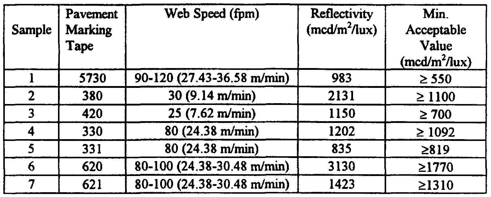
- pavement marking tapes were coated with the release coating to a range of heights (thickness) as described below. As shown, with the addition of a conductivity enhancer, different pavement marking tapes can be electrosprayed at different coat heights and web speeds. Pavement Marking Coat Height
- This example demonstrates electrospraying a release coating having an onium salt onto pavement marking tapes.
- a release coating composition was prepared by mixing together the following:
- the release coating was electrosprayed onto the following pavement marking tapes available from 3M as described in Example 8:
- Pavement marking tapes were electrosprayed with a release coating and measurements were taken of the silicone transfer.
- a release coating composition was prepared by mixing the following components at room temperature in a suitable vessel: 1800 g IOA
- the release coating was applied to the pavement marking tapes listed below by electrospray.
- the electrospray coating and UV curing assembly used was as described in Example 8 except the assembly was capable of handling 1.27 m ⁇ 0.05 m wide continuous webs.
- silicone transfer In order to measure silicone transfer, the following procedure was followed: a polybutadiene resin-based pressure sensitive adhesive was coated directly onto sputter etched polyester (4 mil (101.6 ⁇ m) film available from 3M). A strip of this adhesive coated polyester was applied to the release coated side of each of the samples. The samples were then placed under a 5 lb (2.27 kg) mass for three days in order to facilitate transfer. A glass panel was placed on top of each sample in order to evenly distribute the weight over an equal area, 4-inch x 6-inch (102 mm x 152 mm). The adhesive was removed from the surfaces just prior to loading into the spectrometer (Model 5100, available from Physical Electronics, Eden Prairie, MN). Silicone transfer was measured using X-ray Photoelectron Spectroscopy (XPS).
- XPS X-ray Photoelectron Spectroscopy
- the atomic percent of silicon is about 25, thus the silicone transfer from the electrospray release coating is minimal.
- a composition was prepared by mixing the following in a suitable vessel at room temperature:
- the conductivity of the composition was determined as described in Method I.
- the conductivity was 1.2 ⁇ S/m.
- composition was electrosprayed as described in Example 8, with a web speed of 30 fpm (9.14 m/min) and applied to the marking tape at a range of coat heights.
- composition was then UV cured under inert atmosphere.
- silicone transfer test described in Example 10
- atomic concentrations of silicon were measured at a 45° angle. The results are detailed in the following table.
- Samples were prepared using the release coating composition described in Example 10.
- the pavement marking tapes (all available from 3M) listed below were then electrosprayed as described in Example 10.
- a silicone transfer test was then conducted on each sample according to the following procedure.
- a sample was prepared by taking a one foot (0.3 m) by web width (0.33 m) sample without a carrier and cutting it into four 4-inch x 6-inch (0.1 m x 0.15 m) samples across the web.
- Five 4-inch x 6-inch (0.1 m x 0.15 m) samples of 6330 StamarkTM Pavement Marking Tape (available from 3M) were also cut and the liner was peeled off of 4 of the 5 samples.
- a stack was formed by alternating the 6330 tape with the electrospray coated tape, ending with the linered 6330 tape sample on the bottom.
- the stack was placed between two pieces of 0.25 inch (6.4 mm) plate glass with a 5-pound (2.27 kg) mass on the top center of the stack in an oven heated to 200°F (93 °C) for about one hour.
- the "middle" 6330 sample and the linered sample were selected and each was cut into three 25.4 mm strips.
- The-Strips were applied to stainless steel panels with five passes of a 5 pound (2.27 kg) roller. Then, the samples were conditioned at room temperature for about 5 minutes.
- a Sintech tensile strength instrument # 6365, available from Sintech, a division of MTS Systems Corp., Stoughton, MA
- the instrument had a jaw opening of 4 inches (0.1 m), a crosshead speed of 1 foot/min (0.3 m/min), and a 50 pound full scale load (222.5 N).
- test results were within the desired range of a differential of one pound (17.5 N/ 100 mm)or less from the control.
- Example 10 The composition of Example 10 was electrosprayed as described in Example 10 onto the following pavement marking tapes at a one micrometer coating height.
- Electrospray samples were prepared from a master composition containing 100 parts 75/25 IOA/l,6-HDDA, 2 parts Darocur 1173, 0.5 parts Aliquat 336, and 1 part NNDMA. To prepare each sample, 0.1 parts 5K ACMAS (sample 1), 0.2 parts 5K ACMAS (sample 2), 0.3 parts 5K ACMAS (sample 3), and 10 parts 5K ACMAS (sample 4) were added. The samples were electrosprayed as described in Example 8 on 0.036 mm thick polyester film (3M) at a line speed of 17 meter/min. and cured in line under an inert atmosphere with one medium pressure mercury lamp at a power setting of 200 W/2.54 cm (about 7.9 kW/m).
- 3M 0.036 mm thick polyester film
- the effectiveness of the release coating was measured by release and readhesion tests.
- the immediate release value (in N/100 mm) is a quantitative measure of the force required to remove a flexible adhesive tape (#810 tape available from 3M) from the electrospray coated polyester film at a specific angle and rate of removal.
- a 19 mm wide tape sample was laminated to the electrospray coated polyester film (1 pass at 30 cm/min with a 2 kg rubber covered roller) and the sample was tested immediately after roll-down using a slip/peel tester (Model 3M90 from Instrumentors, Inc.) at a rate of 30 cm/min and a peel angle of 180°.
- the aged release testing was conducted in a similar manner with the exception of allowing the adhesive tape/coated polyester film sandwich to age for three days at 65°C.
- Readhesions (both immediate and aged (three days at 65°C)) were measured (reported in N/100 mm) by adhering the freshly pulled tape to a clean glass plate and measuring the peel adhesion as described earlier.
- the release may be tailored from tight to easy by a simple change in the silicone content.
- the release builds after heat-aging, but the readhesion is essentially unaffected, thus showing good cure of the composition.
Abstract
Description


Claims


Priority Applications (5)
| Application Number | Priority Date | Filing Date | Title |
|---|---|---|---|
| AT96923712T ATE192476T1 (en) | 1996-03-26 | 1996-07-09 | SEPARATION LAYER APPLICABLE BY ELECTRO-SPRAYING |
| JP09534354A JP2000507300A (en) | 1996-03-26 | 1996-07-09 | Electrosprayable release coating |
| DE69608138T DE69608138T2 (en) | 1996-03-26 | 1996-07-09 | RELEASE LAYER APPLICABLE BY ELECTRO SPRAYING |
| EP96923712A EP0889940B1 (en) | 1996-03-26 | 1996-07-09 | Electrosprayable release coating |
| AU64561/96A AU6456196A (en) | 1996-03-26 | 1996-07-09 | Electrosprayable release coating |
Applications Claiming Priority (2)
| Application Number | Priority Date | Filing Date | Title |
|---|---|---|---|
| US08/622,075 US5858545A (en) | 1996-03-26 | 1996-03-26 | Electrosprayable release coating |
| US08/622,075 | 1996-03-26 |
Publications (1)
| Publication Number | Publication Date |
|---|---|
| WO1997035941A1 true WO1997035941A1 (en) | 1997-10-02 |
Family
ID=24492843
Family Applications (1)
| Application Number | Title | Priority Date | Filing Date |
|---|---|---|---|
| PCT/US1996/011442 WO1997035941A1 (en) | 1996-03-26 | 1996-07-09 | Electrosprayable release coating |
Country Status (10)
| Country | Link |
|---|---|
| US (1) | US5858545A (en) |
| EP (1) | EP0889940B1 (en) |
| JP (1) | JP2000507300A (en) |
| KR (1) | KR20000004982A (en) |
| CN (1) | CN1215423A (en) |
| AT (1) | ATE192476T1 (en) |
| AU (1) | AU6456196A (en) |
| CA (1) | CA2248312A1 (en) |
| DE (1) | DE69608138T2 (en) |
| WO (1) | WO1997035941A1 (en) |
Cited By (5)
| Publication number | Priority date | Publication date | Assignee | Title |
|---|---|---|---|---|
| US5998534A (en) * | 1998-06-19 | 1999-12-07 | Ppg Industries Ohio, Inc. | Water-soluble or water-dispersible addition copolymer |
| WO2000014053A1 (en) * | 1998-09-09 | 2000-03-16 | Rhodia Inc. | Water-soluble, hydrolytic-stable amphoteric monomer and polymers therefrom |
| EP1535949A1 (en) * | 2003-11-25 | 2005-06-01 | Rohm And Haas Company | Method for preparing polymer electrosprays |
| CN103450830A (en) * | 2013-09-02 | 2013-12-18 | 西北工业大学 | Preparation of high-performance magnetic conductive pressure-sensitive adhesive |
| WO2019241394A1 (en) | 2018-06-12 | 2019-12-19 | Rutgers, The State University Of New Jersey | Thickness-limited electrospray deposition |
Families Citing this family (29)
| Publication number | Priority date | Publication date | Assignee | Title |
|---|---|---|---|---|
| US6958179B2 (en) | 1999-12-30 | 2005-10-25 | 3M Innovative Properties Company | Segmented sheeting and methods of making and using same |
| US6737113B2 (en) * | 2001-01-10 | 2004-05-18 | 3M Innovative Properties Company | Method for improving the uniformity of a wet coating on a substrate using pick-and-place devices |
| US20020192360A1 (en) * | 2001-04-24 | 2002-12-19 | 3M Innovative Properties Company | Electrostatic spray coating apparatus and method |
| US6784222B2 (en) * | 2001-03-07 | 2004-08-31 | Frank David Zychowski | 100% solids radiation curable conductive primer |
| US6761978B2 (en) * | 2001-04-11 | 2004-07-13 | Xerox Corporation | Polyamide and conductive filler adhesive |
| US6579574B2 (en) | 2001-04-24 | 2003-06-17 | 3M Innovative Properties Company | Variable electrostatic spray coating apparatus and method |
| KR100908941B1 (en) * | 2001-08-02 | 2009-07-22 | 쓰리엠 이노베이티브 프로퍼티즈 컴파니 | Optically Transparent Antistatic Pressure Sensitive Adhesive |
| KR100793129B1 (en) * | 2002-02-04 | 2008-01-10 | 아사히 가세이 케미칼즈 가부시키가이샤 | Releasing material and release agent |
| KR101011609B1 (en) * | 2002-03-29 | 2011-01-27 | 디에스엠 아이피 어셋츠 비.브이. | Coating composition less susceptible to surface defects |
| US9353294B2 (en) * | 2004-12-14 | 2016-05-31 | 3M Innovative Properties Company | Microstructured release liners |
| JP2008031307A (en) * | 2006-07-28 | 2008-02-14 | Three Bond Co Ltd | Photocurable organopolysiloxane composition |
| US20080083495A1 (en) * | 2006-09-05 | 2008-04-10 | 3M Innovative Properties Company | Method of Manufacturing Structured Release Liner |
| US20080078500A1 (en) * | 2006-10-02 | 2008-04-03 | 3M Innovative Properties Company | Method of manufacturing structured release liner |
| CN101657522B (en) * | 2007-04-13 | 2014-05-07 | 3M创新有限公司 | Antistatic optically clear pressure sensitive adhesive |
| EP2643098B1 (en) | 2010-11-24 | 2016-08-10 | 3M Innovative Properties Company | Use of a transport coating to apply a thin coated layer |
| US11129799B2 (en) * | 2011-04-12 | 2021-09-28 | Aquestive Therapeutics, Inc. | Dual lane coating |
| CN104583286B (en) | 2012-09-10 | 2018-09-11 | 住友橡胶工业株式会社 | Surface modifying method and surface modified elastic body |
| CN105263995B (en) | 2013-06-20 | 2019-05-28 | 住友橡胶工业株式会社 | Surface modifying method and surface modified body |
| JP5820489B2 (en) | 2014-01-06 | 2015-11-24 | 住友ゴム工業株式会社 | Surface modification method and surface modified elastic body |
| KR101989905B1 (en) * | 2014-09-29 | 2019-06-18 | 주식회사 엘지화학 | Silicon based coating composition and silicon based release film |
| EP3237565A1 (en) | 2014-12-23 | 2017-11-01 | 3M Innovative Properties Company | Dual-sided multi-layer adhesive |
| WO2016106022A1 (en) | 2014-12-23 | 2016-06-30 | 3M Innovative Properties Company | Tie layers prepared from particle-containing waterborne suspensions |
| CN108541267B (en) * | 2015-04-29 | 2021-03-12 | 艾利丹尼森公司 | Non-silicone additives in release coating materials |
| JP6613692B2 (en) * | 2015-08-03 | 2019-12-04 | 住友ゴム工業株式会社 | Surface modification method and surface modified elastic body |
| TWI660830B (en) * | 2018-07-26 | 2019-06-01 | 國立臺灣科技大學 | Method for reducing drawing force during forming process of light curing material |
| EP4061901A1 (en) | 2019-11-20 | 2022-09-28 | 3M Innovative Properties Company | Medical tapes with high optical clarity when over-taped |
| WO2021137123A1 (en) | 2019-12-31 | 2021-07-08 | 3M Innovative Properties Company | Multilayer articles via wet-on-wet processing |
| US20230078390A1 (en) | 2020-04-13 | 2023-03-16 | 3M Innovative Properties Company | Medical adhesive articles having a low effective modulus of elasticity |
| CN116723813A (en) | 2020-12-21 | 2023-09-08 | 3M创新有限公司 | Double-sided adhesive tape with on-demand adhesion |
Citations (2)
| Publication number | Priority date | Publication date | Assignee | Title |
|---|---|---|---|---|
| US4303924A (en) * | 1978-12-26 | 1981-12-01 | The Mead Corporation | Jet drop printing process utilizing a radiation curable ink |
| WO1992016590A1 (en) * | 1991-03-20 | 1992-10-01 | Minnesota Mining And Manufacturing Company | Radiation curable vinyl/silicone release coating |
Family Cites Families (16)
| Publication number | Priority date | Publication date | Assignee | Title |
|---|---|---|---|---|
| US3348965A (en) * | 1964-02-04 | 1967-10-24 | Ransburg Electro Coating Corp | Electrostatic spraying |
| DE2205409C3 (en) * | 1972-02-05 | 1980-04-03 | Henkel Kgaa, 4000 Duesseldorf | Salts of quaternary amine-alkylene oxide adducts as agents for improving electrostatic sprayability |
| US4059444A (en) * | 1974-03-14 | 1977-11-22 | Xerox Corporation | Liquid development using conductive inks |
| US4097417A (en) * | 1974-05-02 | 1978-06-27 | National Starch And Chemical Corporation | Photocurable electroconductive coating composition |
| US4486504A (en) * | 1982-03-19 | 1984-12-04 | General Electric Company | Solventless, ultraviolet radiation-curable silicone coating compositions |
| US4748043A (en) * | 1986-08-29 | 1988-05-31 | Minnesota Mining And Manufacturing Company | Electrospray coating process |
| DE3777808D1 (en) * | 1987-02-06 | 1992-04-30 | Goldschmidt Ag Th | POLYSILOXANES WITH METH ACRYLIC ACID ESTER GROUPS AND THEIR USE AS RADIATION-COATING COATING AGENTS FOR FLAT AREAS. |
| US5364726A (en) * | 1990-03-30 | 1994-11-15 | Xerox Corporation | Liquid developers having curable liquid vehicles |
| CA2030312C (en) * | 1990-06-13 | 2002-04-16 | David S. Cobbledick | In-mold coating composition |
| KR100282103B1 (en) * | 1992-09-30 | 2001-02-15 | 그래햄 이. 테일러 | Electrostatically Painted Polymers and Methods for Making the Same |
| TW268969B (en) * | 1992-10-02 | 1996-01-21 | Minnesota Mining & Mfg | |
| US5326598A (en) * | 1992-10-02 | 1994-07-05 | Minnesota Mining And Manufacturing Company | Electrospray coating apparatus and process utilizing precise control of filament and mist generation |
| US5397673A (en) * | 1992-11-05 | 1995-03-14 | Xerox Corporation | Curable strip-out development processes |
| US5514728A (en) * | 1993-07-23 | 1996-05-07 | Minnesota Mining And Manufacturing Company | Catalysts and initiators for polymerization |
| US5425991A (en) * | 1994-03-25 | 1995-06-20 | Mobil Oil Corporation | Release sheet |
| US5554664A (en) * | 1995-03-06 | 1996-09-10 | Minnesota Mining And Manufacturing Company | Energy-activatable salts with fluorocarbon anions |
-
1996
- 1996-03-26 US US08/622,075 patent/US5858545A/en not_active Expired - Fee Related
- 1996-07-09 EP EP96923712A patent/EP0889940B1/en not_active Expired - Lifetime
- 1996-07-09 WO PCT/US1996/011442 patent/WO1997035941A1/en not_active Application Discontinuation
- 1996-07-09 AU AU64561/96A patent/AU6456196A/en not_active Abandoned
- 1996-07-09 AT AT96923712T patent/ATE192476T1/en active
- 1996-07-09 CN CN96180235A patent/CN1215423A/en active Pending
- 1996-07-09 CA CA002248312A patent/CA2248312A1/en not_active Abandoned
- 1996-07-09 KR KR1019980707593A patent/KR20000004982A/en not_active Application Discontinuation
- 1996-07-09 DE DE69608138T patent/DE69608138T2/en not_active Expired - Fee Related
- 1996-07-09 JP JP09534354A patent/JP2000507300A/en active Pending
Patent Citations (2)
| Publication number | Priority date | Publication date | Assignee | Title |
|---|---|---|---|---|
| US4303924A (en) * | 1978-12-26 | 1981-12-01 | The Mead Corporation | Jet drop printing process utilizing a radiation curable ink |
| WO1992016590A1 (en) * | 1991-03-20 | 1992-10-01 | Minnesota Mining And Manufacturing Company | Radiation curable vinyl/silicone release coating |
Cited By (7)
| Publication number | Priority date | Publication date | Assignee | Title |
|---|---|---|---|---|
| US5998534A (en) * | 1998-06-19 | 1999-12-07 | Ppg Industries Ohio, Inc. | Water-soluble or water-dispersible addition copolymer |
| WO2000014053A1 (en) * | 1998-09-09 | 2000-03-16 | Rhodia Inc. | Water-soluble, hydrolytic-stable amphoteric monomer and polymers therefrom |
| EP1535949A1 (en) * | 2003-11-25 | 2005-06-01 | Rohm And Haas Company | Method for preparing polymer electrosprays |
| CN103450830A (en) * | 2013-09-02 | 2013-12-18 | 西北工业大学 | Preparation of high-performance magnetic conductive pressure-sensitive adhesive |
| CN103450830B (en) * | 2013-09-02 | 2015-05-13 | 西北工业大学 | Preparation of high-performance magnetic conductive pressure-sensitive adhesive |
| WO2019241394A1 (en) | 2018-06-12 | 2019-12-19 | Rutgers, The State University Of New Jersey | Thickness-limited electrospray deposition |
| EP3807013A4 (en) * | 2018-06-12 | 2022-03-23 | Rutgers, The State University of New Jersey | Thickness-limited electrospray deposition |
Also Published As
| Publication number | Publication date |
|---|---|
| DE69608138T2 (en) | 2000-09-21 |
| DE69608138D1 (en) | 2000-06-08 |
| CN1215423A (en) | 1999-04-28 |
| CA2248312A1 (en) | 1997-10-02 |
| ATE192476T1 (en) | 2000-05-15 |
| EP0889940B1 (en) | 2000-05-03 |
| US5858545A (en) | 1999-01-12 |
| JP2000507300A (en) | 2000-06-13 |
| KR20000004982A (en) | 2000-01-25 |
| AU6456196A (en) | 1997-10-17 |
| EP0889940A1 (en) | 1999-01-13 |
Similar Documents
| Publication | Publication Date | Title |
|---|---|---|
| EP0889940B1 (en) | Electrosprayable release coating | |
| US5817376A (en) | Free-radically polymerizable compositions capable of being coated by electrostatic assistance | |
| US5962546A (en) | Cationically polymerizable compositions capable of being coated by electrostatic assistance | |
| US5753346A (en) | Cationically co-curable polysiloxane release coatings | |
| FI98733C (en) | Isoamyl (meth) acrylate copolymer-based, UV-crosslinkable masses | |
| JP3987964B2 (en) | Cationic polymerizable composition applicable by electrostatic assistance | |
| EP0024908B1 (en) | Release agent and products comprising a coating thereof | |
| US5707554A (en) | Electrically conductive surface release polymers | |
| EP0625527B1 (en) | Process for making pressure sensitive adhesive | |
| JPH0328283A (en) | Self-adhesive tape | |
| MXPA98007725A (en) | Coating of release, which can be electrorroc | |
| KR0159272B1 (en) | Indicia-receptive low adhesion backsize | |
| JP3361593B2 (en) | Coating composition | |
| CN113330078B (en) | Release layer and product containing release layer | |
| JP2000044688A (en) | Acrylic functional organopolysiloxane and radioactive ray-curable composition | |
| CA2144418A1 (en) | Epoxy impregnated tape backing | |
| JPS60248745A (en) | Coating material | |
| JP2008138059A (en) | Organosilicone resin emulsion composition and article with coated film of the composition formed thereon | |
| JPS6352066B2 (en) | ||
| EP3986940A1 (en) | Polymers for pressure-sensitive adhesives with antistatic properties | |
| JPS6044573A (en) | Manufacture of pressure-sensitive adhesive tape | |
| JPS59204678A (en) | Manufacture of pressure-sensitive adhesive tape |
Legal Events
| Date | Code | Title | Description |
|---|---|---|---|
| WWE | Wipo information: entry into national phase |
Ref document number: 96180235.9 Country of ref document: CN |
|
| AK | Designated states |
Kind code of ref document: A1 Designated state(s): AL AM AT AU AZ BB BG BR BY CA CH CN CZ DE DK EE ES FI GB GE HU IL IS JP KE KG KP KR KZ LK LR LS LT LU LV MD MG MK MN MW MX NO NZ PL PT RO RU SD SE SG SI SK TJ TM TR TT UA UG UZ VN AM AZ BY KG KZ MD RU TJ TM |
|
| AL | Designated countries for regional patents |
Kind code of ref document: A1 Designated state(s): KE LS MW SD SZ UG AT BE CH DE DK ES FI FR GB GR IE IT LU MC NL PT SE BF BJ CF CG CI CM GA GN |
|
| DFPE | Request for preliminary examination filed prior to expiration of 19th month from priority date (pct application filed before 20040101) | ||
| 121 | Ep: the epo has been informed by wipo that ep was designated in this application | ||
| ENP | Entry into the national phase |
Ref document number: 2248312 Country of ref document: CA Ref document number: 2248312 Country of ref document: CA Kind code of ref document: A |
|
| WWE | Wipo information: entry into national phase |
Ref document number: 1996923712 Country of ref document: EP |
|
| WWE | Wipo information: entry into national phase |
Ref document number: PA/a/1998/007725 Country of ref document: MX |
|
| WWE | Wipo information: entry into national phase |
Ref document number: 1019980707593 Country of ref document: KR |
|
| WWP | Wipo information: published in national office |
Ref document number: 1996923712 Country of ref document: EP |
|
| REG | Reference to national code |
Ref country code: DE Ref legal event code: 8642 |
|
| WWP | Wipo information: published in national office |
Ref document number: 1019980707593 Country of ref document: KR |
|
| WWG | Wipo information: grant in national office |
Ref document number: 1996923712 Country of ref document: EP |
|
| WWW | Wipo information: withdrawn in national office |
Ref document number: 1019980707593 Country of ref document: KR |