SINGLE CHIP VLSI IMPLEMENTATION OF A DIGITAL RECEIVER EMPLOYING ORTHOGONAL FREQUENCY DIVISION MULTIPLEXING
This invention relates to receivers of electromagnetic signals employing multicarπer modulation More particularly this invention relates to a digital receiver which is implemented on a single VLSI chip for receiving transmissions employing orthogonal frequency division multiplexing, and which is suitable for the reception of digital video broadcasts Coded orthogonal frequency division multiplexing ("COFDM") has been proposed for digital audio and digital video broadcasting, both of which require efficient use of limited bandwidth, and a method of transmission which is reliable in the face of several effects For example the impulse response of a typical channel can be modeled as the sum of a plurality of Dirac pulses having different delays Each pulse is subject to a multiplication factor, in which the amplitude generally follows a Rayleigh law Such a pulse train can extend over several microseconds, making unencoded transmission at high bit rates unreliable In addition to random noise, impulse noise, and fading, other major difficulties in digital terrestrial transmissions at high data rates include multipath propagation, and adjacent channel interference, where the nearby frequencies have highly correlated signal variations COFDM is particularly suitable for these applications In practical COFDM arrangements, relatively small amounts of data are modulated onto each of a large number of carriers that are closely spaced in frequency The duration of a data symbol is increased in the same ratio as the number of carriers or subchannels, so that inter-symbol interference is markedly reduced Multiplexing according to COFDM is illustrated in Figs 1 and 2, wherein the spectrum of a single COFDM carrier or subchannel is indicated by line 2 A set of carrier frequencies is indicated by the superimposed waveforms in Fig 2, where orthogonality conditions are satisfied In general two real-valued functions are orthogonal if
"ψp(t) ψq(t) dt = K (1)
where K is a constant, and K = 0 if p ≠ q, K ≠O if p = q Practical encoding and decoding of signals according to COFDM relies heavily on the fast Fourier transform ("FFT"), as can be appreciated from the following equations The signal of a carrier c is given by ω + φc(t)] se(t) = An(t) e Jlu,e, τ ψeiυj (2)
where Ac is the data at time t, ωc is the frequency of the carrier, and φc is the phase. N carriers in the COFDM signal is given by
s.(t) = (1/N) ∑ An(t)eJ [ω"t +φ»(t)l (3) n = 0
ωn = ω0 + nΔω (4)
Sampling over one symbol period, then
Ac(t)^An (6)
With a sampling frequency of 1/T, the resulting signal is represented by
ss( = ( 1 /Λ/) ∑ An(t)e "+n^)kT+*"] (7) n = 0
Sampling over the period of one data symbol T = NT, with ω0 = 0,
N - 1 ss(kT) = ( 1 /N) ∑ Ane )Φne j(nΔω)kτ (8) n -= 0 which compares with the general form of the inverse discrete Fourier transform:
N - 1 g (kT) = (1 /N) ∑ G(n/(kT))e ,πn (k/N) (9) n = 0
In the above equations r\n^n is the input signal in the sampled frequency domain, and ss(kT) is the time domain representation. It is known that increasing the size of the FFT provides longer symbol durations and improves ruggedness of the system as regards echoes which exceed the length of the guard interval. However computational complexity increases according to Nlog2N, and is a practical limitation.
In the presence of intersymbol interference caused by the transmission channel, orthogonality between the signals is not maintained. One approach to this problem has been to deliberately sacrifice some of the emitted energy by preceding each symbol in the time domain by an interval which exceeds the memory of the channel, and any multipath delay. The "guard interval" so chosen is large enough to absorb any intersymbol interference, and is established by preceding each symbol by a replication of a portion of itself. The replication is typically a cyclic extension of the terminal portion
of the symbol. Referring to Fig. 3, a data symbol 4 has an active interval 6 which contains all the data transmitted in the symbol. The terminal portion 8 of the active interval 6 is repeated at the beginning of the symbol as the guard interval 10. The COFDM signal is represented by the solid line 12. It is possible to cyclically repeat the initial portion of the active interval 6 at the end of the symbol.
Transmission of COFDM data can be accomplished according to the known general scheme shown in Fig. 4. A serial data stream 14 is converted to a series of parallel streams 16 in a serial-to-parallel converter 18. Each of the parallel streams 16 is grouped into x bits each to form a complex number, where x determines the signal constellation of its associated parallel stream. After outer coding and interleaving in block 20 pilot carriers are inserted via a signal mapper 22 for use in synchronization and channel estimation in the receiver. The pilot carriers are typically of two types. Continual pilot carriers are transmitted in the same location in each symbol, with the same phase and amplitude. In the receiver, these are utilized for phase noise cancellation, automatic frequency control, and time/sampling synchronization. Scattered pilot carriers are distributed throughout the symbol, and their location typically changes from symbol to symbol. They are primarily useful in channel estimation. Next the complex numbers are modulated at baseband by the inverse fast fourier transform ("IFFT") in block 24. A guard interval is then inserted at block 26. The discrete symbols are then converted to analog, typically low-pass filtered, and then upconverted to radiofrequency in block 28. The signal is then transmitted through a channel 30 and received in a receiver 32. As is well known in the art, the receiver applies an inverse of the transmission process to obtain the transmitted information. In particular an FFT is applied to demodulate the signal. A modern application of COFDM has been proposed in the European Telecommunications Standard ETS 300 744 (March 1997), which specifies the framing structure, channel coding, and modulation for digital terrestrial television. The specification was designed to accommodate digital terrestrial television within the existing spectrum allocation for analog transmissions, yet provide adequate protection against high levels of co-channel interference and adjacent channel interference. A flexible guard interval is specified, so that the system can support diverse network configurations, while maintaining high spectral efficiency, and sufficient protection against co-channel interference and adjacent channel interference from existing PAL/SECAM services. The noted European Telecommunications Standard defines two modes of operation. A "2K mode", suitable for single transmitter operation and for small single frequency networks with limited transmitterdistances. An "8K mode" can be used for either single transmitter operation or for large single frequency networks. Various levels of quadrature amplitude
modulation ("QAM") are supported, as are different inner code rates, in order to balance bit rate against ruggedness. The system is intended to accommodate a transport layer according to the Moving Picture Experts Group ("MPEG"), and is directly compatible with M P E G - 2 c o d e d TV s i g n a l s ( I S O / I E C 1 38 1 8 ) . In the noted European Telecommunications Standard data carriers in a COFDM frame can be either quadrature phase shift keyed ("QPSK"), 16-QAM, 64-QAM, non- uniform 16-QAM, or non-uniform 64-QAM using Gray mapping.
An important problem in the reception of COFDM transmission is difficulty in maintaining synchronization due to phase noise and jitter which arise from upconversion prior to transmission, downconversion in the receiver, and the front end oscillator in the tuner, which is typically a voltage controlled oscillator. Except for provision of pilot carriers to aid in synchronization during demodulation, these issues are not specifically addressed in the noted European Telecommunications Standard, but are left for the implementer to solve. Basically phase disturbances are of two types. First, noisy components which disturb neighbor carriers in a multicarrier system are called the "foreign noise contribution" ("FNC"). Second, a noisy component which disturbs its own carrier is referred to as the "own noise contribution".
Referring to Fig. 5, the position of ideal constellation samples are indicated by "x" symbols 34. The effect of foreign noise contribution is stochastic, resulting in Gaussianlike noise. Samples perturbed in this manner are indicated on Fig. 5 as circles 36. The effects of the own noise contribution is a common rotation of all constellation points, indicated as a displacement between each "x" symbol 34 and its associated circle 36. This is referred to as the "common phase error", which notably changes from symbol to symbol, and must therefore be recalculated each symbol period Ts. The common phase error may also be interpreted as a mean phase deviation during the symbol period Ts.
In order for the receiver 32 to process the data symbols in a practical system, a mathematical operation is performed on the complex signal representing each data symbol. Generally this is an FFT. For valid results to be obtained, a particular form of timing synchronization is required in order to align the FFT interval with the received data symbol.
It is therefore a primary object of the invention to provide a highly integrated, low cost apparatus for the reception of digital broadcasts, such as terrestrial digital video broadcasts, which is implemented on a single VLSI chip. It is another object of the invention to provide an improved method and apparatus for synchronizing a received data symbol with an FFT window in signals transmitted according to COFDM.
It is yet another object of the invention to improve the stability of digital multicarrier receivers in respect of channel estimation
It is still another object of the invention to improve the automatic frequency control circuitry employed in multicarrier digital receivers It is a further object of the invention to improve the automatic sampling rate control circuitry employed in multicarrier digital receivers
The invention provides a digital receiverfor multicarπersignals that are transmitted by orthogonal frequency division multiplexing The multicarrier signal carries a stream of data symbols having an active interval, and a guard interval in which the guard interval is a replication of a portion of the active interval In the receiver an analog to digital converter is coupled to a front end amplifier An l/Q demodulator is provided for recovering in phase and quadrature components from data sampled by the analog to digital converter, and an automatic gam control circuit is coupled to the analog to digital converter In a low pass filter circuit accepting I and Q data from the l/Q demodulator, the I and Q data are decimated and provided to a resampling circuit An interpolator in the resampling circuit accepts the decimated I and Q data at a first rate and outputs resampled I and Q data at a second rate An FFT window synchronization circuit is coupled to the resampling circuit for locating a boundary of the guard interval A realtime pipelined FFT processor is operationally associated with the FFT window synchronization circuit Each stage of the FFT processor has a complex coefficient multiplier, and an associated memory with a lookup table defined therein for multiplicands being multiplied in the complex coefficient multiplier Each multiplicand in the lookup table is unique in value A monitor circuit responsive to the FFT window synchronization circuit detects a predetermined indication that a boundary between an active symbol and a guard interval has been located
According to an aspect of the invention the FFT window synchronization circuit has a first delay element accepting currently arriving resampled I and Q data, and outputting delayed resampled I and Q data A subtracter produces a signal representative of the difference between the currently arriving resampled I and Q data and the delayed resampled I and Q data In a first circuit the subtracter output signal is converted to a signal having a unipolar magnitude, which is preferably the absolute value of the signal provided by the subtracter A second delay element stores the output signal of the first circuit, and a third delay element receives the delayed output of the second delay element In a second circuit a statistical relationship is calculated between data stored in the second delay element and data stored in the third delay element The output of the FFT window synchronization circuit is representative of the statistical relationship
Preferably the statistical relationship is the F ratio. The FFT processor is capable of operation in a 2K mode and in an 8K mode.
The FFT processor has an address generatorfor the memory of each stage, which accepts a signal representing the order dependency of a currently required multiplicand, and generates an address of the memory wherein the currently required multiplicand is stored. In a further aspect of the invention each multiplicand is stored in the lookup table in order of its respective order dependency for multiplication by the complex coefficient multiplier, so that the order dependencies of the multiplicands define an incrementation sequence. The address generator has an accumulator for storing a previous address that was generated thereby, a circuit for calculating an incrementation value of the currently required multiplicand responsive to the incrementation sequence, and an adder for adding the incrementation value to the previous address.
In another aspect of the invention there are a plurality of incrementation sequences. The multiplicands are stored in row order, wherein in a first row a first incrementation sequence is 0, in a second row a second incrementation sequence is 1 , in a third row first and second break points B1 , B2 of a third incrementation sequence are respectively determined by the relationships
N -1
B1 M = 4NB1 M "∑ 4n n =0
B2
' ,N Σ 4" n =0 and in a fourth row a third break point B3 of a third incrementation sequence is determined by the relationship
B3M = 2 x 4N + 2 wherein MN represents the memory of an Nth stage of the FFT processor.
The receiver provides channel estimation and correction circuitry. Pilot location circuitry receives a transformed digital signal representing a frame from the FFT processor, and identifies the position of pilot carriers therein. The pilot carriers are spaced apart in a carrier spectrum of the transformed digital signal at intervals K and have predetermined magnitudes. The pilot location circuitry has a first circuit for computing an order of carriers in the transformed digital signal, positions of said carriers being calculated modulo K. There are K accumulators coupled to the second circuit for accumulating magnitudes of the carriers in the transformed digital signal, the accumulated magnitudes defining a set. A correlation circuit is provided for correlating
K sets of accumulated magnitude values with the predetermined magnitudes In the correlation a first member having a position calculated modulo K in of each of the K sets is uniquely offset from a start position of the frame
According to another aspect of the invention the pilot location circuitry also has a bit reversal circuit for reversing the bit order of the transformed digital signal
According to yet another aspect of the invention amplitudes are used to represent the magnitudes of the carriers Preferably the magnitudes of the carriers and the predetermined magnitudes are absolute values
In a further aspect of the invention the correlation circuitry also has a peak tracking circuit for determining the spacing between a first peak and a second peak of the K sets of accumulated magnitudes, wherein the first peak is the maximum magnitude, and the second peak is the second highest magnitude
The channel estimation and correction circuitry also has an interpolating filter for estimating the channel response between the pilot carriers, and a multiplication circuit for multiplying data carriers output by the FFT processor with a correction coefficient produced by the interpolating filter
The channel estimation and correction circuitry also has a phase extraction circuit accepting a data stream of phase-uncorrected I and Q data from the FFT processor, and producing a signal representative of the phase angle of the uncorrected data The phase extraction circuit includes an accumulator for the phase angles of succeeding phase-uncorrected I and Q data
According to an aspect of the invention the channel estimation and correction circuitry includes an automatic frequency control circuit coupled to the phase extraction circuit, in which a memory stores the accumulated common phase error of a first symbol carried in the phase-uncorrected I and Q data An accumulator is coupled to the memory and accumulates differences between the common phase error of a plurality of pilot carriers in a second symbol and the common phase error of corresponding pilot carriers in the first symbol The output of the accumulator is filtered, and coupled to the l/Q demodulator According to another aspect of the invention the coupled output of the accumulator of the automatic frequency control circuit is enabled in the l/Q demodulator only during reception of a guard interval therein
According to yet another aspect of the invention the channel estimation and correction circuitry also has an automatic sampling rate control circuit coupled to the phase extraction circuit, in which a memory stores the individual accumulated phase errors of pilot carriers in a first symbol carried in the phase-uncorrected I and Q data
An accumulator is coupled to the memory and accumulates differences between the
phase errors of individual pilot carriers in a second symbol and phase errors of corresponding pilot carriers in the first symbol to define a plurality of accumulated intersymbol carrier phase error differentials. A phase slope is defined by a difference between a first accumulated intersymbol carrier phase differential and a second accumulated intersymbol carrier phase differential. The output of the accumulator is filtered and coupled to the l/Q demodulator.
According to one aspect of the invention the sampling rate control circuit stores a plurality of accumulated intersymbol carrier phase error differentials and computes a line of best fit therebetween. According to another aspect of the invention the coupled output signal of the accumulator of the automatic sampling rate control circuit is enabled in the resampling circuit only during reception of a guard interval therein.
According to an aspect of the invention a common memory for storing output of the phase extraction circuit is coupled to the automatic frequency control circuit and to the automatic sampling rate control circuit.
According to another aspect of the invention the phase extraction circuit also has a pipelined circuit for iteratively computing the arctangent of an angle of rotation according to the series
X Y Λ V Λ V Λ i i tan W = * ~ — + — + — - ■ • •, x 1
3 5 7 9 wherein x is a ratio of the phase-uncorrected I and Q data.
The pipelined circuit includes a constant coefficient multiplier, and a multiplexerfor selecting one of a plurality of constant coefficients of the series. An output of the multiplexer is connected to an input of the constant coefficient multiplier.
According to still another aspect of the invention the pipelined circuit has a multiplier, a first memory for storing the quantity x2, wherein the first memory is coupled to a first input of the multiplier, and has a second memory for holding an output of the multiplier. A feedback connection is provided between the second memory and a second input of the multiplier. The pipelined circuit also has a third memory for storing the value of the series. Under direction of a control circuit coupled to the third memory, the pipeline circuit computes N terms of the series, and also computes N+1 terms of the series. An averaging circuit is also coupled to the third memory and computes the average of N terms and N+1 terms of the series. Data transmitted in a pilot carrier of the multicarrier signal is BCH encoded according to a code generator polynomial h(x). A demodulator operative on the BCH encoded data is provided, which includes an iterative pipelined BCH decoding circuit.
The BCH decoding circuit is circuit coupled to the demodulator It forms a Galois Field of the polynomial, and calculates a plurality of syndromes therewith The BCH decoding circuit includes a plurality of storage registers, each storing a respective one of the syndromes, and a plurality of feedback shift registers, each accepting data from a respective one of the storage registers The BCH decoding circuit has a plurality of Galois field multipliers Each of the multipliers is connected in a feedback loop across a respective one of the feedback shift registers and multiplies the output of its associated feedback shift register by an alpha value of the Galois Field An output Galois field multiplier multiplies the outputs of two of the feedback shift registers A logical network forms an error detection circuit connected to the feedback shift registers and to the output Galois field multiplier The output of the error detection circuit indicates an error in a current bit of data, and a feedback line is enabled by the error detection logic and connected to the storage registers Using the feedback line, the data output by the feedback shift registers are written back into the storage registers for use in a second iteration
According to an aspect of the invention the output Galois field multiplier has a first register initially storing a first multiplicand A, a constant coefficient multiplier connected to the first register for multiplication by a value α An output of the constant coefficient multiplier is connected to the first register to define a first feedback loop, whereby in a kth cycle of clocked operation the first register contains a Galois field product Aαk A second register is provided for storing a second multiplicand B An AND gate is connected to the second register and to the output of the constant coefficient multiplier An adder has a first input connected to an output of the AND gate An accumulator is connected to a second input of the adder, and the Galois field product AB is output by the adder
The invention provides a method for the estimation of a frequency response of a channel It is performed by receiving from a channel an analog multicarrier signal that has a plurality of data carriers and scattered pilot carriers The scattered pilot carriers are spaced apart at an interval N and are transmitted at a power that differs from the transmitted power of the data carriers The analog multicarrier signal is converted to a digital representationthereof A Fouπertransform is performed on the digital representation of the multicarrier signal to generate a transformed digital signal The bit order of the transformed digital signal is reversed to generate a bit-order reversed signal Magnitudes of the carriers in the bit-order reversed signal are cyclically accumulated in N accumulators, amd the accumulated magnitudes are correlated with the power of the scattered pilot carriers Responsive to the correlation, a synchronizing signal is
generated that identifies a carrier position of the multicarrier signal, preferably an active carrier.
According to another aspect of the invention the step of accumulating magnitudes is performed by adding absolute values of a real component of the bit-order reversed signal to respective absolute values of imaginary components thereof to generate sums, and respectively storing the sums in the N accumulators.
According to yet another aspect of the invention the step of correlating the accumulated magnitudes also is performed by identifying a first accumulator having the highest of the N values stored therein, which represents a first carrier position, and by identifying a second accumulator which has the second highest of the N values stored therein, which represents a second carrier position. The interval between the first carrier position and the second carrier position is then determined.
To validate the consistency of the carrier position identification, the position of a carrier of a first symbol in the bit-order reversed signal is compared with a position of a corresponding carrier of a second symbol therein.
Preferably interpolation is performed between pilot carriers to determine correction factors for respective intermediate data carriers disposed therebetween, and respectively adjusting magnitudes of the intermediate data carriers according to the correction factors. According to an aspect of the invention a mean phase difference is determined between corresponding pilot carriers of successive symbols of the transformed digital signal. A first control signal representing the mean phase difference, is provided to control the frequency of reception of the multicarrier signal. The first control signal is enabled only during reception of a guard interval. Preferably a line of best fit is determined for the inter-symbol phase differences of multiple carriers to define a phase slope.
For a better understanding of these and other objects of the present invention, reference is made to the detailed description of the invention, by way of example, which is to be read in conjunction with the following drawings, wherein: Fig. 1 illustrates the spectrum of a COFDM subchannel;
Fig. 2 shows a frequency spectrum for multiple carriers in a COFDM signal; Fig. 3 is a diagram of a signal according to COFDM and shows a data symbol format;
Fig. 4 is a block diagram illustrating an FFT based COFDM system; Fig. 5 illustrates certain perturbations in a COFDM signal constellation;
Fig. 6 is a flow diagram of a method of timing synchronization according to a preferred embodiment of the invention;
Fig 7 is a plot of an F ratio test performed on several data symbols for coarse timing synchronization,
Fig 8 is a plot of an incomplete beta function for different degrees of freedom,
Fig 9 is a plot helpful in understanding a test of statistical significance according to the invention,
Fig 10 is an electrical schematic of a synchronization circuit according to an alternate embodiment of the invention,
Fig 11 is an electrical schematic of a synchronization circuit according to another alternate embodiment of the invention, Fig 12 is a block diagram of a single-chip embodiment of a digital receiver in accordance with the invention,
Fig 13 is a block diagram illustrating the front end of the digital receiver shown in Fig 12 in further detail,
Fig 14 is a block diagram illustrating the FFT circuitry, channel estimation and correction circuitry of the digital receiver shown in Fig 12,
Fig 15 is a block diagram illustrating another portion of the digital receiver shown in Fig 12,
Fig 16 is a more detailed block diagram of the channel estimation and correction circuitry shown in Fig 14, Fig 17 is a schematic of the automatic gam control circuitry of the digital receiver shown in Fig 12,
Fig 18 is a schematic of the l/Q demodulator of the digital receiver shown in Fig 12,
Fig 19 illustrates in greater detail a low pass filter shown in Fig 13, Fig 20 shows the response of the low pass filter shown in Fig 19,
Fig 21 shows the resampling circuitry of the digital receiver shown in Fig 12,
Fig 22 illustrates a portion of an interpolator in the resampling circuitry of Fig 21 ,
Fig 23 is a more detailed block diagram of the FFT window circuitry shown in Fig 14, Fig 24 is a schematic of a butterfly unit in the FFT calculation circuitry shown in
Fig 14,
Figs 25 and 26 are schematics of butterfly units in accordance with the prior art,
Fig 27 is a schematic of a radix 22 + 2 FFT processor in accordance with the invention, Fig 28 is 32 point flow graph of the FFT processor shown in Fig 27,
Fig 29 is a schematic of a configurable 2K 8K radix 22+2 single path, delay feedback pipelined FFT processor in accordance with the invention,
Fig 30 is a detailed schematic of a complex multiplier used in the circuitry shown in Fig 29,
Fig 31 is a detailed schematic of an alternateembodimentof a complex multipliers used in the circuitry shown in Fig 29, Fig 32 is another diagram illustrating the organization of the twiddle factors for each of the multipliers in the circuitry shown in Fig 29,
Fig 33 illustratesthe organization of the twiddle factors for each of the multipliers in the circuitry shown in Fig 29,
Fig 34 is a schematic of address generator used in the circuitry shown in Fig 29, Fig 35 is a schematic of a generalization of the address generator shown in Fig
34,
Fig 36 is a flow chart illustrating the process of pilot location conducted by the channel estimation and correction circuitry shown in Fig 16,
Fig 37 is a flow chart of an embodiment of the pilot localization procedure according to the invention
Fig 38 is a more detailed block diagram of the tps sequence block of the circuitry shown in Fig 14,
Fig 39 is a schematic of a BCH decoder used in the tps processing circuitry shown
Fig 40 is a more detailed schematic of a Galois field multiplier shown in Fig 39,
Fig 41 is a block diagram genencally illustrating the automatic sampling control and automatic frequency control loops of the digital receiver shown in Fig 12,
Fig 42 is a more detailed block diagram of the automatic sampling control and automatic frequency control loops shown in Fig 41 Fig 43 is a more detailed block diagram of the phase extract block of the circuitry shown in Fig 42,
Fig 44 is a schematic of the circuitry employed to calculate an arctangent in the block diagram shown in Fig 43,
Fig 45 is a plot of the square error at different values of α of the Taylor expansion to 32 terms,
Fig 46 is a plot of the square error at different values of α of the Taylor expansion to 31 terms,
Fig 47 is a plot of the square error at different values of α of the average of the Taylor expansion to 31 and 32 terms, Fig 48 is a plot of the phase differences of pilot carriers with a line of best fit shown,
Fig. 49 is a more detailed block diagram an alternate embodiment of the automatic sampling control and automatic frequency control loops shown in Fig. 41 ;
Fig. 50 illustrates a coded constellation format used in the demapping circuitry of Fig. 15; Fig. 51 illustratesthe conversion of l,Q data to binary data value using the format shown in Fig. 50;
Fig. 52 is a more detailed block diagram of the symbol deinterleaving circuitry shown in Fig. 15;
Fig. 53 is a more detailed block diagram of the bit deinterleaving circuitry shown in Fig. 15;
Fig. 54 illustratesthe conversion from a coded constellation format to a 24 bit soft l/Q format by the bit deinterleaving circuitry shown in Fig. 53;
Fig. 55 is a more detailed block diagram of the microprocessor interface of the receiver shown in Fig. 12; Fig. 56 is a more detailed block diagram of the system controller of the receiver shown in Fig. 12; and
Fig. 57 is a state diagram relating to channel acquisition in the system controller of the receiver shown in Fig. 56. Alignment of The FFT Window Referring again to Figs. 3 and 4, according to the invention a statistical method is applied to COFDM signals to find the end of the guard interval 10. This method is explained with reference to the above noted European Telecommunications Standard, but is applicable to many forms of frequency division multiplexing having prefixed or postfixed guard intervals. It allows the receiver 32 to find the end of the guard interval given only the received sampled complex signal ( solid line 12) and the size of the active interval 6 . The method relies on the fact that the guard interval 10 is a copy of the last part of the data symbol 4. In the receiver 32, due to echoes and noise from the channel and errors in the local oscillator, the guard interval 10 and the last part of the data symbol 4 will differ. If the errors introduced are random then a statistical method can be applied. According to the invention, the received complex signal is sampled at a rate which is nearly identical to that used in the transmitter. A difference signal is found for a pair of received samples which are separated by a period of time which is as close as possible to the active interval 6. This period should be equal to the size of the fast fourier transform ("FFT") being applied (i.e. 2048 or 8192 samples). Let
' msize I (14)
where S, is the difference signal; s, and §_msae are the current and previous complex input samples of which the modulus is taken. That is, the subscript "i" indexes a linear time sequence of input values. Assuming that the input signal is random, then S, is also random. Within the guard interval s, and s^^wM be similar, although not identical, due to the effects ofthe channel. S, will be therefore a random signal with a small dispersion. As used herein the term "dispersion" means generally the spread of values, and is not restricted to a particular mathematical definition, in general the active part of one symbol is not related to the active part of the next symbol. Outside of the guard interval S, will be random with a much larger dispersion. In order to find the end of the guard interval, the dispersion of the difference signal S, is monitored to look for a significant increase which will occur at the boundary of the guard interval 10 and the active interval 6. The inventors have also observed that a large decrease in dispersion is seen at the start of the guard interval 10.
According to a preferred embodiment of the invention samples of the input signal are stored over an interval which includes at least one symbol period Ts. The dispersion of the difference signal S, is calculated over a block of samples. The block is moved back in time over a number of samples, n, and the dispersion is recalculated. These two blocks are referred to herein as "comparison blocks". The ratio of a current dispersion in a first comparison block to the dispersion in a previous comparison block is found. Then, the F ratio significance test is used to find significant differences in the dispersions of the two comparison blocks. The F ratio is defined as
where n is a positive integer, i indexes the input samples, and VAR(i) is the variance of a block of values of length N samples. Variance can be defined as
While the F ratio significance test is used in the preferred embodiment, other functions of the two dispersion values which give a signal relating to the change in dispersion could be used. There are many such functions. An advantage of the F ratio is that for a random input signal it has a known probability distribution, allowing convenient statistical analysis for purposes of performance analysis and system design. Also the F ratio intrinsically normalizes the signal, making the result independent of the signal level.
The method is disclosed with reference to Fig. 6, in which a first member of a sample pair in a current evaluation block is measured at step 38. A delay of one active interval 6 ( Fig. 3) is experienced in step 40. This may be accomplished with a digital delay such as a FIFO, or equivalently by buffering samples for an active interval in a memory and accessing appropriate cells of the memory. A second member of the sample pair is measured in step 42, and the difference between the first and second member is determined and stored in step 44. The end of the current block is tested at decision step 46. The size of the evaluation block should not exceed the length of a guard interval, and may be considerably smaller. In the event the end of the current block has not yet been reached, another sample is acquired at step 48, and control returns to step 38.
If the end of the current block has been reached, the dispersion of the current block is measured in step 50, and is treated as one of two comparison blocks of data. A test is made at decision step 52 to determine if a group of two comparison blocks have been evaluated. If this test is negative, then another block of data is acquired in step 54, after which control returns to step 38. The other block of data need not be contiguous with the block just completed.
In the event the test at decision step 52 is positive, the F ratio is computed for the group of two comparison blocks at step 56. The results obtained in step 56 are submitted to peak detection in step 60. Peak detection optionally includes statistical tests of significance, as is explained hereinbelow.
If peaks are detected, then the boundary of a guard interval is established in step 62 for purposes of synchronization of the FFT window which is necessary for further signal reconstruction. If peaks are not detected, the above process is repeated with a block of samples taken from another portion of the data stream. Example 1 :
Referring now to Fig. 7 a complex signal was generated according to the above noted European Telecommunicationsstandard using a random number generator, and transmitted across a Ricean channel model together with added white Gaussian noise (SNR = 3.7). Data symbols were then analyzed according to the above described method. The results 6 data symbols are shown in Fig. 7, wherein the F ratio is plotted for convenience of presentation on a logarithmic axis as line 64, because the spikes 66, 68, at the beginning and end of the guard intervals respectively, are very large.
Although it is quite evident from Figure 7 that the ends of the guard intervals are easy to find using any of several well known peak detectors, it is possible to apply a statistical test to more accurately answer the question: do the two blocks of samples have the same dispersion? This is the null hypothesis, H0, i.e. the dispersion is the
same and the observed spike in F is due to random fluctuations only If H0 has very low probability it can be rejected, which would correspond to detection of the start or end of the guard interval From the way the COFDM symbol is constructed H0 is expected to be true for comparison blocks lying entirely within the guard interval or within the active interval, but false when the comparison blocks straddle a boundary at the start or end of the guard interval If comparison blocks of random samples are drawn from the same population then the probability of F is given by
where l() is the incomplete Beta function, v 2
(18) v2 T v,F and v1 and v2 are the number of degrees of freedom with which the first and second dispersions are estimated In this example v1 = v2 = (N-1 ) if n >= N The shape of the function is shown in Fig 8 From a statistical point of view n should be sufficiently large so that the two blocks do not overlap, i e n >= N If the blocks do overlap, then the calculation of the second dispersion will use samples used for the calculation of the first dispersion This effectively reduces the number of degrees of freedom and hence the significance of the result It has been determined that setting n=N works well
The function Q() in equation (13) actually gives the one-tailed probability H0 could be rejected if F is either very large or very small, and so the two-tailed test is required Actually the two tails are identical, so for a two-tailed test the probability is double that given in equation (13) However, this results in values of probability greater than one for F<1 The prooabihty, p, is therefore calculated as follows
P =2/ (γ' γ) <19>
and then if (p > 1), p = 2 - p This probability reflects the viability of H0 Thus if p is small, H0 can be rejected and it can be stated, with a specified degree of certainty, that the comparison blocks come from sample populations with different dispersion The noted European Telecommunications Standard specification states that the block size, N, should be 32 for a correlation algorithm N={32,64} have been successfully tried The probability functions obtained are shown in Fig 9 using these values for N In the preferred embodiment p <= 0 05 has been set for the rejection of H0
A precise implementationwould be to calculate F, then x, then the incomplete Beta function, then p and then apply the threshold test. This algorithm would be very difficult to realize in hardware since the Beta function is very complicated. In the preferred embodiment it is much simpler, and gives the same results, to set the acceptance threshold and N parameter, and thus define an upper and lower limit for F. It is then only necessary to calculate F and compare it with the limits. In order to simply find the end of the guard interval it may be safely assumed that F>1. Only the upper limit on F is needed. To calculate the limits on F accurately, a suitable root-finding method, such as Newton-Raphson may be utilized. Typical values are given in Table 1.
Table 1
This method has been successfully tested using the specified channel model with additive white Gaussian noise (SNR=3.7).
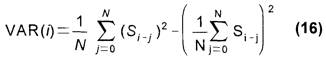
The formula for dispersion given in Equation (12) would require a multiplier for implementation in silicon. The calculation of F is a division in which the (N-1 ) normalisation constants cancel out as long as the two blocks have the same size. Accurate multiplication and division can be expensive in silicon. In the preferred embodiment simplifications have been implemented which give less accurate, but still viable, values for F. S, can be assumed to have zero mean so it is not necessary to calculate the mean from the block of samples. This also increases the number of degrees of freedom from (N-1) to N. Instead of calculating variance using the standard
sum of squares formula, the dispersion can be estimated by the mean absolute deviation. The formula for VAR(i) becomes
The (1/N) factor divides out in the calculation of F if the two blocks have the same size. But there still remains the division of the two dispersions and the squaring required. These can be tackled using logarithms to the base 2. Substituting from Equation (16) into Equation (11) gives
Taking logs to the base 2 gives
log F = 2(log sa - log sb) = y (22)
It is then only necessary to calculate y and compare it with the logarithm to the base 2 of the F upper limit. The comparison can be made by subtracting the log of the limit from 2(log2sa-iog2sb) and comparing with zero. The factor of 2 can be absorbed into the limit.
Calculation of the logs to base two is relatively straightforward in hardware if the numbers are stored as fixed point fractions. The fractions can be split into an exponent and a fractional mantissa: x = A2B. Taking log base 2 gives logx = logA + B. Since A is fractional it is practical to find its logarithm using a lookup table. The exponent B can be found from the position of the MSB (since sa and sb will both be positive numbers).
The calculation can thus be reduced to require only addition and subtraction arithmetic operations. The limit should also be recalculated using v1=v2=N if using this method. In practice, the significance level may be set empirically for a particular application, preferably p = 0.05.
It will be appreciated by those skilled in the art that various measures of dispersion may be utilized without departing from the spirit of the invention, for example the
standard deviation, skew, various moments, histograms, and other calculations known in the art.
In a first alternate embodiment of the invention, the above described method is employed using either the real or the imaginary parts of the signal instead of the modulus. This embodiment achieves economy in hardware.
In a second alternate embodiment of the invention, the n parameter of equation (11) has been optimized. At the end of the guard interval, the two blocks straddle more of the transition to the active interval, giving a well-defined increase in the dispersion. Using any value n>2 has the drawback that several successive points will give significant increases as the later block travels up to the boundary. This small problem is easily overcome by introducing a dead period after detection of the boundary. That is, once a spike has been detected a set of samples equal to the size of the FFT window is accepted before further attempts are made to locate another spike. The dead period has the added benefit of not introducing false spikes. When using larger values of n the spikes 66, 68 ( Fig. 7) increase, whilst the H0 noisy F signal remain much the same. Example 2:
The maximum F-spike height as a function of n has been measured systematically together with the background variation in F. The results are shown in Table 2.
Table 2
Table 2 was developed using the first 5 frames of the signal analyzed in Fig. 7. The statistics in columns (2) and (3) of Table 2 were made by excluding any points where F>=3.0 to exclude spikes from the calculations. The spikes would otherwise affect the values of mean and standard deviation even though they are from a different statistical population.
The results indicate that the background variation in F, Fs d , was affected by n, increasing asymptotically to a value of approximately 0 28 It is likely that this is the effect of overlapping blocks For example, for N=64 and n<64, the blocks over which the dispersions are calculated will contain some of the same values and therefore be correlated To test this theory Fs d was evaluated for n>N, and the results are shown in Table 3
Table 3
The dependence becomes linear at n >= N/2 If F is calculated every n samples rather than every sample, then this dependence may be reduced However, this creates a risk for small guard intervals of not having the first block wholly within the guard interval and the second wholly within the active interval
A third alternateembodimentof the invention is disclosed with reference to Fig 10 which schematically illustrates a timing synchronization circuit 70 The circuit accepts a complex input signal 72, and includes a circuit module 74 which develops the modulus of its input, which is taken from node 83 The circuit module 74 insures that the value being subsequently processed is an unsigned number The input to the circuit module 74 is a difference signal which is developed by a subtracter 75 which takes as inputs the input signal 72 and a delayed version of the input signal 72 which has been processed through a delay circuit 79, preferably realized as a FIFO 77 of length L, where L is the size of the FFT window As explained above, it is also possible to operate this circuit where the input signal 72 is real, imaginary, or complex, or even the modulus of a complex number In the case where the input signal 72 is real, or imaginary, the circuit module 74 can be modified, and can be any known circuit that removes the sign of the output of the subtracter 75, or

sets the sign so that the outputs accumulate monotonically, i e the circuit has a unipolar output The output of the circuit module 74 is ultimately clocked into a digital delay, which is preferably implemented as a FIFO 78 When the FIFO 78 is full, a signal SIG1 80 is asserted and the output of the FIFO 78
becomes available, as indicated by the AND gate 82 An adder/subtracter circuit 84 is also connected to the node 76, and its output is stored in a register 86 A delayed version of the output of the adder/subtractercircuit 84 is taken from the register 86 and fed back as a second input to the adder/subtractercircuit 84 on line 88 In the event the signal SIG1 80 has been asserted, a version of the output of the circuit module 74, delayed by a first predetermined interval N, where N is the number of samples in the comparison blocks, is subtracted from the signal on node 76
The signal on line 88 is an index into a lookup table, preferably implemented as a read-only-memory ("ROM"), and shown as ROM 90 The address of the ROM 90 contains the logarithm to the base 2 of the magnitude of the signal on line 88, which then appears at node 92 The node 92 is connected to a subtracter 94, and to a delay circuit, shown as FIFO 98, which is used to develop the denommatorof the middle term of equation (17)
The subtracter 94 produces a signal which is compared against the log2 of a predetermined threshold value FUM,T in a comparison circuit 106, shown for simplicity as an adder 108 connected to a comparator 110 The output signal SYNC 112 is asserted when the boundary of a guard interval has been located
Although not implemented in the presently preferred embodiment, It is also possible to configure the size of the FIFO 77 dynamically, so that the size of the interval being evaluated can be adjusted according to operating conditions This may conveniently be done by storing the values on the node 92 in a RAM 114 for computation of their dispersion
In a fourth alternate embodimentof the invention explained with reference to Fig 11 , components similar to those of the embodiment shown in Fig 10 have the same reference numerals A timing synchronization circuit 1 16 is similar to the timing synchronization circuit 70, except now the delay circuit 79 is realized as the FIFO 77, and another FIFO 100, one of which is selected by a multiplexer 102 Both of the FIFOs 77, 100 provide the same delay, however the capacities of the two are different The FIFO 100 provides for storage of samples taken in an interval equal to the size of the FFT window, and is normally selected in a first mode of operation, for example during channel acquisition, when it is necessary to evaluate an entire symbol in order to locate a boundary of a guard interval in the noted European Telecommunications standard, up to 8K of data storage is required, with commensurate resource requirements During subsequent operation, the approximate location of the guard interval boundaries will be known from the history of the previous symbols In a second mode of operation, It is therefore only necessary to evaluate a much smaller interval in order to verify the exact location of the guard interval boundary The number of samples used in the computation
of the dispersion can be kept to a small number, preferably 32 or 64, and the much smaller FIFO 77 accordingly selected to hold the computed values The resources saved thereby can be utilized for other functions in the demodulator, and memory utilized by the larger FIFO 100 may also be reallocated for other purposes A control block 81 optionally advances the evaluation interval relative to symbol boundaries in the data stream in successive symbols, and can also be used to delay for the dead period Eventually the moving evaluation interval straddles the boundary of the current symbol's guard interval, and synchronization is then determined The size of the evaluation interval is chosen to minimize the use of memory, yet to be large enough to achieve statistical significance in the evaluation interval The size of the evaluation interval, and the FIFO 77 may be statically or dynamically configured Single Chip Implementation of a COFDM Demodulator Overview
Referring initially to Fig 12, there is shown a high level block diagram of a multicarrier digital receiver 126 in accordance with the invention The embodiment described hereinbelow conforms to the ETS 300 744 telecommunicationsstandard (2K mode), but can be adapted by those skilled in the art to operate with other standards without departing from the spirit of the invention A radio frequency signal is received from a channel such as an antenna 128, into a tuner 130 which is conventional, and preferably has first and second intermediate frequency amplifiers The output of the second intermediate frequency amplifier (not shown), is conducted on line 132 to an analog to digital converter 134 The digitized output of the analog to digital converter 134 is provided to block 136 in which l/Q demodulation, FFT, channel estimation and correction, inner and outer deinterleaving, and forward error correction are conducted Carrier and timing recovery are performed in block 136 entirely in the digital domain, and the only feedback to the tuner 130 is the automatic gain control ("AGC") signal which is provided on line 138 A steady 20 MHz clock on line 140 is provided for use as a sampling clock for the external analog to digital converter 134 A host microprocessor interface 142 can be either parallel or serial The system has been arranged to operate with a minimum of host processor support In particular channel acquisition can be achieved without any host processor intervention
The functions performed within the block 136 are grouped for convenience of presentation into a front end (Fig 13), FFT and channel correction group (Fig 14), and a back end (Fig 15) As shown in Fig 13, l/Q samples at are received by an IQ demodulator 144 from the analog to digital converter 134 (Fig 12) on a bus 146 at a rate of 20 megasamples per second An AGC circuit 148 also takes its input from the bus 146 A frequency rate
control loop is implemented using a numerically controlled oscillator 150, which receives frequency error signals on line 152, and frequency error update information on line 154. Frequency and sampling rate control are achieved in the frequency domain, based on the pilot carrier information. The frequency error signals, which are derived from the pilot carriers, and the frequency error update information will both be disclosed in further detail shortly. The I and Q data output from the IQ demodulator 144 are both passed through identical low pass filters 156, decimated to 10 megasamples per second, and provided to a sine interpolator 158. Sample rate control is achieved using a numerically controlled oscillator 160 which receives sample rate control information derived from the pilot signals on line 162, and receives sample error update timing information on line 164.
As shown in Fig. 14, acquisition and control of the FFT window are performed in block 166, which receives signals from the sine interpolator 158 (Fig. 13). The FFT computations are performed in FFT calculation circuitry 168. Channel estimation and correction are performed in channel estimation and correction block 170, and involves localization of the pilot carriers, as will be described below in greater detail. The tps information obtained during pilot localization is processed in tps sequence extract block 172. Uncorrected pilot carriers are provided by the circuitry of channel estimation and correction block 170 to correction circuitry 174, which develops sampling rate error and frequency error signals that are fed back to the numerically controlled oscillators 150, 160 (Fig. 13).
Referring to Fig. 15, corrected I and Q data output from channel estimation and correction block 170 are provided to demapping circuitry 176. The current constellation and hierarchical constellation parameters, derived from the tps data, are also input on lines 178, 180. The resulting symbols are deinterleaved in symbol deinterleaver 182, utilizing a 1512 x 13 memory store. One bit of each cell in the memory store is used to flag carriers having insufficient signal strength for reliable channel correction. Bit deinterleaver 184 then provides deinterleaved I and Q data to a Viterbi Decoder 186, which discards the flagged carriers, so that unreliable carriers do not influence traceback metrics. A Forney deinterleaver 188 accepts the output of the Viterbi Decoder 186 and is coupled to a Reed-Solomon decoder 190. The forward error correction provided by the Viterbi and Reed-Solomon decoders is relied upon to recover lost data in the case of flagged carriers.
Referring to Fig. 16, in the presently preferred embodiment a mean value is calculated in block 192 for uncorrected carriers with reference to the previous symbol. Data carriers whose interpolated channel response falls below some fraction, preferably 0.2, of this mean will be marked with a bad_carrier flag 194. The bad_carrier flag 194
is carried through the demapping circuitry 176, symbol deinterleaver 182, and bit deinterleaver 184, to the Viterbi Decoder 186 where it is used to discard data relating to the unreliable carriers The parameters used to set the bad_carrιer flag 194 can be varied by the microprocessor interface 142 An output interface 196 produces an output which can be an MPEG-2 transport stream The symbol deinterleaver 182, and the bit deinterleaver 184 are conventional The Viterbi decoder 186, Forney deinterleaver 188, Reed-Solomon decoder 190, and the output interface 196 are conventional They can be the components disclosed in copending Application No 638,273, entitled "An Error Detection and Correction System for a Stream of Encoded Data", filed April 26, 1996, Application No 480,976, entitled "Signal Processing System", filed June 7, 1995, and Application No 481 ,107, entitled "Signal Processing Apparatus and Method", filed June 7, 1995, all of which are commonly assigned herewith, and are incorporated herein by reference The operation of the multicarrier digital receiver 126 (Fig 12) is controlled by a system controller 198 Optionally the hierarchical constellation parameters can be programmed to speed up channel acquisition, rather than derived from the tps data
The input and output signals and the register map of the multicarrier digital receiver 126 are described in tables 4, and 5 respectively Automatic Gain Control The purpose of the AGC circuit 148 (Fig 3)ιs to generate a control signal to vary the gain of the COFDM input signal to the device before it is analog-to-digital converted As shown in greater detail in Fig 17 a Sigma-Delta modulator 200 is used to provide a signal which can be used as a gain control to a tuner once it has been low-pass filtered by an external R-C network The magnitude of the control voltage signal 202 is given by control_voltage = control_voltage - error (23) where error = K ( |data| - mean) (24)
where K is a constant (normally K«1 ) which determines the gam in the AGC control loop The mean value can be determined from the statistics of Gaussian noise, which is a close approximation to the properties of the COFDM input signal, where the input data is scaled to +/-1 The control voltage signal 202 is set back to its initial value when the signal resync 204 is set low, indicating a channel change or some other event requiring resynchronization
The input and output signals and the registers for the microprocessorinterface 142 of the AGC circuit 148 are described in tables 6, 7, and 8 respectively
IQ Demodulator
The function of the IQ demodulator 144 (Fig 13) is to recover m-phase and quadrature components of the received sampled data It is shown in further detail in Fig 18 The numerically controlled oscillator 150 generates m-phase and quadrature sinusoids at a rate of (32/7) MHz, which are multiplied with data samples in multipliers 206 The address generator 208 advances the phase linearly The frequency error input 210 increments or decrements the phase advance value The samples are multiplied with the sinusoids in the multipliers 206usιng 10 bit x 10 bit multiply operations In one embodiment the IQ demodulator 144 is operated at 20 MHZ and then retimed to 40MHz in retiming block 212 In a preferred embodiment the IQ demodulator 144 is operated at 40MHz, in which case the retiming block 212 is omitted
Sinusoids are generated by the address generator 208 on lines 214, 216 The phase value is employed as an address into a lookup table ROM 218 Only quarter cycles are stored in the lookup table ROM 218 to save area Full cycles can be generated from the stored quarter cycles by manipulating the data from the ROM 218 and inverting the data in the case of negative cycles Two values are read from the lookup table ROM 218 for every input sample - a cosine and a sine, which differ in phase by 90 degrees The input and output signals of the IQ demodulator 144 are described in tables 9 and 10 respectively Low Pass Filter
The purpose of the low pass filters 156 (Fig 13) is to remove aliased frequencies after IQ demodulation - frequencies above the 32/7 MHz second IF are suppressed by 40dB I and Q data are filtered separately The output data is decimated to 10 megasamples per second ("Msps") because the filter removes any frequencies above 1/4 of the original 20 Msps sampling rate The filter is constructed with approximately 60 taps which are symmetrical about the center allowing the filter structure to be optimized to reduce the number of multipliers 220 Fig 19 is a block diagram of one of the low pass filters 156, the other being identical Fig 19 shows a representative symmetrical tap 222, and a center tap 224 The required filter response of the low pass filters 156 is shown in Fig 20
The input and output signals of the low pass filters 156 are described in tables 11 and 12 respectively Resampling
Referring to Fig 13, the purpose of resampling is to reduce the 10 Msps data stream output from the low pass filters 156 down to a rate of (64/7) Msps, which is the
nominal sample rate of the terrestrial digital video broadcasting ("DVB-T") modulator at the transmitter.
Resampling is accomplished in the sine interpolator 158, and the numerically controlled oscillator 160. The latter generates a nominal 64/7 MHZ signal. The resampling circuitry is shown in further detail in Fig. 21. The numerically controlled oscillator 160 generates a valid pulse on line 226 and a signal 228 representing the interpolation distance for each 40MHz clock cycle in which a 64/7MHz sample should be produced. The interpolation distance is used to select the appropriate set of interpolating filter coefficients which are stored in coefficient ROMs 230. It should be noted that only the sine interpolatorfor I data is illustrated in Fig. 21. The structures for Q data are identical.
Fig. 22 illustratesthe generation of the interpolation distance and the valid pulse. Nominally Ts = 1/10 Msps, and T = 1/ (64/7) Msps. The sine interpolation circuit disclosed in our noted Application No. 08/638,273 is suitable, with appropriate adjustment of the operating frequencies.
The input and output signals of the sine interpolator 158 and the numerically controlled oscillator 160 are described in tables 13 and 14 respectively. FFT Window
As has been explained in detail above, the function of the FFT Window function is to locate the "active interval" of the COFDM symbol, as distinct from the "guard interval". This function is referred to herein for convenience as "FFT Window". In this embodiment the active interval contains the time domain representation of the 2048 carriers which will be recovered by the FFT itself.
The FFT window operates in two modes; Acquisition and Tracking. In Acquisition mode the entire incoming sample stream is searched for the guard interval/active interval boundary. This is indicated when the F-ratio reaches a peak, as discussed above. Once this boundary has been located, window timing is triggered and the incoming sample stream is searched again for the next guard interval/active interval boundary. When this has been located the length ofthe guard interval is known and the expected position of the next guard/active boundary can be predicted. The FFT window function then switches to tracking mode.
This embodiment is similar to the fourth alternate embodiment discussed above in respect of the tracking mode. In tracking mode only a small section of the incoming sample stream around the point where the guard/active boundary is expected to be is searched. The position of the active interval drifts slightly in response to IF frequency and sampling rate offsets in the front-end before the FFT is calculated. This drift is
tracked and FFT window timing corrected, the corrections being inserted only during the guard interval
It will be appreciated by those skilled in the art that in a practical single chip implementation as is disclosed herein, memory is an expensive resource in terms of chip area, and therefore must be minimized Referring to Fig 23, during Acquisition mode the FFT calculation process is not active so hardware can be shared between the FFT Window and the FFT calculation, most notably a 1024x22 RAM 232 used as a FIFO by the FFT Window, and selected for receipt of FFT data on line 234 by a multiplexer 236 Once in Tracking mode the FFT calculation process is active so that other control loops to recover sampling rate and frequency which depend on FFT data (e g pilots in the COFDM symbol) can initialize Therefore tracking mode requires a dedicated tracking FIFO 238, which is selected by a multiplexer 240
The input and output signals, and signals relating to the microprocessor interface 142 of the FFT Window circuitry shown in Fig 23 are described in tables 15, 16, and 17 respectively
In one embodiment a threshold level, set from statistical considerations, is applied to the F-ratio signal (see Fig 7) to detect the negative and positive spikes which occur at the start and end of the guard interval respectively The distance between the spikes is used to estimate the guard interval size Repeated detection of the positive spikes is used to confirm correct synchronization However with this method under noisy conditions the F-ratio signal becomes noisy and the spikes are not always reliably detectable
In another embodiment peak detection is used to find the spikes in the F-ratios It has been found that a fixed threshold is reliable only at or exceeding about a carπer- to-noise ("C/N") ratio of 12 dB Peak detection is generally more sensitive and more specific, with generally reliable operation generally at 6 - 7 dB The maxima should occur at the end of the guard interval The difference in time between the two maxima is checked against the possible guard interval sizes With an allowance for noise, the difference in time indicates the most likely guard interval size and the maxima themselves provide a good indication of the start of the active part of the symbol
Preferably this process is iterated for several symbols to confirm detection, and is expected to improve performance when the C/N ratio is low
The data stream is passed to accumulators 242, 244, each holding 64 moduli Conversion to logarithms and subtraction of the logarithms is performed in block 246 The peaks are detected in peak detector block 248 Averaging of the symbol peaks is performed in block 250
In noisy conditions, the maxima may be due to noise giving possibly inaccurate indications of the guard interval length and the start of the active symbol The general strategy to cope with this is to perform a limited number of retries
Currently, calculation of the F-ratio is done "on the fly" i e only once at each point The variance estimates are calculated from 64 values only Under noisy conditions, the variance estimates become very noisy and the spikes can become obscured In an optional variation this problem is solved by obtaining more values for the variance estimate, by storing the variance estimate during acquisition for each of the possible T+Gmax points in the storage block 256 The variance estimates themselves may be formed by accumulating variances for each point, and then filtering in time over a number of symbols A moving average filter or an infinite impulse response ("MR") filter is suitable A moving run of symbols, preferably between 16 and 32, are integrated in block 252, which increases the reliability of peak detection under noisy conditions The storage block 256 holding the integrated F-ratio values is searched to find the maximum value This is of length T+Gmax, where Gmax is the maximum guard interval size, T/4 Preferably the memory for storage block 256 is dynamically allocated, depending on whether acquisition mode or tracking mode is operative Any unused memory is released to other processes Similarly in tracking mode the integrated data stream is stored in tracking integration buffer 254 This method has been tested with up to 4 symbols, without an MR filter, and it has been found that the spikes can be recovered However this approach does require increased memory FFT Processor
The discrete Fourier transform ("DFT") has the well known formula
L 1
1 x(k) = Σ x(n)W nk k = 0,1 , ,N -1 (25) n 0 where N = the number of points in the DFT, x(k) = the kth output in the frequency domain, x(n) = the nth input in the time domain and
W nk = e J(2πnk/L) (26)
W is also known as a "twiddle factor" For N > 1000 the DFT imposes a heavy computational burden and becomes impractical Instead the continuous Fourier transform is used, given by
t +00 x(t) = f x(t)e "jωtdt (27) t - -oc
The continuous Fourier transform, when computed according to the well known FFT algorithm, breaks the original N-point sequence into two shorter sequences In the present invention the FFT is implemented using the basic butterfly unit 258 as shown in Fig 24 The outputs C and D represent equations of the form C = A + B, and D = (A - B)Wk The butterfly unit 258 exploits the fact that the powers of W are really just complex additions or subtractions
A real-time FFT processor, realized as the FFT calculation circuitry 168 (Fig 14) is a key component in the implementation of the multicarrier digital receiver 126 (Fig 12) Known 8K pipeline FFT chips have been implemented with 1 5M transistors, requiring an area of 100 mm2 in 0 5μ technology, based on the architecture of Bi and Jones Even using a memory implementation with 3-transιstor digital delay line techniques, over 1 M transistors are needed This has been further reduced with alternative architecture to 0 6M, as reported in the document A New Approach to Pipeline FFT Processor Shousheng He and Mats Torkelson, Teracom Svensk RundRadio DTTV-SA 180, TM 1547 This document proposes a hardware-oriented radιx-22 algorithm having radιx-4 multiplicative complexity However the requirements of the FFT computation in the present invention require the implementation of a radix 22+2 FFT processor
Referring to Fig 25 and Fig 26 the butterfly structures BF2I 260 and BF2II 262 known from the noted Torkelson publication, are shown The butterfly structure BF2II 262 differs from the butterfly structure BF2I 260 in that it has logic 264 and has a crossover 266 for crossing the real and imaginary inputs to facilitate multiplication by -j
Fig 27 illustratesthe retimed architecture of a radix 22 + 2 FFT processor 268 in accordance with the invention, which is fully pipelined, and comprises a plurality of stages, stage-0 270 through stage-6 272 Except for stage-0 270, the stages each comprise one butterfly structure BF2I 260 and one butterfly structure BF2H 262, and storage RAMS 274, 276 associated therewith stage-0 270 only has a single butterfly structure BF2I 260 This architecture performs a straight-forward 32-poιnt FFT stage-6 272 has control logic associated therewith, including demultiplexer 278 and multiplexer 280, allowing stage-6 272 to be bypassed, thus providing a 2K implementation of the FFT Counters 282 configure the butterfly structures BF2I 260 and BF2II 262 to select one of the two possible diagonal computations, during which data is being simultaneously written to and read from the storage RAMS 274, 276
Fig 28 illustrates a 32 point flow graph of the FFT processor 268 using radix 22+2 pipeline architecture Computations are performed using eight 4-poιnt FFTs and four 8- point FFTs These are decomposed in turn into two 4-poιnt FFTs and four 2-poιnt FFTs Fig 29 illustrates the retimed architecture of a configurable 2K/8K radix 22+2 single path, delay feedback pipelined FFT processor 284, in which like elements in Fig 27 are given the same reference numerals The stages have a plurality of pipeline registers 286 which are required for proper timing of the butterfly structures BF2I 260 and BF2II 262 in the various stages As can be seen, the addition of each pipelined stage multiplies the range of the FFT by a factor of 4 There are 6 complex multipliers 288, 290, 292, 294, 296, 298 which operate in parallel This processor computes one pair of l/Q data points every four fast clock cycles, which is equivalentto the sample rate clock Using 0 35μm technology the worst case throughput is 140μs for the 2K mode of operation, and 550μs for the 8K mode, exceeding the requirements of the ETS 300 744 telecommunicationsstandard Data enters the pipeline from the left side of Fig 29, and emerges on the right The intermediate storage requirements are 2K/8K for I data and 2K/8K for Q data, and is mode dependent In practice the radιx-4 stage is implemented as a cascade of two adapted radιx-2 stages that exploit the radιx-4 algorithms to reduce the number of required complex multipliers
Fig 30 is a schematic of one embodiment of the multipliers 288, 290, 292, 294, 296, 298 for performing the complex multiplication C = A x B, where A is data, and B is a coefficient Because the FFT processor 284 has 6 complex multipliers, each requiring 3 hardware multipliers 300, a total of 18 hardware multipliers 300 would be required It is preferable to use the embodiment of Fig 31 in which some ofthe hardware multipliers 300 are replaced by multiplexers 302, 304 Turning again to Fig 29 there are a plurality of RAMS 306, 308, 310, 312, 314,
316 which are preferably realized as ROMs and contain lookup tables containing complex coefficients comprising cosines for the multipliers 288, 290, 292, 294, 296, 298 respectively It has been discovered that by addressing the RAMS 306, 308, 310, 312, 314, 316 according to a particular addressing scheme, the size of these RAMS can be markedly reduced The tradeoff between the complexity of the addressing circuitry and the reduction in RAM size becomes favorable beginning at stage-3318 Referring again to Fig 28 there are two columns 320, 322 Column 320 holds values W2 - W14, followed by W1 - W7, and then W3 - W21 These coefficients are stored in the RAM 308, required by the particular multiplier 290 Column 322 contains values W8, W4, W12, which repeat 3 times Note turtherthat between the values W8, W4, and W4, W12 are connections 324, 326 to the preceding butterfly unit located in column 328 In practice the connections 324, 326 are implemented as multiplications by W° In moving from multiplier to
multiplier toward the left in Fig. 29, the lookup table space is multiplied by a power of 4 at each stage. In Fig. 32 table 330, the lookup table for multiplier M3 contains 512 entries. It can be deduced by extrapolation that multiplier M5 must contain 8192 twiddle factors, and corresponds to the size of the FFT being performed by the FFT processor 284 (Fig. 29).
Before examining the look-up table space in more detail it is helpful to considerthe plurality of horizontal lines 332. Moving downward from the top of Fig. 28, the line beginning at x(3) extends to W8, which is the first twiddle factor required, and is at the third effective step in the flow diagram. Figs. 33 and 32 show the organization of the twiddle factors for each of the multipliers, wherein the terminology Mk represents the multiplier associated with the kth stage. Thus table 334 relates to multiplier M0. The notation for the W values (twiddle factors) is shown in box 336. The subscript "B" at the bottom right represents a time stamp, that is an order dependency in which the twiddle factors are required by the pipeline. The superscript "A" represents the address of the twiddle factor in its lookup table. The superscript "N" is the index of the twiddle factor.
Thus in table 334 it may be seen that W° is required at time 0, W1 at time 1 , and
W° is again required at time 2. Further inspection of the other tables in Figs. 33, 32 reveals that half of the entries in each table are redundant. The storage requirementfor the lookup tables can be decreased by 50% by eliminating redundant entries. This has been accomplished by organizing the W values in ascending order by index, so that the values can be stored in memory in ascending order. Thus in the case of table 338 the index values range from 0 to 21 , with gaps at 11 , 13, 16, 17, 19, and 20.
The procedure for organizing the lookup table and the addressing scheme for accessing the twiddle factors is explained with reference to table 338, but is applicable to the other tables in Fig. 33. (1) Each row is assigned a line number as illustrated. (2) Each twiddle factor is assigned an order dependency which is noted in the lower right of its respective cell in table 338. (3) It is assumed that table 338 in its reduced form will contain only unique twiddle factors in ascending order by index within the memory address space. Consequently each twiddle factor is assigned a memory address as shown in the upper left of its respective cell.
During address generation, for line 3 of table 338 the address is simply held at 0. For line 1 the address is incremented by 1 to the end of the line. However lines 0 and 2 contain non-trivial address sequences. For line 0, looking at table 340, which contains 64 values, it will be observed that the address sequence changes according to the intervals 2,2,2,2, and then later 1 , 1 ,2, 1 , 1 ,2... For line 2, the address first increments by 3, then by 2, and finally by 1. The locations at which the address increments change are
referred to herein as the "break-points". These values ofthe break points range between 0, corresponding to the first point in line 2, to the last position in the line.
By inspection it can be seen that the occurrence of the first break point changes from table to table following the recurrence relationship B1MN = 4B1MH I (28) with the initial condition
B M0 = 1 (29) where MN is the multiplier of the Nth stage of the FFT processor 284.
Expanding the recurrence relationship gives:
B1MN = («4B1Mo-1)x4-1)x4-1) ... (30)
B1, 4NB1 ιN-3 i N-2
(31)
Similarly the second break point B2 for line 2 is determined from the recurrence relation
B2MN = 4B2MN_ + 1 (33) with the initial condition
B2M0 = 1 (34) or
B2MN = (((4B2Mo + 1)x4+1)x4+1) ... {35)
B2MN = ∑4Π (36) n=0
Break point B3 for line 0 at which the sequence changes from increments of 2,2,2,2 to the pattern 1 ,1 ,2,1 ,1 ,2... can be located by inspecting tables 338, 340, and 330. In table 338 the break point B3 occurs very late in the line, such that the second sequence only presents its first two elements. By examining the address locations in the larger noted tables, it can be deduced that the location of break point B3 is related to the number of entries in a particular table as
B3 = ϋ + 2 (37)
where K is the number of table entries In the tables in Fig 29 K = 8, 32, 128, 2048, 8192 Therefore, in terms of the N'th complex multiplier, break point B3 can be expressed as
B3MN = 2 X 4N + 2 (38) where N > 0 Address generators 342, 344, 346, 348 are operative for the lookup tables in
RAMS 310, 312, 314, 316 Silicon area savings for the smaller tables 308, 306 are too small to make this scheme worthwhile
Fig 34 schematically illustrates an address generator 342 for the above described address generation scheme, and is specific for the table 340 and multiplier M2 128 possible input states are accepted in lines ιn_Addr 350, and a multiplexer 352 selects the two most significant bits to decode 1 of 4 values The output of the multiplexer 352 relates to the line number of the input state Actually the output is the address increment applicable to the line number of the input state, and is used to control a counter 354 whose incremental address changes according to value on line 356 Thus, the increment for line 3 of table 340 is provided to the multiplexer 352 on line 358, and has a value of zero, as was explained above Similarly the increment for line 1 of table 340 is provided to the multiplexer 352 on line 360, and has a value of 1
The situations of line 0 and line 2 are more complicated For line 0 the output of decoding logic 362 is provided by multiplexer 364, and has either an incremental value of 2, or the output of multiplexer 366 The latter could be either 1 or 2, depending on the state of a two bit counter 368, which feeds back a value of 0 or 1 as signal count 370 Decoding logic 372 decodes the states for line 2 of table 340 The relationship of the current input state to the two break points of line 2 are tested by comparators 374,
376 The break point is actually set one sample earlier than the comparator output to allow for retiming The outputs of the comparators 374 376 are selectors for the multiplexers 378, 380 respectively
The current address, held in accumulator 382 is incremented by the output of the multiplexer 352 by the adder 384 A simple logic circuit 386 resets the outgoing address, which is contained in register ACC 388, by asserting the signal rst 390 upon completion of each line of table 340 This insures that at the start of the next line the address points to twiddle factor W° The new address is output on the 6 bit bus out_Address 392, which is one bit smaller than the input ιn_Addr 350
Fig 35 is a generalization of address generator 342 (Fig 34), in which the incoming address has a path of B bits Like elements in Figs 34 and 35 are given the same reference numerals The structure of address generator 394 is similar to that of the address generator 342, except now the various lines of the input ιn_addr 396 and the output out_addr[B-2 0] 398 are denoted in terms of B Thus the multiplexer 352 in Fig 35 is selected by input ιn_addr [B-1 B-2] 400 Similarly one of the inputs of comparator 374 and of comparator 376 is ιn_addr [B-3 0] 402 Out_addr[B-2 0] 398 forms the output The advantage of this structure is a reduction in the size of the lookup table RAM of 50% The FFT calculation circuitry 168 (Fig 14) is disclosed in Verilog code listings 1 -
17 The Verilog code for the address generator 394 is generic, enabling any power-of- four table to be implemented Channel Estimation and Correction
The function of the Channel estimation and correction circuitry shown in channel estimation and correction block 170 (Fig 14) is to estimate the frequency response of the channel based on the received values of the continuous and scattered pilots specified in the ETS 300744 telecommunicationsstandard and generate compensation coefficients which correct for the channel effects and thus reconstruct the transmitted spectrum A more detailed block diagram of the channel estimation and correction block 170 is shown in Fig 16
In acquisition mode, the channel estimation and correction block 170 needs to locate the pilots before any channel estimation can take place The circuitry performs a convolution across the 2048 carriers to locate the positions of the scattered pilots which are always evenly spaced, 12 carriers apart Having found the scattered pilots the continual pilots can be located, once this is done the exact position of the 1705 active carriers within the 2048 outputs of the FFT calculation circuitry 168 (Fig 14) is known A timing generator 404 within the block can then be initialized, which then generates reference timing pulses to locate pilots for channel estimation calculation and for use in other functions of the demodulator as well Channel estimation is performed by using the evenly spaced scattered pilots, and then interpolating between them to generate the freαuency response of the channel The received carriers (pilots and data) are complex divided by the interpolated channel response to produced a corrected spectrum A complete symbol is held in a buffer 406 This corrects for the bit-reversed order of the data received from the FFT calculation circuitry 168 It should be noted that raw, uncorrected data is required by the frequency and sampling rate error circuitry
The task of synchronizing to the OFDM symbol in the frequency domain data received from the FFT calculation circuitry 168 (Fig. 14) begins with the localization of the scattered and continual pilots, which occurs in pilot locate block 408. Scattered pilots, which according to the ETS 300 744 telecommunications standard, occur every 12 data samples, offset by 3 samples with respect to the start of the frame in each succeeding frame. As the power of the pilot carriers is 4/3 the maximum power of any data carrier, a succession of correlations are performed using sets of carriers spaced at intervals of 12. One of the 12 possible sets is correlates highly with the boosted pilot carrier power. A first embodiment of the pilot search procedure is now disclosed with reference to Figs. 36 and 16. It should be noted that the scattered pilot search procedure is done on the fly, and storage is only required in so far as is necessary to perform the subsequent step of continual piiot location discussed below. At step 410, after the assertion of the signal resync 204, generally occurring after a channel change or on power up, the signal pilot_lock412 is set low. Then, at step 414 the process awaits the first symbol pulse from the FFT calculation circuitry 168 (Fig. 14) on line 416 indicating the start of the first symbol. The first symbol is received and stored. In one embodiment of the pilot search procedure each point from 0 to 2047 is read in turn, accumulating each value (| h + |Q|) in one of 12 accumulators (not shown). The accumulators are selected in turn in a cycle of 12, thus convolving possible scattered pilot positions. Two well known peak trackers indicate the accumulator with highest value (Peakl ) and the accumulator having the second highest value (Peak2). The accumulator having the highest value corresponds to the scattered pilot orientation. The second highest value is tracked so that the difference between the highest peak and the second highest peak can be used as a "quality" measure. At decision step 418, if the two peaks are not far enough apart, a test for completion of a full range frequency sweep is made at decision step 420. If the test fails, failure of the scattered pilot search is reported at step 422. Otherwise, at step 424 the IQ Demodulator LO frequency is incremented by +1/8 carrier spacing by incrementing the magnitude of the control signal freq_sweep 426. Then the search for scattered pilots is repeated after delaying 3 symbols at step 428 to allow time for the effect of the change to propagate through the FFT calculation circuitry 168 and buffers. The peak difference threshold can be altered by the control microprocessor via the microprocessor interface 142 and block 430.
In a variation of the first embodiment there is only a single peak tracker which indicates the accumulator with highest value, which corresponds to the scattered pilot orientation. The true scattered pilot orientation thus found is one of 12 possible orientations.
If the test at decision step 418 is successful, the search for continual pilots is begun at step 432 by establishing an initial pilot offset from the 0 location in the RAM, storing the FFT data, according to the formula pilot offset = (accumulator # mod 3) (39)
Thus, if the scattered pilot peak is in accumulator 0, 3, 6 or 9 the pilot offset is 0 If the scattered pilot peak is in accumulator 1 , 4, 7, or 10 then pilot offset is 1 , etc Then 45 carrier positions expected for continual pilots are read, adding the pilot offset value to the address, and accumulating (| i | + jq j) values This procedure is repeated until first 115 continual pilot start positions have been searched From the ETS 300 744 telecommunications standard the number of possible first carrier positions among the active carriers lying in a contiguous block between carrier 0 and carrier 2047 is easily calculated as (2048-1705) / 3 = 115, as explained below It is thus guaranteed that the active interval begins within the first (2048-1705) carrier positions The carrier corresponding to the peak value stored is the first active carrier in the symbol
Upon completion of the continual pilot search, at step 434 the timing generator404 is reset to synchronize to the first active carrier and scattered pilot phase The signal pilotjock 412 is then set high at step 436, indicating that the pilots have been located successfully, then at step 436 the timing generator 404 is reset to synchronize to the first active carrier and scattered pilot phase
In a tracking mode of operation, shown as step 438, the scattered pilot search is repeated periodically, and evaluated at decision step 440 This can be done at each symbol, or less frequently, depending upon propagation conditions The predicted movement of the scattered pilot correlation peak is reflected by appropriate timing in the timing generator404, and can be used as a test that timing has remained synchronized Failure of the test at decision step 440 is reported at step 442, and the signal pilotjock
A second embodiment of the pilot search procedure is now disclosed with reference to Figs 16 and 37 At step 444 the assertion of the signal resync 204, generally occurring after a channel change or on power up, the signal pilotjock 412 is set low Then, at step 446 a symbol is accepted for evaluation A search for scattered pilots, conducted according to any of the procedures explained above, is performed at step 448 Then a search for continual pilots is performed as described above at step 450 At decision step 452 it is determined whether two symbols have been processed If the test fails, control returns to step 446 and another symbol is processed If the test succeeds at step 454 another test is made for consistency in the positions of the scattered and continual pilots in the two symbols If the test at step 454 fails, then the
procedure beginning with decision step 420 is performed in the same manner as previously described with reference to Fig 36 If the test at step 454 succeeds at step 456 the timing generator 404 is reset to synchronize to the first active carrier and scattered pilot phase The signal pilotjock 412 is then set high at step 458, indicating that the pilots have been located successfully
In a tracking mode of operation, shown as step 460, the scattered pilot search is repeated periodically, and evaluated at decision step 462 This can be done at each cycle of operation, or less frequently, depending upon propagation conditions The predicted movement of the scattered pilot correlation peak is reflected by appropriate timing in the timing generator 404, and can be used as a test that timing has remained synchronized Failure of the test at decision step 462 is reported at step 464, and the signal pilotjock 412 is set low
It will be appreciated that after the scattered pilots have been located, the task of locating the continual pilots is simplified considerably As the continual pilots are inserted at a known sequence of positions, the first of which is offset by a multiple of 3 positions with respect to start of the frame, as specified by the ETS 300744 telecommunications standard Two of three possible location sets in the data space can therefore be immediately excluded, and it is only necessary to search the third set Accordingly the continual pilot search is repeated, each iteration beginning at a location 3 carriers higher New accumulated values and the current start location are stored if they are larger than the previous accumulated value This is repeated until all continual pilot start positions have been searched The carrier corresponding to the largest peak value stored will be the first active carrier in the symbol It is unnecessary to evaluate the "quality" of the continual pilot correlation peak The scattered pilot search represents a correlation of 142 samples, and has higher noise immunity that of the search for 45 continual pilots The continual pilot search is almost certain to be succeed if scattered pilot search completed successfully
The above sequences locate scattered pilot positions within 1/4 symbol period, assuming accumulation at 40MHz, and locate continual pilots in less than 1 symbol period (45 x 115 clock cycles assuming 40MHz operation)
The I and Q data is provided to the pilot locate block 408 by the FFT calculation circuitry 168 (Fig 14) in bit-reversed order on ne 416 This complicates the problem of utilizing a minimum amount of RAM while computing the correlations during pilot localization Incoming addresses are therefore bit reversed, and computed modulo 12 in order to determine which of 12 possible bins is to store the data In order to avoid the square root function needed to approximate the carrier amplitude, the absolute values of the data are summed instead as a practical approximation The scattered pilots are
determined "on the fly" The continual pilots are located on frames which succeed the frames in which the scattered pilots were located
The operation of the timing generator 404 is now disclosed in further detail The addressing sequence for the RAM buffer 406 is synchronized by a symbol pulse from the FFT calculation circuitry 168 (Fig 14) The FFT calculation process runs continuously once the first symbol from has been received following FFT Window acquisition Addressing alternates between bit-reversed and linear addressing for successive symbols The timing generator 404 also generates all read-write timing pulses
Signals u_symbol 466 and c_symbol 468 are symbol timing pulses indicating the start of a new uncorrected symbol or corrected symbol The signal u_symbol 466 is delayed by latency of the interpolating filter 470 and the complex multiplier 472 which are synchronized to RAM Address Sequence Timing
For carrier timing the signals c_carrιer0 474, pilot timing signals us_pιlot(+) 476, uc_pιlot(+) 478, cJps_pιlot(*) 480 and odd_symbol pulse 482 are referenced to a common start pulse sequence A base timing counter (not shown) is synchronized by the pilot locate sync timing pulse 484, and is therefore offset from symbol timing Pilot timing outputs are also synchronized to uncorrected symbol output from the buffer 406 or the corrected symbol output delayed by the interpolating filter 470 and the complex multiplier 472 On assertion of the signal resync 204 all timing output is set to inactive states until the first symbol is received Let the transmitted pilot at carrier k be Pk and the received pilot be P'k
Pk = H k • wk • Pk (40) where Pk is described below, and
JQ (41) where k indexes pilot carriers, Hk is the channel response and w k is the reference sequence We interpolate Hk to generate compensation values for the received data carriers, D'k
D k = + JQ k (42)
Dk = - (43) Hk where k indexes data carriers Received pilots can be demodulated using a locally generated reference sequence and are then passed to the interpolating filter
The interpolating filter 470, realized in this embodiment with 6 taps and 12 coefficients, is utilized to estimate the portion of the channel between the scattered pilots As explained above pilots are transmitted at known power levels relative to the data carriers and are modulated by a known reference sequence according to the ETS 300 744 teiecommunicationsstandard The transmitted pilot carrier amplitudes are ± 4/3 of nominal data carrier power (+4/3 for reference bit of 1 , -4/3 for the reference bit of 0 quadrature component = 0 in both cases) Interpolation coefficients are selected from the 0-11 cyclic count in the timing generator 404 synchronized to data availability Appropriate correction factors may be selected for data points to provide on-the-fiy correction The coefficientsvary depending on scattered pilot phase Since the positions of reference pilots vary, therefore coefficients to compensate a given data carrier also vary
The input and output signals, and signals relating to the microprocessor interface 142 of the channel estimation and correction block 170 are described in tables 18, 19 and 20 respectively The circuitry of the channel estimation and correction block 170 is disclosed in Verilog code listings 18 and 19 TPS Sequence Extract
The tps sequence extract block 172 (Fig 14), although set out as a separate block for clarity of presentation, is in actuality partially included in the channel estimation and correction block 170 It recovers the 68-bιt TPS data carried in a 68-symbol OFDM frame, and is shown in further detail in Fig 38 Each bit is repeated on 17 differential binary phase shift keyed ("DBPSK") modulated carriers, the tps pilots, within a COFDM symbol to provide a highly robust transport channel The 68-bιt tps sequence includes 14 parity bits generated by a BCH code, which is specified in the ETS 300 744 telecommunications standard Of course appropriate modifications can be made by those skilled in the art for other standards having different BCH encoding, and for modes other than 2K mode
A clipper 486 clips incoming corrected spectrum data to ±1 The sign bit can be optionally evaluated to obtain the clipped result in comparison block 488 clipped received tps pilot symbols are compared against a reference sequence input In the described embodiment a value of 0 in the reference sequence matches -1 in the pilot and a value of 1 in the reference sequence matches +1 in the pilot Majority vote comparisons are used to provide an overall +1 or -1 result A result of +1 implies the same modulation as the reference sequence, and a result of -1 implies inverse modulation
The DBPSK demodulator 490 converts the +/-1 sequence from the majority vote form to a binary form The sequence converts to a value of 0 if the modulation in current
and previous symbols was the same, and to 1 if modulation between successive symbols is inverted
From an uninitialized condition a search for either of two sync words in 68-bιt tps sequence (4 x 68-bιt = 1 superframe) is conducted in the frame synchronizer block 492 The synchronization words of a superframe are as follows
0011010111101110 sync word for frames 1 and 3
1100101000010001 sync word for frames 2 and 4
Having acquired either sync word, a search for the other is conducted in the appropriate position in the next OFDM frame On finding the second sync word synchronization is declared by raising the signal tps_sync 494 Data is then passed to the BCH decoder 496, which operates on 14 parity bits at the end of an OFDM frame against received data in the frame Errors are corrected as necessary
Decoded data is provided to output store block 498, which stores tps data that is found in a full OFDM frame The output store block 498 is updated only at the end of an OFDM frame Only 30 bits of interest are made available Presently some of these bits are reserved for future use The length indicator is not retained
The BCH decoder 496 has been implemented in a manner that avoids the necessity of performing the Berlekamp Algorithm and Chien Search which are conventional in BCH decoding The Galois Field Multiplier used in the BCH decoder496 is an improvement of the Galois Field Multipiierwhich is disclosed in our copending U S
Application No 08/801 ,544
The particular BCH code protecting the tps sequence is specified in the ETS 300
744 telecommunications standard as BCH (67,53,t=2), having a code generator polynomial h(x) = x 1 + x 9 + x 8 + x 6 + x 5 + x 4 + x 2 + x + 1 (44) or equivalents h(x) = (x 7 +x 3 + 1 ) (x 7 +x 3 +x 2 + x + 1 ) (45) The left factor is used to generate the Galois Field which is needed for error detection Referring to Fig 39, this is calculated in syndrome calculation block 500 which can be implemented using a conventional feedback shift register to generate the α values The first three syndromes are then computed by dividing the received signal R(x) by the values α1, 2, and α3, again using a conventional feedback shift register implementa- tion, as is well known in the art of BCH decoding It can be shown that the syndromes are
50 = (α1)e° + ( 1)eι (46)
51 = (α2)e° + (α2)61 (47)
52 = (α3)e° + (α3)β1 (48)
During the syndrome computation the syndromes are stored in storage registers R[2:0] 502.
In the event S0 is 0, then it can be immediately concluded that there are no errors in the current tps sequence, and a signal is asserted on line 504 which is provided to error detect block 506, and the data of the received signal R(x) either output unchanged or toggled according to the output of the error detect block 506 on line 508. As explained below, if
S, O S, (49) then exactly one error is present, a condition which is communicated to the error detect block 506 on line 510. Otherwise it is assumed that two errors are present. More than two errors cannot be detected in the present implementation.
In order to solve the system of three non-linear equations shown above, data flow from the registers R[2:0] 502 into search block 512 is enabled by a signal EOF 514, indicating the end of a frame. Three feedback shift registers 516, 518, 520 having respective Galois Field multipliers 522, 524, 526 for or1 - cf3 in the feedback loop are initialized to 50H, 20H, and 3dH (wherein the notation "H" refers to hexadecimal numbers). The feedback shift registers 516, 518, 520 are clocked each time a new data bit is available. The syndromes and outputs of the feedback shift registers 516, 518, 520 are clocked into to a search module, which performs a search for the error positions using an iterative substitution search technique, which will now be described. The outputs of feedback shift registers 516, 518 are multiplied in a Galois Field Multiplier 528. Considering the case of one error, S0 is added, modulo 2, preferably using a network of XOR gates 530, to the output of the first feedback shift register 516 (α-gen0). If the relationship
(So + cW = 0 (50) holds, it is concluded that there is an error in the present data bit. The bit being currently output from the frame store is toggled. The search is halted, and the data is output from the frame store.
Considering the case of two errors, if the following relationship holds, there is an error in the current bit being output from the frame store:
(S0 +αgen0) ° (S1 + 0 = (S2 + C( gen2) (51) It is now necessary to store the three terms calculated in the immediately preceding equation into the registers R[2:0] 502 which previously stored the syndromes S0 - S2. This is represented by line 532.
The process continues, now looking for the second error, and reusing the data in registers R[2:0] 502, which now contains the syndromes as adjusted by the previous iteration. The adjusted syndromes are denoted S0' - S2'.
so = (S0 + αgeno) -etc. (52)
Now, if (so'+ αgeno) = 0 (53) the second error has been found, and the bit being currently output from the frame store is toggled by XOR gate 534. If the search fails, more than two errors may be present and an error signal (not shown) is set. the Galois Field Multiplier 528 is a clocked digital circuit and is disclosed with reference to Fig. 40. The tps data is received very slowly, relative to the other processes occurring in the multicarrier digital receiver 126. It is thus possible to execute the iterative substitution search slowly, and the Galois Field Multipliers are designed for minimum space utilization. They do not require alpha generators, but rely on small constant coefficient multipliers, with iterative feedback to produce the required alpha values. The arrangementtakes advantage of the relationship in Galois Field arithmetic αn = α1 • αn " 1 (54)
After initialization by a signal init 536 which selects multiplexers 538, 540, the multiplicand A 542 is accumulated in register 544 and repeatedly multiplied by the value α1 in multiplier 546. The output on line 548 is repeatedly ANDed bitwise with the multiplicand B held in a shift register 550. The output of the shift register is provided on a one bit line 552 to the gate 554. The output of the gate 554 is accumulated in register
556 using the adder 558.
The input and output signals and signals relating to the microprocessor interface 142 of the tps sequence extract block 172 are described in tables 21 , 22, and 23.
Circuitry of the tps sequence extract block 172 and the BCH decoder 496 is disclosed in Verilog code listings 20 and 21.
Automatic Fine Frequency Control and Automatic Sampling Rate Control
A non ideal oscillator present in the transmission chain of an orthogonal frequency division multiplexed ("OFDM") signal affects all carriers in the OFDM symbols. The OFDM carriers adopt the same phase and frequency disturbances resulting from the noisy local oscillator. Variations in the frequency of the Local Oscillator lead to phase shifts, and consequent loss of orthogonality within the OFDM symbol. Therefore competent automatic frequency control is required in the receiverto track the frequency offsets relative to the transmitter in order to minimize these phase shifts and hence maintain orthogonality. All the carriers within an OFDM symbol are equally affected by the phase shifts.
This is similar to the common phase error caused by phase noise. The common phase error present on all carriers is used to generate an Automatic Frequency Control ("AFC") signal, which is completely in the digital domain, since l/Q demodulation is performed in the digital domain. The approach taken is the calculation of the common phase error for every OFDM symbol. This is achieved by using the reference pilots. The change in the common phase error is measured over time to detect a frequency offset and is used to derive the AFC control signal. The generic approach for the AFC control loop and the automatic sampling rate control loop disclosed below is illustrated in Fig. 41.
Automatic sampling rate control is required when the receiver's master clock is not aligned with that of the transmitter. The misalignment causes two problems: (1) the demodulating carriers have incorrect spacing; and (2) the interval of the FFT calculation is also wrong.
The effect of this timing error is to introduce a phase slope onto the demodulated OFDM data. This phase slope is proportional to the timing error. The phase slope can be determined by calculating the phase difference between successive OFDM symbols, using reference pilots, and estimating the slope of these phase differences. A least squares approach is used for line fitting. The ASC signal is low-pass filtered and fed back to the sine interpolator 158 (Fig. 13).
The mean phase difference between the reference pilots in subsequent OFDM symbols is used to calculate the frequency deviation. Assuming that the frequency deviations of the local oscillator are constant, then the phase rotates with α, where α = 2πfdmTt rads. Here fd is frequency deviation, m is the number of symbols between repetitions of identical pilot positions, and Tt is the period comprising the sum of the active interval and the guard interval. The AFC signal is generated over time by low pass filtering α. The value of the frequency deviation is then used to control the IQ demodulator 144 (Fig. 13).
The AFC and ASC control signals are effective only when a guard interval is passing indicated by the assertion of signal IQGI on line 154 (Fig 3) This prevents a symbol from being processed under two different conditions
The correction circuitry 174 (Fig 14) is shown in greater detail in Fig 42 Frequency error values output on line 560 are calculated by determining the average of the differences of phase values of corresponding pilots in a current symbol and the previous symbol The resulting frequency error value is filtered in low pass filter 562 before being fed-back to the IQ demodulator 144 (Fig 13) It is optional to also evaluate continual pilots in order to cope with larger frequency errors Sampling rate error, output on line 564 is determined by looking at the phase difference between pilots in a symbol and the same pilots in a previous symbol The differences vary across the symbol, giving a number of points through which a line can be fitted using the well known method of least squares regression The slope of this line is indicative of the magnitude and direction of the sampling rate error The sampling rate error derived in this way is filtered in low pass filter 566 before being fed back to the sine interpolator 158 (Fig 13) A separate store 568 for the scattered pilots contained in 4 symbols is shared by the frequency error section 570 and the sampling rate error section 572 Direct comparison of scattered pilot symbols is thereby facilitated, since the scattered pilot phase repeats every four symbols In an alternate embodiment where scattered pilots are used to provide control information, storage must be provided for four symbols In the preferred embodiment, wherein control information is derived from continual pilots storage for only one symbol is needed
Recovery of the angle of rotation α from the I and Q data is accomplished in the phase extract block 574 where α = tan 1 (Q / I) (55)
In the presently preferred embodiment, the computations are done at a resolution of 14 bits The phase extract block 574 is illustrated in greater detail in Fig 43 The quadrant of α is first determined in block 576 The special cases where I or Q have a zero magnitude or I = Q is dealt with by the assertion of signals on lines 578 If the magnitude of Q exceeds that of I, quotient inversion is accomplished in block 580, utilizing a control signal 582 A positive integer division operation is performed in division block 584 Although this operation requires 11 clock cycles, there is more than enough time allocated for phase extraction to afford it The calculation of the arctangent of the quotient is accomplished by a pipelined, truncated iterative calculation in block 586of the Taylor Series
tan 1(x) = X - — + — - — + — - . ., |x | < 1 (56)
3 5 7 9
Block 586 is shown in greater detail in the schematic of Fig 44 The value x is calculated once in block 588 and stored for use in subsequent iterations Powers of x are then iteratively computed using feedback line 590 and a multιplιer592 The divisions are calculated using a constant multiplier 594 in which the coefficients are hardwired The sum is accumulated using adder/subtractor 596 The entire computation requires 47 - 48 clock cycles at 40 MHz Turning again to Fig 43, quadrant mapping, and the output of special cases is handled in block 598 under control of block 576 It may be noted that the square error of the result of the Taylor Expansion rises rapidly as α approaches 45 degrees, as shown in Fig 45 and Fig 46, which are plots of the square error at different values of α ofthe Taylor expansιon to 32 and 31 terms respectively The Taylor expansionsto 31 and 32 terms are averaged, with the result that the square error drops dramatically, as shown in Fig 47 A memory (not shown) for holding intermediate values for the averaging calculation is provided in block 598
Constant Phase Error across all scattered Pilots is due to frequency offset at IQ Demodulator Frequency Error can be defined as
'- = ^F; (57) where α, m and T. have the same meanings as given above α is determined by taking the average of the difference of phase values of corresponding pilots between the current symbol and a symbol delayed for m symbol periods In the above equation, m = 1 in the case of continual pilots This computation uses accumulation block 600 which accumulates the sum of the current symbol minus the symbol that preceded it by 4 Accumulation block 602 has an x multiplier, wherein x varies from 1 to a minimum of 142 (in 2K mode according to the ETS 300744 telecommumcationsstandard) The low pass filters 562, 566 can be implemented as moving average filters having 10 - 20 taps The data available from the accumulation block 602 is the accumulated total of pilot phases each sampled m symbols apart The frequency error can be calculated from
, _ Acc{new -old} m ~ (N) (2)πmTt (58)
N = 142 in the case of scattered pilots, and 45 for continual pilots, assuming 2K mode of operation according to the ETS 300 744 telecommunications standard The
technique for determining sampling rate error is illustrated in Fig. 48, in which the phase differences of pilot carriers, computed from differences of every fourth symbol (Sn - Sn^} are plotted against frequency of the carriers. The line of best fit 604 is indicated. A slope of 0 would indicate no sampling rate error. Upon receipt of control signal 606 from the pilot locate block 408 (Fig. 14), a frequency sweep is initiated by block 608, which inserts an offset into the low-pass filtered frequency error output using adder 610. Similarly a frequency sweep is initiated by block 612, which inserts an offset into the low-pass filtered sampling rate error output using adder 614. The frequency sweeps are linear in increments of 1/8 of the carrier spacing steps, from 0 - 3.5kHz corresponding to control signal values of 0x0-0x7.
A preferred embodiment of the correction circuitry 174 (Fig. 14) is shown in greater detail in Fig. 49. Continual pilots rather than scattered pilots are held in a memory store 616 at a resolution of 14 bits. The generation of the multiplier x for the computation in the accumulation block 618 is more complicated, since in accordance with the noted ETS 300 744 telecommunicationsstandard, the continual pilots are not evenly spaced as are the scattered pilots. However, it is now only necessary to evaluate 45 continual pilots (in 2K mode according to the ETS 300 744 telecommunicationsstandard). In this embodiment only the continual pilots of one symbol need be stored in the store 616. Inclusion of the guard interval size, is necessary to calculate the total duration of the symbol Tt, is received from the FFT window circuitry (block 166, Fig. 14) on line 620. The input and output signals and signals relating to the microprocessor interface 142 of the circuitry illustrated in Fig. 42 are described in tables 24, 25, 26, and Table 27 respectively. The circuitry is further disclosed in Verilog code listings 24 - 35. Demapper The demapping circuitry 176 (Fig. 15) is shown as a separate block for clarity, but in practice is integrated into the channel estimation and correction circuitry. It converts I and Q data, each at 12-bit resolution into a demapped 12-bit coded constellation format (3-bit I, I soft-bit, 3-bit Q, Q soft-bit). The coded constellation is illustrated in Fig. 50 and Fig. 51. For 64-QAM the 3 bits are used for the I and Q values, 2 bits for 16-QAM 2-bits and 1 bit for QPSK.
For example in Fig. 51 values of l= 6.2, Q= -3.7 would be demapped to: l-data = 001 ; l soft-bit=011 ; Q-data=101 ; Q soft-bit=101.
The input and output signals of the demapping circuitry 176 are described in tables 28 and 29 respectively. Symbol Deinterleaver
The symbol deinterleaver 182 (Fig. 15) reverses the process of symbol interleaving of the transmitted signal. As shown in Fig. 52 the deinterleaver requires a 1512 x 13
memory store, indicated as block 622. The address generator624 generates addresses to write in interleaved data and read out data in linear sequence. In practice the address generator 624 is realized as a read address generator and a separate write address generator. Reading and writing occur at different instantaneous rates in order to reduce the burstiness of the data flow. The address generator 624 is resynchronized for each new COFDM symbol by a symbol timing pulse 626. Carrier of index 0 is marked by carrierO pulse 628. Addresses should be generated relative to the address in which this carrier is stored.
The input and output signals of the symbol deinterleaver 182 are described in tables 30 and 31 respectively. Circuitry of the symbol deinterleaver 182 is disclosed in Verilog code listing 22. Bit Deinterleaver
Referring to Fig. 54, the bit deinterleaver 184 (Fig. 15) reverses the process of bitwise interleaving of the transmitted signal, and is shown further detail in Fig. 53. In soft encoding circuitry 630 input data is reformatted from the coded constellation format to a 24 bit soft l/Q format. The soft encoding circuitry 630 is disclosed for clarity with the bit deinterleaver 184, but is realized as part of the symbol deinterleaver discussed above. The deinterleave address generator 632 generates addresses to read the 6 appropriate soft-bits from the 126 x 24 memory store 634, following the address algorithm in the ETS 300 744 telecommunications standard. The deinterleave address generator 632 is resynchronized for each new COFDM symbol by the symbol timing pulse 626.
The output interface 636 assembles I and Q output data streams from soft-bits read from the memory store 634. Three I soft bits and three Q soft bits are extracted from the memory store 634 at each deinterleave operation, and are parallel-serial converted to provide the input data stream to the Viterbi Decoder 186 (Fig. 15).
The input and output signals of the bit deinterleaver 184 are described in tables 32 and 33 respectively. Circuitry of the bit deinterleaver 184 is disclosed in Verilog code listing 23. Host Microprocessor Interface
The function of the microprocessor interface 142 is to allow a host microprocessor to access control and status information within the multicarrier digital receiver 126 (Fig. 12). The microprocessor interface 142 is shown in greater detail in Fig. 55. A serial interface 638 and a parallel interface 640 are provided, the latter being primarily of value for testing and debugging. The serial interface 638 is of known type and is I2C compatible. The microprocessor interface 142 includes a maskable interrupt capability allowing the receiver to be configured to request processor intervention depending on
internal conditions It should be noted, that the multicarπerdigital receiver 126 does not depend on intervention of the microprocessor interface 142 for any part of its normal operation
The use of interrupts from the point of view of the host processor is now described "Event" is the term used to describe an on-chip condition that a user might want to observe An event could indicate an error condition or it could be informative to user software There are two single bit registers (not shown) are associated with each interrupt or event These are the condition event register and the condition mask register The condition event register is a one bit read/write register whose value is set to one by a condition occurring within the circuit The register is set to one even if the condition only existed transiently The condition event register is then guaranteed to remain set to one until the user's software resets it, or the entire chip is reset The condition event register is cleared to zero by writing the value one Writing zero to the condition event register leaves the register unaltered The condition event register must be set to zero by user software before another occurrence of the condition can be observed
The condition mask register is a one bit read/write register which enables the generation of an interrupt request if the corresponding condition event register is set If the condition event is already set when 1 is written to the condition mask register an interrupt request will be generated immediately The value 1 enables interrupts The condition mask register clears to zero on chip reset Unless stated otherwise a block will stop operation after generating an interrupt request and will restart soon after either the condition event register or the condition mask register are cleared Event bits and mask bits are always grouped into corresponding bit positions in consecutive bytes in the register map This allows interrupt service software to use the value read from the mask registers as a mask for the value in the event registers to identify which event generated the interrupt There is a single global event bit that summarizes the event activity on the chip The chip event register presents the OR of all the on-chip events that have 1 in their respective mask bit A value of 1 in the chip mask bit allows the chip to generate interrupts A value of 0 in the chip mask bit prevents any on-chip events from generating interrupt requests Writing 1 or 0 to the chip event register has no effect The chip event register only clears when all the events enabled by a 1 in their respective mask bits have been cleared The IRQ signal 642 is asserted if both the chip event bit and the chip event mask are set The IRQ signal 642 is an active low, "open collector" output which requires an
off-chip pull-up resistor. When active the IRQ output is pulled down by an impedance of 100Ω or less. A pull-up resistor of approx. 4kΩ is suitable.
The input and output signals of the microprocessor interface 142 are described in tables 34 and 35 respectively. System Controller
The system controller 198 (Fig . 15), which controls the operation of the multicarrier digital receiver 126 (Fig. 12), in particular channel acquisition and the handling of error conditions, is shown in further detail in Fig. 56.
Referring to the state diagram in Fig. 57, the channel acquisition sequence is driven by four timeouts.
(1 ) AGC acquisition timeout. 20 ms (80 symbols) are allowed for the AGC to bring up the signal level, shown in step 644. Then the FFT window is enabled to start acquisition search in block 646.
(2) Symbol acquisition timeout: 200 symbol periods, the maximum guard interval plus active symbol length, is allocated to acquire the FFT window in step 648. Another
35 symbol periods are allocated to pilot location in step 650. Approximately 50 ms are required to process 2K OFDM symbols. An option is provided to exit step 650 as soon as the pilots have been located to save acquisition time in non-extreme situations.
(3) Control Loop Settling timeout: A further 10 ms, representing approximately 40 symbols is allocated to allow the control loops to settle in step 652. An option is provided to exit step 652 and return to an initial step resync 654 if pilots have been lost if control loop settling timeout occurs.
(4) Viterbi synchronizationtimeout: In block 656 approximately 150 symbol periods are allocated for the worst case of tps synchronization, indicated by step 658 and approximately 100 symbol periods for the Viterbi Decoder 186 (Fig. 15) to synchronize to the transmitted puncture rate, shown as step 660. This is approximately 65 ms. In reasonable conditions it is unnecessary to wait this long. As soon as Viterbi synchronization is established, then transition to the system Jock state 662. It is possible to bypass the tps synchronization requirement by setting parameters (see table below) in the receiver parameters register and setting set_rx__parameters to 1.
If acquisition fails at any stage, the process automatically returns to step resync 654 for retry.
Having acquired lock, the system will remain in lock unless a Reed-Solomon overload event occurs, i.e. the number of Reed-Solomon packets with uncorrectable errors exceeds a predetermined value (the rsojimit value) in any 1 second period. If any of the 4 synchronizing state machines in the acquisition sequence, FFT window (step 648), pilot locate (step 650), tps synchronization (step 658) and Viterbi synchroni-
zation (step 660), lose synchronization once channel acquisition has occurred, no action will be taken until an event, rso_event, occurs and the step resync 654 is triggered automatically.
In poor signal conditions acquisition may be difficult, particularly the Viterbi synchronization. Therefore a bit is optionally provided in the microprocessor interface 142 ( Fig. 12), which when set extends the timeouts by a factor of 4.
The input and output signals, and the microprocessor interface registers of the system controller 198 are described in tables 36, 37, 38, and 39 respectively.
Tables
Ta le 28
x38-0x39 11 :0 R/0 vit ill states Viterbi Illegal State Rate (per second) Write to register to latch count which can then be read back
Table 39
Listing 1
// SSccccsslldd:: %%WW%% %%GG%%
Copyright (c) 1997 Pioneer Digital Design Centre Limited Author : Dawood Alam.
Description: Verilog code for butterfly processor BF2I. (RTL) Notes : Computes first stage in radix 4 calculation.
'timescale 1 ns / 10Ops module fft_bf21 (elk, enable_1, in_x1r, in_x1i, in_x2r, in <2i, in_s, out_z1r, out_z1i, out_z2r, out_z2i, out ovf); parameter wordlength = 5; // Data wordlength. input elk, // Master clock. enable l , // Enable on clock 3. in_s; // Control line. input [wordlength-1:0] in_x1r, // Input I from memory. in_x1 i, // Input Q from memory. in <2r, // Input I stage n-1. in 2i; // Input Q stage n-1. output out_ovf; //Overflow flag. output [wordlength-1:0] out ∑lr, // Output I to stage n+1 out_z1i, // Output Q to stage n+1 out_z2r, // Output I to memory. out_z2i; // Output Q to memory. wire [wordlength-1:0] in_x1r, in_x1i, in <2r, in_x2i, out_z1 r, out ∑li, out_z2r, out_z2i; wire in s, enable_1, out ovf; reg [wordlength-1:0] z1r_tmp1, zli mpl, z2r mp1, z2i mp1, z1 r_tmp2, z1i mp2, z2rjmp2,
reg
always @(injs or in_x1r or in_x1i or in <2r or in <2i) begin
{exj"eg0,z1r mp1} = in_x1r + in_x2r; ovfJmpO = in <1r[wordlength-1] && // Overflow check. in <2r[wordlength-1] &&
~z1r_tmp1 [wordlength-1] || ~in_x1 r[word length- 1] && ~in c2r[wordlength-1] && z1r_tmp1[wordlength-1]; if (ovf mpO) // Saturate logic. z1r_tmp1 = (ex_reg0) ? {1'b1,{wordlength-1{1'b0}}} : {1'b0,{wordlength-1{1'b1}}}; {ex_reg1 ,z1 i mpl} = in_x1i + in <2i; ovfjmpl = in 1i[wordlength-1] && If Overflow check. in <2i[wordlength-1] && ~z1ijmp1 [wordlength-1] || ~in_x1i[wordiength-1] && ~in_x2i[wordlength-1] && z1 i _tmp1 [wordlength-1 ]; if (ovfjmpl) // Saturate logic. z1i_tmp1 = (ex_reg1) ? {1'b1, {wordlength-1 {1'b0}}} : {1'b0,{wordlength-1{1'b1}}};
{ex_reg2,z2rjmp1} = in_x1r - in_x2r; ovf mp2 = in_x1r[wordlength-1] && // Overflow check.
~in <2r[wordlength-1] && ~z2r_tmp1 [wordlength-1] || ~in_x1 r[word length- 1 ] && in <2r[wordlength-1] && z2r mp1 [wordlength-1 ]; if (ovf _tmp2) // Saturate logic. z2rjmp1 = (ex_reg2) ? {1'b1, {wordlength-1 {1'b0}}} : {1'b0,{wordlength-1{1'b1}}};
{exj"eg3,z2i mp1} = in_x1i - in <2i; ovf mp3 = in 1 i[wordlength-1] && // Overflow check.
~in <2i[wordlength-1] && ~z2i_tmp1 [wordlength-1] ||
~in <1i[wordlength-1] && in <2i[wordlength-1] && z2i mp1 [wordlength-1]; if (ovf Jmp3) // Saturate logic. z2i mp1 = (ex_reg3) ? {1'b1, {wordlength-1 {1'b0}}} :
{rb0,{wordlength-1{1'b1}}};
// Output stage with two channel mux. if (!in_s) begin: muxjassthru z1r mp2 = in <1r; z1i mp2 = in_x1i; z2r mp2 = in ώr; z2ijmp2 = in_x2i; end else begin: mux_computing z1 r mp2 = z1 rjmpl ; z1ijmp2 = z1i mp1; z2r mp2 = z2r mp1; z2ijmp2 = z2i mp1; end end assign out_z1 r = z1 r mp2; assign out_z1 i = z1 i mp2; assign out_z2r = z2r mp2; assign out_z2i = z2i mp2; always @(posedge elk) if (enable _1) // Butterfly completes at the end of clock cycle 0. ovfjmp <= in_s && (ovfJmpO 11 ovfjmpl 11 ovMmp211 ovfJmp3); assign out ovf = ovfjmp; 'ifdef OVERFLOW _DEBUG_LOW_LEVEL
// Debug code to display overflow output of a particular adder. // Concurrently monitor overflow flag and halt on overflow, always @(ovf mp or ovf JmpO or ovfjmpl or ovf _tmp2 or ovf _tmp3) if (ovf mp) begin if (ovf mpO) $display("ovf mp0 on BF2I = ", ovf JmpO); if (ovfjmpl) $display ("ovf mpl on BF2I = ", ovfjmpl); if (ovf_tmp2) $display("ovfJmp2 on BF2I = ",ovfJmp2); if (ovf_tmp3) $display("ovfJmp3 on BF2I = ",ovf _tmp3); $stop; end 'endif endmodule
Listing 2
// Sccsld: %W%%G% ****************************************************************************** Copyright (c) 1997 Pioneer Digital Design Centre Limited
Author : Dawood Alam.
Description: Verilog code for butterfly processor BF2II. (RTL)
Notes : Computes second stage in radix 4 calculation.
******************************************************************************/
'timescale 1ns/ 100ps module fft_bf2ll (elk, enable_1, in_x1r, in_x1i, in_x2r, in_x2i, in_s, in_t, out_z1r, out_z1i, out_z2r, out_z2i, out Dvf); parameter wordlength = 5; // Data wordlength. input elk, // Master clock. enable_1 , // Enable on clock 3. in_s, // Control line, in J; // Control line, input [wordlength-1 :0] in_x1 r, // Input I from memory. in_x1i, // Input Q from memory. in_x2r, // Input I stage n-1. in_x2i; // Input Q stage n-1. output outjDvf; //Overflow flag. output [wordlength-1 :0] out_z1 r, // Output I to stage n+1 out_z1i, // Output Q to stage n+1 out_z2r, // Output I to memory. out_z2i; // Output Q to memory. wire [wordlength-1 :0] in_x1r, in_x1i, in_x2r, in_x2i, out_z1r, out ∑li, out_z2r, out_z2i; wire in_s, in_t, enable_1,
OUtjDVf, control; reg [wordlength-1 :0] z1 rjmpl , z1i mp1, z2rjmp1, z2i mp1, z1r mp2, z1i mp2, z2r mp2, z2i mp2, x2hjmp1, x2ri mp2; reg ovfjmp, ovf JmpO, ovfjmpl, ovfJmp2, ovf_tmp3, exj^egO, ex_reg1, ex_reg2,
exjOg3; assign control = in_s && ϋn ; always @(in _s or control or in_x1 r or in _x1 i or in_x2r or in_x2i) begin
// Crosspoint switch, used in computing complex j values, if (control) begin: switch :rossed x2rijmp1 = in_x2i; // i -> r. x2ri Jmp2 = in_x2r; // r -> i. end else begin: switch hru x2ri mp1 = in_x2r; // r -> r. x2ri mp2 = in_x2i; // i -> i. end
{exj"eg0,z1 r mpl} = in <1 r + x2rijmp1 ; ovf mpO = in <1r[wordlength-1] && // Overflow check. x2ri mp1 [wordlength-1] && ~z1r mp1 [wordlength-1] || ~in_x1 r[wordiength-1 ] && ~x2ri mp1 [wordlength-1] && z1r mp1 [wordlength-1]; if (ovf JmpO) // Saturate logic. z1r_tmp1 = (ex_reg0) ? {1'b1, {wordlength-1 {1'b0}}} : {1*b0,{wordlength-1{1'b1}}}; {ex_reg1,z1ijmp1} = (control) ? in_x1i - x2ri mp2:in_x1i + x2ri mp2; ovfjmpl = in_x1i[wordlength-1] && // Overflow check,
(control Λ x2riJmp2[wordlength-1]) && // Deals with a
~z1 iJmp1[wordiength-1] 11 // +/- input.
~in_x1 i[wordlength-1] && -(control Λ x2riJmp2[wordlength-1]) && zli mpl [wordlength-1]; if (ovfjmpl ) // Saturate logic. z1i_tmp1 = (ex_reg1) ? {1'b1, {wordlength-1 {1'b0}}} : {1'b0,{wordlength-1{rb1}}};
{ex_reg2,z2r mp1} = in__x1 r - x2ri mp1 ; ovf _tmp2 = in_x1 r[wordlength-1 ] && // Overflow check.
~x2ri mp1 [wordlength-1 ] && // Deals with a
~z2r mp1 [wordlength-1] 11 // - input. ~in_x1 r[wordlength-1 ] && x2ri mp1 [wordlength-1] && z2r mp1 [wordlength-1]; if (ovf _tmp2) // Saturate logic. z2r_tmp1 = (ex_reg2) ? {1'b1, {wordlength-1 {1'b0}}} : {1'b0,{wordlength-1{rb1}}};
{ex_reg3,z2i mp1} = (control) ? in_x1i + x2ri_tmp2:in_x1i - x2rijmp2; ovf mp3 = in 1i[wordlength-1] && // Overflow check.
-(control Λ x2hJmp2[wordlength-1]) && // Deals with a ~z2i mp1 [wordlength-1] 11 //-/+ input.
~in_x1 i[word length- 1] &&
(control Λ x2riJmp2[wordlength-1]) && z2i mp1 [wordlength-1]; if (ovf Jmp3) // Saturate logic. z2i_tmp1 = (ex_reg3) ? {1'b1, {wordlength-1 {1'bO}}} : 5 {1'b0,{wordlength-1{rb1}}};
// Output stage with two channel mux. if (!in_s) begin: muxjassthru 10 z1r mp2 = in_x1r; z1ijmp2 = in_x1 i; z2r mp2 = x2ri mp1; z2i mp2 = x2rijmp2; end 15 else begin: mux_computing z1 r mp2 = z1 r mpl ; z1i mp2 = z1i mp1; z2r mp2 = z2r mp1; 0 z2i mp2 = z2i mp1; end end assign out_z1r = z1r mp2;
25 assign out_z1 i = z1 i Jmp2; assign out_z2r = z2r mp2; assign out_z2i = z2i mp2;
30 always @(posedge elk) if (enable_1) // Butterfly completes at the end of clock cycle 0. ovfjmp <= in_s && (ovf mpO 11 ovfjmpl 11 ovf mp211 ovf mp3); assign out Dvf = ovf mp;
35
'ifdef OVERFLOW _DEBUGJ_OW_LEVEL // Debug code to display overflow output of a particular adder. // Concurrently monitor overflow flag and halt on overflow. 40 always @(ovf Jmp or ovfJmpO or ovfjmpl or ovf mp2 or ovf mp3) if (ovfjmp) begin if (ovf mpO) $display("ovf mp0 on BF2II = ",ovf mp0); if (ovfjmpl) $display("ovf mp1 on BF2II = ", ovf mpl); 45 if (ovf mp2) $display("ovfJmp2 on BF2II = ",ovf mp2); if (ovf mp3) $display("ovfJmp3 on BF2II = ",ovfJmp3); $stop; end 'endif 50 endmodule
Listing 3 // Sccsld: %W% %G%
FC /******************************************************************************
Copyright (c) 1997 Pioneer Digital Design Centre Limited
Author : Dawood Alam.
Description: Verilog code for a variable size ROM with complex data store. (RTL)
Notes : Used to store complex Twiddle factors.
******************************************************************************;
"timescale 1 ns / 10Ops module fftjOm (elk, enable_3, address, romjdata); parameter c /vord length = 1 ; // Coeff wordlength. parameter rom_AddressSize = 1 ; // Address size. parameter FILE = "../../../fft/src/lookupJables/lu_10bit_2048pt 3caleX"; // Lookup tab filename. (Listings 16, 17) input elk, enable_3; input [rom_AddressSize-1 :0] address; output [c_wordlength-1 :0] romjdata; reg [c_wordlength*2-1 :0] rom [0:(1 « rom_AddressSize)-1]; reg [c_wordlength*2-1 :0] b mpl , romjdata; always ©(address) bjmpl = rom[address]; always @(posedge elk) if (enable_3) romjdata <= bjmpl ; initial $readmemb(FILE, rom); endmodule
Listing 4
// Sccsld: %W% %G% ****************************************************************************** Copyright (c) 1997 Pioneer Digital Design Centre Limited
Author : Dawood Alam.
Description: Verilog code for variable length single bit shift register.
Notes : Used to delay pipeline control signals by "length" clocks.
******************************************************************************/
'timescale 1ns / 100ps
module fft_sr_1bit (elk, enable_3, injdata, outjdata); parameter length = 1 ; // Shift reg length. input elk, // Master clock; enable_3; // Enable on clock 3. input injdata; // Input data. output outjdata; // Output data. reg shift_reg [length-1 :0]; // Shift register. wire outjdata; wire elk, enable_3; integer i; always @ (posedge elk) if (enable_3) begin for (i = (length-1); i >= 0; i = i - 1) if (i == 0) shiftj-eg[0] <= injdata; // Force input to SR else shift _reg[i] <= shift_reg[i-1]; // Shift data once. end assign outjdata = shift_reg[length-1]; endmodule
Listing 5
// Sccsld: %W% %G%
/****************************************************************************** Copyright (c) 1997 Pioneer Digital Design Centre Limited
Author : Dawood Alam. Description: Verilog code for a dual-port FIFO. (RTL)
Notes : Used as a pipeline register to delay address into the address decoder.
****************************************************************************** I
'timescale 1 ns / 100ps module fft_sr_addr (elk, enable_3, injdata, outjdata); parameter wordlength = 1 ; // Data wordlength l/Q. parameter length = 1 ; // Shift reg length. input elk, // Master clock; enable_3; // Enable on clock 3. input [wordlength-1 :0] injdata; // SR input data. output [wordiength-1 :0] outjdata; // SR output data.
reg [wordlength-1 :0] shift_reg [length-1 :0]; // Shift register. wire [wordlength-1 :0] outjdata; wire elk, enable_3; integer i; always @ (posedge elk) if (enable_3) begin for (i = (length-1); i >= O; i = i - 1) if (i == 0) shift_reg[0] <= injdata; // Force input to SR. else shift_reg[i] <= shift_reg[i-1]; // Shift data once, end assign outjdata = shift_reg[length-1]; endmodule
Listing 6
// Sccsld: %W% %G%
/* Copyright (c) 1997 Pioneer Digital Design Centre Ltd.
Author : Dawood Alam.
Description: Verilog code for an signed twiddle factor multiplier. (RTL) Notes : Single multiplexed multiplier and 2 adders employed to perform 3 multiplies and 5 additions. Pipeline depth = 2. ar/ai = Complex data, br/bi = Complex coefficient, bi +/- br could be pre-calculated in the ROM lookup, however in this implementation it is NOT an overhead as this path is shared by ar + ai. */
'timescale 1 ns / 100ps module fft_complexjnult_mux (elk, c2, injar, injai, inj r, in_bi, out_cr, out_ci, outjovf); parameter wordlength = 12; // Data wordlength. parameter c_wordlength = 10; // Coeff wordlength. parameter multjscale = 4; // multiplier scalling, // 1 = /4096, 2 = /2048,
// 3 = /1024, 4 = /512. input [wordlength- :0] injar, // Data input I. injai; // Data input Q. input [c_word length- 1 :0] in_br, // Coefficient input I. in_bi; // Coefficient input Q. input elk; // Master clock, input [1 :0] c2; // Two bit count line, output outjDvf; // Overflow flag. output [wordlength-1 :0] out_cr, // Data output I. out_ci; // Data output Q.
wire [wordlength-1 :0] injar, injai, brjmp, bijmp, out_cr, out_ci; wire [c_wordlength-1 :0] in_br, in_bi; wire enablejO, enable_1 , enable_2, enable_3; wire [1 :0] c2; reg [wordlength-1 :0] injai Jmp, injar Jmp, abr mp, abijmp, abri mpl , abri mp2, abri mp4, coeff mpl , mpy mpl , sumJmpO, sum Jmp 1 , sum mp2, ace Jmp, storejmp, crjmp, cijmp; reg [wordlength*2-1 :0] abri mp3, mpyjmp2, coeffJmp2; reg ovf JmpO, ovfjmpl , ovfJmp2, ovfJmp3, exj"eg0, ex_reg1 , c1 , c3, c4;
// Enable signals for registers. assign enable J) = ~c2[1] && ~c2[0]; assign enable_1 = ~c2[1] && c2[0]; assign enable_2 = c2[1] && ~c2[0]; assign enable_3 = c2[1] && c2[0]; // Sign extend coefficients from c_wordlength bits to wordlength. assign brjmp = {{(wordlength-c_wordlength){in_br[c_wordlength-1]}},in_br}; assign bijmp = {{(wordlength-c_wordlength){in_bi[c_wordlength-1]}},in_bi};
// Combinational logic before pipeline register. always @(in jar or brjmp or injai or bi mp or c2) begin
d = c2[0] I I c2[1]; c3 = c2[1]; if (!c1) begin abr mp = injar; abijmp = injai; end else begin abrjmp = brjmp; abijmp = bijmp; end if (c3)
{exj-eg0,abri mp4} = abijxnp - abrjmp; else {ex_reg0,abri mp4} = abi_tmp + abrjmp; ovf JmpO = abiJmp[wordlength-1] && // Overflow check.
(c3 Λ abrJmp[wordlength-1]) && // Deals with a
-abri_tmp4[wordiength-1] 1 1 // +/- input.
~abi_tmp[wordlength-1] &&
~(c3 Λ abrJmp[wordlength-1]) && abri mp4[wordlength-1]; if (ovf JmpO) // Saturate logic, abrijmpl = (ex_regO) ? {1'b1 , {wordlength-1 {1'bO}}} : {1'b0,{wordlength-1{rb1}}}; else abrijmpl = abrijmp4; end // Combinational logic after pipeline register. always @(in_ar mp or injaijmp or brjmp or c2 or storejmp or abri mp2) begin c4 = c2[1] && ~c2[0]; case (c2)
2'bOO: begin coeff_tmp1 = in jar Jmp; sumJmpO = storejmp; end
2'b01 : begin coeff mpl = brjmp; sum JmpO = {wordlength-1 {1 'b0}}; end
2'b10: begin coeffjmpl = injaijmp; sumj:mp0 = storejmp; end
2'b11 :
begin coeffjmpl = injarjmp; sum JmpO = storejmp; end endcase abri mp3 = {{wordlength{abriJmp2[wordlength-1]}},abriJmp2}; // extnd coeffJmp2 = {{wordlength{coeffJmp1[wordlength-1]}},coeffJmp1};// extnd mpyjmp2 = (abrijmp3 * coeff_tmp2); mpyjmpl = mpy mp2[wordlength*2-multjscale:wordlength-(mult_scaie-1 )]; if (c4) {ex_reg1,sum mp2} = sum JmpO - mpyjmpl - mpyJmp2[wordlength-mult_scale]; else
{ex_reg 1 ,sum_tmp2} = mpy_tmp 1 + sum_tmpO + mpy_tmp2[wordlength-multj3cale]; ovfjmpl = (c4 Λ mpyjmpl [wordlength-1]) && // Overflow check. sum mp0[wordlength-1] && // Deals with a
-sumJmp2[wordlength-1] | | // +/- input.
~(c4 Λ mpyjmpl [wordlength-1]) && ~sumjmp0[wordlength-1] && sum Jmp2[wordlength-1 ]; if (ovfjmpl) // Saturate logic. sumjmpl = (ex_reg1) ? {1'b1 , {wordlength-1 {1'bO}}} : {1'b0,{wordlength-1{1'b1}}}; else sumjmpl = sum mp2; end
// Pipeline registers for l/Q data paths and intermediate registers, always @(posedge elk) begin if (enable_2) // Enable on 2nd clock. accjmp <= sumjmpl ; // Temp store. if (enabie_3) // Enable on 3rd clock, crjmp <= accjmp; // Pipeline reg cr if (enable_3) // Enable on 3rd clock. cijmp <= sumjmpl ; // Pipeline reg ci if(enabie_1) storejmp <= sumjmpl ; // Temp store. if (enable_2) injarjmp <= injar; // Reg i/p to mpy. if (enable_1) injaijmp <= injai; // Reg i/p to mpy. if (enablejO 1 1 enable_1 1 1 enable_2) abrijmp2 <= abrijmpl ; // Pipeline reg. end
// Register ovf outputs before final OR, else whole complex multiplier is // treated as combinational, and the intermediate pipeline reg is ignored, always @(posedge elk) // if (enablejO j | enable_1 1 1 enable_2) ovf _tmp2 <= ovf JmpO; always @(posedge elk) ovf mp3 <= ovfjmpl ; assign outjovf = ovf mp2 1 1 ovf_tmp3;
'ifdef OVERFLOW _DEBUG_LOW_LEVEL // Debug code to display overflow output of a particular adder. // Concurrently monitor overflow flag and halt on overflow. always @(posedge elk) if (OUtjOVf) begin if (ovf _tmp2) $display("ovf JmpO on complex multiplier = ",ovf _tmp2); if (ovf mp3) $display("ovfJmp1 on complex multiplier = ",ovf_tmp3); $stop; end 'else 'endif assign out_cr = crjmp; assign outj^i = ci mp; endmodule
Listing 7
// Sccsld: %W% %G% Copyright (c) 1997 Pioneer Digital Design Centre Limited
Author : Dawood Alam.
Description: Verilog code for a dual-port FIFO with complex data store. (RTL)
Notes : A variable bitwidth FIFO shift register for intermediate l/Q calculations.
♦♦A*************************************************************************** !
'timescaie 1 ns / 100ps module fftjsrjq (elk, enable_3, in σ, in_xi, out_xr, out_xi); parameter wordlength = 1 ; // Data wordlength l/Q. parameter length = 1 ; // Shift reg length. input elk, // Master clock; enable_3; // Enable on clock 3. input [wordlength-1 :0] in_xr, // SR input data, I. in_xi; // SR input data, Q.
output [wordlength-1 :0] out_xr, // SR output data I. out_xi; // SR output data Q. reg [wordlength-1 :0] shiftj- [length-1 :0]; // SR for I data. reg [wordlength-1 :0] shiftj [length-1 :0]; // SR for Q data/ wire [wordlength-1 :0] out_xr, out_xi; wire elk, enable_3; integer i; always @ (posedge elk) if (enable_3) begin for (i = (length-1); j >= 0; i = i - 1) begin if (i == 0) begin shift_r[0] <= in_xr; // Force input I to SR. shift_i[0] <= in xi; // Force input Q to SR. end else begin shift_r[i] <= shift_r[i-1]; // Shift data I once. shiftj[i] <= shiftj[i-1]; // Shift data Q once, end end end assign out_xr = shiftj"[length-1]; assign out_xi = shiftj[length-1]; endmodule
Listing 8
I /t/ Sccsld: %W% %G%
******************************************************************************
Copyright (c) 1997 Pioneer Digital Design Centre Limited
Author : Dawood Alam.
Description: Verilog code for 8 hardwired coefficients in a lookup table, of which 4 are unique values.
Notes : Used to store complex Twiddle factors. 8 point FFT twiddle factor coefficients (Radix 4+2). Coefficients stored as non-fractional 10 bit integers. Real Coefficient (cosine value) is coefficient high-byte. Imaginary Coefficient (sine value) is coefficient low-byte. Coefficient addresses are delayed by a pipeline depth of 5, i.e. equivalent to case table values being advanced by 5.
******************************************************************************/
'timescale 1ns / 100ps
module fftJiardwiredJuO (elk, enable_3, address, out_br, out_bi); parameter c_wordlength = 10; // Coeff wordlength. parameter rom_AddressSize = 3; // Address bus size. input elk, enable_3; input [rom_AddressSize-1 :0] address; output [c_wordlength-1 :0] out_br, out_bi; reg [c_wordlength*2- 1 :0] bjmpl , b mp2; always ©(address) case (address)
3*d6: bjmpl = 20'b0000000000_1000000000; // W2_8 = +0.000000 -1.000000 3'dO: bjmpl = 20'b0101101010_1010010110; // W1 _8 = +0.707107 -0.707107 3'd2: b_tmp1 = 20'b1010010110_1010010110; // W3_8 = -0.707107 -0.707107 default:bjmp1 = 20'b0111111111 _0000000000;// W0_8 = +1.000000 -0.000000 endcase always @(posedge elk) if (enable_3) b_tmp2 <= bjmpl ; assign out_br = bJmp2[c_wordlength*2-1 :c_wordlength]; assign outj i = b mp2[c_wordlength-1 :0]; endmodule
Listing 9 // SSccccsslldd:: %%WW%% %%GG%%
/****************************************************************************** /*
Copyright (c) 1997 Pioneer Digital Design Centre Limited
Author : Dawood Alam.
Description: Verilog code for 32 hardwired coefficients in a lookup table, of which 16 are unique values.
Notes : Used to store complex Twiddle factors. 32 point FFT twiddle factor coefficients (Radix 4+2). Coefficients stored as non-fractional 10 bit integers. Real Coefficient (cosine value) is coefficient high-byte. Imaginary Coefficient (sine value) is coefficient low-byte. Coefficient addresses are delayed by a pipeline depth of 4, i.e. equivalent to case table values being advanced by 4.
******************************************************************************;
'timescale 1ns / 100ps module fft_hardwiredju1 (elk, enable_3, address, outj r, out_bi);
parameter c_wordlength = 10; // Coeff wordlength. parameter rom_AddressSize = 5; // Address bus size. input elk, enable_3; input [rom_AddressSize-1 :0] address; output [c_wordlength-1 :0] out_br, out_bi; reg [c_wordlength*2-1 :0] bjmpl , bjmp2; always @(address) case (address) 5'd5,
5'd14:b_tmp1 = 20'b0111011001_1100111100;// W02_32 = +0.923880 -0.382683 5'd6, 5'd16:b_tmp1 = 20'b0101101010_1010010110,7/ W04_32 = +0.707107 -0.707107 5'd7, 5'd18,
5*d22:b mp1 = 20'b0011000100_1000100111 ;// W06_32 = +0.382683 -0.923880 5'd8: bjmpl = 20'b0000000000_1000000000;// W08_32 = +0.000000 -1.000000 5'd9: b mpl = 20'b1100111100_1000100111 ;// W10_32 = -0.382683 -0.923880 5'd10,
5'd24:b mp1 = 20'b1010010110_1010010110;// W12_32 = -0.707107 -0.707107 5'd11 :b mp1 = 20'b1000100111_1100111100;// W14_32 = -0.923880 -0.382683 5'd13:b mp1 = 20'b0111110110_1110011100;// W01_32 = +0.980785 -0.195090 5'd15, 5'd21 :b mp1 = 20'b0110101010_1011100100;// W03_32 = +0.831470 -0.555570 5'd17:bjmp1 = 20*b0100011100_1001010110;// W05_32 = +0.555570 -0.831470 5'd19:b Jmp1 = 20'b0001100100_1000001010;// W07_32 = +0.195090 -0.980785 5'd23:b Jmp1 = 20'b1110011100_1000001010;// W09_32 = -0.195090 -0.980785 5'd25:b mp1 = 20'b1000001010_1110011100;// W15_32 = -0.980785 -0.195090 5'd26:b Jmp1 = 20'b1000100111_0011000100;// W18_32 = -0.923880 +0.382683 5'd27:bjmp1 = 20'b1011100100_0110101010;// W21_32 = -0.555570 +0.831470 default: bjmpl = 20'b0111111111_0000000000;// W00_32 = +1.000000 -0.000000 endcase always @(posedge elk) if (enable_3) b_tmp2 <= bjmpl ; assign out_br = bJmp2[c_wordlength*2-1 :c_wordiength]; assign out_bi = b mp2[c_wordlength-1 :0]; endmodule
Listing 10
// Sccsld: %W% %G% ******************************************************************************
Copyright (c) 1997 Pioneer Digital Design Centre Limited
Author : Dawood Alam.
Description: Verilog code for 128 hardwired coefficients in a lookup table, of which 64 are unique values. Notes : Used to store complex Twiddle factors. 128 point FFT twiddle factor coefficients (Radix 4+2). Coefficients stored as non-fractional 10 bit integers. Real Coefficient (cosine value) is coefficient high-byte. Imaginary Coefficient (sine value) is coefficient low-byte. Coefficient addresses are delayed by a pipeline depth of 3, i.e. equivalent to case table values being advanced by 3.
******************************************************************************/
"timescale 1 ns / 10Ops module fft_hardwiredju2 (elk, enable_3, address, out_br, out_bi); parameter c /vordlength = 10; // Coeff wordlength. parameter rom_AddressSize = 7; // Address bus size. input elk, enable_3; input [rom_AddressSize-1 :0] address; output [c_wordlength-1 :0] out_br, out_bi; reg [c_wordlength*2-1 :0] b mpl , b_tmp2; always ©(address) case (address)
7'd36:b_tmp1 =20'b0111111111_1111100111 ; //W01_128=+0.998795 -0.049068
7'd4, 7'd37:b_tmp1 =20'b0111111110_1111001110; //W02_128=+0.995185 -0.098017
7'd38,
7'd68:b_tmp1 =20'b0111111010_1110110101 ; //W03_128=+0.989177 -0.146730
7'd5,
7'd39:b_tmp1 =20'b0111110110_1110011100; //W04_128=+0.980785 -0.195090 7'd40:b_tmp1 =2O'bO111110001_1110000100; //W05_128=+0.970031 -0.242980
7'd6,
7'd41 ,
7'd69:b_tmp1 =20'b0111101010_1101101011 ; //W06_128=+0.956940 -0.290285
7*d42:b Jmp1 =20'b0111100010_1101010100; //W07_128=+0.941544 -0.336890 7'd7,
7'd43:b_tmp1 =20'b0111011001_1100111100; //W08_128=+0.923880 -0.382683
7'd44,
7'd70:b_tmp1 =20'b0111001111_1100100101 ; //W09_128=+0.903989 -0.427555
7'd8, 7'd45:b_tmp1 =20'b0111000100_1100001111 ; //W10_128=+0.881921 -0.471397
7'd46:b mp1 =20'b0110110111_1011111001 ; //W11_128=+0.857729 -0.514103
7'd9,
7'd47,
7'd71 :b _tmp1 =20'b0110101010_1011100100; //W12_128=+0.831470 -0.555570 7'd48:b_tmp1 =20'b0110011011_1011001111 ; //W13_128=+0.803208 -0.595699
7'd10,
'd49 _tmp1 =20'b0110001100_1010111011; //W14_128=+0.773010 -0.634393 'd50 'd72 Jmp1 =20'b0101111011_1010101000; //W15_128=+0.740951 -0.671559 'd11. 'd51: tmpl =20'b0101101010_1010010110;//W16_128=+0.707107 -0.707107 'd52 tmpl =20'b0101011000_1010000101 ;//W17_128=+0.671559 -0.740951 'd12 'd73 'd53 tmpl =20'b0101000101_1001110100; //W18_128=+0.634393 -0.773010 'd54 Jmp1 =20'b0100110001_1001100101 ;//W19_128=+0.595699 -0.803208 'd13 'd55 Jmp1 =20'b0100011100_1001010110; //W20_128=+0.555570 -0.831470
*d74 'd56 tmpl =20'b0100000111_1001001001 ; //W21_128=+0.514103 -0.857729 'd14 'd57 tmpl =20'b0011110001_1000111100; //W22_128=+0.471397 -0.881921 'd58 tmpl =20'b0011011011_1000110001 ; //W23_128=+0.427555 -0.903989 'd15 'd75 'd59 tmpl =20'b0011000100_1000100111;//W24_128=+0.382683 -0.923880 'd60 Jmp1 =20'b0010101100_1000011110; //W25_128=+0.336890 -0.941544 'd16 'd61 Jmp1 =20'b0010010101_1000010110;//W26_128=+0.290285 -0.956940 'd76 'd62 Jmp1 =20'b0001111100_1000001111; //W27_128=+0.242980 -0.970031 'd17 'd63 Jmp1 =20'b0001100100_1000001010; //W28_128=+0.195090 -0.980785 'd64 Jmp1 =20'b0001001011_1000000110; //W29_128=+0.146730 -0.989177 'd18 000000010 //W30 128=+0.098017 -0.995185 000000001 //W31
" 128=+0.049068 -0.998795 000000000 //W32
" 128=+0.000000 -1.000000 000000001 /ΛΛ/33
" 128=-0.049068
■0.998795 000000010 /ΛΛ/34
" 128=-0.098017
■0.995185 000001010; /ΛΛ/36 128=-0.195090 -0.980785 000010110; //W38 128=-0.290285 -0.956940 000011110; //W39 128=-0.336890 -0.941544 000100111; /W40
" 128=-0.382683 -0.923880 000111100; //W42 128=-0.471397 -0.881921 001010110;//W44
" 128=-0.555570 -0.831470 001100101; /ΛΛ/45
'l28=-0.595699 -0.803208 001110100; /ΛΛ/46 ;i28=-0.634393 -0.773010 010010110; /ΛΛ/48 128=-0.707107 -0.707107 010111011 ; //W50
" "128=-0.773010-0.634393 011001111; /ΛΛ/51
" 128=-0.803208 -0.595699 011100100; //W52_ ;128=-0.831470 -0.555570 100001111; //W54 128=-0.881921 -0.471397 100111100;//W56
" 128=-0.923880 -0.382683 101010100; //W57
'128=-0.941544 -0.336890 101101011; //W58 128=-0.956940 -0.290285
7'd33:b_tmp1 =20'b1000001010_1110011100; //W60_128=-0.980785 -0.195090 7'd34:b_tmp1 = 20'b1000000010_1111001110; //W62_128=-0.995185 -0.098017 7'd88:b_tmp1 = 20'b1000000001_1111100111; //W63_128=-0.998795 -0.049068 7'd89:b_tmp1 ==20'b1000000010_0000110010; //W66_128=-0.995185 +0.098017 7'd90:b_tmp1 = 0'b1000001111_0001111100; //W69_128=-0.970031 +0.242980 7'd91:b_tmp1 = 20'b1000100111_0011000100; //W72_128=-0.923880 +0.382683 7'd92:b_tmp1 =
:20'b1001001001_0100000111; //W75_128=-0.857729 +0.514103 7'd93:b_tmp1 =
:20'b1001110100_0101000101; //W78_128=-0.773010 +0.634393 7'd94:b_tmp1 ==20'b1010101000_0101111011; //W81_128=-0.671559 +0.740951 7'd95:b_tmp1 ==20'b1011100100_0110101010; //W84_128=-0.555570 +0.831470 7'd96:b mp1 =
;20'b1100100101_0111001111; //W87_128=-0.427555 +0.903989 7'd97:b_tmp1 ==20'b1101101011_0111101010; //W90_128=-0.290285 +0.956940 7'd98:b_tmp1 ==20'b1110110101_0111111010; //W93 128=-0.146730 +0.989177 default:b_tmp1 =20'b0111111111J3000000000; //W00 128=+1.000000 -0.000000 endcase always @(posedge elk) if (enable_3) b_tmp2 <= bjmpl ; assign out_br = bJmp2[c_wordlength
*2-1 :c_wordlength]; assign out_bi = b_tmp2[c_wordlength-1 :0]; endmodule
Listing 11
// Sccsld: %W% %G%
'♦A****************************************************************************
/
Copyright (c) 1997 Pioneer Digital Design Centre Limited
Author : Dawood Alam.
Description: Verilog code for a lookup table decoder.
Notes : Used to generate addresses for each coefficient, based on the in_Address. Addresses are dependent on one of 4 rows (see figures) and on the sequence length (rom_AddressSize). Each row gives rise to a unique address sequence based on an algorithm. N refers to the index of the twiddle factor, NOT the absolute address. Breakpoints determine where inc values change on line 2.
******************************************************************************
/
'timescale 1 ns / 100ps module fft_coeffjdcd (elk, enable_3, injaddress, outjaddress, nrst); parameter rom_AddressSize = 1 ; // Twice ROM address, parameter break_point2 = 1 ; // 2nd break pt line 2 parameter break_point3 = 1 ; // 3rd break pt line 2 input [rom_AddressSize-1 :0] injaddress; input elk, nrst,
enable_3; output [rom_AddressSize-2:0] outjaddress; wire [rom_AddressSize-2:0] outjaddress; wire [1 :0] line_number; wire nrst; reg [rom_AddressSize-2:0] outjaddressjmp; reg [1 :0] inc, count; reg rst;
// Decode which of the 4 lines are being addressed and assign it a line no. // Only need upper two bits of injaddress since 4 lines in sequence length. assign line iumber = {in_address[rom_AddressSize-1], in_address[rom_AddressSize-2]};
// Check for end of line and force outjaddress to zero on next clock edge, always ©(injaddress) if (injaddress[rom_AddressSize-3:0] == {rom_AddressSize-2{1'b1}}) rst = 0; else rst = 1 ; // Check for line number and decode appropriate outjaddress using algorithm // derived by studying coefficient tables for mpys M0, M1 and M2. always @(line_number or injaddress or count) case (linejiumber) // 2'dO: // LINE 0, inc by 2, then run the inc sequence 1 ,1 ,2,1 ,1 ,2... begin if (in_address[rom_AddressSize-3] & (| in_address[rom_AddressSize-4:0])) begin if (count == 2'd1 | count == 2'd0) inc = 2'd1 ; else inc = 2'd2; end else inc = 2'd2; end //
2'd1 : // LINE 1 , inc by 1. inc = 1 ; //
2'd2: // LINE 2 inc by 3, (inc by 2 at N/4+1), (inc by 1 at N/2-1). begin if (in_address[rom_AddressSize-3:0] >= breakjpoint3) inc = 2'd1 ; // Third stage, inc by 1. else if (in_address[ron \ddressSize-3:0] >= break_point2) inc = 2'd2; II Second stage, inc by 2. else inc = 2'd3; // First stage, inc by 3. end //•
2'd3: // LINE 3, fixed at address 0.
inc = 2'dO; //. endcase always ©(posedge elk) if (enable_3) begin if (Inrst 1 1 !rst) // outjaddress=0 at end of line or pwr Reset, outjaddress Jmp <= 0; else outjaddress mp <= outjaddress Jmp + inc;
// Only count if at the correct point on line 2. if (in_address[rom_AddressSize-3] & (| in_address[rom_AddressSize-4:0])) count <= ((count == 2'd2) ? 2'dO : count + 2'd1); // Only count to 2. else count <= 2'dO; end assign outjaddress = outjaddressjmp; endmodule
Listing 12 // Sccsld: %W% %G% l******************************************************************************
Copyright (c) 1997 Pioneer Digital Design Centre Limited
Author : Dawood Alam. Description: Verilog code for a configurable 2K/8K radix 2Λ2 + 2, singlepath-delay-feedback, decimation in frequency, (r22+2sdf DIF) Fast Fourier Transform (FFT) processor. (RTL)
Notes : This FFT processor computes one pair of l/Q data points every 4 fast elk cycles. A synchronous active-low reset flushes the entire pipeline and resets the FFT. Therefore the next pair of valid inputs are assumed to be the start of the active interval of the next symbol. There is a latency of 2048/8192 sample points + 7 slow clock cycles. This equates to (2048/8192 + 7)*4 fast elk cycles. When the out_ovf flag is raised an overflow has occured and saturation is performed on the intermediate calculation upon which the overflow has occured. If the validjn flag is held low, the entire pipeline is halted and the valid jout flag is also held low. valid jout is also held low until the entire pipeline is full (after the above number of clock cycles).
To Do: RAM control (MUX), ROM lookup (quadrant lookup), Change BF code for unique saturation nets for synthesis, ovfjdetection (correct) register o/p ovf detection (correct) for mpy and BFs ROM/RAM test stuff.
******************************************************************************/
timescale 1 ns / 100ps module fft_r22sdf (in_xr, in_xi, elk, nrst, in_2k8k, validjn, out_xr, out_xi,
OUtjDVf, enable _Q, enable_1 , enable_2, enable_3, validjDut, ramjaddress, ram_enable, addressjOm3, address_rom4, z2r_4, z2i_4, // RAM input ports. z2rj5, z2ij5, // Output data from this z2r_6, z2i 3, // module. z2r_7, z2i_7, z2rj3, z2ij3, z2r_9, z2ij9, z2r_10, z2i_10, x1 r_4, x1 i_4, // RAM output ports. x1 r_5, x1ij5, // Input data to this x1 r_6, x1 ij3, // module. x1r_7, x1i_7, x1 rj3, x1 ij3, x1 r_9, x1i_9, x1 r_10, x1i_10, br_3, bi_3, br_4, bi_4);
// Parameter definitions.
parameter wordlength = 12; // Data wordlength. parameter c_word length = 10; // Coeff wordlength. parameter AddressSize = 13; // Size of address bus. parameter rom_AddressSize = 13; // ROM address bus size, parameter multjscale = 3; // Multiplier scalling:
// 1 = /4096, 2 = /2048,
// 3 = /1024, 4 = /512. parameter s12_wdlength = 11 ; // Sectn 12 wordlength. parameter s11_wdlength = 12; // Sectn 11 wordlength.
// s11 >= s12 >=wordlen
II II Input/Output ports. II -
input elk, // Master clock, nrst, // Power-up reset. in_2k8k, // 2K mode active low. validjn; // Input data valid. input [9:0] in_xr, // FFT input data, I. in_xi; // FFT input data, Q. input [wordlength-1 :0] x1 r_4, x1i_4, // RAM output ports. x1 rj5, x1 ij5, x1 r_6, x1 i 3, x1r_7, x1i_7, x1 r_8, x1 i 3, x1rj9, x1ij9, x1 r_10, x1M0; input [c_wordlength-1 :0] br_3, bi_3, br_4, bi_4; output outjovf, // Overflow flag. enablejD, // Enable clock 0. enable_1 , // Enable clock 1. enable_2, // Enable clock 2. enable_3, // Enable clock 3. validjout, // Output data valid. ram_enable; output [wordlength-1 :0] out_xr, // FFT output data, I. out_xi; // FFT output data, Q. output [wordlength-1 :0] z2r_4, z2i_4, // RAM input ports. z2r_5, z2i_5, z2r_6, z2i_6, z2r_7, z2i_7, z2r_8, z2i 3, z2r 9, z2i 9, z2r 10, z2i 10; output [rom_AddressSize-6:0] addressjOm3; output [rom_AddressSize-4:0] addressjOm4; output [AddressSize- 1:0] ramjaddress;
//
// Wire/register declarations. // wire [1 :0] control; // elk decode, wire [AddressSize-1 :0] address, // FFT main address bus. s, // Pipeline SRs to BFs. ramjaddress; // RAM address bus. wire [wordlength-1 :0] x1 r_0, x1i_0, // Couples the l/Q data x1 r_1 , x1 i_1 , // outputs from the x1 r_2, x1 i_2, // memory to the x1 r_3, x1 i_3, // respective butterfly x1 r_4, x1 i_4, // processors, via an
x1 rj5, x1 i j5, // input register. x1r_6, x1ij3, x1 r_7, x1 i_7, x1 rj3, x1 i_8, x1 r_9, x1i_9, x1 r_10, x1i_10, x2r_0, x2i_0, // Couples the l/Q data x2r_1 , x2i_1 , // outputs from BF2I x2r_2, x2i_2, // to the l/Q inputs of x2r_3, x2i_3, // BF2H. Also connects x2r_4, x2i_4, // the l/Q ouputs of the x2rj5, x2ij5, // complex multiplier x2r_6, x2i 3, // to the inputs of the x2r_7, x2i_7, // next radix 2Λ2 stage. x2rj3, x2i_8, x2rj9, x2i 9, x2r_10, x2i_10; reg // Registered inputs
wire [s11_wdlength-1 :0] x1 r_11 , x1 i_11 , // Different bit-widths x2r_11 , x2i_11 ; // for l/Q lines, but wire [s12_wdlength-1 :0] x1r_12, x1 i_12; // similar to the above. wire [wordlength-1 :0] ar_0, aijO, // Couples the l/Q data ar_1 , ai_1 , // outputs of the ar_2, ai_2, // previous radix 2
Λ2 ar_3, ai_3, // stage into the ar_4, ai_4, // complex multiplier arj5, aij5; // of the next stage. wire [c_word length- 1 :0] brjO, bi_0, // Couples the l/Q br_1 , bi 1 , // coefficient outputs br_2, bi_2, // from the ROM demapper br_3, bi_3, // to the complex br_4, bi_4, // multiplier. brj5, bij5; wire [wordlength-1 :0] z2r_0, z2i_0, z2r_1 , z2i_1 , z2r_2, z2i_2, z2r_3, z2i_3; reg [wordlength-1 :0] z2r_4, z2i_4, // Registered outputs z2r_5, z2i_5, // to RAM. z2r o, z2ij3, z2r_7, z2i_7, z2rj3, z2i_8, z2r 9, z2i 9;
wire [wordlength-1 :0] z2r_10, z2M0; // WILL CHANGE WHEN RAM RIGHT 2 rg wire [wordlength-1 :0] z2r_4 mp, z2i_4Jmp, // Couple the l/Q data z2r_5Jmp, z2ij5 mp, // outputs of each BF z2rj3Jmp, z2ij3_tmp, // processor to their z2r_7 mp, z2i_7_tmp, // respective memory z2r 3_tmp, z2i_8_tmp, // inputs via an output z2r_9_tmp, z2i 9_tmp, // register. z2r_10_tmp, z2i_10 mp; wire s11_wdlength-1 :0] z2r_11 , z2i_11 ; // Different bit-widths wire s12_wdlength-1 :0] z2r_12, z2i_12; // for the 1st 2 stages. wire rom_AddressSize-8:0] address_rom2; // Couples the address wire rom_AddressSize-6:0] address_rom3; // decoders outputs to wire rom_AddressSize-4:0] addressjOm4; // respective ROMs. wire rom_AddressSize-2:0] addressj-omδ; wire rom_AddressSize-7:0] dcd_address2 // Couples part of the wire rom_AddressSize-5:0] dcdjaddress3 // address bus to the wire rom_AddressSize-3:0] dcdjaddress4 // coefficient decoder. wire rom_AddressSize-1 :0] dcd jaddressδ wire ovf_0, ovf_1 , // Couples overflow ovf_2, ovf_3, // flag outputs from ovf_4, ovf_5, // each butterfly ovfjS, ovf_7, // processor and complex ovf_8, ovfj9, // multiplier into one ovf_10, ovf_11 , // overflow status flag ovf_12, ovf_13, // called "out ovf. ovf_14, ovf_15, ovf_16, ovf_17, ovf 18; wire elk, nrst, in_2k8k, ovf_2k,
OUtjDVf, enablejO, enable_1 , enable_2, enable_3, ram enable; // RAM enable signal. reg ovfjmpl , ovfJmp2, fft_cycle_complete, // End of 1st FFT cycle. output_valid; // Output valid flag. reg [3:0] pipeline_count; // Counts pipeline regs. reg [AddressSize-1 :0] q, t; reg [1:0] r; reg [wordlength-1 :0] x1r_0_reg, x1i_0_reg, xr mp2, // Output data reg, I. xijmp2; // Output data reg, Q. reg [s12_wdlength-1 :0] in_xrjmp, in_xi mp;
reg [9:0] xrj-eg, // Input data reg, I. xi_reg; // Input data reg, Q. reg [wordlength-1 :0] x2r_10Jmp2, x2i_10Jmp2, x2r_10_tmp3, x2i_10Jmp3; wire [wordlength-1 :0] xr_tmp1 , // Final BF2I(0) out, I. xi_tmp1 ; // Final BF2I(0) out, Q. wire [wordlength-1 :0] x2r_10_tmp1 , x2i_10Jmp1 ; wire [s12_wdiength-1 :0] x2r_11 Jmp, x2i_11 Jmp;
//
// Address decoders/Quadrant mappers + pipeline shift registers. // /* fftjsrjaddr #(rom_AddressSize-6, 3) srjaddr_2 (elk, enable_3, address[6:0], // Input. dcdjaddress2); // Output. fft_coeffjdcd #(rom_AddressSize-6, 11 , 21) coeffjdcd_2 (elk, enable_3, dcdjaddress2, addressjOm2, nrst); */
// fftjsrjaddr #(rom_AddressSize-4, 2) srjaddr_3 (elk, enable_3, address[8:0], // Input. dcdjaddress3); // Output. fft_coeffjdcd #(rom_AddressSize-4, 43, 85) coeffjdcd_3 (elk, enable_3, dcdjaddress3, addressjτ>m3, nrst);
// • fftjsrjaddr #(rom_AddressSize-2, 1) srjaddr_4 (elk, enable_3, address[10:0], // Input. dcd_address4); // Output. fftj3oeffjdcd #(rom_AddressSize-2, 171 , 341) coeffjdcd_4 (elk, enable_3, dcdjaddress4, addressjOm4, nrst);
// /* fft_coeff jdcd #(rom_AddressSize, 683, 1365) coeffjdcdj5 (elk, enable_3, address, address_rom5, nrst); */
//
// ROM lookup tables. II fftJiardwiredJuO #(c_word length, rom_AddressSize-10)// Case table instance romO (elk, enable_3, address[2:0], brjO, bi D); // for a hardwired ROM. fftjiardwiredjul #(c_word length, rom_AddressSize-8) // Case table instance roml (elk, enable_3, address[4:0], br_1 , bi_1); // for a hardwired ROM.
fftjιardwiredju2 #(c_wordlength, rom_AddressSize-6) // Case table instance rom2 (elk, enable_3, address[6:0], br_2, bi_2); // for a hardwired ROM.
/*fftjιardwiredju3 #(c_word length, rom_AddressSize-4) // Case table instance rom3 (elk, enable_3, address[8:0], br_3, bi_3); // for a hardwired ROM.*/
/*fft_hardwiredju3 #(c_word length, rom_AddressSize-5)// Case table instance rom3 (elk, enable_3, address_rom3, br_3, bi_3); // for a hardwired ROM.*/ /*fft_rom #(c_wordlength, rom_AddressSize-6,
"../../../fft/src/lookup Jables/lu_10bit_128pt_scale1 ") rom2 (address[6:0], br_2, bi_2); // 128 addresses x 20 bits, no decode. */
/*fft_rom #(c_word length, rom_AddressSize-7, "../..A./fft/src/lookupJables/lu_10bit_128ptj3cale1") rom2 (address_rom2, br_2, bi_2); // 64 addresses x 20 bits, coeff decode. */
/*fft_rom #(c_wordlength, rom_AddressSize-4,
"../../.. /fft/src/lookup Jables/lu_1 Obit J512ptj3cale1") rom3 (address[8:0], br_3, bi_3); // 512 addresses x 20 bits, no decode. */
/* fft_rom #(c_word length, rom_AddressSize-5,
"../../../fft/src/lookupjables/lu_10bit 512ptj3cale1") rom3 (elk, enable_3, addressj-om3, br_3, bi_3); // 256 addresses x 20 bits.*/
/*fftjOm #(c_word length, rom_AddressSize-2,
"../../../fft/src/lookup ables/lu_10bit_2048ptj3cale1") rom4 (address[10:0], br_4, bi_4); // 2048 addresses x 20 bits, no decode. */ /* fft_rom #(c_wordlength, rom_AddressSize-3,
"../../../fft/src/lookupjables/lu_10bit_2048ptj3cale1") rom4 (elk, enable_3, address_rom4, br_4, bi_4); // 1024 addresses x 20 bits.*/
/*fft_rom #(c_wordlength, rom_AddressSize, ".J../../fft/src/lookupJables/lu_10bit 3192ptj3cale1") romδ (address, brj5, bij5); // 8192 addresses x 20 bits, no decode. */
/* fftj-om #(c_word length, rom_AddressSize-1 ,
"../../../fft/src/lookup Jables/lu_1 Obit _8192pt_scale1 ") romδ (elk, enable_3, address_rom5, brj5, bij5); // 4096 addresses x 20 bits.*/
//
// Section 12 and 11 , tail end of FFT pipeline (input stage). // Section 12 is 11 bits wide and incorporates the 2K/8K control logic. n always @(xr_reg or xi_reg or in_2k8k or x2r_10Jmp1 or x2i_10Jmp1 or x2r_10Jmp3 or x2i_10Jmp3) if (!in_2k8k) // Configuring for 2K mode. begin x2r_10_tmp2 = x2r_10Jmp3; x2i_10Jmp2 = x2i_10Jmp3; in_xr mp = 0; in_xi mp = 0; end else // Configuring for 8K mode.
begin x2r_10Jmp2 = x2r_10Jmp1 ; x2i_10 Jmp2 = x2i_10_tmp1 ;
// Sign extend from 10 bits, as section 12 is s12_wdlength bits. in_xr mp = {{(s12_wdlength-9){xr_reg[9]}},xr_reg[8:0]}; in_xi_tmp = {{(s12_wdlength-9){xi_reg[9]}},xi_reg[8:0]}; end always ©(posedge elk) // Pipeline register to enable correct operation in if (enable_3) // 2K mode without retiming the entire pipeline since begin // 8K mode introduces 1 additional pipeline register. // Sign extend 10 bit inputs to wordlength bit inputs. // for bypass lines into stage 5. x2r_10_tmp3 <= {{(wordlength-9){xr_reg[9]}},xr_reg[8:0]}; x2M 0_tmp3 <= {{(wordlength-9){xi _reg[9]}},xi _reg[8:0]}; end assign x2r_10 = x2r_10Jmp2; assign x2i_10 = x2i_10_tmp2;
// Sign extend from s12_wdlength bits to s11_wdlength bits between // sections 12 and 11. Uncomment below if s_11 < > s_12. assign x2r_11 = {{(s11_wdlength-s12_wdlength+1)
{x2r_11 Jmp[s12_wdlength-1]}},x2r_11 Jmp[s12_wdlength-2:0]}; assign x2i_11 = {{(s11_wdlength-s12_wdlength+1)
{x2i_11_tmp[s12_wdlength-1]}},x2i_11_tmp[s12_wdlength-2:0]}; // Uncomment below if s_11 = s_12. /* assign x2r_11 = x2r_11 Jmp; assign x2i_11 = x2i_11 Jmp; */ fft_bf2l #(s12_wdlength) bf2l_6 (elk, enable_1 , x1 r_12, x1 i_12, in_xrjmp, in_xijmp, // Ext In. s[12], x2r_11 Jmp, x2i_11 Jmp, z2r_12, z2i_12, // Outputs. ovf_18);
/* fft_ram #(s12_wdlength, 12) ram_12 (elk, enable_1 , enable_3, ram _address[11 :0], // 4096 addrs. z2r_12, z2i_12, // Inputs. x1 r_12, x1 i_12); // Outputs. */ fft_bf2ll #(s11_wdlength) bf2ll_6 (elk, enable_1 , x1 r_11 , x1 i_11 , x2r_11 , x2i_11 , // Inputs. s[11], s[12], ar_5, aij5, z2r_11 , z2i_11 , // Outputs. ovf_17); fft_sr_1 bit #(1 ) sr_1 bit_11 (elk, enable_3, address[11 ], s[11 ]); // SR 11. fft_sr_1bit #(1) sr_1bit_12 (elk, enable_3, address[12], s[12]); // SR 12.
/* fft_ram #(s11_wdlength, 11) ram_11 (elk, enable_1 , enable_3, ramjaddress[10:0], // 2048 addrs. z2r_11 , z2i_11 , // Inputs. x1 r_11 , x1 i_11); // Outputs. */
// Section 10 and 9. // fft_compiex_mult_mux#(wordlength, c_wordlength, mult scale) m5 (elk, control, arj5, aij5, brj5, bij5, // Inputs. x2r_1 OJmpl , x2i_10_tmp1 , // Outputs. ovf_16); fft_bf2l #(wordlength) bf2l _5 (elk, enable_1 , x1r_10, x1M0, //Inputs. x2r_10, x2i_10, s[10], x2r_9, x2ij9, // Outputs. z2r_10, z2i_10, ovf_15); fft_bf2ll #(wordlength) bf2ll_5 (elk, enable , χ1 r 9Jmp, x1 i_9 mp, // Inputs. x2r 9, x2i_9, s[9],s[10], ar_4, ai_4, // Outputs. z2r_9 mp, z2i 9 mp, ovf_14); fftj3r_1bit #(2) sr_1bit 9 (elk, enable_3, address[9], s[9]); // SR 9. fft_sr_1bit#(2) sr_1bit_10 (elk, enable_3, address[10], s[10]); //SR 10.
//
// Section 8 and 7. // fft_complexjnult_mux#(wordlength, c_wordlength, multjscale) m4 (elk, control, ar_4, ai_4, br_4, bi_4, // Inputs. x2r_8, x2ij3, // Outputs. ovf_13); fft_bf2l #(wordlength) bf2l_4 (elk, enablej, x1 rj3 mp, x1 ij3 mp, // Inputs. x2rj3, x2i_8, s[8], x2r_7, x2i_7, // Outputs. z2r_8 mp, z2i 3 mp, ovf_12); fft_bf2ll #(wordlength) bf2ll_4 (elk, enable , x1 r_7Jmp, x1 i_7 mp, // inputs. x2r_7, x2i_7, s[7], s[8], ar_3, ai_3, // Outputs. z2r_7 mp, z2i_7 mp, ovf_11);
fft_srjbit#(3) sr_1bit_7 (elk, enable_3, address[7], s[7]); // SR 7. fftjsrjbit #(3) srjbit_8 (elk, enable_3, address[8], s[8]); // SR 8.
II
// Section 6 and 5.
II fft_complexjnult_mux#(wordlength, c /vordlength, mult scale) m3 (elk, control, ar_3, ai_3, br_3, bi_3, // Inputs. x2rj3, x2ij3, // Outputs. ovf_10); fft_bf2l # , ts.
fft_bf2ll #(wordlength) bf2ll_3 (elk, enablej,
fft srjbit #(4) sr_1bitj5 (elk, enablej, address[5], s[5]); // SR 5. fftj3r_1bit #(4) srjbit o (elk, enablej, address[6], s[6]); // SR 6.
// // Section 4 and 3.
II fft_complexjTiult_mux#(wordlength, c_wordlength, multjscale) m2 (elk, control, ar_2, a 2, br_2, bi_2, // Inputs. x2r , x2i _4, II Outputs. ovf_7); fft_bf2l #(wordlength) bf2l_2 (elk, enable_1, xlr jmp, xli jmp, //Inputs. x2r , x2i , s[4], x2r _3, x2i_3, // Outputs. z2r jmp, z2i Jmp, ovf_6); fft_bf2ll #(wordlength) bf2ll_2 (elk, enable_1, xlr , x1l_3, //Inputs. x2r , x2i , s[3], s[4], ar_1 , ai_1 , // Outputs.
z2r , z2i , ovf_5); fftjsrjbit #(5) sr_1bit_3 (elk, enablej, address[3], s[3]); // SR 3. fft srjbit #(5) srjbit (elk, enablej, address[4], s[4]); // SR 4. fft srjq #(wordlength, 8) srjq (elk, enable , // Length = 8. z2r , z2i , // Inputs, xlr , x1i_3); //Outputs.
//
// Section 2 and 1. // fft_complex nult_mux #(wordlength, c_wordlength, mult scale) ml (elk, control, ar_1 , ai J , br_1 , bi J , // Inputs. x2r_2, x2i_2, // Outputs, ovf ); fft_bf2l #(wordlength) bf2l_1 (elk, enablej, x1r_2, x1i_2, //Inputs. x2r_2, x2i_2, s[2], x2r_1 , x2i_1 , // Outputs. z2r_2, z2i_2, ovf ); fftjsrjq #(wordlength, 4) srjq_2 (elk, enable , // Length = 4. z2r_2, z2i_2, // Inputs. x1r_2, x1i_2); //Outputs. fft_bf2ll #(wordlength) bf2ll_1 (elk, enable_1, x1r_1,x1i_1, //Inputs. x2rj,x2ij, s[1],s[2], ar_0, aijO, // Outputs. z2r_1,z2i_1, ovf_2); assign s[1] = ~address[1]; // Invert s[1] (see count sequence), SR1 not req. //fft_srjbit#(6) srjbitj (elk, enablej, address[1], s[1]); //SR 1. fftjsrjbit #(6) srjbitj (elk, enablej, address[2], s[2]); // SR 2. fftjsrjq #(wordlength, 2) srjq J (elk, enable , // Length = 2. z2rj,z2ij, //Inputs. x1 r_1 , x1 i_1 ); // Outputs.
// Section 0, front end of FFT pipeline (output stage), mu!t_scale=4. // fft_complexjτιult_mux#(wordiength, c_wordlength, 4) mO (elk, control, ar , ai , br , bi_0, // Inputs. x2r , x2i , // Outputs.
ovfj); fft_bf2l #(wordlength) bf2IJ (elk, enablej , xl r , xli , // Inputs. x2r , x2i_0, s[0], xr mpl , xi mpl , // Outputs. z2r , z2L0, ovf_0); assign s[0] = ~address[0]; // Invert s[0] (see count sequence), SRO not req. //fft_srjbit #(7) srJbitjO (elk, enablej, address[0], s[0]); // SR 0.
// Last stage should be just a single register as only 1 location needed. always ©(posedge elk) // No reset required as data clocked through registers, if (enable ) begin x1 r_0_reg <= z2r jD; x1 \_0 j-eg <= z2i ; end assign x1 r_0 = x1 r _reg; assign x1i_0 = x1i _reg; //
// Register Inputs/Outputs.
II
'ifdef BIN SHIFT always ©(posedge elk) // Registered inputs. if (enable && !address[0]) // == freq bin shift by pi. begin xr_reg <= in_xr; χLre9 <= 'n_xi; end else if (enable && address[0]) // == freq bin shift by pi. begin xr eg <= ~in _xr + 1 'b1 ; // This is equivalent to multiplying by xi_reg <= ~in_xi + 1'b1 ; // exp(-j * pi * n) == (-1)Λn. end
'else always ©(posedge elk) // Registered inputs, if (enable ) begin xr_reg <= in_xr; xij-eg <= in_xi; end 'endif always ©(posedge elk) // Registered outputs. if (enable ) begin xr mp2 <= xrjmpl ; xijmp2 <= xijmpl ; end
assign out_xr = xr mp2; assign out_xi = xi mp2; always ©(posedge elk) // RAMs are latched on outputs so no begin // need to enable. z2r <= z2r_4 mp; // Register FFT outputs to RAM. z2i _4 <= z2i _4 mp; z2r_5 <= z2r_5 mp; z2i_5 <= z2i_5 mp; z2r_6 <= z2r_6 mp; z2i_6 <= z2i_6Jmp; z2r_7 <= z2r_7 mp; z2i_7 <= z2i_7 mp; z2r <= z2r mp; z2i <= z2i mp; z2r_9 <= z2r_9 mp; z2i_9 <= z2i_9 mp; // z2rJ0<=z2rJ0Jmp; // z2iJ0<=z2M0Jmp; xlr mp <= xlr // Register FFT inputs from RAM. x1i_ 4 mp <= x1 4 xlr _5 mp <= •x1 r 5 " xlf 5 mp <= x1 5 xlr "6Jmp <= x1 r 6 xlf _6 mp <= x1 6 xlr Jmp <= •x1 r 7 xlT _7 mp <= x1 7 xlr "8 mp <= = x1 r 8 xlf _8 mp <= x1 8 xlr J Jmp <= x1 r 9 x1i" _9 mp <= x1 _9
// xi" r_10 Jmp <= xlr 10;
// x1 i_10 Jmp <= x1i_ JO; end
// Synchronous butterfly controller.
always ©(posedge elk) if (Inrst) // Synchronous power-up reset. q<=0; else if (enable ) q <=q + 1'b1; assign address = q;
// Synchronous RAM address generator.
//• always ©(posedge elk) if (Inrst) // Synchronous power-up reset, t <= 0; else if (enable )
t <= t + 1'b1 ; assign ramjaddress = t; assign ram_enable = enable 1 1 enablej; // ram enable signal.
II
// valid jout status flag generation.
II always ©(posedge elk) if (Inrst) fft cycle_complete <= 1'bO; // Detect end of 1st fft cycle i.e. 2K or 8K. else if ((-in kδk && &address[10:0]) 1 1 (in kδk && &address[12:0])) fft_cycle_complete <= 1'b1 ; else fft_cycle_complete <= fft_cycle_complete; always ©(posedge elk) // Account for pipeline and I/O registers, if (Inrst) pipeline_count <= 4'bO; // Stop at pipeline Jepth - 1. else if (enablej && fft_cycle_complete & pipeline_count < 8)//pipe depth=8 pipeline_count <= pipeline_count + 1'b1 ; always ©(posedge elk) // Test if the pipeline is full and the input if (Inrst) // is valid before asserting valid_out. output valid <= 1'bO; else if (enable && pipeline_count[3]) output_valid <= 1'b1 ; else output alid <= 1'bO; assign validjDUt = output_valid;
// // Fast 40 MHz clock decoder and validjn control.
// always ©(posedge elk) if (Inrst) // Synchronous power-up reset. r <= 0; else if (validjn) // Count if input data valid. r <= r + 1'b1 ; assign control = {validjn & r[1],validjn & r[0]}; assign enablej = validjn & (~r[1] & ~r[0]); // Gate validjn with assign enablej = validjn & (~r[1] & r[0]); // decoded enable signals assign enablej = validjn & ( r[1] & ~r[0]); // to control all reg's. assign enablej = validjn & ( r[1] & r[0]);
//
// Overflow detection, OR overflows from each stage to give overflow flag. // assign ovf _2k = ovf 1 1 ovfj 1 1 ovf J | ovfj 1 1 ovf 1 1 ovf 5 1 1 ovf 6 1 1 ovf 7 1 1 ovf 8 1 1 ovf 9 1 1
ovfJO ovf 11 I i ovf 12 | | ovf 13 I I ovf 14 ovf 15;
// 2k/8k Overflow flag configuration, always ©(in kδk or ovfj 6 or ovfj 7 or ovfj 8 or ovf _2k) if (in kδk) ovfjmpl = ovf k 1 1 ovfj 6 1 1 ovfj 7 1 1 ovfj 8; else ovfjmpl = ovf _2k; always ©(posedge elk) // Register overflow if (enablej && fft_cycle_complete) // flag to change when ovf_tmp2 <= ovfjmpl ; // l/Q samples are valid
// from FFT processor. assign outjDvf = ovf _tmp2;
'ifdef OVERFLOWJDEBUG
// Debug code to display overflow output of a particular instance. // Concurrently monitor overflow flag and halt on overflow, always @(out_ovf) // ovf c wires are all registered at lower level. if (OUtjDVf) begin $display (Overflow has occurred, type . to continue."); $display ("Overflow flag, outjovf = ",out_ovf); if (ovfj 8) $display ("Overflow on port ovfj 8"); if (ovf J7) $display ("Overflow on port ovfj 7"); if (ovfj 6) Sdisplay ("Overflow on port ovfj 6"); if (ovfj 5) Sdisplay ("Overflow on port ovfj 5"); if (ovf J4) $display ("Overflow on port ovf J4"); if (ovfj 3) Sdisplay (Overflow on port ovfj 3"); if (ovfj 2) Sdisplay ("Overflow on port ovfj 2"); if (ovfj 1) Sdisplay ("Overflow on port ovfj 1"); if (ovf JO) Sdisplay ("Overflow on port ovf JO"); if (ovf Sdisplay ("Overflow on port ovf ") if (ovf _8 Sdisplay ("Overflow on port ovf ") if (ovf Sdisplay ("Overflow on port ovf ") if (ovf Sdisplay ("Overflow on port ovf ") if (ovf Sdisplay ("Overflow on port ovf ") if (ovf Sdisplay ("Overflow on port ovf ") if (ovfj Sdisplay ("Overflow on port ovfj") if (ovf Sdisplay ("Overflow on port ovf ") if (ovfj Sdisplay ("Overflow on port ovfj") if (ovf Sdisplay ("Overflow on port ovf ") Sstop; end
'endif endmodule
Listing 13 // Sccsld: %W% %G%
Copyright (c) 1997 Pioneer Digital Design Centre Limited
Author : Dawood Alam.
Description: Verilog code for the window lookup table, used to determine the
variance of the data and hence the F_ratio.
Notes :
******************************************************************************/
'timescale 1 ns / 100ps module fft_windowJu (elk, enablej, injaddress, out ata); parameter r_wordlength = 10; // Data wordlength. parameter lu_AddressSize = 13; // Address bus size. input elk, enablej; input [lu_AddressSize-1 :0] injaddress; output [r_wordlength-1 :0] out Jata; reg [r_wordlength-1 :0] data Jmp 1 , data mp2; always ©(injaddress) casez (injaddress) 13'bOOOOOOOOOOOOO : datajmpl = 10'b1000000000;
13'b0000000000001 : datajmpl = 10'bOOOOOOOOOO;
13'b0000000000010 : datajmpl = 10'b0000100111 ;
13'b0000000000011 : datajmpl = 10'b0000111110;
13*b0000000000100 : datajmpl = 10'b0001001110; 13'b0000000000101 : datajmpl = 10'b0001011011 ;
13'b0000000000110 : datajmpl = 10*b0001100110;
13'bOOOOOOOOOOm : datajmpl = 10'b0001101110;
13'b0000000001000 : datajmpl = 10'b0001110110;
13'b0000000001001 : datajmpl = 10'b0001111101 ; 13'b0000000001010 : datajmpl = 10'b0010000011 ;
13'b0000000001011 : datajmpl = 10'b0010001000;
13'bOOOOOOOOOHOO : datajmpl = 10'b0010001101 ;
13'b0000000001101 : datajmpl = 10'b0010010001 ;
13'b0000000001110 : datajmpl = 10'b0010010110; 13'b0000000001111 : datajmpl = 10'b0010011010;
'b0000000010000: datajmpl
: 10'b0010011101; 'b0000000010001 : datajmpl
: 10'b0010100001; 'b0000000010010 : datajmpl = 10'b0010100100; 'b0000000010011 : datajmpl
; 10'b0010100111; 'b0000000010100: datajmpl
: 10'b0010101010; 'b0000000010101 : datajmpl
: 10'b0010101101; 'b0000000010110 : datajmpl 10'b0010101111; 'b0000000010111 : datajmpl 10'b0010110010; 'bOOOOOOOOHOOO:: datajmpl 10'b0010110100; 'b0000000011001 :: datajmpl 10'b0010110111; 'b0000000011010:: datajmpl 10'b0010111001; 'b0000000011011 : : datajmpl 10'b0010111011; 'b0000000011100: : datajmpl 10'b0010111101; 'b0000000011101 : : datajmpl 10'b0010111111; 'b0000000011110 : : datajmpl 10'b0011000001; 'b0000000011111 : datajmpl = 10'b0011000011; 'b0000000100000 : datajmpl
■■ 10'b0011000101; 'b0000000100001 : datajmpl
: 10'b0011000110; 'b0000000100010 : datajmpl
: 10'b0011001000; 'b0000000100011 : datajmpl = 10'b0011001010; 'b0000000100100 : datajmpl = 10'b0011001011; 'b0000000100101 : datajmpl
: 10'b0011001101; 'b0000000100110 : datajmpl = 10'b0011001110; 'b0000000100111 : datajmpl = 10'b0011010000; 'b0000000101000 : datajmpl = 10'b0011010001; 'b0000000101001 : datajmpl = 10'b0011010011; 'b0000000101010 : datajmpl = 10'b0011010100; 'b0000000101011 : datajmpl = 10'b0011010101;
'b0000000101100 : datajmpl
: 0'b0011010111 'b0000000101101 : datajmpl
: O'bOO11011000 'b0000000101110 : datajmpl
: 0'b0011011001 'b0000000101111 : datajmpl
: 0'b0011011010 'b0000000110000 : datajmpl
: 0'b0011011100 'b0000000110001 : datajmpl
: 0'b001101 1101 'b0000000110010: datajmpl
: 0'b0011011110 'b0000000110011 : : datajmpl 0'b0011011111 'b0000000110100 : : datajmpl 0'b0011100000 'b0000000110101 : : datajmpl 0'b0011100001 'b0000000110110: : datajmpl 0'b0011100010 'b0000000110111 : : datajmpl 0'b0011 100011 'b0000000111000 : : datajmpl 0'b0011100100 'b0000000111001 : : datajmpl O'bOO11100101 'b0000000111010 : datajmpl 0
*b0011100110 'b0000000111011 : datajmpl O'bOO1 1100111 'b0000000111100 : datajmpl o'boomoiooo 'b0000000111101 : datajmpl 0'b0011101001
*b0000000111110 : datajmpl O'b0011101010 ^0000000111111 : datajmpl 0'b0011101011 'b0000001000000 : datajmpl O'bOO11101100 'b0000001000001 : datajmpl 0'b0011101101 'b0000001000010 : datajmpl 0'b0011101110 'b0000001000011 : datajmpl 0'b0011101111 'b0000001000100 : datajmpl 0'b0011101111 'b0000001000101 : datajmpl O'bOO11110000 'b0000001000110 : datajmpl O'bOO11110001 'b0000001000111 : datajmpl O'bOO11110010 'b000000100100z : datajmpl O'bOO11110011
'b0000001001010 datajmpl O'bOO11110100; 'b0000001001011 datajmpl 0'b0011110101 ; 'b000000100110z: datajmpl 0'b0011110110; 'b0000001001110 datajmpl 0'b0011110111 ; 'b0000001001111 datajmpl O'bOOm HOOO; 'b000000101000z: datajmpl 0'b0011111001; 'b0000001010010 datajmpl 0'b0011111010; 'b0000001010011 datajmpl 0'b0011111011; 'b0000001010100 datajmpl 0'b0011111011; 'b0000001010101 datajmpl O'bOO11111100; 'b000000101011z datajmpl 0'b0011111101; 'b0000001011000 datajmpl 0'b0011111110; 'b0000001011001 datajmpl 0'b0011111111; 'b0000001011010 datajmpl 0^0011111111; 'b0000001011011 : datajmpl 0
*b0100000000; 'b000000101110z : datajmpl 0'b0100000001; 'b000000101111z : datajmpl O'b0100000010; 'b0000001100000 : datajmpl 0'b0100000011; 'b0000001 100001 : datajmpl 0
*b0100000100; 'b0000001 100010 : datajmpl 0'b0100000100; 'b0000001 100011 : datajmpl 0'b0100000101; 'b0000001100100 : datajmpl 0'b0100000101; 'b0000001100101 : datajmpl 0'b0100000110; 'b0000001100110 : datajmpl 0'b0100000110; 'b0000001100111 : datajmpl 0'b0100000111; 'b000000110100z : datajmpl 0'b0100001000; 'b000000110101z : datajmpl 0'b0100001001; 'b0000001 10110z : datajmpl 0
*b0100001010; 'b000000110111z : datajmpl 0
*b0100001011; 'b000000111000z : datajmpl 0'b0100001100; 'b0000001 11001z : datajmpl 0'b0100001101;
'b000000111010z : datajmpl 0'b0100001110 'b000000111011z : datajmpl 0'b0100001111 'b000000111100z : datajmpl 0
*b0100010000 'b000000111101z : datajmpl 0'b0100010001 'b000000111110z : datajmpl 0'b0100010010 'b0000001111110 : datajmpl 0'b0100010010 'b0000001111111 : datajmpl 0'b0100010011 'b0000010000000 : datajmpl 0'b0100010011 'b0000010000001 : : datajmpl 0'b0100010100 'b0000010000010 : : datajmpl 0'b0100010100 'b0000010000011 : : datajmpl 0'b0100010101 'b0000010000100 : : datajmpl O'b0100010101 'b00000100001z1 datajmpl O'b0100010110 'b0000010000110 : datajmpl 0'b0100010110 'b000001000100z : datajmpl 0'b0100010111 'b000001000101z datajmpl O'bOI00011000 'b0000010001100 : datajmpl O'bOI00011000 'b0000010001101 datajmpl 0'b0100011001 'b0000010001110 datajmpl 0'b0100011001 'b0000010001111 datajmpl 0'b0100011010 'b000001001000z datajmpl 0'b0100011010 'b000001001001z : datajmpl = 0'b0100011011 'b000001001010z datajmpl O'bOI00011100 'b0000010010110 datajmpl O'boiooomoo 'b0000010010111 datajmpl 0'b0100011101 'b000001001100z datajmpl 0'b0100011101 'b000001001101z : datajmpl = 0'b0100011110 'b000001001110z datajmpl 0'b0100011111 'b0000010011110 datajmpl 0'b0100011111 'b0000010011111 datajmpl O'b0100100000 'b000001010000z datajmpl 0'b0100100000 "b000001010001z datajmpl 0'b0100100001 'b0000010100100 datajmpl O'bOI00100001 'b00000101001z1 datajmpl 0'b0100100010 'b0000010100110 datajmpl 0'b0100100010
'b000001010100z : datajmpl ■ O'bOI00100011; 'b0000010101010 : datajmpl 0'b0100100011; 'b0000010101011 : datajmpl 0'b0100100100; 'b000001010110z : datajmpl 0'b0100100100; 'b00000 010111z : datajmpl 0'b0100100101; 'b0000010110000 : datajmpl 0'b0100100101; 'b00000101100z1 : datajmpl 0'b0100100110; 'b0000010110010 : datajmpl 0'b0100100110; 'b000001011010z : datajmpl 0'b0100100111; 'b0000010110110 : datajmpl O'bOI00100111; 'b0000010110111 : datajmpl 0'b0100101000; 'b000001011100z : datajmpl 0'b0100101000; 'b000001011101z : datajmpl 0
*b0100101001; 'b000001011110z : datajmpl 0'b0100101001; 'b000001011111z : datajmpl 0'b0100101010; 'b0000011000000 : datajmpl 0'b0100101010; 'b00000110000z1 : datajmpl 0'b0100101011; 'b0000011000010 : datajmpl 0'b0100101011; 'b00000110001zz : datajmpl 0'b0100101100; 'b000001100100z datajmpl 0'b0100101101; 'b0000011001010 datajmpl 0'b0100101101; 'b0000011001011 datajmpl 0'b0100101110; 'b000001100110z datajmpl 0'b0100101110; 'b0000011001110 datajmpl 0'b0100101110; 'b0000011001111 datajmpl 0'b0100101111; 'b000001101000z datajmpl 0'b0100101111; 'b0000011010010 datajmpl 0'b0100101111; 'bO000011O10011 datajmpl 0'b0100110000; 'b000001101010z datajmpl 0'b0100110000; 'b000001101011z datajmpl 0'b0100110001; 'b000001101100z datajmpl 0'b0100110001; 'b000001101101z datajmpl 0'b0100110010; 'b000001101110z datajmpl 0'b0100110010; 'bOOOOOI IOI I Hz datajmpl 0'b0100110011; 'bOOOOOmOOOOz datajmpl 0'b0100110011; 'b000001110001z datajmpl 0'b0100110100; 'b000001110010z datajmpl 0'b0100110100; 'b000001110011z: datajmpl = 10'b0100110101;
'b000001110100z : datajmpl = 10'bOI 00110101 ; 'b000001110101z : datajmpl 0'b0100110110; 'b000001110110z : datajmpl 0'b0100110110; 'b000001110111z : datajmpl 0'b0100110111; 'b000001111000z : datajmpl 0'b0100110111; 'b000001111001z : datajmpl O'bOI00111000 'b000001111010z : datajmpl O'bOI00111000 'b0000011110110 : datajmpl O'bOI00111000 'b0000011110111 : datajmpl 0'b0100111001 'b00000111110Oz : data mpl 0'b0100111001 'b0000011111010 : data mpl 0'b0100111001 'b0000011111011 datajmpl 0'b0100111010; 'b000001111110z : datajmpl 0'b0100111010; 'b0000011111110 datajmpl 0'b0100111010; "b0000011111111 datajmpl 0'b0100111011; 'b00001000000zz : datajmpl 0'b0100111011; 'b00001000001zz : data_ tmpl 0'b0100111100; 'b0000100001000 data _tmp1 0'b0100111100; "b00001000010z1 datajmpl 0'b0100111101 'b0000100001010 datajmpl 0'b0100111101 'b0000100001100 datajmpl 0'b0100111101 'b00001000011z1 : datajmpl 0
*b0100111110; 'b0000100001110 : datajmpl 0'b0100111110; 'b000010001000z : datajmpl 0'b0100111110; 'b000010001001z : datajmpl 0'b0100111111 'b000010001010z : datajmpl 0'b0100111111 'b0000100010110 : datajmpl 0'b0100111111 'b0000100010111 : datajmpl 0
*b0101000000; 'b00001000110zz : datajmpl 0'b0101000000; 'b00001000111zz : datajmpl O'b0101000001; 'b0000100100000 : datajmpl 0'b0101000001; 'b00001001000z1 : datajmpl 0'b0101000010 'b0000100100010 : datajmpl 0'b0101000010 'b000010010010z : datajmpl 0'b0101000010 'b000010010011z : datajmpl 0'b0101000011 'b000010010100z : datajmpl 0'b0101000011 'b0000100101010 : datajmpl 0'b0101000011 'b0000100101z11 : datajmpl 0'b0101000100 'b000010010110z : datajmpl 0'b0101000100 'b0000100101110 : datajmpl 0'b0101000100 'b0000100110000 : datajmpl 0'b0101000100
'b00001001100z1 datajmpl 0'b0101000101 'b0000100110010 datajmpl 0'b0101000101 'b000010011010z datajmpl 0'b0101000101 'b000010011011z : datajmpl 0'b0101000110 'b000010011100z : datajmpl 0'b0101000110 'b0000100111010 : datajmpl 0'b0101000110 'b0000100111z11 datajmpl 0'b0101000111 'b000010011110z datajmpl 0'b0101000111 'b0000100111110 datajmpl O'bOI 01000111 'b0000101000000 datajmpl 0'b0101000111 'b00001010000z1 datajmpl 0'b0101001000 'b0000101000z10 datajmpl 0'b0101001000 'b000010100010z datajmpl 0'b0101001000 'b0000101000111 : datajmpl 0'b0101001001 ; 'b00001010010zz : datajmpl 0'b0101001001 ; 'b0000101001100 : datajmpl 0'b0101001001 ; 'b00001010011z1 : datajmpl O'b0101001010 'b0000101001110 : datajmpl 0'b0101001010 'b000010101000z : datajmpl 0'b0101001010 'b0000101010z1z : datajmpl 0'b0101001011 ; 'b000010101010z : datajmpl 0'b0101001011 ; 'b00001010110zz : datajmpl 0'b0101001100 'b000010101110z : datajmpl 0'b0101001100 'b0000101011110 : datajmpl 0'b0101001100 'b0000101011111 : datajmpl 0'b0101001101 ; 'b00001011000zz : datajmpl 0'b0101001101 ;
*b0000101100100 : datajmpl 0'b0101001101 ; 'b00001011001z1 datajmpl 0'b0101001110 'b0000101100110 datajmpl 0'b0101001110
*b000010110100z datajmpl 0'b0101001110 'b0000101101010 datajmpl 0'b0101001110 'b0000101101z11 datajmpl 0'b0101001111 'b000010110110z datajmpl 0'b0101001111 'b0000101101110 datajmpl 0'b0101001111 'b0000101110000 datajmpl 0'b0101001111 'b00001011100z1 datajmpl 0'b0101010000 'b0000101110z10 datajmpl 0'b0101010000 'b000010111010z datajmpl 0'b0101010000 'b0000101110111 : datajmpl 0'b0101010000 'b00001011110zz datajmpl 0'b0101010001 'b000010111110z datajmpl O'b0101010001 'b0000101111110 : datajmpl 0'b0101010001 'b0000101111111 : datajmpl = 10'bOI 01010010;
'b00001100000zz : datajmpl 0'b0101010010; 'b000011000010z datajmpl 0'b0101010010; 'b000011000011z : datajmpl 0'b0101010011; 'b00001100010zz : datajmpl 0'b0101010011; 'b00001100011zz datajmpl 0'b0101010100 'b000011001000z datajmpl 0'b0101010100 'b0000110010010 : datajmpl 0'b0101010100 'b0000110010z11 : datajmpl = 0'b0101010101 'b000011001010z : datajmpl ■ 0'b0101010101 'b0000110010110 : datajmpl 0'b0101010101 'b000011001100z : datajmpl
; 0'b0101010101 'b0000110011010 : datajmpl 0'b0101010101 'b0000110011z11 : datajmpl 0'b0101010110 'b000011001110z : datajmpl 0'b0101010110 'b0000110011110 : data Jmp 1 0'b0101010110 'b000011010000z : datajmpl 0'b0101010110 'b0000110100z1z : datajmpl ■ 0'b0101010111 'b00001101001 Oz : datajmpl 0'b0101010111 'b0000110101000 : datajmpl 0'b0101010111 'b00001101010z1 : datajmpl 0'b0101011000 'b0000110101z10 : datajmpl 0'b0101011000 'b000011010110z : datajmpl 0'b0101011000 'b0000110101111 : datajmpl 0'b0101011000 'b0000110110000 : datajmpl 0'b0101011000 'b00001101100z1 : datajmpl 0'b0101011001 'b0000110110z10 : datajmpl 0'b0101011001 'b000011011010z : datajmpl 0'b0101011001
*b0000110110111 : datajmpl 0'b0101011001 'b0000110111000 : data Jmp1 0'b0101011001 'b00001101110z1 : datajmpl 0'b0101011010 'b0000110111z10 : datajmpl 0'b0101011010 'b0000110111 0z : datajmpl 0'b0101011010 'b0000110111111 : datajmpl 0'b0101011010 'b0000111000zzz : datajmpl 0'b0101011011; 'b0000111001zzz : datajmpl = 0'b0101011100; 'b0000111010zzz : datajmpl = 0'b0101011101; 'b0000111011000 : datajmpl = O'b0101011101; 'b00001110110z1 : datajmpl 0'b0101011110 'b0000111011z10 : datajmpl 0'b0101011110 'b000011101110z : datajmpl 0'b0101011110 'b0000111011111 : datajmpl 0'b0101011110 'b0000111100000 : datajmpl 0'b0101011110 'b00001111000z1 : datajmpl = 10'bOI01011111;
'b0000111100z10 datajmpl 10'b0101011111; 'b000011110010z datajmpl 10'b0101011111; 'b0000111100111 datajmpl 10'b0101011111; 'b000011110100z datajmpl 10'b0101011111; 'b0000111101z1z datajmpl 10'bOI01100000; 'b000011110110z datajmpl 10'b0101100000; 'b000011111000z datajmpl 10'bOI01100000; 'bOOOOH 1110z1z : datajmpl = 10'bOI01100001; 'b000011111010z : datajmpl 10'b0101100001; 'b00001111110Oz : datajmpl 10'b0101100001; 'b0000111111010 : datajmpl
■ 10'b0101100001; 'b0000111111z11 : datajmpl 10'b0101100010; 'b000011111110z : data mpl 10'b0101100010; 'b0000111111110 : datajmpl
: 10'b0101100010; 'b00010000000zz : datajmpl : 10'b0101100010; 'b00010000001zz : datajmpl 10'b0101100011; 'b00010000010zz : datajmpl 10'b0101100011; 'b0001000001100 : datajmpl
: 10'b0101100011; 'b00010000011z1 : datajmpl
: 10'b0101100100; 'b0001000001110 : datajmpl
: 10'b0101100100; 'b000100001 OOzz : datajmpl 10'b0101100100; 'b00010000101 Oz : datajmpl
: 10'b0101100100; 'b0001000010110 : datajmpl = 10'b0101100100; 'b000100001z111 datajmpl = 10'b0101100101; 'b00010000110zz datajmpl
: 10
*b0101100101; 'b00010000111 Oz datajmpl
: 10'b0101100101; 'b0001000011110 : datajmpl = 10'b0101100101; 'b0001000100zzz : datajmpl 10'b0101100110; 'b000100010100z : datajmpl = 10'b0101100110; *b0001000101z1z : datajmpl = 10'b0101100111; 'b000100010110z : datajmpl = 10'b0101100111; 'b000100011 OOzz : datajmpl = 10'b0101100111; 'b00010001101zz datajmpl
: 10'b0101101000; 'b00010001110zz datajmpl = 10'b0101101000; 'b000100011110z datajmpl = 10'b0101101000; 'b000100011111z : datajmpl = 10'b0101101001; 'b0001001000zzz datajmpl
: 10'b0101101001; 'b0001001001zzz : datajmpl = 10'b0101101010; 'b000100101000z : datajmpl = 10'b0101101010; 'b0001001010z1z datajmpl = 10'b0101101011; 'b000100101010z datajmpl = 10'b0101101011; 'b00010010110zz datajmpl = 10'b0101101011; 'b0001001011100 : datajmpl = 10'b0101101011;
'b00010010111z1 : datajmpl : 10'b0101101100 'b0001001011110 : datajmpl 10'b0101101100 *b00010011000zz : datajmpl = 10'b0101101100 'b000100110010z : datajmpl 10'b0101101100 'b0001001100110 : datajmpl 10'b0101101100 'b000100110z111 : datajmpl 10'b0101101101 'b00010011010zz : datajmpl = 10'b0101101101 'bOO0100110110z : datajmpl 10'b0101101101 'b0001001101110 : datajmpl 10'b0101101101 'b000100111000z : datajmpl 10'b0101101101 'b0001001110z1z : datajmpl 10'b0101101110; 'b000100111010z : datajmpl 10'b0101101110; 'b00010011110zz : datajmpl 10'b0101101110; 'b0001001111100 : data Jmp 1 10
*b0101101110; 'b00010011111z1 : datajmpl 10'b0101101111; 'bOO01001111110 : datajmpl 10'b0101101111; 'b0001010000zzz : datajmpl ■
■ 101)0101101111; 'b0001010001000 : datajmpl 10'b0101101111; 'b00010100010z1 : datajmpl 10'b0101110000 'b0001010001z10 : datajmpl 10'bOI01110000 'b000101000110z : datajmpl 10'b0101110000 'b0001010001111 : datajmpl
: 10'b0101110000 'b00010100100zz : datajmpl 10'bOI01110000 'b000101001z1zz : datajmpl 10'b0101110001; 'b00010100110zz : datajmpl 10'b0101110001; 'b0001010100zzz : datajmpl 10'b0101110010; 'b00010101010zz : datajmpl 10'b0101110010; 'b00010101011zz : datajmpl 10'b0101110011; 'b0001010110zzz : datajmpl 10'b0101110011; 'b0001010111zzz datajmpl 10'b0101110100; 'b00010110000zz datajmpl 10'b0101110100; 'b000101100z1zz : datajmpl : 10'b0101110101 'b00010110010zz : datajmpl 10'b0101110101 'b0001011010000 : datajmpl = 10'b0101110101 'b00010110100z1 : datajmpl = 10'b0101110110 'b0001011010z10 : datajmpl = 10'b0101110110 'b000101101z10z : datajmpl = 10'b0101110110 'b0001011010111 : datajmpl = 10'b0101110110 'b00010110110zz : datajmpl : 10'b0101110110 'b000101101111z: datajmpl 10'b0101110111;
*b0001011100zzz : datajmpl 10'b0101110111; 'b0001011101OOz: datajmpl 10'b0101110111; 'b0001011101010 : datajmpl = 10'b0101110111; 'b0001011101z11 : datajmpl = 10'b0101111000;
000 o o o o o o o o o o o o ^ — ^ — 000 ooo o o o o o oo0o OoO"° 2°oo oo oo o oo o o OOo oo o o δ o o o o o o o o o o oo oo ooo o oo oo ooo0o oo oo ooo0 o oo oo O O O o O oo O O O o o
CM oo0 ooo ooooooo OOOOOO oooOo 0000 Oo O oo0o oo oo0 ooo ooooooo o o o o o o o o o o o o o0oo oooo o o o o oooo o o O o o -Q-Pxt xi -Q x» xi xi xi xi XI XI XI XI XI XI J XI XI XI xixi i -ΩχtXJ:P -Ci χι xi xi i-Q XI J XI .Q J όo0 όόό όόόόoόo ό o o o o o ό o o o o o o0όό ooόo o O o o ooόo o ό ό o O
II > II II II II II II II II II II II n n i n u n n » n u " n u n ιι u
00
LO LO o LO o LO o LO o LO
CM CM CO CO LO LO
'b0001101111z1z : datajmpl 10'b0110000010; 'b000110111110z : datajmpl 10'bO110000010; 'b0001110000zzz : datajmpl 10'bO110000010; 'b000111000100z : datajmpl 10'b0110000010; 'b0001110001z1z datajmpl 10*b0110000011 ; 'bOOOH 1000110z datajmpl 10'b0110000011 ; 'b0001110010zzz : datajmpl 10'bO110000011 ; 'b000111001100z datajmpl 10'b0110000011 ; 'b0001110011z1z : datajmpl 10'bO110000100; 'b000111001110z : datajmpl 10'b0110000100; 'b0001110100zzz : datajmpl 10'b0110000100; 'b000111010100z : datajmpl ■ 10'bO110000100; 'b0001110101010 : datajmpl = 10'bO110000100; 'b0001110101z11 : datajmpl 10'b0110000101 ; 'b000111010110z : datajmpl 10'b0110000101 ; 'b0001110101110 : datajmpl 10'b0110000101 ; 'b0001110110zzz datajmpl 10'b0110000101 ; 'b000111011100z : datajmpl 10'b0110000101 ; 'b0001110111010 : datajmpl 10'b0110000101 ; 'b0001110111z11 : datajmpl 10*b0110000110; 'bOO0111011110z : data Jmp 1 10'b0110000110; 'bOOOH 10111110 : datajmpl 10'b0110000110; 'b000111 lOOOzzz : datajmpl ■ 10'b0110000110; 'b0001111001 Ozz : data mpl 10'bO110000110; 'b00011110011zz : data Jmp1 10'bO110000111 ; 'b0001111010zzz : datajmpl = 10'b0110000111 ; 'b00011110110zz : datajmpl 10'b0110000111 ; 'b0001111011100 : datajmpl ■■ 10'bO110000111 ; 'b00011110111z1 : datajmpl 10'b0110001000; ^0001111011110 : datajmpl = 10'bO110001000; 'b0001111 lOOzzz : datajmpl ; 10'bO110001000; 'b00011111010zz : datajmpl 10'bO110001000; 'b000111110110z : data Jmp1 10'bO110001000; 'bOOOm 1101110 : datajmpl = 1 O'bO110001000; "bOOO1111 z1111 : datajmpl ■ 10'b0110001001; 'b000111111 Ozzz : data mpl 10'b0110001001; 'b0001111111 Ozz : datajmpl 10'b0110001001; 'b000111111110z : data mpl = 10*b0110001001; 'b0001111111110 : datajmpl : 10'b0110001001; 'bO010000000000 : datajmpl = 10'b0110001001; 'b001 00000000z1 datajmpl 10'bO11 0001010 'b001OOOOOOOzlO datajmpl 10'bO110001010 'b001OOOOOOzlOz datajmpl 10'bO110001010 'b001 oooooozm datajmpl 10'bO110001010 'b001 0000001 Ozz datajmpl 10'bO110001010 'b0010000001110 datajmpl 10'bO110001010 'b001000001 OOOz datajmpl 10'bO110001010 'b0010000010010 datajmpl 10'bO110001010
en en 4- - CO CO M ro en o on o en o en o en en
00 CO CO CO 00 CO CO CO CO 00 cf f f cf cf ooooo ooooo O OOOO O OOOO O OOOO 0 OOOO 0 -i oooo ->■ -- N N O ->. O -»
•-»
• N -i N -i. O ->• __ N O N -— Q. CL Q. Q. Q. rn Q Q) _ CD Q) ω o) 0) α) IU IUU I UI U I 33333 3 X
1 XI X
1 J
qtoεto. toqεot. oqεtot.
Os 00
< 1 υ Pk
d o o — - .!_''—- oό'ό'oό" 2dgo OOOOOO T- -r- -- gd ÷-"-^r?; 0
OoOO O Q CD R oo o o o o o o r — - — — - OoO oo° ~ -
— - — - — - -— . ~~ ~~ ~~ 0 O O o o o o o o OOOOOO O O O O — " — - — -
O O o 00 CD o o o
V" ^— — - o — - — - o oo — - o oo — - ~ - — - — - ~- T— -r- ΣT oo°o O o CD o o o o o ooooo Oooo o o o δ 00 OOOOOO O O O O £ 0 oo° O r^ o o o o ooo o o o o o 00000 o0oo o o o o o o oooooo O O O O O °oo oo O
^ — — -° ^ ^ ^
* ' - — -^ ~~~ ~- ■" - J^ o o o o O o C 00000
O O O O o ooooo O O o o o o o o OOOOOO 9,00 00° O J χι XI ι -Q _3 -Q XJ J J ;PXt __- P XiXt -Q XJ XI XI XI XI XJ i XJ -Q XI XI XI XI :P xixi XJXJ J
0 O O ό 00CD o o ό o o ό ό ό ό 0 0000 o ό o ό o ό όooooo ό 00 ό 0 oo0 ~ - oό° ό
~ ~ — -
II 1 n II ii II II II II II 11 11 II 11 II II II II II II II II II II II II II II 11 11 11 11 11 11 11 11 11 11 1' II I
— - T— ~ " -— — - x—
CL Q. Q- Q. Q-Q.CL CL Q.Q. O. Q. 0.0.0-0-0. β-CLCLCL Q. Q. Q. Q_ Q. Q. CL Q. Q. Q- Q. Q- Q- Q. Q. Q. Q- - Q- C Q.
E E E E E|E E E E E E E E E E E E E E E E E E E E E E E Jl E E E E E E
*"ι 1""ι 1 | 1-*~ι 1 1 * "^I^I 1
-' m1 1 1 1 1 1 1 ro ro ^ ro o ro ro co ¥ co ror ror ror ro. W l ro ro ro co ro ro ro co ro ro co ro ro co ro co B
B ∞B ro r B to ro BB co ro co ro co ro co "• ro co ro ro co co co ro ro ro ro-g co ro ro ro ro co ro ro co co ro co co ro O CO co co US -2 ro co ro ro-S ro J xi x1 xi XJ 3 -3 3 J xi xi x1 XJ XI XI J XI XI XJ TJ xi xi xi xi XJ XI XI XI ~3 T J^ TJ
N N N N M N N N N O N N N N N N N N N N N N N N N N O N N° T-
— - N O N N O N N N O T- T- N O N N O v- N N O N O T- N O N -- N N2 N
— - O - " N N N O T- T- T- O - N O -" T- N O -- O —- -- O -- N - N N O O
N T- T- O — - O — - T- - — - T- N O O N -J- T- O - T- ■r- O T- t- O O N - T- O - T- N O O
O N O — - 0 ~- T- T— — T- O V- T- T- T- - O O O N T- T- T- O O O N N -- — -
O O O O O T- 1- OOOOO O T- T- T- T- - T- O O O O OOO - - - O O O T- T-
OOOOO OOOO OOO—-—-—- -- 00 OOO 0
OOOOO oooo OOOOOO δδδo 00 ooooo O T δ -- — - — - — - — - — - ___,τ -—- ---— ~ -
— - ^- - IOOOO OOO ooo ON OOOO OOO O O O O O OOOOO oooo O O O O O O OOOOOO ooooo _ 0__0 -_0 -_-. - O__O -_—O— 0 ___, _
00 OOOO OOO OOOOO OOOOO oooo O O O O O O OOOOOO ooooo 000 O O O 0 oooo ooo O OO O O ooooo oooo O O O O O O OOOOOO ooooo 000 O O O 0 o xi xi xi ixi XI XI XI XI XI XI XI .Q J J XI XI XI XJ XI XJ XJ xixi ixip XI XI XJ XI XJ XI XI XI XI XI XI XI
CO O CO CO O CO O CO CO O O CO CO CO CO CO CO CO CO CO O O O O CO CO CO CO CO O O CO O CO CO CO CO CO CO CO CO CO CO CO O C
as
H U a-
oooO Too o o o o o o o Oo o oo o ό o o o o o O O o o o o o ooo o o o OOOO r- - o ooo δoδoo oooo0o T— —" —- o oo oo oo oo oo 2 o o o ooooo oooogo o o o oooo o o o o o o o o o o o ooo ooooo 000050 o o o oooo o o o o oo o o o o o O O O 0 O O 0 O oo OOoOOo° ooo oδooo oooo0o OOO OOO o o o O i co o o o o oO o oooooO
CM o o o o o o p oδoδopop O O o o o o P oop o δ o o p ooop0o xi XJ xi χι xi xixi-QxjXi xiP XJ XI XJ XI XI xi i ___ XJ XI XI XJ ;, XI o o o ooop xi -Q xi XlXl-O Λ oΌ δ o- o ό o o o o o o ooόoόoόo o ό o o o o o o o o o o o 00 oόόo 0o o ό o ooόo ό ό o
II II II ii II II II II II II II II II I II II ll II I II II 11 ll ll II 11 11 II II » 11 11 11 11 1
Q. Q- Q. O. Q. Q. Q- O Q-. O Q.. Q Q.- Q jjj.. O ±±..9 —- Q .__. Q. Q. Q.Q.Q-Q- Q. C 0.0.9. Q- L Q- CL Q- Q- Q. Q- 9- Q^ Q. CL Q- Q. 0.0.0.9- 0.0.0- 0-
E E E E E E E EEEEEE^ E E EEEEEE EEE EE EE E-- E E ~ E " Eε E E E E
I I o ro og ro ro ' o _ r co ro co co o ro ro co co ro J I. ro O CO ro co ro co ro ro' o1 ro' co' ro' co' »_ ■_! _ 4- co ro co r o_ _ ro
•*- ' -t_ " r ro co co ΠJ co ro co co or ■S ro'- B B B B -2 ti -•— o s ro'-g ro roS B-a ro B B ro ro co o ro co US ro ro O ro o ro ro ro 4- - - CO O co ro ro CO ro ro co ro co ro ro ro ro ro ro xi x> XJ TJXJ J -
T3 XI TJ X* XJ XI ~3 XJ TJ xi -a J XJ XI X1 J XI TJ J X5 xi ^ TJ JXJ xi xi xi xi "3 XI T XJ 3 Ό TJXJ TJ Tj XJ
N r- N O N O T- N O N N N O T- O N N -- NO N N N N N N O T- N N O N N N N N N N N N N N N N O r- N -- N T- T- O - N N N O N τ- NOτ- N ~- N N N N N N O T- v- N O T- N N N N N N N N O N N O N O T- N O - r- O - N O O N T- T- NO O T- T- — - o — - — " N — " N N O r- N O -" T- —- O -" —" N — O N N
N N -- ~" O - r- O O O N - - T- O T- N O T- N O O O N —- —- —- NO N — - N N O T- T- «- O r- T- v- T- T- T- O O O O N N ' O O O O N N N - - O — - — T- O T- T- T- x — O T- O O O N —- —- t- T- t- - T- O O O O O O O O O - OOO o - ^ ^ ^ v- O O 00 — - v- O O O O O O O
OOO o —o-—o-—o- —o O OO OT-T- ~r~ — - v— T- O O O O O O O O O O O τ- v- -" OOO ooooo OOOOOO 000 O T- ~" T-
OOO ooooo OOOOOO 000 0000 O O O O
0\ oδooόόo OOOOOOOO oooooo
00 oδoδoδo OOOOOOOO OOOOOOO 000 ooooo OOOOOO O O O oooo O O O O OO O O ooooooo OOOOOOOO ooooooo 000 ooooo OOOOOO 000 oooo XI O xi xi xi XJ xi xi xi XlXlXlXJXlXlXlXJ J XJ XJ XI XI XI XI XJ XI XJ XI XI XJ XI XI XJ xi xi xi xi xi XI XJ XI xi xi xi xi J XI XI O O O O CO CO O CO CO CO CO CO O CO CO CO CO O CO CO CO CO
CO CO CO O CO CO CO COCOCOCOCOCOCOCO CO CO O CO CO CO O O CO O
ttooq.εt
0\ otooq.tεt
00
O Vi
%
O O o o o o o o o ooooooo OOO —- - r- ό"ό"ό"o OO
OOOOooOo ooo° OOOOOOOQOO T- —-—-—-—-—-—- — —_—- — oo oooo O o° OO0O0O 0 O O O o o o oo OOOOOOQO OOOOOOQO —- —- —- —- —- —- — —-—-—-—-—-—--—.—-—- o OOOOOO QOO OO —-—---—-—-—- — —- o — -o—-δ—- — o- o r—δ —- t°— oooooooδ ooo ooo o o o
CO δδ O O O o o o , o o OOOO Oo° OOOOoθ00 ooo o o o δ o o o ooooδooδoo o δ CM —- ^— —- —- —- — —- —- --•r-----_.----_---τ- oo o o δ o o δ P xi i oooopoo χ XiχιXi χι ooooδopδ oooo ooooδo ^oo oo X XI Xj xi i -OXixiXixixi xi ooo ooo
XI XJ XI iXlXlχiX|Xl iXlXl XI XI όό XI XI XI XI XJ XI XlX όόόoόό0ό ό ό ό ό ό ό όόo oό o ό ό ό ό ό ό ό ό ό o όόo oόόό ό ό ό
II II II II II II II II II II II II II II II II II II II ll II II II ii n n u n II II II II II II II II II II II II II ll CL Q_ Q. Q. CL Q. EEE EE 4c—on 4c—o ro—r 4ro—nj ■*_O-B»c—or 4ro—θc-gJ ~ .( ro— .»co_ ro co cσ ro ro co "c xi X "° XI XJ N N O T- N N O T- — - O NOO Nτ- T- O T- -— - T- -— - O O O O N O O O O O T- O O O OO
00 O O O
O O O O XIXIXI c coco
o.oqεtttt q.ooεtttt
O 00 l
Os Vi
H υ
'b01010000zzzzz: datajmpl = 10'b0110111110; 'b0101000100zzz datajmpl = 10'b0110111110; 'b01010001010zz datajmpl = ' 10'b0110111110; 'b0101000101100 datajmpl = = 10'b0110111110; 'b0101 0001011z1 datajmpl = 10^0110111111 ; 'b01010001z1110 datajmpl = 10'b0110111111 ; 'b0101000110zzz datajmpl = 10^0110111111 ; 'b0101000111Ozz datajmpl = 10^0110111111 ; 'b010100011110Z : datajmpl = 10^0110111111 ; 'b0101000111111 : datajmpl
: 10^0110111111 ; 'b0101OOIOOzzzz datajmpl = 10^0110111111 ; 'b0101001010zzz datajmpl = 10'b0110111111 ; 'b010100101100Z : datajmpl = 10^0110111111 ; 'b0101001011010 : datajmpl
: = 10^0110111111 ; 'b0101 001011z11 : datajmpl = 10'b0111000000; 'b0101001z1110z : datajmpl = 10'bO111000000; 'b0101001z11110 : datajmpl
: 10'bO111 OOOOOO; 'b010100110zzzz datajmpl = 10'bO111000000; 'b0101oomozzz : datajmpl = 10'bO111000000; 'b0101 0011110ZZ : datajmpl
: 10'bO111 OOOOOO; 'b0101001111111 : datajmpl
: = 10'b0111000000; 'b0101OIOOOOzzz : datajmpl = 10'bO111000000; 'b010101000100Z : datajmpl
: = 1 O'bO111000000; 'b010101 0001z1z : datajmpl = = 10'b0111000001 ; 'b01010100z110z : datajmpl
: = 10'bO111000001 ; 'b010101 OzlOzzz : datajmpl = 10'bO111000001 ; 'b0101010011Ozz : datajmpl
: = 10'b0111000001 ;
*b010101001111z : datajmpl
; = 10'bO111000001 ; 'b010101 OIOzzzz : datajmpl = 10'b0111000001 ; 'b010101omooz : datajmpl = 10'bO111000001 ; 'b0101010111z1z : datajmpl
: = 10'bO111000010; 'b010101011110z : datajmpl = 10'b0111000010; 'b01010110zzzzz : datajmpl = 10'bO111000010; 'b0101011100zzz : datajmpl
: = 10'b0111000010; 'b010101110100z : datajmpl = 10'b0111000010; 'b0101011101010 : datajmpl = 10
*b0111000010; 'b0101 011101z11 datajmpl 10'bO11 1000011 'b01010111z110z datajmpl 10'bO111000011 'b01010111z1110 datajmpl
■1O'bO111000011 3'b0101011110ZZZ datajmpl 10'bO111000011 3'b01010111110zz datajmpl 10'b0111000011 3'b0101011111111 datajmpl = 1O'bO111000011 3'b01011 OOOOzzzz datajmpl
: 10'bO111000011 3'b0101100010zzz datajmpl 10'bO111000011 3'b0101100011 Ozz datajmpl 10'bO111000011 3'b0101100z111zz: datajmpl 10'bO111000100; 3'b010110010zzzz : datajmpl 10'b0111000100; 3'b0101100110zzz : datajmpl 10'bO111000100; 3'b01011001110zz : datajmpl 10'b0111000100; 3'b0101101000zzz : datajmpl 10
*b0111000100;
'b011001000zzzz : datajmpl = 10'bO111001010; 'b0110010010000 : datajmpl = 10'bO111001010; 'b01 100100100z1 : datajmpl 1O'b01110O1O11 'b01 10010010z10 : datajmpl 10'b0111001011 'b01 1001001z10z : datajmpl 10'b0111001011 'b01 1001001z111 : datajmpl 10'b0111001011 'b01 10010z110zz : datajmpl = 10'b0111001011 'b01 10010z11110 : datajmpl : 10'b0111001011 'b01 1001 OI Ozzzz : datajmpl = 10'b0111001011 'b01 10010110zzz : datajmpl : 10'b0111001011 'b01 1001011110z : datajmpl : = 10'b0111001011 'b01 10010111111 : datajmpl = 10'b0111001011 'b01 10011000zzz : datajmpl = 10'b0111001011 'b01 1001100100z : datajmpl : 10'b0111001011 'b01 10011001010 : datajmpl = 10'b0111001011 'b01 10011001z11 : datajmpl 10'b0111001100; 'b01100110z110z : datajmpl = 10'b0111001100; 'b01100110z1110 : datajmpl 10'b0111001100; 'b0110011z10zzz : datajmpl : 10'b0111001100; 'b0110011z11 Ozz : datajmpl : 10'b0111001100; 'b0110011z11111 : datajmpl : 10'b0111001100; 'b011001110ZZZZ : datajmpl : 10'b0111001100; 'b011001111110Z : datajmpl ■■ 10*b0111001100; 'b0110011111110 : datajmpl : 10'b0111001100; 'b01101000000zz : datajmpl 10'b0111001100; 'b0110100000100 : datajmpl = 10'b0111001100; 'b01 101000001z1 : datajmpl 10'b0111001101 'b011010000z110 : datajmpl 10'b0111001101 'b01101000z10zz : datajmpl : 10'b0111001101 'b01101000z110z : datajmpl 10'b0111001101 'b01101000z1111 : datajmpl 10'b0111001101 'b0110100z10zzz : datajmpl : 10'b0111001101: 'b0110100z11110 : datajmpl 10'b0111001101 'b011010010zzzz : datajmpl : 10'b0111001101 'b0110100111 Ozz : datajmpl 10'b0111001101 'b011010011110z : datajmpl = 10'b0111001101 'b0110100111111 : datajmpl = 10'b0111001101 'b01101010zzzzz : datajmpl = 10'b0111001110: 'b0110101 lOzzzz : datajmpl = 10'b0111001110 'b0110101110zzz : datajmpl ■ 10'b0111001110 'b01101011110zz : datajmpl : 10'b0111001110 'b01101011111zz : datajmpl 10'b0111001111; 'b01101100zzzzz : datajmpl = 10'b0111001111; 'b011011 OIOzzzz : datajmpl ■ 10'bO1110O1111; 'b0110110110zzz : datajmpl 10'b0111001111; 'b0110110111000 : datajmpl = 10'b0111001111; 'b01101101110z1 datajmpl = 10*b0111010000 'b0110110111z10 datajmpl = 10'b0111010000 onononnoz datajmpl = 10'bO111010000 'b0110110111111 datajmpl = 10'bO11101OOOO
'b01101110zzzzz: datajmpl = 10'bO111010000; 'b011011110zzzz: datajmpl = 10'bO111010000; 'b0110111110zzz: datajmpl = 10'bO111010000; 'b0110111111zzz: datajmpl = 10'b0111010001; 'b01110000zzzzz : datajmpl = 10'bO111010001; 'b01110001 Ozzzz: datajmpl = 10'bO111010001; 'b011100011 OOzz: datajmpl = 10'bO111010001; 'b01110001101 Oz : datajmpl = 10'bO111010001; ^0111000110110 : datajmpl = 10'bO111010001; 'b011100011z111 : datajmpl = 1O'bO11101OO10; 'b0111000111 Ozz : datajmpl = 10'bO111010010; 'b011100011110z : datajmpl = 10'bO111010010; 'b0111000111110 : datajmpl = 10'bO111010010; 'b0111001 Ozzzzz: datajmpl = 10'bO111010010; 'b01110011 Ozzzz : datajmpl = 10'bO111010010; 'b0111001110zzz: datajmpl = 10'bO111010010; 'b0111001111zzz: datajmpl = 10'bO111010011; 'b011101 OOzzzzz: datajmpl = 10'bO111010011; 'b01110101 Ozzzz: datajmpl = 10'bO111010011; 'b0111010110zzz: datajmpl = 10'bO111010011; 'b011101011100z: datajmpl = 10'bO111010011; 'b0111010111z1z : datajmpl = 10'bO111O1O1OO; 'b011101011110z: datajmpl = 1O'b0111O1O1OO; 'b0111011 Ozzzzz : datajmpl = 10'bO111010100; 'b01110111 Ozzzz: datajmpl = 10'bO111010100; 'bOIIIOIIHOzzz: datajmpl = 10'bO111010100; 'b01110111110zz: datajmpl = 10'bO111010100; ^0111011111100: datajmpl = 10'bO111010100; 'b01110111111z1 : datajmpl = 10'bO111010101; 'b0111011111110: datajmpl = 10'bO111O1O1O1 ; 'b0111100zzzzzz: datajmpl = 10'bO111010101; 'b0111101000000 : datajmpl = 10'b0111010101; 'b01111010000z1 : datajmpl = 10'bO111010110; 'b0111101000z10: datajmpl = 10'bO111010110; 'b011110100z10z: datajmpl = 10'bO111010110; 'b011110100z111 : datajmpl = 10'bO111010110; 'b01111010z10zz: datajmpl = 10'bO111010110; 'b01111010z1110: datajmpl = 10'bO111010110; 'b0111101z10zzz: datajmpl = 10'bO111010110; 'b0111101z1110z: datajmpl = 10'bO111010110; 'b0111101z11111 : datajmpl = 10*b0111010110; 'b011110110zzzz: datajmpl = 10'bO111010110; 'b01111011110zz: datajmpl = 10'bO111010110; 'b0111101111110 : datajmpl = 10'b0111010110; 'b01111100000zz: datajmpl = 10'bO111010110; 'b011111000010z : datajmpl = 10'bO111010110; 'b011111000z11z: datajmpl = 10'bO111010111; 'b01111100z10zz: datajmpl = 10'bO111010111; 'b01111100z110z: datajmpl = 10'bO111010111;
Os 00
Os Vi
en
TT
Os
00
Os o
Os 00
OS
Vi υ
TT
Os
Os o
en en •t- -t- CO eo NJ NO en o cn o en o en o en en
ooo
OOO J XI t ooό T- T- T- T I II II I Q. Q. Q. EEE I I I BBB ro ro ro xi xi xi NN NNN "~ ° N NT-O O N T- OO N τ-τ— ■—-T OOO T- - T- T- T- T- T OOO £ £}£ CO O O C
Os 00 t-
OS
Vi
H U
3'b111011111110z : datajmpl = 1O'bO111111100; 3'b1110111111110 : datajmpl = 10'b0111111100; 3'b1111000zzzzzz : datajmpl = 10'bO111111100; 3'b1111001000zzz : datajmpl = 101.0111111100; 3'b1111001001 Ozz : datajmpl = 10'bO111111100; 3'b111100100110z : datajmpl = 10'bO111111100; 3'b11110010z111z : datajmpl = 10^0111111101 ; 3'b1111001z10zzz : datajmpl = 1O'bO111111101 ; 3'b1111001z110zz : datajmpl = 10^0111111101 ; 3'b1111001z1110z : datajmpl = 10'b0111111101 ;
13'b11110011 Ozzzz : datajmpl = 10'bO111111101 ; 3'b111100111111z : datajmpl = 10'b0111111101 ;
13'b1111010zzzzzz : datajmpl = 10'bO111111101 ; 13*b111101100zzzz : datajmpl = 10'b0111111101 ;
13'b1111011010zzz : datajmpl = 10'b01111 1101 ;
13'b1111011z11zzz : datajmpl = 1O'bO111111110; 13'b111101110zzzz : datajmpl = 10'b0111111110; 13'b1111011110zzz : datajmpl = 10^0111111110; 13'b111110Ozzzzzz : datajmpl = 10'bO111111110; 13'b1111101 Ozzzzz : datajmpl = 1O'bO111111110; 13'b11111011000zz : datajmpl = 10'b0111111110; 13'b111110110z1zz : datajmpl = 10^0111111111 ;
13'b11111011z10zz : datajmpl = 10'b0111111111 ;
13'b11111z1110zzz : datajmpl = 10'b0111111111 ;
13'b11111z11111zz : datajmpl = 1O'bO111111111 ;
13'b1111110zzzzzz : datajmpl = 10'bO111111111 ; 13'b11111110zzzzz : datajmpl = 10'b0111111111 ;
13'b1111111 lOzzzz : datajmpl = 10'b0111111111 ;
13'b11111111110zz : datajmpl = 10*b0 11111111 ; default: datajmpl = 10'bxxxxxxxxxx; endcase always @(posedge elk) if (enable_3) datajmp2 <= datajmpl ; assign out_data = datajmp2; endmodule
Listing 14
// Sccsld: %W% %G%
/******************************************************************************
Copyright (c) 1997 Pioneer Digital Design Centre Limited Author : Dawood Alam.
Description: Verilog code for windowing algorithm to enable detection of the "active interval" of the COFDM symbol for guard values of: 64, 128, 256, 512 and an active interval of 2048. (RTL)
Notes : This module generates the window signal for the FFT in the form
of validjn and provides the necessary signals for the l/Q demodulator, sync interpolator and error handler.
To DO: Check between successive symbol acquires for consistency in timing.
Window timing pulse tracking mode, filter peaks IQ and sync interpolator guard pulses. Override functions for timing. Gain confidence by comparing symbol_acq vs retrys
******************************************************************************
'timescale 1 ns / 100ps module fft_window (in_xr, in_xi, elk, nrst, validjn, valid_out, in_resync, outjqgi, out_sincgi, out_rx_guard, out_acquired, out_fft_window, enable_3_4, outjest, track_ram_address, xrijmpl , xrijmpδ, track_ram_rnotw, track_ram_enable, ram_addr, ram_enable, ram_rnotw, ramlOJn, ram10_put, x1 r_10, // To FFT datapath (I). x1 i_10, // To FFT datapath (Q). z2r_10, // From FFT datapath (I) z2i_10, // From FFT datapath (Q) fft_ram_rnotw, // From FFT addr gen. fft_ram_enable, // From FFT addr gen. fft_ram_addr); // From FFT addr gen.
//
// Parameter definitions. // • parameter wordlength = 12; // Data wordlength. parameter r_word length = 10; // ROM data wordlength. parameter AddressSize = 13; // Size of address bus. parameter FIFO_L = 256; // Tracking FIFO length, parameter FIFO_L_bits = 8; // Track FIFO addr bits
parameter FIFO_N = 64; // Ace length S(i-j). parameter FIFO_n = 64; // Ace length S(i-n-j). parameter FIFO_A = 32; // t_offset dly FIFO+1. parameter FIFO_A_bits = 5; // Track FIFO bits, parameter lu__AddressSize = 15; // log lu address size, parameter delta = 20; // Gu threshold distance parameter acquired_symbols = 2; // Acq symbls before trk parameter posjhreshold = 3; // For info only, parameter t_offsetJhreshold = 10; // t_offset valid thresh parameter w_advance = 10; // win trig frm boundary parameter sincintjatency = 2; // Latency to sine intep parameter iqdemodjatency = 168; // Latency to IQ demod. parameter start = 3'b000, // Search for neg peak, peakl = 3'b001 , // 1st pos peak found. peak2 = 3'b010, // 2nd pos peak found. peak3 = 3'b011 , // 3rd pos peak found, trackl = 3'b100, // Tracking model . track2 = 3'b101 ; // Tracking model .
//
// Input/Output ports. // input elk, // Master clock, nrst, // Power-up reset. validjn, // Input data valid. in_resync, // Sync FSM into Acqure. fft_ram_rnotw, fft_ram_enable; input [AddressSize-1 :0] fft_ram_addr; input [wordlength-3:0] in_xr, // FFT input data, I. in_xi, // FFT input data, Q. xri Jmp5; // Track RAM output. input [wordlength*2-1 :0] raml 0_out; // From 1 K x 24 bit RAM. input [wordlength-1 :0] z2r_10, z2i_10; // From FFT datapath. output [wordlength*2-1 :0] raml OJn; // To 1 K x 24 bit RAM. output [wordlength-3:0] xrijmpl ; // Track RAM input. output [14:0] outjest; // Temp testpin output. output outjqgi, // l/Q demod guard info. out_sincgi, // Sine int. guard info. out_acquired, // Symbol acquired flag. out_fft_window, // FFT processor st/stp enable_3_4, valid_out, track_ram_rnotw, track_ram_enable, ram_enable,
ram_motw; output [FIFO_L_bits-1 :0] track_ram_address; // Tracking ram address output [1 :0] out_rx_guard; // Acquired gu length, output [AddressSize-1 :0] ram_addr; output [wordlength-1 :0] x1 r_10, x1 i_10; // To FFT datapath.
//
// Wire/register declarations. // reg out_acquired, // Symbol acquired flag. out_fft_window, // FFT window signal. tracking, // Tracking mode data. acc_add, // Ace add only flag. acc_add_sub, // Ace add/sub flag. fifo_a_add_sub, // FIFO_A add/sub flag. f_ratio_valid, // F ratio is valid read, // Track FIFO read flag. write, // Track FIFO write flag track_mode, // Track/Acq status flag dpctl_reset, // Datapath control rst. t_reset, // Timing counter reset. g_a_reset, // Guard_active cnt rst. guard_valid, // Guard signal is valid t_retime_acq, // Retime timing counter t_retimejrk, // Retiming for tracking t_offset_valid, // Peak offset valid. t_offset_avg_valid, // Average offset valid. pulse, // Pulse on states 4 & 5 enable ft, // FFT enabled flag. out_sincgi, // Guard int to sincint. outjqgi, // Guard int to iq demod ram_enable, ram_rnotw; reg [14:0] guard_active; // Guard+active length, reg [3:0] retry, // No failed retry's. acq_symbols; // No of acquired symbls reg [wordlength-2:0] xrijmp7; // Delayed difference, reg [wordlength-3:0] xr_reg, // (10 bits) xi eg, xrijmpl , // Sum of 111 + | Q | . xrijmp3, // Delayed | difference | . xrijmpβ; // FIFO 2K L output. reg [FIFO_L_bits-1 :0] read_address, // Track FIFO read addr. write_address, // Track FIFO write adr. track_ram_address; // Tracking ram address; reg [lu_AddressSize-1 :0] ace; // Holds input variance. reg [wordlength-4:0] xrjmpl , // | l | . xijmpl ; // |Q| .
reg [2:0] r; // Clock decode counter, reg [1 :0] out_rx_guard; // Determined guard, reg [r_wordlength:0] f_ratio; // Statistical F ratio, reg [10:0] fft_valid_count; // Counts no of FFT vlds reg [AddressSize-1 :0] window_ram_addr, // ram_address counter. ram_addr; reg [14:0] t_count, // Window timing count. t_offset; // Peak offset from t_ct reg [14:0] g_a_count; // Guard_active counter. reg [14:0] dp_count; // Datapath timing count reg [14:0] t_offset_avg; // Averaged offset, reg [2:0] state, // Acq/Track FSM state. old_state; // Old tracking state, reg [9:0] guard Jength; // Thresholded guard len reg [FIFO_A_bits:0] fifo_a_count; // Count till fifo_a ful // 1 bit more -> retime reg [r_wordiength-1 :0] max_peak; // Maximum positive peak reg [wordlength-1 :0] msb_ utjmp, // Temporary stores for
Isbjn Jmp; // even symbols to RAM. wire [AddressSize-1 :0] fft_ram_addr; // From FFT RAM addr gen wire elk, // Master clock, nrst, // Power-up reset. enable_0_4, // Clock enable 0 in 4. enable J_4, // Clock enable 1 in 4. enable_2_4, // Clock enable 2 in 4. enable_3_4, // Clock enable 3 in 4. enable_0_8, // Clock enable 0 in 8. enable _8, // Clock enable 1 in 8. enable_2_8, // Clock enable 2 in 8. enable_3_8, // Clock enable 3 in 8. enable_4_8, // Clock enable 4 in 8. enable_5_8, // Clock enable 5 in 8. enable_6_8, // Clock enable 6 in 8. enable_7_8, // Clock enable 7 in 8. ram_enable_8, // Acq FIFO enable. track_ram_enable, // Tracking RAM enable track_ram_motw, // Tracking RAM rnotw. even_symbol, // valid on even symbols inj-esync, // Resync to acqn mode. pos_peak, // +ve peak, ref only! dp_control, // Datapath acq/trk ctl. t_offset_ctl, // Trk averager dp ctl. fft_ram notw, fft_ram_enable; wire [lu_AddressSize-1 :0] lu_address; wire [r_wordlength-1 :0] lu_data, xrijmpθ; wire [wordlength-3:0] xrijmp2, xrijmp4, xrijmpδ, in_q, out_q;
wire [wordlength-1 :0] ramjn; reg [wordlength-1 :0] Isb out, msb_out; reg [wordlength-1 :0] rarr_out, msbjn, Isbjn; wire [wordlength*2-1:0] ramlO Dut; reg [wordlength*2-1:0] ramlOJn; reg [wordlength-1 :0] x1r_10, x1i_10; wire [wordlength-1 :0] z2rJ0, z2M0; wire [14:0] out Jest; wire [14:0] t_offset_diff, //Actual +/- difference t offsetjhresh, // Valid offset (maybe) t offset jly, // Delayed of above. t offset_scalled, // Scalled to t offset. read_pos, // read trig, +ve offset readjieg, // read trig, -ve offset write jos, // write trg, +ve offset write_neg; // write trg, -ve offset assign outjest = t >ffset__diff; till Fast 40 MHz clock decoder and valid in control. II always @(posedge elk) if (Inrst) // Synchronous power-up reset. r<=0; else if (validjn) // Count if input data valid. r<= r+ 1'b1; assign enable_0_4 = validjn & ~r[1] & ~r[0]); // Gate validjn with assign enable _4 = validjn & ~r[1] & r[0]); // decoded enable signals assign enable_2_4 = validjn & r[1] & ~r[0]j; // to control all reg's. assign enable_3_4 = validjn & r[1] & r[0]); // Enables every 4 elk's assign enable _8 = valid_ n& ~r[2]&~r[1]&r[0]); assign enablej, 3 = valid_ n & ~r[2]&r[1]&~r[0]); assign enable_3 3 = valid_ n& ~r[2]&r[1]&r[0]); assign enable_4j3 = valid_ n & r[2] & ~r[1] & ~r[0]); // Enables every 8 assign enable 5 3 = valid, n& r[2]&~r[1]&r[0]);// elk's assign enablejo 3 = valid_ n & r[2]&r[1]&~r[0]); assign enablej7 3 = valid_ n& r[2]&r[1]&r[0]);
//
// The entire data path incorporating the FIFO's, ROM and comparators. //
// Register the data inputs to the windowing module, always @(posedge elk) if (in_resync | j Inrst)
begin xr eg <= in_xr; xij-eg <= in_xi; end else if (enable_3_4) begin xr_reg <= in <r; xi_reg <= in_xi; end
// Take the modulus of in _xr and in <i and add together (|in_xr| + |in_xi|). always @(xr_reg or xi eg) begin if (xr_reg[wordlength-3]) // Checking MSB for negative number. xrjmpl = -xr eg; else xrjmpl = xrjeg; if (xi_reg[wordlength-3]) // Checking MSB for negative number. xijmpl = -xijeg; else xijmpl = xijeg; xrijmpl = xrjmpl + xijmpl; end assign even symbol = r[2]; always @(even_symbol or msb DutJmp or ramjn or lsb_out) // Mux MSB/LSB to if (even symbol) // allow 1 K RAM begin // to act as a 2K ramjout = Isbjout; // FIFO, possible
Isbjnjmp = ramjn; // since data end // bitwidth is 2b else // bits wide in begin // the 1 K RAM and ram_out = msbjDutJmp; // only b bits are msbjn = ramjn; // required in the end // data path. always @(posedge elk) // Delay even begin // symbols by one if (enable 5j3) // symbol so that
Isbjn <= Isbjnjmp; // two symbols are if (enable _7_8) // written & read msb DutJmp <= msbj-ut; // to the ram. end assign xrijmp2 = ram Dut; // Map RAM I/O assign ramjn = xrijmpl ; // to dp wires. always @(ram10jDut or msbjn or Isbjn or z2r_10 or z2i_10 or ram_enable 3 or enablej} 3 or fft arn _enable or fft_ram notw or window am addr or fft amjaddr or tracking) // FFT/WINDOW FIFO
begin // RAM Mux code, if (Itracking) // In window acq begin // mode. msbj_ut = ram10j_ut[2*wordlength-1 :wordlength]; lsb_out = raml 0 j_ut[wordlength-1 :0]; // Connect window ram10Jn[2*wordlength-1 :wordlength] = msbjn; // datapath & RAM raml 0 Jn[wordlength-1 :0] = Isbjn; // control signals ram_enable = ram_enablej3; ramjnotw = enable_3j3; ram jaddr = window_ram addr; end else // In tracking begin // mode, therefore x1 0 = ram10j_ut[2*wordlength-1 :wordlength]; // FFT functional. x1M0 = ram10j_ut[wordlength-1:0]; raml 0Jn[2*wordlength-1 :wordlength] = z2r_10; // Connect FFT raml 0 Jn[wordlength-1 :0] = z2i_10; // datapath & RAM ram_enable = fftjam_enable; // control signals ram j-notw = fft_ram_rnotw; ramjaddr = fftjamjaddr; end end assign track j-amjnotw = enable_3_4 & read; assign track_ram_enable = (enable_3_4 & read) 1 1 (enable 1_4 & write);
// Select which FIFO we read data from depending on tracking or acquire mode, always @(xri Jmp5 or xri Jmp2 or tracking) if(tracking) xri Jmp6 = xri Jmp5; // Tracking mode else // data. xrijmp6 = xrijmp2; // Acquisition
// mode data. // Perform computation of s(i-j) always @(xri Jmp 1 or xri Jmp6) xrijmp7 = xrijmpl - xrijmp6;
// Take the modulus of xrijmp7; always @(xrijmp7) if (xri mp7[wordlength-2]) // Check MSB for xrijmp3 = -xhjmp7; // neg number, else xrijmp3 = xrijmp7; // Setup FIFO to perform moving summation of s(i-j) values. fft_sr_addr #(wordlength-2, FIFOJM) srj (elk, dp_control, // Length=FIFOjN. xrijmp3, // Input. xrijmp4); // Output. // Compute the moving summation i.e S(i-j) = s(i-1 ,j-1) + s(i-2,j-2) + ...
// We must NOT truncate or round ace as the error will grow across a symbol, always @(posedge elk) if (inj-esync | j Inrst 1 1 dpctlj-eset) // Clear accumulator at ace <= 0; // power-up or Resync or trk. else if (dp_control & accjadd) // Wait until ace data valid.
// Subtract as well as add when 2K/8K FIFO is full.
ace <= ace + xrijmp3 - ((acc_add_sub) ? xrijmp4 : 0); assign lujaddress = ace; // Ensure lujaddress is large enough to // accomodate ace number range. fft_windowJu #(r_word length, lu_AddressSize) // Case table instance logju (elk, dp_control, lujaddress, lujdata); // for a log lookup.
// Setup 5 bit FIFO to determine the delayed variance. fft_sr_addr #(r_wordlength, FIFO_n) sr_n (elk, dp_control, // Length=FIFO_n.
Iu_data, // Input, xrijmpθ); // Output.
// Determine difference of logs and hence the f _ratio when it is valid. always @(lu_data or xri Jmp9 or f jatio alid) fjatio = (fj-atio alid) ? lujjata - xrijmpθ : 1'b0;
//
// Positive threshold (for information only) // assign posjpeak =((f jatio >= posjhreshold && fj-atio < (1 « r_word length)) ? 1'b1 : 1'bO); //
// FFT window datapath control registers.
// always @(posedge elk) if (in jesync \ Inrst 1 1 dpctl_reset) // Synchronous reset, begin fjatio /alid <= 1'b0; // Initalise datapath accjadd <= 1'b0; // control registers. acc_add_sub <= 1'b0; end else if (enable_3_4 && -read) // Acquisition mode begin // Use 2K/8K FIFO, if (dp_count == 2047 + FIFOj + FIFO_n + 1 + 1) // fjatio only valid fj-atio alid <= 1'b1 ; // after sum of FIFO if (dp_count == 2047) // +acc+ROM latencys accjadd <= 1 'b1 ; // Add if ace full, if (dp_count == 2047+FIFOJM) // Add/sub when FIFO acc_add_sub <= 1'b1 ; // N is full, end else if (enable_3_4 && read) // Tracking mode begin // Use FIFO_L. if (dp_count == FIFO_L + FIFOjN + FIFO_n + 1 + 1) // f_ratio only valid f jatio /alid <= 1'b1 ; // after sum of FIFO if (dp_count == FIFOJ.) // +acc+ROM latencys accjadd <= 1 'b1 ; // Add if ace full. if (dp_count == FIFO_L + FIFOjN) // Add/sub when FIFO acc_add_sub <= 1'b1 ; // N is full, end always @(posedge elk) if (in jesync ' I Inrst) // Synchronous reset.
fιfo_a_add_sub <= 0; else if (enable_3_4 && fifo_a_count == FIFO_A) // fifoja is full fifojajadd _sub <= 1 ; // so add and sub. always @(posedge elk) if (in j-esync 1 1 Inrst) // Synchronous reset. t_offsetjavg_valid <= 1'b0; // Average value is else if (enable_3_4 && fιfo_a_count == FIFO_A + 1) // valid one cycle tjDffset javg_valid <= 1 'b1 ; // after add _sub sig. assign dp_control = enable_3_4 && // Datapath enable
(-trackjnode 1 1 trackjnode && read); // in acq/track mode. assign tjDffset_ctl = enable_3_4 && tjDffset_valid // clock averager && pulse && Iread && tracking; // dp control signal.
//
// FFT window timing and sync acquisition/tracking timing counters. // always @(posedge elk) if (in_resync 1 1 Inrst 1 1 t_reset) // Synchronous power-up reset. t_count <= 0; // Reset main timing counter, else if (enable_3_4 && t_retime_acq) // Retime to count from last t_count <= t_count - guardjactive; // peak to current time. else if (enable_3_4 && -trackjnode) // Count if not in track mode t_count <= t_count + 1'b1 ; else if (enable_3_4 && t etimejrk) // Otherwise must be in track t_count <= tj:ount - guardjactive // so advance timing for acq + (2*FIFOjN + FIFO_n + 2); // FIFO_L read trig point then else if (enable_3_4) begin // wrap round t_count at if (t xjunt == 2047+guard Jength) // end of guard+active length. t_count <= 0; // Needed as a reference to else // track peak movement in t_count <= t_count + 1'b1 ; // capture window, end always @(posedge elk) if (injesync | \ Inrst 1 1 g _a_reset) // Synchronous power-up reset. gja_count <= 0; // Reset guardjactive counter, else if (enabie_3_4 && f _ratio_valid) // g ja count when f jatio vald gja_count <= gja_count + 1'b1 ; // Guard active timing counter always @(posedge elk) // Datapath timing counter. if (in_resync 1 1 Inrst 1 1 dpctlj"eset) // Synchronous reset. dp ;ount <= 0; // Reset datapath control. else if (enable_3_4 && -trackjnode) // Always count in acquire dp_count <= dp ;ount + 1'b1; // mode on elk 0. else if (enable_3_4 && trackjnode && read) // Count when reading data in dp_count <= dp_count + 1'b1 ; // tracking mode. always @(posedge elk) if (injesync 1 1 Inrst) // Synchronous reset. fιfoja_count <= 0; else if (enable_3_4 && t_offset_ctl) // Only clock averager if Trk
fifoja_count <= fifo_aj_ount + 1 'b1 ; // and t_offset is valid. always @(posedge elk) // Create pulse on entering if (enable_3_4) // track 4 or track 5 to elk begin // tjoffset_ctl once per state if ((state == trackl && // transition. We need to old_state != trackl) 1 1 // clock the averager only (state == track2 && // once on entering state 4 or old _state != track2)) // state 5 hence tjDffset_ctl pulse <= 1'b1 ; // is gated with pulse, else pulse <= 1'bO; oldjstate <= state; end always @(posedge elk) if (injesync 1 1 Inrst) tracking <= 1 'b0; // Read from 2K/8K FIFO first, else if (enable_3_4 && trackjnode && dpj-ount == FIFO _L+1 ) // Check if FIFO _L full in trk tracking <= 1'b1 ; // then read tracking FIFO_L.
//
// FFT window timing and sync acquisition/tracking FSM II always @(posedge elk) // Acquisition mode FSM. if (in _resync 1 1 Inrst) // Synchronous power-up reset. begin state <= start; // FSM starts in resync. trackjnode <= 1'b0; // Start in acquisition mode. t_reset <= 1'b0; // Reset main timing counter. dpctljreset <= 1'b0; // dp_ctl out of reset. gja_reset <= 1'b0; // Reset guardjactive counter. max peak <= 1'b0; // Reset max peak value, retry <= 0; // Reset no of retry's. acqjsymbols <= 0; // Reset acquired no symbols. guard_valid <= 1'b0; // Guard data is valid. t_retime_acq <= 1'b0; // Do not retime at resync. tj-etimejrk <= 1'b0; // Do not retime at resync. end else if (enable_3_4) case (state) /*S0*/ start: begin gjaj-eset <= 1'b0; // gjajeset out of rst tjeset <= 1'b0; // t_count out of reset. guard_valid <= 1'b0; // Guard invalid.
// MUST ACT ON RETRYS TOO!! state <= peakl ; // Enter peakl state, end
/*S1*/ peakl : begin t _reset <= 1 'b0; // t_count out of reset, if (gja_count < 2048+512) // Search for pos peakl begin if (f Jatio > max_peak &&
f_ratio < (1 « r_wordlength)) // Is new peak larger? begin maxjpeak <= fjatio; // If so assign maxjpeak tj"eset <= 1 ; // Reset timing counter. end end else // First block complete, begin t j-eset <= 1 'b0; // 1 j_ount out of reset. g_a j-eset <= 1 'b1 ; // Reset g ja_count. maxjpeak <= 1'bO; // Reset max peak value. state <= peak2; // Next block search. end end
/*S2*/ peak2: begin gja j-eset <= 1'bO; // Next block start cnt if (gja_count < 2048+512) // Search for pos peak2 begin if (f atio > maxjpeak && fjatio < (1 « r_word length)) // Is new peak larger? begin maxjpeak <= f_ratio; // If so assign maxjpeak guardjactive <= t_count; // Assign guardjactive. end end // Second block complete else if(// First, one peak per block situation (large guards) (guardjactive < (2560+delta)&& // Test for 2048+512 guardjactive > (2560-delta))| j // pt guard length.
(guardjactive < (2304+delta)&& // Test for 2048+256 guardjactive > (2304-delta))| | // pt guard length.
(guardjactive < (2176+delta)&& // Test for 2048+128 guardjactive > (2176-delta))| | // pt guard length.
(guardjactive < (2112+delta)&& // Test for 2048+64 guardjactive > (2112-delta))| | // pt guard length. // Now two peaks per block situation (small guards)
(guardjactive < (5120+delta)&& // Test 4096+512+512 guardjactive > (5120-delta))| | // pt guard length.
(guardjactive < (4608+delta)&& // Test 4096+256+256 guardjactive > (4608-delta))| | // pt guard length.
(guardjactive < (4352+delta)&& // Test 4096+128+128 guardjactive > (4352-delta))| | // pt guard length. (guardjactive < (4224+delta)&& // Test 4096+64+64 guardjactive > (4224-delta))) // pt guard length, begin state <= peak3; // Next peak search, g ja j-eset <= 1 'b1 ; // Reset g_a_count. maxjpeak <= 1'b0; // Reset maximum peak, guard /alid <= 1'b1 ;
t_retime_acq <= 1'b1 ; end else // Acquisition failed so begin // jump to start and state <= start; // increment the retry retry <= retry + 1'b1 ; // counter. t_reset <= 1 *b1 ; // Reset t_count. gja j-eset <= 1 'b1 ; // Reset g ja_count. maxjpeak <= 1'bO; // Reset maximum peak. end end
/*S3*/ peak3: begin t_retime_acq <= 1'bO; gja j-eset <= 1'bO; // Next block start cnt if (gja_count < 2048+512) // Search for pos peak2 begin if (f jatio > maxjpeak && fj-atio < (1 « r_wordlength)) // Is new peak larger? begin maxjpeak <= f _ratio; // If so assign maxjpeak guardjactive <= t_count; // Assign guardjactive. end end // third block complete else if(// First, one peak per block situation (large guards)
(guardjactive < (2048+guardJength // Peak test 2048 +delta)&& // + guard length, guardjactive > (2048+guardJength -delta)) 1 1
// Now two peaks per block situation (small guards) (guardjactive < (4096+(2*guard_length)// Peak 4096 + 2
+delta)&& //*guard length, guardjactive > (4096+(2*guardJength) -delta))) begin acq_symbols <= acq_symbols+1'b1 ;// Another sym acqurd g ja jeset <= 1 'b1 ; // Reset g ja_count. maxjpeak <= 1'b0; // Reset maximum peak. tjetimejrk <= 1 'b1 ; // Retime t_count to trk trackjnode <= 1 'b1 ; // Enter track mode. dpctl_reset <= 1 'b1 ; // Reset datapath count state <= trackl ; // Enter trackl state, end

end end /*S4*/ trackl : begin t retime trk <= 1'b0; li t count out retime.
dpctlj-eset <= 1'bO; // dp ctl out of reset, if (read && f jatio /alid) // Peak detect on rd&vld begin if (f _ratio > maxjpeak && fj-atio < (1 « r Λ/ordlength)) // Is new peak larger? begin maxjpeak <= fj-atio; // If so assign maxjpeak tjDffset <= t junt; // Store peak offset, end if (readjaddress == FIFOJ_-1) // If at end of FIFOJ. begin // move to next state, state <= track2; // (read_Addr <> FIFO_L) maxjpeak <= 1'bO; // Reset max peak value, end end else state <= trackl ; // else wait in trackl . end /*S5*/ track2: begin if (read && fjatio alid) // Peak detect on rd&vld begin if (f _ratio > maxjpeak && fjatio < (1 « r_wordlength)) // Is new peak larger? begin maxjpeak <= f jatio; // If so assign maxjpeak tjDffset <= tj-:ount; // Store peak offset end if (readjaddress == FIFO_L-1) // At end of FIFOJ. begin // move to next state. state <= trackl ; // (read_Addr <> FIFO_L) maxjpeak <= 1'bO; // Reset max peak value, end end else state <= track2; // Wait in this state, end default: state <= 3'bXXX; endcase
II
// FFT window output decode logic. II always @(posedge elk) if (injesync \ ! inrst) // Synchronous reset, outjqgi <= 0; else if (enable_3_4 && tracking && t_count == 15'dO - iqdemodjatency) // iqgi guard start, outjqgi <= 1'b1 ; else if (enable_3_4 && tracking && tjDOunt == iqdemodjatency) // iqgi guard stop, outjqgi <= 1'b0; always @(posedge elk)
if (in esync 1 1 Inrst) // Synchronous reset. outjsincgi <= 0; else if (enable_3_4 && tracking && t_count == 15'dO - sincintjatency) // sincgi guard start. out_sincgi <= 1'b1 ; else if (enable_3_4 && tracking && // TO COMPLETE LATENCY STUFF t_count == sincintjatency) // sincgi guard stop, outjsincgi <= 1'bO; always @(posedge elk) // Count over active if (in j-esync 1 1 Inrst) // interval to generate enable Jft <= 1'bO; // FFT valid pulse. else if (enable_3_4 && tracking && t_count == guardjength + FIFO_L/2 - wjadvance) // FFT start point is enable Jft <= 1'b1 ; // in middle of write else if (enable_3_4 && tracking && // into FIFO_L + advced. fft alid j_ount == 2047) // FFT stop after 2048 enable Jft <= 1'b0; // samples. always @(posedge elk) if (inj-esync 1 1 Inrst) // Synchronous reset. fft_valid jDOunt <= 0; else if (enable_3_4 && tracking && -enable Jft) // Valid count = 0. fft alid_count <= 0; // until fft is enabled. else if (enable_3_4 && tracking && enable Jft) fft_valid_count <= fft_valid_count + 1'b1 ; // Count when enabled. assign valid jDut = enable Jft & validjn; //MUST SYNCHROS Vld every 3 elks? //
// Synchronous RAM address generators.
// always @(posedge elk) // Acqsition FIFO address gen. if (inrst 1 1 injesync) // Synchronous reset. windowj-amjaddr <= 0; // Address gen for acq mode. else if (enable 2j3) windowj-amjaddr <= window_ramjaddr + 1'b1 ; assign ram_enablej3 = enablej- j3 1 1 enable_3j3 1 1 enable_4j3 11 enable 5 3; always @(posedge elk) // Tracking FIFO address gen. begin if (Inrst 1 1 injesync) begin readjaddress <= 0; // Reset track FIFO read addr. writejaddress <= 0; // Reset track FIFO write addr write <= 1'b0; // Track FIFO, write disabled. read <= 1'b0; // Track FIFO, read disabled, end else if (enable_3_4) begin if (trackjnode && t_count == 0) // Track FIFO read read <= 1'b1 ; // trigger point.
if (read) // Read if 'read' begin // flag is set. if (readjaddress == FIF0_L-1) // Stop read at begin // end of FIFO. readjaddress <= 0; read <= 1'bO; // Clr read flag, end else readjaddress <= readjaddress + 1'b1 ; // Inc r address. end if (trackjnode && t_count == guard Jength+1 ) // Write if the write <= 1'b1 ; // read is guard
// depth into FIFO if (write) begin if (write jaddress == FIFO _L-1 ) // Stop write at begin // end of FIFO, writejaddress <= 0; write <= 1'b0; end else writejaddress <= writejaddress + 1 'b1 ; // Inc w address, end end end always @(enable 1_4 or enable_3_4 or read or write or // Assign read and readjaddress or writejaddress) // write addresses if (enable_3_4 && read) // onto common trackjamjaddress = readjaddress; // address bus else if (enablej l && write) // for tracking trackjamjaddress = writejaddress; // tsyncram RAM. //
// Thresholding function to determine precise guard interval.
II always @(posedge elk) if (enabie_3_4 && guard_valid) begin // First, one peak per block situation (large guards) if (guardjactive < (2560+delta)&& // Test for 2048+512 guardjactive > (2560-delta)) // pt guard length. begin out_rx_guard <= 2'b11 ; guard Jength <= 512; end if (guardjactive < (2304+delta)&& // Test for 2048+256 guardjactive > (2304-delta)) // pt guard length. begin out_rx_guard <= 2'b10; guardjength <= 256; end
if (guardjactive < (2176+delta)&& // Test for 2048+128 guardjactive > (2176-delta)) // pt guard length, begin out_rx_guard <= 2'b01 ; guard Jength <= 128; end if (guardjactive < (2112+delta)&& // Test for 2048+64 guardjactive > (2112-delta)) // pt guard length. begin out_rx_guard <= 2'b00; guardjength <= 64; end // Now two peaks per block situation (small guards) if (guardjactive < (5120+delta)&& // Test for 4096+512+512 guardjactive > (5120-delta)) // 512 pt guard length, begin out_rx_guard <= 2'b11 ; guardjength <= 512; end if (guardjactive < (4608+delta)&& // Test for 4096+256+256 guardjactive > (4608-delta)) // 256 pt guard length. begin out_rx_guard <= 2'b10; guardjength <= 256; end if (guardjactive < (4352+delta)&& // Test for 4096+128+128 guardjactive > (4352-delta)) // 128 pt guard length. begin out_rx_guard <= 2'b01; guardjength <= 128; end if (guardjactive < (4224+delta)&& // Test for 4096+64+64 guardjactive > (4224-delta)) // 64 pt guard length, begin out_rx_guard <= 2'b00; guardjength <= 64; end end //
// Averager for tjDffset in tracking mode.
// assign tjDffset jdiff = tjDffset - (2*FIFO_N + FIFOji); //dly 2 for latency? always @(posedge elk) if (injesync j | inrst) //NEED TO ENABLE THIS!!!!!! tjDffset_valid <= 0; else if ((tjDffset jdiff < (1 « 14 + 1) - tjDffset Jhreshold && // Neg tjDffset Jiff > (1 « 14 - 1 )) 1 1
(tjDffsetj iff > tjDffset Jhreshold && // Pos
tjDffset j-iff < (1 « 14)) //CORRECT TO DETECT vld = 1 not 0
) tjDffsetjyalid <= 0; else 5 tjDffset yalid <= 1 ; assign tjDffsetJhresh = (tjDffsetjyalid) ? tjDffset_diff : 0;
// Setup FIFO to perform moving summation of tjDffset values. 0 fft_sr_addr #(15, FIFO_A) sr_A (elk, tjDffset_ctl, tjDffsetJhresh, // Input. tjDffsetj_ly); // Output.
// Compute the moving summation i.e tjDffset(i-l) + tjDffset(i-2) + ... 5 // We must NOT truncate or round ace as the error will grow across a symbol, always @(posedge elk) if (injesync 1 1 Inrst) // Clear accumulator at tjDffsetjavg <= 0; // power-up or Resync. else if (t_offset_ctl) // Wait until tjDffset valid. 0 // Subtract as well as add when averager is full. tjDffset j3vg <= tjDffsetjavg + tjDffsetJhresh - ((fifo_a_add_sub) ? t _ffeet_dly : 0); assign tjDffset jscalled = 5 {{(FIFO_A_bits){tjDffsetjavg[14]}},t_offsetjavg[14:FIFO_A_bits]};
//
// Code to determine conditions for advancing/retarding tracking window. // 0 assign readjpos = tjDffset jscalled; // +ve (late) so
// delay read assign readjieg = 2047 + guardjength + 1 - // -ve (early) so 5 (~tjDffset_scalled + 1); // advance read assign writejpos = guardjength + 1 + // +ve (late) so tjDffsetjscalled; // delay write 0 // PROBLEMS WHEN offset > guardjength + 1
// (should not happen as we range check peaks in acq mode) assign writejieg = guardjength + 1 - // -ve (early) so
(-tjDffsetjscalled + 1); // advance write 5 endmodule
Listing 15
// Sccsld: %W% %G% e i******************************************************************************
Copyright (c) 1997 Pioneer Digital Design Centre Limited
Author : Dawood Alam.
55 Description: Verilog code for a structural netlist coupling the Fast Fourier Transform (FFT) processor to the window acquisition hardware.
Notes :
******************************************************************************
"timeseale 1 ns / 100ps module fftjop (ijjata,
// Parameter definitions. //
parameter wordlength = 12; // Data wordlength. parameter c_wordlength = 10; // Coeff wordlength. parameter AddressSize = 13; // Size of address bus. parameter rom_AddressSize = 13; // ROM address bus size, parameter multjscale = 3; // Multiplier scalling:
// 1 = /4096, 2 = /2048,
// 3 = /1024, 4 = /512. parameter r_wordlength = 10; // ROM data wordlength. parameter FIFOJ. = 256; // Tracking FIFO length. parameter FIFO L_bits = 8; // Track FIFO addr bits parameter FIFOjN = 64; // Ace length S(i-j). parameter FIFO_n = 64; // Ace length S(i-n-j). parameter FIFO_A = 32; // tjDffset delay FIFO. parameter FIFO A bits = 5; // Track FIFO bits. parameter lu_AddressSize = 15; // log rom address size, parameter delta = 20; // Gu threshold distance parameter acquired jsymbols = 2; // Acq symbls before trk parameter posjhreshold = 3; // for info only. parameter tjDffset Jhreshold = 10; // tjDffset valid thresh parameter wjadvance = 10; // win trig frm boundary parameter sincintjatency = 2; // Latency to sine intep parameter iqdemodjatency = 168; // Latency to IQ demod.
// Input/Output ports.
// • input elk, // Master clock, nrst, // Power-up reset. in_2k8k, // 2K mode active low. validjn, // Input data valid, injesync; input [9:0] ijdata, // FFT input data, I. q_data; // FFT input data, Q. input [wordlength-3:0] trackjdatajDut; input [wordlength*2-1 :0] ram4jDut, // Couple the l/Q data ramδ jDUt, // outputs from the ramδjDut, // memory to the ram7jDut, // respective butterfly ramδjDut, // processors. ramθjDut, ramlOjDut; input [c_wordlength*2-1 :0] rom3j_ata, rom4j_ata; output [rom_AddressSize-6:0] rom3_addr; output [rom_AddressSize-4:0] rom4_addr; output [14:0] outjest; // Temp testpin output. output [1 :0] out_rx_guard; // Acquired gu length.
output [wordlength-3:0] trackjdatajn; output [wordlength*2-1 :0] ram4 Jn, // Couple the l/Q data ramδjn, // outputs of each BF ram6Jn, // processor to their ram7Jn, // respective memory ramδjn, // inputs, ramθjn, ramlOJn; output [AddressSize-1:0] ram jaddr; // RAM address bus. output OUtjDVf, // Overflow flag. enablejO, // Enable clock 0. enablej, // Enable clock 1. enable_2, // Enable clock 2. enable_3, // Enable clock 3. validjDUt, // Output data valid. ram_enable, // RAM enable. ramjnotw, trackjnw, trackjam_enable outjqgi, outjsincgi; output [FIFO_L_bits-1 :0] trackjaddr; output [wordlength-1 :0] i jDut, // FFT output data, qjDut; // FFT output data, Q.
//
// Wire/register declarations.
// wire [9:0] i_data, // FFT/WIN input q_data; // FFT/WIN output Q. wire [wordlength-1 :0] ijDut, // FFT output data, qjDut; // FFT output data, Q. wire [wordlength*2-1 :0] ram4Jn, ramδjn, ramδjn, ram7Jn, ramδjn, ram9Jn, ramlOJn; wire [wordlength*2-1 :0] ram4jDut, ramδjDut, ramθjDut, ram7_out, ramδjDut, ramθjDut, ramlOjDUt;
wire [AddressSize- 1 :0] ram jaddr, // RAM address bus. ram jadd r _fft_2_win ; wire elk, nrst, in_2k8k, injesync, validjn,
OUtjDVf, enable _0, enable_1 , enable_2, enable_3, validjDUt, ram_enable, // RAM enable signal, ramjnotw, valid win_2Jft, ram jnotw ft_2 /vin , ram jsnable jTt_2_win , trackjnw, trackjam_enable, outjqgi, out_sincgi; wire [wordlength-1 :0] x1 M0, x1 i_10, z2M0, z2M0; wire [wordlength-3:0] track_datajn, track_data_out; wire [FIFO_L_bits-1:0] track jaddr; wire [1 :0] out_rx_guard; // Determined guard. wire [c_wordlength*2-1 :0] rom3jdata, rom4_data; wire [rom_AddressSize-6:0] rom3jaddr; wire [rom_AddressSize-4:0] rom4jaddr; wire [14:0] outjest;
//
// Instance FFT processor. // fft_r22sdf #(word length, c_wordlength, AddressSize, rom_AddressSize, mult_scale) fft (.in_xr(i_data), // FFT input data, I. .in_xi(q_data), // FFT input data, Q .clk(clk), // Master clock. .nrst(nrst), // Power-up reset.
.in_2kδk(in_2k8k), // 2K active low.
.validjn(valid_win_2_fft),// Input valid. .out σ(ijDut), // FFT output data, I. .out (qjDut), // FFT output data, Q. .outjDvf(outjDvf), // Overflow flag. .enableJD(enableJ)), .enable (enable ), .enable_2(enable_2), .enable_3(ramj-notwJft_2_win), .valid jDut(validjDut), .ramj3ddress(ramjaddr_fft_2_win), .ramj_nable(ramj_nablejft __win), .address_rom3(rom3jaddr), .address_rom4(rom4 jaddr),
// RAM input ports.
.z2r_4(ram4Jn[wordlength-1 :0]), .z2i_4(ram4Jn[wordlength*2-1 :word length]),
.z2rj5(ramδJn[wordiength-1 :0]), .z2ij5(ramδJn[wordlength*2-1 :wordlength]),
.z2rj3(ram6Jn[wordiength-1 :0]), .z2ij3(ram6Jn[wordlength*2-1 :wordiength]),
.z2rJ7(ram7Jn[wordlength-1 :0]), .z2j7(ram7Jn[wordlength*2-1 :wordlength]),
.z2rj3(ramδJn[wordlength-1 :0]), .z2ij3(ramδJn[wordlength*2-1 :wordlength]),
.z2rj9(ram9Jn[wordlength-1 :0]), .z2ij9(ram9Jn[wordlength*2-1.wordlength]),
.z2r 0(z2r_10),// Frm FFT datapath to window (I). .z2i_10(z2i_10),// Frm FFT datapath to window (Q).
// RAM output ports.
.x1 r_4(ram4jDut[wordlength-1 :0]), .x1 i_4(ram4 jDut[wordlength*2-1 :wordlength]
.x1 rj5(ramδjDut[wordlength-1 :0]), .x1 i j5(ram5 jDut[wordlength*2-1 :wordlength]
.x1 rj3(ram6jDut[wordlength-1 :0]), .x1 ij3(ram6 jDut[wordlength*2-1 :wordiength]
.x1 r_7(ram7jDut[wordlength-1 :0]),
.x1 J7(ram7jDut[wordlength*2-1 :wordlength]
.x1 rj3(ramδjDut[word length-1 :0]), .x1 i j3(ramδjDut[wordiength*2-1 :wordlength]
.x1 rj9(ram9 jDut[wordlength-1 :0]), .x1 ij (ram9jDut[wordlength*2-1 :word length]
.x1r_10(x1r_10),// To FFT datapath frm window (I).
.x1 _10(x1 M0),// To FFT datapath frm window (Q).
// ROM output ports.
.br_3(rom3j ata[c_wordlength*2-1 :c_wordlength]),
.bi_3(rom3j_ata[c_wordlength-1 :0]),
.br_4(rom4j ata[c_wordlength*2-1 :c_wordlength]),
.bi_4(rom4_data[c_wordlength-1 :0]));
// // Instance FFT window processor. //
Listing 16 // 204δ point FFT twiddle factor coefficients (Radix 4+2). // Coefficients stored as non-fractional 10 bit integers (scale 1 ). 5 // Real Coefficient (cosine value) is coefficient high-byte.
// Imaginary Coefficient (sine value) is coefficient low-byte.
ϋl n 4- 4- GO co NJ NJ en O Ol O ϋi o 01 O n on
II II 11 II II II 11 II II II II II II II II II II II II II II II II II II II II II II II II II II II II II II II II II II II II II II II II II II II II II + + + + + + + + + + + + + + + + OOOOOOOOOOOOOOO--
0111111000 1110101000 // W0056_2048 +0.985276 -0.170962 0111111000 1110100111 // W0057 2048 +0.984749 -0.173984 0111111000 "1110100101 // W005δ~2048 +0.964210 -0.177004 0111111000 1110100100 // W0059_2048 +0.963662 -0.180023 0111110111 1110100010 // W0060_204δ +0.963105 -0.183040 0111110111 "1110100001 // W0061" 2048 +0.962539 -0.186055 0111110111 "1110011111 // W0062"'2046 +0.961964 -0.189069 0111110110 1110011110 // W0063" 204δ +0.981379 -0.192080 0111110110 1110011100 // W0064"'2046 +0.980785 -0.195090 0111110110 "1110011011 // W0065"'2048 +0.980182 -0.198098 0111110110 "1110011001 // W0066""204δ +0.979570 -0.201105 0111110101 "1110010111 // W0067" 2048 +0.978948 -0.204109 0111110101 "1110010110 // W0063""2048 +0.978317 -0.207111 0111110101 "1110010100 // W0069""2048 +0.977677 -0.210112 0111110100 1110010011 // W0070"'2048 +0.977028 -0.213110 0111110100 1110010001 // W0071""2048 +0.976370 -0.216107 0111110100 "1110010000 // W0072""2048 +0.975702 -0.219101 0111110011 "1110001110 // W0073""2048 +0.975026 -0.222094 0111110011 1110001101 // W0074"'2048 +0.974339 -0.226084 0111110011 1110001011 // W007δ" 2048 +0.973644 -0.228072 0111110010 1110001010 // W0076" 2048 +0.972940 -0.231058 0111110010 1110001000 // W0077" 2048 +0.972226 -0.234042 0111110001 1110000111 // W0078"'2048 +0.971504 -0.237024 0111110001 1110000101 // W0079"'2048 +0.970772 -0.240003 0111110001 "1110000100 // W0080""2048 +0.970031 -0.242980 0111110000 "1110000010 // W0081""2048 +0.969281 -0.245955 0111110000 "1110000001 // W0082""2048 +0.968522 -0.248928 0111101111 "1101111111 // W0083""2048 +0.967754 -0.251898 0111101111 "1101111110 // W0084" 2048 +0.966976 -0.254866 0111101111 "1101111100 // W008δ" 2048 +0.966190 -0.257831 0111101110 "1101111010 // W0086""2048 +0.965394 -0.260794 0111101110 "1101111001 // W0067""2048 +0.964690 -0.263755 0111101101 "1101110111 // wooδδ""2048 +0.963776 -0.266713 0111101101 "1101110110 // W0069""2048 +0.962953 -0.269668 0111101101 1101110100 // W0090""2048 +0.962121 -0.272621 0111101100 1101110011 // W0091" 2048 +0.961280 -0.275572 0111101100 1101110001 // W0092" 2048 +0.960431 -0.278520 0111101011 1101110000 // W0093" 2048 +0.959572 -0.281465 0111101011 "1101101110 // W0094""2048 +0.958703 -0.284408 0111101010 "1101101101 // W009δ""2048 +0.957826 -0.287347 0111101010 "1101101011 // W0096""2048 +0.956940 -0.290285 0111101001 "1101101010 // W0097""2048 +0.956045 -0.293219 0111101001 1101101000 // W0098""2048 +0.956141 -0.296151 0111101001 J101100111 // W0099""2048 +0.954228 -0.299080 0111101000 J101100101 // W0100""2048 +0.953306 -0.302006 0111101000 101100100 // W0101""2046 +0.952375 -0.304929 0111100111 "1101100010 // W0102""2046 +0.951435 -0.307850 0111100111 101100001 // W0103'"2046 +0.950486 -0.310767 0111100110 1101011111 // W0104""2046 +0.949528 -0.313682 0111100110 "1101011110 // W010δ""2046 +0.946561 -0.316593 0111100101 J101011100 // W0106""2046 +0.947586 -0.319502 0111100101 J101011011 // W0107""2046 +0.946601 -0.322408 0111100100 J101011001 // W0108""2046 +0.945607 -0.325310 0111100100 J101011000 // W0109""2048 +0.944605 -0.328210 0111100011 J101010110 // W0110""2048 +0.943693 -0.331106 0111100011 1101010101 // W0111" 2048 +0.942573 -0.334000
0111100010 1101010100 //W0112_204δ = +0.941544 -0.336890 0111100010 '1101010010 //W0113_ 204δ = +0.940506 -0.339777 0111100001 1101010001 //W0114 2048 = +0.939459 -0.342661 0111100000 "1101001111 //W0115" 2048 = +0.938404 -0.345541 0111100000 '1101001110 //W0116" 2048 = +0.937339 -0.348419 0111011111 '1101001100 //W0117" 2048 = +0.936266 -0.351293 0111011111 "1101001011 //W0116" 2048 = +0.935184 -0.354164 0111011110 "1101001001 //W0119" 2048 = +0.934093 -0.357031 0111011110 '1101001000 //W0120" 2048 = +0.932993 -0.359895 0111011101 "1101000110 //W0121" 2046 = +0.931884 -0.362756 0111011101 "1101000101 //W0122" 2048 = +0.930767 -0.365613 0111011100 "1101000011 //W0123" 2048 = +0.929641 -0.368467 0111011011 "1101000010 //W0124" 2048 = +0.928506 -0.371317 0111011011" "1101000000 //W0125" 2048 = +0.927363 -0.374164 0111011010 "1100111111 //W0126 2048 = +0.926210 -0.377007 0111011010 "1100111110 //W0127" 2048 = +0.925049 -0.379847 0111011001" "1100111100 //W012δ" 2048 = +0.923860 -0.382683 0111011000" "1100111011 //W0129" 204δ = +0.922701 -0.385516 0111011000 "1100111001 //W0130" 2046 +0.921514 -0.3δδ345 0111010111" "1100111000 //W0131" 2046 +0.920318 -0.391170 0111010111' "1100110110 //W0132" 2046 +0.919114 -0.393992 0111010110" "1100110101 //W0133" 2048 +0.917901 -0.396810 0111010101 "1100110011 //W0134" 2048 +0.916679 -0.399624 0111010101" "1100110010 //W0136" 2048 +0.915449 -0.402435 0111010100" "1100110001 //W0136" 204δ +0.914210 -0.405241 0111010011" "1100101111 //W0137" 204δ +0.912962 -0.408044 0111010011" "1100101110 //W0133" "204δ +0.911706 -0.410843 0111010010" "1100101100 //W0139" "2046 +0.910441 -0.413638 0111010001' "1100101011 //W0140" "204δ +0.909168 -0.416430 0111010001' "1100101001 //W0141" "2046 +0.907886 -0.419217 0111010000' "1100101000 //W0142" "204δ +0.906596 -0.422000 0111010000 "1100100111 //W0143" "2046 +0.905297 -0.424780 0111001111 "1100100101 //W0144" "2046 +0.903989 -0.427555 0111001110 "1100100100 //W014δ" "204δ +0.902673 -0.430326 0111001101 "1100100010 //W0146" "204δ +0.901349 -0.433094 0111001101 "1100100001 //W0147" "2046 +0.900016 -0.435857 0111001100 "1100011111 //W0146" 204δ +0.898674 -0.438616 0111001011' "1100011110 //W0149" "204δ +0.897325 -0.441371 0111001011' "1100011101 //W0150' "204δ +0.895966 -0.444122 0111001010 "1100011011 //W0151" "2046 +0.894599 -0.446869 0111001001 1100011010 //W0162" "2046 +0.893224 -0.449611 0111001001 "1100011000 //W0153" "204δ +0.891841 -0.452350 0111001000 "1100010111 //W0154" "204δ +0.890449 -0.455084 0111000111 "1100010110 //W0156 "204δ +0.869046 -0.457813 0111000110 "1100010100 //W0156" "204δ +0.δδ7640 -0.460539 0111000110 100010011 //W0167" "2046 +0.686223 -0.463260 0111000101 1100010001 //W015δ" "2046 +0.864797 -0.465976 0111000100 1100010000 //W0169" "2046 +0.δδ3363 -0.468689 0111000100 1100001111 //W0160" "2046 +0.661921 -0.471397 0111000011 1100001101 //W0161" "2046 +0.δδ0471 -0.474100 0111000010 1100001100 //W0162" "204δ +0.δ79012 -0.476799 0111000001 1100001010 //W0163" "204δ +0.677546 -0.479494 0111000001 1100001001 //W0164" 2046 +0.676070 -0.482184 0111000000 1100001000 //W0166" "204δ +0.874587 -0.484869 0110111111 100000110 //W0166" "2046 +0.873095 -0.487550 0110111110 1100000101 //W0167" 204δ +0.871595 -0.490226
0110111101 1100000100 // W0168_ 2046 +0.670087 -0.492898 0110111101 1100000010 // W0169 2048 +0.866571 -0.495565 0110111100 1100000001 // W0170" 2048 +0.867046 -0.498228 0110111011 1100000000 // W0171" 2046 +0.865514 -0.500885 0110111010 1011111110 // W0172" 2048 +0.863973 -0.503538 0110111010 1011111101 // W0173" "2046 +0.862424 -0.506187 0110111001 1011111011 // W0174" 2046 +0.860867 -0.508830 0110111000 1011111010 // W0176" '2048 +0.859302 -0.511469 0110110111" 1011111001 // W0176" '2046 +0.857729 -0.514103 0110110110 1011110111 // W0177" '2048 +0.856147 -0.516732 0110110110 1011110110 // W0178" 2048 +0.854558 -0.519356 0110110101 1011110101 // W0179" '2046 +0.852961 -0.521975 0110110100 1011110011 // W0180" 204δ +0.851355 -0.524590 0110110011 1011110010 // W0181" "204δ +0.849742 -0.527199 0110110010 1011110001 // W0182" "2046 +0.848120 -0.529804 0110110001 1011101111 // W0183" "204δ +0.846491 -0.532403 0110110001 1011101110 // W0184" 204δ +0.844854 -0.534998 0110110000 1011101101 // W0185" 2048 +0.843208 -0.537587 0110101111 1011101011 // W0186" 2046 +0.841555 -0.540171 0110101110 1011101010 // W0187" 2046 +0.839894 -0.542751 0110101101 1011101001 // W0188" 204δ +0.838225 -0.545325 0110101100 1011100111 // W0189" 204δ +0.836548 -0.547894 0110101011 1011100110 // W0190" "2046 +0.834863 -0.550458 0110101011 1011100101 // W0191" 204δ +0.833170 -0.553017 0110101010 1011100100 // W0192" 204δ +0.831470 -0.555570 0110101001 1011100010 // W0193" 204δ +0.829761 -0.558119 0110101000 1011100001 // W0194" 2046 +0.828045 -0.560662 0110100111 1011100000 // W0196" 2046 +0.826321 -0.563199 0110100110 1011011110 // W0196" 204δ +0.824589 -0.565732 0110100101 1011011101 // W0197" 204δ +0.822650 -0.568259 0110100100 1011011100 // W0198" 2048 +0.821103 -0.570781 0110100100 '1011011010 // W0199" 2048 +0.819346 -0.573297 0110100011 1011011001 // W0200" 2048 +0.817585 -0.575808 0110100010 '1011011000 // W0201" 2048 +0.815814 -0.578314 0110100001 "1011010111 // W0202" 204δ +0.814036 -0.580814 0110100000 "1011010101 // W0203" 2048 +0.812251 -0.583309 0110011111 '1011010100 // W0204" "2048 +0.810457 -0.565798 0110011110 "1011010011 // W0206" "2048 +0.80δ656 -0.58δ282 0110011101 '1011010010 // W0206" "2046 +0.806846 -0.590760 0110011100 '1011010000 // W0207" "2046 +0.805031 -0.593232 0110011011 '1011001111 // W0208" "2046 +0.803208 -0.595699 0110011010 '1011001110 // W0209" "2048 +0.801376 -0.598161 0110011001 "1011001100 // W0210" "2048 +0.799537 -0.600616 0110011000 "1011001011 // W0211" "2048 +0.797691 -0.603067 0110010111 "1011001010 // W0212" "204δ +0.795837 -0.605511 0110010111 "1011001001 // W0213" "2046 +0.793975 -0.607950 0110010110 "1011000111 // W0214" "204δ +0.792107 -0.610383 0110010101 "1011000110 // W0215" "2046 +0.790230 -0.612810 0110010100 "1011000101 // W0216" "2046 +0.788346 -0.615232 0110010011 "1011000100 // W0217" "204δ +0.786455 -0.617647 0110010010 "1011000011 // W021δ" "2046 +0.784557 -0.620057 0110010001 "1011000001 // W0219" "204δ +0.782651 -0.622461 0110010000 "1011000000 // W0220" "204δ +0.780737 -0.624859 0110001111 "1010111111 // W022Ϊ "2046 +0.778617 -0.627252 0110001110 "1010111110 // W0222" "2046 +0.776686 -0.629638 0110001101 "1010111100 // W0223" "2046 +0.774953 -0.632019
cn n 4- 4- CO o NJ NJ n o cn O cn o cn o n cn
o o ooo oooo ooo ooo ooo oo oo ooo ooo oo oo ooo oo oo oo ooooooooooooooo
II II IIII IIII IIII II II II II II II II II II II II II II II II II II II II II II II II II II II II II II II II II II II II II II II II II II II II II II II
+ + + + + + + + + + + + + + + + + + + + + + + + + + -I- + -I- + + + + + + + + + + + + -I- + + + + -I- + + + + + -I- + -I- + ppoppoooooooooooooooooooooooooooooooooooooopooooooopoopo cπ cΛcπσ cΛOTOTcΩcΛOTOTcΛCRσ>c^ ϋlϋlOTOJCΛOTCπ -^-vl^-vlCOOOCOC»OOCOCOCOCOOOOOO-------*NJWNJWNJW
C^-^ONJ4_- ICD-_C0C^C»ONJϋl- JCD--*CJC0C0ONJ4-^CD-*ωϋl-JθNJ4-CΛ∞ 4-00_-4-^O ϋlCOθωOTC»OOJCJ1-vlCO--ωϋl-vJCD-- 4-Ul-JC»0-*NJω coo-*----oc»cΛt_cocjιo4-c»_-4-ϋi-j-4^σjϋ»ωo->jωc» W ^ 4- OT --. O W CD CD OJ O -_ O 4- I -_ CD ---* ^ C^ D UI 4- -N1 CAJ N UI -* O W
O cn ϋi
NJ o
0101001110_ 1001111100 // W0280204δ +0.653173 -0.757209 0101001101_ 1001111011 //W0281" 2048 +0.650847 -0.759209 0101001100_ 1001111010 // W0282" 2048 +0.648514 -0.761202 0101001011_ 1001111001 // W0283" 204δ +0.646176 -0.763188 0101001010_ 1001111000 // W0284" 2046 +0.643832 -0.765167 0101001000_ 1001110111 // W0265" 204δ +0.641481 -0.767139 0101000111_ 1001110110 // W0286" 204δ +0.639124 -0.769103 0101000110_ 1001110101 // W0287" 2048 +0.636762 -0.771061 0101000101_ 1001110100 // W0288" 2048 +0.634393 -0.773010 0101000100_ 1001110011 // W0289"'2048 +0.632019 -0.774953 0101000010_ 1001110010 // W0290" 2048 +0.629638 -0.776888 0101000001_ 1001110001 //W0291" 2048 +0.627252 -0.778817 0101000000_ 1001110000 // W0292"'2048 +0.624859 -0.780737 0100111111, 1001101111 // W0293"'2048 +0.622461 -0.782651 0100111101_ 1001101110 // W0294"'2048 +0.620057 -0.784557 0100111100_ 1001101101 // W0295""2048 +0.617647 -0.786455 0100111011, 1001101100 // W0296""2048 +0.615232 -0.788346 0100111010. 1001101011 // W0297""2048 +0.612810 -0.790230 0100111001 1001101010 // W0298""2048 +0.610383 -0.792107 0100110111 1001101001 // W0299" 2048 +0.607950 -0.793975 0100110110 1001101001 // W0300" 2048 +0.605511 -0.795837 0100110101 1001101000 //W0301""2048 +0.603067 -0.797691 0100110100 1001100111 // W0302" 2048 +0.600616 -0.799537 0100110010 1001100110 // W0303"'2048 +0.598161 -0.801376 0100110001 1001100101 // W0304""2048 +0.595699 -0.803208 0100110000_ 1001100100 // W0305" 2048 +0.593232 -0.805031 0100101110 1001100011 // W0306" 2048 +0.590760 -0.806848 0100101101 1001100010 // W0307""2048 +0.588282 -0.808656 0100101100 1001100001 // W0308""2048 +0.585798 -0.810457 0100101011 1001100000 // W0309" 2048 +0.583309 -0.812251 0100101001 1001011111 //W0310""2048 +0.560814 -0.814036 0100101000 1001011110 //W0311""2048 +0.578314 -0.815814 0100100111 1001011101 //W0312""2048 +0.575808 -0.817585 0100100110 1001011100 //W0313""2046 +0.573297 -0.819348 0100100100 1001011100 //W0314""2048 +0.570781 -0.821103 0100100011 1001011011 //W0315""2048 +0.568259 -0.822850 0100100010 1001011010 //W0316" 2048 +0.565732 -0.824589 0100100000 1001011001 //W0317""2048 +0.563199 -0.826321 0100011111 1001011000 //W0318""2048 +0.560662 -0.828045 0100011110 1001010111 //W0319""2048 +0.558119 -0.829761 0100011100 1001010110 // W0320" 2048 +0.555570 -0.831470 0100011011" 1001010101 //W0321""2048 +0.553017 -0.833170 0100011010" 1001010101 //W0322""2048 +0.550458 -0.834863 0100011001" 1001010100 // W0323""2048 +0.547894 -0.836548 0100010111 '1001010011 // W0324""2048 +0.545325 -0.838225 0100010110" 1001010010 //W0325""204δ +0.542751 -0.839894 0100010101 1001010001 // W0326""2046 +0.540171 -0.841555 0100010011" '1001010000 // W0327""2046 +0.537587 -0.843208 0100010010" '1001001111 //W0326""2048 +0.534998 -0.844854 0100010001" '1001001111 // W0329""2048 +0.532403 -0.846491 0100001111 '1001001110 // W0330""2048 +0.529804 -0.848120 0100001110" 1001001101 // W0331""2048 +0.527199 -0.849742 0100001101 1001001100 // W0332""2048 +0.524590 -0.851355 0100001011 '1001001011 // W0333""2046 +0.521975 -0.852961 0100001010 '1001001010 // W0334""2048 +0.519356 -0.854556 0100001001 1001001010 // W0335" 2048 +0.516732 -0.656147
n cn 4- 4- O o NJ NJ n o o n o ϋi O ϋi ϋi
I
o -_*-__*ooo-* oo ooooo-*o-*o-*--** ooo-*o-*o-* o o oo
+ + + + + + + + + + + + + + + + + + + + + + + + + + + + + + + + + + + + + + + + + + + + + + + + + + + + + + + poooopooooooooooooooooooooooooooooooooopooooooooopoooooo ωωωwΛωcjoωωωωωωω4-4-4-4-'4-4--^4^ cΛC3oσ -vi-4~vi-jc»∞coco ocD Ωθoo---*---*rjNjrjωωω woι∞-_*-^vvicoNJuic»-*ωcΛcDN ϋic»oωc coNJ -^oωc^c» ^OT4-ω-*oc»cΛϋiω_*cD∞c^4-NJθ∞c 4-N θ si Λωoc»cjoω-*
CΛ-*C _*CΛO4_C»--4-^C0_*Wω4-4-4-ωω_*OC»0l C0UI-_^NJOT C30 J^-vl4-^-viωσJϋlONJ04-ϋn-*4-C CX)O^OOϋlCΛ4_-vJC -* CD_*θ4-ωCDOOT
pppppppoppppppppppppoppppoopppopopoopoppppopppoooppoooop
CD CO CO CD CO CD CD CD CO CD CO CO CO CO CO CD O CO CD CO CO CD CD CD CD
WW NJW NJNJNJM NJ NJM-* -*-*-- - -* -- -*OOOOOOOOC0 CΩC0 CDC0CDC0∞∞C0OT00
-* O CO C» ^ C300i ω W -* O CO ^ CΛ Ul -^ N -* O O ^ <-n CΛ ω N -* 0 ∞ -> CΛ 4_
CX> ^ CΛ ϋl W N O C» ^ C^ ω -* CO CJθ 4_ NJ CD ^ 4_ -* CX CJl N CD σ W θ ro ω CD CJl N C»
C»CΛ 4- O CΛ --4- 00 O -*-* -* O ^ 4- -- <_JO 4- CJ0 CX) CD COC» ^ 4- _* ^ M CΛ CD NJ 4- 4- 4-
4- ^-*roωocoo -*4_c» 4--*cD cooMC3o- ∞σjcΛ^cDωcocπ -cflcaco
0010111000_ 1000100010 // W0392 2048 +0.359895 -0.932993 0010110111_ 1000100010 // W0393" 2048 +0.357031 -0.934093
0010110101, 1000100001 // W0394" 2048 +0.354164 -0.935184 0010110100, 1000100001 // W0395I 2048 +0.351293 -0.936266 0010110010, 1000100000 // W0396 2048 +0.348419 -0.937339 0010110001, 1000100000 // W0397" 2048 +0.345541 -0.938404 0010101111, 1000011111 // W0398" 2048 +0.342661 -0.939459 0010101110, 1000011110 // W0399" 2048 +0.339777 -0.940506 0010101100, 1000011110 // W0400" 2048 +0.336890 -0.941544 0010101011, 1000011101 // W0401""2048 +0.334000 -0.942573 0010101010, 1000011101 // W0402" 2048 +0.331106 -0.943593 0010101000 1000011100 // W0403" 2048 +0.326210 -0.944605 0010100111, 1000011100 // W0404" 2046 +0.325310 -0.945607 0010100101, 1000011011 // W0405"'2048 +0.32240δ -0.946601 0010100100, 1000011011 // W0406" 204δ +0.319502 -0.947586 0010100010 1000011010 // W0407" 2046 +0.316593 -0.948561 0010100001 1000011010 // W0408" 2048 +0.313662 -0.949528 0010011111, 1000011001 // W0409" 2048 +0.310767 -0.950486 0010011110, 1000011001 // W0410" 2048 +0.307850 -0.951435 0010011100, 1000011000 // W0411" 2048 +0.304929 -0.952375 0010011011, 1000011000 // W0412" 2048 +0.302006 -0.953306 0010011001, 1000010111 // W0413" 2048 +0.299080 -0.954228 0010011000, 1000010111 // W0414" 2048 +0.296151 -0.955141 0010010110 1000010111 // W0415""2048 +0.293219 -0.956045 0010010101 1000010110 // W0416" 2048 +0.290285 -0.956940 0010010011, 1000010110 // W0417" 2048 +0.287347 -0.957826 0010010010 1000010101 // W0413""2048 +0.284408 -0.958703 0010010000 1000010101 // W0419""2048 +0.281465 -0.959572 0010001111 1000010100 // W0420" 2048 +0.278520 -0.960431 0010001101 '1000010100 // W0421" 2048 +0.275572 -0.961280 0010001100 '1000010011 // W0422" 2048 +0.272621 -0.962121 0010001010 1000010011 // W0423" 2048 +0.269668 -0.962953 0010001001 '1000010011 // W0424" 2048 +0.266713 -0.963776 0010000111 '1000010010 // W0425" 2048 +0.263755 -0.964590 0010000110 '1000010010 // W0426 2048 +0.260794 -0.965394 0010000100 1000010001 // W0427" 2048 +0.257831 -0.966190 0010000010 '1000010001 // W0426" 2048 +0.254866 -0.966976 0010000001 1000010001 // W0429" 2048 +0.251898 -0.967754 0001111111 '1000010000 // W0430" 2048 +0.248926 -0.968522 0001111110 '1000010000 // W0431""2048 +0.245955 -0.969281 0001111100 "1000001111 // W0432" 2048 +0.242980 -0.970031 0001111011 "1000001111 // W0433" 2048 +0.240003 -0.970772 0001111001 '1000001111 // W0434""2048 +0.237024 -0.971504 0001111000 "1000001110 // W0435" 2048 +0.234042 -0.972226 0001110110 "1000001110 // W0436" 2048 +0.231058 -0.972940 0001110101 "1000001101 // W0437" 2048 +0.228072 -0.973644 0001110011 1000001101 // W0436" 2048 +0.225084 -0.974339 0001110010 "1000001101 // W0439" 2048 +0.222094 -0.975025 0001110000 "1000001100 // W0440" 2048 +0.219101 -0.975702 0001101111 '1000001100 // W0441""2048 +0.216107 -0.976370 0001101101 "1000001100 // W0442""2048 +0.213110 -0.977028 0001101100 "1000001011 // W0443" 204δ +0.210112 -0.977677 0001101010 "1000001011 // W0444" 204δ +0.207111 -0.978317 0001101001 '1000001011 // W0445" 204δ +0.204109 -0.978948 0001100111 "1000001010 // W0446" 204δ +0.201105 -0.979570 0001100101 "1000001010 // W0447" 2048 +0.198098 -0.980182
0001100100 1000001010 // W0448,2048 +0.195090 -0.980785 0001100010 "1000001010 // W0449 204δ +0.192080 -0.981379 0001100001 '1000001001 // W0450" 2048 +0.189069 -0.981964 0001011111 "1000001001 //W0451, 2048 +0.186055 -0.982539 0001011110" '1000001001 // W0452, 2048 +0.183040 -0.983105 0001011100 "1000001000 // W0453 2048 +0.160023 -0.983662 0001011011 "1000001000 // W0454" 2048 +0.177004 -0.984210 0001011001 "1000001000 // W0455" 2046 +0.173984 -0.984749 0001011000 "1000001000 // W0456" '2048 +0.170962 -0.985278 0001010110 "1000000111 // W0457" 2048 +0.167938 -0.985798 0001010100 "1000000111 // W0458" 2048 +0.164913 -0.98630δ 0001010011 "1000000111 // W0459" '2048 +0.161886 -0.986809 0001010001 "1000000111 // W0460" 2048 +0.158858 -0.987301 0001010000 "1000000110 //W0461" 2048 +0.155828 -0.987784 0001001110 "1000000110 // W0462" 2048 +0.152797 -0.988258 0001001101 "1000000110 // W0463" 204δ +0.149765 -0.988722 0001001011 "1000000110 // W0464" 2048 +0.146730 -0.989177 0001001010 "1000000101 // W0465" 2048 +0.143695 -0.989622 0001001000 "1000000101 // W0466" 2048 +0.140658 -0.990058 0001000110 "1000000101 // W0467 2048 +0.137620 -0.990485 0001000101 "1000000101 // W0468" 2048 +0.134581 -0.990903 0001000011 "1000000100 // W0469" 2048 +0.131540 -0.991311 0001000010 "1000000100 // W0470" 2048 +0.128498 -0.991710 0001000000 "1000000100 // W0471" 2048 +0.125455 -0.992099 0000111111 "1000000100 // W0472" 2046 +0.122411 -0.992480 0000111101 "1000000100 // W0473" 2048 +0.119365 -0.992850 0000111100 "1000000011 // W0474" 2048 +0.116319 -0.993212 0000111010 "1000000011 // W0475" 2048 +0.113271 -0.993564 0000111000 "1000000011 // W0476" 2048 +0.110222 -0.993907 0000110111 "1000000011 // W0477" "2048 +0.107172 -0.994240 0000110101 "1000000011 // W0478" 2048 +0.104122 -0.994565 0000110100 "1000000011 // W0479" 2048 +0.101070 -0.994879 0000110010 "1000000010 // W04δ0" 2048 +0.098017 -0.995185 0000110001' "1000000010 //W0481" 2048 +0.094963 -0.995481 0000101111 "1000000010 // W0482" 2048 +0.091909 -0.995767 0000101101" 1000000010 // W0483" 2048 +0.088854 -0.996045 0000101100' "1000000010 // W0484" 2048 +0.085797 -0.996313 0000101010 "1000000010 // W0485" 2048 +0.082740 -0.996571 0000101001 "1000000010 // W0486" "2046 +0.079682 -0.996820 0000100111' 1000000010 // W0487" "204δ +0.076624 -0.997060 0000100110 "1000000001 // W0488" 2046 +0.073565 -0.997290 0000100100 "1000000001 // W0489" "2048 +0.070505 -0.997511 0000100011 "1000000001 // W0490" "2048 +0.067444 -0.997723 0000100001 "1000000001 //W0491" 2048 +0.064383 -0.997925 0000011111 "1000000001 // W0492" "2046 +0.061321 -0.998118 0000011110 "1000000001 // W0493" "204δ +0.058258 -0.998302 0000011100 "1000000001 // W0494" 204δ +0.055195 -0.998476 0000011011 "1000000001 // W0495" "204δ +0.052132 -0.998640 0000011001 "1000000001 //W0496" "2046 +0.049068 -0.998795 0000011000 "1000000001 // W0497" "2048 +0.046003 -0.998941 0000010110 ,1000000000 // W0498" 2048 +0.042938 -0.999078 0000010100 1000000000 // W0499" "2048 +0.039873 -0.999205 0000010011 000000000 // W0500" 2048 +0.036807 -0.999322 0000010001 ,1000000000 //W0501" "2048 +0.033741 -0.999431 0000010000 000000000 // W0502" 2048 +0.030675 -0.999529 0000001110 1000000000 // W0503" 2046 +0.027608 -0.999619
cn cn 4- 4- CO w NJ NJ n o cn o ϋl o cn o cn cn
o oooo oo O O OoOoOoO O O oooo ooo £ o:o> ooo ooo oo ooo oooo cno cn c ϋl ui ϋi ϋl ϋi ϋl ϋi cn cn Ui Ui Ui cn ui ui Ul Ui cnuicn UI Ul ϋl ϋl o Ul UoloϋloϋloUloUloUloϋloUloϋl
0000 In
-vlIcji O nui ϋi ϋl ϋl ϋli ϋϋll ϋϋll ϋl ϋl ϋl -vl Il jI Ui uicnc
- - j -si -vl -vl OJ II ϋi cn cn σ cj coσ OJOJϋ Oliϋϋilϋϋilϋiϋiϋi 4- 4- 4- 4- 4- 4- 4- CO CO O O CO CO CO NJ NJ NJ NJN NJ _*_*_*_*oooooo NJ O CD 00 CO 4- CO NJ OO -vl CO 4- NJ -* O 0o0oCc0oC cnn4- NJ O D 00 CO 4- CO NJ O 00 -vl CD 4- NJ O 00 co cn 4- NJO CD 00 CD 4- C0 NJ -* O CD 00 -vl C0 Cn 4-
I I I I I I I I I I I I I I I I I I . I I I I I I I I I I I I I I I I I I I I I I I I I I I I I I I I I I NJ NJ NJ NJ NJ NJ NJ NJ NJ NJ NJ NJ NJ NJ NJ NJ NJ NJ NJ NJ NJ NJ NJ NJ NJ NJ NJ NJ NJ NJ NJ NJ NJ NJ NJ NJ NJ NJ NJ NJ NJ NJ NJ NJ NJ NJ NJ NJ NJ NJ NJ NJ NJ NJ NJ NJ oo oo oo oooo oo oo o o ooo ooo oooo ooo oo ooo ooo oo ooo oooo
4- 4- 4- 4- 4- 4- 4- 4- 4- 4- 4- 4- 4- 4- 4- 4- 4- 4- 4- 4- 4- 4- 4- 4- 4- 4- 4- 4- 4- 4- 4- 4- 4- 4- 4- 4- 4- 4- 4- 4- 4- 4- 4-4-4-4- o 4-o4-o4-o4-o4-o4-o4-o4-o4- 4o- 0000 oo oo 000000000000 oo oo oo co oo oo 00000000000000000000000000 oo oo 00000000 CO 0000000000000000 oooo oooooooooooooooooooo
II II II 11 II II II II II II II II II II II II II II II II II II II II 11 II II II II II II II II II II II II II II II II II II II II II II II II II ooooo pop op ooooooo op oooooo ooopoopoopoopoopoppo op ++++++ o +o +o + oooooo
NJNJNJNJ '_* _* -- _* '-_ '--_ -* -* -- '-_s. _* -* -^ oo
-* O O O C0 C» 0000 -V| -VI CD OT UI UI 4- 4- 4- W CAJ NJ NJ --* -* -* O CD C0 C0 C» oo bob b b b b b b
W -v44- -* Uι C0 C30 ω -vl θ -vl 4- ∞ NJ C0 C30 O 4- -* C» NJ ω o 4- ∞ 4- -* C^ co o ooo O _*-*_* NJ NJ
-* -* -* -* O O O O O CO CD CD CO -v| -v4 ^ OT Ul Ul 4- 4- W NJ NJ -^ O CD CD ^ σj σJ Ui 4- C -- _*o O CO CO CD NJ Ui 00 _* 4-
-* -^O O CO CΛ CΛ 4- O Cπ ω _* CΛ CO CΛ ω Cfl ∞ 4- CO -_ _* --vl N -* C300 CD∞ W CO OJ oo_* NJ NJ CO 4- 4- ϋl
O CO CO
0 _* CD CJ10 CD ϋl 04_ M ∞ J C» -vl Ul O C» -- O OD -* CD --* NJ NJ -vl ω cD -vl NJ 4- ϋl 4- -* ∞ C3 00 O -v| CO O -l 4- O 00 CO 4- NJCD ^J 4- -*
oooooooooooooopooooooooooooooooooooopooooopoooo-oooooooo b -vJb^b- b^ώCXJ∞bCOώCOOOώ∞bOOώOOOOώ∞ώ∞ώCObCDώCOώCObCObCOώCObCObCDώCDώCObCDώCDCOώCDώCOώCObOώώbώ
-i∞oocoo--*ww4_CΛUiOT^cx>∞cooo-*-*N ωωω4-uιcΛU^ oωcouι- cocΛ-_N W^ωωw-vj-*ocoω^4-N uιcocΛ-*4--v!ωc»θN^ w-*4_-vjc»σ ωo-*-v4cooouiN --vicno-*-*c»-*cΛoc3θc»c-
„vj »ocji4*_woMco„-ωι vj„„_ooM vicflw-vjωoooωooN)„cfl„
ϋl ϋl 4- 4- CO co NJ NJ
Ol o Ol O ϋl o cn o cn cn
oo oo oo ooo oooo ooooooooooooooooooooooooooooooooooo-*-*-*-*-*-*-*-* oo oo oo ooo oooo ooooooo-*-*-*_*-*-*-*-*-*-*-*---*-*-*-*-*-*-*-*-*-*-*-*-*-*-*-*oooooooo oo oo o -* ______________00000000000000-*-*-*-*-*-*-*-*-*-*-*-*-*-*00000000
-* o ooo o-* -* o o o -* _o__o_ o__ o-* ___-___-____-_0000000--*-- -*--- -*-*0000000-*-*-*-*-*-*-*0000000-* ooo-*—*—*-*ooo—*-*—*-*ooo-*_*—*-*ooo-*-*—*-*oooo—*—*-*oooo—*-*-*o _*o -*o -* _* o o -* -*o o-*-*o-*---*o-*-*oo-*-*o_*-*oo_--*oo-*ooo-*oo-*-*o-*-*o-*-*-*o-*-*o ooo o_* o _*o-*oo-*-*-*o-*o-*-*-*oo_*ooo-*o-*oo-*-*-*o-*o-*--o-*ooo-*-*o-*o o -*o o o -* ____o-*oo—*o—*oo—*o—*—*ooo—*o—*—*o—*oo—*o—*—*o—*ooo_*o—*—*o_*oo
I I I I I I I I l l I I I I I I I I I I I I I I I I I I I I I I I I I I I I I I I I I I I I I I I I I I I I ooooooooooooooooooooooooooooooooooooooooooooooooo ooooooo ooooooooooooooooooooooooooooooooooooooooooooooooo ooooooo ooooooooooooooooooooooooooooooooooooooooooooooooo ooooooo
______>_i____._*_________-_____-_____-_i_*_*._-____-_____0000000000000000000000 ooooooo _i ooooooo
- _*io__o___o_o_ioo_io__o_^0-*-0*0-*0-*0-*-0-0-*-0*o0o00oo0o0o0o0o0o0o0--**--^*_-**-_-*_-**-_-*--**_-**-_**_-**o-*o-*o--*o-*o-*o-*o-*o-*o-*o-*o-*o-* o-*--_*-*oooo_*-*-*-*oooo-*-*-*_*oooooo-*_*---*-*ooooo-*-*-*-*-*-*oooooo o--*-*oo--*-*oo---*oo-*-*oo-*-*-*o--*-*-*ooo---*ooo----*ooo-*-_--ooo-*---*ooo — * o o o o-*o-*o---o^o-*o--*o-*o-*o-*oo---*--o-*oo--o--oo-*o-*--.o-*-*o--*oo-*_*o-*-*o o -* -* o
pppppppppppppppppppppppppppppppppp 4-4-4-4-4-4- 4- 4-4-4- 4- - 4- ωωωωωω
Ul 4- 4- 4- W ω W NJ NJ -* -- -- O CO CD CΩ ∞ 00 -vJ -vJ -J CJD C3D CΛ CJl 4_ 4- 4- ω cjι co coo 4- c» ω o -vi r cD ω o uι co OT ω ∞ N CD -vi --* ui M co 4- c»
O CJ0 CJ3 -* C30 θ ω Ul O 4- C3D C» NJ C3J C» CD W σJ C5D θ ω CJD -vJ CJD -- 4- UI
00 _* CDD -* C0 M CΛ θω ω 4- 4- _* C04_ CX) 4- O -_ -* Ul CD C0 -- 4- CD CD O -- -* O C»
4- -* CD NJ CJD4- CJ0 UiOOCJD CJ --4-O CΛ C0 -vJ -- -
vg ω cπ uι - CD -- -* O00OONJNJ
o OoOoOoOoOoOpOpOpOpOpOpOpOpOOppOpOOpOppOppppppoppoppoppoppoopoopoopooooopooo c C C»DOcCC»OOcCCDD-cCCDDocCCOO»ώOOώOObOOώOObOOb-*b-*b-*b-*b--b-*bNJώ_bNJbNJώM ωώC ώCΛJώωbω ω ω 4- 4- 4- 4- 4- 4- Cn uι Uι Ul Ui Uι ϋi ro θO ωC044-- CUnl ∞00 __** NNJJ ωC0 C0DDJ CCDD OO _* 4 4 ,-- .. C _Jθ. --v> ,Ji CCDD ---- ωω CC^^ CC33DD CCJJDD OO --** NNJJ UUll --vvll CCJJ33 CCDD --** ωω 44-- CC^^ --vv|| CC^D O -- ω CΛ C3D σJOO O ^ > . _- >_. -. . 4- NJ Ul CO OJ CO CJJCO Ul -- 4- -vJ NJ OJ CO ϋl ∞ O NJ Uι ^ ∞CD -* C04_ 4- Ul Ui σJ CJD Ul Ul 4- 4- ω -* O C0 ^ 4- -* -4 W --*CO Ul O ^ 4- NJ COCD -vJ 4- -v!COCOC3J4-0 -- -v40 -* -*„4*--ooj∞_κωow-^_oo„N)raωo4* -4*oωooMvi__ Mωvio-i-ωNio CD 4- COOJ 4- CO CO COOJ OO _*CD O CO -* 4- 4- O CD O C3D -vl 4- ω 4- C04- CD 4- ωCΛ ^ OTC» C}D Ul CJD -* C~ θ ω -- 0 -*Cπ
176
1100010100, 1000111010 // W0668, 204δ -0.460539 -0.887640 1100010011, 1000111010 // W0669,204δ -0.463260 -0.866223 1100010001, 1000111011 // W0670 2048 -0.465976 -0.884797 1100001111, 1000111100 // W0672" 2048 -0.471397 -0.881921 1100001100, 1000111110 // W0674" 2048 -0.476799 -0.879012 1100001010, 1000111111 // W0675"'2048 -0.479494 -0.877545 1100001001, 1000111111 // W0676" 2048 -0.482184 -0.876070 1100000110, 1001000001 // W0676" 2048 -0.487550 -0.873095 1100000100, 1001000011 // W0680" 2048 -0.492898 -0.870087 1100000010, 1001000011 // W06δl""2048 -0.495565 -0.868571 1100000001, 1001000100 // W0662"'2048 -0.498228 -0.867046 1011111110, 1001000110 // W0684""2048 -0.503538 -0.863973 1011111011, 1001000111 // W0686"'2048 -0.508830 -0.860867 1011111010, 1001001000 // W0687""204δ -0.511469 -0.859302 1011111001, 1001001001 // W068δ""2048 -0.514103 -0.857729 1011110110, 1001001010 // W0690""2048 -0.519356 -0.854558 1011110011, 1001001100 // W0692""2048 -0.524590 -0.851355 1011110010 1001001101 // W0693""2046 -0.527199 -0.849742 1011110001, 1001001110 // W0694""2048 -0.529804 -0.846120 1011101110, 1001001111 // W0696""2048 -0.534998 -0.844854 1011101011, 1001010001 // W0698""2046 -0.540171 -0.841555 1011101010, 1001010010 // W0699""2046 -0.542751 -0.839894 1011101001, 1001010011 // W0700""2046 -0.545325 -0.83δ225 1011100110 1001010101 // W0702""2048 -0.550458 -0.634863 1011100100, 1001010110 // W0704""2048 -0.555570 -0.831470 1011100010 1001010111 // W0705" 2048 -0.558119 -0.829761 1011100001 1001011000 // W0706" 2048 -0.560662 -0.826045 1011011110 1001011010 // W0708" 2046 -0.565732 -0.824589 1011011100 1001011100 // W0710" 204δ -0.570781 -0.821103 1011011010 1001011100 // W0711" 204δ -0.573297 -0.819346 1011011001 1001011101 // W0712" 2046 -0.575808 -0.8175δ5 1011010111 '1001011111 // W0714" 2046 -0.580814 -0.814036 1011010100 '1001100001 // W0716" 2046 -0.585798 -0.810457 1011010011 '1001100010 // W0717""2048 -0.588282 -0.808656 1011010010 '1001100011 // W0718""2048 -0.590760 -0.80684δ 1011001111 '1001100101 // W0720""2048 -0.595699 -0.803208 1011001100 '1001100111 // W0722""2048 -0.600616 -0.799537 1011001011 "1001101000 // W0723""2048 -0.603067 -0.797691 1011001010" "1001101001 // W0724" 2048 -0.605511 -0.795837 1011000111 '1001101010 // W0726" 2048 -0.610383 -0.792107 1011000101 '1001101100 // W072δ""2048 -0.615232 -0.78δ346 1011000100 "1001101101 // W0729""2046 -0.617647 -0.786455 1011000011 '1001101110 // W0730""204δ -0.620057 -0.784557 1011000000 "100 110000 // W0732""2046 -0.624859 -0.780737 1010111110 "1001110010 // W0734""2046 -0.629638 -0.776888 1010111100 "1001110011 // W0735""204δ -0.632019 -0.774953 1010111011 "1001110100 // W0736""2046 -0.634393 -0.773010 1010111001 "1001110110 // W0736""2048 -0.639124 -0.769103 1010110110" "1001111000 // W0740""2048 -0.643832 -0.765167 1010110101" "1001111001 // W0741""2048 -0.646176 -0.763188 1010110100 "1001111010 // W0742" 2048 -0.648514 -0.761202 1010110010 "1001111100 // W0744""2048 -0.653173 -0.757209 1010101111 "1001111110 // W0746""2048 -0.657807 -0.753187 1010101110 "1001111111 // W0747""2048 -0.660114 -0.751165 1010101101 "1010000000 // W0746" 2048 -0.662416 -0.749136 1010101010 "1010000011 // W0750" 2048 -0.667000 -0.745058
1010101000,1010000101 // W0752,2048 -0.671559 -0.740951 1010100111,1010000110 // W0753,2048 -0.673829 -0.738887 1010100110, 1010000111 // W0754,204δ -0.676093 -0.736817 1010100100,1010001001 // W0756,2048 -0.680601 -0.732654 1010100001,1010001011 // W0758 2048 -0.685084 -0.728464 1010100000, 1010001100 // W0759"2048 -0.687315 -0.726359 1010011111,1010001101 // W0760"204δ -0.689541 -0.724247 1010011101, 1010001111 // W0762 2046 -0.693971 -0.720003 1010011010, 1010010010 // W0764 2048 -0.698376 -0.715731 1010011001, 1010010011 // W0765"'2048 -0.700569 -0.713585 1010011000, 1010010100 // W0766"2048 -0.702755 -0.711432 1010010110, 1010010110 // W0768"'2048 -0.707107 -0.707107 1010010100, 1010011000 // W0770, 2048 -0.711432 -0.702755 1010010011, 1010011001 //W0771""2048 -0.713585 -0.700569 1010010010, 1010011010 // W0772" 2048 -0.715731 -0.698376 1010001111, 1010011101 // W0774"'2048 -0.720003 -0.693971 1010001101, 1010011111 // W0776"'2048 -0.724247 -0.689541 1010001100, 1010100000 // W0777"'2048 -0.726359 -0.687315 1010001011, 1010100001 // W0778" 2048 -0.728464 -0.685084 1010001001 1010100100 // W0780 2048 -0.732654 -0.680601 1010000111 1010100110 // W0782 '2048 -0.736817 -0.676093 1010000110" 1010100111 // W0783""2048 -0.738887 -0.673829 1010000101" 1010101000 // W07842048 -0.740951 -0.671559 1010000011" 1010101010 // W0786""2048 -0.745058 -0.667000 1010000000" 1010101101 // W0788""2048 -0.749136 -0.662416 1001111111 1010101110 // W0789" 2048 -0.751165 -0.660114 1001111110 1010101111 // W07902048 -0.753187 -0.657807 1001111100 1010110010 // W0792 2048 -0.757209 -0.653173 1001111010 1010110100 // W0794" 2048 -0.761202 -0.648514 1001111001 '1010110101 // W0795" 2048 -0.763188 -0.646176 1001111000 '1010110110 // W0796" 2048 -0.765167 -0.643832 1001110110 '1010111001 // W0798" 2048 -0.769103 -0.639124 1001110100 '1010111011 // W0800""2046 -0.773010 -0.634393 1001110011 '1010111100 //W0801 2048 -0.774953 -0.632019 1001110010 '1010111110 // W0802" 2048 -0.776888 -0.629638 1001110000 "1011000000 // W0804 "204δ -0.780737 -0.624859 1001101110""1011000011 // W0806""204δ -0.784557 -0.620057 1001101101""1011000100 // W0807""2046 -0.786455 -0.617647 1001101100""1011000101 // W0808""2048 -0.786346 -0.615232 1001101010 '1011000111 //W0810""2048 -0.792107 -0.610383 1001101001" 1011001010 //W0812""2048 -0.795837 -0.605511 1001101000""1011001011 //W0813""2048 -0.797691 -0.603067 1001100111""1011001100 //W0814""2048 -0.799537 -0.600616 1001100101""1011001111 //W0816""204δ -0.803208 -0.595699 1001100011 "1011010010 //W0818""204δ -0.806848 -0.590760 1001100010""1011010011 //W0819""2048 -0.808656 -0.588282 1001100001""1011010100 // W0820""2048 -0.810457 -0.585798 1001011111 "1011010111 // W0822""204δ -0.814036 -0.580814 1001011101""1011011001 // W0824""2048 -0.817585 -0.575808 1001011100""1011011010 // W0825""2048 -0.819348 -0.573297 1001011100""1011011100 // W0826""204δ -0.821103 -0.570781 1001011010""1011011110 // W0828""204δ -0.824589 -0.565732 1001011000""1011100001 // W0830""2046 -0.628045 -0.560662 1001010111""1011100010 //W0831""2048 -0.829761 -0.558119 1001010110""1011100100 // W0832" 2048 -0.831470 -0.555570 1001010101" 1011100110 // W0834""2048 -0.834863 -0.550458
1001010011 1011101001 // W0836,204δ -0.838225 -0.545325 1001010010 1011101010 // W0837,2046 -0.839894 -0.542751 1001010001 1011101011 // W0833,2046 -0.841555 -0.540171 1001001111 1011101110 // W0840,2048 -0.844854 -0.534998 1001001110 1011110001 // W0842, 2046 -0.848120 -0.529804 1001001101 1011110010 // W0843,2046 -0.849742 -0.527199 1001001100 1011110011 // W0844 2048 -0.851355 -0.524590 1001001010 1011110110 // W0846 2048 -0.854558 -0.519356 1001001001 1011111001 // W084δ 2048 -0.857729 -0.514103 1001001000 1011111010 // W0849" 2048 -0.859302 -0.511469 1001000111 1011111011 // W0850" 2048 -0.860867 -0.508830 1001000110 1011111110 // W0852"'2048 -0.863973 -0.503538 1001000100 1100000001 // W0854""2048 -0.867046 -0.498228 1001000011 1100000010 // W0855" 2048 -0.868571 -0.495565 1001000011 1100000100 // W0856" 2048 -0.870087 -0.492898 1001000001 1100000110 // W0858"'2048 -0.873095 -0.487550 1000111111 1100001001 // W0860" 2048 -0.876070 -0.462184 1000111111 1100001010 // W0861 2048 -0.877545 -0.479494 1000111110 1100001100 // W0862 2048 -0.879012 -0.476799 1000111100 1100001111 // W0864""2048 -0.δ81921 -0.471397 1000111011 1100010001 // W0866""2048 -0.884797 -0.465976 1000111010 1100010011 // W0867""2046 -0.886223 -0.463260 1000111010 1100010100 // W0868""2046 -0.887640 -0.460539 1000111000 1100010111 // W0δ70" 2048 -0.890449 -0.455084 1000110111 1100011010 // W0872""2048 -0.893224 -0.449611 1000110110 '1100011011 // W0873""2048 -0.894599 -0.446869 1000110101 '1100011101 // W0874""2046 -0.895966 -0.444122 1000110100 '1100011111 // W0876" 2048 -0.898674 -0.438616 1000110011 "1100100010 // W0878 2046 -0.901349 -0.433094 1000110010 '1100100100 // W0879" 204δ -0.902673 -0.430326 1000110001 '1100100101 // W0880" 204δ -0.903989 -0.427555 1000110000 "1100101000 // W0882" 2046 -0.906596 -0.422000 1000101111' "1100101011 // W0884" 2046 -0.909168 -0.416430 1000101110' "1100101100 // W0885" 2048 -0.910441 -0.413638 1000101101 "1100101110 // W08δ6""204δ -0.911706 -0.410843 1000101100 "1100110001 // woβδδ""2046 -0.914210 -0.405241 1000101011 "1100110011 // W0δ90""2046 -0.916679 -0.399624 1000101010 '1100110101 // W0891""2048 -0.917901 -0.396810 1000101001 "1100110110 // W0892" 2048 -0.919114 -0.393992 1000101000 1100111001 // W0894""2048 -0.921514 -0.388345 1000100111 "1100111100 // W0896""2048 -0.923880 -0.382683 1000100110 "1100111110 // W0897""2048 -0.925049 -0.379847 1000100110 "1100111111 // W0898""2048 -0.926210 -0.377007 1000100101 "1101000010 // W0900""2048 -0.928506 -0.371317 1000100011 "1101000101 // W0902"'2048 -0.930767 -0.365613 1000100011 "1101000110 // W0903""2048 -0.931884 -0.362756 1000100010 "1101001000 // W0904""2048 -0.932993 -0.359895 1000100001 "1101001011 //W0906""204δ -0.935184 -0.354164 1000100000 "1101001110 // W0908""2046 -0.937339 -0.348419 1000100000 "1101001111 // W0909""204δ -0.938404 -0.345541 1000011111 "1101010001 //W0910""2046 -0.939459 -0.342661 1000011110 "1101010100 //W0912""2048 -0.941544 -0.336890 1000011101 "1101010110 //W0914""2048 -0.943593 -0.331106 1000011100 "1101011000 //W0915" 2046 -0.944605 -0.328210 1000011100 "1101011001 //W0916""2048 -0.945607 -0.325310 1000011011 "1101011100 //W091δ" 2048 -0.947586 -0.319502
1000011010, 1101011111 // W0920 204δ -0.949528 -0.313682 1000011001, 1101100001 //W092f2048 -0.950486 -0.310767 1000011001, 1101100010 // W0922,2048 -0.951435 -0.307850 1000011000, 1101100101 // W0924, 2048 -0.953306 -0.302006 1000010111, 1101101000 // W0926,2048 -0.955141 -0.296151 1000010111, 1101101010 // W0927 2048 -0.956045 -0.293219 1000010110, 1101101011 // W0928" 204δ -0.956940 -0.290285 1000010101, 1101101110 // W0930" 204δ -0.958703 -0.284408 1000010100, 1101110001 // W0932"2048 -0.960431 -0.278520 1000010100, 1101110011 // W0933"'2048 -0.961280 -0.275572 1000010011, 1101110100 // W0934" 2048 -0.962121 -0.272621 1000010011, 1101110111 // W0936" 2048 -0.963776 -0.266713 1000010010, 1101111010 // W0938""204δ -0.965394 -0.260794 1000010001, 1101111100 // W0939" 2046 -0.966190 -0.257831 1000010001, 1101111110 // W0940" 204δ -0.966976 -0.254866 1000010000, 1110000001 // W0942" 2046 -0.968522 -0.248928 1000001111, 1110000100 // W0944"'2046 -0.970031 -0.242980 1000001111, 1110000101 // W0945" 2048 -0.970772 -0.240003 1000001111 1110000111 // W0946" 2048 -0.971504 -0.237024 1000001110, 1110001010 // W0948" 2048 -0.972940 -0.231058 1000001101 1110001101 // W0950" 2048 -0.974339 -0.225084 1000001101 1110001110 //W0951" 2048 -0.975025 -0.222094 1000001100 1110010000 // W0952" 2048 -0.975702 -0.219101 1000001100 '1110010011 // W0954" 2048 -0.977028 -0.213110 1000001011 '1110010110 // W0956" 2048 -0.978317 -0.207111 1000001011 '1110010111 // W0957""2048 -0.978946 -0.204109 1000001010 1110011001 // W0958""2048 -0.979570 -0.201105 1000001010 1110011100 // W0960" 2048 -0.980785 -0.195090 1000001001 '1110011111 // W0962"'2048 -0.981964 -0.189069 1000001001 '1110100001 // W0963""204δ -0.982539 -0.186055 1000001001 "1110100010 // W0964""2046 -0.9δ3105 -0.183040 1000001000 "1110100101 // W0966""2046 -0.964210 -0.177004 1000001000 '1110101000 // W0968""204δ -0.965278 -0.170962 1000000111 '1110101010 // W0969""2046 -0.98579δ -0.167938 1000000111""1110101100 // W0970""2048 -0.96630δ -0.164913 1000000111 "1110101111 // W0972" 2048 -0.9δ7301 -0.158858 1000000110 "1110110010 // W0974" 2048 -0.98δ25δ -0.152797 1000000110 '1110110011 // W0975" 2048 -0.988722 -0.149765 1000000110 '1110110101 // W0976" 2046 -0.989177 -0.146730 1000000101"'1110111000 // W0976""2046 -0.990058 -0.140658 1000000101"'1110111011 // W0960" 2048 -0.990903 -0.134581 1000000100 "1110111101 //W0981""2048 -0.991311 -0.131540 1000000100""1110111110 // W0962""2048 -0.991710 -0.128498 1000000100 "1111000001 // W0964""2048 -0.992480 -0.122411 1000000011""1111000100 // W0966""2048 -0.993212 -0.116319 1000000011 "1111000110 // W0987" 204δ -0.993564 -0.113271 1000000011""1111001000 // W0988""2046 -0.993907 -0.110222 1000000011""1111001011 //W0990""2046 -0.994565 -0.104122 1000000010 "1111001110 // W0992""2048 -0.995185 -0.098017 1000000010 "1111001111 // W0993""2048 -0.995481 -0.094963 1000000010""1111010001 // W0994""2048 -0.995767 -0.091909 1000000010 '1111010100 // W0996" 2048 -0.996313 -0.085797 1000000010""1111010111 // W099δ""2048 -0.996820 -0.079682 1000000010""1111011001 // W0999""2048 -0.997060 -0.076624 1000000001 "1111011010 //W1000" 2048 -0.997290 -0.073565 1000000001 1111011101 //W1002" 2048 -0.997723 -0.067444
1000000001 111100001 // W1004 2048 -0.996118 -0.061321 1000000001 111100010 // W1005 2048 -0.998302 -0.058258 1000000001 111100100 // W1006 2048 -0.998476 -0.055195 1000000001 111100111 // W1008 2048 -0.998795 -0.049068 1000000000 111101010 // W1010" 2048 -0.999078 -0.042938 1000000000 111101100 // W1011" 204δ -0.999205 -0.039873 1000000000 111101101 // W1012" 204δ -0.999322 -0.036807 1000000000 111110000 // W1014" 2048 -0.999529 -0.030675 1000000000 111110011 // W1016" 2048 -0.999699 -0.024541 1000000000 111110101 // W1017" 2048 -0.999769 -0.021474 1000000000 111110111 // wioiδ" 2048 -0.999831 -0.018407 1000000000 111111010 // W1020" 2048 -0.999925 -0.012272 1000000000 111111101 // W1022" 204δ -0.999981 -0.006136 1000000000 111111110 // W1023" 2048 -0.999995 -0.003068 1000000000 0000000011 // W1026" 2048 -0.999981 +0.006136 1000000000 0000001000 // W1029" 2046 -0.999882 +0.015339 1000000000 0000001101 // W1032" 2048 -0.999699 +0.024541 1000000000 0000010001 // W1035" 2048 -0.999431 +0.033741 1000000000 0000010110 // W1038" 2048 -0.999078 +0.042938 1000000001 0000011011 // W1041" 2048 -0.998640 +0.052132 1000000001 0000011111 // W1044" 2048 -0.998118 +0.061321 1000000001 0000100100 // W1047" 2048 -0.997511 +0.070505 1000000010 0000101001 // W1050" 2048 -0.996820 +0.079682 1000000010 0000101101 // W1053" 2048 -0.996045 +0.088854 1000000010 0000110010 // W1056" 2048 -0.995185 +0.098017 1000000011 0000110111 // W1059" 2048 -0.994240 +0.107172 1000000011 0000111100 // W1062" 2048 -0.993212 +0.116319 1000000100 0001000000 // W1065" 2048 -0.992099 +0.125455 1000000101 0001000101 // W106δ" 2048 -0.990903 +0.134581 1000000101 0001001010 // W1071" 2048 -0.989622 +0.143695 1000000110 0001001110 // W1074" 2048 -0.988258 +0.152797 1000000111 0001010011 // W1077" 2048 -0.986809 +0.161886 1000001000 0001011000 // W10δ0" 2048 -0.985278 +0.170962 1000001000 0001011100 // W1083" 2048 -0.983662 +0.180023 1000001001 0001100001 // W1086" 2048 -0.981964 +0.189069 1000001010 0001100101 // W1089" 2048 -0.980182 +0.198098 1000001011 0001101010 // W1092" 2048 -0.978317 +0.207111 1000001100 0001101111 // W1095" 2048 -0.976370 +0.216107 1000001101 0001110011 // W1098" 2048 -0.974339 +0.225084 1000001110 0001111000 // W1 101" 2048 -0.972226 +0.234042 1000001111 0001111100 // W1104" 2048 -0.970031 +0.242980 1000010001 0010000001 // W1107" 2048 -0.967754 +0.251898 1000010010 0010000110 // W1110" '2048 -0.965394 +0.260794 1000010011 "0010001010 // W1113" 2048 -0.962953 +0.269668 1000010100 0010001111 // W1116" 2048 -0.960431 +0.278520 1000010110 0010010011 // W1119" 2048 -0.957826 +0.287347 1000010111 0010011000 // W1 122" '2048 -0.955141 +0.296151 1000011000 "0010011100 // W1125" 2048 -0.952375 +0.304929 1000011010 0010100001 // W1 126" '2048 -0.949528 +0.313682 1000011011 0010100101 // W1 131" 2048 -0.946601 +0.322408 1000011101 0010101010 // W1134" 2048 -0.943593 +0.331106 1000011110 "0010101110 // W1137" '2046 -0.940506 +0.339777 1000100000 0010110010 // W1140" 2048 -0.937339 +0.348419 1000100010 "0010110111 // W1 143" 2048 -0.934093 +0.357031 1000100011 "0010111011 // W1 146" 2048 -0.930767 +0.365613 1000100101 0011000000 // W1149" 204δ -0.927363 +0.374164
ϋi ϋι 4^ -t_ C0 C0 NJ NJ -* -*
Ui O Ul O Ul O Ui O Ui O Ul
§ C §C0 Ω__Ω3CS03WSNJ3NJ_N_J_N_J_N_J_N_J_N_J_N_J_M_3NJ§NJ3NJ^M NJ _ NJ NJ NJ NJ N. NJ NJ NJ NJ NJ NJ NJ NJ NJ NJ NJ NJ NJ -- ■_* _-OOOCOCO CD CD CJ3COOO ^ -V| -VJ CTJCJDCTJOTUI UI UI 4- 4- 4- C*JWO WNJ M
- -^--iC»CJi Cθσ WO-vl --*C»ϋl CDCDωθ^ ---C )C1NJω
I I I I I I I I I I I I I I I I I I I I I I I I I I I I I I I I I I I I I I I I I I I I I I I I I I I I I I I I NJN N rsJNJN N WMWNJN NJt N NJ MM NJ WNJ N M
OOOOOOOOO OOOOOOOO OOOOOOOO OOOOOOOOOOOOOO OOOOO OOOOOOOOOOOO 4-.^.^ _ -.4-. _.-^. 4-.-^4--^ _.^4-^.^ -4_4-.fc-4_4-.N4-4_ OO OO COOOOOOO OOOOOO OO OOOOOOOO OOOO OO ODOOOOOOOOOOOO OO CO OOOOOOOOOOOOOOOOOOOOOOOOOOOO OOCOOO∞
II ll ll ll II II II II II II II II II II II II II II II II II II II II II II II II II II II II II II II II II II II II 11 II II II II II II II
I I I I I I I I I I I I I I I I I I I I I I I I I I I I I I I I I I I I I I I I I I I I I I I I I I I I I I I I oppooppppppooppopoppoppooooopopooopoopoopoppoopoooooooop broc» )cB )bbo) „vjvj' ivj i j j jvj g vg^
NJWω4-CΛUlCT)-vJ-vi∞CDCDO-^-^NJωω4-.^CJlCDCD-vl-vl∞φ h_C0OTWO^4--*∞Ul--∞4----vl4-OCJDωCΩϋl-*-vlωC»4^OC^
4-CJ-vl∞C»C»^ϋiωθ-v|C0C04^CJ3NJCΛC»O-*NJM-*OC0UlMC»ω∞ σ)ωc»ω -o-*ϋicjιoocΛ ωω -Ncn-*oωooω_i_iCjιωw jj_cΛα
-_C»NJ -vJ--J-*CDθ4-C0CτJ4-NJO-viω-v|∞OT--NJC0O-vJ--4O-v]
OS
00
OS
H , .. -,. _, . ... . ... a. - ,- ~- ~. __--.-. .
. .-. __ _ OOOOOOOOOOOOOOOOO
+ + + + + + + + + + + + + + + + -1-
C OCOC ∞^f--<3 O^-- OC OUD∞ J C3θσ C300C I'^UDI'^ U^ lO -C CJθτ- OCπt. r»opc C COCJ CJDCOC UDCNJlO-^ c\ιcΛcoc i^c r^τ-Lθco-- i-ιorv.oocococorv.coιo CO lO CNi CO ^r CJO UO O - ∞ C CO O C UO CO O C ^ CO ^ CO CTJ θ O -- -- -- O O CDCO rv.OC LOCOOC lOtv-OCNI'NtCOOOOC 'Nl-CDCOOCNJ ^ lθ rv. CT O C C UO I^ ∞ C30 -- C ^ ur Cθ r^ C300 -- CNJ C ^ UD r . CO C3D O τ- C^
--oococor-rv.coιθ'sr- c cNi--ooσjoorv.cDcθLθ J -- r- O C3^ ∞ |v. D UD UD -r C -- O Cτ) C3 Oθ rv. O r - C C -- τ- O C^
COCOCOU^IO U^ U^IOlOUD IΛiniΩ UD UO UO -t 't -t 'l- 'vf 'vf t -r τ - C C C C Cθ C C COCO C C OJCN CNC C C CN C C CN CNJC τ- τ- iώ ό όc5(5o<^^c ώ cD I^ 1 I Iiώ I Ii o I o I o I o I o I o I o I o I o I o I o I o I o I o I o I o I o I o I o I o I o I o I o I o I o I o I o I o 1 o I o I o I o I o I o I
II 11 II II II II II II II II II II II II II II II II II II II II 11 11 11 11 II II II II II II II II 11 II II 11 II II II II II II II II II II II II II II II II
"vf CO oooooooooooooooDooco CO ∞ CO CO OO OD OO CO CXJ OD OO ∞cooocococ»coα_cococococoo_oooo∞ -vj-'φ"Ni-'f "Nr'f'Nr-*-ι--j- 'f-r'vi-'j-'r-*-j--">i---- -- oooo oooooo O O O O O O O O O O O O O O O O O O O O O O O O O O O O O O O O O O
CM C CM CM C C C CS. C CNI o CNJoCNJ CoM CooCNJoC oC oC CoN CooC CNJ C C C C C C C\| C C\J C C C C C C CN1 C\1 C C C C C C C^
I I I I I I I I I I i , I I I I I I I I I I I I I I I I I I I I I I I I I I I I I I I I I I oo cococM-oooT-'vtrv- O C0 C0 CD C\| lΩ C0 -- -4- |v- O C CD CD C UO ∞ --- -t rv- O C CO CJJ C lO OO τ- ^ |v. O C CΩ CD C
CMCMC CMC COC 'f -t't lO lO l lO CO CO CO h- f^- h- CO ∞∞∞C7>C>C3JOOOτ-τ-τ-τ-CNJC C C C Cθ-*-r-txJ-inιn cocococococococococo cococococococococococo co coc co^^^^ f- ^^^^t^^r^^^^^^^^^r^^^^,v 'vi-,Ni-
^^^^^^^^^^^^^^^^^^^^^^^^^^^^^^^^^^^^^^^^^^^^^^^^^^^^^^^ o----o--oo--oo----oo----τ-oooo--------------τ-ooooτ----τ-oo----o--τ-o-- O T- T- 0 -- 00 -- 0 -- o--oo----o----o--oo--o--oo--o--o--o--o--o--o--o----oτ-o----o----o---- O O τ- O O τ~ τ- τ- O O
— -T-O--T-O----O--T-O----OO--OO— -■— "OO— ---OO'— -•— -OO-— - -T-00----'— -OOO'- -— -— - O O O T- T- T- T- T- O O ooτ-τ-τ-oooτ--r-τ-oooτ-τ-τ-oooor-τ-τ----ooooτ-τ-τ-τ-τ-oooooτ-τ-τ-τ-τ-τ- O O O O O O O O T- T- τ-r-τ-r-τ-OOOOOOτ-τ-τ---τ-τ-00000000--τ-τ-τ-τ-τ---τ-τ-00000000000
00000 -- -- T- -- -- -- T- -- -- -- -- -- 0000000000000000 O '-- -- -- -- -- -- -- -- -- -- --
00000000000000000 '-- τ- τ- τ- r- τ- τ- τ- τ- τ- τ- τ- τ- τ- τ- τ- τ- τ- τ- τ- τ- -- τ- -- τ- τ- -- τ-
00O0O000O0O0O000O0O0O0O0O0O000O0O0O0O0O0OOOOOOO0OO0OOO0
I I I I I I I I I I I I I I I I I I I I I I I I I I I I I I I I I I I I I I I I I I I I I I -I-I0I0I--I0I0I--I0I -T-OOOOOOO-T--—-—-T-----0000000--------000--—---oo—-—---00----00--00— oooooooooτ---------τ-ooooooooooo----------τ-ooooo--------ooo------τ-ooo------o
T- O T- O T- O T- O '— -τ-Oτ-Oτ-OOτ-Oτ-Oτ-Oτ- - O T- O T- O T- O T- O O T- O T- O T- O T- O O T- O T- - O T- O O T- - O T- -Or- - T- -
Os O T- - T- - O O T- - T- - O O O T- - T- - O O T- - O O - - T- - O O T- - — ■ - O O T- - T- " O O T- - T- " O T- - T- O O T- - T- - O O T- -OO-— - T- O O T- O O T- .— - O O T- O O O T- - T- T- --—-OOOOO-- -— -— -OOOO— ---■— - — O O O O T- - T- T- - T- O O O T- T- -— - T- O O O T- - T- T- - T- O O O '— -■— - T- -— -coo1
00 O OO O O O O T- - T- T- -T-—-T-T-— -OOOOOOOO— - T- T- - T- T- -■— - T- T- O O O O O O O T- - T- T- -•—-■— - T- T- O O O O O O O T- '— -■—-■ -τ-τ-τ-τ-τ-'--τ-τ-τ-'--'r-'--τ-τ-OOOOOOOOOOOOO0O0— - T- T - T- T- T-T-T-T-T-T- T-T -T- OO OOO OOOOO o --τ-'--'--'--τ-'--'--'----τ-'r-'--'--τ-0O000O000O0O0000O000OOO0O0O0O0'--'--τ-τ-'--------τ-τ-'
OOOOOOOOOOOOOOOτ-τ-τ-τ--τ-τ-τ-τ-τ-τ-τ----τ-τ-τ-τ-τ-τ-τ-τ-τ-v-τ-τ-τ-τ-τ-τ-τ-τ-τ-τ-τ-τ-τ---τ-τ-τ-τ-
to lO o lO o m o UJ o UD
CN CNI CO co "vf lO lO
1110110101 0111111010 //W14882048 = -0.146730 +0.989177
1110111010 "01111 11011 //W1491 2048 = -0.137620 +0.990485
1110111110 01111 11100 //W14942048 = -0.128496 +0.991710
1111000011 01111 11100 //W14972048 = -0.119365 +0.992850
1111001000 01111 11101 //W15002048 = -0.110222 +0.993907
1111001100 01111 11101 //W15032048 = -0.101070 +0.994879
1111010001 "01111 11110 //W15062048 = -0.091909 +0.995767
1111010110 "01111 11110 //W15092048 = -0.082740 +0.996571
1111011010 "01111 11111 //W15122048 = -0.073565 +0.997290
1111011111 "01111 11111 //W15152048 = -0.064383 +0.997925
1111100100 "01111 11111 //W15182048 = -0.055195 +0.998476
1111101000 "01111 11111 //W1521 2048 = -0.046003 +0.998941
1111101101 01111 11111 //W15242048 = -0.036807 +0.999322
1111110010 "01111 11111 //W15272048 = -0.027608 +0.999619
1111110111 "01111 11111 //W15302048 = -0.018407 +0.999831
1111111011 "01111 11111 //W15332046 = -0.009204 +0.999958
Listing 17
// 512 point FFT twiddle factor coefficients (Radix 4+2). // Coefficients stored as non-fractional 10 bit integers (scale 1 ). // Real Coefficient (cosine value) is coefficient high-byte. // Imaginary Coefficient (sine value) is coefficient low-byte.
0111111111 oooooooooo //woooo 0512 +1.000000 -0.000000
0111111111 1111111010 // W0001" 0512 +0.999925 -0.012272
0111111111 "1111110011 // W0002" 0512 +0.999699 -0.024541
0111111111 "1111101101 // W0003" 0512 +0.999322 -0.036807
0111111111 "1111100111 // W0004" 0512 +0.998795 -0.049068
0111111111 "1111100001 // W0005" 0512 +0.998118 -0.061321
0111111111 "1111011010 // W0006" 0512 +0.997290 -0.073565
0111111110 1111010100 // W0007" 0512 +0.996313 -0.085797
0111111110 1111001110 // W0008" 0512 +0.995185 -0.098017
0111111101 1111001000 // W0009""0512 +0.993907 -0.110222
0111111100 1111000001 // W0010" 0512 +0.992480 -0.122411
0111111011 1110111011 // W0011" 0512 +0.990903 -0.134581
0111111010 "1110110101 // W0012 0512 +0.989177 -0.146730
0111111001 "1110101111 // W0013" 0512 +0.987301 -0.158858
0111111000 "1110101000 // W0014""0512 +0.985276 -0.170962
0111110111 1110100010 // W0015" 0512 +0.983105 -0.183040
0111110110 "1110011100 // W0016""0512 +0.980785 -0.195090
0111110101 1110010110 // W0017""0512 +0.978317 -0.207111
0111110100 "1110010000 // W001 δ""0512 +0.975702 -0.219101
0111110010 "1110001010 // W0019""0512 +0.972940 -0.231058
0111110001 1110000100 // W0020""0512 +0.970031 -0.242980
0111101111 "1101111110 // W0021""0512 +0.966976 -0.254866
0111101101 "1101110111 // W0022""0512 +0.963776 -0.266713
0111101100 1101110001 // W0023""0512 +0.960431 -0.278520
0111101010 "1101101011 // W0024" 0512 +0.956940 -0.290285
0111101000 "1101100101 // W0025""0512 +0.953306 -0.302006
0111100110 "1101011111 // W0026""0512 +0.949526 -0.313682
0111100100 "1101011001 // W0027""0512 +0.945607 -0.325310
0111100010 "1101010100 // W0023""0512 +0.941544 -0.336890
0111100000 "1101001110 // W0029""0512 +0.937339 -0.348419
0111011110 "1101001000 // W0030""0512 +0.932993 -0.359895
0111011011 "1101000010 // W0031""0512 +0.928506 -0.371317
1δ6
0111011001 1100111100 // W0032 0512 +0.923δ80 -0.382683 0111010111 "1100110110 // W0033" 0512 +0.919114 -0.393992 0111010100 1100110001 // W0034" 0512 +0.914210 -0.405241 0111010001 "1100101011 // W0035" 0512 +0.909168 -0.416430 0111001111 1100100101 // W0036" 0512 +0.903989 -0.427555 0111001100 1100011111 // W0037" 0512 +0.898674 -0.438616 0111001001 '1100011010 // W0038" 0512 +0.893224 -0.449611 0111000110 "1100010100 // W0039" 0512 +0.8δ7640 -0.460539 0111000100 "1100001111 // W0040" 0512 +0.δδ1921 -0.471397 0111000001 1100001001 //W0041" 0512 +0.876070 -0.482184 0110111101 "1100000100 // W0042" 0512 +0.870087 -0.492898 0110111010 "1011111110 // W0043" 0512 +0.863973 -0.503538 0110110111 "1011111001 // W0044" 0512 +0.857729 -0.514103 0110110100 "1011110011 // W0045" 0512 +0.851355 -0.524590 0110110001 "1011101110 // W0046" 0512 +0.844854 -0.534998 0110101101 "1011101001 // W0047" 0512 +0.838225 -0.545325 0110101010 "1011100100 // W0048" 0512 +0.831470 -0.555570 0110100110 "1011011110 // W0049" 0512 +0.824589 -0.565732 0110100011 "1011011001 // W0050" 0512 +0.817585 -0.575808 0110011111 "1011010100 //W0051""0512 +0.810457 -0.585798 0110011011 "1011001111 // W0052" 0512 +0.803208 -0.595699 0110010111 "1011001010 // W0053" 0512 +0.795837 -0.605511 0110010100 "1011000101 // W0054" 0512 +0.786346 -0.615232 0110010000 "1011000000 // W0055""0512 +0.780737 -0.624859 0110001100 "1010111011 // W0056" 0512 +0.773010 -0.634393 0110001000 "1010110110 // W0057" 0512 +0.765167 -0.643832 0110000100 "1010110010 // W0058" 0512 +0.757209 -0.653173 0110000000 "1010101101 // W0059""0512 +0.749136 -0.662416 0101111011 "1010101000 // W0060" 0512 +0.740951 -0.671559 0101110111 "1010100100 //W0061""0512 +0.732654 -0.680601 0101110011 "1010011111 // W0062" 0512 +0.724247 -0.689541 0101101110 "1010011010 // W0063""0512 +0.715731 -0.698376 0101101010 1010010110 // W0064""0512 +0.707107 -0.707107 0101100110 "1010010010 // W0065""0512 +0.698376 -0.715731 0101100001 1010001101 // W0066""0512 +0.669541 -0.724247 0101011100 1010001001 // W0067" 0512 +0.680601 -0.732654 0101011000 "1010000101 // W006δ" 0512 +0.671559 -0.740951 0101010011 "1010000000 // W0069""0512 +0.662416 -0.749136 0101001110 "1001111100 // W0070""0512 +0.653173 -0.757209 0101001010 "1001111000 //W0071""0512 +0.643832 -0.765167 0101000101 "1001110100 // W0072" 0512 +0.634393 -0.773010 0101000000 "1001110000 // W0073""0512 +0.624859 -0.780737 0100111011 "1001101100 // W0074""0512 +0.615232 -0.788346 0100110110 "1001101001 // W0075""0512 +0.605511 -0.795837 0100110001 "1001100101 // W0076""0512 +0.595699 -0.803208 0100101100 "1001100001 // W0077""0512 +0.585798 -0.810457 0100100111 "1001011101 // W007δ""0512 +0.575808 -0.817585 0100100010 "1001011010 //W0079""0512 +0.565732 -0.824589 0100011100 "1001010110 // WOOδO""0512 +0.555570 -0.831470 0100010111 "1001010011 //W0081""0512 +0.545325 -0.838225 0100010010 "1001001111 // W0082""0512 +0.534998 -0.844854 0100001101 "1001001100 // W0083""0512 +0.524590 -0.851355 0100000111 "1001001001 // W0064""0512 +0.514103 -0.857729 0100000010 "1001000110 // W0085""0512 +0.503538 -0.863973 0011111100 "1001000011 // W0086""0512 +0.492898 -0.870087 0011110111 "1000111111 // W00δ7" 0512 +0.482184 -0.876070
0011110001 1000111100 // W0088 0512 +0.471397 -0.881921 0011101100 1000111010 // W0089""0512 +0.460539 -0.887640 0011100110 1000110111 // W0090""0512 +0.449611 -0.893224 0011100001 "1000110100 // W0091""0512 +0.438616 -0.898674 0011011011 "1000110001 // W0092""0512 +0.427555 -0.903989 0011010101 1000101111 // W0093""0512 +0.416430 -0.909168 0011001111 "1000101100 // W0094""0512 +0.405241 -0.914210 0011001010 "1000101001 // W0095" 0512 +0.393992 -0.919114 0011000100' "1000100111 // W0096" 0512 +0.382683 -0.923880 0010111110 "1000100101 // W0097""0512 +0.371317 -0.928506 0010111000 "1000100010 // W0098""0512 +0.359895 -0.932993 0010110010 "1000100000 // W0099""0512 +0.348419 -0.937339 0010101100 "1000011110 // W0100""0512 +0.336890 -0.941544 0010100111 "1000011100 // W0101" 0512 +0.325310 -0.945607 0010100001 "1000011010 // W0102" 0512 +0.313682 -0.949528 0010011011 "1000011000 // W0103" 0512 +0.302006 -0.953306 0010010101 1000010110 // W0104" 0512 +0.290285 -0.956940 0010001111 1000010100 // W0105" 0512 +0.278520 -0.960431 0010001001 1000010011 // W0106""0512 +0.266713 -0.963776 0010000010 1000010001 // W0107""0512 +0.254866 -0.966976 0001111100 "1000001111 // W0108" 0512 +0.242980 -0.970031 0001110110 "1000001110 // W0109" 0512 +0.231058 -0.972940 0001110000 "1000001100 // W0110" 0512 +0.219101 -0.975702 0001101010 "1000001011 //worn""0512 +0.207111 -0.978317 0001100100 "1000001010 // W0112""0512 +0.195090 -0.980785 0001011110 "1000001001 // W0113" 0512 +0.183040 -0.983105 0001011000 "1000001000 // W0114" 0512 +0.170962 -0.985278 0001010001 "1000000111 // W0115""0512 +0.158858 -0.987301 0001001011 "1000000110 // W0116""0512 +0.146730 -0.989177 0001000101 1000000101 // W0117""0512 +0.134581 -0.990903 0000111111 1000000100 // W0118""0512 +0.122411 -0.992480 0000111000 1000000011 // W0119""0512 +0.110222 -0.993907 0000110010 1000000010 // W0120""0512 +0.098017 -0.995185 0000101100" "1000000010 // W0121""0512 +0.085797 -0.996313 0000100110 "1000000001 // W0122" 0512 +0.073565 -0.997290 0000011111 "1000000001 // W0123""0512 +0.061321 -0.998118 0000011001 "1000000001 // W0124" 0512 +0.049068 -0.998795 0000010011 "1000000000 // W0125" 0512 +0.036807 -0.999322 0000001101 1000000000 // W0126" 0512 +0.024541 -0.999699 0000000110' "1000000000 // W0127""0512 +0.012272 -0.999925 oooooooooo "1000000000 // W0128""0512 +0.000000 -1.000000
1111111010 1000000000 // W0129" 0512 -0.012272 -0.999925 1111110011 "1000000000 // W0130""0512 -0.024541 -0.999699 1111100111 1000000001 // W0132" 0512 -0.049068 -0.998795 1111011010 "1000000001 // W0134""0512 -0.073565 -0.997290 1111010100' 1000000010 // W0135" 0512 -0.085797 -0.996313 1111001110 "1000000010 // W0136""0512 -0.098017 -0.995185 1111000001 1000000100 // W0138""0512 -0.122411 -0.992480 1110110101 1000000110 // W0140" 0512 -0.146730 -0.989177 1110101111 1000000111 // W0141""0512 -0.158858 -0.987301 1110101000 "1000001000 // W0142" 0512 -0.170962 -0.985278 1110011100 "1000001010 // W0144" 0512 -0.195090 -0.980785 1110010000 "1000001100 // W0146" 0512 -0.219101 -0.975702 1110001010 "1000001110 // W0147" 0512 -0.231058 -0.972940 1110000100 1000001111 // W0148" 0512 -0.242980 -0.970031 1101110111 1000010011 // W0150" 0512 -0.266713 -0.963776
1101101011 1000010110 // W0152 0512 -0.290285 -0.956940 1101100101 '1000011000 // W0153 0512 -0.302006 -0.953306 1101011111 '1000011010 // W0154" 0512 -0.313682 -0.949528 1101010100 "1000011110 // W0156" 0512 -0.336890 -0.941544 1101001000 '1000100010 // W0158" 0512 -0.359895 -0.932993 1101000010 "1000100101 // W0159" 0512 -0.371317 -0.928506 1100111100 "1000100111 // W0160" 0512 -0.382683 -0.923880 1100110001 1000101100 // W0162" 0512 -0.405241 -0.914210 1100100101 "1000110001 // W0164" 0512 -0.427555 -0.903989 1100011111 "1000110100 // W0165" 0512 -0.438616 -0.898674 1100011010 1000110111 // W0166" 0512 -0.449611 -0.893224 1100001111 "1000111100 // W0168" 0512 -0.471397 -0.881921 1100000100 "1001000011 // W0170" 0512 -0.492898 -0.870087 1011111110 "1001000110 // W0171" 0512 -0.503538 -0.863973 1011111001 1001001001 // W0172" 0512 -0.514103 -0.857729 1011101110 "1001001111 // W0174" 0512 -0.534998 -0.844854 1011100100 "1001010110 // W0176" "0512 -0.555570 -0.831470 1011011110 "1001011010 // W0177" "0512 -0.565732 -0.824589 1011011001 "1001011101 // W0178" 0512 -0.575808 -0.817585 1011001111 1001100101 // W0180" "0512 -0.595699 -0.803208 1011000101 1001101100 // W0182" 0512 -0.615232 -0.788346 1011000000 1001110000 // W0183" 0512 -0.624859 -0.780737 1010111011 "1001110100 // W0184" "0512 -0.634393 -0.773010 1010110010 1001111100 // W0186" "0512 -0.653173 -0.757209 1010101000 "1010000101 // W0188" "0512 -0.671559 -0.740951 1010100100 "1010001001 // W0189" "0512 -0.680601 -0.732654 1010011111 "1010001101 // W0190" "0512 -0.689541 -0.724247 1010010110 "1010010110 // W0192" "0512 -0.707107 -0.707107 1010001101 1010011111 // W0194" 0512 -0.724247 -0.689541 1010001001 "1010100100 // W0195" 0512 -0.732654 -0.680601 1010000101 "1010101000 // W0196" "0512 -0.740951 -0.671559 1001111100 "1010110010 // W0198" "0512 -0.757209 -0.653173 1001110100 1010111011 // W0200" "0512 -0.773010 -0.634393 1001110000 1011000000 // W0201" "0512 -0.780737 -0.624859 1001101100 1011000101 // W0202" "0512 -0.788346 -0.615232 1001100101 1011001111 // W0204" 0512 -0.803208 -0.595699 1001011101 1011011001 // W0206" 0512 -0.817585 -0.575808 1001011010 "1011011110 // W0207" 0512 -0.824589 -0.565732 1001010110 "1011100100 // W0208" "0512 -0.831470 -0.555570 1001001111 1011101110 // W0210" 0512 -0.844854 -0.534998 1001001001 "1011111001 // W0212" "0512 -0.857729 -0.514103 1001000110 "1011111110 // W0213" 0512 -0.863973 -0.503538 1001000011 1100000100 // W0214" "0512 -0.870087 -0.492898 1000111100 "1100001111 // W0216" 0512 -0.881921 -0.471397 1000110111 "1100011010 // W0218" "0512 -0.893224 -0.449611 1000110100 "1100011111 // W0219" '0512 -0.898674 -0.438616 1000110001 "1100100101 // W0220" 0512 -0.903989 -0.427555 1000101100 "1100110001 // W0222" 0512 -0.914210 -0.405241 1000100111 1100111100 // W0224" 0512 -0.923880 -0.382683 1000100101 "1101000010 // W0225" 0512 -0.928506 -0.371317 1000100010 "1101001000 // W0226" "0512 -0.932993 -0.359895 1000011110 "1101010100 // W0228" "0512 -0.941544 -0.336890 1000011010 "1101011111 // W0230" "0512 -0.949528 -0.313682 1000011000 "1101100101 // W0231" "0512 -0.953306 -0.302006 1000010110 "110110101 1 // W0232" "0512 -0.956940 -0.290285 1000010011 1101110111 // W0234" 0512 -0.963776 -0.266713
1000001111, 1110000100 // W0236 0512 -0.970031 -0.242980 1000001110, 1110001010 // W0237" 0512 -0.972940 -0.231058 1000001100, 1110010000 // W0238" 0512 -0.975702 -0.219101 1000001010, 1110011100 // W0240" 0512 -0.980785 -0.195090 1000001000, 1110101000 // W0242" 0512 -0.985278 -0.170962 1000000111, 1110101111 // W0243" 0512 -0.987301 -0.158858 1000000110 1110110101 // W0244" 0512 -0.989177 -0.146730 1000000100 1111000001 // W0246" 0512 -0.992480 -0.122411 1000000010, 1111001110 // W0248" 0512 -0.995185 -0.098017 1000000010 1111010100 // W0249" 0512 -0.996313 -0.085797 1000000001, 1111011010 // W0250" 0512 -0.997290 -0.073565 1000000001, 1111100111 // W0252" 0512 -0.998795 -0.049068 1000000000 1111110011 // W0254" 0512 -0.999699 -0.024541 1000000000 1111111010 // W0255" 0512 -0.999925 -0.012272 1000000000, 0000001101 // W0258" 0512 -0.999699 +0.024541 1000000001, 0000011111 //W0261" 0512 -0.998118 +0.061321 1000000010, 0000110010 // W0264" 0512 -0.995185 +0.098017 1000000101, 0001000101 // W0267" 0512 -0.990903 +0.134581 1000001000, 0001011000 // W0270""0512 -0.985278 +0.170962 1000001011 0001101010 // W0273" 0512 -0.978317 +0.207111 1000001111, 0001111100 // W0276" 0512 -0.970031 +0.242980 1000010100 0010001111 // W0279" 0512 -0.960431 +0.278520 1000011010 0010100001 // W0282" 0512 -0.949528 +0.313682 1000100000 0010110010 // W0285""0512 -0.937339 +0.348419 1000100111 0011000100 // W0288" 0512 -0.923880 +0.382683 1000101111 0011010101 //W0291""0512 -0.909168 +0.416430 1000110111 0011100110 // W0294""0512 -0.893224 +0.449611 1000111111 0011110111 // W0297""0512 -0.876070 +0.482184 1001001001 0100000111 // W0300" 0512 -0.857729 +0.514103 1001010011 0100010111 // W0303" 0512 -0.838225 +0.545325 1001011101 0100100111 // W0306""0512 -0.817585 +0.575808 1001101001 0100110110 // W0309" 0512 -0.795837 +0.605511 1001110100 0101000101 //W0312" 0512 -0.773010 +0.634393 1010000000" 0101010011 //W0315" 0512 -0.749136 +0.662416 1010001101 0101100001 //W0318""0512 -0.724247 +0.689541 1010011010 0101101110 //W0321""0512 -0.698376 +0.715731 1010101000 0101111011 // W0324""0512 -0.671559 +0.740951 1010110110 0110001000 // W0327""0512 -0.643832 +0.765167 1011000101 0110010100 // W0330" 0512 -0.615232 +0.788346 1011010100 0110011111 // W0333" 0512 -0.585798 +0.810457 1011100100 0110101010 // W0336""0512 -0.555570 +0.831470 1011110011 0110110100 // W0339""0512 -0.524590 +0.851355 1100000100" 0110111101 // W0342" 0512 -0.492898 +0.870087 1100010100 0111000110 // W0345""0512 -0.460539 +0.887640 1100100101" 0111001111 // W0348" 0512 -0.427555 +0.903989 1100110110 0111010111 //W0351""0512 -0.393992 +0.919114 1101001000 0111011110 // W0354" 0512 -0.359895 +0.932993 1101011001" 0111100100 // W0357""0512 -0.325310 +0.945607 1101101011" 0111101010 // W0360""0512 -0.290285 +0.956940 1101111110" 0111101111 // W0363""0512 -0.254866 +0.966976 1110010000 0111110100 // W0366" 0512 -0.219101 +0.975702 1110100010 0111110111 // W0369""0512 -0.183040 +0.983105 1110110101 0111111010 // W0372" 0512 -0.146730 +0.989177 1111001000 0111111101 // W0375""0512 -0.110222 +0.993907 1111011010 0111111111 // W0378" 0512 -0.073565 +0.997290 1111101101 0111111111 //W0381""0512 -0.036807 +0.999322
Listing 18 ΛFOLDBEGINS 0 0 "Copyright"*/ Copyright (c) Pioneer Digital Design Centre Limited
NAME: pillocjtl.v PURPOSE: Pilot location CREATED: June 1997 BY: T. Foxcroft MODIFIED:
USED IN PROJECTS: cofdm only.
ΛFOLDENDS*/
ΛFOLDBEGINS 0 0 "Defines"*/
'define FFTSIZE 2048
'define DATABINS 1705
'define SCATNUM 45 'define SCALEFACTOR64Q 3792 //3x8192/sqrt(42)
'define SCALEFACTOR16Q 3886 //3x8192/sqrt(10)*2
'define SCALEFACTORQPS 2172 //3x8192/sqrt(2)*8
'define AVERAGESF 12'hc49 1/0.04x4096x32768/1705 = 3145
ΛFOLDENDS*/ module chanest (elk, resync, in_valid, in_data, constellation, u_symbol, us_pilots, uc_pilots, ct_pilots, out_tps, tps_valid, uncorrectedjq, out_valid, outi, outq, c_symbol, incfreq, wrstrb, ramindata, ramoutdata, ramaddr); ΛFOLDBEGINS 0 0 "i/o"7 input elk, resync, in_valid; input [23:0] in_data; input [1 :0] constellation; output u_symbol; output us_pilots, uc_pilots, ct_pilots; output out_tps, tps_valid; output [23:0] uncorrectedjq; output out_valid; output [7:0] outi; output [7:0] outq; output c_symbol; output incfreq; output wrstrb; output [23:0] ramindata; input [23:0] ramoutdata; output [10:0] ramaddr;
ΛFOLDENDS*/
ΛFOLDBEGINS 0 0 "TPS location "7 reg [10:0] tpsloc; reg [4:0] tpscount;
always @(tpscount) begin case(tpscount)
5'bOOOOO: tpsloc = = 34;
5'b00001: tpsloc == 50;
5'b00010: tpsloc == 209
5'bOOOH: tpsloc := 346
5'b00100: tpsloc == 413
5'b00101: tpsloc == 569
5'bOOHO: tpslOC == 595
5*b00111: tpsloc == 688
5'b01000: tpslOC == 790
5'b01001: tpsloc == 901
5'b01010: tpsloc == 1073
5'b01011: tpsloc := 1219
5'bOHOO: tpsloc == 1262
5'b01101: tpsloc == 1286
5'b01110: tpsloc == 1469
5*b01111: tpsloc == 1594 default: tpsloc 1687; endcase end
ΛFOLDENDS*/
ΛFOLDBEGINS 00 "continuous pilot location"*/ reg [10:0] contloc; reg [5:0] contloccount; always @(contloccount) begin case(contioccount)
6'bOOOOOO: cont oc = 0; 6'b000001:cont oc = 48 6'b000010:contoc = 54 6'b000011:contoc = 87 6'b000100: cont oc = 141 6'b000101:contloc= 156 6'b000110:cont oc=192 6'b000111:contloc = 201 6'b001000: cont oc = 255 6'b001001: cont oc = 279 6'b001010: cont oc = 282 6'b001011: cont oc = 333 6'b001100: cont oc = 432 6'b001101:contloc = 450 6'b001110: cont oc = 483 6'b001111: cont oc = 525 6'b010000: cont oc = 531 6'b010001: cont!oc = 618 6'b010010: cont!oc = 636 6'b010011:contloc = 714 6'b010100:contoc = 759 6'b010101:cont oc = 765 6'b010110:contoc = 780 6'b010111:contoc = 804 6'b011000: cont oc = 873 6'b011001: cont oc = 888 β'b011010: cont oc = 918
6'b011011 : con
6'b011100: con
6'b011101 : con
6'b011110: con
6'b011111 : con
6'b100000: con
6'b100001 : con
6'b100010: con
6'b100011 : con
6'b100100: con
6'b100101 : con
6'b100110: con
6'b100111: con
6'b101000: con
6'b101001 : con
6'b101010: con
6"b101011 : con
default: contloc = 1704; endcase end
ΛFOLDENDS*/
ΛFOLDBEGINS 0 0 "continuous pilot location"*/ Λreg [10:0] contloc [44:0]; reg [5:0] contloccount; initial begin contloc[0] = 0; contloc[1] = 48; contloc[2] = 54; contloc[3] = 87; contloc[4] = 141 contloc[5] = 156; contloc[6] = 192; contloc[7] = 201 ; contloc[8] = 255; contloc[9] =
279; contloc[10] 282; contloc[11] = 333; contloc[12] = 432; contloc[13] = 450 contloc[14] 483; contloc[15] 525; contloc[16] = 531 ; contloc[17] = 618; contloc[18] = 636 contloc[19] 714; contloc[20] 759; contloc[21] = 765; contloc[22] = 780; contloc[23] = 804 contloc[24] 873; contloc[25] 888; contloc[26] = 918; contloc[27] = 939; contloc[28] = 942 contloc[29] 969; contloc[30] 984; contloc[31] = 1050; contloc[32] = 1101 ; contloc[33] = 1107 contloc[34] = 1110; contloc[35] = 1137; contloc[36] 1140; contloc[37] = 1146; contioc[38] = 1206 contloc[39] = 1269; contloc[40] = 1323; contloc[41] = 1377; contloc[42] = 1491 ; contloc[43] = 1683 contloc[44] = 1704; end */
ΛFOLDENDS*/
ΛFOLDBEGINS 0 0 "Control vars"7 reg [1 :0] constell; reg resynch; reg Valid,valid0,valid1 ,valid2,valid3,valid4,valid5,valid6,valid7,valid8; reg [1 :0] whichsymbol; reg [1 :0] pwhichsymbol; reg incwhichsymbol; reg [23:0] fftdata; reg [10:0] fftcount; reg [10:0] tapcount; reg [3:0] count12;
reg [3:0] dcount12; reg ramdatavalid; reg tapinit; reg tapinitl ,tapinit2; reg [7:0] nscat; reg pilot; reg tapload; //controls when the taps are loaded reg tapload2; reg shiftinnewtap; reg filtgo;
ΛFOLDENDS*/
ΛFOLDBEGINS 0 0 "Channel Est vars"7 reg [11 :0] tapi [5:0]; reg [11 :0] tapq [5:0]; reg [27:0] sumi; reg [27:0] sumq; reg [11 :0] chani; reg [11 :0] chanq; wire [27:0] chani wire [27:0] chanq_; reg [11 :0] idata; reg [11 :0] qdata;
ΛFOLDENDS*/
ΛFOLDBEGINS 0 0 "RAM vars"7 reg [10:0] ramaddr; reg [10:0] pilotaddr; wire [10:0] ramaddr wire [10:0] ramaddrrev reg [23:0] ramindata; wire [23:0] ramoutdata; reg [23:0] ramout; reg [23:0] ramot; reg wrstrb; reg rwtoggle; reg framedata, framedataO; reg frav, firstfrav; reg [23:0] avchannel; reg [11 :0] avchan; reg avlow; wire [23:0] avchan
ΛFOLDENDS*/
ΛFOLDBEGINS 0 0 "Channel calc vars"*/ reg chan_val; reg Chan yal0,chan_val1 ,chan yal2,chan_val3,chan yal4,out yalid; reg [23:0] sum; reg [11 :0] sumsq; reg [11 :0] sumsqtemp; reg [11 :0] topreal; reg [11 :0] topimag; reg [7:0] outi; reg [7:0] outitemp; reg [5:0] outitem; reg [7:0] outq; reg [10:0] prbs; //integer intsumi, intsumq,intsumsq,intouti,intoutq;
ΛFOLDENDS*/
ΛFOLDBEGINS 0 0 "uncorrected pilot vars"*/ reg u symbol; reg usj ilots; reg uc_pilots; reg [23:0] uncorrectedjq; reg [2:0] tpsj ilots; reg [5:0] tpsmajcount; wire [5:0] tpsmajcount_; reg ctjpilots; reg out_tps, tps_valid; reg [1 :0] pilotdata;
ΛFOLDENDS*/
ΛFOLDBEGINS 0 0 "pilot locate vars"*/ wire [1 :0] which _symbol; wire [10:0] cpoffset; wire [10:0] pilotramaddr wire [23:0] pilotramin_; wire pilotwrstrb_; wire found j ilots; reg pilotlocated;
ΛFOLDENDS*/
ΛFOLDBEGINS 0 0 "sync function arrays"*/ reg [11:0] syncO; reg [11 :0] synd ; reg [11 :0] sync2; reg [3:0] syncoffset; always @(dcount12 or validl or valid2) begin if( validl 1 1 valid2) syncoffset = 4'hc-dcount12; else syncoffset = dcount12; ΛFOLDBEGINS 0 2 ""*/ case(syncoffset) 4'h1 : begin syncO = 4046; synd = 272; sync2 = 95; end 4'h2: begin syncO = 3899; synd = 476; sync2 = 168; end 4'h3: begin syncO = 3661 ; synd = 614; sync2 = 217; end 4'h4: begin syncO = 3344; synd = 687; sync2 = 243; end 4'h5: begin syncO = 2963; synd = 701 ; sync2 = 248; end
4'h6:
begin syncO = 2534; synd = 665 sync2 = 234; end
4'h7: begin syncO = 2076; synd = 590 sync2 = 205; end
4'h8: begin syncO = 1609; synd = 486 sync2 = 167; end
4'h9: begin syncO = 1152; synd = 364 sync2 = 123; end
4'ha: begin syncO = 722; synd = 237; sync2 = = 78; end default begin syncO = 334; synd = 113; sync2 = = 36; end endcase
ΛFOLDENDS*/ end
ΛFOLDENDS*/ always @(posedge elk) begin
ΛFOLDBEGINS 0 2 "Control "*/ constell <= constellation; resynch <= resync; if(resynch) begin ΛFOLDBEGINS 0 2 ""*/ valid <= 1'b0; validO <= 1'b0 validl <= 1'b0 valid2 <= 1'b0 valid3 <= 1'b0 valid4 <= 1'b0 validδ <= 1'b0 validδ <= 1'b0 valid7 <= 1'b0 validδ <= 1'b0 fftcount <= 11'b0; ramdatavalid <= 1'b0; chan val <= 1'b0; tapinit <= 1'b0; tapinitl <= 1'b0; tapinit2 <= 1'b0; rwtoggle <= 1'b0; ΛFOLDENDS*/ end else
begin ΛFOLDBEGINS 0 2 ""*/ valid <= in alid; validO <= valid&&pilotlocated; validl <= validO; valid2 <= validl ; valid3 <= valid2; valid4 <= valid3; validδ <= valid4; valid6 <= validδ; valid7 <= validθ; validδ <= valid7; if(valid2) fftcount <= fftcount + 1'b1 ; chan /al <= valid4&&filtgo&&framedata; incwhichsymbol <= valid 1&&(fftcount == ('FFTSIZE-1)); if(incwhichsymbol) begin rwtoggle <= Irwtoggle; tapinit <= 1'b1 ; ramdatavalid <= 1'b1 ; end else if(validδ) tapinit <= 1'bO;
tapinitl <= tapinit; tapinit2 <= tapinitl ; ΛFOLDENDS*/ end fftdata <= injdata;
ΛFOLDBEGINS 0 0 "frame averager"*/ if(resynch) begin frav <= 1*b0; firstfrav <= 1'bO; end else begin if(chan_val&&framedata) frav <= 1'b1; else if(!framedata&&framedataO) frav <= 1'b0; if(chan_val&&framedata&&!frav) firstfrav <= 1'b1 ; else if(chan /al) firstfrav <= 1'b0; ΛFOLDBEGINS 0 2 "calculate 0.2 x mean channel amplitude"*/ if(chan_val0) begin if(firstfrav) begin avchannel <= avmult(sumsqtemp); avchan <= avchan_[11:0]; end
else avchannel <= avmult(sumsqtemp) + avchannel; end
ΛFOLDENDS*/ if(chan_ al1) avlow <= (sumsqtemp<avchan)? 1 :0; end
ΛFOLDENDS*/ if(resynch) begin framedata <= 1'bO; framedataO <= 1'bO; tapload <= 1'bO; end else begin framedataO <= framedata; if(incwhichsymbol&&(cpoffset==0)) framedata <= 1 ; else if(ramdatavalid&&valid2&&(fftcount == (cpoffset - 1))) framedata <= 1 ; else if(valid2&&(fftcount == (cpoffset + 'DATABINS))) framedata <= 0; tapload <= framedata; end filtgo <= ramdatavalid&&( valid2? tapload : filtgo); tapload2 <= valid&&tapload&&(count12==11 )&&(fftcount!=0); pilot <= (count12==0); dcount12 <= count12; shiftinnewtap <= !((nscat == 139) 1 1 (nscat == 140) | | (nscat == 141)); if(incwhichsymbol) begin if(!ramdatavalid) begin whichsymbol <= pwhichsymbol; tapcount <= pwhichsymbol*2'b11 + cpoffset; end else begin whichsymbol <= whichsymbol + 1'b1 ; tapcount <= {whichsymbol[1]Λwhichsymbol[0],!whichsymbol[0]}*2'b11 + cpoffset; end end else if(framedata) begin if(fftcount==cpoffset) begin ΛFOLDBEGINS 0 4 "set up the counters"*/ //count12 <= ((4-whichsymbol)&4'b0011)*3; countl 2 <= {whichsymbol[1 ]Λwhichsymbol[0],whichsymbol[0]}*2'b11 ; if(validθ)
nscat <= 8'bO; ΛFOLDENDS*/ end else δ begin
ΛFOLDBEGINS 0 4 ""*/ if(valid) begin count12 <= (count12==11)? 4'b0 : count12 + 1'b1 ; 0 tapcount <= tapcount + 1 'b1 ; if(count12==11) nscat <= nscat + 1'b1 ; end 5 ΛFOLDENDS*/ end end else begin 0 if(tapinit2&&valid5) nscat <= 8'bO; if(tapinit) begin if(valid3| |valid4| |validδ&&(whichsymbol==2'b0)) 6 tapcount <= tapcount + 4'hc; else if(valid6) tapcount <= tapcount + {whichsymbol[1]Λwhichsymbol[0],whichsymbol[0]}*2'b11 + 1'b1 ; 0 end end
ΛFOLDENDS*/ ΛFOLDBEGINS 0 2 "Channel Estimation"*/ if(tapinit2) 35 begin
ΛFOLDBEGINS 0 4 "Read in first 3 or 4 taps"*/ if(validδ) prbs <= alpha12(alpha(whichsymbol)); else 0 if(vaiid6| |valid7| | (valid8&&(whichsymbol==2'b0))) prbs <= alpha12(prbs); if(validδ) begin tapi[0] <= pseudo(ramout[23:12],1'b1); 6 tapi[1 ] <= pseudo(ramout[23: 12], 1 'b1 ); tapi[2] <= pseudo(ramout[23:12],1'b1); tapi[3] <= pseudo(ramout[23:12],1'b1); tapq[0] <= pseudo(ramout[11 :0], 1'b1); tapq[1] <= pseudo(ramout[11 :0], 1'b1);
60 tapq[2] <= pseudo(ramout[11 :0], 1 'b1 ); tapq[3] <= pseudo(ramout[11 :0], 1'b1); end else if( !((whichsymbol!=2'b0)&&valid8)) begin δδ tapi[δ] <= tapi[4]; tapi[4] <= tapi[3];
end
ΛFOLDENDS*/ end 1 δ else if(framedata) begin ΛFOLDBEGINS 0 4 "update taps in normal op."*/ if(tapload2) begin 20 prbs <= alpha12(prbs); tapi[δ] <= tapi[4]; tapi[4] <= tapi[3]; tapi[3] <= tapi[2]; tapi[2] <= tapi[1]; 26 tapi[1] <= tapi[0]; if(shiftinnewtap) tapi[0] <= pseudo(ramout[23:12],prbs[0]); tapq[δ] <= tapq[4]; tapq[4] <= tapq[3]; 30 tapq[3] <= tapq[2]; tapq[2] <= tapq[1]; tapq[1] <= tapq[0]; if(shiftinnewtap) tapq[0] <= pseudo(ramout[11 :0],prbs[0]); 3δ end
ΛFOLDENDS*/ ΛFOLDBEGINS 0 4 "Channel interpolate"*/ if(pilot) begin 40 if(valid4) begin chani <= tapi[3]; chanq <= tapq[3]; end 46 if(vaiid3) begin idata <= ramot[23:12]; qdata <= ramot[11 :0]; end 60 end else begin if(validl) begin δδ sumi <= mult(tapi[0],sync2) - mult(tapi[1],synd); sumq <= mult(tapq[0],sync2);
end else if(valid2) begin sumi <= sumi + mult(tapi[2],sync0); δ sumq <= sumq + mult(tapq[2],sync0) - mult(tapq[1],synd); end else if(valid3) begin
10 sumi <= sumi + mult(tapi[3],sync0) - mult(tapi[4],synd); sumq <= sumq + mult(tapq[3],sync0) + 12'hδ00; //204δ for final rounding idata <= ramot[23:12]; qdata <= ramot[11 :0]; 1δ end else if(valid4) begin chani <= chani_[23:12]; chanq <= chanq_[23:12]; 0 end end
//intsumi = (chani[11])? {20'hfffff,chani[11 :0]}:chani; //intsumq = (chanq[11])? {20'hfffff,chanq[11 :0]}:chanq; //if(chanjyal) $display(intsumi*intsumi+intsumq*intsumq); 6 ΛFOLDENDS*/ end end assign chani_ = sumi + mult(tapi[δ],sync2) + 12'h800; assign chanq_ = sumq + mult(tapq[δ],sync2) - mult(tapq[4],synd); 30 assign avchan_ = avchannel + 24'h000800;
ΛFOLDENDS*/ ΛFOLDBEGINS 0 2 "Calculate channel"*/ always @(posedge elk)
4δ begin chan alO <= chanjyal; chanjyall <= chanj/alO; chan_val2 <= chanjyall ; chan al3 <= chanj al2; 60 chan_val4 <= chan_val3;
//outjyalid <= chanjyal4; outjyalid <= chanjyal4&&ramdatavalid&&!pilotdata[1]; end if(chanjyal) δδ sumsqtemp <= sum[22: 11 ]; if(chanjyalθ)
topreal <= sum[23:12]; if(chanjyal1) topimag <= sum[23:12]; if(chanjyal2) sumsq <= sum[23:12]; if(chanjyal3) begin outitemp <= divider(topreal, sumsq, (constell==0)); outitem <= divplussoft(topreal, sumsq, constell); end if(chanjyal4) begin outq <= divider(topimag,sumsq,(constell==0)); outi <= outitemp; end
//intouti = (outi[7])? {24'hffffff,outi[7:0]}:outi; //intoutq = (outq[7])? {24'hffffff,outq[7:0]}:outq; //if(chanjyal&&ramdatavalid) $display(intsumi); //if(chanj/al4&&ramdatavalid) $displayb(outitemp,, outitem); end always @(chanj al or chanjyalO or chanjyall or chani or chanq or constell or idata or qdata or sumsqtemp) begin if(chanjyal) sum = smult(chani, chani, 1) + smult(chanq,chanq,1) + 24'h000400; else if(chanjyalθ) sum = smult(idata, chani, 1) + smult(qdata,chanq,1 ) + 24'hOOOδOO; else if(chanjyaM) sum = smult(qdata,chani,1) - smult(idata, chanq, 1) + 24'hOOOδOO; else //chanj al2 begin case(constell) 2'bOO: sum = smult(sumsqtemp,'SCALEFACTORQPS,0) + 24'h000300;
2'b01 : sum = smult(sumsqtemp,'SCALEFACTOR16Q,0) + 24'h000800; default: sum = smult(sumsqtemp,'SCALEFACTOR64Q,0) + 24'h000800; endcase end end
ΛFOLDENDS*/ ΛFOLDBEGINS 0 2 "Extract Continual and scattered pilots for Freq + Sampling Error Block"*/ always @(posedge elk) begin if(resynch) contloccount <= 6'bO; else if(ramdatavalid&&valid2&&(pilotaddr==contloc)) contloccount <= (contloccount == 44)? 6'bO : contloccount + 1'b1 ; if(ramdatavalid&&valid2&&((pilotaddr==contloc) 1 1 pilot)) uncorrectedjq <= ramot; ucjpilots <= ramdatavalid&&framedata&&(pilotaddr==contloc)cS c0xvalid2&&!resynch;
usjpilots <= ramdatavalid&&framedata&&pilot&cSvalid2&&!resynch; ujsymbol <= Iresynch&&ramdatavalid&&(valid2? (pilotaddr==0) : ujsymbol); //$display(pilotaddr,,ramot[23:12],,valid2,, contloccount,, uncorrected_iq[ 23:12], ,uncorrected_iq[11 :0],,ucjpilots,, usjpilots); end
ΛFOLDENDS*/ ΛFOLDBEGINS 0 2 "Extract TPS pilots "*/ always @(posedge elk) begin if(resynch) begin tpscount <= δ'bO; tpsjpilots <= 3'bO; tpsjyalid <= 1'bO; ctjpilots <= 1'bO; end else begin if(ramdatavalid&&valid2&&(pilotaddr==tpsloc)) tpscount <= (tpscount[4])? δ'bO : tpscount + 1'b1 ; tpsjpilots[0] <= valid2? ramdatavalid&&framedata&&(pilotaddr==tpsloc) : tps_pilots[0]; tpsjpilots[1] <= (chanjyal? tpsjpilots[0] : tpsjpilots[1]); tpsjpilots[2] <= tpsjpilots[1]&&chanjyal3; tpsjyalid <= (tpscount==0)&&tpsjpilots[2]; ctjpilots <= tpsjpilots[2]; end if(resynch) tpsmajcount <= 6'bO; else begin if(tpsjpilots[2]) begin if(tpscount==0) begin tpsmajcount <= 6'bO; out_tps <= tpsmajcount_[δ]; end else tpsmajcount <= tpsmajcount_; end end if(resynch) pilotdata <= 2'bO; else begin if(valid2) pilotdata[0] <= ramdatavalid&&framedata&&( (pilotaddr==tpsloc)| |
(pilotaddr==contloc)| | pilot
); pilotdata[1] <= chanjyalO? pilotdata[0] : pilotdata[1]; end
//$display(pilotaddr„ramot[23:12],,valid2,, contloccount,, uncorrected jq[2 3:12], ,uncorrectedjq[11 :0],,uc_pilots,, usjpilots); //$display(valid2,,pilotdata[0],,pilotdata[1],,pilotdata[2]„ctjpilots„,, ,, outjyalid, ,pilotaddr); δ end assign tpsmajcount, = tps(topreal[11],tpscount,tpsmajcount);
ΛFOLDENDS*/
ΛFOLDBEGINS 1 2 "pilot locate control "*/ 10 always @(posedge elk) begin if(resynch) pilotlocated <= 1'bO; else 1δ if(foundjpilots) begin pilotlocated <= 1'b1 ; pwhichsymbol <= which jsymbol + 2'b10; end 20 end
ΛFOLDENDS*/ ΛFOLDBEGINS 0 2 "RAM"*/ always @(posedge elk) begin 26 if(pilotlocated) begin wrstrb <= IvalidO; if(valid) ramindata <= fftdata; 30 pilotaddr <= ramaddr_ - cpoffset; ramaddr <= rwtoggle? ramaddr_ : ramaddrrev_; if(validδ) ramot <= ramout; end else 35 begin
ΛFOLDBEGINS 04 ""*/ wrstrb <= pilotwrstrb ramindata <= pilotramin ramaddr <= pilotramaddr 40 ΛFOLDENDS*/ end ramout <= ramoutdata; end assign ramaddr_ = (tapinit] |framedata&&(valid2&&(count12==11)))? tapcount 45 fftcount; assign ramaddrrev, = {ramaddr_[0],ramaddr_[1],ramaddr_[2],ramaddr_[3],ramaddr_[4],ramaddr_[5], ramaddr_[6],ramaddr_[7],ramaddr_[6],ramaddr_[9],ramaddr_[10]}; 60 ΛFOLDENDS*/ assign cjsymbol = whichsymbol[0];
ΛFOLDBEGINS 0 0 ""*/ always @(posedge elk) δδ begin
//$display(chanjyal,, framedata, ,frav,,firstfrav,,,,valid2,,valid4, .outjyalid ,, avchannel, ,avchan,,sumsqtemp,,,avlow,, chanjyall ,,); //$display(tpsjyalid,,out_tps,,tpscount,,tpsjpilots[2]); //$display(in_data, , filtgo, ,valid4,, tapload,,, nscat,, count12,, fftcount,, incw δ hichsymbol,,,
//tapcount,, ramaddr,,wrstrb,,rwtoggle
//(resynch,, valid,, fftcount,, ramaddr,, ramindata[23:12],,ramoutdata[23:12],,t apinit,,tapinit2,, tapcount,, ramout[23: 12],, 0 //tapi[0]„tapi[1]„tapi[2]„tapi[3]„tapi[4]„tapi[δ]);
//$display(tapcount,,tapinit2,,valid4,, valid, ,valid2,, wrstrb, /fftcount, ,fram edata„count12„tapi[0]„tapi[1]„tapi[2]„tapi[3]„tapi[4]„tapi[δ]); //$display(,,,,intouti,,intoutq,, outjyalid,, ,,valid4,,valid2,,chanjyal,,filt go, .framedata, , fftcount, , ramindata[23: 12]); δ //if(whichsymbol==1)
$display(tapinit, ,tapcount, .fftcount, ,ramindata[23: 12], , , ,tapcount, ,tapi[0] ,,tapi[1],,tapi[2],,tapi[3],,tapi[4],,tapi[δ],, intsumi, ,intsumq,,idata,,qda ta); //$display(framedata,,pilotaddr,,fftcount,,tapcount,, ramaddr,, ramout[23:12], , ramindata[23: 12],, prbs,, usjpilots, ,ucjpilots,,ctjpilots,, outjyalid,,, contl occount,, 0 //tpsjpilots[0],,tpsjpilots[1],,tpsjpilots[2]); end
ΛFOLDENDS*/ pilloc pilloc (.clk(clk), .resync(resync), .injyalid(injyalid), .in_data(in_data), .found jpilots(foundjpilots), .which _symbol(which_symbo!), 6 .cpoffset(cpoffset), .incfreq(incfreq),
.ramaddr(pilotramaddr_) , .ramin(pilotramin_), .ramout(ramout), .wrstrb(pilotwrstrb_)); ΛFOLDBEGINS 0 2 "functions"*/ ΛFOLDBEGINS 0 0 "tps demod "*/ 0 function [6:0] tps; input tpssign; input [4:0] tpscount; input [5:0] tpsmajcount; reg tpsflip; 5 begin case(tpscount) δ'b00001 ,δ'b00011 ,6'b00100,6'b00110,δ'b01011 ,5'b01110: tpsflip = 0; //added 1 since tpscount already incremented default: 0 tpsflip = 1 ; endcase tps = (tpsflipΛtpssign)? tpsmajcount - 1'b1 : tpsmajcount + 1'b1 ; end endfunction 5 ΛFOLDENDS*/
ΛFOLDBEGINS 0 0 "pseudo function"*/ function [11 :0] pseudo; input [11 :0] data; 0 input flip; begin pseudo = flip? -data + 1'b1 : data; end endfunction 6 ΛFOLDENDS*/
ΛFOLDBEGINS 0 0 "averager multiplier"*/
function [11 :0] avmult; input [11 :0] i; reg [23:0] res; begin res = (i*' AVERAGESF) + 23'h000800; //multiply and round avmult = res[23:12]; end endfunction ΛFOLDENDS*/ ΛFOLDBEGINS 0 0 "filter tap multiplier"*/ function [27:0] mult; input [11 :0] i; input [11 :0] j; reg [23:0] res; reg [11 :0] modi; reg [11 :0] invi; begin invi = ~i + 1'b1 ; modi = i[11]? invi : i; res = (modi*j); //multiply and round mult = i[11]? {4'hf,~res} + 1'b1 : res; end endfunction ΛFOLDENDS*/ ΛFOLDBEGINS 0 0 "signed multiplier"*/ function [23:0] smult; input [11 :0] i; input [11 :0] j; input signedj; reg [23:0] res; reg [11 :0] modi; reg [11 :0] modj; begin modi = i[11]? ~i + 1'b1 : i; modj = 0[11]&&signedj)? -j + 1'b1 : j; res = (modi*modj); smult = (i[11]Λ(j[11]&&signedj))? -res + 1'b1 : res; end endfunction ΛFOLDENDS*/
ΛFOLDBEGINS 0 0 "divider function"*/ function [7:0] divider; input [11 :0] dividend; input [11 :0] divisor; input qpsk; reg [11 :0] moddividend; reg signresult; reg [12:0] intval; reg [12:0] carry; reg [7:0] divide; reg [8:0] signeddivide; integer i; begin signresult = dividend[11]; moddividend = dividend[11]? -dividend + 1'b1 : dividend;
divide = 0; carry = qpsk? {1'bO,moddividend}:{moddividend,1 'bO}; ΛFOLDBEGINS 0 2 ""*/ for(i=0;i<8;i=i+1) begin intval = carry - divisor; divide[7-i] = !intval[12J; carry = (intval[12])? {carry[11 :0], 1 'b0} : {intval[11 :0], 1 'bO}; end ΛFOLDENDS*/
//signeddivide = signresult? -divide + 2'b10 : divide + 1'b1 ; signeddivide = signresult? {1'b1 , -divide} + 2'b10 : {1'b0,divide} + 1'b1 ; //$displayb(signeddivide,,divide„signresult,, constellation,,); divider = signeddivide[8:1]; end endfunction ΛFOLDENDS*/
ΛFOLDBEGINS 0 0 "divider function with soft decisions added"*/ function [5:0] divplussoft; input [11 :0] dividend; input [11 :0] divisor; input [1 :0] constellation; reg [11 :0] moddividend; reg signresult; reg [12:0] intval; reg [12:0] carry; reg [8:0] divide; reg [10:0] signeddivide; reg [11 :0] fracdivide; integer i; begin signresult = dividend[11]; moddividend = dividend[11]? -dividend + 1 'b1 : dividend; divide = 0; carry = (constellation==0)? {1'b0,moddividend}:{moddividend,1 'b0};
ΛFOLDBEGINS 0 2 ""*/ for(i=0;i<9;i=i+1) begin intval = carry - divisor; divide[8-i] = !intval[12]; carry = (intval[12])? {carry[11 :0], 1 'b0} : {intval[11 :0], 1 'b0}; end
ΛFOLDENDS*/ signeddivide = signresult? {2'b11 , -divide} + 1'b1 : {2'bO, divide};
//$displayb(signeddivide,, divide,, signresult,, constellation,,); ΛFOLDBEGINS 0 2 "qpsk"*/ if(constellation==2'b0) begin //$writeh(, .signeddivide,,,,); signeddivide = signeddivide + 8'hδO; //$writeh(signeddivide,,„); if(signeddivide[10]) fracdivide = 9'hO; else if(signeddivide[9] 1 1 signeddivide[8])
fracdivide = 12'h700; else begin fracdivide = signeddivide[7:0] + {signeddivide[7:0],1'b0} + {signeddivide[7:0],2'b0}; /Λ7 fracdivide = fracdivide + 8'h80; end divplussoft = {3'b0,fracdivide[10:8]}; end else
ΛFOLDENDS*/ ΛFOLDBEGINS 0 2 "16qam"*/ if(constellation==2'b01) begin $writeh(, .signeddivide,,,,); signeddivide = signeddivide + 8'hcO; $writeh(,,signeddivide,,„); if(signeddivide[10]) begin signeddivide = 10'bO; fracdivide = 9'hO; end else if(signeddivide[9] 1 1 (signeddivide[δ:7]==2'b11 )) begin fracdivide = 12'h3δ0; signeddivide = 10'h100; end else begin fracdivide = signeddivide[6:0] + {signeddivide[6:0],1'b0} + {signeddivide[6:0],2'b0}; /Λ7 fracdivide = fracdivide + 3'h40; end divplussoft = {1'b0,signeddivide[8:7],fracdivide[9:7]}; end
ΛFOLDENDS*/ ΛFOLDBEGINS 0 2 "32qam"*/ else begin signeddivide = signeddivide + 8'heO; if(signeddivide[10]) begin signeddivide = 10'b0; fracdivide = 9'hO; end else if(signeddivide[9] 1 1 (signeddivide[δ:6]==3'b111 )) begin signeddivide = 10Tι180; fracdivide = 9'h1c0; end else begin
fracdivide = signeddivide[5:0] + {signeddivide[5:0],1'b0} + {signeddivide[5:0],2'b0}; 11*7 fracdivide = fracdivide + 8'h20; end divplussoft = {signeddivide[δ:6],fracdivide[δ:6]}; end
ΛFOLDENDS*/ end endfunction ΛFOLDENDS*/
ΛFOLDBEGINS 0 0 "PRBS alpha3/6/9/12 multiplier"*/ function [10:0] alpha; input [1 :0] whichjsymbol; begin case(whichjsymbol)
2'bO: alpha = 11^11111111111 ;
2'b01 : alpha = 11'b00011111111 ;
2"b10: alpha = 11'bOOOOOO11111 ;
2'b11 : alpha = 11'b00000000011 ; endcase end endfunction ΛFOLDENDS*/
ΛFOLDBEGINS 0 0 "PRBS alpha12 multiplier"*/ function [10:0] alpha12; input [10:0] prbs n; reg [10:0] prbs0 reg [10:0] prbs1 reg [10:0] prbs2 reg [10:0] prbs3 reg [10:0] prbs4 reg [10:0] prbs5 reg [10:0] prbs6 reg [10:0] prbs7 reg [10:0] prbsδ reg [10:0] prbs9 reg [10:0] prbs10; begin prbsO = {prbsin[0] Λ prbsin[2],prbsin[10:1]}; prbsl = {prbs0[0] Λ prbs0[2] ,prbs0[10:1]} prbs2 = {prbs1[0] Λ prbs1[2] ,prbs1[10:1]} prbs3 = {prbs2[0] Λ prbs2[2] ,prbs2[10:1]} prbs4 = {prbs3[0] Λ prbs3[2] ,prbs3[10:1]} prbsδ = {prbs4[0] Λ prbs4[2] ,prbs4[10:1]} prbs6 = {prbsδ[0] Λ prbsδ[2] ,prbsδ[10:1]} prbs7 = {prbs6[0] Λ prbs6[2] ,prbs6[10:1]} prbsδ = {prbs7[0] Λ prbs7[2] ,prbs7[10:1]} prbs9 = {prbsδ[0] Λ prbsδ[2] ,prbsδ[10:1]} prbsl 0 = {prbs9[0] Λ prbs9[2] ,prbs9[10:1]}; alpha12 = {prbs10[0] Λ prbs10[2],prbs10[10:1]}; end
endfunction ΛFOLDENDS*/ ΛFOLDENDS*/ endmodule
Listing 19 ΛFOLDBEGINS 0 0 "Copyright"*/
Copyright (c) Pioneer Digital Design Centre Limited
NAME: pilloc tl.v PURPOSE: Pilot location CREATED: June 1997 BY: J. Parker (C code) MODIFIED: BY: T. Foxcroft
USED IN PROJECTS: cofdm only.
********************************************************/ ΛFOLDENDS*/
'define FFTSIZE 2046 'define SCATNUM 45 module pilloc (elk, resync, inj alid, injdata, found jpilots, whichjsymbol, cpoffset, incfreq, ramaddr , ramin, ramout, wrstrb);
ΛFOLDBEGINS 0 0 "i/o"7 input elk, resync, inj/alid; input [23:0] injdata; output found jpilots; output [1 :0] whichjsymbol; output [10:0] cpoffset; output incfreq; ΛFOLDENDS*/ ΛFOLDBEGINS 0 0 "ram i/o"7 output [10:0] ramaddr; reg [10:0] ramaddr output [23:0] ramin; input [23:0] ramout; output wrstrb; reg [10:0] ramaddr; reg [23:0] ramin; reg wrstrb;
ΛFOLDENDS*/ ΛFOLDBEGINS 0 0 "vars"*/ reg found jpilots; reg [1 :0] whichjsymbol; reg [1 :0] which jsymbolcount; reg [1 :0] which_symbol_; reg [10:0] cpoffset; reg incfreq;
reg foundjpilot; reg [19:0] v; reg [19:0] sum; reg [3:0] splocoffset; wire [10:0] carrier_number; reg [10:0] continual jpilot_offset; reg resynch; reg [3:0] valid; reg [23:0] fftdata; reg [10:0] fftcount; reg contcomplete; reg firstcontsearch; reg finishedsearch; reg [4:0] firstseatcomplete; reg [4:0] failedtolock; reg [2:0] spmax; reg [2:0] spmaxfirst; reg [10:0] pilot_offset; reg [1 :0] splod zero; reg [10:0] splocO; reg [5:0] splod ; reg [10:0] splocmaxcount; reg [3:0] spoffset; reg [19:0] sumscat [11 :0]; reg [19:0] sumscatmax; reg [3:0] sumscatmaxnoO; reg [3:0] sumscatmaxnol ; wire [19:0] sumscatl ; wire [19:0] sumscat3; wire [19:0] sumscatδ; reg [11 :0] sumscatfirst; reg [4:0] fftfinished; reg ramwritestop; //botch for development purposes wire [3:0] mod12fftcount; ΛFOLDENDS*/
ΛFOLDBEGINS 0 0 "continuous pilot location"*/ reg [10:0] contloc; always @(splod) begin case(splod) 6'bOOOOOO: contloc = 0; 6*b000001 : contloc = 4δ; 6'b000010: contloc = 64
6'bOOOOH : contloc = δ7 6'b000100: contloc = 141 6'b000101 : contloc = 166 6'bOO0110: contloc = 192 6'b000111 : contloc = 201
6'b001000: contloc = 256 6'b001001 : contloc = 279 6'b001010: contloc = 282 6'b001011 : contloc = 333 6'b001100: contloc = 432
6'b001101 : contloc = 450
6'bθθmθ: contloc = 483;
6'b001111 : contloc = 525;
6'b010000: contloc = 531 ;
6"b010001 : contloc = 618;
6'b010010: contloc = 636;
6'b010011 : contloc = 714;
6'b010100: contloc = 759;
6'b010101 : contloc = 765;
6'b010110: contloc = 780;
6'b010111 : contloc = 804;
6'bOHOOO: contloc = 873;
6'b011001 : contloc = 8δδ;
6'b011010: contloc = 918;
6'b011011 : contloc = 939;
6'bθmθO: contloc = 942;
6'b011101 : contloc = 969;
6'b011110: contloc = 984;
6'b011111 : contloc = 1050;
6'b100000: contloc = 1101 ;
6'b100001 : contloc = 1107;
6'b100010: contloc = 1110;
6'b100011 : contloc = 1137;
6'b100100: contloc = 1140;
6'b100101 : contloc = 1146;
6'b100110: contloc = 1206;
6'b100111 : contloc = 1269;
6'b101000: contloc = 1323;
6'b101001 : contloc = 1377;
6'b101010: contloc = 1491 ;
6'b101011 : contloc = 1683; default: contloc = 1704; endcase end
ΛFOLDENDS*/ always @(posedge elk) begin resynch <= resync; if(resynch) begin valid <= 4'bO; fftcount <= 11'b0; firstseatcomplete <= 5'bO; sum <= 20'bO; splocO <= 11'b0; splod <= 6'bC ; contcomplete <= = 1'b0; failedtolock <= 5'bO; spmax <= 1'b0; spmaxfirst <= 1'b0; ramwritestop <= 1'b0; foundjpilots <= 1'b0; foundjpilot <= ' I'bO; firstcontsearch < = 1'b0; finishedsearch < = 1'b0; whichjsymbolcount <= 2'bO;
incfreq <= 1'bO; end else begin incfreq <= !failedtolock[1]&&failedtolock[0]&&fftfinished[4]; foundjpilots <= !foundjpilot&&finishedsearch; foundjpilot <= finishedsearch; valid[0] <= injyalid; valid[1] <= valid[0]; valid[2] <= valid[1]; valid[3] <= valid[2]; fftdata <= in_data; if(valid[0]&&!finishedsearch) fftcount <= fftcount + 1'b1 ; //if(fftfinished[0])
// $display("frame",, fftcount);
//if(incfreq)
// $display("tweek"); ΛFOLDBEGINS 0 4 "locate continual pilots"*/ spmax[1] <= spmax[0]; spmax[2] <= spmax[1j; spmaxfirst[1] <= spmaxfirstfO]; spmaxfirst[2] <= spmaxfirst[1]; //if(fftfinished[3])
// $display(spoffset,,which_symbol); if(fftfinished[3]) begin faiiedtolock[1] <= failedtolock[0] failedtolock[2] <= failedtolock[1] failedtolock[3] <= failedtolock[2] failedtolock[4] <= failedtolock[3] if(failedtolock[0]) begin ΛFOLDBEGINS 0 2 ""*/ if(failedtolock[4]) failedtolock[0] <= 1'bO; firstseatcomplete <= 5'bO; ramwritestop <= 1'b0; firstcontsearch <= 1'b0; ΛFOLDENDS*/ end else begin ΛFOLDBEGINS 0 4 ""*/ firstscatcomplete[0] <= 1'b1 ; firstcontsearch <= IfirstscatcompletefO]; ramwritestop <= !ramwritestop| | finishedsearch; contcomplete <= ramwritestop; if(!finishedsearch&cSfirstscatcomplete[0]&&ramwritestop) begin finishedsearch <= firstcontsearch? 1'b0 : (cpoffset==continualjpilot_offset); cpoffset <= continualjpilot_offset;
faiiedtolock[0] <= !firstcontsearch&&(cpoffset!=continualjpilot_offset); end
ΛFOLDENDS*/ end δ end else begin firstscatcomplete[1] <= firstscatcomplete[0]&&!contcomplete; firstscatcomplete[2] <= firstscatcomplete[1]; 0 if(firstscatcomplete[0]&&!finishedsearch&cSt!contcomplete&&!finishedsearc h
&&(splod==44)&&(sploc0==splocmaxcount)) contcomplete <= 1'b1 ; end if(foundjpilots) δ $display(which_symbol„ cpoffset,, spoffset);
//$display(sum,, contcomplete,, ramwritestop,, which _symbol,,spoffset,,,splo cO, ,splocmaxcount, ,v, ,,,, ,fftfιnished[3], .finishedsearch);
//$display(fftcount,,firstscatcomplete[0], .ramwritestop,, spoffset,, sumsca tmaxnol ,,, .finishedsearch,, found jpilots,,
//pilot_offset,,whichj3ymbol,,,,cpoffset,,faiiedtoloc ); splodzero[0] <= (splod == 0); splodzero[1] <= splod zero[0]; 6 if(firstscatcomplete[0]&&!finishedsearch&&!contcompletecSicSt!finishedsearch) begin if(splod==44) begin 0 ΛFOLDBEGINS 0 4 ""*/
//$display(splocO,,splocmaxcount); pilot_offset <= splocO + splocoffset; whichjsymbol <= which _symbol_ - which jsymbolcount; if(splocO==splocmaxcount) 6 begin splocO <= 11'b0; //contcomplete <= 1'b1 ; whichjsymbolcount <= 2'bO; end 0 else begin splocO <= splocO + 2'b11 ; whichjsymbolcount <= whichjsymbolcount + 1'b1 ; end 5 if(sploc0==0) spmaxfirst[0] <= 1'b1 ; splod <= 6'bO; spmax[0] <= 1'b1 ; ΛFOLDENDS*/ 0 end else begin ΛFOLDBEGINS 04 ""*/ splod <= splod + 1'b1 ; 5 spmax[0] <= 1'b0; spmaxfirst[0] <= 1'b0;
ΛFOLDENDS*/ end end if(fιrstscatcomplete[2]) begin if(splodzero[1]) sum <= modulus(ramout[23:12],ramout[11 :0]); else sum <= modulus(ramout[23:12],ramout[11 :0]) + sum; end
ΛFOLDENDS*/ end
ΛFOLDBEGINS 0 2 "search for largest continous pilot correlation"*/ if(spmax[2]) begin if(spmaxfirst[2]) begin v <= sum; continualjpilot_offset <= pilot_offset; end else begin if(sum>v) begin v <= sum; continualjpilot -tffset <= pilot_offset; end end //$display(sum,, continual jpilot_offset,, contcomplete, .ramwritestop, .which
_symbol,,spoffset,,, splocO, ,splocmaxcount,,v); //$display(sum); end
ΛFOLDENDS*/ end assign carrier iumber = contloc + splocO + splocoffset; ΛFOLDBEGINS 0 0 "scattered pilot offset mod 3"*/ always @(spoffset) begin splocoffset = 2'bO; splocmaxcount = 342; which _symbol_ = 2'bO; case(spoffset)
4'b0000,4'b0011 ,4'b0110,4'b1001 : begin splocoffset = 2'bO; splocmaxcount = 342; end
4'b0001 ,4'b0100,4'b0111 ,4'b1010: begin splocoffset = 2'b01 ; splocmaxcount = 339; end
//4'b0010,4'b0101 ,4'b1000,4'b1011 : default: begin
splocoffset = 2'b10; splocmaxcount = 339; end endcase case(spoffset)
4'b0000,4'b0001 ,4'b0010: which_symbol_ = 2'bO; 4'b0011 ,4'b0100,4'b0101 : which jsymbol_ = 2'b01 ; 4^0110,4^0111 ,4^1000: which jsymbol_ = 2'b10; / 'blOOI ^'blOIO^'blOH : default: which_symbol_ = 2'b11 ; endcase end
ΛFOLDENDS*/
ΛFOLDBEGINS 1 0 "Search for scattered pilots"*/ always @(posedge elk) begin if(resynch) sumscatfirst <= 12'hfff; else begin if(valid[0]&&!finishedseareh) ΛFOLDBEGINS 1 2 "do the accumulations"*/ case(mod 12fftcount) 4"h0: begin sumscat[0] <= (sumscatfirst[0])? modulus(fftdata[23:12],fftdata[11 :0]) : sumscatfO] + modulus(fftdata[23:12],fftdata[11 :0]); sumseatfιrst[0] <= 1'b0; end
4'h1 : begin sumscat[1] <= (sumscatfirst[1])? modulus(fftdata[23:12],fftdata[11 :0]) : sumscat[1] + modulus(fftdata[23:12],fftdata[11 :0]); sumscatfirst[1] <= 1'b0; end 4'h2: begin sumscat[2] <= (sumscatfirst[2])? modulus(fftdata[23:12],fftdata[11 :0]) : sumscat[2] + modulus(fftdata[23:12],fftdata[11 :0]); sumscatfιrst[2] <= 1'b0; end 4'h3: begin sumscat[3] <= (sumscatfirst[3])? modulus(fftdata[23: 12],fftdata[11 :0]) : sumscat[3] + modulus(fftdata[23:12],fftdata[11 :0]); sumscatfirst[3] <= 1'b0; end 4'h4: begin
sumscat[4] <= (sumscatfirst[4])? modulus(fftdata[23:12],fftdata[11 :0]) : sumscat[4] + modulus(fftdata[23:12],fftdata[11 :0]); sumscatfirst[4] <= 1'bO; end 4'hδ: begin sumscat[5] <= (sumscatfirst[δ])? modulus(fftdata[23:12],fftdata[11 :0]) : sumscatfδ] + modulus(fftdata[23:12],fftdata[11 :0]); sumscatfιrst[δ] <= 1'bO; end
4'h6: begin sumscat[6] <= (sumscatfirst[6])? modulus(fftdata[23:12],fftdata[11 :0]) : sumscat[6] + modulus(fftdata[23:12],fftdata[11 :0]); sumscatfιrst[6] <= 1'bO; end 4'h7: begin sumscat[7] <= (sumscatfirst[7])? modulus(fftdata[23:12],fftdata[11 :0]) : sumscat[7] + modulus(fftdata[23: 12],fftdata[11 :0]); sumscatfirst[7] <= 1'bO; end 4'h8: begin sumscat[8] <= (sumscatfirst[δ])? modulus(fftdata[23:12],fftdata[11 :0]) : sumscat[8] + modulus(fftdata[23:12],fftdata[11 :0]); sumscatfirst[δ] <= 1'bO; end 4'h9: begin sumscat[9] <= (sumscatfirst[9])? modulus(fftdata[23:12],fftdata[11 :0]) : sumscat[9] + modulus(fftdata[23:12],fftdata[11 :0]); sumscatfirst[9] <= 1'bO; end
4'ha: begin sumscat[10] <= (sumscatfirst[10])? modulus(fftdata[23:12],fftdata[11 :0]) : sumscat[10] + modulus(fftdata[23:12],fftdata[11 :0]); sumscatfιrst[10] <= 1'bO; end default: begin sumscat[11] <= (sumscatfirst[11])? modulus(fftdata[23:12],fftdata[11 :0]) : sumscat[11] + modulus(fftdata[23:12],fftdata[11 :0]); sumscatfιrst[11] <= 1'bO; end endcase ΛFOLDENDS*/ else if(fftfinished[0]) sumscatfirst <= 12'hfff; end ΛFOLDBEGINS 1 0 "Find offset"*/ if(resynch) fftfinished <= δ'bO; else
begin fftfinished[0] <= valid[0]&&!finishedsearch&&(fftcount==2047); fftfinished i <= fftfinished[0]; fftfinished[2] <= fftfinished[1] fftfinished[3] <= fftfinished[2] fftfinished[4] <= fftfinished[3] end if(lramwritestop) begin
10 if(fftfinished[0]) begin sumscatfO] = (sumscatfO sumscat ? sumscatfO] sumscat[1]; sumscat[1] = (sumscat[0 sumscat ? 0 : 1 ; sumscat[2] = (sumscat[2 sumscat ? sumscat[2] sumscat[3];
1δ sumscat[3] = (sumscat[2 sumscat] ? 2 : 3; sumscat[4] < == (sumscat[4 sumscat] ? sumscat[4] sumscat[5]; sumscatfδ] = (sumscat[4 sumscat] ? 4 : δ; sumscat[6] <= (sumscat[6 sumscatj ? sumscat[6] sumscat[7]; sumscat[7] = (sumscat[6 sumscat ? 6 : 7;
20 sumscat[8] < == (sumscat[8 sumscat ? sumscat[8] sumscat[9]; sumscat[9] = (sumscat[δ sumscat ? 8 : 9; sumscat[10] <= (sumscat[ 0]= >sumscat[11])? sumscat[10] : sumscat[11]; sumscat[11] < == (sumscat[10]>sumscat[11])? 10 : 11 ;
2δ end if(fftfinished[1]) begin sumscatfO] <= (sumscat[0] sumscat[2])? sumscat[0] sumscat[2]; sumscat[1] <= (sumscat[0] sumscat[2])? sumscat[1] sumscat[3];
30 sumscat[2] <= (sumscat[4] sumscat[6])? sumscat[4] : sumscat[6]; sumscat[3] <= (sumscat[4] sumscat[6])? sumscatfδ] : sumscat[7]; sumscat[4] <= (sumscat[δj sumscat[10])? sumscat[δ] : sumscat[10]; sumscat[δ] <= (sumscat[δ] sumscat[10])? sumscat[9] : sumscat[11]; end
3δ if(fftfinished[2]&&!ramwritestop) spoffset <= sumscatmaxnol ; end if(fftfιnished[0]) begin
40 $display(sumscat[0])
$display(sumscat[1])
$display(sumscat[2])
$display(sumscat[3])
$display(sumscat[4])
4δ $display(sumscat[δj)
$display(sumscat[6])
$display(sumscat[7])
$display(sumscat[δ])
$display(sumscat[9])
60 $display(sumscat[10]);
$display(sumscat[11]);
$display(); end δδ end
21δ always @(sumscat[0] or sumscat[1] or sumscat[2] or sumscat[3] or sumscat[4] or sumscat[δ] or sumscatl or sumscat3 or sumscatδ) begin δ sumscatmax = (sumscat[0] > sumscat[2])? sumscatfO] : sumscat[2]; sumscatmaxnoO = (sumscatfO] > sumscat[2])? sumscatl [3:0] : sumscat3[3:0]; sumscatmaxnol = (sumscatmax > sumscat[4])? sumscatmaxnoO : sumscatδ[3:0]; end assign mod12fftcount = mod12(fftcount); 10 assign sumscatl = sumscat[1]; assign sumscat3 = sumscat[3]; assign sumscatδ = sumscatfδj;
ΛFOLDENDS*/ 16 ΛFOLDENDS*/
ΛFOLDBEGINS 0 0 "ram"*/ always @(posedge elk) ramaddr_ <= ramaddr; always ©(ramwritestop or valid or finishedsearch or fftcount or carrierjiumber or 20 ramwritestop or ramaddr_ or fftdata) begin ramaddr = ramaddr_; if(lramwritestop) 2δ begin if(valid[0]&&lfinishedsearch) ramaddr = {fftcount[0],fftcount[1 ],fftcount[2],fftcount[3],fftcount[4],fftcount[ δ],fftcount[6], fftcount[7],fftcount[δ],fftcount[9],fftcount[10]}; 30 end else ramaddr = carrierjiumber; ramin = fftdata; wrstrb = !(!ramwritestop&&valid[1]); 3δ end
ΛFOLDENDS*/
ΛFOLDBEGINS 0 0 "modulus approximation function"*/ function [11 :0] modulus; 40 input [11 :0] I; input [11 :0] j; reg [11 :0] modi; reg [11 :0] modj; begin 4δ modi = (i[11]? -i : i) + i[11]; modj = (j[11]? ~j : j) + j[11]; modulus = modi + modj; end endfunction 60 ΛFOLDENDS*/
ΛFOLDBEGINS 0 0 "mod12"7 function [3:0] mod 12; input [10:0] count; reg [14:0] onetwelfth; δδ reg [7:0] modulus12; parameter TWELFTH = 12'haab;
begin onetwelfth = {count[0],count[1],count[2],count[3],count[4],count[δ], count [6], count[7],count[δ],count[9],count[10]} * TWELFTH; modulus12 = {onetwelfth[14:9],1'b0} + onetwelfth[14:9] + 4'hδ; /Λ12 mod12 = modulus12[7:4]; end
ΛFOLDENDS*/ endfunction endmodule
Listing 20
// Sccsld : @(#)bch jdecode.v 1.2 δ/22/97 ΛFOLDBEGINS 0 0 "copyright"*/ / ***********************************************************
// Copyright (c) 1997 Pioneer Digital Design Centre Limited //
// NAME: BCH tl.v // // PURPOSE: BCH decoder for TPS pilots. Flags up to two error // positions using search technique.
//
/<************************************************************
ΛFOLDENDS*/ 'define DATA0_SIZE 7'b0110100 'define DATAI SIZE 7'b0110111 module bchjdecode (elk, resync, injdata, inj alid, injTinalwhte, outjyalid, outjdata);
ΛFOLDBEGINS 0 0 "l/Os"*/ input elk, resync; input injdata, inj/alid, injfinalwrite; output outjyalid; output out_data; reg outjdata; reg outjyalid;
ΛFOLDENDS*/
ΛFOLDBEGINS 0 0 "variables"*/ reg resynch; reg valid; reg finalwhte; reg indata; reg [6:0] SO; reg [6:0] S1 ; reg [6:0] S2; reg [6:0] count; reg search 1 error, found2error, oneerror, twoerror; wire twoerror reg noerrors; reg delayO, delayl , delay2; reg [6:0] GsO; reg [6:0] Gs1; reg [6:0] Gs2;
ΛFOLDENDS*/ always @(posedge elk) begin
ΛFOLDBEGINS 0 2 "read in data and calculate syndromes"*/ resynch <= resync; if(resynch) begin 5 valid <= 1'bO;
50 <= 7'bO;
51 <= 7'bO;
52 <= 7'bO; end
10 else begin valid <= inj alid; if(delay1 &&twoerror_) begin 16 ΛFOLDBEGINS 0 4 "update after one in two errors found"*/
50 <= S0ΛGs0;
51 <= S1ΛGs1 ;
52 <= S2ΛGs2; ΛFOLDENDS*/
20 end else if(valid) begin
50 <= indata Λ MULTA1(S0);
51 <= indata Λ MULTA2(S1); 2δ S2 <= indata Λ MULTA3(S2); end end indata <= injdata; ΛFOLDENDS*/ 30 ΛFOLDBEGINS 0 2 "outjyalid control"*/ if(resynch) begin delayO <= 1'b0; 3δ delayl <= 1'b0; delay2 <= 1'b0; outjyalid <= 1'b0; finalwhte <= 1'b0; end 40 else begin finalwhte <= in_finalwrite; if(valid&&finalwrite) delayO <= 1'b1 ; 46 else if(count == 'DATA1_SIZE-4) delayO <= 1'b0; delayl <= delayO; delay2 <= delayl; 60 outjyalid <= delay2; end
ΛFOLDENDS*/ ΛFOLDBEGINS 0 2 "error search algorithm"*/ if(delay0&&!delay1) δδ begin noerrors <= (SO == 7'b0);
searchlerror <= (GFULL(S0,S1 ) == S2); found2error <= 1'bO; twoerror <= 1'bO; count <= 7'bO; GsO <= 7'hδO;
Gs1 <= 7'h20; Gs2 <= 7'h3d; end else if(delayl) begin oneerror <= ((S0ΛGs0) == 7'b0)&&search1 error; twoerror <= twoerror_; if(twoerror_) begin searchlerror <= 1'b1 ; found2error <= 1'b1 ; end
Gs0 <= DIV1(Gs0); Gs1 <= DIV2(Gs1);
Gs2 <= DIV3(Gs2); count <= count + 1'b1 ; end out_data <= (twoerror| |oneerror)&&!noerrors; ΛFOLDENDS*/ end assign twoerror_ = ( GFULL((S0ΛGs0),(S1ΛGs1)) (S2ΛGs2))&&!found2error&&!twoerror; ΛFOLDBEGINS 0 0 "functions"*/ ΛFOLDBEGINS 0 0 "GFULL function"*/ function [6:0] GFULL; input [6:0] X; input [6:0] Y; reg [6:0] A0, A1 , A2, A3, A4, A5, A6; integer i; begin A0 = X;
A1 = {A0[5],A0[4],A0[3],A0[2] Λ A0[6],A0[1] ,A0[0],A0[6]} A2 = {A1[δ],A1[4],A1[3],A1[2] Λ A1[6],A1[1] ,A1 [0],A1 [6]} A3 = {A2[5],A2[4],A2[3],A2[2] Λ A2[6],A2[1] ,A2[0],A2[6]} A4 = {A3[δ].A3[4],A3[3],A3[2] Λ A3[6],A3[1] ,A3[0],A3[6]} A5 = {A4[δ],A4[4],A4[3],A4[2] Λ A4[6],A4[1] ,A4[0],A4[6]} A6 = {Aδ[5],A5[4],Aδ[3],Aδ[2] Λ Aδ[6],A5[1] ,A5[0],Aδ[6]} for(i=0;i<7;i=i+1) begin
A0[ A0[ ] && Y[0]
A1[ A1[ ] && Y[1]
A2[ A2[ ] && Y[2]
A3[ A3[ ] && Y[3]
A4[ A4[ ] && Y[4]
Aδ[ A5[ ] && Y[δ]
A6[ A6[ ] && Y[6] end GFULL = A0 Λ A1 Λ A2 Λ A3 Λ A4 Λ A5 Λ A6;
end endfunction ΛFOLDENDS*/
ΛFOLDBEGINS 0 0 "MULTA1 function"*/ function [6:0] MULTA1 ; input [6:0] X; begin MULTA1 = {X[5],X[4],X[3],X[2] Λ X[6],X[1],X[0],X[6]}; end endfunction
ΛFOLDENDS*/
ΛFOLDBEGINS 0 0 "MULTA2 function"*/ function [6:0] MULTA2; input [6:0] X; begin
MULTA2 = {X[4],X[3],X[2]ΛX[6],X[1]ΛX[5],X[0],X[6],X[5]}; end endfunction ΛFOLDENDS*/ ΛFOLDBEGINS 0 0 "MULTA3 function"*/ function [6:0] MULTA3; input [6:0] X; begin MULTA3 = {X[3],X[2]ΛX[6],X[1]ΛX[5],X[0]ΛX[4],X[6],X[5],X[4]}; end endfunction ΛFOLDENDS*/
ΛFOLDBEGINS 0 0 "DIV1 function"*/ function [6:0] DIV1 ; input [6:0] X; begin DIV1 = {X[0],X[6],X[5],X[4],X[3]ΛX[0],X[2],X[1]}; end endfunction ΛFOLDENDS*/
ΛFOLDBEGINS 0 0 "DIV2 function"*/ function [6:0] DIV2; input [6:0] X; begin DIV2 = {X[1],X[0],X[6],X[5],X[4]ΛX[1],X[3]ΛX[0],X[2]}; end endfunction ΛFOLDENDS*/
ΛFOLDBEGINS 0 0 "DIV3 function"*/ function [6:0] DIV3; input [6:0] X; begin DIV3 = {X[2],X[1],X[0],X[6],X[5]ΛX[2],X[4]ΛX[1],X[3]ΛX[0]}; end endfunction
ΛFOLDENDS*/ ΛFOLDENDS*/ ΛFOLDBEGINS 0 0 ""*/ //always @(posedge elk) // $display(injyalid,,in_data,,in_finalwrite,,,, outjyalid, ,out_data,,, SO,, S1 ,,S2 ,,,); //always @(psedge elk)
// $display(resynch,, inj alid,, injdata, .outjyalid,, SO, ,S1 ,,,,count,,,delay0,,del ay1 „delay2„,,
// ,,,,delay2,,noerrors,,oneerror,,twoerror,,out_data, .outjyalid);
//always @(posedge elk)
// $dispiay(injyalid,,in_data,,,,outjyalid,,out_data,,,S0,,S1 ,,S2,,,);
//always @(posedge elk)
// $display(injyalid,,in_data,,,,outjyalid,,out_data,,,S0,,S1 ,,S2,,,);
ΛFOLDENDS*/ endmodule
10
Listing 21
// Sccsld: @(#)tps.v 1.2 9/15/97
ΛFOLDBEGINS 0 0 "copyright"*/
A J- I I***********************************************************
// Copyright (c) 1997 Pioneer Digital Design Centre Limited
//
// NAME: tpsjll.v
// 20 // PURPOSE: Demodulates TPS pilots using DPSK. Finds sync bits.
// Corrects up to two errors using BCH.
// (DPSK produces two errors for each transmission error)
// HISTORY:
// 15/9/97 PK Added scan IO ports, te, tdin ,tdout 25 //
II************************************************************
ΛFOLDENDS*/
'define SYNCSEQO 16'b0111011110101100 'define SYNCSEQ1 16'b1000100001010011 30 module tps (resync, elk, tpsjyalid, tpsjpilot, tpsjsync, tpsjdata, upsel, upaddr, uprstr, lupdata, te, tdin, tdout);
ΛFOLDBEGINS 0 0 "i/os"*/ input resync, elk, tpsjyalid, tpsjpilot, upsel, uprstr, te, tdin; 35 input [1 :0] upaddr; inout [7:0] lupdata; output tpsjsync, tdout; output [30:0] tpsjdata;
ΛFOLDENDS*/ 40 ΛFOLDBEGINS 0 0 "registers"*/ reg resynch; reg [1 :0] foundsync; reg [66:0] tpsreg; reg [15:0] syncreg; 45 reg [1 :0] tpsvalid; reg [1 :0] pilot; reg tpsjsync; reg [7:0] bch_count; reg [2:0] bch_go; 60 reg bch_finalwrite; wire bchjdata; wire bchjyalid; wire bch_error; integer i; δδ wire upselO; wire upsel 1 ;
wire upsel2; wire upsel3; ΛFOLDENDS*/ always @(posedge elk) begin
ΛFOLDBEGINS 0 2 "Synchronise to TPS"*/ resynch <= resync; if(tpsvalid[0]&&l(foundsync[0]| |foundsync[1]| | tpsjsync)) begin tpsreg[66] <= pilot[1]Λpilot[0]; for(i=0;i<66;i=i+1) tpsreg[i] <= tpsreg[i+1]; end else if(bch_valid&&bch_error) tpsreg[bch_count] <= !tpsreg[bch_count]; if(tpsvalid[0]&&(foundsync[0]| |foundsync[1])) begin syncreg[15] <= pilot[1]Λpilot[0]; for(i=0;i<15;i=i+1) syncregfi] <= syncreg[i+1]; end pilot[0] <= tpsjpilot; pilot[1] <= pilot[0]; if(resynch) begin tpsvalid <= 2'bO; tpsjsync <= 1'bO; bch_go <= 3'bO; bch_finalwrite <= 1'bO; bch_count <= 8'bO; foundsync <= 2'bO; end else begin tpsvalid[0] <= tpsjyalid; tpsvalid[1] <= tpsvalid[0]; bch_go[1] <= bch_go[0]; bch_go[2] <= bch_go[1]; bch_finalwhte <= (bch_count == 65)&&bch_go[2]; if((bch_count == 52)&&bch jyalid) tpsjsync <= 1'b1 ;
ΛFOLDBEGINS 0 2 "counter*/ if(bch_count == 66) bch_count <= 8'bO; else if(tpsvalid[1]&&!(foundsync[0] 1 1 foundsync[1])) begin if(tpsreg[1δ:0] == 'SYNCSEQ1) bchjcount <= 8'hfe; 11-2 if(tpsreg[1δ:0] == 'SYNCSEQ0) bch_count <= δ'hfe; 11-2 end else if(tpsvalid[1]&&(bch_count==15)&&(foundsync[0] | | foundsync[1]))
bch_count <= δ'hfe; 11-2 else begin if(bch_valid | | bch_go[0] | | ((foundsync[0] | | foundsync[1])&&tpsvalid[0])) bch_count <= bch_count + 1'b1 ; end
ΛFOLDENDS*/ ΛFOLDBEGINS 0 2 "BCH + second SYNC reg control"*/ if(bch_count == 66) begin bch_go <= 3'bO; end else if(tpsvalid[1]) begin if(foundsyne[0] | | foundsync[1]) begin if(bch_count==15) begin if(((syncreg[16:0] == 'SYNCSEQ0)&&foundsync[1]) 1 1 ((syncreg[15:0]
== 'SYNCSEQ1)&&foundsync[0]) ) bch_go[0] <= 1'b1 ; else foundsync <= 2'b0; end end else begin if(tpsreg[15:0] == 'SYNCSEQ1) foundsync[1] <= 1'b1 ; if(tpsreg[1δ:0] == 'SYNCSEQ0) foundsync[0] <= 1'b1 ; end end ΛFOLDENDS*/ end
ΛFOLDENDS*/ end assign bchjdata = tpsreg[bch_count]; ΛFOLDBEGINS 0 0 ""*/ //always @(posedge elk) //begin
// $write(tpsjyalid,,tpsjsync,,tpsjpilot,,tpsvalid[1],, pilot,
// bch_finalwrite,,,,,,bch_go[2],,bch_data,,bchjyalid,,bch_error,,bch_count,,tps jsync );
// $displayb(tpsreg, .syncreg,, foundsync); //end
ΛFOLDENDS*/
ΛFOLDBEGINS 0 0 "micro access"*/ assign upselO = upsel&&uprstr&&!upaddr[1]&&!upaddr[0]; assign upseh = upsel&&uprstr&&!upaddr[1]&& upaddr[0]; assign upsel2 = upsel&&uprstr&& upaddr[1]&&!upaddr[0]; assign upsel3 = upsel&&uprstr&& upaddr[1]&& upaddr[0]; assign lupdata = upselO? {1'b0,tps_data[30:24]} : 8'bz, lupdata = upsel1? tps_data[23:16] : 8'bz, lupdata = upsel2? tps_data[15:8] : δ'bz,
lupdata = upsel3? tps_data[7:0] : 8'bz; ΛFOLDENDS*/ assign tps_data = tpsreg[52:22]; bch_decode behl (.clk(clk), .resync(resync), .injyalid(bch_go[2]), δ .in_finalwrite(bch_finalwrite), .in_data(bch_data),
.outjyalid(bchjyalid), .out_data(bch_error)); endmodule
10
Listing 22 //SccslD = %W% %G%
//FOLDBEGINS 0 0 "Copyright (c) 1997 Pioneer Digital Design Centre Limited 15 /*
Copyright (c) 1997 Pioneer Digital Design Centre Limited
NAME: sydint tl.v
20 PURPOSE: <a one line description>
CREATED: Thu 14 Aug 1997 BY: Paul(Paul McCloy)
MODIFICATION HISTORY: 2δ 1 δ/9/97 PK Increased width to 13 to allow for bad_carrier flag */
//FOLDENDS
30 //FOLDBEGINS 0 0 "module symdint ... <- top level" module symdint //FOLDBEGINS 0 0 "pins ..."
( 36 outjdata, valid, djsymbol, validjn, 40 demap_data, oddjsymbol, symbol, carrierO, constellation, 46
//FOLDBEGINS 0 3 "ram pins ..."
//FOLDBEGINS 0 3 "scan pins ..." tdin, δδ tdout,
te, //FOLDENDS nrst, elk
);
//FOLDENDS parameter WIDTH = 13; // Modified by PK 15/9/97; 12->13 parameter ADDR jWIDTH = 11 ;
//FOLDBEGINS 0 2 "outputs ..." output tdout; output valid; output [17:0]out_data; output djsymbol; output [ADDRjWIDTH-1 :0]ram _a; output [WIDTH- 1 :0]ram_di; output ramj/vreq; //FOLDENDS //FOLDBEGINS 0 2 "inputs ..." input validjn; input [WIDTH-1 :0]demap_data; input odd_symbol; input symbol; input carrierO; input [WIDTH-1 :0]ram_do; input [1 :0]constellation; input tdin, te; input nrst, elk;
//FOLDENDS //FOLDBEGINS 0 2 "regs / wires ..."
//FOLDBEGINS 0 0 "inputs regs ..." reg validjn eg; reg [WIDTH-1 :0]demap_data_reg; reg oddjsymbol eg; reg symbol eg; reg [WIDTH-1 :0]ram_do_reg; reg [1 :0]constellation_reg; //FOLDENDS //FOLDBEGINS 0 0 "output regs ..." reg valid; reg [17:0]out_data; reg djsymbol; reg [ADDRJWIDTH-1 :0]ram _a; reg [WIDTH-1 :0]ram_di;
eg ramj/vreq;
//FOLDBEGINS 0 0 "instatejreg ... " parameter INSTATE JWAITJSYMBOL = 2'dO; parameter IN STATE jWAITjVALID = 2'd1 ; parameter INSTATE jWRITE = 2'd2; parameter INSTATEjWRITE_RAM = 2'd3; reg [1 :0]instate_reg;
//FOLDENDS
//FOLDBEGINS 0 0 "outstate_reg ..." parameter OUTSTATEjWAITjWRITEFINISHED = 3'dO; parameter OUTSTATEjWAITO = 3'd1 ; parameter OUTSTATE_WAIT1 = 3'd2; parameter OUTSTATEj EADRAM = 3'd3; parameter OUTSTATEJWAIT2 = 3'd4; parameter OUTSTATEjOUTPUTDATA = 3'd5; parameter OUTSTATEJWAIT3 = 3'd6; reg [2:0]outstate_reg; //FOLDENDS reg [ADDRjWIDTH-1 : 0] read jaddr eg; reg [WIDTH-1 :0]data_reg; reg next_read_reg, next_write_reg; reg frist_data_reg; reg odd_read eg, oddjyvrite_reg; reg sym_rst_read_reg, sym_rstjyvrite_reg; reg [17:0] demapped; reg [3:0] iminus; reg [3:0] qminus; reg [8:0] outi; reg [8:0] outq; reg [5:0] demap;
//FOLDBEGINS 0 0 "wires ..." wire [ADDR_WIDTH-1 :0]address ead, addressj/vrite; wire finished jread, finished j/vrite; wire validjread, writej alid; wire [5:0]ini, inq;
//FOLDENDS
//FOLDENDS ag #(ADDR_WIDTH) r
//FOLDBEGINS 0 2 "pins ..."
( .address(address_read), .finished(finished_read),
.next(next_read_reg),
.random(odd_read eg),
.sym st(sym st_read_reg),
.nrst(nrst),
.clk(clk)
5 );
//FOLDENDS
//FOLDBEGINS 0 2 "latch inputs ..." always @(posedge elk) begin valid_in_reg <= validjn; 25 demapjdatajreg <= demapjdata; oddjsymboljreg <= odd_symbol; symbol_reg <= symbol; ram_do_reg <= ramjdo; constellation eg <= constellation; 30 end
//FOLDENDS always @(posedge elk) begin 35 if( -nrst )
//FOLDBEGINS 0 4 "reset ..." begin instate j:eg <= INSTATE_WAIT_SYMBOL; outstatejreg <= OUTSTATE jWAITjWRITEFINISHED; 40 next_read_reg <= 0; end
//FOLDENDS else begin 45 //FOLDBEGINS 0 4 "input state machine ..."
//$write("DB(%0d %m): instate_reg=%0d fw=%b\n", // $time, instate_reg, finishedj/vrite); case (instate_reg)
INSTATE _WAIT_SYMBOL: begin 50 sym_rst j/vrite eg <= 1 ; nextj/vrite_reg <= 0; ramjwreq <= 0; if( symbol_reg ) δδ begin
//$write("DB(%0d %m): GOT = %x (NEW SYMBOL)\n", $time, demap_data_reg); $write("DB(%0d %m): START WRITE\n", $time); oddj/vrite_reg <= oddjsymboljreg; δ data_reg <= demap_data_reg; instate jreg <= IN STATE jWRITE; end
else begin if( validjn _reg ) 0 begin data eg <= demap_data_reg; instate_reg <= IN STATE jWRITE; end end
0 else instate jreg <= INSTATE JWAIT VALID; end endcase //FOLDENDS 5 //FOLDBEGINS 0 4 "output state machine ..."
//$write("DB(%Od %m): outstate_reg=%0d nr:%b r:%b\n", // $time, outstate eg, next_read_reg, oddjsymboljreg); case (outstate_reg)
OUTSTATE JWAITJWRITEFINISHED: begin 0 sym_rst _read_reg <= 1 ; frist_data_reg <= 1 ; valid <= 0; if( finished jyvrite ) δ begin odd eadjreg <= oddj/vrite_reg;
outstate_reg <= OUTSTATE jWAITO; $write("DB(%0d %m): START READ\n", $time); //$write("DB(%0d %m): Read (NEW SYMBOL)\n", $time, address_read); δ end end OUTSTATE jWAITO: begin sym_rst_read_reg <= 0; outstate_reg <= OUTSTATEjWAITI ; 0 end
OUTSTATEjWAITI : begin outstate_reg <= OUTSTATE_READRAM; end
OUTSTATEj EADRAM: begin 6 //$write("DB(%0d %m): Read [%x]\n", $time, address_read); ram _a <= addressjread; ramjyvreq <= 0; next_read_reg <= 1 ; outstate _reg <= OUTSTATEJWAIT2; 0 end
OUTSTATE JWAIT2: begin next_read_reg <= 0; outstate_reg <= OUTSTATE J3UTPUTDATA; end 5 OUTSTATE jOUTPUTDATA: begin outjdata <= {outi[8:6], outq[8:6], outi[5:3], outq[5:3], outi[2:0], outq[2:0]}; valid <= 1 ; djsymbol <= frist_data_reg; 0 frist_data_reg <= 0; outstatej-eg <= OUTSTATE JWAIT3; end
OUTSTATE JWAIT3: begin valid <= 0; 35 if( finished_read ) begin outstate_reg <= OUTSTATE jWAITjWRITEFINISHED; $write("DB(%0d %m): END READ\n", $time); end 40 else outstate_reg <= OUTSTATE JWAITO; end endcase //FOLDENDS 45 end end always @(constellation_reg or ini or inq) //FOLDBEGINS 0 2 "demapper ..." 50 begin
//FOLDBEGINS 0 2 "coarse demapping" iminus = {ini[δ:3],1'b0} -2,d3; qminus = {inq[5:3],1'b0} -2'd3; δδ if(constellation_reg==2'b01) begin
5
end 0 else if(constellation_reg==2'b10) begin iminus = {ini[5:3],1'b0} -3'd7; qminus = {inq[5:3],1'b0} -3'd7; demap = { iminus[3], δ qminus[3],
!(iminus[3]Λiminus[2]), !(qminus[3]Λqminus[2]), (iminus[2]Λiminus[1]), (qminus[2]Λqminus[1]) 0 }; end else demap = 6'bO; 5 //FOLDENDS if(constellation eg==2'b01 ) begin //FOLDBEGINS 0 4 "16QAM" 0 if(!iminus[1]&&iminus[0]) begin outi[8:6] = 3'bO; outi[5:3] = demap[3]? 3*b111 : 3'bO; outi[2:0] = iminus[2]? ini[2:0] : ~ini[2:0]; 5 end else begin outi[8:6] = 3'bO; outi[5:3] = -ini[2:0]; 0 outi[2:0] = 3'b111 ; end if(!qminus[1]&&qminus[0]) begin outq[δ:6] = 3'bO; δ outq[δ:3] = demap[2]? 3'b111 : 3'bO; outq[2:0] = qminus[2]? inq[2:0] : -inq[2:0]; end else begin 0 outq[3:6] = 3'bO; outq[5:3] = -inq[2:0]; outq[2:0] = 3'b111 ; end 5
//FOLDENDS
233 end else if(constellation_reg==2'b10) begin
//FOLDBEGINS 0 4 "64QAM" if(!iminus[1]) begin outi[3:6] = demap[5]? 3'b111 : 3'bO; outi[δ:3] = demap[3]? 3'b111 : 3'bO; outi[2:0] = iminus[2]? -ini[2:0] : ini[2:0]; 0 end else if(!iminus[2]) begin outi[δ:6] = demap[5]? 3'b111 : 3'bO; outi[δ:3] = iminus[3]? ini[2:0] : ~ini[2:0]; δ outi[2:0] = demap[1]? 3'b111 : 3'bO; end else begin outi[3:6] = ~ini[2:0]; 0 outi[5:3] = demap[3]? 3'b111 : 3'bO; outi[2:0] = demap[1]? 3'b111 : 3'bO; end if(!qminus[1]) begin δ outq[6:6] = demap[4]? 3'b111 : 3'bO; outq[5:3] = demap[2]? 3'b111 : 3'bO; outq[2:0] = qminus[2]? ~inq[2:0] : inq[2:0]; end else if(!qminus[2]) 0 begin outq[8:6] = demap[4]? 3'b111 : 3'bO; outq[5:3] = qminus[3]? inq[2:0 ] : ~inq[2:0]; outq[2:0] = demap[0]? 3'b111 : 3'bO; end 6 else begin outq[8:6] = ~inq[2:0]; outq[5:3] = demap[2]? 3,b111 : 3'bO; outq[2:0] = demap[0]? 3'b111 : 3'bO; 0 end
//FOLDENDS end else begin 5 //FOLDBEGINS 0 4 "QPSK" outi = {6'b0,~ini[2:0]}; outq = {6'b0,~inq[2:0]};
//FOLDENDS end 0 end
//FOLDENDS assign ini = ram_do_reg[11 :6]; 5 assign inq = ram_do_reg[5:0];
endmodule //FOLDENDS
//FOLDBEGINS 0 0 "module ag (address gereration).. " 6 //////////////////////////////////////////////////////////////////////// module ag //FOLDBEGINS 0 0 "pins ..."
( address, 10 finished, next, random, sym_rst,
15 nrst, elk
);
//FOLDENDS
20 parameter ADDRjWIDTH = 12;
//FOLDBEGINS 0 2 "outputs ..." output [ADDRjWIDTH-1 :0] address; 25 output finished;
//FOLDENDS
//FOLDBEGINS 0 2 "inputs ..." input next; input random; 30 input symjrst; input nrst, elk;
//FOLDENDS
//FOLDBEGINS 0 2 "regs ..." 36 integer i; reg finished; reg [9:0] prsr_reg; reg [11:0] count_reg;
40 wire addressjyalid; //FOLDENDS always @(posedge elk) 46 begin if( -nrst ) begin count eg <= 0;
60 prsr_reg <= 10'd0; end else begin if(sym st) δδ begin finished <= 0;
236 count_reg <= 0; end else if( next I (laddressj alid & random) ) begin
//$write("DB(%Od %m): Next(r:%d)\n", $time, random); if( random ) //FOLDBEGINS 0 δ "do the random stuff ..." begin if( laddressjyalid ) begin //FOLDBEGINS 0 4 "drive the prsr ..." if( count_reg == 11'dO ) prsrjreg <= 10'dO; else if( count_reg == 11'd1 ) prsr eg <= 10'd1 ; else begin for(i=0;i<9;i=i+1) prsr eg[i] <= prsr eg[i+1]; prsr_reg[9] <= prsr eg[0] Λ prsr_reg[3]; end
//FOLDENDS count_reg <= count_reg + 1 ;
//$write("DB(%0d %m): count=%0d Rand(Retry)\n", $time, count eg); end else begin if( count_reg == 11 *d2047 ) begin //$write("DB(%0d %m): *** FINISHED Rand\n", $time); finished <= 1 ; countjreg <= 0; prsr_reg <= 10'd0; end else begin //FOLDBEGINS 0 6 "drive the prsr ..." if( countjeg == 11'd0 ) prsrjreg <= 10'd0; else if( countjreg == 11'd1 ) prsrjreg <= 10'd1 ; else begin for(i=0;i<9;i=i+1) prsr_reg[i] <= prsr eg[i+1]; prsr_reg[9] <= prsr_reg[0] Λ prsr_reg[3]; end //FOLDENDS countjreg <= count eg + 1 ;
//$write("DB(%0d %m): count=%0d Rand\n", $time, countjeg); finished <= 0; end end end
//FOLDENDS else //FOLDBEGINS 0 8 "do the sequential stuff ..." begin if ( countjeg != 11'd 1611 ) begin
//$write("DB(%0d %m): count=%0d Sequ\n", $time, countjreg); countjeg <= countjreg +1 ; finished <= 0; end else begin
//$whte("DB(%0d %m): *** FINISHED Sequ\n", $time); finished <= 1 ; countjeg <= 0; end end //FOLDENDS end end end
assign addressj alid = (address < 11'd1512); endmodule
//FOLDENDS
Listing 23 //SccslD: "@(#)bitdeint.v 1.4 9/14/97"
//FOLDBEGINS 0 0 "Copyright (c) 1997 Pioneer Digital Design Centre Limited" ********************************************************
Copyright (c) 1997 Pioneer Digital Design Centre Limited
NAME: bitdeintjtl.v PURPOSE: bit deinterleaver
CREATED: Wed 23 Jul 1997 BY: Paul(Paul McCloy) MODIFICATION HISTORY:
C A******************************************************* !
//FOLDENDS module bitdeint //FOLDBEGINS 0 2 "pins ..." 10 ( ijdata, q_data, discardj, discard_q, 16 valid, // output
//FOLDBEGINS 0 2 "ramO pins ..."
20 ramOja, ramOjdi, ram0_do, ramOj/vreq, ramO_ce, 2δ //FOLDENDS
//FOLDBEGINS 0 2 "raml pins ..." ram1_a, ram1_di, 30 ram1_do, ramljyvreq, ram1_ce,
//FOLDENDS //FOLDBEGINS 0 2 "ram2 pins ..." 36
bad_carrier, validjn, 45 datajn, symbol, constellation, // constellation alpha, // does not do anything yet
50 //FOLDBEGINS 0 2 "scan pins ..." tdin, tdout, te, //FOLDENDS δδ nrst,
236 elk
);
//FOLDENDS parameter SBW = 3; // soft bit width
//FOLDBEGINS 0 2 "outputs ..."
//FOLDBEGINS 0 0 "ramO outputs ..." output [6:0]ram0_a; output [((SBW+1)«1)-1:0]ram0jdi; output ram0_ce; output ramOj/vreq;
//FOLDENDS
//FOLDBEGINS 0 0 "raml outputs ..." output [6:0]ram1_a; output [((SBW+1)«1)-1 :0]ram1_di; output ram1_ce; output raml jyvreq;
//FOLDENDS //FOLDBEGINS 0 0 "ram2 outputs ..." output [6:0]ram2_a; output [((SBW+1)«1)-1 :0]ram2_di; output ram2_ce; output ram2 jyvreq; //FOLDENDS output tdout; output [SBW-1 :0]i_data; output [SBW-1 :0]qjdata; output discardj; output discard_q; output valid;
//FOLDENDS //FOLDBEGINS 0 2 "inputs input [((SBW+1)«1)-1 :0]ram0_do input [((SBW+1)«1)-1 :0]ram1_do input [((SBW+1)«1)-1 :0]ram2_do input bad_carrier; input validjn; input [((SBW«2)+(SBW«1))-1 :0]data_in; // 6*SBW bits input symbol; input [1 :0] constellation; input [2:0] alpha; input tdin, te; input nrst, elk; //FOLDENDS //FOLDBEGINS 0 2 "reg / wire ..." //FOLDBEGINS 0 0 "outputs ..."
//FOLDBEGINS 00 "ramO regs ..." reg [6:0]ram0_a; reg [((SBW+1)«1)-1:0]ramO_di; reg ramO_ce; reg ramO jyvreq;
//FOLDENDS
//FOLDBEGINS 00 "raml regs ..." reg [6:0]ram1_a; reg [((SBW+1)«1)-1:0]ram1_di; reg ram1_ce; reg ram 1 jyvreq;
//FOLDENDS
//FOLDBEGINS 00 "ram2 regs ..." reg [6:0]ram2_a; reg[((SBW+1)«1)-1:0]ram2_di; reg ram2_ce; reg ram2 jyvreq;
//FOLDENDS reg[SBW-1:0]ijdata; reg[SBW-1:0]qjdata; reg discardj; reg discard_q; reg valid;
//FOLDENDS //FOLDBEGINS 00 "inputs ..." reg valid_in_reg; reg [((SBW«2)+(SBW«1))-1 :0]data_in eg; // 6*SBW bits reg symbol jeg, bad_carrier_reg; reg [1:0] constellation eg; reg [2:0] alpha eg; reg [((SBW+1)«1)-1:0]ram0_do eg; reg [((SBW+1)«1)-1:0]ram1_do eg; reg[((SBW+1)«1)-1:0]ram2_do_reg;
//FOLDENDS reg [6:0]i0_adr_reg; reg [6:0]i1 jadr eg; reg [6:0]i2_adr eg; reg [6:0]i3_adr eg; reg [6:0]i4_adr eg; reg [6:0]i5_adr_reg; reg [2:0] mode eg; reg [(SBW«2)+(SBW«1)-1:0]data eg; //6*(SBW) bits reg [((SBW+1 )«1 )+SBW:0]i_out_buf eg, q_out_buf_reg; // 3*(SBW+1 ) bits reg ram_filled eg, out_buf_full_reg, bad_car_reg; wire [SBW:0] iOJn, qOjn, i1_in, q1 jn ,i2_in ,q2_in; wire [SBW:0] iO am, qO_ram, i1_ram, q1_ram ,i2_ram ,q2 ram;
//FOLDENDS
//FOLDBEGINS 0 2 "latch inputs ..." always @(posedge elk) begin bad_carrier_reg <= bad_carrier; δ valid_in_reg <= validjn; datajnj-eg <= datajn; symbol_reg <= symbol; constellation eg <= constellation; alpha_reg <= alpha; 0 ramO_do_reg <= ramO do; raml do eg <= ram1_do; ram2_do_reg <= ram2_do; end
//FOLDENDS 6 always @(posedge elk) begin if( -nrst )
//FOLDBEGINS 0 4 "reset ..." 0 begin mode_reg <= 2'b00; valid <= 0; i0_adr_reg <= 0; i1 _adr_reg <= 63; 5 i2jadr eg <= 105; i3_adr_reg <= 42; i4_adr_reg <= 21 ; i5_adr_reg <= 84; 0 i_out_buf_reg <= 0; q_out_buf_reg <= 0; ram_filled_reg <= 0; out_buf_full_reg <= 0; 6 end
//FOLDENDS else begin if( validjn _g ) 0 //FOLDBEGINS 0 6 "start cycle ...." begin data_reg <= data_in_reg; bad_car_reg <= bad_carrier_reg;
//$write("DB(%0d %m): data eg=%X(%b.%b.%b)\n", $time, data_in_reg, 5 // bad_carrier, bad_carher_reg, bad_car_reg)-
//FOLDBEGINS 0 2 "logic to read i0,1 ,2 ..." ramOja <= i0_adr_reg; ramOjyvreq <= 0; 0 raml _a <= i1_adr_reg; raml jyvreq <= 0; ram2_a <= i2_adr_reg; ram2 jyvreq <= 0; δ //FOLDENDS
ram0_ce <= 1 ; ram1_ce <= (constellation eg == 2'b10) |
(constellation eg == 2'b01); ram2_ce <= (constellation_reg == 2'b10);
//FOLDBEGINS 0 2 "output i1 and q1 ..." if( out_buf_full_reg & (constellation eg != 2'b00)) begin valid <= 1 ; 0 i_data <= i_out_buf_reg[((SBW+1)«1)-2:(SBW+1)]; discardj <= i_out_buf eg[((SBW+1)«1)-1]; qjdata <= q_out_buf eg[((SBW+1)«1)-2:(SBW+1)]; 5 discard_q <= q_out_buf eg[((SBW+1)«1)-1];
//$whte("DB(%0d %m): OUT(1):%x %x\n", $time, // i_out_buf_reg[((SBW+1)«1)-2:(SBW+1)],
II q_out_buf_reg[((SBW+1)«1)-2:(SBW+1)]); 0 end
//FOLDENDS mode eg <= 3'b001 ; end 5 //FOLDENDS else begin //$write("DB(%0d %m): m=%b\n", $time, mode_reg); 0 case( modejreg )
//FOLDBEGINS 0 8 "3'b001 : ... "
3'b001 : begin
//FOLDBEGINS 0 4 "logic to read q0,1 ,2 ..." ram0_a <= i3_adr_reg; 5 ramO jyvreq <= 0; raml a <= i4_adr_reg; ram 1 jyvreq <= 0;
valid <= 0; mode eg <= 3'b010; δ end
//FOLDENDS
//FOLDBEGINS 0 δ "3'b010: ..." 3'b010: begin mode_reg <= 3'b011 ; 0 //FOLDBEGINS 0 4 "output i2 and q2 ..." if( out_buf_full_reg & (constellation jreg == 2'b10)) begin valid <= 1 ; δ i_data <= i_out_buf eg[SBW-1 :0]; discardj <= i_out_buf_reg[SBW];
qjdata <= q_out_buf eg[SBW-1 :0]; discard_q <= q_out_buf eg[SBW];
//$write("DB(%Od %m): OUT(2):%x %x\n", $time, // i_out_buf_reg[SBW-1 :0],
// q_out_buf eg[SBW-1 :0]); end
//FOLDENDS end //FOLDENDS
//FOLDBEGINS 0 8 "3'bOH : ... 3'b011 : begin valid <= 0; //$write("DB(%0d %m): ram read i0:%x i1 :%x i2:%x\n",
// $time,
// ram0_do_reg[((SBW+1)«1)-1 :SBW+1],
// ram1_do_reg[((SBW+1)«1)-1 :SBW+1],
// ram2_do_reg[((SBW+1)«1)-1 :SBW+1]); i_out_buf_reg <= {ram0_do eg[((SBW+1 )«1)-1 :SBW+1], ram1_do_reg[((SBW+1 )«1)-1 :SBW+1], ram2_do_reg[((SBW+1)«1)-1 :SBW+1]}; //FOLDBEGINS 0 4 "logic to write new iO, 1 ,2 ..." ram0_a <= i0_adr_reg; ramO jyvreq <= 1 ; ramOjdi <= {i0_in, q0_ram}; raml _a <= i1_adr_reg; ram 1 jyvreq <= 1 ; ram1_di <= {i1_in, q1 am}; ram2_a <= i2_adr_reg; ram2 jyvreq <= 1 ; ram2_di <= {i2_in, q2 am}; //FOLDENDS mode jeg <= 3'b100; end
//FOLDENDS
//FOLDBEGINS 0 δ "3'b100: ... 3"b100: begin //$write("DB(%0d %m): ram read q0:%x q1 :%x q2:%x\n",
// $time,
// ram0_do_reg[SBW:0],
// ram1_do_reg[SBW:0],
// ram2_do_reg[SBW:0]); q_out_buf_reg <= {ram0_do eg[SBW:0], ram1_do_reg[SBW:0], ram2_do_reg[SBW:0]}; out_buf_full eg <= ram_filled_reg;
//FOLDBEGINS 0 4 "logic to write new q0,1 ,2 ..."
ram0_a <= i3_adr_reg; ramO jyvreq <= 1 ; ramOjdi <= {iO_ram, qO_in}; ram1_a <= i4_adr eg; ram 1 jyvreq <= 1; ram1_di <= {i1_ram, q1 _in}; ram2_a <= iδjadr_reg; ram2 jyvreq <= 1 ; ram2_di <= {i2_ram, q2_in}; //FOLDENDS
//FOLDBEGINS 04 "output iO and qO ..." if( out_buf_full_reg ) begin valid <= 1; i_data <= i_out_buf eg[((SBW+1)«1)+SBW-1:((SBW+1)«1)]; discardj <= i_out_buf eg[((SBW+1)«1)+SBW]; q_data <= q_out_buf eg[((SBW+1)«1)+SBW-1:((SBW+1)«1)]; discard_q <= q_out_buf eg[((SBW+1)«1)+SBW];
//$whte("DB(%0d %m): OUT(0):%x %x\n", $time,
// i_out_buf_reg[((SBW+1)«1)+SBW-1:((SBW+1)«1)], // q_out_buf_reg[((SBW+1)«1)+SBW-1:((SBW+1)«1)]); end
//FOLDENDS mode eg <=3'b101; end //FOLDENDS
//FOLDBEGINS 08 "3'b101: ..." 3'b101:begin valid <= 0;
//FOLDBEGINS 04 "increment ram address ..." if(i0_adr_reg==7*d12δ) begin i0_adr_reg <= 0;
//FOLDBEGINS 02 "do i1 _adr_reg (63 offset)..." i1 jadr_reg <= (i1 _adr_reg == 7'd20) ? 7'd84 : (i1 jadr_reg == 7*d41) ? 7'd10δ : (i1 jadr_reg == 7*d62) ? 7'dO : (i1 jadr_reg == 7'dδ3) ? 7'd21 :
(i1 jadr_reg == 7'd104) ? 7'd42 :
7'd63 ; //FOLDENDS
//FOLDBEGINS 02 "do i2_adr_reg (105 offset)..." i2_adr eg <= (i2_adr eg == 7'd20) ? 7'd42 :
(i2_adr eg == 7'd41) ? 7'd63 : (i2jadr eg == 7'd62) ? 7'dδ4 : (i2jadr eg == 7'dδ3) ? 7'd105 : (i2jadr eg == 7'd104) ? 7'd0 : 7'd21
//FOLDENDS
//FOLDBEGINS 0 2 "do i3_adr_reg (42 offset)..." i3_adr_reg <= (i3_ adrjeg == 7'd20) ? 7'd 105 : (i3_adr_reg == 7'd41) ? 7*d0 : (i3jadr_reg == 7'd62) ? 7'd21 : (i3jadr eg == 7'dδ3) ? 7'd42 : (i3jadr eg == 7'd104) ? 7'd63
7'dδ4 ; //FOLDENDS
//FOLDBEGINS 0 2 "do i4_adr_reg (21 offset)..." i4_adr eg <= (i4_ adr eg == 7'd20) ? 7'dO : (i4_adr_reg == 7'd41) ? 7'd21 (i4_adr_reg == 7'd62) ? 7'd42 (i4_adr_reg == 7'dδ3) ? 7'd63 (i4_adr eg == 7'd104) ? 7'd84
7'd105 ; //FOLDENDS
//FOLDBEGINS 0 2 "do i5_adr_reg (84 offset)..." i5_adr eg <= (iδ. adrjeg == 7'd20) ? 7'd63 : (i5_adr eg == 7'd41) ? 7'd84 : (i5_adr eg == 7'd62) ? 7'd105 (i5_adr eg == 7'dδ3) ? 7'dO : (i5jadr_reg == 7'd104) ? 7*d21
7'd42 ; //FOLDENDS ram_filled_reg <= 1 ; else begin iO adr reg <= iO adr reg + 1 ; i1 adr reg <= (i1 adr reg == 7'd125) ? 0 i1_adr_reg +1 i2 adr reg <= (i2 adr reg == 7'd12δ) ? 0 i2_adr_reg +1 i3 adr reg <= (i3 adr reg == 7'd12δ) ? 0 i3_adr_reg +1 i4 adr reg <= (i4 adr reg == 7'd125) ? 0 i4_adr_reg +1 iδ_adr eg <= (iδjadr eg == 7'd125) ? 0 iδjadr_reg +1 end
//FOLDENDS end
//FOLDENDS endcase end end end
246 data_reg[SBW-1 :0]}; assign iO_ram = _out_buf_reg[((SBW+1)«1)+SBW:((SBW+1)«1)]; assign qO_ram = q_out_buf_reg[((SBW+1)«1 )+SBW:((SBW+1)«1)]; assign iljram = _out_buf_reg[((SBW+1)«1)-1 :SBW+1]; assign q1_ram = q_out_buf eg[((SBW+1)«1)-1 :SBW+1]; assign i2_ram i_out_buf_reg[SBW:0]; assign q2_ram = q_out_buf_reg[SBW:0]; endmodule
Listing 24
// Sccsld: %W% %G% ************************************************************** Copyright (c) 1997 Pioneer Digital Design Centre Limited
**************************************
/
module accjprod (elk, resync, load, symbol, newjphase, oldjphase, xcount, acc_out); input elk, resync, load, symbol; input [10:0] xcount; input [13:0] newjphase, oldjphase; output [29:0] acc_out; reg [29:0] acc_out; reg [29:0] accjnt; reg [14:0] diff; reg [26:0] xdiff; reg sign; reg [14:0] modjdiff; reg [25:0] modjxdiff;
always @ (posedge elk) begin if (resync) begin acc_out <= 0; accjnt <= 0; end else begin if (load) accjnt <= accjnt + {xdiff[2δ], xdiff[25], // sign extend xdiff[25], xdiff[2δ], xdiff}; if (symbol) begin acc_out <= accjnt; accjnt <= 0; end
end end always @ (newjphase or oldjphase or xcount) begin diff = {newjphase[13], newjphase} // sign extend up to allow
- {oldjphase[13], oldjphase}; // differences up to 360 sign = diff[14]; mod_diff = sign ? (~diff + 1) : diff; mod jxdiff = mod fiff * {4'bO, xcount}; xdiff = sign ? (-mod jxdiff + 1) : mod jxdiff; end endmodule
Listing 25
// Sccsld: %W% %G%
/************************************************************** Copyright (c) 1997 Pioneer Digital Design Centre Limited
**************************************************************
module accjsimple (elk, resync, load, symbol, newjphase, oldjphase, acc_out); input elk, resync, load, symbol; input [13:0] newjphase, oldjphase; output [20:0] acc_out; reg [20:0] acc_out; reg [20:0] accjnt; reg [14:0] diff;
always @ (posedge elk) begin if (resync) begin acc_out <= 0; accjnt <= 0; end else begin if (load) accjnt <= accjnt + {diff[14], diff[14], // sign extend diff[14], diff[14], diff[14], diff[14], diff}; if (symbol) begin accjDut <= accjnt; accjnt <= 0; end end
end always @ (newjphase or oldjphase) diff = {newjphase[13], newjphase} // sign extend up to allow - {oldjphase[13], oldjphase}; // differences up to 360 always @ (diff or load) begin: display reg[14:0] real_diff; if (load) begin if (diff[14]) begin real_diff = (~diff + 1);
$display ("diff = -%0d", real_diff); end else Sdisplay ("diff = %0d", diff); end end // display endmodule
Listing 26 // Sccsld: %W% %G% ********************************************************
Copyright (c) 1997 Pioneer Digital Design Centre Limited
*********************************************************** . .
/
module addr_gen (elk, resync, ujsymbol, ucjpilot, gotjphase, en, load, guard, addr, xcount, guard_reg, symbol); input elk, resync, ujsymbol, ucjpilot, gotjphase; input [1 :0] guard; output en, load, symbol; output [1 :0] guard_reg; output [9:0] addr; output [10:0] xcount; reg en, load, loadjp, inc_count2, symbol; reg [1 :0] guard_reg; reg [5:0] count45; reg [10:0] xcount; reg [9:0] addr;
always @ (posedge elk) begin if (resync) begin count45 <= 0;
246 load jp <= 0; load <= 0; inc_count2 <= 0; symbol <= 0; guard eg <= 0; end else begin if (ujsymbol) begin inc_count2 <= 1 ; guardjreg <= guard; end if (inc_count2 && ucjpilot) begin inc_count2 <= 0; count45 <= 0; end if (gotjphase) count4δ <= count45 + 1 ; loadjp <= en; load <= loadjp; symbol <= (inc_count2 && ucjpilot); addr <= count45; en <= gotjphase && Iresync && (count45 < 45); // 45? end end always @ (count45) case (count45) 1: xcount = 1; 2: xcount = 49 3: xcount = 55 4: xcount = δδ 5: xcount = 142 6: xcount = 157 7: xcount = 193 8: xcount = 202 9: xcount = 256 10: xcount = 280 11: xcount = 283 12: xcount = 334 13: xcount = 433 14: xcount = 451 15: xcount = 484 16: xcount = 526 17: xcount = 532 18: xcount = 619 19: xcount = 637 20: xcount = 715 21: xcount = 760 22: xcount = 766 23: xcount = 781 24: xcount = 805
26: xcount = δ74 26: xcount = 889 27: xcount = 919 28: xcount = 940 29: xcount = 943 30: xcount = 970 31: xcount = 985 32: xcount = 1051 33: xcount = 1102 34: xcount = 1108 35: xcount = 1111 36: xcount = 1138 37: xcount = 1141 38: xcount = 1147 39: xcount = 1207 40: xcount = 1270 41: xcount = 1324 42: xcount = 1376 43: xcount = 1492 44: xcount = 1684 45: xcount = 1705 default: xcount = 0; endcase endmodule
Listing 27
// Sccsld: %W% %G%
/**************************************************************
Copyright (c) 1997 Pioneer Digital Design Centre Limited
************************************************************** .
module avg_8 (elk, resync, symbol, injdata, avg_out); parameter phase jyvidth = 12; input elk, resync, symbol; input [phasejyvidth-2:0] injdata; output [phasej/vidth-2:0] avg_out; reg [phasej/vidth-2:0] avg_out; reg [phasejyvidth-2:0] store [7:0];
wire [phase_ width 2:0] store7 store[7 wire [phase, width 2:0] storeδ store[6 wire [phase_ width 2:0] storeδ store[δ wire [phase_ "width 2:0] store4 store[4 wire [phase_ width 2:0] store3 store[3 wire [phase_ width 2:0] store2 store[2 wire [phase_ width 2:0] storel store[1 wire [phase_ width 2:0] storeO store[0
wire [phase jyvidth+ 1 :0] sum = ({s tore7[phasejyvidth-2], store7[phasej/vidth-2], store7[phasejyvidth-2], store7}
+ {store6[phasejyvidth-2 ], store6[phasejyvidth-2], store6[phasejyvidth-2], storeδ}
+ {store5[phasej/vidth-2 ], store5[phasejyvidth-2], storeδ[phasejyvidth-2], storeδ} + {store4[phasejyvidth-2 ], store4[phasejyvidth-2], store4[phasejyvidth-2], store4} + {store3[phasejyvidth-2 ], store3[phasej/vidth-2], store3[phasejyvidth-2], store3} + {store2[phasej/vidth-2 ], store2[phasejyvidth-2], store2[phasej/vidth-2], store2} + {store 1 [phase j/vidth-2 ], store 1 [phase j/vidth-2], store1[phasejyvidth-2], store 1} + {store0[phasejyvidth-2 ], store0[phasejyvidth-2], store0[phasejyvidth-2], storeO}); always @ (posedge elk) begin if (resync) begin store[7 7] <= 0; store[6 3] <= 0; storefδ 5] <= 0; store[4 \] <= 0; store[3 3] <= 0; store[2 I] <= 0; store[1 l] <= 0; store[0 )] <= 0; avg_out <= 0; end else if (symbol) begin store[7 <= store[6] store[6 <= storefδ] storefδ <= store[4] store[4 <= store[3] store[3 <= store[2]; store[2 <= store[1]; store[1 <= storefO]; store[0 <= in_data; avg_out <= sum » 3; end end endmodule
Listing 28
// Sccsld: %W% %G%
/**************************************************************
Copyright (c) 1997 Pioneer Digital Design Centre Limited
**************************************************************
module twowire26 (elk, rst, inj alid, din, out_accept, outjyalid, in_accept,
dout, set);
input elk, rst, set, inj alid, out_accept; input [25:0] din; output in_accept, outjyalid; output [25:0] dout; reg injaccept, outjyalid, accjnt, accjntjeg, inj alid_reg, valjnt; reg [25:0] dout, din_reg; always @ (posedge elk) begin if (rst) outjyalid <= 0; else if (accjnt 1 1 set) outjyalid <= valjnt; if (injaccept) begin injyalid_reg <= inj alid; din eg <= din; end if (accjnt) dout <= in_accept ? din : dinjeg; if (set) accjntjeg <= 1 ; else acc_int_reg <= accjnt; end always @ (out_accept or outjyalid or accjntjeg or inj alid or in jyalid jeg) begin accjnt = out_accept 1 1 lout jyalid; in_accept = accjntjeg 1 1 ϋn alid eg; valjnt = in_accept ? injyalid : inj alid eg; end endmodule
module buffer (elk, nrst, resync, ujsymboljn, ucjpilotjn, ui_data_in, uq_data_in, ujsymbol_out, ucjpilot_out, ui_data_out, uq_data_out, gotjphase); input elk, nrst, resync, ujsymboljn, ucjpilotjn, gotjphase; input [11 :0] uijdatajn, uq_data_in; output ujsymbol_out, ucjρilot_out; output [11 :0] ui_data_out, uq_data_out; reg u_symbolj_ut, uc_pilot_out, accept; wire u_symbolj_, ucjpilot_o; reg [11 :0] ui_data_out, uq_data_out; wire [11 :0] ui_data_o, uq_data_o; wire a, v;
wire [25:0] d; wire inj alid = ujsymboljn 1 1 ucjpilotjn; wire rst = Inrst ] | resync;
twowire26 tw1 (.clk(clk), .rst(rst), .injyalid(injyalid), .din({ujsymboi_in, ucjpilotjn, uijdatajn, uq_data_in}), .outjaccept(a), .outjyalid(v), .in_accept(), .dout(d), .set(l'bθ)); twowire26 tw2 (.clk(clk), .rst(rst), .injyalid(v), .din(d),
.outjaccept(accept), .out j alid(out jyalid), .injaccept(a), .dout({ujsymbol_o, ucjpilot_o, uijdata_o, uq data o}), .set(l'bθ));
always @ (u jsymbol_o or ucjpilot , or ui_data_o or uq_data_o or outjyalid or accept) begin if (outjyalid && accept) begin u_symbol_out = u_symbol_o; ucjpilotjDUt = ucjpilot_o; ui_data_out = ui_data_o; uq_data_out = uq_data_o; end else begin ujsymbol_out = 0; ucjpilotjout = 0; ui_data_out = 0; uq_data_out = 0; end end always @ (posedge elk) begin if (rst 1 1 gotjphase) accept <= 1 ; else if (ucjpilot_out) accept <= 0; end endmodule
Listing 29
// Sccsld: %W% %G%
;************************************************************** Copyright (c) 1997 Pioneer Digital Design Centre Limited
**************************************************************/
module divide (elk, go, numer, denom, answ, got);
**************************************************************************** this divider is optimised on the principal that the answer will always be less than 1 - ie denom > numer
**************************************************************************** 7/
input elk, go; input [10:0] numer, denom; output got; output [10:0] answ; reg got; reg [10:0] answ; reg [20:0] sub, internal; reg [3:0] dcount;
always @ (posedge elk) begin if (go) begin dcount <= 0; internal <= numer « 10; sub <= denom « 9; end if (dcount < 11) begin if (internal > sub) begin internal <= internal - sub; answ[10 - dcount] <= 1 ; end else begin internal <= internal; answ[10 - dcount] <= 0; end sub <= sub » 1 ; dcount <= dcount + 1 ; end got <= (dcount == 10); end endmodule
Listing 30 // Sccsld: %W% %G% ************************************************************** Copyright (c) 1997 Pioneer Digital Design Centre Limited
**************************************************************
/
module fseπ str (elk, nrst, resync, ujsymbol, ucjpilot, ui data, uqjdata, guard,
freqjsweep, srjsweep, lupdata, upaddr, upwstr, uprstr, upsell , upsel2, ram_di, te, tdin, freq_err, samp_err, ram_mw, ramjaddr, ram_do, tdout);
6 input elk, nrst, resync, ujsymbol, ucjpilot, upwstr, uprstr, te, tdin, upseh , upsel2; input [1 :0] guard; input [3:0] freqjsweep, srjsweep, upaddr; input [11 :0] ui_data, uqjdata; 10 input [13:0] ram jdo; output ramjnw, tdout; output [9:0] ram_addr; output [12:0] freq_err, samp_err; output [13:0] ram_di; 15 inout [7:0] lupdata; wire gotjphase, en, load, symbol, u_symbo _buf, ucjpilotj uf; wire freq_open, sample_open; wire [1 :0] guard jreg; 20 wire [10:0] xcount; wire [11 :0] ui_data_buf, uq_data_buf; wire [13:0] phasejn, phase_out; wire [20:0] acc_outjsimple; wire [29:0] acc_outjprod; 25 wire [12:0] freq_err_uf, samp_err_uf; wire [12:0] freq_err_fil, samp_err_fil, freq_twiddle, sample_twiddle;
30 buffer buffer (.clk(clk), .nrst(nrst), .resync(resync), .ujsymbol_in(uj3ymbol), .ucjpilot_in(ucjpilot), .ui_data_in(ui_data), .uq_data_in(uq_data), .ujsymbol_out(ujsymbol_buf), .ucjpilot_out(ucjpilot_buf), .ui_data_out(ui_data_buf), .uq_data_out(uq_data_buf), .gotjphase(gotjphase)); 36 tan_taylor phase_extr (.clk(clk), .nrst(nrst), .resync(resync), .ucjpilot(ucjpilot_buf), .ui_data(ui_data_buf), .uq_data(uq_data_buf), .phase(phase_in), .gotjphase(gotjphase));
40 addr_gen addr_gen (.clk(clk), .resync(resync), .ujsymbol(uj3ymbol_buf), .ucjpilot(ucjpilot_buf), .gotjphase(gotjphase), .en(en), .load(load), .guard(guard), . add r( ram jaddr), .xcount(xcount), .guard_reg(guard_reg), .symbol(symbol));
4δ pilotjstore pilotjstore (.clk(clk), .en(en), .ram_do(ram_do),
.phase_in(phase_in), .ram_mw(ram_mw),
.ram_di(ram_di), .phase_out(phase_out));
60 accjsimple accjsimple (.clk(clk), .resync(resync), .load(load), .symbol(symbol), .newjphase(phase_in), .oldjphase(phase_out), .acc_out(acc_outjsimple)); accjprod accjprod (.clk(clk), .resync(resync), .load(load), δδ .symbol(symbol), .newjphase(phase_in),
.oldjphase(phase_out), .xcount(xcount),
256
.acc_out(acc_outjprod)); slowjarith slow_arith (.accjsimple(acc_outjsimple), .accjprod(acc_outjprod), .guard(guard eg), .freq_err_uf(freq_err_uf), •samp_err_uf(samp_err_uf)); avgj3 #(14) lpf_freq (.clk(clk), .resync(resync), .symbol(symbol), .in_data(freq_err_uf), .avg_out(freq_err_fil)); 0 avg_8 #(14)
Ipfjsamp (.clk(clk), .resync(resync), .symbol(symbol), .in_data(samp_err_uf), .avg_out(samp_err_fil)); 5 /* median_filter #(14)
Ipfjreq (.clk(clk), .nrst(nrst), .injyalid(symbol), .din(freq_err_uf), .dout(freq_err_fil)); median_filter #(14) 0 Ipfjsamp (.clk(clk), .nrst(nrst), .injyalid(symbol),
.din(samp_err_uf), .dout(samp_err_fil)); */
sweep_twiddle sweep_twiddle (.freq_err_fil(freq_err_fil), 5 .samp_err_fil(samp_err_fil),
.freqjsweep(freqjsweep),
.srjsweep(srjsweep), .freq_open(freq_open),
.sample_open(sample_open),
.freq_twiddle(freq_twiddle), 0 .sample widdle(sample widdle),
.freq_err_out(freq_err),
.samp_err_out(samp_err)); lupidec lupidec (.clk(clk), .nrst(nrst), .resync(resync), .upaddr(upaddr), 5 .upwstr( upwstr), .uprstr(uprstr), .lupdata(lupdata),
.freq_open(freq_open), .sample_open(sample_open), .freq_twiddle(freq_twiddle), .sample_twiddle(sample_twiddle), .sample_loop_bw(), .freq_loop_bw(), .freq_err(freq_err), .samp_err(samp_err), .f_err_update(), .s_err_update()); 0 endmodule
Listing 31 // Sccsld: %W% %G%
Λ C **************************************************************
Copyright (c) 1997 Pioneer Digital Design Centre Limited
**************************************************************/
0 module lupidec (elk, nrst, resync, upaddr, upwstr, uprstr, lupdata, freq_open, sample_open, freq_twiddle, sample widdle, samplejoopj w, freq_loop_bw, freq_err, samp_err, f_err_update, s_err_update); 6 input elk, nrst, resync, upwstr, uprstr, fjaπ update, s_err_update;
input [3:0] upaddr; input [12:0] freq_err, samp_err; inout [7:0] lupdata; output freq_open, sample_open; output [12:0] freq_twiddle, sample_twiddle, samplejoopjbw, freqjoopjow; reg freq_open, sample_open; reg [12:0] freq widdle, sample_twiddle, samplejoopjbw, freqjoopj w; wire wrjstr; wire [3:0] wr jaddr; wire [7:0] wr_data;
ΛFOLDBEGINS 0 2 "address decode"*/
ΛFOLDBEGINS 0 0 "read decode"*/ wire f_err_h_ren = (upaddr == 4'he); wire f_err_l_ren = (upaddr == 4'hf); wire s_err_h_ren = (upaddr == 4'hc); wire s_err_l_ren = (upaddr == 4'hd); wire f_twd_h_ren = (upaddr == 4'h4); wire f_twdj_ren = (upaddr == 4'h5); wire s_twd_h_ren = (upaddr == 4'h8); wire s_twdj_ren = (upaddr == 4'h9); wire fjbw_h_ren = (upaddr == 4'h6); wire fjbwj_ren = (upaddr == 4'h7); wire sjbw_h _ren = (upaddr == 4'ha); wire sjbwj_ren = (upaddr == 4'hb);
/*FOLDENDS*/
ΛFOLDBEGINS 0 0 "write decode"*/ wire f wd Jijven = (wrjaddr == 4'h4); wire f wd Jj/ven = (wrjaddr == 4'h5); wire s_twd_hjyven = (wr_addr == 4'h8); wire s_twd Jjyven = (wr_addr == 4'h9); wire fjbwjijyven = (wr_addr == 4'h6); wire fjbw Jjyven = (wrjaddr == 4'h7); wire sjbw_hjyven = (wr_addr == 4'ha); wire sjbwjjyven = (wrjaddr == 4'hb); ΛFOLDENDS*/
ΛFOLDENDS*/
ΛFOLDBEGINS 0 2 "upi regs"*/ ΛFOLDBEGINS 0 0 "freq error status reg "7 upi_status_reg2 fi err (.clk(clk), .nrst(nrst), .statusj alue({3'b0, freq_err}), .capturejstrobe(f_err_update), .readjstrobe(uprstr), .regjselectj(f_errj_ren), .reg_select_h(f_err_h_ren), .lupdata(lupdata)); ΛFOLDENDS*/
ΛFOLDBEGINS 0 0 "sample error status reg"*/ upijstatus_reg2 sr_err (.clk(clk), .nrst(nrst), .statusj alue({3'b0, samp_err}), . capture j3trobe(s_err_update), .readjstrobe(uprstr), .regjselectj(s_errj_ren), .reg_select_h(s_err_h_ren), .lupdata(lupdata));
ΛFOLDENDS*/
ΛFOLDBEGINS 0 0 "control regs write latch"*/ upijyvritejatch #(3) writejat (.clk(clk), .nrst(nrst), .lupdata(lupdata), .upaddr(upaddr), .writejstrobe(upwstr), .write_data(wr_data),
. write _address(wr _addr), . write jsync(wrjstr)); ΛFOLDENDS*/
ΛFOLDBEGINS 0 0 "freq twiddle etc rdbk regs"*/ upi_rdbk_reg freqj upper (.control j alue({freq_open, 2'bO, freq widdle[12:8]}), .readjstrobe(uprstr), .regjselect(f_twd_h_ren), .lupdata(lupdata)); upi_rdbk_reg freqj lower (.controljyalue(freq_twiddle[7:0]), .readjstrobe(uprstr), .regj3elect(f_twdj_ren), .lupdata(lupdata));
ΛFOLDENDS*/
ΛFOLDBEGINS 0 0 "samp twiddle etc rdbk regs"*/ upi_rdbk_reg samp jjpper (.controljyalue({sample_open, 2'bO, sample Jwiddle[12:8]}),
.readjstrobe(uprstr), .regjselect(s_twd_h_ren),
.lupdata(lupdata)); upi_rdbk_reg samp jower (.controljyalue(sample_twiddle[7:0]), .read_strobe(uprstr),
.regjselect(s_twdj_ren), .lupdata(lupdata)); ΛFOLDENDS*/
ΛFOLDBEGINS 0 0 "freq loop bw rdbk regs"*/ upi_rdbk_reg frjpj upper (. control j alue({3'b0, freq Joop_bw[12:8]}), .readjstrobe(uprstr), .regjseiect(f_lbw_h_ren), .lupdata(lupdata)); upi_rdbk eg frJp_rJower (.controljyalue(freqjoop_bw[7:0]), .readjstrobe(uprstr), .reg_select(fjbwj_ren),
.lupdata(lupdata)); ΛFOLDENDS*/
ΛFOLDBEGINS 0 0 "samp loop bw rdbk regs"*/ upi_rdbk_reg srjpjjjpper (.control j alue({3'b0, sampleJoop_bw[12:8]}), .readjstrobe(uprstr), .regjselect(sjbw_h_ren), .lupdata(lupdata)); upi_rdbk_reg srjpj lower (.control j alue(samplejoopj_w[7:0]), .readjstrobe(uprstr), .regjselect(s_lbwj_ren),
.lupdata(lupdata)); ΛFOLDENDS*/ ΛFOLDENDS*/ ΛFOLDBEGINS 0 2 "control regs"*/ always @ (posedge elk) begin if (Inrst) begin freq_open <= 0; sample_open <= 0;
freq widdle <= 0; sample widdle <= 0; samplejoopjbw <= 0; //???? freqjoopjbw <= 0; //???? 5 end else begin if (wrjstr) begin 10 if (f wdji j/ven) begin freqj-pen <= wr_data[7]; freq_twiddle[12:8] <= wr_data[4:0]; end
15 if (f wd J j/ven)
if (s wd Jij/ven)
25 if (s Jwd Jjven) sample_twiddle[7:0] <= wr_data[7:0]; if (fjbwjij/ven) freq Joop_bw[12:8] <= wr_data[4:0];
30 if (f JbwJ jyven) freqjoop_bw[7:0] <= wr_data[7:0]; if (s_lbw_h jyven) 35 sample Joop_bw[12:8] <= wr_data[4:0]; if (s_lbw_l jyven) samplejoop_bw[7:0] <= wr_data[7:0];
40 end end end ΛFOLDENDS*/
46 endmodule
Listing 32
// Sccsld: %W% %G%
CΛ /**************************************************************
Copyright (c) 1997 Pioneer Digital Design Centre Limited
★A************************************************************ .
δδ
269 module pilotjstore (elk, en, ramjdo, phasejn, ramjriw, ramjdi, phase_out); input elk, en; // input [9:0] addr; input [13:0] phasejn; input [13:0] ramjdo; output ramj-nw; output [13:0] ramjdi, phase_out; wire ram_rnw;
// reg en_d1 ;
// reg [9:0] addrjreg;
// reg [13:0] mem [579:0]; reg [13:0] phase_out; //, phasejn eg; wire [13:0] ram_di;
always @ (posedge elk) begin // en_d1 <= en; if (en) begin
// phasejnjreg <= phasejn; // addrjeg <= addr; phasej_ut <= ramjdo; // phase_out <= memfaddr]; end
// if (en_d1) // mem[addr_reg] <= phase Jn_reg; end assign ramjdi = phasejn; assign ramjnw = !en; endmodule
Listing 33 // Sccsld: %W% %G% **************************************************************
Copyright (c) 1997 Pioneer Digital Design Centre Limited
**************************************************************
/
module slowjarith (acc_simple, accjprod, guard, freq_err_uf, samp_err_uf); input [1 :0] guard; input [20:0] accjsimple; input [29:0] accjprod; output [12:0] freq_err_uf, samp_err_uf; reg [12:0] freq_err_uf, samp_err_uf; reg [20:0] freqjscale; reg [38:0] inter_freq;
reg sign; reg [20:0] mod_acc; reg [38:0] mod runcjsat; reg [41 :0] mod; δ reg signja, signjb, signjnterjsr; reg [20:0] modjaccjs; reg [29:0] mod_accjp; reg [36:0] a, modja; 0 reg [36:0] b, mod_b; reg [36:0] mod_diff, diff; reg [46:0] interjsr, modjnterjsr;
6 parameter sp = 46, accjx = 33927, sampjscale = 11'b10100100110; always @ (guard) case (guard)
2'b00: freqjscale = 21'b011110100111110001011 ; // guard == 64 0 2'b01 : freqjscale = 21'b011101101110001000011 ; // guard == 128
2'b10: freqjscale = 21 'b011100000100011101010; // guard == 256 2'b11 : freqjscale = 21'b011001010000110011111 ; // guard == 512 endcase δ always @ (accjsimple or freqjscale) begin sign = acc_simple[20]; mod_acc = sign ? (~acc_simple + 1) : accjsimple; 0 mod = (freqjscale * modjacc);
// inter_freq = sign ? (~mod + 1) : mod; if (mod[41 :38] > 0) begin 5 mod runcjsat = 39'h3fffffffff;
$display("freq_err saturated"); end else modjruncjsat = mod[38:0]; 0 inter req = sign ? (-modjruncjsat + 1) : modJrunc_sat; freq_err_uf = interjreq » 26; end 5 always @ (accjsimple or accjprod) begin signja = accjprod[29]; 0 modjaccjp = signja ? (-accjprod + 1) : accjprod; modja = sp * modjaccjp; a = sign_a ? (-modja + 1) : modja; signjb = acc_simple[20]; 6 mod_acc_s = signjb ? (-accjsimple + 1) : acc_simple; modjb = ace x * mod accjs;
b = signjb ? (~mod_b + 1 ) : mod_b; diff = {a[35], a} - {b[35], b}; // sign extend
5 signjnterjsr = diff[36]; modjdiff = signjnterjsr ? (-diff + 1) : diff; modjnterjsr = (mod_diff * samp_scale); interjsr = signjnter_sr ? (-modjnterjsr + 1) : modjnterjsr;
10 samp_err_uf = interjsr » 34; //! Iscaling ! ! end endmodule
15 Listing 34
// Sccsld: %W% %G%
/**************************************************************
Copyright (c) 1997 Pioneer Digital Design Centre Limited
— , — j ************************************************************** / module sweep widdle (freq_err_fil, samp_err_fil, freqjsweep, srjsweep, freq_open, sample_open, freq_twiddle, sample_twiddle, freq_err_out, samp_err_out);
25 input freq_open, sample_open; input [3:0] freqjsweep, srjsweep; input [12:0] freq_err_fil, samp_err_fil, freq_twiddle, sample Jwiddle; output [12:0] freq_err_out, samp_err_out;
30 reg [12:0] freq_err_out, samp_err_out; reg [12:0] freq_errjswept, samp_errjswept;
always @ (freqjsweep or freq_err_fil) 35 case (freqjsweep)
4'bOOOO: freq_errjswept = freq_err_fil;
4'b0001 : freq_errjswept = freq_err_fil + 500;
4'b0010: freq_errjswept = freq_err_fil + 1000
4'b0011 : freq_errjswept = freq_err_fil + 1500 40 4'b0100: freq_err_swept = freq_err_fil + 2000
4'b0101 : freq_errjswept = freq_err_fil + 2500
4'b0110: freq_errjswept = freq_err_fil + 3000
4'b0111 : freq_errjswept = freq_err_fil + 3500 default: freq_err_swept = freq_err_fil; 45 endcase always @ (srjsweep or samp_err_fil) case (srjsweep)
4'bOOOO: samp_errjswept = samp_err_fil; 50 4'b0001 : samp_errjswept = samp_err_fil + 500;
4'b0010: samp_errjswept = samp_err_fil - 500;
4'b0011 : samp_errjswept = samp_err_fil + 1000
4'b0100: samp_err_swept = samp_err_fil - 1000;
4'b0101 : samp_errjswept = samp_err_fil + 1500 55 4'b0110: samp_err_swept = samp_err_fil - 1500;
4'b0111 : samp_err_swept = samp_err il + 2000
4'b1000: samp_err_swept = samp_err_fil - 2000; default: samp_err_swept = samp_err il; endcase always @ (freq_errjswept or freq_open or freq_twiddle) if (freq_open) freq_err_out = freqjwiddle; else freq_err_out = freq_err_swept + freq_twiddle; always @ (samp_err_swept or sample_open or sample_twiddle) if (sampie_open) samp_err_out = sample_twiddle; else samp_err_out = samp_errjswept + sample Jwiddle;
endmodule Listing 3δ
// Sccsld: %W% %G%
/**************************************************************
Copyright (c) 1997 Pioneer Digital Design Centre Limited **************************************************************
module tan Jaylor (elk, nrst, resync, ucjpilot, ui data, uqjdata, phase, gotjphase); input elk, nrst, resync, ucjpilot; input [11 :0] uijdata, uqjdata; output gotjphase; output [13:0] phase; reg gotjphase; reg [13:0] phase; reg add, qgti, modqeqi, ijzero_reg, q_zero eg, go; reg [1 :0] quadrant; reg [6:0] count, count_d1 ; reg [10:0] modj, mod_q, coeff, numer, denom; reg [21 :0] xjsqd, xjpow, nextjerm, sum, flip, nextjermjjnshift, prevjsum, xjsqdjjnshift, xjpow_unshift; wire got; wire [10:0] div; parameter pi = 6434, pi_over2 = 3217, minus jpi_o2 = 13167, pi_over4 = 1609;
divide divl (elk, go, numer, denom, div, got); always @ (posedge elk) begin if (Inrst 1 1 resync) count <= 7'b1111111 ;
else begin if (ucjpilot) begin modj <= ui_data[11] ? (~ui_data[10:0] + 1) : ui_data[10:0]; mod_q <= uq_data[11] ? (~uq_data[10:0] + 1) : uqjdata[10:0]; quadrant <= {uq_data[11], ui_data[11]}; count <= 0; go <= 0; end else begin if (count == 0) begin qgti <= (mod_q > modj); modqeqi <= (mod_q == modj); ijzero_reg <= (modj == 0); q_zero_reg <= (mod_q == 0); add <= 0; go <= 1 ; count <= 1 ; end if ((count >= 3) && (count < 71 )) count <= count + 2; if (count == 1) begin go <= 0; if (got) begin sum <= div; xjpow <= div; x_sqd <= x_sqd_unshift » 11 ; count <= 3; end end if ((count > 1 ) && (count < 69)) xjpow <= xjpowjjnshift » 11 ; if ((count > 3) && (count < 69)) nextjerm <= nextjerm jjnshift » 12; if ((count > 5) && (count < 69)) begin prevjsum <= sum; sum <= add ? (sum + nextjerm) : (sum - nextjerm); add <= ladd; end end if (count == 67) sum <= (prevjsum + sum) » 1 ; if (count == 69) casex ({i_zero_reg, q_zero_reg, qgti, modqeqi, quadrant}) 6'b1xx0_0x: phase <= pi_over2;
6'b1xx0_1x: phase <= minusjpi_o2;
6'b01x0 x0: phase <= 0; 6'b01x0jx1: phase <= pi;
6'b0010_00: phase <= {2'b00, flip[11:0]}; 6'b0010_01 : phase <= pi - {2'b00, flip[11 :0]}; 6'b0010_10: phase <= 0 -{2'b00, flip[11:0]}; 6'b0010_11 : phase <= {2'b00, flip[11 :0]} - pi;
6'bOOOOjOO: phase <= {2'b00, sum[11:0]}; 6'b0000_01: phase <= pi - {2'bOO, sum[11:0]}; 6'b0000_10: phase <= 0 - {2'bOO, sum[11 :0]}; 6'b0000_11 : phase <= {2'bOO, sum[11 :0]} - pi;
6'bxxx1_00: phase <= pi_over4; 6'bxxx1 j31: phase <= pi - pi_over4; 6'bxxx1_10: phase <= 0 - pi_over4; 6'bxxx1_11 : phase <= pi_over4 - pi; endcase count jd1 <= count; gotjphase <= (count == 69); end end always @ (div) xjsqd jjnshift = div * div; // had to do this in order to stop synthesis throwing away! always @ (xjpow or coeff) next ermjjnshift = (xjpow * coeff); // compass dp_cell mult_booth_csum always @ (xjpow or xjsqd) xjpowjjnshift = (xjpow * xjsqd); // compass dp_cell mult_booth_csum always @ (count_d1) case (count_d1)
3: coeff = 11'b10101010101
5: coeff = 11'b01100110011
7:coeff=11'b01001001001
9: coeff =11'b00111000111 11: coeff = 11'b001011 0100
13: coeff = 11'b00100111011
15: coeff =11'b00100010001
17: coeff =11'b00011110001
19: coeff = 11'b00011010111 21 : coeff = 11 'b00011000011
23: coeff =11'b00010110010
25: coeff =11'b00010100011
27:coeff=11'b00010010111
29: coeff = 11'b00010001101 31:coeff=11'b00010000100
33: coeff =11'b00001111100
35: coeff =11'b00001110101
37: coeff =11'b00001101110
39: coeff =11'b00001101001 41: coeff =11'b00001100100
43: coeff = 11 'b00001011111
46: coeff = 1'b00001011011
47: coeff = 1'b00001010111
49: coeff = 1'b00001010011
51 : coeff = 1'b00001010000
53: coeff = 1'b00001001101
56: coeff = 1'b00001001010
57: coeff = 1'b00001000111
59: coeff = 1'b00001000101
61 : coeff = 1'b00001000011
63: coeff = 1'bOOOOI000001
// 65: coeff = irb00000111111
// 67: coeff = H'bOOOOOHHOI
// 69: coeff = 11'b00000111011
// 71 : coeff = 11'b00000111001
// 73: coeff = 11'b00000111000
// 75: coeff = 11'b00000110110
// 77: coeff = 11'b00000110101 default: coeff : = 11'bx; endcase always @ (mod_q or modj or qgti) begin numer = qgti ? modj : mod_q; denom = qgti ? mod_q : modj; end always @ (sum) flip = pi_over2 - sum;
// always @ (got)
// if (got)
// $display("numer was %d, denom was %d, div then %d", numer, denom, div);
// always @ (count)
// if (count < 68 ) $display("as far as x to the %0d term, approx = %d", (count-6), sum); always @ (gotjphase) begin: display reg [13:0] realjphase; if (phase[13]) begin realjphase = (-phase + 1); if (gotjphase) $display("%t: got phase, phase = -%0d", $time, realjphase); end else begin if (gotjphase) $display("%t: got phase, phase = %0d", $time, phase); end end // display endmodule
While this invention has been explained with reference to the structure disclosed herein, it is not confined to the details set forth and this application is intended to cover any modifications and changes as may come within the scope of the following claims:


