WO1999004316A2 - Electrochromic device - Google Patents
Electrochromic device Download PDFInfo
- Publication number
- WO1999004316A2 WO1999004316A2 PCT/IT1998/000198 IT9800198W WO9904316A2 WO 1999004316 A2 WO1999004316 A2 WO 1999004316A2 IT 9800198 W IT9800198 W IT 9800198W WO 9904316 A2 WO9904316 A2 WO 9904316A2
- Authority
- WO
- WIPO (PCT)
- Prior art keywords
- electrochromic
- component
- cathodic
- cell
- electrodes
- Prior art date
Links
Classifications
-
- G—PHYSICS
- G02—OPTICS
- G02F—OPTICAL DEVICES OR ARRANGEMENTS FOR THE CONTROL OF LIGHT BY MODIFICATION OF THE OPTICAL PROPERTIES OF THE MEDIA OF THE ELEMENTS INVOLVED THEREIN; NON-LINEAR OPTICS; FREQUENCY-CHANGING OF LIGHT; OPTICAL LOGIC ELEMENTS; OPTICAL ANALOGUE/DIGITAL CONVERTERS
- G02F1/00—Devices or arrangements for the control of the intensity, colour, phase, polarisation or direction of light arriving from an independent light source, e.g. switching, gating or modulating; Non-linear optics
- G02F1/01—Devices or arrangements for the control of the intensity, colour, phase, polarisation or direction of light arriving from an independent light source, e.g. switching, gating or modulating; Non-linear optics for the control of the intensity, phase, polarisation or colour
- G02F1/15—Devices or arrangements for the control of the intensity, colour, phase, polarisation or direction of light arriving from an independent light source, e.g. switching, gating or modulating; Non-linear optics for the control of the intensity, phase, polarisation or colour based on an electrochromic effect
- G02F1/1503—Devices or arrangements for the control of the intensity, colour, phase, polarisation or direction of light arriving from an independent light source, e.g. switching, gating or modulating; Non-linear optics for the control of the intensity, phase, polarisation or colour based on an electrochromic effect caused by oxidation-reduction reactions in organic liquid solutions, e.g. viologen solutions
-
- G—PHYSICS
- G02—OPTICS
- G02F—OPTICAL DEVICES OR ARRANGEMENTS FOR THE CONTROL OF LIGHT BY MODIFICATION OF THE OPTICAL PROPERTIES OF THE MEDIA OF THE ELEMENTS INVOLVED THEREIN; NON-LINEAR OPTICS; FREQUENCY-CHANGING OF LIGHT; OPTICAL LOGIC ELEMENTS; OPTICAL ANALOGUE/DIGITAL CONVERTERS
- G02F1/00—Devices or arrangements for the control of the intensity, colour, phase, polarisation or direction of light arriving from an independent light source, e.g. switching, gating or modulating; Non-linear optics
- G02F1/01—Devices or arrangements for the control of the intensity, colour, phase, polarisation or direction of light arriving from an independent light source, e.g. switching, gating or modulating; Non-linear optics for the control of the intensity, phase, polarisation or colour
- G02F1/15—Devices or arrangements for the control of the intensity, colour, phase, polarisation or direction of light arriving from an independent light source, e.g. switching, gating or modulating; Non-linear optics for the control of the intensity, phase, polarisation or colour based on an electrochromic effect
- G02F2001/1502—Devices or arrangements for the control of the intensity, colour, phase, polarisation or direction of light arriving from an independent light source, e.g. switching, gating or modulating; Non-linear optics for the control of the intensity, phase, polarisation or colour based on an electrochromic effect complementary cell
-
- G—PHYSICS
- G02—OPTICS
- G02F—OPTICAL DEVICES OR ARRANGEMENTS FOR THE CONTROL OF LIGHT BY MODIFICATION OF THE OPTICAL PROPERTIES OF THE MEDIA OF THE ELEMENTS INVOLVED THEREIN; NON-LINEAR OPTICS; FREQUENCY-CHANGING OF LIGHT; OPTICAL LOGIC ELEMENTS; OPTICAL ANALOGUE/DIGITAL CONVERTERS
- G02F1/00—Devices or arrangements for the control of the intensity, colour, phase, polarisation or direction of light arriving from an independent light source, e.g. switching, gating or modulating; Non-linear optics
- G02F1/01—Devices or arrangements for the control of the intensity, colour, phase, polarisation or direction of light arriving from an independent light source, e.g. switching, gating or modulating; Non-linear optics for the control of the intensity, phase, polarisation or colour
- G02F1/15—Devices or arrangements for the control of the intensity, colour, phase, polarisation or direction of light arriving from an independent light source, e.g. switching, gating or modulating; Non-linear optics for the control of the intensity, phase, polarisation or colour based on an electrochromic effect
- G02F1/1514—Devices or arrangements for the control of the intensity, colour, phase, polarisation or direction of light arriving from an independent light source, e.g. switching, gating or modulating; Non-linear optics for the control of the intensity, phase, polarisation or colour based on an electrochromic effect characterised by the electrochromic material, e.g. by the electrodeposited material
- G02F2001/15145—Devices or arrangements for the control of the intensity, colour, phase, polarisation or direction of light arriving from an independent light source, e.g. switching, gating or modulating; Non-linear optics for the control of the intensity, phase, polarisation or colour based on an electrochromic effect characterised by the electrochromic material, e.g. by the electrodeposited material the electrochromic layer comprises a mixture of anodic and cathodic compounds
Definitions
- the present invention relates to an electrochromic light-attenuation or -filtration device comprising an electrochromic composition having at least a solvent, at least a cathodic electrochromic component, and at least an anodic electrochromic component.
- the present invention relates to organic-compound-based electrochromic compositions from which to produce reversible electrochromic light- attenuation devices such as adjustable-light-transmission optical filters, automotive variable-reflection rearview mirrors, automotive sun roofs, windows for various building applications, etc.
- reversible electrochromic light- attenuation devices such as adjustable-light-transmission optical filters, automotive variable-reflection rearview mirrors, automotive sun roofs, windows for various building applications, etc.
- BACKGROUND ART Light-attenuation devices employing organic electrochromic materials for variable light transmission, variable light reflection and light transmission are known from USA Patent N. 4,902,108 (Ref.l) and European Patent Application N. 0 612 826 Al (Ref. 2).
- An essential requirement of electrochromic devices is the use of highly reversible organic electrochromic compositions, which include: a composition employing diperchlorate or methylviologen ditetrafluoborate or 3-ethyl-2- benzthiazolazine in an organic solvent solution (see Shelepin et al. "Electrochimiya” 13, 32-37, 1977 (Ref. 3)), and a modified composition in which 5, 10-dihydro- 5, 10-dimethylphenazine is used as the anodic component (see Shelepin et al. "Electrochimiya" 13, 404-408, 1977 (Ref. 4)).
- Organic electrochromic compositions are also known in which 4 , 4 ' -dipyridine salts are extended, and 5, 10-dihydro-5, 10-dimethylphenazine and its derivatives are used as the anodic component, as well as other known compounds which form reversible redox-pair ⁇ when electrooxidized (Ref. 1).
- Various organic solvents are used, such as dimethylformamide, propylene carbonate, ⁇ -butyrolactone, etc. (Ref. 1, 2, 3, 4).
- all electrochromic devices employing an electrochemically active liquid solution are subject to segregation of the electrocoloured state of the compounds, which results in nonuniform fade time of different regions of the cell, and consequently in nonuniform fading of cyclically operated devices, especially when subjected to prolonged direct current.
- a cathodic component of 4,4' -dipyridine salts with volumetric anions such as dicarbo-11-carborate in combination with ferrocene derivatives or 5, 10-dihydro- 5, 10-dimethylphenazine in ⁇ -butyrolactone or propylene carbonate (see USSR Patent Application N.972815 (5) and International Patent Application N.
- WO 96/02017 (6) provides, under certain conditions, for eliminating gravitational segregation and stabilizing the fade time of the electrochromic liquid material layer when subjected to prolonged direct-current voltage.
- gravitational segregation of small-area electrochromic devices may in fact be eliminated when the voltage drop on the surface of the optically transparent electrodes is negligible.
- Violating the equipotentiality of the electrodes, which have an ohmic final resistance results in the formation of an optical absorption gradient and eventually in another negative effect, that of anode-cathode segregation.
- a solution - employing thickeners and a particular arrangement of the current supply bars for vertical electrochromic devices - has been found when two segregations of the coloured forms of the electrochromic components partially compensate each other.
- Producing solid organic electrochromic compositions is therefore, basically, the one and only correct way of obtaining large-size electrochromic light-attenuation devices of good uniform coloration and absolutely no gravitational segregation.
- forming the solid or gelatinous state of the electrochromic material using photopolymerizing mono eric compositions maintaining ionic conductivity can hardly be considered a discovery (Ref. 2), even though such use is known, is characterized by simplicity, and may be used on a large scale in the future.
- the above additives are reaction-sensitive compounds, may interact with both the initial electrochromic components and their redox- activated state, and may even alter the surface state of the electrodes - a fairly critical factor in electrochemical processes - by including electron- transfer reactions with the aid of the organic compounds.
- DISCLOSURE OF INVENTION It is an object of the present invention to provide an electrochromic device involving no anode-cathode segregation, and which provides for constant light absorption and no gravitational segregation, especially over large-area surfaces.
- an electrochromic light-attenuation or filtration device characterized by a photosensitive oligomeric or low-molecular-weight polymeric component which, in radiation from an electromagnetic radiation source, converts the electrochromic composition from a liquid state to a solid film state.
- an electrochromic composition which, when exposed to UV rays directly in the cell (manufactures), polymerizes with no noticeable shrinkage following polymerization and attainment of the solid state.
- an electrochromic composition containing a mixture of dipyridine salts and anions of various volumes in a ratio depending on the electric resistance and size of the electrodes and on the viscosity of the solution.
- a multiple-cell electrochromic device which provides for highly uniform electrocolouration, and which may be produced in various sizes and various degrees of complexity.
- Figure 1 shows a multiple-cell embodiment of the electrochromic device
- Figure 2 shows a detail of the supply bars for manufactures employing the electrochromic compositions according to the invention.
- the electrochromic device 10 comprises two supports 11, e.g. made of glass or plastic, facing each other and coated on the adjacent faces with respective transparent current-conducting coatings 12.
- conducting coatings (electrodes) 12 are supplied with direct voltage by respective electric conductors or supply bars 21 and 22, and are partly insulated by insulating lines 19 defining a number of adjacent electrically connected cells 18.
- an electrochromic composition 14 described in detail later on - to absorb or filter light variably and reversibly alongside a variation in the voltage applied between electrodes 12, and a number of glued joints 13 for separating cells 18 and sealing electrochromic device 10.
- supply bars 21 and 22 may be inserted respectively inside the glued joints 13 ( Figure 2) at the ends of device 10, so that each supply bar 21, 22 is adjacent to one of the two conducting coatings 12, and the two supports 11 may be positioned facing and aligned with each other ( Figures 1 and 2).
- Electrochromic device 10 may of course be formed in a single-cell embodiment without departing from the scope of the invention.
- the most commonly used cathodic organic electrochromic components are compounds in the dipyridine salt (viologen) class, which form redox-stable systems in the case of electrical reduction.
- Electrochromic compositions whose compounds include viologens with anions of various volumes show a different degree of gravitational segregation (see Ushakov et al. "Electrochimiya" 21, 918-922, 1985 (Ref. 7)) which depends on the density gradient of the catholyte and anolyte, which in turn is due to redistribution of the charged particles during electrolysis.
- viologens with large-volume anions such as triphenylcyanborate which has the following formula :
- Forming mixture compositions therefore enables control of the degree of gravitational segregation, which is essential for mutually compensating the two negative segregation effects - gravitational and anode-cathode - the latter being caused by nonequipotentiality of the electrodes.
- the concentration ratio of viologens with anions of different volumes may be selected according to the resistance of the electrodes and the viscosity of the solution to achieve stable operation of electrochromic devices with no detectable segregation. This of course applies to vertical devices and when the electrodes are biased from the top and bottom.
- the present invention proposes using liquid UV-polymerizable electrochromic compositions directly in the manufacture.
- the UV-polymerizable component may comprise UV-polymerizable glues in the polyacrylate class, such as Loctite 1650, Loctite 358 and others, which mix well with liquid electrochromic solutions containing solvents normally used in organic compound electrochemistry, and which in this case act as plasticizing agents.
- the weight ratio of the UV-polymerizable component to the electrochromic solution ranges from 1:10 to 10:1. The best actual ratio range is 1:3 to 3:1.
- polymerization may range from a few seconds to one hour.
- the gap between electrodes 12 may range from 20 ⁇ m to 1000 ⁇ m : the best range is 50 ⁇ m to 250 ⁇ m.
- the present invention proposes a multiple-section structure of cell 18 - defined as before by two glass or plastic supports 11 ( Figure 1) - wherein electrodes 12 are insulated electrically from each other, the volume of each element of cell 18 is separated from the adjacent element by glued joint 13, and spacers are used to define a narrow gap (of up to 100 ⁇ m) .
- Device 10 as a whole comprises a row of cells 18 connected in series in the form of strips of equal area. With this arrangement, current is reduced considerably, which is extremely important in the case of large-size devices. Depending on actual requirements, the elements may differ in area to change the current density of each cell 18.
- the control voltage in this case increases n times , where n is the number of elements in the mosaic pattern.
- the relative reduction in the capacitive component of the total current in the proposed structure provides for greatly improving the time response characteristics of electrochromic devices.
- Proposed glues for fabricating the devices may comprise any epoxy, polyacrylate or other materials having a heat-setting and/or UV-setting component with or without fillers, providing they are chemically compatible with the organic-solvent-based electrochromic compositions.
- the glue compositions may contain gap- defining spacers in the form of calibrated solid polymer- or mineral-based particles.
- Another proposal is to use epoxy- or polyacrylic- or polyurethane-based glues in the form of films calibrated according to thickness, which greatly simplifies fabrication of the devices by virtue of its own simplicity and by also enabling current supply bars 21 and 22 ( Figures 1 and 2) to be arranged without offsetting supports 11 with the conducting coatings.
- Inert silicoorganic materials may conveniently be used to seal the holes after filling.
- Electrochromic solutions must comprise at least one cathodic component of O.OOIM to 0.2M concentration at 25°C.
- the cathodic composition solution shows at least one reversible cathode-anode wave, and, following electron transfer to the cathode potential region, forms a product with a higher degree of optical extinction in the visible spectrum region as compared with the initial form.
- Electrochromic solutions must also contain at least one anodic component capable of reversible electrochemical transfer of at least one electron to the anode potential region, and which, when oxidized, forms a redox form with or without a higher degree of optical extinction as compared with the initial form.
- Concentration of the anodic component at 25°C ranges from O.OOIM to 0.2M.
- the solution may contain indifferent electrolytes, or electrolytes of sufficient concentrations to make the composition ionically conductive, such as alkaline salts, alkaline-earth salts with different anions (CL0 4 " ⁇ , BF 4 ⁇ , AsF 6 ⁇ , PF 6 " , etc.), or organic salts such as tetraalkylammonium.
- Solvents for preparing the electrochromic compositions may comprise dimethylformamide, butyrolactone, propylene carbonate, acetonitrile, butyronitrile, and others stable in time and at the electrochemical potential work region.
- thickeners soluble in the solvents used may be added, such as polymethyl methacrylate, polyvinyl butyral, acetyl cellulose propionate, polyvinyl pyrrolidone, polyurethane, etc. in a weight concentration of 0.5 to 30%.
- these may contain a 0.1 to 20% by weight concentration of UV stabilizers, such as "UVINOL” or "TINUVIN” (registered trademarks) in the benzophenone and triazole class, as well as others.
- the cathode components for preparing the solutions may comprise the following compounds: - viologens
- R 1X and R 12 may be, independently of each other, alkyl groups with 1-10 carbon atoms, alkoxy groups with 1-10 carbon atoms, benzyl groups, benzyl groups with various arrangements of the 1-4-carbon-atom alkyl substitutes of each carbon atom in the benzol ring, or F, Cl, Br, I, CN; where R 13 , R 14 , R 15 , R 16 may be, independently of one another, H or alkyl groups with 1-4 carbon atoms; where X and X 12 may be CI0 4 , PF 6 ⁇ , AsF 6 , N0 3 ⁇ or a large-ionic-radius anion such as triphenylcyanborate. - di(dipyridine salts)
- R 21 and R 22 may be, independently of each other, alkyl groups with 1-10 carbon atoms, alkoxy groups with 1-10 carbon atoms, benzyl groups, benzyl groups with various 1-4-carbon-atom alkyl substitutes of each carbon atom in the benzol ring, or F, Cl, Br, I, CN; where R 23 may be an alkyl group with 1-10 carbon atoms; where X 21 , X 22 ⁇ / X 2 3 *" > X 24 ⁇ ma y b e / independently of one another, CL0 4 " , BF 4 ⁇ , PF 6 " , AsF 6 " , N0 3 ⁇ or a large-ionic-radius anion such as triphenylcyanborate. - anthraquinones
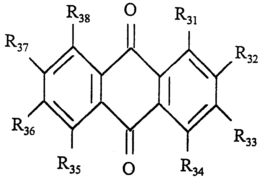
- R 3 i ⁇ R 38 ma Y be, independently of one another, hydrogen, any alkyl substitute with 1-10 carbon atoms, alkoxy groups with 1-10 carbon atoms, alkoxyphenyl substitutes with 1-4 carbon atoms in the alkyl group, or alkylbenzyl substitutes with 1-4 carbon atoms in the alkyl group.
- the anode components for preparing the electrochromic solutions may comprise the following known compounds:
- R 43 and R 44 may be, independently of each other, hydrogen or dialkylamine groups with 1-6 carbon atoms in the alkyl substitute; where R 41 may be oxygen, sulfur or
- R 42 and R 45 may be, independently of each other, alkyl substitutes with 1-10 carbon atoms, benzyl groups, benzyl groups with various positions of the substitutes of each carbon atom in the benzol ring, alkyl substitutes with 1-4 carbon atoms, or F, Cl, Br, I, CN.
- R 51 and R 52 may be, independently of each other, hydrogen or alkyl groups with 1-10 carbon atoms; and where M may be Fe, Ni, Co, Cr, Mo, W or Ti.
- the device cells were filled using any known method, e.g. vacuum filling through a hole, injection filling, sandwiching, etc. with two holes, to completely insulate (from side to side) the electrochromic compositions.
- Example 1 An electrochromic device and compositions proposed according to the present invention: Example 1
- Two cells were fabricated from 55x100 mm glass sheets.
- the optically transparent electrodes comprised ITO coatings with a surface resistance of 4.2 - 4.5 ohms/square; the gap between the electrodes was determined by interposing 130 ⁇ m spacers in the glue composition; the glass sheets were shifted parallel to each other to form the current supply bars on the longer sides; and the glue comprised LI - 1650 (Loctite) UV glue with a polymerization time of one minute in radiation from a 250 W xenon lamp (Uvahand 250).
- the inner volumes were vacuum filled with the electrochromic composition, and the filler holes sealed with silicoorganic sealing material.
- One cell was filled with an electrochromic solution of 0.03M diperchlorate 1, 1 ' -dimethyl-4,4 ' - dipyridine and 0.03M 5, 10-dihydro-5, 10-dimethylphenazine in ⁇ -butyrolactone containing 5% by weight of polymethyl methacrylate; and the second cell was filled with a solution of 0.03M ditriphenylcyanborate 1, 1 ' -dimethyl-
- Fading showed segregation of the coloured redox forms of the electrochromic components : in the first cell - a surplus accumulation of the "reduced" blue form of the methylviologen in the form of a band at the top of the cell; in the second cell - a surplus accumulation of the blue redox form of the viologen in the form of a band at the bottom of the device, along the current supply bar.
- a cell was fabricated from 100x110 mm glass sheets; the optically transparent electrodes comprised ITO coatings with a surface resistance of 4.2 - 4.5 ohms/square; the gap between the electrodes was determined by interposing 130 ⁇ m spacers in the glue composition; the cell comprised two insulated coplanar volumes, and the electrodes were so arranged as to ensure series switching of two elements of the same area; current was supplied by bars on the 100 mm side; the glue comprised Loctite 358 UV-setting glue with a polymerization time of one minute in radiation from a 250 W xenon lamp (Uvahand 250) .
- the vacuum filling method was used, and the filler hole sealed with silicoorganic sealing material.
- the electrochromic composition comprised 0.01M diperchlorate 1,1* -di ethy1-4 , 4 ' -dipyridine, 0.02M ditriphenylcyanborate 1,1' -dimethyl-4 , 4 ' - dipyridine, and 0.03M 5 , 10-dihydro-5 , 10-dimethylphenazine in ⁇ -butyrolactone containing 5% by weight of polymethyl methacrylate.
- the device positioned vertically, was supplied with voltage from a 2.4 V direct-current source so that the negative polarity was connected to the bottom current supply bar.
- initial light transmission was 78%, which, when voltage was applied, fell to 7% in five seconds.
- electrocolouring by biasing for two hours the voltage was cut off and the electrodes shorted. In this case, fading occurred rapidly with no visible segregation of the coloured electrochromic components.
- a cell was fabricated from 300x400 mm glass sheets with optically transparent ITO conducting coatings with a surface resistance of 6.8 ohms/square; the gap between the electrodes was determined by interposing 150 ⁇ m spacers in the glue composition; the cell comprised five insulated coplanar volumes, and the electrodes were so arranged as to ensure series switching of five elements of the same area; the glue comprised Loctite 350 UV- setting glue with a polymerization time of one minute in radiation from a 250 W xenon lamp (Uvahand 250).
- the vacuum filling method was used; the filler holes were sealed with silicoorganic sealing material; and the current supply bars were formed on the 400 mm side.
- the electrochromic composition comprised 0.03M diperchlorate 1 , 1 ' -dimethyl-4 , 4 ' -dipyridine and 0.03M butylferrocene in ⁇ -butyrolactone containing 5% by weight of polymethyl methacrylate.
- the device was supplied with a voltage of 2.5 to 6.0 V from a direct-current source. Depending on the voltage, the device assumed different shades of blue uniformly over the surface. When the voltage was cut off, fading occurred uniformly to assume the initial pale- yellow state.
- a cell was fabricated from 300x400 mm glass sheets with optically transparent Sn0 2 :F (TEC-15) conducting coatings with a surface resistance of 15 ohms/square; the gap between the electrodes was determined by interposing 190 ⁇ m spacers in the glue composition; the glass sheets were shifted parallel to each other to form the current supply bars on the longer side; and the glue comprised Loctite 350 UV-setting glue with a polymerization time of one minute in radiation from a 250 W xenon lamp (Uvahand 250) .
- TEC-15 optically transparent Sn0 2 :F
- the inner volume was vacuum filled with the electrochromic composition, and the filler hole sealed with silicoorganic sealing material.
- the electrochromic composition comprised 0.02M diperchlorate 4,4 '-dimethyl-4 ,4 ' -dipyridine and 0.02M 5, 10-dihydro-5, 10-dimethylphenazine in ⁇ -butyrolactone containing 30% by weight of Loctite LI-1650 glue.
- the composition was polymerized to the solid state in radiation for one hour from a 250 W xenon lamp (Uvahand 250), with no evidence of shrinkage.
- Example 5 A cell was made from two 200x300 mm glass sheets with a surface resistance of 6.8 ohms/square.
- the sheets were offset to form an electrode on the longer side, and were bonded about the edge with two- sided Sellotape, the thickness of which determined a gap of 300 ⁇ m between the electrodes.
- the cell was injection filled with the electrochromic solution, and the hole was sealed with Loctite 352 UV-setting glue with a setting time of 20 seconds when exposed to radiation from a 250 W xenon lamp (Uvahand 250) .
- the electrochromic compound comprised 0.018M 1,1'- dimethyl-4 , 4 ' -dipyridine diperchlorate and 0.018M terbutyl ferrocene in ⁇ -butyrolactone containing 37.5% by weight of photosensitive components.
- the photosensitive component comprised an Enterprise "VIKOS” photosensitive composition (USn Specification TU2435-002-32587395-96; Russian Patent N. RU 2059666C1), the monomers of which were first converted to the oligomeric state in radiation from a 250 W xenon lamp (Uvahand 250) for 40 minutes, with absolutely no segregation.
- a voltage of 0.6 to 1.5 V was supplied by a direct-current source, a light-blue colour, varying with voltage, was obtained. Total darkening time was 30 seconds. When the voltage was cut off and the electrodes shorted, the colour faded uniformly to pale yellow.
- a cell was made from two 60x200 mm glass sheets with an ITO conductive coating with a surface resistance of 10 ohms/square.
- the sheets were offset to form an electrode on the longer side, and were bonded about the edge with two- sided Sellotape, the thickness of which determined a gap of 150 ⁇ m between the electrodes.
- the cell was vacuum filled with the electrochromic solution, and the hole sealed with silicoorganic sealer.
- the electrochromic compound comprised 0.02M 1,1'- dibenzyl-4 ,4 ' -dipyridine diperchlorate, O.OOIM 2- terbutylanthraquinone and 0.02M 5, 10-dihydro-5, 10- dimethyIphenazine in ⁇ -butyrolactone containing 50% by weight of photosensitive components.
- the photosensitive components comprised light- setting compounds as in Example 5.
- the composition was polymerized to a uniformly solid film directly in the cell by radiation from a 250 W xenon lamp (Uvahand 250) for 40 minutes, with absolutely no segregation.
- Total optical transmittance of the visible portion of the spectrum in the final state was 80.5%.
- the cell When supplied with a voltage of 1.2 V from a direct-current source, the cell assumed a dark blue colour uniformly over the entire surface. In this case, optical transmittance fell to 8%; total darkening time was 7 seconds; and, when the voltage was cut off and the electrodes shorted, the colour faded uniformly to the colourless state within 12/15 seconds.
- a cell was made from two 60x200 mm glass sheets with a surface resistance of 10 ohms/square. The sheets were offset to form an electrode on the longer side, and were bonded about the edge with two- sided Sellotape, the thickness of which determined a gap of 150 ⁇ m between the electrodes.
- the cell was filled with the electrochromic solution and the hole sealed as in Example 6.
- the photosensitive component comprised an Enterprise "MACROMER” compound (Russian Specification TU2226-021-1048805/-96; Russian Patent N. RU 2087510C1) , set in radiation from a 250 W xenon lamp (Uvahand 250).
- the electrochromic composition comprised 0.025M 1,1 '-dimethyl-4 ,4 '-dipyridine diperchlorate and 0.025M terbutyl ferrocene dissolved in a mixture with 37.5% by weight of the above photosensitive component.
- the monomers of the photosensitive component were converted to the oligomeric state in radiation from a Uvahand 250 lamp for 1.5 minutes, and then added to 62.5% by weight of ⁇ -butyrolactone.
- the liquid solution was converted into a uniformly solid film with no segregation.
- the cell assumed a uniform colour when supplied with a voltage of 1.2 V, and faded uniformly when the electrodes were shorted.
- Example 8 A cell was ormed as in Example 7. The cell was filled in the same way as in Example 6.
- the electrochromic composition comprised 0.025M 1, 1 '-dimethyl-4 ,4 '-dipyridine diperchlorate and 0.025M 5, 10-dihydro-5,10-dimethyIphenazine dissolved in a 37.5% solution of the same photosensitive component as in Example 7 , the monomers of which were first converted to the oligomeric state as in Example 7 and then added to 62.5% by weight of ⁇ -butyrolactone. Following exposure of the cell for 1 hour, the initial liquid electrochromic solution was converted into a uniformly solid film with no segregation.
- the cell assumed a uniform colour when supplied with a voltage of 1 V, and faded uniformly when the electrodes were shorted.
Abstract
Description


Claims
Priority Applications (6)
| Application Number | Priority Date | Filing Date | Title |
|---|---|---|---|
| SI9830386T SI0995146T1 (en) | 1997-07-15 | 1998-07-15 | Electrochromic device |
| AT98932512T ATE231248T1 (en) | 1997-07-15 | 1998-07-15 | ELECTROCHROMIC DEVICE |
| AU82414/98A AU8241498A (en) | 1997-07-15 | 1998-07-15 | Electrochromic light-attenuation or -filtration device |
| DK98932512T DK0995146T3 (en) | 1997-07-15 | 1998-07-15 | Electrochromic device |
| DE69810776T DE69810776T2 (en) | 1997-07-15 | 1998-07-15 | ELECTROCHROME DEVICE |
| EP98932512A EP0995146B1 (en) | 1997-07-15 | 1998-07-15 | Electrochromic device |
Applications Claiming Priority (2)
| Application Number | Priority Date | Filing Date | Title |
|---|---|---|---|
| ITPD97A000160 | 1997-07-15 | ||
| IT97PD000160A IT1294790B1 (en) | 1997-07-15 | 1997-07-15 | ELECTROCHROMIC DEVICE FOR ATTENUATION OR FILTERING OF LIGHT |
Publications (2)
| Publication Number | Publication Date |
|---|---|
| WO1999004316A2 true WO1999004316A2 (en) | 1999-01-28 |
| WO1999004316A3 WO1999004316A3 (en) | 1999-04-08 |
Family
ID=11391867
Family Applications (1)
| Application Number | Title | Priority Date | Filing Date |
|---|---|---|---|
| PCT/IT1998/000198 WO1999004316A2 (en) | 1997-07-15 | 1998-07-15 | Electrochromic device |
Country Status (9)
| Country | Link |
|---|---|
| EP (1) | EP0995146B1 (en) |
| AT (1) | ATE231248T1 (en) |
| AU (1) | AU8241498A (en) |
| DE (1) | DE69810776T2 (en) |
| DK (1) | DK0995146T3 (en) |
| ES (1) | ES2189199T3 (en) |
| IT (1) | IT1294790B1 (en) |
| PT (1) | PT995146E (en) |
| WO (1) | WO1999004316A2 (en) |
Cited By (5)
| Publication number | Priority date | Publication date | Assignee | Title |
|---|---|---|---|---|
| JP2019066619A (en) * | 2017-09-29 | 2019-04-25 | スタンレー電気株式会社 | Electrochemical optical device |
| EP3487952A4 (en) * | 2016-07-20 | 2020-04-08 | University of Utah Research Foundation | Active electrochromic films |
| WO2020121845A1 (en) * | 2018-12-10 | 2020-06-18 | キヤノン株式会社 | Light control element |
| WO2021157594A1 (en) * | 2020-02-06 | 2021-08-12 | キヤノン株式会社 | Dimming element, and optical device, imaging device, and lens unit using dimming element |
| CN114203946A (en) * | 2021-12-15 | 2022-03-18 | 安徽熙泰智能科技有限公司 | Preparation method of Micro OLED display structure |
Families Citing this family (3)
| Publication number | Priority date | Publication date | Assignee | Title |
|---|---|---|---|---|
| WO2013091743A1 (en) | 2011-12-23 | 2013-06-27 | Isoclima S.P.A. | Glass pane construction |
| DE102011122199A1 (en) | 2011-12-23 | 2013-06-27 | Isoclima S.P.A. | Glass pane construction e.g. bulletproof glass pane used for motor vehicle, has transparent pane and layers comprising glass or synthetic material, which are connected in layered laminate by transparent ultraviolet filtering layer unit |
| ES2734705T3 (en) | 2013-03-25 | 2019-12-11 | Isoclima Spa | Crystal structure |
Citations (6)
| Publication number | Priority date | Publication date | Assignee | Title |
|---|---|---|---|---|
| US3567453A (en) * | 1967-12-26 | 1971-03-02 | Eastman Kodak Co | Light sensitive compositions for photoresists and lithography |
| US4902108A (en) * | 1986-03-31 | 1990-02-20 | Gentex Corporation | Single-compartment, self-erasing, solution-phase electrochromic devices, solutions for use therein, and uses thereof |
| EP0612826A1 (en) * | 1993-02-26 | 1994-08-31 | Donnelly Corporation | Electrochromic polymeric solid films, manufacturing electrochromic devices using such solid films, and processing for making such solid films and devices |
| WO1995030495A1 (en) * | 1994-05-05 | 1995-11-16 | Donnelly Corporation | Electrochromic mirrors and devices |
| WO1996003475A1 (en) * | 1994-07-22 | 1996-02-08 | Gentex Corporation | Electrochromic layer and devices comprising same |
| EP0725304A1 (en) * | 1994-07-11 | 1996-08-07 | Moskowskoe Nauchno-Proizvodstvennoe Obiedinenie "Niopik" | Electrochromic compound |
Family Cites Families (2)
| Publication number | Priority date | Publication date | Assignee | Title |
|---|---|---|---|---|
| RU2087510C1 (en) * | 1993-09-29 | 1997-08-20 | Товарищество с ограниченной ответственностью Научно-производственное предприятие "Макромер" | Adhesive composition for adhesion of materials being optically transparent |
| RU2059666C1 (en) * | 1994-03-01 | 1996-05-10 | Сергей Викторович Бурин | Photohardened composition for manufacturing of multilayer glasses which contains polyether with unsaturated groups and method for production of polyether with unsaturated groups |
-
1997
- 1997-07-15 IT IT97PD000160A patent/IT1294790B1/en active IP Right Grant
-
1998
- 1998-07-15 WO PCT/IT1998/000198 patent/WO1999004316A2/en active IP Right Grant
- 1998-07-15 EP EP98932512A patent/EP0995146B1/en not_active Expired - Lifetime
- 1998-07-15 ES ES98932512T patent/ES2189199T3/en not_active Expired - Lifetime
- 1998-07-15 DK DK98932512T patent/DK0995146T3/en active
- 1998-07-15 PT PT98932512T patent/PT995146E/en unknown
- 1998-07-15 AT AT98932512T patent/ATE231248T1/en not_active IP Right Cessation
- 1998-07-15 DE DE69810776T patent/DE69810776T2/en not_active Expired - Fee Related
- 1998-07-15 AU AU82414/98A patent/AU8241498A/en not_active Abandoned
Patent Citations (6)
| Publication number | Priority date | Publication date | Assignee | Title |
|---|---|---|---|---|
| US3567453A (en) * | 1967-12-26 | 1971-03-02 | Eastman Kodak Co | Light sensitive compositions for photoresists and lithography |
| US4902108A (en) * | 1986-03-31 | 1990-02-20 | Gentex Corporation | Single-compartment, self-erasing, solution-phase electrochromic devices, solutions for use therein, and uses thereof |
| EP0612826A1 (en) * | 1993-02-26 | 1994-08-31 | Donnelly Corporation | Electrochromic polymeric solid films, manufacturing electrochromic devices using such solid films, and processing for making such solid films and devices |
| WO1995030495A1 (en) * | 1994-05-05 | 1995-11-16 | Donnelly Corporation | Electrochromic mirrors and devices |
| EP0725304A1 (en) * | 1994-07-11 | 1996-08-07 | Moskowskoe Nauchno-Proizvodstvennoe Obiedinenie "Niopik" | Electrochromic compound |
| WO1996003475A1 (en) * | 1994-07-22 | 1996-02-08 | Gentex Corporation | Electrochromic layer and devices comprising same |
Non-Patent Citations (2)
| Title |
|---|
| DATABASE WPI Section Ch, Week 9705 Derwent Publications Ltd., London, GB; Class A14, AN 97-050261 XP002084003 & RU 2 059 666 C (BURIN S V), 10 May 1996 cited in the application * |
| DATABASE WPI Section Ch, Week 9816 Derwent Publications Ltd., London, GB; Class A14, AN 98-177589 XP002084002 & RU 2 087 510 C (MAKROMER CO LTD) , 20 August 1997 cited in the application * |
Cited By (5)
| Publication number | Priority date | Publication date | Assignee | Title |
|---|---|---|---|---|
| EP3487952A4 (en) * | 2016-07-20 | 2020-04-08 | University of Utah Research Foundation | Active electrochromic films |
| JP2019066619A (en) * | 2017-09-29 | 2019-04-25 | スタンレー電気株式会社 | Electrochemical optical device |
| WO2020121845A1 (en) * | 2018-12-10 | 2020-06-18 | キヤノン株式会社 | Light control element |
| WO2021157594A1 (en) * | 2020-02-06 | 2021-08-12 | キヤノン株式会社 | Dimming element, and optical device, imaging device, and lens unit using dimming element |
| CN114203946A (en) * | 2021-12-15 | 2022-03-18 | 安徽熙泰智能科技有限公司 | Preparation method of Micro OLED display structure |
Also Published As
| Publication number | Publication date |
|---|---|
| EP0995146A2 (en) | 2000-04-26 |
| DE69810776T2 (en) | 2003-09-18 |
| PT995146E (en) | 2003-04-30 |
| ATE231248T1 (en) | 2003-02-15 |
| ES2189199T3 (en) | 2003-07-01 |
| EP0995146B1 (en) | 2003-01-15 |
| ITPD970160A1 (en) | 1999-01-15 |
| DE69810776D1 (en) | 2003-02-20 |
| IT1294790B1 (en) | 1999-04-15 |
| AU8241498A (en) | 1999-02-10 |
| DK0995146T3 (en) | 2003-04-07 |
| WO1999004316A3 (en) | 1999-04-08 |
Similar Documents
| Publication | Publication Date | Title |
|---|---|---|
| EP1740672B1 (en) | Novel electrochromic materials and devices | |
| CA2335270C (en) | Electrochromic media with concentration-enhanced stability, process for the preparation thereof and use in electrochromic devices | |
| EP0240226B1 (en) | Single-compartment, self-erasing, solution-phase electrochromic devices, solutions for use therein, and uses thereof | |
| US7626748B2 (en) | Gel polymers containing ionic liquids | |
| US6195192B1 (en) | Electrochromic materials with enhanced ultraviolet stability | |
| KR20170140388A (en) | Electrochromic device, display device and driving method thereof | |
| RU2224275C1 (en) | Method for manufacture of electrochromium device and electrochromium device | |
| EP0698226A4 (en) | Complementary surface confined polymer electrochromic materials, systems, and methods of fabrication therefor | |
| EP1671179A2 (en) | Reversible electrodeposition devices and associated electrochemical media | |
| US6545793B2 (en) | UV-protected electrochromic solution | |
| RU2642558C1 (en) | Method of manufacturing electrochromic device and electrochromic device | |
| EP0995146B1 (en) | Electrochromic device | |
| KR20010022994A (en) | Electrochromic System With Coupled Red-Ox System and Special Anions | |
| KR100697154B1 (en) | Electrochromic device and medium having improved switching behaviour | |
| US6532098B1 (en) | Electrochromic element | |
| JP2003161963A (en) | Electrochromic element | |
| JP4227716B2 (en) | Electrochromic element | |
| US6538792B1 (en) | Electrochromic device | |
| KR100345510B1 (en) | Electrochromic composition | |
| KR20090098427A (en) | Electrochromic viologen derivatives and electrochromic device with corresponding electrode materials leuco-dye | |
| KR980009422A (en) | Multicolor electrochromic composition and multicolor electrochromic device | |
| JP2019191579A (en) | Electrochromic element and method for manufacturing electrochromic element | |
| JP2002311459A (en) | Method for driving electrochromic mirror | |
| JP2002311460A (en) | Method for driving electrochromic mirror | |
| KR980009421A (en) | Multicolor electrochromic composition and multicolor electrochromic device |
Legal Events
| Date | Code | Title | Description |
|---|---|---|---|
| AK | Designated states |
Kind code of ref document: A2 Designated state(s): AL AM AT AU AZ BA BB BG BR BY CA CH CN CU CZ DE DK EE ES FI GB GE GH GM HR HU ID IL IS JP KE KG KP KR KZ LC LK LR LS LT LU LV MD MG MK MN MW MX NO NZ PL PT RO RU SD SE SG SI SK SL TJ TM TR TT UA UG US UZ VN YU ZW |
|
| AL | Designated countries for regional patents |
Kind code of ref document: A2 Designated state(s): GH GM KE LS MW SD SZ UG ZW AM AZ BY KG KZ MD RU TJ TM AT BE CH CY DE DK ES FI FR GB GR IE IT LU MC NL PT SE BF BJ CF CG CI CM GA GN GW ML MR NE SN TD TG |
|
| AK | Designated states |
Kind code of ref document: A3 Designated state(s): AL AM AT AU AZ BA BB BG BR BY CA CH CN CU CZ DE DK EE ES FI GB GE GH GM HR HU ID IL IS JP KE KG KP KR KZ LC LK LR LS LT LU LV MD MG MK MN MW MX NO NZ PL PT RO RU SD SE SG SI SK SL TJ TM TR TT UA UG US UZ VN YU ZW |
|
| AL | Designated countries for regional patents |
Kind code of ref document: A3 Designated state(s): GH GM KE LS MW SD SZ UG ZW AM AZ BY KG KZ MD RU TJ TM AT BE CH CY DE DK ES FI FR GB GR IE IT LU MC NL PT SE BF BJ CF CG CI CM GA GN GW ML MR NE SN TD TG |
|
| DFPE | Request for preliminary examination filed prior to expiration of 19th month from priority date (pct application filed before 20040101) | ||
| 121 | Ep: the epo has been informed by wipo that ep was designated in this application | ||
| NENP | Non-entry into the national phase |
Ref country code: KR |
|
| WWE | Wipo information: entry into national phase |
Ref document number: 1998932512 Country of ref document: EP |
|
| WWP | Wipo information: published in national office |
Ref document number: 1998932512 Country of ref document: EP |
|
| REG | Reference to national code |
Ref country code: DE Ref legal event code: 8642 |
|
| NENP | Non-entry into the national phase |
Ref country code: CA |
|
| WWG | Wipo information: grant in national office |
Ref document number: 1998932512 Country of ref document: EP |