WO1999008762A1 - Techniques and apparatus for entertainment sites, amusement parks and other information and/or entertainment dispensing sites - Google Patents
Techniques and apparatus for entertainment sites, amusement parks and other information and/or entertainment dispensing sites Download PDFInfo
- Publication number
- WO1999008762A1 WO1999008762A1 PCT/IL1998/000392 IL9800392W WO9908762A1 WO 1999008762 A1 WO1999008762 A1 WO 1999008762A1 IL 9800392 W IL9800392 W IL 9800392W WO 9908762 A1 WO9908762 A1 WO 9908762A1
- Authority
- WO
- WIPO (PCT)
- Prior art keywords
- game
- nodes
- node
- operative
- individual
- Prior art date
Links
Classifications
-
- A—HUMAN NECESSITIES
- A63—SPORTS; GAMES; AMUSEMENTS
- A63F—CARD, BOARD, OR ROULETTE GAMES; INDOOR GAMES USING SMALL MOVING PLAYING BODIES; VIDEO GAMES; GAMES NOT OTHERWISE PROVIDED FOR
- A63F13/00—Video games, i.e. games using an electronically generated display having two or more dimensions
- A63F13/30—Interconnection arrangements between game servers and game devices; Interconnection arrangements between game devices; Interconnection arrangements between game servers
-
- A63F13/12—
Definitions
- the present invention relates to apparatus and methods for amusement parks and to apparatus and methods for dispensing information and other services.
- Amusement parks and other crowd-servicing centers typically comprise a plurality of service-providing nodes which are typically manned by human operators.
- Locating badges worn by mobile units of a system such as by medical personnel in a hospital system, or by mobile medical equipment in a hospital system, are known.
- the badges enable the location of individual medical personnel to be determined at any given time such that, for example, telephone calls may be directed to a particular person at his current location.
- Automatic teller machines are interactive automated points of service which are conventionally associated with a central computer via a wired network.
- Magnetic cards are conventionally held by members of an organization, such as employees in a company, and are used to provide a number of functions such as access control to access-limited locations, time-stamping, and recordal of utilization of services such as cafeteria services.
- toys which are remotely controlled by wireless communication and which are not used in conjunction with a computer system.
- toys include vehicles whose motion is controlled by a human user via a remote control device.
- US Patent 4,712,184 to Haugerud describes a computer controlled educational toy, the construction of which teaches the user computer terminology and programming and robotic technology. Haugerud describes computer control of a toy via a wired connection, wherein the user of the computer typically writes a simple program to control movement of a robot.
- US Patent 4,840,602 to Rose describes a talking doll responsive to an external signal, in which the doll has a vocabulary stored in digital data in a memory which may be accessed to cause a speech synthesizer in the doll to simulate speech.
- US Patent 5,191,615 to Aldava et al. describes an interrelational audio kinetic entertainment system in which movable and audible toys and other animated devices spaced apart from a television screen are provided with program synchronized audio and control data to interact with the program viewer in relationship to the television program.
- US Patent 5,195,920 to Collier describes a radio controlled toy vehicle which generates realistic sound effects on board the vehicle. Communications with a remote computer allows an operator to modify and add new sound effects.
- US Patent 5,270,480 to Hikawa describes a toy acting in response to a MIDI signal, wherein an instrument-playing toy performs simulated instrument playing movements.
- US Patent 5,289,273 to Lang describes a system for remotely controlling an animated character.
- the system uses radio signals to transfer audio, video and other control signals to the animated character to provide speech, hearing vision and movement in real-time.
- US Patent 5,388,493 describes a system for a housing for a vertical dual keyboard MIDI wireless controller for accordionists.
- the system may be used with either a conventional MIDI cable connection or by a wireless MIDI transmission system.
- German Patent DE 3009-040 to Neuhierl describes a device for adding the capability to transmit sound from a remote control to a controlled model vehicle.
- the sound is generated by means of a microphone or a tape recorder and transmitted to the controlled model vehicle by means of radio communications.
- the model vehicle is equipped with a speaker that emits the received sounds.
- the present invention seeks to provide improved apparatus and methods for dispensing amusement services, information services and other services to crowds.
- amusement park apparatus including a first plurality of entertainment providing nodes playing a second plurality of games with a third plurality of players who are simultaneously playing the second plurality of games, a node controller operative to assign each player from among the third plurality of players to an individual game from among the second plurality of games and operative to control each individual node from among the first plurality of nodes such that when the individual node enters into an interaction with an individual player, the node plays, with the individual player, the game assigned to the individual player and a communication network operative to associate each of the first plurality of nodes with the node controller.
- amusement park apparatus including a first plurality of entertainment providing nodes each operative to sequentially participate in any of a second plurality of games being played, a node controller operative to control the first plurality of nodes, and a communication network operative to associate each of the first plurality of nodes with the node controller.
- amusement park apparatus including a first plurality of entertainment providing nodes, a node controller operative to control the first plurality of nodes to play a second plurality of games such that at least one of the first plurality of nodes participates in each of at least two ongoing ones of the second plurality of games, and a communication network operative to associate each of the first plurality of nodes with the node controller.
- the node controller is operative to control the first plurality of nodes so as to accommodate a third plurality of players participating in at least two ongoing ones of the second plurality of games.
- the second plurality of games includes at least one group game in which at least one encounter between an individual player of the group game and one of the first plurality of nodes is affected by at least one previous encounter between at least one other player of the group game and at least one of the first plurality of nodes.
- a system for dispensation of infotainment including a multiplicity of lifesize fanciful figures distributed in a crowd-accommodating area in which infotainment services are dispensed to a crowd, a central fanciful figure controller operative to provide at least some of the infotainment services to the crowd by controlling said multiplicity of fanciful figures and a communication network operative to associate each of the multiplicity of fanciful figures with the central fanciful figure controller.
- the crowd-accommodating area comprises an amusement park and the infotainment services comprise amusement park services.
- At least a portion of the crowd-accommodating area comprises an outdoor area.
- a multiplicity of fanciful figures includes a plurality of stationary figures.
- the multiplicity of fanciful figures includes at least one mobile figure.
- At least some of the fanciful figures include a commodity dispenser.
- the multiplicity of fanciful figures includes at least one talking figure.
- a central fanciful figure controller is operative to continuously control the mobile figure even as it roams from one cell to another.
- an information providing system including a multiplicity of information providing nodes each including at least one sensor, other than an alphanumeric input device, for sensing events in its vicinity, an interactive central node controller operative to receive an indication of an event from an individual one of the information providing nodes and to control another one of the multiplicity of information providing nodes in accordance with the indication of the event, and a communication network operative to provide communication between each of the multiplicity of nodes and the central node controller.
- the nodes are distributed in a crowd-accommodating area.
- At least one sensor includes an artificial vision system for sensing visual information in its vicinity.
- At least one sensor includes an audio reception system for sensing audio information in its vicinity.
- the audio reception system includes a speech recognition unit.
- At least one talking figure generates pre-recorded speech specimens.
- At least one talking figure generates synthesized speech.
- At least one talking figure assembles pre-recorded speech segments, thereby to generate speech. Further in accordance with a preferred embodiment of the present invention at least one talking figure assembles synthesized speech segments, thereby to generate speech.
- infotainment providing nodes include moving parts which are visible to a user.
- the central node controller is operative to cause the infotainment providing nodes to take actions having known significance.
- the actions having known significance include smiling, pointing and illuminating.
- the senor is capable of identifying an individual in its vicinity and the central node controller is operative to record the nodes which each individual has encountered.
- At least some of the infotainment providing nodes are operative to provide an individual with infotainment whose contents take into account the individual's past encounters with nodes of the system.
- At least some of the infotainment providing nodes are operative to provide an individual with infotainment whose contents take into account other individuals' past encounters with nodes of the system.
- the commodity dispenser is operative to dispense at least one of the following articles: gifts, prizes, coupons, maps, souvenirs, change, tokens.
- At least some of the infotainment providing nodes are operative to provide an individual with infotainment whose contents take into account at least one characteristic of the individual, e.g. language, age, preferences, disabilities.
- a two-way user servicing system including a multiplicity of game-playing nodes each including a user identity receiving device for identifying presence of an individual user, an interactive central node controller operative to receive from a particular node an indication of the presence of a particular user at the particular node and to control participation of at least one of the multiplicity of game-playing nodes in at least one game in accordance with the indication, and a communication network operative to provide communication between each of the multiplicity of nodes and the central node controller.
- the node controller is operative to maintain, for at least one particular user, a record of nodes the particular user has visited and to control at least one node currently visited by the user in accordance with the record.
- the user identity receiving device includes a user identity input device.
- the user identity receiving device includes a user identity sensing device.
- the user identity sensing device includes a receiver for sensing a user- identifying transmission sent by a wearable tag.
- a two-way game system including a multiplicity of game participant nodes each including a user identity receiving device for identifying presence of an individual user, an interactive central node controller operative to receive from a particular node an indication of the presence of first and second users at the particular node and to instruct the particular node to play a first game with the first user, to play a second game with the second user, and a communication network operative to provide communication between each of the multiplicity of nodes and the central node controller.
- a method of providing entertainment including providing a first plurality of entertainment providing nodes playing a second plurality of games with a third plurality of players who are simultaneously playing the second plurality of games, providing a node controller operative to assign each player from among the third plurality of players to an individual game from among the second plurality of games and operative to control each individual node from among the first plurality of nodes such that when the individual node enters into an interaction with an individual player, the node plays, with the individual player, the game assigned to the individual player, and networking each of the first plurality of nodes with the node.
- a method of providing entertainment including providing a first plurality of entertainment providing nodes each operative to sequentially participate in any of a second plurality of games being played simultaneously with any of a third plurality of players who are simultaneously playing the second plurality of games, controlling the first plurality of nodes, and networking each of the first plurality of nodes with the node controller.
- a method of providing entertainment including providing a first plurality of entertainment providing nodes, controlling the first plurality of nodes to play a second plurality of games such that at least one of the first plurality of nodes participates in each of at least two ongoing ones of the second plurality of games, and networking each of the first plurality of nodes with the node controller.
- a method of providing entertainment including distributing a multiplicity of fanciful lifesize figures in a crowd-accommodating area, controlling the multiplicity of fanciful figures centrally, and networking each of the multiplicity of fanciful figures with the central fanciful figure controller.
- a method of providing information including providing a multiplicity of information providing nodes each including at least one sensor other than an input device for sensing events in its vicinity, interactively and centrally receiving indications of the events from the information providing nodes and controlling the multiplicity of information providing nodes in accordance with the indications of the events, and providing networked communication between each of the multiplicity of nodes and the central node controller.
- a method of providing two-way user servicing including providing a multiplicity of game-playing nodes each including a user identity receiving device for identifying presence of an individual user, interactively and centrally receiving from a particular node an indication of the presence of a particular user at the particular node and controlling participation of at least one of the multiplicity of game- playing nodes in at least one game in accordance with the indication, and providing networked communication between each of the multiplicity of nodes and the central node controller.
- a method of providing two-way gaming including providing a multiplicity of game participant nodes each including a user identity receiving device for identifying presence of an individual user, interactively and centrally receiving from a particular node an indication of the presence of first and second users at the particular node and instructing the particular node to play a first game with the first user, to play a second game with the second user, and providing networked communication between each of the multiplicity of nodes and the central node controller.
- Advantages of some of the preferred embodiments of the present invention in which a record is maintained of the visitor's experiences in the amusement park, include: a. Visitors can be directed to attractions and/or games and/or nodes which they have not yet experience. b. Stimuli such as explanations provided to visitors can be adjusted to take into account what the visitor has already seen e.g. information already provided to a visitor may be omitted and information now being provided to the visitor may include an explanation of the relationship between the information now being provided to the user and information previously provided to the user.
- questions posed by visitors to the nodes are recorded and analyzed off-line, typically by a human operator, in order to identify questions for which a more satisfactory or different answer should be provided.
- the database is then updated, typically manually, so as to provide a more satisfactory or different answer.
- a wireless computer controlled toy system including a computer system operative to transmit a first transmission via a first wireless transmitter and at least one toy including a first wireless receiver, the toy receiving the first transmission via the first wireless receiver and operative to carry out at least one action based on the first transmission.
- the computer system may include a computer game.
- the toy may include a plurality of toys, and the at least one action may include a plurality of actions.
- the first transmission may include a digital signal.
- the first transmission includes an analog signal and the analog signal may include sound.
- the computer system includes a computer having a MIDI port and wherein the computer may be operative to transmit the digital signal by way of the MIDI port.
- the sound includes music, a pre-recorded sound and/or speech.
- the speech may include recorded speech and synthesized speech.
- the at least one toy has a plurality of states including at least a sleep state and an awake state, and the first transmission includes a state transition command, and the at least one action includes transitioning between the sleep state and the awake state.
- a sleep state may typically include a state in which the toy consumes a reduced amount of energy and/or in which the toy is largely inactive, while an awake state is typically a state of normal operation.
- the first transmission includes a control command chosen from a plurality of available control commands based, at least in part, on a result of operation of the computer game.
- the computer system includes a plurality of computers.
- the first transmission includes computer identification data and the second transmission includes computer identification data.
- the at least one toy is operative to transmit a second transmission via a second wireless transmitter and the computer system is operative to receive the second transmission via a second wireless receiver.
- system includes at least one input device and the second transmission includes a status of the at least one input device.
- the at least one toy includes at least a first toy and a second toy, and wherein the first toy is operative to transmit a toy-to-toy transmission to the second toy via the second wireless transmitter, and wherein the second toy is operative to carry out at least one action based on the toy-to-toy transmission.
- operation of the computer system is controlled, at least in part, by the second transmission.
- the computer system includes a computer game, and wherein operation of the game is controlled, at least in part, by the second transmission.
- the second transmission may include a digital signal and/or an analog signal.
- the computer system has a plurality of states including at least a sleep state and an awake state, and the second transmission include a state transition command, and the computer is operative, upon receiving the second transmission, to transition between the sleep state and the awake state.
- at least one toy includes sound input apparatus, and the second transmission includes a sound signal which represents a sound input via the sound input apparatus.
- the computer system is also operative to perform at least one of the following actions: manipulate the sound signal; and play the sound signal.
- the sound includes speech
- the computer system is operative to perform a speech recognition operation on the speech.
- the second transmission includes toy identification data
- the computer system is operative to identify the at least one toy based, at least in part, on the toy identification data.
- the first transmission includes toy identification data.
- the computer system may adapt a mode of operation thereof based, at least in part, on the toy identification data.
- the at least one action may include movement of the toy, movement of a part of the toy and/or an output of a sound.
- the sound may be transmitted using a MLDI protocol.
- a game system including a computer system operative to control a computer game and having a display operative to display at least one display object, and at least one toy in wireless communication with the computer system, the computer game including a plurality of game objects, and the plurality of game objects includes the at least one display object and the at least one toy.
- the at least one toy is operative to transmit toy identification data to the computer system, and the computer system is operative to adapt a mode of operation of the computer game based, at least in part, on the toy identification data.
- the computer system may include a plurality of computers.
- the first transmission includes computer identification data and the second transmission includes computer identification data.
- a data transmission apparatus including first wireless apparatus including musical instrument data interface (MTDI) apparatus operative to receive and transmit MIDI data between a first wireless and a first MIDI device and second wireless apparatus including MLDI apparatus operative to receive and transmit MIDI data between a second wireless and a second MIDI device, the first wireless apparatus is operative to transmit MIDI data including data received from the first MLDI device to the second wireless apparatus, and to transmit MLDI data including data received from the second wireless apparatus to the first MLDI device, and the second wireless apparatus is operative to transmit MLDI data including data received from the second MTDI device to the first wireless apparatus, and to transmit MIDI data including data received from the first wireless apparatus to the second MIDI device.
- MLDI musical instrument data interface
- the second wireless apparatus includes a plurality of wirelesses each respectively associated with one of the plurality of MLDI devices, and each of the second plurality of wirelesses is operative to transmit MIDI data including data received from the associated MLDI device to the first wireless apparatus, and to transmit MLDI data including data received from the first wireless apparatus to the associated MLDI device.
- the first MLDI device may include a computer, while the second MLDI device may include a toy.
- the first wireless apparatus also includes analog interface apparatus operative to receive and transmit analog signals between the first wireless and a first analog device
- the second wireless apparatus also includes analog interface apparatus operative to receive and transmit analog signals between the second wireless and a second analog device
- the first wireless apparatus is also operative to transmit analog signals including signals received from the first analog device to the second wireless apparatus, and to transmit analog signal including signals received from the second wireless apparatus to the first analog device
- the second wireless apparatus is also operative to transmit analog signals including signals received from the second analog device to the first wireless apparatus, and to transmit analog signals including data received from the first wireless apparatus to the second analog device.
- a method for generating control instructions for a computer controlled toy system includes selecting a toy, selecting at least one command from among a plurality of commands associated with the toy, and generating control instructions for the toy including the at least one command.
- the step of selecting at least one command includes choosing a command, and specifying at least one control parameter associated with the chosen command.
- the at least one control parameter includes at least one condition depending on a result of a previous command.
- At least one of the steps of selecting a toy and the step of selecting at least one command includes utilizing a graphical user interface.
- the previous command includes a previous command associated with a second toy.
- the at least one control parameter includes an execution condition controlling execution of the command.
- the execution condition may include a time at which to perform the command and/or a time at which to cease performing the command.
- the execution condition may also include a status of the toy.
- the at least one control parameter includes a command modifier modifying execution of the command. Still further in accordance with a preferred embodiment of the present invention the at least one control parameter includes a condition dependent on a future event.
- the at least one command includes a command to cancel a previous command.
- a signal transmission apparatus for use in conjunction with a computer, the apparatus including wireless transmission apparatus; and signal processing apparatus including at least one of the following analog/digital sound conversion apparatus operative to convert analog sound signals to digital sound signals, to convert digital sound signals to analog sound signals, and to transmit the signals between the computer and a sound device using the wireless transmission apparatus; a peripheral control interface operative to transmit control signals between the computer and a peripheral device using the wireless transmission apparatus; and a MLDI interface operative to transmit MLDI signals between the computer and a MLDI device using the wireless transmission apparatus.
- a computer system including a computer, and a sound card operatively attached to the computer and having a MLDI connector and at least one analog connector, wherein the computer is operative to transmit digital signals by means of the MLDI connector and to transmit analog signals by means of the at least one analog connector.
- the computer is also operative to receive digital signals by means of the MLDI connector and to receive analog signals by means of the at least one analog connector.
- the term "crowd-accommodating area" is intended to include areas capable of accommodating hundreds and preferably thousands or even tens of thousands of visitors.
- Figs. 1 - 32C illustrate a toy system for use in conjunction with a computer system wherein:
- Fig. 1A is a partly pictorial, partly block diagram illustration of a computer control system including a toy, constructed and operative in accordance with a preferred embodiment of the present invention
- Fig. IB is a partly pictorial, partly block diagram illustration a preferred implementation of the toy 122 of Fig. 1 A;
- Fig. 1C is a partly pictorial, partly block diagram illustration of a computer control system including a toy, constructed and operative in accordance with an alternative preferred embodiment of the present invention
- Figs. 2A - 2C are simplified pictorial illustrations of a portion of the system of Fig. 1 A in use;
- Fig. 3 is a simplified block diagram of a preferred implementation of the computer radio interface 110 of Fig. 1A;
- Fig. 4 is a more detailed block diagram of the computer radio interface 110 of Fig. 3;
- Figs. 5A - 5D taken together comprise a schematic diagram of the apparatus of Fig. 4;
- Fig. 5E is an schematic diagram of an alternative implementation of the apparatus of Fig. 5D;
- Fig. 6 is a simplified block diagram of a preferred implementation of the toy control device 130 of Fig. 1 A;
- Figs. 7A - 7F taken together with either Fig. 5D or Fig. 5E, comprise a schematic diagram of the apparatus of Fig. 6;
- Fig. 8A is a simplified flowchart illustration of a preferred method for receiving radio signals, executing commands comprised therein, and sending radio signals, within the toy control device 130 of Fig. 1 A;
- FIG. 8B - 8T taken together, comprise a simplified flowchart illustration of a preferred implementation of the method of Fig. 8A;
- Fig. 9A is a simplified flowchart illustration of a preferred method for receiving M DI signals, receiving radio signals, executing commands comprised therein, sending radio signals, and sending MIDI signals, within the computer radio interface 110 of Fig. 1A;
- Figs. 9B - 9N taken together with Figs. 8D - 8M, comprise a simplified flowchart illustration of a preferred implementation of the method of Fig. 9 A;
- Figs. 10A - IOC are simplified pictorial illustrations of a signal transmitted between the computer radio interface 110 and the toy control device 130 of Fig. 1A;
- Fig. 11 is a simplified flowchart illustration of a preferred method for generating control instructions for the apparatus of Fig. 1 A;
- Figs. 12A - 12C are pictorial illustrations of a preferred implementation of a graphical user interface implementation of the method of Fig. 11;
- Fig. 13 is a block diagram of a first sub-unit of a multi-port multi-channel implementation of the computer radio interface 110 of Fig. 1A, which sub-unit resides within computer 100 of Fig. 1A;
- Fig. 14 is a block diagram of a second sub-unit of a multi-port multichannel implementation of the computer radio interface 110 of Fig. 1A, which sub-unit complements the apparatus of Fig. 13 and resides exteriorly to computer 100 of Fig. 1A;
- Fig. 16 is a simplified flowchart illustration of a preferred method by which a computer selects a control channel pair in anticipation of a toy becoming available and starts a game-defining communication over the control channel each time both a toy and a transceiver of the computer radio interface are available;
- Fig. 17 is a simplified flowchart illustration of a preferred method for implementing the "select control channel pair" step of Fig. 16;
- Fig. 18 A is a simplified flowchart illustration of a preferred method for implementing the "select information communication channel pair" step of Fig. 16;
- Fig. 18B is a simplified flowchart illustration of a preferred method for performing the "locate computer" step of Fig. 18A;
- Fig. 19 is a simplified flowchart illustration of a preferred method of operation of the toy control device 130;
- Fig. 20 is a simplified illustration of a remote game server in association with a wireless computer controlled toy system which may include a network computer;
- Fig. 21 is a simplified flowchart illustration of the operation of the computer or of the network computer of Fig. 20, when operating in conjunction with the remote server;
- Fig. 22 is a simplified flowchart illustration of the operation of the remote game server of Fig. 20;
- Fig. 23 is a semi-pictorial semi-block diagram illustration of a wireless computer controlled toy system including a proximity detection subsystem operative to detect proximity between the toy and the computer;
- Figs. 24A - 24E taken together, form a detailed electronic schematic diagram of a multi-channel implementation of the computer radio interface 110 of Fig. 3 which is similar to the detailed electronic schematic diagrams ofFigs. 5A - 5D except for being multi-channel, therefore capable of supporting full duplex applications, rather than single-channel;
- Figs. 25A - 25E taken together, form a detailed schematic illustration of a computer radio interface which connects to a serial port of a computer rather than to the sound board of the computer;
- FIGS. 26A - 26D taken together, form a detailed schematic illustration of a computer radio interface which connects to a parallel port of a computer rather than to the sound board of the computer.;
- Figs. 27A - 27J are preferred flowchart illustrations of a preferred radio coding technique which is an alternative to the radio coding technique described above with reference to Figs. 8E, 8G - 8M and 10A - C;
- Figs. 28A - 28K taken together, form a detailed electronic schematic diagram of the multi-port multi-channel computer radio interface sub-unit of Fig. 13;
- Figs. 29A - 291 taken together, form a detailed electronic schematic diagram of the multi-port multi-channel computer radio interface sub-unit of Fig. 14;
- Fig. 30 is a partly pictorial, partly block diagram illustration of a computer control system including a toy, constructed and operative in accordance with a further preferred embodiment of the present invention
- Fig. 31 is a block diagram is a simplified block diagram illustrating the combination of the computer radio interface and the toy control device as used in the embodiment of Fig. 30;
- Figs. 33 - 81 illustrates embodiments of the toy system of Figs. 1 - 32C wherein:
- FIG. 33 A - 33C taken together, form a simplified pictorial illustration of an amusement park system constructed and operative in accordance with a preferred embodiment of the present invention
- Fig. 34 is a simplified pictorial illustration of a first state of some of the elements of an amusement park system constructed and operative in accordance with another preferred embodiment of the present invention.
- Fig. 35 is a simplified pictorial illustration of a second state of the amusement park system of Fig. 34;
- Fig. 36 is a simplified pictorial illustration of one of the elements of the amusement park system ofFigs. 34 - 35;
- Fig. 37 is a simplified flowchart illustration of a preferred method of operation by which the central amusement park controller of Fig. 33 performs each of a multiplicity of node control tasks for each of a corresponding multiplicity of nodes;
- Fig. 38 is a simplified flowchart illustration of a preferred method for performing the "visitor localization" step of Fig. 37;
- Fig. 39 is a simplified flowchart illustration of a preferred method for performing the "new visitor welcoming" step of Fig. 37;
- Fig. 40 is a simplified flowchart illustration of a preferred method for performing the "launch execution of next script item" step of Fig. 37;
- Fig. 41 is a simplified flowchart illustration of a preferred method for performing the "analyze conditions" step of Fig. 40;
- Fig. 42 is a simplified flowchart illustration of a preferred method for performing the "perform action set" step of Fig. 40;
- Figs. 43 A - 43 C taken together, form a diagram of a data structure typically residing in the central amusement park controller 2010 and suitable for storing information regarding visitors to the amusement park;
- Fig. 44 is a bubble diagram of a "find lost person" game
- Fig. 45 is a diagram of two "Visitor Record” data structures of Fig. 43 A storing information regarding two respective visitors playing the "find lost person” game of Fig. 44, of which one is the lost person and the other is the seeker;
- Fig. 46A is a diagram of three "Game State Record” data structures of Figs. 43 A - 43 C storing information regarding three of the four respective game states within the "find lost person" game of Fig. 44;
- Fig. 46B is a diagram of the fourth "Game State Record” data structure of Figs. 43 A - 43 C which stores information regarding the fourth of the four respective game states within the "find lost person" game of Fig. 44;
- Fig. 47 is a diagram of a "Node Record” data structure of Figs. 43A - 43 C storing information regarding a node which is operating within the "find lost person” game of Fig. 44;
- Fig. 48 is a simplified flowchart illustration of a preferred chain of events which typically occur in setting up for and playing the "find lost person” game ofFigs. 44 - 47;
- Fig. 49 is a bubble diagram of a game for groups, "zoo-keeper", in which powers or credits are accumulated;
- Figs. 50A - 50E taken together, form a diagram of 2010 "Visitor Record” data structures of Figs. 43 A - 43C storing information regarding seven visitors playing the group game of Fig. 48, the visit being arranged into two sub-groups, the two sub-groups defining a "main group” or "parent group” comprising both of them, wherein:
- Fig. 50A comprises two "Visitor Record” data structures representing the main group and one of the sub-groups respectively;
- Fig. 50B comprises two "Visitor Record” data structures representing the other of the sub- groups and one of the visitors respectively;
- Figs. 50C - 50E each comprise two "Visitor Record” data structures representing two of the visitors, respectively;
- Fig. 51 is a diagram of a "Node Record” data structure of Figs. 43 A - 43 C storing information regarding a node, "deer”, which is operating within the group game of Fig. 48;
- Fig. 52 is a diagram of a "Game State Record” data structure ofFigs. 43A - 43C storing information regarding one of the game states, "feed bear", within the group game ofFigs. 49 - 51;
- Fig. 53 is a diagram of another "Game State Record” data structure of Figs. 43A - 43C storing information regarding another of the game states, "feed deer", within the group game ofFigs. 49 - 51;
- Figs. 54A - 54B are simplified flowchart illustrations of different aspects of a preferred chain of events including some of the events which typically occur in playing the "zoo-keeper" game ofFigs. 49 - 53;
- Fig. 55 is a bubble diagram of a game for an individual, "tree-quiz", in which a prize or other token is dispensed to the individual player by one of the nodes in the amusement park;
- Figs. 56A - 56B taken together, form a diagram of one alternative "Game State Record” data structure of Figs. 43 A - 43 C, storing information regarding one of the game states, "ask question", within the individual game of Fig. 55;
- Figs. 56A and 56C taken together, form a diagram of another alternative "Game State Record” data structure of Figs. 43A - 43C, storing information regarding one of the game states, "ask question", within the individual game of Fig. 55;
- Fig. 57 is a diagram of two "Game State Record” data structures ofFigs. 43 A - 43 C storing information regarding two additional game states, "record answer” and “give present", within the individual game of Fig. 55;
- Fig. 58 is a diagram of a "Visitor Record" data structure of Figs. 43 A - 43 C storing information regarding an individual visitor playing the individual game of Figs. 55 - 57;
- Fig. 59 is a diagram of a "Node Record” data structure of Figs. 43 A - 43C storing information regarding two nodes, "tree” and “clown", which are operating within the individual game ofFigs. 55 - 58;
- Fig. 60A - 60B taken together, form a simplified flowchart illustration of a preferred chain of events including the events which typically occur in playing the "tree-quiz" game ofFigs. 55 - 59;
- Fig. 61 is a bubble diagram of a game for an individual, "common encounters", in which a player makes a common comment or complaint or asks a common question such as "where are the restrooms" of one of the nodes in the amusement park and a suitable answer is provided to the individual player by that node;
- Fig. 62 is a diagram of a "Game State Record” data structure element of Figs. 43A - 43C storing information regarding a game state, "ask question", of the "common encounters” game of Fig. 61;
- Fig. 63 A is a diagram of a "Game State Record” data structure element of Figs. 43 A - 43C storing information regarding a game state, "analyze", of the "common encounters” game of Fig. 61;
- Fig. 63B is a diagram of two "Game State Record” data structure elements of Figs. 43 A - 43 C storing information regarding two respective game states, "provide information” and “record", of the "common encounters” game of Fig. 61;
- Fig. 64 is a diagram of a "Node Record” data structure of Figs. 43 A - 43C storing information regarding a node, "moving dog” 2140, which is operating within the game ofFigs. 61 - 66;
- Figs. 65A - 65B taken together, form a play record data strucutre of an example of a play record operative to store oral and/or textual information to be played (i.e. orally presented) to a user who has asked for directions to the restrooms;
- Fig. 66 is a diagram of 2 "Frequent inquiry record” data structures of Figs. 43A - 43C storing information regarding two frequently posed inquiries: "where is the bathroom” and "please clean the bathroom”;
- Fig. 67A is a simplified flowchart illustration of a process that suspends a game
- Fig. 67B is a simplified flowchart illustration of a process that resumes a game
- Fig. 68A is a simplified flowchart illustration of a first preferred chain of events including all operations performed by the central node controller 2010, on behalf of a node approached by a player in the course of playing a "common encounters" game ofFigs. 62 - 66 provided in accordance with a first preferred embodiment of the present invention;
- Fig. 68B is a simplified flowchart illustration of a preferred method by which the central node controller effects the "analyze keywords" step of Fig. 68A;
- Fig. 68C is a simplified flowchart illustration of the "compute total weights" step of Fig. 68B;
- Fig. 69 is a simplified flowchart illustration of a second preferred chain of events including all operations performed by the central node controller 2010, on behalf of a node approached by a player in the course of playing a "common encounters" game of Figs. 62 - 66 provided in accordance with a second preferred embodiment of the present invention;
- Fig. 70 is a simplified flowchart illustration of a preferred method for playing speech and simultaneously appropriately moving at least one body part so as to provide an appropriate physical expression or demeanor
- Fig. 71 is a simplified block diagram of a preferred hardware implementation of node control device 2214 of Fig. 36 which is suitable for a node whose connection to the central node controller comprises a wireless connection;
- Fig. 72 is a simplified block diagram of a first computer board which, in conjunction with the computer board of Fig. 73, comprises a preferred implementation of the computer-node interface of the central node controller of Fig. 33B, for wireless applications;
- Fig. 73 is a simplified block diagram of a second computer board which, in conjunction with the computer board of Fig. 72, comprises a preferred implementation of the computer-node interface of the central node controller of Fig. 33B, for wireless applications;
- Fig. 74 is a simplified block diagram of a preferred hardware implementation of node control device 2214 of Fig. 36 which is suitable for a node whose connection to the central node controller comprises a cable connection;
- Fig. 75 is a simplified block diagram of circuitry which comprises a preferred implementation of the computer-node interface of the central node controller of Fig. 33B, for cable applications in which nodes are connected via cables to the central node controller;
- Fig. 76 is a pictorial illustration of a node which is operative to dispense an item of value to a player and specifically to print coupons and dispense them to players in accordance with control instructions, arriving from the central node controller, which determine differential entitlement of different players;
- Fig. 77 is a pictorial illustration of a node which is operative to interact physically with a player and specifically to sense at least one physical, non-verbal aspect of a player's performance of a task which typically forms part of a game and to provide an evaluation thereof to the central node controller;
- Fig. 78 is a pictorial illustration of a plurality of nodes participating in various games played by a plurality of visitors wherein at least some of the nodes participate in more than one simultaneously ongoing games, and wherein, for at least some nodes, there is a queue of visitors including a first visitor playing a first game and a second visitor playing a second game;
- Fig. 79 is a simplified flowchart illustration of a preferred method for computing the Direction function stored in the Begin field of the Play Record of Fig. 65 A, as a function of a pointing node (Parameter 1) and a target node (Parameter 2), wherein Direction represents the direction in which a visitor must proceed in order to move from the pointing node to the target node;
- Figs. 80A - 80C taken together, form a simplified flowchart illustration of a preferred method by which a node can suggest a new game to a visitor who approaches the node and who is not playing any game;
- Fig. 81 is a simplified flowchart illustration of a preferred procedure followed by a human attendant servicing an entrance to the park and for registering new visitors to the park.
- Appendix A is a detailed description of and preferred elements of one alternative embodiment of the present invention.
- Fig. 1 A is a partly pictorial, partly block diagram illustration of a computer control system including a toy, constructed and operative in accordance with a preferred embodiment of the present invention.
- the system of Fig. 1A comprises a computer 100, which may be any suitable computer such as, for example, an BM-compatible personal computer.
- the computer 100 is equipped with a screen 105.
- the computer 100 is preferably equipped with a sound card such as, for example, a Sound Blaster Pro card commercially available from Creative Labs, Inc., 1901 McCarthy Boulevard, Milpitas CA 95035 or from Creative Technology Ltd., 67 Ayer Rajah Crescent #03-18, Singapore, 0513; a hard disk; and, optionally, a CD-ROM drive.
- a sound card such as, for example, a Sound Blaster Pro card commercially available from Creative Labs, Inc., 1901 McCarthy Boulevard, Milpitas CA 95035 or from Creative Technology Ltd., 67 Ayer Rajah Crescent #03-18, Singapore, 0513
- the computer 100 is equipped with a computer radio interface 110 operative to transmit signals via wireless transmission based on commands received from the computer 100 and, in a preferred embodiment of the present invention, also to receive signals transmitted elsewhere via wireless transmission and to deliver the signals to the computer 100.
- commands transmitted from the computer 100 to the computer radio interface 110 are transmitted via both analog signals and digital signals, with the digital signals typically being transmitted by way of a MIDI port. Transmission of the analog and digital signals is described below with reference to Fig. 3.
- the transmitted signal may be an analog signal or a digital signal.
- the received signal may also be an analog signal or a digital signal.
- Each signal typically comprises a message.
- a preferred implementation of the computer radio interface 110 is described below with reference to Fig. 3.
- the system of Fig. 1A also comprises one or more toys 120.
- the system of Fig. 1A comprises a plurality of toys, namely three toys 122, 124, and 126 but it is appreciated that, alternatively, either one toy only or a large plurality of toys may be used.
- Fig. IB is a partly pictorial, partly block diagram illustration of the toy 122 of Fig. 1 A.
- Each toy 120 comprises a power source 125, such as a battery or a connection to line power.
- Each toy 120 also comprises a toy control device 130, operative to receive a wireless signal transmitted by the computer 100 and to cause each toy 120 to perform an action based on the received signal.
- the received signal may be, as explained above, an analog signal or a digital signal.
- a preferred implementation of the toy control device 130 is described below with reference to Fig. 6.
- Each toy 120 preferably comprises a plurality of input devices 140 and output devices 150, as seen in Fig. IB.
- the input devices 140 may comprise, for example on or more of the following: a microphone 141; a microswitch sensor 142; a touch sensor (not shown in Fig. IB); a light sensor (not shown in Fig. IB); a movement sensor 143, which may be, for example, a tilt sensor or an acceleration sensor.
- Appropriate commercially available input devices include the following: position sensors available from Hamlin Inc., 612 East Lake Street, Lake Mills, WI 53551, USA; motion and vibration sensors available from Comus International, 263 Hillside Avenue, Nutley, New Jersey 07110, USA; temperature, shock, and magnetic sensors available from Murata Electronics Ltd., Hampshire, England; and switches available from C & K Components Inc., 15 Riverdale Avenue, Newton, MA 02058-1082, USA or from Micro Switch Inc., a division of Honeywell, USA.
- the output devices 150 may comprise, for example, one or more of the following: a speaker 151; a light 152; a solenoid 153 which may be operative to move a portion of the toy; a motor, such as a stepping motor, operative to move a portion of the toy or all of the toy (not shown in Fig. IB).
- a motor such as a stepping motor, operative to move a portion of the toy or all of the toy (not shown in Fig. IB).
- Appropriate commercially available output devices include the following: DC motors available from Alkatel (dunkermotoren), Postfach 1240, D-7823, Bonndorf/Schwarzald, Germany; stepping motors and miniature motors available from Haydon Switch and Instruments, Inc. (HSI), 1500 Meriden Road, Waterbury, CT, USA; and DC solenoids available from Communications Instruments, Inc., P.O. Box 520, Fairview, North Carolina 28730, USA.
- Examples of actions which the toy may perform include the following: move a portion of the toy; move the entire toy; or produce a sound, which may comprise one or more of the following: a recorded sound, a synthesized sound, music including recorded music or synthesized music, speech including recorded speech or synthesized speech.
- the received signal may comprise a condition governing the action as, for example, the duration of the action, or the number of repetitions of the action.
- the portion of the received signal comprising a message comprising a command to perform a specific action as, for example, to produce a sound with a given duration comprises a digital signal.
- the portion of the received signal comprising a sound typically comprises an analog signal.
- the portion of the received signal comprising a sound, including music may comprise a digital signal, typically a signal comprising MIDI data.
- the action the toy may perform also includes reacting to signals transmitted by another toy, such as, for example, playing sound that the other toy is monitoring and transmitting.
- the toy control device 130 is also operative to transmit a signal intended for the computer 100, to be received by the computer radio interface 110.
- the computer radio interface 110 is preferably also operative to poll the toy control device 130, that is, transmit a signal comprising a request that the toy control device 130 transmit a signal to the computer radio interface 110. It is appreciated that polling is particularly preferred in the case where there are a plurality of toys having a plurality of toy control devices 130.
- the signal transmitted by the toy control device 130 may comprise one or more of the following: sound, typically sound captured by a microphone input device 141; status of sensor input devices 140 as, for example, light sensors or micro switch; an indication of low power in the power source 125; or information identifying the toy.
- a sound signal transmitted by the device 130 may also include speech.
- the computer system is operative to perform a speech recognition operation on the speech signals.
- the signal from the radio control interface 110 may also comprise, for example, one or more of the following: a request to ignore input from one or more input devices 140; a request to activate one or more input devices 140 or to stop ignoring input from one or more input devices 140; a request to report the status of one or more input devices 140; a request to store data received from one or more input devices 140, typically by latching a transition in the state of one or more input devices 140, until a future time when another signal from the radio control interface 110 requests the toy control device 130 to transmit a signal comprising the stored data received from the one or more input devices 140; or a request to transmit analog data, typically comprising sound, typically for a specified period of time.
- all signals transmitted in both directions between the computer radio interface 110 and the toy control device 130 include information identifying the toy.
- Fig. 1C is a partly pictorial, partly block diagram illustration of a computer control system including a toy, constructed and operative in accordance with an alternative preferred embodiment of the present invention.
- the system of Fig. IC comprises two computers 100. It is appreciated that, in general, a plurality of computers 100 may be used.
- all signals transmitted in both directions between the computer radio interface 110 and the toy control device 130 typically include information identifying the computer.
- the computer 100 runs software comprising a computer game, typically a game including at least one animated character.
- the software may comprise educational software or any other interactive software including at least one animated object.
- animated object includes any object which may be depicted on the computer screen 105 and which interacts with the user of the computer via input to and output from the computer.
- An animated object may be any object depicted on the screen such as, for example: a doll; an action figure; a toy, such as, for example, an activity toy, a vehicle, or a ride-on vehicle; a drawing board or sketch board; or a household object such as, for example, a clock, a lamp, a chamber pot, or an item of furniture.
- FIG. 2 A depicts a portion of the system of Fig. 1A in use.
- the apparatus of Fig. 2 A comprises the computer screen 105 of Fig. 1A.
- animated objects 160 and 165 are depicted on the computer screen.
- Fig. 2B depicts the situation after the toy 122 has been brought into range of the computer radio interface 110 of Fig. 1A, typically into the same room therewith.
- the toy 122 corresponds to the animated object 160.
- the toy 122 and the animated object 160, shown in Fig. 2 are both a teddy bear.
- the apparatus of Fig. 2B comprises the computer screen 105, on which is depicted the animated object 165.
- the apparatus of Fig. 2B also comprises the toy 122.
- the computer 100 having received a message via the computer radio interface 110, from the toy 122, no longer displays the animated object 160 corresponding to the toy 122.
- the functions of the animated object 160 are now performed through the toy 122, under control of the computer 100 through the computer radio interface 110 and the toy control device 130.
- Fig. 2C depicts the situation after the toy 126 has also been brought into range of the computer radio interface 110 of Fig. 1A, typically into the same room therewith.
- the toy 126 corresponds to the animated object 165.
- the toy 126 and the animated object 165 shown in Figs. 2A and 2B, are both a clock.
- the apparatus of Fig. 2C comprises the computer screen 105, on which no animated objects are depicted.
- the apparatus of Fig. 2C also comprises the toy 126.
- the computer 100 having received a message via the computer radio interface 110 from the toy 126, no longer displays the animated object 165 corresponding to the toy 126.
- the functions of the animated object 165 are now performed through the toy 126, under control of the computer 100 through the computer radio interface 110 and the toy control device 130.
- Fig. 2 the user interacts with the animated objects 160 and 165 on the computer screen, typically using conventional methods.
- Fig. 2B the user also interacts with the toy 122, and in Fig. 2C typically with the toys 122 and 126, instead of interacting with the animated objects 160 and 165 respectively.
- the user may interact with the toys 122 and 126 by moving the toys or parts of the toys; by speaking to the toys; by responding to movement of the toys which movement occurs in response to a signal received from the computer 100; by responding to a sound produced by the toys, which sound is produced in response to a signal received from the computer 100 and which may comprise music, speech, or another sound; or otherwise.
- FIG. 3 is a simplified block diagram of a preferred embodiment of the computer radio interface 110 of Fig. 1A.
- the apparatus of Fig. 3 comprises the computer radio interface 110.
- the apparatus of Fig. 3 also comprises a sound card 190, as described above with reference to Fig. 1A.
- Fig. 3 the connections between the computer radio interface 1 10 and the sound card 190 are shown.
- the computer radio interface 110 comprises a DC unit 200 which is fed with power through a MIDI interface 210 from a sound card MLDI interface 194, and the following interfaces: a MLDI interface 210 which connects to the sound card MIDI interface 194; an audio interface 220 which connects to an audio interface 192 of the sound card 190; and a secondary audio interface 230 which preferably connects to a stereo sound system for producing high quality sound under control of software running on the computer 100 (not shown).
- the apparatus of Fig. 3 also comprises an antenna 240, which is operative to send and receive signals between the computer radio interface 110 and one or more toy control devices 130.
- Fig. 4 is a more detailed block diagram of the computer radio interface 110 of Fig. 3.
- the apparatus of Fig. 4 comprises the DC unit 200, the MIDI interface 210, the audio interface 220, and the secondary audio interface 230.
- the apparatus of Fig. 4 also comprises a multiplexer 240, a micro controller 250, a radio transceiver 260, a connection unit 270 connecting the radio transceiver 260 to the micro controller 250, and a comparator 280.
- Figs. 5A - 5D taken together comprise a schematic diagram of the apparatus of Fig. 4.
- Transistors 2N2222 and MPSA14 Motorola, Phoenix, AZ, USA. Tel. No.(602)897-5056.
- Ul of Fig. 5D may be replaced by:
- U2 of Fig. 5D may be replaced by:
- FIG. 5E is a schematic diagram of an alternative implementation of the apparatus of Fig. 5D.
- the following is a preferred parts list for the apparatus of Fig. 5E:
- Ul may be replaced by:
- one of item 1 or either of the alternate items 1 may be used for Ul.
- the apparatus of Fig. 5E has similar functionality to the apparatus of Fig. 5D, but has higher bit rate transmission and reception capacity and is, for example, preferred when MLDI data is transmitted and received.
- Figs. 5A - 5E are self-explanatory with regard to the above parts lists.
- Fig. 6 is a simplified block diagram of a preferred embodiment of the toy control device 130 of Fig. 1A.
- the apparatus of Fig. 6 comprises a radio transceiver 260, similar to the radio transceiver 260 of Fig. 4.
- the apparatus of Fig. 6 also comprises a microcontroller 250 similar to the microcontroller 250 of Fig. 4.
- the apparatus of Fig. 6 also comprises a digital input/output interface (digital I/O interface) 290, which is operative to provide an interface between the microcontroller 250 and a plurality of input and output devices which may be connected thereto such as, for example, four input device and four output devices.
- digital I/O interface 290 A preferred implementation of the digital I/O interface 290 is described in more detail below with reference to Fig. 7 A - 7F.
- the apparatus of Fig. 6 also comprises an analog input/output interface (analog I/O interface) 300 operatively connected to the radio transceiver 260, and operative to receive signals therefrom and to send signals thereto.
- analog I/O interface analog input/output interface
- the apparatus of Fig. 6 also comprises a multiplexer 305 which is operative, in response to a signal from the microcontroller 250, to provide output to the analog I/O interface 300 only when analog signals are being transmitted by the radio transceiver 260, and to pass input from the analog I/O interface 300 only when such input is desired.
- the apparatus of Fig. 6 also comprises input devices 140 and output devices 150.
- the input devices 140 comprise, by way of example, a tilt switch operatively connected to the digital JJO interface 290, and a microphone operatively connected to the analog I/O interface 300. It is appreciated that a wide variety of input devices 140 may be used.
- the output devices 150 comprise, by way of example, a DC motor operatively connected to the digital I/O interface 290, and a speaker operatively connected to the analog I/O interface 300. It is appreciated that a wide variety of output devices 150 may be used.
- the apparatus of Fig. 6 also comprises a DC control 310, a preferred implementation of which is described in more detail below with reference to Figs. 7A - 7F.
- the apparatus of Fig. 6 also comprises a comparator 280, similar to the comparator 280 of Fig. 4.
- the apparatus of Fig. 6 also comprises a power source 125, shown in Fig. 6 by way of example as batteries, operative to provide electrical power to the apparatus of Fig. 6 via the DC control 310.
- a power source 125 shown in Fig. 6 by way of example as batteries, operative to provide electrical power to the apparatus of Fig. 6 via the DC control 310.
- Figs. 7A - 7F which, taken together with either Fig. 5D or 5E, comprise a schematic diagram of the toy control device of Fig. 6. If the schematics of Fig. 5E is employed to implement the computer radio interface of Fig. 4, using RY3GB021 as Ul of Fig. 5E, then the same schematics of Fig. 5E are preferably employed to implement the toy control device of Fig. 6 except that RY3GH021 is used to implement Ul rather than RY3GB021.
- Figs. 7A - 7F are self-explanatory with reference to the above parts list.
- the signals transmitted between the computer radio interface 110 and the toy control device 130 may be either analog signals or digital signals. It the case of digital signals, the digital signals preferably comprise a plurality of predefined messages, known to both the computer 100 and to the toy control device 130.
- Each message sent by the computer radio interface 110 to the toy control device 130 comprises an indication of the intended recipient of the message.
- Each message sent by the toy control device 130 to the computer radio interface 110 comprises an indication of the sender of the message.
- messages also comprise the following: each message sent by the computer radio interface 110 to the toy control device 130 comprises an indication of the sender of the message; and each message sent by the toy control device 130 to the computer radio interface 110 comprises an indication of the intended recipient of the message.
- a preferred set of predefined messages is as follows:
- the Audio is sent to the Toy control device by the computer sound card and the Computer radio interlace.
- T I .T2 TIME 00- FF H (SBC) example:
- Fig. 8 is a simplified flowchart illustration of a preferred method for receiving radio signals, executing commands comprised therein, and sending radio signals, within the toy control device 130 of Fig. 1A.
- each message as described above comprises a command, which may include a command to process information also comprised in the message.
- the method of Fig. 8A preferably comprises the following steps:
- a synchronization signal or preamble is detected (step 400).
- a header is detected (step 403).
- a command contained in the signal is received (step 405).
- the command contained in the signal is executed (step 410). Executing the command may be as described above with reference to Fig. 1 A.
- a signal comprising a command intended for the computer radio interface 110 is sent (step 420).
- FIG. 8B - 8T which, taken together, comprise a simplified flowchart illustration of a preferred implementation of the method of Fig. 8 A.
- the method ofFigs. 8B - 8T is self-explanatory.
- Fig. 9A is a simplified flowchart illustration of a preferred method for receiving MIDI signals, receiving radio signals, executing commands comprised therein, sending radio signals, and sending MIDI signals, within the computer radio interface 110 of Fig. 1A.
- Some of the steps of Fig. 9 A are identical to steps of Fig. 8 described above.
- Fig. 9A also preferably comprises the following steps:
- a MIDI command is received from the computer 100 (step 430).
- the MIDI command may comprise a command intended to be transmitted to the toy control device 130, may comprise an audio in or audio out command, or may comprise a general command.
- a MIDI command is sent to the computer 100 (step 440).
- the MTDI command may comprise a signal received from the toy control device 130, may comprise a response to a MTDI command previously received by the computer radio interface 110 from the computer 100, or may comprise a general command.
- the command contained in the MIDI command or in the received signal is executed (step 450). Executing the command may comprise, in the case of a received signal, reporting the command to the computer 100, whereupon the computer 100 may typically carry out any appropriate action under program control as, for example, changing a screen display or taking any other appropriate action in response to the received command.
- executing the command may comprise transmitting the command to the toy control device 130.
- Executing a MIDI command may also comprise switching audio output of the computer control device 110 between the secondary audio interface 230 and the radio transceiver 260. Normally the secondary audio interface 230 is directly connected to the audio interface 220 preserving the connection between the computer sound board and the peripheral audio devices such as speakers, microphone and stereo system.
- FIG. 9B - 9N Reference is now made to Figs. 9B - 9N, and additionally reference is made back to Figs. 8D - 8M, all of which, taken together, comprise a simplified flowchart illustration of a preferred implementation of the method of Fig. 9A.
- Figs. 10A - 10C are simplified pictorial illustrations of a signal transmitted between the computer radio interface 110 and the toy control device 130 of Fig. 1A.
- Fig. 10A comprises a synchronization preamble.
- the duration T_SYNC of the synchronization preamble is preferably .500 millisecond, being preferably substantially equally divided into on and off components.
- Fig. 10B comprises a signal representing a bit with value 0
- Fig. 10C comprises a signal representing a bit with value 1.
- FIGs. 10B and 10C refer to the case where the apparatus of Fig. 5D is used.
- functionality corresponding to that depicted in Figs. 10B and 10C is provided within the apparatus of Fig. 5E.
- each bit is assigned a predetermined duration T, which is the same for every bit.
- a frequency modulated carrier is transmitted, using the method of frequency modulation keying as is well known in the art.
- An "off' signal (typically less than 0.7 Nolts) presented at termination 5 of U2 in Fig. 5D causes a transmission at a frequency below the median channel frequency.
- An "on” signal (typically over 2.3 Nolts) presented at pin 5 of U2 in Fig. 5D causes a transmission at a frequency above the median frequency.
- Receipt of an on signal as shown in Fig. 10B of duration between 0.01 * T and 0.40 * T is preferably taken to be a bit with value 0.
- Receipt of an on signal as shown in Fig. 10C of duration greater than 0.40 * T is preferably taken to be a bit with value 1.
- T has a value of 1.0 millisecond.
- the duration of the subsequent off signal is measured.
- the sum of the durations of the on signal and the off signal must be between 0.90 T and 1.10 T for the bit to be considered valid. Otherwise, the bit is considered invalid and is ignored.
- Fig. 11 is a simplified flowchart illustration of a method for generating control instructions for the apparatus of Fig. 1A.
- the method of Fig. 11 preferably includes the following steps:
- a toy is selected (step 550). At least one command is selected, preferably from a plurality of commands associated with the selected toy (steps 560 - 580). Alternatively, a command may be entered by selecting, modifying, and creating a new binary command (step 585).
- selecting a command in steps 560 - 580 may include choosing a command and specifying one or more control parameters associated with the command.
- a control parameter may include, for example, a condition depending on a result of a previous command, the previous command being associated either with the selected toy or with another toy.
- a control parameter may also include an execution condition governing execution of a command such as, for example: a condition stating that a specified output is to occur based on a status of the toy, that is, if and only if a specified input is received; a condition stating that the command is to be performed at a specified time; a condition stating that performance of the command is to cease at a specified time; a condition comprising a command modifier modifying execution of the command, such as, for example, to terminate execution of the command in a case where execution of the command continues over a period of time; a condition dependent on the occurrence of a future event; or another condition.
- an execution condition governing execution of a command such as, for example: a condition stating that a specified output is to occur based on a status of the toy, that is, if and only if a specified input is received; a condition stating that the command is to be performed at a specified time; a condition stating that performance of the command is to cease at a
- the command may comprise a command to cancel a previous command.
- the output of the method of Fig. 1 1 typically comprises one or more control instructions implementing the specified command, generated in step 590.
- the one or more control instructions are comprised in a command file.
- the command file is called from a driver program which typically determines which command is to be executed at a given point in time and then calls the command file associated with the given command.
- a user of the method of Fig. 1 1 performs steps 550 and 560 using a computer having a graphical user interface.
- Figs. 12A - 12C are pictorial illustrations of a preferred embodiment of a graphical user interface implementation of the method of Fig. 11.
- Fig. 12A comprises a toy selection area 600, comprising a plurality of toy selection icons 610, each depicting a toy.
- the user of the graphical user interface ofFigs. 12A - 12C typically selects one of the toy selection icons 610, indicating that a command is to be specified for the selected toy.
- Fig. 12A also typically comprises action buttons 620, typically comprising one or more of the following: a button allowing the user, typically an expert user, to enter a direct binary command implementing an advanced or particularly complex command not otherwise available through the graphical user interface ofFigs. 12A - 12C; a button allowing the user to install a new toy, thus adding a new toy selection icon 610; and a button allowing the user to exit the graphical user interface ofFigs. 12A - 12C.
- Fig. 12B depicts a command generator screen typically displayed after the user has selected one of the toy selection icons 610 of Fig. 12 A.
- Fig. 12B comprises an animation area 630, preferably comprising a depiction of the selected toy selection icon 610, and a text area 635 comprising text describing the selected toy.
- Fig. 12B also comprises a plurality of command category buttons 640, each of which allow the user to select a category of commands such as, for example: output commands; input commands; audio in commands; audio out commands; and general commands.
- command category buttons 640 each of which allow the user to select a category of commands such as, for example: output commands; input commands; audio in commands; audio out commands; and general commands.
- Fig. 12B also comprises a cancel button 645 to cancel command selection and return to the screen of Fig. 12 A.
- Fig. 12C comprises a command selection area 650, allowing the user to specify a specific command.
- a wide variety of commands may be specified, and the commands shown in Fig. 12C are shown by way of example only.
- Fig. 12C also comprises a file name area 655, in which the user may specify the name of the file which is to receive the generated control instructions.
- Fig. 12C also comprises a cancel button 645, similar to the cancel button 645 of Fig. 12B.
- Fig. 12C also comprises a make button 660. When the user actuates the make button 660, the control instruction generator of Fig. 11 generates control instructions implementing the chosen command for the chosen toy, and writes the control instructions to the specified file.
- Fig. 12C also comprises a parameter selection area 665, in which the user may specify a parameter associated with the chosen command.
- the steps for programming the microcontrollers of the present invention include the use of a universal programmer, such as the Universal Programmer, type EXPRO 60/80, manufactured by Sunshine Electronics Co. Ltd., Taipei, Taiwan.
- a universal programmer such as the Universal Programmer, type EXPRO 60/80, manufactured by Sunshine Electronics Co. Ltd., Taipei, Taiwan.
- Fig. 1 C includes a description of a preferred set of predefined messages including a category termed "General commands".
- General commands are defined by the following description: MULTIPORT COMMANDS AVAILABILITY INTERROGATION COMMAND
- a computer transmits this command to verify that the radio channel is vacant. If another computer is already using this channel it will respond with the Availability Response Command. If no response is received within 250msec the channel is deemed vacant.
- P Computer address 00-03 H A unit address - 00-FF II
- a computer transmits this command in response to an Availability Interrogation Command to announce that the radio channel is in use.
- P Computer address 00-03 H
- a Toy transmits this command to declare its existence and receive in response a Channel Pair Selection Command designating the computer that will control it and the radio channels to use.
- a computer transmits this command in response to a Toy Availability Command to inform the toy the radio channels to be used P Computer address 00-03 I I
- FIGs. 13 and 14 there are illustrated block diagrams of multiport multichannel implementation of the computer radio interface 110 of Fig. 1A.
- Fig. 13 illustrates the processing sub-unit of the computer interface that is implemented as an add-in board installed inside a PC.
- Fig. 14 is the RF transceiver which is a device external to the computer and connects to the processing subunit by means of a cable.
- the RF unit there are 4 transceivers each capable of utilizing two radio channels simultaneously.
- both sound and control commands may be transmitted via the MIDI connector 210 rather than transmitting sound commands via the analog connector 220.
- the functions of the interfaces 210 and 220 between the computer radio interface 110 and the sound card 190 may, alternatively, be implemented as connections between the computer radio interface 110 to the serial and/or parallel ports of the computer 100, as shown in Figs. 25 A - 25E and Figs 26A -26D, respectively.
- each transceiver 260 which forms part of the computer radio interface 110 of Fig. 1A preferably is operative to transmit on a first channel pair and to receive on a different, second channel pair.
- the transceiver 260 (Fig. 4) which forms part of the toy control device 130 of Fig. 1A preferably is operative to transmit on the second channel and to receive on the first channel.
- any suitable technology may be employed to define at least two channel pairs such as narrow band technology or spread spectrum technologies such as frequency hopping technology or direct sequence technology, as illustrated in Figs. 15A - 15E, showing a Multi-Channel Computer Radio Interface, and in Figs. 24A - 24E showing a Multi-Channel Toy Control Device.
- Fig. 16 is a simplified flowchart illustration of a preferred method of operation of a computer radio interface (CRI) 110 operative to service an individual computer 100 of Fig. 1A without interfering with other computers or being interfered with by the other computers, each of which is similarly serviced by a similar CRI.
- the method of Fig. 16 is implemented in software on the computer 100 of Fig. 1A.
- the CRI includes a conventional radio transceiver (260 of Fig. 4) which may, for example, comprise an RY3 GB021 having 40 channels which are divided into 20 pairs of channels. Typically, 16 of the channel pairs are assigned to information communication and the remaining 4 channel pairs are designated as control channels.
- one of the 4 control channel pairs is selected by the radio interface (step 810) as described in detail below in Fig. 17.
- the selected control channel pair i is monitored by a first transceiver (step 820) to detect the appearance of a new toy which is signaled by arrival of a toy availability command from the new toy (step 816).
- a first transceiver step 820
- an information communication channel pair is selected (step 830) from among the 16 such channel pairs provided over which game program information will be transmitted to the new toy.
- a preferred method for implementing step 830 is illustrated in self-explanatory flowchart Fig. 18 A.
- the "Locate Computer" command in Fig. 18A (step 1004) is illustrated in the flowchart of Fig. 18B.
- the identity of the selected information communication channel pair is sent over the control channel pair to the new toy (step 840).
- a game program is then begun (step 850), using the selected information communication channel pair.
- the control channel pair is then free to receive and act upon a toy availability command received from another toy. Therefore, it is desirable to assign another transceiver to that control channel pair since the current transceiver is now being used to provide communication between the game and the toy.
- the transceiver which was formerly monitoring that control channel is marked as busy in a transceiver availability table (step 852).
- the transceiver availability table is then scanned until an available transceiver, i.e. a transceiver which is not marked as busy, is identified (step 854).
- This transceiver is then assigned to the control channel i (step 858).
- Fig. 17 is a simplified flowchart illustration of a preferred method for implementing "select control channel pair" step 810 of Fig. 16.
- the four control channels are scanned.
- the computer sends an availability interrogation command (step 910) and waits for a predetermined time period, such as 250 ms, for a response (steps 930 and 940). If no other computer responds, i.e. sends back an "availability response command", then the channel pair is deemed vacant. If the channel pair is foun ⁇ to be occupied the next channel is scanned. If none of the four channel pairs are found to be vacant, a "no control channel available" message is returned.
- Fig. 19 is a self-explanatory flowchart illustration of a preferred method of operation of the toy control device 130 which is useful in conjunction with the "multichannel" embodiment ofFigs. 16 - 18B.
- the toy control device sends a "toy availability command” (step 1160) which is a message advertising the toy's availability, on each control channel i in turn (steps 1140, 1150, 1210), until a control channel is reached which is being monitored by a computer.
- the computer responds (step 1180) by transmitting a "channel pair selection command" which is a message designating the information channel pair over which the toy control device may communicate with the game running on the computer.
- the toy control device may begin receiving and executing game commands which the computer transmits over the information channel pair designated in the control channel i.
- a computer system in communication with a remote game server, as shown in Fig. 20.
- the remote game server 1250 is operative to serve to the computer 100 at least a portion of at least one toy-operating game, which operates one or more toys 1260.
- an entire game may be downloaded from the remote game server 1250.
- a new toy action script or new text files may be downloaded from the remote game server 1250 whereas the remaining components of a particular game may already be present in the memory of computer 100.
- Downloading from the remote game server 1250 to the computer 100 may take place either off-line, before the game begins, or on-line, in the course of the game. Alternatively, a first portion of the game may be received off-line whereas an additional portion of the game is received on-line.
- the communication between the remote game server 1250 and the computer 100 may be based on any suitable technology such as but not limited to ISDN; X.25; Frame-Relay; and Internet.
- An advantage of the embodiment of Fig. 20 is that a very simple computerized device may be provided locally, i.e. adjacent to the toy, because all "intelligence" may be provided from a remote source.
- the computerized device may be less sophisticated than a personal computer, may lack a display monitor of its own, and may, for example, comprise a network computer 1270.
- Fig. 21 is a simplified flowchart illustration of the operation of the computer 100 or of the network computer 1260 of Fig. 20, when operating in conjunction with the remote server 1250.
- Fig. 22 is a simplified flowchart illustration of the operation of the remote game server 1250 of Fig. 20.
- Fig. 23 is a semi-pictorial semi-block diagram illustration of a wireless computer controlled toy system including a toy 1500 having a toy control device 1504, a computer 1510 communicating with the toy control device 1504 by means of a computer-radio interface 1514 and a proximity detection subsystem operative to detect proximity between the toy and the computer.
- the proximity detection subsystem may for example include a pair of ultrasound transducers 1520 and 1530 associated with the toy and computer respectively.
- the toy's ultrasound transducer 1520 typically broadcasts ultrasonic signals which the computer's ultrasound transducer 1530 detects if the computer and toy are within ultrasonic communication range, e.g. are in the same room.
- Figs. 24A - 24E taken together, form a detailed electronic schematic diagram of a multi-channel implementation of the computer radio interface 110 of Fig. 3 which is similar to the detailed electronic schematic diagrams ofFigs. 5 A - 5D except for being multi-channel, therefore capable of supporting full duplex applications, rather than single-channel.
- FIGS. 25A - 25E taken together, form a detailed schematic illustration of a computer radio interface which connects to a serial port of a computer rather than to the sound board of the computer.
- Figs. 26A - 26D taken together, form a detailed schematic illustration of a computer radio interface which connects to a parallel port of a computer rather than to the sound board of the computer.
- Figs. 27A - 27J are preferred self-explanatory flowchart illustrations oi a preferred radio coding technique, based on the Manchester coding, which is an alternative to the radio coding technique described above with reference to Figs. 8E, 8G - 8M and lOA - C.
- Figs. 28A - 28K taken together, form a detailed electronic schematic diagram of the multi-port multi-channel computer radio interface sub-unit of Fig. 13.
- Figs. 29A - 291 taken together, form a detailed electronic schematic diagram of the multi-port multi-channel computer radio interface sub-unit of Fig. 14.
- Fig. 30 illustrates a further embodiment of the present invention which includes a combination of a Computer Radio Interface (CRI) and a Toy Control Device (TCD), 1610.
- CRI Computer Radio Interface
- TCD Toy Control Device
- the combined unit 1610 controls a toy 1620 which is connected to the computer 100 by a device, such as a cable, and communicates with other toys, 120, by means such as radio communication, using the computer radio interface 110.
- the toy 1620 is operated in a similar manner as the toy device 120.
- Fig. 31 illustrates a simplified block diagram of the combined unit 1610.
- Figs. 32A, 32B and 32C taken together form a simplified schematic diagram of the EP900 EPLD chip (U9) of Fig. 28H.
- the code to program the EPLD chip for this schematic diagram preferably uses the programming package "Max Plus II Ner. 6.2" available from Altera Corporation, 3525 Monroe Street, Santa Clara, CA. 5051, USA.
- Figs. 33 - 81 illustrated hereinbelow, illustrate embodiments of the toy system ofFigs. 1 - 32C in the context of an amusement park system.
- Figs. 33A - 33C taken together, form a simplified pictorial illustration of an amusement park system constructed and operative in accordance with a preferred embodiment of the present invention.
- the amusement park system includes a multiplicity of fanciful toy figures or nodes which are in cable or wireless, such as radio, communication with a central amusement park controller 2010, also termed herein the "central node controller".
- the central node controller typically includes a computer node interface 2012.
- a preferred embodiment of computer node interface 2012, for wireless applications, is described in detail below with reference to Figs. 72 - 73.
- a preferred embodiment of computer node interface 2012, for cable applications, is described in detail below with reference to Fig. 75.
- the multiplicity of fanciful toy figures may, for example, number dozens or even hundreds of fanciful toy figures, including life-size figures.
- the fanciful toy figures and/or their surroundings are configured so as to clarify to visitors to the amusement park, the location at which a visitor must stand in order for the figure to "hear” what the visitor is saying and to "participate" in an encounter with the visitor.
- fanciful toy figures may include a microphone seated within an ear and the visitor may be instructed to speak into the ear of each toy figure with which he wishes to converse.
- the nodes or radio-communicating toy figures include clown dolls 2020 playing an acrobatic game, elephant dolls 2030 playing a parading game, automatic booths 2040 for dispensing food services and/or for dispensing value such as tickets, tokens, or prizes.
- Other radio communicating toy figures include boats 2050, boat riding figures 2060 such as Viking figures, talking trees 2070, cow figures 2080, a dairy farmer figure 2090, bear figures 2100 playing a ball game, horse figures 2110 playing a horse race game and referee figures 2120.
- the amusement park apparatus includes a matrix of stationary locating poles 2045 which are operative to continuously scan their vicinities and identify visitors and/or mobile nodes and/or portable nodes which have entered these vicinities and to report on the identities of these visitors and/or nodes to the central node controller 2010.
- Figs. 34 and 35 are simplified pictorial illustrations of some of the elements of an amusement park system constructed and operative in accordance with another preferred embodiment of the present invention.
- the amusement park system of Fig. 34 includes central amusement park controller 2010 and also a restrictedly mobile reindeer doll 2130 operative to advance along a track 2134, a freely mobile cartoon figure doll 2140, a portable owl doll 2150, a talking, freely mobile clown doll 2160, and a talking stationary tree doll 2170.
- FIG. 35 is a simplified pictorial illustration of a second state of the amusement park system of Fig. 34.
- the reindeer doll 2130 has advanced along the track 2134, the freely mobile cartoon figure doll 2140 has moved, and a human visitor 2190 has carried the portable owl doll 2150 from one location to another.
- the clown doll 2160 has moved toward the human visitor 2190, extended his hand, issued a greeting including the name of the visitor, and presented the visitor with a prize.
- a quiz game is playing a quiz game with a child visitor 2200 whose level of quiz game skill and/or age is preferably known to the tree doll as described in detail below.
- An adult visitor 2210 is waiting his turn.
- Fig. 35 the child visitor 2200 has moved on, and the tree doll 2170 is now quizzing the adult visitor 2210.
- Fig. 36 is a simplified pictorial illustration of one of the radio- communicating elements of the amusement park system of Figs. 34 - 35, specifically the portable owl 2150.
- Each of the radio-communicating elements typically includes an antenna 2180, a node-control device 2214 and an associated power supply 2216.
- Preferably, some or all of the following functional devices are also provided: a. A microphone 2220 and loudspeaker 2230 for communicating with visitors; b. A video camera 2240 operative to provide artificial vision; c.
- a motor 2250 for providing motion of the radio-communicating element itself or of portions thereof, such as limbs. In Fig. 36, the motor 2250 flaps the wings.
- node control device 2214 of Fig. 36 which is suitable for a node whose connection to the central node controller comprises a wireless connection is illustrated in Fig. 71.
- Figs. 33 - 36 may be formed of any suitable material such as suitable plastics.
- Figs. 37 - 42 are simplified flowchart illustrations of preferred methods of operation for the central amusement park controller of Fig. 33 which are more easily understood with reference to the data structure illustrated in Figs. 43A - 43C.
- Fig. 37 is a simplified flowchart illustration of a preferred method of operation by which the central amusement park controller of Fig. 33 performs each of a multiplicity of node control tasks for each of a corresponding multiplicity of nodes.
- the method of Fig. 37 is repeated constantly or periodically.
- the central amusement park controller 2010 preferably includes a multitasking operating system such as Unix or Windows NT residing within one or more suitable computers such as one or more Sun workstations or IBM-compatible personal computers interconnected by a suitable network such as an Ethernet LAN.
- the controller 2010 typically operates an array of DSP boards such as the Antaref boards marketed by Dialogic Corporation, 1515 Route Ten, Parsippany NJ 07054-4596, USA and speech recognition software such as the software marketed by Lernaut and Hauspies, Koning Albert 1 Laan 64, 1780 Wemmel, Belgium.
- the controller 2010 also typically includes suitable wireless communication circuitry such as a suitable number of the boards illustrated in Figs. 72 - 73.
- the controller 2010 also or alternatively typically includes cable communication circuitry, such as the circuitry illustrated in Fig. 75.
- Each node from among a multiplicity of nodes is preferably operated by a dedicated task.
- Each node typically communicates with its dedicated task over an independent dedicated communication channel such as that described hereinabove with reference to Figs. 1 - 32C.
- More than one task at a time may be involved in control of a single node in order to support concurrent node functions such as playing voice in parallel to moving lips or other portions of the body.
- each game comprises a script including a multiplicity of script items.
- the relationship between the script items can be represented by a state machine, as described in detail below.
- each script item corresponds to a state, represented in Figs. 44, 49, 55 and 61 as a bubble and represented in memory, according to a preferred embodiment of the present invention, as game state record 2810 ofFigs. 43 A -
- a task which a node performs may include any of the following: a script item 2380; the locating routine of step 2310; and the welcoming routine of step 2350.
- the node is instructed to welcome whichever new (i.e. not-yet-welcomed) visitors have arrived thereat. This is psychologically relieving to the new visitors because it clarifies that their presence is recognized and assures them that they are to receive attention in due course.
- step 2360 the central computer determines whether node I is involved in the next script item in the game currently being played by the current visitor at node I. If so, the current visitor remains current. If not, i.e. if node I is not involved in the next script item in the current visitor's game, then the highest priority visitor (typically the longest- waiting visitor) becomes the current visitor (step 2370).
- launch refers to performance by the central computer 2010 of all foreground operations required in order to cause a particular node to perform a particular task.
- the “launch” is over when only background operations are required to allow the task to go forward.
- Fig. 38 is a simplified flowchart illustration of a preferred method by which the central computer 2010 is operative to perform the visitor localization step of Fig. 37.
- each visitor wears an identification badge 2405 (Fig. 34) which typically receives radio query signals from the nodes.
- the nodes are operative to automatically and periodically generate radio query signals.
- Each badge broadcasts a radio acknowledgment signal comprising unique visitor-identification data.
- Each node upon receiving a radio acknowledgment signal, measures that signal's energy level.
- the node Upon request of the central computer (step 2420), the node transmits the visitor-identification data and the associated energy level to the central computer (step 2430).
- the node who detected the visitor's identification data with the highest energy level is regarded as being the location of the visitor.
- RFID radio frequency identification
- U227OB interrogator device such as a U227OB interrogator device
- e5530 identifying transponder device may be worn by each visitor.
- Both of the above devices are commercially available from TEMIC, RYODEN Trading Co. Ltd. 3-15-15 Higashi Icobokuru, Toshima Ku, Tokyo 170.
- Another alternative implementation of the above- described feature is by means of infra-red technology such as the EIRIS system from Elpas Electro-optic Systems Ltd., 11 Hasadna St. Raanana 43650, Israel.
- Fig. 39 is a simplified flowchart illustration of a preferred method for performing the "welcome new visitors" step 2350 of Fig. 37.
- a welcome message is played to each visitor.
- different welcome messages are played to different visitors, depending, e.g., on the visitors' ages.
- Fig. 40 is a simplified flowchart illustration of a preferred method for performing the "launch execution of next script item" step of Fig. 37.
- steps 2520 - 2530 all groups and sub-groups of the current visitor are loaded into the system's memory.
- players of games can accumulate credits or powers which facilitate later stages of the game.
- the credits and/or powers are stored in the Credit Record 2830 ofFigs. 43A - 43C.
- Fig. 41 is a simplified flowchart illustration of a preferred method for performing the "analyze conditions" step of Fig. 40.
- an analysis is performed of all the condition sets of the Game State Record 2810 (Fig. 43A) of the current state of the game currently being played.
- the analysis is effected by comparison to the relevant credits accumulated either by the visitor or by the group to which he/she belongs, in order to determine which condition set has been fulfilled.
- Fig. 42 is a simplified flowchart illustration of a preferred method for performing step 2550 of Fig. 40.
- a “state” is a state of the system in which a system performs one or more predefined actions, forming an action set, upon fulfillment of one or more conditions, forming a condition set, and transfers itself into another state once the action set has been completed.
- a state may include several condition sets, each associated witn one action set and one transition.
- An "action sequence” comprises at least a subset of an action set which includes action items which are performed in sequence rather than in parallel. Different action sequences within the same action set may be performed in parallel.
- Figs. 43A - 43C taken together, form a diagram of a data structure typically residing in the central amusement park controller 2010 and suitable for storing information pertaining to the amusement park and its visitors.
- the data structure includes the following substructures: A Nisitor Record 2790, which is comprised of Nisitor Profile Record 2800, Past Game Record 2820, Credit Record 2830 and Current Game Track Record 2840; Node Record 2890 which is comprised of Node Profile record 2850, Node Figure Record 2860, Node feature Record 2870 and Class List Record 2880; Game State Record 2810; Play Record 2900; Frequent Inquiry record 2910; Temporary Table 2915; and Game Record 2920.
- Past Games Record 2820 is useful, for example, if a first game is interrupted and, after an interval, which may or may not be spent playing a second game, a visitor wishes to return to his first, interrupted game.
- a child may be playing Zookeeper and may then be declared lost by a parent, teacher or guardian, at which point the child's Current Game is changed from Zookeeper to Lost Person. Once the child has been found (i.e. the End Game state of the Lost Person game has been reached) the Zookeeper game may be resumed.
- Past Games Record uses include recording the level at which the visitor has been playing a particular game in order to perhaps assign the visitor henceforth to the next level; allowing a plurality of games to be defined as a sequence such that the visitor is "led” from game to game in accordance with the sequence; and allowing a user to temporarily leave the park and upon returning to the park, resume the game he left in the state he left it in.
- Figs. 44 - 48 (“find lost person” game), Figs. 49 - 54B (“Zoo Keeper”) respectively, and Figs. 55 - 60 (“tree quiz” game).
- the "find lost person” game is now described with reference to Figs. 44 -
- Fig. 44 is a bubble diagram of a "find lost person" game.
- Fig. 45 is a diagram of two "Nisitor Record” data structures 2790 of Fig. 43A storing information regarding two respective visitors playing the "find lost person" game of Fig. 44.
- the bottom data structure is that of the searched-for person (typically a child) and the top data structure is that of the searching person (typically an adult).
- the visitor-characterizing information stored in the data structures of Fig. 45 preferably includes some or all of the following: a. Visitor's name, sex, age, level of skill for a selected game, and accent (to facilitate speech recognition). b.
- Game visitor wishes to play, the visitor's level of skill within the game (if game is multi-skill), the visitor's state from among the states in the state chart of the game, and the visitor's location in the park, i.e. the node with which the visitor is presently interacting or for which he is presently waiting.
- c. Group and sub-group affiliation if the visitor is playing a group game. Typically, there is no specific field for defining sub-groups. Instead, a chain of parent group/s can be extended to form a complex tree. Typically, an entire chain of parent groups of parent groups of the current visitor is loaded.
- Attribute 3 in the visitor profile record 2800 of the searching person stores the visitor ID of the searched person.
- Attribute 2 in the visitor profile record of the searched person stores the visitor ID of the searching person.
- the "find lost person" game can be played as a group game in which more than one person try to find a single lost person or more than one lost persons.
- attributes 2 and 3 store the names of the groups to which the searching and searched persons, respectively, belong.
- Fig. 46A is a diagram of three "Game State Record” data structures of Figs. 43 A - 43 C storing information regarding the following three of the four respective game states within the "find lost person” game of Fig. 44: "start”, "searching person” and "searched person”.
- Fig. 46B is a diagram of the fourth "Game State Record” data structure 2890 of Fig. 43 A which stores information regarding the fourth of the four respective game states within the "find lost person” game of Fig. 44, namely the "end game” state.
- Fig. 47 is a diagram of a "Node Record” data structure 2890 of Fig. 43 A storing information regarding an individual node. For simplicity, the diagram includes only the information within the node's "Node record” data structure which is applicable to the "find lost person” game of Fig. 44.
- Fig. 48 is a simplified flowchart illustration of a preferred chain of events which typically occur in setting up for and playing the "find lost person" game ofFigs. 44 - 47.
- the "find lost person” game may, for example, proceed as follows, as described in detail below with reference to Fig. 48: a. An adult who arrived at the amusement part of Fig. 33A - 33C accompanied by a child finds that the child has been separated from him. b. The adult approaches the central amusement park controller 2010. A human operator at the central amusement park controller 2010 initiates the "find lost person” game and is then prompted by the controller 2010 to stipulate the name of the person who is lost. The identity of the seeker is known to the controller 2010 by reading the adult's visitor ID off the badge of the adult who has arrived at the controller.
- the controller 2010 then retrieves the child's current location which is stored in the Current Location field of the child's Visitor Profile Record 2800, and instructs the adult to proceed toward that current location.
- the controller 2010 then enters the following information into the database ofFigs. 43 A - 43 C; i. Current Game field in the Visitor Profile Records of the adult and of the child receives the value "find lost person"; ii. Attribute 1 of Visitor Profile Record of child receives the value "searched person" and attribute 2 receives the visitor ID of the searching person (or group) iii. Attribute 2 of Visitor Profile Record of adult receives the value
- searching person and attribute 3 receives the visitor ID of the searched person.
- the node at which the child is located (the "current location” node) completes the interaction with the player he is currently interacting with and (preferably before continuing on to the player next on line) informs the child that the adult is searching for him and requests that he stay at that node.
- the adult proceeds to the node which has been stipulated to be the current location of the child, however by the time the adult arrives at the node, the child may no longer be at the node. The adult may approach any node he encounters, including the node to which he was directed to proceed, and receive an update as to the current location of the child.
- the game does not terminate until the adult and the child approach a node together at which point the node terminates the "find lost person" game and restores the adult and the child to the game they had previously played, at the game state they had previously been in.
- This information is available to the central node controller because the visitor records 2790 of the adult and of the child include a Past Games record 2820 which stores information regarding each game which the adult and child have played in the past.
- Fig. 49 is a bubble diagram of a game for groups, "zoo-keeper", in which powers or credits are accumulated.
- a group is defined as a set of visitors each of whom, of course, has a visitor record 2790 which includes a visitor profile record 2800 whose "group" field has a common value.
- each group has its own Visitor Record data structure 2790.
- the credits accumulated by a group i.e. accumulated by visitors belonging to the group, on behalf of the group
- the Name field in the Visitor Profile Record of a group typically stores the same string as does the Group field of the Visitor Profile Record of each visitor belonging to that group.
- the Group field in the Visitor Profile Record of a subgroup stores the same string as does the Name field in the Visitor Profile Record of the group of which the subgroup is part.
- Figs. 50A - 50E taken together, form a diagram of 10 "Visitor Record” data structures of Figs. 43 A - 43 C storing information regarding seven visitors (Tony, Sara, Mark, Sheila, Frank, Barbara, and Dean) playing the group game of Fig. 48, the visitors being arranged into two sub-groups (A Team and Dragons), the two sub-groups defining a "main group” or "parent group” (Camp Oriole), wherein:
- Fig. 50A comprises two "Visitor Record” data structures 2790 representing the main group, Camp Oriole, and one of the sub-groups (A Team) respectively;
- Fig. 50B comprises two "Visitor Record” data structures 2790 representing the other of the sub- groups (Dragons) and one of the visitors, Tony, respectively;
- Figs. 50C - 50E each comprise two "Visitor Record” data structures 2790 representing two of the visitors, respectively.
- Fig. 50C pertains to Sara and Mark
- Fig. 50D pertains to Sheila and Frank
- Fig. 50E pertains to Barbara and Dean.
- Fig. 51 is a diagram of a "Node Record” data structure 2890 ofFigs. 43 A - 43C storing information regarding a node, "deer”, which is operating within the group game of Fig. 48.
- Fig. 52 is a diagram of a "Game State Record” data structure ofFigs. 43 A - 43C storing information regarding one of the game states, "feed bear”, within the group game ofFigs. 49 - 51.
- Fig. 53 is a diagram of another "Game State Record” data structure of Figs. 43 A - 43 C storing information regarding another of the game states, "feed deer", within the group game ofFigs. 49 - 51.
- the Game State Record includes four condition sets, four corresponding action sets and four corresponding transitions. Therefore, in the "feed deer" game state, if any of the four conditions stipulated in Condition Sets 1 - 4 are fulfilled, then: a. the actions stipulated in the appropriate action sets from among action sets 1 - 4 are carried out; and b. the game moves into a different state as stipulated in the appropriate Transition from among Transitions 1 - 4.
- Figs. 54A - 54B are simplified flowchart illustrations of different aspects of a preferred chain of events including some of the events which typically occur in playing the "zoo-keeper” game of Figs. 49 - 53 and specifically, the events which occur while the "zoo-keeper” game is within its "Feed Deer” state.
- a node ask questions of visitors and/or give tasks to the visitors, as illustrated in Fig. 35. If the question is appropriately answered and/or if the task is completed, the same node or another node dispenses a prize, coupon or other valued item to the visitor.
- the node which dispenses the valued item physically extends the valued item toward the visitor and preferably hands the valued item to the visitor.
- the coupon or other valued item is positioned such that the visitor extends his hand and takes the valued item.
- the tree 2170 asks a question and since the question is answered correctly by the visitor 2210, the tree directs the visitor to proceed to clown 2160 to receive a present.
- some or all of the nodes are actuated by insertion of coins, tokens or other credits into a suitable slot associated with the node and typically formed on the node.
- the player may be debited electronically for some or all node actuations.
- the node recognizes the player and decrements a suitable field associated with that player and storing that player's balance, such as the Credit2 field in the Credits Record 2830 belonging to visitor Tonny Dunn, as illustrated in Fig. 50B.
- Fig. 55 is a bubble diagram of a game for an individual, "tree-quiz", in which a prize or other token is dispensed to the individual player by one of the nodes in the amusement park.
- Figs. 56A - B taken together, form a diagram of one alternative "Game State Record” data structure of Figs. 43 A - 43 C, storing information regarding one of the game states, "ask question", within the individual game of Fig. 55.
- Figs. 56A and 56C taken together, form a diagram of another alternative "Game State Record” data structure of Figs. 43 A - 43C, storing information regarding one of the game states, "ask question", within the individual game of Fig. 55.
- each correct answer increments a counter filed in the Visitor Profile Record and each incorrect answer decrements the counter. This counter is available for several different games and enables the visitor to gain a point that can later be converted in a gift or coupon.
- Fig. 57 is a diagram of two "Game State Record” data structures ofFigs. 43A - 43C storing information regarding two additional game states, "record answer” and “give present", within the individual game of Fig. 55.
- Fig. 58 is a diagram of two "Nisitor Record" data structures ofFigs. 43 A - 43C storing information regarding two visitors playing the individual game ofFigs. 55 - 57.
- Fig. 59 is a diagram of a "Node Record” data structure of Figs. 43 A - 43C storing information regarding a node, "tree", which is operating within the individual game ofFigs. 55 - 58.
- Fig. 60A - 60B taken together, form a simplified flowchart illustration of a preferred chain of events including the events which typically occur in playing the "tree-quiz” game ofFigs. 55 - 59.
- the "common encounters" game is initiated by the central node controller when a visitor approaches a node and the Game Name in the visitor's Nisitor Profile Record indicates that the game does not require the visitor to approach that node.
- the cue for initiating the "common encounters” game is simply that key words such as "bathroom” or "help” are recognized in the speech of a visitor approaching the node, even if the contact between the visitor and the node is within the normal course of the game whose name is stored in the Game Name of the visitor's Nisitor Profile Record.
- the Game Name and State Name fields in the visitor's Nisitor Profile Record are not changed.
- the game in the visitor's Game Name field is suspended and Common Encounters is entered as a value to the visitor's Game Name field. After the Common Encounters game is terminated, the previous game and the last state reached in that game is resurrected from the Past Games Record and that previous game can then be resumed.
- Fig. 61 is a bubble diagram of a game for an individual, "common encounters", in which a player makes a common comment or complaint or asks a common question such as "where are the restrooms" of one of the nodes in the amusement park and a suitable answer is provided to the individual player by that node;
- Fig. 62 is a diagram of two "Game State Record” data structure elements of Figs. 43A - 43C storing information regarding two game states of the "common encounters" game of Fig. 61;
- Fig. 63 A is a diagram of a "Game State Record” data structure element of Figs. 43 A - 43C storing information regarding a game state, "analyze", of the "common encounters” game of Fig. 61.
- Fig. 63B is a diagram of two "Game State Record” data structure elements of Figs. 43 A - 43 C storing information regarding two respective game states, "provide information” and “record", of the "common encounters” game of Fig. 61.
- Fig. 64 is a diagram of a "Node Record” data structure of Figs. 43 A - 43 C storing information regarding a node, "moving dog” 2140, which is operating within the game ofFigs. 61 - 63;
- Figs. 65 A - 65B taken together, form a play record data structure of an example of a play record operative to store oral and/or textual information to be played (i.e. orally presented) to a user who has asked for directions to the restrooms.
- a play record also includes information other than that which is to be orally presented to the user such as information defining expressions, gestures or other physical acts which are to accompany the oral presentation of the information.
- Figs. 65A - 65B mention the following 5 voice files containing sound information which may, for example, include representations of the following phrases:
- Fig. 66 is a diagram of 2 "Frequent inquiry record" data structures of Figs. 43 A - 43 C storing information regarding two frequently posed inquiries: "where is the bathroom” and "please clean the bathroom”.
- Fig. 67A is a simplified flowchart illustration of a process that suspends a game.
- Fig. 67B is a simplified flowchart illustration of a process that resumes a game.
- a game is suspended, suitable details documenting the state of the game when suspended are copied to a Past Game Record 2820, and a new game is set and loaded.
- the latest suspended game is resumed using the Past Game Record 2820 defined for that game.
- Fig. 68A is a simplified flowchart illustration of a first preferred chain of events including all operations performed by the central node controller 2010, on behalf of a node approached by a player in the course of playing a "common encounters" game ofFigs. 62 - 66 provided in accordance with a first preferred embodiment of the present invention.
- Fig. 68B is a simplified flowchart illustration of a preferred method by which the central node controller effects the "analyze keywords" step of Fig. 68A.
- Fig. 68C is a simplified flowchart illustration of the "compute total weights" step of Fig. 68B.
- Fig. 69 is a simplified flowchart illustration of a second preferred chain of events including all operations performed by the central node controller 2010, on behalf of a node approached by a player in the course of playing a "common encounters" game of Figs. 62 - 66 provided in accordance with a second preferred embodiment of the present invention.
- Fig. 70 is a simplified flowchart illustration of a preferred method for playing speech and simultaneously appropriately moving at least one body part so as to provide an appropriate physical expression or demeanor.
- the method of Fig. 70 is suitable for implementing any of the "play" steps shown and described herein such as steps 3600 and 3645 of Fig. 68A or step 3050 in Fig. 48.
- the "lypsync" file includes a temporal string of commands that implements a movement of the mouth in synchronization with the spoken syllables, as is known in the art.
- Fig. 71 is a simplified block diagram of a preferred hardware implementation of node control device 2214 of Fig. 36 which is suitable for a node whose connection to the central node controller comprises a wireless connection.
- a suitable implementation of Fig. 71, in schematic block diagram form, are Figs. 7A - 7F.
- Fig. 72 is a simplified block diagram of a first computer board which, in conjunction with the computer board of Fig. 73, comprises a preferred implementation of the computer-node interface of the central node controller 2010 of Fig. 33B, for wireless applications.
- Fig. 73 is a simplified block diagram of a second computer board which, in conjunction with the computer board of Fig. 72, comprises a preferred implementation of the computer-node interface of the central node controller 2010 of Fig. 33B, for wireless applications.
- Fig. 74 is a simplified block diagram of a preferred hardware implementation of node control device 2214 of Fig. 36 which is suitable for a node whose connection to the central node controller comprises a cable connection.
- Fig. 75 is a simplified block diagram of circuitry which comprises a preferred implementation of the computer-node interface of the central node controller of Fig. 33B, for cable applications in which nodes are connected via cables to the central node controller 2010 of Fig. 33B.
- Element 4390 may, for example, comprise a Viper806 and element 4395 may, for example, comprise a TEK 857, both commercially available from Teknor Industrial Computers, Inc., 7900 Glaes Road, Boca Raton, FI 33434, USA.
- a number of board pairs such as a suitable number of the board pairs illustrated in Figs. 72 - 73 and/or a suitable number of the board pairs illustrated in Fig. 75 can be provided.
- Fig. 76 is a pictorial illustration of a node 4420 which is operative to dispense an item of value to a player and specifically to print coupons and dispense them to players in accordance with control instructions, arriving from the central node controller, which determine differential entitlement of different players.
- Fig. 77 is a pictorial illustration of a node 4430 which is operative to interact physically with a player and specifically to sense at least one physical, non-verbal aspect of a player's performance of a task which typically forms part of a game and to provide an evaluation thereof to the central node controller.
- Fig. 78 is a pictorial illustration of a plurality of nodes such as animals and trees participating in various games played by a plurality of visitors 4440 - 4449.
- the players and nodes participating in a first game are encircled by imaginary circle 4500.
- the players and nodes participating in a second game are encircled by imaginary circle 4510.
- the players and nodes participating in a third game are encircled by imaginary circle 4520.
- each player typically plays only one game at a time, however at least some of the nodes participate in more than one simultaneously ongoing games.
- lion 4480 participates in all three games and therefore is included in the intersection of circles 4500, 4510 and 4520. It is appreciated that, of course, the geographic areas including the players and nodes involved in various games are not generally configured as overlapping circles and that the circles shown in Fig. 78 are imaginary circles showing relationships between games being played and nodes and players participating in those games.
- node 4452 there is a queue of visitors playing different games.
- the queue includes a first visitor 4443 playing the first game (corresponding to circle 4500) and a second visitor 4447 playing the second game (corresponding to circle 4510).
- the node controller 2010 (not shown) is preferably operative to assign each player including the illustrated players 4440 - 4449 to an individual game such as one of the three games corresponding to the three circles 4500, 4510 and 4520.
- a player playing an individual game interacts with each of the nodes participating in that game.
- visitor 4441 interacts with all of the nodes included within circle 4500.
- the players playing the same game (such as the 4 players 4446 - 4449 playing the game corresponding to circle 4520) may each be playing in a different state of the game.
- the node controller is also preferably operative to control each individual node such that when the individual node enters into an interaction with an individual player, the node plays, with the individual player, the game assigned to that individual player.
- node 4460 plays the first game (the game corresponding to circle 4500) with visitor 4441.
- the nodes can sequentially participate in any of a plurality of games being played simultaneously by any of a number of players and at least one node, and preferably many or even all nodes, participates in each of at least two ongoing games.
- the games may include group games in which at least one encounter between an individual player of the group game and a node participating in the group game is affected by at least one previous encounter between at least one other player of the group game and that node or some other node.
- the game corresponding to circle 4510 may be a group game and visitors 4443, 4444 and 4445 may all be members of a single group.
- a game may be played as a competition between two competing groups.
- game 4520 may be played as a competition between first and second competing groups, the first comprising visitors 4446 and 4447 and the second comprising visitors 4448 and 4449.
- Fig. 79 is a simplified flowchart illustration of a preferred method for computing the Direction function stored in the Begin field of the Play Record of Fig. 65 A, as a function of a pointing node (Parameter 1) and a target node (Parameter 2), wherein Direction represents the direction in which a visitor must proceed in order to move from the pointing node to the target node.
- Figs. 80A - C taken together, form a simplified flowchart illustration of a preferred method by which a node can suggest a new game to a visitor who approaches the node and who is not playing any game.
- Fig. 81 is a simplified flowchart illustration of a preferred procedure followed by a human attendant servicing an entrance to the park and for registering new visitors to the park.
- the software components of the present invention may, if desired, be implemented in ROM (read-only memory) form.
- the software components may, generally, be implemented in hardware, if desired, using conventional techniques.
- Creator's Multinode system supports three features that are each unique and furthermore unique as a combination:
- Each game can be distributed over several "entertainment nodes”.
- a player can, and should, travel between the nodes to proceed with the game.
- the travel that is, which node the player chooses to approach next, may affect the development of the game.
- Each entertainment node can support many games concurrently.
- Each of these games is shared with (distributed among) several other nodes and each node plays one or more parts of the game.
- Each of these games is normally played by a different player.
- the players play with the node one at a time, one (different) part of their personal games every time.
- the node identifies each player automatically and loads and plays the appropriate part of the appropriate game. At any time, any node will react to any player, personally, even if that node has nothing to do with the game, or the state of the game, that the player currently plays.
- Games can be played in groups so that one player playing one part of the game affects other players playing other parts of that game.
- Results of one game can be ported and affect other games, or prizes provided by other games.
- a game is made of a network of states.
- Each state is made of "associations". Each association is made of one condition set, one action set and one transition:
- a condition set is a Boolean phrase of several conditions.
- An action set is a list of actions associated with a condition set.
- a state is entered the list of condition sets is analyzed.
- a condition set is found where all the conditions are fulfilled, the associated set of actions is executed.
- the list of actions is scanned "top down" which represent the order of priority of the associations.
- the action set is a group of action items to be performed. The action set is executed until it is done or until another condition set, that is associated with a preemptive action and is of a higher priority, is fulfilled.
- Each action item may have parameters according to its type.
- Transition may occur anywhere from the point an action set is launched and until it is done.
- the transition launching instruction (rather than the transition pointer discussed above) is an action within the action set. (For "dissociation” see below in “multi-node games”.)
- Each state is associated with a "node of interaction".
- Nodes of interaction may be implemented in physical figures or as virtual entities.
- a game may be implemented in one node or distributed over several nodes.
- each node may have many states of different games, some may be initiated and completed within the same node and some may be parts of games distributed over several nodes.
- Multi-Node Games
- a node participating in a multi-node game may host "disconnected states". Therefore, when a transition to another state occurs it also means a transition to another node. Hence the player has to advance that other node to continue the game.
- a node participating in a multi-node game may also have sets of states (or sub games) where several states are connected and played within the same node and then the game continues in another node.
- Multi-node games may have "diversions".
- a diversion occurs when the player can continue the game by moving from the current node to more than one other node, e.g., the player can select the next node to continue.
- the diversion is a "meta-state" that is associated with more than one node. The transition from the current state is made to the diversion state and when the player approaches one of the possible nodes the (proximity) condition in the diversion state is fulfilled and there is a transition to the appropriate state associated with the approached node.
- Dissociation is an association of condition-action-transition that is mandatory in each state of a multi-node game. It contains the action that must be carried by a node that is not associated with the current (pending) state. There may be several dissociation for different types of nodes and situations.
- a state is always associated with a specific node. Therefore the player must approach the correct node to proceed with the game.
- several nodes may serve this purpose. For example, when they are indistinguishable like trees in a forest or when they belong to a well-defined group like the mammals or each of the seven dwarfs of Snow- white. Therefore nodes can be grouped in classes and a state can be associated with a specific class.
- a node can be a member of several classes within the same game and within different games. 2.5. Nodes and Actions
- the actions in an action set can be invoked in sequence when they apply to the same peripheral or in parallel when they apply to different peripherals.
- sound files such as speech sentences
- Motion of the hand can be executed in parallel to the sensing of a switch in the finger.
- the action set is therefore a pointed graph of parallel (concurrent) sequences of action items.
- action items typically have templates. There are basic action templates for each type of peripheral and more advanced action templates for types of figures in which the peripheral is installed. There are action templates for figures for each game in which the figure takes part. Combined action templates where one action item operates several peripherals (e.g., speech and lipsync). Action templates for node classes. Action templates for storing parameters in the memory for future use according to the structure of the game (e.g., "gaining power"), etc.
- a game may require two nodes acting in the same time in response to the fulfillment of a certain condition.
- An action can be defined for a node class.
- the "class action” will be executed by all nodes that are members of that class concurrently.
- the central computer that executes all of the game program code for all game programs) sends the relevant action commands to all nodes that are members of that node class.
- Class action items are based on class action templates that are combined action templates for several nodes. These nodes can be the same node types (e.g., trees), different node types (e.g., dog and cat) or same type performing differently (e.g., twin clowns in a lake).
- a game is played by each player independently. Many players can play the same game or different games within the same environment using the same nodes.
- the node loads the visitor's record from the main database.
- It is the main computer that process all the program code needed to perform the activities that are presented here as node activities. However, since all node activities are performed in virtual concurrence it is easier to present it as if the node itself performed the game code).
- the node loads the game that the player is playing at that time and locates the state of the game that the visitor is currently playing.
- the node analyzes the condition sets and performs the necessary actions and transitions (whether the current state involves the current node or not). Therefore each player plays his or hers game independently of all other players. There is therefore a "program game” that is shared by all the players of the same game and a “played game” that is the individual, independent game played by each of the players of the same program game.
- a multi-party game involves several players in the same "played game".
- the players can share the same interest (and cooperate), can compete with each other, or can be grouped in two or more competing groups.
- the participants in the same played game are defined (in their player records) as members of the same "players group”.
- each player is defined as a member of a sub-group and the sub-group is defined as a member of a players group.
- the players defined within a sub-group cooperate to compete with other sub-groups within the same players group.
- Groups and sub-groups have database records similar to individual players. These records host parameters (achievements, constraints, requirements, etc.) for that "individual" sub-group and group.
- a condition set of a state of a multi-party game may involve parameters from the individual player, sub-group (if so defined) and group (default) records. Several players groups can play the same game(or different games) within the same environment (nodes) at the same time.
- the most basic tool is a third generation programming language. This is an extension of the well-known Basic programming languages enhanced with special functions. This method is widely used in macro programming languages of popular software packages such as Word from Microsoft, Lotus 123 from Lotus, etc.
- the next programming tool is a windows-like user interface.
- This tool enables the programmer to select and open well designed programming windows and there select functions and their possible parameters from various types of "drop down menus" and selection boxes.
- This method relives the programmer from the need to learn and remember all possible functions, their parameters and the syntax of the programming language. Each such selection represents an expression of the basic programming language.
- the skilled programmer can still enter the macro programming window and create special macro routines that are otherwise unavailable. These macro routines can be then used as additional options in the appropriate pull down menus and windows.
- the highest level is a graphical programming tool.
- This tool presents the various entities as interrelated graphical images such as icons connected by arrows that are marked by special symbols.
- This method clearly displays to the programmer the relations between the various objects in the program that is very difficult to comprehend using the other tools.
- the programmer can:
- the player In a well-designed game state the player is limited to very few and well-defined possible actions. If none of these actions is recognized the player is thought to be in error and the game redirects the player towards the correct action. In certain situations the player may perform many variations of the expected actions. In other situations there is no specific action that is expected from the "player". For example, when a visitor requests general help in a verbal manner. In such a case the node records the player speech and speech recognition is performed. The system then matches the identified speech items against a knowledge database. The system then plays (through the same node) a phrase that is associated with the best match. There are two means for programming the knowledge processing engine:
- the main computer runs a multitasking operating system (such as Unix, Windows NT, etc.). Each node has its own main task that controls its behavior at all times and without interruptions. There is a dedicated, continuous, communication channel between the computer and each node to support the continuous controlling fiinctions. In certain situations the Main Node Task invokes other tasks to perform parallel operations such as playing or recording of voice, speech recognition, etc.
- the main computer may use peripheral processing equipment for specialized missions such as high power DSP boards for speech recognition, sound compression, video capture, etc. Additional tasks support the system operators (see below), background administration, resource management, inter-task coordination and general system monitoring.
- More tasks are operative to support regular computer terminals available to human operators or
- the main data structure is the visitor record.
- the Visitor Record is made of four entities, each is implemented as a separate record: Visitor Profile Record is the main record and the other four records are associated with it by means of the Visitor ID field.
- the other records are: Credits Record, Current Game Track Record and Past Game Record.
- the Credits Record contains all the credits accumulated by the visitor and effective.
- the record typically contains the fields: Visitor ID, Game Name and the list of credits for that game.
- the Game Name and its credits can be repeated.
- the Current Game Track Record is a log of the activity of the visitor within the current game as is useful to determine the future progress of the game.
- the record typically contains the fields: Visitor ID, Game Name and the list of Game States in the chronological order at which they occurred.
- the Past Game Record contain essential information about games played by the visitor in the past. It is useful to suggest new games or to resume games that were suspended for various reasons.
- Each past game has a record and therefore there may be several such records for each visitor.
- Each such record typically contains the fields: Visitor ID, Game Name, Level at which the game was played, Status of the game or reason for termination, The Game State at which the game was terminated. The Date and the Time at which the game was terminated.
- Visitor Record, Group Record, and Sub-group Record are the same structure.
- the Group field in the record defines the relation: The field may identify the record to represent a user (e.g. have zero value) or contain the name of the parent group (or subgroup).
- the "family tree" is virtually infinite since any sub-group can be the parent group of another sub-group. However, every visitor must belong to some group. Individual players belong to the default INDIVIDUALS group. As in a common directory tree of a file system, the identifying names of visitors and sub-groups must be unique within the same parent group but can be the same if in different groups.
- the child data overrides the parent data.
- the parent data serves as the default (or template) values when a new child record is opened.
- the parent data serves as a fall-back option. For example, when a player finishes a game he or she may "fallback" automatically to the group "game” that can direct them to the point of gathering.
- the Node Figure entity that defines in details the mechanical and electronical features of the node. For example a tree, a cow or a clown having a speaker a microphone, a moving limb, a flashing light, etc. Virtual nodes do not have physical entity.
- the Node Feature entity that describes the performance characteristics of the node. This is helpful to relieve the programmer from stating a different behavior for each possible node that may perform the specific action of the game. For example: the programmer can instruct the node to play a specific phrase. The node will perform the playing of the phrase according to its characterization, e.g. young bear, old duck, weird clown as specified in its feature record.
- the Node Profile entity that describes a specific node having a specific Figure and a specific Feature and several other specific values such as location.
- Games consist of one main entity, the Game State record. States are made of three main entities: Conditions, actions and transitions. For each transition there is a set of action and a set of conditions. For ease of handling by the computer, condition sets and action sets are also data entities implemented in independent data structures.
- the Play Data Structure is a list of pre-recorded sound files and text files.
- the text files are used for Text-to-Speech conversion into playable speech.
- Each Play record contains an identifier, a sound or text file and a list of expression parameters.
- the expression parameters characterize the content of the voice or text file such as funny, serious, mysterious, informative and accompanying gestures such as synchronized lipsync file, eye motion, hand motion, etc.
- the parameters provided by the Play Record are interpreted by the functions provided by the Node Feature Record to adapt to the capabilities of the specific node.
- Scripting is the programming of condition sets and action sets. Scripting can be done in all three programming tools: Basical, Visual and Graphical. Basical is the most powerful tool but requires programming knowledge while Graphical is the easiest and most intuitive but relatively limited tool.
- a condition set is a Boolean query sentence.
- Action set is a list of actions organized in sequences. Actions in sequences are performed one after the other while sequences are performed in parallel. The initiation of a sequence may depend on the completion of an action in another sequence executed in parallel. To coordinate the execution of sequences a sequence may begin with an ON action. The ON action tests a certain condition one or more fields. The ON action should not be confused with a condition set though the scripting is the same. The fields of the ON action are modified by other actions in other sequences using the SET action.
- each node is capable of various motions, gestures, facial and verbal expressions.
- body, head and hands gestures facial expressions such as smile, eye brows motion, eye lighting, etc. verbal intonation and lipsync, etc.
- the expressions available to the node are presented in the Node Feature Record.
- the expressions and the motions of a node in a specific situation may be explicitly expressed as a part of the actions to be performed or may be indirectly and automatically derived from other accumulating parameters associated with the interaction with the -visitor.
- These parameters are continuously analyzed and processed to provide input to the node feature functions in the Node Feature Record.
- These functions interpret the input data provided by the expression processing algorithm, adapt it to the capabilities of the specific node and convert it to physical signals that operate the node's limbs. For example, automatic generation of lipsync is performed using SpeechSynch toolkit from Lernout & Hauspie, Belgium. As always, all this is performed by the task in the central computer that is responsible to operate the specific node.
- Expression parameters are stored in the Local Parameter fields of the Game State Record.
- An expression parameter includes the expression type and its value. The parameters are transferred to the next Game State Record or initialized in each new state. The default action (transfer or initialize) is normally stated at the Game Start state but can be modified in any state.
- a SET action will either increase the value of a certain parameter type or add a new parameter type (with an initialization value) if this parameter type does not exist yet at that game state.
- an EXPRESSION command instructs the task that manages the specific node that performs the specific game state to invoke all Feature functions in the Node Feature Record that are associated with the performance of expressions.
- Each of the Feature functions scans the Local Parameter fields of the Game State Record for expression types it is capable of performing.
- the Feature function loads the value of the relevant parameters into the function and decrements the value of the Local Parameter field.
- This mechanism enables the following:
- the creator of the game is relieved from the details of each node.
- the programmer creates the game and sets the emotions.
- the node takes care of the performance of the expressions.
- a game state may be performed by different types of nodes with different physical capabilities and different "emotional" characteristics. The same emotions will be realized in different expressions by different nodes.
- the computer center has a control center manned with operators.
- the operators are able to display in textual and in graphical modes each and every record. This means that an operator can display the exact situation of any played game, any node and any player.
- the operator can also display a trace record for each played game, each node and each player.
- An operator at the control center can initiate direct communication with any node and remote control the node's activity. For example the operator can initiate verbal communication with a person located by a node through the node's speaker and microphone.
- Some nodes are equipped with an "emergency button”. Pressing this button causes an alarm message to be displayed on the operators' screens. The operator can then immediately locate that node and initiate direct communication with the person besides it.
- the Visitors Center is an annex of the control center and is used to register visitors. Registration incorporates filling in the visitor's/player's record. This includes the detailed of the individual, his or hers group and sub-group associations and the game to be played.
- Each visitor/group has a Visitor Record that consists of: Visitor-Profile-Record, Past- Games-Record, Credits-Record and Current-Game-Track-Record.
- Visitor Profile Record (Number 2800 in Fig. 43 A) The Visitor Profile Record contains:
- Age The age, or age group of the visitor
- Visitor ID Unique ID of the visitor (or group) that links the Visitor-Profile- Record with other associated records such as the Past-Games- Record, Credits-Record and Current-Game-Track-Record.
- the visitor's Credit Record contains information about credits acquired by the visitor while playing a specific game.
- the Credit Record contains the Visitor ID that links it to the Visitor Profile Record, the name of the game for which the credits were received and a list of the credits. 8.1.3. Past Game Record (Number 2820 in Fig. 43 A)
- the visitor's Past Games Record contains information about games played by the visitor (other than the current game).
- the Past Games Record contains the Visitor ID that links it to the Visitor Profile Record, the name of the game, the Level at which the game was played, the status and the Game State at which the game was paused or terminated.
- the Current Game Track Record stores a log of the activities of the visitor while playing the game.
- the log contains the Visitor ID that links it to the Visitor Record Profile, the game name and the list of states traversed by the player in the chronological order in which they occurred.
- Some games can be played in various patterns, that is, the player can accumulate the necessary credits through different states, different nodes or different order of travel between the same nodes.
- the Current Game Track Record enables the system to select the next state based on the past development of the specific game played by the specific player.
- Each node has a Node Record that consists of: Node-Profile-Record, Figure-Record and
- the Node-Profile-Record (Number 2850 in Fig. 43A) stores the data pertaining to the specific node.
- the Figure Record (Number 2860 in Fig. 43 A) describes the physical characteristics of the node (e.g. contains a moving hand, etc.) or a class of physically identical nodes.
- the Feature Record (Number 2870 in Fig. 43 A) describes the animation characteristics of the node (e.g. sound pitch, speech rate) or a class of nodes that are similar from their behavior aspect but may be different from their physical aspect.
- Class-list-Record (Number 2880 in Fig. 43 A) Stores the list of classes with which the specific node is associated. 8.3. Game record
- Game records are used to allocate a game to a visitor according to his age, level, credits and games that he already played. This information can be used by the attendant at the visitor's care center at the central amusement park controller, or, automatically, by any node that the visitor approaches when the Current Game field in his Visitor profile Record is blank.
- the Required Credits and the Required Past Games fields provide conditions to the allocation of the game to the visitor. This conditions are provided as Boolean expressions such as:
- a play record is used each time a node has to output sound, including voice, speech, etc.
- the play record includes a pointer to one or more sound files, text files for text-to - speech conversion and may also include instructions for playing the sound, such as sound effects, facial and body expressions, conditions on the performance of some of the voice files. This enables the Game State Action that contains the Play Action to adapt to the characteristics of each node.
- Figure 78 shows three games: 4500, 4510 and 4520.
- Game 4500 can be played with several nodes: elephant nodes 4502 and 4504, deer nodes
- Game 4510 can be played with the nodes: deer node 4452, bear node 4462 tree node
- Game 4520 can be played with the nodes: elephant nodes 4506, 4508, deer nodes 4452,
- the games are distributed over their respective nodes so that to play game 4500 a visitor will travel and play with all or some of the nodes 4502, 4504, 4450, 4452, 4460, 4462,
- Each visitor is playing independently. Each visitor is playing in a different state of the game.
- Lion node 4480, tree node 4472 and deer node 4452 can provide games 4500 and 4520.
- Deer node 4452 and bear node 4462 can provide games 4500 and 4510.
- Lion node 4480 and deer node 4452 provide games 4510 and 4520.
- the lion node 4480 and the deer node 4452 can provide the three games 4500, 4510, and 4520.
- Each node can support several visitors concurrently, providing them with his part in each games he supports, one visitor at a time.
- Visitor 4444 and visitor 4442 are now at bear node 4462.
- Visitor 4444 is now playing a state of the game associated with a bear node and visitor 4442 is now waiting for his turn to play with this node.
- control center can do three things:
- State 1 determines which state should be processed for the participant: Searching Person state or Searched Person state.
- State 2 is processed until the searched person is found. Each node processing this state will inform the searching person the current location of the searched person.
- State 3 is processed until the searched person is found. Each node processing this state will inform the searched person that he is searched and requests him to stay at that location.
- Each bubble represents a state of the game (a Game State Record) and each arrow represents a transition.
- Each transition has a set of conditions, that if fulfilled, initiates a series of actions that includes a transition to another state. Sometime the transition can terminate at the same state. The game ends when the visitor (or group of visitors) reaches the End-Game state.
- the game Tree Quiz asks the visitor a verbal question, and, if the visitor answers correctly, the tree gives him a prize.
- the game has five states:
- the game can provide answers to frequently asked questions.
- the game can be played by any node capable of speaking and recording voice.
- the game has six states:
- Start Game The node identifies a visitor that is not playing a game or that the game played is not associated with that node.
- the node compares the spotted words with the keywords in the Frequent Inquiry Records. The node calculates the total weight of all spotted keywords for each Frequent Inquiry Record and the record with the highest weight is selected.
- the location data of each node and visitor consists three elements:
- Cell location Identifies the cell in which the node or visitor is currently located, in
- Cell ID values normally as AAOl to ZZ 99 where the AA to ZZ denotes X axis and the 01 to 99 denotes Y axis.
- Absolute Location Identifies the absolute location of the node or the visitor, in X and Y coordinates measured in meters with respect of an absolute triangulation point.
- the Location function returns the absolute location of the target object while the
- Direction function returns the relative location of the target object to the pointing object.
- the Location function receives the name of the target object and returns the cell location, the absolute location (X,Y values) and the facing angle (if known).
- Target_Object_Name , Cell_Location , X_location , Y_Location ,
- the absolute location of a target object is received by means of the Location function described above.
- the relative direction is received by means of the Direction function described below.
- the Direction Function receives the name of the pointing object and the target object and returns the relative distance, angle and positioning from the pointing object to the target object.
- Relative body direction are used when the pointer is unable to provide, or the directed person can not understand exact angular information (which is the most common situation).
- the relative angular direction will be given as "in front of me and to my right". This requires that the space around the pointer is divided into eight sections: Front, Front & Right, Right, Behind & Right, Behind, Behind & Left, Left, Front and Left. These values are given as two digits, the first denotes front/back and the second denotes right/left, as follows:
- the Creator has defined a method that enables a Creator application system to become increasingly competent in use of its knowledge database over time, thereby enabling its robot guides to respond with increasing contextual and logical appropriateness to user questions/comments.
- the developed method achieves this high performance level by "growing" the system's knowledge database and the set of algorithms used to derive responses.
- the method involves identifying new queries on an ongoing basis, absorbing the new queries into the database and, on a daily basis, inputting new, appropriate responses to the new queries and new and modified parameters.
- the method is based on the principle that over a defined period of time, over the course of daily use of the system, the most commonly asked questions and comments and most of their variants will surface. By accumulating this data and properly categorizing it, as well as refining the system's mechanisms for producing responses, the system can achieve a highly functional dialog capability relatively quickly.
- the knowledge database and its related mechanisms serve the entire Creator system: all robot guides connected to the system access the same database and use its mechanisms to generate responses.
- This knowledge network is the very reservoir of each robot's "intelligence" and the human-like dialog it is capable of conducting.
- the method incorporates existing knowledge, new knowledge added over the course of natural use of the system, defined parameters, KDD (Knowledge Discovery and Data Mining) strategies, and fuzzy logic algorithms.
- the robot guide formulates answers/comments by applying a set of rules to a set of accumulated data.
- the set of accumulated data consists of:
- User's individual database This database is begun when the user first registers with the system (for example, upon entering the theme park) and is updated dynamically as the user interacts with the system (for example, during the current visit to the theme park and during subsequent visits).
- An individual's database contains different information about the user, such as: age, sex, all questions previously asked by the user, native language, preferred topics of conversation, how many times has visited).
- the user wears an ID badge throughout the visit; this badge is automatically "read" by the robot guide when the user passes by. The robot then gains a wealth of knowledge about the user that it takes into account when engaging in dialog and providing answers to the user's questions.
- the rule mechanism that operates the database consists of:
- I l l Parameters defined and entered. These parameters stipulate the guidelines for evaluating whether a sentence is a question and what type of question, for determining how closely a word matches one or more other words, for determining the subject of the sentence (taking into account the subject that appeared in previous sentences in the same dialog), and more. Each parameter is assigned a percentage, which determines how heavy an impact the parameter has (among all the parameters) in the evaluation of a word, phrase, or sentence.
- System provides response. The system generates the most appropriate response to the existing data. If no appropriate response exists, the system provides a "sidestepping" response that shifts the dialog in another direction.
- Voice recognition tool activated. This tool assigns nearness percentages of new data to existing data.
- Fuzzy logic and Al algorithms operated.
- the set of algorithms consists of transformational grammar and other language-based rules.
- the algorithms use the most recently defined parameters to analyze the data to determine its format, subject, meaning, context, and more, omit unnecessary words, count the number of known words in the sentence, and perform other tasks.
- the algorithms automatically catalog the new, analyzed data into subject and context, and add the data to the existing database. Note: The algorithms take a global approach: once they establish that certain words do not contribute to meaning or context and can be omitted, such words will be automatically omitted from like sentences added in the future. 7.
- Responses and parameters updated At the end of each day, system experts review all new data. New responses are prepared and entered and parameters are modified as necessary to take into account the newly acquired information. For example, percentages determining a parameter's weight may be altered in light of the day's input. Al development tools are available from:
- Action Set 5 Play "Go to the Blue clown and ask him where to proceed”.
- Action Set 6 Play "Thank you very much for this delicious meal” Play "I will tell you a secret, a sad clown knows your way”
Abstract
Description


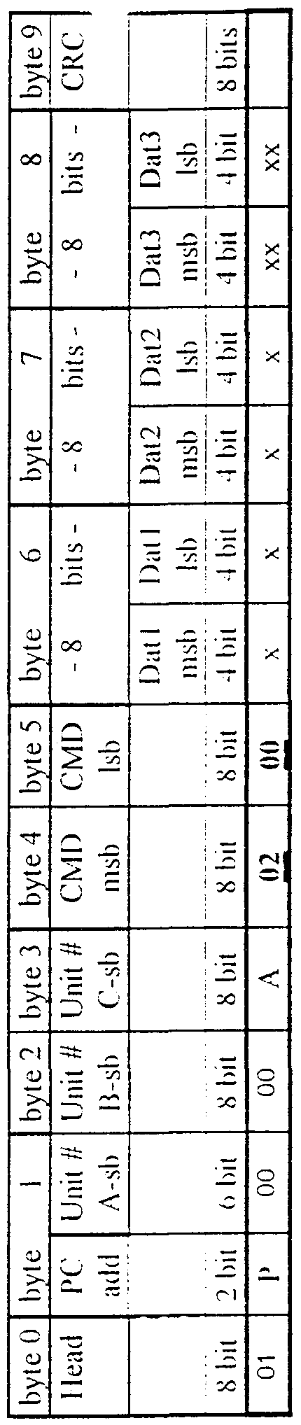


Claims
Priority Applications (2)
| Application Number | Priority Date | Filing Date | Title |
|---|---|---|---|
| AU88198/98A AU8819898A (en) | 1997-08-18 | 1998-08-18 | Techniques and apparatus for entertainment sites, amusement parks and other information and/or entertainment dispensing sites |
| EP98939824A EP0934105A1 (en) | 1997-08-18 | 1998-08-18 | Techniques and apparatus for entertainment sites, amusement parks and other information and/or entertainment dispensing sites |
Applications Claiming Priority (4)
| Application Number | Priority Date | Filing Date | Title |
|---|---|---|---|
| IL121574 | 1997-08-18 | ||
| IL12157497A IL121574A0 (en) | 1997-08-18 | 1997-08-18 | Techniques and apparatus for entertainment sites amusement parks and other information and/or entertainment dispensing sites |
| US09/062,500 | 1998-04-17 | ||
| US09/062,500 US6352478B1 (en) | 1997-08-18 | 1998-04-17 | Techniques and apparatus for entertainment sites, amusement parks and other information and/or entertainment dispensing sites |
Publications (1)
| Publication Number | Publication Date |
|---|---|
| WO1999008762A1 true WO1999008762A1 (en) | 1999-02-25 |
Family
ID=26323490
Family Applications (1)
| Application Number | Title | Priority Date | Filing Date |
|---|---|---|---|
| PCT/IL1998/000392 WO1999008762A1 (en) | 1997-08-18 | 1998-08-18 | Techniques and apparatus for entertainment sites, amusement parks and other information and/or entertainment dispensing sites |
Country Status (3)
| Country | Link |
|---|---|
| EP (1) | EP0934105A1 (en) |
| AU (1) | AU8819898A (en) |
| WO (1) | WO1999008762A1 (en) |
Cited By (25)
| Publication number | Priority date | Publication date | Assignee | Title |
|---|---|---|---|---|
| US6773344B1 (en) | 2000-03-16 | 2004-08-10 | Creator Ltd. | Methods and apparatus for integration of interactive toys with interactive television and cellular communication systems |
| US7321315B2 (en) | 2003-12-29 | 2008-01-22 | Kimberly-Clark Worldwide, Inc. | System and method for identifying disposable absorbent products |
| US7644861B2 (en) | 2006-04-18 | 2010-01-12 | Bgc Partners, Inc. | Systems and methods for providing access to wireless gaming devices |
| US8162756B2 (en) | 2004-02-25 | 2012-04-24 | Cfph, Llc | Time and location based gaming |
| US8221220B2 (en) * | 2006-08-11 | 2012-07-17 | Disney Enterprises, Inc. | Method and/or system for adaptive gaming experience |
| US8292741B2 (en) | 2006-10-26 | 2012-10-23 | Cfph, Llc | Apparatus, processes and articles for facilitating mobile gaming |
| US8319601B2 (en) | 2007-03-14 | 2012-11-27 | Cfph, Llc | Game account access device |
| US8397985B2 (en) | 2006-05-05 | 2013-03-19 | Cfph, Llc | Systems and methods for providing access to wireless gaming devices |
| US8504617B2 (en) | 2004-02-25 | 2013-08-06 | Cfph, Llc | System and method for wireless gaming with location determination |
| US8506400B2 (en) | 2005-07-08 | 2013-08-13 | Cfph, Llc | System and method for wireless gaming system with alerts |
| US8510567B2 (en) | 2006-11-14 | 2013-08-13 | Cfph, Llc | Conditional biometric access in a gaming environment |
| US8581721B2 (en) | 2007-03-08 | 2013-11-12 | Cfph, Llc | Game access device with privileges |
| US8613658B2 (en) | 2005-07-08 | 2013-12-24 | Cfph, Llc | System and method for wireless gaming system with user profiles |
| US8645709B2 (en) | 2006-11-14 | 2014-02-04 | Cfph, Llc | Biometric access data encryption |
| US8690679B2 (en) | 2005-08-09 | 2014-04-08 | Cfph, Llc | System and method for providing wireless gaming as a service application |
| US8784197B2 (en) | 2006-11-15 | 2014-07-22 | Cfph, Llc | Biometric access sensitivity |
| US8825642B2 (en) | 2011-01-27 | 2014-09-02 | Electronic Entertainment Design And Research | Game recommendation engine for mapping games to disabilities |
| US8840018B2 (en) | 2006-05-05 | 2014-09-23 | Cfph, Llc | Device with time varying signal |
| US8956231B2 (en) | 2010-08-13 | 2015-02-17 | Cfph, Llc | Multi-process communication regarding gaming information |
| US8974302B2 (en) | 2010-08-13 | 2015-03-10 | Cfph, Llc | Multi-process communication regarding gaming information |
| US9183693B2 (en) | 2007-03-08 | 2015-11-10 | Cfph, Llc | Game access device |
| US9306952B2 (en) | 2006-10-26 | 2016-04-05 | Cfph, Llc | System and method for wireless gaming with location determination |
| US10460566B2 (en) | 2005-07-08 | 2019-10-29 | Cfph, Llc | System and method for peer-to-peer wireless gaming |
| US10726664B2 (en) | 2004-02-25 | 2020-07-28 | Interactive Games Llc | System and method for convenience gaming |
| US10783744B2 (en) | 2004-02-25 | 2020-09-22 | Cfph, Llc | System and method for wireless lottery |
Citations (2)
| Publication number | Priority date | Publication date | Assignee | Title |
|---|---|---|---|---|
| US4339798A (en) * | 1979-12-17 | 1982-07-13 | Remote Dynamics | Remote gaming system |
| US5504675A (en) * | 1994-12-22 | 1996-04-02 | International Business Machines Corporation | Method and apparatus for automatic selection and presentation of sales promotion programs |
-
1998
- 1998-08-18 EP EP98939824A patent/EP0934105A1/en not_active Withdrawn
- 1998-08-18 WO PCT/IL1998/000392 patent/WO1999008762A1/en not_active Application Discontinuation
- 1998-08-18 AU AU88198/98A patent/AU8819898A/en not_active Abandoned
Patent Citations (2)
| Publication number | Priority date | Publication date | Assignee | Title |
|---|---|---|---|---|
| US4339798A (en) * | 1979-12-17 | 1982-07-13 | Remote Dynamics | Remote gaming system |
| US5504675A (en) * | 1994-12-22 | 1996-04-02 | International Business Machines Corporation | Method and apparatus for automatic selection and presentation of sales promotion programs |
Cited By (66)
| Publication number | Priority date | Publication date | Assignee | Title |
|---|---|---|---|---|
| US6773344B1 (en) | 2000-03-16 | 2004-08-10 | Creator Ltd. | Methods and apparatus for integration of interactive toys with interactive television and cellular communication systems |
| US7321315B2 (en) | 2003-12-29 | 2008-01-22 | Kimberly-Clark Worldwide, Inc. | System and method for identifying disposable absorbent products |
| US11024115B2 (en) | 2004-02-25 | 2021-06-01 | Interactive Games Llc | Network based control of remote system for enabling, disabling, and controlling gaming |
| US10360755B2 (en) | 2004-02-25 | 2019-07-23 | Interactive Games Llc | Time and location based gaming |
| US9430901B2 (en) | 2004-02-25 | 2016-08-30 | Interactive Games Llc | System and method for wireless gaming with location determination |
| US11514748B2 (en) | 2004-02-25 | 2022-11-29 | Interactive Games Llc | System and method for convenience gaming |
| US8308568B2 (en) | 2004-02-25 | 2012-11-13 | Cfph, Llc | Time and location based gaming |
| US10347076B2 (en) | 2004-02-25 | 2019-07-09 | Interactive Games Llc | Network based control of remote system for enabling, disabling, and controlling gaming |
| US10726664B2 (en) | 2004-02-25 | 2020-07-28 | Interactive Games Llc | System and method for convenience gaming |
| US8162756B2 (en) | 2004-02-25 | 2012-04-24 | Cfph, Llc | Time and location based gaming |
| US8504617B2 (en) | 2004-02-25 | 2013-08-06 | Cfph, Llc | System and method for wireless gaming with location determination |
| US10391397B2 (en) | 2004-02-25 | 2019-08-27 | Interactive Games, Llc | System and method for wireless gaming with location determination |
| US10515511B2 (en) | 2004-02-25 | 2019-12-24 | Interactive Games Llc | Network based control of electronic devices for gaming |
| US10783744B2 (en) | 2004-02-25 | 2020-09-22 | Cfph, Llc | System and method for wireless lottery |
| US9355518B2 (en) | 2004-02-25 | 2016-05-31 | Interactive Games Llc | Gaming system with location determination |
| US10653952B2 (en) | 2004-02-25 | 2020-05-19 | Interactive Games Llc | System and method for wireless gaming with location determination |
| US8613658B2 (en) | 2005-07-08 | 2013-12-24 | Cfph, Llc | System and method for wireless gaming system with user profiles |
| US8708805B2 (en) | 2005-07-08 | 2014-04-29 | Cfph, Llc | Gaming system with identity verification |
| US10733847B2 (en) | 2005-07-08 | 2020-08-04 | Cfph, Llc | System and method for gaming |
| US10510214B2 (en) | 2005-07-08 | 2019-12-17 | Cfph, Llc | System and method for peer-to-peer wireless gaming |
| US10460566B2 (en) | 2005-07-08 | 2019-10-29 | Cfph, Llc | System and method for peer-to-peer wireless gaming |
| US8506400B2 (en) | 2005-07-08 | 2013-08-13 | Cfph, Llc | System and method for wireless gaming system with alerts |
| US11069185B2 (en) | 2005-07-08 | 2021-07-20 | Interactive Games Llc | System and method for wireless gaming system with user profiles |
| US8690679B2 (en) | 2005-08-09 | 2014-04-08 | Cfph, Llc | System and method for providing wireless gaming as a service application |
| US11636727B2 (en) | 2005-08-09 | 2023-04-25 | Cfph, Llc | System and method for providing wireless gaming as a service application |
| US10957150B2 (en) | 2006-04-18 | 2021-03-23 | Cfph, Llc | Systems and methods for providing access to wireless gaming devices |
| US10460557B2 (en) | 2006-04-18 | 2019-10-29 | Cfph, Llc | Systems and methods for providing access to a system |
| US8403214B2 (en) | 2006-04-18 | 2013-03-26 | Bgc Partners, Inc. | Systems and methods for providing access to wireless gaming devices |
| US7644861B2 (en) | 2006-04-18 | 2010-01-12 | Bgc Partners, Inc. | Systems and methods for providing access to wireless gaming devices |
| US10286300B2 (en) | 2006-05-05 | 2019-05-14 | Cfph, Llc | Systems and methods for providing access to locations and services |
| US8397985B2 (en) | 2006-05-05 | 2013-03-19 | Cfph, Llc | Systems and methods for providing access to wireless gaming devices |
| US11229835B2 (en) | 2006-05-05 | 2022-01-25 | Cfph, Llc | Systems and methods for providing access to wireless gaming devices |
| US11024120B2 (en) | 2006-05-05 | 2021-06-01 | Cfph, Llc | Game access device with time varying signal |
| US10751607B2 (en) | 2006-05-05 | 2020-08-25 | Cfph, Llc | Systems and methods for providing access to locations and services |
| US8695876B2 (en) | 2006-05-05 | 2014-04-15 | Cfph, Llc | Systems and methods for providing access to wireless gaming devices |
| US8740065B2 (en) | 2006-05-05 | 2014-06-03 | Cfph, Llc | Systems and methods for providing access to wireless gaming devices |
| US10535223B2 (en) | 2006-05-05 | 2020-01-14 | Cfph, Llc | Game access device with time varying signal |
| US8840018B2 (en) | 2006-05-05 | 2014-09-23 | Cfph, Llc | Device with time varying signal |
| US8939359B2 (en) | 2006-05-05 | 2015-01-27 | Cfph, Llc | Game access device with time varying signal |
| US8899477B2 (en) | 2006-05-05 | 2014-12-02 | Cfph, Llc | Device detection |
| US8221220B2 (en) * | 2006-08-11 | 2012-07-17 | Disney Enterprises, Inc. | Method and/or system for adaptive gaming experience |
| US10535221B2 (en) | 2006-10-26 | 2020-01-14 | Interactive Games Llc | System and method for wireless gaming with location determination |
| US9306952B2 (en) | 2006-10-26 | 2016-04-05 | Cfph, Llc | System and method for wireless gaming with location determination |
| US8292741B2 (en) | 2006-10-26 | 2012-10-23 | Cfph, Llc | Apparatus, processes and articles for facilitating mobile gaming |
| US11017628B2 (en) | 2006-10-26 | 2021-05-25 | Interactive Games Llc | System and method for wireless gaming with location determination |
| US8510567B2 (en) | 2006-11-14 | 2013-08-13 | Cfph, Llc | Conditional biometric access in a gaming environment |
| US10706673B2 (en) | 2006-11-14 | 2020-07-07 | Cfph, Llc | Biometric access data encryption |
| US9280648B2 (en) | 2006-11-14 | 2016-03-08 | Cfph, Llc | Conditional biometric access in a gaming environment |
| US8645709B2 (en) | 2006-11-14 | 2014-02-04 | Cfph, Llc | Biometric access data encryption |
| US11182462B2 (en) | 2006-11-15 | 2021-11-23 | Cfph, Llc | Biometric access sensitivity |
| US9411944B2 (en) | 2006-11-15 | 2016-08-09 | Cfph, Llc | Biometric access sensitivity |
| US8784197B2 (en) | 2006-11-15 | 2014-07-22 | Cfph, Llc | Biometric access sensitivity |
| US10546107B2 (en) | 2006-11-15 | 2020-01-28 | Cfph, Llc | Biometric access sensitivity |
| US10332155B2 (en) | 2007-03-08 | 2019-06-25 | Cfph, Llc | Systems and methods for determining an amount of time an object is worn |
| US10424153B2 (en) | 2007-03-08 | 2019-09-24 | Cfph, Llc | Game access device with privileges |
| US9183693B2 (en) | 2007-03-08 | 2015-11-10 | Cfph, Llc | Game access device |
| US8581721B2 (en) | 2007-03-08 | 2013-11-12 | Cfph, Llc | Game access device with privileges |
| US11055958B2 (en) | 2007-03-08 | 2021-07-06 | Cfph, Llc | Game access device with privileges |
| US8319601B2 (en) | 2007-03-14 | 2012-11-27 | Cfph, Llc | Game account access device |
| US10366562B2 (en) | 2007-03-14 | 2019-07-30 | Cfph, Llc | Multi-account access device |
| US11055954B2 (en) | 2007-03-14 | 2021-07-06 | Cfph, Llc | Game account access device |
| US8956231B2 (en) | 2010-08-13 | 2015-02-17 | Cfph, Llc | Multi-process communication regarding gaming information |
| US10744416B2 (en) | 2010-08-13 | 2020-08-18 | Interactive Games Llc | Multi-process communication regarding gaming information |
| US8974302B2 (en) | 2010-08-13 | 2015-03-10 | Cfph, Llc | Multi-process communication regarding gaming information |
| US10406446B2 (en) | 2010-08-13 | 2019-09-10 | Interactive Games Llc | Multi-process communication regarding gaming information |
| US8825642B2 (en) | 2011-01-27 | 2014-09-02 | Electronic Entertainment Design And Research | Game recommendation engine for mapping games to disabilities |
Also Published As
| Publication number | Publication date |
|---|---|
| AU8819898A (en) | 1999-03-08 |
| EP0934105A1 (en) | 1999-08-11 |
Similar Documents
| Publication | Publication Date | Title |
|---|---|---|
| US6352478B1 (en) | Techniques and apparatus for entertainment sites, amusement parks and other information and/or entertainment dispensing sites | |
| WO1999008762A1 (en) | Techniques and apparatus for entertainment sites, amusement parks and other information and/or entertainment dispensing sites | |
| US6290566B1 (en) | Interactive talking toy | |
| US9070247B2 (en) | Automated virtual assistant | |
| McDermott | Mind and mechanism | |
| US6773322B2 (en) | Programmable assembly toy | |
| US6206745B1 (en) | Programmable assembly toy | |
| Steels | Language games for autonomous robots | |
| US9950421B2 (en) | Humanoid game-playing robot, method and system for using said robot | |
| US20050154594A1 (en) | Method and apparatus of simulating and stimulating human speech and teaching humans how to talk | |
| US11017551B2 (en) | System and method for identifying a point of interest based on intersecting visual trajectories | |
| US20190202063A1 (en) | System and method for selective animatronic peripheral response for human machine dialogue | |
| WO1997018871A2 (en) | I*doll | |
| US20220215678A1 (en) | System and method for reconstructing unoccupied 3d space | |
| US20190202061A1 (en) | System and method for detecting physical proximity between devices | |
| US20190251716A1 (en) | System and method for visual scene construction based on user communication | |
| US20190251350A1 (en) | System and method for inferring scenes based on visual context-free grammar model | |
| WO2021003471A1 (en) | System and method for adaptive dialogue management across real and augmented reality | |
| CN210155626U (en) | Information processing apparatus | |
| WO2019160611A1 (en) | System and method for dynamic robot configuration for enhanced digital experiences | |
| WO2019160613A1 (en) | System and method for dynamic program configuration | |
| KR20070041531A (en) | A method for contesting at least two interactive systems against each other and an interactive system competition arrangement | |
| WO2001070361A2 (en) | Interactive toy applications | |
| Clark et al. | Natural-born cyborgs: Minds, technologies, and the future of human intelligence | |
| Roden et al. | Toward mobile entertainment: A paradigm for narrative-based audio only games |
Legal Events
| Date | Code | Title | Description |
|---|---|---|---|
| AK | Designated states |
Kind code of ref document: A1 Designated state(s): AL AM AT AT AU AZ BA BB BG BR BY CA CH CN CU CZ CZ DE DE DK DK EE EE ES FI FI GB GE GH GM HR HU ID IL IS JP KE KG KP KR KZ LC LK LR LS LT LU LV MD MG MK MN MW MX NO NZ PL PT RO RU SD SE SG SI SK SK SL TJ TM TR TT UA UG US UZ VN YU ZW |
|
| AL | Designated countries for regional patents |
Kind code of ref document: A1 Designated state(s): GH GM KE LS MW SD SZ UG ZW AM AZ BY KG KZ MD RU TJ TM AT BE CH CY DE DK ES FI FR GB GR IE IT LU MC NL PT SE BF BJ CF CG CI CM GA GN GW ML MR NE SN TD TG |
|
| WWE | Wipo information: entry into national phase |
Ref document number: 1998939824 Country of ref document: EP |
|
| 121 | Ep: the epo has been informed by wipo that ep was designated in this application | ||
| WWP | Wipo information: published in national office |
Ref document number: 1998939824 Country of ref document: EP |
|
| REG | Reference to national code |
Ref country code: DE Ref legal event code: 8642 |
|
| NENP | Non-entry into the national phase |
Ref country code: JP Ref document number: 1999512985 Format of ref document f/p: F |
|
| NENP | Non-entry into the national phase |
Ref country code: CA |
|
| WWW | Wipo information: withdrawn in national office |
Ref document number: 1998939824 Country of ref document: EP |