WO1999014878A1 - A method of and apparatus for transmitting data in a multiple carrier system - Google Patents
A method of and apparatus for transmitting data in a multiple carrier system Download PDFInfo
- Publication number
- WO1999014878A1 WO1999014878A1 PCT/US1998/019335 US9819335W WO9914878A1 WO 1999014878 A1 WO1999014878 A1 WO 1999014878A1 US 9819335 W US9819335 W US 9819335W WO 9914878 A1 WO9914878 A1 WO 9914878A1
- Authority
- WO
- WIPO (PCT)
- Prior art keywords
- data
- channel
- symbols
- rate
- channels
- Prior art date
Links
Classifications
-
- H—ELECTRICITY
- H04—ELECTRIC COMMUNICATION TECHNIQUE
- H04B—TRANSMISSION
- H04B1/00—Details of transmission systems, not covered by a single one of groups H04B3/00 - H04B13/00; Details of transmission systems not characterised by the medium used for transmission
- H04B1/69—Spread spectrum techniques
-
- H—ELECTRICITY
- H04—ELECTRIC COMMUNICATION TECHNIQUE
- H04L—TRANSMISSION OF DIGITAL INFORMATION, e.g. TELEGRAPHIC COMMUNICATION
- H04L5/00—Arrangements affording multiple use of the transmission path
- H04L5/0001—Arrangements for dividing the transmission path
- H04L5/0014—Three-dimensional division
- H04L5/0016—Time-frequency-code
- H04L5/0017—Time-frequency-code in which a distinct code is applied, as a temporal sequence, to each frequency
-
- H—ELECTRICITY
- H04—ELECTRIC COMMUNICATION TECHNIQUE
- H04B—TRANSMISSION
- H04B1/00—Details of transmission systems, not covered by a single one of groups H04B3/00 - H04B13/00; Details of transmission systems not characterised by the medium used for transmission
- H04B1/69—Spread spectrum techniques
- H04B1/707—Spread spectrum techniques using direct sequence modulation
-
- H—ELECTRICITY
- H04—ELECTRIC COMMUNICATION TECHNIQUE
- H04J—MULTIPLEX COMMUNICATION
- H04J13/00—Code division multiplex systems
- H04J13/0007—Code type
- H04J13/004—Orthogonal
- H04J13/0048—Walsh
-
- H—ELECTRICITY
- H04—ELECTRIC COMMUNICATION TECHNIQUE
- H04L—TRANSMISSION OF DIGITAL INFORMATION, e.g. TELEGRAPHIC COMMUNICATION
- H04L1/00—Arrangements for detecting or preventing errors in the information received
- H04L1/004—Arrangements for detecting or preventing errors in the information received by using forward error control
- H04L1/0056—Systems characterized by the type of code used
- H04L1/0059—Convolutional codes
-
- H—ELECTRICITY
- H04—ELECTRIC COMMUNICATION TECHNIQUE
- H04L—TRANSMISSION OF DIGITAL INFORMATION, e.g. TELEGRAPHIC COMMUNICATION
- H04L1/00—Arrangements for detecting or preventing errors in the information received
- H04L1/004—Arrangements for detecting or preventing errors in the information received by using forward error control
- H04L1/0056—Systems characterized by the type of code used
- H04L1/0071—Use of interleaving
-
- H—ELECTRICITY
- H04—ELECTRIC COMMUNICATION TECHNIQUE
- H04L—TRANSMISSION OF DIGITAL INFORMATION, e.g. TELEGRAPHIC COMMUNICATION
- H04L25/00—Baseband systems
- H04L25/02—Details ; arrangements for supplying electrical power along data transmission lines
- H04L25/03—Shaping networks in transmitter or receiver, e.g. adaptive shaping networks
- H04L25/03828—Arrangements for spectral shaping; Arrangements for providing signals with specified spectral properties
- H04L25/03866—Arrangements for spectral shaping; Arrangements for providing signals with specified spectral properties using scrambling
-
- H—ELECTRICITY
- H04—ELECTRIC COMMUNICATION TECHNIQUE
- H04L—TRANSMISSION OF DIGITAL INFORMATION, e.g. TELEGRAPHIC COMMUNICATION
- H04L5/00—Arrangements affording multiple use of the transmission path
- H04L5/0001—Arrangements for dividing the transmission path
- H04L5/0014—Three-dimensional division
- H04L5/0016—Time-frequency-code
- H04L5/0021—Time-frequency-code in which codes are applied as a frequency-domain sequences, e.g. MC-CDMA
-
- H—ELECTRICITY
- H04—ELECTRIC COMMUNICATION TECHNIQUE
- H04L—TRANSMISSION OF DIGITAL INFORMATION, e.g. TELEGRAPHIC COMMUNICATION
- H04L5/00—Arrangements affording multiple use of the transmission path
- H04L5/003—Arrangements for allocating sub-channels of the transmission path
- H04L5/0044—Arrangements for allocating sub-channels of the transmission path allocation of payload
- H04L5/0046—Determination of how many bits are transmitted on different sub-channels
-
- H—ELECTRICITY
- H04—ELECTRIC COMMUNICATION TECHNIQUE
- H04L—TRANSMISSION OF DIGITAL INFORMATION, e.g. TELEGRAPHIC COMMUNICATION
- H04L5/00—Arrangements affording multiple use of the transmission path
- H04L5/003—Arrangements for allocating sub-channels of the transmission path
- H04L5/0058—Allocation criteria
- H04L5/0064—Rate requirement of the data, e.g. scalable bandwidth, data priority
Definitions
- the present invention relates to a method of and apparatus for transmitting data in a multiple carrier system.
- the present invention may be used for maximizing system throughput and increasing signal diversity by dynamically multiplexing signals onto multiple carriers in a spread spectrum communication system.
- a traditional CDMA channel (as standardized for cellular communication in the United States) is capable of carry digital data at a maximum rate of 9.6 bits per second using a 64 bit Walsh spreading function at 1.2288 MHz.
- CDMA code division multiple access
- TDMA time division multiple access
- FDMA frequency division multiple access
- AM modulation schemes such as amplitude companded single sideband (ACSSB)
- TDMA time division multiple access
- FDMA frequency division multiple access
- AM modulation schemes such as amplitude companded single sideband (ACSSB)
- TDMA time division multiple access
- FDMA frequency division multiple access
- AM modulation schemes such as amplitude companded single sideband (ACSSB)
- ACSB amplitude companded single sideband
- CDMA has significant advantages over these other modulation techniques for multiple access communication systems.
- Code division multiple access communications systems have been standardized in the United States in Telecommunications Industry Association Interim Standard IS-95, entitled "Mobile Station-Base Station Compatibility Standard for Dual Mode Wideband Spread Spectrum Cellular System", which is incorporated by reference herein.
- the CDMA waveform by its inherent nature of being a wideband signal offers a form of frequency diversity by spreading the signal energy over a wide bandwidth. Therefore, frequency selective fading affects only a small part of the CDMA signal bandwidth.
- Space or path diversity on the forward /reverse link is obtained by providing multiple signal paths through simultaneous links to/from a mobile user through two or more antennas, cell sectors or cell-sites.
- FIG. 1 illustrates a transmission scheme for a multiple-carrier code division multiple access (CDMA) system in which each carrier carries a fixed fraction of the transmitted data.
- CDMA code division multiple access
- Variable rate frame of information bits are provided to encoder 2 which encodes the bits in accordance with a convolutional encoding format.
- the encoded symbols are provided to symbol repetition means 4.
- Symbol repetition means 4 repeats the encoded symbols so as to provide a fixed rate of symbols out of symbol repetition means 4, regardless of the rate of the information bits.
- the repeated symbols are provided to block interleaver 6 which rearranges the sequence in which the symbols are to be transmitted.
- the interleaving process coupled with the forward error correction, provides time diversity which aids in the reception and error recovery of the transmitted signal in the face of burst errors.
- the interleaved symbols are provided to data scrambler 12.
- Data scrambler 12 multiplies each interleaved symbol by +1 or -1 according to a pseudonoise (PN) sequence.
- PN pseudonoise
- the pseudonoise sequence is provided by passing a long PN sequence generated by long code generator 8 at the chip rate through decimator 10 which selectively provides a subset of the chips of the long code sequence at the rate of the interleaved symbol stream.
- the data from data scrambler 12 is provided to demultiplexer
- Demultiplexer 14 divides the data stream into three equal sub- streams.
- the first sub-stream is provided to transmission subsystem 15a, the second sub-stream to transmission subsystem 15b and the third sub-stream to transmission subsystem 15c.
- the subframes are provided to serial-to- parallel converters (BINARY TO 4 LEVEL) 16a-16c.
- the outputs of serial to parallel converters 16a-16c are quaternary symbols (2bits/symbol) to be transmitted in a QPSK modulation format
- the signals from serial-to-parallel converters 16a-16c are provided to Walsh coders 18a-18c.
- Walsh coders 18a-18c the signal from each converter 16a-16k is multiplied by a Walsh sequence consisting of ⁇ 1 values.
- the Walsh coded data is provided to QPSK spreaders 20a-20c, which spread the data in accordance with two short PN sequences.
- the short PN sequence spread signals are provided to amplifiers 22a-22b which amplify the signals in accordance with a gain factor.
- the available numerology is limited to frames with a number of code symbols that will divide evenly by a factor of three.
- Table 1 below illustrates the limited number of possible rate sets which are available using the transmission system illustrated in FIG. 1.
- the total data rate is limited by the carrier with the least power available or requiring the highest SNR. That is the total data rate is equalt to three times te data rate of the "worst" link (here the worst means the one requiring the highest SNR or having the least power avaialble). This reduces the system throughput, because the worst link's rate is always chosen as the common rate for all three carriers, which results in under utilization of the channel resource on the two better links.
- frequency dependent fading can severely affect one of the frequencies while having a limited effect on the remaining frequencies.
- This implementation is inflexible and does not allow transmission of a frame to be provided in a way that reduces the effects of the poor channel.
- the fading will typically always affectthe same groups of symbolsof each frame.
- the invention provides a transmitter for transmitting data at a data rate in a plurality of channels each having a capacity less than the data rate, the transmitter comprising: a controller for determining the capacity of each of a plurality channels and selecting a data rate for each channel depending on the determined capacity; a plurality of transmission subsystems responsive to the controller and each associated with a respective one of the plurality of channels for scrambling encoded data with codes unique to the channel for transmission in the channel; and a variable demultilplexer responsive to the controller for demultiplexing the encoded data into the plurality of transmission subsystems at a demultiplexing rate derived from the data rates selected for the channels by the controller.
- the invention provides a receiver comprising: a receiving circuit for receiving signals simultaneously in a plurality of channels each of which signals define scrambled encoded symbols which together represent data from a common origin; a controller for determining a symbol rate for the signals in each channel; a plurality of receiving subsystems responsive to the controller and each associated with a respective one of the plurality of channels for descrambling encoded symbols with codes unique to the channel to enable the data to be extracted therefrom; and a variable multiplexer responsive to the controller for multiplexing the data from the plurality of receiving subsystems at a multiplexing rate derived from the symbol rates determined for the channels by the controller onto an output.
- the invention provides a wireless transmitter, comprising: encoder for receive a set of information bits and encoding said information bits to provide a set of code symbols; and a transmission subsystem for receiving said code symbols and for providing a subset of said code symbols on a first carrier frequency and the remaining symbols on at least one additional carrier frequency.
- the invention also provides a method of transmitting data at a data rate in a plurality of channels each having a capacity less than the data rate, the method comprising: determining the capacity of each of a plurality channels and selecting a data rate for each channel depending on the determined capacity; scrambling encoded data with codes unique to the channel for transmission in the channel; and demultiplexing the encoded data into the plurality of channels at a demultiplexing rate derived from the data rates selected for the channels by the controller.
- the invention further provides a method of receiving data, the method comprising: receiving signals simultaneously in a plurality of channels each of which signals define scrambled encoded symbols which together represent data from a common origin; determining a symbol rate for the signals in each channel; descrambling encoded symbols in each channel with codes unique to the channel to enable the data to be extracted therefrom; and multiplexing the descrambled data from the plurality of channels at a multiplexing rate derived from the symbol rates determined for the channels.
- Walsh function rate can be 1228800, 614400, 307200,..., 75 for Walsh function length from 1 to 16384. Given the Walsh function length, if the symbol rate is lower than the
- Walsh function rate symbol repetition is used to "match" the rate.
- the repetition factor can be any number, integer or fractional. It will be understood by one skilled in the art that when repetition is present, the total transmit power can be proportionately reduced to keep the code symbol energy constant.
- the Walsh function length may or may not be the same on the three carriers, depending on whether we need to save code channels. For example, if the supportable code symbol rate on the three channels are 153600 sps, 30720 sps and 102400 sps (for rate 1/2 coding, these correspond to data rates of 76.8 kbps, 15.36 kbps and 51.2 kbps, respectively - the total data rate is 143.36 kbps), then the inverse-multiplexing ratio will be 15:3:10.
- each code symbol is transmitted twice, 10 times, and three times on the three channels, respectively. Additional time diversity can be obtained if the repeated symbols are further interleaved.
- different Walsh function lengths are used. For example, Walsh functions for the three channels in the example of above of length 16, 16 and 8 respectively can be used, with each code symbol transmitted once on the first channel, five times on the second, and three times on the third.
- FIG. 1 is a block diagram illustrating a multiple frequency CDMA communication system with fixed rates and carriers;
- FIG. 2 is a block diagram illustrating a transmission system embodying the present invention
- FIG. 3 is a block diagram illustrating a receiver system embodying the present invention.
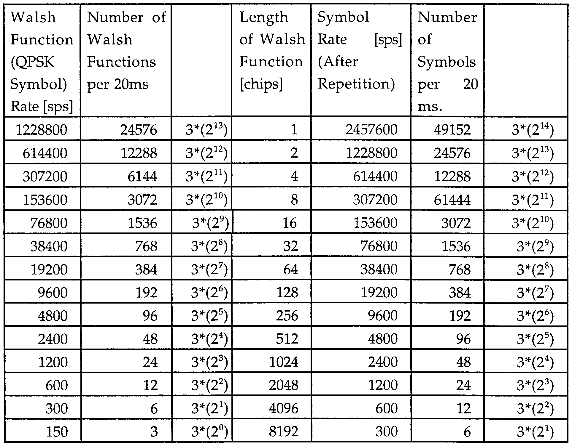
- FIG. 4 is a table of code channel Walsh symbols in a traditional IS-95 CDMA communication system.
- the first operation to be performed is to determine the amount of data which can be supported on each of the carriers.
- Three such carriers are illustrated in FIG. 2, though one skilled in the art will realize that the present invention is easily extended to any number of carriers.
- Control processor 50 based on a set of factors such as the loading on each of the carriers, the amount of data queued for transmission to the mobile station and the priority of the information to be transmitted to the mobile station determines the rate of data transmission on each of the carriers.
- control processor 50 selects a modulation format that is capable of transmitting data at the selected rate.
- different length Walsh sequences are used to modulate the data depending on the rate of the data to be transmitted.
- the use of different length Walsh sequences selected to modulate the data depending on the rate of the data to be transmitted is described in detail in co-pending U.S. Patent Application Serial No. 08/654,443, filed May 28, 1996, entitled “HIGH RATE DATA WIRELESS COMMUNICATION SYSTEM", which is assigned to the assignee of the present invention and incorporated by reference herein.
- the high rate data can be supported by bundling of CDMA channels as described in the aforementioned Patent Applications Serial Nos. 08/431,180 and 08/838,240.
- control processor 50 calculates an inverse multiplexing ratio that will determine the amount of each transmission that will be carried on each of the carriers. For example, if the supportable code symbol rate on the three channels are 153600 sps, 30720 sps and 102400 sps (for rate 1/2 coding, these correspond to data rates of 76.8 kbps, 15.36 kbps and 51.2 kbps, respectively - the total data rate is 143.36 kbps), then the inverse- multiplexing ratio will be 15:3:10. In the exemplary embodiment, frames of information bits are provided to frame formatter 52.
- formatter 52 generates and appends to the frame a set of cyclic redundancy check (CRC) bits.
- CRC cyclic redundancy check
- formatter 52 appends a predetermined set of tail bits.
- CRC cyclic redundancy check
- encoder 54 is a convolutional encoder, though the present invention can be extended to other forms of encoding.
- a signal from control processor 50 indicates to encoder 54 the number of bits to be encoded in this transmission cycle.
- encoder 54 is a rate 1/4 convolutional encoder with a constraint length of 9. It should be noted that because of the additional flexibility provided by the present invention, essentially any encoding format can be used.
- variable ratio de-multiplexer 56 provides the encoded symbols to a set of outputs based on a symbol output signal provided by control processor 50.
- control processor 50 provides a signal indicative of the number of encoded symbols to be provided on each of the three outputs.
- the present invention is easily extended to an arbitrary number of frequencies.
- the encoded symbols provided on each of the outputs of variable ratio de-multiplexer 56 are provided to a corresponding symbol repetition means 58a-58c.
- Symbol repetition means 58a-58c generate repeated versions of the encoded symbols so that the resultant symbol rate matches with the rate of data supported on that carrier and the in particular matches Walsh function rate used on that carrier.
- the implementation of repetition generators 58a-58c is known in the art and an example of such is described in detail in U.S. Patent No. 5,629,955, entitled “Variable Response Filter", which is assigned to the assignee of the present invention and incorporated by reference herein.
- Control processor 50 provides a separate signal to each repetition generator 58a-58c indicating the rate of symbols on each carrier or alternatively the amount of repetition to be provided on each carrier.
- repetition means 58a-58c In response to the signal from control processor 50, repetition means 58a-58c generate the requisite numbers of repeated symbols to provide the designated symbol rates. It should be noted that in the preferred embodiment, the amount of repetition is not limited to integer number wherein all symbols are repeated the same number of times. A method for providing non-integer repetition is described in detail in co-pending U.S. Patent Application Serial No.
- Control processor 50 provides an interleaving format signal to each of interleavers 60a-60c which indicates one of a predetermined set of interleaving formats.
- the interleaving format is selected from a predetermined set of bit reversal interleaving formats.
- the reordered symbols from interleavers 60a-60c are provided to data scramblers 62a-62c.
- Each of data scramblers 62a-62c changes the sign of the data in accordance with a pseudonoise (PN) sequence.
- PN sequence is provided by passing a long PN code generated by long code or PN generator 82 at the chip rate through a decimator 84a-84c, which selectively provides ones of the spreading symbols to provide a PN sequence at a rate no higher than that provided by PN generator 82. Because the symbol rate on each carrier may be different from one another, the decimation rate of decimators 84a-84c may be different.
- Decimators 84a-84c are sample and hold circuits which sample the PN sequence out of PN generator 82 and continue to output that value for a predetermined period.
- the implementation of PN generator 82 and decimators 84a-84c are well known in the art and are described in detail in the aforementioned U.S. Patent No. 5,103,459.
- Data scramblers 62a-62c exclusively-OR the binary symbols from interleavers 60a- 60c with the decimated pseudonoise binary sequences from decimators 84a- 84c.
- the binary scrambled symbol sequences are provided to serial to parallel converters (BINARY TO 4-LEVEL) 64a-64c. Two binary symbols provided to converters 64a-64c are mapped to a quaternary constellation with values ( ⁇ 1, ⁇ 1). The constellation values are provided on two outputs from converters 62a-62c. The symbol streams from converters 64a-64c are separately provided to Walsh spreaders 66a-66c.
- the Walsh sequence length is varied in accordance with the rate of the data to be modulated. Shorter Walsh sequences are used to modulate higher speed data and longer Walsh sequences are used to modulate lower rate data. For example, a 64 bit Walsh sequence can be used to transmit data at 19.2 Ksps. However, a 32 bit Walsh sequence can be used to modulate data at 38.4 Ksps.
- FIG. 4 illustrates the Walsh functions in a traditional IS-95 CDMA system.
- the Walsh codes used by Walsh coders 66a-66c are 64/2 N symbols long, rather than the 64 symbols used with the IS-95 Walsh codes.
- 2 of the possible 64 quaternary-phase channels with 64-symbol Walsh are eliminated from use.
- Table I provides a list of the possible Walsh codes for each value of N and the corresponding sets of allocated 64-symbol Walsh codes.
- the + and - indicate a positive or negative integer value, where the preferred integer is 1.
- the number of Walsh symbols in each Walsh code varies as N varies, and in all instances is less than the number of symbols in the IS-95 Walsh channel codes.
- the symbols are applied at a rate of 1.2288 Megachips per second (Mcps).
- Mcps Megachips per second
- Control processor 50 provides a signal to Walsh coding elements 66a-66c which indicates the Walsh sequence to be used to spread the data.
- Channel bundling techniques Alternative methods for transmitting high rate data in CDMA communication system also include methods generally referred to as channel bundling techniques.
- the present invention is equally applicable to the channel bundling methods for providing high speed data in a CDMA communciation system.
- One method of providing channel bundled data is to provide a plurality of Walsh channels for use by a signal user. This method is described in detail in the aforementioned U.S. Patent Application Serial No. 08/739,482.
- An alternative channel bundling technique is to provide the user with use of one Walsh code channel but to differentiate the signals from one another by means of different scrambling signals as described in detail in co-pending U.S. Patent Application Serial No. 08/838,240.
- the Walsh spread data is provided to PN spreaders 68a-68c, which apply a short PN sequence spreading on the output signals.
- the PN spreading is performed by means of a complex multiplication as described in detail in the aforementioned co- pending U.S. Patent Application Serial No. 08/784,281.
- Data channels Dr . and D Q are complex multiplied, as the first real and imaginary terms respectively, with spreading codes PN ⁇ and PN Q , as the second real and imaginary terms respectively, yielding in-phase (or real) term X ⁇ and quadrature-phase (or imaginary) term X Q .
- Spreading codes PN T and PN Q are generated by spreading code generators 67 and 69.
- Spreading codes PNT and PN Q are applied at 1.2288 Mcps. Equation (1) illustrates the complex multiplication performed.
- In-phase term X ! is then low-pass filtered to a 1.2288 MHz bandwidth (not shown) and upconverted by multiplication with in-phase carrier COS( ⁇ c t).
- quadrature-phase term X Q is low-pass filtered to a 1.2288 MHz bandwidth (not shown) and upconverted by multiplication with quadrature-phase carrier SIN( ⁇ c t).
- the upconverted X ⁇ and X Q terms are summed yielding forward link signal s(t).
- the complex multiplication allows quadrature-phase channel set to remain orthogonal to the in-phase channel set and therefore to be provided without adding additional interference to the other channels transmitted over the same path with perfect receiver phase recovery.
- the PN spread data is, then, provided to filters 70a-70c which spectrally shape the signals for transmission.
- the filtered signals are provided to gain multipliers 72a-72c, which amplify the signals for each carrier.
- the gain factor is supplied to gain elements 72a-72c by control processor 50.
- control processor 50 selects the gain factor for each carrier in accordance with the channel condition and the rate of the information data to be transmitted on that carrier. As is known by one skilled in the art, data that is transmitted with repetition can be transmitted with lower symbol energy than data without repetition.
- the amplified signals are provided to an optional switch 74.
- Switch 74 provides the additional flexibility of channel hopping the data signals onto different carriers. Typically, switch 74 is only used when the number of carriers actually used to transmit the signal is smaller that the total number of possible carriers (3 in the present example).
- the data is passed by switch 74 to carrier modulators 76a-76c.
- Each of carrier modulators 76a-76c upconvert the data to a different predetermined frequency.
- the upconverted signals are provided to transmitter 78 where they are combined with other similarly processed signals, filtered and amplified for transmission through antenna 80.
- the amplified frequency upon which each of the signals are transmitted varies with time. This provides additional frequency diversity for the transmitted signals. For example a signal that is currently being transmitted through carrier modulator 76a will at predetermined time interval be switched so as to be transmitted on a different frequency through carrier modulators 76b or 76c.
- switch 74 directs an amplified input signal from gain multiplier 72a-72c to an appropriate carrier modulator 76a-76c.
- FIG. 3 a receiver system embodying the present invention is illustrated.
- the signal received at antenna 100 is passed to receiver (RCVR) 102, which amplifies and filters the signal before providing it to switch 104.
- the data is provided through switch 104 to an appropriate carrier demodulator 106a-106c.
- switch 104 When the carriers on which the data is transmitted are rotated or hopped to provide additional frequency diversity, switch 104 provides the received signal to a selected carrier demodulator 106a-106c in response to a control signal from control processor 125. When the carrier frequencies are not hopped or rotated, then switch 104 is unnecessary.
- Each of carrier demodulators 106a-106c Quaternary Phase Shift Keying (QPSK) demodulate the received signal to baseband using a different downconversion frequency to provide a separate I and Q baseband signals.
- QPSK Quaternary Phase Shift Keying
- the downconverted signals from each of carrier demodulators 106a- 106c are provided to a corresponding PN despreader 108a-108c which removes the short code spreading from the downconverted data.
- the I and Q signals are despread by complex multiplication with a pair of short PN code.
- the PN despread data is provided to Walsh demodulators HOa-llOc, which uncover the data in accordance with the assigned code channel sequences.
- Walsh functions are used in the generation and reception of the CDMA signals but other forms of code channel generation are equally applicable.
- Control processor 125 provides a signal to Walsh demodulators HOa-llOc indicating the Walsh sequences to be used to uncover the data.
- the Walsh despread symbols are provided to parallel-to-serial converters (4-LEVEL TO BINARY) 112a-112c, which map the 2-dimensional signal into a 1-dimensional signal.
- the symbols are then provided to descramblers 114a-114c.
- Descramblers 114a-114c descramble the data in accordance with a decimated long code sequence generated as described with respect to the decimated long code sequences used to scramble the data in FIG. 2.
- the descrambled data is provided to de-interleavers (DE-INT) 116a- 116c.
- De-interleavers 116a-116c reorder the symbols in accordance with selected de-interleaver formats that are provided by control processor 125.
- control processor 125 provides a signal indicative of the size of the deinterleaver and the scheme of de-interleaving to each of de-interleavers 116a-116c.
- the de- interleaving scheme is selected from a predetermined set of bit reversal de- interleaving schemes.
- decoder 122 is a maximum likelihood decoder, the implementation of which is well known in the art.
- decoder 122 contains a buffer (not shown) which waits until an entire frame of data has been provided to it before beginning the decoding process.
- the decoded frame is provided to CRC check means 124 which determines whether the CRC bits check and if so provides them to the user otherwise an erasure is declared.
Abstract
Description

Claims
Priority Applications (12)
| Application Number | Priority Date | Filing Date | Title |
|---|---|---|---|
| IL13491998A IL134919A (en) | 1997-09-16 | 1998-09-16 | Method of and apparatus for transmitting data in a multiple carrier system |
| CA2302391A CA2302391C (en) | 1997-09-16 | 1998-09-16 | A method of and apparatus for transmitting data in a multiple carrier system |
| BRPI9812311-4A BR9812311B1 (en) | 1997-09-16 | 1998-09-16 | Method and equipment for data transmission in multiple carrier cdma systems. |
| AU95693/98A AU753676B2 (en) | 1997-09-16 | 1998-09-16 | A method of and apparatus for transmitting data in a multiple carrier system |
| UA2000031375A UA62980C2 (en) | 1997-09-16 | 1998-09-16 | Method and device for transmitting and receiving data in a communication system with several carrier frequencies |
| IL15634898A IL156348A0 (en) | 1997-09-16 | 1998-09-16 | Method of and apparatus for transmitting data in a multiple carrier system |
| KR1020007002780A KR100686776B1 (en) | 1997-09-16 | 1998-09-16 | A method of and apparatus for transmitting data in a multiple carrier system |
| DE69831255T DE69831255T2 (en) | 1997-09-16 | 1998-09-16 | METHOD AND DEVICE FOR TRANSFERRING DATA IN A MULTI-TRANSMISSION SYSTEM |
| EP98949354A EP1016234B1 (en) | 1997-09-16 | 1998-09-16 | A method of and apparatus for transmitting data in a multiple carrier system |
| JP2000512302A JP4285901B2 (en) | 1997-09-16 | 1998-09-16 | Method and apparatus for transmitting data on multiple carrier systems |
| NO20001335A NO326768B1 (en) | 1997-09-16 | 2000-03-15 | Method and apparatus for transmission in a multi-carrier system |
| HK00108324A HK1030298A1 (en) | 1997-09-16 | 2000-12-21 | A method of and apparatus for transmitting data ina multiple carrier system |
Applications Claiming Priority (2)
| Application Number | Priority Date | Filing Date | Title |
|---|---|---|---|
| US08/931,536 | 1997-09-16 | ||
| US08/931,536 US6389000B1 (en) | 1997-09-16 | 1997-09-16 | Method and apparatus for transmitting and receiving high speed data in a CDMA communication system using multiple carriers |
Publications (1)
| Publication Number | Publication Date |
|---|---|
| WO1999014878A1 true WO1999014878A1 (en) | 1999-03-25 |
Family
ID=25460935
Family Applications (1)
| Application Number | Title | Priority Date | Filing Date |
|---|---|---|---|
| PCT/US1998/019335 WO1999014878A1 (en) | 1997-09-16 | 1998-09-16 | A method of and apparatus for transmitting data in a multiple carrier system |
Country Status (18)
| Country | Link |
|---|---|
| US (2) | US6389000B1 (en) |
| EP (2) | EP1016234B1 (en) |
| JP (1) | JP4285901B2 (en) |
| KR (1) | KR100686776B1 (en) |
| CN (1) | CN100417051C (en) |
| AU (1) | AU753676B2 (en) |
| BR (1) | BR9812311B1 (en) |
| CA (1) | CA2302391C (en) |
| DE (2) | DE69838824T2 (en) |
| HK (2) | HK1030298A1 (en) |
| ID (1) | ID25458A (en) |
| IL (1) | IL134919A (en) |
| NO (1) | NO326768B1 (en) |
| RU (1) | RU2216866C2 (en) |
| TW (1) | TW431083B (en) |
| UA (1) | UA62980C2 (en) |
| WO (1) | WO1999014878A1 (en) |
| ZA (1) | ZA988431B (en) |
Cited By (27)
| Publication number | Priority date | Publication date | Assignee | Title |
|---|---|---|---|---|
| WO2000005831A1 (en) * | 1998-07-20 | 2000-02-03 | Telefonaktiebolaget Lm Ericsson (Publ) | Spreader for multiple data rates |
| EP1009117A1 (en) * | 1998-12-10 | 2000-06-14 | Alcatel | Method of matching resources required and resources allocated in a mobile radio system |
| WO2000065764A1 (en) * | 1999-04-28 | 2000-11-02 | Tantivy Communications, Inc. | Forward error correction scheme in a wireless system |
| WO2002005506A2 (en) | 2000-07-12 | 2002-01-17 | Qualcomm Incorporated | Multiplexing of real time services and non-real time services for ofdm systems |
| JP2002542713A (en) * | 1999-04-15 | 2002-12-10 | クゥアルコム・インコーポレイテッド | Interleaver and deinterleaver used in a diversity transmission communication system |
| EP1330045A1 (en) * | 2000-10-24 | 2003-07-23 | Mitsubishi Denki Kabushiki Kaisha | Transmitter and receiver of spectrum spread communication system, and modulation and demodulation methods thereof |
| US6785323B1 (en) | 1999-11-22 | 2004-08-31 | Ipr Licensing, Inc. | Variable rate coding for forward link |
| US6952454B1 (en) | 2000-03-22 | 2005-10-04 | Qualcomm, Incorporated | Multiplexing of real time services and non-real time services for OFDM systems |
| US6973140B2 (en) | 1999-03-05 | 2005-12-06 | Ipr Licensing, Inc. | Maximizing data rate by adjusting codes and code rates in CDMA system |
| US7006483B2 (en) | 2001-02-23 | 2006-02-28 | Ipr Licensing, Inc. | Qualifying available reverse link coding rates from access channel power setting |
| US7593380B1 (en) | 1999-03-05 | 2009-09-22 | Ipr Licensing, Inc. | Variable rate forward error correction for enabling high performance communication |
| JP2011176850A (en) * | 2003-03-06 | 2011-09-08 | Qualcomm Inc | System and method for using code space in spread-spectrum communication |
| EP2077541A3 (en) * | 2000-06-22 | 2012-04-18 | Airbiquity, Inc. | Enhanced in-band signalling for data communications over digital wireless telecommunications networks |
| US8676128B2 (en) | 2003-03-06 | 2014-03-18 | Qualcomm Incorporated | Method and apparatus for providing uplink signal-to-noise ratio (SNR) estimation in a wireless communication system |
| US8699452B2 (en) | 2003-02-18 | 2014-04-15 | Qualcomm Incorporated | Congestion control in a wireless data network |
| US8711785B2 (en) | 2008-03-25 | 2014-04-29 | Qualcomm Incorporated | Fast carrier allocation in multi-carrier systems |
| US8855226B2 (en) | 2005-05-12 | 2014-10-07 | Qualcomm Incorporated | Rate selection with margin sharing |
| US8873365B2 (en) | 2002-10-25 | 2014-10-28 | Qualcomm Incorporated | Transmit diversity processing for a multi-antenna communication system |
| US8913529B2 (en) | 2002-10-25 | 2014-12-16 | Qualcomm Incorporated | MIMO WLAN system |
| US8977283B2 (en) | 2003-02-18 | 2015-03-10 | Qualcomm Incorporated | Scheduled and autonomous transmission and acknowledgement |
| US9031097B2 (en) | 2002-10-25 | 2015-05-12 | Qualcomm Incorporated | MIMO system with multiple spatial multiplexing modes |
| US9155106B2 (en) | 2002-10-29 | 2015-10-06 | Qualcomm Incorporated | Uplink pilot and signaling transmission in wireless communication systems |
| US9154274B2 (en) | 2002-10-25 | 2015-10-06 | Qualcomm Incorporated | OFDM communication system with multiple OFDM symbol sizes |
| US9312935B2 (en) | 2002-10-25 | 2016-04-12 | Qualcomm Incorporated | Pilots for MIMO communication systems |
| US9473269B2 (en) | 2003-12-01 | 2016-10-18 | Qualcomm Incorporated | Method and apparatus for providing an efficient control channel structure in a wireless communication system |
| US9480074B2 (en) | 2004-07-23 | 2016-10-25 | Qualcomm Incorporated | Enabling quick and easy demodulation |
| US9998379B2 (en) | 2003-02-18 | 2018-06-12 | Qualcomm Incorporated | Method and apparatus for controlling data rate of a reverse link in a communication system |
Families Citing this family (85)
| Publication number | Priority date | Publication date | Assignee | Title |
|---|---|---|---|---|
| US6075792A (en) | 1997-06-16 | 2000-06-13 | Interdigital Technology Corporation | CDMA communication system which selectively allocates bandwidth upon demand |
| US6542481B2 (en) | 1998-06-01 | 2003-04-01 | Tantivy Communications, Inc. | Dynamic bandwidth allocation for multiple access communication using session queues |
| US6081536A (en) | 1997-06-20 | 2000-06-27 | Tantivy Communications, Inc. | Dynamic bandwidth allocation to transmit a wireless protocol across a code division multiple access (CDMA) radio link |
| US6151332A (en) | 1997-06-20 | 2000-11-21 | Tantivy Communications, Inc. | Protocol conversion and bandwidth reduction technique providing multiple nB+D ISDN basic rate interface links over a wireless code division multiple access communication system |
| US6389000B1 (en) * | 1997-09-16 | 2002-05-14 | Qualcomm Incorporated | Method and apparatus for transmitting and receiving high speed data in a CDMA communication system using multiple carriers |
| US9525923B2 (en) | 1997-12-17 | 2016-12-20 | Intel Corporation | Multi-detection of heartbeat to reduce error probability |
| US7394791B2 (en) * | 1997-12-17 | 2008-07-01 | Interdigital Technology Corporation | Multi-detection of heartbeat to reduce error probability |
| US6222832B1 (en) * | 1998-06-01 | 2001-04-24 | Tantivy Communications, Inc. | Fast Acquisition of traffic channels for a highly variable data rate reverse link of a CDMA wireless communication system |
| US7496072B2 (en) * | 1997-12-17 | 2009-02-24 | Interdigital Technology Corporation | System and method for controlling signal strength over a reverse link of a CDMA wireless communication system |
| US20040160910A1 (en) * | 1997-12-17 | 2004-08-19 | Tantivy Communications, Inc. | Dynamic bandwidth allocation to transmit a wireless protocol across a code division multiple access (CDMA) radio link |
| US7936728B2 (en) | 1997-12-17 | 2011-05-03 | Tantivy Communications, Inc. | System and method for maintaining timing of synchronization messages over a reverse link of a CDMA wireless communication system |
| US8175120B2 (en) | 2000-02-07 | 2012-05-08 | Ipr Licensing, Inc. | Minimal maintenance link to support synchronization |
| US7221664B2 (en) * | 1998-06-01 | 2007-05-22 | Interdigital Technology Corporation | Transmittal of heartbeat signal at a lower level than heartbeat request |
| US7773566B2 (en) | 1998-06-01 | 2010-08-10 | Tantivy Communications, Inc. | System and method for maintaining timing of synchronization messages over a reverse link of a CDMA wireless communication system |
| US8134980B2 (en) | 1998-06-01 | 2012-03-13 | Ipr Licensing, Inc. | Transmittal of heartbeat signal at a lower level than heartbeat request |
| US7027484B1 (en) | 1998-07-10 | 2006-04-11 | Qualcomm Incorporated | Method and apparatus for transmitting and receiving high speed data using code division multiple access channels |
| FR2784821B1 (en) * | 1998-10-16 | 2000-12-15 | Cit Alcatel | SPECTRUM SPREAD TRANSMISSION SYSTEM WITH FILTERED MULTI-CARRIER MODULATION |
| DE69835087T2 (en) * | 1998-10-23 | 2007-02-01 | Sony Deutschland Gmbh | Receiver architecture for a multiple scrambling code CDMA transmission method |
| US6128330A (en) | 1998-11-24 | 2000-10-03 | Linex Technology, Inc. | Efficient shadow reduction antenna system for spread spectrum |
| US6754189B1 (en) * | 1999-04-08 | 2004-06-22 | Lucent Technologies Inc. | Method of queue length based burst management in wireless communication systems |
| US6804214B1 (en) * | 1999-04-19 | 2004-10-12 | Telefonaktiebolaget Lm Ericsson (Publ) | System and method for implementing multiple carriers in cellular networks |
| FR2792788B1 (en) * | 1999-04-21 | 2001-07-13 | Mitsubishi Electric France | METHOD FOR BALANCING THE Eb / I RATIO IN A CDMA MULTIPLEXING SERVICE SYSTEM AND TELECOMMUNICATION SYSTEM USING THE SAME |
| JP3565102B2 (en) * | 1999-08-13 | 2004-09-15 | 日本電気株式会社 | Downlink spreading code allocation method and base station |
| EP1077532A1 (en) * | 1999-08-17 | 2001-02-21 | BRITISH TELECOMMUNICATIONS public limited company | Spread Spectrum Signal Generator and Decoder for Single Sideband Transmission |
| FR2797736B1 (en) * | 1999-08-19 | 2001-10-12 | Mitsubishi Electric France | METHOD FOR CONFIGURING A TELECOMMUNICATIONS SYSTEM |
| US6526034B1 (en) | 1999-09-21 | 2003-02-25 | Tantivy Communications, Inc. | Dual mode subscriber unit for short range, high rate and long range, lower rate data communications |
| US8463255B2 (en) | 1999-12-20 | 2013-06-11 | Ipr Licensing, Inc. | Method and apparatus for a spectrally compliant cellular communication system |
| DE19961777A1 (en) * | 1999-12-21 | 2001-07-12 | Rudolf Bannasch | Methods and devices for transmitting information |
| US6898743B2 (en) * | 2000-07-03 | 2005-05-24 | Lg Electronics Inc. | Data rate matching method in 3GPP2 system |
| EP1320936B1 (en) * | 2000-08-03 | 2014-04-02 | Intel Mobile Communications GmbH | Flexible preamble processing |
| US7085802B1 (en) * | 2000-10-06 | 2006-08-01 | International Business Machines Corporation | Device for connecting two workstations with several links |
| US7190683B2 (en) * | 2000-10-27 | 2007-03-13 | L-3 Communications Corporation | Two-dimensional channel bonding in a hybrid CDMA/FDMA fixed wireless access system to provide finely variable rate channels |
| KR100847187B1 (en) * | 2000-11-16 | 2008-07-17 | 소니 가부시끼 가이샤 | Information processing apparatus and communication apparatus |
| US20020097780A1 (en) * | 2000-11-30 | 2002-07-25 | Odenwalder Joseph P. | Preamble generation |
| US8155096B1 (en) | 2000-12-01 | 2012-04-10 | Ipr Licensing Inc. | Antenna control system and method |
| US6731668B2 (en) * | 2001-01-05 | 2004-05-04 | Qualcomm Incorporated | Method and system for increased bandwidth efficiency in multiple input—multiple output channels |
| US7027418B2 (en) | 2001-01-25 | 2006-04-11 | Bandspeed, Inc. | Approach for selecting communications channels based on performance |
| US7551663B1 (en) | 2001-02-01 | 2009-06-23 | Ipr Licensing, Inc. | Use of correlation combination to achieve channel detection |
| US6954448B2 (en) | 2001-02-01 | 2005-10-11 | Ipr Licensing, Inc. | Alternate channel for carrying selected message types |
| US7116722B2 (en) * | 2001-02-09 | 2006-10-03 | Lucent Technologies Inc. | Wireless communication system using multi-element antenna having a space-time architecture |
| US6836504B2 (en) * | 2001-02-14 | 2004-12-28 | Motorola, Inc. | Method and apparatus for spreading symbols in a communication system |
| EP1705808A1 (en) * | 2001-04-05 | 2006-09-27 | Nortel Networks Limited | Transmitter for a wireless communications system using multiple codes and multiple antennas |
| US7068701B2 (en) * | 2001-04-16 | 2006-06-27 | Motorola, Inc. | Data transmission and reception within a spread-spectrum communication system |
| EP2479905B1 (en) | 2001-06-13 | 2017-03-15 | Intel Corporation | Method and apparatuses for transmittal of heartbeat signal at a lower level than heartbeat request |
| US20030053521A1 (en) * | 2001-09-17 | 2003-03-20 | Xiaojing Huang | System and electronic device for providing a multi-carrier spread spectrum signal |
| US20030110434A1 (en) * | 2001-12-11 | 2003-06-12 | Amrutur Bharadwaj S. | Serial communications system and method |
| FR2834152B1 (en) * | 2001-12-26 | 2004-04-30 | Nortel Networks Ltd | PROCESS FOR PROCESSING DIGITAL SYMBOLS IN A COMMUNICATION SYSTEM AND SENDER AND RECEIVER FOR IMPLEMENTING THE PROCESS |
| US8699505B2 (en) * | 2002-05-31 | 2014-04-15 | Qualcomm Incorporated | Dynamic channelization code allocation |
| US6873606B2 (en) * | 2002-10-16 | 2005-03-29 | Qualcomm, Incorporated | Rate adaptive transmission scheme for MIMO systems |
| KR100465315B1 (en) * | 2002-10-25 | 2005-01-13 | 한국전자통신연구원 | System for spreading/inverse spreading of Multicarrier-Code Division Multiple Access and method thereof |
| EP1556961A1 (en) * | 2002-11-01 | 2005-07-27 | Nokia Corporation | Data transmission method and transmitter |
| US20050175073A1 (en) * | 2002-11-01 | 2005-08-11 | Kari Pajukoski | Data transmission method and transmitter |
| US7103896B2 (en) * | 2003-01-08 | 2006-09-05 | Hewlett-Packard Development Company, L.P. | Mechanism to aid optical beam focusing on optical disc |
| US8081598B2 (en) | 2003-02-18 | 2011-12-20 | Qualcomm Incorporated | Outer-loop power control for wireless communication systems |
| DE602004018489D1 (en) * | 2003-05-16 | 2009-01-29 | Thomson Licensing | DEMODULATION AND REPEAT DECODING OF MULTILAYER SIGNALS |
| US7933250B2 (en) * | 2003-06-23 | 2011-04-26 | Qualcomm Incorporated | Code channel management in a wireless communications system |
| US8072942B2 (en) * | 2003-11-26 | 2011-12-06 | Qualcomm Incorporated | Code channel management in a wireless communications system |
| CA2571438C (en) * | 2004-07-15 | 2012-10-09 | Cubic Corporation | Enhancement of aimpoint in simulated training systems |
| US8730877B2 (en) | 2005-06-16 | 2014-05-20 | Qualcomm Incorporated | Pilot and data transmission in a quasi-orthogonal single-carrier frequency division multiple access system |
| US8064424B2 (en) * | 2005-07-22 | 2011-11-22 | Qualcomm Incorporated | SDMA for WCDMA |
| WO2007049208A1 (en) * | 2005-10-28 | 2007-05-03 | Koninklijke Philips Electronics N.V. | Multiple antenna transmission with variable diversity gain |
| US8023575B2 (en) * | 2006-06-13 | 2011-09-20 | Bandspeed, Inc. | Approach for spectrum analysis in a receiver |
| US8693525B2 (en) * | 2006-07-14 | 2014-04-08 | Qualcomm Incorporated | Multi-carrier transmitter for wireless communication |
| EP1928115A1 (en) * | 2006-11-30 | 2008-06-04 | Nokia Siemens Networks Gmbh & Co. Kg | Adaptive modulation and coding in a SC-FDMA system |
| US7978773B2 (en) * | 2006-12-29 | 2011-07-12 | Agere Systems Inc. | Multi-channel receiver with improved AGC |
| WO2008098020A2 (en) * | 2007-02-05 | 2008-08-14 | Bandspeed, Inc. | Approach for mitigating the effects of rogue wireless access points |
| US7809343B2 (en) | 2007-04-25 | 2010-10-05 | Agere Systems Inc. | Multi-channel receiver with improved AGC |
| US7769357B2 (en) * | 2007-04-25 | 2010-08-03 | Agere Systems Inc. | Multi-channel receiver with improved AGC |
| EP2086193B1 (en) * | 2008-01-29 | 2018-12-05 | Samsung Electronics Co., Ltd. | Efficient transmission and reception of preambles in a DVB system |
| KR101469977B1 (en) * | 2008-01-29 | 2014-12-10 | 삼성전자주식회사 | Apparatus and method for transmitting/receiving preamble in digital video broadcast system |
| US8724636B2 (en) * | 2008-03-31 | 2014-05-13 | Qualcomm Incorporated | Methods of reliably sending control signal |
| US8447252B2 (en) * | 2009-01-21 | 2013-05-21 | Bandspeed, Inc. | Adaptive channel scanning for detection and classification of RF signals |
| US8849213B2 (en) * | 2009-01-21 | 2014-09-30 | Bandspeed, Inc. | Integrated circuit for signal analysis |
| KR101728736B1 (en) | 2009-02-12 | 2017-04-20 | 엘지전자 주식회사 | Method and Apparatus Of Tranmsitting A Signal |
| US8023899B2 (en) | 2009-04-30 | 2011-09-20 | Bandspeed, Inc. | Approach for selecting communications channels in communication systems to avoid interference |
| ES2690075T3 (en) * | 2011-05-02 | 2018-11-19 | Telefonaktiebolaget Lm Ericsson (Publ) | Method and apparatus for prohibiting the transmission of resonance reference signals in newly activated secondary cells in a wireless communication system |
| CN102707307B (en) * | 2012-04-28 | 2014-05-21 | 中国科学院国家天文台 | Processing method for real-time data from lunar satellite high-energy solar particle detector |
| US9768860B2 (en) * | 2012-09-07 | 2017-09-19 | Agency For Science, Technology And Research | Method and system for high bandwidth and low power body channel communication |
| US9008049B2 (en) * | 2012-09-11 | 2015-04-14 | Qualcomm Incorporated | Forward link frame generation in a machine-to-machine (M2M) wireless wide area network (WAN) |
| US9923621B2 (en) | 2013-02-16 | 2018-03-20 | Cable Television Laboratories, Inc. | Multiple-input multiple-output (MIMO) communication system |
| US9065523B2 (en) | 2013-02-16 | 2015-06-23 | Cable Television Laboratories, Inc. | Multiple-input multiple-output (MIMO) communication system |
| US9088313B2 (en) * | 2013-02-16 | 2015-07-21 | Cable Television Laboratories, Inc. | Multiple-input multiple-output (MIMO) communication system |
| US9584243B2 (en) * | 2014-01-29 | 2017-02-28 | Qualcomm Incorporated | Orthogonal modulation using M-sequences and Hadamard transforms |
| CN105991159B (en) | 2015-02-13 | 2019-07-02 | 中兴通讯股份有限公司 | Data transmission method and device |
| US20210356592A1 (en) * | 2020-05-16 | 2021-11-18 | Silc Technologies, Inc. | Monitoring signal chirp in lidar output signals |
Citations (3)
| Publication number | Priority date | Publication date | Assignee | Title |
|---|---|---|---|---|
| US5410538A (en) * | 1993-11-09 | 1995-04-25 | At&T Corp. | Method and apparatus for transmitting signals in a multi-tone code division multiple access communication system |
| WO1996027250A1 (en) * | 1995-02-28 | 1996-09-06 | Qualcomm Incorporated | Method and apparatus for providing variable rate data in a communications system using non-orthogonal overflow channels |
| US5608725A (en) * | 1995-01-26 | 1997-03-04 | Motorola, Inc. | Method and apparatus of a communications system having a DMT infrastructure |
Family Cites Families (61)
| Publication number | Priority date | Publication date | Assignee | Title |
|---|---|---|---|---|
| US4135059A (en) | 1977-07-07 | 1979-01-16 | Satellite Business Systems | Multiple channel per burst tdma multiple transponder network |
| GB2022365A (en) | 1978-06-02 | 1979-12-12 | Texas Instruments Inc | Communications network for data and voice |
| US4291409A (en) | 1978-06-20 | 1981-09-22 | The Mitre Corporation | Spread spectrum communications method and apparatus |
| US4256925A (en) | 1978-12-12 | 1981-03-17 | Satellite Business Systems | Capacity reallocation method and apparatus for a TDMA satellite communication network with demand assignment of channels |
| US4322845A (en) | 1979-09-28 | 1982-03-30 | Ibm Corporation | Demand assignment technique for TDMA satellite communication network |
| US4319353A (en) | 1980-02-29 | 1982-03-09 | Ibm Corporation | Priority threaded message burst mechanism for TDMA communication |
| US4339818A (en) | 1980-04-30 | 1982-07-13 | Broadcom, Incorporated | Digital multiplexer with increased channel capacity |
| US4477900A (en) | 1980-04-30 | 1984-10-16 | Broadcom, Incorporated | Successive frame digital multiplexer with increased channel capacity |
| NL8004200A (en) | 1980-07-22 | 1982-02-16 | Philips Nv | PLASTIC-BONDED ELECTROMAGNETIC COMPONENT AND METHOD FOR MANUFACTURING THE SAME |
| US4494232A (en) | 1981-12-04 | 1985-01-15 | Racal-Milgo, Inc. | Statistical multiplexer with dynamic bandwidth allocation for asynchronous and synchronous channels |
| US4455649A (en) | 1982-01-15 | 1984-06-19 | International Business Machines Corporation | Method and apparatus for efficient statistical multiplexing of voice and data signals |
| US4562572A (en) | 1983-01-11 | 1985-12-31 | International Telephone And Telegraph Corporation | Cellular mobile radio service telephone system |
| US4547880A (en) | 1983-05-13 | 1985-10-15 | Able Computer | Communication control apparatus for digital devices |
| US4491947A (en) | 1983-05-31 | 1985-01-01 | At&T Bell Laboratories | Technique for dynamic scheduling of integrated circuit- and packet-switching in a multi-beam SS/TDMA system |
| US4587652A (en) | 1984-06-21 | 1986-05-06 | Itt Corporation | Data control for telephone system |
| US4594476A (en) | 1984-08-31 | 1986-06-10 | Freeman Michael J | Broadcast interactive telephone system |
| JPS6291027A (en) | 1985-10-17 | 1987-04-25 | Kokusai Denshin Denwa Co Ltd <Kdd> | Demmand assignment communication system |
| US4700341A (en) | 1985-10-30 | 1987-10-13 | Racal Data Communications Inc. | Stochastic time division multiplexing |
| WO1987006082A1 (en) | 1986-03-25 | 1987-10-08 | Motorola, Inc. | Method and apparatus for controlling a tdm communication device |
| US4970648A (en) | 1987-08-12 | 1990-11-13 | Fairchild Space And Defense Corporation | High performance flight recorder |
| US5003534A (en) | 1988-08-26 | 1991-03-26 | Scientific Atlanta | Link utilization control mechanism for demand assignment satellite communications network |
| JP2733110B2 (en) | 1989-09-19 | 1998-03-30 | 日本電信電話株式会社 | Wireless signal transmission method |
| IL95920A0 (en) | 1989-10-24 | 1991-07-18 | Motorola Inc | Distributed synchronization method for a wireless fast packet communication system |
| US5168575A (en) | 1990-09-28 | 1992-12-01 | Motorola, Inc. | Demand driven wide-area radio system resource assignment method and apparatus |
| US5121383A (en) | 1990-11-16 | 1992-06-09 | Bell Communications Research, Inc. | Duration limited statistical multiplexing in packet networks |
| US5195090A (en) | 1991-07-09 | 1993-03-16 | At&T Bell Laboratories | Wireless access telephone-to-telephone network interface architecture |
| US5276730A (en) | 1992-04-30 | 1994-01-04 | At&T Bell Laboratories | Access method for distributed dynamic channel allocation in microcells |
| US5351240A (en) | 1992-05-08 | 1994-09-27 | Scientific-Atlanta, Inc. | Communication link having dynamically allocatable auxiliary channel for data bursts |
| JP2726220B2 (en) * | 1993-07-05 | 1998-03-11 | 沖電気工業株式会社 | Code division multiple access equipment |
| US5521937A (en) * | 1993-10-08 | 1996-05-28 | Interdigital Technology Corporation | Multicarrier direct sequence spread system and method |
| US5418813A (en) * | 1993-12-06 | 1995-05-23 | Motorola, Inc. | Method and apparatus for creating a composite waveform |
| CN1129263C (en) * | 1994-02-17 | 2003-11-26 | 摩托罗拉公司 | Method and apparatus for group encoding signals |
| JP3889038B2 (en) * | 1994-02-17 | 2007-03-07 | モトローラ・インコーポレイテッド | Method and apparatus for controlling coding rate in a communication system |
| JP3202125B2 (en) * | 1994-03-10 | 2001-08-27 | 沖電気工業株式会社 | Code division multiple access system |
| US5519691A (en) * | 1994-06-03 | 1996-05-21 | At&T Corp. | Arrangement for and method of providing radio frequency access to a switching system |
| US6141353A (en) * | 1994-09-15 | 2000-10-31 | Oki Telecom, Inc. | Subsequent frame variable data rate indication method for various variable data rate systems |
| US5729570A (en) * | 1994-12-08 | 1998-03-17 | Stanford Telecommunications, Inc. | Orthogonal code division multiple access communication system having multicarrier modulation |
| US5790588A (en) * | 1995-06-07 | 1998-08-04 | Ntt Mobile Communications Network, Inc. | Spread spectrum transmitter and receiver employing composite spreading codes |
| US5790516A (en) * | 1995-07-14 | 1998-08-04 | Telefonaktiebolaget Lm Ericsson | Pulse shaping for data transmission in an orthogonal frequency division multiplexed system |
| US5950124A (en) * | 1995-09-06 | 1999-09-07 | Telxon Corporation | Cellular communication system with dynamically modified data transmission parameters |
| FI101332B1 (en) * | 1995-12-18 | 1998-05-29 | Nokia Telecommunications Oy | Discontinuous transmission in a multi-channel high-speed data transmission |
| US5781583A (en) * | 1996-01-19 | 1998-07-14 | Motorola, Inc. | Method and system for communication over multiple channels in a spread spectrum communication system |
| US5710990A (en) * | 1996-03-21 | 1998-01-20 | Motorola, Inc. | Transmitter which adjusts peak-to-average power of a multicarrier signal by switching between a group of channels and a phase-adjusted group of channels |
| US6396804B2 (en) * | 1996-05-28 | 2002-05-28 | Qualcomm Incorporated | High data rate CDMA wireless communication system |
| US5930230A (en) * | 1996-05-28 | 1999-07-27 | Qualcomm Incorporated | High data rate CDMA wireless communication system |
| JPH1051354A (en) * | 1996-05-30 | 1998-02-20 | N T T Ido Tsushinmo Kk | Ds-cdma transmission method |
| US5822372A (en) * | 1996-08-02 | 1998-10-13 | Motorola, Inc. | Multicarrier system using subchannel characteristics to implement different error rates within a data stream |
| US5862133A (en) * | 1996-08-02 | 1999-01-19 | Golden Bridge Technology | Packet-switched spread-spectrum system |
| US6064663A (en) * | 1996-09-10 | 2000-05-16 | Nokia Mobile Phones Limited | Cellular CDMA data link utilizing multiplexed channels for data rate increase |
| US5805567A (en) * | 1996-09-13 | 1998-09-08 | Lucent Technologies Inc. | Orthogonal modulation scheme |
| JP3282518B2 (en) * | 1996-09-25 | 2002-05-13 | ケイディーディーアイ株式会社 | Spread spectrum communication system |
| US5831978A (en) * | 1996-10-18 | 1998-11-03 | Telefonaktiebolaget L M Ericsson Publ. | Method for multiplexing of parallel information streams in a CDMA system |
| US6222828B1 (en) * | 1996-10-30 | 2001-04-24 | Trw, Inc. | Orthogonal code division multiple access waveform format for use in satellite based cellular telecommunications |
| US5881093A (en) * | 1997-02-10 | 1999-03-09 | Motorola, Inc. | Method of interleaving a convolutionally coded signal in a spread spectrum communication system |
| US5982807A (en) * | 1997-03-17 | 1999-11-09 | Harris Corporation | High data rate spread spectrum transceiver and associated methods |
| US5923650A (en) * | 1997-04-08 | 1999-07-13 | Qualcomm Incorporated | Method and apparatus for reverse link rate scheduling |
| US5946356A (en) * | 1997-07-16 | 1999-08-31 | Motorola, Inc. | Method and apparatus for data transmission within a broad-band communications system |
| IL134287A0 (en) * | 1997-07-31 | 2001-04-30 | Stanford Syncom Inc | Means and method for a synchronous network communications system |
| US6389000B1 (en) * | 1997-09-16 | 2002-05-14 | Qualcomm Incorporated | Method and apparatus for transmitting and receiving high speed data in a CDMA communication system using multiple carriers |
| KR100407342B1 (en) * | 1998-05-30 | 2003-11-28 | 삼성전자주식회사 | Apparaus and method for communication in cdma communication system |
| US6353627B1 (en) * | 1998-11-04 | 2002-03-05 | Linex Technologies, Inc. | High data rate spread-spectrum system and method |
-
1997
- 1997-09-16 US US08/931,536 patent/US6389000B1/en not_active Expired - Lifetime
-
1998
- 1998-09-15 ZA ZA988431A patent/ZA988431B/en unknown
- 1998-09-16 CA CA2302391A patent/CA2302391C/en not_active Expired - Lifetime
- 1998-09-16 IL IL13491998A patent/IL134919A/en not_active IP Right Cessation
- 1998-09-16 DE DE69838824T patent/DE69838824T2/en not_active Expired - Lifetime
- 1998-09-16 CN CNB988091097A patent/CN100417051C/en not_active Expired - Lifetime
- 1998-09-16 UA UA2000031375A patent/UA62980C2/en unknown
- 1998-09-16 ID IDW20000526A patent/ID25458A/en unknown
- 1998-09-16 WO PCT/US1998/019335 patent/WO1999014878A1/en active IP Right Grant
- 1998-09-16 JP JP2000512302A patent/JP4285901B2/en not_active Expired - Lifetime
- 1998-09-16 RU RU2000109598/09A patent/RU2216866C2/en active
- 1998-09-16 AU AU95693/98A patent/AU753676B2/en not_active Expired
- 1998-09-16 EP EP98949354A patent/EP1016234B1/en not_active Expired - Lifetime
- 1998-09-16 DE DE69831255T patent/DE69831255T2/en not_active Expired - Lifetime
- 1998-09-16 EP EP04018872A patent/EP1507379B1/en not_active Expired - Lifetime
- 1998-09-16 BR BRPI9812311-4A patent/BR9812311B1/en not_active IP Right Cessation
- 1998-09-16 KR KR1020007002780A patent/KR100686776B1/en not_active IP Right Cessation
-
1999
- 1999-02-11 TW TW087115437A patent/TW431083B/en not_active IP Right Cessation
-
2000
- 2000-03-15 NO NO20001335A patent/NO326768B1/en not_active IP Right Cessation
- 2000-12-21 HK HK00108324A patent/HK1030298A1/en not_active IP Right Cessation
- 2000-12-21 HK HK05106190A patent/HK1074548A1/en not_active IP Right Cessation
-
2002
- 2002-01-30 US US10/062,133 patent/US7333465B2/en not_active Expired - Fee Related
Patent Citations (3)
| Publication number | Priority date | Publication date | Assignee | Title |
|---|---|---|---|---|
| US5410538A (en) * | 1993-11-09 | 1995-04-25 | At&T Corp. | Method and apparatus for transmitting signals in a multi-tone code division multiple access communication system |
| US5608725A (en) * | 1995-01-26 | 1997-03-04 | Motorola, Inc. | Method and apparatus of a communications system having a DMT infrastructure |
| WO1996027250A1 (en) * | 1995-02-28 | 1996-09-06 | Qualcomm Incorporated | Method and apparatus for providing variable rate data in a communications system using non-orthogonal overflow channels |
Non-Patent Citations (1)
| Title |
|---|
| CHEN Q ET AL: "MULTICARRIER CDMA WITH ADAPTIVE FREQUENCY HOPPING FOR MOBILE RADIO SYSTEMS", IEEE JOURNAL ON SELECTED AREAS IN COMMUNICATIONS, vol. 14, no. 9, December 1996 (1996-12-01), pages 1852 - 1858, XP000639647 * |
Cited By (73)
| Publication number | Priority date | Publication date | Assignee | Title |
|---|---|---|---|---|
| AU757060B2 (en) * | 1998-07-20 | 2003-01-30 | Telefonaktiebolaget Lm Ericsson (Publ) | Spreader for multiple data rates |
| WO2000005831A1 (en) * | 1998-07-20 | 2000-02-03 | Telefonaktiebolaget Lm Ericsson (Publ) | Spreader for multiple data rates |
| US6625136B1 (en) | 1998-07-20 | 2003-09-23 | Telefonaktiebolaget Lm Ericsson (Publ) | Spreader for multiple data rates |
| EP1009117A1 (en) * | 1998-12-10 | 2000-06-14 | Alcatel | Method of matching resources required and resources allocated in a mobile radio system |
| FR2787279A1 (en) * | 1998-12-10 | 2000-06-16 | Cit Alcatel | ADAPTATION PROCESS BETWEEN REQUIRED RESOURCES AND ALLOCATED RESOURCES IN A MOBILE RADIOCOMMUNICATIONS SYSTEM |
| EP1564921A3 (en) * | 1998-12-10 | 2006-03-15 | Alcatel | Method of matching resources required and resources allocated in a mobile radio system |
| EP1564921A2 (en) * | 1998-12-10 | 2005-08-17 | Alcatel | Method of matching resources required and resources allocated in a mobile radio system |
| US8437329B2 (en) | 1999-03-05 | 2013-05-07 | Intel Corporation | Variable rate coding for enabling high performance communication |
| US8964909B2 (en) | 1999-03-05 | 2015-02-24 | Intel Corporation | Maximizing data rate by adjusting codes and code rates |
| US7502424B2 (en) | 1999-03-05 | 2009-03-10 | Ipr Licensing, Inc. | Maximizing data rate by adjusting codes and code rates |
| US7826437B2 (en) | 1999-03-05 | 2010-11-02 | Ipr Licensing, Inc. | Variable rate coding for enabling high performance communication |
| US9369235B2 (en) | 1999-03-05 | 2016-06-14 | Intel Corporation | Maximizing data rate by adjusting codes and code rates |
| US8068474B2 (en) | 1999-03-05 | 2011-11-29 | Ipr Licensing, Inc. | Variable rate coding for enabling high performance communication |
| US9306703B2 (en) | 1999-03-05 | 2016-04-05 | Intel Corporation | Variable rate coding for enabling high performance communication |
| US7593380B1 (en) | 1999-03-05 | 2009-09-22 | Ipr Licensing, Inc. | Variable rate forward error correction for enabling high performance communication |
| US6973140B2 (en) | 1999-03-05 | 2005-12-06 | Ipr Licensing, Inc. | Maximizing data rate by adjusting codes and code rates in CDMA system |
| US8204140B2 (en) | 1999-03-05 | 2012-06-19 | Ipr Licensing, Inc. | Subscriber unit and method for variable forward error correction (FEC) decoding |
| US7145964B2 (en) | 1999-03-05 | 2006-12-05 | Ipr Licensing, Inc. | Maximizing data rate by adjusting codes and code rates in CDMA system |
| JP2002542713A (en) * | 1999-04-15 | 2002-12-10 | クゥアルコム・インコーポレイテッド | Interleaver and deinterleaver used in a diversity transmission communication system |
| US7366154B2 (en) | 1999-04-28 | 2008-04-29 | Interdigital Technology Corporation | Forward error correction scheme for high rate data exchange in a wireless system |
| WO2000065764A1 (en) * | 1999-04-28 | 2000-11-02 | Tantivy Communications, Inc. | Forward error correction scheme in a wireless system |
| US9344220B2 (en) | 1999-04-28 | 2016-05-17 | Ipr Licensing, Inc. | Forward error correction scheme for high rate data exchange in a wireless system |
| US6614776B1 (en) | 1999-04-28 | 2003-09-02 | Tantivy Communications, Inc. | Forward error correction scheme for high rate data exchange in a wireless system |
| US9294222B2 (en) | 1999-11-22 | 2016-03-22 | Intel Corporation | Variable rate coding for forward and reverse link |
| US7426241B2 (en) | 1999-11-22 | 2008-09-16 | Ipr Licensing, Inc. | Variable rate coding for forward link |
| US6785323B1 (en) | 1999-11-22 | 2004-08-31 | Ipr Licensing, Inc. | Variable rate coding for forward link |
| US8194783B2 (en) | 1999-11-22 | 2012-06-05 | Ipr Licensing, Inc. | Variable rate coding for a forward and reverse link |
| US7664193B2 (en) | 2000-03-22 | 2010-02-16 | Qualcomm Incorporated | Multiplexing of real time services and non-real time services for OFDM systems |
| US7813441B2 (en) | 2000-03-22 | 2010-10-12 | Qualcomm Incorporated | Multiplexing of real time services and non-real time services for OFDM systems |
| USRE47228E1 (en) | 2000-03-22 | 2019-02-05 | Qualcomm Incorporated | Multiplexing of real time services and non-real time services for OFDM systems |
| US7751492B2 (en) | 2000-03-22 | 2010-07-06 | Qualcomm Incorporated | Multiplexing of real time services and non-real time services for OFDM systems |
| US8194776B2 (en) | 2000-03-22 | 2012-06-05 | Qualcomm Incorporated | Multiplexing of real time services and non-real time services for OFDM systems |
| US6952454B1 (en) | 2000-03-22 | 2005-10-04 | Qualcomm, Incorporated | Multiplexing of real time services and non-real time services for OFDM systems |
| EP2077541A3 (en) * | 2000-06-22 | 2012-04-18 | Airbiquity, Inc. | Enhanced in-band signalling for data communications over digital wireless telecommunications networks |
| KR101038406B1 (en) * | 2000-07-12 | 2011-06-01 | 퀄컴 인코포레이티드 | Multiplexing of real time services and non-real time services for ofdm systems |
| JP2004503181A (en) * | 2000-07-12 | 2004-01-29 | クゥアルコム・インコーポレイテッド | Multiplexing real-time and non-real-time services for OFDM systems |
| JP4880177B2 (en) * | 2000-07-12 | 2012-02-22 | クゥアルコム・インコーポレイテッド | Multiplexing real-time and non-real-time services for OFDM systems |
| WO2002005506A2 (en) | 2000-07-12 | 2002-01-17 | Qualcomm Incorporated | Multiplexing of real time services and non-real time services for ofdm systems |
| CN1448015B (en) * | 2000-07-12 | 2010-05-12 | 高通股份有限公司 | Multiplexing of real time services and non-real time services for OFDM systems |
| WO2002005506A3 (en) * | 2000-07-12 | 2002-08-29 | Qualcomm Inc | Multiplexing of real time services and non-real time services for ofdm systems |
| EP1330045A4 (en) * | 2000-10-24 | 2007-05-09 | Mitsubishi Electric Corp | Transmitter and receiver of spectrum spread communication system, and modulation and demodulation methods thereof |
| EP1330045A1 (en) * | 2000-10-24 | 2003-07-23 | Mitsubishi Denki Kabushiki Kaisha | Transmitter and receiver of spectrum spread communication system, and modulation and demodulation methods thereof |
| US9185604B2 (en) | 2001-02-23 | 2015-11-10 | Ipr Licensing, Inc. | Qualifying available reverse link coding rates from access channel power setting |
| US8811367B2 (en) | 2001-02-23 | 2014-08-19 | Ipr Licensing, Inc. | Qualifying available reverse link coding rates from access channel power setting |
| US10638468B2 (en) | 2001-02-23 | 2020-04-28 | Ipr Licensing, Inc. | Qualifying available reverse link coding rates from access channel power setting |
| US9913271B2 (en) | 2001-02-23 | 2018-03-06 | Ipr Licensing, Inc. | Qualifying available reverse link coding rates from access channel power setting |
| US7006483B2 (en) | 2001-02-23 | 2006-02-28 | Ipr Licensing, Inc. | Qualifying available reverse link coding rates from access channel power setting |
| US9497761B2 (en) | 2001-02-23 | 2016-11-15 | Ipr Licensing, Inc. | Qualifying available reverse link coding rates from access channel power setting |
| US8934329B2 (en) | 2002-10-25 | 2015-01-13 | Qualcomm Incorporated | Transmit diversity processing for a multi-antenna communication system |
| US9312935B2 (en) | 2002-10-25 | 2016-04-12 | Qualcomm Incorporated | Pilots for MIMO communication systems |
| US9031097B2 (en) | 2002-10-25 | 2015-05-12 | Qualcomm Incorporated | MIMO system with multiple spatial multiplexing modes |
| US9048892B2 (en) | 2002-10-25 | 2015-06-02 | Qualcomm Incorporated | MIMO system with multiple spatial multiplexing modes |
| US9967005B2 (en) | 2002-10-25 | 2018-05-08 | Qualcomm Incorporated | Pilots for MIMO communication systems |
| US9154274B2 (en) | 2002-10-25 | 2015-10-06 | Qualcomm Incorporated | OFDM communication system with multiple OFDM symbol sizes |
| US10382106B2 (en) | 2002-10-25 | 2019-08-13 | Qualcomm Incorporated | Pilots for MIMO communication systems |
| US9240871B2 (en) | 2002-10-25 | 2016-01-19 | Qualcomm Incorporated | MIMO WLAN system |
| US8873365B2 (en) | 2002-10-25 | 2014-10-28 | Qualcomm Incorporated | Transmit diversity processing for a multi-antenna communication system |
| US8913529B2 (en) | 2002-10-25 | 2014-12-16 | Qualcomm Incorporated | MIMO WLAN system |
| US9013974B2 (en) | 2002-10-25 | 2015-04-21 | Qualcomm Incorporated | MIMO WLAN system |
| US9155106B2 (en) | 2002-10-29 | 2015-10-06 | Qualcomm Incorporated | Uplink pilot and signaling transmission in wireless communication systems |
| US8977283B2 (en) | 2003-02-18 | 2015-03-10 | Qualcomm Incorporated | Scheduled and autonomous transmission and acknowledgement |
| US9998379B2 (en) | 2003-02-18 | 2018-06-12 | Qualcomm Incorporated | Method and apparatus for controlling data rate of a reverse link in a communication system |
| US8699452B2 (en) | 2003-02-18 | 2014-04-15 | Qualcomm Incorporated | Congestion control in a wireless data network |
| US8676128B2 (en) | 2003-03-06 | 2014-03-18 | Qualcomm Incorporated | Method and apparatus for providing uplink signal-to-noise ratio (SNR) estimation in a wireless communication system |
| US8705588B2 (en) | 2003-03-06 | 2014-04-22 | Qualcomm Incorporated | Systems and methods for using code space in spread-spectrum communications |
| JP2011176850A (en) * | 2003-03-06 | 2011-09-08 | Qualcomm Inc | System and method for using code space in spread-spectrum communication |
| US9876609B2 (en) | 2003-12-01 | 2018-01-23 | Qualcomm Incorporated | Method and apparatus for providing an efficient control channel structure in a wireless communication system |
| US9473269B2 (en) | 2003-12-01 | 2016-10-18 | Qualcomm Incorporated | Method and apparatus for providing an efficient control channel structure in a wireless communication system |
| US10742358B2 (en) | 2003-12-01 | 2020-08-11 | Qualcomm Incorporated | Method and apparatus for providing an efficient control channel structure in a wireless communication system |
| US9871617B2 (en) | 2004-07-23 | 2018-01-16 | Qualcomm Incorporated | Method of optimizing portions of a frame |
| US9480074B2 (en) | 2004-07-23 | 2016-10-25 | Qualcomm Incorporated | Enabling quick and easy demodulation |
| US8855226B2 (en) | 2005-05-12 | 2014-10-07 | Qualcomm Incorporated | Rate selection with margin sharing |
| US8711785B2 (en) | 2008-03-25 | 2014-04-29 | Qualcomm Incorporated | Fast carrier allocation in multi-carrier systems |
Also Published As
Similar Documents
| Publication | Publication Date | Title |
|---|---|---|
| EP1016234B1 (en) | A method of and apparatus for transmitting data in a multiple carrier system | |
| US6501787B1 (en) | High-data-rate supplemental channel for CDMA telecommunications system | |
| US6678311B2 (en) | High data CDMA wireless communication system using variable sized channel codes | |
| RU2242086C2 (en) | Subscriber unit and its use in wireless communication system | |
| KR100472692B1 (en) | Subscriber unit for CDMA wireless communication system | |
| MXPA00002633A (en) | A method of and apparatus for transmitting data in a multiple carrier system |
Legal Events
| Date | Code | Title | Description |
|---|---|---|---|
| WWE | Wipo information: entry into national phase |
Ref document number: 134919 Country of ref document: IL Ref document number: 98809109.7 Country of ref document: CN |
|
| AK | Designated states |
Kind code of ref document: A1 Designated state(s): AL AM AT AU AZ BA BB BG BR BY CA CH CN CU CZ DE DK EE ES FI GB GE GH GM HR HU ID IL IS JP KE KG KP KR KZ LC LK LR LS LT LU LV MD MG MK MN MW MX NO NZ PL PT RO RU SD SE SG SI SK SL TJ TM TR TT UA UG UZ VN YU ZW |
|
| AL | Designated countries for regional patents |
Kind code of ref document: A1 Designated state(s): GH GM KE LS MW SD SZ UG ZW AM AZ BY KG KZ MD RU TJ TM AT BE CH CY DE DK ES FI FR GB GR IE IT LU MC NL PT SE BF BJ CF CG CI CM GA GN GW ML MR NE SN TD TG |
|
| 121 | Ep: the epo has been informed by wipo that ep was designated in this application | ||
| DFPE | Request for preliminary examination filed prior to expiration of 19th month from priority date (pct application filed before 20040101) | ||
| WWE | Wipo information: entry into national phase |
Ref document number: 95693/98 Country of ref document: AU |
|
| ENP | Entry into the national phase |
Ref document number: 2302391 Country of ref document: CA Ref document number: 2302391 Country of ref document: CA Kind code of ref document: A |
|
| WWE | Wipo information: entry into national phase |
Ref document number: PA/a/2000/002633 Country of ref document: MX |
|
| ENP | Entry into the national phase |
Ref document number: 2000 512302 Country of ref document: JP Kind code of ref document: A |
|
| WWE | Wipo information: entry into national phase |
Ref document number: 1020007002780 Country of ref document: KR Ref document number: 1200000224 Country of ref document: VN |
|
| WWE | Wipo information: entry into national phase |
Ref document number: 1998949354 Country of ref document: EP |
|
| WWP | Wipo information: published in national office |
Ref document number: 1998949354 Country of ref document: EP |
|
| REG | Reference to national code |
Ref country code: DE Ref legal event code: 8642 |
|
| WWP | Wipo information: published in national office |
Ref document number: 1020007002780 Country of ref document: KR |
|
| WWG | Wipo information: grant in national office |
Ref document number: 95693/98 Country of ref document: AU |
|
| WWE | Wipo information: entry into national phase |
Ref document number: 156348 Country of ref document: IL |
|
| WWG | Wipo information: grant in national office |
Ref document number: 1998949354 Country of ref document: EP |
|
| WWG | Wipo information: grant in national office |
Ref document number: 1020007002780 Country of ref document: KR |