WO1999056878A1 - Device for transporting liquids along predetermined guideways - Google Patents
Device for transporting liquids along predetermined guideways Download PDFInfo
- Publication number
- WO1999056878A1 WO1999056878A1 PCT/EP1999/003104 EP9903104W WO9956878A1 WO 1999056878 A1 WO1999056878 A1 WO 1999056878A1 EP 9903104 W EP9903104 W EP 9903104W WO 9956878 A1 WO9956878 A1 WO 9956878A1
- Authority
- WO
- WIPO (PCT)
- Prior art keywords
- capillary
- elevations
- spacing
- along predetermined
- support plate
- Prior art date
Links
Classifications
-
- B—PERFORMING OPERATIONS; TRANSPORTING
- B01—PHYSICAL OR CHEMICAL PROCESSES OR APPARATUS IN GENERAL
- B01L—CHEMICAL OR PHYSICAL LABORATORY APPARATUS FOR GENERAL USE
- B01L3/00—Containers or dishes for laboratory use, e.g. laboratory glassware; Droppers
- B01L3/02—Burettes; Pipettes
- B01L3/0289—Apparatus for withdrawing or distributing predetermined quantities of fluid
- B01L3/0293—Apparatus for withdrawing or distributing predetermined quantities of fluid for liquids
-
- B—PERFORMING OPERATIONS; TRANSPORTING
- B01—PHYSICAL OR CHEMICAL PROCESSES OR APPARATUS IN GENERAL
- B01J—CHEMICAL OR PHYSICAL PROCESSES, e.g. CATALYSIS OR COLLOID CHEMISTRY; THEIR RELEVANT APPARATUS
- B01J19/00—Chemical, physical or physico-chemical processes in general; Their relevant apparatus
- B01J19/0046—Sequential or parallel reactions, e.g. for the synthesis of polypeptides or polynucleotides; Apparatus and devices for combinatorial chemistry or for making molecular arrays
-
- B—PERFORMING OPERATIONS; TRANSPORTING
- B01—PHYSICAL OR CHEMICAL PROCESSES OR APPARATUS IN GENERAL
- B01L—CHEMICAL OR PHYSICAL LABORATORY APPARATUS FOR GENERAL USE
- B01L3/00—Containers or dishes for laboratory use, e.g. laboratory glassware; Droppers
- B01L3/50—Containers for the purpose of retaining a material to be analysed, e.g. test tubes
- B01L3/502—Containers for the purpose of retaining a material to be analysed, e.g. test tubes with fluid transport, e.g. in multi-compartment structures
- B01L3/5027—Containers for the purpose of retaining a material to be analysed, e.g. test tubes with fluid transport, e.g. in multi-compartment structures by integrated microfluidic structures, i.e. dimensions of channels and chambers are such that surface tension forces are important, e.g. lab-on-a-chip
-
- B—PERFORMING OPERATIONS; TRANSPORTING
- B01—PHYSICAL OR CHEMICAL PROCESSES OR APPARATUS IN GENERAL
- B01J—CHEMICAL OR PHYSICAL PROCESSES, e.g. CATALYSIS OR COLLOID CHEMISTRY; THEIR RELEVANT APPARATUS
- B01J2219/00—Chemical, physical or physico-chemical processes in general; Their relevant apparatus
- B01J2219/00274—Sequential or parallel reactions; Apparatus and devices for combinatorial chemistry or for making arrays; Chemical library technology
- B01J2219/00277—Apparatus
- B01J2219/00279—Features relating to reactor vessels
- B01J2219/00306—Reactor vessels in a multiple arrangement
- B01J2219/00313—Reactor vessels in a multiple arrangement the reactor vessels being formed by arrays of wells in blocks
- B01J2219/00315—Microtiter plates
- B01J2219/00317—Microwell devices, i.e. having large numbers of wells
-
- B—PERFORMING OPERATIONS; TRANSPORTING
- B01—PHYSICAL OR CHEMICAL PROCESSES OR APPARATUS IN GENERAL
- B01J—CHEMICAL OR PHYSICAL PROCESSES, e.g. CATALYSIS OR COLLOID CHEMISTRY; THEIR RELEVANT APPARATUS
- B01J2219/00—Chemical, physical or physico-chemical processes in general; Their relevant apparatus
- B01J2219/00274—Sequential or parallel reactions; Apparatus and devices for combinatorial chemistry or for making arrays; Chemical library technology
- B01J2219/00277—Apparatus
- B01J2219/00351—Means for dispensing and evacuation of reagents
- B01J2219/00364—Pipettes
- B01J2219/00367—Pipettes capillary
- B01J2219/00369—Pipettes capillary in multiple or parallel arrangements
-
- B—PERFORMING OPERATIONS; TRANSPORTING
- B01—PHYSICAL OR CHEMICAL PROCESSES OR APPARATUS IN GENERAL
- B01J—CHEMICAL OR PHYSICAL PROCESSES, e.g. CATALYSIS OR COLLOID CHEMISTRY; THEIR RELEVANT APPARATUS
- B01J2219/00—Chemical, physical or physico-chemical processes in general; Their relevant apparatus
- B01J2219/00274—Sequential or parallel reactions; Apparatus and devices for combinatorial chemistry or for making arrays; Chemical library technology
- B01J2219/00277—Apparatus
- B01J2219/00351—Means for dispensing and evacuation of reagents
- B01J2219/00427—Means for dispensing and evacuation of reagents using masks
- B01J2219/0043—Means for dispensing and evacuation of reagents using masks for direct application of reagents, e.g. through openings in a shutter
-
- B—PERFORMING OPERATIONS; TRANSPORTING
- B01—PHYSICAL OR CHEMICAL PROCESSES OR APPARATUS IN GENERAL
- B01J—CHEMICAL OR PHYSICAL PROCESSES, e.g. CATALYSIS OR COLLOID CHEMISTRY; THEIR RELEVANT APPARATUS
- B01J2219/00—Chemical, physical or physico-chemical processes in general; Their relevant apparatus
- B01J2219/00274—Sequential or parallel reactions; Apparatus and devices for combinatorial chemistry or for making arrays; Chemical library technology
- B01J2219/00277—Apparatus
- B01J2219/00457—Dispensing or evacuation of the solid phase support
- B01J2219/00459—Beads
- B01J2219/00468—Beads by manipulation of individual beads
-
- B—PERFORMING OPERATIONS; TRANSPORTING
- B01—PHYSICAL OR CHEMICAL PROCESSES OR APPARATUS IN GENERAL
- B01J—CHEMICAL OR PHYSICAL PROCESSES, e.g. CATALYSIS OR COLLOID CHEMISTRY; THEIR RELEVANT APPARATUS
- B01J2219/00—Chemical, physical or physico-chemical processes in general; Their relevant apparatus
- B01J2219/00274—Sequential or parallel reactions; Apparatus and devices for combinatorial chemistry or for making arrays; Chemical library technology
- B01J2219/00277—Apparatus
- B01J2219/00497—Features relating to the solid phase supports
- B01J2219/005—Beads
-
- B—PERFORMING OPERATIONS; TRANSPORTING
- B01—PHYSICAL OR CHEMICAL PROCESSES OR APPARATUS IN GENERAL
- B01J—CHEMICAL OR PHYSICAL PROCESSES, e.g. CATALYSIS OR COLLOID CHEMISTRY; THEIR RELEVANT APPARATUS
- B01J2219/00—Chemical, physical or physico-chemical processes in general; Their relevant apparatus
- B01J2219/00274—Sequential or parallel reactions; Apparatus and devices for combinatorial chemistry or for making arrays; Chemical library technology
- B01J2219/00277—Apparatus
- B01J2219/00497—Features relating to the solid phase supports
- B01J2219/00527—Sheets
-
- B—PERFORMING OPERATIONS; TRANSPORTING
- B01—PHYSICAL OR CHEMICAL PROCESSES OR APPARATUS IN GENERAL
- B01J—CHEMICAL OR PHYSICAL PROCESSES, e.g. CATALYSIS OR COLLOID CHEMISTRY; THEIR RELEVANT APPARATUS
- B01J2219/00—Chemical, physical or physico-chemical processes in general; Their relevant apparatus
- B01J2219/00274—Sequential or parallel reactions; Apparatus and devices for combinatorial chemistry or for making arrays; Chemical library technology
- B01J2219/00583—Features relative to the processes being carried out
- B01J2219/00585—Parallel processes
-
- B—PERFORMING OPERATIONS; TRANSPORTING
- B01—PHYSICAL OR CHEMICAL PROCESSES OR APPARATUS IN GENERAL
- B01J—CHEMICAL OR PHYSICAL PROCESSES, e.g. CATALYSIS OR COLLOID CHEMISTRY; THEIR RELEVANT APPARATUS
- B01J2219/00—Chemical, physical or physico-chemical processes in general; Their relevant apparatus
- B01J2219/00274—Sequential or parallel reactions; Apparatus and devices for combinatorial chemistry or for making arrays; Chemical library technology
- B01J2219/00583—Features relative to the processes being carried out
- B01J2219/0059—Sequential processes
-
- B—PERFORMING OPERATIONS; TRANSPORTING
- B01—PHYSICAL OR CHEMICAL PROCESSES OR APPARATUS IN GENERAL
- B01J—CHEMICAL OR PHYSICAL PROCESSES, e.g. CATALYSIS OR COLLOID CHEMISTRY; THEIR RELEVANT APPARATUS
- B01J2219/00—Chemical, physical or physico-chemical processes in general; Their relevant apparatus
- B01J2219/00274—Sequential or parallel reactions; Apparatus and devices for combinatorial chemistry or for making arrays; Chemical library technology
- B01J2219/00583—Features relative to the processes being carried out
- B01J2219/00596—Solid-phase processes
-
- B—PERFORMING OPERATIONS; TRANSPORTING
- B01—PHYSICAL OR CHEMICAL PROCESSES OR APPARATUS IN GENERAL
- B01J—CHEMICAL OR PHYSICAL PROCESSES, e.g. CATALYSIS OR COLLOID CHEMISTRY; THEIR RELEVANT APPARATUS
- B01J2219/00—Chemical, physical or physico-chemical processes in general; Their relevant apparatus
- B01J2219/00274—Sequential or parallel reactions; Apparatus and devices for combinatorial chemistry or for making arrays; Chemical library technology
- B01J2219/00583—Features relative to the processes being carried out
- B01J2219/00603—Making arrays on substantially continuous surfaces
- B01J2219/00605—Making arrays on substantially continuous surfaces the compounds being directly bound or immobilised to solid supports
- B01J2219/00612—Making arrays on substantially continuous surfaces the compounds being directly bound or immobilised to solid supports the surface being inorganic
-
- B—PERFORMING OPERATIONS; TRANSPORTING
- B01—PHYSICAL OR CHEMICAL PROCESSES OR APPARATUS IN GENERAL
- B01J—CHEMICAL OR PHYSICAL PROCESSES, e.g. CATALYSIS OR COLLOID CHEMISTRY; THEIR RELEVANT APPARATUS
- B01J2219/00—Chemical, physical or physico-chemical processes in general; Their relevant apparatus
- B01J2219/00274—Sequential or parallel reactions; Apparatus and devices for combinatorial chemistry or for making arrays; Chemical library technology
- B01J2219/00583—Features relative to the processes being carried out
- B01J2219/00603—Making arrays on substantially continuous surfaces
- B01J2219/00605—Making arrays on substantially continuous surfaces the compounds being directly bound or immobilised to solid supports
- B01J2219/00614—Delimitation of the attachment areas
- B01J2219/00621—Delimitation of the attachment areas by physical means, e.g. trenches, raised areas
-
- B—PERFORMING OPERATIONS; TRANSPORTING
- B01—PHYSICAL OR CHEMICAL PROCESSES OR APPARATUS IN GENERAL
- B01J—CHEMICAL OR PHYSICAL PROCESSES, e.g. CATALYSIS OR COLLOID CHEMISTRY; THEIR RELEVANT APPARATUS
- B01J2219/00—Chemical, physical or physico-chemical processes in general; Their relevant apparatus
- B01J2219/00274—Sequential or parallel reactions; Apparatus and devices for combinatorial chemistry or for making arrays; Chemical library technology
- B01J2219/00583—Features relative to the processes being carried out
- B01J2219/00603—Making arrays on substantially continuous surfaces
- B01J2219/00605—Making arrays on substantially continuous surfaces the compounds being directly bound or immobilised to solid supports
- B01J2219/00623—Immobilisation or binding
- B01J2219/0063—Other, e.g. van der Waals forces, hydrogen bonding
-
- B—PERFORMING OPERATIONS; TRANSPORTING
- B01—PHYSICAL OR CHEMICAL PROCESSES OR APPARATUS IN GENERAL
- B01J—CHEMICAL OR PHYSICAL PROCESSES, e.g. CATALYSIS OR COLLOID CHEMISTRY; THEIR RELEVANT APPARATUS
- B01J2219/00—Chemical, physical or physico-chemical processes in general; Their relevant apparatus
- B01J2219/00274—Sequential or parallel reactions; Apparatus and devices for combinatorial chemistry or for making arrays; Chemical library technology
- B01J2219/00583—Features relative to the processes being carried out
- B01J2219/00603—Making arrays on substantially continuous surfaces
- B01J2219/00646—Making arrays on substantially continuous surfaces the compounds being bound to beads immobilised on the solid supports
- B01J2219/00648—Making arrays on substantially continuous surfaces the compounds being bound to beads immobilised on the solid supports by the use of solid beads
-
- B—PERFORMING OPERATIONS; TRANSPORTING
- B01—PHYSICAL OR CHEMICAL PROCESSES OR APPARATUS IN GENERAL
- B01J—CHEMICAL OR PHYSICAL PROCESSES, e.g. CATALYSIS OR COLLOID CHEMISTRY; THEIR RELEVANT APPARATUS
- B01J2219/00—Chemical, physical or physico-chemical processes in general; Their relevant apparatus
- B01J2219/00274—Sequential or parallel reactions; Apparatus and devices for combinatorial chemistry or for making arrays; Chemical library technology
- B01J2219/00583—Features relative to the processes being carried out
- B01J2219/00603—Making arrays on substantially continuous surfaces
- B01J2219/00659—Two-dimensional arrays
-
- B—PERFORMING OPERATIONS; TRANSPORTING
- B01—PHYSICAL OR CHEMICAL PROCESSES OR APPARATUS IN GENERAL
- B01J—CHEMICAL OR PHYSICAL PROCESSES, e.g. CATALYSIS OR COLLOID CHEMISTRY; THEIR RELEVANT APPARATUS
- B01J2219/00—Chemical, physical or physico-chemical processes in general; Their relevant apparatus
- B01J2219/00274—Sequential or parallel reactions; Apparatus and devices for combinatorial chemistry or for making arrays; Chemical library technology
- B01J2219/00718—Type of compounds synthesised
- B01J2219/0072—Organic compounds
- B01J2219/00722—Nucleotides
-
- B—PERFORMING OPERATIONS; TRANSPORTING
- B01—PHYSICAL OR CHEMICAL PROCESSES OR APPARATUS IN GENERAL
- B01L—CHEMICAL OR PHYSICAL LABORATORY APPARATUS FOR GENERAL USE
- B01L2300/00—Additional constructional details
- B01L2300/08—Geometry, shape and general structure
- B01L2300/089—Virtual walls for guiding liquids
-
- B—PERFORMING OPERATIONS; TRANSPORTING
- B01—PHYSICAL OR CHEMICAL PROCESSES OR APPARATUS IN GENERAL
- B01L—CHEMICAL OR PHYSICAL LABORATORY APPARATUS FOR GENERAL USE
- B01L2400/00—Moving or stopping fluids
- B01L2400/04—Moving fluids with specific forces or mechanical means
- B01L2400/0403—Moving fluids with specific forces or mechanical means specific forces
- B01L2400/0406—Moving fluids with specific forces or mechanical means specific forces capillary forces
-
- B—PERFORMING OPERATIONS; TRANSPORTING
- B01—PHYSICAL OR CHEMICAL PROCESSES OR APPARATUS IN GENERAL
- B01L—CHEMICAL OR PHYSICAL LABORATORY APPARATUS FOR GENERAL USE
- B01L2400/00—Moving or stopping fluids
- B01L2400/04—Moving fluids with specific forces or mechanical means
- B01L2400/0475—Moving fluids with specific forces or mechanical means specific mechanical means and fluid pressure
- B01L2400/0487—Moving fluids with specific forces or mechanical means specific mechanical means and fluid pressure fluid pressure, pneumatics
-
- C—CHEMISTRY; METALLURGY
- C40—COMBINATORIAL TECHNOLOGY
- C40B—COMBINATORIAL CHEMISTRY; LIBRARIES, e.g. CHEMICAL LIBRARIES
- C40B40/00—Libraries per se, e.g. arrays, mixtures
- C40B40/04—Libraries containing only organic compounds
- C40B40/06—Libraries containing nucleotides or polynucleotides, or derivatives thereof
-
- C—CHEMISTRY; METALLURGY
- C40—COMBINATORIAL TECHNOLOGY
- C40B—COMBINATORIAL CHEMISTRY; LIBRARIES, e.g. CHEMICAL LIBRARIES
- C40B60/00—Apparatus specially adapted for use in combinatorial chemistry or with libraries
- C40B60/14—Apparatus specially adapted for use in combinatorial chemistry or with libraries for creating libraries
-
- G—PHYSICS
- G01—MEASURING; TESTING
- G01N—INVESTIGATING OR ANALYSING MATERIALS BY DETERMINING THEIR CHEMICAL OR PHYSICAL PROPERTIES
- G01N35/00—Automatic analysis not limited to methods or materials provided for in any single one of groups G01N1/00 - G01N33/00; Handling materials therefor
- G01N2035/00178—Special arrangements of analysers
- G01N2035/00237—Handling microquantities of analyte, e.g. microvalves, capillary networks
Definitions
- the invention relates to a device for the transport of liquids along predetermined routes.
- Pipetting systems matched to planar carrier plates for liquid samples have been used in automated laboratory technology for decades.
- the use of this technology enables parallel, fast and very efficient processing of the samples.
- the samples are usually arranged in a grid so that the identity of the sample can be linked to a surface coordinate and an exact position control of the pipetting systems is possible.
- the commercial pipetting systems are subject to continuous miniaturization with the advancement of the dosing technology, whereby these physical limits are set, below which a reliable dosing of the smallest volumes is no longer possible.
- a seamless, detachable connection between the carrier and cover plate, which prevents crosstalk of the liquids, requires an intermediate sealing material and a complex mechanical design, which makes the system unsuitable for complex reagent distribution sequences and automation.
- the invention has for its object to provide a device for the transport of liquids along predetermined routes, which avoids crosstalk between different routes due to capillary effects and avoids the other disadvantages of the prior art.
- the essence of the invention is that the device according to the invention specifically generates capillary gaps which cause the liquid to be transported by capillary forces, the course of the liquid transport being predetermined by the course of the capillary gaps and crosstalk between the different liquids being avoided in the manner in which they are used.
- FIG. 1 shows a first embodiment of the device according to the invention
- Fig. 2 shows a second embodiment of the device according to the invention. - 4 -
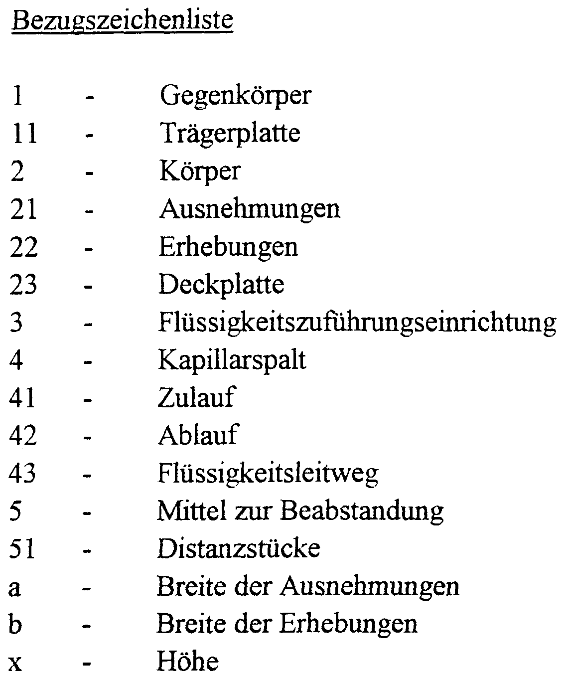
- a body 2 is assumed, the structures forming the routes being attachable to a correspondingly complementary counter body 1. If, within the scope of the invention, the requirement is set that the body 2 is complementarily shaped to the counter body 1, this means that, for example, in the case of a flat support plate 11, the body 2 is also flat before the recesses 21 are introduced; The same applies to, for example, convexly shaped bodies 2 and counter bodies 1 or any other shaped body 2 and counter body 1, such as, for example, pipes.
- the body 2 is provided with capillary gap-forming elevations 22 and recesses 21, with a respective recess 21 remaining between adjacent elevations 22 such that it is capillary-active.
- means 5 for spacing which are shown in FIGS. 1 and 2
- meterable liquid supply devices 3 which are shown by way of example in FIG. 1 a
- the shapes of the body 2 and the correspondingly complementarily shaped counter body 1 can be designed as desired, depending on the routes to be formed. So what is not shown in detail, e.g. When a route is formed along the surface and in the longitudinal direction of a cylinder, the recesses 21 and elevations 22 are, for example, helically formed in the inner walls of a second cylinder comprising the first cylinder.
- a particularly advantageous embodiment of the body 2 which carries the elevations 22 and recesses 21 and which is particularly advantageous for the purposes described below is, as shown in FIGS. 1 and 2, that of a flat cover plate 23, the counter body 1 being in the form of a flat support plate 11 assigned.
- the means 5 for spacing, as shown in FIG. 1, can be formed as a component of the cover plate 23 or, as not shown separately, as a component of the support plate 11, for example as a regularly distributed webs. - 5 -
- the means 5 for spacing the cover plate 23 and the support plate 11 are provided as sealingly insertable, separately designed spacers 1, which, depending on the medium to be conducted through the capillary gap 4, have a predefined height x is given.
- the capillary gap-forming elevations 22 are, for example, as shown in FIGS. 1 and 2, designed as continuous webs, the arrangement and the course of the elevations 22 corresponding to the liquid conduits 43 provided on the support plate 11.
- the cover plate 23 is releasable on the support plate 11, can be placed tension-free in different directions and on the support plate 11 there are provided several, independent capillary gaps 4, each with an inlet and outlet 41; 42 are provided, each capillary gap 4 being provided with a separate liquid supply device 3, which is shown in FIG.
- a plurality of capillary gaps 4 can be provided, which are partially or completely connected to one another and are each provided with an inlet and outlet 41; 42.
- the device according to the invention is particularly suitable, for example, for complex reagent distribution sequences and automations based on planar carriers.
- the dimensions of the capillary gap 4 are, depending on the wettability of the materials used for the body 2 and the counter body 1, as well as that of the state of the liquid media to be conducted, such that only capillary forces for transporting
- Liquids work.
- the dimensions of the recesses are dimensioned such that they are capillary-active themselves.
- the elevations 22, which run parallel to one another have a width b in
- the recesses 21 Magnitude of 1.25 mm, the recesses 21 a width a of at least 1000 microns and a depth of at least 1500 microns.
- the generated capillary gaps 4 have a length of the order of magnitude
- cover plate 23 is in the order of magnitude of 1 ⁇ m to 1000 ⁇ m.
- the material used for the cover plates 23 For example, borofloat glass, which has a high flatness of the surface, is used.
- Another possibility of making the recesses 21 in the cover plate 23 is, for example, the use of diamond tools.
- One possibility of realizing a cover plate 23 with parallel recesses 21 and elevations 22 is, for example, to connect strips of freely selectable material with different dimensions to one another (for example by gluing or fusing) such that an arrangement with recesses 21 and elevations 22, for example is formed analogously to Fig. 1.
- the means 5 for spacing are connected, for example, by gluing or fusing to the cover plate 23 or the support plate 11 or are loosely inserted between the plates 11 and 23. Alternatively, they can be worked out directly from the material of the carrier plate 11 or the cover plate 23 by the structuring technologies used.
- the various liquids are brought to the respective inlet 41 of the elevations 22 by the liquid supply device 3 shown in FIG. 1 a, whereby the respective capillary gaps 4 are filled by means of the acting capillary forces.
- the liquid is supplied either by the liquid supply device 3 shown in the left part of FIG. 1 a via the cover plate 23 or possibly by the liquid S2 guide device 3 shown in the right part of FIG. 1 a, which is in the support plate 11 - 7 -
- the liquid is removed via the outlet 42.
- flat, planar or recessed substrate plates are used as support plates 11, these recesses being able to represent cavities provided with microbeads, for example.
- Microplates or nanotite plates as well as biochips designed in the form of flat, planar substance libraries can advantageously be used as support plates 11.
- a square support plate 11 with n rows of n different liquids can be wetted by a square cover plate 23 provided with n + 1 recesses 21 running parallel to one another.
- a cover plate 23 After removing the cover plate 23, removing the liquids from the support plate 11, rotating the cover plate 23 by 90 ° and reestablishing the spaced connection of the cover plate 23 to the support plate 11, wetting with n columns of n different liquids is possible that an n • n grid of the intersection of the rows and columns arises.
- an orthogonal liquid distribution as is required, for example, in combinatorial chemistry for the synthesis of substance libraries, can be implemented in a particularly simple manner.
Abstract
Description
Claims
Priority Applications (5)
| Application Number | Priority Date | Filing Date | Title |
|---|---|---|---|
| AT99924890T ATE244068T1 (en) | 1998-04-30 | 1999-04-29 | DEVICE FOR TRANSPORTING LIQUIDS ALONG PREFINED ROUTES |
| EP99924890A EP1075326B1 (en) | 1998-04-30 | 1999-04-29 | Device for transporting liquids along predetermined guideways |
| DK99924890T DK1075326T3 (en) | 1998-04-30 | 1999-04-29 | Device for transporting liquids along predetermined conduits |
| DE59906190T DE59906190D1 (en) | 1998-04-30 | 1999-04-29 | DEVICE FOR TRANSPORTING LIQUIDS ALONG SPECIFIC ROUTES |
| AU41393/99A AU4139399A (en) | 1998-04-30 | 1999-04-29 | Device for transporting liquids along predetermined guideways |
Applications Claiming Priority (4)
| Application Number | Priority Date | Filing Date | Title |
|---|---|---|---|
| DE19819302.5 | 1998-04-30 | ||
| DE19819302 | 1998-04-30 | ||
| DE19827754.7 | 1998-06-23 | ||
| DE19827754A DE19827754C1 (en) | 1998-06-23 | 1998-06-23 | Device for the almost simultaneous synthesis of a large number of samples |
Publications (1)
| Publication Number | Publication Date |
|---|---|
| WO1999056878A1 true WO1999056878A1 (en) | 1999-11-11 |
Family
ID=26045865
Family Applications (1)
| Application Number | Title | Priority Date | Filing Date |
|---|---|---|---|
| PCT/EP1999/003104 WO1999056878A1 (en) | 1998-04-30 | 1999-04-29 | Device for transporting liquids along predetermined guideways |
Country Status (6)
| Country | Link |
|---|---|
| EP (1) | EP1075326B1 (en) |
| AT (1) | ATE244068T1 (en) |
| AU (1) | AU4139399A (en) |
| DE (2) | DE29907804U1 (en) |
| DK (1) | DK1075326T3 (en) |
| WO (1) | WO1999056878A1 (en) |
Cited By (9)
| Publication number | Priority date | Publication date | Assignee | Title |
|---|---|---|---|---|
| WO2004050245A1 (en) | 2002-12-05 | 2004-06-17 | International Business Machines Corporation | Confinement of liquids on surfaces |
| WO2004050246A1 (en) | 2002-12-05 | 2004-06-17 | International Business Machines Corporation | Method and device for flowing a liquid on a surface |
| US6795192B2 (en) | 2000-02-22 | 2004-09-21 | Graffinity Pharmaceutical Design Gmbh | SPR sensor and SPR sensor array |
| WO2005043154A2 (en) * | 2003-10-27 | 2005-05-12 | Massachusetts Institute Of Technology | High density reaction chambers and methods of use |
| EP1595598A1 (en) | 2004-05-07 | 2005-11-16 | International Business Machines Corporation | Confinement of fluids on surfaces |
| US7736907B2 (en) | 2004-06-04 | 2010-06-15 | Boehringer Ingelheim Microparts Gmbh | Device for collecting blood and separating blood constituents, method for separating blood constituents and use of said device |
| US9393217B2 (en) | 2007-06-14 | 2016-07-19 | Massachusetts Institute Of Technology | Self assembled films for protein and drug delivery applications |
| US10278927B2 (en) | 2012-04-23 | 2019-05-07 | Massachusetts Institute Of Technology | Stable layer-by-layer coated particles |
| US11419947B2 (en) | 2017-10-30 | 2022-08-23 | Massachusetts Institute Of Technology | Layer-by-layer nanoparticles for cytokine therapy in cancer treatment |
Families Citing this family (6)
| Publication number | Priority date | Publication date | Assignee | Title |
|---|---|---|---|---|
| FR2790684B1 (en) * | 1999-03-09 | 2001-05-11 | Biomerieux Sa | APPARATUS FOR CAPILLARITY TRANSFER OF LIQUIDS |
| DE10142788A1 (en) * | 2001-08-31 | 2003-03-27 | Advalytix Ag | To form a thin liquid film on a carrier, for chemical/biological sample analysis, the flat carrier is shrouded by a spaced cover, for liquid to pass through a passage drilling and spread by capillary action |
| AT6318U1 (en) * | 2002-10-22 | 2003-08-25 | Johann Dipl Ing Roitner | MOLDED BODY AND USE OF A MOLDED BODY |
| US9198875B2 (en) | 2008-08-17 | 2015-12-01 | Massachusetts Institute Of Technology | Controlled delivery of bioactive agents from decomposable films |
| US20150290669A1 (en) * | 2012-10-26 | 2015-10-15 | Massachusetts Institute Of Technology | Devices and Methods for Layer-by-Layer Assembly |
| WO2014134029A1 (en) | 2013-02-26 | 2014-09-04 | Massachusetts Institute Of Technology | Nucleic acid particles, methods and use thereof |
Citations (5)
| Publication number | Priority date | Publication date | Assignee | Title |
|---|---|---|---|---|
| EP0075605A1 (en) * | 1981-09-25 | 1983-04-06 | Winfried Dr. med. Stöcker | Apparatus for photometric analyses |
| WO1991017832A1 (en) * | 1990-05-23 | 1991-11-28 | Rainer Dylla | Drop plate for wet or damp preparations, e.g. blood |
| US5429807A (en) * | 1993-10-28 | 1995-07-04 | Beckman Instruments, Inc. | Method and apparatus for creating biopolymer arrays on a solid support surface |
| WO1997033737A1 (en) * | 1996-03-15 | 1997-09-18 | President And Fellows Of Harvard College | Method of forming articles and patterning surfaces via capillary micromolding |
| WO1999000657A1 (en) * | 1997-06-26 | 1999-01-07 | Perseptive Biosystems, Inc. | High density sample holder for analysis of biological samples |
-
1999
- 1999-04-29 DE DE29907804U patent/DE29907804U1/en not_active Expired - Lifetime
- 1999-04-29 EP EP99924890A patent/EP1075326B1/en not_active Expired - Lifetime
- 1999-04-29 DE DE59906190T patent/DE59906190D1/en not_active Expired - Fee Related
- 1999-04-29 DK DK99924890T patent/DK1075326T3/en active
- 1999-04-29 AU AU41393/99A patent/AU4139399A/en not_active Abandoned
- 1999-04-29 AT AT99924890T patent/ATE244068T1/en not_active IP Right Cessation
- 1999-04-29 WO PCT/EP1999/003104 patent/WO1999056878A1/en active IP Right Grant
Patent Citations (5)
| Publication number | Priority date | Publication date | Assignee | Title |
|---|---|---|---|---|
| EP0075605A1 (en) * | 1981-09-25 | 1983-04-06 | Winfried Dr. med. Stöcker | Apparatus for photometric analyses |
| WO1991017832A1 (en) * | 1990-05-23 | 1991-11-28 | Rainer Dylla | Drop plate for wet or damp preparations, e.g. blood |
| US5429807A (en) * | 1993-10-28 | 1995-07-04 | Beckman Instruments, Inc. | Method and apparatus for creating biopolymer arrays on a solid support surface |
| WO1997033737A1 (en) * | 1996-03-15 | 1997-09-18 | President And Fellows Of Harvard College | Method of forming articles and patterning surfaces via capillary micromolding |
| WO1999000657A1 (en) * | 1997-06-26 | 1999-01-07 | Perseptive Biosystems, Inc. | High density sample holder for analysis of biological samples |
Cited By (12)
| Publication number | Priority date | Publication date | Assignee | Title |
|---|---|---|---|---|
| US6795192B2 (en) | 2000-02-22 | 2004-09-21 | Graffinity Pharmaceutical Design Gmbh | SPR sensor and SPR sensor array |
| WO2004050245A1 (en) | 2002-12-05 | 2004-06-17 | International Business Machines Corporation | Confinement of liquids on surfaces |
| WO2004050246A1 (en) | 2002-12-05 | 2004-06-17 | International Business Machines Corporation | Method and device for flowing a liquid on a surface |
| US7329111B2 (en) | 2002-12-05 | 2008-02-12 | International Business Machines Corporation | Method and device for flowing a liquid on a surface |
| US7740472B2 (en) | 2002-12-05 | 2010-06-22 | International Business Machines Corporation | Method and device for flowing a liquid on a surface |
| WO2005043154A2 (en) * | 2003-10-27 | 2005-05-12 | Massachusetts Institute Of Technology | High density reaction chambers and methods of use |
| WO2005043154A3 (en) * | 2003-10-27 | 2005-09-15 | Massachusetts Inst Technology | High density reaction chambers and methods of use |
| EP1595598A1 (en) | 2004-05-07 | 2005-11-16 | International Business Machines Corporation | Confinement of fluids on surfaces |
| US7736907B2 (en) | 2004-06-04 | 2010-06-15 | Boehringer Ingelheim Microparts Gmbh | Device for collecting blood and separating blood constituents, method for separating blood constituents and use of said device |
| US9393217B2 (en) | 2007-06-14 | 2016-07-19 | Massachusetts Institute Of Technology | Self assembled films for protein and drug delivery applications |
| US10278927B2 (en) | 2012-04-23 | 2019-05-07 | Massachusetts Institute Of Technology | Stable layer-by-layer coated particles |
| US11419947B2 (en) | 2017-10-30 | 2022-08-23 | Massachusetts Institute Of Technology | Layer-by-layer nanoparticles for cytokine therapy in cancer treatment |
Also Published As
| Publication number | Publication date |
|---|---|
| AU4139399A (en) | 1999-11-23 |
| ATE244068T1 (en) | 2003-07-15 |
| EP1075326B1 (en) | 2003-07-02 |
| EP1075326A1 (en) | 2001-02-14 |
| DE29907804U1 (en) | 1999-10-07 |
| DK1075326T3 (en) | 2003-10-27 |
| DE59906190D1 (en) | 2003-08-07 |
Similar Documents
| Publication | Publication Date | Title |
|---|---|---|
| EP1075326B1 (en) | Device for transporting liquids along predetermined guideways | |
| DE10227593B4 (en) | Flow circuit microdevices | |
| DE60307552T2 (en) | Device for discharging small volumes of liquid along a microchain line | |
| DE60208235T2 (en) | MICROFLUIDIC DEVICES WITH DISTRIBUTION ENCLOSURES | |
| DE60300980T2 (en) | HOLE MICRO MIXER | |
| EP0758917B1 (en) | Static micromixer | |
| DE10228767B4 (en) | Micro device and method for component separation in a fluid | |
| DE69719743T2 (en) | METHOD AND DEVICE FOR DIFFUSION EXCHANGE BETWEEN IMMISIBLE LIQUIDS | |
| DE60214167T2 (en) | Multilayered microfluidic splitter | |
| EP1521631B1 (en) | Method for transferring heterogeneous liquids in microchannels without the occurrence of mixing | |
| WO2004103565A2 (en) | Device and method for structuring liquids and for dosing reaction liquids into liquid compartments immersed in a separation medium | |
| DE60310997T2 (en) | MICROFLUIDES SYSTEM WITH STABILIZED LIQUID-FLUID BONDING AREA | |
| DE10309583A1 (en) | Microplate with an integrated microfluidic system for parallel processing of tiny fluid volumes | |
| EP1979738B1 (en) | Arrangement for generating liquid flows and/or particle flows, method for producing and operating said arrangement and use of the latter | |
| DE102011078770B4 (en) | Microfluidic device, microfluidic system and method of transporting fluids | |
| DE112005000445T5 (en) | Microchemical system | |
| EP1714698B1 (en) | Device and method for handling liquids | |
| EP2248588B1 (en) | Mountable and dismountable microfluid system and method for flooding the system | |
| DE112017000632T5 (en) | Vertical microfluidic probe head with openings for large scale surface finishing | |
| DE112017004280B4 (en) | Microfluidic chip with bead integration system | |
| DE19910392B4 (en) | Micro column reactor | |
| DE60213645T2 (en) | METHOD FOR FILLING HOLES IN SUBSTRATES | |
| DE19728520A1 (en) | Switchable dynamic micromixer with minimal dead volume | |
| DE102010041833B4 (en) | Microfluidic chip with multiple cylinder-piston arrangements | |
| EP1343587A2 (en) | Device for receiving and discharging liquid substances |
Legal Events
| Date | Code | Title | Description |
|---|---|---|---|
| AK | Designated states |
Kind code of ref document: A1 Designated state(s): AE AL AM AT AU AZ BA BB BG BR BY CA CH CN CU CZ DK EE ES FI GB GD GE GH GM HR HU ID IL IN IS JP KE KG KP KR KZ LC LK LR LS LT LU LV MD MG MK MN MW MX NO NZ PL PT RO RU SD SE SG SI SK SL TJ TM TR TT UA UG US UZ VN YU ZA ZW |
|
| AL | Designated countries for regional patents |
Kind code of ref document: A1 Designated state(s): GH GM KE LS MW SD SL SZ UG ZW AM AZ BY KG KZ MD RU TJ TM AT BE CH CY DE DK ES FI FR GB GR IE IT LU MC NL PT SE BF BJ CF CG CI CM GA GN GW ML MR NE SN TD TG |
|
| 121 | Ep: the epo has been informed by wipo that ep was designated in this application | ||
| DFPE | Request for preliminary examination filed prior to expiration of 19th month from priority date (pct application filed before 20040101) | ||
| WWE | Wipo information: entry into national phase |
Ref document number: 1999924890 Country of ref document: EP |
|
| WWE | Wipo information: entry into national phase |
Ref document number: 09674370 Country of ref document: US |
|
| NENP | Non-entry into the national phase |
Ref country code: KR |
|
| WWP | Wipo information: published in national office |
Ref document number: 1999924890 Country of ref document: EP |
|
| NENP | Non-entry into the national phase |
Ref country code: CA |
|
| WWG | Wipo information: grant in national office |
Ref document number: 1999924890 Country of ref document: EP |