WO2001043387A2 - Voip switch with a distributed mtp level 2 architecture - Google Patents
Voip switch with a distributed mtp level 2 architecture Download PDFInfo
- Publication number
- WO2001043387A2 WO2001043387A2 PCT/CA2000/001111 CA0001111W WO0143387A2 WO 2001043387 A2 WO2001043387 A2 WO 2001043387A2 CA 0001111 W CA0001111 W CA 0001111W WO 0143387 A2 WO0143387 A2 WO 0143387A2
- Authority
- WO
- WIPO (PCT)
- Prior art keywords
- signalling
- units
- gateway
- packets
- stream
- Prior art date
Links
Classifications
-
- H—ELECTRICITY
- H04—ELECTRIC COMMUNICATION TECHNIQUE
- H04M—TELEPHONIC COMMUNICATION
- H04M7/00—Arrangements for interconnection between switching centres
- H04M7/12—Arrangements for interconnection between switching centres for working between exchanges having different types of switching equipment, e.g. power-driven and step by step or decimal and non-decimal
- H04M7/1205—Arrangements for interconnection between switching centres for working between exchanges having different types of switching equipment, e.g. power-driven and step by step or decimal and non-decimal where the types of switching equipement comprises PSTN/ISDN equipment and switching equipment of networks other than PSTN/ISDN, e.g. Internet Protocol networks
- H04M7/125—Details of gateway equipment
-
- H—ELECTRICITY
- H04—ELECTRIC COMMUNICATION TECHNIQUE
- H04L—TRANSMISSION OF DIGITAL INFORMATION, e.g. TELEGRAPHIC COMMUNICATION
- H04L12/00—Data switching networks
- H04L12/66—Arrangements for connecting between networks having differing types of switching systems, e.g. gateways
-
- H—ELECTRICITY
- H04—ELECTRIC COMMUNICATION TECHNIQUE
- H04Q—SELECTING
- H04Q3/00—Selecting arrangements
- H04Q3/0016—Arrangements providing connection between exchanges
- H04Q3/0025—Provisions for signalling
-
- H—ELECTRICITY
- H04—ELECTRIC COMMUNICATION TECHNIQUE
- H04M—TELEPHONIC COMMUNICATION
- H04M7/00—Arrangements for interconnection between switching centres
- H04M7/06—Arrangements for interconnection between switching centres using auxiliary connections for control or supervision, e.g. where the auxiliary connection is a signalling system number 7 link
Definitions
- the present invention relates generally to SS7 signalling and more particularly to a method and apparatus for distributing the Message Transfer Part (MTP) Level 2 functionality between a Signalling Gateway and a Media Gateway.
- MTP Message Transfer Part
- FISU Fill-in Signal Unit a signalling unit complying with MTPL2
- MSU Message Signal Unit a signalling unit complying with MTPL2
- OM-MG Operational Measurement located at the Media Gateway OM-SG Operational Measurement located at the Signalling Gateway
- SIB Status Indicator Busy (used by LSSUs)
- SIOS Status Indicator Out of Service (used by LSSUs)
- TXC Transmit Control (TCX-SG Transmit Control located at Signalling Gateway; TCX-MG Transmit Control located at Media Gateway) UL-MTPL2 Upper Level - Message Transfer Part Level 2, a portion of the
- a Public Switched Telephone Network is, conventionally, comprised of two networks - a voice/data network and a signalling network.
- the signalling network carries information for call set-up and tear down.
- the Common Channel Signalling System #7 (CC- SS7) protocol is used for call set-up and tear down.
- the PSTN provides users with a dedicated, end-to-end circuit connection for the duration of each call.
- the circuits are reserved between the originating call, tandem switches (if any), and the terminating switch based on the called party number.
- a typical Intelligent Network such as the North American SS7 network
- SSP Service Switching Point
- SS7 messages are exchanged between the two SSPs using the SS7 network.
- VoIP Voice over IP
- VoIP switches need to interface to the existing PSTN networks (voice and signalling) to allow PSTN phones to use the VoIP network.
- a VoIP switch would interface to the PSTN Voice network using a Media Gateway.
- the Media Gateway provides the translation between Time Division Multiplexed (TDM) data and IP packet data.
- TDM Time Division Multiplexed
- This VoIP switch would interface to the PSTN Signalling network using a Signalling Gateway.
- the Signalling Gateway provides the translation between SS7 and IP.
- the Signalling Gateway In a quasi-associated SS7 signalling network, the Signalling Gateway would connect to the local STP mated pair using A-links. In a fully associated SS7 Signalling network, the signalling gateway would connect directly with the SSPs using F-links. In the fully associated network signalling case, the SS7 signalling link is usually carried over the same facilities as the voice trunks. Since these voice trunks terminate on the media gateway, external circuitry (e.g. channel banks) are required to extract the signalling channel and route it to the signalling gateway. Moreover, since the media and signalling gateways are typically geographically quite dispersed, the equipment associated with transmitted the extracted signalling channel to the signalling gateway is expensive.
- This invention distributes the MTP Level 2 functionality between the Signaling Gateway and the Media Gateway. It allows F-links in a fully associated SS7 signaling network to be terminated on the Meoia Gateway and the SS7 messages to be passed between the Media Gateway and the Signaling Gateway over IP.
- a method providing distributed Message Transfer Part (MTP) functionality over an Internet Protocol (IP) network comprising: at a first media gateway: receiving conventional MTP signalling units from a first network element; removing repeated MTP signalling units from said MTP signalling units received; either before or after said removing, encapsulating received MTP signalling units into data packets to form a reduced signalling unit packet stream; transmitting said reduced signalling unit packet stream to a signalling gateway; receiving at said signalling gateway said reduced packet stream at said signalling gateway; transmitting packets encapsulating MTP signalling units to one of said first media gateway and a second media gateway, said transmitted packets being responsive to said received reduced signalling unit packet stream; receiving at said one of said first media gateway and said second media gateway said packets transmitted by said signalling gateway; and at said one of said first media gateway and said second media gateway, re-creating conventional MTP signalling units based on said routed packets and transmitting said re-created conventional MTP
- IP Internet Protocol
- VoIP Voice over IP
- MTPL2 distributed Message Transfer Part Level 2
- VoIP switch comprising: a plurality of media gateways, each of said media gateways in communication with a conventional SS7 physical link, said conventional SS7 physical link in communication with a network element; a signalling gateway; an IP network providing IP communication between said plurality of media gateways and said signalling gateway.
- MTPL2 distributed Message Transfer Part Level 2
- a media gateway comprising: a receiver for receiving a contiguous stream of signalling units from a network element; a filter for discarding repeated signalling units in said received stream; an encapsulated data transmitter adapted to transmit data encapsulating said signalling units over a packet switched network; an encapsulated data receiver adapted to receive encapsulated data encapsulating signalling units from a packet switched network; a processor adapted to: encapsulate signalling units forming said stream of signalling units either before or after said discarding by said filter; and de-encapsulate signalling units received by said encapsulated data receiver and generate signalling units to re-create a contiguous stream of signalling units; and a signalling unit transmitter transmitting a re-created contiguous stream of signalling units to a network element.
- a signalling gateway comprising: an encapsulated data receiver for receiving encapsulated signalling units from a packet switched network; an encapsulated data transmitter adapted to transmit data encapsulating signalling units over a packet switched network; a processor adapted to: de-encapsulate said received encapsulated signalling units and generate signalling units compliant with the Message Transfer Part Level 2 protocol; transmit said generated signalling units to a Message Transfer Part Level 3 processor; receive conventional signalling units from said Message Transfer Part Level 3 processor; and encapsulate said received conventional signalling units for transmission by said encapsulated data transmitter.
- Figure 1 illustrates a conventional quasi-associated SS7 network in communication with a conventional a VoIP switch
- Figure 2 illustrates a fully associated SS7 network in communication with a conventional VoIP switch
- Figure 3 illustrates a fully associated network in communication with a VoIP switch incorporating an embodiment of the invention
- Figure 4 detailed schematic of an enlarged portion of Figure 3
- Figure 5 is a schematic illustrating the distribution of a conventional MTP stack between portions of Figure 4;
- Figure 6A is a schematic of a protocol stack embodying one aspect of the invention.
- Figure 6B is a detailed schematic of a first portion of Figure 6A;
- Figure 6C is a detailed schematic of a second portion of Figure 6 A;
- Figure 7 is a detailed schematic of a portion of Figure 4.
- Figure 8 is a first signal flow diagram of the operation of the SS7 network portion of Figure 4.
- Figure 9 is a second signal flow diagram of the operation of the SS7 network portion of Figure 4.
- a conventional quasi-associated signalling network 100 having dedicated facilities 124 (e.g. Tl or El) carrying signalling traffic between SG 102 of VoIP 120 and SS7 Signalling network 108 is illustrated.
- dedicated facilities 124 e.g. Tl or El
- Separate facilities 122 are used to connect MG 106 with the PSTN voice network 110.
- facilities 206 carry both the signalling channel and the voice trunks. Since the same facilities 206 carry both voice trunks and signalling channels an external MUX 204 is required to extract the signalling channel from the facility 206 and route it to the SG 102 of VoIP switch 120 over dedicated signalling facilities 210.
- the voice trunks on facilities 206 are transmitted by MUX 204 to MG 106 of VoIP 120 over dedicated voice facilities 208.
- Figure 3 shows a fully associated signalling network comprising SSPs 12 and voice/signalling links 14 in communication with VoIP switch 20 embodying one aspect of the invention.
- SSPs 12 and voice/signalling links 14 in communication with VoIP switch 20 embodying one aspect of the invention.
- both the voice trunks and signalling channels carried on links 14A, 14B are terminated and MG 22.
- the signalling channel information is then routed via IP from the MGs 22 to the SG 24.
- Advantageously external MUXes are no longer required to extract the signalling channel.
- Links 14B may be any conventional physical links such as, for example, an E-l, DS-1, DS-3, or other similar links. Although a single link 14 is shown terminating at each Media Gateway (MG) 22, the present invention, an embodiment of which is illustrated in Figure 3, would likely have a plurality of links terminating at each MG 22 when actually deployed.
- MG Media Gateway
- calling party 11 In communication with SSP 12A is calling party telecommunications device 11 (hereinafter calling party 11).
- called party telecommunications device 13 (hereinafter called party 13) is in communication with SSP 12B.
- Calling party 11 and called party 13 may be, for example, a telephone handset, a computer, a wireless voice or data terminal, or the like.
- VoIP switch 20 comprises media gateways (MGs) 22A, 22B (collectively MGs 22) in communication with SSPs 12A, 12B via links 14A, 14B, respectively, and each other. Also in communication with MGs 22 is Signalling Gateway (SG) 24 and Media Gateway Controller (MGC) 26 via communications links 28. Communications links 28 represent logical, transient routing paths over an IP network such, as for example, the Internet. Moreover, it should be noted that VoIP switch 20, while represented as a single entity physically located at a single physical site, it may not always be so configured. In fact, MGs 22, SG 24 and MGC 26 are likely to be physically separate but inter-operate to provide similar MTP functionality over an IP network that is conventionally provided by an Intelligent Network (IN) such as, for example, an SS7 network.
- I Intelligent Network
- VoIP switch 20 is illustrated with two MGs 22, a single SG 24 and a single MGC 26, it may be desirable to implement the present invention with a different number of the elements forming VoIP switch 20.
- a plurality of MGs 22, a plurality of SGs 24 and a plurality of MGCs 26 may be in communication with each other over network 30, all forming VoIP switch 20.
- SSP 12 A in operation of voice and data network 10, SSP 12 A, through a conventional request made by a calling party 11, requires communication with SSP
- Voice and SS7 signals are transmitted by SSP 12A to MG 22 A.
- the signalling data is extracted and by MG 22 A and transmitted to SG 24 in IP packets over the network formed by connections 28.
- the IP packets received by SG 24 are further processed and transmitted to MGC 26 as IP packets over communications links 28.
- MGC 26 determines the MG 22 associated with the called party 13, which in this example is MG 22B.
- MGC 26 communicates with MG 22B and SSP 12B via SG 24 and a voice connection from calling party 11 to called party 13 is created via SSP 12A, link 14A, MGs 22A and 22B, link 14 and SSP 12B.
- VoIP switch 20 a more detailed and functional view of VoIP switch 20 is illustrated. Since there are no fixed connections between the elements of VoIP switch 20 (i.e., network 30 provides connectionless communications between a pair of these elements), each element (i.e. each MG 22, SG 24 and MGC 26) can communicate directly with every other element of VoIP switch 20.
- MGs 22 and SG 24 interact to provide MTPL2 functionality that is distributed between these two components of VoIP switch 20. That is, when viewed from the perspective of a network element, such as, for example, an SSP 12, signalling units (SUs) complying with the conventional MTPL2 standard are transmitted to and received from VoIP switch 20 at the MGs 22.
- a network element such as, for example, an SSP 12
- signalling units (SUs) complying with the conventional MTPL2 standard are transmitted to and received from VoIP switch 20 at the MGs 22.
- conventional MTPL3 comprises MTPL3 network management functions 40 and MTPL3 message handling functions 42.
- Conventional MTPL2 comprises
- MTPL2 LSSU and MSU handling functions 44 MTPL2 LSSU and MSU handling functions 44, MTPL2 FISU handling functions 46 and MTPL2 framing 48.
- the distributed MTPL2 protocol described herein maintains MTPL3 functions which are performed by MTPL3 functional block 36.
- the MTPL2 functions are distributed between LL-MTPL2 functional block 32 (which performs MTPL2 framing and MTPL2 FISU handling functions 48 and 46, respectively) and UL- MTPL2 block 34 which performs MTPL2 LSSU and MSU handling functions 44.
- both MGs 22 and SG 24 provide a portion of the MTPL2 functionality.
- MGs 22 incorporate Lower Level MTPL2 (LL-MTPL2) functional block 32 while SG 24 includes Upper Level MTPL2 (UL-MTPL2) functional block 34.
- MGs 22 and SG 24 communicate via communications links 28 over IP network 30.
- Network 30 is, for example, the internet, an intranet, or other IP network.
- SG 24 also includes MTPL3 functional block 36 which is in communication with UL-MTPL2 block 34 and is described in greater detail below.
- VoIP switch 20 will receive at MG 22A, for example, conventional MTPL2 compliant SUs over link 14A.
- a data link such as link 14A transmits a continuous stream of MTPL2 compliant data in both directions.
- This continuous stream of data will include Message Signalling Units (MSUs), Link Status Signalling Units (LSSUs) and Fill-in Signalling Units (FISUs).
- MSUs Message Signalling Units
- LSSUs Link Status Signalling Units
- FISUs Fill-in Signalling Units
- the continuous data stream will include repetitive and identical LSSUs and FISUs.
- VoIP switch 20 receives at a VoIP switch and transmits from the VoIP switch c onventional MTPL2 compliant SUs in conventional numbers (i.e., a continuous data stream corresponding to MSUs, LSSUs and FISUs are transmitted and received on links 14).
- VoIP switch 20 MGs 22 filters extraneous and duplicate FISUs and LSSUs. Accordingly, the number of packets that must be transmitted over IP network is significantly reduced. From the view of a conventional MTPL2 compliant network element such as SSPs 12, VoIP switch 20 appears as simply another MTPL2 network element.
- FIGS. 6A, 6B and 6C illustrate the data structures - which incorporate conventional
- IP Internet Protocol
- the distributed MTPL2 protocol is used for communication between the SG 24 and MGs 22 ( Figures 4 and 7) and, specifically, between the UL-MTPL2 34 and LL-MTPL2 32 components. Referencing Figure 6A,
- DPS 300 is comprised of an IP layer 314, a User Datagram
- UDP User Datagram Protocol
- DL2P Distributed L2 Protocol
- Header layer 308 MG Control
- DPS 300 Data 301 which represents the SS7 signal payload (e.g., ISUP).
- IP layer 314 and UDP layer 312 are illustrated in greater detail in Figure 6B and described and discussed below.
- Information header layer 306 contains control information used to control the resources of the
- MTPL2 304 conforms to the SS7 standards (i.e. ANSI Tl.111.3 or ITU-T Q.703, the contents of which are hereby incorporated herein). That is, the MTPL2 header 304 contains the data necessary to form the three standard signalling units under the conventional MTPL2 protocol, namely the Fill-in Signal Units (FISUs), Link Status Signal Units (LSSUs) and the Message Signal Units (MSUs).
- FISUs Fill-in Signal Units
- LSSUs Link Status Signal Units
- MSUs Message Signal Units
- FISUs carry basic level two information (e.g., acknowledgement of signalling unit receipt by a remote network element). Because a CRC checksum is calculated for each FISU, signalling link quality between the two network elements is checked continuously by both network elements at either end of the link.
- LSSUs carry one or two octets (8-bit bytes) of link status information between network elements at either end of a signalling link. The link status is used to control link alignment and to indicate the status of a network element (e.g., local processor outage) to another network element.
- MSUs carry all call control, database query, database response, network management and network maintenance data.
- MTPL2 header 304 is populated with conventional data known to those skilled in the art. This data is used, in part, used in sequencing of received SUs. Similarly, MTPL3 header 302 contains the header information for MTPL3 which is conventionally stored in each MSUs' Signalling Information Field (SIF).
- SI Signalling Information Field
- IP header 312 and UDP header 314 are illustrated in greater detail. Other fields found in a conventional IP header are not illustrated but may also be used.
- the Source IP Address 330 and Destination IP Address 332 are standard 32-bit addresses.
- UDP header 312 which conforms to RFC 768, the contents of which are hereby incorporated herein, comprises an eight bit Zero field 334; an eight bit Protocol field 336; an eight bit UDP length field 338, identifying the length of the UDP datagram; a sixteen bit Source Port field 340, identifying the port in the source host (associated with source IP address 33) to which a reply may be sent; a sixteen bit Destination Port field 342, identifying the point of termination in destination host; a sixteen bit Length field, indicating the total length of the IP packet, and a sixteen bit Checksum field 346, for performing an enor check on the IP header 312 and UDP header 312, and the remaining portions of DPS 300 and payload data 301. Accordingly, a checksum field in the remaining portions of DPS 300 may be unnecessary in some applications since Checksum 346 is calculated for the entire packet.
- a mapping operation will be performed based on the source IP address 330 and the source port 340 stored within the IP header 314 and UDP header 312, respectively. Messages with an unknown source IP address 330 or unknown source port 340 will be discarded by SG 24.
- SG 24 provides service for each signalling link terminating on a serviced MG 22.
- a mapping or routing table is generated and stored at SG 24 which identifies the: IP address for each MG 22 serviced by the SG 24; and the UDP source ports associated with each link 14 terminating on a serviced MG 22.
- a similar mapping or routing table will be generated and stored at each MG 22.
- the MG routing table will include the UDP port associated with each link 14 terminating at MG 22, the IP address of any SG 24 which services the MG 22 and the UDP port associated with the IP address of the SG 24 associated with the MG 22.
- the thirty-two bit DL2P Header 308 four eight bit fields, namely the version field 356, the filler field 354, the type field 352 and the sub-type field 350.
- the Version field 356 identifies the release version of the Distributed MTPL2 protocol that is being used. If a message identifies a version of the distributed MTPL2 architecture is unknown to the receiving node (such as the MGs 22 or the SG 24), the receiving node will respond with a signal indicating a supporting version of the distributed MTPL2 architecture. This signal will inform the sender of the message using an unknown version of the Distributed MTPL2 protocol that a message with an unsupported version has been received. Moreover, the signal message indicates to the receiver of this message (i.e., the sender of the message of unknown protocol version) the version of the protocol supported by the sender of the signal message. Filler field 354 is set to zero ai d is used to ensure that DL2P Header 308 is long word aligned (i.e., DL2P header 308 is a multiple of thirty-two bits).
- VoIP switch 20 ( Figure 3) will support the values in Type field 352 of DL2P Header 308 identified in Table 1.
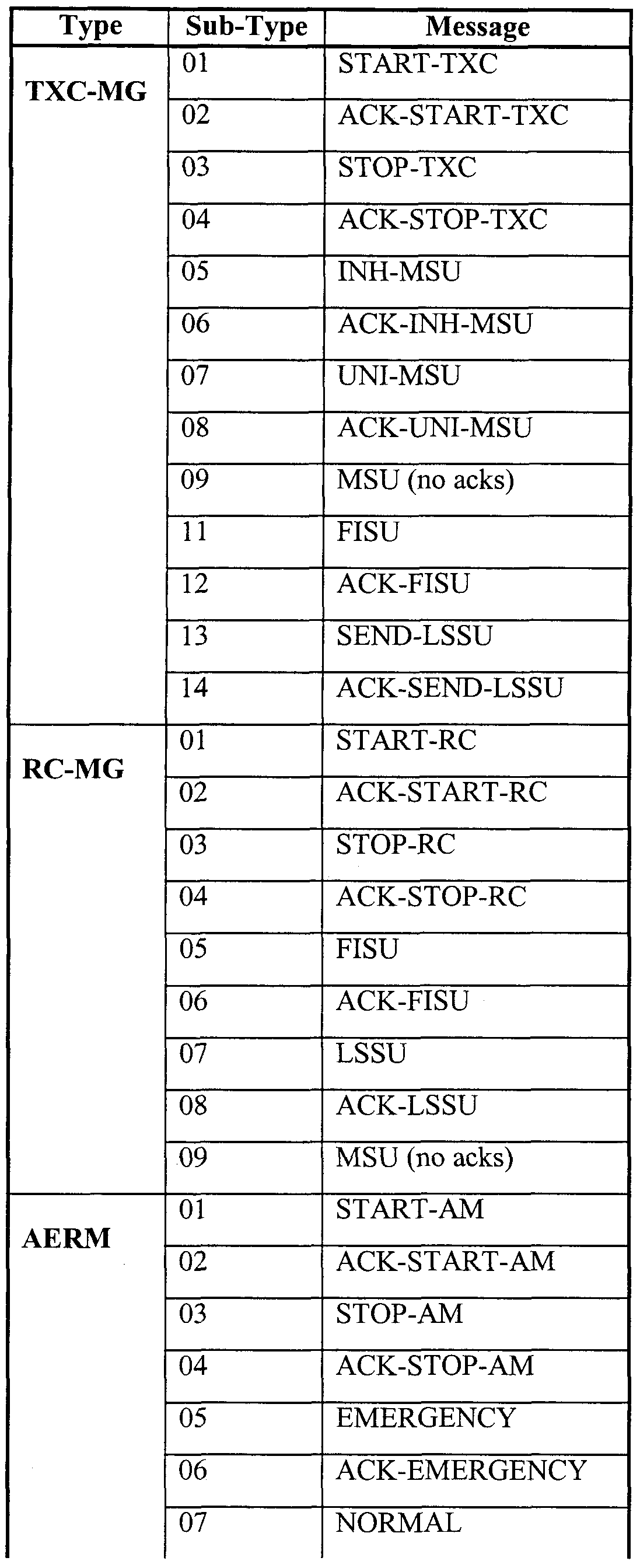
- MGs 22 and SG 24 will populate sub-type field 350 of DL2P Header 308 with one of many possible values corresponding to a value in Type field 352.
- Table 2 lists the values that can be entered into Sub-type field 350 by the components of VoIP switch 20 and the message represented by those values.
- Table 2 - Sub-Type Field 350 Entries of VoIP Switch 20 Additional information may be required for some DL2P messages. This information would be passed in the MG Control information field 306. Table 3 identifies the extra information that may be used in the DL2P messages.
- Figure 7 shows the split in MTP Level 2 functionality between the SG 24 and the MG 22.
- the UL-MTPL2 block 34 (Upper Layer of MTP Level 2) resides on SG 24, while the LL- MTPL2 block 32 (Lower Layer of MTP Level 2) resides on MG 22. Examples of the signal flows between LL-MTPL2 and UL-MTPL2 functional blocks 32 and 34 are illustrated in Figures 8 and 9. Signals transmitted between LL-MTPL2 functional block 32, which forms part of MG 22, and UL-MTPL2 functional block 34, forming part of SG 24, are transmitted across network 30, which is illustrated as a dotted line boundary between UL-MTPL2 block 34 and LL-MTPL2 block 32 in Figures 7, 8 and 9.
- MG 22 comprises LL-MTPL2 functional block 32 which operates to perform: the reception of conventional data signals on data links 14; the transmission of data complying with the distributed MTPL2 architecture described herein to UL-MTPL2 functional block 34 of SG 24; the reception of data from SG 24; and the transmission of conventional data on links 14.
- LL-MTPL2 functional block 32 comprises: Delimitation, Alignment, Enor Detection Receive (DAEDR) block 402; Receive Control located at Media Gateway (RC- MG) block 406; Transmit Control located at Media Gateway (TXC-MG) block 408; and Delimitation, Alignment, Error Detection Transmit (DAEDT) block 410.
- bit Error Rate Testing (BERT) block 404
- Signalling Unit Enor Rate Monitor (SUERM) block 412
- Alignment Error Rate Monitor (AERM) block 414
- Operational Measurement at the MG (OM-MG) block 416.
- SG 24 comprises UL-MTPL2 functional block 34 which operates to perform: the reception of MTPL3 data from MTPL3 36; the transmission of data complying to with the distributed MTPL2 architecture to LL-MTPL2 functional block 32 of MG 22; the reception of data from MG 22; and the transmission of MTPL3 data to MTPL3 36.
- UL-MTPL2 functional block 34 comprises: Reception Control at the SG (RC-SG) block 420 and Transmission Control at the SG (TCX-SG) block 426.
- TCX-SG block 426 comprises Transmission Buffer (TB) block 434 and Re-Transmission Buffer (RTB) block 436.
- TCX- SG 426 transmits sequenced data packets and stores a copy in RTB 436.
- UL- MTPL2 functional block 34 further comprises Congestion Control (CC) block 422; Operational Measurements at the SG (OM-SG) block 424; Link State Control (LSC) block 428; and Initial Alignment Control (IAC) block 430.
- CC Congestion Control
- OM-SG Operational Measurements at the SG
- LSC Link State Control
- IAC Initial Alignment Control
- DAEDR block 402 receives conventional MTPL2 data from link 14.
- the data is processed (i.e., delimited and enor detection is performed) and transferred to RC-MG block 406 which filters the received data to remove repeated LSSUs and FISUs.
- the filtered data is then transmitted to RC-SG 420 of SG 24.
- RC-SG 420 performs management of the sequence numbers of the received data based on the information stored in MTPL2 header 304.
- the data received by SG 24 is processed and MSUs are transmitted to MTPL3 36 while FISUs and LSSUs are processed by the RC-SG block 420.
- Transmitted MTPL3 data is transferred to TCX-SG block 426 where, as described above, sequence number management is performed.
- the TCX-SG block 426 transmits, over IP network 30 ( Figure 7), the MTPL3 data to the TXC-MG block 408 where repetitive tasks (e.g., generation of repetitive LSSUs and FISUs) are performed.
- Data received and generated by TXC-MG block 408 is transmitted to DAEDT block, processed (i.e., delimited, aligned - into conventional SS7 signals) and then transmitted by MG 22 over link 14 to an SS7 network element such as, for example, an SSP 12.
- SUERM block 412, AERM block 414 and OM-MG block 416 also form part of MG 22.
- the SUERM and AERM blocks, 412 and 414, respectively, communicate with DAEDR block 402 and monitor the number of signalling unit (SU) errors detected by the DAEDR block 402.
- the OM-MG block 416 records operational measurements (OMs) of LL-MTPL2 functional block 32. These OMs are transmitted, when requested, to SG 24. The OMs are cleared from OM-MG 416 when uploaded to SG 24.
- CC block 422 Also forming part of SG 24 are CC block 422, OM-SG block 424, LSC block 428 and
- IAC block 430 operates to control congestion on SG 24 by monitoring the
- OM-SG block 424 records a number of operational measurements of
- the OM-SG block 424 is also in communication with OM- MG block 416 of MG 22, and may send a request to the OM-MG block 416 to transmit its OMs records to the OM-SG block 424. OM-SG block 424 will then store the OM data uploading to OM-SG 424 in response to this request.
- LSC block 428 provides general management of the MTPL2 link 14.
- IAC block 430 which is in communication with AERM block 414 of MG 22, performs initial alignment of links 14, monitors LSSUs received from link 14 and communicates with AERM block 414 of MG 22 to determine the quality of the link 14 during the proving period.
- DAEDR functional block 402 receives a data stream from voice/signaling link 14 and extracts the signaling data therefrom. DAEDR 402 then, as is conventional, performs delimitation, alignment, error detection on the received signalling data forming conventional MTPL2 signalling units.
- the RC-MG block 406 in co-operation with RC-SG block 420 of SG 24, provides signal reception control.
- RC-MG block 404 is tasked with performing repetitive functions in order to reduce IP traffic between MG 22 and SG 24.
- FISUs are conventionally transmitted, in both directions, continuously over a signaling link, such as links 14, unless LSSUs or MSUs art present. This process would, if performed over an IP network, such as network 30 ( Figure 4), waste network resources.
- RC-MG 406 performs operations to reduce IP traffic between MG 22 and SG 24 while simultaneously providing the benefits of the MTP protocol.
- RC-MG block 406 transitions from IDLE to IN-SERVICE upon receipt of a START- RC message from RC-SG block 420 of SG 24.
- START-RC message Type: 01, Sub-Type: 02 are entered in fields 352 and 350, respectively, of DL2P Header 308 - Figure 6C
- RC-MG 406 will transmit an acknowledgement signal (ACK-START-RC) to RC-SG block 406 of SG 24.
- ACK-START-RC acknowledgement signal
- messages transmitted between LL- MTPL2 functional block 32 of MG 22 and UL-MTPL2 functional block 34 of SG 24 are transmitted over network 30.
- RC-MG block 406 transitions from IN-SERVICE to IDLE upon receipt of a STOP-RC message from RC-SG block 420.
- a STOP-RC message received by RC-MG block 406 is acknowledged by the transmission of an ACK-STOP-RC message from RC-MG 406 to RC-SG 420.
- RC-MG 406 While in IN-SERVICE mode RC-MG 406 will, upon receipt of an FISU, LSSU or MSU from DAEDR block 402, transmit a corresponding FISU, LSSU or MSU message complying with the distributed standard described herein (i.e. sub-type field 350 - Figure 6C - having the value of 05, 07 or 09), to RC-SG block 420. RC-MG 406 will receive, in response to an FISU or LSSU message, an ACK-FISU or ACK-LSSU, respectively, from RC-SG block 420. To reduce IP traffic between RC-MG 406 and RC-SG 420, RC-MG 406 will filter out duplicate FISUs and LSSUs received from DAEDR 402.
- This filtering involves transmitting only one FISU (or LSSU) in a continuous stream of FISUs (or LSSUs) in a pre-determined period (i.e. only one FISU - or LSSU - every T san j ty period). Further, RC-MG 406 will not receive an acknowledgement of MSUs transmitted to RC-SG 420 thereby further reducing traffic on IP network 30.
- a summary of the substantive message i.e., non-ACK style messages
- Table 4 - RC-MG Block 406 Message Table RC-MG block 406 transmits to and receives IP messages from RC-SG block 420 of SG 24. These IP messages transmitted between RC-SG 420 and RC-MG 406 are transmitted over network 30. RC-SG 420 sends IP packets to RC-MG 406 that initiate and cease operation of RC-MG 402. Accordingly, RC-MG 406 operates under partial control of RC- SG 420. In response to the control messages (sent by RC-SG 420) received by RC-MG 406, RC-MG 406 transmits IP packets incorporating an acknowledgement portion in the sub-type field 350 ( Figure 6C).
- IP packets sent by RC-MG 420 to RC-SG 420 include FISU, LSSU and MSU messages.
- FISUs and LSSUs (only) transmitted by RC- MG 402 In response to the FISUs and LSSUs (only) transmitted by RC- MG 402, RC-SG 420 sends acknowledgement messages upon receipt of these messages.
- LSC block 428 provides some of the control of SG 24 and MG 22.
- LSC 428 interfaces with MTPL3 block 36 and controls the distributed MTPL2 functions of MG 22 and SG 24.
- LSC 428 issues messages to RC-SG 420 to start and stop the receipt and transmission of IP packets between SG 24 and MG 22.
- RC-SG 420 transmits the start and stop messages to RC-MG 406 described above.
- LSC 428 has the following states: POWER OFF, OUT OF SERVICE, INITIAL ALIGNMENT, ALIGNED/READY, ALIGNED/NOT READY, IN SERVICE and PROCESSOR OUTAGE. These state conditions are transmitted to MTPL3 block 36 ( Figure 4) in accordance with the MTPL3 protocol.
- IAC block 430 also provides some of the operational control of SG 24.
- IAC 420 performs initial alignment between SG 24 and a link 14, when an alignment request is received from a link 14.
- IAC 430 interacts with
- IAC 430 has four states: IDLE, NOT ALIGNED, ALIGNED and PROVING. IAC 430 will transmit IP packets (via the transmission facilities provided by TXC-SG 426) to AERM block 414 to start and stop error monitoring and to indicate an emergency status. IAC 430 will receive from AERM 414 messages indicating that the signaling units received during the monitoring phase are acceptable (CORRECT SU) or that the link should be aborted (ABORT). Table 6 includes of a summary of the messages transmitted between IAC 430 and AERM 414.
- TXC-SG 426 which includes transmission (TB) and re-transmission (RTB) buffers 434, 436, respectively, provides general transmission facilities to SG 24. These two buffers operate to manage the forward and backward sequence numbers in a manner known by those skilled in the art.
- TXC-MG 408 has two states IDLE and IN-SERVICE.
- IDLE The transition from IDLE to IN-SERVICE is initiated by the receipt of a START TXC message transmitted by TXC-SG 426 and received by TXC- MG 408.
- TXC-MG 408 Upon receipt of a START TXC message, TXC-MG 408 will request DEADT block 410 to commence operation.
- TXC-MG 408 and TXC-SG 426 interact to minimize the number of messages that are transmitted over network 30.
- the quantity of SS7 messages (in IP packets) that need to be transmitted over network 30 are lower than the quantity of conventional SS7 signals that are ultimately transmitted over link 14 by MG 24.
- TXC-MG 408 will only receive a single message (FISU - see Table 5), transmitted over network 30, that indicates that FISUs are to be generated and transmitted to a desired network element, such as, for example, SS7 12A.
- MG 22 Upon receipt of this message, MG 22 will commence generation and transmission of a stream of identical of FISUs to SSP 12A until indicated otherwise.
- TXC-SG 426 also transmits to TXC-MG 408 an INH-MSU message which informs TXC-MG 408 to only send FISUs (that is inhibit the transmission of LSSUs and MSUs).
- a UNI-MSU (Uninhibit MSU) message received by TXC-MG 408 indicates that MSU and LSSU transmission can re-commence.
- An MSU message received by TXC-MG 408 indicates that an MSU is being transmitted to TXC-MG 408 and is stored in payload 301 ( Figure 6A).
- a FISU message transmitted to TXC-MG 408 indicates that FISUs are to generated and transmitted from TXC-MG 408 and, eventually, to link 14 (after operations are performed by DAEDT 410) until a message indicating otherwise is transmitted from TXC- SG 426 and received by TXC-MG 408.
- the FISU message is generally used to check for quality of the transmission media between the two signaling points (in this case, MG 22 and SG 24.
- An LSSU message received from TXC-SG 426 will indicate that an LSSU message is to be generated with the status field of the standard LSSU set to one of: SIB (which indicates that SG 24 is busy); SIOS (out of service indicator); SIPO (processor outage); SIO (out of alignment indicator); SIE (emergency indicator); and SIN (system normal indicator).
- a summary of the messages, the source or destination of the message, i.e., an entry in the Signal Source column indicates that the block entered in the cell is the transmitter of the associated signal message to TXC-MG Block 408 while an entry in the Signal Destination column indicates that TXC-MG block 408 is transmitting the associated signal message to the block entered in the Signal Destination cell
- an associated comment for each message is found in Table 5.
- DAEDT (Delimitation, Alignment, Enor Detection Transmit) block 410 provides functionality necessary for the transmission of conventional MTPL2 compliant messages from an MG 22 to an SSP 12 over link 14. Similar to many of the other blocks, DAEDT 410 has two states: IDLE and IN-SERVICE. When in the IDLE state, DAEDT 410 generates and transmits 7Eh flags onto link 14.
- DAEDT 410 When IN-SERVICE, that is when a signal is transmitted to DAEDT 410 from TXC-MG 408, DAEDT 410 will, after generating check- bits, inserting zeros, and generating and inserting flags between signalling units, transmit an SS7 signalling unit complying with conventional MTPL2 which has been generated from the FISU, LSSU or MSU received from TXC-MG 408, to a network element, such as an SSP 12.
- CC (Congestion Control) block 422 monitors the number of signaling units waiting to be processed by MTPL3 36.
- AERM (Alignment Enor Rate Monitor) block 414 of MG 22 generally provides error monitoring tasks (using, for example, a "leaky bucket” algorithm), in co-operation with DAEDR 402, under control of IAC block 430 of SG 24.
- a signal flow diagram for AERM block 414 is illustrated in Figure 8.
- AERM 414 has two states: IDLE and MONITORING. In the IDLE state AERM 414 lies dormant and provides no functions. In the MONITORING state, AERM 414 monitors the number of signaling unit enors detected by DAEDR 402. If too many errors (determined based on a stored parameter which may be changed by an operator of VoIP switch 20 - Figure 3) are detected, an ABORT message is relayed to IAC 430.
- AERM 414 The transition of AERM 414 from IDLE to MONITORING is instigated by a START-AM message received from IAC 430.
- IAC 430 may also transmit an EMERGENCY message to AERM 430, indicating that the alignment between a link 14 and SG 24 is in an emergency mode. If IAC 430 sends an EMERGENCY message, IAC 430 will set also an internal counter (Tj) equal to an emergency counter (Tj e ) which defines the parameters in the emergency testing or proving period.
- Tj internal counter
- Tj e an emergency counter
- AERM 430 will issue an ABORT message to IAC 430.
- AERM 430 may also receive from LSC 428 a NORMAL message indicating that SG 24 is operating in normal alignment mode.
- AERM 414 will set the Tj parameter to Tj n .
- AERM 414 If AERM 414 identifies, during the NORMAL proving or testing period (defined by the time P n also described in greater detail below), a quantity of signaling unit enors greater than the Tj parameter, AERM 414 will issue the ABORT message to IAC 430.
- the values for Tj in an EMERGENCY proving period may be, for example, set to single error detected over a short period, such as, for example, 0.7 s.
- the number of detected enors allowed before triggering an ABORT message may be much greater, such as for example, for signaling unit enors, over a longer period, such as, for example, 2.4 s.
- SUERM (Signalling Unit Error Rate Monitor) block 412 also has two modes of operation: IDLE, wherein no functions are performed; and IN-SERVICE, wherein SUERM block 412 monitors the number of errors detected by DAEDR block 402.
- IDLE wherein no functions are performed
- IN-SERVICE wherein SUERM block 412 monitors the number of errors detected by DAEDR block 402.
- a signal flow diagram for SUERM block 412 is illustrated in Figure 5.
- SUERM 412 transitions from IDLE to IN-SERVICE on receipt of a START-EM message from LSC 428.
- the reverse transition, from IN-SERVICE to IDLE results from the receipt of a STOP-EM message also transmitted by LSC 428.
- SUERM 412 detects too many errors on link 14 (an error having been determined by DAEDR 402), SUERM transmits a LINK-FAIL message to LSC 428 indicating this condition. Moreover, the connection between MG 22 and link 14 is also brought down.
- a summary of the messages, the signal source or signal destination of the message i.e., an entry in the Signal Source column indicates that the entered block transmits the associated signal message to SUERM block 412 while an entry in the Signal Destination column indicates that SUERM block 412 transmits the associated signal message to the entered block
- an explanatory comment for each message is found in Table 7.
- BERT (Bit Enor Rate Testing) block 404 generally performs the procedures for testing and maintaining SS7 links as described in Tl.l 11.17. Similar to other blocks, BERT 404 has two states: IDLE, where no functions performed; and IN-SERVICE. A transition from IDLE to IN-SERVICE results from the reception of a START-BERT message received by BERT 404 from LSC 428. A reverse transition, from IN-SERVICE to IDLE, results from the reception by BERT 404 of a STOP-BERT transmitted by LSC 428. Upon receipt of a
- BERT 404 will return a ACK-STOP-BERT, which will include the results of error testing.
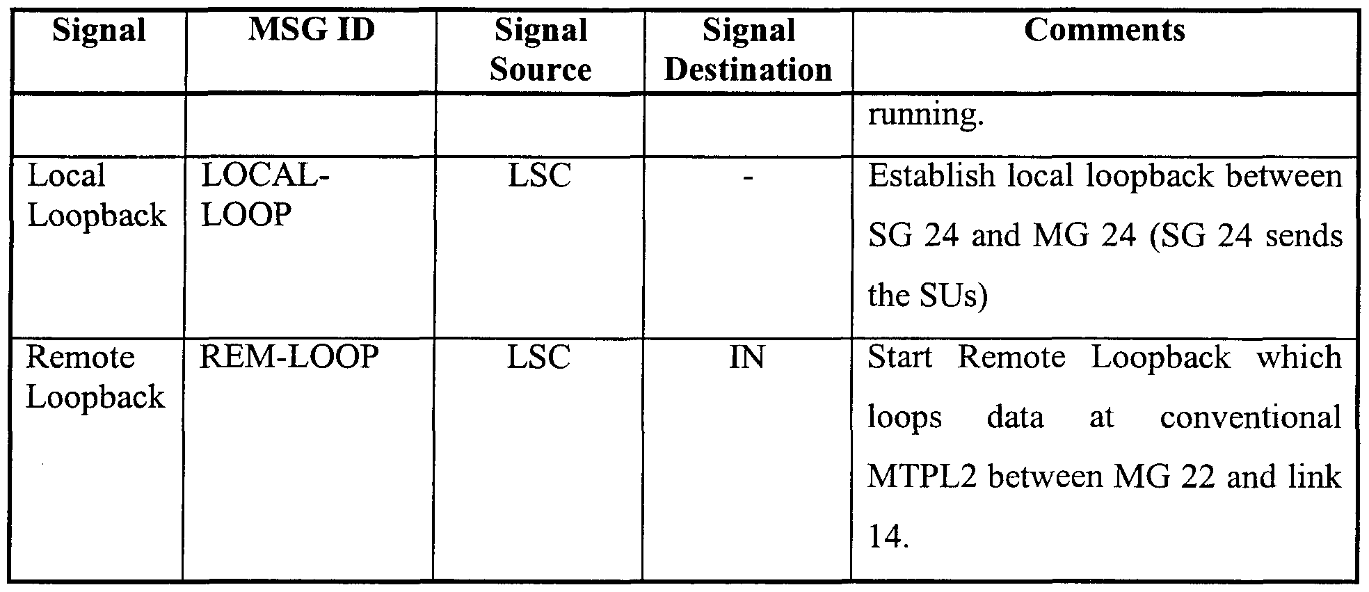
- Error testing of messages sent between SG 24 and MG 22, or between MG 22 and an SSP 12 ( Figure 3), may be performed by establishing a loopback system.
- a "local" loopback will be established between SG 24 and MG 22 upon receipt of a LOCAL-LOOP message at BERT 404 which has been issued by LSC 428.
- the signalling units used in the local loopback will be issued by SG 24, received by MG 22 and returned.
- "Remote" loopbacks, conducted between MG 22 and link 14, can also be established by the reception of a REM-LOOP message issued by LSC 428.
- LSC 428 will periodically request, by the issuance of a STATUS-BERT message, the status of the BERT testing.
- MG 22 through operation of BERT 404, will transmit BERT testing results to SG 24 on a periodic basis, such as, every 5 seconds.
- a summary of the messages, the signal source or signal destination of the message i.e., an entry in the Signal Source column indicates that the entered block transmits the associated signal message to BERT block 404 while an entry in the Signal Destination column indicates that BERT block 404 transmits the associated signal message to the entered block
- comments about the message is found in Table 8.
- OM-MG block 416 (of MG 22) and OM-SG 424 (of SG 24) provide general operational management support for VoIP switch 20 (Figure 4).
- OM-MG 416 records OMs about the signals received by MG 22 and uploads these messages, when requested by OM-SG 424 via a OM-START message, to SG 24. Once the OM signal units are uploaded to SG 24, via an OM-DATA message generated by OM-MG 416, the OM signal units are cleared.
- timers are used during the operation of VoIP switch 20 (Figure 3). These timers are mostly resident on SG 24 with a few timers also existing on MG 22. A list of the timers and their purpose is include in Table 10.
- communications links 28 ( Figure 3) and network 30 ( Figure 4) over which communication between MGs 22, SG 24 and MGC 26 takes place could, instead of an IP network, be another type of routed or switched packet network.
- the MGs 22 and SG 24 of exemplary embodiment disclosed separate the functions of UL-MTPL2 block 34 and LL-MTPL2 block 32 as existing on separately on SG 24 and MG 22, respectively
- an alternative embodiment falling within the scope of the present invention combines the functions of UL-MTPL2 block 34 and LL-MTPL2 32 on a single component of VoIP switch 20, such as MGs 22. Accordingly, the same functionality, including a fully associated network, of the exemplary embodiment would be maintained but without requiring any SGs 24.
Abstract
Description


Claims
Priority Applications (2)
| Application Number | Priority Date | Filing Date | Title |
|---|---|---|---|
| CA002393686A CA2393686A1 (en) | 1999-12-08 | 2000-09-27 | Method and apparatus for distributed mtp level 2 architecture |
| EP00963820A EP1238544A2 (en) | 1999-12-08 | 2000-09-27 | Voip switch with a distributed mtp level 2 architecture |
Applications Claiming Priority (2)
| Application Number | Priority Date | Filing Date | Title |
|---|---|---|---|
| US09/456,560 US6687251B1 (en) | 1999-12-08 | 1999-12-08 | Method and apparatus for distributed MTP Level 2 architecture |
| US09/456,560 | 1999-12-08 |
Publications (2)
| Publication Number | Publication Date |
|---|---|
| WO2001043387A2 true WO2001043387A2 (en) | 2001-06-14 |
| WO2001043387A3 WO2001043387A3 (en) | 2001-11-08 |
Family
ID=23813247
Family Applications (1)
| Application Number | Title | Priority Date | Filing Date |
|---|---|---|---|
| PCT/CA2000/001111 WO2001043387A2 (en) | 1999-12-08 | 2000-09-27 | Voip switch with a distributed mtp level 2 architecture |
Country Status (4)
| Country | Link |
|---|---|
| US (1) | US6687251B1 (en) |
| EP (1) | EP1238544A2 (en) |
| CA (1) | CA2393686A1 (en) |
| WO (1) | WO2001043387A2 (en) |
Cited By (5)
| Publication number | Priority date | Publication date | Assignee | Title |
|---|---|---|---|---|
| WO2005034454A2 (en) | 2003-10-01 | 2005-04-14 | Santera Systems, Inc. | Voice over ip media gateway |
| US7346047B1 (en) | 1999-06-01 | 2008-03-18 | Cisco Technology, Inc. | Method and apparatus for backhaul of telecommunications signaling protocols over packet-switching networks |
| US7843853B2 (en) | 2004-09-10 | 2010-11-30 | Huawei Technologies Co., Ltd. | Method for implementing media gateway controller status monitoring of media gateway |
| US7940660B2 (en) | 2003-10-01 | 2011-05-10 | Genband Us Llc | Methods, systems, and computer program products for voice over IP (VoIP) traffic engineering and path resilience using media gateway and associated next-hop routers |
| US7969890B2 (en) | 2003-10-01 | 2011-06-28 | Genband Us Llc | Methods, systems, and computer program products for load balanced and symmetric path computations for VoIP traffic engineering |
Families Citing this family (24)
| Publication number | Priority date | Publication date | Assignee | Title |
|---|---|---|---|---|
| US6922404B1 (en) * | 1999-10-14 | 2005-07-26 | Nortel Networks Limited | Mobile IP extensions rationalization (MIER) |
| EP1122959A1 (en) * | 2000-02-03 | 2001-08-08 | Telefonaktiebolaget Lm Ericsson | Handling of circuit-switched data services in IP-based GSM networks |
| US7301952B2 (en) * | 2000-04-06 | 2007-11-27 | The Distribution Systems Research Institute | Terminal-to-terminal communication connection control method using IP transfer network |
| US6973075B1 (en) * | 2000-10-03 | 2005-12-06 | Sprint Spectrum L.P. | Computer program and method for modifying data tables in a telecommunications switch |
| WO2002035784A1 (en) * | 2000-10-23 | 2002-05-02 | Radisys Corporation | Method and apparatus for common channel communication using a packet switched network |
| US7027389B2 (en) * | 2000-12-11 | 2006-04-11 | Cisco Technology, Inc. | Fast failure detection using RTT time considerations on a non-retransmit medium |
| EP1348307B1 (en) * | 2001-01-02 | 2005-07-13 | Siemens Aktiengesellschaft | System for transmitting signalings between different networks |
| US7568001B2 (en) * | 2001-01-30 | 2009-07-28 | Intervoice, Inc. | Escalated handling of non-realtime communications |
| US7254641B2 (en) * | 2001-01-30 | 2007-08-07 | Intervoice, Inc. | Digital multimedia contact center with tier escalation and deescalation in response to changed criteria |
| US20040213206A1 (en) * | 2001-02-06 | 2004-10-28 | Mccormack John | Multiprotocol convergence switch (MPCS) and method for use thereof |
| US6993013B1 (en) * | 2001-09-28 | 2006-01-31 | Sprint Communications Company L.P. | Method and apparatus for proactive analysis of signaling messages exchanged between a call processing telecommunications system and voice-over-internet protocol devices |
| US20030231643A1 (en) * | 2001-10-23 | 2003-12-18 | Gilchrist Seamus G. | Signaling gateway for common channel communication through a packet switched network |
| US7155532B2 (en) * | 2002-01-04 | 2006-12-26 | Scientific-Atlanta, Inc. | Transmitting streams over asynchronous networks |
| US8171420B2 (en) | 2002-08-16 | 2012-05-01 | Intervoice, Inc. | Automatic management of the visual space while performing a task |
| US7274787B1 (en) | 2002-08-16 | 2007-09-25 | Intervoice, Inc. | Scheduled return to queue with priority (SRQP) |
| US7230946B2 (en) * | 2002-08-16 | 2007-06-12 | Nuasis Corporation | Remote agent access method to a VoIP contact center where high QoS is not supported |
| EP1546841A4 (en) * | 2002-08-16 | 2006-03-01 | Nuasis Corp | High availability voip subsystem |
| US20040252721A1 (en) * | 2003-06-16 | 2004-12-16 | International Business Machines Corporation | Bundled internet protocol packets |
| US20050047434A1 (en) * | 2003-08-29 | 2005-03-03 | Ulticom, Inc. | System and method for network filtering |
| US7478429B2 (en) * | 2004-10-01 | 2009-01-13 | Prolexic Technologies, Inc. | Network overload detection and mitigation system and method |
| US7508817B2 (en) | 2005-02-08 | 2009-03-24 | At&T Intellectual Property I, L.P. | Method and apparatus for measuring data transport quality over an internet protocol |
| US8527661B1 (en) * | 2005-03-09 | 2013-09-03 | Oracle America, Inc. | Gateway for connecting clients and servers utilizing remote direct memory access controls to separate data path from control path |
| US20070002828A1 (en) * | 2005-06-30 | 2007-01-04 | Tekelec | Methods, systems, and computer program products for taking a high-speed signaling link out of service from a proving state of an initial alignment procedure |
| WO2012174554A2 (en) | 2011-06-17 | 2012-12-20 | Cassidian Communications, Inc. | Systems, apparatus, and methods for collaborative and distributed emergency multimedia data management |
Citations (1)
| Publication number | Priority date | Publication date | Assignee | Title |
|---|---|---|---|---|
| US5974052A (en) * | 1996-05-10 | 1999-10-26 | U.S.T.N. Services | Frame relay access device and method for transporting SS7 information between signaling points |
Family Cites Families (10)
| Publication number | Priority date | Publication date | Assignee | Title |
|---|---|---|---|---|
| US5757895A (en) * | 1995-11-09 | 1998-05-26 | Unisys Corporation | Extracting and processing data derived from a common channel signalling network |
| US5680437A (en) * | 1996-06-04 | 1997-10-21 | Motorola, Inc. | Signaling system seven distributed call terminating processor |
| US5923659A (en) * | 1996-09-20 | 1999-07-13 | Bell Atlantic Network Services, Inc. | Telecommunications network |
| US5940598A (en) * | 1997-01-28 | 1999-08-17 | Bell Atlantic Network Services, Inc. | Telecommunications network to internetwork universal server |
| US6292479B1 (en) * | 1997-03-19 | 2001-09-18 | Bell Atlantic Network Services, Inc. | Transport of caller identification information through diverse communication networks |
| US6324183B1 (en) * | 1998-12-04 | 2001-11-27 | Tekelec | Systems and methods for communicating messages among signaling system 7 (SS7) signaling points (SPs) and internet protocol (IP) nodes using signal transfer points (STPS) |
| US6434140B1 (en) * | 1998-12-04 | 2002-08-13 | Nortel Networks Limited | System and method for implementing XoIP over ANSI-136-A circuit/switched/packet-switched mobile communications networks |
| US6427071B1 (en) * | 1998-12-08 | 2002-07-30 | At&T Wireless Services, Inc. | Apparatus and method for providing transporting for a control signal |
| US6377799B1 (en) * | 1999-06-17 | 2002-04-23 | Ericason Inc. | Interworking function in an internet protocol (IP)-based radio telecommunications network |
| US6523068B1 (en) * | 1999-08-27 | 2003-02-18 | 3Com Corporation | Method for encapsulating and transmitting a message includes private and forwarding network addresses with payload to an end of a tunneling association |
-
1999
- 1999-12-08 US US09/456,560 patent/US6687251B1/en not_active Expired - Lifetime
-
2000
- 2000-09-27 CA CA002393686A patent/CA2393686A1/en not_active Abandoned
- 2000-09-27 WO PCT/CA2000/001111 patent/WO2001043387A2/en not_active Application Discontinuation
- 2000-09-27 EP EP00963820A patent/EP1238544A2/en not_active Withdrawn
Patent Citations (1)
| Publication number | Priority date | Publication date | Assignee | Title |
|---|---|---|---|---|
| US5974052A (en) * | 1996-05-10 | 1999-10-26 | U.S.T.N. Services | Frame relay access device and method for transporting SS7 information between signaling points |
Non-Patent Citations (1)
| Title |
|---|
| ONG L ET AL: "Framework Architecture for Signaling Transport" IETF RFC 2719, October 1999 (1999-10), XP002169054 * |
Cited By (7)
| Publication number | Priority date | Publication date | Assignee | Title |
|---|---|---|---|---|
| US7346047B1 (en) | 1999-06-01 | 2008-03-18 | Cisco Technology, Inc. | Method and apparatus for backhaul of telecommunications signaling protocols over packet-switching networks |
| WO2005034454A2 (en) | 2003-10-01 | 2005-04-14 | Santera Systems, Inc. | Voice over ip media gateway |
| EP1671459A2 (en) * | 2003-10-01 | 2006-06-21 | Santera Systems Inc. | Voice over ip media gateway |
| EP1671459A4 (en) * | 2003-10-01 | 2010-01-06 | Santera Systems Inc | Voice over ip media gateway |
| US7940660B2 (en) | 2003-10-01 | 2011-05-10 | Genband Us Llc | Methods, systems, and computer program products for voice over IP (VoIP) traffic engineering and path resilience using media gateway and associated next-hop routers |
| US7969890B2 (en) | 2003-10-01 | 2011-06-28 | Genband Us Llc | Methods, systems, and computer program products for load balanced and symmetric path computations for VoIP traffic engineering |
| US7843853B2 (en) | 2004-09-10 | 2010-11-30 | Huawei Technologies Co., Ltd. | Method for implementing media gateway controller status monitoring of media gateway |
Also Published As
| Publication number | Publication date |
|---|---|
| WO2001043387A3 (en) | 2001-11-08 |
| US6687251B1 (en) | 2004-02-03 |
| EP1238544A2 (en) | 2002-09-11 |
| CA2393686A1 (en) | 2001-06-14 |
Similar Documents
| Publication | Publication Date | Title |
|---|---|---|
| US6687251B1 (en) | Method and apparatus for distributed MTP Level 2 architecture | |
| US7830860B2 (en) | Packet data network voice call quality monitoring | |
| US7813332B1 (en) | Voice call alternative routing through PSTN and internet networks | |
| JP4391590B2 (en) | System for translating routing addresses within a telecommunications network | |
| US6064653A (en) | Internetwork gateway to gateway alternative communication | |
| JP3936400B2 (en) | Network protocol conversion module in telecommunication system | |
| Ong et al. | Framework architecture for signaling transport | |
| US6680952B1 (en) | Method and apparatus for backhaul of telecommunications signaling protocols over packet-switching networks | |
| US6078582A (en) | Internet long distance telephone service | |
| US6122255A (en) | Internet telephone service with mediation | |
| US20030235207A1 (en) | Common channel protocol message format for communicating data through a packet switched network | |
| US6937596B2 (en) | IP based telephone system | |
| CA2312909A1 (en) | Mapping function and method of transmitting signaling system 7 (ss7) telecommunications messages over data networks | |
| WO2000036852A2 (en) | Mechanism and method for distributing isup stacks over multiple loosely coupled processors | |
| EP1049981A1 (en) | Method and system for media connectivity over a packet-based network | |
| EP0979573A1 (en) | A method and a system for use in a telecommunication network | |
| US6990124B1 (en) | SS7-Internet gateway access signaling protocol | |
| EP1198945B1 (en) | An ip based telephone system | |
| US20040151178A1 (en) | Method for testing a bearer channel connection in a telecommunication system | |
| EP1715658A1 (en) | Method and systems for communicating SS7 messages | |
| Ong et al. | RFC2719: Framework Architecture for Signaling Transport | |
| Cisco | SS7 Protocol Stack | |
| US20030231643A1 (en) | Signaling gateway for common channel communication through a packet switched network | |
| Ahamed et al. | The Role of the OSI Model | |
| Schwarzbauer et al. | Network Working Group L. Ong Request for Comments: 2719 Nortel Networks Category: Informational I. Rytina M. Garcia Ericsson |
Legal Events
| Date | Code | Title | Description |
|---|---|---|---|
| AK | Designated states |
Kind code of ref document: A2 Designated state(s): CA |
|
| AL | Designated countries for regional patents |
Kind code of ref document: A2 Designated state(s): AT BE CH CY DE DK ES FI FR GB GR IE IT LU MC NL PT SE |
|
| 121 | Ep: the epo has been informed by wipo that ep was designated in this application | ||
| DFPE | Request for preliminary examination filed prior to expiration of 19th month from priority date (pct application filed before 20040101) | ||
| AK | Designated states |
Kind code of ref document: A3 Designated state(s): CA |
|
| AL | Designated countries for regional patents |
Kind code of ref document: A3 Designated state(s): AT BE CH CY DE DK ES FI FR GB GR IE IT LU MC NL PT SE |
|
| WWE | Wipo information: entry into national phase |
Ref document number: 2000963820 Country of ref document: EP |
|
| WWE | Wipo information: entry into national phase |
Ref document number: 2393686 Country of ref document: CA |
|
| WWP | Wipo information: published in national office |
Ref document number: 2000963820 Country of ref document: EP |
|
| WWW | Wipo information: withdrawn in national office |
Ref document number: 2000963820 Country of ref document: EP |