WO2002049279A2 - System and method for assisting in controlling real-time transport protocol flow through multiple networks via media flow routing - Google Patents
System and method for assisting in controlling real-time transport protocol flow through multiple networks via media flow routing Download PDFInfo
- Publication number
- WO2002049279A2 WO2002049279A2 PCT/US2001/048161 US0148161W WO0249279A2 WO 2002049279 A2 WO2002049279 A2 WO 2002049279A2 US 0148161 W US0148161 W US 0148161W WO 0249279 A2 WO0249279 A2 WO 0249279A2
- Authority
- WO
- WIPO (PCT)
- Prior art keywords
- route information
- received
- route
- field
- local policy
- Prior art date
Links
- 238000000034 method Methods 0.000 title claims abstract description 98
- 239000000969 carrier Substances 0.000 claims description 31
- 238000012545 processing Methods 0.000 claims description 26
- 238000012216 screening Methods 0.000 claims description 12
- 230000006870 function Effects 0.000 claims description 10
- 230000000977 initiatory effect Effects 0.000 claims description 7
- 238000003860 storage Methods 0.000 claims description 4
- 239000003795 chemical substances by application Substances 0.000 description 163
- 230000036961 partial effect Effects 0.000 description 57
- 230000008569 process Effects 0.000 description 53
- 238000004891 communication Methods 0.000 description 37
- 238000010586 diagram Methods 0.000 description 24
- 238000007726 management method Methods 0.000 description 20
- 230000007246 mechanism Effects 0.000 description 19
- 244000023493 Phoenix rupicola Species 0.000 description 13
- 230000011664 signaling Effects 0.000 description 13
- 230000008859 change Effects 0.000 description 10
- 238000009826 distribution Methods 0.000 description 10
- 230000001186 cumulative effect Effects 0.000 description 8
- 230000002776 aggregation Effects 0.000 description 7
- 238000004220 aggregation Methods 0.000 description 7
- 238000005516 engineering process Methods 0.000 description 7
- 230000004044 response Effects 0.000 description 7
- 241001522296 Erithacus rubecula Species 0.000 description 5
- 238000011161 development Methods 0.000 description 4
- 230000018109 developmental process Effects 0.000 description 4
- 230000003287 optical effect Effects 0.000 description 4
- 230000002441 reversible effect Effects 0.000 description 4
- 238000012552 review Methods 0.000 description 4
- 230000002459 sustained effect Effects 0.000 description 4
- 238000012360 testing method Methods 0.000 description 4
- 238000012546 transfer Methods 0.000 description 4
- 230000004913 activation Effects 0.000 description 3
- 230000008901 benefit Effects 0.000 description 3
- 238000004422 calculation algorithm Methods 0.000 description 3
- 230000009849 deactivation Effects 0.000 description 3
- 230000000670 limiting effect Effects 0.000 description 3
- 238000012423 maintenance Methods 0.000 description 3
- 238000013519 translation Methods 0.000 description 3
- 230000014616 translation Effects 0.000 description 3
- 241000721701 Lynx Species 0.000 description 2
- 230000009471 action Effects 0.000 description 2
- 230000006835 compression Effects 0.000 description 2
- 238000007906 compression Methods 0.000 description 2
- 238000012790 confirmation Methods 0.000 description 2
- 230000000694 effects Effects 0.000 description 2
- 230000003993 interaction Effects 0.000 description 2
- 230000002452 interceptive effect Effects 0.000 description 2
- 238000012986 modification Methods 0.000 description 2
- 230000004048 modification Effects 0.000 description 2
- 230000002085 persistent effect Effects 0.000 description 2
- RYGMFSIKBFXOCR-UHFFFAOYSA-N Copper Chemical compound [Cu] RYGMFSIKBFXOCR-UHFFFAOYSA-N 0.000 description 1
- 238000006424 Flood reaction Methods 0.000 description 1
- 102100034184 Macrophage scavenger receptor types I and II Human genes 0.000 description 1
- 101710134306 Macrophage scavenger receptor types I and II Proteins 0.000 description 1
- 101100533548 Neurospora crassa (strain ATCC 24698 / 74-OR23-1A / CBS 708.71 / DSM 1257 / FGSC 987) sip-5 gene Proteins 0.000 description 1
- 238000013459 approach Methods 0.000 description 1
- 230000006399 behavior Effects 0.000 description 1
- 230000009286 beneficial effect Effects 0.000 description 1
- 230000005540 biological transmission Effects 0.000 description 1
- 229910052802 copper Inorganic materials 0.000 description 1
- 239000010949 copper Substances 0.000 description 1
- 230000007423 decrease Effects 0.000 description 1
- 238000012217 deletion Methods 0.000 description 1
- 230000037430 deletion Effects 0.000 description 1
- 238000013461 design Methods 0.000 description 1
- 238000001514 detection method Methods 0.000 description 1
- 230000003203 everyday effect Effects 0.000 description 1
- 230000003090 exacerbative effect Effects 0.000 description 1
- 230000007717 exclusion Effects 0.000 description 1
- 238000004880 explosion Methods 0.000 description 1
- 230000006872 improvement Effects 0.000 description 1
- 238000003780 insertion Methods 0.000 description 1
- 230000037431 insertion Effects 0.000 description 1
- 238000012544 monitoring process Methods 0.000 description 1
- 239000013307 optical fiber Substances 0.000 description 1
- 230000008447 perception Effects 0.000 description 1
- 230000000644 propagated effect Effects 0.000 description 1
- 238000010926 purge Methods 0.000 description 1
- 230000002829 reductive effect Effects 0.000 description 1
- 230000010076 replication Effects 0.000 description 1
- 230000000717 retained effect Effects 0.000 description 1
- 239000004248 saffron Substances 0.000 description 1
- 239000004065 semiconductor Substances 0.000 description 1
- 238000010561 standard procedure Methods 0.000 description 1
- 238000007619 statistical method Methods 0.000 description 1
- 238000011144 upstream manufacturing Methods 0.000 description 1
- 238000010200 validation analysis Methods 0.000 description 1
Classifications
-
- H—ELECTRICITY
- H04—ELECTRIC COMMUNICATION TECHNIQUE
- H04L—TRANSMISSION OF DIGITAL INFORMATION, e.g. TELEGRAPHIC COMMUNICATION
- H04L65/00—Network arrangements, protocols or services for supporting real-time applications in data packet communication
- H04L65/10—Architectures or entities
- H04L65/102—Gateways
- H04L65/1043—Gateway controllers, e.g. media gateway control protocol [MGCP] controllers
-
- H—ELECTRICITY
- H04—ELECTRIC COMMUNICATION TECHNIQUE
- H04L—TRANSMISSION OF DIGITAL INFORMATION, e.g. TELEGRAPHIC COMMUNICATION
- H04L45/00—Routing or path finding of packets in data switching networks
- H04L45/302—Route determination based on requested QoS
- H04L45/306—Route determination based on the nature of the carried application
- H04L45/3065—Route determination based on the nature of the carried application for real time traffic
-
- H—ELECTRICITY
- H04—ELECTRIC COMMUNICATION TECHNIQUE
- H04L—TRANSMISSION OF DIGITAL INFORMATION, e.g. TELEGRAPHIC COMMUNICATION
- H04L65/00—Network arrangements, protocols or services for supporting real-time applications in data packet communication
- H04L65/1066—Session management
- H04L65/1101—Session protocols
- H04L65/1104—Session initiation protocol [SIP]
-
- H—ELECTRICITY
- H04—ELECTRIC COMMUNICATION TECHNIQUE
- H04M—TELEPHONIC COMMUNICATION
- H04M3/00—Automatic or semi-automatic exchanges
- H04M3/42—Systems providing special services or facilities to subscribers
- H04M3/42136—Administration or customisation of services
- H04M3/42144—Administration or customisation of services by service provider
-
- H—ELECTRICITY
- H04—ELECTRIC COMMUNICATION TECHNIQUE
- H04M—TELEPHONIC COMMUNICATION
- H04M7/00—Arrangements for interconnection between switching centres
- H04M7/12—Arrangements for interconnection between switching centres for working between exchanges having different types of switching equipment, e.g. power-driven and step by step or decimal and non-decimal
- H04M7/1205—Arrangements for interconnection between switching centres for working between exchanges having different types of switching equipment, e.g. power-driven and step by step or decimal and non-decimal where the types of switching equipement comprises PSTN/ISDN equipment and switching equipment of networks other than PSTN/ISDN, e.g. Internet Protocol networks
- H04M7/128—Details of addressing, directories or routing tables
-
- H—ELECTRICITY
- H04—ELECTRIC COMMUNICATION TECHNIQUE
- H04Q—SELECTING
- H04Q3/00—Selecting arrangements
- H04Q3/0016—Arrangements providing connection between exchanges
- H04Q3/0025—Provisions for signalling
-
- H—ELECTRICITY
- H04—ELECTRIC COMMUNICATION TECHNIQUE
- H04Q—SELECTING
- H04Q3/00—Selecting arrangements
- H04Q3/0016—Arrangements providing connection between exchanges
- H04Q3/0029—Provisions for intelligent networking
- H04Q3/0045—Provisions for intelligent networking involving hybrid, i.e. a mixture of public and private, or multi-vendor systems
-
- H—ELECTRICITY
- H04—ELECTRIC COMMUNICATION TECHNIQUE
- H04Q—SELECTING
- H04Q3/00—Selecting arrangements
- H04Q3/64—Distributing or queueing
- H04Q3/66—Traffic distributors
-
- H—ELECTRICITY
- H04—ELECTRIC COMMUNICATION TECHNIQUE
- H04L—TRANSMISSION OF DIGITAL INFORMATION, e.g. TELEGRAPHIC COMMUNICATION
- H04L69/00—Network arrangements, protocols or services independent of the application payload and not provided for in the other groups of this subclass
- H04L69/22—Parsing or analysis of headers
-
- H—ELECTRICITY
- H04—ELECTRIC COMMUNICATION TECHNIQUE
- H04Q—SELECTING
- H04Q2213/00—Indexing scheme relating to selecting arrangements in general and for multiplex systems
- H04Q2213/13034—A/D conversion, code compression/expansion
-
- H—ELECTRICITY
- H04—ELECTRIC COMMUNICATION TECHNIQUE
- H04Q—SELECTING
- H04Q2213/00—Indexing scheme relating to selecting arrangements in general and for multiplex systems
- H04Q2213/13097—Numbering, addressing
-
- H—ELECTRICITY
- H04—ELECTRIC COMMUNICATION TECHNIQUE
- H04Q—SELECTING
- H04Q2213/00—Indexing scheme relating to selecting arrangements in general and for multiplex systems
- H04Q2213/13103—Memory
-
- H—ELECTRICITY
- H04—ELECTRIC COMMUNICATION TECHNIQUE
- H04Q—SELECTING
- H04Q2213/00—Indexing scheme relating to selecting arrangements in general and for multiplex systems
- H04Q2213/13106—Microprocessor, CPU
-
- H—ELECTRICITY
- H04—ELECTRIC COMMUNICATION TECHNIQUE
- H04Q—SELECTING
- H04Q2213/00—Indexing scheme relating to selecting arrangements in general and for multiplex systems
- H04Q2213/13138—Least cost routing, LCR
-
- H—ELECTRICITY
- H04—ELECTRIC COMMUNICATION TECHNIQUE
- H04Q—SELECTING
- H04Q2213/00—Indexing scheme relating to selecting arrangements in general and for multiplex systems
- H04Q2213/13141—Hunting for free outlet, circuit or channel
-
- H—ELECTRICITY
- H04—ELECTRIC COMMUNICATION TECHNIQUE
- H04Q—SELECTING
- H04Q2213/00—Indexing scheme relating to selecting arrangements in general and for multiplex systems
- H04Q2213/13166—Fault prevention
-
- H—ELECTRICITY
- H04—ELECTRIC COMMUNICATION TECHNIQUE
- H04Q—SELECTING
- H04Q2213/00—Indexing scheme relating to selecting arrangements in general and for multiplex systems
- H04Q2213/13176—Common channel signaling, CCS7
-
- H—ELECTRICITY
- H04—ELECTRIC COMMUNICATION TECHNIQUE
- H04Q—SELECTING
- H04Q2213/00—Indexing scheme relating to selecting arrangements in general and for multiplex systems
- H04Q2213/13204—Protocols
-
- H—ELECTRICITY
- H04—ELECTRIC COMMUNICATION TECHNIQUE
- H04Q—SELECTING
- H04Q2213/00—Indexing scheme relating to selecting arrangements in general and for multiplex systems
- H04Q2213/13299—Bus
-
- H—ELECTRICITY
- H04—ELECTRIC COMMUNICATION TECHNIQUE
- H04Q—SELECTING
- H04Q2213/00—Indexing scheme relating to selecting arrangements in general and for multiplex systems
- H04Q2213/13332—Broadband, CATV, dynamic bandwidth allocation
-
- H—ELECTRICITY
- H04—ELECTRIC COMMUNICATION TECHNIQUE
- H04Q—SELECTING
- H04Q2213/00—Indexing scheme relating to selecting arrangements in general and for multiplex systems
- H04Q2213/13345—Intelligent networks, SCP
-
- H—ELECTRICITY
- H04—ELECTRIC COMMUNICATION TECHNIQUE
- H04Q—SELECTING
- H04Q2213/00—Indexing scheme relating to selecting arrangements in general and for multiplex systems
- H04Q2213/13348—Channel/line reservation
-
- H—ELECTRICITY
- H04—ELECTRIC COMMUNICATION TECHNIQUE
- H04Q—SELECTING
- H04Q2213/00—Indexing scheme relating to selecting arrangements in general and for multiplex systems
- H04Q2213/13352—Self-routing networks, real-time routing
-
- H—ELECTRICITY
- H04—ELECTRIC COMMUNICATION TECHNIQUE
- H04Q—SELECTING
- H04Q2213/00—Indexing scheme relating to selecting arrangements in general and for multiplex systems
- H04Q2213/13376—Information service, downloading of information, 0800/0900 services
-
- H—ELECTRICITY
- H04—ELECTRIC COMMUNICATION TECHNIQUE
- H04Q—SELECTING
- H04Q2213/00—Indexing scheme relating to selecting arrangements in general and for multiplex systems
- H04Q2213/13384—Inter-PBX traffic, PBX networks, e.g. corporate networks
-
- H—ELECTRICITY
- H04—ELECTRIC COMMUNICATION TECHNIQUE
- H04Q—SELECTING
- H04Q2213/00—Indexing scheme relating to selecting arrangements in general and for multiplex systems
- H04Q2213/13389—LAN, internet
-
- H—ELECTRICITY
- H04—ELECTRIC COMMUNICATION TECHNIQUE
- H04Q—SELECTING
- H04Q2213/00—Indexing scheme relating to selecting arrangements in general and for multiplex systems
- H04Q2213/13395—Permanent channel, leased line
-
- H—ELECTRICITY
- H04—ELECTRIC COMMUNICATION TECHNIQUE
- H04Q—SELECTING
- H04Q2213/00—Indexing scheme relating to selecting arrangements in general and for multiplex systems
- H04Q2213/13399—Virtual channel/circuits
Definitions
- the present invention generally relates to telecommunication networks, and more particularly, is related to a system and method for assisting in controlling real-time transport protocol flow through multiple networks via media flow routing.
- PSTN public switched telephone network
- every telephone number in the world can be broken down into similar components, and a geographic determination can be made as to which network element (e.g., telephone switch) can terminate the communication.
- portable number technology has been implemented to allow companies to make their numbers mobile in instances where they, for example, moved or relocated. Initially, this technology was directed toward toll- free numbers (e.g., 1-800-FLOWERSTM) to permit the owner to change long distance carriers.
- toll- free numbers e.g., 1-800-FLOWERSTM
- the 800 exchange was recognized as a toll- free exchange and translated into a "real" network number that adhered to the fixed hierarchy at a database (i.e., service control point (SCP)).
- SCP service control point
- the process of resolving an 800 or toll-free number into a real number i.e., shadow address
- the technology is similar to the toll-free technology discussed herein above in that an exchange is declared portable and a database (i.e., SCP) is used to get the location of the "real" address. The location returned is actually the telephone number of a terminating switch. The call is then placed to this phantom number on a signaling system #7 (SS7) network, with the real number carried passively as a separate information element to the endpoint in an initial address message (LAM). Once again, the number used to route the call was a real number that adhered to the fixed hierarchy. This mechanism for local number portability (LNP) is also known. In wireless networks, a home location register (HLR) and visitor location register (NLR) mechanism is used.
- HLR home location register
- NLR visitor location register
- a telephone periodically registers on the networks with which it is capable of communicating. This registration informs the network of the location of the telephone so that calls can be appropriately directed to the user.
- the equipment is capable of routing the call to/from a correct base station.
- a phantom number is allocated and a new call is directed to the new system, which then connects the telephone to a new endpoint.
- the allocated phantom number is used to adhere to the established hierarchy.
- the PSTN is not currently capable of routing an actual communication session on anything other than an address that conforms to the hierarchy present in the PSTN since telephone numbers and their parts are used to discover a path to an endpoint of the communication. Portability mechanisms use a phantom or shadow number to direct the communication through the network.
- the Internet is based on an Internet Protocol (LP). LP messages are routed or forwarded from one link to the next (i.e., from a source of the data flow to a destination of the data flow).
- Each LP packet contains an LP address, which, in Internet protocol version 4 (IPv4), has 32 bits.
- IPv4 Internet protocol version 4
- Each LP address also has a certain number of bits dedicated to a network portion and a certain number of bits dedicated to a host portion.
- LP routers are used to take a packet from one network (or link) and place it onto another network (or link). Tables are located within LP routers that contain information or criteria used to determine a best way to route a packet.- An example of this information may be the state of network links and programmed distance indications.
- LP routers typically route packets by destination LP address, which does not assist in finding a proper route for transportation. There are some exceptions to this routing system, however. By using intelligent devices on both sides of a network domain, it is possible to allocate a temporary address to route a packet through a network and restore the original address on the far side of the network, when the packet leaves the network. This is the basis for many current virtual private network (VPN) products and is understood in the art.
- VPN virtual private network
- MPLS multi-protocol label switching
- tag switching This method of routing LP packets allows a destination LP address to potentially be separated from the route that the packet actually takes through a network.
- One of the best uses of MPLS is to create a VPN or virtual leased lines (VLL).
- VLL virtual leased lines
- IP destinations base all real forwarding of IP packets on LP destinations.
- IP destinations are associated with network topology and, like the telephone network, are used to deliver packets.
- MPLS tags and paths can provide override forwarding for LP packets based on a set of rules that is tied to the LP address portion used for routing, such as, for example, a forward equivalence class (FEC).
- FEC forward equivalence class
- Distributed electronic switching and routing is important to making networks scale to required sizes.
- Distributed electronic switching and routing equipment need to have a defined role in a communication session. Networks simply would not scale if every endpoint had to manage a connection to every other endpoint.
- the distribution of control into a hierarchical scheme further emphasizes difficulty in changing underlying addressing.
- the network elements e.g., switches in the telephone network, routers in the data network
- signaling systems are used to provide this information.
- signaling systems used are either SS7 or are equivalent to SS7.
- the signaling system provides information about individual links, link sets, routes, etc.
- protocols such as border gateway protocol (BGP), interior gateway protocol (IGP), open shortest path first (OSPF), etc., are used to determine link states and routes.
- the signaling system is also used to establish an end-to-end . path (i.e., ISDN User Part (ISUP)) through the network.
- ISUP ISDN User Part
- the signaling system is also used to establish an end-to-end . path (i.e., ISDN User Part (ISUP)) through the network.
- ISUP ISDN User Part
- LP networks there is no end-to-end path allocation. Instead, to engage in a communication session, there must be a system to associate endpoints with names or purposes.
- e-mail electronic-mail
- Internet directories do not include a geographic location since geographic locations are not part of Internet domain addresses, unless the directory entry is entered manually.
- the search can be narrowed if the city or town is known, but this type of search is not as easy in Internet directories.
- Uniform resource locators typically define endpoints or locations on the Internet.
- a user name followed by a domain name is the current method to address users, wherein the domain name is owned by an entity that allows the user to employ it.
- a gateway is used to facilitate a media flow between a packet data network and a PSTN.
- Gateways are installed at edges between data networks and voice networks, wherein the gateways are used to convert media (and signaling) to ensure communication.
- SLP Session initiation protocol
- Certain simple gateways such as, but not limited to, the Cisco AS5300, can forward SLP- based call requests to a SLP proxy server.
- these gateways have low densities and frequently lack the sophistication of softswitches in setting up routing policies.
- These routers therefore, cannot be interconnected to create networks without a Softswitch controller.
- hierarchical routing networks are segmented into different layers. The layers are interconnected into a pyramid to enable anywhere-to-anywhere routing. This method is the basis of the current PSTN.
- the hierarchical routing method uses a tiered model wherein the number of tiers in the hierarchy depends on the size of the network.
- the Internet today does not conform to a hierarchy. In fact, much of the Internet could be described as a full mesh, with many possible routes going from one place to another.
- One of the principal design goals of BGP- is to avoid multiple circuitous routes, which indicate just how many different interconnections exist.
- the hierarchical model can be complex when trying to apply it to today's peering environment. While the higher levels of the hierarchy are owned by some entity, from a business or political environment, it is hard to imagine how ownership and peering issues can be resolved since the data networks do not adhere to a hierarchy. Because the data network owners are competing for the same business, it is unlikely that peering arrangements, which are not mutually beneficial, can be established.
- the hierarchical model also creates single points of failure that can lead to larger ripple effects.
- the public data network PDN has evolved with no single points of failure, and largely subscribes to a distributed peer arrangement. Given this, single softswitches, which could affect large pieces of a network, are ill advised.
- the hierarchical model also comprises careful route configuration at every point in the hierarchy (i.e., no two softswitches can have the same configuration and no two softswitches can predict the route that a particular communication will traverse).
- a hierarchical routing system therefore uses a distributed route plan in an incredibly coordinated manner.
- the hierarchical model has the vendors adhere to similar signaling systems to ensure proper routing, end-to-end. For example, to enable proper routing, each Softswitch would have to share information about circuit availability to ensure proper route-around functionality as the network becomes full. Since there, are currently no standards for accomplishing this, vendors have been building proprietary methods; and these proprietary methods may not interoperate correctly.
- the preferred embodiment of the present invention generally relates to a system and method for assisting in controlling real-time transport protocol flow through multiple networks via media flow routing.
- the system utilizes a first computer and a second computer connected to the first computer, via a group of associated computers.
- Each of the first computer, second computer, and group of associated computers comprise a transceiver, a memory having logic stored therein defining functions to be performed by the computers, and a processor.
- the processor is configured by the memory to perform the functions of: performing an inbound screen on route information received from the first computer, to determine if the received route information should be discarded; if the route information is not discarded, comparing the received and screened route information to a local policy defined within the second computer; performing an outbound screen on the received and screened information prior to transmitting the received and screened route information to the first computer; and selecting a primary route from the received route information and local route information in accordance with the local policy, wherein the primary route is a path from the second computer to the first computer via the group of associated computers.
- the present invention can also be viewed as providing a method for assisting in controlling real-time transport protocol flow through multiple networks via media flow routing.
- the method can be broadly summarized by the following steps: receiving information regarding a route from a first computer to a second computer, via a group of associated computers; performing an inbound screen on the route information received from the first computer, to determine if the received route information should be discarded; if the route information is not discarded, comparing the received and screened route information to a local policy; performing an outbound screen on the received and screened route information prior to transmitting the received and screened information; and selecting a primary route from the received route information and local route information in accordance with the local policy, wherein the primary route is a path from the second computer to the first computer via the group of associated computers.
- FIG. 1 is a block diagram that illustrates a multiple domain communication network, in accordance with the preferred embodiment of the invention.
- FIG 2 is a block diagram that illustrates interaction by the SLP protocol.
- FIG. 3 A is a block diagram of a data map that shows policies stored on a session router located within the network of FIG. 1.
- FIG. 3B is a block diagram continuing the data map illustrated by FIG. 3 A.
- FIG. 4 is a block diagram that illustrates the structure of the session router apparatus that is located within the network of FIG. 1.
- FIG. 5 is a block diagram that illustrates software systems, or protocols, that may be resident within the local memory of the session router of FIGS 1 and 4.
- FIG. 6 is a flow chart that illustrates operations performed during the startup of the session router of FIGS. 1 and 4.
- FIG. 7 is a block diagram that illustrates policy screens used by the session router of FIGS. 1 and 4.
- FIG. 8 is a block diagram that illustrates logic defined by the TRIP decision process as performed by the session router of FIGS. 1 and 4.
- FIG. 9A is a block diagram that illustrates the major components of a TRIP "update" message that may be received or transmitted from or to the session router of FIGS. 1 and 4.
- FIG. 9B is a block diagram that is a continuation of FIG. 9 A.
- FIG. 10 is a block diagram that provides an example of an IT AD topology comprising session routers such as those illustrated by FIGS. 1 and 4.
- FIG. 11 is a flow chart that illustrates the process of using a best matching screen to determine is a given policy should be advertised externally, as performed by the session routers of FIGS. 1 and 4.
- FIG. 12A is a flow chart that illustrates steps taken by a SLP proxy to analyze a SLP message.
- FIG. 12B is a flow chart that is a continuation of FIG. 11 A.
- FIG. 13 A is a flowchart that illustrates steps taken to determine a particular SP agent within a group of SLP agents to forward a route.
- FIG. 13B is a flow chart that is a continuation of FIG. 13A.
- FIG. 14 is a block diagram illustrating how RTP flows are managed through the use of media routing in the SR of FIGS 1 and 4.
- FIG. 15 is a block diagram that illustrates a network comprising singular session routers such as those illustrated by FIGS. 1 and 4.
- FIG. 16 is a block diagram that illustrates a network comprising clusters of routers such as those illustrated by FIGS. 1 and 4.
- the present invention provides a controlling system for assisting in controlling real-time transport protocol flow through multiple networks.
- the controlling system of the present invention can be implemented in software, firmware, hardware, or a combination thereof.
- a portion of the controlling system is implemented in software that is executed by a computer, for example, but not limited to, a personal computer, workstation, minicomputer, or mainframe computer.
- the software portion of the controlling system which comprises an ordered listing of executable instructions for implementing logical functions, can be embodied in any computer- readable medium for use by, or in connection with, an instruction execution system, apparatus, or device such as a computer-based system processor-containing system, or other system that can fetch the instructions from the instruction execution system, apparatus, or device and execute the instructions.
- a "computer-readable medium” can be any means that can contain, store, communicate, propagate or transport the program for use by or in connection with the instruction execution system, apparatus or device.
- the computer-readable medium can be, for example, but not limited to, an electronic, magnetic, optical, electromagnetic, infrared, or semiconductor system, apparatus, device, or propagation medium.
- the computer-readable medium would include the following: an electrical connection (electronic) having one or more wires, a portable computer diskette (magnetic), a random access memory (RAM) (magnetic), a read-only memory (ROM) (magnetic), an erasable programmable read-only memory EPROM or Flash memory) (magnetic), an optical fiber (optical), and a portable compact disk read-only memory (CD ROM) (optical).
- an electrical connection electronic having one or more wires
- a portable computer diskette magnetic
- RAM random access memory
- ROM read-only memory
- EPROM or Flash memory erasable programmable read-only memory
- CD ROM portable compact disk read-only memory
- the computer-readable medium could even be paper or another suitable medium upon which the program is printed, as the program can be electronically captured, via for instance, optical scanning of the paper or other medium, then compiled, interpreted or otherwise processed in a suitable manner, if necessary, and then stored in a computer memory.
- FIG. 1 is a block diagram illustrating a multiple domain communication network 100, in accordance with the preferred embodiment of the invention.
- FIG. 1 is representative of many of the typical types of internetworking used to make voice over Internet protocol (VoLP) deployments feasible and scalable.
- a first and a second autonomous system (AS) 102, 104 are illustrated and are connected by a first session router 122.
- an autonomous system is a set of routers under a single technical administration, using an interior gateway protocol and common metrics to route packets within the AS, and using an exterior gateway protocol to route packets to other ASs.
- ASs are typically a set of border gateway protocol-4 (BGP-4) routers grouped by a common administrative authority.
- BGP-4 border gateway protocol-4
- ITADs Internet telephony administrative domains
- TIP Internet Protocol
- a first management station 112 is located within the first IT AD 102 and a second management station 114 is located within the second ITAD 104.
- a first long distance carrier 152 is connected to the first ITAD 102 via a first gateway 172.
- Long distance carriers provided herein preferably use a PSTN system, wherein the telephone system is based on copper wires carrying analog voice data. Alternatively, the long distance carrier may also provide digital data or a combination of analog and digital data.
- gateways provided herein preferably provide both media and signaling gateway support between PSTN-based networks and packet-based data networks.
- a first incumbent local exchange carrier 162 is also connected to the first ITAD 102 via a second gateway 174.
- a first soft-switch, or call agent, 202 located within the first ITAD 102, is connected to both the first long distance carrier 152 and the first incumbent local exchange carrier 162, via the first and second gateways 172, 174 respectively.
- Soft-switches provided herein control the gateways through a media gateway communication protocol (MGCP), or an equivalent protocol.
- MGCP media gateway communication protocol
- an intelligent gateway may not require a soft-switch, but instead, may directly communicate with an ITAD by creating session initiation protocol (SLP) based telephone calls without the use of a soft-switch.
- SLP session initiation protocol
- SLP is a protocol that has a number of key mechanisms defined.
- a first SLP mechanism is called a "register” message. When sent to a SLP proxy server, this message indicates that the endpoint is capable of receiving a communication for a specific user. This "register” message binds the physical LP address to the user using the IP address.
- a second SLP mechanism is the "invite” message. This message is sent to another endpoint to request a communication session. The "invite” message is sent all the way to the endpoint of the receiver of the communication. The receiver of the "invite” will then respond with an OK message indicating that the communication is accepted.
- a SLP proxy server acts as a go-between.
- the SLP proxy server receives and forwards the "invite" messages that are received for its users that have previously sent a "register” message.
- FIG. 2 provides a detailed illustration of interaction between two SLP agents via a SLP proxy. For example, if a user sends a "register" message 242 from a first SIP user agent 244, a SLP proxy server 246 acknowledges the registration.
- a second SLP user agent 248 sends an first "invite” message 252 for the user that transmitted the "register” message” 242
- the first "invite” message 252 is received by the SLP proxy server 246.
- the SLP proxy server 246 transfers a second "invite” message 254 to the first SLP user agent 244. If the first SLP user agent 244 is willing to accept communication from the second SLP user agent 248, the first SLP user agent 244 transmits a message of approval to the SLP proxy server 246 which is then transmitted to the second SLP user agent 248.
- a third SLP mechanism is the "bye" message, which unilaterally sends a communication session, and frees all of the network resources in use.
- SLP Session Initiation Protocol
- Handley et al. which is an Internet draft having draft number rfc2543, dated March 1999, the disclosure of which is incorporated herein by reference. Further discussion of the SLP protocol is provided herein below.
- an enterprise network 192 is connected to the first ITAD via a fourth session router 128.
- the enterprise network 192 comprises a third gateway 176 that provides connectivity to a first private branch exchange (PBX) 212.
- PBX private branch exchange
- users of a PBX share a certain number of outside lines for making telephone calls external to the PBX.
- a SLP phone 222 such as those produced by Pingtel of Massachusetts, and a SLP user agent 232 (i.e., a computer), such as those produced by Dynamicsoft of New Jersey, U.S.A., may be located within the enterprise network 192 that are connected to the first ITAD via the fourth session router 128.
- a second long distance carrier 154 is connected to the second ITAD 104 via a fourth gateway 178.
- a second incumbent local exchange carrier 164 is connected to the second ITAD 104 via a fifth gateway 182.
- a second soft-switch, or call agent, 204 located within the second ITAD 104 is connected to both the second long distance carrier 154, and the second incumbent local exchange carrier 164 via the fourth and fifth gateways 178, 182 respectively.
- an intelligent gateway may not require a soft-switch, but instead, may directly communicate with an ITAD by creating SL -based telephone calls without the use of a soft-switch.
- a second PBX 214 may be connected to the second ITAD 104 via a sixth gateway 184.
- a second SLP user agent 234 and a second SLP phone 224 may be connected to the second ITAD 104.
- the number of session routers, LP carriers, long distance carriers, incumbent local exchange carriers, enterprise networks, PBXs, SLP phones, SLP user agents, ITADs, management stations and gateways are not intended to be limited in number or relationship based upon FIG. 1. Instead, any number of the previously mentioned devices may be used. In fact, certain of the devices may be excluded, yet still fall within the category of a multiple domain communication network.
- TRLP is in Internet draft form.
- the proposal of TRIP is to use a protocol similar to BGP-4 to share information about reachable telephone destinations across domains based upon policies. Furthermore, the proposal describes an internal system of routing information sharing within a domain. Like BGP-4, the protocol supports route aggregation and propagation (i.e., flooding) between participating entities. These features create a scalable solution for telephone number routing. TRIP was designed to help the originators of telephone calls on an LP network find a gateway to the PSTN. Additionally, the protocol helps calls that ingress into a data network, find an optimal egress gateway based on a particular policy.
- TRLP has several attributes that can be briefly described, as follows.
- a first attribute of TRLP is route advertisement.
- Each TRLP server can be provisioned with supported routes, wherein these supported routes can be advertised to each adjacent neighbor as part of a TRLP "update" message.
- a second attribute of TRLP is route aggregation. Specifically, when the routes are advertised to adjacencies that are from different networks, the collection of input routes can be aggregated to simplify the information transfer to neighbors.
- a third attribute of TRLP is policy at the borders. Since each router can have a programmable set of routes that are advertised, and since each border router can be programmed to accept or decline routes that are received, a complete policy management system is provided.
- TRIP currently does not support: routing by to-from (i.e., origination- destination) pairs; routing by requested carrier; routing by time of day/day of week; resolution of DNS/ENUM destinations, wherein ENUM refers to the use of an E.164 number (the international telephone numbering plan), in reverse, with domain notation (i.e., dotted); and routing based on current endpoint capacity.
- TRIP also fails to specify how the TRIP information should be used to route SLP' messages from one location to another. Therefore, the implementation of systems to use the sent/received information via TRLP is not disclosed publicly.
- the use of TRIP in accordance with the preferred embodiment of the invention addresses these mentioned shortcomings of TRIP.
- the preferred embodiment of the invention utilizes a form of TRLP that advertises the availability of network routes for ranges including E.164 style numbering, Internet style addresses of endpoints (URI), and traditional telephone addresses (SLP and non-SLP).
- TRLP network route for ranges including E.164 style numbering, Internet style addresses of endpoints (URI), and traditional telephone addresses (SLP and non-SLP).
- best routes to endpoints are selected based upon cost, time of day, and quality of service.
- routing by to-from (i.e., origination-destination) pairs and routing by requested carrier are provided.
- the preferred embodiment of the invention also provides the ability to set a future date at which time a policy is advertised or withdrawn.
- a telephone routing information base For a session router to route SLP invitations to a correct location, a telephone routing information base (TRIB) is established at each forwarding point, or, in accordance with the preferred embodiment of the invention, at each session router.
- the TRIB contains a set of policies that are examined upon receipt of a SIP invitation to select a set of potential rules.
- a policy comprises one or more origin addresses sharing one or more destination addresses, a common next hop, and one or more carriers.
- FIGS. 3A and 3B illustrate a data map that shows policies stored on a session router, in accordance with the preferred embodiment of the invention.
- the policy comprises the following data objects: carrier 302; administrative account 332; adjacent router 342; session router 362; SLP agent 402; SLP agent group 432; and local policy 462.
- the carrier data object 302 is a configured entity used to organize and manage relationships with upstream and downstream networks. Each carrier is given a name 304 for references in other data objects. As an example, line 301 and line 303 illustrate how the carrier name 304 is used within the local policy 462 definition.
- a carrier description 306 is used to provide demographic or descriptive information about the carrier.
- An enabled/disabled 308 flag is used to disable or enable a carrier and all of its associated policy attributes 486 in a single place. This functionality is useful for managing carrier contracts.
- a carrier indicator code (CIC) (PSTN) 312 defines a string of digits used by the PSTN to uniquely identify carriers in the numbering plan in use.
- a SDP/firewali/MPLS 314 field contains SDP formatting instructions for use at either network boundaries or for originating sources.
- the administrative account data object 332 is used to define administrative abilities for users that are trying to modify or configure an SR. Each administrative user can have different access rights 334.
- access rights 334 are determined when an administrator accesses and authenticates himself through a management station 112, 114 (FIG. 1), otherwise referred to as an interface.
- the administrator administers and maintains the current router.
- a userLD 336 is used in combination with a password 338 to authenticate the administrator. It is also possible to use radius authentication as is known in the art.
- Line 307 references a list of accounts contained as part of a session router (identified by the SR data object 362) configuration; each session router 362 has one or more of the administrative accounts 332. Table 1, provided below, identifies different types of access rights that may be part of an SR.
- the adjacent router data object 342 describes SRs that are adjacent to the present SRs. This object is used to describe every SR's TRIP peer, which includes both internal peers (i.e., within the same ITAD 112, 114) and external peers.
- a domain address 344 field signifies the address (either a domain name or dotted LP address) to which a TCPTP connection needs to be established for exchanging TRIP data.
- a TRIP identifier 346 field is also used within the adjacent router data object 342, which is a locally assigned SR number within the same ITAD 112, 114. Any integer value can be used as the TRIP identifier 346, however, the TRIP identifier 346 is preferably a four-octet unsigned integer.
- An ITAD identifier 348 is provided within the adjacent router data object 342, which is preferably an integer.
- the SR data object 362 describes a configuration for a specific SR, namely, the present SR, wherein each SR preferably has only one SR data object 362.
- a domain address field 364 stores the address from which the present SR is operating. Preferably, each SR listens on port 6069 for TRIP connections on the domain address. Further, the domain address 364 is used for sending and receiving SIP messages on a recommended SLP port, preferably, port 5060.
- a TRLP identifier 366 is an integer assigned to the present SR, which is unique within the same ITAD 112, 1 14.
- An ITAD identifier 368 is provided within the SR data object 362 providing an integer for identification purposes.
- a name 372 field, provided within the SR data object 362, contains a text name given to the current SR. The management stations 112, 114 use the text name 372 for presentation purposes. '
- a description field 374 is used to further describe the SR and can contain any text related to the SR.
- a location field 376 is a geographic (latitude and longitude) configuration used to properly locate the SR from the management stations 112, 114.
- a TRIP version field 378 is the current TRLP protocol version supported by the SR.
- a SEP version 382 field refers to the current SLP version supported by the SR.
- a router version 384 refers to the installed software version for the servers and clients that make up an SR.
- An administrative accounts 386 field provides an array of administrative accounts that have access to the current SR as shown by line 307.
- An adjacent routers 388 field provides an array of adjacent routers 342 that have a configured adjacency to the current SR, as illustrated by line 305.
- a known SLP agents 392 field provides an array of SLP agents that are known to the current SR. It should be noted that any SEP agent that is to be communicated with is to be on this list, since this list is used to provide for such communication.
- An enabled/disabled 394 field provides a flag that indicates whether or not the current SR should be active and interactive, or passive and non-interactive with its peers, including, for example, SEP agents 402, and adjacent routers 388.
- a SEP agent data object 402 provided within the SR describes a specific SLP endpoint, such as, but not limited to, a SLP phone or a SLP user agent.
- the SLP endpoint is a proxy server.
- Proxy servers can be either stateful or stateless. When stateful, a proxy remembers the incoming request that generated outgoing requests, and the outgoing requests. A stateless proxy forgets all information once an outgoing request is generated. As an example, a forking proxy should be stateful and proxies that accept TCP connections should be stateful.
- the SLP endpoint may also be a user agent.
- a domain address 404 field provides the Internet address of the SLP endpoint.
- a name 406 field provides a text name for the SLP endpoint and is used for administrative purposes.
- a description 408 field within the SIP agent data object 402 provides additional demographic information regarding the SLP endpoint.
- a registration interval 412 field is the expected registration interval for SLP agents that are registering with the SR. Exceeding this interval preferably results in the SR considering the SIP endpoint to be out of service. Therefore, for every SLP agent 402 configured with a non-zero registration interval 412, the endpoint will be considered available for traffic if a "register" message, is received within the interval defined by the registration interval 412 field. For endpoints that have an interval set to zero, no registration is expected or required.
- a carriers 414 field is located within the SLP agent data object 402, which provides an array of carrier name(s) 304, as illustrated by line 309.
- the list of carrier names is optionally used to provide one or more carrier associations with inbound traffic from the SLP endpoint.
- the carrier associations when compared to carrier attributes of outbound routes, can be used to provide a routing policy, as illustrated herein below.
- the carrier associations can also be used to seed specific CICs 312 with inbound sessions that otherwise would not have one.
- the first carrier in the array defined by the carriers 414 field is used to provide a CIC.
- a constraints 416 field contains a definition of any known constraints for the present agent.
- each agent has at least one constraint defined. Table 2, provided herein below, provides examples of constraints. It should be noted, however, that other constraints may also be considered.
- a SLP agent group 432 data object is also provided within the SR, which defines a collection of one or more SLP agent(s) 402.
- the SLP agent group 432 data object provides a means of grouping and specifying strategies for using SLP agent(s), as identified by a group name 431 and a description 433.
- a strategy field 434 located within the SLP agent group 432 data object, defines the method of selection of SLP agent(s) 402 when routing communication requests.
- the strategy field is applicable when there are two or more members in the SLP agent group. Table 3, provided herein below, provides examples of strategies for selecting SLP agents to which to route.
- a number of agents field 436 defines the number of members in the SLP agent group.
- the minimum field value is 1. If the minimum field value is zero (0) the group is deemed empty and meaningless.
- An agent type field 438a, 438b describes whether the agent is a SLP agent or a SLP agent group. Acceptable values for the agent type field may be group or agent.
- the SLP agent group 432 can contain another agent group within its agent list. This nesting of groups permits a scaleable arrangement, where SLP agents can be clustered, and clusters can be clustered, etc.
- a SLP agent 439a, 439b field defines a pointer to another SLP agent group or an actual SLP agent configuration, illustrated as line 311. This referential manner of accessing configured SLP agents allows for flexible configuration.
- a single SLP agent can be in several SLP agent groups and, when any aspect of the SLP agent changes (e.g., its domain address 404), all group references are updated simultaneously. This mechanism is memory-efficient and avoids duplication.
- the local policy data object 462 describes policies used by the present SR. Policies are added and removed using the management station 112, 114.
- a creator field 464 contains the name of an administrator, otherwise referred to as the user ED 336.
- the creator field 464 is not a pointer or reference, since administrators may be removed from the system, but the instantiated policies may continue to be used.
- a date added field 466 describes the actual date that the policy was added to the SR.
- An activate date/time field 468 contains the exact date and time that the policy is to be enabled, which is also shared with peers. This permits the creation of policies that are not currently effective.
- a deactivate date/time field 472 defines the exact date and time that this policy needs to be withdrawn and removed from the network.
- a from address field 474 describes a partial origination address, such as, but not limited to, a uniform/universal resource identifier (URI), which, in TRIP, is a partial telephone number.
- URI uniform/universal resource identifier
- the from address 474 may also be any valid network address.
- the from address field 474 is an attribute associated with the "update" message that is optional. When a from address attribute is not in an "update” message, then the policy is for "any originations," but when there is a from address attribute present, the policy or route will only apply to those communications with a complete partial match described above.
- the address attribute comprises an address family field, an application protocol field, a length field, and a from address field.
- the address family field provides the type of address for the originating address attribute.
- An example of two standard address families includes includes plain old telephone service (POTS) " numbers and routing numbers.
- POTS plain old telephone service
- address family code 254 has been added for addresses that are partial domain addresses (referred to as URI).
- the partial domain address preferably does not contain usernames (i.e. : do not have the form username@sr.acmepacket.com).
- Sr.acmepacket.com is a valid address.
- the address also preferably does not contain raw LP addresses such as, 192.168.0.1.
- the application protocol field provides the protocol for which the from address 474 is provided. Examples of protocols include, but are not limited to, SIP, and H.323-H.225.0 - Q.931. Since this preferred embodiment of the invention is focused primarily on SLP-based signaling systems, the application protocol is set at SEP.
- the length field contains the length of the from address field, preferably, in bytes.
- the from address field contains the address that the policy or route that is being updated will use as a partial or full from address.
- a to address 476 field is a partial address indicating a destination for a particular policy.
- the address is also permitted to be either a telephone number or any other valid URI.
- the from address 474 - to address 476 combinations are used for selecting valid policies.
- an empty from address field 474 or to address field 476 is specified by either "", NULL, "*", or any other commonly understood way of indicating an empty field.
- a SEP agent group field 478 located within the local policy data object 462, describes the SLP agent that is the next hop server for the present policy.
- the SLP agent group as specified by the SLP agent group data object 432, may contain one or more SLP agents 402. Also, it should be noted that if there is more than one SLP agent, the above strategy is used to select the correct agent.
- An enabled/disabled field 482 indicates whether the policy will be used or not. If the field 482 is set to enabled then the polrcy will be used, however, if the field 482 is set to disabled, then the policy is not used.
- a number of policy attributes field 484 indicates the number of attributes of the policies defined by the from address 474, to address 476, SLP agent group 478, and enabled/disabled 482 fields.
- the policy attributes are used to compare what are otherwise equal policies.
- the following fields are located within the first policy attributes 486a through the nth policy attributes 486b.
- a carrier field 488a, 488b should match one of the desired or requested carriers for the policy to be included.
- the carrier field which is optional, provides routing policies based on the user selection of a carrier.
- the carrier field provides a means of specifying the carrier as part of an advertised path. Originators of reachable routes can indicate the available carriers by time of day and day of week parameters. Additionally, each route originator can assign a relative cost attribute for the route, which will help to select the lowest cost route; each route originator can also assign a QoS attribute for the route, which will help select the best quality for the route. It should be noted that multiple carrier entries can be added to a single carrier attribute, however, it is preferred that only one carrier attribute is permitted per update message. Additional carrier entries may simply be appended to the previous carrier entry.
- Each carrier field 488a, 488b may be associated with the following carrier attributes: carrier length; carrier; time of day length; time of day; day of week length; day of week; cost; QoS latency/QoS Jitter; and QoS encoding scheme.
- the carrier length attribute provides the length of the carrier entry, preferably in bytes.
- the carrier attribute contains a text entry (alphanumeric) that describes the carrier.
- a configuration of specifics for the carrier can be established on an SR basis by using the management station interface. Specifically, the carrier data object 302 (FIGS. 3A and 3B) exists if the SR is to generate a CIC or provide special MPLS capabilities associated with the carrier.
- the time of day length attribute 492a, 492b contains the length (in bytes) of the time of day attribute.
- the time of day attribute is a comma-separated list of military time ranges.
- the format includes "0000-2400" time ranges, where 2400 is the end of the day entry. Time ranges are separated by commas and do not overlap, with the exception of the boundary second. For example, "0000-0700,0700-2400" is a valid entry, even though 0700 from the first range overlaps with 0700 from the second range. In general, however, these ranges will not overlap. There is no limit to the number of ranges.
- the day of week length attribute 494a, 494b contains the length (in bytes) of the day of week attribute.
- the day of week attribute contains a comma-separated list of weekday ranges.
- the following characters are an example of characters that may be used to specify each weekday: U - Sunday; M - Monday; T - Tuesday; W - Wednesday; H - Thursday; F - Friday; and S - Saturday.
- the specification for the days of week attribute includes non-overlapping ranges. For example, a specification of U-S includes all of the days of the week (including weekends); M-F indicates every weekday; M, H, S indicates Monday, Thursday, and Saturday; U-W, F-S indicates every day of the week, except Thursday.
- the cost attribute 496a, 496b preferably contains a 32-bit integer with a cost value. This value may contain a system- wide divisor in an attempt to reflect actual currency. For the purpose of advertising routes, there is preferably one universal currency and no decimal point. The originators of routes can offer the route for any cost wherein the lower the cost, the more desirable the route.
- the QoS attribute 498a, 498b comprises two parts, namely, a relative QoS indicator and an indicator of the compression available.
- the QoS latency/QoS jitter 498a, 498b contain the level of quality that is available when this route is advertised. Values for this field may selected from the group comprising: 1 -super high quality (SHQ) - latency under 100 milliseconds, near zero (0) jitter; 2-high quality (HQ) - latency under 200 milliseconds, little jitter; 3-normaI quality (NQ) - latency under 300 milliseconds, occasional jitter; 4-low quality (LQ) - latency under 500 milliseconds, frequent jitter; and, 5-very low quality (VLQ) - latency under 1,000 milliseconds, frequent jitter.
- SHQ super high quality
- HQ 2-high quality
- NQ 3-normaI quality
- LQ low quality
- VLQ 5-very low quality
- the QoS encoding scheme attribute contains the recommended encoding scheme for communication on the advertised route.
- no request is routed that has a lower level of compression than the advertised policy provides.
- the session request should seek another route.
- a time of day 492a, 492b field and a day of week field 494a, 494b are used to see if the carrier/cost pair is valid and available.
- the time of day field 492a, 492b preferably contains a text string with a comma-separated list of times in military format. The end of the day is indicated by 2400 hours, which is not a valid time, but indicates the last second of the day. As an example, the time of day entry might be 0000-0700, or 1700-2400.
- the day of week 494a, 494b field holds a comma-separated list of weekday ranges. Preferably, for this field, a U specifies Sunday and an H specifies Thursday. As an example, a valid day of week entry might be U, T-H, S, which indicates Sunday, Tuesday through Thursday, and Saturday.
- a cost field 496a, 496b is a decimal integer that contains some indication as to the relative costs or preferences of various policies.
- a quality of service (QoS) 498a, 498b field contains information that describes a minimum QoS expected by the policy attribute. Table 4, provided herein below, provides an example of indication types that may be contained by the QoS field 498a, 498b.
- the SDP portion of the "invite” message defines both a media type and a bandwidth indicator.
- the QoS 498a and 498b field offered by a particular policy it can be determined whether the policy should be added to those under consideration or rejected due to poor or insufficient quality.
- an enabled disabled field 499a, 499b can also be used to set a particular policy attribute as enabled or disabled.
- a successful SLP invitation comprises two requests, an "invite” followed by an "ack.”
- the "invite request asks the callee to join a particular conference or establish a two-party conversation. After the callee has agreed to participate in the call, the caller confirms that it has received that response by sending an "ack” request. If the caller no longer wants to participate in the call, it sends a "bye” request instead of an "ack.”
- the "invite" request typically contains a session description, for example written in SDP format, that provides the called party with enough information to join the session.
- the session description enumerates the media types and formats that are allowed to be distributed to that session.
- the session description enumerates the media types and formats that the caller is willing to use and where it wishes the media data to be sent. In either case, the callee wishes to accept the call, it responds to the invitation by returning a similar description listing the media it wishes to use.
- the callee should only return a session description if it is unable to receive the media indicated in the caller's description or wants to receive data via unicast.
- FIG. 4 is a block diagram that illustrates the structure of the session router apparatus.
- the session router 122, 124, 126, 128 (FIG 1) is an computer having at least one Ethernet interface 602, or any other packet interface that are capable of sending and receiving TCP/IP data, or ' any other data.
- the computer comprises two or more Ethernet interfaces.
- An example of the computer may be a Pentium Ill-based computer system packed in a 1U rack-mount unit.
- a 1U unit from a company such as International Business Machines Corporation (EBM) of Armonk, New York; Compaq Computer Corporation of Houston, Texas; or any other manufacturer of turnkey 1U computer systems is sufficient for the session router (SR).
- the SR could have additional dedicated Ethernet subsystems for media transport.
- the SR comprises a power quick two processor using an embedded operating system such as, but not limited to, VxWorks.
- the SR 122 (FIG. 1) comprises a local storage device 604 for storing any persistent data, computer operating system, and/or SR software, as provided herein.
- the SR 122 (FIG. 1) also comprises a processor 606, which executes logic provided within a local memory 608.
- a flash memory device 612 may be provided for storing configuration data for backup/restore functionality.
- a hard disk controller 615 may be provided within the SR 122 (FIG. 1) for communicating with the local storage device 604 and flash memory device 612.
- a floppy disk drive 614 and floppy disk controller 616 may be provided within the SR 122 (FIG. 1) for maintenance reasons.
- a video adapter 618 may also be provided within the SR 122 (FIG. 1) for local maintenance.
- SR 122 (FIG. 1)
- other structural elements may be provided within the SR 122 (FIG. 1), including computational elements known to one skilled in the art, including, as an example ⁇ a level-2 cache, numeric co-processor, or a network processor.
- the local memory 608, Ethernet interface 602, hard disk controller 612, floppy disk controller 616, video adapter 618, and processor 606 communicate within the SR 122 (FIG. 1) via a PCI bus 613.
- PCI bus 613 PCI bus 613.
- Alternative bus structures could be used, including a power PC bus when power quick processors are used.
- FIG. 5 is a block diagram illustrating software systems, or protocols, that may be resident within the local memory 608 (FIG. 4) of the SR.
- An operating system 632 is provided to control the functions of the SR. Any operating system may be provided within the SR. While Linux is preferred as the operating system provided within the memory 608 (FIG. 4), other operating systems, including, but not limited to, real-time embedded operating systems such as Lynx, PSOS, Solaris, or VxWorks, may be provided in the alternative.
- the software protocols provided within the memory 608 (FIG. 4) utilize the LP 635.
- TRIP 634 processing (performed by a TRIP location server) may be performed by the SR over a socket-based transmission control protocol (TCP) 636.
- SLP 638 processing (performed by a SEP proxy server), the lightweight directory access protocol (LDAP) 642, and extensible markup language (XML) 644 preferably utilize the user/universal datagram protocol (UDP) 646, which is connectionless.
- UDP universal datagram protocol
- Proprietary policy-based routing algorithms may also be provided, which are based on TRIP 634, SLP 638, and LDAP 642, but may include statistical techniques as well.
- the management stations 112, 114 (FIG. 1) communicate with the SR 122 (FIG. 1) using XML 644 in a UDP 646 datagram.
- FIG. 6 is a flow chart illustrating operations performed by the session router at startup.
- each block represents a module, segment, or portion of code, which comprises one or more executable instructions for implementing the specified logical function(s).
- the functions noted in the blocks may occur out of the order noted. For example, two blocks shown in succession may in fact be executed substantially concurrently, or the blocks may sometimes be executed in the reverse order, depending upon the functionality involved.
- the SR boots-up the operating system 632 (FIG. 5).
- the operating system is Linux, however, the operating system may be any other operating system such as, but not limited to, Lynx, PSOS, Solaris, or VxWorks.
- an SR startup script is then executed as part of the operating system boot-up process.
- diagnostic mode a mode where no action is taken until an operator intervenes
- a test for diagnostic mode block 676 is completed. If the SR does not start in diagnostic mode, systematically checking (blocks 678, 682, 684) for whether a particular daemon, or process, is configured to run is performed.
- SR runs TRIP block 678
- SR runs SEP block 682
- SR runs LDAP block 684
- Each of the respective daemons is then started if SR runs the daemon (blocks 688, 692, 694 respectively).
- the TRIP LS 634 processes and provides routing information for the SR.
- One of the TRIP LS 634 first steps is to read each adjacent router record 342 (FIG. 3 A) from the stored configuration.
- a TRLP LS 634 serves endpoint lookup requests based on routing information received from other TRLP LSs.
- the TRIP LS 634 then begins initializing specific TRIBs.
- Each of the TRIBs contains temporary data that is frequently modified.
- a mechanism to store these databases, which have dynamic properties, could be an in-memory doubly linked list, an indexed sequential access method (ISAM) database, or any other mechanism that would provide rapid access and provide for each insertion and deletion.
- a standard template library list is used.
- the initialization of the TRIBs when using a library list, includes the instantiation of an empty list. When initialization is complete, a TREB exists for each external adjacent router, a TRIB exists for each internal adjacent router, an output TRIB exists, and a local TRIB exists, all of which are empty and ready for entries.
- the persistently stored (local) policy database which holds individual policies, is then opened.
- the database could be any form of persistent storage, including a structured query language (SQL) database server or an ISAM database; it could also be stored as a flat file or as XML data.
- SQL structured query language
- a SQL server is used.
- the policy is determined to be active; otherwise, the policy is pending future activation. If the policy is active, then that policy will be included in the processing. If the policy is pending future activation, then a wake-up timer is established to activate the policy at a specific date/time. Once the timer is set, the process skips the rest of the processing and goes directly to the next policy. When the timer expires, the policy will be processed at that future time.
- the timers used in accordance with the preferred embodiment are typical timeout queue mechanisms. The address of a data object can be added to a unified timeout list and, when the timer expires, the data object can be referenced in the future.
- an activate date/time 468 (FIG. 3 A) value of zero (0) implies that the policy is immediately active. If the deactivate date/time 472 in the local policy data object 462 is non-zero (0), then the policy has a deactivation that needs to be queued. Note that when the policy is deactivated, it is removed from the stored local policies managed by the SQL database to prevent policies that could never be valid from being considered. If the deactivate date/time 472 (FIG. 3A) value is non-zero (0) and the deactivate date/time 472 (FIG. 3 A) value is less than the current date/time, the record is deleted and processing for this record is skipped.
- a timer is set to automatically deactivate the policy in the future. Once the timers have been set for a policy and the policy is currently active, the policy is added to the local TRIB. Policies are then checked against a configuration to determine if they should be shared externally. To better understand this check, a detailed description of ITAD-based policies is provided herein below.
- each TRIB contains all, or a portion of the following.
- Table 5 TRJB Entry Data
- TRIB entry timer When a route is withdrawn, it is not actually removed from a TRIB; instead a purge timer is started after which time the route is removed. Auto-activation and deactivation also use a timer. Active period start If inbound and outbound screens are cached internally as TRIB entries, then this field and the next can be used instead of an activation timer. Active period end If inbound and outbound screens are cached internally as TRJJB entries, then this field and the previous one can be used instead of a deactivation timer.
- TRIB TRIP ED list links same received policy links, aggregate class, active period start and active period end entries may or may not be useful depending on a specific implementation.
- FIG. 7 is a block diagram illustrating the policy screens in accordance with the preferred embodiment of the invention. These policy screens are also referred to as policy information bases (PEBs). These data objects are provisioned in the same manner as the SR data is provisioned in FIGS. 3A and 3B. These data objects are used, however, to screen inbound or outbound data policies that are either arriving or destined for a foreign ITAD.
- the data table is configured for each cluster of SRs in the manner in which the SR is configured in FIGS. 3 A and 3B.
- Each ITAD is preferably defined by a 32-bit integer that is assigned by the Internet assigned numbers authority (I AN A).
- Each SR (cluster) has a configured set of policy screens that are used to manage collections of advertised routes received from, and transmitted to, foreign ITADs.
- an adjacent ITAD 702 data object contains a foreign ITAD identifier 704, which is similar to the ITAD identifier 348 (FIG. 3A) contained in the adjacent router 342 (FIG. 3A) data object. If there is no configured adjacent ITAD 702 data object, then no routes will be advertised outside the ITAD and no received routes from the foreign ITAD will be used. This provides a high degree of security over routing algorithms, if required.
- Each adjacent ITAD 702 configuration there are name 706 and description 708 fields to describe the ITAD; these fields are used for descriptive purposes only and have no algorithmic consequence.
- Each adjacent ITAD 702 has an array of inbound policy screen 714 data objects referenced by a pointer 712. This array has some of the same attributes as a policy, including creator 724, date added 726, activate date/time 728, deactivate date/time 732, allowed/denied 734, partial to address 736, and no. of policy attributes 742 fields.
- the longest match on the reachable route address, compared to the partial to address 736, will result in one of the following situations: no partial match found; partial match found with allowed/denied 734 set to denied; or partial match found with allowed/denied 734 set to allowed.
- the "update" message is discarded and no changes are made to the local routing databases (i.e., TRIB).
- the advertised route is accepted and is added to the TRJJB databases.
- ail of the settings for all of the default (policy) attributes 752a and 752b that include carrier 754, 768, time of day 756, 772, day of week 758, 774, cost 762, 776, and QoS 764, 778 are all taken as defaults for the routes when the policy attribute is enabled 766, 782.
- a default from address 738 field is used to assign default from addresses (e.g., URIs). This provides enhanced source-based routing by ensuring that every routing decision can have completely equivalent routing data. Examples of this type of routing policy in action are provided herein below.
- the advertised reachable route address in a received "update" message from a TRIP peer server is longer than the partial to address 736.
- the advertised reachable route address in a received "update” message from a TRIP peer server is shorter than or equal to the partial to address 736.
- an SR has an adjacent router 342 (FIG. 3 A) provision with a foreign ITAD identifier 348 (FIG. 3 A) (a foreign ITAD is an ITAD that does not equal the ITAD identifier 368 (FIG. 3B) in an SR's base configuration 362 (FIG. 3B)), special rules exist for controlling the advertisements that are exported to that foreign ITAD. These rules are defined within the outbound policy screen 802 data object of FIG 7. This data is provisioned in the SR in much the same manner as the SR data in FIGS. 3 A and 3B is provisioned.
- the adjacent ITAD 702 data object has an array of outbound policy screen 802 records for each ITAD identifier 704 that is pointed to by pointer 804.
- This array has some of the same attributes as a policy, including the creator 806, date added 808, activate date/time 812, and deactivate date/time 814 fields.
- An allowed/denied 816 parameter is used to control whether or not the policies are to be advertised to the peer.
- a first possibility is that there is no partial match of the reachable route (To) in the TREB with the screen's partial to address 818.
- a second possibility is that there is a best (partial) match of the reachable route (To) in the TRIB with the screen's partial to address 818 and the allowed/denied 816 field is set to denied.
- a third possibility is that there is a best (partial) match of the reachable route (to) address in the TRIB with the screen's partial to address 818 and the allowed/denied 816 field is set to allowed.
- a number of policy attributes 817 field is also included for purposes similar to the number of policy attributes 742 field included in the inbound policy screen 722.
- the to address is longer than or equal to the partial to address 818.
- the advertised policy to the foreign ITAD includes the aggregated reachable route.
- a second possibility is that the to address is shorter than the partial to address 818. In this situation, the advertised policy to the foreign ITAD includes a partial to address 818 that is narrower (i.e., more limiting).
- the best match (for POTS or routing number addresses) of a policy to an outbound policy screen is one in which the policy's reachable route attribute address shares the most contiguously matching characters, starting from the left, with the attributes of the outbound policy screen 802.
- the attributes 819, 821 of the outbound policy screen 802 which are defined by a carrier 822, 836, time of day 824, 838, day of week 826, 842, cost criteria 828, 844, and QoS criteria 832, 846, are also matched against the attributes of the route. For each carrier in the route, there should be a match with the outbound screen attributes (i.e., carrier, time of day, day of week, cost criteria, and QoS criteria).
- the narrower (i.e., more specific) attributes of the outbound screen will apply.
- a route may define M-F, 0000-2400 for a given carrier, but the outbound screen defines T-F, 0700-1700; given that, the narrower attribute defined by the outbound screen is the route that will be used.
- the route is used if the attributes match and the set of matched attributes is marked enabled, within the enabled disabled fields 834, 848, to ensure that the policy attributes advertised to the external ITAD are a subset of those in the outbound screen. Additionally, as described above, the partial to address 818 itself may influence the externally advertised reachable route attribute address.
- This functionality presents some inventive options to control route advertisement based on the attributes specified in an outbound screen. For each adjacent internal router, a TCP/IP socket is opened, and adjacent routers begin negotiating versions through the use of the "open" message. In addition to a fixed-size TRIP header, an "open" message contains the following fields: version; hold time; my ITAD; TRIP identifier; an optional parameters length; and an optional parameter.
- the "update” message comprises a list of routing attributes. These attributes comprise the following: withdrawn route; reachable route; next hop server (SIP proxy address); advertisement path; routed path; atomic aggregate; local preference; communities; multi-exit discriminator; ITAD topology; and authentication. In accordance with the preferred embodiment of the invention, the following attributes are also included in the "update” message list of routing attributes: from address (URI); carrier; time of day; day of week; cost; and QoS.
- the withdrawn route, reachable route, and next hop server (SEP proxy address) attributes are utilized as the primary means of policy communication, along with the additional attributes: from address (URI); carrier; time of day; day of week; cost; and QoS.
- URI address
- carrier time of day
- day of week day of week
- cost cost
- QoS QoS
- the advertisement path, routed path, atomic aggregate, ITAD topology and authentication attributes are all attributes used to manage the acceptance or rejection of an "update" message.
- the advertisement path and routed path attributes are used to detect duplicate advertisements and circular references. This is similar to the BGP-4 duplicate detection method.
- the atomic aggregate attribute indicates to external ITADs that the advertisements are refined from other discrete advertisements received by the originator. In accordance with the preferred embodiment of the invention, aggregation is not performed in the manner provided by the atomic aggregate attribute. However, if the attribute is received, it is passed o to the next router.
- the ITAD topology attribute included in the "update" message is used to assist in flooding information to local servers within the same ITAD. The sender performs authentication and the receiver understands the authentication, thereby guaranteeing that no changes were made to the advertisement and that the advertisement should be accepted. None of these parameters affect the actual stored policy.
- the local preference, communities, and multi-exit discriminator attributes while used by TREP to provide some form of policy management, are not suited for the kind of routing that is planned by the present network 100 (FIG. 1). Also, these parameters are not generally shared across ITAD boundaries. A detailed description of the routing attributes is provided in "Telephony Routing over LP
- TRLP Rosenberg et al.
- section 4.3 which is an Internet draft having draft number draft- ietf-iptel-trip-04.txt, dated November 2000, the disclosure of which is incorporated herein' by reference. Examples of the TRIBs being exchanged are provided herein below.
- a review of the current ITAD-based screening mechanism described above is used to determine if the policy is to be shared. The above process of obtaining a valid communication session via TCP TP and then exchanging policies via the "update" message is repeated for adjacent external routers.
- the TRIP server then processes the received routes and computes a local TRIB for the SEP proxy server to use for routing session requests. Additionally, an external TRIB is created for each foreign ITAD peer.
- FIG. 8 is a block diagram that illustrates logic defined by the TRIP decision process.
- ovals 852, 854, 856, 858, 862, and 864 represent various TRIBs
- blocks 872, 874, 876, and 878 represent the various phases of the decision process defined by TRIP.
- Oval 852 represents the local policy, which is the set of routes defined in the local SR.
- Oval 856 represents the Adj-TRJJB-In (external), which is the set of route advertisements received from external TRIP peers. It should be noted that there is preferably one Adj-TREB-In (external) 856 for each external peer.
- Oval 858 represents the Adj-TREB-In (internal), which is the set of route advertisements received from internal TRIP peers.
- Adj-TREB-In (internal) 858 for each TRIP instance within the ITAD (populated by the TRIP flooding mechanism).
- the contents of these internal TRIBs are advertised to all internal peers, which are represented in FIG. 8 by the int peers arrow out of Adj-TRJJB-In (internal) 858.
- Oval 854 represents the Ext-TREB, which is the set of routes from the local policy 852 and received from foreign ITADs to be advertised to internal peers.
- Oval 862 represents the Loc-TREB, which is the set of routes used to make routing decisions within the SR.
- Oval 864 represents the Adj-TREB-Out, which is the set of routes that will be advertised to an external peer. Preferably, there is an Adj-TRJJB-Out 864 for each external peer.
- TRIP defines local preference as a numeric value, which is configured into local routes and passed on to internal peers. This preference assists in choosing between sets of routes to the same destination.
- TRIP has been enhanced by adding a number of attributes to the routes, including from address, carrier, day of week, time of day, cost, and QoS. The application of these attributes to session invitations is preferably done at run-time since it involves matching the attributes of a session invitation to the route attributes.
- a first phase of the TRIP decision process involves using the PEB defined in the SR to determine a preference value.
- inbound screening is performed using inbound screen data, which is provided within the inbound policy screen 722 (FIG. 7) to select acceptable received routes and add default attributes to them.
- inbound screening 802 is performed using outbound screen data, which is provided within the outbound policy screen 802 (FIG. 7).
- the resulting set of screened external routes is input into a first part of a second phase of the decision process.
- this phase selects the routes with the highest degree of preference. Since all routes have equal preference in the SR this phase adds the screened external routes to the local policy in order to load the Ext-TRJB 854. This phase will also take into account whether or not the SLP Agent(s) referred to by the local policy are in service. Only routes for SLP Agent(s) that are active and in service are included. This set of routes is then advertised to all internal peers. It should be noted that it is only necessary for the first part of the second phase to be run when the local policy 852 changes or an Adj-TRIB-In (external) 856 is changed.
- the Ext-TRJB 854 and the Adj-TREB-In (internal) 858 comprise the input for a second part of the second phase of the decision process. According to the TRIP specification, this phase selects the routes with the highest degree of preference. For the SR, the input TREBs are merged to create the Loc-TRIB 862 output. This set of routes is used to route session invitations.
- a third phase of the decision process operates on the Loc-TREB 862 to produce sets of routes to advertise to external peers.
- This phase applies an outbound screen 884 defined in the PEB to select a set of routes for each external peer (i.e., Adj-TREB-Out 864).
- This phase also aggregates routes. It should be noted that the three phases of the decision process should be run each time an input route is added, changed, or removed from either the local policy 852 or one of the Adj-TRJB-In(s) 856 and 858.
- the TRIP LS preferably sets a short timer (on the order of, for example, a few seconds) when one of the input TRIBs changes.
- the decision process runs when this timer expires. If another ⁇ hange occurs before the timer expires, the timer is reset. Another timer, that is longer than the first timer, is set when the first change occurs. This second timer is cancelled if the shorter timer expires and the decision process runs. If the short timer is repeatedly reset because of continual updates, the longer timer eventually expires and causes the decision process to run.
- the longer timer forces the decision process to run within an adequate amount of time and prevents the short timer from continuously delaying the decision process from running.
- the same thread of execution that processes changes to the input TRIBs runs the decision process so that the input TREBs cannot be changed while the decision process is running.
- the message arrives at the TRIP server daemon, it is parsed.
- C++ software is used to parse the messages and their attributes.
- the attributes are parsed, which is performed by examining an attribute flag 924 and an attribute type code 926, the attributes are extracted into one of the types identified in FIGS. 9a and 9B, including the withdrawn route 942, reachable route 962, next hop server 982, from address 992, and carrier 1012 types.
- An attribute length field 928 is used to determine the length of the attribute that follows so that the parser can accommodate variable-length attributes or skip unknown attributes.
- the parsed attributes are then processed in the order received. Therefore, the withdrawn route 942 attribute is preferably processed before the reachable route 962 attribute.
- the withdrawn route 942, reachable route 962, and from address 992 attributes all have the same format.
- the address family fields 944, 964, and 994 refer to POTS or routing numbers.
- the address family code of 254 has been added to indicate a URI address.
- the protocol field 946, 966, and 996 is usually set to SIP or a value of 1.
- the length field 948, 968, and 998 is the actual length (preferably, in bytes) of the address portion 952, 972, and 1002.
- the address portion can be either a partial telephone number or a partial URI.
- the next hop server 982 and carrier 1012 types are preferably parsed in a similar fashion.
- TRIP UPDATE withdrawn route none reachable route: 1 [seq. Num.: 1, origin TRIP ID: 1 11] next hop server: sip: server. com
- ITAD topology 222 from address: tel: 1-617 carrier: NextGen 0000-2400/U-S/0.50/SHQ, G.711
- the from address 992 is a URI and the reachable route 962 is a partial telephone number. Further, it should be noted that the carrier 1012 has five parts, in the format of: name/hours/days/cost/quality.
- the text within the brackets next to the reachable route attribute 962 indicates the link state attribute's sequence number and originating TRIP ED. There are no withdrawn routes specified in this example, so, in this case, the text is omitted.
- the topology comprises the following SRs:
- FIG. 10 is a block diagram illustrating the example of an ITAD topology.
- ITAD 1024, TRJP ID 111 may be written as 1024: 111.
- SRs are identified either by their domain address 364 (FIG. 3B) or their TRIP identifier 366 (FIG. 3B) and ITAD identifier 368 (FIG. 3B).
- SRs 1024:222 and 555:789 are adjacent to 1024: 111
- SRs 1024:222 and 1024:333 are adjacent to each other.
- SR sr.acme.com 2000 has two adjacent peers (SRs 1024:222 and 555:789), one external peer (external.carrier.com 2003 in ITAD 2055 with TRIP ED 789), and one internal peer (sr2.acme.com 2001 with TRIP ED 222). It should be noted that since SR sr.acme.com and SR sr2.acme.com are internal TRIP peers, they have the same ITAD number. Additionally, ITAD 2024 contains one additional SR, namely, SR sr3.acme.com 2002 with TRIP JJD 333, that is adjacent only to sr2.acme.com 2001having TRIP
- • sr3.acme.com 2002 has a local policy that allows access from any address to any number beginning with 1-978 via gateway D 2006 that uses a faraway carrier anytime on Saturday or Sunday at a cost of 0.10.
- TRIBs there are five TRIBs, each of which is described relative to SR ' 2000.
- An adjacent TRIB input (Adj-TREB-In) is split into external adjacent TRIB Input (Ext- Adj-TRIB-In) and internal adjacent TRIB input (Int-Adj-TRLB-In).
- Ext-Adj-TRIB-In External adjacent TRIB Input
- Int-Adj-TRLB-In Internal adjacent TRIB input
- Ext-TRJB Ext-TRJB
- local-TRJB containing the routing information used by this router to make routing decisions
- adjacent TRIB output Adj-TRIB-Out
- the initialized TRIBs are as follows:
- the server reads all of its stored polices and populates the local-TRJB, Ext-TRJB and the Adj-TRJB-Out. This example assumes that the following local configuration data:
- Gateway A Name: Gateway A
- Gateway B Name: Gateway B
- SLP Agent Group Group A Strategy: Hunt Number of Agents: 1
- Agent Type SLP Endpoint SLP Agent: Gateway A
- Agent Type SLP Endpoint SLP Agent: Gateway B SLP Agent Group: Group C Strategy: Hunt Number of Agents: 1 Agent Type: SLP Endpoint SLP Agent: Gateway C
- SLP Agent Group Group A+B: Strategy: Hunt Number of Agents: 2 Agent Type: SLP Endpoint
- SLP Agent Gateway A Agent Type: SLP Endpoint SLP Agent: Gateway B SR
- Adjacent RoutersQ ⁇ external.carrier.com, sr2.acme.com ⁇
- Carrier NextGen Service State: Enabled Time of Day: 0000-2400 Day of Week: S
- Carrier NextGen Service State: Enabled Time of Day:0000-0700, 1700-2400 Day of Week: M-F
- Time of Day 0700- 1700 Day of Week: M-F Cost: 0.30 QoS: SHQ, G.711
- Carrier Enterprise Service State: Enabled Time of Day: 0000-0700, 1700-2400 Day of Week: M-F
- URI To Address
- tel 1-617 Next Hop: Group A+B Service State: Enabled No. of Route Attrs.: 1 1 st Attribute
- Carrier External Service State: Enabled Time of Day: 0000-2400
- the following provides an explanation of the local policies defined above prior to a more complex explanation of "update" message processing that will be provided herein below. It should be noted that local policies may be focused on other attributes besides carriers.
- the first three carriers defined i.e., NextGen, LastGen, and Enterprise
- the last carrier i.e., External
- the adjacent router(s) contain information about sr.acme.com's 2000 TRJP internal and external peers, that used to open connections and validate message content.
- the adjacent SLP agents indicate the three gateways to which this SR controls access.
- the three SLP agent groups defined i.e., groups A, B, and C are simply single-agent groups; there is one for each gateway.
- the SR describes data unique to this session router (i.e., data used for startup, message validation, and "update" message processing).
- Local policy preferably pertains to gateways adjacent to the SR.
- the carriers NextGen, LastGen, and Enterprise have been defined for SR sr.acme.com 2000.
- the first through fourth pohcies indicate routes through adjacent gateways by which sessions from a particular from address and to a particular to address can be sent, depending on associated timeframes and cost.
- the adjacent ITAD's entry indicates external ITADs with which the present router exchanges policy.
- Screens (inbound 722, FIG. 7 and outbound 802, FIG. 7) are used to filter information between this ITAD 2024 and any external ITADs to which this SR 2000 may communicate.
- the default carrier external is established to extend policy received from ITAD 2055 because, at this time, external ITADs will not be sending or processing carrier attributes.
- the example's ITAD 2024 will process these attributes.
- An inbound screen is established to accept policies destined to any number (denoted by a *). When these policies are accepted, they are associated with the carrier external, regardless of the policy's time of day or day of week restrictions.
- the first policy is reviewed to see if it was active, which is accomplished by comparing the activate date/time value with the current time. If a policy is not currently active, a timer is set to re-inject this policy from the stored local policy database at a particular time in the future. If a policy is not currently active, there is no point in processing it beyond this determination. If a policy is preferred and selected over others with the same from address 474 (FIG. 3 A) and to address 476 (FIG. 3 A) fields, a deactivate timer can be started to cause the route to be withdrawn at a particular time in the future. Because the activate date/time 468 (FIG. 3 A) value is zero (0) and the deactivate date/time 472 (FIG. 3 A) value is zero (0), the policy is always active. The policy should then be added immediately to the Ext-TREB.
- the TRIP LS does not prefer one route to another during decision phase one. These decisions are left to the SIP proxy server when an "invite" message is processed, which this allows for more complicated route choices based on criteria such as time of day or a distribution pattern over routes deemed equivalent. Preferably, the local preference attribute is set to a value of one. It should be noted that the TRIP SR startup scenario is a specific case of decision phase one and the first part of decision phase two, where all Adj-TRJB-Ins are empty since peer connections have not yet been opened. In accordance with the preferred embodiment of the invention, since routes as described herein may contain more information than standard TRIP or BGP-4 routes, it is not likely that a route will be more or less specific in the destination address only.
- the entries in the Ext-TRIB are not advertised to internal peers since there are none to talk to yet. Furthermore, there is no input from the Int-Adj-TREB-In so the second part of the second phase yields a local-TRIB that is the same as the Ext-TRIB.
- the decision phases used in accordance with the preferred embodiment of the invention depart from those used by standard TRIP implementation.
- Carrier Enterprise Service State: Enabled Time of Day: 0000-2400 Day of Week: U-S
- FIG. 11 is a flow chart illustrating the process of using the best matching screen to determine if a given policy should be advertised externally.
- a check is made to determine the screen's activate date/time and deactivate date/time values. Since the activate date/time and deactivate date/time values are' both zero (0), the policy under consideration remains active.
- a check is then made to determine the screen's allowed/denied status. Since the allowed/denied attribute is set to allowed, the policy under consideration remains active.
- the policy is added into the adjacent TREB output, while enforcing the time of day and day of week values if they are more restrictive.
- the time of day, day of week, cost, and QoS attributes are less restrictive in the outbound policy screen. Therefore, the carrier attributes of the policy are extended unchanged to the adjacent router.
- policies and carrier entries are preferably not advertised policy, instead they are part of the local configuration. If a policy or one of its carriers is disabled, that policy or portion thereof is not entered into any TRIBs and is not advertised. Because the SR needs to be aware of the traffic flows to the gateways that it controls, a local gateway next hop server address is replaced with an SR when an advertisement
- Carrier Enterprise Service State: Enabled Time of Day: 0700-1500 Day of Week: U-S
- the policy as extended to external TRJP servers, would include the following carrier attribute. (Note that the service state field is deliberately omitted
- Outbound policy screening is a powerful tool for controlling which policies are exported. Since, to be exported, this policy has to pass all of these tests, it provides a great deal of flexibility. It should be noted that it is also possible to narrow the reachable route or the to address attributes. Therefore, the native policy could refer to 1-781, but the outbound screen could be for 1-781-933. In this case, the exported policy would have the narrower 1-781-933 advertised, and not 1-781.
- Adj-TREB-Out (2055:789):
- the next step is to open connections to the peers.
- Local peers use a flooding scheme, to share their local policies with sr.acme.com 2000.
- TRIP'S flooding process may be described as follows. When a TRJP LS receives an "update" message from an internal peer, the TRIP LS floods the new information from that message to all of its other internal peers. Flooding is used to efficiently synchronize all of the TRIP LSs within a domain without putting any constraints on the internal topology of the
- a connection to the internal SR peer is opened.
- the "update” messages start to flood in both directions. Messages from sr2.acme.com 2001 will begin flowing towards sr.acme.com 2000, sharing with sr.acme.com 2000 all of its Ext-TRIB entries.
- sr.acme.com begins sending all of its Ext-TRJB entries to sr2.acme.com 2001.
- internal SRs exchange Ext-TRJB entries and propagate any entries in the Int-Adj-TRJB-Ins for the other internal peers to the newly accessible peer.
- externally adjacent SRs exchange Adj- TRIB-Out entries.
- "update" messages are sent for the entries in the Ext-TRJB, to •internal peers with the following contents: TRIP UPDATE:
- Carrier Enterprise/0000-0700, 1700-2400/M-F/0.25/SHQ, G.711
- Next Hop Server sr.acme.com From Address: * Carrier: Enterprise/0000-2400/M-F/0.25/SHQ, G.711 TREP UPDATE:
- a generation/version number referred to as a sequence number
- TRLP the sequence number is used to determine when one version of a route is newer than another version of a route. A larger sequence number indicates a newer version.
- the sequence number is assigned by the TRIP LS originating the route into the local ITAD.
- next hop server instead of a next hop server ofgateway3.acme.com 2008, the next hop server is set to sr.acme.com 2000. Nevertheless, the TRIP LS uses the true next hop server (gateway) for its decisions. Only four “update” messages (i.e., routes) are sent (even though there are five "update” messages in the Ext-TRJB) because the first two routes have the same from. address and the same to address value. When the next hop server is replaced with the TRIP LS's domain address, these two routes are combined into one, since all three of the key fields are now the same.
- each route included in the "update” message has the same from address and carrier entries. It is possible, however, that the withdrawn route • and reachable route attributes can be present in the same "update” message. Another possibility is the withdrawal of a more general route and its replacement with one or more specific routes with exactly the same attributes.
- SR sr2.acme.com 2001 begins flooding its Ext-TRJB entries for the use ofsr.acme.com 2000. After connections with local peers are established, connections with external peers proceed.
- Carrier Faraway/0000-2400/U,S/0.10/SHQ, G.711
- this "update" message When this "update" message is received from sr2.acrae.com 2001, it identifies its version as one, which indicates that the route originator just created it. It also sends the ITAD topology, which indicates the presence of a new local router (e.g., not adjacent to sr.acme.com) with TRIP ED 333. The presence of this topology change is significant, in that sr.acme.com now receives a flood of Ext-TRJB policies from TRIP ED 333 (via TRIP ED 222 or sr2.acme.com). SR sr.acme.com 2000 then creates a new Adj-TREB-In for the newly discovered internal SR sr3.acme.com 2002.
- TRIP ED 222 receives a flood of "update” messages from sr.acme.com 2000, they are forwarded on to sr3.acme.com 2002. Likewise, any additional "update” message sent from sr3.acme.com 2002 to sr2.acme.com 2001 is forwarded to sr.acme.com 2000.
- each TRIP LS replaces the true next hop server with itself in its ⁇ local pohcy before originating route advertisements to local peers.
- the local-TRIB then goes through decision phase three. As part of phase three, the outbound screen configuration is reviewed to see if it is possible to advertise this local policy to the external peers. This process was previously disclosed within this example when local policies were accepted; and, if the same process is followed, it can be shown that this route should now be advertised (which is more specific than the screen) to all external peers of the SR. Adj-TRIB-Out now appears as it does in the following table.
- Carrier Enterprise Service State: Enabled Time of Day: 0000-2400 Day of Week: U-S
- group A policy is excluded from the Adj-TRLB-Out for ITAD 2055 because it has no matching carriers.
- group C policy is added in its entirety because the carrier, enterprise, is the only one allowed through the screen.
- the externally sharable policies should be equal. If the carrier, time of day, day of week, cost, and QoS attributes are not used in communicating with the external peer, then these are not considered in the aggregation.
- Ext-TRJB and the local-TRJB are identical except for the last route (i.e., from: *, to: 1-978, sr3.acme.com) because the policies received from adjacent peers only enter the local-TRJB; they are propagated to all other local peers before any decision processing is applied.
- the next step is to begin the process of exchanging foreign policies.
- the exchanging of foreign policies is similar to the flooding process, except that no sequence numbers are included, and each of the policies that survive the screening process are sent to the external peer, removing any attributes that are used locally. If the external SR has connected to SR 2000, the following "update" messages flow from sr.acme.com 2000 to the external SR with the address external.carrier.com 2003.
- Adj-TRJB-Out there is one Adj-TRJB-Out for each external peer that contains the routes shared with , that peer.
- the from address and carrier attributes are excluded from the "update” messages.
- the address family code of the policy's to address (URI) was 254 with the "tel: ⁇ number>" format, it would have to be converted to the POTS or routed number format before it could be added to the reachable route attribute.
- the policy's to address contained an Internet address that was not of the "tel: ⁇ number>” format, the reachable route attribute could not be populated. If no reachable route attribute can be populated, the "update" message is not sent.
- the version negotiation described in the prior TRIP specification if it were detected that this peer is capable of these parameters, they would be sent as well.
- the originating ITAD's SR undergoes additional processing to ensure that the permitted timeframes defined by this attribute are somehow communicated to its external peer.
- This processing involves advertising the policy to the external ITAD when the current time enters a carrier attribute defined timeframe or withdrawing the policy from that ITAD when the current time exits a carrier attribute defined timeframe.
- the pohcy advertised to ITAD 2055 is reachable: 1-781, but the actual internal policy upon which that was based has a carrier entry (LastGen) that is only valid on Saturday (all day). Therefore, at 12:00 A.M.
- the advertisement path and routed path attributes are detailed in the TRLP "update" message below (they were omitted previously, since they are meaningless in local policy management). Basically, the advertisement path attribute identifies the ITADs through which routing information carried in an advertisement has passed, while the routed path attribute identifies the ITADs through which messages sent using this oute would pass. Essentially, the ITADs in this path are a subset of those in the advertisement path.
- the external.carrier.com TRIP server can direct the network to send calls with matching addresses to the servers of sr.acme.com.
- policies from the external carrier will be sent to our SR sr.acme.com. It is assumed that the SR receives the following "update" message:
- Next Hop Server sip: external. carrier.
- com AdvertisementPath 2055 RoutedPath: 2055 Processing this external or foreign policy comprises the following steps:
- the policy (in raw form) is added to the Ext- Adj-TREB-In for SR 2055:789 2003. Since there are no sequence numbers to detect duplicates, it is quite possible that the policy is already in the Ext-Adj-TREB-In.
- the first step is to scan the Ext-Adj-TRIB-In to be certain there is no duplicate entry. All elements received from the external peer should be identical for this policy to be declared a duplicate. Any detected duplicates are discarded. Otherwise, the policy is added to the Ext-Adj-TRIB-In, as shown below:
- the advertisement path and routed path attributes are also stored in the Ext-TRIB.
- the second step examines these attributes to detect circular paths; it looks for the presence of the present ITAD in the list, which would indicate that the route has looped. If a loop is detected, the route is removed from the Ext-TRJB. Other types of scanning could be performed to select the shortest path. If a shorter path to a particular ITAD is found, the advertisement path in the longer entry can be updated to be the shorter path. This update reduces the number of routing entries processed internally and has no effect on the routing pohcy.
- a review of the input-screening configuration for this SR is performed.
- the inbound pohcy screen data for ITAD 2055 is as follows:
- Carrier External Service State: Enabled Time of Day: 0000-2400 Day of Week: U-S
- Ext-TREB (including the carrier attribute) and most restrictive processing, the policies are added to the Ext- TRJB.
- Ext-TREB Ext-TREB
- the local-TRIB which is used by the TREP LS on this SR to fill route queries made by SLP proxy servers, contains processed routes from external peers and from internal peers.
- Two additional policy changes that may be included in the present system include, a withdrawing a route pohcy and an adjacency communication error policy.
- the withdrawing a route policy change is identical to adding a route, except that the route is removed from service.
- the process of aggregation and the updating of peers occurs identically, as with the advertisement of new routes. An administrator can withdraw routes at any time.
- the adjacency communication error policy change removes routes because a TRIP server was unable to communicate with a peer for a period long enough to declare the routes unavailable. This situation results in the removal of all routes utilizing or passing through the next hop server managed by this adjacent router.
- the following provides a detailed description of the SEP proxy server and functionality.
- the SLP proxy server receives SEP messages and process them. Special processing that takes place that is related to the preferred embodiment of the invention is the mechanism for processing "invite” and "bye” messages based on the collected TRJ data. Additionally, further disclosure of a method and apparatus for controlling the flow of the subsequent RTP packets once the communication session is established, is provided. Another inventive feature is the implementation of statistical methods, which are enumerated in this disclosure for managing constrained routes, and other defined methods of intelligent routing and route-around behavior. Further, the following describes a method of managing clustered configurations of SIP proxy servers to minimize downtime, maximize scalability, and prevent route flapping during maintenance. FIGS.
- the SR waits for a fixed amount of time that is programmable via an end_of_startup_guard_time parameter (block 2202).
- a fixed amount of time that is programmable via an end_of_startup_guard_time parameter (block 2202).
- end_of_startup_guard_time parameter (block 2202)
- the SR's SLP proxy server opens its UDP socket and listens. Preferably, requests received before the SR is ready are returned with a response stating that service is unavailable. After the SR is ready, the SR begins listening for SIP messages to arrive 247 (block 2206).
- a branch is performed based on the type of SLP message received.
- the message types include “invite” (block 2208), “bye” (block 2212), “register” (block 2214), “ack” (block 2216), “cancel” (block 2218), and “options” (block 2222).
- messages other than the "invite” message are processed in accordance with standard SEP.
- One of the major objectives of the present invention is to route SLP "invite” messages.
- the "invite” branch continues onto FIG 12b. Referring to FIG. 12b, the next step is to parse the SLP "invite” message into all of its components that will be used for routing (block 2232).
- the from address and the to address are extracted.
- Other information that may also be used in the selection of a route includes data from the SDP portion of the "invite" message, the type of media flow requested, the type of desired encoding, etc.
- a scan is then performed of the local-TRJB to find a list of acceptable routes.
- Acceptable routes may include those that meet the following criteria: routes with a partial from address match; routes with a partial to address match; routes that include either no carriers or routes that have at least one of the carriers with a valid time of day/day of week entry; and/ or routes that meet the minimum required QoS. At this point, all of the possible routes that could be taken are obtained. The possible routes are then sorted in order of preference.
- the sorting of the possible routes into a preferential order is based on the following set of rules: 1.
- the routes with the best or longest match in the from address field are sorted to the top.
- the best or longest match is based on equal domains (in reverse order).
- sip:sales. acmepacket.com the sip:acmepacket.com address would be the best and longest match, since the base domain of "com” is equal and the next higher part of "acmepacket” is also equal. If the from address is:
- the domain address match is preferably used for sorting purposes.
- the routes that have this SR as (the next hop server are sorted; these are the local routes that terminate at one of this SR's gateways.
- Each route in this list is a valid route (block 2236), but some may offer different levels of quality or cost than others.
- a route search for a session originating at (from address) 1-781-933-6166, terminating at (to address) 1- 617-555-1212, using carrier MCI, and being processed on sr4.itad.com.
- the constraints 416 are defined as advisory limitations that are not necessarily tied to physical limitations, but are tied to configured limits based on network planning. For example, a gateway with 24 ports of capacity configured for one-way outbound calling might have an advisory constraint value of 24, while the same gateway configured for two-way calling might have an advisory constraint value of 12.
- the constraint is an integer limit of supportable sessions on this SLP agent.
- the SR To determine the number of sessions on a specific SLP agent, the SR must maintain statistics about how many sessions are established across a specific SLP agent; therefore, a data table must be kept within each SR.
- Possible constraints were identified previously, but include combinations of the statistics in table 6. If there are no constraints configured and the first SLP agent in the SLP agent group returns an indication that there are no resources available, then the SLP agent group is disabled for a period of time. This period of time is programmable and is indicated in the table above within the time to resume column. The process of reviewing the statistics (in the table above) to determine if a route should be selected is depicted as block 2248 in FIG. 12b.
- FIGS. 13 A and 13B are flowcharts that further illustrate an algorithm for determining a particular SEP agent within a group of SLP agents to forward a route, in accordance with the preferred embodiment of the invention.
- the current date and time are obtained.
- the current time is employed for two separate uses. The first use of the current time is to compare it to the time to resume column in the session router data table for information regarding the inclusion or exclusion of a particular SLP agent.
- the second use of the current time is to stamp the last use column value in the session router data table for a particular SLP agent after that SLP agent has been selected.
- the next step is to "explode" the
- SLP agent group into a fully resolved list of SLP agent(s). Each group contains either additional groups or SLP agent(s). This list of SIP agent(s) is preferably kept in the order in which the SLP agent(s) appear within the SLP agent group's agent lists. If a SLP agent is referenced in several groups, it is listed only once.
- Gateway 2 Group 3 Least Busy
- Group 3 Least Busy 1. Gateway 1 2. Gateway 2
- gateway one and gateway two are not repeated. Note that only the initial SEP agent group strategy is used, no matter how much nesting of groups occurs. Given this, at the end of process performed in block 2304, there is a complete list of SIP agent group(s) (listed in the order in which the groups are referenced in the SLP agent group(s) that encapsulate them). As shown by block 2306, the list of SIP agent(s) is then used. For each SIP agent in the ordered list, a confirmation of the configured constraints is performed (block 2308).
- This confirmation includes verifying the following possible constraints: the time to resume value is later than or equal to the current time; the burst rate for the SLP agent exceeds or equals the limit established; the sustained session request rate for the SLP agent exceeds or equals the limit established; and the total session count exceeds or equals the session count limit established.
- constraints such as maximum observed jitter, maximum observed latency, and round trip packet times could be used to set constraints that should be confirmed on each session setup.
- the current SLP agent is removed from the list of SLP agent(s) (block 2312).
- the functionality of block 2306 is repeated to look at the next SLP agent, until such time as there are no more SLP agent(s) in the hst. If the constraint is not exceeded, then the SLP agent remains on the list, and the process continues looking at the next SEP agent (block 2314).
- the result is a list of SEP agent(s) that do not exceed any of the estabhshed constraints.
- a check is then performed to determine if there is at least one SEP agent that has passed the constraint checking.
- Block 2318 relates to block 2252 in FIG. 12B. This scenario results in removal of the route and use of the next possible route 2252 (FIG. 12b). If a SEP agent remains on the list, control is transferred based upon the type of strategy in place (block 2322). If using the hunt strategy, then the first SEP agent is chosen, as shown in block 2324. If using the round robin strategy, then the SEP agent with the lowest or oldest last use time is selected (block 2326). For the proportional distribution strategy, each SEP agent has a configured constraint for maximum simultaneous sessions, which are accumulated to provide a maximum cumulative session (block
- Example Gateway 1 10-session limit; Cumulative Sessions: 10
- Gateway 2 20-session limit; Cumulative Sessions: 30 Gateway 3: 15-session limit; Cumulative Sessions: 45
- the above-described process continues, until all of the SEP agent(s) in the hst have been added to the cumulative list. SLP agent(s) that appear more than once are counted as many times as they are present.
- the maximum cumulative session number is preferably the cumulative sessions attributed to the last SEP agent in the list. A random number between one and the maximum cumulative session number is chosen. In the example provided above, this is a random number from one to forty-five, with each possible number .___.
- gateway one is chosen; for eleven through thirty, gateway two is chosen; and for thirty-one through forty-five, gateway three is chosen.
- Block 2332 illustrates the least busy strategy, in which all of the SLP agent(s) in the list are reviewed for the SEP agent that has the lowest ratio of active sessions to total sessions allowed. The ratio is preferably determined by adding the inbound and outbound sessions and dividing the result by the total sessions allowed.
- Block 2334 illustrates the lowest sustained rate strategy.
- all of the SLP 0 agent(s) in the list are reviewed for the SLP agent that has the lowest sustained rate of sessions being established.
- the statistics in the SIP agent are updated so that they reflect the SEP agent being chosen for the attempt. Specifically, the statistics may be as follows:
- block 2338 after updating the statistics, control is transfened back to FIG. 12B wherein the available route is selected. Specifically, block 2338 relates to block 2254 of FIG. 12B wherein an available route was returned. As a result, a route is made to a local SIP 5 agent block 2254 (FIG. 12B).
- the SLP proxy server forwards the "invite" message to the SLP proxy server associated with the SLP agent returned. It should be noted that the invite message may be transmitted via multiple SLP agents on a path to the SEP proxies on a linear path to the destination SLP agent.
- the above disclosure teaches the ability to select multiple routes and process them in order, selecting from a set of SLP agent(s) that are otherwise equal using various distribution strategies. This process leads to managing the path of the resulting RTP flow.
- MPLS multiprotocol label switching
- the forward equivalence class is a representation of a group of packets that share the same requirements for their transport. All packets in such a group are provided the same treatment en route to the destination.
- the assignment of a particular packet to a particular FEC is done once, as the packet enters the network. _.
- the communications devices supported by the present system may be used for other purposes.
- a computer could be used to make real-time session oriented communications, as well as 'surf the Web.
- MPLS tags should be applied.
- the application-specific nature of tagging packets is therefore one of the many benefits of the present system.
- the system also provides solutions for non-MPLS-based networks.
- FIG. 14 is a block diagram illustrating how RTP flows are managed through the use of media routing in the SR.
- Media routing provides the equivalent of network address translations (NATs) and port address translations (PATs) based on SLP-signaled session requests.
- NATs network address translations
- PATs port address translations
- the selection of the SRs and gateways to use is performed in accordance with the disclosure provided herein above.
- the SR In order to route the media flows for sessions across a separate high-quality network, the SR is connected to two separate networks. One network communicates with the SEP proxy server, while the other network interface is connected to the high-quality transport network. Within the SR a set of TCP/IP ports is configured that will be used for media flows. Preferably, there are sets of ports for each network. These ports are allocated to send and receive RTP media flows for sessions established through the SLP proxy server.
- FIG. 14 illustrates the media flow between a first 2402 and second 2404 endpoint (i.e. :
- Labels A, B, C, D, E, and F represent the RTP ports used to send and receive RTP packets. These ports are TCP/IP ports that are defined by an LP address and port number.
- the "invite” includes an SDP body that contains the RTP port of the originating endpoint 2402.
- the response to the "invite" from the destination endpoint will include an SDP body, which identifies the destination RTP port F.
- RTP flow between the first endpoint 2402 and the second endpoint 2404.
- Packets preferably flow between the endpoints via normal LP routing (e.g., across the public Internet).
- normal LP routing e.g., across the public Internet.
- media routing there are three RTP flows: 1) between A and B; 2) between C and D; and 3) between E and F.
- the SIP "invite" specifies the RTP port as A.
- the SEP proxy server of the first SR 2406 processes the "invite," it allocates RTP ports B and C on the first SR 2406 for the media flow.
- the RTP port in the "invite” that is forwarded from the SEP proxy server of the first SR 2406 to SLP proxy server of the second SR 2408 is set to C.
- RTP ports D and E are allocated on the second SR 2408.
- the "invite” that is forwarded from the SLP proxy server of the second SR 2408 and arrives at the second endpoint 2404 specifies the RTP port as E.
- the second endpoint 2404 indicates an RTP port of F in response to the "invite" message.
- the SLP proxy server of the second SR 2408 then passes the response back to the SEP proxy server of the first SR 2406 and changes the RTP port to D.
- the SLP proxy server of the first SR 2406 then passes the response back to the first endpoint 2402 and changes the RTP port to B. From the perspective of the first endpoint 2402, the flow is between A and B. However, from the perspective of second endpoint 2404, the flow is between E and F. Therefore, the endpoints 2402, 2404 are unaware that the SRs are involved. It should be noted that the SRs monitor the RTP flows and measure the latency and jitter. They also detect when RTP flow stops and, as a result, notify the SLP proxy server, which, in turn, sends a "bye" message.
- multiple SRs can share configuration and policy data.
- An SR can "subscribe" to specific sets of configuration and policy data in the database server.
- Network redundancy, reliability, and scalability can be achieved by clustering SRs that share the same local policy. Therefore, when multiple SRs are serving a set of SLP agent(s) (i.e., gateways), the loss of a single SR will not affect the routing capability of the network.
- FIG. 15 is a block diagram that illustrates a network comprising singular SRs A, B, C.
- SR A is connected to gateways AG1 and AG2;
- SR B is connected to gateway BG; and
- SR C is connected to gateways CGI and CG2.
- FIG. 16 is a block diagram that illustrates the same network using clusters of routers A, B, C.
- cluster A is connected to gateways AG1 and AG2;
- cluster B is connected to gateway BG; and cluster C is connected to gateways CGI and CG2.
- FIG. 15 comprises three SRs A B, C and
- FIG. 16 comprises three clusters A, B, C of three SRs.
- FIGS. 15 and 16 are merely provided as examples.
- the SRs in a cluster preferably share a database server (not shown by FIG. 16) where the policy for the cluster is stored.
- the SRs in a cluster are essentially identical, but still function as independent SRs within the SLP and TRIP framework.
- all three SRs are TRLP peers of each other, however, with four or more SRs in a cluster, there need only be enough TRIP connectivity so that there are at least two paths for route advertisements to flow within the cluster to ensure redundancy.
- there are two TRIP connections between each cluster so that there are two paths for route advertisements to flood the internal TRLP LSs.
- the gateways and SRs in a cluster are preferably set up to use a method that is similar to
- DNS round robin so that the gateways have a singular domain address for the cluster.
- SEP proxy server receives a round robin request, it responds to the gateway with its specific address so that future requests for the session go to the appropriate SR.
Abstract
Description


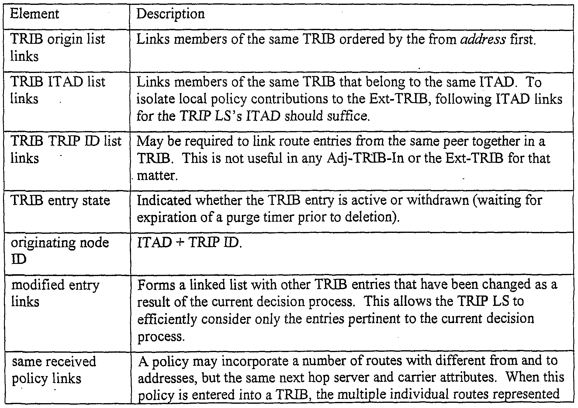


Claims
Priority Applications (3)
| Application Number | Priority Date | Filing Date | Title |
|---|---|---|---|
| JP2002550659A JP4636781B2 (en) | 2000-12-11 | 2001-12-11 | System and method for supporting control of real-time transport protocol flow through multiple networks via media flow routing |
| EP01991047A EP1342350B1 (en) | 2000-12-11 | 2001-12-11 | System and method for assisting in controlling real-time transport protocol flow through multiple networks vida media flow routing |
| DE60126647T DE60126647T2 (en) | 2000-12-11 | 2001-12-11 | System and method to support the control of real-time transport protocol flows across multiple networks |
Applications Claiming Priority (4)
| Application Number | Priority Date | Filing Date | Title |
|---|---|---|---|
| US25484000P | 2000-12-11 | 2000-12-11 | |
| US60/254,840 | 2000-12-11 | ||
| US09/844,964 US7028092B2 (en) | 2000-12-11 | 2001-04-27 | System and method for assisting in controlling real-time transport protocol flow through multiple networks via media flow routing |
| US09/844,964 | 2001-04-27 |
Publications (2)
| Publication Number | Publication Date |
|---|---|
| WO2002049279A2 true WO2002049279A2 (en) | 2002-06-20 |
| WO2002049279A3 WO2002049279A3 (en) | 2002-12-12 |
Family
ID=26944267
Family Applications (1)
| Application Number | Title | Priority Date | Filing Date |
|---|---|---|---|
| PCT/US2001/048161 WO2002049279A2 (en) | 2000-12-11 | 2001-12-11 | System and method for assisting in controlling real-time transport protocol flow through multiple networks via media flow routing |
Country Status (6)
| Country | Link |
|---|---|
| US (1) | US7028092B2 (en) |
| EP (1) | EP1342350B1 (en) |
| JP (1) | JP4636781B2 (en) |
| AT (1) | ATE354234T1 (en) |
| DE (1) | DE60126647T2 (en) |
| WO (1) | WO2002049279A2 (en) |
Cited By (34)
| Publication number | Priority date | Publication date | Assignee | Title |
|---|---|---|---|---|
| JP2009118498A (en) * | 2003-09-02 | 2009-05-28 | Nokia Corp | Transmission of embedded information relating to quality of service |
| US7764605B2 (en) | 2004-10-07 | 2010-07-27 | Genband Inc. | Methods and systems for measurement-based call admission control in a media gateway |
| US7774481B2 (en) | 2006-12-29 | 2010-08-10 | Genband Us Llc | Methods and apparatus for implementing a pluggable policy module within a session over internet protocol network |
| US7860990B2 (en) | 2006-01-31 | 2010-12-28 | Genband Us Llc | Session data records and related alarming within a session over internet protocol (SOIP) network |
| US7861003B2 (en) | 2006-01-31 | 2010-12-28 | Genband Us Llc | Adaptive feedback for session over internet protocol |
| US7865612B2 (en) | 2006-01-31 | 2011-01-04 | Genband Us Llc | Method and apparatus for partitioning resources within a session-over-internet-protocol (SoIP) session controller |
| US7912062B2 (en) | 2007-09-28 | 2011-03-22 | Genband Us Llc | Methods and apparatus for managing addresses related to virtual partitions of a session exchange device |
| US8085758B2 (en) | 2004-12-31 | 2011-12-27 | Genband Us Llc | Methods and apparatus for controlling call admission to a network based on call peers |
| US8204043B2 (en) | 2006-02-28 | 2012-06-19 | Genband Us Llc | Quality of service prioritization of internet protocol packets using session-aware components |
| US8259706B2 (en) | 2006-02-28 | 2012-09-04 | Genband Us Llc | Multistage prioritization of packets within a session over internet protocol (SOIP) network |
| US8509218B2 (en) | 2006-02-28 | 2013-08-13 | Genband Us Llc | Prioritization within a session over internet protocol (SOIP) network |
| US8649372B2 (en) | 2003-11-08 | 2014-02-11 | Ericsson Ab | Call set-up systems |
| US9060047B2 (en) | 2005-12-21 | 2015-06-16 | Genband Us Llc | Media stream management |
| US9641432B2 (en) | 2013-03-06 | 2017-05-02 | Icu Medical, Inc. | Medical device communication method |
| US9971871B2 (en) | 2011-10-21 | 2018-05-15 | Icu Medical, Inc. | Medical device update system |
| US10042986B2 (en) | 2013-11-19 | 2018-08-07 | Icu Medical, Inc. | Infusion pump automation system and method |
| US10242060B2 (en) | 2006-10-16 | 2019-03-26 | Icu Medical, Inc. | System and method for comparing and utilizing activity information and configuration information from multiple medical device management systems |
| US10238799B2 (en) | 2014-09-15 | 2019-03-26 | Icu Medical, Inc. | Matching delayed infusion auto-programs with manually entered infusion programs |
| US10238801B2 (en) | 2009-04-17 | 2019-03-26 | Icu Medical, Inc. | System and method for configuring a rule set for medical event management and responses |
| US10311972B2 (en) | 2013-11-11 | 2019-06-04 | Icu Medical, Inc. | Medical device system performance index |
| US10314974B2 (en) | 2014-06-16 | 2019-06-11 | Icu Medical, Inc. | System for monitoring and delivering medication to a patient and method of using the same to minimize the risks associated with automated therapy |
| US10434246B2 (en) | 2003-10-07 | 2019-10-08 | Icu Medical, Inc. | Medication management system |
| US10692595B2 (en) | 2018-07-26 | 2020-06-23 | Icu Medical, Inc. | Drug library dynamic version management |
| US10741280B2 (en) | 2018-07-17 | 2020-08-11 | Icu Medical, Inc. | Tagging pump messages with identifiers that facilitate restructuring |
| US10765799B2 (en) | 2013-09-20 | 2020-09-08 | Icu Medical, Inc. | Fail-safe drug infusion therapy system |
| US10861592B2 (en) | 2018-07-17 | 2020-12-08 | Icu Medical, Inc. | Reducing infusion pump network congestion by staggering updates |
| US10898641B2 (en) | 2014-04-30 | 2021-01-26 | Icu Medical, Inc. | Patient care system with conditional alarm forwarding |
| US11235100B2 (en) | 2003-11-13 | 2022-02-01 | Icu Medical, Inc. | System for maintaining drug information and communicating with medication delivery devices |
| US11309070B2 (en) | 2018-07-26 | 2022-04-19 | Icu Medical, Inc. | Drug library manager with customized worksheets |
| US11328804B2 (en) | 2018-07-17 | 2022-05-10 | Icu Medical, Inc. | Health checks for infusion pump communications systems |
| US11574737B2 (en) | 2016-07-14 | 2023-02-07 | Icu Medical, Inc. | Multi-communication path selection and security system for a medical device |
| US11571508B2 (en) | 2013-08-30 | 2023-02-07 | Icu Medical, Inc. | System and method of monitoring and managing a remote infusion regimen |
| US11587669B2 (en) | 2018-07-17 | 2023-02-21 | Icu Medical, Inc. | Passing authentication token to authorize access to rest calls via web sockets |
| US11605468B2 (en) | 2015-05-26 | 2023-03-14 | Icu Medical, Inc. | Infusion pump system and method with multiple drug library editor source capability |
Families Citing this family (169)
| Publication number | Priority date | Publication date | Assignee | Title |
|---|---|---|---|---|
| US6829654B1 (en) | 2000-06-23 | 2004-12-07 | Cloudshield Technologies, Inc. | Apparatus and method for virtual edge placement of web sites |
| US7003555B1 (en) * | 2000-06-23 | 2006-02-21 | Cloudshield Technologies, Inc. | Apparatus and method for domain name resolution |
| US9444785B2 (en) | 2000-06-23 | 2016-09-13 | Cloudshield Technologies, Inc. | Transparent provisioning of network access to an application |
| US7032031B2 (en) * | 2000-06-23 | 2006-04-18 | Cloudshield Technologies, Inc. | Edge adapter apparatus and method |
| US8204082B2 (en) | 2000-06-23 | 2012-06-19 | Cloudshield Technologies, Inc. | Transparent provisioning of services over a network |
| US7114008B2 (en) * | 2000-06-23 | 2006-09-26 | Cloudshield Technologies, Inc. | Edge adapter architecture apparatus and method |
| US7111163B1 (en) | 2000-07-10 | 2006-09-19 | Alterwan, Inc. | Wide area network using internet with quality of service |
| US7002973B2 (en) * | 2000-12-11 | 2006-02-21 | Acme Packet Inc. | System and method for assisting in controlling real-time transport protocol flow through multiple networks via use of a cluster of session routers |
| US7072303B2 (en) * | 2000-12-11 | 2006-07-04 | Acme Packet, Inc. | System and method for assisting in controlling real-time transport protocol flow through multiple networks |
| US7133923B2 (en) * | 2000-12-11 | 2006-11-07 | Acme Packet, Inc. | System and method for assisting in controlling real-time transport protocol flow through multiple networks via screening |
| US7120682B1 (en) * | 2001-03-08 | 2006-10-10 | Cisco Technology, Inc. | Virtual private networks for voice over networks applications |
| US7075922B2 (en) * | 2001-04-30 | 2006-07-11 | Level 3 Communications, Inc. | Screening inbound calls in a packet-based communications network |
| US8868659B2 (en) * | 2001-05-15 | 2014-10-21 | Avaya Inc. | Method and apparatus for automatic notification and response |
| US7020707B2 (en) * | 2001-05-30 | 2006-03-28 | Tekelec | Scalable, reliable session initiation protocol (SIP) signaling routing node |
| US7562112B2 (en) * | 2001-07-06 | 2009-07-14 | Intel Corporation | Method and apparatus for peer-to-peer services for efficient transfer of information between networks |
| US7546363B2 (en) * | 2001-07-06 | 2009-06-09 | Intel Corporation | Adaptive route determination for peer-to-peer services |
| US7440994B2 (en) * | 2001-07-06 | 2008-10-21 | Intel Corporation | Method and apparatus for peer-to-peer services to shift network traffic to allow for an efficient transfer of information between devices via prioritized list |
| US20030014532A1 (en) * | 2001-07-16 | 2003-01-16 | Shean-Guang Chang | Method and apparatus for multicast support |
| US7031311B2 (en) * | 2001-07-23 | 2006-04-18 | Acme Packet, Inc. | System and method for providing rapid rerouting of real-time multi-media flows |
| US7362707B2 (en) * | 2001-07-23 | 2008-04-22 | Acme Packet, Inc. | System and method for determining flow quality statistics for real-time transport protocol data flows |
| US20030023739A1 (en) * | 2001-07-28 | 2003-01-30 | Lan Ngoc Vu | System and method for multi-tier multi-casting over the Internet |
| US7984110B1 (en) * | 2001-11-02 | 2011-07-19 | Hewlett-Packard Company | Method and system for load balancing |
| US7516236B2 (en) * | 2001-12-21 | 2009-04-07 | Nokia Corporation | Method to improve perceived access speed to data network content using a multicast channel and local cache |
| US8090866B1 (en) * | 2002-01-18 | 2012-01-03 | Cisco Technology, Inc. | TCP proxy connection management in a gigabit environment |
| US7233593B2 (en) * | 2002-03-05 | 2007-06-19 | Nortel Networks Limited | System, device, and method for routing information in a communication network using policy extrapolation |
| US20030215080A1 (en) * | 2002-05-17 | 2003-11-20 | Wengrovitz Michael S. | Presence-aware private branch exchange (PBX) |
| US8015303B2 (en) * | 2002-08-02 | 2011-09-06 | Astute Networks Inc. | High data rate stateful protocol processing |
| US7502332B1 (en) * | 2002-08-08 | 2009-03-10 | Redback Networks, Inc. | Method and apparatus for route oscillation reduction |
| US7912899B2 (en) * | 2002-09-06 | 2011-03-22 | Oracle International Corporation | Method for selectively sending a notification to an instant messaging device |
| US7899879B2 (en) | 2002-09-06 | 2011-03-01 | Oracle International Corporation | Method and apparatus for a report cache in a near real-time business intelligence system |
| US7945846B2 (en) * | 2002-09-06 | 2011-05-17 | Oracle International Corporation | Application-specific personalization for data display |
| US7412481B2 (en) | 2002-09-16 | 2008-08-12 | Oracle International Corporation | Method and apparatus for distributed rule evaluation in a near real-time business intelligence system |
| US8255454B2 (en) | 2002-09-06 | 2012-08-28 | Oracle International Corporation | Method and apparatus for a multiplexed active data window in a near real-time business intelligence system |
| US8165993B2 (en) | 2002-09-06 | 2012-04-24 | Oracle International Corporation | Business intelligence system with interface that provides for immediate user action |
| US7941542B2 (en) * | 2002-09-06 | 2011-05-10 | Oracle International Corporation | Methods and apparatus for maintaining application execution over an intermittent network connection |
| US7668917B2 (en) * | 2002-09-16 | 2010-02-23 | Oracle International Corporation | Method and apparatus for ensuring accountability in the examination of a set of data elements by a user |
| US7401158B2 (en) | 2002-09-16 | 2008-07-15 | Oracle International Corporation | Apparatus and method for instant messaging collaboration |
| US8151278B1 (en) | 2002-10-17 | 2012-04-03 | Astute Networks, Inc. | System and method for timer management in a stateful protocol processing system |
| US7814218B1 (en) * | 2002-10-17 | 2010-10-12 | Astute Networks, Inc. | Multi-protocol and multi-format stateful processing |
| US7154901B2 (en) * | 2003-02-07 | 2006-12-26 | Mobile 365, Inc. | Intermediary network system and method for facilitating message exchange between wireless networks |
| US7672267B2 (en) * | 2003-02-07 | 2010-03-02 | Sybase 365, Inc. | Intermediary network system and method for facilitating message exchange between wireless networks |
| US7558256B1 (en) * | 2003-02-11 | 2009-07-07 | Juniper Networks, Inc. | Slim bandwidth reservation protocol over an IP network |
| US7904823B2 (en) * | 2003-03-17 | 2011-03-08 | Oracle International Corporation | Transparent windows methods and apparatus therefor |
| US7480723B2 (en) * | 2003-04-08 | 2009-01-20 | 3Com Corporation | Method and system for providing directory based services |
| US20040243719A1 (en) * | 2003-05-28 | 2004-12-02 | Milt Roselinsky | System and method for routing messages over disparate networks |
| US20050047412A1 (en) * | 2003-08-25 | 2005-03-03 | Susan Hares | Establishment and enforcement of policies in packet-switched networks |
| US7886348B2 (en) * | 2003-10-03 | 2011-02-08 | Verizon Services Corp. | Security management system for monitoring firewall operation |
| US7853996B1 (en) * | 2003-10-03 | 2010-12-14 | Verizon Services Corp. | Methodology, measurements and analysis of performance and scalability of stateful border gateways |
| US7421734B2 (en) * | 2003-10-03 | 2008-09-02 | Verizon Services Corp. | Network firewall test methods and apparatus |
| US7886350B2 (en) | 2003-10-03 | 2011-02-08 | Verizon Services Corp. | Methodology for measurements and analysis of protocol conformance, performance and scalability of stateful border gateways |
| US7417981B2 (en) | 2003-10-15 | 2008-08-26 | Vonage Holdings Corp. | Method and apparatus for enhanced Internet Telephony |
| CN100375470C (en) * | 2003-11-18 | 2008-03-12 | 株式会社东芝 | Apparatus for and method of setting communication path |
| US7761571B2 (en) * | 2003-11-25 | 2010-07-20 | Panasonic Corporation | SIP service for home network device and service mobility |
| US7860115B1 (en) * | 2003-12-18 | 2010-12-28 | Cisco Technology, Inc. | Withdrawing multiple advertised routes based on a single tag which may be of particular use in border gateway protocol |
| KR100590882B1 (en) * | 2004-01-30 | 2006-06-19 | 삼성전자주식회사 | apparatus and method of setting timer |
| US7386111B2 (en) | 2004-02-10 | 2008-06-10 | Vonage Network Inc. | Method and apparatus for placing a long distance call based on a virtual phone number |
| JP2005229273A (en) * | 2004-02-12 | 2005-08-25 | Fujitsu Ltd | Server backup system |
| US20080168181A1 (en) * | 2004-02-19 | 2008-07-10 | Koninklijke Philips Electronics, N.V. | Initiating Communication Sessions from a First Computer Network to a Second Computer Network |
| US20050209990A1 (en) * | 2004-03-18 | 2005-09-22 | Ordille Joann J | Method and apparatus for a publish-subscribe system with access controls |
| US7734731B2 (en) | 2004-03-18 | 2010-06-08 | Avaya Inc. | Method and apparatus for a publish-subscribe system with third party subscription delivery |
| US7623464B2 (en) * | 2004-07-09 | 2009-11-24 | Cisco Technology, Inc. | Rapid protocol failure detection |
| US8090858B2 (en) * | 2004-07-23 | 2012-01-03 | Nokia Siemens Networks Oy | Systems and methods for encapsulation based session initiation protocol through network address translation |
| US7330429B2 (en) * | 2004-10-27 | 2008-02-12 | Rockwell Electronic Commerce Technologies, Inc. | Method and apparatus for internet protocol transaction routing |
| US8213413B2 (en) * | 2004-11-19 | 2012-07-03 | Northrop Grumman Systems Corporation | Real-time packet processing system and method |
| DE112005002821B4 (en) * | 2004-12-21 | 2008-08-21 | Samsung Electronics Co., Ltd., Suwon | A method and system for providing a personal telephone call service to mobile subscribers and a wireless soft-broker therefor |
| US7903546B2 (en) * | 2005-01-14 | 2011-03-08 | Cisco Technology, Inc. | Detecting unavailable network connections |
| US20060174035A1 (en) * | 2005-01-28 | 2006-08-03 | At&T Corp. | System, device, & method for applying COS policies |
| US20060210036A1 (en) | 2005-03-16 | 2006-09-21 | Jeffrey Citron | System for effecting a telephone call over a computer network without alphanumeric keypad operation |
| US8683044B2 (en) | 2005-03-16 | 2014-03-25 | Vonage Network Llc | Third party call control application program interface |
| US8155014B2 (en) * | 2005-03-25 | 2012-04-10 | Cisco Technology, Inc. | Method and system using quality of service information for influencing a user's presence state |
| US8015403B2 (en) * | 2005-03-28 | 2011-09-06 | Cisco Technology, Inc. | Method and system indicating a level of security for VoIP calls through presence |
| WO2006116920A1 (en) * | 2005-04-30 | 2006-11-09 | Huawei Technologies Co., Ltd. | A communication system and method for achieving ip cross-domain intercommunication via an edge media gateway |
| US20060251054A1 (en) * | 2005-05-04 | 2006-11-09 | Peters Robert Y Jr | Method for providing terminating services treatment for calls terminating in an IP network |
| US8079062B2 (en) * | 2005-05-16 | 2011-12-13 | Cisco Technology, Inc. | Method and system using presence information to manage network access |
| US7764699B2 (en) * | 2005-05-16 | 2010-07-27 | Cisco Technology, Inc. | Method and system using shared configuration information to manage network access for network users |
| US9036619B2 (en) * | 2005-05-16 | 2015-05-19 | Mist Silicon Limited Liability Company | Systems and methods for a session initiation protocol (SIP) translator |
| US7920847B2 (en) * | 2005-05-16 | 2011-04-05 | Cisco Technology, Inc. | Method and system to protect the privacy of presence information for network users |
| US20070291734A1 (en) * | 2005-05-27 | 2007-12-20 | Medhavi Bhatia | Methods and Apparatus for Multistage Routing of Packets Using Call Templates |
| US20060294248A1 (en) * | 2005-06-28 | 2006-12-28 | Microsoft Corporation | Automatic server configuration based on user agent |
| US7502320B2 (en) * | 2005-07-06 | 2009-03-10 | Cisco Technology, Inc. | Method and apparatus for network-based admission control using path-coupled quality of service signaling |
| JP2006067614A (en) * | 2005-09-29 | 2006-03-09 | Hitachi Ltd | Session control unit for performing hierarchical relay processing |
| TWI294230B (en) * | 2005-11-04 | 2008-03-01 | Hon Hai Prec Ind Co Ltd | Network device with routing function and policy route setting method thereof |
| US8027251B2 (en) * | 2005-11-08 | 2011-09-27 | Verizon Services Corp. | Systems and methods for implementing protocol-aware network firewall |
| US9374342B2 (en) | 2005-11-08 | 2016-06-21 | Verizon Patent And Licensing Inc. | System and method for testing network firewall using fine granularity measurements |
| EP1949660A4 (en) | 2005-11-09 | 2010-10-13 | Vonage Holdings Corp | Method and system for customized caller identification |
| KR100785307B1 (en) * | 2006-02-01 | 2007-12-12 | 삼성전자주식회사 | Redirection transport system and method in internet protocol private branch exchange |
| US20070186010A1 (en) * | 2006-02-03 | 2007-08-09 | Rockwell Automation Technologies, Inc. | Extending industrial control system communications capabilities |
| US20070186011A1 (en) * | 2006-02-03 | 2007-08-09 | Rockwell Automation Technologies, Inc. | Industrial protocol and gateway |
| US8917717B2 (en) | 2007-02-13 | 2014-12-23 | Vonage Network Llc | Method and system for multi-modal communications |
| AU2007217346B2 (en) | 2006-02-27 | 2011-07-28 | Vonage Holdings Corp. | Automatic device configuration |
| US7602737B2 (en) * | 2006-03-01 | 2009-10-13 | Cisco Technology, Inc. | Methods and apparatus for providing an enhanced dynamic multipoint virtual private network architecture |
| CN101496387B (en) | 2006-03-06 | 2012-09-05 | 思科技术公司 | System and method for access authentication in a mobile wireless network |
| US9100407B2 (en) * | 2006-03-23 | 2015-08-04 | Cisco Technology, Inc. | Method and system to enhance performance of a session initiation protocol network and its elements |
| FR2900300A1 (en) * | 2006-04-21 | 2007-10-26 | France Telecom | METHOD FOR PROPAGATING MULTIPLE IP TELEPHONY ROUTES, CORRESPONDING COMPUTER DEVICE AND PROGRAM |
| US9749296B1 (en) * | 2006-06-30 | 2017-08-29 | Avaya Inc. | Method and apparatus for modifying address information in signaling messages to ensure in-path devices remain in signaling path between endpoints |
| US7630485B2 (en) * | 2006-07-06 | 2009-12-08 | At&T Intellectual Property I, L.P. | Method and system to bypass ENUM to reach a callee via a PSTN or a PLMN |
| US7929419B2 (en) * | 2006-08-04 | 2011-04-19 | Tekelec | Methods, systems, and computer program products for inhibiting message traffic to an unavailable terminating SIP server |
| US7965699B1 (en) * | 2006-08-29 | 2011-06-21 | Tellme Networks, Inc. | Routing/switching on a heterogeneous network |
| US20080080543A1 (en) * | 2006-09-28 | 2008-04-03 | Rockwell Automation Technologies, Inc. | Network switch with controller i/o capability |
| US9473529B2 (en) | 2006-11-08 | 2016-10-18 | Verizon Patent And Licensing Inc. | Prevention of denial of service (DoS) attacks on session initiation protocol (SIP)-based systems using method vulnerability filtering |
| US8966619B2 (en) * | 2006-11-08 | 2015-02-24 | Verizon Patent And Licensing Inc. | Prevention of denial of service (DoS) attacks on session initiation protocol (SIP)-based systems using return routability check filtering |
| US8432895B2 (en) * | 2007-02-23 | 2013-04-30 | Aip Acquisition Llc | Intelligent routing of VoIP traffic |
| US8788704B1 (en) * | 2007-04-18 | 2014-07-22 | Cisco Technology, Inc. | Sending incoming calling ID to devices after initiation of a call |
| US8570373B2 (en) * | 2007-06-08 | 2013-10-29 | Cisco Technology, Inc. | Tracking an object utilizing location information associated with a wireless device |
| US8302186B2 (en) | 2007-06-29 | 2012-10-30 | Verizon Patent And Licensing Inc. | System and method for testing network firewall for denial-of-service (DOS) detection and prevention in signaling channel |
| US8522344B2 (en) * | 2007-06-29 | 2013-08-27 | Verizon Patent And Licensing Inc. | Theft of service architectural integrity validation tools for session initiation protocol (SIP)-based systems |
| WO2009018418A2 (en) * | 2007-07-31 | 2009-02-05 | Tekelec | Systems, methods, and computer program products for distributing application or higher layer communications network signaling entity operational status information among session initiation protocol (sip) entities |
| JP2009059160A (en) * | 2007-08-31 | 2009-03-19 | Sony Corp | Server device, network system, content discovery notification method and computer program |
| US8776080B2 (en) * | 2007-09-25 | 2014-07-08 | Intel Corporationa | Management component transport protocol interconnect filtering and routing |
| EP2045349A1 (en) * | 2007-10-05 | 2009-04-08 | Linde Aktiengesellschaft | Method and apparatus for continuous hot-dip coating of metal strips |
| US8797377B2 (en) | 2008-02-14 | 2014-08-05 | Cisco Technology, Inc. | Method and system for videoconference configuration |
| US8355041B2 (en) * | 2008-02-14 | 2013-01-15 | Cisco Technology, Inc. | Telepresence system for 360 degree video conferencing |
| US8319819B2 (en) * | 2008-03-26 | 2012-11-27 | Cisco Technology, Inc. | Virtual round-table videoconference |
| US8390667B2 (en) | 2008-04-15 | 2013-03-05 | Cisco Technology, Inc. | Pop-up PIP for people not in picture |
| US8509081B2 (en) * | 2008-05-01 | 2013-08-13 | Saudi Arabian Oil Company | Adaptive hybrid wireless and wired process control system and method |
| US9237086B2 (en) * | 2008-05-30 | 2016-01-12 | Genband Us Llc | Methods and apparatus for network traffic distribution based on random number values |
| US8694658B2 (en) * | 2008-09-19 | 2014-04-08 | Cisco Technology, Inc. | System and method for enabling communication sessions in a network environment |
| TWI387240B (en) * | 2008-09-25 | 2013-02-21 | Inst Information Industry | Packet transmission system and packet transmission method, packet update method, host apparatus, and computer program product thereof for the packet transmission system |
| US7916729B2 (en) * | 2008-09-30 | 2011-03-29 | Cisco Technology, Inc. | Automatic RD rewrite technique to achieve fast convergence in inter-as networks |
| US8639821B2 (en) | 2008-10-06 | 2014-01-28 | Verizon Patent And Licensing Inc. | Method and system for providing a setup timer in a sip-based network |
| US8051136B2 (en) * | 2008-10-13 | 2011-11-01 | International Business Machines Corporation | Optimizing a presence enabled managed service |
| KR101619736B1 (en) * | 2008-10-23 | 2016-05-12 | 삼성전자주식회사 | Method, apparatus and system for manageing private network remotely using session initiation protocol |
| US8385215B1 (en) | 2008-11-13 | 2013-02-26 | Cisco Technoogy, Inc. | System and method for providing testing in an Ethernet network environment |
| US8659637B2 (en) | 2009-03-09 | 2014-02-25 | Cisco Technology, Inc. | System and method for providing three dimensional video conferencing in a network environment |
| US8477175B2 (en) * | 2009-03-09 | 2013-07-02 | Cisco Technology, Inc. | System and method for providing three dimensional imaging in a network environment |
| US9641567B2 (en) | 2009-05-14 | 2017-05-02 | Qualcomm Incorporated | Controlling media and informing controller status in collaborative sessions |
| US9641564B2 (en) * | 2009-05-14 | 2017-05-02 | Qualcomm Incorporated | Maintaining controllee information in collaborative sessions |
| US8659639B2 (en) | 2009-05-29 | 2014-02-25 | Cisco Technology, Inc. | System and method for extending communications between participants in a conferencing environment |
| US9082297B2 (en) | 2009-08-11 | 2015-07-14 | Cisco Technology, Inc. | System and method for verifying parameters in an audiovisual environment |
| US8463914B2 (en) * | 2010-01-30 | 2013-06-11 | Eliza Corporation | Facilitating rapid establishment of human/machine voice communication links over an IP network using last-known call-host endpoint states |
| US9225916B2 (en) | 2010-03-18 | 2015-12-29 | Cisco Technology, Inc. | System and method for enhancing video images in a conferencing environment |
| USD626102S1 (en) | 2010-03-21 | 2010-10-26 | Cisco Tech Inc | Video unit with integrated features |
| USD628968S1 (en) | 2010-03-21 | 2010-12-14 | Cisco Technology, Inc. | Free-standing video unit |
| USD628175S1 (en) | 2010-03-21 | 2010-11-30 | Cisco Technology, Inc. | Mounted video unit |
| USD626103S1 (en) | 2010-03-21 | 2010-10-26 | Cisco Technology, Inc. | Video unit with integrated features |
| US9313452B2 (en) | 2010-05-17 | 2016-04-12 | Cisco Technology, Inc. | System and method for providing retracting optics in a video conferencing environment |
| US8896655B2 (en) | 2010-08-31 | 2014-11-25 | Cisco Technology, Inc. | System and method for providing depth adaptive video conferencing |
| US8599934B2 (en) | 2010-09-08 | 2013-12-03 | Cisco Technology, Inc. | System and method for skip coding during video conferencing in a network environment |
| US8599865B2 (en) | 2010-10-26 | 2013-12-03 | Cisco Technology, Inc. | System and method for provisioning flows in a mobile network environment |
| US8699457B2 (en) | 2010-11-03 | 2014-04-15 | Cisco Technology, Inc. | System and method for managing flows in a mobile network environment |
| US8902244B2 (en) | 2010-11-15 | 2014-12-02 | Cisco Technology, Inc. | System and method for providing enhanced graphics in a video environment |
| US8730297B2 (en) | 2010-11-15 | 2014-05-20 | Cisco Technology, Inc. | System and method for providing camera functions in a video environment |
| US9143725B2 (en) | 2010-11-15 | 2015-09-22 | Cisco Technology, Inc. | System and method for providing enhanced graphics in a video environment |
| US9338394B2 (en) | 2010-11-15 | 2016-05-10 | Cisco Technology, Inc. | System and method for providing enhanced audio in a video environment |
| US8542264B2 (en) | 2010-11-18 | 2013-09-24 | Cisco Technology, Inc. | System and method for managing optics in a video environment |
| US8723914B2 (en) | 2010-11-19 | 2014-05-13 | Cisco Technology, Inc. | System and method for providing enhanced video processing in a network environment |
| US9111138B2 (en) | 2010-11-30 | 2015-08-18 | Cisco Technology, Inc. | System and method for gesture interface control |
| USD678894S1 (en) | 2010-12-16 | 2013-03-26 | Cisco Technology, Inc. | Display screen with graphical user interface |
| USD678320S1 (en) | 2010-12-16 | 2013-03-19 | Cisco Technology, Inc. | Display screen with graphical user interface |
| USD682294S1 (en) | 2010-12-16 | 2013-05-14 | Cisco Technology, Inc. | Display screen with graphical user interface |
| USD678307S1 (en) | 2010-12-16 | 2013-03-19 | Cisco Technology, Inc. | Display screen with graphical user interface |
| USD682293S1 (en) | 2010-12-16 | 2013-05-14 | Cisco Technology, Inc. | Display screen with graphical user interface |
| USD682864S1 (en) | 2010-12-16 | 2013-05-21 | Cisco Technology, Inc. | Display screen with graphical user interface |
| USD682854S1 (en) | 2010-12-16 | 2013-05-21 | Cisco Technology, Inc. | Display screen for graphical user interface |
| USD678308S1 (en) | 2010-12-16 | 2013-03-19 | Cisco Technology, Inc. | Display screen with graphical user interface |
| US8719926B2 (en) * | 2011-02-11 | 2014-05-06 | Verizon Patent And Licensing Inc. | Denial of service detection and prevention using dialog level filtering |
| US8692862B2 (en) | 2011-02-28 | 2014-04-08 | Cisco Technology, Inc. | System and method for selection of video data in a video conference environment |
| US8670019B2 (en) | 2011-04-28 | 2014-03-11 | Cisco Technology, Inc. | System and method for providing enhanced eye gaze in a video conferencing environment |
| US8786631B1 (en) | 2011-04-30 | 2014-07-22 | Cisco Technology, Inc. | System and method for transferring transparency information in a video environment |
| US8934026B2 (en) | 2011-05-12 | 2015-01-13 | Cisco Technology, Inc. | System and method for video coding in a dynamic environment |
| TWI439088B (en) * | 2011-06-01 | 2014-05-21 | Accton Technology Corp | Domain gateway control system and method thereof |
| US8947493B2 (en) | 2011-11-16 | 2015-02-03 | Cisco Technology, Inc. | System and method for alerting a participant in a video conference |
| US8682087B2 (en) | 2011-12-19 | 2014-03-25 | Cisco Technology, Inc. | System and method for depth-guided image filtering in a video conference environment |
| GB2498517B (en) * | 2012-01-10 | 2019-02-27 | Media Network Services As | Data transport |
| US9681154B2 (en) | 2012-12-06 | 2017-06-13 | Patent Capital Group | System and method for depth-guided filtering in a video conference environment |
| US9843621B2 (en) | 2013-05-17 | 2017-12-12 | Cisco Technology, Inc. | Calendaring activities based on communication processing |
| US9531808B2 (en) * | 2013-08-22 | 2016-12-27 | Avaya Inc. | Providing data resource services within enterprise systems for resource level sharing among multiple applications, and related methods, systems, and computer-readable media |
| US9516061B2 (en) | 2013-11-26 | 2016-12-06 | Cisco Technology, Inc. | Smart virtual private network |
| US11012931B2 (en) | 2019-05-24 | 2021-05-18 | Oracle International Corporation | Methods, systems, and computer readable media for enhanced signaling gateway (SGW) status detection and selection for emergency calls |
Family Cites Families (113)
| Publication number | Priority date | Publication date | Assignee | Title |
|---|---|---|---|---|
| USRE21065E (en) * | 1939-05-02 | Dispensing device for sheet rubber deposited prom an aqueous dispersion | ||
| US524219A (en) * | 1894-08-07 | Theodore f | ||
| US732889A (en) * | 1903-05-04 | 1903-07-07 | Charles Nelson Paver | Wrapping material. |
| US950785A (en) * | 1908-10-05 | 1910-03-01 | Robeson L Low | Bottle-wrapper. |
| US1063154A (en) * | 1912-04-04 | 1913-05-27 | Joseph Nester | Packaging bottles. |
| US1525015A (en) * | 1920-12-24 | 1925-02-03 | Weeks Engineering Corp | Art of wrapping packages |
| US1446563A (en) * | 1922-07-25 | 1923-02-27 | Frances T Hughes | Decorative covering for flowerpots, bouquets, and the like |
| US1697751A (en) * | 1926-01-18 | 1929-01-01 | Benjamin F Blake | Flowerpot cover |
| US1794212A (en) * | 1929-01-18 | 1931-02-24 | Allie A Snyder | Flowerpot cover |
| US1811574A (en) * | 1930-03-14 | 1931-06-23 | William E Barrett | Collapsible bag |
| US1863216A (en) * | 1931-03-12 | 1932-06-14 | Wordingham George | Wrapper |
| US2048123A (en) * | 1934-08-03 | 1936-07-21 | Pneumatic Scale Corp | Wrapped package |
| US2170147A (en) * | 1937-01-21 | 1939-08-22 | John D Lane | Package of gummed bands or stickers |
| US2200111A (en) * | 1937-02-24 | 1940-05-07 | Bensel Corp | Dispensing paper package |
| US2322229A (en) * | 1938-05-04 | 1943-06-22 | Diamond Harry | Pressure switching |
| US2323287A (en) * | 1939-08-14 | 1943-07-06 | Universal Paper Products Compa | Paper cup |
| US2278673A (en) * | 1940-03-13 | 1942-04-07 | Savada Martin | Adhesive coated sheet material |
| US2371985A (en) * | 1943-02-08 | 1945-03-20 | Louis D Freiberg | Wrapped article and method of wrapping the same |
| US2510120A (en) * | 1946-05-31 | 1950-06-06 | Russell J Leander | Masking paper |
| US2648487A (en) * | 1947-07-25 | 1953-08-11 | St Regis Paper Co | Bag for packaging tacky polymeric materials |
| US2883262A (en) * | 1954-06-11 | 1959-04-21 | American Hospital Supply Corp | Method for sterilizing instruments |
| US3130113A (en) * | 1954-08-09 | 1964-04-21 | United Merchants & Mfg | Self-adhesive decorative surface covering material |
| US2846060A (en) * | 1954-11-15 | 1958-08-05 | Stanley G Yount | Wrapping means for articles of sheet form |
| US2822287A (en) * | 1956-07-25 | 1958-02-04 | Kalamazoo Vegets Le Parchment | Moistureproof heat sealable wrapping sheet |
| US2989828A (en) * | 1958-09-04 | 1961-06-27 | Flex O Glass Inc | Plastic plant package |
| US3080680A (en) * | 1959-04-29 | 1963-03-12 | Willis Reynolds Corp | Jacketed fibre transplanter pot |
| US3022605A (en) * | 1959-05-11 | 1962-02-27 | Alfred O Reynolds | Method of packing seedling plants for shipment |
| US3094810A (en) * | 1960-12-19 | 1963-06-25 | Max L Kalpin | Containers for plants and the like |
| US3121647A (en) * | 1961-10-24 | 1964-02-18 | Harris | Bottle wrapping apparatus |
| US3322325A (en) * | 1962-01-30 | 1967-05-30 | Roy L Bush | Bag seal utilizing pressure sensitive tape having weakened transverse zones |
| US3508372A (en) * | 1962-04-24 | 1970-04-28 | Lawrence B Wallerstein | Flower protective system |
| NL300500A (en) * | 1962-11-14 | 1900-01-01 | ||
| US3431706A (en) * | 1966-11-08 | 1969-03-11 | Modern Mfg Co Inc | Floral sacker |
| US3376666A (en) * | 1966-11-16 | 1968-04-09 | William H. Leonard | Packages for bunches of flowers |
| US3552059A (en) * | 1967-12-07 | 1971-01-05 | Moore Paper Boxes Inc | Cut flower package |
| US3556389A (en) * | 1967-12-21 | 1971-01-19 | Gregoire Flowers Inc | Cut flower package |
| US3510054A (en) * | 1968-07-23 | 1970-05-05 | Dino Di Carlo | Dispenser packet |
| US3512700A (en) * | 1968-10-30 | 1970-05-19 | Jaite Display Bag Co The | Flexible bag construction |
| US3557516A (en) * | 1968-10-30 | 1971-01-26 | Reynolds Metals Co | Method of making a package construction |
| US3554434A (en) * | 1968-11-08 | 1971-01-12 | Dave Chapman | Free-standing flexible package |
| US3681105A (en) * | 1970-04-22 | 1972-08-01 | Borden Inc | Pressure-sensitive adhesive web printed on back with transfer-proof ink |
| US3888443A (en) * | 1972-02-14 | 1975-06-10 | Cameron D Flanigen | Support stand for puzzle blocks or other items |
| US3793799A (en) * | 1973-02-26 | 1974-02-26 | Grace W R & Co | Method of film sheet dispensing and wrapping |
| US3869828A (en) * | 1973-07-16 | 1975-03-11 | Mitsuo M Matsumoto | Planter package |
| US3962503A (en) * | 1973-08-06 | 1976-06-08 | Crawford Mildred A | Decorative and protective device for use with a floral container |
| US4043077A (en) * | 1976-05-10 | 1977-08-23 | Clara Francis Stonehocker | Expandable pot for containing plants and method therefor |
| US4216620A (en) * | 1976-12-01 | 1980-08-12 | Highland Supply Corporation | Flower pot wrap with lace pattern edging |
| US4091925A (en) * | 1977-08-15 | 1978-05-30 | Standun, Inc. | Snag resistant vented flower sleeve |
| USD259333S (en) * | 1977-10-11 | 1981-05-26 | Charbonneau Robert R | Combined shipping and packaging envelope for a potted plant |
| US4189868A (en) * | 1978-02-22 | 1980-02-26 | General Mills, Inc. | Package for perishable produce |
| US4265049A (en) * | 1978-10-03 | 1981-05-05 | Lynda Gorewitz | Temporary plant covers |
| US4380564A (en) * | 1979-07-16 | 1983-04-19 | Clopay Corporation | Cross-tearable decorative sheet material |
| US4248347A (en) * | 1979-08-06 | 1981-02-03 | Trimbee Robert J | Packaging for florist arrangements |
| US4280314A (en) * | 1979-09-07 | 1981-07-28 | Modern Mfg. Co., Inc. | Device for packaging elongated articles |
| EP0039115B1 (en) * | 1980-04-25 | 1984-04-18 | Koninklijke Emballage Industrie Van Leer B.V. | A package containing pot plants |
| US4333267A (en) * | 1980-04-28 | 1982-06-08 | Meridian Industries Inc. | Protective sleeve for plants |
| USD279279S (en) * | 1983-10-24 | 1985-06-18 | Curtis Wagner Co., Inc. | Floral container |
| US5199242A (en) * | 1984-05-22 | 1993-04-06 | Highland Supply Corporation | Method for wrapping flower pots using a self adhering wrapping material |
| US4835834A (en) * | 1986-06-20 | 1989-06-06 | Highland Supply Corporation | Method of shaping and holding a sheet of material about a flower pot with a collar |
| US5181364A (en) * | 1988-09-26 | 1993-01-26 | Highland Supply Corporation | Wrapping a floral grouping with sheets having adhesive or cohesive material applied thereto |
| US5111638A (en) * | 1984-05-22 | 1992-05-12 | Highland Supply Corporation | Method for wrapping an object with a material having pressure sensitive adhesive thereon |
| US5428939A (en) * | 1988-09-26 | 1995-07-04 | Highland Supply Corporation | Method for crimping a wrapper about a floral grouping |
| US5105599A (en) * | 1989-02-24 | 1992-04-21 | Highland Supply Corporation | Means for securing a decorative cover about a flower pot |
| US5007229A (en) * | 1984-05-22 | 1991-04-16 | Highland Supply Corporation | Method of wrapping utilizing a self adhering wrapping material |
| NL8500720A (en) * | 1984-05-22 | 1985-07-01 | Highland Supply Corp | SYSTEM FOR FORMING ARTICLES. |
| US4765464A (en) * | 1985-10-07 | 1988-08-23 | Ristvedt-Johnson, Inc. | Wrapped coin roll and method of forming same |
| US4640079A (en) * | 1985-11-20 | 1987-02-03 | Modern Mfg. Co. Inc. | Device for packaging plants |
| US4733521A (en) * | 1986-05-20 | 1988-03-29 | Highland Supply Corporation | Cover forming apparatus |
| FR2603026B1 (en) * | 1986-08-21 | 1989-08-18 | Castel Jean Claude | IMPROVED PROCESS FOR THE PRODUCTION OF FLEXIBLE CONTAINERS OR CONTAINERS OF VARIOUS FORMS |
| US4801014A (en) * | 1986-10-28 | 1989-01-31 | Meadows Patricia H | Bouquet sleeve |
| US4717262A (en) * | 1987-01-09 | 1988-01-05 | T.C. Manufacturing Company, Inc. | Flat bottom plastic bag and method of making same |
| USD301991S (en) * | 1987-08-17 | 1989-07-04 | Van Sant Lisa P | Flower container |
| US5625979A (en) * | 1992-09-04 | 1997-05-06 | Southpac Trust International, Inc. | Sleeve having a detachable portion forming a skirt and methods |
| US5493809A (en) * | 1988-09-26 | 1996-02-27 | Highland Supply Corporation | Sleeve having a detachable portion for forming a pot cover |
| US5205108A (en) * | 1992-06-29 | 1993-04-27 | Highland Supply Corporation | Method of wrapping a floral grouping with a wrapper having a central opening |
| NL8802814A (en) * | 1988-11-15 | 1990-06-01 | Klerk S Plastic Ind B V | METHOD AND APPARATUS FOR MANUFACTURING POCKET OR BAG PACKAGING, AND SUCH PACKAGING |
| USD315700S (en) * | 1989-03-14 | 1991-03-26 | Carrol E. Stephens | Flower holder |
| US4941572A (en) * | 1989-05-24 | 1990-07-17 | Jetram Sales, Inc. | Method and package for fresh cut flower arrangements and plants |
| US5526932A (en) * | 1989-06-02 | 1996-06-18 | The Family Trust U/T/A | Flower pot assembly formed from a sheet with an opening |
| US5120382A (en) * | 1989-09-15 | 1992-06-09 | Highland Supply Corporation | Process for forming a paper, burlap or cloth flower pot cover |
| USD335105S (en) * | 1990-03-28 | 1993-04-27 | Heinrich Kossmann Ag Plasticfabrikation | Flower pot sleeve |
| NL9002569A (en) * | 1990-11-26 | 1992-06-16 | Bernardus Johannes Martinus Ma | PACKAGING FOR PLANTS OR FLOWERS PLACED IN A POT-HOLDER. |
| US5235782A (en) * | 1991-11-27 | 1993-08-17 | Simcha Landau | Cover for potted plants and method for covering potted plants |
| JPH05191455A (en) * | 1992-01-10 | 1993-07-30 | Mitsubishi Electric Corp | Packet switching device |
| US5715944A (en) * | 1992-02-14 | 1998-02-10 | Heinz-Dieter Schmidt | Transport vase for cut flowers |
| US5239775A (en) * | 1992-06-01 | 1993-08-31 | Simcha Landau | Elastic wrap for plant materials and method for covering such materials |
| JP3110583B2 (en) * | 1993-05-25 | 2000-11-20 | 三菱電機株式会社 | Router device |
| NL9301532A (en) * | 1993-09-06 | 1995-04-03 | Jei Lee Corp | Method and device for the manufacture of a sleeve-shaped package as well as such a sleeve-shaped package. |
| US5388695A (en) * | 1994-05-23 | 1995-02-14 | Professional Package Company | Flat trapezoidal container of brightly printed thermally sealable film |
| US5647168A (en) * | 1994-05-23 | 1997-07-15 | Professional Package Company | Flat trapezoidal container of brightly printed thermally sealable film |
| USD368025S (en) * | 1994-07-19 | 1996-03-19 | Professional Package Company | Floral wrapping material |
| US5647193A (en) * | 1995-03-13 | 1997-07-15 | Southpac Trust International, Inc. | Pot wrapping apparatus and method |
| US5624320A (en) * | 1996-03-11 | 1997-04-29 | Martinez; Benjimin P. | Flower presentation device |
| USD404684S (en) * | 1996-05-17 | 1999-01-26 | Berwick Industries, Inc. | Flower pot cover with matte surface |
| US6335927B1 (en) | 1996-11-18 | 2002-01-01 | Mci Communications Corporation | System and method for providing requested quality of service in a hybrid network |
| US6754181B1 (en) * | 1996-11-18 | 2004-06-22 | Mci Communications Corporation | System and method for a directory service supporting a hybrid communication system architecture |
| US5999518A (en) | 1996-12-04 | 1999-12-07 | Alcatel Usa Sourcing, L.P. | Distributed telecommunications switching system and method |
| US6084855A (en) | 1997-02-18 | 2000-07-04 | Nokia Telecommunications, Oy | Method and apparatus for providing fair traffic scheduling among aggregated internet protocol flows |
| US6085245A (en) | 1997-07-24 | 2000-07-04 | Paradyne Corporation | System and method for the implicit support of IP subnetworks |
| JP3516432B2 (en) * | 1997-11-18 | 2004-04-05 | 株式会社東芝 | Node device and packet transfer method |
| JP3011177B2 (en) * | 1998-03-23 | 2000-02-21 | 日本電気株式会社 | Address resolution processing method |
| US6212570B1 (en) * | 1998-04-29 | 2001-04-03 | Nippon Telegraph & Telephone Corporation | Information distribution device selection system |
| US6584093B1 (en) * | 1998-08-25 | 2003-06-24 | Cisco Technology, Inc. | Method and apparatus for automatic inter-domain routing of calls |
| USD419436S (en) * | 1998-12-14 | 2000-01-25 | Kevin Celtorius | Flower bag |
| US6775269B1 (en) * | 1999-03-30 | 2004-08-10 | Telecom Technologies, Inc. | Method and system for routing telephone calls between a public switched telephone network and an internet protocol network |
| US6765931B1 (en) | 1999-04-13 | 2004-07-20 | Broadcom Corporation | Gateway with voice |
| US7346022B1 (en) * | 1999-09-28 | 2008-03-18 | At&T Corporation | H.323 user, service and service provider mobility framework for the multimedia intelligent networking |
| US6917612B2 (en) * | 2000-09-01 | 2005-07-12 | Telefonaktiebolaged L M Ericsson | System and method for address resolution in internet protocol (IP)-based networks |
| US7002973B2 (en) * | 2000-12-11 | 2006-02-21 | Acme Packet Inc. | System and method for assisting in controlling real-time transport protocol flow through multiple networks via use of a cluster of session routers |
| US7072303B2 (en) | 2000-12-11 | 2006-07-04 | Acme Packet, Inc. | System and method for assisting in controlling real-time transport protocol flow through multiple networks |
| US7133923B2 (en) * | 2000-12-11 | 2006-11-07 | Acme Packet, Inc. | System and method for assisting in controlling real-time transport protocol flow through multiple networks via screening |
| US7599351B2 (en) * | 2001-03-20 | 2009-10-06 | Verizon Business Global Llc | Recursive query for communications network data |
| US20030014644A1 (en) * | 2001-05-02 | 2003-01-16 | Burns James E. | Method and system for security policy management |
-
2001
- 2001-04-27 US US09/844,964 patent/US7028092B2/en not_active Expired - Lifetime
- 2001-12-11 EP EP01991047A patent/EP1342350B1/en not_active Expired - Lifetime
- 2001-12-11 JP JP2002550659A patent/JP4636781B2/en not_active Expired - Fee Related
- 2001-12-11 AT AT01991047T patent/ATE354234T1/en not_active IP Right Cessation
- 2001-12-11 DE DE60126647T patent/DE60126647T2/en not_active Expired - Lifetime
- 2001-12-11 WO PCT/US2001/048161 patent/WO2002049279A2/en active IP Right Grant
Non-Patent Citations (2)
| Title |
|---|
| ROSENBERG ET AL.: "A framework for telephony routing over IP" [Online] June 2000 (2000-06) , IETF , INTERNET XP002201353 Retrieved from the Internet: <URL: http://www.faqs.org/rfcs/rfc2871.html> [retrieved on 2002-06-05] page 3, line 11 - line 12 page 4, line 19 - line 22 page 6, line 26 - line 31 page 12, line 18 - line 20 page 13, line 2 - line 8 page 13, line 24 - line 26 figures 2,3 page 13, paragraph 9.2.1 -page 14, paragraph 9.2.3 * |
| See also references of EP1342350A2 * |
Cited By (76)
| Publication number | Priority date | Publication date | Assignee | Title |
|---|---|---|---|---|
| US9178748B2 (en) | 2003-09-02 | 2015-11-03 | Microsoft Technology Licensing, Llc | Transmission of information relating to a quality of service |
| JP2009118498A (en) * | 2003-09-02 | 2009-05-28 | Nokia Corp | Transmission of embedded information relating to quality of service |
| US8380848B2 (en) | 2003-09-02 | 2013-02-19 | Core Wireless Licensing S.A.R.L. | Transmission of information relating to a quality of service |
| US8239521B2 (en) | 2003-09-02 | 2012-08-07 | Core Wireless Licensing S.A.R.L. | Transmission of information relating to a quality of service |
| US10434246B2 (en) | 2003-10-07 | 2019-10-08 | Icu Medical, Inc. | Medication management system |
| US10484435B2 (en) | 2003-11-08 | 2019-11-19 | Telefonaktiebolaget Lm Ericsson (Publ) | Call set-up systems |
| US8649372B2 (en) | 2003-11-08 | 2014-02-11 | Ericsson Ab | Call set-up systems |
| US11235100B2 (en) | 2003-11-13 | 2022-02-01 | Icu Medical, Inc. | System for maintaining drug information and communicating with medication delivery devices |
| US7764605B2 (en) | 2004-10-07 | 2010-07-27 | Genband Inc. | Methods and systems for measurement-based call admission control in a media gateway |
| US10171514B2 (en) | 2004-12-31 | 2019-01-01 | Genband Us Llc | Method and system for routing media calls over real time packet switched connection |
| US8194640B2 (en) | 2004-12-31 | 2012-06-05 | Genband Us Llc | Voice over IP (VoIP) network infrastructure components and method |
| US8254265B2 (en) | 2004-12-31 | 2012-08-28 | Genband Us Llc | Methods and apparatus for routing IP media data based on cost |
| US8085758B2 (en) | 2004-12-31 | 2011-12-27 | Genband Us Llc | Methods and apparatus for controlling call admission to a network based on call peers |
| US9871829B2 (en) | 2004-12-31 | 2018-01-16 | Genband Us Llc | Voice over IP (VoIP) network infrastructure components and method |
| US8755371B2 (en) | 2004-12-31 | 2014-06-17 | Genband Us Llc | Methods and apparatus for multistage routing of packets using call templates |
| US8547962B2 (en) | 2004-12-31 | 2013-10-01 | Genband Us Llc | Methods and apparatus for forwarding IP calls through a proxy interface |
| US10171513B2 (en) | 2004-12-31 | 2019-01-01 | Genband Us Llc | Methods and apparatus for controlling call admission to a network based on network resources |
| US9692710B2 (en) | 2005-12-21 | 2017-06-27 | Genband Us Llc | Media stream management |
| US9060047B2 (en) | 2005-12-21 | 2015-06-16 | Genband Us Llc | Media stream management |
| US7865612B2 (en) | 2006-01-31 | 2011-01-04 | Genband Us Llc | Method and apparatus for partitioning resources within a session-over-internet-protocol (SoIP) session controller |
| US7861003B2 (en) | 2006-01-31 | 2010-12-28 | Genband Us Llc | Adaptive feedback for session over internet protocol |
| US7860990B2 (en) | 2006-01-31 | 2010-12-28 | Genband Us Llc | Session data records and related alarming within a session over internet protocol (SOIP) network |
| US8509218B2 (en) | 2006-02-28 | 2013-08-13 | Genband Us Llc | Prioritization within a session over internet protocol (SOIP) network |
| US8259706B2 (en) | 2006-02-28 | 2012-09-04 | Genband Us Llc | Multistage prioritization of packets within a session over internet protocol (SOIP) network |
| US8204043B2 (en) | 2006-02-28 | 2012-06-19 | Genband Us Llc | Quality of service prioritization of internet protocol packets using session-aware components |
| US11194810B2 (en) | 2006-10-16 | 2021-12-07 | Icu Medical, Inc. | System and method for comparing and utilizing activity information and configuration information from multiple device management systems |
| US10242060B2 (en) | 2006-10-16 | 2019-03-26 | Icu Medical, Inc. | System and method for comparing and utilizing activity information and configuration information from multiple medical device management systems |
| US7774481B2 (en) | 2006-12-29 | 2010-08-10 | Genband Us Llc | Methods and apparatus for implementing a pluggable policy module within a session over internet protocol network |
| US7912062B2 (en) | 2007-09-28 | 2011-03-22 | Genband Us Llc | Methods and apparatus for managing addresses related to virtual partitions of a session exchange device |
| US11654237B2 (en) | 2009-04-17 | 2023-05-23 | Icu Medical, Inc. | System and method for configuring a rule set for medical event management and responses |
| US10238801B2 (en) | 2009-04-17 | 2019-03-26 | Icu Medical, Inc. | System and method for configuring a rule set for medical event management and responses |
| US11013861B2 (en) | 2009-04-17 | 2021-05-25 | Icu Medical, Inc. | System and method for configuring a rule set for medical event management and responses |
| US9971871B2 (en) | 2011-10-21 | 2018-05-15 | Icu Medical, Inc. | Medical device update system |
| US11626205B2 (en) | 2011-10-21 | 2023-04-11 | Icu Medical, Inc. | Medical device update system |
| US9641432B2 (en) | 2013-03-06 | 2017-05-02 | Icu Medical, Inc. | Medical device communication method |
| US10333843B2 (en) | 2013-03-06 | 2019-06-25 | Icu Medical, Inc. | Medical device communication method |
| US11470000B2 (en) | 2013-03-06 | 2022-10-11 | Icu Medical, Inc. | Medical device communication method |
| US11571508B2 (en) | 2013-08-30 | 2023-02-07 | Icu Medical, Inc. | System and method of monitoring and managing a remote infusion regimen |
| US10765799B2 (en) | 2013-09-20 | 2020-09-08 | Icu Medical, Inc. | Fail-safe drug infusion therapy system |
| US10311972B2 (en) | 2013-11-11 | 2019-06-04 | Icu Medical, Inc. | Medical device system performance index |
| US11501877B2 (en) | 2013-11-11 | 2022-11-15 | Icu Medical, Inc. | Medical device system performance index |
| US10042986B2 (en) | 2013-11-19 | 2018-08-07 | Icu Medical, Inc. | Infusion pump automation system and method |
| US11037668B2 (en) | 2013-11-19 | 2021-06-15 | Icu Medical, Inc. | Infusion pump automation system and method |
| US11763927B2 (en) | 2013-11-19 | 2023-09-19 | Icu Medical, Inc. | Infusion pump automation system and method |
| US10898641B2 (en) | 2014-04-30 | 2021-01-26 | Icu Medical, Inc. | Patient care system with conditional alarm forwarding |
| US11628246B2 (en) | 2014-04-30 | 2023-04-18 | Icu Medical, Inc. | Patient care system with conditional alarm forwarding |
| US11628254B2 (en) | 2014-06-16 | 2023-04-18 | Icu Medical, Inc. | System for monitoring and delivering medication to a patient and method of using the same to minimize the risks associated with automated therapy |
| US10646651B2 (en) | 2014-06-16 | 2020-05-12 | Icu Medical, Inc. | System for monitoring and delivering medication to a patient and method of using the same to minimize the risks associated with automated therapy |
| US10314974B2 (en) | 2014-06-16 | 2019-06-11 | Icu Medical, Inc. | System for monitoring and delivering medication to a patient and method of using the same to minimize the risks associated with automated therapy |
| US10799632B2 (en) | 2014-09-15 | 2020-10-13 | Icu Medical, Inc. | Matching delayed infusion auto-programs with manually entered infusion programs |
| US10238799B2 (en) | 2014-09-15 | 2019-03-26 | Icu Medical, Inc. | Matching delayed infusion auto-programs with manually entered infusion programs |
| US11289183B2 (en) | 2014-09-15 | 2022-03-29 | Icu Medical, Inc. | Matching delayed infusion auto-programs with manually entered infusion programs |
| US11574721B2 (en) | 2014-09-15 | 2023-02-07 | Icu Medical, Inc. | Matching delayed infusion auto-programs with manually entered infusion programs |
| US11605468B2 (en) | 2015-05-26 | 2023-03-14 | Icu Medical, Inc. | Infusion pump system and method with multiple drug library editor source capability |
| US11574737B2 (en) | 2016-07-14 | 2023-02-07 | Icu Medical, Inc. | Multi-communication path selection and security system for a medical device |
| US11373753B2 (en) | 2018-07-17 | 2022-06-28 | Icu Medical, Inc. | Converting pump messages in new pump protocol to standardized dataset messages |
| US11670416B2 (en) | 2018-07-17 | 2023-06-06 | Icu Medical, Inc. | Tagging pump messages with identifiers that facilitate restructuring |
| US11923076B2 (en) | 2018-07-17 | 2024-03-05 | Icu Medical, Inc. | Converting pump messages in new pump protocol to standardized dataset messages |
| US11152109B2 (en) | 2018-07-17 | 2021-10-19 | Icu Medical, Inc. | Detecting missing messages from clinical environment |
| US11483403B2 (en) | 2018-07-17 | 2022-10-25 | Icu Medical, Inc. | Maintaining clinical messaging during network instability |
| US11483402B2 (en) | 2018-07-17 | 2022-10-25 | Icu Medical, Inc. | Maintaining clinical messaging during an internet outage |
| US11139058B2 (en) | 2018-07-17 | 2021-10-05 | Icu Medical, Inc. | Reducing file transfer between cloud environment and infusion pumps |
| US11328805B2 (en) | 2018-07-17 | 2022-05-10 | Icu Medical, Inc. | Reducing infusion pump network congestion by staggering updates |
| US11328804B2 (en) | 2018-07-17 | 2022-05-10 | Icu Medical, Inc. | Health checks for infusion pump communications systems |
| US10964428B2 (en) | 2018-07-17 | 2021-03-30 | Icu Medical, Inc. | Merging messages into cache and generating user interface using the cache |
| US11587669B2 (en) | 2018-07-17 | 2023-02-21 | Icu Medical, Inc. | Passing authentication token to authorize access to rest calls via web sockets |
| US11881297B2 (en) | 2018-07-17 | 2024-01-23 | Icu Medical, Inc. | Reducing infusion pump network congestion by staggering updates |
| US10950339B2 (en) | 2018-07-17 | 2021-03-16 | Icu Medical, Inc. | Converting pump messages in new pump protocol to standardized dataset messages |
| US10861592B2 (en) | 2018-07-17 | 2020-12-08 | Icu Medical, Inc. | Reducing infusion pump network congestion by staggering updates |
| US10741280B2 (en) | 2018-07-17 | 2020-08-11 | Icu Medical, Inc. | Tagging pump messages with identifiers that facilitate restructuring |
| US11783935B2 (en) | 2018-07-17 | 2023-10-10 | Icu Medical, Inc. | Health checks for infusion pump communications systems |
| US11152110B2 (en) | 2018-07-17 | 2021-10-19 | Icu Medical, Inc. | Tagging pump messages with identifiers that facilitate restructuring |
| US11152108B2 (en) | 2018-07-17 | 2021-10-19 | Icu Medical, Inc. | Passing authentication token to authorize access to rest calls via web sockets |
| US10692595B2 (en) | 2018-07-26 | 2020-06-23 | Icu Medical, Inc. | Drug library dynamic version management |
| US11309070B2 (en) | 2018-07-26 | 2022-04-19 | Icu Medical, Inc. | Drug library manager with customized worksheets |
| US11437132B2 (en) | 2018-07-26 | 2022-09-06 | Icu Medical, Inc. | Drug library dynamic version management |
Also Published As
| Publication number | Publication date |
|---|---|
| ATE354234T1 (en) | 2007-03-15 |
| US7028092B2 (en) | 2006-04-11 |
| EP1342350B1 (en) | 2007-02-14 |
| US20020112073A1 (en) | 2002-08-15 |
| WO2002049279A3 (en) | 2002-12-12 |
| DE60126647D1 (en) | 2007-03-29 |
| JP2004527932A (en) | 2004-09-09 |
| EP1342350A2 (en) | 2003-09-10 |
| JP4636781B2 (en) | 2011-02-23 |
| DE60126647T2 (en) | 2007-11-15 |
Similar Documents
| Publication | Publication Date | Title |
|---|---|---|
| EP1342348B1 (en) | System for assisting in controlling real-time transport protocol flow through multiple networks via use of a cluster of session routers | |
| US7028092B2 (en) | System and method for assisting in controlling real-time transport protocol flow through multiple networks via media flow routing | |
| US7072303B2 (en) | System and method for assisting in controlling real-time transport protocol flow through multiple networks | |
| US7133923B2 (en) | System and method for assisting in controlling real-time transport protocol flow through multiple networks via screening | |
| US7016343B1 (en) | PSTN call routing control features applied to a VoIP | |
| US7330470B2 (en) | Router and sip server | |
| US6977933B2 (en) | Methods and systems for providing session initiation protocol (SIP) trunk groups | |
| JP3880867B2 (en) | IP packet access gateway (IPPAG) system and method and computer program product for managing IP bearer paths between IP endpoints | |
| US6711159B1 (en) | Load balancing among media gateways | |
| US7843835B2 (en) | System and method of monitoring an internet based telephone call routing system | |
| US7630372B1 (en) | Method and apparatus for providing access and egress uniform resource identifiers for routing | |
| US9219677B2 (en) | Methods, systems, and computer readable media for centralized routing and call instance code management for bearer independent call control (BICC) signaling messages | |
| EP1686749B1 (en) | System and Method for assisting in controlling real-time transport flow through multiple networks via media flow routing | |
| KR20010067254A (en) | H.323 user, service and service provider mobility framework for the multimedia intelligent networking | |
| US6983329B1 (en) | Method for reducing signaling in an telecommunications network by arranging gatekeepers in a hierarchical structure | |
| Beijar | Distribution of Numbering Information in Interconnected Circuit and Packet Switched Networks |
Legal Events
| Date | Code | Title | Description |
|---|---|---|---|
| AK | Designated states |
Kind code of ref document: A2 Designated state(s): JP |
|
| AL | Designated countries for regional patents |
Kind code of ref document: A2 Designated state(s): AT BE CH CY DE DK ES FI FR GB GR IE IT LU MC NL PT SE TR |
|
| 121 | Ep: the epo has been informed by wipo that ep was designated in this application | ||
| AK | Designated states |
Kind code of ref document: A3 Designated state(s): JP |
|
| AL | Designated countries for regional patents |
Kind code of ref document: A3 Designated state(s): AT BE CH CY DE DK ES FI FR GB GR IE IT LU MC NL PT SE TR |
|
| DFPE | Request for preliminary examination filed prior to expiration of 19th month from priority date (pct application filed before 20040101) | ||
| WWE | Wipo information: entry into national phase |
Ref document number: 2002550659 Country of ref document: JP |
|
| WWE | Wipo information: entry into national phase |
Ref document number: 2001991047 Country of ref document: EP |
|
| WWP | Wipo information: published in national office |
Ref document number: 2001991047 Country of ref document: EP |
|
| WWG | Wipo information: grant in national office |
Ref document number: 2001991047 Country of ref document: EP |