Wireless Commmunications Methods and Systems for Long-Code and Other Spread Spectrum Waveform Processing
Background of the Invention
This application claims the benefit of priority of (i) US Provisional Application Serial No. 60/275,846 filed March 14, 2001, entitled "Improved Wireless Communications Systems and Methods"; (ii) US Provisional Application Serial No. 60/289,600 filed May 7, 2Q01, entitled "Improved Wireless Communications Systems and Methods Using Long-Code Multi- User Detection'" and (iii) US Provisional Application Serial Number. 60/295,060 filed June 1 , 2001 entitled "Improved Wireless Communications Systems and Methods for a Communications Computer," the teachings all of which are incorporated herein by reference.
The invention pertains to wireless communications and, more particularly, by way of example, to methods and apparatus providing multiple user detection for use in code division multiple access (CDMA) communications. The invention has application, by way of non-limiting example, in improving the capacity of cellular phone base stations.
Code-division multiple access (CDMA) is used increasingly in wireless communica- tions. It is a form of multiplexing communications, e.g., between cellular phones and base stations, based on distinct digital codes in the communication signals. This can be contrasted with other wireless protocols, such as frequency-division multiple access and time-division multiple access, in which multiplexing is based on the use of orthogonal frequency bands and orthogonal time-slots, respectively.
A limiting factor in CDMA communication and, in particular, in so-called direct sequence CDMA (DS-CDMA) communication, is the interference between multiple cellular phone users in the same geographic area using their phones at the same time, which is referred to as multiple access interference (MAI). Multiple access interference has an effect of limiting the capacity of cellular phone base stations, driving service quality below acceptable levels when there are too many users.
A technique known as multi-user detection (MUD) is intended to reduce multiple access interference and, as a consequence, increases base station capacity. It can reduce inter- ference not only between multiple transmissions of like strength, but also that caused by users so close to the base station as to otherwise overpower signals from other users (the so-called near/far problem). MUD generally functions on the principle that signals from multiple simultaneous users can be jointly used to improve detection ofthe signal from any single user. Many
forms of MUD are discussed in the literature; surveys are provided in Moshavi, "Multi-User Detection for DS-CDMA Systems," IEEE Communications Magazine (October, 1996) and Duel-Hallen et al, "Multiuser Detection for CDMA Systems," IEEE Personal Communications (April 1995). Though a promising solution to increasing the capacity of cellular phone base stations, MUD techniques are typically so computationally intensive as to limit practical application.
An object of this invention is to provide improved methods and apparatus for wireless communications. A related object is to provide such methods and apparatus for multi-user detection or interference cancellation in code-division multiple access communications.
A further related object is to provide such methods and apparatus as provide improved short-code and/or long-code CDMA communications.
A further object of the invention is to provide such methods and apparatus as can be cost-effectively implemented and as require minimal changes in existing wireless communications infrastructure.
A still further object ofthe invention is to provide methods and apparatus for executing multi-user detection and related algorithms in real-time.
A still further object of the invention is to provide such methods and apparatus as manage faults for high-availability.
Summary of the Invention
Wireless Communication Systems And Methods For Long-code Communications For Regenerative Multiple User Detection Involving Implicit Waveform Subtraction
The foregoing and other objects are among those attained by the invention which provides, in one aspect, an improved spread-spectrum communication system of the type that processes one or more spread-spectrum waveforms, e.g., a CDMA transmissions, each repre- sentative of a waveform received from, or otherwise associated with, a respective user (or other transmitting device). The improvement is characterized by a first logic element, e.g., operating in conjunction with a wireless base station receiver and/or modem, that generates a residual composite spread-spectrum waveform as a function of a composite spread-spectrum waveform and an estimated composite spread-spectrum waveform. It is further characterized by one or more second logic elements that generate, for at least a selected user (or other transmitter), a refined matched-filter detection statistic as a function of the residual composite spread-spectrum waveform generated by the first logic element and a characteristic of an estimate of the selected user's spread-spectrum waveform.
Related aspects of the invention as described above provide a system as described above in which the first logic element comprises arithmetic logic that generates the composite spread-spectrum waveform based on a relation
wherein
rl \f\ is the residual composite spread-spectrum waveform,
r[t] represents the composite spread-spectrum waveform,
r " [t] represents the estimated composite spread-spectrum waveform,
t is a sample time period, and
/2 is an iteration count,
The estimated composite spread-spectrum waveform, according to further related aspects, can be pulse-shaped and based on estimated complex amplitudes, estimated symbols, and codes encoded within the user waveforms.
Still further aspects of the invention provide improved spread-spectrum communication systems as described above in which the one or more second logic elements comprise rake logic and summation logic, which generate the refined matched-filter detection statistic for at least the selected user based on a relation
wherein
Λ" represents an amplitude statistic,
bk n ni represents a soft symbol estimate for the /Vh user for the /n* symbol period ,
y "ιk[m represents a residual matched-filter detection statistic for the A* user, and
n is an iteration count.
Further related aspects ofthe invention provide improved systems as described above wherein the refined matched-filter detection statistics for each user is iteratively generated.
Related aspects of the invention provide such systems in which the user spread-spectrum waveform for at least a selected user is generated by a receiver that operates on long-code
CDMA signals.
Further aspects ofthe invention provide a spread spectrum communication system, e.g., ofthe type described above, having a first logic element which generates an estimated composite spread-spectrum waveform as a function of estimated user complex channel amplitudes, time lags, and user codes. A second logic element generates a residual composite spread-spectrum waveform a function of a composite user spread-spectrum waveform and the estimated composite spread-spectrum waveform. One or more third logic elements generate a refined matched-filter detection statistic for at least a selected user as a function of the residual composite spread-spectrum waveform and a characteristic of an estimate of the selected user's spread-spectrum waveform.
A related aspects ofthe invention provides such systems in wliich the first logic element generates the estimated re-spread waveform based on a relation
wherein
Kv is a number of simultaneous dedicated physical channels for all users,
δ[t] is a discrete-time delta function,
άk is an estimated complex channel amplitude for the pth multipath component for the tth user,
ck [r] represents a user code comprising at least a scrambling code, an orthogonal variable spreading factor code, and ay factor associated with even numbered dedicated physical channels,
represents a soft symbol estimate for the A* user for the * symbol period,
τkp is an estimated time lag for the ?* multipath component for the ic1 user ,
Nk is a spreading factor for the &* user,
t is a sample time index,
L is a number of multi-path components.,
Nc is a number of samples per chip, and
n is an iteration count.
Related aspects of the invention provide systems as described above wherein the first logic element comprises arithmetic logic that generates the estimated composite spread-spectrum waveform based on the relation
rin)[t] = ∑g[ M[t-r], r wherein
r " [t] represents the estimated composite spread-spectrum waveform,
g[t] represents a raised-cosine pulse shape.
Related aspects ofthe invention provide such systems that comprise a CDMA base station, e.g., of the type for use in relaying voice and data traffic from cellular phone and/or modem users. Still further aspects of the invention provide improved spread spectrum communication systems as described above in which the user waveforms are encoded using long- code CDMA protocols.
Still other aspects ofthe invention provide methods multiple user detection in a spread- spectrum communication system paralleling the operations described above.
Wireless Communication Systems And Methods For Long-code Com- munications For Regenerative Multiple User Detection Involving
Matched-filter Outputs
Further aspects ofthe invention provide an improved spread spectrum communication system, e.g., of the type described above, having first logic element operating in conjunction with a wireless base station receiver and/or modem, that generates an estimated composite spread-spectrum waveform as a function of user waveform characteristics, e.g., estimated complex amplitudes, time lags, symbols and code. The invention is further characterized by one or more second logic elements that generate for at least a selected user a refined matched- filter detection statistic as a function of a difference between a first matched-filter detection statistic for that user and an estimated matched-filter detection statistic — the latter of which is a function of the estimated composite spread-spectrum waveform generated by the first logic element.
Related aspects of the invention as described above provide for improved wireless communications wherein each ofthe second logic elements generate the refined matched-filter detection statistic for the selected user as a function of a difference between (i) a sum ofthe first matched-filter detection statistic for that user and a characteristic of an estimate of that user's
spread-spectrum waveform, and (ii) the estimated matched-filter detection statistic for that user based on the estimated composite spread-spectrum waveform.
Further related aspects of the invention provide systems as described above in which the second logic elements comprise rake logic and summation logic which generates refined matched-filter detection statistics for at least a selected user in accord with the relation
wherein
A n) represents an amplitude statistic,
represents a soft symbol estimate for the tc* user for the røth symbol period,
y[n)[m represents the first matched-filter detection statistic,
yl ]k[m represents the estimated matched-filter detection statistic, and
n is an iteration count.
Other related aspects of the invention include generating the refined matched-filter detection statistic for the selected user and iteratively refining that detection statistic zero or more times.
Related aspects of the invention as described above provide for improved wireless communications methods wherein an estimated composite spread-spectrum waveform is based on the relation
L is a number of multi-path components,
akp is an estimated complex channel amplitude for the/>th multipath component for the A* user,
Nk is a spreading factor for the /c* user,
r [t] represents the estimated composite spread-spectrum waveform,
Nc is a number of samples per chip,
τkp is an estimated time lag for the pth multipath component for the tc* user,
m is a symbol period,
Tk is a data bit duration,
n is an iteration count, and
c toιM represents a user code comprising at least a scrambling code, an orthogonal variable spreading factor code, and ay factor associated with even numbered dedicated physical channels.
Wireless Communication Systems And Methods For Long-code Com- munications For Regenerative Multiple User Detection Involving Pre- maximal Combination Matched Filter Outputs
Still further aspects of the invention provide improved-spread spectrum communication systems, e.g., of the type described above, having one or more first logic elements, e.g., operating in conjunction with a wireless base station receiver and/or modem, that generate a first complex channel amplitude estimate corresponding to at least a selected user and a selected finger of a rake receiver that receives the selected user waveforms. One or more second logic elements generate an estimated composite spread-spectrum waveform that is a function of one or more complex channel amplitudes, estimated delay lags, estimated symbols, and/or codes of the one or more user spread-spectrum waveforms. One or more third logic elements generate a second pre-combination matched-filter detection statistic for at least a selected user and for at least a selected finger as a function of a first pre-combination matched- filter detection statistic for that user and a pre-combination estimated matched-filter detection statistic for that user.
Related aspects ofthe invention provide systems as described above in which one or more fourth logic elements generate a second complex channel amplitude estimate corresponding to at least a selected user and at least selected fineer.
Still further aspects of the invention provide systems as described above in which the third logic elements generate the second pre-combination matched-filter detection statistic for at least the selected user and at least the selected finger as a function of a difference between (i) the sum of the first pre-combination matched-filter detection statistic for that user and that finger and a characteristic of an estimate of the selected user's spread-spectrum wavefonn and (ii) the pre-combination estimated matched-filter detection statistic for that user and that finger.
Related aspects ofthe invention as described above provide for the first logic elements generating a complex channel amplitude estimated corresponding to at least a selected user and at least a selected finger of a rake receiver that receives the selected user waveforms based on a relation
ά/φ is a complex channel amplitude estimate corresponding to they>th finger of the * user,
w[s is a filter,
Np is a number of symbols,
['"] is a first pre-combination matched-filter detection statistic corresponding to they»th finger ofthe A* user for the mlh symbol period,
M is a number of symbols per slot,
bk [m] represents a soft symbol estimate for the A* user for the mth symbol period,
m is a number symbol period index,
s is a slot index, and
n is an iteration count.
Further related aspects of the invention as described above provide for one or more second logic elements, each coupled with a first logic element and using the complex channel amplitudes generated therefrom to generate an estimated composite re-spread waveform based on the relation
Kv is a number of simultaneous dedicated physical channels for all users,
δ[t] is a discrete-time delta function,
ak is an estimated complex channel amplitude for they?* multipath component for the A"1 user,
ck [r] represents a user code comprising at least a scrambling code, an orthogonal variable spreading factor code, and a j factor associated with even numbered dedicated physical channels,
bk n m represents a soft symbol estimate for the A"1 user for the mth symbol period,
xAp is an estimated time lag for they>* multipath component for the A"1 user ,
Nk is a spreading factor for the /c* user,
t is a sample time index,
L is a number of multi-path components.,
Nc is a number of samples per chip, and
n is an iteration count.
Further related aspects of the invention provide systems as described above in which the second logic element comprises arithmetic logic that generates the estimated composite spread-spectrum waveform based on a relation
ϊ(n [t] = ∑g[r]p^[t-r] r wherein
r " [t] represents the estimated composite spread-spectrum waveform,
g[t] represents a pulse shape.
Still further related aspects of the invention provide systems as described above in which the third logic elements comprise arithmetic logic that generates the second pre-combination matched-filter detection statistic based on the relation
wherein
>^'+I [m] represents the pre-combination matched-filter detection statistic for the ?* finger for the A"1 user for the »z* symbol period,
άk is the complex channel amplitude for the ?* finger for the A"1 user,
represents a soft symbol estimate for the A"
1 user for the * symbol period,
yk ( p' I [rø] represents the first pre-combination matched-filter detection statistic for they* finger for the A* user for the mth symbol period,
yl"lkp[m] represents the pre-combination estimated matched-filter detection statistic for the y?* finger for the A* user for the mΛ symbol period, and
n is an iteration count.
Still further aspects of the invention provide methods of operating multiuser detector logic, wireless base stations and/or other wireless receiving devices or systems operating in the manner ofthe apparatus above. Further aspects ofthe invention provide such systems in which the first and second logic elements are implemented on any of processors, field programmable
gate arrays, array processors and co-processors, or any combination thereof. Other aspects of the invention provide for interatively refining the pre-combination matched-filter detection statistics zero or more time.
Other aspects of the invention provide methods for an improved spread-spectrum communication system as the type described above.
Brief Description of the Illustrated Embodiment
A more complete understanding of the invention may be attained by reference to the drawings, in which:
5
Figure 1 is a block diagram of components of a wireless base-station utilizing a multiuser detection apparatus according to the invention.
Figure 2 is a detailed diagram of a modem of the type that receives spread-spectrum I o waveforms and generates a baseband spectrum waveform together with amplitude and time lag estimates as used by the invention.
Figures 3 and 4 depict methods according to the invention for multiple user detection using explicitly regenerated user waveforms which are added to a residual waveform.
15
Figure 5 depicts methods according to the invention for multiple user detection in which user waveforms are regenerated from a composite spread-spectrum pulsed-shaped waveform.
20 Figure 6 depicts methods according to the invention for multiple user detection using matched-filter outputs where a composite spread-spectrum pulse-shaped waveform is rake- processed.
Figure 7 depicts methods according to the invention for multiple user detection using 30 pre-maximum ratio combined matched-filter output, where a composite spread-spectrum pulse-shaped waveform is rake processed.
Figure 8 depicts an approach for processing user waveforms using full or partial decoding at various time-transmission intervals based on user class.
35
Figure 9 depicts an approach for combining multi-path data across received frame boundaries to preserve the number of multi user detection processing frame counts.
Figure 10 illustrates the mapping of rake receiver output to virtual to preserve spreading 40 factor and number of data channels across multiple user detection processing frames where the data is linear and contiguous in memory.
Figure 11 depicts a long-code loading implementation utilizing pipelined processing and a triple-iteration of refinement in a system according to the invention; and
Figure 12 illustrates skewing of multiple user waveforms.
Detailed Description ofthe Illustrated Embodiment
Code-division multiple access (CDMA) waveforms or signals transmitted, e.g., from a user cellular phone, modem or other CDMA signal source, can become distorted by, and undergo amplitude fades and phase shifts due to phenomena such as scattering, diffraction and/or reflection off buildings and other natural and man-made structures. This includes CDMA, DS/CDMA, IS-95 CDMA, CDMAOne, CDMA2000 IX, CDMA2000 lxEV-DO, WCDMA (or UTMS), and other forms of CDMA, which are collectively referred to hereinafter as CDMA' or WCDMA. Often the user or other source (collectively, "user") is also moving, e.g., in a car or train, adding to the resulting signal distortion by alternately increasing and decreasing the distances to and numbers of building, structures and other distorting factors between the user and the base station.
In general, because each user signal can be distorted several different ways en route to the base station or other receiver (hereinafter, collectively, "base station"), the signal may be received in several components, each with a different time lag or phase shift. To maximize detection of a given user signal across multiple tag lags, a rake receiver is utilized. Such a receiver is coupled to one or more RF antennas (which serve as a collection point(s) for the time-lagged components) and includes multiple fingers, each designed to detect a different multipath component of the user signal. By combining the components, e.g., in power or amplitude, the receiver permits the original waveform to be discerned more readily, e.g., by downstream elements in the base station and/or communications path.
A base station must typically handle multiple user signals, and detect and differentiate among signals received from multiple simultaneous users, e.g., multiple cell phone users in the vicinity ofthe base station. Detection is typically accomplished through use of multiple rake receivers, one dedicated to each user. This strategy is referred to as single user detection (SUD). Alternately, one larger receiver can be assigned to demodulate the totality of users jointly. This strategy is referred to as multiple user detection (MUD). Multiple user detection can be accomplished through various techniques which aim to discern the individual user signals and to reduce signal outage probability or bit-error rates (BER) to acceptable levels.
However, the process has heretofore been limited due to computational complexities which can increase exponentially with respect to the number of simultaneous users. Described below are embodiments that overcome this, providing, for example, methods for multiple user detection wherein the computational complexity is linear with respect to the number of users and providing, by way of further example, apparatus for implementing those and other methods that improve the throughput of CDMA and other spread-spectrum receivers. The illus-
trated embodiments are implemented in connection with long-code CDMA transmitting and receiver apparatus; however those skilled in the art will appreciate that the methods and apparatus therein may be used in connection with short-code and other CDMA signalling protocols and receiving apparatus, as well as with other spread spectrum signalling protocols and receiv- ing apparatus. In these regards and as used herein, the terms long-code and short-code are used in their conventional sense: the former referring to codes that exceed one symbol period; the latter, to codes that are a single symbol period or less.
> Five embodiments of long-code regeneration and waveform refinement are presented herein. The first two may be referred to as a base-line embodiment and a residual signal embodiment. The remaining three embodiments use implicit waveform subtraction, matched- filter outputs rather than antenna streams and pre-maximum ratio combination of matched- filter outputs. It will be appreciated by those skilled in the art, that other modifications to these techniques can be implemented that produce the like results based on modifications of the methods described herein.
Figure 1 depicts components of a wireless base station 100 of the type in which the invention is practiced. The base station 100 includes an antenna array 114, radio frequency/ intermediate frequency (RF/IF) analog-to-digital converter (ADC), multi-antenna receivers 110, rake modems 112, MUD processing logic 118 and symbol rate processing logic 120, coupled as shown.
Antenna array 114 and receivers 110 are conventional such devices ofthe type used in wireless base stations to receive wideband CDMA (hereinafter "WCDMA") transmissions from multiple simultaneous users (here, identified by numbers 1 through K). Each RF/IF receiver (e.g., 110) is coupled to antenna or antennas 114 in the conventional manner known in the art, with one RF/IF receiver 110 allocated for each antenna 114. Moreover, the antennas are arranged per convention to receive components of the respective user waveforms along different lagged signal paths discussed above. Though only three antennas 114 and three receivers 110 are shown, the methods and systems taught herein may be used with any number of such devices, regardless of whether configured as a base station, a mobile unit or otherwise. Moreover, as noted above, they may be applied in processing other CDMA and wireless communications signals.
Each RF/IF receiver 110 routes digital data to each modem 112. Because there are multiple antennas, here, Q of them, there are typically Q separate channel signals communicated to each modem card 112.
Generally, each user generating a WCDMA signal (or other subject wireless communication signal) received and processed by the base station is assigned a unique long-code code sequence for purpose of differentiating between the multiple user waveforms received at the basestation, and each user is assigned a unique rake modem 112 for purpose of demodulating the user's received signal. Each modem 112 may be independent, or may share resources from a pool. The rake modems 112 process the received signal components along fingers, with each receiver discerning the signals associated with that receiver's respective user codes. The received signal components are denoted here as ^M denoting the channel signal (or waveform) from the A:th user from the qth antenna, or rk[t] denoting all channel signals (or wave- forms) originating from the kth user, in which case rk[t] is understood to be a column vector with one element for each of the Q antennas. The modems 112 process the received signals M to generate detection statistics yk (0) [m] for the * user for the mth symbol period. To this end, the modems 122 can, for example, combine the components r^[t] by power, amplitude or otherwise, in the conventional manner to generate the respective detection statistics y[ [m . In the course of such processing, each modem 112 determines the amplitude (denoted herein as a) of and time lag (denoted herein as τ ) between the multiple components ofthe respective user channel. The modems 112 can be constructed and operated in the conventional manner known in the art, optionally, as modified in accord with the teachings of some of the embodiments below.
The modems 112 route their respective user detection statistics *i
0)[?w] , as well as the amplitudes and time lags, to common user detection (MUD) 118 logic constructed and operated as described in the sections that follow. The MUD logic 118 processes the received signals from each modem 112 to generate a refined output,
where n is an index reflecting the number of times the detection statistics are iteratively or regeneratively processed by the logic 118. Thus, whereas the detection statistic produced by the modems is denoted as y
k (0 [m] indicating that there has been no refinement, those generated by processing the }>{
0>bw] detection statistics with logic 118 are denoted y
k '[m], those generated by processing the yj^t'"] detection statistics with logic 118 are denoted y£
2)[w] , and so forth. Further waveforms used and generated by logic 118 are similarly denoted, e.g., r
n) [t] .
Though discussed below are embodiments in which the logic 118 is utilized only once, i.e., to generate
from y
k (0)[m] , other embodiments may employ that logic 118 multiple times to generate still more refined detection statistics, e.g., for wireless communications appli- cations requiring lower bit error rates (BER). For example, in some implementations, a single logic stage 118 is used for voice applications, whereas two or more logic stages are used for data applications. Where multiple stages are employed, each may be carried out using the
same hardware device (e.g., processor, co-processor or field programmable gate array) or with a successive series of such devices.
The refined user detection statistics, e.g.,
are com- municated by the MUD process 118 to a symbol process 120. This determines the digital information contained within the detection statistics, and processes (or otherwise directs) that information according to the type of user class for which the user belongs, e.g., voice or data user, all in the conventional manner.
Though the discussion herein focuses on use of MUD logic 118 in a wireless base station, those skilled in the art will appreciate that the teachings hereof are equally applicable to MUD detection in any other CDMA signal processing environment such as, by way of non- limiting example, cellular phones and modems. For convenience, such cellular base stations other environments are referred to herein as "base stations."
Referring to Figure 2, modem 112 receives the channel-signals r[t] 112 from the RF/ IC receiver (Figure 1). The signals are first input into a searcher receiver 212. The searcher receiver analyzes the digital waveform input, and estimates a time offset τkp for each signal component (e.g. for each finger). As those skilled in the art will appreciate, the "hat" or Λ symbol denotes estimated values. The time offset for each antenna channel is communicated to a corresponding rake receiver 214.
The rake receiver receivers 214 receive both the digital signals r[t] from the RF/IF receivers, and the time offsets, τkp . The receivers 214 calculate the pre-combination matched- filter detection statistics, ylp° [m] , and estimate signal amplitude, akp , for each of the signals. The amplitudes are complex in value, and hence include both the magnitude and phase information. The pre-combination matched-filter detection statistics, ykp [m] , and the amplitudes akp for each finger receiver 212, are routed to a maximal ratio combining (MRC) 216 process and combined to form a first approximation ofthe symbols transmitted by each user, denoted yk 0) [m] . While the MRC 216 process is utilized in the illustrated embodiment, other methods for combining the multiple signals are known in the art, e.g., optimal combining, equal gain combining and selection combining, among others, and can be used to achieve the same results.
At this point, it can be appreciated by one skilled in the art that each detection statistic, , A°) im] , contains not only the signal originating from user k, but also has components (e.g., interference and noise) that have originated in the channel (e.g., the environment in which the signal was propagated and/or in the receiving apparatus itself). Hence, it is further necessary
to differentiate each user's signal from all others. This function is provided by the multiple user detection (MUD) card 118.
The methods and apparatus described below provide for processing long-code WCDMA at sample rates and can be introduced into a conventional base station as an enhancement to the matched-filter rake receiver. The algorithms and processes can be implemented in hardware, software, or any combination of the two including firmware, field programmable gate arrays
(FPGAs), co-processors, and/or array processors.
The following discussion illustrates the calculations involved in the illustrated multiple user detection process. For the following discussion, and as can be recognized by one skilled in the art, the term physical user refers to an actual user. Each physical user is regarded as a composition of virtual users. The concept of virtual users is used to account for both the dedicated physical data channels (DPDCH) and the dedicated physical control channel (DPCCH). There are 1 + Ndk virtual users corresponding to the k'h physical user, where Ndk is the number ofDPDCHs for the k"' user.
As one with ordinary skill in the art can appreciate, when long-codes are used, the baseband received signals , r [t] , , which is a column vector with one element per antenna, can be modeled as:
^M = ∑∑^[^-^]b ^]+^] (1) k=\ m where t is the integer time sample index, Kv is the number of virtual users, Tk = NkNc is the channel symbol duration, which depends on the user spreading factor, Nk is the spreading factor for the kth virtual user, Nc is the number of samples per chip, w| J is receiver noise and other-cell interference, s^ [t] is the channel-corrupted signature waveform for the k'h virtual user over the m'h symbol period, and bk[m] is the channel symbol for the k'h virtual user over the m"' symbol period.
Since long-codes extend over many symbol periods, the user signature waveform and hence the channel-corrupted signature waveform vary from symbol period to symbol period. For L multi-path components, the channel-corrupted signature waveform for the k" virtual user is modeled as,
where a
kp are the complex multi-path amplitudes. The amplitude ratios β^ are incorporated into the amplitudes . One skilled in the art will see that if k and / are virtual users corresponding to the DPCCH and the DPDCHs of the same physical user, then, aside from scaling by β^ and β , the amplitudes a
kp and a
!p are equal. This is due to the fact that the signal waveforms for both the DPCCH and the DPDCH pass through the same channel.
The waveform skm l J is referred to as the signature waveform for the k'h virtual user over the mth symbol period. This waveform is generated by passing the code sequence chl [n] through a pulse-shaping filter g [ J ,
Nk-\ shn[^ ∑ S{t- rNc Cknι[r] (3)
where g[t] is the raised-cosine pulse shape. Since g[t] is a raised cosine pulse as opposed to a root-raised-cosine pulse, the received signal r [t] represents the baseband signal after filtering by the matched chip filter. The code sequence chn[r] ≡ ck[r + mNk] represents the combined scrambling code, orthogonal variable spreading factor (ONSF) code and j factor associated with even numbered DPDCHs.
The received signal r[t] which has been match-filtered to the chip pulse is next match- filtered by the user long-code sequence filter and combined over multiple fingers. The resulting detection statistic is denoted here as y^m], the matched-filter output for the I
th virtual user over the m"' symbol period. The matched-filter
for the I
th virtual user can be written,
y
![m] ≡
. where " is the estimate of , and
/? is the estimate of ι,
q .
Because of the extreme computational complexity of symbol-rate multiple user detection for long-codes, it is advantageous to resort to regenerative multiple user detection when long-codes are used. Although regenerative multiple user detection operates at the sample rate, for long-codes the overall complexity is lower than with symbol-rate multiple user detection. Symbol-rate multiple user detection requires calculating the correlation matrices every symbol period, which is unnecessary with the signal regeneration methods described herein.
For regenerative multiple user detection, the signal waveforms of interferers are regenerated at the sample rate and effectively subtracted from the received signal. A second pass
through the matched filter then yields improved performance. The computational complexity of regenerative multiple user detection is linear with the number of users.
By way of review, the implementation ofthe regenerative multiple user detection can be implemented as a baseline implementation. Referring back to the received signal,
: Kv L t] = ∑∑∑ kpskm[t-τkp -mTk ^ + .t] k=\ m p=\
= ∑rk[t] + w[t]
(5) rk W ≡ ∑ ∑ skm I* ~ kP ~mT } k [m] m p~\
For the baseline implementation, all estimated interference is subtracted yielding a cleaned-up signal r s (n" [t] as follows
rι [t] = r[t]~ ∑ r kV [t] k=\ k≠l
,» kp ' A*' Hp ■mTk] -bin)[m] m p=l (6)
The implementation represented by Equation (6) corresponds to a total subtraction of the estimated interference. One skilled in the art will appreciate that performance can typically be improved if only a fraction ofthe total estimated interference is subtracted (i.e., partial interference subtraction), this owing to channel and symbol estimation errors. Equation (6) is easily modified so as to incorporate partial interference cancellation by introducing a multiplicative constant of magnitude less than unity to the sum total ofthe estimated interference. When mul- tiple cancellation stages are used the optimum value of this constant is different for each stage.
The above equations are implemented in the baseline long-code multiple user detection process 118 as illustrated in Figure 3. The receiver base-band signal r[t] 122 is input to the rake receiver cards 112 (i.e., one rake receiver for each user) as described above. Each ofthe rake receivers 112 processes the base-band signal r [t] 122 and outputs the first approximation ofthe transmitted symbol, yk {ϋ [m\ 304 for each user k (e.g., user 1 through user X), as well as the estimated amplitude a^ , time lag τfø and user code 306. For ease of notation, here, the
Λ (0) superscript refers to the n" regeneration iteration. Hence, for example, a^ refers to the baseband because no iterations have been performed.
The
£ 0)[»z] 304 output from the rake receiver 112 is input into a detector which outputs hard or soft symbol estimates
effects of multiple access interference (MAI). One skilled in the art will appreciate that many different detectors may be used, including the hard-limiting (sign function) detector, the null-zone detector, the hyperbolic tangent detector and the linear-clipped detector, and that soft detectors (all but the first listed above) typically yield improved performance.
The outputs from the rake receivers 112 and the soft symbol estimates are input into a respreading process 310 which assembles an estimated spread-spectrum waveform corresponding to the selected user but without pulse shaping. The re-spread signals are input into the raised-cosine filter 312 which produces an estimate ofthe received spread-spectrum waveform for the selected user.
The raised-cosine pulse shaping process accepts the signals from each of the respread processes (e.g., one for each user), and produces the estimated user waveforms r [t] . Next, the waveforms r [t] are further processed in a series of summation processes 314, 316, 318 to determine each user's cleaned-up signal r;"+ [t] according to the above equation (6).
Therefore, for example, to determine the signal corresponding to the 1st user, the baseband signal r[t] 122 from the RF/IF receivers 110 containing information from all simultane- ous users is reduced by the estimated signals r [t] for all users except the 1 user. After the subtraction of the r " [t] signals (e.g., r2" [t] through rA [t] as illustrated), the remainder signal contains predominately the signal for the 1st user. Hence, the summation function 314, applies the above equation (6) to produce the cleaned up signal r "+ [t] . This process is performed for each simultaneous user.
The output from the summation processes 314, 316, 318 is supplied to the rake receivers 320 (or re-applied to the original rake receivers 112). The resulting signal produced by the rake receivers 320 is the refined matched-filter detection statistic ^^[w] . The superscript (1) indicates that this is the first iteration on the base-band signal. Hence, the base-line long-code multiple user detection is implemented. As illustrated, only one iteration is performed, however, in other embodiments, multiple iterations may be performed depending on limitations (e.g., computational complexity, bandwidth, and other factors).
It can be appreciated by one skilled in the art that the above methods are limited by bandwidth and computational complexity. Specifically, for example, if K = 128 , i.e., there are 128 simultaneous users for this implementation, the total bisection bandwidth is 998.8 Gbytes/ second, determined with the following assumption, for example:
3.84 Mchips / sec / antenna / stream x 2 antennas x 8 samples / chip x 1 bytes / sample x 128(128 - 1) streams
= 998.8 Gbytes / sec
The computational complexity is calculated in tenns of billion operations per second (GOPS), and is calculated separately for each of the processes of re-spreading, raised-cosine filtering, interference cancellation (IC), and the finger receiver operations. The re-spread process involves amplitude-chip-bit multiply-accumulate operations (macs). Assuming, for example, that there are only four possible chips and further that the amplitude chip multiplications are performed via a table look-up requiring zero GOPS, then the re-spread computational complexity is the (amplitude-chip)x(bit macs). Therefore, the re-spread computational cost (in GOPS) is:
3.84 Mchips / sec / antenna / finger / virtual-user / multiple user detection stage x 2 antennas x 4 fingers x 256 virtual users x 1 multiple user detection stage x 4 ops / chip (real x complex mac) = 31.5 GOPS
Based on the same assumptions, the raised-cosine filter requires:
3.84 Mchips / sec / antenna / physical-user / multiple user detection stage x 8 samples / chip x 2 antennas x 128 physical users x 1 multiple user detection stage x 6 ops / sample / tap (complex additions then real x complex mac)
x 24 taps (using symmetry) = 1,132.5 GOPS
The computational cost ofthe IC process is
3.84 Mchips / sec / antemia / physical-user / multiple user detection stage x 8 samples / chip x 2 antennas x 128 physical users x 1 multiple user detection stage x 2 ops / sample / physical users (complex add)) x 128 users
= 2,013.3 GOPS
Finally, the computational complexity for the rake receiver processes is:
3.84 Mchips / sec / antenna / physical-user / multiple user detection stage x 2 antennas x 4 fingers x 256 virtual users x 1 multiple user detection stage x 8 ops / chip (complex mac) = 62.9 GOPS
Summing the separate computational complexities for each of the above processes yields the following results:
Process GOPS
Re-Spread 31.5
Raised Cosine Filtering 1,132.5
IC 2,013.3
Finger Receivers 62.9
TOTAL 3,240.2
However, both the bandwidth and computation complexity are reduced by employing a residual-signal implementation as now described. The bandwidth can be reduced by forming the residual signal, which is the difference between the received signal and the total (i.e., all
users and all multi-paths) estimated signal. Then, the cleaned-up signal r "+1 [t] expressed in terms ofthe residual signal is:
K,
= r » (,") [t] + r[t]-∑rk (n)[t) k=\
10 - rS,") Vl+ >[t]
r^[t] ≡ r[t]- rw[t]
This implementation is illustrated in Figure 4. One skilled in the art can recognize that through the point of determining the output from the raised-cosine filters, the residual signal implementation is identical with that above illustrated within Figure 3. It is at this point, the . residual signal implementation varies as now described.
A summation process 402 calculates r^ [t] according to equation (7) above by accepting the base-band signal r[t] and subtracting the signal r(n)[t] (i.e., the output from all ofthe raised-cosine filters 310).
30
Differing from the baseline implementation, here, a first summation process 402 is performed by subtracting from the baseband signal r[t] 122 the output from each raised-cosine pulse shaping process 310. This produces the residual signal ^[t] corresponding to the baseband signal and the total (e.g., all users in all multi-paths) estimated signal.
35
The residual signal r^ [t] is supplied to a further summation process for each user (e.g., 404) where the output from that user's raised-cosine pulse shaping process 312 is added to the r r"s \ signal as described in above equation (7), thus determining the cleaned-up signal r, [t] for each user.
40
Next, as with the baseline implementation, the cleaned-up signal r "+ [t] for each user is supplied to a rake receiver 320 (or reapplied to 112) for processing into the resultant y "+1) [m] detection statistics ready for processing by the symbol processor 120.
One skilled in the art can recognize that both the bandwidth and computational complexity is improved (i.e., lowered) for this implementation compared with the base-line implementation described above. Specifically, continuing with the assumptions used in determining the bandwidth and computational complexity as above and applying those assumptions to the residual-signal implementation, the bandwidth can be estimated as follows:
3.84 Mchips / sec / antenna / stream x 2 antennas x 8 samples / chip x 1 bytes / sample x 129 streams = 7.9 Gbytes / sec
The computational complexity for each ofthe processes is as follows: the re-spreading and raised-cosine are the same as with the baseline implementation.
For the IC processes, the computational complexity is:
3.84 Mchips / sec / antenna / physical-user / multiple user detection stage x 8 samples / chip x 2 antennas x 128 physical users x 1 multiple user detection stage x 2 ops / sample / waveform addition (complex add)) x 3 waveform additions
= 47.2 GOPS
Finally, the finger receiver processes are the same as with the base-line implementation above. Therefore, summing the separate computational complexities for each of the above processes yields the following results:
Process GOPS
Re-Spread 31.5
Raised Cosine Filtering 1,132.5
IC 47.2
Finger Receivers 62.9
TOTAL 1,274.1
Therefore, both the bandwidth and computational complexity is improved, however, it can be recognized by one skilled in the art that even with such improvement, the computational complexity may be a limiting factor.
Further improvement is possible and is now described within in the following three embodiments, although other embodiments can be recognized by one skilled in the art. One improvement is to utilize a implicit waveform subtraction rather than the explicit waveform subtraction described for use with both the baseline implementation and the residual long-code implementation above. A considerable reduction in computational complexity results if the individual user waveforms are not explicitly calculated, but rather implicitly calculated.
The illustrated embodiment utilize implicit waveform subtraction by expanding on equation (7) above, and using approximations as shown below in equation (8).
= 4(")2-^) +A
The two approximations used, as indicated within equation (8), include neglecting inter- symbol interference terms for the user of interest, and further, neglecting cross-multi-path interference terms for the user of interest. Because the user of interest term has a strong deterministic term, the omission of these low-level random contributions is justified. These contri- butions could be included in a more detailed embodiment without incurring excessive increases in computational complexity. However, implementation computational complexity would increase somewhat. Such an embodiment may be appropriate for high data-rate, low spreading factor users where inter-symbol and cross multi-path term are larger.
A noteworthy aspect of equation (8) above is that the rake receiver operation on the estimated user of interest signal r " [t] can be calculated analytically. Thus, the signal need not be explicitly formed, but rather, the corresponding contribution is added after the rake receiver operation on the residual signal alone. Now referring to Figure 5, this implicit waveform subtraction implementation is illustrated.
One skilled in the art can glean from the illustration that separate re-spreading and raised-cosine processing is no longer performed on each individual user signal, but rather, is performed only once on the baseband composite re-spread signal p π)[t] . Thus, the re-spread process 312 accumulates the composite signal p(n)[t] based on the amplitudes kp , time lags τ. and user codes. The output from the re-spreading process produces another composite signal r " [t] 502 as described below and in equation (9).
At this point, it is of note that a substantial reduction in computational complexity accrues due to not having to explicitly calculate the individual user estimated waveforms. As illustrated in Figure 5, the individual user waveforms are not required, hence, the composite signal p(n) [t] 502 representing the sum of all estimated user waveforms can be formed by calculating this composite waveform first without performing the raised-cosine filtering process on each individual waveform. Only one filtering operation need be performed, which represents a substantial reduction in computational complexity.
The form of p [t] is as follows:
(9)
Now that an understanding of the composite waveform ρ(,,)[t] is accomplished, referring back to Figure 5, this waveform is transformed into r " [t] via the raised-cosine pulse shaping filter 312. From here, a summation process 506 subtracts r " [t] from the base-line waveform r[t] producing the residual waveform rr^[t] as shown above (e.g., in equation (7))-
Unlike the residual signal implementation described above, here, the r^ [t] is applied directly to the rake receivers 506 (or reapplied to the rake receivers 112) for each user together with the user code for that user. The output from each rake receiver is applied to a summation process, where the
-b " [m] values are added to the rake receiver output as described above in equation (8) producing the y "
+ [m] detection statistics suitable for symbol processing 120.
The computational complexity of this embodiment is reduced as now described. The re-spread processing and rake receiver computational costs are the same as with the previous implementations. However, the raise-cosine filtering and interference cancellation computational cost is now:
For the raised-cosine filtering,
, 3.84 Mchips / sec / antenna / multiple user detection stage x 8 samples / chip x 2 antennas x 1 multiple user detection stage x 6 ops / sample (complex addition then real x complex mac) x 24 taps (using symmetry) = 8.8 GOPS The computational cost ofthe IC process is
3.84 Mchips / sec / antenna / multiple user detection stage x 8 samples / chip x 2 antennas x 1 multiple user detection stage x 2 ops / sample / waveform addition (complex add) x 1 waveform addition
= 0.123 GOPS
Summing the separate computational complexities for each of the above processes yields the following results:
Process GOPS
Re-Spread 31.5
Raised Cosine Filtering 8.8
IC 0.1
Finger Receivers 62.9
TOTAL 103.3
Another embodiment using matched-filter outputs rather than antenna streams is now presented. This embodiment follows from equation (8) above where the rake receiver outputs are:
and further user equation (7) above, equation (10) can be re- written as:
and then, combining equation (11) with equation (8) yields:
This embodiment improves the above approaches in that the antenna streams do not need to be input into the multiple user detection process, however, it is not possible to re-esti- mate the channel amplitudes.
Referring to Figure 6, an illustration of the matched-filter output embodiment is illustrated. As illustrated, the processing of the baseband r[t] waveform is accomplished as
described in Figure 5 above, and further, ρ(n [t] is determined in accordance with equation (9) and is applied to the raised-cosine pulse shaping process 602.
Differing from the above embodiment, however, there is no summation process before applying r(,,)[t] of the second rake receiver process 604. Rather, r [t] is applied directly to the rake receiver process 604. The output from the rake receivers 604 is subtracted 606 from the output yjπ)[m] from the first rake receivers 112. This difference is then added to the Aι" • b! [m] value to produce yj"+1) [m] . This process is described within the above equations (11) and (12).
The computational complexity is reduced because there is no longer an explicit interference canceling (IC) operation, and thus, the interference canceling computational cost is zero. The rake receiver computational cost is half the previous embodiment's value because now the re-estimate ofthe amplitudes cannot be performed, and there is no need to cancel interference on the dedicated physical control channel (DPCCH). Therefore, the computational cost is:
Process GOPS
Re-Spread 31.5
Raised Cosine Filtering 8.8
IC 0.0
Finger Receivers 31.5
TOTAL 71.8
Another embodiment using matched-filter outputs obtained before the maximal ratio combination (MRC) is now described. The pre-MRC rake matched-filter outputs can be described as:
y^im^ —r ∑ nN, + τ(°X mT,] ■ cl[n] (13)
The same detection statistics based on the cleaned up signal r; ("+I [t] is
<+ ] = ^ 2 !"+I)[«Nc +τ °X mTχci[n] (14)
Now from Equation (7),
Hence the first-stage pre-MRC matched-filter outmits can be re-written:
— T r
(n) [nN
c +τ X mT,]- c. [n] 2N,
c ■ '" ' '"'
ljsι »=° • (16)
where the following approximation has been used,
•^N «=0 v1 '
Given the pre-MRC matched-filter outputs the re-estimated channel amplitudes are
Np-\ a Λ («+l) V _.(n+l) r.. (»)
Np m=0 (.t o
wherein
{S] is a filter,
Np is a number of symbols, and
M is a number of symbols per slot,
and the post-MRC matched-filter outputs are then
This embodiment is illustrated in Figure 7. Here, the y^ fn] detection statistics are produced as with the above embodiments, however, before being applied to the MRC, the estimated amplitude a, is determined first. Next, the MRC produces the y 0) [m] detection statistics which are from the amplitudes a, and the pre-combination matched-filter detection statistics as in Equation (19) above.
The r[t] waveform is applied (or reapplied) to a rake receiver 704. The output from the rake receiver 704 is subtracted 706 from the ylq [m] detection statistics. Next, the difference from the subtraction 706 is summed 708 with the a, • b{ [m] value, thus producing y,q [m] in accordance with equation (19) above.
After n iterations are performed, the 3 detection statistics for each of the users corresponding to each antenna has been determined. The detection statistics for each user,
is next determined via estimating the complex amplitudes 710 across the Q channels for that user, and performing a maximum ratio combination 712 using those amplitudes.
It is helpful to understand that although the computational complexity increased, here, it is possible to re-estimate channel amplitudes, and hence, cancel interference on the dedicated physical control channels (DPCCH). The computational complexity of this embodiment is:
Process GOPS
Re-Spread 31.5
Raised Cosine Filtering 8.8
IC 0.0
Finger Receivers 62.9
TOTAL 103.2
which is still within a practical range.
Therefore, as shown in all the embodiments above, and other non-illustrated embodiments, methods for performing multiple user detection are illustrated.
Turning now to software implementations for the above, one of several implementations is designed to allow full or partial decoding of users at various transmission time intervals (TTIs) within the multiple user detection (MUD) iterative loop. The approach, illustrated in
Figure 8, allows users belonging to different classes (e.g., voice and data) to be processed with different latencies. For example, voice users could be processed with a 10+ ms latency 802, whereas data users could be process with an 80+ ms latency 804. Alternately, voice users could be processed with a 20+ms latency 806 or a 40+ ms latency 808, so as to include voice decod- ing in the MUD loop. Other alternatives are possible depending on the implementation and limitations ofthe processing requirements.
If a particular data user is to be processed with an 80+ ms latency 804 so as to include the full turbo decode within the MUD loop then the input channel bit-error rate (BER) pertain- ing to these users might be extraordinarily high. Here, the MUD processing might be configured so as to not include any cancellation of the data users within the 10+ ms latency 802. These data users would then be cancelled in the 20+ ms latency 806 period. For this cancellation it could be opted to perform MUD only on data users. The advantage of canceling the voice users in the first latency range (e.g., first box) would still benefit the second latency range processing.
Alternately, the second box 806 could perform cancellation on both voice and data users. The reduced voice channel bit-error rate would not benefit the voice users, whose data has already been shipped out to meet the latency requirement, but the reduced voice channel BER would improve the cancellation of voice interference from the data users. In the case that voice and data users are cancelled in the second box 806, another, possible configuration would be to arrange the boxes in parallel. Other reduced-latency configurations with mixed serial and parallel arrangements ofthe processing boxes are also possible.
Depending on the arrangement chosen, the performance for each class of user will vary.
The approach above tends to balance the propagation range for data and voice users, and the particular arrangement can be chosen to tailor range for the various voice and data services.
Each box is the same code but configured differently. The parameters that differ are:
N FRAMES_RAKE_OUTPUT;
Decoding to be performed (e.g. repetition decoding, turbo decoding, and the like);
Classes of users to be cancelled;
Threshold parameters.
The pseudo code for the software implementation of one long-code multiple user detection processing box is as follows:
Initialize
Zero data
Generate OVSF codes
Generate raised cosine pulse Allocate memory
Open rake output files Open mod output files Align mod data
Main Frame Loop {
Determine number of physical users Read_in_rake_output_records (N frames) Reformat_rake_outρut_data (N frames at a time) for stage = 1 : N_stages
Perform appropriate decoding(SRD, turbo, and the like, depending on TTI) Perform_long_code_mud end
}
Free memory
The following four functions are described below:
Read_in_rake_output_records;
Reformat_rake_output_data
Perform appropriate decoding(SRD, turbo, and the like, "depending on TTI);
Perform_long_code mud.
The Read_in_rake_output_records function performs: Reading in data for each user; and Assigning data structure pointers.
The rake data transferred to MUD is associated with structures of type Rake_output_ data_type. The elements of this structure are given in Table 1. There is a parameter N_ FRAMES_RAKE_OUTPUT with values { 1, 2, 4, 8 } that specifies the number of frames to be read-in at a time. The following table tabulates the Structure Rake_output_buf_type elements:
Element Type Name unsigned long Frame_number unsigned long physical_user_code_number
int physical_user_tfci int physical_user_sf int physical_user_beta_c int physical_user_beta_d int N_dpdchs int compressed__rnode_flag int compressed_mode_frame int N_first int TGL int slot_format int N_rake_fingers int N_antennas unsigned long mpath_offset[N_ANTENNAS] unsigned long tau_offset unsigned long y_offset
COMPLEX* mpath[N_ANTENNAS] unsigned long* tau_hat float * y_data
It is helpful to describe several structure elements for a complete understanding. The element slot_format is an integer from 0 to 11 representing the row in the following table (DPCCH fields), 3GPP TS 25.211. By way of non-limiting example, when slotjformat = 3, it maps to the fourth row in the table corresponding to slot format 1 with 8 pilot bits and 2 TPC bits. The offset values (e.g. tau_offset) give the location in memory relative to the top ofthe structure where the corresponding data is stored. These offset values are used for setting the corresponding pointers (e.g. tau_hat). For example, if Rbuf is a pointer to the structure then:
Rbuf->tau_hat = (unsigned long*)( (unsigned long)Rbuf + Rbuf->tau_offset );
is used to set the tau_hat pointer.
The rake output structure associated data (mpath, tau_hat and y_data) is ordered as follows:
mpath[n][q + s * L] = amplitude data tau_hat[q] = delay data y_data[ 0 + m * M ] = DPCCH data for symbol period m y_data[ l+j+(d-l)*J + m * M ] = dth DPDCH data for symbol period m
where n = antenna index (0 : Na-1) q = finger index (0 : L-1) s = slot index (0 : Nslots-1) m = symbol index (0 : 149) j = bit index (0 : J-1) d = DPDCH index (1 : Ndpdchs)
Na = N_ANTENNAS
L = N_RAKEJFINGERS_MAX
Nslots =N_SLOTS_PER_FRAME = 15
J = 256 / SF
M = 1 + J * Ndpdchs.
The memory required for the rake output buffers is dominated by the y-data memory requirement. The maximum memory requirement for a user is Nsym * ( l + 64 * 6 ) floats per frame, where Nsym = 150 is the number of symbols per frame. This corresponds to 1 DPCCH at SF 256 and 6 DPDCHs at SF 4. If 128 users are all allocated to this memory then possible memory problems arise. To minimize allocation problems, the following table gives the maximum number of user that the MUD implementation will be designed to handle at a given SF and Ndpdchs.
In the proceeding table, the Bits per symbol = 1 + ( 256 / SF ) * N_DPDCHs, Mean bits per symbol = (Number users) * (Bits per symbol) / 128, and Ndpdchs = Number DPDCHs.
From the above table it is noted that the parameter specifying the mean number of bits per symbol be set to MEAN_BITS_PER_SYMBOL = 16. The code checks to see if the physi-
cal users specifications are consistent with this memory allocation. Given this specification, the following are estimates for the memory required for the rake output buffers.
Data Type Size Count Count Bytes
Rake_output_buf Structure 88 1 1 88 mpath COMPLEX 88 Lmax * Nslots * Na 240 1,920 tau int 4 Lmax 8 32 y float 4 Nsym * Nbits 2400 9,600 ylq COMPLEX 88 Nsym * Nbits * Lmax : * Na 307,200
Total bytes per user per frame 318,840
Total bytes for 128 users and 9 frames 367 Mbytes
Where Count is the per physical user per frame, assuming numeric values based on:
Lmax =N_RAKE_FINGERS_MAX = 8
Nslots = N_SLOTS_PER^FRAME = 15
Na = N_ANTENNAS = 2
Nsym = N_SYMBOLS_PER_FRAME = 150 Nbits = MEAN BITS_PER_SYMBOL = 16
The location of each structure is stored in an array of pointers
Rake_output_bufTUser + Frame_idx * N_USERS_MAX]
where Frame_idx varies- from 0 to N_FRAMES_RAKE_OUTPUT inclusive. Frame 0 is initially set with zero data. After all frames are processed, the structure and data corresponding to the last frame is copied back to frame 0 and N_FRAMES_RAKE_OUTPUT new structures and data are read from the input source.
The Reformat_rake_output_data function performs:
Combining of multi-path data across frame boundaries; Determines number of rake fingers for each MUD processing frame Filling virtual-user data structures
Separates DPCHs into virtual users Determines chip and sub-chip delays for all fingers Determines the minimum SF and maximum number of DPDCHs for each user
Reformats user b-data to correspond to the minimum SF Reformats rake data to be linear and contiguous in memory.
Interference cancellation is performed over MUD processing frames. Due to multi-path and asynchronous users, the MUD processing frame will not correspond exactly with the user frames. MUD processing frames, however, are defined so as to correspond as closely as possible to user frames. It is preferable for MUD processing that the number of multi-path returns be constant across MUD processing frames. The function of multi-path combining is to format the multi-path data so that it appears constant to the long-code MUD processing function. Each time after N = N_FRAMES_RAKE_OUTPUT frames of data is read from the input source the combining function is called.
Figure 9 shows a hypothetical set of multi-path lags corresponding to several frames of user data 902. Also shown are the corresponding MUD processing frames 904. Notice that MUD processing frame k overlaps with user frames k-1 and k. For example, processing frame 1 906 overlaps with user frame 0 908, and further, overlaps with user frame 1 910. The MUD processing frame is positioned so that this is true for all multi-paths of all users. A one-symbol period corresponds to a round trip for a 10 km radius cell. Hence even large cells are typically only a few symbols asynchronous.
The multi-path combining function determines all distinct delay lags from user frames k-1 and k. Each of these lags is assigned as a distinct multi-path associated with MUD processing frame k, even if some ofthe distinct lags are obviously the same finger displaced in delay due to channel dynamics. The amplitude data for a finger that extends into a frame where the finger wasn't present is set to zero. The illustrated thin lag-lines (e.g., 912) represent finger amplitude data that is set to zero. After the tentative number of fingers is assessed in this way, the total finger energy that falls within the MUD processing frame is assessed for each tentative finger and the top N_RAKE_FINGERS_MAX fingers are assigned. In the assignment of fingers the finger indices for fingers that were active in the previous MUD processing frame are kept the same so as not to drop data.
The user SF and number of DPDCHs can change every frame. It is helpful for efficient MUD processing that the user SF and number of DPDCHs be constant across MUD processing frames. This function, Reformat_rake_output_data formats the user b-data so that it appears constant to the long-code MUD processing function. Each time after N = N_FRAMES_ RAKE_OUTPUT frames of data is read from the input source this function is called. The function scans the N frames of rake output data and determined for each user the minimum SF and maximum number of DPDCHs. Virtual users are assigned according to the maximum
number of DPCHs. If for a given frame the user has fewer DPCH the corresponding b-data and a-data are set to zero.
Note that this also applies to the case where the number of DPDCHs is zero due to inac- tive users, and also to the case where the number of DPCHs is zero due to compressed mode. It is anticipated that the condition of multiple DPDCHs will not often arise due to the extreme use of spectrum. If for a given frame the SF is greater than the minimum the b-data is expanded to correspond to the lower SF. That is, for example, if the minimum SF is 4, but over some frames the SF is 8, then each SF-8 b-data bit is replicated twice so as to look like SF-4 data. Before the maximum ration combination (MRC) operation the y-data corresponding to expanded b-data is averaged to yield the proper SF-8 y-data.
Figure 10 shows how rake output data is mapped to (virtual) user data structures. Each small box (e.g., 1002) in the figure represents a slot's-worth of data. For DPCCH y-data or b- data, for example, each box would represent 150 values. Data is mapped so as to be linear in memory and contiguous frame to frame for each antenna and each finger. The reason for this mapping is that data can easily be accessed by adjusting a pointer. A similar mapping is used for other data except the amplitude data, where it would be imprudent to attempt to keep the number of fingers constant over a time period of up to 8 frames. For the virtual-user code data there are generally 38,400 data items per frame; and for the b-data and y-data there are generally 150 x 256 / SF data items per frame.
Note that for pre-MRC y-data, the mapping is linear and contiguous in memory for each antenna and each finger. Each DPCH is mapped to a separate virtual user data structure. The initial conditions data (frame 0 1004) is initially filled with zero data (except for the codes). After frame N data is written, this data is copied back to frame 0 1004, and the next frame of data that is written is written to frame 1 1006. For all data types the 0-index points to the first data item written to frame 0 1004. For example, the initial-condition b-data (frame 0) for an SF 256 virtual user is indexed b[0], b[l], ..., b[149], and the b-data corresponding to frame 1 is b[150], b[151], ..., b[299].
Four indices are of interest: chip index, bit index, symbol index, and slot index. The chip index r is always positive. All indices are related to the chip index. That is, for chip index r we have
Chip index = r
Bit index = r /Nk
Symbol index = r / 256
Slot index = r / 2560 where Nk is the spreading factor for virtual user k.
The elements for the (virtual) user data structures are given in the following table along with the memory requirements.
Element Type Name Bytes Bytes • int Dpch_type 4 4 int Sf 4 4 int log2Sf 4 4 float Beta 4 4 int Mrc_bit_idx 4 4 int N_bits_per_dpch 4 4 int N_rake_fingers[Nf] 4*8 32 int Chip_idx_rs[Lmax] 4*8 32 int Chip_idx_ds[Lmax] 4*8 32 int Delay_lag[Lmax] 4*8 32 int finger_idx_max_lag 4 4 int Chip_delay[Lmax] 4*8 32 int Sub_chip_delay [Lmax] 4*8 32
COMPLEX axcode[Nf][Na][Lmax][Nslots * 2][4] 8*8*2*8*15*2*4 122880
COMPLEX a_hat_ds[Nf] [Na] [Lmax] [Nslots * 2] 8*8*2*8*15*2 30720
COMPLEX* mf_ylq[Na][Lmax] 4*2*8 64
COMPLEX* mud_ylq[Na][Lmax] 4*2*8 64 float* mf_y_data 4 4 float* mud_y_data 4 4 char* mf_b_data 4 4 char* mud_b_data 4 4 char* mod_b_data 4 4 char Code[Nchips * (l+Nf)] 1*38400*9 345600
COMPLEX mud__ylq_save[Na][Lmax] 8*2*8 128 int Mrc_bit_idx_save 4 4 float Repetition rate 4 4
COMPLEX1.2 mf_ylq[Na][Lmax][Nbitsl * (1+Nf)] 8*2*8*1200*9 1382400
COMPLEX1.2 mud_ylq[Na][Lmax][Nbitsl *(1+Nf)] 8*2*8*1200*9 1382400 floatl,2 mf_y_data[Nbitsl * (1+Nf)] 4*1200*9 43200 floatl,2 mud_y_data[Nbitsl * (1+Nf)] 4*1200*9 43200 char(l,2) mf_b_data[Nbitsl * (1+Nf)] 1 *1200*9 10800
char(l,2) mud_b_data[Nbitsl * (1+Nf)] 1*1200*9 10800 char(l,2) mod_b_data[Nbitsl * (1+Nf)] 1*1200*9 10800
Total 3,383,304 x 256 v-users 866 Mbytes
OLD:
COMPLEX Code[Nchips * 2] 8*38400*2 614400
where the following notations are defined:
1 - Associated data, not explicitly part of structure
2 - Based on 8 bits per symbol on average Lmax = N_RAKE_FINGERS_MAX 8 Na = N_ANTENNAS ■ 2
Nslots = N_SLOTS_PER_FRAME 15
(Nbitsmaxl = N_BITS_PER_FRAME_MAX_1 9600) Nchips =N_CHIPS_PER_FRAME ■■ 38400
Nf = N_FRAMES_RAKE_OUTPUT 8
Nbits 1 = MEAN BITS PER FRAME 1 = 150*4.25 ~= 640.
Each user class has a specified decoding to be performed. The decoding can be:
None
Soft Repetition Decoding (SRD) Turbo decoding Convolutional decoding.
All decoding is Soft-Input Soft-Output (SISO) decoding. For example, an SF 64 voice user produces 600 soft bits per frame. Thus 1,200 soft bits per 20 ms transmission time intervals (TTIs) are produced. These 1,200 soft bits are input to a SISO de-multiplex and convolution decoding function that outputs 1,200 soft bits. The SISO de-multiplex and convolution decoding function reduces the channel bit error rate (BER) and hence improve MUD perfor- mance. Since data is linear in memory no reformatting of data is necessary and the operation can be performed in-place. If further decoders are included, reduced complexity partial-decode variants can be employed to reduce complexity. For turbo decoding, for example, the number of iterations may be limited to a small number.
The Long-code MUD performs the following operations:
Respread
Raised-Cosine Filtering Despread
Maximal-Ratio Combining (MRC).
The re-spread function calculates r[t] given by
m ≡ ∑ ∑∑^t-Xkp→Nχakp[rl2560]-ck[r]-bk[rlNk]
A-=0 p=Q r (20)
The function r[f] is calculated over the interval t = 0 : Nf*M*Nc - 1, where M = 38400 is the number of chips per frame and Nf is the number of frames processed at a time. The actual function calculated is
Pm[t] ≡ p[t + mNcNMps]
t = 0 : NcNchips -l (21)
which represents a section ofthe waveform of length Nchips chips, and the calculation is performed for m = 0 : Nf*M*Nc / Nchips - 1 . The function is defined (and allocated) for negative indices - (Lg -1) : -1, representing the initial conditions which are set to zero at startup. The parameter Lg is the length ofthe raised-cosine filter discussed below.
Note that every finger of every user adds one and only one non-zero contribution per chip within this interval corresponding to chip indices r. Given the delay lag tlq for the qth finger ofthe 1th user we can determine which chip indices r contribute to a given interval. To this end define
t = nNc + q, 0 ≤ q < Nc p ≡ >hpNc + > ° ≤ < (22)
The first definition defines t as belonging to the nth chip interval; the second is a decom- position ofthe delay lag into chip delay and sub-chip delay. Given the above we can solve for r and q using
r = n — nt q = akp (23)
Notice that chip indices r as given above can be negative. In the implementation the pointers a
kp , c
k and
point to the first element of frame 1 1006 (Figure 10).
The repeated amplitude-code multiplies are avoided by using:
(a- c)kp [s] [ck [r]] ≡ akp [s] ■ ck [r]
The raised-cosine filtering operation applied to the re-spread signal r[t] produces an estimate ofthe received signal given by:
r[t] = ∑ g[t lp[t-t >] (25)
/ =o
where g[t] is the raised-cosine pulse and
t = 0 : Nc*Nchips - 1
t' 0 : Lg - l
Lg = Nsamples-rc (length of raised-cosine filter)
For example, if an impulse at t = 0 is passed through the above filter the output is g[t]. The position of the maximum of the filter then specifies the delay through filter. The delay is
relevant since it specifies the synchronization information necessary for subsequent despread- ing. The raised cosine filter is calculated over the time period n = ( nl : n2 ) / Nc, where Nc is the number of samples per chip, and time is in chips. Note that nl is negative, and the position of the maximum of the filter is at n = 0. The length of the filter is then Lg = n2 - nl, and the maximum occurs at sample nl. The delay is thus nl samples, and the chip delay is nl / Nc chips. For simplicity of implementation nl is required to be a multiple of Nc.
The de-spread operation calculates the pre-MRC detection statistics corresponding to the estimate ofthe received signal:
zj ι "=° (26)
Prior to the MRC operation, the MUD pre-MRC detection statistics are calculated according to:
These are then combined with antenna amplitudes to form the post-MRC detection statistics:
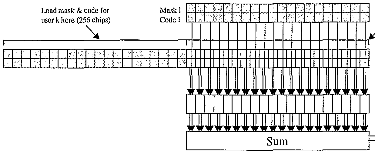
Multiuser detection systems in accord with the foregoing embodiments can be implemented in any variety of general or special purpose hardware and/or software devices. Figure 11 depicts one such implementation. In this embodiment, each frame of data is processed three times by the MUD processing card 118 (or, "MUD processor" for short), although it can be recognized that multiple such cards could be employed instead (or in addition) for this purpose. During the first pass, only the control channels are respread which the maximum ratio combination (MRC) and MUD processing is performed on the data channels. During subsequent passes, data channels are processed exclusively, with new y (i.e., soft decisions) and b (i.e., hard decisions) data being generated as shown in the diagram.
Amplitude ratios and amplitudes are determined via the DSP (e.g., element 900, or a DSP otherwise coupled with the processor board 118 and receiver 110), as well as certain
waveform statistics. These values (e.g., matrices and vectors) are used by the MUD processor in various ways. The MUD processor is decomposed into four stages that closely match the structure of the software simulation: Alpha Calculation and Respread 1302, raised-cosine filtering 1304, de-spreading 1306, and MRC 1308. Each pass through the MUD processor is equivalent to one processing stage of the implementations discussed above. The design is pipelined and "parallelized." In the illustrated embodiment, the clock speed can be 132 MHz resulting in a throughput of 2.33 ms/frame, however, the clock rate and throughput varies depending on the requirements. The illustrated embodiment allows for three-pass MUD processing with additional overhead from external processing, resulting in a 4-times real-time processing throughput.
The alpha calculation and respread operations 1302 are carried out by a set of thirty-two processing elements arranged in parallel. These can be processing elements within an ASIC, FPGA, PLD or other such device, for example. Each processing element processes two users of four fingers each. Values for b are stored in a double-buffered lookup table. Values of a and jά are pre-multiplied with beta by an external processor and stored in a quad-buffered lookup table. The alpha calculation state generated the following values for each finger, where subscripts indicate antenna identifier:
Jv^ = 0 - (jC-a0+C-jaQ) al = 1 -(C-a1-jC-ja1) C ι = βι - /C- fl1 + C - 7 fl1)
These values are accumulated during the serial processing cycle into four independent 8-times oversampling buffers. There are eight memory elements in each buffer and the element used is determined by the sub-chip delay setting for each finger.
Once eight fingers have been accumulated into the oversampling buffer, the data is passed into set of four independent adder-trees. These adder-trees each termination in a single output, completing the respread operation. The four raised-cosine filters 1304 convolve the alpha data with a set of weights determined by the following equation:
The filters can be implemented with 97 taps with odd symmetry. The filters illustrated run at 8-times the chip rate, however, other rates are possible. The filters can be implemented in a variety of compute elements 220, or other devices such as ASICs, FPGAs for example.
The despread function 1306 can be performed by a set of thirty-two processing elements arranged in parallel. Each processing element serially processes two users of four fingers each. For each finger, one chip value out of eight, selected based on the sub-chip delay, is accepted from the output ofthe raised-cosine filter. The despread state performs the following calculations for each finger (subscripts indicate antenna):
SF-l jy0 ■jr0 -jC - rQ 0
SF-l
Λ = ■ ∑ XJC-jr, o c- r
SF-l
M x ■ jr -jC- rx
The MRC operations are carried out by a set of four processing elements arranged in parallel, such as the compute elements 220 for example. Each processor is capable of serially processing eight users of four fingers each. Values for;/ are stored in a double-buffered lookup table. Values for b are derived from the MSB of the y data. Note that the b data used in the MUD stage is independent ofthe b data used in the respread stage. Values of a and ja <are pre-multiplied with β by an external processor and stored in a quad-buffered lookup table. Also, ∑(a +ja ) for each channel is stored in a quad-buffered table.
The output stage contains a set of sequential destination buffer pointers for each channel. The data generated by each channel, on a slot basis, is transferred to the crossbar (or other interconnect) destination indicated by these buffers. The first word of each of these transfers will contain a counter in the lower sixteen bits indicating how many y values were generated.
The upper sixteen bits will contain the constant value 0xAA55. This will allow the DSP to avoid interrupts by scanning the first word of each buffer. In addition, the DSP UPDATE register contains a pointer to single crossbar location. Each time a slot or channel data is transmitted, an internal counter is written to this location. The counter is limited to 10 bits and will wrap around with a terminal count value of 1023.
The method of operation for the long-code multiple user detection algorithm (LCMUD) is as follows. Spread factor for four-channels requires significant amount of data transfer. In order to limit the gate count of the hardware implementation, processing an SF4 channel can result in reduced capability.
A SF4 user can be processed on certain hardware channels. When one of these special channels is operating on an SF4 user, the next three channels are disabled and are therefore unavailable for processing. This relationship is as shown in the following table:
The default y and b data buffers do not contain enough space for SF4 data. When a channel is operating on SF4 data, the and b buffers extend into the space ofthe next channel in sequence. For example, if channel 0 is processing SF data, the channel 0 and channel 1 b buffers are merged into a single large buffer of 0x40 32-bit words. The y buffers are merged similarly.
In typical operation, the first pass of the LCMUD algorithm will respread the control channels in order to remove control interference. For this pass, the b data for the control channels should be loaded into BLUT while the y data for data channels should be loaded into YDEC. Each channel should be configured to operate at the spread factor ofthe data channel stored into the YDEC table.
Control channels are always operated at SF 256, so it is likely that the control data will need to be replicated to match the data channel spread factor. For example, each bit (b entry)
of control data would be replicated 64 times if that control channel were associated with an SF 4 data channel.
Each finger in a channel arrives at the receiver with a different delay. During the Respread operation, this skew among the fingers is recreated. During the MRC stage of MUD processing, it is necessary to remove this skew and realign the fingers of each channel. This is accomplished in the MUD processor by determining the first bit available from the most delayed finger and discarding all previous bits from all other fingers. The number of bits to discard can be individually programmed for each finger with the Discard field of the MUD- PARAM registers. This operation will typically result in a 'short' first slot of data. This is unavoidable when the MUD processor is first initialized and should not create any significant problems. The entire first slot of data can be completely discarded if 'short' slots are undesirable.
A similar situation will arise each time processing is begun on a frame of data. To avoid losing data, it is recommended that a partial slot of data from the previous frame be overlapped with the new frame. Trimming any redundant bits created this way can be accomplished with the Discard register setting or in the system DSP. In order to limit memory requirements, the LCMUD FPG A processes one slot of data at a time. Doubling buffering is used for b and y data so that processing can continue as data is streamed in. Filling these buffers is complicated by the skew that exists among fingers in a channel.
Figure 12 illustrates the skew relationship among fingers in a channel and among the channels themselves. The illustrated embodiment allows for 20us (77.8 chips) of skew among fingers in a channel and certain skew among channels, however, in other embodiments these skew allowances vary.
There are three related problems that are introduced by skew: Identifying frame & slot boundaries, populating b and y tables and changing channel constants. Because every finger of every channel can arrive at a different time, there are no universal frame and slot boundaries.
The DSP must select an arbitrary reference point. The data stored in b & y tables is likely to come from two adjacent slots.
Because skew exists among fingers in a channel, it is not enough to populate the b & y tables with 2,560 sequential chips of data. There must be some data overlap between buffers to allow lagging channels to access "old" data. The amount of overlap can be calculated dynamically or fixed at some number greater than 78 and divisible by four (e.g. 80 chips). The starting point for each register is determined by the Chip Advance field ofthe MUDPARAM register.
A related problem is created by the significant skew among channels. As can be seen in Figure 12, Channel 0 is receiving Slot 0 while Channel 1 is receiving Slot 2. The DSP must take this skew into account when generating the b and y tables and temporally align channel data.
Selecting an arbitrary "slot" of data from a channel implies that channel constants tied to the physical slot boundaries may change while processing the arbitrary slot. The Constant Advance field of the MUDPARAM register is used to indicate when these constants should change. Registers affected this way are quad-buffered. Before data processing begins, at least two of these buffers should be initialized. During normal operation, one additional buffer is initialized for each slot processed. This system guarantees that valid constants data will always be available.
The following two tables shown the long-code MUD FPGA memory map and control/ status register:
The register YB indicates which of two y and b buffers are in use. If the system is currently not processing, YB indicates the buffer that will be used when processing is initiated.
CBUF indicates which of four round-robin buffers for MUD constants (aΛ beta) is currently in use. Finger skew will result in some fingers using a buffer one in advance of this indicator. To guarantee that valid data is always available, two full buffers should be initialized before operation begins. If the system is currently not processing, CBUF indicates the buffer that will be used when processing is restarted. It is technically possible to indicate precisely which buffer is in use for each finger in both the Respread and Despread processing stages. However, this would require thirty-two 32-bit registers. Implementing these registers would be costly, and the information is of little value.
Al and A0 indicate which y and b buffers are currently being processed. Al and A0 will never indicate ' 1 ' at the same time. An indication of '0' for both Al and A0 means that MUD processor is idle. RI and RO are writable fields that indicate to the MUD processor that data is available. RI corresponds to y and b buffer 1 and RO corresponds to y and b buffer 0. Writing a ' 1 ' into the correct register will initiate MUD processing. Note that these buffers follow strict round-robin ordering. The YB register indicates which buffer should be activated next.
These registers will be automatically reset to '0' by the MUD hardware once processing is completed. It is not possible for the external processor to force a '0' into these registers. A ' 1 ' in this bit indicates that this is the last slot of data in a frame. Once all available data for the slot has been processed, the output buffers will be flushed. A ' 1 ' in this bit will place the MUD processor into a reset state. The external processor must manually bring the MUD processor out of reset by writing a '0' into this bit.
DSPJ PDATE is arranged as two 32-bit registers. A RACEway™ route to the MUD DSP is stored at address 0x0000_0008. Apointer to a status memory buffer is located at address
0x0000_000C. Each time the MUD processor writes a slot of channel data to a completion buffer, an incrementing count value is written to this address. The counter is fixed at 10 bits and will wrap around after a terminal count of 1023.
A quad-buffered version ofthe MUD parameter control register exists for each finger to be processed. Execution begins with buffer 0 and continues in round-robin fashion. These buffers are used in synchronization with the MUD constants (Beta * a_hat, etc.) buffers. Each finger is provided with an independent register to allow independent switching of constant values at slot and frame boundaries. The following table shows offsets for each MUD chan- nel:
The following table shows buffer offsets within each channel:
The following table shown details ofthe control register:
The spread factor field determines how many chip samples are used to generate a data bit. In the illustrated embodiment, all fingers in a channel have the same spread factor setting, however, it can be appreciated by one skilled in the art that such constant factor setting can be variable in other embodiments. The spread factor is encoded into a 3 -bit value as shown in the following table:
The field specifies the sub-chip delay for the finger. It is used to select one of eight accumulation buffers prior to summing all Alpha values and passing them into the raised- cosine filter. Discard determines how many MUD-processed soft decisions (y values) to discard at the start of processing. This is done so that the first y value from each finger corresponds to the same bit. After the first slot of data is processed, the Discard field should be set to zero.
The behavior of the discard field is different than that of other register fields. Once a non-zero discard setting is detected, any new discard settings from switching to a new table entry are ignored until the current discard count reaches zero. After the count reaches zero, a new discard setting may be loaded the next time a new table entry is accessed.
All fingers within a channel will arrive at the receiver with different delays. Chip Advance is used to recreate this signal skew during the Respread operation. Y and b buffers are arranged with older data occupying lower memory addresses. Therefore, the finger with the earliest arrival time has the highest value of chip advance. Chip Advanced need not be a mul- tiple of Spread Factor.
Constant advance indicates on which chip this finger should switch to a new set of constants (e.g. a" ) and a new control register setting. Note that the new values take effect on the chip after the value stored here. For example, a value of 0x0 would cause the new constants to take effect on chip 1. A value of OxFF would cause the new constants to take effect on chip 0 of the next slot. The b lookup tables are arranged as shown in the following table. B values each occupy two bits of memory, although only the LSB is utilized by LCMUD hardware.
The following table illustrates how the two-bit values are packed into 32-bit words.
Spread Factor 4 channels require more storage space than is available in a single channel buffer. o allow for SF4 processing, the buffers for an even channel and the next highest odd channel are joined together. The even channel performs the processing while the odd channel is dis- abled.
The beta*a-hat table contains the amplitude estimates for each finger pre-multiplied by the value of Beta. The following table shows the memory mappings for each channel.
The following table shows buffers that are distributed for each channel:
The following table shows a memory mapping for individual fingers of each antenna.
The y (soft decisions) table contains two buffers for each channel. Like the b lookup table, an even and odd channel are bonded together to process SF4. Each y data value is stored as a byte. The data is written into the buffers as packed 32-bit words.
The sum ofthe a-hat squares is stored as a 16-bit value. The following table contains a memory address mapping for each channel.
Within each buffer, the value for antenna 0 is stored at address offset 0x0 with the value for antenna one stored at address offset 0x04. The following table demonstrates a mapping for each finger.
Each channel is provided a crossbar (e.g., RACEway™) route on the bus, and a base address for buffering output on a slot basis. Registers for controlling buffers are allocated as shown in the following two tables. External devices are blocked from writing to register addresses marked as reserved.
Slot buffer size is automatically determined by the channel spread factor. Buffers are used in round-robin fashion and all buffers for a channel must be arranged contiguously. The buffers control register determines how many buffers are allocated for each channel. A setting of 0 indicates one available buffer, a setting of 1 indicates two available buffers, and so on.
A further understanding ofthe operation ofthe illustrated and other embodiments of the invention may be attained by reference to (i) US Provisional Application Serial No. 60/ 275,846 filed March 14, 2001, entitled "Improved Wireless Communications Systems and Methods"; (ii) US Provisional Application Serial No. 60/289,600 filed May 7, 2001, entitled "Improved Wireless Communications Systems and Methods Using Long-Code Multi-User Detection'" and (iii) US Provisional Application Serial Number. 60/295,060 filed June 1, 2001 entitled "Improved Wireless Communications Systems and Methods for a Communications Computer," the teachings all of which are incoφorated herein by reference, and a copy of the latter of which may be filed herewith.
The above embodiments are presented for illustrative purposes only. Those skilled in the art will appreciate that various modifications can be made to these embodiments without
departing from the scope ofthe present invention. For example, multiple summations can be utilized by a system ofthe invention, and not separate summations as described herein. Moreover, by way of further non-limiting example, it will be appreciated that although the terminology used above is largely based on the UMTS CDMA protocols, that the methods and apparatus described herein are equally applicable to DS/CDMA, CDMA2000 IX, CDMA2000 lxEV-DO, and other forms of CDMA.
Therefore, in view ofthe foregoing, what we claim is:
Background ofthe Invention
The invention pertains to wireless communications and, more particularly, to communications computers. The invention has application, by way of non-limiting example, in improving the capacity of cellular phone base stations.
Code-division multiple access (CDMA) is used increasingly in wireless communications. It is a form of multiplexing communications, e.g., between cellular phones and base stations, based on distinct digital codes in the communication signals. This can be contrasted with other wireless protocols, such as frequency-division multiple access and time-division multiple access, in which multiplexing is based on the use of orthogonal frequency bands and orthogonal time- slots, respectively.
A limiting factor in CDMA communication and, particularly, in so-called direct sequence CDMA (DS-CDMA), is the interference between multiple simultaneous communications, e.g., multiple cellular phone users in the same geographic area using their phones at the same time. This is referred to as multiple access interference (MAI). It has effect of limiting the capacity of cellular phone base stations, since interference may exceed acceptable levels — driving service quality below acceptable levels — when there are too many users.
A technique known as multi-user detection (MUD) reduces multiple access interference and, as a consequence, increases base station capacity. MUD can reduce interference not only between multiple signals of like strength, but also that caused by users so close to the base station as to otherwise overpower signals from other users (the so-called near/far problem). MUD generally functions on the principle that signals from multiple simultaneous users can be jointly used to improve detection ofthe signal from any single user. Many forms of MUD are known; surveys are provided in Moshavi, "Multi-User Detection for DS-CDMA Systems," IEEE Communications Magazine (October, 1996) and Duel-Hallen et al, "Multiuser Detection for CDMA Systems," IEEE Personal Communications (April 1995). Though a promising solution to increasing the capacity of cellular phone base stations, MUD techniques are typically so computationally intensive as to limit practical application.
An object of this invention is to provide improved methods and apparatus for wireless communications. A related object is to provide such methods and apparatus for multi-user detection or interference cancellation in code-division multiple access communications.
A further object ofthe invention is to provide such methods and apparatus as can be cost- effectively implemented and as require minimal changes in existing wireless communications infrastructure.
A still further object ofthe invention is to provide methods and apparatus for executing multi-user detection and related algorithms in real-time.
A still further object ofthe invention is to provide such methods and apparatus as manage faults for high-availability.
Summary ofthe Invention
These and other objects are met by the invention which provides, in one aspect, a communications computer, referred to as the "MCW-1 " (among other terms) in the materials that follow, and methods of operation thereof. An overview of that system is provided in the section entitled "Communications Computer," beginning on page 5 hereof. A more complete understanding of its implementation may be attained by reference to the other attached materials.
In view of those materials, aspects ofthe invention include, but are not limited to the following:
. architecture and operation of a communications computer for a wireless communications system, including a fully programmable computer inserted into base transceiver station (BTS) to support compute-intensive and/or highly data-dependent functions such as adaptive processing and interference cancellation
These and other aspects ofthe invention (including utilization ofthe aforementioned methods and aspects for other than wireless communications and/or interference cancellation) are evident in the materials that follow.
Detailed Description ofthe Invention
See the attached materials on pages 5 - 11 hereof, providing description and block diagram of a preferred structure and operation of a communications computer for wireless applications according to the invention.
The aforementioned materials pertain to improvements on the methods and apparatus described in United States Provisional Application Serial No. 60/275,846, filed March 14, 2001, entitled IMPROVED WIRELESS COMMUNICATIONS SYSTEMS AND METHODS and United States Provisional Application Serial No. 60/289,600, filed May 7, 2001, entitled IMPROVED WIRELESS COMMUNICATIONS SYSTEMS AND METHODS USING LONG- CODE MULTI-USER DETECTION, the teachings of both of which are incorporated herein by reference and copies of at least portions of which are attached hereto. Those copies bears the U.S. Postal Service Express Mail label number of both prior filings, as well as that of this filing (the latter being referred to as the "New Exp. Mail Label No.").
• Fully programmable computer inserted into base transceiver station (BTS) to support compute-intensive and/or highly data-dependent functions such as adaptive processing and interference cancellation
- Overcomes rigidity of ASIC-based application implementation
- Overcomes limitations of DSP instruction sets
- Overcomes traditional inter-processor bandwidth limitations
• By using modern processor interconnect technology rather than busses
- Enables remote modification of functionality by software download
• High-profile applications:
- Multi-user detection (MUD)
- Interference cancellation
- Smart and adaptive antenna processing
- Interference avoidance
Multiple communications computers can be interconnected to promote
- Load balancins amons cell site sectors
- Improved fault resilience
- Additional algorithm sophistication/complexity
- Functionality of additional algorithms
Communications computer concept can be extended by intercoimection to encompass full BTS functionality
67
Interconnectable telco-grade multicomputer boards and system software suitable for MUD, Interference cancellation, and other adaptive processing applications
- Hardware: Four G4 Nitros and SDRAM; plus MPC824G, watchdogs, NVRAM, PCI and Enet connectivity...
• Scalable up and down in complexity
- Software: Application; autonomous fault monitoring, detection, isolation, recoveiy; automatic remote software update; remote access via embedded web server
Background of the Invention
The invention pertains to wireless communications and, more particularly, to methods and apparatus for interference cancellation in code-division multiple access communications. The invention has application, by way of non-limiting example, in improving the capacity of cellular phone base stations.
Code-division multiple access (CDMA) is used increasingly in wireless communications. It is a form of multiplexing communications, e.g., between cellular phones and base stations, based on distinct digital codes in the commumcation signals. This can be contrasted with other wireless protocols, such as frequency-division multiple access and time-division multiple access, in which multiplexing is based on the use of orthogonal frequency bands and orthogonal time- slots, respectively.
A limiting factor in CDMA communication and, particularly, in so-called direct sequence CDMA (DS-CDMA), is the interference between multiple simultaneous communications, e.g., multiple cellular phone users in the same geographic area using their phones at the same time. This is referred to as multiple access interference (MAI). It has effect of limiting the capacity of cellular phone base stations, since interference may exceed acceptable levels ~ driving service quality below acceptable levels — when there are too many users.
A technique known as multi-user detection (MUD) reduces multiple access interference and, as a consequence, increases base station capacity. MUD can reduce interference not only between multiple signals of like strength, but also that caused by users so close to the base station as to otherwise overpower signals from other users (the so-called near/far problem). MUD generally functions on the principle that signals from multiple simultaneous users can be jointly used to improve detection ofthe signal from any single user. Many forms of MUD are known; surveys are provided in Moshavi, "Multi -User Detection for DS-CDMA Systems," IEEE Communications Magazine (October, 1996) and Duel-Hallen et al, "Multiuser Detection for CDMA Systems," IEEE Personal Communications (April 1995). Though a promising solution to increasing the capacity of cellular phone base stations, MUD techniques are typically so ' computationally intensive as to limit practical application.
1
An object of this invention is to provide improved methods and apparatus for wireless communications. A related object is to provide such methods and apparatus for multi-user detection or interference cancellation in code-division multiple access communications.
A further object ofthe invention is to provide such methods and apparatus as can be cost- effectively implemented and as require minimal changes in existing wireless communications infrastructure.
A still further object ofthe invention is to provide methods and apparatus for executing multi-user detection and related algorithms in real-time.
A still further object ofthe invention is to provide such methods and apparatus as manage faults for high-availability.
Summary of the Invention
These and other objects are met by the invention which provides, in one aspect, a wireless communications system, referred to as the "MCW-1" (among other terms) in the materials that follow, and methods of operation thereof. An overview of that system is provided in the document entitled "Software Architecture ofthe MCW-1 MUD Board," immediately following this Summary. A more complete understanding of its implementation may be attained by reference to the other attached materials.
In view of those materials, aspects ofthe invention include, but are not limited to, the following:
• methods and apparatus for long-code multi-user detection (MUD) in a wireless communications system.
These and other aspects ofthe invention (including utilization ofthe aforementioned methods and aspects for other than wireless communications and/or interference cancellation) are evident in the materials that follow.
Detailed Description of the Invention
See the attached materials on pages 5 - 12 hereof, providing a block diagram of a preferred algorithm for long code MUD which includes identification of (roughly) how many GOPS are involved in each major function; a diagram showing interfaces between a long code MUD processing card according to the invention and a modem, e.g., ofthe type provided by Motorola (or another supplier of such components); and two block diagrams ofthe same BASELINE 0 board hardware architecture at a top level identifiying the processing nodes. The attached diagram entitled "Long-code Mapping to Hardware" illustrates support of 64 users for long code MUD and shows parts ofthe long code MUD algorithm supported by each processing node. The diagram entitled "Short-code Mapping to Hardware" illustrates support of 128 users for short code MUD and shows parts ofthe short code MUD algorithm would be supported by each processing node.
The aforementioned materials pertain to improvements on the methods and apparatus described in United States Provisional Application Serial No. 60/275,846, filed March 14, 2001, entitled IMPROVED WIRELESS COMMUNICATIONS SYSTEMS AND METHODS, the teachings of which are incoφorated herein by reference and a copy of which is attached hereto. That copy bears the U.S. Postal Service Express Mail label number of both the original filing, as well as that of this filing (the latter being referred to as the "New Exp. Mail Label No.").
Long-Code
ltiuser Detection
Enhancement Concept
Optional antenna-stream input to MUD processing card allows multiple-stage interference cancellation and multiuser channel- amplitude estimation.
* etwm mmASyssttomw 'ικ.
codes
Computational complexity figures (GOPS) are based on
• 128 SF 256 users
• 8 samples per chip
Data Transferred to or from Ml
Inputs Processing Card
- Frame number
- Post-MRC matched-filter outputs yk for DPCCH and DPDCHs
- Number of DPDCHs
- DPCCH slot format
- Number of rake fingers
- Number of antennas used
- Channel amplitude estimates akq
- Channel lag estimates τkq
- Spreading factor SF^
- Code number
- Compressed mode information
• Compressed mode flag, Compressed mode frame, N_fϊrst, TGL
- Amplitude ratios βdk, βck
- Antenna streams r[t] (Optional)
- Cleaned data bit estimates bk
Card Interface Bandwidth
r
•$øtσιx,fos.
Mm
Long-code Mapping to Hardware
PPC 7410s FPGAs
Short-code Ma JpL JpL ing_9 to Hardware
PPC 7410s FPGAs
IN THE UNITED STATES PATENT AND TRADEMARK OFFICE
UNITED STATES PROVISIONAL PATENT APPLICATION
for
IMPROVED WIRELESS COMMUNICAΗONS SYSTEMS AND METHODS
Inventors:
John H. Oates Steven R. hnperiali
598 Seaverns Bridge Road 43 Haynes Road
Amherst, New Hampshire 03031 Townsend, Massachusetts 01469
Alden J. Fuchs Kathleen J. Jacques
160 Pine Hill Road 10 Juniper Street
Nashua, New Hampshire 03063 Jay, Maine 04239
Jonathan E. Greene William J. Jenkins
83n Hollenbeck Avenue 61 Heritage Lane #C4
Great Barrington, Massachusetts 01230 Leominster, Massachusetts 01453
Frank P. Lauginiger David E. Majchrzak 772 Russell Station Road 11 Regine Street Francestown, New Hampshire 03043 Hudson, New Hampshire 03051
Paul E. Cantrell Miiza Cifric
15 Prescott Drive 705 Mass Avenue
Chelmsford, Massachusetts 01863 Boston, Massachusetts 02118
Jan N. Dunn Michael J. Vinskus
48 North Court Street, #1 5 Cranberry Lane
Providence, Rhode Island 02903 Litchfield, New Hampshire 03052
Background of the Invention
The invention pertains to wireless communications and, more particularly, to methods and apparatus for interference cancellation in code-division multiple access communications. The invention has application, by way of non-limiting example, in improving the capacity of cellular phone base stations.
Code-division multiple access (CDMA) is used increasingly in wireless communications. It is a form of multiplexing communications, e.g., between cellular phones and base stations, based on distinct digital codes in the communication signals. This can be contrasted with other wireless protocols, such as frequency-division multiple access and time-division multiple access, in which multiplexing is based on the use of orthogonal frequency bands and orthogonal time- slots, respectively.
A limiting factor in CDMA communication and, particularly, in so-called direct sequence CDMA (DS-CDMA), is the interference between multiple simultaneous communications, e.g., multiple cellular phone users in the same geographic area using their phones at the same time. This is referred to as multiple access interference (MAI). It has effect of limiting the capacity of cellular phone base stations, since interference may exceed acceptable levels — driving service quality below acceptable levels — when there are too many users.
A technique known as multi-user detection (MUD) reduces multiple access interference and, as a consequence, increases base station capacity. MUD can reduce interference not only between multiple signals of like strength, but also that caused by users so close to the base station as to otherwise overpower signals from other users (the so-called near/far problem). MUD generally functions on the principle that signals from multiple simultaneous users can be jointly used to improve detection ofthe signal from any single user. Many forms of MUD are known; surveys are provided in Moshavi, "Multi-User Detection for DS-CDMA Systems," IEEE Communications Magazine (October, 1996) and Duel-Hallen et al, "Multiuser Detection for CDMA Systems," JJEEE Personal Communications (April 1995). Though a promising solution to increasing the capacity of cellular phone base stations, MUD techniques are typically so computationally intensive as to limit practical application.
1
An object of this invention is to provide improved methods and apparatus for wireless communications. A related object is to provide such methods and apparatus for multi-user detection or interference cancellation in code-division multiple access communications.
A further object ofthe invention is to provide such methods and apparatus as can be cost- effectively implemented and as require minimal changes in existing wireless communications infrastructure.
A still further object of the invention is to provide methods and apparatus for executing multi-user detection and related algorithms in real-time.
A still further object ofthe invention is to provide such methods and apparatus as manage faults for high-availability.
Summary of the Invention
These and other objects are met by the invention which provides, in one aspect, a wireless communications system, referred to as the "MCW-1" (among other terms) in the materials that follow, and methods of operation thereof. An overview of that system is provided in the document entitled "Software Architecture ofthe MCW-1 MUD Board," immediately following this Summary. A more complete understanding of its implementation may be attained by reference to the other attached materials.
In view of those materials, aspects ofthe invention include, but are not limited to, the following:
• hardware and/or software architectures (and methods of operation thereof) for multi-user detection in wireless communications systems and particularly, for example, in a wireless communications base station;
• a hardware architecture (and methods of operation thereof) for multi-user detection in wireless communications systems pairing each processing node with NVRAM and watchdog PLD for fault management;
• methods and apparatus for connecting watchdog PLDs with an out-of-band fault- management bus;
• methods and apparatus for use of an embedded host with the RACEway™ architecture of Mercury Computer Systems, Inc.
• methods and apparatus for interfacing a digital signal processor to the RACEway™ architecture;
. methods and apparatus for interfacing the RACEway™ architecture to a programming port in a device for multi-user detection in wireless communications systems;
• methods and apparatus for implementing a DMA Engine FPGA for use in multiuser detection in a wireless communications systems;
• methods and apparatus for implementing a hardware-based reset voter and stop voter;
• methods and apparatus for scalable mapping of handset and BTS functions to multiple processors;
methods and apparatus for facilitating allocation and management of buffers for interconnecting processors that implement the aforementioned mapping;
• methods and apparatus for implementing a hybrid operating system, e.g., with the VxWorks operating system (of WindRiver Systems, Inc.) on a host computer and the MC/OS operating system on RACE®-based nodes. (Race and MC/OS are trademarks of Mercury Computer Systems, Inc.);
methods and apparatus for high-availability multi-user detection in wireless communications systems, including (by way of non-limiting example) round- robin fault testing and use of NVRAM to store fault symptoms and use of master to diagnose faults from NVRAM contents;
class library-based methods and apparatus for facilitating interprocessor communications, by way of non-limiting example, in buffering for multi-user detection in wireless communications systems;
• methods and apparatus for implementation of R-matrix, gamma-matrix and MPIC computations on separate processors in a device for multi-user detection in wireless communications systems;
• methods and apparatus for computing complementary R-matrix elements in parallel using multiple processors in a device for multi-user detection in wireless communications systems;
• methods and apparatus for depositing results of R-matrix calculations contiguously in memory in a device for multi-user detection in wireless communications systems;
methods and apparatus for increasing the number of MPIC and R-matrix calculations performed in cache in a device for multi-user detection in wireless communications systems;
• methods and apparatus for performing a gamma-matrix calculation in FPGA in a device for multi-user detection in wireless communications systems;
• methods and apparatus for equalizing load of R-matrix-element calculation among multiple processors in a device for multi-user detection in wireless communications systems; and
methods and apparatus for use of Altivec registers and instruction set in performing MUD calculations in a wireless communications system.
These and other aspects ofthe invention (including utilization ofthe aforementioned methods and aspects for other than wireless communications and/or interference cancellation) are evident in the materials that follow.
Detailed Description of the Invention
(see attached materials)
Software Architecture ofthe MCW-1 MUD Board
Table of Contents
1 PURPOSE 3 2 GLOSSARY 3 3 APPLICATION EXECUTION ENVIRONMENT 3 3.1 OVERVIEW 3 3.2 OPERATING SYSTEM 4 3.3 IPC 5 3.4 I/O 5 3.5 HIGH AVAILABILITY 6 4 OPERATING SYSTEM ENVIRONMENT 6 4.1 OVERVIEW 6 4.2 BOOTSTRAP 6? 4.3 MULTICOMPUTER CONFIGURATION 7 4.4 MULTICOMPUTER LOADING 8 4.5 TCP/IP BRIDGE 8 4.6 FILE SYSTEM 8 4.7 REMOTE SOFTWARE UPGRADE 8 5 HIGH AVAILABILITY 9 5.1 GOALS 9 5.2 FAULT DETECTION & ISOLATION 9 5.3 DEGRADED APPLICATION 9 5.4 REMOTE SOFTWARE UPGRADE 10
Table of Figures
Figure 1 4 Figure 2 5
Mercury Computer Systems, Inc. Confidential
Software Architecture ofthe MCW-1 MUD Board
1 Purpose The purpose of this document is to describe the software architecture ofthe MCW-1 board. The MCW-1 application is a digital signal processing application that performs interference cancellation for a cellular base station modem board. The software project consists of 3 major parts: • Support for the custom MCW-1 board being designed by the Wireless Communications Group hardware department. This consists of porting the existing host (VxWorks) and multicomputer (MC/OS) software to the board, and adding code to support specialized features ofthe board such as LED control, voltage monitoring, hardware watchdogs, etc. • Increasing the MTBF ofthe system by addition of high availability software. This software includes monitoring features such as watchdogs, fault detection/repair algorithms, and remote software download. • Implementation ofthe application software. This includes optimal implementation ofthe MUD algorithms, as well as implementing degraded versions of the algorithm that can be executed when some of the computational hardware is unavailable due to failures. Detailed information on the design of new software for the MCW-1 board can be found in the appropriate functional design documents, which are listed in the References section of this document. 2 Glossary
1. MTBF - Mean Time Between Failures 2. MUD - Multi User Detection. A class of algorithms to detect multiple interference sources and remove those effects from the signal. 3. Multicomputer - a parallel computer which achieves it's increase in performance by having more than one CPU working on the application simultaneously. 4. VxWorks - a proprietary real time operating system sold by Wind River, Inc. 3 Application Execution Environment 3.1 Overview The purpose ofthe MUD application is to input raw antenna data from the base station modem card, detect sources of interference, produce a new stream of data which has had interference removed, and then output the data to the modem card for further processing. Characteristics of this processing are-are that it must have low latency (< 300 microseconds), ami-must deal with large amounts of data (> 110 million bytes of data per second), and must be very reliable. The Mercury computer system is well suited to this kind of signal processing, exhibiting both very low latencies and high bandwidths.
Mercury Computer Systems, Inc. Confidential
Software Architecture ofthe MCW-1 MUD Board
83 The system hardware and software were not designed with high availability as
84 a goal, so reliability is in line with other standard computer systems designed for
85 commercial applications
86 Input data flows from the Modem Motherboard, over the PCI bus, through the
87 PXB++ bridge, onto the fabric, through the crossbar, and into the memory ofthe
88 computing elements. Output data flows in the opposite direction. Some data will
89 also flow between the 8240 Host CPU and the compute elements, via a similar
90 pathway, i.e. from the PCI bus through the PXB++ and thus onto the fabric.
91 Although the software tries to treat the system as if the hardware were
92 symmetric, as can be seen in the following figure, the host 8240 CPU is attached
93 via the PCI bus, not directly to the fabric. 94
95 I Error! Not a valid link.
96 Figure 1
97 3.2 Operating System
98 MC/OS was selected as the operating system for the MCW-1 board because it
99 provides the low latencies and high I/O and IPC bandwidths required for these
100 sorts of algorithms, and also because it already provides support for most ofthe
101 hardware being incorporated on the MCW-1 board.
102 The MUD application can be kept as portable as possible by minimizing the
103 use of non-POSLX MC/OS system calls, and encapsulating calls into proprietary
104 MC/OS interfaces such as DX.
105 MC/OS requires the presence of a host computer system, which in this case
106 will be a Motorola 8240 PowerPC processor running the VxWorks operating
107 system.
Mercury Computer Systems, Inc. Confidential
Software Architecture ofthe MCW-1 MUD Board
Host Compute 8240 Elements
108 109 Figure 2
110 3.3 IPC
111 The MC/OS DX subsystem will be used for IPC within the application. This 112 API provides low overhead, low latency access to the Mercury DMA engines, 113 which in turn provide high bandwidth transfers of data. DX will be used to move 114 data between the G4 compute elements during parallel processing, and also will 115 be used to move data between the MC/OS compute elements, the VxWorks host 116 computer, and the motherboard modem card.
117 3.4 HO
118 Input / Output between the MUD card and the motherboard modem card takes 119 place by moving data between the Race++ Fabric and the PCI bus via the PXB++ 120 bridge. The application will use DX to initialize the PXB++ bridge, and to cause 121 input/output data to move as if it were regular DX IPC traffic. 122 Discussions with the customer need to take place in order to determine exactly 123 how data flows over the PCI bus. For instance, it is currently unclear who will 124 initiate data transfers, and how the initiator will know which PCI addresses should 125 be involved m the transfer. A number of meetings with the customer are required 126 to resolve these issues.
Mercury Computer Systems, Inc. Confidential
Software Architecture ofthe MCW-1 MUD Board
127 3.5 High Availability
128 The approach to high availability on the MCW-1 card is to do most ofthe high
129 availability processing at a time when the application is not running. Specifically,
130 faults are handled by rebooting the system (fairly quickly). When the system
131 comes up, the application can determine which processing resources are available,
132 and it is up to the application to determine how to map its processing needs onto
133 the available resources .
134 This approach to high availability means that there are short interruptions in
135 service, but that the application does not need to know how to continue execution
136 across faults. For instance, the application can make the assumption that the
137 hardware configuration will not change without the system first rebooting.
138 If the application has state which needs to be preserved across reboots, the
139 application is responsible for checkpointing the data on a regular basis. The
140 system software will provide an API to a portion ofthe non-volatile RAM for this
141 purpose. It should be noted that the non-volatile RAM is quite small, and that
142 storage of more than a few hundred bytes of data will require another mechanism
143 to be put in place.
144 4 Operating System Environment
145 4.1 Overview
146 Mercury Computer Systems, Inc. has historically had the concept of a host
147 computer system. This dates back to the days when Mercury produced array
148 processors that were attached to customers' mainframe computers. The evolution
149 of Mercury multicomputers has left a vestigial host that often performs little more
150 service than as a bootstrap device for the multicomputer.
151 The host computer system survives in the MCW-1 design primarily as a way to
152 reduce schedule risk. The existence of a host computer system is assumed in so
153 many ways by the existing Mercury software, that it would add significant
154 schedule risk to attempt to remove this assumption in the MCW-1 timeframe.
155 In the MCW-1 board, the host system performs the following functions:
156 • It configures the Compute Elements, Fabric, and Bridges
157 • It loads executable code into the Compute Elements
158 • It serves as a bridge to the TCP/IP internetwork
159 • It serves as a file system daemon
160 • It runs some ofthe application software
161 • It manages some of the specialized high availability hardware
162 4.2 Bootstrap
163 The host computer system is based on a Motorola 8240 PowerPC processor on
164 the MCW-1 board. The 8240 is attached to an amount of linear flash memory.
165 This flash memory serves several purposes.
166 The first purpose the flash memory serves is as a source of instructions to
167 execute when the 8240 comes out of reset. Linear flash is flash which can be
168 addressed as if it was normal RAM. Flash memories can also be organized to look
169 like disk controllers; however in that configuration they require a disk driver to
Mercury Computer Systems, Inc. Confidential
Software Architecture ofthe MCW-1 MUD Board
170 provide access to the flash memory. Although such an organization has several
171 benefits such as automatic reallocation of bad flash cells, and write wear leveling,
172 it is not appropriate for initial bootstrap.
173 The flash memory also serves as a file system for the host (see Section 4.6),
174 and as a place to store board permanent information (such as a serial number).
175 Refer to the function design specification (TBS) for more details on how flash
176 memory is used.
177 When the 8240 first comes out of reset, memory is not turned on. Since high
178 level languages such as C assume some memory is present (for a stack, for
179 instance), the initial bootstrap code must be coded in assembler. This assembler
180 bootstrap should only be a few hundred lines of code, sufficient to configure the
181 memory controller, initialize memory, and initialize the configuration ofthe 8240
182 internal registers.
183 After the assembler bootstrap has finished execution, control is passed to the
184 MCW-1 H.A. code (which is also contained in boot flash memory). The purpose
185 ofthe H.A. code is to attempt to configure the fabric, and load the compute
186 element CPUs with H.A. code. Once this is complete, all the processors
187 participate in the H.A. algorithm. The output ofthe algorithm is a configuration
188 table which details which hardware is operational and which hardware is not. This
189 is an input to the next stage of bootstrap, the Multicomputer Configuration.
190 4.3 Multicomputer Configuration
191 MC/OS expects the host computer system to configure the multicomputer. The
192 configmc program reads a textual description ofthe computer system
193 configuration, and produces a series of binary data structures that describe the
194 computer system configuration. These data structures are used in MC/OS to
195 describe the routing and configuration ofthe multicomputer.
196 The MCW-1 board will use almost exactly the same sequence to configure the
197 multicomputer. The major difference is that MC/OS expects configurations to be
198 totally static, whereas the MCW-1 configuration will need to change dynamically
199 as faulty hardware cause various resources to be unavailable for use.
200 There are currently two proposals being considered for how this dynamic
201 reconfiguration takes place.
202 The first proposal is that the binary data structures produced by configmc are
203 modified to include flags that indicate whether a piece of hardware is usable or
204 not. A modification to MC/OS would prevent it from using hardware marked as
205 broken. The risk here is that the modifications to MC/OS may be non-trivial. The
206 benefit may be faster reboot times.
207 The second proposal is that the output ofthe H.A. algorithm is used to produce
208 a new configuration file input to configmc, the configmc execution is repeated
209 with the new file, and MC/OS is configured and loaded with no knowledge ofthe
210 broken hardware whatsoever. This proposal has the added benefit that configmc
211 may be able to calculate the most optimal routing tables in the face of failed
212 hardware, minimizing the performance impact ofthe failure on the remaining
213 components. This proposal provides risk reduction given that MC/OS changes
214 would not be required.
Mercury Computer Systems, Inc. Confidential
Software Architecture ofthe MCW-1 MUD Board
215 4.4 Multicomputer Loading
216 After the host computer has configured the multicomputer, the runmc program
217 loads the functional compute elements with a copy of MC/OS. The only changes
218 required for the MCW- 1 board is for the loading process to examine which
219 hardware may be offline because it is faulty, and take this into account when
220 determining which compute elements need to be loaded.
221 4.5 TCP IIP Bridge
222 We believe that the customer is likely to require access to the MCW-1 board
223 from a TCP/IP network. MC/OS nodes do not contain a TCP/IP stack; therefore
224 the host computer system acts as a connection to the TCP/IP network. The
225 VxWorks operating system contains a fully functional TCP/IP stack. All currently
226 envisioned daemons that need access to the TCP/IP network will run on the host
227 processor. Should the need arise for compute elements to access network
228 resources, the host computer would have to act as a proxy, exchanging
229 information with the compute element utilizing DX transfers, and then making the
230 appropriate TCP/IP calls on behalf of the compute element.
231 4.6 File System
232 The host computer system needs a file system to store configuration files,
233 executable programs, and MC/OS images. Rotating disks have insufficient MTBF
234 times; therefore flash memory will be utilized. Rather than have a separate flash
235 memory from the host computer boot flash, the same flash is utilized for both
236 bootstrap purposes and for holding file system data. A commercial flash file
237 system will be purchased and ported which provides DOS file system semantics
238 as well as write wear leveling. Wear leveling attempts to spread the number of
239 writes evenly across the sectors of flash memory, as flash memory can only be
240 written a finite number of times before it is worn out. Modern flash devices can be
241 written around 100,000 times before they are worn out.
242 4.7 Remote Software Upgrade
243 The current design ofthe MCW-1 board assumes that the customer will want
244 to update system and application code in the field, via network. There are two
245 portions of code which need to be updated — the bootstrap code which is executed
246 by the 8240 processor when it comes out of reset, and the rest ofthe code which
247 resides on the flash file system as files.
248 When code is initially downloaded to the MCW-1 , it is written as a group of
249 files within a directory in the flash file system. A single top level file keeps track
250 of which directory tree is used to boot the system. This file continues to point at
251 the existing directory tree until a download of new software is successfully
252 completed. When a download has been completed and verified, the top-level file
253 is updated to point to the new directory tree, the boot flash is rewritten, and the
254 system can be rebooted.
255 A possible problem in multi-board systems is how to deal with different
256 versions of released software on different boards. For instance, if board 1 has
257 revision 1.0 ofthe software distribution, and board 2 has revision 1.1 ofthe
258 software distribution, will the two versions work together, or will there be a way
I Mercury Computer Systems, Inc. Confidential
Software Architecture ofthe MCW-1 MUD Board
259 to ensure that the same version of software is installed on all boards. This issue
260 does not occur on the MCW-1 because it is a single board solution; therefore this
261 issue can be addressed at a later time.
262 A commercial solution to remote software upgrade is available, and has been
263 ported to VxWorks. It is our intent to port this code at a future date.
264 5 High Availability
265 5.1 Goals
266 The goal ofthe high availability features ofthe MCW-1 is to increase the
267 MTBF ofthe system as much as possible with little or no increase in cost to the
268 board. The requirement for minimal cost increase rules out such common
269 approaches as hot or cold standby, replicated hardware, etc.
270 It is not a goal to provide uninterrupted computing during hardware or software
271 failures, nor is it a goal to provide fault tolerance.
272 4X5.2 Fault Detection & Isolation
273 Fault detection is performed by having each CPU in the system gather as much
274 information about what it observed during a fault, and then comparing the
275 information in order to detect which components could be the common cause of
276 the symptoms. In some cases, it may take multiple faults before the algorithm can
277 detect which component is at fault. The requirement not to add expensive
278 hardware for fault detection means that in many cases the algorithm will not be
279 able to determine which component is at fault.
280 The MCW-1 board has many single points of failure. Specifically, everything
281 on the board is a single point of failure except for the compute elements. This
282 means that the only hard failures that can be configured out are failures in the
283 compute elements. However, many failures are transient or soft, and these can be
284 recovered from with a reboot cycle. Therefore, we expect the high availability
285 features to have a positive effect on the MTBF ofthe card.
286 More detailed information is available in the functional design specification
287 (1).
288 5.3 Degraded Application
289 In the case of hard failures of a compute element, the application will have to
290 execute with reduced demand for computing resources. There are several
291 strategies possible for the MUD algorithm to decrease computing demands, such
292 as working with a smaller number of interference sources, or performing a less
293 complete job of interference cancellation.
294 We expect the computing requirements ofthe algorithm to be high enough that
295 failure of more than a single compute element will cause the board to be
296 inoperative. Therefore, the MCW-1 application only needs to handle two
297 configurations: all compute elements functional and 1 compute element
298 unavailable. We believe that a small amount of startup code can map the
299 application onto the two possible configurations. Note that the single crossbar
300 means that there are no issues as to which processes need to go on which
301 processors - the bandwidth and latencies for any node to any other node are
Mercury Computer Systems, Inc. Confidential
Software Architecture ofthe MCW-1 MUD Board
302 identical on the MCW-1. This will not be true of larger systems in the future, and
303 we will eventually need a way to map computing and I/O requirements onto
304 arbitrary hardware configurations.
305 5.4 Remote Software Upgrade
306 Downtime due to the updating of software is counted against the availability of
307 a computer system, and therefore a remote reload of software is a necessity. The
308 MCW-1 is capable of downloading new software during normal operation. The
309 reboot strategy means that the downtime due to starting up new software is only a
310 few seconds. 311
312 Referenced Documents
313
314 1. "MC/OS High Availability Functional Design Specification", Yevgeniy
315 Tarashchanskiy, 17 April, 2000. 316
Mercury Computer Systems, Inc. Confidential
Mercury Computer Systems. Inc. COMPANY CONFIDENTIAL
Mercury Computer Systems
Wireless Communications Hardware Engineering
MCW-1 a Functional Specification
Memorandum #SRI-1 31 January 2001
Revision 3.00
This document was created using MS Word 97 and is located at TBD
Notice: If you are not viewing this document in electronic form at the above full path-name, it is not guaranteed to be the latest revision.
MCW-1 a Functional Specification
Mercury Computer Systems. Inc. COMPANY CONFIDENTIAL
1 REVISION HISTORY 5
2 REFERENCE DOCUMENTS 5
3 MERCURY PART NUMBER 6
4 FUNCTIONAL DESCRIPTION 7
4.1 OVERVIEW 7
4.2 FEATURES 10
4.3 CONFIGURATION OPTIONS 11
4.3.1 CPU Options 11
4.3.2 SDRAM Options 1 1
4.3.3 FLASH Memory Options 11
4.3.4 Ethernet Options 1 1
4.4 REQUIREMENTS 12
4.4.1 Mechanical Form Factor 12
4.4.2 Power Requirements 12
4.4.3 Electrical Interface 12
4.4.4 Functional 12
4.5 COMPATIBILITY 12
4.6 PERFORMANCE 12
4.7 DETAILED DESCRIPTION 13
4.7.1 Modem Board Interface 13
4.7.2 Board Resets 13
4.7.3 Watchdog Monitor 15
4.7.4 Operating Frequency 15
4.7.4.1 Clock Margining 1
4.7.5 Serial Configuration EEPROM 16
4.7.5.1 PXB-H- FPGA Serial EEPROM 16
4.7.5.2 XBAR++ ASIC Serial EEPROM 16
4.7.6 RACEway++ Interconnect 16
4.7.7 Local PCI I/O Bus 16
4.7.7.1 PXB-H- Program EEPROM 17
4.7.8 Ethernet Interface 17
4.7.9 MPC7400 or Nitro Computer Nodes (CNs) 17
4.7.9.1 Processor 17
4.7.9.2 MPC7400 L2 Cache 17
4.7.9.3 PCE133 ASIC 17
4.7.9.4 Address Map 17
4.7.9.5 Interrupt 19
4.7.9.6 PCE133 DIAG Bits 20
4.7.9.7 MPC7400 Reset 20
4.7.9.8 Boot Procedures 20
4.7.9.9 MPC7400 CN SDRAM 20
4.7.9.10 MPC7400 Non- Volatile RAM 20
4.7.10 MPC8240 Host Controller 21
4.7.10.1 Address Map 22
4.7.10.2 Register Description 23
4.7.10.3 Interrupt 23
4.7.10.4 MPC8240 Reset 24
4.7.10.5 Boot Procedure 24
4.7.1 1 Bulk FLASH Memory 24
4.7.12 Real Time Clock 24
4.7.13 Nonvolatile Memory 24
4.7.14 Fault Status and Control Registers 25
4.7.15 Majority Voter 25
4.7.16 Discrete I/O 26
4.7.17 Interrupt Controller 28
4.7.17.1 Interrupt Controller Operation 28
MCW-1 a Functional Specification
Mercury Computer Systems. Inc. COMPANY CONFIDENTIAL
4.7.18 Configuration Jumpers 29
4.7.19 LEDs , 29
4.7.20 Power Supply 29
4.7.20.1 MPC7400 Core Power Supply 29
4.7.20.2 Main 3.3V Power Supply 29
4.7.20.3 Core and I/O 2.5V Power Supply 29
4.7.20.4 ASICs Power Supplies Tolerance Requirements 29
4.7.20.5 Power Supply Voltage Sequencing 30
4.7.20.6 Power Supply Monitoring 31
5 ELECTRICAL INTERFACE 32
5.1.1 Power Consumption 32
5.1.2 I/O 32
5.1.2.1 Over-the-Top RACEway++ Interlink 32
5.1.2.2 PCI 32-Bit Modem Connector 32
5.1.2.3 Ethernet 10/100BT 32
5.1.2.4 PPC Debugger 32
6 MECHANICAL 33
6.1.1 Physical Outline Error! Bookmark not defined.
6.1.2 Packaging 33
6.1.3 Physical Constraint 33
7 ENVIRONMENTAL .....33
7.1.1 Temperature & Air Flow 33
7.1.2 Humidity 33
7.1.3 Operating Altitude 33
7.1.4 Shock & Vibration 33
7.1.5 Compliance 33
7.1.6 Reliability 33
8 SWITCHES & JUMPERS 33
8.1 J9 JUMPER 33
8.2 J10 JUMPER 33
8.3 J17 JUMPER 34
8.4 J18 JUMPER 34
8.5 J19 JUMPER 34
8.6 J20 JUMPER 34
8.7 J21 JUMPER 34
8.8 J22 JUMPER 34
9 TESTABILITY 34
9.1 JTAG TEST SCAN 35
10 Appendix A: RACEway-H- Over-the-Top Connector Pinout 35
1 1 Appendix B: Modem Board Connector Pinout 38
12 Appendix C: Ethernet Connector Pinout Error! Bookmark not defined.
13 Appendix D: JTAG Connector Pinout 40
14 Appendix E: MCW-1 A Part Cost Error! Bookmark not defined.
15 Appendix H: Design Notes 42
15.1 MPC7400 AND NITRO Bus SIGNALING VOLTAGE SUPPORT 42
15.2 BYPASS CAPACITORS SELECTION 42
15.3 TANTALUM CAPACITORS SELECTION 42
TABLE 1. ROUTE CODES FOR MCW-1 A BOARD XBAR 9
TABLE 2. TEST CLOCK CONNECTOR 16
MCW-1 a Functional Specification
Mercury Computer Systems. Inc. COMPANY CONFIDENTIAL
TABLE 3. MASTER ADDRESS MAP 19 TABLE 4. BOOT FLASH ADDRESS MAP 19 TABLE 5. SLAVE ADDRESS MAP 19 TABLE 6. MPC8240 ADDRESS MAP B 22 TABLE 7. PORT X ADDRESS MAP 22 TABLE 8. FAULT STATUS REGISTER FORMAT 25 TABLE 9. FAULT CONTROL REGISTER DEFINITION 25 TABLE 10. DISCRETE OUTPUT WORDS 27 TABLE 11. DISCRETE INPUT WORDS 27 TABLE 12. INTERRUPT CONTROLLER INPUTS 28 TABLE 13. MCW-1CN POWER CONSUMPTION 32 TABLE 14. MCW-l POWER CONSUMPTION 32 TABLE 15. RACEWAY-H- Fl CABLE MODE CONNECTOR PINOUT J-27 35 TABLE 16. RACEWAY-H- F2 CABLE MODE CONNECTOR PINOUT J-28 36 TABLE 17. MODEM BOARD CONNECTOR PIN ASSIGNMENTS 38 TABLE 18. ETHERNET J8CONNECTOR PIN ASSIGNMENTS ERROR! BOOKMARK NOT DEFINED. TABLE 19. JTAG JX CONNECTORS PIN ASSIGNMENTS 40 TABLE 20. MCW-1 CN @ 400 MHz PART COST ERROR! BOOKMARK NOT DEFINED. TABLE 21. MCW-IPART COST ERROR! BOOKMARK NOT DEFINED.
FIGURE 1. MCW-1 A BLOCK DIAGRAM 8 FIGURE 2. MCW-1 A BOARD-LEVEL TOPOLOGY 9 FIGURE 3. HARD RESET FUNCTIONAL BLOCK DIAGRAM 14 FIGURE 4. EXAMPLE WATCHDOG SERVICE SEQUENCES 15 FIGURE 5. IDEAL POWER SUPPLY SEQUENCING 30 FIGURE 6. REAL POWER SUPPLY SEQUENCING 30 FIGURE 7. VOLTAGE SEQUENCING CIRCUITS 31 FIGURE 8. MCW-IOUTLINE ERROR! BOOKMARK NOT DEFINED.
MCW-1 a Functional Specification
Mercury Computer Systems. Inc. COMPANY CONFIDENTIAL
1 REVISION HISTORY
Revision 0.0 - 3/17/00 Steven Imperial! Initial Entry
Revision 0.01 - 4/25/00 Steven Imperiali
Minor corrections, filled in missing sections.
Revision 0.1 - 5/5/00 Steven Imperiali Incorporated review comments.
Revision 0.2 - 5/8/00 Steven Imperiali
Incorporated review comments.
Removed reference to RapidlO/Race-H- bridge Revision 0.21 - 5/16/00 Steven Imperiali
Incorporated review comments.
Modified MPC8240 memory map Revision 0.22 - 5/26/00 Steven Imperiali
Modified MPC8240 Memory Map
Revision 1.00 - 7/24/00 Steven Imperiali Modified MPC8240 Memory Map Updated memo with current design status
Revision 2.01 - 11/01/00 Steven Imperiali
Modified power supply ramp requirements
Revision 2.02 - 11/15/00 Steven Imperiali Modified interrupt controller
Revision 2.03 - 1/26/01 Steven Imperiali Minor documentation corrections
Revision 3.00 - 1/31/01 Steven Imperiali
Modified memo to reflect MCW-1 a modules
REFERENCE DOCUMENTS
American National Standard for RACEway Interlink (ANSI/VITA 5-1994)
PCI Rev 2.2 Local Bus Specification
PCE133 ASIC Hardware Specification
XBAR++ Function Specification
PXB++ PCI Bridge Functional Specification
PowerPC 7400 PPC Microprocessor Hardware Specification
Flash Memory Specification p/n TBD
MCW-1 Product Definition Document (PDD) vTBD
9. Technical brief of Mercury Computer Systems RACE++ series topologies
10. MPC8240 Users Manual (MPC8240UM/D 07/1999 Rev. 0)
MCW-1 a Functional Specification
Mercury Computer Systems. Inc. COMPANY CONFIDENTIAL
3 MERCURY PART NUMBER
The board identifier name is MCW-1 a and the Mercury part number is 560549.
MCW- 1 a Functional Specification Created on 2/2/01
Mercury Computer Systems. Inc. COMPANY CONFIDENTIAL
4 FUNCTIONAL DESCRIPTION
4.1 OVERVIEW
The MCW-la is designed to be an algorithm processing daughter card utilizing the MPC7400 PPC, MPC8240, PCE133 ASIC, XBAR++ ASIC, and PXB-H- FPGA. The MCW-lmates with a Motorola base station modem board. MCW-la can provide additional connectivity between processing elements in different sector slots utilizing over-the-top RACEway-H- cables. It is a Motorola form factor card with four computational nodes and one host node. The computational nodes (CNs) are based on the latest MPC7400 PPC microprocessor and the host is an MPC8240. The MCW-1 can provide one Ethernet 10/100 BT port on the front panel. A 32-bit, 66 MHz PCI interface provide the interface to the Motorola board.
The MCW-la block diagram is shown in Figure 1.
MCW-1 a Functional Specification
Mercury Computer Systems. Inc. COMPANY CONFIDENTIAL
Figure 1. MCW-lA BLOCK DIAGRAM
MCW-la Functional Specification
Mercury Computer Systems. Inc. COMPANY CONFIDENTIAL
Figure 2 shows the MCW-la system topology. Table 1 gives the proposed route codes for the board.
Figure 2. MCW-lA BOARD-LEVEL TOPOLOGY
Table 1. Route Codes for MCW-la Board XBAR
MCW-la Functional Specification
Mercury Computer Systems. Inc. COMPANY CONFIDENTIAL
4.2 FEATURES
• Custom size daughter card
• Master PCI 32-bit @ 66MHz compliant with REV2.2 PCI local bus spec. PCI write peak performance is 240 MB/sec.
PCI read peak performance is 220 MB/sec.
• Single IEEE802.3 compliant Ethernet 1 OB ASE-T// 100BASE-T
• Four computation nodes (CNs) based on MPC7400 PPC running @ 400 MHz. 1 MB L2 cache per CN @ 200 MHz to 266 MHz.
128 MB SDRAM with ECC per CN @ 133 MHz. Hardware based watchdog monitor. One PCE133 ASIC per CN.
• Two, over-the-top, 66 MHz RACEway++ interlink ports configured in cable mode.
• PCI interface 32-bit @ 66 MHz.
• RACEway-H- crossbar to connect nodes.
• PXB-H- 64-bit @ 33 MHz PCI bus.
• Non-transparent 64-bit/33 MHz to 32-bit/66 MHz PCI bridge.
• 200MHz PPC8240 PowerPC processor. 32-bit 33MHz PCI bus.
100MHz, 64Mbytes SDRAM.
• Bulk FLASH interface. Linear address mode. 32 banks of 1 Mbytes.
• LEDs.
• δKbytes non-volatile SRAM.
• Real time clock.
• Compute node fault isolation control.
• JTAG test port.
MCW-la Functional Specification
Mercury Computer Systems. Inc. COMPANY CONFIDENTIAL
4.3 CONFIGURATION OPTIONS
4.3.1 CPU Options
• MPC7400 @ 400 MHz.
• MPC7410 @ 400 MHz.
4.3.2 SDRAM Options
• 128 MB SDRAM @ 133 MHz with ECC.
4.3.3 FLASH Memory Options
• 16 MB FLASH memory.
• 32MB FLASH memory
4.3.4 Ethernet Options
• No Ethernet.
• Simgle Ethernet
MCW-1 a Functional Specification
Mercury Computer Systems. Inc. COMPANY CONFIDENTIAL
4.4 REQUIREMENTS
4.4.1 Mechanical Form Factor
The MCW-la form factor conforms to TBD Motorola mechanical requirements.
4.4.2 Power Requirements
The MCW-la requires +5.0 volts from the modem board. The +1.5V to +2.1 V MPC7400 core voltage required by the core of MPC7400 is converted from +5.0V on the board. There are two core supplies used to power the four cpu cores. The 2.5V voltage required is converted from +5.0V by an onboard power supply. The 3.3V voltage required is also converted from +5.0V by an onboard power supply. The MCW-la estimated typical power dissipation is 50 watts @ 5.0V.
4.4.3 Electrical Interface
The MCW-la provides a PCI 32-bit, 66 MHz interface to the Motorola modem board via an 80-pin connector.
The MCW-la provides two over-the-top RACEway++ ports via two connectors located on the front panel.
The MCW-la provides the single Ethernet 10/100 BT interface available from one RJ-45 connector. The Ethernet interface is provided by a third party Ethernet-to-PCI interface controller chip that is bridged to the crossbar RACEway++ port by means of a PXB++ FPGA (See Figure 2).
4.4.4 Functional
1. Shall have the Main SDRAM memory at 133MHz or greater.
2. Shall have a 1Mbyte L2 Cache at 200MHz or greater.
3. All CE nodes shall have 128Mbyte of SDRAM.
4. Host node shall have at least 32Mbytes of nonvolatile memory.
Form factor requirements:
5. Shall be a daughter card that is % of a Motorola proprietary form factor modem payload card sized 1 1 " by 14". On 20mm centers board to board. {actual shape, dimensions etc TBD via drawings from Motorola.}
6. Shall be electrically a PMC module, TBD from further discussions with customer.
7. Shall use P 1 , P2 for 32/66MHz PCI bus.
8. Shall have a maximum heat dissipation of 50W
System requirements
9. A minimum of 105Mbyte/sec from the modem payload module to the MCW-la card shall be provided through the PCI interface.
10. From the MCW-l a card to Motorola Modem Payload module output bandwidth shall be at least 200kbyte/sec, concurrent with the 105Mbyte/sec input.
1 1. The system shall have a bandwidth of at least 250Mbyte/sec between CE's, e.g. RACE++ at 66Mhz, as a minimum.
12. Shall have non-volatile memory, for at least 32Mbytes of data.
13. Shall support software upgrade from remote locations.
4.5 COMPATIBILITY
The MCW-1 a board is a custom daughter card designed for the Motorola base station modem board.
4.6 PERFORMANCE
The PCI bus standard and the PXB++ FPGA limits the RACEway++ to the PCI performance. Peak transfers of 240 MB/sec are achievable between the PXB++, PPC8240 and the non-transparent PCI Bridge. (See Figure 1)
MCW-la Functional Specification
Mercury Computer Systems. Inc. COMPANY CONFIDENTIAL
Data transfers of up to 266 MB/sec peak are supported for access from RACEwayH- to/from the MPC7400 CE's local SDRAM memory.
PCE133 ASIC-initiated DMA transfers run at optimum RACEway++ speeds approaching 266 MB/sec peak. Data can be transferred with the DMA from a single DMA command transfer to/from the CN's local SDRAM memory to/from RACEway++. The DMA engine formats transfers across RACEwayH- optimally using packets up to 2048 Bytes.
The operating clock frequency ofthe PCE133 ASIC, SDRAM, and MPC7400 processor bus is 133 MHz. Likewise, the operating frequency for the RACEway++ is 66 MHz. The local PCI clock is used by the corresponding PXB++ FPGA and does not exceed 33 MHz.
A separate 25 MHz oscillator is included on the MCW-la for driving the Ethernet interface.
4.7 DETAILED DESCRIPTION
The MCW-la block diagram is shown in Figure 1.
4.7.1 Modem Board Interface
TBD (PCI 32-bit 66MHz). TBD PCI to PCI bridge stuff. TBD Motorola requirements.
4.7.2 Board Resets
There are several sources of reset to the daughter card. A MAX823 voltage supervisor will generate a 200ms reset after VCC rises above 4.38 volts. When the MAX823 reset is deasserted, state machine logic will monitor PCI_RESET_0. The state machine will continue driving RESET_0 until both the MAX823 and PCI_RESET_0 are deasserted. Either reset will generate the signal RESET_0 which will reset the card into its power-on state. RESETJ) will also generate the HRESETJ) and TRST signals to the five CPUs. HRESET ) and TRST for each of the cpus can also be generated by their JTAG ports; JTAGJHRESETJ) and JTAG_TRST respectively. The MCP8240 is capable of generating a reset request, a soft reset (C_SRESET_0) to each CPU, a checkstop request, and a CE ASIC reset (CE_RESET_0) to each of the four CE ASICs. A discrete from the 5v powered reset PLD will generate the signal NPORESET_l (not a power on reset). This signal is fed into the MPC8240's discrete input word. The MPC8240 will read this signal as a logic low only if it is coming out of reset due to either a power condition or an external reset from offboard. Each node, as well as the MPC8240 may request a board level reset. These requests are majority voted, and the result RESETVOTEJ) will generate a board level reset
MCW-la Functional Specification
Mercury Computer Systems. Inc. COMPANY CONFIDENTIAL
Figure 3 shows the MCW-1 a hard reset generation function
Figure 3. HARD RESET FUNCTIONAL BLOCK DIAGRAM
MCW-la Functional Specification
Mercury Computer Systems. Inc. COMPANY CONFIDENTIAL
4.7.3 Watchdog Monitor
There are five independent watchdog monitors on the MCW-la card. Each processor node is responsible for strobing its watchdog once every 20 msec (initial window after board level reset is 2 sec) but no sooner than 500 usec. Strobing the watchdog for the processing nodes is accomplished by writing a zero/one sequence to the DIAG3 discrete coming from the PC133PCE ASIC. The MPC8240's watchdog is serviced by writing to the memory mapped discrete location FFFF_D027. A single write of any value will strobe the watchdog. Upon power-on, the watchdogs come up in a failed state; once a valid strobe is issued; the watchdog will be satisfied. If the CPU fails to service the watchdog within the valid window, the watchdog will fail. A watchdog of a failing processing node will trigger an interrupt to the MPC8240. An MPC8240 watchdog fault will trigger a reset to the board. The watchdog will then remain in a latched failed state until a CPU reset occurs followed by a valid service sequence. Figure 4 shows a valid service sequences ofthe watchdog.
Reset
Figure 4. EXAMPLE WATCHDOG SERVICE SEQUENCES
4.7.4 Operating Frequency
The MPC7400 bus runs at 133 MHz. The L2 cache bus ofthe MPC7400 runs at 200 MHz to 266 MHz. The SDRAMs run at 133 MHz. The RACEway++ interface runs at 66 MHz. The local PCI bus runs at 33 MHz and the off board PCI runs at 66MHz. The MPC8240's internal frequency is 200 MHz while its SDRAM interface is 100 MHz.
4.7.4.1 Clock Margining
This card has two crystal oscillators for the three clock domains present on the card, a 66 MHz oscillator for the RACEway++ interface and MPC7400 CNs. The 66MHz frequency is divided in half to generate a 33 MHz signal for the PCI interface. A second oscillator, 25 MHz, clocks the Ethernet and watchdog circuitry. Both the PCI and MPC clocks are marginable. In order to provide clock margining, a 4-pin connector allows the test engineer to functionally disable the onboard oscillator and replace it with a test frequency. The pinout of this connector is detailed in Table 2.
MCW-la Functional Specification
Mercury Computer Systems. Inc. COMPANY CONFIDENTIAL
Table 2. Test Clock Connector
4.7.5 Serial Configuration EEPROM
There are several serial EEPROMs used to loadconfiguration to the CE ASICs, PXB++ and XBAR4 ■ after reset. The serial PROM functionality can be found in the ASIC's functional specification.
4.7.5.1 CE ASIC Serial EEPROM
The serial EEPROM can be read and programmed by means ofthe RACEway++ bus. It is programmed during manufacture ofthe MCW-la to contain configuration information for CE ASIC. The serial EEPROM AT24C128 is controlled from the CE ASIC. After reset, the CE ASIC automatically reads the first location from the serial EPROM. Refer to the CE ASIC functional specification, reference 3, for information on reading and writing this device.
4.7.5.2 PXB++ FPGA Serial EEPROM
The serial EEPROM can be read and programmed by means ofthe PCI bus or the RACEway++ bus. It is programmed during manufacture ofthe MCW-la to contain configuration information for PXB. The serial EEPROM AT24C128 device is 128K bits and is controlled from the PXB++. After reset, the PXB++ automatically reads 8 KB from the serial EEPROM and initializes the PXB++ internal registers. Refer to the PXB++ FPGA functional specification, reference 5, for information on reading and writing this device.
4.7.5.3 XBAR++ ASIC Serial EEPROM
The serial EEPROM can be read and programmed by means ofthe RACEway++ bus. It is programmed during manufacture ofthe MCW-la to contain configuration information for XBAR++. The serial EEPROM AT24C128 is controlled from the XBAR++ ASIC. After reset, the XBAR++ ASIC automatically reads from the serial EPROM and initializes the XBAR++ internal registers. Refer to the XBAR++ ASIC functional specification, reference 4, for information on reading and writing this device.
4.7.5.3.1 Register Description
Reference 4 f describes the registers ofthe XBAR++ ASIC.
4.7.6 RACEway++ Interconnect
Communication between all processing and I/O elements on the system card is provided by a Mercury eight-port crossbar XBAR++ ASIC. The XBAR++ provide up to three simultaneous 266 MB/sec peak throughput data paths between elements for a total peak throughput of 798 MB/sec. Three crossbar ports connect to the RapidIO Bridge FPGA. Each MPC7400 CN uses one crossbar port. The Ethernet and MPC8240 interface to a crossbar port through the PXB++. (See 0) Reference 4 describes the operation and registers ofthe XBAR++ ASIC.
4.7.7 Local PCI I/O Bus
The PXB++ FPGA provides the local PCI I/O bus. This bus is accessible by means ofthe RACEway++ from the processing nodes. All resources on this bus are initialized and controlled by the MPC8240. This bus provides access to an Ethernet controller, PCI to PCI transparent bridge and the PPC8240 host controller. Transfers from devices on this local PCI bus to and from devices on the RACEway++ can achieve 240 MB/sec for writes and 220 MB/sec for reads. These rates assume block transfers of reasonable size.
MCW-la Functional Specification
Mercury Computer Systems. Inc. COMPANY CONFIDENTIAL
4.7.7.1 PXB++ Program EEPROM
The PXB++ FPGA is programmed by an XC18V04 configuration EEPROM running in parallel mode. Configuration initiates when a power-on or board level reset occurs. Dividing the onboard 33MHz generates the configuration clock of 16.6MHz. The configuration EEPROM itself is onboard programmable through the JTAG scan chain.
4.7.7.1.1 Register Description
Reference 5 describes the registers ofthe PXB++ ASIC.
4.7.8 Ethernet Interface
The PCI-to-Ethernet interface uses the AM79C973 Pcnet-FAST III single chip 10/100 Mbps Ethernet controller. This device is equipped with a built in physical layer interface to achieve a minimal parts count Ethernet interface. A 25 MHz oscillator provides the proper clock frequency to the Ethernet chip. The PCI interrupt from the Ethernet chip is wired to the MPC8240's external interrupt controller.
4.7.9 MPC7400 or Nitro Computer Nodes (CNs)
The board contains four MPC7400 CNs. Each MPC CN uses a PCE133 ASIC to interface the cpu to RACEway++. The PCE133 ASIC provides all the standard features of a CN, such as a DMA engine, mail box interrupts, timers, RACEway++ page mapping registers, SDRAM interface, and so on. Local memory for each CN consists of 32, 64, or 128 MB SDRAM, and L2 cache SRAM. Each CN also has a nonvolatile SRAM and watchdog monitor. The cpu bus is 64-bit data, 32-bit address, and operates synchronously at 133 MHz.
4.7.9.1 Processor
The MCW-1 a card is designed to use either the 400 MHz MPC7400 or the 400 MHz Nitro processors. The processor is packaged in a 25mm, 360-ball CBGA package. Each processor requires the attachment of a heat sink to keep it within its thermal limits.
4.7.9.2 MPC7400 L2 Cache
The MPC7400 L2 cache for each CN is composed of pipelined, single-cycle deselect, sync burst SRAM. This is implemented using two 64K, 128K, or 256K by 36-bit sync burst SRAM parts to make a 0.5 MB, 1 MB, or 2 MB L2 cache. MPC7400 L2 cache can be depopulated to 0 MB.
4.7.9.3 PCE133 ASIC
The MPC processor compute element ASIC (PCE133 ASIC) is a Mercury-designed component. It provides the interface between the MPC7400, the synchronous DRAM, and the RACEway++. All the PCE133 features such as DMA, mailbox interrupts, timers, address snooping, prefetch buffers, and so on, are available in this configuration. This chip is provided in a 35mm, 388-ball BGA package. Reference 3 describes the operation and registers ofthe PCE133 ASIC.
4.7.9.3.1 Register Description
Reference 3 describes the registers ofthe PCE133 ASIC.
4.7.9.4 Address Map
4.7.9.4.1 Master Address Map
MCW-la Functional Specification
Mercury Computer Systems. Inc. COMPANY CONFIDENTIAL
Transfers from the MPC7400 to the PCE133 ASIC and RACEway++ are address mapped as shown in Table 3. The SDRAM is 8-, 16-, 32-, or 64-bit addressable. RACEway++ locked read/write and locked read transactions are supported for all data sizes. The 16 Mbyte boot FLASH area is further divided in Table 4
MCW-la Functional Specification
Mercury Computer Systems. Inc. COMPANY CONFIDENTIAL
Table 3. Master Address Map
Table 4. Boot FLASH Address Map
4.7.9.4.2 Slave Address Map
Slave accesses are defined as accesses initiated by an external RACEway++ device directed toward the MPC7400 CN. The MPC is not accessible as a slave device. The SDRAM is 8-, 16-, 32-, or 64-bit addressable. RACEwayH- locked read/write and locked read are supported for all data sizes. The PCE RACEway port supports a 256 MB address space partitioned as follows in Table 5:
Table 5. Slave Address Map
4.7.9.5 Interrupt
Reference 3 describes the internal interrupt sources for the PCE 133 ASIC. The external interrupt pin on the PCE 133 ASIC is driven by the HA PLD and is currently not used. The interrupt output from the PCE 133 ASIC is wired to the CPU's external interrupt input pin.
MCW-la Functional Specification
Mercury Computer Systems. Inc. COMPANY CONFIDENTIAL
4.7.9.6 PCE133 DIAG Bits
The D1AG3 signal is wired to the HA PLD and is used to strobe the nodes hardware watchdog monitor. The DIAG2 signal is wired to the MPC8240's interrupt controller and is used, by the node, to generate a general purpose interrupt to the MPC8240. The DIAGBIT signal is wired to the HA PLD and is currently not used.
4.7.9.7 MPC7400 Reset
The MPC7400 hard reset signal is driven by three sources gated together: the HRESETJ) pin on the PCE 133 ASIC, HRESETJ) from the JTAG connector, and HRESETJ) from the majority voter. The HRESETJ) pin from the CE ASIC is set by the "node run" bit field (bit 0) o the PCE133 ASIC's Miscon_A register. Setting HRESETJ) low causes the MPC7400 to be held in reset. HRESETJ) is low immediately after system reset or power-up, the MPC7400 is held in reset until the HRESETJ) line is pulled high by setting the node run bit to 1. The JTAG HRESETJ) is controlled by debugger software when a JTAG debugger module is connected to the card. The HRESETJ) from the majority voter is generated by a majority vote from all healthy nodes to reset.
4.7.9.8 Boot Procedures
When a cpu reset is asserted, the MPC7400 is put into reset state. The MPC7400 will remain in a reset state until the RUN bit 0 ofthe Miscon_A register is set to 1 and the MPC8240 has released the reset signals in the discrete output word. The RUN bit should be set to 1 after the boot code has been loaded into the SDRAM starting at location OxOOOOjπOO. The ASIC maps the reset vector OxFFFOJHOO generated by the MPC7400 to address OxOOOOJHOO.
4.7.9.9 MPC7400 CN SDRAM
The main memory for each CN is composed of one bank of synchronous DRAM. This is implemented using five K4S280832A-TC/L75 @133 MHz synchronous DRAM parts. As shown in the memory map (See Table 3), the main memory begins at address 0x0 and grows upward in the address space as memory is increased. The PCE 133 ASIC supports error correction (ECC) on the SDRAM.
The SDRAM operates as zero wait state memory and can provide up to 1 GB/sec peak bandwidth on writes from MPC7400 and 800 MB/sec peak bandwidth on read from the MPC7400. ECC error correction is supported.
4.7.9.10 MPC7400 Non-Volatile RAM
Each node will be equipped 8Kx8 of non-volatile RAM for the storage of fault record data and configuration information. This function is implemented using a SIMTEK STK12C68S45 NOVRAM attached to the PCE133 ASIC's boot FLASH interface. The data bus of the device is isolated from the PCE ASIC through an IDT IDTQS32244SO buffer. This buffer provides loading isolation and 3.3v to 5v translation.
MCW-la Functional Specification
Mercury Computer Systems. Inc. COMPANY CONFIDENTIAL
4.7.10 MPC8240 Host Controller
The MPC8240 integrated processor is comprised of a peripheral logic block and a 32-bit embedded MPC603e PowerPC processor core. The peripheral logic integrates a PCI bridge, memory controller, DMA controller, EPIC interrupt controller, a message unit, and an I2C controller. The processor core is a full featured, high-performance processor with floating-point support, memory management, 16Kbytes instruction cache, 16Kbytes data cache, and power management features.
Major features ofthe MPC8240 are as follows: Peripheral logic - Memory interface
High-bandwidth bus, 64-bit data bus, to SDRAM.
ECC Protected SDRAM
16 Mbytes of ROM space (32Mbytes paged).
8-bit ROM.
Write buffering for PCI and processor accesses.
- PCI Interface
32-bit PCI interface operating at 33 MHz (66 MHz capable).
PCI 2.1 -compatible.
Support for accesses to all PCI address spaces.
Selectable big- or little-endian operation.
Store gathering of processor-to-PCI write and PCI-to-memory write accesses.
PCI bus arbitration unit (five request/ rant pairs).
- Two-channel integrated DMA controller
Supports direct mode or chaining mode (automatic linking of DMA transfers). Supports scatter gathering read or write discontinuous memory. Interrupt on completed segment, chain, and error. Local-to-local memory. PCl-to-PCI memory. PCI-to-local memory. Local-to-PCI memory. - Message unit
Two doorbell registers. Inbound and outbound messaging registers. 1 2 0 message controller. - 1 2 C controller with full master/slave support
- Embedded programmable interrupt controller (EPIC)
Five hardware interrupts (IRQs) or 16 serial interrupts. Four programmable timers.
- Integrated PCI bus and SDRAM clock generation
- Programmable memory and PCI bus output drivers
- Debug features
Memory attribute and PCI attribute signals. Debug address signals.
MIV signal: Marks valid address and data bus cycles on the memory bus. Error injection/capture on data path. IEEE 1 149.1 (JTAG)Λest interface. Processor core
- High-performance, superscalar processor core
Integer unit (IU).
Foating-point unit (FPU) (user enabled or disabled).
Load/store unit (LSU).
System register unit (SRU).
Branch processing unit (BPU).
MCW-l a Functional Specification
Mercury Computer Systems. Inc. COMPANY CONFIDENTIAL
- 16-Kbyte instruction cache
- 16-Kbyte data cache
- Lockable LI cache - entire cache or on a per-way basis
- Dynamic power management
4.7.10.1 Address Map
The MPC8240 in PCI host mode supports two address mapping configurations designated as address map A, and address map B. Address map A conforms to the PowerPC reference platform (PReP) specification. Address map B conforms to the PowerPC microprocessor common hardware reference platform (CHRP). Note that the support of map A is provided for backward compatibility only. It is strongly recommended that new designs use map B because map A may not be supported in future devices.
Address map B complies with the PowerPC microprocessor common hardware reference platform (CHRP). The address space of map B is divided into four areas: system memory, PCI memory, PCI I/O, and system ROM space. When configured for map B, the MPC8240 translates addresses across the internal peripheral logic bus and the external PCI bus as shown in Table 6.
Table 6. MPC8240 Address Map B
Notes:
(1) This bank of FLASH is not used.
(2) This bank of FLASH is configured in 8-bit mode and is further broken down in Table 7.
Table 7. Port X Address Map
MCW-l a Functional Specification
Mercury Computer Systems. Inc. COMPANY CONFIDENTIAL
Notes:
(1) Thirtyone 1Mbyte blocks of application memory residing at address FFE0J3000 FFEFJFFFF selected by the FLASH page bits.
(2) 2Mbyte block available after reset.
(3) Always available
4.7.10.2 Register Description
Reference 10 describes the registers ofthe MPC8240.
4.7.10.3 Interrupt
The MPC8240 contains an embedded programmable interrupt controller (EPIC) device. The EPIC implements the necessary functions to provide a flexible and general-purpose interrupt controller solution. The EPIC pools hardware-
MCW-1 a Functional Specification
Mercury Computer Systems. Inc. COMPANY CONFIDENTIAL
generated interrupts from many sources, both within the MPC8240 and externally, and delivers them to the processor core in a prioritized manner. The solution adopts the OpenPIC architecture (architecture developed jointly by AMD and Cyrix for SMP interrupt solutions) and implements the logic and programming structures according to that specification. The MPC8240's EPIC unit supports up to five external interrupts, four internal logic-driven interrupts and four timers with interrupts. See Reference 10 for a detailed description ofthe EPIC unit.
The five external interrupt inputs to the EPIC are wired to the external interrupt controller PLD.
4.7.10.4 MPC8240 Reset
The MPC8240 can be reset from three sources: a board level reset (RESETJ)), JTAG controlled reset, or a failure in it's watchdog monitor. Any reset to the MPC8240 shall cause the discrete output registers to reset (low) state, this in turn, will cause all G4 nodes to enter the reset state.
4.7.10.5 Boot Procedure
After the release of reset to the MPC8240, it will begin executing code out of the FLASH memory. A reset will automatically set the FLASHSEL(4:0) bits to all zero's, therefore, the MPC8240's boot code must reside in bank 0. Once it's application code is copied to SDRAM, the MPC8240 can then sequence through the FLASH banks by setting the appropriate bits in the discrete output word. Application code for the G4 nodes resides in the remaining thirtyone banks of FLASH.
4.7.11 Bulk FLASH Memory
There are 32Mbytes of bulk FLASH memory, comprised of two Intel 28F128J3 StrataFLASH memory devices. The MPC8240's memory map limits the size of the 8-bit wide FLASH to 2Mbytes, this requires hardware to divide the FLASH into thirty-two 1Mbyte banks. Five software-controlled discretes allow switching between banks. Accesses to the 1Mbyte address range of FFE0J)000 through FFEFJTFF will always access the first first block of FLASH, NOVRAM,Discrete I/O, HA registers, watchdog monitor, and the interrupt controller. Accesses to the 1Mbyte address range of FFFOJ)000 through FFFFJ'FFF will access a page of memory in the FLASH. The actual page is selected is based on the five FLASH select bits, driven by the Discrete Output word.
4.7.12 Real Time Clock
The PCF8563 is a CMOS real-time clock/calendar optimized for low power consumption. A programmable clock output, interrupt output and voltage-low detector are also provided. All addresses and data are transferred serially via a two-line bidirectional I 2 C-bus. Maximum bus speed is 400 kbits/s.
Real Time Clock Features:
- Provides year, month, day, weekday, hours, minutes and seconds
(Based on an external 32.768 kHz quartz crystal)
- Century flag
- Wide operating supply voltage range: 1.0 to 5.5 V
- Low back-up current; typical 0.25 mA at VDD = 3.0 V and Tamb =2 °C
- 400 kHz two-wire I 2 C-bus interface (at VDD = 1.8 to 5.5 V)
- Programmable clock output for peripheral devices: 32.768 kHz, 1024 Hz, 32 Hz and 1 Hz
- Alarm and timer functions
- Voltage-low detector
- Integrated oscillator capacitor
- Internal power-on reset
- 1 2 C-bus slave address: read A3H; write A2H
- Open drain interrupt pin
4.7.13 Nonvolatile Memory
The MPC8240 will be equipped with 8Kx8 of non-volatile RAM for the storage of fault record data and configuration information. This function is implemented using a SIMTEK STK12C68S45 NOVRAM attached to the local bus
MCW-la Functional Specification
Mercury Computer Systems. Inc. COMPANY CONFIDENTIAL
interface. The device's data bus is isolated from the local bus through an IDT IDTQS32244SO buffer. This buffer provides 3.3v to 5v translation.
4.7.14 Fault Status and Control Registers
The MPC8240 has access to five 8-bit status registers. One register represents its own status while the others represent that fault status ofthe other four G4 CPUs. Each register has the identical format as shown in Table 8: These five registers grant the MPC8240 status information from each node on the board, without going through the Raceway fabric.
The MPC8240 will have one 8-bit Fault control register. The control register for each CPU will have the following format as shown in Table 9:
Table 8. Fault Status Register Format
Table 9. Fault Control Register Definition
4.7.15 Majority Voter
There are two different functions controlled by majority voters. The first is local to each CPU, this voter controls the assertion of CHECKSTOP JN to the CPU. The second voter is centralized to the board, it will control the master reset to the board. Both voters shall follow the same set of rules: The output will follow the majority of non-checkstopped CPUs. A 1-on-l or 2-on-2 condition in either voter will result in a board level reset.
MCW-la Functional Specification
Mercury Computer Systems. Inc. COMPANY CONFIDENTIAL
4.7.16 Discrete I/O
There are 16 discrete output signals directly controllable and readable by the MPC8240. The 16 discretes are divided up into two addressable 8-bit words. Writing to a discrete output register will cause the upper 8-bits of the data bus to be written to the discrete output latch. Reading a discrete output register will drive the 8-bit discrete output onto the upper 8-bits of the MPC8240's data bus. Table 10 defines the bits in the discrete output word.
There are 16 discrete input signals accessible by the MPC8240. Reads from the discrete input address space will latch the state of the signals, and return the latched state of the discretes to the MPC8240. Table 11 defines the bits in the discrete input word.
MCW-1 a Functional Specification
Mercury Computer Systems. Inc. COMPANY CONFIDENTIAL
Table 10. Discrete Output Words
Table 11. Discrete Input Words
MCW-la Functional Specification
Mercury Computer Systems. Inc. COMPANY CONFIDENTIAL
4.7.17 Interrupt Controller
The MPC8240 interfaces with an 8-input interrupt controller external from MPC8240 itself. The interrupt inputs are wired, through the controller to interrupt zero ofthe MPC8240 external interrupt inputs. The remaining four MPC8240 interrupt inputs are unused.
The Interrupt Controller comprises the following five 8-bit registers;
Pending Register - A low bit indicates a falling edge was detected on that interrupt (read only)
Clear Register - Setting a bit low will clear the corresponding latched interrupt (write only)
Mask Register — Setting a bit low will mask the pending interrupt from generating an MPC8240 interrupt
Unmasked Pending Register - A low bit indicates a pending interrupt that is not masked out
Interrupt State Register - indicates the actual logic level of each interrupt input pin
4.7.17.1 Interrupt Controller Operation
Table 12 lists the interrupt input sources and their bit positions within each ofthe six registers. A falling edge on an interrupt input will set the appropriate bit in the pending register low. The pending register is gated with the mask register and any unmasked pending interrupts will activate the interrupt output signal to the MPC8240's external interrupt input pin. Software will then read the unmasked pending register to determine which interrupt(s) caused the exception. Software can then clear the interrapt(s) by writing a zero to the corresponding bit in the clear register. If multiple interrupts are pending, the software has the option of either servicing all pending interrupts at once and then clearing the pending register or servicing the highest priority interrupt (software priority scheme) and the clearing that single interrupt. If more interrupts are still latched, the interrupt controller will generate a second interrupt to the MPC8240 for software to service. This will continue until all interrupts have been serviced. An interrupt that is masked will show up in the pending register but not in the unmasked pending register and will not generate an MPC8240 interrupt. If the mask is then cleared, that pending interrupt will flow through the unmasked pending register and generate an MPC8240 interrupt.
Table 12. Interrupt Controller Inputs
MCW-la Functional Specification
Mercury Computer Systems. Inc. COMPANY CONFIDENTIAL
4.7.18 Configuration Jumpers
J18-1 — J18-2, the watchdog monitor mask, when installed, will mask all watchdog failures.
J 18-3 - J18-4, the serial EEPROM's write enable jumper, when installed, enables modification ofthe serial EEPROMs. J18-5 - J18-6, the flash write-protect jumper, when installed, prevents modification of any flash memory location. J18-7 - J18-8, the PXBO use PROM jumper, when installed will enable the PXBO's serial configuration PROM.
4.7.19 LEDs
There are nine LEDs, visible at the top ofthe board.
LD1 is a software controlled LED LD2 is a software controlled LED LD3 is the Node 0 watchdog fail LED LD4 is the Node 1 watchdog fail LED LD5 is the Node 2 watchdog fail LED LD6 is the Node 3 watchdog fail LED LD7 is the MPC8240 watchdog fail LED LD8 indicates the state ofthe board level reset LD9 indicates a XBAR system error.
There are an additional two LEDs on the Ethernet connector for Ethernet status (located on the Ethernet connector).
4.7.20 Power Supply
The MCW-la board requires 3.3V, 2.5V, and 1.8V. There are two 1.8V supplies, each drives the core voltage for two cpus. To provide power to the MCW-la, the three voltages must have separate switching supplies, and proper power sequencing to the device must be provided. All three voltages are converted from 5.0V. The power to the daughter card is provided directly from the modem board.
4.7.20.1 MPC7400 Core Power Supply
There are two core voltage power supplies, each one is dedicated to two MPC7400 PPC cores. The core voltage can be in the 2.2V to 1.5V range. This power supply is rated at 12A in the range from 2.2V to 1 ,5V.
4.7.20.2 Main 3.3V Power Supply
A 3.3V power supply is used to provide power to the SBSRAM core, SDRAM, SCSI, PXB++, and XBAR++ PCE133 I/O. This power supply is rated at TBD Amp.
4.7.20.3 Core and I/O 2.5V Power Supply
A 2.5V power supply is used to provide power to the PCE 133 and can also power the PXB++ FPGA core. The MPC7400 processor bus can run at 2.5V signaling. The MPC7400 L2 bus can operate at 2.5V signaling. This 2.5V power supply is rated at TBD Amp.
4.7.20.4 ASICs Power Supplies Tolerance Requirements
SBSRAM VDD = 3.3V+0.165V/-0.165V power supply
SBSRAM VDDQ = 3.3V+0.165V/-0.165V for 3.3V I/O or 2.5V+0.4V/-0.125V for 2.5V I/O
SDRAM VDD= 3.3V+0.3V/-0.3V power supply
XBAR++ VDD= 3.3V+0.3V/-0.3V power supply
PCE 133 VDD= 2.5V+?V/-?V power supply
PCE133 VDD33= 3.3V+?V/-?V power supply
MCW-la Functional Specification
Mercury Computer Systems. Inc. COMPANY CONFIDENTIAL
4.7.20.5 Power Supply Voltage Sequencing
The power sequencing is very important in multivoltage digital boards. It is necessary for long-term reliability. The right power supply sequencing can be accomplished by using power_good and inhibit signals. To provide fail-safe operation ofthe device, power should be supplied so that if the core supply fails during operation, the I/O supply is shut down as well.
The general rule is to ramp all power supplies up and down at the same time. This is shown in Figure 5. In reality, ramp up and down depend on multiple factors: power supply, total board capacities that need to be charged, power supply load, and so on. Figure 6 shows ideal worst-case sequencing for ramp up and down that is performed by the protection sequencing circuits shown in Figure 7. This circuit keeps the voltage difference within the required range. The MPC7400 requires the core supply to not exceed the I/O supply by more than 0.4 volts at all times. Also, the I/O supply must not exceed the core supply by more than 2 volts.
Volt
Figure 5. IDEAL POWER SUPPLY SEQUENCING
Figure 6. REAL POWER SUPPLY SEQUENCING
3.3V 2.5V 1.8V J
MCW-la Functional Specification Created on 2/2/01
Mercury Computer Systems. Inc. COMPANY CONFIDENTIAL
Figure 7. VOLTAGE SEQUENCING CIRCUITS
0.7V voltage drops across one diode.
During power up sequencing:
Dl and D2 provide the ramp up voltage for the 2.5V power supply as soon as the 3.3V power supply reaches 1.4V. D3 and D4 provide the ramp up voltage for the 1.8V_1 power supply as soon as the 2.5V power supply reaches 1 ,4V. D7 and D8 provide the ramp up voltage for the 1.8V_2 power supply as soon as the 2.5V power supply reaches 1.4V.
During power down sequencing:
D5 provides the ramp down for the 2.5V power supply as soon as the 3.3V power supply reaches 1.8V. D6 provides the ramp down for the 1.8VJ power supply as soon as the 2.5V power supply reaches 1.1V. D9 provides the ramp down for the 1.8V_2 power supply as soon as the 2.5V power supply reaches 1.1 V.
The 3.3V power supply is connected to the VCC3P3 power plane. The 2.5V power supply is connected to the VCC2P5 power plane. The 1.8V_1 power supply is connected to the VCC1P8J power plane. The 1.8V_2 power supply is connected to the VCC1P8_2 power plane.
4.7.20.6 Power Supply Monitoring
A PLD is used to monitor the voltage status signals from the onboard supplies. It is powered up from +5V and monitors +3.3 V, +2.5V, 1.8V and +1.8V_2. This circuit monitors the power_good signals from each supply. In the case of a power failure in one or more supplies, the PLD will issue a restart to all supplies and a board level reset to the daughter card. A latched power status signal will be available from each supply as part of the discrete input word. The latched discrete shall indicate any power fault condition since the last off-board reset condition.
MCW-l a Functional Specification
Mercury Computer Systems. Inc. COMPANY CONFIDENTIAL
5 ELECTRICAL INTERFACE
5.1.1 Power Consumption
Table 13. MCW-1 a CN Power Consumption
TBD
Table 14. MCW-la Power Consumption
TBD
5.1.2 I/O
5.1.2.1 Over-the-Top RACEway++ Interlink
See Appendix A for the over-the-top RACEway-H- interlink connector pinout.
5.1.2.2 PCI 32-Bit Modem Connector
See Appendix B for the PCI 32-bit modem connector pinout.
5.1.2.3 Ethernet 10/lOOBT
See Appendix C for the Ethernet 10/100 BT connector pinout.
5.1.2.4 PPC Debugger
See Appendix D for the PPC Debugger connector pinout.
MCW-la Functional Specification
Mercury Computer Systems. Inc. COMPANY CONFIDENTIAL
6 MECHANICAL
6.1.1 Packaging
The MCW-lis a dual-side PCB assembly. The board is designed to be used in a custom system. The MCW- 1PCB is TBD thick and TBD layers.
6.1.2 Physical Constraint
The PCB board must comply with the Motorola daughter card form factor.
7 ENVIRONMENTAL
7.1.1 Temperature & Air Flow
Operating temperature: TBD Storage temperature: TBD
7.1.2 Humidity TBD
7.1.3 Operating Altitude
TBD
7.1.4 Shock & Vibration
TBD
7.1.5 Compliance TBD
7.1.6 Reliability
TBD
8 SWITCHES & JUMPERS
8.1 J22 Jumper
Provisional Hotswap switch interface for the PXBO.
8.2 Jll Jumper
Raceway clock master selection
MCW-la Functional Specification
Mercury Computer Systems. Inc. COMPANY CONFIDENTIAL
8.3 J10 Jumper
Fl Raceway XBREQI - XBREQO crossover.
8.4 J4 Jumper
F2 Raceway XBREQI - XBREQO crossover.
8.5 J3 Jumper
F2 Raceway CBLJXKJ) - CBLJXKJ crossover.
8.6 J9 Jumper
Fl Raceway CBLJXK O - CBLJXKJ crossover.
8.7 J18 Jumper
Miscellaneous control
8.8 J21 Jumper
Master clock source selector
9 TESTABILITY
MCW-la Functional Specification
Mercury Computer Systems. Inc. COMPANY CONFIDENTIAL
9.1 JTAG Test Scan
The MPC7400, MPC8240, PCI-PCI bridge, PCE 133 ASIC, PXB++ ASIC, XBAR++ ASIC, and the Ethernet controller provide support for the IEEE Standard 1149.1 test port (JTAG). Refer to the individual component specifications to obtain their JTAG test access port (TAP) descriptions.
The MCW-la board contains several ITAG scan chains. They provide access to the JTAG test port on the
MPC7400s, MPC8240, L2 caches, XBAR-H-, PCE133s, Ethernet, PCI-PCI bridge, and the PXB devices. The scan chain is defined as;
Chain 1 -> MPC7400J
Chain 2 -> MPC7400_2
Chain 3 -> MPC7400_3
Chain 4 -> MPC7400_3
Chain 5 -> MPC8240
Chain 6 -> RESET_PLD, PCEFIX1JPLD, NODEOjHAJXD, NODE1J-1AJXD, PCEFIX2JXD,
NODE2_HA_PLD, NODE3_HA_PLD, 8240_DECODEJ»LD, VOTER_SYNCJPLD, S240JHA PLD,
PXB >ROM, L2 CacheJ, PCE 133 , L2 Cache_2, PCE133_2, XBAR, L2_Cache_3, PCE133_3, L2
Cache_4, PCE133_4, PXB-H-, PCI-PCI Bridge, Ethernet
The scan path is accessible via connector J16. The enable for the scan chain buffer is controlled by jumper J20.
The RACEway-H- interlink external connectors will be tested with external loop-back connectors.
Note: Both the RACEway-H- clock (66 MHz) and the PCI clock (33 MHz) must be running to allow the scan path in the PXB to function properly.
10 RACEway-H- Over-the-Top Connector Pinout Table 15. RACEway-H- Fl Cable Mode Connector Pinout J-l
MCW-la Functional Specification Created on 2/2/01
Mercury Computer Systems. Inc. COMPANY CONFIDENTIAL
Table 16. RACEway-H- F2 Cable Mode Connector Pinout J-2
MCW-1 a Functional Specification
Mercury Computer Systems. Inc. COMPANY CONFIDENTIAL
MCW-la Functional Specification
Mercury Computer Systems. Inc. COMPANY CONFIDENTIAL
11 Modem Board Connector Pinout
Table 17. Modem Board Connector Pin Assignments
MCW-la Functional Specification
Mercury Computer Systems. Inc. COMPANY CONFIDENTIAL
MCW-1 a Functional Specification
Mercury Computer Systems. Inc. COMPANY CONFIDENTIAL
12 Processor JTAG Connector Pinout
The JTAG connectors are unique to each processor. Table 18 shows the generic signal names on each connector pin, the actual names will have each processor's extension appended to the generic signal name. Table 18. JTAG Jx Connectors Pin Assignments
MCW-1 a Functional Specification
Mercury Computer Systems. Inc. COMPANY CONFIDENTIAL
13 Non-Processor JTAG Connector Pinout
The non-processor JTAG connector ties together all the remaining JTAG capable devices together. Table 18 shows the signal names on each connector pin. The connector is designed to only include the programmable PLDs and PROM when the program cable is installed, or the entire chain when the Boundary scan test connector is installed. Table 19. JTAG J16 Connectors Pin Assignments
PLD Program Configuration
TMS J16-1 TMS_JTAG
TDI PLD
J16-2 TDLJTAG → PLD PROM
TCK J16-5 TCK_JTAG
TDO J16-7 PXB 3NF_TDO —
Power J16-9 Power
TESTN
GND
Boundary Scan Test Configuration
Figure 8. JTAG CONNECTOR CONFIGURATION OPTIONS
MCW-la Functional Specification
Mercury Computer Systems. Inc. COMPANY CONFIDENTIAL
14 Design Notes
14.1 MPC7400 and Nitro Bus Signaling Voltage Support
14.2 Bypass Capacitors Selection
(Based on App. Note from Micron TN-00-06)
Vcore = 3.3V +/- 0.165V, which is 5% Vi/o = 2.5V +/- 0.125V, which is 5%
When the SBSRAMs are driving 21pf load from 0V to 2.5V with Ins edges, the transient current is:
I = (C * dV)/dt = (30pf*2.5V)/lns = 75ma per one I/O pin.
For 36 I/O, 36*75ma = 2.7A in Ins time interval.
The SyncBurst SRAM has a VDD tolerance of 3.3 V +/-0.165V. Considering some droop from the power bus and a switching time of 1 ns, and allowing a maximum voltage dip (DV) on the SRAM of -0.05 V, the choice of bypass capacitor becomes:
C = ( I * dt)/dV = (2.7A * 1V0.05 = 54nF per one SBSRAM.
Choosing 6 x lOnf allows some margin.
It is better to use reverse ratio capacitors 0508, 0406, or 0204.
The low ESR is also very important.
Temperature stable dielectric as X7R.
From Vishay VJ0402 style X7R.
14.3 Tantalum Capacitors Selection
Ultra-low ESR tantalum capacitors T510 are used in the switching power supply, besides several bulk storage capacitors distributed around the PCB that feed Vcore and Vi/o plains, to enable quick recharging of the bypass chip capacitors. The number ofthe bulk-storage tantalum capacitors depends on the power supply response time characteristic.
The MPC7400 can go from nap mode to full-on mode power within two cycles.
I core = (10W - 2W) /l .8V = 4.5A dt = l Oμs
C = (I * dt)/dV = (4.5 A * lOμs) / 0.05V = 900μF
MCW-l a Functional Specification
TO
FROM Alden Fuchs
ABOUT Preliminary Framework interface
Memorandum # AF-4
VERSION V0.2
DATE 8 December, 2000
COPIES TO
DISTRIBUTION
MEMO AF-4 Prototype Framework VO.1
Introduction 3
1.1. Transform Object 4
1.2. Red-Box 4
Transform Object Sample 5
2.1. Include the following files to define the interface, and variables required 5
The contents of dx_dma_var.h: 5
2.2. Initialize the interface 5
2.3. Receive input 6
2.3.1. An Example ofthe receiving of data from input pin 0 6
2.4. Send Output 7
2.4.1. An Example of the sending data on output pin 0 7
Transforms for WCDM Simulation: 8
3.1. handset (one of n): 8
3.1.1. input pins: 8
3.1.2. Output pins: 8
3.2. Chan (set of one to m objects): 8
3.2.1. Input pins: 8
3.2.2. Output pins: 9
3.3. broadcast (set of one to k objects): 9
3.3.1. Input pins: 9
3.3.2. Output pins: 9
3.4. Rake (one of n): 9
3.4.1. Input pins: 10
3.4.2. Output pins: 10
3.5. MUX (set of one to L objects): 10
3.5.1. Input pins: 10
3.5.2. Output pins: 10
3.6. MUD (one object for now): 10
3.6.1. Input pins: 1
3.6.2. Output pins: 1
3.7. BER (set of one to m objects): 1
3.7.1. Input pins: 1
3.7.2. Output pins: 1
MEMO AF-4 Prototype Framework V0.1
1. Introduction
This is a very brief description ofthe prototype framework and how to use it. The purpose of this memo is to describe the software interfaces from within a transform object.
The above figure depicts the software architecture, and the transform object is a part ofthe Application that is managed by the Application framework.
MEMO AF-4 Prototype Framework V0.1
1.1. Transform Object
The transform object is the basic building block and can be like a Turbo -coder, QAM modulator etc.
1.2. Red-Box
The red-box collects transform objects into a logical grouping that describes all ofthe processing that will be carried out on a single CPU.. (Note for reasons of non real-time operation eg simulation collections of red-boxes can be on a single CPU).
MEMO AF-4 Prototype Framework V0.1
2. Transform Object Sample
2.1. Include the following files to define the interface, and variables required..
#include "mc_error.h" #include "mcwl.h" #include "dx_dma.h" #include "dx_dma_var.h"
2.1.1. The contents of dx_dma_var.h: int my_logical_ce ; CONFIG_data *ptr_conf ig_base ; CONFIG_data *ptr_cur_conf ig; CONFIG_data *ptr_tmp_config; int active_in_ce [ (MAX_CE+l) * MAX_CHAN] ; int active_in_ch [ (MAX_CE+1) * MAX_CHAN] ; int active_in_buf_size [ (MAX_CE+l) * MAX CHAN] ; char *active_in_buf [ (MAXJ E+1 ) * MAX_CHAN] ; int active_in_index; int active_out_ce [ (MAX_CE+1) * MAX_CHAN] ; int active_out_ch[(MAX_CE+l) * MAX_CHAN] ; int active_out_buf_size[(MAX_CE+l) * MAX_CHAN] ; char *active_out_buf [(MAX_CE+1) * MAX_CHAN] ; int active_out_index;
#define dma_send_pin (pin) \ dma_send { \ my_logical_ce, \ active_out_ce [pin] , \ active_out_ch [pin] , \ (char **) &active_out_buf [pin] \ )
#define dma_rec_pin (pin) \ dma_rec ( \ active_in_ce [pin] , \ τny_logical_ce, \ active_in_ch [pin] , \ (char **) &active_in_buf [pin] \ )
2.2. Initialize the interface
// get config SMB dma_all_init( my_logical_.ce, active_in_ce, active_in_ch, active_in_buf_size,
MEMO AF-4 Prototype Framework V0.1
active_in_buf,
(int *)&active_in_index, active_out_ce, active_out_ch, active_out_buf_size, active_out_buf,
(int *)&active_out_index,
(CONFIG_data **)&ptr_config_base
); ptr_cur_config = &ptr_config_base[my_logical_ce]; #ifdef debug_print printf("Vir CE %i, module name is %s\n", my_logical_ce,ptr_cur_config->module_name); #endif ptr_cur_config->state = STATE_RDY; /* all init done now ready */ //wait for rx to be ready ptr mp_config = &ptr_config_base[active_out_ce[0]]; while (ptr Jmp_config->state != STATE_RDY) //need reciver to be ready sched_yield(); //wait for tx to be ready ptr mρ_config = &ptr_config_base[active_in_ce[0]]; while (ptrJmp_config->state != STATE_RDY) //need reciver to be ready sched_yield(); #ifdef debug_print printf("\nCE % , Virtual CE %i, Starting\n",(int)ce_getid(),my_logical_ce); #endif
2.3. Receive input
Receive input data if required, input pins can be left unused.
2.3.1. An Example of the receiving of data from input pin 0
/* get data from other CE */ re = dma_rec_pin(0); ERROR_MCWl(rc);
OR re = dma_rec( active_in_ce[0], my_logical_ce, active_in_ch[0],
(char **)&active_in_buf[0]
);
ERROR_MCWl(rc);
MEMO AF-4 Prototype Framework V0.1
The data is available in the active_in_buf pointer,, note this always points to the next available input buffer in the case of multi -buffering,, at a later date the size of input chunk and offset will be provided so that a FIFO like structure can be used.
2.4. Send Output
Send output data if required, output pins can be left unused.
2.4.1. An Example of the sending data on output pin 0
/* send data to other CE */ re = dma_send_pin(0); ERROR_MCWl(rc);
OR re = (long)dma_send( my_logical_ce, active_out_ce[0], active_out_ch[0],
(char **)&active_out_buf[0]
);
ERROR_MCWl(rc);
The data in the acrive_out_buf pointer will be sent, on return this always points to the next available output buffer in the case of multi -buffering. At a later date the size of output chunk and offset will be provided so that a FIFO like structure can be used.
MEMO AF-4 Prototype Framework V0.1
3. Transforms for WCDM Simulation:
3.1. handset (one of n):
This object has two input pins and one output pin. It performs the:
1. Generate transport channel
2. MUX and channel coding
3. Generate TX waveform
4. Simulate RX system for Power control etc.
5. Outputs to the chan model
3.1.1. input pins:
3.1.1.1. power_control pin 0 :
Input to this pin is from output pin 0 of the rake block and is the slot power control.
3.1.1.2. nex t_chunk pin 1:
Input to this pin is from output pin 1 of the BER block and is the send next n symbols for processing e.g. 2 symbols, or a slot etc.
3.1.1.3. next_chunk pin 1:
Optional input pin, used to provide external ie outside of the Generate traffic channel bits, access to the raw data input ie if we did a codec the output of the codec would go into this block.
3.1.2. Output pins:
3.1.2.1. signal_out pin 0 :
This pin goes to one input pin of the chan object group.
3.1.2.2. rawjbits pin 1:
This pin has the raw data bits as encoded into the Data channel so that the BER, BLER calculations can be done.
3.2. Chan (set of one to m objects):
In this group of objects, each has; two to n input pins; and one output pin each. They collectively perform the:
1. Channel model for each of the inputs except the carry pin
2. Sums the local signals, and adds the carry input pin
3. Outputs to the front_end object to send same data to all rake inputs
3.2.1. Input pins:
3.2.1.1. sum_in pin 0 :
Input to this pin is from output pin 0 of other channel object, currently a dummy input is required on this pin for the process to fire (needs more thought ie a special first chan??).
3.2.1.2. signal_in pin 1 to n:
Input to this pin is from output pin 0 of the handset block.
MEMO AF-4 Prototype Framework V0.1
3.2.2. Output pins:
3.2.2.1. signal_out pin 0 :
This pin goes to input pin 0 of the broadcast object.
3.3. front_end (one object):
In this object, each has; one input pin; and one output pin. It performs the:
1. Adds the-ffmtejpfe antenna. aftd-e t&pReceiver distortions and noise
2. Simulate RX system (AGC. A/D, multiple antennas) etc.
3. Outputs to the broadcast object to send same data to all rake inputs
Multiple antennas should be treated as separate data streams. The rake receiver will process them independently, until the MRC stage.
3.3.1. Input pins:
3.3.1.1. signal_in pin 0 :
Input to this pin is from output pin 0 of the last channel object.
3.3.2. Output pins:
3.3.2.1. signal_out pin 0 to n:
This pin goes to input pin 0 of the broadcast objects.
3.4. broadcast (set of one to k objects):
This object is required to simulate broadcast, until the simple framework supports this feature, we need this object.
Each object in the group has one input pin and one to n output pins. They collectively perform the:
1. Takes one input and copies it to all of the output pins un-modified
2. Outputs same data to all rake input 0 pins.
3.4.1. Input pins:
3.4.1.1. signal_in pin 0 :
Input to this pin is from output pin 0 of the front_end object.
3.4.2. Output pins:
3.4.2.1. signaI_out pin 0 to n:
This pin goes to input pin 0 of the rake objects.
3.5. Rake (one of n):
This object has one input pin and two output pins. It performs the:
1. AG€ AFC
2. initial signal acquisition and sSearcher receiverRX
3. Multiple finger reeeiyersfe
MEMO AF-4 Prototype Framework V0.1
4. Channel estimation. MRC etc.
5. Final data channel despreading. 5 6. Outputs to;
* MUD group of processes
* Soft-decision symbol processing (FEC decoding and demultiplexing (25.212)
3.5.1. Input pins:
3.5.1.1. signaljun pin 0 :
This is the data from the broadcast set, and carries the signals of all the handsets, and noise etc.
3.5.2. Output pins:
3.5.2.1. po er_control pin 0 :
This is the slot power control to be sent back to the handset.
3.5.2.2. signal_out pin 0 :
This pin goes to one input pin of the MUX object group.
3.6. MUX (set of one to L objects):
This object is required to gather and package inf ormation from the 1 to n rake objects. The inputs are placed into packets(???) or into arrays (???) To Be Determined (TBD). This object should be morphed into the best approximation of the packaging to be provided by a targeted modem.
Each object in the group has one to n input pins and one output pin. They collectively perform the:
1. Package rake information into simulated modem sourced data.
2. Outputs to MUD input 0 pin (for now until MUD integration there will be a dummy placeholder block).
3.6.1. Input pins:
3.6.1.1. signal_in pin 0 to L:
Input to this pin is from output pin 1 of the a rake object, or another MUX objects output pin 0 .
3.6.2. Output pins:
3.6.2.1. signaI_out pin 0 :
This pin goes to input pin 0 of the rake objects.
3.7. MUD (one object for now):
This object is required to place hold until a real mud is implemented.
MUD has one input pin and one output pin.
1. Passes through data and formats it for the BER block
2. Outputs to BER input 0 pin.
MEMO AF-4 Prototype Framework V0.1
3.7.1. Input pins:
3.7.1.1. signal_in pin 0 :
Input to this pin is from output pin 0 of the MUX object.
3.7.2. Output pins:
3.7.2.1. signal_out pin 0 :
This pin goes to input pin 0 of the BER object.
3.8. BER (set of one to m objects):
This object is required to gather and package information from the 1 to n handset objects and the MUD. The inputs are placed into packets(???) or into arrays (???) To Be Determined (TBD). This object should be morphed into the best approximation ofthe packaging to be required by a targeted modem. It also compares the raw input data and raw received data. It also does the FEC detection and correction and Block error rate.
Each object in the group has one to n input pins and one to n+1 output pins. They collectively perform the:
1. Package rake/MUD information into simulated modem destination data.
2. Perform all of the bit level processing, interleaving, FEC, — This should be in a separate block.
3. BER. BLER etc. BLER should be done via the CRC check, after all symbol decoding is performed.
3τ4. Outputs to GUI input 0 pin to display the stats.
4 5. Outputs the generate the next slot command to the one to n handsets.
3.8.1. Input pins:
3.8.1.1. signal_in pin 0 torn:
Input to this pin is from output pin 0 {for now until MUD integrated} ofthe MUD object, or another output pin 0 of a BER object.
3.8.2. Output pins:
3.8.2.1. stats_out pin 0 :
This pin goes to input pin 0 of the host object for display of data on the GUI.
3.8.2.2. next_slot pin 1 (one of n):
This pin goes to input pin 1 of the handset object to indicate the system is ready for the next slot of data.
From: Jon Greene <greene@mc.com>
To: "Lauginiger, Frank" <fpl@mc.com>, <joates@mc.com>, <afuchs@mc.com>,
<mvinskus@mc.com>
Date: 6/23/003:05PM
Subject: Some MUD analysis
All:
Obviously, I've been thinking about MUD a lot. Below is some analysis.
First, some news. We apparently have 400 Mhz, 2 meg / 266 Mhz L2 Nitros in house (samples). Vitaly is presently working to bring them up. This is excellent news. Besides the above speed/size properties, Nitros use significantly lower power than Max's and allow for varying L2 configuration options. Nitro L2's can be configured the normal way (as a cache) or all or half (1 meg) as SRAM memory and can be addressed as such directly. For example, one can write a buffer into this memory with vmov or, better yet, as the output of some computation. I'm not sure if it could be the source or target of a RACEway xfer but we should try to find this out. Even if configured as a coherent cache, it can be easily locked and unlocked in user mode. I think configuring as 2 meg of SRAM may work the best for MUD but we should determine this empirically.
Now, a critical analysis of ops, buffer sizes, bandwidth, access patterns, algorithm structure and phases of the moon, are all essential to arriving at a strategy that stands a chance of working. This of course is not easy because various techniques impact all of the above in unequal ways. Let's just consider the R1/R1m R-matrix processing on the above Nitro with a maximum of 100 users. *Without* taking advantage of the diagonal symmetry in the Corr matrix, which I now believe will be very difficult to do in the R-matrix ucoded processing loop(s) (we should discuss this), but still assuming Corr *can* effectively exist as a byte matrix without degrading accuracy beyond acceptability, a single plane (i.e., a processor's worth) of the Corr matrix requires 200 * 200 * 32 = 1 ,280,000 bytes which fits, albeit uncomfortably, into the L2. At 2 gigabyes/sec (~ 266 * 8), this matrix (if L2 resident) can theoretically be consumed in 0.64 ms (remember, 1.33 ms. is our budget). Now, *if* we go with a completely separate X matrix calculation without stripmining *and* we also store it as byte values, it would require at most 100 * 100 * 32 = 320,000 bytes. This must be entirely produced and consumed in the 1.33 ms. time slice. In *theory*, this can be done in 0.32 ms. Finally, the R1 Jemp output is of size 200 * 200 = 40,000 bytes and can be produced in .02 ms. So, with the fully separate X matrix approach and no symmetry in the Corr, we theoretically require ~1 ,750,000 bytes of buffer size (I added a little more for stray stuff such as the C vectors and the phys <=> virt Luts, etc.) and ~1.0 ms. to produce and consume these buffers. If we stripmined X, which seems a better way to go, we could hopefully keep it resident in L1 , thereby reducing L2 buffers to ~1 ,350,000 bytes and 0.7 ms of L2 I/O. The stripmining also allows us the option of keeping the X strip as shorts rather than bytes.
Now lets consider the ops count. For the R1/R1m processing (including the generation of the X matrix and 2 antennas), I come up with (2 * 6 * 100 * 100 * 16 + 4 * 200 * 200 * 16) * 750 = (1920,000 + 2,560,000) * 750 = 3.36 GOPS. (BTW, if you were wondering, 750 = 1000/1.33.) The R0 processing has less GOPS due to the symmetry. I get (1920,000 + 2,560,000/2) * 750 = 2.40 GOPS. Since the R0 and R1/R1m processing use the same X matrix, we may be
tempted to consider having only the RO processor compute the X matrix and ship it to the R1/R1m processor. This looks nice from a GOPS perspective (RO = 2.40, R1/R1m = 1.92) but I'm not sure it will work very well given the lockstep nature of the processing pipe. For example, will the R1/R1m processor simply be idle waiting for the X matrix or will it be completing the *prior* R1 Jemp processing while the RO processor is computing the current X?
But the real killer about having RO ship X to R1/R1 m is that the X matrix (320,000 bytes) will take at least 1.23 ms. over RACE++ (320,000/260,000,000). And let's not forget the 40,000 byte RJemp output matrix that has to also be shipped out in the same time frame. So I don't think this OPs balancing approach will work.
We therefore appear to require 3.36 GOPS out of R1/R1m and we might just not even bother with the R0 symmetry since it doesn't buy you very much given that mpic needs both R0 and R1/R1m as inputs. In other words, have both R-matrix processors run essentially the same code. (Will this work?)
Now 3.36 GOPS out of one processor is a tall order. We may have to resort to a more asymmetric division of labor (The R0 processor takes advantage of the R0 symmetry and also does a portion of R1/R1m). But, I'd like to pursue the more balanced division until we are absolutely sure it won't work.
It this approach, both the R0 and R1/R1m processors independently produce and consume X in strips. A variant could instead produce and consume a single "value" (actually 32 shorts) of X in a single ucode primitive that does both the complex multiplies and the dot products (the MUDder of all primitives). The former is certainly the easier approach and might get us all the way there but the latter, if it can be cleverly coded, may perform better. In all cases, the ops don't change but at least the L2 gets some breathing room.
In any event, the so-called dot-product loop, whether it's separate or includes the complex multiply, still remains a difficult piece of code to fully optimize if we allow the number of virtual to physical users to vary as MUD (and Dr. Oates) demands. Using a LUT to acquire the index list and count of virtual users for a given physical user will tend to throttle the dot product code due to short vector lengths, funny address calculations, and "random" load and store patterns. The load isn't so bad since it's two cache lines no matter where it comes from. We may want to reorder Corr anyway just to ease the address arithmetic and DST logic. We could also simply store in the order we produce and leave it to the mpic processor to reorder (poor guy). As for the short vector count, I think this can be overcome with a clever primitive that "pauses" as little as possible between index lists but this will take some careful design.
I think we should try for the "balanced" stripmine approach with essentially the same two primitives running in each processor. In the absence of dissenting views, I will continue modifying the C code to realize this structure. I'm still not sure where the Amp/fac_xx multiply(s)/shift(s) belong but for now I'll rid them entirely from the R-matrix functions that I'm preparing for ucoding.
- Jon
CC: "Kenny , Jamie" <jfk@mc.com>
•a Λ Computer Systems
Report
To: Wireless Communications Group
From: J. H. Oates
Subject: Channel Estimation Date: October 20, 2000
1. Introduction
In the conventional RAKE receiver, channel amplitude1 estimation is required for maximal ratio combining the RAKE fingers. The BER performance is not strongly dependent on the accuracy of the channel amplitude estimates. For Multi-User Detection (MUD) the channel amplitude estimates are used for signal subtraction, and accuracy of the channel amplitude estimates is more critical. In addition, the channel estimation error is larger when MUD is used since channel estimation is performed in a higher interference environment. This report investigates the accuracy of the conventional channel amplitude estimation techniques under elevated multiple access interference. The effect of channel amplitude estimation error on MUD efficiency is then assessed. The analysis presented here is intended to be a first-look. There are a number of ways to increase the channel amplitude estimation accuracy. A few of these are discussed below.
Section 2 presents a model for the received signal and match-filter outputs. The effect of channel estimation error on MUD efficiency is addressed in section 3. In section 4 the accuracy of the conventional channel amplitude estimates is assessed. In section 5 improved single-user methods are presented for channel amplitude estimation. Section 6 presents a multi-user channel amplitude estimation method. Section 7 addresses the effect of uncancelled multipath on the MUD efficiency, which is used in section 8 to assess the effect of dropping small amplitudes. It is shown that the overall MUD efficiency is improved by dropping small amplitudes. Conclusions are drawn in section 9.
2. Signal Model and Matched-Filter Outputs
The baseband received signal can be written
1 Amplitudes are complex and hence include magnitude and phase.
] = £ y sk [t - mT]bk [m] + w[t] fl)
*=1 m where £ is the integer time sample index, T = NNC is the data bit duration, N = 256 is the short-code length, Nc is the number of samples per chip, w[t] is receiver noise, and where $k[t] is the channel-corrupted signature waveform for virtual user k. For L multipath components the channel-corrupted signature waveform for virtual user k is modeled as
s*M = ∑<V*l>-'r«P ] (2) p=\ where akp are the complex multipath amplitudes. Notice that akp = alp if k and / are two virtual users corresponding to the same physical user. This is due to the fact that the signal waveforms of all virtual users corresponding to the same physical user pass through the same channel. For multiple antennas akp is a vector. For dual antennas, for example, primary and diversity,
The waveform sjt] is referred to as the signature waveform for the kth virtual user. This waveform is generated by passing the spreading code sequence ck[n] through a pulse- shaping filter g[t]
N-i skm = ∑8lt - rNc]ck[r] (4) r=0 where N = 256 and g[t] is the raised-cosine pulse shape. Since g[t] is a raised-cosine pulse as opposed to a root-raised-cosine pulse, the received signal r[t] represents the baseband signal after filtering by the matched chip filter. Note that for spreading factors less than 256 some of the chips ck[r] are zero.
Combining Equations (1) through (4) gives
rlt} = αkpsk Vt -mT -τkp-\bk{m] + w[t-\ (5) k=\ m p=l
The output of the despreading operation for a single multipath component is the complex statistic
Clkqp[m'] ≡ - Sk[,ιNc + m'T + τlq -τkp] - c^ή]
w,g [m] ≡ — — ∑ w[nNc + τlq + mT] ■ c* [ti] 2/V, „
where τ,q is the estimate of τlq , and Λ// is the (non-zero) length of code c{n]. The values yiq[m] are complex and are referred to as the pre-MRC matched-filter outputs. For multiple antennas, r[t], w[t], yιq[m] and Wιq[m] are column vectors.
The matched-filter output is then
K„
= ∑∑rιΛm' bk lm -m'] + w, [m] (7) k=\ m'
where ά"q is the estimate of α"q and w{m] is the match-filtered receiver noise. The terms for m'≠ 0 result from asynchronous users.
3. Effect of Amplitude Estimation Error on MUD Efficiency
MUD efficiency is defined in terms of the ratio of the intra-cell interference with MUD ( lMUD) to the intra-cell interference with the Matched Filter (MF), that is, the intra-cell interference without MUD (IMF):
^-f1 (8)
The total interference without MUD is l
MF + J, where J is the inter-cell interference. Similarly, the total interference with MUD is I
MUD + J. The ratio of inter-cell interference to intra-cell interference without MUD is denoted f = J/l
MF. The increase in system capacity is equal to the ratio of the total interference without MUD to the total interference with MUD, which is (IMF + J)/(IMUD + J) = MF +
0.3 and
MU
D = 0.7, MUD increases the system capacity by a factor of 1.3/(1 - 0.7 +0.3) = 2.2. Hence, if our goal is to double system capacity the MUD efficiency must be approximately 70% or greater.
In the following we estimate the loss in MUD efficiency, 1 - βMuD, due to imperfect channel estimation. For simplicity of presentation we consider approximately synchronous users.
Recall that in a synchronous system the matched -filter outputs can be expressed as κv yi = rubi + ∑r,A +n, (9) k=l,k≠l and that the intra-cell interference is then
'*F = ∑*fa} (10) k=l,k≠l
The effect of channel amplitude errors is that the estimates of the R-matrix elements (rft) are imperfect, which reduces the interference that is cancelled. When MUD is employed with imperfect R-matrix estimates the detection statistic is
y, - ∑r,A = k=ϊ,k≠!
Kv
= Afb, + ∑(rlk -rlk)bk +η, k=l,k≠l where for the present case we have assumed that the bit estimates are perfect. With MUD the intra-cell interference is
IMUD≡ ∑ ∑E{(rlk-ηk)(ηk.-ηk.)}E{bkbk.} k=\,k≠l k'=\X≠l
(12)
= ∑E{(rlk-rlk)2} k=\,k≠l
Now from Equation (7), specialized for synchronous users
= ;ΣΣWq • Clkqp + a"p ' ClqpS q=\ p=\
' Ikqp
+ akp
aiq
' ϋ Ikqp J
ri (13)
εkp ≡a kp- k,
Hence the second-order statistics are
E{(r
lk + ε
k H,a
!q.c;
kq,
p,
= "T _ι ^EψιqεkpClkqp ■εkp.alq.Clkq.p, + εkpalqClkqp ■aιq>εkp<C,kq,p.j q,p=A q',p'=l l 4-
∑ { εkp-εk H P +ε"p - εp,
4N, ,^
1
Λ/ Σ -∑Ε -[2 + 2Re(
;? ;)]
2-E,2-2.[l+|p|2]
2N;
≡E{a
pM
≡E{ε
pM, |
2}
≡Ek
,„ |
2}
where we have assumed that the amplitude error is independent of the amplitude and we have used
The second expression is discussed below. We refer to Ek as the error amplitude for the klh virtual user. The residual interference after MUD IC is
A2
[( -l)αE2+iΩE2]-2-[l+|p|2] (16)
2N,
A2K
[a + ]E2.2.[l+|p|2]
2N,
where all data channels have amplitude A. The error amplitude for the control channels is denoted Ec and the error amplitude for the data channels is denoted Ed. All data channel amplitudes are determined by scaling the corresponding control channel amplitudes by 1/βc. Hence Ed = EJβc.
Similarly we can show that
so that the matched-filter interference is
A2
[(K - ϊ)aA2 + Kβ2A2 ]• 2 • [l+ 1 p |2 ] (18)
2N, A2K [α + /?2]A2.2.[l+|p|2]
2N,
Finally, the MUD efficiency is
4. Conventional Channel Estimation
The conventional channel amplitude estimate is given by
K„ L M M
-∑∑a kp-∑C!kgp[m —∑bl[m]-bk[m-m'] +—∑wlq[m]-bl[m] (20) k=l p=\ m' M =l M m=\
Kv I
= ΣΣHlqkp-akp+WIq k=ϊ p=l
where
Hιqkp≡∑Clkqp[ιrϊ]-I,k[nϊ]
In the above bι[m] represent the known pilot bits. (The Λh virtual user is implicitly a control channel.) The number M represents the number of pilot bits used to derive the channel amplitude estimates. The channel amplitude estimate can be rewritten
L K, L
= ∑ Hlqlp • αlp +∑∑Hl≠p ■ αkp + wlq (22) k=\ p=\ k≠l
:αiq+ΣHlqlp-αip+ΣΣHh ■ α,„ + w,r p=\ A=l /;= p≠q k≠l
It is shown in the appendix that
E{ I≠P ■ H„y Jlq≠k.p = δι IrIδk kkk,δqqqq,δpppp.E{ I Hl Iqqkkpp \ l2 \ J,q≠kp (23)
Hence the variance of the estimate is
+ ∑∑E{\ Hlqkp \2}-E{axΛp -ay +E{wxJq - X
A=l p= k≠l
K,
E{\ εpJq \2}= E{\ εdJq |2}= ∑E p | 2}- A2 + ∑∑ε{\ Hlqkp I'K +W2 ≡ E2 q (24) p=l k=l p=l p≠q k≠l
T K J
E p,iq - iq}= ∑E{H,qIp 12} plpA2 p +∑∑E{\ Hlqkp I2}- pkpA2 p » pεΕ2 ?
P=l A-=l
P≠?
The factor ρε simply reflects the fact that the off-diagonal elements are smaller than the diagonal elements due to partial correlations pkp between the antenna elements. In the Appendix it is also shown that
Now combining Equations (24) and (25) gives for the variance of the channel amplitude estimate
A', L = ∑E{\ H, lp |2Η2 +∑∑E „ |2}- Akp +W2 p=l k=\ p=l p≠q k≠l
iV ; p=i Ml , k=1 p=l p≠q k≠l
where we have used A
\p - A?/L. The first term represents the variance due to a user's own multipath interference. This term is small compared to the variance arising from the total multiple-access interference. For simplicity we incorporate part of this term into the second term and drop the remainder. The final term represents thermal noise and other- cell interference. For now we assume that thermal noise in small. The interference arising from other cells is assumed to be proportional to the same-cell interference, with a constant of proportionality f= 0.35. With these assumptions we have
Notice that the magnitude of the error E; is approximately the same for all users. Also, the Λh users is implicitly a control channel, and hence Nι = PG = 256. If the Kv virtual users are all at the highest spreading factor, then in terms of the K = K 2 physical users we have
E2 = (l + /) [κβ2A + KaA2] (28)
M PG where E0 is the magnitude of the channel amplitude error for a control channel, βc is the relative control channel amplitude, A is the amplitude for the data channels, and where α is the activity factor for the data channels. Since the channel amplitudes for the data channels are determined by scaling the amplitude of the corresponding control channel it is evident that Ed = Ec/ Hence,
Given the parameters
/ = 0.35
K = 128
L = 4
M = 18
PG = 256 a = 0.4 βc = 0.7333 we get
= 0.51
The number of pilot bits, M, is taken to be 18, which represents 6 bits per slot, the amplitudes averaged over 3 slots. The corresponding MUD efficiency is
fE„ β. MUD = 1 - : 1- (0.51)2 = 0.74 (31)
5. Improved Channel Amplitude Estimates
One method for significantly improving the channel amplitude estimates is to perform a second estimate directly on the data channels after the initial data channel demodulation. Performance is improved for two reasons. First, the entire slot can be used for integration. Hence we have M = 3(10) = 30 bits. Secondly, the error is not scaled by 1/ 3C since the estimate is performed directly on the data channel. For this method we have
A M PG c J
= (1 + 0.35) (128)(4) [(0.7333)2 +0.4θ] (32)
"V (30)(256) L J
0.29
and the corresponding MUD efficiency is
Slightly better performance can be achieved by using both data and control channels. This method can be performed either on the daughter card or on the modem card since it is a single user method. The assumption is that the matched-filter BER is sufficiently good.
6. Multiuser Channel Amplitude Estimation
Given the conventional channel estimates and the detected user bits it is possible to subtract the MAI which corrupts channel estimation. This method of channel estimation is referred to as multiuser channel estimation, as opposed to the conventional single-user estimation techniques. A simple multiuser channel estimation technique is presented below without analysis. Performance should be determined via simulation.
From Equation (22) the conventional estimate is
= ΣHlqkp - a p +W,q (34) kp
A multiuser estimate is obtained by subtracting the known interference among the channel estimates
lqkp-
akp+
Wlq
aiq
≡Ulq ~ J I≠'
P'
'a 'p' k'p'≠lq
(35) ,„ + Σ≡ Iqkp ■ + w,. qk'p aVp' + kp≠lq k Σ'p'≠lq" t Σ» k'p'kp ■akP+wky kp≠k'p'
— a,, 2-ι 2-I ≠'p' '"k'p 'kp akp + w,„ 'p' k' p'≠lq kp≠ p' k' Σp'" lqk'p'Wk ≠lq
where the (hopefully) improved multiuser channel estimate is denoted alq . The first term above is the actual channel amplitude. The second term is the residual interference, and the last term represents thermal noise and other-cell interference, which is amplified by the multiuser interference subtraction. The extent of the amplification needs to be determined.
7. Effect of Uncancelled Multipath Interference
It is expected that a typical RAKE receiver will be capable of tracking up to approximately 16 multipath components. Since the computational complexity of symbol-rate MUD is quadratic in the number of multipaths L it is unlikely that MUD implementations will be able to cancel all multipath interference. The effect of uncancelled multipath is assessed below.
Suppose that the RAKE receiver processes V multipath components, but that the MUD implementation cancels interference for L < L' components. From Equation (13) we have
1 r i rik =~^ 2-12-1 Vlq akp '(-lkqp~'rakpaiq ' ^ Ikqp J q=\ p=\ L L
= Σ Σ fe? Up ■ Clkqp +akp ■ C qp }+-∑X fe" akp ■ Clkqp + « J ' Clqp } q=\ p=l q=\ p=L+l
Vlk rik ~ j ^ lqεp'Clkqp+ kpaiq-Clkqp + , j£ll<iakp' ^Ikqp +akpaiq' Clqp S q=\ p=l q=l p=i+l
+ ΣΣft ' Cllqp + Qkp ■ Clkqp }+ - Σ Σψ"q aip ' Clkqp + Qkp ' ,* kqp }
2 q=L+l p=\ ^ q=L+l p=L+\ and the variance is then
Note that ,k is the ratio of the uncancelled to cancelled interference for the rth users. Similarly, we have
Now, neglecting the second order terms βxβx, and averaging over the users βx = E{βXιι} we arrive at
IMUD
Note that j8 is the ratio of the uncancelled to cancelled interference.
In order to assess typical value for βx multipath models [1][2][3] were used to generate random profiles. The models are based on data collected in four areas (A, B, C, and D) in the San Francisco-Oakland bay area. Table 1 below summarizes the key results. The table shows the βx versus the number of multipath components L
Suppose βx = 0.05 and (E/A)2 = 0.512 = 0.260. Without taking uncancelled multipath into account we found βMuo = 0.74. Taking uncancelled multipath into account we find
= 1- [(0.51)2 + 2(0.05)] (40)
1 + 2(0.05) = 0.67 where a worst-case βx = 0.05 is used.
8. Improved MUD Efficiency Due to Dropping Small Amplitudes
If small amplitude multipath components are not included in the cancellation the MUD efficiency is reduced slightly due to the additional uncancelled multipath interference, but it is also increased because of the absence error resulting from the inclusion of these small noisy estimates. The net effect is a substantial increase in the MUD efficiency. From Equation (30) we have
= 0.065
where EΛ 2 is the error due to a single multipath (i.e. L = 1). From Equation (37) it is evident that if a particular multipath amplitude satisfies Akp < Edι2 then it is advantageous not to incorporate this amplitude into the cancellation since the error is greater than the amplitude. Table 2 shows the mean number of paths E{L} which satisfy A p > Ed1 2 and the ratio βx of the uncancelled to cancelled interference if only these mulitpaths are cancelled. The MUD efficiency is then calculated using
Table 2. Im roved MUD efficienc MuD due to dro in small am litudes.
9. Conclusions
This report represents a first-look at channel estimation and the effect of errors on the MUD efficiency. Only the case where all users are at the highest spreading factor has been examined. The initial results indicate that if the conventional channel estimates are used the MUD efficiency drops to 74% due to estimation errors. If the effect of uncancelled multipath interference is also considered the MUD efficiency drops down to 67%. If small amplitude multipath components are not included in the cancellation the MUD efficiency is reduced slightly due to the additional uncancelled multipath interference, but it is also increased because of the absence error resulting from the inclusion of these small noisy estimates. The net effect is a substantial increase in the
MUD efficiency, which is increased to 76%. The actual MUD efficiency will, of course, be less due to other factors which degrade efficiency. If an improved single-user channel estimation is used the MUD efficiency can be increased to 92%. This improved method requires knowledge of the pre-MRC matched-filter outputs. It is perhaps possible to further increase the MUD efficiency by employing multiuser channel estimation. These techniques also require knowledge of the pre-MRC matched-filter outputs. The above referenced MUD efficiency numbers are based on 128 users processed by the basestation. If fewer users are allowed access to the system in order to increase range the MUD efficiency is unchanged shine the total interference and noise remains unchanged.
References
[1] G. L. Turin, F. D. Clapp, T. L. Johnston, S. B. Fine, D. Lavry, "A statistical model of urban multipath propagation," IEEE Trans, on Vehicular Technology, vol. VT-21 , No. 1 , February 1972, pp. 1 - 9.
[2] H. Suzuki, "A statistical model for urban radio propagation," IEEE Trans, on Communications, vol. COM-25, No. 7, July 1977, pp. 673 - 680.
[3] H. Hashemi, "Simulation of the urban radio propagation channel," IEEE Trans. Vehicular Technology, vol. VT-28, No. 3, August 1979, pp. 213 - 225.
Appendix A
In order to estimate the variance of the channel amplitude estimate we need the second order statistics
E{H^ - H, ,y Jlq≠,kp = ∑∑E{c, [ ] - C;,,?y[ ']}- E{/;,[ ]-/;, [m']}
N,kqp [ ']
-δll'δkk'δqq'δpp'Σ- E{lfkim']}
N,
where we have used
E{c,kqp[m - C;k,qy[m']}≡ ^- -διr . δkk, ■ δqq, ■ δpp, • δmm. ■^^- (A2)
which is derived in Appendix B assuming random codes. In order to evaluate
we consider two cases: 1 ) k = l , and 2) k ≠ l . For k = / we have
m0 M M whereas for k≠l we have
Hence, combining Equations (A3) and (A4) we have
Equation (A1) then becomes
N,kΛm']
E{H Iqkp ■H
I'l' 'p' Slq≠kp :— διrδkk' qq' pp Σ E{lfdm']}
N
= !T διrδ kk'δqq.δpp,∑ (A6)
Now specializing Equation (A6) to the case where k = I
The above expression is further, simplified if we assume that users are approximately synchronous so that Nnqp[0] ~ Λ//> which gives
Similarly, specializing Equation (A6) to the case where k ≠ I
Appendix B
In Appendix A we used the approximation
^[«]-c;w[ }S^δB.δu.5M.5ff.* -^^ (B1)
under the restriction that Iq≠kp . We show here that this expression is exactly true for chip-synchronous users, and that the approximation is reasonably valid for chip- asynchronous users, particularly when differences in delay lag are greater than about 2 chips. The analysis is based on random user codes.
The user correlations can be explicitly related to the code correlations as follows
C,kqp[m] = --∑∑g[(i-j)Nc+mT + τlq-τkp]-c;[i]-ck[j]
(B2)
C,dτ]≡-^-∑∑g[(i-j)N
c+τ]-c;[i]-c
k[j]
v; i j
Consider two cases: 1 ) l≠k , and 2) / = k . Case 1
When l≠k the second-order statistics become
1
^kM- [τ,]}= τr^∑s τ]-^.[τ ^fe*m-c/.[π-cjJπ-c;.[ ]}
4N,Nr ,„, τ^ ∑gvM.g,,,[τ 2δ/A.-2«5u,δj;.
(B3)
111
wnere we have used the assumption of random user codes, independent among the users. Note also that the summation over i is over the range where Cι[i] is non-zero, and similarly the summation over j is over the range where ck[i]\s non-zero.
Case 2
Now consider case 2 where / = k
M-c .[τ }=-^∑gy[τ]^,y[τ']-E{c;[]-C[π- ;[7]- [ ]}
4NlNr ,„,
(B4)
_ Λ„,'k M' ∑8,J[τyg,Υ[τ']-E{:[i]-cl[j]-cr[n-c[f]}
^J\ !J\r y,y
E{cjτ]- ;,,[r }=- ^Xgv[τ]-g, τ']-E{c;[]-e,[7Tc;,[']-c;.[ ]}
4./V jj ,, IJt<
'vr ■∑89m-8,'Λ*'l-2δg-2δ,.y
4N,Nr 'J " ' (B5)
'IV ∑g[τ]-g[τ']
N,Nr ,,
= < [τ]-g[τ']
whereas when / = /' we have
Hence combining Equations (B5) and (B6c) we have
and combining cases for / ≠ k and / = k we have
E{c/ τ]-C;;.[τ']}=^ •g>vg[τ]-g[τl] + gft 'δ δ'v {∑g τ]-g τ -N;grτ]-gfr'_}
+ (l-^)^-^∑gy[τ].gv[τ-]
= g τ']-N
;g[τ]-g[τ']
(B8)
The above expression can be used to determine the second-order statistics for the general case of symbol-asynchronous and chip-asynchronous users with arbitrary spreading factors. In what follows we will be interested in approximating the above expression so as to get simple but meaningful results. In order to simplify the expressions we consider users all at the highest spreading factor, and we assume that certain small values are zero.
To assess the accuracy of channel estimation we need to determine the second order statistics
^
Λv['«]-C;
ιw[
,]}= 7
ft[τ
Λ,[ ]]-C;
t.[τ
rιw[
1]]}
with Iq ≠ kp . The function <?[τ]c?[τ'] in Equation (B8) above is small unless both τ and τ' are close to zero, and for the chip-asynchronous case function is exactly zero since unless both τ and τ' are equal to zero. Since for lq ≠ kp the probability that τι
qp[m] is close to zero is small a good approximation is to assume that these functions are zero. The third term can be written
{C,M c;
k [τ
>]}≡ g,
j[τ'] (B10)
The double summation in the brackets
S,Jτ,τ'] ≡^- T gy[τl gu [τ'] (B11)
' / >J is plotted in Figure B1 for N, = Nk = 256 versus τ - ' for (τ + τ' )/2 = 0.
Figure B1. Plot of Sft[τ,τ'] for N, = Nk = 256 versus τ - τ' for (τ + τ' )/2 = 0.
The sharp localization around τ - τ' = 0 is valid for all values of (τ + τ' )/2, except that for (τ + τ' )/2 large peak value drops off due to the partial overlap of the codes. Hence for delay lag differences τ - τ' greater than about 2 chips a good approximation is
Slk[τ,τ'] ≡ δττ Slk [τ,τ] (B12)
This approximation then gives δ„ {c,kW c;A [τ']}= II δ "kk δrr Slk[τ,τ] (B13)
N,
which implies
E{cikqp[m]-c;k,qylm']}≡ --δtt. -δk, -δqq, -δpp, -δmm, -S!k[τ,τ] (B14)
provided the delay spread is less than a symbol period. Now it can be shown that
sik Vτlkqp{m'],τ,kqp[m;]] = ∑g2[τ,kqp[m']]
' iJ (B15)
where Nιkqp[m'] is the overlap between the user codes. Our final result is then
E{cikqp[m] ■ C;k,qy[m']}≡ ±- ■ διr ■ δkk, • δqq, ■ δpp, ■ δmm, • ^^ (B16)
To: Wireless Communications Group
From: J. H. Oates
Subject: MUD interface to modem Date: January 3, 2001
1. Multi-User Signal Model
The Rake receiver operation described in the next section is based a signal model. The MUD algorithm and implementation are based on the same model. This model is described below.
Figure 1 shows how the uplink complex spreading for the Dedicated Physical Data CHannels (DPDCHs) and the Dedicated Physical Control CHannel (DPCCH). There can be from 1 to 6 DPDCHs, denoted DPDCHk, for k from 1 to 6. If there is more than one DPDCH, then the spreading factor for all DPDCHs must be equal to 4. For a single DPDCH (DPDCHi) the spreading factor can vary from 4 to 256. The data bits for channel DPDCHi are spread by channelization code cdj 1 = C .SF.SFM, where SF is the DPDCH spreading factor. These channelization codes are referred to as Orthogonal Variable Spreading Factor (OVSF) codes. They are equivalent to Hadamard codes, except for their ordering. When there are multiple DPDCHs then dedicated channels DPDCHk, for k from 1 to 6 are spread by channelization codes cdιk = CCh,4,n, where the relationship between n and k is represented in Table 1.
Table 1. Relationship between n and k.
The data bits for the DPCCH are spread by code c
c = C
ch,256,o- The spreading factor for the DPCCH is always equal to 256. The multipliers β
c and β
d are constants used to select the relative amplitudes of the control and data channels. At least one of these constants must be equal to 1 for any given symbol period m.
Figure 1. Uplink complex spreading of DPDCHs and DPCCH
The uplink spreading for any one of the seven Dedicated CHannels (DCHs) above can be represented as shown in Figure 2.
Figure 2. A second representation of the uplink spreading for any one of the seven Dedicated CHannels (DCHs). where the code c[n] is given by
'Cchι756Xn]-jSsh[n], DPCCH
Ccl„2s6,64[ -Ssh[n], DPDCH,
C*∞MW-JSΛ[nl DPDCH2 c[n] = ch,256, ["] • $si, in], DPDCH3 (1)
C. cΛ,256,192 [ln]XSsh[n], DPDCH4 c, riι,256,128 [ In]-S n], DPDCH5
Cch,2S6,m n]-jSsh[n], DPDCH6
and
For a DCH with a spreading factor less than 256 there are J = 256/SF data bits transmitted during a single 256-chip symbol period (i.e. 1/15 ms). From a signal model perspective, the J data bits transmitted per symbol period can be viewed as arising from J virtual users, each transmitting a single bit per symbol period. The idea is illustrated in Figure 3.
Figure 3. Transforming a single user with bit rate J bits per symbol period into J virtual users, each with bit rate 1 bit per symbol period.
The codes for these virtual users are formed by extracting SF elements at a time out of the DCH code sequence to form J new codes. Each of the J codes is of length 256 chips, but with only SF non-zero chips. That is,
\ c[n], j - SF ≤ n < (j + Y) - SF c .[n] ≡ (3)
0, otherwise
This code-partitioning concept is illustrated in Figure 4 for the case SF = 64 so that J = 256/SF = 4 codes are derived from the one DCH code.
< 1 1
+
■ ' C2 ! !
+
C3
+
. r J . > c4 - .
Figure 4. Code partitioning concept illustrated for the case SF= 64, whereby J = 256/SF = 4 codes are derived from a single DCH code.
The control channel can also be viewed as a virtual user. Hence, for a given physical user with spreading factor SF there are 1 + 256 No/ SF virtual users, where ND is the number of DPDCHs. (Recall that for Λ/D > 1 , SF= 4.)
It turns out to be convenient to use a double indexing scheme to i dentify virtual users. Let paired indices kj represent the βh virtual user associated with the /rth dedicated channel. Index j varies from 0 <= j < Jk = 256/SFk, where SFk is the spreading factor for the k dedicated channel. For the remainder of this section the spreading factors SFk are assumed to be constant. In section 3 the equations are reformulated to allow for symbol- by-symbol changes in the spreading factor.
The transmitted signal for virtual user kj can be written xkJ[t} = βk ∑vkjit-mT]bkj[m] (4)
where t is the integer time sample index, 7 = NNC is the data bit duration, N = 256 is the short-code length, Nc is the number of samples per chip, bkJ[m] are the data bits, and where vkJ[t] is the transmit signature waveform for virtual user kj. This waveform is generated by passing the spread code sequence ckJ[n] through a root-raised-cosine pulse- shaping filter h[t]
N-l skj[t] = ∑h[t- pNc]ckj[p] (5)
Note that βk = βc if the kfih virtual user corresponds to a control channel. Otherwise βk = βύ.
The total number of virtual users is denoted
*=1 ώ Α where rD is the total number of dedicated channels. The baseband received signal after root-raised-cosine matched-filtering can be written
m = ∑ ∑∑skj[t~mT]bkj[m] + w[t] (7)
4=1 =0 m where w/ϊ/ is receiver noise with a raised-cosine power spectral density, and where skJ[t] is the channel-corrupted signature waveform for virtual user kj. For L multipath components the channel-corrupted signature waveform for virtual user Ay is modeled as
L
~\ = ∑a
kps
kj[t -τ
kp] (8) p=l where a
kp are the complex multipath amplitudes. The amplitude ratios β
k are incorporated into the amplitudes a
kp. Notice that if k and /are two dedicated channels corresponding to the same physical user then, aside from scaling the by β
k and β
h a
kp and
are equal. This is due to the fact that the signal waveforms of all virtual users corresponding to the same physical user pass through the same channel. The waveform s
kj[t] is referred to as the signature waveform for the kjth virtual user. This waveform is generated by passing the spread code sequence c
kj[n] through a raised cosine pulse-shaping filter g[t]
skj t] = ∑g[t- PNc]ckj[p] (9) p=0
Note that for spreading factors less than 256 some of the chips ckJ[p] are zero.
2. Rake Receiver Operation
This section describes the operation of a typical Rake receiver. Figure 1 shows a representation of the received antenna data that is delivered to the Rake receivers of all users.
One symbol (i.e.256 chips)
Start of I .buffer
User l
- T i i lIq Start of frame for user 1
User k
- rτ, kp ϊ S.tart of frame for user k
J lip
Start of MUD processing frame
Figure 5. Received antenna data delivered to the Rake receivers of all users.
The figure shows the received signals corresponding to users / and k. These signals are combined in free space so that the receivers gets one composite signal, which we denote r[t]. The buffer length is assumed to be an integral number of frames in length so that delay lag values T/q are approximately constant with each new filling of the buffer. For each finger of each user there is a delay lag value T/q indicating the start of frame for the qth multipath of the Λh user. Lag values Tq are assumed to be constant over a frame, but are allowed to change from frame to frame in response to the delay locked loop operation and in response to new searcher-receiver sweeps where new delay lags are found. The lower case values %ιq = T/q mod 256NC denote the symbol-period offset relative to the start of an internal symbol period reference clock. Notice that the user spreading factors change on user frame boundaries. Since users are asynchronous it is impossible to have a MUD processing frame that corresponds to all user frame boundaries. Hence the MUD processing frame is matched as close as possible to the user frame boundaries, but does not necessarily correspond precisely to any user's frame boundary. Consequently there will be spreading factor changes that occur during a MUD processing frame. Handling these mid-frame changes is the subject of section 3 below. *
The received signal above, which has been match-filtered to the chip pulse, must next be match-filtered by the user code-sequence filter. Since the spreading factor for the DPDCHs is not known, the Rake receiver performs an initial 4-chip despreading over all DPDCHs. The Fast Hadamard Transformation (FHT) can be used here to reduce the number of operations. The detection statistics for the multiple fingers and multiple antennas are maximal-ratio combined. Since the DPCCH is always spread with a spreading factor of 256 the DPCCH can be entirely despread during each symbol period. TFCI bits are extracted each slot from the DPCCH. After an entire frame is processed the TFCI is decoded and the spreading factor for that frame is determined. After spreading factor determination the final DPDCH despreading is performed. The resulting detection statistics are denoted here as yJ[m], the matched-filter output for the A/th virtual user for the trrth symbol period. Since there are Kv codes, there are Kv such detection statistics,
which are collected into a column vector y[m] for the trrth symbol period. The matched- filter output y{mj, for the /Λh virtual user can be written
where 5,
? is the estimate of a
lq , τ
lq is the estimate of τ,
q , and Λ// is the (non-zero) length of codes Cn[n] (i.e., the spreading factor for the Λh dedicated channel). The intermediate result yn,
q[m] represents the despread signal at the qth lag, and is here referred to the pre- MRC matched-filter output. When multiple antennas are employed, r[t], yn,
q[m] and ά
lq are column vectors with one complex element per antenna.
The matched-filter detector estimates the transmitted data bits as bu[m] ≡ sign{yti[m]] . Multiuser detection is considered in the next section.
3. Multiuser Detection Equations and Asynchronous Processing
As shown in Figure 5 a MUD processing interval must necessarily by asynchronous with most user's frame boundaries since the users are asynchronous. Because of this spreading factors will change during a MUD processing frame. When the spreading factor changes during the processing frame the MUD equations are modified. These modifications are considered in this section.
The modem delivers matched-filter data to the MUD function on a frame-by-frame basis. Let Np[r] represent the number of physical users accessing the system during frame r. For each frame the following data is received for physical users p = 1 to NP[r] and each dedicated channel /
Number of DPDCHs, ND,P
Spreading factor, SF/
Amplitude ratios βd and βc
Slot format
Channel amplitude estimates aq
Channel lag estimates T!q
Matched-filter outputs frfm] for all DCHs
Code numbers
Gap information for compressed mode
Matched-filter outputs fn[m] correspond to the matched-filter outputs yn[m]. If the Λh dedicated channel is a DPCCH then matched-filter outputs are only received for the TPC, TFCI and FBI bits. The frfm] values are mapped to the yn[m] values as described below. The mapping accounts for the frame offsets between the various users. The amount of matched-filter data received per physical user depends on the DPDCH spreading factor.
For each dedicated channel a symbol offset m
t is determined accordin
g t<->
where div denotes integer division (i.e. with truncation). The symbol offset represents the fact that the users and hence the frame data are asynchronous. The y-data used for interference cancellation is derived from the frame data using yι
i[m] = f
u[m-m
l] (12)
Figure 6 shows an example mapping of user data frames to MUD processing frames. To illustrate concepts the frames are each 16 symbol periods long rather than the actual 150 symbols for WCDMA. The height of the blocks represents the number of virtual users per physical user. For physical users 1 and 4 the spreading factor changes in going from data frame 1 to data frame 2. As shown in the figure this results in spreading factor changes within the MUD processing frame. The MUD function is designed to Calculate the C- matrix once per frame. Hence mid-frame changes to user spreading factors pose a problem which requires special treatment. It turns out, and will be shown below, that mid- frame changes to the spreading factor can be accommodated by performing modified calculations based on the minimum spreading factor over the MUD processing frame.
User data frames MUD processing frames Frame 1 Frame 2 Frame 1 Frame 2
Physical User 1 iϊlϊifll Physical User 2
Physical User
3 Physical User 4
Figure 6. Mapping of user data frames to MUD processing frames.
First we develop the MUD matrix signal model which allows user spreading factors to change on a symbol-by-symbol basis. We then show how we can perform the processing based on the minimum user spreading factors over the MUD processing frame.
Let us reformulate the signal model presented in section 1 so as to allow spreading factors to change every symbol period. For every DCH k, there are J [m] virtual users, where index m is the symbol period index. The number of DCHs Jk[m] \s
256
Jk[m] \ (13) SFΛm]
where SF[m] is the spreading factor for the /cth dedicated channel during the mh symbol period. The signature waveform for the yth virtual user of Jk[m] total belonging to the /rth DCH over the mth symbol period can be written
Λf-l
Skj t] = ∑ g[t - pNc]ck. m[p] (14) p=0 where the codes and hence the signature waveforms now include the symbol-period index m to account for symbol-by-symbol spreading factor changes. The channel-corrupted signature waveform is then
L j,m W = ∑akP skj,m [t -^kp ] (15) p=l and thus the received signal corresponding to KD dedicated channels is
KD JΛm -l t] = ∑∑ ∑skj t -mT]bkj[m] + (16) k=ϊ m j=0
The MUD matrix signal model proceeds from substituting the received signal r[t] from Equation (16) into Equation (10) for the matched-filter outputs
= ∑∑ ∑rlikj[m, n]bkj[n] + ηH[m] n 4=1 j=0
(17) kj [m, n] = ∑ ∑ Re{aζ akp ■ CUkjqp [m, n]} q=\ p=l
Cu
kjqp [m, n] ≡ g[(r - s)N
c + (m - n)T + f
!q - τ
kp ]c
* m [r] • c
kj<n [s]
where ηn[m] is the match-filtered receiver noise and Nι[m] = SFι[m]. The terms for m'oO result from asynchronous users.
The delay lags %ιq for a given DCH / will under most circumstances be grouped within a range of from 4 to 8 μs. Under extreme conditions the delay spread will be as high as 20 μs. In any event, let τ represent the mean delay lag τtq over index q. According to Equation (10) above, the matched-filter detection statistic yn[0] is the result found by correlating the received signal starting roughly at delay lag τ/, where τt is approximately in the range 0 to 256ΛC. If xf moves significantly outside this range an adjustment in the symbol period alignment will need to be made to restore τt back to within the desired range. More will be said about this below. Along the same lines, the detection statistic
yι,[m] is the result found by correlating the received signal starting roughly at delay lag τt + mT.
For efficient MUD processing it is important for the C-matrices to be constant over a 10 ms MUD processing frame. We now describe a method which operates on constant C- matrices. Handling changes to user spreading factors is relegated to the IC portion of the MUD processing. Let us define
J^ ≡ Αx Jk[m] (18) m where the maximization is over symbol periods m that contribute to the current MUD processing frame. This includes not only symbol periods that fall within the MUD processing frame, but in addition a few symbol periods on either side due to asynchronous users. Note that the minimum spreading factor for the /rth DCH is SF = 256/Jk. Now define the DCH contraction factor -for the th symbol period as
CL[m m- - (19)
Jk [m]
The DCH codes for a given symbol period can be expressed as a sum of the DCH codes corresponding to the minimum spreading factor. For the dh DCH there are at most Jk virtual users corresponding to the minimum spreading factor. Let the codes for these users be denoted ckJ[r], 0 <= j < J . The codes for the trrth symbol period, where there might be fewer virtual users, are denoted cki,m[rj, 0 <=j < Jk[m], where +D CjM-l
"'Λ/.m W = ∑cv[r] (20) j'=j k[m]
With this result we are now able to represent the MUD signal model in terms of the C- matrix and R-matrix elements based on the codes corresponding to the minimum DCH spreading factors. The C-matrix in Equation () above becomes
[s]
+ τ
lq -τ
kp]c„,[r] -c
kj,[s]
2N, r ,
(21)
where N= min Nf[m]= SF. Similarly, the R-matrix becomes
rllkj[m,n
j (ι+l)C,[m]-l (;+l)C
λW-l ^ -T ∑ ∑ r
w[m-n] (22) iV/LWJ ,'=,C,[m] =;CJ«]
r/,4, [m-n]≡££ Refø" • CIlkjqp [m - n]}
?=1 p=l so that the matched-filter outputs become
y,, M
This last equation can be written
y,,M = + ϊ?;,M
,'M
where we have defined b
kJ{n] = b
kJ[n] tor \C
k[n] <= j' < (j + 1)C
k[n]. Equation (24) is based entirely in terms of matrix elements corresponding to the minimum spreading factor for the MUD processing frame.
187
Computer Systems,
To: Wireless Communications Group
From: J. H. Oates
Subject: WCDMA Downlink MUD Date: February 23, 2001
1. Introduction
Multiuser Detection (MUD) is most often thought of as a technique to improve either capacity or coverage for the uplink. A few reasons why MUD is uplink-focussed are
• Downlink MUD must be performed in the handsets, which are limited in processing power
• Each handset is interested in only one signal
• In the downlink users are separated by orthogonal codes
However, there is typically a greater demand for capacity in the downlink. If MUD is only applied in the uplink the imbalance is even greater. While in the downlink users are separated by orthogonal codes, because of multipath there is still significant intra-cell interfernece. Equalization has been suggested as a means of restoring orthogonality, however the computationally attractive linear equalization methods tend to amplify the othe-cell interference and noise.
A downlink MUD method is described in the next section which has reduced complexity. The Fast Hadamard Transform (FHT) is used to reduce complxity. The FHT is used in both the forward (demodulation) and backward (regeneration) directions.
2. The Method
The method proceeds according to the following steps
• Receive amplitude and delay information form the searcher receiver
• Start with the largest multipath
• Multiply the received signal by the conjugate of the scrambling code (512 chips at a time)
• Perform the FHT on the result (for multirate users, this is done in stages)
• Determine soft data estimates
Set user-of-interest data symbols to zero.
Do same for all multipaths
Proceed till end of slot
Estimate amplitudes and gain factors
Diversity combine results and make hard decisions
Use hard decisions, gain estimates and FHT to reconstruct chip sequence c[n] (with user of interest nulled)
Multiple c[n] by cSh[n] to form d[n] (with user of interest nulled)
Use amplitude estimates, delay lag estimates (from searcher) and raised-cosine pulse to construct chip filter
Pass d[n] (with user of interest nulled) through chip filter to reconstruct interference signal
Subtract interference signal from received signal
Demodulate with conventional RAKE receiver
The WCDMA transmitted signal can be represented as
s[t] = ∑ g[t -nNc]d[n]
d[n] = \ ∑ Gkbk [n div Nk ] • cch k [n] i ■ csh [ή]
0 = c[n] - c n]
c[n] ≡ ∑ Gkbk [n div Nk ] ■ cch k [n]
4=1 where g[t] is the raised-cosine pulse1, Nc is the number of samples per chip, and d[n] is the composite chip sequence from all users. The received signal is then
L r[t] = ∑ ηs[t-τq]
0 = ∑aq ∑ g[t -τq - nNc]d[ή] q-\ n
The received signal advanced to the delay of interest is
1 The chip-matched filter is artificially placed in the transmitter for simplicity of preser
r[nNc +τp] = ∑aqs[nNc +τp -τq] q=\
L
= Σa<,∑Skp -τq -mNc]d[m + ri
9=1
The received signal multiplied by the conjugate of the scrambling codes is
r[nNc + τp ] ■ cs * h [n] = ∑aq∑g[τp -τq - mNc ]c[m + n]csh [m + n] ■ c h [n]
9=ι aqg τp -τ ] ■ c[n] + w[n] ff=l
= ap ■ c[n] + w[n] 0
ap ≡ ∑a,8 τp q=\ -χi
This result can now be demultiplexed using the 512 x 512 FHT. Since 512 = 2 , the FHT proceeds in 9 stages. After the first two stages the SF 4 symbols can be extracted. Similarly, after k stages the SF 2k symbols can be extracted. The amplitudes ap can be determined from the embedded pilot symbols, or searcher-receiver estimates can be used. If embedded pilot symbols are used the measurements Mp ot the pth multipath of the /dh user is in the form
which includes the user gain factor. After measurements are taken for all multipaths and all users for a given slot, the multipath amplitudes and user gains can be separated by determining the dominant left and right singular vectors of the rank-1 matrix M
p (aside from an arbitrary scale factor which can be given to either amplitudes or the gains). One the approximate amplitudes a
p are known the actual amplitudes a
p are determined by inverting the diagonally dominant system of equations
° PI o i- p g -l
The chip filter h[t]tor reconstructing the interference signal is
] = ∑ qs[t-τq]
L
= ∑aq∑g[t- ■τq -nNc]d[n]
?=ι
= ∑h[t-nNc]d[n]
h[t]≡∑aqg[t-τq]
?=ι
Raceway DMA Engine
Raceway
Possible DSP Raceway Architecture
Revisions
This document contains information which is Proprietary and Confidential to Mercury Computer Systems, Inc. and must not be reproduced or disclosed without Mercury's prior written authorization.
H.A. Bootstrap Functional Design Specification
Table of Contents
1 PURPOSE 3 2 GLOSSARY. 4 3 OVERVIEW 4 4 PROBLEM IDENTIFICATION. 4 4.1 REQUIREMENT FOR A FRAGMENT /DEFRAGMENT PROTOCOL 4 4.2 REQUIREMENT FOR THEDSP TO BE RUNNING CODE 5 4.3 LOWER TRANSFER RATES 5 4.4 IT IS DIFFERENT 5 5 AN ALTERNATIVE ARCHITECTURE 5 5.1 ARCHITECTURE DESCRIPTION 6 5.2 SYNCHRONIZATION ISSUES 7 5.3 SAMPLE TRANSFERS. 7 5.3.1 Raceway Reading DSP Memory 7 5.3.2 Raceway Writing DSP Memory 8 5.4 ADDITIONAL THOUGHTS 8
Mercury Computer Systems, Inc. Confidential
H.A. Bootstrap Functional Design Specification
1 Purpose The purpose of this memo is to document parts ofthe discussion we have been having on how the TI 6414 DSP may connect to the raceway.
Mercury Computer Systems, Inc. Confidential
H.A. Bootstrap Functional Design Specification
2 Glossary EMIF - A port on the DSP 6000 series peripheral bus which allows the connection of memory devices. SDRAM - In the context of this memo, means the main external memory of the TI DSP - the one which contains the program and data. 3 Overview
So far, a proposed architecture is that we use the second EMIF (External Memory Inter-Face) ofthe TI 6414 DSP to connect to a dual ported RAM. Raceway transfers actually access the RAM, and then additional processing takes place on the DSP to move the data to the correct place in SDRAM. In fact, if the dualport RAM is not large enough to buffer an entire Raceway transfer, then there will have to be a messaging protocol between the two endpoint DSPs wishing to exchange messages (because the message will have to be fragmented in order to not exceed the reserved buffer space). An additional restriction of this design is that as more Raceway endpoints are added, the size of the dualport RAM needs to be increased, or the maximum fragment size needs to shrink, such that the RAM is big enough to contain at least 2*F*N*P buffers of size F, where F is the size ofthe fragment, N is the number of Raceway endpoints with which this DSP can exchange messages, P is the number of parallel transfers which can be active on any endpoint at a time, and the constant 2 represents double buffering so that one buffer can be transferred to/from the Raceway, while a second buffer can be transferred to the DSP. The constant becomes 4 if you want to be able to emulate a full duplex connection. With a 4 node system, this might be 4*8K*4*4 or 512K plus a little extra for bookkeeping information. This probably means the minimum size is IM bytes for the dual port device.
4 Problem Identification There are several characteristics of this architecture which could prove problematic:
4.1 Requirement For A Fragment! Defragment Protocol Raceway transfers can currently be very long. This architecture would require a protocol for breaking transfers down into fragments. If the DSP is sourcing a transfer greater than the fragment size, then it has to either dedicate itself for the period ofthe transfer to programming the DMA engine, or it has to respond to interrupts as each fragment is transferred. In either case, there is a substantial performance impact above and beyond the normal performance hit due to memory bandwidth utilization.
Mercury Computer Systems, Inc. Confidential
HA. Bootstrap Functional Design Specification
73 If the DSP is on the receiving end of a Raceway transfer, a similar process has
74 to take place, except that there must be an interrupt to get the attention ofthe DSP
75 (polling would not be sufficient in such a case).
76 Beyond the performance hit such a protocol would impose on the DSP, there is
77 a major disadvantage in that only endpoints willing to implement this protocol can
78 exchange data with the DSP. It is in effect, defining a defacto standard subset of
79 Raceway. This is a major interoperability issue (you can no longer plug a board of
80 DSPs into a fabric and have them work as a standard Raceway Adjunct
81 Processor).
82 4.2 Requirement For The DSP To Be Running Code
83 If the DSP is involved in the Raceway transfers, then the DSP must already be
84 running in order to perform Raceway transfers. This will require that all nodes on
85 the Raceway be self booting.
86 4.3 Lower Transfer Rates
87 Raceway is less efficient with smaller transfer sizes. If the fragment size is kept
88 small to minimize dual port ram requirements, then aggregate Raceway transfer
89 rates will be lower because of less effiicient utilization of the fabric.
90 4.4 It Is Different
91 By changing the way Raceway works, we initiate a significant departure from
92 the way all current Mercury systems work. While there are many other possible
93 architectures which will perform well, it is inherently risky to change a
94 fundemental model of how our multiprocessors communicate.
95 5 An alternative Architecture
96 It may be possible to implement a different architecture which addresses some
97 of these shortcomings.
Mercury Computer Systems, Inc. Confidential
H.A. Bootstrap Functional Design Specification
100
101 5.1 Architecture Description
102 The proposed architecture still has approximately the same hardware as the
103 existing architecture. The changes are in the way that the Raceway transfers move
104 between SDRAM and the Raceway.
105 In the proposed architecture, the FPGA connects to both the buffering device
106 (dual port RAM or FIFO) and the DSP. The connection to the buffering device
107 (hereafter FIFO) is used to move Raceway data to/from the FIFO.
108 The second connection is to the DSP Host Port. Dave currently believes this is
109 a moderately high performance interconnect - on the order of 75 Mbytes per
110 second. This interconnect could itself be used to move data to/from the DSP. The
111 host port can access data in the DSP on-chip memory, as well as any ofthe
112 peripheral devices, including the SDRAM. However, 75Mbytes per second is
113 pretty slow compared to normal Raceway bandwidth, and we think we can do
114 better.
115 The 6414 contains a second EMIF which can be attached to the FIFO (this is
116 similar to what the current architecture proposal intends). The difference in this
117 proposed architecture is that rather than have the DSP program the DMA engine
Mercury Computer Systems, Inc. Confidential
H.A. Bootstrap Functional Design Specification
118 to move data between the FIFO and the DSP/SDRAM, we propose that the FPGA
119 can program the DMA engine directly via the Host Port.
120 The Host Port is a peripheral like the EMTF and the Serial Ports. The difference
121 is that the Host Port can master transfers into the DSP datapaths, i.e. it can read
122 and write any location in the DSP. Because the Host Port can access the DMA
123 Controller (we think), it can be used to initiate transfers via the DMA engine.
124 The advantage of this architecture is that Raceway transfers can be initiated
125 without the cooperation of the DSP. Thus, the DSP does not have to be self
126 booting. Performance is increased in two ways: the DSP is free to continue to
127 compute while Raceway transfers take place, and performance on the Racway is
128 increased because there is no need to fragment messages.
129 The internal datapaths of the DSP are flexible enough that we can control
130 which devices have priority access to memory and datapath. Specifically, we can
131 choose to give Raceway transfers priority over the CPU, or vice versa.
132 5.2 Synchronization Issues
133 There is an issue to be solved in how we match data rates between Raceway
134 and the DSP. The EMIF looks to the DSP as if it were a memory, thus it is
135 reasonable for the DSP to assume it can get at the data it needs at any time.
136 However, if we indeed use a FIFO to buffer data, the implication is that there is a
137 way to hold off the DSP when we are waiting for the Raceway to empty or fill our
138 FIFO. A possibility is that the buffer device remains a dual port RAM rather than
139 a FIFO, and the FPGA actually does a fragment defragment into the RAM, and
140 then programs the DMA engine to move that fragment into/out-of the DSP. This
141 starts to look somewhat like the original architecture, except that because the
142 FPGA performs the frag/defrag, the actual transfers over the Raceway can be
143 arbitrarilly sized (assuming we can throttle the Raceway).
144 Synchronization remains one of the larger problems to be solved with this
145 proposed architecture.
146 5.3 Sample Transfers
147 In order to illustrate how this architecture would work, two examples are
148 given. The first example is when the Raceway attempts to read data out of the
149 DSP memory.
150 5.3.1 Raceway Reading DSP Memory
151 In this example, we assume that another DSP is trying to read the SDRAM of
152 the local DSP.
153 1) The FPGA detects a Raceway packet arriving, and decodes that it is a read
154 of address 0x10000 (for instance).
155 2) The FPGA writes over the Host Port Interface in order to program the
156 DMA engine. It programs the DMA engine to transfer data starting at
157 location 0x10000 (a location in the primary EMIF corresponding to a
158 location in SDRAM) to a location in the secondary EMIF (the buffer
Mercury Computer Systems, Inc. Confidential
HA. Bootstrap Functional Design Specification
159 device FIFO). As data arrives in the buffer device, the FPGA reads the
160 data out ofthe buffer device, and moves it onto the Raceway. When the
161 proper number of bytes have been moved, the DMA engine finishes the
162 transfer, and the FPGA finishes moving data from the FIFO to the
163 Raceway.
164 5.3.2 Raceway Writing DSP Memory
165 In this example, we assume that another DSP is trying to write to the SDRAM
166 of the local DSP.
167 1) The FPGA detects a Raceway packet arriving, and decodes that it is a
168 write of location 0x20000 (for instance).
169 2) The FPGA fills some amount of the buffer device with data from the
170 Raceway, and then:
171 3) The FPGA writes over the Host Port Interface in order to program the
172 DMA engine. It programs the DMA engine to transfer data from the buffer
173 device (secondary EMTF) and to write it to the primary EMIF at address
174 0x20000.
175 4) At the end ofthe transfer, we could either interrupt the DSP to signal that
176 a Raceway packet has arrived, or we can use the standard Mercury method
177 of polling a location in the SMB to see whether the transfer has completed
178 yet.
179 5.4 Additional Thoughts
180 1) We need to verify that the Host Port Interface can program the DMA
181 engine. The documentation on the 6201 clearly states that it can write to
182 any location in internal memory, and to anywhere on the peripheral bus,
183 however the DMA engine/controller is the datapath controller for all that,
184 so it is always possible that there is a special case which does not allow
185 writing of the DMA engine/controller registers frpm HPI. The chance of
186 this being so is quite remote, but needs to be verified.
187 2) We need to understand the transfer rates and latencies of the HPI. This
188 architecture relies on fairly low latency access through the HPI, otherwise
189 more buffering space would be required, and at some point bandwidth
190 begins to be affected.
191 3) We need to understand the limitations of Raceway with respect to
192 throttling, etc. The best case would be that Raceway can provide data as
193 fast as the EMIF can take it (so we wouldn't worry about having data
194 ready when EMIF wanted it), and also for Raceway to be able to be
195 throttled so that it can take the data at the rate the EMIF can provide it.
196 The more the reality deviates from this best case scenerio, the more extra
197 logic is required in the FPGA until at some point complexity may prevent
198 the architecture from being viable.
Mercury Computer Systems, Inc. Confidential
H.A. Bootstrap Functional Design Specification
199 4) What we currently know about the 6414 is actually educated guesses
200 based on documentation of earlier DSPs. We are making some
201 assumptions about how TI will have enhanced their chip.
202 5) If/when TI ever puts a RapidlO interface on their DSPs, it will almost
203 certainly look like a high speed HPI, i.e. it will sit on the peripheral bus,
204 have a separate datapath channel, data coming in will simply flow to the
205 correct addresses, and outgoing data transfers will happen by
206 programming the DMA engine to send data to the RapidlO peripheral
207 address. This proposed architecture looks almost exactly like that, and so
208 probably will not require major changes to use a RapidlO enhanced DSP.
209 6) There are probably more thoughts., but this is probably a good start... 210
211 212 213
Mercury Computer Systems, Inc. Confidential
6201 Design Options
Option 1
RACEWAY
L Option 2
HPI HPI
FPGA
EM IF EMIF
6201 6201
LOCAL RACE LOCAL SDRAM SDRAM SDRAM
Option 1 is the original proposal submitted at the DSP meeting Monday. Option 2 was created during the meeting.
The main shortfall in Option 1 is the sharing of the EMIF bus between the 6201 and the Raceway DMA FPGA. During DMA operations over the Raceway, the 6201 will not have access to the EMIF interface. Any data or instruction fetches from SDRAM will stall. Given the relatively small size of the internal SRAM, this will impose a significant penalty to the operation of the 6201. Option 1 also requires the FPGA to take over SDRAM refresh operation when it takes control of the EMIF bus. This passing back and forth of the refresh task will not be clean.
Option 2 places a bi-directional transceiver between the 6201's EMIF bus and the Raceway SDRAM. This allows the 6201 to process data and fetch instructions without any interruption from it's local SDRAM while the DMA FPGA is accessing the Raceway SDRAM. The HPI interface is used by the 6201 to program the DMA engine and by the DMA engine to indicate the DMA complete status to the FPGA. Option 2 also lends itself to a dual 6201 node per raceway interface. Decode logic, controlling access to the Raceway SDRAM can be designed in a number/combination of ways:
Total access to both 6201s
Separate areas for each 6201
Read but no write to the other 6201 's memory space
A separate common area accessible to both for message passing
The ability of one 6201 to go through the transceiver to the others local SDRAM (not recommended)
For a migration story to the 6414, Option 2 is a better sell, Option 3 shows the 6414 design, the transceiver is stripped off and the Raceway SDRAM is connected to the second EMIF. Tlie design will go to one DSP per raceway due to the increased in processing power of the 6414.
Option 3
To: Jonathan Schonfeld Date: 23-FEB-2001
From: Nmf
Subject: An Efficient WCDMA Receiver Design based on File Ref: mjv-019- the FFT efficient wcdma receiver.doc
1. Introduction
Typical processing:
Signal is sampled at N samples per chip.
Despread by upsampling chipping sequence by interpolating and using the RRC chip pulse matched filter as an interpolation filter
Multiplying digitized receive signal by upsampled and interpolated chip sequence
Accumulate (integrate) results for an entire DPCCH symbol.
Repeat at the early lead and late lag sample offset values to calculate delay locked loop variables
Sweep the code correlator N*256 lags to determine code synchronization and channel response
Spreading sequence is 256 chips long
Typical filter is 12 chips long typical oversampling rate on the receiver is N=8
Key calculations
Interpolation of the spreading code - precomputed and stored
Correlation process: N*256 CMAC
Correlation repeated for N*256 + 2 (DLL) times
Total CMACS: N*256 * (N * 256 + 2) = NΛ2*65536 + 512 * N
For N = 8, this results in: 4,198,400 CMAC
1 CMAC = 4 RMUL + 2 RADD = 6 ROP
Results in 25,190,400 Real operations
At 15000 Hz symbol rate, need: 378 GOP/s
2. A New Design
Use of FFT to perform efficient circular convolution of spreading code sequence
Results in
Short code synchronization ( chip sync only, not slot or frame )
DPCCH demodulation
Early and late Delay Locked Loop variables
Rough channel estimate values for an entire symbol worth of differential delay
Polyphase signal processing
Digitize the signal at an Nx oversample rate and filter with the RRC filter and split into N streams at the lx rate.
Compute the complex conjugate of the FT of the spreading code sequence at the chip rate - precomputed and stored
Computation:
Filter data at Nx oversample rate and split into N streams at lx rate
For each stream,
Compute 256 point FFT
Complex multiply FFT with stored FFT values of spreading code
Inverse 256-point FFT
Ops calculation:
Input filter: could be done using FFT as well. but for time domain processing: 8*256 points, filter length 96 =>
96 RMUL per point, 95 RADD per point,
Total of 19608 RMUL, 194,560 RADD per symbol == > 391,168 ROP per symbol
I and Q streams, => 782336 ROP
Stream processing ( 8 streams )
Radix 4 FFT: 256*4*(4 CMUL + 8 CADD) = 34,816 ROP 256 CMUL = 1536 ROP
Radix 4 IFFT: 256*4*(4 CMUL + 8 CADD) = 34,816 ROP TOTAL per stream: 71168 ROP
Total stream calcs: 569,344 ROP
Total ops per second at 15000 Hz symbol rate is: 20.3 GOPS more than 18 times more efficient than traditional approach.
Also, the DLL circuitry can be eliminated since the entire channel response is calculated at the symbol rate.
FFT numbers may be off by a factor of 2 larger in the number of complex multiplications needed.
3. References:
Scholtz, et. al. Spread Spectrum Handbook.
Proakis and Manolakis. Introduction to Digital Signal Processing. Macmillian, 1988.
Mapping to Processors
Practical Implementation of an Iterative Hard-Decision MUD Algorithm for the UMTS FDD Uplink
John H. Oates Mercury Computer Systems, Inc. Wireless Communications Group
199 Riverneck Road
Chelmsford, MA 01824-2820 USA
Tel: 978-256-0052 x 1659
FAX: 978-256-8596
E-mail: ioates@mc.com
Technical Area: 03
Introduction
Multi-User Detection (MUD) has been shown to provide a number of significant benefits[l][2]. These include increased system capacity, increased range, enhanced Quality of Service (QoS), improved near-far resistance, extended battery life, and reduced handset transmit power. This paper describes the practical implementation of Multi-User Detection (MUD) for the UMTS uplink using short codes. The focus is on practical implementation details such as efficient implementation of the calculations, processing requirements, latencies, MUD efficiency, and mapping to hardware.
The use of short codes allows MUD to be performed at the symbol rate. As such MUD can be introduced into a conventional Base-Transceiver-Station (BTS) as an enhancement to the Matched-Filter (MF) RAKE receiver. The MUD processing takes the MF detection statistics, performs interference cancellation, and then delivers improved hard or soft-decision symbol estimates to the symbol-rate BTS processing functions. The MUD processing introduces only a few milliseconds latency. Because of the reduced computational complexity of MUD operating at the symbol rate the entire MUD functionality can be implemented in software on a single card or daughter card populated with a minimal number of processors. We present here an implementation of an iterative hard-decision Interference Cancellation (IC) algorithm on four Power PC 7410 processors. The processors are connected together with a high-bandwidth RACE++ interconnect fabric.
In order to perform MUD at the symbol rate the correlation between the user channel-corrupted signature waveforms must be calculated. These correlations are stored as elements of matrices, here referred to as the R-matrices. Since the channel is continually changing these correlations must be updated in real time. There are two elements to updating the R-matrices. The first part is based on the user code correlations. These depend on the relative lag between the various user multipath components. It is assumed that these lags change with a time constant of about 400 ms. The second part is due to the fast variation of the Rayleigh-fading multipath amplitudes. It is assumed that these amplitudes are changing with a time constant of about 1.33 ms. The R-matrices are used to cancel the multiple access interference through the Multi-stage Decision-Feedback Interference Cancellation (MDFIC) technique.
UMTS Uplink Multi-rate Signal Model and RAKE Processing
We derive here the equations describing the MF outputs based on the WCDMA transmitted waveform. The users accessing the system will hereafter be referred to as physical users. Each physical user is regarded as a composition of virtual users. Each virtual user transmits a single bit per symbol period, where by symbol period we mean a time duration of 256 chips (i.e. 1/15 ms). The number of virtual users, then, for a given physical user is equal to the number of bits transmitted in a symbol period. At a minimum each active physical user is composed of two virtual users, one for the Dedicated Physical Control Channel
(DPCCH)[3] and one for the Dedicated Physical Data CHannel (DPDCH). If the physical user is a data user with Spreading Factor (SF) less than 256 then there are J = 256/SF data bits and one control bit transmitted per symbol period. Hence for the rth physical user with data-channel spreading factor SFr, there are a total of 1 + 256/SF,, virtual users. The total number of virtual users is denoted
256
* Σ 1 + (1) SF,
The transmitted waveform for the rth physical user can be written as
N-l sklt] ≡ ∑h[t-pNc]ck[p]
where t is the integer time sample index, T = NNC is the data bit duration, N = 256 is the short-code length, Nc is the number of samples per chip, and where βk = βc if the Ath virtual user is a control channel and βk = βa if the Mi virtual user is a data channel. The multipliers βc and βj are constants used to select the relative amplitudes ofthe control and data channels. At least one of these constants must be equal to 1 for any given symbol period m. The waveform srft] is referred to as the transmitted signature waveform for the kth virtual user. This waveform is generated by passing the spread code sequence ck[n] through a root-raised- cosine pulse shaping filter [t]. If the Mi virtual user corresponds to a data user with spreading factor less than 256 then the code cjti] still has length 256, but only Nk of the 256 elements are non-zero, where N is the spreading factor for the kth virtual user. The non-zero values are extracted from the code Ccι,,256,64 Ssh[n][3]. The W-CDMA standard actually allows for up to six DPDCHs to be multiplexed with a single DPCCH. This functionality is not presently incorporated in the MUD algorithms described below.
The baseband received signal can be written
'M = ∑∑S_[f -»«7']i.[»»] + wM ιv.
I
**M ≡ ∑α*,»Sι-'-Vl where w[t] is receiver noise, [t] is the channel-corrupted signature waveform for virtual user k, L is the number of multipath components, and akq- are the complex multipath amplitudes. The amplitude ratios β are incorporated into the amplitudes akq: Notice that if k and / are two virtual users corresponding to the same physical user then, aside from scaling the by βk and βh a^ and a!q; are equal. This is due to the fact that the signal waveforms of all virtual users corresponding to the same physical user pass through the same channel. The waveform sk[t] is now the received signature waveform for the kth virtual user. This waveform is identical to the transmitted signature waveform given in Equation (2) except that the root- raised-cosine pulse h[t] is replaced with the raised-cosine pulse g[t].
Thus far the received signal has been match-filtered to the chip pulse. It must next be match -filtered by the user code-sequence filter. The resulting detection statistic is denoted here as y , the matched-filter output for the Mi virtual user. Since there are Kv codes, there are Kv such detection statistics, which are collected into a column vector y[m] for the mth symbol period. The matched-filter output y m], for the Ith virtual user can be written
j>,[m] -- Re|∑a,; .-X rlnNc +τl(l + mT}-c [n] \ (4)
where ", is the estimate of , τ, is the estimate of τ, , Ni is the (non-zero) length of code crfn], and r\\[m] is the match-filtered receiver noise. Substituting r[t] from Equation (3) above gives
= ∑I [m']bk[m - nϊ] +η,[m]
r '] 3 R<J∑ti; .-ir∑Si[ ιiVr +fJ. + ιπT].c [B] ,=! AN i n J
(5)
= ΣΣRe"k< • ^T-∑^ lnNc + m'T+f,q -τt,] ■ C ] j
The terms for m'≠ 0 result from asynchronous users.
MUD Algorithm and Functions
A vast number of MUD algorithms have been proposed [1][2]. Many of these are too computationally complex to be implemented with current technology. The linear-iterative class of MUD algorithms [4][5][6] are the least computationally complex. For this class of algorithms software implementation is feasible. The hard-decision variants of these algorithms also enjoy a significant performance advantage in that they do not tend to amplify other-cell interference. The down side is that performance degrades under high input BER. Since channel decoding reduces the BER by orders of magnitude, it is possible to be operating with raw channel BERs as high as 10%. A number of methods have been proposed to address this issue, including the null-zone detector [4], and partial interference cancellation [4][5][6]. We employ partial interference cancellation in conjunction with a new thresholding technique which reduces computational complexity. Our method provides excellent performance under high input BER.
The implementation of MUD at the symbol rate can be divided into two functions. The first function is the calculation of the R-matrix elements. The second function is interference cancellation, which relies on knowledge of the R-matrix elements. The calculation of these elements and the computational complexity are described in the following section. Computational complexity is expressed in Giga Operations Per Second (GOPS). The subsequent section describes the MUD IC function. The method of interference cancellation employed is Multistage Decision Feedback IC (MDFIC) [2] [7].
R-matrix
From Equation (5) above, the R-matrix calculations can be divided into three separate calculations, each with an associated time constant for real-time operation, as follows
r,k M = ∑∑Rei ■ ~∑∑8l(n - P)NC + m'T +τ,q -T„]C, [p] ■ c ] \ ?-ι «'-ι L l"l " P J
= ∑∑Refaakq, - C,km.[m']}
i (6)
Cw['«'] ≡ —∑∑8\.(n ~ P)NC + m'T+τlq - ]ct [p] • c,*[«]
^•tV/ /; p + '»'7
,+τ,
(, - ]Xc
4[«-7n]- c;[ ]
/; where we have omitted the hats indicating parameter estimates. Hence we must calculate the R-matrices, which depend on the C-matrices (Cn,qqfm']), which depend on the r-matrix (XnJmJ). The r-matrix has the slowest time constant. This matrix represents the user code correlations for all values of offset m. For the case of 100 voice users the total memory requirement is 21 MB based on two bytes (real and imaginary parts) per element. This matrix is updated only when new codes (new users) are added to the system. Hence this is essentially a static matrix. The computational requirements are negligible. The most efficient method of calculation depends on the non-zero length of the codes. For high data-rate users the non-zero length of the codes is only 4 chips long. For these codes a direct convolution is the most efficient method to calculation the elements. For low data-rate users it is more efficient to calculation the elements using the FFT to perform the convolutions in the frequency domain.
The C-matrix is calculated from the r-matrix. These elements must be calculated whenever a users delay lag changes. For now assume that on average each multipath component changes every 400 ms. The length of the g[] function is 48 samples. Since we are oversampling by 4, there are 12 multiply-accumulations (real x complex) to be performed per element, or 48 operations per element. When there are 100 low-rate users on the system (200 virtual users) and a single multipath lag (of 4) changes for one user a total of (1.5)(2)KVLNV elements must be calculated. The factor of 1.5 comes from the 3 C-matrices (m' = -1, 0, 1), reduced by a factor of 2 due to a conjugate symmetry condition. The factor of 2 results because both rows and columns must be updated. The factor Nv is the number of virtual users per physical user, which for the lowest rate users is Nv = 2. In total then this amounts to 230400 operations per multipath component per physical user. Assuming 100 physical users with 4 multipath components per user, each changing once per 400 ms gives 230 MOPS.
The R-matrices are calculated from the C-matrices. From Equation (6) above the R-matrix elements are
rlk M = ∑∑Reføα, ■ C,kq,[m']}= Refe" ■ Ctt [m>] ■ ak } W
«-l ,'-1 where a
k are L x 1 vectors, and CnJm'] are L x L matrices. The rate at which these calculations must be performed depends on the velocity of the users. The selected update rate is 1.33 ms. If the update rate is too slow such that the estimated R-matrix values deviate significantly from the actual R-matrix values then there is a degradation in the MUD efficiency. Figure 1 below shows the degradation in MUD efficiency versus user velocity for an update rate of 1.33 ms, which corresponds to two WCDMA time slots. The plot indicates that there is high MUD efficiency for users with velocity less than about 100 km/hr. The plot indicates that the interference corresponding to fast users is not cancelled as effectively as the interference due to slow users. For a system with a mix of fast and slow users the resulting MUD efficiency is a average of the MUD efficiency for the various user velocities.
Figure 1. MUD efficiency versus user velocity in km/Iir
From Equation (7) the calculation of the R-matrix elements can be calculated in terms of an X-matrix which represents amplitude-amplitude multiplies rlk [ni] = e [af ■ C,k [m'} ■ ak ]}= Re [cik [ni] ■ ak ■ a? }≡ Re{/r[C,t [ni] • Xlk ]} = trfc*[ni] - X*]-tr[cik[ni]- Xil]
(8)
Xlk ≡ ak - a, ≡ Xlk + jXlk C,k[m<] ≡ C,R k[m'] + jC;klm'}
The advantage of this approach is that the X-matrix multiplies can be reused for all virtual users associated with a physical user and for all m' (i.e. m' = 0, 1). Hence these calculations are negligible when amortized. The remaining calculations can be expressed as a single real dot product of length 21} = 32. The calculations are be performed in 16-bit fixed-point math. The total operations is thus 1.5(4)(KVL)2 = 3.84 Mops. The processing requirement is then 2.90 GOPS. The X-matrix multiplies when amortized amount to an additional 0.7 GOPS. The total processing requirement is then 3.60 GOPS.
MDFIC
From Equation (5) above the matched-filter outputs are given by
The first term represents the signal of interest. All the remaining terms represent Multiple Access Interference (MAI) and noise. The MDFIC algorithm iteratively solves for the symbol estimates $,[m] using
with initial estimates given by hard decisions on the matched-filter detection statistics, b,[m] = sign y, [?«]}•
The MDFIC [7] technique is closely related to the SIC and PIC technique. Notice that new estimates S,[m] are immediately introduced back into the interference cancellation as they are calculated. Hence at any given cancellation step the best available symbol estimates are used. This idea is analogous to the Gauss- Siedel method for solving diagonally dominant linear systems.
The above iteration is performed on a block of 20 symbols, for all users. The 20-symbol block size represents two WCDMA time slots. The R-matrices are assumed to be constant over this period. Performance is improved under high input BER if the sign detector in Equation (10) is replaced by the hyperbolic tangent detector [6]. This detector has a single slope parameter which is variable from iteration to iteration.
The three R-matrices (R[-l], R[0] and R[l]) are each Kvx Kv in size. The total number of operation then is 6KV 2 per iteration. The computational complexity of the MDFIC algorithm depends on the total number of virtual users, which depends on the mix of users at the various spreading factors. For Kv = 200 users (e.g. 100 low-rate users) this amounts to 240,000 operations. In the current implementation two iterations are used, requiring a total of 480,000 operation. For real-time operation these operations must be performed in 1/15 ms. The total processing requirement is then 7.2 GOPS. Computational complexity is markedly reduced if a threshold parameter is set such that IC is performed only for values \yfm]\ below the threshold. The idea is that if \yι[m]\ is large there is little doubt as to the sign of bfm], and IC need not be performed. The value of the threshold parameter is variable from stage to stage.
Mapping to Hardware
The above calculations are performed on a single 9"x6" card populated with four Power PC 7410 processors. These processors employ the AltiVec SIMD vector arithmetic-logic unit, which has 32 128-bit vector registers. These registers can hold either 4 32-bit floats, 4 32 bit ints, 8 16-bit shorts, or 16 8-bit chars. Two vector SIMD operation (multiply and accumulate) can be performed by clock. The clock rate used for the current implementation is 400 MHz. The processors, however, can be operated at 500 MHz with higher clock speeds in the near future. Each processor has 32KB of LI cache and 2MB of 266MHz L2 cache. The maximum theoretical performance of these processors is thus 3.2 GFLOPS, 6.4 GOPS (16-bit), or 12.8 GOPS (8-bit). The current implementation used a combination of floating-point, 16-bit fixed-point and 8-bit fixed-point calculations.
The four PPC7410 processors are interconnected with a RACE++ 266MB/s 8-port switched fabric as shown in Figure 2. The high bandwidth fabric allows transfer of large amounts of data with very low latency so as to achieve efficient parallelism of the four processors. The maximum theoretical performance of the card is thus 51.2 GOPS.
Figure 2. Partitioning of MUD functions across four processors
As shown in Figure 2 the MDFIC and C-matrix calculations are allocated to a single processor. The other three processors are given to the R-matrix calculations which are considerably more complex.
MUD BER Performance
A sample of the Bit Error Rate (BER) performance of the MUD algoritlim is shown in Figure 3. For comparison the matched-filter BER is also shown. The figure shows that MUD doubles system capacity.
20 40 60 80 100 120
Figure 3. LoglO bit error rate versus system capacity for matched filter (blue) and multiuser detection (red)
The above performance is based on the following assumptions:
• A single receive antenna is used
• The target BER is 0.001
The percentage of systems users in handoff is 30%
Other-cell interference is 35% of intra-cell interference. This is lower than the typical value (0.60) used. The reason is that the other-cell users in handoff with the cell of interest are included in the intra- cell interference. This is because the cell of interest is processing these users and hence can cancell there interference using MUD.
A 4-tap multipath channel is used. Each tap is Rayleigh fading. The composite power of all paths is perfectly power controlled. The channel amplitude estimation error is 10% The channel delay estimation is VA chip The activity factor for voice is 0.40 The relative amplitude ofthe control channel is βc = 0.5333
Conclusions
The current state of processor technology is such that iterative hard-decision MUD for the UMTS uplink can be implemented in software on a single card or daughter card populated with four Power PC 7410 processors, connected together with a high-bandwidth RACE++ interconnect fabric. The use of short codes allows MUD to be performed at the symbol rate. The advantage of symbol-rate processing is that MUD can be introduced into a BTS as an enhancement to the conventional RAKE receiver. The MUD processing takes the MF detection statistics, performs interference cancellation, and then delivers improved hard or soft-decision symbol estimates to the symbol-rate BTS processing functions. The latency introduced is only a few milliseconds. In order to perform MUD at the symbol rate the R-matrices must be updated in real time. There is a minimal degradation in MUD efficiency if these elements are updated at a rate of once per 1.33 ms. The R-matrices are used to cancel the multiple access interference through the MDFIC interference cancellation technique. At a BER of 0.001 the use of the above MUD technique doubles system capacity.
References
[1] A. Duel-Hallen, J. Holtzman, and Z. Zvonar. Multiuser detection for CDMA systems. IEEE Personal Communications, 2(2):46-58, April 1995.
[2] S. Moshavi. Multi-user detection for DS-CDMA communications. IEEE Communications Magazine, pages 124-136, October 1996.
[3] 3G TS 25.213: "Spreading and modulation (FDD)"; 3GPP
[4] D. Divsalar and M.K. Simon. Improved CDMA performance using parallel interference cancellation. IEEE MILCOM, pages pp. 911-917, October 1994.
[5] D. Divsalar, M. Simon, and D. Raphaeli. A new approach to parallel interference cancellation for CDMA. IEEE Global Telecommunications Conference, pages 1452-1457, 1996.
[6] D. Divsalar, M.K. Simon, and D. Raphaeli. Improved parallel interference cancellation for CDMA. IEEE Trans. Commun., 46(2):258-268, February 1998.
[7] T.R. Giallorenzi and S.G. Wilson. Decision feedback multiuser receivers for asynchronous CDMA systems. IEEE Global Telecommunications Conference, pages 1677-1682, June 1993.
To: Wireless Communications Group
From: J. H. Oates
Subject: Long-Code MUD Date: November 3, 2000
1. Introduction
This report briefly describes long-code Multi-User Detection (MUD). Section 2 describes the long-code signal model, which is different from the short-code model. Section 3 describes the matched-filtering operation for long codes and gives a lower bound on the GOPS required for long-code symbol-rate MUD. The lower bound is 19.7 TOPS (i.e. Tera Operations Per Second; 1 TOPS = 1000 GOPS). Because of the extreme computational complexity of symbol-rate MUD for long codes regenerative MUD is examined. It is shown in Section 4 that although regenerative MUD operates at the chip rate, the overall complexity is lower for long codes. Two methods are examined. The first method is a somewhat straight-forward implementation of regenerative MUD. The required computational complexity is shown to be 774.6 GOPS for 100 users. The second method is based on combining impluse trains and subsequently raised-cosine filtering the composite signal. The total computational complexity is shown to be 109.6 GOPS for 100 users. Regenerative MUD is linear in the number of users, so that if the number of users is reduced to 64 the complexity drops to 70.1 GOPS. The complexity is also linear in the number of multipaths subtracted, so that if the number of multipaths subtracted is reduced from 4 to 2 the complexity drops to 35.1 GOPS. It may be desirable for MUD performance to subtract only the two largest multipaths due channel amplitude estimation errors. The above complexity figures are for a single interference cancellation stage. For two stages the computation is doubled. To perform regenerative MUD the baseband antenna stream data must be brought onto the MUD board. The required bandwidth is 123 MB/s. Note that the figures given above can perhaps be reduced through a clever implementation. A block diagram of regenerative MUD is shown to facilitate an investigation into the feasibility of an FPGA or ASIC implementation.
2. Signal Model
The received signal model for short-code WCDMA is given in [1]. When long codes are used the signal model is different since effectively the codes change from symbol to symbol. We present here the WCDMA signal model for long codes. The baseband received signal can be written
2K
W = ∑ ∑ skm [t - mTk ]bk [TO] + w[t] (1) k=l m where t is the integer time sample index, Tk = NkNc is the data bit duration, which depends on the user spreading factor, Nk is the spreading factor for the /rth virtual user, Nc is the number of samples per chip, / is the total number of physical users, w[t] is receiver noise, and where s^lt] is the channel-corrupted signature waveform for the rth virtual user over the th symbol period. The concept of virtual users is used to account for both the DPDCH and the DPCCH. Hence if there are K physical users, then there are Kv - 2K virtual users. The user signature waveform and hence the channel-corrupted signature waveform vary from symbol period to symbol period since long codes by definition extend over many symbol periods. For L multipath components the channel-corrupted signature waveform for virtual user k is modeled as
where a
kp are the complex multipath amplitudes. The amplitude ratios β
k are incorporated into the amplitudes a
p. Notice that if k and / are virtual users corresponding to the DPCCH and the DPDCH of the same physical user then, aside from scaling the by β
k and β
h a
p and a/
p, are equal. This is due to the fact that the sig nal waveforms for both the DPCCH and the DPDCH pass through the same channel.
The waveform skm[t] is referred to as the signature waveform for the kth virtual user over the /77th symbol period. This waveform is generated by passing the spreading code sequence ckm[n] through a pulse-shaping filter g[t]
skm[t] = ∑g[t- rNc]ckm[r] r=0 N Nk, --ll (3) '
= ∑g[t- rNc]ck[r + mNk] r=0 where g[t] is the raised-cosine pulse shape. Since g[t] is a raised-cosine pulse as opposed to a root-raised-cosine pulse, the received signal r[t] represents the baseband signal after filtering by the matched chip filter.
3. Matched filter
The received signal above, which has been match-filtered to the chip pulse, must next be match-filtered by the user code-sequence filter. The resulting detection statistic is
denoted here as y [m], the matched-filter output for the kth virtual user over the mth symbol period. Since there are Kv codes, there are Kv such detection statistics, which are collected into a column vector y[m]. The matched-filter output y(m], for the Ith virtual user can be written
yι[m] ≡ r[nN
c +τ
lq (4)
where άζ is the estimate of aξ , f
lq is the estimate of τ
lq , and η{m] is the match-filtered receiver noise. Substituting r[t]trom Equation (1 ) above gives
+ w[nNc +τ, +mT,]
1 N'~l Clkqp[m,nϊ] ≡ -— ∑skm[nNc +τ,kqp[m,m!]]- c* m[ή]
ηι[m] ≡ »inN
c +t
Iq +mT
l] -c
m[nY
[
In order to subtract interference we must, at a minimum, calculate Cιkqp[m,m'] tor all virtual users and for all multipath components. A lower bound on the computational complexity can be determined by considering the above calculations for synchronous users. For synchronous users, all at the highest spreading factor, the required number of operations to calculate Cιkqp[m,m'] is 8(256)(2rO.)2 = 1.31 Gops for K = 100 and L = 4. For real time operation 15000 such computations must be performed every second. This amounts to 19.7 TOPS (i.e. Tera Operations Per Second).
4. Regenerative MUD
Because of the extreme computational complexity of symbol-rate MUD for long codes it is advantageous to resort to regenerative MUD when long codes are used. Although regenerative MUD operates at the chip rate, the overall complexity is lower for long codes. For regenerative MUD the signal waveforms of interferers are regenerated at the sample rate and effectively subtracted from the received signal. A second pass through the matched filter then yields improved performance. It turns out that the computational complexity of regenerative MUD is linear in the number of users.
The received signal can be written
2K rW = ∑∑∑ skm[t-τkp - mT >k\m] + w[t]
4=1 m p=l 2K
= ∑rk[t] + w[t] (6) k=\ f ] ≡ Σ Σ akp Skm \! ~ ϊkp ~ mTk Im] m p=
Subtracting interference gives a cleaned-up signal x{t]
2K
*,M = rM- ∑rk[t] k=l,k≠l 2K
= r[t]- ∑rk[t] + η[t] k=l
= r[t]-r[t] + r,M
r
res[t] ≡ r[t] - r[t]
m W = ∑ ∑ ά
kp s
km [t - f
kp - mT
k b
k [TO]
Two methods are presented below for performing regenerative MUD.
First Method
In order to subtract interference we must reconstruct (regenerate) the waveform skm[t] as given in Equation (3). The waveform can be reconstructed using
Nt-i
^kmit] = ∑ g[t - rN ckm[r] r=0
: g[t - (4p + j)N
c]
Ckm[4p + j]
N∑ ∑ 8lt -4pNc - jNc]Ckmp[j] p=0 j=0
Shnp M ≡ ∑ glt - pNc - jNc ]ckmp[j]
ChnpU ≡ Chn[4p + j]
The idea is that skm[t] can be represented as a summation of shifted waveforms skmp[t], which are entirely specified by the 8 binary numbers comprising the complex sequence ck plj] of length 4. Hence there are only 28 = 256 such waveforms. For what follows we assume that the signals are sampled at Nc = 8 samples per chip. Each is of length 96 + 3(4) = 108 samples assuming that g[t] is of length 96. For 2 bytes per sample (real and imaginary parts) the total memory requirement is 216*256 = 55296 bytes, which spills out of L1 cache, but fits entirely in L2 cache.
To generate fk[t] tor a single symbol period, 64 of these waveforms must be read from memory. For each of these 64 waveforms L complex macs are required per sample per symbol period. Hence 64(8 )(108) operations are required per symbol period. For L = 4 this amounts to 64(32)(108) = 221184 operations per symbol period (1/15 ms), or 3.32 GOPS. The formation of rres[t] then requires 2 times this, or 3.32(200) = 664 GOPS for K = 100 physical users. To form η[t] + rres[t] requires an additional 2(96+255*4) = 2232 operations per symbol period per virtual user, or another 6.7 GOPS. Finally, the matched filter operation needs to be performed for each user, which from Equation (4) requires NLK complex macs (N = 256), or 256(4)(100)(8)*15000 = 12.3 GOPS. The GOPS figures above are for a single antenna. For two antennas the operations are doubled. Hence the total computational complexity is 2(664 + 6.7 + 12.3) = 1.37 TOPS. This is for a single- stage MPIC algorithm. For two stages the computation is doubled.
To perform regenerative MUD the baseband antenna stream data must be brought onto the MUD board. The required bandwidth is
[2 Bytes(complex)/Sa/Ant][2 Ant][8 Sa/chip][3.84 Mchips/ second] = 123 MB/s
Second Method
The second method is to represent the waveform for each multipath for each user as a complex impulse train with Λ/c = 8 samples per impulse. The complex amplitude of each impulse is the product of the complex chip, complex multipath amplitude and the binary (real) data bit estimate. These 2KL complex streams (times 2 for 2 antennas) are added to form a composite signal. Since this composite signal is a sum many impulse trains, all
asynchronous, the composite signal is a dense (i.e. no systematic zeros) signal at the sample rate. A block diagram of the processing is shown in Figure 1.
Figure 1. A block diagram of the long-code MUD processing From Equations (7) and (8) rres[t]≡r[t]-r[t]
2K I
= ∑∑a kp∑8[t-fkp-nNc]ck[n]bk[n/Nk t k=l p=l n
2A' i
= ∑∑ ∑∑8[r]δ[t-r-τkp-nNc]ck[n]bk{nlNk^ k=\ p=Λ r n
IK L
= ∑∑8[r]∑∑δ[t-r-τkp-nNc]-dkp.ck[n].bk[ln/Nk i k=\ r p-\ n
= ∑g[r]α[t-r]
(9)
2K L
^≡∑∑∑S[t-fkP~nNc]-αkp -ck[n] AllV^ k=l p=\
where α[t] is the composite signal. For each symbol period this requires 256(10)(2 L) operations per antenna. For two antennas this amounts to 5120(200)(4) = 4096000 operations per symbol period, or 61.4 GOPS.
The estimate of the received signal is then determined by passing the composite signal through the raised-cosine filter g[t] ot length 96, which requires 96 real macs, or 192 real operations, per sample per real stream. There are a total of 4 real streams (2 antennas, real and imaginary streams). The total GOPS then for Λ/c = 8 samples per chip is 192(4)(8)(3.84M) = 23.6 GOPS.
The final step is to pass the cleaned-up signal xt[t] = r,[t] + rrø[t] through the matched-filter (i.e. rake receiver) which gives the improved detection statistic
L L ΛT,-
-HΣΣ ■ ∑slm[nNc +τ!q -f„.] -c [B] ,[ ] + y,® [ ]
L?=ι ?'=ι 2N,
JV.-l y?L[m] ≡ \∑α -^∑ r nNc +τ +mTχcl[rι ,
L ?=ι
The matched filter operation requires NLK complex macs, or 256(4)(100)(8)*15000 = 12.3 GOPS. The GOPS figures above are for a single antenna. For two antennas the operations are doubled, giving 24.6 GOPS. The total computational complexity for the second method is then 61.4 + 23.6 + 24.6 = 109.6 GOPS.
References
[1] J. H. Oates, "MUD Algorithms," Mercury Wireless Communication Group Report, August 22, 2000.
MUD Functions
i o3 Tk(!
(ykq
o
R-matrix Calculation
1.9 MB array split over 3 processors: 640K per processor, L2 cache resident
Report
To: Wireless Communications Group
From: J. H. Oates
Subject: R-matrix GOPS Date: June 21 , 2000
1. Introduction
This report investigates a number of different methods for calculating the R- matrix elements. There are two parts to the calculation. First is the calculation of the user code correlations at lag offsets determined by the searcher receivers. This calculation must be performed every time a multipath component changes to a new lag. The assumption used here is that every 100 ms one multipath component changes to a new lag for each user. Hence, if each user has 4 multipath lags, then all R-matrix elements will have changed after 400 ms. The validity of this assumption will have to be tested with measured data. Note that the WCDMA standard call out a test with 2 multipath components, where one lag changes every 191 ms [1]. The second part is the actual calculation of the R- matrix elements, which requires a double summation of code correlations over all multipath components, with each term scaled by the Rayleigh-fading multipath amplitudes. The maximum time period to perform this calculation is about 1.33 ms. Hence there are two parts to the calculation, each with a different update rate.
Section 2 is devoted the first part of the calculation, the code correlations. Section 3 covers the actual calculation of the Rmatrix elements.
2. Calculation of User Code Correlations
The R-matrix elements can be expressed as [2]
ClkqqW] ≡ —-∑sk[nNc +mΥ +τlq -f^- cM' (1)
LΪ \ n
= ^∑∑8[(n- p)Nc +mΥ +flq -τkq,]ck[p]- C;[n] -N l n p where C qq' [m'J is a five-dimensional matrix of code correlations. Both / and k range from 1 to Kv, where Kv is the number of virtual users. If there are K physical users, all operating at the highest spreading factor, then there are Kv = 2K virtual users. For now consider K = 128 so that Kv = 256. The indices q and q' range from 1 to L, the number of multipath components, which for this report is assumed to be equal to 4. The symbol period offset m' ranges from -1 to 1. The total number of matrix elements to be calculated is then Nc = 3(KVL)2 = 3(1024)2 = 3 complex elements, or 24 MB if each element is a float. This number is reduced, however, due to the symmetries
Ck,q'q[-m'] =^∑∑g[(n- p)Nc -mΥ + tkq. ~t,q]cl[p] -cl[n]
^Λ k n p
(2)
∑∑g[(n- p)Nc + m'T + τ,q -τkq.]cl[p] - cl[n]
2N
so that it is sufficient to store elements for offsets m' = 0, 1. The memory requirement is then 16 MB if each element is a float. If the elements are stored as bytes the requirement is reduced to 4 MB.
Referring to Equation 1 , line 2, it is evident that each element of Cι
qq- [m'J is a complex dot product between a code vector
and a waveform vector s
kqq: The length of the code vector is 256. The length of the waveform vector is L
g + 255N where L
g is the length of the raised -cosine pulse vector g[t] and N
c is the number of samples per chip. The values for these parameters as currently implemented are L
g = 48 and N
c = 4. The length of the waveform vector is then 1068, but for the dot product it is accessed at a stride of N
c - 4, which gives effectively a length of 267. Note that the code and waveform vectors in general do not entirely overlap. Also note that an increment or decrement in the symbol offset index m' slides the waveform vector 256 elements to the left or right respectively. Figure 1 shows that the total number of complex macs (cmacs) for all three (m'= -1 , 0, 1) dot products is 267, irrespective of any relative offset.
S(m' = 1) s(m' =0) s(m' * -l)
Figure 1. Overlap of waveform and code vectors. The total number of complex macs (cmacs) for all three (m' = -1, 0, 1) dot products is 267, irrespective of any relative offset.
Hence for any given combination of indices Ikqq' the three elements Qkqq' [m'], corresponding to m' = -1 , 0 and 1 require 267 cmacs to calculate all three. Since there are (KVL)2 combinations of indices, the calculation of all elements kqq- [m'] requires (KVL)2 (267) cmacs. Given the symmetry condition, only half of the elements need to be calculated, and noting that each cmac requires 8 operation to perform, the total number of operations required is
N = (KVL)2 (267)(8) = i(1024)2 (267)(8) = \.\2 G ops (3)
The total number of GOPS (Giga Operations Per Second), then, given the 400 ms update rate is
(KvLf (267)(8)ops \ (1024)2 (267)(&)ops
NGOPS = 2.80 GOPS (4)
400ms 400ms
The next section addresses the calculation of the R-matrix elements.
3. Calculation of R-matrix Elements
Consider the calculation of the R-matrix elements
L L p,k[m']Ak = ∑∑Re{a;qakq, ■ C,kqq.[m']} (5) q=\ ?'=1
The total number of matrix elements to be calculated is Np = K . This number is reduced, however, due to the symmetries
Pkil-mlA,
(6)
so that the total number of matrix elements to be calculated is N
p = -§
2.
Now let us consider the operations per element. Dropping explicit reference to the symbol period offset [m , the matrix elements are
A brute-force calculation requires L2(6 + 3 + 1) operations (1 complex multiply, one half-complex multiply - i.e. the real part ~ and one real add, or 6 real multiplies and 4 real adds). The total operations is then
Nops = ±(KvL)2(10) (8)
For a vehicular speed of 120 km/h the Doppler frequency is 216.67 Hz for a user at frequency 1950 MHz. The coherence bandwidth is thus 433.33 MHz, and the corresponding coherence time is about 2.3 ms. Hence the multipath amplitudes are changing with a time constant of about 2 ms, and consequently the second part of the calculation must be updated at least every 2 ms. The channel amplitudes are calculated on a time slot by time slot basis. Each time slot is 10/15 = 2/3 = 0.67 ms. Hence 2 ms equals 3 time slots, whereas two slots equals 1.33 ms. Figures 2 and 3 below show the MUD efficiency versus user velocity for 2 ms and 1.33 ms update times respectively. The plots show that to be able to effectively handle high velocity users the update time should be 1.33 ms. When users are at various speeds the interference from low speed users is cancelled more effectively than the interference from high speed users. The MUD efficiency
will then be an average of the MUD efficiency corresponding to each user's speed.
Figure 2. MUD efficiency versus user velocity for a 2 ms R-matrix update time.
Figure 3. MUD efficiency versus user velocity for a 1.33 ms R-matrix update time.
The calculations below are based on a 1.33 ms update time. Note that most of the capacity and coverage benefits calculated for MUD so far have assumed
70% MUD efficiency. The 1.33 ms update time is sufficient to achieve 70% MUD efficiency. The total GOPS are then,
where we have assumed L = 4 multipath components. A better way to perform this operation is
The inner sum is a matrix-vector multiply, hence requiring L2 cmacs, and the outer sum is the real part of a compex dot product, which requires L half-cmacs. The total is then (L2 + L/2) = 1.125 L2 cmacs (for L = 4) times 8 operations per cmac, or 9L2 operations, which gives
The above calculations are represented in terms of complex numbers, which are not directly calculable. To express the above equations explicitly in terms of real numbers it is convenient to cast the calculations into matrix form
P,Λ = ΣΣReR< • C,kqq)
=1 o'=l
(12)
≡ Re{a" - Clk - ak}
The quadratic form aιHCι a can be expressed
Re{ • Clk ■ ak }= Refe - ja] ]- [Cr + jC, ]- [br + jb, ]}
= Refc - ja,τ ]■ [Crbr - C,b, + j(Crb, + C,br )]}
(13)
≡ aτ - C - b
The matrix-vector multiplication requires (2Lf macs. The dot product adds (2L) macs so that the total is (2L)2 + (2L) macs. For L = 4 we have 1.125(2L)2 macs = 4.5L2 macs = 9 2 operations. The total GOPS are then
f (tfvL)2(9) 1.5(256 - 4)2 (9)
N GOPS - 10.6 GOPS (14)
1.33 ms 1.33 ms
Now consider a different formulation which attempts to reuse the amplitude- amplitude multiplications. Consider the calculation aτ C h
aτ - C - b = tr[aτ ■ C b]= tr[c ■ (baτ)]= tr[C ■ X]
The calculations to produce matrix X are pure multiplications, but the elements, once calculated, can be reused for the other virtual users corresponding to the same physical users. For voice-only users there are 2 virtual users per physical user. For data users there can be up to 65 virtual users per physical user. For now, however, we stay with our 128 voice-user scenario. To calculate X, then, requires (2L)2 = 4L2 multiplications. This calculation is performed once per pair of physical users, so the total number of operations is
Nops = (KL)2 (4) = (KVL)2(\) = (KVL)2(±) (16)
Effectively, then, X requires (2/3)L operations. The details to calculate aτ C b are
where c,- is the rth row of C and x,- is the Λh column of X. Hence we have 2L dot products of length 2L, which require (2Lf macs = 8L
2 operations. To calculate a" C b then requires 8L
2+ (2/3)L
2 = 8.67L
2 operations, which gives
Nm . M « = 1.5(256.4)'(8.67) _ ^ Gops (18)
1.33 ms 1.33 ms
A better way to perform this calculation is as follows
ΣΣRefc.- ;,)-(c, + ic;? ,)}
9=1 ?'=1
= ΣΣ(^ •c '+^. •C'\) (19)
?=1 ?'=1
• = Ω?
•«?' -
■ • where for convenience we have dropped A, the Ik subscripts and the hat symbols. The calculation of X requires
N = ( )2(6) = (ΛTv )2(6/4) =| (KvL)2(l) (20)
operations. Note that, once the X values are calculated, the remainder of the calculation is a long dot product of length 2L2, hence requiring 2L2 macs, or 4L2 operations, which gives
^ --X^ = XXn5) ~-5.9 GOPS (21)
1.33 ms 1.33 ms
Dual. Diversity Antennas
When dual diversity antennas are employed, the calculation of the R-matrix elements becomes
(22)
_ Σ q=l Σ q'=\ \-X OT' ' ?V + X ??' ' OT' J
To calculate Nfor dual diversity antennas, then, requires
operations. The remainder of the calculation is again a long dot product of length 2l3 requiring 4L
2 operations, which gives
Reuse of C data
So far we have not addressed the problem associated with a lack of data reuse, which renders our calculations I/O limited. The C data can be reused by introducing extra latency into the calculations. For a given user, a single multipath component changes on average once every 100 ms, or once every 150 slots. Suppose we collect and save in cache 4 amplitude estimate vectors ak[q],
where q is the 2 ms update index. The total latency is then 8 ms = 12 time slots. During this time the probability that a multipath lag changes is (8 ms)/(100 ms) = .08. The probability that the matrix k changes is then = 1-(1 -0.08)2 = 0.15. Hence for most matrices Q we will be able to calculate f [q] - Clk - ak[q] (25)
for 12 time slots q for only one read of Q from memory. The penalty for this reuse is the 8 ms of latency incurred.
References
[1] "3rd Generation Partnership Project (3GPP) Technical Specification Group (TSG) RAN WG4 UE Radio transmission and Reception (FDD)", TS 25.101 V3.1.0 (1999-12), Annex B.
[2] J. H. Oates, "MUD Algorithms," Mercury Wireless Communications Group Report, April 25, 2000.
■ MERCURY COMPUTER SYSTEMS PROPRIETARY INFORMATION -
Memorandum
To: John Oates, John Greene, Alden Fuchs, Frank Date: 31-AUG-2000
Lauginiger
From: Mike Vinskus
Subject: Theoretically optimum load balancing for the R File Ref: mjv-9.doc matrix calculations
This memo describes the calculation of optimum R matrix partitioning points in normalized virtual user space. These partitioning points provide an equal, and hence balanced, computation load per processor. The computational model ofthe R matrix calculations does not include any data access overhead or caching effects. It is shown that a closed form recursive solution exists that can be solved for an arbitrary number of processors.
Although three R matrices are output from the R matrix calculation function, only half of the elements are explicitly calculated. This is due to the symmetry condition that exists between R matrices:
R k (m) = ξRkJ (-m) .
In essence, only two matrices need to be calculated. The first one is a combination of R(l) and R(-l). The second is the R(0) matrix. In this case, the essential R(0) matrix elements have a triangular structure to them. The number of computations performed to generate the raw data for the R(l)/R(-1) and R(0) matrices are combined and optimized as a single number. This is due to the reuse ofthe X matrix outer product values across the two R matrices. Since the bulk ofthe computations involve combining the X matrix and correlation values, they dominate the processor utilization. These computations are used as a cost metric in determining the optimum loading of each processor.
The optimization problem is formulated as an equal area problem, where the solution results in each partition area to be equal. Since the major dimensions ofthe R matrices are in terms ofthe number of active virtual users, the solution space for this problem is in terms ofthe number of virtual users per processor. By normalizing the solution space by the number of virtual users, the solution is applicable for an arbitrary number of virtual users.
- MERCURY COMPUTER SYSTEMS PROPRIETARY INFORMATION -
- MERCURY COMPUTER SYSTEMS PROPRIETARY INFORMATION -
Figure 1 : Normalized R matrix computation model.
Figure 1 shows the model ofthe normalized optimization problem. The computations for the R(l)/R(-1) matrix are represented by the square HJKM, while the computations for the R(0) matrix are represented by the triangle ABC. From geometry, the area of a rectangle of length b and height h is
Ar = bh .
For a triangle with a base width b and height h, the area is calculated by
A = -bh .
' 2
When combined with a common height at, the formula for the area becomes
- a. + — ,
' 2 '
The formula for At gives the area for the total region below the partition line. For example, the formula for A2 gives the area within the rectangle HQRM plus the region within triangle AFG. For the cost function, the difference in successive areas is used. That is
1 2 1 2
= 2 Ω'- + aι - 2 a'-i ~ a'-
- MERCURY COMPUTER SYSTEMS PROPRIETARY INFORMATION -
- MERCURY COMPUTER SYSTEMS PROPRIETARY INFORMATION -
For an optimum solution, the B, must be equal for i = 1, 2, ..., N, where Nis the number of processors performing the calculations. Because the total normalized load is equal to AN, the loading per processor load is equal to AN IN.
A
B. ■N , for i = l, 2, ..., JV.
N 2N
By combining the two equation for B„ the solution for a, is found by finding the roots of the equation:
— 1 a, 2 + a, ■ = 0 .
2 ' 2 J 2N
The solution for a, is:
a, = -l±Λ|l + α _1 + 2α1_1 +— , for / = 1, 2, ..., N.
Since the solution space must fall in the range [0, 1], negative roots are not valid solutions to the problem. On the surface, it appears that the a, must be solved by first solving for case where / = 1. However, by expanding the recursions ofthe a, and using the fact that CLQ equals zero, a solution that does not require previous a, , i = 0, 1, ..., n-\ exists. The solution is:
3i_ a, = -1 + 1 +
N
Table 1 shows the normalized partition values for two, three, and four processors. To calculate the actual partitioning values, the number of active virtual users is multiplied by the corresponding table entries. Since a fraction of a user cannot be allocated, a ceiling operation is performed that biases the number of virtual users per processor towards the processors whose loading function is less sensitive to perturbations in the number of users.
Table 1 : Normalized partition locations for two, three, and four processors.
■ MERCURY COMPUTER SYSTEMS PROPRIETARY INFORMATION -
To: Jonathan Schonfeld Date: 23-FEB-2001
From: Nmf
Subject: Degraded mode of operation for the MUD File Ref: mjv-018- algorithm degraded_mode_desc.doc
Reference [1] showed that the load balancing for the R matrix calculations resulted in anon -uniform partitioning of the rows of the final R matrices over a number of processors. In summary, the partition sizes increase as the partition starting user index increases.
When the system is running at full capacity (i.e. the maximum number of users is processed while still within the bounds of real-time operation ) and a computational node has a failure, the impact can be significant.
This impact can be minimized by allocating the first user partition to the disabled node. Also the values that would have been calculated by that node are set to zero. This reduces the effects of the failed node. Also, by changing which user data is set to zero (i.e. which users are assigned to the failed node ) the overall errors due to the lack of non -zero output data for that node are averaged over all ofthe users, providing a "soft" degradation.
References:
[1] M. Vinskus. "mjv-009: Theoretically optimum load balancingfor the R matrix calculations."
31-AUG-2000.
[2] M. Vinskus. "mjv-010: Preliminary degraded MUD operation results." 19-OCT-2000.
[3] J. Oates. "jho-001: MUD Algorithms", 25 -APR-2000
To: Wireless Communications Group
From: J. H. Oates
Subject: Methods for Calculating the C-matrix Elements Date: November 13, 2000
1. Direct Method
The direct method for calculating the C-matrix elements is
(1 ) Clkgq.[m'] ≡ -±--∑ sk[nNc + m'T +flq -τ kq.] - c][n]
Symmetry
Ck„q[-m'] = ^C;kqq,[m'] (2)
Due to symmetry there are 1.5(KVL)2 elements to calculate. Assuming all users are at SF 256, each calculation requires 256 cmacs, or 2048 operations. The probability that a multipath changes in a 10 ms time period is approximately 10/200 = 0.05 if all users are at 120 kmph. Assuming a mix of user velocities, let's say the probability is 0.025. Since the C-matrix elements represent the interaction between two users, the probability that C-matrix elements change in a 10 ms time period is approximately 0.10 for all users are at 120 kmph, or 0.05 for a mix of user velocities. The GOPS are tabulated in Table 1 below.
The C-matrix elements also need to be updated when the spreading factor changes. The spreading factor can change due to
• AMR codec rate changes
• Multiplexing of DCCH
• Multiplexing data services
For lack of a better number, assume that 5% of the users, hence 10% of the elements change rate every 10 ms.
Table 1. GOPS to u date C-matrix elements usin the direct method.
2. FFT Method
The FFT can be used to calculate the correlations for a range of offsetsτ using
Clkqq.[m']≡--∑sk[nNc +m'T+τlq -f*,. ]•<: ]
• NJ n
= C, τ;w[rø']]
(3)
Clk [τ] ≡ — — X s4 [τιNc + T] ■ c,* [#ι] τ<kqA>n']≡m'T + τlq-tkq,
The length of the waveform sk[t] is g + 255Λ/C = 1068 for Lg = 48 and Λ/c = 4. This is represented as Nc waveforms of length L NC + 255 = 267.
One advantage of this approach is that elements can be stored for a range of offsets τ so that calculations do not need to be performed when lags change. For delay spreads of about 4μs 32 samples need to be stored for each m'.
3. Using Code Correlations
The C-matrix elements can be represented in terms of the underlying code correlations using
= -~∑∑8l(n- p)Nc +mΥ + τlq -τkq,] -ck[p]- c;[n] Nl n p
= ^-∑∑ 8[mN c +τ cdn->n] - c*[n]
2N
= ∑ g[mNc +τ] -Tlk[m]
T'k Cm] ≡ 2N~ ∑ °' ["] ' °k [n " m] τ ≡ m'T+τ,q -τkq,
If the length of g[t] is Lg = 48 and Nc = 4, then the summation over m requires 48/4 =12 macs for the real part and 12 macs for the imaginary part. The total ops is then 48 ops per element. (Compare with 2048 operations for the direct method.) Hence for the case where there are 200 virtual users and 20% of the C- matrix needs updating every 10 ms the required complexity is (960000 el)(48 ops/el)(0.20)/(0.010 sec) = 921.6 MOPS. This is the required complexity to compute the C-matrix from the r-matrix. The cost of computing the r-matrix must also be considered. There is reason to hope that the r-matrix can be efficiently computed since the fundamental operation is a convolution of codes with elements constrained to be +/-1 +/-j.
The r-matrix elements can be calculated using
• the FFT
• Modulo-2 arithmetic
• Hardware XOR
• Short-code generator(?)
4. Using Fundamental Correlations
The waveform sk[t] can be decomposed into fundamental waveforms corresponding to 4-chip segments of the corresponding complex user codes. There are 2 = 256 such waveforms. Each of these can be correlated with another 256 possible 4-chip code segments. For each correlation there are about 64 offsets that produce a non-zero correlation. Hence all correlation calculations can be represented in terms of 256(256)(64) = 4M fundamental complex correlations. The C-matrix elements are then
1
C,k [T] ≡ 2N~ ∑ [nNc + T] ' C* [n
63 63 I 3
Clk[τ] ≡ ∑∑^-r∑skj[nNc +τ] - c [n]
,=0 j=0 ^v / π=0
1 3
Cn n [τ] ≡ T sn [nN +τ] - c* [n]
2N "kj c "b (5)
Using the above, each C-matrix element requires 64(64) = 4096 complex adds, or 8192 operations to calculate. (Compare with 2048 operations for the direct method.)
Alternately, the calculations can be represented in terms of 4-chip real code segments and the corresponding waveforms. Hence all correlation calculations can be represented in terms of 16(16)(64) = 16K fundamental real correlations.
_ g Computer Systems,
Report
To: Wireless Communications Group
From: J. H. Oates
Subject: Calculation of C-matrix Elements Date: August 10, 2000
1. Introduction
The C-matrix elements are used to calculate the R-matrices, which are used by the MDF interference cancellation routine. Each C-matrix element can be calculated as a dot product between the /rth user's waveform and the Λh user's code stream, each offset by some multipath delay. For this method of calculation, each time a user's multipath profile changes all C-matrix elements associated with the changed profile must be recalculated. It is estimated that a user profile changes every 100 ms. This number, however, is based on very little data, and there is considerable risk that profiles may change more rapidly and compromise real-time operation. In addition, there is a large amount of overhead that must be performed before each dot product. In a recent benchmark the overhead consumed nearly all of the time allocated for the entire C-matrix update. Finally, if the C- matrix is calculated as described above then an entire processor must be allocated for this calculation.
In view of the above observations a better approach is to pre-calculate the code correlations up-front when a user is added to the system. This calculation is performed over all possible code offsets and the calculations are stored in a large array, approximately 21 Mbytes in size. We will henceforth refer to this large matrix as the T matrix. The C-matrix elements are updated when a profile changes by extracting the appropriate elements from the T matrix and performing minor calculations. Since the r matrix elements are calculated for all code offsets the FFT can be effectively used to speed up the calculations. Since all code offsets are pre-calculated, there is no risk associated with rapidly changing multipath profiles. Under normal operating conditions when the number of users accessing system is constant the resources which must be allocated to extracting the C-matrix elements are minimal, and so extra resources may be allocated to the R-matrix calculation.
Section 2 below outlines the calculation of the T matrix elements. It is shown that the r matrix elements are given in terms of a convolution. Section 3 shows how to calculate the T matrix elements using the FFT. Section 4 describes how the r-matrix elements might be
accessed from SDRAM. In section 5 various processing times are estimated, and a summary with conclusions is given in section 6.
2. C-matrix Elements Expressed in Terms of Code Correlations
The R-matrix elements are given in terms of the C-matrix elements as [1]
L L r * ι β!k[m']AlAk = ∑X e{fll * fll9. - ,w[m']}
<H q'=\
(1)
C!kqq mX ? nNc +mT +f,? -ft?,] - c; [n]
2N,
where Cιkqq{m'] \s a five-dimensional matrix of code correlations. Both / and k range from 1 to Kv, where Kv is the number of virtual users. The indices g and q' range from 1 to L, the number of multipath components, which is assumed to be equal to 4. The symbol period offset m' ranges from -1 to 1. The total number of matrix elements to be calculated is then Nc = 3(KVL)2 = 3(800)2 = 1.92M complex elements, or 3.84 MB if each element is a byte. This number is cut in half, however, due to the symmetries [2]
CkWq[-m<] = ^C;kqq,[m<] (2)
The memory requirement is then 1.92 MB.
Referring to Equation (1) it is evident that each element of Cikqq{m'] is a complex dot product between a code vector c/ and a waveform vector skqq: The length of the code vector is 256. The waveform s [t] is referred to as the signature waveform for the kth virtual user. This waveform is generated by passing the spread code sequence ck[ ] through a pulse-shaping filter g[t]
sk[t] = ∑g[t- PNc]ck[p] (3) p=0 where N = 256 and g[t] is the raised-cosine pulse shape. Since g[t] is a raised-cosine pulse as opposed to a root-raised-cosine pulse, the signature waveform sk[t] includes the effects of filtering by the matched chip filter. Note that for spreading factors less than 256 some of the chips ck[p] are zero. The length of the waveform vector is Lg + 255NC, where Lg is the length of the raised-cosine pulse vector g[t] and Nc is the number of samples per chip. The values for these parameters as currently implemented are Lg = 48 and Nc = 4. The length of the waveform vector is then 1068, but for the dot product it is accessed at a stride of Nc = 4, which gives effectively a length of 267.
The raised-cosine pulse vector g[t] is defined to be non-zero from r = -LJ2 + 1:Lg 2, with g[0] = 1. With this definition the waveform sk[t] is non-zero from t = -Lg/2 + 1: Lg/2+ 255NC.
By combining Equations (1) and (3) the calculation of the C-matrix elements can be expressed directly in terms of the user code correlations. These correlations can be calculated up front and stored in SDRAM. The C-matrix elements expressed in terms of the code correlations Tιk[m] are
Clkqq'[ '] = ^-∑^ [ Nc + m'T +flq - kq.] ■ Cl [ri
= p)N
c +mΥ + t
lq -f
kqXc
k[p]- c;[n]
= ^Σ∑S [m^c + ]- c "- " *[n]
= ∑ g[mNc + τ] • — — ∑ c* [n] - ck [n- m] (4) m ^Nl n
= ∑g[mNc +τ] -rik[m]
Ttt [m] ≡ — — ∑ c* [n] ■ ck [n - m] τ ≡ m'T +flq -τkq,
Since the pulse shape vector g[n] is of length Lg there are at most 2LJNC = 24 real macs to be performed to calculate each element Qkqq{m']. (The factor of 2 is because the code correlations Tιk[m] are complex.) Given τ it is important to be able to efficiently calculate the range of values m tor which g[mNc + τ ] \s non-zero. The minimum value of m is given by mmm1Nc + τ = - LJ2 + 1. Now τ is given by τ = m'NNc + - τkq-. If each τ value is decomposed τ,q = n,qNc + plq, then mmιn1 = ceil[ (- τ - LJ2 + 1)/Λ/C ] = -m'N - nιq + nkq- - Lg/(2NC) + ceil[ (p q-- pιq + 1)/Λ/C ]. Now ceil[ (pkq— piq + 1)/Λ/C ] will be either 0 or 1. It is convenient to set this to 0. In order that we do not access values outside the allocation for g[n] we must set g[n] = 0.0 for n = - L</2: - Lg/2 - (Nc - 1). Note that of the N 2 possible values for ceil[ (pkq>- Pιq + 1 )/Λ/c ], all but one are 0. Hence we have mmm , = -rri N -nlq + nkq. - Lg l(2N c ) (5)
Note that L9 must be divisible by 2Λ/C, and that L^(2NC) should be a system constant.
The maximum value of m is given by mmax1Nc + τ = LJ2. This gives mmax1 = floor[ (- τ + Lg/2)/Nc ] = -m'N - n!q + nkq- + Lg/(2NC) + floor[ (pkq— plq)INc ]. Now floor[ (p q>- pιq)/Nc ] will be either -1 or 0. It is convenient to set this to 0. In order that we do not access values outside the allocation for g[n] we must set g[n] = 0.0 for n = -Lg/2 + 1: Lg/2 + Nc. Note that of the Nc possible values for floorf (p q— pιq)INc ], about half are 0. Hence we have in, 1 = -m'N -nlq +nkq. + Lg /(2Nc) (6)
These values are quickly calculable.
The r matrix is calculated in the next section for all values m by exploiting the FFT. Notice that the calculation of the C-matrix elements requires only a small subset of the T matrix elements.
3. Using the FFT to Calculate the r-matrix Elements
In the previous section it was shown that the r-matrix elements can be represented as a convolution. This fact is here exploited to calculate the r-matrix elements using the FFT convolution theorem. From Equation (4) the r-matrix elements are
1 JV-l r,* [m] ≡ — — ∑ c* [n] - ck[n- m] (7)
2N / n=0 where N = 256. Three streams are related by this equation. In order to apply the convolution theorem all three streams must be defined over the same time interval. The code streams ck[n] and c{n] are non-zero from n = 0:255. These intervals are based on the maximum spreading factor. For higher data-rate users the intervals over which the streams are non-zero are reduced further. We are concerned here, however, with the intervals derived from the highest spreading factor since these will be the largest intervals and we wish to define a common interval for all streams. The common interval allows the FFTs to be reused for all user interactions.
Figure 1. Interval for FFT calculation of the r matrix elements. Shown For the case where Nk = 256 and Ni = 128.
The range of values m tor which Tιk[m] is non-zero can be derived from the above intervals. The maximum value of m is limited by n-m ≥ 0 , which gives
255 - /nmax = 0 "»™ = 255 (8) and the minimum value is limited by n-m ≤ 255 , which gives
0- m ; = 255 => mmi = -255 (9)
To achieve a common interval for all three streams we select the interval m =-M/2: M/2 1, M = 512. Where necessary the streams are zero-padded to fill up the interval.
Now, the DFT and IDFT of the streams are
2 -1 rft[ ] ≡ -/M] • £, [«]
2N ' „-.
' 2
Hence Tιk[m] can be calculated using the FFTs. Notice that the FFT gives values for all m. From the analysis above we know that many of these values will be zero for high data rate users. To conserve memory we wish to store only the non-zero values. The values of m tor which Tι [m] is non-zero can be determined analytically. This subject is treated in the next section where the storage and retrieval of the r-matrix elements is considered.
4. Storage and Retrieval of r-matrix Elements
In order to efficiently store the r-matrix elements we must determine which values are non-zero. For high data rate users certain elements c{n] are zero, even within the interval n = 0:N -1, N = 256. These zero values reduce the interval over which Tι [m] is non-zero. In order to determine the interval for non-zero values consider
1 W-l r, m] ≡ — -∑c*[n] - ck[n-m] (12) N/ n=0
Define index jι for the Λh virtual user such that c{n] is non-zero only over the interval n = j,N, :j,N, +N, -1. Correspondingly, the vector ck[n] s non-zero only over the interval n - Jk N k '• Jk N k + Nt ~1 ■ Given these definitions Tιk[m] can be rewritten as
JV.-l m^≡- r c*[n + j,NlVck[n+ ^N^ni (13)
2N / n=0
The minimum value of mfor which Tιk[m] is non-zero is mmin2=-JkNk + jINl-Nk+l (14)
and the maximum value of m tor which Tιk[m] is non-zero is mmm2=Nl-l-jkNk+j,Nl (15)
The total number of non-zero elements is then „ *min2 + 1
(16)
= N,+Nt-1
Table 1 below gives the number of bytes per l,k virtual-user pair based on 2 bytes per element - one byte for the real part and one byte for the imaginary part.
Now we are in a position to determine the memory requirements for the r matrix for a given number of users at each spreading factor. Let there be Kq virtual users at spreading factor Nq ≡ 2~q , q = 0:6, where Kq is the qth element of the vector K. Note that some elements of K may be zero. Let Table 1 above be stored in matrix M with elements Mqq: For example, M0Q = 1022, and M0ι = 766. The total memory required by the r matrix in bytes is then
For example, for 200 virtual users at spreading factor N
0 = 256 we have K
q = 2005
q0, which gives M
byteε = VzKo(K
0 + 1 )M
00 = 100(201 )(1022) = 20.5 MB.
For 10 384 Kbps users we have Kq = K0δq0 + K6δq6 with K0 = 10 and K6 = 640. This gives Mby,es = V2K0(Ko + 1 )M00 + KoKβMoβ + ΛhK^K6 + Λ)M66 = 5(11)(1022) + 10(640)(518) + 320(641)(14) = 6.2 MB.
Now consider addressing, storing and accessing the r-matrix data. For each pair (l,k), k >= I we have 1 complex value Tιk[m] value for each value of m, where m ranges from mmin2 to mmaX2, and the total number of non -zero elements is mtotai = mmax2 - mmln2 + 1. Hence for each pair (l,k), k >= I we have 2 aι time-contiguous bytes. To access the data, create an array of structures: struct { int m__min2; int m_max2; int m_total; char * Glk; } G_info[N_VU_MAX][ N_VU_MAX];
The C-matrix data is then retrieved using something like: mmin2 = G_info[l][k].m_min2 mmaX2 = G_info[l][k].m_max2
for q = 0:L -1 for q' = 0:L -1 n
kq>
m
max = min[ m
max1 , m
max2 ] if i imax >= m
m!n fflspan
= tn
max — min + ' sum 1 = 0.0; ptrl = &G_info[l][k].GIk[m
min] ptr2 = &g[m
min * N
c + τ ] while m
span > 0 suml += ( *ptr1++)
* (
*ptr2++ ) mspan end
C[m'][l][k][q][q'] = sum1 end end end end
5. Estimated Processing Times
The following processing times are estimated below:
• Calculate T-matrix elements
• Write to r-matrix elements to SDRAM
• Pack T-matrix elements in SDRAM
• Extract T-matrix elements/Form C-matrix from SDRAM
• Write C-matrix elements to L2 cache
• Pack C-matrix elements in L2 cache
Processing times are calculated for two cases of interest. The first case is where K= 100 users (Kv = 200 virtual users) are accessing the system and a voice user is added to the system. Not all of these users are active. The control channels are always active, but the data channels have activity factor AF = 0.4. The mean number of active virtual users is then K + AF*K = 140. The standard deviation is σ = ^jK - AF - (l - AF) = 4.90. With high probability, then, we have Kv < 140 + 3σ < 155 active users.
The second case is the worst case scenario. This occurs when a number of voice users are accessing the system and a single 384 Kbps data user is added. A single 384 Kbps data user adds interference equal to (.25 + 0.125*100)/(.25 + 0.400*1) ~= 20 voice users. Hence, the number of voice users accessing the system must be reduced to approximately K= 100 - 20 = 80 (Kv = 160). The 3σ number of active virtual users is then 80 + (0.125)80 +3(3.0) = 99 active virtual users. The reason this scenario is stressful is that when a single 384 Kbps data user is added to the system, J+ 1 = 64 +1 = 65 virtual users are added to the system.
Calculate r-matrix elements
The T-matrix elements can be calculated in one of two ways. The first is using the SAL zconvx to perform the direct convolution. The second is using the SAL fft_zipx to perform the calculation via the FFT. The first method is preferable when the vector lengths are small. SAL timing are given in Table 2. These timings are based on a 400 MHz PPC7400 with 160MHz, 2MB L2 cache. The data is assumed resident in L1 cache. The performance loss for data L2 cache resident is not severe.
The time to perform a 512 complex FFT, with in -place calculation (fft_zipx), on a 400 MHz PPC7400 with 160MHz, 2MB L2 cache is 10.94 μs for data L1 resident. Prior to
performing the (final) FFT we must perform a complex vector multiply of length 512. The SAL timings for zvmulx are given in Table 3.
Table 3. SAL timin s and GFLOPS forzvmulx function
We will also be interested in the time to move data. Hence the SAL timings for zvmovx are given in Table 4.
Figure 2 shows the elements that must be calculated (in gray) when a physical user is added to the system. When a physical user is added to the system there are 1 + J virtual users added to the systems: that is, 1 control channel + J = 256/SF data channels. The number Kv represents the number of virtual users that are using the system to begin with.
r, lk Columns k 1 J
Rows l
Figure 2. Elements that must be calculated (in gray) when a physical user is added to the system.
Hence there are (Kv + 1) elements added due to the control channel, and J(KV + 1) + J(J + 1)/2 elements added due to the data channels. The total number of elements added is then (J+ 1 )[/ev + 1 + J/2j.
Suppose that the FFT is used to perform the calculations. The total number of FFTs to perform is (J + 1) + (J + 1)[KV + 1 + J/2]. The first term represents the FFTs to transform ck[n], and the second term represents the (J + 1)[rv + 1 + J/2] inverse FFTs of FFT{ck[n]}*FFl{cι"[n]}. The time to perform the complex 512 FFTs is 10.94 μs, whereas the time to perform the complex vector multiply and the complex 512 FFT is 24.27/2 + 10.94 = 23.08 μs.
For the first scenario there are Kv = 200 virtual users accessing the system and a voice user is added to the system (J = 1). The total time to add the voice user is then (1 + 1)(10.94 μs) + (1 + 1)[200 + 1 + 1/2](23.08 μs) = 9.3 ms.
For the second scenario there are Kv = 160 virtual users accessing the system and a 384 Kbps data user is added to the system (J = 64). The total time to add the 384 Kbps user is then (64 + 1)(10.94 μs) + (64 + 1)[160 + 1 + 64/2](23.08 μs) = 290 ms! This number is way too big and hence for high data-rate users, at least, the T-matrix elements must be calculated via convolutions.
The direct method to calculate the T-matrix elements is to use the SAL zconvx function to perform the convolution
rft [m
For each value of m there are Nmin = min{Λ//, Nk} complex macs (cmacs). Each cmac requires 8 flops, and there are mto i = N/ + Nk - 1 m-values to calculate. Hence the total number of flops is 8Nmin(Nι + Nk - 1). For what follows we assume the convolution calculation is performed at 1.50 GOPs = 1500 ops/μs. The calculation time to perform the convolutions is presented in Table 5.
The shaded cells indicate times faster than the 23.08 μs FFT time. Equation 17 gives the size of the r-matrix in bytes. Similarly, the total time to calculate the T-matrix is
= -[κ -diag(T) + Kτ T - κ]
where Tqq are the elements in Table 5. Now suppose K' = K+ A, where Δq = Jxδqx + Jyδqy, where x and y are not equal. Then
ATr ≡Tr(K') -Tr(K)
For the first scenario there are Kv = 200 virtual users accessing the system and a voice user is added to the system (J = 1). Hence we have Kq = Kvδq0 (SF = 256), Kv = 200, Jx = J = 2 and Jy = 0. The total time is then
V2J(J+ )T00 + JKvToo = (0.5)(2)(3)(0.70 ms) + (2)(200)(0.70 ms) = 283 ms
This number is way too big and hence for voice users, at least, the r-matrix elements must be calculated via FFTs.
For the second scenario there are Kv = 160 virtual users accessing the system and a 384 Kbps data user is added to the system (J = 64). Hence we have Kq = Kvδq0 (SF = 256), Kv = 160, Jx = 1 (control) and Jy = J= 64 (data). The total time is then
(Kv + 1 ) Too + J(KV + 1)Toβ + (J+ 1 )(J/2) T6β
= (161)(697.7 μs) + (64)(161)(5.53 μs) + (65)(32)(0.15 μs) =
112.33 ms + 56.98 ms + 0.31 ms = 169.62 ms
Since T00 = 697.7 μs is so large, these calculations should be performed using the FFT, which costs 23.08 μs per convolution. We also have 1 FFTs to compute FFT{ck[n]}) tor the single control channel. This costs an additional 10.94 μs. The total time, then, to add the 384 Kbps user is
10.94 μs + (161)(23.08) μs + (64)(161)(5.53) μs + (65)(32)(0.15) μs = = 61.02 ms
Write to r-matrix elements to SDRAM
The numbers in Table 1 represent the 2mtolaι bytes per r-matrix element. Recall that the size of the r-matrix in bytes from Equation 17 is
= -[_? • diαg(M) + KT -M - κ]
Now suppose K'= K+ Δ, where Δq = Jx<5q + Jyδqy, where x and y are not equal. Then
+ϊ)Myy + JxJyMxy ' (22)
Consider the first scenario where Kq = 2005q0 (SF = 256) and that a single voice user is added to the system: Jx = 2 (data plus control), and Jy = 0. The total number of bytes is then 0.5(2)(3)(1022) + 200(2)(1022) = 0.412 MB. The SDRAM write speed is 133MHz*8 bytes * 0.5 = 532 MB/s. The time to write to SDRAM is then 0.774 ms.
Now for the second scenario Kq = 160δQ0 (SF = 256), and that a single 384 Kbps (SF = 4) user is added to the system: Jx = 1 (control) and Jy = 64 (data). The total number of bytes is then 0.5(1 )(2)(1022) + 0.5(64)(65)(14) + 160(1 (1022) + 64(518)} = 5.498 MB. The SDRAM write speed is 133MHz*8 bytes * 0.5 = 532 MB/s. The time to write to SDRAM is then 10.33 ms.
Pack r-matrix elements in SDRAM
The maximum total size of the r-matrix is 20.5 MB. Suppose that in order to pack the matrix every element must be moved. This is the worst case. The SDRAM speed is 133MHz*8 bytes * 0.5 = 532 MB/s. The move time is then 2(20.5 MB)/(532 MB/s) = 77.1 ms. If the r-matrix is divided over three processors this time is reduced by a factor of 3. The packing can be done incrementally, so there is no strict time limit.
Extract T-matrix elements/Form C-matrix from SDRAM
Recall that the C-matrix data is retrieved using something like: mmin2 = G_info[l][k].m_min2 mmax2 = G_info[l][k].m_max2
for q = 0:L -1 for q'= 0:L -1 x = m'T+ τι
q - τ
q- m
mini = N1 - nι
q + n
kq'
ITImaxl = mmini + N
g m
min = max[ m
m!n1 , m
min2 ] m
max = min[ m
maxι , m
max2 ]
mispan = m
max — m
mm' + ' suml = 0.0; ptrl = &G_info[l][k].GIk[m
min] ptr2 = &g[m
min *Nc + τ ] while m
span > 0 sum 1 += ( *ptr1++ )
* ( *ptr2++ ) mspan end
C[m'][l][k][q][q'] = sum1 end end end end
Time to extract elements when a new user is added to the system
We calculated above the time to calculate the r-matrix elements when a new user is added to the system. Here we consider the time to extract the corresponding C-matrix elements.
Notice that Glk[m] are accessed from SDRAM. Values will almost certainly not be in either L1 or L2 cache. For a given (l,k) pair, however, the spread in τ will for most cases be less than 8 μs (i.e for a 4 μs delay spread), which equates to (8 μs)(4 chips/μs)(2 bytes/chip) = 64 bytes, or 2 cache lines. Since data must be read in for two values of m' a total of 4 cache lines must be read. This will require 16 clocks, or about 16/133 = 0.12 μs. However, measured results for zvmovx indicate that accesses to SDRAM are performed at about 50% efficiency so that the required time is about 0.24 μs.
Now suppose, for example, user / = x is added to the system. We must fetch the elements C[m'][x][k][q][q'] tor all m k, q and q'. As indicated above, all the m', q and q' values will be contained typically in 4 cache lines. Hence if there are Kv virtual users we must read in 4KV cache lines, or 2>2KV clocks, where we have doubled the clocks to account for the 50%
efficiency. In general J + 1 virtual users are added to the system at a time. This will require 32KV(J+ 1) clocks.
For the first case where we have 155 active virtual users and a new voice user is added to the system, the time required to read in the C-matrix elements will be 32(155)(1 + 1) clocks/(133 clocks/μs) = 74.6 μs. The industry standard hold time tn tor a voice call is 140 s. The average rate λ of users added to the system can be determined from λtn = K, where / is the average number of users using the system. For K= 100 users we have λ = 100/140 s = 1 users added per 1.4 s.
For the case where we have 99 active virtual users and a 384 Kbps user is added to the system, the time required to read in the C-matrix elements will be 32(99)(64 + 1) cfocks/(133 clocks/μs) = 1.55 ms. However data users presumably will be added to the system more infrequently than voice users.
Time to extract elements when τxy changes
Now suppose, for example, user / = x lag q = y changes. Then we must fetch the elements C[m'][x][k][y][q'] tor all m', k and q'. All the q' values will be contained typically in 1 cache line. Hence we must read in 2(/ )(1) = 2KV cache lines, or 16/ clocks, where we have doubled the clocks to account for the 50% efficiency. In general, when a lag changes there are J + 1 virtual users for which the C-matrix elements must be updated. This will require 16K" V(J + 1) clocks.
For the first case where we have 155 active virtual users and a voice user's profile (one lag) changes, the time required to read in the C-matrix elements will be 16(155)(1 + 1) clocks/(133 clocks/μs) = 37.3 μs. Recall that for high mobility users such changes should occur at a rate of about 1 per 100 ms per physical user. This equates to about once per 1.33 ms processing interval if there are 100 physical users so that approximately 37.3 μs will be required every 1.33 ms.
For the case where we have 99 virtual users and a 384 Kbps data user's profile (one lag) changes, the time required to read in the C-matrix elements will be 16(99)(64 + 1) clocks/(133 clocks/μs) = 0.774 ms. However data users will have lower mobility and hence such changes should occur infrequently.
Write C-matrix elements to L2 cache
Time to write elements when a new user is added to the system
Consider again the case where user / = x is added to the system. We must write elements C[m'][x][k][q][q'] tor all m', k, q and q'. If there are Kv active virtual users we must write 4KVL2 bytes, where we have doubled the bytes since the elements are complex. In general J + 1 virtual users are added to the system at a time. This will require 4KVL2(J+ 1) bytes to be written to L2 cache.
For the first case where we have 155 active virtual users and a new voice user is added to the system, the time required to write the C-matrix elements will be 4(155)(16)(1 + 1) bytes/(2128 bytes/μs) = 9.3 μs.
For the second case where we have 99 active virtual users and a 384 Kbps user is added to the system, the time required to write the C-matrix elements will be 4(99)(16)(64 + 1) bytes/(2128 bytes/μs) = 193.5 μs. Recall, however, that data users presumably will be added to the system more infrequently than voice users.
Time to extract elements when tyy changes
Now suppose, for example, user / = x lag q = y changes. We must write elements C[m'][x][k][q][q'] tor all m', and q'. If there are Kv active virtual users we must write 4KVL bytes, where we have doubled the bytes since the elements are complex. In general J + 1 virtual users are added to the system at a time. This will require 4KVL(J + 1) bytes to be written to L2 cache.
For the first case where we have 155 active virtual users and a voice user's profile (one lag) changes, the time required to write the C-matrix elements will be 4(155)(4)(1 + 1 ) bytes/(2128 bytes/μs) = 2.33 μs.
For the second case where we have 99 active virtual users and a 384 Kbps data user's profile (one lag) changes, the time required to write the C-matrix elements will be 4(99)(4)(64 + 1)bytes/(2128 bytes/μs) = 48.4 μs. However data users will have lower mobility and hence such changes should occur infrequently.
Pack C-matrix elements in L2 cache
The C-matrix elements will need to be packed in memory every time a new user is added to or deleted from the system and every time a new user becomes active or inactive. The size of the C-matrix is 2(3/2)(KvL)2 = 3(KVL)2 bytes, however, divided over three processors this becomes (KVL)2 bytes per processor. Assume that the entire matrix must be moved. The move is within L2 cache. Hence the total move time is 2(KVL)2 bytes/(2128 bytes/μs), where the factor of 2 accounts for read and write.
For the first case where we have 155 active virtual users the time required to move the C - matrix elements will be 2(155*4)2 bytes/(2128 bytes/μs) = 0.361 ms.
For the first case where we have 99 active virtual users the time required to move the C- matrix elements will be 2(99*4)2 bytes/(2128 bytes/μs) = 0.147 ms.
These events will occur typically once every 10 ms, that is, once per frame.
6. Summary and Conclusions
In summary, we have determined
• The T-matrix will require approximately 20.5 MB of SDRAM
• To efficiently calculate the r-matrix elements will require both direct convolution and FFT calculations
• To pack the r matrix in SDRAM will require approximately 77.1 ms
The following processing times are estimated:
These times are based on a single but devoted G4 allocated to perform the calculations.
References
[1] J. H. Oates, "MUD Algorithms," Mercury Wireless Communications Group Report, April 25, 2000.
[2] J. H. Oates, "R-matrix GOPS," Mercury Wireless Communications Group Report, June 21 , 2000.
To: Wireless Communications Group
From: J. H. Oates
Subject: Hardware Calculation of r-matrix Elements Date: November 13, 2000
The C-matrix elements can be represented in terms of the underlying code correlations using
C,kqqW ≡-^r∑sk[nNc +m'T+τlq -τ^-c^n]
∑∑g[mNc+τ]-ck[n-m]-c*[n]
2N
= ∑g[mN
c +τ]-——∑c
*[n]- c
k[n-m] (1)
m /V
t „
T,, [m] ≡ — ∑ c* [n] ■ ck [n - m] τ≡m'T+τlq-τkq,
The r-matrix represents the correlation between the complex user codes. The complex code for user / is assumed to be infinite in length, but with only Ni nonzero values. The non-zero values are constrained to be ±l±j. The T-matrix can represented in terms of the real and imaginary parts of the complex user codes becomes
rtt [m] ≡ — — ∑ c* [n] ■ ck [n - m]
2N;
+ jcf [n] • ck' [n - m] - jc{ [n] ■ ck [n - m]}
= r, RR [m]+r, [m] + ;{r, m]-T£ [m]} where
Consider any one of the above real correlations, denoted
r [m] ≡- -∑c [n]- c[[n-m] (4) /v; „
where X and Y can be either R or /. Since the elements of the codes are now constrained to be ± 1 or 0, we can define
where γf [n] and mf [n] are both either zero or one. The sequence mf [n] is a mask used to account for values of cf [n] that are zero. With these definitions Equation (4) becomes
r
ι?[m] ≡ -^-∑(l- 2γ? [n])- m? [n] - {l-2γ
k ϊ[n-m])- m
k ϊ[n-m]
2N i „
∑ [l - 2(γ,x [n] ® y\ [n - m])]- mf [n] ■ m\ [n - m] N, ^n
■ 2∑ frf in] © [ [n -mi)- mf [n]
■ (6)
Nf [m] ≡ ∑ (γf [n] θ y\ [n - m])- mf [n] ■ mk Y [n - m] n where θ indicates modulo-2 addition (or logical XOR).
The hardware to perform these operations is shown in Figures 1 - 3. Figure 1 shows the initial register configuration after loading code and mask sequences. The boolean functions are shown in Figure 2, and Figure 3 shows the register configuration after a number of shifts.
Load mask & code for user 1 here (256 chips)
\
Initialize wilh all zeros as Code k
— Boolean operations
Figure 1. Initial register configuration after loading code and mask sequences.
Figure 2. Boolean functions.
Maskl
Shift mask & code right code l 1 chip at a time
Maskk Code
Load zeros m fro Tm left
Perform a total of 512 shifts, shifting mask k and code k out of registers at light.
Sum Output
Figure 3. Register configuration after a number of shifts.
The above hardware calculates the functions MfXm] and NfXm] . The remaining calculations to form r,f [m] and subsequently r,k[m] can be performed in software. Note that the four functions Tt r[m] corrsponding to X, Y = R, / which are components of Tlk [m] can be calculated in parallel. For Kv = 200 virtual users, and assuming that 10% of all (/, k) pairs must be calculated in 2 ms, then for real-time operation we must calculate 0.10(200)2 = 4000 Tlk[m] elements
(all shifts) in 2 ms, or about 2M elements (all shifts) per second. For Kv = 128 virtual users the requirement drops to 0.8192M elements (all shifts) per second.
In what has been presented
elements are calculated for all 512 shifts. Not all of these shifts are needed, so it is possible to reduce the number of calculations per T
lk[m] elements. The cost is increased design complexity.
Maskl Codel
Maskk Codek
To summing function
This line shifts with
— Boolean XOR operations
Two outputs representing code correlation at offsets separated by 256 chips are produced every clock cycle. This idea can be extended to handle virtual -user code correlations, in which case many outputs are produced every clock cycle.
Hardware vs. Software Calculation
of G-matrix Elements
Calculation of G-matrix elements
- Requires performing XOR, bit-sum, bit-masking and bit-shifting operations on 256-bit registers
- Approximately one million elements must be calculated every second
Problems with using the AltiVec
- The AltiVec solution is approximately 40 times slower than the FPGA solution because: κ» • The AltiVec does not have a bit-sum instruction
O -4 • Two 128-bit AltiVec registers are required to represent a 256 bit register
- The PPC/ AltiVec processor draws from 8 to 10 Watts
Advantages of an FPGA implementation
- XOR, bit-sum, bit-masking and bit-shifting operations are ideally suited for FPGA implementation
- The G-matrix calculations are fundamental to MUD operation and will be identical for any variations in MUD algorithm
- The FPGA implementation will run real-time with a single FPGA
- The FPGA draws only 2 to 3 Watts
- The slower FPGA clock speed can be counterbalanced by implementing multiple calculation functions in parallel
FPGA Gamma Matrix Calculation, pg. 1 December 19, 2000
Makefile 2/23/2001
#
. SUFFIXES : . a . c .mac . o . S
ARCH = ppc7400 MUDLIB = mudlib.a
###CFLAGS = -Ot -t ${ARCH} -I. -DCOMPILE_C
CFLAGS = -Ot -t ${ARCH} -I.
ASFLAGS = -t ${ARCH) -DBUILD_MAX -I.
#
# Make object files #
.CO: ccmc ${CFLAGS} -0 $*.o -c $*.c
# # Make ASM #
.mac .0: rm -f $*.S cp $*.mac $*.S ccmc ${ASFLAGS} -0 $*.o -c $*.S rm -f $* .S
OBJS = \ get sizes.o \ get sizes v.o \ reformat corr.o \ rmats.o \ reformat_r.o \ mpic.o \ gen x row.o \ gen r sums .o \ gen r sums2. o \ gen r matrices. o \ mtrans32 δbit.o \ mtriangle 8bit.o \ dotpr3 8bit.o \ dotprδ 8bit.o \ dotpr9 βbit.o \ sve3 8bit.o \ fixed cdotpr.o \ zdotpr4 vmx.o \ zdotpr_vmx.o
${MUDLIB}: Makefile ${OBJS} armc -c $@ ${0BJS}
#
# Cleanup
# clean: rm -f ${OBJS} *.S ${MUDLIB} get sizes.o: mudlib.h get_sizes.c reformat_corr . o : mudlib.h reformat_corr . c rmats.o: mudlib.h rmats.c \ gen x row.mac gen r_sums.mac gen_r_sums2.mac gen r matrices.mac reformat r.o: mudlib.h reformat_r.c mpic.o: mudlib.h mpic.c \ dotpr3 δbit.mac dotpr6_8bit .mac dotpr9_8bi .mac sve3_8bit .mac dotpr3 8bit.o: dotpr3 8bit.mac salppc.inc dotpr6_8bit .0: dotpr6_8bit .mac salppc.inc
Makefile 2/23/2001 dotpr9 8bit.o: dotpr9 8bit.mac salppc.inc sve3 8bit.o: sve3 βbit.mac salppc.inc fixed cdotpr.o: zdotpr4 vmx.mac salppc.inc zdotpr4_vmx . o : zdotpr4_vm . mac zdotpr4_vmx . k salppc.inc
rmats . c 2/23/2001
#include "mudlib . h"
#define DO CALC STATS 0 ttdefine DO TRUNCATE 1
#define DO SATURATE 1
#define DO_SQUELCH 0
#define SQUELCH THRESH 1.0 #define TRUNCATE_BIAS 0.0
#if DO TRUNCATE
#define SATURATE_THRESH (128.0 + TRUNCATE_BI S)
#else
#define SATURATE_THRESH 127.5
#endif
#define SATURATE ( f ) \
{ \ if ( (f) >= SATURATE THRESH ) f = (SATURATE THRESH - 1.0); \ else if ( (f) < -SATURATE THRESH ) f = -SATURATE THRESH; \
}
#if DO TRUNCATE #if 0
#define BF8_FIX( f ) ( (BF8) (FABS(f) <= TRUNCATE BIAS) ? 0 : \
(((f) > 0.0) ? ((f) - TRUNCATE BIAS) : \ ((f) + TRUNCATE_BIAS) ) ) #define BF8_FIX( f ) ((BF8) (f)) #else
#define BF8 FIX ( f ) ( (BF8) ( ( ( ( (f) < 0.0)) && ((f) == (float) ( (int) (f) )) ) ? \
((f) + 1.0) (f)))
#endif
#else
#define BF8_FIX( f ) ( (BF8) ( ( (f) >= 0.0) ? ((f) +0.5) : ((f) -0.5)))
#endif
#define UPDATE MAX ( f, max ) \ if ( FABS ( f ) > max ) max = FABS ( f ) ;
#define uchar unsigned char #define ushort unsigned short #define ulong unsigned long
#if DO_CALC STATS static float max_R__value;
#endif void gen X row (
COMPLEX BF16 *mpathl bf, COMPLEX BF16 *mpath2_bf, COMPLEX BF16 *X_bf, int phys index, int tot_phys_users ); void gen R sums (
COMPLEX BF16 *X bf, COMPLEX BF8 *corr_bf, uchar *ptov map, BF32 *R sums, int num_johys_users ); void gen_R_sums2 (
rmats . c 2/23/2001
COMPLEX BF16 *X bf, COMPLEX BF8 *corra bf, COMPLEX BF8 *corrb_bf, uchar *ptov map, BF32 *R sumsa, BF32 *R sumsb, int num_phys_users
) void gen R matrices ( BF32 *R sums, float *bf scalep, float *inv scalep, float *scalep, BF8 *no scale row bf, BF8 *scale row bf, int num virt users
); void mudlib gen R ( COMPLEX BF16 *mpathl bf, COMPLEX BF16 *mpath2 bf, COMPLEX BF8 *corr 0 bf, /* adjusted for starting physical user */ COMPLEX BF8 *corr 1 bf, /* adjusted for starting physical user */ uchar *ptov map, /* no more than 256 virts. per phys */ float *bf scalep, /* scalar: always a power of 2 */ float *inv scalep, /* start at 0 ' th physical user */ float *scalep, /* start at 0*th physical user */ char *L1 cachep, /* temp: 32K bytes, 32-byte aligned */ BF8 *R0 upper bf, BF8 *R0 lower bf, BF8 *R1 trans_bf, BF8 *Rlm bf, int tot phys users, int tot virt users, int start phys user, /* zero-based starting row (inclusive) */ int start virt user, /* relative to start phys user */ int end phys user, /* zero-based ending row (inclusive) */ int end virt user /* relative to end_phys_user */
)
COMPLEX BF16 *X bf; BF32 *R sumsO, *R sumsl; uchar *R0_ptov_map; int bump, byte offset, i, iv, last virt user; int R0_align, R0_skipped_virt_users, R0_tcols, R0_virt_users , Rl_tcols;
#if DO CALC STATS max R_value = 0.0; #endif
X_bf = (COMPLEX_BF16 *)Ll_cachep; byte offset = tot phys users * NUM FINGERS SQUARED * sizeof (COMPLEX BF16) ; R_sums0 = (BF32 *) (((ulong)X bf + byte_offset + R_MATRIX_ALIGN_MASK) & ~R_MATRIX_ALIGN_MASK) ; byte offset = tot virt users * sizeof (BF32) ;
R_sumsl = (BF32 *) (((ulong)R sumsO + byte_offset + R_MATRIX_ALIGN_MASK) & ~R_MATRIX_ALIGN_MASK) ;
R0_ptov_map = (uchar *) (((ulong)R sumsl + byte offset +
R_MATRIX_ALIGN_MASK) & ~R_MATRIX_ALIGN_MASK) ;
RI tcols = (tot virt users + R MATRIX ALIGN MASK) & ~R MATRIX ALIGN MASK;
rmats.c 2/23/2001
RO virt_users = 0; for ( i = start_phys user; i < tot phys_users; i++ ) {
RO virt users += (int)ptov map[i];
R0_ptov_map [i] = ptov_map[i];
R0 ptov map [start phys user] -= start virt user;
R0 skipped virt users = tot virt users - R0_virt_users + start_virt_user;
R0_virt_users -= (start_virt_user + 1) ;
--inv_scalep; /* predecrement to allow for common indexing */ for ( i = start_phys_user; i <= end_phys_user; i++ ) { gen X row ( mpathl bf, mpath2_bf,
X bf, ' i, tot_phys_users );
--R0_ptov_map [i] ; /* excludes R0 diagonal */ last_virt_user = (i < end_phys_user) ? ((int) tov map [i] - 1) : end_virt_user; for ( iv = start_virt_user; (iv + 1) <= last_virt_user; iv += 2 ) { gen R sums2 (
X bf + (i * NUM_FINGERS_SQUARED) , corr 0 bf, corr 0 bf + ( (R0_virt_users - 1) * NUM_FINGERS_SQUARED) ,
R0 ptov_map + i,
R sumsO + (R0 skipped virt users + 1) ,
R sumsl + (R0 skipped_virt_users + 1) , tot_phys_users - i ) ;
R0 tcols = RI tcols - (R0 skipped_virt users & ~R MATRIX_ALIGN_MASK) ; R0_align = (R0_skipped_virt_users & R_MATRIX_ALIGN_MASK) + 1; gen R matrices (
R sumsO + (R0_skipped_yirt_users + 1) , bf scalep, inv scalep + (R0 skipped virt users + 1) , scalep + (R0 skipped virt_users + 1) ,
R0 lower bf + R0 align,
R0 upper bf + R0_align,
R0_virt_users ) ;
R0_upper_bf [ R0_align - 1 ] = 0; /* zero diagonal element */
R0 lower bf += R0 tcols ; R0_upper_bf += R0_tcols;
R0_tcols = Rl_tcols - ( (R0 skipped virt users + 1) &
~R MATRIX ALIGN MASK) ; R0_align = ( (R0_skipped_virt_users + 1) & R_MATRIX_ALIGN_MASK) + 1; gen R matrices (
R sumsl + (R0_skipped_virt_users + 2) , bf scalep, inv scalep + (R0 skipped virt users + 2) , scalep + (R0 skipped virt_users + 2) , R0_lower bf + R0 align,
rmats . c 2/23/2001
RO upper bf + RO align, RO_virt_users - 1 ) ;
RO_upper_bf [ R0_align - 1 ] = 0 ; /* zero diagonal element */
R0 lower bf += R0 tcols ; R0_upper_bf += R0_tcols ;
/*
* create ptov map [i] number of 32-element dot products involving
* X bf [i] and corr 1 bf [i] [j ] where 0 < j < ptov map [i]
*/ gen R sums2 (
X bf, corr 1 bf, corr 1 bf + (tot_virt_users * NUM_FINGERS_SQUARED) , ptov map,
R sumsO,
R sumsl, tot_phys users );
/*
* scale the results and create two output rows (1 per matrix)
*/ gen R matrices (
R sumsO, bf scalep, inv scalep + (R0_skipped_virt_users + 1) , scalep,
RI trans_bf,
Rim bf, tot_virt_users );
Rl trans bf += RI tcols; Rlm_bf += Rl_tcols; gen R matrices (
R sumsl, bf scalep, inv scalep + (R0_skiρped_yirt_users + 2) , scalep,
Rl trans_bf,
Rim bf , tot_virt_users );
Rl trans bf += Rl tcols; Rlm_bf += Rl_tcols; corr 0 bf += ( ( (2 * R0 virt users) - 1) * NUM FINGERS SQUARED) ; corr 1 bf += ( (2 * tot_virt_users) * NUM_FINGERS_SQUARED) ; R0 ptov map [i] -= 2; R0 virt users -= 2; R0 skipped virt users += 2; } ~ " ~ if ( iv <= last_virt_user ) { bump = R0 ptov_map [ i ] ? 0 : 1; gen R sums (
X bf + ( (i + bump) * NUM_FINGERS_SQUARED) , corr 0 bf,
RO ptov nap + i + bump,
R_sums0 + (R0_skipped_virt_users + 1) ,
rmats . c 2/23/2001 tot_phys_users - i - bump ) ;
RO tcols = Rl tcols - (RO skipped_virt users & ~R MATRIX_ALIGN_MASK) ; R0_align = (RO_skipped_virt_users & R_MATRIX_ALIGN_MASK) + 1 ; gen R matrices (
R sumsO + (R0_skipped_virt_users + 1) , bf scalep, inv scalep + (RO skipped virt users + 1) , scalep + (RO skipped virt_users + 1) ,
RO lower bf + RO align,
RO upper bf + R0_align,
R0_virt_users );
R0_upper_bf [ R0_align - 1 ] = 0; /* zero diagonal element */
R0 lower bf += R0 tcols; R0_upper_bf += R0_tcols;
/*
* create ptov map [i] number of 32-element dot products involving
* X_bf ti] and corr_l_bf [i] [j ] where 0 < j < ptov map [i] */ gen R sums ( ' X bf, corr 1 bf, ptov map,
R sumsO, tot_phys_users );
/*
* scale the results and create two output rows (1 per matrix) */ gen R matrices (
R sums0 , bf scalep, inv scalep + (R0_skipped_virt_users + 1) , scalep,
Rl trans_bf,
Rim bf , tot_ irt_users );
Rl trans bf += Rl tcols ; Rlm_bf += Rl_tcols; corr 0 bf += (R0 virt users * NUM FINGERS SQUARED) ; corr 1 bf += (tot_virt_users * NUM_FINGERS_SQUARED) ;
R0 ptov map [i] -= 1;
R0 virt users -= 1;
R0 skipped virt users += 1;
} ~ start_virt_user = 0; /* for all subsequent passes */
#if DO CALC STATS printf ( "max R value = %f\n" , max_R_value ) ; if ( max_R_value > 127.0 ) printf ( ****** OVERFLOW *****\n" ); #endif }
#if COMPILE C
rmats.c 2/23/2001 void gen X row (
COMPLEX BF16 *mpathl bf, COMPLEX BF16 *mpath2_bf, COMPLEX BF16 *X_bf, int phys index, int tot_phys_users
COMPLEX BF16 *in mpathlp, *in mpath2p;
COMPLEX_BF16 *out_mpathlp, *out_mpath2p; int i, j, q, ql;
BF32 sir, sli, s2r, s2i;
BF32 air, ali, a2r, a2i;
BF32 cr, ci; out mpathlp = mpathl bf + (phys index * NUM FINGERS) ; out_mpath2p = mpath2_bf + (phys_index * NUM_FINGERS) ; for ( i = 0 ; i < tot_phys_users ; i++ ) { in mpathlp = mpathl bf + (i * NUM FINGERS) ; /* 4 complex values */ in_mpath2p = mpath2_bf + (i * NUM_FINGERS) ; /* 4 complex values */ j = 0; for ( ql = 0; ql < NUM_FINGERS; ql++ ) { sir = (BF32)out mpathl [ql] .real; sli = (BF32)out mpathl [ql] . imag; s2r = (BF32)out mpath2p[ql] .real; s2i = (BF32)out_mpath2p[qlϊ .imag; for ( q = 0; q < NUM_FINGERS; q++ ) { air = (BF32)in mpathlp [q] .real ali = (BF32) in mpathlp [q] .imag a2r = (BF32)in mpath2p [q] .real a2i = (BF32) in_mpath2p [q] .imag cr = (air * sir) + (ali * sli) ; ci = (air * sli) - (ali * sir) ; cr += (a2r * s2r) + (a2i * s2i) ; ci += (a2r * s2i) - (a2i * s2r) ;
X bf [i * NUM FINGERS SQUARED + j] .real (BF16) (cr » 16) ; X bf[i * NUM_FINGERS_SQUARED + j ] . imag (BF16) (ci » 16) ; ++j;
void gen R sums (
COMPLEX BF16 *X bf, COMPLEX BF8 *corr_bf, uchar *ptov map, BF32 *R sums, int num_phys_users )
int i, j , k; BF32 sum; for ( i = 0; i < num phys users; i++ ) { for ( j = 0; j < (int)ptov_map[i] ; j++ ) { sum = 0;
rmats . c 2/23/2001 for ( k = 0 ; k < 16 ; k++ ) { sum += (BF32) X bf [k] . real ' (BF32)corr bf->real; sum += (BF32) X_bf [k] . imag • (BF32) corr_bf->imag; ++corr bf ;
}
*R sums++ = sum;
} "
X_bf += NUM FINGERS SQUARED;
void gen R sums2 (
COMPLEX BF16 *X bf, COMPLEX BF8 *corra bf, COMPLEX BF8 *corrb_bf, uchar *ptov map, BF32 *R sumsa, BF32 *R sumsb, int num_jphys_users )
int i , j , ; BF32 suma, sumb; for ( i = 0; i < num phys users; i++ ) { for ( j = 0; j < (int)ptov_map [i] ; j++ ) { suma = 0 ; sumb = 0 ; for ( k = 0; k < 16; k++ ) { suma += (BF32)X bf [k] .real (BF32)corra bf->real; suma += (BF32)X bf [k] .imag (BF32)corra bf->imag; sumb += (BF32)X bf [k] .real (BF32)corrb bf->real; sumb += (BF32)X_bf [k] .imag (BF32) corrb_bf->imag;
++corra bf;
++corrb bf;
}
*R sumsa++ = suma;
*R sumsb++ = sumb;
} ~
X bf += NUM FINGERS SQUARED;
} void gen R matrices ( BF32 *R sums, floa't *bf scalep, float *inv scalep, float *scalep, BF8 *no scale row bf, BF8 *scale row bf, int num_virt_users )
int i ; float bf scale, fsum, fsum scale, inv scale, scale; bf scale = *bf scalep; inv_scale = *inv_scalep; for ( i = 0; i < num_virt_users ,- i++ ) { scale = scalep [i] ; fsum = (float) (R sums[i]); fsum *= bf scale; fsum scale = fsum * inv scale;
rmats.c 2/23/2001 fsum_scale *= scale;
#if DO CALC STATS
UPDATE MAX( fsum scale, max R_value )
UPDATE_MAX( fsum, max_R_value ) #endif
#if DO_SQUΞLCH if ( FABS( fsum_scale ) <= SQUELCH THRESH ) fsum scale = 0.0; if ( FABS( fsum ) <= SQUELCH THRESH ) fsum = 0.0; #endif
#if DO SATURATE
SATURATE ( fsum_scale )
SATURATE ( fsum ) #endif no scale row bf [i] = BF8 FIX( fsum ); scale row bf [i] = BF8 FIX( fsum scale );
#endif /* COMPILE_C */
dotpr3_8bit .mac 2/23/2001
MC Standard Algorithms -- PPC Macro language Version
File Name: dotpr3_8bit .mac
Description: Source code for routine which computes three dot products, combining the three sums prior to exit .
Mercury Computer Systems, Inc. Copyright (c) 2000 All rights reserved
Revision Date Engineer Reason
0.0 000510 fpl Created 0.1 000521 fpl Added num cached_rows
000521 fpl Changed to fixed point
000605 fpl Changed to .k file
000926 jg Back to .mac and no dsts
#include "salppc . inc"
#define LVX_B ( vT, rA, rB ) LVX( vT, rA, rB )
#define FUNC ENTRY dotpr3 8bit #define VMSUM( vT, vA, vB, vC ) VMSUMMBM( vT, vA, vB, vC ) #define LOOP COUNT SHIFT 6 #define HALF BLOCK BIT 0x20 #define QUARTER_BLOCK_BIT 0x10
#define LOOP BLOCK SIZE 64
/**
Input parameters ** /
#define btlmptr r3
#define rlptr r4
#define rOptr r5
#define rlmptr r6
#define C r7
#define N r8
#define hat_tc r9 **
Local loop registers **
#define btOptr rlO #define btlptr rll #define indexl rl2 #define index2 rl3
#define index3 rO #define icount hat_tc
/**
G4 registers ** ttdefine rqlO vO #define rqll vl #define rql2 v2 #define rql3 v3 #define zero v3
#define rqOO v4 #define rqOl v5 #define rq02 v6
dotpr3_8bit.mac 2/23/2001
#define rq03 v7
#define rqlmO v8 #define rqlml v9 #define rqlm2 vlO #define rqlm3 vll
#define btlmO vl2 #define btlml vl3 #define btlm2 vl4 #define btlm3 vl5
#define btlO vl6 #define btll vl7 #define btl2 vl8 #define btl3 vl9 ttdefine btOO v20 #define btOl v21 #define bt02 v22 #define bt03 v23
#define sumO v24 #define suml v25 #define sum2 v26 #define sum3 v27
/**
Begin code text
Setup loop registers, test for zero N **/
FUNC PROLOG
ENTRY 7( FUNC_ENTRY, btlmptr, rlptr, rOptr, rlmptr, C, N, hat_tc ) SAVE rl3
USE_THRU_v27 ( VRSAVE_COND ) **
Load up local loop registers ** /
ADD(btOptr, btlmptr, hat_tc) VXOR (sumO , sumO , sumO) ADD(btlptr, btOptr, hat_tc)
LK indexl , 16 )
VXOR ( suml , suml , suml )
LI ( index2 , 32 )
VXOR (sum2 , sum2 , sum2)
LI(index3, 48)
VXOR (sum3 , sum3 , sum3 )
SRWI C(icount, N, LOOP_COUNT_SHIFT) /* 32 sum updates per loop trip */
BEQ (do_half_block) /**
Loop entry code **
LVX( rqlO, 0, rlptr ) LVX( rqll, rlptr, indexl ) LVX( rql2, rlptr, index2 ) LVX ( rql3, rlptr, index3 ) DECR_C(icount)
LVX BT( btlmO, 0, btlmptr )
LVX BT( btlml, btlmptr, indexl )
ADDI (rlptr, rlptr, LOOP_BLOCK SIZE)
LVX BT( btlm2, btlmptr, index2 )
LVX BT( btlm3, btlmptr, index3 )
ADDI (btlmptr, btlmptr, LOOP_BLOCK_SIZE)
BR( mid_loop )
dotpr3_8bit .mac 2/23/2001
Loop computes three dot products held in 16 parts ** /
LABEL ( loop )
/* { */
LVX( rqlO, 0, rlptr ) VMSUM( sumO, rqlmO, btlO, sumO ) LVX( rqll, rlptr, indexl ) VMSUM( suml, rqlml, btll, suml ) LVX( rql2, rlptr, index2 ) VMSUM( sum2, rqlm2, btl2, sum2 ) LVX( rql3, rlptr, index3 ) DECR_C(icount)
LVX BT( btlmO, 0, btlmptr )
VMSUM( sum3, rqlm3, b l3, sum3 )
LVX BT( btlml, btlmptr, indexl )
ADDI (rlptr, rlptr, LOOP_BLOCK SIZE)
LVX BT( btlm2, btlmptr, index2 )
LVX BT( btlm3, btlmptr, index3 )
ADDI (btlmptr, btlmptr, LOOP_BLOCK_SIZE)
LABEL ( mid_loop )
LVX( rqOO, 0, rOptr ) VMSUM( sumO, rqlO, btlmO, sumO ) LVX( rqOl, rOptr, indexl ) VMSUM( suml, rqll, btlml, suml ) LVX( rq02, rOptr, index2 ) VMSUM( sum2, rql2, btlm2, sum2 ) LVX( rq03, rOptr, index3 )
LVX BT( btOO, 0, btOptr )
VMSUM( sum3, rql3, btlm3, sum3 )
LVX BT( btOl, btOptr, indexl )
ADDKrOptr, rOptr, LOOP BLOCK SIZE)
LVX BT( bt02, btOptr, index2 )
LVX BT( bt03, btOptr, index3 )
ADDI (btOptr, btOptr, LOOP_BLOCK_SIZE)
LVX( rqlmO, 0, rlmptr ) VMSUM( sumO, rqOO, btOO, sumO ) LVX( rqlml, rlmptr, indexl ) VMSUM( suml, rqOl, btOl, suml ) LVX( rqlm2, rlmptr, index2 ) VMSUM( sum2, rq02, bt02, sum2 ) LVX ( rqlm3 , rlmptr, index3 )
LVX BT( btlO, 0, btlptr )
VMSUM( sum3, rq03, bt03, sum3 )
LVX BT( btll, btlptr, indexl )
ADDI (rlmptr, rlmptr, LOOP BLOCK_SIZE)
LVX BT( btl2, btlptr, index2 )
LVX BT( btl3, btlptr, index3 )
ADDKbtlptr, btlptr, LOOP_BLOCK_SIZE)
/* } */
BNE( loop ) /**
Loop exit code
VMSUM( sumO, rqlmO, btlO, sumO )
VMSUM( suml, rqlml, btll, suml )
VMSUM( sum2, rqlm2, btl2, sum2 )
VMSUM( sum3, rqlm3, btl3, sum3 ) /**
Remainders ** j
LABEL (do half block)
dotpr3_8bit . mac 2/23/2001
ANDI C ( icount , N, HALF_BLOCK_BIT )
BEQ (do quarter block)
LVX ( rqlO , 0 , rlptr )
LVX( rqll, rlptr, indexl )
LVX BT( btlmO, 0, btlmptr )
LVX BT( btlml, btlmptr, indexl )
ADDI (rlptr, rlptr, (LOOP BLOCK SIZE » 1) )
ADDI (btlmptr, btlmptr, (LOOP_BLOCK_SIZE » 1) )
VMSUM( sumO, rqlO, btlmO, sumO ) VMSUM( suml, rqll, btlml, suml )
LVX( rqOO, 0, rOptr )
LVX( rqOl, rOptr, indexl )
LVX BT( btOO, 0, btOptr )
LVX BT( btOl, btOptr, indexl )
ADDKrOptr, rOptr, (LOOP BLOCK SIZE » 1) )
ADDI (btOptr, btOptr, (LOOP_BLOCK_SIZE >> 1) )
VMSUM( sumO, rqOO, btOO, sumO ) VMSUM( suml, rqOl, btOl, suml )
LVX( rqlmO, 0, rlmptr )
LVX( rqlml, rlmptr, indexl )
LVX BT( btlO, 0, btlptr )
LVX BT( btll, btlptr, indexl )
ADDI (rlmptr, rlmptr, (LOOP BLOCK SIZE » 1) )
ADDI (btlptr, btlptr, (LOOP_BLOCK_SIZE » 1) )
VMSUM( sumO, rqlmO, btlO, sumO ) VMSUM( suml, rqlml, btll, suml )
LABEL (do quarter block)
ANDI C( icount, N, QUARTER_BLOCK_BIT )
BEQ (combine)
LVX( rqlO, 0, rlptr )
LVX BT( btlmO, 0, btlmptr )
VMSUM( sumO, rqlO, btlmO, sumO )
LVX( rqOO, 0, rOptr ) LVX BT( btOO, 0, btOptr ) VMSUM( sumO, rqOO, btOO, sumO )
LVX( rqlmO, 0, rlmptr ) LVX BT( btlO, 0, btlptr ) VMSUM( sumO, rqlmO, btlO, sumO ) /**
Combine sums and return **
LABE (combine)
VXOR( zero, zero, zero )
VADDSWS( sumO, sumO, suml ) /* sOO sOl s02 s03 */
VADDSWS ( sum2 , sum2, sum3 ) /* s22 s21 s22 s23 */
VADDSWS( sumO, sumO, sum2 ) /* SOO sOl s02 s03 */
VSUMSWS ( sumO, sumO, zero ) /* xxx xxx xxx sOO */
VSPLTW( sumO, sumO, 3 ) /* sOO sOO sOO sOO */
STVEWX( sumO, 0, C ) /**
Return **
LABEL ( ret )
FREE THRU_v27 ( VRSAVE_COND )
REST rl3
RETURN FUNC EPILOG
dotpr6_8bit .mac 3/9/2001
MC Standard Algorithms -- PPC Macro language Version
File Name: dotpr6_8bit .mac Description: Source code for routine which computes six dot products, combining the six sums prior into two outputs prior to exit .
Mercury Computer Systems, Inc. ■Copyright (c) 2000 All rights reserved
Revision Date Engineer Reason
0.0 000510 fpl Created 0.1 000521 fpl Changed to fixed point 0.2 000521 fpl Added num cached rows 0.3 000605 fpl Changed to .k file 0.4 000926 jg Back to .mac and no dsts
#include "salppc.inc"
#define LVX_BT( vT, rA, rB )' LVX( vT, rA, rB )
#define FUNC ENTRY dotprδ 8bit #define VMSUM( vT, vA, vB, vC ) VMSUMMBM( vT, vA, vB, vC ) #define LOOP COUNT SHIFT 6 #define HALF BLOCK BIT 0x20 #define QUARTER BLOCK BIT 0x10
#define LOOP_BLOCK_SIZE 64 **
Input parameters **/
#define btlmptr r3
#define rlptr r4
#define rOptr r5
#define rlmptr r6
#define C r7
#define N r8
#define hat_tc r9 /**
Local loop registers **/
#define btOptr rlO #define btlptr rll #define bt2ptr rl2 #define indexl rl3 #define index2 rl4
#define index3 rO #define icount hat_tc
/**
G4 registers **/
#define rqlO vO ftdefine rqll vl #define rql2 v2 #define rql3 v3 #define zero v3
#define rqOO v4 #define rqOl v5
dotpr6_8bit.mac 3/9/2001
#define rq02 v6 #define rq03 v7
#define rqlmO v8 #define rqlml v9 #define rqlm2 vlO #define rqlm3 vll
#define btlmO vl2 idefine btlml vl3 #define btlm2 vl4 #define btlm3 vl5
#define btlO vl2 #define btll vl3 #define btl2 vl4 #define btl3 vl5
#define btOO vl6 #define btOl vl7 #define bt02 vl8 ttdefine bt03 vl9
#define bt20 vl6 ttdefine bt21 vl7 #define bt22 vl8 idefine bt23 vl9 ttdefine su OO v20
#define sumOl v21
#define sum02 v22
#define sum03 v23
#define sumlO v24
#define sumll v25
#define suml2 v 6
#define suml3 v27 /**
Begin code text ** /
FUNC PROLOG
ENTRY 7( FUNC ENTRY, btlmptr, rlptr, rOptr, rlmptr, C, N, hat_tc )
SAVE rl3 rl4
USE_THRU_v27 ( VRSAVE_COND ) /**
Load up local loop registers **
ADD (btOptr, btlmptr, hat tc) VXOR(sum00, sumOO, sumOO) ADD (btlptr, btOptr, hat_tc) LI (indexl, 16) ADD(bt2ρtr, btlptr, hat_tc)
VXOR(sum01, sumOl, sumOl) LI(index2, 32) VXOR(sum02, sum02, sum02) Ll(index3, 48) VXOR(sum03, sum03, sum03)
VXOR (suml0, sumlO, sumlO)
VXOR( suml1 , suml1 , suml1)
VXOR(suml2, suml2, suml2)
VXOR (suml3 , suml3 , suml3) SRWI C (icount, N, LOOP_COUNT_SHIFT) BEQ (do_half_block) /**
Loop entry code
dotpr6_8bit .mac 3/9/2001
** /
LVX BT( btlmO, 0, btlmptr ) DECR C (icount) LVX BT( btlml, btlmptr, indexl LVX BT( btlm2, btlmptr, index2 LVX BT( btlm3, btlmptr, index3
LVX( rqlO, 0, rlptr ) LVX( rqll, rlptr, indexl ) ADDI (btlmptr, btlmptr, LOOP_BLOCK_SIZE) LVX( rql2, rlptr, index2 ) LVX( rql3, rlptr, index3 ) BR ( mid_loop ) **
Loop computes three dot products held in 16 parts ** /
LABEL ( loop )
/* { */
LVX BT( btlmO, 0, btlmptr ) VMSUM( sumlO, rqlmO , bt20, sumlO ) LVX BT( btlml, btlmptr, indexl ) VMSUM( sumll, rqlml, bt21, sumll ) LVX BT( btlm2, btlmptr, index2 ) DECR C (icount)
VMSUM( suml2, rqlm2 , bt22, suml2 ) LVX_BT( btlm3, btlmptr, index3 )
LVX( rqlO, 0, rlptr )
VMSUM( suml3, rqlm3 , bt23, suml3 )
LVX( rqll, rlptr, indexl )
LVX( rql2, rlptr, index2 )
ADDI(bt2ptr, bt2ptr, LOOP_BLOCK_SIZE)
LVX( rql3, rlptr, index3 )
ADDI (btlmptr, btlmptr, LOOP_BLOCK_SIZE)
LABEL ( mid_loop )
LVX BT( btOO, 0, btOptr ) VMSUM( sumOO, rqlO, btlmO, sumOO ) LVX BT( btOl, btOptr, indexl ) VMSUM( sumOl, rqll, btlml, sumOl ) LVX BT( bt02, btOptr, index2 ) VMSUM( sum02, rql2, btlm2, sum02 ) LVX BT( bt03, btOptr, index3 ) ADDI (rlptr, rlptr, LOOP_BLOCK_SIZE)
LVX( rqOO, 0, rOptr )
VMSUM( sum03, rql3, btlm3, sum03 )
LVX( rqOl, rOptr, indexl )
VMSUM( sumlO, rqlO, btOO, sumlO )
LVX( rq02, rOptr, index2 )
VMSUM( sumll, rqll, btOl, sumll )
ADDI (btOptr, btOptr, LOOP BLOCK SIZE)
VMSUM( suml2, rql2, bt02, suml2 )
LVX( rq03, rOptr, index3 )
VMSUM( suml3, rql3, bt03, suml3 )
LVX BT( btlO, 0, btlptr )
VMSUM( sumOO, rqOO, btOO, sumOO )
LVX BT( btll, btlptr, indexl ) ADDKrOptr, rOptr, LOOP BLOCK_SIZE)
LVX BT( btl2, btlptr, index2 )
VMSUM( sumOl, rqOl, btOl, sumOl )
LVX BT( btl3, btlptr, index3 )
VMSUM( sum02, rq02, bt02, sum02 )
LVX( rqlmO, 0, rlmptr )
dotpr6_8bit .mac 3/9/2001
VMSUM( sum03, rq03, bt03, sum03 ) ADDKbtlptr, btlptr, LOOP BLOCK SIZE) VMSUM( sumlO, rqOO, btlO, sumlO ) LVX( rqlml, rlmptr, indexl ) VMSUM( sumll, rqOl, btll, sumll ) LVX( rqlm2, rlmptr, index2 ) VMSUM( suml2, rq02, btl2, suml2 ) LVX( rqlm3, rlmptr, index3 ) ADDKrlmptr, rlmptr, LOOP_BLOCK_SIZE)
LVX BT( bt20 0, bt2ptr ) VMSUM( suml3 rq03, btl3, suml3 ) LVX BT( bt21 bt2ptr, indexl ) VMSUM ( sumO0 rqlmO, btlO, sumOO ) LVX BT( bt22 bt2ptr, index2 ) VMSU ( sumOl rqlml, btll, sumOl ) LVX BT( bt23 bt2ptr, index3 ) VMSUM ( sum02 rqlm2, btl2, sum02 ) VMSUM ( sum03 rqlm3, btl3, sum03 )
/* } "I BNE( loop ) **
Loop exit code **
VMSUM ( sumlO, rqlmO, bt20, sumlO ) VMSUM ( sumll, rqlml, bt21, sumll ) ADDI(bt2ptr, bt2ptr, LOOP_BLOCK_SIZE) VMSUM ( suml2, rqlm2, bt22, suml2 ) VMSUM ( suml3, rqlm3, bt23, suml3 ) **
Remainders **/
LABEL (do half block)
ANDI C( icount, N, HALF_BLOCK_BIT ) BEQ (do_quarter_block)
LVX BT( btlmO, 0, btlmptr )
LVX BT( btlml, btlmptr, indexl )
ADDKbtlmptr, btlmptr, (LOOP_BLOCK_SIZE » 1 ) )
LVX( rqlO, 0, rlptr )
LVX( rqll, rlptr, indexl )
ADDKrlptr, rlptr, (LOOP_BLOCK_SIZE » 1) )
VMSUM ( sumOO, rqlO, btlmO, sumOO ) VMSUM ( sumOl, rqll, btlml, sumOl )
LVX BT( btOO, 0, btOptr )
LVX BT( btOl, btOptr, indexl )
ADDKbtOptr , btOptr, (LOOP_BLOCK_SIZE » 1) )
VMSUM ( sumlO, rqlO, btOO, sumlO ) VMSUM ( sumll, rqll, btOl, sumll )
LVX( rqOO, 0, rOptr )
LVX( rqOl, rOptr, indexl )
ADDI(rOptr, rOptr, (LOOP_BLOCK_SIZE » 1) )
VMSUM ( sumOO, rqOO, btOO, sumOO ) VMSUM ( sumOl, rqOl, btOl, sumOl )
LVX BT( btlO, 0, btlptr )
LVX BT( btll, btlptr, indexl )
ADDKbtlptr, btlptr, (LOOP_BLOCK_SIZE >> 1)
VMSUM ( sumlO, rqOO, btlO, sumlO ) VMSUM ( sumll, rqOl, btll, sumll )
dotpr6_8bit .mac 3/9/2001
LVX( rqlmO, 0, rlmptr )
LVX( rqlml, rlmptr, indexl )
ADDI (rlmptr, rlmptr, (LOOP_BLOCK_SIZE » 1) )
VMSUM ( sumOO, rqlmO, btlO, sumOO ) VMSUM ( sumOl, rqlml, btll, sumOl )
LVX BT( bt20, 0, bt2ptr )
LVX BT( bt21, bt2ptr, indexl )
ADDI(bt2ptr, bt2ptr, (LOOP_BLOCK_SIZE » 1) )
VMSUM ( sumlO, rqlmO, bt20, sumlO ) VMSUM ( sumll, rqlml, bt21, sumll )
LABEL (do quarter block)
ANDI C( icount, N, QUARTER_BLOCK_BIT ) BEQ(combine)
LVX BT( btlmO, 0, btlmptr )
LVX( rqlO, 0, rlptr )
VMSUM ( sumOO, rqlO, btlmO, sumOO )
LVX BT( btOO, 0, btOptr )
VMSUM ( sumlO, rqlO, btOO, sumlO )
LVX( rqOO, 0, rOptr )
VMSUM( sumOO, rqOO, btOO, sumOO )
LVX BT( btlO, 0, btlptr ) VMSUM ( sumlO, rqOO, btlO, sumlO ) LVX( rqlmO, 0 rlmptr ) VMSUM ( sumOO, rqlmO, btlO, sumOO LVX BT( bt20, 0, bt2ptr ) VMSU ( sumlO, rqlmO, bt20, sumlO ) /**
Combine sums and return **/
LABEL (combine)
VXOR ( zero, zero, zerc VADDSWS( sumOO, sumO 0 , sumOl ) /* sOO sOl s02 s03 */ VADDSWS( sumlO, suml0 , sumll ) VADDSWS( sum02, sum02, sum03 ) /* s22 s21 s22 s23 */ VADDSWS( suml2, suml2, suml3 ) VADDSWS( sumOO, sumO0 , sum02 ) /* sOO sOl s02 s03 */ VADDSWS( sumlO, suml0 , suml2 )
VSUMSWS ( sumOO, sumOO, zero ) /* xxx xxx xxx sOO */ VSUMSWS ( sumlO, sumlO, zero ) VSPLTW( sumOO, sumOO, 3 ) /* sOO sOO sOO sOO */ STVEWX( sumOO, 0, C ) ADDI( C, C, 4 ) VSPLTW( sumlO, sumlO, 3 ) STVEWX( sumlO, 0, C ) /**
Return **
LABEL ( ret )
FREE THRU v27 ( VRSAVE_COND )
REST rl3_rl4
RETURN FUNC EPILOG
dotpr9_8bit .mac 2/23/2001
MC Standard Algorithms -- PPC Macro language Version
File Name: dotpr9_8bit .mac Description: Source code for routine which computes nine dot products, combining the nine sums prior into three outputs prior to exit.
Mercury Computer Systems, Inc. Copyright (c) 2000 All rights reserved
Revision Date Engineer Reason
0.0 000510 fpl Created
0.1 000512 fpl Added num cached_rows
0.2 000521 fpl Changed to fixed point
0.3 000605 fpl Changed to . file
0.4 000926 jg Back to .mac and no dsts
#include "salppc.inc"
#define LVX_BT ( vT, rA, rB ) LVX( vT, rA, rB )
#define FUNC ENTRY dotpr9 8bit #define VMSUM ( vT, vA, vB, vC ) VMSUMMBM( vT, vA, vB, vC #define LOOP COUNT SHIFT 6 #define HALF BLOCK BIT 0x20 #define QUARTER_BLOCK_BIT 0x10
#define LOOP BLOCK SIZE 64
/**
Input parameters ** /
#define btlmptr r3
#define rlptr r4
#define rOptr r5
#define rlmptr r6
#define C r7
#define N r8
#define hat_tc r9 /**
Local loop registers **
#define btOptr rlO ttdefine btlptr rll #define bt2ptr rl2 #define bt3ptr rl3 #define indexl rl4 #define index2 rl5 ttdefine index3 rO #define icount hat_tc
/**
G4 registers ** /
#define rqlO vO #define rqll vl #define rql2 v2 #define rql3 v3 ttdefine zero v3
#define bt30 vO
dotpr9_8bit .mac 2/23/2001
#define bt31 vl #define bt32 v2 #define bt33 v3
#define rqOO v4 #define rqOl' v5 #define rq02 v6 #define rq03 v7
#define rqlmO v8 #define rqlml v9 #define rqlm2 vlO #define rqlm3 vll
#define btlmO vl2 #define btlml vl3 #define btlm2 vl4 ttdefine btlm3 vl5
#define btlO vl2 #define btll vl3 #define btl2 vl4 ϊdefine btl3 vl5
#define btOO vl6 #define btOl vl7 #define bt02 vl8 #define bt03 vl9
#define bt20 vl6 ttdefine bt21 vl7 #define bt22 vl8 #define bt23 vl9
#define sumOO v20 #define sumOl v21 #define sum02 v22 #define sum03 v23
#define sumlO v2 #define sumll v25 #define suml2 v26 #define suml3 v27
#define sum20 v28 #define sum21 v29 #define sum22 v30 #define sum23 v31 **
Begin code text **/
FUNC PROLOG
ENTRY 7( FUNC ENTRY, btlmptr, rlptr, rOptr, rlmptr, C, N, hat_tc )
SAVE rl3 rl5
USE_THRU_v31 ( VRSAVE_COND ) /**
Load up local loop registers **/
ADD (btOptr, btlmptr, hat tc)
VXOR(sum00, sumOO, sumOO) ADD (btlptr, btOptr, hat_tc)
LI(indexl, 16)
ADD(bt2ptr, btlptr, hat tc)
VXOR(sum01, sumOl, sumOl)
ADD(bt3ptr, bt2ptr, hat_tc)
dotpr9_8bit .mac 2/23/2001
LI(index2, 32) VXOR(sum02, sum02, sum02) LI(index3, 48) VXOR(sum03, sum03, sum03)
VXOR (suml0, sumlO, sumlO)
VXOR (sumll, sumll, sumll)
VXOR (suml2, suml2, suml2)
VXOR (suml3, suml3, suml3)
VXOR (sum20 , sum20 , sum20)
VXOR(sum21, sum21, sum21)
VXOR(sum22, sum22, sum22)
VXOR (sum23 , sum23 , sum23 ) SRWI C (icount, N, LOOP_COUNT_SHIFT) BEQ (do_half_block) /**
Loop entry code ** /
LVX BT( btlmO, 0, btlmptr ) LVX BT( btlml, btlmptr, indexl ) DECR C (icount) LVX BT( btlm2, btlmptr, index2 ) LVX BT( btlm3, btlmptr, index3 )
LVX( rqlO, 0, rlptr )
ADDI (btlmptr, btlmptr, LOOP_BLOCK_SIZE) LVX( rqll, rlptr, indexl ) LVX( rql2, rlptr, index2 ) LVX ( rql3, rlptr, index3 ) LVX_BT( btOO, 0, btOptr ) BR( mid_loop )
I* *
Nine dot products producing 3 sums: sumO = (Rl Btlm) (R0 BtO) (Rim * Btl) suml = (Rl * BtO) (R0 * Btl) (Rim * Bt2) sum2 = (Rl * Btl) (R0 * Bt2) (Rim * Bt3) **
LABEL ( loop )
/* { */
LVX BT( btlmO, 0, btlmptr ) VMSUM ( sum20, rqlmO, bt30, sum20 ) /* Rim * Bt3 */ LVX BT( btlml, btlmptr, indexl ) VMSU ( sum21, rqlml, bt31, sum21 ) LVX BT( btlm2, btlmptr, index2 ) VMSUM( sum22, rqlm2 , bt32, sum22 ) LVX_BT( btlm3, btlmptr, index3 )
LVX( rqlO, 0, rlptr )
VMSUM ( sum23, rqlm3, bt33, sum23 )
ADDI (btlmptr, btlmptr, LOOP_BLOCK_SIZE)
LVX( rqll, rlptr, indexl )
VMSUM( sum20, rqOO, bt20, sum20 ) /* R0 * Bt2 */
LVX( rql2, rlptr, index2 )
VMSUM( sum21, rqOl, bt21, sum21 )
DECR C (icount)
VMSUM ( sum22, rq02, bt22, sum22 )
LVX( rql3, rlptr, index3 )
VMSUM( sum23, rq03, bt23, sum23 ) LVX_BT( btOO, 0, btOptr ) /**
Loop entry **/ '
LABEL ( mid_loop )
VMSUM ( sumOO, rqlO, btlmO, sumOO ) /* Rl * Btlm */
LVX_BT( btOl, btOptr, indexl )
dotpr9__8bit .mac 2/23/2001
ADDI (rlptr, rlptr, LOOP BLOCK SIZE) LVX BT( bt02, btOptr, index2 ) VMSUM( sumOl, rqll, btlml, sumOl ) LVX_BT( bt03, btOptr, index3 )
VMSUM ( sum02, rql2, btlm2 , sum02 )
LVX( rqOO, 0, rOptr )
VMSUM ( sum03, rql3, btlm3, sum03 )
ADDKbtOptr, btOptr, L00P_BL0CK_S1ZE)
VMSUM ( sumlO, rqlO, btOO, sumlO ) /* Rl * BtO */
LVX( rqOl, rOptr, indexl )
VMSUM ( sumll, rqll, btOl, sumll )
LVX( rq02, rOptr, index2 )
VMSUM ( suml2, rql2, bt02, suml2 )
LVX( rq03, rOptr, index3 )
ADDI (rOptr, rOptr, LOOP BLOCK SIZE)
VMSUM ( suml3, rql3, bt03, suml3 )
LVX BT( btlO, 0, btlptr )
LVX BT( btll, btlptr, indexl )
VMSUM ( sumOO, rqOO, btOO, sumOO ) /* RO * BtO */
LVX BT( btl2, btlptr, index2 )
VMSUM( sumOl, rqOl, btOl, sumOl )
LVX_BT( btl3, btlptr, index3 )
VMSUM ( sum02, rq02, bt02, sum02 )
VMSUM ( sum03, rq03, bt03, sum03 )
LVX( rqlmO, 0, rlmptr )
VMSUM ( sum20, rqlO, btlO, sum20 ) /* Rl * Btl */
LVX( rqlml, rlmptr, indexl )
VMSUM ( sum21, rqll, btll, sum21 )
LVX( rqlm2, rlmptr, index2 )
ADDI (btlptr, btlptr, LOOP BLOCK_SIZE)
LVX ( rqltrβ , rlmptr, index3 )
VMSUM ( sum22, rql2, btl2, sum22 )
LVX BT( bt20, 0, bt2ptr )
VMSUM ( sum23, rql3, btl3, sum23 )
LVX BT( bt21, bt2ptr, indexl )
VMSUM ( sumlO, rqOO, btlO, sumlO ) /* RO * Btl */
ADDI (rlmptr, rlmptr, LOOP_BLOCK_SIZE)
VMSUM ( sumll, rqOl, btll, sumll )
LVX BT( bt22, bt2ptr, index2 )
VMSUM ( suml2, rq02, btl2, suml2 )
LVX_BT( bt23, bt2ptr, index3 )
VMSUM ( suml3, rq03, btl3, suml3 )
LVX BT( bt30, 0, bt3ptr )
LVX BT( bt31, bt3ptr, indexl )
VMSUM ( sumOO, rqlmO, btlO, sumOO ) /* Rim * Btl */
LVX BT( bt32, bt3ptr, index2 )
VMSUM ( sumOl, rqlml, btll, sumOl )
LVX_BT( bt33, bt3ptr, index3 )
VMSUM ( sum02, rqlm2 , btl2, sum02 ) VMSUM ( sum03, rqlm3 , btl3, sum03 ) ADDI(bt2ptr, bt2ptr, LOOP BLOCK SIZE) VMSUM ( sumlO, rqlmO, bt20, sumlO ) /* Rim * Bt2 */ VMSUM ( sumll, rqlml, bt21, sumll ) ADDI(bt3ptr, bt3ptr, LOOP BLOCK SIZE) VMSUM ( suml2, rqlm2 , bt22, suml2 )
VMSUM ( suml3, rqlm3 , bt23, suml3 ) /* } */
BNE( loop ) /**
Loop exit code **
dotpr9_8bit .mac 2/23/2001
VMSUM ( sum20, rqlmO, bt30, sum20 ) /* Rim * Bt3 */
VMSUM ( sum21, rqlml, bt31, sum21 )
VMSUM ( sum22, rqlm2, bt32, sum22 )
VMSUM ( sum23, rqlm3, bt33, sum23 )
VMSUM ( sum20, rqOO, bt20, sum20 ) /* RO * Bt2 */
VMSUM ( sum21, rqOl, bt21, sum21 )
VMSUM ( sum22, rq02, bt22, sum22 )
VMSUM ( sum23, rq03, bt23, sum23 ) **
Remainders **/
LABE (do half block)
ANDI C( icount, N, HALF_BLOCK_BIT ) BEQ (do_quarter_block)
LVX BT( btlmO, 0, btlmptr )
LVX BT( btlml, btlmptr, indexl )
ADDI (btlmptr, btlmptr, (LOOP_BLOCK_SIZE » 1) )
LVX( rqlO, 0, rlptr )
LVX( rqll, rlptr, indexl )
ADDI (rlptr, rlptr, (LOOP_BLOCK_SIZE » 1) )
VMSUM ( sumOO, rqlO, btlmO, sumOO ) /* Rl * Btlm */ VMSUM ( sumOl, rqll, btlml, sumOl )
LVX BT( btOO, 0, btOptr )
LVX BT( btOl, btOptr, indexl )
ADDKbtOptr, btOptr, (LOOP_BLOCK_SIZE >> 1) )
VMSUM ( sumlO, rqlO, btOO, sumlO ) /* Rl * BtO */ VMSUM ( sumll, rqll, btOl, sumll )
LVX( rqOO, 0, rOptr )
LVX( rqOl, rOptr, indexl )
ADDKrOptr, rOptr, (LOOP_BLOCK_SIZE >> 1) )
VMSUM ( sumOO, rqOO, btOO, sumOO ) /* RO * BtO */ VMSUM ( sumOl, rqOl, btOl, sumOl )
LVX BT( btlO, 0, btlptr )
LVX BT( btll, btlptr, indexl )
ADDKbtlptr, btlptr, (LOOP_BLOCK_SIZE >> 1) )
VMSUM( sum20, rqlO, btlO, sum20 ) /* Rl * Btl */ VMSUM ( sum21, rqll, btll, sum21 )
VMSUM ( sumlO, rqOO, btlO, sumlO ) /* RO * Btl */ VMSUM ( sumll, rqOl, btll, sumll )
LVX( rqlmO, 0, rlmptr )
LVX( rqlml, rlmptr, indexl )
ADDI (rlmptr, rlmptr, (LOOP_BLOCK_SIZE >> 1) )
VMSUM ( sumOO, rqlmO, btlO, sumOO ) /* Rim * Btl */ VMSUM ( sumOl, rqlml, btll, sumOl )
LVX BT( bt20, 0, bt2ptr )
LVX BT( bt21, bt2ptr, indexl )
ADDI(bt2ptr, bt2ptr, (LOOP_BLOCK_SIZE >> 1) )
VMSUM( sum20, rqOO, bt20, sum20 ) /* RO * Bt2 */ VMSUM ( sum21, rqOl, bt21, sum21 )
VMSUM ( sumlO, rqlmO, bt20, sumlO ) /* Rim * Bt2 */ VMSUM ( sumll, rqlml, bt21, sumll )
dotpr9_8bit .mac 2/23/2001
LVX BT( bt30, 0, bt3ptr )
LVX BT( bt31, bt3ptr, indexl )
ADDI(bt3ptr, bt3ptr, (LOOP_BLOCK_SIZE >> 1) )
VMSUM ( sum20, rqlmO, bt30, sum20 ) /* Rim * Bt3 */ VMSUM ( sum21, rqlml, bt31, sum21 ) /** four more sums ** /
LABEL (do quarter block)
ANDI C( icount, N, QUARTER_BLOCK_BIT ) BEQ (combine)
LVX BT( btlmO, 0, btlmptr )
LVX( rqlO, 0, rlptr )
VMSUM ( sumOO, rqlO, btlmO, sumOO ) /* Rl * Btlm */
ADDI (btlmptr, btlmptr, 16)
LVX BT( btOO, 0, btOptr )
VMSUM( sumlO, rqlO, btOO, sumlO ) /* Rl * BtO */
LVX( rqOO, 0, rOptr )
VMSUM ( sumOO, rqOO, btOO, sumOO ) /* RO * BtO */
LVX_BT( btlO, 0, btlptr )
VMSUM( sum20, rqlO, btlO, sum20 ) /* Rl * Btl */ VMSUM( sumlO, rqOO, btlO, sumlO ) /* RO * Btl */
LVX( rqlmO, 0, rlmptr )
VMSUM( sumOO, rqlmO, btlO, sumOO ) /* Rim * Btl */
LVX BT( bt20, 0, bt2ptr )
VMSUM( sum20, rqOO, bt20, sum20 ) /* RO * Bt2 */
VMSUM ( sumlO, rqlmO, bt20, sumlO ) /* Rim * Bt2 */
LVX BT( bt30, 0, bt3ptr )
VMSUM( sum20, rqlmO, bt30, sum20 ) /* Rim * Bt3 */ /**
Combine sums and return **/
LABEL (combine)
VXOR( zero, zero, zero )
VADDSWS sumOO, sumOO, sumOl VADDSWS sumlO, sumlO, sumll VADDSWS sum20 , sum20 , sum21
VADDSWS sum02, sum02, sum03 VADDSWS suml2, suml2, suml3 VADDSWS sum22, sum22, sum23
VADDSWS sumOO, sumOO, sum02 VADDSWS sumlO, sumlO, suml2 VADDSWS sum20, sum20, sum22
VSUMSWS sumOO, sumOO, zero ) /* xxx xxx xxx sOO */ VSUMSWS sumlO, sumlO, zero ) VSUMSWS sum20, sum20, zero )
VSPLTW( sumOO, sumOO, 3 ) /* sOO sOO sOO sOO */
STVEWXf sumOO, 0, C )
ADDK C, C, 4 )
VSPLTW( sumlO, sumlO, 3 )
STVEWX( sumlO, 0, C )
ADDK C, C, 4 )
VSPLTW( sum20, sum20, 3 )
STVEWX( sum20, 0, C )
dotpr9_8bit.mac 2/23/2001
/**
Return **
LABEL ( ret )
FREE THRU v31( VRSAVE_COND )
REST rl3_rl5
RETURN FUNC EPILOG
fixed_cdotpr .mac 2/23/2001
#include "salppc.inc"
#undef BR IF VMX Z2
#define BR_IF_VMX_Z2 ( root_name, uroot name, min n imm, unit_s_imm, \ prl, pil, si, pr2, pi2, s2, n, eflag ) \ cmplwi n, min n_imm; \ bit z_skip vmx; \ cmpwi si, unit s imm; \ bne z_skip vmx; \ cmpwi s2, unit s imm; \ xor rO, prl, pil; \ bne z_skip vmx; \ andi. rO, rO, Oxf; \ xor rO, pr2, pi2; \ bne z_skip vmx; \ andi. rO, rO, Oxf; \ xor rO, prl, pr2; \ bne z_skip vmx; \ andi. rO, rO, Oxf; \ bne z unaligned vmx; \
BR VMX Z2( root_name, eflag, si ) \ z_unaligned vmx: \
BR VMX Z2 ( uroot__name, eflag, si ) \ z_skip_vmx:
#define ACOND 5 #define ABIT 2 ttdefine BCOND 6
fixed_cdotpr .mac 2/23/2001
#define BBIT 1
/**
API registers
** /
#define A r3
#define I r4
#define B r5
#define J r6
#define C r7
#define N r8
#define EFLAG r9
/** z input args
**/
#define Ar A
#define Ai rlO ttdefine Br B
#define Bi rll ttdefine Cr C ttdefine Ci rl2
/**
Local registers ** /
#define count rl3 #define rtmp rl3 #define nextline rl4
/**
Fpu registers **/ ftdefine rsumrO fO #define rsumiO fl #define isumrO f2 #define isumiO f3
#define arO f4 #define aiO f5 #define arl 6 #define ail f7 #define ar2 f8 #define ai2 f9 #define ar3 flO #define ai3 fll
#define brO fl2
#define bio fl3
#define brl fl4
#define bil fl5
#define br2 fl6
#define bi2 fl7
#define br3 fl8
#define bi3 fl9
#if defined ( BUILD_MAX )
#if MCOS 55
DECLARE_VMX_Z2 ( _zdotpr_vmx_cc
#else
DECLARE_VMX_Z2 ( _zdotpr_vmx )
#endif
DECLARE_VMX_Z2 ( _zdotpr4_vmx )
#endif
/** Code text: Conjugate
f ixed_cdotpr . mac 2/23/2001
**/
FUNC PROLOG
#ifndef COMPILE C
U_ENTRY( fixed cidotpr ) /* Fortran SAL */
FORTRAN DREF 3( I, J, N ) U_ENTRY( fixed cidotpr ) /* C SAL */
LI( EFLAG, SAL NNN ) /* NNN EFLAG (default) *
BR ( cidotprx common ) /* common path */ U_ENTRY( fixed cidotprx ) /* Fortran ESAL */
FORTRAN DREF 4( I, J, N, EFLAG ) U ENTRY ( fixed cidotprx ) /* C ESAL */ LABEL ( cidotprx common ) /* common path */
ADDK Ai, Ar, 4 )
MR( Bi, Br )
ADDK Br, Br, 4 )
MR( Ci, Cr )
ADDK Cr, Cr, 4 )
BR ( common ) / * common path * / /**
Normal ** /
FUNC PROLOG #ifndef COMPILE C U__ENTRY( fixed cdotpr_ ) /* Fortran SAL * /
FORTRAN DREF 3( I, J, N ) U_ENTRY( fixed cdotpr ) /* C SAL */
LI( EFLAG, SAL NNN ) /* NNN EFLAG (default) */
BR( cdotprx common ) /* common path */ U_ENTRY( fixed cdotprx ) /* Fortran ESAL */
FORTRAN DREF 4( I, J, N, EFLAG ) U ENTRY { fixed cdotprx ) /* C ESAL */ LABEL ( cdotprx common ) /* common path */
ADDK Ai, Ar, 4 )
ADDI ( Bi, Br, 4 )
ADDK Ci, Cr, 4 )
BR ( common ) /* common path */ /**
Split complex entries: Conjugate ** /
U_ENTRY( fixed zidotpr ) /* Fortran SAL */
FORTRAN DREF 3 ( I , J, N ) U_ENTRY( fixed zidotpr ) /* C SAL */
LI ( EFLAG, SAL NNN ) /* NNN EFLAG (default) */
BR( zidotprx common ) U_ENTRY( fixed zidotprx ) /* Fortran ESAL */
FORTRAN_DREF_4 ( I, J, N, EFLAG ) #endif
ENTRY 7 ( fixed zidotprx, A, I, B, J, C, N, EFLAG) LABEL ( zidotprx_common ) **
Assign split complex pointers, do the conjugate trick **/
LWZ( Ai, A, )
LWZ( Ar, A,
LWZ( Bi, B,
LWZ( Br, B,
LWZ( Ci, C,
LWZ( Cr, C, BR ( z_common ) /**
Normal **/
U_ENTRY( fixed zdotpr_ ) /* Fortran SAL */ FORTRAN DREF 3( I, J, N )
U_ENTRY( fixed zdotpr ) /* C SAL */ LI( EFLAG, SAL NNN ) /* NNN EFLAG (default) * BR ( zdotprx_common )
fixed_cdotpr .mac 2/23/2001
U_ENTRY ( fixed zdotprx ) /* Fortran ESAL */
FORTRAN_DREF_4 ( I , J, N, EFLAG ) #endif /**
C ESAL **
ENTRY 7( fixed zdotprx, A, I, B, J, C, N, EFLAG) DECLARE rlO rl4 DECLARE_f0_fl9
LABEL ( zdotprx_common )
/**
Assign split complex pointers **
LWZ( Ai, A, 4 ) /* must load imag first since Ar reg = A reg */
LWZ( Ar, A, 0 )
LWZ( Bi, B, 4 )
LWZ( Br, B, 0 )
LWZ( Ci, C, 4 )
LWZ( Cr, C, 0 ) /**
VMX API filter
Test if okay to enter VMX code and branch to VMX code VMX loop - process all N points ** /
LABEL ( z_common )
#if defined ( BUILD_MAX ) ttdefine MIN VMX N 20 #define UNIT_STRIDE 1
#if MCOS 55
BR_IF_VMX_Z2 ( zdotpr_vmx cc, zdotpr4_vmx, MIN__VMX_N, UNIT_STRIDE, \ Ar, Ai, I, Br, Bi, J, N, EFLAG ) #else
BR_IF_VMX_Z2 ( zdotpr_vmx, zdotpr4_vmx, MIN_VMX_N, UNIT_STRIDE, \ Ar, Ai, I, Br, Bi, J, N, EFLAG ) #endif
#endif /* BUILD_MAX */
/**
Point of common path where all entries join
Test for small counts ** /
LABEL ( common )
SAVE rl3 rl4
SAVE fl4 fl9
CMPLWKN, 0)
BEQ(ret)
CMPLWKN, 1)
BEQ(dol)
CMPLWKN, 2)
BEQ(do2)
CMPLWKN, 3)
BEQ(do3) /** check for uncached (and local) vectors ** /
SET_2_DCBT_COND ( ACOND, ABIT, BCOND, BBIT, EFLAG, rtmp )
LI(nextline, 32) /**
740 code segment, start up loop code
f ixed_cdotpr . mac 2/23/2001
**
#if defined ( BUILD 750 ) | | defined ( BUILD_MAX )
LFS( arO, Ar, 0 )
SRWI ( count, N, 2 ) /* count = N >> 2 */
LFS( brO, Br, 0 )
SLWK I, I, 2 ) /* byte strides */
LFS( aiO, Ai, 0 )
SLWI ( J, J, 2 )
LFS( biO, Bi, 0 )
LFSUX arl, Ar, I ) LFSUX brl, Br, J ) LFSUX ail, Ai, I ) LFSUX bil, Bi, J )
LFSUX ar2, Ar, I ) LFSUX br2, Br, J ) LFSUX ai2, Ai, I ) LFSUX bi2, Bi, J )
FMULS ( rsumrO , arO , brO ) LFSUX ( ar3, Ar, I ) LFSUX ( br3, Br, J ) FMULS ( rsumiO, aiO, biO ) LFSUX ( ai3, Ai, I ) LFSUX ( bi3, Bi, J ) FMULS ( isumiO, arO, biO ) DECR C( count ) FMULS ( isumrO, aiO, brO ) BEQ(flush loop_740) BR(mloop_740) **
Top of 740 loop **
LABEL (loop_740)
LFSUX ( ar3, Ar I ) FMADDS ( rsumrO arO, brO, rsumrO ) LFSUX ( br3, Br J ) FMADDS ( rsumi0 aiO, biO, rsumiO ) LFSU ( ai3, Ai I ) FMADDS ( isumiO arO, biO, isumiO ) FMADDS ( isumrO aiO, brO, isumrO ) LFSUX ( bi3, Bi J )
LABEL (mloop_740)
FMADDS ( rsumrO arl, brl, rsumrO ) LFSUX ( arO, Ar I )
DCBT IF( ACOND Ar, nextline ) FMADDS ( rsumiO ail, bil, rsumiO ) LFSUX ( brO, Br J )
DECR C( count FMADDS ( isumiO arl, bil, isumiO ) LFSUX ( aiO, Ai I ) FMADDS ( isumrO ail, brl, isumrO ) LFSUX ( biO, Bi J )
DCBT IF( BCOND Br, nextline ) FMADDS ( rsumrO ar2, br2, rsumrO ) LFSUX ( arl, Ar I ) LFSUX ( brl, Br J ) FMADDS ( rsumiO ai2, bi2, rsumiO ) LFSUX ( ail, Ai I ) FMADDS ( isumiO ar2, bi2, isumiO ) LFSUX( bil, Bi J ) FMADDS ( isumrO ai2, br2, isumrO )
fixed_cdotpr.mac 2/23/2001
FMADDS ( rsumrO, ar3 , br3 , rsumrO ) LFSUX ( ar2, Ar, I ) FMADDS ( rsumi0, ai3, bi3, rsumiO ) LFSUX ( br2, Br, J ) FMADDS ( isumiO, ar3 , bi3, isumiO ) LFSUX ( ai2, Ai, I ) LFSUX ( bi2, Bi, J ) FMADDS ( isumrO , ai3, br3, isumrO ) BNE( loop_740 ) **
Finish last pass ** /
FMADDS ( rsumrO , arO, brO, rsumrO ) LFSUX ( ar3, Ar, I ) LFSUX ( br3, Br, J ) FMADDS ( rsumiO, aiO, biO, rsumiO ) LFSUX ( ai3, Ai, I ) LFSUX ( bi3, Bi, J ) FMADDS ( isumiO, arO, biO, isumiO ) FMADDS ( isumrO, aiO, brO, isumrO )
LABE ( flush loop 740 )
FMADDS rsumrO, arl, brl, rsumrO FMADDS rsumiO, ail, bil, rsumiO
FMADDS isumiO, arl, bil, isumiO FMADDS isumrO, ail, brl, isumrO
FMADDS rsumrO , ar2 , br2 , rsumrO FMADDS rsumiO, ai2, bi2, rsumiO FMADDS isumiO, ar2, bi2, isumiO FMADDS isumrO, ai2, br2, isumrO
FMADDS ( rsumrO, ar3, br3, rsumrO
FMADDS ( rsumi0 , ai3, bi3, rsumi0
FMADDS ( isumiO, ar3, bi3, isumiO
FMADDS ( isumrO, ai3, br3, isumrO
BR (remain) #endif /** 750 specific code section **/ /** set up for loop entry, here if N >= 2 **/
#if defined ( BUILD_603 ) LABEL (start 603)
LFS ( arO, Ar, 0 ) SLWK I, I, 2 ) /* byte strides */ LFS( aiO, Ai, 0 ) SRWK count, N, 2 ) /* count = N >> 2 */ LFSU ( arl, Ar, I ) SLWK J, J, 2 ) LFSUX ( ail, Ai, I LFSUX ( ar2, Ar, I LFSUX ( ai2, Ai, I LFSUX ( ar3, Ar, I LFSUX ( ai3, Ai, I
DCBT_IF( ACOND, Ar, nextline )
LFS ( brO, Br, 0 ) DECR_C ( count ) LFS( biO, Bi, 0 ) LFSUX ( brl, Br, J ) LFSUX ( bil, Bi, J ) LFSU ( br2, Br, J ) LFSU ( bi2, Bi, J ) LFSUX ( br3, Br, J ) LFSUX ( bi3, Bi, J )
fixed_cdotpr .mac 2/23/2001
DCBT_IF( BCOND, Br, nextline )
FMULS ( rsumrO, arO , brO )
FMULS ( rsumiO, aiO, biO )
FMULS ( isumiO, arO, biO )
FMULS ( isumrO, aiO, brO )
FMADDS rsumrO, arl, brl, rsumrO FMADDS rsumiO, ail, bil, rsumiO FMADDS isumiO, arl, bil, isumiO FMADDS isumrO, ail, brl, isumrO
FMADDS rsumrO , ar2 , br2 , rsumrO FMADDS rsumiO, ai2, bi2, rsumiO FMADDS isumiO, ar2, bi2, isumiO FMADDS isumrO, ai2, br2 , isumrO
FMADDS rsumrO , ar3 , br3 , rsumrO FMADDS rsumiO, ai3, bi3, rsumiO FMADDS isumiO, ar3, bi3, isumiO FMADDS isumrO, ai3, br3, isumrO
BEQ( remain ) ** main loop maintains four partial sums representing two complex sum updates per pass ** /
LABEL (loop)
LFSUX ( arO, Ar, I )
LFSUX ( aiO, Ai, I )
LFSUX ( arl, Ar, I )
LFSUX ( ail, Ai, I )
LFSUX ( ar2, Ar, I )
LFSUX ( ai2, Ai, I )
LFSU ( ar3, Ar, I )
LFSUX ( ai3, Ai, I )
DCBT_IF( ACOND, Ar, nextline ) DECR C( count )
LFSUX ( brO, Br J )
LFSUX ( biO, Bi J )
LFSUX ( brl, Br J )
LFSUX ( bil, Bi J )
LFSUX ( br2, Br J )
LFSUX ( bi2, Bi J )
LFSUX ( br3 , Br J )
LFSUX ( bi3, Bi J )
DCBT_IF( BCOND Br, nextline )
FMADDS rsumrO arO, brO, rsumrO )
FMADDS rsumiO aiO, biO, rsumiO )
FMADDS isumiO arO, biO, isumiO )
FMADDS isumrO aiO, brO, isumrO )
FMADDS rsumrO arl, brl, rsumrO )
FMADDS rsumiO ail, bil, rsumiO )
FMADDS isumiO arl, bil, isumiO )
FMADDS isumrO ail, brl, isumrO )
FMADDS rsumrO ar2, br2, rsumrO )
FMADDS rsumiO ai2, bi2, rsumiO )
FMADDS isumiO ar2, bi2, isumiO )
FMADDS isumrO ai2. br2, isumrO )
FMADDS rsumrO ar3, br3, rsumrO )
FMADDS rsumi0 ai3, bi3, rsumiO )
FMADDS isumiO ar3, bi3, isumiO )
FMADDS isumrO ai3 , br3, isumrO )
fixed_cdotpr.mac 2/23/2001
BNE( loop ) #endif /** 603 specific code section **/ /** remainder loop **/
LABE (remain)
ANDI_C( count, N, 2 ) /* bit 2 */ BEQ( suml )
LFSUX ( arO, Ar, I )
LFSUX ( aiO, Ai, I )
LFSUX ( arl, Ar, I )
LFSUX ( ail, Ai, I )
LFSUX ( brO, Br, J )
LFSUX ( biO, Bi, J )
LFSUX ( brl, Br, J )
LFSUX( bil, Bi, J )
FMADDS ( rsumrO, arO, brO, rsumrO
FMADDS ( rsumiO, aiO, biO, rsumiO
FMADDS ( isumiO, arO, biO, isumiO
FMADDS ( isumrO, aiO, brO, isumrO
FMADDS ( rsumrO, arl, brl, rsumrO
FMADDS ( rsumiO, ail, bil, rsumiO
FMADDS ( isumiO, arl, bil, isumiO
FMADDS ( isumrO, ail, brl, isumrO
LABEL (suml)
ANDI_C( count, N, 1 /* bit 0 */ BEQ ( combine ) /* if no sums left */
LFSUX ( arO, Ar, I )
LFSUX ( brO, Br, J )
LFSUX ( aiO, Ai, I )
LFSUX ( biO, Bi, J )
FMADDS ( rsumrO , arO , brO , rsumrO )
FMADDS ( rsumiO, aiO, biO, rsumiO )
FMADDS ( isumiO, arO, biO, isumiO )
FMADDS ( isumrO, aiO, brO , isumrO ) /** combine partial sums, write out results and return **
LABEL (combine)
FSUBS( rsumrO, rsumrO, rsumiO ) /** rsumrO = rsumrO - rsumiO **/
STFS( rsumrO, Cr, 0 ) /** * (S + 0) = rsumrO **/
FADDS ( isumiO, isumiO, isumrO )
STFS( isumiO, Ci, 0 )
BR(ret) /** here for N 1,2,3 **/
LABEL (do3)
LFS( arO, Ar, 0 ) SLWI ( 1, 1, 2 ) /* byte strides */ LFS ( aiO, Ai, 0 ) LFSUX ( arl, Ar, I ) SLWK J, J, 2 ) LFSUX ( ail, Ai, LFSUX ( ar2, Ar, LFSUX ( ai2, Ai,
LFS( brO, Br, 0 ) DECR_C ( count ) LFS( biO, Bi, 0 )
fixed_cdotpr.mac 2/23/2001
LFSUX ( brl, Br, J )
LFSUX( bil, Bi, J )
LFSU ( br2, Br, J )
LFSUX ( bi2, Bi, J )
FMULS ( rsumrO , arO , brO )
FMULS ( rsumiO, aiO, biO )
FMULS ( isumiO, arO, biO )
FMULS ( isumrO, aiO, brO )
FMADDS ( rsumrO, arl, brl, rsumrO
FMADDS ( rsumiO, ail, bil, rsumiO
FMADDS ( isumiO, arl, bil, isumiO
FMADDS ( isumrO, ail, brl, isumrO
FMADDS ( rsumrO , ar2, br2, rsumrO FMADDS ( rsumiO, ai2, bi2, rsumiO FMADDS ( isumiO, ar2, bi2, isumiO FMADDS ( isumrO, ai2, br2, isumrO BR (combine)
LABEL (do2)
LFS ( arO, Ar, 0 ) SLWK I, I, 2 ) /* byte strides */ LFS( aiO, Ai, 0 ) LFSUX ( arl, Ar, I ) SLWI ( J, J, 2 ) LFSUX ( ail, Ai, I )
LFS( brO, Br, 0 ) LFS( biO, Bi, 0 ) LFSUX ( brl, Br, J ) LFSUX ( bil, Bi, J )
FMULS ( rsumrO , arO , brO )
FMULS ( rsumiO, aiO, biO )
FMULS ( isumiO, arO , biO )
FMULS ( isumrO, aiO, brO )
FMADDS ( rsumrO, arl, brl, rsumrO )
FMADDS ( rsumiO, ail, bil, rsumiO )
FMADDS ( isumiO, arl, bil, isumiO )
FMADDS ( isumrO, ail, brl, isumrO ) BR (combine)
LABE (dol)
LFS( aiO, Ai, 0 )
LFS( biO, Bi, 0 )
LFS( brO, Br, 0 )
LFS( arO, Ar, 0 )
FMULS ( rsumiO, aiO, biO) FMULS ( isumrO, aiO, brO) FMSUBS ( rsumrO, arO, brO, rsumiO) STFS( rsumrO, Cr, 0 ) FMADDS ( isumiO, arO, biO, isumrO) STFS( isumiO, Ci, 0 ) /** return **/
LABEL (ret)
REST fl4 fl9
REST rl3_rl4
RETURN FUNC EPILOG
gen_r_sums .mac 2/23/2001
MC Standard Algorithms -- PPC Macro language Version
File Name: GEN R SUMS.MAC
Description: Multiple small dot product routine for wireless group application. Entry/params : GEN_R_SUMS (X_bf, Coor_bf, Ptov_map, R_sums, Num_phys_users)
Formula: num_sums = 0; for ( i = 0; i < Num phys users; i++ ) { for ( j = 0; j < (int) Ptov_map[i] ; j++ ) { sum = 0 ; for ( k = 0; k < 16; k++ ) { sum += (BF32)X bf[k].real * (BF32)Corr bf->real; sum += (BF32)X_bf [k] .imag * (BF32) Corr_bf->imag; ++Corr bf;
}
*R sums++ = sum;
++num sums;
} } X bf += N-FINGERS-MAX-SQUARED;
Mercury Computer Systems, Inc. Copyright (c) 2000 All rights reserved
Revision Date Engineer Reason
0.0 000906 fpl Created
#include "salppc.inc"
#define DO IO 1 #define DO PREFETCH :
#if DO IO
#define PTOV BUMP 1 1
#define CORR BUMP 32 32
#define CORR BUMP 64 64
#define X BUMP 6 " 64
#define RSUM BUMP 8 8
#define RSUM_BUMP_ _4 4
#else
#define PTOV BUMP 1 0
#define CORR BUMP 32 0
#define CORR BUMP 64 0
#define X BUMP 64 0
#define RSUM BUMP 8 0
#define RSUM BUMP 4 0
#endif
#define LOAD__CORR ( vT, rA, rB ) LVX ( vT, rA, rB )
#define DST__BUMP CORR_BUMP_64
#if DO PREFETCH
#define PREFETCH ( rA, rB, STRM ) \
DST( rA, rB, STRM ) \
ADDK rA, rA, DST_BUMP ) #else
#define PREFETCH ( rA, rB, STRM ) #endif
gen_r_sums . mac 2/23/2001
#define 0LOOP BIT 6
/**
Input parameters
**
#define X bf r3
#define Corr bf r4
#define Ptov map r5
#define R sump r6
#define Num_jphys_users r7 /**
Local GPRs **
#define icount r8
#define ptov count r9 ttdefine indxl rlO
#define indx2 rll ttdefine indx3 rl2
#define sindexl rl3
#define dstp rl4
#define dst_code rl5 /**
G4 registers ** /
#define corr00 vO ttdefine corrOl vl #define corrlO v2 ttdefine corrll v3
#define CO 0 v4 #define CI 0 v5 #define CO 8 v6 #define Cl_8 v7
#define CO 16 v8 ttdefine CI 16 v9 #define CO 24 vlO #define Cl_24 vll
#define X0 vl2
#define X8 vl3
#define X16 vl4
#define X24 vl5
#define sumO vl6 #define suml vl7 #define zero vl8 **
Begin code text ** /
FUNC PROLOG
ENTRY_5 ( gen_R_sums, X_bf, Corr_bf, Ptov_map, R_sump, Num_phys_users )
CMPWI ( Num_phys_users , 0 )
BGT( start )
RETURN
LABEL ( start )
SAVE rl3 rl5
USE_THRU_vl8 ( VRSAVE_COND ) **
DST setup ** /
MAKE STREAM CODE IIR( dst code, DST BUMP, 1, 0 )
gen_r_sums .mac 2/23/2001
ADDK dstp, Corr bf, 80 ) /* start prefetch advanced */ PREFETCH ( dstp, dst_code, 0 )
/**
Setup for outer loop entry Read and expand two coor vectors Set outer loop counter condition
** /
LI( indxl, 16 )
LI( indx2, 32 )
LI( indx3, 48 )
LI ( sindexl, 4 )
CMPWI CR( OLOOP BIT, Num phys users, 0 )
LVX( corrOO, 0, Corr bf )
VX0R( zero, zero, zero )
LVX( corrOl, Corr bf, . indxl )
LVX( corrlO, Corr bf, . indx2 )
LVX( corrll, Corr_ bf, , indx3 )
VUPKHSB( CO 0, corr00 )
ADDK Corr bf, Corr bf, CORR_BUMP_64 )
VUPKLSB( CO 8, corrOO )
ADDI ( Ptov map, Ptov map, -PTOV BUMP 1 )
VUPKHSB( CI 0, corrlO )
ADDI ( R sump, R sump, -RSUM_BUMP_8 )
VUPKLSB( CI 8, corrlO ) VUPKHSB( CO 16, corrOl ) VUPKLSB( CO 24, corrOl ) VUPKHSB( CI 16, corrll ) VUPKLSB( Cl_24, corrll ) **
Outer loop for each physical user **/
LABEL ( oloop )
/* { */
DECR( Num phys users )
LBZU( ptov count, Ptov_map, 1 )
BEQ CR( OLOOP BIT, ret )
LVX( X0, 0, X bf )
LVX( X8, X bf, indxl )
SRWI_C( icount, ptov count, 1 )
LVX( X16, X bf, indx2 )
LVX( X24, X_bf, indx3 )
ADDI( X bf, X bf, X BUMP 64 )
CMPWI CR( OLOOP BIT, Num_phys_users , 0 )
BEQ_MINUS ( one_sum ) **
Top of sum loop Produces two sums each pass **
LABEL ( iloop )
/* { */
PREFETCH ( dstp, dst code, 0 ) VMSUMSHS ( sumO, CO 0, X0 , zero ) VMSUMSHS( suml, CI 0, X0 , zero ) LVX( corrOO, 0, Corr bf ) LVX( corrOl, Corr bf, indxl ) LVX( corrlO, Corr bf, indx2 ) VMSUMSHS ( sumO , C0_8 , X8 , sumO ) DECR C( icount )
VMSUMSHS ( suml, CI 8, X8 , suml ) LVX( corrll, Corr bf, indx3 ) VUPKHSB( CO 0, corrOO ) VUPKLSB( CO 8, corrOO ) VMSUMSHS ( sumO, CO 16, X16, sumO ) VMSUMSHS ( suml, CI 16, XI6, suml ) VUPKHSB( C1_0, corrlO )
gen_r_sums .mac 2/23/2001
ADDK R sump, R sump, RSUM_BUMP_8 ;
VUPKLSB( CI 8, corrlO )
VMSUMSHS ( sumO, CO 24, X24, sumO )
VUPKHSB( CO 16, corrOl ) VMSUMSHS ( suml, CI 24, X24, suml ) VUPKLSB( CO 24, corrOl ) VUPKHSB( CI 16, corrll )
VSUMSWS ( sumO, sumO , zero )
VUPKLSB( CI 24,. corrll )
VSUMSWS ( suml, suml, zero )
ADDK Corr bf , CCoorrrr_jboff,, CCOORRRR__BBUUMMPP__6644 )
VSPLTW( sumO, sumO , 3 )
STVEWX ( sumO, 0, R sump )
VSPLT ( suml, suml , 3 )
STVEWX( suml, R_sump, sindexl ) /* } */
BNE ( iloop ) /**
Drop out, check for remainders ** /
ANDI_C (icount, ptov_count, 0x1) BEQ ( oloop ) /**
One more sum:
Enters and exits with two coor vectors are loaded and expanded to 16 bit
**
LABEL ( one sum )
VMSUMSHS ( sumO, CO 0, X0, :zero )
VMSUMSHS ( sumO, CO 8, X8, !sumO )
ADDI ( R sump, E '. sump, RSUM BUMP
VMSUMSHS ( sumO, CO 16 , X16 , sumO
VMSUMSHS ( sumO, CO 24 , X24 , sumO
VSUMSWS ( fsumO, sumO , zero )
VSPLTW ( sumO, sumO , 3 ) STVEWX ( sumO, 0 , R sump ) ADDI ( R_sump, R_sump, -RSUM_BUMP_4 /* pre-dec pointer for loop reentry */
Seup for loop re-entry: corrOO consumed in one sum section loop exit ptr v corrOO corrlO corrOO corrlO corrOO corrlO corrOO corrlO loop re-entry ptr ** /
VMR( corrOO, corrlO )
LVX( corrlO, 0, Corr bf )
VMR( corrOl, corrll )
LVX( corrll, Corr bf, indxl )
ADDK Corr_bf , Corr_bf , CORR_BUMP_32 )
VUPKHSB( CO 0, corrOO )
VUPKLSB( CO 8, corrOO )
VUPKHSB( CI 0, corrlO )
VUPKLSB( CI 8, corrlO )
VUPKHSB( CO 16, corrOl )
VUPKLSB( CO 24, corrOl )
VUPKHSB( CI 16, corrll )
VUPKLSB( Cl_24, corrll )
/* ) */
BR( oloop ) /**
Exit routine ** /
LABEL ( ret )
FREE THRU vl8 ( VRSAVE_COND ) REST rl3 rl5
gen_r_sums . mac 2/23/2001
RETURN FUNC EPILOG
gen_r_sums2.mac 2/23/2001 /*
MC Standard Algorithms PPC Macro language Version
File Name: GEN R SUMS2.MAC
Description: Multiple small dot product routine for wireless group application. Entry/params : GEN R SUMS2 (X bf, CorrO bf, Corrl bf,
Ptov_map, R_sums0, R_sumsl, Num_phys_users)
Formula: num_sums = 0 ; for ( i = 0 ; i < Num phys users; i++ ) { for ( j = 0; j < (int) Ptov_map[i] ; j++ ) { sum = 0 ; for ( k = 0; k < 16; k++ ) { sumO += ((BB:F32)X bf [k] .real * (BF32)CorrO bf->real; sumO += ((BB:F32)X_bf [k] .imag * (BF32) Corr0_bf->imag; suml += (BF32)X bf[k].real * (BF32)Corrl bf->real; suml += (BF32)X_bf [k] .imag * (BF32) Corrl_bf->imag; ++Corr0 bf; ++Corrl bf;
*R sums0++ = sumO ; *R sumsl++ = suml ; ++num sums ;
}
X bf += N FINGERS MAX SQUARED;
} ~ Mercury Co~mput~er Systems, Inc.
Copyright (c) 2000 All rights reserved Revision Date Engineer Reason
0.0 000906 fpl Created
0.1 000908 fpl Fixed zero bug
#include "salppc.inc"
#define DO IO 1 #define DO PREFETCH :
#if DO IO
#define PTOV BUMP 1 1
#define CORR BUMP 32 32
#define CORR BUMP_64 64
#define X BUMP 64 64
#define RSUM BUMP 8 8
#define RSUM BUMP 4 4
#else
#define PTOV BUMP 1
#define CORR BUMP 32
#define CORR BUMP_ 64
#define X BUMP 64 0
#define RSUM BUMP
#define RSUM BUMP
#endif ttdefine LOAD_CORR ( vT, rA, rB ) LVX ( vT , rA, rB ) #define DST BUMP CORR BUMP 64
#if DO PREFETCH ttdefine PREFETCH ( rA, rB , STRM ) \
gen_r_sums .mac 2/23/2001
DST( rA, rB, STRM ) \
ADDI ( rA, rA, DST_BUMP ) #else
#define PREFETCH ( rA, rB, STRM ) #endif
#define OLOOP_BIT 6 **
Input parameters **/
#define X bf r3 ttdefine CorrO bf r4
#define Corrl bf r5
#define Ptov map r6
#define R sumpO r7
#define R sumpl r8 #define Num_phys_users r9 /**
Local GPRs **/ ttdefine icount rlO #define ptov count rll #define indxl rl2 #define indx2 rl3 #define indx3 rl4 #define sindexl rl5 #define dstp rl6 #define dst code rl7 #define dst_stride indx3 /**
G4 registers **/
#define corrOO vO
#define corrOl vl
#define corrlO v2 ttdefine corrll v3
#define corr20 v4
#define corr21 v5
#define corr30 v6
#define corr31 corrOO
#define zero v7
#define CO 0 v8 #define CI 0 v9 #define C2 0 vlO #define C3_0 vll
#define CO 8 vl2 #define CI 8 vl3 #define C2 8 vl4 #define C3_8 vl5
#define CO 16 vl6 #define CI 16 vl7 ttdefine C2 16 vl8 #define C3_16 vl9
#define CO 24 v20 #define CI 24 v21 #define C2 24 v22 #define C3_24 v23
#define X0 v24 #define X8 v25 #define X16 v26 #define X24 v27
gen__r_sums2 .mac 2/23/2001
#define sumO v28 #define suml v29 #define sum2 v30 #define sum3 v31 /**
Begin code text ** /
FUNC_PROLOG
#if 1
NOP /****** alignment may be important ******/
#endif
ENTRY_7 ( gen R sums2 , X_bf , Corr0_bf , Corrl_bf , Ptov_map , R_sump0 , R_sumpl , Num_ phys_users )
CMPWI ( Num_jphys_users , 0 )
BGT ( start )
RETURN
LABEL ( start )
SAVE rl3 rl7
USE_THRU_v31 ( VRSAVE_COND ) / **
DST setup * *
SUB( dst stride, Corrl bf, CorrO bf )
MAKE STREAM_CODE IIR( dst code, DST_BUMP, 2, dst_stride )
ADDK dstp, CorrO bf, 80 ) /* start prefetch advanced */
/* 48: 1087, 64: 1094, 80: 1043, 96: 1058, 112: 1049, 128: 1061 */ PREFETCH ( dstp, dst_code, 0 )
/**
Setup for outer loop entry
Read and expand two coor vectors
Set outer loop counter condition **/
LI( indxl, 16 )
LI( indx2, 32 )
LI ( ,indx3, 48 )
LI( 'sindexl, 4 )
CMPWI_CR( OLOOP_BIT, Num_phys_users , 0 )
LOAD CORR( corrOO, 0, CorrO bf ) LOAD CORR( corrlO, CorrO bf, indx2 ) ADDI( Ptov_map, Ptov map, -PTOV BUMP_1 ) LOAD CORR( corr20, 0, Corrl bf ) ADDK R sumpO, R sumpO, -RSUM BUMP_8 ) LOAD_CORR( corr30, Corrl_bf, indx2 )
LOAD CORR( corrOl, CorrO bf, indxl ) ADDK R sumpl, R sumpl, -RSUM BUMP_8 ) LOAD CORR( corrll, Corr0_bf, indx3 ) VXOR( zero, zero, zero ) LOAD_CORR( corr21, Corrl_bf, indxl )
VUPKHSB( CO 0, corrOO )
ADDK CorrO bf, Corr0_bf, CORR_BUMP_64 )
VUPKHSB( CI 0, corrlO )
VUPKHSB( C2 0, corr20 )
VUPKHSB( C3_0, corr30 )
VUPKLSB( CO 8, corrOO )
LOAD CORR( corr31, Corrl_bf, indx3 ) /* corrOO, corr31 same register */
VUPKLSB( CI 8, corrlO )
ADDK Corrl bf, Corrl_bf, CORR BUMP 64 )
gen_r_sums2.mac 2/23/2001
VUPKLSB( C2 8, corr20 ) VUPKLSB( C3_8, corr30 )
VUPKHSB( CO 16, corrOl
VUPKHSB( CI 16, corrll
VUPKHSB( C2 16, corr21
VUPKHSB( C3_16, corr31
VUPKLSB( CO 24, corrOl
VUPKLSB( CI 24, corrll
VUPKLSB( C2 24, corr21
VUPKLSB( C3_24, corr31 /**
Outer loop for each physical user **
LABEL ( oloop )
/* { */
DECR( Num phys users )
LBZU( ptov count, Ptov_map, PTOV_BUMP_l )
BEQ CR( OLOOP BIT, ret )
LVX( X0, 0, X bf )
LVX( X8, X bf, indxl )
SRWI_C( icount, ptov count, 1 )
LVX( X16, X bf, indx2 )
LVX( X24, X_bf, indx3 )
ADDI( X bf, X bf, X BUMP 64 )
CMPWI CR( OLOOP BIT, Num_johys_users, 0 )
BEQ_MINUS ( one_sum ) /**
Top of sum loop Produces four sums each pass **/
LABEL ( iloop )
/* { */
PREFETCH ( dstp, dst code, 0 )
LOAD CORR( corrOO, 0, Corr0_bf )
DECR C( icount )
LOAD CORR( corrlO, CorrO bf, indx2 )
VMSUMSHS ( sumO, C0_0 , X0, zero )
LOAD CORR( corr20, 0, Corrl bf )
VMSUMSHS ( suml , C1_0 , X0 , zero )
LOAD CORR( corr30, Corrl bf, indx2 )
LOAD CORR( corrOl, CorrO bf, indxl )
VMSUMSHS ( sum2, C2_0, X0, zero )
LOAD CORR( corrll, CorrO bf, indx3 )
LOAD CORR( corr21, Corrl bf, indxl )
VMSUMSHS ( sum3 , C3 0 , X0 , zero )
VUPKHSB( CO 0, corrOO )
VMSUMSHS ( sumO, CO 8, X8 , sumO )
VUPKHSB( CI 0, corrlO )
ADDI ( R sumpO , R sumpO , RSUM_BUMP_8 )
VUPKHSB( C2 0, corr20 )
VMSUMSHS ( suml, CI 8, X8, suml )
VUPKHSB( C3 0, corr30 )
VMSUMSHS ( sum2, C2 8, X8, sum2 )
VUPKLSB( CO 8, corrOO )
VMSUMSHS ( sum3, C3 8, X8, sum3 )
ADDK CorrO bf, CorrO bf, CORR BUMP 64 )
LOAD CORR( corr31, Corrl_bf, indx3 ) /* corrOO, corr31 same register */
VUPKLSB( CI 8, corrlO )
VMSUMSHS ( sumO, CO 16, XI6, sumO )
VUPKLSB{ C2 8, corr20 )
VMSUMSHS ( suml, CI 16, X16, suml )
VUPKLSB( C3 8, corr30 )
ADDI ( R sumpl , R sumpl, RSUM_BUMP_8 )
VUPKHSB(' CO 16, corrOl )
VMSUMSHS ( sum2, C2 16, X16, sum2 )
gen_r_sums2.mac 2/23/2001
VUPKHSB( CI 16 corrll ) VMSUMSHS ( sum3 C3 16, X16, sum3 ) VUPKHSB( C2 16 corr21 ) VMSUMSHS ( sumO CO 24, X24, sumO ) ADDI( Corrl bf Corrl bf, CORR BUMP_64 ) VMSUMSHS ( suml CI 24, X24, suml ) VUPKHSB( C3 16 corr31 ) VMSUMSHS ( sum2 C2 24, X24, sum2 ) VUPKLSB( CO 24 corrOl ) VMSUMSHS ( sum3 C3 24, X24, sum3 ) VSUMSWS ( sumO , sumO, zero ) VUPKLSB ( CI 24 corrll ) VSUMSWS ( suml, suml, zero ) VUPKLSB ( C2 24 corr21 ) VSUMSWS ( sum2 , sum2 , zero ) VUPKLSB ( C3 24 corr31 ) VSPLTW ( sumO, sumO , 3 ) VSUMSWS ( sum3 , sum3, zero ) VSPLTW ( suml, suml , 3 ) STVEW ( sumO, 0, R sumpO ) VSPLTW ( sum2, sum2 , 3 ) STVEWX ( suml, R sumpO, sindexl ) VSPLTW ( sum3, sum3 , 3 ) STVEWX ( sum2, 0, R sumpl ) STVEWX ( sum3, R_sumpl, sindexl )
} */
BNE( iloop )
/**
Drop out, check for remainders ** /
ANDI_C(icount, ptov_count, 0x1) BEQ ( oloop ) /**
One more sum:
Enters and exits with two coor vectors are loaded and expanded to 16 bit ** /
LABEL ( one sum )
VMSUMSHS ( sumO , CO 0, X0, zero )
ADDI ( R sumpO , R sumpO, RSUM BUMP_8
VMSUMSHS ( sum2 , C2 0, X0, zero )
ADDI ( R sumpl, R sumpl, RSUM BUMP_8
VMSUMSHS ( sumO, CO X8, sumO )
VMSUMSHS ( sum2 , C2 8 , X8, sum2 )
VMSUMSHS ( sumO, CO 16, XI6, sumO
VMSUMSHS ( sum2, C2 16, X16, sum2
VMSUMSHS ( sumO, CO 24, X24, sumO
VMSUMSHS ( sum2, C2 24, X24, sum2 VSUMSWS ( sumO , sumO , zero )
VSUMSWS ( sum2, sum2, zero )
VSPLTW ( sumO, sumO, 3 ) STVEWX ( sumO, 0, R sumpO ) VSPLTW ( sum2, sum2, 3 ) STVEWX ( sum2, 0, R sumpl )
ADDK R_sump0, R_sump0, -RSUM_BUMP_4 ) /* pre-dec pointers for loop reentry */
ADDI( R_sumpl, R_sumpl, -RSUM_BUMP_4 ) /**
Setup for loop re-entry: corrOO consumed in one_sum section exit ptr v corrOO corrlO corrOO corrlO corrOO corrlO corrOO corrlO re-entry ptr **
VMR ( corr21, corr31 ) /* corrOO, corr31 same register */ VMR( corrOO, corrlO )
gen_r_sums2.mac 2/23/2001
LOAD_CORR( corrlO, 0, Corr0_bf )
VMR( corrOl, corrll )
LOAD_CORR( corrll, Corr0_bf, indxl )
VMR( corr20, corr30 )
LOAD_CORR( corr30, 0, Corrl_bf )
VUPKHSB( CO 0, corrOO ) VUPKLSB ( CO 8, corrOO ) LOAD CORR( corr31, Corrl_bf, indxl ) /* corrOO, corr31 same register */
VUPKHSB( CI 0 corrlO )
VUPKLSB ( CI 8 corrlO )
VUPKHSB( C2 0 corr20 )
VUPKLSB ( C2 8 corr20 )
VUPKHSB( C3 0 corr30 )
VUPKLSB ( C3 8 corr30 )
VUPKHSB ( CO 16, corrOl )
ADDI ( CorrO bf, CorrO bf, CORR_BUMP_32 )
VUPKLSB ( CO 24, ccoorrrrOOll ))
ADDK Corrl bf, C Coorrrrll bbff,, CORR_BUMP_32 )
VUPKHSB ( CI 16, ccoorrrrllll )
VUPKLSB ( CI 24, ccoorrrrllll )
VUPKHSB ( C2 16, ccoorrrr2211 )
VUPKLSB ( C2 24, ccoorrrr2211 )
VUPKHSB ( C3 16, ccoorrrr3311 )
VUPKLSB ( C3_ 24, ccoorrrr3311 )
/* } */
BR ( oloop )
/**
Exit routine
** /
LABEL ( ret ) 1
FREE THRU v31( VRSAVE CONE
REST rl3 rl7
RETURN
FUNC EPILOG
gen_x_row.mac 2/23/2001
MC Standard Algorithms -- PPC Macro language Version
File Name: GEN X ROW.MAC
Description: 2 Complex sealers (4x1) 2 complex vectors (4xN) 16 bit complex multiplication producing a 16 bit complex vector of length 16*N.
Entry/params: GEN_X_ROW (Al, A2 , C, Phys_index, N)
Formula: for ( i = 0; i < tot_phys_users; i++ ) { in mpathlp = mpathl bf + (i * N FINGERS MAX) ; in_mpath2p = mpath2_bf + (i * N_FINGERS_MAX) ; j = 0; for ( ql 0; ql < N_FINGERS_MAX; ql++ ) { sir = (BF32)out mpathlp [ql] .real; sli = (BF32)out mpathlp [ql] . imag; s2r = (BF32)out mpath2p[ql] .real; s2i = (BF32)out_mpath2p[ql] .imag; for ( q = 0; q < N_FINGERS_MAX ; q++ ) { air = (BF32)in mpathlp [q] .real; ali = (BF32)in mpathlp [q] .imag; a2r = (BF32)in mpath2p [q] .real; a2i = (BF32) in_mpath2p [q] .imag; cr = (air * sir) + (ali * sli) ; ci = (air * sli) - (ali * sir) ; cr += (a2r * s2r) + (a2i * s2i) ; ci += (a2r * s2i) - (a2i * s2r) ;
X_bf [i * N_FINGERS_MAX_SQUARΞD + j] .real
= (BF16) (cr » 16) ;
X_bf[i * N_FINGERS_MAX_SQUARED + j ] . imag
= (BF16) (ci » 16) ;
++j;
Mercury Computer Systems , Inc . Copyright (c) 2000 All rights reserved
Revision Date Engineer Reason 0.0 000907 fpl Created
#include "salppc.inc"
#define LOG N FINGERS MAX 2
#define LOG ELEMENT_SIZE 2 ttdefine INDEX_SHIFT (LOG_N_FINGERS_MAX + LOG_ELEMENT_SIZE)
/**
Local read-only Permute vector table ** /
RODATA SECTION ( 6 )
gen_x_row.mac 2/23/2001
START_L_ARRAY ( local_table )
L_PERMUTE_MASK( 0x02031011, 0x06071415, 0x0a0bl819, OxOeOflcld )
/**
32 -> 16 bit: select the 16 MSBs of each 32 bit field **/
L_PERMUTE_MASK ( 0x00011011, 0x04051415, 0x08091819, OxOcOdlcld ) END_ARRAY **
API registers ** /
#define Al r3 #define A2 r4 #define C r5
#define Phys_index r6 #define N r7
/**
Integer loop registers **/ ttdefine CpO C ttdefine Cpl r8 #define sptrl r8 #define Cp2 r9 #define sptr2 r9 #define Cp3 rlO #define tptr rlO #define cindex rll #define aindex rl2 #define index rl2
/**
G4 registers **/
#define crOO vO #define crOl vl #define cr02 v2 #define cr03 v3
#define vtmpO vO #define vtmp2 v2
#define ciOO v4 ϊdefine ciOl v5 #define ci02 v6 #define ci03 v7
#define srOO v8 #define srOl v9 #define sr02 vlO #define sr03 vll
#define siOO vl2 #define siOl vl3 #define si02 vl4 #define si03 vl5
#define srlO vl6 #define srll vl7 #define srl2 vl8 #define srl3 vl9
#define silO v20 #define sill v21 #define sil2 v22
gen_x_row.mac 2 /23 /2001
#define sil3 v23
#define cO v2 #define cl v24 #define c2 v25 #define c3 v26
#define aOO v27 #define aiO v27 ϊdefine aOl v28 ttdefine all v29
#define sval v28 #define neg_sval v29
#define vc v30 ttdefine zero v31 **
Begin code text ** /
FUNC PROLOG
ENTRY 5( gen X row, Al, A2, C, Phys_index, N )
USE_THRU_v31 ( VRSAVE_COND ) /**
Load up complex sealer sval = srO siO srl sil sr2 si2 sr3 si3 ** /
LA( tptr, local table, 0 ) VXOR( zero, zero, zero ) LI (index, 0) /**
Byte offset into 16 bit complex vector **/
SLWI ( Phys index, Phys index, INDEX_SHIFT ) ADD ( sptrl , Al , Phys index ) ADD( sptr2, A2 , Phys_index ) **
Load up first sealer: if sval = sr0,si0 srl, sil sr2,si2 sr3,si3 = sO si s2 S3 **/
LVX( sval, sptrl, index ) /* read 4 16 bit complex values */ VSUBSHS ( neg sval, zero, sval ) /* negate complex sealer values */ VMRGHW(vtmp0, sval, sval) /* vtmpO = SO sO sl Sl */ VMRGLW(vtmp2 , sval , sval) /* vtmp2 = s2 s2 S3 S3 */ VMRGHW (srOO, vtmpO, vtmpO) /* srO = sO sO sO sO */ VMRGL (srOl, vtmpO, vtmpO) /* srl = Sl Si sl sl */ VMRGHW(sr02, vtmp2, vtmp2) /* sr2 = s2 s2 s2 s2 */ VMRGL (sr03, vtmp2 , vtmp2) /* sr3 = S3 S3 S3 s3 */
/' if neg sval sr0,si0 srl, sil sr2,si2 sr3,si3 after perm:
= si0,-sr0 sil, -srl si2,-sr2 si3,-sr3
= nsO nsl ns2 ns3 **/
LVX( vc, tptr, index )
VPERM( neg sval, sval, neg sval, vc ) /* si -sr <l
VMRGHW (vtmpO , neg sval, neg sval) /* vtmpO = nsO nsO nsl nsl */
VMRGL (vtmp2 , neg sval, neg sval) /* vtmp2 = ns2 ns2 ns3 ns3 */
VMRGHW (siOO, vtmpO, vtmpO) /* siO = nsO nsO nsO nsO */
VMRGL (siOl, vtmpO, vtmpO) /* sil = nsl nsl nsl nsl */
VMRGHW (si02, vtmp2, vtmp2) /* si2 = ns2 ns2 ns2 ns2 */
VMRGLW(si03, vtmp2 , vtmp2) /* si3 = ns3 ns3 ns3 ns3 */
I*
Load up second sealer:
gen_x_row.mac 2/23/2001 **
LVX( sval, sptr2, index ) /* read 4 16 bit complex values */ ADDI(index, index, 16) VSUBSHS ( neg sval, zero, sval ) /* negate complex sealer values */ VMRGHW (vtmpO , sval , sval) /* vtmpO = sO sO sl sl */ VMRGLW (vtmp2 , sval , sval) /* vtmp2 = s2 s2 S3 S3 */ VMRGH (srlO, vtmpO, vtmpO) /* srO = sO sO SO sO */ VMRGLW (srll, vtmpO, vtmpO) /* srl = sl sl sl sl */ VMRGHW (srl2, vtmp2 , vtmp2) /* sr2 = s2 s2 s2 s2 */ VMRGLW (srl3, vtmp2 , vtmp2) /* sr3 = S3 S3 s3 s3 */
VPERM( neg sval, sval, neg sval, vc ) /* si -sr */
VMRGHW(vtmpO, neg sval, neg sval) /* vtmpO = nsO nsO nsl nsl
VMRGLW (vtm 2 , neg sval, neg sval) /* vtmp2 = ns2 ns2 ns3 ns3
VMRGHW(silO, vtmpO, vtmpO) /* siO nsO nsO nsO nsO */
VMRGLW(sill, vtmpO, vtmpO) /* sil nsl nsl nsl nsl
VMRGH (sil2, vtmp2, vtmp2) /* si2 ns2 ns2 ns2 ns2 * /
VMRGLW (sil3, vtmp2 , vtmp2) /* si3 ns3 ns3 ns3 ns3 */
I "
Assign loop pointers and index registers:
Loop permute control vector assumes 16 bit input vectors
C[] -> 16 x N complex elements
A[] -> 4 x N complex elements
N -> 4 byte (i.e. interleaved complex) elements ** /
LVX( vc, tptr, index ) /* interleaves 16 MSBs of real, imaginary */
LKaindex, 0)
LKcindex, 0)
ADDK Cpl, C, 16 )
ADDK Cp2, C, 32 )
ADDK Cp3, C, 48 ) /**
Start up loop code: Each read on A[] brings in 4 complex input values **/
LVX( aOO, Al, aindex ) DECR_C (N)
LVX{ aOl, A2, aindex )
ADDI (aindex, aindex, 16)
VMSUMSHS ( crOO, srOO, aOO, zero
VMSUMSHS ( ciOO, siOO, aOO, zero
VMSUMSHS ( crOl, srOl, aOO, zero
VMSUMSHS ( ciOl, siOl, aOO, zero
VMSUMSHS ( cr02, sr02, aOO, zero
VMSUMSHS ( ci02, si02, aOO, zero
VMSUMSHS ( cr03, sr03, aOO, zero
VMSUMSHS ( ci03, si03, aOO, zero BEQ( dol )
DECR_C (N)
LVX( aiO, Al, aindex ) /* read input for next pass */
VMSUMSHS ( crOO, srlO, aOl, crOO
VMSUMSHS ( ciOO, silO, aOl, ciOO
LVX( all, A2, aindex
VMSUMSHS ( crOl, srll, aOl, crOl ) BR( mid_looρ0 ) /**
Top of double loop **/
LABEL ( loopO )
/* { */
VMSUMSHS ( crOO, srOO, aOO, zero )
VMSUMSHS ( ciOO, siOO, aOO, zero )
VPERM( c2, cr02, ci02 , vc
STVX( cl, Cpl, cindex )
VMSUMSHS ( crOl, srOl, aOO, zero )
gen_x_ro . mac 2/23/2001
DECR C(N)
VMSUMSHS ( ciOl, siOl, aOO, zero )
VMSUMSHS ( cr02, sr02, aOO, zero )
VMSUMSHS ( ci02, si02, aOO, zero )
VPERM( c3, , cr03 , ci03 , c :
STVX( c2, Cp2, icindex )
VMSUMSHS ( cr03, sr03, aOO, zero )
VMSUMSHS ( ci03, si03, aOO, zero )
LVX( aiO, Al , aindex ) 1 /* read input for next pass */
VMSUMSHS ( crOO, srlO, aOl, crOO )
VMSUMSHS ( ciOO, silO, aOl, ciOO )
LVX( all, A2, a;index ] 1
STVX( c3, Cp3, . □index )
VMSUMSHS ( crOl, srll, aOl, crOl )
ADDI (cindex, cindex, < 54)
LABEL ( mid loopO )
VMSUMSHS ( ciOl, sill, aOl, ciOl )
VMSUMSHS ( cr02, srl2, aOl, cr02 )
VPERM( cO, , crOO , ciOO , c /* begin permute cycle for this pass */
STVX( CO, CpO, icindex ) /* begin write cycle from last pass */
VMSUMSHS ( ci02, sil2, aOl, ci02 )
ADDI (aindex, aindex, : 16)
VMSUMSHS ( cr03, srl3, aOl, cr03 )
VMSUMSHS ( ci03, sil3, aOl, ci03 )
VPERM( cl, , crOl , ciOl , vc
/* } */
BNE( loopl )
/**
Drop out to flush
** /
VMSUMSHS ( crOO, srOO, aiO, zero )
VMSUMSHS ( ciOO, siOO, aiO, zero )
VPERM( c2, , cr02 , ci02 , vc
STVX( cl, Cpl, -cindex )
VMSUMSHS ( crOl, srOl, aiO, zero )
VMSUMSHS ( ciOl, siOl, aiO, zero )
VMSUMSHS ( cr02. sr02, aiO, zero )
VMSUMSHS ( ci02, si02, aiO, zero )
VPERM( c3 , cr03 , ci03 , vc
STVX( c2, Cp2, cindex )
VMSUMSHS ( cr03, sr03, aiO, zero )
VMSUMSHS ( ci03, si03, aiO, zero )
VMSUMSHS ( crOO, srlO, all, crOO )
VMSUMSHS ( ciOO, silO, all, ciOO )
STVX( c3, Cp3, cindex )
VMSUMSHS ( crOl, srll. all, crOl )
ADDI (cindex, cindex, i S4)
VMSUMSHS ( ciOl, sill, all, ciOl )
VMSUMSHS ( cr02, srl2, all, cr02 )
VPERM( cO, , crOO , ciOO , vc /* begin permute cycle for this pass */
STVX( cO, CpO, cindex ) /* begin write cycle from last pass */
VMSUMSHS ( ci02, sil2, all, ci02 )
VMSUMSHS ( cr03, srl3, all, cr03 )
VMSUMSHS ( ci03, sil3, all, ci03 )
VPERM( cl , crOl , ciOl , vc
VPERM( c2, cr02, ci02, vc ) STVX( cl, Cpl, cindex ) VPERM( c3, cr03, ci03, vc ) STVX( c2, Cp2, cindex ) STVX( c3, Cp3, cindex ) BR( ret ) /**
Top of second loop **/
LABEL ( loopl )
/* { */
gen_x__row . mac 2/23/2001
VMSUMSHS ( crOO, srOO, aiO, zero ) VMSUMSHS ( ciOO, siOO, aiO, zero ) VPERM( c2, cr02, ci02, vc ) STVX( cl, Cpl, cindex ) VMSUMSHS ( crOl, srOl, aiO, zero ) DECR C(N)
VMSUMSHS ( ciOl, siOl, aiO, zero ) VMSUMSHS ( cr02, sr02, aiO, zero ) VMSUMSHS ( ci02, si02, aiO, zero ) VPERM( c3, cr03, ci03, vc ) STVX( c2, Cp2, cindex ) VMSUMSHS ( cr03, sr03, aiO, zero ) VMSUMSHS ( ci03, si03, aiO, zero ) DVX( aOO, Al, aindex ) /* read input for next pass */ VMSUMSHS ( crOO, srlO, all, crOO ) VMSUMSHS ( ciOO, silO, all, ciOO ) LVX( aOl, A2, aindex ) STVX( c3, Cp3, cindex ) VMSUMSHS ( crOl, srll, all, crOl ) ADDKcindex, cindex, 64) VMSUMSHS ( ciOl, sill, all, ciOl ) VMSUMSHS ( cr02, srl2, all, cr02 ) VPERM( cO, crOO, ciOO, vc ) /* begin permute cycle for this pass */ STVX( cO, CpO, cindex ) /* begin write cycle from last pass */ VMSUMSHS ( ci02, sil2, all, ci02 ) ADDI(aindex, aindex, 16) VMSUMSHS ( cr03, srl3, all, cr03 ) VMSUMSHS ( ci03, sil3, all, ci03 ) VPERM( cl, crOl, ciOl, vc )
/* } */
BNE( loopO )
/**
Flush loop **/
VMSUMSHS ( crOO, srOO, aOO, zero ) VMSUMSHS ( ciOO, siOO, aOO, zero ) VPERM( c2, cr02, ci02, vc ) STVX( cl, Cpl, cindex ) VMSUMSHS ( crOl, srOl, aOO, zero ) VMSUMSHS ( ciOl, siOl, aOO, zero ) VMSUMSHS ( cr02, sr02, aOO, zero ) VMSUMSHS ( ci02, si02, aOO, zero ) VPERM( c3, cr03, ci03, vc ) STVX( c2, Cp2, cindex ) VMSUMSHS ( cr03, sr03, aOO, zero ) VMSUMSHS ( ci03, si03, aOO, zero ) VMSUMSHS ( crOO, srlO, aOl, crOO ) VMSUMSHS( ciOO, silO, aOl, ciOO ) STVX( c3, Cp3, cindex ) VMSUMSHS ( crOl, srll, aOl, crOl ) ADDI (cindex, cindex, 64) VMSUMSHS ( ciOl, sill, aOl, ciOl ) VMSUMSHS ( cr02, srl2, aOl, cr02 ) VPERM( cO, crOO, ciOO, vc ) /* begin permute cycle for this pass */ STVX( cO, CpO, cindex ) /* begin write cycle from last pass */ VMSUMSHS ( ci02, sil2, aOl, ci02 ) VMSUMSHS ( cr03, srl3, aOl, cr03 ) VMSUMSHS ( ci03, sil3 , aOl, ci03 ) VPERM( cl, crOl, ciOl, vc )
VPERM( c2, cr02, ci02, vc ) STVX( cl, Cpl, cindex ) VPERM( c3, cr03, ci03, vc ) STVX( c2, Cp2, cindex ) STVX( c3, Cp3, cindex ) BR( ret )
gen_x_row.mac 2/23/2001
LABEL ( dol )
VMSUMSHS ( crOO, srlO, aOl, crOO )
VMSUMSHS ( ciOO, silO, aOl, ciOO )
VMSUMSHS ( crOl, srll, aOl, crOl )
VMSUMSHS ( ciOl, sill, aOl, ciOl )
VMSUMSHS ( cr02, srl2, aOl, cr02 )
VPERM( cO, crOO, ciOO, vc ) /* begin permute cycle for this pass */
STVX( cO, CpO, cindex ) /* begin write cycle from last pass */
VMSUMSHS ( ci02, sil2, aOl, ci02 )
VMSUMSHS ( cr03, srl3, aOl, cr03 )
VMSUMSHS ( ci03, sil3, aOl, ci03 )
VPERM( cl, crOl, ciOl, vc )
VPERM( c2, cr02, ci02, vc )
STVX( cl, Cpl, cindex )
VPERM( c3, cr03, ci03, vc )
STVX( c2, Cp2, cindex )
STVX( c3, Cp3, cindex )
/**
Return **/
LABEL ( ret )
FREE THRU_v31 ( VRSAVE_COND )
RETURN FUNC EPILOG
get_sizes . c 2/23/2001
#include "mudlib.h"
/*
* Return the offset in units of complex elements into the CorrO matrix
* corresponding to a specified starting physical user and starting virtual
* user (within the starting physical user) pair. */ int mudlib get CorrO offset ( unsigned char *ptov_map, /* no more than 256 virts . per phys */ int num fingers, /* typically, 4 */ int tot virt_users, /* sum of ptov map over all phys users */ int start phys user, /* zero-based index into ptov map */ int start virt_user /* must be < ptov_map [start_phys_user] */ )
{ int num_Corrs , num_virt_users ; num virt users = mudlib_get_num_ irt_users ( ptov_map, 0, 0, start_phys_user, start_virt_user ) - 1; num_Corrs = (num virt users * tot virt users) -
( (num_virt_users * (num_virt_users + 1) ) / 2) ; return ( num Corrs * (num fingers * num fingers) ) ; }
/*
* Return the size (in bytes) of the portion of the CorrO matrix
* corresponding to a specified starting physical user, virtual
* user (within the starting physical user) pair and an ending physical
* user, virtual user pair, inclusive. Elements of CorrO are assumed
* to be of type C0MPLEX_BF8.
*/ int mudlib get CorrO size ( unsigned char *ptov_map, /* no more than 256 virts. per phys */ int num fingers, /* typically, 4 */ int tot_virt users, /* sum of ptov_map over all phys users
*/ int start phys user, /* zero-based index into ptov map */ int start virt_user, /* must be < ptov map [start_phys_user]
*/ int end phys user, /* zero-based index into ptov map */ int end_virt_user /* must be < ptoy_map [end_phys_user] */ )
{ int start_offset, end_offset; start_offset = mudlib_get_CorrO_offset ( ptov map, num fingers, tot virt users, start phys user, start_virt_user ) ;
MUDLIB_INCR_VIRT_USER ( ptoy nap, end_phys_user, end_virt_user ) end_offset = mudlib_get_CorrO_offset ( ptov map, num fingers, tot virt users, end phys user, end_virt_user ) ; return ( (end offset - start offset) * sizeof (COMPLEX BF8) ) ; }
get_sizes . c 2/23/2001
/*
* Return the offset in units of complex elements into the Corrl matrix
* corresponding to a specified starting physical user and starting virtual
* user (within the starting physical user) pair.
*/ int mudlib get Corrl offset ( unsigned char *ptov_map, /* no more than 256 virts. per phys */ int num fingers, /* typically, 4 */ int tot_virt_users, /* sum of ptov_map over all phys users
*/ int start phys user, /* zero-based index into ptov map */ int start_virt_user /* must be < ptov_map [start_phys_user] */ )
{ int num_Corrs , num_virt_users ; num virt users = mudlib_get_num_virt_users ( ptov_map, 0, 0, start_phys_user, start_virt_user ) - 1; num_Corrs = (num_virt_users * tot_virt_users) ; return ( num Corrs * (num fingers * num fingers) ) ; }
/*
* Return the size (in bytes) of the portion of the Corrl matrix
* corresponding to a specified starting physical user, virtual
* user (within the starting physical user) pair and an ending physical
* user, virtual user pair, inclusive. Elements of Corrl are assumed
* to be of type COMPLEX BF8.
*/ int mudlib get Corrl size ( unsigned char *ptov_map, /* no more than 256 virts. per phys */ int num fingers, /* typically, 4 */ int tot_virt_users, /* sum of ptov_map over all phys users
*/ int start phys user, /* zero-based index into ptov map */ int start_virt user, /* must be < ptovjnap [start_phys_user]
*/ int end phys user, /* zero-based index into ptov map */ int end_virt_user /* must be < ptov_map [end_phys_user] */ )
{ int start_offset, end_offset; start_offset = mudlib_get_Corrl_offset ( ptov map, num fingers, tot virt users, start phys user, start_virt_user ) ;
MUDLIB_INCR_VIRT_USER ( ptovjnap, end_phys_user, end_ irt_user ) end_offset = mudlib_get_Corrl_offset ( ptov map, num fingers, tot virt users, end phys user, end_virt_user ) ; return ( (end offset - start offset) * sizeof (COMPLEX BF8) ) ; }
/*
* Return the offset into the R0 matrix corresponding to a specified
* starting physical user and starting virtual user (within the
* starting physical user) pair.
get_sizes . c 2/23/2001
*/ int mudlib get RO offset ( unsigned char *ptov_map, /* no more than 256 virts. per phys */ int tot_virt_users, /* sum of ptovjnap over all phys users */ int start phys user, /* zero-based index into ptov map */ int start_virt_user /* must be < ptovjnap [start_phys_user] */ )
{ int i, num_virt_users , offset, tcols; tcols = (tot virt users + R MATRIX ALIGN MASK) & ~R MATRIX ALIGN_MASK; num virt users = mudlib_get_num_virt_users ( ptovjnap, 0, 0, start_phys__user, start_virt_user ) - 1; offset = 0; for ( i = 0 ; i < num_virt_users ; i++ ) offset += (tcols - (i & ~R_MATRIX_ALIGN_MASK) ) ; return offset; }
/*
* Return the size (in bytes) of the portion of the R0 matrix
* corresponding to a specified starting physical user, virtual
* user (within the starting physical user) pair and an ending physical
* user, virtual user pair, inclusive. Elements of R0 are assumed
* to be of type BF8. */ int mudlib get R0 size ( unsigned char *ptov_map, /* no more than 256 virts. per phys */ int tot_virt_users, /* sum of ptov_map over all phys users
*/ int start phys user, /* zero-based index into ptov map */ int start_virt_user, /* must be < ptov_map [start phys_user]
*/ int end phys user, /* zero-based index into ptov map */ int end_virt_user /* must be < ptovjnap [end_phys_user] */
)
{ int start_offset, end_offset; start_offset = mudlib_get_R0_offset ( ptov map, tot virt users, start phys user, start_virt_user ) ;
MUDLIB_INCR_VIRT_USER ( ptov_map, end_phys_user, end_virt_user ) end_offset = mudlib_get_R0_offset ( ptov map, tot virt users, end phys user, end_virt_user ) ; return ( (end offset - start offset) * sizeof (BF8) ); }
/*
* Return the offset into the Rl matrix corresponding to a specified
* starting physical user and starting virtual user (within the
* starting physical user) pair.
*/ int mudlib get Rl offset ( unsigned char *ptov_map, /* no more than 256 virts. per phys */ int tot_virt_users , /* sum of ptov_map over all phys users
*/ int start_phys_user, /* zero-based index into ptovjnap */
get_sιzes . c 2/23/2001 int start_virt_user /* must be < ptov_map [start_phys_user]
*/ )
{ int num_virt_users , tcols; tcols = (tot virt users + R MATRIX ALIGN MASK) & ~R MATRIX ALIGN_MASK; num virt users = mudlib_get_num_virt_users ( ptovjnap, 0, 0, start_phys_user, start_virt_user ) - 1; return ( num virt users * tcols ) ; } ~ ~
/*
* Return the size (in bytes) of the portion of the Rl matrix
* corresponding to a specified starting physical user, virtual
* user (within the starting physical user) pair and an ending physical
* user, virtual user pair, inclusive. Elements of Rl are assumed
* to be of type BF8. */ int mudlib get Rl size ( unsigned char *ptov_map, /* no more than 256 virts. per phys */ int tot_virt_users, /* sum of ptovjnap over all phys users
*/ int start phys user, /* zero-based index into ptov map */ int start_virt_user, /* must be < ptov_map [start_phys user] */ int end phys user, /* zero-based index into ptov map */ int end_virt_user /* must be < ptovjnap [end_phys_user] */ )
{ int start_offset, end_offset; start_offset = mudlib_get_Rl_offset ( ptov map, tot virt users, start phys user, start_virt_user ) ;
MUDLIB_INCR_VIRT_USER ( ptov_map, endphys_user, end_virt_user ) end_offset = mudlib_get_Rl_offset ( ptov map, tot virt users, end phys user, end_virt_user ) ; return ( (end offset - start offset) * sizeof (BF8) ); }
/*
* Return the number of virtual users
* corresponding to a specified starting physical user, virtual
* user (within the starting physical user) pair and an ending physical
* user, virtual user pair, inclusive.
*/ int mudlib get num_virt_users ( unsigned char *ptov map, /* no more than 256 virts. per phys */ int start phys user, /* zero-based index into ptov map */ int start virt user, /* must be < ptov_map [start_phys user]
*/ int end phys user, /* zero-based index into ptov map */ int end_virt_user /* must be < ptov_map [end_phys_user] */ )
{ int i , num_virt_users ; if ( start_ hys user == end phys user ) return ( end virt user - start virt user + 1 ) ;
get_sιzes .c 2/23/2001 else { num_virt users = ptov map [start phys_user] - start virt_user; for ( i = (start phys user + 1) ; i < end_phys_user; i++ ) num virt users += ptov map[i] ; num virt_users += (end virt_user + 1) ; return ( num virt users ) ;
. } ~ ~
/* * For a specified starting physical user, virtual user (within the starting physical user) pair and a specified number of virtual users inclusive of the starting pair, return (in separate arguments) , the corresponding ending physical user, virtual user pair (inclusive) .
*/ void mudlib get end user_pair ( unsigned char *ptov map, /* no more than 256 virts. per phys */ int start phys user. /* zero-based index into ptov map */ int start_virt_user, /* must be < ptov_map [start_ρhys_user]
*/ int num virt users, /* number from start (must be > 0) */ int *end phys user, /* zero-based index into ptov map */ int *end_virt_user /* will be < ptovjnap [*end_phys_user] */
int i , j ,- for ( i = start phys user; ; i++ ) { for ( j = start virt user; j < ptov map[i] ; j++ ) if ( --num virt users == 0 ) break; if ( num virt users == 0 ) break; start virt user = 0; } ~ "
*end phys user = i; *end_virt_user = j ;
get_sizes_v. c 2/23/2001
#include "mudlib . h"
/**********************************************************************
* Virtual users version **********************************************************************/ int mudlib get CorrO offset v ( unsigned char *ptov_map, /* no more than 256 virts. per phys */ int num fingers, /* typically, 4 */ int tot_virt users, /* sum of ptov map over all phys users
*/ int start phys user, /* zero-based index into ptov map */ int start_virt_user /* must be < ptov_map [start_phys_user]
*/
)
{ int i, num_fingers_squared, remaining_size, skipped_virt_users, total_size; num fingers squared = num_fingers * num_fingers; skipped_virt_users = 0 ,- for ( i = 0; i < start phys user; i++ ) skipped_virt_users += (int) ptovjnap [i] ; skipped_virt_users += start virt_user;
// Always even total size = tot_virt users * ( tot_virt users - 1 ) ; remaining_size = ( tot virt users - skipped virt users )
* ( tot_virt_users - skipped_virt_users - 1 ) ;
// zero based units of complex elements return ( num_fingers_squared * ( ( total_size - remaining_size ) >> 1 ) ) ;
int mudlib get Corrl offset v ( unsigned char *ptov_map, /* no more than 256 virts. per phys */ int num fingers, /* typically, 4 */ int tot_virt users, /* sum of ptov map over all phys users
*/ int start phys user, /* zero-based index into ptov map */ int start_virt_user /* must be < ptov_map [start_phys_user]
*/
)
{ int i, num_fingers_squared, skipped_virt_users ,- num fingers squared = num_fingers * num_fingers ; skipped_virt_users = 0 ; for ( i = 0; i < start phys user; i++ ) skipped_virt_users += (int) ptovjnap [i] ; skipped_virt_users += start_virt_user; return ( num_fingers_squared * ( skipped_virt_users * tot_virt_users ) ) ;
int mudlib get R0 offset_v ( unsigned char *ptov_map, /* no more than 256 virts. per phys */ int tot virt users, /* sum of ptov map over all phys users */
gec_sιzes_v . c 2/23/2001 i Lnntt start phys user, /* zero-based index into ptov map */ i Lnntt start_virt_user /* must be < ptovjnap [start_phys_user] '/
{ int i, iv; int R0_skipped_virt_users, R0_tcols, tcols, size; tcols = (tot_virt_users + R_MATRIX_ALIGN_MASK) & ~R_MATRIX_ALIGN_MASK;
RO_skipped_virt_users = 0 ; size = 0; for ( i = 0; i < start phys user; i++ ) { for ( iv = 0; iv < (int) ptovjnap [i] ; iv++ ) {
R0_tcols = tcols - (R0_skipped_virt_users & ~R_MATRIX_ALIGN_MASK) ; size += R0 tcols;
++R0 skipped virt users;
. ' ~ ~ "
/* Handle last physical user, potentially split on virt users */ for ( iv = 0; iv < (int) start_virt_user; iv++ ) {
R0_tcols = tcols - (R0_skipped_virt_users & ~R_MATRIX_ALIGN_MASK) ; size += R0 tcols,-
++R0 skipped virt users;
} ~ ~ return size;
int mudlib get R0 size v ( unsigned char *ptov_map, /* no more than 256 virts. per phys */ int tot_virt_users, /* sum of ptovjnap over all phys users */ int start phys user, /* zero-based index into ptov map */ int start_virt_user, /* must be < ptovjnap [start_jphys_user] */ int end phys user, /* zero-based index into ptov map */ int end_virt_user /* must be < ptov_map [end_phys_user] */ )
{ int i, iv; int R0_skipped_virt_users, R0_tcols, tcols, size; tcols = (tot_virt_users + R_MATRIX_ALIGN_MASK) & ~R_MATRIX_ALIGN_MASK;
R0 skipped virt users = 0; for ( i = 0; i < start phys user; i++ )
R0_skipped_virt_users += (int) ptovjnap [i] ;
R0_skipped_virt_users += start_virt_user;
// printf ("skipped: %d\n", R0_skipped_virt_users) ,- size = 0; if ( start_phys_user == end_phys_user )
// printf ("start == end phys\n") ;
get_sizes_v.c 2/23/2001
// <= for Inclusive for ( iv = start_virt_user; iv <= (int) end_virt_user; iv++ ) {
R0_tcols = tcols - (RO_skipped_virt_users & ~R_MATRIX_ALIGN_MASK) ; size += RO tcols;
// printf ("size: %d, ROtc: %d\n", size, R0_tcols) ;
++R0 skipped virt users;
. ' " " " else for ( i = start_phys_user; i < end phys user; i++ ) { for ( iv = 0; iv < (int) ptovjnap [i] ; iv++ ) {
R0_tcols = tcols - (R0_skipped_virt_users & ~R_MATRIX_ALIGN_MASK) ; size += R0 tcols;
// printf ("size: %d, ROtc: %d\n", size, R0_tcols) ;
++R0 skipped virt users;
) J " " "
/* Handle last physical user, potentially split on virt users */
// printf ("last phys user \n");
// <= for Inclusive for ( iv = start_virt_user; iv <= (int) end_virt_user; iv++ ) {
R0_tcols = tcols - (R0_skipped_virt_users & ~R_MATRIX_ALIGN_MASK) ; size += R0 tcols;
// printf ("size: %d, ROtc: %d\n" , size, R0_tcols) ;
++R0 skipped virt users;
return size; } int mudlib get Rl offset_v ( unsigned char *ptov_map, /* no more than 256 virts. per phys */ int tot_virt_users , /* sum of ptovjnap over all phys users */ int start phys user, /* zero-based index into ptov map */ int start_virt_user /* must be < ptovjnap [start_phys_user] */
)
{ int i, tcols, virt_users; tcols = (tot_virt_users + R_MATRIX_ALIGN_MASK) & ~R_MATRIX_ALIGN_MASK; virt_users = 0 ;
// Main loop for ( i = 0; i < start phys user; i++ ) { virt users += (int) ptov map[i]; }
// Trailing virtual users virt_users += start_virt_user; return ( virt users * tcols ) ;
get_sιzes_v.c 2/23/2001 int mudlib get Rl size v { unsigned char *ptovjnap, /* no more than 256 virts. per phys */ int tot virt users, /* sum of ptov map over all phys users */ int start phys user, /* zero-based index into ptov map */ int start virt_user, /* must be < ptov map [start_phys user] */ int end phys user, /* zero-based index into ptov map */ int end_virt_user /* must be < ptov_map [end_phys_user] */ )
{ . int i, tcols, virt_users; tcols = (tot_virt_users + R_MATRIX_ALIGN_MASK) & ~R_MATRIX_ALIGN_MASK; virt_users = 0 ; if ( start_jphys_user == endjphys_user ) } virt users = end_virt_user - start_virt_user + 1; else if (start_phys_user < end_phys_user)
// Leading virtual users virt_users = (int) ptovjnap [start_phys_user] - start_virt_user;
// Main loop for ( i = (start phys user + 1) ; i < end_phys_user; i++ ) virt_users += (int) ptovjnap [i] ;
// Trailing virtual users virt users += (end virt user + 1) ;
} ~ " return ( virt users * tcols ) ;
2/23/2001
#define IO 1 #define TIME 0
//
// Asynchronous MPIC
//
#if TIME
#include <tmr.h>
#endif
#include "mudlib.h" void sve3_8bit( BF8 *A, BF8 *B, BF8 *C, BF32 *sum, int n ); void dotpr3_8bit( BF8 *A, BF8 *B0, BF8 *B1, BF8 *B2, BF32 *sums, int N, int tcols ) ; void dotpr6_8bit( BF8 *A, BF8 *B0, BF8 *B1, BF8 *B2, BF32 *sums, int N, int tcols ) ; void dotpr9_8bit( BF8 *A, BF8 *B0, BF8 *B1, BF8 *B2, BF32 *sums, int N, int tcols ) ;
#if TIME static int time_count = 0; static int z; static float time; static TMR ts timeO, timel; static TMR_timespec elapsed;
#endif
/*
* void async multirate mpic ( BF8 *Bt hat, BF8 *R0 hat,
* BF8 *R1 hat, BF8 *Rlm hat,
* BF32 *Y, BF32 Ythresh,
* int N_users, int N_bits, int N_stages *
* N users must be > 0 and divisible by 4
* N_bits must be >= 5 */ void mudlibjnpic ( BF8 *Bt hat,
BF8 *R0 hat, BF8 *R1 hat, BF8 *Rlm_hat, BF32 *Y, BF32 Ythresh, int N users, int N bits, int N_stages )
{
BF8 *Bt hatp;
BF8 *R0 hatp, *Rl_hatp, *Rlm_hatp;
BF32 *Yp;
BF32 R bias, sums [3] ; int hat_tc, i, m, N_usersj?ad, stage; hat tc = (N_users + R MATRIX ALIGN MASK) & ~R MATRIX ALIGN MASK; N_users_pad = (N_users + ALTIVEC_ALIGN_MASK) & ~ALTIVEC_ALIGN_MASK;
#if 0 if ( ( (long)Bt hat | (long)RO upper bf | (long)RO lower bf |
(long)Rl trans bf | (long) Rim bf) & ALTIVEC ALIGN_MASK ) { printf ( "***** inputs are NON-ALIGNED *****\n" ) ; exit ( -1 ) ;
mpic.c 2/23/2001
} #endif
//
// Subtract interference in N_stages
// for ( stage = 0; stage < N_stages; stage++ ) {
RO hatp = RO hat; Rl hatp = Rl hat; Rim hatp = Rlm_hat; Yp = Y; for ( i = 0; i < N_users; i++ ) { sve3_8bit ( R0_hatp, Rl_hatp, Rlm_hatp, &R_bias, N_users_pad ) ;
#if 0
R0_hatp[i] = BF8_ZERO; /* zero diagonal element */
#endif
Bt hatp = Bt_hat + hat_tc; /* points to leading row */ m = 2; while ( m < (N bits-4) ) { if ( BFABS( Yp[m] ) < Ythresh ) { if ( BFABS( Yp[m+1] ) < Ythresh ) { if ( BFABS( Yp[m+2] ) < Ythresh ) { dotpr9_8bit( Bt hatp, Rl hatp, R0 hatp, Rlm_hatp, sums, N_users_pad, hat_tc ) ; sums[0] -= R bias; sums[l] -= ((BF32)Bt hatp [hat tc + i] * (BF32) Rl_hatp [i] ) ; if ( (Yp[m] - sums[0]) > BF32 ZERO )
Bt_hatp [hat_tc + i] = 1 + BIAS_8BIT; else
Bt hatp [hat tc + i] = -1 + BIAS 8BIT; sums[l] += ( (BF32)Bt_hatp[hat_tc + i] * (BF32) Rl_hatp [i] ) ; sums [1] -= R bias; sums [2] -= ((BF32)Bt hatp[2*hat tc + i] * (BF32) Rl_hatp [i] ) ; if ( (Yp[m+1] - sums[l]) > BF32 ZERO )
Bt_hatp[2*hat_tc + i] = 1 + BIAS_8BIT; else
Bt hatp[2*hat tc + i] = -1 + BIAS 8BIT; sums[2] += ( (BF32)Bt_hatp[2*hat_tc + i] * (BF32) Rl_hatp [i] ) ; sums [2] -= R bias; if ( (Yp[m+2] - sums [2]) > BF32 ZERO )
Bt_hatp[3*hat_tc + i] = 1 + BIAS_8BIT; else
Bt hatp[3*hat tc + i] = -1 + BIAS 8BIT;
} else { /* skip third sum */ dotpr6_8bit( Bt hatp, Rl hatp, R0 hatp, Rlm_hatp, sums, N_users_pad, hat_tc ) ; sums[0] -= R bias; sums[l] -= ((BF32)Bt hatp [hat tc + i] * (BF32) Rl_hatp [i] ) ; if ( (Yp[m] - sums[0]) > BF32 ZERO )
Bt_hatp [hat_tc + i] = 1 + BIAS_8BIT; else
Bt hatp [hat tc + i] = -1 + BIAS 8BIT; sums[l] += ((BF32)Bt_hatp[hat_tc + i] * (BF32) Rl_hatp [i] ) ; sums [1] -= R bias; if ( (Yp[m+ll - sums[l]) > BF32 ZERO )
Bt_hatp[2*hat_tc + i] = 1 + BIAS_8BIT; else
Bt_hatp [2*hat_tc + i] = -1 + BIAS_8BIT;
}
#if IO
Bt_hatp += hat_tc; /* bump leading row pointer */ #endif ++m; /* bump row */
} else { /* skip second sum */ dotpr3_8bit( Bt hatp, Rl hatp, RO hatp, Rlm_hatp, sums, N_users_pad, hat_tc ) ; sums[0] -= R bias; if ( (Yp[m] - sums[0]) > BF32 ZERO )
Bt_hatp [hat_tc + i] = 1 + BIAS_8BIT; else
Bt hatp [hat tc + i] = -1 + BIAS 8BIT; }
#if IO
Bt_hatp += hat_tc; /* bump leading row pointer */ #endif
++m; /* bump row */ }
#if IO
Bt_hatp += hat_tc; /* bump leading row pointer */ #endif ++m; /* bump row */
}
/*
* do last 0, 1 or 2 dot product calculations */ while ( m < (N bits-2) ) { if ( BFABS( Yp[m] ) < Ythresh ) { dotpr3_8bit( Bt hatp, Rl hatp, R0 hatp, Rlm_hatp, sums, N_users_pad, hat_tc ) ,- sums [0] -= R bias; if ( (Yp[m] - sums[0]) > BF32 ZERO )
Bt_hatp [hat_tc + i] = 1 + BIAS_8BIT; else
Bt hatp [hat tc + i] = -1 + BIAS 8BIT; }
#if IO
] 3t hatp += hat_tc; /* bump leading row pointer */ #endif +m;
} '
#if IO
R0 hatp += hat tc; /* bump pointer */ Rl hatp += hat tc; /* bump pointer */ Rim hatp += hat_tc; /* bump pointer */ Yp += N_bits; /* bump pointer */
/* end of loop over N users */ /* end of loop over N_stages */
#if defined ( COMPILE_C ) void dotpr3_8bit( BF8 *A, BF8 *B0, BF8 *B1, BF8 *B2, BF32 *sums, int N, int tcols )
{ int j ; sums [0] = BF32_ZERO; for ( j = 0 ; j < N; j ++ ) {
sums[0] += (BF32)A[j] * (BF32) BO [j] ; sums[0] += (BF32)A[tcols+j] * (BF32)B1 [j] ; sums[0] += (BF32)A[(tCθls«l)+j] * (BF32)B2 [j] ;
void dotpr6_8bit( BF8 *A, BF8 *B0, BF8 *B1, BF8 *B2, BF32 *sums, int N, int tcols ) int i, j ,
s + j] ' (BF32)B0[j]
; tcols + j] * (BF32)Bl[j] tcols + j] * (BF32)B2[j]
} void dotpr9_8bit( BF8 *A, BF8 *B0, BF8 *B1, BF8 *B2, BF32 *sums, int N, int tcols )
{ int i , j ; for ( i = 0; i < 3; i++ ) { sums[i] = BF32 ZERO; for ( j = 0; j < N; j++ ) { sums [i] += (BF32)A[i*tCθls + j] * (BF32)B0[j] ; sums [i] + = (BF32)A[(i+l) *tcols + j] * (BF32) Bl [j ] ; sums [i] + = (BF32)A[(i+2) *tcols + j] * (BF32) B2 [j ] ;
}
} void sve3 8bit ( BF8 *A, BF8 *B, BF8 *C, BF32 *sum, int n )
{ int i ; BF32 wsum; wsum = 0; for ( i = 0; i < n; i++ ) { wsum += (BF32)A[i] ; wsum += (BF32)B[i] ; wsum += (BF32)C[i] ;
} *sum = WS'
} #endif
gen_r_matrices .mac 2/23/2001
MC Standard Algorithms -- PPC Macro language Version
File Name: GEN R_MATRICES .MAC
Description: Float and scale R matrix values, convert to byte.
Entry/params: GEN_R_MATRICES ( Rsump, Bf scalep, Inv scalep,
Scalep, No scale row bfp, Scale_row_bfp, Num virt_users )
Formula: bf scale = *bf scalep; inv_scale = *inv_scalep; for ( i = 0; i < num_virt_users; i++ ) { scale = scalep' [i] ; fsum = (float) (R sums [i] ) ; fsum *= bf_scale; fsum scale = fsum * inv_scale; fsum_scale *= scale;
SATURATE ( fsum_scale ) SATURATE ( fsum ) no scale row bfp[i] = BF8 FIX( fsum ); scale_row_bfp [i] = BF8_FIX( fsum_scale );
Mercury Computer Systems, Inc. Copyright (c) 2000 All rights reserved
Revision Date Engineer Reason
0.0 000910 fpl Created
0.1 000914 fpl Removed VMAXFP and added windin code
0.3 000920 fpl Removed all windin and windout
►/
#include "salppc . inc"
#define D0_IO 1
#if DO 10
#define SCALE_BUMP_16 16
#else
#define SCALE_BUMP_16 0
#endif
#define STORE_SCALE ( vS, rA, rB ) STVX ( vS, rA, rB )
#define ZERO_COND 6
RODATA_SECTION ( 6 )
START_L_ARRAY ( local_table )
/**
First stage for byte pack **/
L_PERMUTE_MASK( 0x0004080c, 0x1014181c, 0x0004080c, 0x1014181c ) /**
gen_r_matrices .mac 2/23/2001
Second stage for byte pack **/
L_PERMUTE_MASK( 0x00010203, 0x04050607, 0x10111213, 0x14151617 END_ARRAY **
Input parameters **
#define Rsump r3
#define Bf scalep r4
#define Inv scalep r5
#define Scalep r6
#define No scale row bfp r7
#define Scale row bfp r8
#define Num virt users r9 **
Local GPRs
**
#define indxl rlO
#define indx2 rll
#define indx3 rl2
#define low4 rO
#define tptr indx2
#define 1OW4X4 low4 **
G4 registers
**
#define zero vO
#define inv scale vl
#define bf_scale v2
#define byte pack v3
#define byte_merge v4
#define scaleO v5
#define scalel v6
#define vtmp scalel
#define scale2 v7
#define vtmp2 scale2
#define scale3 v8
#define fsumO v9
#define fsuml vlO
#define fsum2 vll
#define fsum3 vl2
#define fsum scaleO vl3
#define fsum scalel vl4
#define fsum scale2 vl5
#define fsum_scale3 vl6
#define bsumO vl7
#define bsuml vl8
#define bsum2 vl9
#define bsuπβ v20
#define bsum scaleO v21
#define bsum scalel v22
#define bsum scale2 v23
#define bsum scale3 v24
#define bvector v25
gen_r_matrices.mac 2/23/2001
#define bscale vector v26
#define rsumO v27
#define rsumi v28
#define rsum2 v29 ttdefine rsum3 v30
#define seven v31
/**
Begin code text
**
FUNC PROLOG
ENTRY_7 ( gen R matrices, Rsump, Bf scalep, Inv scalep, Scalep, \ No_scale_row_bfp, Scale_row_bfp, Num_virt_users )
CMPWI ( Num_virt_users , 0 )
BGT( start )
RETURN
LABEL ( start )
USE_THRU_v31 ( VRSAVE_COND ) /**
Load up permute vectors and loop sealers ** /
LA( tptr, local_table, 0 )
LI( indxl, 16 )
LVX( bytejpack, 0, tptr )
VSPLTISB( seven, 7 )
LVX( byte merge, tptr, indxl )
SCALAR SPLAT ( bf scale, vtmp, Bf scalep )
SCALAR_SPLAT( inv_scale, vtmp, Inv_scalep )
/**
Back up to nearest 16-byte boundary. It's okay to write before and after to nearest 16-byte boundary in both directions. ** /
RLWINM( low4, No scale_row_bfp, 0, 28, 31 ) /* lower 4 bits */
VXOR( zero, zero, zero )
ADD ( Num virt users, Num virt users, low4 )
SUB ( No scale row bfp, No scale row bfp, low4 )
SUB ( Scale row bfp, Scale__row_bfp, low4 )
SLWI ( 1OW4X4 , low4 , 2 )
LI( indx2, 32 )
SUB ( Rsump, Rsump, low4x4 )
/**
Start up loop ** /
LVX( rsumO, 0, Rsump )
LI( indx3, 48 )
LVX( rsumi, Rsump, indxl )
SUB( Scalep, Scalep, low4x4 )
LVX ( rsum2 , Rsump, indx2 )
VCFSX( fsumO, rsumO, 0 )
LVX ( rsum3 , Rsump, indx3 )
VCFSX( fsuml, rsumi, 0 )
LVX( scaleO, 0, Scalep )
VCFSX( fsum2, rsum2, 0 )
LVX( scalel, Scalep, indxl )
VCFSX( fsum3, rsum3, 0 )
LVX( scale2, Scalep, indx2 )
VMADDFP( fsumO, fsumO, bf scale, zero )
LVX( scale3, Scalep, indx3 )
VMADDFP( fsuml, fsuml, bf scale, zero )
ADDIC C( Num virt users, Num virt users, -16 )
VMADDFP( fsum2, fsum2, bf scale, zero )
gen_r_matπces .mac 2/23/2001
VMADDFP ( fsum3 , fsum3 , bf scale, zero ) VMADDFP( fsum scaleO, fsumO, inv scale, zero ) VMADDFP ( fsum scalel, fsuml, inv scale, zero ) VMADDFP ( fsum scale2, fsum2, inv scale, zero ) ADDI ( Rsump, Rsump, 64 ) VMADDFP ( fsum_scale3, fsum3 , inv scale, zero ) ADDI ( Scalep, Scalep, 64 ) VMADDF ( fsum scaleO, fsum scaleO, scaleO, zero ) VMADDFP ( fsum scalel, fsum scalel, scalel, zero ) VMADDFP ( fsum scale2, fsum scale2, scale2, zero ) VMADDFP ( fsum scale3, fsum_scale3, scale3, zero ) BLE ( sixteen sums )
LVX( rsumO, 0, Rsump ) LVX( rsumi, Rsump, indxl
VCTSXS ( bsumO , fsumO , 24 )
LVX( rsum2, Rsump, indx2 )
VCTSXS ( bsuml, fsuml, 24 )
VCTSXS ( bsum2, fsum2, 24 )
LVX( rsum3, Rsump, indx3 )
ADDI( Rsump, Rsump, 64 )
VCTSXS ( bsuπtf, fsum3, 24 )
LVX( scaleO, 0, Scalep )
VCTSXS ( bsum scaleO, fsum scaleO, 24 )
VCTSXS ( bsum_scalel, fsum scalel, 24 )
LVX( scalel, Scalep, indxl )
VCTSXS ( bsum_scale2, fsum scale2, 24 )
LVX( scale2, Scalep, indx2 )
ADDI ( No scale row bfp, No scale row_bfp, SCALE BUMP 16 )
VCTSXS ( bsum scale3, fsum scale3, 24 )
ADDK Scale_row_bfp, Scale_row_bfp, -SCALE_BUMP_16 )
BR( mloop ) **
Top of loop outputs 32 bytes per trip **
LABEL ( loop ) /* { */
STORE SCALE ( bvector, 0, No scale_row bfp ) VCTSXS ( bsum_scale3, fsum scale3, 24 ) STORE_SCALE( bscale_vecto , 0, Scale_row_bfp )
LABEL ( mloop )
LVX( scale3, Scalep, indx3 )
VCFSX( fsumO, rsumO, 0 )
VPERM ( bsumO , bsumO , bsuml , byte_j?ack )
VCFSX( fsuml, rsumi, 0 )
VCFSX( fsum2, rsum2 , 0 )
ADDI ( No scale row bfp, No_scale_row_bfp, SCALE_BUMP_16 )
VCFSX( fsum3, rsum3, 0 )
ADDI( Scale row_bfp, Scale row bfp, SCALE_BUMP_16 )
VMADDF ( fsumO, fsumO, bf scale, zero )
VPERM( bsum2, bsum2 , bsum3 , byte_pack )
VMADDFP ( fsuml, fsuml, bf scale, zero )
VMADDFP ( fsum2, fsum2 , bf_scale, zero )
VMADDFP ( fsum3, fsum3, bf scale, zero )
VMADDFP ( fsum scaleO, fsumO, inv scale, zero )
VPERM ( bvector, bsumO, bsum2, byte merge )
VMADDFP ( fsum scalel, fsuml, inv scale, zero )
ADDIC C( Num virt users, Num virt users, -16 )
VMADDF ( fsum scale2, fsum2, inv scale, zero )
VMADDFP ( fsum_scale3, fsum3, inv_scale, zero )
ADDK Scalep, Scalep, 64 )
VMADDFP ( fsum scaleO, fsum scaleO, scaleO, zero )
VPER ( bsum scaleO, bsum scaleO, bsum scalel, byte_pack )
VMADDFP ( fsum scalel, fsum_scalel, scalel, zero )
gen_r_matrices .mac 2/23/2001
VMADDFP ( fsum scale2, fsum scale2, scale2, zero ) VMADDF ( fsum scale3, fsum scale3, scale3, zero ) VPERM ( bsum scale2, bsum scale2, bsum_scale3, byte_pack )
VSRB ( vtmp, bvector, seven ) VPERM ( bscale vector, bsum scaleO, bsum_scale2, byte_merge )
VSRB ( vtmp2, bscale_vector, seven ) BLE ( loop_flush )
LVX ( rsumO , 0 , Rsump )
VADDSBS ( bvector, bvector, vtmp ) LVX( rsumi, Rsump, indxl )
VADDSBS ( bscale vector, bscale_vector, vtmp2 ) LV ( rsum2 , Rsump, indx2 ) VCTSXS ( bsumO, fsumO, 24 ) LV ( rsum3 , Rsump, indx3 ) VCTSXS ( bsuml, fsuml, 24 ) ADDI ( Rsump, Rsump, 64 ) VCTSXS ( bsum2, fsum2, 24 ) LVX( scaleO, 0, Scalep ) VCTSXS ( bsum3, fsum3, 24 ) LVX( scalel, Scalep, indxl ) VCTSXS ( bsum scaleO, fsum scaleO, 24 ) VCTSXS ( bsum_scalel, fsum scalel, 24 ) LVX( scale2, Scalep, indx2 ) VCTSXS ( bsum_scale2, fsum_scale2, 24 ) /* } */
BR( loop )
/**
Flush loop ** /
LABEL ( loop flush )
VADDSBS ( bvector, bvector, vtmp ) STORE SCALE ( bvector, 0, No scale row bfp )
VADDSBS ( bscale vector, bscale vector, vtmp2 ) STORE_SCALE ( bscale vector, 0, Scale row bfp ) ADDK No scale row bfp, No scale row bfp, SCALE BUMP_16 ) ADDK Scale_row_bfp, Scale_row_bfp, SCALE_BUMP_16 )
LABEL ( sixteen sums )
VCTSXS ( bsumO, fsumO , 24 )
VCTSXS ( bsuml, fsuml, 24 )
VCTSXS ( bsum2, fsum2, 24 )
VCTSXS ( bsum3, fsum3, 24 )
VCTSXS ( bsum scaleO, fsum scaleO, 24 )
VPER ( bsumO , bsumO , bsuml , byte pack )
VCTSXS ( bsum scalel, fsum scalel, 24 )
VPERM ( bsum2 , bsum2 , bsum3 , byte pack )
VCTSXS ( bsum scale2, fsum scale2, 24 )
VPERM ( bvector, bsumO, bsum2, byte merge )
VCTSXS ( bsum_scale3, fsum_scale3, 24 )
VPER ( bsum scaleO, bsum scaleO, bsum scalel, byte pack ) VPERM ( bsum scale2, bsum scale2, bsum_scale3, byte_pack )
VSRB ( vtmp, bvector, seven ) VPERM ( bscale vector, bsum scaleO, bsum_scale2, bytejnerge )
VADDSBS ( bvector, bvector, vtmp )
VSRB ( vtmp, bscale vector, seven ) STORE SCALE ( bvector, 0, No scale row bfp )
VADDSBS ( bscale vector, bscale vector, vtmp ) STORE_SCALE ( bscale vector, 0, Scale_row_bfp ) /**
Return **
LABEL ( ret )
FREE THRU v31 ( VRSAVE COND )
gen_r_matrices .mac 2/23/2001
RETURN FUNC EPILOG
m voter. hd 3/9/2001 ************************************************************* *************************************************************
__**
--** Majority Voter Control Logic __**
__** Description: This Module serves as a generic majority voter
__**
__**
--** Author : Steven Imperiali/Mirza Cifric
--** Date : 5-15-2000 **
_ _**
__*************************************************************
LIBRARY IEEE;
USE IEEE.STD LOGIC 1164.ALL; use ieee.std logic arith.all; use ieee.std logic unsigned. all;
USE STD.TEXTIO.ALL;
ENTITY m voter IS
P0RT( elk 66 palδ IN std logic ; reset 0 IN std logic; requestO 0 IN std logic ; request1 0 IN std logic,- request2 0 IN std logic; request3 0 IN std logic; request4 0 IN std logic; healthy0 1 IN std logic,- healthyl 1 IN std logic; healthy2 1 IN std logic; healthy3 1 IN std logic; healthy4 1 IN std logic ; voteout_0 OUT std _logic) ,-
END m_voter;
ARCHITECTURE voter OF m voter IS signal pro: STD_LOGIC VECTOR (3 downto 0) ; signal against: STD_LOGIC_VECTOR (3 downto 0) ; signal result: STD_LOGIC;
BEGIN
check result :process (request0_0, requestl_0, request2_0 , request3_0 , request4_0,h ealthyO 1, healthyl_l,healthy2 l,healthy3 l,healthy4 1) variable pro: STD_LOGIC VECTOR (3 downto 0) ; variable against: STD LOGIC VECTOR (3 downto 0) ; variable solution: STD_LOGIC; begin pro:= "0000"; -- set number of pro voters against: ="0000"; -- set number of against voters-- Get the number of pros if (healthy0_l = '1' and request0_0= ' 1 ' ) then pro := pro + "0001" ; end if; if (healthyl l='l' and requestl_0=' 1' ) then pro := pro + "0001"; end if; if (healthy2_l='l' and request2_0=' 1' ) then
m voter.vhd 3/9/2001 pro := pro + "0001"; end if ; if (healthy3 l='l' and request3_0= ' 1 ' ) then pro := pro + "0001"; end if; if (healthy4 1= ' 1 ' and request4_0= ' 1 ' ) then pro := pro + "0001"; end if; -- Get the number of cons if (healthyO 1 = '1' and request0_0= '0 ' ) then against := against + "0001"; end if; if (healthyl 1 = ' 1 ' and requestl_0 = ' 0 ' ) then against := against + "0001"; end if; if (healthy2 1 = '1' and request2_0 ='0') then against := against + "0001"; end if; if (healthy3 1 ='1' and request3_0 ='0') then against := against + "0001"; end if; if (healthy4 1 ='1' and request4_0 ='0') then against := against + "0001"; end if; -- final score if (pro = "0001" and against < "0001") then solution := '1' elsif(pro = "0010" and against < "0010") then solution := '1' elsif(pro = "0011" and against < "0011") then solution := '1' elsif(pro = "0100" and against < "0011") then solution := '1' elsif (pro = "0101" and against < "0011") then solution : = ' 1 ' ,- else solution := ' 0 ' ; end if ; result <= solution; -- put variable val into signal val
-- voteout_0 <= solution; -- put variable val into signal val
end process check_result;
result_latch:process (reset_0, clk_66_pal6) begin
IF (reset 0 = '0') THEN voteout 0 <= ' 1 ' ; ELSIF rising edge (elk 66 pal6) THEN IF result = '0 ' THEN voteout 0 <= ' 0 ' ;
END IF;
END IF; END PROCESS;
END voter;
m voter. vhd 3/9/2001
mudlib.h 2/23/2001
/**************************************************************************** *
* FILENAME: mudlib.h *
* CC NUMBER: *
* ABSTRACT: *
* USAGE: *
* COMMENTS: *
* AUTHOR: M. Vinskus *
* DATE: 18-JUL-2000 *
**************************************************************************** **/
/* ©MERCURY. COPYRIGHT.H@ */
mudlib .h 2/23/2001
#ifndef MUDLIB H #define _MUDLIB_H
/******* ********** ****** ******* ***************** * ***** *********************** ***
* INCLUDE FILES
************* ************************************* ************************** **/
#include <sal . h>
/**************************************************************************** ***
* DEFINED CONSTANTS
**************************************************************************** **/
#define NUM FINGERS LOG 2
#define NUM FINGERS_SQUARED LOG (2 * NUM FINGERS_LOG)
#define NUM FINGERS (1 << NUM FINGERS LOG)
#define NUM_FINGERS_SQUARED (1 << NUM_FINGERS_SQUARED_LOG) ttdefine LI CACHE SIZE 32768 #define L1_CACHE_LINE_SIZE 32
#define LI CACHE ALIGN_LOG 5
#define LI CACHE ALIGN (1 « LI CACHE ALIGN_LOG)
#define L1_CACHE_ALIGN_MASK (L1_CACHE_ALIGN - 1)
#define R MATRIX ALIGN_LOG 5
#define R MATRIX ALIGN (1 « R MATRIX ALIGN_LOG)
#define R_MATRIX_ALIGN_MASK (R_MATRIX_ALIGN - 1)
#define ALTIVEC ALIGN_LOG 4 ttdefine ALTIVEC ALIGN (1 << ALTIVEC ALIGN_LOG)
#define ALTIVEC_ALIGN_MASK (ALTIVEC_ALIGN - 1)
#define BF CORR FRAC BITS 8
#define BF_CORR_FACTOR ( (float) (1 « BF_CORR_FRAC_BITS) )
#define BF MPATH FRAC BITS 15 /* this should be dynamic */
#define BF_MPATH_FACTOR ( (float) (1 << BF_MPATH_FRAC_BITS) )
#define BF RSUMS FRAC_BITS ( (2 * BF_MPATH_FRAC_BITS) - 16 + BF CORR_FRAC BITS)
#define BF RSUMS FACTOR ( (float) (1 << BF RSUMS FRAC_BITS) ) #define BF_RSUMS_RFACTOR (1.0 / BF_RSUMS_FACTOR)
#define BF RY FRAC BITS 9 /* 0 <= BF RY_FRAC_BITS <= 14 */
#define BF RY FACTOR ( (float) (1 << BF RY FRAC_BITS) ) #define BF_RY_RFACTOR (1.0 / BF_RY_FACTOR)
#define BF COMBINED FACTOR ((float) ( 1 « (BF RSUMS FRAC BITS-BF RY FRAC BITS) ) ) #define BF_COMBINED_RFACTOR (1.0 / BF_COMBINED_FACTOR)
#define BF8 ZERO 0
#define BF8 MAX 0x7f
#define BF8 RY ONE ( (BF8) (1 « BF RY FRAC BITS))
#define BF16 RY ONE ( (BF16) (1 « BF_RY_FRAC_BITS) )
#define BF16 RY MONE (-BF16_RY_ONE)
#define BF16 ZERO 0 ttdefine BF16 MAX 0x7fff ttdefine BF32 ZERO 0 ttdefine BF32 RY ONE ( (BF32) (1 « BF_RY_FRAC_BITS) ) ttdefine BF32 MAX 0x7fffffff
mudlib . h 2/23/2001 ttdefine BIAS_8BIT 1
#define BFABS ( x ) ( ( (x) >= 0 ) ? (x) : ( - (x) ) ) ttdefine FABS ( f ) ( ( ( f ) >= 0 . 0 ) ? ( f ) : ( - ( f ) ) )
/**************************************************************************** ***
* TYPE DEFINITIONS
**************************************************************************** ** / typedef long BF32; typedef short BF16; typedef char BF8 ; typedef struct {
BF8 real ;
BF8 imag; } COMPLEX_BF8; typedef struct {
BF16 real;
BF16 imag; } COMPLEX_BF16; typedef struct {
BF32 real;
BF32 imag; } COMPLEXJ3F32;
/**************************************************************************** ***
* MACRO DEFINITIONS
**************************************************************************** **/
/* assumes (-(2.0 A 7) - 0.5) < (bf_factor * s) < ((2.0 Λ 7) - 0.5) */
#define SFtoBFβ ( bf factor, s ) \
((BF8) ( (bf_factor) * (s) + ( ( (s) > 0.0) ? 0.5 : -0.5)))
#define VFtoBF8 ( bf factor, v, bfv, n ) \
{ \ int i ; \ float factor = bf factor; \ vsmulx ( v, 1, &factor, v, 1, n, 0 ) ; \ for ( i = 0; i < n; i++ ) \ bfv[i] = (v[i] > 0.0) ? (BF8) (v[i] + 0.5) : (BF8)(v[i] - 0.5); \ }
#define SBF8toF( bf rfactor, bfs ) \ ( (bf_rfactor) * (float) (bfs) )
#define VBF8toF( bf rfactor, bfv, v, n ) \
{ \ int i ,- \ float rfactor = bf rfactor; \ for ( i = 0; i < n; i++ ) \ v[i] = (float) bfv [i] ; \ vsmulx ( v, 1, &rfactor, v, 1, n, 0 ) ; \ }
/* assumes (-(2.0 Λ 15) - 0.5) < (bf_factor * s) < ((2.0 Λ 15) - 0.5) */
#define SFtoBFlδ ( bf factor, s ) \
( (BF16) ((bf_factor) * (s) + ( ( (s) > 0.0) ? 0.5 : -0.5)))
#define VFtoBF16( bf factor, v, bfv, n ) \ { \
mudlib.h 2/23/2001 float factor = bf factor; \ vsmulx ( (float *)v, 1, &factor, (float *)v, 1, n, 0 ) ; \ vfixrx ( (float *)v, 1, (BF16 *)bfv, 1, n, 0 ); \ }
#define SBF16toF( bf rfactor, bfs ) \ ( (bf_rfactor) * (float) (bfs) )
#define VBF16toF( bf rfactor, bfv, v, n ) \
{ \ float rfactor = bf rfactor; \ vfltx ( (short *)bfv, 1, v, 1, n, 0 ) ; \ vsmulx ( v, 1, &rfactor, v, 1, n, 0 ) ; \ }
/* assumes (-(2.0 Λ 31) - 0.5) < (bf_factor * x) < ((2.0 Λ 31) - 0.5) */
#define SFtoBF32 ( bf factor, s ) \
( (BF32) ( (bf_factor) * (s) + ( ( (s) > 0.0) ? 0.5 : -0.5)))
#define VFtoBF32 ( bf factor, v, bfv, n ) \
{ \ float factor = bf factor; \ vsmulx ( v, 1, &factor, (float *)bfv, 1, n, 0 ) ; \ vfixr32x ( (float *)bfv, 1, (int *)bfv, 1, n, 0 ) ; \ }
#define SBF32toF( bf rfactor, bfs ) \ ( (bf_rfactor) * (float) (bfs) )
#define VBF32toF( bf rfactor, bfv, v, n ) \
{ \ float rfactor = bf rfactor; \ vflt32x ( (int *)bfv, 1, v, 1, n, 0 ); \ vsmulx ( v, 1, &rfactor, v, 1, n, 0 ) ; \
}
#define CORR SFtoBF ( s ) SFtoBFδ ( BF CORR FACTOR, s )
#define MPATH_VFtoBF ( v, bfv, n ) VFtoBF16 ( BF_MPATH_FACTOR, v, bfv, ((n)«l)
)
#define BHAT SFtoBF( s ) ( (BF8) ( (s) + (float)BIAS 8BIT) )
#define BHAT SBFtoF( bfs ) ( (float) (bfs) - (float) BIAS_8BIT) #define BHAT VFtoBF ( v, bfv, n ) \
{ \ float bias = (float) BIAS 8BIT; \ vsaddx( v, 1, &bias, v, 1, n, 0 ) ; \ fixpixax( v, 1, bfv, n, 0 ) ; \ }
#define BHAT VBFtoF ( bfv, v, n ) \
{ \ float bias = (float) (-BIAS 8BIT) ; \ fltpixax( bfv, v, 1, n, 0 ) ; \ vsaddx( v, 1, &bias, v, 1, n, 0 ) ; \
}
#define RHAT SFtoBF ( s ) SFtoBFΘ ( BF RY FACTOR, s )
#define RHAT SBFtoF ( bfs ) SBF8toF( BF RY RFACTOR, bfs )
#define RHAT VFtoBF ( v, bfv, n ) VFtoBF8 ( BF RY FACTOR, v, bfv, n )
#define RHAT_VBFtoF( bfv, v, n ) VBF8toF( BF_RY_RFACTOR, bfv, v, n )
#define Y SFtoBF ( s ) SFtoBF32 ( BF RY FACTOR, s )
#define Y SBFtoF ( bfs ) SBF32toF( BF RY RFACTOR, bfs )
#define Y VFtoBF ( v, bfv, n ) VFtoBF32 ( BF RY FACTOR, v, bfv, n )
#define Y VBFtoF ( bfv, v, n ) VBF32toF( BF RY RFACTOR, bfv, v, n )
mudlib.h 2/23/2001
#define MUDLIB DECR VIRT USER( ptov map, phys user, virt user ) \
{ \ "
--virt user; \ if ( virt user < 0 ) { \ --phys user; \ virt user = ptov map [phys user] - 1 ; \
. n " " "
#define MUDLIB INCR VIRT USER ( ptov map, phys user, virt user ) \
{ \
++virt user; \ if ( virt user == ptovjmap [phys_user] ) { \ ++phys user; \ virt user = 0 ; \
/**************************************************************************** ***
* PUBLIC FUNCTION PROTOTYPES
**************************************************************************** ** / int mudlib get CorrO offset ( unsigned char *ptov_map, /* no more than 256 virts. per phys */ int num fingers, /* typically, 4 */ int tot_virt users, /* sum of ptovjnap over all phys users
*/ int start phys user, /* zero-based index into ptov map */ int start_virt user /* must be < ptovjnap [start phys_user] */
); int mudlib get CorrO size ( unsigned char *ptov_map, /* no more than 256 virts. per phys */ int num fingers, /* typically, 4 */ int tot v/irt_users, /* sum of ptovjnap over all phys users
*/ int start phys user, /* zero-based index into ptov map */ int start_virt_user, /* must be < ptovjmap [start_phys_user]
*/ int end phys user, /* zero-based index into ptov map */ int end_virt_user /* must be < ptov_map [end_phys_user] */ ); int mudlib get Corrl offset ( unsigned char *ptov_map, /* no more than 256 virts. per phys */ int num fingers, /* typically, 4 */ int tot_virt_users, /* sum of ptovjnap over all phys users
*/ int start phys user, /* zero-based index into ptov map */ int start virt_user /* must be < ptovjnap [start_phys_user] */ ); int mudlib get Corrl size ( unsigned char *ptov map, /* no more than 256 virts. per phys */ int num fingers, /* typically, 4 */ int tot_virt_users , /* sum of ptov_map over all phys users
*/ int start phys user, /* zero-based index into ptov map */ int start_virt_user, /* must be < ptovjnap [start_phys_user] */ int end phys user, /* zero-based index into ptov map */ int end_virt_user /* must be < ptov_map [end_phys_user] */ );
mudlib .h 2/23/2001
int mudlib get RO offset ( unsigned char *ptov_map, I* no more than 256 virts. per phys */ int tot virt users , I* sum of ptovjnap over all phys users
*/ int start phys user, /* zero-based index into ptov map */ int start virt user /* must be < ptovjnap [start_phys_user]
<l
) int mudlib get RO size { unsigned char *ptov_map, /* no more than 256 virts. per phys */ int tot virt_users, /* sum of ptov_map over all phys users
*/ int start phys user, /* zero-based index into ptov map */ int start_virt_user, /* must be < ptovjnap [start_phys_user]
*/ int end phys user, /* zero-based index into ptov map */ int end virt user /* must be < ptov_map [end_phys_user] */
) int mudlib get Rl offset ( unsigned char *ptov_map, /* no more than 256 virts. per phys */ int tot_virt_users, /* sum of ptovjnap over all phys users */ int start phys user, /* zero-based index into ptov map */ int start virt user /* must be < ptov_map [start_phys_user] */ ); int mudlib get Rl size ( unsigned char *ptov_map, * no more than 256 virts. per phys */ int tot virt users, /* sum of ptovjnap over all phys users
*/ int start phys user, /* zero-based index into ptov map */ int start_virt_user, /* must be < ptovjnap [start_phys_user]
*/ int end phys user, /* zero-based index into ptov map */ int end virt user /* must be < ptovjnap [end_phys_user] */
) int mudlib get num_virt_users ( unsigned char *ptov map, /* no more than 256 virts. per phys */ int start phys user, /* zero-based index into ptov map */ int start virt user, /* must be < ptovjnap [start_phys_user]
*/ int end phys user, /* zero-based index into ptov map */ int end virt user /* must be < ptovjnap [end_phys_user] */
void mudlib get end user pair ( unsigned char *ptov map, /* no more than 256 virts. per phys */ int start phys user, /* zero-based index into ptov map */ start virt user, /* must be < ptov_map [start_phys_user]
*/ int num virt users, /* number from start (must be > 0) */ int *end phys user, /* zero-based index into ptov map */ int *end virt user /* will be < ptovjnap [*end_phys_user] */
) void mudlib gen R (
COMPLEX BF16 *mpathl bf, COMPLEX BF16 *mpath2 bf, COMPLEX_BF8 *corr 0 bf, /* adjusted for starting physical user */
COMPLEX_BF8 *corr 1 bf, /* adjusted for starting physical user */
muαiio . h 2/23/2001 unsigned char *ptov_map, /* no more than 256 virts. per phys */ float *bf scalep, /* scalar: always a power of 2 */ float *inv_scalep, /* adjusted for starting physical user */ float *scalep, /* start at O'th physical user */ char *L1 cachep,
BF8 *R0 upper bf, /* must be 32-byte aligned */
BF8 *R0 lower bf,
BF8 *R1 trans_bf,
BF8 *Rlm bf, int tot phys users, int tot virt users, int start phys user, /* zero-based ("starting row") */ int start virt user, /* relative to start phys user */ int end_jphys_user, /* actual number of "rows" to process
*/ int end virt user /* relative to endjphys_user */
); void mudlib 4R_to 3R (
BF8 *R0 upper bf, /* input matrix */
BF8 *R0 lower bf, /* input matrix */
BF8 *R1 trans bf, /* input matrix */ char *L1 cachep, /* 32K-byte temp, 32-byte aligned */
BF8 *R0 bf, /* output matrix */
BF8 *R1 bf, /* output matrix */ int tot virt users
); void mudlib_mpic ( BF8 *Bt hat, BF8 *R0 hat, BF8 *R1 hat, BF8 *Rlm_hat, BF32 *Y, BF32 Ythresh, int N users, int N bits, int N_stages ) ,- void mudlib_reformat_corr ( COMPLEX *in_corr,
COMPLEX BF8 *corr 0 bf, COMPLEX BF8 *corr l_bf, int num virt users, int numjnultipath ) ; void fixed_zidotprx ( COMPLEX SPLIT *A, int I, COMPLEX SPLIT *B, int J,
COMPLEX_SPLIT *C, int N, int X ) ;
/* * temp names (_v)
*/ int mudlib get CorrO offset v ( unsigned char *ptovjnap, /* no more than 256 virts. per phys */ int num fingers, /* typically, 4 */ int tot_virt_users, /* sum of ptovjnap over all phys users
*/ int start phys user, /* zero-based index into ptov map */ int start virt user /* must be < ptovjnap [start_phys_user]
'/
); int mudlib get Corrl offset v ( unsigned char *ptovjnap, /* no more than 256 virts. per phys */ int num fingers , /* typically, 4 */ int tot_virt_users, /* sum of ptovjnap over all phys users
*/ int start_jphys_user, /* zero-based index into ptovjnap */
mu np.n 2/23/2001 int start_virt_user /* must be < ptov map [start__phys_user] */ ); int mudlib get RO offset v ( unsigned char *ptov_map, /* no more than 256 virts. per phys */ int tot_virt_users, /* sum of ptov map over all phys users */ int start phys user, /* zero-based index into ptov map */ int start_virt_user /* must be < ptov_map [start_phys_user] */ ); int mudlib get RO size v ( unsigned char *ptovjnap, /* no more than 256 virts. per phys */ int tot virt users, /* sum of ptov map over all phys users
*/ int start phys user, /* zero-based index into ptov map */ int start_virt_user, /* must be < ptovjnap [start phys_user]
*/ int end phys user, /* zero-based index into ptov map */ int end_virt_user /* must be < ptov_map [end_phys_user] */ ); int mudlib get Rl offset_v ( unsigned char *ptovjnap, /* no more than 256 virts. per phys */ int tot_virt_users , /* sum of ptov map over all phys users */ int start phys user, /* zero-based index into ptov map */ int start virt_user /* must be < ptov map [start_jρhys_user] */ ); int mudlib get Rl size v ( unsigned char *ptov_map, /* no more than 256 virts. per phys */ int tot_virt_users, /* sum of ptov map over all phys users */ int start phys user, /* zero-based index into ptov map */ int start virt_user, /* must be < ptov map [start_phys_user] */ int end phys user, /* zero-based index into ptov map */ int end_virt_user /* must be < ptovjnap [end_phys_user] */ );
#endif /* _MUDLIB_H */
retormat corr. c 2/23/2001
#include "mudlib.h"
#define INDEX_5D TO_LIN(a0, al, a2, a3 , a4, max al, max a2 , max a3, max a4) \ ((a4) + (max a4) * ( (a3) + (max a3) * ( (a2) + (max a2) * ((al) \
+ (max al) * (aO) ) ) ) ) void mudlib reformat corr ( COMPLEX *in_corr, COMPLEX BF8 *corr 0 bf, COMPLEX BF8 *corr l_bf, int num virt users, int num fingers )
{ int i, j, q, ql; for ( i = 0; i < num virt users; i++ ) { for ( j = (i+1) ; j < num virt users; j++ ) { for ( q = 0 ; q < num_fingers ; q++ ) { for ( ql = 0 ; ql < num fingers ; ql++ ) { corr 0 bf->real = CORR SFtoBF ( in_corr [INDEX 5D_T0_LIN(
0, i, j, ql, q, num virt users, num virt users, num fingers, num fingers) ] . real ) ; corr_0_bf->imag = CORR_SFtoBF( in_corr [INDEX 5D_TO_LIN (
0 , i , j , ql , q, num virt users, num virt users, num fingers, num_fingers) ] .imag ) ;
++corr_0 bf ;
}
} for ( i = 0; i < num virt users; i++ ) { for ( j = .0; j < num virt users; j++ ) { for ( q = 0; q < num_fingers; q++ ) { for ( ql = 0; ql < num fingers; ql++ ) { corr_l_bf->real = CORR_SFtoBF ( in_corr [INDEX 5D_T0_LIN(
1, i, j, ql, q, num virt users, num virt users, num fingers, num fingers)] .real ) ; corr_l_bf->imag = CORR_SFtoBF ( in_corr [INDEX 5D_TO_LIN(
1, i, j, ql, q, num virt users, num virt users, num fingers, num_fingers) ] .imag ) ; ++corr 1 bf;
}
}
reformat r.c 2/23/2001
#include "mudlib.h" void mtrans32 8bit ( BF8 *A, /* logically contiguous input 32 x 32 blocks */ BF8 *C, /* output blocks separated by 32 * out_tc elements
*/ char *L1 cachep, int A ncols, int A nrows, int C_tcols ); void mtriangle 8bit ( BF8 *A, BF8 *C, int N
void mudlib 4R to 3R (
BF8 *R0 upper bf, /* input matrix */
BF8 *R0 lower bf, /* input matrix */
BF8 *R1 trans bf, /* input matrix */ char *Ll_cachep, /* temp: 32K bytes, 32-byte aligned
V
BF8 *R0 bf, /* output matrix */
BF8 *R1 bf, /* output matrix */ int tot virt users
)
BF8 *R0 work; int i, nrows, R0_tcols, tcols; tcols = (tot_virt_users + R_MATRIX_ALIGN_MASK) & ~R_MATRIX_ALIGN_MASK; nrows = R_MATRIX ALIGN; for ( i = tot virt_users; i > 0; i -= R_MATRIX_ALIGN ) { if ( nrows > i ) nrows = i; mtrans32_8bit ( Rl trans bf, Rl_bf, Ll_cachep, tot_virt_users, nrows, tcols ) ;
Rl trans_bf += (tcols << R_MATRIX_ALIGN_LOG) ;
Rl bf += R MATRIX ALIGN; } ~ ~
R0 work = R0 bf;
R0 tcols = tcols; nrows = R_MATRIX ALIGN; for ( i = tot virt_users; i > 0; i -= R_MATRIX_ALIGN ) { if ( nrows > i ) nrows = i ; mtrans32 8bit ( R0 lower_bf, R0 work, LI cachep, i, nrows, tcols ) ;
R0 lower bf += (R0_tcols << R MATRIX ALIGN LOG) ;
R0 work += ( (tcols « R MATRIX_ALIGN_LOG) + R_MATRIX_ALIGN) ;
R0 tcols -= R MATRIX ALIGN; } ~ " mtriangle_8bit ( R0_upper_bf, R0_bf, tot_virt_users );
#if COMPILE C void mtrans32 8bit BF8 *A, /* logically contiguous input A_nrows x A ncols blocks */ BF8 *C, /* output blocks separated by 32 * C_tcols elements */ char *L1 cachep, int A ncols,
reformat_r . c 2/23 /2001 int A nrows , int C_tcols )
{
BF8 *Ap, *Cp ; int A tcols, Cjirows; int i , j ;
(void) l_cachep;
A tcols = (A ncols + R MATRIX_ALIGN_MASK) & ~R_MATRIX_ALIGN_MASK; C_nrows = R_MATRIX_ALIGN; while ( A ncols ) { if ( A ncols < C_nrows ) Cjirows = A_ncols; Ap = A; Cp = C; for ( i = 0; i < A_nrows; i++ ) { for ( j = 0; j < C nrows; j++ )
Cp[j * C tcols] = Ap[j] ; Ap += A tcols; Cp += 1;
A += R MATRIX_ALIGN; /* input travels horizontally */
C += (C_tcols « R MATRIX_ALIGN_LOG) ; /* output travels vertically */ A ncols -= C nrows;
, ' " void mtriangle Sbit ( BF8 *A, BF8 *C, int N )
{ int A counter, A_tcols, altivec_N, C_tcols; int i , j ;
A counter = (N + R MATRIX_ALIGN_MASK) & ~R_MATRIX_ALIGN_MASK; C_tcols = A_counter + 1; altivec_N = (N + ALTIVEC_ALIGN_MASK) & ~ALTIVEC_ALIGN_MASK; for ( i = 0 ; i < N; i++ ) { for ( j = 0 ; j < altivec_N; j ++ ) C [j ] = A [j ] ;
--altivec N;
--A counter;
A_tcols = (A counter + R_MATRIX_ALIGN_MASK) & ~R_MATRIX_ALIGN_MASK;
A += (A tcols + 1) ;
C += C tcols;
) ! "
#endif /* C0MPILE_C */
mtrans32 βbit .mac 2/23/2001
MC Standard Algorithms -- PPC Macro Language Version
File Name: mtrans32 Sbit.mac
Description: Perform N_tiles 32 x 32 byte transposes void mtrans32 8bit ( BF8 *A, contiguous input 32 x 32 blocks BF8 *C, output blocks separated by 32 * out tc elements char *L1 cache, int A ncols, int A nrows, int C tcols
BF8 *Ap, *Cp; int A tcols, C_nrows; int i , j ;
A_tcols = (A ncols + R MATRIX ALIGNjMASK) &
~R MATRIX ALIGNjMASK; C_nrows = R_MATRIX_ALIGN; while ( A ncols ) { if ( A ncols < C_nrows ) C_nrows = A_ncols ; Ap = A; Cp = C ; for ( i = 0 ; i < A_nrows ; i++ ) { for ( j = 0 ; j < C nrows ; j ++ )
Cp [j * C tcols] = Ap [j ] ; Ap += A tcols ; Cp += 1 ;
}
A += R MATRIX_ALIGN;
C += (C_tcols « R MATRIX_ALIGN_LOG) ; A ncols -= C nrows; } ~
}
Restrictions: A, C and LI cache must all be 16-byte aligned. C_tcols must be a multiple of 16.
Mercury Computer Systems, Inc. Copyright (c) 2000 All rights reserved
Revision Date Engineer Reason
0.0 000913 fpl Created
#include "salppc.inc"
#define DO_PREFETCH 1
#define LOAD INPUT ( vT, rA, rB ) LVXL( vT, rA, rB ) #define LOAD_CACHE ( vT, rA, rB ) LVX( vT, rA, rB )
#define STORE CACHE ( vS, rA, rB ) STVX( vS, rA, rB ) #define STOREJDUTPU ( vS, rA, rB ) STVX( vS, rA, rB )
#define R MATRIX ALIGN_LOG 5
#define R MATRIX ALIGN (1 << R MATRIX ALIGN_L0G)
#define R MATRIX ALIGN MASK (R MATRIX ALIGN - 1)
mtrans32 8bit .mac 2/23/2001
#define ALTIVEC ALIGN_LOG #define ALTIVEC ALIGN (1 « ALTIVEC ALIGN_LOG) #define ALTIVEC ALIGN MASK (ALTIVEC ALIGN - 1)
#if DO PREFETCH
#define PREFETCH ( rA, rB, STRM, DSTJ3UMP ) \
DSTT( rA, rB, STRM ) \
ADD ( rA, rA, DST_BUMP ) #else
#define PREFETCH ( rA, rB, STRM, DST_BUMP ) #endif **
Four permute vectors for output stage **
RODATA_SECTION ( 5 )
START L ARRAY ( local table )
L PERMUTE MASK( 0x00010405, 0x08090c0d, 0x10111415, 0xl8191cld )
L PERMUTE MASK( 0x02030607, OxOaObOeOf , 0x12131617, Oxlalblelf )
L PERMUTE MASK( 0x00020406, 0x080a0c0e, 0x10121416, 0xl81alcle )
L_PERMUTE_MASK ( 0x01030507, 0x090b0d0f , 0x11131517, 0xl91bldlf )
END_ARRAY **
Input parameters
**
#define A r3
#define C r4
#define Ll_cache r5
#define NC r6
#define NR r7
#define TCC r8
#define NC left NC
#define TCA r9
#define TCA4 rlO
#define icount rll
#define aptrO rl2
#define aptrl rl3
#define aptr2 rl4
#define aptr3 rl5
#define aindxO rl6
#define aindxl rl7
#define aindx2 rl8
#define aindx3 rl9
#define cptrO r20
#define cptrl r21
#define cptr2 r22
#define cptr3 r23
#define cindxO r24
#define cindxl r25
#define cindx2 r26
#define cindx3 r27
#define cindx4 aindxO
#define cindxδ aindxl
#define cindx6 aindx2
#define cindx7 aindx3
mtrans32 Sbit . mac 2/23/2001
#define out indxO aptrO
#define out indxl aptrl
#define out indx2 aptr2
#define out indx3 aptr3 ttdefine cptr cptrO #define outptrO cptrl #define outptrl cptr2 #define TCC4 cptr3 ttdefine tptr icount #define temp aptr3
#define Cbump rO #define dstp rO #define dst_code r28
/**
G4 registers ** / ttdefine aOO vO ttdefine aOl vl ttdefine a02 v2 ttdefine a03 v3 ttdefine aiO v4 ttdefine all v5 ttdefine al2 v6 ttdefine al3 v7 ttdefine a20 v8 ttdefine a21 v9 ttdefine a22 vlO ttdefine a23 vll ttdefine a30 vl2 ttdefine a31 vl3 ttdefine a32 vl4 ttdefine a33 vl5 ttdefine cOO vl6 ttdefine cOl vl7 ttdefine c02 vl8 ttdefine c03 vl9 ttdefine clO v20 ttdefine ell v21 ttdefine cl2 v22 ttdefine cl3 v23 ttdefine c20 cOO ttdefine c21 cOl ttdefine c22 c02 ttdefine c23 c03 ttdefine c30 clO ttdefine c31 ell ttdefine c32 cl2 ttdefine c33 cl3 ttdefine vtO v24 ttdefine vtl v25 ttdefine vt2 v26 ttdefine vt3 v27 ttdefine vt cOO ttdefine vt5 cOl
mtrans32 Sbit .mac 2/23/2001 ttdefine vt6 c02 ttdefine vt7 c03 ttdefine vpO v28 ttdefine vpl v29 ttdefine vp2 v30 ttdefine vp3 v31 ttdefine cO aOO ttdefine cl aOl ttdefine c2 a02 ttdefine c3 a03 ttdefine c4 aiO ttdefine c5 all ttdefine c6 al2 ttdefine c7 al3 ttdefine outO a20 ttdefine outl a21 ttdefine out2 a22 ttdefine out3 a23 ttdefine out4 a30 ttdefine out5 a31 ttdefine out6 a32 ttdefine out7 a33
/**
Text begins * */
FUNC PROLOG
ENTRY_5 ( mtrans32_8bit , A, C, Ll_eache , N, TCC )
SAVE rl3 r28
USE_THRU_v31 ( VRSAVE_COND )
ADDI ( TCA, NC, R MATRIX_ALIGN_MASK )
CMPWK NC left , 32 )
RLWINM ( TCA, TCA, 0 , 0 , ( 31 - R_MATRIX_ALIGN_LOG) )
LA( tptr, local table, 0 ) MAKE_STREAM_CODE_IIR( dst_code, 64, 4, TCA )
LVX( vpO, 0, tptr )
ADDK tptr, tptr, 16 )
LVX( vpl, 0, tptr )
ADDI( tptr, tptr, 16 )
XORK temp, A, 32 )
LVX( vp2, 0, tptr )
ADDK tptr, tptr, 16 )
SLWK TCA4, TCA, 2 )
LVX( vp3, 0, tptr )
BLE( cont )
ANDI C( temp, temp, 32 ) BR( cont )
/**
Outer loop transposes 2 (or 1 at end) 32 x 32 tiles per trip **/
LABEL ( outer loop ) /* { */
CMPWK NC_left, 32 )
LABEL ( cont )
ADD( dstp, A, TCA4 ) /* start prefetch advanced */
MR( aptrO, A )
mtrans32_8bit .mac 2/23/2001
ADD( dstp, dstp, TCA ) /* advanced further */
LI ( aindxO , 0 )
ADD( aptrl, aptrO, TCA )
LI( aindxl, 16 )
ADD( aptr2, aptrl, TCA )
MR( cptrO, LI cache )
ADD( aptr3, aptr2, TCA )
ADDI( cptrl, cptrO, 512 ) LI ( cindxO , 0 )
LOAD INPUT ( aOO, aptrO, aindxO ) /*** begins next sequence ***/ LI( cindxl, 128 )
LOAD INPUT ( aiO, aptrl, aindxO ) LI( cindx2, 256 )
LOAD INPUT ( a20, aptr2 , aindxO ) LI( cindx3, 384 )
LOAD INPUT ( a30, aptr3, aindxO ) MR( icount, NR )
BLE ( input_loop_dol )
LI( aindx2, 32 ) /* these are used only in two tile loop */
LOAD INPUT ( a02, aptrO , aindx2 ) LI( aindx3, 48 )
LOAD INPUT ( al2, aptrl, aindx2 ) ADDK cptr2, cptrl, 512 )
LOAD INPUT ( a22, aptr2, aindx2 ) ADDI( cptr3, cptr2, 512 )
LOAD_INPUT( a32, aptr3 , aindx2 )
/**
Top of input loop processes a 4 x 64 byte tile each trip **/
LABEL ( input loop do2 ) /* { */
PREFETCH ( dstp, dst code, 0, TCA4 ) ADDIC C( icount, icount, -4 )
VMRGHW (vtO, aOO, a20) /* vtO = aOO [0-3 a20[0-3] a00[4-7 a20[4-7] */
LOAD INPUT ( aOl, aptrO, aindxl )
VMRGLW(vt2, aOO, a20) /* vt2 = aOO [8-b a20[8-b] a00[c-f a20[c-f] */
LOAD INPUT ( all, aptrl, aindxl )
VMRGHW (vtl, aiO, a30) /* vtl = aiO [0-3 a30[0-3] al0[4-7 a30[4-7] */
LOAD INPUT ( a21, aptr2, aindxl )
VMRGLW(vt3, aiO, a30) /* vt3 = aiO [8-b al0[8-b] a30[c-f a30[c-f] */
LOAD_INPUT( a31, aptr3, aindxl )
VMRGHW (cOO, vtO, vtl) /* cOO = a00[0-3 al0[0-3] a20[0-3 a30[0-3] */ STORE CACHE ( cOO, cptrO, cindxO )
VMRGLW (cOl, vtO, vtl) /* cOl = aOO [4-7 al0[4-7] a20[4-7 a30[4-7] */ STORE CACHE ( cOl, cptrO , cindxl )
VMRGHW (c02, vt2, vt3) /* c02 : a00[8- al0[8-b] a20[8-b a30[8-b] */ STORE CACHE ( c02, cptrO, cindx2 )
VMRGL (c03, vt2, vt3) /* c03 > aOO [c-f alO[c-f] a20[c-f a30[c-f] */ STORE_CACHE( c03, cptrO , cindx3 )
VMRGHW (vtO, aOl, a21) /* vtO = aOl [0-3 a21[0-3] a01[4-7 a21[4-7] */ LOAD INPUT ( a03, aptrO, aindx3 )
VMRGLW (vt2, aOl, a21) /* vt2 = aOl [8-b: a21[8-b] a01[c-f a21[c-f] */ LOAD INPUT ( al3, aptrl, aindx3 )
VMRGHW (vtl, all, a31) /* vtl ■■ all [0-3 a31[0-3] all [4-7 a31[4-7] */ LOAD INPUT ( a23, aptr2, aindx3 )
VMRGL (vt3, all, a31) /* Vt3 : all [8-b all [8-b] a31[c-f a31[c-f] */ LOAD INPUT ( a33, aptr3 , aindx3 )
VMRGHW (clO, vtO, vtl) /* clO = a01[0-3 all [0-3] a21[0-3 a31[0-3] */
STORE CACHE ( clO, cptrl, cindxO )
VMRGLW (ell, vtO, vtl) /* ell : aOl [4-7 all [4-7] a21[4-7 a31[4-7] */
mtrans32 8bit.mac 2/23/2001
STORE CACHE ( ell, cptrl, cindxl )
VMRGH (cl2, vt2, vt3) /* cl2 = aOl [8-b] all [8-b] a21 [8-b] a31 [8-b] */
STORE CACHE ( cl2, cptrl, cindx2 )
VMRGLW(cl3, vt2 , vt3) /* cl3 = aOl [c-f] all [c-f] a21 [c-f] a31[c-f] */
STORE_CACHE( cl3 , cptrl, cindx3 )
BLE ( flush_input_loop_do2 )
ADD( aindxO, aindxO, TCA4 ) /* bump for next load sequence */
ADD( aindxl, aindxl, TCA4 )
ADD( aindx2, aindx2 , TCA4 )
ADD( aindx3, aindx3 , TCA4 )
VMRGHW (vtO, a02, a22) /* vtO = a02[0-3] a22[0-3 a02 [4-7: a22[4-7] */ LOAD INPUT ( aOO, aptrO, aindxO ) /*** begins next sequence *** /
VMRGLW (vt2, a02, a22) /* vt2 = a02[8-b] a22[8-b: a02 [c-f a22[c-f] */ LOAD INPUT ( a02, aptrO, aindx2 )
VMRGHW (vtl, al2, a32) /* vtl = al2[0-3] a32[0-3 al2 [4-7 a32[4-7] */ LOAD INPUT ( aiO, aptrl, aindxO )
VMRGLW (vt3, al2, a32) /* vt3 = al2[8-b] al2[8-b: a32 [c-f a32[c-f] */ LOAD_INPUT( al2, aptrl, aindx2 )
VMRGHW (c20, vtO, vtl) /* c20 = a02[0-3] al2[0-3 a22 [0-3 a32[0-3] */ STORE CACHE ( c20, cptr2 , cindxO )
VMRGLW (c21, vtO, vtl) /* c21 = a02[4-7] al2[4-7 a22[4-7 a32[4-7] */ STORE CACHE ( c21, cptr2 , cindxl )
VMRGHW (c22, vt2 , vt3) /* c22 = a02 [8-b] al2[8-b a22 [8-b a32[8-b] */ STORE CACHE ( C22, cptr2 , cindx2 )
VMRGLW (c23, vt2 , vt3) /* c23 = a02[c-f] al2[c-f a22 [c-f a32[c-f] */ STORE_CACHE( c23, cptr2 , cindx3 )
VMRGH (vtO, a03, a23) /* vtO = a03[0-3] a23[0-3 a03 [4-7 a23[4-7] */ LOAD INPUT ( a20, aptr2, aindxO )
VMRGLW (vt2, a03, a23) /* vt2 = a03[8-b] a23[8-b a03 [c-f a23[c-f] */ LOAD INPUT ( a22, aptr2, aindx2 )
VMRGHW (vtl, al3, a33) /* vtl : al3[0-3] a33[0-3 al3 [4-7 a33[4-7] */ LOAD INPUT ( a30, aptr3 , aindxO )
VMRGL (vt3, al3, a33) /* vt3 = al3[8-b] al3[8-b a33 [c-f a33[c-f] */ LOAD_INPUT( a32, aptr3 , aindx2 )
VMRGHW (c30, vtO, vtl) /* c30 = a03[0-3] al3[0-3 a23 [0-3 a33[0-3] */ STORE CACHE ( c30, cptr3 , cindxO )
VMRGLW(c31, vtO, vtl) /* c31 : a03[4-7] al3[4-7 a23 [4-7 a33[4-7] */ STORE CACHE ( c31, cptr3 , cindxl )
VMRGHW (c32, vt2 , vt3) /* C32 : a03[8-b] al3[8-b a23 [8-b a33[8-b] */ STORE CACHE ( c32, cptr3 , cindx2 )
VMRGL (c33, vt2 , vt3) /* c33 ■■ a03[c-f] al3[c-f a23 [c-f a33[c-f] */ STORE_CACHE( c33, cptr3 , cindx3 )
ADDI( cindxO, cindxO, 16 ) /* bump for next store sequence */
ADDI( cindxl, cindxl, 16 )
ADDK cindx2, cindx2, 16 )
ADDI ( cindx3, cindx3, 16 )
BR ( input_loop_do2 )
LABEL ( f lush_input_loop_do2 )
VMRGHW (vtO, a02, a22) /* vtO = a02[0-3] a22[0-3] a02 [4-7] a22 [4-7] */
VMRGL (vt2, a02, a22) /* vt2 = a02 [8-b] a22 [8-b] a02 [c-f ] a22 [c-f ] */
VMRGHW (vtl, al2, a32) /* vtl = al2 [0-3] a32[0-3] al2 [4-7] a32 [4-7] */
VMRGLW (vt3, al2, a32) /* vt3 = al2[8-b] al2 [8-b] a32 [c-f ] a32 [c-f ] */
VMRGHW(c20, vtO, vtl) /* c20 = a02 [0-3] al2 [0-3] a22 [0-3] a32[0-3] */
STORE CACHE ( c20, cptr2 , cindxO )
VMRGLW(σ21, vtO, vtl) /* c21 = a02 [4-7] al2 [4-7] a22 [4-7] a32 [4-7] */
STORE_CACHE( c21, cptr2 , cindxl )
mtrans32_8bit.mac 2/23/2001
VMRGHW(c22, vt2 , vt3) /* c22 = a02 [8-b] al2 [8-b] a22 [8-b] a32 [8-b] */
STORE CACHE ( c22, cptr2, cindx2 )
VMRGLW(c23, vt2 , vt3) /* c23 = a02 [c-f] al2 [c-f ] a22 [c-f ] a32 [c-f ] */
STORE_CACHE( c23, cptr2, cindx3 )
VMRGHW(vtO, a03, a23) /* vtO = a03 [0-3] a23 [0-3] a03[4-7] a23 [4-7] */
VMRGLW(vt2, a03, a23) /* vt2 = a03 [8-b] a23 [8-b] a03 [c-f ] a23 [c-f ] */
VMRGHW(vtl, al3, a33) /* vtl = al3 [0-3] a33 [0-3] al3[4-7] a33 [4-7] */
VMRGLW(vt3, al3, a33) /* vt3 = al3 [8-b] al3 [8-b] a33 [c-f ] a33 [c-f ] */
VMRGHW(c30, vtO, vtl) /* c30 = a03 [0-3] al3 [0-3] a23[0-3] a33 [0-3] */
STORE CACHE ( c30, cptr3 , cindxO )
VMRGLW(c31, vtO, vtl) /* c31 = a03 [4-7] al3 [4-7] a23 [4-7] a33 [4-7] */
STORE CACHE ( c31, cptr3 , cindxl )
VMRGHW(c32, vt2 , vt3) /* c32 = a03 [8-b] al3 [8-b] a23 [8-b] a33 [8-b] */
STORE CACHE ( c32, cptr3 , cindx2 )
VMRGLW(c33, vt2 , vt3) /* c33 = a03 [c-f ] al3 [c-f] a23 [c-f ] a33 [c-f ] */
STORE_CACHE( c33, cptr3 , cindx3 )
MR( outptrO, C ) /* set for output loop in current pass */
SLWK Cbump, TCC, 6 )
ADDK A, A, 64 )
ADD( C, C, Cbump ) /* bump C for next pass */
LI ( icount, 64 ) /* set icount for 2 tiles */
BR( output_start ) /* join to common output loop */ **
Top of input loop processes a 4 x 32 byte tile each trip **
LABEL ( input_loop dol ) /* { */
PREFETCH ( dstp, dst code, 0, TCA4 ) ADDIC C( icount, icount, -4 )
VMRGHW(vt0, aOO, a20) /* vtO = aOO [0-3] a20 [0-3] a00[4-7] a20 [4-7] */
LOAD INPUT ( aOl, aptrO, aindxl )
VMRGLW(vt2, aOO, a20) /* vt2 = aOO [8-b] a20 [8-b] aOO [c-f ] a20 [c-f ] */
LOAD INPUT ( all, aptrl, aindxl )
VMRGH (vtl, aiO, a30) /* vtl = aiO [0-3] a30 [0-3] al0[4-7] a30[4-7] */
LOAD INPUT ( a21, aptr2, aindxl )
VMRGL (vt3, aiO, a30) /* vt3 = aiO [8-b] aiO [8-b] a30[c-f] a30 [c-f ] */
LOAD_INPUT( a31, aptr3 , aindxl )
VMRGHW(c00, vtO, vtl) /* cOO = aOO [0-3] aiO [0-3] a20[0-3] a30 [0-3] */
STORE CACHE ( cOO, cptrO , cindxO )
VMRGLW(c01, vtO, vtl) /* cOl = aOO [4-7] aiO [4-7] a20[4-7] a30[4-7] */
STORE CACHE ( cOl, cptrO , cindxl )
VMRGHW(c02, vt2, vt3) /* c02 = aOO [8-b] aiO [8-b] a20[8-b] a30[8-b] */
STORE CACHE ( c02, cptrO , cindx2 )
VMRGLW(c03, vt2, vt3) /* c03 = aOO [c-f ] aiO [c-f] a20 [c-f ] a30 [c-f ] */
STORE_CACHE( c03, cptrO, cindx3 )
BLE ( f lush_input_loop_dol )
ADD( aindxO, aindxO, TCA4 ) /* bump for next load sequence */ ADD( aindxl, aindxl, TCA4 )
VMRGHW (vtO, aOl, a21) /* vtO = aOl [0-3] a21[0-3] a01[4-7] a21[4-7] */
LOAD INPUT ( aOO, aptrO, aindxO ) /*** begins next sequence ***/
VMRGLW(vt2, aOl, a21) /* vt2 = aOl [8-b] a21[8-b] aOl [c-f ] a21 [c-f ] */
LOAD INPUT ( aiO, aptrl, aindxO )
VMRGHW (vtl, all, a31) /* vtl = all [0-3] a31 [0-3] all [4-7] a31 [4-7] */
LOAD INPUT ( a20, aptr2, aindxO )
VMRGLW (vt3, all, a31) /* vt3 = all [8-b] all [8-b] a31[c-f] a31 [c-f ] */
LOAD_INPUT( a30, aptr3, aindxO )
VMRGHW(cl0, vtO, vtl) /* clO = aOl [0-3] all [0-3] a21[0-3] a31 [0-3] */ STORE_CACHE( clO, cptrl, cindxO )
mtrans32_8bit.mac 2/23/2001
VMRGLW (ell, vtO, vtl) /* ell = aOl [4-7] all [4-7] a21[4-7] a31 [4-7] */
STORE CACHE ( ell, cptrl, cindxl )
VMRGHW(cl2, vt2, vt3) /* cl2 = aOl [8-b] all [8-b] a21[8-b] a31 [8-b] */
STORE CACHE ( cl2 , cptrl, cindx2 )
VMRGLW(cl3, vt2, vt3) /* cl3 = aOl [c-f ] all [c-f ] a21[c-f] a31 [c-f ] */
STORE_CACHE( cl3, cptrl, cindx3 )
ADDK cindxO, cindxO, 16 ) /* bump for next store sequence */
ADDK cindxl, cindxl, 16 )
ADDI( cindx2, cindx2, 16 )
ADDI ( cindx3, cindx3, 16 )
BR ( input_loop_dol )
LABEL ( f lush_input_loop_dol )
VMRGHW(vtO, aOl, a21) /* vtO = aOl [0-3] a21 [0-3] a01[4-7] a21[4-7] */
VMRGLW (vt2, aOl, a21) /* vt2 = a01[8-b] a21 [8-b] a01[c-f] a21[c-f] */
VMRGHW (vtl, all, a31) /* vtl = all [0-3] a31 [0-3] all [4-7] a31[4-7] */
VMRGLW (vt3, all, a31) /* vt3 = all [8-b] all [8-b] a31[c-f] a31 [c-f ] */
VMRGHW(cl0, vtO, vtl) /* clO = aOl [0-3] all [0-3] a21[0-3] a31[0-3] */
STORE CACHE ( clO, cptrl, cindxO )
VMRGL (ell, vtO, vtl) /* ell = a01[4-7] all [4-7] a21[4-7] a31[4-7] */
STORE CACHE ( ell, cptrl, cindxl )
VMRGHW(cl2, vt2, vt3) /* cl2 = aOl [8-b] all [8-b] a21[8-b] a31[8-b] */
STORE CACHE ( cl2, cptrl, cindx2 )
VMRGLW(cl3, vt2 , vt3) /* cl3 = aOl [c-f] all [c-f ] a21 [c-f ] a31[c-f] */
STORE_CACHE( cl3 , cptrl, cindx3 )
MR( outptrO, C ) /* set for output loop in current pass */
SLWK Cbump, TCC, 5 )
ADDK A, A, 32 )
ADD( C, C, Cbump ) /* bump C for next pass */
LI( icount, 32 ) /* set icount for 1 tile */
/**
Second stage of transposition, write output **/
LABEL ( output_start )
CMPW_CR( 6, icount, NC_left )
MR( cptr, LI cache )
SLWK TCC4, TCC, 2 )
LI( cindxO, 0 )
LI( cindxl, 16 )
LI( cindx2, 2*16 )
LI( cindx3, 3*16 )
LI( cindx4, 4*16 )
LI( cindx5, 5*16 )
LI( cindxδ, 6*16 )
BLE_CR( 6, PC OFFSET ( 8 ) ) MR( icount, NC_left )
LI( cindx7, 7*16 )
SUB( NC Left, NC_left, icount )
ADDIC C( icount, icount, -4 ) LI ( out indxO , 0 )
LOAD CACHE ( cO, cptr, cindxO ) ADD( out indxl, out indxO , TCC )
LOAD CACHE ( cl, cptr, cindxl ) ADD( out indx2, out indxl, TCC )
LOAD CACHE ( c2, cptr, cindx2 ) ADD ( out indx3 , out_indx2 , TCC )
mtrans32_8bit.mac 2/23/2001
LOAD CACHE ( c3 , cptr, cindx3 )
ADDK outptrl, outptrO, 16 )
LOAD CACHE ( c4 , cptr, cindx4 )
VPERM ( vtO, CO, cl, vpO )
LOAD CACHE ( c5 , cptr, cindx5 )
VPERM ( vtl, CO, cl, vpl )
LOAD CACHE ( c6, cptr, cindx6 )
VPERM ( vt2, c2, c3, vpO )
LOAD CACHE ( c7 , cptr, cindx7 )
VPERM ( vt3, c2, c3, vpl ) ADDK cptr, cptr, 128 ) BR( output_mloop )
/**
Loop outputs four 32 byte rows **
LABEL ( output loop )
ADDIC_C( icount, icount, -4 ) ADDK cptr, cptr, 128 )
STORE OUTPUT ( outO, outptrO, out_indx0
VPERM ( out4, vt4, vt6, vp2 )
STORE OUTPUT ( out4, outptrl, out_indx0
VPERM ( out5, vt4, vt6, vp3 )
STORE OUTPUT ( outl, outptrO, out_indxl
VPERM ( out6, vt5, vt7 , vp2 )
STORE OUTPUT ( out5, outptrl, out_indxl
VPERM ( out7, vt5, vt7, vp3 )
STORE OUTPUT ( out2, outptrO, out_indx2
VPERM ( vtO, CO, cl, vpO )
STORE OUTPUT ( out6, outptrl, out_indx2
VPERM ( vtl, CO, cl, vpl )
STORE OUTPUT ( out3, outptrO, out_indx3
VPERM ( vt2, c2, c3, vpO )
STORE OUTPUT ( out7, outptrl, out_indx3
VPERM ( vt3, c2, c3, vpl )
ADD( outptrO, outptrO, TCC4 ) ADD( outptrl, outptrl, TCC4 )
LABEL ( output mloop )
BLE ( flush output_loop )
LOAD CACHE ( cO, cptr, cindxO )
VPERM ( vt4, c4, c5, vpO )
LOAD CACHE ( cl, cptr, cindxl )
VPERM ( vt5, c4, c5, vpl )
LOAD CACHE ( c2 , cptr, cindx2 )
VPERM( vt6, c6, c7, vpO )
LOAD CACHE ( c3 , cptr, cindx3 )
VPERM ( vt7, c6, c7, vpl )
LOAD CACHE ( c4 , cptr, cindx4 )
VPERM ( outO, vtO, vt2, vp2 )
LOAD CACHE ( c5, cptr, cindx5 )
VPERM ( outl, vtO, vt2, vp3 )
LOAD CACHE ( c6, cptr, cindxδ )
VPERM ( out2, vtl, vt3 , vp2 )
LOAD CACHE ( c7 , cptr, cindx7 )
VPERM ( out3, vtl, vt3 , vp3 )
BR ( output_loop )
LABEL ( flush_output_loop )
VPERM ( vt4, c4, c5, vpO ) VPERM ( vt5, c4, c5, vpl )
mtrans32_8bi .mac 2/23/2001
VPERM ( vt6, c6, c7, vpO ) VPERM ( vt7, c6, c7, vpl )
CMPWK icount, -3 )
VPERM ( outO, vtO, vt2, vp2 )
STORE OUTPUT ( outO, outptrO, out_indx0
VPERM ( out4, vt4, vt6, vp2 )
STORE OUTPUT ( out4, outptrl, out_indx0 BEQ ( oloop_next )
CMPWK icount, -2 )
VPERM ( outl, vtO, vt2, vp3 ) STORE OUTPUT ( outl, outptrO, out_indxl
VPERM ( out5, vt4, vt6, vp3 ) STORE OUTPUT( out5, outptrl, out_indxl BEQ ( oloop_next )
CMPWK icount, -1 )
VPERM ( out2, vtl, vt3, vp2 ) STORE OUTPUT ( out2, outptrO, out_indx2
VPER ( out6, vt5, vt7, vp2 ) STORE OUTPUT ( out6, outptrl, out_indx2 BEQ( oloop_next )
VPERM ( out3, vtl, vt3, vp3 )
STORE OUTPUT ( out3, outptrO, out_indx3
VPERM ( out7, vt5, vt7, vp3 )
STORE_OUTPUT ( out7, outptrl, out_indx3
/**
Next four rows of C? **
LABEL ( oloop next )
BLT_CR( 6, outer_loop ) /* branch if icount < NC left */
/**
Exit routine ** /
LABE ( ret )
FREE THRU v31 ( VRSAVE_COND )
REST rl3_r28
RETURN
FUNC EPILOG
mtriangle_8bit .mac 2/23/2001
MC Standard Algorithms -- PPC Macro language Version
File Name: mtriangle_8bit .mac.
Description: Move from an upper triangular matrix stored as a series of 32-line rectangles, each of width 32 elements less than its immediate predecessor to the upper triangle of an full N x N matrix. mtriangle_8bit ( char *A, char *C, int N )
Restrictions: A, B and C must all be 16-byte aligned. N must be a multiple of 16 and >= 16.
Mercury Computer Systems, Inc. Copyright (c) 2000 All rights reserved
Revision Date Engineer Reason
0.0 000605 jg Created
ttinclude "salppc.inc" ttdefine LOAD A( vT, rA, rB ) LVXL( vT, rA, rB ) ttdefine LOAD C( vT, rA, rB ) LVX( vT, rA, rB ) ttdefine STORE C( vS, rA, rB ) STVX( vS, rA, rB ) ttdefine R MATRIX ALIGN_LOG 5 ttdefine R MATRIX ALIGN (1 « R MATRIX ALIGN_LOG) ttdefine R MATRIX ALIGN MASK (R MATRIX ALIGN - 1) ttdefine ALTIVEC ALIGN_LOG ttdefine ALTIVEC ALIGN (1 << ALTIVEC ALIGN_LOG) ttdefine ALTIVEC ALIGN MASK (ALTIVEC ALIGN - 1)
/**
Input parameters
**/ ttdefine A r3 ttdefine C r4 ttdefine N r5 ttdefine A tcols r6 ttdefine C tcols r7 ttdefine altivec N r8 ttdefine A counter r9 ttdefine indexO rlO ttdefine indexl rll ttdefine index2 rl2 ttdefine index3 rl3 ttdefine count rO ttdefine aO vO ttdefine al vl ttdefine a2 v2 ttdefine a3 v3 ttdefine cO v4 ttdefine shift v5 ttdefine shift_incr v6 ttdefine mask v7 ttdefine left v8 ttdefine right v9
mtriangle_8bit .mac 2/23/2001
FUNC_PROLOG
ENTRY_3 ( mtriangle_8bit, A, C, N )
SAVE rl3
USE_THRU_v9( VRSAVE_COND )
ADDI( A counter, N, R MATRIX ALIGN_MASK )
VSPLTISW( shift_incr, 8 ) ADDI ( altivec N, N, ALTIVEC ALIGN_MASK )
VXOR( shift, shift, shift ) RLWINM( A counter, A counter, 0, 0, (31 - R MATRIX ALIGN LOG) )
RLWINM( altivec N, altivec N, 0, 0, (31 - ALTIVEC ALIGN_LOG ) ) ADDI ( C tcols, A counter, 1 )
LABEL ( oloop )
ADDIC C( count, altivec_N, -64 ) LOAD C( cO, 0, C )
VSPLTISW( mask, -1 ) LOAD A( aO, 0, A )
VSRO( mask, mask, shift )
LI( indexO, 16 )
VANDC( left, cO, mask ) M( indexl, 32 )
VAND ( right , aO , mask ) LI( index2 , 48
VOR( cO, left, right )
STORE C( cO, 0, C )
BLE ( dosmall )
LI ( index3 , 64
LABE ( iloop )
LOAD A( aO, A, indexO )
ADDIC C( count, count, -64 LOAD A( al, A, indexl ) LOAD A( a2, A, index2 ) LOAD A( a3, A, index3 ) STORE C( aO, C, indexO
ADDK indexO, indexO, 64 STORE C( al, C, indexl
ADDI ( indexl, indexl, 64 STORE C( a2, C, index2
ADDI ( index2, index2 , 64 STORE C( a3, C, index3
ADDK index3, index3 , 64
BGT ( iloop )
LABEL ( dosmall ) ADDIC C( count, count , 48 BLE ( windout )
LABEL ( sloop )
ADDIC C( count, count, -16 )
LOAD A( aO, A, indexO )
STORE C( aO, C, indexO ) ADDI ( indexO, indexO, 16 ) BGT( sloop )
LABE ( windout ) DECR_C( N )
VADDUWM( shift, shift, shift_incr ) ADDI ( A counter, A_counter, -1 ) ADDI ( A, A, 1 )
ADDK A tcols, A counter, R_MATRIX_ALIGN_MASK ) DECR( altivec N )
mtriangle_8bit.mac 2/23/2001
RLWINM( A tcols, A_tcols, 0, 0, (31 - R_MATRIX_ALIGN_LOG) ) ADD( C, C, C tcols ) ADD( A, A, A_tcols ) BNE ( oloop )
FREE THRU_v9 ( VRSAVE_COND )
REST rl3
RETURN
FUNC EPILOG
salppc.h 2/23/2001
#if ! defined ( SALPPC_H ) ttdefine SALPPCJK
#if 0 _j_**************************************************************************+
*** MC Standard Algorithms -- PPC Version *** **************************************************************************
* *
* File Name: salppc.h *
* Description: SAL macro include file *
* *
* Source files should have extension .mac. For example, vadd.mac *
* and must include this file (salppc.h) . *
* *
* To assemble for PPC ucode, use the following basic *
* makefile build rule: *
* *
* .SUFFIXES: .mac .c .s .o *
* *
* .mac.o: *
* cp $*.mac $*.c *
* ccmc -o $*.s -E $*.c *
* ccmc -c -o $*.o $*.s *
* rm -f $*.s
* rm -f $*.c *
* *
* To compile for C, use the following basic makefile build rule: *
* *
* .SUFFIXES: .mac .c .o *
* *
* .mac . o : *
* cp $*.mac $*.c *
* ccmc -DCOMPILE_C -c -o $*.o $*.c *
* rm -f $*.c *
* *
* The first 8 function arguments are passed in GPR registers *
* r3 - rlO. Arguments beyond 8 are passed on the stack and may *
* be obtained with the GET_ARG8, GET_ARG9, ... GET ARG15 macros. *
* Additional GPR registers should be assigned in ascending order *
* starting from the last function argument. These may be declared *
* with the DECLARE_rx[ ry] macros. For example, a function with *
* 5 arguments that requires 3 additional GPR registers would *
* issue: DECLARE r8 rlO. rO, if required, should be declared *
* separately with the DECLARE rO macro. GPR registers above rl2 *
* must be saved and restored using the SAVE_rl3 [_ry] and *
* REST_rl3 [_ry] macros, respectively. *
* *
* FPR registers should be assigned in ascending order starting *
* with fO [dO] . These may be declared with the DECLARE_f0 [_fy] *
* or DECLARE dO [ dy] macros . *
* For example, DECLARE fO fll. FPR registers above f13 [dl3] must *
* be saved and restored using the SAVE f14 [ fy] and REST f14 [_fy] *
* or SAVE_dl4 [_dy] and REST_dl4 [_dy] macros, respectively. *
*
All variables must be assigned a register using the pre-processor ttdefine directive. GPR registers are named rO - r31; Single precision FPR registers are named fO - f31. Double precision FPR registers are named dO - d31. Different variables may be assigned to the same register as in: ttdefine vara fl2 ttdefine varb fl2
Functions must begin with the FUNC_PROLOG macro and end with the FUNC EPILOG macro.
salppc.h 2/23/2001
ENTRY 10 (foo x, A, I, B, J, C, K, D, L, N, EFLAG) DECLARE rl3 rl6 DECLARE fO fl5 GET_ARG9( EFLAG ) /* get the 9 ' th arg (EFLAG) off stack */
LABEL (common)
*
* SAVE CR /* needed if using fields 2,3 or 4 */ *
* SAVE rl3 rl6
* SAVE fl4_fl5 *
* SAVE_LR /* needed if making a function call */ *
* *
* GET_ARG8( N ) /* get the 8 ' th arg (N) off stack */ *
* *
* /* ... body of function ... */ *
* *
* REST CR *
* REST rl3 rl6 *
* REST fl4_fl5 *
* REST LR *
* RETURN *
* *
* FUNC_EPILOG /* must conclude function */ *
* *
* Mercury Computer Systems, Inc. *
* Copyright (c) 1996 All rights reserved *
* *
* Revision Date Engineer; Reason *
* *
* 0.0 960223 jg; Created *
* 0.1 970109 jfk; Added POSTING BUFFER COUNT and made *
* TEST IF DCBZ macro time "stw" instead *
* of doing the TEST IF DCBT macro (lwz) *
* 0.2 970124 jfk; Added SALCACHE ALLOC SIZE , *
* ALIGN SALCACHE, CREATE_SALCACHE_FRAME *
* DESTROY SALCACHE FRAME *
* 0 . 3 970521 j fk; Added SET DCB [TZ] COND macros . *
* Made old macros not assemble *
* 0 .4 980813 j fk; Changes SALCACHE ALLOC SIZE for 750 * +****** *************************************************** *****************+ ttendif /* header */ ttinclude <math . h> ttdefine uchar unsigned char ttdefine ulong unsigned long ttdefine ushort unsigned short ttdefine CR _cr ttdefine CTR _ctr ttdefine VSCR _vscr
/*
* define a structure to represent a VMX register */ typedef union { char c [16] ; uchar uc [16] ; short s [8] ; ushort us [8] ; long 1 [4] ; ulong ul [4] ; float f [4] ; } VMX_reg; ttdefine FUNC PROLOG
salppc . h 2/23/2001
ttdefine FUNC EPILOG \ } ttdefine TEXTjSECTION ( logb2_align ) ttdefine DATA__SECTION ( logb2_align ) ttdefine RODATA_SΞCTION ( logb2_align )
/*
* macro for C extern declarations
*/ ttdefine EXTERN_DATA( symbol ) \ extern long symbol; ttdefine EXTERN_FUNC ( func ) \ extern void func ( void ) ;
/*
* macro for a global declaration */ ttdefine GLOBAL ( symbol )
/*
* macro for a local declaration
*/ ttdefine LOCA ( symbol )
/*
* macros for creating static arrays */ ttdefine START_ARRAY( type, name ) \ type name##[] = { ttdefine START C ARRAY ( name ) START ARRAY ( char, name ) ttdefine START UC ARRAY ( name ) START ARRAY ( uchar, name ) ttdefine START S ARRAY ( name ) START ARRAY ( short, name ) ttdefine START US ARRAY ( name ) START ARRAY ( ushort, name ) ttdefine START L ARRAY ( name ) START ARRAY ( long, name ) ttdefine START UL ARRAY ( name ) START ARRAY ( ulong, name ) ttdefine START_F_ARRAY ( name ) START_ARRAY ( float, name ) ttdefine END ARRAY \
}; ttdefine DATA( dl ) \ dl, ttdefine DATA2 ( dl, d2 ) \ dl, d2, ttdefine DATA4 ( dl, d2, d3 , d4 ) \ dl, d2, d3, d4, ttdefine DATA8 ( dl, d2, d3 , d , d5, d6, d7, d8 ) \ dl, d2, d3, d4, d5, d6, d7, d8, ttdefine C DATA( dl ) DATA ( dl ) ttdefine UC DATA( dl ) DATA ( dl ) ttdefine S DATA( dl ) DATA( dl ) ttdefine US DATA ( dl ) DATA( dl ) ttdefine L DATA( dl ) DATA( dl ) ttdefine UL DATA( dl ) DATA( dl ) ttdefine F_DATA( dl ) DATA( dl ) ttif defined ( LITTLE ENDIAN )
salppc.h 2/23/2001 ttdefine D_DATA( dl, d2 ) DATA2 ( d2 , dl ) ttelse ttdefine D_DATA( dl, d2 ) DATA2 ( dl , d2 ) ttendif ttdefine C DATA2 ( dl, d2 DATA2 ( dl , d2 ttdefine UC DATA2 ( dl, d2 DATA2 ( dl , d2 ttdefine S DATA2 ( dl, d2 DATA2 ( dl , d2 ttdefine US DATA2 ( dl, d2 DATA2 ( dl , d2 ttdefine L DATA2 ( dl, d2 DATA2 ( dl , d2 ttdefine UL DATA2 ( dl, d2 DATA2 ( dl , d2 ttdefine F_DATA2 ( dl, d2 DATA2 ( dl , d2 ttdefine C DATA4 ( dl, d2, d3 , d4 ) DATA4 ( dl , d2 , d3 , d4 ) ttdefine UC DATA ( dl , d2 d3 , d4 ) DATA4 ( dl , d2 , d3 , d4 ) ttdefine S DATA4 ( dl, d2, d3 , d4 ) DATA4 ( dl , d2 , d3 , d4 ) ttdefine US DATA4 ( dl , d2 d3, d4 ) DATA4( dl, d2 , d3 , d4 ) ttdefine L DATA4 ( dl, d2, d3, d4 ) DATA4( dl, d2 , d3 , d4 ) ttdefine UL DATA ( dl, d2 d3, d4 ) DATA4( dl, d2, d3 , d4 ) ttdefine F_DATA4 ( dl, d2, d3, d4 ) DATA ( dl, d2, d3 , d4 ) ttdefine C DATA8 ( dl, d2, d3, d4, d5, d6, d7, d8 ) \
DATA8( dl, d2, d3 , d4, d5, d6, d7, d8 ) ttdefine UC DATA8 ( dl, d2, d3, d4, d5, d6, d7 , d8 ) \
DATA8 ( dl , d2 , d3 , d4 , d5 , d6 , d7 , d8 ) ttdefine S DATA8 ( dl, d2, d3, d4, d5, d6, d7, d8 ) \
DATA8( dl, d2, d3, d4, d5, d6 , d7, d8 ) ttdefine US DATA8 ( dl, d2, d3, d4, d5, d6, d7, d8 ) \
DATA8 ( dl , d2 , d3 , d4 , d5 , d6 , d7 , d8 ) ttdefine L DATA8 ( dl, d2, d3 , d4 , d5, d6, d7, d8 ) \
DATA8( dl, d2, d3 , d4, d5, d6, d7, d8 ) ttdefine UL DATA8 ( dl, d2 , d3 , d4, d5, d6, d7, d8 ) \
DATA8( dl, d2, d3 , d4, d5, d6, d7, d8 ) ttdefine F DATA8 ( dl, d2, d3, d4 , d5, d6, d7, d8 ) \
DATA8 ( dl , d2 , d3 , d4 , d5 , d6 , d7 , d8 )
macros for creating vmx permute masks (1 8-bits)
*/
#if defined ( LITTLE_ENDIAN ) ttdefine L PERMUTE MUNGE ( 1 ) ( (1) Oxlclclclc ttdefine S PERMUTE MUNGE ( s ) '( (s) Oxlele ) ttdefine C PERMUTE MUNGE ( c ) ( (c) Oxlf ) ttdefine L INDEX MUNGE ( x ) ( (x) " 0x3 ) ttdefine S INDEX MUNGE ( x ) ( (x) Λ 0x7 ) ttdefine C_INDEX_MUNGE ( x ) ( (x) Λ Oxf ) ttelse ttdefine L PERMUTE MUNGE ( 1 ) ( 1 ) ttdefine S PERMUTE MUNGE ( s ) ( s ) ttdefine C_PERMUTE_MUNGE ( c ) ( c ) ttdefine L INDEX MUNGE ( x ) ( x ) ttdefine S INDEX MUNGE ( x ) ( x ) ttdefine C_INDEX_MUNGE ( x ) ( x ) ttendif ttdefine L PERMUTE MASK( 11, 12, 13, 14 ) \
L PERMUTE MUNGE { 11 ) , L PERMUTE MUNGE ( 12 ) , \
L_PERMUTE_MUNGE ( 13 ) , L_PERMUTE_MUNGE ( 14 ) , ttdefine S PERMUTE MASK( sl, s2, s3, s4, s5, s6, s7, s8 ) \ S_PERMUTE_MUNGE ( sl ) , S_PERMUTΞ_MUNGE ( s2 ) , \
salppc.h 2/23/2001
S PERMUTE MUNGE ( S3 ) , S PERMUTE MUNGE ( s4 ) , \ S PERMUTE MUNGE ( s5 ) , S PERMUTE MUNGE ( s6 ) , \ S_PERMUTE_MUNGE ( s7 ) , S_PERMUTE_MUNGE ( s8 ), ttdefine C_PERMUTE_MASK ( cl, c2, c3, c4, c5, c6, c7, c8, \ c9, clO, ell, cl2, cl3, cl4, cl5, cl6 ) \ C PERMUTE MUNGE ( cl ) , C PERMUTE MUNGE ( c2 ) , \ C PERMUTE MUNGE ( c3 ) , C PERMUTE MUNGE ( c4 ) , \ C PERMUTE MUNGE ( c5 ) , C PERMUTE MUNGE ( c6 ) , \ C PERMUTE MUNGE ( c7 ) , C PERMUTE MUNGE ( c8 ) , \ C PERMUTE MUNGE ( c9 ) , C PERMUTE MUNGE ( clO ), \ C PERMUTE MUNGE ( ell ) , C PERMUTE MUNGE ( cl2 ) , \ C PERMUTE MUNGE ( cl3 ) , C PERMUTE MUNGE ( cl4 ) , \ C_PERMUTE_MUNGE ( cl5 ) , C_PERMUTE_MUNGE ( Cl6 ) ,
/*
* macro for a microcode entry point (e.g. vaddx, vaddx_)
* U_ENTRY is a "nop" for C code */ ttdefine U_ENTRY( func_name )
/*
* macros for C function prototypes
*/ ttdefine C PROTOTYPE_0 ( func_name ) \ void func_name ( void ) ; ttdefine C PROTOTYPE_l ( func_name ) \ void func_name ( long ) ; ttdefine C PROTOTYPE_2 ( func name ) \ void funcjiarae ( long, long ) ; ttdefine C PROTOTYPE_3 ( func name ) \ void func_name ( long, long, long ) ; ttdefine C PROTOTYPE_4 ( func name ) \ void func_name ( long, long, long, long ) ; ttdefine C PROTOTYPE_5 ( func name ) \ void funcjiame ( long, long, long, long, long ) ; ttdefine C PROTOTYPE_6 ( func name ) \ void func_name ( long, long, long, long, long, long ) ; ttdefine C PROTOTYPE_7 ( func name ) \ void func_name ( long, long, long, long, long, long, long ) ; ttdefine C PR0T0TYPE_8 ( func name ) \ void func_name ( long, long, long, long, long, long, long, long ) ; ttdefine C PR0T0TYPE_9 ( func name ) \ void func_name ( long, long, long, long, long, long, long, long, \ long ) ; ttdefine C PROTOTYPE_10 ( func name ) \ void funcjiame ( long, long, long, long, long, long, long, long, \ long, long ) ; ttdefine C PROTOTYPE_ll ( func name ) \ void func_name ( long, long, long, long, long, long, long, long, \ long, long, long ) ; ttdefine C PR0T0TYPE_12 ( func name ) \ void func_name ( long, long, long, long, long, long, long, long, \ long, long, long, long ) ;
salppc.h 2/23/2001 ttdefine C PROTOTYPE_13 ( func name ) \ void func_name ( long, long, long, long, long, long, long, long, \ long, long, long, long, long ) ; ttdefine C PROTOTYPE_14 ( func name ) \ void func_name ( long, long, long, long, long, long, long, long, \ long, long, long, long, long, long ) ; ttdefine C PROTOTYPE_15 ( func name ) \ void funcjiame ( long, long, long, long, long, long, long, long, \ long, long, long, long, long, long, long ) ; ttdefine C PR0T0TYPE_16 ( func name ) \ void func_name ( long, long, long, long, long, long, long, long, \ long, long, long, long, long, long, long, long ) ; ttdefine AUT0_r3 r31 \ long r3, r4, r5, r6, r7, r8, r9, rlO, rll, rl2, rl3, rl4, rl5, rl6, rl7,
\ rl8, rl9, r20, r21, r22, r23, r24, r25, r26, r27, r28, r29, r30, 31; ttdefine AUTO r4 r31 \ long r4 , r5, r6, r7, r8, r9, rlO, rll, rl2, rl3, rl4, rl5, rl6, rl7, \ rl8 rl9, r20, r21, r22, r23, r24, r25, r26, r27, r28, r29, r30, r31 ttdefine AUTO r5 r31 \ long r5, r6, r7, r8, r9 , rlO, rll, rl2, rl3, rl4 , rl5, rl6, rl7, \ rl8 rl9, r20, r21, r22, r23, r24, r25, r26, r27, r28, r29, r30, r31 ttdefine AUT0_ r6 r31 \ long r6 , r7, r8, r9, rlO, rll, rl2, rl3, rl4, rl5, rl6, rl7, \ rl8 rl9, r20, r21, r22, r23, r24, r25, r26, r27, r28, r29, r30, r31 ttdefine AUTO r7 r31 \ long r7 , r8, r9, rlO, rll, rl2, rl3, rl4, rl5, rl6, rl7, \ rl8 rl9, r20, r21, r22, r23, r24, r25, r26, r27, r28, r29, r30, r31 ttdefine AUTO r8 r31 \ long r8, r9, rlO, rll, rl2, rl3, rl4, rl5, rl6, rl7, \ rl8 rl9, r20, r21, r22, r23, r24, r25, r26, r27, r28, r29, r30, r31 ttdefine AUTO r9 r31 \ long r9, rlO, rll, rl2, rl3, rl4, rl5, rl6, rl7, \ rl8 rl9, r20, r21, r22, r23, r24, r25, r26, r27, r28, r29, r30, r31 ttdefine AUTO rlO r31 \ long rlO' rll, rl2, rl3, rl4, rl5, rl6, rl7, \ rl8 rl9, r20, r21, r22, r23, r24, r25, r26, r27, r28, r29, r30, r31 ttdefine AUTO rll r31 \ long rll rl2, rl3, rl4, rl5, rl6, rl7, \ rl8 rl9, r20, r21, r22, r23, r24, r25, r26, r27, r28, r29, r30, r31 ttdefine AUTO rl2 r31 \ long rl2 rl3, rl4, rl5, rl6, rl7, \ rl8 rl9, r20, r21, r22, r23, r24, r25, r26, r27, r28, r29, r30, r31 ttdefine AUTO rl3 r31 \ long rl3 rl4, rl5, rl6, rl7, rl8, rl9, r20, r21, r22, r23, r24, r25, \ r26 r27, r28, r29, r30, r31; ttdefine AUTO rl4 r31 \ long rl4 rl5, rl6, rl7, rl8, rl9, r20, r21, r22, r23, r24, r25, \ r26 r27, r28, r29, r30, r31; ttdefine AUTO rl5 r31 \ long rl5 rl6, rl7, rl8 , rl9, r20, r21, r22, r23 , r24, r25, \ r26 r27, r28, r29, r30, r31; ttdefine AUTO rl6 r31 \
salppc.h 2/23/2001 long rl6, rl7, rl8, rl9, r20, r21, r22, r23, r24, r25, \ r26, r27, r28, r29, r30, r31; ttdefine AUTO rl7 r31 \ long rl7, rl8, rl9, r20, r21, r22, r23, r24, r25, \ r26, r27, r28, r29, r30, r31; ttdefine AUTO rl8 r31 \ long rl8, rl9, r20, r21, r22, r23, r24, r25, \ r26, r27, r28, r29, r30, r31; ttdefine AUTO rl9 r31 \ long rl9, r20, r21, r22, r23, r24, r25, \ r26, r27, r28, r29, r30, r31; ttdefine AUTO fO f31 \ float fO, fl, f2, f3, f4, f5, f6, f7, f8, f9, flO, fll, fl2, fl3, fl4, \ fl5, fl6, fl7, fl8, fl9, f20, f21, f22, f23, f24, f25, f26, f27, \ f28, f29, f30, f31; ttdefine AUTO dO d31 \ double dO, dl, d2, d3, d4, d5, d6, d7, d8, d9, dlO, dll, dl2, dl3, dl4, \ dl5, dl6, dl7, dl8, dl9, d20, d21, d22, d23, d24, d25, d26, d27, \ d28, d29, d30, d31; ttif defined ( BUILD MAX ) ttdefine AUTO v0_v31 \
VMX_reg vO, vl, v2, v3, v , v5, vδ, v7, v8, v9, vlO, vll, vl2, vl3, vl4,
\ vl5, vl6, vl7, vl8, vl9, v20, v21, v22, v23, v24, v25, v26, v27, \ v28, V29, v30, v31; ttendif
/*
* For C implementation, create a dummy stack on function entry of size 4096.
*/ ttdefine STACK_SIZE 4096
/*
* macros for C and Fortran callable entry points
*/ ttdefine ENTRY 0 ( func name ) \ C PROTOTYPE 0 ( func name ) \ void func name ( void ) \
{ \ long CR[8]; ulong CTR; ulong VSCR; long rO; \
AUTO r3 r31 \
AUTO fO f31 \
AUTO dO d31 \
AUTO_v0 v31 \ long gpr save area [ 19 + 4 ] ; \ long fpr save area [ 2*18 + 4 ] ; \ long vr save area [ 4*12 + 4 ] ; \ long stack [STACK_SIZE + 4], sp; ttdefine ENTRY 1( func name, argO ) \ C PROTOTYPE 1 ( func name ) \ void func name ( long argO ) \
{ \ long CR[8]; ulong CTR; ulong VSCR; long rO; \
AUTO r4 r31 \
AUTO fO f31 \
AUTO do d31 \
AUTO_v0 v31 \ long gpr save area [ 19 + 4 ] ; \ long fpr save area [ 2*18 + 4 ] ; \ long vr save area [ 4*12 + 4 ]; \ long stack [STACK_SIZE + 4], sp;
salppc . h 2/23/2001 ttdefine ENTRY 2( func name, argO, argl ) C PROTOTYPE ( func name ) \ void func name ( long argO, long argl ) \
{ \ long CR[8] ; ulong CTR; ulong VSCR; long rO; \ AUTO r5 r31 \ AUTO fO f31 \ AUTO dO d31 \ AUTO vO v31 \ long gpr save area [ 19 + 4 ] ,- \ long fpr save area [ 2*18 + 4 ] ; \ long vr save area [ 4*12 + 4 ] ; \ long stack [STACK_SIZE + 4], sp; ttdefine ENTRY 3( func name, argO, argl, arg2 ) \ C PROTOTYPE 3 ( func name ) \ void func name ( long argO, long argl, long arg2 ) \
{ \ long CR[8],- ulong CTR; ulong VSCR; long rO ; \
AUTO r6 r31 \
AUTO fO f31 \
AUTO dO d31 \
AUTO vO v31 \ long gpr save area [ 19 + 4 ] ; \ long fpr save area [ 2*18 + 4 ]; \ long vr save area [ 4*12 + 4 ] ; \ long stack [STACK_SIZE + 4], sp; ttdefine ENTRY 4 ( func name, argO, argl, arg2, arg3 ) \ C PROTOTYPE 4 ( func name ) \ void func name ( long argO, long argl, long arg2, long arg3 )
{ \ long CR[8] ; ulong CTR; ulong VSCR; long rO; \ AUTO r7 r31 \ AUTO fO f31 \ AUTO dO d31 \ AUTO vO v31 \ long gpr save area [ 19 + 4 ] ; \ long fpr save area [ 2*18 + 4 ] ; \ long vr save area [ 4*12 + 4 ] ,- \ long stack [STACK_SIZE + 4], sp; ttdefine ENTRY 5( func name, argO, argl, arg2, arg3, arg4 ) \ C PROTOTYPE 5 ( func name ) \ void func name ( long argO, long argl, long arg2, long arg3, long arg4 ) \
{ \ long CR[8]; ulong CTR; ulong VSCR; long rO ; \
AUTO r8 r31 \
AUTO fO f31 \
AUTO dO d31 \
AUTO_v0 v31 \ long gpr save area [ 19 + 4 ] ; \ long fpr save area [ 2*18 + 4 ] ; \ long vr save area [ 4*12 + 4 ]; \ long stack [STACK_SIZE + 4], sp; ttdefine ENTRY 6( func name, argO, argl, arg2, arg3, arg4, arg5 ) \ C PROTOTYPE 6 ( func name ) \ void func_name ( long argO, long argl, long arg2, long arg3, long arg4, \ long arg5 ) \
{ \ long CR[8]; ulong CTR; ulong VSCR; long rO ; \
AUTO r9 r31 \
AUTO fO f31 \
AUTO dO d31 \
AUTO_v0 v31 \ long gpr_save_area [ 19 + 4 ] ; \
salppc.h 2/23/2001 long fpr save area [ 2*18 + 4 ] ; \ long vr save area [ 4*12 + 4 ] ; \ long stack [STACK_SIZE + 4], sp; ttdefine ENTRY_7 ( func_name, argO, argl, arg2, arg3, arg4, arg5 , \ arg6 ) \ C PROTOTYPE 7 ( func name ) \ void func_name ( long argO, long argl, long arg2, long arg3, long arg4, \ long arg5, long argδ ) \
{ \ long CR[8]; ulong CTR; ulong VSCR; long rO; \
AUTO rlO r31 \
AUTO fO f31 \
AUTO dO d31 \
AUTOjvO v31 \ long gpr save area [ 19 + 4 ] ; \ long fpr save area [ 2*18 + 4 ] ; \ long vr save area [ 4*12 + 4 ] ; \ long stack [STACK_SIZE + 4], sp; ttdefine ENTRY_8 ( func_name, argO, argl, arg2, arg3, arg4, arg5, \ argδ, arg7 ) \ C PROTOTYPE 8 ( func name ) \ void func_name ( long argO, long argl, long arg2, long arg3, long arg4, \ long arg5, long arg6, long arg7 ) \
{ \ long CR[8]; ulong CTR; ulong VSCR; long rO; \
AUTO rll r31 \
AUTO fO f31 \
AUTO dO d31 \
AUTO_v0 v31 \ long gpr save area [ 19 + 4 ] ; \ long fpr save area [ 2*18 + 4 ]; \ long vr save area [ 4*12 + 4 ] ; \ long stack [STACK_SIZE + 4], sp; ttdefine ENTRY_9 ( func_name, argO, argl, arg2, arg3, arg4, arg5, \ arg6, arg7, arg8 ) \ C PROTOTYPE 9 ( func name ) \ void func_name ( long argO, long argl, long arg2, long arg3, long arg4, \ long arg5, long argδ, long arg7, long arg8 ) \
{ \ long CR[8]; ulong CTR; ulong VSCR; long rO; \
AUTO rl2 r31 \
AUTO fO f31 \
AUTO dO d31 \
AUTOjvO v31 \ long gpr save area [ 19 + 4 ] ; \ long fpr save area [ 2*18 + 4 ] ; \ long vr save area [ 4*12 + 4 ] ; \ long stack[STACK_SIZE + 4], sp; ttdefine ENTRY_10( func_name, argO, argl, arg2, arg3, arg4, arg5, \ arg6, arg7, arg8, arg9 ) \ C PROTOTYPE 10 ( func name ) \ void func_name ( long argO, long argl, long arg2, long arg3, long arg4, \ long arg5, long arg6, long arg7, long arg8, long arg9 ) \
{ \ long CR[8]; ulong CTR; ulong VSCR; long rO ; \
AUTO rl3 r31 \
AUTO fO f31 \
AUTO dO d31 \
AUTO_v0 v31 \ long gpr save area [ 19 + 4 ] ; \ long fpr save area [ 2*18 + 4 ] ; \ long vr save area [ 4*12 + 4 ]; \ long stack [STACK_SIZE + 4], sp;
salppc.h 2/23/2001
ttdefine ENTRY_11 ( funcjiame, argO , argl, arg2 , arg3, arg4, arg5, \ argδ, arg7, arg8, arg9, arglO ) \ C PROTOTYPE 11 ( func name ) \ void func_name ( long argO, long argl, long arg2, long arg3, long arg4, \ long arg5, long argδ, long arg7, long argβ, long arg9, \ long arglO ) \
{ \ long CR[8] ; ulong CTR; ulong VSCR; long rO ; \
AUTO rl4 r31 \
AUTO fO f31 \
AUTO dO d31 \
AUTO_v0 v31 \ long gpr save area [ 19 + 4 ] ; \ long fpr save area [ 2*18 + 4 ]; \ long vr save area [ 4*12 + 4 ] ; \ long stack [STACK_SIZE + 4], sp; ttdefine ENTRY_12 ( func_name, argO , argl, arg2 , arg3 , arg4, arg5, \ arg6, arg7, argβ, arg9, arglO, argil ) \ C PROTOTYPE 12 ( func name ) \ void func_name ( long argO, long argl, long arg2, long arg3, long arg4, \ long arg5, long arg6, long arg7, long arg8, long arg9, \ long arglO, long argil ) \
{ \ long CR[8] ; ulong CTR; ulong VSCR; long rO; \
AUTO rl5 r31 \
AUTO fO f31 \
AUTO dO d31 \
AUTOjvO v31 \ long gpr save area[ 19 + 4 ] ; \ long fpr save area [ 2*18 + 4 ] ; \ long vr save area [ 4*12 + 4 ]; \ long stack [STACK_SIZE + 4], sp; ttdefine ENTRY_13 ( funcjiame, argO , argl, arg2, arg3 , arg4, arg5, \ argδ, arg7, arg8, arg9, arglO, argil, \ argl2 ) \ C PROTOTYPE 13 ( func name ) \ void funcjiame ( long argO, long argl, long arg2, long arg3, long arg4, \ long arg5, long arg6, long arg7, long argβ, long arg9, \ long arglO, long argil, long argl2 ) \
{ \ long CR[8] ; ulong CTR; ulong VSCR; long rO ; \
AUTO rl6 r31 \
AUTO fO f31 \
AUTO dO d31 \
AUTO_v0 v31 \ long gpr save area [ 19 + 4 ]; \ long fpr save area [ 2*18 + 4 ] ; \ long vr save area [ 4*12 + 4 ] ; \ long stack [STACK_SIZΞ + 4], sp; ttdefine ENTRY_14 ( funcjiame, argO, argl, arg2, arg3 , arg4, arg5, \ arg6, arg7, arg8 , arg9, arglO, argil, \ argl2, argl3 ) \ C PROTOTYPE 14 ( func name ) \ void funcjiame ( long argO, long argl, long arg2, long arg3, long arg4, \ long arg5 , long arg6 , long arg7 , long arg8 , long arg9 , \ long arglO, long argil, long argl2, long argl3 ) \
{ \ long CR[8] ; ulong CTR; ulong VSCR; long rO; \
AUTO rl7 r31 \
AUTO fO f31 \
AUTO dO d31 \
AUTOjvO v31 \ long gpr savejarea [ 19 + 4 ] ; \
sa ppc.n 2/23/2001 long fpr save area [ 2*18 + 4 ] ; \ long vr save area [ 4*12 + 4 ] ; \ long stack [STACK_SIZE + 4], sp; ttdefine ENTRY_15 ( funcjiame, argO , argl, arg2 , arg3 , arg4, arg5, \ argδ, arg7, arg8, arg9, arglO, argil, \ argl2, argl3, argl4 ) \ C PROTOTYPE 15 ( func name ) \ void funcjiame ( long argO, long argl, long arg2, long arg3, long arg4, \ long arg5, long argδ, long arg7, long arg8, long arg9, \ long arglO, long argil, long argl2, long argl3, \ long argl4 ) \
{ \ long CR[8]; ulong CTR; ulong VSCR; long rO; \
AUTO rl8 r31 \
AUTO fO f31 \
AUTO dO d31 \
AUTOjvO v31 \ long gpr save area [ 19 + 4 ] ; \ long fpr save area [ 2*18 + 4 ] ; \ long vr save area [ 4*12 + 4 ] ; \ long stack [STACKJ3IZE + 4], sp; ttdefine ENTRY_16 ( funcjiame, argO, argl, arg2, arg3, arg4, arg5, \ argδ, arg7, arg8, arg9, arglO, argil, \ argl2, argl3, argl4, argl5 ) \ C PROTOTYPE 16 ( func name ) \ void funcjiame ( long argO, long argl, long arg2, long arg3, long arg4, \ long arg5, long arg6, long arg7, long argδ, long arg9, \ long arglO, long argil, long argl2, long argl3, \ long argl4, long argl5 ) \
{ \ long CR[8],- ulong CTR; ulong VSCR; long rO; \
AUTO rl9 r31 \
AUTO fO f31 \
AUTO dO d31 \
AUTOjvO v31 \ long gpr save area [ 19 + 4 ] ; \ long fpr save area [ 2*18 + 4 ] ; \ long vr save area [ 4*12 + 4 ] ; \ long stack [STACK_SIZE + 4], sp;
/ *
* macros to get GPR arguments beyond 8 */ ttdefine GET ARG8 ( rD ) ttdefine GET ARG9 ( rD ) ttdefine GET ARG10 ( rD ttdefine GET ARG11 ( rD ttdefine GET ARG12 ( rD ttdefine GET ARG13 ( rD ttdefine GET ARG14 ( rD ttdefine GET ARG15 ( rD ttdefine. GET ARG16 ( rD ttdefine GET_ARG17 ( rD
/*
* macros to set GPR arguments beyond 8 */ ttdefine SET ARG8 ( rD ) ttdefine SET ARG9 ( rD ) ttdefine SET ARG10 ( rD ) ttdefine SET ARG11 ( rD ) ttdefine SET ARG12 ( rD ) ttdefine SET ARG13 ( rD ) ttdefine SET ARG14 ( rD ) ttdefine SET ARG15 ( rD )
salppc . h 2/23/2001 ttdefine SET ARG16 ( rD ) ttdefine SET_ARG17 ( rD )
/*
* macro to branch from one entry point to another */ ttdefine BR FUNC( funcjiame ) \ funcjiame ( ) ; \
/*
* macros to call functions */ ttdefine CALL_FUNC ( funcjiame ) \ funcjiame ( ) ;
/*
* macros to call functions */ ttdefine CALL_0 ( funcjiame ) \ funcjiame ( ) ; ttdefine CALL_1 ( func name, argO ) \ funcjiame ( argO ) ; ttdefine CALL_2 ( funcjiame, argO, argl ) \ funcjiame ( argO, argl ) ; ttdefine CALL_3 ( funcjiame, argO, argl, arg2 ) \ funcjiame ( argO, argl, arg2 ) ; ttdefine CALL i ( funcjiame, argO, argl, arg2, arg3 ) \ funcjiame ( argO, argl, arg2, arg3 ) ; ttdefine CALL_5 ( funcjiame, argO, argl, arg2, arg3, arg4 ) \ funcjiame ( argO, argl, arg2 , arg3, arg4 ); ttdefine CALL _6 ( funcjiame, argO, argl, arg2, arg3, arg4, arg5 ) \ funcjiame ( argO, argl, arg2, arg3, arg4, arg5 ) ; ttdefine CALL_7 ( funcjiame, argO, argl, arg2, arg3, arg4, arg5, argδ ) \ funcjiame ( argO, argl, arg2, arg3, arg4, arg5, argδ ) ; ttdefine CALL_8 ( funcjiame, argO, argl, arg2, arg3, arg4, arg5, argδ, arg7 ) \ funcjiame ( argO, argl, arg2, arg3, arg4, arg5, argδ, arg7 ) ; ttdefine CALL_9 ( funcjiame, argO, argl, arg2, arg3, arg4, arg5, arg6, arg7, \ argδ ) \ funcjiame ( argO, argl, arg2, arg3, arg4, arg5, arg6, arg7, \ argδ ) ; ttdefine CALL_10 ( func name, argO, argl, arg2, arg3, arg4, arg5, argδ, arg7, \ arg8, arg9 ) \ funcjiame ( argO, argl, arg2, arg3, arg4, arg5, argβ, arg7, \ arg8, arg9 ) ; ttdefine CALL_11 ( func name, argO, argl, arg2, arg3, arg4, arg5, argδ, arg7, \ arg8, arg9, arglO ) \ funcjiame ( argO, argl, arg2, arg3, arg4, arg5, arg6, arg7, \ arg8, arg9, arglO ) ; ttdefine CALL_12 { func name, argO, argl, arg2, arg3, arg4, arg5, argδ, arg7, \ argδ, arg9, arglO, argil ) \ funcjiame ( argO, argl, arg2, arg3, arg4, arg5, argδ, arg7, \ arg8, arg9, arglO, argil ); ttdefine CALL_13 ( func name, argO, argl, arg2, arg3 , arg4, arg5, argδ, arg7, \ argδ, arg9, arglO, argil, argl2 ) \
salppc.h 2/23/2001 funcjiame ( argO, argl, arg2, arg3, arg4, arg5, argδ, arg7, \ arg8, arg9, arglO, argil, argl2 ) ; ttdefine CALL_14 ( func name, argO, argl, arg2, arg3, arg4, arg5, arg6, arg7, \ arg8, arg9, arglO, argil, argl2, argl3 ) \ funcjiame ( argO, argl, arg2, arg3, arg4, arg5, arg6, arg7, \ arg8, arg9, arglO, argil, argl2, argl3 ); ttdefine CALL_15( func name, argO, argl, arg2, arg3 , arg4, arg5, arg6, arg7, \ arg8, arg9, arglO, argil, argl2, argl3, argl4 ) \ funcjiame ( argO, argl, arg2, arg3, arg4, arg5, argδ, arg7, \ arg8, arg9, arglO, argil, argl2, argl3, argl4 ) ; ttdefine CALL_16( func name, argO, argl, arg2, arg3, arg4, arg5, arg6, arg7, \ arg8, arg9, arglO, argil, argl2, argl3, argl4, argl5 ) \ funcjiame ( argO, argl, arg2, arg3, arg4, arg5, argδ, arg7, \ arg8, arg9, arglO, argil, argl2, argl3, argl4, argl5 ) ;
#if defined ( BUILD_MAX )
/*
* G4 macros to create a dummy jump table.
* (not supported in C) */ ttdefine DECLARE VMX VI root name ttdefine DECLARE VMX V2 root name ttdefine DECLARE VMX V3 root name ttdefine DECLARE VMX V4 root name ttdefine DECLARE_VMX_V5 rootjiame ttdefine DECLARE VMX Zl root name ttdefine DECLARE VMX Z2 root name ttdefine DECLARE VMX Z3 root name ttdefine DECLARE VMX Z4 root name ttdefine DECLARE VMX Z5 root name
/"
G4 macros to decide whether to enter a VMX loop VMX loop is entered if at least minimum count, all vectors have the same relative alignment (i.e., same lower 4 bits) and all strides are unit. Note, a unit s imm argument is provided because some packed interleaved complex functions (stride 2) such as cvaddxO can be implemented with a VMX loop. Only one macro should be invoked per source file, (not supported in C) ttdefine BR IF VMX VI ( root name, min n imm, unit s imm, pi, sl, n, eflag ) ttdefine BR_IF_VMX_V1_ALIGNED ( root name, min njLmm, unitjβjLmm, \ pi, sl, n, eflag ) ttdefine BR_IF_VMX_V2 ( root name, min n imm, unitj5jLmm, \ pi, sl, p2, s2, n, eflag ) ttdefine BR_IF__VMX_V2_LS ( root name, min n imm, unit ^jlmm, \ pi, sl, ps, s2, n, eflag ) ttdefine BR_IF_VMX_V2_LC ( root name, minji imm, unit s Lmm, \ pi, sl, pc, n, eflag ) ttdefine BR_IF_VMX_V2_ALIGNED ( root name, min n imm, unitjsjLmm, \ pi, sl, p2, s2, n, eflag ) ttdefine BR_IF_VMX_V3 ( root name, min n imm, unitjs imm, \ pi, sl, p2, s2, p3, s3, n, eflag ) ttdefine BR_IF_VMX_V3_ALIGNED ( root name, min n imm, unit s imm, \ pi, sl, p2, s2, p3, S3, n, eflag ) ttdefine BR_IF_VMX_V4 ( root name, min n imm, unit s imm, \ pi, sl, p2, s2, p3, s3, p4, s4, n, eflag ) ttdefine BR_IF_VMX_V4_ALIGNED( root name, min n imm, unit s imm, \ pi, sl, p2, s2, p3, s3, p4, s4, n, eflag ) ttdefine BR_IF_VMX_V5 ( rootjiame, minji lmm, unitji Lmm, \
salppc.h 2/23/2001 pi, sl, p2, s2, p3, S3, p4, s4, p5, s5, n, eflag ) ttdefine BR_IF_VMX_V5_ALIGNED ( root name, min n imm, unit s imm, \ pi, sl, p2, s2, p3, s3, p4, s4, p5, s5, n, eflag ) ttdefine BR_IF_VMX_Z1 ( rootjiame, min n lmrn, unitjsjlmm, \ prl, pil, sl, n, eflag ) ttdefine BR_IF_VMX_Z ( rootjiame, min n imm, unit s imm, \ prl, pil, sl, pr2, pi2, s2, n, eflag ) ttdefine BR_IF_VMX_ 3 ( rootjiame, min n imm, unit s imm, \ prl, pil, sl, pr2, pi2, s2, pr3, pi3, s3, n, eflag ) ttdefine BR_IF_VMX_Z4 ( rootjiame, min n imm, unit s imm, \ prl, pil, sl, pr2, pi2, s2, pr3 , pi3, s3, \ pr4, pi4, s4, n, eflag ) ttdefine BR_IF_VMX_ 5 ( rootjiame, min n imm, unit s imm, \ prl, pil, sl, pr2, pi2, s2, pr3, pi3, s3, \ pr4, pi4, s4, pr5, pi5, s5, n, eflag ) ttdefine BR_IF_VMX_CONV ( root name, min n imm, \ pi, sl, s2, p3, s3, n, eflag ) ttdefine BR_IF_VMX_ZCONV( rootjiame, min n imm, \ prl, pil, sl, s2, pr3 , pi3, s3, n, eflag )
/*
* G4 macro to get VMX unaligned (FP) count
* assumes all vectors have the same relative alignment
* and that the last 2 bits of ptr are 0
* sets condition code CRO */ ttdefine GET VMX UNALIGNED COUNT ( count, ptr ) \
{ \ ~ ~
(count) = - (ptr) ; \
(count) = ( (count) >> 2) & 3; \
CR[0] = (long) (count) ; \ }
/*
* G4 macro to get VMX unaligned short count
* assumes that the last bit of ptr is 0
* sets condition code CRO
*/ ttdefine GET VMX UNALIGNED COUNT S( count, ptr ) \
{ \ ~ ~
(count) = - (ptr) ; \
(count) = ( (count) >> 1) & 7; \
CR[0] = (long) (count) ; \ }
/*
* G4 macro to get VMX unaligned char count
* sets condition code CRO */ ttdefine GET VMX UNALIGNED COUNT C( count, ptr ) \
{ \
(count) = - (ptr) ; \
(count) = (count) & 15; \
CR[0] = (long) (count) ; \ }
/*
* G4 macro to load and splat an FP scalar independent of alignment */ ttdefine SCALAR SPLAT ( vt, vtmp, scalarp ) \
(vt).f[0] = (vt).f[l] = (vt).f[2] = (vt).f[3] = *scalarp; ttendif /* end BUILD_MAX */
/*
* cache (DCBT and DCBZ) macros.
salppc .h 2/23/2001
*/ ttdefine DCBT TRUE ( cond_bit, scratch ) \
CR [ (cond_bit) ] = -1 ; /* true ( <= 0) */ ttdefine DCBZ TRUE ( cond_bit, scratch ) \ DCBT_TRUE( cond_bit, scratch ) ttdefine DCBT FALSE ( cond_bit, scratch ) \
CR[(cond_bit)] = 1; /* false (> 0) */ ttdefine DCBZ FALSE ( cond_bit, scratch ) \ DCBT_FALSE( cond_bit, scratch ) ttdefine SET DCBT COND ( cond bit, cache bit, eflag, scratchl ) \ CR[(cond_bit)] = (eflag & (cache_bit) ) ; ttdefine SET_DCBZJ >ND ( cond bit, cache bit, eflag, buffer, stride, \ unit stride, count, tmpl, tmp2, tmp3) \ CR[ (cond_bit) ] = (eflag & (cache_bit) ) ; ttdefine DCBT IF( cond bit, rA, rB ) \ if ( CR[(cond bit)] <= 0 ) \ { DCBT( rA, rB ) } ttdefine DCBZ IF( cond bit, rA, rB ) \ if ( CR[(cond bit)] <= 0 ) \ { DCBZ( rA, rB ) } ttdefine DCBT IF CACHABLE ( cond_bit, rA, rB ) \ DCBT_IF( cond_bit, rA, rB ) ttdefine DCBZ IF CACHABLE ( cond_bit, rA, rB ) \ DCBZ_IF( cond_bit, rA, rB ) ttdefine BR IF CACHABLE ( cond bit, label ) \ if ( CR[(cond bit)] <= 0 ) \ goto label; ttdefine BR IF NOT CACHABLE ( cond_bit, label ) \ if ( CR[(cond bit)] > 0 ) \ goto label;
/*
* ASIC macros
*/ #if defined ( COMPILE_PREFETCH ) ttdefine LOAD PREFETCH CONTROL ( mode, scratchl, scratch2 ) \ * (volatile long * ) PREFETCHjONTROL = (mode) ; ttdefine LOAD MISCON B( mode, scratchl, scratch2 ) \ ♦(volatile long *)MISC0N_B = (mode); ttdefine RESET PREFETCH CONTROL ( scratchl, scratch2 ) \
{ \ volatile long i; \ i = * (volatile long *)MISCON_B; \ i &= PREFETCH MASK; \ i |= USE PREFETCH CONTROL; \
* (volatile long *) PREFETCH_CONTROL = i; \
ttelse ttdefine LOAD PREFETCH CONTROL ( mode, scratchl, scratch2 ) ttdefine LOAD MISCON B( mode, scratchl, scratch2 ) ttdefine RESET PREFETCH CONTROL ( scratchl, scratch2 )
salppc.h 2/23/2001
ttendif
/* * instruction macros
*/ ttdefine ADD( rD, rA, rB ) (rD) = (rA) + (rB) ; ttdefine ADD_C( rD, rA, rB ) (rD) = (rA) + (rB) ; CR[0] = (long) (rD) ; ttdefine ADDI ( rD, rA, SIMM ) (rD) = (rA) + (SIMM) ; ttdefine ADDIC_C( rD, rA, SIMM ) (rD) = (rA) + (SIMM); CR[0] = (long) ( rD) ,- ttdefine ADDIS ( rD, rA, SIMM ) (rD) = (rA) + ( (SIMM) << 16) ; ttdefine AND ( rA, rS, rB ) (rA) = (rS) & (rB) ; ttdefine AND_C ( rA, rS, rB ) (rA) = (rS) & (rB) ; CR[0] = (long) (rA) ; ttdefine ANDC( rA, rS, rB ) (rA) = (rS) & ~(rB) ; ttdefine ANDC K rA, rS, rB ) (rA) = (rS) & ~(rB); CR[0] = (long) (rA) ; ttdefine ANDI_C ( rA, rS, UIMM ) (rA) = (rS) & (UIMM); CR[0] = (long) ( rA) ; ttdefine ANDIS K rA, rS, UIMM ) (rA) = (rS) & ( (UIMM) << 16) ; \
CR[0] = (long) (rA) ; ttdefine BA( addr ) goto (addr) ; ttdefine BCTR (*(void (*) (void) ) CTR) () ,- ttdefine BEQ( label ) if ( CR[0] == 0 ) goto label; ttdefine BEQ PLUS ( label ) BEQ( label ) ttdefine BEQ MINUS ( label ) BEQ( label ) ttdefine BEQ CR( bit, label ) if ( CR[(bit)] == 0 ) goto label; ttdefine BEQ CR PLUS ( bit, label ) BEQ CR( bit, label ) ttdefine BEQ CR_MINUS ( bit, label ) BEQ CR( bit, label ) ttdefine BEQLR if ( CR[0] == 0 ) return; ttdefine BEQLR PLUS BEQLR ttdefine BEQLR MINUS BEQLR ttdefine BEQLR CR( bit ) if ( CR[(bit)] == 0 ) return; ttdefine BEQLR CR PLUS ( bit ) BEQLR CR( bit ) ttdefine BEQLR CR MINUS ( bit ) BEQLR CR( bit ) ttdefine BGE ( label ) if ( CR[0] >= 0 ) goto label; ttdefine BGE PLUS ( label ) BGE( label ) ttdefine BGE MINUS ( label ) BGE( label ) ttdefine BGE CR( bit, label ) if ( CR[(bit)] >= 0 ) goto label; ttdefine BGE CR PLUS ( bit, label ) BGE CR( bit, label ) ttdefine BGE CR_MINUS ( bit, label ) BGE CR( bit, label ) ttdefine BGELR if ( CR[0] >= 0 ) return; ttdefine BGELR PLUS BGELR ttdefine BGELR MINUS BGELR ttdefine BGELR CR( bit ) if ( CR[(bit)] >= 0 ) return; ttdefine BGELR CR PLUS ( bit ) BGELR CR( bit ) ttdefine BGELR CR MINUS ( bit ) BGELR CR( bit ) ttdefine BGT( label ) if ( CR[0] > 0 ) goto label; ttdefine BGT PLUS ( label ) BGT( label ) ttdefine BGT MINUS ( label ) BGT( label ) ttdefine BGT CR( bit, label ) if ( CR[(bit)] > 0 ) goto label; ttdefine BGT CR PLUS ( bit, label ) BGT CR( bit, label ) ttdefine BGT CR_MINUS ( bit, label ) BGT CR( bit, label ) ttdefine BGTLR if ( CR[0] > 0 ) return; ttdefine BGTLR PLUS BGTLR ttdefine BGTLR MINUS BGTLR ttdefine BGTLR CR( bit ) if ( CR[(bit)] > 0 ) return; ttdefine BGTLR CR PLUS ( bit ) BGTLR CR( bit ) ttdefine BGTLR CR MINUS ( bit ) BGTLR CR( bit ) ttdefine BL ( func name ) funcjiame ( ) ; ttdefine BLE ( label ) if ( CR[0] <= 0 ) goto label; ttdefine BLE PLUS ( label ) BLE( label ) ttdefine BLE MINUS ( label ) BLE( label ) ttdefine BLE CR( bit, label ) if ( CR[(bit)] <= 0 ) goto label; ttdefine BLE CR PLUS ( bit, label ) BLE CR( bit, label )
salppc . h 2/23/2001 ttdefine BLE CR_MINUS( bit, label ) BLE CR( bit, label ) ttdefine BLELR if ( CR[0] <= 0 ) return; ttdefine BLELR PLUS BLELR ttdefine BLELR MINUS BLELR ttdefine BLELR CR( bit ) if ( CR[(bit)] <= 0 ) return; ttdefine BLELR CR PLUS( bit ) BLELR CR( bit ) ttdefine BLELRJR_MINUS ( bit ) BLELR CR( bit ) ttdefine BLR return ; ttdefine BLT( label ) if ( CR[0] < 0 ) goto label; ttdefine BLT PLUS( label ) BLT( label ) ttdefine BLT MINUS ( label ) BLT( label ) ttdefine BLT CR( bit, label ) if ( CR[(bit)] < 0 ) goto label; ttdefine BLT CR PLUS( bit, label ) BLT CR( bit, label ) ttdefine BLT CR_MINUS( bit, label ) BLT CR( bit, label ) ttdefine BLTLR if ( CR[0] < 0 ) return; ttdefine BLTLR PLUS BLTLR ttdefine BLTLR MINUS BLTLR ttdefine BLTLR CR( bit ) if ( CR[(bit)] < 0 ) return; ttdefine BLTLR CR PLUS( bit ) BLTLR CR( bit ) ttdefine BLTLR CR MINUS ( bit ) BLTLR CR( bit ) ttdefine BNE( label ) if ( CR[0] != 0 ) goto label; ttdefine BNE PLUS( label ) BNE( label ) ttdefine BNE MINUS ( label ) BNE( label ) ttdefine BNE CR( bit, label ) if ( CR[(bit)] ! = 0 ) goto label; ttdefine BNE CR PLUS( bit, label ) BNE CR( bit, label ) ttdefine BNE CR_MINUS( bit, label ) BNE CR( bit, label ) ttdefine BNELR if ( CR[0] != 0 ) return; ttdefine BNELR PLUS BNELR ttdefine BNELR MINUS BNELR ttdefine BNELR CR( bit ) if ( CR[(bit)] != 0 ) return; ttdefine BNELR CR PLUS( bit ) BNELR CR( bit ) ttdefine BNELR CR MINUS ( bit ) BNELR CR( bit ) ttdefine BR( label ) goto label; ttdefine CLRLWK rA, rS, nbits ) (rA) = (rS) & ((1 << (32-nbits) ) - 1) ; ttdefine CLRLWI C( rA, rS, nbits ) (rA) = (rS) & ( (1 << (32-nbits)) - 1) ; \
CR[0] = (long) (rA) ; ttdefine CLRRWK rA, rS, nbits ) (rA) = (rS) & ~((1 << nbits) - 1) ; ttdefine CLRRWI_C ( rA, rS, nbits ) (rA) = (rS) & ~((1 << nbits) - 1); \
CR[0] = (long) (rA) ; ttdefine CMPLW( rA, rB ) CR[0] = (((rA)KrB)) & (1 « 3D) ? \
( (rB) - (rA) ) : ( (rA) - (rB) ) ; ttdefine CMPLWJ2R( bit, rA, rB ) CRC (bit)] = (((rA)A(rB)) & (1 << 31)) ? \
( (rB) - (rA) ) : ( (rA) - (rB) ) ; ttdefine CMPLWI ( rA, UIMM ) CR[0] = ( ( (rA) KUIMM) ) & (1 << 31)) ? \
( (UIMM) - (rA) ) : ( (rA) - (UIMM) ) ; ttdefine CMPLWI_CR ( bit, rA, UIMM ) CR[(bit)] = ( ( (rA)A(UIMM)) & (1 « 3D) ? \
( (UIMM) - (rA) ) : ( (rA) -
(UIMM) ) ; ttdefine CMPW( rA, rB ) CR[0] = (rA) - (rB) ; ttdefine CMPW CR( bit, rA, rB ) CR[(bit)] = (rA) - (rB) ; ttdefine CMPWK rA, SIMM ) CR[0] = (rA) - (SIMM); ttdefine CMPWI CR( bit, rA, SIMM ) CR[(bit)] = (rA) - (SIMM) ; ttdefine DCBF( rA, rB ) ttdefine DCBI( rA, rB ) ttdefine DCBSK rA, rB ) ttdefine DCBT( rA, rB ) ttdefine DCBTSK rA, rB ) ttdefine DCBZ( rA, rB ) *(long *) (((rA)+(rB)) & ■ -CACHE LINE MASK) = 0 ; \
* ( long *) ((((rA)+(rB)) & -CACHE LINE MASK) +4) = 0; \
* (long *) ((((rA)+(rB)) & -CACHE LINE MASK) +8) = 0; \
* (long *) ((((rA)+(rB)) & -CACHE LINE MASK) +12) = 0 ; \
salppc.h 2/23/2001
*(long *) ( ( ((rA) + (rB) ) & ~CACHE_LINE_MASK)+16) = 0
\
*(long *) ( (((rA)+(rB) ) & ~CACHE_LINE_MASK)+20) = 0
\
*(long *) ( (((rA)+(rB) ) & ~CACHE_LINE_MASK)+24) = 0
\
* (long *) ( ( ((rA) + (rB) ) & ~CACHE_LINE_MASK)+28) = 0 ttdefine DECR( rD ) — (rD); ttdefine DECR C ( rD ) --(rD) ; CR[0] = (long) (rD) ; ttdefine DIVW( rD, rA, rB ) (rD) = (rA) / (rB) ; ttdefine DIVW_C ( rD, rA, rB ) (rD) = (rA) / (rB) ; CR[0] = (long) (rD) ; ttdefine DIVWU( rD, rA, rB ) (rD) = (ulong) (rA) / (ulong) (rB) ; ttdefine DIVWU K rD, rA, rB ) (rD) = (ulong) (rA) / (ulong) (rB) ; \ CR[0] = (long) (rD) ; ttdefine EQV( rA, rS, rB ) (rA) = -~((rS) Λ (rB)); ttdefine EQV_C ( rA, rS, rB ) (rA) = - ((rS) A (rB)); \ CR[0] = (long) (rA) ; ttdefine FABS ( frD, frB ) (frD) = ( (frB) >= 0.0) ? (frB) : -(frB) ; ttdefine FADD( frD, frA, frB ) (frD) = (frA) + (frB) ; ttdefine FADDS ( frD, frA, frB ) (frD) = (frA) + (frB) ; ttdefine FCMPO ( bit, frA, frB ) \
{ \ if ( (frA) < (frB) ) CR[(bit) 1 = -1; \ else if ( (frA) > (frB) ) CR[ (bit)] = 1; \ else CR[ (bit)] = 0; \
} ttdefine FCMPU( bit, frA, frB ) FCMPO ( bit, frA, frB ) ttdefine FCTIW( frD, frB ) ttdefine FCTIWZ ( frD, frB ) \
{ \ union { \ long i[2] ; \ double d; \ } ; \ u.i[0] = (long) (frB) ; \ u.i[l] = 0; \ (frD) = u.d; \
} ttdefine FDIV( frD, frA, frB ) (frD) = (frA) / (frB) ; ttdefine FDIVS ( frD, frA, frB ) (frD) = (frA) / (frB) ; ttdefine FMADD ( frD, frA, frC, frB) (frD) = (frA) * (frC) + (frB) ; ttdefine FMADDS ( frD, frA, frC, frB) (frD) = (frA) * (frC) + (frB) ; ttdefine FMOV ( frD, frB ) (frD) = (frB) ,- ttdefine FMR( frD, frB ) (frD) = (frB) ,- ttdefine FMUL ( frD, frA, frB ) (frD) = (frA) * (frB) ; ttdefine FMULS ( frD, frA, frB ) (frD) = (frA) * (frB) ,- ttdefine FMSUB ( frD, frA, frC, frB ) (frD) = (frA) * (frC) - (frB) ; ttdefine FMSUBS ( frD, frA, frC, frB (frD) = (frA) * (frC) - (frB) ; ttdefine FNABS ( frD, frB ) (frD) = ((frB) : >= 0.0) '. ? -(frB)
(frB) ; ttdefine FNEG( frD, frB ) (frD) = -(frB); ttdefine FNMADD ( frD, frA, frC, frB (frD) = -((frA) * (frC) + (frB)) ttdefine FNMADDS ( frD, frA, frC, frB (frD) = -((frA) * (frC) + (frB) ) ttdefine FNMSUB ( frD, frA, frC, frB (frD) = - ( (frA) * (frC) - (frB) ) ttdefine FNMSUBS ( frD, frA, frC, frB (frD) = -((frA) * (frC) - (frB)) ttdefine FRES ( frD, frB ) ttdefine FRSP( frD, frB ) (frD) = (float) (frB) ; ttdefine FRSQRTE ( frD, frB ) ttdefine FSEL( frD, frA, frC, frB ) (frD) = ((frA) : >= 0.0) '. ? (frC) :
(frB) ; ttdefine FSUB( frD, frA, frB ) (frD) = (frA) - (frB) ; ttdefine FSUBS ( frD, frA, frB ) (frD) = (frA) - (frB) ; ttdefine GOTO ( label ) BR( label ) ttdefine INCR( rD ) ++(rD) ; ttdefine INCR C ( rD ) ++ (rD) ; CR[0] = (long) (rD) ;
saippc . 2/23/2001 ttdefine LA( rD, symbol, SIMM ) (rD) = (long) &(symbol) ; ttdefine LABEL ( label ) X 1 aαJhJpcJl..* ttdefine LBZ ( rD, rA, d ) (rD) = * (uchar *) ( (rA) + (d) ) ,- ttdefine LBZA( rD, symbol ) (rD) = * (uchar *)&(symbol) ; ttdefine LBZU( rD, rA, d ) (rD) = * (uchar *) ( (rA) += (d) ) ; ttdefine LBZUX ( rD, rA, rB ) (rD) = * (uchar *) ( (rA) += (rB) ) ; ttdefine LBZX( rD, rA, rB ) (rD) = * (uchar *) ( (rA) + (rB) ) ; ttdefine LFD ( frD, rA, d ) (frD) = * (double *) ( (rA) + (d) ) ; ttdefine LFDU( frD, rA, d ) (frD) = * (double *) ((rA) += (d) ) ; ttdefine LFDUX( frD, rA, rB ) (frD) = * (double *) ((rA) += (rB) ) ; ttdefine LFDX( frD, rA, rB ) (frD) = * (double *) ( (rA) + (rB) ) ,- ttdefine LFS ( frD, rA, d ) (frD) = * (float *) ((rA) + (d) ) ; ttdefine LFSA( frD, symbol, rT ) (frD) = * (float *)& (symbol); ttdefine LFSU( frD, rA, d ) (frD) = * (float *) ( (rA) += (d) ) ; ttdefine LFSUX ( frD, rA, rB ) (frD) = * (float *) ( (rA) += (rB) ) ; ttdefine LFSX( frD, rA, rB ) (frD) = * (float *) ((rA) + (rB) ) ; ttdefine LHA( rD, rA, d ) (rD) = *( short *) ( (rA) + (d) ) ; ttdefine LHAA( rD, symbol ) (rD) = *( short *)& (symbol); ttdefine LHAU( rD, rA, d ) (rD) = * (short *) ((rA) += (d) ) ; ttdefine LHAUX( rD, rA, rB ) (rD) = * (short *) ((rA) += (rB) ) ; ttdefine LHAX( rD, rA, rB ) (rD) = * (short *) ( (rA) + (rB) ) ; ttdefine LHZ ( rD, rA, d ) (rD) = * (ushort *) ( (rA) + (d) ) ; ttdefine LHZA( rD, symbol ) (rD) = * (ushort *)& (symbol) ; ttdefine LHZU ( rD, rA, d ) (rD) = * (ushort *) { (rA) += (d) ) ; ttdefine LHZUX( rD, rA, rB ) (rD) = * (ushort *) ((rA) += (rB) ) ; ttdefine LHZX( rD, rA, rB ) (rD) = * (ushort *) ( (rA) + (rB) ) ; ttdefine LI( rD, SIMM ) (rD) = (SIMM) ; ttdefine LIS( rD, SIMM ) (rD) = ( (SIMM) << 16) ; ttdefine LOAD_COUNT( rD ) CTR = (rD) ; ttdefine LWZ ( rD, rA, d ) (rD) = *(long *) ( (rA) + (d) ) ; ttdefine LWZA( rD, symbol ) (rD) = *(long *)& (symbol); ttdefine LWZU( rD, rA, d ) (rD) = *(long *) ((rA) += (d) ) ; ttdefine LWZUX( rD, rA, rB ) (rD) = *(long *) ((rA) += (rB) ) ; ttdefine LWZX( rD, rA, rB ) (rD) = *(long *) ((rA) + (rB) ) ; ttdefine MCRF( crfD, crfS ) ttdefine MCRFS ( crfD, crfS ) ttdefine MFCR( rD ) ttdefine MFCTR( rD ) ttdefine MFLR( rD ) ttdefine MFSPR( rD, SPR ) ttdefine MOV( rA, rS ) (rA) = = (rS) ttdefine MOVjK rA, rS ) (rA) = = (rS) CR[0] = (long) (rA) ; ttdefine MR( rA, rS ) (rA) = = (rS) ttdefine MR C( rA, rS ) (rA) = = (rS) CR[0] = (long) (rA) ; ttdefine MTCR( rD ) ttdefine MTCTR( rD ) ttdefine MTFSFI ( crfD, IMM ) ttdefine MTLR( rD ) ttdefine MTSPR( SPR, rS ) ttdefine MULLI ( rD, rA, SIMM ) (rD) (rA) * (SIMM) ; ttdefine MULLW( rD, rA, rB ) (rD) (rA) * (rB) ; ttdefine MULLW K rD, rA, rB ) (rD) = (rA) * (rB) ; CR[0] = (long) (rD) ; ttdefine NAND( rA, rS, rB ) (rA) = ~((rS) & (rB) ) ; ttdefine NAND K rA, rS, rB ) (rA) ~((rS) & (rB) ) ; CR[0] = (long) ( rA) ; ttdefine NEG( rD, rA ) (rD) = -(rA) ttdefine NEGJK rD, rA ) (rD) -(rA) CR[0] = (long) (rA) ; ttdefine NOP ttdefine NOR( rA, rS, rB ) (rA) ~((rS) 1 (rB) ) ; ttdefine NOR_C ( rA, rS, rB ) (rA) = ~((rS) j (rB)) ; CR[0] = (long) ( rA) ; ttdefine OR( rA, rS, rB ) (rA) = (rS) (rB) ; ttdefine OR C( rA, rS, rB ) (rA) (rS) (rB) ; CR[0] = (long) (rA) ; ttdefine ORC( rA, rS, rB ) (rA) (rS) ~(rB); ttdefine ORC C( rA, rS, rB ) (rA) _ (rS) ~(rB) ; CR[0] =
salppc.h 2/23/2001
(long) (rA) ; ttdefine ORI( rA, rS, UIMM ) (rA) = (rS) (UIMM) ; ttdefine ORIS( rA, rS, UIMM ) (rA) = (rS) ( (UIMM) « 16) ttdefine RETURN BLR ttdefine RLWIMI ( rA, rS, SH, MB, ME ) \
{ \ ulong mask; \ mask = ((1 « ((ME) - (MB) + 1)) - 1) « (31 (ME)); \
(rA) &= -mask; \
(rA) 1= ( ( ( (rS) << (SH)) I ( (ulong) (rS) » (32 -- ((SSHH)) )) )) )) && mmaasskk)) ; \
} ttdefine RLWIMI C( rA, rS, SH, MB, ME ) \
{ \ ulong mask; \ mask = ((1 « ((ME) - (MB) + 1)) - 1) << (31 - (ME)); \
(rA) &= -mask; \
(rA) |= ( ( ( (rS) « (SH) ) | ( (ulong) (rS) » (32 - (SH) ) ) ) & mask) ; \ CR[0] = (long) (rA) ; \ ttdefine RLWINM ( rA, rS, SH, MB, ME ) \
{ \ ulong mask; \ mask = ({1 « ((ME) - (MB) + 1)) - 1) << (31 (ME)); \ (rA) = ( ( (rS) « (SH)) I ( (ulong) (rS) >> (32 (SH) ) ) ) & mask; \
} ttdefine RLWINM C( rA, rS, SH, MB, ME ) \
{ \ ulong mask; \ mask = ((1 « ((ME) - (MB) + 1)) - 1) << (31 (ME)); \ (rA) = ( ( (rS) << (SH) ) | ( (ulong) (rS) » (32 (SH))) ) & mask; \ CRCO] = (long) (rA) ; \
} ttdefine RLWN ( rA, rS, rB, MB, ME ) RLWINM ( rA, rS, (rB) & Oxlf, MB, ME ) ttdefine RLWNM_C( rA, rS, rB, MB, ME ) RLWINM_C ( rA, rS, (rB) & Oxlf, MB, ME
) ttdefine EXTLWI ( rA, rS, n, b ) RLWINM( rA, rS, (b) , 0, (n) -1 ) ttdefine EXTLWI C( rA, rS, n, b ) RLWINM C( rA, rS, (b) , 0, (n) -1 ) ttdefine EXTRWI (' rA, rS, n, b ) RLWINM ( rA, rS, (b) + (n) , 32- (n) , 31 ) ttdefine EXTRWI C( rA, rS, n, b ) RLWINM ( rA, rS, (b) + (n) , 32- (n) , 31 ) ttdefine INSLWI ( rA, rS, n, b ) RLWIMI ( rA, rS, 32- (b) , (b) , (b)+(n)-l
) ttdefine INSLWI_C( rA, rS, n, b ) RLWIMI_C( rA, rS, 32-(b), (b) ,
(b)+(n)-l ) ttdefine INSRWI ( rA, rS, n, b ) RLWIMI ( rA, rS, 32- ( (b) + (n) ) , (b) , (b)
+ (n)-l ) ttdefine INSR I_C( rA, rS, n, b ) RLWIMI_C( rA, rS, 32- ( (b) + (n) ) , (b) , ( b) + (n)-l ) ttdefine ROTLW( rA, rS, rB ) RLWNM( rA, rS, rB, 0, 31 ) ttdefine ROTLW C( rA, rS, rB ). RLWNM C( rA, rS, rB, 0, 31 ) ttdefine ROTLWK rA, rS, n ) RLWINM( rA, rS, (n) , 0, 31 ) ttdefine ROTLWI C( rA, rS, n ) RLWINM C( rA, rS, (n) , 0, 31 ) ttdefine ROTRWI ( rA, rS, n ) RLWINM( rA, rS, 32- (n) , 0, 31 ) ttdefine ROTRWI C( rA, rS, n ) RLWINM ( rA, rS, 32- (n) , 0, 31 ) ttdefine SLW( rA, rS, rB ) (rA) = (rS) « (rB) ; ttdefine SL _C ( rA, rS, rB ) (rA) = (rS) « (rB) ; CR[0] =
(long) (rA) ; ttdefine SLWI( rA, rS, SH ) (rA) = (rS) « (SH) ; ttdefine SLWI_C( rA, rS, SH ) (rA) = (rS) « (SH) ; CR[0] =
(long) (rA) ,• ttdefine SRA ( rA, rS, rB ) (rA) = (long) (rS) >> (rB) ; ttdefine SRAW_C( rA, rS, rB ) (rA) = (long) (rS) » (rB) ; CR[0] = ( long) (rA) ; ttdefine SRAWI ( rA, rS, SH ) (rA) = (long) (rS) >> (SH) ; ttdefine SRAWI _C ( rA, rS, SH ) (rA) = (long) (rS) >> (SH) ; CR[0] = ( long) (rA) ; ttdefine SRW( rA, rS, rB ) (rA) = (ulong) (rS) >> (rB) ; ttdefine SRW C( rA, rS, rB ) (rA) = (ulong) (rS) » (rB) ; CR[0] = (
salppc.h 2/23/2001 long) (rA) ; ttdefine SRWI ( rA, rS, SH ) (rA) = (ulong) (rS) (SH) ; ttdefine SRWI_C ( rA, rS, SH ) (rA) = (ulong) (rS) (SH) ; CR[0] = ( long) (rA) ; ttdefine STB ( rS, rA, d ) * (char *) ( (rA) + (d)) = (rS) ; ttdefine STBU( rS, rA, d ) * (char *) ( (rA) + (d)) = (rS) ; ttdefine STBUX( rS, rA, rB ) * (char *) ( (rA) + (rB)) = (rS) ; ttdefine STBX( rS, rA, rB ) * (char *) ( (rA) + (rB)) = (rS) ; ttdefine STFD( frD, rA, d ) * (doubl e *) ((rA) + (d)) = (frD) ; ttdefine STFDU( frD, rA, d ) * (doubl e *) ((rA) += (d)) = (frD); ttdefine STFDUX ( frD, rA, rB ) * (doubl e *) ((rA) += (rB) ) = (frD) ; ttdefine STFDX( frD, rA, rB ) * (doubl e *) ((rA) + (rB)) = (frD); ttdefine STFS { frD, rA, d ) * (float *) ((rA) (d)) = (frD) ; ttdefine STFSU( frD, rA, d ) * (float *) ((rA) = (d)) = (frD) ; ttdefine STFSUX ( frD, rA, rB ) * (float *) (rA) = (rB)) = (frD); ttdefine STFSX( frD, rA, rB ) * (float *) (rA) (rB)) = (frD) ; ttdefine STH( rS, rA, d ) * (short *) ((rA) (d)) = (rS) ; ttdefine STHU( rS, rA, d ) * (short *) (rA) = (d)) = (rS) ; ttdefine STHUX( rS, rA, rB ) * (short *) ((rA) = (rB)) = (rS) ; ttdefine STHX( rS, rA, rB ) * (short *) ((rA) (rB)) = (rS) ; ttdefine STW( rS, rA, d ) * (long *) ( (rA) + (d)) = (rS) ; ttdefine STWU( rS, rA, d ) * (long *) ( (rA) + += (d)) = (rS) ; ttdefine STWUX( rS, rA, rB ) * (long *) ( (rA) + += (rB)) (rS) ; ttdefine STWX( rS, rA, rB ) * (long *) ( (rA) + + (rB)) = (rS) ; ttdefine SUB( rD, rA, rB ) (rD) = (rA) - ( (rrB I) ttdefine SUB_C ( rD, rA, rB ) (rD) = (rA) - ((IrB) CR[0] (long) (rD) ; ttdefine SUBFIC ( rD, rA, SIMM ) (rD) (SIMM) - (rA) ttdefine SUBI( rD, rA, SIMM ) (rD) (rA) - (SIMM) ttdefine SUBIC K rD, rA, SIMM ) (rD) (rA) - (SIMM) CR[0] = (long) ( rD) ; ttdefine SUBIS ( rD, rA, SIMM ) (rD) (rA) - ( (SIMM) << 16) ttdefine TESTJ >UNT( label ) if ( -CTR ) goto label; ttdefine X0R( rA, rS, rB ) (rA) (rS) (rB); ttdefine XOR_C( rA, rS, rB ) (rA) (rS) (rB) ; CR[0] = (long) (rA) ; ttdefine XORI( rA, rS, UIMM ) (rA) (rS) (UIMM) ; ttdefine XORIS ( rA, rS, UIMM ) (rA) (rS) A ( (UIMM) « 16) ttif defined ( BUILD MAX
/*
* VMX instructions
*/ ttdefine BR VMX ALL TRUE ( label ) if( CR[6] & 0x8 ) goto label; ttdefine BR VMX ALL FALSE ( label ) if ( CR[6] & 0x2 ) goto label; ttdefine BR VMX NONE TRUE ( label ) if( CR[6] & 0x2 ) goto label; ttdefine BR VMX SOME FALSE ( label if ( ! (CR[6] & 0x8! ) goto label ; ttdefine BR VMX SOME TRUE ( label ) if ( ! (CR[6] & 0x2: ) goto label; ttdefine DSS ( STRM ) ttdefine DSSALL ttdefine DST( rA, rB, STRM ) ttdefine DSTT( rA, rB, STRM ) ttdefine DSTST( rA, rB, STRM ) ttdefine DSTSTT ( rA, rB, STRM ) ttif defined ( COMPILE NON_ALIGNED ) ttdefine VMX_ADDR_MASK 0 ttelse ttdefine VMX_ADDR_MASK 15 ttendif ttif defined ( COMPILE_LVX 2HARS ) ttdefine LVX( vT, rA, rB ) \ { \
salppc .n 2/23/2001 char *addr; \ ulong i ; \ addr = (char *) (((ulong) (rA) + (ulong) (rB) ) & ~VMX_ADDR_MASK) ; \ for ( i = 0; i < 16; i++ ) \
(vT).c[C INDEX MUNGE ( i )] = addr[i]; \
} ttdefine LVEBX( vT, rA, rB ) \
{ \ char *addr; \ ulong i; \ addr = (char *) ((ulong) (rA) + (ulong) (rB) ) ; \ i = (ulong) addr & VMX_ADDR_MASK; \
(vT).c[C INDEX MUNGE ( i )] = addrCO]; \
} ttdefine LVEHX( vT, rA, rB ) \
{ \ char *addr; \ ulong i; \ addr = (char *) ( ( (ulong) (rA) + (ulong) (rB) ) & -1) ; \ i = (ulong) addr & VMX_ADDR_MASK; \
(vT).c[C INDEX MUNGE ( i )] = addrCO]; \
(vT).c[C INDEX MUNGE ( i + 1 )] = addr[l]; \
} ttdefine LVEWX( vT, rA, rB ) \
{ \ char *addr; \ ulong i; \ addr = (char *)(( (ulong) (rA) + (ulong) (rB) ) & -3); \ i = (ulong) addr & VMX_ADDR_MASK; \
(vT).c[C INDEX MUNGE ( i )] = addr[0]; \
(vT).c[C INDEX MUNGE ( i + 1 )] = addr[l]; \
(vT).c[C INDEX MUNGE ( i + 2 )] = addr [2]; \
(vT).c[C INDEX MUNGE ( i + 3 )] = addr [3]; \
} ttelif defined ( COMPILE_LVXJ3HORTS ) ttdefine LVX( vT, rA, rB ) \
{ \ short *addr; \ ulong i; \ addr = (short *)(( (ulong) (rA) + (ulong) (rB) ) & ~VMX_ADDR_MASK) ; \ for ( i = 0; i < 8; i++ ) \
(vT).sCS INDEX MUNGE ( i )] = addr[i]; \
} ttdefine LVEBX( vT, rA, rB ) \
{ \ char *addr; \ ulong i; \ addr = (char *) ( (ulong) (rA) + (ulong) (rB) ) ; \ i = (ulong) addr & VMX_ADDR_MASK; \
(vT).c[C INDEX MUNGE ( i )] = addr[0]; \
} ttdefine LVEHX( vT, rA, rB ) \
{ \ short *addr; \ ulong i; \ addr = (short *)(( (ulong) (rA) + (ulong) (rB) ) & -1); \ i = ((ulong) addr & VMX ADDR MASK) » 1; \
(vT).s[S INDEX MUNGE ( i )] = addr[0]; \
} ttdefine LVEWX( vT, rA, rB ) \
{ \ short *addr; \ ulong i; \ addr = (short *) (((ulong) (rA) + (ulong) (rB) ) & -3); \ i = ((ulong) addr & VMX ADDR MASK) » 1; \
(vT).s[S INDEX MUNGE ( i )] = addrCO]; \
salppc .h 2/23/2001
(vT) . s [S INDEX MUNGE ( i + 1 ) ] = addr [1] ; \ } ttelse ttdefine LVX ( vT, rA, rB ) \
{ \ long *addr; \ ulong i ; \ addr = (long * ) ( ( (ulong) (rA) + (ulong) (rB) ) & ~VMX_ADDR_MASK) ; \ for ( i = 0 ; i < 4 ; i++ ) \
(vT).l[L INDEX MUNGE ( i )] = addr[i]; \
} ttdefine LVEBX( vT, rA, rB ) \
{ \ char *addr,- \ ulong i; \ addr = (char *) ( (ulong) (rA) + (ulong) (rB) ) ; \ i = (ulong) addr & VMX_ADDR_MASK; \
(vT).c[C INDEX MUNGE ( i )] = addr[0]; \
} ttdefine LVEHX( vT, rA, rB ) \
{ \ short *addr; \ ulong i; \ addr = (short *)(( (ulong) (rA) + (ulong) (rB) ) & -1); \ i = ((ulong) addr & VMX ADDR MASK) » 1; \
(vT).s[S INDEX MUNGE ( i )] = addr[0]; \
} ttdefine LVEWX( vT, rA, rB ) \
{ \ long *addr; \ ulong i; \ addr = (long *)(( (ulong) (rA) + (ulong) (rB) ) & -3); \ i = ((ulong) addr & VMX ADDR MASK) » 2; \
(vT).l[L INDEX MUNGE ( i )] = addr[0]; \ } ttendif ttif defined ( COMPILΞJ3TVXJ2HARS ) ttdefine STVX ( vS , rA, rB ) \
{ \ char *addr; \ ulong i ; \ addr = (char *) ( ( (ulong) (rA) + (ulong) (rB) ) & ~VMX_ADDR_MASK) ; \ for ( i = 0; i < 16; i++ ) \ addr[i] = (vS).c[C INDEX MUNGE ( i ) ] ; \
} ttdefine STVEBX( vS, rA, rB ) \
{ \ char *addr; \ ulong i; \ addr = (char *) ( (ulong) (rA) + (ulong) (rB) ) ; \ i = (ulong) addr & VMX ADDR MASK; \ addr[0] = (vS).c[C INDEX MUNGE ( i ) ] ; \
} ttdefine STVEHX( vS, rA, rB ) \
{ \ char *addr; \ ulong i; \ addr = (char *) (((ulong) (rA) + (ulong) (rB) ) & -1); \ i = (ulong) addr & VMX ADDR MASK; \ addr[0] = (vS).c[C INDEX MUNGE ( i )]; \ addr[l] = (vS) . c [C_INDEX MUNGE ( i + 1 ) ] ; \
}
salppc.h 2/23/2001 ttdefine STVEWX ( vS, rA, rB ) \
{ \ char *addr; \ ulong i; \ addr = (char *) (( (ulong) (rA) + (ulong) (rB) ) & -3) ; \ i = (ulong) addr & VMX ADDR MASK; \ addr[0] = (vS) .c[C INDEX MUNGE ( i )] ; \ addr[l] = (vS) .c[C INDEX MUNGE ( i + 1 )]; \ addr [2] = (vS) .c[C INDEX MUNGE ( i + 2 ) ] ; \ addr [3] = (vS) .c[C INDEX MUNGE ( i + 3 ) ] ; \
} ttelif defined ( COMPILE 3TVX 3HORTS ) ttdefine STVX( vS, rA, rB ) \
{ \ short *addr; \ ulong i ; \ addr = (short *)(( (ulong) (rA) + (ulong) (rB) ) & -VMX_ADDR_MASK) ; \ for ( i = 0; i < 8; i++ ) \ addr[i] = (vS).s[S INDEX MUNGE ( i ) ] ; \
} ttdefine STVEBX ( vS, rA, rB ) \
{ \ char *addr; \ ulong i; \ addr = (char *) ( (ulong) (rA) + (ulong) (rB) ) ; \ i = (ulong) addr & VMX ADDR MASK; \ addr[0] = (vS).c[C INDEX MUNGE ( i )]; \
} ttdefine STVEHX( vS, rA, rB ) \
{ \ short *addr,- \ ulong i; \ addr = (short *) (((ulong) (rA) + (ulong) (rB) ) & -1); \ i = ((ulong) addr & VMX ADDR MASK) » 1; \ addr[0] = (vS).s[S INDEX MUNGE ( i )]; \
} ttdefine STVEWX ( vS, rA, rB ) \
{ \ short *addr; \ ulong i ; \ addr = (short *)(( (ulong) (rA) + (ulong) (rB) ) & -3); \ i = ((ulong) addr & VMX ADDR MASK) » 1; \ addr[0] = (vS).s[S INDEX MUNGE ( i )]; \ addr[l] = (vS).s[S INDEX MUNGE ( i + 1 )]; \ } ttelse ttdefine STVX( vS, rA, rB ) \
{ \ long *addr; \ ulong i; \ addr = (long *) (( (ulong) (rA) + (ulong) (rB) ) & ~VMX_ADDR_MASK) ; \ for ( i = 0; i <' 4; i++ ) \ addr[i] = (vS).l[L INDEX MUNGE ( i ) ] ; \
} ttdefine STVEB { vS, rA, rB ) \
{ \ char *addr; \ ulong i; \ addr = (char *) ( (ulong) (rA) + (ulong) (rB) ) ; \ i = (ulong) addr & VMX ADDR MASK; \ addr[0] = (vS).c[C INDEX MUNGE ( i )]; \
} ttdefine STVEHX ( vS, rA, rB ) \
saippc.n 2/23/2001 { \ short *addr,- \ ulong i; \ addr = (short *) (( (ulong) (rA) + (ulong) (rB) ) & -1) ; \ i = ( (ulong) addr & VMX ADDR MASK) >> 1; \ addr[0] = (vS) .s [S_INDEX_MUNGE ( i )] ; \ ttdefine STVEWX ( vS, rA, rB ) \
{ \ long *addr; \ ulong i; \ addr = (long *) (((ulong) (rA) + (ulong) (rB) ) & -3); \ i = ((ulong) addr & VMX ADDR MASK) » 2; \ addr[0] = (vS) .l[L INDEX MUNGE ( i )] ; \ } ttendif ttdefine LVSL BE ( vT, rA, rB ) \
{ \ ulong i , j ; \ j = ( (ulong) (rA) + (ulong) (rB) ) & VMX_ADDR_MASK; \ for ( i = 0; i < 16; i++ ) \ (vT) .uc[i] = j + i; \
} ttdefine LVSR BE ( vT, rA, rB ) \
{ \ ulong i, j ; \ j = 16 - ( ( (ulong) (rA) + (ulong) (rB) ) & VMX_ADDR_MASK) ; \ for ( i = 0; i < 16; i++ ) \ (vT) .uc[i] = j + i; \
} ttif defined ( LITTLE ENDIAN ) ttdefine LVSL ( vT, rA, rB ) LVSR BE( vT, rA, rB ) ; ttdefine LVSR( vT, rA, rB ) LVSL_BE( vT, rA, rB ); ttelse ttdefine LVSL( vT, rA, rB ) LVSL BE( vT, rA, rB ) ; ttdefine LVSR( vT, rA, rB ) LVSR BE( vT, rA, rB ) ; ttendif ttdefine LVXL( vT, rA, rB ) LVX( vT, rA, rB ) ttdefine STVXL ( vS, rA, rB ) STVX( vS, rA, rB ) ttdefine VADDFP ( vT, vA, vB )
{ \ ulong i; \ float a, b, c; \ for ( i = 0 ; i < 4 ; i++ ) { \ a = (vA) .f [i] ; \ b = (vB) .f [i] ; \ c = a + b; \
(vT) .f [i] = c; \
ttdefine VADDSBS ( vT, vA, vB ) \
{ \ ulong i; \ long itemp; \ for ( i = 0; i < 16; i++ ) { \ itemp = (long) (vA) .c[i] + (long) (vB) .c[i] ; \ if ( itemp < -128 ) (vT).c[i] = -128; \ else if ( itemp > 127 ) (vT).c[i] = 127; \ else (vT).c[i] = (char) itemp; \
} \
} ttdef ine VADDSHS( vT, vA, vB ) \
{ \
salppc.h 2/23/2001 ulong i; \ long itemp; \ for ( i = 0; i < 8; i++ ) { \ itemp = (long) (vA) .s[i] + (long) (vB) .s[i] ; \ if ( itemp < -32768 ) (vT).s[i] = -32768; \ else if ( itemp > 32767 ) (vT).s[i] = 32767; \ else (vT).s[i] = (short) itemp; \
. l λ ttdefine VADDSWS ( vT, vA, vB ) \
{ \ ulong i; \ long itemp; \ for ( i = 0; i < 4; i++ ) { \ itemp = (vA).l[i] + (vB).l[i]; \ if ( ( (vA).l[i] > 0) && ( (vB).l[i] > 0) && (itemp < 0) ) \
(vT).l[i] = (long) 0x7fffffff ; \ else if ( ( (vA).l[i] < 0) && ( (vB).l[i] < 0) && (itemp > 0) ) \
(vT).l[i] = (long) 0x80000000; \ else (vT) .1 = itemp[i]; \
. ttdefine VADDUBM( vT, vA, vB ) \
{ \ ulong i; \ for ( i = 0; i < 16; i++ ) \
(vT) .uc[i] = (vA).uc[ij + (vB).uc[i]; \
} ttdefine VADDUBS ( vT, vA, vB ) \
{ \ ulong i, itemp; \ for ( i = 0; i < 16; i++ ) { \ itemp = (ulong) (vA) .uc[i] + (ulong) (vB) .uc[i] ; \ if ( itemp > 255 ) (vT).uc[i] = 255; \ else (vT).uc[i] = (uchar) itemp; \
, n ttdefine VADDUHM( vT, vA, vB ) \
{ \ ulong i; \ for ( i = 0; i < 8; i++ ) \
(vT).us[i] = (vA).us[i] + (vB).us[i]; \
} ttdefine VADDUHS ( vT, vA, vB ) \
{ \ ulong i, itemp; \ for ( i = 0; i < 8; i++ ) { \ itemp = (ulong) (vA) .us [i] + (ulong) (vB) .us [i] ; \ if ( itemp > 65535 ) (vT).uc[i] = 65535; \ else (vT).uc[i] = (ushort) itemp; \
) ttdefine VADDUWM( vT, vA, vB ) \
{ \ ulong i ; \ for ( i = 0 ; i < 4 ; i++ ) \
(vT) .ul[i] = (vA).ul[i] + (vB).ul[i]; \
} ttdefine VADDUWS ( vT, vA, vB ) \
{ \ ulong i, itemp; \ for ( i = 0; i < 4; i++ ) { \ itemp = (vA).ul[i] + (vB) .ul [i] ; \ if ( itemp < (vA).ul[i] ) (vT).ul[i] = (ulong) Oxffffffff; \ else (vT).ul[i] = itemp; \ } \ }
salppc.h 2/23/2001 ttdefine VAND ( vT, vA, vB ) \
{ \ ulong i ; \ for ( i = 0 ; i < 4 ; i++ ) \
(vT).ul[i] = (vA).ul[i] & (vB).ul[i]; \
} ttdefine VANDC ( vT, vA, vB ) \
{ \ ulong i; \ for ( i = 0; i < 4; i++ ) \
(vT).ul[i] = (vA).ul[i] & - (vB) .ul [i] ; \
} ttdefine VCMPEQFP ( vT, vA, vB ) \
{ \ ulong i ; \ for ( i = 0 ; i < 4 ; i++ ) \
(vT).ul[i] = ( (vA).f[i] == (vB).f[i] ) ? Oxffffffff : 0; \
} ttdefine VCMPEQFP C( vT, vA, vB ) \
{ \ ulong i; \ ulong t, f; \ t = Oxffffffff; \ f = 0; \ for ( i = 0; i < 4; i++ ) { \
(vT).ul[i] = ( (vA).f[i] == (vB).f[i] ) ? Oxffffffff : 0; \ t &= (vT) .ul[i] ; \ f |= (vT) .ul[i] ; \
} \ if ( t ) CR[6] = 0x8; \ else if ( !f ) CR[6] = 0x2; \ else CR[6] = 0; \
} ttdefine VCMPEQUB ( vT, vA, vB ) \
{ \ ulong i; \ for ( i = 0; i < 16; i++ ) \
(vT).uc[i] = ( (vA).uc[i] == (vB) .uc[i] ) ? Oxff : 0; \
} ttdefine VCMPEQUB C( vT, vA, vB ) \ ulong i; \ uchar t, f; \ t = Oxff; \ f = 0; \ for ( i = 0; i < 16; i++ ) { \
(vT).uc[i] = ( (vA).uc[i] == (vB) .uc[i] ) ? Oxff : 0; \ t &= (vT) .uc[i] ; \ f 1= (VT) .UC[i] ; \
} \ if ( t ) CR[6] = 0x8; \ else if ( !f ) CR[6] = 0x2; \ else CR[6] = 0; \
} ttdefine VCMPEQUH ( vT, vA, vB ) \
{ \ ulong i; \ for ( i = 0; i < 8; i++ ) \
(vT).us[i] = ( (vA).us[i] == (vB) .us[i] ) ? Oxffff : 0; \
} ttdefine VCMPEQUH C( vT, vA, vB ) \
{ \ ulong i ; \ ushort t, f; \ t = Oxffff; \ f = 0; \ for ( i = 0; i < 8; i++ ) { \
salppc.h 2/23/2001 ) ? Oxffff : 0; \
) ? Oxffffffff : 0; \
) ? Oxffffffff : 0; \
? Oxffffffff : 0; \
? Oxffffffff : 0; \
? Oxffffffff : 0; \
? Oxffffffff : 0; \
salppc.h 2/23/2001 if ( t ) CR[6] = 0x8; \ else if ( !f ) CR[6] = 0x2; \ else CR[6] = 0; \
1 ttdefine VCMPGTSB ( vT, vA, vB ) \
{ \ ulong i; \ for ( i = 0; i < 16; i++ ) \
(vT).uc[i] = ( (vA).c[i] > (vB).c[i] ) ? Oxff : 0; \
} ttdefine VCMPGTSB C( vT, vA, vB ) \
{ \ ~ ulong i; \ uchar t, f; \ t = Oxff; \ f = 0; \ for ( i = 0; i < 16; i++ ) { \
(vT).uc[i] = ( (vA).c[i] > (vB).c[i] ) ? Oxff : 0; \ t &= (vT) .uc[i] ; \ f |= (vT) .uc[i] ; \
} V if ( t ) CR[6] = 0x8; \ else if ( !f ) CR[6] = 0x2; \ else CR[6] = 0; \
} ttdefine VCMPGTSH( vT, vA, vB ) \
{ \ ulong i ; \ for ( i = 0; i < 8; i++ ) \
(vT) .us[i] = ( (vA).s[i] > (vB) .s[i] ) ? Oxffff : 0; \
} ttdefine VCMPGTSH C( vT, vA, vB ) \
{ \ ulong i; \ ushort t, f; \ t = Oxffff; \ f = 0; \ for ( i = 0; i < 8; i++ ) { \
(vT) .us[i] = ( (vA).s[i] > (vB) .s[i] ) ? Oxffff : 0; \ t &= (vT) .us [i] ; \ f |= (vT) .us[i] ; \
} \ if ( t ) CR[6] = 0x8; \ else if ( !f ) CR[6] = 0x2; \ else CR[6] = 0; \
} ttdefine VCMPGTSW( vT, vA, vB ) \
{ \ ulong i; \ for ( i = 0; i < 4; i++ ) \
(vT) .ul[i] = ( (vA).l[i] > (vB).l[i] ) ? Oxffffffff : 0; \
} ttdefine VCMPGTSW C( vT, vA, vB ) \
{ \ ulong i; \ ulong t, f; \ t = Oxffffffff; \ f = 0; \ for ( i = 0; i < 4; i++ ) { \
(vT).ul[i] = ( (vA).l[i] > (vB).l[i] ) ? Oxffffffff. : 0; \ t &= (vT) .ul[i] ; \ f |= (vT) .ul[i] ; \
} \ if ( t ) CR[6] = 0x8; \ else if ( If ) CR[6] = 0x2; \ else CR[6] = 0; \ }
salppc.h 2/23/2001 ttdefine VCMPGTUB ( vT, vA, vB ) \
{ \ ulong i ; \ for ( i = 0; i < 16; i++ ) \
(vT).uc[i] = ( (vA).uc[i] > (vB).uc[i] ) ? Oxff : 0; \
} ttdefine VCMPGTUB C( vT, vA, vB ) \
{ \ " ulong i; \ uchar t, f; \ t = Oxff; \ f = 0; \ for ( i = 0; i < 16; i++ ) { \
(vT).uc[i] = ( (vA) .uc[i] > (vB) .uc[i] ) ? Oxff : 0; \ t &= (vT) .uc[i] ; \ f |= (vT) .uc[i] ; \
} \ if ( t ) CR[6] = 0x8; \ else if ( if ) CR[6] = 0x2; \ else CR[6] = 0; \
} ttdefine VCMPGTUH( vT, vA, vB ) \
{ \ ulong i; \ for ( i = 0; i < 8; i++ ) \
(vT).us[i] = ( (vA) .us[i] > (vB) .us[i] ) ? Oxffff : 0; \
} ttdefine VCMPGTUH C( vT, vA, vB ) \
{ \ ulong i; \ ushort t , f ; \ t = Oxffff; \ f = 0; \ for ( i = 0; i < 8; i++ ) { \
(vT).us[i] = ( (vA).us[i] > (vB).us[i] ) ? Oxffff : 0; \ t &= (vT) .us[i] ; \ f |= (vT) .us[i]; \
} \ if ( t ) CR[6] = 0x8; \ else if ( !f ) CR[6] = 0x2; \ else CR[6] = 0; \
} ttdefine VCMPGTUW( vT, vA, vB ) \
{ \ ulong i; \ for ( i = 0; i < 4; i++ ) \
(vT).ul[i] = ( (vA) .ul[i] > (vB).ul[i] ) ? Oxffffffff : 0; \
} ttdefine VCMPGTUW C( vT, vA, vB ) \
{ \ ulong i; \ ulong t, f; \ t = Oxffffffff; \ f = 0; \ for ( i = 0; i < 4; i++ ) { \
(vT).ul[i] = ( (vA).ul[i] > (vB).ul[i] ) ? Oxffffffff : 0; \ t &= (vT) .ul[i] ; \ f |= (vT) .ul[i] ; \
} \ if ( t ) CR[6] = 0x8; \ else if ( !f ) CR[6] = 0x2; \ else CR[6] = 0; \
} ttdefine VCFSX( vT, vB, UIMM ) \
{ \ float fj; \ ulong i, j ; \
salppc.h 2/23/2001 j = (127 - ((UIMM) & Oxlf)) « 23; \ fj = * (float *)&j; \ for ( i = 0; i < 4; i++ ) \
(vT).f[i] = (float) ((vB) .l[i]) / fj ; \
} ttdefine VCFUX( vT, vB, UIMM ) \
{ \ float fj; \ ulong i, j ; \ j = (127 - ((UIMM) & Oxlf)) << 23; \ fj = * (float *)&j; \ for ( i = 0; i < 4; i++ ) \
(vT).f[i] = (float) ((vB) .ul[i]) / fj ; \
} ttdefine VCTSXS ( vT, vB, UIMM ) \
{ \ float f, g, max, scale; \ ulong i; \ long 1; \ i = (127 + 31) « 23; \ max = * (float *)&i; \ i = (127 + ((UIMM) & Oxlf)) « 23; \ scale = * (float *)&i; \ for ( i = 0 ; i < 4 ; i++ ) { \ f = (vB) .f [i] ; \ g = f * scale; \ if ( g <= -max ) 1 = 0x80000000; \ else if ( g >= max ) 1 = 0x7fffffff; \ else 1 = (long)f << ((UIMM) & Oxlf); \
(vT) .l[i] = 1; \
. ttdefine VCTUXS ( vT, vB, UIMM ) \
{ \ float f, g, max, scale; \ ulong i, ul; \ i = (127 + 32) << 23; \ max = * (float *)&i; \ i = (127 + ((UIMM) & Oxlf)) « 23; \ scale = * (float *)&i; \ for ( i = 0; i < 4; i++ ) { \ f = (vB) .f [i] ; \ g = f * scale; \ if ( g <= 0 ) ul = 0; \ else if ( g >= max ) ul = Oxffffffff; \ else ul = (ulong) f « ((UIMM) & Oxlf); \
(vT) .ul[i] = ul; \
. , λ ttdefine VEXPTEFP ( vT, vB ) \
{ \ for ( i = 0 ; i < 4 ; i++ ) \
(vT) . f [i] = exp ( 0 . 693147180559945 * (vB) . f [i] ) ; \
} ttdefine VLOGEFP ( vT, vB ) \
{ \ for ( i = 0 ; i < 4 ; i++ ) \
(vT) . f [i] = 1.442695040888963 * log ( (vB) . f [i] ) ; \ ttdefine VMADDFP ( vT, vA, vC , vB ) \
{ \ ulong i ; \ float a, b, c , d; \ for ( i = 0 ; i < 4 ; i++ ) { \ a = (vA) . f [i] ; \ b = (vB) . f [i] ; \ c = (vC) . f [i] ; \
salppc.h 2/23/2001 d = a * c; \ d = b + d; \ ( T) .f [i] = d; \
ttdefine VMAXFP ( vT, vA, vB ) \
{ \ ulong i; \ for ( i = 0; i < 4; i++ ) \
(vT) .f[i] = ((vA) .f[i] >= (vB) .f[i]) ? (vA) .f [i] : (vB) .f[i] ; \
} ttdefine VMAXSB ( vT, vA, vB ) \
{ \ ulong i ; \ for ( i = 0; i < 16; i++ ) \
(vT) .c[i] = ((vA) .c[i] >= (vB) .c[i]) ? (vA) .c[i] : (vB) .c[i] ; \
} ttdefine VMAXSH ( vT, vA, vB ) \
{ \ ulong i; \ for ( i = 0; i < 8; i++ ) \
(vT) .s[i] = ((vA) .s[i] >= (vB) .s[i]) ? (vA) .s[i] : (vB) .s[i] ; \
} ttdefine VMAXSW( vT, vA, vB ) \
{ \ ulong i; \ for ( i = 0; i < 4; i++ ) \
(vT) .l[i] = ((vA) .l[i] >= (vB) .l[i]) ? (vA) .l[i] : (vB) .l[i] ; \
} ttdefine VMAXUB ( vT, vA, vB ) \
{ \ ulong i; \ for ( i = 0; i < 16; i++ ) \
(vT).uc[i] = ((vA).uc[i] >= (vB).uc[i]) ? (vA).uc[i] : (vB) .uc [i] ; \
} ttdefine VMAXUH ( vT, vA, vB ) \
{ \ ulong i; \ for ( i = 0; i < 8; i++ ) \
(vT).us[i] = ({vA).us[i] >= (vB).us[i]) ? (vA).us[i] : (vB).us[i]; \
} ttdefine VMAXU ( vT, vA, vB ) \
{ \ ulong i; \ for ( i = 0; i < 4; i++ ) \
(vT) .ul[i] = ((vA) .ul[i] >= (vB) .ul[i]) ? (vA) .ul [i] : (vB) .ul [i] ; \
} ttdefine VMHADDSHS ( vD, vA, vB, vC ) \
{ \ ulong i; \ long a; \ for ( i = 0; i < 8; i++ ) { \ a = (long) (vA) .s[i] * (long) (vB) . s [i] ; \ a >>= 15; \ a += (long) (vC) .s[i] ; \ if ( a > 32767 ) a = 32767; \ else if ( a < -32768 ) a = -32768; \
(vD) .s[i] = (short) a; \
. , X ttdefine VMHRADDSHS ( vD, vA, vB, vC ) \
{ \ ulong i; \ long a; \ for ( i = 0; i < 8; i++ ) { \ a = (long) (vA) .s [i] * (long) (vB) .s [i] ; \ a += 0x00004000; \
salppc.h 2/23/2001 a >>= 15; \ a += (long) (vC) .s[i] ; \ if ( a > 32767 ) a = 32767; \ else if ( a < -32768 ) a = -32768; \
(vD).s[i] = (short)a; \
. 1 ttdefine VMINFP ( vT, vA, vB ) \
{ \ ulong l; \ for ( i = 0; i < 4; i++ ) \
(vT).f[i] = ((vA).f[i] <= (vB).f[i]) ? (vA).f[i] : (vB).f[i]; \
} ttdefine VMINSB ( vT, vA, vB ) \
{ \ ulong i; \ for ( i = 0; i < 16; i++ ) \
(vT) .c[i] = ((vA) .c[i] <= (vB) .c[i_) ? (vA) .c[i] : (vB) .c[i]; \
} ttdefine VMINSH ( vT, vA, vB ) \
{ \ ulong i; \ for ( i = 0; i < 16; i++ ) \
(vT) .s[i] = ((vA) .s[i] <= (vB) .s[i]) ? (vA) .s[i] : (vB) .s[i] ; \
} ttdefine VMINSW ( vT, vA, vB ) \
{ \ ulong i; \ for ( i = 0; i < 16; i++ ) \
(vT) .l[i] = ((vA) .l[i] <= (vB) .l[i]) ? (vA) .l[i] : (vB) .l[i] ; \
} ttdefine VMINUB ( vT, vA, vB ) \
{ \ ulong l; \ for ( i = 0; i < 16; i++ ) \
(vT) .uc[i] = ((vA) .uc[i] <= (vB) .uc[i]) ? (vA) .uc[i] : (vB) .uc [i] ; \
} ttdefine VMINUH ( vT, vA, vB ) \
{ \ ulong i; \ for ( i = 0; i < 16; i++ ) \
(vT) .us[i] = ((vA) .us[i] <= (vB) .us[i]) ? (vA) .us[i] : (vB) .us [i] ; \
} ttdefine VMINUW( vT, vA, vB ) \
{ \ ulong i; \ for ( i = 0; i < 16; i++ ) \
(vT) .ul[i] = ((vA) .ul[i] <= (vB) .ul[i]) ? (vA) .ul [i] : (vB) .ul [i] ; \
} ttdefine VMLADDUHM ( vD, vA, vB, vC ) \
{ \ ulong l; \ ulong a, b, c; \ for ( i = 0; i < 8; i++ ) { \ a = (ulong) (vA) .us[i] ; \ b = (ulong) (vB) .us[i] ; \ c = (ulong) (vC) .us[i] ; \ c += (a * b) ; \
(vD) .us[i] = (ushort) c; \
. , x ttdefine VM ( vD, vS ) \
{ \ ulong i; \ for ( i = 0 ; i < 4 ; i++ ) \ (vD) .ul[i] = (vS) .ul[i] ; \ }
saippc.h 2/23/2001 ttdefine VMRGHB BE ( vT, vA, vB ) \
{ \
VMX reg v; \ ulong i , j ; \ for ( i = 0; i < 8; i++ ) { \ j = i + i; \ v.uc[j] = (vA) .uc[i]; \ v.uc[(j+l)] = (vB) .uc[i]; \
} \ for ( i = 0; i < 4; i++ ) \ (vT) .ul[i] = v.ul[i]; \
} ttdefine VMRGHH BE ( vT, vA, vB ) \
{ \
VMX reg v; \ ulong i, j ; \ for ( i = 0; i < 4; i++ ) { \ j = i + i; \ v.us[j] = (vA).us[i]; \ v.us[(j + l)] = (vB) .us[i]; \
} \ for ( i = 0; i < 4; i++ ) \ (vT) .ul[i] = v.ul[i] ; \
} ttdefine VMRGHW BE ( vT, vA, vB ) \
{ \
VMX reg v; \ ulong i, j ; \ for ( i = 0; i < 2; i++ ) { \ j = i + i; \ v.ul[j] = (vA) .ul[i] ; \ v.ul[(j + l)] = (vB) .ul[i] ; \
} \ for ( i = 0; i < 4; i++ ) \ (vT) .ul[i] = v.ul[i] ; \
} ttdefine VMRGLB BE ( vT, vA, vB ) \
{ \
VMX reg v; \ ulong i , j ; \ for ( i = 0; i < 8; i++ ) { \ j = i + i; \ v.uc[j] = (vA) .uc[(8+i)] ; \ v.uc[(j+l)] = (vB) .uc[(8+i)] ; \
} \ for ( i = 0; i < 4; i++ ) \ (vT) .ul [i] = v.ulfi] ; \
} ttdefine VMRGLH BE ( vT, vA, vB ) \
{ \
VMX reg v; \ ulong i , j ; \ for ( i = 0; i < 4; i++ ) { \ j = i + i; \ v.ustj] = (vA) .us[(4+i) ] ; \ v.us[(j+l)] = (vB) .us[(4+i)] ; \
} \ for ( i = 0 ; i < 4 ; i++ ) \ (vT) .ul[i] = v.ul[i] ; \
} ttdefine VMRGLW BE ( vT, vA, vB ) \
{ \
VMX reg v; \ ulong i, j ; \ for ( i = 0; i < 2; i++ ) { \ j = i + i; \ v.ul[j] = (vA) .ul[(2+i)] ; \
salppc.h 2/23/2001 v.ul[(j+l)] = (vB) .ul[(2+i)]
} \ for ( i = 0 ; i < 4 ; i++ ) \ (vT) .ul[i] = v.ul[i] ; \
ttif defined ( LI ITTTTLLEE _ENDIAN ) ttdefine VMRGHB ( vT, vA, vB ) VMRGLB BE vT, vB, vA ttdefine VMRGHH ( vT, vA, vB ) VMRGLH BE vT, vB, vA ttdefine VMRGHW ( vT, vA, vB ) VMRGLW BE vT, vB, vA ttdefine VMRGLB ( vT, vA, vB ) VMRGHB BE vT, vB, vA ttdefine VMRGLH ( vT, vA, vB ) VMRGHH BE vT, vB, vA ttdefine VMRGLW ( vT, vA, vB ) VMRGHW_ _BE vT, vB, vA ttelse ttdefine VMRGHB ( vT, vA, vB ) VMRGHB BE vT, vA, vB ttdefine VMRGHH ( vT, vA, vB ) VMRGHH BE vT, vA, vB ttdefine VMRGHW ( vT, vA, vB ) VMRGHW BE vT, vA, vB ttdefine VMRGLB ( vT, vA, vB ) VMRGLB BE vT, vA, vB ttdefine VMRGLH ( vT, vA, vB ) VMRGLH BE vT, vA, vB ttdefine VMRGLW ( vT, vA, vB ) VMRGLW BE vT, vA, vB ttendif ttdefine VMSUMMBM( vT, vA, vB, vC ) \
{ \ ulong i , j ; \ long a, c; \ ulong b; \ for ( i = 0; i < 4; i++ ) { \ c = (vC) .l[i] ; \ for ( j = 0; j < 4; j++ ) { \ a = (long) (vA) .c[4*i+j] ; \ b = (ulong) (vB) .uc [4*i+j] ; \ c += (a * b) ; \
} \
(VT) .l[i] = c; \
. n ttdefine VMSUMSHM( vT, vA, vB, vC ) \
{ \ ulong i, j; \ long a, b, c; \ for ( i = 0 ; i < 4 ; i++ ) { \ c = (vC) .l[i]; \ for ( j = 0; j < 2; j++ ) { \ a = (long) (vA) .s [4*i+j] ; \ b = (long) (vB) .s[4*i+j] ; \ c += (a * b) ; \
} \
(vT) .l[i] = c; \
ttdefine VMSUMSHS ( vT, vA, vB, vC ) \
{ \ ulong i , j ; \ long a, b; \ double c; \ for ( i = 0; i < 4; i++ ) { \ c = (double) (vC) .l[i] ; \ for ( j = 0; j < 2; j++ ) { \ a = (long) (vA) .s[4*i+j] ; \ b = (long) (vB) .s[4*i+j] ; \ c += (double) (a * b) ; \
} \ if ( c >= 2147483647.0 ) c = 2147483647.0; \ else if ( c <= -2147483648.0 ) c = -2147483648.0; \ (vT) .l[i] = (long)c; \ } \
salppc.h 2/23/2001
} ttdefine VMSUMUBM( vT, vA, vB, vC ) \
{ \ ulong i, j ; \ ulong a, b, c; \ for ( i = 0; i < 4; i++ ) { \ c = (vC) .ul[i] ; \ for ( j = 0; j < 4; j++ ) { \ a = (ulong) (vA) .uc[4*i+j] ; \ b = (ulong) (vB) .uc[4*i+j] ; \ c += (a * b) ; \
} \
(VT) -Ul[i] = c; \
ttdefine VMSUMUHM( vT, vA, vB, vC ) \
{ \ ulong l, j; \ ulong a, b, c; \ for ( i = 0; i < 4; i++ ) { \ c = (vC) .ul[i] ; \ for ( j = 0; j < 2; j++ ) { \ a = (ulong) (vA) .us[4*i+j] ; \ b = (ulong) (vB) .us[4*i+j] ; \ c += (a * b) ; \
} \
(vT) -ul[i] = c; \
. n ttdefine VMSUMUHS ( vT, vA, vB, vC ) \
{ \ ulong i, j; \ ulong a, b; \ double c ; \ for ( i = 0; i < 4; i++ ) { \ c = (double) (vC) .ul [i] ; \ for ( j = 0; j < 2; j++ ) { \ a = (ulong) (vA) .us[4*i+j] ; \ b = (ulong) (vB) .us[4*i+j] ; \ c += (double) (a * b) ; \
} \ if ( c >= 4294967295.0 ) c = 4294967295.0; \
(vT).ul[i] = (ulong)c; \
. ttdefine VMULESB ( vT, vA, vB ) \
{ \ ulong i; \ long a, b, c; \ for ( i = 0; i < 8; i++ ) { \ a = (long) (vA) .c[2*i] ; \ b = (long) (vB) .c[2*i] ; \ c = a * b; \
(vT).s[i] = (short) c; \
. M ttdefine VMULESH( vT, vA, vB ) \
{ \ ulong i; \ long a, b, σ; \ for ( i = 0; i < 4; i++ ) { \ a = (long) (vA) .s[2*i] ; \ b = (long) (vB) .s[2*i] ; \ c = a * b; \
(vT) .l[i] = (long)c; \ } \
}
salppc.h 2/23/2001 ttdefine VMULEUB ( vT, vA, vB ) \
{ \ ulong i ; \ ulong a, b, c; \ for ( i = 0; i < 8; i++ ) { \ a = (ulong) (vA) .uc[2*i] ; \ b = (ulong) (vB) .uc[2*i] ; \ c = a * b; \
(vT) .us[i] = (ushort)c; \
. n ttdefine VMULΞUH ( vT, vA, vB ) \
{ \ ulong i; \ ulong a, b, c; \ ' for ( i = 0; i < 4; i++ ) { \ a = (ulong) (vA) .us[2*i] ; \ b = (ulong) (vB) .us [2*i] ; \ c = a * b; \ (vT) .ul[i] = (ulong) c; \
. , λ ttdefine VMULOSB ( vT, vA, vB ) \
{ \ ulong i ; \ long a, b, c; \ for ( i = 0; i < 8; i++ ) { \ a = (long) (vA) .c[2*i+l] ; \ b = (long) (vB) .c[2*i+l] ; \ c = a * b; \
(vT) .s[i] = (short) c; \
. ) ttdefine VMUL0SH( vT, vA, vB ) \
{ \ ulong i ; \ long a, b, c; \ for ( i = 0; i < 4; i++ ) { \ a = (long) (vA) .s [2*i+l] ,- \ b = (long) (vB) .s[2*i+l] ; \ c = a * b; \
(vT) .l[i] = (long)c; \
, ttdefine VMULOUB ( vT, vA, vB ) \
{ \ ulong i; \ ulong a, b, c; \ for ( i = 0; i < 8; i++ ) { \ a = (ulong) (vA) .uc[2*i+l] ; \ b = (ulong) (vB) .uc[2*i+l] ; \ c = a * b; \
(vT).us[i] = (ushort)c; \
, , N ttdefine VMULOUH( vT, vA, vB ) \
{ \ ulong i ; \ ulong a, b, c; \ for ( i = 0; i < 4; i++ ) { \ a = (ulong) (vA) .us [2*i+l] ; \ b = (ulong) (vB) .us [2*i+l] ; \ c = a * b; \
(vT).ul[i] = (ulong) c; \
. , x ttdefine VNMSUBF ( vT, vA, vC, vB ) \
salppc.h 2/23/2001
I (vB).ul[i]); \ VNOR ( vT, vA, vA )
(vB).ul[i]; \ \
\ (vA) .uc [field] : (vB) .uc [field - 16]; \
e ) \
\
e ) \
(uchar) 255 : (vA) .uc [ ( j ) ] ; \ ? (uchar) 255 : (vB) .uc [ ( j ) ] ,- \
e ) \
salppc.h 2/23/2001 for ( i = 0; i < 8; i++ ) { \ if ( (vA) .s[i] <= 0 ) v.uc[i] = 0; \ else if ( (vA).s[i] >= 255 ) v.uc[i] = 255; \ else v.uc[i] = (vA).uc[j]; \ if ( (vB) .s[i] <= 0 ) v.uc[i+8] = 0; \ else if ( (vB).s[i] >= 255 ) v.uc[i+8] = 255; \ else v.uc[i+8] = (vB).uc[j]; \ j += 2; \
I \ for ( i = 0; i < 4; i++ ) \ (vT) .ul[i] = v.ul[i] ; \
} ttdefine VPKSHSS BE ( vT, vA, vB, base ) \
{ \
VMX reg v; \ ulong i , j ; \ j = base; \ for ( i = 0; i < 8; i++ ) { \ if ( (vA) .s[i] <= -128 ) v.c[i] = -128; \ else if ( (vA).s[i] >= 127 ) v.c[i] = 127; \ else v.c[i] = (vA) .c[j]; \ if ( (vB) .s[i] <= -128 ) v.σ[i+8] = -128; \ else if ( (vB).s[i] >= 127 ) v.c[i+δ] = 127; \ else v.c[i+8] = (vB).c[j]; \ j += 2; \
} \ for ( i = 0; i < 4; i++ ) \ (vT) .ul[i] = v.ul[i]; \
} ttdefine VPKUWUM BE ( vT, vA, vB, base ) \
{ \
VMX reg v; \ ulong i , j ; \ j = base; \ for ( i = 0; i < 4; i++ ) { \ v.us[i] = (vA) .us [ (j) ] ; \ v.us[i+4] = (vB) .us [ (j) ] ; \ j += 2; \
} \ for ( i = 0 ; i < 4 ; i++ ) \ (vT) .ul[i] = v.ulfi]; \
} ttdefine VPKUWUS BE ( vT, vA, vB, base ) \
{ \
VMX reg v; \ ulong i , j ; \ j = base; \ for ( i = 0; i < 4; i++ ) { \ v.us[i] = (vA) .us[(j l)] ? (ushort) 65535 : (vA) .us [ ( j ) ] ; \ v.us[i+4] = (vB) .us[(jAl)] ? (ushort) 65535 : (vB) .us [ ( j ) ] ; \ j += 2; \ } \ for ( i = 0; i < 4; i++ ) \
(vT) .ul[i] = v.ulfi] ; \
} ttdefine VPKSWUS BE ( vT, vA, vB, base ) \
{ \
VMX reg v; \ ulong i , j ; \ j = base; \ for ( i = 0; i < 4; i++ ) { \ if ( (vA) .l[i] <= 0 ) v.us[i] = 0; \ else if ( (vA).l[i] >= 65535 ) v.us[i] = 65535; \ else v.us[i] = (vA).us[j]; \ if ( (vB) .l[i] <= 0 ) v.us[i+4] = 0;'\ else if ( (vB).l[i] >= 65535 ) v.us[i+4] = 65535; \ else v.us[i+4] = (vB) .us[j]; \
salppc.h 2/23/2001 j += 2; \
} \ for ( i = 0; i < 4; i++ ) \ (vT) .ul[i] = v.ul[i] ; \
} ttdefine VPKSWSS BE ( vT, vA, vB, base ) \
{ \
VMX reg v; \ ulong i, j; \ j = base; \ for ( i = 0; i < 8; i++ ) { \ if ( (vA).l[i] <= -32768 ) v.s[i] = -32768; \ else if ( (vA).l[i] >= 32767 ) v.s[i] = 32767; \ else v.s[i] = (vA).s[j]; \ if ( (vB).l[i] <= -32768 ) v.s[i+8] = -32768; \ else if ( (vB).l[i] >= 32767 ) v.s[i+8] = 32767; \ else v.s[i+8] = (vB).s[j]; \ j += 2; \
} \ for ( i = 0; i < 4; i++ ) \ (vT) .ul[i] = v.ul[i]; \ }
#if defined ( LITTLE ENDIAN ) ttdefine VPERM ( vT, vA, vB, vC ) VPERM BE( vT, vB, vA, vC ) ; ttdefine VPKUHUM ( vT, vA, B ) VPKUHUM BE( vT, vB, vA, 0 ) ttdefine VPKUHUS ( vT, vA, vB ) VPKUHUS BE( vT, vB, vA, 0 ) ttdefine VPKSHUS ( vT, vA, vB ) VPKSHUS BE( vT, vB, vA, 0 ) ttdefine VPKSHSS ( vT, vA, B ) VPKSHSS BE( vT, vB, vA, 0 ) ttdefine VPKUWUM ( vT, vA, vB ) VPKUWUM BE( vT, vB, vA, 0 ) ttdefine PKUWUS ( vT, vA, vB ) VPKUWUS BE( vT, vB, vA, 0 ) ttdefine VPKSWUS ( vT, vA, vB ) VPKSWUS BE( vT, vB, vA, 0 ) ttdefine VPKSWSS ( vT, vA, vB ) VPKSWSS_BE ( vT, vB, vA, 0 ) ttelse ttdefine VPERM ( vT, vA, vB, vC ) VPERM BE( vT, vA, vB, vC ); ttdefine VPKUHUM ( vT, vA, vB ) VPKUHUM BE( vT, vA, vB, 1 ) ttdefine VPKUHUS ( vT, vA, B ) VPKUHUS BE( vT, vA, vB, 1 ) ttdefine VPKSHUS ( vT, vA, VB ) VPKSHUS BE( vT, vA, vB, 1 ) ttdefine VPKSHSS ( vT, vA, vB ) VPKSHSS BE( vT, vA, vB, 1 ) ttdefine VPKUWUM ( vT, vA, vB ) VPKUWUM BE( vT, vA, vB, 1 ) ttdefine VPKUWUS ( vT, vA, vB ) VPKUWUS BE( vT, vA, vB, 1 ) ttdefine VPKSWUS ( vT, vA, vB ) VPKSWUS BE( vT, vA, vB, 1 ) ttdefine VPKSWSS ( vT, vA, vB ) VPKSWSS BE( vT, vA, vB, 1 ) ttendif ttdefine VREFP ( vT, vB ) \
{ \ for ( i = 0; i < 4; i++ ) \
(VT) .f [i] = 1.0 / (VB) .f [i] ; \
} ttdefine VRFIM( vT, vB ) \
{ \ float f, max, r; \ ulong i; \ i = (127 + 31) « 23; \ max = * (float *) &i ,- \ for ( i = 0; i < 4; i++ ) { \ f = (vB) .f [i]; \ if ( (f >= -max) && (f < max) ) { \ r = (float) ( (long)f) ; \ if ( r > f ) --r; \ f = r; \ } \
(VT) .f [i] = f; \
ttdefine VRFIN( vT, vB ) \
salppc . h 2/23/2001
{ \ float f, r, s; \ ulong i ; \ long lr; \ for ( i = 0; i < 4; i++ ) { \ s = f = (vB).f [i]; \ if ( f < 0.0 ) f = -f; \ r = f + 0.5; \ if ( r != f ) { \ lr = (long)r; \ f = (float) lr; Λ if ( f == r ) f = (float) (lr & -1) ; \
} \ if ( S < 0.0 ) f = -f; \
(vT) .f [i] = f; \
> ttdefine VRFIP( vT, vB ) \
{ \ float f, max, r; \ ulong i ; \ i = (127 + 31) « 23; \ max = * (float *)&i; \ for ( i = 0; i < 4; i++ ) { \ f = (vB) .f [i] ; \ if ( (f >= -max) && (f < max) ) { \ r = (float) ( (long)f) ; \ if ( r < f ) ++r; \ f = r; \
} \
(vT) .f [i] = f; \
> ttdefine VRFIZ( vT, vB ) \
{ \ float f, max; \ ulong i ; \ i = (127 + 31) « 23; \ max = * (float *)&i; \ for ( i = 0 ; i < 4 ; i++ ) { \ f = (vB) .f [i] ; \ if ( (f >= -max) && (f < max) ) \ f = (float) ( (long)f) ; \
(vT) .f [i] = f; \
ttdefine VRLB ( vT, vA, vB ) \
{ \ ulong i, sh; \ for ( i = 0; i < 16; i++ ) { \ sh = (vB).uc[i] & 0x7; \ (vT).uc[i] = ((vA).uc[i] « sh) I ((vA).uc[i] » (8-sh) ) ; \
) ttdefine VRLH( vT, vA, vB ) \
{ \ ulong i, sh; \ for ( i = 0; i < 8; i++ ) { \ sh = (vB).us[i] & Oxf; \ (vT).us[i] = ((vA).us[i] « sh) | ((vA).us[i] » (16-sh)); \
. , V ttdefine VRSQRTEFP ( vT, vB ) \
{ \ for ( i = 0 ; i < 4 ; i++ ) \
(vT).f[i] = 1.0 / sqrt((vB) .f [i] ) ; \
salppc.h 2/23/2001 ttdefine VRLW( vT, vA, vB ) \
{ \ ulong i, sh; \ for ( i = 0; i < 4; i++ ) { \ sh = (vB).ul[i] & Oxlf; \
(vT).ul[i] = ((vA).ul[i] « sh) ((vA) .ul[i] » (32-sh)); \
ttdefine VSEL( vT, vA, vB, vC ) \
{ \ ulong atemp, btemp, i; \ for ( i = 0; i < 4; i++ ) { \ atemp = (vA) .ul[i] & (vC) .ul[i] ; \ btemp = (vA) .ul[i] & (vC) .ul[i]; \ (vT) .ul [i] = atemp | btemp; \
} \
} ttdefine VSL( vT, vA, vB ) \
{ \ ulong i, sh; \ sh = (vB) .ul [3] & 0x7 \
(vT) .ul[0] ( (vA) .ul[0] « sh) ((vA) .ul[l] » (32-sh)); \
(vT) .ul[l] ( (vA) .ul[l] « sh) ((vA) .ul[2] » (32-sh)) ; \
(vT) .ul[2] ( (vA) .ul[2] « sh) ((vA) .ul[3] » (32-sh)); \
(vT) .ul[3] (vA) .ul[3] « sh; \
} ttdefine VSLDOI ( vT, vA, vB, UIMM ) \
{ \
VMX reg v; \ ulong i, j, sh; \ sh = (UIMM) & Oxf; \ for ( i = 0; i < (16-sh) ; i++ ) \ v.uc[i] = (vA) .uc [i+sh] ; \ for ( j = i; j < 16; j++ ) \ v.uc[j] = (vB) .uc [j-i] ; \ for ( i = 0 ; i < 4 ; i++ ) \ (vT) .ul[i] = v.ul[i] ; \
} ttdefine VSLB ( vT, vA, vB ) \
{ \ ulong i, sh; \ for ( i = 0; i < 16; i++ ) { \ sh = (vB).uc[i] & 0x7; \ (vT) .uc[i] = (vA) .uc[i] << sh; \
. ttdefine VSLH( vT, vA, vB ) \
{ \ ulong i, sh; \ for ( i = 0; i < 8; i++ ) { \ sh = (vB).us[i] & Oxf; \ (vT).us[i] = (vA).us[i] << sh; \
ttdefine VSLO( vT, vA, vB ) \
{ \ ulong i, j, sh; \ sh = ((vB).ul[3] » 3) & Oxf; \ for ( i = 0; i < (16-sh); i++ ) \
(vT) .uc[i] = (vA) .uc[i+sh] ; \ for ( j = i; j < 16; j++ ) \
(vT) .uc[j] = 0; \ ttdefine VSLW( vT, vA, vB ) \
{ \ ulong i, sh; \ for ( i = 0; i < 4; i++ ) { \
salppc.h 2/23/2001 sh = (vB).ul[i] & Oxlf; \ (vT).ul[i] = (vA).ul[i] « sh; \
} \
} ttdefine VSR( vT, vA, vB ) \
{ \ ulong i, sh; \ sh = (vB) .ul[3] & 0x7; \
(vT).ul[3] = ((vA) .ul[3] » sh) ((vA) .ul[2] « (32-sh)) ; \
(vT).ul[2] = ((vA) .ul[2] » sh) ((vA) .ul[l] « (32-sh)); \
(vT).ul[l] = ((vA) .ul[l] » sh) ((vA) .ul[0] « (32-sh)); \
(vT).ul[0] = (vA).ul[0] » sh; \
} ttdefine VSRAB ( vT, vA, vB ) \
{ \ ulong i, sh; \ for ( i = 0; i < 16; i++ ) { \ sh = (vB).uc[i] & 0x7; \ (vT).c[i] = (vA).c[i] » sh; \
. M ttdefine VSRAH( vT, vA, vB ) \
{ \ ulong i, sh; \ for ( i = 0; i < 8; i++ ) { \ sh = (vB) .us[i] & Oxf; \ (vT) .s[i] = (vA).s[i] » sh; \
. M ttdefine VSRAW( vT, vA, vB ) \
{ \ ulong i, sh; \ for ( i = 0; i < 4; i++ ) { \ sh = (vB) .ul[i] & Oxlf; \ (vT).l[i] = (vA).l[i] » sh; \
. ) v ttdefine VSRB ( vT, vA, vB ) \
{ \ ulong i, sh; \ for ( i = 0; i < 16; i++ ) { \ sh = (vB).uc[i] & 0x7; \ (vT).uc[i] = '(vA).uc[i] >> sh; \
. , X ttdefine VSRH( vT, vA, vB ) \
{ \ ulong i, sh; \ for ( i = 0; i < 8; i++ ) { \ sh = (vB).us[i] & Oxf; \ (vT).us[i] = (vA).us[i] >> sh; \
, ttdefine VSRO ( vT, vA, vB ) \
{ \ long i, j, sh; \ sh = ((vB).ul[3] >> 3) & Oxf; \ for ( i = 15; i >= sh; i-- ) \
(vT) .uc[i] = (vA) .uc [i-sh] ; \ for ( j = i; j >= 0; j-- ) \
(vT) .uc[j] = 0; \ ttdefine VSRW( vT, vA, vB ) \
{ \ ulong i, sh; \ for ( i = 0 ; i < 4 ,- i++ ) { \ sh = (vB).ul[i] & Oxlf; \
salppc.h 2/23/2001
(vT) .ul[i] = (vA).ul[i] » sh; \
, ) x ttdefine VS LTB ( vT, vB, UIMM ) \
{ \ uchar c; \ ulong i; \ c = (vB) .uc[C INDEX MUNGE ( UIMM ) & Oxf]; \ for ( i = 0; i < 16; i++ ) \ (vT) .uc[i] = c; \
} ttdefine VSPLTH( vT, vB, UIMM ) \
{ \ ushort s ; \ ulong i; \ s = (vB) .us[S INDEX_MUNGE( UIMM ) & 0x7]; \ for ( i = 0; i < 8; i++ ) \ (vT) .us[i] = s; \
} ttdefine VSPLTW ( vT, vB, UIMM ) \
{ \ ulong i , 1 ; \
1 = (vB).ul[L INDEX_MUNGE( UIMM ) & 0x3]; \ for ( i = 0; i < 4; i++ ) \ (vT) .ul[i] = 1; \
} ttdefine VSPLTISB( vT, SIMM ) \
{ \ ulong i; \ for ( i = 0; i < 16; i++ ) \
(vT).c[i] = (char) (SIMM) ; \
} ttdefine VSPLTISH( vT, SIMM ) \
{ \ ulong i ; \ for ( i = 0; i < 8; i++ ) \
(vT).s[i] = (short) (SIMM) ; \
} ttdefine VSPLTISW( vT, SIMM ) \
{ \ ulong i; \ for ( i = 0 ; i < 4 ; i++ ) \
(vT).l[i] = (long) (SIMM) ; \
I ttdefine VSUBFP ( vT, vA, vB ) \
{ \ ulong i; \ float a, b, c; \ for ( i = 0 ; i < 4 ; i++ ) { \ a = (vA) .f [i] ; \ b = (vB) .f [i]; \ c = a - b; \
(vT) .f [i] = c; \
, , X ttdefine VSUBSBS ( vT, vA, vB ) \
{ \ ulong i; \ long itemp; \ for ( i = 0; i < 16; i++ ) { \ itemp = (long) (vA) . c[i] - (long) (vB) .c[i] ; \ if ( itemp < -128 ) (vT) .c[i] = -128; \ else if ( itemp > 127 ) (vT).c[i] = 127; \ else (vT).c[i] = (char)itemp; \
> , x ttdefine VSUBSHS ( vT, vA, vB ) \
salppc.h 2/23/2001
{ \ ulong ; \ long itemp; \ for ( i = 0; i < 8; i++ ) { \ itemp = (long) (vA) .s[i] - (long) (vB) .s[i] ; \ if ( itemp < -32768 ) (vT).s[i] = -32768; \ else if ( itemp > 32767 ) (vT).s[i] = 32767; \ else (vT).s[i] = (short) itemp; \
, , ttdefine VSUBSWS ( vT, vA, vB ) \
{ \ ulong i ; \ long itemp; \ for ( i = 0; i < 4; i++ ) { \ itemp = (vA).l[i] - (vB).l[i]; \ if ( ( (vA).l[i] >= 0) && ( (vB).l[i] < 0) && (itemp < 0) ) \
(vT).l[i] = (long)0x7fffffff; \ else if ( ( (vA).l[i] < 0) && ( (vB).l[i] > 0) && (itemp > 0) ) \
(vT).l[i] = (long) 0x80000000; \ else (vT) .1 = itemp [i] ; \
. , x ttdefine VSUBUBM( vT, vA, vB ) \
{ \ ulong i ; \ for ( i = 0; i < 16; i++ ) \
(vT) .uc[i] = (vA) .uc[i] - (vB).uc[i]; \
} ttdefine VSUBUBS ( vT, vA, vB ) \
{ \ ulong i; \ for ( i = 0; i < 16; i++ ) { \ if ( (vA).uc[i] <= (vB).uc[i] ) (vT).uc[i] = 0; \ else (vT).ucϊi] = (vA).uc[i] - (vB).uc[i]; \
. 1 ttdefine VSUBUHM( vT, vA, vB ) \
{ \ ulong i; \ for ( i = 0; i < 8; i++ ) \
(vT).us[i] = (vA).us[i] - (vB).us[i]; \ } ttdefine VSUBUHS ( vT, vA, vB ) \
{ \ ulong i; \ for ( i = 0; i < 8; i++ ) { \ if ( (vA).us[i] <= (vB).us[i] ) (vT).us[i] = 0; \ else (vT) .usii] = (vA).us[i] - (vB) .us[i]; \
. l x ttdefine VSUBUWM( vT, vA, vB ) \
{ \ ulong i; \ for ( i = 0; i < 4; i++ ) \
(vT) .ul[i] = (vA) .ul[i] - (vB).ul[i]; \
} ttdefine VSUBUWS ( vT, vA, vB ) \
{ \ ulong i; \ for ( i = 0 ; i < 4 ; i++ ) { \ if ( (vA).ul[i] <= (vB).ul[i] ) (vT).ul[i] = 0; \ else (vT).ul[i] = (vA).ul[i] - (vB).ul[i]; \
, l x ttdefine VSUMSWS ( vT, vA, vB ) \
salppc . h 2/23/2001
{ \ ulong i ; \ double sum; \ sum = (double) (vB) .1 [L INDEX_MUNGE ( 3 ) ] ; \ for ( i = 0; i < 4; i++ ) \ sum += (double) (vA) .l[i] ; \ if ( sum > (double) (0x7fffffff) ) \
(vT).l[L INDEX MUNGE( 3 )] = 0x7fffffff; \ else if ( sum < (double) (0x80000000) ) \
(vT) .1 [L_INDEX_MUNGE( 3 )] = 0x80000000; \ else \
(vT).l[L INDEX MUNGE ( 3 )] = (long) sum; \
} ttdefine VSUM2SWS( vT, vA, vB ) \
{ \ ulong i; \ double suml, sum2; \ suml = (double) (vB) .1[L INDEX MUNGE ( 1 ) ] ; \ sum2 = (double) (vB) .1[L_INDEX MUNGE ( 3 ) ] ; \ for ( i = 0 ; i < 2 ; i++ ) { \~ suml += (double) (vA) . 1 [L INDEX MUNGE ( i ) ] ; \ sum2 += (double) (vA) . 1 [L_INDEX_MUNGE ( i+2 ) ] ; \
} \ if ( suml > (double) (0x7fffffff) ) \
(vT) .1[L INDEX MUNGE ( 1 )] = 0x7fffffff; \ else if ( suml < (double) (0x80000000) ) \
(vT) .1 [L_INDEX_MUNGE ( 1 )] = 0x80000000; \ else \
(vT) .1 [L_INDEX MUNGE ( 1 )] = (long) suml; \ if ( sum2 > (double) (0x7fffffff) ) \
(vT) .1 [L INDEX MUNGE ( 3 )] = 0x7fffffff; \ else if ( sum2 < (double (0x80000000) ) \
(vT) .1 [L_INDEX_MUNGE ( 3 )] = 0x80000000; \ else \
(vT) .1[L INDEX MUNGE ( 3 )] = (long)sum2; \
} ttdefine VSUM4SBS( vT, vA, vB ) \
{ \ ulong i, j; \ double sum; \ for ( i = 0; i < 4; i++ ) { \ sum = (double) (vB) .l[i] ; \ for ( j = 0; j < 4; j++ ) { \ sum += (double) (vA) .c[4*i + j] ; \ if ( sum > (double) (0x7fffffff) ) \
(vT).l[i] = 0x7fffffff; \ else if ( sum < (double) (0x80000000) ) \
(vT) 1 [i] = 0x80000000; \ else \ (vT) 1 [i] = (long) sum; \
} \
} \
} ttdefine VSUM4SHS ( vT, vA, vB ) \
{ \ ulong i, j; \ double sum; \ for ( i = 0; i < 4; i++ ) { \ sum = (double) (vB) .l[i] ; \ for ( j = 0; j < 2; j++ ) { \ sum += (double) (vA) . s[2*i + j] ; \ if ( sum > (double) (0x7fffffff) ) \
(vT).l[i] = 0x7fffffff; \ else if ( sum < (double) (OxδOOOOOOO) ) \
(vT).l[i] = OxδOOOOOOO; \ else \
(vT).l[i] = (long) sum; \
saippc .n 2/23/2001
} \
} \
} ttdefine VSUM UBS ( vT, vA, vB ) \
{ \ ulong i, j ; \ double sum; \ for ( i = 0; i < 4; i++ ) { \ sum = (double) (vB) .ul[i] ; \ for ( j = 0; j < 4; j++ ) { \ sum += (double) (vA) .uσ[4*i + j]; \ if ( sum > (2.0 * (double) (0x7fffffff) + 1.0) ) \
(vT).ul[i] = Oxffffffff; \ else \
(vT).ul[i] = (ulong) sum; \
, ' M ttdefine VUPKHSB BE( vT, vB ) \
{ \ long i; \ for ( i = 7; i >= 0; i-- ) \
(vT) .s[i] = (short) (vB) .c[i] ; \
} ttdefine VUPKHSH BE ( vT, vB ) \
{ \ long i; \ for ( i = 3; i >= 0; i-- ) \
(vT) .l[i] = (long) (vB) .s[i] ; \
} ttdefine VUPKLSB BE ( vT, vB ) \
{ \ ulong i; \ for ( i = 0; i < 8; i++ ) \
(vT).s[i] = (short) (vB) .c[i+8] ; \
} ttdefine VUPKLSH BE ( vT, vB ) \
{ \ ulong i ; \ for ( i = 0 ; i < 4 ; i++ ) \
(vT).l[i] = (long) (vB) .s[i+4] ; \ } ttif defined ( LITTLE ENDIAN ) ttdefine VUPKHSB ( vT, vB ) VUPKLSB BE( vT, vB ttdefine VUPKHSH ( vT, vB ) VUPKLSH BE( vT, vB ttdefine VUPKLSB ( vT, vB ) VUPKHSB BE( vT, vB ttdefine VUPKLSH ( vT, vB ) VUPKHSH_BE( vT, vB ttelse ttdefine VUPKHSB ( vT, vB ) VUPKHSB BE( vT, vB ttdefine VUPKHSH ( vT, vB ) VUPKHSH BE( vT, vB ttdefine VUPKLSB ( vT, vB ) VUPKLSB BE( vT, vB ttdefine VUPKLSH ( vT, vB ) VUPKLSH_BE( vT, vB ttendif ttdefine VX0R( vT, vA, vB ) \
{ \ ulong i; \ for ( i = 0; i < 4; i++ ) \ (vT) .ul[i] = (vA) .ul[i] ' (vB) .ul[i] ; \ } ttendif /* end BUILD_MAX */ /* stack and register macros
*/
salppc . h 2/23/2001 ttdefine VRSAVE_COND 7 /* recommended VR condition bit */
/*
* macros to save and restore the CR register */ ttdefine SAVE CR ttdefine RESTJR
/*
* macros to save and restore the LR register
*/ ttdefine SAVE LR ttdefine REST_LR
/*
* GET FPR SAVE AREA places the start of the FPR save area into a register
* GET_GPR_SAVE_AREA places the start of the GPR save area into a register *
* For MAX only: *
* GET_VR 3AVE_AREA places the start of the VR save area into a register */ ttdefine GET GPR SAVE AREA ( ptr ) \ ptr = (long) ( ( (ulong) gprjsavej^rea + 15 ) & -15) ; ttdefine GET FPR SAVE AREA ( ptr ) \ ptr = (long) ( ( (ulong) fpr save irea + 15) & -15) ; ttif defined ( BUILD MAX ) ttdefine GET VR SAVE AREA ( ptr ) \ ptr = (long) ( ( (ulong) vr savejarea + 15) & -15) ; ttendif
/*
* macros to allocate and free space on the user stack.
* For C implementation, the size is limited to 4096 bytes.
*/ ttdefine PUSH STACK ( nbytes ) \ sp = (long) (( (ulong) stack + 15) & -15); ttdefine POP_STACK{ nbytes ) \ sp = 0; ttdefine ALLOCATE STACK SPACE ( ptr, nbytes ) \ PUSH STACK ( nbytes ) \ ptr = sp; ttdefine FREE_STACK_SPACE ( nbytes ) POP_STACK( nbytes ) ttdefine CREATEJ3TACK FRAME ( nbytes ) \ PUSH_STACK( nbytes ) ttdefine CREATE STACK FRAME X( nbytes ) \ CREATE STACK_FRAME ( nbytes ) ttdefine DESTROY_STACK_FRAME \ sp = 0; ttdefine CREATE STACK BUFFER ( bufferp, byte align, nbytes ) \ ALLOCATE_STACK_SPACE ( bufferp, nbytes ) ttdefine CREATE STACK BUFFER X( bufferp, byte ilign, nbytes ) \ CREATE_STACK_BUFFER ( bufferp, byte ilign, nbytes ) ttdefine DESTR0YJ3TACK_BUFFER \ sp = 0;
salppc . h 2/23/2001
/*
* macros to create salcache from the stack , used in ucode only */ ttdefine CREATE STACK SALCACHE \ char localcachebuffer [SALCACHE_ALLOC_SIZE] ; ttdefine DESTROY_STACK_SALCACHE
/*
* macros for saving and restoring non-volatile
* floating point registers (FPRs) */ ttdefine SAVE fl4 ttdefine SAVE fl4 fl5 ttdefine SAVE fl4 fl6 ttdefine SAVE fl4 fl7 ttdefine SAVE fl4 fl8 ttdefine SAVE fl4 fl9 ttdefine SAVE fl4 f20 ttdefine SAVE fl4 f21 ttdefine SAVE fl4 f22 ttdefine SAVE fl4 f23 ttdefine SAVE fl4 f24 ttdefine SAVE fl4 f25 ttdefine SAVE fl4 f26 ttdefine SAVE fl4 f27 ttdefine SAVE fl4 f28 ttdefine SAVE fl4 f29 ttdefine SAVE fl4 f30 ttdefine SAVE fl4 f31 ttdefine SAVE dl4 ttdefine SAVE dl4 dl5 ttdefine SAVE dl4 dl6 ttdefine SAVE dl4 dl7 ttdefine SAVE dl4 dl8 ttdefine SAVE dl4 dl9 ttdefine SAVE dl4 d20 ttdefine SAVE dl4 d21 ttdefine SAVE dl4 d22 ttdefine SAVE dl4 d23 ttdefine SAVE dl4 d24 ttdefine SAVE dl4 d25 ttdefine SAVE dl4 d26 ttdefine SAVE dl4 d27 ttdefine SAVE dl4 d28 ttdefine SAVE dl4 d29 ttdefine SAVE dl4 d30 ttdefine SAVE ll4jl31 ttdefine REST fl4 ttdefine REST fl4 fl5 ttdefine REST fl4 fl6 ttdefine REST fl4 fl7 ttdefine REST fl4 fl8 ttdefine REST fl4 fl9 ttdefine REST fl4 f20 ttdefine REST fl4 f21 ttdefine REST fl4 f22 ttdefine REST fl4 f23 ttdefine REST fl4 f24 ttdefine REST fl4 f25 ttdefine REST fl4 f26 ttdefine REST fl4 f27 ttdefine REST fl4 f28 ttdefine REST fl4 f29 ttdefine REST fl4 f30
salppc .h 2/23/2001 ttdefine REST_fl4_f31 ttdefine REST dl4 ttdefine REST dl4 dl5 ttdefine REST dl4 dl6 ttdefine REST dl4 dl7 ttdefine REST dl4 dl8 ttdefine REST dl4 dl9 ttdefine REST dl4 d20 ttdefine REST dl4 d21 ttdefine REST dl4 d22 ttdefine REST dl4 d23 ttdefine REST dl4 d24 ttdefine REST dl4 d25 ttdefine REST dl4 d26 ttdefine REST dl4 d27 ttdefine REST dl4 d28 ttdefine REST dl4 d29 ttdefine REST dl4 d30 ttdefine REST il4 531
/*
* macros for saving and restoring non-volatile
* general purpose registers (GPRs) */ ttdefine SAVE rl3 ttdefine SAVE rl3 rl4 ttdefine SAVE rl3 rl5 ttdefine SAVE rl3 rl6 ttdefine SAVE rl3 rl7 ttdefine SAVE rl3 rlδ ttdefine SAVE rl3 rl9 ttdefine SAVE rl3 r20 ttdefine SAVE rl3 r21 ttdefine SAVE rl3 r22 ttdefine SAVE rl3 r23 ttdefine SAVE rl3 r24 ttdefine SAVE rl3 r25 ttdefine SAVE rl3 r26 ttdefine SAVE rl3 r27 ttdefine SAVE rl3 r28 ttdefine SAVE rl3 r29 ttdefine SAVE rl3 r30 ttdefine SAVEJC13J31 ttdefine REST rl3 ttdefine REST rl3 rl4 ttdefine REST rl3 rl5 ttdefine REST rl3 rl6 ttdefine REST rl3 rl7 ttdefine REST rl3 rl8 ttdefine REST rl3 rl9 ttdefine REST rl3 r20 ttdefine REST rl3 r21 ttdefine REST rl3 r22 ttdefine REST rl3 r23 ttdefine REST rl3 r24 ttdefine REST rl3 r25 ttdefine REST rl3 r26 ttdefine REST rl3 r27 ttdefine REST rl3 r28 ttdefine REST rl3 r29 ttdefine REST rl3 r30 ttdefine REST rl3jc31 ttdefine SAVE rl4 ttdefine SAVE rl4 rl5
salppc.h 2/23/2001 ttdefine SAVE rl4 rl6 ttdefine SAVE rl4 rl7 ttdefine SAVE rl4 rl8 ttdefine SAVE rl4 rl9 ttdefine SAVE rl4 r20 ttdefine SAVE rl4 r21 ttdefine SAVE rl4 r22 ttdefine SAVE rl4 r23 ttdefine SAVE rl4 r24 ttdefine SAVE rl4 r25 ttdefine SAVE rl4 r26 ttdefine SAVE rl4 r27 ttdefine SAVE rl4 r28 ttdefine SAVE rl4 r29 ttdefine SAVE rl4 r30 ttdefine SAVE cl4 c31 ttdefine REST rl4 ttdefine REST rl4 rl5 ttdefine REST rl4 rl6 ttdefine REST rl4 rl7 ttdefine REST rl4 rlδ ttdefine REST rl4 rl9 ttdefine REST rl4 r20 ttdefine REST rl4 r21 ttdefine REST rl4 r22 ttdefine REST rl4 r23 ttdefine REST rl4 r24 ttdefine REST rl4 r25 ttdefine REST rl4 r26 ttdefine REST rl4 r27 ttdefine REST rl4 r28 ttdefine REST rl4 r29 ttdefine REST rl4 r30 ttdefine REST :14_r31 ttdefine SAVE rl5 ttdefine SAVE rl5 rlδ ttdefine SAVE rl5 rl7 ttdefine SAVE rl5 rl8 ttdefine SAVE rl5 rl9 ttdefine SAVE rl5 r20 ttdefine SAVE rl5 r21 ttdefine SAVE rl5 r22 ttdefine SAVE rl5 r23 ttdefine SAVE rl5 r24 ttdefine SAVE rl5 r25 ttdefine SAVE rl5 r26 ttdefine SAVE rl5 r27 ttdefine SAVE rl5 r28 ttdefine SAVE rl5 r29 ttdefine SAVE rl5 r30 ttdefine SAVE rl5 :31 ttdefine REST rl5 ttdefine REST rl5 rlδ ttdefine REST rl5 rl7 ttdefine REST rl5 rl8 ttdefine REST rl5 rl9 ttdefine REST rl5 r20 ttdefine REST rl5 r21 ttdefine REST rl5 r22 ttdefine REST rl5 r23 ttdefine REST rl5 r24 ttdefine REST rl5 r25 ttdefine REST rl5 r26 ttdefine REST rl5 r27
salppc . h 2/23/2001 ttdefine REST rl5 r28 ttdefine REST rl5 r29 ttdefine REST rl5 r30 ttdefine REST rl5 r31 ttdefine SAVE rl6 ttdefine SAVE rl6 rl7 ttdefine SAVE rlδ rlδ ttdefine SAVE rl6 rl9 ttdefine SAVE rl6 r20 ttdefine SAVE rl6 r21 ttdefine SAVE rl6 r22 ttdefine SAVE rl6 r23 ttdefine SAVE rl6 r24 ttdefine SAVE rlδ r25 ttdefine SAVE rl6 r26 ttdefine SAVE rl6 r27 ttdefine SAVE rl6 r2δ ttdefine SAVE rlδ r29 ttdefine SAVE rlδ r30 ttdefine SAVE _rlδ_ _r31 ttdefine REST rlδ ttdefine REST rlδ rl7 ttdefine REST rl6 rlδ ttdefine REST rl6 rl9 ttdefine REST rlδ r20 ttdefine REST rl6 r21 ttdefine REST rl6 r22 ttdefine REST rlδ r23 ttdefine REST rl6 r24 ttdefine REST rl6 r25 ttdefine REST rl6 r26 ttdefine REST rl6 r27 ttdefine REST rl6 r2δ ttdefine REST rlδ r29 ttdefine REST rlδ r30 ttdefine REST _rl6_ r31
/* * VMX registers */ ttdefine USE THRU v0( cond ) ttdefine USE THRU vl( cond ) ttdefine USE THRU v2 ( cond ) ttdefine USE THRU v3 ( cond ) ttdefine USE THRU v4 ( cond ) ttdefine USE THRU v5( cond ) ttdefine USE THRU vδ( cond ) ttdefine USE THRU v7( cond ) ttdefine USE THRU vδ( cond ) ttdefine USE THRU v9( cond ) ttdefine USE THRU vlO cond ) ttdefine USE THRU vll cond ) ttdefine USE THRU vl2 cond ) ttdefine USE THRU vl3 cond ) ttdefine USE THRU vl4 cond ) ttdefine USE THRU vl5 cond ) ttdefine USE THRU vl6 cond ) ttdefine USE THRU vl7 cond ) ttdefine USE THRU vl8 cond ) ttdefine USE THRU vl9 cond ) ttdefine USE THRU v20 cond ) ttdefine USE THRU v21 cond ) ttdefine USE THRU v22 cond ) ttdefine USE THRU v23 cond ) ttdefine USE THRU v24 cond )
salppc . h 2/23/2001 ttdefine USE ttdefine USE ttdefine USE ttdefine USE ttdefine USE ttdefine USE ttdefine USE ttdefine FRE ttdefine FRE ttdefine FRE ttdefine FRE ttdefine FRE ttdefine FRE ttdefine FRE ttdefine FRE ttdefine FRE ttdefine FRE

ttdefine FREE THRU vlO cond ttdefine FREE THRU vll cond ttdefine FREE THRU vl2 cond ttdefine FREE THRU vl3 cond ttdefine FREE THRU vl4 cond ttdefine FREE THRU vl5 cond ttdefine FREE THRU vlδ cond ttdefine FREE THRU vl7 cond ttdefine FREE THRU vl8 cond ttdefine FREE THRU vl9 cond ttdefine FREE THRU v20 cond ttdefine FREE THRU v21 cond ttdefine FREE THRU v22 cond ttdefine FREE THRU v23 cond ttdefine FREE THRU v24 cond ttdefine FREE THRU v25 cond ttdefine FREE THRU v26 cond ttdefine FREE THRU v27 cond ttdefine FREE THRU v28 cond ttdefine FREE THRU v29 cond ttdefine FREE THRU v30 cond ttdefine FREE THRU v31 cond ttendif /* end SALPPC H */ /*
END OF FILE salppc.h
salppc . inc 3/9/2001
#if ! defined ( SALPPC_INC ) ttdefine SALPPC_INC ttif 0
+ **************************************************************************.)
*** MC Standard Algorithms -- PPC Version *** **************************************************************************
* *
* File Name: salppc.inc *
* Description: SAL macro include file *
* *
* Source files should have extension .mac. For example, vadd.mac *
* and must include this file (salppc.inc). *
* *
* To assemble for PPC ucode, use the following basic *
* makefile build rule: *
* *
* .SUFFIXES: .mac . c . s .o *
* *
* .mac . o: *
* cp $*.mac $*.c *
* ccmc -o $*.s -E $*.c *
* ccmc -c -o $*.o $*.s *
* rm -f $*.s *
* rm -f $*.c *
* To compile for C, use the following basic makefile build rule: *
* *
* .SUFFIXES: .mac .c .o *
* *
* .mac.o: *
* cp $*.mac $*.c *
* ccmc -DCOMPILE_C -c -o $*.o $*.c *
* rm -f $*.c *
* *
* The first δ function arguments are passed in GPR registers *
* r3 - rlO. Arguments beyond β are passed on the stack and may *
* be obtained with the GET_ARGδ, GET_ARG9, ... GET ARG15 macros. *
* Additional GPR registers should be assigned in ascending order *
* starting from the last function argument. These may be declared *
* with the DECLAREjcx[ ry] macros. For example, a function with *
* 5 arguments that requires 3 additional GPR registers would *
* issue: DECLARE rδ rlO. rO, if required, should be declared *
* separately with the DECLARE rO macro. GPR registers above rl2 *
* must be saved and restored using the SAVE :13 [ y] and *
* REST rl3 [ ry] macros, respectively. *
* *
* FPR registers should be assigned in ascending order starting *
* with f0 [dO] . These may be declared with the DECLARE f0 [_fy] *
* or DECLARE dO [ dy] macros . *
* For example, DECLARE fO fll. FPR registers above fl3 [dl3] must *
* be saved and restored using the SAVE f14 [ fy] and REST f14 [_fy] *
* or SAVEj314 [jly] and RESTjll4 [ ly] macros, respectively. *
* *
* All variables must be assigned a register using the *
* pre-processor ttdefine directive. GPR registers are named *
* rO - r31; Single precision FPR registers are named fO - f31. *
* Double precision FPR registers are named do - d31. Different *
* variables may be assigned to the same register as in: *
* *
* ttdefine vara fl2 *
* ttdefine varb fl2 *
* *
* Functions must begin with the FUNC_PROLOG macro and end *
* with the FUNC EPILOG macro. *
salppc . inc 3/9/2001
Macros are provided for both Fortran and C entry points.
The GET SALCACHE macro should be used to get the address of the "current" salcache buffer into a GPR register.
Avoid terminating macro lines with a semicolon.
The following example demonstrates typical usage: ttinclude "salppc.inc"
/*
* assign variables to registers
*/ ttdefine A r3 ttdefine I r4 ttdefine B r5 ttdefine J r6 ttdefine C r7 ttdefine K rδ ttdefine D r9 ttdefine L rlO ttdefine N rl2 ttdefine EFLAG rll ttdefine count rll ttdefine to rl3 ttdefine tl rl3 ttdefine t2 rl4 ttdefine t3 rl4 ttdefine t4 rl5 ttdefine t5 rl5 ttdefine t6 rl6 ttdefine aO fO ttdefine al fl ttdefine a2 f2 ttdefine a3 f3 ttdefine bO f4 ttdefine bl f5 ttdefine b2 fδ ttdefine b3 f7 ttdefine cO fδ ttdefine cl f9 ttdefine c2 flO ttdefine c3 fll ttdefine dO fl2 ttdefine dl fl3 ttdefine d2 fl4 ttdefine d3 fl5
FUNC_PROLOG /* must precede function */ ttif ! defined ( COMPILE_C ) U ENTRY (foo )
FORTRAN DREF 4(1, J, K, L) FORTRAN_DREF_ARGδ
U ENTRY (foo) LKEFLAG, 0) BR (common)
U ENTRY (foo x ) FORTRAN DREF 4(1, J, K, L) FORTRAN DREF ARG8 FORTRAN_DREF_ARG9 ttendif
salppc . inc 3/9/2001
ENTRY 10 ( foo x, A, I , B , J, C , K, D , L , N, EFLAG) DECLARE rl3 rlδ DECLARE fO fl5 GET_ARG9 ( EFLAG ) /* get the 9 • th arg (EFLAG) off stack */
LABEL ( common)
SAVE CR /* needed if using fields 2,3 or 4 */ SAVE rl3 rlδ SAVE fl4 E15 SAVE_LR /* needed if making a function call */
GET ARG8 ( N ) /* get the 8'th arg (N) off stack */
/* body of function
* REST CR * REST rl3 rlδ * REST fl4 fl5 * REST LR * RETURN
*
* FUNC EPILOG /* must conclude function */
Mercury Computer Systems, Inc. Copyright (c) 1996 All rights reserved
* Revision Date Engineer; Reason
* 0.0 960223 jg; Created *
* 0.1 970109 jfk; Added POSTING BUFFER COUNT and made *
* TEST IF DCBZ macro time "stw" instead *
* of doing the TEST IF DCBT macro (Iwz) *
* 0.2 970124 jfk; Added SALCACHE ALLOC SIZE , *
* ALIGN SALCACHE, CREATE 3ALCACHE_FRAME *
* DESTROY SALCACHE FRAME *
* 0.3 970521 jfk; Added SET DCB [TZ] COND macros. *
* Made old macros not assemble *
* 0.4 980813 jfk; Changes SALCACHE ALLOC SIZE for 750 * +**************************************************************************. ttendif /* header */ ttif !defined( BUILDJ503 ) && !defined( BUILD 750 ) && !defined( BUILD_MAX ) tterror You must define BUILDJ303 or BUILD_750 or BUILD_MAX ttendif
/*
* define single precision floating point field sizes,
* limits, and values
*/ ttdefine F FLOAT SIZE 32 ttdefine F FRAC SIZE 23 ttdefine F HIDDEN SIZE 1 ttdefine F EXP SIZE 8 ttdefine F SIGN SIZE 1 ttdefine F SIGN BIT (F FLOAT SIZE - F SIGN SIZE) ttdefine F EXP MASK ( (1 « F EXP SIZE) - 1) ttdefine F EXP BIAS ((1 « (F_EXPJ3IZE-1) ) - 1) ttdefine F MAX EXP F EXP BIAS ttdefine F_MIN_EXP ( - (F_EXP_BIAS-1) )
/*
* define double precision floating point field sizes,
* limits, and values */ ttdefine D FLOAT SIZE 64
salppc . inc 3 /9/2001 ttdefine D FRAC SIZE 52 ttdefine D HIDDEN SIZE 1 ttdefine D EXP SIZE 11 ttdefine D SIGN SIZE 1 ttdefine D SIGN BIT (D FLOAT SIZE - D SIGN SIZE) ttdefine D EXP MASK ( ( 1 << D EXP SIZE) - 1 ) ttdefine D EXP BIAS ( ( 1 << (D_EXP_SIZE-1 ) ) - 1 ) ttdefine D MAX EXP D EXP BIAS ttdefine D_MIN_EXP ( - (D_EXP_BIAS-1 ) ) ttif defined ( BUILLJ603 ) ttdefine L0G2_CACHE_SIZE (14) /* Log (base 2) of 603 data cache */ ttelif defined ( BUILD 750 ) I I defined ( BUILD MAX ) ttdefine LOG2 CACHE SIZE (15) /* Log (base 2) of 750 or MAX data cache */ ttendif ttdefine LOG2 CACHE BSIZE (LOG2 CACHE SIZE) ttdefine LOG2 CACHE HSIZE (LOG2 CACHE SIZE • D ttdefine LOG2 CACHE LSIZE (LOG2 CACHE SIZE ■ 2) ttdefine LOG2 CACHE FSIZE (LOG2 CACHE SIZE - 2) ttdefine L0G2 CACHE DSIZE (LOG2 CACHE SIZE 3) ttdefine LOG2 CACHE CSIZE (LOG2 CACHE SIZE • 3) ttdefine LOG2 CACHE ZSIZE (LOG2 CACHE SIZE • 4) ttdefine CACHE SIZE (1 « LOG2 CACHE_SIZE) ttdefine CACHE BSIZE (CACHE SIZE) ttdefine CACHE HSIZE (CACHE SIZE » 1) ttdefine CACHE LSIZE (CACHE SIZE >> 2) ttdefine CACHE FSIZE (CACHE SIZE >> 2) ttdefine CACHE DSIZE (CACHE SIZE » 3) ttdefine CACHE CSIZE (CACHE SIZE >> 3) ttdefine CACHE ZSIZE (CACHE SIZE >> 4) ttdefine LOG2 CACHE LINE 3IZE 5 ttdefine CACHE LINE SIZE (1 << LOG2 CACHE_LINE SIZE) ttdefine CACHE LINE LSIZE (CACHE LINE SIZE >> 2) ttdefine CACHE LINE MASK (CACHE LINE SIZE - 1) ttdefine CACHE_LINE_ADDR_MASK (OxffffffeO) ttdefine LOG2 SALCACHE ALIGN 6 ttdefine SALCACHE ALIGN (1 << LOG2 SALCACHE ALIGN) ttdefine SALCACHE_ALIGN_MASK (SALCACHE ALIGN - 1) ttdefine SALCACHE SIZE CACHE SIZE ttdefine SALCACHE EXTRA SIZE (SALCACHE ALIGN + 64) ttdefine SALCACHE ALLOC SIZE (SALCACHE SIZE + SALCACHE EXTRA SIZE)
/* * Define memory vector non cache (N) / cache (C) FLAG values for Enhanced SAL calls (final argument) . The letters in the symbol correspond to the vectors in the call, moving from left to right so, for example:
* for VMULX, there are the following 8δ ppoossibilities: *
* VMULX (A, I, B, J, C, , N, SAL NNN) A, B, C all not in cache
* VMULX (A, I, B, J, C, , N, SAL NNC) A, B not in cache, C in cache
* VMULX (A, I, B, J, C, K, N, SAL NCN) A, C not in cache, B in cache
* VMULX (A, I, B, J, C, , N, SAL NCC) A not in cache, B, C in cache
* VMULX (A, I, B, J, C, , N, SAL CNN) B, C not in cache, A in cache
* VMULX (A, I, B, J, C, K, N, SAL CNC) B not in cache, A, C in cache
* VMULX (A, I, B, J, C, K, N, SAL CCN) C not in cache, A, B in cache
salppc . inc 3/9/2001
* VMULX (A, I , B, J, C, K, N, SAL CCC) A, B , C all in cache
*/
/*
* 1 vector algorithms
*/ ttdefine SAL N 0 ttdefine SAL_ _C 1
/*
* 2 vector algori .thms
*/ ttdefine SAL NN 0 ttdefine SAL NC 1 ttdefine SAL CN 2 ttdefine SAL_ _CC 3
/*
* 3 vector algorithms
*/ ttdefine SAL NNN 0 \ ttdefine SAL NNC 1 ttdefine SAL NCN 2 ttdefine SAL NCC 3 ttdefine SAL CNN 4 ttdefine SAL CNC 5 ttdefine SAL CCN 6 ttdefine SAL_ _CCC 1
/*
* 4 vector algorithms
*/ ttdefine SAL NNNN 0 ttdefine SAL NNNC 1 ttdefine SAL NNCN 2 ttdefine SAL NNCC 3 ttdefine SAL NCNN 4 ttdefine SAL NCNC 5 ttdefine SAL NCCN 6 ttdefine SAL NCCC 7 ttdefine SAL CNNN δ ttdefine SAL CNNC 9 ttdefine SAL CNCN 10 ttdefine SAL CNCC 11 ttdefine SAL CCNN 12 ttdefine SAL CCNC 13 ttdefine SAL CCCN 14 ttdefine SAL_ _CCCC 15
/*
* 5 veictor algorithms
*/ ttdefine SAL NNNNN 0 ttdefine SAL NNNNC 1 ttdefine SAL NNNCN 2 ttdefine SAL NNNCC 3 ttdefine SAL NNCNN 4 ttdefine SAL NNCNC 5 ttdefine SAL NNCCN 6 ttdefine SAL NNCCC 7 ttdefine SAL NCNNN δ ttdefine SAL NCNNC 9 ttdefine SAL NCNCN 10 ttdefine SAL NCNCC 11 ttdefine SAL NCCNN 12 ttdefine SAL NCCNC 13 ttdefine SAL NCCCN 14
salppc. inc 3/9/2001 ttdefine SAL NCCCC 15 ttdefine SAL CNNNN 16 ttdefine SAL CNNNC 17 ttdefine SAL CNNCN 18 ttdefine SAL CNNCC 19 ttdefine SAL CNCNN 20 ttdefine SAL CNCNC 21 ttdefine SAL CNCCN 22 ttdefine SAL CNCCC 23 ttdefine SAL CCNNN 24 ttdefine SAL CCNNC 25 ttdefine SAL CCNCN 26 ttdefine SAL CCNCC 27 ttdefine SAL CCCNN 28 ttdefine SAL CCCNC 29 ttdefine SAL CCCCN 30 ttdefine SAL_ CCCCC 31
/*
* define byte offsets into FFTjseitup pc603e
*/ ttdefine FFT SETUP HANDLE 0 ttdefine FFT SETUP SMALL TWIDP 4 ttdefine FFT SETUP SMALL BITR TWIDP 8 ttdefine FFT SETUP SMALL LOG2M 12 ttdefine FFT SETUP BIG TWIDP 16 ttdefine FFT SETUP BIG XY TWIDP 20 ttdefine FFT SETUP BIG LOG2MXY 24 ttdefine FFT SETUP BIG LOG2X 28 ttdefine FFT SETUP BIG LOG2Y 32 ttdefine FFT SETUP BIG STRIPX 36 ttdefine FFT SETUP RPASS TWIDP 40 ttdefine FFT SETUP RADIX3 TWIDP 44 ttdefine FFT SETUP RADIX5 TWIDP 48 ttdefine FFT SETUP LOG2M 52 ttdefine FFT SETUP LOG2MR 56 ttdefine FFT SETUP VMX BITR TWIDP 60 ttdefine FFT_ SETUP VMX TABLES 64
/*
* ASIC equates
*/ ttdefine ASIC_H -1024 /* (OxFBFF + 1) */ ttdefine PREFETCH CONTROL (OxFBFFFEOO) ttdefine PREFETCH CONTROL H -1024 /* (OxFBFF + 1) */ ttdefine PREFETCH_CONTROL_L -512 /* (OxFEOO) */ ttdefine MISCON B (0xFBFFFC18) ttdefine MISCON B H -1024 /* (OxFBFF + 1) */ ttdefine MISCON_B_L -1000 /* (0xFC18) */ ttdefine PREFETCH DISABLED 0 ttdefine PREFETCH AUTO 6 1 ttdefine PREFETCH AUTO 5 2 ttdefine PREFETCH AUTO 4 3 ttdefine PREFETCH AUTO 3 4 ttdefine PREFETCH AUTO 2 5 ttdefine PREFETCH AUTO 1 6 ttdefine PREFETCH__AUTOJD 7 ttdefine PREFETCH MANUAL 0 8 ttdefine PREFETCH MANUAL 2 9 ttdefine PREFETCH MANUAL 4 10 ttdefine PREFETCH MANUAL 6 11 ttdefine PREFETCH MANUAL 8 12 ttdefine PREFETCH MANUAL 10 13
salppc . inc 3/9/2001 ttdefine PREFETCH MANUAL 12 14 ttdefine PREFETCH_MANUAL_14 15 ttdefine USE PREFETOΪ CONTROL 16 ttdefine USE MISCON B 0 ttdefine PREFETCH MASK 15 ttdefine PREFETCH DEFAULT (USE PREFETCH CONTROL PREFETCH MANUAL 0) ttdefine PREFETCH OFF (USE PREFETCH CONTROL PREFETCH DISABLED) ttdefine PREFETCH A6 (USE PREFETCH CONTROL PREFETCH AUTO 6) ttdefine PREFETCH A5 (USE PREFETCH CONTROL PREFETCH AUTO 5) ttdefine PREFETCH A4 (USE PREFETCH CONTROL PREFETCH AUTO 4) ttdefine PREFETCH A3 (USE PREFETCH CONTROL PREFETCH AUTO 3) ttdefine PREFETCH A2 (USE PREFETCH CONTROL PREFETCH AUTO 2) ttdefine PREFETCH Al (USE PREFETCH CONTROL PREFETCH AUTO 1) ttdefine PREFETCH, _A0 (USE_ _PREFETCH_ JCONTROL PREFETCH, _AUTO_0 ) ttdefine PREFETCH MO (USE PREFETCH CONTROL PREFETCH MANUAL 0) ttdefine PREFETCH M2 (USE PREFETCH CONTROL PREFETCH MANUAL 2) ttdefine PREFETCH M4 (USE PREFETCH CONTROL PREFETCH MANUAL 4) ttdefine PREFETCH M6 (USE PREFETCH CONTROL PREFETCH MANUAL 6) ttdefine PREFETCH M8 (USE PREFETCH CONTROL PREFETCH MANUAL 8) ttdefine PREFETCH M10 (USE PREFETCH CONTROL PREFETCH MANUAL 10) ttdefine PREFETCH Ml2 (USE PREFETCH CONTROL PREFETCH MANUAL 12) ttdefine PREFETCH M14 (USE PREFETCH CONTROL PREFETCH MANUAL 14)
/*
* macro to compile for PPC assembly (COMPILE_C *not* defined) or
* C code (COMPILE_C defined) */ ttif defined ( COMPILE C ) ttinclude "salppc.h" ttelse
/*
* GPR register eq
*/ ttdefine rO 0 ttdefine sp 1 ttdefine rtoc 2 ttdefine r3 3 ttdefine r4 4 ttdefine r5 5 ttdefine r6 6 ttdefine r7 7 ttdefine r8 8 ttdefine r9 9 ttdefine rlO 10 ttdefine rll 11 ttdefine rl2 12 ttdefine rl3 13 ttdefine rl4 14 ttdefine rl5 15 ttdefine rlδ 16 ttdefine rl7 17 ttdefine rl8 18 ttdefine rl9 19 ttdefine r20 20 ttdefine r21 21 ttdefine r22 22 ttdefine r23 23 ttdefine r24 24 ttdefine r25 25 ttdefine r26 26
l-i H CD CD CQ CQ H- H- ω ffl rr rr
CD
H
CD
Λ
£
(D rf rr
CD to CD
t o o
H
salppc . inc 3/9/2001 ttdefine d22 22 ttdefine d23 23 ttdefine d24 24 ttdefine d25 25 ttdefine d26 26 ttdefine d27 27 ttdefine d28 28 ttdefine d29 29 ttdefine d30 30 ttdefine d31 31 ttif defined ( BUILD_MA
/*
* VMX (g4) register
* ttdefine vO 0 ttdefine vl 1 ttdefine v2 2 ttdefine v3 3 ttdefine v4 4 ttdefine v5 5 ttdefine δ 6 ttdefine v7 7 ttdefine v8 8 ttdefine v9 9 ttdefine vlO 10 ttdefine vll 11 ttdefine V12 12 ttdefine V13 13 ttdefine vl4 14 ttdefine vl5 15 ttdefine vlδ 16 ttdefine vl7 17 ttdefine vl8 18 ttdefine vl9 19 ttdefine v20 20 ttdefine v21 21 ttdefine V22 22 ttdefine v23 23 ttdefine v24 24 ttdefine v25 25 ttdefine v26 26 ttdefine v27 27 ttdefine V28 28 ttdefine v29 29 ttdefine v30 30 ttdefine v31 31 ttendif ttdefine FUNC PROLOG \
.section .text; \
.align 5 ; ttdefine FUNC_EPILOG ttdefine TEXT SECTION ( logb2 dlign ) \ .section .text; \ .align logb2 lign; ttdefine DATA SECTION ( logb2jalign ) \ .section .data; \ .align logb2 ιlign; ttdefine RODATA SECTION ( logb2 align ) \ .section .rodata; \
salppc . inc 3/9/2001
. align logb2 ilign; ttdefine PC_OFFSET ( nbytes ) ( . + (nbytes) )
/*
* make a "double" concat to fool the preprocessor so that input
* arguments get translated before concatenation; otherwise, the
* concatenated symbol doesn't get translated properly */ ttdefine CONCAT ( left, right ) CONCAT NEST ( left, right ) ttdefine CONCAT_NEST( left, right ) leftttttright
/*
* macro for extern declarations and definitions */ ttdefine EXTERN_DATA( symbol ) ttdefine EXTERN_FUNC( func )
/*
* macro for a global declaration */ ttdefine GLOBAL ( symbol ) \ .globl symbol
/*
* macro for a local declaration */ ttdefine LOCA ( symbol )
/*
* macros for creating static arrays */ ttdefine START_ARRAY( name ) \ nametttt : ttdefine START C ARRAY ( name ) START ARRAY ( name ) ttdefine START UC ARRAY ( name ) START ARRAY ( name ) ttdefine START S ARRAY ( name ) START ARRAY ( name ) ttdefine START US ARRAY ( name ) START ARRAY ( name ) ttdefine START L ARRAY ( name ) START ARRAY ( name ) ttdefine START UL ARRAY( name ) START ARRAY ( name ) ttdefine START_F_ARRAY ( name ) START_ARRAY( name ) ttdefine END_ARRAY ttdefine DATA( type, dl ) \ .tttttype dl ttdefine DATA2 ( type, dl, d2 ) \ •tttttype dl, d2 ttdefine DATA ( type, dl, d2, d3 , d4 ) \ .tttttype dl, d2, d3 , d4 ttdefine DATA8 ( type, dl, d2, d3 , d4 , d5, dδ, d7, d8 ) \ .tttttype dl, d2 , d3 , d4, d5, d6, d7, d8 ttdefine C DATA( dl ) DATA( byte, dl ) ttdefine UC DATA( dl ) DATA( byte, dl ) ttdefine S DATA( dl ) DATA( short, dl ) ttdefine US DATA( dl ) DATA ( short, dl ) ttdefine L DATA( dl ) DATA( long, dl ) ttdefine UL DATA( dl ) DATA( long, dl ) ttdefine F_DATA( dl ) DATA( float, dl ) ttif defined ( LITTLE ENDIAN )
salppc . inc 3/9/2001 ttdefine D_DATA ( dl , d2 ) DATA2( long, d2, dl ) ttelse ttdefine D_DATA ( dl , d2 ) DATA2( long, dl, d2 ) ttendif ttdefine C DATA2 ( dl , d2 ) DATA2 ( byte, dl, d2 ) ttdefine UC DATA2 ( dl , d2 ) DATA2 ( byte, dl, d2 ) ttdefine S DATA2 ( dl , d2 ) DATA2 ( short, dl, d2 ) ttdefine US DATA2 ( dl , d2 ) DATA2 ( short, dl , d2 ) ttdefine L DATA2 ( dl , d2 ) DATA2( long, dl, d2 ) ttdefine UL DATA2 ( dl , d2 ) DATA2( long, dl, d2 ) ttdefine F DATA2 ( dl , d2 ) DATA2( float, dl, d2 ) ttdefine C DATA4 ( dl, d2 , d3 , d4 ) DATA4( byte, dl, d2 , d3 , d4 ) ttdefine UC DATA4 ( dl, d2 , d3, d4 DATA4 ( byte, dl, d2 , d3 , d4 ) ttdefine S DATA4 ( dl, d2 , d3 , d4 ) DATA4 ( short , dl , d2 , d3 , d4 ) ttdefine US DATA4 ( dl, d2 , d3 , d4 DATA4 ( short , dl , d2 , d3 , d4 ) ttdefine L DATA ( dl, d2 , d3 , d4 ) DATA4( long, dl, d2 , d3 , d4 ) ttdefine UL DATA4 ( dl, d2 , d3 , d4 DATA4( long, dl, d2 , d3 , d4 ) ttdefine F DATA4 ( dl, d2, d3 , d4 ) DATA4 ( float , dl , d2 , d3 , d4 ) ttdefine C DATA8( dl, d2, d3, d4, d5, d6, d7, d8 ) \ DATA8( byte, dl, d2, d3, d4, d5, d6, d7, d8 ) ttdefine UC DATA8 ( dl , d2,r d3, , d4, , d5, , dδ, , d7; , d8 ) \ DATA8 ( byte, dl, d2, d3, d4, d5, dδ, d7, d8 ) ttdefine S DATA8( dl, d2, d3, d4, d5, dδ, d7, d8 ) \ DATA8 ( short , dl, , d2; , d3, , d4, , d5, , dδ, , d7, d8 ) ttdefine US DATA8 ( dl , d2 , d3 , d4 , d5, , d6, , d7, , d8 ) \ DATA8 ( short , dl , d2,r d3 r d4, , d5.r dδ; , d7, d8 ) ttdefine L DATA8( dl, d2, d3, d4, d5, dδ, d7, d8 ) \ DATA8 ( long, dl, d2, d3, d4, d5, d6, d7, d8 ) ttdefine UL DATA8 ( dl , d2 , d3. , d4 , d5, , d6.r d7, , d8 ) \ DATA8 ( long, dl, d2, d3, d4, d5, d6, d7, d8 ) ttdefine F DATA8 ( dl , d2, d3, d4, d5. d6, d7, d8 ) \ DATA8( float , dl , d2, , d3. , d4; , d5, , d6; , d7, dδ )
* macros for creating vmx permute masks (128-bits) */ ttif defined ( LITTLE_ENDIAN ) ttdefine L PERMUTE MUNGE ( 1 ( (1) Oxlclclclc ) ttdefine S PERMUTE MUNGE ( s ( (s) Oxlele ) ttdefine C PERMUTE MUNGE ( c ( (c) Oxlf ) ttdefine L INDEX MUNGE ( x ) ( (x) Λ 0x3 ) ttdefine S INDEX MUNGE ( x ) ( (x) Λ 0x7 ) ttdefine C_INDEX_MUNGE ( x ) ( (x) Λ Oxf ) ttelse ttdefine L PERMUTE MUNGE ( 1 ) ( 1 ) ttdefine S PERMUTE MUNGE ( s ) ( s ) ttdefine C_PERMUTE_MUNGΞ ( c ) ( c ) ttdefine L INDEX MUNGE ( x ) ( x ) ttdefine S INDEX MUNGE ( x ) ( x ) ttdefine C_INDEX_MUNGE ( x ) ( x ) ttendif ttdefine L PERMUTE MASK( 11, 12, 13, 14 ) \ .long L PERMUTE MUNGE ( 11 ) , L PERMUTE MUNGE ( 12 ) , \ L_PERMUTE_MUNGE ( 13 ), L_PERMUTE_MUNGE ( 14 ) ttdefine S PERMUTE MASK( sl, s2, s3, s4 , s5, s6, s7, s8 ) \ .short S PERMUTE MUNGE ( sl ) , S PERMUTE MUNGE ( s2 ) , \
salppc. inc 3/9/2001
S PERMUTE MUNGE ( s3 ) , S PERMUTE MUNGE ( s4 ) , \ S PERMUTE MUNGE ( s5 ) , S PERMUTE MUNGE ( sδ ) , \ S PERMUTE MUNGE ( s7 ) , S_PERMUTE_MUNGE ( s8 ) ttdefine C_PERMUTE_MASK ( cl , c2, c3, c4, c5, c6, c7, c8, \ c9 , clO, ell, cl2, cl3, cl4 C15, cl6 ) \
. byte PERMUTE MUNGE ( Cl PERMUTE MUNGE ( c2 ), \ PERMUTE MUNGE ( c3 PERMUTE MUNGE ( c4 ) , \ PERMUTE MUNGE ( c5 PERMUTE MUNGE ( cδ ) , \ PERMUTE MUNGE ( c7 PERMUTE MUNGE ( cδ ) , \ PERMUTE MUNGE ( c9 PERMUTE MUNGE ( clO ) \ PERMUTE MUNGE ( ell 1 PERMUTE MUNGE ( cl2 , \
PERMUTE MUNGE ( cl3 C PERMUTE MUNGE ( cl4 ) , \
PERMUTE MUNGE ( cl5 ), C PERMUTE MUNGE ( cl6 )
* macro for a microcode entry point (e.g. vaddx, vaddx )
* U ENTRY is a "nop" for C code */ ttdefine U ENTRY ( funcjiame ) \ .globl funcjiame; \ func name :
* macros for C function prototypes */ ttdefine PROTOTYPE func name ttdefine PROTOTYPE func name ttdefine PROTOTYPE func name ttdefine PROTOTYPE func name ttdefine PROTOTYPE func name ttdefine PROTOTYPE func name ttdefine PROTOTYPE func name ttdefine PROTOTYPE func name ttdefine PROTOTYPE func name ttdefine PROTOTYPE func name ttdefine PROTOTYPE 10 ( func name ttdefine PROTOTYPE 11 ( func name ttdefine PROTOTYPE 12 ( func name ttdefine PROTOTYPE 13 ( func name ttdefine PROTOTYPE 14 ( func name ttdefine PROTOTYPE 15 ( func name ttdefine PROTOTYPE 16 ( funcjiame
I* macros for C and Fortran callable entry points
7 ttdefine ENTRY 0 ( funcjiame ) \ . globl funcjiame ; \ funcjiame : ttdefine ENTRY 1( funcjiame, argO ) \ .globl funcjiame; \ funcjiame : ttdefine ENTRY 2( funcjiame, argO, argl ) \ .globl funcjiame; \ funcjiame : ttdefine ENTRY 3( funcjiame, argO, argl, arg2 ) \ .globl funcjiame; \ funcjiame : ttdefine ENTRY 4( funcjiame, argO, argl, arg2, arg3 ) \ .globl funcjiame; \ func name:
salppc.inc 3/9/2001 ttdefine ENTRY 5( funcjiame, argO, argl, arg2, arg3, arg4 ) \ . globl funcjiame ; \ funcjiame : ttdefine ENTRY 6( funcjiame, argO, argl, arg2, arg3, arg4, arg5 ) \ .globl funcjiame; \ funcjiame : ttdefine ENTRY_7 ( funcjiame, argO, argl, arg2, arg3 , arg4, arg5, \ argδ ) \ .globl funcjiame; \ funcjiame : ttdefine ENTRYJ3 ( funcjiame, argO, argl, arg2 , arg3 , arg4, arg5, \ arg6, arg7 ) \ .globl funcjiame; \ funcjiame : ttdefine ENTRYJ ( funcjiame, argO, argl, arg2, arg3, arg4, arg5, \ arg6, arg7, arg8 ) \ .globl funcjiame; \ funcjiame : ttdefine ENTRY_10 ( funcjiame, argO, argl, arg2, arg3, arg4 , arg5, \ arg6 , arg7 , arg8 , arg9 ) \ .globl funcjiame; \ funcjiame : ttdefine ENTRY_11 ( funcjiame, argO, argl, arg2 , arg , arg4 , arg5, \ arg6, arg7, arg8, arg9, arglO ) \ .globl funcjiame; \ funcjiame : ttdefine ENTRY_12 ( funcjiame, argO, argl, arg2 , arg3 , arg4, arg5, \ argδ, arg7, arg8, arg9, arglO, argil ) \ .globl funcjiame; \ funcjiame : ttdefine ENTRY_13 ( funcjiame, argO, argl, arg2, arg3, arg4 , arg5, \ argδ, arg7, arg8, arg9, arglO, argil, \ argl2 ) \
.globl funcjiame; \ funcjiame : ttdefine ENTRY_14 ( funcjiame, argO, argl, arg2, arg3 , arg4, arg5, \ arg6, arg7, argδ, arg9, arglO, argil, \ argl2, argl3 ) \
.globl funcjiame; \ funcjiame : ttdefine ENTRY_15 ( funcjiame, argO, argl, arg2, arg3 , arg4, arg5, \ arg6, arg7, arg8 , arg9, arglO, argil, \ argl2, argl3, argl4 ) \
.globl funcjiame; \ funcjiame : ttdefine ENTRY_16 ( funcjiame, argO, argl, arg2, arg3, arg4, arg5, \ arg6, arg7, arg8, arg9, arglO, argil, \ argl2, argl3, argl4, argl5 ) \
.globl funcjiame; \ funcjiame :
/*
* macros to de-reference any set of the first 8 arguments
* passed by reference to the Fortran entry point but by
* value to the corresponding C entry point */
salppc . inc 3/9/2001 ttdefine FORTRAN DREF 1 ( argO ) \ lwz argO, O(argO); ttdefine FORTRAN DREF 2 ( argO , argl ) \ lwz argO, O(argO); \ lwz argl, 0 (argl) ; ttdefine FORTRAN DREF 3( argO, argl, arg2 ) \ lwz argO, O(argO); \ lwz argl, O(argl); \ lwz arg2 , 0(arg2); ttdefine FORTRAN DREF 4( argO, argl, arg2, arg3 ) \ lwz argO, O(argO) lwz argl, O(argl) lwz arg2, 0(arg2) lwz arg3, 0(arg3) ttdefine FORTRAN DREF 5( argO, argl, arg2 , arg3 , arg4 ) \ lwz argO , 0 (argO) lwz argl , 0 (argl) lwz arg2 , 0 (arg2) lwz arg3 , 0 (arg3) lwz arg4 0 (arg4) ttdefine FORTRAN DREF 6( argO, argl, arg2, arg3, arg4, arg5 ) \ lwz argO, 0 (argO) ; lwz argl, 0 (argl! lwz arg2 , 0(arg2) ; \ lwz arg3 , 0 (arg3) ; lwz arg4 , 0 (arg4) ; lwz arg5 , 0 (arg5) ; ttdefine FORTRAN DREF 7( argO, argl, arg2, arg3, arg4, arg5, arg6 ) \ lwz argO, 0 (argO) lwz argl, O(argl) lwz arg2 , 0 (arg2) lwz arg3 , 0(arg3) lwz arg4 , 0 (arg4) lwz arg5, 0 (arg5) lwz argδ, 0 (arg6) ttdefine FORTRAN DREF 8( argO, argl, arg2 , arg3 , arg4, arg5, argδ, arg7 ) \ lwz argO, O(argO) - v \ lwz argl , O(argl) \ lwz arg2 , 0 (arg2) \ lwz arg3 , 0(arg3) \ lwz arg4 , 0 (arg4) \ lwz arg5, 0 (arg5) ; \ lwz argδ , 0(arg6) ; \ lwz arg7, 0(arg7) ;
/' macros to de-reference specific arguments beyond the first 8 passed by value to the C entry point ttdefine ARGJ3FF (8 - 8*4) ttdefine FORTRAN DREF_ARG8 \ lwz rl2, (ARG OFF + δ*4) (sp) ; \ lwz rl2, 0(rl2) ; \ stw rl2, (ARGJDFF + 6*4) (sp) ; ttdefine FORTRAN DREF_ARG9 \ lwz rl2, (ARG OFF + 9*4) (sp) ; \ lwz rl2, 0(rl2) ; \ stw rl2, (ARGJDFF + 9*4) (sp) ;
salppc.inc 3/9/2001
ttdefine FORTRAN DREF_ARG10 \ lwz rl2, (ARG OFF + 10*4 sp) ; \ lwz rl2, 0(rl2) ; \ stw rl2, (ARG_OFF + 10*4 sp) ; ttdefine FORTRAN DREF_ARG11 \ lwz rl2, (ARG OFF + 11*4 sp) ; \ lwz rl2, 0 (rl2) ; \ stw rl2, (ARG OFF + 11*4 sp) ; ttdefine FORTRAN DREF_ARG12 \ lwz rl2, (ARG OFF + 12*4 sp) ; \ lwz rl2, 0(rl2) ; \ stw rl2, (ARG OFF + 12*4 sp) ; ttdefine FORTRAN DREF_ARG13 \ lwz rl2, (ARG OFF + 13*4 sp) ; \ lwz rl2, 0(rl2) ; \ stw rl2, (ARGjOFF + 13*4 sp) ; ttdefine FORTRAN DREF__ARG1 \ lwz rl2, (ARG OFF + 14*4 sp) ; \ lwz rl2, 0 (rl2) ; \ stw rl2, (ARGjOFF + 14*4 sp) ; ttdefine FORTRAN DREF_ARG15 \ lwz rl2, (ARG OFF + 15*4 sp) ; \ lwz rl2, 0(rl2) ; \ stw rl2, (ARGjOFF + 15*4 sp) ; ttdefine FORTRAN DREF_ARG16 \ lwz rl2, (ARG OFF + 16*4 sp) ; \ lwz rl2, 0(rl2) ; \ stw rl2, (ARGJOFF + 16*4 sp) ; ttdefine FORTRAN DREF_ARG17 \ lwz rl2, (ARG OFF + 17*4 sp) ; \ lwz rl2, 0(rl2) ; \ stw rl2, (ARG_OFF + 17*4 sp) ;
/' macros to get GPR arguments beyond 8
*/ ttdefine GET ARG8 ( rD ) lwz rD, (ARG OFF + 8*4) (sp) ; ttdefine GET ARG9 ( rD ) lwz rD, (ARG OFF + 9*4) (sp); ttdefine GET ARG10 ( rD lwz rD, (ARG OFF + 10*4) (sp) ; ttdefine GET ARG11 ( rD lwz rD, (ARG OFF + 11*4) (sp) ; ttdefine GET ARG12 ( rD lwz rD, (ARG OFF + 12*4) (sp) ; ttdefine GET ARG13 ( rD lwz rD, (ARG OFF + 13*4) (sp); ttdefine GET ARG14 ( rD lwz rD, (ARG OFF + 14*4) (sp) ; ttdefine GET ARG15 ( rD lwz rD, (ARG OFF + 15*4) (sp); ttdefine GET ARG16 ( rD lwz rD, (ARG OFF + 16*4) (sp) ; ttdefine GET ARG17 ( rD lwz rD, (ARG OFF + 17*4) (sp) ;
macros to set GPR arguments beyond 8
V ttdefine SET ARG8 ( rD ) stw rD, (ARG OFF + 8*4) (sp); ttdefine SET ARG9 ( rD ) stw rD, (ARG OFF + 9*4) (sp) ; ttdefine SET ARG10 ( rD ) stw rD, (ARG OFF + 10*4) (sp); ttdefine SET ARG11 ( rD ) stw rD, (ARG OFF + 11*4) (sp) ; ttdefine SET ARG12 ( rD ) stw rD, (ARG OFF + 12*4) (sp); ttdefine SET ARG13 ( rD ) stw rD, (ARG OFF + 13*4) (sp) ; ttdefine SET ARG1 ( rD ) stw rD, (ARG OFF + 14*4) (sp) ; ttdefine SET ARG15 ( rD ) stw rD, (ARG OFF + 15*4) (sp) ; ttdefine SET ARG16 ( rD ) stw rD, (ARG OFF + 16*4) (sp) ;
salppc . inc 3/9/2001 ttdefine SET_ARG17 ( rD ) stw rD, (ARG OFF + 17*4) (sp) ;
* macro to branch from one entry point to another */ ttdefine BR FUNC ( funcjiame ) \ b funcjiame ;
/*
* macros to call functions * ttdefine CALL FUNC ( funcjiame ) \ bl funcjiame ; ttdefine CALL 0 ( func name ) \
CALL_FUNC funcjiame ) ttdefine CALL 1( func name, argO ) \ CALL_FUNC funcjiame ) ttdefine CALL 2( func name, argO, argl ) \ CALL_FUNC funcjiame ) ttdefine CALL 3( func name, argO, argl, arg2 ) \ CALL_FUNC funcjiame ) ttdefine CALL 4( func name, argO, argl, arg2, arg3 ) \ CALL_FUNC funcjiame ) ttdefine CALL 5( func name, argO, argl, arg2, arg3, arg4 ) \ CALL_FUNC funcjiame ) ttdefine CALL 6( func name, argO, argl, arg2, arg3, arg4 , arg5 ) \ CALL_FUNC funcjiame ) ttdefine CALL 7( func name, argO, argl, arg2, arg3, arg4, arg5, argδ ) \ CALL_FUNC funcjiame ) ttdefine CALL δ( func name, argO, argl, arg2, arg3 , arg4 , arg5, arg6, arg7 ) \ CALL_FUNC funcjiame ) ttdefine CALL 9( funcjiame, argO, argl, arg2, arg3 , arg4 , arg5, argδ, arg7, \ arg8 ) \ CALL_FUNC funcjiame ) ttdefine CALL 10 ( func name, argO, argl, arg2, arg3, arg4, arg5, argδ, arg7, \ arg8, arg9 ) \ CALL FUNC func name ) ttdefine CALL_11( func name, argO, argl, arg2, arg3, arg4, arg5, arg6, arg7, \ arg8, arg9, arglO ) \
CALL_FUNC ( func name ) ttdefine CALL_ 12 ( func name, argO, argl, arg2, arg3, arg4, arg5, arg6, arg7, \ arg8, arg9, arglO, argil ) \
CALL_FUNC < funcjiame ) ttdefine CALL_ 13 ( func name, argO, argl, arg2, arg3, arg4, arg5, argδ, arg7, \ argδ, arg9, arglO, argil, argl2 ) \
CALL_FUNC ( funcjiame ) ttdefine CALL__ 14 ( func name, argO, argl, arg2, arg3, arg4, arg5, arg6, arg7, \ argδ, arg9, arglO, argil, argl2, argl3 ) \
CALL_FUNC ( func name ) ttdefine CALL_15 ( funcjiame, argO, argl, arg2, arg3 , arg4 , arg5, arg6, arg7, \
salppc . inc 3/9/2001 argβ, arg9, arglO, argil, argl2, argl3, argl4 ) \ CALL FUNC ( func name ) ttdefine CALL_16( func name, argO, argl, arg2, arg3 , arg4, arg5, arg6, arg7, \ argβ, arg9 , arglO, argil, argl2, argl3, argl4, argl5 ) \ CALL_FUNC ( funcjiame ) ttif defined ( BUILD MAX ) ttif defined ( COMPILE ESAL JUMP TABLE )
* G4 macros to create an ESAL jump table for 1, 2, 3 and 4 vector algorithms. The table name is <rootjιame>jjump and is made a
* local symbol . (not supported in C) */ ttdefine DECLARE VMX_V1 ( rootjiame ) \
.section .rodata; \
.align 5; \
CONCAT ( root name, jump ) : \
.long CONCAT ( root name, n ); \
.long CONCA ( rootjiame, _c ); ttdefine DECLARE VMX_V2 ( rootjiame ) \
.section .rodata; \
.align 5; \
CONCAT ( root name, jump )
.long CONCAT ( root name, nn ) ; \
.long CONCA ( root name, nc ) ; \
.long CONCAT ( root name, en ) ; \
.long CONCAT ( rootjiame, JJC ); ttdefine DECLARE VMX_V3 ( rootjiame )
.section .rodata; \
.align 5; \
CONCAT ( root name, jjuummpp ) : \
.long CONCAT ( root name, nnn ) ; \ .long CONCAT ( root name, nnc ) ; \ .long CONCAT ( root name, ncn ) ; \ .long CONCAT ( root name, ncc ) ; \ . long CONCAT ( root name, cnn ) ; \ .long CONCAT ( root name, cnc ) ; \ .long CONCA ( root name, ccn ) f \ . long CONCAT ( root name. ccc ) ttdefine DECLARE VMX V4 ( root name ) \ .section .rodata; \ .align 5; \ CONCAT ( root nnaammee,, jump ) : \ .long CONCAT ( root name, nnnn ) \ .long CONCAT ( root name, nnnc ) \ .long CONCAT ( root name, nncn ) \ .long CONCAT ( root name, nncc ) \ .long CONCAT ( root name, ncnn ) \ .long CONCAT ( root name, ncnc ) \ .long CONCAT ( root name, nccn ) \ . long CONCAT ( root name, nccc ) \ . long CONCAT ( root name, cnnn ) \ . long CONCAT ( root name, cnnc ) \ . long CONCAT ( root name, cncn ) \ . long CONCAT ( root name. cncc ) \ . long CONCAT ( root name, ccnn ) \ . long CONCAT ( root name, ccnc ) \ .long CONCAT ( root name, cccn ) \ .long CONCAT ( root_ name, _cccc ) ttdefine DECLARE VMX V5 ( rootjiame ) \ .section .rodata; \
saippc . c 3/9/2001
.align 5; \
CONCAT ( root name, jump ) : \
.long CONCAT ( root name, nnnnn ) , \
.long CONCAT root name, nnnnc ) , \
.long CONCAT root name, nnncn ) , \
.long CONCAT root name, nnncc ) , \
.long CONCAT root name, nncnn ) , \
.long CONCAT root name, nncnc ) , \
.long CONCAT root name, nnccn ) , \
.long CONCAT root name, nnccc ) , \
.long CONCAT root name, ncnnn ) , \
.long CONCAT ( root name, ncnnc ) , \
.long CONCAT root name, ncncn ) , \
.long CONCAT root name, ncncc ) \
.long CONCAT root name, nccnn ) \
.long CONCAT root name, nccnc ) , \
.long CONCAT root name, ncccn ) , \
.long CONCAT root name, ncccc ) , \
.long CONCAT root name, cnnnn ) , \
.long CONCAT root name, cnnnc ) , \
.long CONCAT root name, cnncn ) , \
.long CONCAT root name, cnncc ) \
.long CONCAT root name, cncnn ) \
.long CONCAT root name, cncnc ) \
.long CONCAT root name, cnccn ) \
.long CONCAT root name, cnccc ) \
.long CONCAT root name, ccnnn ) \
.long CONCAT root name, ccnnc ) \
.long CONCAT i root name, ccncn ) \
.long CONCAT ( root name, ccncc ) \
.long CONCAT ( root name, cccnn ) • \
.long CONCAT ( root name, cccnc ) \
.long CONCAT ( root name, ccccn ) \
.long CONCAT ( root_ iame, ΞCCCC ) ttdefine DECLARE VMX Zl ( root name DECLARE VMX VI ( root name ) ttdefine DECLARE VMX Z2 ( root name DECLARE VMX V2 ( root name ) ttdefine DECLARE VMX Z3 ( root name DECLARE VMX V ( root name ) ttdefine DECLARE VMX Z4 ( root name DECLARE VMX V4 ( root name ) ttdefine DECLARE VMX Z5 ( root name DECLARE VMX V5 ( root name )
/* * G4 macros to branch through the <root name> jump table based on
* the value of the ESAL flag, (not supported in C)
* (uses rO as scratch and destroys eflag)
* (not supported in C)
*/ ttdefine BR ESAL_JUMP TABLEJOMMON ( root name, rtemp ) \ addis rtemp, 0, CONCAT ( root name, jumpOha ) ; \ addi rtemp, rtemp, CONCAT ( rootjiame, jjump@l ); lwzx rtemp, rtemp, rO; \ mtctr rtemp; \ bctr; ttdefine BR VMX VI ( rootjiame , eflag, rtemp ) \ rlwinm rO , eflag , 2 , 29 , 29 ; \ BR_ESAL_JUMP_TABLE J0OMMON ( rootjiame , rtemp ) ttdefine BR VMX V2 ( rootjiame , eflag, rtemp ) \ rlwinm rO , eflag, 2 , 28 , 2 9; \ BR_ESAL_JUMP_TABLE_COMMON ( rootjiame, rtemp ) ttdefine BR VMX V3 ( rootjiame , eflag, rtemp ) \ rlwinm rO , eflag, 2 , 27 , 2 9; \ BR ESAL JUMP TABLE COMMON ( rootjiame, rtemp ) ttdefine BR_VMX__V4 ( rootjiame, eflag, rtemp )
sa ppc . me 3/9/2001 rlwinm rO , eflag, 2 , 26 , 29 ; \ BR_ESAL_JUMP_TABLE JOOMMON ( rootjiame , rtemp ) ttdefine BR VMX V5 ( rootjiame, eflag, rtemp ) \ rlwinm rO , eflag, 2 , 25 , 29 ; \ BR_ESAL_JUMP_TABLEj0OMMO ( rootjiame , rtemp ) ttdefine BR VMX Zl root name, eflag, rtemp BR_VMX_V1 root_iame, eflag, rtemp ttdefine BR VMX Z2 root name, eflag, rtemp BR_VMX_V2 root_jiame, eflag, rtemp ttdefine BR VMX Z3 root name, eflag, rtemp BR_VMX_V3 root_ name, eflag, rtemp ttdefine BR VMX Z4 root name, eflag, rtemp BR_VMX_V4 root_ name, eflag, rtemp ttdefine BR VMX Z5 root name, eflag, rtemp BR VMX V5 root_jiame, eflag, rtemp ttelse /* no ESAL jump table */
* G4 macros to create a dummy jump table.
* (not supported in C) */ ttdefine DECLARE VMX VI root name ttdefine DECLARE VMX V2 root name ttdefine DECLARE VMX V3 root name ttdefine DECLARE VMX V4 root name ttdefine DECLARE VMX V5 root name ttdefine DECLARE VMX Zl root name ttdefine DECLARE VMX Z2 root name ttdefine DECLARE VMX Z3 root name ttdefine DECLARE VMX Z4 root name ttdefine DECLARE VMX Z5 root name
/*
* G4 macros to simply branch to rootjiame (no jump table)
* (not supported in C) */ ttdefine BR VMX VI ( rootjiame, eflag, rtemp ) \ b rootjiame; ttdefine BR VMX V2 ( rootjiame, eflag , rtemp ) \ b rootjiame,- ttdefine BR VMX V3 ( rootjiame, eflag , rtemp ) \ b rootjiame; ttdefine BR VMX V4 ( rootjiame, eflag , rtemp ) \ b rootjiame; ttdefine BR VMX V5 ( rootjiame, eflag , rtemp ) \ b rootjiame; ttdefine BR VMX Zl ( root name, eflag, rtemp ) \ BR_VMX_V1 ( rootjiame, eflag, rtemp ) ttdefine BR VMX Z2 ( root name, eflag, rtemp ) \ BR_VMX_V2 ( rootjiame, eflag, rtemp ) ttdefine BR VMX Z3 ( root name, eflag, rtemp ) \ BR_VMX_V3 ( rootjiame, eflag, rtemp )
salppc . inc 3/9/2001
ttdefine BR VMX Z4 ( root name, eflag, rtemp ) \
BR_VMX_V4 ( rootjiame, eflag, rtemp ) ttdefine BR VMX Z5 ( root name, eflag, rtemp ) \
BR_VMX_V5 ( rootjiame, eflag, rtemp ) ttendif /* end COMPILE ESAL JUMP TABLE */
/*
* G4 macros to decide whether to enter a VMX loop
* VMX loop is entered if at least minimum count,
* all vectors have the same relative alignment'
* (i.e., same lower 4 bits) and all strides are unit.
* Note, a unit s imm argument is provided because some
* packed interleaved complex functions (stride 2) such
* as cvaddxO can be implemented with a VMX loop.
* Only one. macro should be invoked per source file.
* (uses rO as scratch)
* (not supported in C) */ ttdefine BR IF VMX VI ( rootjiame, minji Lmm, unitj^ lmm, pi, sl, n, eflag ) \ cmplwi n, min njLmm; \ bit vjikip vmx; \ cmpwi sl, unit s imm; \ bne v skip v x; \
BR VMX VI ( rootjiame, eflag, sl ) \
ttdefine BR_IF_VMX_V1_ALIGNED ( root name, min njLmm, unitj^jmm, \ pi, sl, n, eflag ) \ cmplwi n, min njLmm; \ bit vjskip vmx; \ cmpwi sl, unit s imm; \ bne vj^kip vmx; \ andi. rO, pi, Oxf; \ bne v skipjvmx; \
BR VMX VI ( rootjiame, eflag, sl ) \ v skip ymx: ttdefine BR_IF_VMX_V2 ( root name, min n imm, unitjβjLmm, \ pi, sl, p2, s2, n, eflag ) \ cmplwi n, min njLmm; \ bit vj^kip vmx; \ cmpwi sl, unit s imm; \ bne vjikip vmx; \ cmpwi s2, unit s imm; \ xor rO, pi, p2 ; \ bne vjikip vmx; \ andi. rO, rO, Oxf; \ bne v skipjvmx; \
BR VMX V2 ( rootjiame, eflag, sl ) \ vjskip /mx: ttdefine BR_IF_VMX_V2_LS ( root name, min n imm, unitjsjmm, \ pi, sl, ps, s2, n, eflag ) \ cmplwi n, min njLmm; \ bit vjikip vmx; \ cmpwi sl, unit s imm; \ srwi rO , pi , 1 ; \ bne v skip vmx; \ cmpwi s2, unit s imm; \ xor rO , rO , ps ; \ bne vjβkip vmx; \ andi. rO, rO, 0x6; \ bne v skipjvmx; \ BR_VMX_V2 ( rootjiame, eflag, sl ) \
salppc.inc 3/9/2001 v skip vmx : ttdefine BR_IF__VMX_V2_LC ( root name, minji imm, unitj^jLmm, \ pi, sl, pc, n, eflag ) \ cmplwi n, min njLmm; \ bit vj^kip vmx; \ andi . rO , pc , 1 ; \ bne vjikip vmx; \ cmpwi sl, unit s imm; \ srwi rO, pi, 2; \ bne v skip vmx; \ xor rO, rO, pc; \ andi. rO, rO, 0x3; \ bne v skipjvmx; \
BR VMX V2 ( rootjiame, eflag, sl ) \ jskip vmx : ttdefine BR_IF_VMX_V2_ALIGNED( root name, min n imm, unitj^jlmm, \ pi, sl, p2 , s2, n, eflag ) \ cmplwi n, min njLmm; \ bit vj^kip vmx; \ cmpwi sl, unit s imm; \ bne vjβkip vmx; \ cmpwi s2, unitjβjLmm; \ or rO, pi, p2; \ bne vj^kip vmx; \ andi. rO, rO, Oxf; \ bne v skipjvmx; \
BR VMX V2 ( rootjiame, eflag, sl ) \ vj^kip vmx : ttdefine BR_IF_VMX_V3 ( root name, min n imm, unitjs imm, \ pi, sl, p2, s2, p3, S3, n, eflag ) \ cmplwi n, min njLmm; \ bit vj^kip vmx; \ cmpwi sl, unit s imm; \ bne vj^kip vmx; \ cmpwi s2, unit s imm; \ bne vj^kip vmx; \ cmpwi s3, unit s imm; \ xor rO , pi , p2 ; \ bne v_skip vmx; \ andi. rO, rO, Oxf; \ xor rO , pi , p3 ; \ bne vj^kip vmx; \ andi. rO, rO, Oxf; \ bne v skipjvmx; V
BR VMX V ( rootjiame, eflag, sl ) \ vjβkip vmx : \ ) \
salppc.inc 3/9/2001 vjβkip rmx: ttdefine BR_IF_VMX_V4 ( root name, min n imm, unit s imm, \ pi, sl, p2, s2, p3, S3, p4, s4, n, eflag ) \ cmplwi n, min njimm; \ bit vj^kip vmx; \ cmpwi sl, unit s imm; \ bne vj^kip vmx; \ cmpwi s2 , unit s imm; \ bne vj^kip vmx; \ cmpwi s3, unit s imm; \ bne vjskip vmx; \ cmpwi s4, unit s imm; \ xor rO, pi, p2; \ bne vjβkip vmx; \ andi. rO, rO, Oxf; \ xor rO , pi , p3 ; \ bne vjskip vmx; \ andi. rO, rO, Oxf; \ xor rO, pi, p4; \ bne vj^kip vmx; \ andi . rO , rO , Oxf ; \ bne v skipjvmx; \
BR VMX V4 ( rootjiame, eflag, sl ) \ v_skip πnx: ttdefine BR_IF_VMX_V4_ALIGNED ( root name, min n imm, unit s imm, \ pi, sl, p2, s2, p3, s3, p4, s4, n, eflag ) \ cmplwi n, min njLmm; \ bit v_skip vmx; \ cmpwi sl, unit s imm; \ bne v_skip vmx; \ cmpwi s2, unit s imm; \ bne vjskip vmx; \ cmpwi s3, unit s imm; \ bne vjikip vmx; \ cmpwi s4, unit ^ Lmm; \ or rO, pi, p2 ; \ bne vjβkip vmx; \ andi. rO, rO, Oxf; \ or rO, pi, p3; \ bne vj^kip vmx; \ andi. rO, rO, Oxf; \ or rO, pi, p4; \ bne vjβkip vmx; \ andi. rO, rO, Oxf; \ bne v skipjvmx; \
BR VMX V4 ( rootjiame, eflag, sl ) \ vjskip vmx : ttdefine BR_IF_VMX_V5 ( root name, min n imm, unit s imm, \ pi, sl, p2, s2, p3, s3, p4 , s4, p5, s5, n, eflag ) \ cmplwi n, min njLmm; \ bit vjskip vmx; \ cmpwi sl, unit s imm; \ bne vj^kip vmx; \ cmpwi s2, unit s imm; \ bne vj^kip vmx; \ cmpwi s3, unit s imm; \ bne vjskip vmx; \ cmpwi s4, unit s imm; \ bne vjikip vmx; \ cmpwi s5, unit s imm; \ xor rO, pi, p2; \ bne vjskip vmx; \ andi . rO , rO , Oxf ; \ xor rO , pi , p3 ; \
sa ppc.mc 3/9/2001 bne vjskip vmx; \ andi. rO, rO, Oxf; \ xor rO , pi , p4 ; \ bne vjkip vmx; \ andi. rO, rO, Oxf; \ xor rO, pi, p5; \ bne vjskip vmx; \ andi. rO, rO, Oxf; \ bne v skipjvmx; \
BR VMX V5 ( rootjiame, eflag, sl ) \ vjskip vmx : ttdefine BR_IF_VMX_V5_ALIGNED ( rootjiame, min njLmm, unit s lmm, \ pi, sl, p2, s2, p3, s3, p4 , s4, p5, s5, n, eflag )
\ cmplwi n, min njLmm; \ bit vjskip vmx; \ cmpwi sl, unit s imm; \ bne vjskip vmx; \ cmpwi s2, unit s imm; \ bne vjskip vmx; \ cmpwi s3, unit s imm; \ bne vjskip vmx; \ cmpwi s4, unit s imm; \ bne vjskip vmx; \ cmpwi s5, unitjsjlmm; \ or rO, pi, p2; \ bne vjskip vmx; \ andi. rO, rO, Oxf; \ or rO, pi, p3 ; \ bne vjskip vmx; \ andi. rO, rO, Oxf; \ or rO, pi, p4; \ bne vjskip vmx; \ andi. rO, rO, Oxf; \ or rO, pi, p5 ; \ bne vjskip vmx; \ andi. rO, rO, Oxf; \ bne v skipjvmx; \
BR VMX V5( rootjiame, eflag, sl ) \ vjskip vmx: ttdefine BR_IF_VMX_Z1 ( rootjiame, min njLmm, unitjsjlmm, \ prl, pil, sl, n, eflag ) \ cmplwi n, min njLmm; \ bit zjskip vmx; \ cmpwi sl, unit s imm; \ xor rO, prl, pi2; \ bne zjskip vmx; \ andi. rO, rO, Oxf; \ bne z skipjvmx; \
BR VMX Zl ( rootjiame, eflag, sl ) \ zjskip vτnx: ttdefine BR_IF_VMX_Z2 ( rootjiame, min n imm, unit s imm, \ prl, pil, sl, pr2, pi2, s2, n, eflag ) \ cmplwi n, min njLmm; \ bit zjskip vmx; \ cmpwi sl, unit s imm; \ bne zjskip vmx; \ cmpwi s2, unit s imm; \ xor rO, prl, pil; \ bne zjskip vmx; \ andi. rO, rO, Oxf; \ xor rO, prl, pr2; \ bne zjskip vmx; \ andi. rO, rO, Oxf; \
salppc . inc 3/9/2001 xor rO , prl , pi2 ; \ bne zjskip vmx; \ andi . rO , rO , Oxf ; \ bne z skipjvmx; \
BR VMX Z2 ( rootjiame, eflag, sl ) \ z skip vmx : ttdefine BR_IF_VMX_Z3 ( rootjiame, min n imm, unit s imm, \ prl, pil, sl, pr2, pi2, s2, pr3 , pi3 , s3, n, eflag ) \ cmplwi n, min njlmm; \ bit zjskip vmx; \ cmpwi sl, unit s imm; \ bne zjskip vmx; \ cmpwi s2, unit s imm; \ bne zjskip vmx; \ cmpwi s3, unit s imm; \ xor rO, prl, pil; \ bne zjskip vmx; \ andi . rO , rO , Oxf ; \ xor rO , prl , pr2 ; \ bne zjskip vmx; \ andi . rO , rO , Oxf ; \ xor rO, prl, pi2 ; \ bne zjskip vmx; \ andi. rO, rO, Oxf; \ xor rO, prl, pr3; \ bne zjskip vmx; \ andi. rO, rO, Oxf; \ xor rO , prl , pi3 ; \ bne zjskip vmx; \ andi . rO , rO , Oxf ; \ bne z skipjvmx; \
BR VMX Z3 ( rootjiame, eflag, sl ) \ z skip /mx: ttdefine BR_IF_VMX Z4 ( rootjiame, min n imm, unit s imm, \ prl, pil, sl, pr2, pi2, s2, pr3 , pi3 , s3, \ pr4, pi4, s4, n, eflag ) \ cmplwi n, min njlmm; \ bit zjskip vmx; \ cmpwi sl, unit s imm; bne zjskip vmx; \ cmpwi s2, unit s imm; bne zjskip vmx; \ cmpwi s3, unit s imm; bne zjskip vmx; \ cmpwi s4, unit s imm; xor rO, prl, pil; \ bne zjskip vmx; \ andi. rO, rO, Oxf xor rO, prl, pr2; bne zjskip vmx; \ andi. rO, rO, Oxf xor rO, prl, pi2; bne zjskip vmx; \ andi. rO, rO, Oxf xor rO , prl , pr3 ; bne zjskip vmx; \ andi. rO, rO, Oxf xor rO, prl, pi3; bne zjskip vmx; \ andi. rO, rO, Oxf xor rO, prl, pr4; bne zjskip vmx; \ andi. rO, rO, Oxf xor rO, prl, pi4; bne zjskip /mx; \
salppc . inc 3/9/2001 andi. rO, rO, Oxf; \ bne z skipjvmx; \
BR VMX Z4 ( rootjiame, eflag, sl ) \ zjskip vmx: ttdefine BR_IF_VMX_Z5 ( root name, min n imm, unit s imm, \ prl, pil, sl, pr2, pi2, s2, pr3 , pi3 , s3, \ pr4, pi4, s4, pr5, pi5, s5, n, eflag ) \ cmplwi n, min njlmm; \ bit zjskip vmx; \ cmpwi sl, unit s imm; bne zjskip vmx; \ cmpwi s2, unit s imm; bne zjskip vmx; \ cmpwi s3, unit s imm; bne zjskip vmx; \ cmpwi s4, unit s imm; bne zjskip vmx; \ cmpwi s5, unit s imm; xor rO, prl, pil; \ bne zjskip vmx; \ andi . rO , rO , Oxf ; \ xor rO , prl , pr2 ; \ bne zjskip vmx; \ andi . rO , rO , Oxf ; \ xor rO, prl, pi2; \ bne zjskip vmx; \ andi. rO, rO, Oxf; \ xor rO , prl , pr3 ; \ bne zjskip vmx; \ andi. rO, rO, Oxf; \ xor rO, prl, pi3; \ bne zjskip vmx; \ andi. rO, rO, Oxf; \ xor rO , prl , pr4 ; \ bne zjskip vmx; \ andi . rO , rO , Oxf ; \ xor rO, prl, pi4; \ bne zjskip vmx; \ andi. rO, rO, Oxf; \ xor rO, prl, pr5; \ bne zjskip vmx; \ andi . rO , rO , Oxf ; \ xor rO, prl, pi5; \ bne zjskip vmx; \ andi. rO, rO, Oxf; \ bne z skipjvmx; \ BR VMX Z5 ( rootjiame, eflag, sl ) \ zjskip vmx: ttdefine BR IF VMX CONV( root name, min n imm, \ pi, sl, s2, p3, s3, n, eflag ) \ cmplwi n, min n imm; \ bit vjskip vmx; cmpwi sl, 1; \ bne vjskip vmx; \ cmpwi s2, 1; \ beq PC OFFSET ( 12 ); \ cmpwi s2, -1; \ bne vjskip vmx; cmpwi s3, 1; \ xor rO , pi , p3 ; bne vjskip vmx; andi. rO, rO, Oxf; \ bne v skipjvmx; \ BR VMX V3 ( rootjiame, eflag, sl ) \ vjskip vmx:
salppc . inc 3/9/2001
ttdefine BR IF_VMX_ZCONV ( rootjiame, min n imm, \ prl, pil, sl, s2, pr3, pi3, s3, n, eflag ) \ cmplwi n, min njLmm; \ bit zjskip vmx; \ cmpwi sl, 1; \ bne zjskip vmx; \ cmpwi s2, 1; \ beq PC OFFSET ( 12 ) ; \ cmpwi s2, -1; \ bne vjskip vmx; \ cmpwi s3, 1; \ xor rO, prl, pil; \ bne zjskip vmx; \ andi. rO, rO, Oxf; \ xor rO , prl , pr3 ; \ bne zjskip vmx; \ andi. rO, rO, Oxf; \ xor rO, prl, pi3; \ bne zjskip vmx; \ andi. rO, rO, Oxf; \ bne z skipjvmx; \
BR VMX Z3 ( rootjiame, eflag, sl ) \ zjskip vmx:
/*
* G4 macro to get VMX unaligned word (FP) count
* assumes that the last 2 bits of ptr are 0
* sets condition code CRO
*/ ttdefine GET VMX UNALIGNED_COUNT ( count, ptr ) \ neg count, ptr; \ rlwinm. count, count, 30, 30, 31;
/*
* G4 macro to get VMX unaligned short count
* assumes that the last bit of ptr is 0
* sets condition code CRO
*/ ttdefine GET VMX UNALIGNED ^OUNT_S ( count, ptr ) \ neg count, ptr; \ rlwinm. count, count, 31, 29, 31;
/*
* G4 macro to get VMX unaligned char count
* sets condition code CRO */ ttdefine GET VMX UNALIGNEDj^OUNT_C ( count, ptr ) \ neg count, ptr; \ rlwinm. count, count, 0, 28, 31;
/*
* G4 macro to load and splat an FP scalar independent of alignment
*/ ttif defined ( LITTLE ENDIAN ) ttdefine SCALARJ3PLAT ( vt, vtmp, scalarp ) \ lvxl vt, 0, scalarp; \
Ivsr vtmp, 0, scalarp; \ vperm vt, vt, vt, vtmp,- \ vspltw vt , vt , 3 ; ttelse ttdefine SCALARJ3PLAT ( vt , vtmp, scalarp ) \ lvxl vt , 0 , scalarp; \ lvsl vtmp, 0 , scalarp; \ vperm vt, vt , vt , vtmp; \ vspltw vt , vt , 0 ;
salppc.inc 3/9/2001 ttendif
/*
* G4 macro to construct an FP absolute value mask that can be used with
* vand to take the absolute value of 4 FP numbers in a vector register
* vt = 0x7fffffff7fffffff7fffffff7fffffff
*/ ttdefine MAKE VABS MASK( vt ) \ vspltisw vt, -1; \ vslw vt, vt, vt; \ vnor vt, vt, vt;
/*
* G4 macro to construct an FP sign mask that can be used with:
* vandc to take the absolute value of
* vor to take the negative absolute value of
* vxor to negate
* 4 FP numbers in a vector register
* vt = 0x80000000800000008000000080000000
*/ ttdefine MAKE VSIGN_MASK( vt ) \ vspltisw vt, -1; \ vslw vt, vt, vt;
/*
* G4 macros to construct a coded touch stream control register
* "I" indicates argument is passed as an immediate value
* "R" indicates argument is passed in an integer register *
* bytes oer block = # of bytes in each block
* (0 = 512, 16, 32, ..., 480, 512)
* block count = # of blocks (0 = 256, 1, 2, 3, ... 256)
* byte stride = signed byte stride between start of adjacent blocks
* (-32768 <= bytejstride < 0 ; 0 = 32768; 0 < bytejstride < 32768) */ ttdefine MAKE 3TREAMJOODE_III ( rB, bytes er_block, blockjnount, bytejstride )
\ lis rB, ((((bytes per block) >> 4) & 31) << 8) | ( (blockjjount) & 255); \ ori rB, rB, ((bytejstride) & OxOOOOffff); ttdefine MAKE STREAM CODE ( rB, bytes per block, block count, byte stride ) \
MAKE_STREAM_CODE_III( rB, bytes j>er_block, blockj πint, bytejstride ) ttdefine MAKE STREAM 0ODE_IIR( rB, bytes per_block, block iount, bytejstride )
\ lis rB, ((((bytes per block) >> 4) & 31) << 8) | ( (blockj:ount) & 255); \ rlwimi rB, bytejstride, 0, 16, 31; ttdefine MAKE 3TREAM OODE_IRI ( rB, bytes perjlock, blockjount, bytejstride )
\ rlwinm rB, block count, 16, 8, 15; \ oris rB, rB, ((((bytes per_block) >> 4) & 31) << 8); \ ori rB, rB, ((bytejstride) & OxOOOOffff); ttdefine MAKE STREAMj0ODE_IRR( rB, bytes per_block, blockjjount, bytejstride )
\ rlwinm rB, block count, 16, 8, 15; \ oris rB, rB, ((((bytes per_block) >> 4) & 31) << 8); \ rlwimi rB, bytejstride, 0, 16, 31; ttdefine MAKE_STREAMj0ODE_RII ( rB, bytes per_block, blockjjount, bytejstride )
\ rlwinm rB, bytes per block, 20, 3, 7; \ oris rB, rB, ((block count) & 255); \ ori rB, rB, ((bytejstride) & OxOOOOffff); ttdefine MAKE 3TREAMjOODE_RIR ( rB, bytes oer_block, blockjjount, bytejstride )
salppc . inc 3/9/2001
\ rlwinm rB, bytes per block, 20, 3, 7; \ oris rB, rB, ((block count) & 255); \ rlwimi rB, bytejstride, 0, 16, 31; ttdefine MAKE STREAM CODE RRI ( rB, bytes per_block, block_count, bytejstride ) \ rlwinm rB, bytes per block, 20, 3, 7; \ rlwimi rB, block count, 16, 8, 15; \ ori rB, rB, ((bytejstride) & OxOOOOffff); ttdefine MAKEJ3TREAMJ^0DE_RRR ( rB, bytesjer_block, blockjcount, bytejstride ) rlwinm rB, bytes per block, 20, 3, 7; \ rlwimi rB, block count, 16, 8, 15; \ rlwimi rB, bytejstride, 0, 16, 31; ttendif /* end BUILD_MAX */ ttdefine CACHE TB THRESHOLD 1 /* 2 TB ticks = 12 CPU 100 MHz elks */ ttdefine INSTRUCTION CACHE COUNT 3 /* min. to fully cache instructions */ ttdefine POSTING_BUFFER_COUNT 10 /* min. to fill posting buffer */
/*
* macros to set DCBx conditions explicitly */ ttdefine DCBT TRUE ( cond_bit, scratch ) \ li scratch, 0; \ cmplwi (cond_bit) , scratch, 1; ttdefine DCBZ TRUE ( cond_bit, scratch ) \ DCBT_TRUE( cond_bit, scratch ) ttdefine DCBT FALSE ( cond_bit, scratch ) \ li scratch, 2; \ cmplwi (cond_bit) , scratch, 1; ttdefine DCBZ FALSE ( cond_bit, scratch ) \ DCBT_FALSE( cond_bit, scratch )
/*
* This macro will cause a file not to assemble. */ ttdefine DO_NOT_ASSEMBLE add scratchl, scratch2, 256;
/*
* Obsolete macro will cause assembler error */ ttdefine TEST IF CACHABLE ( cond_bit, buffer, scratchl, scratch2 ) \ DO_NOT ASSEMBLE
/*
* Obsolete macro will cause assembler error */ ttdefine TEST IF CACHABLE_ALIGN ( cond_bit, buffer, scratchl, scratch2 ) \
DO NOT ASSEMBLE /*
* macros to test if a DCBT or DCBZ instruction should be performed on
* a particular buffer based on a bit test (cache bit) on a specified
* ESAL flag. */ ttdefine TEST_IF_DCBT ( cond bit , cache bit, eflag, bufer, scratchl , scratch2 )
\
DO_NOT_ASSEMBLE ttdefine SETjCBTjOOND ( cond_bit, cache_bit, eflag, scratchl ) \
salppc.inc 3/9/2001 andi. scratchl, eflag, (cache bit); \ cmplwi (cond_bit) , scratchl, 0;
Set 2 debt conditions and ensure only one is true
Ins. 1-3 Set both conditions to "No DCBT"
Ins. 4 See if vecl has a C
Ins . 5 Set DCBT condl
Ins. 6 Branch if "DCBT TRUE" (eflag & bitl = 0)
Ins. 7-8 Set DCBT cond2
*/ ttdefine SET_2_DCBT_COND ( condl bit, cache_bitl, cond2_bit, cache_bit2, \ eflag, scratch ) \ li scratch, 2; \ cmplwi (condl bit), scratch, 1; \ cmplwi (cond2 bit), scratch, 1; \ andi. scratch, eflag, (cache_bitl) ; \ cmplwi (condl bit), scratch, 0; \ be 12, ( (condl_bit)<<2)+2, PC OFFSET ( 12 ) ; \ andi. scratch, eflag, (cache_bit2) ; \ cmplwi (cond2_bit) , scratch, 0;
/*
* Set 3 debt conditions and ensure only one is true Logic is the similar to SET_2_DCBTjC0ND ( ) macro
*/ ttdefine SET_3 0CBT COND ( condl bit, cache bitl, cond2 bit , cache_bit2 , \ cond3 bit, cache bit3 , eflag, scratch ) \ li scratch, 2 ; \ cmplwi (condl bit) , scratch, 1; \ cmplwi (cond2 bit), scratch, 1; \ cmplwi (cond3 bit), scratch, 1; \ andi. scratch, eflag, (cache_bit3) ; \ cmplwi (cond3 bit), scratch, 0; \ be 12, ( (cond3_bit)<<2)+2, PC OFFSET ( 24 ) ; \ andi. scratch, eflag, (cache_bit2) ; \ cmplwi (cond2 bit), scratch, 0; \ be 12, ( (cond2_bit)<<2)+2, PC OFFSET ( 12 ) ; \ andi. scratch, eflag, (cache_bitl) ; \ cmplwi (condl_bit) , scratch, 0;
/*
* Set 4 debt conditions and ensure only one is true *
* Logic is the similar to SET_2_DCBT OOND ( ) macro */ ttdefine SΞT ljOCBT OOND ( condl bit, cache bitl, cond2 bit, cache bit2, \ cond3 bit, cache bit3, cond4 bit, cache_bit4, \ eflag, scratch ) \ li scratch, 2; \ cmplwi (condl bit) , scratch, 1; \ cmplwi (cond2 bit) , scratch, l; \ cmplwi (cond3 bit) , scratch, 1; \ cmplwi (cond4 bit) , scratch, 1; \ andi. scratch, eflag, (cache_bit4) \ cmplwi (cond4 bit), scratch, 0; \ be 12, ( (cond4_bit)<<2)+2, PC OFFSET ( 36 ) ; \ andi. scratch, eflag, (cache_bit3) ; \ cmplwi (cond3 bit), scratch, 0; \ be 12, ( (cond3_bit)«2)+2, PC OFFSET ( 24 ) ; \ andi. scratch, eflag, (cache_bit2) ; \ cmplwi (cond2 bit), scratch, 0; \ be 12, ( (cond2_bit)<<2)+2, PC OFFSET ( 12 ); \ andi. scratch, eflag, (cache_bitl) ; \ cmplwi (condl_bit) , scratch, 0;
salppc.inc 3/9/2001
ttif Idefined COMPILE_NO_DCBZ ttdefine SET_DCBZ_COND ( cond bit, cache bit, eflag, buffer, stride, \ unit stride, count, tmpl, tmp2, tmp3) \ andi. tmp3, eflag, (cache bit); \ cmplwi (cond bit), tmp3, 0; \ bne PC_OFFSET( 104 ); \ cmplwi 1, stride, unit stride; \ bne 1, PCJ0FFSET( 92 ) ; \ cmplwi 1, count, (CACHE_LINE_LSIZE<<unitjstride) ; \ bit 1, PC OFFSET ( 84 ) ; \ addi tmp2, buffer, CACHE LINE SIZE; \ li tmp3, CACHE LINE ADDR_MASK; \ and tmp2 , tmp2 , tmp3 ; \ mfcr tmp3 ; \ stw tmp3, CR 3AVE_OFF(sp) ; \ mflr tmp3 ; \ stw tmp3, LR SAVE OFF(sp); \ CREATE STACK_FRAME( 0 ) \ mr tmpl, r3; \ mr r3 , tmp2 ; \ bl ppc buf is dcbz safe; \ DESTROY STACK FRAME \ lwz tmp3, LRJ3AVE_OFF(sp) ; \ mtlr tmp3; \ lwz tmp3, CR_SAVE_OFF(sp) ; \ mtcr tmp3 ; \ li tmp2, 0; \ cmplw 1 , tmp2 , r3 ; \ mr r3 , tmpl ; \ bne 1, PC OFFSET ( 8 ) ; \ cmpwi (cond_bit) , count, -1; ttdefine SET_DCBZ_ALIGNj0OND ( cond bit, cache bit, eflag, buffer, stride, \ unit stride, count, tmpl, tmp2, tmp3) \ andi. tmp3, eflag, (cache bit); \ cmplwi (cond bit), tmp3, 0; \ bne PC_OFFSET( 100 ) ; \ cmplwi 1, stride, unit stride; \ bne 1, PC_OFFSET( 88 ); \ cmplwi 1, count, (CACHE_LINE_LSIZE<<unitjstride) ; \ bit 1, PC OFFSET( 80 ) ; \ andi. tmp3, buffer, CACHE_LINE_MASK; \ bne PC OFFSET ( 72 ) ; \ mfcr tmp3 ; \ stw tmp3, CRJ9AVE_OFF(sp) ; \ mflr tmp3; \ stw tmp3, LR SAVE OFF(sp); \ CREATE STACK_FRAME( 0 ) \ mr tmpl, r3 ; \ mr r3, buffer; \ bl ppc buf is dcbz safe; \ DESTROY STACK FRAME \ lwz tmp3, LR_SAVE_OFF(sp) ; \ mtlr tmp3 ; \ lwz tmp3, CRJ3AVE_OFF(sp) ; \ mtcr tmp3 ; \ li tmp2, 0; \ cmplw 1 , tmp2 , r3 ; \ mr r3, tmpl; \ bne 1, PC OFFSET ( 8 ) ; \ cmpwi (cond_bit) , count, -1; ttelse /* COMPILE_NO_DCBZ is defined */ ttdefine SET_DCBZ_COND ( cond_bit, cache_bit, eflag, buffer, stride, \
salppc . inc 3/9/2001 unit stride, count , tmpl , tmp2 , tmp3 ) \ DCBZ_FALSE ( cond_bit , tmpl ) ttdefine SET_DCBZ_ALIGN 0OND ( cond bit , cache bit , eflag, buffer, stride, \ unitjstride , count , tmpl , tmp2 , tmp3) \ DCBZ_FALSE ( cond_bit , tmpl ) ttendif /* COMPILE_NO_DCBZ */
/*
* macro to perform [or skip] a debt instruction based on the result
* of a prior call to TEST IF DCBT (specifying the same condition bit) .
* debt is performed if the cond "<=" is true; otherwise debt is skipped. */ ttdefine DCBT IF( cond bit, rA, rB ) \ be 12, ( (cond_bit)«2)+l, PC OFFSET ( 8 ); \ debt rA, rB;
/*
* macro to perform [or skip] a dcbz instruction based on the result
* of a prior call to TEST IF DCBZ (specifying the same condition bit) .
* dcbz is performed if the cond "<=" is true; otherwise dcbz is skipped. */ ttif Idefined COMPILE_NO_DCBZ ttdefine DCBZ IF( cond bit, rA, rB ) \ be 12, ( (cond_bit)«2)+l, PC_OFFSET( 8 ); \ dcbz rA, rB; ttelse ttdefine DCBZ IF ( cond bit , rA, rB ) \ be 12 , ( (cond_bit) «2 ) +l , PCJOFFSET ( 8 ) ; \ nop; ttendif
/*
* macro to branch to a label if the buffer specified in a prior
* call to TEST_IF CACHABLE (also specifying the same condition bit)
* was cachable (i.e. TB read time was <= CACHE_TB_THRESHOLD) . */ ttdefine BR IF COND TRUE ( cond bit, label ) \ be 4, ( (cond_bit)«2)+l, label; /* <= */
/*
* macro to branch to a label if the buffer specified in a prior
* call to TEST IF CACHABLE (also specifying the same condition bit)
* was NOT cachable (i.e. TB read time was > CACHE_TB_THRESHOLD) . * ttdefine BR IF COND FALSE ( cond bit, label ) \ be 12, ( (cond_bit)«2)+l, label; /* > */
/*
* ASIC macros
*/ ttif defined ( COMPILE_PREFETCH ) ttdefine LOAD PREFETCHJ^ONTROL ( mode, scratchl, scratch2 ) \ li scratchl, mode; \ addis scratch2, 0, PREFETCH CONTROL H; \ stw scratchl, PREFETCH_CONTROL_L ( scratch2 ); ttdefine LOAD MISCON B( mode, scratchl, scratch2 ) \ li scratchl, mode; \ addis scratch2, 0, MISCON _β H; \ stw scratchl, MISCON B L( scratch2 );
salppc.inc 3/9/2001
ttdefine RESET PREFETCH CONTROL ( scratchl, scratch2 ) \ addis scratch2, 0, ASIC H; \ lwz scratchl, MISCON B L( scratch2 ); \ andi. scratchl, scratchl, PREFETCH MASK; \ ori scratchl, scratchl, USE PREFETCH CONTROL; \ stw scratchl, PREFETCHJOONTROL_L ( scratch2 ) ; ttelse ttdefine LOAD PREFETCH CONTRO ( mode, scratchl, scratch2 ) ttdefine LOAD MISCON B( mode, scratchl, scratch2 ) ttdefine RESET_PREFETCHj0ONTROL ( scratchl, scratch2 ) ttendif
/*
* instruction macros
*/ ttdefine ADD ( rD, rA, rB ) add rD, rA, rB; ttdefine ADD C( rD, rA, rB ) add. rD, rA, rB; ttdefine ADDI ( rD, rA, SIMM ) addi rD, rA, (SIMM) ; ttdefine ADDIC C( rD, rA, SIMM ) addic. rD, rA, (SIMM) ; ttdefine ADDIS ( rD, rA, SIMM ) addis rD, rA, (SIMM) ; ttdefine AND ( rA, rS, rB ) and rA, rS, rB; ttdefine AND C( rA, rS, rB ) and. rA, rS, rB; ttdefine ANDC ( rA, rS, rB ) andc rA, rS, rB; ttdefine ANDC C( rA, rS, rB ) andc. rA, rS, rB; ttdefine ANDI C( rA, rS, UIMM ) andi. rA, rS, (UIMM) ; ttdefine ANDIS C( rA, rS, UIMM ) andis . rA, rS , (UIMM) ; ttdefine BA( label ) ba label; ttdefine BCTR bctr; ttdefine BCTRL bctrl; ttdefine BEQ( label ) beq label; ttdefine BEQ PLUS ( label ) beq+ label; ttdefine BEQ MINUS ( label ) beq- label; ttdefine BEQ CR ( bit, label ) beq (bit) , label; ttdefine BEQ CR PLUS ( bit, label ) beq+ (bit), label; ttdefine BEQ CR_MINUS ( bit, label ) beq- (bit), label; ttdefine BEQLR beqlr; ttdefine BEQLR PLUS beqlr+; ttdefine BEQLR MINUS beqlr- ; ttdefine BEQLR CR( bit ) beqlr (bit) ; ttdefine BEQLR CR PLUS ( bit ) beqlr+ (bit) ; ttdefine BEQLR CR MINUS ( bit ) beqlr- (bit) ; ttdefine BGE ( label ) bge label; ttdefine BGE PLUS ( label ) bge+ label; ttdefine BGE MINUS ( label ) bge- label; ttdefine BGE CR ( bit, label ) bge (bit) , label; ttdefine BGE CR PLUS ( bit, label ) bge+ (bit) , label; ttdefine BGE CR_MINUS ( bit, label ) bge- (bit), label; ttdefine BGELR bgelr; ttdefine BGELR PLUS bgelr+; ttdefine BGELR MINUS bgelr- ; ttdefine BGELR CR( bit ) bgelr (bit) ; ttdefine BGELR CR PLUS ( bit ) bgelr+ (bit) ; ttdefine BGELR CR MINUS ( bit ) bgelr- (bit) ; ttdefine BGT ( label ) bgt label; ttdefine BGT PLUS ( label ) bgt+ label; ttdefine BGT MINUS ( label ) bgt- label ,- ttdefine BGT CR( bit, label ) bgt (bit), label; ttdefine BGT CR PLUS ( bit, label ) bgt+ (bit), label; ttdefine BGT CR_MINUS ( bit, label ) bgt- (bit), label; ttdefine BGTLR bgtlr; ttdefine BGTLR PLUS bgtlr+ ; ttdefine BGTLR MINUS bgtlr- ; ttdefine BGTLR CR( bit ) bgtlr (bit) ;
### ## ω ft ft ft ft ft ftftftftftftftftftftftftftftftftftftftftftftftftftftftftftftftftftftftftftftftftftft fl)
CD CO CD cD m πi Φ ro cD πj ffi cϋ CD ra ro cD Cϋ ffi ro ro cD πi ro ra j πi cD ω cD CD CD ro cD CD fD ro ro ro ro ro ro cD CD ro cD ffi ro ro cD ro ro ro re cD ro cD
Hi Hi Hi Hi Hi μ- μ- μ- μ- μ- μ- H- μ- μ- μ- μ- μ- μ- μ- μ- μ- μ- μ- μ- μ- μ- μ- μ- μ- μ- μ- μ- μ- μ- μ- μ- μ- μ- μ- μ- μ- μ- μ- μ- μ- μ- μ- μ- μ- μ- μ- μ- μ- μ- μ- μ- μ- μ- μ- μ- μ- μ- μ- μ- μ- μ- μ-
3 3 3 3 ft 3 3333333333333333333333333333333333333333333333333333333333 o
CD CD CD CD ro cD ro ro ro ro ro iD cD CD m ro ni ro c CD ro ro πi πi ro πi ni ro ro ro ro ω Φ ro cD αi D ro ro Φ ro ro cD Φ ro cD ro cD ro D ro cD D CD ro re α a α ϋ α H- o α ω ω ω ω μj
<! K M o o o tr1 C f t1 π n tn Cd Cd t?j M ts t?a si fa fa f-3 H P f f f c-1 — lr1 t-1 tn — fo fd fa fa fa n n 3 TJ fa fa o
H — l-i n π 3 TJ — a ci si tr o o α o Si S O 3 > hi fd fd α co tr CD fa fa
HI - - - — a ci ζ TJ α to 3 TJ
Si- H tr1 - ϋ ι-i ι-i t1 cr rr • H f Cd M Cd Cd Cd α μ- l-i BST W co rr fl) tr α co
— 2 DC — — B — μ-1 tr CD KDC tr tr H "t DCB μ- tr μ- n F rr ω
ft fl) fl) 3 ft ftftftftfto o n Ω Ω Ω Ω Ω Ω Ω Ω Ω trtrtrtrtrtrtrtrtrtrtrtrtrtrtrtrtrtrtrtrff CQ CQ CD CD CD rr rT i + μ μμ fl) h{ h-< ft> tr ι + ft) ft> tr CD trtrcD — — CD CD M- tr tr — μ- μ- -• - rr rr — — -. -.
salppc . inc 3/9/2001 ttdefine DIVW C( rD, rA, rB ) divw. rD, rA, rB; ttdefine DIVWU( rD, rA, rB ) divwu rD, rA, rB; ttdefine DIVWU C( rD, rA, rB ) divwu. rD, rA, rB; ttdefine EQV( rA, rS, rB ) eqv rA, rS, rB; ttdefine EQV C( rA, rS, rB ) eqv. rA, rS, rB; ttdefine EXTLWI ( rA, rS, n, b ) rlwinm rA, rS, (b) , 0, (n)-l; ttdefine EXTLWI C( rA, rS, n, b ) rlwinm. rA, rS, (b) , 0, (n)-l; ttdefine EXTRWI ( rA, rS, n, b ) rlwinm rA, rS, (b)+(n), 32- (n), 31; ttdefine EXTRWI C( rA, rS, n, b ) rlwinm. rA, rS, (b) + (n) , 32- (n) , 31; ttdefine FABS( frD, frB ) fabs frD, frB; ttdefine FADD( frD, frA, frB ) fadd frD, frA, frB; ttdefine FADDS( frD, frA, frB ) fadds frD, frA, frB; ttdefine FCMPO ( bit, frA, frB ) fcmpo bit, frA, frB; ttdefine FCMPU( bit, frA, frB ) fcmpu bit, frA, frB; ttdefine FCTIW( frD, frB ) fctiw frD, frB; ttdefine FCTIWZ( frD, frB ) fctiwz frD, frB; ttdefine FDIV( frD, frA, frB ) fdiv frD, frA, frB; ttdefine FDIVS( frD, frA, frB ) fdivs frD, frA, frB; ttdefine FMADD( frD, frA, frC, frB ) fmadd frD, frA, frC, frB; ttdefine FMADDS ( frD, frA, frC, frB ) fmadds frD, frA, frC, frB; ttdefine FMOV( frD, frB ) FMR( frD, frB ) ttdefine FMR( frD, frB ) fmr frD, frB; ttdefine FMUL( frD, frA, frB ) fmul frD, frA, frB; ttdefine FMULS ( frD, frA, frB ) fmuls frD, frA, frB; ttdefine FMSUB( frD, frA, frC, frB ) f sub frD, frA, frC, frB; ttdefine FMSUBS( frD, frA, frC, frB ) fmsubs frD, frA, frC, frB; ttdefine FNABS( frD, frB ) fnabs frD, frB; ttdefine FNEG( frD, frB ) fneg frD, frB; ttdefine FNMADD ( frD, frA, frC, frB ) fnmadd frD, frA, frC, frB; ttdefine FNMADDS ( frD, frA, frC, frB ) fnmadds frD, frA, frC, frB; ttdefine FNMSUB ( frD, frA, frC, frB ) fnmsub frD, frA, frC, frB; ttdefine FNMSUBS( frD, frA, frC, frB ) fnmsubs frD, frA, frC, frB; ttdefine FRES( frD, frB ) fres frD, frB; ttdefine FRSP( frD, frB ) frsp frD, frB; ttdefine FRSQRTE( frD, frB ) frsqrte frD, frB; ttdefine FSEL( frD, frA, frC, frB ) fsel frD, frA, frC, frB; ttdefine FSUB( frD, frA, frB ) fsub frD, frA, frB; ttdefine FSUBS( frD, frA, frB ) fsubs frD, frA, frB; ttdefine GOTO( label ) BR( label ) ttdefine INCR( rD ) addi rD, rD, 1; ttdefine INCR C( rD ) addic. rD, rD, 1; ttdefine INSLWI ( rA, rS, n, b ) rlwimi rA, rS, 32- (b) , (b) , (b)+(n)-l; ttdefine INSLWIj't rA, rS, n, b ) rlwimi. rA, rS, 32- (b) , (b) , (b) +(n)-l; ttdefine INSRWK rA, rS, n, b ) rlwimi rA, rS, 32- ( (b) + (n) ) , (b) , (b) +(n)-l; ttdefine INSRWIJT( rA, rS, n, b ) rlwimi. rA, rS, 32- ( (b) + (n) ) , (b) , (b) +(n)-l; ttdefine LA( rD, symbol, SIMM ) addis rD, 0, (symbol+ (SIMM) )@ha; \ addi rD, rD, (symbol+ (SIMM) ) @1; ttdefine LABEL ( label ) label : ttdefine LBZ ( rD, rA, d ) lbz rD, (d) (rA) ; ttdefine LBZA( rD, symbol ) addis rD, 0, (symbol)@ha; \ lbz rD, (symbol) @1 (rD) ; ttdefine LBZU( rD, rA, d ) lbzu rD, (d) (rA) ; ttdefine LBZU ( rD, rA, rB ) Ibzux rD, rA, rB; ttdefine LBZX ( rD, rA, rB ) lbzx rD, rA, rB; ttdefine LFD ( frD, rA, d ) lfd frD, (d) (rA) ; ttdefine LFDU( frD, rA, d ) Ifdu frD, (d) (rA) ; ttdefine LFDUX( frD, rA, rB ) Ifdux frD, rA, rB; ttdefine LFD ( frD, rA, rB ) lfdx frD, rA, rB; ttdefine LFS ( frD, rA, d ) Ifs frD, (d) (rA) ; ttdefine LFSA( frD, symbol, rT ) addis rT, 0, (symbol)@ha; \ lfs frD, (symbol) @1 (rT) ; ttdefine LFSU( frD, rA, d ) lfsu frD, (d) (rA) ; ttdefine LFSUX ( frD, rA, rB ) lfsux frD, rA, rB; ttdefine LFS ( frD, rA, rB ) lfsx frD, rA, rB;
salppc . inc 3/9/2001 ttdefine LHA( rD, rA, d ) lha rD, (d) (rA) ; ttdefine LHAA( rD, symbol ) addis rD, 0, (symbol)@na; \ lha rD, (symbol) @1 (rD) ,- ttdefine LHAU{ rD, rA, d ) lhau rD, (d) (rA) ,- ttdefine LHAUX( rD, rA, rB ) lhaux rD, rA, rB; ttdefine LHAX( rD, rA, rB ) lhax rD, rA, rB; ttdefine LHZ ( rD, rA, d ) lhz rD, (d) (rA) ; ttdefine LHZA( rD, symbol ) addis rD, 0, (symbol)@ha; \ lhz rD, (symbol) @1 (rD) ; ttdefine LHZU( rD, rA, d ) lhzu rD, (d) (rA) ; ttdefine LHZUX( rD, rA, rB ) lhzux rD, rA, rB; ttdefine LHZX( rD, rA, rB ) lhzx rD, rA, rB; ttdefine LI ( rD, SIMM ) li rD, (SIMM) ; ttdefine LIS( rD, SIMM ) lis rD, (SIMM) ; ttdefine LOAD X>UNT( rD ) mtctr rD; ttdefine LWZ ( rD, rA, d ) lwz rD, (d) (rA) ; ttdefine LWZA( rD, symbol ) addis rD, 0, (symbol)@ha; \ lwz rD, (symbol) @1 (rD) ; ttdefine LWZU( rD, rA, d ) lwzu rD, (d) (rA) ; ttdefine LWZUX( rD, rA, rB ) Iwzux rD, rA, rB; ttdefine LWZX( rD, rA, rB ) lwzx rD, rA, rB; ttdefine MCRF ( crfD, crfS ) mcrf crfD, crfS; ttdefine MCRFS ( crfD, crfS ) mcrfs crfD, crfS; ttdefine MFCR( rD ) mfcr rD; ttdefine MFCTR( rD ) mfctr rD; ttdefine MFLR( rD ) mflr rD; ttdefine MFSPR( rD, SPR ) mfspr rD, SPR; ttdefine MR( rA, rS ) mr rA, rS; ttdefine MR C( rA, rS ) or. rA, rS, rS; ttdefine MOV( rA, rS ) MR( rA, rS ) ttdefine MOV C( rA, rS ) MR C( rA, rS ) ttdefine MTCR( rD ) mtcr rD; ttdefine MTCTR( rD ) mtctr rD; ttdefine MTFSFI ( crfD, IMM ) mtfsfi (crfD) , (IMM) ; ttdefine MTLR( rD ) mtlr rD; ttdefine MTSPR( SPR, rS ) mtspr SPR, rS; ttdefine MULLI ( rD, rA, SIMM ) mulli rD, rA, (SIMM) ; ttdefine MULLW( rD, rA, rB ) mullw rD, rA, rB; ttdefine MULLWJ' ( rD, rA, rB ) mullw. rD, rA, rB; ttdefine NAND ( rA, rS, rB ) nand rA, rS, rB; ttdefine NAND_C ( rA, rS, rB ) nand. rA, rS, rB; ttdefine NEG( rD, rA ) neg rD, rA; ttdefine NEG_C ( rD, rA ) neg. rD, rA; ttdefine NOP nop; ttdefine NOR( rA, rS, rB ) nor rA, rS, rB; ttdefine NORJ- rA, rS , rB ) nor. rA, rS, rB; ttdefine OR ( rA, rS , rB ) or rA, rS, rB; ttdefine OR C( rA, rS, rB ) or. rA, rS, rB; ttdefine ORC ( rA, rS, rB ) ore rA, rS, rB; ttdefine ORC C( rA, rS, rB ) ore. rA, rS, rB; ttdefine ORI ( rA, rS, UIMM ) ori rA, rS, (UIMM) ; ttdefine ORIS ( rA, rS, UIMM ) oris rA, rS, (UIMM) ; ttdefine RETURN BLR ttdefine RLWIMI ( rA, rS, SH, MB, ME ) rlwimi rA, rS, SH, MB, ME; ttdefine RLWIMI C( rA, rS, SH, MB, ME ) rlwimi. rA, rS, SH, MB, ME; ttdefine RLWINM ( rA, rS, SH, MB, ME ) rlwinm rA, rS, SH, MB, ME; ttdefine RLWINM _C ( rA, rS, SH, MB, ME ) rlwinm. rA, rS, SH, MB, ME; ttdefine RLWNM ( rA, rS, rB, MB, ME ) rlwnm rA, rS, rB, MB, ME; ttdefine RLWNM C( rA, rS, rB, MB, ME ) rlwnm. rA, rS, rB, MB, ME; ttdefine ROTLW( rA, rS, rB ) rlwnm rA, rS, rB, 0, 31; ttdefine ROTLW C( rA, rS, rB ) rlwnm. rA, rS, rB, 0, 31; ttdefine ROTLWI ( rA, rS, n ) rlwinm rA, rS, (n) , 0, 31; ttdefine ROTLWI C( rA, rS, n ) rlwinm. rA, rS, (n) , 0, 31; ttdefine ROTRWI ( rA, rS, n ) rlwinm rA, rS, 32- (n) , 0, 31; ttdefine ROTRWI C( rA, rS, n ) rlwinm. rA, rS, 32- (n) , 0, 31; ttdefine SLW( rA, rS, rB ) slw rA, rS, rB; ttdefine SLW C( rA, rS, rB ) slw. rA, rS, rB;
sa±ppc . inc 3/9/2001 ttdefine SLWI( rA, rS, SH ) slwi rA, rS, (SH) ; ttdefine SLWI C( rA, rS, SH ) slwi. rA, rS, (SH) ; ttdefine SRAW( rA, rS, rB ) sraw rA, rS, rB; ttdefine SRAW C( rA, rS, rB ) sraw. rA, rS, rB; ttdefine SRAWI ( rA, rS, SH ) srawi rA, rS, (SH) ; ttdefine SRAWI C( rA, rS, SH ) srawi. rA, rS, (SH) ; ttdefine SRW( rA, rS, rB ) srw rA, rS, rB; ttdefine SRW C( rA, rS, rB ) sr . rA, rS, rB; ttdefine SRWI( rA, rS, SH ) srwi rA, rS, (SH) ; ttdefine SRWIJ_:( rA, rS, SH ) srwi. rA, rS, (SH) ; ttdefine STB( rS, rA, d ) stb rS, (d) (rA) ; ttdefine STBU( rS, rA, d ) stbu rS, (d) (rA) ; ttdefine STBUX( rS, rA, rB ) stbux rS, rA, rB; ttdefine STBX( rS, rA, rB ) stbx rS, rA, rB; ttdefine STFD( frD, rA, d ) stfd frD, (d) (rA) ; ttdefine STFDU( frD, rA, d ) stfdu frD, (d) (rA) ; ttdefine STFDUX( frD, rA, rB ) stfdux frD, rA, rB; ttdefine STFDX( frD, rA, rB ) stfdx frD, rA, rB; ttdefine STFS( frD, rA, d ) stfs frD, (d) (rA) ; ttdefine STFSU( frD, rA, d ) stfsu frD, (d) (rA) ; ttdefine STFSUX( frD, rA, rB ) stfsux frD, rA, rB; ttdefine STFSX( frD, rA, rB ) stfsx frD, rA, rB; ttdefine STH( rS, rA, d ) sth rS, (d) (rA) ,- ttdefine STHU( rS, rA, d ) sthu rS, (d) (rA) ; ttdefine STHUX( rS, rA, rB ) sthux rS, rA, rB; ttdefine STHX( rS, rA, rB ) sthx rS, rA, rB; ttdefine STW( rS, rA, d ) stw rS, (d) (rA) ; ttdefine STWU( rS, rA, d ) stwu rS, (d) (rA) ; ttdefine STWUX( rS, rA, rB ) stwux rS, rA, rB; ttdefine STWX( rS, rA, rB ) stwx rS, rA, rB; ttdefine SUB( rD, rA, rB ) sub rD, rA, rB; ttdefine SUB C( rD, rA, rB ) sub. rD, rA, rB; ttdefine SUBFIC( rD, rA, SIMM ) subfic rD, rA, (SIMM) ; ttdefine SUBI( rD, rA, SIMM ) subi rD, rA, (SIMM) ; ttdefine SUBIC C( rD, rA, SIMM ) subic. rD, rA, (SIMM) ; ttdefine SUBIS( rD, rA, SIMM ) subis rD, rA, (SIMM) ; ttdefine TΞSTJOUNT( label ) bdnz label; ttdefine XOR( rA, rS, rB ) xor rA, rS, rB; ttdefine XOR C( rA, rS, rB ) xor. rA, rS, rB; ttdefine XORI( rA, rS, UIMM ) xori rA, rS, (UIMM) ; ttdefine XORIS( rA, rS, UIMM ) xoris rA, rS, (UIMM) ;
/*
* VMX instructions
*/ ttdefine BR VMX ALL TRUE ( label ) bt 24, label; ttdefine BR VMX ALL FALSE ( label ) bt 26, label; ttdefine BR VMX NONE TRUE ( label ) bt 26, label; ttdefine BR VMX SOME FALSE ( label ) bf 24, label; ttdefine BR VMX SOME_TRUE( label ) bf 26, label; ttdefine DSS( STRM ) dss STRM, 0; ttdefine DSSALL dss 0, 1; ttdefine DST( rA, rB, STRM ) dst rA, rB, STRM; ttdefine DSTST( rA, rB, STRM ) dstst rA, rB, STRM; ttdefine DSTT( rA, rB, STRM ) dstt rA, rB, STRM; ttdefine DSTSTT( rA, rB, STRM ) dststt rA, rB, STRM; ttdefine LVEBX( vT, rA, rB ) lvebx vT, rA, rB; ttdefine LVEHX( vT, rA, rB ) Ivehx vT, rA, rB; ttdefine LVEWX( vT, rA, rB ) lvewx vT, rA, rB; ttif defined ( LITTLE ENDIAN ) ttdefine LVSL( vT, rA, rB ) lvsr vT, rA, rB; ttdefine LVSR( vT, rA, rB ) lvsl vT, rA, rB; ttelse ttdefine LVSL( vT, rA, rB ) Ivsl vT, rA, rB; ttdefine LVSR( vT, rA, rB ) lvsr vT, rA, rB; ttendif
<! <1 <! <! < < m ra tn tn rn ft) ft) fl) ft) ft) fl) rr rr rr rr rr <! < 3 " 3 - 3 ' 3 3 3 33 ftft ft ft ft ft ft ft ft ft <! <! <! < <1 X X ft ft ft ft ft ft ft ft ft ft ft X X fl) CD (1) M CD CD CD CD CD Ω C r. n C 01 M 5? 3" tr <1
H
H
H.
to
O O
salppc . inc 3/9/2001 ttdefine VMLADDUHM ( vD , vA, vB , vC ) vmladduhm vD, vA, vB, vC; ttdefine VMR ( vD , vS ) vor vD, vS, vS;
#if defined ( LITTLE ENDIAN ttdefine VMRGHB vT, vA, vB vmrglb vT, vB, vA ttdefine VMRGHH vT, vA, vB vmrglh vT, vB, vA ttdefine VMRGHW vT, vA, vB vmrglw vT, vB, vA ttdefine VMRGLB vT, vA, vB vmrghb vT, vB, vA ttdefine VMRGLH vT, vA, vB v rghh vT, vB, vA ttdefine VMRGLW vT, vA, vB vmrghw vT, vB, vA ttelse ttdefine VMRGHB vT, vA, vB vmrghb vT, vA, vB ttdefine VMRGHH vT, vA, vB vmrghh vT, vA, vB ttdefine VMRGHW vT, vA, vB vmrghw vT, vA, vB ttdefine VMRGLB vT, vA, vB vmrglb vT, vA, vB ttdefine VMRGLH vT, vA, vB vmrglh vT, vA, vB ttdefine VMRGLW vT, vA, vB vmrglw vT, vA, vB ttendif ttdefine VMSUMMBM ( vT, vA, vB, vC ) vmsummbm vT, vA, vB, vC; ttdefine VMSUMSHM ( vT, vA, vB, vC ) vmsumshm vT, vA, vB, vC; ttdefine VMSUMSHS ( vT, vA, vB, vC ) vmsumshs vT, vA, B, VC; ttdefine VMSUMUBM ( vT, vA, vB, vC ) vmsumubm vT, vA, B, vC; ttdefine VMSUMUHM ( vT, vA, vB, vC ) vmsumuhm vT, vA, vB, vC ; ttdefine VMSUMUHS ( vT, vA, vB, vC ) vmsumuhs vT, vA, vB, vC; ttdefine VMULESB ( vT, vA, vB vmulesb vT, vA, vB ttdefine VMULESH ( vT, vA, vB vmulesh vT, vA, vB ttdefine VMULEUB ( vT, vA, vB vmuleub vT, vA, vB ttdefine VMULEUH ( vT, vA, vB vuleuh vT, vA, vB ttdefine VMULOSB ( vT, vA, vB vmulosb vT, vA, vB ttdefine VMULOSH ( T, vA, vB vmulosh vT, vA, vB ttdefine VMULOUB ( vT, vA, vB vmuloub vT, vA, vB ttdefine VMULOUH ( vT, vA, vB vmulouh vT, vA, vB ttdefine VNMSUBFP ( vT, A, vC, vB ) vnmsubfp vT, vA, vC -, VB; ttdefine VNOR( vT , vA, vB ) vnor vT, vA, vB; ttdefine VNOT( vT , vA ) vnor vT, vA, vA; ttdefine VOR( vT, vA, vB ) vor vT, vA, vB; ttif defined ( LITTLE ENDIAN ) ttdefine VPER ( vT, vA, vB, vC vperm vT, vB, vA, vC; ttdefine VPKUHUM ( vT, vA, vB vpkuhum vT, vB, vA; ttdefine VPKUHUS ( vT, vA, vB vpkuhus vT, vB, vA; ttdefine VPKSHUS ( vT, vA, vB vpkshus vT, vB, vA; ttdefine VPKSHSS ( vT, vA, vB vpkshss vT, vB, vA; ttdefine VPKUWUM ( vT, vA, vB vpkuwum vT, vB, vA; ttdefine VPKUWUS ( vT, vA, vB vpkuwus vT, vB, vA; ttdefine VPKSWUS ( vT, vA, vB vpkswus vT, vB, vA; ttdefine VPKSWSS ( vT, vA, vB vpkswss vT, vB, vA; ttelse ttdefine VPERM ( vT, vA, vB, vC vperm vT, vA, vB, vC; ttdefine VPKUHUM ( vT, vA, vB vpkuhum vT, vA, vB; ttdefine VPKUHUS ( vT, vA, vB vpkuhus vT, vA, vB; ttdefine VPKSHUS ( vT, vA, vB vpkshus vT, vA, vB; ttdefine VPKSHSS ( vT, vA, vB vpkshss vT, vA, vB; ttdefine VPKUWUM ( vT, vA, vB vpkuwum vT, vA, vB; ttdefine VPKUWUS ( vT, vA, vB vpkuwus vT, vA, vB; ttdefine VPKSWUS ( vT, vA, vB vpkswus vT, vA, vB; ttdefine VPKSWSS ( vT, vA, vB vpkswss vT, vA, vB; ttendif ttdefine VREFP ( vT, vB ) vrefp vT, vB ttdefine VRFIM( vT, vB ) vrfim vT, vB ttdefine VRFIN( vT, vB ) vrfin vT, vB ttdefine VRFIP( vT, vB ) vrfip vT, vB ttdefine VRFIZ( vT, vB ) vrfiz vT, vB ttdefine VRLB ( vT, vA, vB vrlb vT, vA, vB; ttdefine VRLH ( vT, vA, vB vrlh vT, vA, VB;
salppc . inc 3/9/2001 ttdef ine VRLW ( vT , vA, vB ) vrlw vT, vA, vB; ttdefine VRSQRTEFP ( vT, vB ) vrsqrtefp vT, vB; ttdefine VSEL ( vT, vA, vB , vC ) vsel vT, vA, vB, vC; ttdefine VSL ( vT , vA, vB ) vsl vT, vA, vB; ttif defined ( LITTLE_ENDIAN ) ttdefine VSLDOI ( vT , vA, vB , UIMM ) vsldoi vT, vB, vA, (16 - (UIMM) ) ; ttelse ttdefine VSLDOI ( vT , vA, vB , UIMM ) vsldoi vT, vA, vB, (UIMM) ; ttendif ttdefine VSLB ( vT, vA, vB ) vslb vT, vA, vB ttdefine VSLH( vT, vA, vB ) vslh vT, vA, vB ttdefine VSLO ( vT, vA, vB ) vslo vT, vA, vB ttdefine VSLW( vT, vA, vB ) vslw vT, vA, vB ttdefine VSR( vT, vA, vB ) vsr vT, vA, vB; ttdefine VSRAB ( vT, vA, vB ) vsrab vT, vA, vB ttdefine VSRAH ( vT, vA, vB ) vsrah vT, vA, vB ttdefine VSRAW( vT, vA, vB ) vsraw vT, vA, vB ttdefine VSRB ( vT, vA, vB ) vsrb vT, vA, vB ttdefine VSRH ( vT, vA, vB ) vsrh vT, vA, vB ttdefine VSRO ( vT, vA, vB ) vsro vT, vA, vB ttdefine VSRW( vT, vA, vB ) vsrw vT, vA, vB ttdefine VSPLTB ( vT, vB, UIMM ) vspltb vT, vB, C INDEX MUNGE ( UIMM ) ttdefine VSPLTH ( vT, vB, UIMM ) vsplth vT, vB, S INDEX MUNGE ( UIMM ) ttdefine VSPLT ( vT, vB, UIMM ) vspltw vT, vB, L INDEX MUNGE ( UIMM ) ttdefine VSPLTISB( vT, SIMM ) vspltisb vT, (SIMM) ttdefine VSPLTISH( vT, SIMM ) vspltish vT, (SIMM) ttdefine VSPLTISW ( vT, SIMM ) vspltisw vT, (SIMM) ttdefine VSUBFP ( vT, vA, vB ) vsubfp vT, vA, vB; ttdefine VSUBSBS ( vT, vA, vB vsubsbs vT, vA, vB; ttdefine VSUBSHS ( vT, vA, vB vsubshs vT, vA, vB ; ttdefine VSUBSWS ( vT, vA, vB vsubsws vT, vA, vB ; ttdefine VSUBUBM( vT, vA, vB vsububm vT, vA, VB ; ttdefine VSUBUBS ( vT, vA, vB vsububs vT, vA, VB ; ttdefine VSUBUHM( vT, vA, vB vsubuhm vT, vA, VB ; ttdefine VSUBUHS ( vT, vA, vB vsubuhs vT, vA, VB ; ttdefine VSUBUWM( vT, vA, vB vsubuwm vT, vA, VB ; ttdefine VSUBUWS ( vT, vA, vB vsubuws vT, vA, VB ; ttdefine VSUMSWS ( vT, vA, vB vsumsws vT, vA, B ; ttdefine VSUM2SWS ( vT, vA, vB ) vsum2sws vT, vA , vB ttdefine VSUM4SBS ( vT, vA, vB ) vsum4sbs vT, vA, vB ttdefine VSUM4SHS ( vT, vA, vB ) vsum4shs vT, vA, vB ttdefine VSUM4UBS ( vT, vA, vB ) vsum4ubs vT, vA, vB ttif defined ( LITTLE ENDIAN ) ttdefine VUPKHSB ( vT, vB ) vupklsb vT, vB ttdefine VUPKHSH ( vT, vB ) vupklsh vT, vB ttdefine VUPKLSB ( vT, vB ) vupkhsb vT, vB ttdefine VUPKLSH ( vT, vB ) vupkhsh vT, vB ttelse ttdefine VUPKHSB ( vT, vB ) vupkhsb vT, vB ttdefine VUPKHSH ( vT, vB ) vupkhsh vT, vB ttdefine VUPKLSB ( vT, vB ) vupklsb vT, vB ttdefine VUPKLSH ( vT, vB ) vupklsh vT, vB ttendif ttdefine VXOR( vT, vA, vB ) vxor vT, vA, vB;
/*
* stack and register macros
*/ ttdefine VRSAVE_COND 7 /* recommended VR condition bit */ ttundef VOLATILE_rl3 /* rl3 volatile or non-volatile */ ttdefine MIN STACK ALIGN 16
salppc . inc 3/9/2001 ttdefine MINJ TACK_ALIGN_MASK (MIN_STACK_ALIGN - 1 ) ttdefine ALIGN STACK ( nbytes ) \
( ( (nbytes ) + MINJ3TACK_ALIGN_MASK) & ~MIN_STACK_ALIGN_MASK) ttdefine LR SAVE OFF 4 ttdefine FPR_SAVE_OFF ( - ( 32 -14 ) * 8 ) ttif defined ( VOLATILE :13 ) ttdefine GPR_SAVEJ3FF ( FPR 3AVE_OFF - ( 32 -14 ) *4 ) ttelse ttdefine GPR SAVE FF ( FPRJ3AVEJDFF - ( 32 - 13 ) *4 ) ttendif ttdefine CRJ3AVE_0FF (GPRJ3AVE_0FF - 4) ttif defined ( BUILD_MAX ) ttdefine VRSAVE 3AVEJDFF (CR 3AVE_OFF - 4) ttif defined ( VOLATILE rl3 ) ttdefine ALIGNMENT_PADDING_OFF (VRSAVEJ3AVEJDFF - 0) ttelse ttdefine ALIGNMENT_PADDING_OFF (VRSAVEJ3AVEJDFF - 12) ttendif ttdefine VR SAVE OFF (ALIGNMENT_PADDING_OFF - (32-20) *16) ttdefine LAST OFF VR_SAVE DFF ttelse ttdefine LAST jFF CR_SAVEJ0FF ttendif ttdefine REG SAVE SIZE ( -LASTJ FF) ttdefine MAX NARGS 18 ttdefine ARGS SIZE (MAX_NARGS * 4 ) ttdefine LINK SIZE 8 ttdefine STACK_FRAMEJ3IZE (REG 3AVEJ3IZE + ARGSJ3IZE + LINKJ9IZE)
/*
* macros to obtain the byte offset into the stack for the last FPR
* and GPR registers for small temporary storage.
* FPRJ3AVE AREA OFFSET points to an area of 8 * (tt of unsaved non-volatile
* FPR registers) .
* GPRJ3AVE AREA OFFSET points to an area of 4 * (# of unsaved non-volatile
* GPR registers) .
* GET FPR SAVE AREA places the start of the FPR save area into a register
* GETJ3PRJ3AVE_AREA places the start of the GPR save area into a register *
* For MAX only: *
* VRJ3AVE AREA OFFSET points to an area of 16 * (# of unsaved non-volatile
* VR registers) .
* GET VR SAVE AREA places the start of the VR save area into a register */ ttdefine FPR SAVE AREA OFFSET FPR SAVE OFF ttdefine GPRJ3AVE_AREAJDFFSET GPRJ3AVEJDFF ttdefine GET FPR SAVE AREA( ptr ) \ addi ptr, sp, FPR_SAVE_AREAjOFFSET; ttdefine GET GPR SAVE AREA( ptr ) \ addi ptr, sp, GPR_SAVE_AREA OFFSE ; ttif defined ( BUILD MAX )
salppc . inc 3/9/2001 ttdefine VRJ3AVE_AREA_0FFSET VR_SAVE_OFF ttdefine GET VR SAVE AREA ( ptr ) \ addi ptr , ' sp , VRJ3AVE_AREA_0FFSET; ttendif
/*
* if the function creates a stack frame with local storage,
* LOCAL STORAGE OFFSET is the stack offset to the start of this
* storage and is guaranteed to have the minimum stack alignment. */ ttdefine LOCAL_STORAGE_OFFSET (LINKJ3IZE + ARGSJBIZE)
/*
* macros to create and destroy a stack frame. *
* CREATEJ3TACK FRAME [ X] creates a stack frame that can handle up to
* 18 GPR register arguments and a local storage size <=
* 32768 - 512 = 32,256 bytes. *
* CREATEJ3TACK_FRAME_X destroys rO . *
* For CREATE 5TACK_FRAME_X, localjibytesjceg must not be rO . *
* Both CREATE STACK FRAME [ X] and DESTROY STACK FRAME should not be
* called before registers are saved or after they are restored. *
* The stack pointer "output from" CREATE STACK_FRAME [_X] must be
* the same "input to" DESTROYJ3TACK_FRAME .
*/ ttdefine CREATE STACK FRAME ( local nbytes ) \ stwu sp, -ALIGNJ3TACK( STACK_FRAMEJ9IZE + (localjibytes) ) (sp) ; ttdefine CREATE STACK FRAME X( local nbytes reg ) \ addi rO, local nytes reg, (STACK FRAMEJ3IZE + MINJ3TACK_ALIGNJ5IZE) ; \ andi. rO, rO, ~MIN_STACK_ALIGN_MASK; \ stwux sp, sp, rO; ttdefine DESTROY STACK_FRAME \ lwz sp, 0 (sp) ;
/*
* macros to allocate and free space on the user stack.
* with a fixed alignment of MIN STACK ALIGN.
* nbytes must be <= (32768 - 432 = 32,336).
* On return, sp points to a buffer of nbytes bytes.
*/ ttdefine PUSH STACK ( nbytes ) \ addi sp, sp, -ALIGNJ3TACK( REG_SAVE 3IZE + (nbytes) ) ; ttdefine P0P_STACK( nbytes ) \ addi sp, sp, ALIGNJ3TACK( REG SAVE_SIZE + (nbytes) ); ttdefine ALLOCATE STACK SPACE ( ptr, nbytes ) \ PUSH STACK( nbytes ) \ mr ptr, sp; ttdefine FREEJ3TACKJ3PACE ( nbytes ) POPjSTACK( nbytes )
/*
* macros to create and destroy a stack buffer with a variable
* alignment and size. *
* CREATE STACK BUFFER [ X] creates a buffer of size nbytes and alignment
* byte align on the stack, returning a pointer to the buffer in the
* GPR bufferp.
salppc.inc 3/9/2001
* bufferp must be a GPR other than rO and rl (sp) .
* byte align must be a power of 2 such that 2 <= bytejilign <= 4096.
* CREATEJ3TACK_BUFFER destroys rO . *
* CREATE STACK BUFFER[ X] stores the original value of the stack pointer
* below the buffer at offset 0 from the new stack pointer. *
* DESTROY STACK BUFFER sets the stack pointer to the value stored
* at the address pointed to by the input stack pointer. *
* Both CREATE STACK BUFFER [ X] and DESTROY STACK BUFFER should not be
* called before registers are saved or after they are restored. *
* The stack pointer "output from" CREATE STACK_BUFFER [_X] must be
* the same "input to" DESTROY STACK BUFFER.
*/ ttdefine CREATE STACK BUFFER ( bufferp, byte align, nbytes ) \ addis bufferp, sp, (-(REG SAVE SIZE + (nbytes)) + 32768)@h; \ li rO, (((byte align) - 1) | MIN STACK ALIGN MASK); \ addi bufferp, bufferp, (- (REGJ3AVEJ3IZE + (nbytes) )) @1 ; \ andc bufferp, bufferp, rO; \ sub rO, bufferp, sp; \ addic rO, rO, -MIN_STACK_ALIGN; \ stwux sp, sp, rO; ttdefine CREATE STACK BUFFER X( bufferp, bytejdlign, nbytesjreg ) \ sub bufferp, sp, nbytes_reg; \ li rO, (((byte align) - 1) | MIN STACK_ALIGN_MASK) ; \ addi bufferp, bufferp, -REG SAVE 3IZE; \ andc bufferp, bufferp, rO; \ sub rO, bufferp, sp; \ addic rO, rO, -MIN 3TACK_ALIGN; \ stwux sp, sp, rO; ttdefine DESTROY STACK_BUFFER \ lwz sp, 0 (sp) ;
/*
* macros to create and destroy the salcache buffer on the user stack. *
* CREATE 3TACKJ3ALCACHE destroys rO . *
* Both CREATE STACK SALCACHE and DESTROY STACK SALCACHE should not be
* called before registers are saved or after they are restored.
*/ ttdefine CREATE STACK SALCACHE ( cachep ) \
CREATE 3TACKJBUFFER ( cachep, SALCACHE_ALIGN, SALCACHE_ALLOC_SIZE ) ttdefine DESTROY STACK SALCACHE DESTROY STACK BUFFER
macros for saving and restoring non-volatile floating point registers (FPRs)
*/ ttdefine SAVE fl4 SR fl4( stfd ) ttdefine SAVE fl4 fl5
~ SR fl4 ttdefine SAVE fl4 fl6 SR fl4 ttdefine SAVE fl4 fl7 SR fl4 ttdefine SAVE fl4 fl8 SR fl4 ttdefine SAVE fl4 fl9 SR fl4 ttdefine SAVE fl4 f20 SR fl4 ttdefine SAVE fl4 f21 SR fl4 ttdefine SAVE fl4 f22 SR fl4 ttdefine SAVE fl4 f23 SR fl4 ttdefine SAVE fl4 f24 SR fl4 ttdefine SAVE fl4 f25 SR fl4 ttdefine SAVE fl4 f26 SR fl4
salppc . inc 3/9/2001 ttdefine SAVE fl4 f27 SR fl4 f27 stfd ttdefine SAVE fl4 f28 SR fl4 f28 stfd ttdefine SAVE fl4 f29 SR fl4 f29 stfd ttdefine SAVE fl4 f30 SR fl4 f30 stfd ttdefine SAVE fl4 f31 SR fl4 f31 stfd ttdefine SAVE dl4 SR fl4( Stfd ) ttdefine SAVE dl4 dl5
"" SR fl4 fl5 stfd ttdefine SAVE dl4 dlS SR fl4 fl6 stfd ttdefine SAVE dl4 dl7 SR fl4 fl7 stfd ttdefine SAVE dl4 dl8 SR fl4 fl8 stfd ttdefine SAVE dl4 dl9 SR fl4 fl9 stfd ttdefine SAVE dl4 d20 SR fl4 f20 stfd ttdefine SAVE dl4 d21 SR fl4 f21 stfd ttdefine SAVE dl4 d 2 SR fl4 f22 stfd ttdefine SAVE dl4 d23 SR fl4 f23 stfd ttdefine SAVE dl4 d24 SR fl4 f24 stfd ttdefine SAVE dl4 d25 SR fl4 f25 stfd ttdefine SAVE dl4 d26 SR fl4 f26 stfd ttdefine SAVE dl4 d27 SR fl4 f27 stfd ttdefine SAVE dl4 d28 SR fl4 f28 stfd ttdefine SAVE dl4 d29 SR fl4 f29 stfd ttdefine SAVE dl4 d30 SR fl4 f30 stfd ttdefine SAVE__dl4_ d31 SR fl4 f31 stfd ttdefine REST fl4 SR fl4i ( lfd ) ttdefine REST fl4 fl5
" SR fl4 fl5 lfd ttdefine REST fl4 fl6 SR fl4 ffll66 lfd ttdefine REST fl4 fl7 SR fl4 ffll77 lfd ttdefine REST fl4 fl8 SR fl4 fl8 lfd ttdefine REST fl4 fl9 SR fl4 fl9 lfd ttdefine REST fl4 f20 S S SRRR ffll44 ff2200 lfd ttdefine REST fl4 f21 SS SRRR ffll44 ff2211 lfd ttdefine REST fl4 f22 SS SRRR ffll44 ff2222 lfd ttdefine REST fl4 f23 S SRR ffll44 f23 lfd ttdefine REST fl4 f24 SSRR ffll44 f24 lfd ttdefine REST fl4 f25 SR fl4 f25 lfd ttdefine REST fl4 f26 SR fl4 ff2266 lfd ttdefine REST fl4 f27 SR fl4 ff2277 lfd ttdefine REST fl4 f28 SR fl4 f28 lfd ttdefine REST fl4 f29 SR fl4 f29 lfd ttdefine REST fl4 f30 SR fl4 f30 lfd ttdefine REST fl4 f31 SR fl4 f31 lfd ttdefine REST dl4 SR fl4( lfd ) ttdefine REST dl4 dl5
" SR fl4 fl5 lfd ttdefine REST dl4 dl6 SR fl4 fl6 lfd ttdefine REST dl4 dl7 SR fl4 fl7 lfd ttdefine REST dl4 dl8 SR fl4 fl8 lfd ttdefine REST dl4 dl9 SR fl4 fl9 lfd ttdefine REST dl4 d20 SR fl4 f20 lfd ttdefine REST dl4 d21 SR fl4 f21 lfd ttdefine REST dl4 d22 SR fl4 f22 lfd ttdefine REST dl4 d23 SR fl4 f23 lfd ttdefine REST dl4 d24 SR fl4 f24 lfd ttdefine REST dl4 d25 SR fl4 f25 lfd ttdefine REST dl4 d26 SR fl4 f26 lfd ttdefine REST dl4 d27 SR fl4 f27 lfd ttdefine REST dl4 d28 SR fl4 f28 lfd ttdefine REST dl d29 SR fl4 f29 lfd ttdefine REST dl4 d30 SR fl4 f30 lfd ttdefine REST dl4 d31 SR fl4 f31 lfd
/* * macros common to both FPR save and restore
*/ ttdefine SR_f1 ( opcode ) \
salppc.inc 3/9/2001 opcode fl4, (FPRJ3AVE OFF + 17*8) (sp) ; ttdefine SR f14_f15 ( opcode ) \ opcode fl5, (FPR_SAVE_OFF + 16*8) (sp) ; \
SR f14 ( opcode ) ttdefine SR f14_f16 ( opcode ) \ opcode fl6, (FPR SAVEJOFF + 15*8) (sp) ; \
SR f14 f15 ( opcode ) ttdefine SR f14_f17 ( opcode ) \ opcode fl7, (FPR SAVEJOFF + 14*8) (sp) ; \
SR f14 f16 ( opcode ) ttdefine SR f14_f18 ( opcode ) \ opcode fl8, (FPR SAVEJOFF + 13*8) (sp) ; \
SR f14 f17 ( opcode ) ttdefine SR f1 _fl9 ( opcode ) \ opcode fl9, (FPR SAVEJOFF + 12*8) (sp) ; \
SR f14 f18 ( opcode ) ttdefine SR fl4_f20( opcode ) \ opcode f20, (FPR SAVEJOFF + 11*8) (sp) ; \
SR fl4 fl9( opcode ) ttdefine SR fl4_f21( opcode ) \ opcode f21, (FPR SAVEJOFF + 10*8) (sp) ; \
SR fl4 f20 ( opcode ) ttdefine SR f14_f22 ( opcode ) \ opcode f22, (FPR SAVEJOFF + 9*8) (sp) ; \
SR f14 f21 ( opcode ) ttdefine SR f14jf23 ( opcode ) \ opcode f23, (FPR SAVEJOFF + 8*8) (sp) ; \
SR f14 f22 ( opcode ) ttdefine SR f14j£24 ( opcode ) \ opcode f24, (FPR SAVEJOFF + 7*8) (sp) ; \
SR f14 f23 ( opcode ) ttdefine SR f14_f25 ( opcode ) \ opcode f25, (FPR SAVEJOFF + 6*8) (sp) ; \
SR f14 f24 ( opcode ) ttdefine SR f14_f26 ( opcode ) \ opcode f26, (FPR SAVEJOFF + 5*8) (sp) ; \
SR f14 f25 ( opcode ) ttdefine SR fl4 27( opcode ) \ opcode f27, (FPR SAVEJOFF + 4*8) (sp) ; \
SR f14 f26 ( opcode ) ttdefine SR fl4_f28( opcode ) \ opcode f28, (FPR SAVEJOFF + 3*8) (sp) ; \
SR f14 f27 ( opcode ) ttdefine SR fl4 f29( opcode ) \ opcode f29, (FPR SAVEJOFF + 2*8) (sp) ; \
SR fl4 f28( opcode ) ttdefine SR fl4_f30( opcode ) \ opcode f30, (FPR SAVEJOFF + 1*8) (sp) ; \
SR fl4 f29( opcode ) ttdefine SR f14 f31 ( opcode ) \ opcode f31, (FPR SAVEJOFF) (sp) ; \
SR_fl4_f30( opcode )
/*
* macros for saving and restoring non-volatile
* general purpose registers (GPRs)
*/ ttif defined ( VOLATILE :13 ) ttdefine SAVE rl3 ttdefine SAVE rl3 rl4 SR rl4 ( stw ) ttdefine SAVE rl3 rl5 SR rl4 rl5 ( stw ) ttdefine SAVE rl3 rl6 SR rl4 rl6 ( stw ) ttdefine SAVE rl3 rl7 SR rl4 rl7 ( stw ) ttdefine SAVE rl3 rl8 SR rl4 rl8( stw ) ttdefine SAVE rl3 rl9 SR rl4 rl9 ( stw ) ttdefine SAVE rl3jc20 SR rl4 r20( stw )
salppc. inc 3/9/2001 ttdefine SAVE rl3 r21 SR rl4 ttdefine SAVE rl3 r22 SR rl4 ttdefine SAVE rl3 r23 SR rl4 ttdefine SAVE rl3 r 4 SR rl4 ttdefine SAVE rl3 r25 SR rl4 ttdefine SAVE rl3 r26 SR rl4 ttdefine SAVE rl3 r27 SR rl4 ttdefine SAVE rl3 r28 SR rl4 ttdefine SAVE rl3 r29 SR rl4 ttdefine SAVE rl3 r30 SR rl4 ttdefine SAVE rl3 r31 SR rl4

ttdefine REST rl3 ttdefine REST rl3 rl4 SR rl4 ( lwz ) ttdefine REST rl3 rl5 SR rl4 rl5 lwz ttdefine REST rl3 rlS SR rl4 rl6 lwz ttdefine REST rl3 rl7 SR rl4 rl7 lwz ttdefine REST rl3 rl8 SR rl4 rl8 lwz ttdefine REST rl3 rl9 SR rl4 rl9 lwz ttdefine REST rl3 r20 SR rl4 r20 lwz ttdefine REST rl3 r21 SR rl4 r21 lwz ttdefine REST rl3 r22 SR rl4 r22 lwz ttdefine REST rl3 r23 SR rl4 r23 lwz ttdefine REST rl3 r24 SR rl4 r24 lwz ttdefine REST rl3 r25 SR rl4 r25 lwz ttdefine REST rl3 r26 SR rl4 r26 lwz ttdefine REST rl3 r27 SR rl4 r27 lwz ttdefine REST rl3 r28 SR rl4 r28 lwz ttdefine REST rl3 r29 SR rl4 r29 lwz ttdefine REST rl3 r30 SR rl4 r30 lwz ttdefine REST rl3 r31 SR rl4 r31 lwz ttelse /* rl3 is non-volatile */ ttdefine SAVE rl3 SR rl3 ( stw ) ttdefine SAVE rl3 rl4
" SR rl3 ttdefine SAVE rl3 rl5 SR rl3 ttdefine SAVE rl3 rl6 SR rl3 ttdefine SAVE rl3 rl7 SR rl3 ttdefine SAVE rl3 rl8 SR rl3 ttdefine SAVE rl3 rl9 SR rl3 ttdefine SAVE rl3 r20 SR rl3 ttdefine SAVE rl3 r21 SR rl3 ttdefine SAVE rl3 r22 SR rl3 ttdefine SAVE rl3 r23 SR rl3 ttdefine SAVE rl3 r24 SR rl3 ttdefine SAVE rl3 r25 SR rl3 ttdefine SAVE rl3 r26 SR rl3 ttdefine SAVE rl3 r27 SR rl3 ttdefine SAVE rl3 r28 SR rl3 ttdefine SAVE rl3 r29 SR rl3 ttdefine SAVE rl3 r30 SR rl3 ttdefine SAVE_ rl3 r31 SR rl3 ttdefine REST rl3 SR rl3 ( lw ttdefine REST rl3 rl4
" " SR rl3 ttdefine REST rl3 rl5 SR rl3 ttdefine REST rl3 rl6 SR rl3 ttdefine REST rl3 rl7 SR rl3 ttdefine REST rl3 rl8 SR rl3 ttdefine REST rl3 rl9 SR rl3 ttdefine REST rl3 r20 SR rl3 ttdefine REST rl3 r21 SR rl3 ttdefine REST rl3 r22 SR rl3 ttdefine REST rl3 r23 SR rl3 ttdefine REST rl3 r24 SR rl3 ttdefine REST rl3 r25 SR rl3
salppc . inc 3/9/2001 ttdefine REST rl3 r26 SR rl3 r26 ( lwz ) ttdefine REST rl3 r27 SR rl3 r27 ( lwz ) ttdefine REST rl3 r28 SR rl3 r28 ( lwz ) ttdefine REST rl3 r29 SR rl3 r29 ( lwz ) ttdefine REST rl3 r30 SR rl3 r30 ( lwz ) ttdefine REST τl3 r31 SRjcl3 :31 ( lwz )
/*
* macros common to both GPR save and restore
*/ ttdefine SR rl3 ( opcode ) \ . opcode rl3, (GPR SAVE OFF + 18*4) (sp) ; ttdefine SR rl3_rl ( opcode ) \ opcode rl4, (GPRJ3AVEJ0FF + 17*4) (sp) ; \
SR rl3 ( opcode ) ttdefine SR rl3_rl5 ( opcode ) \ opcode rl5, (GPR SAVEJOFF + 16*4) (sp) ; \
SR rl3 rl4 ( opcode ) ttdefine SR rl3jcl6( opcode ) \ opcode rl6, (GPR SAVEJOFF + 15*4) (sp) ; \
SR rl3 rl5 ( opcode ) ttdefine SR rl3 rl7( opcode ) \ opcode rl7, (GPR SAVEJOFF + 14*4) (sp) ; \
SR rl3 rl6 ( opcode ) ttdefine SR rl3jcl8 ( opcode ) \ opcode rl8, (GPR SAVEJOFF + 13*4) (sp) ; \
SR rl3 rl7 ( opcode ) ttdefine SR rl3jcl9( opcode ) \ opcode rl9, (GPR SAVEJOFF + 12*4) (sp) ; \
SR rl3 rl8 ( opcode ) ttdefine SR rl3jc20( opcode ) \ opcode r20, (GPR SAVEJOFF + 11*4) (sp) ; \
SR rl3 rl9 ( opcode ) ttdefine SR rl3jc21( opcode ) \ opcode r21, (GPR SAVEJOFF + 10*4) (sp) ; \
SR rl3 r20( opcode ) ttdefine SR rl3 r22 ( opcode ) \ opcode r22, (GPR SAVEJOFF + 9*4) (sp) ; \
SR rl3 r21 ( opcode ) ttdefine SR rl3jc23 ( opcode ) \ opcode r23, (GPR SAVEJOFF + 8*4) (sp) ; \
SR rl3 r22 ( opcode ) ttdefine SR rl3jr24 ( opcode ) \ opcode r24, (GPR SAVEJOFF + 7*4) (sp) ; \
SR rl3 r23 ( opcode ) ttdefine SR rl3jc25( opcode ) \ opcode r25, (GPR SAVEJOFF + 6*4) (sp) ; \
SR rl3 r24 ( opcode ) ttdefine SR rl3 c26( opcode ) \ opcode r26, (GPR SAVEJOFF + 5*4) (sp) ; \
SR rl3 r25 ( opcode ) ttdefine SR rl3jr27( opcode ) \ opcode r27, (GPR SAVEJOFF + 4*4) (sp) ; \
SR rl3 r26 ( opcode ) ttdefine SR rl3jc28( opcode ) \ opcode r28, (GPR SAVEJOFF + 3*4) (sp) ; \
SR rl3 r27 ( opcode ) ttdefine SR rl3jr29( opcode ) \ opcode r29, (GPR SAVEJOFF + 2*4) (sp) ; \
SR rl3 r28( opcode ) ttdefine SR rl3 r30( opcode ) \ opcode r30, (GPR SAVEJOFF + 1*4) (sp) ; \
SR rl3 r29 ( opcode ) ttdefine SR rl3jr31( opcode ) \ opcode r31, (GPR SAVEJOFF) (sp) ; \
SRjl3 :30( opcode )
salppc.inc 3/9/2001 ttendif /* end VOLATILE rl3 */ ttdefine SAVE rl4 SR rl4 Stw ) ttdefine SAVE rl4 rl5 SR rl4 rl5 stw ) ttdefine SAVE rl4 rl6 SR rl4 rl6 stw ) ttdefine SAVE rl4 rl7 SR rl4 rl7 stw ) ttdefine SAVE rl4 rl8 SR rl4 rl8 stw ) ttdefine SAVE rl4 rl9 SR rl4 rl9 stw ) ttdefine SAVE rl4 r20 SR rl4 r20 stw ) ttdefine SAVE rl4 r21 SR rl4 r21 stw ) ttdefine SAVE rl4 r22 SR rl4 r22 stw ) ttdefine SAVE rl4 r23 SR rl4 r23 stw ) ttdefine SAVE rl4 r24 SR rl4 r24 stw ) ttdefine SAVE rl4 r25 SR rl4 r25 stw ) ttdefine SAVE rl4 r26 SR rl4 r26 stw ) ttdefine SAVE rl4 r27 SR rl4 r27 stw ) ttdefine SAVE rl4 r 8 SR rl4 r28 stw ) ttdefine SAVE rl4 r29 SR rl4 r29 stw ) ttdefine SAVE rl4 r30 SR rl4 r30 stw ) ttdefine SAVE_ l4_ _r31 SR_ rl4 r31 stw ) ttdefine REST rl4 SR rl4 ( lwz ) ttdefine REST rl4 rl5 " SR rl4 rl5 ( lwz ) ttdefine REST rl4 rl6 SR rl4 rl6 ( lwz ) ttdefine REST rl4 rl7 SR rl4 rl7 ( lwz ) ttdefine REST rl4 rl8 SR rl4 rl8 lwz ) ttdefine REST rl4 rl9 SR rl4 rl9 ( lwz ) ttdefine REST rl4 r20 SR rl4 r20 ( lwz ) ttdefine REST rl4 r21 SR rl4 r21 lwz ) ttdefine REST rl4 r22 SR rl4 r22 ( lwz ) ttdefine REST rl4 r23 SR rl4 r23 ( lwz ) ttdefine REST rl4 r24 SR rl4 r24 ( lwz ) ttdefine REST rl4 r25 SR rl4 r25 lwz ) ttdefine REST rl4 r26 SR rl4 r26 ( lwz ) ttdefine REST rl4 r27 SR rl4 r27 ( lwz ) ttdefine REST rl4 r28 SR rl4 r 8 lwz ) ttdefine REST rl4 r29 SR rl4 r29 ( lwz ) ttdefine REST rl4 r30 SR rl4 r30 ( lwz ) ttdefine REST rl4 r31 SR rl4 r31 lwz )
* macros common to both GPR save and restore ttdefine SR rl4 ( opcode ) \ opcode rl4, (GPRJ3AVE OFF + 17*4) (sp) ; ttdefine SR rl4jrl5 ( opcode ) \ opcode rl5, (GPR 3AVE_OFF + 16*4) (sp) ; \ SR rl4 ( opcode ) ttdefine SR rl4_rl6 ( opcode ) \ opcode rl6, (GPR SAVEJOFF + 15*4) (sp) ; \ SR rl4 rl5 ( opcode ) ttdefine SR rl4_rl7 ( opcode ) \ opcode rl7, (GPR SAVEJOFF + 14*4) (sp) ; \ SR rl4 rl6 ( opcode ) ttdefine SR rl4_rl8 ( opcode ) \ opcode rl8, (GPR SAVEJOFF + 13*4) (sp) ; \ SR rl4 rl7 ( opcode ) ttdefine SR rl4 cl9 ( opcode ) \ opcode rl9, (GPR SAVEJOFF + 12*4) (sp) ; \ SR rl4 rl8 ( opcode ) ttdefine SR rl4jc20( opcode ) \ opcode r20, (GPR SAVEJOFF + 11*4) (sp) ; \ SR rl4 rl9 ( opcode ) ttdefine SR rl4 c21( opcode ) \ opcode r21, (GPR SAVEJOFF + 10*4) (sp) ; \ SR rl4 r20( opcode ) ttdefine SR rl4jr22 ( opcode ) \
salppc . inc 3/9/2001 opcode r22 (GPR SAVEJOFF + + 9 9**44)) ((sp) ; \ SR rl4 r21 opcode ) ttdefine SR rl4 r23 ( opcode ) \ opcode r23 "(GPR SAVEJOFF + + 8 8**44)) ((sp) ; \ SR rl4 r22 opcode ) ttdefine SR rl4 r24 ( opcode ) \ opcode r24 "(GPR SAVEJOFF + + 7 7**44)) ((sp) ; \ SR rl4 r23 opcode ) ttdefine SR rl4 r25 ( opcode ) \ opcode r25 "(GPR SAVEJOFF + + 6 6**44)) ((sp) ; \ SR rl4 r24 opcode ) ttdefine SR rl4 26( opcode ) \ opcode r26 (GPR SAVEJOFF + + 5 5**44)) ((sp) ; \ SR rl4 r25 Opcode ) ttdefine SR rl4 r27( opcode ) \ opcode r27 "(GPR SAVEJOFF + + 4 4**44)) ((sp) ; \ SR rl4 r26 opcode ) ttdefine SR rl4 r28 ( opcode ) \ opcode r28 "(GPR SAVEJOFF + + 3 3**44)) ((sp) ; \ SR rl4 r27 opcode ) ttdefine SR rl4 r29( opcode ) \ opcode r29 "(GPR SAVEJOFF + + 2 2**44)) ((sp) ; \ SR rl4 r28 opcode ) ttdefine SR rl4 r30 ( opcode ) \ opcode r30 + 1*4 ) ( sp); \ SR rl4 r29 opcode ) ttdefine SR rl4 _r31( opcode ) opcode r31 (GPR SAVEJOFF) (sp) ; \ SR rl4 r30 opcode ) ttdefine SAVE rl5 SR rl5 ( Stw ) ttdefine SAVE rl5 rl6" SR rl5 rl6 stw ttdefine SAVE rl5 rl7 SR rl5 rl7 stw ttdefine SAVE rl5 rl8 SR rl5 rl8 stw ttdefine SAVE rl5 rl9 SR rl5 rl9 stw ttdefine SAVE rl5 r20 SR rl5 r20 stw ttdefine SAVE rl5 r21 SR rl5 r21 stw ttdefine SAVE rl5 r22 SR rl5 r22 stw ttdefine SAVE rl5 r23 SR rl5 r23 stw ttdefine SAVE rl5 r24 SR rl5 r24 stw ttdefine SAVE rl5 r25 SR rl5 r25 stw ttdefine SAVE rl5 r26 SR rl5 r26 stw ttdefine SAVE rl5 r27 SR rl5 r27 stw ttdefine SAVE rl5 r28 SR rl5 r28 stw ttdefine SAVE rl5 r29 SR rl5 r29 stw ttdefine SAVE rl5 r30 SR rl5 r30 stw ttdefine SAVE__ rl5 r31 SR rl5 r31 stw ttdefine REST rl5 SR rl5 ( lwz ) ttdefine REST rl5 rl6" SR rl5 rl6 lwz ttdefine REST rl5 rl7 SR rl5 rl7 lwz ttdefine REST rl5 rl8 SR rl5 rl8 lwz ttdefine REST rl5 rl9 SR rl5 rl9 lwz ttdefine REST rl5 r20 SR rl5 r20 lwz ttdefine REST rl5 r21 SR rl5 r21 lwz ttdefine REST rl5 r22 SR rl5 r22 lwz ttdefine REST rl5 r23 SR rl5 r23 lwz ttdefine REST rl5 r24 SR rl5 r24 lwz ttdefine REST rl5 r25 SR rl5 r25 lwz ttdefine REST rl5 r26 SR rl5 r26 lwz ttdefine REST rl5 r27 SR rl5 r27 lwz ttdefine REST rl5 r28 SR rl5 r28 lwz ttdefine REST rl5 r29 SR rl5 r29 lwz ttdefine REST rl5 r30 SR rl5 r30 lwz ttdefine REST rl5 r31 SR rl5 r31 lwz
salppc . inc 3/9/2001
* macros common to both GPR save and restore
*/ ttdefine SR rl5 ( opcode ) \ opcode rl5 , (GPRJ3AVE OFF + 16*4 ) (sp) ; ttdefine SR rl5 rl6 ( opcode ) \ opcode rl6 , (GPR_SAVE_OFF + 15*4 ) (sp) ; \
SR rl5 ( opcode ) ttdefine SR rl5 rl7 ( opcode ) \ opcode rl7, (GPR SAVEJOFF + 14*4 ) (sp) ; \
SR rl5 rl6 ( opcode ) ttdefine SR rl5jrl8( opcode ) \ opcode rl8, (GPR SAVEJOFF + 13*4 ) (sp) ; \
SR rl5 rl7 ( opcode ) ttdefine SR rl5 cl9 ( opcode ) \ opcode rl9, (GPR SAVEJOFF + 12*4) (sp) ; \
SR rl5 rl8 ( opcode ) ttdefine SR rl5j20( opcode ) \ opcode r20, (GPR SAVEJOFF + 11*4) (sp) ; \
SR rl5 rl9 ( opcode ) ttdefine SR rl5 :21( opcode ) \ opcode r21, ( (GGPPRR SSAAVVEEJOOFFFF + + 10*4) (sp); \
SR rl5 r20 ( opcode ) ttdefine SR rl5_ r22 ( opcode ) \ opcode r22, (GPR SAVEJOFF + 9*4) (sp) ; \
SR rl5 r21( opcode ) ttdefine SR rl5_ r23 ( opcode ) \ opcode r23, (GPR SAVEJOFF + 8*4) (sp); \
SR rl5 r22 ( opcode ) ttdefine SR rl5_ r24 ( opcode ) \ opcode r24, (GPR SAVEJOFF + 7*4) (sp); \
SR rl5 r23 ( opcode ) ttdefine SR rl5_ r25 ( opcode ) \ opcode r25, (GPR SAVEJOFF + 6*4) (sp) ; \
SR rl5 r2 ( opcode ) ttdefine SR rl5_ r26( opcode ) \ opcode r26, (GPR SAVEJOFF + 5*4) (sp) ; \
SR rl5 r25 ( opcode ) ttdefine SR rl5_ r27 ( opcode ) \ opcode r27, (GPR SAVEJOFF + 4*4) (sp) ; \
SR rl5 r26 ( opcode ) ttdefine SR rl5 r28 ( opcode ) \ opcode r28, (GPR SAVEJOFF + 3*4) (sp) ; \
SR rl5 r27( opcode ) ttdefine SR rl5 r29( opcode ) \ opcode r29. (GPR SAVEJOFF + 2*4) (sp) ; \
SR rl5 r28 ( opcode ) ttdefine SR rl5_ r30 ( opcode ) \ opcode r30, (GPR SAVEJOFF + 1*4) (sp) ; \
SR rl5 r29 ( opcode ) ttdefine SR rl5 r31( opcode ) \ opcode r31. (GPR SAVEJOFF) (sp) ; \
. SR τl5j:30( opcode ) ttdefine SAVE rl6 SR rl6 ( stw ) ttdefine SAVE rl6 rl7" SR rlδ rl7 stw ttdefine SAVE rl6 rl8 SR rlβ rl8 stw ttdefine SAVE rl6 rl9 SR rl6 rl9 stw ttdefine SAVE rl6 r20 SR rl6 r20 stw ttdefine SAVE rl6 r21 SR rl6 r21 stw ttdefine SAVE rl6 r22 SR rlβ r22 stw ttdefine SAVE rl6 r23 SR rlβ r23 stw ttdefine SAVE rl6 r24 SR rlβ r24 stw ttdefine SAVE rl6 r25 SR rlδ r25 stw ttdefine SAVE rl6 r26 SR rlδ r26 stw ttdefine SAVE rl6 r27 SR rlδ r27 stw ttdefine SAVE rl6 r28 SR rlδ r28 stw ttdefine SAVE rl6 r29 SR rlδ r29 stw
salppc . inc 3/9/2001 ttdefine SAVE rl6 r30 SR rlδ r30( stw ) ttdefine SAVE_ _rlδ_ _r31 SR_ _rl6_ _r31( stw ) ttdefine REST rlδ SR rl6 lwz ) ttdefine REST rl6 rl7 SR rl6 rl7( lwz ) ttdefine REST rl6 rl8 SR rl6 rl8 ( lwz ) ttdefine REST rl6 rl9 SR rl6 rl9( lwz ) ttdefine REST rlδ r20 SR rl6 r20( lwz ) ttdefine REST rl6 r21 SR rlδ r21( lwz ) ttdefine REST rl6 r22 SR rlδ r22 ( lwz ) ttdefine REST rl6 r23 SR rlδ r23 ( lwz ) ttdefine REST rlδ r24 SR rlδ r24( lwz ) ttdefine REST rl6 r25 SR rlδ r25( lwz ) ttdefine REST rl6 r26 SR rl6 r26( lwz ) ttdefine REST rl6 r27 SR rl6 r27( lwz ) ttdefine REST rlδ r28 SR rl6 r28( lwz ) ttdefine REST rl6 r29 SR rlδ r29( lwz ) ttdefine REST rlδ r30 SR rl6 r30( lwz ) ttdefine REST rlδ r31 SR rlδ r31( lwz )
/*
* macros common to both GPR save and restore
*/ ttdefine SR rl6 ( opcode ) \ opcode rlδ, (GPRJ3AVE OFF + 15*4) (sp) ' ttdefine SR rl6_ rl7 ( opcode ) \ opcode rl7, (GPR SAVE OFF + 14*4) (sp) ; \
SR rlδ ( opcode ) ttdefine SR rl6 rl8 ( opcode ) \ opcode rl8, (GPR SAVEJOFF + 13*4) (sp) ; \
SR rlδ rl7 ( opcode ) ttdefine SR rl6_ rl9 ( opcode ) \ opcode rl9, (GPR SAVEJOFF + 12*4) (sp) ; \
SR rl6 rl8( opcode ) ttdefine SR rlδ_ r20 ( opcode ) \ opcode r20, (GPR SAVEJOFF + 11*4) (sp) ; \
SR rl6 rl9( opcode ) ttdefine SR rlδ_ r21 ( opcode ) \ opcode r21. (GPR SAVEJOFF + 10*4) (sp) ; \
SR rl6 r20( opcode ) ttdefine SR rl6_ r22 ( opcode ) \ opcode r22, (GPR SAVEJOFF + 9*4) (sp) ; \
SR rl6 r21( opcode ) ttdefine SR rlδ r23( opcode ) \ opcode r23, (GPR SAVEJOFF + 8*4) (sp) ; \
SR rlδ r22( opcode ) ttdefine SR rlδ r24 ( opcode ) \ opcode r24, (GPR SAVEJOFF + 7*4) (sp) ; \
SR rl6 r23 ( opcode ) ttdefine SR rl6_ r25( opcode ) \ opcode r25, (GPR SAVEJOFF + 6*4) (sp) ; \
SR rlδ r24( opcode ) ttdefine SR rlδ r26( opcode ) \ opcode r26, (GPR SAVEJOFF + 5*4) (sp) ; \
SR rl6 r25( opcode ) ttdefine SR rl6 r27 ( opcode ) \ opcode r27, (GPR SAVEJOFF + 4*4) (sp) ; \
SR rl6 r26( opcode ) ttdefine SR rlδ r28 ( opcode ) \ opcode r28 , (GPR SAVEJOFF + 3*4) (sp) ; \
SR rl6 r27 ( opcode ) ttdefine SR rl6 r29 ( opcode ) \ opcode r29, (GPR SAVEJOFF + 2*4) (sp) ; \
SR rl6 r28( opcode ) ttdefine SR rlδ r30( opcode ) \ opcode r30, (GPR SAVEJOFF + 1*4) (sp) ; \
SRJΓ16 Γ29( opcode )
salppc . inc 3/9/2001 ttdefine SR rl6_r31 ( opcode ) \ opcode r31 , (GPR SAVEJOFF) (sp) ,- \ SR τl6 :30 ( opcode ) ttif defined ( BUILD_MAX )
/*
* macros for saving and restoring non-
* vector registers (VRs)
* (uses rO as scratch register)
* // ttdefine SAVE v20 SR v20 ( stvx ) ttdefine SAVE v20 v21 SR v20 v21 stvx ) ttdefine SAVE v20 v22 SR v20 v22 stvx ) ttdefine SAVE v20 v23 SR v20 v23 stvx ) ttdefine SAVE v20 v24 SR v20 v24 stvx ) ttdefine SAVE v20 v25 SR V20 v25 stvx ) ttdefine SAVE v20 v26 SR V20 v26 stvx ) ttdefine SAVE v20 v27 SR V20 v27 stvx ) ttdefine SAVE v20 v28 SR V20 v28 stvx ) ttdefine SAVE v20 v29 SR v20 v29 stvx ) ttdefine SAVE v20 v30 SR v20 v30 stvx ) ttdefine SAVE_ _v20_ _v31 SR /20_ v31 stvx ) ttdefine REST v20 SR v20 ( lvx ) ttdefine REST v20 v21 SR v20 v21 lvx ) ttdefine REST v20 v22 SR V20 v22 lvx ) ttdefine REST v20 v23 SR v20 v23 lvx ) ttdefine REST v20 v24 SR v20 v24 lvx ) ttdefine REST v20 v25 SR V20 v25 lvx ) ttdefine REST v20 v26 SR V20 v26 lvx ) ttdefine REST v20 v27 SR v20 v27 lvx ) ttdefine REST v20 v28 SR v20 v28 lvx ) ttdefine REST v20 v29 SR v20 v29 lvx ) ttdefine REST v20 v30 SR v20 v30 lvx ) ttdefine REST v20 v31 SR v20 v31 lvx )
* macros common to both VR save and restore
* (uses rO as scratch register)
*/ ttdefine SR v20 ( opcode ) \ li rO , (VR SAVEJOFF + 11*16 ) ; \ opcode v20, sp, rO; ttdefine SR v20 v21( opcode ) \ li rO, (VR SAVEJOFF + 10*16); \ opcode v21, sp, rO; \
SR v20 ( opcode ) ttdefine SR v20 v22 ( opcode ) \ li rO, (VR SAVEJOFF + 9*16); \ opcode v22, sp, rO; \
SR v20 v21( opcode ) ttdefine SR v20 v23 ( opcode ) \ li rO, (VR SAVEJOFF + 8*16) ; \ opcode v23, sp, rO; \
SR v20 v22 ( opcode ) ttdefine SR v20 v24 ( opcode ) \ li rO, (VR SAVEJOFF + 7*16); \ opcode v24, sp, rO; \
SR v20 v23 ( opcode ) ttdefine SR v20 v25 ( opcode ) \ li rO, (VR SAVEJOFF + 6*16); \ opcode v25, sp, rO; \
SR v20 v24 ( opcode ) ttdefine SR v20 v26( opcode ) \ li rO, (VR SAVEJOFF + 5*16); \ opcode v26, sp, rO; \
salppc.inc 3/9/2001
SR v20 v25 ( opcode ) ttdefine SR v20 v27 ( opcode ) \ li rO, (VR SAVEJOFF + 4*16) ; opcode v27, sp, rO; \ SR v20 v26 ( opcode ) ttdefine SR v20 v28 ( opcode ) \ li rO, (VR SAVEJOFF + 3*16) ; opcode v28, sp, rO; \ SR v20 v27 ( opcode ) ttdefine SR v20 v29 ( opcode ) \ li rO, (VR SAVEJOFF + 2*16) ; opcode v29, sp, rO; \ SR v20 v28 ( opcode ) ttdefine SR v20 v30 ( opcode ) \ li rO, (VR SAVEJOFF + 1*16) ; opcode v30, sp, rO; \ SR v20 v29( opcode ) ttdefine SR v20 v31( opcode ) \ li rO, (VR SAVEJOFF) ; \ opcode v31, sp, rO; \ SR v20 v30 ( opcode )
macros for saving, updating and restoring VRSAVE and saving and restoring non-volatile vector registers (vO - v31) (destroys rO and CRO field of CR)
*/ ttdefine NON VOLATILE VR TEST( last vreg ) \ andi. rO, rO, ((-1 << (31 - (last /reg) ) ) & OxOfff) ; ttdefine RECORD vO vl5 ( lastjreg ) \ oris rO, rO, ((-1 << (15 - (lastj/reg))) & Oxffff) ; \ mtspr %VRSAVE, rO; ttdefine RECORD vl6 v31( lastj/reg ) \ oris rO, rO, Oxffff; \ ori rO, rO, ((-1 << (31 - (lastj/reg))) & Oxffff); \ mtspr %VRSAVE, rO; ttdefine USE vO vl5 ( cond, last /reg ) \ mfspr rO, %VRSAVE; \ cmplwi (cond), rO, 0; \ beq (cond), PC OFFSET ( 8 ); \ Stw rO, VRSAVEJ3AVE OFF(sp); \ RECORD O vl5 ( lastjreg ) ttdefine USE vl6 vl9( cond, lastj/reg ) \ mfspr rO, %VRSAVE; \ cmplwi (cond), rO, 0; \ beq (cond), PC OFFSET ( 8 ); \ stw rO, VRSAVE SAVE OFF(sp); \ RECORD /16_v31 ( last /reg ) ttdefine FREE rO /19 ( cond ) \ li rO, 0; \ beq (cond), PC OFFSET ( 8 ); \ lwz rO, VRSAVE 3AVE_OFF(sp) ; \ mtspr %VRSAVE, rO;
/*
* user-callable macros
*/ ttdefine USE THRU vO ( cond ) USE vO vl5 ( cond, 0 ttdefine USE THRU vl ( cond ) USE vO vl5 ( cond, 1 ttdefine USE THRU v2 ( cond ) USE vO vl5 ( cond, 2 ttdefine USE THRU v3 ( cond ) USE vO vl5 ( cond, 3 ttdefine USE THRU v4 ( cond ) USE vO vl5 ( cond, 4
salppc.inc 3/9/2001 ttdefine USE THRU v5 ( cond ) USE vO vl5 cond, 5 ) ttdefine USE THRU v6 ( cond ) USE vO vl5 cond, 6 ) ttdefine USE THRU v7 ( cond ) USE vO vl5 cond, 7 ) ttdefine USE THRU v8 ( cond ) USE vO vl5 cond, 8 ) ttdefine USE THRU v9 ( cond ) USE vO vl5 cond, 9 ) ttdefine USE THRU vlO ( cond USE vO vl5 cond, 10 ) ttdefine USE THRU vll ( cond USE vO vl5 cond, 11 ) ttdefine USE THRU vl2 ( cond USE vO vl5 cond, 12 ) ttdefine USE THRU vl3 ( cond USE vO vl5 cond, 13 ) ttdefine USE THRU vl4 ( cond USE vO vl5 cond, 14 ) ttdefine USE THRU vl5 ( cond USE vO vl5 cond, 15 ) ttdefine USE THRU vl6 ( cond USE vl6 vl9 { cond 16 ) ttdefine USE THRU vl7 ( cond USE vlδ vl9 ( cond 17 ) ttdefine USE THRU vl8 ( cond USE vlδ vl9 ( cond 18 ) ttdefine USE THRU vl9 ( cond USE _vl6 19 ( cond 19 ) ttdefine USE THRU v20( cond ) \ mfspr rO, %VRSAVE; \ cmplwi (cond), rO, 0; \ beq (cond), PC OFFSET ( 32 ); /* cond set to equal if VRSAVE = 0 */ \ stw rO, VRSAVE SAVE OFF(sp); NONVOLATILE VR TEST ( 20 ) /* v20 in use? */ \ beq PCJOFFSET (16); /* no, cond is set to greater than */ \
SAVE v20 /* leaves a negative value in rO */ \ cmpwi (cond), rO, 0x7fff; /* cond is set to less than */ \ mfspr rO, %VRSAVE; /* reload VRSAVE into rO */ \ RECORD 16 31 ( 20 ) /* indicate vO - v20 in use */ ttdefine USE THRU v21 ( cond ) \ mfspr rO, %VRSAVE; \ cmplwi (cond), rO, 0; \ beq (cond), PC OFFSET(40); /* cond set to equal if VRSAVE = 0 */ \ stw rO, VRSAVE SAVE OFF(sp); NONVOLATILE VR TEST ( 21 ) /* v20 - v21 in use? */ \ beq PCJOFFSET (24) ; /* no, cond is set to greater than */ \
SAVE v20 v21 /* leaves a negative value in rO */ \ cmpwi (cond) , rO, 0x7fff ; /* cond is set to less than */ \ mfspr rO, %VRSAVE; /* reload VRSAVE into rO */ \ RECORD /lδ 31 ( 21 ) /* indicate vO - v21 in use */ ttdefine USE THRU v22 ( cond ) \ mfspr rO, %VRSAVE; \ cmplwi (cond), rO, 0; \ beq (cond), PC OFFSET(48); /* cond set to equal if VRSAVE = 0 */ \ stw rO, VRSAVE SAVE OFF(sp); NON_VOLATILE VR TEST ( 22 ) /* v20 - v22 in use? */ \ beq PCJOFFSET (32) ; /* no, cond is set to greater than */
\
SAVE v20 v22 /* leaves a negative value in rO */ \ cmpwi (cond), rO, 0x7fff; /* cond is set to less than */ \ mfspr rO, %VRSAVE; /* reload VRSAVE into rO */ \ RECORD 16 /31 ( 22 ) /* indicate vO -,v22 in use */ ttdefine USE THRU v23 ( cond ) \ mfspr rO, %VRSAVE; \ cmplwi (cond) , rO, 0; \ beq (cond), PCJOFFSET (56) ; /* cond set to equal if VRSAVE = 0 */ \ stw rO, VRSAVE SAVE OFF(sp); NONVOLATILE VR TEST ( 23 ) /* v20 - v23 in use? */ \ beq PCJOFFSET(40) ; /* no, cond is set to greater than */ \
salppc.inc 3/9/2001
SAVE v20 v23 /* leaves a negative value in rO */ \ cmpwi (cond), rO , 0x7fff; /* cond is set to less than */ \ mfspr rO, %VRSAVE; /* reload VRSAVE into rO */ \ RECORD /16 /31 ( 23 ) /* indicate vO - v23 in use */ ttdefine USE THRU v24 ( cond ) \ mfspr rO, %VRSAVE; \ cmplwi (cond), rO, 0; \ beq (cond), PCJOFFSET (64) ; /* cond set to equal if VRSAVE = 0 */
\ stw rO, VRSAVE SAVE OFF(sp); \
NONVOLATILE VR TEST ( 24 ) /* v20 - v24 in use? */ \ beq PCJOFFSET (48) ; /* no, cond is set to greater than */
\
SAVE v20 v24 /* leaves a negative value in rO */ \ cmpwi (cond), rO, 0x7fff; /* cond is set to less than */ \ mfspr rO, %VRSAVE; /* reload VRSAVE into rO */ \
RECORD /16j/31 ( 24 ) /* indicate vO - v24 in use */ ttdefine USE THRU v25( cond ) \ mfspr rO,' %VRSAVE; \ cmplwi (cond), rO, 0; \ beq (cond), PCJOFFSET (72) ; /* cond set to equal if VRSAVE = 0 */ \
Stw rO, VRSAVE SAVE OFF(sp); \ NONVOLATILE VR TEST ( 25 ) /* v20 - v25 in use? */ \ beq PCJOFFSET (56) ; /* no, cond is set to greater than */
\
SAVE v20 v25 /* leaves a negative value in rO */ \ cmpwi (cond), rO, 0x7fff; /* cond is set to less than */ \ mfspr rO, %VRSAVE; /* reload VRSAVE into rO */ \
RECORD 16 31 ( 25 ) /* indicate vO - v25 in use */ ttdefine USE THRU v26( cond ) \ mfspr rO, %VRSAVE; \ cmplwi (cond), rO, 0; \ beq (cond), PCJOFFSET ( 80) ; /* cond set to equal if VRSAVE = 0 */ \ stw rO, VRSAVE SAVE OFF(sp); \ NONVOLATILE VR TEST ( 26 ) /* v20 - v26 in use? */ \ beq PC OFFSET (64) ; /* no, cond is set to greater than */ \
SAVE v20 v26 /* leaves a negative value in rO */ \ cmpwi (cond), rO , 0x7fff; /* cond is set to less than */ \ mfspr rO, %VRSAVE; /* reload VRSAVE into rO */ \ RECORD 16j31 ( 26 ) /* indicate vO - v26 in use */ ttdefine USE THRU v27 ( cond ) \ mfspr rO,' %VRSAVE; \ cmplwi (cond), rO, 0; \ beq (cond), PC OFFSET(88); /* cond set to equal if VRSAVE = 0 */ \ stw rO, VRSAVE SAVE OFF(sp); \ NONVOLATILE VR TEST ( 27 ) /* v20 - v27 in use? */ \ beq PCJOFFSET ( 72 ) ; /* no, cond is set to greater than */
\
SAVE v20 v27 /* leaves a negative value in rO */ \ cmpwi (cond), rO , 0x7fff; /* cond is set to less than */ \ mfspr rO, %VRSAVE; /* reload VRSAVE into rO */ \
RECORD /16j31 ( 27 ) /* indicate vO - v27 in use */ ttdefine USE THRU v28 ( cond ) \ mfspr rO, %VRSAVE; \ cmplwi (cond), rO, 0; \ beq (cond), PCJOFFSET (96) ; /* cond set to equal if VRSAVE = 0 */
\ stw rO , VRSAVE 3AVE_OFF ( sp) ; \
salppc . inc 3/9/2001
NONVOLATILE VR TEST ( 28 ) /* v20 - v28 in use? */ \ beq PCJOFFSET ( 80 ) ; /* no, cond is set to greater than */
\
SAVE v20 v28 /* leaves a negative value in rO */ \ cmpwi (cond), rO, 0x7fff; /* cond is set to less than */ \ mfspr rO, %VRSAVE; /* reload VRSAVE into rO */ \
RECORD /16j31 ( 28 ) /* indicate vO - v28 in use */ ttdefine USE THRU v29 ( cond ) \ mfspr rO, %VRSAVE; \ cmplwi (cond), rO, 0; \ beq (cond), PC OFFSET (104) ; /* cond set to equal if VRSAVE = 0 */ \
Stw rO, VRSAVE SAVE OFF(sp); NON_ OLATILE VR TEST ( 29 ) /* v20 - v29 in use? */ \ beq PCJOFFSET (88) ; /* no, cond is set to greater than */
\
SAVE v20 v29 /* leaves a negative value in rO */ \ cmpwi (cond), rO, 0x7fff; /* cond is set to less than */ \ mfspr rO, %VRSAVE; /* reload VRSAVE into rO */ \
RECORD /16j31( 29 ) /* indicate vO - v29 in use */ ttdefine USE THRU v30( cond ) \ mfspr rO, %VRSAVE; \ cmplwi (cond) , rO, 0; \ beq (cond), PC OFFSET (112) ; /* cond set to equal if VRSAVE = 0 */
\
Stw rO , VRSAVE SAVE OFF ( sp) ; NONVOLATILE VR TEST ( 30 ) /* v20 - v30 in use? */ \ beq PCJOFFSET ( 96 ) ; /* no, cond is set to greater than */
\
SAVE v20 v30 /* leaves a negative value in rO */ \ cmpwi (cond), rO, 0x7fff; /* cond is set to less than */ \ mfspr rO, %VRSAVE; /* reload VRSAVE into rO */ \
RECORD 16 /31 ( 30 ) /* indicate vO - v30 in use */ ttdefine USE THRU v31 ( cond ) \ mfspr rO , % VRSAVE ; \ cmplwi ( cond) , rO , 0 ; \ beq ( cond) , PCJOFFSET ( 120 ) ; /* cond set to equal if VRSAVE = 0 */
\ stw rO, VRSAVE SAVE OFF(sp ); \ NONVOLATILE VR TEST ( 31 ) /* v20 - v31 in use? */ \ beq PCJOFFSET (104) ; /* no, cond is set to greater than */
\
SAVE v20 v31 /* leaves a negative value in rO */ \ cmpwi (cond), rO, 0x7fff; /* cond is set to less than */ \ mfspr rO, %VRSAVE; /* reload VRSAVE into rO */ \
RECORD vl6 v31 ( 31 ) /* indicate vO - v31 in use */ ttdefine FREE THRU vO ( cond ) FREE vO ttdefine FREE THRU vl ( cond ) FREE vO ttdefine FREE THRU v2 ( cond ) FREE vO ttdefine FREE THRU v3 ( cond ) FREE vO ttdefine FREE THRU v4 ( cond ) FREE vO ttdefine FREE THRU v5 ( cond ) FREE vO ttdefine FREE THRU v6 ( cond ) FREE vO ttdefine FREE THRU v7 ( cond ) FREE vO ttdefine FREE THRU v8 ( cond ) FREE vO ttdefine FREE THRU v9 ( cond ) FREE vO ttdefine FREE THRU vlO ( cond ) FREE vO ttdefine FREE THRU vll( cond ) FREE vO ttdefine FREE THRU vl2 ( cond ) FREE vO ttdefine FREE THRU vl3 ( cond ) FREE vO ttdefine FREE THRU vl4 ( cond ) FREE vO ttdefine FREE THRU vl5 ( cond ) FREE vO ttdefine FREE THRU vlδ ( cond ) FREE vO

salppc . inc 3/9/2001 ttdefine FREE THRU vl7 ( cond ) FREE vO vl9 ( cond ) ttdefine FREE THRU vl8 ( cond ) FREE .vO vl9 ( cond ) ttdefine FREE THRU /19 ( cond ) FREE vO vl9 ( cond ) ttdefine FREE_THRU /20 ( cond ) \ li rO, 0; \ beq (cond), PC OFFSET (20) ; \ bgt (cond), PCJOFFSE (12) ; \ REST v20; \ lwz rO, VRSAVEj3AVE_OFF(sp) ; \ mtspr %VRSAVE, r0;
#define FREE_THRU_v21 ( cond ) \ li rO, 0; \ beq (cond), PC OFFSET (28) ; \ bgt (cond), PC OFFSET (20) ; \ REST v20 v21; \ lwz rO, VRSAVEJ3AVE_OFF(sp) ; \ mtspr %VRSAVE, rO; ttdefine FREE_THRU /22 ( cond ) \ li rO, 0; \ beq (cond), PC OFFSET (36); \ bgt (cond), PC OFFSET (28); \ REST v20 v22; \ lwz rO, VRSAVEJAVE_OFF(sp) ; \ mtspr %VRSAVE, rO; ttdefine FREE_THRU /23 ( cond ) \ li rO, 0; \ beq (cond), PC OFFSET(44); \ bgt (cond), PC OFFSET (36); \ REST v20 v23; \ lwz rO, VRSAVE_SAVE_OFF(sp) ; \ mtspr %VRSAVE, rO; ttdefine FREE_THRU /24 ( cond ) \ li rO, 0; \ beq (cond), PC OFFSET(52) ; \ bgt (cond), PC OFFSET(44) ; \ REST v20 v24; \ lwz rO, VRSAVE 3AVEjDFF(sp) ; \ mtspr %VRSAVE, rO; ttdefine FREE_THRU /25 ( cond ) \ li rO, 0; \ beq (cond), PC OFFSET (60); \ bgt (cond), PC OFFSET(52) ; \ REST v20 v25; \ lwz rO, VRSAVEJ3AVE_OFF(sp) ; \ mtspr %VRSAVE, rO; ttdefine FREE_THRU /26 ( cond ) \ li rO, 0; \ beq (cond), PC OFFSET (68) ; \ bgt (cond), PC OFFSET (60) ; \ REST v20 v26; \ lwz rO, VRSAVEJ3AVE OFF(sp) ; \ mtspr %VRSAVE, rO;
#define FREE_THRU /27 ( cond ) \ li rO, 0; \ beq (cond), PC OFFSET(76); \ bgt (cond), PC OFFSET (68) ; \ REST v20 v27; \ lwz rO, VRSAVEJ3AVE_OFF(sp) ; \ mtspr %VRSAVE, rO;
salppc . inc 3/9/2001
ttdefine FREE_THRU /28 ( cond ) \ li rO , 0 ; \ beq (cond), PC OFFSET(84); \ bgt (cond), PC OFFSET (76); \ REST V20 v28; \ lwz rO, VRSAVEj3AVE_OFF(sp) ; \ mtspr %VRSAVE, rO; ttdefine FREΞ_THRU /29 ( cond ) \ li rO, 0; \ beq (cond), PC OFFSET(92); \ bgt (cond), PC OFFSET(84) ; \ REST v20 v29; \ lwz rO, VRSAVΞJ3AVE_OFF(sp) ; \ mtspr %VRSAVE, rO; ttdefine FREE_THRU /30 ( cond ) \ li rO, 0; \ beq (cond), PC OFFSET(IOO); \ bgt (cond), PC OFFSET(92) ; \ REST v20 v30; \ lwz rO, VRSAVEj3AVE_OFF(sp) ; \ mtspr %VRSAVE, rO; ttdefine FREE_THRU 31 ( cond ) \ li rO , 0 ; \ beq (cond), PC OFFSET(108); \ bgt (cond), PC OFFSE (100) ; \ REST v20 v31; \ lwz rO, VRSAVEJ3AVE 0FF(sp) ; \ mtspr %VRSAVE, rO; ttendif /* end BUILD MAX *./ /* macros to save and restore the CR register (uses rO as scratch register)
*/ ttdefine SAVE CR \ mfcr rO ; \ stw rO, CRj3AVE_OFF(sp) ; ttdefine REST CR \ lwz rO, CRj3AVE_OFF(sp) ; \ mtcr rO;
/*
* macros to save and restore the LR register
* (uses rO as scratch register)
*/ ttdefine SAVE LR \ mflr rO; \ stw rO, LR_SAVE_OFF(sp) ; ttdefine REST LR \ lwz rO , LRJ3AVE_OFF ( sp) ; \ mtlr rO ; ttendif /* end COMPILEJ */
* macros for declaring GPR, FPR and VMX registers */ declare rO
salppc . inc 3/9/2001
*/ ttdefine DECLARE rO
/*
* r3 declare set */ ttdefine DECLARE r3 ttdefine DECLARE r3 r4 ttdefine DECLARE r3 r5 ttdefine DECLARE r3 r6 ttdefine DECLARE r3 r7 ttdefine DECLARE r3 r8 ttdefine DECLARE r3 r9 ttdefine DECLARE r3 rlO ttdefine DECLARE r3 rll ttdefine DECLARE r3 rl2 ttdefine DECLARE r3 rl3 ttdefine DECLARE r3 rl4 ttdefine DECLARE r3 rl5 ttdefine DECLARE r3 rlδ ttdefine DECLARE r3 rl7 ttdefine DECLARE r3 rl8 ttdefine DECLARE r3 rl9 ttdefine DECLARE r3 r20 ttdefine DECLARE r3 r21 ttdefine DECLARE r3 r22 ttdefine DECLARE r3 r23 ttdefine DECLARE r3 r24 ttdefine DECLARE r3 r25 ttdefine DECLARE r3 r26 ttdefine DECLARE r3 r27 ttdefine DECLARE r3 r28 ttdefine DECLARE r3 r29 ttdefine DECLARE r3 r30 ttdefine DECLARE_r3jr31
/*
* r4 declare set */ ttdefine DECLARE r4 ttdefine DECLARE r4 r5 ttdefine DECLARE r4 r6 ttdefine DECLARE r4 r7 ttdefine DECLARE r4 r8 ttdefine DECLARE r4 r9 ttdefine DECLARE r4 rlO ttdefine DECLARE r4 rll ttdefine DECLARE r4 rl2 ttdefine DECLARE r4 rl3 ttdefine DECLARE r4 rl4 ttdefine DECLARE r4 rl5 ttdefine DECLARE r4 rl6 ttdefine DECLARE r4 rl7 ttdefine DECLARE r4 rl8 ttdefine DECLARE r4 rl9 ttdefine DECLARE r4 r20 ttdefine DECLARE r4 r21 ttdefine DECLARE r4 r22 ttdefine DECLARE r4 r23 ttdefine DECLARE r4 r24 ttdefine DECLARE r4 r25 ttdefine DECLARE r4 r26 ttdefine DECLARE r4 r27 ttdefine DECLARE r4 r28 ttdefine DECLARE r4 r29 ttdefine DECLARE r4 r30 ttdefine DECLARE r4 r31
saippc . inc 3/9/2001
/*
* r5 declare set
*/ ttdefine DECLARE r5 ttdefine DECLARE r5 r6 ttdefine DECLARE r5 r7 ttdefine DECLARE r5 r8 ttdefine DECLARE r5 r9 ttdefine DECLARE r5 rlO ttdefine DECLARE r5 rll ttdefine DECLARE r5 rl2 ttdefine DECLARE r5 rl3 ttdefine DECLARE r5 rl4 ttdefine DECLARE r5 rl5 ttdefine DECLARE r5 rl6 ttdefine DECLARE r5 rl7 ttdefine DECLARE r5 rl8 ttdefine DECLARE r5 rl9 ttdefine DECLARE r5 r20 ttdefine DECLARE r5 r21 ttdefine DECLARE r5 r22 ttdefine DECLARE r5 r23 ttdefine DECLARE r5 r24 ttdefine DECLARE r5 r25 ttdefine DECLARE r5 r26 ttdefine DECLARE r5 r27 ttdefine DECLARE r5 r28 ttdefine DECLARE r5 r29 ttdefine DECLARE r5 r30 ttdefine DECLARE r5jr31
/*
* r6 declare set
*/ ttdefine DECLARE r6 ttdefine DECLARE rδ r7 ttdefine DECLARE rδ r8 ttdefine DECLARE rδ r9 ttdefine DECLARE rδ rlO ttdefine DECLARE rδ rll ttdefine DECLARE rδ rl2 ttdefine DECLARE rδ rl3 ttdefine DECLARE rδ rl4 ttdefine DECLARE rδ rl5 ttdefine DECLARE rδ rl6 ttdefine DECLARE r6 rl7 ttdefine DECLARE rδ rl8 ttdefine DECLARE rδ rl9 ttdefine DECLARE rδ r20 ttdefine DECLARE rδ r21 ttdefine DECLARE rδ r22 ttdefine DECLARE rδ r23 ttdefine DECLARE rδ r24 ttdefine DECLARE r6 r25 ttdefine DECLARE r6 r26 ttdefine DECLARE rδ r27 ttdefine DECLARE r6 r28 ttdefine DECLARE rδ r29 ttdefine DECLARE r6 r30 ttdefine DECLAREJC6J:31
/*
* r7 declare set
*/ ttdefine DECLARE r7 ttdefine DECLARE r7 r8
salppc.inc 3/9/2001 ttdefine DECLARE r7 r9 ttdefine DECLARE r7 rlO ttdefine DECLARE r7 rll ttdefine DECLARE r7 rl2 ttdefine DECLARE r7 rl3 ttdefine DECLARE r7 rl4 ttdefine DECLARE r7 rl5 ttdefine DECLARE r7 rl6 ttdefine DECLARE r7 rl7 ttdefine DECLARE r7 rl8 ttdefine DECLARE r7 rl9 ttdefine DECLARE r7 r20 ttdefine DECLARE r7 r21 ttdefine DECLARE r7 r22 ttdefine DECLARE r7 r23 ttdefine DECLARE r7 r24 ttdefine DECLARE r7 r25 ttdefine DECLARE r7 r26 ttdefine DECLARE r7 r27 ttdefine DECLARE r7 r28 ttdefine DECLARE r7 r29 ttdefine DECLARE r7 r30 ttdefine DECLARE f7_r31
/*
* rδ declare set
*/ ttdefine DECLARE r8 ttdefine DECLARE r8 r9 ttdefine DECLARE r8 rlO ttdefine DECLARE r8 rll ttdefine DECLARE r8 rl2 ttdefine DECLARE r8 rl3 ttdefine DECLARE r8 rl4 ttdefine DECLARE r8 rl5 ttdefine DECLARE r8 rl6 ttdefine DECLARE r8 rl7 ttdefine DECLARE r8 rl8 ttdefine DECLARE r8 rl9 ttdefine DECLARE r8 r20 ttdefine DECLARE r8 r21 ttdefine DECLARE r8 r22 ttdefine DECLARE r8 r23 ttdefine DECLARE r8 r24 ttdefine DECLARE r8 r25 ttdefine DECLARE r8 r26 ttdefine DECLARE r8 r27 ttdefine DECLARE r8 r28 ttdefine DECLARE r8 r29 ttdefine DECLARE r8 r30 ttdefine DECLAREj8jr31
/*
* r9 declare set
*/ ttdefine DECLARE r9 ttdefine DECLARE r9 rlO ttdefine DECLARE r9 rll ttdefine DECLARE r9 rl2 ttdefine DECLARE r9 rl3 ttdefine DECLARE r9 rl4 ttdefine DECLARE r9 rl5 ttdefine DECLARE r9 rl6 ttdefine DECLARE r9 rl7 ttdefine DECLARE r9 rl8 ttdefine DECLARE r9 rl9 ttdefine DECLARE r9 r20
salppc . inc 3/9/2001 ttdefine DECLARE r9 r21 ttdefine DECLARE r9 r22 ttdefine DECLARE r9 r23 ttdefine DECLARE r9 r24 ttdefine DECLARE r9 r25 ttdefine DECLARE r9 r26 ttdefine DECLARE r9 r27 ttdefine DECLARE r9 r28 ttdefine DECLARE r9 r29 ttdefine DECLARE r9 r30 ttdefine DECLARE : 9 r31
/*
* rlO declare set
*/ ttdefine DECLARE rlO ttdefine DECLARE rlO rll ttdefine DECLARE rlO rl2 ttdefine DECLARE rlO rl3 ttdefine DECLARE rlO rl4 ttdefine DECLARE rlO rl5 ttdefine DECLARE rlO rlδ ttdefine DECLARE rlO rl7 ttdefine DECLARE rlO rl8 ttdefine DECLARE rlO rl9 ttdefine DECLARE rlO r20 ttdefine DECLARE rlO r21 ttdefine DECLARE rlO r22 ttdefine DECLARE rlO r23 ttdefine DECLARE rlO r24 ttdefine DECLARE rlO r25 ttdefine DECLARE rlO r26 ttdefine DECLARE rlO r27 ttdefine DECLARE rlO r28 ttdefine DECLARE rlO r29 ttdefine DECLARE rlO r30 ttdefine DECLARE rl0 r31
/*
* rll declare set
*/ ttdefine DECLARE rll ttdefine DECLARE rll rl2 ttdefine DECLARE rll rl3 ttdefine DECLARE rll rl4 ttdefine DECLARE rll rl5 ttdefine DECLARE rll rl6 ttdefine DECLARE rll rl7 ttdefine DECLARE rll rl8 ttdefine DECLARE rll rl9 ttdefine DECLARE rll r20 ttdefine DECLARE rll r21 ttdefine DECLARE rll r22 ttdefine DECLARE rll r23 ttdefine DECLARE rll r24 ttdefine DECLARE rll r25 ttdefine DECLARE rll r26 ttdefine DECLARE rll r27 ttdefine DECLARE rll r28 ttdefine DECLARE rll r29 ttdefine DECLARE rll r30 ttdefine DECLARE :lljc31
/*
* rl2 declare set */ ttdefine DECLARE rl2
salppc.inc 3/9/2001 ttdefine DECLARE rl2 rl3 ttdefine DECLARE rl2 rl4 ttdefine DECLARE rl2 rl5 ttdefine DECLARE rl2 rl6 ttdefine DECLARE rl2 rl7 ttdefine DECLARE rl2 rl8 ttdefine DECLARE rl2 rl9 ttdefine DECLARE rl2 r20 ttdefine DECLARE rl2 r21 ttdefine DECLARE rl2 r22 ttdefine DECLARE rl2 r23 ttdefine DECLARE rl2 r24 ttdefine DECLARE rl2 r25 ttdefine DECLARE rl2 r26 ttdefine DECLARE rl2 r27 ttdefine DECLARE rl2 r28 ttdefine DECLARE rl2 r29 ttdefine DECLARE rl2 r30 ttdefine DECLARE :12_r31
/*
* rl3 declare set */ ttdefine DECLARE rl3 ttdefine DECLARE rl3 rl4 ttdefine DECLARE rl3 rl5 ttdefine DECLARE rl3 rl6 ttdefine DECLARE rl3 rl7 ttdefine DECLARE rl3 rl8 ttdefine DECLARE rl3 rl9 ttdefine DECLARE rl3 r20 ttdefine DECLARE rl3 r21 ttdefine DECLARE rl3 r22 ttdefine DECLARE rl3 r23 ttdefine DECLARE rl3 r24 ttdefine DECLARE rl3 r25 ttdefine DECLARE rl3 r26 ttdefine DECLARE rl3 r27 ttdefine DECLARE rl3 r28 ttdefine DECLARE rl3 r29 ttdefine DECLARE rl3 r30 ttdefine DECLARE rl3_r31
/*
* rl4 declare set
*/ ttdefine DECLARE rl4 ttdefine DECLARE rl4 rl5 ttdefine DECLARE rl4 rl6 ttdefine DECLARE rl4 rl7 ttdefine DECLARE rl4 rl8 ttdefine DECLARE rl4 rl9 ttdefine DECLARE rl4 r20 ttdefine DECLARE rl4 r21 ttdefine DECLARE rl4 r22 ttdefine DECLARE rl4 r23 ttdefine DECLARE rl4 r24 ttdefine DECLARE rl4 r25 ttdefine DECLARE rl4 r26 ttdefine DECLARE rl4 r27 ttdefine DECLARE rl4 r28 ttdefine DECLARE rl4 r29 ttdefine DECLARE rl4 r30 ttdefine DECLAREj:14 r31
/*
* rl5 declare set
salppc . mc 3/9/2001
*/ ttdefine DECLARE rl5 ttdefine DECLARE rl5 rl6 ttdefine DECLARE rl5 rl7 ttdefine DECLARE rl5 rl8 ttdefine DECLARE rl5 rl9 ttdefine DECLARE rl5 r20 ttdefine DECLARE rl5 r21 ttdefine DECLARE rl5 r22 ttdefine DECLARE rl5 r23 ttdefine DECLARE rl5 r24 ttdefine DECLARE rl5 r25 ttdefine DECLARE rl5 r26 ttdefine DECLARE rl5 r27 ttdefine DECLARE rl5 r28 ttdefine DECLARE rl5 r29 ttdefine DECLARE rl5 r30 ttdefine DECLARE_ l5_ 31
7* * rlδ declare set
*/ ttdefine DECLARE rl6 ttdefine DECLARE rl6 rl7 ttdefine DECLARE rlδ rl8 ttdefine DECLARE rlδ rl9 ttdefine DECLARE rl6 r20 ttdefine DECLARE rl6 r21 ttdefine DECLARE rl6 r22 ttdefine DECLARE rl6 r23 ttdefine DECLARE rl6 r24 ttdefine DECLARE rl6 r25 ttdefine DECLARE rl6 r26 ttdefine DECLARE rl6 r27 ttdefine DECLARE rlδ r28 ttdefine DECLARE rlδ r29 ttdefine DECLARE rl6 r30 ttdefine DECLARE_ lδ_ _r31
/*
* rl7 declare set
*/ ttdefine DECLARE rl7 ttdefine DECLARE rl7 rl8 ttdefine DECLARE rl7 rl9 ttdefine DECLARE rl7 r20 ttdefine DECLARE rl7 r21 ttdefine DECLARE rl7 r22 ttdefine DECLARE rl7 r23 ttdefine DECLARE rl7 r24 ttdefine DECLARE rl7 r25 ttdefine DECLARE rl7 r26 ttdefine DECLARE rl7 r27 ttdefine DECLARE rl7 r28 ttdefine DECLARE rl7 r29 ttdefine DECLARE rl7 r30 ttdefine DECLARE_ _rl7_ 31
/* * rl8 declare set
*/ ttdefine DECLARE rl8 ttdefine DECLARE rl8 rl9 ttdefine DECLARE rl8 r20 ttdefine DECLARE rl8 r21 ttdefine DECLARE rl8 r22 ttdefine DECLARE rl8 r23
salppc . inc 3/9/2001 ttdefine DECLARE rl8 r24 ttdefine DECLARE rlδ r25 ttdefine DECLARE rlδ r26 ttdefine DECLARE rl8 r27 ttdefine DECLARE rlβ r28 ttdefine DECLARE rl8 r29 ttdefine DECLARE rlβ r30 ttdefine DECLARE jrl 8 jc31
/*
* rl9 declare set
*/ ttdefine DECLARE rl9 ttdefine DECLARE rl9 r20 ttdefine DECLARE rl9 r21 ttdefine DECLARE rl9 r22 ttdefine DECLARE rl9 r23 ttdefine DECLARE rl9 r24 ttdefine DECLARE rl9 r25 ttdefine DECLARE rl9 r26 ttdefine DECLARE rl9 r27 ttdefine DECLARE rl9 r28 ttdefine DECLARE rl9 r29 ttdefine DECLARE rl9 r30 ttdefine DECLARE rl9_r31
/*
* FPR single precision declare set
*/ ttdefine DECLARE fO ttdefine DECLARE fO fl ttdefine DECLARE fO f2 ttdefine DECLARE fO f3 ttdefine DECLARE fO f4 ttdefine DECLARE fO fS ttdefine DECLARE fO f6 ttdefine DECLARE fO f7 ttdefine DECLARE fO f8 ttdefine DECLARE fO f9 ttdefine DECLARE fO flO ttdefine DECLARE fO fll ttdefine DECLARE fO fl2 ttdefine DECLARE fO fl3 ttdefine DECLARE fO fl4 ttdefine DECLARE fO fl5 ttdefine DECLARE fO fl6 ttdefine DECLARE fO fl7 ttdefine DECLARE fO fl8 ttdefine DECLARE fO fl9 ttdefine DECLARE fO f20 ttdefine DECLARE fO f21 ttdefine DECLARE fO f22 ttdefine DECLARE fO f23 ttdefine DECLARE fO f24 ttdefine DECLARE fO f25 ttdefine DECLARE fO f26 ttdefine DECLARE fO f27 ttdefine DECLARE fO f28 ttdefine DECLARE fO f29 ttdefine DECLARE fO f30 ttdefine
/*
* FPR double precision declare set
*/ ttdefine DECLARE dO ttdefine DECLARE dO dl
salppc.inc 3/9/2001 ttdefine DECLARE do d2 ttdefine DECLARE do d3 ttdefine DECLARE do d4 ttdefine DECLARE do d5 ttdefine DECLARE dO d6 ttdefine DECLARE do d7 ttdefine DECLARE dO d8 ttdefine DECLARE dO d9 ttdefine DECLARE do dlO ttdefine DECLARE do dll ttdefine DECLARE do dl2 ttdefine DECLARE do dl3 ttdefine DECLARE do dl4 ttdefine DECLARE dO dl5 ttdefine DECLARE dO dlδ ttdefine DECLARE do dl7 ttdefine DECLARE do dl8 ttdefine DECLARE do dl9 ttdefine DECLARE do d20 ttdefine DECLARE dO d21 ttdefine DECLARE dO d22 ttdefine DECLARE do d23 ttdefine DECLARE dO d24 ttdefine DECLARE dO d25 ttdefine DECLARE dO d26 ttdefine DECLARE dO d27 ttdefine DECLARE dO d28 ttdefine DECLARE dO d29 ttdefine DECLARE dO d30 ttdefine DECLAREj3.0jl31
/*
* VMX declare set
*/ ttdefine DECLARE vO ttdefine DECLARE vO vl ttdefine DECLARE vO v2 ttdefine DECLARE vO v3 ttdefine DECLARE vO v4 ttdefine DECLARE vO v5 ttdefine DECLARE vO vδ ttdefine DECLARE vO v7 ttdefine DECLARE vO vδ ttdefine DECLARE vO v9 ttdefine DECLARE vO vlO ttdefine DECLARE vO vll ttdefine DECLARE vO vl2 ttdefine DECLARE vO vl3 ttdefine DECLARE vO vl4 ttdefine DECLARE vO vl5 ttdefine DECLARE vO vl6 ttdefine DECLARE vO vl7 ttdefine DECLARE vO vlδ ttdefine DECLARE vO vl9 ttdefine DECLARE vO v20 ttdefine DECLARE vO v21 ttdefine DECLARE vO v22 ttdefine DECLARE vO v23 ttdefine DECLARE vO v24 ttdefine DECLARE vO v25 ttdefine DECLARE vO v26 ttdefine DECLARE vO v27 ttdefine DECLARE vO v2δ ttdefine DECLARE vO v29 ttdefine DECLARE vO v30 ttdefine DECLARE vO v31
salppc.inc 3/9/2001 ttendif /* end SALPPC INC */
/*
*
END OF FILE salppc.inc
*_- */
sve3 δbit.mac 2/23/2001
MC Standard Algorithms PPC Macro language Version
File Name: SVE3 8BIT.MAC
Description: Sum the elements of 3 signed byte vectors each of length N. sve3_8bit ( char *A, char *B, char *C, long *SUM, int N )
Restrictions: A, B and C must all be 16-byte aligned. N must be a multiple of 16 and >= 16.
Mercury Computer Systems, Inc. Copyright (c) 2000 All rights reserved
Revision Date Engineer Reason
0.0 000605 fpl Created
ttinclude "salppc.inc"
Input parameters
** / ttdefine A r3 ttdefine B r4 ttdefine C r5 ttdefine SUM r6 ttdefine N r7 ttdefine AOp A ttdefine BOp B ttdefine COp C ttdefine Alp r8 ttdefine Blp r9 ttdefine Clp rlO ttdefine index rll ttdefine zero vO ttdefine one vl ttdefine aO v2 ttdefine al v3 ttdefine bO v4 ttdefine bl v5 ttdefine cO v6 ttdefine cl v7 ttdefine sumO v8 ttdefine suml v9 ttdefine sum2 vlO
FUNC_PROLOG
ENTRY_5 ( sve3J3bit , A, B , C, SUM , N )
USE_THRU /10 ( VRSAVE OOND )
LI ( index, 0 )
VXOR( zero, zero, zero ) ADDIC C( N, N, -32 ) LVX( aO, AOp, index )
VSPLTISB( one, 1 ) LVX( bO, BOp, index ) ADDI( Alp, AOp, 16 )
VXOR( sumO, sumO, sumO )
sve3 MDit.mac 2/23/2001
ADDK Blp, BOp, 16 )
VXOR( suml, suml, suml ) ADDI( Clp, COp, 16 )
VXOR ( sum2 , sum2 , sum2 ) BLT( dol6 )
LABEL ( loop )
ADDIC C( N, N, -32 ) LVX( cO, COp, index )
VMSUMMBM( sumO, aO, one, sumO ) LVX( al, Alp, index )
VMSUMMBM( suml, bO, one, suml ) LVX( bl, Blp, index )
VMSUMMBM( sum2, cO, one, sum2 ) LVX( cl, Clp, index ) ADDI( index, index, 32 )
VMSUMMBM( sumO, al, one, sumO ) LVX( aO, AOp, index )
VMSUMMBM( suml, bl, one, suml ) LVX( bO, BOp, index )
VMSUMMBM( sum2, cl, one, sum2 ) BGE( loop )
CMPWI ( N, -32 ) BEQ( combine )
LABEL ( dolδ )
LVX( cO, COp, index )
VMSUMMBM( sumO, aO, one, sumO ) VMSUMMBM( suml, bO, one, suml ) VMSUMMBM( sum2, cO, one, sum2 )
LABE ( combine )
VADDUWM( sumO, sumO, suml ) VADDUWM( sumO, sumO , sum2 ) VSUMSWS ( sumO, sumO , zero ) VSPLTW ( sumO, sumO, 3 ) STVEWX ( sumO, 0, SUM )
FREE THRUj10( VRSAVE OOND ) RETURN
FUNC EPILOG
voter_sync .vhd 3/9/2001
. _ ************************************************************* ._*************************************************************
-** Majority Voter/Sync Control logic TOP LEVEL Module: voter_sync .vhd .**
-** Description: This Module is the top level of the
-** Majority Voter and Raceway Sync Logic
.**
-** Author : Steven Imperiali
-** Date : 7-05-2000
-** Date : 10-25-2000 Modified cable clock and sync
.*************************************************************
- This PLD handles the following functions:
1) Raceway clock source and skew control
2) Raceway sync generation
3) Majority voter logic
4) I2C reset logic
5) Inverter for the HS LED signal
LIBRARY IEEE;
USE IEEE.STD LOGIC 1164.ALL;
USE STD.TEXTIO.ALL; use ieee.std logic arith.all; use ieee . std_logicjmsigned. all ;
ENTITY voter sync IS
PORK elk 66 pal6 IN std logic- elk 33 pall IN std logic; reset 0 IN std logic; x rst brd 0 OUT std logic- x rst brd 1 OUT std logic,- pil rng sel OUT std logic- pil freq sel OUT std logic; fb sk sel OUT std logic ,- fb dev by 2 0 OUT std logic- main sk selO OUT std logic; main sk sell OUT std logic- jk sk selO OUT std logic; jk sk sell OUT std logic- jxl elk oe OUT std logic; jx2 elk oe OUT std logic- sw elk mode2_l IN std logic vector (2 downto 1) ; mux elk selO OUT std logic; mu _c1k_se11 OUT std_ JLogic;
testn IN std logic- tmsO IN std logic; rsync x ndO OUT std logic- rsync x ndl OUT std logic; rsync x nd2 OUT std logic; rsync x nd3 OUT std logic- rsync x pxbO OUT std logic; rsync bar OUT std_ JLogic; ndO resetreq 0 IN std logic; ndl resetreq 0 IN std logic- nd2 resetreq 0 IN std logic; nd3 resetreq 0 IN std logic- pq resetreq_0 ■IN std logic; resetvoteJO :OUT std_ JLogic; nd0jkstpreqnd0_( 3 :IN std_ JLogic;
voter_sync .vhd 3/9/2001 ndO ckstpreqndl C :IN std logic- ndO ckstpreqnd2 C ) :IN std logic; ndO ckstpreqnd3 C :IN std logic- ndO ckstpreqpq 0 :IN std logic; ndl ckstpreqndO C ) :IN std logic- ndl ckstpreqndl C ) :IN std logic; ndl ckstpreqnd2 C ) :IN std logic- ndl ckstpreqnd3 C :IN std logic; ndl ckstpreqpq 0 :IN std logic- nd2 ckstpreqndO C ) :IN std logic; nd2 ckstpreqndl C ) :IN std logic- nd2 ckstpreqnd2 C ) :IN std logic; nd2 ckstpreqnd3 C ) :IN std logic; nd2 ckstpreqpq 0 :IN std logic- nd3 ckstpreqndO C ) :IN std logic; nd3 ckstpreqndl ( ) :IN std logic- nd3 ckstpreqnd2 0 .-IN std logic; nd3 ckstpreqnd3 C ) :IN std logic- nd3 ckstpreqpq 0 :IN std logic; pq ckstpreqndO 0 :IN std logic- pq ckstpreqndl 0 :IN std logic; pq ckstpreqnd2 0 :IN std logic; pq ckstpreqnd3 0 :IN std logic- pq ckstpreqpq_0 :IN std logic; pq ckstopin 0 :OUT std logic; ndO ckstopin 0 :OUT std logic- ndl ckstopin 0 :OUT std logic; nd2 ckstopin 0 :OUT std logic; nd3 :kstopinJJ :OUT std_ JLogic; i2c rst_0 IN std logic- sda INOUT std logic; sci INOUT std logic- pxbO hs_led IN std logic; hs led OUT std JLogic );
END voterJ5ync;
ARCHITECTURE TOP_LEVEL roterj3ync OF voterjβync IS ***************************************************************
__***************************************,************************
--** Component Declearation
__*************************************************************** ***************************************************************
COMPONENT m voter PORT ( elk 66 pal6 IN std logic; reset 0 IN std logic; requestO 0 IN std logic- request1 0 IN std logic; request2 0 IN std logic- request3 0 IN std logic ; request4 0 IN std logic- healthyO 1 IN std logic; healthyl 1 IN std logic; healthy2 1 IN std logic ,- healthy3 1 IN std logic- healthy4 1 IN std logic; voteout 0 OUT std JLogic) ,-
END COMPONENT;
***************************************************************
voterjsync.vhd 3/9/2001
--** Signals to Connect All of the Components Together ***************************************************************
Signal healthyO 1 :std logic; Signal healthyl 1 :std logic,- Signal healthy2 1 :std logic; Signal healthy3 1 :std logic; Signal healthy4 l :std logic; Signal sync dl :std logic; Signal sync d2 :std logic; Signal sync d3 :std logic;
Signal ndO ckstop JD , ndl j:kstopJ , nd2 jΛstopJ , nd3j kstopj0, pαjckstop O : std logic- Signal g ndO resetreq 0 : std logic; Signal g ndl resetreq 0 : std logic, - Signal g nd2 resetreq 0 : std logic ; Signal gjιd3jresetreq_0 : std_logic ;
BEGIN
.***************************************************************
-** Begin Architecture Here (Instantiations) .***************************************************************
ndOjjkstop voter : m /oter PORT Map ( elk 66 palδ, reset 0, ndO ckstpreqndO 0 , ndl ckstpreqndO 0, nd2 ckstpreqndO 0 , nd3 ckstpreqndO 0, pq ckstpreqndOJO, healthyO 1, healthyl 1, healthy2 1, healthy3 1, healthy4 1, ndOjjkstop 0) ,-
ndljΛstop voter : mjoter PORT Map ( elk 66 palδ, reset 0, ndO ckstpreqndl 0 , ndl ckstpreqndl 0 , nd2 ckstpreqndl 0 , nd3 ckstpreqndl 0 , pq ckstpreqndlJO, healthyO 1, healthyl 1, healthy2 1, healthy3 1, healthy4 1, ndl ckstopJO) ;
nd2jjkstop voter : mj/oter PORT Map ( elk 66 palδ, reset 0, ndO ckstpreqnd2 0 , ndl ckstpreqnd2 0 , nd2jkstpreqnd2JO ,
voter sync.vhd 3/9/2001 nd3 ckstpreqnd2 0, pq ckstpreqnd2J0, healthyO 1, healthyl 1, healthy2 1, healthy3 1, healthy4 1, nd2jkstopj) ;
nd3jkstop voter : mjoter PORT Map ( elk 66 palδ, reset 0, ndO ckstpreqnd3 0 , ndl ckstpreqnd3 0 , nd2 ckstpreqnd3 0 , nd3 ckstpreqnd3 0 , pq ckstpreqnd3J0, healthyO 1, healthyl 1, healthy2 1, healthy3 1 , healthy4 1, nd3j3kstopj0) ;
pq_ckstop voter : m voter PORT Map ( elk 66 pal6, reset 0, ndO ckstpreqpq 0, ndl ckstpreqpq 0 , nd2 ckstpreqpq 0, nd3 ckstpreqpq 0 , pq ckstpreqpq_0 , healthyO 1 , healthyl 1, healthy2 1, healthy3 1, healthy4 1, pq_ckstop O) ,-
-- ###tttt##tt#####tttt######tttt##tt###tttt#tt#tttt###tt##tt#######tt#
-- this section was added to force a board level reset when
-- the 8240 has a watchdog failure.
-- this should have been done by feeding the 8240 's WDFAIL -- to the reset PLD instead of forcing the 8240' s resetreq -- to drive all other resetrequests. g ndO resetreq 0 <= ndO resetreq 0 AND pq resetreq 0; g ndl resetreq 0 <= ndl resetreq 0 AND pq resetreq 0 g nd2 resetreq 0 <= nd2 resetreq 0 AND pq resetreq 0 gjιd3 resetreqJO <= nd3jesetreq_0 AND pq_resetreq_0
- - #####################tttt##tt#tttt######tt##tt##tttt##########
reset q voter : m voter PORT Map elk 66 palδ, reset 0, g ndO resetreq 0, g ndl resetreq 0, g nd2 resetreq 0, g_ nd3 esetreq_0,
voter jβync . vhd 3/9/2001 pq resetreq_0, healthyO 1, healthyl 1, healthy2 1, healthy3 1, healthy4 1 , resetvote 0) ,-
healthyO 1 <= ndO ckstop 0 healthyl 1 <= ndl ckstop 0 healthy2 1 <= nd2 ckstop 0 healthy3 1 <= nd3 ckstop 0 healthy4_l <= pαjckstop ,- ndO ckstopin 0 <= ndO ckstop 0 ndl ckstopin 0 <= ndl ckstop 0 nd2 ckstopin 0 <= nd2 ckstop 0 nd3 ckstopin 0 <= nd3 ckstop 0 pq_ckstopinj <= pq_ckstopj;
WITH i2c rst 0 SELECT sda <= clk_33jall WHEN '0' ' Z' WHEN '1'
< Z < WHEN OTHERS;
WITH i2c rst 0 SELECT sci <= clk_33jjall WHEN ' 0 ' •Z' WHEN '1'
• Z ' WHEN OTHERS;
hs_led <= NOT(pxb0jιs led);
-- Sync Control process (elk 66 pal6, reset 0)
BEGIN
IF (reset 0 = '0' ) THEN sync dl <= ' 1 ■ ,- sync d2 <= '1',- sync d3 <= ' 1 ' ; rsync x ndO <= '0 ' ; rsync x ndl <= ' 0 ' ; rsync x nd2 <= ' 0 ' ; rsync x nd3 <= '0'; rsync x pxbO <= ' 0 ' ; rsync c bar <= ' 0 ' ;
ELSIF (testn = '0' AND reset 0 11 ' ) THEN rsync x ndO <= tmsO rsync x ndl <= tmsO rsync x nd2 <= tmsO rsync x nd3 <= tmsO rsync x pxbO <= ' 0 ' ; rsync c tbar <= ' 0 ' ;
ELSIF rising edge (elk 66 palδ) THEN sync dl <= NOT (sync dl) ,- syncj32 <= (NOT (syncj32) AND sync_dl OR syncj32 AND
voterj5ync .vhd 3/9/2001
N N NOOOTTT (((sssyyynnnccc dddlll))) ))) sync d3 <= (NOT (NOT (sync dl) AND sync_d2) ) ; rsync x ndO ^= smymnc- Hd-3} - rsync x ndl sync d3 rsync x nd2 sync d3 rsync x nd3 sync d3 rsync x pxbO sync d3 rsync t djar syncj!3
END IF;
END process;
x rst brd 0 <= reset 0 ,- x rst brd 1 <= NOT (reset 0) ,-
WITH sw elk mode2 1 SELECT mux elk selO <= ' 0 ' WHEN " 00 " , -- 66MHz local
'0- WHEN "01", -- 33MHz cable 1
WHEN "10", -- 33MHz cable 2
'0' WHEN "11", -- 66 MHz local
'1' WHEN
WITH sw elk mode2 1 SELECT mux elk sell <= '0' WHEN "00",
'1' WHEN "01", '1' WHEN "10",
'0' WHEN "11", '!' WHEN OTHERS;
WITH sw elk mode2 1 SELECT fb lev_by_2 j <= ' 0 ' WHEN "00",
'Z' WHEN "01",
Z' WHEN "10",
'0' WHEN "11",
WHEN OTHERS ;
WITH sw clk _mode2 1 SELECT j xlj lkjoe <= ' 1 ' WHEN "00",
1' WHEN "01",
WHEN "10",
1' WHEN "11",
WHEN OTHERS ;
WITH sw clkjnode2 1 SELECT j x2j lk )e <= ■1' WHEN "00", '1' WHEN "01", '1' WHEN "10", '1' WHEN "11",
WHEN OTHERS;
WITH sw clkjnode2 1 SELECT pil rngj^el <= ' 1 ' WHEN "00",
'!' WHEN "01",
'1' WHEN "10",
'!' WHEN "11",
WHEN OTHERS ;
WITH sw elk mode2 1 SELECT pll req_sel 'Z' WHEN "00",
'0' WHEN "01",
'0' WHEN "10",
'Z' WHEN "11",
vocer ync . vhd 3/9/2001
WHEN OTHERS ;
-- select 0 skew for all modes
WITH sw .dk mode2_l SELECT fb sk βel <= 'Z' WHEN "00",
'Z1 WHEN "01",
'_' WHEN "10" ,
'Z' WHEN "11",
'1' WHEN OTHERS;
WITH sw dk mode2 1 SELECT main sk selO <= 'Z WHEN "00"
<Z< WHEN "01",
WHEN "10"
'Z' WHEN "11",
WHEN OTHERS;
WITH swjdk mode2 1 SELECT main sk sell <= 'Z' WHEN "00",
'Z' WHEN "01",
WHEN "10",
'Z' WHEN "11",
WHEN OTHERS;
WITH swjdk ιnode2 1 SELECT jkj3k selO <= 'Z' WHEN "00"
■Z' WHEN "01",
WHEN "10"
■Z' WHEN "11",
WHEN OTHERS;
WITH swjdk mode2 1 SELECT jk sk sell <= 'Z' WHEN "00",
'Z' WHEN "01",
•Z' WHEN "10",
'Z' WHEN
<1> WHEN OTHERS ;
END TOP_LEVEL voterjsync;
zdotpr4 /mx . k 2/23/2001 /*
MC Standard Algorithms -- PPC Macro language Version
File Name: ZDOTPR4 VMX.K
Description: CPP Source code for Vector Single Precision Split Complex Dot Product given that input vectors are relivatively unaligned.
Entry/params: ZD0TPR4 VMX (A, I, B, J, C, N) _ZID0TPR4_VMX (A, I, B, J, C, N)
Formula: C[0] sum (A- >realp [ml] *B- >realp [mJ]
-/+ A->imagp [ml] *B- >imagp [mJ] ) C[l] sum (A->realp [ml] *B->imagp [mJ]
+/- A->imagp [ml] *B->realp [mJ] ) for m=0 to N-l
Mercury Computer Systems , Inc . Copyright (c) 2000 All rights reserved
Revision Date Engineer Reason 0.0 000608 fpl Created (from zdotpr vmx.k) ttinclude "salppc.inc" /**
ESAL CPP definitions **/ ttundef FUNC ENTRY ttundef LOAD A ttundef LOAD B ttundef SUFFIX ttif defined ( VMX SAL ) ttdefine FUNC ENTRY zdotpr4 vmx ttdefine FUNC CONJ ENTRY jiidotpr4 vmx ttdefine LOAD A( vT, rA, rB ) LVX( vT, rA, rB ) ttdefine LOAD B( vT, rA, rB ) LVX( vT, rA, rB ) ttdefine SUFFIX ( label ) label
*elif defined ( VMX NN ) ttdefine FUNC ENTRY zdotpr4 vmx nn ttdefine FUNC CONJ ENTRY _zidotpr4jm jin ttdefine LOAD A( vT, rA, rB ) LVXL( vT, rA, rB ttdefine LOAD B( vT, rA, rB ) LVXL( vT, rA, rB ttdefine SUFFIX ( label ) labeltttt nn ttelif defined ( VMX NC ) ttdefine FUNC ENTRY zdotpr4 vmx nc ttdefine FUNC CONJ ENTRY jiidotpr4 rmxjιc ttdefine LOAD A( vT, rA, rB ) LVXL ( vT, rA, rB ) ttdefine LOAD B( vT, rA, rB ) LVX ( vT, rA, rB ) ttdefine SUFFIX ( label ) labeltttt nc ttelif defined ( VMX CN ) ttdefine FUNC ENTRY zdotpr4 vmx en ttdefine FUNC CONJ ENTRY j_idotpr4 vmx en ttdefine LOAD A( vT, rA, rB ) LVX( vT, rA, rB ) ttdefine LOAD B( vT, rA, rB ) LVXL( vT, rA, rB ) ttdefine SUFFIX ( label ) labeltttt en ttelif defined ( VMX CC )
zdotpr4 /mx . k 2/23/2001
ttdefine FUNC ENTRY zdotpr4 vmx cc ttdefine FUNC CONJ ENTRY j«idotpr4 vmx cc ttdefine LOAD A( vT, rA, rB ) LVX( vT, rA, rB ) ttdefine LOAD B( vT, rA, rB ) LVX( vT, rA, rB ) ttdefine SUFFIX ( label ) labeltttt cc ttelse tterror YOU MUST DEFINE VMX cxx, where x = C or N ttendif ttdefine VREGSAVEJ0OND VRSAVEJ0OND /* defined as 7 in salppc . inc */ **
Local CPP definitions ** / ttdefine NMASK2 0x8 ttdefine NMASK1 0x4 ttdefine NSHIFT 4 ttdefine ADDRESS INCREMENT 16 **
Input args
**/ ttdefine A r3 ttdefine I r4 ttdefine B r5 ttdefine J r6 ttdefine C r7 ttdefine N rδ ttdefine EFLAG r9
/**
Split complex parameters
**/ ttdefine ArO A ttdefine AiO rlO ttdefine BrO B ttdefine BiO rll ttdefine Cr C ttdefine Ci rl2
/**
Local registers **/ ttdefine count r4 ttdefine rtmpO r4 ttdefine rtmpl rl3 ttdefine Arl rl3 ttdefine Ail rl4 ttdefine Ar2 rl5 ttdefine Ai2 rlδ ttdefine Ar3 rl7 ttdefine Ai3 rlδ ttdefine Brl rl9 ttdefine Bil r20 ttdefine Br2 r21 ttdefine Bi2 r22 ttdefine Br3 r23 ttdefine Bi3 r24 ttdefine aoffset r25 ttdefine coffset r25 ttdefine boffset r26 ttdefine addr incr r27
zdotpr mx . k 2/23/2001
/**
VMX registers ** ttdefine rsumr vO ttdefine rsumi vl ttdefine isumr v2 ttdefine isumi v3 ttdefine rsumO v4 ttdefine rsumi v5 ttdefine isumO v6 ttdefine isuml v7 ttdefine arO v4 ttdefine aiO v5 ' ttdefine arl vδ ttdefine ail v7 ttdefine ar2 v8 ttdefine ai2 v9 ttdefine ar3 vlO ttdefine ai3 vll ttdefine brO V12 ttdefine biO Vl3 ttdefine brl Vl4 ttdefine bil vl5 ttdefine br2 vl6 ttdefine bi2 vl7 ttdefine br3 vl8 ttdefine bi3 vl9 ttdefine apC v20 ttdefine atrO v21 ttdefine atiO v22 ttdefine atrl v23 ttdefine atil v24 ttdefine atr2 v25 ttdefine ati2 v26 ttdefine atr3 v27 ttdefine ati3 v28 **
FPU registers ** ttdefine far fO ttdefine fbr fl ttdefine fai f2 ttdefine fbi f3 ttdefine frsu r f4 ttdefine frsumi f5 ttdefine fisumi f6 ttdefine fisumr f7 ttdefine frsum f8 ttdefine fisum f9 ttdefine rsum vmx flO ttdefine isum /mx fll
/** Begin code text, Save some registers Here for conjugate inner product
**/
U_ENTRY( FUNC CONJ_ENTRY ) MR(rtmpO, Cr) MR(Cr, Ci) MR(Ci, rtmpO) MR(rtmpO, BrO) MR(BrO, BiO) MR (BiO, rtmpO)
zdotpr4 j mx . k 2/23/2001
/**
Here for normal inner product **/
FUNC PROLOG
U_ENTRY( FUNC ENTRY )
DECLARE fO fll
DECLARE r3 r27
DECLAREJ/0 /2δ /**
Initial setup code **/
SAVE rl3 r27
USE THRU v28( VREGSAVEjOOND ) LFS ( frsumr, ArO, 0 ) FSUBS (frsumr, frsumr, frsumr) FMR(frsumi, frsumr) FMR(fisumr, frsumr) FMR(fisumi, frsumr) FMR(rsum vmx, frsumr) FMR (isum mx, frsumr) **
Process unaligned vector section first **/
LABEL ( SUFFIX ( cont ) )
GET_VMX UNALIGNEDJ^OUNT { count, BrO )
LI ( aoffset, 0 )
LI( boffset, 0 )
BEQ( SUFFI ( aligned ) )
SUB( N, N, count ) /* adjust N for after loop */ **
Here to do first 1 to 3 points using standard FP Store result for later post_loop processing **/
LFSX( far, ArO, aoffset LFSX( fai, AiO, aoffset DECR C( count ) LFSX( fbr, BrO, boffset LFSX( fbi, BiO, boffset FMULS ( frsumr, far, fbr
FMULS ( frsumi , fai , fbi FMULS ( fisumi, far, fbi FMULS ( fisumr, fai, fbr ADDK ArO, ArO, 4 ) ADDK AiO, AiO, 4 )
ADDK BrO, BrO, 4 ) ADDI( BiO, BiO, 4 ) BEQ( SUFFIX ( aligned ) ) **
Loop does 1 or 2 more sum updates **/
LABEL ( SUFFIX ( pre_loop ) ) LFSX( far, ArO, aoffset ) LFSX( fai, AiO, aoffset ) DECR C( count ) LFSX( fbr, BrO, boffset ) LFSX( fbi, BiO, boffset ) FMADDS ( frsumr, far, fbr, frsumr ) ADDI ( ArO , ArO , 4 ) FMADDS ( frsumi, fai, fbi , frsumi ) ADDK AiO, AiO, 4 ) FMADDS ( fisumi, far, fbi, fisumi ) ADDK BrO, BrO, 4 ) FMADDS ( fisumr, fai, fbr, fisumr ) ADDK BiO, BiO, 4 )
BNE( SUFFIX ( pre_loop) ) *
Here for VMX aligned loop code
zdotpr4 /mx.k 2/23/2001
Prepare for loop entry: assign loop pointers, counters **
LABEL ( SUFFI ( aligned ) )
SRWI C( count, N, 4 ) /* 16 per trip */ LVSL( apC, ArO, aoffset ) LI ( aoffset, 0 ) LI( boffset, 0 )
ADDI Arl, ArO, 16 ) VXOR rsumr, rsumr, rsumr ) ADDI Ar2, ArO, 32 ADDI Ar3, ArO, 48
ADDI Ail, AiO, 16 VXOR isumi, isumi, isumi ) ADDI Ai2, AiO, 32 ADDI Ai3, AiO, 48
ADDI Brl, BrO, 16 VXOR rsumi , rsumi , rsumi ) ADDI Br2, BrO, 32 ADDI Br3, BrO, 48
ADDK Bil, BiO, 16 ADDK Bi2, BiO, 32 VXOR( isumr, isumr, isu r ) ADDK Bi3, BiO, 48 ) BEQ( SUFFIX (two_left) ) /**
Loop windin section **/
LOAD A( atrO, ArO, aoffset )
LOAD A( atiO, AiO, aoffset )
LOAD A( atrl, Arl, aoffset )
LOAD_A( atil, Ail, aoffset )
LOAD A( atr2, Ar2 , aoffset ) LOAD A( ati2, Ai2, aoffset ) VPERM ( arO, atrO, atrl, apC ) LOAD B( brO, BrO, boffset ) LOAD B( biO, BiO, boffset ) DECR C( count ) VPERM ( aiO, atiO, atil, apC ) LOAD B( brl, Brl, boffset ) VPERM ( arl, atrl, atr2, apC ) LOAD A( atr3, Ar3 , aoffset ) BR( SUFFIX ( mid_loop ) ) **
Top of vector loop **
LABEL ( SUFFIX ( loop ) ) /* { */
LOAD A( atr2, Ar2 , aoffset ) VMADDFP ( rsumr, ar3 , br3 , rsumr ) LOAD A( ati2, Ai2, aoffset )
VPERM ( arO, atrO , atrl, apC ) /* uses last pass value */ VMADDFP ( rsumi, ai3, bi3, rsumi ) LOAD B( brO, BrO, boffset ) LOAD B( biO, BiO, boffset ) DECR C( count ) VPERM ( aiO, atiO, atil, apC ) LOAD B( brl, Brl, boffset ) VPERM ( arl, atrl, atr2, apC ) VMADDFP ( isumi, ar3 , bi3, isumi ) LOAD A( atr3, Ar3 , aoffset ) VMADDFP ( isumr, ai3, br3 , isumr ) /**
zdotpr4 j m . k 2/23/2001
Loop entry ** /
LABEL ( SUFFI ( mid loop ) )
VMADDFP ( rsumr, arO, brO, rsumr )
VPERM ( ail, atil, ati2, apC )
VMADDFP ( rsumi, aiO, biO, rsumi )
LOAD A( ati3, Ai3, aoffset )
VMADDFP ( isumr, aiO, brO, isumr )
LOAD B( bil, Bil, boffset )
ADDK aoffset, aoffset, 64 )
VPERM ( ar2, atr2, atr3, apC )
VMADDFP ( isumi, arO, biO, isumi )
LOAD B( br2, Br2, boffset )
VMADDFP ( rsumr, arl, brl, rsumr )
LOAD B( bi2, Bi2, boffset )
VMADDFP ( isumr, ail, brl, isumr ) **
Loop exit **/
VPERM ( ai2, ati2, ati3, apC ) BEQ( SUFFIX (loop exit ) ) LOAD A( atrO, ArO, aoffset ) VMADDFP ( rsumi, ail, bil, rsumi ) LOAD A( atiO, AiO, aoffset ) VMADDFP ( isumi, arl, bil, isumi ) LOAD B( br3, Br3 , boffset ) VPERM ( ar3, atr3 , atrO, apC ) VMADDFP ( rsumr, ar2 , br2, rsumr ) LOAD A( atrl, Arl, aoffset ) VMADDFP ( rsumi, ai2, bi2, rsumi ) VPERM ( ai3, ati3, atiO, apC ) VMADDFP ( isumi, ar2, bi2, isumi ) LOAD B( bi3, Bi3, boffset ) ADDI( boffset, boffset, 64 ) LOAD A( atil, Ail, aoffset ) VMADDFP ( isumr, ai2, br2, isumr ) /* } */
BR( SUFFI ( loop ) ) /** windout section **/
LABE ( SUFFIX (loop exit ) )
LOAD A( atrO, ArO, aoffset ) VMADDFP ( rsumi, ail, bil, rsumi ) LOAD A( atiO, AiO, aoffset ) VMADDFP ( isumi, arl, bil, isumi ) LOAD B( br3, Br3 , boffset ) VPERM ( ar3, atr3, atrO, apC ) VMADDFP ( rsumr, ar2, br2, rsumr ) VMADDFP ( rsumi, ai2, bi2, rsumi ) VPERM ( ai3, ati3, atiO, apC ) VMADDFP ( isumi, ar2, bi2 , isumi ) LOAD B( bi3, Bi3, boffset ) ADDI( boffset, boffset, 64 )
VMADDFP ( isumr, ai2, br2, isumr )
VMADDFP ( rsumr, ar3, br3, rsumr )
VMADDFP ( rsumi , ai3, bi3, rsumi )
VMADDFP ( isumi, ar3 , bi3, isumi )
VMADDFP ( isumr, ai3, br3, isumr )
/**
Remaining sum updates **/
LABEL ( SUFFIX (two_left) )
ANDIJO ( count, N, 0x8 ) /* bit 3 */ BEQ{ SUFFIX (one_left ) )
LOAD_B( brO, BrO, boffset )
zdotpr 4 mx . k 2/23/2001
LOAD B( biO, BiO, boffset ) LOAD B( brl, Brl, boffset ) LOAD B( bil, Bil, boffset ) ADDK boffset, boffset, 32 )
LOAD A( atrO, ArO, aoffset )
LOAD A( atiO, AiO, aoffset )
LOAD A( atrl, Arl, aoffset )
LOAD A( atil, Ail, aoffset )
LOAD A( atr2, Ar2, aoffset )
LOAD A( ati2, Ai2, aoffset )
ADDK aoffset, aoffset, 32 )
VPERM ( arO, atrO, atrl, apC ) /* uses last pass value */
VPERM ( aiO, atiO, atil, apC )
VPER ( arl, atrl, atr2 , apC )
VPERM( ail, atil, ati2, apC )
VMADDFP ( rsumr, arO, brO, rsumr
VMADDFP ( rsumi, aiO, biO, rsumi
VMADDFP ( isumr, aiO, brO, isumr
VMADDFP ( isumi, arO, biO, isumi
VMADDFP ( rsumr, arl, brl, rsumr
VMADDFP ( isumr, ail, brl, isumr
VMADDF ( rsumi, ail, bil, rsumi
VMADDFP ( isumi, arl, bil, isumi VMR(atr3, atrl) VMR(ati3, atil)
LABEL ( SUFFIX (one_left) ) ANDI K count, N, 0x4 ) /* bit 2 */ BEQ( SUFFIX(combine ) )
LOAD B( brO, BrO, boffset ) LOAD B( biO, BiO, boffset ) ADDK boffset, boffset, 16 )
LOAD A( atrO, ArO, aoffset )
LOAD A( atiO, AiO, aoffset )
LOAD A( atrl, Arl, aoffset )
LOAD A( atil, Ail, aoffset )
ADDI( aoffset, aoffset, 16 )
VPERM ( arO, atrO, atrl, apC ) /* uses last pass value */ VPERM ( aiO, atiO, atil, apC )
VMADDFP ( rsumr, arO, brO, rsumr )
VMADDFP ( rsumi, aiO, biO, rsumi )
VMADDFP ( isumr, aiO, brO, isumr )
VMADDFP ( isumi, arO, biO, isumi ) ** combine partial sums, permute, write out results **
LABE ( SUFFI (combine) )
VSUBFP ( rsumr, rsumr, rsumi ) /* rsumr = rsumr - rsumi */
VADDFP( isumi, isumi, isumr ) /** δ bytes/cycle shuffle: real/imag logic should be intermixed for efficiency **/
VMRGH (rsu O, rsumr, rsumr)
ANDI C( addr incr, N, 0x3 )
VMRGH (isumO, isumi, isumi)
VMRGLW (rsumi, rsumr, rsumr)
SUB ( addr incr, N, addr incr ) /* offset index for remainders */
VMRGL (isumi, isumi, isumi)
zdotpr j/mx.k 2/23/2001
VADDFP ( rsumO, rsumi, rsumO ) SLWKaddr incr, addr incr, 2) /* byte offset */ VADDFP ( isumO, isumi, isumO )
VMRGHW (rsumi, rsumO, rsumO) ADD (ArO, ArO, addr incr) VMRGH (isumi, isumO, isumO) ADD (AiO, AiO, addr incr) VMRGLW (rsumO, rsumO, rsumO) ADD (BrO, BrO, addr incr) VMRGLW (isumO, isumO, isumO) ADD(BiO, BiO, addr incr) VADDFP ( rsumr, rsumi , rsumO ) LKcoffset, 0) /* needed for output */ VADDFP ( isumi, isumi, isumO ) /**
4 byte stores ** /
STVEWX ( rsumr, Cr, coffset STVEWX ( isumi, Ci, coffset /**
Remainders of 1 3 more to do **/
ANDI_ _C( N, N, 3 )
LFS ( rrssuumm vvmmxx,, CCrr,, 0 ) LFS ( iissuumm vvmmxx,, CCii,, 0 ) BEQ( SSUUFFFFIIXX (( sseeaalleerr mx_ combine ) ) /**
Here to do last 1-3 points using standard FP **/
LABE ( SUFFIX ( post_loop ) )
LFS( far, ArO, LFS( fai, AiO, DECRJK N ) LFS( fbr, BrO, LFS( fbi, BiO, FMADDS ( frsumr, far, fbr, frsumr FMADDS ( frsumi, fai, fbi, frsumi FMADDS ( fisumi, far, fbi, fisumi FMADDS ( fisumr, fai, fbr, fisumr ADDKArO, ArO, 4) ADDKBrO, BrO, 4) ADDI (AiO, AiO, 4) ADDI (BiO, BiO, 4)
BNE( SUFFIX ( post_loop) ) **
Write out result ** /
LABEL ( SUFFIX ( sealer vmx combine ) ) FSUBS ( frsum, frsumr, frsumi ) /* rsumr = rsumr - rsumi */ FADDS ( fisum, fisumi, fisumr ) FADDS ( frsum, frsum, rsum vmx ) FADDS ( fisum, fisum, isum vmx ) STFS( frsum, Cr, 0 ) STFS( fisum, Ci, 0 )
/** return **/
LABE ( SUFFIX(ret) )
FREE THRU v28 ( VREGSAVEJ0OND )
REST rl3j27
RETURN FUNC EPILOG
zdotpr4 m . mac 2/23/2001
/'
MC Standard Algorithms -- PPC Macro language Version
File Name: ZDOTPR4 VMX.MAC
Description: Vector Single Precision Complex Dot Product
CPP dummy file for unaligned vector processing
Entry/params: ZDOTPR4 VMX (A, I, B, J, C, N) Formula: C[0] = sum (A->realp [ml] *B->realp [mJ]
- A->imagp[mI] *B->imagp,[mJ] ) C[l] = sum (A->realp[mI] *B->imagp[mJ]
+ A->imagp [ml] *B->realp [mJ] ) for m=0 to N-l
Mercury Computer Systems, Inc. Copyright (c) 1998 All rights reserved
Revision Date Engineer Reason 0.0 000607 fpl Created (from zdotpr vmx.mac) ttif defined (. BUILD_MAX ) ttundef VMX SAL ttundef VMX NN ttundef VMX NC ttundef VMX CN ttundef VMXjOC ttif ! defined ( COMPILE_ESAL_JUMP TABLE )
/* 1 variant: j2dotpr4_vm ( ) */ ttdefine VMX SAL ttinclude "zdotpr4jmx.k" ttelse /* 5 variants based on ESAL flag */ ttdefine VMX NN ttinclude " zdotpr4 /mx. k" ttundef VMX NN ttdefine VMX NC ttinclude "zdotpr4 m . " ttundef VMX NC ttdefine VMX CN ttinclude " zdotpr4j mx. k" ttundef VMX CN ttdefine VMX CC ttinclude " zdotpr4 mx. k" ttundef VMX_CC ttendif /* end COMPILE_ESAL_JUMP_TABLE */ ttendif /* end BUILD MAX */
zdotpr /mx.k 2/23/2001 /*
MC Standard Algorithms PPC Macro language Version
File Name: ZDOTPR.K
Description: CPP Source code for Vector Single Precision
Split Complex Dot Product Entry/params: ZDOTPR (A, I, B, J, C, N)
ZIDOTPR (A, I, B, J, C, N)
Formula : C [0] sum (A->realp [ml] *B->realp [mJ]
-/+ A->imagp [ml] *B- >imagp [mJ] ) C [l] sum (A->real [ml] *B- >imagp [mJ]
+/- A->imagp [ml] *B->real [mJ] ) for m=0 to N-l
Mercury Computer Systems, Inc. Copyright (c) 1998 All rights reserved
Revision Date Engineer Reason
0.0 981215 fpl Created
0.1 990310 fpl Integrated with 750 library
0.2 000131 jfk salppc . inc changes
0.3 000223 fpl Fixed pre-loop bug
0.4 000717 fpl Added dsts, removed LVXLs
.*/ ttinclude "salppc.inc" **
ESAL CPP definitions **/ ttundef FUNC CONJ ENTRY ttundef FUNC ENTRY ttundef LOAD A ttundef LOAD B ttundef SUFFIX ttif defined ( VMX SAL ) ttdefine FUNC ENTRY zdotpr vmx ttdefine FUNC CONJ ENTRY zidotpr vmx ttdefine LOAD A( vT, rA, rB ) LVX ( vT, rA, rB ttdefine LOAD B( vT, rA, rB ) LVX ( vT, rA, rB ttdefine SUFFIX ( label ) label ttundef DSTA( ptr, control ) ttundef DSTB( ptr, control ) ttdefine DSTA( ptr, control ) ttdefine DSTB( ptr, control ) ttundef DST ENABLE ttelif defined ( VMX_NN ) ttdefine FUNC ENTRY zdotpr vmx nn ttdefine FUNC CONJ ENTRY zidotpr vmx nn ttdefine LOAD A( vT, rA, rB ) LVX ( vT, rA, rB ttdefine LOAD B( vT, rA, rB ) LVX ( vT, rA, rB ttdefine SUFFIX ( label ) label##jιn ttundef DSTA( ptr, control ) ttundef DSTB( ptr, control ) ttdefine DSTA( ptr, control ) ttdefine DSTB( ptr, control ) ttundef DST ENABLE ttelif defined ( VMX_NC ) ttdefine FUNC ENTRY _zdotpr_vmxjιc
zdotpr /mx . k 2/23/2001 ttdefine FUNC CONJ ENTRY _zidotpr_vmxjιc ttdefine LOAD A( vT, rA, rB ) LV ( vT, rA, rB ) ttdefine LOAD B( vT, rA, rB ) LVX( vT, rA, rB ) ttdefine SUFFIX ( label ) label##jιc ttundef DSTA( ptr, control ) ttundef DSTB( ptr, control ) ttdefine DSTA( ptr, control DST( ptr, control, 0 ) \ ADDK ptr, ptr, 64 ) ttdefine DSTB ( ptr, control ttdefine DST ENABLE ttelif defined ( VMX CN ) ttdefine FUNC ENTRY zdotpr vmx en ttdefine FUNC CONJ ENTRY JL idotpr /mx :n ttdefine LOAD A( vT, rA, rB ) LVX ( vT, rA, rB ) ttdefine LOAD B( vT, rA, rB ) LVX ( vT, rA, rB ) ttdefine SUFFIX ( label ) labeltttt en ttundef DSTA( ptr, control ) ttundef DSTB( ptr, control ) ttdefine DSTA( ptr, control ) ttdefine DSTB( ptr, control ) DST( ptr, control, 0 ) ADDK ptr, ptr, 64 ) ttdefine DST ENABLE ttelif defined( VMXJOC )
//ttdefine FUNC ENTRY zdotpr vmx :c ttdefine FUNC ENTRY ttdefine FUNC CONJ ENTRY ttdefine LOAD A( vT, rA,
rB ttdefine LOAD B{ vT, rA, rB ) LVX( vT, rA, rB ttdefine SUFFIX ( label ) labeltttt_cc ttundef DSTA( ptr, control ) ttundef DSTB( ptr, control ) ttdefine DSTA( ptr, control ) ttdefine DSTB ( ptr, control ) ttundef DST_ENABLE ttelse tterror YOU MUST DEFINE VMX cxx, where x = C or N ttendif ttdefine VREGSAVEJ0OND VRSAVEJ0OND /* defined as 7 in salppc . inc */
/**
Local CPP definitions ** / ttdefine NMASK2 0x8 ttdefine NMASK1 0x4 ttdefine NSHIFT 4 ttdefine ADDRESSjINCREMENT 16
/**
Input args ** / ttdefine A r3 ttdefine I r4 ttdefine B r5 ttdefine J r6 ttdefine C r7 ttdefine N r8 ttdefine EFLAG r9
Split complex parameters
zdotpr /mx. 2/23/2001
** / ttdefine ArO A ttdefine AiO rlO ttdefine BrO B ttdefine BiO rll ttdefine Cr C ttdefine Ci rl2
/**
Local registers ** ttdefine count r4 ttdefine rtmpO r4 ttdefine rtmpl rl3 ttdefine dst stride rl3 ttdefine num_blocks rl4 ttdefine Arl rl3 ttdefine Ail rl4 ttdefine Ar2 rl5 ttdefine Ai2 rl6 ttdefine Ar3 rl7 ttdefine Ai3 rl8 ttdefine Brl rl9 ttdefine Bil r20 ttdefine Br2 r21 ttdefine Bi2 r22 ttdefine Br3 r23 ttdefine Bi3 r24 ttdefine ptr offsetO r25 ttdefine ptr offsetl r26 ttdefine addr incr r27 ttdefine dst rptr r28 ttdefine dst iptr r29 ttdefine dstj^ontrol r30
/**
VMX registers ** / ttdefine rsumr vO ttdefine rsumi vl ttdefine isumr v2 ttdefine isumi v3 ttdefine rsumO v4 ttdefine rsumi v5 ttdefine isumO v6 ttdefine isumi v7 ttdefine arO v4 ttdefine aiO v5 ttdefine arl v6 ttdefine ail v7 ttdefine ar2 vδ ttdefine ai2 v9 ttdefine ar3 vlO ttdefine ai3 vll ttdefine brO vl2 ttdefine biO v!3 ttdefine brl vl4 ttdefine bil vl5 ttdefine br2 vl6 ttdefine bi2 vl7 ttdefine br3 vlδ ttdefine bi3 vl9 /**
zdotpr /mx . k 2/23/2001
FPU registers ** ttdefine far fO ttdefine fbr fl ttdefine fai f2 ttdefine fbi f3 ttdefine frsumr f4 ttdefine frsumi f5 ttdefine fisumi fδ ttdefine fisumr f7 ttdefine frsum f8 ttdefine fisum f9 ttdefine rsum vmx flO ttdefine isum mx fll
/**
Begin code text, Save some registers
Here for conjugate inner product **/
U_ENTRY( FUNC CONJ_ENTRY )
MR(rtmpO, Cr)
MR(Cr, Ci)
MR(Ci, rtmpO)
MR(rtmpO, BrO)
MR(BrO, BiO)
MR (BiO, rtmpO) /**
Here for normal inner product **/
U_ENTRY( FUNC ENTRY )
DECLARE fO fll
DECLARE r3 r30
DECLARE /0 /19 /**
Initial setup code **/
SAVE rl3 r30
USE THRU vl9 ( VREGSAVEJ0OND ) LFS( frsumr, ArO, 0 ) FSUBS (frsumr, frsumr, frsumr) FMR (frsumi , frsumr) FMR (fisumr, frsumr) FMR (fisumi, frsumr) FMR (rsum vmx, frsumr) FMR (isumjmx, frsumr) **
Process unaligned vector section first ** /
LABEL ( SUFFIX ( cont ) )
GET_VMX UNALIGNED COUNT ( count, ArO )
LI( ptr offsetO, 0 )
BEQ( SUFFIX ( aligned ) )
SUB ( N, N, count ) /* adjust N for after loop */ **
Here to do first 1 to 3 points using standard FP Store result for later post_loop processing **/
LFSX( far, ArO, ptr offsetO ) LFSX( fai, AiO, ptr jffsetO ) DECR C( count ) LFSX( fbr, BrO, ptr offsetO ) LFSX( fbi, BiO, ptr jffsetO ) FMULS ( frsumr, far, fbr ) FMULS ( frsumi, fai, fbi ) FMULS ( fisumi, far, fbi ) FMULS ( fisumr, fai, fbr ) ADDK ArO, ArO, 4 )
zdotpr mx.k 2/23/2001
ADDK AiO, AiO, 4 ) ADDK BrO, BrO, 4 ) ADDI( BiO, BiO, 4 ) BEQ( SUFFIX ( aligned ) ) /**
Loop does 1 or 2 more sum updates **/
LABEL ( SUFFIX ( pre_loop ) )
LFSX( far, ArO, ptr offsetO )
LFSX( fai, AiO, ptrj>ffsetO )
DECR C ( count )
LFSX( fbr, BrO, ptr offsetO
LFSX( fbi, BiO, ptr offsetO )
FMADDS ( frsumr, far, fbr, frsumr )
ADDI ( ArO , ArO , 4 )
FMADDS ( frsumi , fai, fbi, frsumi )
ADDI( AiO, AiO, 4 )
FMADDS ( fisumi , far, fbi, fisumi )
ADDI( BrO, BrO, 4 )
FMADDS ( fisumr, fai, fbr, fisumr )
ADDK BiO, BiO, 4 )
BNE( SUFFIX ( pre_loop) )
Here for VMX aligned loop code
Prepare for loop entry: assign loop pointers, counters **
LABEL ( SUFFIX ( aligned ) ) /**
DST setup: bring in 2 cachelines
MAKE STREAM_CODE( control register, bytes per_block, block ount, bytejstride ) **/ ttif defined ( DST ENABLE )
#if defined ( EXPAND_NCC )
MR( dst rptr, Ar )
MR( dst iptr, Ai ) ttelif defined ( EXPANDJONC )
MR( dst rptr, Br )
MR( dstjLptr, Bi ) ttendif
MAKE STREAM CODE ( dst control, 64, 1, 0 ) DSTA( dst rptr, dst control ) DSTA( dst iptr, dst control ) DSTB( dst rptr, dst control ) DSTB( dstjLptr, dstjjontrol ) ttendif
SRWI C( count, N, NSHIFT ) /* 16 per trip */ LI (addr incr, ADDRESS INCREMENT) /* constants defined above */ SLWI (ptr offsetl, addr incr, 2) NEGfptrjjffsetl, ptrjjffsetl) /* will be adding addrjLncr << 3 */
ADD (Arl, ArO, addr incr) VXOR( rsumr, rsumr, rsumr ) ADD (Brl, BrO, addr incr) ADD (Ail, AiO, addr incr) VXOR( rsumi, rsumi, rsumi ) ADD (Bil, BiO, addrjLncr)
ADD(Ar2, Arl, addr incr) VXOR( isumr, isumr, isumr ) ADD(Br2, Brl, addr incr) ADD(Ai2, Ail, addr incr) VXOR( isumi, isumi, isumi ) ADD(Bi2, Bil, addr incr)
zdotprj mx. k 2/23/2001
ADD(Ar3, Ar2, addr incr) ADD(Br3, Br2, addr incr) ADD(Ai3, Ai2, addr incr) ADD(Bi3, Bi2, addr incr)
SLWKaddrjLncr, addrjLncr, 3) /* bump by 8 elements */ /**
Loop entry code **/
DSTA( dst rptr, dst control ) LOAD A( arO, ArO, ptr offsetO ) DSTB( dst rptr, dst control ) LOAD B( brO, BrO, ptr offsetO ) LOAD A( aiO, AiO, ptr offsetO ) LOAD_B( biO, BiO, ptrjjffsetO ) /**
Top of double loop structure **
LABEL ( SUFFIX (loopO ) )
LOAD A( arl, Arl, ptr offsetO )
VMADDFP ( rsumr, arO, brO, rsumr )
DSTA( dst iptr, dst control )
LOAD B( brl, Brl, ptr offsetO )
VMADDFP ( rsumi, aiO, biO, rsumi )
LOAD A( ail, Ail, ptr offsetO )
LOAD B( bil, Bil, ptr offsetO )
DSTB( dst iptr, dstjjontrol )
DECR C( count )
LOAD A( ar2, Ar2 , ptr offsetO )
VMADDFP ( isumi, arO, biO, isumi )
VMADDFP ( isumr, aiO, brO, isumr )
LOAD B( br2, Br2, ptr offsetO )
VMADDFP ( rsumr, arl, brl, rsumr )
ADD (ptr offsetl, ptrjjffsetl, addrjLncr)
VMADDFP ( rsumi, ail, bil, rsumi )
LOAD A( ai2, Ai2, ptr offsetO )
VMADDFP ( isumi, arl, bil, isumi )
LOAD B( bi2, Bi2, ptr offsetO )
VMADDFP ( isumr, ail, brl, isumr )
VMADDFP ( rsumr, ar2 , br2, rsumr )
LOAD A( ar3, Ar3 , ptr offsetO )
VMADDFP ( rsumi, ai2, bi2, rsumi )
LOAD B( br3, Br3 , ptr offsetO )
LOAD A( ai3, Ai3, ptr offsetO )
VMADDFP ( isumi, ar2 , bi2, isumi )
LOAD B( bi3, Bi3 , ptr offsetO )
VMADDFP ( isumr, ai2, br2 , isumr )
BEQ( SUFFIX (loopO exit ) )
DSTA( dst rptr, dst control )
LOAD A( arO, ArO, ptr offsetl )
VMADDF ( rsumr, ar3, br3, rsumr )
VMADDFP ( rsumi, ai3, bi3, rsumi )
DSTB( dst rptr, dst control )
LOAD B( brO, BrO, ptr offsetl )
VMADDFP ( isumi, ar3 , bi3, isumi )
LOAD A( aiO, AiO, ptr offsetl )
LOAD B( biO, BiO, ptr offsetl )
VMADDFP ( isumr, ai3, br3 , isumr )
BR( SUFFIX (loopl ) ) /** loop exit ** /
LABEL ( SUFFIX (loopO exit ) )
MR (ptr offsetO, ptr offsetl)
BR( SUFFIX (looplj≥xit ) ) /**
Top of second loop
zdotpr mx.k 2/23/2001
**/
LABEL ( SUFFIX (loopl ) )
LOAD A( arl, Arl, ptr offsetl ) VMADDFP ( rsumr, arO, brO, rsumr ) DSTA( dst iptr, dst control ) LOAD B( brl, Brl, ptr offsetl ) VMADDFP ( rsumi, aiO, biO, rsumi ) LOAD A( ail. Ail, ptr offsetl ) LOAD B( bil, Bil, ptr offsetl ) DSTB( dst iptr, dstjjontrol ) DECR C( count )
LOAD A( ar2, Ar2 , ptr offsetl ) VMADDFP ( isumi, arO, biO, isumi ) VMADDFP ( isumr, aiO, brO, isumr ) LOAD B( br2, Br2 , ptr offsetl ) VMADDFP ( rsumr, arl, brl, rsumr ) ADD (ptr offsetO, ptrjjffsetO, addrjLncr) VMADDFP ( rsumi, ail, bil, rsumi ) LOAD A( ai2, Ai2, ptr offsetl ) VMADDFP ( isumi, arl, bil, isumi ) LOAD B( bi2, Bi2, ptr offsetl ) VMADDFP ( isumr, ail, brl, isumr ) VMADDFP ( rsumr, ar2 , br2 , rsumr ) LOAD A( ar3, Ar3 , ptr offsetl ) VMADDFP ( rsumi, ai2, bi2, rsumi ) LOAD B( br3, Br3, ptr offsetl ) LOAD A( ai3, Ai3, ptr offsetl ) VMADDFP ( isumi, ar2 , bi2, isumi ) LOAD B( bi3, Bi3, ptr offsetl ) VMADDFP ( isumr, ai2, br2 , isumr ) BEQ( SUFFIX (loopl exit ) ) DSTA( dst rptr, dst control ) LOAD A( arO, ArO, ptr offsetO ) VMADDFP ( rsumr, ar3, br3, rsumr ) VMADDFP ( rsumi, ai3, bi3, rsumi ) DSTB ( dst rptr, dst control ) LOAD B( brO, BrO, ptr offsetO ) VMADDFP ( isumi, ar3 , bi3, isumi ) LOAD A( aiO, AiO, ptr offsetO ) LOAD B( biO, BiO, ptr offsetO ) VMADDFP ( isumr, ai3, br3, isumr ) BR( SUFFI (loopO ) )
/**
Drop out of loop, flush pipe ** j
LABEL ( SUFFIX (loopl exit ) )
VMADDFP ( rsumr, ar3 , br3 , rsumr )
VMADDFP ( rsumi, ai3, bi3, rsumi )
VMADDFP ( isumi, ar3, bi3, isumi )
VMADDFP ( isumr, ai3, br3 , isumr )
/**
Remaining sum updates ** /
LABEL ( SUFFIX (two_left) )
ANDIjK count, N, 0x8 ) /* bit 3 */ BEQ( SUFFIX (one left ) )
LOAD A( arO, ArO, ptr offsetO )
LOAD B( brO, BrO, ptr offsetO )
LOAD A( aiO, AiO, ptr offsetO )
LOAD_B( biO, BiO, ptrjjffsetO )
LOAD A( arl, Arl, ptr offsetO )
LOAD B( brl, Brl, ptr offsetO )
LOAD A( ail, Ail, ptr offsetO )
LOAD_B( bil, Bil, ptr_offset0 )
zootpr j/mx . k 2/23/2001
VMADDFP ( rsumr, arO, brO, rsumr
VMADDFP ( rsumi, aiO, biO, rsumi
VMADDFP ( isumi, arO, biO, isumi
VMADDFP ( isumr, aiO, brO, isumr
VMADDFP ( rsumr, arl, brl, rsumr VMADDFP ( rsumi, ail, bil, rsumi VMADDFP ( isumi, arl, bil, isumi VMADDFP( isumr, ail, brl, isumr ADDI( ptrjjffsetO, ptrjjffsetO, 32 )
LABEL ( SUFFIX (one_left) )
ANDI_C( count, N, 0x4 ) /* bit 2 */
BEQ( SUFFIX (combine ) )
LOAD A( arO, ArO, ptr offsetO )
LOAD B( brO, BrO, ptr offsetO )
LOAD A( aiO, AiO, ptr offsetO )
LOAD B( biO, BiO, ptr offsetO )
VMADDFP ( rsumr, arO, brO, rsumr )
VMADDFP ( rsumi, aiO, biO, rsumi )
VMADDFP ( isumi, arO, biO, isumi )
VMADDFP ( isumr, aiO, brO, isumr )
ADDI( ptrjjffsetO, ptrjjffsetO, 16 ) ** combine partial sums, permute, write out results **/
LABEL ( SUFFIX (combine) )
VSUBFP ( rsumr, rsumr, rsumi ) /* rsumr = rsumr - rsumi */
VADDFP ( isumi, isumi, isumr ) /**
8 bytes/cycle shuffle: real/imag logic should be intermixed for efficiency **/
VMRGHW (rsumO, rsumr, rsumr)
ANDI C( addr incr, N, 0x3 )
VMRGHW(isumO, isumi, isumi)
VMRGLW (rsumi, rsumr, rsumr)
SUB ( addr incr, N, addr incr ) /* offset index for remainders */
VMRGLW (isuml , isumi , isumi)
VADDFP ( rsumO , rsumi, rsumO )
SLWKaddr incr, addr incr, 2) /* byte offset */
VADDFP ( isumO, isumi, isumO )
VMRGH (rsumi, rsumO, rsumO) ADD (ArO, ArO, addr incr) VMRGHW (isumi, isumO, isumO) ADD (AiO, AiO, addr incr) VMRGLW (rsumO, rsumO , rsumO) ADD (BrO, BrO, addr incr) VMRGL (isumO, isumO, isumO) ADD(Bi0, BiO, addr incr' VADDFP ( rsumr ■, rsumi, rsumO ) LI (ptr offset 0, 0) /* needed for output */ VADDFP ( isumi . iissuummii,. iissuummOO )) **
4 byte stores ** /
STVEWX ( rsumr Cr, ptr offsetO ) STVEWX ( isumi Ci, ptr_offse 0 ) /**
Remainders of 1-3 more to do **
ANDI_C( N, N, 3 ) LFS ( rsum vmx Cr, 0 ) LFS ( isum vmx Ci, 0 ) BEQ( SUFFIX ( sealer vmxjombine ) )
zdotpr vmx.k 2/23/2001
/**
Here to do last 1-3 points using standard FP **
LABEL ( SUFFIX ( post loop ) )
LFS( far, ArO, ") LFS( fai, AiO, DECR_C( N ) LFS ( fbr, BrO, LFS( fbi, BiO, FMADDS ( frsumr, far, fbr, frsumr FMADDS ( frsumi , fai, fbi, frsumi
FMADDS ( fisumi, far, fbi, fisumi
FMADDS ( fisumr, fai, fbr, fisumr
ADDI (ArO, ArO, 4)
ADDI (BrO, BrO, 4)
ADDKAiO, AiO, 4)
ADDI (BiO, BiO, 4)
BNE( SUFFI ( post_loop) ) /**
Write out result ** /
LABEL ( SUFFIX ( sealer vmx combine ) ) FSUBS ( frsum, frsumr, frsumi ) /* rsumr = rsumr - rsumi */ FADDS ( fisum, fisumi, fisumr ) FADDS ( frsum, frsum, rsum vmx ) FADDS ( fisum, fisum, isum vmx ) STFS ( frsum, Cr,
STFS( fisum, Ci,
/** return **/
LABEL ( SUFFIX (ret) )
FREE THRU vl9 ( VREGSAVEJ0OND )
REST rl3 :30
RETURN FUNC EPILOG
zdotpr j/m . mac 2/23/2001 ttdefine ZDOTPR 0 ttdefine ZIDOTPR 1
MC Stand
File Name:
Description
Entry/param
Formula: C[ C [
Revision
0.0
0.1
0.1
ttdefine COMPILE_ESAL_JUMP_TABLE ttdefine FUNC_TYPE ZDOTPR ttif defined ( BUILD_MAX ) ttundef VMX SAL ttundef VMX NN ttundef VMX NC ttundef VMX CN ttundef VMX OC
#if ! defined ( COMPILE ESAL_JUMP_TABLE ) | | defined ( COMPILE_NO_ESAL_JUMP_TABLE )
/* 1 variant: jzdotpr /mx ( ) */ ttdefine VMX SAL ttinclude "zdotpr /mx.k" ttelse /* 5 variants based on ESAL flag */ ttdefine VMX NN ttinclude "zdotprj/mx.k" ttundef VMX NN ttdefine VMX NC ttinclude "zdotprj/mx.k" ttundef VMX NC ttdefine VMX CN ttinclude "zdotprjmx.k" ttundef VMX CN ttdefine VMX CC ttinclude "zdotpr mx.k" ttundef VMXJOC ttendif /* end COMPILE_ESAL_JUMP_TABLE */ ttendif /* end BUILD MAX */