WO2003019432A2 - Project modelling and management tool - Google Patents

Project modelling and management tool Download PDF

Info

Publication number
WO2003019432A2
WO2003019432A2 PCT/EP2002/009094 EP0209094W WO03019432A2 WO 2003019432 A2 WO2003019432 A2 WO 2003019432A2 EP 0209094 W EP0209094 W EP 0209094W WO 03019432 A2 WO03019432 A2 WO 03019432A2
Authority
WO
WIPO (PCT)
Prior art keywords
model
link
project
node
stage
Prior art date
Application number
PCT/EP2002/009094
Other languages
French (fr)
Other versions
WO2003019432A3 (en
Inventor
Pierre Chereau
Jacques Chereau
François LEDUC
Philippe Rideau
Original Assignee
Memba Sarl
Priority date (The priority date is an assumption and is not a legal conclusion. Google has not performed a legal analysis and makes no representation as to the accuracy of the date listed.)
Filing date
Publication date
Application filed by Memba Sarl filed Critical Memba Sarl
Priority to CA002457878A priority Critical patent/CA2457878A1/en
Priority to US10/487,095 priority patent/US20050027582A1/en
Priority to EP02776930A priority patent/EP1419470A2/en
Publication of WO2003019432A2 publication Critical patent/WO2003019432A2/en
Publication of WO2003019432A3 publication Critical patent/WO2003019432A3/en

Links

Classifications

    • GPHYSICS
    • G06COMPUTING; CALCULATING OR COUNTING
    • G06QINFORMATION AND COMMUNICATION TECHNOLOGY [ICT] SPECIALLY ADAPTED FOR ADMINISTRATIVE, COMMERCIAL, FINANCIAL, MANAGERIAL OR SUPERVISORY PURPOSES; SYSTEMS OR METHODS SPECIALLY ADAPTED FOR ADMINISTRATIVE, COMMERCIAL, FINANCIAL, MANAGERIAL OR SUPERVISORY PURPOSES, NOT OTHERWISE PROVIDED FOR
    • G06Q10/00Administration; Management
    • G06Q10/04Forecasting or optimisation specially adapted for administrative or management purposes, e.g. linear programming or "cutting stock problem"
    • GPHYSICS
    • G06COMPUTING; CALCULATING OR COUNTING
    • G06QINFORMATION AND COMMUNICATION TECHNOLOGY [ICT] SPECIALLY ADAPTED FOR ADMINISTRATIVE, COMMERCIAL, FINANCIAL, MANAGERIAL OR SUPERVISORY PURPOSES; SYSTEMS OR METHODS SPECIALLY ADAPTED FOR ADMINISTRATIVE, COMMERCIAL, FINANCIAL, MANAGERIAL OR SUPERVISORY PURPOSES, NOT OTHERWISE PROVIDED FOR
    • G06Q10/00Administration; Management
    • G06Q10/06Resources, workflows, human or project management; Enterprise or organisation planning; Enterprise or organisation modelling
    • G06Q10/063Operations research, analysis or management
    • G06Q10/0631Resource planning, allocation, distributing or scheduling for enterprises or organisations

Definitions

  • the present invention relates to a project management tool covering not only planning but also monitoring needs.
  • a project is broken down into tasks whose accomplishment tends to the achievement of a determined objective, namely the project.
  • the accomplishment of these tasks requires the implementation of a set of resources offered by an organization such as a company carrying out an activity in a given field. Resources are mainly made up of organizational staff and the machines available to the organization.
  • activities grouping together a small number of large projects use a large number of resources for a relatively long period of time
  • small projects also called notably files, cases, or contracts, use a small number of resources which are shared between several projects at a time given.
  • the breakdown into tasks of a large project is generally hierarchical, tasks grouping other tasks at a lower level. Furthermore, the tasks of the same project can be linked together by constraints of the predecessor / successor type so as to introduce a temporal scheduling of the execution of the tasks. Such scheduling is generally represented in the form of GANTT or PERT diagrams.
  • Project management is a macroscopic activity, each hour of work not being planned, while management of the use of resources is a microscopic activity because it must take into account each hour of work. Consequently, either we favor project management with a limited number of tasks, and the granularity of the tasks is insufficient for the management of time spent, in particular if the number of resources to be implemented to carry out a task is important, or one privileges the management of resources, which implies a number of tasks far too important to be able to carry out a serious planning with a traditional project management tool.
  • the present invention aims to eliminate these drawbacks.
  • This objective is achieved by providing a project management tool including a plurality of terminals communicating with a central server, characterized in that at least one of the terminals comprises:
  • each project model comprising a list of step models, each step of a project representing a set of collective work participating in the realization of the project with a view to an intermediate result, and being associated with a progress report,
  • each scenario defining succession links between two nodes associated respectively with step models, namely a link origin node and a link destination node, each link being associated with a condition expressed as a function of properties of the step model associated with the link origin node,
  • each terminal comprising:
  • stage models - means for generating stages from stage models
  • - means for monitoring projects allowing updating and viewing the state of the stages of projects which have previously been generated using the means of generation of stages, and to trigger the generation of a new stage from a stage model associated with a destination node of a link of a scenario when a condition associated with the link is satisfied by the properties a step associated with the origin node of the link.
  • each stage model of at least part of the stage models comprises a list of task models defining tasks which are necessary for the completion of a stage generated from the stage model, the tool project management comprising means for generating tasks from task models and means for updating and monitoring tasks which have been previously generated.
  • the management tool comprises means for defining at least one scenario for a stage model which is inserted into the library of models, in association with the corresponding stage model, each scenario defining succession links between two nodes associated respectively with task models, namely a link origin node and a destination node of the link, each link being associated with a condition expressed as a function of the properties of the task model associated with the origin node of the link.
  • the management tool comprises means for defining models of sub-projects of a project model or another model of sub-project, and means for defining scenarios comprising succession links between two models taken from project models and sub-project models, namely an origin model of the link and a destination model of the link.
  • the management tool comprises means for defining a terminal node in a scenario, which node is associated with a node originating from another scenario, and means for triggering a scenario whose the origin node is linked to a terminal node of another running scenario, when a condition relating to a model associated with the terminal node is satisfied.
  • the management tool comprises a step model includes the definition of at least one forecast or effective date, a step according to this model comprising at least one forecast or effective date, each link of a scenario being associated with a deadline and a date chosen from the provisional or actual dates of a stage defined by its model corresponding to a node for anchoring the link.
  • the anchoring node of a link is the original node of the link.
  • the means to define a scenario include:
  • the management tool comprises means for associating with a model a form for entering information specific to an object generated from the model, and conversion means for converting a form defined by the user in a standard description language into a form usable by the project management and associated with this model and with objects created according to this model.
  • a scenario comprises means for detecting the modification of a property of a step associated with a node of the scenario, means for searching for the node associated with the step and the links leaving this node, means for obtaining a condition associated with each of the outgoing links thus found, means for verifying each of the conditions obtained, means for obtaining the destination node of the link associated with a verified condition and the step model associated with the node destination obtained, and means for creating a stage on the stage model thus obtained.
  • FIG. R schematically represents a system allowing the implementation of the project management tool according to the invention.
  • Figures 2a, 2b and 2c show according to the formalism object of the UML method the structure of models and objects manipulated by the project management tool according to the invention
  • Figures 3a, 3b, 3c and 3d show according to the object formalism the UML method the structure of a scenario and its operation;
  • FIG. 4 illustrates in the form of a sequence diagram of the UML method, the mechanisms implemented in a scenario according to the invention
  • FIG. 5 shows the main modules of the project management tool according to the invention
  • Figure 6 shows in detail one of the main modules shown in Figure 5;
  • Figures 7a, 7b and 7c are examples of scenarios created and used by the project management tool according to the invention.
  • FIG. 1 represents a system in which the project management tool according to the invention is implemented.
  • This system comprises a plurality of terminals 2 to 4 made available to users of one or more organizations and connected via a private 5 and / or public network for transmitting data to one or more server computers 1
  • the server 1 is also connected to a storage unit 6 containing a database.
  • the terminals 2 to 4 are generally constituted by desktop computers, but can also be constituted by mobile telephones or also by pocket computers or what are called personal assistants.
  • the server 1 is preferably of the Web server type.
  • the network 5 can be constituted by one or more public or private data transmission networks.
  • the server 1 makes available to the terminals 2 to 4 the various functions of the project management tool, as well as the information generated and stored by the project management tool in the storage unit 6.
  • access rights can be assigned to the different users of these terminals in order to prohibit them from accessing certain of these functions or information as a function of these access rights.
  • stage corresponds to the commitment of a set of resources involved in the project to deliver a certain result by a given due date.
  • a commitment corresponds, for example, to a customer's order, a project package, a deliverable or a billable service.
  • stage due date i.e. the date on which the result of the stage is supplied or delivered.
  • the task is analyzed as the participation of one or more resources in this commitment. Project planning is then based on this breakdown into stages which hides the details of the task list. As a result, a task can be added to a stage at any time without having a direct impact on planning.
  • Project monitoring consists of monitoring the stages and tasks by the resources involved. Thanks to the invention, the stages and the planning of the project are automatically updated by consolidating the information collected on the tasks.
  • the present invention is based on the observation that, in the activities of small projects, the projects or businesses can be grouped in a limited number of sets of similar projects. The same is true for steps and tasks. Starting from this observation, it introduces the concept of object model, namely project, stage or task, which brings together all the elements common to the objects of the same set of similar objects.
  • the common elements of a set of projects gathered in a project model notably include scenarios which make it possible to reproduce, in the projects derived from these models, reproducible patterns of recurrences.
  • the project management tool implements a modeling phase, that is to say construction of the models and a production phase, that is to say management of the objects created according to these models.
  • Modeling consists in identifying on the one hand the different activities or types of projects of the organization, and possibly in organizing these project models according to a hierarchical model by identifying models of "sub-projects", and on the other hand to identify the models of stages, the models of tasks and the types of resources which intervene throughout the course of these models of projects managed by the organization.
  • a project or sub-project model comprises:
  • a step model comprises:
  • - a list of properties of the stage model, to be entered in one or more specific forms of the stage model, and in particular, a set of states and expected durations between two states,
  • the project management tool makes it possible to monitor the state of a stage over time and issue alerts if a stage is late or if a deadline has passed.
  • the stage models make it possible to predefine the way in which a stage generated from a stage model must take place, that is to say all the delays to be monitored from the creation of the stage. at its end.
  • Each stage is associated with two series of dates, namely:
  • the due date and the effective date of the milestone are separate in the planning and implementation. Indeed, let's take the example of "contract signing". This stage includes a certain number of tasks before (preparation of the contract) and after (recording and invoicing of the contract) the effective date of signature.
  • the effective date of signature is the effective date of the milestone of the "signature of the contract" stage.
  • the due date is the corresponding scheduled date. If the milestone date of the stage is later than or not indicated on the stage due date, the stage deadline is considered to have passed.
  • a stage created is in project.
  • the stage awaits a decision, which can take the form of an order from a client, an internal decision or an external event. Then the step is decided when its execution has been confirmed. The step then goes to the started state when its execution has started. Finally, the stage goes to the finished state, unless it has been abandoned.
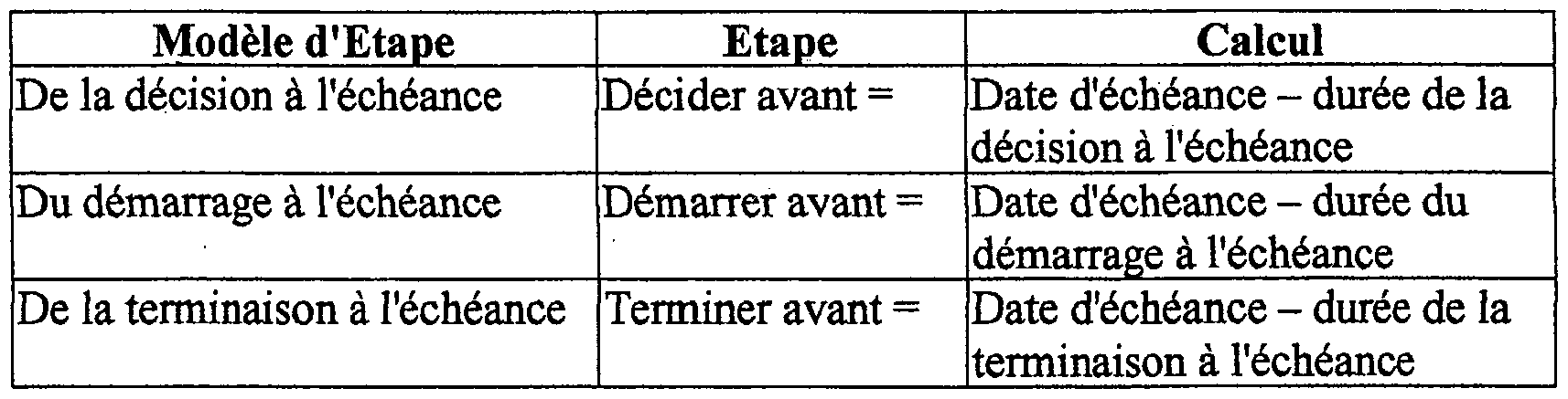
  • a stage model includes the definition of durations for the calculation of forecast dates in the form of deadlines calculated from the due date. As soon as the due date of a stage created according to a model is defined, the forecast dates are automatically calculated according to the durations defined by the model.
  • a task model comprises:
  • an "object” indicates a project, a stage, a task or a resource
  • a "model” indicates a project model, a stage model, a task model or a type of resource.
  • Figure 2a shows in the formalism defined by UML (Unified Modeling Language), the relationships between the different types of models and the different types of objects.
  • UML Unified Modeling Language
  • This figure shows different blocks representing classes of objects, divided into three parts, namely a first part (from the top) containing the designation of the block, a second part containing the list of attributes of the block and a third part containing the list of block methods.
  • the list of attributes brings together different parameters defining the state of the block, while the methods are functions or procedures which are associated with the block.
  • This figure includes "Model” and "Object” blocks which define two categories of blocks specified by the links marked by a triangle.
  • the "Model” block is linked to “Project Model”, “Stage Model” and “Task Model” blocks, while the “Object” block is linked to “Project”, “Stage” and “Task” blocks .
  • This representation simply indicates that the "Model” category gathers project models, step models and task models, and that the "Object” category gathers project, stage and task objects.
  • the models and the objects themselves are abstract. Only projects and project models, stages and stage models, tasks and task models actually have persistent occurrences in the system.
  • the "Project Model”, “Stage Model” and “Task Model” blocks are linked in series by links marked with a diamond.
  • This representation means that the project models contain stage models, which contain task models.
  • a task model is necessarily contained in a stage model and a stage model in a project model.
  • projects contain steps, which contain tasks.
  • a task is necessarily contained in a step and a step in a project.
  • the "Model” block contains in particular the "creerObjetTorrentModele” method which allows you to generate an object according to a model. Introducing attributes and methods in a category block allows you to specify implicitly that all blocks in the category contain these attributes or methods.
  • the "Object” block contains the "getModel” method which allows each object to keep the memory of the model from which it was created and therefore to find it.
  • Each link marked with a diamond is associated with numbers "1" and series of numbers "0..n” respectively to the source and destination block of the link.
  • the diamond on the side of the source or origin block of the link means that it aggregates the destination block whose life depends on the origin block, for example the deletion of a project implies the deletion of the stages which depend on it.
  • the numbers mean that the original block of the link contains between 0 and n occurrences of the destination block of the link, for example a project contains between 0 and n steps.
  • the link destination block belongs to one and only one link origin block. For example, a step belongs to one and only one project.
  • the blocks "Project model”, “Stage model” and “Task model” are linked by unmarked links whose ends are associated with series of numbers “0..1” and “0..n” respectively to the "Project”, “Stage” and “Task” blocks.
  • the absence of a diamond on the link means that the destruction of one of the two blocks does not result in the destruction of the other block.
  • these links correspond to the "getModel” method for each of the "Project", “Stage” and “Task” blocks.
  • Figure 2b shows using the same formalism another presentation of the relationships between the different types of models and the different types of objects.
  • This presentation reveals a hierarchical organization of project models and projects, by introducing the abstract notions of collective work and collective work model which group projects and stages, on the one hand, and project and stage models respectively. on the other hand.
  • projects can contain other projects, called sub-projects
  • the projects contain collective work, that is to say projects or sub-projects, and stages.
  • the project models contain collective work models, i.e. models of projects or models of sub-projects, and models of stages.
  • Hierarchies can possibly be generalized on the objects and the models, in particular for a breakdown on the one hand of the tasks into elementary tasks and grouping tasks, and on the other hand of the models of tasks into models of elementary tasks and models of tasks of regrouping.
  • Figure 2c details the constitution of models and objects.
  • a model defines a set of model properties and default values for these model properties.
  • the "creerObjetTorrentModele” method creates an object and copies for this object all the model properties defined by the model with their default values in object properties.
  • Certain model properties are possibly transformed during this copying by the "creerObjetTorrentModele” method, for example duration model properties can be transformed by a calculation into object type properties of date. The values of the object properties can then be changed independently of the default values of the model properties.
  • the stages of a project can be linked together by one or more stage scenarios, modeling the succession of stages necessary for the realization of a project and making it possible in particular to automatically generate the stages of the project conditionally depending on the properties and progress of other stages of the project.
  • a scenario is an automaton that automatically creates objects according to the models specified in the scenario when they are needed.
  • a scenario is a set of nodes and links. The nodes represent the models to be used for the creation of the objects according to the scenario. It should be noted that the same model can be referenced by several nodes of the same scenario.
  • Such an automaton can apply as well to projects or sub-projects, as to stages or tasks.
  • a stage scenario is made up of stage models symbolized by nodes linked together by links symbolizing a delay between a stage model origin of the link and a stage model destination of the link.
  • Each link therefore designates:
  • condition expressed as a function of the step model properties.
  • This condition can advantageously be implemented in the form of a script interpreted by the system.
  • the link In the case where the origin and destination nodes of a link are identical, the link is said to be recurrent. When these nodes are different, the link is non-recurring.
  • Figure 3a details the definition of the scenarios.
  • the "link" blocks as such are abstract, that is to say that only recurring links and non-recurring links actually have persistent occurrences in the system.
  • a scenario further includes a scenario origin node which is the only node to the destination of no link.
  • FIG. 3a can be easily modified to allow chaining of the scenarios, for example by introducing a subclass "terminal node” of the class "node” defining a node which would not be the origin of 'no link in the scenario, but would be associated with the origin node of another scenario.
  • Figure 3b shows the links between the scenarios and the objects.
  • Objects including projects, steps, and tasks, are not necessarily created automatically by scenarios. They can be done manually according to a model.
  • an object was created by a scenario, it preserves the reference of the node, therefore of the scenario which made it possible to create it. This reference lets you know the next object to create, via the links. It is obtained by the "getNode" method of the object.
  • the model of a scenario node is called the model to which said node refers and which is returned by the "getModel" method of said node.
  • origin model respectively destination model
  • origin object respectively destination object
  • This method is called, an object created according to a scenario node obtains said node by the "getNode” method.
  • This node is the origin of the link considered for generation.
  • the "getOutboundLinks” method of said source node returns the collection of outbound links.
  • the application of the “getDestinationNode” method on each of the outgoing links makes it possible to obtain a collection of link destination nodes.
  • the application of the “getModel” method on each of the destination nodes of the links makes it possible to obtain the collection of the corresponding models, to then create the corresponding destination objects by calling the "creerObjetTorrentModele” method on each of the said models.
  • each object keeps a reference to its successors. Whenever a generation of destination object is attempted along a link, the existence of a successor object referencing the destination node of this link must be tested so as to avoid repeating a generation which has already taken place.
  • Figure 3c shows the implementation of a condition for the generation of a destination object according to a scenario link.
  • An origin model contains a set of predefined conditions for the generation of destination objects according to the links of a scenario.
  • a link starting from a node referencing this origin model possibly designates a condition of this set for the generation of the destination object according to this link.
  • the condition is verified by the "estConditionVerifiee" method, which is an expression relating to the properties of the same model and whose return value is a boolean. This method takes the origin object as a parameter and uses the values of the properties of the origin object corresponding to the model properties designated by the expression to evaluate the condition.
  • the destination object is only created according to the scenario if the condition is satisfied.
  • the first stage model corresponding to the first node, at the origin of the link, is a "contract signature” and the second stage model corresponding to the second node, at the destination of the link, is a "credit check” .
  • the "contract signature” stage model includes a property of type monetary type and named “amount”.
  • the condition associated with the link is "amount greater than 10,000.00” which means that the credit check is only performed if the amount is greater than 10,000.00.
  • the "signing of Mr. Dupont contract” step is a particular instance of the "contract signing” model. If the object property linked to "amount" has the value of 18,000.00, the condition is checked and the credit check step of Mr. Dupont is generated for its execution.
  • the generation of the object according to the link is controlled by an action of the user interface.
  • this execution is caused on the basis of a system event, for example as soon as the object property "amount" is valued.
  • Figure 4 shows the sequence diagram according to the UML method of applying scenarios with such a condition and such events.
  • the object Whenever a new value is assigned to an object property, the object is notified by calling the "proprieteChangee" method of said object.
  • the object searches by the "getNode” method for the scenario node which eventually made it possible to create it. If such a node does not exist, the object does not participate in a scenario and the sequence does not apply. Otherwise, the object calls the “getOutboundLinks” method from this node and retrieves the collection of outbound links from that node. For each of said outgoing links, a call to the "getCondition” method returns the applicable condition which is verified by calling the "isCondition Verified” method.
  • the sequence goes to the next outgoing link in the collection. If the condition is satisfied, the object obtains the destination node of the link by calling the method "getDestinationNode” on the outgoing link, and the attached model, by calling the “getModel” method of the destination node. Finally a call to the method “creerObjetTorrentModele” of the destination model allows to create the destination object. The sequence goes to the next link in the collection of outgoing links until reaching the last element in this collection.
  • FIG. 3d presents a particular application of the scenarios according to the invention.
  • the scenario automatically creates stages and positions them over time. To do this, all the steps include the object properties "debutPrevu”, “debutEffectif,” finPrevue “,” finEffective “(see also Figures 2a and 2b) from which the states are deduced:
  • the scenario is used to calculate the expected end date "endPrevue” of a destination step “EtapeDest” of a link according to the delay “delaiEntreEtapes” between the origin step “EtapeOrigine” and the destination step of the link, and the stage model "ModeleEtapeDest” allows to deduce the planned start date
  • EtapeDest.finPrevue EtapeOrigine.finEffective + Lien.delaiEntreEtapes et
  • EtapeDest.debutPrevu EtapeDestfinPrevue - ModeleEtapeDest.dureePrevue
  • the link designates an "anchor" node for the calculation.
  • stage model anchors the stage model designated by the anchor node of a scenario link. The calculation becomes:
  • EtapeDest.finPrevue EtapeAncre. endEffective + Link.delaiEntreEtapes et
  • EtapeDest.debutPrevu EtapeDest.finPrevue - ModeleEtapeDest.dureePrevue
  • the first variant is a special case of the second variant in which origin node and anchor node are identical.
  • the condition is "EtapeAncre.finEffective filled (not null)".
  • the creation of the destination step is carried out by notification of the change in value of the object property "finEffective" when it is completed.
  • the date of the anchor step on which the calculation is based is specified in the link in the form of a "selectedDate" which can refer to any of the properties of objects "debutPrevu”, “startEffective,” endPrevue “or” endEffective "and the calculation becomes:
  • the project management tool comprises three main modules (see FIG. 5), namely a module for managing models 10, a module for object management 20, and an object tracking module 30.
  • the model management module 10 comprises a module for creating / updating 11 models, in particular project models, stage models, task models and types of resources, which are stored in a library of models 6a stored in the storage unit 6, and a module 12 for searching for these models.
  • the object management module 20 comprises a module 21 for creating / updating objects, in particular projects, stages, tasks and resources in accordance with the models found in the library 6a, these objects being stored in a base object data 6b also stored in the storage unit 6, as well as a module 22 for searching for these objects.
  • the object tracking module 30 is designed to edit lists of objects according to criteria to be introduced, in particular the state of these objects on a given date.
  • This module includes a step tracking module 31 designed to edit lists of steps and a task tracking module 32 designed to edit lists of tasks, and in particular in a period and for a given resource.
  • the task tracking module can take the form of a time sheet or a personal electronic agenda.
  • the module for creating / updating models 11 comprises a function 13 for defining a project model, a function 16 for creating personalized input forms, a function 14 for defining step models, a scenario definition function 15, a function 18 for defining task models, and a function 17 for defining resource types.
  • the project model definition function 13 makes it possible to enter general information relating to the project model, such as a description, and a description of the project model.
  • This function introduces the notion of sub-project model allowing to decompose a project model into sub-project models.
  • the function of defining a project model makes it possible to specify whether the new project model to be created is a "root" project model or a sub-project model to be linked to an already existing project model, says parent project model. If the new model to be created is a subproject model, function 13 also allows you to specify whether the corresponding subproject should be created automatically following the creation of the parent project corresponding to the parent project model, and define a minimum and maximum number of occurrences of subprojects in the parent project.
  • the function 16 for creating personalized forms makes it possible to load into the database of models 6a one or more new forms previously defined in a standard language such as HTML or to select an already existing form to assign it to a model. In this way, it suffices to use a specific editor for this language, to create a form usable by the project management tool according to the invention. Function 16 also makes it possible to analyze the fields of the HTML form and to create in the model database 6a, the set of model properties for the model to which the form relates.
  • model base 6a These model properties are stored in the model base 6a in the form of a table described in the table below:
  • a specific keyword can be added to the HTML language for type control in text boxes.
  • HTML a text box is described by the following label:
  • Function 16 also makes it possible to interpret a form and display it with its data as read in the table above.
  • the document object model of a browser allows you to read and write data in the fields of the form as displayed by the browser.
  • Function 14 allows you to define the step models that belong to the project model. This function allows in particular to enter general information relating to a stage model, such as a label, and a description of stage model. This function calls function 16 to associate one or more forms for entering specific information with a step according to this model. It also makes it possible to define the forecast durations of the stage model, and possibly to specify a list of tasks which must be performed to carry out the stage, using the task model definition function 18. Function 18 also makes it possible to decompose a step model into a list of task models and for each task model introduced into the list, to specify a task label, a description of task model, as well as a duration. and a forecast workload necessary to perform the corresponding task. To assign one or more types of resources to a task model, function 18 calls function 17.
  • Resource types correspond to the functions that a resource can play in a project, for example project manager, engineer, consultant, technician, assistant, etc.
  • the scenario definition function 15 makes it possible to specify a scenario label, a description and possibly a range of validity dates for the scenario, as well as to introduce graphically into a drawing window, nodes and links between two nodes .
  • the introduction of a node triggers the display for selection of the list of step models of the project model being defined, and the introduction of a link between two already introduced nodes requires entering a date anchor, deadline and condition.
  • This function also makes it possible to introduce recurring links, that is to say links whose origin and destination nodes are identical.
  • Figures 7a, 7b and 7c show examples of scenarios.
  • Figure 7a illustrates a scenario for selling a maintenance-free device.
  • This scenario includes a first step symbolized by a source node 51 of the scenario, corresponding to the signing of the sales contract by the customer, a step symbolized by a second node 53, corresponding to the delivery of the device, and a step symbolized by a third node 55, corresponding to the installation of the device.
  • the first and second nodes are linked together by a link associated with a delay 52, indicating that the delivery of the material to the customer must be made 16 days after the signing of the contract.
  • the second and third nodes are also linked together by a link associated with a delay 54, indicating that the installation of the device must be carried out 16 days after its delivery.
  • the anchoring date not represented is the date of achievement of the milestone of the origin step, because it is not possible to deliver without signature, nor to install without delivery.
  • Figure 7b illustrates a sales scenario for a device with maintenance that is renewable every year and includes two annual preventive visits.
  • This scenario comprises, in addition to steps 51, 53, 55 and links 52, 54 of the maintenance-free sales scenario, shown in FIG. 7a, a first step 57 of preventive maintenance visit, triggered 3 months after the signing of the contract. (link 56) and a second stage 59 of preventive visit triggered 6 months (link 58) after the first stage of preventive visit 57.
  • the anchoring date not shown is the due date of the origin step, because even if the first visit 57 is delayed or canceled, the second must take place in the terms agreed upon signature.
  • the corresponding scenario includes a renewal step 61, linked to the signing step 51 by a link 60 associated with a period of one year, and the renewal step is linked to itself by a recurring link 62 associated with a period of one year.
  • Stage 61 is also linked (link 56) to a first stage 57 of preventive visit, which is linked (link 58) to a second preventive visit 59.
  • the anchoring date for link 60 is the date of achievement of the milestone (date of signature) and the anchoring date for link 62 is the renewal due date, in order to ensure a due date on the anniversary date of the signing date.
  • Figure 7c illustrates a scenario for the rental of a device, for a period of three years, including two annual preventive maintenance visits to the device.
  • This scenario also includes an origin node 51 corresponding to the signature of the contract and nodes 53 and 55 symbolizing the stages of delivery and installation, these three nodes being linked together by the links 52 and 54.
  • stage 55 installation is linked by a link 56 associated with a period of 3 months to a first stage of preventive visit 57, which is linked by a link 58 associated with a delay of 6 months in a second stage of preventive visit 59.
  • the annual balance step 66 is linked by a link 67 associated with a period of one year to a renewal step 68.
  • the anchoring dates are deduced from the previous models and are not detailed.
  • the project model "rental / sale of equipment” which includes the three scenarios shown in Figures 7a, 7b and 7c, as well as the stage models involved also includes an additional stage model which does not participate in any scenario, namely a model of curative visit stage, which is only triggered at the request of the customer in the event of a device failure.
  • the scenario definition function 15 also makes it possible to copy and modify an already existing scenario in order to create a new one.
  • the functions 13 and 14 for defining a project and stage model make it possible to copy and modify an existing project and stage model to create new ones.
  • the module 21 for creating / updating objects is designed to present the user with a list of all the project models in the library.
  • these models can be grouped by field of activity to facilitate the selection of a model.
  • this function creates a new project object in the object library 6b and displays on the screen of the user's terminal a window for entering general information and the custom form (s) corresponding to the selected project model.
  • the module 21 for creating / updating objects gives access to the list of step models and scenarios of the project model created previously. It is possible to create a first step from a step template from the list. It is also possible to designate a scenario in the list to create the first step from the model associated with the origin node of the scenario. In both cases, it is mandatory to enter the deadline for the step to be created.
  • the module 21 creates a new step object in the object library 6b and displays on the screen of the user's terminal a window for entering general information, the forecast dates calculated from the durations defined in the model d 'stage, the completion dates to be entered and the personalized form (s) corresponding to the stage model selected.
  • the task list for the step is generated from the list of task models of the corresponding step model.
  • this generation is carried out at the request of the user or automatically when the step goes to a predefined state. For example, it is useless to break it down into tasks one year before renewing a contract.
  • the step monitoring module 31 makes it possible to know the list of steps due within a certain period and which are in a certain state on a given date, for example due in the next 6 months and not yet decided on the date of the day. Like the module 22 for searching and updating objects, the module 31 for monitoring the stages makes it possible to record the dates of completion and the changes of state of the stages.
  • the user can use the module 22 for searching and updating objects or the module 31 to allocate resources to each task of the step. For this purpose, he must for each task from the list of tasks appearing in the step object, select the name of one or more resources, generally among the employees of the organization that hosts the system, in the list of resources. of the object library 6b, according to the types of resources allocated to the task model in the step model.
  • a resource can use the task tracking module 32 to record the progress of their work.
  • the task tracking module allows you to list all the tasks involving the resource and which depend on steps decided and not completed by a certain date.
  • the task tracking module 32 presents a time sheet, that is to say a table comprising the tasks of the list online, in column of the days in a period considered, generally the week or the current month. , and in the cells at the intersection of the rows and the columns, fields for entering time portions in hours and minutes, engaged by a resource to carry out all or part of a task in the day corresponding to the cell. Portions of times contain only durations, and their sum for all the resources of the same task constitutes the workload necessary for the accomplishment of the task.
  • the duration of the task is determined by the period between the first and the last time portion of said task.
  • the module 20 for managing objects and the module 30 for tracking objects also make it possible to mark the tasks as completed.
  • the states of the stages are advantageously calculated according to the states of the tasks:
  • a step is started when at least one of its tasks is started and the start date of the step is the date of the first portion of time worked by a resource on this task;
  • stage termination date is the date of the last portion of time worked by a resource on the stage tasks
  • the object management module 20 makes it possible to modify the calculated start and end dates of the steps, in particular to take account of unsaved work.
  • the changes in stage states determined by the changes in the value of their properties, trigger the call to the module 21 for creating / updating objects for the execution of the scenario previously initialized on the project. If the scenario identifies a link leaving the current stage and the current stage contains the data necessary for the creation of the destination object of this link, this one is created with a due date based on the date of anchoring of the calculation and the period defined by the link between said anchoring date for the origin step and the due date of the destination step.
  • the corresponding destination steps are created in the object database 6b.
  • the destination step then appears in the follow-up of the steps not decided and the treatments described above. are reproduced for this second step.
  • the end of the "signature” step triggers the creation of the "delivery", "preventive visit” and "renewal” steps from the corresponding step models.
  • the module 10 for modeling projects may only be accessible to some of the terminals 2 to 4, and in particular to the terminals of those responsible for the organization, while the module 20 for managing objects and the module 30 for monitoring objects are accessible to all terminals, so that each of the organization's resources can follow up on its work and enter into the object database 6b information relating to the projects, stages and tasks it performs .
  • the system includes means for printing details and lists of objects and models.

Abstract

The invention concerns a project management tool comprising a plurality of terminals communicating with a central server, at least one of the terminals including: means (11) for defining project models and for inserting them in a model library (6a), each project model including a list of step models, one step representing a set of tasks contributing to the achievement of the project; means (15) for defining a scenario defining links between a source model and a target model, each link being associated with a condition concerning the properties of the source model of the link; means (21) for generating projects from project models and steps from step models; and means (30) for updating and display the state of the project steps, and for generating a new step from the target model of a scenario link, when the condition associated with the link is fulfilled.

Description

OUTIL DE MODELISATION ET DE GESTION DE PROJETS.MODELING AND PROJECT MANAGEMENT TOOL.
La présente invention concerne un outil de gestion de projets couvrant non seulement les besoins de planification mais aussi de suivi.The present invention relates to a project management tool covering not only planning but also monitoring needs.
Traditionnellement, un projet est décomposé en tâches dont l'accomplissement tend à la réalisation d'un objectif déterminé, à savoir le projet. L'accomplissement de ces tâches nécessite la mise en œuvre d'un ensemble de ressources offertes par une organisation telle qu'une entreprise exerçant une activité dans un domaine déterminé. Les ressources sont principalement constituées du personnel de l'organisation et des machines dont dispose l'organisation.Traditionally, a project is broken down into tasks whose accomplishment tends to the achievement of a determined objective, namely the project. The accomplishment of these tasks requires the implementation of a set of resources offered by an organization such as a company carrying out an activity in a given field. Resources are mainly made up of organizational staff and the machines available to the organization.
D'une manière générale, on peut distinguer deux types d'activités, à savoir les activités regroupant un faible nombre de grands projets, et les activités regroupant un grand nombre de petits projets. Les grands projets mettent en œuvre un grand nombre de ressources pendant une durée relativement longue, tandis que les petits projets, aussi appelés notamment dossiers, affaires, ou contrats, mettent en œuvre un petit nombre de ressources qui se partagent entre plusieurs projets à un instant donné.Generally speaking, two types of activities can be distinguished, namely activities grouping together a small number of large projects, and activities grouping together a large number of small projects. Large projects use a large number of resources for a relatively long period of time, while small projects, also called notably files, cases, or contracts, use a small number of resources which are shared between several projects at a time given.
Les outils de gestion de projet existants sont conçus pour gérer et planifier les grands projets.Existing project management tools are designed to manage and plan large projects.
La décomposition en tâches d'un grand projet est généralement hiérarchique, des tâches regroupant d'autres tâches de plus bas niveau. Par ailleurs, les tâches d'un même projet peuvent être liées entre elles par des contraintes de type prédécesseur/successeur de manière à introduire un ordonnancement temporel de l'exécution des tâches. Un tel ordonnancement est généralement représenté sous la forme de diagrammes de GANTT ou de PERT.The breakdown into tasks of a large project is generally hierarchical, tasks grouping other tasks at a lower level. Furthermore, the tasks of the same project can be linked together by constraints of the predecessor / successor type so as to introduce a temporal scheduling of the execution of the tasks. Such scheduling is generally represented in the form of GANTT or PERT diagrams.
Cette approche pose une première série de problèmes.This approach poses a first series of problems.
La gestion de projet est une activité macroscopique, chaque heure de travail n'étant pas planifiée, tandis que la gestion de l'utilisation des ressources est une activité microscopique car elle doit tenir compte de chaque heure de travail. Par conséquent, soit on privilégie la gestion de projet avec un nombre de tâches limité, et la granularité des tâches est insuffisante pour la gestion des temps passés, en particulier si le nombre de ressources à mettre en œuvre pour réaliser une tâche est important, soit on privilégie la gestion des ressources, ce qui implique un nombre de tâches beaucoup trop important pour pouvoir réaliser une planification sérieuse avec un outil de gestion de projet classique.Project management is a macroscopic activity, each hour of work not being planned, while management of the use of resources is a microscopic activity because it must take into account each hour of work. Consequently, either we favor project management with a limited number of tasks, and the granularity of the tasks is insufficient for the management of time spent, in particular if the number of resources to be implemented to carry out a task is important, or one privileges the management of resources, which implies a number of tasks far too important to be able to carry out a serious planning with a traditional project management tool.
Par ailleurs, la gestion d'un projet est focalisée sur le projet dans son ensemble et en particulier, sur la date de fin du projet. Même si des jalons sont introduits pour détecter des dérives éventuelles, il est fréquent que les dépassements de délai qu'ils révèlent ne soient pas très significatifs du fait que des tâches oubliées ont été rajoutées, ou que les tâches prévues ont été exécutées dans un ordre différent de l'ordre planifié. Pour cela, il est fréquent de décomposer les grands projets en sous-projets. Toutefois, une telle décomposition nécessite de consolider le projet à partir des sous-projets, ce qui est un exercice généralement long et difficile et donc constitue une source importante d'erreurs.In addition, the management of a project is focused on the project as a whole and in particular, on the end date of the project. Even if milestones are introduced to detect possible drifts, it is frequent that the timeouts which they reveal are not very significant because the forgotten tasks were added, or that the planned tasks were executed in order different from the planned order. For this, it is common to break down large projects into sub-projects. However, such a breakdown requires consolidating the project from the subprojects, which is generally a long and difficult exercise and therefore constitutes an important source of errors.
En outre, les outils de gestion de projets existants sont conçus pour gérer un seul projet à la fois, ce qui pose un problème lorsqu'une même ressource doit être affectée à plusieurs projets. Il est en effet difficile de contrôler la charge de travail d'une ressource affectée à plusieurs projets. En outre, ces outils qui sont fondés sur la méthode du chemin critique, sont conçus pour déterminer la date de fin du projet, mais ne sont pas adaptés au calcul et au suivi de plusieurs échéances intermédiaires.In addition, existing project management tools are designed to manage only one project at a time, which is problematic when the same resource needs to be assigned to multiple projects. It is indeed difficult to control the workload of a resource assigned to several projects. In addition, these tools, which are based on the critical path method, are designed to determine the end date of the project, but are not suitable for calculating and monitoring several intermediate deadlines.
L'approche classique de gestion de projet pose également une seconde série de problèmes. Les petits projets ne sont généralement pas planifiés dans la mesure où la charge de réalisation ne justifie pas la charge de planification. La décomposition du projet en tâches allouées à des ressources reste pourtant nécessaire pour le suivi des tâches. Les outils de gestion de projet classiques ne permettent pas de générer automatiquement l'information nécessaire au suivi de grands volumes de petits projets, qu'il serait trop lourd, voir impossible, de produire manuellement.The classic project management approach also poses a second series of problems. Small projects are generally not planned since the implementation cost does not justify the planning load. However, breaking down the project into tasks allocated to resources is still necessary for monitoring tasks. Conventional project management tools do not automatically generate the information necessary to monitor large volumes of small projects, which would be too heavy, if not impossible, to produce manually.
En outre, certains petits projets durent plusieurs années mais ne nécessitent que de petites interventions souvent récurrentes au cours de la vie du projet. Les outils de gestion de projet classiques n'ont pas d'automatisme pour planifier et suivre les échéances de ces étapes récurrentes.In addition, some small projects last several years but only require small interventions which are often recurrent during the life of the project. Conventional project management tools do not have an automatic mechanism for planning and monitoring the deadlines for these recurring stages.
La présente invention a pour but de supprimer ces inconvénients. Cet objectif est atteint par la prévision d'un outil de gestion de projets comprenant une pluralité de terminaux communiquant avec un serveur central, caractérisé en ce qu'au moins un des terminaux comprend :The present invention aims to eliminate these drawbacks. This objective is achieved by providing a project management tool including a plurality of terminals communicating with a central server, characterized in that at least one of the terminals comprises:
- des moyens pour définir des modèles de projets et pour les insérer dans une bibliothèque de modèles, accessible par l'intermédiaire du serveur central, chaque modèle de projet comprenant une liste de modèles d'étapes, chaque étape d'un projet représentant un ensemble de travaux collectifs participant à la réalisation du projet en vue d'un résultat intermédiaire, et étant associée à un état d'étape,means for defining project models and for inserting them into a library of models, accessible via the central server, each project model comprising a list of step models, each step of a project representing a set of collective work participating in the realization of the project with a view to an intermediate result, and being associated with a progress report,
- des moyens pour définir au moins un scénario pour un modèle de projet qui est inséré dans la bibliothèque de modèles en association avec le modèle de projet correspondant, chaque scénario définissant des liens de succession entre deux nœuds associés respectivement à des modèles d'étapes, à savoir un nœud origine du lien et un nœud destination du lien, chaque lien étant associé à une condition exprimée en fonction de propriétés du modèle d'étape associé au nœud origine du lien,means for defining at least one scenario for a project model which is inserted into the library of models in association with the corresponding project model, each scenario defining succession links between two nodes associated respectively with step models, namely a link origin node and a link destination node, each link being associated with a condition expressed as a function of properties of the step model associated with the link origin node,
- des moyens pour générer un projet à partir d'un modèle de projet sélectionné dans la bibliothèque de modèles, chaque terminal comprenant :- means for generating a project from a project model selected from the model library, each terminal comprising:
- des moyens de génération d'étapes à partir de modèles d'étapes, et - des- moyens de suivi de projets permettant de mettre à jour et visualiser l'état des étapes des projets qui ont préalablement été générées à l'aide des moyens de génération d'étapes, et pour déclencher la génération d'une nouvelle étape à partir d'un modèle d'étape associé à un nœud destination d'un lien d'un scénario lorsqu'une condition associée au lien est satisfaite par les propriétés d'une étape associée au nœud origine du lien.- means for generating stages from stage models, and - means for monitoring projects allowing updating and viewing the state of the stages of projects which have previously been generated using the means of generation of stages, and to trigger the generation of a new stage from a stage model associated with a destination node of a link of a scenario when a condition associated with the link is satisfied by the properties a step associated with the origin node of the link.
Avantageusement, chaque modèle d'étape d'au moins une partie des modèles d'étapes comprend une liste de modèles de tâches définissant des tâches qui sont nécessaires à la réalisation d'une étape générée à partir du modèle d'étape, l'outil de gestion de projet comportant des moyens de génération de tâches à partir de modèles de tâches et des moyens de mise à jour et de suivi de tâches qui ont été préalablement générées.Advantageously, each stage model of at least part of the stage models comprises a list of task models defining tasks which are necessary for the completion of a stage generated from the stage model, the tool project management comprising means for generating tasks from task models and means for updating and monitoring tasks which have been previously generated.
De préférence, l'outil de gestion comprend des moyens pour définir au moins un scénario pour un modèle d'étape qui est inséré dans la bibliothèque de modèles, en association avec le modèle d'étape correspondant, chaque scénario définissant des liens de succession entre deux nœuds associés respectivement à des modèles de tâches, à savoir un nœud origine du lien et un nœud destination du lien, chaque lien étant associé à une condition exprimée en fonction de propriétés du modèle de tâche associé au nœud origine du lien.Preferably, the management tool comprises means for defining at least one scenario for a stage model which is inserted into the library of models, in association with the corresponding stage model, each scenario defining succession links between two nodes associated respectively with task models, namely a link origin node and a destination node of the link, each link being associated with a condition expressed as a function of the properties of the task model associated with the origin node of the link.
Selon une particularité de l'invention, l'outil de gestion comprend des moyens pour définir des modèles de sous-projets d'un modèle de projet ou d'un autre modèle de sous-projet, et des moyens pour définir des scénarios comportant des liens de succession entre deux modèles pris parmi des modèles de projets et modèles de sous-projets, à savoir un modèle origine du lien et un modèle destination du lien.According to a feature of the invention, the management tool comprises means for defining models of sub-projects of a project model or another model of sub-project, and means for defining scenarios comprising succession links between two models taken from project models and sub-project models, namely an origin model of the link and a destination model of the link.
Selon une autre particularité de l'invention, l'outil de gestion comprend des moyens de définition d'un nœud terminal dans un scénario, lequel nœud est associé à un nœud origine d'un autre scénario, et des moyens pour déclencher un scénario dont le nœud origine est lié à un nœud terminal d'un autre scénario en cours d'exécution, lorsqu'une condition portant sur un modèle associé au nœud terminal est vérifiée.According to another particular feature of the invention, the management tool comprises means for defining a terminal node in a scenario, which node is associated with a node originating from another scenario, and means for triggering a scenario whose the origin node is linked to a terminal node of another running scenario, when a condition relating to a model associated with the terminal node is satisfied.
Selon encore une autre particularité de l'invention, l'outil de gestion comprend un modèle d'étape comprend la définition d'au moins une date prévisionnelle ou effective, une étape selon ce modèle comprenant au moins une date prévisionnelle ou effective, chaque lien d'un scénario étant associé à un délai et une date choisie parmi les dates prévisionnelles ou effectives d'une étape définie par son modèle correspondant à un nœud d'ancrage du lien.According to yet another feature of the invention, the management tool comprises a step model includes the definition of at least one forecast or effective date, a step according to this model comprising at least one forecast or effective date, each link of a scenario being associated with a deadline and a date chosen from the provisional or actual dates of a stage defined by its model corresponding to a node for anchoring the link.
Avantageusement, le nœud d'ancrage d'un lien est le nœud d'origine du lien.Advantageously, the anchoring node of a link is the original node of the link.
En particulier, les moyens pour définir un scénario comprennent :In particular, the means to define a scenario include:
- des moyens pour insérer dans une fenêtre d'écran d'affichage un symbole graphique de type nœud représentant un modèle d'étape, - des moyens pour insérer dans ladite fenêtre un symbole graphique de type lien reliant deux symboles de type nœud, et représentant un lien entre deux étapes, et- Means for inserting into a display screen window a graphic symbol of node type representing a step model, - means for inserting into said window a graphic symbol of link type connecting two symbols of node type, and representing a link between two stages, and
- des moyens pour insérer dans ladite fenêtre un symbole graphique de type lien récursif ayant pour origine et destination un même symbole de type nœud, indiquant que l'étape représentée par le nœud origine et destination du lien doit être exécutée plusieurs fois à intervalles réguliers.- Means for inserting into said window a graphic symbol of the recursive link type having for origin and destination the same node type symbol, indicating that the step represented by the origin and destination node of the link must be executed several times at regular intervals.
De préférence, l'outil de gestion selon l'invention comprend des moyens pour associer à un modèle un formulaire de saisie d'informations spécifiques à un objet généré à partir du modèle, et des moyens de conversion pour convertir un formulaire défini par l'utilisateur dans un langage de description standard en un formulaire utilisable par l'outil de gestion de projet et associé à ce modèle et aux objets créés selon ce modèle.Preferably, the management tool according to the invention comprises means for associating with a model a form for entering information specific to an object generated from the model, and conversion means for converting a form defined by the user in a standard description language into a form usable by the project management and associated with this model and with objects created according to this model.
Avantageusement, durant l'exécution d'un scénario, il comprend des moyens pour détecter la modification d'une propriété d'une étape associée à un nœud du scénario, des moyens pour rechercher le nœud associé à l'étape et les liens sortant de ce nœud, des moyens pour obtenir une condition associée à chacun des liens sortants ainsi trouvés, des moyens pour vérifier chacune des conditions obtenues, des moyens pour obtenir le nœud destination du lien associé à une condition vérifiée et le modèle d'étape associé au nœud destination obtenu, et des moyens pour créer une étape sur le modèle d'étape ainsi obtenu.Advantageously, during the execution of a scenario, it comprises means for detecting the modification of a property of a step associated with a node of the scenario, means for searching for the node associated with the step and the links leaving this node, means for obtaining a condition associated with each of the outgoing links thus found, means for verifying each of the conditions obtained, means for obtaining the destination node of the link associated with a verified condition and the step model associated with the node destination obtained, and means for creating a stage on the stage model thus obtained.
Un mode de réalisation préféré d'un outil de gestion de projets selon l'invention sera décrit ci-après, à titre d'exemple non limitatif, avec référence aux dessins annexés dans lesquels :A preferred embodiment of a project management tool according to the invention will be described below, by way of nonlimiting example, with reference to the appended drawings in which:
La figure r représente schématiquement un système permettant la mise en œuvre de l'outil de gestion de projets selon l'invention ;FIG. R schematically represents a system allowing the implementation of the project management tool according to the invention;
Les figures 2a, 2b et 2c montrent suivant le formalisme objet de la méthode UML la structure des modèles et des objets manipulés par l'outil de gestion de projets selon l'invention ;Figures 2a, 2b and 2c show according to the formalism object of the UML method the structure of models and objects manipulated by the project management tool according to the invention;
Les figures 3a, 3b, 3c et 3d montrent suivant le formalisme objet la méthode UML la structure d'un scénario et son fonctionnement ;Figures 3a, 3b, 3c and 3d show according to the object formalism the UML method the structure of a scenario and its operation;
La figure 4 illustre sous la forme d'un diagramme de séquence de la méthode UML, les mécanismes mis en œuvre dans un scénario selon l'invention ;FIG. 4 illustrates in the form of a sequence diagram of the UML method, the mechanisms implemented in a scenario according to the invention;
La figure 5 montre les principaux modules de l'outil de gestion de projets selon l'invention ; La figure 6 montre en détail l'un des principaux modules représentés sur la figure 5 ;FIG. 5 shows the main modules of the project management tool according to the invention; Figure 6 shows in detail one of the main modules shown in Figure 5;
Les figures 7a, 7b et 7c sont des exemples de scénarios créés et utilisés par l'outil de gestion de projets selon l'invention.Figures 7a, 7b and 7c are examples of scenarios created and used by the project management tool according to the invention.
La figure 1 représente un système dans lequel l'outil de gestion de projets selon l'invention est mis en œuvre. Ce système comprend une pluralité de terminaux 2 à 4 mis à la disposition d'utilisateurs d'une ou plusieurs organisations et connectés par l'intermédiaire d'un réseau privé 5 et/ou public de transmission de données à un ou plusieurs calculateurs serveurs 1. Le serveur 1 est par ailleurs connecté à une unité de stockage 6 contenant une base de données. Dans un tel système, les terminaux 2 à 4 sont généralement constitués par des ordinateurs de bureau, mais peuvent également être constitués par des téléphones mobiles ou encore par des ordinateurs de poche ou ce que l'on appelle des assistants personnels. Par ailleurs, le serveur 1 est de préférence de type serveur Web. Bien entendu, le réseau 5 peut être constitué par un ou plusieurs réseaux publics ou privés de transmission de données.FIG. 1 represents a system in which the project management tool according to the invention is implemented. This system comprises a plurality of terminals 2 to 4 made available to users of one or more organizations and connected via a private 5 and / or public network for transmitting data to one or more server computers 1 The server 1 is also connected to a storage unit 6 containing a database. In such a system, the terminals 2 to 4 are generally constituted by desktop computers, but can also be constituted by mobile telephones or also by pocket computers or what are called personal assistants. Furthermore, the server 1 is preferably of the Web server type. Of course, the network 5 can be constituted by one or more public or private data transmission networks.
Dans ce système, le serveur 1 met à disposition des terminaux 2 à 4 les différentes fonctions de l'outil de gestion de projet, ainsi que les informations générées et stockées par l'outil de gestion de projet dans l'unité de stockage 6. Bien entendu, des droits d'accès peuvent être attribués aux différents utilisateurs de ces terminaux en vue de leur interdire l'accès à certaines de ces fonctions ou informations en fonction de ces droits d'accès.In this system, the server 1 makes available to the terminals 2 to 4 the various functions of the project management tool, as well as the information generated and stored by the project management tool in the storage unit 6. Of course, access rights can be assigned to the different users of these terminals in order to prohibit them from accessing certain of these functions or information as a function of these access rights.
Par rapport à la décomposition classique d'un projet en sous-projets, puis en tâches, l'invention introduit un niveau de décomposition supplémentaire entre le projet et la tâche, appelé "étape" qui correspond à l'engagement d'un ensemble de ressources impliquées dans le projet en vue de fournir un certain résultat à une date d'échéance donnée. Un tel engagement correspond par exemple à la commande d'un client, un lot de projet, un livrable ou une prestation facturable. Une des propriétés principales d'une étape est donc son jalon, c'est-à-dire la date à laquelle le résultat de l'étape est fourni ou livré. A la date effective du jalon est assortie une date de prévision appelée date d'échéance de l'étape, c'est-à-dire la date avant laquelle le résultat de l'étape doit être fourni ou livré, cette date étant éventuellement assortie de délais de grâce qui permettent de réaliser l'étape sans compromettre le déroulement du projet. Dans cette décomposition, la tâche s'analyse comme la participation d'une ou plusieurs ressources à cet engagement. La planification du projet est alors basée sur cette décomposition en étapes qui masque le détail de la liste des tâches. Il en résulte qu'une tâche peut être ajoutée à tout moment à une étape sans impact direct sur la planification. Le suivi de projet consiste dans le suivi des étapes et des tâches par les ressources impliquées. Grâce à l'invention, les étapes et la planification du projet sont automatiquement mises à jour par consolidation des informations recueillies sur les tâches.Compared to the classic breakdown of a project into sub-projects, then into tasks, the invention introduces an additional level of breakdown between the project and the task, called "stage" which corresponds to the commitment of a set of resources involved in the project to deliver a certain result by a given due date. Such a commitment corresponds, for example, to a customer's order, a project package, a deliverable or a billable service. One of the main properties of a stage is therefore its milestone, i.e. the date on which the result of the stage is supplied or delivered. There is a forecast date on the effective date of the milestone called the stage due date, i.e. the date before which the result of the stage must be supplied or delivered, this date possibly being matched grace periods that allow the stage to be carried out without compromising the progress of the project. In this breakdown, the task is analyzed as the participation of one or more resources in this commitment. Project planning is then based on this breakdown into stages which hides the details of the task list. As a result, a task can be added to a stage at any time without having a direct impact on planning. Project monitoring consists of monitoring the stages and tasks by the resources involved. Thanks to the invention, the stages and the planning of the project are automatically updated by consolidating the information collected on the tasks.
En outre, la présente invention se base sur la constatation selon laquelle, dans les activités de petits projets, les projets ou affaires peuvent être regroupés dans un nombre limité d'ensembles de projets similaires. Il en est de même des étapes et des tâches. En partant de cette constatation, elle introduit la notion de modèle d'objet, à savoir de projet, d'étape ou de tâche, qui rassemble tous les éléments communs aux objets d'un même ensemble d'objets similaires.Furthermore, the present invention is based on the observation that, in the activities of small projects, the projects or businesses can be grouped in a limited number of sets of similar projects. The same is true for steps and tasks. Starting from this observation, it introduces the concept of object model, namely project, stage or task, which brings together all the elements common to the objects of the same set of similar objects.
Les éléments communs d'un ensemble de projets rassemblés dans un modèle de projet comportent notamment des scénarios qui permettent de reproduire, dans les projets dérivés de ces modèles, des schémas de récurrences reproductibles.The common elements of a set of projects gathered in a project model notably include scenarios which make it possible to reproduce, in the projects derived from these models, reproducible patterns of recurrences.
L'outil de gestion de projet selon l'invention met en œuvre une phase de modélisation, c'est-à-dire de construction des modèles et une phase de production, c'est à dire de gestion des objets créés selon ces modèles.The project management tool according to the invention implements a modeling phase, that is to say construction of the models and a production phase, that is to say management of the objects created according to these models.
La modélisation consiste à identifier d'une part les différentes activités ou types de projets de l'organisation, et éventuellement à organiser ces modèles de projets selon un modèle hiérarchique en identifiant des modèles de "sous- projets", et d'autre part à identifier les modèles d'étapes, les modèles de tâches et les types de ressources qui interviennent tout au long du déroulement de ces modèles de projets gérés par l'organisation.Modeling consists in identifying on the one hand the different activities or types of projects of the organization, and possibly in organizing these project models according to a hierarchical model by identifying models of "sub-projects", and on the other hand to identify the models of stages, the models of tasks and the types of resources which intervene throughout the course of these models of projects managed by the organization.
Selon l'invention, un modèle de projet ou de sous-projet comprend :According to the invention, a project or sub-project model comprises:
- éventuellement une liste de modèles de sous-projet et des règles de création de sous-projets selon ces modèles, - une liste de propriétés du modèle de projet, à saisir dans un ou plusieurs formulaires spécifiques du modèle, - une liste de modèles d'étapes et des règles de création d'étapes selon ces modèles,- possibly a list of sub-project models and rules for creating sub-projects according to these models, - a list of properties of the project model, to be entered in one or more specific forms of the model, - a list of stage models and rules for creating stages according to these models,
- et éventuellement des scénarios de sous-projets ou d'étapes permettant de spécifier des enchaînements de sous-projets ou d'étapes dans le modèle de projet.- and possibly scenarios of sub-projects or stages making it possible to specify sequences of sub-projects or stages in the project model.
Selon l'invention, un modèle d'étape comprend :According to the invention, a step model comprises:
- une liste de propriétés du modèle d'étape, à saisir dans un ou plusieurs formulaires spécifiques du modèle d'étape, et en particulier, un ensemble d'états et de durées prévisionnelles entre deux états,- a list of properties of the stage model, to be entered in one or more specific forms of the stage model, and in particular, a set of states and expected durations between two states,
- une liste ordonnée ou non de modèles de tâches et des règles de création des tâches selon ces modèles,- an ordered or unordered list of task models and the rules for creating tasks according to these models,
- et éventuellement des scénarios de tâches permettant de spécifier des enchaînements de tâches dans le modèle d'étape.- and possibly task scenarios making it possible to specify sequences of tasks in the stage model.
Comme les étapes ont des durées d'exécution variables et qu'il ne s'agit pas d'attendre le dernier moment pour s'inquiéter de leur bon déroulement, l'outil de gestion de projets selon l'invention permet de surveiller l'état d'une étape au cours du temps et d'émettre des alertes si une étape est en retard ou si une échéance est passée. A cet effet, les modèles d'étape permettent de prédéfinir la façon dont doit se dérouler une étape générée à partir d'un modèle d'étape, c'est- à-dire tous les délais à surveiller de la création de l'étape à sa fin. Chaque étape est associée à deux séries de dates, à savoir :As the stages have variable execution times and it is not a matter of waiting for the last moment to worry about their smooth progress, the project management tool according to the invention makes it possible to monitor the state of a stage over time and issue alerts if a stage is late or if a deadline has passed. To this end, the stage models make it possible to predefine the way in which a stage generated from a stage model must take place, that is to say all the delays to be monitored from the creation of the stage. at its end. Each stage is associated with two series of dates, namely:
- des dates de prévision qui sont définies et enregistrées à la création de l'étape, et- forecast dates which are defined and recorded when the stage is created, and
- des dates de réalisation qui sont définies au cours de la vie de l'étape.- achievement dates which are defined during the life of the stage.
Si au cours de la vie de l'étape, une date de réalisation intervient après une date de prévision, on considère que l'étape est en retard.If during the life of the stage, a completion date occurs after a forecast date, it is considered that the stage is late.
La date d'échéance et la date effective du jalon sont à part dans la prévision et la réalisation. En effet, prenons l'exemple de la "signature de contrat". Cette étape comprend un certain nombre de tâches avant (préparation du contrat) et après (enregistrement et facturation du contrat) la date effective de signature. La date effective de signature est la date effective du jalon de l'étape "signature du contrat". La date d'échéance est la date prévue correspondante. Si la date de jalon de l'étape est postérieure ou non renseignée à la date d'échéance de l'étape, on considère que l'échéance de l'étape est dépassée.The due date and the effective date of the milestone are separate in the planning and implementation. Indeed, let's take the example of "contract signing". This stage includes a certain number of tasks before (preparation of the contract) and after (recording and invoicing of the contract) the effective date of signature. The effective date of signature is the effective date of the milestone of the "signature of the contract" stage. The due date is the corresponding scheduled date. If the milestone date of the stage is later than or not indicated on the stage due date, the stage deadline is considered to have passed.
A titre d'exemple non limitatif, on prévoit les dates et états présentés dans le tableau suivant pour le suivi des étapes:By way of nonlimiting example, the dates and states presented in the following table are provided for monitoring the steps:
Par défaut, une étape créée est en projet. Dans cet état, l'étape attend une décision, qui peut prendre la forme d'un ordre d'un client, d'une décision interne ou d'un événement extérieur. Ensuite, l'étape est décidée lorsque son exécution a été confirmée. L'étape passe ensuite à l'état démarré lorsque son exécution a commencé. Enfin, l'étape passe à l'état terminé, à moins qu'elle n'ait été abandonnée.By default, a stage created is in project. In this state, the stage awaits a decision, which can take the form of an order from a client, an internal decision or an external event. Then the step is decided when its execution has been confirmed. The step then goes to the started state when its execution has started. Finally, the stage goes to the finished state, unless it has been abandoned.
Un modèle d'étape comporte la définition de durées pour le calcul des dates prévisionnelles sous la forme de délais calculés à partir de la date d'échéance. Dès que la date d'échéance d'une étape créée selon un modèle est définie, les dates de prévision sont automatiquement calculées d'après les durées définies par le modèle.A stage model includes the definition of durations for the calculation of forecast dates in the form of deadlines calculated from the due date. As soon as the due date of a stage created according to a model is defined, the forecast dates are automatically calculated according to the durations defined by the model.
Figure imgf000011_0002
Selon l'invention, un modèle de tâche comprend :According to the invention, a task model comprises:
- une charge de travail et une durée prévisionnelle nécessaire à l'accomplissement de la tâche,- a workload and a forecast duration necessary for the accomplishment of the task,
- une liste de types de ressources nécessaires à l'accomplissement de la tâche selon le modèle,- a list of types of resources necessary for the accomplishment of the task according to the model,
- et éventuellement un numéro d'ordre. Dans la suite, un "objet" désigne un projet, une étape, une tâche ou une ressource, et un "modèle" désigne un modèle de projet, un modèle d'étape, un modèle de tâche ou un type de ressource.- and possibly a serial number. In the following, an "object" indicates a project, a stage, a task or a resource, and a "model" indicates a project model, a stage model, a task model or a type of resource.
La figure 2a montre dans le formalisme défini par le langage UML (Unified Modeling Language), les relations entre les différents types de modèles et les différents types d'objets. Cette figure montre différents blocs représentant des classes d'objets, divisés en trois parties, à savoir une première partie (en partant du haut) contenant la désignation du bloc, une seconde partie contenant la liste des attributs du bloc et une troisième partie contenant la liste des méthodes du bloc. La liste des attributs rassemble différents paramètres définissant l'état du bloc, tandis que les méthodes sont des fonctions ou procédures qui sont associées au bloc. Cette figure comprend des blocs "Modèle" et "Objet" qui définissent deux catégories de blocs spécifiés par les liens marqués par un triangle. Ainsi, le bloc "Modèle" est relié à des blocs "Modèle Projet", "Modèle Etape" et "Modèle Tâche", tandis que le bloc "Objet" est relié à des blocs "Projet", "Etape" et "Tâche". Cette représentation permet simplement d'indiquer que la catégorie "Modèle" rassemble des modèles de projets, des modèles d'étapes et des modèles de tâches, et que la catégorie "Objet" rassemble des objets projet, étape et tâche.Figure 2a shows in the formalism defined by UML (Unified Modeling Language), the relationships between the different types of models and the different types of objects. This figure shows different blocks representing classes of objects, divided into three parts, namely a first part (from the top) containing the designation of the block, a second part containing the list of attributes of the block and a third part containing the list of block methods. The list of attributes brings together different parameters defining the state of the block, while the methods are functions or procedures which are associated with the block. This figure includes "Model" and "Object" blocks which define two categories of blocks specified by the links marked by a triangle. Thus, the "Model" block is linked to "Project Model", "Stage Model" and "Task Model" blocks, while the "Object" block is linked to "Project", "Stage" and "Task" blocks . This representation simply indicates that the "Model" category gathers project models, step models and task models, and that the "Object" category gathers project, stage and task objects.
Les modèles et les objets proprement dits sont abstraits. Seuls les projets et modèles de projets, les étapes et modèles d'étapes, les tâches et modèles de tâches ont effectivement des occurrences persistantes dans le système.The models and the objects themselves are abstract. Only projects and project models, stages and stage models, tasks and task models actually have persistent occurrences in the system.
Ensuite, les blocs "Modèle Projet", "Modèle Etape" et "Modèle Tâche" sont reliés en série par des liens marqués par un losange. Cette représentation signifie que les modèles de projets contiennent des modèles d'étape, lesquels contiennent des modèles de tâches. Un modèle de tâche est nécessairement contenu dans un modèle d'étape et un modèle d'étape dans un modèle de projet.Then, the "Project Model", "Stage Model" and "Task Model" blocks are linked in series by links marked with a diamond. This representation means that the project models contain stage models, which contain task models. A task model is necessarily contained in a stage model and a stage model in a project model.
Les blocs "Projet", "Etape" et "Tâche" sont liés entre eux de la même manière.The "Project", "Stage" and "Task" blocks are linked together in the same way.
Cela signifie que les projets contiennent des étapes, lesquelles contiennent des tâches. Une tâche est nécessairement contenue dans une étape et une étape dans un projet.This means that projects contain steps, which contain tasks. A task is necessarily contained in a step and a step in a project.
Le bloc "Modèle" contient en particulier la méthode "creerObjetSelonModele" qui permet de générer un objet d'après un modèle. Le fait d'introduire des attributs et des méthodes dans un bloc de type catégorie permet de spécifier implicitement que tous les blocs de la catégorie contiennent ces attributs ou ces méthodes.The "Model" block contains in particular the "creerObjetSelonModele" method which allows you to generate an object according to a model. Introducing attributes and methods in a category block allows you to specify implicitly that all blocks in the category contain these attributes or methods.
Le bloc "Objet" contient la méthode "obtenirModele" qui permet à chaque objet de conserver la mémoire du modèle à partir duquel il a été créé et donc de retrouver celui-ci.The "Object" block contains the "getModel" method which allows each object to keep the memory of the model from which it was created and therefore to find it.
Chaque lien marqué par un losange est associé à des nombres " 1 " et des séries de nombres "0..n" respectivement au bloc d'origine et de destination du lien. Le losange du côté du bloc source ou origine du lien signifie qu'il agrège le bloc destination dont la vie dépend du bloc origine, par exemple la suppression d'un projet implique la suppression des étapes qui en dépendent. Les nombres signifient que le bloc d'origine du lien contient entre 0 et n occurrences du bloc destination du lien, par exemple un projet contient entre 0 et n étapes. A l'inverse, le bloc destination du lien appartient à un et un seul bloc d'origine du lien. Par exemple une étape appartient à un et un seul projet. Par ailleurs, les blocs "Modèle projet", "Modèle Etape" et "Modèle Tâche" sont reliés par des liens non marqués dont les extrémités sont associées à des séries de nombres "0..1" et "0..n" respectivement aux blocs "Projet" "Etape" et "Tâche". Cela signifie par exemple qu'un modèle de projet peut être associé à un ou plusieurs projets. L'absence de losange sur le lien signifie que la destruction de l'un des deux blocs n'entraîne pas la destruction de l'autre bloc. En fait, ces liens correspondent à la méthode "obtenirModele" pour chacun des blocs "Projet", "Etape" et "Tâche".Each link marked with a diamond is associated with numbers "1" and series of numbers "0..n" respectively to the source and destination block of the link. The diamond on the side of the source or origin block of the link means that it aggregates the destination block whose life depends on the origin block, for example the deletion of a project implies the deletion of the stages which depend on it. The numbers mean that the original block of the link contains between 0 and n occurrences of the destination block of the link, for example a project contains between 0 and n steps. Conversely, the link destination block belongs to one and only one link origin block. For example, a step belongs to one and only one project. In addition, the blocks "Project model", "Stage model" and "Task model" are linked by unmarked links whose ends are associated with series of numbers "0..1" and "0..n" respectively to the "Project", "Stage" and "Task" blocks. This means, for example, that a project template can be associated with one or more projects. The absence of a diamond on the link means that the destruction of one of the two blocks does not result in the destruction of the other block. In fact, these links correspond to the "getModel" method for each of the "Project", "Stage" and "Task" blocks.
Les différentes dates de prévision et de réalisation d'étape, mentionnées ci-avant s'analysent en premier ressort comme des propriétés d'étapes. Par simplification, ces dates sont introduites en tant qu'attributs ou propriétés au niveau de l'objet étape, dans la mesure où ces dates sont partagées par toutes les étapes.The various dates for forecasting and carrying out stages, mentioned above, are analyzed in the first instance as properties of stages. For simplicity, these dates are introduced as attributes or properties at the stage object level, insofar as these dates are shared by all the stages.
La figure 2b montre en utilisant le même formalisme une autre présentation des relations existant entre les différents types de modèles et les différents types d'objets. Cette présentation fait apparaître une organisation hiérarchique des modèles de projets et des projets, en introduisant les notions abstraites de travail collectif et de modèle de travail collectif qui regroupent respectivement les projets et étapes d'une part, et les modèles de projet et d'étape d'autre part. En outre, pour faire apparaître que les projets peuvent contenir d'autres projets, appelés sous-projets, les projets contiennent des travaux collectifs, c'est-à-dire des projets ou sous-projets, et des étapes. De même, les modèles de projets contiennent des modèles de travaux collectifs, c'est-à-dire des modèles de projets ou modèles de sous-projets, et des modèles d'étapes.Figure 2b shows using the same formalism another presentation of the relationships between the different types of models and the different types of objects. This presentation reveals a hierarchical organization of project models and projects, by introducing the abstract notions of collective work and collective work model which group projects and stages, on the one hand, and project and stage models respectively. on the other hand. In addition, to show that projects can contain other projects, called sub-projects, the projects contain collective work, that is to say projects or sub-projects, and stages. Likewise, the project models contain collective work models, i.e. models of projects or models of sub-projects, and models of stages.
Ces hiérarchies peuvent être éventuellement généralisées sur les objets et les modèles, en particulier pour une décomposition d'une part des tâches en tâches élémentaires et tâches de regroupement, et d'autre part des modèles de tâches en modèles de tâches élémentaires et modèles de tâches de regroupement.These hierarchies can possibly be generalized on the objects and the models, in particular for a breakdown on the one hand of the tasks into elementary tasks and grouping tasks, and on the other hand of the models of tasks into models of elementary tasks and models of tasks of regrouping.
La figure 2c détaille la constitution des modèles et des objets. Un modèle définit un ensemble de propriétés de modèle et de valeurs par défaut pour ces propriétés de modèle. La méthode "creerObjetSelonModele" crée un objet et recopie pour cet objet l'ensemble des propriétés de modèle définies par le modèle avec leurs valeurs par défaut dans des propriétés d'objet. Certaines propriétés de modèle sont éventuellement transformées au cours de cette recopie par la méthode "creerObjetSelonModele", par exemple des propriétés de modèle de type durée peuvent être transformées par un calcul en propriétés d'objet de type date. Les valeurs des propriétés d'objet peuvent ensuite être modifiées indépendamment des valeurs par défaut des propriétés de modèle.Figure 2c details the constitution of models and objects. A model defines a set of model properties and default values for these model properties. The "creerObjetSelonModele" method creates an object and copies for this object all the model properties defined by the model with their default values in object properties. Certain model properties are possibly transformed during this copying by the "creerObjetSelonModele" method, for example duration model properties can be transformed by a calculation into object type properties of date. The values of the object properties can then be changed independently of the default values of the model properties.
Selon l'invention, les étapes d'un projet peuvent être reliées entre elles par un ou plusieurs scénarios d'étapes, modélisant la succession d'étapes nécessaires à la réalisation d'un projet et permettant notamment de générer automatiquement les étapes du projet de manière conditionnelle en fonction des propriétés et de l'état d'avancement d'autres étapes du projet.According to the invention, the stages of a project can be linked together by one or more stage scenarios, modeling the succession of stages necessary for the realization of a project and making it possible in particular to automatically generate the stages of the project conditionally depending on the properties and progress of other stages of the project.
Un scénario est un automate qui crée automatiquement des objets selon les modèles spécifiés dans le scénario au moment où ils sont nécessaires. Un scénario est un ensemble de nœuds et de liens. Les nœuds représentent les modèles à utiliser pour la création des objets d'après le scénario. Il est à noter qu'un même modèle peut être référencé par plusieurs nœuds d'un même scénario. Un tel automate peut aussi bien s'appliquer aux projets ou sous- projets, qu'aux étapes ou aux tâches.A scenario is an automaton that automatically creates objects according to the models specified in the scenario when they are needed. A scenario is a set of nodes and links. The nodes represent the models to be used for the creation of the objects according to the scenario. It should be noted that the same model can be referenced by several nodes of the same scenario. Such an automaton can apply as well to projects or sub-projects, as to stages or tasks.
Un scénario d'étapes est constitué de modèles d'étapes symbolisés par des nœuds reliés entre eux par des liens symbolisant un délai entre un modèle d'étape origine du lien et un modèle d'étape destination du lien. Chaque lien désigne donc :A stage scenario is made up of stage models symbolized by nodes linked together by links symbolizing a delay between a stage model origin of the link and a stage model destination of the link. Each link therefore designates:
- un nœud source ou origine du lien, associé à un modèle d'étape origine ; - un nœud destination du lien, associé à un modèle d'étape destination ;- a source or origin node of the link, associated with an origin step model; - a link destination node, associated with a destination step model;
- un type de date d'ancrage parmi les dates connues d'une étape origine : date (prévue) de décision, date (prévue) de démarrage, date (prévue) de terminaison, date d'échéance et date de réalisation du jalon ; - un délai exprimée en jours, mois et années entre la date d'ancrage de la source du lien et la date d'échéance de l'étape associée au nœud destination du lien ;- a type of anchor date among the dates known from an origin stage: (planned) decision date, (planned) start date, (planned) termination date, due date and date of achievement of the milestone; - a delay expressed in days, months and years between the date of anchoring of the source of the link and the date of expiration of the step associated with the destination node of the link;
- et éventuellement, une condition exprimée en fonction des propriétés de modèle d'étape. Cette condition peut être avantageusement implémentée sous la forme d'un script interprété par le système.- and optionally, a condition expressed as a function of the step model properties. This condition can advantageously be implemented in the form of a script interpreted by the system.
Dans le cas où les nœuds origine et destination d'un lien sont identiques, le lien est dit récurrent. Lorsque ces nœuds sont différents, le lien est non récurrent.In the case where the origin and destination nodes of a link are identical, the link is said to be recurrent. When these nodes are different, the link is non-recurring.
La figure 3a détaille la définition des scénarios. Dans cette figure, les blocs "lien" en tant que tels sont abstraits, c'est-à-dire que seuls les liens récurrents et les liens non récurrents ont effectivement des occurrences persistantes dans le système. Un scénario comprend en outre un nœud origine du scénario qui est le seul nœud à la destination d'aucun lien.Figure 3a details the definition of the scenarios. In this figure, the "link" blocks as such are abstract, that is to say that only recurring links and non-recurring links actually have persistent occurrences in the system. A scenario further includes a scenario origin node which is the only node to the destination of no link.
Il est à noter que le diagramme de la figure 3a peut être facilement modifié pour autoriser le chaînage des scénarios, par exemple en introduisant une sous-classe "nœud terminal" de la classe "nœud" définissant un nœud qui ne serait l'origine d'aucun lien dans le scénario, mais serait associé au nœud origine d'un autre scénario.It should be noted that the diagram in FIG. 3a can be easily modified to allow chaining of the scenarios, for example by introducing a subclass "terminal node" of the class "node" defining a node which would not be the origin of 'no link in the scenario, but would be associated with the origin node of another scenario.
La figure 3b montre les liens entre les scénarios et les objets. Les objets, notamment les projets, étapes et tâches, ne sont pas nécessairement automatiquement créés par des scénarios. Ils peuvent l'être manuellement d'après un modèle. Par contre, si un objet a été créé par un scénario, il conserve la référence du nœud, donc du scénario qui a permis de le créer. Cette référence permet de connaître le prochain objet à créer, via les liens. Elle est obtenue par la méthode "obtenirNœud" de l'objet.Figure 3b shows the links between the scenarios and the objects. Objects, including projects, steps, and tasks, are not necessarily created automatically by scenarios. They can be done manually according to a model. On the other hand, if an object was created by a scenario, it preserves the reference of the node, therefore of the scenario which made it possible to create it. This reference lets you know the next object to create, via the links. It is obtained by the "getNode" method of the object.
Par extension, on appelle modèle d'un nœud de scénario, le modèle auquel ledit nœud fait référence et qui est retourné par la méthode "obtenirModele" dudit nœud. On appelle modèle origine, respectivement modèle destination, le modèle correspondant au nœud origine, respectivement nœud destination, d'un lien de scénario. On appelle objet origine, respectivement objet destination, un objet crée par un scénario selon un modèle origine, respectivement un modèle destination.By extension, the model of a scenario node is called the model to which said node refers and which is returned by the "getModel" method of said node. We call origin model, respectively destination model, the model corresponding to the origin node, respectively destination node, of a link scenario. We call origin object, respectively destination object, an object created by a scenario according to an origin model, respectively a destination model.
Les classes dérivées de la classe "Objet" qui utilisent les scénarios pour une génération automatique, en particulier projet, étape et tâche, implémentent la méthode "genererSelonScenario" (voir également les figures 2a et 2c). A l'appel de cette méthode, un objet créé selon un nœud de scénario obtient ledit nœud par la méthode "obtenirNoeud". Ce nœud est origine du lien considéré pour la génération. La méthode "obtenirLiensSortants" dudit nœud origine retourne la collection des liens sortants. L'application de la méthode "obtenirNoeudDestination" sur chacun des liens sortants permet d'obtenir une collection de nœuds destinations des liens. L'application de la méthode "obtenirModele" sur chacun des nœuds destination des liens permet d'obtenir la collection des modèles correspondants, pour créer ensuite les objets destination correspondants par appel de la méthode "creerObjetSelonModele" sur chacun desdits modèles.The classes derived from the "Object" class which use the scenarios for an automatic generation, in particular project, step and task, implement the "generateSelonScenario" method (see also Figures 2a and 2c). When this method is called, an object created according to a scenario node obtains said node by the "getNode" method. This node is the origin of the link considered for generation. The "getOutboundLinks" method of said source node returns the collection of outbound links. The application of the "getDestinationNode" method on each of the outgoing links makes it possible to obtain a collection of link destination nodes. The application of the "getModel" method on each of the destination nodes of the links makes it possible to obtain the collection of the corresponding models, to then create the corresponding destination objects by calling the "creerObjetSelonModele" method on each of the said models.
Il est possible de contrôler l'existence d'un objet destination avant de le générer selon le modèle destination défini par un lien, de façon à ne pas exécuter plusieurs fois la même génération. Pour cela, chaque objet conserve une référence sur ses successeurs. A chaque fois qu'une génération d'objet destination est tentée suivant un lien, l'existence d'un objet successeur référençant le nœud destination de ce lien doit être testée de façon à éviter de répéter une génération qui a déjà eu lieu.It is possible to check the existence of a destination object before generating it according to the destination model defined by a link, so as not to execute the same generation several times. For this, each object keeps a reference to its successors. Whenever a generation of destination object is attempted along a link, the existence of a successor object referencing the destination node of this link must be tested so as to avoid repeating a generation which has already taken place.
La figure 3c montre l'implémentation d'une condition pour la génération d'un objet destination selon un lien de scénario. Un modèle origine contient un ensemble de conditions prédéfinies pour la génération des objets destinations selon les liens d'un scénario. Un lien partant d'un nœud référençant ce modèle origine désigne éventuellement une condition de cet ensemble pour la génération de l'objet destination selon ce lien. La condition est vérifiée par la méthode "estConditionVerifiee", qui est une expression portant sur les propriétés d'un même modèle et dont la valeur de retour est un booléen. Cette méthode prend en paramètre l'objet origine et utilise les valeurs des propriétés de l'objet origine correspondant aux propriétés de modèle désignées par l'expression pour évaluer la condition. L'objet destination n'est créé selon le scénario que si la condition est vérifiée. Si l'on considère à titre d'exemple un scénario comportant au moins deux nœuds et un lien. Le premier modèle d'étape correspondant au premier nœud, à l'origine du lien, est une "signature de contrat" et le deuxième modèle d'étape correspondant au second nœud, à la destination du lien, est une "vérification de crédit". Le modèle d'étape "signature de contrat" comporte une propriété de modèle de type monétaire et nommée "montant". La condition associée au lien est "montant supérieur à 10 000,00" qui signifie que la vérification de crédit n'est réalisée qui si le montant est supérieur à 10 000,00. L'étape "signature du contrat de Mr. Dupont" est une instance particulière du modèle "signature de contrat". Si la propriété d'objet liée à "montant" a pour valeur 18 000,00, la condition est vérifiée et l'étape de vérification de crédit de Mr. Dupont est générée pour son exécution.Figure 3c shows the implementation of a condition for the generation of a destination object according to a scenario link. An origin model contains a set of predefined conditions for the generation of destination objects according to the links of a scenario. A link starting from a node referencing this origin model possibly designates a condition of this set for the generation of the destination object according to this link. The condition is verified by the "estConditionVerifiee" method, which is an expression relating to the properties of the same model and whose return value is a boolean. This method takes the origin object as a parameter and uses the values of the properties of the origin object corresponding to the model properties designated by the expression to evaluate the condition. The destination object is only created according to the scenario if the condition is satisfied. If we consider as an example a scenario comprising at least two nodes and a link. The first stage model corresponding to the first node, at the origin of the link, is a "contract signature" and the second stage model corresponding to the second node, at the destination of the link, is a "credit check" . The "contract signature" stage model includes a property of type monetary type and named "amount". The condition associated with the link is "amount greater than 10,000.00" which means that the credit check is only performed if the amount is greater than 10,000.00. The "signing of Mr. Dupont contract" step is a particular instance of the "contract signing" model. If the object property linked to "amount" has the value of 18,000.00, the condition is checked and the credit check step of Mr. Dupont is generated for its execution.
A ce stade, la génération de l'objet selon le lien est commandée par une action de l'interface utilisateur. De préférence, cette exécution est provoquée sur la base d'un événement du système, par exemple dès que la propriété d'objet "montant" est valorisée.At this stage, the generation of the object according to the link is controlled by an action of the user interface. Preferably, this execution is caused on the basis of a system event, for example as soon as the object property "amount" is valued.
Pour cela, on peut par exemple prévoir un mécanisme de notification, utilisé pour créer un modèle d'événement. La modification d'une valeur de propriété d'objet par la méthode "assignerValeur" déclenche systématiquement la notification de l'événement à l'objet dont dépend la propriété d'objet par appel de la méthode "proprieteChangee" dudit objet.For this, we can for example provide a notification mechanism, used to create an event model. The modification of an object property value by the "assignValue" method systematically triggers the notification of the event to the object on which the object property depends by calling the "proprieteChangee" method of said object.
La figure 4 montre le diagramme de séquence selon la méthode UML de l'application des scénarios avec une telle condition et de tels événements. A chaque fois qu'une nouvelle valeur est assignée à une propriété d'objet, l'objet est notifié par appel de la méthode "proprieteChangee" dudit objet. L'objet recherche par la méthode "obtenirNoeud" le nœud de scénario qui a permis éventuellement de le créer. Si un tel nœud n'existe pas, l'objet ne participe pas d'un scénario et la séquence ne s'applique pas. Dans le cas contraire, l'objet appelle la méthode "obtenirLiensSortants" de ce nœud et récupère la collection des liens sortants dudit nœud. Pour chacun desdits liens sortants, un appel à la méthode "obtenirCondition" retourne la condition applicable qui est vérifiée par appel de la méthode "estCondition Vérifiée". Si la condition n'est pas vérifiée, la séquence passe au lien sortant suivant de la collection. Si la condition est vérifiée, l'objet obtient le nœud destination du lien par appel de la méthode "obtenirNoeudDestination" sur le lien sortant, et le modèle attaché, par appel de la méthode "obtenirModele" du nœud destination. Enfin un appel à la méthode "creerObjetSelonModele" du modèle destination permet de créer l'objet destination. La séquence passe au lien suivant de la collection des liens sortants jusqu'à arriver au dernier élément de cette collection.Figure 4 shows the sequence diagram according to the UML method of applying scenarios with such a condition and such events. Whenever a new value is assigned to an object property, the object is notified by calling the "proprieteChangee" method of said object. The object searches by the "getNode" method for the scenario node which eventually made it possible to create it. If such a node does not exist, the object does not participate in a scenario and the sequence does not apply. Otherwise, the object calls the "getOutboundLinks" method from this node and retrieves the collection of outbound links from that node. For each of said outgoing links, a call to the "getCondition" method returns the applicable condition which is verified by calling the "isCondition Verified" method. If the condition is not satisfied, the sequence goes to the next outgoing link in the collection. If the condition is satisfied, the object obtains the destination node of the link by calling the method "getDestinationNode" on the outgoing link, and the attached model, by calling the "getModel" method of the destination node. Finally a call to the method "creerObjetSelonModele" of the destination model allows to create the destination object. The sequence goes to the next link in the collection of outgoing links until reaching the last element in this collection.
La figure 3d présente une application particulière des scénarios selon l'invention. Le scénario crée automatiquement des étapes et les positionne dans le temps. Pour ce faire, toutes les étapes comportent les propriétés d'objet "debutPrevu", "debutEffectif, "finPrevue", "finEffective" (voir également figures 2a et 2b) dont on déduit les états :FIG. 3d presents a particular application of the scenarios according to the invention. The scenario automatically creates stages and positions them over time. To do this, all the steps include the object properties "debutPrevu", "debutEffectif," finPrevue "," finEffective "(see also Figures 2a and 2b) from which the states are deduced:
- "En projet" ou "non démarrée" si la date de début effectif et la date de fin effective n'ont pas été renseignées, - "Démarrée" ou "non terminée" si la date de début effectif a été renseignée, mais pas la date de fin effective,- "In project" or "not started" if the effective start date and the effective end date have not been entered, - "Started" or "not completed" if the effective start date has been entered, but not the effective end date,
- "Terminée" si la date de fin effective a été renseignée.- "Completed" if the effective end date has been entered.
Le scénario est utilisé pour calculer la date de fin prévue "finPrevue" d'une étape destination "EtapeDest" d'un lien en fonction du délai "delaiEntreEtapes" entre l'étape origine "EtapeOrigine" et l'étape destination du lien, et le modèle d'étape "ModeleEtapeDest" permet d'en déduire la date de début prévueThe scenario is used to calculate the expected end date "endPrevue" of a destination step "EtapeDest" of a link according to the delay "delaiEntreEtapes" between the origin step "EtapeOrigine" and the destination step of the link, and the stage model "ModeleEtapeDest" allows to deduce the planned start date
"debutPrevu" d'après la durée "dureePrevue" du modèle de l'étape destination."debutPrevu" according to the duration "durePrevue" of the model of the destination step.
Dans une première variante, on applique les relations suivantes :In a first variant, the following relationships are applied:
EtapeDest.finPrevue = EtapeOrigine.finEffective + Lien.delaiEntreEtapes etEtapeDest.finPrevue = EtapeOrigine.finEffective + Lien.delaiEntreEtapes et
EtapeDest.debutPrevu = EtapeDestfinPrevue - ModeleEtapeDest.dureePrevueEtapeDest.debutPrevu = EtapeDestfinPrevue - ModeleEtapeDest.dureePrevue
Dans une deuxième variante, le lien désigne un nœud "ancre" pour le calcul. On appelle modèle d'étape ancre le modèle d'étape désigné par le nœud ancre d'un lien de scénario. Le calcul devient :In a second variant, the link designates an "anchor" node for the calculation. We call stage model anchors the stage model designated by the anchor node of a scenario link. The calculation becomes:
EtapeDest.finPrevue = EtapeAncre. finEffective + Lien.delaiEntreEtapes etEtapeDest.finPrevue = EtapeAncre. endEffective + Link.delaiEntreEtapes et
EtapeDest.debutPrevu = EtapeDest.finPrevue - ModeleEtapeDest.dureePrevueEtapeDest.debutPrevu = EtapeDest.finPrevue - ModeleEtapeDest.dureePrevue
Noter que la première variante est un cas particulier de la deuxième variante dans lequel nœud origine et nœud ancre sont identiques.Note that the first variant is a special case of the second variant in which origin node and anchor node are identical.
Dans une troisième variante, la condition est "EtapeAncre.finEffective renseignée (non nulle)". Par extension, la création de l'étape destination est réalisée par notification du changement de valeur de la propriété d'objet "finEffective" quand celle-ci est renseignée.In a third variant, the condition is "EtapeAncre.finEffective filled (not null)". By extension, the creation of the destination step is carried out by notification of the change in value of the object property "finEffective" when it is completed.
Dans une quatrième variante, la date de l'étape ancre sur laquelle est fondé le calcul, est spécifiée dans le lien sous la forme d'une "dateChoisie" pouvant faire référence à l'une quelconque des propriétés d'objets "debutPrevu", "debutEffectif, "finPrevue" ou "finEffective" et le calcul devient :In a fourth variant, the date of the anchor step on which the calculation is based, is specified in the link in the form of a "selectedDate" which can refer to any of the properties of objects "debutPrevu", "startEffective," endPrevue "or" endEffective "and the calculation becomes:
EtapeDestfmPrevue = EtapeAncre.dateChoisie + Lien.delaiEntreEtapes et EtapeDest.debutPrevu = EtapeDestfinPrevue - ModeleEtapeDestdureeEtapeDestfmPrevue = EtapeAncre.dateChoisie + Lien.delaiEntreEtapes et EtapeDest.debutPrevu = EtapeDestfinPrevue - ModeleEtapeDestduree
Il est possible d'envisager toute une série de dates pour les propriétés d'objet d'une étape : date de commande, date de planification, date de facturation, etc.It is possible to envisage a whole series of dates for the object properties of a stage: order date, planning date, billing date, etc.
Pour la mise en œuvre de tous les mécanismes qui viennent d'être décrits, l'outil de gestion de projets selon l'invention comprend trois modules principaux (voir figure 5), à savoir un module de gestion des modèles 10, un module de gestion des objets 20, et un module de suivi des objets 30.For the implementation of all the mechanisms which have just been described, the project management tool according to the invention comprises three main modules (see FIG. 5), namely a module for managing models 10, a module for object management 20, and an object tracking module 30.
Le module de gestion des modèles 10 comprend un module de création/mise à jour 11 de modèles, en particulier de modèles de projets, de modèles d'étapes, de modèles de tâches et des types de ressources, qui sont rangés dans une bibliothèque de modèles 6a stockée dans l'unité de stockage 6, et un module 12 de recherche de ces modèles. Le module de gestion des objets 20 comprend un module 21 de création/mise à jour d'objets, notamment les projets, les étapes, les tâches et les ressources conformément aux modèles se trouvant dans la bibliothèque 6a, ces objets étant rangés dans une base de données d'objets 6b également stockée dans l'unité de stockage 6, ainsi qu'un module 22 de recherche de ces objets. Le module de suivi des objets 30 est conçu pour éditer des listes d'objets en fonction de critères à introduire, en particulier l'état de ces objets à une date donnée. Ce module comprend un module de suivi des étapes 31 conçu pour éditer des listes d'étapes et un module de suivi des tâches 32 conçu pour éditer des listes de tâches, et en particulier dans une période et pour une ressource donnée. Le module de suivi des tâches peut prendre la forme d'une fiche de temps ou d'un agenda électronique personnel.The model management module 10 comprises a module for creating / updating 11 models, in particular project models, stage models, task models and types of resources, which are stored in a library of models 6a stored in the storage unit 6, and a module 12 for searching for these models. The object management module 20 comprises a module 21 for creating / updating objects, in particular projects, stages, tasks and resources in accordance with the models found in the library 6a, these objects being stored in a base object data 6b also stored in the storage unit 6, as well as a module 22 for searching for these objects. The object tracking module 30 is designed to edit lists of objects according to criteria to be introduced, in particular the state of these objects on a given date. This module includes a step tracking module 31 designed to edit lists of steps and a task tracking module 32 designed to edit lists of tasks, and in particular in a period and for a given resource. The task tracking module can take the form of a time sheet or a personal electronic agenda.
Comme cela est montré plus en détail sur la figure 6, le module de création/mise à jour des modèles 11 comprend une fonction 13 de définition de modèle de projet, une fonction 16 de création de formulaires de saisie personnalisés, une fonction 14 de définition de modèles d'étapes, une fonction 15 de définition de scénarios, une fonction 18 de définition de modèles de tâches, et une fonction 17 de définition de types de ressources.As shown in more detail in FIG. 6, the module for creating / updating models 11 comprises a function 13 for defining a project model, a function 16 for creating personalized input forms, a function 14 for defining step models, a scenario definition function 15, a function 18 for defining task models, and a function 17 for defining resource types.
La fonction de définition de modèle de projet 13 permet de saisir des informations générales relatives au modèle de projet, telles qu'un libellé, et un descriptif du modèle de projet. Cette fonction introduit la notion de modèle de sous-projet permettant de décomposer un modèle de projet en modèles de sous- projets. Dans cette optique, la fonction de définition d'un modèle de projet permet de spécifier si le nouveau modèle de projet à créer est un modèle de projet "racine" ou un modèle de sous-projet à rattacher à un modèle de projet déjà existant, dit modèle de projet parent. Si le nouveau modèle à créer est un modèle de sous-projet, la fonction 13 permet en outre de spécifier si le sous- projet correspondant doit être créé automatiquement à la suite de la création du projet parent correspondant au modèle de projet parent, et de définir un nombre minimum et maximum d'occurrences des sous-projets dans le projet parent.The project model definition function 13 makes it possible to enter general information relating to the project model, such as a description, and a description of the project model. This function introduces the notion of sub-project model allowing to decompose a project model into sub-project models. With this in mind, the function of defining a project model makes it possible to specify whether the new project model to be created is a "root" project model or a sub-project model to be linked to an already existing project model, says parent project model. If the new model to be created is a subproject model, function 13 also allows you to specify whether the corresponding subproject should be created automatically following the creation of the parent project corresponding to the parent project model, and define a minimum and maximum number of occurrences of subprojects in the parent project.
La fonction 16 de création de formulaires personnalisés permet de charger dans la base de données de modèles 6a un ou plusieurs nouveaux formulaires préalablement définis dans un langage standard tel que HTML ou de sélectionner un formulaire déjà existant pour l'assigner à un modèle. De cette manière, il suffit d'utiliser un éditeur spécifique de ce langage, pour créer un formulaire utilisable par l'outil de gestion de projets selon l'invention. La fonction 16 permet également d'analyser les champs du formulaire HTML et de créer dans la base de données de modèles 6a, l'ensemble des propriétés de modèles pour le modèle auquel le formulaire se rapporte.The function 16 for creating personalized forms makes it possible to load into the database of models 6a one or more new forms previously defined in a standard language such as HTML or to select an already existing form to assign it to a model. In this way, it suffices to use a specific editor for this language, to create a form usable by the project management tool according to the invention. Function 16 also makes it possible to analyze the fields of the HTML form and to create in the model database 6a, the set of model properties for the model to which the form relates.
Ces propriétés de modèles sont stockées dans la base de modèles 6a sous la forme d'une table décrite dans le tableau ci-dessous :These model properties are stored in the model base 6a in the form of a table described in the table below:
Figure imgf000020_0001
Figure imgf000021_0001
Eventuellement, un mot-clé spécifique peut être ajouté au langage HTML pour le contrôle de type dans les zones de texte. En HTML, une zone de texte est décrite par l'étiquette suivante :Optionally, a specific keyword can be added to the HTML language for type control in text boxes. In HTML, a text box is described by the following label:
<input type="text" name="Tl " size="20"><input type = "text" name = "Tl" size = "20">
qui peut-être complétée avec le mot clé de contrôle de type de la manière suivante:which can be completed with the type control keyword as follows:
<input type="texf name≈' l " size="20" data-type="date"><input type = "texf name≈ 'l" size = "20" data-type = "date">
afin de contrôler le type de données saisies dans la zone de texte. D'autres mots- clés peuvent être ajoutés sur le même principe en particulier pour le contrôle de domaines des données saisies.to control the type of data entered in the text box. Other keywords can be added on the same principle, in particular for checking the fields of the data entered.
La fonction 16 permet aussi d'interpréter un formulaire et de l'afficher avec ses données telles que lues dans la table ci-dessus. Le modèle objet de document (document object model) d'un butineur permet de lire et écrire les données dans les champs du formulaire tel qu'il est affiché par le butineur.Function 16 also makes it possible to interpret a form and display it with its data as read in the table above. The document object model of a browser allows you to read and write data in the fields of the form as displayed by the browser.
La fonction 14 permet de définir les modèles d'étapes qui appartiennent au modèle de projet. Cette fonction permet en particulier de saisir des informations générales relatives à un modèle d'étape, telles qu'un libellé, et un descriptif de modèle d'étape. Cette fonction appelle la fonction 16 pour associer un ou plusieurs formulaires de saisie d'informations spécifiques à une étape selon ce modèle. Elle permet également de définir les durées prévisionnelles du modèle d'étape, et éventuellement de spécifier une liste de tâches qui doivent être effectuées pour réaliser l'étape, à l'aide de la fonction de définition de modèles dé tache 18. La fonction 18 permet en outre de décomposer un modèle d'étape en une liste de modèles de tâche et pour chaque modèle de tâche introduit dans la liste, de spécifier un libellé de tâche, un descriptif de modèle de tâche, ainsi qu'une durée et une charge de travail, prévisionnelles nécessaires pour effectuer la tâche correspondante. Pour attribuer un ou plusieurs types de ressources à un modèle de tâche, la fonction 18 fait appel à la fonction 17.Function 14 allows you to define the step models that belong to the project model. This function allows in particular to enter general information relating to a stage model, such as a label, and a description of stage model. This function calls function 16 to associate one or more forms for entering specific information with a step according to this model. It also makes it possible to define the forecast durations of the stage model, and possibly to specify a list of tasks which must be performed to carry out the stage, using the task model definition function 18. Function 18 also makes it possible to decompose a step model into a list of task models and for each task model introduced into the list, to specify a task label, a description of task model, as well as a duration. and a forecast workload necessary to perform the corresponding task. To assign one or more types of resources to a task model, function 18 calls function 17.
Outre l'assignation des types de ressources aux modèles de tâches, la fonction 17 permet de constituer une liste de types de ressources disponibles pour la réalisation des projets. Les types de ressources correspondent aux fonctions que peut jouer une ressource dans un projet, par exemple chef de projet, ingénieur, consultant, technicien, assistant, etc.In addition to assigning types of resources to task models, function 17 allows you to build up a list of types of resources available for carrying out projects. Resource types correspond to the functions that a resource can play in a project, for example project manager, engineer, consultant, technician, assistant, etc.
La fonction 15 de définition de scénarios permet de spécifier un libellé de scénario, un descriptif et éventuellement une plage de dates de validité du scénario, ainsi que d'introduire sous forme graphique dans une fenêtre de dessin, des nœuds et des liens entre deux nœuds. L'introduction d'un nœud déclenche l'affichage pour sélection de la liste des modèles d'étape du modèle de projet en cours de définition, et l'introduction d'un lien entre deux nœuds déjà introduits requiert la saisie d'une date d'ancrage, d'un délai et d'une condition.The scenario definition function 15 makes it possible to specify a scenario label, a description and possibly a range of validity dates for the scenario, as well as to introduce graphically into a drawing window, nodes and links between two nodes . The introduction of a node triggers the display for selection of the list of step models of the project model being defined, and the introduction of a link between two already introduced nodes requires entering a date anchor, deadline and condition.
Cette fonction permet également d'introduire des liens récurrents, c'est-à-dire des liens dont les nœuds origine et destination sont identiques.This function also makes it possible to introduce recurring links, that is to say links whose origin and destination nodes are identical.
Les figures 7a, 7b et 7c montrent des exemples de scénarios.Figures 7a, 7b and 7c show examples of scenarios.
La figure 7a illustre un scénario de vente d'un appareil sans maintenance. Ce scénario comporte une première étape symbolisée par un nœud origine 51 du scénario, correspondant à la signature du contrat de vente par le client, une étape symbolisée par un second nœud 53, correspondant à la livraison de l'appareil, et une étape symbolisée par un troisième nœud 55, correspondant à l'installation de l'appareil. Les premier et second nœuds sont reliés entre eux par un lien associé à un délai 52, indiquant que la livraison du matériel au client doit être effectuée 16 jours après la signature du contrat. Les seconds et troisièmes nœuds sont également reliés entre eux par un lien associé à un délai 54, indiquant que l'installation de l'appareil doit être effectuée 16 jours après la livraison de celui-ci. Pour les deux liens 52 et 54, la date d'ancrage non représentée est la date de réalisation du jalon de l'étape origine, car il n'est pas possible de livrer sans signature, ni d'installer sans livraison.Figure 7a illustrates a scenario for selling a maintenance-free device. This scenario includes a first step symbolized by a source node 51 of the scenario, corresponding to the signing of the sales contract by the customer, a step symbolized by a second node 53, corresponding to the delivery of the device, and a step symbolized by a third node 55, corresponding to the installation of the device. The first and second nodes are linked together by a link associated with a delay 52, indicating that the delivery of the material to the customer must be made 16 days after the signing of the contract. The second and third nodes are also linked together by a link associated with a delay 54, indicating that the installation of the device must be carried out 16 days after its delivery. For the two links 52 and 54, the anchoring date not represented is the date of achievement of the milestone of the origin step, because it is not possible to deliver without signature, nor to install without delivery.
La figure 7b illustre un scénario de vente d'un appareil avec maintenance renouvelable tous les ans et comporte deux visites préventives annuelles. Ce scénario comporte, en plus des étapes 51, 53, 55 et des liens 52, 54 du scénario de vente sans maintenance, montré sur la figure 7a, une première étape 57 de visite préventive de maintenance, déclenchée 3 mois après la signature du contrat (lien 56) et une seconde étape 59 de visite préventive déclenchée 6 mois (lien 58) après la première étape de visite préventive 57. Pour les deux liens 56 et 58, la date d'ancrage non représentée est la date d'échéance de l'étape origine, car même si la première visite 57 est retardée ou annulée, la seconde doit avoir lieu dans les termes convenus à la signature.Figure 7b illustrates a sales scenario for a device with maintenance that is renewable every year and includes two annual preventive visits. This scenario comprises, in addition to steps 51, 53, 55 and links 52, 54 of the maintenance-free sales scenario, shown in FIG. 7a, a first step 57 of preventive maintenance visit, triggered 3 months after the signing of the contract. (link 56) and a second stage 59 of preventive visit triggered 6 months (link 58) after the first stage of preventive visit 57. For the two links 56 and 58, the anchoring date not shown is the due date of the origin step, because even if the first visit 57 is delayed or canceled, the second must take place in the terms agreed upon signature.
II est à noter que conformément à une variante de réalisation exposée ci-avant sous la forme d'enchaînement de scénarios, il est avantageux de factoriser les visites préventives dans un scénario indépendant et de chaîner la signature 51 et le renouvellement 61 à ce scénario. On évite ainsi de dupliquer la structure des étapes 57 et 59 et du lien 58.It should be noted that, in accordance with an alternative embodiment described above in the form of a sequence of scenarios, it is advantageous to factor the preventive visits into an independent scenario and to chain the signature 51 and the renewal 61 to this scenario. This avoids duplicating the structure of steps 57 and 59 and of link 58.
Comme le contrat de maintenance est renouvelable tous les ans, le scénario correspondant comporte une étape 61 de renouvellement, liée à l'étape de signature 51 par un lien 60 associé à un délai de un an, et l'étape de renouvellement est liée à elle-même par un lien récurrent 62 associé à un délai de un an. L'étape 61 est également liée (lien 56) à une première étape 57 de visite préventive, laquelle est liée (lien 58) à une seconde visite préventive 59. La date d'ancrage pour le lien 60 est la date de réalisation du jalon (date de signature) et la date d'ancrage pour le lien 62 est la date d'échéance du renouvellement, afin d'assurer une date d'échéance à la date d'anniversaire de la date de signature.As the maintenance contract is renewable every year, the corresponding scenario includes a renewal step 61, linked to the signing step 51 by a link 60 associated with a period of one year, and the renewal step is linked to itself by a recurring link 62 associated with a period of one year. Stage 61 is also linked (link 56) to a first stage 57 of preventive visit, which is linked (link 58) to a second preventive visit 59. The anchoring date for link 60 is the date of achievement of the milestone (date of signature) and the anchoring date for link 62 is the renewal due date, in order to ensure a due date on the anniversary date of the signing date.
La figure 7c illustre un scénario de contrat de location d'un appareil, d'une durée de trois ans, incluant deux visites préventives annuelles de maintenance de l'appareil. Ce scénario comporte également un nœud origine 51 correspondant à la signature du contrat et nœuds 53 et 55 symbolisant les étapes de livraison et d'installation, ces trois nœuds étant reliés entre eux par les liens 52 et 54. Par ailleurs, l'étape 55 d'installation est reliée par un lien 56 associé à un délai de 3 mois à une première étape de visite préventive 57, laquelle est reliée par un lien 58 associée à un délai de 6 mois à une seconde étape de visite préventive 59. Le paiement du solde annuel des loyers par le client (étape 64), un an après l'étape de signature 51 (lien 63), est suivi 3 mois après (lien 56), de deux étapes de visite préventive 56, 57 à 6 mois d'intervalle (lien 58). Ces étapes sont répétées durant la troisième année du contrat (lien 65 avec l'étape 64 et étape 66).Figure 7c illustrates a scenario for the rental of a device, for a period of three years, including two annual preventive maintenance visits to the device. This scenario also includes an origin node 51 corresponding to the signature of the contract and nodes 53 and 55 symbolizing the stages of delivery and installation, these three nodes being linked together by the links 52 and 54. Furthermore, stage 55 installation is linked by a link 56 associated with a period of 3 months to a first stage of preventive visit 57, which is linked by a link 58 associated with a delay of 6 months in a second stage of preventive visit 59. The payment of the annual rent balance by the client (stage 64), one year after the signature stage 51 (link 63), is followed 3 months after (link 56), two stages of preventive visit 56, 57 to 6 months apart (link 58). These steps are repeated during the third year of the contract (link 65 with step 64 and step 66).
Comme le contrat est renouvelable, l'étape de solde annuel 66 est reliée par un lien 67 associé à un délai de un an à une étape de renouvellement 68. Les dates d'ancrage se déduisent des modèles précédents et ne sont pas détaillées.As the contract is renewable, the annual balance step 66 is linked by a link 67 associated with a period of one year to a renewal step 68. The anchoring dates are deduced from the previous models and are not detailed.
Il est à noter que le modèle de projet "location/vente de matériel" qui comporte les trois scénarios représentés figures 7a, 7b et 7c, ainsi que les modèles d'étapes impliqués comporte aussi un modèle d'étape supplémentaire qui ne participe à aucun scénario, à savoir un modèle d'étape de visite curative, laquelle n'est déclenchée qu'à la demande du client en cas de panne de l'appareil.It should be noted that the project model "rental / sale of equipment" which includes the three scenarios shown in Figures 7a, 7b and 7c, as well as the stage models involved also includes an additional stage model which does not participate in any scenario, namely a model of curative visit stage, which is only triggered at the request of the customer in the event of a device failure.
La fonction 15 de définition de scénarios permet également de copier et modifier un scénario déjà existant pour en créer un nouveau. De même, les fonctions 13 et 14 de définition d'un modèle de projet et d'étape permettent de copier et modifier un modèle de projet et d'étape existant pour en créer de nouveaux.The scenario definition function 15 also makes it possible to copy and modify an already existing scenario in order to create a new one. Likewise, the functions 13 and 14 for defining a project and stage model make it possible to copy and modify an existing project and stage model to create new ones.
Le module 21 de création/mise à jour d'objets est conçu pour présenter à l'utilisateur la liste de tous les modèles de projets figurant dans la bibliothèqueThe module 21 for creating / updating objects is designed to present the user with a list of all the project models in the library.
6a, ces modèles pouvant être regroupés par domaine d'activité pour faciliter la sélection d'un modèle.6a, these models can be grouped by field of activity to facilitate the selection of a model.
A la suite de la sélection d'un modèle par l'utilisateur, cette fonction crée un nouvel objet projet dans la bibliothèque d'objets 6b et affiche à l'écran du terminal de l'utilisateur une fenêtre de saisie d'informations générales et le ou les formulaires personnalisés correspondant au modèle de projet sélectionné.Following the selection of a model by the user, this function creates a new project object in the object library 6b and displays on the screen of the user's terminal a window for entering general information and the custom form (s) corresponding to the selected project model.
Une fois que le projet a été créé suivant un modèle, la phase suivante consiste à initier un scénario. A cet effet, le module 21 de création/mise à jour d'objets donne accès à la liste des modèles d'étapes et des scénarios du modèle de projet créé précédemment. Il est possible de créer une première étape à partir d'un modèle d'étape de la liste. Il est aussi possible de désigner un scénario dans la liste pour créer la première étape à partir du modèle associé au nœud origine du scénario. Dans les deux cas, il est obligatoire de saisir la date d'échéance de l'étape à créer. Le module 21 crée un nouvel objet étape dans la bibliothèque d'objets 6b et affiche à l'écran du terminal de l'utilisateur une fenêtre de saisie d'informations générales, les dates de prévision calculées à partir des durées définies dans le modèle d'étape, les dates de réalisation à saisir et le ou les formulaires personnalisés correspondant au modèle d'étape sélectionné.Once the project has been created according to a model, the next phase consists in initiating a scenario. To this end, the module 21 for creating / updating objects gives access to the list of step models and scenarios of the project model created previously. It is possible to create a first step from a step template from the list. It is also possible to designate a scenario in the list to create the first step from the model associated with the origin node of the scenario. In both cases, it is mandatory to enter the deadline for the step to be created. The module 21 creates a new step object in the object library 6b and displays on the screen of the user's terminal a window for entering general information, the forecast dates calculated from the durations defined in the model d 'stage, the completion dates to be entered and the personalized form (s) corresponding to the stage model selected.
Eventuellement, la liste des tâches de l'étape est générée d'après la liste des modèles de tâche du modèle d'étape correspondant. De préférence, cette génération est effectuée à la demande de l'utilisateur ou automatiquement quand l'étape passe à un état prédéfini. Par exemple, il est inutile de faire la décomposition en tâches un an avant le renouvellement d'un contrat.Optionally, the task list for the step is generated from the list of task models of the corresponding step model. Preferably, this generation is carried out at the request of the user or automatically when the step goes to a predefined state. For example, it is useless to break it down into tasks one year before renewing a contract.
Le module 31 de suivi des étapes permet de connaître la liste des étapes dues dans un certain délai et qui sont dans un certain état à une date donnée, par exemple dues dans les 6 prochains mois et non encore décidées à la date du jour. Tout comme le module 22 de recherche et de mise à jour des objets, le module 31 de suivi des étapes permet d'enregistrer les dates de réalisation et les changements d'états des étapes.The step monitoring module 31 makes it possible to know the list of steps due within a certain period and which are in a certain state on a given date, for example due in the next 6 months and not yet decided on the date of the day. Like the module 22 for searching and updating objects, the module 31 for monitoring the stages makes it possible to record the dates of completion and the changes of state of the stages.
L'utilisateur peut faire appel au module 22 de recherche et mise à jour des objets ou au module 31 pour affecter des ressources à chaque tâche de l'étape. A cet effet, il doit pour chaque tâche de la liste de tâches figurant dans l'objet étape, sélectionner le nom d'une ou plusieurs ressources, généralement parmi les personnes employées de l'organisation qui héberge le système, dans la liste des ressources de la bibliothèque d'objets 6b, en fonction des types de ressources attribués au modèle de tâche dans le modèle d'étape.The user can use the module 22 for searching and updating objects or the module 31 to allocate resources to each task of the step. For this purpose, he must for each task from the list of tasks appearing in the step object, select the name of one or more resources, generally among the employees of the organization that hosts the system, in the list of resources. of the object library 6b, according to the types of resources allocated to the task model in the step model.
Une ressource peut faire appel au module de suivi des tâches 32 pour enregistrer la progression de son travail. Le module de suivi des tâches permet de lister toutes les tâches impliquant la ressource et qui dépendent d'étapes décidées et non terminées à une certaine date. Avantageusement, le module de suivi des tâches 32 présente une fiche de temps, c'est-à-dire une table comportant en ligne les tâches de la liste, en colonne les jours dans une période considérée, généralement la semaine ou le mois en cours, et dans les cellules à l'intersection des lignes et des colonnes, des champs de saisie de portions de temps en heures et en minutes, engagées par une ressource pour réaliser tout ou partie d'une tâche dans la journée correspondant à la cellule. Les portions de temps ne contiennent que des durées, et leur somme pour toutes les ressources d'une même tâche constitue la charge de travail nécessaire à la réalisation de la tâche. La durée de la tâche est déterminée par la période comprise entre la première et la dernière portion de temps de ladite tâche.A resource can use the task tracking module 32 to record the progress of their work. The task tracking module allows you to list all the tasks involving the resource and which depend on steps decided and not completed by a certain date. Advantageously, the task tracking module 32 presents a time sheet, that is to say a table comprising the tasks of the list online, in column of the days in a period considered, generally the week or the current month. , and in the cells at the intersection of the rows and the columns, fields for entering time portions in hours and minutes, engaged by a resource to carry out all or part of a task in the day corresponding to the cell. Portions of times contain only durations, and their sum for all the resources of the same task constitutes the workload necessary for the accomplishment of the task. The duration of the task is determined by the period between the first and the last time portion of said task.
Le module 20 de gestion d'objets et le module 30 de suivi d'objets permettent en outre de marquer les tâches comme terminées. Les états des étapes sont avantageusement calculés d'après les états des tâches :The module 20 for managing objects and the module 30 for tracking objects also make it possible to mark the tasks as completed. The states of the stages are advantageously calculated according to the states of the tasks:
- une étape est démarrée quand au moins une de ses tâches est démarrée et la date de démarrage de l'étape est la date de la première portion de temps travaillée par une ressource sur cette tâche ;- a step is started when at least one of its tasks is started and the start date of the step is the date of the first portion of time worked by a resource on this task;
- une étape est terminée quand toutes ses tâches sont terminées et la date de terminaison de l'étape est la date de la dernière portion de temps travaillée par une ressource sur les tâches de l'étape ;- a stage is completed when all of its tasks are completed and the stage termination date is the date of the last portion of time worked by a resource on the stage tasks;
Toutes les informations saisies par l'utilisateur ou déterminées à partir des modèles de projets, d'étapes et de tâches, sont insérées par les modules 20. et 30 dans la base de données d'objets 6b, dans de nouveaux objets "étape" et "tâche" en relation avec l'objet "projet" correspondant.All the information entered by the user or determined from the models of projects, stages and tasks, are inserted by the modules 20. and 30 in the object database 6b, in new "stage" objects. and "task" in relation to the corresponding "project" object.
Le module 20 de gestion des objets permet de modifier les dates calculées de démarrage et de terminaison des étapes, en particulier pour tenir compte de travaux non enregistrés.The object management module 20 makes it possible to modify the calculated start and end dates of the steps, in particular to take account of unsaved work.
Les changements d'états des étapes, déterminés par les changements de valeur de leurs propriétés, déclenchent l'appel au module 21 de création/mise à jour d'objets pour l'exécution du scénario précédemment initialisé sur le projet. Si le scénario identifie un lien sortant de l'étape en cours et que l'étape en cours comporte les données nécessaires à la création de l'objet destination de ce lien, celui-ci est créé avec une date d'échéance fondée sur la date d'ancrage du calcul et le délai défini par le lien entre ladite date d'ancrage pour l'étape origine et la date d'échéance de l'étape destination.The changes in stage states, determined by the changes in the value of their properties, trigger the call to the module 21 for creating / updating objects for the execution of the scenario previously initialized on the project. If the scenario identifies a link leaving the current stage and the current stage contains the data necessary for the creation of the destination object of this link, this one is created with a due date based on the date of anchoring of the calculation and the period defined by the link between said anchoring date for the origin step and the due date of the destination step.
En fonction du nombre de liens sortants, les étapes destination correspondantes sont créées dans la base de données d'objets 6b. L'étape destination apparaît alors dans le suivi des étapes non décidées et les traitements décrits ci-avant sont reproduits pour cette deuxième étape. Dans l'exemple de la figure 7b, la fin de l'étape "signature" déclenche la création des étapes "livraison", "visite préventive" et "renouvellement" à partir des modèles d'étapes correspondants.Depending on the number of outgoing links, the corresponding destination steps are created in the object database 6b. The destination step then appears in the follow-up of the steps not decided and the treatments described above. are reproduced for this second step. In the example of FIG. 7b, the end of the "signature" step triggers the creation of the "delivery", "preventive visit" and "renewal" steps from the corresponding step models.
Et ainsi de suite jusqu'à la dernière étape du scénario. A la terminaison de celle- ci, le projet est éventuellement considéré comme terminé.And so on until the last stage of the scenario. At the end of this, the project is eventually considered finished.
Le module 10 de modélisation de projets peut n'être accessible qu'à certains des terminaux 2 à 4, et en particuliers aux terminaux des responsables de l'organisation, tandis que le module 20 de gestion des objets et le module 30 de suivi des objets sont accessibles à tous les terminaux, pour que chacune des ressources de l'organisation puisse faire le suivi de son travail et introduire dans la base de données d'objets 6b les informations relatives aux projets, aux étapes et aux tâches qu'elle réalise.The module 10 for modeling projects may only be accessible to some of the terminals 2 to 4, and in particular to the terminals of those responsible for the organization, while the module 20 for managing objects and the module 30 for monitoring objects are accessible to all terminals, so that each of the organization's resources can follow up on its work and enter into the object database 6b information relating to the projects, stages and tasks it performs .
Avantageusement, le système comporte des moyens d'impression des détails et des listes d'objets et de modèles. Advantageously, the system includes means for printing details and lists of objects and models.

Claims

REVENDICATIONS
1. Outil de gestion de projets comprenant une pluralité de terminaux (2, 3, 4) communiquant avec un serveur central (1), caractérisé en ce qu'au moins un des terminaux comprend :1. Project management tool comprising a plurality of terminals (2, 3, 4) communicating with a central server (1), characterized in that at least one of the terminals comprises:
- des moyens (11) pour définir des modèles de projets et pour les insérer dans une bibliothèque de modèles (6a), accessible par l'intermédiaire du serveur central (1), chaque modèle de projet comprenant une liste de modèles d'étapes, chaque étape d'un projet représentant un ensemble de travaux collectifs participant à la réalisation du projet en vue d'un résultat intermédiaire, et étant associée à un état d'étape,means (11) for defining project models and for inserting them into a library of models (6a), accessible via the central server (1), each project model comprising a list of step models, each stage of a project representing a set of collective work participating in the realization of the project with a view to an intermediate result, and being associated with a stage state,
- des moyens (15) pour définir au moins un scénario pour un modèle de projet qui est inséré dans la bibliothèque de modèles (6a) en association avec le modèle de projet correspondant, chaque scénario définissant des liens de succession (52, 54) entre deux nœuds (51, 53) associés respectivement à des modèles d'étapes, à savoir un nœud origine (51) du lien et un nœud destination du lien (53), chaque lien étant associé à une condition exprimée en fonction de propriétés du modèle d'étape associé au nœud origine du lien,- means (15) for defining at least one scenario for a project model which is inserted in the library of models (6a) in association with the corresponding project model, each scenario defining succession links (52, 54) between two nodes (51, 53) respectively associated with step models, namely an origin node (51) of the link and a destination node of the link (53), each link being associated with a condition expressed as a function of properties of the model step associated with the origin node of the link,
- des moyens (21) pour générer un projet à partir d'un modèle de projet sélectionné dans la bibliothèque de modèles, chaque terminal comprenant :- means (21) for generating a project from a project model selected from the model library, each terminal comprising:
- des moyens (21) de génération d'étapes à partir de modèles d'étapes, et- means (21) for generating steps from step models, and
- des moyens (30) de suivi de projets permettant de mettre à jour et visualiser l'état des étapes des projets qui ont préalablement été générées à l'aide des moyens de génération d'étapes, et pour déclencher la génération d'une nouvelle étape à partir d'un modèle d'étape associé à un nœud destination d'un lien d'un scénario lorsqu'une condition associée au lien est satisfaite par les propriétés d'une étape associée au nœud origine du lien.- Project monitoring means (30) making it possible to update and view the status of the stages of the projects which have previously been generated using the stage generation means, and to trigger the generation of a new one stage starting from a stage model associated with a destination node of a link of a scenario when a condition associated with the link is satisfied by the properties of a stage associated with the node origin of the link.
2. Outil de gestion de projets selon la revendication 1, caractérisé en ce que chaque modèle d'étape d'au moins une partie des modèles d'étapes comprend une liste de modèles de tâches définissant des tâches qui sont nécessaires à la réalisation d'une étape générée à partir du modèle d'étape, l'outil de gestion de projet comportant des moyens (21) de génération de tâches à partir de modèles de tâches et des moyens de mise à jour et de suivi (32) de tâches qui ont été préalablement générées.2. Project management tool according to claim 1, characterized in that each stage model of at least part of the stage models comprises a list of task models defining tasks which are necessary for the realization of a step generated from the step model, the project management tool comprising means (21) for generating tasks from task models and means for updating and monitoring (32) tasks which have been previously generated.
3. Outil de gestion de projets selon la revendication 2, caractérisé en ce qu'il comprend des moyens (15) pour définir au moins un scénario pour un modèle d'étape qui est inséré dans la bibliothèque de modèles, en association avec le modèle d'étape correspondant, chaque scénario définissant des liens de succession entre deux nœuds associés respectivement à des modèles de tâches, à savoir un nœud origine du lien et un nœud destination du lien, chaque lien étant associé à une condition exprimée en fonction de propriétés du modèle de tâche associé au nœud origine du lien.3. Project management tool according to claim 2, characterized in that it comprises means (15) for defining at least one scenario for a step model which is inserted in the model library, in association with the corresponding step model, each scenario defining succession links between two nodes associated respectively with task models, namely a link origin node and a link destination node, each link being associated with a condition expressed as a function of properties of the task model associated with the link origin node.
4. Outil de gestion de projets selon l'une des revendications 1 à 3, caractérisé en ce qu'il comprend des moyens (11) pour définir des modèles de sous-projets d'un modèle de projet ou d'un autre modèle de sous-projet, et des moyens (15) pour définir des scénarios comportant des liens de succession entre deux modèles pris parmi des modèles de projets et modèles de sous-projets, à savoir un modèle origine du lien et un modèle destination du lien.4. Project management tool according to one of claims 1 to 3, characterized in that it comprises means (11) for defining models of sub-projects of a project model or of another model of subproject, and means (15) for defining scenarios comprising succession links between two models taken from among project models and subproject models, namely a link origin model and a link destination model.
5. Outil de gestion de projets selon l'une des revendications 1 à 4, caractérisé en ce qu'il comprend des moyens de définition d'un nœud terminal dans un scénario, lequel nœud est associé à un nœud origine d'un autre scénario, et des moyens pour déclencher un scénario dont le nœud origine est lié à un nœud terminal d'un autre scénario en cours d'exécution, lorsqu'une condition portant sur un modèle associé au nœud terminal est vérifiée.5. Project management tool according to one of claims 1 to 4, characterized in that it comprises means for defining a terminal node in a scenario, which node is associated with a source node of another scenario , and means for triggering a scenario whose origin node is linked to a terminal node of another running scenario, when a condition relating to a model associated with the terminal node is verified.
6. Outil de gestion de projets selon l'une des revendications 1 à 5, caractérisé en ce qu'un modèle d'étape comprend la définition d'au moins une date prévisionnelle ou effective, une étape selon ce modèle comprenant au moins une date prévisionnelle ou effective, chaque lien d'un scénario étant associé à un délai et une date choisie parmi les dates prévisionnelles ou effectives d'une étape définie par son modèle correspondant à un nœud d'ancrage du lien.6. Project management tool according to one of claims 1 to 5, characterized in that a stage model comprises the definition of at least one forecast or effective date, a stage according to this model comprising at least one date provisional or effective, each link in a scenario being associated with a deadline and a date chosen from the provisional or effective dates of a stage defined by its model corresponding to a node for anchoring the link.
7. Outil de gestion de projets selon la revendication 6, caractérisé en ce que le nœud d'ancrage d'un lien est le nœud d'origine du lien.7. Project management tool according to claim 6, characterized in that the anchoring node of a link is the original node of the link.
8. Outil de gestion de projets selon l'une des revendications 1 à 7, caractérisé en ce que les moyens pour définir un scénario comprennent :8. Project management tool according to one of claims 1 to 7, characterized in that the means for defining a scenario include:
- des moyens pour insérer dans une fenêtre d'écran d'affichage un symbole graphique de type nœud représentant un modèle d'étape,means for inserting into a display screen window a graphical symbol of the node type representing a stage model,
- des moyens pour insérer dans ladite fenêtre un symbole graphique de type lien reliant deux symboles de type nœud, et représentant un lien entre deux étapes, et - des moyens pour insérer dans ladite fenêtre un symbole graphique de type lien récursif ayant pour origine et destination un même symbole de type nœud, indiquant que l'étape représentée par le nœud origine et destination du lien doit être exécutée plusieurs fois à intervalles réguliers.means for inserting in said window a graphic symbol of type link connecting two node type symbols, and representing a link between two steps, and - means for inserting in said window a graphic symbol of recursive link type having for origin and destination the same node type symbol, indicating that the step represented by the origin and destination node of the link must be executed several times at regular intervals.
9. Outil de gestion de projets selon l'une des revendications 1 à 8, caractérisé en ce qu'il comprend des moyens (16) pour associer à un modèle un formulaire de saisie d'informations spécifiques à un objet généré à partir du modèle, et des moyens de conversion pour convertir un formulaire défini par l'utilisateur dans un langage de description standard en un formulaire utilisable par l'outil de gestion de projet et associé à ce modèle et aux objets créés selon ce modèle.9. Project management tool according to one of claims 1 to 8, characterized in that it comprises means (16) for associating with a model a form for entering information specific to an object generated from the model. , and conversion means for converting a form defined by the user in a standard description language into a form usable by the project management tool and associated with this model and with the objects created according to this model.
10. Outil de gestion de projets selon l'une des revendications 1 à 9, caractérisé en ce que durant l'exécution d'un scénario, il comprend des moyens pour détecter la modification d'une propriété d'une étape associée à un nœud du scénario, des moyens pour rechercher le nœud associé à l'étape et les liens sortant de ce nœud, des moyens pour obtenir une condition associée à chacun des liens sortants ainsi trouvés, des moyens pour vérifier chacune des conditions obtenues, des moyens pour obtenir le nœud destination du lien associé à une condition vérifiée et le modèle d'étape associé au nœud destination obtenu, et des moyens pour créer une étape sur le modèle d'étape ainsi obtenu. 10. Project management tool according to one of claims 1 to 9, characterized in that during the execution of a scenario, it comprises means for detecting the modification of a property of a step associated with a node. of the scenario, means for finding the node associated with the step and the links leaving this node, means for obtaining a condition associated with each of the outgoing links thus found, means for checking each of the conditions obtained, means for obtaining the destination node of the link associated with a verified condition and the stage model associated with the destination node obtained, and means for creating a stage on the stage model thus obtained.
PCT/EP2002/009094 2001-08-20 2002-08-12 Project modelling and management tool WO2003019432A2 (en)

Priority Applications (3)

Application Number Priority Date Filing Date Title
CA002457878A CA2457878A1 (en) 2001-08-20 2002-08-12 Project modelling and management tool
US10/487,095 US20050027582A1 (en) 2001-08-20 2002-08-12 Project modelling and management tool
EP02776930A EP1419470A2 (en) 2001-08-20 2002-08-12 Project modelling and management tool

Applications Claiming Priority (2)

Application Number Priority Date Filing Date Title
LU90817 2001-08-20
LU90817A LU90817B1 (en) 2001-08-20 2001-08-20 Modeling and project management tool

Publications (2)

Publication Number Publication Date
WO2003019432A2 true WO2003019432A2 (en) 2003-03-06
WO2003019432A3 WO2003019432A3 (en) 2004-01-29

Family

ID=19732009

Family Applications (1)

Application Number Title Priority Date Filing Date
PCT/EP2002/009094 WO2003019432A2 (en) 2001-08-20 2002-08-12 Project modelling and management tool

Country Status (5)

Country Link
US (1) US20050027582A1 (en)
EP (1) EP1419470A2 (en)
CA (1) CA2457878A1 (en)
LU (1) LU90817B1 (en)
WO (1) WO2003019432A2 (en)

Cited By (2)

* Cited by examiner, † Cited by third party
Publication number Priority date Publication date Assignee Title
EP1508867A2 (en) * 2003-08-22 2005-02-23 Peter Dilger Method for generating at least a project reference model, method for generating a structured configuration information using such a project reference model and apparatus for implementing, managing and organising such methods
FR3004568A1 (en) * 2013-04-11 2014-10-17 Claude Rivoiron PROJECT MONITORING

Families Citing this family (44)

* Cited by examiner, † Cited by third party
Publication number Priority date Publication date Assignee Title
CN102024347A (en) 2001-01-09 2011-04-20 托普科德公司 Systems and methods for coding competitions
US20060248504A1 (en) * 2002-04-08 2006-11-02 Hughes John M Systems and methods for software development
WO2003088119A1 (en) * 2002-04-08 2003-10-23 Topcoder, Inc. System and method for soliciting proposals for software development services
US8776042B2 (en) * 2002-04-08 2014-07-08 Topcoder, Inc. Systems and methods for software support
AU2003284303A1 (en) * 2002-10-21 2004-05-13 The Boeing Company System and method for creating a pert chart
US7437739B1 (en) * 2002-11-26 2008-10-14 Unisys Corporation Synchronizing data between a data store and a project management client tool
US7634485B2 (en) * 2004-10-28 2009-12-15 Microsoft Corporation Project property sheets
TW200709088A (en) * 2005-08-26 2007-03-01 wen-xian Chen Intelligent management method and the system thereof
US20070061428A1 (en) * 2005-09-09 2007-03-15 Autodesk, Inc. Customization of applications through deployable templates
US20070078893A1 (en) * 2005-09-30 2007-04-05 Eric Milhet Automated project management method
EP1999662A4 (en) * 2006-01-20 2010-10-13 Topcoder Inc System and method for design development
US20070220479A1 (en) * 2006-03-14 2007-09-20 Hughes John M Systems and methods for software development
US7958487B2 (en) * 2006-03-21 2011-06-07 International Business Machines Corporation Apparatus, system, and method for modifying an integration software template
US20070250378A1 (en) * 2006-04-24 2007-10-25 Hughes John M Systems and methods for conducting production competitions
US20080052146A1 (en) * 2006-05-01 2008-02-28 David Messinger Project management system
US7818288B1 (en) * 2006-07-21 2010-10-19 Sprint Communications Company L.P. eTOM enhancement of functional requirements modeling
US8626557B2 (en) * 2006-09-26 2014-01-07 International Business Machines Corporation System and method of providing snapshot to support approval of workflow changes
US20080167960A1 (en) * 2007-01-08 2008-07-10 Topcoder, Inc. System and Method for Collective Response Aggregation
US20080184231A1 (en) * 2007-01-31 2008-07-31 Alexander Dreiling Method and system for analyzing process models
US20080196000A1 (en) * 2007-02-14 2008-08-14 Fernandez-Lvern Javier System and method for software development
US20080222074A1 (en) * 2007-02-22 2008-09-11 Peter Lieberwirth Method or corresponding system employing templates for creating an organizational structure of knowledge
US20080222055A1 (en) * 2007-03-07 2008-09-11 Hughes John M System and Method for Creating Musical Works
US8073792B2 (en) 2007-03-13 2011-12-06 Topcoder, Inc. System and method for content development
US20080243575A1 (en) * 2007-03-30 2008-10-02 Keith Weinberger System and Method for Dynamically Allocating Human Resources to a Project Plan
US20080249816A1 (en) * 2007-04-05 2008-10-09 Luke Khalilian System and Method for Monitoring Workflow in a Project Management System
US20080312980A1 (en) * 2007-06-13 2008-12-18 International Business Machines Corporation Method and system for staffing and cost estimation models aligned with multi-dimensional project plans for packaged software applications
US20080313008A1 (en) * 2007-06-13 2008-12-18 International Business Machines Corporation Method and system for model-driven approaches to generic project estimation models for packaged software applications
US8032404B2 (en) * 2007-06-13 2011-10-04 International Business Machines Corporation Method and system for estimating financial benefits of packaged application service projects
US7971180B2 (en) * 2007-06-13 2011-06-28 International Business Machines Corporation Method and system for evaluating multi-dimensional project plans for implementing packaged software applications
US8006223B2 (en) * 2007-06-13 2011-08-23 International Business Machines Corporation Method and system for estimating project plans for packaged software applications
US8055606B2 (en) * 2007-06-13 2011-11-08 International Business Machines Corporation Method and system for self-calibrating project estimation models for packaged software applications
US8005706B1 (en) * 2007-08-03 2011-08-23 Sprint Communications Company L.P. Method for identifying risks for dependent projects based on an enhanced telecom operations map
US8000992B1 (en) 2007-08-03 2011-08-16 Sprint Communications Company L.P. System and method for project management plan workbook
US20090192849A1 (en) * 2007-11-09 2009-07-30 Hughes John M System and method for software development
WO2009089447A1 (en) * 2008-01-11 2009-07-16 Topcoder, Inc. System and method for conducting competitions
US9405513B2 (en) * 2008-04-18 2016-08-02 Software Ag Systems and methods for graphically developing rules for transforming models between description notations
US20100033788A1 (en) * 2008-08-01 2010-02-11 University Of Florida Research Foundation, Inc. Micromirror and fabrication method for producing micromirror
US20100036691A1 (en) * 2008-08-06 2010-02-11 International Business Machines Corporation Phase driven modeling services
US20100306007A1 (en) * 2009-06-01 2010-12-02 Microsoft Corporation Enterprise project types
US11416830B2 (en) * 2018-09-25 2022-08-16 Salesforce.Com, Inc. Method and system for automatically creating action plans based on an action plan template
US11113667B1 (en) 2018-12-18 2021-09-07 Asana, Inc. Systems and methods for providing a dashboard for a collaboration work management platform
US11449836B1 (en) 2020-07-21 2022-09-20 Asana, Inc. Systems and methods to facilitate user engagement with units of work assigned within a collaboration environment
US11694162B1 (en) * 2021-04-01 2023-07-04 Asana, Inc. Systems and methods to recommend templates for project-level graphical user interfaces within a collaboration environment
US11676107B1 (en) 2021-04-14 2023-06-13 Asana, Inc. Systems and methods to facilitate interaction with a collaboration environment based on assignment of project-level roles

Citations (3)

* Cited by examiner, † Cited by third party
Publication number Priority date Publication date Assignee Title
EP0950971A2 (en) * 1998-04-16 1999-10-20 Hitachi, Ltd. Project work management method and system
US5995937A (en) * 1997-11-07 1999-11-30 Deroyal Industries, Inc. Modular health-care information management system utilizing reusable software objects
US6023702A (en) * 1995-08-18 2000-02-08 International Business Machines Corporation Method and apparatus for a process and project management computer system

Family Cites Families (6)

* Cited by examiner, † Cited by third party
Publication number Priority date Publication date Assignee Title
US6381739B1 (en) * 1996-05-15 2002-04-30 Motorola Inc. Method and apparatus for hierarchical restructuring of computer code
JP3274393B2 (en) * 1997-09-22 2002-04-15 株式会社ディジタル・ビジョン・ラボラトリーズ Network system, data distribution method, and computer-readable recording medium recording distribution data
US6349238B1 (en) * 1998-09-16 2002-02-19 Mci Worldcom, Inc. System and method for managing the workflow for processing service orders among a variety of organizations within a telecommunications company
US6721713B1 (en) * 1999-05-27 2004-04-13 Andersen Consulting Llp Business alliance identification in a web architecture framework
US7139999B2 (en) * 1999-08-31 2006-11-21 Accenture Llp Development architecture framework
US20020099679A1 (en) * 2001-01-19 2002-07-25 Usitalo Scott Kenneth Virtual interactive expert solution system

Patent Citations (3)

* Cited by examiner, † Cited by third party
Publication number Priority date Publication date Assignee Title
US6023702A (en) * 1995-08-18 2000-02-08 International Business Machines Corporation Method and apparatus for a process and project management computer system
US5995937A (en) * 1997-11-07 1999-11-30 Deroyal Industries, Inc. Modular health-care information management system utilizing reusable software objects
EP0950971A2 (en) * 1998-04-16 1999-10-20 Hitachi, Ltd. Project work management method and system

Non-Patent Citations (1)

* Cited by examiner, † Cited by third party
Title
BENJAMIN P C ET AL: "An introduction to using PROSIM for business process simulation and analysis" , SIMULATION CONFERENCE PROCEEDINGS, 1998. WINTER WASHINGTON, DC, USA 13-16 DEC. 1998, PISCATAWAY, NJ, USA,IEEE, US, PAGE(S) 315-321 XP010319612 ISBN: 0-7803-5133-9 le document en entier *

Cited By (3)

* Cited by examiner, † Cited by third party
Publication number Priority date Publication date Assignee Title
EP1508867A2 (en) * 2003-08-22 2005-02-23 Peter Dilger Method for generating at least a project reference model, method for generating a structured configuration information using such a project reference model and apparatus for implementing, managing and organising such methods
EP1508867A3 (en) * 2003-08-22 2005-05-04 Peter Dilger Method for generating at least a project reference model, method for generating a structured configuration information using such a project reference model and apparatus for implementing, managing and organising such methods
FR3004568A1 (en) * 2013-04-11 2014-10-17 Claude Rivoiron PROJECT MONITORING

Also Published As

Publication number Publication date
US20050027582A1 (en) 2005-02-03
EP1419470A2 (en) 2004-05-19
WO2003019432A3 (en) 2004-01-29
LU90817B1 (en) 2003-02-21
CA2457878A1 (en) 2003-03-06

Similar Documents

Publication Publication Date Title
WO2003019432A2 (en) Project modelling and management tool
US8296170B2 (en) Process management system and method
US7930201B1 (en) EDP portal cross-process integrated view
AU2005202447B2 (en) Hierarchical projects in a computer-enabled project management method and system
US7530025B2 (en) Systems and methods for handling time-stamped data
US20080065460A1 (en) Apparatus, system, method, and computer program for task and process management
US20020022982A1 (en) Method and system for remotely managing business and employee administration functions
US10013676B2 (en) For-your-information events
CA2864043A1 (en) System and method for providing access to data in a plurality of software development systems
US11429913B2 (en) Systems and methods for converting sales opportunities to service tickets, sales orders, and projects
US8037140B2 (en) System, method and program product for managing communications pursuant to an information technology (IT) migration
JP2014238854A (en) Integrated official management system
FR2948788A1 (en) APPLICATION MANAGEMENT SYSTEM
JP5853017B2 (en) Remote portal for billing, docketing and document management
Bailey et al. Activity-based management of IT service delivery
US20210272216A1 (en) Severance event modeling and management system
US20130138720A1 (en) Reporting work with user profile contacts
Mohamed et al. Quantifying the time and cost associated with the request for information (RFI) process in construction
US7564959B2 (en) Billable activity processing
FR3076370A1 (en) METHOD AND SYSTEM FOR OPTIMIZING LOT TREATMENT ORDERING
EP2962196A1 (en) Method of centralised planning of tasks to be executed by computers satisfying certain qualitative criteria within a distributed set of computers
US20070260983A1 (en) Method for providing a summary of user activities
WO2014000082A1 (en) Interactive time management tool
KR100625073B1 (en) Service providing business management apparatus and method thereof
FR3120458A3 (en) METHOD AND SYSTEM FOR ASSIGNING A RESOURCE, MEDIA, COMPUTER PROGRAM PRODUCT

Legal Events

Date Code Title Description
AK Designated states

Kind code of ref document: A2

Designated state(s): AE AG AL AM AT AU AZ BA BB BG BR BY BZ CA CH CN CO CR CU CZ DE DK DM DZ EC EE ES FI GB GD GE GH GM HR HU ID IL IN IS JP KE KG KP KR KZ LC LK LR LS LT LU LV MA MD MG MK MN MW MX MZ NO NZ OM PH PL PT RO RU SD SE SG SI SK SL TJ TM TN TR TT TZ UA UG US UZ VN YU ZA ZM ZW

Kind code of ref document: A2

Designated state(s): AE AG AL AM AT AU AZ BA BB BG BY BZ CA CH CN CO CR CU CZ DE DM DZ EC EE ES FI GB GD GE GH HR HU ID IL IN IS JP KE KG KP KR LC LK LR LS LT LU LV MA MD MG MN MW MX MZ NO NZ OM PH PL PT RU SD SE SG SI SK SL TJ TM TN TR TZ UA UG US UZ VN YU ZA ZM

AL Designated countries for regional patents

Kind code of ref document: A2

Designated state(s): GH GM KE LS MW MZ SD SL SZ TZ UG ZM ZW AM AZ BY KG KZ MD RU TJ TM AT BE BG CH CY CZ DE DK EE ES FI FR GB GR IE IT LU MC NL PT SE SK TR BF BJ CF CG CI CM GA GN GQ GW ML MR NE SN TD TG

Kind code of ref document: A2

Designated state(s): GH GM KE LS MW MZ SD SL SZ UG ZM ZW AM AZ BY KG KZ RU TJ TM AT BE BG CH CY CZ DK EE ES FI FR GB GR IE IT LU MC PT SE SK TR BF BJ CF CG CI GA GN GQ GW ML MR NE SN TD TG

121 Ep: the epo has been informed by wipo that ep was designated in this application
DFPE Request for preliminary examination filed prior to expiration of 19th month from priority date (pct application filed before 20040101)
WWE Wipo information: entry into national phase

Ref document number: 2002776930

Country of ref document: EP

WWE Wipo information: entry into national phase

Ref document number: 2457878

Country of ref document: CA

WWE Wipo information: entry into national phase

Ref document number: 2002339442

Country of ref document: AU

WWP Wipo information: published in national office

Ref document number: 2002776930

Country of ref document: EP

WWE Wipo information: entry into national phase

Ref document number: 10487095

Country of ref document: US

WWW Wipo information: withdrawn in national office

Ref document number: 2002776930

Country of ref document: EP

NENP Non-entry into the national phase

Ref country code: JP

WWW Wipo information: withdrawn in national office

Country of ref document: JP