WO2003030414A1 - Layered space-time multiple antenna system - Google Patents

Layered space-time multiple antenna system Download PDF

Info

Publication number
WO2003030414A1
WO2003030414A1 PCT/US2002/023399 US0223399W WO03030414A1 WO 2003030414 A1 WO2003030414 A1 WO 2003030414A1 US 0223399 W US0223399 W US 0223399W WO 03030414 A1 WO03030414 A1 WO 03030414A1
Authority
WO
WIPO (PCT)
Prior art keywords
sub
channel
signal vector
channels
decision
Prior art date
Application number
PCT/US2002/023399
Other languages
French (fr)
Inventor
Akbar Muhammad Sayeed
Ke Liu
Original Assignee
Wisconsin Alumni Research Foundation
Priority date (The priority date is an assumption and is not a legal conclusion. Google has not performed a legal analysis and makes no representation as to the accuracy of the date listed.)
Filing date
Publication date
Application filed by Wisconsin Alumni Research Foundation filed Critical Wisconsin Alumni Research Foundation
Priority to EP20020761157 priority Critical patent/EP1446901A4/en
Publication of WO2003030414A1 publication Critical patent/WO2003030414A1/en

Links

Classifications

    • HELECTRICITY
    • H04ELECTRIC COMMUNICATION TECHNIQUE
    • H04LTRANSMISSION OF DIGITAL INFORMATION, e.g. TELEGRAPHIC COMMUNICATION
    • H04L1/00Arrangements for detecting or preventing errors in the information received
    • H04L1/02Arrangements for detecting or preventing errors in the information received by diversity reception
    • H04L1/06Arrangements for detecting or preventing errors in the information received by diversity reception using space diversity
    • H04L1/0618Space-time coding

Definitions

  • the present invention is directed to wireless communication systems.
  • the present invention is directed to wireless communication systems utilizing multiple antenna arrays.
  • multiple antenna arrays are used for transmitting data in wireless communication systems. For example, multiple antennas are used at both the transmitter and at the receiver for transmitting data. These multiple antenna arrays can increase wireless channel capacity linearly by the number of transmit antennas, providing the number of receive antennas is greater or equal to the number of transmit antennas. Unfortunately, the relatively high dimensional nature of multiple antenna array systems has high computational complexity in practical systems.
  • BLAST Layered Space-Time
  • An example of such systems utilizes, for example, four transmitter antennas and four receiver antennas.
  • This system can create four independent sub-channels within a single bandwidth by coding the sub-channels individually as opposed to coding them jointly.
  • the system increases capacity within a bandwidth by four-fold by exploiting the idea of diversity such that each channel corresponds with transmitting over many Raleigh fading channels. Accordingly, even if one channel is bad, it is combined with the other good channels to reduce the fluctuation of signal strength. This is because each channel then has enough diversity so that each one ends up appearing as a traditional additive white Gaussian noise channel from clear signal processing.
  • the creation of the sub-channels requires signal processing to remove interference between the sub-channels.
  • the BLAST system performs signal processing to create four parallel sub-channels in a sequential procedure.
  • This sequential method involves removing channel interference by sequentially subtracting the signal of one sub-channel from the other subchannels.
  • the system ends up starting with the sub-channel with the lowest diversity. This is a problem because the sub-channel with the lowest diversity order is, in essence, the worst channel.
  • the higher diversity sub-channels are created by subtracting decisions from the worst sub-channel to create more reliable sub-channels. Therefore, this method is backward in the sense that it starts with the least reliable decision to create successive, more reliable sub-channels.
  • problems with the worst sub-channel can create problems with the more reliable sub-channels.
  • this method is excessively complex and thus requires a significant amount of processing power.
  • this method has the problem in that it creates unequal levels of diversity. For example, in a four sub-channel system, one sub-channel has a first order diversity, another sub-channel has a second order diversity, another sub-channel has a third order diversity, and the last subchannel has a fourth order diversity. This creates more unreliability because the lower order diversity sub-channels are more unreliable.
  • the present invention provides a more reliable wireless communication system utilizing a multiple antenna array.
  • the system is more reliable at least because it begins with a higher order diversity sub-channel.
  • the present invention provides a less complex method of determining initial decisions on sub-channels.
  • the present invention is very efficient.
  • the present invention provides dramatic performance improvements over traditional systems.
  • a decision of a desired sub-channel of the signal vector is generated by nulling out the interference of a first set of sub-channels by multiplying the received signal vector by a unitary matrix generated from a QR decomposition of a channel matrix.
  • An improved symbol decision is generated by successively canceling channel interference due to a second set of sub-channels.
  • the symbol represents transmitted bits, transmitted coded bits, or other useful transmitted information. For example, the symbol represents the decoded or coded bits of a digital transmission.
  • the system and method performs an extended space-time processing.
  • An improved symbol decision of a desired sub-channel of the signal vector is generated by generating a baseline decision for the sub-channel.
  • This baseline decision can be generated by the baseline method, by the BLAST system, or by any other method useful for generating a decision for a sub-channel.
  • a contribution of a strongest sub-channel is subtracted from the signal vector to generate a modified signal vector.
  • the modified signal vector is multiplied by a unitary matrix generated from a QR decomposition of another channel matrix. Channel interference of the remaining sub-channels of the modified signal vector is successively cancelled from a remaining sub-channel.
  • Fig. 1 is an exemplary block diagram of a wireless system according to one embodiment
  • Fig. 2 is an exemplary flowchart outlining the operation of the processor according to a baseline method
  • Fig. 3 is an exemplary illustration of a space-time processing schematic for a six transmitter and six receiver system according to one baseline embodiment
  • Fig. 4 is an exemplary illustration of a schematic for processing similar to BLAST for a (6, 6) system according to one embodiment
  • Fig. 5 is an exemplary illustration of performance analysis of the baseline method according to one embodiment
  • Fig. 6 is an exemplary flowchart outlining the operation of the processor according to the extended method according to one embodiment.
  • Fig. 7 is an exemplary illustration of performance analysis of the extended method according to one embodiment.
  • the wireless system 100 includes a transmitter 110 including an array of transmit antennas 120, a receiver 130 including an array of receive antennas 140, and a controller or processor 150.
  • the number of transmit antennas np is equal to the number of receive antennas n R .
  • the transmitter 110 transmits a signal vector via the array of transmit antennas 120.
  • the signal vector is received by the receiver 130 via the array of receive antennas 140.
  • the transmitter 110 transmits different bit streams on different sub-channels on different transmit antennas 120.
  • the number of subchannels preferably corresponds to the number of receive antennas n .
  • the signal vector received by the receive antennas 140 can be represented as:
  • the received signal vector values can further be represented as:
  • the noise vector can be assumed to be an n r dimensional complex Gaussian vector with zero mean and covariance matrix I. Noise is assumed to be independent at different time instants.
  • a k-dimensional complex (real) Gaussian random vector with mean m and covariance matrix R can be denoted by:
  • Each entry hj j in the channel matrix H represents the path gain between the i-th receive antenna and the j-th transmit antenna.
  • all entries are modeled as independent identically distributed (iid) 0 ⁇ (0,1) random variables.
  • A chi- squared variable with K degrees of freedom denoted by ⁇ is defined as:
  • E[ «] denotes expectation
  • t means transpose for real matrices where the transpose is Hermitian for complex matrices
  • _L stands for "orthogonal to.”
  • SNR signal to noise ratio
  • the transmitted power is generally fixed independent of the number of transmit antennas.
  • the channel matrix H changes over time due to channel fading.
  • a quasi- static approximation of the fading channel is adopted.
  • the channel remains unchanged during a coherent channel period which lasts T COh time instants.
  • the channel changes independently from one coherence period to another.
  • H is generally known to the receiver 130, but not to the transmitter 110.
  • the ergodic capacity of the multiple antenna system 100 can be represented as:
  • the processor generates a decision of a desired sub-channel of the signal vector by nulling out the interference of a first set of sub-channels by multiplying the received signal vector by a unitary matrix generated from a QR decomposition of a channel matrix and the processor further generates the improved symbol decision by successively canceling channel interference due to a second set of sub-channels.
  • the symbol represents transmitted bits, transmitted coded bits, or other useful transmitted information. For example, the symbol represents the decoded or coded bits of a digital transmission.
  • the channel matrix H can be written as (hi, h , . . . , h n ) where h j with 1 ⁇ j ⁇ n denotes the j-th column of H. Then, let H j denote the linear space spanned by hi, h 2 , . . . , h j . Accordingly, Hj - Span(h l5 h 2 , . . . , hj). Fig.
  • step 205 the operation begins.
  • step 210 the processor 150 performs a QR decomposition of the channel matrix H.
  • Q is a unitary matrix with the following properties:
  • H j Span(q 1 ,...,q y ) l ⁇ j ⁇ n H j ⁇ ⁇ qj , l ⁇ j ⁇ n.
  • the signal vector received by the receive antennas 140 can be rewritten as:
  • step 215 the processor 150 performs interference nulling in one step by multiplying r by Q t .
  • This is a significant simplification over present systems that perform extensive processing to null out interfering sub-channels.
  • present systems perform interference nulling by decoding s n by projecting r onto H Monol_ , thus avoiding interference from symbols s l .., s n .
  • the signal due to s n is then subtracted from r and s n-1 is decoded by nulling out interference from s to s n-2 . This processing proceeds until the signal is decoded.
  • the processor 150 decodes the symbol y n of the n transmit antenna according to:
  • a s is the power normalization constant
  • g n>n is the upper triangular matrix
  • s n is the transmitted signal
  • w n is the noise.
  • the corresponding decision is denoted s n .
  • step 245 the processor 150 decodes the symbol decision S j based on y j .
  • the j th sub-channel corresponds to n-j+1 order diversity.
  • Fig. 3 is an exemplary illustration of a space-time processing schematic for a six transmitter and six receiver (6, 6) system according to one baseline embodiment.
  • Tx represents the transmitter index and D represents the diversity order associated with the corresponding sub-channel.
  • the horizontal direction indicates time instants and the vertical direction indicates spatial sub-channels created by the baseline method. As shown, each subchannel is associated with a particular transmit antenna.
  • the space-time processing is visualized by a two dimensional stack of rectangles where STj ;t denotes the rectangle corresponding to the j th sub-channel at the t th time instant.
  • the baseline method provides a framework to construct various layered space-time structures.
  • Fig. 4 is an exemplary illustration of a schematic for processing similar to BLAST for a (6, 6) system.
  • a layer is composed of six units in the diagonal direction where the arrow indicates the processing from left to right.
  • each of the six diagonal unit in the schematic comprises a layer upon which codes can be applied.
  • Different layers are processed from left to right for interference cancellation.
  • the baseline method improves on BLAST at least in its simplicity and efficiency of operation.
  • the probability of bit error, P e , of ⁇ the binary phase shift keying (BPSK) is then determined according to:
  • P e is calculated for all sub-channels under a Gaussian approximation of interference.
  • the processor 150 performs an extended space- time processing method or extended method.
  • the strongest sub-channel with the largest diversity order is formed by successive decision feedbacks from the rest of the sub-channels. Accordingly, the strongest sub-channel has better performance than those with less diversity.
  • this fact is not utilized in a BLAST-type space-time processing structure.
  • the present inventors have recognized that a direct way to improve system performance is to subtract the strongest sub-channel from the total received signal using the strongest sub-channel's decision. This is defined as a "loopback" process because it forms a feedback flow in a reverse order. Loopback operation can effectively remove the contribution of the transmit antenna corresponding to the strongest sub-channel.
  • a (6,6) system can be used to further explain the loopback procedure.
  • decisions are generated for the sub-channels using the baseline operation, BLAST, or the like.
  • the resulting diversity order for each respective sub-channel is 6, 5, 4, 3, 2, 1.
  • a signal due to, for example, the 1 st transmit antenna is effectively reconstructed.
  • This signal is subtracted from the received signal.
  • the received signal is now effectively a 5 transmitter and 6 receiver (5,6) system.
  • the baseline operation is performed, the diversity order of all of the sub-channels from 2 to 6 is improved by 1 diversity order.
  • the first iteration of a loopback operation results in a diversity order for each respective sub-channel being 6, 6, 5, 4, 3, 2. This accordingly improves the diversity order of the second sub-channel to full diversity.
  • the loopback operation can be continued by subtracting successively improving sub-channels. For example, both the 1 st and 2 nd sub-channels are next subtracted, thus effectively forming a (4,6) system.
  • the processor 150 In the extended method, the processor 150 generates an improved symbol decision of a desired sub-channel of the signal vector by first generating a baseline decision for the subchannel. This baseline decision can be generated by the baseline method, by the BLAST system, or by any other method useful for generating a decision for a sub-channel. Next, the processor 150 subtracts a contribution of a strongest sub-channel from the signal vector to generate a modified signal vector. Then, the processor 150 multiplies the modified signal vector by a unitary matrix generated from a QR decomposition of another channel matrix. Finally, the processor 150 successively cancels channel interference of the remaining sub- channels of the modified signal vector from a remaining sub-channel.
  • This baseline decision can be generated by the baseline method, by the BLAST system, or by any other method useful for generating a decision for a sub-channel.
  • the processor 150 subtracts a contribution of a strongest sub-channel from the signal vector to generate a modified signal vector. Then, the processor 150 multiplies the modified signal vector by a unit
  • Fig. 6 is an exemplary flowchart 600 outlining the operation of the processor 150 according to the extended method.
  • the operation begins.
  • the processor 150 generates the initial symbol decisions (JS J , i? 2 ••• s n J.
  • the processor 150 can generate these symbol decisions by utilizing the baseline method, a method such as BLAST, or any like method.
  • the processor 150 decodes each sub-channel utilizing the baseline method for (n ⁇ 5 ⁇ R ).
  • the decision at the k th sub-channel is denoted s k .
  • step 620 the processor 150 determines if i > Iioopback- If so, the processor advances to step 660. If i ⁇ Iioopb a ck, the processor 150 advances to step 625.
  • step 625 the processor subtracts the signals from the sub-channels 1 to i to generate an improved received signal r according to:
  • step 630 the processor 150 decodes the received signal r to generate symbol decisions
  • the processor 150 can decode the received signal r by utilizing the baseline method, a method such as BLAST, or any like method.
  • step 640 the processor determines whether to exit the loop based on k ⁇ l. If k ⁇ l, the processor advances to step 645.
  • step 645 the processor cancels the interference from the other sub-channels according to:
  • step 650 the processor 150 decrements k and returns to step 640.
  • Fig. 7 is an exemplary illustration of performance analysis of the extended method. As discussed above, the performance can be studied analytically by approximating the residual interference after the decision feedback as Gaussian random variables. P e in each step of the extended algorithm is obtained by calculating the variance of residual interference.
  • Fig. 7 illustrates the performance improvement with loopback cancellation in the extended method for a (6,6) system.
  • bits are sent using BPSK at each transmit antenna.
  • L- ma ⁇ is fixed to be 1 while varying the loopback depth Iioop ac k from 1 to 5.
  • the performance of a baseline or BLAST-type algorithm is included for comparison.
  • large performance gain is achieved by using loopback cancellation.
  • the system with full loopback at 4dB already achieves P e of the BLAST system at 9dB, thus resulting in a 5dB savings.
  • Performance gain increases as SNR increases, which projects more power savings at higher SNR's. Also, a few loopback cancellations can be sufficient.

Abstract

A system and method for performing extended space-time processing. An improved symbol decision (630) is generated of a desired sub-channel of the signal vector by first generating a baseline decision for the sub-channel. A contribution of a strongest sub-channel is subtracted from the signal vector to generate a modified signal vector (625). The modified signal vector is multiplied by a unitary matrix generated from a QR decomposition of another channel matrix. Channel interference of the remaining sub-channels of the modified signal vector is cancelled from a remaining sub-channel (645).

Description

LAYERED SPACE TIME PROCESSING IN A MULTIPLE ANTENNA SYSTEM
This invention was made with United States government support awarded by the following agencies: NSF CCR-9875805, NSF ECS-9979408, and DARPA F30602-00-2-
0555. The United States has certain rights in this invention.
BACKGROUND OF THE INVEN ION
1. Field of Invention The present invention is directed to wireless communication systems. In particular, the present invention is directed to wireless communication systems utilizing multiple antenna arrays.
2. Description of Related Art Presently, multiple antenna arrays are used for transmitting data in wireless communication systems. For example, multiple antennas are used at both the transmitter and at the receiver for transmitting data. These multiple antenna arrays can increase wireless channel capacity linearly by the number of transmit antennas, providing the number of receive antennas is greater or equal to the number of transmit antennas. Unfortunately, the relatively high dimensional nature of multiple antenna array systems has high computational complexity in practical systems.
One example of a wireless communication system for generating a high data rate using a multiple antenna array is disclosed in U.S. Patent No. 6,097,771, issued August 1, 2000. This system is otherwise known as a Bell Laboratories Layered Space-Time (BLAST) system. The BLAST system utilizes multiple transmit antennas and multiple receive antennas along with signal processing for interference cancellation.
An example of such systems utilizes, for example, four transmitter antennas and four receiver antennas. This system can create four independent sub-channels within a single bandwidth by coding the sub-channels individually as opposed to coding them jointly. Thus, the system increases capacity within a bandwidth by four-fold by exploiting the idea of diversity such that each channel corresponds with transmitting over many Raleigh fading channels. Accordingly, even if one channel is bad, it is combined with the other good channels to reduce the fluctuation of signal strength. This is because each channel then has enough diversity so that each one ends up appearing as a traditional additive white Gaussian noise channel from clear signal processing. However, the creation of the sub-channels requires signal processing to remove interference between the sub-channels.
In operation, the BLAST system performs signal processing to create four parallel sub-channels in a sequential procedure. This sequential method involves removing channel interference by sequentially subtracting the signal of one sub-channel from the other subchannels. Unfortunately, the system ends up starting with the sub-channel with the lowest diversity. This is a problem because the sub-channel with the lowest diversity order is, in essence, the worst channel. The higher diversity sub-channels are created by subtracting decisions from the worst sub-channel to create more reliable sub-channels. Therefore, this method is backward in the sense that it starts with the least reliable decision to create successive, more reliable sub-channels. Thus, problems with the worst sub-channel can create problems with the more reliable sub-channels. Also, this method is excessively complex and thus requires a significant amount of processing power. Furthermore, this method has the problem in that it creates unequal levels of diversity. For example, in a four sub-channel system, one sub-channel has a first order diversity, another sub-channel has a second order diversity, another sub-channel has a third order diversity, and the last subchannel has a fourth order diversity. This creates more unreliability because the lower order diversity sub-channels are more unreliable.
SUMMARY OF THE INVENTION
The present invention provides a more reliable wireless communication system utilizing a multiple antenna array. The system is more reliable at least because it begins with a higher order diversity sub-channel. Additionally, the present invention provides a less complex method of determining initial decisions on sub-channels. Also, the present invention is very efficient. Furthermore, the present invention provides dramatic performance improvements over traditional systems.
These features, along with other features described below, are provided for by a system and method for performing space-time processing method for removing interference for a multiple antenna array system. A decision of a desired sub-channel of the signal vector is generated by nulling out the interference of a first set of sub-channels by multiplying the received signal vector by a unitary matrix generated from a QR decomposition of a channel matrix. An improved symbol decision is generated by successively canceling channel interference due to a second set of sub-channels. The symbol represents transmitted bits, transmitted coded bits, or other useful transmitted information. For example, the symbol represents the decoded or coded bits of a digital transmission.
According to another embodiment, the system and method performs an extended space-time processing. An improved symbol decision of a desired sub-channel of the signal vector is generated by generating a baseline decision for the sub-channel. This baseline decision can be generated by the baseline method, by the BLAST system, or by any other method useful for generating a decision for a sub-channel. Next, a contribution of a strongest sub-channel is subtracted from the signal vector to generate a modified signal vector. The modified signal vector is multiplied by a unitary matrix generated from a QR decomposition of another channel matrix. Channel interference of the remaining sub-channels of the modified signal vector is successively cancelled from a remaining sub-channel.
BRIEF DESCRIPTION OF THE DRAWINGS The preferred embodiments of the present invention will be described with reference to the following figures, wherein like numerals designate like elements, and wherein: Fig. 1 is an exemplary block diagram of a wireless system according to one embodiment;
Fig. 2 is an exemplary flowchart outlining the operation of the processor according to a baseline method; Fig. 3 is an exemplary illustration of a space-time processing schematic for a six transmitter and six receiver system according to one baseline embodiment;
Fig. 4 is an exemplary illustration of a schematic for processing similar to BLAST for a (6, 6) system according to one embodiment; Fig. 5 is an exemplary illustration of performance analysis of the baseline method according to one embodiment;
Fig. 6 is an exemplary flowchart outlining the operation of the processor according to the extended method according to one embodiment; and
Fig. 7 is an exemplary illustration of performance analysis of the extended method according to one embodiment.
DETAILED DESCRIPTION OF PREFERRED EMBODIMENTS Fig. 1 is an exemplary block diagram of a wireless system 100 according to a first embodiment. The wireless system 100 includes a transmitter 110 including an array of transmit antennas 120, a receiver 130 including an array of receive antennas 140, and a controller or processor 150. Preferably, the number of transmit antennas np is equal to the number of receive antennas nR. In operation, the transmitter 110 transmits a signal vector via the array of transmit antennas 120. The signal vector is received by the receiver 130 via the array of receive antennas 140. For example, the transmitter 110 transmits different bit streams on different sub-channels on different transmit antennas 120. The number of subchannels preferably corresponds to the number of receive antennas n .
The signal vector received by the receive antennas 140 can be represented as:
rt = AsHtst + nt
where rt represents the received signal vector, As represents a power normalization constant, Ht represents the channel matrix, st represents the transmitted signal vector, nt represents a noise vector, and t represents a discrete time instant. For simplification, the time index may be ignored in the following descriptions. The received signal vector values can further be represented as:
Figure imgf000007_0001
Figure imgf000007_0002
Figure imgf000007_0003
Figure imgf000007_0004
The noise vector can be assumed to be an nr dimensional complex Gaussian vector with zero mean and covariance matrix I. Noise is assumed to be independent at different time instants. A k-dimensional complex (real) Gaussian random vector with mean m and covariance matrix R can be denoted by:
CNk(m, R)(Nk(m, R)). Each entry hj j in the channel matrix H represents the path gain between the i-th receive antenna and the j-th transmit antenna. In a rich scattering environment, all entries are modeled as independent identically distributed (iid) 0^(0,1) random variables. A chi- squared variable with K degrees of freedom denoted by ^ is defined as:
Σ ι=l «?
where a\ represents independent identically distributed N1 (0,1/2) random variables.
For further analysis, E[«] denotes expectation, t means transpose for real matrices where the transpose is Hermitian for complex matrices, and _L stands for "orthogonal to."
Generally, transmitted power is equally distributed between transmit antennas and the same signal constellation is used at all transmit antennas. The power normalization constant As normalizes the signal constellation to have unit average power. Since the noise has unit power in the channel model, the signal to noise ratio (SNR) is represented as:
SNR = nTAs
The transmitted power is generally fixed independent of the number of transmit antennas.
Generally, the channel matrix H changes over time due to channel fading. A quasi- static approximation of the fading channel is adopted. For example, the channel remains unchanged during a coherent channel period which lasts TCOh time instants. However, the channel changes independently from one coherence period to another. Also, H is generally known to the receiver 130, but not to the transmitter 110.
The ergodic capacity of the multiple antenna system 100 can be represented as:
C = E[C(H)] = E[log det(I + (SNR/nT)HHt)]
In particular, C(H) = log(l + SNR χ2 2\ ) for a k-order diversity (l,k) system According to one embodiment, the processor performs baseline space-time processing method or baseline method for removing interference for nj = nR = n. In this method, the processor generates a decision of a desired sub-channel of the signal vector by nulling out the interference of a first set of sub-channels by multiplying the received signal vector by a unitary matrix generated from a QR decomposition of a channel matrix and the processor further generates the improved symbol decision by successively canceling channel interference due to a second set of sub-channels. The symbol represents transmitted bits, transmitted coded bits, or other useful transmitted information. For example, the symbol represents the decoded or coded bits of a digital transmission. A more detailed description of the baseline method is described below.
For initial definitions, a tight lower bound of C(H) for a n transmitter and n receiver, (n,n), system is found according to:
C(H) > ∑log(l + (SNi?/n)^ ', 2k k=\
While this baseline space-time processing analysis is calculated for a (n,n) system, it can also apply to a p transmitter and nR receiver, (nτ,n ), system. The channel matrix H can be written as (hi, h , . . . , hn) where hj with 1 < j < n denotes the j-th column of H. Then, let Hj denote the linear space spanned by hi, h2, . . . , hj. Accordingly, Hj - Span(hl5 h2, . . . , hj). Fig. 2 is an exemplary flowchart 200 outlining the more detailed operation of the processor 150 according to the baseline method. In step 205, the operation begins. In step 210, the processor 150 performs a QR decomposition of the channel matrix H. hi particular, H=QG, where Q is a unitary matrix and G is an upper triangular matrix (the variable G is used instead of the classic R because R is already used as a variable in the process). Accordingly,
Figure imgf000010_0001
Where Q is a unitary matrix with the following properties:
Hj = Span(q1,...,qy) l ≤ j ≤ n H ± qj , l ≤ j ≤ n.
The entries in the upper triangular matrix G have particular distributions summarized as:
Figure imgf000010_0002
The signal vector received by the receive antennas 140 can be rewritten as:
Figure imgf000010_0003
Symbols from different antennas interfere with each other. Accordingly, in step 215, the processor 150 performs interference nulling in one step by multiplying r by Qt. This is a significant simplification over present systems that perform extensive processing to null out interfering sub-channels. In particular, present systems perform interference nulling by decoding sn by projecting r onto H„_ , thus avoiding interference from symbols sl .., sn. The signal due to sn is then subtracted from r and sn-1 is decoded by nulling out interference from s to sn-2. This processing proceeds until the signal is decoded. According to the present invention, the processor 150 determines the symbol y=Qtr, where r is the received signal and Qt is the Hermitian transpose of Q. In other words, y=Gs+w, where s is the transmitted signal and w is the noise. Therefore, the interference nulling pattern is created directly by the unitary transformation. In step 220, the processor 150 decodes the symbol yn of the n transmit antenna according to:
Figure imgf000011_0001
Again, where As is the power normalization constant, gn>n is the upper triangular matrix, sn is the transmitted signal, and wn is the noise. The corresponding decision is denoted sn .
In the following steps, the processor 150 successively decodes the symbols from n-1 to the first transmit antenna. Accordingly, in step 225, the processor sets j=n-l. In step 230, the processor determines if j<l. If true, then the processor exits the operation in step 235. If false, the processor proceeds to step 240 where it subtracts interference from the next symbol according to:
Figure imgf000011_0002
which can be rewritten as:
n
■ AsSj, j + ∑ gjΛsk -sk)+ w, k=j+l
h step 245, the processor 150 decodes the symbol decision Sj based on yj . In step 250, the processor decrements j by one and returns to step 230. This process effectively creates n non-interfering one-dimensional sub-channels where the j sub-channel is described as: yj,t = As§j ,tsj,t + wj,t^ j ≤ n
where
° j,j,ι X: 2(«~7+l)
In particular, the jth sub-channel corresponds to n-j+1 order diversity.
Fig. 3 is an exemplary illustration of a space-time processing schematic for a six transmitter and six receiver (6, 6) system according to one baseline embodiment. Tx represents the transmitter index and D represents the diversity order associated with the corresponding sub-channel. The horizontal direction indicates time instants and the vertical direction indicates spatial sub-channels created by the baseline method. As shown, each subchannel is associated with a particular transmit antenna. The space-time processing is visualized by a two dimensional stack of rectangles where STj;t denotes the rectangle corresponding to the jth sub-channel at the tth time instant. This symbolizes a space-time processing unit aimed at retrieving information from the j* sub-channel at the tth time instant by subtracting interference from other transmitters and forming decisions Sj according to the particular coding scheme used. Similarly, a row of rectangles represent the processing with respect to the corresponding spatial sub-channel at different time instants and a column of rectangles represent the processing at the corresponding time instant for all spatial subchannels. Accordingly, the system equation for STμ can be written as
yjj sSj,k,tsk,t + Wj,t
Figure imgf000012_0001
which shows that interference from the transmit antennas 120 corresponding to rectangles above the unit have been nulled out and that interference from transmit antennas 120 corresponding to rectangles below the unit must be cancelled by using decision feedbacks. Therefore, the baseline method provides a framework to construct various layered space-time structures.
Fig. 4 is an exemplary illustration of a schematic for processing similar to BLAST for a (6, 6) system. According to this processing, a layer is composed of six units in the diagonal direction where the arrow indicates the processing from left to right. Accordingly, each of the six diagonal unit in the schematic comprises a layer upon which codes can be applied. Different layers are processed from left to right for interference cancellation. The baseline method improves on BLAST at least in its simplicity and efficiency of operation. For performance analysis, a D order diversity channel is described as y=hx+n where ~ χ1D , n ~ CN1 (O, σ2 j and As normalizes the signal constellation to have unit power.
The average SΝR per diversity branch is denoted p = -^ A2 . The probability of bit error, Pe, of σ the binary phase shift keying (BPSK) is then determined according to:
Figure imgf000013_0001
where
Figure imgf000013_0002
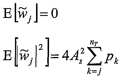
The term ^T AsgJ k (sk —sk ) + Wj is the interference term due to imperfect decision
A=7+l feedbacks. In order to quantify the effect of interference, it is approximated as a Gaussian random variable, Wj . Pe is defined for S to be pk. That is, Pr(-?A ≠ sk) = pk . Given an equal probability of 1 and -1 under BPSK modulation, it is easy to verify that E[s* -£ = 0
and
E s - sk = 4Pk
Therefore, the mean and variance of w . are given by:
Figure imgf000014_0001
Figure imgf000014_0002
and it is independent of sk -sk . Then, Pe is calculated for all sub-channels under a Gaussian approximation of interference. Pe is calculated by first calculating p of the nx sub-channel by using the equation for Pe with a diversity order of D=nR-nτ+l and
As I . Second, p is calculated successively from nχ-1 to 1. For a given k , the interference power σ1 is calculated. Then, p is calculated by utilizing the equation for Pe
with D=nR-k+l and p ■ l2 Third, the overall probability of bit error, Pe, is obtained by
1 + σ2 averaging across all the sub-channels. Accordingly,
∑Pk P (SNR) = -^ — Fig. 5 is an exemplary illustration of performance analysis of the baseline method. This performance analysis illustrates the lower bound for the probability of bit error. This is based on a simulation of baseline processing for a 6 transmitter and 6 receiver (6,6) system with TCO = 10,000 time instants. BPSK was used at the transmitter. The estimated performance was averaged over 10,000 channel coherence periods, or a total of 108 time instants. The nominal Pe performance, assuming perfect interference cancellation was computed using the above equations and served as a lower bound on the actual Pe performance. As described in the Background, since feedback from sub-channels with low diversity are used to create sub-channels with high diversity, imperfect decision feedbacks can compromise the performance of the sub-channels with a high diversity order. In Fig. 5, the nominal and the actual Pe is plotted for several sub-channels in the (6,6) system. In comparing nominal performance with actual simulation data, it is shown that imperfect decision feedbacks can affect sub-channels with large diversity order. Also, the system performance can be limited by the worst sub-channel. Thus, the worst sub-channel in a layered space-time structure can be a bottleneck in limiting system performance.
According to another embodiment, the processor 150 performs an extended space- time processing method or extended method.
As shown above, the strongest sub-channel with the largest diversity order is formed by successive decision feedbacks from the rest of the sub-channels. Accordingly, the strongest sub-channel has better performance than those with less diversity. Unfortunately, this fact is not utilized in a BLAST-type space-time processing structure. The present inventors have recognized that a direct way to improve system performance is to subtract the strongest sub-channel from the total received signal using the strongest sub-channel's decision. This is defined as a "loopback" process because it forms a feedback flow in a reverse order. Loopback operation can effectively remove the contribution of the transmit antenna corresponding to the strongest sub-channel.
A (6,6) system can be used to further explain the loopback procedure. First, decisions are generated for the sub-channels using the baseline operation, BLAST, or the like. The resulting diversity order for each respective sub-channel is 6, 5, 4, 3, 2, 1. From the generated decisions, a signal due to, for example, the 1st transmit antenna is effectively reconstructed. This signal is subtracted from the received signal. The received signal is now effectively a 5 transmitter and 6 receiver (5,6) system. If the baseline operation is performed, the diversity order of all of the sub-channels from 2 to 6 is improved by 1 diversity order. These improved sub-channels produce improved decisions which thus assist in the decoding of the 1st sub-channel. Thus, the first iteration of a loopback operation results in a diversity order for each respective sub-channel being 6, 6, 5, 4, 3, 2. This accordingly improves the diversity order of the second sub-channel to full diversity. The loopback operation can be continued by subtracting successively improving sub-channels. For example, both the 1st and 2nd sub-channels are next subtracted, thus effectively forming a (4,6) system.
The depth of the loopback operation is defined as Iioopback- Therefore, sub-channels 1 to Iioop ack are used successively in the loopback cancellation. Since processing structure evolves after each loopback operation, the final structure has the property that the first Iloopback + 1 sub-channels have full diversity order, while the rest have 5 down to 1 + Iιoopback- For example, the baseline operation corresponds to Iioopback = 0. Also, the loopback processing can iterate at the final stage Ifmaι times without looping back to the next sub-channel.
In the extended method, the processor 150 generates an improved symbol decision of a desired sub-channel of the signal vector by first generating a baseline decision for the subchannel. This baseline decision can be generated by the baseline method, by the BLAST system, or by any other method useful for generating a decision for a sub-channel. Next, the processor 150 subtracts a contribution of a strongest sub-channel from the signal vector to generate a modified signal vector. Then, the processor 150 multiplies the modified signal vector by a unitary matrix generated from a QR decomposition of another channel matrix. Finally, the processor 150 successively cancels channel interference of the remaining sub- channels of the modified signal vector from a remaining sub-channel.
A more detailed description of the extended method is described below: Fig. 6 is an exemplary flowchart 600 outlining the operation of the processor 150 according to the extended method. In step 605, the operation begins. In step 610, the processor 150 generates the initial symbol decisions (JSJ , i?2 ••• sn J. The processor 150 can generate these symbol decisions by utilizing the baseline method, a method such as BLAST, or any like method. For example, the processor 150 decodes each sub-channel utilizing the baseline method for (nχ5 ΏR). The decision at the kth sub-channel is denoted sk .
In step 615, the processor 150 sets i=l to begin a loop for i=l to Iioopback to use sub-channels 1 to Iioopback successively in loopback cancellation. In step 620, the processor 150 determines if i > Iioopback- If so, the processor advances to step 660. If i < Iioopback, the processor 150 advances to step 625.
In step 625, the processor subtracts the signals from the sub-channels 1 to i to generate an improved received signal r according to:
Figure imgf000017_0001
= AsUisi + ∑AshJ(sj -sJ) + n
7=1
= A.Hls, + n
In step 630, the processor 150 decodes the received signal r to generate symbol decisions
Sj = [sM , • • • , sn j , where t stands for the transpose. The processor 150 can decode the received signal r by utilizing the baseline method, a method such as BLAST, or any like method.
In step 635, the processor 150 sets k=l to begin a loop for k=i to 1 to cancel interference from the other sub-channels. In step 640, the processor determines whether to exit the loop based on k<l. If k≥l, the processor advances to step 645. In step 645, the processor cancels the interference from the other sub-channels according to:
Figure imgf000017_0002
y and then updates symbol decision skby decoding rk . In step 650, the processor 150 decrements k and returns to step 640.
If k<l in step 640, the processor 150 increments i in step 665 and returns to step 620. If i>IiooPback in step 620, the processor 150 advances to step 660 where it fixes
Figure imgf000018_0001
In step 665, the processor 150 performs the functions of steps 625-650 for Ifmai-1 iterations. In step 670, the operation ends.
Fig. 7 is an exemplary illustration of performance analysis of the extended method. As discussed above, the performance can be studied analytically by approximating the residual interference after the decision feedback as Gaussian random variables. Pe in each step of the extended algorithm is obtained by calculating the variance of residual interference.
The performance algorithm is given by setting p = [p • ••, p„τ f to be a vector of Pe's of all sub channels at each step of the extended algorithm with a specific Iioopback and If,naι. Then set
p = (p1 -, p )'. Given a SNR, \A \ = . Then, p is calculated in accordance with τ nτ the baseline structure. Next, a loop is set from i = 1 to Iι00pback- By Gaussian approximation of residual interference, the noise n is distributed as CN"R (O, σ2 J with
σa =l + 4 ,a ^
7=1
Then, pi is generated as described above with respect to the baseline operation. Next, from k = i to 1, pk is updated using the above equations with a diversity order of D = nR and
Figure imgf000018_0002
Fig. 7 illustrates the performance improvement with loopback cancellation in the extended method for a (6,6) system. As before, bits are sent using BPSK at each transmit antenna. L-maι is fixed to be 1 while varying the loopback depth Iioop ack from 1 to 5. The performance of a baseline or BLAST-type algorithm is included for comparison. As illustrated, large performance gain is achieved by using loopback cancellation. For example, the system with full loopback at 4dB already achieves Pe of the BLAST system at 9dB, thus resulting in a 5dB savings. Performance gain increases as SNR increases, which projects more power savings at higher SNR's. Also, a few loopback cancellations can be sufficient.
As illustrated in Fig. 7, large performance improvements are achieved with only 1 or 2 levels of loopback.
While this invention has been described with specific embodiments thereof, it is evident that many alternatives, modifications, and variations will be apparent to those skilled in the art. For example, various elements and various steps of different aspects and embodiments may be combined with various elements and various steps of other aspects and embodiments. Accordingly, the preferred embodiments of the invention as set forth herein are intended to be illustrative, not limiting. Various changes may be made without departing from the spirit and scope of the invention.

Claims

WHAT IS CLAIMED IS:
1. A wireless receiver comprising: a plurality of antennas configured to receive a signal vector; a processor coupled to the plurality of antennas, the processor being configured to generate an improved symbol decision of a desired sub-channel of the signal vector by subtracting a contribution of a strongest sub-channel from the signal vector to generate a modified signal vector, and successively canceling channel interference of remaining sub-channels of the modified signal vector from another remaining sub-channel.
2. The wireless receiver according to claim 1, wherein the processor further generates the improved signal decision by multiplying the modified signal vector by a unitary matrix generated from a QR decomposition of another channel matrix after subtracting a contribution of the strongest sub-channel, and successively canceling channel interference of the remaining sub-channels of the modified signal vector from a remaining strongest subchannel.
3. The wireless receiver according to claim 1, wherein the processor further generates the improved signal decision by nulling out the interference of a first set of sub- channels, and successively canceling channel interference due to a second set of subchannels.
4. The wireless receiver according to claim 1 , wherein the processor performs nulling by multiplying the received signal vector by a unitary matrix generated from a QR decomposition of a channel matrix.
5. The wireless receiver according to claim 1, wherein the processor is further configured to successively cancel channel interference caused by symbols in other subchannels.
6. The wireless receiver according to claim 1, wherein the signal of the desired sub-channel and the signals of the remaining sub-channels comprise a normalization component and an upper triangular matrix component.
7. The wireless receiver according to claim 6, wherein the processor cancels channel interference by decoding a symbol of the desired sub-channel, subtracting the contribution of the decoded symbol from the remaining sub-channels, and repeating the process of decoding and subtracting on the remaining sub-channels to decode the sub- channels.
8. A wireless receiver comprising: a plurality of antennas configured to receive a signal vector; and a processor coupled to the plurality of antennas, the processor being configured to generate a symbol decision of a desired sub-channel of the signal vector by nulling out interference of a first set of sub-channels by multiplying the received signal vector by a unitary matrix generated from a QR decomposition of a channel matrix and the processor further generates the improved symbol decision by successively canceling channel interference due to a second set of sub-channels.
9. The wireless receiver according to claim 8, wherein the processor is further configured to successively cancel channel interference caused by symbols in other subchannels.
10. The wireless receiver according to claim 8, wherein the signal of the desired sub-channel and the signals of the second set of sub-channels comprise a normalization component and an upper triangular matrix component.
11. The wireless receiver according to claim 10, wherein the processor cancels channel interference by decoding a symbol of the desired sub-channel, subtracting the contribution of the decoded symbol from the remaining sub-channels, and repeating the process of decoding and subtracting on the remaining sub-channels to decode the sub- channels.
12. The wireless receiver according to claim 8, wherein the processor further generates the decision by subtracting a contribution of a strongest sub-channel from the signal vector to generate a modified signal vector, multiplying the modified signal vector by a unitary matrix generated from a QR decomposition of another channel matrix, and successively canceling interference of the remaining sub-channels of the modified signal vector from another remaining sub-channel.
13. A wireless communication system comprising: a plurality of receive antennas configured to receive a signal vector; and a processor coupled to the plurality of receive antennas, the processor being configured to generate a decision and then generate an improved decision by subtracting a contribution of a strongest sub-channel from the signal vector to generate a modified signal vector and successively canceling channel interference of remaining sub-channels of the modified signal vector from the strongest sub-channel.
14. The wireless communication system according to claim 13, wherein the strongest sub-channel has an diversity order higher than the remaining sub-channels.
15. The wireless communication system according to claim 13, wherein the strongest sub-channel has an diversity order approximately equal to the number of receive antennas.
16. The wireless communication system according to claim 13, further comprising a plurality of transmit antennas configured to transmit the signal vector.
17. The wireless communication system according to claim 13, wherein the processor further generates the improved signal decision by nulling out the interference of a first set of sub-channels, and successively canceling channel interference due to a second set of sub-channels.
18. A method for generating an improved signal decision in a wireless receiver comprising: receiving a signal vector via a plurality of antennas; subtracting a contribution of a strongest sub-channel of the signal vector from the signal vector to generate a modified signal vector; and successively canceling channel interference of the remaining sub-channels of the modified signal vector from another remaining sub-channel.
19. The method for generating an improved signal decision in a wireless receiver according to claim 18, further comprising: multiplying the modified signal vector by a unitary matrix generated from a QR decomposition of another channel matrix after subtracting a contribution of a strongest sub-channel; wherein the successively canceling channel interference step further comprises successively canceling channel interference of the remaining sub-channels of the modified signal vector from a remaining strongest sub-channel.
20. The method for generating an improved signal decision in a wireless receiver according to claim 18, further comprising: nulling out interference of a first set of sub-channels; and successively canceling channel interference due to a second set of sub- channels.
21. The method for generating an improved signal decision in a wireless receiver according to claim 18, wherein the nulling step further comprises multiplying the received signal vector by a unitary matrix generated from a QR decomposition of a channel matrix.
22. The method for generating an improved signal decision in a wireless receiver according to claim 18, further comprising successively canceling channel interference caused by symbols in other sub-channels.
23. The method for generating an improved signal decision in a wireless receiver according to claim 18, wherein the signal of the desired sub-channel and the signals of the second set of sub-channels comprise a normalization component and an upper triangular matrix component.
24. The method for generating an improved signal decision in a wireless receiver according to claim 23 further comprising: decoding a symbol of the desired sub-channel; subtracting interference of the second set of sub-channels; and successively decoding symbols of the second set of sub-channels.
25. A method of generating a decision on a signal vector in a multiple antenna array receiver comprising: receiving the signal vector via a plurality of antennas; nulling out interference of a first set of sub-channels by multiplying the received signal vector by a unitary matrix generated from a QR decomposition of a channel matrix; and successively canceling channel interference due to a second set of subchannels.
26. The method of generating a decision on a signal vector in a multiple antenna array according to claim 25, further comprising successively canceling channel interference caused by symbols in other sub-channels.
27. The method of generating a decision on a signal vector in a multiple antenna array according to claim 25, wherein the signal of the desired sub-channel and the signals of the second set of sub-channels comprise a normalization component and an upper triangular matrix component.
28. The method of generating a decision on a signal vector in a multiple antenna array according to claim 27, further comprising: decoding a symbol of the desired sub-channel; successively decoding symbols of the second set of sub-channels; and subtracting interference of the second set of sub-channels.
29. The method of generating a decision on a signal vector in a multiple antenna array according to claim 25, further comprising: subtracting a contribution of a strongest sub-channel from the signal vector to generate a modified signal vector; multiplying the modified signal vector by a unitary matrix generated from a
QR decomposition of another channel matrix; and successively canceling interference of the remaining sub-channels of the modified signal vector from another remaining sub-channel.
30. A method of generating a decision in a multiple antenna array wireless communication system comprising: receiving a signal vector via a plurality of receive antennas; generating a decision; and generating an improved decision by subtracting a contribution of a strongest sub-channel from the signal vector to generate a modified signal vector, and successively canceling channel interference of some of the remaining sub-channels of the modified signal vector.
31. The method of generating a decision in a multiple antenna array wireless communication system according to claim 30, wherein the strongest sub-channel has an diversity order higher than the remaining sub-channels.
32. The method of generating a decision in a multiple antenna array wireless communication system according to claim 30, wherein the strongest sub-channel has an diversity order approximately equal to the number of receive antennas.
33. The method of generating a decision in a multiple antenna array wireless communication system according to claim 30, further comprising transmitting the signal vector via a plurality of transmit antennas.
34. The method of generating a decision in a multiple antenna array wireless communication system according to claim 30, further comprising: nulling out the interference of a first set of sub-channels; and successively canceling channel interference due to a second set of subchannels.
PCT/US2002/023399 2001-10-04 2002-07-23 Layered space-time multiple antenna system WO2003030414A1 (en)

Priority Applications (1)

Application Number Priority Date Filing Date Title
EP20020761157 EP1446901A4 (en) 2001-10-04 2002-07-23 Layered space-time multiple antenna system

Applications Claiming Priority (2)

Application Number Priority Date Filing Date Title
US09/971,071 2001-10-04
US09/971,071 US7218906B2 (en) 2001-10-04 2001-10-04 Layered space time processing in a multiple antenna system

Publications (1)

Publication Number Publication Date
WO2003030414A1 true WO2003030414A1 (en) 2003-04-10

Family

ID=25517895

Family Applications (1)

Application Number Title Priority Date Filing Date
PCT/US2002/023399 WO2003030414A1 (en) 2001-10-04 2002-07-23 Layered space-time multiple antenna system

Country Status (3)

Country Link
US (1) US7218906B2 (en)
EP (1) EP1446901A4 (en)
WO (1) WO2003030414A1 (en)

Cited By (33)

* Cited by examiner, † Cited by third party
Publication number Priority date Publication date Assignee Title
WO2008004921A1 (en) * 2006-07-07 2008-01-10 Telefonaktiebolaget L M Ericsson (Publ) Method and arrangement relating to radio signal transmissions
CN101542993B (en) * 2006-05-04 2013-01-09 新加坡科技研究局 Method and system for determining a signal vector
US8462859B2 (en) 2005-06-01 2013-06-11 Qualcomm Incorporated Sphere decoding apparatus
US8582509B2 (en) 2005-10-27 2013-11-12 Qualcomm Incorporated Scalable frequency band operation in wireless communication systems
US8599945B2 (en) 2005-06-16 2013-12-03 Qualcomm Incorporated Robust rank prediction for a MIMO system
US8693405B2 (en) 2005-10-27 2014-04-08 Qualcomm Incorporated SDMA resource management
US8787347B2 (en) 2005-08-24 2014-07-22 Qualcomm Incorporated Varied transmission time intervals for wireless communication system
US8842619B2 (en) 2005-10-27 2014-09-23 Qualcomm Incorporated Scalable frequency band operation in wireless communication systems
US8879511B2 (en) 2005-10-27 2014-11-04 Qualcomm Incorporated Assignment acknowledgement for a wireless communication system
US8885628B2 (en) 2005-08-08 2014-11-11 Qualcomm Incorporated Code division multiplexing in a single-carrier frequency division multiple access system
US8917654B2 (en) 2005-04-19 2014-12-23 Qualcomm Incorporated Frequency hopping design for single carrier FDMA systems
US9088384B2 (en) 2005-10-27 2015-07-21 Qualcomm Incorporated Pilot symbol transmission in wireless communication systems
US9130810B2 (en) 2000-09-13 2015-09-08 Qualcomm Incorporated OFDM communications methods and apparatus
US9137822B2 (en) 2004-07-21 2015-09-15 Qualcomm Incorporated Efficient signaling over access channel
US9136974B2 (en) 2005-08-30 2015-09-15 Qualcomm Incorporated Precoding and SDMA support
US9143305B2 (en) 2005-03-17 2015-09-22 Qualcomm Incorporated Pilot signal transmission for an orthogonal frequency division wireless communication system
US9144060B2 (en) 2005-10-27 2015-09-22 Qualcomm Incorporated Resource allocation for shared signaling channels
US9148256B2 (en) 2004-07-21 2015-09-29 Qualcomm Incorporated Performance based rank prediction for MIMO design
US9154211B2 (en) 2005-03-11 2015-10-06 Qualcomm Incorporated Systems and methods for beamforming feedback in multi antenna communication systems
US9172453B2 (en) 2005-10-27 2015-10-27 Qualcomm Incorporated Method and apparatus for pre-coding frequency division duplexing system
US9179319B2 (en) 2005-06-16 2015-11-03 Qualcomm Incorporated Adaptive sectorization in cellular systems
US9184870B2 (en) 2005-04-01 2015-11-10 Qualcomm Incorporated Systems and methods for control channel signaling
US9209956B2 (en) 2005-08-22 2015-12-08 Qualcomm Incorporated Segment sensitive scheduling
US9210651B2 (en) 2005-10-27 2015-12-08 Qualcomm Incorporated Method and apparatus for bootstraping information in a communication system
US9225488B2 (en) 2005-10-27 2015-12-29 Qualcomm Incorporated Shared signaling channel
US9225416B2 (en) 2005-10-27 2015-12-29 Qualcomm Incorporated Varied signaling channels for a reverse link in a wireless communication system
US9246560B2 (en) 2005-03-10 2016-01-26 Qualcomm Incorporated Systems and methods for beamforming and rate control in a multi-input multi-output communication systems
US9307544B2 (en) 2005-04-19 2016-04-05 Qualcomm Incorporated Channel quality reporting for adaptive sectorization
US9426012B2 (en) 2000-09-13 2016-08-23 Qualcomm Incorporated Signaling method in an OFDM multiple access system
US9461859B2 (en) 2005-03-17 2016-10-04 Qualcomm Incorporated Pilot signal transmission for an orthogonal frequency division wireless communication system
US9520972B2 (en) 2005-03-17 2016-12-13 Qualcomm Incorporated Pilot signal transmission for an orthogonal frequency division wireless communication system
US9660776B2 (en) 2005-08-22 2017-05-23 Qualcomm Incorporated Method and apparatus for providing antenna diversity in a wireless communication system
US10805038B2 (en) 2005-10-27 2020-10-13 Qualcomm Incorporated Puncturing signaling channel for a wireless communication system

Families Citing this family (12)

* Cited by examiner, † Cited by third party
Publication number Priority date Publication date Assignee Title
US7024166B2 (en) * 2002-12-18 2006-04-04 Qualcomm, Incorporated Transmission diversity systems
US7822150B2 (en) * 2003-03-15 2010-10-26 Alcatel-Lucent Usa Inc. Spherical decoder for wireless communications
WO2005081411A1 (en) * 2004-02-25 2005-09-01 Mitsubishi Denki Kabushiki Kaisha Receiver apparatus
CN100370719C (en) * 2005-02-04 2008-02-20 西安交通大学 Receiving and detecting method of vertical layered space-time system based on self adaptive modulation
US8971461B2 (en) * 2005-06-01 2015-03-03 Qualcomm Incorporated CQI and rank prediction for list sphere decoding and ML MIMO receivers
US7428269B2 (en) * 2005-06-01 2008-09-23 Qualcomm Incorporated CQI and rank prediction for list sphere decoding and ML MIMO receivers
TWI274482B (en) * 2005-10-18 2007-02-21 Ind Tech Res Inst MIMO-OFDM system and pre-coding and feedback method therein
US8483761B2 (en) * 2006-01-18 2013-07-09 Intel Corporation Singular value decomposition beamforming for a multiple-input-multiple-output communication system
US7949070B2 (en) * 2006-11-15 2011-05-24 Sanyo Electric Co., Ltd. Method and apparatus for executing MIMO eigenmode transmission
KR101267799B1 (en) * 2007-11-12 2013-06-04 삼성전자주식회사 Apparatus and method for canceling inter symbol interference of othogonal coded signal in mobile communication system
US8488652B2 (en) * 2010-03-11 2013-07-16 Nec Laboratories America, Inc. Systems and methods for blind equalization in a digital receiver
JP6151074B2 (en) * 2013-04-15 2017-06-21 京セラ株式会社 Communication system and communication control method

Citations (5)

* Cited by examiner, † Cited by third party
Publication number Priority date Publication date Assignee Title
US5323418A (en) * 1993-01-13 1994-06-21 Motorola, Inc. Code division multiple access (CDMA) inbound messaging system utilizing interference cancellation to recover inbound messages
US6097771A (en) 1996-07-01 2000-08-01 Lucent Technologies Inc. Wireless communications system having a layered space-time architecture employing multi-element antennas
US6127971A (en) * 1997-07-16 2000-10-03 At&T Corp Combined array processing and space-time coding
WO2001048944A1 (en) 1999-12-23 2001-07-05 Institut National De La Recherche Scientifique Interference suppression in cdma systems
US6317466B1 (en) * 1998-04-15 2001-11-13 Lucent Technologies Inc. Wireless communications system having a space-time architecture employing multi-element antennas at both the transmitter and receiver

Family Cites Families (4)

* Cited by examiner, † Cited by third party
Publication number Priority date Publication date Assignee Title
GB2219106B (en) * 1988-05-26 1992-04-15 Secr Defence Processor for constrained least squares computations
US5151919A (en) * 1990-12-17 1992-09-29 Ericsson-Ge Mobile Communications Holding Inc. Cdma subtractive demodulation
US5294933A (en) * 1993-01-29 1994-03-15 Westinghouse Electric Corp. Wideband radar system utilizing adaptive interference canceler
US6782036B1 (en) * 1999-05-26 2004-08-24 Board Of Regents, The University Of Texas System Smart antenna multiuser detector

Patent Citations (5)

* Cited by examiner, † Cited by third party
Publication number Priority date Publication date Assignee Title
US5323418A (en) * 1993-01-13 1994-06-21 Motorola, Inc. Code division multiple access (CDMA) inbound messaging system utilizing interference cancellation to recover inbound messages
US6097771A (en) 1996-07-01 2000-08-01 Lucent Technologies Inc. Wireless communications system having a layered space-time architecture employing multi-element antennas
US6127971A (en) * 1997-07-16 2000-10-03 At&T Corp Combined array processing and space-time coding
US6317466B1 (en) * 1998-04-15 2001-11-13 Lucent Technologies Inc. Wireless communications system having a space-time architecture employing multi-element antennas at both the transmitter and receiver
WO2001048944A1 (en) 1999-12-23 2001-07-05 Institut National De La Recherche Scientifique Interference suppression in cdma systems

Non-Patent Citations (1)

* Cited by examiner, † Cited by third party
Title
See also references of EP1446901A4 *

Cited By (47)

* Cited by examiner, † Cited by third party
Publication number Priority date Publication date Assignee Title
US10313069B2 (en) 2000-09-13 2019-06-04 Qualcomm Incorporated Signaling method in an OFDM multiple access system
US9130810B2 (en) 2000-09-13 2015-09-08 Qualcomm Incorporated OFDM communications methods and apparatus
US11032035B2 (en) 2000-09-13 2021-06-08 Qualcomm Incorporated Signaling method in an OFDM multiple access system
US9426012B2 (en) 2000-09-13 2016-08-23 Qualcomm Incorporated Signaling method in an OFDM multiple access system
US10237892B2 (en) 2004-07-21 2019-03-19 Qualcomm Incorporated Efficient signaling over access channel
US10517114B2 (en) 2004-07-21 2019-12-24 Qualcomm Incorporated Efficient signaling over access channel
US10194463B2 (en) 2004-07-21 2019-01-29 Qualcomm Incorporated Efficient signaling over access channel
US9148256B2 (en) 2004-07-21 2015-09-29 Qualcomm Incorporated Performance based rank prediction for MIMO design
US9137822B2 (en) 2004-07-21 2015-09-15 Qualcomm Incorporated Efficient signaling over access channel
US10849156B2 (en) 2004-07-21 2020-11-24 Qualcomm Incorporated Efficient signaling over access channel
US11039468B2 (en) 2004-07-21 2021-06-15 Qualcomm Incorporated Efficient signaling over access channel
US9246560B2 (en) 2005-03-10 2016-01-26 Qualcomm Incorporated Systems and methods for beamforming and rate control in a multi-input multi-output communication systems
US9154211B2 (en) 2005-03-11 2015-10-06 Qualcomm Incorporated Systems and methods for beamforming feedback in multi antenna communication systems
US9520972B2 (en) 2005-03-17 2016-12-13 Qualcomm Incorporated Pilot signal transmission for an orthogonal frequency division wireless communication system
US9461859B2 (en) 2005-03-17 2016-10-04 Qualcomm Incorporated Pilot signal transmission for an orthogonal frequency division wireless communication system
US9143305B2 (en) 2005-03-17 2015-09-22 Qualcomm Incorporated Pilot signal transmission for an orthogonal frequency division wireless communication system
US9184870B2 (en) 2005-04-01 2015-11-10 Qualcomm Incorporated Systems and methods for control channel signaling
US8917654B2 (en) 2005-04-19 2014-12-23 Qualcomm Incorporated Frequency hopping design for single carrier FDMA systems
US9307544B2 (en) 2005-04-19 2016-04-05 Qualcomm Incorporated Channel quality reporting for adaptive sectorization
US9036538B2 (en) 2005-04-19 2015-05-19 Qualcomm Incorporated Frequency hopping design for single carrier FDMA systems
US9408220B2 (en) 2005-04-19 2016-08-02 Qualcomm Incorporated Channel quality reporting for adaptive sectorization
US8462859B2 (en) 2005-06-01 2013-06-11 Qualcomm Incorporated Sphere decoding apparatus
US8599945B2 (en) 2005-06-16 2013-12-03 Qualcomm Incorporated Robust rank prediction for a MIMO system
US9179319B2 (en) 2005-06-16 2015-11-03 Qualcomm Incorporated Adaptive sectorization in cellular systems
US8885628B2 (en) 2005-08-08 2014-11-11 Qualcomm Incorporated Code division multiplexing in a single-carrier frequency division multiple access system
US9693339B2 (en) 2005-08-08 2017-06-27 Qualcomm Incorporated Code division multiplexing in a single-carrier frequency division multiple access system
US9860033B2 (en) 2005-08-22 2018-01-02 Qualcomm Incorporated Method and apparatus for antenna diversity in multi-input multi-output communication systems
US9660776B2 (en) 2005-08-22 2017-05-23 Qualcomm Incorporated Method and apparatus for providing antenna diversity in a wireless communication system
US9240877B2 (en) 2005-08-22 2016-01-19 Qualcomm Incorporated Segment sensitive scheduling
US9209956B2 (en) 2005-08-22 2015-12-08 Qualcomm Incorporated Segment sensitive scheduling
US9246659B2 (en) 2005-08-22 2016-01-26 Qualcomm Incorporated Segment sensitive scheduling
US8787347B2 (en) 2005-08-24 2014-07-22 Qualcomm Incorporated Varied transmission time intervals for wireless communication system
US9136974B2 (en) 2005-08-30 2015-09-15 Qualcomm Incorporated Precoding and SDMA support
US9172453B2 (en) 2005-10-27 2015-10-27 Qualcomm Incorporated Method and apparatus for pre-coding frequency division duplexing system
US8693405B2 (en) 2005-10-27 2014-04-08 Qualcomm Incorporated SDMA resource management
US8842619B2 (en) 2005-10-27 2014-09-23 Qualcomm Incorporated Scalable frequency band operation in wireless communication systems
US9225488B2 (en) 2005-10-27 2015-12-29 Qualcomm Incorporated Shared signaling channel
US9210651B2 (en) 2005-10-27 2015-12-08 Qualcomm Incorporated Method and apparatus for bootstraping information in a communication system
US9225416B2 (en) 2005-10-27 2015-12-29 Qualcomm Incorporated Varied signaling channels for a reverse link in a wireless communication system
US9144060B2 (en) 2005-10-27 2015-09-22 Qualcomm Incorporated Resource allocation for shared signaling channels
US8879511B2 (en) 2005-10-27 2014-11-04 Qualcomm Incorporated Assignment acknowledgement for a wireless communication system
US9088384B2 (en) 2005-10-27 2015-07-21 Qualcomm Incorporated Pilot symbol transmission in wireless communication systems
US8582509B2 (en) 2005-10-27 2013-11-12 Qualcomm Incorporated Scalable frequency band operation in wireless communication systems
US10805038B2 (en) 2005-10-27 2020-10-13 Qualcomm Incorporated Puncturing signaling channel for a wireless communication system
CN101542993B (en) * 2006-05-04 2013-01-09 新加坡科技研究局 Method and system for determining a signal vector
WO2008004921A1 (en) * 2006-07-07 2008-01-10 Telefonaktiebolaget L M Ericsson (Publ) Method and arrangement relating to radio signal transmissions
US8259833B2 (en) 2006-07-07 2012-09-04 Telefonaktiebolaget Lm Ericsson (Publ) Method and arrangement relating to radio signal transmissions

Also Published As

Publication number Publication date
US7218906B2 (en) 2007-05-15
US20030068994A1 (en) 2003-04-10
EP1446901A4 (en) 2010-12-01
EP1446901A1 (en) 2004-08-18

Similar Documents

Publication Publication Date Title
WO2003030414A1 (en) Layered space-time multiple antenna system
KR100778647B1 (en) Combined channel coding and space-block coding in a multi-antenna arrangement
CN109921882B (en) Deep learning-based MIMO decoding method, device and storage medium
US7545875B2 (en) System and method for space-time-frequency coding in a multi-antenna transmission system
US6127971A (en) Combined array processing and space-time coding
EP1619809B1 (en) Feeding back antenna shuffling information in a multiple-input multiple-output system using a multiple space-time block coding technique and a method therefor
US7933564B2 (en) Method for the multi-antenna transmission of a linearly-precoded signal, corresponding devices, signal and reception method
US7539261B2 (en) Multi-layer coded modulation for non-ergodic block fading channels
US7397874B2 (en) Method and device for detecting vertical bell laboratories layered space-time codes
US8107543B2 (en) High diversity time-space coding and decoding for MIMO systems
US20060146965A1 (en) Apparatus and method for detecting a signal in a multiple-input multiple-output mobile communication system
WO2001069800A2 (en) Robust utilization of feedback information in space-time coding
JP4377435B2 (en) Apparatus and method for space-time block coding with maximum diversity and maximum transmission rate using two transmission antennas
US7215718B1 (en) Combined channel coding and space-time block coding in a multi-antenna arrangement
Bazdresch et al. A family of hybrid space-time codes for MIMO wireless communications
Vía et al. Blind decoding of MISO-OSTBC systems based on principal component analysis
US20110019777A1 (en) Apparatus, and associated method, for detecting values of a space-time block code using selective decision-feedback detection
Kusume et al. MMSE block decision-feedback equalizer for spatial multiplexing with reduced complexity
KR101100116B1 (en) Apparatus for transmiter processing precoding using the number of transmiter antenna in open loop communication system and method for the same
Badic Space-time block coding for multiple antenna systems
Zhou et al. Fast recursive algorithm for efficient transmit antenna selection in spatial multiplexing systems
CN112039562B (en) Progressive coding space shift keying method
Revathi et al. Performance analysis of TCM aided Block Diagonalization using STBCs for MIMO systems
AMELİA et al. PERFORMANCE of MULTIUSER V-BLAST WITH LIMITED FEEDBACK for USER SCHEDULING over NAKAGAMI-m FADING CHANNELS
Zhao et al. An vertical layered space-time coding and the symbol detection

Legal Events

Date Code Title Description
AK Designated states

Kind code of ref document: A1

Designated state(s): AE AG AL AM AT AU AZ BA BB BG BY BZ CA CH CN CO CR CU CZ DE DM DZ EC EE ES FI GB GD GE GH HR HU ID IL IN IS JP KE KG KP KR LC LK LR LS LT LU LV MA MD MG MN MW MX MZ NO NZ OM PH PL PT RU SD SE SG SI SK SL TJ TM TN TR TZ UA UG UZ VN YU ZA ZM

AL Designated countries for regional patents

Kind code of ref document: A1

Designated state(s): GH GM KE LS MW MZ SD SL SZ UG ZM ZW AM AZ BY KG KZ RU TJ TM AT BE BG CH CY CZ DK EE ES FI FR GB GR IE IT LU MC PT SE SK TR BF BJ CF CG CI GA GN GQ GW ML MR NE SN TD TG

121 Ep: the epo has been informed by wipo that ep was designated in this application
WWE Wipo information: entry into national phase

Ref document number: 2002761157

Country of ref document: EP

WWP Wipo information: published in national office

Ref document number: 2002761157

Country of ref document: EP

NENP Non-entry into the national phase

Ref country code: JP

WWW Wipo information: withdrawn in national office

Country of ref document: JP