WO2003100559A2 - System and method for making managing wireless network activity - Google Patents
System and method for making managing wireless network activity Download PDFInfo
- Publication number
- WO2003100559A2 WO2003100559A2 PCT/US2003/015844 US0315844W WO03100559A2 WO 2003100559 A2 WO2003100559 A2 WO 2003100559A2 US 0315844 W US0315844 W US 0315844W WO 03100559 A2 WO03100559 A2 WO 03100559A2
- Authority
- WO
- WIPO (PCT)
- Prior art keywords
- data
- wireless
- received
- network
- access point
- Prior art date
Links
Classifications
-
- H—ELECTRICITY
- H04—ELECTRIC COMMUNICATION TECHNIQUE
- H04L—TRANSMISSION OF DIGITAL INFORMATION, e.g. TELEGRAPHIC COMMUNICATION
- H04L41/00—Arrangements for maintenance, administration or management of data switching networks, e.g. of packet switching networks
- H04L41/08—Configuration management of networks or network elements
- H04L41/0893—Assignment of logical groups to network elements
-
- H—ELECTRICITY
- H04—ELECTRIC COMMUNICATION TECHNIQUE
- H04L—TRANSMISSION OF DIGITAL INFORMATION, e.g. TELEGRAPHIC COMMUNICATION
- H04L63/00—Network architectures or network communication protocols for network security
- H04L63/14—Network architectures or network communication protocols for network security for detecting or protecting against malicious traffic
- H04L63/1408—Network architectures or network communication protocols for network security for detecting or protecting against malicious traffic by monitoring network traffic
- H04L63/1416—Event detection, e.g. attack signature detection
-
- H—ELECTRICITY
- H04—ELECTRIC COMMUNICATION TECHNIQUE
- H04L—TRANSMISSION OF DIGITAL INFORMATION, e.g. TELEGRAPHIC COMMUNICATION
- H04L63/00—Network architectures or network communication protocols for network security
- H04L63/14—Network architectures or network communication protocols for network security for detecting or protecting against malicious traffic
- H04L63/1408—Network architectures or network communication protocols for network security for detecting or protecting against malicious traffic by monitoring network traffic
- H04L63/1425—Traffic logging, e.g. anomaly detection
-
- H—ELECTRICITY
- H04—ELECTRIC COMMUNICATION TECHNIQUE
- H04L—TRANSMISSION OF DIGITAL INFORMATION, e.g. TELEGRAPHIC COMMUNICATION
- H04L63/00—Network architectures or network communication protocols for network security
- H04L63/14—Network architectures or network communication protocols for network security for detecting or protecting against malicious traffic
- H04L63/1441—Countermeasures against malicious traffic
-
- H—ELECTRICITY
- H04—ELECTRIC COMMUNICATION TECHNIQUE
- H04W—WIRELESS COMMUNICATION NETWORKS
- H04W12/00—Security arrangements; Authentication; Protecting privacy or anonymity
- H04W12/12—Detection or prevention of fraud
- H04W12/121—Wireless intrusion detection systems [WIDS]; Wireless intrusion prevention systems [WIPS]
- H04W12/122—Counter-measures against attacks; Protection against rogue devices
-
- H—ELECTRICITY
- H04—ELECTRIC COMMUNICATION TECHNIQUE
- H04W—WIRELESS COMMUNICATION NETWORKS
- H04W12/00—Security arrangements; Authentication; Protecting privacy or anonymity
- H04W12/12—Detection or prevention of fraud
- H04W12/126—Anti-theft arrangements, e.g. protection against subscriber identity module [SIM] cloning
-
- H—ELECTRICITY
- H04—ELECTRIC COMMUNICATION TECHNIQUE
- H04L—TRANSMISSION OF DIGITAL INFORMATION, e.g. TELEGRAPHIC COMMUNICATION
- H04L41/00—Arrangements for maintenance, administration or management of data switching networks, e.g. of packet switching networks
- H04L41/06—Management of faults, events, alarms or notifications
-
- H—ELECTRICITY
- H04—ELECTRIC COMMUNICATION TECHNIQUE
- H04L—TRANSMISSION OF DIGITAL INFORMATION, e.g. TELEGRAPHIC COMMUNICATION
- H04L41/00—Arrangements for maintenance, administration or management of data switching networks, e.g. of packet switching networks
- H04L41/08—Configuration management of networks or network elements
- H04L41/0894—Policy-based network configuration management
Definitions
- the present invention is directed to systems and methods for enhancing security associated with electronic communications. More specifically, without limitation, the present invention relates to computer-based systems and methods for assessing security risks and identifying and responding to threats in wireless network environments.
- the Internet is a global network of connected computer networks. Over the last several years, the internet has grown in significant measure. A large number of computers on the Internet provide information in various forms. Teen with a computer connected to the Internet can potentially tap into this vast pool of information.
- the information available via the Internet encompasses information available via a variety of types of application layer information servers such as SMTP (simple mail transfer protocol), POP3 (Post Office Protocol), GOPHER (RFC 1436), WAIS,
- SMTP simple mail transfer protocol
- POP3 Post Office Protocol
- GOPHER RRC 1436
- WAIS WAIS
- HTTP Hypertext Transfer Protocol
- FTP file transfer protocol
- the Web consists of a subset of the computers connected to the Internet; the computers in this subset run Hypertext Transfer Protocol
- HTTP HyperText Transfer Protocol
- Web servers Web servers
- HTTP HyperText Transfer Protocol
- RFC 2774 extension framework
- RFID 2617 authentication
- Information on the Internet can be accessed through the use of a Uniform Resource Identifier (URI, RFC 2396).
- URI Uniform Resource Identifier
- a URI uniquely specifies the location of a particular piece of information on the Internet.
- a URI will typically be composed of several components. The first component typically designates the protocol by which the address piece of information is accessed (e.g., HTTP, GOPHER, etc.). This first component is separated from the remainder of the URI by a colon (':').
- the remainder of the URI will depend upon the protocol component. Typically, the remainder designates a computer on the Internet by name, or by IP number, as well as a more specific designation of the location of the resource on the designated computer.
- a typical URI for an HTTP resource might be: http://www.server.com/dirl/dir2/resource.htm where http is the protocol, www.server.com is the designated computer and /dirl/dir2/resouce.htm designates the location of the resource on the designated computer.
- URI includes Uniform Resource Names (URN's) including
- Web servers host information in the form of Web pages; collectively the server and the information hosted are referred to as a Web site.
- a significant number of Web pages are encoded using the Hypertext Markup Language (HTML) although other encodings using SGML, extensible Markup Language (XML), DHMTL or XHTML are possible.
- HTML Hypertext Markup Language
- XML extensible Markup Language
- DHMTL extensible Markup Language
- Web pages in these formatting languages may include links to other Web pages on the same Web site or another.
- Web pages may be generated dynamically by a server by integrating a variety of elements into a formatted page prior to transmission to a Web client.
- Web servers, and information servers of other types await requests for the information from Internet clients.
- Client software has evolved that allows users of computers connected to the Internet to access this information.
- Advanced clients such as Netscape's Navigator and Microsoft's Internet Explorer allow users to access software provided via a variety of information servers in a unified client environment.
- client software is referred to as browser software.
- Electronic mail is another wide spread application using the Internet.
- a variety of protocols are often used for e-mail transmission, delivery and processing including SMTP and POP3 as discussed above. These protocols refer, respectively, to standards for communicating e-mail messages between servers and for server-client communication related to e-mail messages. These protocols are defined respectively in particular RFC's (Request for Comments) promulgated by the IETF (Internet Engineering Task Force).
- the SMTP protocol is defined in RFC 821
- the POP3 protocol is defined in RFC 1939.
- RFC 1869 that defines a framework for extending the SMTP service by defining a means whereby a server SMTP can inform a client SMTP as to the service extensions it supports
- RFC 1891 that defines an extension to the SMTP service, which allows an SMTP client to specify (a) that delivery status notifications (DSNs) should be generated under certain conditions, (b) whether such notifications should return the contents of the message, and (c) additional information, to be returned with a DSN, that allows the sender to identify both the recipient(s) for which the DSN was issued, and the transaction in which the original message was sent.
- DSNs delivery status notifications
- IMAP protocol has evolved as an alternative to POP3 that supports more advanced interactions between e-mail servers and clients. This protocol is described in RFC 2060.
- RFC's are hereby incorporated by reference herein for all purposes. These RFC's are available to the public through the Internet Engineering Task Force (IETF) and can be retrieved from its Web site (http://www.ietf.org/rfc.html).
- IETF Internet Engineering Task Force
- the specified protocols are not intended to be limited to the specific RFC's quoted herein above but are intended to include extensions and revisions thereto. Such extensions and/or revisions may or may not be encompassed by current and/or future RFC's.
- E-mail server software includes such products as sendmail-based servers, Microsoft Exchange, Lotus Notes Server, and Novell Group Wise; sendmail-based servers refer to a number of variations of servers originally based upon the sendmail program developed for the UNIX operating systems.
- sendmail-based servers refer to a number of variations of servers originally based upon the sendmail program developed for the UNIX operating systems.
- a large number of e-mail clients have also been developed that allow a user to retrieve and view e-mail messages from a server; example products include Microsoft Outlook, Microsoft Outlook Express, Netscape Messenger, and Eudora.
- some e-mail servers, or e-mail servers in conjunction with a Web server allow a Web browser to act as an e-mail client using the HTTP standard.
- FIG. 1 depicts a typical LAN 190 including both wired and wireless components.
- the wired component depicted in FIG. 1 includes a variety of connected systems including local servers 120, local clients 130 and network accessible data storage components 110.
- access points 180A, 180B to the wired network (e.g., Ethernet 150 and router 140)
- personal computers and laptops equipped with WLAN cards 170A, 170B can connect with the wired network at broadband speeds.
- IEEE Institute of Electrical and Electronics Engineers
- 802.11b operates over the unregulated 2.4 GHz frequency spectrum.
- the 802. l ib standard offers connectivity of up to 11 Mbps - fast enough to handle large e-mail attachments and run bandwidth-intensive applications like video conferencing.
- 802.11b standard now dominates the WLAN market, other variations of the 802.11 standard, such as 802.1 la, 802.1 lg, and supporting standards such as 802. IX, are being developed to handle increased speeds and enhanced functionality.
- WLAN vendors have committed to supporting a variety of standards.
- a firewall 145 may effectively deter an attack from a wired hacker 135 via the internet 160; however, wireless hackers 195A, 195B typically enter the LAN 190 through access points 180A, 180B that are already behind the firewall 145. Companies must constantly monitor their airwaves to survey wireless activity and guard against intruders.
- eavesdroppers 195 A, 195B who merely listen to the airwaves can easily pick up unencrypted messages. Additionally, messages encrypted with the Wired Equivalent Privacy (WEP) security protocol can be decrypted with a little time and easily available hacking tools.
- WEP Wired Equivalent Privacy
- These passive intruders put businesses at risk of exposing sensitive information to corporate espionage. The theft of an authorized user's identity poses one the greatest threats.
- Service Set Identifiers (SSIDs) that act as crude passwords and Media Access Control (MAC) addresses that act as personal identification numbers are often used to verify that clients are authorized to connect with an access point.
- SSIDs Service Set Identifiers
- MAC Media Access Control
- existing encryption standards are not foolproof and allow knowledgeable intruders to pick up approved SSIDs and MAC addresses to connect to a WLAN as an authorized user with the ability to steal bandwidth, corrupt or download files, and wreak havoc on the entire network.
- DoS Denial-of-Service
- WLAN can be easily installed by attaching a $150 access point to a wired network and a $100 WLAN card to a laptop, employees are deploying unauthorized WLANs or peer-to-peer wireless connections 175 when IT departments are slow to adopt the new technology. Incorrectly configured access points are an avoidable but significant hole in
- WLAN security Many access points are initially configured to broadcast unencrypted SSIDs of authorized users. While SSIDs are intended to be passwords to verify authorized users, intruders can easily steal an unencrypted SSID to assume the identity of an authorized user. Authorized users can also threaten the integrity of the network with abuses that drain connection speeds, consume bandwidth, and hinder a WLAN's overall performance. A few users who clog the network by trading large files such as MP3 audio or MPEG video files can affect the productivity of everyone on the wireless network.
- the systems and methods according to the present invention provide solutions to these and other security and/or management issues associated with WLANs and/or encrypted computer networks.
- the present invention is directed to systems and methods for enhancing network security.
- One preferred embodiment according to the present invention includes a system data store (SDS), a system processor and one or more interfaces to one or more communications channels which may include one or more interfaces to wireless and/or encrypted communications network over which electronic communications are transmitted and received.
- SDS stores data needed to provide the desired security tracking and/or assessment functionality and may include, for example, received communications, data associated with such communications, information related to known security risks and predetermined responses to the identification of particular security risks and situations.
- the SDS may include multiple physical and/or logical data stores for storing the various types of information. Data storage and retrieval functionality may be provided by either the system processor or data storage processors associated with, or included within, the SDS.
- the system processor is in communication with the SDS via any suitable communication channel(s); the system processor is in communication with the one or more interfaces via the same, or differing, communication channel(s).
- the system processor may include one or more processing elements that provide electronic communication reception, transmission, interrogation, analysis and/or other functionality.
- the system processor can include local, central and/or peer processing elements depending upon equipment and the configuration thereof.
- Each interface to a wireless network includes at least one receiver adapted to receive wireless communications; each interface can also include one or more transmitters adapted to transmit wireless communications.
- Each interface to a wired network if any, include a receiver, a transmitter, both or a plurality of one and/or both; such receivers and/or transmitters adapted to receive or transmit communication over the wired network to which the interface connects.
- the communication interface includes at least one wireless receiver.
- Network sensors can include at least one wireless receiver, the SDS (or a portion thereof) and the system processor (or a portion thereof).
- the system processor, or portion thereof, in the network sensor extracts data into one or more logical units such as frames from received wireless signals according a selected wireless protocol such as a variant of 802.11. These logical units are inspected for a variety of information (e.g., frame type, source, destination, etc.). Information derived from the inspection is stored in the SDS, or the portion thereof, in the network sensor.
- Information from one or more further network sensors can be received via the wireless receiver or an additional communication interface, stored the SDS and processed by the system processor along with the locally derived information. Such storage and processing can occur in the network sensor, one or more peer network sensor or one or more central servers. The stored information is analyzed in the aggregate to generate a security rating which is then output to a user or a further data processing system.
- one preferred method of security enhancement includes a variety of steps that may, in certain embodiments, be executed by the environment summarized above and more fully described below or be stored as computer executable instructions in and/or on any suitable combination of computer-readable media.
- Configuration data associated with an access point on a wireless computer network potentially compromised by an intruder is received, information contained within and/or derived from the received configuration data is stored.
- Communication with the intruder is continued by emulating the identification characteristics of the potentially compromised access point. In some embodiments, communication may appear to come from an access point that appears less secure than the potentially compromised access point.
- a channel change request is transmitted to the potentially compromised access point to reroute communication between the potentially compromised access point and authorized stations such that communications may continue on a different channel.
- the configuration data associated with the potentially compromised access point is received from an intrusion detection system such as described in greater detail below.
- the configuration data may be included as part of a generated security violation alarm.
- an alarm signal is received that triggers the generation and transmission of a request for information regarding the potentially compromised access point.
- Some embodiments involving an intrusion detection system may include the intrusion detection system while other respond to input from such a system.
- Some embodiments further include the mapping of the identification of the intruder's node and/or the mapping of the location of the intruder's node within the wireless network.
- a notification of the triggering of the honeypot trap can be sent to an administrator; some such notifications may include an identification and/or location of the node associated with the intruder in embodiments that include node identification and location mapping.
- the configuration data includes one or more risk criteria, network default data, network policy, performance and/or usage data. This configuration information may be received from one or more of a variety of sources including from a configuration file, an interactive data entry interface or a command line or from monitoring the wireless computer network.
- Some embodiments may further include updating of various types of stored information; different embodiment may update all, none or any combination of the various types of stored information. For instance, some embodiments can update station information associated with the various stations in the wireless computer network based upon the received data. Further, some embodiments can update state information regarding the security of the wireless computer network based upon the received data. In addition, some embodiments can update statistics based upon the received data. Such updates can occur each time data is received, in response to reaching a fixed amount of such update data, in response to reacliing a fixed time or the end of a predetermined duration, or some combination of these approaches. Additional advantages of the invention will be set forth in part in the description which follows, and in part will be obvious from the description, or may be learned by practice of the invention.
- FIG. 1 graphically depicts a typical LAN with both wired and wireless components.
- FIGs. 2A-E graphically depicts LANs incorporating various preferred embodiments according to the present invention.
- FIG. 3 is a flow chart of a multi-dimensional wireless intrusion detection process according to one preferred embodiment of the present invention.
- FIG. 4 is a flow chart of an example multiple input wireless intrusion detection process including multiple input correlation and long-term data fusion.
- FIG. 5 is a flow chart of an exemplary dynamic channel change active defense process that includes a honeypot trap.
- FIGs. 6A-B are flow charts of example station identification and location mapping processes.
- FIGs. 7A-C are diagram depicting exemplary architectures for sensor devices.
- FIGs. 8A-B are flow charts depicting an exemplary security data collection process performed according to the present invention.
- FIG. 9 is a flow chart depicting steps in an exemplary wireless network topology tracking process.
- FIG. 10 is a flow chart depicting an automated wireless network policy enforcement process.
- FIG. 11 is a flow chart depicting an adaptive scanning process.
- FIG. 12 is a figure depicting a sample visualization of a wireless network topology.
- FIGs. 13A-B depict sample screens providing interfaces for configuration of automated policy enforcement.
- FIG. 14 depicts an exemplary interface for configuring a default or baseline scan pattern.
- Ranges may be expressed herein as from “about” one particular value, and/or to “about” another particular value. When such a range is expressed, another embodiment includes from the one particular value and/or to the other particular value. Similarly, when values are expressed as approximations, by use of the antecedent "about,” it will be understood that the particular value forms another embodiment. It will be further understood that the endpoints of each of the ranges are significant both in relation to the other endpoint, and independently of the other endpoint.
- Wi-Fi is short for wireless fidelity and is another name for IEEE
- frame as used herein shall mean broadly any discretely defined communication transmitted via a computer network and shall not be limited to those specific frame types (control, management, data and error) defined according to 802.1 IX standards.
- FIGs. 2A-E depicts several LAN environments including several preferred embodiments according to the present invention. These figures depict a typical LAN environment as depicted in FIG. 1 having wired and wireless components. In contrast to FIG. 1, FIGs. 2A-E include one or more hardware components supporting preferred embodiments according to the present invention.
- the depicted hardware components include a system processor, an SDS and one or more interfaces to one or more wireless and/or encrypted communications network over which electronic communications are transmitted and received.
- the hardware components depicted in these figures are outlined as follows: •
- the hardware components include a single device 210A that includes a local processor serving as the system processor, or at least a portion thereof, and the one or more interfaces to the wireless network.
- the device includes a local processor serving as the system processor, or at least a portion thereof, and the one or more interfaces to the wireless network.
- 210A is preferably a mobile computer system such as a notebook computer.
- the local primary and/or secondary storage of device 210A may serve as the SDS; alternatively, portions of the SDS may be provided by other systems capable of communicating with the device 210A such as network addressable data storage 110, local servers 120 and/or wireless stations 170 A, 170B.
- the device's interfaces to the wireless network may be limited to one or more wireless receivers.
- the interfaces may include one or more wireless transmitters as well as one or more transmitters. If wireless transmitters are included, the device 210 may communicate over LAN 190 using a wireless access point 180A, 180B.
- the device 210A may further include a wired connection (not shown) to Ethernet 150 allowing direct communication between it and systems connected to the wired portion of LAN 190.
- the hardware components include multiple devices 210A, 21 OB,
- Each device 210A-D includes a local processor and one or more interfaces to the wireless network and is preferably a mobile computer system such as a notebook computer.
- the individual local processors in the aggregate serve as the system processor.
- the SDS may include a combination of storage local to each of the devices and/or external storage accessible via the LAN 190.
- each device includes at least a wireless receiver but may also include additional wireless receivers and/or wireless transmitters.
- Each device may also include a wired connection (not shown) to Ethernet 150.
- the devices 210A-D may further use existing interfaces and/or incorporate additional interfaces to allow peer-to-peer communication among themselves.
- the hardware components include multiple devices 210A, 210B,
- Each device 210A-D may include the various components as described above with respect to FIG.2B.
- Device 220 includes a local processor and one or more communication interfaces; this device may be referred to hereinafter as the host system.
- Device 220 's communication interfaces may include only a wired communication interface and may receive data related to wireless communications as forwarded by devices 210A-D over the wire Ethernet 150.
- device 220 may include a one or more wireless communication interfaces each of which may include a wireless receiver, a wireless transmitter or both.
- device 220 may in some of such embodiments participate in the peer-to-peer communication and, in such instances, its communication interfaces would include the appropriate communication interface to support this participation.
- the system processor functionality in the depicted embodiment may be provided by the host system alone and/or by some combination of the devices 210A-D.
- the host system may in some embodiments provide the SDS for the environment; alternatively, the SDS may be supported by some combination of the local storage among the devices 210A-D, the local storage in the host system and external storage available through LAN 190.
- the hardware components include multiple devices 210A, 21 OB, 210C, 210D, 220, 230A, 230B.
- Devices 210A-D, 220 support the same functionality and include the same range of components as provided above with respect to FIG. 2C.
- devices 230A, 230B are sensor devices that monitor wireless traffic over the wireless network. These sensor devices at least include a wireless receiver for monitoring the traffic and a communication interface wired (as depicted) or wireless (not shown) allowing communication with one or more of the devices 210A-D and/or the host system 220.
- the sensor devices 230 A, 230B may include a wireless transmitter for supporting communication with the other hardware components and/or for supporting various active wireless network defensive measures as discussed below.
- the sensor device 230 A, 230B may further include local processing capability and or local storage capability; in some such embodiments, the system processor and/or the SDS may incorporate these local capabilities of the sensor devices 230A, 230B.
- the hardware components include multiple devices 220, 230A, 230B.
- the host system 220 and sensor devices 230A, 230B include the same functionality and range of components as discussed above with respect to FIGs. 2D and 2E respectively.
- the host system 220 will typically provide a significant portion of the system processor functionality and will only have limited capacity to directly receive wireless network communication, hi some of these embodiments, the host system 220 may have no wireless communication interface.
- the depicted hardware components include a system processor potentially including multiple processing elements, that may be distributed across the depicted hardware components, where each processing element may be supported via Intel- compatible processor platforms preferably using at least one PENTIUM III or CELERON (Intel Corp., Santa Clara, CA) class processor; alternative processors such as UltraSPARC (Sun Microsystems, Palo Alto, CA) could be used in other embodiments.
- security enhancement functionality as further described below, may be distributed across multiple processing elements.
- the term processing element may refer to (1) a process running on a particular piece, or across particular pieces, of hardware, (2) a particular piece of hardware, or either (1) or (2) as the context allows.
- the sensor devices 230A, 230B depicted in FIGs. 2D-E may in some preferred embodiments include more limited optimized local processors such as a digital signal processor (DSP). Other embodiment can use application specific integrated circuits (ASIC) or a field programmable gate arrays (FPGA).
- DSP digital signal processor
- ASIC application specific integrated
- the depicted hardware components include an SDS that could include a variety of primary and secondary storage elements.
- the SDS would include RAM as part of the primary storage; the amount of RAM might range from 64 MB to 4 GB in each individual hardware device although these amounts could vary and represent overlapping use such as where the host system 220 supports additional functionality such as integrated with firewall system 145 for providing unified wired and wireless security.
- the primary storage may in some embodiments include other forms of memory such as cache memory, registers, non- volatile memory (e.g., FLASH, ROM, EPROM, etc.), etc.
- the sensor devices 230A, 230B depicted in FIGs. 2D-E may in some preferred embodiments include more limited amounts and kinds of primary storage.
- the primary storage in the sensor devices includes FLASH memory.
- the SDS may also include secondary storage including single, multiple and/or varied servers and storage elements.
- the SDS may use internal storage devices connected to the system processor.
- a single processing element supports all of the security analysis functionality, such as seen in FIGs. 2A and 2E
- a local hard disk drive may serve as the secondary storage of the SDS, and a disk operating system executing on such a single processing element may act as a data server receiving and servicing data requests.
- the different information used in the security enhancement processes and systems according to the present invention may be logically or physically segregated within a single device serving as secondary storage for the SDS; multiple related data stores accessible through a unified management system, which together serve as the SDS; or multiple independent data stores individually accessible through disparate management systems, which may in some embodiments be collectively viewed as the SDS.
- the various storage elements that comprise the physical architecture of the SDS may be centrally located, or distributed across a variety of diverse locations.
- database(s) are used to store and manipulate the data; in some such embodiments, one or more relational database management systems, such as DB2 (IBM, White Plains, NY), SQL Server (Microsoft, Redmond, WA), ACCESS (Microsoft, Redmond, WA), ORACLE 8i (Oracle Corp., Redwood Shores, CA), Ingres (Computer Associates, Islandia, NY), MySQL (MySQL AB, Sweden) or Adaptive Server Enterprise (Sybase Inc., Emeryville, CA), may be used in connection with a variety of storage devices/file servers that may include one or more standard magnetic and/or optical disk drives using any appropriate interface including, without limitation, IDE and SCSI.
- DB2 IBM, White Plains, NY
- SQL Server Microsoft, Redmond, WA
- ACCESS Microsoft, Redmond, WA
- ORACLE 8i Oracle Corp., Redwood Shores, CA
- Ingres Computer Associates, Islandia, NY
- MySQL MySQL AB
- a tape library such as Exabyte X80 (Exabyte Corporation, Boulder, CO), a storage attached network (SAN) solution such as available from (EMC, Inc., Hopkinton, MA), a network attached storage (NAS) solution such as a NetApp Filer 740 (Network Appliances, Sunnyvale, CA), or combinations thereof may be used.
- the data store may use database systems with other architectures such as object-oriented, spatial, object-relational or hierarchical.
- certain embodiments may use other storage implementations such as hash tables or flat files or combinations of such architectures.
- Such alternative approaches may use data ' servers other than database management systems such as a hash table look-up server, procedure and/or process and/or a flat file retrieval server, procedure and/or process.
- the SDS may use a combination of any of such approaches in organizing its secondary storage architecture.
- the hardware components may each have an appropriate operating system such as WINDOWS/NT, WINDOWS 2000 or WINDOWS/XP Server (Microsoft, Redmond, WA), Solaris (Sun Microsystems, Palo Alto, CA), or LINUX (or other UNLX variant).
- the devices 210A-D and/or host system 220 include a LINUX (or other UNIX variant) operating system; although other embodiments may include a WINDOWS/XP (or other WINDOWS family) operating system.
- server software may be included to support the desired access for the purpose of configuration, monitoring and/or reporting.
- Web server functionality may be provided via an Internet Information Server (Microsoft, Redmond, WA), an Apache HTTP Server (Apache Software Foundation, Forest Hill, MD), an iPlanet Web Server (iPlanet E-Commerce Solutions - A Sun - Netscape Alliance, Mountain View, CA) or other suitable Web server platform.
- the e-mail services may be supported via an Exchange Server (Microsoft, Redmond, WA), sendmail or other suitable e-mail server.
- Some embodiments may include one or more automated voice response (ANR) systems that are in addition to, or instead of, the aforementioned access servers.
- ANR automated voice response
- Such an AVR system could support a purely voice/telephone driven interface to the environment with hard copy output delivered electronically to suitable hard copy output device (e.g., printer, facsimile, etc.), and forward as necessary through regular mail, courier, inter-office mail, facsimile or other suitable forwarding approach.
- suitable hard copy output device e.g., printer, facsimile, etc.
- FIG. 7A depicts a sensing device having combined functionality of an access point and sensor.
- the device includes a transceiver antenna 705 and a sensing antenna 710.
- the transceiver antenna 705 allows receipt and transmission of wireless signals according to a predetermined protocol such as a variant of IEEE 802.11.
- Wireless stations associate with the active radio (transceiver antenna) which connects through port 720 to a wired network such as a network interface to a local Ethernet and or to a further wireless network (transceiver not shown), a modem allowing connection to a network or direct connection to a host system or peer system or combinations thereof.
- the sensing antenna 710 allows reception of wireless signals according to the protocol without impacting performance of transceiver.
- the sensing antenna 710 receives all wireless signals in parallel with the transceiver antenna 705.
- the sensor can further include local data storage 715 that serves as the SDS, or a portion thereof.
- This local storage 715 contains any necessary operating code and/or data such as accumulated security data, network configuration data, sensor identification information and/or network communication related data.
- This local storage typically include DRAM, FLASH memory or combinations thereof.
- the sensor can further include a local processor 725 that serves as the system processor, or a portion thereof. This local processor 725 supports communication management and security collection, and in some embodiment security analysis, functionality.
- the local processor can be any microprocessor, ASIC, FPGA or combination thereof that has the computing power capable of managing the two wireless components 705 and 710 and the auxiliary components of the device (e.g., local storage 715, network interface 720, etc.); for example, a Pentium I Class microprocessor (Intel) or faster is capable of managing the computing needs.
- the device will also include a connection to a power source such as depicted alternating current (AC) interface 730 although other embodiments could in addition, or instead, include a power over Ethernet compatible interface or a repository for one or more disposable and/or rechargeable batteries.
- AC alternating current
- FIG. 7B depicts a stand-alone sensor embodiment.
- a wireless transceiver for supporting access point functionality is not included.
- the description above with respect to FIG. 7 A provides description of the like numbered components in FIG. 7B.
- This embodiment includes a further communication interface 735.
- This additional interface can be used to coimect further devices such as a standard access point. This would be useful for installing a sensor at a location with an existing access point without having to run another network line. Any data sent outbound from the device connected to interface 735 would be forwarded via network interface 720. Any data received at network interface 720 directed to the device would be forwarded via interface 735.
- FIG. 7C depicts a modified access point embodiment.
- a separate antenna is not provided for parallel monitoring of wireless signals.
- wireless transceiver 705 is responsible for both access point and signal monitor functionality.
- This functionality can be implemented in software or hardware of the local processor 725, or as a modified logic within the transceiver itself.
- This embodiment has the advantage that existing access points with sufficient local processing capability can be modified through either a hardware addition or a software upgrade to support the monitoring capability.
- One disadvantage is that the original access point may not have been intended to support both functionality and, therefore, access point functionality may be degraded in some instances.
- the sensors 230A-B and/or devices 210A-D in some embodiments collect and forward security related data to a host system 220 for further processing and analysis.
- FIGs. 8A-B are flow charts depicting an exemplary security data collection process performed according to the present invention, hi some embodiments, this process can be executed by sensors 230A-B and/or devices 210A-D.
- the hardware sensors read 802.11 radio waves and strip management and control frames, aggregate statistics and send collected information to a backend server.
- a hardware sensor can have several embodiments. Three embodiments such as depicted in FIGs. 7A-7C would be a stand-alone hardware sensor (FIG. 7B), a combination 802.11
- FIG. 7A Access Point/hardware sensor
- FIG. 7C modified 802.11 Access Point capable of stripping management and control frames and sending them back to a central server for analysis
- a hardware sensor will typically include at least one 802.11 radio capable of reading 802.11 radio waves.
- the hardware sensor strips 802.11 management and control frames off of wireless data transmissions and sends real-time or batched data back to a centralized server (e.g., host system 220) for analysis and processing to determine intrusions or other network activity such as health or performance monitoring or performing such analysis and processing locally in peer-to-peer configurations.
- a centralized server e.g., host system 220
- the stand-alone hardware sensor would have an 802.11 radio operating in "promiscuous mode" in order to be undetectable from the airwaves and still read all 802.11 network traffic.
- the hardware sensor In operating in promiscuous mode, the hardware sensor would not be able to transmit data such as beacon management and would be in a read-only operation mode.
- the sensor software embedded on the device would read 802.11 frames from the wireless network and interrogate them to strip the management and control frames from the data frames, collect the data and send it to the back-end server.
- the process to collect the data in one preferred approach is as follows:
- the physical hardware powers up and loads the operating system (preferred OS: Real-Time Linux or RTOS) to an operational state, step 800.
- OS Real-Time Linux or RTOS
- the first-time execution of the sensor process after power up (step 805), a timer is initialized for management and control frames buffering (step 810).
- the timer allows the management and control frames to be buffered until the timer reaches a predetermined elapsed time, at which point they will be forwarded to a server or peer for processing or processed locally. Although other embodiments can forward unbuffered management and control frames and would therefore not require a timer, or any process steps involving the timer.
- a wireless packet frame is then read from the wireless network, step 820. Frames are read so that the frame content can be interrogated in down-stream processes. This is also the entry point 815 in the process for retrieving the next frame after interrogation of the present frame.
- the packet frame read off the wireless network is interrogated to determine if the frame is of a redundant type such as management or control frames, step 825. If the frame is of a redundant type, processing continues at entry point 830 in FIG. 8B. Management and control frames are broadcast more frequently than data frames and are protocol specific. Further interrogation of a management or control frame is performed to determine whether the frame is a redundant type frame (i.e., Beacon Frame), step 855. If not, control passes back to entry point 815 in FIG. 8A. Management and control frames such as beacon frames are broadcast more frequently than data frames and can be buffered as one record with a frame count and to reduce the traffic on the network as frames are transmitted to the server or to a peer or to reduce overhead of local processing.
- a redundant type such as management or control frames
- the buffering can be accomplished by maintaining a frame count for the particular type of redundant frame (step 860) and populating an appropriate data structure based upon the redundant frame type (step 865). If an appropriate time interval has elapsed or if a particular time has been reached (step 870), or if no buffering is intended, processing proceeds to entry point 845 in FIG. 8A for forwarding of the redundant frame information to the central server or peer or for local processing depending upon the particular embodiment. If the timer does not trigger transmission or processing, processing continues at entry point 815 for retrieval of the next frame in FIG. 8A.
- step 835 processing continues at step 835 where the header data is stripped from the wireless packet frame.
- the header data is used to get origin/destination data as well as for maintaining state.
- a data structure is populated with pertinent information concerning wireless station state and protocol activity as well as origin and destination information for later down-line processing by a backend analysis server, by a peer or a local processor.
- step 850 Once data is accumulated and preprocessed by the remote sensor, the resulting data structures are passed back to the central server or a peer over IP or locally processed for intrusion detection analysis (step 850). The process continues at entry point 815 with the retrieval of the next frame.
- the embodiment of a combination hardware sensor and access point one
- 802.11 radio would operate as a normal 802.11 access point operating in infrastructure mode that would allow wireless stations to associate and pass data through to the wired network.
- the additional 802.11 radio would operate in promiscuous mode just as a stand-alone hardware sensor would operate. This would give the device the ability to send and receive data as a normal 802.11 access point while utilizing the additional radio to monitor the airwaves against intrusions and monitor the wireless network for performance and health monitoring.
- an access point modified to provide monitoring capability would utilize a single 802.11 radio to send and receive data with wireless stations but would utilize an SNMP mechanism to send traps back to a back end server when events occur such as intrusions or attacks against the access point.
- This method is not as effective as the previously mentioned embodiments but can provide additional information that is not collected by standard operating access points.
- devices 210A-D and host system 220 can be configured locally or remotely, and configuration can occur through an interactive interface and/or through a command line interface.
- the interactive interface is accessible locally whereas the command line interface is accessible either locally or remotely.
- Remote access is preferably granted through the use of a secure shell (SSH) client communicating with an SSH server running on the device or host system.
- SSH secure shell
- Wireless Network Topology Mapping and Visualization Management of a wireless network differs in many ways from the management of a wired network. One important difference is the more dynamic nature of nodes (computers,PDAs, 802.11 cell phones,etc) in the network. In a wired network, connections to the network occur only at fixed locations. In a wireless network, nodes are not tied to physical connectivity to the network; a wireless network has no traditional boundaries and its topology can change at a fairly high rate.
- FIG. 9 depicts a process that supports the capture, and in some embodiments visualization, of a wireless network topology over time. This mechanism utilizes the stateful analysis capabilities of the network behavior engine to capture and track the connectivity patterns of users and the networks that are established over time.
- Network data is accumulated over a defined time period (an epoch).
- This epoch may vary in length depending upon the depth of analysis and state accumulation desired, hi any case, at the end of an epoch, statistical and state analysis is performed on the accumulated data to generate a network topology.
- this topology can then be represented mathematically as a graph, with a set of nodes and edges interconnecting the nodes per the observed pattern.
- This generated topology can also be further processed to generate a visualization or to compare with a prior network topology to evaluate potential security and/or policy violations.
- the topology comparison in some embodiments could include rules-based comparison for potential security and/or policy violations.
- the topology could be subject to a pattern matching-based comparison to identify a topology state that violates security and/or policy constraints. Any suitable pattern matching approach could be used; in some instances, neural networks, lexical analysis and/or bit masking could be included as part of such pattern matching.
- the topology can be constructed and updated over time as new state information is collected by the system. Additional information also includes device identity and classification, allowing each node in the network to be represented in terms of its capabilities, its state and its usage patterns. Further, these patterns can also be analyzed via a number of mechanisms including pattern matching to discriminate between normal and anomalous activity.
- FIG. 12 depicts an example visualization interface showing a tracked topology.
- an interactive interface for configuring the access point and various hardware components and supplying a variety of configuration data including thresholds values of various kinds.
- an administration program area provides such an interface and allows:
- the administration program area offers standard windowing interface featuring tabbed pages for easy navigation between configuration functions. From within each of the tabbed pages, an Edit button allows modification of the values. After editing the data, Accept temporarily saves the changes. Commit permanently saves and applies edits (until edited again). Accepted changes persist until the system is restarted whereas committed changes persist until across restarts.
- One preferred embodiment automatically attempts to detect and record all the configured properties for all access points it observes. The settings constitute access point "policies" ⁇ when access point properties deviate from those recorded, one or more alarms can be generated. The values for an access point can be modified manually to alter the generation of specific alarms. Policies for off-line access points can also be created in some embodiments using an Add feature.
- a station maintenance screen or menu may allow the specification of the stations that are authorized to use it.
- One preferred embodiment of such a screen or menu automatically detects all stations within the footprint of the access point's Basic Service Set (BSS) and enters their MAC addresses in an Observed column.
- BSS Basic Service Set
- Such stations can be indicated as an authorized member of the BSS by selecting them in the Observed column and designating them as Valid.
- Designated stations are moved to a Valid column. (Stations can, in some embodiments, be designated as invalid by selecting and marking them in the Valid column.)
- Stations not auto-detected can be manually entered by specifying its MAC address in a Enter New Station input field and triggering an Add Station feature.
- Access Point Threshold Configuration and Aggregate Station TIresholds Systems and methods according to the present invention generate alerts if network traffic that exceeds thresholds is detected. In one preferred embodiment, all detected or manually configured off-line access points are listed in a Select AP pick list. Thresholds associated with each access point in the pick list can be edited by selecting the particular access point. Such threshold values can be either temporary (until the next restart) or persistent across restarts (until a further edit designated as persistent).
- # of Associated one time with this access point The number should reflect the actual Stations number of stations. If a greater number is detected, an alarm can be generated.
- the "transmission rate" of the access point— how much data it can transmit— is the first consideration. If the transmission rate is only 1 megabyte per second, the thresholds will be much lower than if the transmission rate is 11 megabytes per second.
- the following table outlines a set of thresholds, in one preferred embodiment, applied to the access point itself, and will typically be somewhat more than the Aggregate Station thresholds.
- the set of thresholds outlined in the table below apply to any individual station in one prefe ⁇ ed embodiment, and will typically be lower than the Aggregate Station thresholds.
- the set of thresholds in the table below applies to all unauthorized access points in one prefe ⁇ ed embodiment.
- Some embodiments may allow for self-configuration of some or all of the thresholds discussed above. Such self-configuration could occur through a learning mode in which the systems and methods according to the present invention monitor traffic on the wireless computer network for the first several hours or days after installation. In such a learning mode, alarm notifications can be disabled. It is expected that, in the beginning, the generation of alarms will be very high— hundreds or thousands per day depending on actual network traffic— until thresholds in accordance with the network's normal activity are determined. Once an accurate picture of normal network traffic has been captured, and thresholds are reflective of normal activity, a switch to normal operations mode enables alarm notifications. In one prefe ⁇ ed embodiment, a command line interface is provided to configure settings that are not available within the graphical user interface.
- the IP address of a hardware component can be changed, its system clock reset or set to "sync" with a network time server.
- the graphical user interface and/or the command line interface can allow significant overlap of configuration capability. Further, some embodiments have only one or the other interface type.
- some embodiments provide no interactive interface for configuration and are limited to reading configuration data from a file, deriving configuration data from past monitoring of the wireless computer network or otherwise receiving this data.
- the command line interface in one prefe ⁇ ed embodiment can be accessed either on the hardware component such as through a command shell such as the Linux Gnome Terminal or over the network using an SSH (preferably, version 2) client.
- a command shell automatically opens on the hardware component after booting.
- a terminal icon can appear on the task bar at the bottom of the display; clicking the icon opens additional terminal windows.
- a command is entered to launch the command line interface.
- the screen displays in the te ⁇ riinal window provide five "program areas":
- Network offering options to change IP address, DNS servers, hostname, domain name, mail server, ARP, and create “allow” and “deny” lists.
- Date allowing time and date editing, time zone setting, and configuration of an NTP server.
- Service providing tools to fine-tune the hardware component parameters, configure data management, and reboot and shut down the component.
- Vulnerability assessment is accomplished by analyzing WLAN traffic, and discovering access points and workstations.
- the system determines how many bytes of data stations are sending and receiving, the mean signal strength for an entire day or the hi/low signal strength for each minute. It can distinguish between network traffic internal to the wireless network and traffic originating from or destined to the physical, wired-network and which stations are the largest senders and receivers of data.
- the system produces broad summaries of data that report high, low, and mean values for a variety of traffic parameters, and detailed views that show minute-by-minute snapshots of your traffic.
- Traffic parameters include the breakdown of frame traffic (control, management, data, and e ⁇ or frames) and network routing info ⁇ nation.
- the system determines if any traffic has not been encrypted, users are authenticated, and all hardware is properly configured.
- the system detects rogue deployments by identifying and locating unauthorized WLANs and ad hoc networks (peer-to-peer networks) that violate company policy and jeopardize security.
- the system identifies suspicious WLAN traffic across unauthorized channels and frequencies, which can be a common sign of intruders accessing your WLAN or employees abusing their network privileges.
- the systems and methods according to one prefe ⁇ ed embodiment use an audit of existing wireless hardware and perform a survey the air space su ⁇ ounding the wireless network prior to activating intrusion detection. In this way, a baseline activity level can be determined.
- Identify every access point in the wireless computer network Obtain or determine for each its MAC address, Extended Service Set name, manufacturer, supported transmission rates, authentication modes, and whether or not it is configured to run Wired Equivalent Privacy (WEP) and wireless administrative management.
- WEP Wired Equivalent Privacy
- identify every workstation equipped with a wireless network interface card and record the MAC address of each device. Take note of any physical features in the environment (walls, competing electronic devices such as microwave ovens, cordless phones, etc.) that might interfere with wireless signals.
- the hardware audit serves as the baseline against which the systems and methods according to the present invention can compare. That is, all access points and wireless stations should be detected by the various embodiments of the present invention. (If an access point or station is not detected, follow logical troubleshooting steps.) On the other hand, it is likely that more devices than expected will be detected. Some of these may be stations or access points not identified or of which no one was aware. Others may be "rogue" devices— surreptitious or unauthorized installations in the network—or harmless equipment belonging to nearby companies, and others may be actual hackers. Once the systems and methods according to the present invention are in intrusion detection mode, all detected access points and stations can be reported. Step 2: Survey Perimeter
- a mobile hardware component according to the present invention is walked around the perimeter of the wireless computer network in a powered up state (allowing it to collect data as it is moved), or placed in a central location for 12 to 24 hours to collect a larger amount of data.
- the benefit of a "walk-around” survey is that it generates a nearly immediate picture of the existing wireless "air space.”
- the benefit of a "stationary” survey is that over a longer period of time, is greater certainty of detecting devices that only operate intermittently or hackers attempting to penetrate the network off-hours. Repetition of the survey, whether walking or stationary, should occur on all 11 channels. Stationary Data Collection
- a hardware component can be placed at the four corners or at intermediate points in the Extended Service Set footprint. At each location, the component should be allowed to passively monitor network traffic for 12-24 hours. Hard copy of network data should be preserved prior to each move. Walk-around Data Collection
- Step 4 Place hardware components in discrete locations throughout the wireless network.
- the intrusion detection system (IDS) engine listens to wireless network traffic.
- FIG. 3 depicts one prefe ⁇ ed process the IDS follows in evaluating data associated with received traffic.
- all packets pass through four detections systems: signature-based testing, protocol-based testing, anomaly-based testing, and policy deviation-based testing; other embodiments may use one or more of these tests, or other tests, in varying combinations.
- configuration information is received in step 305, typically including network default data and risk criteria. This information can be retrieved from a file, derived or obtained from monitoring the network and/or entered interactively at the outset of the process.
- the system reads or receives frames from the wireless network instep 310. The received frames are inte ⁇ o gated as follows.
- the information within the frame is inte ⁇ ogated to determine if a known attack signature has been identified in step 325.
- Signatures encode datalink layer attack patters as combinations of packet sequences and state. For example, active probing emits a pattern or sequence of network requests. This sequence can be recognized by its packet sequence signature. If the attack signature is identified, the intrusion detection system signals an alarm manager to deliver an alert to the administrator in step 345.
- the frame information is passed through a protocol violation engine to determine if the protocol used in the frame is authorized in step 330.
- Protocol analysis examines whether or not protocol usage is legitimate. For example, emitting a large number of association or disassociation requests in a short interval is not a legitimate use of the protocol. If the protocol used in the frame is outside of the authorized protocol set, the intrusion detection system signals an alarm manager to deliver an alert to the administrator in step 345. If the protocol test passes, in step 335, the IDS checks the frame data for statistical anomalies against the SDS, or a statistics database maintained therein. Anomaly based detection computes such values as the mean, non-zero mean, standard deviation, autoco ⁇ elation and peak for each time slice throughout the day.
- the system inte ⁇ o gates the frame to determine if a pre-defined policy has been violated in step 340.
- Policy testing compares the observed activity with a configurable set of activity rules stored in the SDS. For example, a rule can declare that only specific hosts with specific addresses and specific network cards can access the network. If a pre-defined policy has been violated, the intrusion detection system signals an alarm manager to deliver an alert to the administrator in step 345.
- the tests outlined above and depicted in FIG. 3 are performed serially. In other embodiments, one or more of these tests may occur in parallel. Further, subsequent tests only occur if a prior test was passed. In a further prefe ⁇ ed embodiment, all tests occur krespective of the outcome of a prior test; consequently, a single read frame could potentially generate an ala ⁇ n for every test performed on it.
- Alerts can be in the any suitable form delivered to any suitable platform including, without limitation, a screen display to a monitor, a page to a pager, an outgoing voice call to telephone, a SMS message to a mobile telephone, an e-mail message to a valid address, posted to a Web page available via an appropriate Web server or WAP alert to a WAP enabled device.
- Various types of screen displays and reports may be used to provide information regarding generated alarms.
- the outputs of all IDS test are then compared and a confidence level computed in step 345.
- a confidence level computed in step 345 in the case where only a statistical anomaly is detected, it is flagged as a lower level performance alert.
- the alarm is elevated to an intrusion alarm.
- Some embodiments may use a variety of data stores in implementing the above process to track data across multiple iterations of the process; such data stores can in one prefe ⁇ ed embodiment be part of an SDS as described above.
- Some such embodiments can include a statistics database, a station database and/or a state data store.
- a station database is updated. This database contains, in one prefe ⁇ ed embodiment, per station and per access point records with information describing device address, communications state, timestamps of first and last activity, counts of byte transmissions and local policy info ⁇ nation describing whether device is authorized or not for usage in the monitored network.
- state inforaiation is updated. State refers to whether or not the device has been seen before and whether or not the station is unauthenticated and unassociated, authenticated, authenticated and associated or unknown state information associated with the wireless computer network.
- step 350 a determination is made as to whether a particular statistics interval has been complete. If so, statistics in an SDS are updated in step 355, and processing continues with the next frame in step 310. Otherwise, processing simply continues in step 310 with the next reading or receiving of a frame.
- step 410 is analogous to step 305 from the process of FIG. 3.
- configuration information is received. As before, this is typically done through reading system configuration files, monitoring the network and/or interactive entry at the outset of the process. This information typically includes network default data and risk criteria such as, access point configuration data (MAC Address of the access point, Access Point Name, etc.), station configuration data and various thresholds values.
- MAC Address of the access point, Access Point Name, etc. MAC Address of the access point, Access Point Name, etc.
- station configuration data typically includes network default data and risk criteria such as, access point configuration data (MAC Address of the access point, Access Point Name, etc.), station configuration data and various thresholds values.
- a wireless packet frame is received from each input device (e.g., hardware components 210A-D, host system 220 and/or sensors 230A, 230B). Frames are read so that the frame content can be inte ⁇ ogated.
- Each read frame is inte ⁇ ogated by a multi-dimensional intrusion detection system (IDS) such as detailed above with respect to FIG. 3, and the outputs of all IDS tests are then compared and a confidence level computed in step 435.
- IDS intrusion detection system
- other tests in either alone, in combination with each other or in combination with one or more of those described above may be used in other embodiments.
- step 440 in the case where only a statistical anomaly is detected, it is flagged as a lower level performance alert.
- the alarm is elevated to an intrusion alarm and an alarm manger is alerted in step 444.
- Other embodiments do not rely on aggregate test outcome but determine alarm status on single test outcomes.
- some embodiments can use other test types and outcome combinations to determine type and severity of alarms generated. If an ala ⁇ n is not detected in step 440, a test to see if a predetermined interval for gathering statistics has been reached occurs in step 460. If the end of the pre- configured statistics gathering interval has occu ⁇ ed, the SDS is updated in step 470 to reflect the statistics gathered from the received frames over the interval. Statistics are gathered by monitoring traffic between network nodes, minute-by-minute statistics about BSS frame types and traffic volumes, summaries of transmission statistics for all stations associated with access points, current-minute transmission statistics for all Stations, and detailed minute-by-minute transmission statistics for any individual station in the wireless computer network. Data fusion occurs on a batch basis by aggregating data from multiple databases.
- This process begins at step 414.
- the process integrates statistical data from multiple databases that is generated through frame monitoring and intrusion detection engines.
- This approach provides a methodology for managing data received from input devices such as hardware devices 210A-D and/or sensors 230A, 230B deployed at multiple sites and for aggregating enterprise data at a single central system such as host 220.
- the Attack and Station Profile database is read at step 418 to begin a processing loop to integrate databases from separate sources.
- Co ⁇ elation and pattern recognition is perfonned at step 420 to update the attack and station profiles in step 424.
- the processing loop then sleeps at step 428 until the next processing loop interval is to take place based on the pre-configured time interval or trigger.
- step 444 the attack and station profile database is read in step 448; in this step, existing attacks are queried and existing station security state is queried.
- step 450 this data is compared to the newly generated alarm. If it is sufficiently similar, no new external notification occurs in step 454. If it is not, a new notification message is generated in step 454 and console display and/or external messaging of the alarm occurs in step 458.
- the scanning of air waves for network activity can be adaptive in nature.
- wireless network channels are scanned for activity according to a predefined pattern.
- the predefined pattern can serve as an initial and/or baseline pattern. This pattern can then be adapted based upon actual activity in the scanned channels.
- FIG. 11 depicts a flow chart of a process for performing adaptive scanning.
- This mechanism allows the system to deterministically scan all wireless channels through time-based multiplexing while also allowing the system to adaptively adjust the time spent on a given channel based on cu ⁇ ent and past activity.
- a typical scenario would be to monitor a fixed set of channels and periodically perform a background scan of the remaining channels;
- FIG. 14 depicts an example interface for configuring such a baseline or default scan pattern. If any activity is observed on a channel expected to be idle or unauthorized activity is discovered, the system adapts by adding this channel to its primary scanning pattern. If activity then diminishes, this channel will be- removed from the primary scanning pattern and then scanned next during the background scanning mode.
- the system can utilize either pre-configured thresholds or user-entered thresholds to dete ⁇ nine the trigger point at which to start or stop dynamic monitoring of the channel. Additionally, automated controls can be included that will lock onto the channel if a security violation has been detected per the underlying multi-dimensional analysis engine.
- enhanced embodiments may utilize multi-channel receivers in which adaptive scanning may occur uniquely per receiver. This allows, for example, multiple channels or multiple frequency bands to be scanned and monitored in parallel.
- systems and methods according to the present invention can automatically generate alarms whenever certain events or conditions occur within your wireless network.
- an alarm manager providing an interface for viewing can be provided; such an interface is described in greater detail in co- pending "SYSTEMS AND METHODS FOR NEWTORK SECURITY" filed May 20, 2002 bearing Attorney Docket No. 19282.0001U1.
- the following table identifies the alarms, alarm subtypes and severities available in one prefe ⁇ ed embodiment refe ⁇ ed to as AirDefense Mobile.
- the present systems and methods allow an end-user to specify and implement the security and policy constraints associated with a particular wireless network deployment. Once configured with such information, the network activity is monitored on a continuous basis to determine if the activity is within the guidelines specified by the established constraints.
- a real-time alarm is generated and reported to the user through a number of mechanisms. These mechanisms can include Web, Email, SNMP and Syslog notification. In some embodiments, the response is not limited to notification. These embodiments can include automated enforcement and/or active defensive measures as discussed below. Automated Policy Enforcement
- Some embodiments support automated enforcement of constraints.
- attempts to rectify the policy deviation through re-configuration of the affected device or devices can occur automatically upon detection of the deviation. This reconfiguration attempts to implement the specified policy within the relevant devices.
- FIG. 10 depicts an exemplary process that includes automated policy enforcement. Normal monitoring of network activity occurs. The monitored activity is checked for compliance with established constraints. If a constraint is violated, a notification (alert) is generated and forwarded to a user and/or other systems. A procedure associated with the alert is triggered that attempts to manually or automatically rectify the underlying cause of the violation. If the procedure successfully rectifies the cause of the violation, the triggered alert can be cancelled, updated or otherwise modified to indicate the present status of the violation.
- Automatic resolution of the policy violation can employ a management and control interface on the monitored equipment to effect the desired change.
- This interface may be in the form of an HTTP, HTTPS, SNMP or vendor-specific command line interface reachable via Telnet, SSH or another remote login interface; in addition, or instead, alternative interfaces could be provided via automated voice and/or tone recognition systems for handling telephone based configuration of the environment. Multiple such interfaces could be simultaneously available.
- An example Web-based interface is depicted in FIGs. 13A-B.
- one or more active defense mechanisms may be triggered in response to alarm conditions, in addition to, or instead of, the notification process described above.
- the system may provide active defense from attacks by broadcasting data into the wireless network as well as being able to trap and/or map an intruder's workstation by triangulating the position of the intruder's workstation relative to the wireless network access points. It also may attempt alter the access point configuration in a manner that makes it difficult or impossible for the targeted attacker to continue communications.
- CRC e ⁇ ors into the wireless stream, the system can actively defeat an attacker that is monitoring the stream for patterns to crack the encryption.
- CRC e ⁇ ors are introduced by transmitting at the same time as the detected intruder. Due the shared medium nature of the wireless computer network, the cause the packet transmission to be corrupted, preventing the intruder from successfully communicating with the network.
- Chaf is a fo ⁇ ii of randomized packet transmission that is designed to reduce the probability that a statistical analysis of the packet sequence would result in breaking of the encryption key. This is done by emitting a low-rate background transmission of packets that are emitted using the same characteristics (e.g., address, initialization vector, etc.) of legitimately observed traffic but with a randomized payload.
- the system can lock-down a wireless network by jamming, a technique to prevent any unauthorized access to the wireless access point by introducing enough noise into the wireless network that workstations cannot physically connect to the wireless network.
- Jamming is a physical layer transmission that is performed to disrupt all unwanted wireless communications. It is equivalent to introducing a noise signal on top of the unwanted signal transmission such that any receiver would not be able to successfully receive the transmission.
- Dynamic channel change can be used to reroute authorized traffic to a different communication channel to avoid an intruder detected on a particular channel.
- a channel change request is transmitted to the access point believed to be compromised and authorized stations use the new channel to communicate with the access point.
- This approach can also be used to avoid interference causing problems in communication between an access point and its authorized stations.
- FIG. 5 depicts a flow chart of a process starting at step 510 used in some such embodiment incorporating the honeypot trap.
- Step 520 configuration information is received. This step is much the same as previously described steps 305 and 410 in FIGs. 3 and 4 respectively.
- Step 530 represents a waiting loop that waits until an attack has been detected.
- an intrusion detection system generates a signal that triggers departure from this loop; in some prefe ⁇ ed embodiments, the intrusion detection system contains the hardware and/or executes the process described above.
- the signal from the intrusion detection system typically includes an indicator of the access point believed to be under attack. In the case that an attack has been detected in 530, processing is passed to step
- a trap thread is started in step 580; the thread initializes itself with the identity of the monitored access point believed to be attacked. This identity typically includes the MAC address, Service Set Identifier, encryption mode, network mode and transmission modes.
- the thread moves to step 590, the Trap Intruder process. This process is designed to logically fool the identifier attacker into believing communication is still occu ⁇ ing with the original access point. This is accomplished through complete emulation of the original access point's identity and behavior. By maintaining communication with the attacker, a trap is created such that the attacker's physical proximity is assured as long as communication continues.
- a new identity may be assumed such that a weaker or more vulnerable appearing access point can be presented to the attacker. This is done by again emulating access point functionality, but in this case with an identity and set of characteristics that appear vulnerable. This vulnerability appearance may be created through the use of no or weak encryption modes or the appearance of default manufacturing modes with known passwords and user IDs.
- a control packet is sent to the original access point to change channels or suspend transmission while the trap is engaged.
- This packet encapsulates a message indicating the above request and may be sent in or out-of-band to the access point.
- In-band refers to over-the-air transmission to the access point's wireless network interface whereas out-of-band transmission refers to transmission to the wired side interface of the access point.
- Processing in the main loop then returns to attack detection in 530.
- Triangulation determines the location of an attacker by mapping her relative position within the deployed wireless access points. The mapping and location detection process according to one or more prefe ⁇ ed embodiments of the present invention as depicted in FIGs. 6A-B are discussed in greater detail below.
- the process of FIG. 6 A is used to create an internal database of IP addresses and/or names mapped to co ⁇ esponding MAC addresses. Every Address Resolution Protocol (ARP) transaction is detected in step 605. In step 610, the information in the detected transaction is used to update the internal database. Some embodiments can perfo ⁇ n the identification and location processing such as depicted in FIG. 6B without reference to such an internal database. This database is created and maintained in one prefe ⁇ ed embodiment to make the station identification and location process easier and more efficient.
- ARP Address Resolution Protocol
- FIG. 6B depicts a process for identifying and locating a station within the wireless network.
- this process can be used to pinpoint the location of a potential attacker; in some such embodiments, activation of the process is triggered by an intrusion detection system. In a prefe ⁇ ed embodiment, the process is triggered by one of the intrusion detections systems and methods described in detail above.
- a lookup occurs in the internal database, such as created via the process depicted in FIG. 6A, on the cu ⁇ ent MAC address to determine if an IP or name mapping is already available. If found, the internal database is updated in step 640 and execution proceeds to step 645 to query the wireless sensor a ⁇ ay— to begin position or location resolution. As indicated above, the internal database is one approach to acquiring the desired information. Some embodiments may skip this step and use either the wired network sensor or the reverse address resolution protocol (RARP) approach discussed below.
- RARP reverse address resolution protocol
- an optional wired network sensor can be queried for the name mapping in step 625.
- This sensor is preferably deployed within the wired network at a location convenient to sniffing DHCP, LDAP, DNS or other service/name mapping protocols. If found, the internal database is updated in step 640 and execution proceeds to step 645 to query the wireless sensor a ⁇ ay— to begin position or location resolution. Some embodiments may not include such a wired network sensor; in which case this step is skipped.
- step 630 a RARP request is issued. This request asks the receiver population for the JJP address of the MAC address in question. If found, the internal database is updated in step 640 and execution proceeds to step 645 to query the wireless sensor a ⁇ ay—to begin position or location resolution.
- name/IP mapping is not available at cu ⁇ ent time for this MAC address.
- name/JJ? mapping may not be desired but location or position information is in which case the process can begin in such embodiments at step 645.
- Step 645 begins the position or location resolution with a query to the wireless sensor array.
- Each sensor is queried for tracking information on the cu ⁇ ent MAC address in question.
- This tracking info ⁇ nation identifies whether the MAC is cu ⁇ ently observable by a given sensor, the sensor ID, and the signal strength associated with the MAC in question.
- the sensor a ⁇ ay may include not only sensor devices (e.g., 230A, 230B) but also other wireless nodes accessible from this process such as devices 210A- D and/or host system 220.
- the position relative to grid of sensors is calculated in step 650 by computing the "signal strength" distance to each sensor. This distance is computed as the square root of the sum of squares of three sensor signal strength values.
- the position is then estimated to be within the proximity of the sensors determined to have the smallest signal strength distance to the MAC address in question per the above computation.
- the position is further refined by selected the position as within the proximity of the sensor within above set with the strongest signal strength. In some embodiments, the process ends at this point with the position info ⁇ nation being returned.
- this database is updated in step 660 with the position of the MAC address in question.
- the process then ends at step 670.
- the techniques utilized to monitor WLANs can apply in general to monitoring and analyzing any network link using encryption of the payload or at the IP layer and above rather than just WLANs.
- Layer 1 and Layer 2 are observed and decisions made at these layers in terms of signature, protocol, policy and statistical anomaly analysis to assess network health and security.
- This technique is thus applicable to any network (wired or wireless) exhibiting the above encryption characteristics of the network traffic.
- the multi-dimensional IDS implemented per our framework is more broadly applicable to managing and securing any encrypted network.
- a WLAN running WEP is one particular instance of an encrypted network.
Abstract
Description


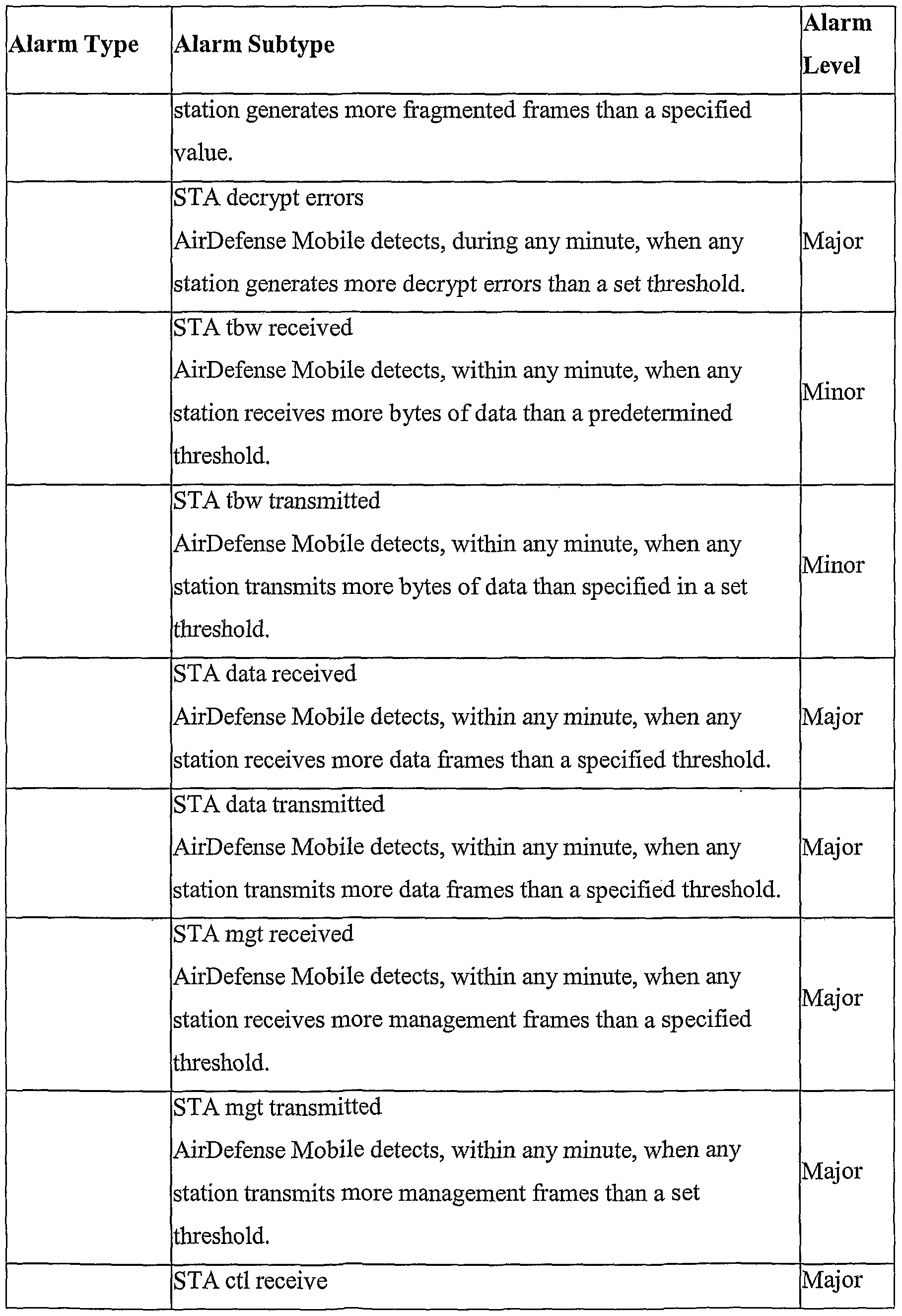


Claims
Priority Applications (4)
| Application Number | Priority Date | Filing Date | Title |
|---|---|---|---|
| CA2486519A CA2486519C (en) | 2002-05-20 | 2003-05-20 | System and method for making managing wireless network activity |
| EP03731262.6A EP1522020B1 (en) | 2002-05-20 | 2003-05-20 | System for managing wireless network activity |
| AU2003241523A AU2003241523B2 (en) | 2002-05-20 | 2003-05-20 | System and method for managing wireless network activity |
| ES03731262.6T ES2558302T3 (en) | 2002-05-20 | 2003-05-20 | System to manage the activity of a wireless network |
Applications Claiming Priority (16)
| Application Number | Priority Date | Filing Date | Title |
|---|---|---|---|
| US38182902P | 2002-05-20 | 2002-05-20 | |
| US60/381,829 | 2002-05-20 | ||
| US10/161,443 | 2002-06-03 | ||
| US10/161,137 | 2002-06-03 | ||
| US10/161,443 US7058796B2 (en) | 2002-05-20 | 2002-06-03 | Method and system for actively defending a wireless LAN against attacks |
| US10/161,440 US7042852B2 (en) | 2002-05-20 | 2002-06-03 | System and method for wireless LAN dynamic channel change with honeypot trap |
| US10/161,142 US7086089B2 (en) | 2002-05-20 | 2002-06-03 | Systems and methods for network security |
| US10/160,904 US20040203764A1 (en) | 2002-06-03 | 2002-06-03 | Methods and systems for identifying nodes and mapping their locations |
| US10/161,440 | 2002-06-03 | ||
| US10/161,137 US7383577B2 (en) | 2002-05-20 | 2002-06-03 | Method and system for encrypted network management and intrusion detection |
| US10/161,142 | 2002-06-03 | ||
| US10/160,904 | 2002-06-03 | ||
| US10/360,587 US7277404B2 (en) | 2002-05-20 | 2003-02-06 | System and method for sensing wireless LAN activity |
| US10/360,587 | 2003-02-06 | ||
| US46446403P | 2003-04-21 | 2003-04-21 | |
| US60/464,464 | 2003-04-21 |
Publications (2)
| Publication Number | Publication Date |
|---|---|
| WO2003100559A2 true WO2003100559A2 (en) | 2003-12-04 |
| WO2003100559A3 WO2003100559A3 (en) | 2004-05-13 |
Family
ID=29588005
Family Applications (1)
| Application Number | Title | Priority Date | Filing Date |
|---|---|---|---|
| PCT/US2003/015844 WO2003100559A2 (en) | 2002-05-20 | 2003-05-20 | System and method for making managing wireless network activity |
Country Status (5)
| Country | Link |
|---|---|
| EP (1) | EP1522020B1 (en) |
| AU (1) | AU2003241523B2 (en) |
| CA (1) | CA2486519C (en) |
| ES (1) | ES2558302T3 (en) |
| WO (1) | WO2003100559A2 (en) |
Cited By (7)
| Publication number | Priority date | Publication date | Assignee | Title |
|---|---|---|---|---|
| US7257107B2 (en) | 2003-07-15 | 2007-08-14 | Highwall Technologies, Llc | Device and method for detecting unauthorized, “rogue” wireless LAN access points |
| US7421266B1 (en) | 2002-08-12 | 2008-09-02 | Mcafee, Inc. | Installation and configuration process for wireless network |
| US7448073B2 (en) | 2002-09-23 | 2008-11-04 | Wimetrics Corporation | System and method for wireless local area network monitoring and intrusion detection |
| US7673146B2 (en) | 2003-06-05 | 2010-03-02 | Mcafee, Inc. | Methods and systems of remote authentication for computer networks |
| US8014376B2 (en) | 2005-01-05 | 2011-09-06 | Lg Electronics, Inc. | Managing channel configuration information in a wireless communication system |
| US8369830B2 (en) | 2004-12-30 | 2013-02-05 | Telecom Italia S.P.A. | Method and system for detecting attacks in wireless data communications networks |
| CN104159252A (en) * | 2014-08-25 | 2014-11-19 | 醴陵恒茂电子科技有限公司 | Centralized network management device for wireless access point and management method thereof |
Families Citing this family (8)
| Publication number | Priority date | Publication date | Assignee | Title |
|---|---|---|---|---|
| US20180159735A1 (en) * | 2016-12-02 | 2018-06-07 | Hewlett Packard Enterprise Development Lp | Managing hardware resources |
| US10438124B2 (en) * | 2017-01-25 | 2019-10-08 | Centurylink Intellectual Property Llc | Machine discovery of aberrant operating states |
| US10346756B2 (en) | 2017-01-25 | 2019-07-09 | Centurylink Intellectual Property Llc | Machine discovery and rapid agglomeration of similar states |
| EP3448081B1 (en) * | 2017-08-21 | 2020-06-17 | Nokia Solutions and Networks Oy | Device and method for automated tuning of auto-channel selection (acs) in wireless networks |
| US11444961B2 (en) * | 2019-12-20 | 2022-09-13 | Intel Corporation | Active attack detection in autonomous vehicle networks |
| US11799736B2 (en) * | 2019-12-27 | 2023-10-24 | Digital Guardian Llc | Systems and methods for investigating potential incidents across entities in networked environments |
| CN111818048B (en) * | 2020-07-08 | 2022-05-27 | 珠海市鸿瑞信息技术股份有限公司 | Safety protection authentication system and method based on distribution network automation |
| CN113536738A (en) * | 2021-07-05 | 2021-10-22 | 国网山东省电力公司电力科学研究院 | Multi-protocol wireless conversion device based on neural network |
Citations (1)
| Publication number | Priority date | Publication date | Assignee | Title |
|---|---|---|---|---|
| US6321338B1 (en) | 1998-11-09 | 2001-11-20 | Sri International | Network surveillance |
Family Cites Families (14)
| Publication number | Priority date | Publication date | Assignee | Title |
|---|---|---|---|---|
| US6484029B2 (en) * | 1998-10-13 | 2002-11-19 | Symbol Technologies, Inc. | Apparatus and methods for adapting mobile unit to wireless LAN |
| US6188681B1 (en) * | 1998-04-01 | 2001-02-13 | Symbol Technologies, Inc. | Method and apparatus for determining alternative second stationary access point in response to detecting impeded wireless connection |
| US7159237B2 (en) * | 2000-03-16 | 2007-01-02 | Counterpane Internet Security, Inc. | Method and system for dynamic network intrusion monitoring, detection and response |
| AU3054102A (en) * | 2000-11-30 | 2002-06-11 | Lancope Inc | Flow-based detection of network intrusions |
| US20020090089A1 (en) * | 2001-01-05 | 2002-07-11 | Steven Branigan | Methods and apparatus for secure wireless networking |
| US20020090952A1 (en) * | 2001-01-08 | 2002-07-11 | Cantwell Charles E. | Location of devices using wireless network nodes |
| US7058358B2 (en) * | 2001-01-16 | 2006-06-06 | Agere Systems Inc. | Enhanced wireless network security using GPS |
| US7168093B2 (en) * | 2001-01-25 | 2007-01-23 | Solutionary, Inc. | Method and apparatus for verifying the integrity and security of computer networks and implementation of counter measures |
| US7392537B2 (en) * | 2001-10-08 | 2008-06-24 | Stonesoft Oy | Managing a network security application |
| US20030084323A1 (en) * | 2001-10-31 | 2003-05-01 | Gales George S. | Network intrusion detection system and method |
| US7039017B2 (en) * | 2001-12-28 | 2006-05-02 | Texas Instruments Incorporated | System and method for detecting and locating interferers in a wireless communication system |
| CA2414789A1 (en) * | 2002-01-09 | 2003-07-09 | Peel Wireless Inc. | Wireless networks security system |
| US7362865B2 (en) * | 2002-04-15 | 2008-04-22 | Hewlett-Packard Development Company, L.P. | Wireless network system |
| US7778606B2 (en) * | 2002-05-17 | 2010-08-17 | Network Security Technologies, Inc. | Method and system for wireless intrusion detection |
-
2003
- 2003-05-20 EP EP03731262.6A patent/EP1522020B1/en not_active Expired - Lifetime
- 2003-05-20 WO PCT/US2003/015844 patent/WO2003100559A2/en not_active Application Discontinuation
- 2003-05-20 AU AU2003241523A patent/AU2003241523B2/en not_active Ceased
- 2003-05-20 ES ES03731262.6T patent/ES2558302T3/en not_active Expired - Lifetime
- 2003-05-20 CA CA2486519A patent/CA2486519C/en not_active Expired - Fee Related
Patent Citations (1)
| Publication number | Priority date | Publication date | Assignee | Title |
|---|---|---|---|---|
| US6321338B1 (en) | 1998-11-09 | 2001-11-20 | Sri International | Network surveillance |
Non-Patent Citations (3)
| Title |
|---|
| BARDWELL J, ASSESSING WIRELESS SECURITY WITH AIRPEEK, Retrieved from the Internet <URL:http:/www.packetnexus.com/docs/AiroPeek_Security.pdf> |
| DEBAR H ET AL.: "COMPUTER NETWORKS", vol. 31, ELSEVIER SCIENCE PUBLISHERS B.V., article "Towards a taxonomy of intrusion-detection systems", pages: 805 - 822 |
| See also references of EP1522020A4 |
Cited By (8)
| Publication number | Priority date | Publication date | Assignee | Title |
|---|---|---|---|---|
| US7421266B1 (en) | 2002-08-12 | 2008-09-02 | Mcafee, Inc. | Installation and configuration process for wireless network |
| US7448073B2 (en) | 2002-09-23 | 2008-11-04 | Wimetrics Corporation | System and method for wireless local area network monitoring and intrusion detection |
| US7849500B2 (en) | 2002-09-23 | 2010-12-07 | Wimetrics Corporation | System and method for wireless local area network monitoring and intrusion detection |
| US7673146B2 (en) | 2003-06-05 | 2010-03-02 | Mcafee, Inc. | Methods and systems of remote authentication for computer networks |
| US7257107B2 (en) | 2003-07-15 | 2007-08-14 | Highwall Technologies, Llc | Device and method for detecting unauthorized, “rogue” wireless LAN access points |
| US8369830B2 (en) | 2004-12-30 | 2013-02-05 | Telecom Italia S.P.A. | Method and system for detecting attacks in wireless data communications networks |
| US8014376B2 (en) | 2005-01-05 | 2011-09-06 | Lg Electronics, Inc. | Managing channel configuration information in a wireless communication system |
| CN104159252A (en) * | 2014-08-25 | 2014-11-19 | 醴陵恒茂电子科技有限公司 | Centralized network management device for wireless access point and management method thereof |
Also Published As
| Publication number | Publication date |
|---|---|
| EP1522020A2 (en) | 2005-04-13 |
| ES2558302T3 (en) | 2016-02-03 |
| AU2003241523B2 (en) | 2009-08-06 |
| EP1522020B1 (en) | 2015-12-02 |
| EP1522020A4 (en) | 2011-01-19 |
| CA2486519A1 (en) | 2003-12-04 |
| AU2003241523A1 (en) | 2003-12-12 |
| CA2486519C (en) | 2015-01-27 |
| WO2003100559A3 (en) | 2004-05-13 |
Similar Documents
| Publication | Publication Date | Title |
|---|---|---|
| US7277404B2 (en) | System and method for sensing wireless LAN activity | |
| US8196199B2 (en) | Personal wireless monitoring agent | |
| US7359676B2 (en) | Systems and methods for adaptively scanning for wireless communications | |
| US7522908B2 (en) | Systems and methods for wireless network site survey | |
| US7322044B2 (en) | Systems and methods for automated network policy exception detection and correction | |
| US7355996B2 (en) | Systems and methods for adaptive monitoring with bandwidth constraints | |
| US7324804B2 (en) | Systems and methods for dynamic sensor discovery and selection | |
| US7532895B2 (en) | Systems and methods for adaptive location tracking | |
| US7383577B2 (en) | Method and system for encrypted network management and intrusion detection | |
| US7086089B2 (en) | Systems and methods for network security | |
| US7042852B2 (en) | System and method for wireless LAN dynamic channel change with honeypot trap | |
| US7058796B2 (en) | Method and system for actively defending a wireless LAN against attacks | |
| US20060123133A1 (en) | Detecting unauthorized wireless devices on a wired network | |
| US20040210654A1 (en) | Systems and methods for determining wireless network topology | |
| WO2004095192A2 (en) | Systems and methods for securing wireless computer networks | |
| US8694624B2 (en) | Systems and methods for concurrent wireless local area network access and sensing | |
| US20030135762A1 (en) | Wireless networks security system | |
| US20040203764A1 (en) | Methods and systems for identifying nodes and mapping their locations | |
| US20040107219A1 (en) | System and method for wireless local area network monitoring and intrusion detection | |
| US20030084321A1 (en) | Node and mobile device for a mobile telecommunications network providing intrusion detection | |
| AU2003241523B2 (en) | System and method for managing wireless network activity | |
| EP3422665B1 (en) | Sensor-based wireless network vulnerability detection | |
| OLADIPO et al. | A Secure Wireless Intrusion Detection System (JBWIDS) | |
| Sinha et al. | Wireless intrusion protection system using distributed collaborative intelligence |
Legal Events
| Date | Code | Title | Description |
|---|---|---|---|
| AK | Designated states |
Kind code of ref document: A2 Designated state(s): AE AG AL AM AT AU AZ BA BB BG BR BY BZ CA CH CN CO CR CU CZ DE DK DM DZ EC EE ES FI GB GD GE GH GM HR HU ID IL IN IS JP KE KG KP KR KZ LC LK LR LS LT LU LV MA MD MG MK MN MW MX MZ NI NO NZ OM PH PL PT RO RU SC SD SE SG SK SL TJ TM TN TR TT TZ UA UG UZ VC VN YU ZA ZM ZW |
|
| AL | Designated countries for regional patents |
Kind code of ref document: A2 Designated state(s): GH GM KE LS MW MZ SD SL SZ TZ UG ZM ZW AM AZ BY KG KZ MD RU TJ TM AT BE BG CH CY CZ DE DK EE ES FI FR GB GR HU IE IT LU MC NL PT RO SE SI SK TR BF BJ CF CG CI CM GA GN GQ GW ML MR NE SN TD TG |
|
| 121 | Ep: the epo has been informed by wipo that ep was designated in this application | ||
| DFPE | Request for preliminary examination filed prior to expiration of 19th month from priority date (pct application filed before 20040101) | ||
| WWE | Wipo information: entry into national phase |
Ref document number: 2486519 Country of ref document: CA Ref document number: 2003241523 Country of ref document: AU |
|
| WWE | Wipo information: entry into national phase |
Ref document number: 3644/DELNP/2004 Country of ref document: IN |
|
| WWE | Wipo information: entry into national phase |
Ref document number: 2003731262 Country of ref document: EP |
|
| WWP | Wipo information: published in national office |
Ref document number: 2003731262 Country of ref document: EP |
|
| NENP | Non-entry into the national phase |
Ref country code: JP |
|
| WWW | Wipo information: withdrawn in national office |
Ref document number: JP |