SQUID MAGNETOMETER SQUID MAGNETOMETER
Die Erfindung betrifft einen Magnetometer ' nach dem Oberbegriff des Anspruchs 1.The invention relates to a magnetometer according to the preamble of claim 1.
Stand der TechnikState of the art
Bislang werden Magnetometer zur hochpräzisen Messung von Magnetfeldern regelmäßig auf der Basis von supraleitenden Quanten-Interferenz-Detektoren (SQUID) aufgebaut. Bei derartigen SQUIDs werden einfach geschlossene supraleitende Stromschlaufen verwendet, welche üblicherweise zwei, in vereinzelten Anwendungen auch mehr Josephsonkontakte enthalten. Sofern diese Stromschlaufen mit einem Strom getrieben werden, der unter einem kritischen Strom liegt, fällt an den Kontakten keine Spannung ab. In der Magnetometer-Anwendung werden die Stromschlaufen jedoch durch einen überkritischen Strom getrieben, so dass zwischen den beiden supraleitenden Elektroden zu beiden Seiten der Kontakte eine sich zeitlich schnell ändernde WechselSpannung abfällt. Die Frequenz dieser WechselSpannung hängt von der Stärke des treibenden Stromes und der Stärke des magnetischen Flusses ab, der die Schlaufe durchsetzt . Als einfach zugängliche Messgröße dient beim Magnetometer die über der Stromschlaufe abfallende Gleichspannung, welche durch zeitliche Mittlung der sich schnell ändernden Wechselspannung
über eine oder mehrere Perioden entsteht. Die Eichkurve eines typischen Zwei-Kontakt-DC-QUID besitzt eine Periodizität mit der Periode Φ0 • Φo ist dabei das elementare Flussquant Φ0 = h/2e. Immer dann, wenn der Fluss, der die Stromschlaufen durchsetzt, einem ganzzahligen Vielfachen des elementaren Flussquants entspricht, nimmt die Eichkurve ein Minimum an, für halbzahlicje Vielfache des elementaren Flussquants Φ0 hingegen ein Maximum. Die Eichkurven derartiger SQUID-Systeme besitzen eine solche Periodizität. In Magnetometern muss bei sich stärker ändernden magnetischen Feldern bei der Messung die Anzahl der Perioden der Eichkurve des SQUID bestimmt werden, die bei einer Änderung des Magnetfeldes durchlaufen werden. Aus der Anzahl der durchlaufenden Perioden lässt sich dann die Größe der Magnetfeldänderung bestimmen. Das Zählen der Periodendurchläufe ist nicht nur schaltungstechnisch vergleichsweise aufwändig, sondern unterliegt auch im Hinblick auf maximal mögliche Änderungen pro Zeiteinheit einer Begrenzung. Denn sofern das Äußere zu messende magnetische Feld zu schnell ansteigt, kann die Zählung außer Trit geraten, wodurch die Messung nutzlos wird.Up to now, magnetometers for high-precision measurement of magnetic fields have been built on the basis of superconducting quantum interference detectors (SQUID). SQUIDs of this type use single-closed superconducting current loops, which usually contain two Josephson contacts, which in isolated applications also contain more. If these current loops are driven with a current that is below a critical current, no voltage drops across the contacts. In the magnetometer application, however, the current loops are driven by a supercritical current, so that a rapidly changing AC voltage drops between the two superconducting electrodes on both sides of the contacts. The frequency of this AC voltage depends on the strength of the driving current and the strength of the magnetic flux that passes through the loop. The easily accessible measurement variable for the magnetometer is the direct voltage dropping across the current loop, which is obtained by averaging the rapidly changing alternating voltage over time arises over one or more periods. The calibration curve of a typical two-contact DC QUID has a periodicity with the period Φ 0 • Φo is the elementary flux quantum Φ 0 = h / 2e. Whenever the flow that passes through the current loops corresponds to an integer multiple of the elementary flow quant, the calibration curve assumes a minimum, but for half-integer multiples of the elementary flow quant Φ 0 a maximum. The calibration curves of such SQUID systems have such a periodicity. In the case of magnetic fields with changing magnetic fields, the number of periods of the calibration curve of the SQUID that are run through when the magnetic field changes must be determined in magnetometers. The magnitude of the magnetic field change can then be determined from the number of periods running through. Counting the cycle times is not only comparatively complex in terms of circuit technology, but is also subject to a limitation with regard to the maximum possible changes per unit of time. If the external magnetic field to be measured rises too quickly, the count can get out of step, making the measurement useless.
Aufgabe und Vorteile der ErfindungObject and advantages of the invention
Der Erfindung liegt die Aufgabe zugrunde, ein Magnetometer insbesondere zur hochpräzisen Messung von Magnetfeldern auf der Grundlage von supraleitenden, geschlossenen Schlaufen, die jeweils mehrere Josephsonkontakte beinhalten sowie mit einer Elektronikeinheit bereitzustellen, mit welchen sich eine Magnetfeldänderung im Hinblick auf den Norrichtungsaufwand vergleichsweise einfacher und insgesamt zuverlässiger bestimmen lässt.The invention has for its object to provide a magnetometer, in particular for high-precision measurement of magnetic fields on the basis of superconducting, closed loops, each of which contains several Josephson contacts, and with an electronic unit with which a change in the magnetic field is comparatively easier and more reliable overall with regard to the directional effort can be determined.
Diese Aufgabe wird durch die Merkmale des Anspruchs 1 gelöst. In den Unteransprüchen sind vorteilhafte und zweckmäßige Weiterbildungen der Erfindung beschrieben.
Die Erfindung geht zunächst von einem Magnetometer, insbesondere zur hochpräzisen Messung von magnetischen Feldern aus , das geschlossene, supraleitende eine Stromschleife bildende Zellen, die j eweils mehrere Josephsonkontakte enthalten sowie eine Elektronikeinheit umfasst . Der Kern der Erfindung liegt nun darin, dass die Zellen einen supraleitenden Quanten-Interferenz-Filter bilden, bei welchem wenigstens drei dieser Zellen supraleitend und/ oder nicht supraleitend in Verbindung stehen, die Kontakte der wenigstens drei Zellen derart bestromt werden, dass j eweils über mindestens zwei Kontakte einer Zelle eine zeitveränderliche Spannung abfällt, deren zeitliches Mittel nicht verschwindet , die wenigstens drei Zellen auf eine Weise geometrisch unterschiedlich ausgestaltet sind, dass die bei einem vorhandenen magnetischen Feld von ölen Zellen eingeschlossenen magnetischen Flüsse sich derart unterscheiden, dass das Frequenz Spektrum der Spannungsantwortfunktion in Bezug auf den magnetischen Fluss keinen signifikanten Φ0 -periodischen Anteil besitzt , oder, falls ein diskretes Frequenz spektrum existiert , der Beitrag des Φ0 -periodischen Anteils des diskreten Frequenz Spektrums im Vergleich zu den nicht Φ0- periodischen Anteilen des diskreten Frequenz Spektrums nicht dominant ist , dass die wenigstens drei Zellen derart, insbesondere geometrisch und hinsichtlich der Kontakte, ausgestaltet sind, dass bei einem vorhandenen magnetischen Feld die in den Zellen fließenden Abschirmströme in der Mehrzahl der wenigstens drei Zellen keinen magnetischen Fluss erzeugen, der größer ist als das elementare magnetische Flussquant Φ0 , dass eine mit der Elektronikeinheit verbundene, insbesondere elektrisch und/oder optisch verbundene und mit dem supraleitenden Quanten-Interferenz- Filter magnetisch gekoppelte, elektrisch leitende Rückkoppelschlaufe vorgesehen ist und dass mittels der Elektronikeinheit in der Rückkoppelschlaufe ein Strom derart einstellbar ist, dass am supraleitenden Quanten- Interferenz-
Filter eine von der Elektronikeinheit vorgegebene Spannung abfällt und aus der Größe des durch die Rückkoppelschlaufe fließenden Stroms- die Stärke des eingekoppelten magnetischen Feldes bestimmbar ist. Damit das Magnetometer eine ausreichende Empfindlichkeit erzielen kann, muss das von im supraleitenden Quanten-Interferenz-Filter (im Folgenden mit SQIF abgekürzt) fließenden Abschirmströmen erzeugte magnetische Feld beschränkt werden. Der bei .Anwesenheit eines äußeren magnetischen Feldes um jede SQIF-Zelle fließende Abschirmstrom darf kein sekundäres magnetisches Feld erzeugen, welches in der Mehrzahl der Schlaufen magnetische Flüsse erzeugt, die größer sind als das elementare magnetische Flussquant Φ0. Ansonsten könnte der von den Abschirmströmen induzierte magnetische Fluss den vom äußeren zu messenden magnetischen Feld induzierten magnetischen Fluss zu stark abschwächen und der Spannungsabfall über dem SQIF würde stark degradieren.This object is solved by the features of claim 1. Advantageous and expedient developments of the invention are described in the subclaims. The invention is initially based on a magnetometer, in particular for the high-precision measurement of magnetic fields, the closed, superconducting cells forming a current loop, each of which contains a plurality of Josephson contacts and an electronic unit. The essence of the invention lies in the fact that the cells form a superconducting quantum interference filter, in which at least three of these cells are connected in a superconducting and / or non-superconducting manner, the contacts of the at least three cells are energized in such a way that in each case via At least two contacts of a cell drop a time-varying voltage, the temporal mean of which does not disappear, the at least three cells are configured in a geometrically different manner in such a way that the magnetic fluxes enclosed by an oil cell in the presence of a magnetic field differ in such a way that the frequency spectrum of the Voltage response function with respect to the magnetic flux has no significant Φ 0 periodic component, or, if a discrete frequency spectrum exists, the contribution of the Φ 0 periodic component of the discrete frequency spectrum compared to the non Φ 0 - periodic components of the discrete Fre quenz spectrum is not dominant that the at least three cells are designed in such a way, in particular geometrically and with respect to the contacts, that in the presence of a magnetic field, the shielding currents flowing in the cells in the majority of the at least three cells do not generate a magnetic flux that is greater as the elementary magnetic flux quantum Φ 0 that an electrically conductive feedback loop connected to the electronics unit, in particular electrically and / or optically connected and magnetically coupled to the superconducting quantum interference filter, and that a current of this type is provided in the feedback loop by means of the electronics unit it is adjustable that the superconducting quantum interference Filter drops a voltage predetermined by the electronics unit and the strength of the coupled magnetic field can be determined from the size of the current flowing through the feedback loop. In order for the magnetometer to achieve sufficient sensitivity, the magnetic field generated by the shielding currents flowing in the superconducting quantum interference filter (hereinafter abbreviated to SQIF) must be limited. The shielding current flowing around each SQIF cell in the presence of an external magnetic field must not generate a secondary magnetic field which generates magnetic fluxes in the majority of the loops which are greater than the elementary magnetic flux quantum Φ 0 . Otherwise the magnetic flux induced by the shielding currents could weaken the magnetic flux induced by the external magnetic field too much and the voltage drop across the SQIF would degrade significantly.
Um die Degradation zu verhindern, müssen die einzelnen SQIF- Zellen bzw. SQIF-Schlaufen und die Geometrie des gesamten SQIF wegen der Periodizitatseigenschaften der Einzelschlaufen derart ausgelegt werden, dass die bei Anwesenheit eines äußeren magnetischen Feldes fließenden Abschirmströme in der Mehrzahl der SQIF-Schlaufen keinen magnetischen Fluss erzeugen, welcher größer ist als das elementare Flussquant Φo-In order to prevent degradation, the individual SQIF cells or SQIF loops and the geometry of the entire SQIF must be designed in such a way that the shielding currents flowing in the presence of an external magnetic field do not have any in the majority of the SQIF loops due to the periodicity properties of the individual loops generate magnetic flux which is larger than the elementary flux quantum Φo-
Die Begrenzung der von den Abschirmströmen erzeugten magnetischen Felder kann dabei auf unterschiedliche Art und Weise erfolgen. Zunächst kann die Geometrie des SQIF, insbesondere die Leitungsführung und die Leiterbreite bzw. der Leiterquerschnitt sowie die Schlaufengröße mit Hilfe der bekannten elektrotechnischen Verfahren derart berechnet werden, dass die Induktivitäten der einzelnen Schlaufen klein genug sind. Da der maximale supraleitende A-bschirmstrom durch die Größe des kritischen Stroms, der durch die
Josephsonkontakte fließen kann, gegeben ist, kann mit Hilfe der berechneten Induktivitäten der in den einzelnen Schlaufen induzierte magnetische Fluss bestimmt werden. Ist dieser Fluss zu groß, dann kann er entweder durch Veränderung der Geometrie des SQIF bzw. der SQIF-Schlaufen oder durch die Wahl von Josephsonkontakten, welche kleinere kritische Ströme besitzen, entsprechend reduziert werden.The magnetic fields generated by the shielding currents can be limited in different ways. First of all, the geometry of the SQIF, in particular the line routing and the conductor width or the conductor cross section and the loop size, can be calculated using the known electrotechnical methods in such a way that the inductances of the individual loops are small enough. Since the maximum superconducting shielding current is determined by the size of the critical current through the Given that Josephson contacts can flow, the magnetic flux induced in the individual loops can be determined using the calculated inductances. If this flow is too large, it can be reduced accordingly either by changing the geometry of the SQIF or the SQIF loops or by choosing Josephson contacts that have smaller critical currents.
Im Gegensatz zu den bekannten SQUIDs oder den bekannten periodischen Anordnungen von identischen Schlaufen ist es zur Erzielung einer optimalen Leistungsfähigkeit des Magnetometers bei SQIFs jedoch nicht notwendig, dass bei Anwesenheit eines magnetischen Feldes die Abschirmströme in allen Schlaufen einen magnetischen Fluss erzeugen, welcher kleiner ist als das elementare Flussquant Φ0. Da sich die magnetischen Abschirmfelder in erfindungsgemäßen SQIFs zumindest teilweise gegenseitig aufheben und durch die unterschiedlichen Schlaufengrößen unterschiedliche induktive Kopplungen zwischen den Schlaufen auftreten, hat es sich herausgestellt, dass es ausreichend ist, wenn in der Mehrzahl der Schlaufen kein magnetischer Fluss erzeugt wird, welcher größer ist als das elementare Flussquant Φ0. In der praktischen Anwendung ist dies ein großer Vorteil von SQIFs gegenüber bekannten Anordnungen, da die effektive Gesamtfläche und damit die Sensitivität des Magnetometers in einfacher Weise stark gesteigert werden kann.In contrast to the known SQUIDs or the known periodic arrangements of identical loops, in order to achieve optimal performance of the magnetometer in SQIFs, it is not necessary that the shielding currents in all loops generate a magnetic flux which is smaller than that in the presence of a magnetic field elementary flux quantum Φ 0 . Since the magnetic shielding fields in SQIFs according to the invention at least partially cancel each other out and, due to the different loop sizes, different inductive couplings occur between the loops, it has been found that it is sufficient if no magnetic flux which is larger is generated in the majority of the loops as the elementary flux quantum Φ 0 . In practical use, this is a great advantage of SQIFs compared to known arrangements, since the effective total area and thus the sensitivity of the magnetometer can be greatly increased in a simple manner.
Vorzugsweise umfasst das Magnetometer Auswertemittel, die z.B. im Magnetometer integriert sind, um die Bestimmung des magnetischen Felds auf der Grundlage des durch die Rückkoppelschlaufe fließenden Stromes automatisiert vornehmen zu können. Durch die Verwendung eines supraleitenden Quanten- Interferenz-Filters lässt sich die Elektronikeinheit im Vergleich zu bekannten Auswerteschaltungen bei Magnetometern deutlich einfacher ausgestalten.
Die oben angegebenen allgemeinen Merkmale eines supraleitenden Quanten-Interferenz-Filters und eine Vielzahl von Konkretisierungen sind aus der DE 100 43 657 AI bekannt. Auf diese deutsche Offenlegungsschrift soll daher ausdrücklich Bezug genommen werden. Hieraus ist nicht nur die oben beschriebene Grundform eines supraleitenden Quanten- Interferenz-Filters (im Folgenden auch mit SQIF bezeichnet) bekannt, sondern auch eine Vielzahl von Weiterbildungen entsprechend den nachstehenden Ausführungen AI) bis A12) :The magnetometer preferably comprises evaluation means which are integrated, for example, in the magnetometer in order to be able to carry out the determination of the magnetic field on the basis of the current flowing through the feedback loop in an automated manner. By using a superconducting quantum interference filter, the electronic unit can be made significantly simpler in comparison to known evaluation circuits in magnetometers. The above-mentioned general features of a superconducting quantum interference filter and a large number of concretizations are known from DE 100 43 657 AI. Reference should therefore expressly be made to this German publication. From this, not only the basic form of a superconducting quantum interference filter described above (also referred to below as SQIF) is known, but also a large number of further developments in accordance with the following explanations AI) to A12):
AI) Im Hinblick auf die Periodizität derAI) With regard to the periodicity of the
Spannungsantwortfunktion kann für das SQIF auch der folgende funktionale Ansatz gewählt werden: Dass die wenigstens drei Zellen derart geometrisch unterschiedlich ausgestaltet sind, dass die bei einem vorhandenen magnetischen Feld von den Zellen eingeschlossenen magnetischen Flüsse derart in einem Verhältnis zueinander stehen, dass die Periode der Spannungsantwortfunktion des Netzwerks in Bezug auf den die Netzwerkzellen in ihrer Gesamtheit durchs tzenden magnetischen Fluss größer oder sehr viel größer als der Wert eines elementaren Flussquants ist bzw. die Spannungsantwort keinen Φ0-periodischen Anteil mehr aufweist. Im Idealfall besitzt die Spannungsantwortfunktion keine Periode mehr, wenn die von den Zellen eingeschlossenen magnetischen Flüsse in keinem rationalen Verhältnis zueinander stehen. Vorzugsweise sind zusätzlich die Flächenunterschiede der einzelnen Zellen vergleichsweise groß. Insbesondere in diesem Fall superpositionieren supraleitend verbundene Zellen in einer Weise, dass die Spannungsantwortfunktion keine Periode mehr aufweist.The following functional approach can also be selected for the SQIF voltage response function: that the at least three cells are configured in such a geometrically different manner that the magnetic fluxes enclosed by the cells in an existing magnetic field are in a relationship to one another such that the period of the voltage response function of the Network with respect to which the network cells in their entirety due to the corrosive magnetic flux is larger or much larger than the value of an elementary flux quantum or the voltage response no longer has a Φ 0 periodic component. In the ideal case, the voltage response function no longer has a period when the magnetic fluxes enclosed by the cells have no rational relationship to one another. In addition, the surface differences of the individual cells are preferably comparatively large. In this case in particular, superconductively connected cells superposition in such a way that the voltage response function no longer has a period.
Somit werden gezielt unterschiedliche Zellen miteinander verschaltet, was der Fachmann bei herkömmlichen SQUID- Anordnungen immer vermeiden möchte. Dies kommt beispielsweise in der Veröffentlichung von HANSEN, BINSL.EV J. , LINDELOF
P.E.: Static and dynamic interactions between Josephson junctions. In: Reviews of Modern Physics, Vol. 56, No. 3, July 1984, S. 431 - 459; zum Ausdruck. In dieser Veröffentlichung wird auf S. 434, linke Spalte, letzter Absatz sowie folgend auf der rechten Spalte ein System mit identischen Zellen und identischen Kontakten favorisiert und dagegen Unsymmetrien als kontraproduktiv für die Funktion des diesbezüglich beschriebenen SQUIDs eingestuft.Different cells are thus specifically interconnected, which the person skilled in the art would always like to avoid in the case of conventional SQUID arrangements. This occurs, for example, in the publication by HANSEN, BINSL.EV J., LINDELOF PE: Static and dynamic interactions between Josephson junctions. In: Reviews of Modern Physics, Vol. 56, No. 3, July 1984, pp. 431-459; to expression. In this publication, on p. 434, left column, last paragraph and the right column below, a system with identical cells and identical contacts is favored and asymmetries, on the other hand, are classified as counterproductive for the function of the SQUID described in this regard.
Supraleitende Quanten-Interferenz-Filter zeigen den physikalischen Effekt der multiplen makroskopischen Quanten- Interferenz auf eine Weise, dass die Mehrdeutigkeit der Eichkurven herkömmlicher SQUID-Magnetometer und -Gradiometer beseitigt wird.Superconducting quantum interference filters show the physical effect of multiple macroscopic quantum interference in a way that eliminates the ambiguity of the calibration curves of conventional SQUID magnetometers and radiometers.
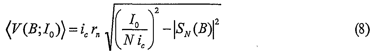
In einem supraleitenden Quanten-Interferenz-Filter interferieren die quantenmechanischen Wellenfunktionen, welche den Zustand des supraleitenden Festkörpers beschreiben, derart, dass eine eindeutige makroskopische Eichkurve (V(B;I0)\ entsteht. Die Eichkurve (v(B;I0)\ des supraleitenden Quanten-Interferenz-Filters besitzt im Idealfall keine Periodizität mit der Periode Φ0 und ist eine in einem bestimmten Messbereich monoton steigende Funktion des Betrags des äußeren magnetischen Feldes B am Ort des SQIF.In a superconducting quantum interference filter, the quantum mechanical wave functions, which describe the state of the superconducting solid, interfere in such a way that a clear macroscopic calibration curve (V (B; I 0 ) \ is created. The calibration curve (v (B; I 0 ) \ of the superconducting quantum interference filter ideally has no periodicity with the period Φ 0 and is a function of the magnitude of the external magnetic field B at the location of the SQIF that increases monotonically in a certain measuring range.
Die Eindeutigkeit der Eichkurve und die hohe Empfindlichkeit von supraleitenden Quanten-Interferenz-Filtern erlauben die direkte Messung zeitveränderlicher elektromagnetischer Felder in einem kontinuierlichen Frequenzbereich, dessen untere Schranke bei v∞(«0 und dessen obere Schranke je nach Art der verwendeten Josephsonkontakte oder weak links zur Zeit bei mehreren hundert GHz bis THz liegt. Dieser gesamte Frequenzbereich ist mit einem einzigen entsprechend ausgelegten supraleitenden Quanten-Interferenz-Filter zugänglich. Bei der Detektion elektromagnetischer Wellen
operiert der supraleitende Quanten-Interferenz-Filter simultan als Empfangsantenne, Filter und leistungsfähiger Verstärker. Das Eigenrauschen von geeignet ausgelegten Quanten-Interferenz -Filtern kann dabei um mehrere Größenordnungen kleiner sein als das Eigenrauschen konventioneller SQUID-Magnetometer. Ein weiterer Vorteil gegenüber herkömmlichen Antennen und Filtern liegt dabei unter anderem darin, dass bedingt durch das Messprinzip der Frequenzbereich nicht von der räumlichen Ausdehnung des supraleitenden Quanten-Interferenz-Filters abhängt. Die räumliche Ausdehnung kann lediglich die Empfindlichkeit beeinflusse .The uniqueness of the calibration curve and the high sensitivity of superconducting quantum interference filters allow the direct measurement of time-varying electromagnetic fields in a continuous frequency range, the lower bound of which at v « ( « 0 and the upper bound depending on the type of Josephson contacts used or weak links to Time is several hundred GHz to THz This entire frequency range is accessible with a single, appropriately designed, superconducting quantum interference filter for the detection of electromagnetic waves the superconducting quantum interference filter operates simultaneously as a receiving antenna, filter and powerful amplifier. The inherent noise of suitably designed quantum interference filters can be several orders of magnitude smaller than the inherent noise of conventional SQUID magnetometers. Another advantage over conventional antennas and filters is that, due to the measuring principle, the frequency range does not depend on the spatial extent of the superconducting quantum interference filter. The spatial extent can only affect the sensitivity.
Die Herstellung von supraleitenden Quanten-Interferenz- Filtern kann nach bekannten kostengünstigen technischen Verfahren erfolgen, wie sie etwa in der modernen Fertigung konventioneller SQUIDs angewandt werden. Da sich die räumliche Ausdehnung von supraleitenden Quanten-Inter erenz- Filtern nicht wesentlich von der räumlichen Ausdehnung konventioneller SQUID-Systeme unterscheiden muss, können die für konventionelle SQUID-Systeme entwickelten Kryotechnologien direkt übernommen werden. Spezielle Entwicklungen auf dem Gebiet der Kryotechnologie sind nicht nötig.The production of superconducting quantum interference filters can be carried out using known, inexpensive technical processes, such as those used in the modern production of conventional SQUIDs. Since the spatial extent of superconducting quantum interference filters does not have to differ significantly from the spatial extent of conventional SQUID systems, the cryotechnologies developed for conventional SQUID systems can be adopted directly. Special developments in the field of cryotechnology are not necessary.
A2) Vorzugsweise sind in einem System aus oben beschriebenen Zellen zumindest für eine Zelle, günstigerweise für den größten Teil der Zellen genau zwei Kontakte pro Zelle vorgesehen, welche supraleitend verbunden und elektrisch parallel geschaltet sind. Durch genau zwei Kontakte lassen sich die soeben beschriebenen Effekte vergleichsweise einfach und gut erreichen.A2) Preferably, in a system of cells described above, at least for one cell, advantageously for the majority of the cells, exactly two contacts per cell are provided, which are superconductively connected and electrically connected in parallel. With exactly two contacts, the effects just described can be achieved comparatively easily and well.
A3) Die gewünschten Effekte lassen sich jedoch auch in günstiger Weise erzielen, wenn in einer Zelle mehr als zwei Kontakte vorgesehen sind, die supraleitend verbunden und
elektrisch parallel geschaltet sind, und zwar in Form einer Serienschaltung von Kontakten, die mit einem Einzelkontakt parallel geschaltet ist , oder in Form von zwei parallel geschalteten Serienschaltungen von Kontakten .A3) However, the desired effects can also be achieved in a favorable manner if more than two contacts are provided in a cell which are connected superconductively and are electrically connected in parallel, in the form of a series connection of contacts which is connected in parallel with a single contact, or in the form of two series connections of contacts connected in parallel.
A4) Die erfindungsgemäßen Effekte lassen sich j edoch auch durch Strukturen wenigstens einer Zelle eines Netzwerks erreichen, bei denen neben einer Grundform von mindestens zwei Kontakten, an welchen eine im zeitlichen Mittel nicht verschwindende, zeitveränderliche Spannung abfällt , insbesondere neben einer Grundform von zwei elektrisch parallel geschalteten Kontakten , ein weiterer Kontakt oder mehrere weitere Kontakte vorgesehen sind, welche Kontakte nicht direkt bestromt werden und daher an diesen Kontakten im Mittel keine Spannung abfällt . Die Verbindungen aller Kontakte in den einzelnen Zellen ist dabei weiterhin supraleitend . Solche Aus führungs formen können von Vorteil sein, da durch zusätzliche Kontakte die von einem magnetischen Feld in den einzelnen Zellen induzierten Abschirmströme reduziert werden können. Der Einfluss von Eigen- und Gegeninduktivitäten kann dadurch vermindert werde .A4) However, the effects according to the invention can also be achieved by structures of at least one cell of a network in which, in addition to a basic form of at least two contacts, to which a time-varying voltage that does not vanish on average over time, drops, in particular in addition to a basic form of two electrically parallel switched contacts, another contact or more contacts are provided, which contacts are not energized directly and therefore no voltage drops across these contacts on average. The connection of all contacts in the individual cells is still superconducting. Such embodiments can be advantageous, since the shielding currents induced by a magnetic field in the individual cells can be reduced by additional contacts. This can reduce the influence of self-inductance and mutual inductance.
A5) In einer besonders bevorzugten Aus führungs form bilden mehrere Zellen ein Netzwerk oder einen Netzwerkabschnitt , in welchem alle Kontakte elektrisch parallel geschaltet sind, so dass die Kontakte gleich gerichtet bestrombar sind . Insbesondere , wenn in diesem Zusammenhang die Zellen supraleitend miteinander in Verbindung stehen, lassen sich durch eine derartige Anordnung besonders große Empfindlichkeiten für die Messung eines Magnetfeldes erzielen .A5) In a particularly preferred embodiment, several cells form a network or a network section in which all contacts are electrically connected in parallel, so that the contacts can be energized in the same direction. In particular, if the cells are connected to one another in a superconducting manner in this context, particularly great sensitivities for the measurement of a magnetic field can be achieved by such an arrangement.
A6) Mehrere Zellen oder Netzwerkabschnitte lassen sich vorteilhafterweise j edoch auch elektrisch in Reihe schalten, so das s wiederum die Kontakte im Netzwerk in der gleichen
Richtung bestrombar sind. Durch diese Maßnahme kann die Größe des Messsignals erhöht werden, da sich in der Reihenschaltung die Spannungen an den Kontakten addieren.A6) However, several cells or network sections can advantageously also be electrically connected in series, so that in turn the contacts in the network are in the same Direction can be energized. This measure allows the size of the measurement signal to be increased, since the voltages at the contacts add up in the series connection.
A7) Eine besonders hohe Empfindlichkeit kann auch durch die Parallelschaltung von Serienanordnungen mehrerer Zellen oder Netzwerkabschnitte erreicht werden. Vorzugsweise sind in dieser Ausführungsform die Netzwerkabschnitte oder Zellen supraleitend verschaltet, insbesondere durch supraleitende twisted-pair-Kabel. Das Auflösungsvermögen von supraleitenden Quanten-Interferenz-Filtern kann dabei bis in den Bereich von aT (10"18 Tesla) und darunter reichen. Die Eichkurve bleibt auch für solche Messbereiche eindeutig, so dass absolute quantitative Messungen von extrem kleinen Feldern möglich weirden.A7) A particularly high sensitivity can also be achieved by connecting series arrangements of several cells or network sections in parallel. In this embodiment, the network sections or cells are preferably connected in a superconducting manner, in particular by means of superconducting twisted-pair cables. The resolution of superconducting quantum interference filters can range up to aT (10 "18 Tesla) and below. The calibration curve remains clear even for such measuring ranges, so that absolute quantitative measurements of extremely small fields are possible.
A8) Das Netzwerk kann spannungsgetrieben oder stromgetrieben eingesetzt werden.A8) The network can be voltage or current driven.
A9) Um möglichst ideale Josephson-Effekte zu erzielen, wird überdies vorgeschlagen, dass die Kontakte als Punktkontakte ausgeführt sind.A9) In order to achieve the ideal Josephson effects, it is also proposed that the contacts be designed as point contacts.
AlO ) Um die Empfindlichkeit eines SQIF zu erhöhen, kann außerdem die Geometrie der Zellenanordnung derart ausgeführt werden, dass ein magnetisches Übersprechen einer Zelle auf eine benachbarte Zelle aufgrund des durch einen in den Zellen fließenden Stroms hervorgerufenen magnetischen Eigenfeldes reduziert wird.AlO) In order to increase the sensitivity of an SQIF, the geometry of the cell arrangement can also be carried out in such a way that magnetic crosstalk from one cell to an adjacent cell is reduced on account of the magnetic field generated by a current flowing in the cells.
Ali) In einer weiteren bevorzugten Ausgestaltung sind die Zellen des Netzwerkes und/oder Netzwerkabschnitte räumlich, insbesondere räumlich zwei- oder dreidimensional ausgerichtet. Durch diese Maßnahme wird es möglich, zusätzlich zum Betrag des Magnetfeldes einzelne Magne feldkomponenten zu bestimmen. Bei einer räumlich
dreidimensionalen Anordnung lässt sich somit die Richtung des Magnetfelds messen.Ali) In a further preferred embodiment, the cells of the network and / or network sections are spatially, in particular spatially two or three-dimensionally aligned. This measure makes it possible to determine individual magnetic field components in addition to the amount of the magnetic field. With a spatially three-dimensional arrangement, the direction of the magnetic field can thus be measured.
A12) Im Weiteren ist es bevorzugt, wenn der die Kontakte treibende Strom durch ohmsche Widerstände, welche insbesondere als bus-bar-Widerstände ausgeführt sind, eingespeist und/oder wieder abgeführt wird. Denn Messungen haben gezeigt, dass die Einspeisung des treibenden Stroms durch ohmsche Widerstände die Performance des SQIF erheblich verbessern kann.A12) Furthermore, it is preferred if the current driving the contacts is fed in and / or discharged again through ohmic resistors, which are in particular in the form of busbar resistors. Measurements have shown that feeding the driving current through ohmic resistors can significantly improve the performance of the SQIF.
Für weitere Ausgestaltungen von SQIFs wird auf die Figuren 9a bis 20 und deren dazugehörigen Beschreibungsteile im Anschluss an die Figurenbeschreibung zu den Figuren 1 bis 8 verwiesen.For further refinements of SQIFs, reference is made to FIGS. 9a to 20 and their associated description parts following the description of the figures for FIGS. 1 to 8.
Der Einsatz von einem supraleitenden Quanten-Interferenz- Filter hat im Weiteren den Vorteil, dass derartige Filter einen im Vergleich zu bekannten SQUID größeren Spannungshub besitzen. Hierdurch wird die Gefahr, dass der Messbereich verlassen wird, reduziert. Außerdem wird der Einfluss von Rauschen auf die Messung vermindert. Durch den Einsatz eines supraleitenden Quanten-Interferenz-Filters mit einer eindeutigen Spannungsantwortfunktion lässt sich nach einem Verlassen des Arbeitsbereichs des Magnetometers aufgrund der Eindeutigkeit der ursprüngliche Arbeitspunkt wieder auffinden, wodurch weitere Messungen fehlerfrei an die vorangehenden Messungen anschließen können.The use of a superconducting quantum interference filter has the further advantage that such filters have a larger voltage swing than known SQUIDs. This reduces the risk of leaving the measuring range. In addition, the influence of noise on the measurement is reduced. By using a superconducting quantum interference filter with a clear voltage response function, the original operating point can be found again after leaving the working range of the magnetometer due to the uniqueness, so that further measurements can connect to the previous measurements without errors.
Für ein Magnetometer lassen sich eine Vielzahl von unterschiedlichen Ausgestaltungen eines supraleitenden Quanten-Interferenz-Filters verwenden. Alle supraleitenden Quanten-Interferenz-Filter umfassen, wie bereits oben beschrieben, verschieden große supraleitende Zellen bzw. Schleifen mit mehreren Josephsonkontakten. Einige besonders vorteilhafte hierauf aufgebaute Strukturen von supraleitenden
Quanten-Interferenz-Filtern sind nachfolgend beschrieben:A large number of different configurations of a superconducting quantum interference filter can be used for a magnetometer. As already described above, all superconducting quantum interference filters include different sized superconducting cells or loops with several Josephson contacts. Some particularly advantageous superconducting structures based thereon Quantum interference filters are described below:
Bl) Bei einer ersten Ausführungsform sind die supraleitenden Schleifen in Serie angeordnet. Hierdurch addieren sich die Spannungshübe der einzelnen Schleifen, woraus ein größerer Messbereich um den Arbeitspunkt resultiert. Ein weiterer Vorteil besteht darin, dass das Eigenrauschen der Anordnung gegenüber einer einzelnen Schleife um den Faktor N verringert wird ( N ist gleich die Anzahl der Schleifen) . Dies bringt eine entsprechende Verbesserung der rauschbegrenzten Magnetfeldempfindlichkeit. Insbesondere bei hochtemperatursupraleitenden Anordnungen werden sehr kleine kritische Ströme der Josephsonkontakte eingestellt. Dadurch wird gesichert, dass beim verwendeten Betriebsstrom des supraleitenden Quanten-Interferenz-Filters (Betriebsstrom ist gleich der Strom, bei dem ein unikaler Spannungspeak der nicht periodischen Eichkurze am besten ausgeprägt ist) möglichst viele der Einzelschleifen zusammenarbeiten. Dies trägt dem Umstand Rechnung, dass insbesondere bei hochtemperatursupraleitenden Josephsonschaltungen, die kritischen Ströme von mehreren Josephsonkontakten in einem bestimmten Bereich streuen. Bei kleinen kritischen Strömen treten zwei für den Betrieb des supraleitenden Quanten- Interferenz-Filters günstige Umstände auf: Zum einen überlappen die Arbeitsbereiche der einzelnen Kontakte bei gleicher relativer Streuung der kritischen Ströme umso mehr, je kleiner ihre absolute Größe ist. Zum anderen tritt bei kleinen kritischen Strömen eine verstärkte Rauschverrundung auf, welche die Arbeitsbereiche der einzelnen Kontakte noch weiter vergrößert.B1) In a first embodiment, the superconducting loops are arranged in series. This adds up the voltage swings of the individual loops, which results in a larger measuring range around the operating point. Another advantage is that the inherent noise of the arrangement is reduced by a factor of N compared to a single loop (N is equal to the number of loops). This brings a corresponding improvement in the noise-limited magnetic field sensitivity. In the case of high-temperature superconducting arrangements in particular, very small critical currents of the Josephson contacts are set. This ensures that when the operating current of the superconducting quantum interference filter is used (operating current is the current at which a unique voltage peak of the non-periodic calibration curve is best pronounced) as many of the individual loops as possible work together. This takes into account the fact that, particularly in the case of high-temperature superconducting Josephson circuits, the critical currents from several Josephson contacts scatter in a specific region. In the case of small critical currents, two circumstances which are favorable for the operation of the superconducting quantum interference filter occur: on the one hand, the working areas of the individual contacts overlap with the same relative spread of the critical currents, the smaller their absolute size. On the other hand, with small critical currents there is an increased noise rounding, which increases the working areas of the individual contacts even further.
B2) Die Schleifen des supraleitenden Quanten-Interferenz- Filters lassen sich auch parallel schalten. Bei gleichem Spannungshub wie bei einer einzelnen Schleife wird hier die
Empfindlichkeit gegenüber einem äußeren Magnetfeld entsprechend der Anzahl der Schleifen erhöht . Daraus resultiert eine ebensolche Verringerung des Eigenrauschens im Vergleich zu einer einzelnen Schleife so wie bei der Serienanordnung, wodurch ebenfalls eine entsprechende Verbesserung der rauschbegrenzten Magnetfeldempfindlichkeit erreicht wird. Die Parallelanordnung ist insbesondere auch bei einer Realisierung auf der Grundlage von Hochtemperatursupraleitern vorteilhaft . Im Gegensatz zur Serienanordnung stellen sich die Arbeitspunkte der einzelnen Schleifen automatisch richtig ein, man benötigt also keine gezielte Einstellung niedriger kritischer Ströme . Dies ist deshalb so, weil im Gegensatz zu den kritischen Strömen Ic das Produkt IcRn mehrer Josephsonkontakte nur sehr wenig streut . Hierbei ist Rn der Betriebswiderstand des Josephsonkontakts . Bei einer Parallelschaltung von Josephsonkontakten teilt sich der Betriebsstrom umgekehrt proportional zu den Betriebswiderständen auf . Daher erhält j eder Josephsonkontakt den Strom, den er braucht , um in seinem optimalen Arbeitsbereich betrieben werden zu können .B2) The loops of the superconducting quantum interference filter can also be connected in parallel. With the same voltage swing as with a single loop, the Sensitivity to an external magnetic field increased according to the number of loops. This results in a reduction in the intrinsic noise as compared to a single loop as in the series arrangement, which likewise leads to a corresponding improvement in the noise-limited magnetic field sensitivity. The parallel arrangement is particularly advantageous even when implemented on the basis of high-temperature superconductors. In contrast to the series arrangement, the operating points of the individual loops are automatically set correctly, so you do not need to specifically set low critical currents. This is because, in contrast to the critical currents I c, the product I c R n of several Josephson contacts scatters very little. Here R n is the operating resistance of the Josephson contact. If Josephson contacts are connected in parallel, the operating current is divided in inverse proportion to the operating resistances. Therefore, each Josephson contact receives the power it needs to operate in its optimal working area.
B3 ) Eine weitere vorteilhafte Aus führungs form besteht in der Kombination einer parallelen und seriellen Anordnung von Schleifen. Diese Anordnung besteht z . B . aus einer Reihenschaltung mehrerer Parallelanordnungen von Schleifen . Vorzugsweise findet sich in der Gesamtanordnung aller Schleifen die gleiche Schleifenverteilung wie bei der reinen Serien- oder Parallelanordnung wieder. Die parallel-serielle Anordnung vereint die Vorteile einer Reihen- und Parallelschaltung. Die Parallelschleifen sichern die Einstellung des optimalen Betriebs Stromes für alle Schleifen, aus der Serienanordnung resultiert ein größerer Spannungshub . Die Verbesserung der rauschbegrenztenB3) Another advantageous embodiment is the combination of a parallel and serial arrangement of loops. This arrangement consists, for. B. from a series connection of several parallel arrangements of loops. The overall arrangement of all loops preferably has the same loop distribution as in the pure series or parallel arrangement. The parallel-serial arrangement combines the advantages of a series and parallel connection. The parallel loops ensure the setting of the optimal operating current for all loops, the series arrangement results in a larger voltage swing. The improvement of noise limited
Magnet feldempfindlicnkeit tritt auch hier ein. Die parallel - serielle Anordnung hat noch einen weiteren Vorteil in der
praktischen Anwendung. Durch geeignete Wahl der Zahl von Schleifen in der Parallelanordnung und in Reihe geschalteter solcher Parallelanordnungen kann man den Gesamtbetriebswiderstand des supraleitenden Quanten- Interferenz-Filters einstellen, so dass er an eine äußere Elektronik angepasst werden kann.Magnetic field sensitivity also occurs here. The parallel - serial arrangement has another advantage in the practical application. The total operating resistance of the superconducting quantum interference filter can be adjusted by suitable selection of the number of loops in the parallel arrangement and such parallel arrangements connected in series, so that it can be adapted to external electronics.
Bei einer weiteren besonders bevorzugten Ausgestaltung eines Magnetometers ist in der Rückkoppelschleife ein Strom einstellbar, der im supraleitenden Quanten-Interferenz-Filter einen magnetischen Fluss erzeugt, dessen Betrag mindestens dem Betrag des magnetischen Flusses entspricht, der durch ein von außen in den supraleitenden Quanten-Interferenz-Filter eingekoppeltes magnetisches Feld erzeugt wird. Hierdurch wird es möglich, den supraleitenden Quanten-Interferenz-Filter unabhängig vom zu messenden äußeren magnetischen Feld immer im Arbeitspunkt zu betreiben. In diesem Zusammenhang ist es insbesondere vorteilhaft, wenn die Elektronikeinheit für die Realisierung einer Suchfunktion Mittel zur Einstellung des durch den Strom in der Rückkoppelschleife erzeugten magnetischen Felds umfasst, wobei das magnetische Feld derart veränderbar ist, dass der im Operationsbereich liegende Arbeitspunkt des supraleitenden Quanten-Interferenz-Filters automatisch auffindbar ist. Es geht also darum, unabhängig von der Größe des zu messenden Felds möglichst schnell den Arbeitspunkt des supraleitenden Quanten-Interferenz-Filters einzustellen, um hieraus das zu messende Feld dann bestimmen zu können.In a further particularly preferred embodiment of a magnetometer, a current can be set in the feedback loop which generates a magnetic flux in the superconducting quantum interference filter, the magnitude of which corresponds at least to the magnitude of the magnetic flux caused by external interference in the superconducting quantum interference -Filter coupled magnetic field is generated. This makes it possible to always operate the superconducting quantum interference filter regardless of the external magnetic field to be measured at the operating point. In this context, it is particularly advantageous if the electronic unit for implementing a search function comprises means for setting the magnetic field generated by the current in the feedback loop, the magnetic field being changeable such that the operating point of the superconducting quantum interference located in the operating range -Filters can be found automatically. It is therefore a matter of setting the operating point of the superconducting quantum interference filter as quickly as possible, regardless of the size of the field to be measured, in order then to be able to determine the field to be measured from this.
Hierfür kann die Elektronikeinheit in unterschiedlicher Weise ausgeführt werden. Beispielsweise ist es vorteilhaft, wenn die Mittel zur Einstellung des magnetischen Felds eine vergleichsweise schnell durchfahrbare Rampe für den Strom durch die Rückkoppelschlaufe umfassen. Eine derartige Rampe kann im Bereich von Nanosekunden durchfahren werden, wodurch sich die Bestimmung des magnetischen Feldes entsprechend
schnell .realisieren lässt. Die Rampe lässt sich beispielsweise so einstellen, dass das über den Strom in der Rückkoppelschleife sich ausbildende Referenzmagnetfeld immer bei Startwerten deutlich unterhalb des letzten Messwertes beginnt und dann hoch gefahren wird. Dieser Vorgang endet, sobald am supraleitenden Quanten-Interferenz-Filter eine vorgegebene Spannung abfällt. .B. kann auch darauf geregelt werden, dass das Referenzmagnetfeld mit dem zu messenden Magnetfeld übereinstimm .For this purpose, the electronic unit can be designed in different ways. For example, it is advantageous if the means for setting the magnetic field comprise a ramp for the current through the feedback loop that can be passed through comparatively quickly. Such a ramp can be traversed in the range of nanoseconds, which means that the magnetic field is determined accordingly can be realized quickly. The ramp can be set, for example, in such a way that the reference magnetic field that is formed via the current in the feedback loop always starts at start values well below the last measured value and is then ramped up. This process ends as soon as a predetermined voltage drops across the superconducting quantum interference filter. .B. can also be regulated so that the reference magnetic field matches the magnetic field to be measured.
Um die Empfindlichkeit des Magnetometers gegenüber äußeren Magnetfeldern zu verbessern, wird im Weiteren vorgeschlagen, dass zur Einkopplung des zu messenden magnetischen Feldes von außen in den supraleitenden Quanten-Interferenz-Filter zusätzliche supraleitende Strukturen vorgesehen sind. Dies kann dadurch erfolgen, dass ein möglichst großer Bereich der geometrisch zur Verfügung stehenden Fläche mit supraleitende Material ausgefüllt und/oder in diesem Bereich supraleitende Schleifen angeordnet werden. Die zusätzlichen supraleitenden Strukturen können galvanisch unmittelbar mit dem supraleitenden Quanten-Interferenz-Filter verbunden sein. Eine Kopplung kann jedoch auch induktiv stattfinden.In order to improve the sensitivity of the magnetometer to external magnetic fields, it is further proposed that additional superconducting structures are provided for coupling the magnetic field to be measured from the outside into the superconducting quantum interference filter. This can be done by filling the largest possible area of the geometrically available area with superconducting material and / or arranging superconducting loops in this area. The additional superconducting structures can be directly galvanically connected to the superconducting quantum interference filter. However, coupling can also take place inductively.
Bei einer weiteren besonders vorteilhaften Ausführungsform der Erfindung sind die zusätzlichen supraleitenden Strukturen derart ausgelegt, dass sie das einzukoppelnde Feld fokussieren. Dies kann beispielsweise durch eine supraleitende Fläche oder eine supraleitende Schleife realisiert werden, die im Bereich des supraleitenden Quanten- Interferenz-Filters angeordnet wird, so dass das durch den Strom in cLen zusätzlichen Strukturen erzeugte magnetische Feld in den supraleitenden Quanten-Interferenz-Filter einkoppeln kann.In a further particularly advantageous embodiment of the invention, the additional superconducting structures are designed such that they focus on the field to be coupled in. This can be realized, for example, by means of a superconducting surface or a superconducting loop which is arranged in the region of the superconducting quantum interference filter, so that the magnetic field generated by the current in cLen additional structures can couple into the superconducting quantum interference filter ,
In einer außerdem vorteilhaften Ausgestaltung der Erfindung sind der supraleitende Quanten-Interferenz-Filter und die
zusätzliche supraleitende Einkoppelstruktur auf separaten Trägern bzw . Substraten angeordnet, die magnetisch und/oder elektrisch gekoppelt sind. Ein derartiger Aufbau ist in technologischer Hinsicht einfacher, da bei der Herstellung die einzelnen Substrate getrennt behandelt werden können und erst nach Fertigstellung ein Zusammenfügen stattfindet .In a further advantageous embodiment of the invention, the superconducting quantum interference filter and the additional superconducting coupling structure on separate supports or. Arranged substrates that are magnetically and / or electrically coupled. From a technological point of view, such a structure is simpler, since the individual substrates can be treated separately during manufacture, and assembly only takes place after completion.
Die magnetische Kopplung der separaten Träger kann besonders effektiv durch einen Flusstransformator erfolgen, durch welchen eine weitere Erhöhung der Empfindlichkeit ermöglicht wird .The magnetic coupling of the separate carriers can take place particularly effectively by means of a flux transformer, by means of which a further increase in sensitivity is made possible.
Um einen kompakten Aufbau zu erhalten, ist es auch vorteilhaft , wenn der supraleitende Quanten-Interferenz- Filter auf der Oberseite eines ersten Trägers und eine fluss fokussierende Struktur auf der Unterseite eines zweiten Trägers aufgebracht ist und beide Träger übereinander liegen.In order to obtain a compact structure, it is also advantageous if the superconducting quantum interference filter is applied to the top of a first carrier and a flow-focusing structure is applied to the underside of a second carrier and the two carriers lie one above the other.
Bei einer wesentlichen Aus führungs form der Erfindung sind Mittel auf der Basis einer supraleitenden Struktur vorgesehen , mit welchen eine oder mehrere räumliche Ableitungen eines zu messenden magnetischen Feldes in den supraleitenden Quanten-Interferenz-Filter einkoppelbar sind. Auf diese Weise wird es möglich, z . B . den Gradienten des Magnetfelds zu bestimmen. Hierzu wird beispielsweise der supraleitende Quanten-Interferenz-Filter induktiv an eine Antenne angekoppelt, wobei die Antenne die Form zweier über einen Mittelsteg verbundener Schleifen ( zwei Aufnahmeschleifen sind parallel geschaltet) oder die Form einer 8 ( zwei Aufnahmeschlaufen sind in Serie geschaltet) haben kan .In an essential embodiment of the invention, means are provided on the basis of a superconducting structure, with which one or more spatial derivatives of a magnetic field to be measured can be coupled into the superconducting quantum interference filter. In this way it becomes possible e.g. B. to determine the gradient of the magnetic field. For this purpose, for example, the superconducting quantum interference filter is inductively coupled to an antenna, whereby the antenna can have the form of two loops connected via a central web (two recording loops are connected in parallel) or the shape of an 8 (two recording loops are connected in series).
Zur Messung von Magnetfeldgradienten werden in beiden Fällen anstelle zweier separater Antennenschleifen, die auf zwei Seiten induktiv oder direkt an einen supraleitenden Quanten- Interferenz -Filter angekoppelt sind, zwei zu einer einzigen
Schleife verbundene Teilschleifen verwendet . A j eweiligen Mittelsteg lässt sich dann ein supraleitender Quanten- Interferenz-Filter anordnen, der dadurch den Differenzstrom in den Teilschleifen, also das Gradientensignal misst .To measure magnetic field gradients, instead of two separate antenna loops, which are inductively or directly coupled to a superconducting quantum interference filter on two sides, two become a single one Loop connected sub-loops used. A respective central web can then be arranged with a superconducting quantum interference filter, which thereby measures the differential current in the partial loops, that is to say the gradient signal.
Ein weiterer wesentlicher Aspekt der Erfindung liegt darin, dass der supraleitende Quanten-Interferenz-Filter selbst geometrisch derart ausgelegt ist , dass eine Messung der räumlichen Ableitung von magnetischen Feldern erster oder höherer Ordnung möglich ist . Diese Variante erfordert in der technologischen Umsetzung supraleitende Überkreuzungen und ist daher vergleichsweise einfacher auf der Basis von Niedertemperatursupraleitern herstellbar, allerdings nicht prinzipiell darauf beschr nkt .Another essential aspect of the invention is that the superconducting quantum interference filter itself is designed geometrically in such a way that the spatial derivation of magnetic fields of first or higher order is possible. This variant requires superconducting crossovers in the technological implementation and is therefore comparatively easier to manufacture on the basis of low-temperature superconductors, but is not limited in principle to this.
Bei weiteren Aus führungs formen ist es außerdem denkbar, Einkoppelstrukturen in Gradiometerform mit einem supraleitenden Quanten-Interferenz-Filter zu kombinieren, der ebenfalls zur Messung eines Magnetfeldgradienten ausgelegt ist . Dies hat den Vorteil , dass die Gesamtanordnung nicht mehr sensitiv gegenüber homogenen Feldern ist . Dadurch wird das sonst durch homogene Magnetfelder erzeugte Messsignal eliminiert .In other embodiments, it is also conceivable to combine coupling structures in the form of a gradiometer with a superconducting quantum interference filter, which is also designed to measure a magnetic field gradient. This has the advantage that the overall arrangement is no longer sensitive to homogeneous fields. This eliminates the measurement signal otherwise generated by homogeneous magnetic fields.
In einer überdies bevorzugten Ausgestaltung der Erfindung enthält der Magnetometer mehrere supraleitende Quanten- Interferenz-Filter, welche einzeln oder in Gruppen von einer einzelnen oder mehreren Elektronikeinheiten und durch eine einzelne oder mehrere Rückkoppelschlaufen getrennt oder gemeinsam steuerbar sind. Es sind also eine Vielzahl von Strukturvarianten möglich , mit welchen sich ein Präzisionsmagnetometer aufbauen lässt .In a further preferred embodiment of the invention, the magnetometer contains a plurality of superconducting quantum interference filters, which are individually or in groups of a single or more electronics units and can be separated or controlled jointly by a single or more feedback loops. A large number of structure variants are therefore possible with which a precision magnetometer can be constructed.
Zeichnungen
Mehrere Ausführungsbeispiele der Erfindung sind in den Zeichnungen dargestellt und unter Angabe weiterer Vorteile und Einzelheiten näher erläutert .drawings Several exemplary embodiments of the invention are illustrated in the drawings and explained in more detail with the specification of further advantages and details.
Es zeigenShow it
Fig. 1 eine schematische Darstellung einerFig. 1 is a schematic representation of a
Magnetometer-Anordnung umfassend einen supraleitenden Quanten-Interferenz- Filter mit zwei Einkoppelschlaufen in einer Draufsicht,Magnetometer arrangement comprising a superconducting quantum interference filter with two coupling loops in a top view,
Fig. 2 eine zu Fig. 1 entsprechendeFig. 2 is a corresponding to Fig. 1
Anordnung, jedoch mit Einkoppelflächen,Arrangement, but with coupling surfaces,
Fig. 3 eine schematische Anordnung inFig. 3 shows a schematic arrangement in
Draufsicht mit einer Vielzahl von supraleitenden Quanten-Interferenz- Filtern,Top view with a variety of superconducting quantum interference filters,
Fig. 4 eine schematische Anordnung inFig. 4 shows a schematic arrangement in
Draufsicht, bei welcher der supraleitende Quanten-Interferenz- Filter galvanisch mit Einkoppelantennen verbunden ist,Top view, in which the superconducting quantum interference filter is galvanically connected to coupling antennas,
Fig. 5 eine schematische Anordnung inFig. 5 shows a schematic arrangement in
Draufsicht mit supraleitendem Quanten- Interferenz-Filter, in den über einen Flusstransformator das Magnetfeld eingekoppelt wird,Top view with superconducting quantum interference filter, into which the magnetic field is coupled via a flux transformer,
Fig. 6a bzw. 6b eine schematische Anordnung eines
supraleitenden Quanten-Interferenz- Filters mit Flusstransformator auf zwei Substraten in einer perspektivischen Ansicht mit getrennten Substraten (Fig. 6a) sowie zusammengefügten Substraten (Fig. 6fc>) ,6a and 6b a schematic arrangement of a superconducting quantum interference filter with a flux transformer on two substrates in a perspective view with separate substrates (FIG. 6a) and joined substrates (FIG. 6fc>),
Fig. 7 eine schematische Anordnung inFig. 7 shows a schematic arrangement in
Draufsicht mit einem supraleitenden Quanten-Interferenz-Filter und einem. Flusstransformator zur Messung eines Feldgradienten,Top view with a superconducting quantum interference filter and a. Flux transformer for measuring a field gradient,
Fig. 8 die schematische Darstellung vonFig. 8 shows the schematic representation of
Schleifen eines supraleitenden Quanten-Interferenz-Filters, die zur Messung von Feldgradienten ausgelegt sind,Looping a superconducting quantum interference filter, which are designed for measuring field gradients,
Fig. 9a und b ein mehrzelliges SQIF aus parallel geschalteten Josephsonkontakten in räumlicher Darstellung,9a and b show a multi-cell SQIF from Josephson contacts connected in parallel in a spatial representation,
Fig. 10 das Schaltbild eines äquivalenten supraleitenden Stromkreises eines Quanten-Interferenz-Filters mit N = 10 Kontakten,10 shows the circuit diagram of an equivalent superconducting circuit of a quantum interference filter with N = 10 contacts,
Fig. 10a bis f Schaltbilder von weiteren supraleitenden Stromkreisen,10a to f circuit diagrams of further superconducting circuits,
Fig. 11 eine Spannungsantwortfunktion für einen SQIF mit N = 30 Kontakten,11 shows a voltage response function for an SQIF with N = 30 contacts,
Fig. 12a und b periodische Spannungsantwortfunktionen für herkömmliche SQUIDs,
Fig. 12 c die Spannungs an twort funkt ion eines supraleitenden Quanten- Interferenz - Filters ,12a and b periodic voltage response functions for conventional SQUIDs, 12 c shows the voltage at two functions of a superconducting quantum interference filter,
Fig. 12 d die Spannungs antwort funkt ion einesFig. 12 d the voltage response funtion ion one
SQUID und eines SQIF,SQUID and a SQIF,
Fig. 13 eine symbolisch dargestellte räumlicheFig. 13 is a symbolically represented spatial
Anordnung eines supraleitenden Quanten- Interferenz -Arrangement of a superconducting quantum interference -
Filters mit angedeuteter vektorieller Basis des dreidimensionalen Raumes ,Filters with an indicated vectorial basis of three-dimensional space,
Fig. 14 ein schematisch dargestelltes , ebenes supraleitendes Quanten-Interferenz- Filter mit einer Magnetfeldkompensationseinrichtung,14 shows a schematically illustrated, flat superconducting quantum interference filter with a magnetic field compensation device,
Fig . .15 ein supraleitendes Quanten-Fig. .15 a superconducting quantum
Interferenz-Filter mit einer parallel geschalteten Steuerleitung in schematischer Ansicht ,Interference filter with a control line connected in parallel in a schematic view,
Fig. 16 eine schematisch dargestellteFig. 16 shows a schematically
Vernetzung von SQIF-Abschnitten ,Networking of SQIF sections,
Fig. 17a bis c schematisch dargestellte , ebene , supraleitende Quanten-Interferenz- Filter mit einer geometrischen Anordnung zur Minimierung des Einflusses von Eigenfeldern,17a to c schematically shown, flat, superconducting quantum interference filter with a geometric arrangement to minimize the influence of natural fields,
Fig. 18a ein Netzwerk aus in Serie geschaltetenFig. 18a a network of series connected
Zellen,
Fig. 18b eine zu einem Netzwerk gemäß Fig. 18a entsprechende Spannungsantwortfunktion bei einer Serienschaltung für N = 100 Zellen,cells, 18b shows a voltage response function corresponding to a network according to FIG. 18a in a series connection for N = 100 cells,
Fig. 18c eine Stromspannungskennlinie eines18c shows a current-voltage characteristic of a
Netzwerks gemäß Fig. 18a, wenn es als Stromverstärker mit Hilfe eines Kompensationsstromkreises betrieben wird,18a, if it is operated as a current amplifier with the aid of a compensation circuit,
Fig. 19a im oberen Bild die typischeFig. 19a in the upper picture the typical
Spannungsantwortfunktion eines herkömmlichen SQUID mit dem zugehörigen Frequenzspektrum im unteren Bild,Voltage response function of a conventional SQUID with the associated frequency spectrum in the image below,
Fig. 19b im oberen Bild eine typischeFig. 19b in the upper picture a typical
Spannungsantwortfunk ion eines Netzwerks aus identischen Zellen und das zugehörige Frequenzspektrum im unteren Bild,Voltage response function of a network of identical cells and the associated frequency spectrum in the image below,
Fig. 19c im oberen Bild dieFig. 19c in the upper picture
Spannungsantwortfunktion eines supraleitenden Quanten-Interferenz- Filters ohne Periodizität und das dazugehörige Spektrum im unteren Bild,Voltage response function of a superconducting quantum interference filter without periodicity and the associated spectrum in the lower picture,
Fig. 19d im oberen Bild eineFig. 19d in the picture above
Spannungsantwortfunktion und im unteren Bild das zugehörige Spektrum eines Quanten-Interferenz-Filters , welcher eine technisch bedingte, vergleichsweise große Periodizität besitzt und
Fig. 20 ein schematisch dargestelltes, ebenes supraleitendes Quanten-Interferenz- Filter mit einer das primäre magnetische Feld am Ort des Filters verstärkenden supraleitenden Einkoppelschlaufe (pick-up-loop) .Voltage response function and in the picture below the associated spectrum of a quantum interference filter, which has a technically related, comparatively large periodicity and 20 shows a schematically illustrated, flat superconducting quantum interference filter with a superconducting coupling loop (pick-up loop) which amplifies the primary magnetic field at the location of the filter.
Beschreibung der AusführungsbeispieleDescription of the embodiments
In Fig. 1 ist schematisch ein supraleitender Quanten- Interferenz-Filter 1 (nachstehend auch mit SQIF bezeichnet) mit zwei symmetrisch angeordneten, supraleitenden Einkoppelschlaufen 2, 3 sowie einer um diese Anordnung herumgeführte Stromschlaufe 4 dargestellt. In der Stromschlaufe 4 kann über eine RückkoppelSchaltung 5 ein Rückkoppelfeld erzeugt werden. Hierzu ist die1 schematically shows a superconducting quantum interference filter 1 (hereinafter also referred to as SQIF) with two symmetrically arranged superconducting coupling loops 2, 3 and a current loop 4 which is guided around this arrangement. A feedback field can be generated in the current loop 4 via a feedback circuit 5. For this is the
Rückkoppelschlaufe 4 über Verbindungsleitungen 4a, 4b mit der RückkoppelSchaltung 5 verbunden. Außerdem ist die Rückkoppelschaltung über elektrische Leitungen la und lb elektrisch mit dem supraleitenden Quanten-Interferenz-Filter 1 verbunden.Feedback loop 4 connected to the feedback circuit 5 via connecting lines 4a, 4b. In addition, the feedback circuit is electrically connected to the superconducting quantum interference filter 1 via electrical lines 1 a and 1 b.
Bei Anwesenheit eines magnetischen Feldes fließt durch die Einkoppelschlaufen 2, 3, die als Magne feldantennen wirken, ein supraleitender Abschirmstrom, der am Ort des SQIF 1 ein verstärktes Magnetfeld erzeugt. Entlang des SQIF haben für eine wirksame induktive Einkopplung die Einkoppelschlaufen 2, 3 einen vergleichsweise dünnen Leitungsquerschnitt. Sie sind aber nicht galvanisch mit dem SQIF verbunden.In the presence of a magnetic field, a superconducting shielding current flows through the coupling loops 2, 3, which act as magnetic field antennas, which generates an amplified magnetic field at the location of the SQIF 1. Along the SQIF, the coupling loops 2, 3 have a comparatively thin cable cross section for effective inductive coupling. However, they are not electrically connected to the SQIF.
Bei Anwesenheit eines magnetischen Feldes, das dann auf den SQIF eingekoppelt wird, findet eine Änderung des Spannungsabfalls am SQIF statt. Der Spannungsabfall am SQIF wird in die elektronische RückkoppelSchaltung 5 über die
Leitungen la, lb eingespeist . Diese treibt in der Rückkoppel - Stromschlaufe 4 einen Strom in einer solchen Stärke, dass die Änderung des Spannungsabfalls am SQIF wieder aufgehoben wird. Die Stärke des eingespeisten Stroms ist dann direkt proportional mit der Stärke des anliegenden Feldes .In the presence of a magnetic field, which is then coupled to the SQIF, the voltage drop at the SQIF changes. The voltage drop at the SQIF is in the electronic feedback circuit 5 via the Lines la, lb fed. This drives a current in the feedback current loop 4 to such an extent that the change in the voltage drop at the SQIF is canceled again. The strength of the current fed is then directly proportional to the strength of the field.
Die Einkoppelschlaufen sind im Bereich des SQIF nicht nur im Leitungsquerschnitt dünner ausgeführt, sondern liegen auch dicht am SQIF.The coupling loops are not only thinner in the area of the SQIF, but are also close to the SQIF.
Fig. 2 entspricht im Wesentlichen dem Aufbau von Fig. 1 bis auf die Ausgestaltung der Einkoppelschlaufen, wenn auch einzelne Elemente in Fig . 2 nicht dargestellt sind. Anstatt der Einkoppelschlaufen sind in Fig. 2 flussfokussierende supraleitende Einkoppel flächen 6 , 7 ausgebildet . In Anwesenheit eines magnetischen Felds fließt ein Abschirmstrom entlang der Umrandung der Flächen 6 , 7. Dieser Abschirmstrom erzeugt im SQIF ein magnetisches Feld. Die Einkoppelflächen 6 , 7 wirken wie die Einkoppelschlaufen 2 , 3 fluss fokussierend, d.h. sie verstärken ein zu messendes außen anliegendes Magnetfeld in einem definierten Bereich.FIG. 2 essentially corresponds to the structure of FIG. 1 except for the configuration of the coupling loops, although individual elements in FIG. 2 are not shown. Instead of the coupling loops, flow-focusing superconducting coupling surfaces 6, 7 are formed in FIG. 2. In the presence of a magnetic field, a shielding current flows along the edge of the surfaces 6, 7. This shielding current generates a magnetic field in the SQIF. The coupling surfaces 6, 7, like the coupling loops 2, 3, have a flow-focusing effect, i.e. they amplify an external magnetic field to be measured in a defined area.
In Fig. 3 sind wesentliche Elemente eines weiteren Magnetometers 8 dargestellt. Hierbei schließt eine Rückkoppel -Stromschlaufe 4 eine Vielzahl von in Serie geschalteten SQIFs ein. Dabei ist die gesamte innerhalb der Rückkoppelschlaufe zur Verfügung stehende Fläche mit SQIFs ausgefüllt . Die SQIFs müssen nicht zwangsläufig in Serie angeordnet werden. Die SQIFs können auch in einer Vielzahl von anderen Schaltungsarten in der Schlaufenfläche platziert werden. Prinzipiell kann auch lediglich ein SQIF in der Schlaufenfläche untergebracht werden. Ein teilweises Bedecken der Schlaufenfläche mit SQIF-Strukturen ist ebenfalls möglich. Für die Messempfindlichkeit ist es jedoch sinnvoll, dass die Schlaufenfläche vollständig ausgefüllt wird. Diese Aus führungs formen ohne flussfokussierende supraleitende
Elemente sind nicht hysteretisch, weshalb sie sich für die A-bsolutmessung von Magnetfeldern eignen. Zur Einstellung des Stromes in der Rückkoppel-Stromschlaufe 4 und einer Arbeitsspannung in den SQIFs kann eine Beschaltung so wie in der Ausführungsform gemäß Fig. l zur Anwendung kommen.3 shows essential elements of a further magnetometer 8. Here, a feedback current loop 4 includes a plurality of SQIFs connected in series. The entire area available within the feedback loop is filled with SQIFs. The SQIFs do not necessarily have to be arranged in series. The SQIFs can also be placed in the loop area in a variety of other circuit types. In principle, only one SQIF can be accommodated in the loop area. It is also possible to partially cover the loop area with SQIF structures. For measurement sensitivity, however, it makes sense that the loop surface is completely filled. These designs without flux-focusing superconducting Elements are not hysteretic, which is why they are suitable for the absolute measurement of magnetic fields. To set the current in the feedback current loop 4 and a working voltage in the SQIFs, a circuit as in the embodiment according to FIG. 1 can be used.
Fig. 4 zeigt ausschnittsweise ein Magnetometer 10, bei welchem innerhalb der Rückkoppel -Stromschlaufe 4 ein SQIF 1 vorgesehen ist, das unmittelbar mit supraleitenden Magnetfeldantennen 11, 12 gekoppelt ist. Eine derartige Anordnung ist insbesondere bei einem SQIF aus parallelgeschalteten Josephsonschlaufen problemlos möglich.4 shows a section of a magnetometer 10, in which an SQIF 1 is provided within the feedback current loop 4, which SQIF 1 is directly coupled to superconducting magnetic field antennas 11, 12. Such an arrangement is possible without any problems, in particular in the case of an SQIF comprising Josephson loops connected in parallel.
In Fig. 5 ist ein Teil eines Magnetometers 13 abgebildet, bei welchem eine supraleitende Magnetfeldantenne 14 als Flusstransformator ausgelegt ist . Dabei ist die Magnetfeldantenne 14 im Bereich des SQIF 1 mehrfach um den SQIF spiralförmig herumgeführt. Damit wird das durch den in der Magnetfeldantenne 14 bei einem vorhandenen Magnetfeld fließenden Abschirmstrom am Ort des SQIF erzeugte Magnetfeld erheblich verstärkt. Aufgrund dessen, dass bei dieser S iralanordnung der Einkoppelantenne 14 Überkreuzungen notwendig sind, ist im Hinblick auf die Zahl der supraleitenden Lagen eine Zweilagentechnik erforderlich.5 shows part of a magnetometer 13 in which a superconducting magnetic field antenna 14 is designed as a flux transformer. The magnetic field antenna 14 in the area of the SQIF 1 is guided several times around the SQIF in a spiral. The magnetic field generated by the shielding current flowing in the magnetic field antenna 14 in the presence of a magnetic field at the location of the SQIF is thus considerably increased. Due to the fact that 14 crossovers are necessary with this coupling arrangement of the coupling antenna, a two-layer technique is necessary with regard to the number of superconducting layers.
Die Herstellung von SQIF-Strukturen mit Flusstransformator lässt sich vereinfachen, wenn, wie in Fig. 6a dargestellt, das SQIF 1 auf einem ersten Träger 15, z.B. auf der Oberseite und eine flussfokussierende supraleitende Struktur in Form einer Magnetfeldantenne 16 und einer anschließenden Spule 17 zur Ausbildung eines Flusst ansformators 18 auf der Unterseite eines zweiten Trägers 19 angeordnet sind.The production of SQIF structures with a flux transformer can be simplified if, as shown in Fig. 6a, the SQIF 1 on a first carrier 15, e.g. on the top and a flux-focusing superconducting structure in the form of a magnetic field antenna 16 and a subsequent coil 17 to form a flux transformer 18 on the bottom of a second carrier 19 are arranged.
Die beiden Träger 15, 18 müssen dann lediglich, wie inThe two carriers 15, 18 then only have to, as in
Fig. 6b gezeigt, übereinandergelegt und durch ein geeignetesFig. 6b shown, superimposed and by a suitable
Verfahren miteinander verbunden werden.
In Fig. 7 ist ein Magnetometer 20 dargestellt, das eine flussfokussierende Magnetfeldantenne 21 umfasst, die als Gradiometerschlaufe ausgelegt ist. Das heißt, die Schlaufe ist an einer Stelle getwistet. Der SQIF liegt zum Beispiel gemäß Fig. 7 im Zentrum einer getwisteten Spule 22. Im Fall eines homogenen Feldes fließt durch die getwistete Spule kein Abschirmstrom, da wegen des Twists der Fluss durch die Schlaufe verschwindet. Dies gilt jedoch nur, wenn die Flächen der hierdurch abstrakt gesehen, ausgebildeten "8" identisch sind. Besitzt das Feld einen Gradienten, dann verschwindet der Fluss nicht und es fließt ein Abschirmstrom, der im Bereich des SQIF ein Magnetfeld erzeugt. Sowohl diese Struktur gemäß Fig. 7 als auch die Struktur gemäß Fig. 6a und 6b werden bevorzugt wie in den vorangegangenen Ausführungsformen, wenn auch nicht dargestellt, mit einer Rückkoppelstromschlaufe mit entsprechender Beschaltung kombiniert.Procedures are linked together. FIG. 7 shows a magnetometer 20 which comprises a flux-focusing magnetic field antenna 21 which is designed as a gradiometer loop. That means the loop is twisted at one point. 7, for example, the SQIF lies in the center of a twisted coil 22. In the case of a homogeneous field, no shielding current flows through the twisted coil, since the flow through the loop disappears because of the twist. However, this only applies if the surfaces of the "8", which is thereby abstractly formed, are identical. If the field has a gradient, the flow does not disappear and a shielding current flows, which generates a magnetic field in the area of the SQIF. Both this structure according to FIG. 7 and the structure according to FIGS. 6a and 6b are preferably combined with a feedback current loop with corresponding wiring, as in the previous embodiments, although not shown.
Bei einer weiteren besonders bevorzugten Ausführungsform der Erfindung sind, wie in Fig. 8 dargestellt, einzelne, hier beispielhaft alle Schlaufen 23 bis 26 eines SQIF 27 selbst als Gradiometerschlaufen ausgeführt. Bei homogenem magnetischen Feld fließt durch die Josephsonkontakte 28, 29 des magnetischen Felds kein Abschirmstrom, d.h. der Spannungsabfall am SQIF ändert sich nicht. Bei einem Feldgradienten fließen Abschirmströme, wodurch eine Spannungsänderung am SQIF 27 auftritt, die proportional zum anliegenden Feldgradienten ist. Die einzelnen Schlaufen 22,In a further particularly preferred embodiment of the invention, as shown in FIG. 8, individual loops 23 to 26 of an SQIF 27 themselves are designed as gradiometer loops. In the case of a homogeneous magnetic field, no shielding current flows through the Josephson contacts 28, 29 of the magnetic field, i.e. the voltage drop at the SQIF does not change. Shield currents flow in the case of a field gradient, as a result of which a voltage change occurs on the SQIF 27 which is proportional to the applied field gradient. The individual loops 22,
26 sind über Leitungen 30 miteinander verbunden, um den SQIF26 are interconnected via lines 30 to the SQIF
27 auszubilden.' 27 to train. '
Die in Fig. 9 skizzierten Ausführungsbeispiele für einen SQIF werden im Folgenden näher erläutert. Die Abbildungen gemäß Fig. 9a und 9b zeigen die physikalischen Realisierungen von einfachen Mehrschlaufen-Netzwerken 101, 102 mit
Josephsonkontakten 103, 104, deren Geometrie und Detektionsverhalten supraleitende Quanten-Interferenz-Filter konstituieren. Die Netzwerke 101, 102 bestehen aus supraleitenden Bereichen 105, 106, die durch die Josephsonkontakte 103, 104 miteinander verbunden sind. Die supraleitenden Bereiche können dabei sowohl aus tieftemperatur-supraleitenden Materialen als auch aus hochtemperatur-supraleitenden Materialien bestehen. Auch von der speziellen Ausführung der Josephsonkontakte (z.B. break- junctions, step-junctions, Mikrobrücken etc.) hängt die Funktionsfähigkeit des Netzwerks nicht ab. Die quantitativen Angaben zu den Ausführungsbeispielen beziehen sich beispielhaft auf die Parameterspezifikationen der dem Stand der Technik entsprechenden typischen Josephsonkontakte aus konventionellen Supraleitern, zum Beispiel solche mit der Nb/AlOx /Nb -Technologie hergestellten Josephsonkontakten, wie sie in herkömmlichen SQUID-Magnetometer zum Einsatz kommen. Solche Kontakte besitzen typische kritische Ströme ic von etwa 200 μ A und einen Normalwiderstand rn , der durch einen extern parallelgeschalteten Ohmschen Widerstand definiert ist von z.B. etwa lΩ, sowie eine geometrische shunt-Kapazi ät cn im Bereich von Pikofarad. Die räumliche Ausdehnung des Netzwerks kann vergleichbar mit der herkömmlicher SQUIDs sein. Die Abmessungen der Zellen der Netzwerke liegen dann im Bereich von um bis mm. SQIF-Netzwerke können je nach Anwendung aber auch Zellen mit größeren oder kleineren Abmessungen aufweisen.The exemplary embodiments for an SQIF outlined in FIG. 9 are explained in more detail below. 9a and 9b also show the physical implementations of simple multi-loop networks 101, 102 Josephson contacts 103, 104, whose geometry and detection behavior constitute superconducting quantum interference filters. The networks 101, 102 consist of superconducting regions 105, 106 which are connected to one another by the Josephson contacts 103, 104. The superconducting regions can consist of low-temperature superconducting materials as well as high-temperature superconducting materials. The functionality of the network does not depend on the special design of the Josephson contacts (eg break junctions, step junctions, micro bridges, etc.). The quantitative information on the exemplary embodiments relates, for example, to the parameter specifications of the typical Josephson contacts from conventional superconductors corresponding to the prior art, for example those Josephson contacts produced with the Nb / AlO x / Nb technology, as are used in conventional SQUID magnetometers , Such contacts have typical critical currents i c of about 200 μ A and a normal resistance r n , which is defined by an externally connected ohmic resistance of, for example, about 1Ω, and a geometric shunt capacitance c n in the picofarad range. The spatial extent of the network can be comparable to that of conventional SQUIDs. The dimensions of the cells of the networks are then in the range from um to mm. Depending on the application, SQIF networks can also have cells with larger or smaller dimensions.
In den Fig. 9a und 9b wird der supraleitende Quanten- Interferenz-Filter konstituiert durch ein ebenes Netzwerk 101, 102 aus den Josephsonkontakten 103, 104, das Zellen 107 bis 113 bzw. 107a bis 114a besitzt, welche jeweils zwei Kontakte in Stromrichtung besitzen. Das Schaltbild des äquivalenten supraleitenden Stromkreises eines SQIF mit N =10 Kontakten ist in Fig. 10 dargestellt. Das Netzwerk ist dadurch gekennzeichnet, dass die einzelnen Flächen der Zellen
101 bis 109 eine unterschiedliche Größe besitzen und die Flächeninhalte a\ der verschiedenen Netzwerkzellen in keinem rationalen Verhältnis zueinander stehen. Mit 114 sind Ersatzwiderstände bezeichnet. Das Kreuz kennzeichnet die Josephsonkontakten 101 bis 110. Durch den strichpunktierten Kasten um die Josephsonkontakte wird der supraleitend verbundene Bereich verdeutlicht . Die fett durchgezogenen Linien innerhalb dieses Kastens symbolisieren supraleitende Verbindungen. Insbesondere unter diesen Voraussetzungen entsteht der physikalische Effekt der multiplen makroskopischen Quanten-Interferenz derart, dass die quantenmechanischen Wellenfunktionen, welche den Zustand der einzelnen supraleitenden Bereiche des Netzwerks beschreiben, nur dann konstruktiv interferieren, wenn der das Netzwerk durchsetzende magnetische Fluss identisch verschwindet. Der makroskopische Gesamtzustand des Netzwerks kann dadurch ausgelesen werden, dass das Netzwerk durch einen konstanten oder einen zeitveränderlichen überkritischen Strom IQ getrieben wird. Dann ergibt sich eine9a and 9b, the superconducting quantum interference filter is constituted by a flat network 101, 102 from the Josephson contacts 103, 104, which has cells 107 to 113 and 107a to 114a, each of which has two contacts in the current direction. The circuit diagram of the equivalent superconducting circuit of an SQIF with N = 10 contacts is shown in FIG. 10. The network is characterized in that the individual areas of the cells 101 to 109 are of different sizes and the areas of the various network cells are not rationally related to one another. Replacement resistors are designated with 114. The cross marks the Josephson contacts 101 to 110. The dash-dotted box around the Josephson contacts shows the superconductively connected area. The bold lines within this box symbolize superconducting connections. Under these conditions in particular, the physical effect of multiple macroscopic quantum interference arises in such a way that the quantum mechanical wave functions, which describe the state of the individual superconducting regions of the network, only interfere constructively when the magnetic flux passing through the network disappears identically. The overall macroscopic state of the network can be read out in that the network is driven by a constant or a time-varying supercritical current I Q. Then there is one
Spannungsantwortfunktion (V(B;I0) , die nur ein globales absolutes Minimum bei | R |= 0 besitzt und bei anwachsendem | R | monoton ansteigt, bis schließlich ein annähernd konstant bleibender Wert VVD3SL (B;Iϋ) erreicht wird, der sich bei weiter anwachsendem \ B \ nicht mehr wesentlich ändert, wie dies in Fig. 11 für ein Netzwerk mit N =30 Kontakten schematisch dargestellt ist. Für ein am Ort des Netzwerks vorhandenes magnetisches Feld B mit 0 <\ B \<\ B \s ist die Spannungsantwortfunktion des supraleitenden Quanten- Interferenz-Filters daher eindeutig. Für |.5|>|2?|f ergibt sich eine nahe bei max schwankende Spannungsantwort, deren Varianz mit anwachsendem TV schnell kleiner wird, wobei VτtWi das globale absolute Maximum der Spannungsantwortfunktion ist (vgl. Fig. 11) . Der Messbereich des supraleitenden Quanten- Interferenz-Filters wird bestimmt durch den Abstand zwischen dem globalen Minimum Vah = (V(\ B \ = 0;I0)) und Vmsx -AV , wobei AV den Abstand zwischen dem kleinsten lokalen Minimum für
| .S |>| .ff 1^ und VmBK bezeichnet. Der Wert | R | =0 definiert damit die untere Grenze des Messbereichs und der Wert von \ B \ , an dem die Spannungsantwort den Wert Vmβκ -AV erreicht, definiert die obere Grenze \ B \S des Messbereichs (vgl. Fig. 11). Die Größe von AV hängt dabei von der Zahl der Zellen, welche das Netzwerk besitzt, und von der Wahl der Flächeninhalte der einzelnen Netzwerkzellen, bzw. von deren Verhältnissen zueinander ab. Dies wird in der im nächsten Absatz folgenden theoretischen Beschreibung des supraleitenden Quanten- Interferenz-Filters näher erläutert.Voltage response function (V (B; I 0 ), which has only a global absolute minimum at | R | = 0 and increases monotonically with increasing | R | until finally a constant value V VD3SL (B; I ϋ ) is reached, which no longer changes significantly as \ B \ grows, as shown schematically for a network with N = 30 contacts in Fig. 11. For a magnetic field B present at the location of the network with 0 <\ B \ <\ B \ s is the voltage response function of the superconducting quantum interference filter therefore clearly for |. .5 |> | 2 |? f there is a near max voltage response fluctuating whose variance with increasing TV is rapidly smaller, V τtWi the global absolute The maximum voltage response function is (see FIG. 11) The measuring range of the superconducting quantum interference filter is determined by the distance between the global minimum V ah = (V (\ B \ = 0; I 0 )) and V msx - AV, where AV is the distance between the smallest local minimum for | .S |> | .ff 1 ^ and V mBK designated. The value | R | = 0 thus defines the lower limit of the measuring range and the value of \ B \ at which the voltage response reaches the value V mβκ -AV defines the upper limit \ B \ S of the measuring range (cf. Fig. 11). The size of AV depends on the number of cells that the network has and on the choice of the area of the individual network cells, or on their relationships to one another. This is explained in more detail in the theoretical description of the superconducting quantum interference filter which follows in the next paragraph.
In den Fig. 10b bis f sind Ausführungsformen von Netzwerken skizziert, bei welchen die einzelnen Netzwerkzellen zusätzlich zu den zwei funktional notwendigen Kontakten 103 gemäß Fig. 10a einen weiteren Kontakt oder mehrere weitere Kontakte umfassen. Die Kontakte sind dabei als Kreuze gekennzeichnet. Die dick durchgezogenen Linien kennzeichnen supraleitende Verbindungen. Die dünn durchgezogenen Linien können normalleitend oder supraleitend sein. Die zusätzlichen Kontakte können dabei derart in den einzelnen Netzwerkzellen angebracht werden, dass durch sie kein oder nur ein geringer Teil des treibenden Stroms fließt (nicht direkt bestromte Kontakte 103a) und im Mittel auch keine zeitveränderliche Spannung abfällt. Durch solche Ausführungsformen können die von einem magnetischen Feld in den einzelnen Zellen induzierten Abschirmströme reduziert werden. Des Weiteren kann daher der Einfluss von Eigen- und Gegeninduktivitäten dadurch vermindert werden. Die zusätzlichen Kontakte können jedoch auch so angebracht sein, dass sie vom treibenden Strom I durchflössen werden (direkt bestromte Kontakte 103b) . Auch eine Kombination von einem Kontakt 103a oder mehreren Kontakten 103a und einem Kontakt 103b oder mehreren Kontakten 103b in einzelnen oder mehreren Zellen des Netzwerks ist möglich.
In den Fig . 12a bis 12c ist zum direkten Vergleich die Spannungsantwortfunktion eines konventionellen Eins chlauf en- SQUIDs (Fig . 12a) , eines konventionellen Mehrschlaufen- SQUID mit regelmäßigen Einheitszellen identischer Größe ( Fig . 12b) und eines supraleitenden Quanten- Interferenz -Filters (Fig . 12c) dargestellt . Besagtes Beispiel zum Einschiauf en-SQUID besteht aus einer einzelnen supraleitenden Schlaufe bzw. Zelle mit zwei Josephsonkontakten, der Mehrschlaufen- SQUID aus einer Parallelanordnung solcher identischer Einschlaufen- SQUIDs ( "Leiterarray" ) mit N =30 Kontakten, und der supraleitende Quanten-Interferenz-Filter besitzt ebenfalls N =30 Kontakte . Der treibende Strom 70 ist für alle drei Anordnungen so gewählt , dass für | R ]= 0 der Strom pro Kontakt den Wert 1 . 1 ic besitzt, so dass der Spannungshub VτalΑ -Vmiτι für alle drei Vorrichtungen gleich ist . In Fig . 12d sind die Spannungsantwortfunktionen eines konventionellen SQUIDs und eines SQIFS noch einmal anhand eines konkreten Ausführungsbeispiels dargestellt . Während Einschiauf en-SQUID s und Mehrschlaufen- SQUIDs eine periodische Spannungsantwortfunktion (V) mit der Periode Φ0 derart besitzen, dass keine absolute Messung des magnetischen Feldes möglich ist , besitzt der ebene supraleitende Quanten- Interferenz-Filter eine eindeutige Spannungs antwort unktion. Diese Spannungsantwortfunktion des SQIFs ermöglicht dadurch die absolute quantitative Messung des magnetischen Feldes . Im gewählten Beispiel liegt der Messbereich zwischen Φ=0 und Φ≡ -5IR' «0.02Φ0 . Bei einer mittleren Νetzwerkzellenf lache. F im Bereich von μm2 entspricht dies Magnetfeldstärken zwischen Bλ =0 und B1 =10'4 T und für F im Bereich von mm2 Magnetfeldstärken zwischen Rx =0 T und R1 =10-10 T. Die Auflösungsgrenze kann bei diesen Beispielen im Bereich von 10"13 T bis 10"16 T liegen.10b to f outline embodiments of networks in which the individual network cells comprise, in addition to the two functionally necessary contacts 103 according to FIG. 10a, a further contact or a plurality of further contacts. The contacts are marked as crosses. The solid lines indicate superconducting connections. The thin solid lines can be normal or superconducting. The additional contacts can be attached in the individual network cells in such a way that no or only a small part of the driving current flows through them (contacts 103a not directly energized) and, on average, no time-varying voltage drops. The shielding currents induced by a magnetic field in the individual cells can be reduced by such embodiments. Furthermore, the influence of self-inductance and mutual inductance can be reduced. However, the additional contacts can also be attached in such a way that the driving current I flows through them (directly energized contacts 103b). A combination of a contact 103a or more contacts 103a and a contact 103b or more contacts 103b in individual or more cells of the network is also possible. In the Fig. 12a to 12c is the voltage response function of a conventional single-loop SQUID (FIG. 12a), a conventional multi-loop SQUID with regular unit cells of identical size (FIG. 12b) and a superconducting quantum interference filter (FIG. 12c) for direct comparison. shown. Said example for the en-SQUID consists of a single superconducting loop or cell with two Josephson contacts, the multi-loop SQUID consists of a parallel arrangement of such identical single-loop SQUIDs (“conductor array”) with N = 30 contacts, and the superconducting quantum interference Filter also has N = 30 contacts. The driving current 7 0 is chosen for all three arrangements such that | R] = 0 the current per contact the value 1. 1 i c has, so that the voltage swing V τalΑ -V miτι is the same for all three devices. In Fig. 12d, the voltage response functions of a conventional SQUID and a SQIFS are shown again using a specific exemplary embodiment. While single-loop SQUIDs and multi-loop SQUIDs have a periodic voltage response function (V) with the period Φ 0 such that an absolute measurement of the magnetic field is not possible, the level superconducting quantum interference filter has a clear voltage response function. This voltage response function of the SQIF enables the absolute quantitative measurement of the magnetic field. In the selected example, the measuring range is between Φ = 0 and Φ≡ -5 I R '«0.02Φ 0 . With a medium network cell area. F in the range of μm 2 corresponds to magnetic field strengths between B λ = 0 and B 1 = 10 '4 T and for F in the range of mm 2 magnetic field strengths between R x = 0 T and R 1 = 10 -10 T. The resolution limit can be at these examples are in the range of 10 "13 T to 10 " 16 T.
Durch Verwendung einer Kompensationsschaltung, mit deren Hilfe ein magnetischer Fluss bekannter Stärke kontrolliert in den supraleitenden Quanten-Interferenz-Filter eingekoppelt werden kann, lässt sich der Messbereich der erfindungsgemäßen
Vorrichtung bei gleichbleibender Empfindlichkeit beliebig variiere .By using a compensation circuit, with the aid of which a magnetic flux of known strength can be coupled into the superconducting quantum interference filter in a controlled manner, the measuring range of the invention can be measured Vary the device as desired with constant sensitivity.
Die elektrotechnische theoretische Beschreibung des supraleitenden Quanten- Interferenz -Filters kann mit Hilfe des sogenannten RCSJ -Modells (RCSJ = resistively and capacitively shunted junction) für die einzelnen Josephsonkontakte unter Berücksichtigung der Netzwerktheorie für supraleitende Schaltungen erfolgen. Im RCSJ-Modell wird der einzelne Josephsonkontakt durch eine nichtlineare Induktivität beschrieben, der ein ohmscher shunt -Widerstand rn und eine geometrische, die Tunnelbarriere charakterisierende shunt-Kapazität cn parallelgeschaltet sind. Die Beschreibung des makroskopischen Zustande der Josephsonkontakte erfolgt durch die eichinvariante Differenz der makroskopischen quantenmechanischen Phasen an den beiden gegenüberliegenden supraleitenden Elektroden des jeweiligen Kontakts . Diese Phasendifferenz wird mit φj bezeichnet , wobei j =l... N die einzelnen Kontakte des Netzwerks indiziert . Die der Netzwerkdynamik zugrundeliegenden Relationen sind dann durchThe electrotechnical theoretical description of the superconducting quantum interference filter can be made using the so-called RCSJ model (RCSJ = resistively and capacitively shunted junction) for the individual Josephson contacts, taking into account the network theory for superconducting circuits. In the RCSJ model, the individual Josephson contact is described by a nonlinear inductance, which is connected in parallel with an ohmic shunt resistor r n and a geometric shunt capacitance c n that characterizes the tunnel barrier. The macroscopic state of the Josephson contacts is described by the gauge-invariant difference between the macroscopic quantum mechanical phases on the two opposite superconducting electrodes of the respective contact. This phase difference is denoted by φ j , where j = 1 ... N indicates the individual contacts of the network. The relations underlying the network dynamics are then through
gegeben, wobei I} den durch den Kontakt mit Index j fließenden Strom mit ΣJ=lIJ = I0 und Φ. den die Netzwerkzelle mit Index j durchsetzenden magnetischen Fluss bezeichnet. Gleichung 1 beschreibt die nichtlineare Relation zwischen dem Strom Ij und der über dem Kontakt abfallenden Spannung v7(t) im RCSJ Modell. Gleichung 2 entspricht der zweiten Josephson-
Relation, nach der die über dem Kontakt abfallende Spannung Vj(t) direkt proportional der zeitlichen Ableitung dtφj der Phasendifferenz φj ist . Gleichung 3 ist Ausdruck der Quantis ierung des magnetischen Flusses durch eine geschlossene supraleitende Schlaufe .given, where I } is the current flowing through the contact with index j with Σ J = l I J = I 0 and Φ. denotes the magnetic flux penetrating the network cell with index j. Equation 1 describes the non-linear relationship between the current I j and the voltage v 7 (t) dropping across the contact in the RCSJ model. Equation 2 corresponds to the second Josephson Relation according to which the voltage V j (t) dropping across the contact is directly proportional to the time derivative d t φ j of the phase difference φ j . Equation 3 is an expression of the quantization of the magnetic flux through a closed superconducting loop.
Der Einfachheit halber wird bei der theoretischen Beschreibung angenommen, dass die Netzwerkkontakte identisch sind, d . h. dass sowohl die kritischen Ströme ic als auch die parallelgeschalteten shunt -Widerstände rn und shunt - Kapazitäten cn nicht statistisch oder systematisch streuen . Das Auftreten von typischen fertigungsbedingten Parameterstreuungen beeinträchtigt die Funktionsfähigkeit des supraleitenden Quanten- Interferenz -Filters j edoch nicht . Die theoretische Beschreibung im Rahmen des RCSJ-Modells beschränkt sich zudem auf sogenannte Punktkontakte , d . h . auf Kontakte , die so klein sind, dass die Phasendifferenzen über die Ausdehnung der Kontaktbarriere nicht variieren . Dies ist eine auch bei der theoretischen Beschreibung konventioneller SQUIDs übliche Annahme . Bei supraleitenden Quanten- Interferenz -Filtern ist diese Annahme in besonderer eise gerechtfertigt, da im Gegensatz zu konventionellen SQUIDs die auftretenden Interferenzmuster mit wachsender Zahl der Netzwerkzellen von der Netzwerkdynamik dominiert werden und daher nur äußerst schwach von der speziellen Geometrie der einzelnen Kontakte abhängen.For the sake of simplicity, the theoretical description assumes that the network contacts are identical, i. H. that both the critical currents i c and the parallel shunt resistors r n and shunt capacitances c n do not scatter statistically or systematically. However, the occurrence of typical manufacturing-related parameter scattering does not impair the functionality of the superconducting quantum interference filter. The theoretical description in the context of the RCSJ model is also limited to so-called point contacts, i.e. H . on contacts that are so small that the phase differences do not vary over the extent of the contact barrier. This is also a common assumption in the theoretical description of conventional SQUIDs. In the case of superconducting quantum interference filters, this assumption is particularly justified because, in contrast to conventional SQUIDs, the interference patterns that occur are dominated by the network dynamics with an increasing number of network cells and are therefore only extremely weakly dependent on the special geometry of the individual contacts.
Die aus der Stromerhaltung und den Gleichungen 1 bis 3 folgenden Netzwerkgleichungen verknüpfen das am Ort des Netzwerks wirkende Magnetfeld B und den treibenden Strom I0 mit der über der Schaltung abfallenden Spannung V(t) . Für statische oder im Vergleich zur Netzwerkfrequenz langsam variierende Magnetfelder B kann die Netzwerkgleichung für den SQIF dieses Ausführungsbeispiels und allgemein für SQIFs , die aus parallel geschalteten Netzwerkzellen bestehen, als nichtlineare Differentialgleichung der Form
2e .c t Y l 2e ιc rn dt φ i + φj smtφ (4)
fr ^ι( = 2^ d' ι (5)The network equations resulting from current conservation and equations 1 to 3 combine the magnetic field B acting at the location of the network and the driving current I 0 with the voltage V (t) dropping across the circuit. For static or slowly varying magnetic fields B in comparison to the network frequency, the network equation for the SQIF of this exemplary embodiment and generally for SQIFs which consist of network cells connected in parallel can be in the form of a nonlinear differential equation 2e. c t Y l 2e ι c r n d t φ i + φj smtφ (4) fr ^ ι (= 2 ^ d 'ι (5)
geschrieben werden, wobei sich das Magnetfeld B =Bext + Bc aus dem zu messenden, primärem äußeren Feld Bext und eventuell einem kontrolliert erzeugten, sekundären magnetischen Kompensationsfeld Bc zusammensetzt . Der in Gleichung 4 Strukturfaktor
ibt die geometrischen und dynamischen Eigenschaften des aus N -l Zellen zusammengesetzten supraleitenden Quanten- Interferenz -Filters , Er bestimmt die räumlichen und zeitlichenare written, the magnetic field B = B ext + B c being composed of the primary external field B ext to be measured and possibly a controlled, generated secondary magnetic compensation field B c . The structure factor in equation 4 specifies the geometric and dynamic properties of the superconducting quantum interference filter composed of N-1 cells. It determines the spatial and temporal
Interferenzeigenschaften des Netzwerks in Abhängigkeit von der Stärke des zu messenden Magnetfelds . Die Phasenverschiebung δN hängt ebenfalls von der speziellen Geometrie der Anordnung ab, hat j edoch keinen Einfluss auf die zeitlich gemittelte Spannungsantwort funkt ion (V(B;IQ)\ .Interference properties of the network depending on the strength of the magnetic field to be measured. The phase shift δ N also depends on the special geometry of the arrangement, however, it has no influence on the time-averaged voltage response function (V (B; I Q ) \.
Der komplexe Strukturfaktor SN(B) ist zuThe complex structure factor S N (B) is closed
1 .2π i n 1 .2π i n
SN(B) ∑exP( φ (6) n=0 ^*-0 =0S N (B) ∑ ex P (φ (6) n = 0 ^ * - 0 = 0
definiert , wobei die Vektoren am die orientiertendefined, the vectors a m the oriented
Flächenelemente
Flächeninhalt der -ten Schlaufe) der einzelnen Netzwerkschlaufen bezeichnen und aQ = O gilt. Für den die einzelnen Netzwerkschlaufen durchsetzenden magnetischen Fluss gilt damit Φm = (B, am\ , wobei für zwei beliebige Vektoren a, b das Skalarprodukt
Magnetfeld ber d e Ausdehnung der Schlaufe, dann tritt an die Stelle dieses Skalarprodukts die entsprechende Integraldarstellung. Die Periodizität des Netzwerks wird durch die akkumulierten magnetischen Flüsse
n = ∑(B,am) m= O)surface elements Designate the area of the -th loop) of the individual network loops and a Q = O applies. For the magnetic flux that penetrates the individual network loops, gilt m = (B, a m \, with the dot product for any two vectors a, b Magnetic field over the extension of the loop, then the corresponding integral representation takes the place of this scalar product. The periodicity of the network is determined by the accumulated magnetic fluxes n = ∑ (B, a m ) m = O)
mit « = 0...N-1 bestimmt.determined with «= 0 ... N-1.
Für konventionelle Einschiaufen-SQUIDs, bei denen nur eine n Wert che
Me rschlaufen-SQUIDs m t dent sc en Schlaufen l chen dass
ist, mit dem Ergebnis \SN\ = ^^-§J - Die Strukturfaktoren für solche dem derzeitigen Stand der Technik entsprechenden konventionellen SQUIDs besitzen somit unabhängig von der Zahl der Kontakte periodische Strukturfaktoren. Diese periodischen Strukturfaktoren sind die Ursache für die ebenfalls streng Φ0 -periodischen Spannungsantwortfunktionen (V(B;IQ)) solcher Vorrichtungen, und damit die Ursache dafür, dass mit solchen dem Stand der Technik entsprechenden Vorrichtungen eine absolute Messung des magnetischen Feldes nicht möglich ist. Supraleitende Quanten-Interferenz-Filter besitzen demgegenüber keine periodischen Strukturfaktoren, da SNψ) nach Gleichung 6 für inkommensurable akkumulierte magnetische Flüsse n keine Periodizität aufweisen kann. Supraleitende Quanten-Interferenz-Filter besitzen damit auch keine periodischen Spannungsantwortfunktionen {V(B;I0) und ermöglichen dadurch die absolute Messung magnetischer Felder.For conventional single-loop SQUIDs in which only one value is used 

Nach Gleichung 3 gilt für statische oder im Vergleich zur Netzwerkfrequenz langsam variierende äußere Felder vj(t) = vl(t) für alle j = 1 ...N, d.h. v,(t) definiert die über den supraleitenden Quanten-Interferenz-Filter abfallende Wechselspannung. Die Netzwerkfrequenz v hängt über die
Einstein-Relation hv = 2e(V(B;IQ)\ mit dem zeitlichen Mittelwert dieser WechselSpannung, der Spannungsantwortfunktion gilt. Für typische
Nb A Ox N -Josephsonkontakte liegt d e Netzwerkfrequenz v bei etwa 100 GHz, so dass die Frequenz vext des äußeren Feldes in einem Bereich zwischen
bis etwa 20 GHz liegen kann. Als einfach zugängliche Messgrδße kann wie bei konventionellen SQUIDs die im zeitlichen Mittel über das Netzwerk abfallende Gleichspannung (V(B;IQ)j dienen. Der Einfluss von Induktivitäten und durch den Treiberstrom verursachten Eigenfelder wird in Gleichung 4 und 5 der besseren Verständlichkeit halber vernachlässigt. Tatsächlich können Induktivitäten und Eigenfelder bei geeigneter Auslegung des supraleitenden Quanten-Interferenz-Filters so minimiert werden, dass deren Funktionsfähigkeit durch diese Einflüsse nicht beeinträchtigt wird. Entsprechende Vorrichtungen werden in den weiteren Ausführungsbeispielen vorgestellt .According to equation 3 applies to static or slowly varying external fields compared to the network frequency v j (t) = v l (t) for all j = 1 ... N, ie v, (t) defines the superconducting quantum interference -Filter dropping AC voltage. The network frequency v depends on the Einstein relation hv = 2e (V (B; I Q) \ with the time mean value of the alternating voltage, the voltage response function applies to typical. Nb AO x N -Josephsonkontakte de network frequency v is about 100 GHz, so that the frequency v ext of the outer field in a range between can be up to about 20 GHz. As with conventional SQUIDs, the easily accessible measurement can be the direct voltage (V (B; I Q ) j), which drops over time over the network. The influence of inductances and self-fields caused by the driver current is neglected in Equations 4 and 5 for the sake of clarity In fact, with a suitable design of the superconducting quantum interference filter, inductances and eigenfields can be minimized so that their functionality is not impaired by these influences. Corresponding devices are presented in the further exemplary embodiments.
Die Vernachlässigung der shunt-Kapazitäten cn , die für typische Josephsonkontakte in sehr guter Näherung gerechtfertigt ist, ermöglicht eine analytische Lösung für die Spannungsantwortfunktion:The neglect of the shunt capacitances c n , which is justified in a very good approximation for typical Josephson contacts, enables an analytical solution for the voltage response function:
Für alle dem derzeitigen Stand der Technik entsprechenden SQUIDs ist diese Spannungsantwortfunktion periodisch mit Periode Φ0, wie dies in Fig. 12a skizziert ist. Für SQIFs hingegen ist die Spannungsantwortfunktion nicht periodisch. Dies ist in Fig. 12c dargestellt. Die Spannungsantwortfunktion des supraleitenden Quanten- Interferenz-Filters besitzt wie die Spannungsantwortfunktion konventioneller SQUIDs ein Minimum für Φ=0. Im Gegensatz zu konventionellen SQUIDs wiederholt sich dieses Minimum bei anwachsendem äußerem Feld jedoch nicht. Damit ist die
Spannungsantwort für Φ=0 eindeutig ausgezeichnet und ermöglicht j e nach Auslegung direkt oder mit Hilfe einer geeigneten Kompensationsschaltung für das magnetische Feld die absolute quantitative Messung des äußeren magnetischen Feldes . Da der Betrag des Strukturfaktors SN in Gl . 8 quadratisch eingeht, schwankt die Spannungs antwort funkt ion für die SQIFs auf dem oberen Teil des Graphen nur sehr leicht um den Wert Vmsκ und es ergibt sich eine ausgeprägt steile Flanke zwischen Vmm und Vτaai (vgl . Fig. 12c) .For all SQUIDs corresponding to the current state of the art, this voltage response function is periodic with period Φ 0 , as is sketched in FIG. 12a. For SQIFs, however, the voltage response function is not periodic. This is shown in Fig. 12c. Like the voltage response function of conventional SQUIDs, the voltage response function of the superconducting quantum interference filter has a minimum for Φ = 0. In contrast to conventional SQUIDs, this minimum does not repeat itself when the external field grows. So that's it Voltage response for Φ = 0 is clearly distinguished and, depending on the design, enables the absolute quantitative measurement of the external magnetic field either directly or with the aid of a suitable compensation circuit for the magnetic field. Since the amount of the structural factor S N in Eq. 8 incoming quadratic, the voltage response function for the SQIFs on the upper part of the graph fluctuates only very slightly around the value V msκ and there is a distinctly steep flank between V mm and V τaai (see FIG. 12c).
Der Strukturfaktor SN(B) des supraleitenden Quanten- Interferenz - Filters kann derart optimiert werden, dass die Spannungsantwortfunktion (V(B;I0)j einen maximalen MessbereichThe structure factor S N (B) of the superconducting quantum interference filter can be optimized such that the voltage response function (V (B; I 0 ) j has a maximum measuring range
0< B < \B besitzt. Dies ist dann der Fall, wenn der Abstand AV zwischen dem kleinsten lokalen Minimum von V und dem maximalen Spannungswert Vιmκ für gegebene Gesamtfläche ∑^l|αm| (vgl. auch Fig. 11) und gegebene Zahl der Netzwerkkontakte N im Operationsbereich minimal wird. Der maximale Operationsbereich eines supraleitenden Netzwerkes ist dabei durch die maximal erreichbare Kompensationsfeldstärke bestimmt.0 <B <\ B. This is the case if the distance AV between the smallest local minimum of V and the maximum voltage value V ιmκ for a given total area ∑ ^ l | α m | (cf. also FIG. 11) and given number of network contacts N in the operating area becomes minimal. The maximum operating range of a superconducting network is determined by the maximum compensation field strength that can be achieved.
Für ebene Netzwerke kann der Fall eintreten, dass eine durch den Fertigungsprozess verursachte minimal mögliche Längenvariation /0 der Leiterbahnen auftritt. Die Flächeninhalte |αm| der Netzwerkschlaufen können dann durch |flm| = #m/o definiert werden, wobei die Zahlen qm positive ganze Zahlen sind. Im ungünstigsten Fall dürfen sich damit zwei Flächenelemente fertigungsbedingt nur um den Betrag von Z2 unterscheiden. Dies führt dazu, dass der Strukturfaktor SN(B) und damit die Spannungsantwortfunktion (V(B;I0)\ des supraleitenden Quanten-Interferenz-Filters rein theoretisch betrachtet periodisch variieren könnte. Die möglicherweise auftretende Periode ist allerdings in Bezug auf Φ0 sehr groß und entspricht
wenn GGT der größte gemeinsame Teiler der Beträge lαJ der orientierten Flächenelemente eines
planaren Netzwerks ist und AtoC die Gesamtfläche des SQIF, 0f
bezeichnet . Ein typischer, dem Stand der Technik entsprechender Wert für /0 beträgt etwa hundert nm (Niob- Prozess) . Die minimale Flächendifferenz l2 liegt damit in der Größenordnung von \QT2 μ m2 bei einer angenommenen Netzwerkzellenfläche des supraleitender Quanten- Interferenz - Filters von 10~2 m2 . Sind die Zahlen qm nun selbst teilerfremd, etwa dadurch, dass sie zu (verschiedenen) Primzahlen gewählt werden, dann ist die Periode der Spannungs antwort funkt ion zu -^4-t gegeben. Diese Periode liegt für typische Gesamtflächen Atot von mehreren 1000 μ m2 weit außerhalb des praktisch relevanten Mess - oder Operationsbereichs . Für einen in einer bestimmten Anwendung gegebenen Operationsbereich existiert damit immer ein supraleitender Quanten-Interferenz-Filter mit optimaler Fläche, Kontaktanzahl und zugehörigem Strukturfaktor .For flat networks, the case may arise that a minimal possible length variation / 0 of the conductor tracks caused by the manufacturing process occurs. The area | α m | the network loops can then be | fl m | = # m / o are defined, where the numbers q m are positive integers. In the worst case, two surface elements may only differ by the amount of Z 2 due to manufacturing reasons. This means that the structure factor S N (B) and thus the voltage response function (V (B; I 0 ) \ of the superconducting quantum interference filter could vary periodically from a purely theoretical point of view. However, the period that may occur is in relation to Φ 0 very large and corresponds if GGT is the greatest common divisor of the amounts lαJ of the oriented surface elements of a planar network and A toC is the total area of SQIF, 0f designated . A typical state-of-the-art value for / 0 is approximately one hundred nm (niobium process). The minimum area difference l 2 is thus in the order of magnitude of \ QT 2 μ m 2 with an assumed network cell area of the superconducting quantum interference filter of 10 ~ 2 m 2 . If the numbers q m are themselves prime factors, for example by choosing them to be (different) prime numbers, then the period of the voltage response function is given - ^ 4- t . For typical total areas A tot of several 1000 μm 2, this period is far outside the practically relevant measuring or operating range. For a given area of operation in a specific application, there is always a superconducting quantum interference filter with an optimal area, number of contacts and associated structure factor.
Ein weiteres Ausführungsbeispiel der Erfindung ist in Fig. 13 dargestellt . Die Netzwerkzellen zerfallen hier in drei Gruppen derart , dass aus den orientierten Flächenelementen am eine vollständige vektorielle Basis des dreidimensionalen Raumes gebildet werden kann. Diese Ausführung der Erfindung, die im Folgenden als Vektor-SQIF bezeichnet wird, hat den Vorteil , dass durch entsprechend ausgelegte Kompensationsfelder, die zum Beispiel j eweils ein kontrollierbares sekundäres Feld parallel zu j edem der aus den am gebildeten Basisvektoren erzeugen, sowohl die Stärke als auch die Richtung des zu messenden primären magnetischen Feldes eindeutig und mit sehr hoher Genauigkeit bestimmt werden kann . Dies ermöglicht die eindeutige quantitative Rekonstruktion des primären Magnetfeldvektors Bext nach Betrag, Richtung und Phase, und erlaubt eine Vielzahl neuartiger Anwendungen. Schon mit zwei solcher Anordnungen ist es z . B . möglich, die Quellen eines magnetischen Feldes exakt zu lokalisieren und ihre Stärke zu bestimmen. Hierzu kann das drahtlose Auslesen von Detektorfeldern gehören, wenn
die einzelnen Detektorsignale aus temporären elektrischen Strömen bestehen . Auch das Auslesen oder die Verarbeitung von elektronischen oder magnetischen Datenspeichern ist durch solche Anordnungen berührungslos und praktisch ohne Leistungsaufnahme oder -abgäbe durch den SQIF bei einer sehr hohen zeitlichen Auflösung und damit einer extrem schnellen Verarbeitungsgeschwindigkeit im GHz bis THz Bereich möglich. Weitere Beispiele für die Anwendung solcher Vektor-SQIFs sind die räumlich und zeitlich hochaufgelöste Messung von Stoffwechselvorgängen, etwa im menschlichen Gehirn, von Signalen der Kernspin-Resonanz oder der Magnetfeldverteilung in der oberen Erdkruste, wie etwa in der Geoexploration. In Fig. 13 sind durch die Kreuze die Josephsonkontakte symbolisiert, mit dem Bezugszeichen 115 sind bus-bar- Widerstände bezeichnet . Die dicken durchgezogenen Linien stellen supraleitende Verbindungen dar . Die beiden dicken durchgezogenen Linien 116 , 117 begrenzen zudem den supraleitend verbundenen Teil des Netzwerks .Another embodiment of the invention is shown in FIG. 13. The network cells break down into three groups in such a way that a complete vectorial basis of the three-dimensional space can be formed from the oriented surface elements a m . This embodiment of the invention, which is hereinafter referred to as vector SQIF has, that by suitably designed compensation fields j, for example, in each case a controllable secondary field to j parallel edem the basis vectors formed from the a m the advantage of producing both the strength and the direction of the primary magnetic field to be measured can be determined clearly and with very high accuracy. This enables the unambiguous quantitative reconstruction of the primary magnetic field vector B ext according to magnitude, direction and phase, and permits a large number of novel applications. With just two such arrangements it is z. B. possible to pinpoint the sources of a magnetic field and determine their strength. This can include wireless reading of detector fields, if the individual detector signals consist of temporary electrical currents. Such arrangements also make it possible to read or process electronic or magnetic data storage devices without contact and practically without power consumption or loss by the SQIF with a very high temporal resolution and thus an extremely fast processing speed in the GHz to THz range. Further examples of the use of such vector SQIFs are the spatially and temporally high-resolution measurement of metabolic processes, for example in the human brain, of signals from nuclear magnetic resonance or of the magnetic field distribution in the upper earth's crust, such as in geo-exploration. The Josephson contacts are symbolized by the crosses in FIG. 13, and the reference symbol 115 denotes busbar resistors. The thick solid lines represent superconducting connections. The two thick solid lines 116, 117 also delimit the superconductively connected part of the network.
In einem nicht dargestellten Ausführungsbeispiel ist der Vektor- SQIF aus drei unabhängig voneinander operierenden einzelnen ebenen SQIFs , deren Flächennormalen eine vektorielle Basis des dreidimensionalen Raumes bilden, aufgebaut . Diese Vorrichtung hat den Vorteil , dass die einzelnen ebenen SQIFs mit den dem derzeitigen Stand der Technik entsprechenden Standardmethoden der Dünnschichttechnologie problemlos gefertigt werden können . Die quantitative Messung kann hier entweder durch simultane Kompensation der drei Komponenten des äußeren Magnetfelds wie im Ausführungsbeispiel des letzten Abschnitts oder durch direkte Messung der an j edem einzelnen SQIF abfallenden Spannung erfolgen. Letztere Messmethode ist für bestimmte Anwendungen ein weiterer Vorteil solcher Anordnungen, da dann keine Kompensationsvorrichtungen notwendig sind.
In zwei weiteren nicht dargestellten Ausführungsbeispielen ist der Vektor-SQIF entsprechend dem letzten oder vorletzten Abschnitt so aufgebaut, dass die Flächennormalen der einzelnen SQIFs oder die orientierten Flächenelemente am derart angeordnet sind, dass aus ihnen eine vollständige vektorielle Basis eines zweidimensionalen Unterraumes des dreidimensionalen Raumes gebildet werden kann. Diese Ausführung kann dann von Vorteil sein, wenn das magnetische Feld nur in einer Ebene gemessen werden soll, z.B. wenn es sich um ebene Detektorfelder oder Speicher handelt.In an exemplary embodiment not shown, the vector SQIF is constructed from three individual plane SQIFs operating independently of one another, the surface normals of which form a vectorial basis of the three-dimensional space. This device has the advantage that the individual plane SQIFs can be manufactured without any problems using the standard methods of thin-film technology which correspond to the current state of the art. The quantitative measurement can take place here either by simultaneous compensation of the three components of the external magnetic field as in the exemplary embodiment of the last section or by direct measurement of the voltage dropping at each individual SQIF. The latter measurement method is a further advantage of such arrangements for certain applications, since then no compensation devices are necessary. In two further exemplary embodiments (not shown), the vector SQIF is constructed in accordance with the last or penultimate section such that the surface normals of the individual SQIFs or the oriented surface elements a m are arranged in such a way that a complete vectorial basis of a two-dimensional subspace of the three-dimensional space is formed from them can be. This version can be of advantage if the magnetic field is to be measured only in one plane, for example if the detector fields or memories are flat.
In Fig. 14 ist ein Ausführungsbeispiel eines ebenen SQIFs dargestellt, bei dem das magnetische Kompensationsfeld durch zwei Steuerleitungen 118, 119, welche parallel zum Netzwerk und damit senkrecht zur Richtung des treibenden Stromes liegen, erzeugt wird. Fließt in einer solchen erfindungsgemäßen Anordnung ein Strom Ikl, 1^ durch eine oder beide Steuerleitungen 118, 119, so wird in die Zellen des SQIF ein durch diesen Strom sehr genau kontrollierbarer magnetischer Fluss bekannter Stärke eingekoppelt. Dieser Fluss kann den durch ein äußeres magnetisches Feld verursachten Fluss derart kompensieren, dass die über den SQIF abfallende Spannung minimal wird. Dieser sogenannte Arbeitspunkt liegt dann immer im absoluten Minimum der Eichkurve (v(B;I0)) des SQIF. Über den Wert des Kompensätionsstroms kann, da der Abstand zwischen Steuerleitung und Netzwerk bekannt ist, die Stärke des äußeren Magnetfelds direkt bestimmt werden. Auch die Wahl eines anderen Arbeitspunkts innerhalb des Messbereichs des SQIF ist möglich. Diese Ausführung hat den Vorteil, dass der Operationsbereich des SQIF, d.h. der Bereich der Magnetfeldstärken, die mit der Vorrichtung gemessen werden können, prinzipiell nur durch Feldstärken, die die Phasenkohärenz zwischen den durch Tunnelbarrieren getrennten supraleitfähigen Bereichen zerstören, nach oben hin begrenzt ist. Ein weiterer Vorteil ist, dass in dieser Ausführung
SQIFs auch dann noch voll funktionsfähig betrieben werden können, wenn der eigentliche Messbereich, d.h. der Bereich in dem die Spannungsantwortfunktion ein-eindeutig ist, sehr klein wird. Dies kann dann auftreten, wenn durch fertigungsbedingte Toleranzen Nebenminima der Spannungsantwortfunktion auftreten, deren Spannungswerte sich nicht sehr stark vom Spannungswert des absoluten Minimums unterscheiden. Solange, der Messbereich jedoch größer als die Auflösungsgrenze des SQIF, die typischerweise bei einigen nV liegt, bleibt die Vorrichtung erfindungsgemäß in einer Ausführung mit KompensationsSchaltung voll funktionsfähig. Vorteilhaft an einer Ausführung mit Steuerleitungen ist auch, dass die Kompensationsschaltung on-chip angebracht ist und keine zusätzlichen Fertigungsschritte erfordert. Entsprechend dem derzeitigen Stand der Technik können die Steuerleitungen bei Dünnschichtaufbauten in den über oder den unter den Netzwerk-Zuführungsleitungen liegenden Schichten angebracht werden. Auch das Anbringen von mehreren Steuerleitungen kann von Vorteil sein, etwa wenn zu Präzisionsmessungen einem statischen Kompensationsfeld ein zeitlich variierendes Kompensationsfeld überlagert werden soll.14 shows an exemplary embodiment of a flat SQIF in which the magnetic compensation field is generated by two control lines 118, 119, which are parallel to the network and thus perpendicular to the direction of the driving current. If in such an arrangement according to the invention a current I kl , 1 ^ flows through one or both control lines 118, 119, a magnetic flux of known strength which can be controlled very precisely by this current is coupled into the cells of the SQIF. This flux can compensate for the flux caused by an external magnetic field in such a way that the voltage drop across the SQIF becomes minimal. This so-called working point then always lies in the absolute minimum of the calibration curve (v (B; I 0 )) of the SQIF. Since the distance between the control line and the network is known, the strength of the external magnetic field can be determined directly via the value of the compensation current. It is also possible to choose a different working point within the measuring range of the SQIF. This embodiment has the advantage that the operational area of the SQIF, ie the area of the magnetic field strengths that can be measured with the device, is in principle only limited by field strengths that destroy the phase coherence between the superconducting areas separated by tunnel barriers. Another advantage is that in this version SQIFs can still be operated fully functional if the actual measuring range, ie the range in which the voltage response function is unambiguous, becomes very small. This can occur if, due to manufacturing-related tolerances, secondary minima of the voltage response function occur, the voltage values of which do not differ very much from the voltage value of the absolute minimum. As long as the measuring range, however, is greater than the resolution limit of the SQIF, which is typically a few nV, the device according to the invention remains fully functional in an embodiment with a compensation circuit. Another advantage of an embodiment with control lines is that the compensation circuit is attached on-chip and does not require any additional manufacturing steps. According to the current state of the art, the control lines in thin-layer structures can be attached in the layers above or below the network feed lines. Attaching several control lines can also be advantageous, for example if a time-varying compensation field is to be superimposed on a static compensation field for precision measurements.
Für Operationsmodi, bei denen zeitlich variierende Kompensationsfelder verwendet werden, sollten SQIFs ihre maximale Empfindlichkeit erreichen. In solchen Modi ist darüber hinaus nicht nur die simultane Bestimmung der Stärke und der Richtung des zu messenden Feldes, sondern auch seiner Phasenlage möglich. Dies erlaubt die vollständige Rekonstruktion des gemessenen zeitveränderlichen Signals und damit die Erstellung einer identischen Kopie dieses Signals. Der Vorteil der' Vorrichtungen liegt darin, dass solche Kopien ohne jeden Informationsverlust verstärkt und weitergeleitet werden können.SQIFs should reach their maximum sensitivity for operating modes in which time-varying compensation fields are used. In such modes, it is not only possible to determine the strength and direction of the field to be measured simultaneously, but also its phase position. This permits the complete reconstruction of the measured time-varying signal and thus the creation of an identical copy of this signal. The advantage of 'devices is that such copies can be amplified without any loss of information and forwarded.
In Fig. 14 symbolisieren wiederum die Kreuze die Josephsonkontakte. Mit dem Bezugszeichen 120 sind symbolisch
dargestellte bus-bar-Widerstände bezeichnet. Die strichpunktierte Linie beschreibt die Begrenzung des notwendigerweise supraleitenden Teils des Netzwerks .In Fig. 14 the crosses again symbolize the Josephson contacts. With the reference numeral 120 are symbolic shown bus bar resistors. The dash-dotted line describes the limitation of the necessarily superconducting part of the network.
In einer nicht dargestellten Ausführung fürIn a version not shown for
Präzisionsmessungen ist die Kompensationsschaltung außerhalb) des SQIF angebracht und besteht aus einem Spulenpaar, welches derart orientiert ist, dass der SQIF in einer Ebene senkrecht zur Achse des Spulenpaars zwischen den beiden Spulen liegt . Solche KompensationsSchaltungen können den Vorteil haben, dass das magnetische Kompensationsfeld am Ort des SQIF eine sehr hohe Homogenität aufweist und dadurch äußerst präzise Messungen ermöglicht. Auch Ausführungen, bei denen lokal, d.h. durch Steuerleitungen, und durch außerhalb des SQIF angebrachte Kompensationsschaltungen, kompensiert wird, können von Vorteil sein, um den Einfluss von Störungen, wie etwa Rauschen und Fluktuationen, zu minimieren. SQIF, welche über Kompensationsschaltungen, etwa in Form von Steuerleitungen verfügen, können auch als Logikbauelemente (Aktoren) für ultraschnelle Hochleistungsrechner verwendet werden. SQIFs mit zwei lokalen Steuerleitungen können ODER- Logikbausteine bereitstellen, die nur dann schalten, wenn durch beide Steuerleitungen ein exakt gleicher paralleler Strom fließt. Die Schaltzeiten solcher Aktoren liegen dabei im Bereich der Netzwerkfrequenz, d.h. im GHz bis THz Bereich. Ein Vorteil solcher Logikbausteine liegt dabei auch darin, dass sie gleichzeitig als Verstärker wirken, da sehr kleine Steuerströme bereits zur maximalen Spannungsantwort führen, die für heutzutage typische Josephsonkontakte mehrere hundert μ V bis mV beträgt.Precision measurements, the compensation circuit is attached outside the SQIF and consists of a pair of coils, which is oriented such that the SQIF lies in a plane perpendicular to the axis of the pair of coils between the two coils. Such compensation circuits can have the advantage that the magnetic compensation field at the location of the SQIF has a very high degree of homogeneity and thus enables extremely precise measurements. Also versions in which local, i.e. by control lines, and by compensation circuits located outside the SQIF, can be advantageous to minimize the influence of interference such as noise and fluctuations. SQIF, which have compensation circuits, for example in the form of control lines, can also be used as logic components (actuators) for ultra-fast high-performance computers. SQIFs with two local control lines can provide OR logic modules that only switch when an exactly identical parallel current flows through both control lines. The switching times of such actuators are in the range of the network frequency, i.e. in the GHz to THz range. An advantage of such logic modules is that they act as amplifiers at the same time, since very small control currents already lead to the maximum voltage response, which is several hundred μV to mV for typical Josephson contacts today.
Durch eine Serienschaltung von SQIFs, wie dies in Fig. 15 dargestellt ist, die durch eine aktive Steuerleitung 121, welche ihrerseits wiederum Josephsonkontakte enthält, miteinander gekoppelt sind, kann die Empfindlichkeit bzw. der Verstärkungsfaktor der erfindungsgemäßen Anordnungen
vervielfacht werden. Die Kreuze symbolisieren Josephsonkontakte. Mit dem Bezugszeichen 122 sind symbolisch dargestellte bus-bar-Widerstände bezeichnet. Die dick ausgezogenen Linien innerhalb des Netzwerks repräsentieren supraleitende Verbindungen und symbolisieren den supraleitenden Bereich 123 , der auch die Josephsonkontakte enthält .The series connection of SQIFs, as shown in FIG. 15, which are coupled to one another by an active control line 121, which in turn contains Josephson contacts, can increase the sensitivity or the amplification factor of the arrangements according to the invention be multiplied. The crosses symbolize Josephson contacts. The reference symbol 122 denotes symbolically represented bus bar resistors. The thick solid lines within the network represent superconducting connections and symbolize the superconducting area 123, which also contains the Josephson contacts.
Die aktive Steuerleitung 121 bewirkt hierbei eine Synchronisation des eindimensionalen SQIF-arrays auch bei stark abweichenden Strukturfaktoren der verschiedenen SQIF- Abschnitte und Parameterinhomogenitäten. Sind die Fertigungstoleranzen klein, kann unter Umständen auf die aktive Steuerleitung auch verzichtet werden. Der Vorteil solcher SQIF-arrays, die auch zweidimensional ausgelegt sein können, liegt darin, dass die Auflösungsgrenze der Vorrichtung mit der Zahl der SQIF-Abschnitte 123 abnimmt und der Verstärkungsfaktor mit der Zahl der SQIF-Abschnitte - anwächst. Im Bereich der Magnetfeldmessung sollten sich mit solchen Anordnungen bei optimaler Wahl des Operationsmodus zum Beispiel Auflösungsgrenzen erreichen lassen, die viele Größenordnungen niedriger sind als die bei konventionellen SQUID-Systemen. Auch SQIF-arrays lassen sich mit den dem Stand der Technik entsprechenden Fertigungsverfahren problemlos herstellen.The active control line 121 brings about a synchronization of the one-dimensional SQIF array even in the case of strongly deviating structural factors of the different SQIF sections and parameter inhomogeneities. If the manufacturing tolerances are small, the active control line can also be dispensed with under certain circumstances. The advantage of such SQIF arrays, which can also be designed two-dimensionally, is that the resolution limit of the device decreases with the number of SQIF sections 123 and the amplification factor increases with the number of SQIF sections. In the field of magnetic field measurement, such arrangements should be able to achieve, for example, resolution limits that are many orders of magnitude lower than those of conventional SQUID systems with an optimal selection of the operating mode. SQIF arrays can also be easily manufactured using state-of-the-art manufacturing processes.
Ein Ausführungsbeispiel bei dem mehrere SQIF-Abschnitte 124 in einem hierarchisch gegliederten SQIF-array verschaltet sind, ist in Fig. 16 gezeigt. Die Basiselemente eines solchen hierarchischen SQIF-arrays sind hier identische Basis-SQIFs 124 mit identischem Strukturfaktor. Diese Basis-SQIFs sind auf einer zweiten Hierarchieebene wiederum in Form eines SQIFs 125 angeordnet, welcher erneut als Basis-SQIF 125 für eine dritte Hierarchieebene dient. Auch Anordnungen mit mehr als drei Hierarchieebenen (£ = 1,2,3,...) sind möglich. Der Vorteil solcher Anordnungen liegt darin, dass je nach den
Verhältnissen der orientierten Flächenelemente des Basis -SQIF und dem oder der SQIFs höherer Hierarchieebenen, bedingt durch die im Allgemeinen verschiedenen Strukturfaktoren auf den verschiedenen Ebenen, die Inter erenzmuster, die auf den verschiedenen Ebenen erzeugt werden, wiederum zu einem Gesamtmuster interferieren, was eine außerordentlich hohe Auflösung ermöglicht . Da die orientierten Flächenelemente am in den verschiedenen Hierarchieebenen unterschiedlich ausgerichtet werden können, ist das resultierende Interferenzmuster zudem extrem sensitiv bezüglich der Richtung des äußeren Feldes . Nach dem derzeitigen Stand der Fertigungstechnik können solche mehrdimensional ausgelegten SQIF-Systeme nicht on-chip realisiert werden. Es ist j edoch möglich, die einzelnen ebenen Bestandteile eines mehrdimensionalen SQIF-Systems mit herkömmlichen Methoden der Dünnschichttechnologie herzustellen und diese dann mit supraleitenden twisted-pair-Kabeln so zu verbinden, dass ein Gesamtsystem der beschriebenen Art entsteht . Solche supraleitenden twisted-pair-Kabel haben dabei den Vorteil , dass in sie kein effektiver Fluss eindringt . Die Verbindung verschiedener Teile eines SQIF-Systems mit solchen supraleitenden twisted-pair-Kabeln beeinflusst die Funkt ionsfähigkeit des Gesamt-SQIFs daher nicht, da in Gl . 6 das Kabel lediglich als orientiertes Flächenelement mit verschwindend kleiner Fläche eingeht .An exemplary embodiment in which a plurality of SQIF sections 124 are interconnected in a hierarchically structured SQIF array is shown in FIG. 16. The basic elements of such a hierarchical SQIF array are identical basic SQIFs 124 with an identical structure factor. These basic SQIFs are in turn arranged on a second hierarchical level in the form of an SQIF 125, which again serves as basic SQIF 125 for a third hierarchical level. Arrangements with more than three hierarchy levels (£ = 1,2,3, ...) are also possible. The advantage of such arrangements is that, depending on the Relationships of the oriented surface elements of the basic -SQIF and the SQIF (s) of higher hierarchical levels, due to the generally different structure factors at the different levels, the interference patterns that are generated at the different levels in turn interfere with an overall pattern, which is an extraordinarily high level Allows resolution. Since the oriented surface elements a m can be aligned differently in the different hierarchy levels, the resulting interference pattern is also extremely sensitive to the direction of the outer field. According to the current state of manufacturing technology, such multi-dimensional SQIF systems cannot be implemented on-chip. However, it is possible to manufacture the individual flat components of a multi-dimensional SQIF system using conventional methods of thin-film technology and then to connect them with superconducting twisted-pair cables in such a way that an overall system of the type described is created. Such superconducting twisted-pair cables have the advantage that no effective flow penetrates them. The connection of different parts of an SQIF system with such superconducting twisted-pair cables therefore does not influence the functionality of the overall SQIF, as in Eq. 6 the cable only comes in as an oriented surface element with a vanishingly small area.
Ein Ausführungsbeispiel eines SQIF, das zeigt , wie die zwischen den verschiedenen Netzwerkzellen wirksamen induktiven Kopplungen minimiert werden können, ist in Fig . 17a dargestellt . Solche induktiven Kopplungen können die Empfindlichkeit der Vorrichtung vermindern, wenn das Netzwerk aus sehr vielen Zellen besteht . Da durch j eden Kontakt ein überkritischer Strom fließt , erzeugt die resultierende Stromverteilung in diesem Fall ein Eigenfeld, das unter Umständen nicht vernachlässigt werden kann. Durch erfindungsgemäße Ausführungen, wie s ie etwa in Fig . 17b
dargestellt sind, lässt sich der Einfluss der Eigenfelder stark reduzieren , in Fig . 17a und 17b s ind die Leiterbahnen der Netzwerkzellen 126 , 127 so ausgeführt , dass der durch einen Netzwerkkontakt 128 fließende Strom in der j eweils übernächsten Netzwerkzelle nur einen vernachlässigbaren Fluss induziert , da das magnetische Feld eines stromdurchf lossenen kurzen Leiterstücks im Wesentlichen auf einen Bereich senkrecht zum Leiterstück beschränkt ist . Da für Φ=0 j eder Kontakt von einem Strom gleicher Stärke durchflössen wird, verschwinden für diesen Fall alle Induktivitäten und das globale Minimum der Spannungsantwortfunktion entspricht dem nach Gl . 8 . Um die Eigenfelder der stromzuführenden und abführenden Leitungen zu minimieren, wird der Treiberstrom I0 durch de Stand der Technik entsprechende bus-bar-Widerstände 129 , deren Entfernung zum Netzwerk groß genug gewählt werden kann, zu- und wieder abgeführt . Eine alternative, die gegenseitigen induktiven Einflüsse ebenfalls minimierende Ausführung eines SQIF ist in Fig . 17c dargestellt .An embodiment of an SQIF, which shows how the inductive couplings effective between the different network cells can be minimized, is shown in FIG. 17a. Such inductive couplings can reduce the sensitivity of the device if the network consists of a large number of cells. Since a supercritical current flows through each contact, the resulting current distribution creates an eigenfield in this case, which under certain circumstances cannot be neglected. Through embodiments according to the invention, such as in FIG. 17b the influence of the eigenfields can be greatly reduced, in Fig. 17a and 17b, the conductor tracks of the network cells 126, 127 are designed in such a way that the current flowing through a network contact 128 induces only a negligible flow in the network cell that is next but one, since the magnetic field of a short conductor section that has lost current is essentially perpendicular to a region is limited to the ladder section. Since each contact is flowed through by a current of equal strength for Φ = 0, all inductances disappear in this case and the global minimum of the voltage response function corresponds to that according to Eq. 8th . In order to minimize the intrinsic fields of the power supply and discharge lines, the driver current I 0 is fed in and out again through bus-bar resistors 129 corresponding to the state of the art, the distance of which from the network can be chosen large enough. An alternative embodiment of an SQIF, which also minimizes the mutual inductive influences, is shown in FIG. 17c.
Ein Ausführungsbeispiel , bei dem die verschiedenen Netzwerkzellen in Serie geschaltet sind, ist in Fig. 18a dargestellt . Die orientierten Flächenelemente am sind auch hier so gewählt, dass die Spannungsantwort funkt ion des Netzwerks nicht periodisch ist oder nur eine im Vergleich zu Φ0 sehr große Periode besitzt . Im Fall einer nichtperiodischen Spannungsantwort funkt ion liegt genau bei B = 0 das globale absolute Minimum dieser Spannungs antwortfunkt ion . In Fig . 18b ist eine typische Spannungs antwort funkt ion einer Serienschaltung für N = 100 Νetzwerk eilen ax bis aioo und sehr großer Periode dargestellt .An embodiment in which the various network cells are connected in series is shown in FIG. 18a. The oriented surface elements a m are also selected here so that the voltage response function of the network is not periodic or only has a very large period compared to Φ 0 . In the case of a non-periodic voltage response function, the global absolute minimum of this voltage response function is exactly B = 0. In Fig. 18b shows a typical voltage response function of a series circuit for N = 100 network ropes a x to aioo and a very large period.
Solche Ausführungen besitzen den Vorteil , dass sich bedingt durch die Serienschaltung die Spannungs antwort funkt ionen der einzelnen Νetzwerkzellen addieren . Dadurch entsteht ein Quanten-Interferenz-Filter mit einem sehr großen
Spannungshub, der bis in den Bereich mehrerer mV oder gar V kommen kann. Im Gegensatz zur Parallelschaltung ergibt sich dabei jedoch keine Verminderung der Breite der Spannungsantwortfunktion (Varianz) um B = 0 im Vergleich zu konventionellen zwei-Kontakt-SQUIDs. Da der Abstand benachbarter Netzwerkschlaufen in Serienanordnungen jedoch beliebig gewählt werden kann, ohne dieSuch designs have the advantage that, due to the series connection, the voltage response functions of the individual network cells add up. This creates a quantum interference filter with a very large one Voltage swing that can come in the range of several mV or even V. In contrast to the parallel connection, however, there is no reduction in the width of the voltage response function (variance) by B = 0 in comparison to conventional two-contact SQUIDs. However, since the spacing between adjacent network loops can be chosen arbitrarily in series arrangements, without the
Quanteninterferenzbedingung zu verletzen, können mit solchen Anordnungen die parasitären gegenseitigen Induktivitäten minimiert werden. Zudem können Serienschaltungen bei der Fertigung technisch bedingte Vorteile haben. Insbesondere ist eine erhöhte Packungsdichte möglich, was bei der Integration der Schaltungen auf einem Chip von Vorteil sein kann.To violate the quantum interference condition, the parasitic mutual inductances can be minimized with such arrangements. In addition, series connections can have technical advantages during production. In particular, an increased packing density is possible, which can be advantageous when integrating the circuits on a chip.
Die theoretische Beschreibung von Serien-SQIFs kann mit Hilfe von Gleichung 8 erfolgen, da ein Serien-SQIF die einfachste Realisierung eines zweidimensionalen SQIF-arrays darstellt. Für identische Netzwerkkontakte ist die über einer einzelnen Netzwerkzelle für einen überkritischen Treiberstrom I0 > 2ic abfallende mittlere Gleichspannung durchThe theoretical description of series SQIFs can be done using equation 8, since a series SQIF represents the simplest implementation of a two-dimensional SQIF array. For identical network contacts, the average DC voltage dropping across a single network cell for a supercritical driver current I 0 > 2i c is complete
gegeben, wobei Φn = ( B,an ) gilt . Die über das gesamte Serienarray abfallende mittlere Gleichspannung (V) ergibt sich daraus zugiven, where Φ n = (B, a n ) applies. The average direct voltage (V) dropping across the entire series array results from this
w-iw. (10)w-iw. (10)
B=lB = l
Zwar kann, bedingt durch die Serienanordnung der Netzwerkzellen α„ , nicht direkt ein Strukturfaktor wie für
die Parallelanordnung definiert werden, durch entsprechende Wahl der Folge {α„} ist es jedoch auch hier möglich, den Verlauf der Spannungsantwortfunktion und insbesondere den Mess- bzw. Operationsbereich einzustellen.It is true that, due to the series arrangement of the network cells α “, a structural factor as for cannot the parallel arrangement can be defined, however, by appropriate selection of the sequence {α "}, it is also possible here to set the course of the voltage response function and in particular the measurement or operation area.
Im Ausführungsbeispiel der Fig. 18b etwa wurden die orientierten Flächenelemente an in einer ebenen Serienanordnung entsprechend der arithmetischen RelationIn the exemplary embodiment in FIG. 18b, for example, the oriented surface elements a n were arranged in a flat series arrangement according to the arithmetic relation
gewählt, wobei α„=|5„| gilt und aN die größte Fläche des Serien-SQIF mit N Νetzwerkzeilen und 2N Kontakten bezeichnet. Eine solche Wahl hat z.B. den Vorteil, dass das Maximum der Spannungsantwortfunktion direkt auf das Minimum folgt (vgl. Fig. 18b) und so der Spannungshub maximal wird. chosen, where α "= | 5" | applies and a N denotes the largest area of the series SQIF with network lines and 2N contacts. Such a choice has the advantage, for example, that the maximum of the voltage response function follows the minimum directly (cf. FIG. 18b) and the voltage swing thus becomes maximum.
In Fig. 18a ist neben dem Serien-SQIF eine typische Ankoppel- und SteuerSchaltung schematisch eingezeichnet. Bei entsprechender Auslegung wird durch den Kompensationsstrom Icomp am Ort der einzelnen Νetzwerkzellen ein magnetisches Kompensationsfeld erzeugt, das ein äußeres Feld und/oder das Feld, das durch den Strom Iinp erzeugt wird, kompensiert. Dies ermöglicht den Betrieb des SQIF im extrem empfindlichen Νullabgleichmodus . Der Strom Iinp ist dabei etwa der input- Strom einer pick-up-loop- oder einer anderen Signalquelle.In addition to the series SQIF, a typical coupling and control circuit is shown schematically in FIG. 18a. With appropriate design, a magnetic compensation field is generated by the compensation current I comp at the location of the individual Νetzwerkzellen that compensates an external field and / or which is produced by the current I inp the field. This enables the SQIF to be operated in the extremely sensitive zero balance mode. The current I inp is about the input current of a pick-up loop or another signal source.
Serien-SQIFs können auch deshalb von großem Vorteil sein, weil das Eigenrauschen der Schaltung, etwa bei ihrer Verwendung als (Strom-) Verstärker, nur proportional zu VN anwächst, während der Spannungshub proportional zu N anwächst. Dies ist deshalb der Fall, weil das Spannungsrauschen der unterschiedlichen Νetzwerkzellen, bzw. der Josephsonkontakte in diesen Zellen, nicht korreliert ist (reine Stromkopplung) , und sich daher nur inkohärent überlagert. Mit Serien-SQIFs oder allgemeinen SQIF-Arrays
lassen sich dadurch etwa extrem rauscharme Verstärker realisieren. Eine typische Strom-Spannungskennlinie eines solchen Verstärkerbauteils, das durch einen SQIF realisiert werden kann, ist in Fig. 18c dargestellt. Je nach Auslegung des SQIF können in diesem Operationsmodus auch sehr kleine Ströme (<10-12.4) detektiert bzw. verstärkt werden. Weitere Vorteile solcher Verstärkerbauteile sind ihre sehr schnellen Schaltzeiten und ihre Anwendbarkeit bis zu sehr hohen Frequenzen.Series SQIFs can also be of great advantage because the intrinsic noise of the circuit, e.g. when used as a (current) amplifier, only increases proportionally to VN, while the voltage swing increases proportionally to N. This is the case because the voltage noise of the different network cells, or the Josephson contacts in these cells, is not correlated (pure current coupling) and therefore only overlaps incoherently. With series SQIFs or general SQIF arrays extremely low-noise amplifiers can be implemented. A typical current-voltage characteristic of such an amplifier component, which can be realized by an SQIF, is shown in FIG. 18c. Depending on the design of the SQIF, very small currents (<10 -12 .4) can be detected or amplified in this operating mode. Further advantages of such amplifier components are their very fast switching times and their applicability up to very high frequencies.
Die Periodizitatseigenschaften der Spannungsantwortfunktion sind ein wesentliches Merkmal von SQIFs. Das Frequenzspektrum der Spannungsantwortfunktionen von SQIFs in Bezug auf den magnetischen Fluss unterscheidet sich daher eindeutig von konventionellen SQUID-Interferometern. Dieser Sachverhalt ist in den Fig. 19a bis 19d anhand von typischen Frequenzspektren von SQUIDs (Fig. 19a und 19b) und von SQIFs (Fig. 19c und 19d) dargestellt.The periodicity properties of the voltage response function are an essential feature of SQIFs. The frequency spectrum of the voltage response functions of SQIFs in relation to the magnetic flux therefore clearly differs from conventional SQUID interferometers. This situation is shown in FIGS. 19a to 19d using typical frequency spectra of SQUIDs (FIGS. 19a and 19b) and SQIFs (FIGS. 19c and 19d).
Fig. 19a zeigt im oberen Bild die typische Spannungsantwortfunktion eines herkömmlichen SQUID. Die (V(Φ)) -Kurve ist periodisch mit der Periode Φ0. Das zugehörige Frequenzspektrum im unteren Bild der Fig. 19a zeigt dementsprechend eine bei weitem dominierende Amplitude bei l/Φo- Da die Spannungsantwortfunktion eines SQUID nicht harmonisch ist (vgl. G1.8), treten zusätzlich noch höhere harmonische Moden bei 2Φ0 und 3Φ0 auf, die jedoch lediglich eine sehr kleine Amplitude besitzen. Das Frequenzspektrum herkömmlicher SQUIDs wird damit vom Φ0-periodischen Beitrag dominiert. Wie Fig. 19b zeigt, ist dies auch bei Mehrschlaufenanordnungen, welche aus identischen Netzwerkzellen aufgebaut sind, der Fall, und zwar unabhängig davon, ob es sich um Serienanordnungen oder19a shows the typical voltage response function of a conventional SQUID in the upper image. The (V (Φ)) curve is periodic with the period Φ 0 . The associated frequency spectrum in the lower image in FIG. 19a accordingly shows a by far dominating amplitude at l / Φo. Since the voltage response function of a SQUID is not harmonic (see G1.8), even higher harmonic modes occur at 2Φ 0 and 3Φ 0 which, however, have only a very small amplitude. The frequency spectrum of conventional SQUIDs is thus dominated by the Φ 0 periodic contribution. As FIG. 19b shows, this is also the case with multi-loop arrangements which are constructed from identical network cells, regardless of whether they are series arrangements or
Parallelanordnungen identischer SQUID-Schlaufen handelt. Auch bei Parameterimperfektionen oder geometrischen Imperfektionen zeigen dem Stand der Technik entsprechende Quanten-
Interferometer immer ein diskretes Frequenz spektrum, das vom Φ0 — periodischen Beitrag dominiert wird . Bei Imperfektionen zusätzlich auftreten kann lediglich ein zusätzliches kontinuierliches Spektrum, das von den Imperfektionen herrührt und von der Art der Imperfektionen abhängt .Parallel arrangements of identical SQUID loops. Even in the case of parameter imperfections or geometric imperfections, quantum Interferometer always a discrete frequency spectrum, which is dominated by the Φ 0 - periodic contribution. In the case of imperfections, an additional continuous spectrum can only occur, which originates from the imperfections and depends on the type of imperfections.
Quanten-Interferenz-Filter hingegen besitzen keinen dominanten Φ0 -periodischen Beitrag im Frequenz spektrum ihrer Spannungsantwortfunktionen. Dieser Sachverhalt ist in Fig . 19c und Fig . 19d dargestellt . Die Frequenzspektren in den Fig. 19a bis 19c (untere Bilder) sind in den j eweils gleichen willkürlichen Einheiten aufgetragen, so dass ein direkter Vergleich möglich ist . Die Spannungsantwort und das zugehörige Frequenz spektrum eines Quanten- Interferenz - Filters , welche keine Periodizität besitzt, ist in Fig . 19c gezeigt . Das Spektrum ist praktisch kontinuierlich, ein diskretes Spektrum existiert nicht . Insbesondere existiert kein signifikanter Φ0 periodischer Beitrag. Die Amplituden des praktisch kontinuierlichen Spektrums sind um zwei bzw . eine Größenordnung kleiner als bei den herkömmlichen Anordnungen nach Fig . 19a bzw . Fig. 19b . In Fig . 19d ist die Spannungsantwortfunktion und das zugehörige Spektrum eines Quanten- Interferenz -Filters dargestellt , welcher eine technisch bedingte Periodizität besitzt . Die Spannungsantwort funktion hat die Eigenschaft, dass ihre Periode sehr viel größer als Φ0 ist und das Frequenz spektrum besitzt einen diskreten Anteil mit einer sehr kleinen Amplitude bei der Periode Φ0 . Diese Amplitude bei der Periode Φo ist nicht signifikant und liefert j edenfalls keinen dominanten Beitrag zum Frequenz spektrum. Das diskrete Spektrum ist zudem wiederum dadurch ausgezeichnet , dass dessen Amplituden im Vergleich zu den herkömmlichen Anordnungen um ein bis zwei Größenordnungen kleiner sind.Quantum interference filters, on the other hand, do not have a dominant Φ 0 periodic contribution in the frequency spectrum of their voltage response functions. This fact is shown in Fig. 19c and Fig. 19d shown. The frequency spectra in FIGS. 19a to 19c (lower images) are plotted in the same arbitrary units, so that a direct comparison is possible. The voltage response and the associated frequency spectrum of a quantum interference filter, which has no periodicity, is shown in Fig. 19c shown. The spectrum is practically continuous, a discrete spectrum does not exist. In particular, there is no significant Φ 0 periodic contribution. The amplitudes of the practically continuous spectrum are two or. an order of magnitude smaller than in the conventional arrangements according to FIG. 19a or. Fig. 19b. In Fig. 19d shows the voltage response function and the associated spectrum of a quantum interference filter, which has a technically determined periodicity. The voltage response function has the property that its period is much larger than Φ 0 and the frequency spectrum has a discrete part with a very small amplitude for the period Φ 0 . This amplitude at the period Φo is not significant and in any case does not make a dominant contribution to the frequency spectrum. The discrete spectrum is also distinguished in turn by the fact that its amplitudes are one to two orders of magnitude smaller than in the conventional arrangements.
Die Frequenz spektren der Quanten-Interferenz-Filter sind im Hinblick auf den Φ0 -periodischen Beitrag des
FrequenzSpektrums robust. Parameterimperfektionen oder geometrische Imperfektionen verändern die oben beschriebenen qualitativen Eigenschaften der Anordnungen nicht.The frequency spectra of the quantum interference filter are with regard to the Φ 0 -periodic contribution of Frequency spectrum robust. Parameter imperfections or geometric imperfections do not change the qualitative properties of the arrangements described above.
In Fig. 20 ist ein Ausführungsbeispiel eines ebenen SQIF 130 schematisch dargestellt, das mit einer supraleitenden Einkoppelschlaufe (pick-up-loop) versehen ist. Solche Einkoppelschlaufen verstärken das primäre magnetische Feld, indem sie den durch dieses Feld in ihrem Innern erzeugten Fluss nach außen verdrängen. Solche Vorrichtungen haben den Vorteil, dass durch eine geeignete Anordnung das primäre magnetische Feld am Ort des SQIF stark verstärkt werden kann. Ein weiterer Vorteil von SQIFs besteht darin, dass die Gesamtfläche von SQIFs so ausgelegt werden kann, dass die Impedanz-Fehlanpassung zwischen pick-up-loop und SQIF minimiert wird. Die Empfindlichkeit und die Auflösung von SQIFs kann durch solche Vorrichtungen erheblich gesteigert werden. Anstatt eines pick-up-loop können auch supraleitende Flächen (sog. washer) verwendet werden, welche ebenfalls zu den genannten Vorteilen führen. Auch die Ankopplung einer Gradiometerschlau e ist möglich und führt zu den genannten Vorteilen bei der Messung von Magnetfeldgradienten. Bei der Detektion zeitveränderlicher elektromagnetischer Felder sind geeignet ausgelegt supraleitende Einkoppelschlaufen ebenfalls von Vorteil, da sie gleichzeitig als Empfangsantennen dienen können.
20 schematically shows an exemplary embodiment of a flat SQIF 130 which is provided with a superconducting coupling loop (pick-up loop). Such coupling loops strengthen the primary magnetic field by displacing the flux generated by this field inside them. Such devices have the advantage that the primary magnetic field at the location of the SQIF can be greatly increased by a suitable arrangement. Another advantage of SQIFs is that the total area of SQIFs can be designed so that the impedance mismatch between pick-up loop and SQIF is minimized. The sensitivity and resolution of SQIFs can be significantly increased by such devices. Instead of a pick-up loop, superconducting surfaces (so-called washer) can also be used, which also lead to the advantages mentioned. The coupling of a gradiometer loop is also possible and leads to the advantages mentioned when measuring magnetic field gradients. In the detection of time-varying electromagnetic fields, suitably designed superconducting coupling loops are also advantageous, since they can simultaneously serve as receiving antennas.