WO2004062491A1 - Photoacoustic assay method and apparatus - Google Patents

Photoacoustic assay method and apparatus Download PDF

Info

Publication number
WO2004062491A1
WO2004062491A1 PCT/IL2004/000034 IL2004000034W WO2004062491A1 WO 2004062491 A1 WO2004062491 A1 WO 2004062491A1 IL 2004000034 W IL2004000034 W IL 2004000034W WO 2004062491 A1 WO2004062491 A1 WO 2004062491A1
Authority
WO
WIPO (PCT)
Prior art keywords
light
wavelength
region
target
interface
Prior art date
Application number
PCT/IL2004/000034
Other languages
French (fr)
Inventor
Benny Pesach
Gabriel Bitton
Michal Balberg
Original Assignee
Glucon Inc.
Priority date (The priority date is an assumption and is not a legal conclusion. Google has not performed a legal analysis and makes no representation as to the accuracy of the date listed.)
Filing date
Publication date
Application filed by Glucon Inc. filed Critical Glucon Inc.
Priority to EP04701664A priority Critical patent/EP1585440A1/en
Priority to US10/542,600 priority patent/US20060264717A1/en
Priority to JP2006500373A priority patent/JP2006516207A/en
Publication of WO2004062491A1 publication Critical patent/WO2004062491A1/en

Links

Classifications

    • AHUMAN NECESSITIES
    • A61MEDICAL OR VETERINARY SCIENCE; HYGIENE
    • A61BDIAGNOSIS; SURGERY; IDENTIFICATION
    • A61B5/00Measuring for diagnostic purposes; Identification of persons
    • A61B5/145Measuring characteristics of blood in vivo, e.g. gas concentration, pH value; Measuring characteristics of body fluids or tissues, e.g. interstitial fluid, cerebral tissue
    • A61B5/1455Measuring characteristics of blood in vivo, e.g. gas concentration, pH value; Measuring characteristics of body fluids or tissues, e.g. interstitial fluid, cerebral tissue using optical sensors, e.g. spectral photometrical oximeters
    • AHUMAN NECESSITIES
    • A61MEDICAL OR VETERINARY SCIENCE; HYGIENE
    • A61BDIAGNOSIS; SURGERY; IDENTIFICATION
    • A61B5/00Measuring for diagnostic purposes; Identification of persons
    • A61B5/0093Detecting, measuring or recording by applying one single type of energy and measuring its conversion into another type of energy
    • A61B5/0095Detecting, measuring or recording by applying one single type of energy and measuring its conversion into another type of energy by applying light and detecting acoustic waves, i.e. photoacoustic measurements
    • AHUMAN NECESSITIES
    • A61MEDICAL OR VETERINARY SCIENCE; HYGIENE
    • A61BDIAGNOSIS; SURGERY; IDENTIFICATION
    • A61B5/00Measuring for diagnostic purposes; Identification of persons
    • A61B5/145Measuring characteristics of blood in vivo, e.g. gas concentration, pH value; Measuring characteristics of body fluids or tissues, e.g. interstitial fluid, cerebral tissue
    • A61B5/14532Measuring characteristics of blood in vivo, e.g. gas concentration, pH value; Measuring characteristics of body fluids or tissues, e.g. interstitial fluid, cerebral tissue for measuring glucose, e.g. by tissue impedance measurement
    • GPHYSICS
    • G01MEASURING; TESTING
    • G01NINVESTIGATING OR ANALYSING MATERIALS BY DETERMINING THEIR CHEMICAL OR PHYSICAL PROPERTIES
    • G01N21/00Investigating or analysing materials by the use of optical means, i.e. using sub-millimetre waves, infrared, visible or ultraviolet light
    • G01N21/17Systems in which incident light is modified in accordance with the properties of the material investigated
    • G01N21/1702Systems in which incident light is modified in accordance with the properties of the material investigated with opto-acoustic detection, e.g. for gases or analysing solids
    • GPHYSICS
    • G01MEASURING; TESTING
    • G01NINVESTIGATING OR ANALYSING MATERIALS BY DETERMINING THEIR CHEMICAL OR PHYSICAL PROPERTIES
    • G01N29/00Investigating or analysing materials by the use of ultrasonic, sonic or infrasonic waves; Visualisation of the interior of objects by transmitting ultrasonic or sonic waves through the object
    • G01N29/22Details, e.g. general constructional or apparatus details
    • G01N29/24Probes
    • G01N29/2418Probes using optoacoustic interaction with the material, e.g. laser radiation, photoacoustics
    • GPHYSICS
    • G01MEASURING; TESTING
    • G01NINVESTIGATING OR ANALYSING MATERIALS BY DETERMINING THEIR CHEMICAL OR PHYSICAL PROPERTIES
    • G01N29/00Investigating or analysing materials by the use of ultrasonic, sonic or infrasonic waves; Visualisation of the interior of objects by transmitting ultrasonic or sonic waves through the object
    • G01N29/22Details, e.g. general constructional or apparatus details
    • G01N29/30Arrangements for calibrating or comparing, e.g. with standard objects
    • GPHYSICS
    • G01MEASURING; TESTING
    • G01NINVESTIGATING OR ANALYSING MATERIALS BY DETERMINING THEIR CHEMICAL OR PHYSICAL PROPERTIES
    • G01N29/00Investigating or analysing materials by the use of ultrasonic, sonic or infrasonic waves; Visualisation of the interior of objects by transmitting ultrasonic or sonic waves through the object
    • G01N29/34Generating the ultrasonic, sonic or infrasonic waves, e.g. electronic circuits specially adapted therefor
    • G01N29/348Generating the ultrasonic, sonic or infrasonic waves, e.g. electronic circuits specially adapted therefor with frequency characteristics, e.g. single frequency signals, chirp signals
    • GPHYSICS
    • G01MEASURING; TESTING
    • G01NINVESTIGATING OR ANALYSING MATERIALS BY DETERMINING THEIR CHEMICAL OR PHYSICAL PROPERTIES
    • G01N29/00Investigating or analysing materials by the use of ultrasonic, sonic or infrasonic waves; Visualisation of the interior of objects by transmitting ultrasonic or sonic waves through the object
    • G01N29/44Processing the detected response signal, e.g. electronic circuits specially adapted therefor
    • G01N29/4409Processing the detected response signal, e.g. electronic circuits specially adapted therefor by comparison
    • G01N29/4427Processing the detected response signal, e.g. electronic circuits specially adapted therefor by comparison with stored values, e.g. threshold values

Definitions

  • the invention relates to non-invasive in-vivo methods and apparatus for determining the concentration of a substance in a body.
  • glucometers that are easy to use and that perform non-invasive in-vivo assays of blood sugar.
  • Non-invasive, in-vivo glucometer that uses a photoacoustic effect in which light energy is converted to acoustic energy to measure a person's blood glucose.
  • Pulses of light at a wavelength for which light is absorbed by glucose is directed by the glucometer to illuminate a part of the person's body, such as a fingertip, comprising soft tissue.
  • the light pulses are typically focused to a relatively small focal region inside the body part and light from the light pulses is absorbed by glucose in the focal region and generates photoacoustic waves that radiate out from a neighborhood of the focal region.
  • An acoustic sensor that contacts the body part senses intensity of the photoacoustic waves, which is a function of the concentration of glucose in the region.
  • PCT Publication WO 02/15776 the disclosure of which is incorporated herein by reference, describes locating, optionally using ultrasound, a blood vessel in the body and determining glucose concentration in a bolus of blood in the blood vessel. The glucose concentration in the blood bolus is determined by illuminating the bolus with light to generate photoacoustic waves in the bolus and sensing intensity of the generated photoacoustic waves.
  • Assaying an analyte in a region of body tissue using photoacoustic waves stimulated by light in the region usually involves determining an abso ⁇ tion coefficient for the analyte responsive to pressure of the photoacoustic waves and intensity of light stimulating the photoacoustic waves in the region.
  • body tissue is an optically turbid medium that absorbs and scatters light as a function of concentrations of many different components in the tissue. Intensity of light transmitted into a region of body tissue, as a function of position in the region therefore depends upon both the abso ⁇ tion coefficient and the scattering coefficient for the light in the region.
  • An aspect of some embodiments of the present invention relates to providing apparatus and a method for assaying an analyte in a body by stimulating a photoacoustic effect in the body using light at a wavelength that is absorbed by the analyte.
  • the analyte being assayed is referred to as a "target analyte” and the wavelength of light used to stimulate the photoacoustic effect is referred to as a "target wavelength”.
  • the target analyte is assayed in a first region of the body in a neighborhood of an interface between the first region and a second region in the body.
  • the first and second regions are hereinafter referred to as target and reference regions respectively.
  • an interface between the target and reference regions is illuminated with at least one pulse of target light and with at least one pulse of light at a wavelength, a "reference wavelength", different from the target wavelength.
  • the reference region is a region for which the abso ⁇ tion coefficient for target light in the reference region relative to the abso ⁇ tion coefficient for reference light in the reference region is known during a time period for which assays of the analyte are to be performed.
  • the reference wavelength and reference region are chosen so that reflectance of light at the target and reference wavelengths at the interface between the reference and target regions is substantially the same.
  • the reference wavelength is chosen to be close to the target wavelength.
  • the reference wavelength is chosen so that, for the target region, abso ⁇ tion and scattering of the reference light is determined substantially only by concentration of a single "reference" analyte in the target region.
  • the reference analyte is characterized by having a known abso ⁇ tion cross section for reference and target light.
  • the reference analyte is also characterized by having a known scattering cross section for target light and/or a scattering cross section so small as to negligibly affect intensity of reference light transmitted into the target region as a function of position in the target region.
  • a concentration of the analyte in the target region is determined as a function of a ratio between intensities of target and reference light in the target region and a known abso ⁇ tion cross section of the reference analyte. Since, in accordance with an embodiment of the invention, reflectance of the target light and the reference light at the interface are substantially the same, the "intensity ratio" in the target region is substantially equal to an intensity ratio between target and reference light in the reference region.
  • the intensity ratio in the reference region is determined as a function of measured pressures of photoacoustic waves generated by the target and reference light at the interface and/or in the neighborhood of the interface and the known abso ⁇ tion coefficients for target and reference light in the reference region.
  • the determined intensity ratio for the reference region is used for the target region intensity ratio in the function that defines concentration of the analyte.
  • concentration of the analyte in the target region is determined substantially independent of the intensity of target and reference light in the target region. Therefore, an assay of the analyte determined in accordance with an embodiment of the invention obviates sources of error that may affect determinations provided by prior art photoacoustic assay methods that require determining intensity of light that generates photoacoustic waves used to provide an assay.
  • the reference region is a region of an implant introduced into the body for which the abso ⁇ tion coefficients are known.
  • the implant is a multilayer implant formed from layers of material having different optic and acoustic characteristics. Photoacoustic waves generated at and/or near an interface between the implant and the target region and at and/or near an interface between layers of the implant are used to determine concentration of an analyte
  • the reference region is a region of the body for which concentrations of analytes therein are substantially constant over a time period for which assays of the analyte are to be performed. Abso ⁇ tion coefficients for target and reference light in the reference region are determined by a calibration procedure. The calibration procedure is performed at a time close enough to the assay time period so that the abso ⁇ tion coefficients during the assay time period are substantially equal to the determined abso ⁇ tion coefficients.
  • the reference and target analytes are water and glucose respectively in the body of a human or animal patient.
  • a reference region that is a part of the patient's body is a region of bone tissue.
  • the reference region in the patient is a region of keratinous tissue, connective tissue such as cartilaginous tissue or tissue in ligaments or tendons.
  • an artificial implant introduced into a patient's body to provide a reference region is a "tattoo implant" that introduces a suitable reference material into and/or below the skin of a patient.
  • a method of assaying an analyte in a body part comprising: illuminating the body part with at least one pulse of light at each of first and second wavelengths that stimulates photoacoustic waves in a first, target, region and a second, reference, region of the body part, wherein the reference region interfaces with the target region and has at least one known optoacoustic property and wherein light at the first wavelength is absorbed and/or scattered by the analyte; sensing pressure in the photoacoustic waves from the target and reference regions stimulated by the light at the first and second wavelengths; and using the sensed pressures and the at least one known optoacoustic property to assay the analyte in the target region.
  • the reference region is a natural region of the body part.
  • the reference region is an artificial implant located in the body part.
  • using the sensed pressures optionally comprises determining a concentration of the analyte in accordance with a function dependent on the known property and having dependence on the pressures only through ratios of pressures.
  • dependence on ratios comprises dependence on a ratio between pressure of photoacoustic waves stimulated by light at the first wavelength and pressure of photoacoustic waves stimulated by light at the second wavelength in a same region.
  • dependence on only ratios comprises dependence on a ratio between pressure of photoacoustic waves stimulated by light at the first wavelength in one of the target and reference regions and pressure of photoacoustic waves stimulated by light at the second wavelength in a different one of the target and reference regions.
  • sensing pressures comprises sensing pressures from photoacoustic on opposite sides of the interface sufficiently close to the interface so that a ratio of intensity of light at the first wavelength to intensity of light at the second wavelength in the target region is substantially equal to a ratio of intensity of light at the first wavelength to intensity of light at the second wavelength in the reference region.
  • the method comprises acquiring a value for the at least one optoacoustic property responsive to a calibration procedure comprising: acquiring at least one assay of the analyte in accordance with a method that is independent of the function; and determining a value for the known property by requiring that for each assay acquired by the independent method an assay determined in accordance with the function be substantially equal to the acquired assay.
  • the at least one optoacoustic property comprises a ratio between the abso ⁇ tion coefficients for light in the implant at the first and second wavelengths.
  • the method comprises choosing the first and second wavelengths so that at the interface between the target region and the reference region reflectance of light at the ' wavelengths is substantially the same.
  • choosing the wavelengths comprises choosing the wavelength sufficiently close to each other so that the reflectance is substantially the same.
  • the implant is a layered body comprising a plurality of contiguous layers.
  • the implant comprises two layers, first and second contiguous layers, which first layer interfaces with the target region.
  • the first layer is substantially transparent to light at the first and second wavelengths.
  • the second layer absorbs light at the first and second wavelengths.
  • the method optionally comprises choosing the first and second wavelengths so that reflectance at the interface between the target region and the first layer is substantially the same for light at the first and second wavelengths.
  • the method comprises choosing the first and second wavelengths so that reflectance at the interface between the first and second layers is substantially the same for light at the first and second wavelengths.
  • choosing the wavelengths comprises choosing the wavelength sufficiently close to each other so that the reflectance is substantially the same.
  • using the sensed pressures comprises determining a concentration of the analyte in accordance with a function dependent on the known property and having dependence on the pressures only through ratios of the pressures.
  • sensing pressure in photoacoustic waves comprises sensing pressure from photoacoustic waves stimulated substantially at the interface between the target region and the first layer.
  • sensing pressure comprises sensing pressure from photoacoustic waves stimulated substantially at the interface between the first and second layers.
  • dependence on ratios comprises dependence on a ratio between pressure of photoacoustic waves stimulated by light at the first wavelength and pressure of photoacoustic waves stimulated by light at the second wavelength substantially at a same interface.
  • Dependence on pressures optionally comprises dependence on a ratio between pressure of photoacoustic waves stimulated by light at the first wavelength at one of the first and second interfaces and pressure of photoacoustic waves stimulated by light at the second wavelength in a different one of the interfaces.
  • a method in accordance with the present invention comprises acquiring a value for the at least one optoacoustic property responsive to a calibration procedure comprising: acquiring at least one assay of the analyte without using the function; and determining a value for the known property by requiring that for each assay acquired by the different method an assay determined in accordance with the function be substantially equal to the acquired assay.
  • the at least one optoacoustic property comprises a ratio between the abso ⁇ tion coefficients for light in the implant at the first and second wavelengths.
  • the implant comprises three layers, a first layer contiguous with the target region and a second layer contiguous with a third layer.
  • the first layer has a thickness substantially less than a diffusion length for heat in the material from which the first layer is formed.
  • the photoacoustic coefficient of the first layer is substantially less than the photoacoustic coefficient of the target region and of the second layer.
  • the first layer absorbs a major portion of light incident on the layer at the second wavelength.
  • the portion is greater than about 70%.
  • the portion is greater than about 80%.
  • the portion is greater than about 90%.
  • the first layer is optionally substantially transparent to light at the first wavelength.
  • the second layer is substantially transparent to light at both the first and second wavelengths.
  • the third layer optionally absorbs light at both the first and second wavelengths.
  • reflectance for light at the first and second wavelengths at the interface between the second and third layers is substantially the same.
  • choosing the wavelengths comprises choosing the wavelength sufficiently close to each other so that the reflectance is substantially the same.
  • using the sensed pressure comprises determining a concentration of the analyte in accordance with a function dependent on the known property and having dependence on the pressures only through ratios of the pressures.
  • sensing pressure in photoacoustic waves comprises sensing pressure from photoacoustic waves stimulated substantially at the interface between the target region and the first layer and at least one interface between the layers.
  • sensing pressure from photoacoustic waves stimulated substantially at the interface between at least one interface between the layers comprises sensing pressure from photoacoustic waves stimulated substantially at the interface between the second and third layers.
  • dependence on ratios comprises dependence on a ratio between pressure of photoacoustic waves stimulated by light at the first wavelength and pressure of photoacoustic waves stimulated by light at the second wavelength substantially at a same at least one interface.
  • the at least one interface comprises the interface between the target region and the first layer. Additionally or alternatively the at least one interface optionally comprises the interface between the second and third layers.
  • the function is dependent upon a ratio between the abso ⁇ tion coefficient for light at the first and second wavelengths in the third layer.
  • the function is dependent upon a ratio between intensity of light at the second wavelength in the first layer and near to the interface between the first layer and the target region and intensity of light at the second wavelength in the second layer near to the interface between the first and second layers.
  • dependence on pressures comprises dependence on a ratio between pressure of photoacoustic waves stimulated by light at the first wavelength at one of the interface between the target region and the first layer and the interface between the second and third layers and pressure of photoacoustic waves stimulated
  • the method comprises acquiring a value for the at least one optoacoustic property responsive to a calibration , procedure comprising: acquiring at least one assay of the analyte without using the function; and determining a value for the known property by requiring that for each assay acquired by the different method an assay determined in accordance with the function be substantially equal to the acquired assay.
  • the at least one optoacoustic property comprises a ratio between the abso ⁇ tion coefficients for light in the implant at the first and second wavelengths.
  • the function is dependent on a parameter that is a function of concentrations of analytes in the target region other than the target analyte, and comprising determining a value for the parameter, which value is used in the function for determining concentrations of the target analyte at least twice during a period of time for which the parameter is considered to be constant.
  • the time period is less than or equal to about an hour.
  • the time period is less than or equal to about 8 hours.
  • the time period is less than or equal to about 24 hours.
  • the method comprises choosing the second wavelength so that abso ⁇ tion and scattering of light in the target region is a function substantially only of a concentration of a single particular analyte in the target region and an abso ⁇ tion and/or a scattering cross section of the particular analyte.
  • the extinction coefficient for light in the target region at the second wavelength is a function substantially only of the concentration and abso ⁇ tion cross section of the particular analyte. Additionally or alternatively, for the second wavelength, a ratio between the abso ⁇ tion and scattering cross sections in the target region is known.
  • the particular analyte is water.
  • the body is a living body.
  • the analyte is glucose.
  • a method of assaying an analyte in a body part comprising: illuminating the body part with at least one pulse of light that is absorbed and/or scattered by the analyte and stimulates photoacoustic waves in a first, target, region and a second, reference, region of the body part, wherein the reference region interfaces with the target region and has at least one known optoacoustic property; sensing pressure in the photoacoustic waves from the target and reference regions stimulated by the light; and using the sensed pressures and the at least one known optoacoustic property to assay the analyte in the target region.
  • the reference region is a natural region of the body part.
  • the reference region is an artificial implant located in the body part.
  • Fig. 1 schematically shows an assay apparatus assaying glucose in a region of a patient's body, in accordance with an embodiment of the present invention
  • Fig. 2 shows a schematic graph of pressure indicative of that sensed by acoustic sensors in the assay apparatus shown in Fig. 1 responsive to a pulse of target light that illuminates the region of the patients body, in accordance with an embodiment of the present invention
  • Fig. 3 schematically shows an assay apparatus assaying glucose in a region of a patient's body having a multilayer implant as a reference region, in accordance with an embodiment of the present invention
  • Fig. 4 shows a graph of pressure indicative of pressure sensed by acoustic sensors in the assay apparatus shown in Fig. 3 responsive to a pulse of target light that illuminates the region of the patient's body, in accordance with an embodiment of the present invention
  • Fig. 5 schematically shows an assay apparatus assaying glucose in a region of a patient's body having a three layer implant as a reference region, in accordance with an embodiment of the present invention.
  • FIG. 1 schematically shows an assay apparatus 20, hereinafter referred to as a
  • target region 22 is optionally located in a region 26 of soft tissue of body part 24 and comprises a body fluid, such as for example interstitial fluid, having a concentration of glucose.
  • target region 22 is a volume of body fluid having a concentration of glucose and region 26 is a region of a fluid cavity containing the body fluid.
  • the body fluid may be blood and the fluid cavity a blood vessel.
  • Target region 22 is adjacent to an artificial implant 28 that functions as a reference region for assaying glucose, in accordance with an embodiment of the invention.
  • implant 28 may be a small implant fixed to the wall of the blood vessel or a region of a stent.
  • Glucometer 20 optionally comprises a controller 32, a light source 34, optionally located in the controller, and an optic fiber 36 coupled to the light source.
  • An end 38 of fiber 36 is optionally mounted to a support structure 40, hereinafter a "probe head", to which an acoustic sensor or array of acoustic sensors is mounted.
  • a support structure 40 hereinafter a "probe head”
  • Any of various appropriate acoustic sensors or array of detectors may be used in the practice of the invention.
  • probe head 40 has an array of acoustic sensors 42 positioned circumferentially around end 38 of optic fiber 36. Only two sensors of the array are shown. Probe head 40 is pressed to skin 44 of body part 24 to position end 38 of fiber 36 close to or contiguous with the body part and acoustically couple acoustic sensors 42 to the body part.
  • Artificial implant 28 is formed from a material for which optical and acoustic properties, such as the abso ⁇ tion coefficients for light at suitable target and reference wavelengths and acoustic attenuation, are known or may be determined from a calibration procedure as discussed below.
  • a suitable artificial body in accordance with an embodiment of the invention, may be a small plastic "splinter” introduced and anchored beneath the skin or a tattoo that introduces a suitable material under the skin.
  • Target region 22 and reference region 28 i.e. artificial implant 28 are contiguous along an interface 30.
  • controller 32 controls light source 34 to illuminate body part 24 with at least one pulse of light at a first wavelength, a target wavelength " ⁇ ⁇ ", and at least one pulse of light at a second reference wavelength " ⁇ p".
  • the at least one pulse of light (either target or reference light) is schematically represented in Fig. 1 by wavy arrows 50.
  • the target and reference wavelengths ⁇ ⁇ and ⁇ p are chosen so that glucose absorbs light at the target wavelength and reflectance of light from interface 30 at the target and reference wavelengths is substantially the same.
  • reference wavelength ⁇ p is chosen so that for target region 22, abso ⁇ tion and scattering of the reference light is determined substantially only by concentration of a single "reference" analyte in the body.
  • target wavelength ⁇ ⁇ is chosen so that glucose absorbs light at the. target wavelength strongly.
  • the target wavelength is a wavelength at which the abso ⁇ tion cross-section of glucose peaks.
  • the target wavelength has minimal cross talk with the abso ⁇ tion bandwidth of other species or analytes in the solution.
  • the scattering cross-section of the reference analyte is substantially smaller than the abso ⁇ tion cross-section of the reference analyte. Additionally or alternatively the scattering cross-section is known relative to the abso ⁇ tion cross-section.
  • a suitable reference analyte for determining glucose concentration in accordance with an embodiment of the invention is water, and suitable target and reference wavelengths ⁇ ⁇ and ⁇ p are 1650 nm and 1440 nm respectively.
  • Wavelength 1650 is a wavelength at which the abso ⁇ tion wavelength of glucose has a large peak.
  • Water is the largest component of soft tissue and at 1440 nm the abso ⁇ tion cross-section of water has a large peak, which is more than about 100 times larger than the scattering cross-section of water at 1440 nm. At 1440 nm therefore the abso ⁇ tion cross-section of water dominates attenuation of light propagating in soft tissue.
  • the photoacoustic waves generated by at least one light pulse 50 are schematically represented by starbursts 52.
  • Acoustic energy from photoacoustic waves 52 is incident on sensors 42, which generate signals responsive to pressure generated on the sensors by the incident acoustic energy.
  • the signals are transmitted to controller 32, which processes the signals in accordance with an embodiment of the invention, as described below, to determine glucose concentration in target region 22.
  • the at least one pulse of target light and at least one pulse of reference light are transmitted at different times to illuminate target region 22 and reference region 28.
  • the at least one pulse comprises a train of pulses.
  • the pulses in the train of target light pulses are transmitted at a different pulse repetition rate than a repetition rate at which pulses in the reference light pulse train are transmitted.
  • the target and reference light pulse trains are transmitted simultaneously. Signals generated by acoustic sensors 42 responsive to photoacoustic waves 52 generated responsive to the target light pulse train and reference light pulse train are distinguished using signal processing techniques known in the art, such as appropriate heterodyning and phase locking techniques.
  • concentration in target region 22 of a "j-th" analyte other than glucose or water be represented by xj and let abso ⁇ tion cross-sections of the j-th analyte for light at the target and reference wavelengths be represented by ⁇ j( ⁇ ⁇ ) and ⁇ j( ⁇ p) respectively.
  • Concentrations of the other analytes in target region 22 that absorb light at the target and reference wavelengths and generate photoacoustic waves in the target region are assumed to be substantially the same for all locations in the target region.
  • light pulse 50 shown in Fig. 1 is a pulse of target light and that photoacoustic waves 52 are generated by the target light pulse.
  • Pressure sensed by acoustic sensors 42 responsive to photoacoustic waves 52 is time dependent.
  • ⁇ ( ⁇ ⁇ ,T) is an abso ⁇ tion coefficient at which material in target region 22 absorbs energy from target light
  • K is a proportionality coefficient
  • I ⁇ (d ⁇ / ) is intensity of light pulse 50 at distance dj; from probe head 40.
  • K inco ⁇ orates inter alia geometrical factors arising from the spread of light pulse 50 with distance from entry point 54, attenuation of photoacoustic waves propagated in soft tissue region 26 through a distance d and thermal and acoustic properties of the tissue conventionally included in a thermoacoustic efficiency coefficient.
  • thermoacoustic efficiency coefficient of a material is equal to c 2 ⁇ /Cp, where ⁇ is the thermal expansion coefficient of the material and Cp is the heat capacity of the material.
  • ⁇ ( ⁇ ⁇ ,T) ⁇ g ( ⁇ ⁇ )x g + ⁇ w ( ⁇ ⁇ )x w + ⁇ ⁇ ⁇ ( ⁇ . )x .
  • equation similar to equation (1) may be written for pressure P( ⁇ p,t) generated at sensors 42 by photoacoustic waves 52 stimulated in target region 22 by a pulse of reference light 50 (light pulse 50 represents either target or reference light).
  • Ip(dj/) intensity of light in reference light pulse 50 at distance d from probe head 40
  • oc( ⁇ p,T) is an abso ⁇ tion coefficient for reference light in target regions 22, which is assumed to be dependent substantially only on the concentration, x w of water in the target region and the abso ⁇ tion cross section, ⁇ w ( ⁇ p), of water for reference light.
  • the coefficient K has a same value for both target and reference light.
  • light pulses 50 of both target and reference light are formed so that areas of interface 30 that they respectively illuminate are substantially congruent and/or have dimensions small compared to distance D.
  • the geometrical factor K is substantially the same for both wavelengths.
  • ⁇ ( ⁇ p,T) ⁇ w ( ⁇ p )x w ( 5 ) and
  • Equations (3) and (6) may be algebraically manipulated to provide an expression fo. glucose concentration x g at distance & ⁇ in target region 22 in which,
  • x g is dependent on the abso ⁇ tion coefficient ( ⁇ p,T) of water in target region 22, a ratio Ip(d ⁇ / )/I ⁇ (d ⁇ ) and the sum ⁇ .( ⁇ )x . .
  • Pressure P( ⁇ ⁇ ,t) from photoacoustic waves stimulated by target light pulse 50 for distance d R may be written,
  • pressure P( ⁇ p,t) from photoacoustic waves stimulated by a reference light pulse 50 for the distance d R may be written
  • the ratio Ip(d )/I ⁇ (d ⁇ ) is determined from a ratio Ip(dR)/I ⁇ (dp determined for reference region 28 from measurements of P ⁇ ,d R /c) and P( ⁇ p,d R /c). In particular, from equations (8) and (9)
  • Ip(d R )/I ⁇ (d R ) [P( ⁇ p ,d R /c)/P( ⁇ ⁇ ,d R /c)][ ( ⁇ ⁇ ,R)/ ( ⁇ p,R)] (10)
  • distance dp and d R are determined to be close to a distance D from entry point 54 at which interface 30 is located.
  • Location D of interface 30 may be determined from the photoacoustic response of . body region 24 to illumination with target light pulse 50 (or a reference light pulse 50).
  • concentrations of the analytes exhibit discontinuities and change rapidly over relatively small distances.
  • the relatively large changes in analyte concentrations with distance at interface 30 generate relatively intense photoacoustic waves at the interface and its immediate neighborhood when the interface is illuminated by a pulse of target or reference light 50.
  • the intense photoacoustic waves mark the location of the interface.
  • the ratio Ip(d' )/I ⁇ (d ⁇ ) in equation (7) is substantially equal to the ratio Ip(dR)/I ⁇ (dR)-
  • Substituting the expression for the reference ratio Ip(d )/I ⁇ (d ) given in equation (10) for Ip(d ⁇ )/I ⁇ (d ⁇ /) in equation (7) provides an expression for x g ,
  • Equation (11) determines glucose concentration x g as a function of pressures P ⁇ ,t) and P( ⁇ p,t) sensed by acoustic sensors 42 resulting from photoacoustic waves generated in body part 24 by target and reference light pulses 50 at times corresponding to distances dj and d .
  • the equation is substantially independent of intensities of target and reference light.
  • Pressure P( ⁇ ⁇ ,t) sensed by sensors 42 is indicated in arbitrary units along the ordinate.
  • the general shape of curves representing time dependent pressure sensed by acoustic sensors 42 is similar for photoacoustic waves generated by a pulse of target light and by a pulse of reference light.
  • Graph 60 is assumed to represent pressure responsive to a pulse of target light by way of example for illustrative pu ⁇ oses.
  • Concentration x g in equation (11) is also a function of abso ⁇ tion coefficients ( ⁇ p,T), oc( ⁇ ⁇ ,R) and ( ⁇ p,R). These coefficients may be evaluated from the shape of time dependent pressure sensed by acoustic sensors 42 and graph 60 is also useful in discussing evaluation of these coefficients. Coefficients oc ⁇ ,R) and ⁇ ( ⁇ p,R) may also be known from known characteristics of material from which reference region 28 is formed.
  • Acoustic energy from photoacoustic waves generated by light pulse 50 is first incident on sensors 42, generally with relatively large and rapid changes in pressure, at about a time t ⁇ from tissue voxels in an immediate neighborhood of skin 44.
  • the skin is an interface surface at which concentrations of analytes in body part 24 exhibit large discontinuities relative to their concentrations outside the body.
  • pressure P( ⁇ ⁇ ,t) decreases until about a time t2 in accordance with equation (1) as intensity I ⁇ (d) of light pulse 50 decreases with distance d that the light pulse penetrates body part 24.
  • I ⁇ (d) intensity of light pulse 50 decreases with distance d that the light pulse penetrates body part 24.
  • sensors 43 relatively large and rapid changes are again sensed by sensors 43 as acoustic energy from photoacoustic waves generated at interface 30, which is located at distance D from. entry point 54, reaches the sensors.
  • the decrease in I ⁇ (d) is substantially exponential with distance d as light from light pulse 50 is absorbed and scattered by the material in soft tissue region 26.
  • the rate of decrease of I ⁇ (d) with d is determined by an "extinction" coefficient which is a function of the abso ⁇ tion coefficient and a reduced scattering coefficient of light at target wavelength ⁇ ⁇ .
  • g is a function of the anisotropy and is a number greater than or equal to 0 and less than 1.
  • the abso ⁇ tion coefficient in soft tissue region 26 is substantially equal to the abso ⁇ tion coefficient ⁇ ( ⁇ ⁇ ,T) in target region 22 for all locations in the soft tissue region.
  • ⁇ ' s ( ⁇ ⁇ T) represent the reduced scattering coefficient and let ⁇ ( ⁇ ⁇ T) represent the extinction coefficient for light of wavelength ⁇ in soft tissue region 26.
  • I ⁇ (d) I OT e p(-0-E ⁇ T)d), where I o ⁇ is a constant.
  • ( X X X ' g( ⁇ ⁇ ,T) can be determined from a rate of decrease of P( ⁇ ,t) determined from measurements of P( ⁇ ⁇ ,t) acquired for a plurality of distances d (i.e. corresponding times t) in soft tissue region 26.
  • a value for the target light abso ⁇ tion coefficient ( ⁇ ⁇ ,T) in target region 22 is not required to determine x g from equation (11), a value for the reference abso ⁇ tion coefficient ⁇ ( ⁇ p,T) in target region 22 is required.
  • reference light ⁇ is chosen so that the scattering coefficient for the reference light in target region 22 is substantially smaller than the abso ⁇ tion coefficient and/or the scattering coefficient is known.
  • the sum ⁇ .( l )x . is j determined in a calibration procedure and is considered to be a known constant for a plurality of glucose assays performed over some period of t ne for which glucose of a patient is to be assayed.
  • glucometer 20 is being used by a diabetes patient who must assay his or her glucose many times during the day.
  • the sum Y ⁇ .(-l )x . is determined by performing, optionally in the morning, a
  • a calibration value "x g *" for glucose concentration in a target region of a patient's body part is determined independently of a determination provided by glucometer 20.
  • the calibration value for x g * may be determined using any conventional method for assaying glucose. For example, x g * may be determined by drawing blood from the patient by finger pricking or by collecting interstitial fluid and conventionally assaying glucose in the blood or interstitial fluid.
  • controller 32 controls light source 34 to illuminate body part 24 with at least one pulse of target light 50 and at least one pulse of reference light 50.
  • a sufficient number of values for each of P( ⁇ ⁇ ,d/c) and P( ⁇ p,d/c) are determined from signals generated by sensors 42 responsive to photoacoustic waves stimulated by the light pulses to provide from equation (11) at least two independent equations for x g having as unknowns the
  • reference region 28 in body part 24 is an artificial implant
  • a "natural" re " gion of the body for which analyte concentrations are relatively stable is used as a reference region.
  • a region of bone tissue that interfaces with a region of soft tissue for which glucose concentration is to be determined may be used as a reference region.
  • the reference region in the patient is a region of keratinous tissue, connective tissue such as cartilaginous tissue or tissue in ligaments or tendons.
  • an artificial implant comprising a plurality of layers, each formed from a different material is used as a reference .region.
  • Fig. 3 schematically shows an exemplary artificial implant 70 being used for a reference region for a soft tissue target region 26 of a body for which glucose is being assayed by a glucometer 72, in accordance with an embodiment of the invention.
  • Implant 70 optionally comprises first and second "reference" layers 74 and 76 respectively that are contiguous along an interface 75.
  • Implant 70 interfaces with soft tissue region 22 along an interface 78.
  • Glucometer 72 is similar to glucometer 20 shown in Fig. 1.
  • glucometer 72 illuminates target region 22 and reference region 70 (implant 70) with at least one pulse 50 of target light at a wavelength ⁇ ⁇ and at least one pulse 50 of reference light at a wavelength ⁇ p.
  • Target and reference light stimulate photoacoustic waves represented by starbursts 52 in target region 22 and in artificial implant 70.
  • target and reference wavelengths and materials from which reference layers 74 and 76 are formed are determined so that layer 74 is substantially transparent to target and reference light and layer 76 absorbs both target and reference light.
  • the materials and wavelengths are also determined so that reflectances of target light at interfaces 78 and 75 are substantially equal to reflectances of reference light at the respective interfaces.
  • target and reference wavelengths are chosen so that they are close to each other.
  • Target wavelength ⁇ ⁇ is optionally chosen so that glucose absorbs light at the target wavelength strongly.
  • the target wavelength may be a wavelength at which the abso ⁇ tion cross-section of glucose peaks.
  • the extinction coefficient for the light in target region 22 is dependent substantially only on the abso ⁇ tion cross section for the light of a single reference analyte in the target region.
  • the reference analyte is water.
  • pressures sensed by acoustic sensors 42 from “interface” photoacoustic waves stimulated at interface 78 and interface 75 by reference light and target light are processed by controller 32 to assay glucose in target region 22.
  • controller 32 receives pressure from photoacoustic waves originating at locations displaced from interface 30 of soft tissue region 26 and reference region 28 to determine glucose concentration.
  • Fig. 4 shows a graph 80 schematically representing time dependence of pressure sensed by acoustic sensors 42 resulting from photoacoustic waves stimulated by a pulse 50 of target light or a pulse 50 of reference light.
  • the time dependence of pressure sensed by sensors 42 is similar for target light and reference light. And as in the above discussion, for convenience of presentation, it is assumed hereinafter that graph 80 shows time dependence of sensed pressure resulting from photoacoustic waves stimulated by target light. Relatively large and rapidly changing pressure is sensed by sensors 42 at and at times close to times t ⁇ , _ > - an d t3- Time t ⁇ corresponds to a time at which acoustic energy is incident on sensors 42 from tissue voxels in an immediate neighborhood of skin 44. Time t2 corresponds to a time at which acoustic energy is incident on sensors 42 from photoacoustic waves generated at and in a neighborhood of interface 78 between soft tissue region 22 and implant 70.
  • Time -3 corresponds to pressure from photoacoustic waves generated at and in a neighborhood of interface 75 between layers 74 and 76. If the distances at which interfaces 75 and 78 are located relative to entry point 54 are represented by d ⁇ $ and d g, then t2 --- d g/c and t3 --- ⁇ lz.
  • t2 and t3 assume that the speed of sound in layer 74 is substantially equal to the speed of sound in tissue region 26. If this is not the case, known characteristics of layer 74 may be used to estimate a value for t3. However, it is noted that exact values for the times t2 and t3 are not required in order to provide a value for glucose concentration x g , in accordance with an embodiment of the invention. Pressure sensed by sensors 42 responsive to photoacoustic waves originating at and in neighborhoods of interfaces 75 and 78 is indicated by the distinctive form of the time dependence of pressure from these photoacoustic waves. The correspondence between times t2 and t3 with distances dyg and dy5/c are shown in graph 80.
  • pressure sensed by the sensors decreases as acoustic energy from photoacoustic waves reach the sensors from distances farther from entry point 54.
  • d+ and d. are distances from entry point 54, which are slightly greater than and slightly less than d respectively.
  • a difference (d+- d.) is a distance over which parameters and analytes that characterize material on one side of the interface change to parameters and analytes that characterize material on the other side of the interface.
  • the distance (d+- d.) may be considered a characteristic distance of the interface that defines a thickness of the interface.
  • the thermoacoustic coefficient T discussed above and included in the constant of proportionality K in preceding equations (e.g. equations 1 and 3) is explicitly written in equation 12 and parameters r(d+) and r(d.) are thermoacoustic coefficients for material at locations d+ and d. respectively.
  • - ⁇ (d+) and ⁇ (d_) are abso ⁇ tion coefficients of material at d+ and d_ respectively and I ⁇ (d+) and I ⁇ (d_) are intensities of target light at d+ and d_ respectively.
  • the constant Q is a proportionality constant that includes factors in the proportionality constant K that are not accounted for by the thermoacoustic coefficient, i.e. geometrical factors that determine an amount of acoustic energy that reaches sensors 42 from the photoacoustic wave generated at distance d.
  • Q also includes a factor l/(d+- d_).
  • Equation (13) Q_7g is the proportionality constant for interface 78; T(R74) is the photoacoustic coupling constant for material in layer 74; oc( ⁇ ⁇ ,R74) is the abso ⁇ tion coefficient of material in reference layer 74 for light at target wavelength ⁇ ⁇ ; and I ⁇ (R74) is intensity of target light in reference layer 74 close to interface 78.
  • -T(T) is the thermoacoustic coefficient for target region 22; ⁇ ( ⁇ ⁇ ,T) is the abso ⁇ tion coefficient for target light in the target region; and I ⁇ (T) is the intensity of target light in the target region close to interface 78.
  • symbols corresponding to symbols in equation (13), but which are subscripted with the numeral 76, refer to reference layer 76.
  • Ip(R 76 )/I x (R 76 ) [P( ⁇ p ,d 75 /c)/P( ⁇ ⁇ ,d 75 /c)] [ ⁇ ( ⁇ ⁇ ,R 76 )/ ⁇ ( ⁇ p ,R 76 )] (22).
  • the target and reference wavelengths are additionally determined so that reflectances of target light at interfaces 78 and 75 are substantially the same as reflectances of reference light at interfaces 78 and 75 respectively,
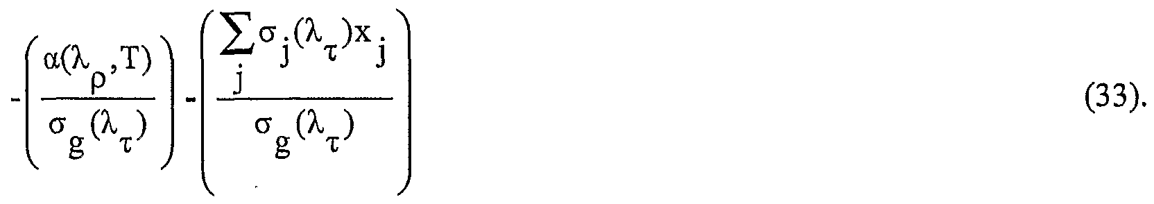
  • equation (24) may be manipulated to provide an expression for glucose concentration x g in accordance with an embodiment of the invention:
  • equation (25) is independent of intensity of target and reference light. Abso ⁇ tion cross sections and the sum term ( ⁇ .( l )x . )/ ⁇ ( ⁇ ⁇ ) are
  • an artificial implant comprising three reference layers is used as a reference region.
  • Fig. 5 schematically shows a glucometer 90 assaying glucose in a soft tissue target region 22 located in a soft tissue region 26 adjacent to a three layered reference implant 100, in accordance with an embodiment of the invention.
  • Glucometer 90 is similar to glucometers 20 and 72 and performs glucose assays by illuminating a target region 22 and implant 100 with target light and reference light.
  • implant 100 comprises a relatively thin reference layer 102 and two thicker reference layers 104 and 106.
  • Layer 102 is contiguous with target region 22 along an interface 101 and contiguous with layer 104 along an interface 103.
  • Layers 104 and 106 are contiguous along an interface 105.
  • Target and reference light wavelengths ⁇ ⁇ and ⁇ p and/or the materials from which reference layers 102, 104 and 106 are formed are determined so that the following conditions are satisfied: 1) Thin film layer 102 has a thickness substantially less than a diffusion length for heat in the material from which the layer is formed;
  • Thin film layer 102 has a photoacoustic coefficient T(Ri02) substantially less than that of target region 22, -T(T) and reference layer T(R ⁇ 04);
  • Thin film layer 102 is relatively opaque to reference light, in some embodiments of the invention absorbing more than 70% of reference light incident on the layer while in some embodiments absorbing more than 80% and optionally about 90% of incident reference light; 4) Thin film layer 102 is substantially transparent to target light;
  • Reference layer 104 is substantially transparent to both target light and reference light
  • Reference layer 106 absorbs both target and reference light; 7) A ratio between the reflectance of target light and reflectance of reference light at interface 105 is known.
  • a diffusion speed of heat in target region 22 is much larger than a diffusion speed of heat in layer 102.
  • the index of refraction of reference layer 102 is sufficiently larger than that of target region 22 so that the absolute value of a difference between the indices of refraction is much larger than changes in the absolute value of the difference due to changes in the target layer.
  • the extinction coefficient for the light in target region 22 is dependent substantially only on the abso ⁇ tion cross section for the light of a single reference analyte in the target region.
  • the reference analyte is water.
  • target wavelength is close to reference wavelength.
  • layer 102 functions as a thin film layer that does not generate photoacoustic waves by itself but functions to couple optical energy that it absorbs into material with which it is adjacent.
  • the adjacent material generates photoacoustic waves from the energy that it receives from the thin layer.
  • the coupling of optical energy by a thin layer into material adjacent to the thin layer, which adjacent material generates photoacoustic waves from the coupled energy is discussed by E.
  • a suitable material for forming thin "photoacoustic coupling layer" 102 is a material having relatively strong abso ⁇ tion at the reference wavelength and relatively weak abso ⁇ tion at the target wavelength.
  • a material having a bandgap less than the energy of a photon at wavelength ⁇ p but greater than energy of a photon at ⁇ ⁇ is optionally used to form layer 102.
  • layer 102 is optionally formed from InN having a bandgap of 0.75-0.8eV.
  • a material that absorbs optical energy in a relatively narrow energy band that includes energy of photons at wavelength ⁇ p but not energy of photons at wavelength ⁇ ⁇ is optionally used to form layer 102.
  • a material comprising an epoxy admixed with carbon nanotubes having a diameter of about 1.4nm has a narrow energy abso ⁇ tion bandwidth, which includes energy of photons at wavelength ⁇ p but does not include energy of photons at wavelength ⁇ .
  • glucometer 90 illuminates target region 22 and implant 100 with reference light
  • thin layer 102 absorbs energy from the reference light and couples a portion of the energy into target region 22.
  • target region 22 At and in the neighborhood of interface 101 target region 22 generates photoacoustic waves responsive to the coupled energy.
  • the photoacoustic waves generate a pressure P( ⁇ p,d ⁇ o ⁇ /c) at acoustic sensors 42,
  • P( ⁇ p ,d ⁇ o ⁇ /c) CQ ⁇ o ⁇ [r(T) ⁇ ( ⁇ p ,R ⁇ o2)Ip(Rl02)] (26), where, as in previous equations, Qioi s a "geometrical" proportionality constant, ⁇ ( ⁇ p,Ri Q2) i the abso ⁇ tion constant of thin layer 102 and Ip(Ri02) * s me intensity of reference light at layer 102.
  • the coefficient "C” is a coefficient that depends on thermal properties of thin layer 102.
  • pressure P( ⁇ ⁇ ,d ⁇ l/c) from photoacoustic waves stimulated by target light at interface 101 and pressures P( ⁇ p,di ()5/c) and P( ⁇ x ,d ⁇ o5/c) rom photoacoustic waves stimulated reference and target light respectively at interface 105 may be written,
  • the thermal coefficient C is absent since thin layer 102 is substantially transparent to target light (condition 4) and the thin layer is not involved in generation of photoacoustic waves at interface 105.
  • equation (28) it is noted that while thin layer 102 is highly absorbent of reference light, in accordance with an embodiment of the invention it is not totally opaque to reference light. Photoacoustic waves stimulated by reference light at interface 105 is stimulated by that relatively small portion of reference light incident on thin layer 102 that is transmitted through the thin layer.
  • intensities of reference and target light in reference layers 102, 104 and 106 of implant 100 from conditions 5 and 7 we may write,
  • Equations (25)-(30) can be used to provide a ratio, ⁇ ( ⁇ ⁇ ,T) ⁇ ( ⁇ R 102 )
  • equation (32) All factors in equation (32) are known either from pressure measurements provided by sensors 42 or from known characteristics of implant 100. For example, the last term in
  • Equation (32) y R ⁇ o2> is a function of known characteristics of implant 100. It is noted
  • I p (R 102 ) ratio is therefore known from the optical characteristics of the materials from which thin layer 102 and reference layer 104 are formed and condition 9.
  • equation (32) may be manipulated to provide an expression for glucose concentration x g in accordance with an embodiment of the invention: ⁇ g
  • equation (32) is independent of intensity of target and reference light. Abso ⁇ tion cross section ⁇ ( ⁇ p ,T) and the sum term (Y ⁇ .(l ) . )/a g ⁇ ) are
  • target and reference wavelengths are chosen so that for light at the target and reference wavelengths reflectance from an interface between the reference region and the target region or between layers in a reference region is substantially the same.
  • the reflectance at a germane interface is not substantially the same, but the relative reflectance at the interface is known.
  • appropriate expressions for concentration of glucose similar to expressions 11, 25 and 33 are used.
  • a target wavelength and a reference wavelength, of light were used to perform an assay
  • a single wavelength of light is used to assay an analyte. For example, assume that characteristics of reference region 28 (Fig.
  • Equation 12 which may be a natural reference region or an artificial implant, are such that in equation 12 the term (r(d+) ⁇ (d-(-)I ⁇ (d-
  • P( ⁇ ⁇ ,d c) -Qr(d.) (d.)I ⁇ (d.) (34), which is substantially a function only of characteristics of target region 22 near to interface 30.
  • a suitable target wavelength for performing the assay is 810 nm. At a wavelength- of 810 nm abso ⁇ tion of light in tissue is dominated by abso ⁇ tion of hemoglobin.
  • the abso ⁇ tion coefficient of hemoglobin is sufficiently larger than its scattering coefficient so that the extinction coefficient aji T) of light in target region 22 at 810 nm is substantially equal to the abso ⁇ tion coefficient of hemoglobin.
  • I ⁇ (d_) may be written I 0 exp(- ⁇ j 1 ( ⁇ ⁇ )x] 1 (d--.)d_), where I 0 is a known initial light intensity, ⁇ is the abso ⁇ tion cross section of hemoglobin at 810 nm and xh(d_) is the concentration of hemoglobin at d_ Using the expression for I ⁇ (d_) equation 34 becomes,
  • a value for Qr(d.) may be determined for target region 22 from a suitable calibration procedure.
  • concentration xh(d.) may be determined by drawing fluid, which may be blood from target region 22 and assaying hemoglobin in the fluid, by NIR reflection or using optical coherence tomography (OCT).
  • OCT optical coherence tomography
  • a subsequent measurement of P( ⁇ ⁇ ,d/c) for photoacoustic waves stimulated in target region 22 by light at target wavelength ⁇ ⁇ and the determined value for x] 1 (d.) may then be used to determine QT(d.).
  • Distance of interface 30 from point 54 and distance d. may be determined from a time at which a photoacoustic wave from interface 30 stimulated by the target light wavelength reaches sensors 42.
  • Hemoglobin in target region 22 at distance d. may thereafter be assayed by stimulating photoacoustic waves in the target region with the target light and using the value for Qr(d_) determined in the calibration procedure to solve equation (35) for Xh(d_).
  • the invention is not limited to assaying glucose, nor to assaying analytes in a living body.
  • the invention may be practiced for assaying analytes in a living body other than glucose and for assaying analytes in inanimate objects.

Abstract

A method of assaying an analyte in a body part comprising: illuminating the body part with at least one pulse of light at each of first and second wavelengths that stimulates photoacoustic waves in a first, target, region and a second, reference, region of the body part, wherein the reference region interfaces with the target region and has at least one known optoacoustic property and wherein light at the first wavelength is absorbed by the analyte; sensing pressure in the photoacoustic waves from the target and reference regions stimulated by the light at the first and second wavelengths; and using the sensed pressures and the at least one known optoacoustic property to assay the analyte in the target region.

Description

PHOTOACOUSTIC ASSAY METHOD AND APPARATUS RELATED APPLICATIONS
This application claims the benefit under 35 U.S.C. 119(e) of US Provisional Application 60/439,435 filed January 13, 2003, the disclosure of which is incorporated herein by reference.
FIELD OF THE INVENTION The invention relates to non-invasive in-vivo methods and apparatus for determining the concentration of a substance in a body.
BACKGROUND OF THE INVENTION Methods and apparatus for in-vivo and in-vitro measurements of blood glucose levels are known in the art. Generally, the methods and apparatus are relatively complicated and measurements of a person's blood glucose levels are usually performed in a clinic or laboratory with the aid of a technician. As a result costs of the measurements are relatively high. Methods and apparatus for determining blood glucose levels for use in the home, for example by a diabetic who must monitor blood glucose levels frequently, are available. These methods and associated devices are generally invasive and usually involve taking blood samples by fmger pricking. Often a diabetic must determine blood glucose levels many times daily and finger pricking is perceived as inconvenient and unpleasant. To avoid fmger pricking diabetics tend to monitor their glucose levels less frequently than is advisable.
Moreover, many conventional glucometers require routine purchasing of sample sticks and pricking needles, which is bothersome and adds cost to the user. There is a need for glucometers that are easy to use and that perform non-invasive in-vivo assays of blood sugar.
PCT Publication WO 98/38904, the disclosure of which is incorporated herein by reference, describes a "non-invasive, in-vivo glucometer" that uses a photoacoustic effect in which light energy is converted to acoustic energy to measure a person's blood glucose. Pulses of light at a wavelength for which light is absorbed by glucose is directed by the glucometer to illuminate a part of the person's body, such as a fingertip, comprising soft tissue. The light pulses are typically focused to a relatively small focal region inside the body part and light from the light pulses is absorbed by glucose in the focal region and generates photoacoustic waves that radiate out from a neighborhood of the focal region. An acoustic sensor that contacts the body part senses intensity of the photoacoustic waves, which is a function of the concentration of glucose in the region. PCT Publication WO 02/15776, the disclosure of which is incorporated herein by reference, describes locating, optionally using ultrasound, a blood vessel in the body and determining glucose concentration in a bolus of blood in the blood vessel. The glucose concentration in the blood bolus is determined by illuminating the bolus with light to generate photoacoustic waves in the bolus and sensing intensity of the generated photoacoustic waves.
Assaying an analyte in a region of body tissue using photoacoustic waves stimulated by light in the region usually involves determining an absoφtion coefficient for the analyte responsive to pressure of the photoacoustic waves and intensity of light stimulating the photoacoustic waves in the region. However, body tissue is an optically turbid medium that absorbs and scatters light as a function of concentrations of many different components in the tissue. Intensity of light transmitted into a region of body tissue, as a function of position in the region therefore depends upon both the absoφtion coefficient and the scattering coefficient for the light in the region. Furthermore, because of the relatively complicated dependence of the absoφtion and scattering coefficients on concentrations of analytes in the region, in general, at any given location in the tissue region a ratio between the absoφtion and scattering coefficients is not known. It is therefore often difficult to accurately determine intensity of the transmitted light at a given location in the region. As a result, it is often difficult to determine accurate values for the absoφtion coefficient and concentration of the analyte at the given location. SUMMARY OF THE INVENTION
An aspect of some embodiments of the present invention relates to providing apparatus and a method for assaying an analyte in a body by stimulating a photoacoustic effect in the body using light at a wavelength that is absorbed by the analyte. Hereinafter, the analyte being assayed is referred to as a "target analyte" and the wavelength of light used to stimulate the photoacoustic effect is referred to as a "target wavelength".
According to an aspect of some embodiments of the invention the target analyte is assayed in a first region of the body in a neighborhood of an interface between the first region and a second region in the body. The first and second regions are hereinafter referred to as target and reference regions respectively. In accordance with an embodiment of the invention, an interface between the target and reference regions is illuminated with at least one pulse of target light and with at least one pulse of light at a wavelength, a "reference wavelength", different from the target wavelength.
The reference region is a region for which the absoφtion coefficient for target light in the reference region relative to the absoφtion coefficient for reference light in the reference region is known during a time period for which assays of the analyte are to be performed. The reference wavelength and reference region are chosen so that reflectance of light at the target and reference wavelengths at the interface between the reference and target regions is substantially the same. Optionally, to arrange for reflectance at the target and reference wavelengths to be substantially the same, the reference wavelength is chosen to be close to the target wavelength.
In addition, in accordance with an embodiment of the invention, the reference wavelength is chosen so that, for the target region, absoφtion and scattering of the reference light is determined substantially only by concentration of a single "reference" analyte in the target region. The reference analyte is characterized by having a known absoφtion cross section for reference and target light. The reference analyte is also characterized by having a known scattering cross section for target light and/or a scattering cross section so small as to negligibly affect intensity of reference light transmitted into the target region as a function of position in the target region.
In accordance with an embodiment of the invention, a concentration of the analyte in the target region is determined as a function of a ratio between intensities of target and reference light in the target region and a known absoφtion cross section of the reference analyte. Since, in accordance with an embodiment of the invention, reflectance of the target light and the reference light at the interface are substantially the same, the "intensity ratio" in the target region is substantially equal to an intensity ratio between target and reference light in the reference region. The intensity ratio in the reference region is determined as a function of measured pressures of photoacoustic waves generated by the target and reference light at the interface and/or in the neighborhood of the interface and the known absoφtion coefficients for target and reference light in the reference region. In accordance with an embodiment of the invention, the determined intensity ratio for the reference region is used for the target region intensity ratio in the function that defines concentration of the analyte.
As a result, in accordance with an embodiment of the invention, concentration of the analyte in the target region is determined substantially independent of the intensity of target and reference light in the target region. Therefore, an assay of the analyte determined in accordance with an embodiment of the invention obviates sources of error that may affect determinations provided by prior art photoacoustic assay methods that require determining intensity of light that generates photoacoustic waves used to provide an assay. According to an aspect of some embodiments of the invention, the reference region is a region of an implant introduced into the body for which the absoφtion coefficients are known. In some embodiments of the invention the implant is a multilayer implant formed from layers of material having different optic and acoustic characteristics. Photoacoustic waves generated at and/or near an interface between the implant and the target region and at and/or near an interface between layers of the implant are used to determine concentration of an analyte
According to an aspect of some embodiments of the invention the reference region is a region of the body for which concentrations of analytes therein are substantially constant over a time period for which assays of the analyte are to be performed. Absoφtion coefficients for target and reference light in the reference region are determined by a calibration procedure. The calibration procedure is performed at a time close enough to the assay time period so that the absoφtion coefficients during the assay time period are substantially equal to the determined absoφtion coefficients. In some embodiments of the invention, the reference and target analytes are water and glucose respectively in the body of a human or animal patient. In some embodiments of the resent invention, a reference region that is a part of the patient's body is a region of bone tissue. In some embodiments of the invention the reference region in the patient is a region of keratinous tissue, connective tissue such as cartilaginous tissue or tissue in ligaments or tendons. In some embodiments of the invention an artificial implant introduced into a patient's body to provide a reference region is a "tattoo implant" that introduces a suitable reference material into and/or below the skin of a patient.
There is therefore provided, in accordance with an embodiment of the present invention, a method of assaying an analyte in a body part comprising: illuminating the body part with at least one pulse of light at each of first and second wavelengths that stimulates photoacoustic waves in a first, target, region and a second, reference, region of the body part, wherein the reference region interfaces with the target region and has at least one known optoacoustic property and wherein light at the first wavelength is absorbed and/or scattered by the analyte; sensing pressure in the photoacoustic waves from the target and reference regions stimulated by the light at the first and second wavelengths; and using the sensed pressures and the at least one known optoacoustic property to assay the analyte in the target region. Optionally, the reference region is a natural region of the body part. Optionally, the reference region is an artificial implant located in the body part.
Additionally or alternatively, using the sensed pressures optionally comprises determining a concentration of the analyte in accordance with a function dependent on the known property and having dependence on the pressures only through ratios of pressures. Optionally, dependence on ratios comprises dependence on a ratio between pressure of photoacoustic waves stimulated by light at the first wavelength and pressure of photoacoustic waves stimulated by light at the second wavelength in a same region. Additionally or alternatively, dependence on only ratios comprises dependence on a ratio between pressure of photoacoustic waves stimulated by light at the first wavelength in one of the target and reference regions and pressure of photoacoustic waves stimulated by light at the second wavelength in a different one of the target and reference regions.
In some embodiments of the present invention, sensing pressures comprises sensing pressures from photoacoustic on opposite sides of the interface sufficiently close to the interface so that a ratio of intensity of light at the first wavelength to intensity of light at the second wavelength in the target region is substantially equal to a ratio of intensity of light at the first wavelength to intensity of light at the second wavelength in the reference region.
In some embodiments of the present invention, the method comprises acquiring a value for the at least one optoacoustic property responsive to a calibration procedure comprising: acquiring at least one assay of the analyte in accordance with a method that is independent of the function; and determining a value for the known property by requiring that for each assay acquired by the independent method an assay determined in accordance with the function be substantially equal to the acquired assay.
In some embodiments of the present invention, the at least one optoacoustic property comprises a ratio between the absoφtion coefficients for light in the implant at the first and second wavelengths.
In some embodiments of the present invention, the method comprises choosing the first and second wavelengths so that at the interface between the target region and the reference region reflectance of light at the' wavelengths is substantially the same. Optionally, choosing the wavelengths comprises choosing the wavelength sufficiently close to each other so that the reflectance is substantially the same.
In some embodiments of the present invention,' the implant is a layered body comprising a plurality of contiguous layers. Optionally, the implant comprises two layers, first and second contiguous layers, which first layer interfaces with the target region. Optionally, the first layer is substantially transparent to light at the first and second wavelengths. Optionally, the second layer absorbs light at the first and second wavelengths.
The method optionally comprises choosing the first and second wavelengths so that reflectance at the interface between the target region and the first layer is substantially the same for light at the first and second wavelengths. Optionally the method comprises choosing the first and second wavelengths so that reflectance at the interface between the first and second layers is substantially the same for light at the first and second wavelengths. Optionally, choosing the wavelengths comprises choosing the wavelength sufficiently close to each other so that the reflectance is substantially the same. i some embodiments of the present invention, using the sensed pressures comprises determining a concentration of the analyte in accordance with a function dependent on the known property and having dependence on the pressures only through ratios of the pressures. Optionally, sensing pressure in photoacoustic waves comprises sensing pressure from photoacoustic waves stimulated substantially at the interface between the target region and the first layer. Optionally, sensing pressure comprises sensing pressure from photoacoustic waves stimulated substantially at the interface between the first and second layers. Optionally, dependence on ratios comprises dependence on a ratio between pressure of photoacoustic waves stimulated by light at the first wavelength and pressure of photoacoustic waves stimulated by light at the second wavelength substantially at a same interface. Dependence on pressures optionally comprises dependence on a ratio between pressure of photoacoustic waves stimulated by light at the first wavelength at one of the first and second interfaces and pressure of photoacoustic waves stimulated by light at the second wavelength in a different one of the interfaces. In some embodiments a method in accordance with the present invention comprises acquiring a value for the at least one optoacoustic property responsive to a calibration procedure comprising: acquiring at least one assay of the analyte without using the function; and determining a value for the known property by requiring that for each assay acquired by the different method an assay determined in accordance with the function be substantially equal to the acquired assay.
In some embodiments of the present invention, the at least one optoacoustic property comprises a ratio between the absoφtion coefficients for light in the implant at the first and second wavelengths. In some embodiments of the present invention, the implant comprises three layers, a first layer contiguous with the target region and a second layer contiguous with a third layer. Optionally, the first layer has a thickness substantially less than a diffusion length for heat in the material from which the first layer is formed. Optionally, the photoacoustic coefficient of the first layer is substantially less than the photoacoustic coefficient of the target region and of the second layer. Optionally, the first layer absorbs a major portion of light incident on the layer at the second wavelength. Optionally, the portion is greater than about 70%. Optionally, the portion is greater than about 80%. Optionally, the portion is greater than about 90%.
The first layer is optionally substantially transparent to light at the first wavelength. Optionally, the second layer is substantially transparent to light at both the first and second wavelengths. The third layer optionally absorbs light at both the first and second wavelengths. Optionally, reflectance for light at the first and second wavelengths at the interface between the second and third layers is substantially the same. Optionally, choosing the wavelengths comprises choosing the wavelength sufficiently close to each other so that the reflectance is substantially the same.
In some embodiments of the present invention, using the sensed pressure comprises determining a concentration of the analyte in accordance with a function dependent on the known property and having dependence on the pressures only through ratios of the pressures. In some embodiments of the present invention, sensing pressure in photoacoustic waves comprises sensing pressure from photoacoustic waves stimulated substantially at the interface between the target region and the first layer and at least one interface between the layers.
In some embodiments of the present invention, sensing pressure from photoacoustic waves stimulated substantially at the interface between at least one interface between the layers comprises sensing pressure from photoacoustic waves stimulated substantially at the interface between the second and third layers. Optionally, dependence on ratios comprises dependence on a ratio between pressure of photoacoustic waves stimulated by light at the first wavelength and pressure of photoacoustic waves stimulated by light at the second wavelength substantially at a same at least one interface. Optionally, the at least one interface comprises the interface between the target region and the first layer. Additionally or alternatively the at least one interface optionally comprises the interface between the second and third layers. Optionally, the function is dependent upon a ratio between the absoφtion coefficient for light at the first and second wavelengths in the third layer. some embodiments of the present invention, the function is dependent upon a ratio between intensity of light at the second wavelength in the first layer and near to the interface between the first layer and the target region and intensity of light at the second wavelength in the second layer near to the interface between the first and second layers. In some embodiments of the present invention, dependence on pressures comprises dependence on a ratio between pressure of photoacoustic waves stimulated by light at the first wavelength at one of the interface between the target region and the first layer and the interface between the second and third layers and pressure of photoacoustic waves stimulated
"' by light at the second wavelength in the other of the interfaces. In some embodiments of the present invention, the method comprises acquiring a value for the at least one optoacoustic property responsive to a calibration , procedure comprising: acquiring at least one assay of the analyte without using the function; and determining a value for the known property by requiring that for each assay acquired by the different method an assay determined in accordance with the function be substantially equal to the acquired assay.
In some embodiments of the present invention, the at least one optoacoustic property comprises a ratio between the absoφtion coefficients for light in the implant at the first and second wavelengths.
In some embodiments of the present invention, the function is dependent on a parameter that is a function of concentrations of analytes in the target region other than the target analyte, and comprising determining a value for the parameter, which value is used in the function for determining concentrations of the target analyte at least twice during a period of time for which the parameter is considered to be constant.
Optionally, the time period is less than or equal to about an hour. Optionally, the time period is less than or equal to about 8 hours. Optionally, the time period is less than or equal to about 24 hours.
In some embodiments of the present invention, the method comprises choosing the second wavelength so that absoφtion and scattering of light in the target region is a function substantially only of a concentration of a single particular analyte in the target region and an absoφtion and/or a scattering cross section of the particular analyte.
Optionally, the extinction coefficient for light in the target region at the second wavelength is a function substantially only of the concentration and absoφtion cross section of the particular analyte. Additionally or alternatively, for the second wavelength, a ratio between the absoφtion and scattering cross sections in the target region is known. In some embodiments of the present invention, the particular analyte is water.
In some embodiments of the present invention, the body is a living body. In some embodiments of the present invention, the analyte is glucose. There is further provided in accordance with an embodiment of the present invention, a method of assaying an analyte in a body part comprising: illuminating the body part with at least one pulse of light that is absorbed and/or scattered by the analyte and stimulates photoacoustic waves in a first, target, region and a second, reference, region of the body part, wherein the reference region interfaces with the target region and has at least one known optoacoustic property; sensing pressure in the photoacoustic waves from the target and reference regions stimulated by the light; and using the sensed pressures and the at least one known optoacoustic property to assay the analyte in the target region.
Optionally, the reference region is a natural region of the body part. Optionally, the reference region is an artificial implant located in the body part. BRIEF DESCRIPTION OF FIGURES
Non-limiting examples of embodiments of the invention are described below with reference to figures attached hereto. In the figures, identical structures, elements or parts that appear in more than one figure are generally labeled with the same numeral in all the figures in which they appear. Dimensions of components and features shown in the figures are chosen for convenience and clarity of presentation and are not necessarily shown to scale. The figures are listed below.
Fig. 1 schematically shows an assay apparatus assaying glucose in a region of a patient's body, in accordance with an embodiment of the present invention;
Fig. 2 shows a schematic graph of pressure indicative of that sensed by acoustic sensors in the assay apparatus shown in Fig. 1 responsive to a pulse of target light that illuminates the region of the patients body, in accordance with an embodiment of the present invention;
Fig. 3 schematically shows an assay apparatus assaying glucose in a region of a patient's body having a multilayer implant as a reference region, in accordance with an embodiment of the present invention;
Fig. 4 shows a graph of pressure indicative of pressure sensed by acoustic sensors in the assay apparatus shown in Fig. 3 responsive to a pulse of target light that illuminates the region of the patient's body, in accordance with an embodiment of the present invention; and Fig. 5 schematically shows an assay apparatus assaying glucose in a region of a patient's body having a three layer implant as a reference region, in accordance with an embodiment of the present invention.
DETAILED DESCRIPTION OF EXEMPLARY EMBODIMENTS Fig. 1 schematically shows an assay apparatus 20, hereinafter referred to as a
"glucometer", assaying glucose in a target region 22 of a body part 24 of a patient, in accordance with an embodiment of the invention. Target region 22 is optionally located in a region 26 of soft tissue of body part 24 and comprises a body fluid, such as for example interstitial fluid, having a concentration of glucose. Optionally, target region 22 is a volume of body fluid having a concentration of glucose and region 26 is a region of a fluid cavity containing the body fluid. For example, the body fluid may be blood and the fluid cavity a blood vessel. Target region 22 is adjacent to an artificial implant 28 that functions as a reference region for assaying glucose, in accordance with an embodiment of the invention. For a case in which the body fluid is blood and the fluid cavity a blood vessel, target region 26, implant 28 may be a small implant fixed to the wall of the blood vessel or a region of a stent.
Glucometer 20 optionally comprises a controller 32, a light source 34, optionally located in the controller, and an optic fiber 36 coupled to the light source. An end 38 of fiber 36 is optionally mounted to a support structure 40, hereinafter a "probe head", to which an acoustic sensor or array of acoustic sensors is mounted. Any of various appropriate acoustic sensors or array of detectors may be used in the practice of the invention. By way of example, in Fig. 1 probe head 40 has an array of acoustic sensors 42 positioned circumferentially around end 38 of optic fiber 36. Only two sensors of the array are shown. Probe head 40 is pressed to skin 44 of body part 24 to position end 38 of fiber 36 close to or contiguous with the body part and acoustically couple acoustic sensors 42 to the body part.
Artificial implant 28 is formed from a material for which optical and acoustic properties, such as the absoφtion coefficients for light at suitable target and reference wavelengths and acoustic attenuation, are known or may be determined from a calibration procedure as discussed below. A suitable artificial body, in accordance with an embodiment of the invention, may be a small plastic "splinter" introduced and anchored beneath the skin or a tattoo that introduces a suitable material under the skin. Target region 22 and reference region 28 (i.e. artificial implant 28) are contiguous along an interface 30. To determine glucose concentration in target region 22, controller 32 controls light source 34 to illuminate body part 24 with at least one pulse of light at a first wavelength, a target wavelength "λτ", and at least one pulse of light at a second reference wavelength "λp". The at least one pulse of light (either target or reference light) is schematically represented in Fig. 1 by wavy arrows 50. The target and reference wavelengths λτ and λp are chosen so that glucose absorbs light at the target wavelength and reflectance of light from interface 30 at the target and reference wavelengths is substantially the same. In addition, reference wavelength λp is chosen so that for target region 22, absoφtion and scattering of the reference light is determined substantially only by concentration of a single "reference" analyte in the body. Optionally, target wavelength λτ is chosen so that glucose absorbs light at the. target wavelength strongly. Optionally, the target wavelength is a wavelength at which the absoφtion cross-section of glucose peaks. Optionally, the target wavelength has minimal cross talk with the absoφtion bandwidth of other species or analytes in the solution. Optionally, for light at reference wavelength λp, the scattering cross-section of the reference analyte is substantially smaller than the absoφtion cross-section of the reference analyte. Additionally or alternatively the scattering cross-section is known relative to the absoφtion cross-section.
A suitable reference analyte for determining glucose concentration in accordance with an embodiment of the invention is water, and suitable target and reference wavelengths λτ and λp are 1650 nm and 1440 nm respectively. Wavelength 1650 is a wavelength at which the absoφtion wavelength of glucose has a large peak. Water is the largest component of soft tissue and at 1440 nm the absoφtion cross-section of water has a large peak, which is more than about 100 times larger than the scattering cross-section of water at 1440 nm. At 1440 nm therefore the absoφtion cross-section of water dominates attenuation of light propagating in soft tissue.
The at least one pulse of light at target wavelength λτ and at least one pulse of light at reference wavelength λp that glucometer 20 transmits to illuminate body part 24 stimulate photoacoustic waves in soft tissue region 26, target region 22 and in reference region 28. In Fig. 1 the photoacoustic waves generated by at least one light pulse 50 are schematically represented by starbursts 52. Acoustic energy from photoacoustic waves 52 is incident on sensors 42, which generate signals responsive to pressure generated on the sensors by the incident acoustic energy. The signals are transmitted to controller 32, which processes the signals in accordance with an embodiment of the invention, as described below, to determine glucose concentration in target region 22.
In some embodiments of the invention the at least one pulse of target light and at least one pulse of reference light are transmitted at different times to illuminate target region 22 and reference region 28. In some embodiments of the invention the at least one pulse comprises a train of pulses. In some embodiments of the invention the pulses in the train of target light pulses are transmitted at a different pulse repetition rate than a repetition rate at which pulses in the reference light pulse train are transmitted. Optionally, the target and reference light pulse trains are transmitted simultaneously. Signals generated by acoustic sensors 42 responsive to photoacoustic waves 52 generated responsive to the target light pulse train and reference light pulse train are distinguished using signal processing techniques known in the art, such as appropriate heterodyning and phase locking techniques.
Let the absoφtion cross-sections of glucose for light at the target and reference wavelengths be represented by σgτ) and σg(λp) respectively. Assume that the glucose concentration is substantially the same for all locations in target region 22 and let the glucose concentration be represented by xg. Similarly, let the absoφtion cross-sections of water for light at the target and reference wavelengths be represented by σwτ) and σw(λp) respectively. Let the concentration of water in target region 22, which is assumed to be substantially the same for all locations in the target region, be represented by xw. Glucose and water are of course not the only analytes in body part 24. Let the concentration in target region 22 of a "j-th" analyte other than glucose or water be represented by xj and let absoφtion cross-sections of the j-th analyte for light at the target and reference wavelengths be represented by σj(λτ) and σj(λp) respectively. Concentrations of the other analytes in target region 22 that absorb light at the target and reference wavelengths and generate photoacoustic waves in the target region are assumed to be substantially the same for all locations in the target region.
Assume that light pulse 50 shown in Fig. 1 is a pulse of target light and that photoacoustic waves 52 are generated by the target light pulse. Pressure sensed by acoustic sensors 42 responsive to photoacoustic waves 52 is time dependent. Pressure sensed at a time "t" following a time at which light pulse 50 illuminates body part 24 arises from photoacoustic waves generated at locations in the body part for which distance from acoustic sensors 42 is substantially equal to ct, where c is the speed of sound. Let a location in body part 24 be determined relative to a coordinate system having an origin at a point 54 at which light from optic fiber 36 enters the body part. Let the pressure sensed by acoustic sensors 42 at time t responsive to a pulse of target light 50 that illuminates body part 24 be represented by Pττ,t). Then for photoacoustic waves generated at locations in target region 22 at a distance dj; from entry point 54, Pττ,t) can be written:
Pττ,t) = Pττ,dT/c) = Kα(λτ,T)Iτ(dτ) (1)
In the expression for Pτ(t), α(λτ,T) is an absoφtion coefficient at which material in target region 22 absorbs energy from target light, K is a proportionality coefficient and Iτ(dτ/) is intensity of light pulse 50 at distance dj; from probe head 40. K incoφorates inter alia geometrical factors arising from the spread of light pulse 50 with distance from entry point 54, attenuation of photoacoustic waves propagated in soft tissue region 26 through a distance d and thermal and acoustic properties of the tissue conventionally included in a thermoacoustic efficiency coefficient. The thermoacoustic efficiency coefficient of a material, usually represented by T, is equal to c2β/Cp, where β is the thermal expansion coefficient of the material and Cp is the heat capacity of the material. Expressing the absoφtion coefficient α(λτ,T) in target region 22 explicitly as a function of the absoφtion cross-sections and concentrations of the analytes in target region 22, α(λτ,T) = σgτ)xgwτ)xw+ ∑ σ ^ (λ . )x . (2) j and equation 1 can be rewritten,
P(λτ,dT/c) = K [σgτ)xgwτ)xw+∑σ .(λχ)x . ]Iτ(dT). (3) j
An equation similar to equation (1) may be written for pressure P(λp,t) generated at sensors 42 by photoacoustic waves 52 stimulated in target region 22 by a pulse of reference light 50 (light pulse 50 represents either target or reference light).
Pτp,t) = Pτp,dT/c) = Kα(λp,T)Ip(dτ) (4) In equation (4) Ip(dj/) is intensity of light in reference light pulse 50 at distance d from probe head 40, and oc(λp,T) is an absoφtion coefficient for reference light in target regions 22, which is assumed to be dependent substantially only on the concentration, xw of water in the target region and the absoφtion cross section, σw(λp), of water for reference light.
It is noted that in writing equation (4) it has been tacitly assumed that the coefficient K has a same value for both target and reference light. In accordance with an embodiment of the present invention, to provide that K has a same value for target and reference wavelengths, light pulses 50 of both target and reference light are formed so that areas of interface 30 that they respectively illuminate are substantially congruent and/or have dimensions small compared to distance D. To an extent that the illuminated areas of interface 30 are congruent and or small relative to D, the geometrical factor K is substantially the same for both wavelengths.
Expressing α(λp,T) in terms of the absoφtion cross-section and concentration of water in target region 22, α(λp,T) = σwp)xw (5) and
P(λp,dτ/c) = K[σw(λp)xw]Ip(dτ) (6).
Equations (3) and (6) may be algebraically manipulated to provide an expression fo. glucose concentration xg at distance &γ in target region 22 in which,
Figure imgf000016_0001
It is noted that the expression for xg is dependent on the absoφtion coefficient (λp,T) of water in target region 22, a ratio Ip(dτ/)/Iτ(dχ) and the sum ^σ .(λ )x . . The
expression is independent of the proportionality coefficient K and cross sections σwτ) and σw(λp) are known.
In accordance with an embodiment of the invention, a value for Ip(dχ)/Iτ(d' ) is provided by acquiring measurements of P(λτ,t) and P(λp,t) for a distance dR (i.e. t = dR/c) in reference region 28. Pressure P(λτ,t) from photoacoustic waves stimulated by target light pulse 50 for distance dR may be written,
P(λτ,t) = P(λτ,dR/c) = K* (λτ,R)Iτ(dR) (8)
Similarly, pressure P(λp,t) from photoacoustic waves stimulated by a reference light pulse 50 for the distance dR may be written
P(λp,t) = P(λp,dR/c) = K* (λp,R)Ip(dR). (9). In equations (8), and (9) (λτ,R) and (λp,R) are the absoφtion coefficients for target light λτ and reference light λp respectively in reference region 28 and K* is a proportionality coefficient (which is generally different from K).
In accordance with an embodiment of the invention, the ratio Ip(d )/Iτ(dτ) is determined from a ratio Ip(dR)/Iτ(dp determined for reference region 28 from measurements of P^,dR/c) and P(λp,dR/c). In particular, from equations (8) and (9)
Ip(dR)/Iτ(dR) = [P(λp,dR/c)/P(λτ,dR/c)][ (λτ,R)/ (λp,R)] (10)
In accordance with an embodiment of the invention, distance dp and dR are determined to be close to a distance D from entry point 54 at which interface 30 is located. In some embodiments of the invention d- = (D - Δd) and dR = (D + Δd), where Δd is equal to the spatial resolution for locating sources of photoacoustic waves provided by acoustic sensors 42. Distances d- = (D - Δd) and dR = (D + Δd) are shown in Fig. 1.
Location D of interface 30 may be determined from the photoacoustic response of. body region 24 to illumination with target light pulse 50 (or a reference light pulse 50). At interface 30 concentrations of the analytes exhibit discontinuities and change rapidly over relatively small distances. The relatively large changes in analyte concentrations with distance at interface 30 generate relatively intense photoacoustic waves at the interface and its immediate neighborhood when the interface is illuminated by a pulse of target or reference light 50. The intense photoacoustic waves mark the location of the interface.
Since d^ and dR are close to each other and since reflectance (and as a result transmittance) of light for target and reference wavelengths λτ and λp at interface 30 are substantially equal, the ratio Ip(d' )/Iτ(dχ) in equation (7) is substantially equal to the ratio Ip(dR)/Iτ(dR)- Substituting the expression for the reference ratio Ip(d )/Iτ(d ) given in equation (10) for Ip(dτ)/Iχ(dτ/) in equation (7) provides an expression for xg,
Figure imgf000017_0002
Figure imgf000017_0001
Equation (11) determines glucose concentration xg as a function of pressures P^,t) and P(λp,t) sensed by acoustic sensors 42 resulting from photoacoustic waves generated in body part 24 by target and reference light pulses 50 at times corresponding to distances dj and d . The equation is substantially independent of intensities of target and reference light. Fig. 2 shows a schematic graph 60 indicative of pressure sensed by acoustic sensors 42 as a function of time from photoacoustic waves generated by a target light pulse 50 that illuminates body part 24. Times corresponding to distances d = (D - Δd) and dR = (D + Δd) are indicated on the graph. Light pulse 50 is assumed to be transmitted into body part 24 at time t = 0. Pressure P(λτ,t) sensed by sensors 42 is indicated in arbitrary units along the ordinate. The general shape of curves representing time dependent pressure sensed by acoustic sensors 42 is similar for photoacoustic waves generated by a pulse of target light and by a pulse of reference light. Graph 60 is assumed to represent pressure responsive to a pulse of target light by way of example for illustrative puφoses.
Concentration xg in equation (11) is also a function of absoφtion coefficients (λp,T), oc(λτ,R) and (λp,R). These coefficients may be evaluated from the shape of time dependent pressure sensed by acoustic sensors 42 and graph 60 is also useful in discussing evaluation of these coefficients. Coefficients oc^,R) and α(λp,R) may also be known from known characteristics of material from which reference region 28 is formed.
Acoustic energy from photoacoustic waves generated by light pulse 50 is first incident on sensors 42, generally with relatively large and rapid changes in pressure, at about a time t\ from tissue voxels in an immediate neighborhood of skin 44. The skin is an interface surface at which concentrations of analytes in body part 24 exhibit large discontinuities relative to their concentrations outside the body. Time t\ is substantially coincident with time t = 0 because, as is shown in Fig. 1, end 38 of fiber 36 and acoustic sensors 42 are substantially contiguous with surface 50. Separation of time t\ from the time origin of graph 60 is exaggerated for convenience of presentation.
Following the rapid pressure changes that occur at about ti , pressure P(λτ,t) decreases until about a time t2 in accordance with equation (1) as intensity Iτ(d) of light pulse 50 decreases with distance d that the light pulse penetrates body part 24. At time t2, relatively large and rapid changes are again sensed by sensors 43 as acoustic energy from photoacoustic waves generated at interface 30, which is located at distance D from. entry point 54, reaches the sensors. The decrease in Iτ(d) is substantially exponential with distance d as light from light pulse 50 is absorbed and scattered by the material in soft tissue region 26. The rate of decrease of Iτ(d) with d is determined by an "extinction" coefficient which is a function of the absoφtion coefficient and a reduced scattering coefficient of light at target wavelength λτ. The reduced scattering coefficient for light at a given wavelength is equal to the scattering coefficient of the light corrected for angular anisotropy in scattering of the light. If αs is the scattering coefficient and 's the reduced scattering coefficient, then α's is conventionally written as α's = (l-g)αs. In the expression for α's, g is a function of the anisotropy and is a number greater than or equal to 0 and less than 1. Assume, by way of example, that the absoφtion coefficient in soft tissue region 26 is substantially equal to the absoφtion coefficient α(λτ,T) in target region 22 for all locations in the soft tissue region. Let α'sτ T) represent the reduced scattering coefficient and let β(λτ T) represent the extinction coefficient for light of wavelength λ^ in soft tissue region 26. For distances d from entry point 54 greater than about two mean free paths of photons having wavelength -^ in target region 26, aiβ(λτ,T) may be approximated by the expression αg(λτ,T =
/3 α(λ T)(α(λ T) + αc,(λ )) and Iτ(d) = IOTe p(-0-E^ T)d), where I is a constant.
( X X X ' g(λτ,T) can be determined from a rate of decrease of P(^,t) determined from measurements of P(λτ,t) acquired for a plurality of distances d (i.e. corresponding times t) in soft tissue region 26. However, it is generally not possible to determine (λτ,T) from such measurements since generally s,(λτ,T) is not known. Whereas a value for the target light absoφtion coefficient (λτ,T) in target region 22 is not required to determine xg from equation (11), a value for the reference absoφtion coefficient α(λp,T) in target region 22 is required. And while it is generally not possible to determine α(λτ,T) from a rate of decrease of P(λp,t) with distance in target region 22 it is possible to determine α(λp,T) from a rate of decrease of P(λp,t) with distance in the target region 22.
As noted above, in accordance with an embodiment of the invention, reference light λ is chosen so that the scattering coefficient for the reference light in target region 22 is substantially smaller than the absoφtion coefficient and/or the scattering coefficient is known. As a result, o.E(λp,T) = (λp,T) and the absoφtion coefficient for reference light λp in target region 22 may be determined from the extinction coefficient for reference light in the target region, which in turn may be determined from a rate of decrease of P(λp,t) in the target region.
In addition to determining a value for (λp,T), a value a value for
Figure imgf000020_0001
the sum must be determined to determine glucose
Figure imgf000020_0002
concentration xg from equation (11) (the cross section σ (λτ) is known). In some
embodiments of the invention, known from characteristics of material from
Figure imgf000020_0003
which artificial implant 28 is formed. In some embodiments of the invention,
Figure imgf000020_0004
determined in a calibration procedure such as the calibration procedure used to determine the sum ∑σ ,(λ )x . discussed below j
J Concentration of glucose in soft tissue such as tissue region 26 is relatively labile and can exhibit substantial changes during the course of a day. Concentrations of other analytes in soft tissue region 26 on the other hand generally change relatively slowly and during the course of a day may exhibit little if any change. Once the sum ∑ σ . (λ ) . is determined it is j expected to be substantially the same over a period of time, such as for example a day, during which it may be, and usually is, desired to acquire repeated glucose assays for a patient.
Therefore, in accordance with an embodiment of the invention, the sum ∑σ .( l )x . is j determined in a calibration procedure and is considered to be a known constant for a plurality of glucose assays performed over some period of t ne for which glucose of a patient is to be assayed. For example, assume that glucometer 20 is being used by a diabetes patient who must assay his or her glucose many times during the day. In accordance with an embodiment of the invention, the sum Y σ .(-l )x . is determined by performing, optionally in the morning, a
J τ J J calibration procedure for glucometer 20. The sum is stored in controller 32 and thereafter used during the rest of the day by the controller for determining the patient's glucose concentration whenever glucometer 20 is used to assay the patient's glucose. . In a calibration procedure for glucometer 20, in accordance with an embodiment of the invention, a calibration value "xg*" for glucose concentration in a target region of a patient's body part is determined independently of a determination provided by glucometer 20. The calibration value for xg* may be determined using any conventional method for assaying glucose. For example, xg* may be determined by drawing blood from the patient by finger pricking or by collecting interstitial fluid and conventionally assaying glucose in the blood or interstitial fluid.
In addition, controller 32 controls light source 34 to illuminate body part 24 with at least one pulse of target light 50 and at least one pulse of reference light 50. A sufficient number of values for each of P(λτ,d/c) and P(λp,d/c) are determined from signals generated by sensors 42 responsive to photoacoustic waves stimulated by the light pulses to provide from equation (11) at least two independent equations for xg having as unknowns the
variables The two equations are then solved for the variables
Figure imgf000021_0001
the calibration value xg* for xg.
Figure imgf000021_0002
Whereas, in the above example reference region 28 in body part 24 is an artificial implant, in some embodiments of the invention, a "natural" re"gion of the body for which analyte concentrations are relatively stable is used as a reference region. For example, a region of bone tissue that interfaces with a region of soft tissue for which glucose concentration is to be determined may be used as a reference region. In some embodiments of the invention the reference region in the patient is a region of keratinous tissue, connective tissue such as cartilaginous tissue or tissue in ligaments or tendons.
In some embodiments of the invention, an artificial implant comprising a plurality of layers, each formed from a different material is used as a reference .region. Fig. 3 schematically shows an exemplary artificial implant 70 being used for a reference region for a soft tissue target region 26 of a body for which glucose is being assayed by a glucometer 72, in accordance with an embodiment of the invention. Implant 70 optionally comprises first and second "reference" layers 74 and 76 respectively that are contiguous along an interface 75. Implant 70 interfaces with soft tissue region 22 along an interface 78. Glucometer 72 is similar to glucometer 20 shown in Fig. 1.
As in the assay performed by glucometer 20 shown in Fig. 1, glucometer 72 illuminates target region 22 and reference region 70 (implant 70) with at least one pulse 50 of target light at a wavelength λτ and at least one pulse 50 of reference light at a wavelength λp. Target and reference light stimulate photoacoustic waves represented by starbursts 52 in target region 22 and in artificial implant 70.
In accordance with an embodiment of the invention, target and reference wavelengths and materials from which reference layers 74 and 76 are formed are determined so that layer 74 is substantially transparent to target and reference light and layer 76 absorbs both target and reference light. The materials and wavelengths are also determined so that reflectances of target light at interfaces 78 and 75 are substantially equal to reflectances of reference light at the respective interfaces. Optionally, to satisfy the above conditions target and reference wavelengths are chosen so that they are close to each other.
Target wavelength λτ is optionally chosen so that glucose absorbs light at the target wavelength strongly. For example, the target wavelength may be a wavelength at which the absoφtion cross-section of glucose peaks. Optionally, for light at reference wavelength λp, the extinction coefficient for the light in target region 22 is dependent substantially only on the absoφtion cross section for the light of a single reference analyte in the target region. Optionally, the reference analyte is water.
In accordance with an embodiment of the invention, pressures sensed by acoustic sensors 42 from "interface" photoacoustic waves stimulated at interface 78 and interface 75 by reference light and target light are processed by controller 32 to assay glucose in target region 22. This is unlike the assay performed by glucometer 20, in which pressure from photoacoustic waves originating at locations displaced from interface 30 of soft tissue region 26 and reference region 28 are used to determine glucose concentration. Fig. 4 shows a graph 80 schematically representing time dependence of pressure sensed by acoustic sensors 42 resulting from photoacoustic waves stimulated by a pulse 50 of target light or a pulse 50 of reference light. As noted above in the discussion of Fig. 2, the time dependence of pressure sensed by sensors 42 is similar for target light and reference light. And as in the above discussion, for convenience of presentation, it is assumed hereinafter that graph 80 shows time dependence of sensed pressure resulting from photoacoustic waves stimulated by target light. Relatively large and rapidly changing pressure is sensed by sensors 42 at and at times close to times t\, _>- and t3- Time t\ corresponds to a time at which acoustic energy is incident on sensors 42 from tissue voxels in an immediate neighborhood of skin 44. Time t2 corresponds to a time at which acoustic energy is incident on sensors 42 from photoacoustic waves generated at and in a neighborhood of interface 78 between soft tissue region 22 and implant 70. Time -3 corresponds to pressure from photoacoustic waves generated at and in a neighborhood of interface 75 between layers 74 and 76. If the distances at which interfaces 75 and 78 are located relative to entry point 54 are represented by dη$ and d g, then t2 --- d g/c and t3 --- η^lz.
The expressions for t2 and t3 assume that the speed of sound in layer 74 is substantially equal to the speed of sound in tissue region 26. If this is not the case, known characteristics of layer 74 may be used to estimate a value for t3. However, it is noted that exact values for the times t2 and t3 are not required in order to provide a value for glucose concentration xg, in accordance with an embodiment of the invention. Pressure sensed by sensors 42 responsive to photoacoustic waves originating at and in neighborhoods of interfaces 75 and 78 is indicated by the distinctive form of the time dependence of pressure from these photoacoustic waves. The correspondence between times t2 and t3 with distances dyg and dy5/c are shown in graph 80.
Between times t\ and -2, following the relatively large and rapidly changing pressure excursions sensed by sensors 42 at and at times close to time \\, pressure sensed by the sensors decreases as acoustic energy from photoacoustic waves reach the sensors from distances farther from entry point 54. (Since intensity of target light decreases with distance from entry point 54, unless there is a substantial change in concentration of an analyte that absorbs the target light, such as occurs at an interface, intensity of photoacoustic waves stimulated by the light decreases with distance from the entry point.) Between the relatively large pressure excursions at, and at times close to, times t2 and t3, sensed pressure is relatively weak as acoustic energy reaches the sensors from reference region 74, which is substantially transparent to target and reference light. Pressure of a photoacoustic wave generated by a pulse 50 of target light at a distance d from entry point 54 is substantially proportional to a first derivative with respect to d of energy absorbed from the light pulse by material at location d. Therefore, for an interface located at a distance d from entry point 54, pressure P(λτ,d/c) sensed by sensors 42 at time t = d/c from a photoacoustic wave generated at the interface may be expressed by the following equation,
P(λτ,d/c) = Q(r(d+)α(d+)Iτ(d+) - (r(d.)α(d.)Iτ(d.)) (12)
In equation (12), d+ and d. are distances from entry point 54, which are slightly greater than and slightly less than d respectively. A difference (d+- d.) is a distance over which parameters and analytes that characterize material on one side of the interface change to parameters and analytes that characterize material on the other side of the interface. The distance (d+- d.) may be considered a characteristic distance of the interface that defines a thickness of the interface. The thermoacoustic coefficient T discussed above and included in the constant of proportionality K in preceding equations (e.g. equations 1 and 3) is explicitly written in equation 12 and parameters r(d+) and r(d.) are thermoacoustic coefficients for material at locations d+ and d. respectively. Similarly, -α(d+) and α(d_) are absoφtion coefficients of material at d+ and d_ respectively and Iτ(d+) and Iχ(d_) are intensities of target light at d+ and d_ respectively. The constant Q is a proportionality constant that includes factors in the proportionality constant K that are not accounted for by the thermoacoustic coefficient, i.e. geometrical factors that determine an amount of acoustic energy that reaches sensors 42 from the photoacoustic wave generated at distance d. Q also includes a factor l/(d+- d_).
Modifying equation (12) to express pressures P(λτ,d7g/c) and P(λτ,d75/c) sensed by sensors 42 from photoacoustic waves stimulated by target light at and in the neighborhood of interfaces 75 and 78 respectively we have:
P(λτ,d78/c) = Q78[r(R74) (λτ,R74)Iτ(R74) - T(T)α(λτ,T)Iτ(T)] (13)
P(λτ,d75/c) = Q75[r(R76)α(λτ,R76)Iτ(R76) - r(R74) (λτ,R74)Iτ(R74)] (14)
In equation (13): Q_7g is the proportionality constant for interface 78; T(R74) is the photoacoustic coupling constant for material in layer 74; oc(λτ,R74) is the absoφtion coefficient of material in reference layer 74 for light at target wavelength λτ; and Iχ(R74) is intensity of target light in reference layer 74 close to interface 78. Similarly: -T(T) is the thermoacoustic coefficient for target region 22; α (λτ,T) is the absoφtion coefficient for target light in the target region; and Iτ(T) is the intensity of target light in the target region close to interface 78. In equation (14), symbols corresponding to symbols in equation (13), but which are subscripted with the numeral 76, refer to reference layer 76.
Equations similar to equation (13) and (14) may be written for reference light, P(λp,d78/c) = Q78[r(R74) (λp)R74)Ip(R74) - r(T)α(λp,T)Ip(T)] (15)
P(λp,d75/c) = Q75[r(R76) (λp,R76)Ip(R76) - r(R74)α(λp,R74)Ip(R74)] (16)
Since, in accordance with an embodiment of the invention, layer 74 is substantially transparent to target and reference light, the absoφtion coefficients (λτ,R74) and (λp,R74) are substantially equal to zero or sufficiently small so that the terms in equations (13)-(16) containing the absoφtion coefficients maybe neglected. Equations (13)-(16) then reduce to, P(λτ,d7g/c) = -Q7g[r(T) (λτ,T)Iτ(T)] (17)
P(λτ,d75/c) = Q75[r(R76)α(λτ,R76)Iτ(R76)] (18)
P(λp,d78/c) = -Q7g[r(T) (λp,T)Ip(T)] (19)
P(λp,d75/c) = Q75[r(R76) (λp,R76)Ip(R76)] (20)
Equations (17) and (19) can be manipulated to provide a ratio, (λτ,T)/ (λp,T) = [P(λτ,d78/c)/P(λp,d78/c)] [Ip(T)/τ(T)] (21) and equations (18) and (20) can be manipulated to provide a ratio,
Ip(R76)/Ix(R76) = [P(λp,d75/c)/P(λτ,d75/c)] [α(λτ,R76)/α(λp,R76)] (22).
Since, in accordance with an embodiment of the invention, the target and reference wavelengths are additionally determined so that reflectances of target light at interfaces 78 and 75 are substantially the same as reflectances of reference light at interfaces 78 and 75 respectively,
Ip(R76)/Iχ(R76) ≡ Ip(R74) Iτ(R74) = Ip(T)/Iτ(T). (23)
Using the results of equation (23) and replacing the ratio Ip(T)/Iτ(T) in equation (21) with expression for Iτ(R76)/Ip(R76) from equation (22) yields an expression, flyT) P(λτ,d7g /c) P(λ p' d 7755 /c)Vα(λ ,R ^76 ) (24). α(λp,T) P(Vd78 /c> P(λχ,d75 /c) α(λ R?6)
Using the explicit expressions for absoφtion coefficients α(λτ,T) and α(λp,T) given respectively in equation (2) and (5) above, equation (24) may be manipulated to provide an expression for glucose concentration xg in accordance with an embodiment of the invention:
Figure imgf000026_0001
As in the case of equation (11), equation (25) is independent of intensity of target and reference light. Absoφtion cross sections and the sum term (∑σ .( l )x . )/σ (λτ) are
J τ J J evaluated, in accordance with an embodiment of the invention, as discussed above for the case of the assay performed by glucometer 20.
In some embodiments of the invention, an artificial implant comprising three reference layers is used as a reference region. Fig. 5 schematically shows a glucometer 90 assaying glucose in a soft tissue target region 22 located in a soft tissue region 26 adjacent to a three layered reference implant 100, in accordance with an embodiment of the invention.
Glucometer 90 is similar to glucometers 20 and 72 and performs glucose assays by illuminating a target region 22 and implant 100 with target light and reference light.
In accordance with an embodiment of the invention, implant 100 comprises a relatively thin reference layer 102 and two thicker reference layers 104 and 106. Layer 102 is contiguous with target region 22 along an interface 101 and contiguous with layer 104 along an interface 103. Layers 104 and 106 are contiguous along an interface 105.
Target and reference light wavelengths λτ and λp and/or the materials from which reference layers 102, 104 and 106 are formed are determined so that the following conditions are satisfied: 1) Thin film layer 102 has a thickness substantially less than a diffusion length for heat in the material from which the layer is formed;
2) Thin film layer 102 has a photoacoustic coefficient T(Ri02) substantially less than that of target region 22, -T(T) and reference layer T(Rι 04);
3) Thin film layer 102 is relatively opaque to reference light, in some embodiments of the invention absorbing more than 70% of reference light incident on the layer while in some embodiments absorbing more than 80% and optionally about 90% of incident reference light; 4) Thin film layer 102 is substantially transparent to target light;
5) Reference layer 104 is substantially transparent to both target light and reference light;
6) Reference layer 106 absorbs both target and reference light; 7) A ratio between the reflectance of target light and reflectance of reference light at interface 105 is known.
8) A diffusion speed of heat in target region 22 is much larger than a diffusion speed of heat in layer 102.
9) The index of refraction of reference layer 102 is sufficiently larger than that of target region 22 so that the absolute value of a difference between the indices of refraction is much larger than changes in the absolute value of the difference due to changes in the target layer.
As in glucose assays performed by glucometers 20 and 72, optionally, for light at reference wavelength λp, the extinction coefficient for the light in target region 22 is dependent substantially only on the absoφtion cross section for the light of a single reference analyte in the target region. Optionally, the reference analyte is water. Optionally, target wavelength is close to reference wavelength.
From the first, second, third and eighth conditions, layer 102 functions as a thin film layer that does not generate photoacoustic waves by itself but functions to couple optical energy that it absorbs into material with which it is adjacent. The adjacent material generates photoacoustic waves from the energy that it receives from the thin layer. The coupling of optical energy by a thin layer into material adjacent to the thin layer, which adjacent material generates photoacoustic waves from the coupled energy is discussed by E. Biagi et al, "Efficient Laser Ultrasound Generation by Using Heavily Absorbing Films as Targets"; IEEE Transactions on Ultrasonics, Ferroelectrics and Frequency Control; Vol 48 issue (6); pp 1669 - 1680; November 2001 , the disclosure of which is incoφorated herein by reference.
A suitable material for forming thin "photoacoustic coupling layer" 102, in accordance with an embodiment of the invention, is a material having relatively strong absoφtion at the reference wavelength and relatively weak absoφtion at the target wavelength. In ah embodiment of the invention for which target wavelength % is greater than reference wavelength λp, a material having a bandgap less than the energy of a photon at wavelength λp but greater than energy of a photon at λτ is optionally used to form layer 102. For example, if λp =1440nm and λτ =1650nm, layer 102 is optionally formed from InN having a bandgap of 0.75-0.8eV. In an embodiment of the invention, for which λτ < λp, a material that absorbs optical energy in a relatively narrow energy band that includes energy of photons at wavelength λp but not energy of photons at wavelength λτ is optionally used to form layer 102. By way of an example, for λτ = 1650 and λp = 1900nm (another peak of water absoφtion) a material comprising an epoxy admixed with carbon nanotubes having a diameter of about 1.4nm has a narrow energy absoφtion bandwidth, which includes energy of photons at wavelength λp but does not include energy of photons at wavelength λ^.
As a result, when glucometer 90 illuminates target region 22 and implant 100 with reference light, thin layer 102 absorbs energy from the reference light and couples a portion of the energy into target region 22. At and in the neighborhood of interface 101 target region 22 generates photoacoustic waves responsive to the coupled energy. The photoacoustic waves generate a pressure P(λp,dι oι/c) at acoustic sensors 42,
P(λp,dιoι/c) = CQιoι[r(T)α(λp,Rιo2)Ip(Rl02)] (26), where, as in previous equations, Qioi s a "geometrical" proportionality constant, α(λp,Ri Q2) i the absoφtion constant of thin layer 102 and Ip(Ri02) *s me intensity of reference light at layer 102. The coefficient "C" is a coefficient that depends on thermal properties of thin layer 102.
As a result of conditions 4-6, pressure P(λτ,dιøl/c) from photoacoustic waves stimulated by target light at interface 101 and pressures P(λp,di ()5/c) and P(λx,dιo5/c) rom photoacoustic waves stimulated reference and target light respectively at interface 105 may be written,
P(λτ,dιoι/c) = Qιoi[r(T)α(λp,T)Iτ(T)] (27)
P(λp,dιo5/c) = Ql05[r(Rl06Mλp,Rl06)Ip(Rl06)] (28) P(λτ,dιo5/c) = Ql05[r(Rl06)α(λτ.Rl06)Iτ(RT06)J (29).
It is noted that in equations (27), (28) and (29) the thermal coefficient C is absent since thin layer 102 is substantially transparent to target light (condition 4) and the thin layer is not involved in generation of photoacoustic waves at interface 105. With respect to equation (28) it is noted that while thin layer 102 is highly absorbent of reference light, in accordance with an embodiment of the invention it is not totally opaque to reference light. Photoacoustic waves stimulated by reference light at interface 105 is stimulated by that relatively small portion of reference light incident on thin layer 102 that is transmitted through the thin layer. With regard to intensities of reference and target light in reference layers 102, 104 and 106 of implant 100, from conditions 5 and 7 we may write,
Ip(Rl04)/ Iτ(Rl04) ≡ Ip(Rl06)/ Iτ(Rl06) (30).
Let the transmittance of thin layer 102 or reference light be represented by "TR". Then conditions 4, 5 and 7 we may write the following relationship between intensities of reference and target light in target region 22 and reference layers 104 and 106,
Figure imgf000029_0001
Equations (25)-(30) can be used to provide a ratio, α(λτ,T) α(λ R102)
Figure imgf000029_0002
All factors in equation (32) are known either from pressure measurements provided by sensors 42 or from known characteristics of implant 100. For example, the last term in
equation (32) yRιo2> is a function of known characteristics of implant 100. It is noted
TR » I (T) P that Ip( i02) is e intensity of reference light in thin layer 102 near to interface 101 while TR»Ip(T) is intensity of reference light in reference region 104 and near to interface 103. The
Ip(R102) ratio is therefore known from the optical characteristics of the materials from
Figure imgf000029_0003
which thin layer 102 and reference layer 104 are formed and condition 9.
Using the explicit expressions for absoφtion coefficients α(λτ,T) and (λp,T) given respectively in equation (2) and (5) above, equation (32) may be manipulated to provide an expression for glucose concentration xg in accordance with an embodiment of the invention: λg
Ip(R102) TR . Ip(T)
Figure imgf000030_0001
Figure imgf000030_0002
As in the case of equation (11), equation (32) is independent of intensity of target and reference light. Absoφtion cross section α(λp,T) and the sum term (Y σ .(l ) . )/ag^) are
J evaluated, in accordance with an embodiment of the invention, as discussed above for the case of the assay performed by glucometer 20.
It is noted that in the above examples target and reference wavelengths are chosen so that for light at the target and reference wavelengths reflectance from an interface between the reference region and the target region or between layers in a reference region is substantially the same. In some embodiments of the invention, the reflectance at a germane interface is not substantially the same, but the relative reflectance at the interface is known. For such cases appropriate expressions for concentration of glucose similar to expressions 11, 25 and 33 are used. It is also noted that whereas in the above examples of assaying an analyte two wavelengths, a target wavelength and a reference wavelength, of light were used to perform an assay, in some embodiments of the present invention a single wavelength of light is used to assay an analyte. For example, assume that characteristics of reference region 28 (Fig. 1), which may be a natural reference region or an artificial implant, are such that in equation 12 the term (r(d+)α(d-(-)Iτ(d-|-) may be neglected relative to the.term (r(d_)α(d.)Iτ(d.). Equation then becomes,
P(λτ,d c) = -Qr(d.) (d.)Iτ(d.) (34), which is substantially a function only of characteristics of target region 22 near to interface 30. Assume by way of example that it is desired, in accordance with an embodiment of the invention, to assay hemoglobin at d_ in accordance with equation (34). A suitable target wavelength for performing the assay is 810 nm. At a wavelength- of 810 nm absoφtion of light in tissue is dominated by absoφtion of hemoglobin. In addition, at 810 nm the absoφtion coefficient of hemoglobin is sufficiently larger than its scattering coefficient so that the extinction coefficient aji T) of light in target region 22 at 810 nm is substantially equal to the absoφtion coefficient of hemoglobin. As a result, for a target wavelength λτ of 810 nm, Iχ(d_) may be written I0exp(-σj1τ)x]1(d--.)d_), where I0 is a known initial light intensity, σ^ is the absoφtion cross section of hemoglobin at 810 nm and xh(d_) is the concentration of hemoglobin at d_ Using the expression for Iτ(d_) equation 34 becomes,
P(λτ,d/c) = -Qr(d.)σhτ)xh(d.)I0exp(-σhτ)xh(d.)d.) (35).
A value for Qr(d.) may be determined for target region 22 from a suitable calibration procedure. For example, concentration xh(d.) may be determined by drawing fluid, which may be blood from target region 22 and assaying hemoglobin in the fluid, by NIR reflection or using optical coherence tomography (OCT). A subsequent measurement of P(λτ,d/c) for photoacoustic waves stimulated in target region 22 by light at target wavelength λτ and the determined value for x]1(d.) may then be used to determine QT(d.). Distance of interface 30 from point 54 and distance d. may be determined from a time at which a photoacoustic wave from interface 30 stimulated by the target light wavelength reaches sensors 42.
Hemoglobin in target region 22 at distance d. may thereafter be assayed by stimulating photoacoustic waves in the target region with the target light and using the value for Qr(d_) determined in the calibration procedure to solve equation (35) for Xh(d_). Whereas the exemplary embodiments of the invention discussed above describe methods and apparatus for in-vivo assaying of glucose, the invention is not limited to assaying glucose, nor to assaying analytes in a living body. The invention may be practiced for assaying analytes in a living body other than glucose and for assaying analytes in inanimate objects. In the description and claims of the application, each of the verbs, "comprise"
"include" and "have", and conjugates thereof, are used to indicate that the object or objects of the verb are not necessarily a complete listing of members, components, elements or parts of the subject or subjects of the verb.
The present invention has been described using detailed descriptions of embodiments thereof that are provided by way of example and are not intended to limit the scope of the invention. The described embodiments comprise different features, not all of which are required in all embodiments of the invention. Some embodiments of the present invention utilize only some of the features or possible combinations of the features. Variations of embodiments of the present invention that are described and embodiments of the present invention comprising different combinations of features noted in the described embodiments will occur to persons of the art. The scope of the invention is limited only by the following claims.

Claims

1. A method of assaying an analyte in a body part comprising: illuminating the body part with at least one pulse of light at each of first and second wavelengths that stimulates photoacoustic waves in a first, target, region and a second, reference, region of the body part, wherein the reference region interfaces with the target region and has at least one known optoacoustic property and wherein light at the first wavelength is absorbed and/or scattered by the analyte; sensing pressure in the photoacoustic waves from the target and reference regions stimulated by the light at the first and second wavelengths; and
. using the sensed pressures and the at least one known optoacoustic property to assay the analyte in the target region
2. A method according to claim 1 wherein the reference region is a natural region of the body part.
3. A method according to claim 1 wherein the reference region is an artificial implant located in the body part.
4. A method according to claim 2 or claim 3 wherein using the sensed pressures comprises determining a concentration of the analyte in accordance with a function dependent on the known property and having dependence on the pressures only through ratios of pressures.
5. A method according to claim 4 wherein dependence on ratios comprises dependence on a ratio between pressure of photoacoustic waves stimulated by light at the first wavelength and pressure of photoacoustic waves stimulated by light at the second wavelength in a same region.
6. A method according to claim 4 or claim 5 wherein dependence on only ratios comprises dependence on a ratio between pressure of photoacoustic waves stimulated by light at the first wavelength in one of the target and reference regions and pressure of photoacoustic waves stimulated by light at the second wavelength in a different one of the target and reference regions.
7. A method according to any of claims 4-6 wherein sensing pressures comprises sensing pressures from photoacoustic on opposite sides of the interface sufficiently close to the interface so that a ratio of intensity of light at the first wavelength to intensity of light at the second wavelength in the target region is substantially equal to a ratio of intensity of light at the first wavelength to intensity of light at the second wavelength in the reference region.
8. A method according to any of claims 4-7 and comprising acquiring a value for the at least one optoacoustic property responsive to a calibration procedure comprising: acquiring at least one assay of the analyte in accordance with a method that is independent of the function; and determining a value for the known property by requiring that for each assay acquired by the independent method an assay determined in accordance with the function be substantially equal to the acquired assay.
9. A method according to any of claims 1-8 wherein the at least one optoacoustic property comprises a ratio between the absoφtion coefficients for light in the implant at the first and second wavelengths.
10. A method according to any of claims 1-9 and comprising choosing the first and second wavelengths so that at the interface between the target region and the reference region reflectance of light at the wavelengths is substantially the same.
11. A method according to claim 10 wherein choosing the wavelengths comprises choosing the wavelength sufficiently close to each other so that the reflectance is substantially the same.
12. A method according to claim 3 wherein the implant is a layered body comprising a plurality of contiguous layers.
13. A method according to claim 12 wherein the implant comprises two layers, a first and second contiguous layers, which first layer interfaces with the target region.
14. A method according to claim 13 wherein the first layer is substantially transparent to light at the first and second wavelengths.
15. A method according to claim 14 wherein the second layer absorbs light at the first and second wavelengths.
16. A method according to 15 and comprising choosing the first and second wavelengths so that reflectance at the interface between the target region and the first layer is substantially the same for light at the first and second wavelengths.
17. A method according to claim 16 and comprising choosing the first and second wavelengths so that reflectance at the interface between the first and second layers is substantially the same for light at the first and second wavelengths.
18. A method according to claim 17 wherein choosing the wavelengths comprises choosing the wavelength sufficiently close to each other so that the reflectance is substantially the same.
19. A method according to any of claims 12-18 wherein using the sensed pressures comprises determining a concentration of the analyte in accordance with a function dependent on the known property and having dependence on the pressures only through ratios of the pressures.
20. A method according to claim 19 wherein sensing pressure in photoacoustic waves comprises sensing pressure from photoacoustic waves stimulated substantially at the interface between the target region and the first layer.
21. A method according to claim 20 wherein sensing pressure comprises sensing pressure from photoacoustic waves stimulated substantially at the interface between the first and second layers.
22. A method according to claim 21 wherein dependence on ratios comprises dependence on a ratio between pressure of photoacoustic waves stimulated by light at the first wavelength and pressure of photoacoustic waves stimulated by light at the second wavelength substantially at a same interface.
23. A method according to claim 22 wherein dependence on pressures comprises dependence on a ratio between pressure of photoacoustic waves stimulated by light at the first wavelength at one of the first and second interfaces and pressure of photoacoustic waves stimulated by light at the second wavelength in a different one of the interfaces.
24. A method according to any of claims 19-23 and comprising acquiring a value for the at least one optoacoustic property responsive to a calibration procedure comprising: acquiring at least one assay of the analyte without using the function; and determining a value for the known property by requiring that for each assay acquired by the different method an assay determined in accordance with the function be substantially equal to the acquired assay.
25. A method according to any of claims 13-24 wherein the at least one optoacoustic property comprises a ratio between the absoφtion coefficients for light in the implant at the first and second wavelengths.
26. A method according to claim 3 wherein the implant comprises three layers, a first layer contiguous with the target region and a second layer contiguous with a third layer.
27. A method according to claim 26 wherein the first layer has a thickness substantially less than a diffusion length for heat in the material from which the first layer is formed.
28. A method according to claim 27 wherein the photoacoustic coefficient of the first layer is substantially less than the photoacoustic coefficient of the target region and of the second layer.
29. A method according to claim 28 wherein the first layer absorbs a major portion of light incident on the layer at the second wavelength.
30. A method according to claim 29 wherein the portion is greater than about 70%.
31. A method according to claim 29 wherein the portion is greater than about 80%.
32. A method according to claim 29 wherein the portion is greater than about 90%.
33. A method according to claim 29 wherein the first layer is substantially transparent to light at the first wavelength.
34. A method according to claim 33 wherein the second layer is substantially transparent to light at both the first and second wavelengths.
35. A method according to claim 34 wherein the third layer absorbs light at both the first and second wavelengths.
36. A method according to claim 35 wherein reflectance for light at the first and second wavelengths at the interface between the second and third layers is substantially the same.
37 A method according to claim 36 wherein choosing the wavelengths comprises choosing the wavelength sufficiently close to each other so that the reflectance is substantially the same.
38. A method according to any of claims 26-37 wherein using the sensed pressure comprises determining a concentration of the analyte in accordance with a function dependent on the known property and having dependence on the pressures only through ratios of the pressures.
39. A method according to any of claims 26-38 wherein sensing pressure in photoacoustic waves comprises sensing pressure from photoacoustic waves stimulated substantially at the interface between the target region and the first layer and at least one interface between the layers.
40. A method according to any of claims 26-39 wherein sensing pressure from photoacoustic waves stimulated substantially at the interface between at least one interface between the layers comprises sensing pressure from photoacoustic waves stimulated substantially at the interface between the second and third layers.
41. A method according to claim 40 wherein dependence on ratios comprises dependence on a ratio between pressure of photoacoustic waves stimulated by light at the first wavelength and pressure of photoacoustic waves stimulated by light at the second wavelength substantially at a same at least one interface.
42. A method according to claim 41 wherein the at least one interface comprises the interface between the target region and the first layer.
43. A method according to claim 41 or claim 42 wherein the at least one interface comprises the interface between the second and third layers.
44. A method according to claim 43 wherein the function is dependent upon a ratio between the absoφtion coefficient for light at the first and second wavelengths in the third layer.
45. A method according to any of claims 26-44 wherein the function is dependent upon a ratio between intensity of light at the second wavelength in the first layer and near to the interface between the first layer and the target region and intensity of light at the second wavelength in the second layer near to the interface between the first and second layers.
46. A method according to claim 26-45 wherein dependence on pressures comprises dependence on a ratio between pressure of photoacoustic waves stimulated by light at the first wavelength at one of the interface between the target region and the first layer and the interface between the second and third layers and pressure of photoacoustic waves stimulated by light at the second wavelength in the other of the interfaces.
47. A method according to any of claims 38-46 and comprising acquiring a value for the at least one optoacoustic property responsive to a calibration procedure comprising: acquiring at least one assay of the analyte without using the function; and determining a value for the known property by requiring that for each assay acquired by the different method an assay determined in accordance with the function be substantially equal to the acquired assay.
48. A method according to any of claims 13-47 wherein the at least one optoacoustic property comprises a ratio between the absoφtion coefficients for light in the implant at the first and second wavelengths.
49. A method according to any of claims 4-48 wherein the function is dependent on a parameter that is a function of concentrations of analytes in the target region other than the target analyte, and comprising determining a value for the parameter, which value is used in the function for determining concentrations of the target analyte at least twice during a period of time for which the parameter is considered to be constant.
50. A method according to claim 49 wherein the time period is less than or equal to about an hour.
51. A method according to claim 49 wherein the time period is less than or equal to about 8 hours.
52. A method according to claim 49 wherein the time period is less than or equal to about 24 hours.
53. A method according to any of the preceding claims and comprising choosing the second wavelength so that absoφtion and scattering of light in the target region is a function substantially only of a concentration of a single particular analyte in the target region and an absoφtion and/or a scattering cross section of the particular analyte.
54. A method according to claim 53 wherein the extinction coefficient for light in the target region at the second wavelength is a function substantially only of the concentration and absoφtion cross section of the particular analyte.
55. A method according to claim 53 or claim 54 wherein for the second wavelength a ratio between the absoφtion and scattering cross sections in the target region is known.
56. A method according to any of claims 53-55 wherein the particular analyte is water.
57. A method according to any of the preceding claims wherein the body is a living body.
58. A method according to any of the preceding claims wherein the analyte is glucose.
59. A method of assaying an analyte in a body part comprising: illuminating the body part with at least one pulse of light that is absorbed and/or scattered by the analyte and stimulates photoacoustic waves in a first, target, region and a second, reference, region of the body part, wherein the reference region interfaces with the target region and has at least one known optoacoustic property; sensing pressure in the photoacoustic waves from the target and reference regions stimulated by the light; and using the sensed pressures and the at least one known optoacoustic property to assay the analyte in the target region
60. A method according to claim 1 wherein the reference region is a natural region of the body part.
61. A method according to claim 1 wherein the reference region is an artificial implant located in the body part.
PCT/IL2004/000034 2003-01-13 2004-01-13 Photoacoustic assay method and apparatus WO2004062491A1 (en)

Priority Applications (3)

Application Number Priority Date Filing Date Title
EP04701664A EP1585440A1 (en) 2003-01-13 2004-01-13 Photoacoustic assay method and apparatus
US10/542,600 US20060264717A1 (en) 2003-01-13 2004-01-13 Photoacoustic assay method and apparatus
JP2006500373A JP2006516207A (en) 2003-01-13 2004-01-13 Photoacoustic analysis method and apparatus

Applications Claiming Priority (2)

Application Number Priority Date Filing Date Title
US43943503P 2003-01-13 2003-01-13
US60/439,435 2003-01-13

Publications (1)

Publication Number Publication Date
WO2004062491A1 true WO2004062491A1 (en) 2004-07-29

Family

ID=32713482

Family Applications (1)

Application Number Title Priority Date Filing Date
PCT/IL2004/000034 WO2004062491A1 (en) 2003-01-13 2004-01-13 Photoacoustic assay method and apparatus

Country Status (4)

Country Link
US (1) US20060264717A1 (en)
EP (1) EP1585440A1 (en)
JP (1) JP2006516207A (en)
WO (1) WO2004062491A1 (en)

Cited By (1)

* Cited by examiner, † Cited by third party
Publication number Priority date Publication date Assignee Title
WO2011070985A1 (en) * 2009-12-11 2011-06-16 Canon Kabushiki Kaisha Photoacoustic apparatus and method for controlling the same

Families Citing this family (56)

* Cited by examiner, † Cited by third party
Publication number Priority date Publication date Assignee Title
EP1743576B1 (en) 2004-05-06 2018-01-24 Nippon Telegraph And Telephone Corporation Component concentration measuring device and method of controlling component concentration measuring device
US8317700B2 (en) * 2006-04-11 2012-11-27 The United States Of America As Represented By The Department Of Veterans Affairs Methods and devices for non-invasive analyte measurement
US8501099B2 (en) * 2006-07-11 2013-08-06 The Curators Of The University Of Missouri Photo-acoustic detection device and method
ES2708573T3 (en) * 2006-07-11 2019-04-10 Univ Missouri Photoacoustic detection device and method
JP4751271B2 (en) * 2006-08-11 2011-08-17 東芝メディカルシステムズ株式会社 Photoacoustic analysis method and photoacoustic analysis apparatus for measuring the concentration of an analyte in a specimen tissue
JP5643101B2 (en) 2007-10-25 2014-12-17 ワシントン・ユニバーシティWashington University Scattering medium imaging method, imaging apparatus, and imaging system
US8259967B2 (en) * 2008-04-28 2012-09-04 Tsinghua University Thermoacoustic device
US8270639B2 (en) * 2008-04-28 2012-09-18 Tsinghua University Thermoacoustic device
US8259968B2 (en) * 2008-04-28 2012-09-04 Tsinghua University Thermoacoustic device
US8452031B2 (en) * 2008-04-28 2013-05-28 Tsinghua University Ultrasonic thermoacoustic device
US8249279B2 (en) * 2008-04-28 2012-08-21 Beijing Funate Innovation Technology Co., Ltd. Thermoacoustic device
EP2138998B1 (en) * 2008-06-04 2019-11-06 Tsing Hua University Thermoacoustic device comprising a carbon nanotube structure
CN102137618B (en) 2008-07-25 2015-06-17 健康与环境慕尼黑德国研究中心赫姆霍茨中心(有限公司) Quantitative multi-spectral opto-acoustic tomography (MSOT) of tissue biomarkers
CN101656907B (en) * 2008-08-22 2013-03-20 清华大学 Sound box
CN101715160B (en) * 2008-10-08 2013-02-13 清华大学 Flexible sound producing device and sound producing flag
CN101715155B (en) * 2008-10-08 2013-07-03 清华大学 Earphone
CN101771922B (en) * 2008-12-30 2013-04-24 清华大学 Sounding device
US8300855B2 (en) * 2008-12-30 2012-10-30 Beijing Funate Innovation Technology Co., Ltd. Thermoacoustic module, thermoacoustic device, and method for making the same
US8325947B2 (en) * 2008-12-30 2012-12-04 Bejing FUNATE Innovation Technology Co., Ltd. Thermoacoustic device
US9351705B2 (en) 2009-01-09 2016-05-31 Washington University Miniaturized photoacoustic imaging apparatus including a rotatable reflector
US20100285518A1 (en) * 2009-04-20 2010-11-11 The Curators Of The University Of Missouri Photoacoustic detection of analytes in solid tissue and detection system
CN101922755A (en) * 2009-06-09 2010-12-22 清华大学 Heating wall
JP5566456B2 (en) 2009-06-29 2014-08-06 ヘルムホルツ・ツェントルム・ミュンヒェン・ドイチェス・フォルシュンクスツェントルム・フューア・ゲズントハイト・ウント・ウムベルト(ゲーエムベーハー) Imaging apparatus and imaging method, computer program, and computer readable storage medium for thermoacoustic imaging of a subject
CN101943850B (en) * 2009-07-03 2013-04-24 清华大学 Sound-producing screen and projection system using same
WO2011012274A1 (en) 2009-07-27 2011-02-03 Helmholtz Zentrum München Deutsches Forschungszentrum Für Gesundheit Und Umwelt (Gmbh) Imaging device and method for optoacoustic imaging of small animals
CN101990152B (en) * 2009-08-07 2013-08-28 清华大学 Thermal sounding device and manufacturing method thereof
CN102006542B (en) 2009-08-28 2014-03-26 清华大学 Sound generating device
CN102023297B (en) * 2009-09-11 2015-01-21 清华大学 Sonar system
CN102034467B (en) * 2009-09-25 2013-01-30 北京富纳特创新科技有限公司 Sound production device
CN102056064B (en) * 2009-11-06 2013-11-06 清华大学 Loudspeaker
CN102056065B (en) * 2009-11-10 2014-11-12 北京富纳特创新科技有限公司 Sound production device
CN102065363B (en) * 2009-11-16 2013-11-13 北京富纳特创新科技有限公司 Sound production device
JP5586977B2 (en) * 2010-02-08 2014-09-10 キヤノン株式会社 Subject information acquisition apparatus and subject information acquisition method
JP5773578B2 (en) * 2010-04-08 2015-09-02 キヤノン株式会社 SUBJECT INFORMATION ACQUISITION DEVICE, CONTROL METHOD AND PROGRAM FOR SUBJECT INFORMATION ACQUISITION DEVICE
WO2011127428A2 (en) * 2010-04-09 2011-10-13 Washington University Quantification of optical absorption coefficients using acoustic spectra in photoacoustic tomography
WO2012064809A1 (en) * 2010-11-12 2012-05-18 Siemens Healthcare Diagnostics Inc. Real time measurements of fluid volume and flow rate using two pressure transducers
US8997572B2 (en) 2011-02-11 2015-04-07 Washington University Multi-focus optical-resolution photoacoustic microscopy with ultrasonic array detection
JP5681647B2 (en) * 2012-01-12 2015-03-11 株式会社サカエ Biological component measurement method and apparatus, and biological component inspection system
WO2013108375A1 (en) * 2012-01-18 2013-07-25 キヤノン株式会社 Subject information acquisition device and subject information acquisition method
JP2013214703A (en) * 2012-03-09 2013-10-17 Fujifilm Corp Laser device and photoacoustic measurement device
JP6059232B2 (en) * 2012-08-20 2017-01-11 株式会社アドバンテスト Photoacoustic wave measuring instrument
US11020006B2 (en) 2012-10-18 2021-06-01 California Institute Of Technology Transcranial photoacoustic/thermoacoustic tomography brain imaging informed by adjunct image data
EP2742854B1 (en) * 2012-12-11 2021-03-10 iThera Medical GmbH Handheld device and method for tomographic optoacoustic imaging of an object
EP2754388B1 (en) 2013-01-15 2020-09-09 Helmholtz Zentrum München Deutsches Forschungszentrum für Gesundheit und Umwelt GmbH System and method for quality-enhanced high-rate optoacoustic imaging of an object
US11137375B2 (en) 2013-11-19 2021-10-05 California Institute Of Technology Systems and methods of grueneisen-relaxation photoacoustic microscopy and photoacoustic wavefront shaping
JP6335612B2 (en) * 2014-04-23 2018-05-30 キヤノン株式会社 Photoacoustic apparatus, processing apparatus, processing method, and program
WO2018209046A1 (en) 2017-05-10 2018-11-15 Washington University Snapshot photoacoustic photography using an ergodic relay
US10420469B2 (en) 2017-11-22 2019-09-24 Hi Llc Optical detection system for determining neural activity in brain based on water concentration
US10016137B1 (en) 2017-11-22 2018-07-10 Hi Llc System and method for simultaneously detecting phase modulated optical signals
US10368752B1 (en) 2018-03-08 2019-08-06 Hi Llc Devices and methods to convert conventional imagers into lock-in cameras
US11206985B2 (en) 2018-04-13 2021-12-28 Hi Llc Non-invasive optical detection systems and methods in highly scattering medium
CN110411947B (en) * 2018-04-28 2022-07-22 天津大学 Method and device for measuring concentration by fixed optical path reference of time gate
US11857316B2 (en) 2018-05-07 2024-01-02 Hi Llc Non-invasive optical detection system and method
WO2020037082A1 (en) 2018-08-14 2020-02-20 California Institute Of Technology Multifocal photoacoustic microscopy through an ergodic relay
WO2020051246A1 (en) 2018-09-04 2020-03-12 California Institute Of Technology Enhanced-resolution infrared photoacoustic microscopy and spectroscopy
US11369280B2 (en) 2019-03-01 2022-06-28 California Institute Of Technology Velocity-matched ultrasonic tagging in photoacoustic flowgraphy

Citations (8)

* Cited by examiner, † Cited by third party
Publication number Priority date Publication date Assignee Title
WO1991018548A1 (en) * 1990-06-06 1991-12-12 Vaughan Clift Method and device for in vivo measuring blood sugar levels
EP0829224A2 (en) * 1996-08-14 1998-03-18 Columbus Schleif-und Zerspantechnik Hard-und Software GmbH Differential measuring head for photoacoustic spectroscopy
WO1998038904A1 (en) 1997-03-07 1998-09-11 Optel Instruments Limited Biological measurement system
US6049728A (en) * 1997-11-25 2000-04-11 Trw Inc. Method and apparatus for noninvasive measurement of blood glucose by photoacoustics
EP1048265A1 (en) * 1999-04-30 2000-11-02 V.Lilienfeld-Toal, Hermann, Prof. Dr. med. Apparatus and method for detecting a substance
WO2001066005A1 (en) * 2000-03-08 2001-09-13 Disetronic Licensing Ag Device for in-vivo measurement of the concentration of a substance contained in a body fluid
WO2002015776A1 (en) 2000-08-24 2002-02-28 Glucon Inc. Photoacoustic assay and imaging system
US20020072657A1 (en) * 1999-10-28 2002-06-13 Gerald G. Bousquet Method and apparatus for analyte detection using intradermally implanted skin port

Family Cites Families (9)

* Cited by examiner, † Cited by third party
Publication number Priority date Publication date Assignee Title
US5348002A (en) * 1992-04-23 1994-09-20 Sirraya, Inc. Method and apparatus for material analysis
US6405069B1 (en) * 1996-01-31 2002-06-11 Board Of Regents, The University Of Texas System Time-resolved optoacoustic method and system for noninvasive monitoring of glucose
US7039446B2 (en) * 2001-01-26 2006-05-02 Sensys Medical, Inc. Indirect measurement of tissue analytes through tissue properties
IL129398A (en) * 1999-04-12 2005-05-17 Israel Atomic Energy Comm Metabolism monitoring or body organs
WO2001010295A1 (en) * 1999-08-06 2001-02-15 The Board Of Regents Of The University Of Texas System Optoacoustic monitoring of blood oxygenation
US6751490B2 (en) * 2000-03-01 2004-06-15 The Board Of Regents Of The University Of Texas System Continuous optoacoustic monitoring of hemoglobin concentration and hematocrit
US6466806B1 (en) * 2000-05-17 2002-10-15 Card Guard Scientific Survival Ltd. Photoacoustic material analysis
US6841389B2 (en) * 2001-02-05 2005-01-11 Glucosens, Inc. Method of determining concentration of glucose in blood
US6690958B1 (en) * 2002-05-07 2004-02-10 Nostix Llc Ultrasound-guided near infrared spectrophotometer

Patent Citations (8)

* Cited by examiner, † Cited by third party
Publication number Priority date Publication date Assignee Title
WO1991018548A1 (en) * 1990-06-06 1991-12-12 Vaughan Clift Method and device for in vivo measuring blood sugar levels
EP0829224A2 (en) * 1996-08-14 1998-03-18 Columbus Schleif-und Zerspantechnik Hard-und Software GmbH Differential measuring head for photoacoustic spectroscopy
WO1998038904A1 (en) 1997-03-07 1998-09-11 Optel Instruments Limited Biological measurement system
US6049728A (en) * 1997-11-25 2000-04-11 Trw Inc. Method and apparatus for noninvasive measurement of blood glucose by photoacoustics
EP1048265A1 (en) * 1999-04-30 2000-11-02 V.Lilienfeld-Toal, Hermann, Prof. Dr. med. Apparatus and method for detecting a substance
US20020072657A1 (en) * 1999-10-28 2002-06-13 Gerald G. Bousquet Method and apparatus for analyte detection using intradermally implanted skin port
WO2001066005A1 (en) * 2000-03-08 2001-09-13 Disetronic Licensing Ag Device for in-vivo measurement of the concentration of a substance contained in a body fluid
WO2002015776A1 (en) 2000-08-24 2002-02-28 Glucon Inc. Photoacoustic assay and imaging system

Cited By (2)

* Cited by examiner, † Cited by third party
Publication number Priority date Publication date Assignee Title
WO2011070985A1 (en) * 2009-12-11 2011-06-16 Canon Kabushiki Kaisha Photoacoustic apparatus and method for controlling the same
US9084560B2 (en) 2009-12-11 2015-07-21 Canon Kabushiki Kaisha Photoacoustic apparatus and method for controlling the same

Also Published As

Publication number Publication date
JP2006516207A (en) 2006-06-29
EP1585440A1 (en) 2005-10-19
US20060264717A1 (en) 2006-11-23

Similar Documents

Publication Publication Date Title
EP1585440A1 (en) Photoacoustic assay method and apparatus
US6353226B1 (en) Non-invasive sensor capable of determining optical parameters in a sample having multiple layers
JP5749164B2 (en) Quantitative multispectral photoacoustic tomography of tissue biomarkers
JP4393705B2 (en) Noninvasive optical sensor with control of tissue temperature
US8788003B2 (en) Monitoring blood constituent levels in biological tissue
EP1313396B1 (en) Photoacoustic assay and imaging system
US10188325B2 (en) Wearable, noninvasive glucose sensing methods and systems
JP7458078B2 (en) Tissue measurement sensor
US20100087733A1 (en) Biological information processing apparatus and biological information processing method
US20120172686A1 (en) Noninvasive glucose sensing methods and systems
US20060015021A1 (en) Optical apparatus and method of use for non-invasive tomographic scan of biological tissues
JP2011528923A5 (en)
US20100099961A1 (en) Method for determining microvascular lesions
JP2004500155A (en) Method and apparatus for non-invasive blood sample measurement
US20050151976A1 (en) Method for monitoring of analytes in biological samples using low coherence interferometry
Ciurczak Biomedical applications of near-infrared spectroscopy
WO2001012060A2 (en) Methods for noninvasive analyte sensing
EP3408650A1 (en) Portable optical apparatus for diffuse reflectance spectroscopy
Paithankar et al. Frequency-domain optical detection of subsurface blood vessels: experimental and computational studies using a scattering phantom
Ciurczak Biomedical applications of near-infrared spectroscopy
Cysewska-Sobusiak et al. Improving of Medical Imaging by the Use of Noninvasive Optical Technologies

Legal Events

Date Code Title Description
AK Designated states

Kind code of ref document: A1

Designated state(s): AE AG AL AM AT AU AZ BA BB BG BR BW BY BZ CA CH CN CO CR CU CZ DE DK DM DZ EC EE EG ES FI GB GD GE GH GM HR HU ID IL IN IS JP KE KG KP KR KZ LC LK LR LS LT LU LV MA MD MG MK MN MW MX MZ NA NI NO NZ OM PG PH PL PT RO RU SC SD SE SG SK SL SY TJ TM TN TR TT TZ UA UG US UZ VC VN YU ZA ZM ZW

AL Designated countries for regional patents

Kind code of ref document: A1

Designated state(s): BW GH GM KE LS MW MZ SD SL SZ TZ UG ZM ZW AM AZ BY KG KZ MD RU TJ TM AT BE BG CH CY CZ DE DK EE ES FI FR GB GR HU IE IT LU MC NL PT RO SE SI SK TR BF BJ CF CG CI CM GA GN GQ GW ML MR NE SN TD TG

DPEN Request for preliminary examination filed prior to expiration of 19th month from priority date (pct application filed from 20040101)
121 Ep: the epo has been informed by wipo that ep was designated in this application
WWE Wipo information: entry into national phase

Ref document number: 2006500373

Country of ref document: JP

WWE Wipo information: entry into national phase

Ref document number: 2004701664

Country of ref document: EP

WWP Wipo information: published in national office

Ref document number: 2004701664

Country of ref document: EP

WWE Wipo information: entry into national phase

Ref document number: 2006264717

Country of ref document: US

Ref document number: 10542600

Country of ref document: US

WWP Wipo information: published in national office

Ref document number: 10542600

Country of ref document: US