Beschreibungdescription
Vorrichtung und Verfahren zum Ansteuern elektrischer SchaltgeräteDevice and method for controlling electrical switching devices
Die vorliegende Erfindung betrifft eine Ansteuervorrichtung zum Ansteuern eines magnetischen Aktuators oder eines elektrischen Schaltgeräts, insbesondere von einem Schütz oder Relais, der/das einen Anker aufweist, mit einer Aufnahmeein- richtung zur Aufnahme oder Erfassung einer Bewegungsgroße bezüglich des Ankers und/oder eines damit verbundenen Kontakts und einer Regelungseinrichtung zum Steuern oder Regeln der Bewegung des Ankers beziehungsweise des Kontakts. Ferner betrifft die vorliegende Erfindung ein entsprechendes Verfahren zum Ansteuern eines magnetischen Aktuators oder eines elektrischen Schaltgeräts.The present invention relates to a control device for controlling a magnetic actuator or an electrical switching device, in particular a contactor or relay, which has an armature, with a receiving device for receiving or detecting a movement quantity with respect to the armature and / or a motion associated therewith Contact and a control device for controlling or regulating the movement of the armature or the contact. Furthermore, the present invention relates to a corresponding method for controlling a magnetic actuator or an electrical switching device.
Beim Einschalten von Schützen muss die magnetische Zugkraft die öffnend wirkenden Federkräfte überwinden. Dabei ist zu berücksichtigen, dass beim Schließen der Hauptkontakte von einem Schütz die Federkräfte in einem definierten Abstand vor der Schließposition auf etwa den fünffachen Wert ansteigen. Dennoch ist auch in diesem Bereich zu gewährleisten, dass die Kontakte mit einer Mindestgeschwindigkeit schließen, die Schließgeschwindigkeit aber auch nicht zu hoch ist. Vorteilhaft für die Lebensdauer eines Schützes ist es, wenn zur Verminderung des Einschaltabbrands die Auftreffgeschwindigkeit der Hauptkontakte begrenzt wird. Dadurch wird mechanisches Prellen beim Aufeinandertreffen der Kontakte und ein damit verbundenes Auftreten von Lichtbögen reduziert, was die elektrische Lebensdauer erhöht. Ferner ist es vorteilhaft, wenn das Magnetsystem sanft schließt, was zu einer Erhöhung der mechanischen Lebensdauer führt.When contactors are switched on, the magnetic tensile force must overcome the opening spring forces. It should be taken into account that when the main contacts are closed by a contactor, the spring forces increase to about five times the value at a defined distance from the closed position. Nevertheless, it must also be ensured in this area that the contacts close at a minimum speed, but the closing speed is not too high either. It is advantageous for the service life of a contactor if the impact speed of the main contacts is limited to reduce the switch-on burnup. This reduces mechanical bouncing when the contacts meet and the associated occurrence of arcs, which increases the electrical life. It is also advantageous if the magnet system closes gently, which leads to an increase in the mechanical life.
Derart bevorzugte Schließbewegungen können im Wesentlichen durch eine Regelung zur Ansteuerung des Magnetsystems erreicht werden. So wird beispielsweise in den Druckschriften
EP 0 865 660 und DE 195 35 211 eine Regelung des Magnetflusses vorgenommen. Dabei wird entweder ein Konstantwert oder ein positionsabhängiger Wert des Magnetflusses angestrebt. Der Sollwert des Magnetflusses muss jedenfalls so hoch sein, dass immer ein Zugkraftüberschuss sichergestellt werden kann. Durch die Flussregelung können zwar sehr hohe Auftreffgeschwindigkeiten verhindert werden, aber selbst in günstigen Fällen werden immer noch verhältnismäßig hohe Auftreffgeschwindigkeiten von rund 0,8 m/s erreicht, wie die Simulation gemäß FIG 1 zeigt. In dem obersten Diagramm von FIG 1 ist die Spannung an der Spule mit durchgezogener Linie, die Netzspannung mit gestrichelter Linie und der Strom durch die Spule mit gepunkteter Linie dargestellt. Die Spannung an der Spule wird entsprechend den Regelungszyklen an- und abgeschaltet. Zu Beginn wird die Spannung an der Spule angeschaltet und bleibt solange an, bis ein vorgegebener magnetischer Fluss (durchgezogene Linie im mittleren Diagramm) erreicht wird. Der Strom (gepunktete Linie in dem obersten Diagramm) steigt in diesem Zeitbereich gemäß dem üblichen Einschaltverhalten einer Induktivität rasch an. Durch das Abregein der Spannung bleibt der Strom daraufhin in etwa konstant und fällt dann mit kleiner werdender Öffnung zwischen den Kontakten allmählich auf sehr kleine Werte ab.Such preferred closing movements can essentially be achieved by a control system for controlling the magnet system. For example, in the publications EP 0 865 660 and DE 195 35 211 regulate the magnetic flux. Either a constant value or a position-dependent value of the magnetic flux is aimed for. In any case, the setpoint of the magnetic flux must be so high that an excess traction can always be ensured. The flow control can prevent very high impact speeds, but even in favorable cases, relatively high impact speeds of around 0.8 m / s are still achieved, as the simulation according to FIG. 1 shows. The uppermost diagram in FIG. 1 shows the voltage at the coil with a solid line, the mains voltage with a dashed line and the current through the coil with a dotted line. The voltage on the coil is switched on and off according to the control cycles. At the beginning, the voltage on the coil is switched on and remains on until a predetermined magnetic flux (solid line in the middle diagram) is reached. The current (dotted line in the top diagram) increases rapidly in this time range in accordance with the usual switch-on behavior of an inductor. By de-energizing the voltage, the current then remains approximately constant and then gradually decreases to very small values as the opening between the contacts becomes smaller.
Das mittlere Diagramm von FIG 1 zeigt neben dem mit der Windungszahl N multiplizierten Fluss (durchgezogene Linie) , der auf einen konstanten Wert geregelt wird, die Federkraft (gestrichelte Linie) und die Magnetkraft (gepunktete Linie) . Zu Beginn des Schließvorgangs ist die Federkraft höher als die Magnetkraft, so dass sich der Kontaktträger mit den Kontakten noch nicht bewegt. Nach einer gewissen Zeit übersteigt die Magnetkraft die Federkraft, woraufhin sich die Kontakte relativ zueinander bewegen. Erst nach diesem Zeitpunkt wird der Fluss auf einen konstanten Wert geregelt, so dass sich die Kontakte aufeinander zu bewegen können. Kurz vor dem Schließen erhöht sich die Federkraft - wie eingangs erwähnt - sprunghaft um ein Mehrfaches. Mit der Reduzierung des Öff-
nungsspalts beim Schließen steigt die Magnetkraft (gepunktete Linie) stark an.The middle diagram in FIG. 1 shows, in addition to the flux multiplied by the number of turns N (solid line), which is regulated to a constant value, the spring force (dashed line) and the magnetic force (dotted line). At the beginning of the closing process, the spring force is higher than the magnetic force, so that the contact carrier with the contacts is not yet moving. After a certain time, the magnetic force exceeds the spring force, whereupon the contacts move relative to one another. Only after this point in time is the flow regulated to a constant value so that the contacts can move towards each other. Just before closing, the spring force suddenly increases several times, as mentioned at the beginning. With the reduction of the opening gap when closing, the magnetic force (dotted line) increases sharply.
In dem untersten Diagramm ist der Weg (gestrichelte Linie) und die Geschwindigkeit (durchgezogene Linie) ebenfalls über der Zeit aufgetragen. Die Geschwindigkeit der Kontakte zueinander nimmt beim Schließen stetig zu und erreicht beim Aufeinandertreffen der Kontakte, wo auch die Federkraft sprunghaft zunimmt, einen Höhepunkt. Wegen der erhöhten Federkraft wird die Geschwindigkeit zunächst vermindert. Aufgrund des konstanten Flusses nimmt sie bis zur Schließposition jedoch wieder geringfügig zu. Auch das Schließen erfolgt mit der verhältnismäßig hohen Geschwindigkeit von etwa 0,8 m/s wie bereits erwähnt.In the bottom diagram the path (dashed line) and the speed (solid line) are also plotted against time. The speed of the contacts to each other increases steadily when closing and reaches a peak when the contacts meet, where the spring force also increases by leaps and bounds. The speed is initially reduced due to the increased spring force. Due to the constant flow, however, it increases slightly again up to the closed position. Closing also takes place at the relatively high speed of about 0.8 m / s as already mentioned.
In dem weiteren Dokument DE 195 44 207 ist ein spezielles Verfahren zur Regelung der Geschwindigkeit beim Schließen der Kontakte eines Schützes beschrieben. Dieses Verfahren besitzt dieselben Nachteile wie auch einfachere Geschwindigkeitsreg- 1er. Bei Überschreitung der Sollgeschwindigkeit schaltet der Regler aus und bei Unterschreitung der Sollgeschwindigkeit wieder ein. In dem speziellen Beispiel schaltet der Regler während der gesamten Schließbewegung nur einmal aus und einmal ein. Die elektromagnetische Zeitkonstante und die Massen- trägheit der Mechanik bewirken sehr große Abweichungen vom Sollwert der Geschwindigkeit. Eine Simulation dieser Geschwindigkeitsregelung ist in FIG 2 dargestellt. In den einzelnen Diagrammen sind die gleichen Größen wie in FIG 1 in ihrem zeitlichen Verlauf dargestellt. Zu Beginn des Schließ- Vorgangs wird die Spannung an der Spule angeschaltet (vergleiche durchgezogene Linie im obersten Diagramm von FIG 2) . Die Spannung wird erst wieder abgeschaltet, wenn die Geschwindigkeit der Kontakte zueinander den Wert 0,5 m/s erreicht (vergleiche durchgezogene Linie im untersten Diagramm von FIG 2) . Während die Spannung an der Spule angeschaltet ist steigt der Strom durch die Spule (gepunktete Linie im obersten Diagramm) . Nach dem Abschalten der Spannung sinkt
der Strom allmählich wieder ab. Entsprechend dem Strom steigt der magnetische Fluss (durchgezogene Linie im mittleren Diagramm) und die Magnetkraft (gepunktete Linie) zu einem absoluten bzw. lokalen Maximum bis zum AbschaltZeitpunkt der Spannung an. Für die Geschwindigkeit (durchgezogene Linie im untersten Diagramm von FIG 2) bedeutet dies, dass sie auch nach dem Abschaltzeitpunkt der Spannung weiter ansteigt, da der Strom und somit die Magnetkraft nur sehr langsam zurückgeht. Die Geschwindigkeit erreicht beim Auftreffen der Kon- takte etwa eine Höhe von 1,0 m/s und sinkt dann aufgrund der erhöhten Federkraft (vergleiche gestrichelte Linie im mittleren Diagramm) auf etwa 0,6 m/s ab, wenn die Komponenten des Magnetsystems aufeinandertreffen. Der Weg der Kontakte zueinander, d. h. die Öffnung der Kontakte, nimmt beim Schließen ähnlich wie bei der Regelung gemäß FIG 1 stetig ab.In the further document DE 195 44 207 a special method for regulating the speed when closing the contacts of a contactor is described. This method has the same disadvantages as simpler speed controllers. The controller switches off when the set speed is exceeded and switches on again when the set speed is undershot. In the special example, the controller switches off and on only once during the entire closing movement. The electromagnetic time constant and the inertia of the mechanics cause very large deviations from the speed setpoint. A simulation of this speed control is shown in FIG. 2. In the individual diagrams, the same quantities as in FIG. 1 are shown in their time course. At the beginning of the closing process, the voltage on the coil is switched on (see the solid line in the top diagram of FIG. 2). The voltage is only switched off again when the speed of the contacts to one another reaches the value 0.5 m / s (compare solid line in the bottom diagram of FIG. 2). While the voltage on the coil is switched on, the current through the coil increases (dotted line in the top diagram). After switching off the voltage drops the current gradually decreases. According to the current, the magnetic flux (solid line in the middle diagram) and the magnetic force (dotted line) increase to an absolute or local maximum until the voltage is switched off. For the speed (solid line in the bottom diagram in FIG. 2), this means that it continues to increase even after the voltage has been switched off, since the current and thus the magnetic force decrease only very slowly. The speed reaches a height of about 1.0 m / s when the contacts hit it and then drops due to the increased spring force (see dashed line in the middle diagram) to about 0.6 m / s when the components of the magnet system meet , The path of the contacts to one another, ie the opening of the contacts, decreases steadily when closing, similarly to the control according to FIG. 1.
Die eingangs erwähnten Anforderungen an die Schließbewegung werden bei beiden dokumentierten Regelungen nicht hinreichend erfüllt. Somit besteht die Aufgabe der vorliegenden Erfindung darin, eine Ansteuervorrichtung bzw. ein entsprechendes Verfahren vorzuschlagen, mit denen ein sanftes Schließen der Kontakte beispielsweise eines Schützes möglich ist.The requirements for the closing movement mentioned at the outset are not adequately met in both documented regulations. The object of the present invention is therefore to propose a control device or a corresponding method with which a smooth closing of the contacts, for example of a contactor, is possible.
Erfindungsgemäß wird diese Aufgabe gelöst durch eine Ansteu- ervorrichtung zum Ansteuern eines magnetischen Aktuators oder eines elektrischen Schaltgeräts, insbesondere von einem Schütz oder Relais, der/das einen Anker aufweist, mit einer Aufnahmeeinrichtung zur Aufnahme oder Erfassung einer Bewegungsgröße bezüglich des Ankers und/oder eines damit verbun- denen Kontakts und einer Regelungseinrichtung zum Steuern oder Regeln der Bewegung des Ankers bzw. des Kontakts, wobei mit der Regelungseinrichtung die Beschleunigung des Ankers bzw. des Kontakts Steuer- oder regelbar ist.According to the invention, this object is achieved by a control device for controlling a magnetic actuator or an electrical switching device, in particular a contactor or relay, which has an armature, with a recording device for recording or recording a movement variable with respect to the armature and / or connected with it and a control device for controlling or regulating the movement of the armature or the contact, the acceleration device of the armature or the contact being controllable or regulatable with the control device.
Ferner ist erfindungsgemäß vorgesehen ein Verfahren zum Ansteuern eines magnetischen Aktuators oder eines elektrischen Schaltgeräts, insbesondere von einem Schütz oder Relais,
der/das einen Anker aufweist, durch Aufnehmen oder Erfassen einer Bewegungsgröße bezüglich des Ankers und/oder eines damit verbundenen Kontakts und Steuern oder Regeln der Bewegung des Ankers bzw. des Kontakts, wobei die Beschleunigung des Ankers bzw. des Kontakts gesteuert oder geregelt wird.Furthermore, a method is provided according to the invention for controlling a magnetic actuator or an electrical switching device, in particular a contactor or relay, which has an armature, by recording or detecting a movement quantity with respect to the armature and / or an associated contact and controlling or regulating the movement of the armature or the contact, the acceleration of the armature or the contact being controlled or regulated.
Mit der erfindungsgemäßen Beschleunigungsregelung ist es möglich, dass die Auftreffgeschwindigkeit auf beispielsweise 0,4 m/s bis 0,5 m/s beschränkt werden kann. Eine Kenntnis der Federkraftkurve ist bei diesen Geschwindigkeiten nicht nötig.With the acceleration control according to the invention, it is possible that the impact speed can be limited to, for example, 0.4 m / s to 0.5 m / s. Knowledge of the spring force curve is not necessary at these speeds.
Vorzugsweise wird als Bewegungsgröße der zurückgelegte Weg bzw. die Position erfasst oder aufgenommen. Ebenso kann aber auch die Geschwindigkeit und/oder die Beschleunigung des Ankers direkt erfasst werden.The distance traveled or the position is preferably recorded or recorded as the movement variable. However, the speed and / or the acceleration of the armature can also be recorded directly.
Die Regelung in der Regelungseinrichtung kann anhand einer Sollkurve, die den Zusammenhang von Geschwindigkeit und Posi- tion oder Beschleunigung und Position darstellt, durchgeführt werden. Dabei kann vorausberechnet werden, ob die Sollkurve in einer bestimmten Position über- oder unterschritten wird und eine entsprechende Entscheidung als Grundlage für die An- steuerung der Spule verwendet werden.The control in the control device can be carried out on the basis of a target curve which represents the relationship between speed and position or acceleration and position. It can be calculated in advance whether the target curve will be exceeded or undershot in a certain position and a corresponding decision can be used as the basis for controlling the coil.
Vorzugsweise umfasst die Sollkurve einen Bereich, der die Kontaktberührung und zweckmäßigerweise auch die Magnetberührung einschließt. Damit kann die Bewegung der Kontakte auch nach der Kontaktberührung weiter geregelt werden.The setpoint curve preferably comprises a region which includes the contact contact and expediently also the magnetic contact. This allows the movement of the contacts to be regulated even after the contact has been made.
Die Aufnahmeeinrichtung kann einen Wegsensor umfassen, aus dessen Signal durch analoge oder digitale Differenziation Geschwindigkeit und/oder Beschleunigung für die Regelung abgeleitet wird. Dabei kann der Wegsensor durch eine Spule reali- siert werden, deren Strom gemessen und deren magnetischer Fluss aus dem Integral der induzierten Spannung bestimmt wird, so dass daraus die Position der Kontakte rechnerisch
ermittelt werden kann. Hierzu kann eine spezielle Messspule eingesetzt werden, die an dem Magnetsystem des magnetischen Aktuators oder des elektrischen Schaltgeräts, d. h. an dessen Antriebsspule, angebracht wird. Diese Messspule ist dann un- abhängig von der stromdurchflossenen Antriebsspule, so dass sich der Fluss entsprechend genau messen lässt.The recording device can comprise a displacement sensor, from the signal of which speed and / or acceleration for the control is derived by analog or digital differentiation. The displacement sensor can be implemented by a coil, the current of which is measured and the magnetic flux of which is determined from the integral of the induced voltage, so that the position of the contacts can be calculated can be determined. For this purpose, a special measuring coil can be used, which is attached to the magnet system of the magnetic actuator or the electrical switching device, ie to its drive coil. This measuring coil is then independent of the current-carrying drive coil, so that the flow can be measured precisely.
Die Ansteuervorrichtung kann ferner einen Prozessor und einen Halbleiterschalter aufweisen, wobei der Halbleiterschalter zum An- und Abschalten einer Antriebsspule eingesetzt werden kann und der Prozessor zur Ansteuerung des Halbleiterschalters mit diesem verbunden ist.The control device can furthermore have a processor and a semiconductor switch, wherein the semiconductor switch can be used for switching a drive coil on and off and the processor for controlling the semiconductor switch is connected to the latter.
Darüber hinaus kann die erfindungsgemäße Ansteuervorrichtung einen Freilaufkreis aufweisen, in dem ein Strom beim Abschalten einer Antriebsspule durch eine Gegenspannung abgebaut wird. Damit kann der Strom rascher reduziert werden, so dass die Regelung entsprechend weniger träge ist.In addition, the control device according to the invention can have a freewheeling circuit in which a current is reduced by a counter voltage when a drive coil is switched off. The current can thus be reduced more quickly, so that the regulation is correspondingly less sluggish.
Vorteilhafterweise ist in der Regelungseinrichtung die Entfernung zweier Kontakte oder zweier Magnetkomponenten für die Regelung der Beschleunigung berücksichtigbar. Damit kann in der Nähe der Schließposition ein anderes Regelungsverhalten erreicht werden als in der Offen-Position.The distance between two contacts or two magnetic components for regulating the acceleration can advantageously be taken into account in the control device. This means that a different control behavior can be achieved in the vicinity of the closed position than in the open position.
Die erfindungsgemäßen Steuervorrichtungen in ihren sämtlichen Varianten können gegebenenfalls direkt in elektrische Schaltgeräte, insbesondere Schütze und Relais, integriert werden.The control devices according to the invention in all their variants can optionally be integrated directly into electrical switching devices, in particular contactors and relays.
Die vorliegende Erfindung wird nun anhand der beigefügtenThe present invention will now be described with reference to the accompanying
Zeichnungen näher erläutert, in denen zeigen:Drawings explained in more detail, in which:
FIG 1 Simulationsdiagramme zu einer Regelung gemäß dem Stand der Technik; FIG 2 Simulationsdiagramme zu einer alternativen Regelung gemäß dem Stand der Technik;
FIG 3 ein Blockschaltdiagramm einer erfindungsgemäß angesteuerten Schützspule;1 shows simulation diagrams for a control according to the prior art; 2 shows simulation diagrams for an alternative control according to the prior art; 3 shows a block circuit diagram of a contactor coil controlled according to the invention;
FIG 4 eine Sollwertkurve für die Regelung;4 shows a setpoint curve for the control;
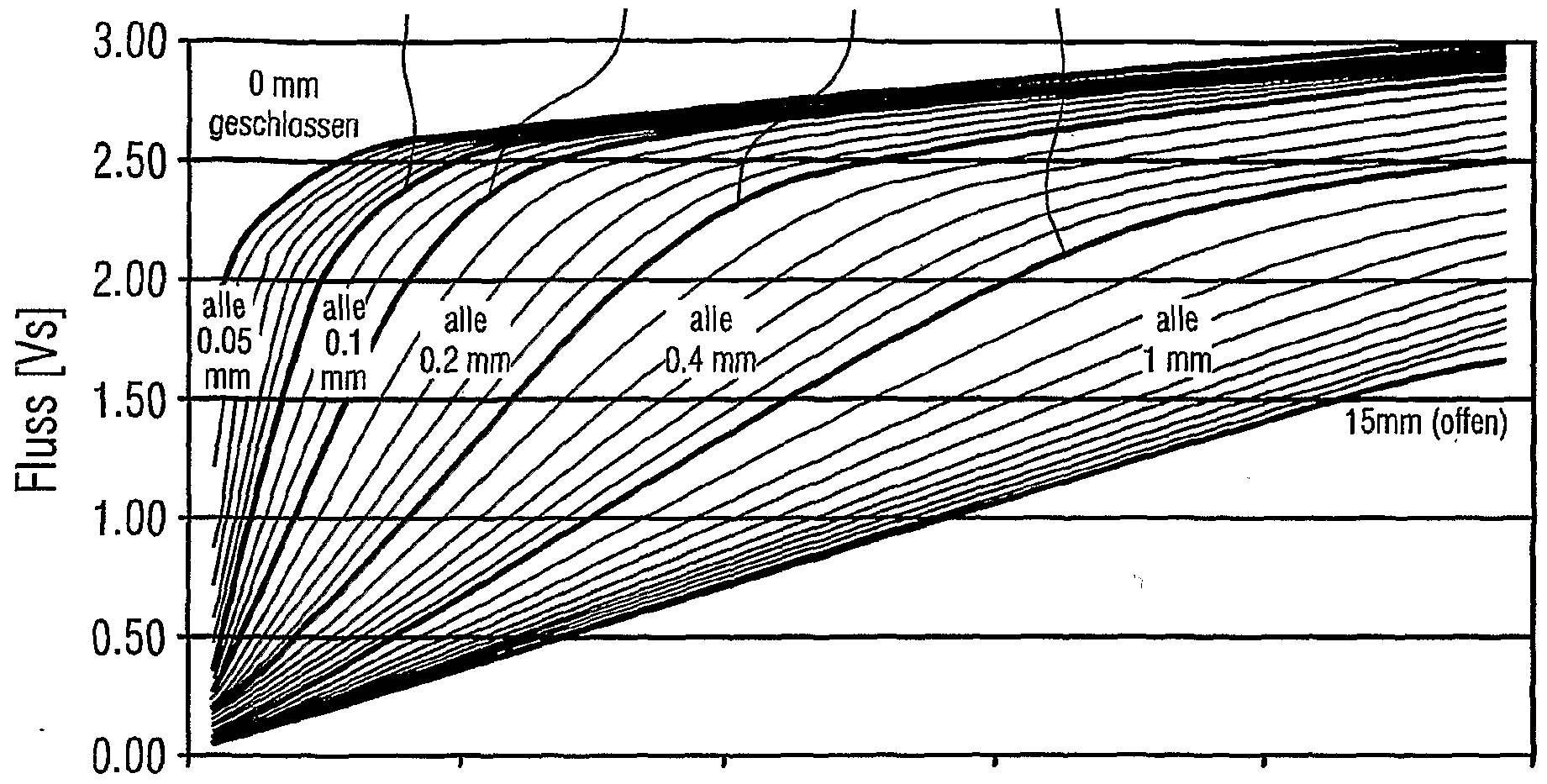
FIG 5 eine Funktionenschar zur Ermittlung des Wegs aus dem Strom- und Flusssignal;5 shows a family of functions for determining the path from the current and flow signal;
FIG 6 Simulationsdiagramme für die Beschleunigungsregelung gemäß der .vorliegenden Erfindung und6 shows simulation diagrams for the acceleration control according to the present invention and
FIG 7 ein Schaltungsdiagramm zur Schnellentregung von Schützen.7 shows a circuit diagram for the rapid de-excitation of contactors.
Die nachfolgend aufgeführten Ausführungsbeispiele stellen bevorzugte Ausführungsformen der vorliegenden Erfindung dar.The exemplary embodiments listed below represent preferred embodiments of the present invention.
Nachdem eine reine Geschwindigkeitsregelung zu träge ist, wird bei dem erfindungsgemäßen Verfahren die Beschleunigung als Regelgröße verwendet. FIG 3 zeigt hierzu ein Prinzipschaltbild. Eine Schützspule Ls wird von einem Regler RG mit Netzspannung versorgt. Die Regelung erfolgt mittels einer Sollwertkurve, in der die Geschwindigkeit v über der Position s aufgetragen ist.Since a pure speed control is too sluggish, the acceleration is used as a control variable in the method according to the invention. 3 shows a basic circuit diagram for this. A contactor coil Ls is supplied with mains voltage by a controller RG. The regulation is carried out by means of a setpoint curve in which the speed v is plotted over the position s.
Die Position s als Stellgröße wird mit Hilfe einer Messspule LM ermittelt. Hierzu wird mit Hilfe einer Auswerteschaltung die in der Messspule LM induzierte Spannung Uϊ und der durch die Spule LM fließende Strom I erfasst. Aus der induzierten Spannung lässt sich durch Integration der magnetische Fluss bestimmen. Anhand einer definierten Beziehung zwischen dem Fluss und dem durch die Spule LM fließenden Strom I kann die Position s ermittelt werden. Sie wird als Stellgröße an den Regler RG weitergeleitet. Gemäß dem nachfolgend näher beschriebenen Regelungsprinzip wird die Kraft auf den Anker in der Schützspule Ls bzw. dessen Beschleunigung auf einen definierten Wert geregelt.The position s as a manipulated variable is determined with the help of a measuring coil LM. For this purpose, the voltage Uϊ induced in the measuring coil LM and the current I flowing through the coil LM are detected with the aid of an evaluation circuit. The magnetic flux can be determined from the induced voltage by integration. The position s can be determined on the basis of a defined relationship between the flux and the current I flowing through the coil LM. It is forwarded to the RG controller as a manipulated variable. According to the control principle described in more detail below, the force on the armature in the contactor coil Ls or its acceleration is regulated to a defined value.
In FIG 4 ist die zur Regelung herangezogene Sollwertkurve „Geschwindigkeit über Position* wiedergegeben. Bei einem Luftspalt von 3,8 mm, in jedem Fall vor dem Schließen der
Hauptkontakte, soll die Geschwindigkeit in etwa 0,5 m/s betragen und bis zum Schließen des Magnetsystems beibehalten werden. Hierzu ist zu bemerken, dass die Hauptkontakte ein vordefiniertes Stück vor dem Auftreffen des Ankers auf das Joch des Magnetsystems bereits in Kontakt treten. Startpunkt beim Schließen ist die Ruhelage (Aus-Position) mit der Geschwindigkeit Null des Ankers bzw. beweglichen Kontakts. In jeder Position bzw. Größe des Luftspalts wird gemäß einer ersten Ausführungsform der vorliegenden Erfindung versucht, die Beschleunigung derart einzustellen, dass die Geschwindigkeit bei 3,8 mm Luftspalt den Wert 0,5 m/s erreicht, wenn diese Beschleunigung konstant beibehalten wird. Dies bedeutet, dass bei der Berechnung eines zu verwendenden Beschleunigungswerts in jedem Messzeitschritt festgestellt wird, ob mit der aktuellen Geschwindigkeit und der aktuellen Beschleunigung der Eckpunkt 0,5 m/s bei 3,8 mm der Geschwindigkeitskurve über- oder unterschritten wird, wenn die aktuelle Beschleunigung beibehalten wird. Dementsprechend wird die Antriebsspule des Magnetsystems an- oder abgeschaltet.FIG. 4 shows the setpoint curve “speed over position * used for the control. With an air gap of 3.8 mm, in any case before closing the Main contacts, the speed should be about 0.5 m / s and should be maintained until the magnet system closes. It should be noted that the main contacts already come into contact a predefined distance before the armature hits the yoke of the magnet system. The starting point for closing is the rest position (off position) with zero speed of the armature or moving contact. In each position or size of the air gap, an attempt is made according to a first embodiment of the present invention to set the acceleration in such a way that the speed at 3.8 mm air gap reaches the value 0.5 m / s if this acceleration is kept constant. This means that when calculating an acceleration value to be used, it is determined in each measurement time step whether the current speed and the current acceleration exceed or fall below the corner point 0.5 m / s at 3.8 mm of the speed curve if the current one Acceleration is maintained. Accordingly, the drive coil of the magnet system is switched on or off.
Die in FIG 4 dargestellte Sollwertkurve kann auch einen anderen Verlauf aufweisen. So kann beispielsweise zwischen der Schließposition (0 mm) und der Position 3,8 mm, bei der die Geschwindigkeit auf 0,5 m/s geregelt wird, gegebenenfalls weitere Eckpunkte definiert werden, um der Mechanik beimThe setpoint curve shown in FIG. 4 can also have a different course. For example, between the closed position (0 mm) and the 3.8 mm position, at which the speed is regulated to 0.5 m / s, further corner points can be defined, if necessary, to ensure the mechanics of the
Schließen des elektrischen Schaltgeräts gegebenenfalls besser Rechnung zu tragen.Closing of the electrical switching device may take better account.
In dem gewählten Ausführungsbeispiel wird nicht direkt ein Weg-, Geschwindigkeits- oder Beschleunigungssensor zur Erfassung der entsprechenden Größen verwendet. Vielmehr wird die Position aus dem Strom- und Flusssignal der Messspule LM hergeleitet.In the selected exemplary embodiment, a distance, speed or acceleration sensor is not used directly to detect the corresponding variables. Rather, the position is derived from the current and flow signals from the measuring coil LM.
FIG 5 zeigt in einer Kurvenschar den diesbezüglichen rechnerischen Zusammenhang Ψ = f (I, x) . Aus der Kurvenschar kann eindeutig bei bekanntem Strom und bekanntem Fluss auf eine
Öffnungsweite der Kontakte geschlossen werden. Gemäß einem einfachen Lösungsansatz kann der Weg s aus den Kurven anhand eines Polynoms dritten oder fünften Grades ermittelt werden. Der anhand dieser Kurvenschar ermittelte Wert des Wegs s wird gemäß FIG 3 von der Auswerteeinheit AW an den Regler RG übermittelt.5 shows in a family of curves the relevant mathematical relationship Ψ = f (I, x). From the family of curves, one can clearly see a known current and a known flow Opening width of the contacts can be closed. According to a simple solution approach, the path s can be determined from the curves using a third or fifth degree polynomial. The value of the path s determined on the basis of this family of curves is transmitted according to FIG. 3 by the evaluation unit AW to the controller RG.
Simulationsergebnisse der erfindungsgemäßen Schaltung mit Beschleunigungsregelung sind in den Diagrammen von FIG 6 darge- stellt. Die dargestellten Größen entsprechen denen von FIG 1 und FIG 2. Auch in FIG 6 ist die Einschaltbewegung eines Schützes über der Zeit dargestellt. Im Idealfall verläuft die Einschaltbewegung entlang der vorgegebenen Sollwertkurve von FIG 4. In diesem Fall wird auf eine konstante Beschleunigung geregelt. Falls bei dem Einschaltvorgang jedoch Punkte neben der Sollwertkurve als Istwerte festgestellt werden, so wird die Beschleunigung derart nachgeführt, dass wiederum der Eckpunkt (vergleiche Pfeile in FIG 4) erreicht wird. Eine solche Abweichung von der Sollwertkurve ist insbesondere beim Ein- satz gleichgerichteter Wechselspannung für die Ansteuerung der Antriebsspule von Bedeutung, da hier die Stromeinbrüche zu Istwerten unterhalb der Sollwertkurve führen.Simulation results of the circuit according to the invention with acceleration control are shown in the diagrams in FIG. 6. The quantities shown correspond to those of FIG. 1 and FIG. 2. FIG. 6 also shows the switching-on movement of a contactor over time. In the ideal case, the switch-on movement runs along the predetermined setpoint curve of FIG. 4. In this case, control is made for constant acceleration. However, if points next to the setpoint curve are determined as actual values during the switch-on process, the acceleration is tracked in such a way that the corner point (compare arrows in FIG. 4) is reached again. Such a deviation from the setpoint curve is particularly important when using rectified AC voltage for driving the drive coil, since the current drops lead to actual values below the setpoint curve.
Wie dem obersten Diagramm von FIG 6 zu entnehmen ist, wird die Spannung an der Antriebsspule zunächst angeschaltet, wie dies auch in dem Beispiel von FIG 1 der Fall ist. Der Strom (gepunktete Linie) steigt entsprechend rasch an. Sobald der Strom einen gewissen Wert erreicht hat, setzt die Regelung durch An- und Abschalten der Spannung ein. Dabei ist zu be- achten, dass an die Antriebsspule auch eine negative Spannung, d. h. eine Gegenspannung, angelegt wird, damit der Strom bzw. Fluss gegebenenfalls rascher abgesenkt werden kann.As can be seen from the uppermost diagram in FIG. 6, the voltage at the drive coil is first switched on, as is also the case in the example in FIG. The current (dotted line) increases accordingly rapidly. As soon as the current has reached a certain value, the control starts by switching the voltage on and off. It should be noted that a negative voltage, ie. H. a counter voltage is applied so that the current or flow can be lowered more quickly if necessary.
Im mittleren Diagramm von FIG 6 ist zu erkennen, dass während der Regelung die Magnetkraft (gepunktete Linie) konstant über der Federkraft (gestrichelte Linie) gehalten wird. Dies be-
deutet, dass die Kraft auf den Anker und damit seine Beschleunigung während des Einschaltvorgangs gleich bleibt.The middle diagram of FIG. 6 shows that the magnetic force (dotted line) is kept constant above the spring force (dashed line) during the control. This is indicates that the force on the armature and thus its acceleration remains the same during the switch-on process.
Beim Erreichen der Geschwindigkeit von 0,5 m/s (vergleiche durchgezogene Linie im untersten Diagramm von FIG 6) wird der Strom und somit auch die Magnetkraft etwas nach unten geregelt, so dass die Magnetkraft der entgegenwirkenden Federkraft betragsmäßig entspricht und die Geschwindigkeit somit beibehalten wird.When the speed of 0.5 m / s is reached (see the solid line in the bottom diagram of FIG. 6), the current and thus also the magnetic force is regulated somewhat downwards, so that the magnetic force corresponds to the amount of the counteracting spring force and the speed is thus maintained ,
Beim anschließenden Auftreffen der Kontakte aufeinander, wenn sich die Federkraft sprunghaft erhöht, muss zur Beibehaltung der Geschwindigkeit die Magnetkraft (gepunktete Linie im mittleren Diagramm) hochgeregelt werden. Dies wird durch ein Anschalten der Spannung an der Spule (durchgezogene Linie im obersten Diagramm) bzw. Anstieg des Stroms durch die Spule (gepunktete Linie im obersten Diagramm) erreicht. Der kurze Geschwindigkeitseinbruch beim Auftreffen der Kontakte aufeinander kann somit kompensiert werden (vergleiche durchgezogene Linie im untersten Diagramm) . Der von den Kontakten beim Einschaltvorgang zurückgelegte Weg (vergleiche gestrichelte Linie im untersten Diagramm von FIG 6) über der Zeit entspricht im Wesentlichen dem von FIG 1.When the contacts meet afterwards, when the spring force increases suddenly, the magnetic force (dotted line in the middle diagram) must be adjusted to maintain the speed. This is achieved by switching on the voltage on the coil (solid line in the top diagram) or increasing the current through the coil (dotted line in the top diagram). The short drop in speed when the contacts hit each other can thus be compensated (see the solid line in the bottom diagram). The distance covered by the contacts during the switch-on process (compare dashed line in the bottom diagram of FIG. 6) over time essentially corresponds to that of FIG. 1.
In dem hier dargestellten Beispiel wird eine nachgeführte Beschleunigungsregelung durchgeführt. Dies bedeutet, dass in einer Tabelle bzw. Kurve entsprechend FIG 4 ein oder mehrere Sollwertpunkte (vsoii, ssoii) vorgegeben werden. Die aktuellen Werte für Beschleunigung, Geschwindigkeit und Weg bakt, vakt und sakt werden gemessen bzw. ausgewertet. Daraus wird gemäß der Formel trest = ( Sakt - Ssoll) / ( (Vsoll + Vakt) / 2 ) eine Restlaufzeit trest berechnet, die vom aktuellen Zustand bis zum Erreichen des Eckpunkts (3,8 mm, 0,5 m/s) von FIG 4 verbleibt. Aus dieser Restlaufzeit wird gemäß der FormelIn the example shown here, a tracking acceleration control is carried out. This means that one or more setpoint points (vsoii, ssoii) are specified in a table or curve according to FIG. The current values for acceleration, speed and distance bakt, vakt and sakt are measured or evaluated. Based on the formula trest = (Sakt - Ssoll) / ((Vsoll + Vakt) / 2), a residual term trest is calculated, from the current state until the corner point (3.8 mm, 0.5 m / s) is reached FIG 4 remains. This remaining term is calculated according to the formula
Vsohalt = Vakt + bakt • trest
ein Schaltgeschwindigkeitswert vsch-αt vorhergesagt, mit dem sich die Kontakte zum SchaltZeitpunkt aufeinander zu bewegen würden, wenn die Beschleunigung beibehalten wird. Als Regelungskriterium gilt nun, dass die Spannung an der Spule ein- geschaltet wird, wenn schait < Vsoii ist. Andernfalls, wenn Vsohait > vsoii ist, wird die Spannung an der Spule ausgeschaltet.Vsohalt = Vakt + bakt • trest a switching speed value vsch-αt is predicted with which the contacts would move towards one another at the switching time if the acceleration is maintained. The regulation criterion is now that the voltage at the coil is switched on when schait <Vsoii. Otherwise, if Vsohait> vsoii, the voltage on the coil is switched off.
Die geschilderte Beschleunigungsregelung kann dahingehend erweitert werden, dass ein weiterer Freiheitsgrad eingeführt wird, der sich insbesondere zu Beginn des Einschaltvorgangs auswirkt. Zur Berechnung der Geschwindigkeit vsohait zum Schaltzeitpunkt wird gemäß der FormelThe acceleration control described can be expanded in such a way that a further degree of freedom is introduced, which has an effect in particular at the start of the switch-on process. To calculate the speed vsohait at the time of switching, use the formula
Vschait = Vakt + k • bakt • trest ein Entfernungsfaktor k berücksichtigt. Dieser lässt sich wie folgt berechnen: = (Sakt - sρι) / (sj - SJ-1)Vschait = Vakt + k • bakt • trest a distance factor k is taken into account. This can be calculated as follows: = (Sakt - sρι) / (sj - SJ-1)
Dabei bedeutet j einen Punkt auf der Sollkurve von Fig. 4. Der Punkt j = 1 entspricht in diesem Beispiel der Offenposition bei akt = 0, der Punkt j = 2 entspricht der Position (3,8 mm, 0,5 m/s) und der Punkt j = 3 entspricht der Geschlossenposition bei s = 0 mm.Here, j means a point on the nominal curve of FIG. 4. In this example, point j = 1 corresponds to the open position at akt = 0, point j = 2 corresponds to the position (3.8 mm, 0.5 m / s) and the point j = 3 corresponds to the closed position at s = 0 mm.
Zu Beginn des Einschaltvorgangs ist k = 0, während am Ende des Einschaltvorgangs k = 1 ist. Dies bedeutet, dass die ak- tuelle Beschleunigung bakt zu Beginn des Einschaltvorgangs auf die Regelung praktisch keinen Einfluss hat. Vielmehr ist die Regelung zu Beginn des Einschaltvorgangs lediglich vom aktuellen Geschwindigkeitswert vakt abhängig, womit sich in dieser Phase eine Geschwindigkeitsregelung ergibt. Am Ende des Ein- schaltvorgangs wird die Geschwindigkeitsregelung von der Beschleunigungsregelung abgelöst.At the start of the switch-on process, k = 0, while at the end of the switch-on process, k = 1. This means that the actual acceleration bakt at the start of the switch-on process has practically no influence on the control. Rather, the regulation at the beginning of the switch-on process is only dependent on the current speed value, which results in a speed regulation in this phase. At the end of the switch-on process, the speed control is replaced by the acceleration control.
Als Variante zu den oben beschriebenen Beschleunigungsregelungen kann auch eine sehr einfache Beschleunigungsregelung eingesetzt werden. Diese besteht lediglich in der Vorgabe einer Tabelle bzw. Funktion der Beschleunigung in Abhängigkeit des Weges bsoiι(s) .Die aktuelle Beschleunigung bakt und der aktu-
eile Weg sakt werden gemessen oder ausgewertet. Zur Regelung wird die Spannung an der Spule eingeschaltet, wenn bakt < bsoii (sakt) ist. Für den Fall, dass bakt > bsoii (sakt) ist, wird die Spannung ausgeschaltet.A very simple acceleration control can also be used as a variant of the acceleration controls described above. This consists only in the specification of a table or function of the acceleration depending on the path bsoiι (s). The current acceleration bakt and the current Rapid movements are measured or evaluated. For control purposes, the voltage at the coil is switched on when bakt <bsoii (sakt). In the event that bakt> bsoii (sakt), the voltage is switched off.
Wie bereits erwähnt und im Zusammenhang mit FIG 5 dargestellt, kann die Positionsbestimmung aus der Messung des Stroms und des Flusses erfolgen. Gemäß einer ersten Ausführungsform kann die Flussmessung, die indirekt über eine Span- nungsmessung erfolgt, mit Hilfe einer getrennten Messwicklung erfolgen, bei der an einer unabhängigen Messspule LM gemäß FIG 3 eine induzierte Spannung U gemessen wird. Der Fluss wird dann mittels numerischer Intregration über die induzierte Spannung Uι berechnet oder mit Hilfe einer Analogschaltung ermittelt.As already mentioned and shown in connection with FIG. 5, the position can be determined from the measurement of the current and the flow. According to a first embodiment, the flux measurement, which takes place indirectly via a voltage measurement, can take place with the aid of a separate measuring winding, in which an induced voltage U is measured on an independent measuring coil LM according to FIG. The flow is then calculated by means of numerical integration over the induced voltage Uι or determined with the aid of an analog circuit.
Entsprechend einer zweiten Ausführungsform wird die Spannungsmessung zur Ermittlung des Flusses direkt an der Erregerwicklung bzw. Antriebsspule ermittelt. Zur exakten Besti - mung der Wicklungsspannung Uw erfolgt eine rechnerische Korrektur des Wicklungswiderstands aus zwei Integrationsintervallen während des Stromanstiegs ohne Bewegung. Hierzu werden beispielsweise ein Intervall 1 von 1 = 0 bis I = 0,5 A und ein Intervall 2 von 1 = 0 bis I = 1,0 A festgelegt. Für das Intervall 1 werden ein Integral über den Strom HO und ein Integral über die Spannung IU01 ermittelt. Für das Intervall 2 werden ebenfalls ein entsprechendes Integral 1102 über den Strom und ein Integral IU02 über die Spannung berechnet. Aus der Formel R = (IU02 - 2 • IU01) / (1102 - 2 • 1101) wird der ohmsche Widerstand der Spule berechnet. In Kenntnis des Stroms i kann entsprechend der FormelAccording to a second embodiment, the voltage measurement for determining the flux is determined directly on the excitation winding or drive coil. For exact determination of the winding voltage Uw, the winding resistance is corrected from two integration intervals during the current rise without movement. For this purpose, for example, an interval 1 of 1 = 0 to I = 0.5 A and an interval 2 of 1 = 0 to I = 1.0 A are specified. An integral over the current HO and an integral over the voltage IU01 are determined for the interval 1. A corresponding integral 1102 over the current and an integral IU02 over the voltage are also calculated for the interval 2. The ohmic resistance of the coil is calculated from the formula R = (IU02 - 2 • IU01) / (1102 - 2 • 1101). Knowing the current i can according to the formula
Uι = Uw - R • i die induzierte Spannung Ui aus der WicklungsSpannung Uw be- rechnet werden.
Damit der magnetische Fluss beim Abregein der oben geschilderten Beschleunigungsregelung schneller abgebaut werden kann, muss in einem Freilaufkreis eine Gegenspannung erzeugt werden. In dem obersten Simulationsdiagramm von FIG 6 ist diese negative Gegenspannung wie bereits erwähnt angedeutet. FIG 7 zeigt hierzu ein Schaltungsdiagramm gemäß dem eine Schützspule Ls angesteuert werden kann. Über einen Gleichrichter GL wird ein Kondensator C und eine Regelungsschaltung RG (vergleiche FIG 3) mit Gleichspannung versorgt. Über eine Brückenschaltung bestehend aus zwei Transistoren Tl und T2 sowie zwei Dioden Dl und D2, die ebenfalls mit der Gleichspannung beaufschlagt wird, wird die Schützspule Ls versorgt. Beim Einschalten der Schützspule fließt der Strom von dem Gleichrichter GL über den Transistor Tl, die Schützspule Ls, dem dem Transistor Tl diagonal gegenüberliegenden Transistor T2 und zurück in den Gleichrichter. Beim Ausschalten der Schützspule Ls fließt der Strom hingegen über die Diode D2, die Schützspule Ls, die der Diode D2 diagonal gegenüberliegende Diode Dl und den zum Gleichrichter GL parallelen Kon- densator C. Der Kondensator C ist bereits auf die Amplitude der Netzspannung Uc geladen und steht als Gegenspannungsquelle zur Verfügung. Ist die Kapazität des Kondensators C sehr groß, so ist die Geschwindigkeit der Erregung der Schützspule Ls in etwa identisch mit der Geschwindigkeit der Entregung. Wird jedoch die Kapazität des Kondensators C klein gewählt, erhöht sich die Gegenspannung durch den Abbau des magnetischen Flusses in der Schützspule Ls auf den Wert U'c. Somit ergibt sich im Kondensator die folgende Energieänderung:Uι = Uw - R • i the induced voltage Ui can be calculated from the winding voltage Uw. In order that the magnetic flux can be broken down more quickly when the acceleration control described above is de-energized, a counter-voltage must be generated in a freewheeling circuit. In the uppermost simulation diagram of FIG. 6, this negative counter voltage is indicated, as already mentioned. 7 shows a circuit diagram according to which a contactor coil Ls can be controlled. A capacitor C and a control circuit RG (see FIG. 3) are supplied with DC voltage via a rectifier GL. The contactor coil Ls is supplied via a bridge circuit consisting of two transistors T1 and T2 and two diodes D1 and D2, which is also supplied with the DC voltage. When the contactor coil is switched on, the current flows from the rectifier GL via the transistor T1, the contactor coil Ls, the transistor T2 diagonally opposite the transistor T1 and back into the rectifier. When the contactor coil Ls is switched off, however, the current flows via the diode D2, the contactor coil Ls, the diode D1 diagonally opposite the diode D2 and the capacitor C parallel to the rectifier GL. The capacitor C is already charged to the amplitude of the mains voltage Uc and is available as a counter voltage source. If the capacitance of the capacitor C is very large, the rate of excitation of the contactor coil Ls is approximately identical to the rate of de-excitation. However, if the capacitance of the capacitor C is chosen to be small, the counter voltage increases due to the reduction of the magnetic flux in the contactor coil Ls to the value U'c. This results in the following energy change in the capacitor:
AEC = - C - (U'C 2-UC 2) Durch diesen Spannungsanstieg am Kondensator ist die Geschwindigkeit der Entregung größer als die Geschwindigkeit der Erregung. Der Kondensator sollte so dimensioniert werden, dass er die maximale auftretende magnetische Energie Eunax von der Schütz- spule Ls aufnehmen kann ( ΔEC = Eimax ) .
AE C = - C - (U ' C 2 -U C 2 ) As a result of this voltage rise at the capacitor, the rate of excitation is greater than the rate of excitation. The capacitor should be dimensioned so that it can absorb the maximum occurring magnetic energy Eunax from the contactor coil Ls (ΔE C = E imax ).