WO2006044996A2 - System and method for automated boundary detection of body structures - Google Patents
System and method for automated boundary detection of body structures Download PDFInfo
- Publication number
- WO2006044996A2 WO2006044996A2 PCT/US2005/037669 US2005037669W WO2006044996A2 WO 2006044996 A2 WO2006044996 A2 WO 2006044996A2 US 2005037669 W US2005037669 W US 2005037669W WO 2006044996 A2 WO2006044996 A2 WO 2006044996A2
- Authority
- WO
- WIPO (PCT)
- Prior art keywords
- matrix
- image
- correlation matrix
- autocorrelation calculation
- processor
- Prior art date
Links
Classifications
-
- G—PHYSICS
- G06—COMPUTING; CALCULATING OR COUNTING
- G06T—IMAGE DATA PROCESSING OR GENERATION, IN GENERAL
- G06T7/00—Image analysis
- G06T7/10—Segmentation; Edge detection
- G06T7/12—Edge-based segmentation
-
- A—HUMAN NECESSITIES
- A61—MEDICAL OR VETERINARY SCIENCE; HYGIENE
- A61B—DIAGNOSIS; SURGERY; IDENTIFICATION
- A61B8/00—Diagnosis using ultrasonic, sonic or infrasonic waves
- A61B8/52—Devices using data or image processing specially adapted for diagnosis using ultrasonic, sonic or infrasonic waves
- A61B8/5269—Devices using data or image processing specially adapted for diagnosis using ultrasonic, sonic or infrasonic waves involving detection or reduction of artifacts
- A61B8/5276—Devices using data or image processing specially adapted for diagnosis using ultrasonic, sonic or infrasonic waves involving detection or reduction of artifacts due to motion
-
- G—PHYSICS
- G06—COMPUTING; CALCULATING OR COUNTING
- G06T—IMAGE DATA PROCESSING OR GENERATION, IN GENERAL
- G06T2207/00—Indexing scheme for image analysis or image enhancement
- G06T2207/10—Image acquisition modality
- G06T2207/10132—Ultrasound image
-
- G—PHYSICS
- G06—COMPUTING; CALCULATING OR COUNTING
- G06T—IMAGE DATA PROCESSING OR GENERATION, IN GENERAL
- G06T2207/00—Indexing scheme for image analysis or image enhancement
- G06T2207/20—Special algorithmic details
- G06T2207/20024—Filtering details
- G06T2207/20032—Median filtering
-
- G—PHYSICS
- G06—COMPUTING; CALCULATING OR COUNTING
- G06T—IMAGE DATA PROCESSING OR GENERATION, IN GENERAL
- G06T2207/00—Indexing scheme for image analysis or image enhancement
- G06T2207/20—Special algorithmic details
- G06T2207/20036—Morphological image processing
-
- G—PHYSICS
- G06—COMPUTING; CALCULATING OR COUNTING
- G06T—IMAGE DATA PROCESSING OR GENERATION, IN GENERAL
- G06T2207/00—Indexing scheme for image analysis or image enhancement
- G06T2207/30—Subject of image; Context of image processing
- G06T2207/30004—Biomedical image processing
- G06T2207/30048—Heart; Cardiac
Definitions
- This invention relates to a system and method for automatic image processing, in particular a technique of autocorrelation of ultrasound echoes to delineate tissue regions, such as the boundary of the endocardium of a patient's heart.
- Echocardiography is a common diagnostic imaging modality that uses ultrasound to capture the structure and function of the heart.
- a comprehensive evaluation typically entails imaging the heart in several planes by placing the ultrasound transducer at various locations on the patient's chest wall. Accordingly, the echocardiogram video displays the three-dimensional heart from a sequence of different two-dimensional cross sections (also referred to herein as "views” or “scans.”). Under different views, different sets of cardiac cavities and other structures are visible. Observation of the cardiac structures in the echocardiogram videos, especially movement of the walls and chambers over time, is typically used to assist in the diagnosis of heart abnormalities.
- echocardiography is useful to detect irregularities in left ventricular wall motion.
- three-dimensional (“3-D") models of the left ventricle can be reconstructed from segmenting the two- dimensional ("2-D") short axis scans and 2-D long axis scans from the end diastole phase to the end systole phase of the heart function.
- Segmentation refers to a method of separating distinct structures from each other.
- structure shall refer to an object or feature in an image. In imaging, it refers to the delineation of such structure in an image and, thus, its separation from other surrounding structures.
- left ventricular borders for as many as 20 2-D short axis slices and twelve 2-D long-axis slices may have to be traced in order for provide data sufficient to reconstruct a single frame of video data a 3-D left ventricle model.
- a dataset such as that used in the exemplary embodiment described hereinbelow, may consist of seven frames between end diastole and end systole, thus providing the reviewing cardiologist with as many as 20 x 12 x 7 frames to manually trace, a total of 1680 frames. This task can be extremely cumbersome for even the most skilled cardiologist.
- a challenge facing those attempting to automate the procedure of image recognition is the image quality of the echo videos being analyzed. Because echo videos are the result of the ultrasound interrogation of the structure of the heart, the images may be highly degraded by multiplicative noise. Moreover, the lower echogenicity of certain tissues, such as the left-ventricular cavity, further complicates the process of automating such procedures.
- It is an object of the current invention is to overcome the aforementioned limitations to provide an automated boundary detection technique.
- a method includes providing an ultrasound image or signal.
- An autocorrelation calculation is performed on matrices representing the signals (amplitudes and phases) of the image to generate a correlation matrix of the signal, which represents the difference in echogenicity between two structures represented in the image, e.g., the ventricular cavity and the endocardium.
- An edge detection technique is used to obtain the boundary of the structure.
- an interpolation of the correlation matrix of pixel values may be performed to resize the image to the same size as the matrices of the original image.
- a threshold procedure may be applied to the correlation matrix to reduce the multiple levels of shading.
- Machine learning techniques may be applied to vary the threshold to improve the boundary detection process. Morphological operations and median filtering may be subsequently executed.
- the autocorrelation procedure may be performed on successive frames.
- the autocorrelation procedure may be useful for determining the displacement or deformation of walls or other structures in the images being studied.
- the object of providing a automated boundary detection technique has been met. Further features of the invention, its nature and various advantages will be apparent from the accompanying drawings and the following detailed description of illustrative embodiments.
- FIG. 1 illustrates the system in accordance with the invention.
- Figure 2 is flow chart which illustrates the stages of boundary detection procedure in accordance with the present invention.
- Figure 3 is an exemplary image obtained using the methods in accordance with the present invention.
- Figure 4 is an exemplary image obtained using the methods in accordance with the present invention.
- Figures 5(a)-(g) are images obtained with a method according to prior art techniques.
- Figures 6(a)-(g) are images obtained in accordance with an exemplary embodiment of the present invention.
- FIGS 7(a)-(g) are images obtained in accordance with another exemplary embodiment of the present invention.
- the same reference numerals and characters, unless otherwise stated, are used to denote like features, elements, components or portions of the illustrated embodiments. It is intended that changes and modifications can be made to the described embodiments without departing from the true scope and spirit of the subject invention as defined by the appended claims.
- FIG. 1 An exemplary embodiment of the system 10 is illustrated in Figure 1, and includes signal or image acquisition equipment 20.
- any known echocardiogram acquisition equipment such as a 3-D Philips Sonos 7500 System having a probe 25, may be used for acquiring the images of the cardiac structure of a patient P.
- Image acquisition equipment may include video/signal capture equipment 30, e.g., a video capture card to digitize the analog video, and data storage equipment 40, e.g., a hard drive or other storage medium, to store the resulting video images/signals.
- the video images may be written onto a tape, memory card, or other medium by an appropriate recording device 45.
- Image processing equipment 50 is used to process the images in accordance with the invention. Image processing may be performed by a personal computer 55, such as a Dell OptiPlex GX270 Small
- MiniTower or other computer, having a central processing unit or processor 57 and memory 59 storing program instructions for execution by the processor 57, an input device 60, such as tape drive, memory card slot, etc., for receiving the digital images and a keyboard 70 for receiving user inputs, and an output device, such a monitor 75, a printer 80, or a recording device 90 for writing the output onto a tape, memory card, or other medium.
- Image processing equipment 50 may also located on several computers, which are operating in a single location or which are connected as a remote network.
- An early stage in the process is the acquisition of the datasets, e.g., echo videos, by the image acquisition equipment 20, such as the 3-D Philips Sonos 7500 System.
- Exemplary images include the 2-D short axis slices. Tracking the function of the heart of the patient P between end diastole to end systole is particularly useful from a diagnostic perspective because it encompasses a substantial range of contraction and expansion of the heart cavities. It is understood that any other echo views, such as the Parasternal Short Axis view or the Apical view, etc., may be used, and any portion of the heart cycle may be studied.
- the automatic segmentation technique may be implemented on the image processing equipment 50 using any available computer software.
- MATLAB v6R 13 was used. Cropping of the images may be performed to provide improved results.
- the automated program may first crop the original images using the end diastole frame as a reference. This procedure assumes that the left ventricle will stay within the same coordinates from end diastole to end systole, since the left ventricle contracts during this period, and the area of the cavity is at a maximum during end diastole.
- the cropping may be utilized to avoid any undesired segmentation of the right ventricle.
- the cropped images are 71 x 61 pixels, although other image sizes are also useful.
- the process 100 in accordance with an exemplary embodiment is illustrated in Figure 2.
- the information from two adjacent frames is used in order to find an accurate border for the structure being studied.
- the two frames being studied do not have to be consecutive, although such frames may preferably be reasonably close in time to ensure that the structure to be segmented has not undergone significant motion between frames.
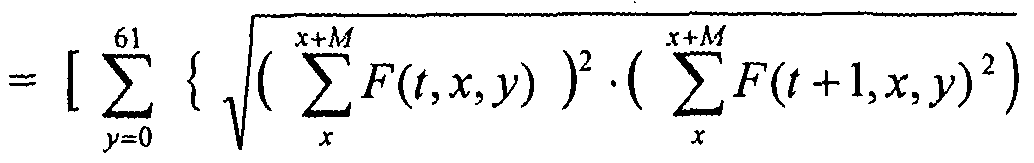
- Use of the autocorrelation function emphasizes the difference in echogenicity between the cavity and the myocardium of the left ventricle.
- F(tjcji) are the grayscale pixel values for the current frame
- F(t+ 1.x ⁇ y) are the grayscale pixel values for the adjacent frame.
- x is the location along the horizontal direction of the image
- y is the location along the vertical direction of the image.
- W refers to windowed signal segment
- W ⁇ refers to frame t
- JF 2 refers to frame tt-1.
- a new image may be formed by taking the inverse of a square root of these sampled autocorrelation values multiplied together (step 120), as indicated in equation (3):
- N(tw) [ ⁇ ⁇ ⁇ J "1 . 0) the inverse square of the regular autocorrelations. This may be used as the criterion for the threshold.
- the maximum index of y is 61.
- equation (3) represents an exemplary case where one dimension of pixels is 61, and this equation could be generalized for larger or smaller frames.
- the matrix N(tjcy) represents a new image, which may be smaller in size than the original 71x61 pixel images. That is, N ⁇ tjc,y) will have an M number fewer rows.
- N(t,x,y) may be resized to the same size as F ⁇ tjc,y) (step 130).
- Exemplary interpolation techniques are the linear or cubic interpolations. It is understood the autocorrelation procedure may be performed on a single matrix of signals values, rather than the two matrices discussed above. The autocorrelation techniques described herein may also be used to determine the motion and/or deformation of the tissue structures between frames, e.g., the wall or the cavity of the patient's heart.
- the resized matrix N(tjc,y) may then be thresholded to permit improved segmentation the left ventricle (step 140).
- An example of such a thresholded technique is described herein: For the cases where N(tjc,y) is less than 0.01, the autocorrelation amplitude is set to zero, while in the opposite case it is set to one.
- Figure 3 illustrates an example of such an autocorrelation image 20 before thresholding.
- Figure 4 illustrates the image 30 obtained after thresholding technique is applied.
- later steps of the process are basic morphological operations, e.g., a. closing operation and a filling operation, to remove small artifacts resulting from the mitral valve and from papillary muscles.
- the 'imclose' and 'imfill' routines were applied for the closing and filling operations, respectively, using the MATLABv6R13 function 'edge' in order to generate a uniform surface, e.g. , to merge isolated pixels, and include all pixels enclosed by the surface.
- These steps may also include a median filtering operation which finds the object within the image that has the largest area and removes any other objects.
- the above- described operations are indicated generally as step 150 in Figure 1. With continued reference to Figure 4, it may be seen that this operation removes pixel data inside the left-ventricular cavity 32 in Figure 3.
- An edge detection is performed using the
- MATLABv6R13 function 'edge' (step 160) in order to delineate the boundary being studied, such as the endocardium.
- the threshold value may be varied for each frame.
- a perceptron machine learning algorithm may optionally be used.
- the threshold is incremented by small values until the automatically detected structure is very close as determined by the best fit to that of the area calculated from a manually traced border for each frame.
- a simple machine learning algorithm can be trained to calculate optimal threshold values for each frame.
- the datasets e.g., echo videos
- 208 2-D short axis slices were saved from end diastole to end systole. There are seven time frames between end diastole and end systole, and each 2-D slice is 160x144 pixels.
- slice numbers 100 is used from the 208 2-D short axis slices from each time frame. This selection allowed for an easier comparison of the automatic border technique to the manually traced borders.
- FIG. 5(a)-(g) illustrate the borders identified by the human observer. Each image is one time frame from the one-hundredth 2-D slice; from the first to the seventh time frame.
- Figures 6(a)-(g) illustrate the borders traced automatically according to process 10, in accordance with the present invention. As with the manually identified images, each image is one time frame from the one-hundredth 2-D slice; from the first to the seventh time frame.
- the threshold value may varied for each frame to aid our segmentation technique.
- Figures 7(a)-(g) illustrate the boundaries wherein the process 10, discussed above, is supplemented by a perceptron machine learning algorithm.
- the threshold was incremented by small values until the automatically detected ventricle area is very close to that of the area calculated from the manually traced borders for each frame.
- Table 1 lists the areas calculated for each frame using the three different techniques.
- left-ventricular (LV) myocardial abnormalities characterized by dyskinetic or akinetic wall motion and/or poor contractile properties
- myocardial elastography to assist in the automated segmentation of the left ventricle.
- blood and muscle scatterers have distinct motion and deformation characteristics that allow for their successful separation when motion and deformation are imaged using Myocardial Elastography (Konofagou E. E., D'hooge J. and Ophir J., IEEE-UFFC Proc Symp, 1273-1276, 2000, which is incorporated by reference in its entirety herein.)
- [disp, str, rho] elalgor2 (pre_frame, 0,0,0,depth, 0,winsize,percent) ;
- ELALGOR2.M function [dpm,e ⁇ r,rho,winsize,shift] elalgor2 (i ⁇ , rf_aln,apps2, apps,depth, flag, winsize,percent) ;
Abstract
Description
Claims
Priority Applications (1)
| Application Number | Priority Date | Filing Date | Title |
|---|---|---|---|
| US11/697,573 US20070276245A1 (en) | 2004-10-15 | 2007-04-06 | System And Method For Automated Boundary Detection Of Body Structures |
Applications Claiming Priority (2)
| Application Number | Priority Date | Filing Date | Title |
|---|---|---|---|
| US61924704P | 2004-10-15 | 2004-10-15 | |
| US60/619,247 | 2004-10-15 |
Related Child Applications (1)
| Application Number | Title | Priority Date | Filing Date |
|---|---|---|---|
| US11/697,573 Continuation US20070276245A1 (en) | 2004-10-15 | 2007-04-06 | System And Method For Automated Boundary Detection Of Body Structures |
Publications (2)
| Publication Number | Publication Date |
|---|---|
| WO2006044996A2 true WO2006044996A2 (en) | 2006-04-27 |
| WO2006044996A3 WO2006044996A3 (en) | 2006-08-03 |
Family
ID=36203687
Family Applications (1)
| Application Number | Title | Priority Date | Filing Date |
|---|---|---|---|
| PCT/US2005/037669 WO2006044996A2 (en) | 2004-10-15 | 2005-10-17 | System and method for automated boundary detection of body structures |
Country Status (2)
| Country | Link |
|---|---|
| US (1) | US20070276245A1 (en) |
| WO (1) | WO2006044996A2 (en) |
Cited By (5)
| Publication number | Priority date | Publication date | Assignee | Title |
|---|---|---|---|---|
| WO2012105718A1 (en) * | 2011-02-04 | 2012-08-09 | Canon Kabushiki Kaisha | Ultra sound imaging signal processing apparatus |
| US9020217B2 (en) | 2008-09-25 | 2015-04-28 | Cae Healthcare Canada Inc. | Simulation of medical imaging |
| US9087369B2 (en) | 2010-11-18 | 2015-07-21 | Koninklijke Philips N.V. | Apparatus for being used for detecting a property of an object |
| WO2016046140A1 (en) | 2014-09-25 | 2016-03-31 | Koninklijke Philips N.V. | Device and method for automatic pneumothorax detection |
| US10078893B2 (en) | 2010-12-29 | 2018-09-18 | Dia Imaging Analysis Ltd | Automatic left ventricular function evaluation |
Families Citing this family (27)
| Publication number | Priority date | Publication date | Assignee | Title |
|---|---|---|---|---|
| US10687785B2 (en) | 2005-05-12 | 2020-06-23 | The Trustees Of Columbia Univeristy In The City Of New York | System and method for electromechanical activation of arrhythmias |
| US8858441B2 (en) | 2005-05-12 | 2014-10-14 | The Trustees Of Columbia University In The City Of New York | System and method for electromechanical wave imaging of body structures |
| US8150128B2 (en) | 2006-08-30 | 2012-04-03 | The Trustees Of Columbia University In The City Of New York | Systems and method for composite elastography and wave imaging |
| WO2011035312A1 (en) | 2009-09-21 | 2011-03-24 | The Trustees Of Culumbia University In The City Of New York | Systems and methods for opening of a tissue barrier |
| WO2010014977A1 (en) | 2008-08-01 | 2010-02-04 | The Trustees Of Columbia University In The City Of New York | Systems and methods for matching and imaging tissue characteristics |
| WO2010030819A1 (en) | 2008-09-10 | 2010-03-18 | The Trustees Of Columbia University In The City Of New York | Systems and methods for opening a tissue |
| US8328726B2 (en) * | 2009-04-01 | 2012-12-11 | Tomy Varghese | Method and apparatus for monitoring tissue ablation |
| WO2011025893A1 (en) | 2009-08-28 | 2011-03-03 | The Trustees Of Columbia University In The City Of New York | Systems, methods, and devices for production of gas-filled microbubbles |
| WO2011028690A1 (en) | 2009-09-01 | 2011-03-10 | The Trustees Of Columbia University In The City Of New York | Microbubble devices, methods and systems |
| US10010709B2 (en) | 2009-12-16 | 2018-07-03 | The Trustees Of Columbia University In The City Of New York | Composition for on-demand ultrasound-triggered drug delivery |
| US10249037B2 (en) * | 2010-01-25 | 2019-04-02 | Amcad Biomed Corporation | Echogenicity quantification method and calibration method for ultrasonic device using echogenicity index |
| WO2011153268A2 (en) | 2010-06-01 | 2011-12-08 | The Trustees Of Columbia University In The City Of New York | Devices, methods, and systems for measuring elastic properties of biological tissues |
| WO2012019172A1 (en) | 2010-08-06 | 2012-02-09 | The Trustees Of Columbia University In The City Of New York | Medical imaging contrast devices, methods, and systems |
| US20120165671A1 (en) * | 2010-12-27 | 2012-06-28 | Hill Anthony D | Identification of objects in ultrasound |
| US9320491B2 (en) | 2011-04-18 | 2016-04-26 | The Trustees Of Columbia University In The City Of New York | Ultrasound devices methods and systems |
| WO2012162664A1 (en) | 2011-05-26 | 2012-11-29 | The Trustees Of Columbia University In The City Of New York | Systems and methods for opening of a tissue barrier in primates |
| WO2014059170A1 (en) | 2012-10-10 | 2014-04-17 | The Trustees Of Columbia University In The City Of New York | Systems and methods for mechanical mapping of cardiac rhythm |
| EP2929327B1 (en) | 2012-12-05 | 2019-08-14 | Perimeter Medical Imaging, Inc. | System and method for wide field oct imaging |
| US9247921B2 (en) | 2013-06-07 | 2016-02-02 | The Trustees Of Columbia University In The City Of New York | Systems and methods of high frame rate streaming for treatment monitoring |
| US10322178B2 (en) | 2013-08-09 | 2019-06-18 | The Trustees Of Columbia University In The City Of New York | Systems and methods for targeted drug delivery |
| US10028723B2 (en) | 2013-09-03 | 2018-07-24 | The Trustees Of Columbia University In The City Of New York | Systems and methods for real-time, transcranial monitoring of blood-brain barrier opening |
| CN105261051B (en) | 2015-09-25 | 2018-10-02 | 沈阳东软医疗系统有限公司 | A kind of method and device obtaining image mask |
| US10786298B2 (en) * | 2016-03-01 | 2020-09-29 | Covidien Lp | Surgical instruments and systems incorporating machine learning based tissue identification and methods thereof |
| JP6843159B2 (en) * | 2016-06-10 | 2021-03-17 | コーニンクレッカ フィリップス エヌ ヴェKoninklijke Philips N.V. | Use of reflected shear waves to monitor damage growth in thermal ablation |
| WO2019014767A1 (en) | 2017-07-18 | 2019-01-24 | Perimeter Medical Imaging, Inc. | Sample container for stabilizing and aligning excised biological tissue samples for ex vivo analysis |
| WO2019145945A1 (en) * | 2018-01-24 | 2019-08-01 | Nina Medical Ltd | Acoustic field mapping with ultrasonic particle velocity estimator |
| CN109919918A (en) * | 2019-02-21 | 2019-06-21 | 清华大学 | Control method and device, computer equipment and the readable storage medium storing program for executing of elastogram |
Citations (9)
| Publication number | Priority date | Publication date | Assignee | Title |
|---|---|---|---|---|
| US5309914A (en) * | 1991-04-17 | 1994-05-10 | Kabushiki Kaisha Toshiba | Ultrasonic imaging apparatus |
| US5435310A (en) * | 1993-06-23 | 1995-07-25 | University Of Washington | Determining cardiac wall thickness and motion by imaging and three-dimensional modeling |
| US5457754A (en) * | 1990-08-02 | 1995-10-10 | University Of Cincinnati | Method for automatic contour extraction of a cardiac image |
| US5601084A (en) * | 1993-06-23 | 1997-02-11 | University Of Washington | Determining cardiac wall thickness and motion by imaging and three-dimensional modeling |
| US5662113A (en) * | 1995-06-30 | 1997-09-02 | Siemens Medical Systems, Inc | Edge enhancement system for ultrasound images |
| US6102865A (en) * | 1996-02-29 | 2000-08-15 | Acuson Corporation | Multiple ultrasound image registration system, method and transducer |
| US6106465A (en) * | 1997-08-22 | 2000-08-22 | Acuson Corporation | Ultrasonic method and system for boundary detection of an object of interest in an ultrasound image |
| US6491636B2 (en) * | 2000-12-07 | 2002-12-10 | Koninklijke Philips Electronics N.V. | Automated border detection in ultrasonic diagnostic images |
| US6689060B2 (en) * | 2001-02-28 | 2004-02-10 | Siemens Medical Solutions Usa, Inc | System and method for re-orderable nonlinear echo processing |
Family Cites Families (90)
| Publication number | Priority date | Publication date | Assignee | Title |
|---|---|---|---|---|
| US3598111A (en) * | 1968-12-09 | 1971-08-10 | Health Technology Corp | Technique and apparatus for measuring and monitoring the mechanical impedance of body tissues and organ systems |
| US4463608A (en) * | 1979-05-07 | 1984-08-07 | Yokogawa Hokushin Electric Corp. | Ultrasound imaging system |
| US4777599A (en) * | 1985-02-26 | 1988-10-11 | Gillette Company | Viscoelastometry of skin using shear wave propagation |
| DE3529195A1 (en) * | 1985-08-14 | 1987-02-26 | Max Planck Gesellschaft | CONTRAST AGENTS FOR ULTRASONIC EXAMINATIONS AND METHOD FOR THE PRODUCTION THEREOF |
| US4822679A (en) * | 1985-08-26 | 1989-04-18 | Stemcor Corporation | Spray-applied ceramic fiber insulation |
| US4858613A (en) * | 1988-03-02 | 1989-08-22 | Laboratory Equipment, Corp. | Localization and therapy system for treatment of spatially oriented focal disease |
| US5038787A (en) * | 1988-08-10 | 1991-08-13 | The Board Of Regents, The University Of Texas System | Method and apparatus for analyzing material properties using reflected ultrasound |
| US5107837A (en) * | 1989-11-17 | 1992-04-28 | Board Of Regents, University Of Texas | Method and apparatus for measurement and imaging of tissue compressibility or compliance |
| US6405072B1 (en) * | 1991-01-28 | 2002-06-11 | Sherwood Services Ag | Apparatus and method for determining a location of an anatomical target with reference to a medical apparatus |
| WO1992020290A1 (en) * | 1991-05-17 | 1992-11-26 | Innerdyne Medical, Inc. | Method and device for thermal ablation |
| AU2317592A (en) * | 1991-07-05 | 1993-02-11 | University Of Rochester | Ultrasmall non-aggregated porous particles entrapping gas-bubbles |
| US5553618A (en) * | 1993-03-12 | 1996-09-10 | Kabushiki Kaisha Toshiba | Method and apparatus for ultrasound medical treatment |
| US6259943B1 (en) * | 1995-02-16 | 2001-07-10 | Sherwood Services Ag | Frameless to frame-based registration system |
| US6351659B1 (en) * | 1995-09-28 | 2002-02-26 | Brainlab Med. Computersysteme Gmbh | Neuro-navigation system |
| US5606971A (en) * | 1995-11-13 | 1997-03-04 | Artann Corporation, A Nj Corp. | Method and device for shear wave elasticity imaging |
| US5810731A (en) * | 1995-11-13 | 1998-09-22 | Artann Laboratories | Method and apparatus for elasticity imaging using remotely induced shear wave |
| EP0881915B1 (en) * | 1996-02-19 | 2003-04-23 | Amersham Health AS | Improvements in or relating to contrast agents |
| US6026173A (en) * | 1997-07-05 | 2000-02-15 | Svenson; Robert H. | Electromagnetic imaging and therapeutic (EMIT) systems |
| US5752515A (en) * | 1996-08-21 | 1998-05-19 | Brigham & Women's Hospital | Methods and apparatus for image-guided ultrasound delivery of compounds through the blood-brain barrier |
| US6090800A (en) * | 1997-05-06 | 2000-07-18 | Imarx Pharmaceutical Corp. | Lipid soluble steroid prodrugs |
| JP2001527547A (en) * | 1997-04-30 | 2001-12-25 | ポイント バイオメディカル コーポレイション | Microparticles useful as ultrasound contrast agents and for drug delivery to the bloodstream |
| US6102864A (en) * | 1997-05-07 | 2000-08-15 | General Electric Company | Three-dimensional ultrasound imaging of velocity and power data using average or median pixel projections |
| US20020039594A1 (en) * | 1997-05-13 | 2002-04-04 | Evan C. Unger | Solid porous matrices and methods of making and using the same |
| DE69841002D1 (en) * | 1997-05-14 | 2009-09-03 | Univ British Columbia | Highly effective encapsulation of nucleic acids in lipid vesicles |
| US5928151A (en) * | 1997-08-22 | 1999-07-27 | Acuson Corporation | Ultrasonic system and method for harmonic imaging in three dimensions |
| JP4260920B2 (en) * | 1998-05-13 | 2009-04-30 | 株式会社東芝 | Ultrasonic diagnostic equipment |
| US6287765B1 (en) * | 1998-05-20 | 2001-09-11 | Molecular Machines, Inc. | Methods for detecting and identifying single molecules |
| US6511426B1 (en) * | 1998-06-02 | 2003-01-28 | Acuson Corporation | Medical diagnostic ultrasound system and method for versatile processing |
| US6241675B1 (en) * | 1998-06-09 | 2001-06-05 | Volumetrics Medical Imaging | Methods and systems for determining velocity of tissue using three dimensional ultrasound data |
| US6425867B1 (en) * | 1998-09-18 | 2002-07-30 | University Of Washington | Noise-free real time ultrasonic imaging of a treatment site undergoing high intensity focused ultrasound therapy |
| US6246895B1 (en) * | 1998-12-18 | 2001-06-12 | Sunnybrook Health Science Centre | Imaging of ultrasonic fields with MRI |
| US6309355B1 (en) * | 1998-12-22 | 2001-10-30 | The Regents Of The University Of Michigan | Method and assembly for performing ultrasound surgery using cavitation |
| US6547730B1 (en) * | 1998-12-31 | 2003-04-15 | U-Systems, Inc. | Ultrasound information processing system |
| FR2791136B1 (en) * | 1999-03-15 | 2001-06-08 | Mathias Fink | IMAGING METHOD AND DEVICE USING SHEAR WAVES |
| AU768759B2 (en) * | 1999-06-14 | 2004-01-08 | Exogen, Inc. | Method and kit for cavitation-induced tissue healing with low intensity ultrasound |
| GB9916851D0 (en) * | 1999-07-20 | 1999-09-22 | Univ Wales Bangor | Manipulation of particles in liquid media |
| US6352507B1 (en) * | 1999-08-23 | 2002-03-05 | G.E. Vingmed Ultrasound As | Method and apparatus for providing real-time calculation and display of tissue deformation in ultrasound imaging |
| US7520856B2 (en) * | 1999-09-17 | 2009-04-21 | University Of Washington | Image guided high intensity focused ultrasound device for therapy in obstetrics and gynecology |
| US6447450B1 (en) * | 1999-11-02 | 2002-09-10 | Ge Medical Systems Global Technology Company, Llc | ECG gated ultrasonic image compounding |
| US6514221B2 (en) * | 2000-07-27 | 2003-02-04 | Brigham And Women's Hospital, Inc. | Blood-brain barrier opening |
| US6529770B1 (en) * | 2000-11-17 | 2003-03-04 | Valentin Grimblatov | Method and apparatus for imaging cardiovascular surfaces through blood |
| US6508768B1 (en) * | 2000-11-22 | 2003-01-21 | University Of Kansas Medical Center | Ultrasonic elasticity imaging |
| EP1345527A4 (en) * | 2000-11-28 | 2007-09-19 | Allez Physionix Ltd | Systems and methods for making non-invasive physiological assessments |
| US6537221B2 (en) * | 2000-12-07 | 2003-03-25 | Koninklijke Philips Electronics, N.V. | Strain rate analysis in ultrasonic diagnostic images |
| US6537217B1 (en) * | 2001-08-24 | 2003-03-25 | Ge Medical Systems Global Technology Company, Llc | Method and apparatus for improved spatial and temporal resolution in ultrasound imaging |
| US6855114B2 (en) * | 2001-11-23 | 2005-02-15 | Karen Drukker | Automated method and system for the detection of abnormalities in sonographic images |
| US7166075B2 (en) * | 2002-03-08 | 2007-01-23 | Wisconsin Alumni Research Foundation | Elastographic imaging of in vivo soft tissue |
| US20030174890A1 (en) * | 2002-03-14 | 2003-09-18 | Masaki Yamauchi | Image processing device and ultrasonic diagnostic device |
| US6683454B2 (en) * | 2002-03-28 | 2004-01-27 | Ge Medical Systems Global Technology Company, Llc | Shifting of artifacts by reordering of k-space |
| US7549985B2 (en) * | 2002-06-26 | 2009-06-23 | The Regents Of The University Of Michigan | Method and system to create and acoustically manipulate a microbubble |
| US6780152B2 (en) * | 2002-06-26 | 2004-08-24 | Acuson Corporation | Method and apparatus for ultrasound imaging of the heart |
| US20040049134A1 (en) * | 2002-07-02 | 2004-03-11 | Tosaya Carol A. | System and methods for treatment of alzheimer's and other deposition-related disorders of the brain |
| US7136518B2 (en) * | 2003-04-18 | 2006-11-14 | Medispectra, Inc. | Methods and apparatus for displaying diagnostic data |
| US7314446B2 (en) * | 2002-07-22 | 2008-01-01 | Ep Medsystems, Inc. | Method and apparatus for time gating of medical images |
| US6749571B2 (en) * | 2002-09-19 | 2004-06-15 | Wisconsin Alumni Research Foundation | Method and apparatus for cardiac elastography |
| US7103400B2 (en) * | 2002-11-08 | 2006-09-05 | Koninklijke Philips Electronics, N.V. | Artifact elimination in time-gated anatomical imaging |
| US7697972B2 (en) * | 2002-11-19 | 2010-04-13 | Medtronic Navigation, Inc. | Navigation system for cardiac therapies |
| CA2552690C (en) * | 2002-12-31 | 2014-12-09 | Ultra-Sonic Technologies, L.L.C. | Transdermal delivery using encapsulated agent activated by ultrasound and/or heat |
| US6994673B2 (en) * | 2003-01-16 | 2006-02-07 | Ge Ultrasound Israel, Ltd | Method and apparatus for quantitative myocardial assessment |
| US7257244B2 (en) * | 2003-02-24 | 2007-08-14 | Vanderbilt University | Elastography imaging modalities for characterizing properties of tissue |
| US20040172081A1 (en) * | 2003-02-28 | 2004-09-02 | Dai-Yuan Wang | Intracardiac pressure guided pacemaker |
| US7344509B2 (en) * | 2003-04-17 | 2008-03-18 | Kullervo Hynynen | Shear mode therapeutic ultrasound |
| JP2007526016A (en) * | 2003-06-25 | 2007-09-13 | シーメンス メディカル ソリューションズ ユーエスエー インコーポレイテッド | System and method for automatic local myocardial assessment of cardiac imaging |
| US6984209B2 (en) * | 2003-07-02 | 2006-01-10 | The Brigham And Women's Hospital, Inc. | Harmonic motion imaging |
| US7055378B2 (en) * | 2003-08-11 | 2006-06-06 | Veeco Instruments, Inc. | System for wide frequency dynamic nanomechanical analysis |
| US7358226B2 (en) * | 2003-08-27 | 2008-04-15 | The Regents Of The University Of California | Ultrasonic concentration of drug delivery capsules |
| US20050054930A1 (en) * | 2003-09-09 | 2005-03-10 | The University Court Of The University Of Dundee | Sonoelastography using power Doppler |
| US7421101B2 (en) * | 2003-10-02 | 2008-09-02 | Siemens Medical Solutions Usa, Inc. | System and method for local deformable motion analysis |
| US7753847B2 (en) * | 2003-10-03 | 2010-07-13 | Mayo Foundation For Medical Education And Research | Ultrasound vibrometry |
| US7896821B1 (en) * | 2003-11-14 | 2011-03-01 | Perfusion Technology, LLC | Low intensity directed ultrasound (LODUS) mediated blood brain barrier disruption |
| AU2004293027A1 (en) * | 2003-11-19 | 2005-06-09 | Barnes-Jewish Hospital | Enhanced drug delivery |
| CN100512764C (en) * | 2003-12-10 | 2009-07-15 | 松下电器产业株式会社 | Ultrasonograph and ultrasonography |
| US8708909B2 (en) * | 2004-01-20 | 2014-04-29 | Fujifilm Visualsonics, Inc. | High frequency ultrasound imaging using contrast agents |
| US7951083B2 (en) * | 2004-02-05 | 2011-05-31 | Siemens Medical Solutions Usa, Inc. | Motion analysis improvements for medical diagnostic ultrasound |
| EP1793865A4 (en) * | 2004-08-05 | 2009-05-13 | Baylor Res Inst | Gene or drug delivery system |
| US7699780B2 (en) * | 2004-08-11 | 2010-04-20 | Insightec—Image-Guided Treatment Ltd. | Focused ultrasound system with adaptive anatomical aperture shaping |
| US20060058651A1 (en) * | 2004-08-13 | 2006-03-16 | Chiao Richard Y | Method and apparatus for extending an ultrasound image field of view |
| US7678050B2 (en) * | 2004-08-24 | 2010-03-16 | General Electric Company | Method and apparatus for detecting cardiac events |
| US20060074315A1 (en) * | 2004-10-04 | 2006-04-06 | Jianming Liang | Medical diagnostic ultrasound characterization of cardiac motion |
| US7223241B2 (en) * | 2004-12-16 | 2007-05-29 | Aloka Co., Ltd. | Method and apparatus for elasticity imaging |
| US8858441B2 (en) * | 2005-05-12 | 2014-10-14 | The Trustees Of Columbia University In The City Of New York | System and method for electromechanical wave imaging of body structures |
| US7967763B2 (en) * | 2005-09-07 | 2011-06-28 | Cabochon Aesthetics, Inc. | Method for treating subcutaneous tissues |
| EP1937151A4 (en) * | 2005-09-19 | 2011-07-06 | Univ Columbia | Systems and methods for opening of the blood-brain barrier of a subject using ultrasound |
| US20090221916A1 (en) * | 2005-12-09 | 2009-09-03 | The Trustees Of Columbia University In The City Of New York | Systems and Methods for Elastography Imaging |
| US8574157B2 (en) * | 2007-02-14 | 2013-11-05 | General Electric Company | Method and apparatus for generating an ultrasound image of moving objects using deformable models |
| EP2200652B1 (en) * | 2007-09-27 | 2018-03-21 | Children's Medical Center Corporation | Microbubbles and methods for oxygen delivery |
| US9089278B2 (en) * | 2008-07-10 | 2015-07-28 | Koninklijke Philips N.V. | Ultrasonic assessment of cardiac synchronicity and viability |
| WO2010014977A1 (en) * | 2008-08-01 | 2010-02-04 | The Trustees Of Columbia University In The City Of New York | Systems and methods for matching and imaging tissue characteristics |
| US8380305B2 (en) * | 2010-07-01 | 2013-02-19 | DynaDx Corporation | System and method for predicting successful defibrillation for ventricular fibrillation cardiac arrest |
| WO2012162664A1 (en) * | 2011-05-26 | 2012-11-29 | The Trustees Of Columbia University In The City Of New York | Systems and methods for opening of a tissue barrier in primates |
-
2005
- 2005-10-17 WO PCT/US2005/037669 patent/WO2006044996A2/en active Application Filing
-
2007
- 2007-04-06 US US11/697,573 patent/US20070276245A1/en not_active Abandoned
Patent Citations (9)
| Publication number | Priority date | Publication date | Assignee | Title |
|---|---|---|---|---|
| US5457754A (en) * | 1990-08-02 | 1995-10-10 | University Of Cincinnati | Method for automatic contour extraction of a cardiac image |
| US5309914A (en) * | 1991-04-17 | 1994-05-10 | Kabushiki Kaisha Toshiba | Ultrasonic imaging apparatus |
| US5435310A (en) * | 1993-06-23 | 1995-07-25 | University Of Washington | Determining cardiac wall thickness and motion by imaging and three-dimensional modeling |
| US5601084A (en) * | 1993-06-23 | 1997-02-11 | University Of Washington | Determining cardiac wall thickness and motion by imaging and three-dimensional modeling |
| US5662113A (en) * | 1995-06-30 | 1997-09-02 | Siemens Medical Systems, Inc | Edge enhancement system for ultrasound images |
| US6102865A (en) * | 1996-02-29 | 2000-08-15 | Acuson Corporation | Multiple ultrasound image registration system, method and transducer |
| US6106465A (en) * | 1997-08-22 | 2000-08-22 | Acuson Corporation | Ultrasonic method and system for boundary detection of an object of interest in an ultrasound image |
| US6491636B2 (en) * | 2000-12-07 | 2002-12-10 | Koninklijke Philips Electronics N.V. | Automated border detection in ultrasonic diagnostic images |
| US6689060B2 (en) * | 2001-02-28 | 2004-02-10 | Siemens Medical Solutions Usa, Inc | System and method for re-orderable nonlinear echo processing |
Cited By (8)
| Publication number | Priority date | Publication date | Assignee | Title |
|---|---|---|---|---|
| US9020217B2 (en) | 2008-09-25 | 2015-04-28 | Cae Healthcare Canada Inc. | Simulation of medical imaging |
| US9087369B2 (en) | 2010-11-18 | 2015-07-21 | Koninklijke Philips N.V. | Apparatus for being used for detecting a property of an object |
| US10078893B2 (en) | 2010-12-29 | 2018-09-18 | Dia Imaging Analysis Ltd | Automatic left ventricular function evaluation |
| WO2012105718A1 (en) * | 2011-02-04 | 2012-08-09 | Canon Kabushiki Kaisha | Ultra sound imaging signal processing apparatus |
| US9448100B2 (en) | 2011-02-04 | 2016-09-20 | Canon Kabushiki Kaisha | Signal processing apparatus |
| WO2016046140A1 (en) | 2014-09-25 | 2016-03-31 | Koninklijke Philips N.V. | Device and method for automatic pneumothorax detection |
| CN107072637A (en) * | 2014-09-25 | 2017-08-18 | 皇家飞利浦有限公司 | The apparatus and method detected for automatic pneumothorax |
| JP2017532116A (en) * | 2014-09-25 | 2017-11-02 | コーニンクレッカ フィリップス エヌ ヴェKoninklijke Philips N.V. | Apparatus and method for automatic pneumothorax detection |
Also Published As
| Publication number | Publication date |
|---|---|
| US20070276245A1 (en) | 2007-11-29 |
| WO2006044996A3 (en) | 2006-08-03 |
Similar Documents
| Publication | Publication Date | Title |
|---|---|---|
| WO2006044996A2 (en) | System and method for automated boundary detection of body structures | |
| US8098912B2 (en) | Method of tracking position and velocity of objects' borders in two or three dimensional digital images, particularly in echographic images | |
| Lin et al. | Combinative multi-scale level set framework for echocardiographic image segmentation | |
| KR101121396B1 (en) | System and method for providing 2-dimensional ct image corresponding to 2-dimensional ultrasound image | |
| Dias et al. | Wall position and thickness estimation from sequences of echocardiographic images | |
| KR101121353B1 (en) | System and method for providing 2-dimensional ct image corresponding to 2-dimensional ultrasound image | |
| JP5108905B2 (en) | Method and apparatus for automatically identifying image views in a 3D dataset | |
| US7983456B2 (en) | Speckle adaptive medical image processing | |
| RU2653274C2 (en) | Coupled segmentation in conventional and contrast ultrasound 3d images | |
| RU2677055C2 (en) | Automated segmentation of tri-plane images for real time ultrasound imaging | |
| KR100961856B1 (en) | Ultrasound system and method for forming ultrasound image | |
| JP2007054635A (en) | Apparatus and method for processing three-dimensional ultrasonic image | |
| US20080095417A1 (en) | Method for registering images of a sequence of images, particularly ultrasound diagnostic images | |
| US20060074312A1 (en) | Medical diagnostic ultrasound signal extraction | |
| EP1772825A1 (en) | Method for registering images of a sequence of images, particularly ultrasound diagnostic images | |
| KR101154355B1 (en) | Automatic left ventricle segmentation method | |
| Bosch et al. | Active appearance motion models for endocardial contour detection in time sequences of echocardiograms | |
| Maes et al. | Automated contour detection of the left ventricle in short axis view in 2D echocardiograms | |
| CN112826535B (en) | Method, device and equipment for automatically positioning blood vessel in ultrasonic imaging | |
| Klein et al. | RF ultrasound distribution-based confidence maps | |
| Lin et al. | Combinative multi-scale level set framework for echocardiographic image segmentation | |
| Yan et al. | LV segmentation through the analysis of radio frequency ultrasonic images | |
| Choy et al. | Extracting endocardial borders from sequential echocardiographic images | |
| US11690599B2 (en) | Volume acquisition method for object in ultrasonic image and related ultrasonic system | |
| Dindoyal | Foetal echocardiographic segmentation |
Legal Events
| Date | Code | Title | Description |
|---|---|---|---|
| AK | Designated states |
Kind code of ref document: A2 Designated state(s): AE AG AL AM AT AU AZ BA BB BG BR BW BY BZ CA CH CN CO CR CU CZ DE DK DM DZ EC EE EG ES FI GB GD GE GH GM HR HU ID IL IN IS JP KE KG KM KP KR KZ LC LK LR LS LT LU LV LY MA MD MG MK MN MW MX MZ NA NG NI NO NZ OM PG PH PL PT RO RU SC SD SE SG SK SL SM SY TJ TM TN TR TT TZ UA UG US UZ VC VN YU ZA ZM ZW |
|
| AL | Designated countries for regional patents |
Kind code of ref document: A2 Designated state(s): BW GH GM KE LS MW MZ NA SD SL SZ TZ UG ZM ZW AM AZ BY KG KZ MD RU TJ TM AT BE BG CH CY CZ DE DK EE ES FI FR GB GR HU IE IS IT LT LU LV MC NL PL PT RO SE SI SK TR BF BJ CF CG CI CM GA GN GQ GW ML MR NE SN TD TG |
|
| WWE | Wipo information: entry into national phase |
Ref document number: 11697573 Country of ref document: US |
|
| NENP | Non-entry into the national phase |
Ref country code: DE |
|
| 121 | Ep: the epo has been informed by wipo that ep was designated in this application |
Ref document number: 05814052 Country of ref document: EP Kind code of ref document: A2 |
|
| WWP | Wipo information: published in national office |
Ref document number: 11697573 Country of ref document: US |
|
| 122 | Ep: pct application non-entry in european phase |
Ref document number: 05814052 Country of ref document: EP Kind code of ref document: A2 |