WO2006119331A2 - Fast color mapping using primary adjustment with gamut adaptation - Google Patents
Fast color mapping using primary adjustment with gamut adaptation Download PDFInfo
- Publication number
- WO2006119331A2 WO2006119331A2 PCT/US2006/016914 US2006016914W WO2006119331A2 WO 2006119331 A2 WO2006119331 A2 WO 2006119331A2 US 2006016914 W US2006016914 W US 2006016914W WO 2006119331 A2 WO2006119331 A2 WO 2006119331A2
- Authority
- WO
- WIPO (PCT)
- Prior art keywords
- gamut
- points
- source
- point
- aimed
- Prior art date
Links
Classifications
-
- H—ELECTRICITY
- H04—ELECTRIC COMMUNICATION TECHNIQUE
- H04N—PICTORIAL COMMUNICATION, e.g. TELEVISION
- H04N1/00—Scanning, transmission or reproduction of documents or the like, e.g. facsimile transmission; Details thereof
- H04N1/46—Colour picture communication systems
- H04N1/56—Processing of colour picture signals
- H04N1/60—Colour correction or control
- H04N1/6058—Reduction of colour to a range of reproducible colours, e.g. to ink- reproducible colour gamut
Definitions
- the present invention relates generally to the field of color-image processing and more particularly to a system and method of adapting from one color gamut to another without gamut mapping every node in the color gamut.
- Any color imaging device has its limit in reproducing color such that it cannot reproduce all color that exists.
- the range of color that a device produces is known as the color gamut of the device.
- Different devices have different color gamuts.
- gamut mapping is typically used. Many gamut-mapping methods and algorithms have been developed, and such methods improve the quality of color transformation in cross-media color reproductions.
- a multiple-dimensional lookup table is typically generated.
- a three dimensional sRGB to CMYK lookup table can be generated for the transformation from monitor sRGB to printer CMYK.
- an ICC profile is generated for the color transformation for each setting mode of a color device.
- a three dimensional lookup table for the transformation from profile connection space (“PCS"), which is CIE LAB or XYZ in a specified illuminant and viewing condition, to CMYK for each rendering intent is included in an ICC profile for a printer CMYK ICC profile.
- PCS profile connection space
- Gamut-mapping algorithms are typically used to gamut map colors point- by-point, that is, they gamut map every node of a lookup table or every pixel of an image. Because of the heavy computation involved in gamut mapping, the gamut mapping is generally not fast enough for real-time device color characterization. Such point-by-point gamut mapping will cause a "bottle-neck" for color management module implementation. Furthermore, in some instances point-by-point processing in gamut mapping can ignore the preservation of relative relationship of neighbor color, which is significant for preserving color appearance.
- Exemplary embodiments of the present invention include a system and method for rendering colors between color devices.
- One embodiment of the method includes establishing a source color gamut for a source device and the source color gamut has a white point, a black point, and primary points.
- the method also includes establishing a destination color gamut for a destination device, and the destination color gamut has a white point, a black point, and primary points.
- White and black point adaptation is performed to adapt the white and black points of the source color gamut to the white and black points of the destination color gamut, respectively.
- Neutral points from the source color gamut are processed to the destination color gamut.
- Aimed primary points are determined from the adapted white and black points and from the source and destination primary points, the destination gamut, and color preference.
- An aimed gamut surface is mapped by geometrically reshaping a combination of the source primary points and its white and black points to a combination of aimed primary points and its white and black points. Interior points of the source gamut surface are
- Figure 1 illustrates a processing system with a source color device and a destination color device.
- Figure 2 illustrates a gamut comparison between sRGB and SWOP CMYK in three-dimensional CIE L*a*b* color space.
- Figure 3 illustrates a gamut comparison between sRGB and SWOP CMYK in two-dimensional CIE a * -b* color space.
- Figure 4 illustrates a hue slice of a sRGB gamut and SWOP CMYK gamut from Figure 2.
- Figure 5A illustrates a three-dimensional gamut represented in a device RGB color space.
- Figure 5B illustrates a three-dimensional gamut represented in an L-S-H color space derived from the RGB color space of Figure 5A.
- Figure 6A illustrates two sets of primaries (RYGCBM and rygcbm) in a chrominance C1-C2 coordinate system.
- Figure 6B illustrates adaptation of a source gamut slice to an aimed gamut slice in accordance with one embodiment.
- Figure 7 illustrates a user interface used in one embodiment to adjust weighting parameters.
- Figure 8 illustrates a constant hue gamut slice plotting lightness against chroma.
- Figure 9A illustrates a difference of a portion of gamut due to the differences of two neighbor primaries between a source gamut and an aimed gamut.
- Figure 9B illustrates the adaptation of the source primaries to the aimed primaries of Fig. 9A.
- Figure 10 illustrates a triangle consisting of a white, a black, and a primary node with separation point Q.
- Figure 11 is a flow chart illustrating one embodiment of a spring-primary mapping process in accordance with the present invention
- FIG. 1 illustrates processing system 2.
- Processing system 2 includes a processing device 4 and source color device 6 and destination color device 8.
- source and destination color devices 6 and 8 are a color monitor and a digital color printer, respectively.
- source and destination color devices 6 and 8 are each color monitors, each color printers, a scanner and a monitor, a scanner and a printer and combinations of these and other color devices.
- processing device 4 facilitates color transformation of images from a source color device to destination color device.
- Each of source and destination color devices 6 and 8 has a color gamut that defines the range of color that the device produces.
- the color gamuts of source and destination color devices 6 and 8 are different from each other. Consequently, in order to preserve similar color appearance when color is transferred from one device into another, for example from a monitor to a printer, the color gamut of each device is considered.
- the process of color matching, in which differences in color gamuts between the source device and the destination device are taken into consideration, is gamut mapping.
- FIG. 2 is a three-dimensional representation of the color gamuts of source and destination color devices 6 and 8.
- CIE L*a*b* color space 10 illustrates a source color gamut 12 for and a destination color gamut 14.
- source color gamut 12 is for a color monitor and is represented in sRGB color space.
- destination color gamut 14 is for a digital color printer and is represented in SWOP CMYK color space.
- processing device 4 uses these different color gamuts 12 and 14 to transfer an image from the monitor to the printer.
- Transforming colors from one device into another via gamut mapping is typically performed in a device-independent color space, such CIELAB, CIECAM02 JAB, or CIECAM97s JAB.
- Figure 2 illustrates that the sRGB source gamut 12 is much larger than the SWOP destination gamut 14, but it does not encompass the entire SWOP gamut. Gamut mapping moves colors in the source device to fit into the destination device.
- Traditional gamut mapping maps colors point by point using a three dimensional lookup table. For example, to generate a 17x17x17 three- dimensional lookup table for the transformation from sRGB to CMYK, each of 17x17x17 (or 4913) nodes goes through a gamut mapping in order to map each node from the sRGB gamut to the CMYK gamut. This process involves extensive computation that, in some applications, demands significant processing resources.
- gamuts 12 and 14 share many points in common, many other color points that are producible in source color gamut 12 are not producible in destination color gamut 14 (for example, see the lower-right portion of color gamut 12 in Figure 2). Similarly, many color points that are producible in destination color gamut 14 are not producible in source color gamut 12 (for example, see the lower-left portion of color gamut 14 in Figure 2).
- gamut compression is performed.
- gamut expansion is performed. Without hue adjustments, some primary colors cannot be printed (in the case of a color printer destination device) with a reasonable lightness and chroma for a given destination printer.
- gamut mapping methods perform gamut mapping in two steps: hue rotation followed by gamut mapping to map colors from the source gamut to the destination gamut.
- FIG 3 is a two-dimensional representation of a gamut comparison between sRGB and SWOP CMYK in CIE a*-b* color space. In other words, it is the illustration of Figure 2 ignoring the L* coordinate.
- CIE a*b* color space 20 illustrates a planar slice 22 from the source color gamut 12 and a planar slice 24 from the destination color gamut 14.
- Planar slice 22 from the source color gamut 12 illustrates primary colors of the source: green (G s ), yellow (Ys), red (Rs), magenta (Ms), blue (Bs), and cyan (Cs).
- planar slice 24 from the destination color gamut 14 illustrates primary colors of the destination: green (G D ), yellow (Y 0 ), red (R 0 ), magenta (M 0 ), blue (BD), and cyan (CD).
- M s is mapped to M s '.
- An sRGB reddish magenta that has lower chroma than that of the sRGB magenta can be mapped to a printed color that has higher chroma than that of the printed color corresponded to the sRGB magenta.
- Hue rotation during primary mapping better preserves the relative color relationship among the gamut surface colors and high saturated colors. It is performed prior to the gamut mapping. In addition to hue adjustment, lightness adjustment is also used to better preserve the relative color relationship among color gamuts, such as between source color gamut 12 and destination color gamut 14.
- Figure 4 illustrates a constant hue slice of sRGB gamut and SWOP CMYK gamut from Figure 2. Lightness is in the vertical direction of the figure, and chroma in the horizontal direction. Constant hue slice 34 is from the source color gamut 12 and constant hue slice 32 is from the destination color gamut 14. The black point (K) is adjusted to zero, and white point (W) is illustrated above the black point (K). The lightness of the source cusp (C 5 ) can be reduced to map this point to the destination cusp (Cd) so that the source white-to-C 3 color ramp can be mapped to the destination white-to-Cd color ramp and the source black-to-Cs color ramp can be mapped to the destination black-to-C d color ramp nicely.
- An aimed point such as C a in Figure 4
- C a can be chosen as a destination mapping primary for an image/photo rendering intent. Because the most saturated source point C 5 is mapped to C 3 , the printable colors from C 3 to C d can not be used.
- the portion of the destination color gamut encompassed by curves or lines from the white point (W) to C a to the black point (K) to the white point (W) can be used as the aimed gamut.
- the portion of the destination gamut illustrated in dotted lines is not used with this mapping.
- While the lightness adjustment can be performed during the gamut mapping, it can also be accomplished in a separated primary adjustment step prior to the gamut mapping, or be done by the joined operation of the primary adjustment and gamut mapping.
- One embodiment of the present invention provides a "spring-primary" gamut mapping apparatus and method.
- Spring-primary gamut mapping combines the primary adjustment and gamut mapping in a single step and well adapts the three-dimensional source gamut into a three-dimensional destination gamut in a three-dimensional manner such that it is easy to visually maintain the color-to-color relative relationship.
- gamut mapping is performed for only a small percentage of nodes in a lookup table, thus it takes significantly less time to generate a lookup table than methods that involve gamut mapping all the nodes of a lookup table.
- This basic concept for primary mapping and gamut adaptation is referred to as a spring-primary mapping process, and will be described in more detail below.
- a three-dimensional gamut in a device RGB color space is transferred to a three- dimensional gamut in an L-S-H (lightness-saturation-hue) color space.
- Figure 5A illustrates a three-dimensional gamut 40 of an RGB color space. Black (K) and white (W) nodes are illustrated, as are the primary colors blue (B), green (G), cyan (C), red (R), magenta (M), and yellow (Y). These nodes each comprise the eight corners of the illustrated rectangular three-dimensional source gamut 40. While more points are usually required to construct a gamut accurately, these eight points approximately represent a device gamut.
- Figure 5B illustrates a three-dimensional gamut 45 in an L-S-H color space derived from the RGB color space of Figure 5A.
- black (K) and white (W) nodes are illustrated, as are the primary colors blue (B), green (G), cyan (C), red (R), magenta (M), and yellow (Y).
- these nodes each comprise the eight corners of the illustrated three-dimensional gamut 45.
- the indexes of each of the 4913 nodes are denoted as (r, g, b), where r, g, and b are integers from 0 to 16. In this way, the indexes of the eight corner nodes are:
- a similar approach can be applied to other group of colors, such as the color ramps of W-to-G, W-to-B, W-to-Y, W-to-M, W-to-Y, K-to-R, K-to-G, K-to-B, K-to-C, K-to-M, and K-to-Y.
- a lookup table for the transformation from a source color space to a destination color space which is based on the relative color relationship of neighbor nodes, is generated by gamut mapping for only a small portion of points. This method provides a more efficient approach to map color points from the source gamut to the destination gamut than gamut mapping each of the points from one color device gamut to another.
- Figure 6A illustrates two sets of primary gamuts in a chrominance C1-C2 coordinate system.
- a*-b* of CIELAB color space 50 illustrates a planer source gamut slice 52 (having primary points RYGCBM) and a planer destination gamut slice 54 (having primary points rygcbm), each of which ignores the lightness channel.
- Primary colors blue (B), green (G), cyan (C), red (R), magenta (M), and yellow (Y) are illustrated in source gamut slice 52, and primary colors blue (b), green (g), cyan (c), red (r), magenta (m), and yellow (y) are also illustrated in destination gamut slice 54.
- planer source gamut slice 52 and planer destination gamut slice 54 do not line up because the primary colors or each have differing hue angles.
- two sets of primaries can also be illustrated in A-B of the CIECAM JAB color space.
- the distance between two primary color nodes Y and R in source gamut slice 52 is typically different than the distance between two primary color nodes y and r in destination gamut slice 54, that is, the length of ⁇ r.
- point R in source gamut slice 52 is mapped to point r in destination gamut slice 54 (pull R to r)
- point Yean not be mapped to point y without changing the length of YR or of yr.
- Figure 6B illustrates how source gamut slice 56 is adapted to aimed gamut slice 58.
- each of the six primary points RYGCBM from source gamut slice 56 are adapted to each of the six primary points rygcbm in aimed gamut slice 58.
- all interior points, which are on each of the lengths between the primary points are adapted to the new shape by geometrical mapping.
- this geometrical mapping is illustrated by springs or coils on each of the lengths between the primary points. In this way, it can be visualized that each of the lengths between the primary points are stretched or contracted in order to fit into the aimed gamut slice 58.
- gamut mapping will be denoted in the LAB color space, although one skilled in the art will understand that gamut mapping is also performed in other lightness-chrominance color space, such as CIELAB, CIELUV, CIECAM97s Jab, or CIECAM02 Jab color space.
- the first step in the spring-primary mapping process is to perform white point and black point adaptation.
- the source white point (W) is mapped to the destination white point (w)
- the source black point (K) is mapped to the destination black point (k).
- a white point adaptation method (such as Von Kries transformation or other advanced color appearance modeling) is applied for the white point adaptation.
- a black point adjustment method is applied to map the source black point to the destination black point. The white point and black point adaptation are performed for all colors.
- White point and black point adaptation can be performed in CIE XYZ space, a color corrected RGB color space, or in other color space.
- a tone mapping or contrast mapping method can be applied for tone adjustment.
- Other preference adjustments can also be applied.
- all colors are adjusted accordingly.
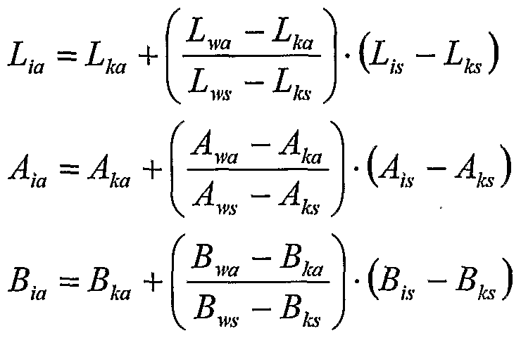
- the next step in the spring-primary mapping process is to process neutral points, that is, the points along the line between the white point and black points (the vertical line in Figure 5B).
- the following linear interpolation equations are applied to compute output color values:
- (Lj S , Aj 5 , Bj 5 ) and (Lj a , Aj a , Bj 3 ) are the LAB values of a source neutral color and its corresponding aimed output mapped color;
- Aj a and Bj a are not computed by above equations. Instead, A and B are simple assigned with zero.
- the indexes of the neutral nodes from W (the white point) to K (the black point) are: (16, 16, 16), (15, 15, 15), (14, 14, 14), (13, 13, 13), (12, 12, 12), (11, 11, 11), (10, 10, 10), (9, 9, 9), (8, 8, 8), (7, 7, 7), (6, 6, 6), (5, 5, 5), (4, 4, 4), (3, 3, 3), (2, 2, 2), (1 , 1 , 1), and (0, 0, 0).
- the next step in the spring-primary mapping process is determining aimed primaries of the gamut surface.
- Aimed primaries are determined before primary mapping.
- the lightness and hue angle of each aimed primary are determined by following weighting equations:
- L aimed ⁇ W L " ⁇ source + U ⁇ W L ) ' * ⁇ 'destination Kimed W h " ⁇ source + Q- ⁇ W h ) ' ⁇ destination
- L aime d, L SO urce, and Ldestination are the aimed lightness, the source lightness, and the destination lightness of a primary, respectively
- h a j me d, hsource, and hdestination are the aimed hue angle, the source hue angle, and the destination hue angle of the same primary, respectively
- w ⁇ _ and W h are a weighting parameter for lightness and hue angle, respectively.
- the WL and wt, values are between 0 and 1.
- weighting parameters for lightness and hue angle w ⁇ _ and w / can be adjusted in order to optimize the destination primaries.
- user interface 60 illustrated in Figure 7, is provided to adjust weighting parameters.
- weighting parameters for each aimed primaries (Red, Green, Blue, Cyan, Magenta, and Yellow) can be adjusted by first clicking an appropriate primary color (Red is illustrated as selected in the example in Figure 7) and then sliding one slider associated with lightness and one slider associated with hue.
- the slider position 0 corresponds to a weight of 1.0 (using the source primary as the aimed primary for the lightness or the hue angle), and the slider position 20 corresponds to a weight of 0 (using the destination primary as the aimed primary for the lightness or the hue angle). In this way, a determination is made for each of the primaries.
- the aimed lightness (Laimed) and the aim hue angle (h a j me d) or the weights WL and w h can be determined by algorithms automatically. For example, they can be determined based on rendering intents (e.g. different aims are determined between photographic mapping and graphic mapping). The user adjustments can be provided for fine-tuning.
- Figure 8 illustrates a constant hue gamut slice, with lightness in the vertical direction and chroma in the horizontal direction. K is the adapted black point, and W is the adapted white point.
- the gamut mapping search the maximum chroma in a constant lightness L a im ed as shown on the dashed line.
- the maximized chroma point P is located as the aimed primary.
- the chrominance A and B of LAB color gamut can be converted from LCh by:
- A C - cos(h) where C is chroma and h is hue angle. This process is then repeated for each primary, such that all six aimed primaries are determined using gamut mapping.
- the aimed primary is the destination primary, and no gamut mapping is required to search the aimed primary point P.
- the next step in the spring-primary mapping process is performing geometrical gamut reshaping in order to map the source gamut to the aimed gamut.
- the weighting parameter for lightness and hue angle corresponds to 0
- the aimed gamut is also the destination gamut.
- Figure 9A illustrates a portion or sub-gamut of each gamut set 80, which is composed by the white point (W), the black point (K), and two neighbor primaries.
- a source sub-gamut is the tetrahedron KP1P2W (solid lines), and an aimed sub-gamut is the tetrahedron Kp1p2W (dotted lines).
- the lightness is in the vertical direction and chrominance A and B are in the horizontal direction.
- the black point (K) and white point (W) of are the adapted black and white points.
- P1 and P2 are two source neighbor primaries, and p1 and p2 are two corresponding aimed primaries.
- the tetrahedron K-P1-P2-W is a portion of a three-dimensional device color gamut illustrated in Figure 5B.
- the tetrahedron K-P1-P2-W is the source gamut that is then mapped into an aimed gamut represented by the tetrahedron K-p1-p2-W (p1 is the aimed primary corresponding to source primary P1, and p2 is the aimed primary corresponding to source primary P2).
- p1 is the aimed primary corresponding to source primary P1
- p2 is the aimed primary corresponding to source primary P2
- source primary P1 is mapped to aimed primary p1
- source primary P2 is mapped to aimed primary p2.
- FIG. 9B illustrates a conceptual view 85 of how each line connecting each of two points in the tetrahedron K-P1-P2-W (solid lines) is an elastic string (or a spring), except the WK line.
- each line connecting each of two points in the tetrahedron K-p1-p2-W (dotted lines) is an elastic string (or a spring), except the WK line. Since the WK line has been mapped by white and black point adaptations and tone mapping, it is not included in the gamut reshaping process. The remaining segments of the tetrahedron, however, are reshaped.
- the sub-gamut represented by four points (W, K and two primaries) only approximately represent the sub-gamut of a device gamut
- some point on the aimed gamut surface can be slightly out of the destination gamut surface, and some points intended to be in the destination gamut surface might not be exactly on the destination gamut surface.
- Gamut mapping or other fine tuning methods are applied to adjust the source gamut surface points to the destination gamut.
- the interior points of the sub-gamut can also be reshaped from the source gamut to the aimed gamut accordingly in this step, they are processed in a later step.
- This primary mapping and reshaping is done for each of six primary sections, that is, for each of the tetrahedrons formed by the combination of the white and black points with two neighboring primaries.
- the elastic strings or springs illustrated in Figure 9B can be envisioned on of the eighteen lines that connect each of the six primaries to a neighbor primary and that connect each primary to each of the white and black points (see Figure 5B).
- eighteen springs are used: six of them are used to connect the white point to each of the six primaries; another six are used to connect the black point to each of the six primaries; and the remaining six are used to connect each primary to its neighbor primaries.
- a post gamut mapping step is used in one embodiment to fine-tune gamut surface colors so that the source gamut fits into the destination gamut. Because the reshaped gamut is already closely fitted into the destination gamut, a simple and fast gamut mapping method can be used to fine-tune the color mapping. And only the points on or closed to the destination gamut surface are fine-tuned.
- the next step in the spring-primary mapping process is processing the interior points, that is, those nodes on the interior of the gamut surface.
- the interior points that is, those nodes on the interior of the gamut surface.
- all nodes on the gamut surface of a three-dimensional lookup table have been mapped to the destination gamut.
- six interior triangles are established. Referring to Figure 5B, there are six triangles, each of which is composed of the white point (W), the black point (K), and a primary (P).
- Such an interior triangle 110 is illustrated in Figure 10, consisting of W, K, and P (a primary).
- a dotted line from P toward the middle of the neutral line between W and K has been added.
- An interior separation point Q is then added on that line.
- P will be outside the destination gamut.
- interior separation point Q is selected such that is far enough inside the destination gamut that a non-adjusted triangle region WQK (the shaded area in Figure 10) is defined within the interior triangle WKP in which no gamut mapping (compression or expansion) is performed.
- each node on the non-adjusted triangle WQK is mostly or all inside the destination gamut. Even in situations where a few nodes can be out of the destination gamut, they typically are close to the gamut surface.
- no color adjustment and gamut mapping is performed for nodes on the non-adjusted triangle WQK.
- the source LAB color of each node in this non-adjusted region is taken as the output LAB color.
- using this step of the spring-primary mapping process avoids gamut mapping for all of these nodes on the non-adjusted triangle WQK, thereby saving significant processing resources and time.
- an interpolation method is applied to compute the output LAB values. For example, a one dimensional interpolation similar to the method described earlier relating to processing neutral points can be applied to compute LAB values for nodes between Q and P. For the remaining points on the WPK plane, geometrical reshaping can be applied to adjust colors (fixing points W, Q, and K, and shaping point P).
- these points are interpolated by a distance-based interpolation using three or more points on the triangle boundary lines of the region (WQ, QP, and PW on the triangle WQP, or KQ, QP, and PK on the triangle KQP).
- the final step in the spring-primary mapping process is processing all remaining points.
- all gamut surface nodes and some interior nodes in a three-dimensional lookup table have been mapped to the destination gamut.
- the rest of the nodes in a lookup table are interpolated in three-dimensional manner.
- six points can be used for interpolation (six-weight interpolation). These six points are found from six directions relative to the point to be processed: up, down, left, right, front, and back.
- the weight for each point is computed based on the distance of the point to the point to be processed (the closer the distance, the smaller the weight).
- the distance can be replaced by a color difference metric using a color difference formula (for example, • E 94 ).
- an interpolation method for example, tetrahedral interpolation is applied to map the LAB into the destination device color space.
- the spring-primary mapping process avoids gamut mapping each node from a source color gamut to a destination color gamut, thereby providing a faster method of transformation of colors from a source color space to a destination color space.
- FIG 11 is a flow chart illustrating one embodiment of transformation of images from a source color device to destination color device using the spring- primary mapping process in accordance with the present invention.
- color gamuts are established for a source device and for a destination device.
- a device-independent color space (denoted LAB) is used for gamut representation and gamut mapping.
- This LAB color space can be CIELAB, CIELuv, CIECAM97s JAB, CIECAM02 JAB, etc.
- the source device is a color monitor and the source color gamut is established by converting the RGB color space into LAB.
- the destination device is a color printer and the destination color gamut is established in LAB converted from the CMYK color space.
- white point and black point adaptation is performed.
- the source white point (W) is mapped to the destination white point (w)
- the source black point (K) is mapped to the destination black point (k) in this step.
- the tone appearance adjustment and or color preference adjustment can be performed.
- neutral points of the color gamuts are processed.
- all the points along the line between the white point and black points are processed from the source to the destination gamut.
- linear interpolation equations are applied to compute output color values, and in another case a distance based interpolation is used.
- the aimed primaries of the gamut surface are processed.
- aimed or destination primaries are determined before the primary mapping.
- the lightness and hue angle of each aimed primary are determined using weighting equations.
- the lightness and hue angle of each aimed primary are determined by rendering intent based modeling.
- the chroma of the aimed primary is computed in one case by gamut mapping in a constant hue angle and constant lightness. This process is used for each primary, such that all six aimed primaries are determined using gamut mapping.
- gamut reshaping is performed in order to map the source gamut to the aimed or destination gamut.
- each pair of source primaries, along with the white and black points, are constructed as a tetrahedron, the source primaries of which are pulled to the corresponding destination primaries, thereby adjusting the points along the lines and planes connecting the primaries as well.
- the source gamut is reshaped to the aimed gamut.
- the overall effect is that each source primary is mapped to its corresponding aimed primary and the source gamut is closely reshaped to the aimed gamut.
- all source gamut surface points are mapped to the aimed gamut surface, and finally to the destination gamut with minor adjustment.
- interior points of the gamut are processed.
- interior triangles are established consisting of W (white point), K (black point), and P (one primary point), or in some embodiments, consisting of W (white point), K (black point), and one point on an edge point between two primaries.
- an interior separation point Q that is, Q is within the aimed gamut and within the destination gamut
- a non- adjusted triangle region WQK is defined.
- No gamut mapping is performed on the interior points, which are those within the non-adjusted triangle region WQK, such that the source LAB color of each node in this non-adjusted region is taken as the output LAB color.
- geometrical reshaping a distance-based interpolation is applied to adjust colors.
- step 212 remaining interior points of the gamut are processed. These remaining nodes are interpolated in three-dimensional manner. For each node, six points can be used for interpolation, such that a six-weight interpolation is used. The weight for each point is computed based on the distance of the point to the point to be processed (the closer the distance, the smaller the weight).
Abstract
Description
Claims
Priority Applications (1)
| Application Number | Priority Date | Filing Date | Title |
|---|---|---|---|
| GB0720269A GB2439682A (en) | 2005-04-29 | 2006-04-27 | Fast colour mapping using primary adjustment with gamut adaptation |
Applications Claiming Priority (2)
| Application Number | Priority Date | Filing Date | Title |
|---|---|---|---|
| US11/118,038 US20060244983A1 (en) | 2005-04-29 | 2005-04-29 | Fast color mapping using primary adjustment with gamut adaptation |
| US11/118,038 | 2005-04-29 |
Publications (2)
| Publication Number | Publication Date |
|---|---|
| WO2006119331A2 true WO2006119331A2 (en) | 2006-11-09 |
| WO2006119331A3 WO2006119331A3 (en) | 2009-01-15 |
Family
ID=37234129
Family Applications (1)
| Application Number | Title | Priority Date | Filing Date |
|---|---|---|---|
| PCT/US2006/016914 WO2006119331A2 (en) | 2005-04-29 | 2006-04-27 | Fast color mapping using primary adjustment with gamut adaptation |
Country Status (3)
| Country | Link |
|---|---|
| US (1) | US20060244983A1 (en) |
| GB (1) | GB2439682A (en) |
| WO (1) | WO2006119331A2 (en) |
Families Citing this family (24)
| Publication number | Priority date | Publication date | Assignee | Title |
|---|---|---|---|---|
| CN100531291C (en) * | 2004-11-01 | 2009-08-19 | 彩色印片公司 | Method and system for mastering and distributing enhanced color space content |
| CN101346984B (en) | 2005-12-21 | 2012-12-26 | 汤姆森特许公司 | Method for displaying colorful image and color display device for image |
| TW200731814A (en) * | 2006-02-14 | 2007-08-16 | Realtek Semiconductor Corp | Image processing method capable of adjusting hue and saturation of specific colors and related image processing apparatus thereof |
| US7755796B1 (en) | 2006-03-07 | 2010-07-13 | Adobe Systems Incorporated | Method and apparatus for selectively converting color values in a document |
| EP1838083B1 (en) * | 2006-03-23 | 2020-05-06 | InterDigital CE Patent Holdings | Color metadata for a downlink data channel |
| JP2007288470A (en) * | 2006-04-17 | 2007-11-01 | Fuji Xerox Co Ltd | Unit and method for color adjustment, unit and method for generating color conversion parameter, unit and method for color conversion, color adjustment program, color conversion parameter generation program, color conversion program, and recording medium |
| JP4788486B2 (en) * | 2006-06-13 | 2011-10-05 | 富士ゼロックス株式会社 | Color gamut outline creation device and color gamut outline creation program |
| EP2087721A1 (en) * | 2006-11-23 | 2009-08-12 | Koninklijke Philips Electronics N.V. | Gamut adaptation |
| US20080123948A1 (en) * | 2006-11-29 | 2008-05-29 | Monotype Imaging, Inc. | Profile creation configuration file |
| JP5262377B2 (en) * | 2007-08-09 | 2013-08-14 | ペンタックスリコーイメージング株式会社 | Imaging device |
| JP4518280B2 (en) * | 2007-11-14 | 2010-08-04 | 富士ゼロックス株式会社 | Color gamut forming device, color conversion device, color gamut forming program, color conversion program |
| US8314979B2 (en) * | 2008-05-27 | 2012-11-20 | Xerox Corporation | Color management methods and systems to adaptively tune colors for image marking devices |
| US10129513B2 (en) | 2008-08-28 | 2018-11-13 | Thomson Licensing | Color metadata for a downlink data channel |
| US8665290B2 (en) * | 2009-05-28 | 2014-03-04 | Canon Kabushiki Kaisha | Image-based source gamut adjustment for compression-type gamut mapping algorithm |
| US9661299B2 (en) | 2011-06-30 | 2017-05-23 | Thomson Licensing | Outlier detection for colour mapping |
| US9613435B1 (en) * | 2014-07-18 | 2017-04-04 | The Mathworks, Inc. | Color maps |
| EP3275190B1 (en) * | 2015-03-25 | 2024-04-17 | Dolby Laboratories Licensing Corporation | Chroma subsampling and gamut reshaping |
| EP3110124A1 (en) * | 2015-06-25 | 2016-12-28 | Thomson Licensing | Hue changing color gamut mapping |
| JP6320440B2 (en) | 2015-08-04 | 2018-05-09 | ドルビー ラボラトリーズ ライセンシング コーポレイション | Signal reconstruction for high dynamic range signals |
| EP3255872A1 (en) * | 2016-06-10 | 2017-12-13 | Thomson Licensing | Method of mapping source colors of an image in a chromaticity plane |
| EP3367659A1 (en) * | 2017-02-28 | 2018-08-29 | Thomson Licensing | Hue changing color gamut mapping |
| US20220132000A1 (en) * | 2019-07-10 | 2022-04-28 | Hewlett-Packard Development Company, L.P. | Color space conversion |
| KR20220069288A (en) * | 2020-11-20 | 2022-05-27 | 주식회사 엘엑스세미콘 | Color gamut mapping device, method for tuning the same and display device using the same |
| KR20220070745A (en) * | 2020-11-23 | 2022-05-31 | 주식회사 엘엑스세미콘 | Tuning method and apparatus for color gamut mapping device |
Citations (4)
| Publication number | Priority date | Publication date | Assignee | Title |
|---|---|---|---|---|
| EP0611231A1 (en) * | 1993-02-12 | 1994-08-17 | Eastman Kodak Company | Method for cross-device color calibration and enhancement using explicit constraints |
| EP0611230A1 (en) * | 1993-02-12 | 1994-08-17 | Eastman Kodak Company | Method and associated apparatus for transforming input color values in an input color space to output color values in an output color space |
| US6014457A (en) * | 1996-11-01 | 2000-01-11 | Fuji Xerox, Co., Ltd. | Image processing apparatus |
| EP1173004A2 (en) * | 2000-07-14 | 2002-01-16 | Canon Kabushiki Kaisha | Colour image processing apparatus and method |
Family Cites Families (5)
| Publication number | Priority date | Publication date | Assignee | Title |
|---|---|---|---|---|
| JP3305265B2 (en) * | 1998-07-24 | 2002-07-22 | キヤノン株式会社 | Image processing apparatus and method |
| JP4223708B2 (en) * | 2001-03-26 | 2009-02-12 | セイコーエプソン株式会社 | Medium recording color conversion program, color conversion program, color conversion table creation method, color conversion device, and color conversion method |
| US6719392B2 (en) * | 2001-12-20 | 2004-04-13 | International Business Machines Corporation | Optimized color ranges in gamut mapping |
| US6826304B2 (en) * | 2002-03-13 | 2004-11-30 | Hewlett-Packard Development Company, L.P. | Reducing halos in spatially dependent gamut mapping |
| US6873439B2 (en) * | 2002-03-13 | 2005-03-29 | Hewlett-Packard Development Company, L.P. | Variational models for spatially dependent gamut mapping |
-
2005
- 2005-04-29 US US11/118,038 patent/US20060244983A1/en not_active Abandoned
-
2006
- 2006-04-27 WO PCT/US2006/016914 patent/WO2006119331A2/en active Application Filing
- 2006-04-27 GB GB0720269A patent/GB2439682A/en not_active Withdrawn
Patent Citations (4)
| Publication number | Priority date | Publication date | Assignee | Title |
|---|---|---|---|---|
| EP0611231A1 (en) * | 1993-02-12 | 1994-08-17 | Eastman Kodak Company | Method for cross-device color calibration and enhancement using explicit constraints |
| EP0611230A1 (en) * | 1993-02-12 | 1994-08-17 | Eastman Kodak Company | Method and associated apparatus for transforming input color values in an input color space to output color values in an output color space |
| US6014457A (en) * | 1996-11-01 | 2000-01-11 | Fuji Xerox, Co., Ltd. | Image processing apparatus |
| EP1173004A2 (en) * | 2000-07-14 | 2002-01-16 | Canon Kabushiki Kaisha | Colour image processing apparatus and method |
Also Published As
| Publication number | Publication date |
|---|---|
| GB0720269D0 (en) | 2007-11-28 |
| GB2439682A (en) | 2008-01-02 |
| WO2006119331A3 (en) | 2009-01-15 |
| US20060244983A1 (en) | 2006-11-02 |
Similar Documents
| Publication | Publication Date | Title |
|---|---|---|
| US20060244983A1 (en) | Fast color mapping using primary adjustment with gamut adaptation | |
| US7403205B2 (en) | Fast primary mapping and gamut adaptation to construct three dimensional lookup tables | |
| EP0611230B1 (en) | Method and associated apparatus for transforming input color values in an input color space to output color values in an output color space | |
| US8045222B2 (en) | Image processing method, image processing apparatus, computer program product, and recording medium for image processing | |
| KR101166388B1 (en) | Color space conversion apparatus and control method for thereof | |
| US7961366B2 (en) | Color gamut modification and color mapping method and apparatus | |
| JPH1013701A (en) | Extension method for range of color of color printer and print method for color printer | |
| JP2012029276A (en) | Image forming device, color adjustment method and color adjustment program | |
| US8243308B2 (en) | Image processing apparatus for setting image quality mode and processing image data based on supplemental information | |
| JP2008219791A (en) | Image processor, image processing method, program, and recording medium | |
| JP4536431B2 (en) | Method and system for controlling a color output device | |
| US6637849B2 (en) | Systems and methods for HUE control | |
| JP5117140B2 (en) | Image forming apparatus, color data conversion method, and color data conversion program | |
| JP4971948B2 (en) | Image processing apparatus, image processing method, program, and recording medium | |
| US10778870B2 (en) | Black generation to optimize color gamut volume and quality within limits on colorant usage | |
| JP2007124243A (en) | Color conversion method | |
| JP2005191808A (en) | Image processing apparatus, image processing method, and image processing program | |
| US20070070363A1 (en) | Color processing color data undefined to a gamut | |
| JP2011155352A (en) | Image processor, image processing method and computer-executable program | |
| US7345786B2 (en) | Method for color cast removal in scanned images | |
| JP4533277B2 (en) | Image processing apparatus, image processing method, and table creation method | |
| JP4380503B2 (en) | Lookup table creation method and separation method | |
| JP4179048B2 (en) | Image processing method and image processing apparatus | |
| Chang et al. | Modeling a CMYK printer as an RGB printer | |
| JP4159912B2 (en) | Color conversion method with hue correction using multiple lookup tables and interpolation |
Legal Events
| Date | Code | Title | Description |
|---|---|---|---|
| ENP | Entry into the national phase |
Ref document number: 0720269 Country of ref document: GB Kind code of ref document: A Free format text: PCT FILING DATE = 20060427 |
|
| WWE | Wipo information: entry into national phase |
Ref document number: 0720269.0 Country of ref document: GB |
|
| NENP | Non-entry into the national phase |
Ref country code: DE |
|
| NENP | Non-entry into the national phase |
Ref country code: RU |
|
| 121 | Ep: the epo has been informed by wipo that ep was designated in this application |
Ref document number: 06758965 Country of ref document: EP Kind code of ref document: A2 |
|
| 122 | Ep: pct application non-entry in european phase |
Ref document number: 06758965 Country of ref document: EP Kind code of ref document: A2 |