WO2006135958A1 - Improved perfluorinated membranes and improved electrolytes for redox cells and batteries - Google Patents
Improved perfluorinated membranes and improved electrolytes for redox cells and batteries Download PDFInfo
- Publication number
- WO2006135958A1 WO2006135958A1 PCT/AU2006/000856 AU2006000856W WO2006135958A1 WO 2006135958 A1 WO2006135958 A1 WO 2006135958A1 AU 2006000856 W AU2006000856 W AU 2006000856W WO 2006135958 A1 WO2006135958 A1 WO 2006135958A1
- Authority
- WO
- WIPO (PCT)
- Prior art keywords
- membrane
- vanadium
- redox
- cell
- group
- Prior art date
Links
Classifications
-
- H—ELECTRICITY
- H01—ELECTRIC ELEMENTS
- H01M—PROCESSES OR MEANS, e.g. BATTERIES, FOR THE DIRECT CONVERSION OF CHEMICAL ENERGY INTO ELECTRICAL ENERGY
- H01M8/00—Fuel cells; Manufacture thereof
- H01M8/10—Fuel cells with solid electrolytes
- H01M8/1016—Fuel cells with solid electrolytes characterised by the electrolyte material
- H01M8/1018—Polymeric electrolyte materials
- H01M8/1069—Polymeric electrolyte materials characterised by the manufacturing processes
- H01M8/1086—After-treatment of the membrane other than by polymerisation
- H01M8/109—After-treatment of the membrane other than by polymerisation thermal other than drying, e.g. sintering
-
- B—PERFORMING OPERATIONS; TRANSPORTING
- B60—VEHICLES IN GENERAL
- B60L—PROPULSION OF ELECTRICALLY-PROPELLED VEHICLES; SUPPLYING ELECTRIC POWER FOR AUXILIARY EQUIPMENT OF ELECTRICALLY-PROPELLED VEHICLES; ELECTRODYNAMIC BRAKE SYSTEMS FOR VEHICLES IN GENERAL; MAGNETIC SUSPENSION OR LEVITATION FOR VEHICLES; MONITORING OPERATING VARIABLES OF ELECTRICALLY-PROPELLED VEHICLES; ELECTRIC SAFETY DEVICES FOR ELECTRICALLY-PROPELLED VEHICLES
- B60L50/00—Electric propulsion with power supplied within the vehicle
- B60L50/50—Electric propulsion with power supplied within the vehicle using propulsion power supplied by batteries or fuel cells
- B60L50/60—Electric propulsion with power supplied within the vehicle using propulsion power supplied by batteries or fuel cells using power supplied by batteries
- B60L50/64—Constructional details of batteries specially adapted for electric vehicles
-
- H—ELECTRICITY
- H01—ELECTRIC ELEMENTS
- H01M—PROCESSES OR MEANS, e.g. BATTERIES, FOR THE DIRECT CONVERSION OF CHEMICAL ENERGY INTO ELECTRICAL ENERGY
- H01M8/00—Fuel cells; Manufacture thereof
- H01M8/10—Fuel cells with solid electrolytes
- H01M8/1016—Fuel cells with solid electrolytes characterised by the electrolyte material
- H01M8/1018—Polymeric electrolyte materials
- H01M8/102—Polymeric electrolyte materials characterised by the chemical structure of the main chain of the ion-conducting polymer
- H01M8/1023—Polymeric electrolyte materials characterised by the chemical structure of the main chain of the ion-conducting polymer having only carbon, e.g. polyarylenes, polystyrenes or polybutadiene-styrenes
-
- H—ELECTRICITY
- H01—ELECTRIC ELEMENTS
- H01M—PROCESSES OR MEANS, e.g. BATTERIES, FOR THE DIRECT CONVERSION OF CHEMICAL ENERGY INTO ELECTRICAL ENERGY
- H01M8/00—Fuel cells; Manufacture thereof
- H01M8/10—Fuel cells with solid electrolytes
- H01M8/1016—Fuel cells with solid electrolytes characterised by the electrolyte material
- H01M8/1018—Polymeric electrolyte materials
- H01M8/1067—Polymeric electrolyte materials characterised by their physical properties, e.g. porosity, ionic conductivity or thickness
-
- H—ELECTRICITY
- H01—ELECTRIC ELEMENTS
- H01M—PROCESSES OR MEANS, e.g. BATTERIES, FOR THE DIRECT CONVERSION OF CHEMICAL ENERGY INTO ELECTRICAL ENERGY
- H01M8/00—Fuel cells; Manufacture thereof
- H01M8/10—Fuel cells with solid electrolytes
- H01M8/1016—Fuel cells with solid electrolytes characterised by the electrolyte material
- H01M8/1018—Polymeric electrolyte materials
- H01M8/1069—Polymeric electrolyte materials characterised by the manufacturing processes
- H01M8/1081—Polymeric electrolyte materials characterised by the manufacturing processes starting from solutions, dispersions or slurries exclusively of polymers
-
- H—ELECTRICITY
- H01—ELECTRIC ELEMENTS
- H01M—PROCESSES OR MEANS, e.g. BATTERIES, FOR THE DIRECT CONVERSION OF CHEMICAL ENERGY INTO ELECTRICAL ENERGY
- H01M8/00—Fuel cells; Manufacture thereof
- H01M8/10—Fuel cells with solid electrolytes
- H01M8/1016—Fuel cells with solid electrolytes characterised by the electrolyte material
- H01M8/1018—Polymeric electrolyte materials
- H01M8/1069—Polymeric electrolyte materials characterised by the manufacturing processes
- H01M8/1086—After-treatment of the membrane other than by polymerisation
- H01M8/1088—Chemical modification, e.g. sulfonation
-
- H—ELECTRICITY
- H01—ELECTRIC ELEMENTS
- H01M—PROCESSES OR MEANS, e.g. BATTERIES, FOR THE DIRECT CONVERSION OF CHEMICAL ENERGY INTO ELECTRICAL ENERGY
- H01M8/00—Fuel cells; Manufacture thereof
- H01M8/20—Indirect fuel cells, e.g. fuel cells with redox couple being irreversible
-
- B—PERFORMING OPERATIONS; TRANSPORTING
- B60—VEHICLES IN GENERAL
- B60L—PROPULSION OF ELECTRICALLY-PROPELLED VEHICLES; SUPPLYING ELECTRIC POWER FOR AUXILIARY EQUIPMENT OF ELECTRICALLY-PROPELLED VEHICLES; ELECTRODYNAMIC BRAKE SYSTEMS FOR VEHICLES IN GENERAL; MAGNETIC SUSPENSION OR LEVITATION FOR VEHICLES; MONITORING OPERATING VARIABLES OF ELECTRICALLY-PROPELLED VEHICLES; ELECTRIC SAFETY DEVICES FOR ELECTRICALLY-PROPELLED VEHICLES
- B60L2240/00—Control parameters of input or output; Target parameters
- B60L2240/40—Drive Train control parameters
- B60L2240/54—Drive Train control parameters related to batteries
- B60L2240/545—Temperature
-
- H—ELECTRICITY
- H01—ELECTRIC ELEMENTS
- H01M—PROCESSES OR MEANS, e.g. BATTERIES, FOR THE DIRECT CONVERSION OF CHEMICAL ENERGY INTO ELECTRICAL ENERGY
- H01M10/00—Secondary cells; Manufacture thereof
- H01M10/05—Accumulators with non-aqueous electrolyte
- H01M10/056—Accumulators with non-aqueous electrolyte characterised by the materials used as electrolytes, e.g. mixed inorganic/organic electrolytes
- H01M10/0564—Accumulators with non-aqueous electrolyte characterised by the materials used as electrolytes, e.g. mixed inorganic/organic electrolytes the electrolyte being constituted of organic materials only
- H01M10/0565—Polymeric materials, e.g. gel-type or solid-type
-
- H—ELECTRICITY
- H01—ELECTRIC ELEMENTS
- H01M—PROCESSES OR MEANS, e.g. BATTERIES, FOR THE DIRECT CONVERSION OF CHEMICAL ENERGY INTO ELECTRICAL ENERGY
- H01M8/00—Fuel cells; Manufacture thereof
- H01M8/18—Regenerative fuel cells, e.g. redox flow batteries or secondary fuel cells
- H01M8/184—Regeneration by electrochemical means
- H01M8/188—Regeneration by electrochemical means by recharging of redox couples containing fluids; Redox flow type batteries
-
- Y—GENERAL TAGGING OF NEW TECHNOLOGICAL DEVELOPMENTS; GENERAL TAGGING OF CROSS-SECTIONAL TECHNOLOGIES SPANNING OVER SEVERAL SECTIONS OF THE IPC; TECHNICAL SUBJECTS COVERED BY FORMER USPC CROSS-REFERENCE ART COLLECTIONS [XRACs] AND DIGESTS
- Y02—TECHNOLOGIES OR APPLICATIONS FOR MITIGATION OR ADAPTATION AGAINST CLIMATE CHANGE
- Y02E—REDUCTION OF GREENHOUSE GAS [GHG] EMISSIONS, RELATED TO ENERGY GENERATION, TRANSMISSION OR DISTRIBUTION
- Y02E60/00—Enabling technologies; Technologies with a potential or indirect contribution to GHG emissions mitigation
- Y02E60/10—Energy storage using batteries
-
- Y—GENERAL TAGGING OF NEW TECHNOLOGICAL DEVELOPMENTS; GENERAL TAGGING OF CROSS-SECTIONAL TECHNOLOGIES SPANNING OVER SEVERAL SECTIONS OF THE IPC; TECHNICAL SUBJECTS COVERED BY FORMER USPC CROSS-REFERENCE ART COLLECTIONS [XRACs] AND DIGESTS
- Y02—TECHNOLOGIES OR APPLICATIONS FOR MITIGATION OR ADAPTATION AGAINST CLIMATE CHANGE
- Y02E—REDUCTION OF GREENHOUSE GAS [GHG] EMISSIONS, RELATED TO ENERGY GENERATION, TRANSMISSION OR DISTRIBUTION
- Y02E60/00—Enabling technologies; Technologies with a potential or indirect contribution to GHG emissions mitigation
- Y02E60/30—Hydrogen technology
- Y02E60/50—Fuel cells
-
- Y—GENERAL TAGGING OF NEW TECHNOLOGICAL DEVELOPMENTS; GENERAL TAGGING OF CROSS-SECTIONAL TECHNOLOGIES SPANNING OVER SEVERAL SECTIONS OF THE IPC; TECHNICAL SUBJECTS COVERED BY FORMER USPC CROSS-REFERENCE ART COLLECTIONS [XRACs] AND DIGESTS
- Y02—TECHNOLOGIES OR APPLICATIONS FOR MITIGATION OR ADAPTATION AGAINST CLIMATE CHANGE
- Y02P—CLIMATE CHANGE MITIGATION TECHNOLOGIES IN THE PRODUCTION OR PROCESSING OF GOODS
- Y02P70/00—Climate change mitigation technologies in the production process for final industrial or consumer products
- Y02P70/50—Manufacturing or production processes characterised by the final manufactured product
-
- Y—GENERAL TAGGING OF NEW TECHNOLOGICAL DEVELOPMENTS; GENERAL TAGGING OF CROSS-SECTIONAL TECHNOLOGIES SPANNING OVER SEVERAL SECTIONS OF THE IPC; TECHNICAL SUBJECTS COVERED BY FORMER USPC CROSS-REFERENCE ART COLLECTIONS [XRACs] AND DIGESTS
- Y02—TECHNOLOGIES OR APPLICATIONS FOR MITIGATION OR ADAPTATION AGAINST CLIMATE CHANGE
- Y02T—CLIMATE CHANGE MITIGATION TECHNOLOGIES RELATED TO TRANSPORTATION
- Y02T10/00—Road transport of goods or passengers
- Y02T10/60—Other road transportation technologies with climate change mitigation effect
- Y02T10/70—Energy storage systems for electromobility, e.g. batteries
-
- Y—GENERAL TAGGING OF NEW TECHNOLOGICAL DEVELOPMENTS; GENERAL TAGGING OF CROSS-SECTIONAL TECHNOLOGIES SPANNING OVER SEVERAL SECTIONS OF THE IPC; TECHNICAL SUBJECTS COVERED BY FORMER USPC CROSS-REFERENCE ART COLLECTIONS [XRACs] AND DIGESTS
- Y02—TECHNOLOGIES OR APPLICATIONS FOR MITIGATION OR ADAPTATION AGAINST CLIMATE CHANGE
- Y02T—CLIMATE CHANGE MITIGATION TECHNOLOGIES RELATED TO TRANSPORTATION
- Y02T90/00—Enabling technologies or technologies with a potential or indirect contribution to GHG emissions mitigation
- Y02T90/10—Technologies relating to charging of electric vehicles
- Y02T90/16—Information or communication technologies improving the operation of electric vehicles
Definitions
- the present invention describes an improved membrane for Redox Flow Batteries, in particular for Vanadium Redox Batteries and energy storage systems and applications employing the Vanadium Redox Cells and Batteries.
- Redox Flow Batteries involve the use of two redox couple electrolytes separated by an ion exchange membrane that is the most important cell component
- a stable, low cost cation exchange membrane is needed for ail redox flow cells that operate with an acidic electrolyte and the use of a highly oxidising positive half-cell redox couple ta all redox flow cell systems means that the membrane must be stable to oxidising agents.
- the Vanadium Redox Batteries include All- Vanadium Redox Cells and Batteries employing a V(II)/V(III) couple in the negative half -cell and a V(W)/V(V) couple in the positive half-cell (referred to as the V/VRB, and Vanadium Bromide Redox Cells and Batteries employing the V(H)/V(III) couple in the negative half-cell and a bromide/polyhalide couple in the negative half-cell (referred to as the VfBvRB).
- V(V) or polyhalide ions in the charged positive half- cell of the V/VRB and V/BrRB systems respectively leads to rapid deterioration of most polymeric membrane materials, so only limited types of membranes can be employed for long life.
- a suitable membrane should therefore possess good chemical stability in the acidic vanadium sulphate or vanadium bromide electrolytes, good resistance to the highly oxidising V(V) or polyhalide ions in the charged positive half- cell electrolyte, low electrical resistance, low permeability to the vanadium ions or polyhalide ions, high permeability to the charge-carrying hydrogen ions, good mechanical properties and low cost.
- V/VRB k The All- Vanadium Redox Flow Battery, referred to here as ihe V/VRB k described in the following patents: Australian patent 575247, AU 696452, AU 704534, US patent 6143443 and US patent 6562514, while the Vanadium Bromide Redox Flow cell, referred to here as the V/BrRB is described in PCT/AU02/01157, PCT/GB2Q03/ 001757 and PCT/AU2004/000310.
- Both batteries employ a vanadium electrolyte solution in both half-cells, but in the case of the V/VRB, a vanadium sulphate solution is used in both half-cells and the cell employs the V(II)/V(II) couple in the negative half-cell and a V(IV)/V(V) couple in the positive half-cell electrolyte.
- the Vanadium Bromide Redox Battery (V/BrRB) employs a vanadium bromide electrolyte solution in both half-cells and the cell employs the V(II)/V(III) couple in the negative half-cell and a Br " /Br 3 or Br/ClBr 2 couple it. the positive half-cell electrolyte,.
- the positive half-cell couples are also referred to as haiide/polyhalide couples.
- the highly oxidising V(V) or polyhalide ions in the charged positive half-cell solutions lead to rapid deterioration of most polymeric membrane materials, so only limited types of membranes can be employed for long life..
- the membrane it can be postulated is therefore the most important component of the Vanadium Redox Batteries (VRBs) and a great amount of effort has been put into the selection or development of a suitable membrane that can offer the following characteristics: good chemical stability in the acidic vanadium sulphate or vanadium bromide electrolytes, good resistance to the highly oxidising V(V) or polyhalide ions in the charged positive half-cell electrolyte, low electrical resistance, low permeability to the vanadium ions or polyhalide ions, high permeability to the charge-carrying hydrogen ions, good mechanical properties and low cost. To date, only limited membranes have been shown to possess all or most of these characteristics.
- the perfiuorinated membranes such as Gore Select, Nafion 112, Nafion U 5 and Nafion 117 have been used with some success in the Vanadium Sulphate Electrolyte V/VRB, but these have tended to show blistering or folding and excessive water transfer behaviour during cycling.
- the degree of water transfer in the Vanadium Bromide Electrolyte Cell can be so high when these membranes are employed, that after only a small number of cycles, the capacity and coulombic efficiency drops dramatically.
- the high level of water or solution transfer is caused by the high level of swelling of the extruded Nafion membranes in water and in the acidic vanadium sulphate and vanadium bromide electrolytes that increases the pore size and therefore the transfer of water and vanadium or polybalide ions across the membrane.
- the degree of swelling is a function of the ionic strength of the solution, but is most severe in distilled water. When a Nafion membrane is transferred from water to the vanadium electrolyte, considerable shrinkage .can occur due to the differences in ionic strength between the pores and the external solution.
- Nafion membranes must first be equilibrated in the battery electrolytes prior to stack assembly since any shrinkage after assembly could give rise to ripping of the membrane sheets Similarly Nafion membranes cannot be assembled dry since the high level of swelling, up to 10%, that occurs when subsequently immersed in the V/VRB and WBrRB electrolytes, will lead to creasing and possible damage of the membrane in the cell stack. Furthermore, once wet, Nafion membranes should not be allowed to dry out as this could cause cracking of the resin and irreversible damage to the membrane. All of these issues give rise to considerable problems in the handling, storage, assembly and operation of redox flow batteries using Nafion membranes.
- Nafion membranes are also subject to fouling, so require higher purity electrolytes that significantly adds to the cost of the V-VRB and V/BrRB. These factors, combined with the high electrolyte volume transfer during charge-discharge cycling., has limited the performance of the Nafion membranes in the V/VRB and V/BrRB and combined with the high cost, has restricted its practical use to date.
- Gore Select membranes have also been tested in the Vanadium Redox Batteries, but significant blistering of the membrane was observed in both the vanadium sulphate and vanadium electrolytes after several weeks of cycling. This showed that the Gore Select perfluorinated membranes are unsuitable for use in the Vanadium Redox Batteries.
- Polysulphone membranes have also shown good chemical stability and good performance in the Vanadium Sulphate Electrolyte V/VRB, but have also been susceptible to fouling and loss of performance, requiring very high purity vanadium that adds to the cost of the electrolyte.
- vanadium electrolyte can cause serious fouling, so that costly purification processes are needed to produce vanadium oxides with low silica levels.
- an improved perfluorinated membrane is described that has shown excellent performance in both the V/VRB and the V/BrRB redox flow batteries, thereby allowing the manufacture of a cell stack that can be used with either the Vanadium Sulphate or Vanadium Bromide electrolyte. Due to the different properties and fabrication method used, the behaviour of these membranes in the vanadium redox flow cells is vastly different from those of the corresponding Nafiort or Gore Select perfluorinated membranes. Fabrication by dissolved resin solution casting has been found to be particularly advantageous since it results in a membrane with isotropic swelling and tensile strength properties and in particular the high level of swelling is considerably reduced compared to Nafion extruded membranes.
- the cast membranes show low linear expansion and insignificant swelling when wetted, can be allowed to dry out without any damage and can therefore be assembled in a dry or wet state.
- the improved perfluorinated membranes are typically pre-treated prior to use, this pre-treatment having the effect of reducing the resistance and therefore increasing the voltage efficiency during charge-discharge cycling.
- the membrane pre-treatment typically involves soaking the membrane in an aqueous solution for periods in excess of 20 minutes prior to use in the V/VRB or V/BrRB cell.
- the type of membrane treatment used has been found to be critical to the performance of the membrane in the V-VBR and V/BrRB and the inventors have found a number of excellent methods that give overall energy efficiencies of over 80% in both systems.
- this improved membrane shows good performance in both electrolytes, so that a redox cell stack tbr use with either electrolyte interchangeably can be manufactured, allowing significant manufacturing cost savings to be achieved.
- complexing agents may be used to bind the bromine.
- a range of complexing agents are available for bromine, but any complexing agent used in the V/BrRB must not interfere with the V 3+ /V 2+ redox reactions in the negative half- cell, nor cause fouling of the ion-exchange membrane.
- PCT/AU2004/000310 describes the use of polyethylene glycol (PEG) as a binding agent for bromine in the vanadium bromide redox cell.
- TAA Tetrabutylammonium bromide
- MEP N-Ethyl-N-Methylpyrrolidiniumbromide
- MEM N-Ethyl-N-Methylmorpholiniumbromide
- V-VRB and V/BrRB an imbalance in the state of charge of the positive and negative half-cell electrolytes can occur due to the air oxidation of the V(II) ions in the negative half-cell, or to the generation of hydrogen at the negative electrode during charging. Both of these processes lead to capacity losses that cannot be corrected by simple electrolyte remixing, so a rebalance cell or process is needed to restore balance and therefore system capacity by restoring the correct approximately 1 :1 ratio of V(E-) to V(V) ions in the negative and positive half-cell solutions respectively of the V/VRB, or approximately 1 : 1 ratio of V(II) to Br3 ' ions in the negative and positive half-cell solutions respectively of the V/BrRB.
- the inventors have found that the addition of certain simple organic compounds to the positive electrolyte can rebalance both V-VRB and V/BrRB cells by partially reducing the V(Y) or Br 3 " species to equalise the states of charge of the positive and negative half-cell electrolytes.
- the addition of ethanol or methanol as rebalancing agents is particularly advantageous since the product of the rebalancing reaction is carbon dioxide and water, so no impurities build up in the electrolyte.
- the amount of cthanol or methanol added can be readily calculated from the positive electrolyte volume and degree of imbalance in the positive and negative half-cell electrolytes.
- This invention also relates to Vanadium Redox Battery energy storage systems integrated into an energy system incorporating a photovoltaic array, wind turbines, diesel generators, electricity grid or other power generation equipment
- the batteries are integrated with a battery controller that monitors battery condition and determines optimum operation.
- the V/BrRB can operate with vanadium bromide concentrations of 2 - 3 M and bromide concentrations up to 9 M, This corresponds to a specific energy of 25-50 Wh/kg and an energy density range of 35-70 Wh/1 for the V/BrRB compared with only 15-25 Wh/kg and 20 - 33 Wh/1 respectively for the V/VRB,. With close to twice the energy density, the V/BrRB is much better suited to electric and hybrid vehicle applications.
- the V/BrRB powers the vehicle and when the available energy is used up, can be either electrically recharged by connecting to a suitable source of DC electric power, including any of the power generation systems described above.
- the V/BrRB can be mechanically refuelled by draining the discharged positive and negative half-cell electrolytes, the catholyte and anolytc respectively, into storage tanks and replacing these with freshly charged solutions.
- the drained solutions can then be recharged by pumping them through a separate charging V/BrRB stack connected to a power generation system such as any of the systems described above.
- the solutions can be recharged using off-peak electricity.
- redox cell may also be referred to m a redox battery and the All-Vanadium Redox Cells or Batteries and the Vanadium Bromide Redox Cells or Batteries may be collectively referred to as Vanadium Redox Batteries.
- redox Cell may also be referred to m a redox battery and the All-Vanadium Redox Cells or Batteries and the Vanadium Bromide Redox Cells or Batteries may be collectively referred to as Vanadium Redox Batteries.
- Disclosed are improved perfluorinated membranes for use in Redox Flow Cells and in particular.
- V/ VRB vanadium sulphate electrolyte in both half-cells
- V/BrRBX vanadium halide electrolyte in both half-cells
- These membranes differ from traditional extruded perfluori ⁇ ated membranes in that they have low swelling or linear expansion in both directions and are typically prepared by casting from a solution of dissolved resin.
- These cast membranes have been developed for use in Proton Exchange Membrane Fuel Cells in which the membrane is used as a solid electrolyte. Surprisingly however, the inventors have discovered that they can be successfully employed in redox flow cells that employ two different solutions containing soluble redox couples wherein the membrane prevents the two solutions from mixing.
- the disclosed resin dissolved cast perfluotmated ton-exchange membranes not only provide good chemical stability in the electrolyte, but also show improved water transfer properties, reduced swelling, reduced fouling and high energy efficiency during cycling.
- the cast perfluorinated membranes are typically pre-treated prior to use, this pre- treatment having the effect of reducing the resistance and therefore increasing the voltage efficiency during charge-discharge cycling in the redox cells,
- a Vanadium Redox Battery employing a cast perfluorinated membrane and a 50:50 vanadium(III)/(rV) solution as the initial feed electrolyte solution in both the positive and negative half cells.
- a Vanadium Redox Battery employing a cast perfluorinated membrane and a negative half-cell electrolyte solution comprising a supporting electrolyte selected from the group H 2 SO 4 , HBr or HBr/HCl mixtures and containing one or more vanadium ions selected from the group vanadium (FV), vanadium (III), and vanadium (H) and a positive half-cell solution comprising a supporting electrolyte selected from the group H2SO4, HBr or HBr/HCl mixtures and containing one or more ions selected from the group vanadium (ITT), vanadium (TV), vanadium (V), Br 3 and ClBr 2 " .
- a method of producing electricity by discharging the fully charged or partially charged Vanadium Redox Cell or Battery is disclosed, as well as methods of recharging the discharged or partially discharged Vanadium Redox Cell or Battery by integrating into a system employing a wind turbine, photovoltaic array, wave generator, diesel generator or other power generating equipment.
- Methods for rebalancing the vanadium electrolyte solutions and for chemically regenerating the positive half-cell solution of the Vanadium Redox Batteries are also disclosed.
- a Vanadium Bromide Redox Cell employing a solution containing a complexing agent for bromine is also disclosed, this complexing agent being selected from Tetrabutylammonium bromide (TBA), N-Ethyl-N-Methylpyrrolidiniumbromide (MEP), N-Ethyl-N-Methylmorpholiniumbromide (MEM), or mixtures thereof- Also disclosed are methods of producing the electrolyte for the V/BrRB,
- An immobilised or gelled electrolyte vanadium redox cell employing the resin cast perfluorinated membrane is also disclosed as well as a method of producing electricity by discharging the fully charged or partially charged Vanadium Redox Cell or Battery or the gelled electrolyte cell or battery is disclosed, as well as methods of recharging the discharged or partially discharged gelled electrolyte Vanadium Redox Cell or Battery.
- a Vanadium Redox Cell or Battery comprising: a positive half cell containing a positive half cell solution comprising a supporting electrolyte plus one or more ions selected from the group vanadium (171), vanadium (IV).
- vanadium (V) and polyhalide a negative half cell containing a negative half cell solution comprising a supporting electrolyte plus one or more vanadium ions selected from the group vanadium (II), vanadium (HI) and vanadium (IV); a perfluorinated ionically conducting membrane or separator disposed between the positive and negative half cells and in contact with the positive and negative half cell solutions, wherein the perfluorinated membrane has a thickness of between 0.5 and 5 mil, an acid capacity of between 0,5 and 2 mmol/g, a conductivity at 25oC of between 0 01 and 1 S/cm, a water uptake of between 30% and 70% at lOOoC for 1 hour, a tensile strength of between 20 and 60 MPa and a melting point ranging from 180 to 240oC.
- a perfluorinated ionically conducting membrane or separator disposed between the positive and negative half cells and in contact with the positive and negative half cell solutions, wherein the perfluorinated
- the perfluorinated cation exchange membrane comprises a polymer selected from the group a PTFE, perfluorosulfonic acid and perfluorosulphonic adid/PTFE copolymer Typically, the perfluorinated cation exchange membrane is in the acid form.
- the perfluorinated membrane is typically produced by casting from a solution of a resin that has an Equivalent Weight (EW) of between 800 and 1100 grams resin per equivalent SO3-, typically 1032 grams resin per equivalent SO3-, or an ion exchange capacity of between. 1.25 and 0 91 milliequivalents SO3- per gram resin, typically
- EW Equivalent Weight
- the membrane may be treated prior to use in the Vartadi um Redox Battery
- the improved membrane is preferably a resin dissolved cast membrane that shows isotropy, in contrast to the corresponding Nafion- UN that is resin fusing extruding membrane that exhibits anisotropy.
- the following table summarises the differences between the improved cast perfluorinated membrane and the corresponding National membrane produced by extrusion.
- a Vanadium Redox Cell or Battery which is fully or partially charged comprising: a positive half cell containing a positive half cell solution comprising a supporting electrolyte and one or more of the ions selected from vanadium (TV) ions, vanadium (V) ions and polyhalide ions; a negative half cell containing a negative half cell solution comprising a supporting electrolyte, vanadium (III) and vanadium (II) ions; a perfluorinated ionically conducting membrane or separator of the first aspect disposed between the positive and negative half cells and in contact with the positive and negative half cell solutions,
- a discharged vanadium redox cell or battery comprising- a positive half cell containing a positive half cell solution comprising a supporting electrolyte and vanadium (IV) ions; a negative half cell containing a negative half cell solution comprising a supporting electrolyte and vanadium (ITI) ions; a perfluorinated ionically conducting membrane or separator of the first aspect disposed between the positive and negative half cells and in contact with the positive and negative half cell solutions.
- the supporting electrolyte can be selected from the group H 2 SO 4 , HBr, of a mixture of HBr and HCl and the vanadium ion concentration can range from 0.1 to 5 Molar, More typically the vanadium ion concentration is between 1 and 4 M or between 1 and 3 M.
- the H 2 SO 4 or HBr concentration is typically between 2 and 9 M, 3 and 8 M, 4 and 6 M or 4 and 8 M and the HBr electrolyte may also contain HCl at a concentration, level of between 0,5 and 3 M or 1 and 2 M.
- the redox cells may be operated over one of the following temperature ranges - 15 to 50, 0 to 50, 5 to 50, -10 to 45, 5 to 40, 0 to 40, -10 to 40, 5 to 35, 0 to 35, -10 to 35, 5 to 30 , 0 to 30, 5 to 25, 5 to 20, 10 to 50, 15 to 50, 18 to 50, 15 to 40, 15 to 35 degrees centigrade..
- a Vanadium Bromide Redox Cell comprising a vanadium bromide electrolyte solution in. both half-cells, the vanadiuni bromide solution also including a complexing agent to bind the bromine and prevent any bromine vapours from being produced.
- the complexing agent may be included in both the anolyte and catholyte solutions, it is preferably added only to the catholyte or positive half-cell electrolyte where bromine is generated during charging.
- Any suitable bromine complexing agent can be used, but preferably, this is Tetrabutylammonium bromide (TBA), N-Ethyl-N-Methylpyrrolidini ⁇ mbromide (MEP), N-Ethyl-N-Methylmor ⁇ holiniumbromide (MEM), or mixtures of these. Even more preferably, the complexing agent is a mixture of N-Ethyl-N-
- the vanadium ion to total complexing agent ratio ranges from 0.25:1.0 to 1.0:0.25, but preferably from 1:1 to 1.0 to 0..5.
- the vanadium electrolyte may be immobilised or gelled, A suitable immobilising agent or gelling agent is fumed silica,
- the redox cell may be a stirred or agitated redox cell or a static redox cell or a flow redox cell or other suitable redox cell such as an immobilised redox cell or a gelled redox cell or other redox cell.
- the vanadium redox cell may be assembled into a bipolar vanadium redox cell stack assembly using bipolar electrodes.
- the positive and negative electrodes as well as the bipolar may be graphite plate, graphite board, carbon, glassy carbon, carbon felt (eg FIvH, Toyoba, Sign carbon or graphite felts), carbon fibre material (e.g. non- woven, type CFT-3000 Ahlstroem, Finland) cellulose carbon knit (e.g. GF-20, Nikon Carbon Company Limited, Japan), or conducting plastic comprising a carbon, filled polyethylene, polypropylene or composite plastic onto which is heat and pressure bonded the carbon felt active layer to provide a high surface area bipolar or end electrode assembly.
- the bipolar electrode is preferably a carbon filled polyethylene or polypropylene conducting plastic substrate on each side of which is heat and pressure bonded a sheet of carbon felt or graphite felt active layer.
- the bipolar electrode may be welded to the flow-frame that distributes electrolyte into each half-cell cavity by vibration welding, infrared welding, ultrasonic welding, heat welding or laser welding,,
- the Vanadium Bromide Redox Battery may also include a phase separation and reconstitution process whereby the organic phase containing the bromine complex is separated by gravity from the aqueous phase in the charged positive half-cell electrolyte of the charging cell, for separate storage and transportation so as to reduce the weight and volume of the stored energy for transportation cost reduction. Before extracting the energy from the charged, concentrated solutions, the organic phase is remixed with the corresponding aqueous phase in the positive half-cell of the discharge cell tanks.
- a process of rebalancing the electrolytes of a vanadium redox cell comprising fully or partially mixing the positive half cell solution with the negative half cell solution to form a fully mixed solution or partially mixed solution in the positive half cell and the negative half cell.
- the positive half cell may be sealed air tight and the positive solution may be deaerated.
- the positive half cell may be deaerated.
- the positive half cell and the positive solution may be dearated with nitrogen, argon, helium, or other suitable gas.
- the positive half cell and the positive solution may be dearated with a non oxygen containing gas.
- the negative half cell may be sealed air tight and the negative solution may be deaerated.
- the negative half cell may be deaerated.
- the negative half cell and the negative solution may be dearated with nitrogen, argon, helium, or other suitable gas.
- the negative half cell and the negative solution may be dearated with a non oxygen containing gas.
- a Vanadium Redox Battery system comprising a Vanadium Redox Battery of any one of the first to sixth aspects of the invention and further comprising a positive solution reservoir positive solution supply and return lines coupled between the positive solution reservoir and the positive half cell, a negative solution reservoir, negative solution supply and return lines coupled between the negative solution reservoir and the negative half cell, and at least one pump in at least one of the positive solution supply and return lines and at least one pump in at least one of the negative solution supply and return lines.
- the system of the seventh aspects may further comprise an electrical charger electrically coupled to a positive electrode in the positive half cell and to a negative electrode in the negative half cell.
- the electrical charger may comprise a power supply and a switch.
- the system may further comprise an electricity withdrawing circuit electrically coupled to a positive electrode in the positive half cell and to a negative electrode in the negative half cell.
- the electricity withdrawing circuit may comprise a resistor and a switch,
- a method of rebalancing the positive and negative electrolyte states of charge and system capacity involves the addition of a predetermined volume of ethanol, methanol or other organic compound that can be chemically oxidised to carbon dioxide and water by V(V), Br 2 or Brf in the positive electrolyte, whereby a proportion of the V(V), Br 2 or Br 3 species is reduced so as to balance the state of charge of the positive and negative half-cell electrolytes,
- a ninth aspect is a method of chemically regenerating the positive half-cell electrolytes of the vanadium redox flow colls using hydrogen peroxide to reduce the electrolyte volume required for each kWh of cell capacity.
- a process for producing the vanadium bromide electrolyte for the vanadium bromide redox cell of the first to seventh aspects involving the oxidative dissolution of vanadium trioxide powder using bromine liquid, bromine aqueous solution or bromine vapour as the oxidising agent.
- a Vanadium Redox Battery of the first to ninth aspects is integrated into an energy or power generation system incorporating a photovoltaic array, a wind turbine, a wave energy generator, a diesel generator or other power generation equipment.
- a redox cell having a positive half cell, a negative half cell, a positive half cell solution and a negative half cell solution further comprising: a perf ⁇ uorinated ionically conducting membrane located between the positive half cell and the negative half cell and in contact with the positive half cell solution and the negative half cell solution wherein the membrane has a thickness selected from the group of consisting of 0.5 to 5 mil, 1 to 2 mil and 25 to 50 micron thickness.
- the membrane has an acid capacity selected from the group consisting of 0.5 to 2 meq/g and 0.9 to 1 meq/g.
- the membrane has a conductivity selected from the group consisting of 0.01 to 1 S/cm and 0.S 1 to 1 S/cm at 25°C,
- the membrane has a water uptake selected from the group consisting of 30% to 70% and 40 to 60% at 100°C for 1 hour.
- the membrane has a tensile strength selected from the group consisting of 20 to 60 MPa and 35 to 50 MPa in both directions when, water soaked at 23°C.
- the membrane has a linear expansion selected from the group consisting of less than 8%, less than 5% and less than 3% in. both directions from 50% Relative Humidity at 23 0 C to water soaked at 23"C.
- the membrane has a melting point selected from the group consisting of 180 to 240°C and 200 to 230°C.
- the membrane is produced by casting from a solution of a resin that has an Equivalent Weight (EW) selected from the group consisting of 800 to 1100 grams resin per equivalent SO 3 " and 1032 grams resin per equivalent SO3 " -
- EW Equivalent Weight
- the membrane is produced by casting from a solution of a resin that has an ion exchange capacity selected from the group consisting of 1.25 to 0,91 milliequivalents SO 3 * per gram resin and 0.97 milliequivlanents SO3 " per gram resin.
- a resin that has an ion exchange capacity selected from the group consisting of 1.25 to 0,91 milliequivalents SO 3 * per gram resin and 0.97 milliequivlanents SO3 " per gram resin.
- micro particles are added to the membrane to increase the water uptake and conductivity as well as decrease the linear expansion of the membrane.
- first supporting electrolyte and the second supporting electrolyte arc substantially identical.
- the membrane has isotropic swelling and tensile strength properties.
- a redox cell having a positive half cell, a negative half cell, a positive half cell solution and a negative half cell solution further comprising: a perfluorinated cationically conducting membrane located between the positive half cell and the negative half cell and in contact with the positive half cell solution and the negative half cell solution wherein the membrane has isotropic swelling and tensile strength properties.
- said cell has a perflourinated cationically conducting membrane wherein the membrane has a thickness selected from the group of consisting of 0.5 to 5 mil, 1 to 2 mil and 25 to 50 micron thickness.
- the membrane has an acid capacity selected from the group consisting of 0.5 to 2 meq/g and 0.9 to 1 meq/g.
- the membrane has a conductivity selected from the group consisting of 0.01 to 1 S/cm and 0.81 to 1 S/cm at 25oC.
- the membrane has a water uptake selected from the group consisting of 30% to 70% and 40 to 60% at 100°C for 1 hour.
- the membrane has a tensile strength selected from the group consisting of 20 to 60 MPa and 35 to 50 MPa in both directions when water soaked at 23°C.
- the membrane has a linear expansion selected from the group consisting of less than 8%, les$ than 5% and less than 3% in both directions from 50% Relative Humidity at 23°C to water soaked at 23°C.
- the membrane has a melting point selected from the group consisting of 180 to 240°C and 200 to 230°C.
- the membrane is produced in use by casting from a solution of a resin that has an Equivalent Weight (EW) selected from the group consisting of 800 to 1100 grams resin per equivalent SO 3 " and 1032 grams resin per equivalent SO3 " .
- EW Equivalent Weight
- the membrane is produced by casting from a solution of a resin that has an ion exchange capacity (1/EW) selected from the group consisting of 1.25 to 0.91 milliequivalents SO 3 " per gram resin and 0.97 milliequivlanents SO3 " per gram resin
- micro particles are added to the membrane to decrease the linear expansion of the membrane.
- a redox cell having a positive half cell, a negative half cell, a positive half cell solution and a negative half cell solution further comprising: a perfluorinated ionically conducting membrane located between the positive half cell and the negative half cell and in contact with the positive half cell solution and the negative half cell solution wherein the membrane has a thickness of between 0.5 to 5 mil; an acid capacity of between 0.5 and 2 meq/g; a conductivity at 25°C of between 0.01 and 1 S/cm; a water uptake of between 30% and 70% at 100°C for 1 hour; a tensile strength of between 20 and 60 MPa in both directions when water soaked at 23°C; a linear expansion of less than 8% from 50% Relative Humidity at 23°C to water soaked at 23"C in both directions; a melting point ranging from 180 to 240°C, wherein the perfluorinated membrane is produced by casting from a solution of a resin, selected from a
- said cell has a perflourinated ionically conducting membrane wherein, the membrane has a thickness selected from the group of consisting of approximately 1 to 2 mil and approximately 25 to 50 micron thickness.
- the membrane has an acid capacity of 0.9 to 1 meq/g.
- the membrane has a conductivity of 0.81 to 1 S/cm at 25oC.
- the membrane has a water uptake of 40 to 60% at 100°C for 1 hour.
- the membrane has a tensile strength of 35 to 50 MPa in both directions when water soaked at 23°C.
- the membrane has a linear expansion selected from the group consisting of less than 5% and less than 3% in both directions from 50% Relative Humidity at 23°C to water soaked at 23°C.
- the membrane has a melting point of 200 to 23O 0 C.
- the membrane is produced by casting from a solution of a resin that has an Equivalent Weight (EW) of 1032 grams resin per equivalent SO3- .
- EW Equivalent Weight
- the membrane is produced by casting from a solution of a resin that has an ion exchange capacity of 0.97 mil ⁇ equivlanents SO3- per gram resin.
- micro particles are added to the membrane to decrease the linear expansion of the membrane.
- the positive half cell solution includes a first supporting electrolyte selected from the group consisting of H 2 S ⁇ 4 , HBr and HBr/HCl mixtures and at least one vanadium ion selected from the group consisting of vanadium (III), vanadium (IV) and vanadium (V); and wherein the negative half cell solution includes a second supporting electrolyte selected from the group consisting of H 2 SO 4 , HBr and HBr/HCl mixtures and at least one vanadium ion selected from the group consisting of vanadium Ql), vanadium (III) and vanadium (IV).
- the positive half cell solution includes at least oae vanadium ion selected from the group consisting of vanadium (III), vanadium (IV) and vanadium (V); and the negative half cell solution includes at least one vanadium ion selected from the group consisting of vanadium (H), vanadium (III) and vanadium (IV).
- a method for treating the perfluorinated membranes of the redox cell described above comprising the step of soaking the membrane in an aqueous solution to reduce resistivity of the membrane and enhance voltage efficiency during charge-discharge cycling.
- the treatment is carried out at above room temperature.
- the membrane treatment is conducted in a process having at least one step and in at least one aqueous solution.
- the aqueous solution is selected from tne group consisting of hydrogen peroxide, HCl, NaOH and sulphuric acid .
- Preferably said method further comprises boiling the membrane in water.
- FIG. 1 illustrates a vanadium redox flow cell employing a perfluorinated cation. exchange membrane (1) to separate the positive and negative half-cells.
- Each half-cell includes a porous graphite feK or matte as the negative (2) or positive (3) flow-through electrode, each making electrical contact with a conducting substrate or current collector (4 and 5).
- the negative and positive electrolyte half-cell solutions are stored in separate external reservoirs (6 and 7) and pumps 8 and 9 are used to pump the electrolytes through the corresponding half-cells where the charge-discharge reactions occur.
- FIG. 2 illustrates a static or gelled electrolyte redox cell employing a perfluorinated membrane (1) to separate the positive and negative half-cells.
- each half-cell contains a graphite felt porous electrode impregnated with the V(3.5+) vanadium electrolyte that also contains sufficient fumed silica such that a gel is formed in both the negative (2) and positive (3) half-cell graphite felt electrodes when allowed to set.
- the graphite felt electrodes make electrical contact to a conducting substrate that is used as current collector in both the negative (4) and positive (5) half- cells.
- Figure 3 shows the voltage versus time curves obtained in a static vanadium bromide redox cell employing a polysulphone anion exchange membrane and 2 M vanadium ions in a supporting electrolyte of 6 M HBr plus 2 M HCl.
- Figure 4 shows typical charge-discharge curves obtained in a static vanadium bromide redox cell employing 2 M vanadium ions in a supporting electrolyte of 6 M HBr plus 2 M HCl.
- the membrane was a 25 cm 2 piece of Nafion 112 and the cell was cycled at 500 mA.
- Figures 5(a) and 5(b) show typical charge- discharge curves obtained in a vanadium.
- Figure 6 shows typical charge-discharge curves obtained in a static vanadium bromide redox cell employing 2 M vanadium ions in a supporting electrolyte of 6 M HBr plus 2 M HCl.
- the membrane was a piece of 50 micron cast perfluorinated membrane
- Figure 7 shows a vanadium bromide redox flow cell employing a complexing agent to bind the bromine and allow gravity separation of the organic phase prior to transportation.
- Figure 8 shows typical charge-discharge curves obtained in a vanadium bromide redox flow cell employing 2 M vanadium ions in a supporting electrolyte of 6 M HBr plus 2 M HCl.
- the membrane was a piece of 50 micron (20 mil) thick cast perfluorinated membrane and the cell employed graphite felt electrodes of area 25 cm2, approximately 60 mis of 2 M vanadium bromide electrolyte in each half-cell.
- the cell was charge- discharge cycled at 1000 mA.
- Figure 9 shows typical charge-discharge curves obtained with a 50 mil thick cast perfluorinated membrane tested in the static Vanadium Bromide Redox Cell at a current of 500 IDA.
- Figure 10 shows the water transfer behaviour of the Nafion 112 membrane in a V-VRB redox cell arrangement
- Figure 11 shows typical charge and discharge curves for a static cell employing the cast perfluorinated membrane and a 2 M vanadium solution in 5 M H 2 SO 4 supporting electrolyte as the electrolyte for both positive and negative half-cells.
- the membrane was boiled in distilled water for 45 minutes prior to use.
- Figure 12 represents typical charge-discharge curves for the cycling of the static vanadium sulphate redox cell that employed a cell cavity of 2 mm thickness and a cast perfluorinated membrane that was treated by boiling in 10 % hydrogen peroxide for 1 hour.
- Figure 13 shows typical charge-discharge curves for a vanadium sulphate redox flow cell containing approximately 60 ml in each half-cell of 1.6 M vanadium solution in H 2 SO 4 .
- the membrane was a 50 micron thick cast perfluorinated membrane treated in 5 M H 2 SO 4 for 30 minutes prior to use.
- Figure 14 shows typical charge-discharge curves obtained in a static cell containing 1 >6 M vanadium in sulphuric acid and a 25 micron thick piece of perfluorinated membrane that was soaked in boiling H 2 SO 4 (removed from hotplate) for 30 minutes prior to use.
- Figure 15 is a plot of capacity versus cycle number for a V-VRB redox flow cell to which 1 ml of ethanol was added to the positive half-cdl electrolyte to rebalance the positive and negative half-cell electrolyte oxidation states and restore capacity.
- Figures 16 (a) and (b) show the effect of addition of hydrogen peroxide to chemically regenerate the positive half-cell electrolyte of a vaoadium redox cell.
- Figure 16(a) shows discharge with hydrogen peroxide added to the positive half cell and
- Figure I6(b) shows discharge without hydrogen peroxide.
- Vanadium Redox Battery is used to refer collectively to the ⁇ U- Vanadium Redox Cell or Battery and the Vanadium Bromide Redox Cell or Battery.
- the supporting electrolytes used in the Vanadium Redox Batteries of the invention are preferably aqueous solutions selected from the group H 2 SO 4 , HBr or HBr/HCl mixtures.
- the Vanadium Redox Batteries can employ an initial feed solution of 0.1 to 5 M vanadium (TJI)/(TV) ions in both half-cells.
- the concentration of vanadium ions in both half-cells may be in the range 0.1 to 4.5M, 0.1 to 4M, 0.1 to 3.5M, 0.1 to 3M, 0.1 to 2.5M, 0.1 to 2M 5 0.1 to 1.9M, 0 1 to 1.75M 0.1 to 1.5M 1 0.1 to L25M, 0 1 to IM, 0.5 to 5M, 05 to 4 M, 0.5 to 3 M, 1 to 2 M, 1 to 3 M, 1 to 5M, 1.5 to 5M, 1.75 to 5M, 1.9 to 5M 5 2 to 5M, 2.25 to 5M 5 2.5 to 5M, 2.75 to SM, 3 to 5M, 3,5 to 5M, 4 to 5M, 4.5 to 5M 1 1.75 to 4 5M, 1.75 to 4M, 1.75 to 3.5M 5 1.75 to 3.25M, 1 to 2, 1 to 3M, 1.5 to 3M, 1.75 to 3M, 1 to 2.75M, L5 to 2.75M 1.75 to 2.75, 1 ,5 to 2.5
- An initial feed solution of 0.5 to 3 M vanadium solution consisting of approximately 50% V(III) and 50% V(IV) ions in a supporting electrolyte of H 2 SO 4 , HBr or HBr/HCl mixtures may be initially placed into the positive and negative half-cells.
- the initial feed solution for the V/VRB is typically 0.5 to 3 M V(III)/V(IV) ions in 2-8 M H 2 SO 4 , but more typically 1- 2 M V(III)/V(IV) ions in 4-6 M or 4-5 M H 2 SO 4 .
- the Vanadium Sulphate electrolyte solution may also contain stabilising agents to prevent the thermal precipitation of V(V) ions at elevated temperatures.
- the electrolyte solution that is initially placed in both half-cells of the Vanadium Bromide Redox Bell may comprise 0.5 to 3 M V(III)/(TV) ions in a supporting electrolyte of 1 to 9 M HBr, for example, or 2 to 9 M HBr or 3 to 8 M HBr or 4 to 6 M HBr.
- the vanadium bromide electrolyte may also contain HCl at a concentration between 0.5 and 3 M or 0.5 to 2 M or 1 to 2 M or 0.1 to 3 M.
- the vanadium bromide electrolyte may also contain a cotnplexing agent for bromine, this complexing agent being selected from Tetrabutylammonium bromide (TBA), N-Ethyl- N-MethylpyrroHdiniumbromide (MEP). N-Ethyl-N-Methylttior ⁇ holiniumbromide (MEM), or mixtures of these, preferably, N-Ethyl-N-Methylpyrrolidiniumbromide (MEP), N-Ethyl-N-Methylmorphollimiurabromide (MEM), or mixtures thereof.
- TAA Tetrabutylammonium bromide
- MEP N-Ethyl- N-MethylpyrroHdiniumbromide
- MEM N-Ethyl-N-Methylttior ⁇ holiniumbromide
- MEM N-Ethyl-N-Methylpyrrol
- the coxnplexing agent is a mixture of N-Ethyl-N- Methylpyrrolidiniumbron-dde (MEP) and N-Ethyl-N-Methylmorphotiniumbromide (MEM) in a molar ratio ranging from 0:1.0 to 1 ,0:0, more preferably in a molar ration ranging from 0.25:0 75 to 0.75:0.25.
- the vanadium ion to total complexing agent molar ratio ranges from 10:1 to 1 :1- but is preferably in the range 8:1 to I 1 I or 6:1 to 1:1 or 3:1 to 1:1.
- the initial feed solution for the positive half-cell is 03 to 3 M V(TV) ions in a supporting electrolyte selected from the group 2-6 M H 2 SO 4 2-6 M total sulphate or 1 to 9 M HBr
- the initial feed solution for the negative half-cell comprises 0,5 to 3 M V(III) ions in a supporting electrolyte selected from the group 2-6 M H 2 SO 4 , 2-6 M total sulphate or 1 to 9,M HBr.
- the total vanadium ion concentration is 0.5 to 5 M or 0.5 to 4 M or 1 to 4 M or 1.5 to 4 M or 1.5 to 3 or 1.5 to 2 or 2 to 4 M or 2 to 3 M and the H2S04, total sulphate or HBr concentration may be 2-9 M, 2-8 M, 2-7 M, 2-6 M, 2-5 M, 3-9 M, 3-8 M, 3-7 M, 3-6 M, 4-9 M, 4-8 M, 4-7 M, 4-6 M, 5-9 M, 5-8 M, 5-7 M, 5-6 M, 6-9 M, 6-8 M,
- the H Br electrolyte may also contain 0.5 to 3 M HCl, more typically 1 -2 M HCl
- the HBr electrolyte may also contain a complexing agent to bind the bromine, the total concentration of N-Ethyl-N- Methylpyrrolidiniumbromide (MEP) and N-Ethyl-N-Methylmorpholiniumbromidc (MEM) ranging
- the MEM to MEP ratio is between 0.25:0.75 and 0.75:0.25, while the vanadium to total MEM/MEP molar ratio is in the range 10:1 to 1:1, or in the range 5:1 to 1:1, and more preferably in the range 4:1 to 2:1.
- a gelled or immobilised vanadium redox cell is also disclosed
- an immobilising or gelling agent such as silica, fumed silica, fumed alumina, fumed titania or polyacrylamide
- the immobilisation or gelling of the electrolyte also binds any bromine vapour produced in the positive half-cell during charging, preventing any bromine escaping from the cell.
- the electrolyte may also contain a complexing agent to bind the bromine and reduce any bromine vapour.
- the two half-eel! electrolytes of me flow-cell are separated by a perfluorinated ion exchange membrane which prevents the bulk mixing of the 2 solutions as they are pumped through the cell or cell stack.
- the ion exchange membrane is a perfluorinated cation exchange membrane which allows the transfer of the charge carrying H + ions.
- the perfluorinated membrane has a thickness of between 0.5 and 5 mil, preferably between approximately 1 and 2 mil or between approximately 25 and 50 micron thickness, an acid capacity of between 05 and 2 meq/g, preferably between 0.9 and 1 meq/g, a conductivity at 25°C of between 0-01 and 1 S/cm, preferably between 0.81 and 1 S/cm, a water uptake of between 30% and 70%, preferably between 40 and 60% at 100oC for 1 hour, a tensile strength of between 20 and 60 MPa, preferably between 35 and 50 MPa in both directions when water soaked at 23°C, a linear expansion of less than 8% from 50% Relative Humidity at 23°C to water soaked at 23°C , preferably less than 5% and more preferably less than 3% in both directions and a melting point ranging from 180 to 240°C, preferably between 200 and 230°C.
- the perfluorinated membrane is typically produced by casting from a solution of a resin that has am Equivalent Weight (EW) of between 800 and 1100 grams resin per equivalent S(V, typically 1032 grams resin per equivalent SO3 " , or an ion exchange capacity (1/EW) of between 1 25 and 0,91 milliequivaleats SO 3 " per gram resin, typically 0.97tnilliequivlanents SO 3 " per gram resin.
- EW Equivalent Weight
- micro particles may be added to the membrane to increase the water uptake and conductivity as well as decrease the linear expansion of membrane.
- the lower EW of this membrane (1032) compared with the corresponding Nafion UN membrane (EW I 124), results in a higher ion exchange capacity (0.97meq/g) which is higher than that of Nafion 1 IN (0.89meq/g), and this also results in a higher conductivity, water uptake, a ⁇ d power density compared with Nafion.
- the cast membrane may be treated prior to use in the vanadium sulphate redox flow cell.
- the perfluorinated cation exchange membrane comprises a polymer selected from the group a PTFE, perfluorosurfomc acid and perfluorosulphonic acid/PTFE copolymer.
- the perfluorinated cation exchange membrane is a cast perflu ⁇ rinated membrane in the acid form.
- the perfluorinated membrane is treated by soaking in an aqueous solution for between 5 minutes and 24 hours.
- the membranes may be soaked in the aqueous solution at temperatures above room temperature.
- the membrane treatment can be a single step or a multi-step process involving the step- wise soaking the membrane in one or more of the treatment solutions at or above room temperature.
- the treatment solutions can include boiling or near boiling water, or solutions of H 2 SO 4 , H 2 O 2 , HC1 or NaOH.
- the treatments in H 2 SO 4 , H 2 O 2 , HCl or NaOH can be at room temperature or at elevated temperature, but typically, the lower the treatment temperature, the longer the necessary treatment time and vice versa.
- Suitable treatments for membranes of less than 50 microns thickness include soaking at or near room temperature in solutions of H 2 SO 4 , H 2 O 2 , HCl or NaOH for periods over 5 hours, preferably for more than 10 hours and even more preferably for more than 20 hours.
- Membranes of thickness equal to or greater than 50 microns are typically treated in solutions Of H 2 SO 4 , H 2 O 2 , HCl or NaOH at above room temperature, more typically at above 50°C, for periods of between 5 and 90 minutes, or preferably for between 10 and 60 minutes or more preferably for between 20 and 60 minutes.
- the negative and positive electrode materials for the vanadium redox flow cell or redox cell may be porous carbon or graphite felt, matte or cloth materials on a graphite, glassy carbon or conducting plastic substrate.
- the positive electrode material can also be an oxide coated titanium metal sheet or expanded metal mesh.
- Multiple cells can also be incorporated into a cell stack consisting of bipolar electrodes, these bipolar electrodes comprising carbon or graphite felt, cloth or matte either pressed against or heat welded onto a conducting plastic substrate, this conducting plastic substrate comprising carbon filled polyethylene, polypropylene or other thermoplastic polymer that may also be mixed with a rubber material to impart good mechanical properties.
- the bipolar electrodes for the vanadium redox flow cell or redox cell can also be produced by heat bonding the porous carbon or graphite felt into each side of apolyethylene, polypropylene or other polymer sheet such that the conducting carbon or graphite felt fibres in each side of the insulating substrate contact each other through the plastic sheet, thereby making electrical contact without the need, to add a conducting filler to the plastic substrate.
- the bipolar electrodes may be welded to the electrolyte flow- frame by infrared welding, vibration welding, ultrasonic welding, heat welding or laser welding.
- the two half-cell electrolytes are stored in external tanks and are pumped through the cell stack where the charging and discharging reactions occur.
- the electrolytes can be electrically charged by connecting the cell or battery terminals to a suitable power source, bat can also be mechanically refuelled by exchanging the discharged solutions with recharged solutions at a refuelling station in the case of electric vehicle applications.
- the charging and discharging of the electrolytes can be performed by two separate stacks, one for charging and one for discharging and the electrolytes can be transported between the charging stacks and the discharging stacks either by road, train or ship.
- the organic MEM-brominc, MEP-bromine and/or MEM-MEP-brornine complex can be separated from the aqueous component of the electrolyte by simple gravity separation and transported to the discharge stack site where it is added to an equivalent aqueous solution and mixed together to produce an emulsion that is pumped through the discharging stacks to release the stored energy.
- the required proportion of the discharged solution is then transported to the charging station where the MEM-bromine, MEP-bromine or MEM-MEP-bromine active species is again produced in the positive half-cell electrolyte during the charging phase and again separated by gravity from the aqueous component of the positive electrolyte prior to transportation to the discharge station.
- water can be removed from the charged negative half-cell electrolyte prior to transportation and reconstituted prior to use
- the stack terminals are connected to a load and whe ⁇ the circuit is closed, electricity is produced by the flow of electrons from the negative terminal to the positive terminal of the cell or battery stack.
- Charging and discharging can be earned out either with the pumps switched on and the electrolytes rccirculating through the external tanks and cell stack, or with the pumps off, allowing the solution in the stack itself to undergo discharge reactions.
- Periodically the two solutions may be remixed to produce the original V(3.5+) electrolyte in both tanks. This mixing allows any chemistry imbalance arising from the transfer of ions across the membrane to be corrected, so that the capacity of the system can be restored.
- the periodic mixing can be full or only partial mixing and also allows for any electrolyte level imbalance in each half-cell reservoir to be equalised.
- the electrolyte level equalisation can be done by using pumps or by simply gravity rebalance. Periodically predetermined volumes of methanol or ethanol are added to the positive electrolyte to restore the balance in the state of charge of the positive and negative half-cell electrolytes.
- the 2-4 M vanadium electrolyte may be gelled with 3-6 wt% fumed silica or other suitable gelling agent to produce a gelled or immobilised electrolyte Vanadium Redox Battery that permits greater stabilisation of the vanadium ions in the electrolyte and minimises electrolyte or in the case of the V/BrRB, bromine vapour leakage from the cell or cell stacks.
- all of the solutions are stored in the cell stack and there are no external tanks or pumps.
- the vanadium bromide redox battery energy storage system (VBRES) of this invention includes reservoirs to store the vanadium electrolyte, an energy conversion mechanism defined as a cell stack, a piping and pumping flow system, and a power conversion system (PCS).
- VBRES vanadium bromide redox battery energy storage system
- PCS power conversion system
- a suitable energy storage system for remote or on-grid power system applications that are supplied by either photovoltaic arrays, wind turbine generators or wave generators would employ a V/BrRB redox battery of the present invention.
- the anolyte and catholyte solutions are pumped from the anolyte and catholyte tanks into the negative and positive half- cells of the cell stack via the anolyte and catholyte supply lines.
- the anolyte and catholyte supply lines each communicate with a variable speed pump and optionally a heat exchanger that transfers generated heat from the anolyte or catholyte solutions to a . fluid or gas medium.
- the anolyte and catholyte supply lines include one or more supply line valves to control the volumetric flow of the solutions.
- the negative and positive electrodes are in electrical communication with a power source and a load.
- a power conversion system may be incorporated to convert DC power to AC power as needed.
- a control system may be embodied as a programmable logic computer with a processor in electrical communication with a memory mat receives and stores executable applications and data.
- the control system turns the pumps on or increases pump speeds to maintain supply of charged electrolyte species to the cells.
- the pump speeds are decreased or can be switched off for a preset time to allow the electrolyte in the cell stacks to provide the reactants for the discharge reactions.
- the pumps arc automatically switched on once the stack or cell voltage reaches a predetermined lower limit during discharge, or as soon as the load exceeds a pre-set value.
- Temperature limits are typically set at a minimum of 5 0 C and at a maximum of 40 °C.
- partial electrolyte mixing can be used as an emergency discharge method to bring the State of Charge (SOC) of the anoiyte and catholyte down to a safe level for the corresponding temperature,.
- SOC State of Charge
- the same system integration and operation can also be used with the V- VRB.
- control module also monitors the levels of the anolyte and catholyte solutions and determines if equalization of solution reservoir levels is needed.
- the control module operates the equalization/mix control valve between the anolyte and catholyte tanks to adjust the reservoirs levels as needed.
- a 1-3 M vanadium solution comprising approximately 50% V(HI) and 50% V(IV) ions in an electrolyte of either 3-6 M total sulphate or in a solution containing 4-9 M HBr plus 0.5-2 M HCl, is added in approximately equal volumes to both sides of the Vanadium Redox Cell or Battery.
- the cells or battery stacks comprise carbon or graphite felt electrodes heat and pressure bonded onto both sides of plastic or conducting plastic sheets as substrate materials and the two half cells are separated by a cast perflu ⁇ rinated or modified resin extruded cation exchange membrane.
- the conducting plastic substrates are typically carbon-filled polyethylene or carbon-filled polypropylene.
- the carbon-f ⁇ lled composite may also include rubber to improve its mechanical properties.
- the bipolar electrodes may be attached to the electrolyte flow- frame by vibration welding, ultrasonic welding, heat welding or laser welding.
- the electrodes of the vanadium redox cell may also be made using carbon or graphite felt or matte compressed against a glassy carbon or graphite sheet substrate.
- the perfluorinated membrane has an approximate thickness of between 1 and 5 mil, preferably between 1 and 2 mil or between 25 and 50 microns, an acid capacity of between 0.5 and 2 mmol/g, a conductivity at 250° of between 0.01 and 1 S/cm, a water uptake of between 30% and 70% at 100°C for 1 hour, a tensile strength of between 20 and 60 MPa and a melting point ranging from 180 to 240°C.
- the perfluorinated membrane is produced by casting from a solution of a resin that has an Equivalent Weight (EW) of between 800 and 1100 grams resin per equivalent SOi, or approximately 1032 grams resin per equivalent SO 3 " , or an ion exchange capacity (1/EW) of between 1.25 and 0.91 milliequivalents SO 3 " per gram resin, typically 0.97millieq ⁇ ivlanents SO 3 " per gram resin
- EW Equivalent Weight
- 1/EW ion exchange capacity
- micro particles may be added to the membrane to increase the water uptake and conductivity as well as decrease the linear expansion of membrane.
- the lower EW of this membrane (1032) compared with the corresponding National 1 IN membrane (EW I 124), results in 1 a higher ion exchange capacity (0.97meq/g) which is higher than that of Nafion 1 IN (0.89meq/g), and this also results in a higher conductivity, water uptake, and power density compared with Nafion.
- the cast membrane may be treated prior to use in the vanadium redox flow cell
- the perfluorinated cation exchange membrane comprises a polymer selected from the group a PTFE, perfl ⁇ orosulfoiiic acid and perfiuorosulphonic acid/PTFE copolymer. Typically, the perfluorinated cation exchange membrane is in the acid form.
- the perfluorinated membrane is treated by soaking the membrane in an aqueous solution to enhance the voltage efficiency during charge- discharge cycling.
- the treatment of the thicker membranes is carried out at above room temperature in a single or multi-step process in one or more aqueous solutions for a time ranging from 1 minute to 5 hours.
- the membrane can also be treated by soaking in an aqueous solution for 5 hours or more at or near room temperature.
- the two half-cell electrolytes are stored in external tanks and are pumped through the ceil stack where the charging and discharging reactions occur.
- the electrolytes can be electrically charged by connecting the cell or battery terminals to a suitable power source selected from grid power, a wind generator, a photovoltaic array, dicsel generator or wave generator, but can also be mechanically refuelled by exchanging the discharged solutions with recharged solutions at a refuelling station.
- the vanadium redox battery system includes an All Vanadium Redox Battery or a Vanadium Bromide Redox Battery which has a positive half cell containing a positive half cell solution and positive electrode, a negative half cell containing negative half cell solution and negative electrode and a cast perfluorinated ionically conducting separator which separates the positive half cell from the negative half cell and is in contact with the positive solution and the negative solution.
- a positive solution reservoir is coupled to the positive half cell by a positive solution supply line and return line.
- the positive solution return line incorporates a pump.
- the negative solution reservoir comprises a negative solution supply line and return line coupled between the negative solution reservoir and the negative half cell.
- the negative solution return line has a pump.
- a power supply is electrically coupled to the positive electrode in the positive half cell and to the negative electrode in the negative half cell.
- An electricity withdrawing circuit or toad is electrically coupled to the positive electrode in the positive half cell and to negative electrode in the negative half cell.
- the half cells and solution reservoirs are sealed air tight and the positive and negative electrolyte solutions may be deaerated.
- the atmosphere above the solutions in the half cells and reservoirs may be an inert gas such as nitrogen, helium or argon, or mixtures thereof, for example.
- the positive and negative half cell solutions comprise vanadium (III) and vanadium (IV) ions ra a V(IIl): V(I V) molar ratio of about 1:1 and the volumes of the negative half ceil solution and the volume of the positive half cell solution are approximately equal.
- sufficient electricity from the power supply is allowed to flow between the electrodes and the positive half cell solution is recirculated through the positive half cell and the negative half cell solution is recirculated through the negative half cell such that predominantly vanadium (IV) ions are formed in the positive half cell solution and predominantly V(III) ions is formed in the negative half cell solution where the cell is at a zero state of charge or near zero state of charge.
- the charging is allowed to continue in a second charging step so that the redox cell is fully or partially charged comprising vanadium (II) in the negative half cell solution,
- the f ⁇ lly or partially charged positive half-cell electrolyte includes Br 2 , Br 3 or ClBr 2 ions.
- a predominantly vanadium (IV) solution in H 2 SO4, HBr, or HBr/HCl mixed electrolyte may be initially placed in the positive half cell and reservoir and a predominantly V(III) solution in H 2 SO 4 , HBr or HBr/HCl mixed electrolyte may be placed in the negative half cell and reservoir in equal volumes such that the cell is at a zero state of charge or near zero state of charge,.
- the cell may then be charged in accordance with the second charging step described above and discharged as described above.
- the Vanadium Redox Battery system incorporates several cells assembled into a monopolar or bipolar cell stack employing end electrodes and monopolar or bipolar electrodes separated by the cast perfluormated membrane.
- the positive half-cell electrolyte is pumped through each positive half-cell, connected hydraulically in series or parallel, while the negative half-cell electrolyte is pumped through each negative half-cell, connected hydrautically in series or parallel.
- the stack uses bipolar electrodes and parallel hydraulic connection of the electrolyte flow lines.
- the number of series connected bipolar cells can range from 2 to 200 in a single stack, although more typically, 5 to 50 cells .are connected in a bipolar arrangements to produce one stack sub-module and several sub-stack modules are connected in series and or parallel to provide the current and voltage needed in the energy storage application
- the electrolytes can be electrically charged by connecting the cell or battery terminals to a suitable power source selected from grid power, a wind generator, a photovoltaic array, diesel generator or wave generator, but can also be mechanically refuelled by exchanging the discharged solutions with recharged solutions at a refuelling station.
- the charging and discharging of the electrolytes can be performed by two separate stacks, one for charging and one for discharging and the electrolytes can be transported between the charging stacks and the discharging stacks either by road, train or ship.
- the organic MEM-bromine, MEP- bromine an ⁇ Jat MEM-MEP-bromine complex can be separated from the aqueous component of the electrolyte by simple gravity separation and transported to the discharge stack site where it is added to an equivalent aqueous solution and mixed together to produce an emulsion that is pumped through the discharging stacks to release the stored energy.
- the required proportion of the discharged solution is then transported to the charging station where the MEM-bromine, MEP-bromine or MEM- MEP-bromine active species is again produced in the positive half-cell electrolyte during the charging phase and again separated by gravity from the aqueous component of the positive electrolyte prior to transportation to the discharge station.
- water can be removed from the charged negative half-cell electrolyte prior to transportation and is reconstituted prior to use.
- Example 1 A piece of polysulphone anion exchange membrane was placed into a static vanadium bromide redox cell.
- Figure 3 shows the voltage versus time curves obtained at a current of 500 mA and electrode area of 25 cm 2 , No discharge curves ⁇ ould be obtained
- Example 2 A piece of Nafion 112 membrane ⁇ vas placed into a Vanadium Bromide static cell comprising 2 M Vanadium in 6 M PTBr plus 2 M HCl electrolyte and graphite felt electrodes of area 25 cm 2 .
- the cell was cycled at a current of 500 mA and typical charge-discharge curves are presented in Figure 4.
- the Nafion initially showed a high, voltage resistance and the following results were obtained: Voltage Efficiency - 47% Columbia Efficiency - 91%
- the 50 micron thick cast perfluorinated membrane had the following properties: Nominal Thickness : 2 mil or 50 microns
- the membrane was soaked in sulphuric acid at 50 °C for 1 hour and then placed in a Static V/Br cell for cycling-
- the Vanadium Bromide (V/Br) static cell comprised 2 M Vanadium in 6 M HBr plus 1.5 M HCl electrolyte and graphite felt electrodes of area 25 cm 2 .
- the ceil was cycled at a current of 500 mA. This showed good, stable results with the following efficiencies as illustrated in Figure 6: Voltage Efficiency - 90%; Coulombic Efficiency - 90%.
- the cell was cycled for several days with no drop in capacity or efficiency.
- Several additional treatments were tested with the 50 micron, 25 micron and 125 micron cast perfluorinated membranes and the results are summarised in the following Table:
- a positive half-cell vanadium bromide electrolyte containing 3 M V in 8 M HBr plus 2 M HCl was prepared by adding l.S mole of V 2 O 5 powder to the HBr/HCl mixture.
- the V(V) powder reacted by the bromide ions to dissolve as V(IV) bromide while forming bromine in the solution that mainly dissolved as the Br 3 or Br 2 Cl " species, but partly produced a red bromine vapour above the solution.
- Methylmorpholiniumbromide were added to the solution forming a red oily compound that separated from the aqueous phase of the electrolyte and completely removed the bromine vapour from above the solution mixture. Small volumes of HBr/HCl solution were added to bring the final vanadium electrolyte concentration to 2.0M. Samples of each solution/mixture were stored at different temperatures for several weeks. The mixture that contained 1 M MEP was found to produce an organic phase that was a liquid at 40 °C, but solidified at below room temperature When MEM was added to the positive electrolyte however, the organic phase that was produced tended to remain liquid at lower temperatures.
- MEM Methylmorpholiniumbromide
- a piece of 50 micron (2 mil) perfluorinated membrane was boiled in 5 M sulphuric acid for 30 minutes and placed in a V/B ⁇ flow cell with graphite felt electrodes of area 25 cm 2 and containing approximately 60 mis 2 M vanadium bromide electrolyte in each half-cell.
- the cell was charge-discharge cycled at 1000 n ⁇ A.
- Figure 8 shows typical charge-discharge curves.
- the preferred thickness of the cast membrane for Vanadium Redox Flow Cell applications is therefore less than 5 mil or 125 microns.
- a 3 M vanadium bromide solution is prepared by slowly mixing 1.5 moles of vanadium trioxide powder with 0.75 moles of bromine liquid in a 1 litre flask containing a 6,5 M HBr/2 M HCl mixture.
- the bromine oxidises the vanadium trioxide powder allowing it to partially dissolve as V(IV) ions while the bromine is reduced to bromide ions.
- the remaining unreacted vanadium trioxide dissolves to form V(III) ions.
- the solution volume is made up to 1 litre by addition of the HBr/HCl stock solution to produce a final solution of composition: 1,5 M V(IlI) plus 1 ,5 M V(IV) (ie 3 M V(3.5+)) in 9 M HBr plus , approximately 1.9 M HCl.
- To this solution is added 1 M MEM plus 0.5 M MEP to complex any bromine produced when the solution is charged in a vanadium bromide redox flow cell.
- a vanadium bromide electrolyte for use in the WBrRB is prepared by adding 0.5 mole of bromine solution to 1 mole V 2 O 3 powder in 1 litre volumetric flask that also contains
- Solution 2 and 3 are thus seen to be potentially suitable electrolyte compositions for the positive half-cell electrolyte, producing a liquid organic phase for the bromine complex: that has good stability over the temperature range 11 to 40 °C ,
- An approximately 3 M vanadium bromide electrolyte for use in the V/BrRB is also prepared by adding 0.75 moles of bromine solution to 1.5 moles V 2 O 3 powder in 1 litre volumetric flask that also contains approximately 0-75 moles of a MEM/MEP mixture. A solution of 8 M HBr and 2 M HCl is then added to make the volume up to 1 litre. Again, the bromine partially oxidises the vanadium trioxide powder, allowing is to dissolve rapidly while forming bromide ions and converting balf of the V(III) to V(IV) ions in solution.
- the water transfer behaviour of the cast perfluorinated membrane of Example 3, was compared to that of National 112 and the results are illustrated in Figure 10.
- the test was conducted by placing a 2 M V(Dl) sulphate solution on one side of the membrane and a 2 M V(TV) sulphate solution on the other side in a circular cell that was. constructed from clear Perspex with a 40 ml cavity in each half-cell.
- the membrane area exposed to the electrolytes was 15.9 cm 2 .
- Each half-cell contained a long Perspex tube, 45 cm in length and an internal diameter of 4.2 mm, drilled through the cell into the cavity area.
- a piece of Nafion 112 membrane was tested in a vanadium redox flow cell employing 60 ml of 2 M vanadium in 5 M sulphuric acid solution in each half cell.
- the cell had an electrode and active membrane area of 25 cm 2 and was charge discharge cycled a 1 Amp.
- a large volume transfer occurred from the positive half-cell to the negative half-cell.
- some of the electrolyte moved back into the positive half-cell through the membrane, but a continuous net solution flow continued to occur into the negative half-cell until the solution level in the positive half- cell reservoir was too low and air began to be sucked into the tubes.
- Figure 11 shows typical charge and discharge curves for a static cell employing the 50 micron cast perfluorinate membrane of Example 3 and a 2 M vanadium solution in 5 M H 2 SO4 supporting electrolyte as the electrolyte for both positive and negative half-cells.
- the membrane was boiled in distilled water for 45 minutes prior to use,,
- the cell employed a 3mm thick graphite felt electrode in a 2.5 mm half-cell cavity.
- the cycles shown are cycles 65 to 70,, From these graphs, 72% voltage efficiency and 94% coulombic efficiency were calculated, giving an overall energy efficiency of 68%.
- the performance of the cell remained constant for more than 80 charge-discharge cycles and no fouling was observed when the membrane was removed from the cell.
- Figure 12 represents typical charge-discharge curves for the cycling of the same static vanadium sulphate redox cell as in Example 11, except that this cell employed a cell cavity of 2 mm thickness and the 50 micron cast perfluorinated membrane was treated by boiling in 10 % hydrogen peroxide for 1 hour.
- the overall energy efficiency of this static cell was approximately 80%, The capacity and performance of this cell remained constant for more than 80 charge-discharge cycles and no fouling was observed when the membrane was removed from the cell.
- Example 13
- Figure 13 shows typical charge-discharge curves for a vanadium sulphate redox flow cell containing approximately 60 ml in each half-cell of 1.6 M vanadium solution in H 2 SO 4 .
- a polysulphone membrane was employed in the all-vanadium redox cell of Example 14.
- the cell was cycled at 1 Amp for several weeks and the initial energy efficiency was 80%.
- the capacity was found to decrease and a steady movement 0 f electrolyte from the positive to the negative half-cell reservoir was observed.
- solution had to be manually transferred from the negative to positive half-cell every 20 to 30 cycles, making operation difficult.
- a drop in voltage efficiency occurred.
- the cell was dismantled a brown discolouration was observed on the membrane showing that fouling had occurred.
- V-VRB redox flow cell was cycled for several months and the capacity was seen to gradually decrease due to the air oxidation of the V(H) ions in the negative half-cell,
- FIG. 15 shows a graph of capacity versus cycle number after the addition of the ethanol.
- a gradual increase in the capacity is observed as the ethanol slowly reduces some of the V(V) ions to V(IV) in the positive half-cell electrolyte so as to equalise the molar ratio of V(V) to V(D) in the positive and negative half-cell solutions respectively and balance the state of charge of the positive half-cell relative to that of the negative half-cell.
- the capacity of the cell started to decrease again as the ethanol had been consumed and air oxidation of the
- V(H) ions in the negative half-cell electrolyte began to dominate once again, The same effect was obtained with the V/BrRB and in the case of both the V-VRB and V/BrRB, the effect is independent of the type of membrane employed,
- a V/BrRB is employed in a transportable energy system that transports energy from a remote wave platform, wind farm or solar array to the nearest grid, avoiding the need to install additional grid lines or submarine cables in the case of off- shore locations
- the V/BrRB is typically installed in one or more large cargo ships with the electrolyte tanks located in the hull of the ship and the battery stacks on the deck.
- the power output from the wave generator, wind generators or solar arrays is used to charge the V/BrRB electrolytes and when fully charged, the ship transports the charged solutions to the nearest grid point for distribution into the electricity network.
- VVBrR-B While one ship is transporting the energy and discharging it into the grid, a second ship with a ' simitar VVBrR-B systems connects to the solar array or to the wind or wave generator and absorbs the generated power until it is fully charged.
- the higher energy density offered by the VTBrRB makes this application more feasible since the transportation costs per kWh of energy is considerably reduced compared with the All Vanadium Redox Battery.
- the Vanadium Redox Batteries of this invention are employed as energy storage systems integrated into an energy system incorporating a photovoltaic array, wind turbines, diesel generators, electricity grid or other power generation equipment
- the batteries are integrated with a battery controller that monitors battery condition and determines optimum operation.
- Typical modes of operation and integration of the Vanadium Batteries of this invention are as described by K. Sato, S Miyake and M,. Skyllas-Kazacos in Features, Advantages and Applications of the Vanadium Redox Battery, 16th International Forum on Applied Electrochemistry, Amelia Island Plantation, Florida, USA, I lth November 2002 and by D. J. Hennessy in US2005158614, Publication date:2005-07-21, US2005156432, 2005-07-21 and US2005156431, 2005-07-21
- V(V) in the case of the V-VRB and of Br3 " in the case of the V/BrRb is a means by which a small volume of the positive half-cell electrolyte can employed in combination with a larger volume of negative half-cell electrolyte so as to reduce the weight and volume of the vanadium redox flow cell for a particular cell capacity.
- Experiments were conducted with a cell employing 140 ml of a 2 M V(IH) solution in 5 M H 2 SO 4 was added to the negative half-ceil of a vanadium redox flow cell and 70 ml of the same solution was added to the positive half-cell.
- the cell had an electrode and membrane area of 25 cm 2 and was first charged at a current density of 20 mA/cm 2 to produce V(H) and V(V) ions in the negative and positive half-cell electrolytes respectively. The cell was then discharged at the same current density to a discharge voltage limit of 0.2 V. The discharge time for the cell is limited by the volume of the positive half-cell electrolyte and as seen from Figure 16(a) the discharge time is half the charge time. In a separate experiment, an identical cell was charged and discharged under the same conditions, but in this case, a 30% hydrogen peroxide solution was added dropwise to the positive half-cell electrolyte during discharge using a syringe.
- the discharge time is twice that obtained without the hydrogen peroxide addition and is due to the fact that as the V(V) ions are reduced to V(TV) in the positive half-cell during discharge, hydrogen peroxide is continually re-oxidising the V(IV) to V(V) so that the discharge capacity becomes limited by the volume of the negative half-cell electrolyte.
- the theoretical volume of 30% hydrogen peroxide needed to re-oxidise 70 ml of V(IV) to V(V) is 7.2 ml, so for a total positive electrolyte volume of 77.2 ml, it should be possible to obtain the same discharge capacity as for a cell containing 140 ml of positive electrolyte. This allows a significant reduction in the total electrolyte weight and volume per kWlJ.
- the membrane is treated by a method comprising soaking the membrane hi an aqueous solution at above room temperature to enhance the voltage efficiency during charge- discharge cycling.
- the membrane treatments or modifications are carried out at above room temperature in a single or multi-step process in one or more aqueous solutions.
- a vanadium bromide redox cell is also described in which the electrolyte contains a complexhig agent such as N-Ethyl-N-Methylpyrrolidmiumbromide (MEP), N-Ethyl-N- Methylmorpholiniumbromide (ME]Nf), or mixtures thereof, to bind the bromine and facilitate the transportation of the charged solution, either in combination with the aqueous phase of the positive electrolyte, or as a separate organic phase that is reconstituted prior to use.
- a complexhig agent such as N-Ethyl-N-Methylpyrrolidmiumbromide (MEP), N-Ethyl-N- Methylmorpholiniumbromide (ME]Nf), or mixtures thereof.
- This invention further relates to power generators and battery storage systems, and more specifically, to power generation systems incorporating photovoiataic arrays, wind turbine generators, wave energy generators and/or diesel fuel generators and vanadium bromide redox batteries.
- a mechanical refuelling system for vanadium bromide redox batteries used to power electric and hybrid vehicles is further described as is a method for rebalancing a Vanadium Redox Cell or Battery.
Abstract
Description


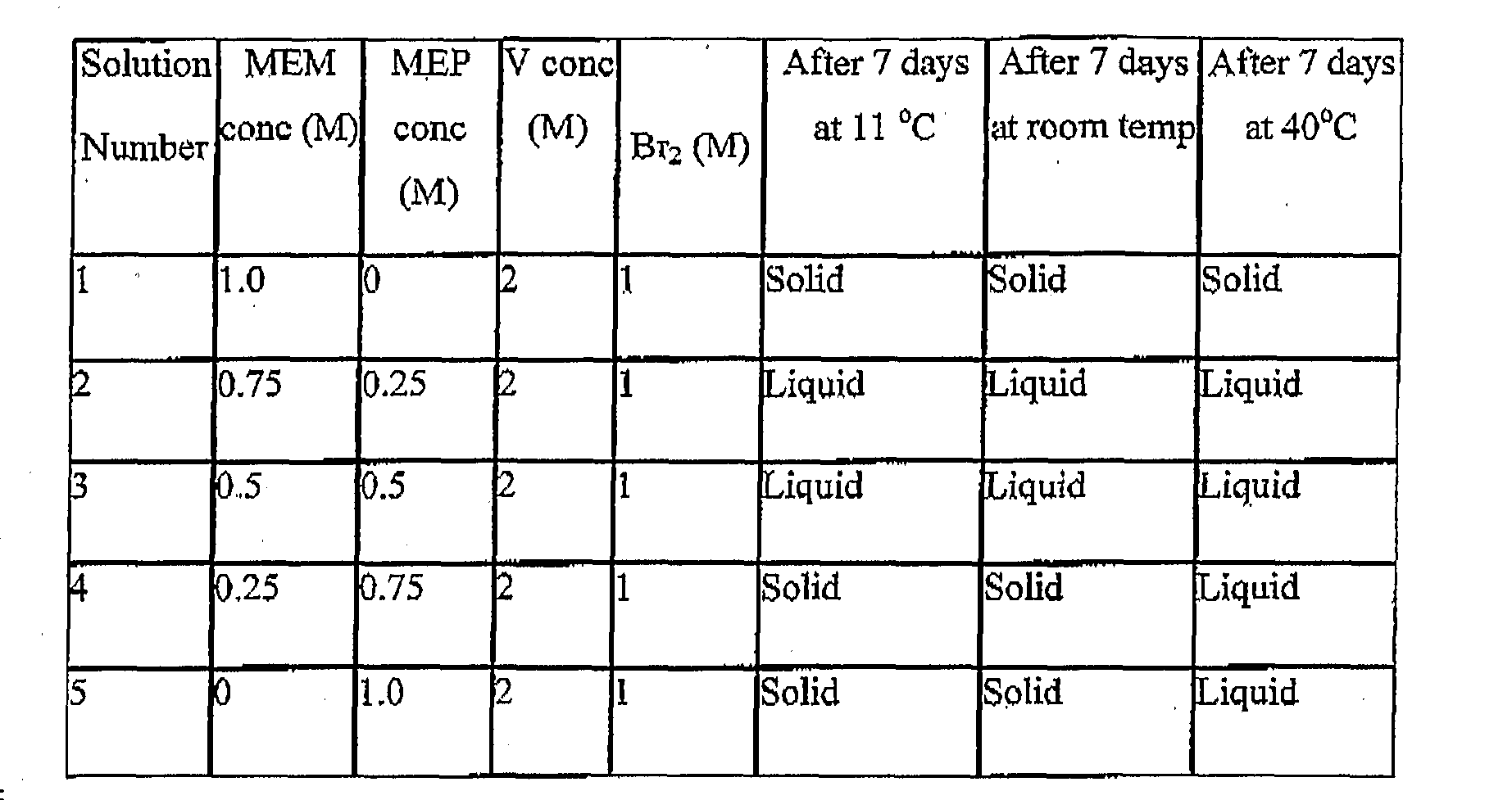

Claims
Priority Applications (8)
| Application Number | Priority Date | Filing Date | Title |
|---|---|---|---|
| EP06741258.5A EP1905117B1 (en) | 2005-06-20 | 2006-06-19 | Improved perfluorinated membranes and improved electrolytes for redox cells and batteries |
| CA2610071A CA2610071C (en) | 2005-06-20 | 2006-06-19 | Improved perfluorinated membranes and improved electrolytes for redox cells and batteries |
| AU2006261573A AU2006261573B2 (en) | 2005-06-20 | 2006-06-19 | Improved perfluorinated membranes and improved electrolytes for redox cells and batteries |
| US11/917,989 US8541138B2 (en) | 2005-06-20 | 2006-06-19 | Perfluorinated membranes and improved electrolytes for redox cells and batteries |
| CN200680022322XA CN101213700B (en) | 2005-06-20 | 2006-06-19 | Improved perfluorinated membranes and improved electrolytes for redox cells and batteries |
| DK06741258.5T DK1905117T3 (en) | 2005-06-20 | 2006-06-19 | IMPROVED PERFLUORATED MEMBRANES AND IMPROVED ELECTROLYTS FOR REDOX CELLS AND BATTERIES |
| JP2008516081A JP5760262B2 (en) | 2005-06-20 | 2006-06-19 | Improved perfluoromembrane and improved electrolyte for redox cells and batteries |
| NZ563797A NZ563797A (en) | 2005-06-20 | 2006-06-19 | Improved perfluorinated membranes and improved electrolytes for redox cells and batteries |
Applications Claiming Priority (4)
| Application Number | Priority Date | Filing Date | Title |
|---|---|---|---|
| AU2005903230A AU2005903230A0 (en) | 2005-06-20 | Membrane for Vanadium Redox Battery | |
| AU2005903230 | 2005-06-20 | ||
| AU2005905012 | 2005-09-12 | ||
| AU2005905012A AU2005905012A0 (en) | 2005-09-12 | Improved Perfluorinated Membranes and Electrolytes for Vanadium Bromide Redox Batteries |
Publications (1)
| Publication Number | Publication Date |
|---|---|
| WO2006135958A1 true WO2006135958A1 (en) | 2006-12-28 |
Family
ID=37570018
Family Applications (1)
| Application Number | Title | Priority Date | Filing Date |
|---|---|---|---|
| PCT/AU2006/000856 WO2006135958A1 (en) | 2005-06-20 | 2006-06-19 | Improved perfluorinated membranes and improved electrolytes for redox cells and batteries |
Country Status (8)
| Country | Link |
|---|---|
| US (1) | US8541138B2 (en) |
| EP (1) | EP1905117B1 (en) |
| JP (1) | JP5760262B2 (en) |
| CN (1) | CN101213700B (en) |
| CA (1) | CA2610071C (en) |
| DK (1) | DK1905117T3 (en) |
| NZ (1) | NZ563797A (en) |
| WO (1) | WO2006135958A1 (en) |
Cited By (64)
| Publication number | Priority date | Publication date | Assignee | Title |
|---|---|---|---|---|
| WO2008148148A1 (en) * | 2007-06-07 | 2008-12-11 | V-Fuel Pty Ltd | Efficient energy storage systems using vanadium redox batteries for electricity trading, fossil fuel reduction and electricity power cost savings for consumers |
| WO2009151639A1 (en) * | 2008-06-12 | 2009-12-17 | Massachusetts Institute Of Technology | High energy density redox flow device |
| US20100092807A1 (en) * | 2008-10-10 | 2010-04-15 | Saroj Kumar Sahu | Magnetic Current Collector |
| US7855005B2 (en) | 2007-02-12 | 2010-12-21 | Deeya Energy, Inc. | Apparatus and methods of determination of state of charge in a redox flow battery |
| US7919204B2 (en) | 2008-10-10 | 2011-04-05 | Deeya Energy, Inc. | Thermal control of a flow cell battery |
| US7927731B2 (en) | 2008-07-01 | 2011-04-19 | Deeya Energy, Inc. | Redox flow cell |
| US8230736B2 (en) | 2008-10-10 | 2012-07-31 | Deeya Energy, Inc. | Level sensor for conductive liquids |
| US8231993B2 (en) | 2008-10-10 | 2012-07-31 | Deeya Energy, Inc. | Flexible multi-walled tubing assembly |
| CN102623722A (en) * | 2012-04-13 | 2012-08-01 | 北京百能汇通科技股份有限公司 | Termination electrode device and preparation method for flow batteries |
| US8264202B2 (en) | 2008-10-10 | 2012-09-11 | Deeya Energy, Inc. | Method and apparatus for determining state of charge of a battery using an open-circuit voltage |
| CN102668224A (en) * | 2009-10-20 | 2012-09-12 | 国立大学法人东北大学 | Vanadium cell |
| US8338008B2 (en) | 2009-05-28 | 2012-12-25 | Deeya Energy, Inc. | Electrolyte compositions |
| US8349477B2 (en) | 2009-05-28 | 2013-01-08 | Deeya Energy, Inc. | Optical leak detection sensor |
| US8394529B2 (en) | 2009-05-28 | 2013-03-12 | Deeya Energy, Inc. | Preparation of flow cell battery electrolytes from raw materials |
| US8551299B2 (en) | 2009-05-29 | 2013-10-08 | Deeya Energy, Inc. | Methods of producing hydrochloric acid from hydrogen gas and chlorine gas |
| US8587255B2 (en) | 2009-05-28 | 2013-11-19 | Deeya Energy, Inc. | Control system for a flow cell battery |
| US8587150B2 (en) | 2008-02-28 | 2013-11-19 | Deeya Energy, Inc. | Method and modular system for charging a battery |
| US8691413B2 (en) | 2012-07-27 | 2014-04-08 | Sun Catalytix Corporation | Aqueous redox flow batteries featuring improved cell design characteristics |
| US8722227B2 (en) | 2008-06-12 | 2014-05-13 | Massachusetts Institute Of Technology | High energy density redox flow device |
| US8723489B2 (en) | 2009-05-28 | 2014-05-13 | Deeya Energy, Inc. | Bi-directional buck-boost circuit |
| US8722226B2 (en) | 2008-06-12 | 2014-05-13 | 24M Technologies, Inc. | High energy density redox flow device |
| US8753761B2 (en) | 2012-07-27 | 2014-06-17 | Sun Catalytix Corporation | Aqueous redox flow batteries comprising metal ligand coordination compounds |
| US8778552B2 (en) | 2009-04-06 | 2014-07-15 | 24M Technologies, Inc. | Fuel system using redox flow battery |
| US8785023B2 (en) | 2008-07-07 | 2014-07-22 | Enervault Corparation | Cascade redox flow battery systems |
| US8877365B2 (en) | 2009-05-28 | 2014-11-04 | Deeya Energy, Inc. | Redox flow cell rebalancing |
| US8883297B2 (en) | 2008-10-10 | 2014-11-11 | Imergy Power Systems, Inc. | Methods for bonding porous flexible membranes using solvent |
| US8906529B2 (en) | 2008-07-07 | 2014-12-09 | Enervault Corporation | Redox flow battery system for distributed energy storage |
| US8916281B2 (en) | 2011-03-29 | 2014-12-23 | Enervault Corporation | Rebalancing electrolytes in redox flow battery systems |
| US8951665B2 (en) | 2010-03-10 | 2015-02-10 | Imergy Power Systems, Inc. | Methods for the preparation of electrolytes for chromium-iron redox flow batteries |
| EP2642572A4 (en) * | 2010-11-15 | 2015-03-04 | Wy Soon Myung | Electrode for redox flow battery, fabrication method thereof, apparatus and method for fabricating electrolyte for redox flow battery, device and method for measuring selected ion concentration of electrolyte, and stand-alone battery system |
| US8980484B2 (en) | 2011-03-29 | 2015-03-17 | Enervault Corporation | Monitoring electrolyte concentrations in redox flow battery systems |
| US8993159B2 (en) | 2012-12-13 | 2015-03-31 | 24M Technologies, Inc. | Semi-solid electrodes having high rate capability |
| EP2351132A4 (en) * | 2008-10-07 | 2015-10-14 | Vionx Energy Corp | System and method for transporting energy |
| CN105103351A (en) * | 2013-04-11 | 2015-11-25 | 昭和电工株式会社 | Carbon member, carbon member manufacturing method, redox flow battery and fuel cell |
| US9281535B2 (en) | 2010-08-12 | 2016-03-08 | Imergy Power Systems, Inc. | System dongle |
| US9362583B2 (en) | 2012-12-13 | 2016-06-07 | 24M Technologies, Inc. | Semi-solid electrodes having high rate capability |
| US9382274B2 (en) | 2012-07-27 | 2016-07-05 | Lockheed Martin Advanced Energy Storage, Llc | Aqueous redox flow batteries featuring improved cell design characteristics |
| US9484569B2 (en) | 2012-06-13 | 2016-11-01 | 24M Technologies, Inc. | Electrochemical slurry compositions and methods for preparing the same |
| US9559374B2 (en) | 2012-07-27 | 2017-01-31 | Lockheed Martin Advanced Energy Storage, Llc | Electrochemical energy storage systems and methods featuring large negative half-cell potentials |
| US9692077B2 (en) | 2012-07-27 | 2017-06-27 | Lockheed Martin Advanced Energy Storage, Llc | Aqueous redox flow batteries comprising matched ionomer membranes |
| US9768463B2 (en) | 2012-07-27 | 2017-09-19 | Lockheed Martin Advanced Energy Storage, Llc | Aqueous redox flow batteries comprising metal ligand coordination compounds |
| US9819039B2 (en) | 2010-09-28 | 2017-11-14 | Battelle Memorial Institute | Redox flow batteries based on supporting solutions containing chloride |
| US9837679B2 (en) | 2014-11-26 | 2017-12-05 | Lockheed Martin Advanced Energy Storage, Llc | Metal complexes of substituted catecholates and redox flow batteries containing the same |
| US9865893B2 (en) | 2012-07-27 | 2018-01-09 | Lockheed Martin Advanced Energy Storage, Llc | Electrochemical energy storage systems and methods featuring optimal membrane systems |
| US9899694B2 (en) | 2012-07-27 | 2018-02-20 | Lockheed Martin Advanced Energy Storage, Llc | Electrochemical energy storage systems and methods featuring high open circuit potential |
| US9938308B2 (en) | 2016-04-07 | 2018-04-10 | Lockheed Martin Energy, Llc | Coordination compounds having redox non-innocent ligands and flow batteries containing the same |
| US10065977B2 (en) | 2016-10-19 | 2018-09-04 | Lockheed Martin Advanced Energy Storage, Llc | Concerted processes for forming 1,2,4-trihydroxybenzene from hydroquinone |
| US10164284B2 (en) | 2012-07-27 | 2018-12-25 | Lockheed Martin Energy, Llc | Aqueous redox flow batteries featuring improved cell design characteristics |
| US10253051B2 (en) | 2015-03-16 | 2019-04-09 | Lockheed Martin Energy, Llc | Preparation of titanium catecholate complexes in aqueous solution using titanium tetrachloride or titanium oxychloride |
| US10316047B2 (en) | 2016-03-03 | 2019-06-11 | Lockheed Martin Energy, Llc | Processes for forming coordination complexes containing monosulfonated catecholate ligands |
| US10320023B2 (en) | 2017-02-16 | 2019-06-11 | Lockheed Martin Energy, Llc | Neat methods for forming titanium catecholate complexes and associated compositions |
| US10343964B2 (en) | 2016-07-26 | 2019-07-09 | Lockheed Martin Energy, Llc | Processes for forming titanium catechol complexes |
| US10377687B2 (en) | 2016-07-26 | 2019-08-13 | Lockheed Martin Energy, Llc | Processes for forming titanium catechol complexes |
| US10497958B2 (en) | 2016-12-14 | 2019-12-03 | Lockheed Martin Energy, Llc | Coordinatively unsaturated titanium catecholate complexes and processes associated therewith |
| US10644342B2 (en) | 2016-03-03 | 2020-05-05 | Lockheed Martin Energy, Llc | Coordination complexes containing monosulfonated catecholate ligands and methods for producing the same |
| US10673090B2 (en) | 2014-10-06 | 2020-06-02 | Battelle Memorial Institute | All-vanadium sulfate acid redox flow battery system |
| US10741864B2 (en) | 2016-12-30 | 2020-08-11 | Lockheed Martin Energy, Llc | Aqueous methods for forming titanium catecholate complexes and associated compositions |
| US10930937B2 (en) | 2016-11-23 | 2021-02-23 | Lockheed Martin Energy, Llc | Flow batteries incorporating active materials containing doubly bridged aromatic groups |
| CN112514150A (en) * | 2018-07-27 | 2021-03-16 | W.L.戈尔及同仁股份有限公司 | Monolithic composite membranes with continuous ionomeric phases |
| US11005087B2 (en) | 2016-01-15 | 2021-05-11 | 24M Technologies, Inc. | Systems and methods for infusion mixing a slurry based electrode |
| US11056698B2 (en) | 2018-08-02 | 2021-07-06 | Raytheon Technologies Corporation | Redox flow battery with electrolyte balancing and compatibility enabling features |
| US11271226B1 (en) | 2020-12-11 | 2022-03-08 | Raytheon Technologies Corporation | Redox flow battery with improved efficiency |
| US11831054B2 (en) | 2013-05-03 | 2023-11-28 | Rtx Corporation | Method of maintaining health of a flow battery |
| US11909077B2 (en) | 2008-06-12 | 2024-02-20 | Massachusetts Institute Of Technology | High energy density redox flow device |
Families Citing this family (61)
| Publication number | Priority date | Publication date | Assignee | Title |
|---|---|---|---|---|
| US8277964B2 (en) * | 2004-01-15 | 2012-10-02 | Jd Holding Inc. | System and method for optimizing efficiency and power output from a vanadium redox battery energy storage system |
| TW200820478A (en) * | 2006-10-18 | 2008-05-01 | Antig Technology Corp | Fuel cell structure |
| US20100227204A1 (en) * | 2009-03-06 | 2010-09-09 | Ralph Zito | Concentration cell energy storage device |
| TWI482329B (en) * | 2012-08-23 | 2015-04-21 | Atomic Energy Council | A charging/discharging apparatus having two flows |
| CN102044648B (en) * | 2009-10-16 | 2013-04-10 | 大连融科储能技术发展有限公司 | Poly(arylene ether benzimidazole) ion exchange membrane and preparation thereof and all-vanadium redox flow battery |
| JP2012054035A (en) * | 2010-08-31 | 2012-03-15 | Tomomi Abe | Vanadium ion battery |
| WO2012038843A1 (en) * | 2010-09-22 | 2012-03-29 | International Business Machines Corporation | Electrochemically powered integrated circuit package |
| US9960443B2 (en) | 2010-09-28 | 2018-05-01 | Battelle Memorial Institute | Redox flow batteries having multiple electroactive elements |
| US8771856B2 (en) * | 2010-09-28 | 2014-07-08 | Battelle Memorial Institute | Fe-V redox flow batteries |
| CN103339762B (en) | 2011-01-13 | 2016-03-30 | 伊莫基动力系统公司 | Flow cell stack |
| US8884578B2 (en) * | 2011-02-07 | 2014-11-11 | United Technologies Corporation | Method and system for operating a flow battery system based on energy costs |
| US8808897B2 (en) * | 2011-07-19 | 2014-08-19 | Fu Jen Catholic University | Electrode structure of vanadium redox flow battery |
| JP5674040B2 (en) * | 2011-07-25 | 2015-02-18 | 独立行政法人産業技術総合研究所 | A lithium semi-redox flow battery that can be regenerated by both electrical charging and chemical oxidation with an oxidizing agent. |
| WO2013048603A1 (en) * | 2011-09-27 | 2013-04-04 | Battelle Memorial Institute | Redox flow batteries having multiple electroactive elements |
| US10141594B2 (en) | 2011-10-07 | 2018-11-27 | Vrb Energy Inc. | Systems and methods for assembling redox flow battery reactor cells |
| US9130219B1 (en) * | 2011-10-11 | 2015-09-08 | University Of South Carolina | Method of making redox materials for solid oxide redox flow battery |
| CN102386427A (en) * | 2011-11-22 | 2012-03-21 | 深圳市金钒能源科技有限公司 | Sealing method of vanadium liquid cavity and vanadium pile system using same |
| US9853454B2 (en) | 2011-12-20 | 2017-12-26 | Jd Holding Inc. | Vanadium redox battery energy storage system |
| US9294026B2 (en) * | 2011-12-20 | 2016-03-22 | United Technologies Corporation | Method of operating a power generation system |
| WO2013100087A1 (en) | 2011-12-28 | 2013-07-04 | 旭化成イーマテリアルズ株式会社 | Redox flow secondary battery and electrolyte membrane for redox flow secondary batteries |
| KR101684036B1 (en) | 2011-12-28 | 2016-12-07 | 아사히 가세이 가부시키가이샤 | Redox flow secondary battery and electrolyte membrane for redox flow secondary batteries |
| JP5972286B2 (en) * | 2011-12-28 | 2016-08-17 | 旭化成株式会社 | Redox flow secondary battery and electrolyte membrane for redox flow secondary battery |
| US9905875B2 (en) | 2011-12-28 | 2018-02-27 | Asahi Kasei Kabushiki Kaisha | Redox flow secondary battery and electrolyte membrane for redox flow secondary battery |
| CN102709579B (en) * | 2012-04-05 | 2015-08-19 | 天津滨海储能技术有限公司 | The preparation method of vanadium liquid |
| US9027483B2 (en) | 2012-04-11 | 2015-05-12 | Electro-Motive Diesel, Inc. | Flow battery power converter |
| US20130316199A1 (en) * | 2012-05-25 | 2013-11-28 | Deeya Energy, Inc. | Electrochemical balance in a vanadium flow battery |
| CN103545539A (en) * | 2012-07-12 | 2014-01-29 | 青岛高泰新材料有限公司 | Three-dimensional netted graphite foam or netted glassy carbon bipolar plate of all-vanadium redox flow battery |
| DE102012016317A1 (en) * | 2012-08-14 | 2014-02-20 | Jenabatteries GmbH | Redox flow cell for storing electrical energy |
| US10868324B2 (en) | 2012-12-17 | 2020-12-15 | The Chemours Company Fc, Llc | Flow battery having a separator membrane comprising an ionomer |
| JP2014130778A (en) * | 2012-12-28 | 2014-07-10 | Tohoku Techno Arch Co Ltd | Stationary vanadium redox battery |
| US8993183B2 (en) * | 2012-12-31 | 2015-03-31 | Enervault Corporation | Operating a redox flow battery with a negative electrolyte imbalance |
| JP2014137946A (en) * | 2013-01-18 | 2014-07-28 | Sumitomo Electric Ind Ltd | Method for operating redox flow cell |
| JP2014157789A (en) * | 2013-02-18 | 2014-08-28 | Tohoku Techno Arch Co Ltd | Vanadium solid-salt battery and method for manufacturing the same |
| CN103199285B (en) * | 2013-04-10 | 2016-01-13 | 大连融科储能技术发展有限公司 | A kind of flow battery halt protection method and flow battery system |
| KR20160008594A (en) * | 2013-05-16 | 2016-01-22 | 유나이티드 테크놀로지스 코포레이션 | Flow battery with hydrated ion-exchange membrane having maximum water domain cluster sizes |
| DE102013107516A1 (en) * | 2013-07-16 | 2015-01-22 | Fraunhofer-Gesellschaft zur Förderung der angewandten Forschung e.V. | Cell and cell stack of a redox flow battery |
| CN103500842A (en) * | 2013-11-04 | 2014-01-08 | 湖南农业大学 | Preparation method of high-energy density solid vanadium battery |
| KR101558079B1 (en) | 2014-02-20 | 2015-10-06 | 오씨아이 주식회사 | Redox flow battery |
| WO2016007555A1 (en) * | 2014-07-07 | 2016-01-14 | Unienergy Technologies, Llc | Systems and methods in a redox flow battery |
| US10186716B2 (en) * | 2014-11-10 | 2019-01-22 | Lanxess Solutions Us Inc. | Non-aqueous flow cell comprising a polyurethane separator |
| MX2017012587A (en) * | 2015-04-14 | 2018-01-25 | Lockheed Martin Advanced Energy Storage Llc | Flow battery balancing cells having a bipolar membrane and methods for use thereof. |
| US10411285B2 (en) * | 2015-04-14 | 2019-09-10 | Lockheed Martin Energy, Llc | Flow battery balancing cells having a bipolar membrane for simultaneous modification of a negative electrolyte solution and a positive electrolyte solution |
| US10418647B2 (en) * | 2015-04-15 | 2019-09-17 | Lockheed Martin Energy, Llc | Mitigation of parasitic reactions within flow batteries |
| US11171350B2 (en) | 2016-03-14 | 2021-11-09 | Dalian Rongkepower Co., Ltd | Flow battery control method, flow battery control system and flow battery |
| US20180019483A1 (en) * | 2016-07-13 | 2018-01-18 | University Of Tennessee Research Foundation | Redox flow battery with increased-surface-area electrode and asymmetric electrolyte concentration |
| JP2018133263A (en) * | 2017-02-16 | 2018-08-23 | 株式会社ギャラキシー | Battery active material liquid of flow type battery |
| CN107946624A (en) * | 2017-11-08 | 2018-04-20 | 常州大学 | A kind of water system full stress-strain flow battery and its construction method and application based on indigo derivative |
| CN110857911B (en) * | 2018-08-24 | 2021-11-26 | 江苏泛宇能源有限公司 | Method for testing electrolyte balance degree of portable all-vanadium redox flow battery |
| US11705571B2 (en) | 2018-09-05 | 2023-07-18 | Nikolai M. Kocherginsky | Foil-based redox flow battery |
| US20220052376A1 (en) * | 2018-09-10 | 2022-02-17 | Evonik Operations Gmbh | Gelled electrolyte and preparation method thereof |
| CN113544886A (en) | 2019-03-08 | 2021-10-22 | 旭化成株式会社 | Electrolyte membrane for redox flow battery, and method for producing electrolyte membrane |
| US11233263B2 (en) | 2019-05-20 | 2022-01-25 | Creek Channel Inc. | Redox flow battery systems and methods of manufacture and operation and reduction of metallic impurities |
| US11362359B2 (en) * | 2019-05-21 | 2022-06-14 | Raytheon Technologies Corporation | Redox flow battery system with electrochemical recovery cell |
| CN111200154A (en) * | 2020-01-10 | 2020-05-26 | 西南交通大学 | Polyhalide-chromium flow battery |
| US11670792B2 (en) * | 2020-05-15 | 2023-06-06 | Ess Tech, Inc. | Redox flow battery and battery system |
| US11936028B1 (en) * | 2020-07-13 | 2024-03-19 | Ampcera Inc. | Systems and methods for heating electrochemical systems |
| US11710844B2 (en) | 2020-11-16 | 2023-07-25 | Cougar Creek Technologies, Llc | Fe-Cr redox flow battery systems and methods utilizing chromium complexes with nitrogen-containing ligands |
| CN113903938A (en) * | 2021-09-10 | 2022-01-07 | 南京工业大学 | Metal organic framework crystal film for all-vanadium redox flow battery |
| WO2023065026A1 (en) * | 2021-10-19 | 2023-04-27 | Cambria Geosciences Inc. | System for replenishing an on-board power source for a propulsion system on a vehicle such as a watercraft and process |
| DE102022109193B3 (en) * | 2022-04-14 | 2023-07-27 | Voith Patent Gmbh | Redox flow battery system and method of operation |
| WO2023219648A1 (en) | 2022-05-09 | 2023-11-16 | Lockheed Martin Energy, Llc | Flow battery with a dynamic fluidic network |
Citations (9)
| Publication number | Priority date | Publication date | Assignee | Title |
|---|---|---|---|---|
| US4298697A (en) * | 1979-10-23 | 1981-11-03 | Diamond Shamrock Corporation | Method of making sheet or shaped cation exchange membrane |
| US4469579A (en) * | 1981-06-26 | 1984-09-04 | Diamond Shamrock Corporation | Solid polymer electrolytes and electrode bonded with hydrophylic fluorocopolymers |
| US5417832A (en) * | 1992-08-25 | 1995-05-23 | The University Of Colorado Foundation, Inc. | Enhancing performance of perfluorinated ionomer membranes via dopant incorporation, method of making thereof and the membrane |
| US6465136B1 (en) * | 1999-04-30 | 2002-10-15 | The University Of Connecticut | Membranes, membrane electrode assemblies and fuel cells employing same, and process for preparing |
| US6562514B1 (en) | 1993-11-17 | 2003-05-13 | Pinnacle Vrb Limited | Stabilized vanadium electrolyte solutions for all-vanadium redox cells and batteries |
| US20030091886A1 (en) | 2000-02-16 | 2003-05-15 | Akihiko Tanioka | Polyelectrolyte, polyelectrolyte film, and fuel cell |
| US6602630B1 (en) * | 2000-03-14 | 2003-08-05 | The Electrosynthesis Company, Inc. | Membrane electrode assemblies for electrochemical cells |
| US20030224235A1 (en) * | 2002-05-31 | 2003-12-04 | Park Jung Ki | Polymer electrolyte membrane for fuel cell and method for producing the same |
| WO2004082056A1 (en) * | 2003-03-14 | 2004-09-23 | Unisearch Limited | Novel vanadium halide redox flow battery |
Family Cites Families (13)
| Publication number | Priority date | Publication date | Assignee | Title |
|---|---|---|---|---|
| US4414090A (en) * | 1981-10-01 | 1983-11-08 | Rai Research Corporation | Separator membranes for redox-type electrochemical cells |
| US4468441A (en) * | 1981-10-01 | 1984-08-28 | Rai Research Corp. | Separator membranes for redox-type electrochemical cells |
| JP3489148B2 (en) * | 1993-09-03 | 2004-01-19 | トヨタ自動車株式会社 | Method for removing impurities from polymer ion exchange membrane |
| ZA952384B (en) * | 1994-04-13 | 1996-09-23 | Nat Power Plc | Cation exchange membranes and method for the preparation of such membranes |
| JPH0992321A (en) * | 1995-09-27 | 1997-04-04 | Kashimakita Kyodo Hatsuden Kk | Redox cell |
| AUPP938799A0 (en) * | 1999-03-23 | 1999-04-15 | Unisearch Limited | Electrodes |
| JP4830190B2 (en) * | 1999-09-27 | 2011-12-07 | 住友電気工業株式会社 | Redox flow battery |
| JP2002367661A (en) * | 2001-06-12 | 2002-12-20 | Sumitomo Electric Ind Ltd | Assembly method for redox flow battery |
| AUPR722101A0 (en) | 2001-08-24 | 2001-09-13 | Skyllas-Kazacos, Maria | Vanadium chloride/polyhalide redox flow battery |
| AUPS192102A0 (en) | 2002-04-23 | 2002-05-30 | Unisearch Limited | Vanadium bromide redox flow battery |
| US7353083B2 (en) | 2004-01-15 | 2008-04-01 | Vrb Power Systems Inc. | Vanadium redox battery energy storage and power generation system incorporating and optimizing diesel engine generators |
| US8277964B2 (en) | 2004-01-15 | 2012-10-02 | Jd Holding Inc. | System and method for optimizing efficiency and power output from a vanadium redox battery energy storage system |
| US7265456B2 (en) | 2004-01-15 | 2007-09-04 | Vrb Bower Systems Inc. | Power generation system incorporating a vanadium redox battery and a direct current wind turbine generator |
-
2006
- 2006-06-19 EP EP06741258.5A patent/EP1905117B1/en active Active
- 2006-06-19 WO PCT/AU2006/000856 patent/WO2006135958A1/en active Application Filing
- 2006-06-19 US US11/917,989 patent/US8541138B2/en active Active
- 2006-06-19 CN CN200680022322XA patent/CN101213700B/en not_active Expired - Fee Related
- 2006-06-19 JP JP2008516081A patent/JP5760262B2/en not_active Expired - Fee Related
- 2006-06-19 CA CA2610071A patent/CA2610071C/en not_active Expired - Fee Related
- 2006-06-19 NZ NZ563797A patent/NZ563797A/en not_active IP Right Cessation
- 2006-06-19 DK DK06741258.5T patent/DK1905117T3/en active
Patent Citations (9)
| Publication number | Priority date | Publication date | Assignee | Title |
|---|---|---|---|---|
| US4298697A (en) * | 1979-10-23 | 1981-11-03 | Diamond Shamrock Corporation | Method of making sheet or shaped cation exchange membrane |
| US4469579A (en) * | 1981-06-26 | 1984-09-04 | Diamond Shamrock Corporation | Solid polymer electrolytes and electrode bonded with hydrophylic fluorocopolymers |
| US5417832A (en) * | 1992-08-25 | 1995-05-23 | The University Of Colorado Foundation, Inc. | Enhancing performance of perfluorinated ionomer membranes via dopant incorporation, method of making thereof and the membrane |
| US6562514B1 (en) | 1993-11-17 | 2003-05-13 | Pinnacle Vrb Limited | Stabilized vanadium electrolyte solutions for all-vanadium redox cells and batteries |
| US6465136B1 (en) * | 1999-04-30 | 2002-10-15 | The University Of Connecticut | Membranes, membrane electrode assemblies and fuel cells employing same, and process for preparing |
| US20030091886A1 (en) | 2000-02-16 | 2003-05-15 | Akihiko Tanioka | Polyelectrolyte, polyelectrolyte film, and fuel cell |
| US6602630B1 (en) * | 2000-03-14 | 2003-08-05 | The Electrosynthesis Company, Inc. | Membrane electrode assemblies for electrochemical cells |
| US20030224235A1 (en) * | 2002-05-31 | 2003-12-04 | Park Jung Ki | Polymer electrolyte membrane for fuel cell and method for producing the same |
| WO2004082056A1 (en) * | 2003-03-14 | 2004-09-23 | Unisearch Limited | Novel vanadium halide redox flow battery |
Non-Patent Citations (1)
| Title |
|---|
| See also references of EP1905117A4 |
Cited By (97)
| Publication number | Priority date | Publication date | Assignee | Title |
|---|---|---|---|---|
| US7855005B2 (en) | 2007-02-12 | 2010-12-21 | Deeya Energy, Inc. | Apparatus and methods of determination of state of charge in a redox flow battery |
| WO2008148148A1 (en) * | 2007-06-07 | 2008-12-11 | V-Fuel Pty Ltd | Efficient energy storage systems using vanadium redox batteries for electricity trading, fossil fuel reduction and electricity power cost savings for consumers |
| US8587150B2 (en) | 2008-02-28 | 2013-11-19 | Deeya Energy, Inc. | Method and modular system for charging a battery |
| US9614231B2 (en) | 2008-06-12 | 2017-04-04 | 24M Technologies, Inc. | High energy density redox flow device |
| US11342567B2 (en) | 2008-06-12 | 2022-05-24 | Massachusetts Institute Of Technology | High energy density redox flow device |
| EP2684734A1 (en) * | 2008-06-12 | 2014-01-15 | Massachusetts Institute Of Technology | High energy density redox flow device |
| US9786944B2 (en) | 2008-06-12 | 2017-10-10 | Massachusetts Institute Of Technology | High energy density redox flow device |
| EP3213956A1 (en) * | 2008-06-12 | 2017-09-06 | Massachusetts Institute Of Technology | Energy storage device |
| US10236518B2 (en) | 2008-06-12 | 2019-03-19 | 24M Technologies, Inc. | High energy density redox flow device |
| US9153833B2 (en) | 2008-06-12 | 2015-10-06 | 24M Technologies, Inc. | High energy density redox flow device |
| US11909077B2 (en) | 2008-06-12 | 2024-02-20 | Massachusetts Institute Of Technology | High energy density redox flow device |
| US8722227B2 (en) | 2008-06-12 | 2014-05-13 | Massachusetts Institute Of Technology | High energy density redox flow device |
| WO2009151639A1 (en) * | 2008-06-12 | 2009-12-17 | Massachusetts Institute Of Technology | High energy density redox flow device |
| US8722226B2 (en) | 2008-06-12 | 2014-05-13 | 24M Technologies, Inc. | High energy density redox flow device |
| US7927731B2 (en) | 2008-07-01 | 2011-04-19 | Deeya Energy, Inc. | Redox flow cell |
| US8785023B2 (en) | 2008-07-07 | 2014-07-22 | Enervault Corparation | Cascade redox flow battery systems |
| US8906529B2 (en) | 2008-07-07 | 2014-12-09 | Enervault Corporation | Redox flow battery system for distributed energy storage |
| EP2351132A4 (en) * | 2008-10-07 | 2015-10-14 | Vionx Energy Corp | System and method for transporting energy |
| US8236463B2 (en) * | 2008-10-10 | 2012-08-07 | Deeya Energy, Inc. | Magnetic current collector |
| US8883297B2 (en) | 2008-10-10 | 2014-11-11 | Imergy Power Systems, Inc. | Methods for bonding porous flexible membranes using solvent |
| US20100092807A1 (en) * | 2008-10-10 | 2010-04-15 | Saroj Kumar Sahu | Magnetic Current Collector |
| US7919204B2 (en) | 2008-10-10 | 2011-04-05 | Deeya Energy, Inc. | Thermal control of a flow cell battery |
| US8230736B2 (en) | 2008-10-10 | 2012-07-31 | Deeya Energy, Inc. | Level sensor for conductive liquids |
| US8231993B2 (en) | 2008-10-10 | 2012-07-31 | Deeya Energy, Inc. | Flexible multi-walled tubing assembly |
| US8264202B2 (en) | 2008-10-10 | 2012-09-11 | Deeya Energy, Inc. | Method and apparatus for determining state of charge of a battery using an open-circuit voltage |
| US9293781B2 (en) | 2009-04-06 | 2016-03-22 | 24M Technologies, Inc. | Fuel system using redox flow battery |
| US8778552B2 (en) | 2009-04-06 | 2014-07-15 | 24M Technologies, Inc. | Fuel system using redox flow battery |
| US8349477B2 (en) | 2009-05-28 | 2013-01-08 | Deeya Energy, Inc. | Optical leak detection sensor |
| US8877365B2 (en) | 2009-05-28 | 2014-11-04 | Deeya Energy, Inc. | Redox flow cell rebalancing |
| US9479056B2 (en) | 2009-05-28 | 2016-10-25 | Imergy Power Systems, Inc. | Buck-boost circuit with protection feature |
| US8338008B2 (en) | 2009-05-28 | 2012-12-25 | Deeya Energy, Inc. | Electrolyte compositions |
| US8587255B2 (en) | 2009-05-28 | 2013-11-19 | Deeya Energy, Inc. | Control system for a flow cell battery |
| US8723489B2 (en) | 2009-05-28 | 2014-05-13 | Deeya Energy, Inc. | Bi-directional buck-boost circuit |
| US8394529B2 (en) | 2009-05-28 | 2013-03-12 | Deeya Energy, Inc. | Preparation of flow cell battery electrolytes from raw materials |
| US9035617B2 (en) | 2009-05-28 | 2015-05-19 | Imergy Power Systems, Inc. | Control system for a flow cell battery |
| US8551299B2 (en) | 2009-05-29 | 2013-10-08 | Deeya Energy, Inc. | Methods of producing hydrochloric acid from hydrogen gas and chlorine gas |
| CN102668224A (en) * | 2009-10-20 | 2012-09-12 | 国立大学法人东北大学 | Vanadium cell |
| US20120301787A1 (en) * | 2009-10-20 | 2012-11-29 | Tohoku University | Vanadium battery |
| US9419279B2 (en) | 2009-10-20 | 2016-08-16 | Tohoku University | Vanadium battery |
| US8951665B2 (en) | 2010-03-10 | 2015-02-10 | Imergy Power Systems, Inc. | Methods for the preparation of electrolytes for chromium-iron redox flow batteries |
| US9281535B2 (en) | 2010-08-12 | 2016-03-08 | Imergy Power Systems, Inc. | System dongle |
| US9819039B2 (en) | 2010-09-28 | 2017-11-14 | Battelle Memorial Institute | Redox flow batteries based on supporting solutions containing chloride |
| EP2642572A4 (en) * | 2010-11-15 | 2015-03-04 | Wy Soon Myung | Electrode for redox flow battery, fabrication method thereof, apparatus and method for fabricating electrolyte for redox flow battery, device and method for measuring selected ion concentration of electrolyte, and stand-alone battery system |
| US8980484B2 (en) | 2011-03-29 | 2015-03-17 | Enervault Corporation | Monitoring electrolyte concentrations in redox flow battery systems |
| US8916281B2 (en) | 2011-03-29 | 2014-12-23 | Enervault Corporation | Rebalancing electrolytes in redox flow battery systems |
| CN102623722A (en) * | 2012-04-13 | 2012-08-01 | 北京百能汇通科技股份有限公司 | Termination electrode device and preparation method for flow batteries |
| US9484569B2 (en) | 2012-06-13 | 2016-11-01 | 24M Technologies, Inc. | Electrochemical slurry compositions and methods for preparing the same |
| US9991544B2 (en) | 2012-07-27 | 2018-06-05 | Lockheed Martin Advanced Energy Storage, Llc | Aqueous redox flow batteries comprising metal ligand coordination compounds |
| US9382274B2 (en) | 2012-07-27 | 2016-07-05 | Lockheed Martin Advanced Energy Storage, Llc | Aqueous redox flow batteries featuring improved cell design characteristics |
| US9559374B2 (en) | 2012-07-27 | 2017-01-31 | Lockheed Martin Advanced Energy Storage, Llc | Electrochemical energy storage systems and methods featuring large negative half-cell potentials |
| US10707513B2 (en) | 2012-07-27 | 2020-07-07 | Lockheed Martin Energy, Llc | Aqueous redox flow batteries comprising metal ligand coordination compounds |
| US9692077B2 (en) | 2012-07-27 | 2017-06-27 | Lockheed Martin Advanced Energy Storage, Llc | Aqueous redox flow batteries comprising matched ionomer membranes |
| US10651489B2 (en) | 2012-07-27 | 2020-05-12 | Lockheed Martin Energy, Llc | Electrochemical energy storage systems and methods featuring optimal membrane systems |
| US9768463B2 (en) | 2012-07-27 | 2017-09-19 | Lockheed Martin Advanced Energy Storage, Llc | Aqueous redox flow batteries comprising metal ligand coordination compounds |
| US10483581B2 (en) | 2012-07-27 | 2019-11-19 | Lockheed Martin Energy, Llc | Electrochemical energy storage systems and methods featuring large negative half-cell potentials |
| US8753761B2 (en) | 2012-07-27 | 2014-06-17 | Sun Catalytix Corporation | Aqueous redox flow batteries comprising metal ligand coordination compounds |
| US10164284B2 (en) | 2012-07-27 | 2018-12-25 | Lockheed Martin Energy, Llc | Aqueous redox flow batteries featuring improved cell design characteristics |
| US10056639B2 (en) | 2012-07-27 | 2018-08-21 | Lockheed Martin Energy, Llc | Aqueous redox flow batteries featuring improved cell design characteristics |
| US10014546B2 (en) | 2012-07-27 | 2018-07-03 | Lockheed Martin Advanced Energy Storage, Llc | Aqueous redox flow batteries comprising metal ligand coordination compounds |
| US9865893B2 (en) | 2012-07-27 | 2018-01-09 | Lockheed Martin Advanced Energy Storage, Llc | Electrochemical energy storage systems and methods featuring optimal membrane systems |
| US9899694B2 (en) | 2012-07-27 | 2018-02-20 | Lockheed Martin Advanced Energy Storage, Llc | Electrochemical energy storage systems and methods featuring high open circuit potential |
| US8691413B2 (en) | 2012-07-27 | 2014-04-08 | Sun Catalytix Corporation | Aqueous redox flow batteries featuring improved cell design characteristics |
| US9991543B2 (en) | 2012-07-27 | 2018-06-05 | Lockheed Martin Advanced Energy Storage, Llc | Aqueous redox flow batteries featuring improved cell design characteristics |
| US9184464B2 (en) | 2012-12-13 | 2015-11-10 | 24M Technologies, Inc. | Semi-solid electrodes having high rate capability |
| US11811119B2 (en) | 2012-12-13 | 2023-11-07 | 24M Technologies, Inc. | Semi-solid electrodes having high rate capability |
| US9831518B2 (en) | 2012-12-13 | 2017-11-28 | 24M Technologies, Inc. | Semi-solid electrodes having high rate capability |
| US9385392B2 (en) | 2012-12-13 | 2016-07-05 | 24M Technologies, Inc. | Semi-solid electrodes having high rate capability |
| US9362583B2 (en) | 2012-12-13 | 2016-06-07 | 24M Technologies, Inc. | Semi-solid electrodes having high rate capability |
| US9831519B2 (en) | 2012-12-13 | 2017-11-28 | 24M Technologies, Inc. | Semi-solid electrodes having high rate capability |
| US8993159B2 (en) | 2012-12-13 | 2015-03-31 | 24M Technologies, Inc. | Semi-solid electrodes having high rate capability |
| US11018365B2 (en) | 2012-12-13 | 2021-05-25 | 24M Technologies, Inc. | Semi-solid electrodes having high rate capability |
| US10483582B2 (en) | 2012-12-13 | 2019-11-19 | 24M Technologies, Inc. | Semi-solid electrodes having high rate capability |
| EP2985827A4 (en) * | 2013-04-11 | 2016-09-28 | Showa Denko Kk | Carbon member, carbon member manufacturing method, redox flow battery and fuel cell |
| CN105103351A (en) * | 2013-04-11 | 2015-11-25 | 昭和电工株式会社 | Carbon member, carbon member manufacturing method, redox flow battery and fuel cell |
| US10109870B2 (en) | 2013-04-11 | 2018-10-23 | Showa Denko K.K. | Carbon member, carbon member manufacturing method, redox flow battery and fuel cell |
| US11831054B2 (en) | 2013-05-03 | 2023-11-28 | Rtx Corporation | Method of maintaining health of a flow battery |
| US11532832B2 (en) | 2014-10-06 | 2022-12-20 | Battelle Memorial Institute | All-vanadium sulfate acid redox flow battery system |
| US10673090B2 (en) | 2014-10-06 | 2020-06-02 | Battelle Memorial Institute | All-vanadium sulfate acid redox flow battery system |
| US9837679B2 (en) | 2014-11-26 | 2017-12-05 | Lockheed Martin Advanced Energy Storage, Llc | Metal complexes of substituted catecholates and redox flow batteries containing the same |
| US10734666B2 (en) | 2014-11-26 | 2020-08-04 | Lockheed Martin Energy, Llc | Metal complexes of substituted catecholates and redox flow batteries containing the same |
| US10253051B2 (en) | 2015-03-16 | 2019-04-09 | Lockheed Martin Energy, Llc | Preparation of titanium catecholate complexes in aqueous solution using titanium tetrachloride or titanium oxychloride |
| US11005087B2 (en) | 2016-01-15 | 2021-05-11 | 24M Technologies, Inc. | Systems and methods for infusion mixing a slurry based electrode |
| US10316047B2 (en) | 2016-03-03 | 2019-06-11 | Lockheed Martin Energy, Llc | Processes for forming coordination complexes containing monosulfonated catecholate ligands |
| US10644342B2 (en) | 2016-03-03 | 2020-05-05 | Lockheed Martin Energy, Llc | Coordination complexes containing monosulfonated catecholate ligands and methods for producing the same |
| US9938308B2 (en) | 2016-04-07 | 2018-04-10 | Lockheed Martin Energy, Llc | Coordination compounds having redox non-innocent ligands and flow batteries containing the same |
| US10377687B2 (en) | 2016-07-26 | 2019-08-13 | Lockheed Martin Energy, Llc | Processes for forming titanium catechol complexes |
| US10343964B2 (en) | 2016-07-26 | 2019-07-09 | Lockheed Martin Energy, Llc | Processes for forming titanium catechol complexes |
| US10065977B2 (en) | 2016-10-19 | 2018-09-04 | Lockheed Martin Advanced Energy Storage, Llc | Concerted processes for forming 1,2,4-trihydroxybenzene from hydroquinone |
| US10930937B2 (en) | 2016-11-23 | 2021-02-23 | Lockheed Martin Energy, Llc | Flow batteries incorporating active materials containing doubly bridged aromatic groups |
| US10497958B2 (en) | 2016-12-14 | 2019-12-03 | Lockheed Martin Energy, Llc | Coordinatively unsaturated titanium catecholate complexes and processes associated therewith |
| US10741864B2 (en) | 2016-12-30 | 2020-08-11 | Lockheed Martin Energy, Llc | Aqueous methods for forming titanium catecholate complexes and associated compositions |
| US10320023B2 (en) | 2017-02-16 | 2019-06-11 | Lockheed Martin Energy, Llc | Neat methods for forming titanium catecholate complexes and associated compositions |
| CN112514150A (en) * | 2018-07-27 | 2021-03-16 | W.L.戈尔及同仁股份有限公司 | Monolithic composite membranes with continuous ionomeric phases |
| CN112514150B (en) * | 2018-07-27 | 2023-05-02 | W.L.戈尔及同仁股份有限公司 | Monolithic composite membranes with continuous ionomer phase |
| US11637298B2 (en) | 2018-08-02 | 2023-04-25 | Raytheon Technologies Corporation | Redox flow battery with electrolyte balancing and compatibility enabling features |
| US11056698B2 (en) | 2018-08-02 | 2021-07-06 | Raytheon Technologies Corporation | Redox flow battery with electrolyte balancing and compatibility enabling features |
| US11271226B1 (en) | 2020-12-11 | 2022-03-08 | Raytheon Technologies Corporation | Redox flow battery with improved efficiency |
Also Published As
| Publication number | Publication date |
|---|---|
| JP5760262B2 (en) | 2015-08-05 |
| US8541138B2 (en) | 2013-09-24 |
| US20080292964A1 (en) | 2008-11-27 |
| CN101213700A (en) | 2008-07-02 |
| JP2008544444A (en) | 2008-12-04 |
| EP1905117A4 (en) | 2012-08-01 |
| CA2610071C (en) | 2014-02-25 |
| DK1905117T3 (en) | 2019-08-19 |
| NZ563797A (en) | 2010-07-30 |
| EP1905117A1 (en) | 2008-04-02 |
| CN101213700B (en) | 2012-11-21 |
| CA2610071A1 (en) | 2006-12-28 |
| EP1905117B1 (en) | 2019-07-24 |
Similar Documents
| Publication | Publication Date | Title |
|---|---|---|
| US8541138B2 (en) | Perfluorinated membranes and improved electrolytes for redox cells and batteries | |
| Ye et al. | Redox flow batteries for energy storage: a technology review | |
| Tempelman et al. | Membranes for all vanadium redox flow batteries | |
| US7976974B2 (en) | Vanadium halide redox flow battery | |
| Cha | Recent development of nanocomposite membranes for vanadium redox flow batteries | |
| Liu et al. | High performance acid-base composite membranes from sulfonated polysulfone containing graphitic carbon nitride nanosheets for vanadium redox flow battery | |
| CA2517690C (en) | Novel vanadium halide redox flow battery | |
| JP2008218327A (en) | Electrolyte, electrolyte film, film-electrode assembly using the same, fuel cell power supply, and fuel cell power supply system | |
| Muthumeenal et al. | Recent research trends in polymer nanocomposite proton exchange membranes for electrochemical energy conversion and storage devices | |
| Ragupathy et al. | Electrochemical energy storage and conversion: An overview | |
| KR20230138951A (en) | Composite proton conducting membrane | |
| Hosseiny et al. | Ion exchange membranes for vanadium redox flow batteries | |
| WO2022099253A1 (en) | Ionically conductive thin film composite membranes for energy storage applications | |
| AU2006261573B2 (en) | Improved perfluorinated membranes and improved electrolytes for redox cells and batteries | |
| JP4802443B2 (en) | Proton exchanger, proton exchange membrane, and fuel cell using the same | |
| Qian et al. | Review and Perspectives of Sulfonated Poly (ether ether ketone) Proton Exchange Membrane for Vanadium Flow Batteries | |
| KR102098447B1 (en) | Polymer electrolyte membrane, electrochemical cell and fuel cell comprising the polymer electrolyte membrane, composition for polymer electrolyte membrane, and method of manufacturing polymer electrolyte membrane | |
| Crivellaro et al. | Membranes for Flow Batteries | |
| EP3627604B1 (en) | Ion exchange separation membrane and flow battery comprising same | |
| Choi et al. | Nanostructured Membranes for Vanadium Redox Flow Batteries | |
| KR101800078B1 (en) | Fuel cell and moving body | |
| KR101839184B1 (en) | Polymer and polymer electrolyte membrane using the same | |
| AU2004219551B2 (en) | Novel vanadium halide redox flow battery | |
| Zhang | Vanadium Flow Batteries: From Materials to Large-Scale Prototypes | |
| Perçin | Development and investigation of slurry electrodes, novel materials and membranes for tubular vanadium redox batteries |
Legal Events
| Date | Code | Title | Description |
|---|---|---|---|
| 121 | Ep: the epo has been informed by wipo that ep was designated in this application | ||
| WWE | Wipo information: entry into national phase |
Ref document number: 2610071 Country of ref document: CA Ref document number: 563797 Country of ref document: NZ |
|
| WWE | Wipo information: entry into national phase |
Ref document number: 2008516081 Country of ref document: JP |
|
| WWE | Wipo information: entry into national phase |
Ref document number: 5630/CHENP/2007 Country of ref document: IN |
|
| WWE | Wipo information: entry into national phase |
Ref document number: 200680022322.X Country of ref document: CN Ref document number: 2006741258 Country of ref document: EP |
|
| NENP | Non-entry into the national phase |
Ref country code: DE |
|
| WWW | Wipo information: withdrawn in national office |
Ref document number: DE |
|
| WWE | Wipo information: entry into national phase |
Ref document number: 2006261573 Country of ref document: AU |
|
| ENP | Entry into the national phase |
Ref document number: 2006261573 Country of ref document: AU Date of ref document: 20060619 Kind code of ref document: A |
|
| WWP | Wipo information: published in national office |
Ref document number: 2006261573 Country of ref document: AU |
|
| WWP | Wipo information: published in national office |
Ref document number: 2006741258 Country of ref document: EP |
|
| WWE | Wipo information: entry into national phase |
Ref document number: 11917989 Country of ref document: US |