WO2007004935A1 - End-to-end considerate link control and routing in a multihop network - Google Patents

End-to-end considerate link control and routing in a multihop network Download PDF

Info

Publication number
WO2007004935A1
WO2007004935A1 PCT/SE2005/001090 SE2005001090W WO2007004935A1 WO 2007004935 A1 WO2007004935 A1 WO 2007004935A1 SE 2005001090 W SE2005001090 W SE 2005001090W WO 2007004935 A1 WO2007004935 A1 WO 2007004935A1
Authority
WO
WIPO (PCT)
Prior art keywords
ete
transmit
link
parameter
parameters
Prior art date
Application number
PCT/SE2005/001090
Other languages
French (fr)
Inventor
Peter Larsson
Zhang Zhang
Original Assignee
Telefonaktiebolaget Lm Ericsson (Publ)
Priority date (The priority date is an assumption and is not a legal conclusion. Google has not performed a legal analysis and makes no representation as to the accuracy of the date listed.)
Filing date
Publication date
Application filed by Telefonaktiebolaget Lm Ericsson (Publ) filed Critical Telefonaktiebolaget Lm Ericsson (Publ)
Priority to JP2008519214A priority Critical patent/JP4782832B2/en
Priority to BRPI0520342-2A priority patent/BRPI0520342A2/en
Priority to US11/919,880 priority patent/US8295173B2/en
Priority to EP05756669.7A priority patent/EP1902552B1/en
Priority to PCT/SE2005/001090 priority patent/WO2007004935A1/en
Priority to TW095115004A priority patent/TW200704028A/en
Publication of WO2007004935A1 publication Critical patent/WO2007004935A1/en

Links

Classifications

    • HELECTRICITY
    • H04ELECTRIC COMMUNICATION TECHNIQUE
    • H04LTRANSMISSION OF DIGITAL INFORMATION, e.g. TELEGRAPHIC COMMUNICATION
    • H04L45/00Routing or path finding of packets in data switching networks
    • HELECTRICITY
    • H04ELECTRIC COMMUNICATION TECHNIQUE
    • H04LTRANSMISSION OF DIGITAL INFORMATION, e.g. TELEGRAPHIC COMMUNICATION
    • H04L45/00Routing or path finding of packets in data switching networks
    • H04L45/12Shortest path evaluation
    • H04L45/123Evaluation of link metrics
    • HELECTRICITY
    • H04ELECTRIC COMMUNICATION TECHNIQUE
    • H04LTRANSMISSION OF DIGITAL INFORMATION, e.g. TELEGRAPHIC COMMUNICATION
    • H04L45/00Routing or path finding of packets in data switching networks
    • H04L45/12Shortest path evaluation
    • H04L45/124Shortest path evaluation using a combination of metrics
    • HELECTRICITY
    • H04ELECTRIC COMMUNICATION TECHNIQUE
    • H04WWIRELESS COMMUNICATION NETWORKS
    • H04W40/00Communication routing or communication path finding
    • H04W40/02Communication route or path selection, e.g. power-based or shortest path routing
    • H04W40/12Communication route or path selection, e.g. power-based or shortest path routing based on transmission quality or channel quality
    • HELECTRICITY
    • H04ELECTRIC COMMUNICATION TECHNIQUE
    • H04WWIRELESS COMMUNICATION NETWORKS
    • H04W52/00Power management, e.g. TPC [Transmission Power Control], power saving or power classes
    • H04W52/04TPC
    • H04W52/18TPC being performed according to specific parameters
    • H04W52/26TPC being performed according to specific parameters using transmission rate or quality of service QoS [Quality of Service]
    • H04W52/267TPC being performed according to specific parameters using transmission rate or quality of service QoS [Quality of Service] taking into account the information rate
    • HELECTRICITY
    • H04ELECTRIC COMMUNICATION TECHNIQUE
    • H04WWIRELESS COMMUNICATION NETWORKS
    • H04W52/00Power management, e.g. TPC [Transmission Power Control], power saving or power classes
    • H04W52/04TPC
    • H04W52/38TPC being performed in particular situations
    • H04W52/46TPC being performed in particular situations in multi hop networks, e.g. wireless relay networks
    • HELECTRICITY
    • H04ELECTRIC COMMUNICATION TECHNIQUE
    • H04WWIRELESS COMMUNICATION NETWORKS
    • H04W28/00Network traffic management; Network resource management
    • H04W28/16Central resource management; Negotiation of resources or communication parameters, e.g. negotiating bandwidth or QoS [Quality of Service]
    • H04W28/18Negotiating wireless communication parameters
    • HELECTRICITY
    • H04ELECTRIC COMMUNICATION TECHNIQUE
    • H04WWIRELESS COMMUNICATION NETWORKS
    • H04W40/00Communication routing or communication path finding
    • H04W40/02Communication route or path selection, e.g. power-based or shortest path routing
    • H04W40/04Communication route or path selection, e.g. power-based or shortest path routing based on wireless node resources
    • H04W40/08Communication route or path selection, e.g. power-based or shortest path routing based on wireless node resources based on transmission power
    • HELECTRICITY
    • H04ELECTRIC COMMUNICATION TECHNIQUE
    • H04WWIRELESS COMMUNICATION NETWORKS
    • H04W40/00Communication routing or communication path finding
    • H04W40/02Communication route or path selection, e.g. power-based or shortest path routing
    • H04W40/12Communication route or path selection, e.g. power-based or shortest path routing based on transmission quality or channel quality
    • H04W40/16Communication route or path selection, e.g. power-based or shortest path routing based on transmission quality or channel quality based on interference
    • YGENERAL TAGGING OF NEW TECHNOLOGICAL DEVELOPMENTS; GENERAL TAGGING OF CROSS-SECTIONAL TECHNOLOGIES SPANNING OVER SEVERAL SECTIONS OF THE IPC; TECHNICAL SUBJECTS COVERED BY FORMER USPC CROSS-REFERENCE ART COLLECTIONS [XRACs] AND DIGESTS
    • Y02TECHNOLOGIES OR APPLICATIONS FOR MITIGATION OR ADAPTATION AGAINST CLIMATE CHANGE
    • Y02DCLIMATE CHANGE MITIGATION TECHNOLOGIES IN INFORMATION AND COMMUNICATION TECHNOLOGIES [ICT], I.E. INFORMATION AND COMMUNICATION TECHNOLOGIES AIMING AT THE REDUCTION OF THEIR OWN ENERGY USE
    • Y02D30/00Reducing energy consumption in communication networks
    • Y02D30/70Reducing energy consumption in communication networks in wireless communication networks

Definitions

  • the present invention generally relates to multihop networks, and more particularly to the control of link parameters for a selected multihop route as well as routing in a multihop network.
  • Multihop networks have been discussed as a key technology for future wireless communication techniques, due to inherent power/energy efficiency and ability to connect nodes out of range via intermediate relaying nodes at feasible power/energy levels.
  • nodes out of reach from each other may benefit from intermediately located nodes that can forward their messages from the source towards the destination.
  • multihop networks have often been associated with so called ad hoc networks where nodes are mostly mobile and no central coordinating infrastructure exists.
  • the idea of multihop networking can also be applied when nodes are fixed.
  • central coordination in particular when nodes are fixed and channels are robust.
  • Routing generally involves the basic tasks of determining suitable routing paths and transporting information through the network.
  • the first of these tasks is normally referred to as route determination and the latter is often referred to as packet forwarding.
  • each node basically determines and maintains a routing table with information, for each of a number of destinations, of a preferred next hop node.
  • a node receives a packet, it forwards the packet to the next hop node on the basis of information on the destination of the packet. The forwarding process continues from node to node until the packet reaches the destination.
  • the network nodes pass routing information and maintain their routing tables through the transfer of various routing information messages.
  • the routing information naturally varies depending on the particular routing scheme used.
  • Hop-by-hop routing schemes are normally categorized into two main classes, namely link-state and distance- vector algorithms.
  • Link-state algorithms generally flood routing information to all nodes (however solutions flooding only part of the network also exist), but each node then only sends information describing the state of its own links.
  • Distance vector algorithms on the other hand are based on exchanging routing cost information only between neighboring nodes.
  • FIG. IA illustrates an example of such a routing tree, here rooted at a given destination node.
  • a shortest path algorithm implying that the determined shortest paths from the various nodes in the tree to the destination node are so-called "least cost paths”.
  • Each link is then normally characterized by a delta cost, and each node is assigned an accumulated cost to reach the destination along the determined shortest path.
  • the tree is continuously updated to manage mobility and changing link conditions.
  • the Bellman-Ford shortest path algorithm is a well known example of a shortest path algorithm (the Dijkstra algorithm is another example of classical routing algorithms).
  • the Bellman-Ford algorithm has played a central role in wired networks such as the Internet, but also has an important function in wireless multihop networks.
  • An advantage of the Bellman-Ford algorithm is that it can provide shortest path determination in a distributed and "uncoordinated" fashion. It also guarantees convergence within a finite time period based on the exchange of routing cost information between neighboring nodes.
  • the cost C 1 of a node v, for each destination J of a given set of destinations may thus be determined through the distributed Bellman Ford equation:
  • v . e N. is the neighbor index of neighbor nodes belonging to node v,. ,. . C£° is the cost for neighbor v 7 to reach destination d
  • ACy is the cost to go from node v, to VJ (i.e. the cost for a hop, or the link cost).
  • the number of iterations may be limited to an integer number, thereby upper limiting the number of hops, e.g. a maximum of two hops.
  • the node when a particular node in the tree wants to send a packet in the subsequent packet forwarding process, the node is considered a source node, and the packet follows the determined routing path from the source to the destination, as illustrated in Fig. IB.
  • Different nodes may send packets to the same destination over time; hence different nodes will act as source nodes and send along their respective shortest path.
  • multiple trees may be generated, each rooted at a corresponding destination.
  • the nodes employ link control such as link adaptation and/or power control to provide efficient transmission.
  • link control such as link adaptation and/or power control to provide efficient transmission.
  • shortest path normally corresponds to a minimum cost path, implying that the path or route is a path that offers the minimum cost with respect to some particular cost metric.
  • a common routing scheme in non-slotted channel access is to keep the transmit power constant for all hops, assuming that all hops experience different path losses, and selecting the path that offers the least accumulated transmit time (or delay).
  • This metric can be seen in two ways. First, for a fixed sized packet, it strives to offer minimum transmit time paths (assuming that the queuing delay in the network is negligible). However, in the context of a multihop scheme with a fixed sized data phase (with varying number of packets in the data phase depending on rate adaptation) it offers the least time resource utilization along a path.
  • the average rate based link metric can be estimated by the classical Shannon capacity:
  • B is the bandwidth (may be neglected if only one common bandwidth is used in the whole system)
  • £ ⁇ ... ⁇ is the expectation value
  • P 1 is the transmit power of node v ( . (which may be fixed or determined by some other mechanism)
  • ⁇ N 2 could potentially also include average interference, then modeled as complex Gaussian noise, apart from receiver noise.
  • the same strategy may be used for a slotted channel access scheme, but then, instead of delay, the end-to-end time utilization for a message will be minimized. Even if this does not minimize the physical layer delay, since the delay will be the number of hops times the duration, it to some extent heuristically strives to enable packing of as many user-transmissions in a multihop network as possible.
  • This metric provides large receiver SNR (Signal-to-Noise Ratio) values (with fixed power), and minimum power routes (with power control).
  • Reference [2] describes the use of link transmit power as a reasonable cost metric to minimize the cumulative transmit power used over an entire path. This is good for battery consumption and also reduces the interference level in the system, leaving space for new connections and thus allowing operation at higher network load.
  • Interference-based type of metrics include Least Interference Routing (LIR) [3], where the idea is to use a route that causes the least destructive interference, and Least Resistance Routing (LRR) [4], where the idea is to use the route encountering the least interference.
  • LIR Least Interference Routing
  • LRR Least Resistance Routing
  • the present invention overcomes these and other drawbacks of the prior art arrangements.
  • the inventors have recognized that by introducing a novel parameter common to all links along the entire multihop route it is possible to more flexibly allocate, for each of a number of the links, a set of three interdependent link transmit parameters representative of a) link transmit energy, b) link transmit time or link transmit bandwidth or number of link transmit code words (link code word consumption), and c) link transmit power.
  • the common parameter is determined based on a given end-to-end (ETE) transmit parameter constraint for the entire multihop route.
  • ETE end-to-end
  • the idea is then to assign or allocate, for each considered link, the three interdependent link transmit parameters based on the common parameter and local link characteristics. In this way, all three link transmit parameters are generally different between at least two links on the route when the links have different link characteristics, assuming that each link transmit parameter is also dependent on the local link characteristics.
  • two of the three interdependent link transmit parameters are explicitly determined for use when transmitting information over the respective link, and the remaining link transmit parameter is 'merely' given by the interdependence of the three link transmit parameters.
  • the common parameter used for the flexible assignment/allocation of link transmit parameters of the invention may for example be determined in a heuristic approach, for example using relatively simple rules of thumb.
  • the common parameter is determined in the process of optimizing a given objective end-to-end (ETE) function with respect to, for each considered link, one of the link transmit parameters under consideration of the given ETE constraint.
  • ETE objective end-to-end
  • a first link transmit parameter may then be determined based on the common parameter and local link characteristics, and a second link transmit parameter may be parameterized by the first link transmit parameter and determined as a function of the first link transmit parameter and the local link characteristics.
  • the determined parameters may be used for advanced link control including issues such as joint link rate adaptation and link power control.
  • the three fundamental physical parameters power, tmWbandwidth/code words and energy are considered, selecting one of the parameters for end-to-end optimization under the constraint of another one of the parameters for a given multihop route.
  • the objective ETE function is selected to include one of the following ETE (end-to-end) transmit parameters: a) an ETE transmit parameter representative of ETE transmit energy; b) an ETE transmit parameter representative of ETE transmit time or ETE transmit bandwidth or ETE number of transmit code words (ETE code word consumption); and c) an ETE transmit parameter representative of ETE transmit power, while another one of the end-to-end (ETE) transmit parameters acts as the ETE constraint.
  • an ETE transmit parameter representative of ETE transmit energy may be optimized under a constraint on an ETE transmit parameter representative of ETE transmit time or ETE transmit bandwidth or ETE number of transmit code words.
  • an ETE transmit parameter representative of ETE transmit time/bandwidth/number of code words is optimized under an ETE energy constraint.
  • Yet another example involves optimization of an ETE transmit parameter representative of ETE transmit power under a constraint on an ETE transmit parameter representative of ETE transmit time or ETE transmit bandwidth or ETE number of transmit code words, or vice versa.
  • the actual ETE objective function may include ETE throughput and/or the aggregate number of sub carriers used over the entire route.
  • An example of a suitable optimization method is the Lagrange multiplier method, where the common parameter is representative of the Lagrange multiplier.
  • the common parameter is distributed to a number of nodes along the multihop route to enable each of the nodes to determine the set of interdependent link transmit parameters.
  • link transmit parameter information related to the selected ETE constrained transmit parameter is preferably 90
  • an aggregated ETE transmit parameter value is formed based on the collected link information.
  • the aggregated ETE transmit parameter value may then compared with the given ETE transmit parameter constraint to decide if the ETE performance is acceptable or if the common parameter needs to be re-calculated and re-distributed to the relevant nodes.
  • each of the link transmit parameters is non-linearly dependent on local link characteristics such as the path-gain-to-noise ratio, and the common parameter is determined based on non-linear processing, e.g. by solving a corresponding system of (coupled) non-linear equations.
  • the invention also proposes an extension of the above idea to enable route selection in the multihop network.
  • the extended idea is to optimize a selected objective ETE function subject to a given ETE constraint for each of a number of possible routes, and select route among those routes that have the most optimum value of the objective ETE function. In this way, it is possible to jointly select optimum route and link parameters, achieving any desired ETE constrained parameter while optimizing another ETE transmit parameter.
  • Fig. IA is a schematic diagram illustrating an example of a traditional routing tree generated during route determination
  • Fig. IB is a schematic diagram illustrating packet forwarding between a source node and a destination node
  • Fig. 2 is a schematic flow diagram of a basic method for controlling link transmit parameters for a multihop route according to a preferred embodiment of the invention
  • Fig. 3 is a schematic block diagram of an exemplary realization of an arrangement for controlling link transmit parameters according to a preferred embodiment of the invention
  • Fig. 4 is a schematic block diagram of a multihop network node according to a particular exemplary embodiment of the invention.
  • Fig. 5 illustrates a schematic system model for a predetermined route
  • Fig. 6 is a schematic diagram illustrating performance examples of ETE energy vs. ETE transmit time
  • Fig. 7 is a schematic diagram illustrating maximum throughput vs. SNR
  • Fig. 8 is a schematic flow diagram illustrating the basic operation according to a particular exemplary embodiment of the invention.
  • Fig. 9 is a schematic diagram illustrating a multihop route and associated control loops according to an exemplary realization of the invention.
  • Fig. 10 is a schematic diagram illustrating performance curves of ETE energy vs. ETE transmit time for two different paths (routes);
  • Fig. 11 is a graphical representation of a solution of power, energy and transmit time per link considering the common parameter and local link characteristics.
  • a route is determined from minimizing accumulated link costs.
  • the link costs are determined under the assumption that at least one of three fundamental (from classical physics) interrelated transmit parameters; power, time or energy, is assumed the same for all links, with path gain as variable.
  • prior art generally assumes optimality for the ETE (end-to-end) path with the given selection of fundamental transmit parameters. At least two main aspects of the prior art can be improved.
  • a basic idea according to the invention is to introduce a novel parameter, not being any of the above fundamental link transmit parameters, that is common to all links along the entire multihop route, to allow for a more flexible assignment or allocation of link transmit parameters.
  • Fig. 2 is a schematic flow diagram of a basic method for controlling link transmit parameters for a multihop route according to a preferred embodiment of the invention.
  • the common parameter is determined, preferably based on a given end-to-end (ETE) transmit parameter constraint for the entire multihop route.
  • ETE end-to-end
  • step S2 a set of the three interdependent link transmit parameters or representations thereof is then jointly allocated, for each considered link, based on the common parameter and local link characteristics. In this way, all three link transmit parameters are generally different between at least two links on the route when said links have different link characteristics, assuming that each link transmit parameter is also dependent on the local link characteristics.
  • suitable link information related to the selected ETE constraint may be collected along the route and used for determining whether the common parameter needs to be adjusted, as indicated by the dashed line in Fig. 2.
  • the link transmit parameters may be more flexibly assigned since we have eliminated the restriction that one of the link transmit parameters have to be constant over all links. In this way, we also allow for a non-linear relationship between any of the fundamental physical link transmit parameters and path gain-to-noise ratio, in contrast to the prior art.
  • the invention also provides a more optimal link control strategy since we are not dealing with local link optimization, but rather ETE considerate link optimization. Advantageous effects of the improved link control strategy also include reduced overall interference, reduced SAR, and increased battery lifetime.
  • the assigned set of interdependent link transmit parameters includes: a) a parameter representative of link transmit energy (E 1 ); b) a parameter representative of link transmit time (T 1 ), or link transmit bandwidth (B 1 or F 1 ) , or number of link transmit code words (C 1 ); c) a parameter representative of link transmit power (P 1 ) .
  • the common parameter used for the flexible assignment/allocation of link transmit parameters of the invention may for example be determined in a heuristic approach or by means of a more systematic approach.
  • a predetermined objective end-to-end (ETE) function is preferably optimized with respect to, for each considered link, a first link transmit parameter under consideration of a given ETE constraint.
  • the Lagrange multiplier method is an example of a suitable optimization method, where the common parameter is representative of the Lagrange multiplier ⁇ .
  • the three fundamental physical parameters power, time/bandwidth/number of code words and energy are for example considered, selecting one of the parameters for end-to-end optimization under the constraint of another one of the parameters for a given multihop route.
  • the objective for example, the objective
  • ETE function is selected to include one of the following ETE (end-to-end) transmit parameters: a) an ETE transmit parameter representative of ETE transmit energy (E); b) an ETE transmit parameter representative of ETE transmit time (T), or ETE transmit bandwidth (B or F), or ETE number of code words (Q; and c) an ETE transmit parameter representative of ETE transmit power (P), while another one of the end-to-end (ETE) transmit parameters acts as the ETE constraint.
  • E ETE transmit parameter representative of ETE transmit energy
  • T ETE transmit time
  • B or F ETE transmit bandwidth
  • Q ETE number of code words
  • P ETE number of code words
  • parameters are derived as a function of a parameter, such as the Lagrange multiplier ⁇ , common to all links along the route.
  • the invention jointly determines fundamental physical link transmit parameters (representative of power, energy and time) such that one fundamental physical ETE transmit parameter is minimized while another fundamental physical ETE transmit parameter acts as constraint.
  • link code word consumption or link code word usage The number of code words used per link is generically referred to as link code word consumption or link code word usage and the number of code words used in an end-to- end (ETE) perspective is generically referred to as ETE code word consumption or ETE code word usage.
  • the common parameter as well as the set of link transmit parameters may both be calculated centrally. In this case, the link transmit parameters determined for a particular node are then forwarded to the node for implementation.
  • the invention may be implemented with different degrees of centralized, decentralized, or distributed operation. Which approach is preferred depends on scenarios, preferences on architecture, how fast the channel changes, what the optimization goal is (average or instantaneous optimization), and so forth.
  • Fig. 3 is a schematic block diagram of an exemplary realization of an arrangement for controlling link transmit parameters according to a preferred embodiment of the invention.
  • the arrangement comprises a central so-called resource controller 10 that determines the common parameter, which in some sense controls the actual allocation and utilization of the resources available for transmission of data on a route in the multihop network.
  • the common parameter affects and connects the link optimization for different links.
  • the resource controller 10 may for example be implemented in a dedicated control node or in a designated one of the nodes along the route. In this particular example, the controller 10 distributes the common parameter to the relevant nodes along the multihop route.
  • Each node 20 comprises a local allocator 22 and optionally also a local information manager 24.
  • Each local allocator 22 receives the common parameter, and basically allocates a corresponding set of interdependent link transmit parameters based on the common parameter and local link characteristics.
  • the information manager 24 determines the local link characteristics by suitable measurements and forwards this information to the allocator 22.
  • the local allocator 22 is configured for determining the local link characteristics by itself.
  • the information manager 24 may also determine local link transmit information related to the selected ETE constrained transmit parameter to enable adaptation of the common parameter in the controller 10.
  • the information collected in each node is then transferred to the controller 10, which preferably forms an aggregated ETE transmit parameter value based on the collected information.
  • the allocator 22 may also inform the information manager 24 of the allocated link transmit parameters, which then preferably form part of the collected information.
  • the aggregated ETE transmit parameter value may then be compared with the given ETE transmit parameter constraint to decide if the ETE performance is acceptable or if the common parameter needs to be re-calculated and re-distributed to the nodes.
  • the local link characteristic may for example be representative of path gain or path gain-to-receiver noise ratio, keeping in mind that the noise terms may be composed of receiver internal and external noise as well as interference from other transmissions.
  • Fig. 4 is a schematic block diagram of a multihop network node according to a particular exemplary embodiment of the invention.
  • the node 20 is normally divided into a transmission module (TX) and a reception module (RX) using one or more antenna elements. In connection with reception and transmission of data packets, the packets are normally organized in buffers.
  • the transmission module preferably includes an allocator 22, a transmission chain based on a modulation and coding unit 25 and a power amplifier 26, and a scheduler 28.
  • the reception module basically includes the information manager 24, and a demodulation and decoding unit 27.
  • the allocator 22 receives information on the common parameter, such as ⁇ , and local link characteristics Fj , and allocates the link transmit parameters, e.g.
  • the allocator 22 may also use additional information from the scheduler 28 in the process of allocating suitable link transmit parameters.
  • the information manager 24 typically performs traditional channel estimation as a base for evaluating the local link characteristics. This information, or rather the link gain to noise ratio, may be used in the own node if channel reciprocity can be assumed, or may alternatively be communicated to the node for which the path gain was measured for.
  • the exemplary inventive approach here is to select an ETE parameter to minimize and an ETE parameter as constraint expressed in one of the fundamental physical parameters power, energy and time.
  • any of the three parameters power, time (or bandwidth or number of code words ) and energy under the constraint of any one of the other two non-selected parameters the main focus will be on a few particularly interesting cases.
  • An interesting example is minimum energy with constrained transmit time.
  • Other examples include minimum transmit time with constrained energy and minimum transmit power with constrained transmit time.
  • another optimization scenario is to minimize the aggregate (ETE) number of sub carriers/code words used, while retaining the ETE energy fixed (or vice versa).
  • the invention is particularly applicable to rate controlled systems that are non-slotted (such as 802.11), the invention may also provide an approximate solution to fixed resource sized systems (such as time slotted systems).
  • the invention can be used in a fixed time system allowing flexible bandwidth/code words assignment with the fundamental link transmit parameters based on power, energy and transmit frequency bandwidth/code word usage.
  • a formulation for minimizing aggregate energy for a presumed optimum route with a transmit time constraint is derived 1 . It is also shown that this minimization is also valid for the reverse situation, i.e. minimizing aggregate transmit time for a route with an energy constraint. This analysis, starting off from a known
  • this derivation technique can be used for minimizing an aggregate ETE power-, rather than energy, metric. route of links/nodes (and hence also known path losses) acts as a base, and may subsequently in its extension be used to also solve the routing problem.
  • the derivation first uses Shannon capacity limits 2 , as Forward Error Correcting (FEC) code performance of today gets very close to this limit, and will be further improved in the future.
  • FEC Forward Error Correcting
  • Example - Minimum ETE Energy with an ETE Transmit Time Constraint (or vice versa) It is assumed that a route is composed of a set of N nodes, where each link is indexed with i.
  • the model used here is that arbitrarily power and rate (the rate affects the transmit duration time) can be selected.
  • the illustrative model is shown in Fig. 5 3 , and is applicable to non-slotted systems with rate control (such is 802.11), but the invention is not limited hereto.
  • the invention may for instance be used to find an approximate optimal solution for a communications system using slotted channel access. Then, the duration of a node's transmission is rounded of to the closest number of slots. Hence, multiple slots are potentially used for each packet transmission.
  • the end-to-end transmit time can be written as the sum of the inverse Shannon rate as:
  • L is the number of bits in the packet
  • link i (note that interference could also be added to the noise term)
  • P 1 is the transmit power
  • N is the number of hops
  • B 1 is the link bandwidth.
  • B 1 typically all B 1 are identical, but we allow for different bandwidths, e.g. if different access technologies, frequency bands and/or terminal bandwidth capabilities would be considered. Equivalently to the transmit time (or delay), one may also talk about an experienced effective rate. Now, the end-to-end energy can be written as the sum of the energy contribution per hop, i.e. the power times the transmission duration for each hop, which is:
  • the Lagrangian multiplier method is applied to the problem of minimizing the energy while using a transmit time constraint. This can be written:
  • T 0 is the desired end-to-end transmit time constraint. This can be cleaned up by removing the B 1 , taking the partial derivative, and then noting that the P, values (different links) do not depend directly on each other, except implicitly from the Lagrangian multiplier.
  • the optimality condition is then:
  • FIG. 6 shows the ETE energy vs. ETE transmit time (delay or duration) with a power law propagation loss model G ⁇ D ⁇ a , where G is the channel gain, D is the distance, and a is the propagation constant (here
  • the optimum power setting curve uses (7) where ⁇ is varied.
  • the transmit time constrained minimum energy problem is solved for a four-hop network with random values of r. uniformly distributed in the interval [0,1], and with a desired transmit time of 10 s-Hz/bit.
  • transmit durations come in integers of timeslots, in contrast to the situation where transmission of arbitrary duration is assumed, the transmit duration need to be rounded off.
  • the transmit power can be adjusted to minimize energy expenditure, accordingly.
  • the packet length L and the slot duration T s need to be known.
  • duration may be dynamically adapted to an integer number of slots depending on each packet length.
  • E 1 ⁇ P 1 T 1 , SNR l0W ⁇ SNRJ opt) ⁇ SNR " ⁇ h h h igh (14) P 1 T 1 , SNR high ⁇ SNR? pt)
  • Example - Minimum ETE Power with an ETE Transmit time Constraint (or vice versa)
  • the end-to-end transmit time can be written as the sum of the inverse Shannon rate as in (4).
  • the end-to-end power can be written as the sum of the power contribution per hop:
  • the Lagrangian multiplier method is applied to the problem of minimizing the power while using a transmit time constraint. This can be written as:
  • OFDM/CDMA OFDM/CDMA
  • the quality is (at least approximately) equal for all OFDM sub carriers at hop /.
  • the amount of used sub carriers can be written as:
  • W 1 kT Amb BJ sc) ratio ⁇ k is Boltzman's Constant, and T Amb is the ambient temperature) for link i (note that interference could also be added to the noise term), P/ Sc) is the transmit power per sub carrier, N is the number of hops, B / 8 ⁇ is the link sub carrier bandwidth (typically all B( Sc) are identical for different links i, but we allow for different bandwidths, e.g. if different access technologies, frequency bands and terminal bandwidth capabilities would ever be considered), and J ⁇ Symb) is the duration of an (OFDM) symbol.
  • the ETE energy is:
  • a reasonable heuristic approach to find a path could be to use shortest path routing, or alternatively using the proposed method with a joint route selection, as will be described, with some chosen metric, e.g. energy, power, or transmit duration. If shortest path routing is used with an energy metric, the problem degenerates to finding the path offering the minimum sum of noise to gain ratio per link.
  • some chosen metric e.g. energy, power, or transmit duration.
  • Fig. 8 an exemplary flowchart shows the basic operation. Assuming that a route exists (SIl), it is checked whether other routes are more optimal to use, and if so a new route is selected. Those two steps (S 12, S 13) are optional (indicated with dotted lines), but are preferably included when nodes are mobile or the channel between nodes changes due to other reasons.
  • ⁇ n is preferably determined such that the average ETE performance meets a desired target. While this "average" type of optimization results in variability of ETE performance parameters (e.g. transmit time and energy), it still follows the optimal trade-off curve between the parameter that is minimized and the "constrained" parameter. If data exist, it may be forwarded here (or later) with the new parameters (Sl 8). As a last step (S19), the ETE performance is characterized and collected for processing a new value of ⁇ n .
  • ETE performance information is collected along the route. For example, given a value of ⁇ n-1 , the aggregate ETE constraint parameter (and potentially other information facilitating easy determination of a new enhanced ⁇ n ) is collected and forwarded to a decision-making node, for example let it be v N in Fig. 9.
  • the node v N assesses the reported ETE performance and compares it to a desired target measure. Based on this, a new value, ⁇ n , is determined and distributed to the nodes along the route.
  • the ETE performance information may be collected independently of data packet transmissions or could be piggybacked onto data packets.
  • the main ETE constraint parameter such as ETE transmit time
  • an alternative embodiment could involve reporting accumulated link noise to gain ratio (which is a measure of the minimum attainable ETE energy).
  • which is a measure of the minimum attainable ETE energy.
  • one may strive to select a value of ⁇ that allows the ETE energy to raise a small amount over the minimum attainable ETE energy. In this way, one strikes a good balance between near minimum energy operation, while ensuring that excessive delay is avoided.
  • control loops are also indicated in Fig. 9. It is shown that ETE information is collected along the route, processed in a node, and then the value of ⁇ is disseminated to the relevant, typically all, nodes along the path. It is also seen that each node determines the gain to noise ratio Fj. Each node then uses these two inputs, ⁇ and Fi, to adjust its transmit parameters. In a sense, finding Fi is an open loop action. Hence, one may envision that each link could potentially also be complemented with a closed loop type of operation.
  • a whole set of paths may be selected, optimized and evaluated. For each value of the ETE constraint, the path offering the minimum of the ETE optimized parameters is selected.
  • a first path may offer the minimum ETE energy in a certain transmit duration range, while a second path offers minimum ETE energy in another transmit duration range, as schematically illustrated in Fig. 10, which shows the exemplary case of ETE energy vs. ETE delay.
  • Fig. 10 shows the exemplary case of ETE energy vs. ETE delay.
  • an exhaustive search among the possible paths may be feasible.
  • the parameter ⁇ is scanned, such that a performance curve, e.g. ETE energy vs. ETE delay, is generated.
  • the minimum energy vs. delay is then taken for all curves. This allows selecting the jointly optimum route and link parameters achieving any desired ETE constrained parameter while minimizing another parameter. Ideally, this is the most optimal solution that can be found, given the preconditions.
  • Two-hop relaying is an interesting solution for future generation cellular systems, in particular as a coverage enhancer for high data rates.
  • the relay can be made aware of the gain from the base station as well as from the mobile station (simply by overhearing transmissions, beacons or probing signals). Hence, it makes sense to use the relay as the node that determines the transmit parameter setting.
  • the equations that have been derived previously, e.g. (4), (5) and (7) versions may be used.
  • the control loops are also of interest here and are preferably rooted in the relay node.
  • the power, energy and transmit time per link may for example be derived from the curves illustrated in Fig.

Abstract

By introducing a novel parameter common to all links along the entire multihop route it is possible to more flexibly allocate, for each of a number of the links, a set of three interdependent link transmit parameters representative of a) link transmit energy, b) link transmit time or link transmit bandwidth or link code word consumption, and c) link transmit power. Basically, the common parameter is determined based on a given end-to-end (ETE) transmit parameter constraint for the entire multihop route (S 1). The idea is then to assign or allocate, for each considered link, the three interdependent link transmit parameters based on the common parameter and local link characteristics (S2). In this way, all three link transmit parameters may (and generally will) be different between at least two links on the route when the links have different link characteristics, assuming that each link transmit parameter is also dependent on the local link characteristics. Preferably, the common parameter is determined in the process of optimizing a given objective ETE function.

Description

END-TO-END CONSIDERATE LINK CONTROL AND ROUTING IN A MULTIHOP NETWORK
TECHNICAL FIELD OF THE INVENTION
The present invention generally relates to multihop networks, and more particularly to the control of link parameters for a selected multihop route as well as routing in a multihop network.
BACKGROUND OF THE INVENTION
Multihop networks have been discussed as a key technology for future wireless communication techniques, due to inherent power/energy efficiency and ability to connect nodes out of range via intermediate relaying nodes at feasible power/energy levels. In a multihop network, nodes out of reach from each other may benefit from intermediately located nodes that can forward their messages from the source towards the destination. Traditionally, multihop networks have often been associated with so called ad hoc networks where nodes are mostly mobile and no central coordinating infrastructure exists. However, the idea of multihop networking can also be applied when nodes are fixed. In addition, one can also envision central coordination, in particular when nodes are fixed and channels are robust. One may also envision hybrid networks involving wired links in addition to wireless links in multihop networks.
Routing generally involves the basic tasks of determining suitable routing paths and transporting information through the network. The first of these tasks is normally referred to as route determination and the latter is often referred to as packet forwarding.
In source-routing, it is normally assumed that the source end node determines the entire route. The intermediate nodes then merely act as store-and-forward units, mindlessly forwarding the packet to the next node on the path to the destination node. In hop-by-hop routing, each node basically determines and maintains a routing table with information, for each of a number of destinations, of a preferred next hop node. When a node receives a packet, it forwards the packet to the next hop node on the basis of information on the destination of the packet. The forwarding process continues from node to node until the packet reaches the destination.
The network nodes pass routing information and maintain their routing tables through the transfer of various routing information messages. The routing information naturally varies depending on the particular routing scheme used.
Hop-by-hop routing schemes are normally categorized into two main classes, namely link-state and distance- vector algorithms. Link-state algorithms generally flood routing information to all nodes (however solutions flooding only part of the network also exist), but each node then only sends information describing the state of its own links. Distance vector algorithms on the other hand are based on exchanging routing cost information only between neighboring nodes.
A classical approach is to span a so-called routing tree. Fig. IA illustrates an example of such a routing tree, here rooted at a given destination node. In multihop networks, it is well known to calculate the routing tree based on a shortest path algorithm, implying that the determined shortest paths from the various nodes in the tree to the destination node are so-called "least cost paths". Each link is then normally characterized by a delta cost, and each node is assigned an accumulated cost to reach the destination along the determined shortest path. In practice, the tree is continuously updated to manage mobility and changing link conditions.
The Bellman-Ford shortest path algorithm is a well known example of a shortest path algorithm (the Dijkstra algorithm is another example of classical routing algorithms).
The Bellman-Ford algorithm has played a central role in wired networks such as the Internet, but also has an important function in wireless multihop networks. An advantage of the Bellman-Ford algorithm is that it can provide shortest path determination in a distributed and "uncoordinated" fashion. It also guarantees convergence within a finite time period based on the exchange of routing cost information between neighboring nodes.
For the Bellman Ford algorithm, the cost C1 of a node v, for each destination J of a given set of destinations may thus be determined through the distributed Bellman Ford equation:
C<"> = mm{ΔCJ +C<"}, (1)
where v . e N. is the neighbor index of neighbor nodes belonging to node v,. ,..C£° is the cost for neighbor v7 to reach destination d , and ACy is the cost to go from node v, to VJ (i.e. the cost for a hop, or the link cost).
The number of iterations may be limited to an integer number, thereby upper limiting the number of hops, e.g. a maximum of two hops.
Anyway, when a particular node in the tree wants to send a packet in the subsequent packet forwarding process, the node is considered a source node, and the packet follows the determined routing path from the source to the destination, as illustrated in Fig. IB.
Different nodes may send packets to the same destination over time; hence different nodes will act as source nodes and send along their respective shortest path. In addition, as multiple destinations may exist, multiple trees may be generated, each rooted at a corresponding destination. When transmitting packets in the forwarding process, the nodes employ link control such as link adaptation and/or power control to provide efficient transmission. As indicated above, a common objective of the routing schemes is normally to find a path that is optimal in some sense. For example, the expression "shortest path" normally corresponds to a minimum cost path, implying that the path or route is a path that offers the minimum cost with respect to some particular cost metric.
For instance, a common routing scheme in non-slotted channel access is to keep the transmit power constant for all hops, assuming that all hops experience different path losses, and selecting the path that offers the least accumulated transmit time (or delay).
In this context, an example of a suitable link metric is to use the estimated average link rate and define link cost as the inverse of the average link rate, i.e. ACtJ = IjT13 , assuming rate adaptation capabilities. This metric can be seen in two ways. First, for a fixed sized packet, it strives to offer minimum transmit time paths (assuming that the queuing delay in the network is negligible). However, in the context of a multihop scheme with a fixed sized data phase (with varying number of packets in the data phase depending on rate adaptation) it offers the least time resource utilization along a path. The average rate based link metric can be estimated by the classical Shannon capacity:
Figure imgf000006_0001
where B is the bandwidth (may be neglected if only one common bandwidth is used in the whole system), £{...} is the expectation value, P1 is the transmit power of node v(. (which may be fixed or determined by some other mechanism),
Figure imgf000006_0002
is the noise level (at node vy ). The term, σN 2 could potentially also include average interference, then modeled as complex Gaussian noise, apart from receiver noise. The same strategy may be used for a slotted channel access scheme, but then, instead of delay, the end-to-end time utilization for a message will be minimized. Even if this does not minimize the physical layer delay, since the delay will be the number of hops times the duration, it to some extent heuristically strives to enable packing of as many user-transmissions in a multihop network as possible.
Another common scheme in slotted channel access assumes that the rate per hop is the same (and hence the transmit time per packet or per bit) for all hops, and then the end- to-end (aggregate) power is minimized by power allocation over involved nodes. Alternatively, for identical rate over all hops, it may be sufficient to minimize the aggregate path loss.
An example of a possible metric in this context is to use the average link gain Gy and define link cost as the inverse of the average link gain [1], i.e. ACy = G"1 . This metric provides large receiver SNR (Signal-to-Noise Ratio) values (with fixed power), and minimum power routes (with power control).
Determining the minimum power routes by using the Shannon capacity for a desired target link rate ^Target) yields:
Figure imgf000007_0001
This generally corresponds to the case of the inverse path gain metric described above, if one assumes a single common target link rate over all links.
Reference [2] describes the use of link transmit power as a reasonable cost metric to minimize the cumulative transmit power used over an entire path. This is good for battery consumption and also reduces the interference level in the system, leaving space for new connections and thus allowing operation at higher network load.
It is possible to include interference in the metrics. Interference-based type of metrics include Least Interference Routing (LIR) [3], where the idea is to use a route that causes the least destructive interference, and Least Resistance Routing (LRR) [4], where the idea is to use the route encountering the least interference.
It is also possible to include traffic load in the metric. However, including such traffic aspects in the metric (e.g. incorporating aspects of traffic load and medium access rules) is not straightforward, as one then also needs to consider stability issues.
As indicated, traditional routing schemes typically ensure that the path taken minimizes accumulated link costs such as the accumulated transmit time (or delay), the accumulated or aggregate transmit power or the number of hops, allowing some link transmit parameter (e.g. link transmit power or link rate) to vary while keeping at least one other link transmit parameter constant (e.g. link rate or transmit power) over all links.
SUMMARY OF THE INVENTION
The present invention overcomes these and other drawbacks of the prior art arrangements.
It is a general object of the present invention to more efficiently assign or allocate link transmit parameters in a multihop network.
It is a specific object to more optimally utilize the available network resources for transmitting information over the links of a multihop route. In particular it is desirable to ensure a certain quality for the route and at the same time optimize (minimize) the use of expensive resources such as transmit energy or power.
It is a specific object to provide an improved method and arrangement for controlling link transmit parameters for a route in the multihop network.
It is also a specific object of the invention to more efficiently perform routing in a multihop network.
These and other objects are met by the invention as defined by the accompanying patent claims.
As previously described, traditional routing schemes ensure that the path taken minimizes accumulated link costs such as the accumulated transmit time (or delay), the aggregate transmit power or the number of hops, allowing some link transmit parameters to vary while keeping at least one of the other link transmit parameters constant over all links. However, a thorough analysis by the inventors reveals that this is indeed a serious constraint that has negative impacts on the control and adaptation of the transmit parameters on the link level including issues such as link adaptation and power control.
The inventors have recognized that by introducing a novel parameter common to all links along the entire multihop route it is possible to more flexibly allocate, for each of a number of the links, a set of three interdependent link transmit parameters representative of a) link transmit energy, b) link transmit time or link transmit bandwidth or number of link transmit code words (link code word consumption), and c) link transmit power. Basically, the common parameter is determined based on a given end-to-end (ETE) transmit parameter constraint for the entire multihop route. The idea is then to assign or allocate, for each considered link, the three interdependent link transmit parameters based on the common parameter and local link characteristics. In this way, all three link transmit parameters are generally different between at least two links on the route when the links have different link characteristics, assuming that each link transmit parameter is also dependent on the local link characteristics.
Preferably, two of the three interdependent link transmit parameters are explicitly determined for use when transmitting information over the respective link, and the remaining link transmit parameter is 'merely' given by the interdependence of the three link transmit parameters.
The common parameter used for the flexible assignment/allocation of link transmit parameters of the invention may for example be determined in a heuristic approach, for example using relatively simple rules of thumb.
Alternatively, in a more systematic approach, the common parameter is determined in the process of optimizing a given objective end-to-end (ETE) function with respect to, for each considered link, one of the link transmit parameters under consideration of the given ETE constraint.
A first link transmit parameter may then be determined based on the common parameter and local link characteristics, and a second link transmit parameter may be parameterized by the first link transmit parameter and determined as a function of the first link transmit parameter and the local link characteristics. The determined parameters may be used for advanced link control including issues such as joint link rate adaptation and link power control.
Advantageously, the three fundamental physical parameters power, tmWbandwidth/code words and energy are considered, selecting one of the parameters for end-to-end optimization under the constraint of another one of the parameters for a given multihop route. More generally, the objective ETE function is selected to include one of the following ETE (end-to-end) transmit parameters: a) an ETE transmit parameter representative of ETE transmit energy; b) an ETE transmit parameter representative of ETE transmit time or ETE transmit bandwidth or ETE number of transmit code words (ETE code word consumption); and c) an ETE transmit parameter representative of ETE transmit power, while another one of the end-to-end (ETE) transmit parameters acts as the ETE constraint.
The actual choice of objective ETE function and ETE constraint depends on overall design goals and performances objectives. For example, an ETE transmit parameter representative of ETE transmit energy may be optimized under a constraint on an ETE transmit parameter representative of ETE transmit time or ETE transmit bandwidth or ETE number of transmit code words. Alternatively, an ETE transmit parameter representative of ETE transmit time/bandwidth/number of code words is optimized under an ETE energy constraint. Yet another example involves optimization of an ETE transmit parameter representative of ETE transmit power under a constraint on an ETE transmit parameter representative of ETE transmit time or ETE transmit bandwidth or ETE number of transmit code words, or vice versa.
When an ETE transmit parameter representative of ETE transmit tin^andwidth/ number of code words is optimized, the actual ETE objective function may include ETE throughput and/or the aggregate number of sub carriers used over the entire route.
An example of a suitable optimization method is the Lagrange multiplier method, where the common parameter is representative of the Lagrange multiplier.
In an exemplary practical realization, the common parameter is distributed to a number of nodes along the multihop route to enable each of the nodes to determine the set of interdependent link transmit parameters. To enable adaptation, link transmit parameter information related to the selected ETE constrained transmit parameter is preferably 90
10
collected along the route, and an aggregated ETE transmit parameter value is formed based on the collected link information. The aggregated ETE transmit parameter value may then compared with the given ETE transmit parameter constraint to decide if the ETE performance is acceptable or if the common parameter needs to be re-calculated and re-distributed to the relevant nodes.
Normally, each of the link transmit parameters is non-linearly dependent on local link characteristics such as the path-gain-to-noise ratio, and the common parameter is determined based on non-linear processing, e.g. by solving a corresponding system of (coupled) non-linear equations.
The invention also proposes an extension of the above idea to enable route selection in the multihop network. Basically, the extended idea is to optimize a selected objective ETE function subject to a given ETE constraint for each of a number of possible routes, and select route among those routes that have the most optimum value of the objective ETE function. In this way, it is possible to jointly select optimum route and link parameters, achieving any desired ETE constrained parameter while optimizing another ETE transmit parameter.
The invention offers the following advantages:
> Efficient assignment/allocation of link transmit parameters in a multihop network;
> Optimized use of available network resources, while meeting a given quality requirement;
> Optimum ETE performance for a multihop route;
> Efficient multihop routing; 005/001090
11
^ Joint routing and ETE-considerate link control;
> Improved link adaptation and power control strategy;
> Reduced interference;
> Reduced SAR (Specific Absorption Rates); and
> Increased battery lifetime.
Other advantages offered by the invention will be appreciated when reading the below description of embodiments of the invention.
BRIEF DESCRIPTION OF THE DRAWINGS
The invention, together with further objects and advantages thereof, will be best understood by reference to the following description taken together with the accompanying drawings, in which:
Fig. IA is a schematic diagram illustrating an example of a traditional routing tree generated during route determination;
Fig. IB is a schematic diagram illustrating packet forwarding between a source node and a destination node;
Fig. 2 is a schematic flow diagram of a basic method for controlling link transmit parameters for a multihop route according to a preferred embodiment of the invention; Fig. 3 is a schematic block diagram of an exemplary realization of an arrangement for controlling link transmit parameters according to a preferred embodiment of the invention;
Fig. 4 is a schematic block diagram of a multihop network node according to a particular exemplary embodiment of the invention;
Fig. 5 illustrates a schematic system model for a predetermined route;
Fig. 6 is a schematic diagram illustrating performance examples of ETE energy vs. ETE transmit time;
Fig. 7 is a schematic diagram illustrating maximum throughput vs. SNR;
Fig. 8 is a schematic flow diagram illustrating the basic operation according to a particular exemplary embodiment of the invention;
Fig. 9 is a schematic diagram illustrating a multihop route and associated control loops according to an exemplary realization of the invention;
Fig. 10 is a schematic diagram illustrating performance curves of ETE energy vs. ETE transmit time for two different paths (routes); and
Fig. 11 is a graphical representation of a solution of power, energy and transmit time per link considering the common parameter and local link characteristics. DETAILED DESCRIPTION OF EMBODIMENTS OF THE INVENTION
Throughout the drawings, the same reference characters will be used for corresponding or similar elements.
For a better understanding of the invention it may be useful to begin with a brief analysis of the prior art approach to routing and link control.
Briefly, in prior art multihop systems, a route is determined from minimizing accumulated link costs. A relevant aspect in this context is that the link costs are determined under the assumption that at least one of three fundamental (from classical physics) interrelated transmit parameters; power, time or energy, is assumed the same for all links, with path gain as variable. In particular, prior art generally assumes optimality for the ETE (end-to-end) path with the given selection of fundamental transmit parameters. At least two main aspects of the prior art can be improved.
It is recognized that there are three fundamental physical measures that can characterize a packet transmission over a link as well as the end-to-end multihop route; they are the power P, the time T and energy E. Those three are not independent, but
follow the relation E P - T when the power is constant
Figure imgf000015_0001
over the packet transmission time T. Note that E = P - T holds directly for a link, but not directly for the ETE multihop route as it is then the sum of energy that is relevant.
First, traditional prior art techniques determine each link cost based on link path gain, under the assumption of another fixed and given link parameter. An example of this is minimum power routing that assumes flexible power setting and different path loss for each link, but only one common transmit duration on all links. It has been recognized that fixing one fundamental physical link parameter, as done in the prior art, is unnecessarily restrictive. Due to this, prior art schemes cannot approach the optimum trade off between ETE (end-to-end) characteristics of fundamental physical link parameters. An example, as will be proposed by the invention as an exemplary embodiment, involves the trade off between ETE energy (or power) and ETE transmit duration.
Due to the way routing is traditionally performed in multihop networks, by fixing one fundamental physical link parameter, the ability to perform flexible (and as we will see optimal) link control such as link rate adaptation and power control is unnecessarily restricted.
Secondly, it may be desirable to ensure a certain quality for a route, such as a maximum allowable accumulated transmit time (or equivalently delay) for a packet of arbitrary length L, and at the same time minimize the use of expensive resources such as energy (or power). Yet, it makes little sense to waste more resources (such as energy or power) to yield a lower delay than actually needed. Prior art have not addressed minimization of an ETE (end-to-end) fundamental physical link parameter (such as energy or power) under an ETE constraint (such as accumulated transmit time). Therefore, prior art methods unnecessarily waste valuable resources by meeting stricter requirements than needed.
The above problem analysis reveals that in prior art routing at least one of the three fundamental and interdependent link transmit parameters (transmit power, transmit time and transmit energy) is constant over all links. A basic idea according to the invention is to introduce a novel parameter, not being any of the above fundamental link transmit parameters, that is common to all links along the entire multihop route, to allow for a more flexible assignment or allocation of link transmit parameters.
Fig. 2 is a schematic flow diagram of a basic method for controlling link transmit parameters for a multihop route according to a preferred embodiment of the invention. In step Sl, the common parameter is determined, preferably based on a given end-to-end (ETE) transmit parameter constraint for the entire multihop route. In step S2, a set of the three interdependent link transmit parameters or representations thereof is then jointly allocated, for each considered link, based on the common parameter and local link characteristics. In this way, all three link transmit parameters are generally different between at least two links on the route when said links have different link characteristics, assuming that each link transmit parameter is also dependent on the local link characteristics. If desired, suitable link information related to the selected ETE constraint may be collected along the route and used for determining whether the common parameter needs to be adjusted, as indicated by the dashed line in Fig. 2.
Consequently the link transmit parameters may be more flexibly assigned since we have eliminated the restriction that one of the link transmit parameters have to be constant over all links. In this way, we also allow for a non-linear relationship between any of the fundamental physical link transmit parameters and path gain-to-noise ratio, in contrast to the prior art. The invention also provides a more optimal link control strategy since we are not dealing with local link optimization, but rather ETE considerate link optimization. Advantageous effects of the improved link control strategy also include reduced overall interference, reduced SAR, and increased battery lifetime.
More generally, the assigned set of interdependent link transmit parameters includes: a) a parameter representative of link transmit energy (E1); b) a parameter representative of link transmit time (T1), or link transmit bandwidth (B1 or F1) , or number of link transmit code words (C1); c) a parameter representative of link transmit power (P1) .
T
As understood from the relation E = jP(t)dt , or more simply E = P - T , when two of o the three interdependent link transmit parameters are determined, the remaining link transmit parameter is given by the interdependence of the three link transmit parameters. In practice, two of the three link transmit parameters are explicitly determined for use when transmitting information over the respective link, whereas the third parameter is given by the other two parameters. An example may be explicit determination of link transmit power and transmit time, where the transmit time is represented by the parameter of transmit rate that is effectively mapped into a modulation and coding scheme (MSC).
The common parameter used for the flexible assignment/allocation of link transmit parameters of the invention may for example be determined in a heuristic approach or by means of a more systematic approach.
In the latter case, a predetermined objective end-to-end (ETE) function is preferably optimized with respect to, for each considered link, a first link transmit parameter under consideration of a given ETE constraint. The Lagrange multiplier method is an example of a suitable optimization method, where the common parameter is representative of the Lagrange multiplier λ.
Advantageously, the three fundamental physical parameters power, time/bandwidth/number of code words and energy are for example considered, selecting one of the parameters for end-to-end optimization under the constraint of another one of the parameters for a given multihop route. For example, the objective
ETE function is selected to include one of the following ETE (end-to-end) transmit parameters: a) an ETE transmit parameter representative of ETE transmit energy (E); b) an ETE transmit parameter representative of ETE transmit time (T), or ETE transmit bandwidth (B or F), or ETE number of code words (Q; and c) an ETE transmit parameter representative of ETE transmit power (P), while another one of the end-to-end (ETE) transmit parameters acts as the ETE constraint. The actual choice of objective ETE function and ETE constraint naturally depends on overall design goals and performances objectives.
With links i and j, i ≠ j where G1 ≠ Gj (or really the gain to noise ratio differs) and when applied to all links along the route, this approach, in contrast to prior art, results in that all fundamental parameters may (and in practice will) differ for different links, i.e. P, ≠ Pj , T. ≠ TJ and E1 ≠ Ej . It should be noted that the time T3 and T1 can be replaced with another dynamic resource parameters such as F and F1 (number of sub- carriers). Some characteristics of this exemplary scheme are:
> Given the previous optimization, parameters are derived as a function of a parameter, such as the Lagrange multiplier λ, common to all links along the route.
> AU parameters [P1 , E1 , T1 } are typically non-linear in G.. > The net result is an optimum ETE performance for a given path.
In other words, in an exemplary preferred embodiment, the invention jointly determines fundamental physical link transmit parameters (representative of power, energy and time) such that one fundamental physical ETE transmit parameter is minimized while another fundamental physical ETE transmit parameter acts as constraint.
The number of code words used per link is generically referred to as link code word consumption or link code word usage and the number of code words used in an end-to- end (ETE) perspective is generically referred to as ETE code word consumption or ETE code word usage.
The invention will now be described with reference to an exemplary realization of the invention that is based on centralized determination of the common parameter, which 5 001090
18
is distributed to the involved nodes for local assignment of the link transmit parameters. However, it should be understood that there is nothing that prevents that the determination of the common parameter is decentralized, and thus calculated in each node. On the other hand, if an overall centralized approach is desired, the common parameter as well as the set of link transmit parameters may both be calculated centrally. In this case, the link transmit parameters determined for a particular node are then forwarded to the node for implementation.
In fact, the invention may be implemented with different degrees of centralized, decentralized, or distributed operation. Which approach is preferred depends on scenarios, preferences on architecture, how fast the channel changes, what the optimization goal is (average or instantaneous optimization), and so forth.
Fig. 3 is a schematic block diagram of an exemplary realization of an arrangement for controlling link transmit parameters according to a preferred embodiment of the invention. Basically the arrangement comprises a central so-called resource controller 10 that determines the common parameter, which in some sense controls the actual allocation and utilization of the resources available for transmission of data on a route in the multihop network. The common parameter affects and connects the link optimization for different links. The resource controller 10 may for example be implemented in a dedicated control node or in a designated one of the nodes along the route. In this particular example, the controller 10 distributes the common parameter to the relevant nodes along the multihop route. Each node 20 comprises a local allocator 22 and optionally also a local information manager 24. Each local allocator 22 receives the common parameter, and basically allocates a corresponding set of interdependent link transmit parameters based on the common parameter and local link characteristics. Preferably, the information manager 24 determines the local link characteristics by suitable measurements and forwards this information to the allocator 22. Alternatively, the local allocator 22 is configured for determining the local link characteristics by itself. In addition to the local link characteristics, the information manager 24 may also determine local link transmit information related to the selected ETE constrained transmit parameter to enable adaptation of the common parameter in the controller 10. The information collected in each node is then transferred to the controller 10, which preferably forms an aggregated ETE transmit parameter value based on the collected information. Optionally, the allocator 22 may also inform the information manager 24 of the allocated link transmit parameters, which then preferably form part of the collected information. The aggregated ETE transmit parameter value may then be compared with the given ETE transmit parameter constraint to decide if the ETE performance is acceptable or if the common parameter needs to be re-calculated and re-distributed to the nodes.
The local link characteristic may for example be representative of path gain or path gain-to-receiver noise ratio, keeping in mind that the noise terms may be composed of receiver internal and external noise as well as interference from other transmissions.
Fig. 4 is a schematic block diagram of a multihop network node according to a particular exemplary embodiment of the invention. The node 20 is normally divided into a transmission module (TX) and a reception module (RX) using one or more antenna elements. In connection with reception and transmission of data packets, the packets are normally organized in buffers. The transmission module preferably includes an allocator 22, a transmission chain based on a modulation and coding unit 25 and a power amplifier 26, and a scheduler 28. The reception module basically includes the information manager 24, and a demodulation and decoding unit 27. The allocator 22 receives information on the common parameter, such as λ, and local link characteristics Fj , and allocates the link transmit parameters, e.g. by controlling the modulation and coding scheme (MCS) and power setting. If desired, the allocator 22 may also use additional information from the scheduler 28 in the process of allocating suitable link transmit parameters. In the reception module, the information manager 24 typically performs traditional channel estimation as a base for evaluating the local link characteristics. This information, or rather the link gain to noise ratio, may be used in the own node if channel reciprocity can be assumed, or may alternatively be communicated to the node for which the path gain was measured for.
The invention will now be described in more detail with reference to particular examples of optimization scenarios. Basically, the exemplary inventive approach here is to select an ETE parameter to minimize and an ETE parameter as constraint expressed in one of the fundamental physical parameters power, energy and time. Although it is possible to minimize any of the three parameters power, time (or bandwidth or number of code words ) and energy under the constraint of any one of the other two non-selected parameters, the main focus will be on a few particularly interesting cases. An interesting example is minimum energy with constrained transmit time. Other examples include minimum transmit time with constrained energy and minimum transmit power with constrained transmit time. In a multicarrier/spreading setting with fixed duration of a transmission, but flexible sub carrier/code word usage, another optimization scenario is to minimize the aggregate (ETE) number of sub carriers/code words used, while retaining the ETE energy fixed (or vice versa).
Although the invention is particularly applicable to rate controlled systems that are non-slotted (such as 802.11), the invention may also provide an approximate solution to fixed resource sized systems (such as time slotted systems). In addition, as mentioned, the invention can be used in a fixed time system allowing flexible bandwidth/code words assignment with the fundamental link transmit parameters based on power, energy and transmit frequency bandwidth/code word usage.
As a first example, a formulation for minimizing aggregate energy for a presumed optimum route with a transmit time constraint is derived1. It is also shown that this minimization is also valid for the reverse situation, i.e. minimizing aggregate transmit time for a route with an energy constraint. This analysis, starting off from a known
1 In the appendix, it is shown that this derivation technique can be used for minimizing an aggregate ETE power-, rather than energy, metric. route of links/nodes (and hence also known path losses) acts as a base, and may subsequently in its extension be used to also solve the routing problem. The derivation first uses Shannon capacity limits 2 , as Forward Error Correcting (FEC) code performance of today gets very close to this limit, and will be further improved in the future. The derivation is complemented with a presentation of an optimal solution for a throughput-SNR approximation to practical modulation and coding schemes.
Example - Minimum ETE Energy with an ETE Transmit Time Constraint (or vice versa) It is assumed that a route is composed of a set of N nodes, where each link is indexed with i. The model used here is that arbitrarily power and rate (the rate affects the transmit duration time) can be selected. The illustrative model is shown in Fig. 53, and is applicable to non-slotted systems with rate control (such is 802.11), but the invention is not limited hereto. The invention may for instance be used to find an approximate optimal solution for a communications system using slotted channel access. Then, the duration of a node's transmission is rounded of to the closest number of slots. Hence, multiple slots are potentially used for each packet transmission.
The end-to-end transmit time can be written as the sum of the inverse Shannon rate as:
r - έ 1 = 1 W£ »,i.,0*r,Λ), <4>
where L is the number of bits in the packet, Y1 is the path gain {Gj) to noise power (Wi =kTAmbB;) ratio (k is Boltzman's Constant, and TAmb is the ambient temperature) for
2 Turbo codes and Low Density Parity Check codes (LDPC) approach the Shannon limit. This validates the assumption of Shannon limits. Also, in practice a limited set of rates may exist, and an exhaustive search among the available rates may be performed, possibly with guidance from the parameters derived here.
3 One could also split a packet into multiple segments, and send those concurrently along the same path. This can reduce delay even further, but this is not the standard approach used in multihop networks. Yet, the approach proposed by the invention may be used for this. link i (note that interference could also be added to the noise term), P1 is the transmit power, N is the number of hops, and B1 is the link bandwidth.
Typically all B1 are identical, but we allow for different bandwidths, e.g. if different access technologies, frequency bands and/or terminal bandwidth capabilities would be considered. Equivalently to the transmit time (or delay), one may also talk about an experienced effective rate. Now, the end-to-end energy can be written as the sum of the energy contribution per hop, i.e. the power times the transmission duration for each hop, which is:
Figure imgf000024_0001
Below, we consider per-bit transmit time and energy which is sufficient for optimization, i.e. we skip the packet length parameter L.
The Lagrangian multiplier method is applied to the problem of minimizing the energy while using a transmit time constraint. This can be written:
Figure imgf000024_0002
where T0 is the desired end-to-end transmit time constraint. This can be cleaned up by removing the B1, taking the partial derivative, and then noting that the P, values (different links) do not depend directly on each other, except implicitly from the Lagrangian multiplier. The optimality condition is then:
(i+r,p;)in(i + r,p,)-r,p, = τ\λ (?)
' Can bepre-calculated for ' constant and known Once Fi is known, λ is selected, giving an optimal link transmit power P,, such that the desired end-to-end transmit time constraint is fulfilled. The link transmit time T1, which is parameterized by P,, may then be calculated as:
ηn
B1 Ig2 (I+ Iy*) (8)
whereas the link transmit energy is given by:
E _ LP1
' B1 Ig2 (I + T1P1) ' (9)
The reverse problem, i.e. minimizing the transmit time while using a energy constraint, yields in practice an equivalent formulation to (6) and (7), i.e. the λ in (7) only need to be replaced with its inverse, but λ is just an arbitrary "constant". Also note that (7) does not depend on the own (or other) link bandwidths B{ as well as the number of bits transmitted L.
Some methods to solve (7) are described in Appendix A. For example, a table look-up method together with trivial substitutions can be used. Some approximate solutions for small values of λ are also presented in the Appendix.
Performance of route of nodes
A performance example with a 20 node route (uniformly distributed along a line) is given in Fig. 6 and compared with other metrics. Fig. 6 shows the ETE energy vs. ETE transmit time (delay or duration) with a power law propagation loss model G ∞ D~a , where G is the channel gain, D is the distance, and a is the propagation constant (here
OF3.5). 1. The optimum power setting curve uses (7) where λ is varied.
2. For the fixed power curve case, the total ETE power is varied but distributed equally on all links, and hence only the duration (due to different rates) differ between all links. Note that this power-setting scheme often arises in many envisioned multihop networks when power is not settable.
3. For the fixed duration curve case, the total ETE power is varied but distributed such that each link has the same SNR, i.e. /? = l in P1 ∞ Tfβ . Hence the power differs between all links, but the duration is identical. This power-setting scheme represents a very common assumption in multihop networks.
4. For the first heuristic curve case, the total ETE power is varied but distributed such that each link has pt <χ Tf p where β = 1/2 .
5. For the second heuristic curve case, the total ETE power is varied but distributed such that each link has P1 ∞ Tf β where β = 1/4 .
In the above, cases 1, 4 and 5 do not constrain power nor duration to any specific value for the different links.
Some conclusions can be drawn from Fig. 6:
> Fixed duration transmission is a bad strategy.
> Fixed power, but with flexible duration, is a suboptimum strategy but at least for a predetermined route it seems to be not too bad. > Case 4, when β = 1/2 , is good at very low SNR as an approximation to the optimum power setting. Yet, case 5 with /7 = 1/4 , is good over a wide range of SNRs.
For further illustration purposes, the transmit time constrained minimum energy problem is solved for a four-hop network with random values of r. uniformly distributed in the interval [0,1], and with a desired transmit time of 10 s-Hz/bit. By using (7) and (4), the following parameters can be determined:
Figure imgf000027_0001
The above results were achieved for Λ=0.1660, where the total energy is 13.9815 [J-Hz/bit].
In addition to the optimization above, one may also perform waterfilling in multicarrier transmissions such as OFDM and then account for frequency selectivity in the channel.
Discretization
In scenarios where transmit durations come in integers of timeslots, in contrast to the situation where transmission of arbitrary duration is assumed, the transmit duration need to be rounded off.
A possibility is to round to closest largest number of timeslots supporting the transmit duration determined in the continuous case. In doing so, the transmit power can be adjusted to minimize energy expenditure, accordingly. In order to do this, the packet length L and the slot duration Ts need to be known. Then, either fixed packet length is assumed or duration may be dynamically adapted to an integer number of slots depending on each packet length. For the latter case, the required number of slots can be calculated as Nflots) = 1 1(^5Ig2 (I + T.^))"1 I . From this follows, that the
modified power is P^ = r:1(2i(W<"s)rl - 1) .
Note that power may also only allow discrete values, so in practice the number of timeslots and power levels may be searched for in discrete spaces.
While Shannon bounds have been used above, in practice a distinct set of modulation and coding scheme may be used. This may also be taken into account in the rounding off process.
Examples of optimization with realistic modulation and coding schemes
For the case where practical rates can not be modeled as constant factors less than the Shannon rate, inverse throughput performance curves for different modulation and coding schemes (MCSs) (possibly even taking retransmission effects into account) can be exploited instead of the Shannon rate. Assume that one expresses the inverse of maximum throughput for all performance curves as a function /(T1P1) . One may then use this with the Lagrange multiplier method:
Figure imgf000028_0001
which yields: /(Tf1) - T1P1 = T1X (11) frlPl (T1P1)
for which the left side can be pre-calculated for the MCS schemes used in the system and then used with (11) solution with a table look up.
For practical MCSs, the derivative is problematic as is noticed from Fig. 7 showing f (T1Pt) = /(SNR) , which is the maximum throughput of several MCSs (Turbo coding with 4 QAM to 64 QAM, and accounting for retransmissions). However, an approximation (indicated by the dotted curve) may be used provided that is has a nonzero and continuous "derivative" defined over an SNR interval [SNRlow> SNRhigh]. Below SNRi0W, the path is infeasible as infinite transmit time result. Above SNRhigh, the transmit time is upper bounded and higher SNRs than SNRhigh does not need to be considered. Hence:
NA. , SNRJopt) < SNR vl1o1w
T ~ < SNRMgh (12)
Figure imgf000029_0001
1
, SNRhi≠ < SNRl (opt)
BJ(SNRMsh)
NA. , SNRlopt) < SNR1 SNRlopt)
Pi = , SNRlow < SNR?pt) < SNRhigh (13)
G1
SNRm
, SNRhi≠ < SNRl (opt)
G1 NA. , SNR^ < SNR -low
E1 = < P1T1 , SNRl0W < SNRJopt) < SNR " hhhigh (14) P1T1 , SNRhigh < SNR?pt)
Example - Minimum ETE Power with an ETE Transmit time Constraint (or vice versa) The end-to-end transmit time can be written as the sum of the inverse Shannon rate as in (4). The end-to-end power can be written as the sum of the power contribution per hop:
^ = ∑^ (15)
The Lagrangian multiplier method is applied to the problem of minimizing the power while using a transmit time constraint. This can be written as:
Figure imgf000030_0001
This may be cleaned up somewhat and the result is:
Figure imgf000030_0002
This equation is solved for the unknown power P1. Then, the equations above may be used in the same way as those for the energy minimization with respect to power and rate settings (as well as routing as will be apparent later on). Example - Minimum ETE Energy with an ETE Frequency/Code Word Resource Constraint (or vice versa)
This section shows that the same link optimization strategy is applicable when replacing the transmit time (with fixed BW) by the amount of used bandwidth / code words resources (with fixed transmit time). The motivation for this is to show that the model is also useful for multicarrier/spread spectrum communication (such as
OFDM/CDMA), i.e. one can adaptively select the amount of bandwidth / code words resources in OFDM/CDMA while the time for an OFDM/CDMA symbol is fixed. In the following, it is assumed that the quality is (at least approximately) equal for all OFDM sub carriers at hop /. The amount of used sub carriers can be written as:
Figure imgf000031_0001
where L is the number of bits in the packet, F(lSC) is the path gain Gt to noise power
W1 = kTAmbBJsc) ratio {k is Boltzman's Constant, and TAmb is the ambient temperature) for link i (note that interference could also be added to the noise term), P/Sc) is the transmit power per sub carrier, N is the number of hops, B /8^ is the link sub carrier bandwidth (typically all B(Sc) are identical for different links i, but we allow for different bandwidths, e.g. if different access technologies, frequency bands and terminal bandwidth capabilities would ever be considered), and J^Symb) is the duration of an (OFDM) symbol. The ETE energy is:
Figure imgf000031_0002
As before, the Lagrangian multiplier method can be applied, and the form of the optimality criterion will be identical to (7), except for some trivial constants. Although equation (18) and (19) was derived for OFDM, the same equations holds for
CDMA with orthogonal words and if higher order modulation (e.g. 4, 16, 64... QAM) and varying forward error correction code rate may be used when spreading each symbol with a code word. More precisely, the number of code words required per link is then C1 - l/(_B(C) Ig2 (l + rjc)^(c))) , where (C) indicate that we are concerned with
a codeword. In analogous manner, the energy term per link is E1 = PIC)LJ[B{C) Ig2 (l + rξc)if c))) . As before, the Lagrangian multiplier method can
be applied, and the form of the optimality criterion will be identical to (7), except for some trivial constants.
Example - ETE Considerate Link Control with Protocols
In this section, it is discussed how the link optimality conditions (7) for a given path of nodes/links may be used in an exemplary embodiment.
First, a short comment on how the path may be given. A reasonable heuristic approach to find a path could be to use shortest path routing, or alternatively using the proposed method with a joint route selection, as will be described, with some chosen metric, e.g. energy, power, or transmit duration. If shortest path routing is used with an energy metric, the problem degenerates to finding the path offering the minimum sum of noise to gain ratio per link.
The idea could be implemented with different degrees of centralized, decentralized, or distributed operation. Which approach is preferred depend on scenarios, preferences on architecture, how fast the channel changes (static: slowly changing, line-of-sight channel due to mobility, fast fading), what the optimization goal is (average or instantaneous optimization), and so forth. In Fig. 8, an exemplary flowchart shows the basic operation. Assuming that a route exists (SIl), it is checked whether other routes are more optimal to use, and if so a new route is selected. Those two steps (S 12, S 13) are optional (indicated with dotted lines), but are preferably included when nodes are mobile or the channel between nodes changes due to other reasons. A check is made (S 14) whether the ETE performance is acceptable or need to be retuned. If it is OK (Y)5 the process preferably continues at Sl 8 where data may be forwarded. At step S 19 the ETE performance is characterized and collected for subsequent processing a new value of λn. Next, it may once again be checked whether the route needs to be updated. However, if the ETE performance is not OK (N) at step S 14, then the common parameter λn for all links is recalculated (S 15) and updated to better meet a target ETE criterion. The new λn is distributed (S 16) to the nodes along the route and then used (S 17) by each node when setting the optimized transmit parameters. Those parameters are then at least used as coarse initial setting for a packet transmission. If the channel gain to noise ratio varies slowly, the correct optimal value of λn will be used for the full path. However, if the channel varies more rapidly than new values can be distributed, then λn is preferably determined such that the average ETE performance meets a desired target. While this "average" type of optimization results in variability of ETE performance parameters (e.g. transmit time and energy), it still follows the optimal trade-off curve between the parameter that is minimized and the "constrained" parameter. If data exist, it may be forwarded here (or later) with the new parameters (Sl 8). As a last step (S19), the ETE performance is characterized and collected for processing a new value of λn.
Just to illustrate a possible exemplary embodiment of an ETE considerate link control scheme, (e.g. joint link adaptation and power control), consider the route in Fig. 9.
Here, ETE performance information is collected along the route. For example, given a value of λn-1, the aggregate ETE constraint parameter (and potentially other information facilitating easy determination of a new enhanced λn) is collected and forwarded to a decision-making node, for example let it be vN in Fig. 9. The node vN assesses the reported ETE performance and compares it to a desired target measure. Based on this, a new value, λn, is determined and distributed to the nodes along the route. The ETE performance information may be collected independently of data packet transmissions or could be piggybacked onto data packets. In addition to reporting the main ETE constraint parameter (such as ETE transmit time), it may be desirable to characterize the ETE performance with respect to the minimization parameter (such as ETE energy).
With ETE energy as minimization parameter an alternative embodiment could involve reporting accumulated link noise to gain ratio (which is a measure of the minimum attainable ETE energy). In this alternative embodiment, one may strive to select a value of λ that allows the ETE energy to raise a small amount over the minimum attainable ETE energy. In this way, one strikes a good balance between near minimum energy operation, while ensuring that excessive delay is avoided.
The control loops are also indicated in Fig. 9. It is shown that ETE information is collected along the route, processed in a node, and then the value of λ is disseminated to the relevant, typically all, nodes along the path. It is also seen that each node determines the gain to noise ratio Fj. Each node then uses these two inputs, λ and Fi, to adjust its transmit parameters. In a sense, finding Fi is an open loop action. Hence, one may envision that each link could potentially also be complemented with a closed loop type of operation.
Example - Extension to routing
Based on the link control mechanism above, i.e. ETE optimization under an ETE constraint for a given path, a whole set of paths may be selected, optimized and evaluated. For each value of the ETE constraint, the path offering the minimum of the ETE optimized parameters is selected.
For link control only it was assumed that a path was given. In the extension with joint routing and link control, it is however suggested to search for the set of paths that T/SE2005/001090
33
optimize the ETE performance in different parameter ranges, e.g. a first path may offer the minimum ETE energy in a certain transmit duration range, while a second path offers minimum ETE energy in another transmit duration range, as schematically illustrated in Fig. 10, which shows the exemplary case of ETE energy vs. ETE delay. With reference to Fig. 10 it can be seen that path 1 provides the minimum ETE energy if the ETE constraint is selected as Tl. However, if the ETE constraint is T2, then path 2 provides the minimum ETE energy.
For a limited number of nodes, and/or fixed nodes, an exhaustive search among the possible paths may be feasible. For each path, the parameter λ is scanned, such that a performance curve, e.g. ETE energy vs. ETE delay, is generated. The minimum energy vs. delay is then taken for all curves. This allows selecting the jointly optimum route and link parameters achieving any desired ETE constrained parameter while minimizing another parameter. Ideally, this is the most optimal solution that can be found, given the preconditions.
Example - Two-hop Relaying
Two-hop relaying is an interesting solution for future generation cellular systems, in particular as a coverage enhancer for high data rates.
It is noted that the relay can be made aware of the gain from the base station as well as from the mobile station (simply by overhearing transmissions, beacons or probing signals). Hence, it makes sense to use the relay as the node that determines the transmit parameter setting. The equations that have been derived previously, e.g. (4), (5) and (7) versions may be used. The control loops are also of interest here and are preferably rooted in the relay node.
The embodiments described above are merely given as examples, and it should be understood that the present invention is not limited thereto. Further modifications, changes and improvements which retain the basic underlying principles disclosed and claimed herein are within the scope of the invention.
90
35
REFERENCES
[1] Link gain metric [Mills], [Lauer95].
[2] US 2003/0161268 Al.
[3] LIR (Least Interference Routing) [Stevens 88].
[4] LRR (Least Resistance Routing) [Pursley et.al 93].
APPENDIX
This appendix elaborates on various exemplary solution strategies for equation (7).
Exact solution over the full SNR range
Here follows a short section on how to solve/calculate (7), (5) and (4). There are N equations of the form in (7), one for each link/hop i. The task is to select a λ , giving powers P1, such that the transmit time constraint in (4) is fulfilled. This involves solving a system of non-linear equations. Off-the-shelf methods for solving non-linear systems of equations may be used for this purpose, e.g. interval halving, Νewton- Raphson and so forth. The functions involved are (at closer scrutiny) seen to be well behaved, in the sense that the transmit time T in (4), the energy E in (5), and powers P2 are absolutely monotonically increasing functions with λ .
It is also possible, and perhaps preferable, to solve (7) off-line and use a table look up approach. Given two dummy parameters, X1 , y. , a table may be produced by solving for x. of (l + X1)In(I + x() - x( = yt . Each node, knowing T1 and λ , can then determine P1 from X1 = T1P1 , y. = T.λ and the pre-calculated table. Graphically, the power, energy and transmit time per link may for example be derived from the curves illustrated in Fig. 11, with f(x) = (l + x)\n(\ + x) - x , E(x) = x/\ogz(l + x) , and T(x)
Figure imgf000038_0001
, Tf
Figure imgf000038_0002
Those curves may be used as the basis for the tables. Interpolation between points in the table should be straightforward due to the curves gentle shape. 
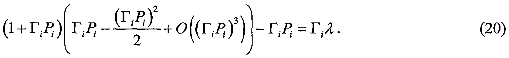
Approximate solution in the low SNR range
While (7) yields the optimal power setting it is instructive to consider an approximate optimization in the low SNR range, i.e. when T1P1 is small. This is achieved by Taylor expansion of the logarithm in (7), with T1P1 as argument, according to:
Figure imgf000039_0001
The result is that the power relates to the channel gain as the inverse square root:
Figure imgf000039_0002
This hints that power exponents is of interest to examine as heuristic solutions of (7). It has been experimentally verified that P1 ∞ T with β = {1/2,..., 1/4} yields very good results, see Fig. 6. In particular, β = 1/2 is asymptotic optimum at low SNRs, but that β = {1/3,... ,1/4} is better at higher SNRs when the non-linearity of (7) kicks in.
At low SNR, where (21) is valid, the time duration and energy can be approximated with:
T, (λ → 0) oc
B1 (IAT1 ) 1/2 (22)
and
1 1 (23)
£,μ -> 0) oc — - cc — .
I I I

Claims

1. A method of controlling link parameters for a multihop route involving at least two links in a multihop network, characterized by determining a parameter common to all links along the entire multihop route based on a given end-to-end (ETE) transmit parameter constraint for the entire multihop route; and assigning, for each of a number of said links, a set of the following three interdependent link transmit parameters, each also being dependent on local link characteristics: a link transmit parameter representative of link transmit energy; a link transmit parameter representative of link transmit time or link transmit bandwidth or link code word consumption; and - a link transmit parameter representative of link transmit power, based on said common parameter and said local link characteristics.
2. The method of claim 1, wherein said set of interdependent link transmit parameters is assigned, for each of a number of said links, under said ETE constraint such that all three interdependent link transmit parameters are generally different between at least two links on the route when said links have different link characteristics.
3. The method of claim 1, wherein said common parameter is determined in the process of optimizing a given objective ETE function under consideration of said ETE . constraint.
4. The method of claim 1, wherein said step of assigning, for each of a number of said links, said set of interdependent link transmit parameters comprises the step of explicitly determining two of said three interdependent link transmit parameters for use when transmitting information over the respective link, whereby the remaining link transmit parameter is given by the interdependence of the three link transmit parameters.
5. The method of claim 4, wherein said common parameter is determined in the process of optimizing a given objective ETE function with respect to, for each considered link, a first link transmit parameter under consideration of said ETE constraint, and said step of explicitly determining two of said three interdependent link transmit parameters comprises the steps of: - determining said first link transmit parameter based on said common parameter and said local link characteristics; and determining a second link transmit parameter as a function of said first link transmit parameter and local link characteristics, said second link transmit parameter being parameterized by said first link transmit parameter.
6. The method of claim 3 or 5, wherein said objective ETE function includes one of the end-to-end (ETE) transmit parameters: an ETE transmit parameter representative of ETE transmit energy; an ETE transmit parameter representative of ETE transmit time or ETE transmit bandwidth or ETE code word consumption; and an ETE transmit parameter representative of ETE transmit power, while another one of the end-to-end (ETE) transmit parameters acts as said ETE constraint.
7. The method of claim 6, wherein an ETE transmit parameter representative of ETE transmit energy is optimized under a constraint on an ETE transmit parameter representative of ETE transmit time or ETE transmit bandwidth or ETE code word consumption.
8. The method of claim 6, wherein an ETE transmit parameter representative of ETE transmit time or ETE transmit bandwidth or ETE code word consumption is optimized under a constraint on an ETE transmit parameter representative of ETE transmit energy.
9. The method of claim 6, wherein an ETE transmit parameter representative of ETE transmit power is optimized under a constraint on an ETE transmit parameter representative of ETE transmit time or ETE transmit bandwidth or ETE code word consumption.
10. The method of claim 6, wherein an ETE transmit parameter representative of ETE transmit time or ETE transmit bandwidth or ETE code word consumption is optimized under a constraint on an ETE transmit parameter representative of ETE transmit power.
11. The method of claim 8 or 10, wherein the ETE transmit parameter representative of ETE transmit time or ETE transmit bandwidth or ETE code word consumption includes ETE throughput.
12. The method of claim 8 or 10, wherein the ETE transmit parameter representative of ETE transmit time or ETE transmit bandwidth or ETE code word consumption includes ETE transmit bandwidth represented by the aggregate number of sub carriers used over the entire route.
13. The method of claim 8 or 10, wherein the ETE transmit parameter representative of ETE transmit time or ETE transmit bandwidth or ETE code word consumption includes ETE code word consumption represented by the aggregate number of code words used over the entire route.
14. The method of claim 3 or 5, wherein said process of optimizing a given objective ETE function is performed by means of the Lagrange multiplier method, and the common parameter is representative of the Lagrange multiplier.
15. The method of claim 4 or 5, wherein said first link parameter is link transmit power, and said second link transmit parameter is link transmit rate, and joint link rate adaptation and link power control is performed based on said determined first and second link transmit parameters.
16. The method of claim 1, wherein said set of interdependent link transmit parameters is assigned, for each individual link on said multihop route, under said ETE constraint such that all three link transmit parameters are different between any, two links on the route.
17. The method of claim 1, wherein said method further comprises the steps of collecting link transmit parameter information related to the ETE constrained transmit parameter along the route, forming an aggregated ETE transmit parameter value from the collected link transmit information and comparing the aggregated ETE transmit parameter value in relation to the given ETE transmit parameter constraint, and wherein said step of determining a common parameter is controlled based on the result of said comparison.
18. The method of claim 17, wherein said steps of collecting, forming, comparing and determining a common parameter are performed iteratively.
19. The method of claim 17 or 18, wherein said method further comprises the step of distributing said common parameter to a number of nodes along the multihop route to enable each of said nodes to allocate said set of interdependent link transmit parameters based on said common parameter and said local link characteristics.
20. The method of claim 1, wherein each of said link transmit parameters is non- linearly dependent on said local link characteristics, and said step of determining a common parameter is based on non-linear processing.
21. A method of routing in a multihop network, characterized by performing the following procedure: optimizing, for each of a number of possible routes and subject to a given ETE transmit parameter constraint common for all routes, a given objective end-to-end (ETE) function with respect to, for each link on the respective route, one of the following three interdependent link transmit parameters: a link transmit parameter representative of link transmit energy; a link transmit parameter representative of link transmit time or link transmit bandwidth or link code word consumption; and a link transmit parameter representative of link transmit power, by means of a parameter common to all links along the considered route such that all three interdependent link transmit parameters, each also being dependent on local link characteristics, are generally different between at least two links on the route when said links have different link characteristics; and selecting route among those routes that have the most optimum value of the objective ETE function.
22. An arrangement for controlling link parameters for a multihop route involving at least two links in a multihop network, characterized by: means for determining a parameter common to all links along the entire multihop route based on a given end-to-end (ETE) transmit parameter constraint for the entire multihop route; and means for assigning, for each of a number of links on said multihop route, a set of the following three interdependent link transmit parameters, each also being dependent on local link characteristics: - a link transmit parameter representative of link transmit energy; a link transmit parameter representative of link transmit time or link transmit bandwidth or link code word consumption; and a link transmit parameter representative of link transmit power, based on said common parameter and said local link characteristics.
23. The arrangement of claim 22, wherein said assigning means is operable for assigning, for each of a number of said links, said set of interdependent link transmit parameters such that all three interdependent link transmit parameters are generally different between at least two links on the route when said links have different link characteristics.
24. The arrangement of claim 22, wherein said means for determining said common parameter comprises means for optimizing a given objective ETE function under consideration of said ETE constraint.
25. The arrangement of claim 22, wherein said means for assigning, for each of a number of said links, said set of interdependent link transmit parameters comprises means for explicitly determining two of said three interdependent link transmit parameters for use when transmitting information over the respective link, whereby the remaining link transmit parameter is given by the interdependence of the three link transmit parameters.
26. The arrangement of claim 25, wherein said means for determining said common parameter comprises means for optimizing a given objective ETE function with respect to, for each considered link, a first link transmit parameter under consideration of said ETE constraint, and said means for explicitly determining two of said three interdependent link transmit parameters comprises: means for determining said first link transmit parameter based on said common parameter and said local link characteristics; and means for determining a second link transmit parameter as a function of said first link transmit parameter and said local link characteristics, said second link transmit parameter being parameterized by said first link transmit parameter.
27. The arrangement of claim 24 or 26, wherein said objective ETE function includes one of the end-to-end (ETE) transmit parameters: an ETE transmit parameter representative of ETE transmit energy; an ETE transmit parameter representative of ETE transmit time or ETE transmit bandwidth or ETE code word consumption; and - an ETE transmit parameter representative of ETE transmit power, while another one of the end-to-end (ETE) transmit parameters acts as said ETE constraint.
28. The arrangement of claim 27, wherein said optimizing means is operable for optimizing an ETE transmit parameter representative of ETE transmit energy under a constraint on an ETE transmit parameter representative of ETE transmit time or ETE transmit bandwidth or ETE code word consumption.
29. The arrangement of claim 27, wherein said optimizing means is operable for optimizing an ETE transmit parameter representative of ETE transmit time or ETE transmit bandwidth or ETE code word consumption under a constraint on an ETE transmit parameter representative of ETE transmit energy.
30. The arrangement of claim 27, wherein said optimizing means is operable for optimizing an ETE transmit parameter representative of ETE transmit power under a constraint on an ETE transmit parameter representative of ETE transmit time or ETE transmit bandwidth or ETE code word consumption.
31. The arrangement of claim 27, wherein said optimizing means is operable for optimizing an ETE transmit parameter representative of ETE transmit time or ETE transmit bandwidth or ETE code word consumption under a constraint on an ETE transmit parameter representative of ETE transmit power.
32. The arrangement of claim 29 or 31, wherein the ETE transmit parameter representative of ETE transmit time or ETE transmit bandwidth or ETE code word consumption includes ETE throughput.
33. The arrangement of claim 29 or 31, wherein the ETE transmit parameter representative of ETE transmit time or ETE transmit bandwidth or ETE code word consumption includes ETE transmit bandwidth represented by the aggregate number of sub carriers used over the entire route.
34. The arrangement of claim 29 or 31, wherein the ETE transmit parameter representative of ETE transmit time or ETE transmit bandwidth or ETE code word consumption includes ETE code word consumption represented by the aggregate number of code words used over the entire route.
35. The arrangement of claim 24 or 26, wherein said means for optimizing a given objective ETE function under consideration of said ETE constraint is configured to operate according to a Lagrange multiplier procedure, and the common parameter is representative of the Lagrange multiplier.
36. The arrangement of claim 25 or 26, wherein said first link parameter is link transmit power, and said second link transmit parameter is link transmit rate, and said arrangement further comprises means for performing joint link rate adaptation and link power control based on said determined first and second link transmit parameters.
37. The arrangement of claim 22, wherein said assigning means is operable for assigning said set of interdependent link transmit parameters, for each individual link on said multihop route, under said ETE constraint such that all three link transmit parameters are different between any two links on the route.
38. The arrangement of claim 22, wherein said arrangement further comprises: - means for collecting link transmit parameter information related to the ETE constrained transmit parameter along the route; means for forming an aggregated ETE transmit parameter value from the collected link transmit information; means for comparing the aggregated ETE transmit parameter value in relation to the given ETE transmit parameter constraint, wherein said means for determining a common parameter is controlled based on the comparison result of said means for comparing.
39. The arrangement of claim 38, wherein said means for collecting, said means for forming, said means for comparing and said means for determining a common parameter are configured to operate iteratively.
40. The arrangement of claim 38 or 39, wherein said arrangement further comprises means for distributing said common parameter to a number of nodes along the multihop route, and each node is operable for assigning said set of interdependent link transmit parameters based on said common parameter and said local link characteristics.
41. The arrangement of any of the claims 22-40, wherein said arrangement is implemented in one or more of the nodes along said multihop route.
42. The arrangement of any of the claims 22-40, wherein said arrangement is implemented in a dedicated control system.
43. The arrangement of claim 22, wherein each of said link transmit parameters is non-linearly dependent on said local link characteristics, and said means for determining a common parameter is configured for non-linear processing.
44. An arrangement for routing in a multihop network, characterized by: means for optimizing, for each of a number of possible routes and subject to a given ETE transmit parameter constraint common for all routes, a given objective end-to-end (ETE) function with respect to, for each link on the respective route, one of the following three interdependent link transmit parameters: - a link transmit parameter representative of link transmit energy; a link transmit parameter representative of link transmit time or link transmit bandwidth or link code word consumption; and a link transmit parameter representative of link transmit power, by means of a parameter common to all links along the considered route such that all three interdependent link transmit parameters, each also being dependent on local link characteristics, are generally different between at least two links on the route when said links have different link characteristics; and means for selecting route among those routes that have the most optimum value of the objective ETE function.
45. An apparatus for controlling link parameters for a multihop route involving at least two links in a multihop network, characterized by: a resource controller configured to determine a parameter common to all links along the entire multihop route based on a given end-to-end (ETE) transmit parameter constraint for the entire multihop route; and a link transmit parameter allocator configured to allocate, to each of a number of links on said multihop route, a set of the following three interdependent link transmit parameters, each also being dependent on local link characteristics: a link transmit parameter representative of link transmit energy; a link transmit parameter representative of link transmit time or link transmit bandwidth or link code word consumption; and a link transmit parameter representative of link transmit power, based on said common parameter and said local link characteristics.
PCT/SE2005/001090 2005-07-01 2005-07-01 End-to-end considerate link control and routing in a multihop network WO2007004935A1 (en)

Priority Applications (6)

Application Number Priority Date Filing Date Title
JP2008519214A JP4782832B2 (en) 2005-07-01 2005-07-01 Link control and routing adapted to end-to-end conditions in multi-hop networks
BRPI0520342-2A BRPI0520342A2 (en) 2005-07-01 2005-07-01 methods and arrangements for controlling link parameters for a multi-transposition route and for routing in a multi-transposition network, and apparatus for controlling link parameters for a multi-transposition route
US11/919,880 US8295173B2 (en) 2005-07-01 2005-07-01 End-to-end considerate link control and routing in a multihop network
EP05756669.7A EP1902552B1 (en) 2005-07-01 2005-07-01 End-to-end considerate link control and routing in a multihop network
PCT/SE2005/001090 WO2007004935A1 (en) 2005-07-01 2005-07-01 End-to-end considerate link control and routing in a multihop network
TW095115004A TW200704028A (en) 2005-07-01 2006-04-27 End-to-end considerate link control and routing in a multihop network

Applications Claiming Priority (1)

Application Number Priority Date Filing Date Title
PCT/SE2005/001090 WO2007004935A1 (en) 2005-07-01 2005-07-01 End-to-end considerate link control and routing in a multihop network

Publications (1)

Publication Number Publication Date
WO2007004935A1 true WO2007004935A1 (en) 2007-01-11

Family

ID=37604706

Family Applications (1)

Application Number Title Priority Date Filing Date
PCT/SE2005/001090 WO2007004935A1 (en) 2005-07-01 2005-07-01 End-to-end considerate link control and routing in a multihop network

Country Status (6)

Country Link
US (1) US8295173B2 (en)
EP (1) EP1902552B1 (en)
JP (1) JP4782832B2 (en)
BR (1) BRPI0520342A2 (en)
TW (1) TW200704028A (en)
WO (1) WO2007004935A1 (en)

Cited By (3)

* Cited by examiner, † Cited by third party
Publication number Priority date Publication date Assignee Title
WO2007091930A1 (en) 2006-02-08 2007-08-16 Telefonaktiebolaget Lm Ericsson (Publ) Link adaptation and power control with consumed energy minimization
US7639639B2 (en) * 2005-08-01 2009-12-29 Ntt Docomo, Inc. Method for relaying information received via a first channel to a second channel and relay apparatus
US8709465B2 (en) 2009-04-13 2014-04-29 Medtronic Vascular, Inc. Diazeniumdiolated phosphorylcholine polymers for nitric oxide release

Families Citing this family (27)

* Cited by examiner, † Cited by third party
Publication number Priority date Publication date Assignee Title
US8798043B2 (en) * 2002-06-28 2014-08-05 Brocade Communications Systems, Inc. Apparatus and method for routing traffic in multi-link switch
US8046019B2 (en) * 2006-08-04 2011-10-25 Futurewei Technologies, Inc. Method and system for optimal allocation of uplink transmission power in communication networks
EP2060088B1 (en) * 2006-09-05 2017-06-28 Telefonaktiebolaget LM Ericsson (publ) Adaptive choice for context source request
US8325654B2 (en) 2006-12-28 2012-12-04 Futurewei Technologies, Inc. Integrated scheduling and power control for the uplink of an OFDMA network
US8031605B2 (en) * 2008-03-31 2011-10-04 Intel Corporation System and method for node-clustering and multi-hop routing in wideband wireless ad-hoc networks
US8023611B2 (en) 2008-09-17 2011-09-20 Au Optronics Corporation Shift register with embedded bidirectional scanning function
US7822029B2 (en) * 2008-11-14 2010-10-26 Mitsubishi Electric Research Laboratories, Inc. Method for routing packets in ad-hoc networks with partial channel state information
WO2010101497A1 (en) * 2009-03-03 2010-09-10 Telefonaktiebolaget L M Ericsson (Publ) Base station and method for scheduler controlled setting of the output power of a base station power amplifier
US8155048B2 (en) * 2009-03-27 2012-04-10 Mitsubishi Electric Research Laboratories, Inc. Resource allocation for rateless transmissions
US8416774B2 (en) * 2009-06-12 2013-04-09 Broadcom Corporation Method and system for energy-efficiency-based packet classification
JP5360653B2 (en) * 2009-08-20 2013-12-04 株式会社国際電気通信基礎技術研究所 Power control apparatus and communication network system including the same
US8681635B2 (en) 2009-12-31 2014-03-25 Mapquest, Inc. Computer-implemented systems and methods for planning a route
JP5678573B2 (en) * 2010-02-24 2015-03-04 富士通株式会社 Route calculation system, route calculation method, and route calculation program
JP5672779B2 (en) * 2010-06-08 2015-02-18 ソニー株式会社 Transmission control apparatus and transmission control method
EP2410294A1 (en) * 2010-07-21 2012-01-25 Harman Becker Automotive Systems GmbH Method and device for providing cost information associated with junctions and method of determining a route
CN103238366B (en) * 2010-12-02 2016-04-20 日本电气株式会社 communication terminal, channel selection method and program
US20130315257A1 (en) * 2010-12-20 2013-11-28 Telefonaktiebolaget L M Ericsson (Publ) Energy efficient routing and switching
WO2012162576A1 (en) * 2011-05-26 2012-11-29 Lantiq Deutschland Gmbh Method for optimal allocation of resources in a multi-user network
JP5787351B2 (en) * 2011-06-29 2015-09-30 Necプラットフォームズ株式会社 Relay node device, ad hoc network, and wireless relay method used therefor
JP5716587B2 (en) 2011-07-19 2015-05-13 富士通株式会社 Route determination device, route determination method, management program, and management device
US9066287B2 (en) * 2012-01-24 2015-06-23 Qualcomm Incorporated Systems and methods of relay selection and setup
US9794796B2 (en) 2012-06-13 2017-10-17 Qualcomm, Incorporation Systems and methods for simplified store and forward relays
US9510271B2 (en) 2012-08-30 2016-11-29 Qualcomm Incorporated Systems, apparatus, and methods for address format detection
JP2019047278A (en) * 2017-08-31 2019-03-22 沖電気工業株式会社 Compression determination processing device, program and method, and radio communication device
US10420007B2 (en) * 2017-10-03 2019-09-17 Itron Networked Solutions, Inc. Energy aware routing for mesh networks
US10425788B2 (en) 2018-02-08 2019-09-24 King Fahd University Of Petroleum And Minerals Equal distance different members node placement method and system
EP3868058A1 (en) 2018-10-19 2021-08-25 Carrier Corporation Energy-balanced and latency-constrained routing methods in wireless network

Citations (3)

* Cited by examiner, † Cited by third party
Publication number Priority date Publication date Assignee Title
US20030161268A1 (en) * 2002-02-22 2003-08-28 Telefonaktiebolaget Lm Ericsson Cross-layer integrated collision free path routing
US20040219922A1 (en) * 2003-05-02 2004-11-04 William Gage Path selection in wireless networks
US20050053007A1 (en) * 2003-09-09 2005-03-10 Harris Corporation Route selection in mobile ad-hoc networks based on traffic state information

Family Cites Families (11)

* Cited by examiner, † Cited by third party
Publication number Priority date Publication date Assignee Title
US6405046B1 (en) * 1998-10-08 2002-06-11 Lucent Technologies, Inc. Method for partitioning mobile stations of a wireless network between an overlay and an underlay
DE60222282T2 (en) * 2001-09-27 2008-06-12 Telefonaktiebolaget Lm Ericsson (Publ) MULTIPLE ROUTING PROCESS FOR DISTRIBUTED WI-FI NETWORKS
US7058018B1 (en) * 2002-03-06 2006-06-06 Meshnetworks, Inc. System and method for using per-packet receive signal strength indication and transmit power levels to compute path loss for a link for use in layer II routing in a wireless communication network
US6954435B2 (en) * 2002-04-29 2005-10-11 Harris Corporation Determining quality of service (QoS) routing for mobile ad hoc networks
US7633894B2 (en) * 2002-09-05 2009-12-15 The Regents Of The University Of California Scheduling methods for wireless networks
US7801042B2 (en) * 2002-12-20 2010-09-21 International Business Machines Corporation Maximum lifetime routing in wireless ad-hoc networks
JP4564012B2 (en) * 2003-05-28 2010-10-20 テレフオンアクチーボラゲット エル エム エリクソン(パブル) Method and system for a wireless communication network utilizing relay
US7085290B2 (en) * 2003-09-09 2006-08-01 Harris Corporation Mobile ad hoc network (MANET) providing connectivity enhancement features and related methods
US7079552B2 (en) * 2003-09-09 2006-07-18 Harris Corporation Mobile ad hoc network (MANET) with quality-of-service (QoS) protocol hierarchy and related methods
US7414977B2 (en) * 2003-11-25 2008-08-19 Mitsubishi Electric Research Laboratories, Inc. Power and delay sensitive ad-hoc communication networks
JP3936328B2 (en) * 2003-11-28 2007-06-27 株式会社国際電気通信基礎技術研究所 Wireless network routing method and wireless communication system

Patent Citations (3)

* Cited by examiner, † Cited by third party
Publication number Priority date Publication date Assignee Title
US20030161268A1 (en) * 2002-02-22 2003-08-28 Telefonaktiebolaget Lm Ericsson Cross-layer integrated collision free path routing
US20040219922A1 (en) * 2003-05-02 2004-11-04 William Gage Path selection in wireless networks
US20050053007A1 (en) * 2003-09-09 2005-03-10 Harris Corporation Route selection in mobile ad-hoc networks based on traffic state information

Non-Patent Citations (1)

* Cited by examiner, † Cited by third party
Title
See also references of EP1902552A4 *

Cited By (5)

* Cited by examiner, † Cited by third party
Publication number Priority date Publication date Assignee Title
US7639639B2 (en) * 2005-08-01 2009-12-29 Ntt Docomo, Inc. Method for relaying information received via a first channel to a second channel and relay apparatus
WO2007091930A1 (en) 2006-02-08 2007-08-16 Telefonaktiebolaget Lm Ericsson (Publ) Link adaptation and power control with consumed energy minimization
EP1982437A1 (en) * 2006-02-08 2008-10-22 Telefonaktiebolaget L M Ericsson (Publ) Link adaptation and power control with consumed energy minimization
EP1982437A4 (en) * 2006-02-08 2012-05-30 Ericsson Telefon Ab L M Link adaptation and power control with consumed energy minimization
US8709465B2 (en) 2009-04-13 2014-04-29 Medtronic Vascular, Inc. Diazeniumdiolated phosphorylcholine polymers for nitric oxide release

Also Published As

Publication number Publication date
BRPI0520342A2 (en) 2009-09-15
TW200704028A (en) 2007-01-16
JP4782832B2 (en) 2011-09-28
EP1902552B1 (en) 2013-09-11
EP1902552A1 (en) 2008-03-26
US20090052327A1 (en) 2009-02-26
JP2009500901A (en) 2009-01-08
EP1902552A4 (en) 2010-07-14
US8295173B2 (en) 2012-10-23

Similar Documents

Publication Publication Date Title
US8295173B2 (en) End-to-end considerate link control and routing in a multihop network
TWI461029B (en) A radio and bandwidth aware routing metric for multi-radio multi-channel multi-hop wireless network
US7339897B2 (en) Cross-layer integrated collision free path routing
JP4598000B2 (en) Cost determination in multi-hop networks
JP5037120B2 (en) Optimal routing in ad hoc wireless communication networks
US20060176829A1 (en) Mobile ad-hoc network
WO2007053141A1 (en) Method for determining a route in a wireless mesh network using a metric based on radio and traffic load
US8391802B2 (en) Link adaptation and power control with consumed energy minimization
Banerjee et al. Energy efficient reliable communication for multi-hop wireless networks
Iannone et al. Mrs: A simple cross-layer heuristic to improve throughput capacity in wireless mesh networks
Nurchis et al. A self-adaptive routing paradigm for wireless mesh networks based on reinforcement learning
Kim et al. Rate-based channel assignment algorithm for multi-channel multi-rate wireless mesh networks
Iannone et al. Evaluating a cross-layer approach for routing in wireless mesh networks
Zawodniok et al. Energy-efficient rate adaptation MAC protocol for ad hoc wireless networks
Al-Zubi et al. Cross-layer design for efficient resource utilization in WiMedia UWB-based WPANs
Hohmann et al. Optimal resource allocation policy for multi-rate opportunistic forwarding
Mahmood et al. Adaptive spreading/coding gains for energy efficient routing in wireless ad hoc networks
Issariyakul et al. Analysis of latency for reliable end-to-end batch transmission in multi-rate multi-hop wireless networks
Hieu et al. A new routing protocol with high throughput route metric for Multi-Rate Mobile Ad-hoc Networks
Rahman et al. A routing protocol for multi-rate wireless ad-hoc networks: Cross layer approach
Li et al. On the efficiency of random walk routing in multihop wireless network
Chang et al. A new routing metric for high throughput in dense ad hoc networks
Hares et al. Multihop relaying with diversity in peer-to-peer networks
Tam et al. Effective cell size scheme in multi-hop cellular networks
Larsson A routing metric for floor acquisition oriented medium access schemes

Legal Events

Date Code Title Description
121 Ep: the epo has been informed by wipo that ep was designated in this application
WWE Wipo information: entry into national phase

Ref document number: 11919880

Country of ref document: US

ENP Entry into the national phase

Ref document number: 2008519214

Country of ref document: JP

Kind code of ref document: A

WWE Wipo information: entry into national phase

Ref document number: 9101/DELNP/2007

Country of ref document: IN

WWE Wipo information: entry into national phase

Ref document number: 2005756669

Country of ref document: EP

NENP Non-entry into the national phase

Ref country code: DE

ENP Entry into the national phase

Ref document number: PI0520342

Country of ref document: BR

Kind code of ref document: A2