WO2007025138A2 - Method and apparatus for packet communications in wireless systems - Google Patents

Method and apparatus for packet communications in wireless systems Download PDF

Info

Publication number
WO2007025138A2
WO2007025138A2 PCT/US2006/033241 US2006033241W WO2007025138A2 WO 2007025138 A2 WO2007025138 A2 WO 2007025138A2 US 2006033241 W US2006033241 W US 2006033241W WO 2007025138 A2 WO2007025138 A2 WO 2007025138A2
Authority
WO
WIPO (PCT)
Prior art keywords
mode
wireless device
dtx
subframes
drx
Prior art date
Application number
PCT/US2006/033241
Other languages
French (fr)
Other versions
WO2007025138A3 (en
Inventor
Juan Montojo
Durga Prasad Malladi
Nathan Edward Tenny
Francesco Grilli
Aziz Gholmieh
Original Assignee
Qualcomm Incorporated
Priority date (The priority date is an assumption and is not a legal conclusion. Google has not performed a legal analysis and makes no representation as to the accuracy of the date listed.)
Filing date
Publication date
Application filed by Qualcomm Incorporated filed Critical Qualcomm Incorporated
Priority to EP06802333A priority Critical patent/EP1932380B1/en
Priority to ES06802333T priority patent/ES2393404T3/en
Priority to JP2008528192A priority patent/JP4865795B2/en
Priority to KR1020107025732A priority patent/KR101111048B1/en
Priority to CN2006800394416A priority patent/CN101297565B/en
Publication of WO2007025138A2 publication Critical patent/WO2007025138A2/en
Publication of WO2007025138A3 publication Critical patent/WO2007025138A3/en

Links

Classifications

    • HELECTRICITY
    • H04ELECTRIC COMMUNICATION TECHNIQUE
    • H04WWIRELESS COMMUNICATION NETWORKS
    • H04W52/00Power management, e.g. TPC [Transmission Power Control], power saving or power classes
    • H04W52/02Power saving arrangements
    • H04W52/0209Power saving arrangements in terminal devices
    • H04W52/0212Power saving arrangements in terminal devices managed by the network, e.g. network or access point is master and terminal is slave
    • H04W52/0216Power saving arrangements in terminal devices managed by the network, e.g. network or access point is master and terminal is slave using a pre-established activity schedule, e.g. traffic indication frame
    • HELECTRICITY
    • H04ELECTRIC COMMUNICATION TECHNIQUE
    • H04WWIRELESS COMMUNICATION NETWORKS
    • H04W76/00Connection management
    • H04W76/20Manipulation of established connections
    • H04W76/28Discontinuous transmission [DTX]; Discontinuous reception [DRX]
    • HELECTRICITY
    • H04ELECTRIC COMMUNICATION TECHNIQUE
    • H04WWIRELESS COMMUNICATION NETWORKS
    • H04W72/00Local resource management
    • H04W72/12Wireless traffic scheduling
    • YGENERAL TAGGING OF NEW TECHNOLOGICAL DEVELOPMENTS; GENERAL TAGGING OF CROSS-SECTIONAL TECHNOLOGIES SPANNING OVER SEVERAL SECTIONS OF THE IPC; TECHNICAL SUBJECTS COVERED BY FORMER USPC CROSS-REFERENCE ART COLLECTIONS [XRACs] AND DIGESTS
    • Y02TECHNOLOGIES OR APPLICATIONS FOR MITIGATION OR ADAPTATION AGAINST CLIMATE CHANGE
    • Y02DCLIMATE CHANGE MITIGATION TECHNOLOGIES IN INFORMATION AND COMMUNICATION TECHNOLOGIES [ICT], I.E. INFORMATION AND COMMUNICATION TECHNOLOGIES AIMING AT THE REDUCTION OF THEIR OWN ENERGY USE
    • Y02D30/00Reducing energy consumption in communication networks
    • Y02D30/70Reducing energy consumption in communication networks in wireless communication networks

Definitions

  • the present disclosure relates generally to communication, and more specifically to techniques for transmitting and receiving data in a wireless communication network.
  • a wireless device in a wireless communication network may operate in one of several operating modes, such as active and idle, at any given moment.
  • the wireless device may be allocated radio resources by the network and may actively exchange data with the network, e.g., for a voice or data call.
  • the wireless device may not be allocated radio resources and may be monitoring overhead channels transmitted by the network.
  • the wireless device may transition between the active and idle modes, as necessary, based on data requirements of the wireless device. For example, the wireless device may transition to the active mode whenever there is data to send or receive and may transition to the idle mode after completing the data exchange with the network.
  • the wireless device may exchange signaling with the network to transition between operating modes.
  • the signaling consumes network resources and delays data transmission until radio resources are allocated to the wireless device.
  • the wireless device may remain in the active mode for an extended period of time.
  • extended stay in the active mode may result in a waste of the allocated radio resources when there is no data to exchange.
  • operation in the active mode may consume more battery power, which may shorten standby time between battery recharges and talk time when there is data to exchange.
  • One embodiment of the invention is a wireless device comprising at least one processor to operate in one of multiple discontinuous transmission (DTX) modes or a no DTX mode, while in a connected mode, for transmission to a wireless network, and to operate in one of at least one discontinuous reception (DRX) mode or a no DRX mode, while in the connected mode, for reception from the wireless network; and a memory coupled to the at least one processor.
  • DTX discontinuous transmission
  • DRX discontinuous reception
  • Another embodiment is a wireless device comprising at least one processor to operate in a connected mode for communication with a wireless network and to operate in one of multiple discontinuous transmission (DTX) modes or a no DTX mode, while in the connected mode, for transmission to a wireless network; and a memory coupled to the at least one processor.
  • DTX discontinuous transmission
  • Another embodiment is a wireless device comprising at least one processor to operate in a connected mode for communication with a wireless network and to operate in one of at least one discontinuous reception (DRX) mode or a no DRX mode, while in the connected mode, for reception from the wireless network; and a memory coupled to the at least one processor.
  • DRX discontinuous reception
  • Another embodiment is a method comprising operating in one of multiple discontinuous transmission (DTX) modes or a no DTX mode, while in a connected mode, for transmission to a wireless network; and operating in one of at least one discontinuous reception (DRX) mode or a no DRX mode, while in the connected mode, for reception from the wireless network.
  • DTX discontinuous transmission
  • DRX discontinuous reception
  • Another embodiment is an apparatus comprising means for operating in one of multiple discontinuous transmission (DTX) modes or a no DTX mode, while in a connected mode, for transmission to a wireless network; and means for operating in one of at least one discontinuous reception (DRX) mode or a no DRX mode, while in the connected mode, for reception from the wireless network.
  • Another embodiment is an apparatus comprising at least one processor to receive from a wireless device operating in one of multiple discontinuous transmission (DTX) modes or a no DTX mode while in a connected mode, and to transmit to the wireless device operating in one of at least one discontinuous reception (DRX) mode or a no DRX mode while in the connected mode; and a memory coupled to the at least one processor.
  • Another embodiment is a method comprising receiving from a wireless device operating in one of multiple discontinuous transmission (DTX) modes or a no DTX mode while in a connected mode; and transmitting to the wireless device operating in one of at least one discontinuous reception (DRX) mode or a no DRX mode while in the connected mode.
  • DTX discontinuous transmission
  • DRX discontinuous reception
  • Another embodiment is an apparatus comprising means for receiving from a wireless device operating in one of multiple discontinuous transmission (DTX) modes or a no DTX mode while in a connected mode; and means for transmitting to the wireless device operating in one of at least one discontinuous reception (DRX) mode or a no DRX mode while in the connected mode.
  • DTX discontinuous transmission
  • DRX discontinuous reception
  • FIG. 1 shows a diagram of a 3GPP network.
  • FIG. 2 shows a state diagram of Radio Resource Control (RRC) states for a User
  • RRC Radio Resource Control
  • UE Radio Equipment
  • FIG. 3 shows an embodiment of the CPC mode.
  • FIG. 4 shows enabled subframes for the CPC mode.
  • FIGS. 5A, 5B and 5C show operation in DTX Tl, DTX T2 and DRX modes, respectively.
  • FIGS. 6 A and 6B show exemplary uplink transmissions in the CPC mode.
  • FIG. 7 shows exemplary downlink and uplink transmissions in the CPC mode.
  • FIG. 8 shows an event flow for transitioning from DRX mode to NO DRX mode.
  • FIG. 9 shows a process performed by the UE in the CPC mode.
  • FIG. 10 shows a process performed by the network for the CPC mode.
  • FIG. 11 shows a block diagram of the UE, a Node B, and an RNC.
  • CDMA Code Division Multiple Access
  • TDMA Time Division Multiple Access
  • FDMA Frequency Division Multiple Access
  • OFDMA Orthogonal FDMA
  • a CDMA network may implement a radio technology such as W-CDMA, cdma2000, and so on.
  • cdma2000 covers IS-2000, IS-856 and IS-95 standards.
  • a TDMA network may implement a radio technology such as Global System for Mobile Communications (GSM). These various radio technologies and standards are known in the art.
  • GSM Global System for Mobile Communications
  • cdma2000 is described in documents from an organization named "3rd Generation Partnership Project 2" (3GPP2). For clarity, the techniques are described below for Universal Mobile Telecommunication System (UMTS), which utilizes W-CDMA. UMTS terminology is used in much of the description below.
  • 3GPP2 3rd Generation Partnership Project 2
  • UMTS Universal Mobile Telecommunication System
  • FIG. 1 shows a diagram of a 3GPP/UMTS network 100 that includes a
  • a UE 110 communicates with a Node B 130 in UTRAN 120.
  • UE 110 may be stationary or mobile and may also be referred to as a wireless device, a mobile station, a user terminal, a subscriber unit, a station, or some other terminology.
  • UE 110 may be a cellular phone, a personal digital assistant (PDA), a handheld device, a wireless modem, and so on.
  • PDA personal digital assistant
  • Node B 130 is generally a fixed station that communicates with the UEs and may also be referred to as a base station, an access point, or some other terminology.
  • Node B 130 provides communication coverage for a particular geographic area and supports communication for UEs located within the coverage area.
  • a Radio Network Controller (RNC) 140 couples to Node B 110 and provides coordination and control for the Node B.
  • Core network 150 may include various network entities that support various functions such as packet routing, user registration, mobility management, etc.
  • UE 110 may communicate with Node B 130 on the downlink and/or uplink at any given moment.
  • the downlink (or forward link) refers to the communication link from the Node B to the UE, and the uplink (or reverse link) refers to the communication link from the UE to the Node B.
  • UMTS data is processed as one or more transport channels at a higher layer.
  • the transport channels may carry data for one or more services, e.g., voice, video, packet data, and so on.
  • the transport channels are mapped to physical channels at a physical layer or Layer 1 (Ll).
  • the physical channels are channelized with different channelization codes and are orthogonal to one another in code domain.
  • HSDPA High-Speed Uplink Packet Access
  • HSUPA High-Speed Uplink Packet Access
  • Tables 1 and 2 list some downlink and uplink physical channels, respectively, in UMTS.
  • the HS- SCCH, HS-PDSCH, and HS-DPCCH are used for HSDPA.
  • the E-DPCCH, E- DPDCH, and E-HICH are used for HSUPA.
  • FIG. 2 shows a state diagram 200 of the Radio Resource Control (RRC) states for the UE.
  • RRC Radio Resource Control
  • the UE Upon being powered on, the UE performs cell selection to find a suitable cell from which the UE can receive service. Thereafter, the UE may transition to an idle mode 210 or a connected mode 220 depending on whether there is any activity for the UE.
  • the idle mode the UE has registered with the UTRAN, is listening for paging messages, and updates its location with the UTRAN when necessary.
  • the UE can receive and/or transmit data, depending on its RRC state and configuration.
  • the connected mode may also be referred to as a connected state, an active mode, an active state, a traffic state, a traffic channel state, and so on.
  • the UE may be in one of four possible RRC states - a
  • the CELLJDCH state is characterized by (1) dedicated physical channels allocated to the UE for the downlink and uplink and (2) a combination of dedicated and shared transport channels being available to the UE.
  • the CELLJ 7 ACH state is characterized by (1) no dedicated physical channels allocated to the UE, (2) a default common or shared transport channel assigned to the UE for use to access the UTRAN, and (3) the UE continually monitoring a Forward Access Channel (FACH) for signaling such as Reconfiguration messages.
  • FACH Forward Access Channel
  • the CELLJPCH and URAJPCH states are characterized by (1) no dedicated physical channels allocated to the UE, (2) the UE periodically monitoring a Paging Channel (PCH) for paging messages, and (3) the UE not being permitted to transmit on the uplink.
  • PCH Paging Channel
  • the modes and states for the UE are described in 3GPP TS 25.331.
  • the UTRAN can command the UE to be in one of the four possible states based on activity of the UE.
  • the UE may transition (1) from the CELL JDCH or CELLJFACH state in the connected mode to the idle mode by performing a Release RRC Connection procedure, (2) from the idle mode to the CELL_DCH or CELL_FACH state by performing an Establish RRC Connection procedure, (3) between the CELLJDCH and CELLJFACH states by performing a reconfiguration procedure, and (4) between different configurations in the CELLJDCH state by also performing a reconfiguration procedure.
  • These procedures are described in 3GPP TS 25.331.
  • the CELLJDCH state comprises a Continuous Packet
  • the Active mode may correspond to operation of the HSDPA and HSUPA channels as described in 3GPP Release 6.
  • data may be sent in any subframe on the downlink and uplink.
  • a subframe is a time interval in which a transmission may be sent on a link.
  • a subframe may have different durations in different networks and/or for different configurations of a given network.
  • the CPC mode may be used to achieve efficient data transmission and reception for the UE.
  • the CPC mode may provide power savings for the UE and/or capacity improvement for the UTRAN.
  • radio resources e.g., physical channels
  • higher layers e.g., Layers 2 and 3
  • the UE may send signaling and/or data on the enabled uplink subframes and may receive signaling and/or data on the enabled downlink subframes.
  • the UE may power down certain circuit blocks and subsystems, e.g., its transmitter and/or receiver, during the non-enabled subframes to conserve battery power.
  • the CPC mode may include any number of DTX modes, any number of DRX modes, and/or other modes.
  • Each DTX mode may be associated with different enabled uplink subframes and/or different actions to be performed by the UE.
  • Each DRX mode may be associated with different enabled downlink subframes and/or different actions to be performed by the UE.
  • FIG. 3 shows an embodiment of the CPC mode.
  • the CPC mode includes DTX modes 310 and 312, a DRX mode 314, and a NO DRX mode 316.
  • DTX mode 310 is also referred to as DTX Tl mode
  • DTX mode 312 is also referred to as DTX T2 mode.
  • Table 3 lists the DTX and DRX modes in FIG. 3 and provides a short description for each mode.
  • Tl, T2 and R any values may be selected for Tl, T2 and R.
  • Tl, T2 and R any values may be selected for Tl, T2 and R.
  • T2 and R are defined such that Tl ⁇ T2 and R ⁇ T2.
  • Tl, T2 and R are selected from a set of possible values.
  • Tl, T2 and R may each be set equal to 1, 4, 8, or 16 and may be expressed as Tl, T2 and R e ⁇ 1, 4, 8, 16 ⁇ .
  • Other sets of possible values may also be used for Tl, T2 and R.
  • the possible values may be power of twos and/or other values.
  • Tl-enabled subframes are enabled subframes for the DTX Tl mode and are spaced apart at intervals of Tl subframes.
  • T2-enabled subframes are enabled subframes for the DTX T2 mode and are spaced apart at intervals of T2 subframes.
  • R-enabled subframes are enabled subframes for the DRX mode and are spaced apart at intervals of R subframes.
  • the T2-enabled subframes are a subset of the Tl- enabled subframes. In other embodiments, the T2-enabled subframes may be selected independently of the Tl-enabled subframes.
  • UE are identified by an Offset from a reference time.
  • This reference time may be a start time in which the CPC mode is effective for the UE and may be given in signaling used to convey CPC parameters.
  • Tl, T2 and R define three enabled subframe patterns or sets that start at a subframe where the CPC configuration was effective (the reference time) plus the Offset.
  • the parameters of the CPC mode comprise Tl, T2, R, Offset, and reference time.
  • the CPC mode may also be defined based on other parameters.
  • the UTRAN may select suitable values for Tl, T2 and R based on various factors such as data activity, network loading, and so on.
  • the UTRAN may select different Offset values for different UEs to distribute these UEs across the available subframes.
  • any values may be selected for Tl, T2 and R. Different values may be more suitable for different services and/or different conditions.
  • the UTRAN may order the UE out of DRX mode whenever there is data to send on the downlink.
  • Various other values may also be used for the CPC parameters to achieve other characteristics.
  • the UTRAN (e.g., the RNC) configures the CPC parameters for the UE during call setup, e.g., using Layer 3 (L3) signaling and/or some other signaling.
  • the UTRAN may configure or modify the CPC parameters through a Reconfiguration message during the call.
  • the UTRAN may also configure or modify the CPC parameters in other manners and/or with other types of signaling.
  • the Tl, T2 and R values may be sent as part of system information signaled by the Node B. Different Tl, T2 and R values may also be defined for different call types.
  • Table 3 lists actions performed by the UE for each DTX and DRX mode, in accordance with an embodiment.
  • FIG. 3 also shows exemplary criteria for transitioning between the DTX and
  • the UE can autonomously transition between the two DTX modes, e.g., based on data activity at the UE.
  • the UE may transition from the DTX T2 mode to the DTX Tl mode whenever there is data to send on the uplink.
  • the UE may transmit just signaling in each Tl -enabled subframe that the UE has no data to send.
  • the UE may transition from the DTX Tl mode to the DTX T2 mode if there is no data to send on the uplink, e.g., if T2 subframes have passed without any uplink data transmission.
  • the UE may revert to full use of all uplink subframes autonomously and instantaneously.
  • the Tl-enabled subframes may be sufficient for light and/or expected exchanges of data.
  • the UE may use more uplink subframes whenever the Tl-enabled subframes are insufficient for the data load at the UE.
  • the UE may, in essence, transition from the DTX T2 mode to the Active mode for data transmission as needed.
  • the UE transitions between the DRX mode and the NO DRX mode as directed by the UTRAN, e.g., the Node B.
  • DRX operation is synchronized between the Node B and the UE.
  • the Node B may direct the UE to transition to the DRX mode based on any of the following: (1) downlink traffic load for the UE is light, (2) downlink data rate is below a threshold and may be served at a reduced subframe rate, (3) there is lack of data activity for the UE, (4) a data queue for the UE has been empty for some time or has just been emptied, or (5) some other reason.
  • the UE While in the DRX mode, the UE may ignore downlink subframes that are not R-enabled subframes.
  • the Node B may direct the UE to transition to the NO DRX mode based on any of the following: (1) data for the UE has just arrived, (2) downlink traffic load for the UE is heavy, (3) the data queue for the UE is above a threshold or is growing at a faster rate than the transmission rate to the UE, (4) cell loading is heavy, or (5) some other reason.
  • the UE receives signaling (e.g., decodes the HS-SCCH) in every subframe and may receive data as indicated by the signaling.
  • the commands to transition between these modes are sent using fast Layer 1 (Ll) and/or Layer 2 (L2) signaling from the Node B to the UE.
  • Ll Layer 1
  • L2 Layer 2
  • a single L1/L2 fast signaling bit may be used to enable or disable the DRX mode.
  • the fast L1/L2 signaling provides the Node B with a fast mechanism to revert to full use of all available downlink subframes and may improve synchronization between the Node B and the IJE.
  • Sending L1/L2 signaling from the Node B to the UE may incur a delay of approximately 5 to 8 ms whereas sending L3 signaling from the RNC to the UE may incur a delay of 100 ms or more. Nevertheless, the commands to transition between modes may be sent using signaling in any layer and in any manner.
  • the command to transition from the NO DRX mode to the DRX mode is referred to as Node B order #1.
  • the command to transition from the DRX mode to the NO DRX mode is referred to as Node B order #2.
  • the UTRAN e.g., the Node B
  • the UTRAN may send Node B order #1 whenever the UTRAN wants to ensure that both the UTRAN and the UE operate in the DRX mode.
  • the UTRAN may send Node B order #2 whenever the UTRAN wants to ensure that both the UTRAN and the UE operate in the NO DRX mode.
  • HSDPA and HSUPA employ hybrid automatic retransmission (HARQ) to improve reliability of data transmission.
  • HARQ for HSDPA and HARQ for HSUPA operate in similar manner.
  • HARQ retransmissions may be sent anytime after a minimum delay, e.g., 6 to 8 TTIs.
  • HARQ retransmissions are sent 8 TTIs later.
  • an HARQ entity at the Node B processes and transmits a packet to the UE.
  • a corresponding HARQ entity at the UE receives and decodes the packet.
  • the UE sends an ACK if the packet is decoded correctly or a NAK if the packet is decoded in error.
  • the Node B retransmits the packet if a NAK is received and transmits a new packet if an ACK is received.
  • the Node B transmits the packet once and may retransmit the packet any number of times until an ACK is received for the packet or the Node B decides to abandon the transmission of the packet.
  • the Node B may transmit packets on up to eight HARQ processes to the UE.
  • the HARQ processes may be viewed as HARQ channels used to send packets.
  • the Node B receives downlink packets to send to the UE and transmits these packets in sequential order to the UE on the available HARQ processes.
  • Each packet is sent on one HARQ process and includes an HARQ process ID (HID) that indicates the HARQ process used for that packet.
  • HID HARQ process ID
  • Each HARQ process carries one packet at a time until the transmission/ retransmission for that packet is completed and may then be used to send another packet.
  • the condition of "no data to send" for the transition from the DTX Tl mode to the DTX T2 mode may correspond to no HARQ process being active. This in turn may be detected by no activity on any of the HARQ processes. When all HARQ processes are acknowledged, the UE may transition to the DTX T2 mode.
  • FIG. 4 shows an embodiment of the enabled subframes for HSDPA and
  • the transmission time line is partitioned into frames, with each frame being identified by the SFN.
  • Each frame has a duration of 10 milliseconds (ms) and is partitioned into five subframes 0 through 4.
  • Each subframe has a duration of 2 ms and covers three slots.
  • the P-CCPCH carries pilot and the SFN.
  • the P-CCPCH is used directly as timing reference for downlink channels and is used indirectly as timing reference for uplink channels.
  • the subframes of the HS-SCCH are time-aligned with the P-CCPCH.
  • the subframes of the E-HICH are delayed by % mcH ⁇ n from the subframes of the HS-SCCH, where ⁇ E.fflCH n is defined in 3GPP TS 25.211.
  • the subframes of the HS-DPCCH are delayed by 7.5 slots from the subframes of the HS-PDSCH at the UE, where ⁇ PD in FIG. 4 denotes the propagation delay from the Node B to the UE.
  • the uplink DPCCH, E-DPCCH, and E- DPDCH are time-aligned and their frame timing is m X 256 chips from the frame timing of the HS-DPCCH.
  • the timing of the uplink DPCCH is not directly related to the timing of the HS-DPCCH.
  • the frame timing for the downlink and uplink channels is described in 3GPP TS 25.211.
  • the Tl-enabled subframes on the uplink DPCCH, E- DPCCH, E-DPDCH, and E-HICH are spaced apart by 4 subframes.
  • the T2-enabled subframes on the uplink DPCCH are spaced apart by 8 subframes.
  • the R-enabled subframes on the HS-SCCH, HS-DPDCH and HS-DPCCH are spaced apart by 4 subframes.
  • the Offset determines the specific subframes to use for the enabled subframes.
  • the Tl-enabled, T2-enabled, and R-enabled subframes may be aligned in time (e.g., as described in TR25.903, section 4.5.2.1) to reduce rise-over-thermal (ROT) and to extend possible sleep time for the UE between the enabled subframes.
  • transmissions on the uplink including ACKs for downlink transmissions
  • Transmissions on the downlink including ACKs for uplink transmissions
  • FIG. 5A shows exemplary operation of the UE in the DTX Tl mode for the
  • the UE transmits pilot and signaling (e.g., TPC) on the uplink DPCCH and signaling (e.g., CQI) on the HS-DPCCH in each Tl-enabled subframe. If the UE has data to send in a given Tl-enabled subframe, then the UE transmits signaling on the E-DPCCH, transmits data on the E-DPDCH, and receives ACK/NAK on the E-HICH.
  • TPC pilot and signaling
  • CQI signaling
  • FIG. 5B shows exemplary operation of the UE in the DTX T2 mode for the
  • the UE transmits pilot and signaling (e.g., TPC) on the uplink DPCCH and signaling (e.g., CQI) on the HS-DPCCH in each T2-enabled subframe.
  • TPC pilot and signaling
  • CQI signaling
  • the UE does not transmit signaling on the E-DPCCH, does not transmit data on the E-DPDCH, and does not receive ACK/NAK on the E-HICH.
  • FIG. 5C shows exemplary operation of the UE in the DRX mode for the CPC configuration shown in FIG. 4.
  • the UE receives signaling on the HS-SCCH in each R- enabled subframe.
  • the UE may receive data on the HS-DPDCH in any R-enabled subframe and may then send ACK/NAK on the HS-DPCCH.
  • CQI reports are sent in the R-enabled subframes.
  • the UE may also send additional CQI reports when sending ACKs/NAKs.
  • the additional CQI reports may be used for retransmissions or new transmissions.
  • the two DTX modes and the DRX mode may be defined independently of one another.
  • the DTX and DRX modes are jointly parameterized, e.g., to time align the Tl-enabled subframes with the R-enabled subframes. This embodiment may extend sleep time and enhance battery savings for the UE.
  • the spacing of Tl and R is such that subframes used for retransmissions are automatically enabled subframes.
  • the UTRAN (e.g., the Node B) expects uplink transmission from the UE only in the Tl-enabled subframes. In another embodiment, the UTRAN expects uplink transmission from the UE in all subframes and thus always listens for the UE. Since the UE can autonomously transition between the DTX Tl mode and the DTX T2 mode, the UTRAN may not receive uplink transmissions in some Tl-enabled subframes.
  • the UTRAN may determine whether the UE transmits the uplink DPCCH in each Tl-enabled subframe (e.g., based on the pilot) and may discard the received signaling (e.g., TPC bits for downlink power control) if the pilot is absent or is of insufficient quality.
  • the received signaling e.g., TPC bits for downlink power control
  • the UE expects downlink transmissions from the UTRAN in the R-enabled subframes while in the DRX mode and in any subframe while in the NO DRX mode.
  • the UE may discard signaling (e.g., TPC bits for uplink power control) that does not correspond to a transmission sent by the UE.
  • the UE starts DRX operation upon receiving Node B order #1 and stops DRX operation upon receiving Node B order #2.
  • the UE attempts to transmit using the Tl-enabled subframes. If the UTRAN expects uplink transmissions from the UE in all subframes, then the UE may use other subframes if the Tl-enabled subframes are not sufficient. The UE does not DTX more than (Tl -I) subframes while there is at least one HARQ process active. If there are no active HARQ processes, then the UE transmits pilot and signaling (e.g., CQI) on the T2-enabled subframes and does not DTX more than (T2 - 1) subframes.
  • pilot and signaling e.g., CQI
  • FIG. 6A shows exemplary uplink transmissions for a CPC configuration
  • the UE may receive vocoder packets from upper layer every 20 ms.
  • Line 1 in FIG. 6 A shows vocoder packets received by the UE.
  • Lines 2 through 5 show packet transmissions and retransmissions for different maximum numbers of retransmissions (N).
  • the Tl-enabled subframes are represented by circles in lines 2 through 5.
  • the T2-enabled subframes are every other circle in lines 2 through 5 and are indicated by label "T2e" above line 2.
  • the UE transitions to the DTX Tl mode upon receiving the first packet 0 for transmission to the UTRAN.
  • N I retransmission in line 2
  • packet 0 is received in subframe S 1 and sent in Tl-enabled subframes S 1 and S 3
  • packet 1 is received in subframe S 4 and sent in Tl- enabled subframes S 5 and S 7 , and so on.
  • Pilot and CQI are sent in Tl-enabled subframes, including subframes S 2 , S 6 , S 9 , S 13 and S 15 without any data transmission.
  • HARQ processes for packets 0, 1, 2 and 3 are completed after subframe S 14 .
  • the UE transitions to the DTX T2 mode in subframe S 16 and sends pilot and CQI in T2-enabled subframes S 17 and S 19 .
  • the UE transitions to the DTX Tl mode upon receiving packet 4 in subframe S 21 and sends this packet in Tl-enabled subframes S 22 and S 24 .
  • N 2 retransmissions in line 3
  • packet 0 is received in subframe S 1 and sent in Tl -enabled subframes S 1 , S 3 and S 6
  • packet 1 is received in subframe S 4 and sent in Tl-enabled subframes S 5 , S 7 and S9, and so on.
  • Pilot and CQI are sent in Tl-enabled subframes, including subframes S 2 and S 15 without any data transmission.
  • HARQ processes for packets 0, 1, 2 and 3 are completed after subframe S 16 .
  • the UE transitions to the DTX T2 mode in subframe S 18 and sends pilot and CQI in T2-enabled subframes S 1 C).
  • the UE transitions to the DTX Tl mode upon receiving packet 4 in subframe S 21 and sends this packet in Tl-enabled subframes S 22 and S 24 .
  • FIG. 6B shows exemplary uplink transmissions for the CPC configuration
  • the UE receives vocoder packets from upper layer every 20 ms.
  • FIG. 7 shows exemplary downlink and uplink transmissions in the CPC mode.
  • the UE operates in the DRX mode upon receiving Node B order #1 and also autonomously selects the DTX T2 mode.
  • the UE has data to send, transitions to the DTX Tl mode, and transmits packet A.
  • the UE transitions to the NO DRX mode upon receiving Node B order #2 and thereafter receives packets 0 through 5.
  • the UE transitions to the DTX T2 mode following a period of no activity after sending packet A.
  • the UE has data to send, transitions to the DTX Tl mode, and transmits packets B through F.
  • the UE transitions to the DTX T2 mode following a period of no activity.
  • the UE transitions to the DRX mode upon receiving Node B order #1.
  • the UE has data to send, transitions to the DTX Tl mode, and transmits packets G through I.
  • the UE transitions to the DTX T2 mode following a period of no activity.
  • the UE transitions to the NO DRX mode upon receiving Node B order #2 and thereafter receives packets 6 through 8.
  • the UE transitions to the DRX mode upon receiving Node B order #1.
  • the UTRAN sends Node B orders to direct the UE to transition between the DRX mode and the NO DRX mode.
  • the Node B orders (e.g., #1 and #2) may be sent in various manners. In general, it is desirable to send the Node B orders using a reliable mechanism since these orders affect network operation and performance. This may be achieved by sending the Node B orders on a control channel with low error probability and/or acknowledgement. In an embodiment, the Node B orders are sent on the HS-SCCH, which is fairly robust and has an ACK mechanism. This improves the reliability of the Node B orders and reduces miscommunication problems due to the UTRAN and the UE being in different modes.
  • FIG. 8 shows an embodiment of an event flow 800 for transitioning from the
  • Node B order #2 is sent on the HS-SCCH.
  • the UTRAN receives downlink packets for the UE.
  • the UTRAN then sends Node B order #2 on the HS- SCCH in the next R-enabled subframe.
  • the average delay in sending Node B order #2 is R /2 subframes.
  • the UE receives Node B order #2 on the HS-SCCH and replies by sending an ACK on the HS-DPCCH.
  • the UTRAN can send packets to the UE in any subframes and is not constrained to the R-enabled subframes.
  • the UTRAN may also send Node B order #1 on the HS-SCCH in similar manner as Node B order #2.
  • the Node B may order the UE out of the DRX mode, and the subsequent delay may be reduced to as low as zero. Retransmissions may further delay a new packet transmission.
  • the delay is under the control of the UE since the UE may transmit in any subframe.
  • certain restrictions may be imposed on when the UE can start uplink transmission in order to aid detection at the Node B. For example, the UE may be restricted to start an uplink transmission in a Tl- enabled subframe, a T2-enabled subframe, or some other subframe.
  • the Node B orders may be sent in various manners.
  • the UE is assigned a first 16-bit HS-DSCH Radio Network Identifier (H-RNTI) for UE identity (as normally done) and is further assigned a second 16-bit H-RNTI for Node B orders.
  • H-RNTI is described in 3GPP TS 25.212, section 4.6.
  • the second H-RNTI provides space of 21 bits for orders and future extensions.
  • one 16-bit H- RNTI is reserved for broadcasting orders.
  • An order message may include the UE- specific H-RNTI (16 bits), creating space of 5 bits for orders and future extensions.
  • the Node B orders may also be sent on other control channels and/or in other manners.
  • the UTRAN and the UE may then operate in different modes. Two different possible error scenarios are described below.
  • the UTRAN may operate in the DRX mode, and the UE may operate in the NO
  • This error situation may arise due to (1) the UTRAN sending Node B order #1 and the UE failing to detect the order or (2) the UE erroneously detecting Node B order #2 when none was sent.
  • the Node B would restrict its downlink transmissions to the R-enabled subframes while the UE receives all subframes. The UE consumes extra battery power, but no data is lost.
  • the UTRAN may operate in the NO DRX mode, and the UE may operate in the
  • This error situation may arise due to (1) the UE erroneously detecting Node B order #1 when none was sent or (2) the UTRAN sending Node B order #2 and the UE failing to detect the order.
  • the UTRAN may transmit on any subframe while the UE receives only the R-enabled subframes. Data transmitted in subframes other than the R-enabled subframes would be lost. This error situation is detectable.
  • the UTRAN may detect for this type of error and may implement a proper recovery mechanism.
  • the CPC mode may provide certain advantages.
  • the DTX Tl mode defines a certain minimum duty cycle Tl that may maximize capacity during data transmission.
  • the UE may synchronize its transmission times with its reception times to extend its sleep cycle.
  • the UTRAN e.g., Node B
  • the DTX T2 mode may facilitate synchronization, simplify detection and search of uplink transmissions, and simplify Node B implementation.
  • the UTRAN has knowledge of the minimum set of enabled subframes, which may reduce impact of searching for the uplink DPCCH from the UE at the Node B.
  • the Node B may not search each subframe if it knows that uplink transmissions are sent in or starting at T2-enabled subframes.
  • the detection at the Node B may also be simplified compared to a system that does not utilize T2- enabled subframes. In such a system, it may be harder for the Node B to detect a signal that is transmitted erratically without a known periodicity, which may help energy accumulation/correlation .
  • the UE may transition from the CPC mode to the
  • the Active mode based on any of the following: (1) the amount of downlink data to send to the UE (e.g., for a new transport and/or logical channel) suggests use of more downlink subframes, (2) the network is congested and scheduler performance may be improved by allowing the scheduler to freely use all of the downlink subframes, and/or (3) some other reason.
  • the UE may transmit data in any uplink subframe and/or receive data in any downlink subframe in the Active mode.
  • the Active mode may improve performance at the expense of more battery power.
  • the UE may transition from the Active mode to the CPC mode based on any of the following: (1) traffic load for the UE is light, (2) there is lack of user data activity, or (3) some other reason.
  • the UTRAN can ascertain downlink data activity of the UE based on the status of the data queue for the UE and can ascertain uplink data activity of the UE based on reception of status reports of a data buffer maintained by the UE.
  • the UTRAN directs the UE to operate in the Active mode or the CPC mode.
  • the UTRAN may direct the UE to switch mode by sending a mode switch command or some other signaling.
  • the UTRAN may also direct the UE to transition to the CPC mode by sending the parameters for the CPC mode.
  • the UE may elect to operate in the Active mode or the CPC mode and may send either a request for a mode switch (if the decision is made by the UTRAN) or an indication of a mode switch (if the decision can be made by the UE).
  • the UTRAN may command the UE to transition to the CPC mode (e.g., by sending the CPC parameters or a mode switch) whenever the UTRAN wants to ensure that both the UTRAN and the UE are operating in the CPC mode.
  • the UTRAN may also command the UE to transition to the Active mode whenever the UTRAN wants to ensure that both the UTRAN and the UE are operating in the Active mode.
  • the CPC mode includes two DTX modes, one DRX mode, and a no DRX mode.
  • the CPC mode may include any number of DTX modes, a no DTX mode, any number of DRX modes, a no DRX mode, or any combination thereof.
  • the CPC mode includes a Connected Deep mode (or simply, a Deep mode) mode in which the UE has one enabled subframe in every T3 subframes on the uplink and one enabled subframe in every R2 subframes on the downlink.
  • T3 and R2 may be defined as T3 > T2 and R 2 > R .
  • T3 and R2 may be set to large values, e.g., much larger than T2 and R, respectively, or possibly infinity.
  • the UE may (a) stop listening or listen very infrequently to the downlink and (b) stop transmitting or transmit very infrequently on the uplink.
  • the UE may measure the CPICH and P-CCPCH and may decode the HS-SCCH of the serving and surrounding Node Bs in the R2-enabled subframes.
  • the UE may update its Active Set of Node Bs, if necessary, based on the measurements.
  • the UE may ignore TPC commands sent by the Node B to adjust the transmit power of the UE.
  • the UE may transition out of the Deep mode based on various triggering events, e.g., if the UE receives data in its buffer or receives a packet on the downlink.
  • the UE may transition to (a) the DTX Tl mode, the DTX T2 mode, or the no DTX mode for transmission on the uplink and (b) the DRX mode or the no DRX mode for reception on the downlink.
  • the UE While in the Deep mode, UE synchronization at the Node B is likely lost.
  • a procedure may be used to re-activate the UE from the Deep mode. This re-activation may be accompanied by a sufficiently long DPCCH preamble to allow the closed-loop power control mechanism to bring the transmit power of the UE back to the proper power level.
  • CPC mode may be a mode or a configuration of the CELLJDCH state, as shown in FIG. 2.
  • the CPC mode may also be employed in other manners in UMTS.
  • the techniques described herein may also be used for other communication networks, other channel structures, other frame and subframe structures, and/or other transmission schemes.
  • the techniques may be used for HARQ as well as non-HARQ transmissions.
  • FIG. 9 shows an embodiment of a process 900 performed by a wireless device for operation in a CPC mode. While in the connected mode, the wireless device operates in one of multiple DTX modes or a no DTX mode for transmission to a wireless network (block 910). The wireless device also operates in one of at least one DRX mode or a no DRX mode for reception from the wireless network (block 920). Each DTX mode may be associated with different subframes usable for sending signaling and/or data to the wireless network. The no DTX mode may be associated with all subframes being usable for sending signaling and/or data to the wireless network. Each DRX mode may be associated with different subframes usable for receiving signaling and/or data from the wireless network.
  • the no DRX mode may be associated with all subframes being usable for receiving signaling and/or data from the wireless network.
  • the wireless device may operate in any of the following: (1) DTX and DRX, (2) DTX and no DRX, (3) no DTX and DRX, or (4) no DTX and no DRX.
  • the multiple DTX modes may comprise first and second DTX modes.
  • the wireless device may transmit signaling in first enabled subframes and may transmit data in the first enabled subframes if there is data to send to the wireless network (block 912).
  • the wireless device may transmit signaling in second enabled subframes (block 914).
  • the wireless device sends signaling for Layer 1 (e.g., pilot, TPC, CQI, and so on) and may send signaling for higher layers in the first DTX mode, and sends only Layer 1 signaling in the second DTX mode.
  • Layer 1 e.g., pilot, TPC, CQI, and so on
  • the wireless device may be allowed to send different types of signaling or may be restricted to send only certain types of signaling in each DTX mode.
  • the signaling sent in the first DTX mode may thus be the same as or different from the signaling sent in the second DTX mode.
  • the at least one DRX mode may comprise a single DRX mode.
  • the wireless device may receive signaling in third enabled subframes and may receive data in the third enabled subframes if the signaling indicates data being sent to the wireless device (block 922).
  • the first enabled subframes may be a subset of the subframes available for the uplink and may be spaced apart by Tl subframes.
  • the second enabled subframes may be a subset of the first enabled subframes and may be spaced apart by T2 subframes.
  • the third enabled subframes may be a subset of the subframes available for the downlink and may be spaced apart by R subframes.
  • Tl, T2, and/or R may be configurable parameters.
  • the wireless device may autonomously transition between the multiple DTX modes and may autonomously transition to a no DTX mode based on data load at the wireless device (block 916).
  • the wireless device may transition between the at least one DRX mode and a no DRX mode based on signaling from the wireless network (block 924).
  • the wireless device may also transition between an active mode and the CPC mode based on signaling from the wireless network.
  • the active mode may correspond to all subframes being usable for transmission and reception.
  • FIG. 10 shows an embodiment of a process 1000 performed by a wireless network for the CPC mode.
  • the wireless network receives from a wireless device operating in one of multiple DTX modes or a no DTX mode while in a connected mode (block 1010).
  • the wireless network transmits to the wireless device operating in one of at least one DRX mode or a no DRX mode while in the connected mode (block 1020).
  • the multiple DTX modes may comprise first and second DTX modes.
  • the wireless network may receive signaling from the wireless device in first enabled subframes and may receive data from the wireless device in the first enabled subframes if the signaling indicates data being sent (block 1012).
  • the wireless network may receive signaling from the wireless device in second enabled subframes (block 1014).
  • the wireless network may detect for signaling from the wireless device in all subframes available for the uplink (block 1016).
  • the at least one DRX mode may comprise a single DRX mode.
  • the wireless network may transmit signaling in third enabled subframes and may transmit data in the third enabled subframes if there is data to send to the wireless device (block 1022).
  • the wireless network may send signaling to direct the wireless device to transition between the DRX mode and a no DRX mode (block 1024).
  • the wireless network may also send signaling to direct the wireless device to transition between the active mode and the CPC mode.
  • FIG. 11 shows a block diagram of an embodiment of UE 110, Node B 130, and
  • RNC 140 in FIG. 1 On the uplink, data and signaling to be sent by UE 110 are processed (e.g., formatted, encoded, and interleaved) by an encoder 1122 and further processed (e.g., modulated, channelized, and scrambled) by a modulator (Mod) 1124 to generate output chips.
  • a transmitter (TMTR) 1132 then conditions (e.g., converts to analog, filters, amplifies, and frequency upconverts) the output chips and generates an uplink signal, which is transmitted via an antenna 1134.
  • antenna 1134 receives a downlink signal transmitted by Node B 130.
  • a receiver (RCVR) 1136 conditions (e.g., filters, amplifies, frequency downconverts, and digitizes) the received signal from antenna 1134 and provides samples.
  • a demodulator (Demod) 1126 processes (e.g., descrambles, channelizes, and demodulates) the samples and provides symbol estimates.
  • a decoder 1128 further processes (e.g., deinterleaves and decodes) the symbol estimates and provides decoded data.
  • Encoder 1122, modulator 1124, demodulator 1126, and decoder 1128 may be implemented by a modem processor 1120. These units perform processing in accordance with the radio technology (e.g., W- CDMA or cdma2000) used by the network.
  • a controller/processor 1140 directs the operation of various units at UE 110.
  • Controller/processor 1140 may perform process 900 in FIG. 9 and/or other processes for the techniques described herein.
  • a memory 1142 stores program codes and data for UE 110, e.g., parameters and orders for CPC operation.
  • FIG. 11 also shows an embodiment of Node B 130 and RNC 140.
  • Node B 130 includes a controller/processor 1150 that performs various functions for communication with UE 110, a memory 1152 that stores program codes and data for Node B 130, and a transceiver 1154 that supports radio communication with UE 110. Controller/processor 1150 may perform process 1000 in FIG. 10 and/or other processes for the techniques described herein and may also send Node B orders to UE 110 in the CPC mode.
  • RNC 140 includes a controller/processor 1160 that performs various functions to support communication for UE 110 and a memory 1162 that stores program codes and data for RNC 140. Controller/processor 1160 may configure the CPC mode and may direct transition between the Active mode and the CPC mode for UE 110.
  • DSP digital signal processor
  • ASIC application specific integrated circuit
  • FPGA field programmable gate array
  • a general-purpose processor may be a microprocessor, but in the alternative, the processor may be any conventional processor, controller, microcontroller, or state machine.
  • a processor may also be implemented as a combination of computing devices, e.g., a combination of a DSP and a microprocessor, a plurality of microprocessors, one or more microprocessors in conjunction with a DSP core, or any other such configuration.
  • a software module may reside in RAM memory, flash memory, ROM memory, EPROM memory, EEPROM memory, registers, hard disk, a removable disk, a CD-ROM, or any other form of storage medium known in the art.
  • An exemplary storage medium is coupled to the processor such that the processor can read information from, and write information to, the storage medium.
  • the storage medium may be integral to the processor.
  • the processor and the storage medium may reside in an ASIC.
  • the ASIC may reside in a user terminal.
  • the processor and the storage medium may reside as discrete components in a user terminal.

Abstract

Techniques for transmitting and receiving data in an efficient manner to potentially improve capacity for a wireless network and achieve power savings for a wireless device are described. The techniques utilize a Continuous Packet Connectivity (CPC) mode comprised of multiple (e.g., two) discontinuous transmission (DTX) modes and at least one (e.g., one) discontinuous reception (DRX) mode. Each DTX mode is associated with different enabled uplink subframes usable for transmission from the wireless device to the network. Each DRX mode is associated with different enabled downlink subframes usable by the network for transmission to the wireless device. The wireless device may send signaling and/or data on the enabled uplink subframes and may receive signaling and/or data on the enabled downlink subframes. The wireless device may power down during non-enabled subframes to conserve battery power. Mechanisms to quickly transition between the DTX and DRX modes are described.

Description

METHOD AND APPARATUS FOR PACKET COMMUNICATIONS
IN WIRELESS SYSTEMS
I. Claim of Priority under 35 U.S.C. §119
[0001] The present Application for Patent claims priority to Provisional Application
Serial No. 60/711,534, entitled "METHOD AND APPARATUS FOR PACKET COMMUNICATIONS IN WIRELESS SYSTEMS," filed August 26, 2005, and Provisional Application Serial No. 60/793,973, entitled "METHOD AND APPARATUS FOR PACKET COMMUNICATIONS IN WIRELESS SYSTEMS," filed 4/21/2006, both assigned to the assignee hereof, and expressly incorporated herein by reference.
BACKGROUND
I. Field
[0002] The present disclosure relates generally to communication, and more specifically to techniques for transmitting and receiving data in a wireless communication network.
II. Background
[0003] A wireless device (e.g., a cellular phone) in a wireless communication network may operate in one of several operating modes, such as active and idle, at any given moment. In the active mode, the wireless device may be allocated radio resources by the network and may actively exchange data with the network, e.g., for a voice or data call. In the idle mode, the wireless device may not be allocated radio resources and may be monitoring overhead channels transmitted by the network. The wireless device may transition between the active and idle modes, as necessary, based on data requirements of the wireless device. For example, the wireless device may transition to the active mode whenever there is data to send or receive and may transition to the idle mode after completing the data exchange with the network.
[0004] The wireless device may exchange signaling with the network to transition between operating modes. The signaling consumes network resources and delays data transmission until radio resources are allocated to the wireless device. To avoid the signaling and delay, the wireless device may remain in the active mode for an extended period of time. However, extended stay in the active mode may result in a waste of the allocated radio resources when there is no data to exchange. Furthermore, operation in the active mode may consume more battery power, which may shorten standby time between battery recharges and talk time when there is data to exchange. [0005] There is therefore a need in the art for techniques to transmit and receive data in an efficient manner.
SUMMARY
[0006] One embodiment of the invention is a wireless device comprising at least one processor to operate in one of multiple discontinuous transmission (DTX) modes or a no DTX mode, while in a connected mode, for transmission to a wireless network, and to operate in one of at least one discontinuous reception (DRX) mode or a no DRX mode, while in the connected mode, for reception from the wireless network; and a memory coupled to the at least one processor.
[0007] Another embodiment is a wireless device comprising at least one processor to operate in a connected mode for communication with a wireless network and to operate in one of multiple discontinuous transmission (DTX) modes or a no DTX mode, while in the connected mode, for transmission to a wireless network; and a memory coupled to the at least one processor.
[0008] Another embodiment is a wireless device comprising at least one processor to operate in a connected mode for communication with a wireless network and to operate in one of at least one discontinuous reception (DRX) mode or a no DRX mode, while in the connected mode, for reception from the wireless network; and a memory coupled to the at least one processor.
[0009] Another embodiment is a method comprising operating in one of multiple discontinuous transmission (DTX) modes or a no DTX mode, while in a connected mode, for transmission to a wireless network; and operating in one of at least one discontinuous reception (DRX) mode or a no DRX mode, while in the connected mode, for reception from the wireless network.
[0010] Another embodiment is an apparatus comprising means for operating in one of multiple discontinuous transmission (DTX) modes or a no DTX mode, while in a connected mode, for transmission to a wireless network; and means for operating in one of at least one discontinuous reception (DRX) mode or a no DRX mode, while in the connected mode, for reception from the wireless network. [0011] Another embodiment is an apparatus comprising at least one processor to receive from a wireless device operating in one of multiple discontinuous transmission (DTX) modes or a no DTX mode while in a connected mode, and to transmit to the wireless device operating in one of at least one discontinuous reception (DRX) mode or a no DRX mode while in the connected mode; and a memory coupled to the at least one processor.
[0012] Another embodiment is a method comprising receiving from a wireless device operating in one of multiple discontinuous transmission (DTX) modes or a no DTX mode while in a connected mode; and transmitting to the wireless device operating in one of at least one discontinuous reception (DRX) mode or a no DRX mode while in the connected mode.
[0013] Another embodiment is an apparatus comprising means for receiving from a wireless device operating in one of multiple discontinuous transmission (DTX) modes or a no DTX mode while in a connected mode; and means for transmitting to the wireless device operating in one of at least one discontinuous reception (DRX) mode or a no DRX mode while in the connected mode.
[0014] Various aspects and embodiments of the invention are described in further detail below.
BRIEF DESCRIPTION OF THE DRAWINGS
[0015] FIG. 1 shows a diagram of a 3GPP network.
[0016] FIG. 2 shows a state diagram of Radio Resource Control (RRC) states for a User
Equipment (UE).
[0017] FIG. 3 shows an embodiment of the CPC mode.
[0018] FIG. 4 shows enabled subframes for the CPC mode.
[0019] FIGS. 5A, 5B and 5C show operation in DTX Tl, DTX T2 and DRX modes, respectively.
[0020] FIGS. 6 A and 6B show exemplary uplink transmissions in the CPC mode.
[0021] FIG. 7 shows exemplary downlink and uplink transmissions in the CPC mode.
[0022] FIG. 8 shows an event flow for transitioning from DRX mode to NO DRX mode.
[0023] FIG. 9 shows a process performed by the UE in the CPC mode.
[0024] FIG. 10 shows a process performed by the network for the CPC mode.
[0025] FIG. 11 shows a block diagram of the UE, a Node B, and an RNC. DETAILED DESCRIPTION
[0026] The word "exemplary" is used herein to mean "serving as an example, instance, or illustration." Any embodiment described herein as "exemplary" is not necessarily to be construed as preferred or advantageous over other embodiments.
[0027] The techniques described herein may be used for various wireless communication networks such as Code Division Multiple Access (CDMA) networks, Time Division Multiple Access (TDMA) networks, Frequency Division Multiple Access (FDMA) networks, and Orthogonal FDMA (OFDMA) networks. The terms "network" and "system" are often used interchangeably. A CDMA network may implement a radio technology such as W-CDMA, cdma2000, and so on. cdma2000 covers IS-2000, IS-856 and IS-95 standards. A TDMA network may implement a radio technology such as Global System for Mobile Communications (GSM). These various radio technologies and standards are known in the art. W-CDMA and GSM are described in documents from an organization named "3rd Generation Partnership Project" (3GPP). cdma2000 is described in documents from an organization named "3rd Generation Partnership Project 2" (3GPP2). For clarity, the techniques are described below for Universal Mobile Telecommunication System (UMTS), which utilizes W-CDMA. UMTS terminology is used in much of the description below.
[0028] FIG. 1 shows a diagram of a 3GPP/UMTS network 100 that includes a
Universal Terrestrial Radio Access Network (UTRAN) 120 and a core network 150. A UE 110 communicates with a Node B 130 in UTRAN 120. UE 110 may be stationary or mobile and may also be referred to as a wireless device, a mobile station, a user terminal, a subscriber unit, a station, or some other terminology. UE 110 may be a cellular phone, a personal digital assistant (PDA), a handheld device, a wireless modem, and so on. The terms "UE", "wireless device", and "user" are used interchangeably herein. Node B 130 is generally a fixed station that communicates with the UEs and may also be referred to as a base station, an access point, or some other terminology. Node B 130 provides communication coverage for a particular geographic area and supports communication for UEs located within the coverage area. A Radio Network Controller (RNC) 140 couples to Node B 110 and provides coordination and control for the Node B. Core network 150 may include various network entities that support various functions such as packet routing, user registration, mobility management, etc.
[0029] UE 110 may communicate with Node B 130 on the downlink and/or uplink at any given moment. The downlink (or forward link) refers to the communication link from the Node B to the UE, and the uplink (or reverse link) refers to the communication link from the UE to the Node B.
[0030] In UMTS, data is processed as one or more transport channels at a higher layer.
The transport channels may carry data for one or more services, e.g., voice, video, packet data, and so on. The transport channels are mapped to physical channels at a physical layer or Layer 1 (Ll). The physical channels are channelized with different channelization codes and are orthogonal to one another in code domain.
[0031] 3GPP Release 5 and later supports High-Speed Downlink Packet Access
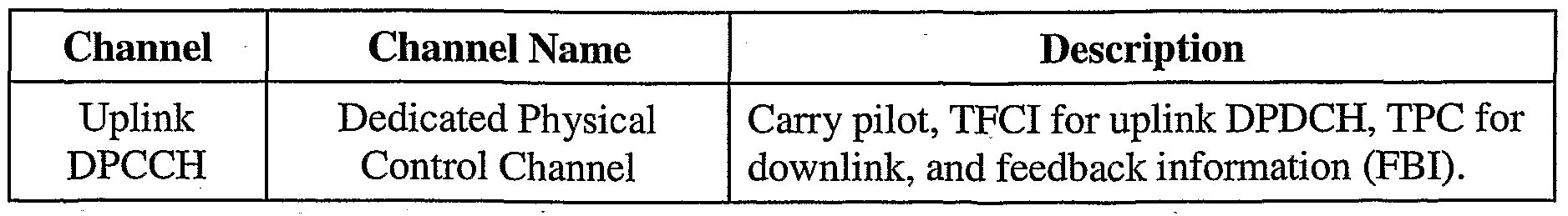
(HSDPA). 3GPP Release 6 and later supports High-Speed Uplink Packet Access (HSUPA). HSDPA and HSUPA are sets of channels and procedures that enable highspeed packet data transmission on the downlink and uplink, respectively. Tables 1 and 2 list some downlink and uplink physical channels, respectively, in UMTS. The HS- SCCH, HS-PDSCH, and HS-DPCCH are used for HSDPA. The E-DPCCH, E- DPDCH, and E-HICH are used for HSUPA.
Table 1 - Downlink Channels
Figure imgf000007_0001
Table 2 - Uplink Channels
Figure imgf000007_0002
Figure imgf000008_0001
[0032] FIG. 2 shows a state diagram 200 of the Radio Resource Control (RRC) states for the UE. Upon being powered on, the UE performs cell selection to find a suitable cell from which the UE can receive service. Thereafter, the UE may transition to an idle mode 210 or a connected mode 220 depending on whether there is any activity for the UE. In the idle mode, the UE has registered with the UTRAN, is listening for paging messages, and updates its location with the UTRAN when necessary. In the connected mode, the UE can receive and/or transmit data, depending on its RRC state and configuration. The connected mode may also be referred to as a connected state, an active mode, an active state, a traffic state, a traffic channel state, and so on.
[0033] In the connected mode, the UE may be in one of four possible RRC states - a
CELLJ)CH state 230, a CELLJ7ACH state 232, a CELLJ1CH state 234, or a URAJ1CH state 236. The CELLJDCH state is characterized by (1) dedicated physical channels allocated to the UE for the downlink and uplink and (2) a combination of dedicated and shared transport channels being available to the UE. The CELLJ7ACH state is characterized by (1) no dedicated physical channels allocated to the UE, (2) a default common or shared transport channel assigned to the UE for use to access the UTRAN, and (3) the UE continually monitoring a Forward Access Channel (FACH) for signaling such as Reconfiguration messages. The CELLJPCH and URAJPCH states are characterized by (1) no dedicated physical channels allocated to the UE, (2) the UE periodically monitoring a Paging Channel (PCH) for paging messages, and (3) the UE not being permitted to transmit on the uplink. The modes and states for the UE are described in 3GPP TS 25.331.
[0034] While in the connected mode, the UTRAN can command the UE to be in one of the four possible states based on activity of the UE. The UE may transition (1) from the CELL JDCH or CELLJFACH state in the connected mode to the idle mode by performing a Release RRC Connection procedure, (2) from the idle mode to the CELL_DCH or CELL_FACH state by performing an Establish RRC Connection procedure, (3) between the CELLJDCH and CELLJFACH states by performing a reconfiguration procedure, and (4) between different configurations in the CELLJDCH state by also performing a reconfiguration procedure. These procedures are described in 3GPP TS 25.331.
[0035] In an embodiment, the CELLJDCH state comprises a Continuous Packet
Connectivity (CPC) mode 240 and an Active mode 250. The Active mode may correspond to operation of the HSDPA and HSUPA channels as described in 3GPP Release 6. In the Active mode, data may be sent in any subframe on the downlink and uplink. A subframe is a time interval in which a transmission may be sent on a link. A subframe may have different durations in different networks and/or for different configurations of a given network. The CPC mode may be used to achieve efficient data transmission and reception for the UE. The CPC mode may provide power savings for the UE and/or capacity improvement for the UTRAN.
[0036] In an embodiment, while in the CPC mode, radio resources (e.g., physical channels) are allocated and states for higher layers (e.g., Layers 2 and 3) are maintained, but only a subset of the subframes available on the downlink and uplink are enabled. The UE may send signaling and/or data on the enabled uplink subframes and may receive signaling and/or data on the enabled downlink subframes. The UE may power down certain circuit blocks and subsystems, e.g., its transmitter and/or receiver, during the non-enabled subframes to conserve battery power.
[0037] In general, the CPC mode may include any number of DTX modes, any number of DRX modes, and/or other modes. Each DTX mode may be associated with different enabled uplink subframes and/or different actions to be performed by the UE. Each DRX mode may be associated with different enabled downlink subframes and/or different actions to be performed by the UE.
[0038] FIG. 3 shows an embodiment of the CPC mode. In this embodiment, the CPC mode includes DTX modes 310 and 312, a DRX mode 314, and a NO DRX mode 316. DTX mode 310 is also referred to as DTX Tl mode, and DTX mode 312 is also referred to as DTX T2 mode. Table 3 lists the DTX and DRX modes in FIG. 3 and provides a short description for each mode.
Table 3
Figure imgf000010_0001
[0039] In general, any values may be selected for Tl, T2 and R. In an embodiment, Tl,
T2 and R are defined such that Tl < T2 and R < T2. In an embodiment, Tl, T2 and R are selected from a set of possible values. For example, Tl, T2 and R may each be set equal to 1, 4, 8, or 16 and may be expressed as Tl, T2 and R e {1, 4, 8, 16}. Other sets of possible values may also be used for Tl, T2 and R. The possible values may be power of twos and/or other values. Tl = 1 means that all uplink subframes are enabled. Similarly, R = I means that all downlink subframes are enabled. The NO DRX mode may be considered as the DRX mode with R = I .
[0040] Tl-enabled subframes are enabled subframes for the DTX Tl mode and are spaced apart at intervals of Tl subframes. T2-enabled subframes are enabled subframes for the DTX T2 mode and are spaced apart at intervals of T2 subframes. R-enabled subframes are enabled subframes for the DRX mode and are spaced apart at intervals of R subframes. In an embodiment, the T2-enabled subframes are a subset of the Tl- enabled subframes. In other embodiments, the T2-enabled subframes may be selected independently of the Tl-enabled subframes.
[0041] In an embodiment, the Tl-enabled, T2-enabled, and R-enabled subframes for the
UE are identified by an Offset from a reference time. This reference time may be a start time in which the CPC mode is effective for the UE and may be given in signaling used to convey CPC parameters. Tl, T2 and R define three enabled subframe patterns or sets that start at a subframe where the CPC configuration was effective (the reference time) plus the Offset. In an embodiment, the parameters of the CPC mode comprise Tl, T2, R, Offset, and reference time. The CPC mode may also be defined based on other parameters. The UTRAN may select suitable values for Tl, T2 and R based on various factors such as data activity, network loading, and so on. The UTRAN may select different Offset values for different UEs to distribute these UEs across the available subframes.
[0042] In general, any values may be selected for Tl, T2 and R. Different values may be more suitable for different services and/or different conditions. In an embodiment, the CPC parameters may be set as R = 4 , Tl = 4 and T2 = 8 for voice-over-Internet Protocol (VoIP). This configuration achieves appropriately 50% sleeping periods during a voice session. In an embodiment, the CPC parameters may be set as R = 8 , Tl = 1 and T2 = 16 for data operation. This configuration achieves a long sleeping period when there is no data to send. The UTRAN may order the UE out of DRX mode whenever there is data to send on the downlink. There is an average of R / 2 subframes of delay to start a downlink packet transmission since the UE is receiving every R subframe. In an embodiment, the CPC parameters may be set as R = I , Tl = 4 and T2 = 8 when downlink delay requirements are stringent or when downlink load is high. Various other values may also be used for the CPC parameters to achieve other characteristics.
[0043] In an embodiment, the UTRAN (e.g., the RNC) configures the CPC parameters for the UE during call setup, e.g., using Layer 3 (L3) signaling and/or some other signaling. Alternatively or additionally, the UTRAN may configure or modify the CPC parameters through a Reconfiguration message during the call. The UTRAN may also configure or modify the CPC parameters in other manners and/or with other types of signaling. For example, the Tl, T2 and R values may be sent as part of system information signaled by the Node B. Different Tl, T2 and R values may also be defined for different call types.
[0044] Table 3 lists actions performed by the UE for each DTX and DRX mode, in accordance with an embodiment.
Table 4
Figure imgf000011_0001
[0045] FIG. 3 also shows exemplary criteria for transitioning between the DTX and
DRX modes. In an embodiment, the UE can autonomously transition between the two DTX modes, e.g., based on data activity at the UE. The UE may transition from the DTX T2 mode to the DTX Tl mode whenever there is data to send on the uplink. The UE may transmit just signaling in each Tl -enabled subframe that the UE has no data to send. The UE may transition from the DTX Tl mode to the DTX T2 mode if there is no data to send on the uplink, e.g., if T2 subframes have passed without any uplink data transmission.
[0046] In an embodiment, the UE may revert to full use of all uplink subframes autonomously and instantaneously. The Tl-enabled subframes may be sufficient for light and/or expected exchanges of data. The UE may use more uplink subframes whenever the Tl-enabled subframes are insufficient for the data load at the UE. The UE may, in essence, transition from the DTX T2 mode to the Active mode for data transmission as needed.
[0047] In an embodiment, the UE transitions between the DRX mode and the NO DRX mode as directed by the UTRAN, e.g., the Node B. Unlike DTX for the uplink, DRX operation is synchronized between the Node B and the UE. The Node B may direct the UE to transition to the DRX mode based on any of the following: (1) downlink traffic load for the UE is light, (2) downlink data rate is below a threshold and may be served at a reduced subframe rate, (3) there is lack of data activity for the UE, (4) a data queue for the UE has been empty for some time or has just been emptied, or (5) some other reason. While in the DRX mode, the UE may ignore downlink subframes that are not R-enabled subframes. The Node B may direct the UE to transition to the NO DRX mode based on any of the following: (1) data for the UE has just arrived, (2) downlink traffic load for the UE is heavy, (3) the data queue for the UE is above a threshold or is growing at a faster rate than the transmission rate to the UE, (4) cell loading is heavy, or (5) some other reason. In the NO DRX mode, the UE receives signaling (e.g., decodes the HS-SCCH) in every subframe and may receive data as indicated by the signaling.
[0048] In an embodiment, to achieve fast transition between the DRX mode and the NO
DRX mode, the commands to transition between these modes are sent using fast Layer 1 (Ll) and/or Layer 2 (L2) signaling from the Node B to the UE. For example, a single L1/L2 fast signaling bit may be used to enable or disable the DRX mode. The fast L1/L2 signaling provides the Node B with a fast mechanism to revert to full use of all available downlink subframes and may improve synchronization between the Node B and the IJE. Sending L1/L2 signaling from the Node B to the UE may incur a delay of approximately 5 to 8 ms whereas sending L3 signaling from the RNC to the UE may incur a delay of 100 ms or more. Nevertheless, the commands to transition between modes may be sent using signaling in any layer and in any manner.
[0049] The command to transition from the NO DRX mode to the DRX mode is referred to as Node B order #1. The command to transition from the DRX mode to the NO DRX mode is referred to as Node B order #2. The UTRAN (e.g., the Node B) may send Node B order #1 whenever the UTRAN wants to ensure that both the UTRAN and the UE operate in the DRX mode. The UTRAN may send Node B order #2 whenever the UTRAN wants to ensure that both the UTRAN and the UE operate in the NO DRX mode.
[0050] HSDPA and HSUPA employ hybrid automatic retransmission (HARQ) to improve reliability of data transmission. HARQ for HSDPA and HARQ for HSUPA operate in similar manner. For HSDPA, HARQ retransmissions may be sent anytime after a minimum delay, e.g., 6 to 8 TTIs. For HSUPA, HARQ retransmissions are sent 8 TTIs later.
[0051] For HSDPA, an HARQ entity at the Node B processes and transmits a packet to the UE. A corresponding HARQ entity at the UE receives and decodes the packet. The UE sends an ACK if the packet is decoded correctly or a NAK if the packet is decoded in error. The Node B retransmits the packet if a NAK is received and transmits a new packet if an ACK is received. The Node B transmits the packet once and may retransmit the packet any number of times until an ACK is received for the packet or the Node B decides to abandon the transmission of the packet.
[0052] The Node B may transmit packets on up to eight HARQ processes to the UE.
The HARQ processes may be viewed as HARQ channels used to send packets. The Node B receives downlink packets to send to the UE and transmits these packets in sequential order to the UE on the available HARQ processes. Each packet is sent on one HARQ process and includes an HARQ process ID (HID) that indicates the HARQ process used for that packet. Each HARQ process carries one packet at a time until the transmission/ retransmission for that packet is completed and may then be used to send another packet.
[0053] If HARQ is used for transmission, then the condition of "no data to send" for the transition from the DTX Tl mode to the DTX T2 mode may correspond to no HARQ process being active. This in turn may be detected by no activity on any of the HARQ processes. When all HARQ processes are acknowledged, the UE may transition to the DTX T2 mode.
[0054] FIG. 4 shows an embodiment of the enabled subframes for HSDPA and
HSUPA. In UMTS, the transmission time line is partitioned into frames, with each frame being identified by the SFN. Each frame has a duration of 10 milliseconds (ms) and is partitioned into five subframes 0 through 4. Each subframe has a duration of 2 ms and covers three slots. Each slot has a duration of 0.667 ms and covers 2560 chips at 3.84 Mcps, or Ts]ot = 2560 chips.
[0055] On the downlink, the P-CCPCH carries pilot and the SFN. The P-CCPCH is used directly as timing reference for downlink channels and is used indirectly as timing reference for uplink channels. The subframes of the HS-SCCH are time-aligned with the P-CCPCH. The subframes of the HS-PDSCH are delayed by rHS.PDSCH = 2Tslot from the subframes of the HS-SCCH. The subframes of the E-HICH are delayed by %mcH <n from the subframes of the HS-SCCH, where τE.fflCH n is defined in 3GPP TS 25.211.
[0056] On the uplink, the subframes of the HS-DPCCH are delayed by 7.5 slots from the subframes of the HS-PDSCH at the UE, where τPD in FIG. 4 denotes the propagation delay from the Node B to the UE. The uplink DPCCH, E-DPCCH, and E- DPDCH are time-aligned and their frame timing is m X 256 chips from the frame timing of the HS-DPCCH. The timing of the uplink DPCCH is not directly related to the timing of the HS-DPCCH. The frame timing for the downlink and uplink channels is described in 3GPP TS 25.211.
[0057] FIG. 4 also shows an exemplary CPC configuration with Tl = 4 , T2 = 8 , R = 4 , and Offset = 1. In this example, the Tl-enabled subframes on the uplink DPCCH, E- DPCCH, E-DPDCH, and E-HICH are spaced apart by 4 subframes. The T2-enabled subframes on the uplink DPCCH are spaced apart by 8 subframes. The R-enabled subframes on the HS-SCCH, HS-DPDCH and HS-DPCCH are spaced apart by 4 subframes. The Offset determines the specific subframes to use for the enabled subframes. The Tl-enabled, T2-enabled, and R-enabled subframes may be aligned in time (e.g., as described in TR25.903, section 4.5.2.1) to reduce rise-over-thermal (ROT) and to extend possible sleep time for the UE between the enabled subframes. For example, transmissions on the uplink (including ACKs for downlink transmissions) may be clubbed or combined together to reduce ROT at the Node B. Transmissions on the downlink (including ACKs for uplink transmissions) may also be clubbed together to reduce wake up time at the wireless device.
[0058] FIG. 5A shows exemplary operation of the UE in the DTX Tl mode for the
CPC configuration shown in FIG. 4. The UE transmits pilot and signaling (e.g., TPC) on the uplink DPCCH and signaling (e.g., CQI) on the HS-DPCCH in each Tl-enabled subframe. If the UE has data to send in a given Tl-enabled subframe, then the UE transmits signaling on the E-DPCCH, transmits data on the E-DPDCH, and receives ACK/NAK on the E-HICH.
[0059] FIG. 5B shows exemplary operation of the UE in the DTX T2 mode for the
CPC configuration shown in FIG. 4. The UE transmits pilot and signaling (e.g., TPC) on the uplink DPCCH and signaling (e.g., CQI) on the HS-DPCCH in each T2-enabled subframe. The UE does not transmit signaling on the E-DPCCH, does not transmit data on the E-DPDCH, and does not receive ACK/NAK on the E-HICH.
[0060] FIG. 5C shows exemplary operation of the UE in the DRX mode for the CPC configuration shown in FIG. 4. The UE receives signaling on the HS-SCCH in each R- enabled subframe. The UE may receive data on the HS-DPDCH in any R-enabled subframe and may then send ACK/NAK on the HS-DPCCH.
[0061] In the embodiment shown in FIGS. 5A through 5C, CQI reports are sent in the
Tl-enabled subframes in the DTX Tl mode and in the T2-enabled subframes in the DTX T2 mode. In another embodiment, CQI reports are sent in the R-enabled subframes. The UE may also send additional CQI reports when sending ACKs/NAKs. The additional CQI reports may be used for retransmissions or new transmissions.
[0062] In an embodiment, the two DTX modes and the DRX mode may be defined independently of one another. In another embodiment, the DTX and DRX modes are jointly parameterized, e.g., to time align the Tl-enabled subframes with the R-enabled subframes. This embodiment may extend sleep time and enhance battery savings for the UE. In yet another embodiment, the spacing of Tl and R is such that subframes used for retransmissions are automatically enabled subframes.
[0063] In an embodiment, the UTRAN (e.g., the Node B) expects uplink transmission from the UE only in the Tl-enabled subframes. In another embodiment, the UTRAN expects uplink transmission from the UE in all subframes and thus always listens for the UE. Since the UE can autonomously transition between the DTX Tl mode and the DTX T2 mode, the UTRAN may not receive uplink transmissions in some Tl-enabled subframes. The UTRAN may determine whether the UE transmits the uplink DPCCH in each Tl-enabled subframe (e.g., based on the pilot) and may discard the received signaling (e.g., TPC bits for downlink power control) if the pilot is absent or is of insufficient quality.
[0064] In an embodiment, the UE expects downlink transmissions from the UTRAN in the R-enabled subframes while in the DRX mode and in any subframe while in the NO DRX mode. The UE may discard signaling (e.g., TPC bits for uplink power control) that does not correspond to a transmission sent by the UE. The UE starts DRX operation upon receiving Node B order #1 and stops DRX operation upon receiving Node B order #2.
[0065] If there is at least one HARQ process active, then the UE attempts to transmit using the Tl-enabled subframes. If the UTRAN expects uplink transmissions from the UE in all subframes, then the UE may use other subframes if the Tl-enabled subframes are not sufficient. The UE does not DTX more than (Tl -I) subframes while there is at least one HARQ process active. If there are no active HARQ processes, then the UE transmits pilot and signaling (e.g., CQI) on the T2-enabled subframes and does not DTX more than (T2 - 1) subframes.
[0066] FIG. 6A shows exemplary uplink transmissions for a CPC configuration with
Tl = 4 = 8 ms and T2 = 8 = 16 ms. In this example, the UE may receive vocoder packets from upper layer every 20 ms. Line 1 in FIG. 6 A shows vocoder packets received by the UE. Lines 2 through 5 show packet transmissions and retransmissions for different maximum numbers of retransmissions (N). The Tl-enabled subframes are represented by circles in lines 2 through 5. The T2-enabled subframes are every other circle in lines 2 through 5 and are indicated by label "T2e" above line 2. The UE transitions to the DTX Tl mode upon receiving the first packet 0 for transmission to the UTRAN.
[0067] For N = I retransmission in line 2, packet 0 is received in subframe S1 and sent in Tl-enabled subframes S1 and S3, packet 1 is received in subframe S4 and sent in Tl- enabled subframes S5 and S7, and so on. Pilot and CQI are sent in Tl-enabled subframes, including subframes S2, S6, S9, S13 and S15 without any data transmission. HARQ processes for packets 0, 1, 2 and 3 are completed after subframe S14. The UE transitions to the DTX T2 mode in subframe S16 and sends pilot and CQI in T2-enabled subframes S17 and S19. The UE transitions to the DTX Tl mode upon receiving packet 4 in subframe S21 and sends this packet in Tl-enabled subframes S22 and S24. [0068] For N = 2 retransmissions in line 3, packet 0 is received in subframe S1 and sent in Tl -enabled subframes S1, S3 and S6, packet 1 is received in subframe S4 and sent in Tl-enabled subframes S5, S7 and S9, and so on. Pilot and CQI are sent in Tl-enabled subframes, including subframes S2 and S 15 without any data transmission. HARQ processes for packets 0, 1, 2 and 3 are completed after subframe S16. The UE transitions to the DTX T2 mode in subframe S18 and sends pilot and CQI in T2-enabled subframes S1C). The UE transitions to the DTX Tl mode upon receiving packet 4 in subframe S21 and sends this packet in Tl-enabled subframes S22 and S24.
[0069] The packet transmission and retransmission occur in similar manner for N = 3 retransmissions in line 4 and N = 4 retransmissions in line 5. Multiple packets may be sent in some Tl-enabled subframes.
[0070] FIG. 6B shows exemplary uplink transmissions for the CPC configuration with
Tl = 4 = 8 ms and T2 = 8 = 16 ms. In this example, the UE receives vocoder packets from upper layer every 20 ms. The UE does not transition to the DTX T2 mode because at least one HARQ process is active during the entire time duration shown in FIG. 6B. More than two packets may be sent in a given Tl-enabled subframe for N = 4 retransmissions.
[0071] FIG. 7 shows exemplary downlink and uplink transmissions in the CPC mode.
At time L1, the UE operates in the DRX mode upon receiving Node B order #1 and also autonomously selects the DTX T2 mode. At time L2, the UE has data to send, transitions to the DTX Tl mode, and transmits packet A. At time L3, the UE transitions to the NO DRX mode upon receiving Node B order #2 and thereafter receives packets 0 through 5. At time L4, the UE transitions to the DTX T2 mode following a period of no activity after sending packet A. At time L5, the UE has data to send, transitions to the DTX Tl mode, and transmits packets B through F. At time L6, the UE transitions to the DTX T2 mode following a period of no activity. At time L7, the UE transitions to the DRX mode upon receiving Node B order #1. At time L8, the UE has data to send, transitions to the DTX Tl mode, and transmits packets G through I. At time L9, the UE transitions to the DTX T2 mode following a period of no activity. At time L10, the UE transitions to the NO DRX mode upon receiving Node B order #2 and thereafter receives packets 6 through 8. At time L11, the UE transitions to the DRX mode upon receiving Node B order #1. [0072] In the embodiment shown in FIG. 3, the UTRAN sends Node B orders to direct the UE to transition between the DRX mode and the NO DRX mode. The Node B orders (e.g., #1 and #2) may be sent in various manners. In general, it is desirable to send the Node B orders using a reliable mechanism since these orders affect network operation and performance. This may be achieved by sending the Node B orders on a control channel with low error probability and/or acknowledgement. In an embodiment, the Node B orders are sent on the HS-SCCH, which is fairly robust and has an ACK mechanism. This improves the reliability of the Node B orders and reduces miscommunication problems due to the UTRAN and the UE being in different modes.
[0073] FIG. 8 shows an embodiment of an event flow 800 for transitioning from the
DRX mode to the NO DRX mode based on downlink activity. This embodiment assumes that Node B order #2 is sent on the HS-SCCH. The UTRAN receives downlink packets for the UE. The UTRAN then sends Node B order #2 on the HS- SCCH in the next R-enabled subframe. The average delay in sending Node B order #2 is R /2 subframes. The UE receives Node B order #2 on the HS-SCCH and replies by sending an ACK on the HS-DPCCH. Upon receiving the ACK, the UTRAN can send packets to the UE in any subframes and is not constrained to the R-enabled subframes. The UTRAN may also send Node B order #1 on the HS-SCCH in similar manner as Node B order #2.
[0074] On the downlink, there is an average delay of R/2 subframes to start a new packet transmission to the UE in the DRX mode. The Node B may order the UE out of the DRX mode, and the subsequent delay may be reduced to as low as zero. Retransmissions may further delay a new packet transmission. In the embodiment described above, on the uplink, the delay is under the control of the UE since the UE may transmit in any subframe. In other embodiments, certain restrictions may be imposed on when the UE can start uplink transmission in order to aid detection at the Node B. For example, the UE may be restricted to start an uplink transmission in a Tl- enabled subframe, a T2-enabled subframe, or some other subframe.
[0075] The Node B orders may be sent in various manners. In an embodiment, the UE is assigned a first 16-bit HS-DSCH Radio Network Identifier (H-RNTI) for UE identity (as normally done) and is further assigned a second 16-bit H-RNTI for Node B orders. H-RNTI is described in 3GPP TS 25.212, section 4.6. The second H-RNTI provides space of 21 bits for orders and future extensions. In another embodiment, one 16-bit H- RNTI is reserved for broadcasting orders. An order message may include the UE- specific H-RNTI (16 bits), creating space of 5 bits for orders and future extensions. The Node B orders may also be sent on other control channels and/or in other manners.
[0076] There may be transmission errors and/or detection errors of the Node B orders.
The UTRAN and the UE may then operate in different modes. Two different possible error scenarios are described below.
[0077] The UTRAN may operate in the DRX mode, and the UE may operate in the NO
DRX mode. This error situation may arise due to (1) the UTRAN sending Node B order #1 and the UE failing to detect the order or (2) the UE erroneously detecting Node B order #2 when none was sent. The Node B would restrict its downlink transmissions to the R-enabled subframes while the UE receives all subframes. The UE consumes extra battery power, but no data is lost.
[0078] The UTRAN may operate in the NO DRX mode, and the UE may operate in the
DRX mode. This error situation may arise due to (1) the UE erroneously detecting Node B order #1 when none was sent or (2) the UTRAN sending Node B order #2 and the UE failing to detect the order. The UTRAN may transmit on any subframe while the UE receives only the R-enabled subframes. Data transmitted in subframes other than the R-enabled subframes would be lost. This error situation is detectable. The UTRAN may detect for this type of error and may implement a proper recovery mechanism.
[0079] The CPC mode may provide certain advantages. The DTX Tl mode defines a certain minimum duty cycle Tl that may maximize capacity during data transmission. The UE may synchronize its transmission times with its reception times to extend its sleep cycle. The UTRAN (e.g., Node B) has a pattern of known times where uplink transmissions are required or are more probable. The DTX T2 mode may facilitate synchronization, simplify detection and search of uplink transmissions, and simplify Node B implementation. The UTRAN has knowledge of the minimum set of enabled subframes, which may reduce impact of searching for the uplink DPCCH from the UE at the Node B. For example, the Node B may not search each subframe if it knows that uplink transmissions are sent in or starting at T2-enabled subframes. The detection at the Node B may also be simplified compared to a system that does not utilize T2- enabled subframes. In such a system, it may be harder for the Node B to detect a signal that is transmitted erratically without a known periodicity, which may help energy accumulation/correlation . [0080] Referring back to FIG. 2, the UE may transition from the CPC mode to the
Active mode based on any of the following: (1) the amount of downlink data to send to the UE (e.g., for a new transport and/or logical channel) suggests use of more downlink subframes, (2) the network is congested and scheduler performance may be improved by allowing the scheduler to freely use all of the downlink subframes, and/or (3) some other reason. The UE may transmit data in any uplink subframe and/or receive data in any downlink subframe in the Active mode. The Active mode may improve performance at the expense of more battery power. The UE may transition from the Active mode to the CPC mode based on any of the following: (1) traffic load for the UE is light, (2) there is lack of user data activity, or (3) some other reason. The UTRAN can ascertain downlink data activity of the UE based on the status of the data queue for the UE and can ascertain uplink data activity of the UE based on reception of status reports of a data buffer maintained by the UE.
[0081] In an embodiment, the UTRAN directs the UE to operate in the Active mode or the CPC mode. The UTRAN may direct the UE to switch mode by sending a mode switch command or some other signaling. The UTRAN may also direct the UE to transition to the CPC mode by sending the parameters for the CPC mode. In another embodiment, the UE may elect to operate in the Active mode or the CPC mode and may send either a request for a mode switch (if the decision is made by the UTRAN) or an indication of a mode switch (if the decision can be made by the UE).
[0082] The UTRAN (e.g., the RNC) may command the UE to transition to the CPC mode (e.g., by sending the CPC parameters or a mode switch) whenever the UTRAN wants to ensure that both the UTRAN and the UE are operating in the CPC mode. The UTRAN may also command the UE to transition to the Active mode whenever the UTRAN wants to ensure that both the UTRAN and the UE are operating in the Active mode.
[0083] In the embodiment shown in FIG. 3, the CPC mode includes two DTX modes, one DRX mode, and a no DRX mode. In general, the CPC mode may include any number of DTX modes, a no DTX mode, any number of DRX modes, a no DRX mode, or any combination thereof. The no DTX mode may be considered as a special case of the DTX Tl mode with Tl = 1.
[0084] In another embodiment, the CPC mode includes a Connected Deep mode (or simply, a Deep mode) mode in which the UE has one enabled subframe in every T3 subframes on the uplink and one enabled subframe in every R2 subframes on the downlink. In general, T3 and R2 may be defined as T3 > T2 and R 2 > R . T3 and R2 may be set to large values, e.g., much larger than T2 and R, respectively, or possibly infinity. The Deep mode may be disabled by setting T3 = T2 and/or R2 = R .
[0085] In the Deep mode, the UE may (a) stop listening or listen very infrequently to the downlink and (b) stop transmitting or transmit very infrequently on the uplink. The UE may measure the CPICH and P-CCPCH and may decode the HS-SCCH of the serving and surrounding Node Bs in the R2-enabled subframes. The UE may update its Active Set of Node Bs, if necessary, based on the measurements. The UE may ignore TPC commands sent by the Node B to adjust the transmit power of the UE. The UE may transition out of the Deep mode based on various triggering events, e.g., if the UE receives data in its buffer or receives a packet on the downlink. If any triggering event occurs, then the UE may transition to (a) the DTX Tl mode, the DTX T2 mode, or the no DTX mode for transmission on the uplink and (b) the DRX mode or the no DRX mode for reception on the downlink. While in the Deep mode, UE synchronization at the Node B is likely lost. A procedure may be used to re-activate the UE from the Deep mode. This re-activation may be accompanied by a sufficiently long DPCCH preamble to allow the closed-loop power control mechanism to bring the transmit power of the UE back to the proper power level.
[0086] For clarity, the techniques have been specifically described for UMTS. The
CPC mode may be a mode or a configuration of the CELLJDCH state, as shown in FIG. 2. The CPC mode may also be employed in other manners in UMTS.
[0087] The techniques described herein may also be used for other communication networks, other channel structures, other frame and subframe structures, and/or other transmission schemes. The techniques may be used for HARQ as well as non-HARQ transmissions.
[0088] FIG. 9 shows an embodiment of a process 900 performed by a wireless device for operation in a CPC mode. While in the connected mode, the wireless device operates in one of multiple DTX modes or a no DTX mode for transmission to a wireless network (block 910). The wireless device also operates in one of at least one DRX mode or a no DRX mode for reception from the wireless network (block 920). Each DTX mode may be associated with different subframes usable for sending signaling and/or data to the wireless network. The no DTX mode may be associated with all subframes being usable for sending signaling and/or data to the wireless network. Each DRX mode may be associated with different subframes usable for receiving signaling and/or data from the wireless network. The no DRX mode may be associated with all subframes being usable for receiving signaling and/or data from the wireless network. The wireless device may operate in any of the following: (1) DTX and DRX, (2) DTX and no DRX, (3) no DTX and DRX, or (4) no DTX and no DRX.
[0089] The multiple DTX modes may comprise first and second DTX modes. In the first DTX mode, the wireless device may transmit signaling in first enabled subframes and may transmit data in the first enabled subframes if there is data to send to the wireless network (block 912). In the second DTX mode, the wireless device may transmit signaling in second enabled subframes (block 914). In an embodiment, the wireless device sends signaling for Layer 1 (e.g., pilot, TPC, CQI, and so on) and may send signaling for higher layers in the first DTX mode, and sends only Layer 1 signaling in the second DTX mode. In general, the wireless device may be allowed to send different types of signaling or may be restricted to send only certain types of signaling in each DTX mode. The signaling sent in the first DTX mode may thus be the same as or different from the signaling sent in the second DTX mode. The at least one DRX mode may comprise a single DRX mode. In the DRX mode, the wireless device may receive signaling in third enabled subframes and may receive data in the third enabled subframes if the signaling indicates data being sent to the wireless device (block 922). The first enabled subframes may be a subset of the subframes available for the uplink and may be spaced apart by Tl subframes. The second enabled subframes may be a subset of the first enabled subframes and may be spaced apart by T2 subframes. The third enabled subframes may be a subset of the subframes available for the downlink and may be spaced apart by R subframes. Tl, T2, and/or R may be configurable parameters.
[0090] The wireless device may autonomously transition between the multiple DTX modes and may autonomously transition to a no DTX mode based on data load at the wireless device (block 916). The wireless device may transition between the at least one DRX mode and a no DRX mode based on signaling from the wireless network (block 924). The wireless device may also transition between an active mode and the CPC mode based on signaling from the wireless network. The active mode may correspond to all subframes being usable for transmission and reception.
[0091] FIG. 10 shows an embodiment of a process 1000 performed by a wireless network for the CPC mode. The wireless network receives from a wireless device operating in one of multiple DTX modes or a no DTX mode while in a connected mode (block 1010). The wireless network transmits to the wireless device operating in one of at least one DRX mode or a no DRX mode while in the connected mode (block 1020).
[0092] The multiple DTX modes may comprise first and second DTX modes. When the wireless device operates in the first DTX mode, the wireless network may receive signaling from the wireless device in first enabled subframes and may receive data from the wireless device in the first enabled subframes if the signaling indicates data being sent (block 1012). When the wireless device operates in the second DTX mode, the wireless network may receive signaling from the wireless device in second enabled subframes (block 1014). The wireless network may detect for signaling from the wireless device in all subframes available for the uplink (block 1016). The at least one DRX mode may comprise a single DRX mode. When the wireless device operates in the DRX mode, the wireless network may transmit signaling in third enabled subframes and may transmit data in the third enabled subframes if there is data to send to the wireless device (block 1022). The wireless network may send signaling to direct the wireless device to transition between the DRX mode and a no DRX mode (block 1024). The wireless network may also send signaling to direct the wireless device to transition between the active mode and the CPC mode.
[0093] FIG. 11 shows a block diagram of an embodiment of UE 110, Node B 130, and
RNC 140 in FIG. 1. On the uplink, data and signaling to be sent by UE 110 are processed (e.g., formatted, encoded, and interleaved) by an encoder 1122 and further processed (e.g., modulated, channelized, and scrambled) by a modulator (Mod) 1124 to generate output chips. A transmitter (TMTR) 1132 then conditions (e.g., converts to analog, filters, amplifies, and frequency upconverts) the output chips and generates an uplink signal, which is transmitted via an antenna 1134. On the downlink, antenna 1134 receives a downlink signal transmitted by Node B 130. A receiver (RCVR) 1136 conditions (e.g., filters, amplifies, frequency downconverts, and digitizes) the received signal from antenna 1134 and provides samples. A demodulator (Demod) 1126 processes (e.g., descrambles, channelizes, and demodulates) the samples and provides symbol estimates. A decoder 1128 further processes (e.g., deinterleaves and decodes) the symbol estimates and provides decoded data. Encoder 1122, modulator 1124, demodulator 1126, and decoder 1128 may be implemented by a modem processor 1120. These units perform processing in accordance with the radio technology (e.g., W- CDMA or cdma2000) used by the network. [0094] A controller/processor 1140 directs the operation of various units at UE 110.
Controller/processor 1140 may perform process 900 in FIG. 9 and/or other processes for the techniques described herein. A memory 1142 stores program codes and data for UE 110, e.g., parameters and orders for CPC operation.
[0095] , FIG. 11 also shows an embodiment of Node B 130 and RNC 140. Node B 130 includes a controller/processor 1150 that performs various functions for communication with UE 110, a memory 1152 that stores program codes and data for Node B 130, and a transceiver 1154 that supports radio communication with UE 110. Controller/processor 1150 may perform process 1000 in FIG. 10 and/or other processes for the techniques described herein and may also send Node B orders to UE 110 in the CPC mode. RNC 140 includes a controller/processor 1160 that performs various functions to support communication for UE 110 and a memory 1162 that stores program codes and data for RNC 140. Controller/processor 1160 may configure the CPC mode and may direct transition between the Active mode and the CPC mode for UE 110.
[0096] Those of skill in the art would understand that information and signals may be represented using any of a variety of different technologies and techniques. For example, data, instructions, commands, information, signals, bits, symbols, and chips that may be referenced throughout the above description may be represented by voltages, currents, electromagnetic waves, magnetic fields or particles, optical fields or particles, or any combination thereof.
[0097] Those of skill would further appreciate that the various illustrative logical blocks, modules, circuits, and algorithm steps described in connection with the embodiments disclosed herein may be implemented as electronic hardware, computer software, or combinations of both. To clearly illustrate this interchangeability of hardware and software, various illustrative components, blocks, modules, circuits, and steps have been described above generally in terms of their functionality. Whether such functionality is implemented as hardware or software depends upon the particular application and design constraints imposed on the overall system. Skilled artisans may implement the described functionality in varying ways for each particular application, but such implementation decisions should not be interpreted as causing a departure from the scope of the present invention.
[0098] The various illustrative logical blocks, modules, and circuits described in connection with the embodiments disclosed herein may be implemented or performed with a general-purpose processor, a digital signal processor (DSP), an application specific integrated circuit (ASIC), a field programmable gate array (FPGA) or other programmable logic device, discrete gate or transistor logic, discrete hardware components, or any combination thereof designed to perform the functions described herein. A general-purpose processor may be a microprocessor, but in the alternative, the processor may be any conventional processor, controller, microcontroller, or state machine. A processor may also be implemented as a combination of computing devices, e.g., a combination of a DSP and a microprocessor, a plurality of microprocessors, one or more microprocessors in conjunction with a DSP core, or any other such configuration.
[0099] The steps of a method or algorithm described in connection with the embodiments disclosed herein may be embodied directly in hardware, in a software module executed by a processor, or in a combination of the two. A software module may reside in RAM memory, flash memory, ROM memory, EPROM memory, EEPROM memory, registers, hard disk, a removable disk, a CD-ROM, or any other form of storage medium known in the art. An exemplary storage medium is coupled to the processor such that the processor can read information from, and write information to, the storage medium. In the alternative, the storage medium may be integral to the processor. The processor and the storage medium may reside in an ASIC. The ASIC may reside in a user terminal. In the alternative, the processor and the storage medium may reside as discrete components in a user terminal.
[00100] The previous description of the disclosed embodiments is provided to enable any person skilled in the art to make or use the present invention. Various modifications to these embodiments will be readily apparent to those skilled in the art, and the generic principles defined herein may be applied to other embodiments without departing from the spirit or scope of the invention. Thus, the present invention is not intended to be limited to the embodiments shown herein but is to be accorded the widest scope consistent with the principles and novel features disclosed herein.

Claims

CLAIMS WHAT IS CLAIMED IS:
1. A wireless device comprising: at least one processor to operate in one of multiple discontinuous transmission (DTX) modes or a no DTX mode, while in a connected mode, for transmission to a wireless network, and to operate in one of at least one discontinuous reception (DRX) mode or a no DRX mode, while in the connected mode, for reception from the wireless network; and a memory coupled to the at least one processor.
2. The wireless device of claim 1, wherein each DTX mode is associated with different subframes usable for sending data, or signaling, or both data and signaling to the wireless network.
3. The wireless device of claim 1, wherein each DRX mode is associated with different subframes usable for receiving data, or signaling, or both data and signaling from the wireless network.
4. The wireless device of claim 1, wherein the multiple DTX modes comprise a first DTX mode, and wherein in the first DTX mode the at least one processor transmits signaling in first enabled subframes corresponding to a subset of subframes available for uplink, and transmits data in the first enabled subframes if there is data to send to the wireless network.
5. The wireless device of claim 4, wherein the multiple DTX modes comprise a second DTX mode, and wherein in the second DTX mode the at least one processor transmits signaling in second enabled subframes corresponding to a subset of the first enabled subframes.
6. The wireless device of claim 4, wherein the first enabled subframes are spaced apart at intervals of Tl subframes, where Tl is a configurable parameter.
7. The wireless device of claim 5, wherein the second enabled subframes are spaced apart at intervals of T2 subframes, where T2 is a configurable parameter.
8. The wireless device of claim 1, wherein the at least one DRX mode comprises a first DRX mode, and wherein in the first DRX mode the at least one processor receives signaling in enabled subframes corresponding to a subset of subframes available for downlink, and receives data in the enabled subframes if the signaling indicates data being sent to the wireless device.
9. The wireless device of claim 8, wherein the enabled subframes are spaced apart at intervals of R subframes, where R is a configurable parameter.
10. The wireless device of claim 1, wherein the multiple DTX modes comprise a DTX mode in which transmit power of the wireless device is not controlled.
11. The wireless device of claim 1, wherein the multiple DTX modes comprise a DTX mode in which the wireless device does not transmit signaling and data on uplink, and wherein the at least one DRX mode comprises a DRX mode in which the wireless device does not receive signaling and data on downlink.
12. The wireless device of claim 1, wherein the at least one processor receives a configuration of Tl, T2, R and offset from the wireless network, with Tl defining spacing between first enabled subframes for a first DTX mode, T2 defining spacing between second enabled subframes for a second DTX mode, R defining spacing between third enabled subframes for a DRX mode, and the offset identifying the first, second and third enabled subframes.
13. The wireless device of claim 1, wherein the at least one processor autonomously transitions between the multiple DTX modes.
14. The wireless device of claim 1, wherein the at least one processor autonomously transitions to the no DTX mode based on data load at the wireless device.
15. The wireless device of claim 1, wherein the at least one processor transitions between the at least one DRX mode and the no DRX mode based on signaling from the wireless network.
16. The wireless device of claim 1, wherein the at least one processor receives the signaling to transition between the at least one DRX mode and the no DRX mode from the wireless network via Layer 1 or Layer 2.
17. The wireless device of claim 1, wherein the at least one processor transitions between an active mode and a continuous packet connectivity (CPC) mode based on signaling from the wireless network, wherein the CPC mode comprises the multiple DTX modes and the at least one DRX mode, and wherein the active mode comprises the no DTX mode and the no DRX mode.
18. A wireless device comprising: at least one processor to operate in a connected mode for communication with a wireless network and to operate in one of multiple discontinuous transmission (DTX) modes or a no DTX mode, while in the connected mode, for transmission to a wireless network; and a memory coupled to the at least one processor.
19. A wireless device comprising: at least one processor to operate in a connected mode for communication with a wireless network and to operate in one of at least one discontinuous reception (DRX) mode or a no DRX mode, while in the connected mode, for reception from the wireless network; and a memory coupled to the at least one processor.
20. A method comprising: operating in one of multiple discontinuous transmission (DTX) modes or a no DTX mode, while in a connected mode, for transmission to a wireless network; and operating in one of at least one discontinuous reception (DRX) mode or a no DRX mode, while in the connected mode, for reception from the wireless network.
21. The method of claim 20, wherein the multiple DTX modes comprise a first DTX mode, and wherein operating in the first DTX mode comprises transmitting signaling in first enabled subframes corresponding to a subset of subframes available for uplink, and transmitting data in the first enabled subframes if there is data to send to the wireless network.
22. The method of claim 21, wherein the multiple DTX modes comprise a second DTX mode, and wherein operating in the second DTX mode comprises transmitting signaling in second enabled subframes corresponding to a subset of the first enabled subframes.
23. The method of claim 20, wherein the operating in one of the at least one DRX mode comprises receiving signaling in enabled subframes corresponding to a subset of subframes available for downlink, and receiving data in the enabled subframes if the signaling indicates data being sent to the wireless device.
24. The method of claim 20, further comprising: autonomously transitioning between the multiple DTX modes; and autonomously transitioning to the no DTX mode based on data load at the wireless device
25. The method of claim 20, further comprising: transitioning between the at least one DRX mode and the no DRX mode based on signaling from the wireless network.
26. An apparatus comprising: means for operating in one of multiple discontinuous transmission (DTX) modes or a no DTX mode, while in a connected mode, for transmission to a wireless network; and means for operating in one of at least one discontinuous reception (DRX) mode or a no DRX mode, while in the connected mode, for reception from the wireless network.
27. The apparatus of claim 26, wherein the multiple DTX modes comprise a first DTX mode, and wherein means for operating in the first DTX mode comprises means for transmitting signaling in first enabled subframes corresponding to a subset of subframes available for uplink, and means for transmitting data in the first enabled subframes if there is data to send to the wireless network.
28. The apparatus of claim 27, wherein the multiple DTX modes comprise a second DTX mode, and wherein means for operating in the second DTX mode comprises means for transmitting signaling in second enabled subframes corresponding to a subset of the first enabled subframes.
29. The apparatus of claim 26, wherein the means for operating in one of the at least one DRX mode comprises means for receiving signaling in enabled subframes corresponding to a subset of subframes available for downlink, and means for receiving data in the enabled subframes if the signaling indicates data being sent to the wireless device.
30. An apparatus comprising: at least one processor to receive from a wireless device operating in one of multiple discontinuous transmission (DTX) modes or a no DTX mode while in a connected mode, and to transmit to the wireless device operating in one of at least one discontinuous reception (DRX) mode or a no DRX mode while in the connected mode; and a memory coupled to the at least one processor.
31. The apparatus of claim 30, wherein the multiple DTX modes comprise a first DTX mode, and wherein when the wireless device operates in the first DTX mode the at least one processor receives signaling from the wireless device in first enabled subframes corresponding to a subset of subframes available for uplink, and receives data from the wireless device in the first enabled subframes if the signaling indicates data being sent by the wireless device.
32. The apparatus of claim 31, wherein the multiple DTX modes comprise a second DTX mode, and wherein when the wireless device operates in the second DTX mode the at least one processor receives signaling from the wireless device in second enabled subframes corresponding to a subset of the first enabled subframes.
33. The apparatus of claim 30, wherein the at least one processor detects for signaling from the wireless device in all subframes available for the uplink.
34. The apparatus of claim 30, wherein the at least one DRX mode comprises a first DRX mode, and wherein when the wireless device operates in the first DRX mode the at least one processor transmits signaling to the wireless device in enabled subframes corresponding to a subset of subframes available for downlink, and transmits data to the wireless device in the enabled subframes if there is data to send to the wireless device.
35. The apparatus of claim 30, wherein the at least one processor sends a configuration of Tl, T2, R and offset to the wireless device, with Tl defining spacing between first enabled subframes for a first DTX mode, T2 defining spacing between second enabled subframes for a second DTX mode, R defining spacing between third enabled subframes for a DRX mode, and the offset identifying the first, second and third enabled subframes. '
36. The apparatus of claim 30, wherein the at least one processor sends signaling to direct the wireless device to transition between the at least one DRX mode and the no DRX mode.
37. The apparatus of claim 30, wherein the at least one processor sends signaling to direct the wireless device to transition between an active mode and a continuous packet connectivity (CPC) mode, wherein the CPC mode comprises the multiple DTX modes and the at least one DRX mode, and wherein the active mode comprises the no DTX mode and the no DRX mode.
38. A method comprising: receiving from a wireless device operating in one of multiple discontinuous transmission (DTX) modes or a no DTX mode while in a connected mode; and transmitting to the wireless device operating in one of at least one discontinuous reception (DRX) mode or a no DRX mode while in the connected mode.
39. The method of claim 38, wherein the multiple DTX modes comprise a first DTX mode, and wherein receiving from the wireless device operating in the first DTX mode comprises receiving signaling from the wireless device in first enabled subframes corresponding to a subset of subframes available for uplink, and receiving data from the wireless device in the first enabled subframes if the signaling indicates data being sent by the wireless device.
40. The method of claim 39, wherein the multiple DTX modes comprise a second DTX mode, and wherein receiving from the wireless device operating in the second DTX mode comprises receiving signaling from the wireless device in second enabled subframes corresponding to a subset of the first enabled subframes.
41. The method of claim 38, wherein the transmitting to the wireless device operating in one of the at least one DRX mode comprises transmitting signaling to the wireless device in enabled subframes corresponding to a subset of subframes available for downlink, and transmitting data to the wireless device in the enabled subframes if there is data to send to the wireless device.
42. An apparatus comprising: means for receiving from a wireless device operating in one of multiple discontinuous transmission (DTX) modes or a no DTX mode while in a connected mode; and means for transmitting to the wireless device operating in one of at least one discontinuous reception (DRX) mode or a no DRX mode while in the connected mode.
43. The apparatus of claim 42, wherein the multiple DTX modes comprise a first DTX mode, and wherein means for receiving from the wireless device operating in the first DTX mode comprises means for receiving signaling from the wireless device in first enabled subframes corresponding to a subset of subframes available for uplink, and means for receiving data from the wireless device in the first enabled subframes if the signaling indicates data being sent by the wireless device.
44. The apparatus of claim 43, wherein the multiple DTX modes comprise a second DTX mode, and wherein means for receiving from the wireless device operating in the second DTX mode comprises means for receiving signaling from the wireless device in second enabled subframes corresponding to a subset of the first enabled subframes.
45. The apparatus of claim 42, wherein the means for transmitting to the wireless device operating in one of the at least one DRX mode comprises means for transmitting signaling to the wireless device in enabled subframes corresponding to a subset of subframes available for downlink, and means for transmitting data to the wireless device in the enabled subframes if there is data to send to the wireless device.
PCT/US2006/033241 2005-08-26 2006-08-25 Method and apparatus for packet communications in wireless systems WO2007025138A2 (en)

Priority Applications (5)

Application Number Priority Date Filing Date Title
EP06802333A EP1932380B1 (en) 2005-08-26 2006-08-25 Method and apparatus for packet communications in wireless systems
ES06802333T ES2393404T3 (en) 2005-08-26 2006-08-25 Procedure and apparatus for packet communications in wireless systems
JP2008528192A JP4865795B2 (en) 2005-08-26 2006-08-25 Method and apparatus for packet communication in a wireless system
KR1020107025732A KR101111048B1 (en) 2005-08-26 2006-08-25 Method and apparatus for packet communications in wireless systems
CN2006800394416A CN101297565B (en) 2005-08-26 2006-08-25 Method and apparatus for packet communications in wireless systems

Applications Claiming Priority (6)

Application Number Priority Date Filing Date Title
US71153405P 2005-08-26 2005-08-26
US60/711,534 2005-08-26
US79397306P 2006-04-21 2006-04-21
US60/793,973 2006-04-21
US11/499,458 US8094595B2 (en) 2005-08-26 2006-08-04 Method and apparatus for packet communications in wireless systems
US11/499,458 2006-08-04

Publications (2)

Publication Number Publication Date
WO2007025138A2 true WO2007025138A2 (en) 2007-03-01
WO2007025138A3 WO2007025138A3 (en) 2007-04-12

Family

ID=37651026

Family Applications (1)

Application Number Title Priority Date Filing Date
PCT/US2006/033241 WO2007025138A2 (en) 2005-08-26 2006-08-25 Method and apparatus for packet communications in wireless systems

Country Status (13)

Country Link
US (2) US8094595B2 (en)
EP (3) EP2234451B1 (en)
JP (4) JP4865795B2 (en)
KR (2) KR101111048B1 (en)
CN (2) CN101297565B (en)
DK (2) DK2677820T3 (en)
ES (3) ES2534778T3 (en)
HU (1) HUE030990T2 (en)
PL (2) PL2677820T3 (en)
PT (2) PT2677820T (en)
SI (1) SI2677820T1 (en)
TW (1) TWI336181B (en)
WO (1) WO2007025138A2 (en)

Cited By (58)

* Cited by examiner, † Cited by third party
Publication number Priority date Publication date Assignee Title
WO2008115029A2 (en) * 2007-03-21 2008-09-25 Lg Electronics Inc. Method of transmitting data in a wireless communication system
WO2008117986A1 (en) * 2007-03-26 2008-10-02 Lg Electronics Inc. Discontinuous reception operation during continuous transmission
JP2008258956A (en) * 2007-04-05 2008-10-23 Nec Corp Wireless communication control method, wireless communication system and radio control station
WO2008132598A2 (en) * 2007-04-30 2008-11-06 Nokia Corporation Method and apparatus for reporting channel quality in a 3gpp system
EP1993302A1 (en) * 2007-05-18 2008-11-19 Research In Motion Limited Method and system for discontinuous reception de-synchronization detection
WO2008155689A2 (en) * 2007-06-20 2008-12-24 Koninklijke Philips Electronics N.V. Method for allocating transmission resources in a telecommunication system, a primary station and a secondary station for carrying out the method.
WO2009026291A2 (en) * 2007-08-20 2009-02-26 Research In Motion Limited System and method for drx control and nack/ack
EP2060031A1 (en) * 2006-10-30 2009-05-20 LG Electronics Inc. Method for transitioning between multiple reception levels
EP2084884A1 (en) * 2007-03-16 2009-08-05 Lg Electronics Inc. Method of monitoring control channel in wireless communication system
WO2009132290A2 (en) 2008-04-25 2009-10-29 Interdigital Patent Holdings, Inc. Method and apparatus for simultaneously receiving on two carriers and performing discontinuous transmission and reception in dual cell high speed downlink packet access
WO2009143774A1 (en) * 2008-05-27 2009-12-03 华为技术有限公司 Method, device and system for processing abnormal conditions of continuous packet connectivity field
EP2134035A1 (en) * 2008-06-13 2009-12-16 Research In Motion Limited Apparatus and method for transmitting messages in mobile telecommunicatons system user equipment
WO2010036967A1 (en) * 2008-09-25 2010-04-01 Qualcomm Incorporated Method and apparatus for uplink and downlink channel alignments for 3gpp continuous packet data connection (cpc) channels
JP2010526495A (en) * 2007-05-01 2010-07-29 クゥアルコム・インコーポレイテッド Extended microsleep for communication
JP2010529419A (en) * 2007-05-01 2010-08-26 クゥアルコム・インコーポレイテッド Locating a wireless communication system
JP2011504021A (en) * 2007-11-13 2011-01-27 リサーチ イン モーション リミテッド Method and apparatus for state / mode transition
EP2320692A1 (en) * 2008-09-04 2011-05-11 Huawei Technologies Co., Ltd. Service configuration method and device
US8005115B2 (en) 2007-05-03 2011-08-23 Lg Electronics Inc. Method of transferring a data block in a wireless communication system
US8027363B2 (en) 2007-04-30 2011-09-27 Lg Electronics Inc. Method of transmitting data in a wireless communication system
US8040806B2 (en) 2007-04-30 2011-10-18 Lg Electronics Inc. Methods of generating data block in mobile communication system
US8064390B2 (en) 2007-04-27 2011-11-22 Research In Motion Limited Uplink scheduling and resource allocation with fast indication
US8081662B2 (en) 2007-04-30 2011-12-20 Lg Electronics Inc. Methods of transmitting data blocks in wireless communication system
EP2405692A1 (en) * 2008-02-01 2012-01-11 InterDigital Patent Holdings, Inc. Method and apparatus for enabling cell reselection for WTRU operating in discontinous reception
US20120051288A1 (en) 2009-11-23 2012-03-01 Research In Motion Limited Method and apparatus for state/mode transitioning
US8130705B2 (en) 2006-09-15 2012-03-06 Qualcomm Incorporated Method and apparatus for service capability modification
US8184576B2 (en) 2007-04-30 2012-05-22 Lg Electronics Inc. Method for state transition of mobile terminal
US8189493B2 (en) 2007-04-30 2012-05-29 Lg Electronics Inc. Method for triggering a measurement report of mobile terminal
WO2013025156A1 (en) * 2011-08-12 2013-02-21 Telefonaktiebolaget L M Ericsson (Publ) Rake resource multiplexing for enhanced uplink data services
US8427986B2 (en) 2008-06-13 2013-04-23 Research In Motion Limited Apparatus and method for transmitting messages in mobile telecommunications system user equipment
US8432818B2 (en) 2007-06-15 2013-04-30 Research In Motion Limited System and method for link adaptation overhead reduction
US8442017B2 (en) 2006-10-30 2013-05-14 Lg Electronics Inc. Method for transmitting random access channel message and response message, and mobile communication terminal
US8514988B2 (en) 2007-05-18 2013-08-20 Qualcomm Incorporated Enhanced pilot signal receiver
US8520632B2 (en) 2008-12-29 2013-08-27 Qualcomm Incorporated Method and apparatus for synchronization during a handover failure in a wireless communication system
US8520644B2 (en) 2006-10-30 2013-08-27 Lg Electronics Inc. Method for re-direction of uplink access
WO2013126164A1 (en) * 2012-02-21 2013-08-29 Qualcomm Incorporated Wireless communication device power reduction method and apparatus
JP2013176162A (en) * 2007-08-13 2013-09-05 Sharp Corp Mobile station device, base station device and wireless communications system
US8588151B2 (en) 2008-08-08 2013-11-19 Qualcomm Incorporated Access terminal capability update
EP2515587A3 (en) * 2007-01-11 2013-12-25 Qualcomm Incorporated Using DTX and DRX in a wireless communication system
US8619682B2 (en) 2006-08-23 2013-12-31 Lg Electronics Inc. Method for performing random access procedure in wireless communication system
US8675568B2 (en) 2007-04-27 2014-03-18 Telefonaktiebolaget L M Ericsson (Publ) Method and a device for saving power in a wireless user terminal
US8711745B2 (en) 2007-09-14 2014-04-29 Blackberry Limited System and method for discontinuous reception control start time
US8797911B2 (en) 2012-02-21 2014-08-05 Qualcomm Incorporated Method and apparatus for reducing power consumption in a wireless communication device
KR101458936B1 (en) * 2007-03-21 2014-11-07 삼성전자주식회사 Method and apparatus for receiving a control channel in a mobile telecommunication system
US8891458B2 (en) 2007-12-05 2014-11-18 Qualcomm Incorporated User equipment capability update in wireless communications
US8948092B2 (en) 2007-03-21 2015-02-03 Samsung Electronics Co., Ltd. Method and apparatus for receiving a control channel in a mobile communication system
US8964652B2 (en) 2007-06-18 2015-02-24 Lg Electronics Inc. Method for enhancing of controlling radio resources, method for transmitting status report, and receiver in mobile communication system
US8964650B2 (en) 2007-06-15 2015-02-24 Blackberry Limited System and method for semi-persistent and dynamic scheduling and discontinuous reception control
US9049657B2 (en) 2011-11-11 2015-06-02 Blackberry Limited System and method of user equipment state transition
US9049655B2 (en) 2007-06-18 2015-06-02 Lg Electronics Inc. Method of performing uplink synchronization in wireless communication system
US9078266B2 (en) 2012-10-11 2015-07-07 Qualcomm Incorporated Devices and methods for facilitating discontinuous transmission on access terminals
US9161308B2 (en) 2013-08-26 2015-10-13 Qualcomm Incorporated Devices and methods for facilitating autonomous discontinuous transmission in access terminals
US9198053B2 (en) 2007-05-18 2015-11-24 Qualcomm Incorporated Positioning using enhanced pilot signal
US9232441B2 (en) 2009-08-31 2016-01-05 Qualcomm Incorporated Power based rate selection
US9277470B2 (en) 2002-08-08 2016-03-01 Qualcomm Incorporated Method of creating and utilizing diversity in a multiple carrier communication system
CN105472712A (en) * 2014-09-11 2016-04-06 中国移动通信集团公司 Data transmission method, device and system
US9661611B2 (en) 2005-12-14 2017-05-23 Blackberry Limited Method and apparatus for user equipment directed radio resource control in a UMTS network
CN103906036B (en) * 2008-03-28 2018-01-12 黑莓有限公司 The order designator of discontinuous reception period is sent
US10582562B2 (en) 2006-05-17 2020-03-03 Blackberry Limited Method and system for signaling release cause indication in a UMTS network

Families Citing this family (131)

* Cited by examiner, † Cited by third party
Publication number Priority date Publication date Assignee Title
US20030127950A1 (en) * 2002-01-10 2003-07-10 Cheng-Hui Tseng Mail opening bag for preventing infection of bacteria-by-mail
US8965440B2 (en) * 2005-05-31 2015-02-24 Alcatel Lucent Method of estimating a current channel condition in a wireless communications network
EP1781057A1 (en) * 2005-10-26 2007-05-02 Matsushita Electric Industrial Co., Ltd. Fast radio bearer establishment in a mobile communication system
KR100648067B1 (en) * 2005-12-10 2006-11-23 한국전자통신연구원 Method for adaptive discontinuous reception based on extended paging indicator for improvement of power effective performance at mobile terminal on wcdma
ES2376284T3 (en) 2005-12-22 2012-03-12 Electronics And Telecommunications Research Institute PROCEDURE FOR DISCONTINUOUS TRANSMISSION / RECEPTION OPERATION TO REDUCE ENERGY CONSUMPTION IN A CELLULAR SYSTEM.
WO2007111941A2 (en) * 2006-03-24 2007-10-04 Interdigital Technology Corporation Method and apparatus for maintaining uplink synchronization and reducing battery power consumption
US20100226308A1 (en) * 2006-08-15 2010-09-09 Comhouse Wireless Lp node- arbitrated media access control protocol for ad hoc broadcast networks carrying ephemeral information
KR101265643B1 (en) 2006-08-22 2013-05-22 엘지전자 주식회사 A mothod of executing handover and controlling thereof in mobile communication system
US7899018B2 (en) * 2006-09-21 2011-03-01 Qualcomm Incorporated Automatic resignation from ad hoc network
KR101430449B1 (en) 2006-10-02 2014-08-14 엘지전자 주식회사 Method for transmitting and receiving paging message in wireless communication system
US8094554B2 (en) * 2006-10-26 2012-01-10 Qualcomm Incorporated Compressed mode operation and power control with discontinuous transmission and/or reception
CN101170718B (en) * 2006-10-26 2010-09-01 中兴通讯股份有限公司 Method and system for obtaining continuous packet connection technology support capability information
US8228829B2 (en) 2006-10-27 2012-07-24 Interdigital Technology Corporation Method and apparatus for enhancing discontinuous reception in wireless systems
WO2008054112A2 (en) 2006-10-30 2008-05-08 Lg Electronics Inc. Methods of performing random access in a wireless communication system
MX2009004655A (en) * 2006-10-31 2009-06-18 Interdigital Tech Corp Providing feedback information to target node b during a serving cell change.
KR100953151B1 (en) * 2006-11-30 2010-04-19 이노베이티브 소닉 리미티드 Method of enhancing continuous packet connectivity in a wireless communications system and related apparatus
US7957360B2 (en) * 2007-01-09 2011-06-07 Motorola Mobility, Inc. Method and system for the support of a long DRX in an LTE—active state in a wireless network
US8045507B2 (en) 2007-01-15 2011-10-25 Samsung Electronics Co., Ltd. Method and apparatus for processing uplink data by DRX-mode terminal in mobile telecommunication system
NO2958395T3 (en) * 2007-01-30 2018-05-12
WO2008097177A2 (en) 2007-02-05 2008-08-14 Telefonaktiebolaget Lm Ericsson (Publ) Improved l1 control signaling for utran hsdpa
TW201538014A (en) 2007-02-05 2015-10-01 Interdigital Tech Corp Paging over a high-speed downlink shared channel
US8072963B2 (en) 2007-02-14 2011-12-06 Research In Motion Limited Method and system for recovering from DRX timing de-synchronization in LTE—ACTIVE
GB2447299A (en) * 2007-03-09 2008-09-10 Nec Corp Control of discontinuous Rx/Tx in a mobile communication system
US7808882B2 (en) 2007-04-17 2010-10-05 Sharp Laboratories Of America, Inc. Method and system for optimized reference signal downlink transmission in a wireless communication system
KR101461236B1 (en) 2007-04-30 2014-11-12 엘지전자 주식회사 Methods for performing an Authentication of entities during establishment of wireless call connection
WO2008133480A1 (en) 2007-04-30 2008-11-06 Lg Electronics Inc. Method for transmitting or receiving data unit using header field existence indicator
US8184570B2 (en) 2007-04-30 2012-05-22 Lg Electronics Inc. Method of transmitting data in wireless communication system supporting multimedia broadcast/multicast service
KR20080097338A (en) 2007-05-01 2008-11-05 엘지전자 주식회사 Discontinuous data transmittion/reception method
KR100917205B1 (en) 2007-05-02 2009-09-15 엘지전자 주식회사 Method of configuring a data block in wireless communication system
EP2143218A4 (en) * 2007-05-08 2017-06-07 Samsung Electronics Co., Ltd. A method and system for transmit power control management in hspa
JP4979632B2 (en) * 2007-05-18 2012-07-18 イノヴァティヴ ソニック リミテッド Method and apparatus for managing queuing functions in a wireless communication system
US8315214B2 (en) * 2007-05-18 2012-11-20 Research In Motion Limited Method and system for discontinuous reception de-synchronization detection
WO2008153365A2 (en) * 2007-06-15 2008-12-18 Electronics And Telecommunications Research Institute Downlink reception indication method in packet based mobile communication system
WO2008156308A2 (en) 2007-06-18 2008-12-24 Lg Electronics Inc. Paging information transmission method for effective call setup
KR101504764B1 (en) * 2007-06-20 2015-03-20 삼성전자주식회사 Apparatus and method for discontinuous reception in mobile telecommunication system
TWI371984B (en) * 2007-08-02 2012-09-01 Innovative Sonic Ltd Method and apparatus for improving continuous packet connectivity in a wireless communications system
KR101387537B1 (en) 2007-09-20 2014-04-21 엘지전자 주식회사 A method for handling correctly received but header compression failed packets
US8284706B2 (en) * 2007-09-20 2012-10-09 Qualcomm Incorporated Semi-connected operations for wireless communications
US8160075B2 (en) * 2007-10-01 2012-04-17 Telefonaktiebolaget Lm Ericsson (Publ) Downlink out of sync detection in continuous packet connectivity
EP2587706B1 (en) * 2007-10-23 2018-03-07 Nokia Technologies Oy Improved re-transmission capability in semi-persistent transmission
CN101426249B (en) * 2007-10-31 2010-10-20 华为技术有限公司 Method, apparatus and system for uplink soft switching
US8340052B2 (en) * 2007-12-05 2012-12-25 Innovative Sonic Limited Method for improving discontinuous reception for a wireless communication system and related communication device
CN101453310A (en) * 2007-12-07 2009-06-10 华为技术有限公司 Method, apparatus and system for status synchronization
CN101953213B (en) * 2007-12-21 2013-08-21 捷讯研究有限公司 System and method for uplink resource utilization
PT3002881T (en) * 2008-02-01 2019-11-12 Guangdong Oppo Mobile Telecommunications Corp Ltd System and method for uplink timing synchronization in conjunction with discontinuous reception
US8121632B2 (en) * 2008-02-04 2012-02-21 Qualcomm Incorporated Suitable trigger mechanism to control new cell identification in UE when in DRX mode
GB2457653A (en) 2008-02-04 2009-08-26 Nec Corp User communications device which maintains and provides idle state cell/tracking area history
US8175050B2 (en) * 2008-02-13 2012-05-08 Qualcomm Incorporated Resource release and discontinuous reception mode notification
US8606336B2 (en) * 2008-03-20 2013-12-10 Blackberry Limited System and method for uplink timing synchronization in conjunction with discontinuous reception
US8121045B2 (en) * 2008-03-21 2012-02-21 Research In Motion Limited Channel quality indicator transmission timing with discontinuous reception
US8179828B2 (en) * 2008-03-28 2012-05-15 Research In Motion Limited Precoding matrix index feedback interaction with discontinuous reception
US9030948B2 (en) 2008-03-30 2015-05-12 Qualcomm Incorporated Encoding and decoding of control information for wireless communication
US8184599B2 (en) * 2008-06-23 2012-05-22 Qualcomm Incorporated Management of UE operation in a multi-carrier communication system
FI20085676A0 (en) 2008-06-30 2008-06-30 Nokia Corp Transmission of delay tolerant data
CN101640917B (en) * 2008-07-30 2013-01-02 华为技术有限公司 Method and device for switching into uplink discontinuous transmitting and downlink discontinuous receiving system
KR101527977B1 (en) * 2008-10-27 2015-06-15 엘지전자 주식회사 Method of operating relay in wireless communication system
EP2356878B1 (en) 2008-11-10 2015-07-29 BlackBerry Limited Method and apparatus of transition to a battery efficient state or configuration by indicating end of data transmission in long term evolution
CN101742618B (en) 2008-11-14 2013-04-24 华为技术有限公司 Method and base station for determining discontinuous transmission mode
US8483130B2 (en) * 2008-12-02 2013-07-09 Qualcomm Incorporated Discontinuous transmission in a wireless network
EP3206443B1 (en) 2009-02-13 2019-09-04 Telefonaktiebolaget LM Ericsson (publ) Controlling energy consumption of a wireless network node
US9084261B2 (en) * 2009-03-16 2015-07-14 Qualcomm Incorporated Discontinuous uplink transmission operation and interference avoidance for a multi-carrier system
GB2469800A (en) * 2009-04-27 2010-11-03 Nec Corp Communications system
US8542620B2 (en) * 2009-05-05 2013-09-24 Qualcomm Incorporated Dynamic energy saving mechanism for access points
ES2856689T3 (en) * 2009-06-15 2021-09-28 Guangdong Oppo Mobile Telecommunications Corp Ltd Method for discontinuous reception operation for long-term evolution advanced carrier aggregation
EP2890209B1 (en) 2009-06-18 2021-05-12 Interdigital Patent Holdings, Inc. Operating in a discontinuous reception mode employing carrier aggregation
US8462736B2 (en) 2009-06-19 2013-06-11 Telefonaktiebolaget L M Ericsson (Publ) Telecommunications method and apparatus for facilitating positioning measurements
KR101657497B1 (en) * 2009-08-14 2016-09-19 엘지전자 주식회사 Method and apparatus of relaying operation using uplink resource
US8576761B1 (en) 2009-09-18 2013-11-05 Qualcomm Incorporated Power save delivery mechanism for wireless communication traffic
US8761093B2 (en) * 2009-09-25 2014-06-24 Telefonaktiebolaget L M Ericsson (Publ) Rate shaping triggered discontinuous transmission in wireless communications
US20110075562A1 (en) * 2009-09-25 2011-03-31 Isaksson Martin Rate Shaping For Wireless Communication Using Token Bucket That Allows Token Debt
CN105228230A (en) * 2009-10-27 2016-01-06 华为技术有限公司 A kind of power-economizing method and system
ES2494193T3 (en) 2009-11-23 2014-09-15 Blackberry Limited Method and apparatus for performing a state / mode transition to rapid inactivity
CN102783242A (en) 2009-11-23 2012-11-14 捷讯研究有限公司 State or mode transition triggering based on SRI message transmission
US8983532B2 (en) 2009-12-30 2015-03-17 Blackberry Limited Method and system for a wireless communication device to adopt varied functionalities based on different communication systems by specific protocol messages
US8537733B1 (en) 2010-02-12 2013-09-17 Qualcomm Incorporated Dynamic power mode switch in a wireless ad-hoc system
CN102164417B (en) * 2010-02-21 2016-07-06 株式会社Ntt都科摩 A kind of method determining scheduling priority of terminal and device
US9311446B1 (en) 2010-03-19 2016-04-12 Qualcomm Incorporated Multicast transmission for power management in an ad-hoc wireless system
US8588156B1 (en) 2010-04-27 2013-11-19 Qualcomm Incorporated Direct data communication in infrastructure mode in wireless communication systems
US8526346B1 (en) 2010-04-28 2013-09-03 Qualcomm Incorporated Power save communication mechanism for wireless communication systems
KR20120002000A (en) * 2010-06-30 2012-01-05 삼성전자주식회사 Method and apparatus for transmitting and receiving harq burst
CN102960027B (en) * 2010-07-20 2015-12-16 中兴通讯股份有限公司 A kind of processing method of transmission gap pattern sequence and system
CN102347782B (en) * 2010-07-28 2015-01-28 中兴通讯股份有限公司 Method and device for realizing continuous packet connection (CPC)
US8599763B2 (en) * 2010-08-16 2013-12-03 Qualcomm Incorporated Timing control in a multi-point high speed downlink packet access network
US8937893B1 (en) * 2010-09-13 2015-01-20 Marvell International Ltd. Method and apparatus for delaying wireless message transmission for saving power
US8675554B2 (en) * 2010-11-08 2014-03-18 Intel Corporation Wireless communication device and method for performing neighbor cell analysis during continuous packet connectivity mode
US9681385B2 (en) * 2010-11-15 2017-06-13 Samsung Electronics Co., Ltd Method and apparatus for optimizing power consumption of a terminal in a mobile communication system
ES2799894T3 (en) * 2010-11-15 2020-12-22 Samsung Electronics Co Ltd Procedure and apparatus to optimize the power consumption of a terminal in a mobile communication system
US8964611B2 (en) * 2010-11-15 2015-02-24 Qualcomm Incorporated Data resume indicator for mobile device power conservation
US20120120860A1 (en) * 2010-11-16 2012-05-17 Chui Jimmy C Power optimized demodulator front end (demfront) receiver subsystem
US10499372B2 (en) 2011-03-29 2019-12-03 Lg Electronics Inc. Method for deciding resource-specific transmission mode in wireless communication system and apparatus for same
US8611268B1 (en) 2011-04-15 2013-12-17 Qualcomm Incorporated Access point power save mechanism for wireless communication systems
CN102752032B (en) * 2011-04-22 2015-04-22 艾利森电话股份有限公司 Same frequency load balance method and device thereof
US8594747B2 (en) 2011-05-06 2013-11-26 Apple Inc. Adaptive fast dormancy in a mobile device
US9363097B2 (en) * 2011-08-09 2016-06-07 Gary W. Grube Acquiring safety status information
US8755316B2 (en) * 2011-08-15 2014-06-17 Broadcom Corporation Coordination of DRX and eICIC
US20130046821A1 (en) * 2011-08-15 2013-02-21 Renasas Mobile Corporation Advanced Machine-To-Machine Communications
US8995283B2 (en) * 2011-09-26 2015-03-31 Telefonaktieboalget L M Ericsson (publ) Managing behavior of Release-7 and Release-8 user equipment during continuous packet connectivity configuration
US9363799B2 (en) * 2011-10-31 2016-06-07 Lg Electronics Inc. Method for transmitting an uplink control signal, user equipment, method for receiving an uplink signal, and base station
WO2013071964A1 (en) * 2011-11-16 2013-05-23 Telefonaktiebolaget L M Ericsson (Publ) Ue control of downlink data
US20130170414A1 (en) * 2012-01-04 2013-07-04 Futurewei Technologies, Inc. System and Method for Device-to-Device Communication Overlaid on a Cellular Network
WO2013109924A1 (en) * 2012-01-18 2013-07-25 Futurewei Technologies, Inc. System and method for network discovery
WO2013113986A1 (en) * 2012-02-03 2013-08-08 Nokia Corporation Data buffer status influenced control channel monitoring
WO2013127322A1 (en) * 2012-02-27 2013-09-06 Qualcomm Incorporated Method and system for early termination of transmissions in response to ack of early decoding
US9049658B2 (en) 2012-03-06 2015-06-02 Qualcomm Incorporated Power save mechanism for peer-to-peer communication networks
US9185649B2 (en) * 2012-03-30 2015-11-10 Qualcomm Incorporated High-speed data channel availability
WO2013158002A1 (en) * 2012-04-17 2013-10-24 Telefonaktiebolaget L M Ericsson (Publ) Scheduling based on ue probing
US9526069B2 (en) * 2012-04-20 2016-12-20 Qualcomm Incorporated Early initiation of dormancy of a radio connection
US8885590B2 (en) * 2012-05-18 2014-11-11 Futurewei Technologies, Inc. Systems and methods for scheduling multiple-input and multiple-output (MIMO) high-speed downlink packet access (HSDPA) pilot channels
US9271234B2 (en) * 2012-08-03 2016-02-23 Sony Corporation Terminal requested base station controlled terminal transmission throttling
US9538403B2 (en) * 2012-09-14 2017-01-03 Telefonaktiebolaget Lm Ericsson (Publ) Methods and devices relating to discontinuous reception
EP2912900B1 (en) * 2012-10-29 2018-01-03 Qualcomm Incorporated Devices and methods for managing discontinuous transmission at a wireless access terminal
KR20140060439A (en) * 2012-11-09 2014-05-20 주식회사 팬택 Apparatus and method of performing ue power saving operation based on discontinuous reception
US9179407B2 (en) * 2012-12-10 2015-11-03 Broadcom Corporation Selective notification of DRX parameter
EP2782409A1 (en) * 2013-03-20 2014-09-24 Panasonic Intellectual Property Corporation of America Deterministic UE behaviour for CSI/SRS Reporting during DRX
US9474089B2 (en) * 2013-10-22 2016-10-18 Acer Incorporated User equipment and base station with configurable carrier
US9215744B2 (en) 2014-05-15 2015-12-15 Telefonaktiebolaget L M Ericsson (Publ) Discontinuous transmission for a mobile phone network node
KR101512180B1 (en) * 2014-11-25 2015-04-17 한국해양과학기술원 Method for processing transmitting and received packets in network layer for second generation modem
US10805000B2 (en) * 2015-07-23 2020-10-13 Qualcomm Incorporated Method and apparatus for discontinuous transmission in bent-pipe relay in satellite communication systems
CN109792364B (en) * 2016-08-10 2022-11-18 Idac控股公司 Method and apparatus for efficient power saving in wireless networks
JP6679658B2 (en) * 2018-06-01 2020-04-15 ソニー株式会社 Mobile terminal, system and method for protocol mode switching
US11290172B2 (en) 2018-11-27 2022-03-29 XCOM Labs, Inc. Non-coherent cooperative multiple-input multiple-output communications
US10756782B1 (en) 2019-04-26 2020-08-25 XCOM Labs, Inc. Uplink active set management for multiple-input multiple-output communications
US11032841B2 (en) 2019-04-26 2021-06-08 XCOM Labs, Inc. Downlink active set management for multiple-input multiple-output communications
US10686502B1 (en) 2019-04-29 2020-06-16 XCOM Labs, Inc. Downlink user equipment selection
US10735057B1 (en) 2019-04-29 2020-08-04 XCOM Labs, Inc. Uplink user equipment selection
US11411778B2 (en) 2019-07-12 2022-08-09 XCOM Labs, Inc. Time-division duplex multiple input multiple output calibration
US11411779B2 (en) 2020-03-31 2022-08-09 XCOM Labs, Inc. Reference signal channel estimation
CN115699605A (en) 2020-05-26 2023-02-03 艾斯康实验室公司 Interference aware beamforming
EP4229846A1 (en) 2020-10-19 2023-08-23 Xcom Labs, Inc. Reference signal for wireless communication systems
WO2022093988A1 (en) 2020-10-30 2022-05-05 XCOM Labs, Inc. Clustering and/or rate selection in multiple-input multiple-output communication systems
WO2023070352A1 (en) * 2021-10-27 2023-05-04 Nec Corporation Method, device and computer storage medium of communication

Citations (5)

* Cited by examiner, † Cited by third party
Publication number Priority date Publication date Assignee Title
WO1999049689A2 (en) * 1998-03-20 1999-09-30 Telefonaktiebolaget Lm Ericsson (Publ) Method and device for estimating the carrier-to-interference ratio in a radio communication system
EP0971489A2 (en) * 1992-04-13 2000-01-12 Telefonaktiebolaget Lm Ericsson Method and transmitter in a CDMA communication system
US20030086379A1 (en) * 2001-10-19 2003-05-08 Terry Stephen E. User equipment having improved power savings during full and partial DTX modes of operation
EP1424796A1 (en) * 2002-11-29 2004-06-02 Siemens Mobile Communications S.p.A. A method for detecting bursts in a telecommunication system
GB2406751A (en) * 2003-10-02 2005-04-06 Samsung Electronics Co Ltd Cyclical paging in a mobile communications system

Family Cites Families (29)

* Cited by examiner, † Cited by third party
Publication number Priority date Publication date Assignee Title
US5239557A (en) * 1992-04-10 1993-08-24 Ericsson/Ge Mobile Communications Discountinuous CDMA reception
US5778026A (en) * 1995-04-21 1998-07-07 Ericsson Inc. Reducing electrical power consumption in a radio transceiver by de-energizing selected components when speech is not present
JPH09261153A (en) * 1996-03-27 1997-10-03 Aiwa Co Ltd Portable terminal equipment
JP2988445B2 (en) 1997-07-25 1999-12-13 日本電気株式会社 Mobile radio systems
JPH11261153A (en) 1998-03-10 1999-09-24 Seiko Epson Corp Surface emitting semiconductor laser and manufacture thereof
FI107861B (en) 1998-08-28 2001-10-15 Nokia Mobile Phones Ltd Neighbor cell measurements for cell reselection
US6377903B1 (en) * 1998-09-21 2002-04-23 Gunther Weber Temperature sensor
KR100651457B1 (en) * 1999-02-13 2006-11-28 삼성전자주식회사 Method of contiguous outer loop power control in dtx mode of cdma mobile communication system
KR100605978B1 (en) * 1999-05-29 2006-07-28 삼성전자주식회사 Transceiver apparatus and method for continuous outer loop power control in dtx mode of cdma mobile communication system
US6282182B1 (en) 2000-01-07 2001-08-28 Motorola, Inc. Method and apparatus for simultaneous circuit switched voice and GPRS data interchange
US7075907B1 (en) * 2000-06-06 2006-07-11 Nokia Corporation Method for signalling DTX periods and allocation of new channels in a statistical multiplexed radio interface
US6400960B1 (en) * 2001-07-13 2002-06-04 Lucent Technologies Inc. Power control of a communication traffic channel with discontinued transmission in the presence of a primary traffic channel
US7072306B2 (en) * 2001-10-05 2006-07-04 Qualcomm Incorporated Reverse outer loop optimization for communication channels with discontinuous transmission (DTX)
CN1264289C (en) * 2001-11-19 2006-07-12 三星电子株式会社 Method and device for controlling up link transmission power in code division multiple access mobile communication system
US6721712B1 (en) * 2002-01-24 2004-04-13 Mindspeed Technologies, Inc. Conversion scheme for use between DTX and non-DTX speech coding systems
EP2081310A1 (en) * 2002-09-20 2009-07-22 Nokia Corporation Method and apparatus for indicating HSDPA activity information
US7437172B2 (en) * 2002-12-10 2008-10-14 Qualcomm Incorporated Discontinuous transmission (DTX) detection in wireless communication systems
KR20040098394A (en) * 2003-05-14 2004-11-20 삼성전자주식회사 Method for transmitting paging information to a mbms service in mobile communication system
US7224993B2 (en) * 2003-05-15 2007-05-29 Lucent Technologies Inc. Power control method with DTX frame detection for a communication channel
US7564819B2 (en) * 2003-09-12 2009-07-21 Alcatel-Lucent Usa Inc. Method of interlacing frames
US7197341B2 (en) * 2003-12-22 2007-03-27 Interdigital Technology Corporation Precise sleep timer using a low-cost and low-accuracy clock
KR100595644B1 (en) * 2004-01-09 2006-07-03 엘지전자 주식회사 Method for receiving notification indicator for point-to-multipoint service in mobile communication system
US7483386B2 (en) * 2005-03-31 2009-01-27 Alcatel-Lucent Usa Inc. Adaptive threshold setting for discontinuous transmission detection
WO2007036787A2 (en) * 2005-09-27 2007-04-05 Nokia Corporation Pilot structure for multicarrier transmissions
WO2007052120A1 (en) * 2005-11-01 2007-05-10 Nokia Corporation Variable length radio link id for resource allocation in mobile communication systems
JP4716282B2 (en) * 2005-12-14 2011-07-06 住友ゴム工業株式会社 Tire mold and tire manufacturing method
US8094554B2 (en) * 2006-10-26 2012-01-10 Qualcomm Incorporated Compressed mode operation and power control with discontinuous transmission and/or reception
DK2183869T3 (en) * 2007-08-14 2017-12-11 Nokia Technologies Oy DISTRIBUTION OF RESOURCES, WHICH POSSIBLE PARTIAL FORCED RETRANSMISSION
US20110002281A1 (en) * 2008-12-30 2011-01-06 Interdigital Patent Holdings, Inc. Discontinuous reception for carrier aggregation

Patent Citations (5)

* Cited by examiner, † Cited by third party
Publication number Priority date Publication date Assignee Title
EP0971489A2 (en) * 1992-04-13 2000-01-12 Telefonaktiebolaget Lm Ericsson Method and transmitter in a CDMA communication system
WO1999049689A2 (en) * 1998-03-20 1999-09-30 Telefonaktiebolaget Lm Ericsson (Publ) Method and device for estimating the carrier-to-interference ratio in a radio communication system
US20030086379A1 (en) * 2001-10-19 2003-05-08 Terry Stephen E. User equipment having improved power savings during full and partial DTX modes of operation
EP1424796A1 (en) * 2002-11-29 2004-06-02 Siemens Mobile Communications S.p.A. A method for detecting bursts in a telecommunication system
GB2406751A (en) * 2003-10-02 2005-04-06 Samsung Electronics Co Ltd Cyclical paging in a mobile communications system

Non-Patent Citations (1)

* Cited by examiner, † Cited by third party
Title
See also references of EP1932380A2 *

Cited By (149)

* Cited by examiner, † Cited by third party
Publication number Priority date Publication date Assignee Title
US9277470B2 (en) 2002-08-08 2016-03-01 Qualcomm Incorporated Method of creating and utilizing diversity in a multiple carrier communication system
US11064462B2 (en) 2005-12-14 2021-07-13 Blackberry Limited Method and apparatus for user equipment directed radio resource control in a UMTS network
US11696260B2 (en) 2005-12-14 2023-07-04 Blackberry Limited Method and apparatus for user equipment directed radio resource control in a UMTS network
US9661611B2 (en) 2005-12-14 2017-05-23 Blackberry Limited Method and apparatus for user equipment directed radio resource control in a UMTS network
US11197342B2 (en) 2006-05-17 2021-12-07 Blackberry Limited Method and system for signaling release cause indication in a UMTS network
US11147121B2 (en) 2006-05-17 2021-10-12 Blackberry Limited Method and system for signaling release cause indication in a UMTS network
US10582562B2 (en) 2006-05-17 2020-03-03 Blackberry Limited Method and system for signaling release cause indication in a UMTS network
US9661662B2 (en) 2006-08-23 2017-05-23 Lg Electronics Inc. Method for performing random access procedure in wireless communication system
US9480085B2 (en) 2006-08-23 2016-10-25 Lg Electronics Inc. Method for performing random access procedure in wireless communication system
US8619682B2 (en) 2006-08-23 2013-12-31 Lg Electronics Inc. Method for performing random access procedure in wireless communication system
US9131493B2 (en) 2006-08-23 2015-09-08 Lg Electronics Inc. Method for performing random access procedure in wireless communication system
US9894684B2 (en) 2006-08-23 2018-02-13 Lg Electronics Inc. Method for performing random access procedure in wireless communication system
US8792443B2 (en) 2006-09-15 2014-07-29 Qualcomm Incorporated Method and apparatus for service capability modification
US8130705B2 (en) 2006-09-15 2012-03-06 Qualcomm Incorporated Method and apparatus for service capability modification
EP2060031A1 (en) * 2006-10-30 2009-05-20 LG Electronics Inc. Method for transitioning between multiple reception levels
US8520644B2 (en) 2006-10-30 2013-08-27 Lg Electronics Inc. Method for re-direction of uplink access
US8442017B2 (en) 2006-10-30 2013-05-14 Lg Electronics Inc. Method for transmitting random access channel message and response message, and mobile communication terminal
US8054759B2 (en) 2006-10-30 2011-11-08 Lg Electronics Inc. Method for transitioning between multiple reception levels
US9516695B2 (en) 2006-10-30 2016-12-06 Lg Electronics Inc. Method for transitioning between multiple reception levels
US9161306B2 (en) 2006-10-30 2015-10-13 Lg Electronics Inc. Method for transitioning between multiple reception levels
EP2060031A4 (en) * 2006-10-30 2011-07-06 Lg Electronics Inc Method for transitioning between multiple reception levels
EP2515587A3 (en) * 2007-01-11 2013-12-25 Qualcomm Incorporated Using DTX and DRX in a wireless communication system
US9432942B2 (en) 2007-01-11 2016-08-30 Qualcomm Incorporated Using DTX and DRX in a wireless communication system
US9674786B2 (en) 2007-01-11 2017-06-06 Qualcomm Incorporated Using DTX and DRX in a wireless communication system
US8755313B2 (en) 2007-01-11 2014-06-17 Qualcomm Incorporated Using DTX and DRX in a wireless communication system
US9072051B2 (en) 2007-03-16 2015-06-30 Lg Electronics Inc. Method of monitoring control channel in wireless communication system
EP2084884A4 (en) * 2007-03-16 2009-12-16 Lg Electronics Inc Method of monitoring control channel in wireless communication system
US8797904B2 (en) 2007-03-16 2014-08-05 Lg Electronics Inc. Method of monitoring control channel in wireless communication system
US8254323B2 (en) 2007-03-16 2012-08-28 Lg Electronics Inc. Method of monitoring control channel in wireless communication system
EP2084884A1 (en) * 2007-03-16 2009-08-05 Lg Electronics Inc. Method of monitoring control channel in wireless communication system
US9326245B2 (en) 2007-03-16 2016-04-26 Lg Electronics Inc. Method of monitoring control channel in wireless communication system
WO2008115029A3 (en) * 2007-03-21 2010-09-23 Lg Electronics Inc. Method of transmitting data in a wireless communication system
WO2008115029A2 (en) * 2007-03-21 2008-09-25 Lg Electronics Inc. Method of transmitting data in a wireless communication system
US8289911B2 (en) 2007-03-21 2012-10-16 Lg Electronics Inc. Method of scheduling of transmitting data in a wireless communication system
KR101458936B1 (en) * 2007-03-21 2014-11-07 삼성전자주식회사 Method and apparatus for receiving a control channel in a mobile telecommunication system
US8948092B2 (en) 2007-03-21 2015-02-03 Samsung Electronics Co., Ltd. Method and apparatus for receiving a control channel in a mobile communication system
WO2008117986A1 (en) * 2007-03-26 2008-10-02 Lg Electronics Inc. Discontinuous reception operation during continuous transmission
US8532073B2 (en) 2007-03-26 2013-09-10 Lg Electronics Inc. Discontinuous reception operation during continuous transmission
EP2127438A4 (en) * 2007-03-26 2014-07-30 Lg Electronics Inc Discontinuous reception operation during continuous transmission
EP2127438A1 (en) * 2007-03-26 2009-12-02 LG Electronics Inc. Discontinuous reception operation during continuous transmission
US8526989B2 (en) 2007-04-05 2013-09-03 Nec Corporation Wireless communication control method, wireless communication system, and radio control station
JP2008258956A (en) * 2007-04-05 2008-10-23 Nec Corp Wireless communication control method, wireless communication system and radio control station
US8204508B2 (en) 2007-04-27 2012-06-19 Research In Motion Limited Uplink scheduling and resource allocation with fast indication
US8675568B2 (en) 2007-04-27 2014-03-18 Telefonaktiebolaget L M Ericsson (Publ) Method and a device for saving power in a wireless user terminal
US8472397B2 (en) 2007-04-27 2013-06-25 Research In Motion Limited Uplink scheduling and resource allocation with fast indication
US8213930B2 (en) 2007-04-27 2012-07-03 Research In Motion Limited Uplink scheduling and resource allocation with fast indication
TWI448185B (en) * 2007-04-27 2014-08-01 Ericsson Telefon Ab L M A method and a device for saving power in a wireless user terminal
US8064390B2 (en) 2007-04-27 2011-11-22 Research In Motion Limited Uplink scheduling and resource allocation with fast indication
US9191895B2 (en) 2007-04-27 2015-11-17 Telefonaktiebolaget L M Ericsson (Publ) Method and a device for saving power in a wireless user terminal
US8040806B2 (en) 2007-04-30 2011-10-18 Lg Electronics Inc. Methods of generating data block in mobile communication system
US8027363B2 (en) 2007-04-30 2011-09-27 Lg Electronics Inc. Method of transmitting data in a wireless communication system
US8081662B2 (en) 2007-04-30 2011-12-20 Lg Electronics Inc. Methods of transmitting data blocks in wireless communication system
US8184576B2 (en) 2007-04-30 2012-05-22 Lg Electronics Inc. Method for state transition of mobile terminal
WO2008132598A3 (en) * 2007-04-30 2009-03-26 Nokia Corp Method and apparatus for reporting channel quality in a 3gpp system
WO2008132598A2 (en) * 2007-04-30 2008-11-06 Nokia Corporation Method and apparatus for reporting channel quality in a 3gpp system
US8189493B2 (en) 2007-04-30 2012-05-29 Lg Electronics Inc. Method for triggering a measurement report of mobile terminal
JP2010526495A (en) * 2007-05-01 2010-07-29 クゥアルコム・インコーポレイテッド Extended microsleep for communication
JP2010529419A (en) * 2007-05-01 2010-08-26 クゥアルコム・インコーポレイテッド Locating a wireless communication system
US9726752B2 (en) 2007-05-01 2017-08-08 Qualcomm Incorporated Position location for wireless communication systems
JP2013040947A (en) * 2007-05-01 2013-02-28 Qualcomm Inc Position identification in wireless communication system
US8908581B2 (en) 2007-05-01 2014-12-09 Qualcomm Incorporated Extended microsleep for communications
US8005115B2 (en) 2007-05-03 2011-08-23 Lg Electronics Inc. Method of transferring a data block in a wireless communication system
US8131310B2 (en) 2007-05-18 2012-03-06 Research In Motion Limited Method and system for discontinuous reception de-synchronization detection
EP1993302A1 (en) * 2007-05-18 2008-11-19 Research In Motion Limited Method and system for discontinuous reception de-synchronization detection
US8514988B2 (en) 2007-05-18 2013-08-20 Qualcomm Incorporated Enhanced pilot signal receiver
US9198053B2 (en) 2007-05-18 2015-11-24 Qualcomm Incorporated Positioning using enhanced pilot signal
US9854522B2 (en) 2007-06-15 2017-12-26 Blackberry Limited System and method for semi-persistent and dynamic scheduling and discontinuous reception control
US9467979B2 (en) 2007-06-15 2016-10-11 Blackberry Limited System and method for semi-persistent and dynamic scheduling and discontinuous reception control
US8432818B2 (en) 2007-06-15 2013-04-30 Research In Motion Limited System and method for link adaptation overhead reduction
US10349349B2 (en) 2007-06-15 2019-07-09 Blackberry Limited System and method for semi-persistent and dynamic scheduling and discontinuous reception control
US8964650B2 (en) 2007-06-15 2015-02-24 Blackberry Limited System and method for semi-persistent and dynamic scheduling and discontinuous reception control
US9049655B2 (en) 2007-06-18 2015-06-02 Lg Electronics Inc. Method of performing uplink synchronization in wireless communication system
US8964652B2 (en) 2007-06-18 2015-02-24 Lg Electronics Inc. Method for enhancing of controlling radio resources, method for transmitting status report, and receiver in mobile communication system
WO2008155689A3 (en) * 2007-06-20 2009-02-19 Koninkl Philips Electronics Nv Method for allocating transmission resources in a telecommunication system, a primary station and a secondary station for carrying out the method.
WO2008155689A2 (en) * 2007-06-20 2008-12-24 Koninklijke Philips Electronics N.V. Method for allocating transmission resources in a telecommunication system, a primary station and a secondary station for carrying out the method.
US8724547B2 (en) 2007-08-13 2014-05-13 Huawei Technologies Co., Ltd. Method and system for control of discontinuous reception (DRX) by a mobile device in a wireless communications network supporting voice-over-internet-protocol (VoIP)
US10154524B2 (en) 2007-08-13 2018-12-11 Huawei Technologies Co., Ltd. Method and system for control of discontinuous reception (DRX) by a mobile device in a wireless communications network
US10772149B2 (en) 2007-08-13 2020-09-08 Huawei Technologies Co., Ltd. Method and system for control of discontinuous reception (DRX) by a mobile device in a wireless communications network
US9066353B2 (en) 2007-08-13 2015-06-23 Huawei Technologies Co., Ltd. Method and system for control of discontinuous reception (DRX) by a mobile device in a wireless communications network supporting voice-over-internet-protocol (VoIP)
US9717113B2 (en) 2007-08-13 2017-07-25 Huawei Technologies Co., Ltd. Method and system for control of discontinuous reception (DRX) by a mobile device in a wireless communications network supporting voice-over-internet-protocol (VolP)
JP2013176162A (en) * 2007-08-13 2013-09-05 Sharp Corp Mobile station device, base station device and wireless communications system
US11432364B2 (en) 2007-08-13 2022-08-30 Huawei Technologies Co., Ltd. Method and system for control of discontinuous reception (DRX) by a mobile device in a wireless communications network
WO2009026291A3 (en) * 2007-08-20 2009-04-23 Research In Motion Ltd System and method for drx control and nack/ack
US8144679B2 (en) 2007-08-20 2012-03-27 Research In Motion Limited Inactivity timer in a discontinuous reception configured system
US10701614B2 (en) 2007-08-20 2020-06-30 Blackberry Limited System and method for DRX control and NACK/ACK
US8265080B2 (en) 2007-08-20 2012-09-11 Motorola Mobility Llc System and method for retransmissions in a discontinuous reception configured system
WO2009026291A2 (en) * 2007-08-20 2009-02-26 Research In Motion Limited System and method for drx control and nack/ack
US10212638B2 (en) 2007-08-20 2019-02-19 Blackberry Limited System and method for DRX control and NACK/ACK
US8369256B2 (en) 2007-08-20 2013-02-05 Research In Motion Limited Inactivity timer in a discontinuous reception configured system
US8699393B2 (en) 2007-08-20 2014-04-15 Blackberry Limited Inactivity timer in a discontinuous reception configured system
US8483624B2 (en) 2007-08-20 2013-07-09 Research In Motion Limited System and method for DRX control and NACK/ACK
US9019884B2 (en) 2007-08-20 2015-04-28 Blackberry Limited Inactivity timer in a discontinuous reception configured system
US8811250B2 (en) 2007-09-14 2014-08-19 Blackberry Limited System and method for discontinuous reception control start time
US9030986B2 (en) 2007-09-14 2015-05-12 Blackberry Limited System and method for discontinuous reception control start time
US8711745B2 (en) 2007-09-14 2014-04-29 Blackberry Limited System and method for discontinuous reception control start time
US10575286B2 (en) 2007-11-13 2020-02-25 Blackberry Limited Method and apparatus for state/mode transitioning
US8208950B2 (en) 2007-11-13 2012-06-26 Research In Motion Limited Method and apparatus for state/mode transitioning
JP2011504021A (en) * 2007-11-13 2011-01-27 リサーチ イン モーション リミテッド Method and apparatus for state / mode transition
US8243683B2 (en) 2007-11-13 2012-08-14 Research In Motion Limited Method and apparatus for state/mode transitioning
JP2012257314A (en) * 2007-11-13 2012-12-27 Research In Motion Ltd Method and apparatus for state/mode transition
US8891458B2 (en) 2007-12-05 2014-11-18 Qualcomm Incorporated User equipment capability update in wireless communications
US8532599B2 (en) 2008-02-01 2013-09-10 Interdigital Patent Holdings, Inc. Method and apparatus for enabling cell reselection for WTRU operating in discontinuous reception
AU2009209066B2 (en) * 2008-02-01 2013-03-07 Interdigital Patent Holdings, Inc Method and apparatus for enabling cell reselection for WTRU operating in discontinuous reception
EP2654352A3 (en) * 2008-02-01 2014-01-15 Interdigital Patent Holdings, Inc. Method and apparatus for enabling cell reselection for WTRU operating in discontinous reception
EP2405692A1 (en) * 2008-02-01 2012-01-11 InterDigital Patent Holdings, Inc. Method and apparatus for enabling cell reselection for WTRU operating in discontinous reception
US10244432B2 (en) 2008-02-01 2019-03-26 Interdigital Patent Holdings, Inc. Method and apparatus for enabling cell reselection for WTRU operating in discontinuous reception
US9736734B2 (en) 2008-02-01 2017-08-15 Interdigital Patent Holdings, Inc. Method and apparatus for enabling cell reselection for WTRU operating in discontinuous reception
CN103906036B (en) * 2008-03-28 2018-01-12 黑莓有限公司 The order designator of discontinuous reception period is sent
EP3288318A1 (en) * 2008-04-25 2018-02-28 Interdigital Patent Holdings, Inc. Method and apparatus for simultaneously receiving on two carriers and performing discontinuous transmission and reception in dual cell high speed downlink packet access
US9307572B2 (en) 2008-04-25 2016-04-05 Interdigital Patent Holdings, Inc. Method and apparatus for simultaneously receiving on two carriers and performing discontinuous transmission and reception in dual cell high speed downlink packet access
WO2009132290A2 (en) 2008-04-25 2009-10-29 Interdigital Patent Holdings, Inc. Method and apparatus for simultaneously receiving on two carriers and performing discontinuous transmission and reception in dual cell high speed downlink packet access
WO2009132290A3 (en) * 2008-04-25 2010-01-21 Interdigital Patent Holdings, Inc. Method and apparatus for simultaneously receiving on two carriers and performing discontinuous transmission and reception in dual cell high speed downlink packet access
JP2011519539A (en) * 2008-04-25 2011-07-07 インターデイジタル パテント ホールディングス インコーポレイテッド Method and apparatus for performing DTX and DRX by simultaneously receiving on two carriers in DC-HSDPA
CN104038992B (en) * 2008-04-25 2017-09-22 交互数字专利控股公司 The method supported DC HSDPA node B and used in node B
CN104038992A (en) * 2008-04-25 2014-09-10 交互数字专利控股公司 Node B supporting DC-HSDPA, and usage method in node B
US9924560B2 (en) 2008-04-25 2018-03-20 Interdigital Patent Holdings, Inc. Method and apparatus for simultaneously receiving on two carriers and performing discontinuous transmission and reception in dual cell high speed downlink packet access
CN104038326B (en) * 2008-04-25 2017-08-04 交互数字专利控股公司 The method supported DC HSDPA WTRU and used in the WTRU
US9609686B2 (en) 2008-04-25 2017-03-28 Interdigital Patent Holdings, Inc. Method and apparatus for simultaneously receiving on two carriers and performing discontinuous transmission and reception in dual cell high speed downlink packet access
KR101554384B1 (en) 2008-04-25 2015-09-18 인터디지탈 패튼 홀딩스, 인크 Method and apparatus for simultaneously receiving on two carriers and performing discontinuous transmission and reception in dual cell high speed downlink packet access
US8929301B2 (en) 2008-04-25 2015-01-06 Interdigital Patent Holdings, Inc. Method and apparatus for simultaneously receiving on two carriers and performing discontinuous transmission and reception in dual cell high speed downlink packet access
WO2009143774A1 (en) * 2008-05-27 2009-12-03 华为技术有限公司 Method, device and system for processing abnormal conditions of continuous packet connectivity field
US9432934B2 (en) 2008-06-13 2016-08-30 Blackberry Limited Apparatus and method for transmitting messages in mobile telecommunications system user equipment
US9913221B2 (en) 2008-06-13 2018-03-06 Blackberry Limited Apparatus and method for transmitting messages in mobile telecommunications system user equipment
US8427986B2 (en) 2008-06-13 2013-04-23 Research In Motion Limited Apparatus and method for transmitting messages in mobile telecommunications system user equipment
EP2134035A1 (en) * 2008-06-13 2009-12-16 Research In Motion Limited Apparatus and method for transmitting messages in mobile telecommunicatons system user equipment
US8588151B2 (en) 2008-08-08 2013-11-19 Qualcomm Incorporated Access terminal capability update
EP2320692A4 (en) * 2008-09-04 2011-08-31 Huawei Tech Co Ltd Service configuration method and device
EP2320692A1 (en) * 2008-09-04 2011-05-11 Huawei Technologies Co., Ltd. Service configuration method and device
US8107422B2 (en) 2008-09-25 2012-01-31 Qualcomm Incorporated Method and apparatus for uplink and downlink channel alignments for 3GPP continuous packet data connection (CPC) channels
WO2010036967A1 (en) * 2008-09-25 2010-04-01 Qualcomm Incorporated Method and apparatus for uplink and downlink channel alignments for 3gpp continuous packet data connection (cpc) channels
KR101226136B1 (en) 2008-09-25 2013-01-25 콸콤 인코포레이티드 Method and apparatus for uplink and downlink channel alignments for 3gpp continuous packet data connection (cpc) channels
EP2382819B1 (en) * 2008-12-29 2016-05-04 QUALCOMM Incorporated Method and apparatus for synchronization during a handover failure in a wireless communication system
US8520632B2 (en) 2008-12-29 2013-08-27 Qualcomm Incorporated Method and apparatus for synchronization during a handover failure in a wireless communication system
US9232441B2 (en) 2009-08-31 2016-01-05 Qualcomm Incorporated Power based rate selection
US11792875B2 (en) 2009-11-23 2023-10-17 Blackberry Limited Method and apparatus for state/mode transitioning
US10555364B2 (en) 2009-11-23 2020-02-04 Blackberry Limited Method and apparatus for state/mode transitioning
US10849182B2 (en) 2009-11-23 2020-11-24 Blackberry Limited Method and apparatus for state/mode transitioning
US20120051288A1 (en) 2009-11-23 2012-03-01 Research In Motion Limited Method and apparatus for state/mode transitioning
EP2742743A4 (en) * 2011-08-12 2015-11-25 Ericsson Telefon Ab L M Rake resource multiplexing for enhanced uplink data services
US8842641B2 (en) 2011-08-12 2014-09-23 Telefonaktiebolaget L M Ericsson (Publ) RAKE resource multiplexing for enhanced uplink data services
WO2013025156A1 (en) * 2011-08-12 2013-02-21 Telefonaktiebolaget L M Ericsson (Publ) Rake resource multiplexing for enhanced uplink data services
US9049657B2 (en) 2011-11-11 2015-06-02 Blackberry Limited System and method of user equipment state transition
US9100919B2 (en) 2012-02-21 2015-08-04 Qualcomm Incorporated Wireless communication device power reduction method and apparatus
WO2013126164A1 (en) * 2012-02-21 2013-08-29 Qualcomm Incorporated Wireless communication device power reduction method and apparatus
US8792407B2 (en) 2012-02-21 2014-07-29 Qualcomm Incorporated Wireless communication device power reduction method and apparatus
US8797911B2 (en) 2012-02-21 2014-08-05 Qualcomm Incorporated Method and apparatus for reducing power consumption in a wireless communication device
US9078266B2 (en) 2012-10-11 2015-07-07 Qualcomm Incorporated Devices and methods for facilitating discontinuous transmission on access terminals
US9161308B2 (en) 2013-08-26 2015-10-13 Qualcomm Incorporated Devices and methods for facilitating autonomous discontinuous transmission in access terminals
CN105472712A (en) * 2014-09-11 2016-04-06 中国移动通信集团公司 Data transmission method, device and system

Also Published As

Publication number Publication date
JP5583819B2 (en) 2014-09-03
JP2009508372A (en) 2009-02-26
CN101297565A (en) 2008-10-29
ES2393404T3 (en) 2012-12-21
EP2234451B1 (en) 2015-01-14
JP2013229878A (en) 2013-11-07
US20070133479A1 (en) 2007-06-14
KR101111048B1 (en) 2012-02-14
EP2677820A1 (en) 2013-12-25
PL2677820T3 (en) 2017-05-31
CN101297565B (en) 2013-09-25
US20110026462A1 (en) 2011-02-03
JP2012039633A (en) 2012-02-23
EP1932380B1 (en) 2012-09-19
KR101042082B1 (en) 2011-06-16
EP1932380A2 (en) 2008-06-18
WO2007025138A3 (en) 2007-04-12
EP2234451A1 (en) 2010-09-29
CN102098767B (en) 2013-03-06
EP2677820B1 (en) 2016-11-02
ES2534778T3 (en) 2015-04-28
PT2234451E (en) 2015-03-11
SI2677820T1 (en) 2016-12-30
JP4865795B2 (en) 2012-02-01
US8098635B2 (en) 2012-01-17
JP5461464B2 (en) 2014-04-02
JP2011172242A (en) 2011-09-01
ES2614038T3 (en) 2017-05-29
PL2234451T3 (en) 2015-06-30
DK2234451T3 (en) 2015-04-27
TW200723911A (en) 2007-06-16
PT2677820T (en) 2017-02-01
DK2677820T3 (en) 2017-01-23
KR20100124858A (en) 2010-11-29
HUE030990T2 (en) 2017-06-28
KR20080052607A (en) 2008-06-11
TWI336181B (en) 2011-01-11
CN102098767A (en) 2011-06-15
US8094595B2 (en) 2012-01-10

Similar Documents

Publication Publication Date Title
US8098635B2 (en) Method and apparatus for packet communications in wireless systems
EP3412086B1 (en) Methods of reliable paging transmission under ue edrx
EP2360985B1 (en) Management of UE operation in a multi-carrier communication system
US10051504B2 (en) Methods and apparatuses for supporting MDT during eDRX
US9088940B2 (en) Method for facilitating synchronisation between a communications network and a wireless communications device operating in a CPC DTX mode and a wireless communications device
CN103209469A (en) Method And Arrangement For Reducing Power Consumption In A Mobile Communication Network
CN101026432B (en) Packet data business transmitting method and system based on high speed packet channel
WO2009149282A1 (en) . method and apparatus for controlling preamble length in discontinuous transmissions

Legal Events

Date Code Title Description
WWE Wipo information: entry into national phase

Ref document number: 200680039441.6

Country of ref document: CN

121 Ep: the epo has been informed by wipo that ep was designated in this application
WWE Wipo information: entry into national phase

Ref document number: 2008528192

Country of ref document: JP

NENP Non-entry into the national phase

Ref country code: DE

WWE Wipo information: entry into national phase

Ref document number: 2006802333

Country of ref document: EP

WWE Wipo information: entry into national phase

Ref document number: 542/MUMNP/2008

Country of ref document: IN

WWE Wipo information: entry into national phase

Ref document number: 1020107025732

Country of ref document: KR