WO2010007733A1 - Analyzing device, and analyzing method using the analyzing device - Google Patents
Analyzing device, and analyzing method using the analyzing device Download PDFInfo
- Publication number
- WO2010007733A1 WO2010007733A1 PCT/JP2009/003007 JP2009003007W WO2010007733A1 WO 2010007733 A1 WO2010007733 A1 WO 2010007733A1 JP 2009003007 W JP2009003007 W JP 2009003007W WO 2010007733 A1 WO2010007733 A1 WO 2010007733A1
- Authority
- WO
- WIPO (PCT)
- Prior art keywords
- cavity
- chamber
- liquid
- overflow
- capillary
- Prior art date
Links
Images


Classifications
-
- B—PERFORMING OPERATIONS; TRANSPORTING
- B01—PHYSICAL OR CHEMICAL PROCESSES OR APPARATUS IN GENERAL
- B01L—CHEMICAL OR PHYSICAL LABORATORY APPARATUS FOR GENERAL USE
- B01L3/00—Containers or dishes for laboratory use, e.g. laboratory glassware; Droppers
- B01L3/50—Containers for the purpose of retaining a material to be analysed, e.g. test tubes
- B01L3/502—Containers for the purpose of retaining a material to be analysed, e.g. test tubes with fluid transport, e.g. in multi-compartment structures
- B01L3/5027—Containers for the purpose of retaining a material to be analysed, e.g. test tubes with fluid transport, e.g. in multi-compartment structures by integrated microfluidic structures, i.e. dimensions of channels and chambers are such that surface tension forces are important, e.g. lab-on-a-chip
- B01L3/502753—Containers for the purpose of retaining a material to be analysed, e.g. test tubes with fluid transport, e.g. in multi-compartment structures by integrated microfluidic structures, i.e. dimensions of channels and chambers are such that surface tension forces are important, e.g. lab-on-a-chip characterised by bulk separation arrangements on lab-on-a-chip devices, e.g. for filtration or centrifugation
-
- B—PERFORMING OPERATIONS; TRANSPORTING
- B01—PHYSICAL OR CHEMICAL PROCESSES OR APPARATUS IN GENERAL
- B01L—CHEMICAL OR PHYSICAL LABORATORY APPARATUS FOR GENERAL USE
- B01L3/00—Containers or dishes for laboratory use, e.g. laboratory glassware; Droppers
- B01L3/50—Containers for the purpose of retaining a material to be analysed, e.g. test tubes
- B01L3/502—Containers for the purpose of retaining a material to be analysed, e.g. test tubes with fluid transport, e.g. in multi-compartment structures
- B01L3/5027—Containers for the purpose of retaining a material to be analysed, e.g. test tubes with fluid transport, e.g. in multi-compartment structures by integrated microfluidic structures, i.e. dimensions of channels and chambers are such that surface tension forces are important, e.g. lab-on-a-chip
- B01L3/502715—Containers for the purpose of retaining a material to be analysed, e.g. test tubes with fluid transport, e.g. in multi-compartment structures by integrated microfluidic structures, i.e. dimensions of channels and chambers are such that surface tension forces are important, e.g. lab-on-a-chip characterised by interfacing components, e.g. fluidic, electrical, optical or mechanical interfaces
-
- B—PERFORMING OPERATIONS; TRANSPORTING
- B01—PHYSICAL OR CHEMICAL PROCESSES OR APPARATUS IN GENERAL
- B01L—CHEMICAL OR PHYSICAL LABORATORY APPARATUS FOR GENERAL USE
- B01L3/00—Containers or dishes for laboratory use, e.g. laboratory glassware; Droppers
- B01L3/50—Containers for the purpose of retaining a material to be analysed, e.g. test tubes
- B01L3/502—Containers for the purpose of retaining a material to be analysed, e.g. test tubes with fluid transport, e.g. in multi-compartment structures
- B01L3/5027—Containers for the purpose of retaining a material to be analysed, e.g. test tubes with fluid transport, e.g. in multi-compartment structures by integrated microfluidic structures, i.e. dimensions of channels and chambers are such that surface tension forces are important, e.g. lab-on-a-chip
- B01L3/50273—Containers for the purpose of retaining a material to be analysed, e.g. test tubes with fluid transport, e.g. in multi-compartment structures by integrated microfluidic structures, i.e. dimensions of channels and chambers are such that surface tension forces are important, e.g. lab-on-a-chip characterised by the means or forces applied to move the fluids
-
- G—PHYSICS
- G01—MEASURING; TESTING
- G01N—INVESTIGATING OR ANALYSING MATERIALS BY DETERMINING THEIR CHEMICAL OR PHYSICAL PROPERTIES
- G01N35/00—Automatic analysis not limited to methods or materials provided for in any single one of groups G01N1/00 - G01N33/00; Handling materials therefor
- G01N35/00029—Automatic analysis not limited to methods or materials provided for in any single one of groups G01N1/00 - G01N33/00; Handling materials therefor provided with flat sample substrates, e.g. slides
- G01N35/00069—Automatic analysis not limited to methods or materials provided for in any single one of groups G01N1/00 - G01N33/00; Handling materials therefor provided with flat sample substrates, e.g. slides whereby the sample substrate is of the bio-disk type, i.e. having the format of an optical disk
-
- B—PERFORMING OPERATIONS; TRANSPORTING
- B01—PHYSICAL OR CHEMICAL PROCESSES OR APPARATUS IN GENERAL
- B01L—CHEMICAL OR PHYSICAL LABORATORY APPARATUS FOR GENERAL USE
- B01L2200/00—Solutions for specific problems relating to chemical or physical laboratory apparatus
- B01L2200/06—Fluid handling related problems
- B01L2200/0605—Metering of fluids
-
- B—PERFORMING OPERATIONS; TRANSPORTING
- B01—PHYSICAL OR CHEMICAL PROCESSES OR APPARATUS IN GENERAL
- B01L—CHEMICAL OR PHYSICAL LABORATORY APPARATUS FOR GENERAL USE
- B01L2200/00—Solutions for specific problems relating to chemical or physical laboratory apparatus
- B01L2200/06—Fluid handling related problems
- B01L2200/0621—Control of the sequence of chambers filled or emptied
-
- B—PERFORMING OPERATIONS; TRANSPORTING
- B01—PHYSICAL OR CHEMICAL PROCESSES OR APPARATUS IN GENERAL
- B01L—CHEMICAL OR PHYSICAL LABORATORY APPARATUS FOR GENERAL USE
- B01L2200/00—Solutions for specific problems relating to chemical or physical laboratory apparatus
- B01L2200/06—Fluid handling related problems
- B01L2200/0647—Handling flowable solids, e.g. microscopic beads, cells, particles
- B01L2200/0652—Sorting or classification of particles or molecules
-
- B—PERFORMING OPERATIONS; TRANSPORTING
- B01—PHYSICAL OR CHEMICAL PROCESSES OR APPARATUS IN GENERAL
- B01L—CHEMICAL OR PHYSICAL LABORATORY APPARATUS FOR GENERAL USE
- B01L2300/00—Additional constructional details
- B01L2300/08—Geometry, shape and general structure
- B01L2300/0803—Disc shape
-
- B—PERFORMING OPERATIONS; TRANSPORTING
- B01—PHYSICAL OR CHEMICAL PROCESSES OR APPARATUS IN GENERAL
- B01L—CHEMICAL OR PHYSICAL LABORATORY APPARATUS FOR GENERAL USE
- B01L2300/00—Additional constructional details
- B01L2300/08—Geometry, shape and general structure
- B01L2300/0861—Configuration of multiple channels and/or chambers in a single devices
- B01L2300/0867—Multiple inlets and one sample wells, e.g. mixing, dilution
-
- B—PERFORMING OPERATIONS; TRANSPORTING
- B01—PHYSICAL OR CHEMICAL PROCESSES OR APPARATUS IN GENERAL
- B01L—CHEMICAL OR PHYSICAL LABORATORY APPARATUS FOR GENERAL USE
- B01L2300/00—Additional constructional details
- B01L2300/08—Geometry, shape and general structure
- B01L2300/0861—Configuration of multiple channels and/or chambers in a single devices
- B01L2300/087—Multiple sequential chambers
-
- B—PERFORMING OPERATIONS; TRANSPORTING
- B01—PHYSICAL OR CHEMICAL PROCESSES OR APPARATUS IN GENERAL
- B01L—CHEMICAL OR PHYSICAL LABORATORY APPARATUS FOR GENERAL USE
- B01L2400/00—Moving or stopping fluids
- B01L2400/04—Moving fluids with specific forces or mechanical means
- B01L2400/0403—Moving fluids with specific forces or mechanical means specific forces
- B01L2400/0406—Moving fluids with specific forces or mechanical means specific forces capillary forces
-
- B—PERFORMING OPERATIONS; TRANSPORTING
- B01—PHYSICAL OR CHEMICAL PROCESSES OR APPARATUS IN GENERAL
- B01L—CHEMICAL OR PHYSICAL LABORATORY APPARATUS FOR GENERAL USE
- B01L2400/00—Moving or stopping fluids
- B01L2400/04—Moving fluids with specific forces or mechanical means
- B01L2400/0403—Moving fluids with specific forces or mechanical means specific forces
- B01L2400/0409—Moving fluids with specific forces or mechanical means specific forces centrifugal forces
-
- B—PERFORMING OPERATIONS; TRANSPORTING
- B01—PHYSICAL OR CHEMICAL PROCESSES OR APPARATUS IN GENERAL
- B01L—CHEMICAL OR PHYSICAL LABORATORY APPARATUS FOR GENERAL USE
- B01L2400/00—Moving or stopping fluids
- B01L2400/04—Moving fluids with specific forces or mechanical means
- B01L2400/0403—Moving fluids with specific forces or mechanical means specific forces
- B01L2400/0457—Moving fluids with specific forces or mechanical means specific forces passive flow or gravitation
-
- G—PHYSICS
- G01—MEASURING; TESTING
- G01N—INVESTIGATING OR ANALYSING MATERIALS BY DETERMINING THEIR CHEMICAL OR PHYSICAL PROPERTIES
- G01N35/00—Automatic analysis not limited to methods or materials provided for in any single one of groups G01N1/00 - G01N33/00; Handling materials therefor
- G01N35/02—Automatic analysis not limited to methods or materials provided for in any single one of groups G01N1/00 - G01N33/00; Handling materials therefor using a plurality of sample containers moved by a conveyor system past one or more treatment or analysis stations
- G01N35/04—Details of the conveyor system
- G01N2035/0439—Rotary sample carriers, i.e. carousels
- G01N2035/0446—Combinations of the above
- G01N2035/0449—Combinations of the above using centrifugal transport of liquid
-
- Y—GENERAL TAGGING OF NEW TECHNOLOGICAL DEVELOPMENTS; GENERAL TAGGING OF CROSS-SECTIONAL TECHNOLOGIES SPANNING OVER SEVERAL SECTIONS OF THE IPC; TECHNICAL SUBJECTS COVERED BY FORMER USPC CROSS-REFERENCE ART COLLECTIONS [XRACs] AND DIGESTS
- Y10—TECHNICAL SUBJECTS COVERED BY FORMER USPC
- Y10T—TECHNICAL SUBJECTS COVERED BY FORMER US CLASSIFICATION
- Y10T436/00—Chemistry: analytical and immunological testing
- Y10T436/25—Chemistry: analytical and immunological testing including sample preparation
- Y10T436/25375—Liberation or purification of sample or separation of material from a sample [e.g., filtering, centrifuging, etc.]
Definitions
- the present invention relates to an analytical device used for analyzing a liquid collected from a living organism.
- a method for analyzing using a device for analysis in which a liquid channel is formed is known.
- the analytical device can control the fluid using a rotating device, and utilizes centrifugal force to dilute the sample liquid, measure the solution, separate the solid component, transfer and distribute the separated fluid, Since a solution and a reagent can be mixed, various biochemical analyzes can be performed.
- the analytical device described in Patent Document 1 that transfers a solution using centrifugal force injects a sample liquid from an inlet 91 into an accommodation cavity 92 using an insertion instrument such as a pipette, and the analytical device. After the sample liquid is transferred to the separation cavity 93 by the rotation of 90 and centrifuged, the solution component is collected in the measurement channel 95 via the connection channel 94, and the measurement channel 95 is collected by the next rotation of the analyzing device 90. The solution components inside can be transferred to the measurement spot 96.
- connection flow path 97 having a siphon shape for discharging the whole blood is disposed on the outermost periphery of the separation cavity 93. Is provided. By using the siphon effect of the connection channel 97, the unnecessary sample liquid in the separation cavity 93 is discharged to the overflow cavity 98.
- the analytical device described in Patent Document 2 that transfers a solution using centrifugal force is a dilute solution measured by a dilute solution measuring chamber 84 using a centrifugal force as shown in FIG. Then, the supernatant plasma is transferred to the mixing chamber 86 by centrifugal force through the siphon channels 82 and 84, stirred in the mixing chamber 86, and then the outer periphery of the mixing chamber 86 through the siphon channel 87. It is transferred to a measuring cell 88 provided for measurement.
- Patent Document 3 An analysis device for measuring a sample using centrifugal force is described in Patent Document 3. This is configured as shown in FIGS.
- FIG. 59 shows an analysis device of the present invention.
- FIG. 60 shows a base substrate on which a microchannel, which is the main part, is formed.
- the analysis device includes a base substrate 3 having microchannels 204a and 204b, a cover substrate 4 that closes an opening of the base substrate 3, and an adhesive layer 300.
- the microchannels 204a and 204b formed on the base substrate 3 are produced by injection molding with a microchannel pattern having irregularities as shown in FIG. 60, and a sample liquid to be analyzed is injected into the analysis device, and centrifugal force and It is possible to move fluid using capillary force.
- the rotation axis 107 indicates the rotation center of the analyzing device when analysis is executed.
- the analysis device is filled with a reaction solution 205 obtained by reacting the sample solution and the reagent in the microchannel 204a, and the absorbance of the reaction solution 205 changes depending on the reaction rate of the sample solution and the reagent. Therefore, by irradiating the microchannel 204a with transmitted light from the light source unit 206 and measuring the amount of transmitted light at the light receiving unit 207, the change in the amount of light transmitted through the reaction solution 205 can be measured to analyze the reaction state. .
- FIG. 61 is a plan view showing the microchannel configuration of the analysis device. 62 (a) to 62 (d) show the transfer process of the analytical device.
- the microchannel configuration has a liquid storage chamber 209 for injecting / accommodating sample liquid, a measurement chamber 210 for measuring and holding a certain amount of sample liquid, and a capacity of the measurement chamber 210.
- the liquid storage chamber 209 is connected to the measurement chamber 210 via a connecting passage 213, and a sample liquid is injected / stored from the injection port 208 into the liquid storage chamber 209 as shown in FIG. By rotating, the sample liquid can be transferred to the measuring chamber 210 as shown in FIG.
- the measuring chamber 210 is connected to the inlet 216 of the overflow chamber 211 disposed inward in the rotational radius direction from the measuring chamber 210 and from the overflow port 214 located in the innermost portion in the rotational radius direction of the measuring chamber 210 to the capillary passage. 217 are connected.
- the measuring chamber 210 is connected to the measuring cell 212 through a connecting passage 215 from a location located on the outermost side in the rotational radius direction of the measuring chamber 210.
- An air hole 218 is provided in the overflow chamber 211 so that the sample liquid can easily flow in, and an air hole 219 is also provided in the measurement cell 212 so that the sample liquid can easily flow through the connection passage 215.
- the connecting passage 215 has a siphon shape including a curved pipe disposed inward from the distance from the rotational axis of the analyzing device to the inlet 216 of the overflow chamber 211 and the interface of the capillary passage 217.
- the sample liquid stored in the liquid storing chamber 209 can be transferred and filled into the measuring chamber 210 by the rotation of the analyzing device, as shown in FIG.
- the sample liquid in the connection passage 215 is only to a position corresponding to the distance in the rotational radial direction from the rotation axis of the analysis device to the inlet 216 of the overflow chamber 211 and the interface of the capillary passage 217. Not filled.
- a capillary force acts in the connection passage 215 and the sample solution is filled up to the inlet of the measurement cell 212 as shown in FIG. At this time, the sample liquid does not flow into the measurement cell 212 because the depth of the measurement cell 212 is deep and the capillary force is extremely smaller than the capillary force of the connection passage 215.
- connection passage 215 After the connection passage 215 is filled, the sample liquid held in the measuring chamber 210 by rotating the analytical device again is transferred to the measurement cell 212 by the siphon effect as shown in FIG.
- the shape of the wall surface located inside the rotation radius direction of the analysis device is inward in the rotation radius direction from the vicinity of the connecting passage 213 of the measurement chamber 210 to the vicinity of the overflow port 214. It is formed to enter. That is, among the wall surfaces constituting the measurement chamber 210, the wall surface located inside the rotation radius direction of the analysis device has a rotation radial direction position of the rotation axis as it goes from the sample solution inlet to the overflow port of the measurement chamber 210.
- the air in the measurement chamber 210 is selectively discharged toward the overflow port 214, so that the measurement chamber 210 is filled. Sometimes the measurement variation of the sample liquid due to air mixing is reduced.
- the depth of the capillary passage 217 is 50 ⁇ m to 200 ⁇ m, and the position corresponding to the rotational radial distance between the inlet 216 of the overflow chamber 211 and the interface of the capillary passage 217 during the rotation of the analytical device.
- the liquid level is stably metered, and when the rotation is decelerated / stopped, the sample liquid is trapped in the capillary passage 217 by the capillary force of the capillary passage 217, so that it can be prevented from flowing out into the overflow chamber 211. Precise weighing is possible.
- the sample liquid trapped in the capillary passage 217 is returned to the measuring chamber 210 by centrifugal force at the next rotation, all the measured sample liquid can be transferred to the next step.
- the sample liquid injected into the liquid storage chamber 209 by the rotation of the analytical device is transferred to the measuring chamber 210, and the sample liquid exceeding the fixed amount is discharged to the overflow chamber 211 via the capillary passage 217.
- a predetermined amount of sample liquid can be measured.
- the sample liquid is injected into the inflow path 284 from the injection port 286 by an insertion instrument such as a pipette, and the sample liquid is rotated by rotating the analysis device.
- the sample liquid is transferred to the measurement cell 285, the sample liquid is sucked up by the capillary force acting on the flow path 287 by decelerating or stopping the rotation, and the rotation is accelerated again to return the sample liquid to the measurement cell 285, thereby stirring the sample liquid and the reagent 288. It is configured to be able to.
- Patent Document 1 there is an individual difference in the transfer speed of whole blood flowing through the connection flow path 97 by capillary force, so it is necessary to allow a sufficient transfer time. However, if the waiting time from the filling to the outlet of the connection channel 97 until the next operation is long, if the whole blood clots and becomes clogged at the outlet of the connection channel 97, the entire separation cavity 93 is completely clogged. A situation occurs in which blood cannot be discharged into the overflow cavity 98.
- the present invention can suppress the coagulation of whole blood at the outlet of the connection channel 97 even if the waiting time until the next operation is long after the outlet until the outlet of the connection channel 97 is long.
- An object of the present invention is to provide an analytical device with improved performance.
- Patent Document 2 since it is necessary to dilute the plasma, it is necessary to arrange a configuration for collecting the plasma and a configuration for measuring the diluting solution adjacent to the mixing chamber 86 and to the next step. Since it is necessary to form all the flow paths for transporting in the outer peripheral direction, since the outer diameter of the analytical device is enlarged and only a part of the disk shape is used, many unnecessary areas indicated by hatching 290 are generated. There is.
- An object of the present invention is to provide an analytical device having a structure that can be miniaturized.
- Patent Document 3 since the inlet 216 of the overflow chamber 211 is arranged in the inner circumferential direction from the overflow port 214 of the measuring chamber 210, the outer periphery side of the liquid storage chamber 209 and the inner peripheral side of the measuring chamber 210 are arranged. It is necessary to provide a space S that can be seen between them, and it is difficult to reduce the size of the analysis device.
- the measuring chamber 210 and the overflow chamber 211 are connected by a capillary passage 217, and the flow rate of the liquid transferred to the measuring chamber 210 is larger than the flow rate of the discharged liquid. There is a possibility that the sample liquid in the connection passage 215 exceeds the innermost bend of the connection passage 215 and the unmeasured sample liquid is transferred to the measurement cell 212.
- a mixing unit that mixes the quantitative inspection target and the quantitative diluent on the upper side of the liquid storage chamber 209 of the base substrate 3; It is necessary to provide a measuring chamber for measuring a fixed amount of diluent from the diluent and an overflow chamber for receiving excess diluent, which makes it difficult to reduce the size of the analytical device. is there.
- the present invention is intended to solve the conventional problems and to provide an analytical device having a weighing mechanism that can be easily miniaturized.
- Patent Document 4 since the measurement cell 285 is arranged at a right angle to the centrifugal direction, when the sample liquid in the measurement cell 285 is optically measured, there are many sample liquids for filling the measurement cell 285. It is necessary and has a problem that it is difficult to reduce the amount of the sample solution.
- the amount of the sample solution in the measurement cell 285, the volume of the flow path 287, and the application position of the reagent 288 in the flow path 287 are not accurately controlled, uneven stirring occurs, and the measurement cell has a high specific gravity. There is a possibility that the reagent may precipitate on the outer peripheral side of 285, and there is a problem that the measurement accuracy is lowered.
- the configuration of the stirring mechanism including the inflow path 284, the measurement cell 285, and the flow path 287 for stirring the sample solution and the reagent is U-shaped, it is formed between the inflow path 284 and the flow path 287. Area is formed as a useless space, and there is a problem that it is not suitable for downsizing of the analysis device.
- the present invention solves the conventional problems, and an object of the present invention is to provide an analytical device that can reduce the amount of a sample solution, eliminate uneven mixing between the sample solution and the reagent, and is suitable for downsizing.
- the analysis device has a microchannel structure for transferring a sample solution toward a measurement spot by centrifugal force generated by rotation driving, and is used for reading to access a reaction solution at the measurement spot.
- a first holding cavity that holds the sample liquid transferred by the centrifugal force, and is arranged adjacent to the first holding cavity in the circumferential direction of the rotational drive.
- An operation cavity a connecting portion that is provided on a side wall of the first holding cavity and sucks the sample liquid held by the first holding cavity by capillary force and transfers the sample liquid to the operation cavity; It is arranged in the outer peripheral direction of the rotational drive and communicates with the outermost peripheral position of the operation cavity via a connecting passage, and the operation cavity And a second holding cavity for holding the sample liquid transferred by centrifugal force from the sample, and the connection portion of the operation cavity is held in the first holding cavity with respect to the rotation axis that generates the centrifugal force. It is characterized by being formed to extend in the outer peripheral direction from the liquid surface of the liquid.
- the analysis device according to claim 2 of the present invention is characterized in that, in claim 1, the cross-sectional dimension in the thickness direction of the operation cavity and the connecting portion is limited to a size on which a capillary force acts.
- the analysis device according to claim 3 of the present invention is characterized in that, in claim 1, a cavity opened to the atmosphere is formed on the inner peripheral side of the operation cavity.
- the analysis device according to claim 4 of the present invention is characterized in that, in claim 3, the cavity is formed by being connected to the first holding cavity.
- the analysis device according to claim 5 of the present invention is the analysis device according to claim 1, wherein the cross-sectional dimension in the thickness direction of the connection passage is limited so that the capillary force of the connection passage is larger than the capillary force acting on the operation cavity. It is characterized by that.
- the analysis device according to claim 6 of the present invention is the analysis device according to claim 1, wherein a reagent is carried in the operation cavity, and a stirring rib extending in the radial direction is formed around the reagent.
- the centrifugal force is transmitted by the centrifugal force via the communication path on which the capillary force acts.
- the sample liquid is transferred to the first holding cavity, and the rotation drive is stopped or decelerated so that the sample liquid in the first holding cavity is adjacent to the first holding cavity in the circumferential direction of the rotation drive.
- the sample is transferred to the arranged operation cavity via a connecting portion on the side wall of the first holding cavity, on which capillary force acts, and is quantified.
- the reagent placed in the operation cavity is dissolved by rocking and stirring, and the sample solution in the operation cavity in which the reagent is dissolved is generated by the centrifugal force generated by the rotation drive.
- the capillary force and wherein the transferring via a connecting passage to act are displaced by rocking and stirring, and the sample solution in the operation cavity in which the reagent is dissolved.
- the analysis device has a microchannel structure for transferring a sample solution toward a measurement spot by centrifugal force, and is used for reading to access a reaction solution at the measurement spot.
- a separation cavity for separating the sample liquid into a solution component and a solid component using the centrifugal force, and a metering flow in which a part of the solution component separated in the separation cavity is transferred and held.
- a liquid reservoir is provided in the circumferential direction and the inner circumferential direction from the exit of the road.
- the analysis device according to claim 9 of the present invention is characterized in that, in claim 8, the analytical device is formed so that the width of the liquid reservoir: w2 is wider than the width of the connection channel: w1.
- the analysis device has a microchannel structure for transferring a sample solution toward a measurement spot by centrifugal force, and is used for reading to access a reaction solution at the measurement spot.
- a separation cavity for separating the sample liquid into a solution component and a solid component using the centrifugal force, and a metering flow in which a part of the solution component separated in the separation cavity is transferred and held.
- the sample liquid received in the separation cavity is separated into a solution component and a solid component by centrifugal force, and the solution component separated in the separation cavity is directed to a measurement spot by centrifugal force.
- the sample solution remaining in the separation cavity is analyzed and the base end is connected to the bottom of the outer periphery of the separation cavity, and the tip is the overflow cavity.
- the sample liquid is sucked up by the capillary force of the connection channel opened in step, and the width w2 of the opening portion in the overflow cavity of the connection channel is made larger than the width w1 of the channel to the tip of the connection channel.
- the centrifugal force larger than before is applied to the separation cavity to discharge the sample liquid in the separation cavity to the overflow cavity. And wherein the door.
- the sample liquid received in the separation cavity is separated into a solution component and a solid component by centrifugal force, and the solution component separated in the separation cavity is separated by centrifugal force.
- Transfer to the measurement spot access the reaction solution at the measurement spot to analyze the solution components, and the sample solution remaining in the separation cavity is connected to the bottom of the outer periphery of the separation cavity and the tip is
- the sample liquid that has been sucked up by capillary force through the connection channel opened in the overflow cavity and has reached the opening portion of the connection channel in the overflow cavity is separated by a liquid storage connection channel different from the connection channel. Further, the sample solution in the separation cavity is sucked up by capillary force, and then the centrifugal force larger than before is applied to the separation cavity. Characterized by discharging the serial overflow cavity.
- the analytical device according to claim 13 of the present invention is an analytical device having a microchannel structure for transporting a sample solution toward a measurement spot by centrifugal force, from the rotational axis for obtaining the centrifugal force toward the outer periphery.
- a capillary channel that sends the liquid in the circumferential direction from the previous process to the subsequent process is arranged intersecting, and the liquid in the overflow cavity passes through the capillary channel by the centrifugal force. It is characterized by overcoming and discharging.
- the analytical device according to claim 14 of the present invention has a microchannel structure in which the sample solution is transferred toward the measurement spot by centrifugal force, and the fixed amount of the diluted solution is measured in the holding cavity, and exceeds the fixed amount. Excess diluted liquid is discharged from the holding cavity into the chamber through the overflow cavity, and the sample liquid and the predetermined amount of the diluted liquid are mixed and diluted in the mixing cavity, and the diluted sample liquid diluted in the mixed cavity is capillaryized.
- An analytical device used for reading which is transferred toward the measurement spot via a flow path and accesses a reaction solution at the measurement spot, wherein the holding cavity and the mixing cavity are arranged in the outer circumferential direction from the center toward the outer circumference.
- the capillary channel is disposed in the middle of the overflow cavity so as to intersect the flow direction of the excess dilution liquid toward the chamber, and the excess dilution liquid in the overflow cavity is caused by the centrifugal force. It is configured so as to flow over the capillary channel and flow into the chamber.
- the analyzing device is configured such that the chamber communicates with the atmosphere via the first overflow channel between the atmosphere-side overflow cavity communicating with the atmosphere and the chamber.
- the atmosphere-side overflow cavity is provided with a blocking overflow cavity communicating with the second overflow channel, and the chamber and the blocking overflow cavity are transferred from the mixing cavity by the capillary channel. Both outlets are shielded from the atmosphere, and the inside is configured to have a negative pressure.
- An analysis method using an analytical device has a microchannel structure for transferring a sample solution toward a measurement spot by centrifugal force, and a fixed amount of dilution liquid is retained in a holding cavity by the centrifugal force.
- Capillary flow in which surplus dilution liquid exceeding the fixed amount is metered into the chamber through the overflow cavity from the holding cavity and crossing the flow direction of the excess dilution liquid toward the chamber in the middle of the overflow cavity
- the diluted sample solution diluted in the mixing cavity is inclined toward the position where it comes into contact with one end of the capillary channel and is transferred toward the measurement spot through the capillary channel, The reaction solution at the measurement spot is accessed and read.
- the analyzing device is connected to the liquid storage chamber by a connecting passage and is disposed outwardly in the rotational radial direction with respect to the liquid storage chamber, and the liquid received from the liquid storage chamber is constant.
- a measuring chamber for holding a volume, an overflow chamber connected to the measuring chamber for receiving an excessive volume of liquid, and a measuring cell arranged downstream of the measuring chamber for measuring the liquid received from the measuring chamber The inflow port of the overflow chamber and the overflow port of the measuring chamber are connected by a capillary passage extending along the same rotational radius direction.
- the analyzing device is connected to the liquid storage chamber by a connection passage and is arranged outwardly in the rotational radial direction with respect to the liquid storage chamber, and the liquid received from the liquid storage chamber is constant.
- a measuring chamber for holding a volume, an overflow chamber connected to the measuring chamber for receiving an excessive volume of liquid, and a measuring cell arranged downstream of the measuring chamber for measuring the liquid received from the measuring chamber The overflow port of the measuring chamber and the inflow port of the overflow chamber are connected by a capillary passage extending outward in the rotational radius direction from the overflow port.
- the analytical device is connected to the liquid storage chamber by the first connection passage, and is disposed outwardly in the rotational radial direction with respect to the liquid storage chamber and received from the liquid storage chamber.
- a first measuring chamber for holding a certain amount of liquid and a second storage passage connected to the liquid storage chamber and disposed outward in the rotational radial direction with respect to the liquid storage chamber and received from the liquid storage chamber A second measuring chamber for holding a certain amount of liquid; and an excess capacity that is disposed between the first measuring chamber and the second measuring chamber and connected to the first measuring chamber and the second measuring chamber.
- An overflow chamber for receiving the liquid, a first measurement cell arranged downstream of the first measurement chamber for measuring the liquid received from the first measurement chamber, and the second measurement chamber.
- a first measuring cell for measuring the liquid Received from the second weighing chamber arranged in the rear stage A first measuring cell for measuring the liquid, and extending the inlet of the overflow chamber and the first overflow of the first metering chamber along the same rotational radial direction. And a second capillary passage extending along the same radial direction of rotation.
- the inflow port of the overflow chamber and the second overflow port of the second metering chamber are connected by a second capillary passage.
- the analysis device is rotated so that the diluted solution or the sample liquid to be analyzed in the liquid storage chamber has a rotation radius greater than that of the liquid storage chamber of the analysis device. While being transferred to a plurality of weighing chambers arranged outside, the diluted solution or sample solution quantified in the weighing chamber is arranged outside the rotation radius with respect to the measuring chamber of the analytical device. The diluting liquid or sample liquid quantified in the measuring chamber is transferred to the overflow chamber, and the analyzing device is rotated after the analyzing device is decelerated or stopped.
- the sample liquid is transferred to a plurality of measurement cells of the analytical device arranged at a later stage, and the sample solution of the fixed amount is reacted with the reagent set in the measurement cell, and each of the analysis devices is rotated during the rotation of the analytical device. Analyte to not transmit light in the number of measurement cells and measuring the absorbance.
- the centrifugal force generated by the rotational drive by controlling the centrifugal force generated by the rotational drive, a very small amount of sample liquid can be formed between the first holding cavity and the operation cavity via the connecting portion. However, it can move and the reagent carried in the operation cavity can be sufficiently stirred with the sample solution.
- the sample liquid in the operation cavity after stirring the reagent and the sample liquid is transferred to the second holding cavity through the connecting passage by controlling the centrifugal force generated by the rotation drive, and the permeability is measured here. Can be analyzed. Further, the analysis device can be miniaturized by arranging the first holding cavity and the operation cavity in the circumferential direction.
- an overflow cavity to which the other end of the connection channel is connected is provided, and a liquid pool is provided from the outlet of the connection channel toward the circumferential direction and the inner circumferential direction.
- a connecting channel for collecting liquid from the outlet of the connecting channel further in the circumferential direction the whole blood coagulates at the outlet of the connecting channel even if the waiting time is long. Can be suppressed.
- the capillary channel for sending the liquid in the circumferential direction from the preceding process to the subsequent process crosses in the middle of the overflow cavity that sends the liquid in the direction from the rotation axis toward the outer circumference. Since the liquid in the overflow cavity is arranged to be discharged over the capillary channel by the centrifugal force, the diluted sample solution is transferred toward the measurement spot through the capillary channel.
- the analysis device can be downsized.
- the chamber arranged in the radial direction can be arranged close to the inner circumferential direction.
- Device can be miniaturized. Moreover, since it can restrict
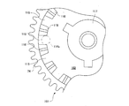
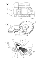
- the perspective view of the state which closed and opened the protective cap of the analytical device in Embodiment 1 of this invention Front and bottom views of the analytical device of the same embodiment Exploded perspective view of the analysis device of the same embodiment Plan view, AA sectional view, side view, rear view, front view of the diluent container of the same embodiment Plan view, side view, BB sectional view, front view of the protective cap of the same embodiment Sectional drawing of the sealing state of the diluent container of the same embodiment, the state which opened the protective cap, and the diluent discharge
- the perspective view of the state which opened the door of the analyzer of the embodiment Sectional view of the analyzer of the same embodiment Enlarged plan view of the turntable of the same embodiment AAAA sectional view and B-BB sectional view of the turntable of the same embodiment
- the state diagram in which the reaction between the diluted plasma in the measurement chamber and the reagent is started in step 12 of the embodiment, and the state diagram of the stirring of the reagent and diluted plasma in step 13 The enlarged perspective view of the state in which the diluent flowing out from the diluent container in Step 2 of the same embodiment flows into the holding cavity through the discharge channel and the diluted plasma are transferred from the mixing cavity to the next step through the capillary channel.
- Process diagram of transfer process of the embodiment The perspective view which shows the microchannel structure of the base substrate of the analytical device in Embodiment 10 of this invention.
- the top view which shows the microchannel structure of the base substrate of the device for analysis in the embodiment Configuration diagram of Patent Document 1
- Configuration diagram of Patent Document 2 Enlarged sectional view of the analytical device of Patent Document 3
- Perspective view of base substrate in the conventional example Plan view showing the microchannel configuration of the analytical device in the conventional example Process diagram of transfer process in the conventional example Plan view and sectional view of Patent Document 4
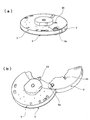
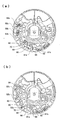
- FIGS. 1A and 1B show a state where the protective cap 2 of the analytical device 1 is closed and opened.
- FIGS. 2A and 2B show a front view and a bottom view of the analytical device 1.
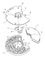
- FIG. 3 shows a state of disassembly with the lower side in FIG.
- This analytical device 1 includes a base substrate 3 having a microchannel structure having a fine unevenness on the surface, a cover substrate 4 covering the surface of the base substrate 3, and a diluent holding a diluent. It is composed of four parts including a container 5 and a protective cap 2 for preventing sample liquid scattering.
- Rotational support portion 15 as a centering fitting portion is formed on the cover substrate 4 on the bottom surface of the analysis device 1 so as to protrude from the bottom portion of the analysis device 1.
- a rotation support portion 16 is formed on the inner peripheral portion of the protective cap 2. In the analysis device 1 with the protection cap 2 closed, the rotation support portion 16 is formed so as to be in contact with the outer periphery of the rotation support portion 15. .
- the cover substrate 4 is formed with a convex portion 114 as a detent engaging portion whose proximal end is connected to the rotation support portion 15 and whose distal end extends toward the outer periphery.
- the base substrate 3 and the cover substrate 4 are joined with the diluent container 5 and the like set therein, and a protective cap 2 is attached to the joined substrate.
- One side of the protective cap 2 is pivotally supported so that it can be opened and closed by engaging with the shafts 6 a and 6 b formed on the base substrate 3 and the cover substrate 4.
- the gap between the flow paths of the microchannel structure on which the capillary force acts is set to 50 ⁇ m to 300 ⁇ m.
- the outline of the analysis process using this analytical device 1 is that the sample solution is spotted on the analytical device 1 in which a diluent is set in advance, and at least a part of the sample solution is diluted with the diluent, and then measurement is performed. It is what.
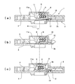
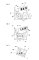
- FIG. 4 shows the shape of the diluent container 5.
- FIG. 4A is a plan view
- FIG. 4B is a cross-sectional view taken along the line AA of FIG. 4A
- FIG. 4C is a side view
- FIG. 4D is a rear view
- FIG. These are front views seen from the opening 7.
- the opening 7 is sealed with an aluminum seal 9 as a seal member after filling the interior 5a of the diluent container 5 with the diluent 8 as shown in FIG. 6 (a).
- a latch portion 10 is formed on the opposite side of the diluent container 5 from the opening 7, a latch portion 10 is formed.
- the dilution liquid container 5 is formed between the base substrate 3 and the cover substrate 4 and is set in the dilution liquid container housing part 11 so that the liquid holding position shown in FIG. 6A and the liquid discharge shown in FIG. It is housed in a freely movable position.
- FIG. 5 shows the shape of the protective cap 2.
- FIG. 5 (a) is a plan view
- FIG. 5 (b) is a side view
- FIG. 5 (c) is a BB cross-sectional view of FIG. 5 (a)
- FIG. 5 (d) is a rear view
- FIG. 6 (a) in the closed state shown in FIG. 1 (a), a locking groove 12 with which the latch portion 10 of the diluent container 5 can be engaged is formed inside the protective cap 2. ing.
- FIG. 6A shows the analysis device 1 before use.
- the protective cap 2 is closed, and the latch portion 10 of the diluent container 5 is engaged with the locking groove 12 of the protective cap 2 so as to prevent the diluent container 5 from moving in the arrow J direction. Locked in position. In this state, it is supplied to the user.
- the sample liquid is spotted on the exposed inlet 13 of the analytical device 1 and the protective cap 2 is closed.
- the wall surface 14 that has formed the locking groove 12 comes into contact with the surface 5 b of the latch portion 10 of the diluent container 5 on the side of the protective cap 2, and the diluent container 5 is pushed in the direction of arrow J (direction approaching the liquid discharge position).
- An opening rib 11a as a protruding portion is formed in the diluent container housing portion 11 from the base substrate 3 side.
- FIG. 7 shows a manufacturing process in which the analysis device 1 is set in the shipping state shown in FIG.
- the groove 42 (see FIGS. 3 and 4 (d)) provided in the lower surface of the diluent container 5 and the hole 43 provided in the cover substrate 4 are aligned
- the protrusion 42a of the locking jig 44 provided separately from the base substrate 3 or the cover substrate 4 is engaged with the groove 42 of the diluent container 5 through the hole 43 to hold the diluent container 5 with the liquid.
- the protective cap 2 is closed in a state where the pressing jig 46 is inserted from the notch 45 (see FIG. 1) formed on the upper surface of the protective cap 2 and the bottom surface of the protective cap 2 is pressed and elastically deformed. Can be set to the state shown in FIG. 6A by releasing the pressing jig 46.
- the groove 42 is provided on the lower surface of the diluent container 5
- the groove 42 is provided on the upper surface of the diluent container 5, and the base substrate corresponds to the groove 42.
- 3 can be configured such that a hole 43 is provided in the groove 3 and the protrusion 44 a of the locking jig 44 is engaged with the groove 42.
- the locking groove 12 of the protective cap 2 directly engages the latch portion 10 of the diluent container 5 to lock the diluent container 5 in the liquid holding position.
- the latch portion 10 of the diluent container 5 can be indirectly engaged to lock the diluent container 5 in the liquid holding position.
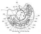
- the analysis device 1 is set on the turntable 101 of the analysis apparatus 100 shown in FIGS.
- the turntable 101 is attached to an inclined rotation axis 107 as shown in FIG. 9 and is inclined by an angle ⁇ with respect to the horizontal line H, depending on the rotation stop position of the analyzing device 1.
- the direction of gravity applied to the solution in the analysis device 1 can be controlled.
- the analysis device 1 When the analysis device 1 is stopped at a position near 60 ° shown in FIG. 32B, the upper left side 123 of the operation cavity 121 faces downward as viewed from the front, so that the solution in the operation cavity 121 125 receives gravity in the upper left direction. Similarly, at a position near 300 ° shown in FIG. 32 (c), the upper right side 124 of the operation cavity 121 faces downward as viewed from the front, so that the solution 125 in the operation cavity 121 becomes gravity toward the upper right direction. receive.
- the magnitude of gravity applied to the solution in the analysis device 1 can be set by adjusting the angle ⁇ of the rotation axis 107, and the amount of liquid to be transferred and the force attached to the wall surface in the analysis device 1 It is desirable to set according to the relationship.
- the angle ⁇ is preferably in the range of 10 ° to 45 °. If the angle ⁇ is smaller than 10 °, the gravity applied to the solution may be too small to obtain the driving force necessary for the transfer, and the angle ⁇ is more than 45 °. If it becomes larger, the load on the rotation axis 107 may increase, or the solution transferred by the centrifugal force may move freely by its own weight and cannot be controlled.
- An annular groove 102 is formed on the upper surface of the turntable 101, and when the analysis device 1 is set on the turntable 101, the rotation support 15 and the protective cap 2 formed on the cover substrate 4 of the analysis device 1 are provided.
- the formed rotation support portion 16 engages with and accommodates the annular groove 102.
- the analysis device 1 When the analysis device 1 is set on the turntable 101 and the door 103 of the analyzer is closed before the turntable 101 is rotated, the set analysis device 1 is moved by the clamper 104 provided on the door 103 side. The position of the turntable 101 on the rotational axis is pressed against the turntable 101 by the biasing force of the spring 105a as the biasing means, and the analysis device 1 is rotationally driven by the rotational driving means 106. It rotates together with 101.
- Reference numeral 107 denotes an axial center of the turntable 101 during rotation.
- a plurality of grooves 115 are provided at equal intervals on the inner periphery of the annular groove 102 of the turntable 101 as detent engagement portions on the turntable 101 side.
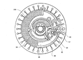
- FIG. 11A is a cross-sectional view taken along the line AAA in FIG. 10
- FIG. 11B is a cross-sectional view taken along the line B-BB in FIG.
- the top of the partition wall 116 between the groove 115 and the groove 115 of the turntable 101 is formed in a chevron shape.
- the inner diameter R1 of the partition wall 116 between the grooves 115 is larger than the outer diameter R2 of the rotation support portion 15 provided at the center of the bottom surface of the analytical device 1 and accommodated in the annular groove 102 of the turntable 101. .
- a central convex portion 117 formed as an alignment fitting portion is formed at the center of the annular groove 102 of the turntable 101. It is located inside the rotation support portion 15 of the analysis device 1 and functions as an alignment fitting portion that aligns the centers of the analysis device 1 and the turntable 101.
- any one of the grooves 115 formed at equal intervals on the inner periphery of the annular groove 102 of the turntable 101 has a tip 114a of the convex portion 114 of the analyzing device 1 as shown in FIGS. And the analysis device 1 does not slip in the circumferential direction of the turntable 101.
- the protective cap 2 is attached to prevent the sample liquid adhering to the vicinity of the inlet 13 from being scattered outside by the centrifugal force during analysis.
- the material of the parts constituting the analysis device 1 As the material of the parts constituting the analysis device 1, a resin material with low material cost and excellent mass productivity is desirable. Since the analysis apparatus 100 analyzes the sample liquid by an optical measurement method for measuring light transmitted through the analysis device 1, the material of the base substrate 3 and the cover substrate 4 may be PC, PMMA, AS, MS, or the like. A synthetic resin having high transparency is desirable.
- a crystalline synthetic resin having a low moisture permeability such as PP and PE is desirable.
- a material of the protective cap 2 there is no particular problem as long as the material has good moldability, and an inexpensive resin such as PP, PE, and ABS is desirable.
- the base substrate 3 and the cover substrate 4 are preferably joined by a method that hardly affects the reaction activity of the reagent carried in the storage area. Ultrasonic welding or laser welding is less likely to generate reactive gas or solvent during joining. Etc. are desirable.
- hydrophilic treatment for increasing the capillary force is applied to the portion where the solution is transferred by the capillary force due to the minute gap between the base substrate 3 and the cover substrate 4 by joining the base substrate 3 and the cover substrate 4.
- hydrophilic treatment using a hydrophilic polymer or a surfactant is performed.
- hydrophilic means that the contact angle with water is less than 90 °, more preferably less than 40 °.
- FIG. 13 shows the configuration of the analyzer 100.
- the analysis apparatus 100 includes a rotation drive unit 106 for rotating the turntable 101, an optical measurement unit 108 for optically measuring the solution in the analysis device 1, and a rotation speed and a rotation direction of the turntable 101. And a control means 109 for controlling the measurement timing of the optical measurement means, a calculation part 110 for processing a signal obtained by the optical measurement means 108 and calculating a measurement result, and a result obtained by the calculation part 110 are displayed. And a display unit 111 for doing so.
- the rotation driving means 106 not only rotates the analyzing device 1 around the rotation axis 107 in a predetermined direction at a predetermined rotation speed via the turntable 101 but also centers the rotation axis 107 at a predetermined stop position.
- the analyzing device 1 can be swung by reciprocating left and right in a predetermined amplitude range and cycle.
- the optical measurement unit 108 includes a light source 112 for irradiating the measurement unit of the analysis device 1 with a specific wavelength light, and the amount of transmitted light that has passed through the analysis device 1 out of the light emitted from the light source 112. And a photodetector 113 for detection.
- the analysis device 1 is rotationally driven by the turntable 101 so that the sample solution taken in from the injection port 13 is rotated around the rotation axis 107 located on the inner periphery of the injection port 13.
- the solution is transferred inside the analysis device 1 by using the centrifugal force generated in this way and the capillary force of the capillary channel provided in the analysis device 1.
- the microchannel structure will be described in detail along with the analysis process.
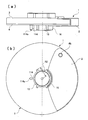
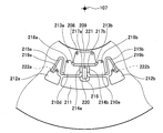
- FIG. 14 shows the vicinity of the inlet 13 of the analytical device 1.
- FIG. 14A shows an enlarged view of the injection port 13 as viewed from the outside of the analytical device 1, and FIG. 14B shows a state when the sample liquid 18 is collected from the fingertip 120 by opening the protective cap 2.
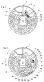
- FIG. 14C shows the microchannel structure as seen through the cover substrate 4 from the turntable 101 side.
- the injection port 13 has a shape protruding in the outer peripheral direction from the rotation axis 107 set in the analysis device 1 and is a minute part formed between the base substrate 3 and the cover substrate 4 so as to extend in the inner peripheral direction. Since it is connected to the capillary cavity 19 that can hold the required amount by the capillary force through the guide portion 17 where the capillary force acts in the gap ⁇ , the protective cap 2 is opened and the sample solution 18 is directly attached to the inlet 13. As a result, the sample liquid adhering to the vicinity of the injection port 13 is taken into the analysis device 1 by the capillary force of the guiding portion 17.
- a bent portion 22 is formed that forms a recess 21 in the base substrate 3 to change the direction of the passage.
- a gap-receiving cavity 23a where a capillary force does not act is formed at the tip of the guide cavity 17 through the capillary cavity 19 when viewed from the guide portion 17.
- a cavity 24 having one end connected to the separation cavity 23 and the other end opened to the atmosphere is formed on a part of the side of the capillary cavity 19, the bent portion 22, and the guiding portion 17. Because of the action of the cavity 24, the sample liquid collected from the inlet 13 is preferentially filled through the side wall on the side where the cavity 24 of the guiding portion 17 and the capillary cavity 19 is not formed. When bubbles are mixed, air is discharged toward the cavity 24 in a section adjacent to the cavity 24 of the guiding portion 17, and the sample liquid 18 can be filled without entraining the bubbles.
- FIG. 15 shows a state before the analysis device 1 after spotting is set on the turntable 101 and rotated. At this time, as explained in FIG. 6C, the aluminum seal 9 of the diluent container 5 collides with the opening rib 11a and is broken.
- Reference numerals 25 a to 25 m denote air holes formed in the base substrate 3.
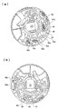
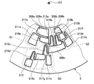
- a capillary tube that sends liquid in the circumferential direction from the previous process to the subsequent process in the middle of the overflow cavity that sends the liquid in the direction (arrow K direction) from the rotation axis 107 that obtains centrifugal force to the outer circumference.
- the flow paths 37 are arranged so as to intersect each other, and the liquid is discharged over the capillary flow paths 37 by the centrifugal force.
- the holding cavity 27 and the mixing cavity 39 are arranged in the outer peripheral direction (arrow K direction) from the center of the analyzing device 1 toward the outer periphery.
- Overflow cavities 29a and 29b and a reference measurement chamber 29c are arranged on the sides of the holding cavity 27 and the mixing cavity 39 in the outer peripheral direction.
- a capillary channel 37 is formed so as to intersect with the flow direction of the excess diluent toward the reference measurement chamber 29c.
- the analytical device 1 is connected between the overflow cavity 29e communicating with the atmosphere and the reference measurement chamber 29c, and the reference measurement chamber 29c communicates with the overflow channel 28c. What is the overflow cavity 29e? An overflow cavity 29d communicating with the overflow channel 28d is provided.
- Step 1 The analytical device 1 in which the sample liquid to be inspected is spotted at the inlet 13 holds the sample liquid in the capillary cavity 19 as shown in FIG. 16A, and the aluminum seal 9 of the diluted solution 5 is broken. Is set on the turntable 101.
- the diluent 8 that has flowed out of the diluent container 5 flows into the holding cavity 27 through the discharge channel 26 as shown in FIGS. 16 (b) and 23 (a).
- the excess diluent 8 flows into the overflow cavity 29a via the overflow channel 28a, and further passes over the capillary channel 37 to overflow the overflow cavity 29b. Then, it flows into the overflow cavity 29c as the reference measurement chamber via the overflow passage 28b.
- the excess dilution liquid flowing into the overflow cavity 29c exceeds a predetermined amount in the same manner as the holding cavity 27, the excess dilution liquid passes through the overflow flow path 28c serving as the reference-side overflow flow path, thereby blocking the overflow cavity. Into the overflow cavity 29d.
- the diluent container 5 has a bottom portion opposite to the opening 7 sealed with the aluminum seal 9 and is formed with an arcuate surface 32 as shown in FIGS. 4 (a) and 4 (b).
- the center m of the arc surface 32 is offset by a distance d so as to be closer to the discharge flow path 26 than the rotation axis 107 as shown in FIG. Therefore, the diluent 8 that has flowed toward the arc surface 32 is changed to a flow (in the direction of arrow n) from the outside toward the opening 7 along the arc surface 32, and the diluent container 5 is changed.
- the filling confirmation area 38a is formed at the outlet of the metering flow path 38 so as to extend in the inner circumferential direction, and is rotated at a low speed around 100 rpm before proceeding to the next process. While the plasma component 18a is held in the filling confirmation area 38a, the presence or absence of the plasma component 18a can be optically detected.
- the inner surface of the filling confirmation area 38a in the analysis device 1 is rough so that light passing through the filling confirmation area 38a is scattered when light is transmitted, and the plasma component 18a is not filled
- the liquid is also filled in the fine irregularities on the surface, so that light scattering is suppressed and the amount of transmitted light is increased. By detecting the difference in the amount of light, it is possible to detect whether or not the plasma component 18a is filled.
- connection channel 34 having a siphon shape that connects the separation cavity 23c and the overflow cavity 36b.
- the water is drawn into the connection channel 41 having a siphon shape connecting the mixing cavities 39.
- the inflow prevention groove 32a formed at the outlet of the connection channel 41 is formed to prevent the diluent 8 from flowing from the connection channel 41 into the measurement channel 38, and the base substrate 3 and Both cover substrates 4 are formed with a depth of about 0.2 mm to 0.5 mm.
- the capillary cavity 33 is formed from the outermost peripheral position of the separation cavity 23b toward the inner peripheral side. In other words, the outermost peripheral position of the capillary cavity 33 is formed to extend in the outer peripheral direction from the separation interface 18c between the plasma component 18a and the blood cell component 18b shown in FIG.
- the outer peripheral end of the capillary cavity 33 is immersed in the plasma component 18a and the blood cell component 18b separated in the separation cavity 23b. Since the viscosity of 18a is lower than that of the blood cell component 18b, the plasma component 18a is preferentially sucked out by the capillary cavity 33, and the plasma component 18a can be transferred toward the measuring channel 38 via the connection channel 30. .
- the path to the middle of the capillary cavity 33 and the connection channel 30 can be replaced with the blood cell component 18b.
- the measuring flow path 38 is filled with the plasma component 18a, the transfer of the liquid in the connection flow path 30 and the capillary cavity 33 is stopped, so that the blood cell component 18b is not mixed into the measuring flow path 38.
- the liquid feeding loss can be minimized as compared with the conventional configuration, the amount of the sample liquid necessary for the measurement can be reduced.
- FIG. 24 shows an enlarged view of the connection channel 34 and its periphery, and the connection channel 34 and its periphery will be described in detail.
- the outermost peripheral position (r1) of the separation cavity 23c is prevented so that the sample liquid remaining in the separation cavities 23b and 23c is sucked into the capillary cavity 33 and not transferred to the next process.
- a connection channel 34 having a siphon shape in which the outlet radial position (r2) is r1 ⁇ r2 is provided. After the sample liquid is primed into the connection channel 34, the turntable 101 is rotated. Thus, the sample liquid remaining in the separation cavities 23b and 23c is discharged to the overflow cavity 36b by the siphon effect.
- the sample liquid is blood, there are individual differences in the transfer speed of the blood cell component 18b flowing through the connection channel 34.
- the time for the blood cell component 18b to reach the outlet of the connection channel 34 will be increased. Need to start spinning. At that time, the blood cell component 18b that has reached the outlet of the connection channel 34 earlier is coagulated during the waiting time until the next step, and when the rotation of the next step starts, It has been found that it cannot be discharged due to clogging. In order to avoid this phenomenon, the position (r2) of the outlet of the connection channel 34 is further extended to the outer peripheral side, so that the outlet of the connection channel 34 is not filled and the coagulation of the blood cell component 18b can be suppressed. However, it is not suitable for miniaturization of the analysis device 1.
- a liquid reservoir 34a is further provided from the outlet of the connection flow path 34 in the circumferential direction and the inner circumferential direction.
- the width (w2) of the liquid reservoir 34a is wider than the width (w1) of the connection channel 34, the direction of the surface tension acting on the liquid tip of the blood cell component 18b is not directed in one direction, and the propulsive force Is dispersed. For this reason, the blood cell component 18b decreases in transfer speed after flowing into the liquid reservoir 34a, and therefore, individual differences in transfer speed can be absorbed in a small area.
- FIG. 24 (c) it is also possible to provide a liquid storage connection channel 34b from the outlet of the connection channel 34 toward the inner circumferential direction.
- An air release cavity 31a and an air hole 25n communicating with the atmosphere are provided in the outlet of the liquid collecting connection channel 34b.
- sample solution 18 in the separation cavities 23b and 23c, the connection passage 30, and the capillary cavity 33 flows into the overflow cavity 36a through the siphon-shaped connection passage 34 and the backflow prevention passage 35.
- the rotation of the turntable 101 is stopped, the analysis device 1 is set to the position shown in FIG. 18B, and the turntable 101 is set to 40 to 80 Hz so as to give the analysis device 1 a swing of about ⁇ 1 mm.
- the diluted plasma 40 to be measured which is composed of the diluent 8 and the plasma component 18a transferred into the mixing cavity 39, is stirred.
- the analysis device 1 is set to the position shown in FIG. 19A, and the turntable 101 is controlled at a frequency of 80 to 200 Hz so as to give the analysis device 1 a swing of about ⁇ 1 mm.
- the diluted plasma 40 held at 39 is transferred to the inlet of the capillary channel 37 formed on the inner peripheral side of the liquid surface of the diluted plasma 40.
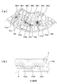
- FIG. 37A shows a perspective view of the vicinity of the inlet of the capillary channel 37 from the mixing cavity 39 side.
- the diluted plasma 40 transferred to the inlet of the capillary channel 37 is sucked into the capillary channel 37 by capillary force, and sequentially transferred to the capillary channel 37, the measuring channels 47a, 47b, 47c, and the overflow channel 47d. Is done.
- FIG. 25A is a plan view showing the state of the liquid level in the mixing cavity 39 before swinging
- FIG. 25B is a plan view showing the state of the liquid level in the mixing cavity 39 after swinging
- FIG. 25C is a cross-sectional view taken along the line AA of the mixing cavity 39 shown in FIG.
- the mixing cavity 39 is formed by an inclined wall surface tapered toward the outermost peripheral position from the inner peripheral side of the mixing cavity 39, and is configured to hold the diluted plasma 40 at the liquid level height (d1).
- the capillary channel inlet 37a for transferring the diluted plasma 40 to the next step is provided at the inner peripheral position (d0) with respect to the liquid level height d1.
- the amount of liquid in the mixing cavity 39 operated in this embodiment is about several tens of ⁇ l. Therefore, the surface tension acting on the wall surface of the mixing cavity 39 is high, and it is difficult to be affected by gravity.
- the movement of the diluted plasma 40 held in the mixing cavity 39 as the operation cavity will be described by taking as an example a case where the oscillation is performed at the position of the operation cavity 121 shown in FIG.
- the liquid level of the diluted plasma 40 in the mixing cavity 39 is moved to the left and right by the inertial force of the swing, so that the diluted plasma 40 is pulled by the wall surfaces on both sides of the mixing cavity 39. A smooth liquid level is formed.
- the height of the liquid surface pulled by the wall surfaces on both sides extends in the inner circumferential direction of the mixing cavity by repeating the swinging, so that it can be transferred toward the inlet 37a of the capillary channel.
- the liquid level of the diluted plasma 40 extends along the top surface (the surface on the base substrate 3 side). Therefore, it cannot reach the inlet 37a of the capillary channel provided in the vicinity of the bonding interface between the base substrate 3 and the cover substrate 4.
- Example 1 Therefore, in this embodiment, the liquid level is controlled by the configuration shown in FIG.
- FIG. 26A is a plan view showing the state of the liquid level in the mixing cavity 39 before swinging
- FIG. 26B is a plan view showing the state of the liquid level in the mixing cavity 39 after swinging
- FIG. 26C is a cross-sectional view taken along the line BB of the mixing cavity 39 shown in FIG.
- the mixing cavity 39 has a configuration in which a step 39a is provided at the inner peripheral position (d2) with respect to the liquid level height (d1) of the diluted plasma 40 so that the thickness is increased (t1 ⁇ t2).
- the liquid surface extending both wall surfaces of the mixing cavity 39 is restrained from expanding by the step 39a provided on the top surface, and instead the bottom surface with the step 39a as a base point.
- the liquid level on the side extends in the inner circumferential direction. This is because the step 39a is provided so that the surface tension is applied in a direction different from the extending direction of the liquid level. Therefore, it becomes possible to reach the inlet 37a of the capillary channel.
- step 5 the plasma component 18a and the diluent 8 need to be held in the mixing cavity 39 and reliably stirred by rocking. Therefore, the liquid level is not supplied to the inlet 37a of the capillary channel during the rocking of step 5. Therefore, the distance between the position (d0) of the inlet 37a of the capillary channel and the liquid surface position (d1) needs to be sufficiently separated so that it is not sucked into the capillary channel 37.
- a liquid amount of several tens of ⁇ l as in the present embodiment is handled, only the configuration shown in FIG.
- FIG. 27A is a plan view showing the state of the liquid level in the mixing cavity 39 before swinging.
- FIG. 27 (b) is a plan view showing the state of the liquid level in the mixing cavity 39 after swinging, and
- FIG. 27 (c) is a cross-sectional view taken along the line CC of the mixing cavity 39 shown in FIG. 27 (b). .
- the mixing cavity 39 further moves toward the inner circumferential direction at the inner peripheral position (d3) from the liquid level height (d1) of the diluted plasma 40 on the side wall 39e opposite to the side wall 39d where the inlet 37a of the capillary channel is located.
- a bent portion 39b that is bent so as to spread is provided.
- the liquid surface extending the side wall 39e opposite to the side wall 39d where the inlet 37a of the capillary channel of the mixing cavity 39 is located is adjusted by the bent portion 39b provided on the wall surface. Elongation is suppressed, and the liquid level on the wall surface where the capillary channel inlet 37a is located further extends in the inner circumferential direction. This is because the bent portion 39b is provided so that the surface tension is applied in a direction different from the extending direction of the liquid level. Therefore, even if the distance of the inlet 37a of the capillary channel is sufficiently separated, it can be reached.
- Example 3 28 controls the liquid level by combining the configuration of FIG. 26 and the configuration of FIG. The movement of the liquid level in the configuration shown in FIG. 26 is as described in FIGS.
- Example 4 In order to further reduce the size of the analytical device 1, as shown in FIG. 29A, the outlet of the measuring channel 38 may be formed in the vicinity of the liquid level of the diluted plasma 40 held in the mixing cavity 39. Conceivable.
- the plasma component 18a held in the measurement channel 38 is transferred to the mixing cavity 39 by centrifugal force generated by the rotation of the analysis device 1, and is transferred so as to wet the surface of the cover substrate 4 at that time. Since the surface tension of the surface once wetted is lowered, the liquid is easily transmitted. Therefore, when the mixing cavity 39 is swung, the diluted plasma 40 is also passed through the path through which the plasma component 18a passes as shown in FIG. Spreads wet, reaches the outlet of the metering channel 38 and flows back into the metering channel 38.
- the liquid level is further controlled by the configuration shown in FIG.
- FIG. 30A is different from FIG. 29A in that the cover substrate 4 is provided with a recess 39c.
- the concave portion 39c is formed at an inner peripheral position with respect to the liquid level height (d1) of the diluted plasma 40, and is not desired to be wetted and spread along the surface of the cover substrate 4 (periphery of the outlet of the measuring channel 38, bent portion). 39b or the like).
- an area 39f having a width w in which no recess is formed is left on the wall surface side where the inlet 37a of the capillary channel is located.
- the diluted plasma 40 is repeatedly swung while the diluted plasma 40 reaches the measuring flow paths 47a, 47b, 47c and the overflow flow path 47d via the capillary flow path 37, thereby diluting to adhere to the mixing cavity 39. Since the surface tension of the plasma 40 can be suppressed by the inertial force of rocking, the transfer speed is further accelerated.
- FIG. 33A is a layout diagram in the case where an overflow cavity 29 c is disposed between the holding cavity 27 and the mixing cavity 39.
- the diluent 8 transferred to the holding cavity 27 exceeds a predetermined amount, the diluent 8 flows into the overflow cavity 29a via the overflow channel 28a, and further flows into the overflow cavity 29c via the overflow channel 28b. is doing.
- the overflow cavity 29c needs to be formed adjacent to the outer peripheral position of the holding cavity 27 in order to reduce the size of the analyzing device 1.
- the position of the mixing cavity 39 is also determined by the radial position where the capillary channel 37 can be arranged. Therefore, by arranging the overflow cavity 29c between the holding cavity 27 and the mixing cavity 39, the outer shape becomes R2 enlarged by a distance ⁇ R1 therebetween.
- the capillary channel 37 is also arranged from the outer periphery, the path to expand to the inner peripheral position becomes longer, so the loss of the diluted plasma 40 increases.
- FIG. 33 (b) is a layout diagram when the overflow cavity 29a is arranged to extend in the circumferential direction.
- the overflow cavity 29a is formed so as to extend in the circumferential direction, the position of the mixing cavity 39 can be arranged on the inner peripheral side adjacent to the holding cavity 27, but because the overflow cavity 29a is arranged in the left area, The inner peripheral position where the capillary channel 37 can be developed is shifted toward the outer peripheral direction by ⁇ R2. For this reason, the space D1 in which the flow paths and cavities necessary for the next process can be arranged becomes D2 reduced by ⁇ R2, which makes it difficult to arrange, and as a result, the outer shape becomes R3 enlarged by ⁇ R2.
- the analysis device 1 is downsized by adopting the configuration shown in FIG.
- the mixing cavity 39 is disposed adjacent to the outer peripheral position of the holding cavity 27, and the capillary channel 37 is disposed so as to cross between the overflow cavity 29a and the overflow cavity 29b in the circumferential direction. That is, the path
- the centrifugal force acts in the direction of the arrow Y as shown in FIG. 23A, so that the diluent 8 passing through the overflow cavity 29a is a capillary tube. Without flowing into the mixing cavity 39 connected to one end in the circumferential direction of the flow path 37, the flow is transferred to the overflow cavity 29c.
- a capillary force acts in the direction of arrow X as shown in FIG.
- the diluted plasma 40 can be transferred without flowing into the overflow cavities 29a and 29b formed adjacent to 37.
- the diluent 8 transferred to the overflow cavity 29c and the overflow cavity 29d is connected to the overflow cavity 29e as the atmosphere-side overflow cavity communicating with the atmosphere as the analysis device 1 stops rotating. Since the overflow channel 28d as the atmosphere-side overflow channel and the overflow channels 28b and 28c are filled, both outlets of the overflow cavities 29c and 29d are blocked from the atmosphere and the inside becomes negative pressure. Therefore, even if the liquid is transferred from the mixing cavity 39 to the capillary channel 37 while swinging, the diluted plasma 40 can be developed to the next step without the diluent 8 flowing out from the overflow cavity 29c. Bubbles 51a and 51b are formed in the overflow cavities 29c and 29d.
- a necessary flow path pattern can be arranged without using an extra region such as ⁇ R1 and ⁇ R2, and thus the analysis device 1 can be downsized. Is feasible.
- the transfer route of the discharged liquid when measuring the diluted solution 8 and the route for transferring the diluted plasma 40 after mixing to the next process are arranged so as to intersect with each other. It is not used in the process.
- the diluted plasma 40 held in the overflow channel 47d at this time flows into the overflow cavity 54 via the backflow prevention passage 55.
- the diluted plasma 40 in the capillary channel 37 flows into the overflow cavity 29c via the overflow cavity 29b and the overflow channel 28b.
- a concave portion 49 is formed in a part of the side wall of the measurement flow path 47a so as to communicate with the atmosphere opening cavity 50 in the vicinity of the bent portion 48a, the force attached to the wall surface in the vicinity of the bent portion 48a is reduced. The liquid breakage at the bent portion 48a is improved.
- the shape of the measurement chambers 52a to 52c is a shape extending in the direction in which the centrifugal force acts. Specifically, the width of the analysis device 1 in the circumferential direction is narrowed from the rotation center of the analysis device 1 to the outermost periphery. Has been.
- the light source 112 having the same wavelength and the corresponding photodetector are used to measure the plurality of measurement chambers 52a to 52c. Since it is not necessary to arrange a plurality of 113 at different radial distances, the cost of the apparatus can be reduced, and measurement can be performed using a plurality of different wavelengths in the same measurement cell, so it is optimal according to the concentration of the mixed solution. Measurement sensitivity can be improved by selecting a suitable wavelength.
- FIG. 34 shows a cross section taken along line FF in FIG.
- the capacitable capacity of the capillary area 56b is formed to be smaller than the capacity capable of accommodating all the sample liquid held in the measurement chamber 52b.
- the capillary areas 56a and 56c are formed in a capacity smaller than the capacity capable of accommodating all the sample liquids held in the respective measurement chambers 52a and 52c.
- the optical path lengths of the measurement chambers 52a to 52c are adjusted according to the range of absorbance obtained from the mixed solution after reacting each component to be inspected and the reagent.
- reagents 58a1, 58a2, 58b1, 58b2, 58b3, 58c1, 58c2 for reacting with the components to be examined are capillary tubes. It is carried on reagent carrying portions 57a1, 57a2, 57b1, 57b2, 57b3, 57c1, 57c2 formed in the areas 56a, 56b, 56c.
- a GG cross section in FIG. 35A is shown in FIG.
- the gap between the reagent carrier 57b1, 57b2, 57b3 and the cover substrate 4 is formed so as to protrude from the capillary area 56b so as to be thinner than the gap between the capillary area 56b and the cover substrate 4.
- the reagents 58b1, 58b2, and 58b3 are applied to the reagent carrying portions 57b1, 57b2, and 57b3, the spread of the reagents 58b1, 58b2, and 58b3 is suppressed by the step between the reagent carrying portions 57b1, 57b2, 57b3 and the capillary area 56b. Therefore, it is possible to carry different types of reagents without mixing them.
- the gap between the reagent holding portions 57b1, 57b2, and 57b3 is thinner than the capillary area 56b, the liquid sucked into the capillary area 56b is surely filled into the reagent holding portions 57b1, 57b2, and 57b3.
- the reagents 58b1, 58b2, and 58b3 can be reliably dissolved.
- the capillary area 56b is formed by a gap where a capillary force of about 50 to 300 ⁇ m acts, the reagent carrying portions 57b1, 57b2, and 57b3 are formed so as to protrude by several tens of ⁇ m from the capillary area 56b. .
- the capillary areas 56a and 56c are similarly configured.
- Step 8- the rotation of the turntable 101 is stopped, the analysis device 1 is set to the position shown in FIG. 20A, and the turntable 101 is moved to 60 to 120 Hz so as to give the analysis device 1 a swing of about ⁇ 1 mm.
- the operating cavity 61 is controlled by the action of capillary force through the connecting portion 59 formed on the side wall of the holding cavity 53 so that the diluted plasma 40 held in the holding cavity 53 is immersed in the liquid surface of the diluted plasma 40. Transport to.
- the turntable 101 is controlled at a frequency of 120 to 200 Hz to stir the reagents 67a and 67b and the diluted plasma 40 carried in the operation cavity 61 shown in FIG. The components and reagents are reacted.
- the diluted plasma 40 transferred to the measurement chambers 52b and 52c is sucked up into the capillary areas 56b and 56c by the capillary force as shown in FIG. 20 (a), and at this time, the reagents 58b1, 58b2, 58b3, 58c1, and 58c2 And the reaction of the specific components contained in the diluted plasma 40 and the reagent is started.
- an operation cavity 61 is formed adjacent to the rotational axis 107 in the circumferential direction of the holding cavity 53.
- a gap between the operation cavity 61 and the cover substrate 4 is formed in a gap where a capillary force acts, and the reagents 67a and 67b are carried on the reagent carrying portions 65a and 65b.
- a stirring rib 63 extending in the radial direction is formed around the reagents 67a and 67b, specifically between the reagents 67a and 67b.
- the cross-sectional dimension in the thickness direction of the stirring rib 63 and the cover substrate 4 is smaller than the cross-sectional dimension in the thickness direction of the operation cavity 61 with the cover substrate 4 as shown in FIG.
- the gap between the reagent carrying portions 65 a and 65 b and the cover substrate 4 is formed so as to protrude from the operation cavity 61 so as to be thinner than the gap between the operation cavity 61 and the cover substrate 4.
- the gap between the reagent holding portions 65a and 65b is thinner than the operation cavity 61, the liquid flowing into the operation cavity 61 is surely filled into the reagent holding portions 65a and 65b. Can be dissolved.
- the reagent holders 65a and 65b are formed so as to protrude from the operation cavity 61 by about several tens of ⁇ m.
- a cavity 62 is formed on the inner peripheral side of the operation cavity 61, and the cavity 62 is connected to the holding cavity 53 through the communication portion 60.
- a gap between the cavity 62 and the cover substrate 4 is formed in a gap where no capillary force acts.
- the cavity 62 communicates with the atmosphere via an air hole 25 h formed in the vicinity of the communication portion 60.
- the holding cavity 53 and the operation cavity 61 are connected via a connecting portion 59 that extends from the side wall of the holding cavity 53 through the communication portion 60.
- a gap between the connecting portion 59 and the cover substrate 2 is formed in a gap where a capillary force acts.
- the tip of the connecting portion 59 is formed to extend in the outer peripheral direction with respect to the rotational axis from the liquid level of the diluted plasma 40 held in the holding cavity 53.
- a separation cavity 66 is formed on the outer peripheral side of the operation cavity 61 and is connected via a connecting passage 64.
- the cross-sectional dimension in the thickness direction between the connecting passage 64 and the cover substrate 4 is limited to be larger than the capillary force acting on the operation cavity 61 in the gap where the capillary force acts.
- the space filled with the diluted plasma 40 and the gap size are the same, but a small space 61a that is not filled with the diluted plasma 40 remains.
- the diluted plasma 40 and the reagents 67a and 67b come into contact with each other, and the reagents 67a and 67b are dissolved in the diluted plasma 40.
- the analyzing device 1 is swung by a predetermined angle around the rotation axis 107 in this state, the diluted plasma 40 in the operation cavity 61 moves in the operation cavity 61 because of the space 61a, and this At the time of stirring, it collides with the stirring rib 63 and is stirred more reliably. Thereby, even if the specific gravity of the reagent is large, it works more effectively so as not to precipitate the reagent.
- the reagent and diluted plasma mixed solution held in the capillary areas 56b and 56c are transferred to the outer peripheral side of the measurement chambers 52b and 52c by centrifugal force, whereby the reagent and diluted plasma are stirred.
- the agitation of the reagent and the diluted plasma is promoted by repeatedly performing the rotation and stop operations of the analytical device 1, the agitation can be performed more reliably and in a shorter time than the agitation only by diffusion. It becomes possible.
- connection channel 68 having a siphon shape connecting the separation cavity 66 and the overflow cavity 81a.
- the mixed solution of the reagent and diluted plasma transferred to the measurement chambers 52b and 52c is again sucked up into the capillary areas 56b and 56c by the capillary force.
- the outermost peripheral position of the capillary cavity 69 is formed to extend in the outer peripheral direction so as to be immersed in the diluted plasma held in the separation cavity 66.
- the capillary cavity 69 By forming the capillary cavity 69 in this way, the supernatant diluted plasma is preferentially sucked out by the capillary cavity 69 rather than the sediment having a higher specific gravity, and is directed to the measuring channel 80 via the connection channel 70.
- the diluted plasma 40 from which the precipitate has been removed can be transferred.
- the diluted plasma 40 in the separation cavity 66, the connection passage 70, and the capillary cavity 69 flows into the overflow cavity 81a via the siphon-shaped connection flow path 68.
- the reagent and diluted plasma mixed solution held in the capillary areas 56b and 56c are transferred to the outer peripheral side of the measurement chambers 52b and 52c by centrifugal force, whereby the reagent and diluted plasma are stirred.
- the diluted plasma 40 transferred to the overflow cavity 81a is filled in the overflow channel 82c connected to the overflow cavity 81b communicating with the atmosphere as the analysis device 1 stops rotating.
- the outlet of the flow cavity 81a is blocked from the atmosphere, and the inside becomes negative pressure. Therefore, it is possible to prevent the diluted plasma 40 from flowing out from the overflow cavity 81a through the connection channel 68.
- the mixed solution of the reagent and diluted plasma transferred to the measurement chambers 52b and 52c is again sucked up into the capillary areas 56b and 56c by the capillary force.
- Step 13- When the turntable 101 is rotated in the clockwise direction (C2 direction), the mixed solution of the reagent and diluted plasma held in the capillary areas 56a, 56b, and 56c is measured by centrifugal force as shown in FIG. 22 (b). The reagent and diluted plasma are agitated by being transferred to the outer peripheral side of the chambers 52a, 52b, and 52c.
- Step 11 and Step 12 are repeatedly performed to promote the stirring of the reagent and the diluted plasma 40. Stirring can be performed in a short time.
- the analysis device 1 is rotationally driven in the counterclockwise direction (C1 direction) or clockwise direction (C2 direction), and at the timing when each measurement chamber 52a, 52b, 52c passes between the light source 112 and the photodetector 113, the calculation unit 110 Reads the detection value of the photodetector 113 and calculates the concentration of the specific component. Note that when the diluted plasma 40 flows into the measurement chambers 52a, 52b, and 52c in the steps 7 and 11, the calculation unit is at a timing when the measurement chambers 52a, 52b, and 52c pass between the light source 112 and the photodetector 113.
- the measurement accuracy is improved by using it as reference data for the measurement chambers 52a, 52b, 52c in the calculation processing in the calculation unit 110. Can be improved.
- the component is measured from the attenuation by optical access in the measurement chamber.
- the component is measured by electrically accessing the reaction product of the reagent and the sample in the measurement chamber. But the same is true.
- This analysis device is the same as FIG. 59 showing the conventional example in that the base substrate 3 having the microchannels 204a and 204b and the cover substrate 4 closing the opening of the base substrate 3 are bonded together.
- the arrangement of the measuring chamber 210 with respect to the liquid storage chamber 209 in the base substrate 3 and the connection between the measuring chamber 210 and the overflow chamber 211 are different from those in FIG.
- FIG. 38 shows a perspective view of the main part of the base substrate 3
- FIG. 39 shows a plan view thereof.
- the inlet 216 of the overflow chamber 211 is arranged on the same rotational radial direction as the overflow outlet 214 of the measuring chamber 210, and the inlet 216 of the overflow chamber 211 and the overflow outlet 214 of the measuring chamber 210 are
- the third capillary passages 217c extending along the same rotational radius direction are connected.
- L1 in the measurement chamber 210 in FIG. 39 indicates the liquid level in a state where the sample liquid flowing from the liquid storage chamber 209 into the measurement chamber 210 via the first connection passage 213a is sampled by a specified amount.
- the surplus sample liquid flowing into the measuring chamber 210 flows into the overflow chamber 211 beyond the installation level of the third capillary passage 217c, and the amount of sample liquid sample in the measuring chamber 210 is quantified.
- the outermost peripheral portion of the measuring chamber 210 has a siphon-like shape having a curved pipe disposed inward from the distance from the rotation axis of the analyzing device to the interface between the inlet 216 of the overflow chamber 211 and the capillary passage 217c. It is connected to the measurement cell 212 via a connecting passage 215. 208 is an inlet communicating with the atmosphere, and 218 and 219 are air holes communicating with the atmosphere.
- the width of the connecting passage 215 is 0.5 mm to 2 mm and the depth is 50 ⁇ m to 200 ⁇ m, but there is no particular limitation as long as the inside of the connecting passage 215 can be filled with the sample solution by capillary force.
- FIG. 61 Because of such a configuration, comparing FIG. 61 and FIG. 39, the space S seen between the outer peripheral side of the liquid storage chamber 209 and the inner peripheral side of the measuring chamber 210 in FIG. 61 can be reduced.
- one measurement cell 212 is provided between the limited radial dimensions of the analysis device.
- the radial dimension of the analysis device is used. Is the same as FIG. 61, more measurement cells 212 can be provided. If the number of measurement cells 212 may be the same as that in FIG. 61, the analysis device can be downsized.
- a capillary valve 222 is provided between the position outside the outermost radial direction of the measuring chamber 210 and the measuring cell 212 as shown by the phantom line, and the measuring chamber 210 and the measuring cell are arranged. 212 can also be linked.
- the liquid storage chamber 209, the measurement chamber 210, the overflow chamber 211, and the measurement cell 212 are formed with a depth of 0.3 mm to 2 mm, but the conditions for measuring the amount of the sample liquid and the absorbance (optical path length, The measurement wavelength, the reaction concentration of the sample solution, the type of reagent, etc. can be adjusted.
- the cross-sectional dimension and the width direction of the first connecting passage 213a in the thickness direction so that the flow rate of the liquid passing through the first connecting passage 213a is smaller than the flow rate of the liquid passing through the third capillary passage 217c.
- At least one of the cross-sectional dimensions is configured to be smaller than the cross-sectional dimension in the thickness direction and the cross-sectional dimension in the width direction of the third capillary passage 217c.
- the cross-sectional dimension of the first connecting passage 213a in the thickness direction is made into a capillary shape having a depth of 50 ⁇ m to 200 ⁇ m so as to be smaller than the third capillary passage 217c, whereby the sample liquid is stored in the liquid storage chamber.
- the weighing process can be made more stable.
- the inlet 216 of the overflow chamber 211 is disposed inward in the rotational radial direction from the overflow outlet 214 of the measuring chamber 210, and the inlet 216 of the overflow chamber 211 and the measuring chamber 210 are arranged.
- the overflow port 214 is connected by the capillary passage 217
- the inlet 216 of the overflow chamber 211 is moved outward from the overflow port 214 of the measuring chamber 210 in the rotational radius direction.
- the inlet 216 of the overflow chamber 211 and the overflow port 214 of the measuring chamber 210 are connected by a fourth capillary passage 217d.
- Others are the same as those in FIG. 39, and the same reference numerals are given to those having the same functions.
- L1 in the measurement chamber 210 in FIG. 41 indicates the liquid level in a state where the sample liquid flowing from the liquid storage chamber 209 is sampled into the measurement chamber 210 by a specified amount, and flows into the measurement chamber 210 from the liquid storage chamber 209.
- the excess sample liquid flows into the overflow chamber 211 beyond the installation level of the fourth capillary passage 217d, and the sampling amount of the sample liquid in the measuring chamber 210 is set to a specified amount.
- FIG. 61 is compared with FIG. 41, the space S seen between the outer peripheral side of the liquid storage chamber 209 and the inner peripheral side of the measuring chamber 210 in FIG. 61 is shown in FIG.
- the number can be reduced.
- FIG. 61 the case where one measurement cell 212 is provided between the limited radial dimensions of the analytical device is illustrated and described.
- the dimension in the radial direction of the analysis device is the same as that in FIG. 61, more measurement cells 212 can be provided. If the number of measurement cells 212 may be the same as that in FIG. 61, the analysis device can be downsized.
- a capillary valve 222 may be provided as shown by the phantom line to connect the measuring chamber 210 and the measurement cell 212.
- the liquid storage chamber 209, the measurement chamber 210, the overflow chamber 211, and the measurement cell 212 are formed with a depth of 0.3 mm to 2 mm, but the conditions for measuring the amount of the sample liquid and the absorbance (optical path length, The measurement wavelength, the reaction concentration of the sample solution, the type of reagent, etc. can be adjusted.
- the cross-sectional dimension in the thickness direction and the width direction of the first connection passage 213a are such that the flow rate of the liquid passing through the first connection passage 213a is smaller than the flow rate of the liquid passing through the fourth capillary passage 217d.
- At least one of the cross-sectional dimensions is configured to be smaller than the cross-sectional dimension in the thickness direction and the cross-sectional dimension in the width direction of the fourth capillary passage 217d.
- the cross-sectional dimension of the first connecting passage 213a in the thickness direction is made into a capillary shape having a depth of 50 ⁇ m to 200 ⁇ m so as to be smaller than the fourth capillary passage 217d, whereby the sample liquid is stored in the liquid storage chamber.
- the weighing process can be made more stable.
- the sample liquid is injected into the liquid storage chamber 209.
- the liquid storage chamber of the base substrate 3 is used.
- a mixing means for mixing a quantitative inspection object and a quantitative diluent, a measuring chamber for measuring the quantitative diluent from the diluent, an overflow chamber for receiving excess diluent, and the like are provided. Is required.
- the sample liquid is quantified in the measuring chamber, the excess sample liquid is received in the overflow chamber, and the sample liquid quantified in the measuring chamber is more than in the measuring chamber.
- the same configuration as the specific components to be transferred to the subsequent stage is further provided on the upper side of the liquid storage chamber 209 of the base substrate 3 so that the dilution liquid can be quantified and the excess dilution liquid can be received in a small space.
- a first group G1 that measures and transfers the diluent to the mixing chamber 209c
- a second group G2 that measures and transfers the blood to the mixing chamber 209c
- a third group G3 for transferring the sample liquid mixed in the mixing chamber 209c to the measurement cell 212 is formed.
- the basic configurations of the first, second, and third groups G1 to G3 are the same, and the diluent holding unit 209a and the blood holding unit 209b correspond to the liquid storage chamber 209 in the third embodiment.
- Diluent measurement chamber 210a, blood quantification chamber 210b, and sample liquid measurement section 210c correspond to measurement chamber 210 in the third embodiment.
- the diluent overflow chamber 211a, the blood discharge chamber 211b, and the sample fluid overflow chamber 211c correspond to the overflow chamber 211 in the third embodiment.
- the surplus diluent in the diluent metering chamber 210a flows into the diluent overflow chamber 211a via the fifth capillary passage 217e corresponding to the third capillary passage 217c in the third embodiment.
- the diluted solution quantified in the diluted solution measuring chamber 210a flows into the mixing chamber 209c through the siphon-shaped first connection passage 215a.
- the fixed amount of blood and the fixed amount of diluent mixed in the mixing chamber 209c flow to the sample liquid measuring unit 210c through the third connection passage 215c having a siphon shape.
- the excess sample liquid in the sample liquid measuring section 210c flows into the sample liquid overflow chamber 211c via the seventh capillary passage 217g corresponding to the third capillary passage 217c in the third embodiment.
- the sample solution quantified by the sample solution measuring section 210c flows into the measurement cell 212 via the siphon-shaped fourth connection passage 215d.
- the diluent holding unit 209a and the diluent measuring chamber 210a in the first group G1 are connected.
- the space between them can be reduced.
- the space between the blood holding part 209b and the blood quantification chamber 210b in the second group G2 can be reduced by connecting the blood quantification chamber 210b and the blood discharge chamber 211b by the sixth capillary passage 217f extending along the same radius. .
- the space between the mixing chamber 209c and the sample liquid measuring section 210c in the third group G3 is connected by connecting the sample liquid measuring section 210c and the sample liquid overflow chamber 211c by the seventh capillary passage 217g extending along the same radius.
- the chambers arranged in the radial direction can be arranged close to the inner circumferential direction, and the analysis device can be downsized.
- FIG. 43 shows a perspective view of the main part of the base substrate 3, and FIG. 44 shows a plan view thereof.
- one measuring chamber 210, one overflow chamber 211, and one measuring cell 212 are provided for one liquid storage chamber 209.
- one liquid storage chamber 209 is provided.
- one overflow chamber 211, a plurality of first and second measuring chambers 210d and 210e, and first and second measurement cells 212a and 212b are provided.
- the base substrate 3 has a liquid storage chamber 209 for storing the sample liquid to be analyzed, relative to the rotation axis 107 serving as the rotation axis of the analysis device during analysis. It is provided on the inner periphery.
- a first measuring chamber 210d and a second measuring chamber 210e are formed outside the liquid storage chamber 209 in the rotational radius direction.
- the first measurement chamber 210d is connected to the liquid storage chamber 209 by the first connection passage 213a.
- the second measuring chamber 210e is connected to the liquid storage chamber 209 by the second connecting passage 213b.
- an overflow chamber 211 is formed in the base substrate 3 between the first weighing chamber 210d and the second weighing chamber 210e, and the inlet 216 of the overflow chamber 211 and the first weighing chamber 210d.
- the first overflow port 214a is connected by a first capillary passage 217a extending along the same rotational radial direction.
- the inlet 216 of the overflow chamber 211 and the second overflow port 214b of the second measuring chamber 210e are connected by a second capillary passage 217b extending along the same rotational radius direction.
- the outermost peripheral portion of the first measuring chamber 210d is disposed inward from the distance from the rotational axis of the analyzing device to the interface between the inlet 216 of the overflow chamber 211 and the first capillary passage 217a. It is connected to the first measurement cell 212a via a siphon-shaped first connecting passage 215a having a curved pipe.
- the outermost peripheral portion of the second measuring chamber 210e is a curved pipe disposed inward from the distance from the rotational axis of the analyzing device to the interface between the inlet 216 of the overflow chamber 211 and the second capillary passage 217b. Is connected to the second measurement cell 212b via a siphon-shaped second connecting passage 215b.
- the first and second connection passages 215a and 215b are formed with a width of 0.5 mm to 2 mm and a depth of 50 ⁇ m to 200 ⁇ m, but the inside of the first and second connection passages 215a and 215b is sampled by capillary force. There is no particular limitation as long as it can be filled with a liquid.
- first and second flow rates of the liquid passing through the first and second connection passages 213a and 213b are smaller than the flow rates of the liquid passing through the first and second capillary passages 217a and 217b. At least one of the cross-sectional dimension in the thickness direction and the cross-sectional dimension in the width direction of the connecting passages 213a and 213b is greater than the cross-sectional dimension in the thickness direction and the cross-sectional dimension in the width direction of the first and second capillary passages 217a and 217b. It is small.
- the first and second connection passages 213a and 213b are made to have a cross-sectional dimension in the thickness direction of a capillary shape having a depth of 50 ⁇ m to 200 ⁇ m and smaller than the first and second capillary passages 217a and 217b.
- the liquid surface of the sample liquid held in the connection passage 215 exceeds the innermost point of the connection passage 215.
- the phenomenon that the sample liquid being measured is transferred to the measurement cell 212 can be avoided, so that the measurement process can be made more stable.
- the overflow chamber 211 is provided with a sill 220 that limits the cross-sectional dimension in the thickness direction to the size at which the capillary force acts.
- 218a, 218b, 219a, 219b, 221 are air holes communicating with the atmosphere side. By forming the air hole 221 in an area where the capillary force does not act on the inner peripheral side of the sill 220 of the overflow chamber 211, an excess amount from the first and second measurement chambers 210d and 210e to the overflow chamber 211 is obtained. The flow is smooth.
- 45 (a) to 45 (d) show the transfer process of the analytical device.
- the sample liquid is injected from the injection port 208 and stored in the liquid storage chamber 209, and the analysis device is rotated, thereby rotating the first and second connection passages 213a and 213b.
- the sample liquid can be transferred to the first and second measuring chambers 210d and 210e.
- the sample liquid in the first and second connection passages 215a and 215b flows from the rotation axis of the analysis device to the inlet 216 of the overflow chamber 211 and the first and second capillary passages 217a and 217b. Only the position corresponding to the distance in the radial direction of rotation to the interface is filled.
- the capillaries in the first and second connection passages 215a and 215b are shown in FIG. 45 (c).
- the sample solution is filled up to the inlets of the first and second measurement cells 212a and 212b.
- the capillary force is very small compared to the capillary forces of the first and second connection passages 215a and 215b, It does not flow into the second measurement cells 212a and 212b.
- the threshold 220 since the threshold 220 is provided, the backflow of the sample liquid from the overflow chamber 211 to the first and second measurement chambers 210d and 210e does not occur when the analysis device is decelerated or stopped.
- the sample liquid held in the first and second measuring chambers 210d and 210e is rotated by rotating the analysis device again. As shown in FIG. 45 (d), they are transferred to the first and second measurement cells 212a and 212b by the siphon effect, and the analysis is performed individually in the first and second measurement cells 212a and 212b.
- one overflow chamber 211 since one overflow chamber 211, a plurality of measuring chambers 210d and 210e, and first and second measurement cells 212a and 212b are appropriately formed on the base substrate 3 with respect to one liquid storage chamber 209.
- the dimensions in the radial direction of the analysis device are the same as those in FIG. 61, more measurement cells 212 can be provided.
- Capillary valves 222a and 222b may be provided between the first and second measuring chambers 210d and 210e and the first and second measuring cells 212a and 212b, respectively, as indicated by phantom lines.
- liquid storage chamber 209, the first and second measuring chambers 210d and 210e, the overflow chamber 211, and the first and second measurement cells 212a and 212b are formed with a depth of 0.3 mm to 2 mm.
- the amount of the sample solution and the conditions for measuring the absorbance can be adjusted.
- Embodiment 7 shows a specific example of an analysis device in which the configuration of Embodiment 6 is developed on the base substrate 3.
- the blood spotted on the blood spotting portion 223 is formed between the cover substrate 4 and the blood.
- the blood is retained by the blood holding unit 225 through the microchannel 224.
- a diluent is set in a dilution container (not shown) set in the diluent reservoir 226.
- the analysis device is driven to rotate about the rotation axis 107, the blood is quantified in the blood quantification chamber 229 via the blood separation unit 228. Excess blood is collected in the blood discharge unit 230.
- the diluent is quantified in the diluent quantification chamber 231.
- Excess diluent is collected in the diluent outlet 232 via the capillary passage 236.
- the blood quantified in the blood quantification chamber 229 and the diluent quantified in the diluent quantification chamber 231 are mixed in the mixing unit 233 and transferred to the liquid storage chamber 209.
- the diluted blood as the sample liquid transferred to the liquid storage chamber 209 is transferred to the first and second measuring chambers 210d and 210e via the first and second connection passages 213a and 213b and quantified. Excess diluted blood is collected in the overflow chamber 211 via the first and second capillary passages 217a and 217b. By rotating the analyzing device again, the diluted blood quantified in the first and second measuring chambers 210d and 210e is siphon-like first and second from the first and second measuring chambers 210d and 210e.
- the sample is transferred to the first and second measurement cells 212a and 212b via the connection passages 215a and 215b, and the analysis is performed individually in the first and second measurement cells 212a and 212b. Reagents 234a, 234b, and 234c are set in the first and second measurement cells 212a and 212b.
- the diluent quantification chamber 231 for quantitatively metering the diluent is disposed so as to surround the diluent reservoir 226, and the excess diluent generated in the diluent quantification chamber 231 is disposed.
- the diluent discharge part 232 for receiving the liquid is also formed around the diluent storage part 226, and the capillary passage 236 connecting the dilution liquid quantification chamber 231 and the diluent discharge part 232 is provided in the first and second capillaries.
- the passages 217a and 217b it has a shape extending along the same rotational radius direction, and effectively acts to reduce the size of the analysis device.
- the connecting passage is such that the flow rate of the liquid passing through the connecting passage 237 connecting the diluent storing unit 226 and the diluent quantifying chamber 231 is smaller than the flow rate of the liquid passing through the capillary passage 236.
- At least one of the cross-sectional dimension in the thickness direction and the cross-sectional dimension in the width direction of 237 is configured to be smaller than the cross-sectional dimension in the thickness direction and the cross-sectional dimension in the width direction of the capillary passage 236.
- the excess sample liquid in the liquid storage chamber 209 is received by the third and fourth measurement cells 212c and 212d via the capillary passage 238 and the diluent discharge part 232. It is configured.
- FIG. 48 shows an eighth embodiment of the present invention.
- the sill 220 is formed in the overflow chamber 211 and the gap with the cover substrate 4 is reduced to limit the size to which the capillary force acts.
- the sill 220 is eliminated. You can also.
- a water-absorbing material 235 having water absorption is arranged in the overflow chamber 211, and the analytical device is decelerated or stopped by the water-absorbing material 235 sucking the sample liquid flowing into the overflow chamber 211.
- the backflow of the sample liquid from the overflow chamber 211 to the first and second measuring chambers 210d and 210e can be prevented.
- the external appearance of the analysis device 1 is a disk shape as shown in FIG. 51, and is driven to rotate about the rotation axis 107.
- the rotational axis 107 is inclined so that the posture of the analyzing device 1 during the rotation is inclined at a predetermined angle of 0 ° to 45 ° with respect to the horizontal.
- the predetermined angle is preferably in the range of 10 ° to 45 °.
- the analyzing device 1 includes a base substrate 3 having a microchannel liquid storage chamber 241, a first holding cavity 243, an operation cavity 245, second holding cavities 247 and 248, and the like.
- the cover substrate 4 that closes the opening is bonded to the adhesive layer 300.
- FIG. 49 shows a perspective view of the main part of the base substrate 3, and FIG. 50 shows a plan view thereof.
- 53 shows an AA sectional view, a BB sectional view, and a CC sectional view in FIG.
- a liquid storage chamber 241 is formed between the rotation axis and the first holding cavity 243 of the base substrate 3.
- a sample liquid is injected into the liquid storage chamber 241 from the through hole 244.
- the liquid storage chamber 241 and the first holding cavity 243 are connected by a communication passage 242.
- a gap between the communication passage 242 and the cover substrate 4 is formed in a gap where a capillary force acts as shown in FIG.
- An operation cavity 245 is formed adjacent to the rotating shaft center in the circumferential direction of the first holding cavity 243 of the base substrate 3.
- a gap between the operation cavity 245 and the cover substrate 4 is formed in a gap where a capillary force acts, and the first reagents 249 and 250 are carried.
- a stirring rib 251 extending in the radial direction is formed around the first reagent 249, 250, specifically between the first reagent 249, 250.
- the cross-sectional dimension in the thickness direction of the stirring rib 251 and the cover substrate 4 is smaller than the cross-sectional dimension in the thickness direction of the operation cavity 245 with the cover substrate 4.
- a cavity 252 is formed on the inner peripheral side of the operation cavity 245, and the cavity 252 is connected to the first holding cavity 243 through a communication portion 253.
- the gap between the cavity 252 and the cover substrate 4 is formed in a gap where no capillary force acts.
- the cavity 252 communicates with the atmosphere via a through hole 254 formed in the first holding cavity 243.
- the first holding cavity 243 and the operation cavity 245 are connected via a connecting portion 255 that extends from the side wall of the first holding cavity 243 through the communication portion 253.
- the gap between the connecting portion 255 and the cover substrate 4 is formed in a gap where a capillary force acts.
- the distal end of the connecting portion 255 is formed so as to extend in the outer peripheral direction with respect to the rotational axis from the liquid surface of the sample liquid held in the first holding cavity 243. More specifically, the distal end of the connecting portion 255 extends to the outermost peripheral portion of the first holding cavity 243.
- Second holding cavities 247 and 248 are formed on the outer peripheral side of the operation cavity 245. Of the second holding cavities 247 and 248, the second holding cavity 247 on the inner peripheral side is deeper than the second holding cavity 248 on the outer peripheral side, and the second holding cavity 247 is connected via the connecting passage 256. Has been.
- the cross-sectional dimension in the thickness direction between the connecting passage 256 and the cover substrate 4 is limited to be larger than the capillary force acting on the operation cavity 245 in the gap where the capillary force acts as shown in FIG. ing.
- Reference numeral 257 denotes a communication hole communicating with the atmosphere.
- a second reagent 258 is carried in the second holding cavity 248.
- the sample solution 283 passes through the communication passage 242 by centrifugal force. Then, it is transferred to the first holding cavity 243.
- the rotational drive of the analytical device 1 is decelerated, or the outermost peripheral portion of the first holding cavity 243 is lowered as shown in FIG.
- the analysis device 1 is stopped in this state, the sample solution 283 in the first holding cavity 243 is transferred to the operation cavity 245 having a greater capillary force than the connection portion 255 by the capillary force via the connection portion 255. It is transferred as shown in (c).
- the space filled with the sample liquid 283 and the size of the gap are the same in the operation cavity 245, but there is a slight amount not filled with the sample liquid 283. Space 246 remains.
- the sample liquid in the operation cavity 245 passes through the connecting passage 256 and is then supplied to the second holding cavity. 247, 248 and is held in the second holding cavity 248 on the outer peripheral side as shown in FIG. 54 (d). Since the second reagent 258 is carried in the second holding cavity 248 on the outer peripheral side, the analysis device 1 is swung at a predetermined angle around the rotation axis 107 in the state shown in FIG. As a result, the second reagent 258 further dissolves in the sample solution.
- the first reagent 249, 250 can be dissolved by reliably moving the sample liquid between the first holding cavity 243 and the operation cavity 245. .
- the sample solution in the operation cavity 245 can be transferred to the second holding cavities 247 and 248 to dissolve the second reagent 258, thereby realizing accurate measurement.
- FIG. 10 shows an analysis device in which a first holding cavity 243, an operation cavity 245, and second holding cavities 247 and 248 are provided during transfer.
- FIGS. 55 and 56 show the base substrate 3 in the tenth embodiment. .
- This analysis device dilutes blood as a sample liquid spotted on the blood spotting part 262 with a diluent set in the diluent storing part 263, and measures the measuring parts 264, 265, 266, 267, 268,
- the light 260 that has been transferred to the H.269 and passed through the measuring units 264 to 269 from the light source 259 is appropriately read by the photodetector 261 to perform analysis.
- the blood spotted on the blood spotting part 262 is sucked up by the blood holding part 271 through the micro flow path 270 formed between the blood and the cover substrate 4.
- blood is quantified in the blood quantification chamber 273 via the blood separation unit 272.
- Excess blood is collected in the blood discharge unit 274.
- the diluent is quantified in the diluent quantification chamber 275.
- Excess diluted solution is collected in the discharge unit 277 via the mixing unit 276.
- the blood quantified in the blood quantification chamber 273 and the diluent quantified in the diluent quantification chamber 275 are mixed in the mixing unit 276 and transferred toward the liquid storage chamber 241.
- the diluted blood as the sample liquid transferred toward the liquid storage chamber 241 is quantified in the diluted blood quantification chambers 278, 279, 280, and 281 on which capillary force acts.
- Rotating the analysis device again causes the diluted blood quantified in the diluted blood quantification chambers 278 to 281 to be transferred to the measuring units 264 to 267.
- the diluted blood quantified in the liquid storage chamber 241 on which the capillary force acts passes through the communication passage 242 and is transferred to the first holding cavity 243.
- the diluted blood in the first holding cavity 243 is sucked into the operation cavity 245 through the connecting portion 255.
- a reagent is supported as in the ninth embodiment.
- the measuring units 264 to 266 and 268 also carry reagents.
- each reagent is dissolved by stirring, and the absorbance is measured while the analytical device is rotating.
- the diluted blood in the operation cavity 245 passes through the connecting passage 256 and is transferred to the second holding cavity 247.
- a part of the diluted blood in the second holding cavity 247 moves to the measurement unit 268 and is transferred to the measurement unit 269 via the siphon-shaped passage 282, and the absorbance is measured during the rotation of the analytical device.
- the present invention is useful for miniaturization and high performance of an analytical device used for component analysis of a liquid collected from a living organism.
Abstract
Disclosed is an analyzing device, wherein an operation cavity (245) is arranged adjacent circumferentially of a rotational drive to a first reserving cavity (243) for reserving a sample liquid, wherein a connecting section (255) is disposed on the side wall of the first reserving cavity (243) so as to suck up the sample liquid by a capillary force and transfer same to the operation cavity (245), and wherein second reserving cavities (247 and 248) are arranged in the outer circumference direction of the rotational drive with respect to the operation cavity (245) so as to communicate with the outermost circumference position of the operation cavity (245) via a connecting passage (256). The analyzing device is characterized in that the connecting section (255) is formed to extend farther in the circumferential direction than the liquid surface of the sample liquid reserved in the first reserving cavity (243). The analyzing device can minimize the quantity of the sample liquid, can eliminate the agitation irregularity between the sample liquid and a reagent and can be reduced in size.
Description
本発明は、生物などから採取した液体の分析に使用する分析用デバイスに関するものである。
The present invention relates to an analytical device used for analyzing a liquid collected from a living organism.
従来、生物などから採取した液体を分析する方法として、液体流路を形成した分析用デバイスを用いて分析する方法が知られている。分析用デバイスは、回転装置を使って流体の制御をすることが可能であり、遠心力を利用して、試料液の希釈、溶液の計量、固体成分の分離、分離された流体の移送分配、溶液と試薬の混合等を行うことができるため、種々の生物化学的な分析を行うことが可能である。
Conventionally, as a method for analyzing a liquid collected from a living organism or the like, a method for analyzing using a device for analysis in which a liquid channel is formed is known. The analytical device can control the fluid using a rotating device, and utilizes centrifugal force to dilute the sample liquid, measure the solution, separate the solid component, transfer and distribute the separated fluid, Since a solution and a reagent can be mixed, various biochemical analyzes can be performed.
遠心力を利用して溶液を移送する特許文献1に記載の分析用デバイスは、図57に示すように注入口91からピペットなどの挿入器具によって試料液を収容キャビティ92へ注入し、分析用デバイス90の回転によって、試料液を分離キャビティ93へ移送し遠心分離した後、連結流路94を介して溶液成分を計量流路95に採取し、分析用デバイス90の次の回転で計量流路95内の溶液成分を測定スポット96へ移送することができる。このとき、分離キャビティ93に残留した全血が後追いで連結流路94,計量流路95に流入しないように、分離キャビティ93の最外周には全血排出用にサイホン形状を有する連結流路97が設けられている。この連結流路97のサイホン効果を利用して分離キャビティ93内の不要な試料液が溢流キャビティ98へ排出されるように構成されている。
As shown in FIG. 57, the analytical device described in Patent Document 1 that transfers a solution using centrifugal force injects a sample liquid from an inlet 91 into an accommodation cavity 92 using an insertion instrument such as a pipette, and the analytical device. After the sample liquid is transferred to the separation cavity 93 by the rotation of 90 and centrifuged, the solution component is collected in the measurement channel 95 via the connection channel 94, and the measurement channel 95 is collected by the next rotation of the analyzing device 90. The solution components inside can be transferred to the measurement spot 96. At this time, in order to prevent the whole blood remaining in the separation cavity 93 from flowing into the connection flow path 94 and the measurement flow path 95, the connection flow path 97 having a siphon shape for discharging the whole blood is disposed on the outermost periphery of the separation cavity 93. Is provided. By using the siphon effect of the connection channel 97, the unnecessary sample liquid in the separation cavity 93 is discharged to the overflow cavity 98.
また、遠心力を利用して溶液を移送する特許文献2に記載の分析用デバイスは、図58に示すように希釈液計量室84で遠心力で計量した希釈液と、分離室80で遠心分離した後の上澄みの血漿を、サイフォン流路82,84を介して遠心力で混合室86に移送し、混合室86で攪拌を行った後に、サイフォン流路87を介して混合室86よりも外周に設けられた測定セル88に移送して測定を行っている。
Further, the analytical device described in Patent Document 2 that transfers a solution using centrifugal force is a dilute solution measured by a dilute solution measuring chamber 84 using a centrifugal force as shown in FIG. Then, the supernatant plasma is transferred to the mixing chamber 86 by centrifugal force through the siphon channels 82 and 84, stirred in the mixing chamber 86, and then the outer periphery of the mixing chamber 86 through the siphon channel 87. It is transferred to a measuring cell 88 provided for measurement.
遠心力を利用して試料を計量する分析用デバイスが、特許文献3に記載されている。これは図59~図62に示すように構成されている。
An analysis device for measuring a sample using centrifugal force is described in Patent Document 3. This is configured as shown in FIGS.
図59は本発明の分析用デバイスを示す。また、図60はその要部であるマイクロチャネルが形成されたベース基板を示す。
FIG. 59 shows an analysis device of the present invention. FIG. 60 shows a base substrate on which a microchannel, which is the main part, is formed.
図59において分析用デバイスは、マイクロチャネル204a,204bを有するベース基板3と、ベース基板3の開口部を閉塞するカバー基板4と、接着層300で構成されている。
59, the analysis device includes a base substrate 3 having microchannels 204a and 204b, a cover substrate 4 that closes an opening of the base substrate 3, and an adhesive layer 300.
ベース基板3に形成されるマイクロチャネル204a,204bは、図60に示すような凹凸のあるマイクロチャネルパターンを射出成形により作製しており、分析する試料液を分析用デバイスに注入し、遠心力と毛細管力を利用して流体移動をさせることが可能となっている。図61において回転軸心107は、分析実行時の分析用デバイスの回転中心を示している。
The microchannels 204a and 204b formed on the base substrate 3 are produced by injection molding with a microchannel pattern having irregularities as shown in FIG. 60, and a sample liquid to be analyzed is injected into the analysis device, and centrifugal force and It is possible to move fluid using capillary force. In FIG. 61, the rotation axis 107 indicates the rotation center of the analyzing device when analysis is executed.
測定時中の分析用デバイスには、マイクロチャネル204a内に試料液と試薬とを反応させた反応溶液205が充填され、反応溶液205は試料液と試薬の反応の割合で吸光度が変化する。そこで、光源部206からマイクロチャネル204aに透過光を照射し、受光部207にてその透過光の光量を測定することで、反応溶液205を透過した光量の変化を測定して反応状態を分析で
きる。 During the measurement, the analysis device is filled with areaction solution 205 obtained by reacting the sample solution and the reagent in the microchannel 204a, and the absorbance of the reaction solution 205 changes depending on the reaction rate of the sample solution and the reagent. Therefore, by irradiating the microchannel 204a with transmitted light from the light source unit 206 and measuring the amount of transmitted light at the light receiving unit 207, the change in the amount of light transmitted through the reaction solution 205 can be measured to analyze the reaction state. .
きる。 During the measurement, the analysis device is filled with a
この分析用デバイスのマイクロチャネル構成および試料液の移送プロセスについて説明する。
The microchannel configuration of this analytical device and the sample liquid transfer process will be described.
図61は分析用デバイスのマイクロチャネル構成を示す平面図である。また、図62(a)~図62(d)は分析用デバイスの移送プロセスを示す。
FIG. 61 is a plan view showing the microchannel configuration of the analysis device. 62 (a) to 62 (d) show the transfer process of the analytical device.
図60と図61に示すようにマイクロチャネル構成は、試料液を注入/収容するための液体収容室209と、試料液を一定量計量し保持する計量室210と、計量室210の容量よりも過剰な容量の試料液を受容するための溢流室211と、計量室210で計量された試料液を移送させて試薬と反応させ吸光度を測定するための測定セル212とで構成されている。
As shown in FIGS. 60 and 61, the microchannel configuration has a liquid storage chamber 209 for injecting / accommodating sample liquid, a measurement chamber 210 for measuring and holding a certain amount of sample liquid, and a capacity of the measurement chamber 210. An overflow chamber 211 for receiving an excessive volume of sample liquid and a measurement cell 212 for transferring the sample liquid weighed in the measuring chamber 210 to react with a reagent and measuring the absorbance.
液体収容室209は計量室210と連結通路213を介して連結されており、注入口208から液体収容室209に図62(a)に示すように試料液を注入/収容し、分析用デバイスを回転させることで、図62(b)に示すように試料液を計量室210に移送することができる。
The liquid storage chamber 209 is connected to the measurement chamber 210 via a connecting passage 213, and a sample liquid is injected / stored from the injection port 208 into the liquid storage chamber 209 as shown in FIG. By rotating, the sample liquid can be transferred to the measuring chamber 210 as shown in FIG.
計量室210は、計量室210より回転半径方向の内方に配置された溢流室211の流入口216に、計量室210の回転半径方向の最内方に位置する溢流口214から毛細管通路217で連結されている。また計量室210は、計量室210の回転半径方向の最外方に位置する場所から連結通路215を介して測定セル212に連結されている。溢流室211には試料液が流入しやすいように空気孔218が設けられており、測定セル212にも試料液が連結通路215を流れやすいように空気孔219が設けられている。
The measuring chamber 210 is connected to the inlet 216 of the overflow chamber 211 disposed inward in the rotational radius direction from the measuring chamber 210 and from the overflow port 214 located in the innermost portion in the rotational radius direction of the measuring chamber 210 to the capillary passage. 217 are connected. The measuring chamber 210 is connected to the measuring cell 212 through a connecting passage 215 from a location located on the outermost side in the rotational radius direction of the measuring chamber 210. An air hole 218 is provided in the overflow chamber 211 so that the sample liquid can easily flow in, and an air hole 219 is also provided in the measurement cell 212 so that the sample liquid can easily flow through the connection passage 215.
連結通路215は、分析用デバイスの回転軸心から溢流室211の流入口216と、毛細管通路217の界面までの距離より内方に配置される曲管を備えたサイフォン形状である。
The connecting passage 215 has a siphon shape including a curved pipe disposed inward from the distance from the rotational axis of the analyzing device to the inlet 216 of the overflow chamber 211 and the interface of the capillary passage 217.
このように計量室210と測定セル212を連結することで、液体収容室209内に収容された試料液を分析用デバイスの回転によって計量室210に移送・充填させても、図62(b)に示すように、連結通路215内の試料液は、分析用デバイスの回転軸心から溢流室211の流入口216と、毛細管通路217の界面までの回転半径方向の距離に相当する位置までしか充填されない。
By connecting the measuring chamber 210 and the measuring cell 212 in this way, the sample liquid stored in the liquid storing chamber 209 can be transferred and filled into the measuring chamber 210 by the rotation of the analyzing device, as shown in FIG. As shown in FIG. 5, the sample liquid in the connection passage 215 is only to a position corresponding to the distance in the rotational radial direction from the rotation axis of the analysis device to the inlet 216 of the overflow chamber 211 and the interface of the capillary passage 217. Not filled.
計量室210の充填完了後に分析用デバイスを停止させると連結通路215内は毛細管力が働き、図62(c)に示すように測定セル212の入口まで試料液で満たされる。このとき、試料液は測定セル212の深さが深く、毛細管力が連結通路215の毛細管力に比べて極めて小さいため、測定セル212内には流入しない。
When the analysis device is stopped after the filling of the measuring chamber 210 is completed, a capillary force acts in the connection passage 215 and the sample solution is filled up to the inlet of the measurement cell 212 as shown in FIG. At this time, the sample liquid does not flow into the measurement cell 212 because the depth of the measurement cell 212 is deep and the capillary force is extremely smaller than the capillary force of the connection passage 215.
連結通路215が満たされた後、分析用デバイスを再度回転させることで計量室210内に保持されている試料液は、図62(d)に示すように、サイフォン効果で測定セル212に移送される。
After the connection passage 215 is filled, the sample liquid held in the measuring chamber 210 by rotating the analytical device again is transferred to the measurement cell 212 by the siphon effect as shown in FIG. The
計量室210を構成する壁面のうち、分析用デバイスの回転半径方向の内側に位置する壁面の形状が、計量室210の連結通路213の付近から溢流口214の付近にかけて回転半径方向の内方に入り込むように形成されている。即ち、計量室210を構成する壁面のうち、分析用デバイスの回転半径方向の内側に位置する壁面は、計量室210の試料液の流入口から溢流口へ向かうに従って回転半径方向位置が回転軸心へ近接するように形成することで、液体収容室209から試料液を移送させた際に、計量室210内の空気が溢流口214に向かって選択的に抜けるため、計量室210の充填時に空気の混入による試料液の計量ばらつきが少なくなる。
Of the wall surfaces constituting the measurement chamber 210, the shape of the wall surface located inside the rotation radius direction of the analysis device is inward in the rotation radius direction from the vicinity of the connecting passage 213 of the measurement chamber 210 to the vicinity of the overflow port 214. It is formed to enter. That is, among the wall surfaces constituting the measurement chamber 210, the wall surface located inside the rotation radius direction of the analysis device has a rotation radial direction position of the rotation axis as it goes from the sample solution inlet to the overflow port of the measurement chamber 210. By forming so as to be close to the heart, when the sample liquid is transferred from the liquid storage chamber 209, the air in the measurement chamber 210 is selectively discharged toward the overflow port 214, so that the measurement chamber 210 is filled. Sometimes the measurement variation of the sample liquid due to air mixing is reduced.
毛細管通路217の深さは50μm~200μmで形成されており、分析用デバイスの回転中は、溢流室211の流入口216と、毛細管通路217の界面までの回転半径方向の距離に相当する位置で液面が安定して計量され、回転の減速/停止時には、試料液は毛細管通路217の毛細管力によって毛細管通路217内にトラップされているため、溢流室211への流出を防ぐことができ、精密な計量が可能となる。また、毛細管通路217内にトラップされている試料液は、次の回転時に遠心力によって計量室210に戻されるため、計量された試料液を全て次の工程に移送することが可能となる。
The depth of the capillary passage 217 is 50 μm to 200 μm, and the position corresponding to the rotational radial distance between the inlet 216 of the overflow chamber 211 and the interface of the capillary passage 217 during the rotation of the analytical device. The liquid level is stably metered, and when the rotation is decelerated / stopped, the sample liquid is trapped in the capillary passage 217 by the capillary force of the capillary passage 217, so that it can be prevented from flowing out into the overflow chamber 211. Precise weighing is possible. In addition, since the sample liquid trapped in the capillary passage 217 is returned to the measuring chamber 210 by centrifugal force at the next rotation, all the measured sample liquid can be transferred to the next step.
このようにして、分析用デバイスの回転によって液体収容室209内に注入された試料液を計量室210に移送し、定量を超えた試料液を毛細管通路217を介して溢流室211に排出させ、所定量の試料液を計量できるよう構成されている。
In this way, the sample liquid injected into the liquid storage chamber 209 by the rotation of the analytical device is transferred to the measuring chamber 210, and the sample liquid exceeding the fixed amount is discharged to the overflow chamber 211 via the capillary passage 217. A predetermined amount of sample liquid can be measured.
また、特許文献4には、図63(a)(b)に示すように注入口286からピペットなどの挿入器具によって試料液を流入路284へ注入し、分析用デバイスの回転によって、試料液を測定セル285へ移送し、回転の減速または停止によって試料液を流路287に働く毛細管力によって吸い上げ、再び回転を加速させることで試料液を測定セル285に戻して試料液と試薬288の攪拌ができるように構成されている。
In Patent Document 4, as shown in FIGS. 63 (a) and 63 (b), the sample liquid is injected into the inflow path 284 from the injection port 286 by an insertion instrument such as a pipette, and the sample liquid is rotated by rotating the analysis device. The sample liquid is transferred to the measurement cell 285, the sample liquid is sucked up by the capillary force acting on the flow path 287 by decelerating or stopping the rotation, and the rotation is accelerated again to return the sample liquid to the measurement cell 285, thereby stirring the sample liquid and the reagent 288. It is configured to be able to.
特許文献1では、連結流路97を毛細管力で流れる全血の移送速度に個人差があるため、移送時間に余裕を持たせる必要がある。しかしながら、連結流路97の出口まで充填されてから次の動作までの待ち時間が長いと、連結流路97の出口で全血が凝固して詰まってしまった場合には、分離キャビティ93の全血を溢流キャビティ98へ排出できない事態が発生する。
In Patent Document 1, there is an individual difference in the transfer speed of whole blood flowing through the connection flow path 97 by capillary force, so it is necessary to allow a sufficient transfer time. However, if the waiting time from the filling to the outlet of the connection channel 97 until the next operation is long, if the whole blood clots and becomes clogged at the outlet of the connection channel 97, the entire separation cavity 93 is completely clogged. A situation occurs in which blood cannot be discharged into the overflow cavity 98.
本発明は、連結流路97の出口まで充填されてから次の動作までの待ち時間が長くても連結流路97の出口で全血が凝固することを抑制することができ、送液の安定性が向上した分析用デバイスを提供することを目的とする。
The present invention can suppress the coagulation of whole blood at the outlet of the connection channel 97 even if the waiting time until the next operation is long after the outlet until the outlet of the connection channel 97 is long. An object of the present invention is to provide an analytical device with improved performance.
特許文献2では、血漿を希釈する必要があるため、血漿を採取するための構成と希釈液を計量するための構成とを、混合室86に隣接させて配置する必要があると共に、次工程へ移送するための流路をすべて外周方向に向かって形成する必要があるため、分析用デバイスの外径の拡大と、円盤形状の一部分しか利用しないため、ハッチング290で示す不要エリアが多く発生する問題がある。
In Patent Document 2, since it is necessary to dilute the plasma, it is necessary to arrange a configuration for collecting the plasma and a configuration for measuring the diluting solution adjacent to the mixing chamber 86 and to the next step. Since it is necessary to form all the flow paths for transporting in the outer peripheral direction, since the outer diameter of the analytical device is enlarged and only a part of the disk shape is used, many unnecessary areas indicated by hatching 290 are generated. There is.
本発明は、小型化を実現できる構造の分析用デバイスを提供することを目的とする。
An object of the present invention is to provide an analytical device having a structure that can be miniaturized.
特許文献3では、溢流室211の流入口216が計量室210の溢流口214より内周方向に配置されているため、液体収容室209の外周側と計量室210の内周側との間に見られるスペースSを設ける必要があり、分析用デバイスを小型化することが困難である。
In Patent Document 3, since the inlet 216 of the overflow chamber 211 is arranged in the inner circumferential direction from the overflow port 214 of the measuring chamber 210, the outer periphery side of the liquid storage chamber 209 and the inner peripheral side of the measuring chamber 210 are arranged. It is necessary to provide a space S that can be seen between them, and it is difficult to reduce the size of the analysis device.
また、計量室210と溢流室211は毛細管通路217で連結されており、計量室210に移送される液体の流量が排出される液体の流量よりも大きくなり、試料液の計量中にサイフォン形状の連結通路215内の試料液が連結通路215の最内周の屈曲部を超えて、未計量の試料液が測定セル212に移送される可能性がある。
Further, the measuring chamber 210 and the overflow chamber 211 are connected by a capillary passage 217, and the flow rate of the liquid transferred to the measuring chamber 210 is larger than the flow rate of the discharged liquid. There is a possibility that the sample liquid in the connection passage 215 exceeds the innermost bend of the connection passage 215 and the unmeasured sample liquid is transferred to the measurement cell 212.
また、測定セル212に数十マイクロリットルの定量の試料液を取り込んで長い光路長を確保して吸光度測定を実施できるが、数十マイクロリットルの定量の試料液を一つの測定セル212にしか供給できないため、複数の項目の分析ができない問題がある。
In addition, it is possible to carry out absorbance measurement by taking a sample solution of several tens of microliters into the measurement cell 212 and securing a long optical path length. However, a sample solution of several tens of microliters is supplied to only one measurement cell 212. There is a problem that multiple items cannot be analyzed because they cannot.
さらに、検査対象を希釈液で希釈したものを試料液とする場合には、ベース基板3の液体収容室209の上手側に、定量の検査対象と定量の希釈液とを混合する混合手段と、希釈液から定量の希釈液を計量する計量室ならびに余剰の希釈液を受容する溢流室などを設けることが必要になり、分析用デバイスを小型化することを更に困難にしているのが現状である。
Further, in the case where the sample to be inspected is diluted with a diluent, a mixing unit that mixes the quantitative inspection target and the quantitative diluent on the upper side of the liquid storage chamber 209 of the base substrate 3; It is necessary to provide a measuring chamber for measuring a fixed amount of diluent from the diluent and an overflow chamber for receiving excess diluent, which makes it difficult to reduce the size of the analytical device. is there.
本発明は、従来の課題を解決するもので、容易に小型化できる計量機構を有する分析用デバイスを提供することを目的とする。
The present invention is intended to solve the conventional problems and to provide an analytical device having a weighing mechanism that can be easily miniaturized.
また、吸光度測定によって同時に複数の項目の分析ができる分析方法を提供することを目的とする。
It is another object of the present invention to provide an analysis method capable of analyzing a plurality of items simultaneously by measuring absorbance.
特許文献4では、測定セル285が遠心方向に対して直角に配置されているため、測定セル285内の試料液を光学的に測定する際に、測定セル285内を満たすための試料液が多く必要となり、試料液の微量化ができにくいという課題を有している。
In Patent Document 4, since the measurement cell 285 is arranged at a right angle to the centrifugal direction, when the sample liquid in the measurement cell 285 is optically measured, there are many sample liquids for filling the measurement cell 285. It is necessary and has a problem that it is difficult to reduce the amount of the sample solution.
また、測定セル285の試料液の量と流路287の体積ならびに流路287における試薬288の塗布位置とを正確に制御しなければ攪拌ムラが発生し、試薬の比重が大きい場合には測定セル285の外周側に試薬が沈殿するおそれがあって測定精度が低下する問題がある。
Further, if the amount of the sample solution in the measurement cell 285, the volume of the flow path 287, and the application position of the reagent 288 in the flow path 287 are not accurately controlled, uneven stirring occurs, and the measurement cell has a high specific gravity. There is a possibility that the reagent may precipitate on the outer peripheral side of 285, and there is a problem that the measurement accuracy is lowered.
また、試料液と試薬を攪拌するための流入路284、測定セル285、流路287で構成される攪拌機構の構成がU字形状であるため、流入路284と流路287の間に形成されるエリアが無駄なスペースとして形成され、分析用デバイスの小型化に適さないという課題を有している。
Further, since the configuration of the stirring mechanism including the inflow path 284, the measurement cell 285, and the flow path 287 for stirring the sample solution and the reagent is U-shaped, it is formed between the inflow path 284 and the flow path 287. Area is formed as a useless space, and there is a problem that it is not suitable for downsizing of the analysis device.
本発明は、従来の課題を解決するもので、試料液の微量化ができ、試料液と試薬との攪拌ムラを解消でき、小型化に適した分析用デバイスを提供することを目的とする。
The present invention solves the conventional problems, and an object of the present invention is to provide an analytical device that can reduce the amount of a sample solution, eliminate uneven mixing between the sample solution and the reagent, and is suitable for downsizing.
本発明の請求項1記載の分析用デバイスは、回転駆動によって発生する遠心力によって試料液を測定スポットに向かって移送するマイクロチャネル構造を有し、前記測定スポットにおける反応液にアクセスする読み取りに使用される分析用デバイスであって、前記遠心力によって移送される試料液を保持する第1の保持キャビティと、前記第1の保持キャビティに対して前記回転駆動の周方向に隣接して配置された操作キャビティと、前記第1の保持キャビティの側壁に設けられ前記第1の保持キャビティに保持された試料液を毛細管力で吸い上げて前記操作キャビティに移送する連結部と、前記操作キャビティに対して前記回転駆動の外周方向に配置され、前記操作キャビティの最外周位置と連結通路を介して連通し、前記操作キャビティから遠心力によって移送される試料液を保持する第2の保持キャビティとを備え、前記操作キャビティの連結部が、前記遠心力を発生させる回転軸心について前記第1の保持キャビティに保持された試料液の液面よりも外周方向に伸長して形成されていることを特徴とする。
The analysis device according to claim 1 of the present invention has a microchannel structure for transferring a sample solution toward a measurement spot by centrifugal force generated by rotation driving, and is used for reading to access a reaction solution at the measurement spot. A first holding cavity that holds the sample liquid transferred by the centrifugal force, and is arranged adjacent to the first holding cavity in the circumferential direction of the rotational drive. An operation cavity, a connecting portion that is provided on a side wall of the first holding cavity and sucks the sample liquid held by the first holding cavity by capillary force and transfers the sample liquid to the operation cavity; It is arranged in the outer peripheral direction of the rotational drive and communicates with the outermost peripheral position of the operation cavity via a connecting passage, and the operation cavity And a second holding cavity for holding the sample liquid transferred by centrifugal force from the sample, and the connection portion of the operation cavity is held in the first holding cavity with respect to the rotation axis that generates the centrifugal force. It is characterized by being formed to extend in the outer peripheral direction from the liquid surface of the liquid.
本発明の請求項2記載の分析用デバイスは、請求項1において、前記操作キャビティおよび前記連結部の厚み方向の断面寸法を毛細管力の作用する大きさに制限したことを特徴とする。
The analysis device according to claim 2 of the present invention is characterized in that, in claim 1, the cross-sectional dimension in the thickness direction of the operation cavity and the connecting portion is limited to a size on which a capillary force acts.
本発明の請求項3記載の分析用デバイスは、請求項1において、前記操作キャビティの内周側の側方に、大気に開放されたキャビティを形成したことを特徴とする。
The analysis device according to claim 3 of the present invention is characterized in that, in claim 1, a cavity opened to the atmosphere is formed on the inner peripheral side of the operation cavity.
本発明の請求項4記載の分析用デバイスは、請求項3において、前記キャビティが前記第1の保持キャビティと連結して形成されていることを特徴とする。
The analysis device according to claim 4 of the present invention is characterized in that, in claim 3, the cavity is formed by being connected to the first holding cavity.
本発明の請求項5記載の分析用デバイスは、請求項1において、前記連結通路の厚み方向の断面寸法は、前記操作キャビティに作用する毛細管力よりも前記連結通路の毛細管力が大きくなるよう制限したことを特徴とする。
The analysis device according to claim 5 of the present invention is the analysis device according to claim 1, wherein the cross-sectional dimension in the thickness direction of the connection passage is limited so that the capillary force of the connection passage is larger than the capillary force acting on the operation cavity. It is characterized by that.
本発明の請求項6記載の分析用デバイスは、請求項1において、前記操作キャビティには、試薬が担持されており、前記試薬の周辺に半径方向に伸長する攪拌リブが形成されていることを特徴とする。
The analysis device according to claim 6 of the present invention is the analysis device according to claim 1, wherein a reagent is carried in the operation cavity, and a stirring rib extending in the radial direction is formed around the reagent. Features.
本発明の請求項7記載の分析方法は、回転駆動によって発生する遠心力によって試料液を分析用デバイスの測定スポットに向かって移送するに際し、毛細管力の作用する連絡通路を介して前記遠心力によって試料液を第1の保持キャビティに移送し、前記回転駆動を停止または減速して前記第1の保持キャビティの試料液を、第1の保持キャビティに対して前記回転駆動の周方向に隣接して配置された操作キャビティに、前記第1の保持キャビティの側壁に設けられた毛細管力の作用する連結部を介して移送して定量し、分析用デバイスを揺動させて前記操作キャビティの試料液を揺動攪拌して前記操作キャビティに配置された試薬を溶解し、前記試薬が溶解した前記操作キャビティの試料液を前記回転駆動によって発生する遠心力によって、前記操作キャビティに対して前記回転駆動の外周方向に配置された後段の測定スポットに向かって、毛細管力が作用する連結通路を介して移送することを特徴とする。
In the analysis method according to claim 7 of the present invention, when the sample liquid is transferred toward the measurement spot of the analytical device by the centrifugal force generated by the rotation drive, the centrifugal force is transmitted by the centrifugal force via the communication path on which the capillary force acts. The sample liquid is transferred to the first holding cavity, and the rotation drive is stopped or decelerated so that the sample liquid in the first holding cavity is adjacent to the first holding cavity in the circumferential direction of the rotation drive. The sample is transferred to the arranged operation cavity via a connecting portion on the side wall of the first holding cavity, on which capillary force acts, and is quantified. The reagent placed in the operation cavity is dissolved by rocking and stirring, and the sample solution in the operation cavity in which the reagent is dissolved is generated by the centrifugal force generated by the rotation drive. , Toward the measuring spot in the subsequent stage arranged in the outer circumferential direction of the rotary drive with respect to the operating cavity, the capillary force and wherein the transferring via a connecting passage to act.
本発明の請求項8記載の分析用デバイスは、試料液を遠心力によって測定スポットに向かって移送するマイクロチャネル構造を有し、前記測定スポットにおける反応液にアクセスする読み取りに使用される分析用デバイスであって、前記試料液を溶液成分と固体成分とに前記遠心力を用いて分離する分離キャビティと、前記分離キャビティにて分離された前記溶液成分の一部が移送されこれを保持する計量流路と、前記分離キャビティの底部に基端が接続され前記分離キャビティの試料液を移送する連結流路と、前記連結流路の他端が接続される溢流キャビティとを設けるとともに、前記連結流路の出口から周方向および内周方向に向かって液溜り部を設けたことを特徴とする。
The analysis device according to claim 8 of the present invention has a microchannel structure for transferring a sample solution toward a measurement spot by centrifugal force, and is used for reading to access a reaction solution at the measurement spot. A separation cavity for separating the sample liquid into a solution component and a solid component using the centrifugal force, and a metering flow in which a part of the solution component separated in the separation cavity is transferred and held. A flow path, a connecting channel that is connected to the bottom of the separation cavity and that transfers the sample liquid in the separation cavity, and an overflow cavity that is connected to the other end of the connection channel. A liquid reservoir is provided in the circumferential direction and the inner circumferential direction from the exit of the road.
本発明の請求項9記載の分析用デバイスは、請求項8において、前記連結流路の幅:w1よりも液溜り部の幅:w2が広がるように形成したことを特徴とする。
The analysis device according to claim 9 of the present invention is characterized in that, in claim 8, the analytical device is formed so that the width of the liquid reservoir: w2 is wider than the width of the connection channel: w1.
本発明の請求項10記載の分析用デバイスは、試料液を遠心力によって測定スポットに向かって移送するマイクロチャネル構造を有し、前記測定スポットにおける反応液にアクセスする読み取りに使用される分析用デバイスであって、前記試料液を溶液成分と固体成分とに前記遠心力を用いて分離する分離キャビティと、前記分離キャビティにて分離された前記溶液成分の一部が移送されこれを保持する計量流路と、前記分離キャビティの底部に基端が接続され前記分離キャビティの試料液を移送する連結流路と、前記連結流路の他端が接続される溢流キャビティとを設けるとともに、前記連結流路の出口から更に周方向に向かって液溜り用連結流路を設けたことを特徴とする。
The analysis device according to claim 10 of the present invention has a microchannel structure for transferring a sample solution toward a measurement spot by centrifugal force, and is used for reading to access a reaction solution at the measurement spot. A separation cavity for separating the sample liquid into a solution component and a solid component using the centrifugal force, and a metering flow in which a part of the solution component separated in the separation cavity is transferred and held. A flow path, a connecting channel that is connected to the bottom of the separation cavity and that transfers the sample liquid in the separation cavity, and an overflow cavity that is connected to the other end of the connection channel. It is characterized in that a connecting channel for collecting liquid is further provided in the circumferential direction from the outlet of the passage.
本発明の請求項11記載の分析方法は、分離キャビティに受け入れた試料液を遠心力によって溶液成分と固体成分とに分離し、前記分離キャビティで分離された溶液成分を遠心力によって測定スポットに向かって移送し、前記測定スポットにおける反応液にアクセスして前記溶液成分を分析するとともに、分離キャビティに残った試料液を、基端が前記分離キャビティの外周側の底部に接続され先端が溢流キャビティで開口した連結流路の毛細管力で吸い上げ、前記連結流路の前記溢流キャビティでの開口部分の幅w2を前記連結流路の前記先端までの流路の幅w1よりも大きくして試料液を溜め、その後に前記分離キャビティにそれまでよりも大きい前記遠心力を作用させて前記分離キャビティの試料液を前記溢流キャビティに排出することを特徴とする。
According to an eleventh aspect of the present invention, the sample liquid received in the separation cavity is separated into a solution component and a solid component by centrifugal force, and the solution component separated in the separation cavity is directed to a measurement spot by centrifugal force. The sample solution remaining in the separation cavity is analyzed and the base end is connected to the bottom of the outer periphery of the separation cavity, and the tip is the overflow cavity. The sample liquid is sucked up by the capillary force of the connection channel opened in step, and the width w2 of the opening portion in the overflow cavity of the connection channel is made larger than the width w1 of the channel to the tip of the connection channel. Then, the centrifugal force larger than before is applied to the separation cavity to discharge the sample liquid in the separation cavity to the overflow cavity. And wherein the door.
本発明の請求項12記載の分析方法は、分離キャビティに受け入れた試料液を遠心力によって溶液成分と固体成分とに前記を用いて分離し、前記分離キャビティで分離された溶液成分を遠心力によって測定スポットに向かって移送し、前記測定スポットにおける反応液にアクセスして前記溶液成分を分析するとともに、分離キャビティに残った試料液を基端が前記分離キャビティの外周側の底部に接続され先端が溢流キャビティで開口した連結流路によって毛細管力で吸い上げ、前記連結流路の前記溢流キャビティでの開口部分に達した試料液を、前記連結流路とは別の液溜まり用連結流路によって更に毛細管力で吸い上げさせ、その後に前記分離キャビティにそれまでよりも大きい前記遠心力を作用させて前記分離キャビティの試料液を前記溢流キャビティに排出することを特徴とする。
According to a twelfth aspect of the present invention, the sample liquid received in the separation cavity is separated into a solution component and a solid component by centrifugal force, and the solution component separated in the separation cavity is separated by centrifugal force. Transfer to the measurement spot, access the reaction solution at the measurement spot to analyze the solution components, and the sample solution remaining in the separation cavity is connected to the bottom of the outer periphery of the separation cavity and the tip is The sample liquid that has been sucked up by capillary force through the connection channel opened in the overflow cavity and has reached the opening portion of the connection channel in the overflow cavity is separated by a liquid storage connection channel different from the connection channel. Further, the sample solution in the separation cavity is sucked up by capillary force, and then the centrifugal force larger than before is applied to the separation cavity. Characterized by discharging the serial overflow cavity.
本発明の請求項13記載の分析用デバイスは、試料液を遠心力によって測定スポットに向かって移送するマイクロチャネル構造を有する分析用デバイスであって、前記遠心力を得る回転軸心から外周に向かう方向に液を送る溢流キャビティの途中に、前工程から後工程に周方向に液を送る毛細管流路が交差して配置され、前記溢流キャビティの液が前記遠心力によって前記毛細管流路を乗り越えて排出することを特徴とする。
The analytical device according to claim 13 of the present invention is an analytical device having a microchannel structure for transporting a sample solution toward a measurement spot by centrifugal force, from the rotational axis for obtaining the centrifugal force toward the outer periphery. In the middle of the overflow cavity that sends the liquid in the direction, a capillary channel that sends the liquid in the circumferential direction from the previous process to the subsequent process is arranged intersecting, and the liquid in the overflow cavity passes through the capillary channel by the centrifugal force. It is characterized by overcoming and discharging.
また、本発明の請求項14記載の分析用デバイスは、試料液を遠心力によって測定スポットに向かって移送するマイクロチャネル構造を有し、定量の希釈液を保持キャビティで計量し、定量を超えた余剰希釈液を前記保持キャビティから溢流キャビティを介してチャンバーに排出し、前記試料液と前記定量の希釈液を混合キャビティで混合して希釈し、前記混合キャビティで希釈された希釈試料液を毛細管流路を介して前記測定スポットに向かって移送し、前記測定スポットにおける反応液にアクセスする読み取りに使用される分析用デバイスであって、中央から外周に向かう外周方向に前記保持キャビティ,前記混合キャビティが配置され、前記保持キャビティと前記混合キャビティの側方に前記外周方向に前記溢流キャビティと前記チャンバーが配置され、前記毛細管流路が前記溢流キャビティの途中に前記チャンバーに向かう前記余剰希釈液の流れ方向と交差して配置され、前記溢流キャビティの前記余剰希釈液が、前記遠心力によって前記毛細管流路を乗り越えて前記チャンバーに流入するように構成したことを特徴とする。
Moreover, the analytical device according to claim 14 of the present invention has a microchannel structure in which the sample solution is transferred toward the measurement spot by centrifugal force, and the fixed amount of the diluted solution is measured in the holding cavity, and exceeds the fixed amount. Excess diluted liquid is discharged from the holding cavity into the chamber through the overflow cavity, and the sample liquid and the predetermined amount of the diluted liquid are mixed and diluted in the mixing cavity, and the diluted sample liquid diluted in the mixed cavity is capillaryized. An analytical device used for reading which is transferred toward the measurement spot via a flow path and accesses a reaction solution at the measurement spot, wherein the holding cavity and the mixing cavity are arranged in the outer circumferential direction from the center toward the outer circumference. Are arranged on the sides of the holding cavity and the mixing cavity in the outer circumferential direction. And the capillary channel is disposed in the middle of the overflow cavity so as to intersect the flow direction of the excess dilution liquid toward the chamber, and the excess dilution liquid in the overflow cavity is caused by the centrifugal force. It is configured so as to flow over the capillary channel and flow into the chamber.
また、本発明の請求項15記載の分析用デバイスは、大気と連通する大気側溢流キャビティと前記チャンバーとの間に、前記チャンバーとは第1の溢流流路を介して連通し、前記大気側溢流キャビティとは第2の溢流流路を介して連通する遮断用溢流キャビティを設けて、前記混合キャビティから前記毛細管流路によって移送中に前記チャンバーと前記遮断用溢流キャビティの両出口が大気と遮断されて内部が負圧になるよう構成したことを特徴とする。
The analyzing device according to claim 15 of the present invention is configured such that the chamber communicates with the atmosphere via the first overflow channel between the atmosphere-side overflow cavity communicating with the atmosphere and the chamber. The atmosphere-side overflow cavity is provided with a blocking overflow cavity communicating with the second overflow channel, and the chamber and the blocking overflow cavity are transferred from the mixing cavity by the capillary channel. Both outlets are shielded from the atmosphere, and the inside is configured to have a negative pressure.
本発明の請求項16記載の分析用デバイスを使用した分析方法は、試料液を遠心力によって測定スポットに向かって移送するマイクロチャネル構造を有し、前記遠心力で定量の希釈液を保持キャビティで計量して定量を超えた余剰希釈液を前記保持キャビティから溢流キャビティを介してチャンバーへ前記溢流キャビティの途中に前記チャンバーに向かう前記余剰希釈液の流れ方向と交差して配置された毛細管流路を乗り越えて前記チャンバーに排出し、前記混合キャビティで希釈された希釈試料液が前記毛細管流路の一端に接する位置に傾けて前記毛細管流路を介して前記測定スポットに向かって移送し、前記測定スポットにおける反応液にアクセスして読み取ることを特徴とする。
An analysis method using an analytical device according to claim 16 of the present invention has a microchannel structure for transferring a sample solution toward a measurement spot by centrifugal force, and a fixed amount of dilution liquid is retained in a holding cavity by the centrifugal force. Capillary flow in which surplus dilution liquid exceeding the fixed amount is metered into the chamber through the overflow cavity from the holding cavity and crossing the flow direction of the excess dilution liquid toward the chamber in the middle of the overflow cavity Overcoming the path and discharging into the chamber, the diluted sample solution diluted in the mixing cavity is inclined toward the position where it comes into contact with one end of the capillary channel and is transferred toward the measurement spot through the capillary channel, The reaction solution at the measurement spot is accessed and read.
本発明の請求項17記載の分析用デバイスは、液体収容室に連結通路によって連結されるとともに前記液体収容室に対して回転半径方向の外方に配置され前記液体収容室から受け入れた液体を一定量保持する計量室と、前記計量室に連結され過剰な容量の液体を受容する溢流室と、前記計量室よりも後段に配置され前記計量室から受け入れた液体を測定する測定セルを有し、前記溢流室の流入口と前記計量室の溢流口とを、同一の回転半径方向に沿って延びる毛細管通路によって連結したことを特徴とする。
The analyzing device according to claim 17 of the present invention is connected to the liquid storage chamber by a connecting passage and is disposed outwardly in the rotational radial direction with respect to the liquid storage chamber, and the liquid received from the liquid storage chamber is constant. A measuring chamber for holding a volume, an overflow chamber connected to the measuring chamber for receiving an excessive volume of liquid, and a measuring cell arranged downstream of the measuring chamber for measuring the liquid received from the measuring chamber The inflow port of the overflow chamber and the overflow port of the measuring chamber are connected by a capillary passage extending along the same rotational radius direction.
本発明の請求項18記載の分析用デバイスは、液体収容室に連結通路によって連結されるとともに前記液体収容室に対して回転半径方向の外方に配置され前記液体収容室から受け入れた液体を一定量保持する計量室と、前記計量室に連結され過剰な容量の液体を受容する溢流室と、前記計量室よりも後段に配置され前記計量室から受け入れた液体を測定する測定セルを有し、前記溢流口より回転半径方向の外方に延びる毛細管通路によって、前記計量室の溢流口と前記溢流室の流入口とを連結したことを特徴とする。
The analyzing device according to claim 18 of the present invention is connected to the liquid storage chamber by a connection passage and is arranged outwardly in the rotational radial direction with respect to the liquid storage chamber, and the liquid received from the liquid storage chamber is constant. A measuring chamber for holding a volume, an overflow chamber connected to the measuring chamber for receiving an excessive volume of liquid, and a measuring cell arranged downstream of the measuring chamber for measuring the liquid received from the measuring chamber The overflow port of the measuring chamber and the inflow port of the overflow chamber are connected by a capillary passage extending outward in the rotational radius direction from the overflow port.
本発明の請求項19記載の分析用デバイスは、液体収容室に第1の連結通路によって連結されるとともに前記液体収容室に対して回転半径方向の外方に配置され前記液体収容室から受け入れた液体を一定量保持する第1の計量室と、液体収容室に第2の連結通路によって連結されるとともに前記液体収容室に対して回転半径方向の外方に配置され前記液体収容室から受け入れた液体を一定量保持する第2の計量室と、前記第1の計量室と前記第2の計量室の間に配置され前記第1の計量室および前記第2の計量室に連結され過剰な容量の液体を受容する溢流室と、前記第1の計量室よりも後段に配置され前記第1の計量室から受け入れた液体を測定する第1の測定セルと、前記第2の計量室よりも後段に配置され前記第2の計量室から受け入れた液体を測定する第2の測定セルを有し、前記溢流室の流入口と前記第1の計量室の第1の溢流口とを、同一の回転半径方向に沿って延びる第1の毛細管通路によって連結し、前記溢流室の流入口と第2の計量室の第2の溢流口とを、同一の回転半径方向に沿って延びる第2の毛細管通路によって連結したことを特徴とする。
According to a nineteenth aspect of the present invention, the analytical device is connected to the liquid storage chamber by the first connection passage, and is disposed outwardly in the rotational radial direction with respect to the liquid storage chamber and received from the liquid storage chamber. A first measuring chamber for holding a certain amount of liquid and a second storage passage connected to the liquid storage chamber and disposed outward in the rotational radial direction with respect to the liquid storage chamber and received from the liquid storage chamber A second measuring chamber for holding a certain amount of liquid; and an excess capacity that is disposed between the first measuring chamber and the second measuring chamber and connected to the first measuring chamber and the second measuring chamber. An overflow chamber for receiving the liquid, a first measurement cell arranged downstream of the first measurement chamber for measuring the liquid received from the first measurement chamber, and the second measurement chamber. Received from the second weighing chamber arranged in the rear stage A first measuring cell for measuring the liquid, and extending the inlet of the overflow chamber and the first overflow of the first metering chamber along the same rotational radial direction. And a second capillary passage extending along the same radial direction of rotation. The inflow port of the overflow chamber and the second overflow port of the second metering chamber are connected by a second capillary passage. And
本発明の請求項20記載の分析方法は、分析用デバイスを回転させてその液体収容室にあった希釈液または分析対象の試料液を、分析用デバイスの前記液体収容室よりも前記回転半径の外側に配置された複数の計量室へ移送するとともに、前記計量室において定量して余剰となった前記希釈液または試料液を、分析用デバイスの前記計量室よりも前記回転半径の外側に配置された溢流室へ移送し、前記計量室において定量された前記希釈液または試料液を、分析用デバイスの回転を減速または停止させた後に分析用デバイスを回転させて、前記それぞれの複数の計量室よりも後段に配置された分析用デバイスの複数の測定セルに移送し、定量の試料液を測定セルにセットされている試薬と反応させ分析用デバイスの回転中に前記それぞれの複数の測定セルの中の分析対象に光を透過させて吸光度を測定することを特徴とする。
In the analysis method according to claim 20 of the present invention, the analysis device is rotated so that the diluted solution or the sample liquid to be analyzed in the liquid storage chamber has a rotation radius greater than that of the liquid storage chamber of the analysis device. While being transferred to a plurality of weighing chambers arranged outside, the diluted solution or sample solution quantified in the weighing chamber is arranged outside the rotation radius with respect to the measuring chamber of the analytical device. The diluting liquid or sample liquid quantified in the measuring chamber is transferred to the overflow chamber, and the analyzing device is rotated after the analyzing device is decelerated or stopped. The sample liquid is transferred to a plurality of measurement cells of the analytical device arranged at a later stage, and the sample solution of the fixed amount is reacted with the reagent set in the measurement cell, and each of the analysis devices is rotated during the rotation of the analytical device. Analyte to not transmit light in the number of measurement cells and measuring the absorbance.
本発明の請求項1~請求項7の構成によると、回転駆動によって発生する遠心力を制御することにより、第1の保持キャビティと操作キャビティの間で連結部を介して微量の試料液であっても移動し、操作キャビティに担持されている試薬を、試料液と十分に攪拌することができる。この試薬と試料液との攪拌後の操作キャビティの試料液は、回転駆動によって発生する遠心力を制御することにより、連結通路を介して第2の保持キャビティに移送されてここで透過度を測定して分析できる。また、第1の保持キャビティと操作キャビティを周方向に配置することによって分析用デバイスの小型化が可能となる。
According to the first to seventh aspects of the present invention, by controlling the centrifugal force generated by the rotational drive, a very small amount of sample liquid can be formed between the first holding cavity and the operation cavity via the connecting portion. However, it can move and the reagent carried in the operation cavity can be sufficiently stirred with the sample solution. The sample liquid in the operation cavity after stirring the reagent and the sample liquid is transferred to the second holding cavity through the connecting passage by controlling the centrifugal force generated by the rotation drive, and the permeability is measured here. Can be analyzed. Further, the analysis device can be miniaturized by arranging the first holding cavity and the operation cavity in the circumferential direction.
また、請求項8~請求項12の構成によると、連結流路の他端が接続される溢流キャビティとを設けるとともに、前記連結流路の出口から周方向および内周方向に向かって液溜り部を設けるか、または前記連結流路の出口から更に周方向に向かって液溜り用連結流路を設けたことによって、待ち時間が長くても連結流路の出口で全血が凝固することを抑制することができる。
According to the configuration of claims 8 to 12, an overflow cavity to which the other end of the connection channel is connected is provided, and a liquid pool is provided from the outlet of the connection channel toward the circumferential direction and the inner circumferential direction. Or by providing a connecting channel for collecting liquid from the outlet of the connecting channel further in the circumferential direction, the whole blood coagulates at the outlet of the connecting channel even if the waiting time is long. Can be suppressed.
また、請求項13~請求項16の構成によると、回転軸心から外周に向かう方向に液を送る溢流キャビティの途中に、前工程から後工程に周方向に液を送る毛細管流路が交差して配置され、前記溢流キャビティの液が前記遠心力によって前記毛細管流路を乗り越えて排出するように構成したため、前記毛細管流路を介して希釈試料液を前記測定スポットに向かって移送することができ、分析用デバイスを小型化できる。
Further, according to the structures of claims 13 to 16, the capillary channel for sending the liquid in the circumferential direction from the preceding process to the subsequent process crosses in the middle of the overflow cavity that sends the liquid in the direction from the rotation axis toward the outer circumference. Since the liquid in the overflow cavity is arranged to be discharged over the capillary channel by the centrifugal force, the diluted sample solution is transferred toward the measurement spot through the capillary channel. The analysis device can be downsized.
また、請求項17~請求項20の構成によると、液体収容室と計量室の間のスペースを削減できるため、径方向に配置されるチャンバーを内周方向に寄せて配置することができ、分析用デバイスの小型化が可能となる。また、計量室に移送される試料液の流量が排出される試料液の流量よりも少なくなるように制限できるため、計量時のエラーを排除することができる。さらには、同時に複数の計量室を設けた場合には試料液をそれぞれ計量できるため、複数項目の測定も可能となる。
According to the structure of claims 17 to 20, since the space between the liquid storage chamber and the measuring chamber can be reduced, the chamber arranged in the radial direction can be arranged close to the inner circumferential direction. Device can be miniaturized. Moreover, since it can restrict | limit so that the flow volume of the sample liquid transferred to a measurement chamber may become smaller than the flow volume of the sample liquid discharged | emitted, the error at the time of measurement can be excluded. Furthermore, when a plurality of measuring chambers are provided at the same time, the sample liquid can be measured, so that a plurality of items can be measured.
(実施の形態1)
図1~図6は分析用デバイスを示す。 (Embodiment 1)
1 to 6 show an analytical device.
図1~図6は分析用デバイスを示す。 (Embodiment 1)
1 to 6 show an analytical device.
図1(a)(b)は分析用デバイス1の保護キャップ2を閉じた状態と開いた状態を示している。図2(a)(b)は分析用デバイス1の正面図と底面図を示している。図3は図1(a)における下側を上に向けた状態で分解した状態を示している。
FIGS. 1A and 1B show a state where the protective cap 2 of the analytical device 1 is closed and opened. FIGS. 2A and 2B show a front view and a bottom view of the analytical device 1. FIG. 3 shows a state of disassembly with the lower side in FIG.
この分析用デバイス1は、微細な凹凸形状を表面に有するマイクロチャネル構造が片面に形成されたベース基板3と、ベース基板3の表面を覆うカバー基板4と、希釈液を保持している希釈液容器5と、試料液飛散防止用の保護キャップ2とを合わせた4つの部品で構成されている。
This analytical device 1 includes a base substrate 3 having a microchannel structure having a fine unevenness on the surface, a cover substrate 4 covering the surface of the base substrate 3, and a diluent holding a diluent. It is composed of four parts including a container 5 and a protective cap 2 for preventing sample liquid scattering.
分析用デバイス1の底面で前記カバー基板4には、分析用デバイス1の底部に突出して調芯用嵌合部としての回転支持部15が形成されている。保護キャップ2の内周部には回転支持部16が形成されており、保護キャップ2を閉じた分析用デバイス1では、回転支持部16が回転支持部15の外周に接するように形成されている。さらに、前記カバー基板4には、基端が回転支持部15に接続されて先端が外周に向かって延びる回り止め用係合部としての凸部114が形成されている。
Rotational support portion 15 as a centering fitting portion is formed on the cover substrate 4 on the bottom surface of the analysis device 1 so as to protrude from the bottom portion of the analysis device 1. A rotation support portion 16 is formed on the inner peripheral portion of the protective cap 2. In the analysis device 1 with the protection cap 2 closed, the rotation support portion 16 is formed so as to be in contact with the outer periphery of the rotation support portion 15. . Further, the cover substrate 4 is formed with a convex portion 114 as a detent engaging portion whose proximal end is connected to the rotation support portion 15 and whose distal end extends toward the outer periphery.
ベース基板3とカバー基板4は、希釈液容器5などを内部にセットした状態で接合され、この接合されたものに保護キャップ2が取り付けられている。
The base substrate 3 and the cover substrate 4 are joined with the diluent container 5 and the like set therein, and a protective cap 2 is attached to the joined substrate.
ベース基板3の上面に形成されている数個の凹部の開口をカバー基板4で覆うことによって、後述の複数の収容エリアとその収容エリアの間を接続するマイクロチャネル構造の流路などが形成されている。
By covering the openings of several recesses formed on the upper surface of the base substrate 3 with the cover substrate 4, a plurality of storage areas described later and a flow channel of a microchannel structure that connects the storage areas are formed. ing.
収容エリアのうちの必要なものには各種の分析に必要な試薬が予め担持されている。保護キャップ2の片側は、ベース基板3とカバー基板4に形成された軸6a,6bに係合して開閉できるように枢支されている。検査しようとする試料液が血液の場合、毛細管力の作用する前記マイクロチャネル構造の各流路の隙間は、50μm~300μmに設定されている。
* Necessary ones in the storage area are preloaded with reagents necessary for various analyses. One side of the protective cap 2 is pivotally supported so that it can be opened and closed by engaging with the shafts 6 a and 6 b formed on the base substrate 3 and the cover substrate 4. When the sample solution to be examined is blood, the gap between the flow paths of the microchannel structure on which the capillary force acts is set to 50 μm to 300 μm.
この分析用デバイス1を使用した分析工程の概要は、希釈液が予めセットされた分析用デバイス1に試料液を点着し、この試料液の少なくとも一部を前記希釈液で希釈した後に測定しようとするものである。
The outline of the analysis process using this analytical device 1 is that the sample solution is spotted on the analytical device 1 in which a diluent is set in advance, and at least a part of the sample solution is diluted with the diluent, and then measurement is performed. It is what.
図4は希釈液容器5の形状を示している。
FIG. 4 shows the shape of the diluent container 5.
図4(a)は平面図、図4(b)は図4(a)のA-A断面図、図4(c)は側面図、図4(d)は背面図、図4(e)は開口部7から見た正面図である。この開口部7は希釈液容器5の内部5aに、図6(a)に示すように希釈液8を充填した後にシール部材としてのアルミシール9によって密封されている。希釈液容器5の開口部7とは反対側には、ラッチ部10が形成されている。この希釈液容器5は、ベース基板3とカバー基板4の間に形成され希釈液容器収容部11にセットされて図6(a)に示す液保持位置と、図6(c)に示す液放出位置とに移動自在に収容されている。
4A is a plan view, FIG. 4B is a cross-sectional view taken along the line AA of FIG. 4A, FIG. 4C is a side view, FIG. 4D is a rear view, and FIG. These are front views seen from the opening 7. The opening 7 is sealed with an aluminum seal 9 as a seal member after filling the interior 5a of the diluent container 5 with the diluent 8 as shown in FIG. 6 (a). On the opposite side of the diluent container 5 from the opening 7, a latch portion 10 is formed. The dilution liquid container 5 is formed between the base substrate 3 and the cover substrate 4 and is set in the dilution liquid container housing part 11 so that the liquid holding position shown in FIG. 6A and the liquid discharge shown in FIG. It is housed in a freely movable position.
図5は保護キャップ2の形状を示している。
FIG. 5 shows the shape of the protective cap 2.
図5(a)は平面図、図5(b)は側面図、図5(c)は図5(a)のB-B断面図、図5(d)は背面図、図5(e)は開口2aから見た正面図である。保護キャップ2の内側には、図1(a)に示した閉塞状態で図6(a)に示すように、希釈液容器5のラッチ部10が係合可能な係止用溝12が形成されている。
5 (a) is a plan view, FIG. 5 (b) is a side view, FIG. 5 (c) is a BB cross-sectional view of FIG. 5 (a), FIG. 5 (d) is a rear view, and FIG. These are the front views seen from the opening 2a. As shown in FIG. 6 (a) in the closed state shown in FIG. 1 (a), a locking groove 12 with which the latch portion 10 of the diluent container 5 can be engaged is formed inside the protective cap 2. ing.
この図6(a)は使用前の分析用デバイス1を示す。この状態では保護キャップ2が閉塞されており、保護キャップ2の係止用溝12に希釈液容器5のラッチ部10が係合して希釈液容器5が矢印J方向に移動しないように液保持位置に係止されている。この状態で利用者に供給される。
FIG. 6A shows the analysis device 1 before use. In this state, the protective cap 2 is closed, and the latch portion 10 of the diluent container 5 is engaged with the locking groove 12 of the protective cap 2 so as to prevent the diluent container 5 from moving in the arrow J direction. Locked in position. In this state, it is supplied to the user.
試料液の点着に際して保護キャップ2が図6(a)でのラッチ部10との係合に抗して図1(b)に示したように開かれると、保護キャップ2の係止用溝12が形成されている底部2bが弾性変形して図6(b)に示すように保護キャップ2の係止用溝12と希釈液容器5のラッチ部10との係合が解除される。
When the protective cap 2 is opened as shown in FIG. 1B against the engagement with the latch portion 10 in FIG. 6A when the sample liquid is spotted, the locking groove of the protective cap 2 As shown in FIG. 6 (b), the bottom portion 2b formed with 12 is elastically deformed, and the engagement between the locking groove 12 of the protective cap 2 and the latch portion 10 of the diluent container 5 is released.
この状態で、分析用デバイス1の露出した注入口13に試料液を点着して保護キャップ2を閉じる。この際、保護キャップ2を閉じることによって、係止用溝12を形成していた壁面14が、希釈液容器5のラッチ部10の保護キャップ2の側の面5bに当接して、希釈液容器5を前記矢印J方向(液放出位置に近づく方向)に押し込む。希釈液容器収容部11には、ベース基板3の側から突出部としての開封リブ11aが形成されており、希釈液容器5が保護キャップ2によって押し込まれると、希釈液容器5の斜めに傾斜した開口部7のシール面に張られていたアルミシール9が図6(c)に示すように開封リブ11aに衝突して破られる。
In this state, the sample liquid is spotted on the exposed inlet 13 of the analytical device 1 and the protective cap 2 is closed. At this time, by closing the protective cap 2, the wall surface 14 that has formed the locking groove 12 comes into contact with the surface 5 b of the latch portion 10 of the diluent container 5 on the side of the protective cap 2, and the diluent container 5 is pushed in the direction of arrow J (direction approaching the liquid discharge position). An opening rib 11a as a protruding portion is formed in the diluent container housing portion 11 from the base substrate 3 side. When the diluent container 5 is pushed in by the protective cap 2, the diluent container 5 is inclined obliquely. The aluminum seal 9 stretched on the sealing surface of the opening 7 collides with the opening rib 11a and is broken as shown in FIG.
なお、図7は分析用デバイス1を図6(a)に示した出荷状態にセットする製造工程を示している。先ず、保護キャップ2を閉じる前に、希釈液容器5の下面に設けた溝42(図3と図4(d)参照)と、カバー基板4に設けた孔43とを位置合わせして、この液保持位置において孔43を通して希釈液容器5の溝42に、ベース基板3またはカバー基板4とは別に設けられた係止治具44の突起44aを係合させて、希釈液容器5を液保持位置に係止した状態にセットする。そして、保護キャップ2の上面に形成されている切り欠き45(図1参照)から、押圧治具46を差し入れて保護キャップ2の底面を押圧して弾性変形させた状態で保護キャップ2を閉じてから押圧治具46を解除することによって、図6(a)の状態にセットできる。
FIG. 7 shows a manufacturing process in which the analysis device 1 is set in the shipping state shown in FIG. First, before closing the protective cap 2, the groove 42 (see FIGS. 3 and 4 (d)) provided in the lower surface of the diluent container 5 and the hole 43 provided in the cover substrate 4 are aligned, At the liquid holding position, the protrusion 42a of the locking jig 44 provided separately from the base substrate 3 or the cover substrate 4 is engaged with the groove 42 of the diluent container 5 through the hole 43 to hold the diluent container 5 with the liquid. Set in a locked state. Then, the protective cap 2 is closed in a state where the pressing jig 46 is inserted from the notch 45 (see FIG. 1) formed on the upper surface of the protective cap 2 and the bottom surface of the protective cap 2 is pressed and elastically deformed. Can be set to the state shown in FIG. 6A by releasing the pressing jig 46.
なお、この実施の形態では希釈液容器5の下面に溝42を設けた場合を例に挙げて説明したが、希釈液容器5の上面に溝42を設け、この溝42に対応してベース基板3に孔43を設けて係止治具44の突起44aを溝42に係合させるようにも構成できる。
In this embodiment, the case where the groove 42 is provided on the lower surface of the diluent container 5 has been described as an example. However, the groove 42 is provided on the upper surface of the diluent container 5, and the base substrate corresponds to the groove 42. 3 can be configured such that a hole 43 is provided in the groove 3 and the protrusion 44 a of the locking jig 44 is engaged with the groove 42.
また、保護キャップ2の係止用溝12が希釈液容器5のラッチ部10に直接に係合して希釈液容器5を液保持位置に係止したが、保護キャップ2の係止用溝12と希釈液容器5のラッチ部10とを間接的に係合させて希釈液容器5を液保持位置に係止することもできる。
Further, the locking groove 12 of the protective cap 2 directly engages the latch portion 10 of the diluent container 5 to lock the diluent container 5 in the liquid holding position. And the latch portion 10 of the diluent container 5 can be indirectly engaged to lock the diluent container 5 in the liquid holding position.
この分析用デバイス1を、図8と図9に示す分析装置100のターンテーブル101にセットする。
The analysis device 1 is set on the turntable 101 of the analysis apparatus 100 shown in FIGS.
この実施の形態では、ターンテーブル101は、図9に示すように傾斜した回転軸心107に取り付けられて水平線Hに対して角度θだけ傾斜しており、分析用デバイス1の回転停止位置に応じて、分析用デバイス1内の溶液にかかる重力の方向を制御できる。
In this embodiment, the turntable 101 is attached to an inclined rotation axis 107 as shown in FIG. 9 and is inclined by an angle θ with respect to the horizontal line H, depending on the rotation stop position of the analyzing device 1. Thus, the direction of gravity applied to the solution in the analysis device 1 can be controlled.
具体的には、図32(a)に示す位置(真上を0°(360°)として表現した場合に180°付近の位置)で分析用デバイス1を停止させた場合は、操作キャビティ121の下側122が正面から見て下側に向くため、操作キャビティ121内の溶液125は外周方向(下側122)に向かって重力を受ける。
Specifically, when the analysis device 1 is stopped at the position shown in FIG. 32A (a position near 180 ° when expressed as 0 ° (360 °) directly above), the operation cavity 121 Since the lower side 122 faces downward as viewed from the front, the solution 125 in the operation cavity 121 receives gravity in the outer peripheral direction (lower side 122).
また、図32(b)に示す60°付近の位置で分析用デバイス1を停止させた場合は、操作キャビティ121の左上側123が正面から見て下側に向くため、操作キャビティ121内の溶液125は左上方向に向かって重力を受ける。同様に、図32(c)に示す300°付近の位置では、操作キャビティ121の右上側124が正面から見て下側に向くため、操作キャビティ121内の溶液125は右上方向に向かって重力を受ける。
When the analysis device 1 is stopped at a position near 60 ° shown in FIG. 32B, the upper left side 123 of the operation cavity 121 faces downward as viewed from the front, so that the solution in the operation cavity 121 125 receives gravity in the upper left direction. Similarly, at a position near 300 ° shown in FIG. 32 (c), the upper right side 124 of the operation cavity 121 faces downward as viewed from the front, so that the solution 125 in the operation cavity 121 becomes gravity toward the upper right direction. receive.
このように、回転軸心107に傾斜を設け、任意の位置に分析用デバイス1を停止させることで、分析用デバイス1内の溶液を所定の方向に移送させるための駆動力の1つとして利用できる。
In this way, by providing the rotation axis 107 with an inclination and stopping the analyzing device 1 at an arbitrary position, it is used as one of driving forces for transferring the solution in the analyzing device 1 in a predetermined direction. it can.
分析用デバイス1内の溶液にかかる重力の大きさは、回転軸心107の角度θを調整することで設定することができ、移送する液量と、分析用デバイス1内の壁面に付着する力との関係に応じて設定することが望ましい。
The magnitude of gravity applied to the solution in the analysis device 1 can be set by adjusting the angle θ of the rotation axis 107, and the amount of liquid to be transferred and the force attached to the wall surface in the analysis device 1 It is desirable to set according to the relationship.
角度θは、10°~45°の範囲が望ましく、角度θが10°より小さいと溶液にかかる重力が小さすぎて移送に必要な駆動力が得られないおそれがあり、角度θが45°より大きくなると回転軸心107への負荷が増大したり、遠心力で移送させた溶液が自重で勝手に動いて制御できなくなるおそれがある。
The angle θ is preferably in the range of 10 ° to 45 °. If the angle θ is smaller than 10 °, the gravity applied to the solution may be too small to obtain the driving force necessary for the transfer, and the angle θ is more than 45 °. If it becomes larger, the load on the rotation axis 107 may increase, or the solution transferred by the centrifugal force may move freely by its own weight and cannot be controlled.
ターンテーブル101の上面には環状溝102が形成されており、分析用デバイス1をターンテーブル101にセットした状態では分析用デバイス1のカバー基板4に形成された回転支持部15と保護キャップ2に形成された回転支持部16が環状溝102に係合してこれを収容している。
An annular groove 102 is formed on the upper surface of the turntable 101, and when the analysis device 1 is set on the turntable 101, the rotation support 15 and the protective cap 2 formed on the cover substrate 4 of the analysis device 1 are provided. The formed rotation support portion 16 engages with and accommodates the annular groove 102.
ターンテーブル101に分析用デバイス1をセットした後に、ターンテーブル101の回転させる前に分析装置のドア103を閉じると、セットされた分析用デバイス1は、ドア103の側に設けられたクランパ104によって、ターンテーブル101の回転軸心上の位置が付勢手段としてのバネ105aの付勢力でターンテーブル101の側に押さえられて、分析用デバイス1は、回転駆動手段106によって回転駆動されるターンテーブル101と一体に回転する。107はターンテーブル101の回転中の軸心を示している。
When the analysis device 1 is set on the turntable 101 and the door 103 of the analyzer is closed before the turntable 101 is rotated, the set analysis device 1 is moved by the clamper 104 provided on the door 103 side. The position of the turntable 101 on the rotational axis is pressed against the turntable 101 by the biasing force of the spring 105a as the biasing means, and the analysis device 1 is rotationally driven by the rotational driving means 106. It rotates together with 101. Reference numeral 107 denotes an axial center of the turntable 101 during rotation.
図10と図11(a)に示すようにターンテーブル101の環状溝102の内周には、等間隔に複数の溝115がターンテーブル101の側の回り止め用係合部として設けられている。図11(a)は図10のA-AA断面図、図11(b)は図10のB-BB断面図を示す。ターンテーブル101の溝115と溝115の間の仕切壁116の頂部は山形形状に成形されている。また、溝115と溝115の間の仕切壁116の内径R1が、分析用デバイス1の底面中央に設けられターンテーブル101の環状溝102に収容される回転支持部15の外径R2よりも大きい。
As shown in FIG. 10 and FIG. 11A, a plurality of grooves 115 are provided at equal intervals on the inner periphery of the annular groove 102 of the turntable 101 as detent engagement portions on the turntable 101 side. . 11A is a cross-sectional view taken along the line AAA in FIG. 10, and FIG. 11B is a cross-sectional view taken along the line B-BB in FIG. The top of the partition wall 116 between the groove 115 and the groove 115 of the turntable 101 is formed in a chevron shape. Further, the inner diameter R1 of the partition wall 116 between the grooves 115 is larger than the outer diameter R2 of the rotation support portion 15 provided at the center of the bottom surface of the analytical device 1 and accommodated in the annular groove 102 of the turntable 101. .
このように構成したため、ターンテーブル101に分析用デバイス1をセットすると、図9に示すように、ターンテーブル101の環状溝102の中央に調芯用嵌合部として形成された中央凸部117が分析用デバイス1の回転支持部15の内側に位置して、分析用デバイス1とターンテーブル101の中心を合わせる調芯用嵌合部として作用する。この際には、ターンテーブル101の環状溝102の内周に等間隔に形成されている溝115の何れかに、図9と図12に示すように分析用デバイス1の凸部114の先端114aが係合して、ターンテーブル101の周方向に分析用デバイス1がスリップしない状態になる。
With this configuration, when the analysis device 1 is set on the turntable 101, as shown in FIG. 9, a central convex portion 117 formed as an alignment fitting portion is formed at the center of the annular groove 102 of the turntable 101. It is located inside the rotation support portion 15 of the analysis device 1 and functions as an alignment fitting portion that aligns the centers of the analysis device 1 and the turntable 101. At this time, any one of the grooves 115 formed at equal intervals on the inner periphery of the annular groove 102 of the turntable 101 has a tip 114a of the convex portion 114 of the analyzing device 1 as shown in FIGS. And the analysis device 1 does not slip in the circumferential direction of the turntable 101.
保護キャップ2は注入口13の付近に付着した試料液が、分析中に遠心力によって外部へ飛散を防止するために取り付けられている。
The protective cap 2 is attached to prevent the sample liquid adhering to the vicinity of the inlet 13 from being scattered outside by the centrifugal force during analysis.
分析用デバイス1を構成する部品の材料としては、材料コストが安価で量産性に優れる樹脂材料が望ましい。前記分析装置100は、分析用デバイス1を透過した光を測定する光学的測定方法によって試料液の分析を行うため、ベース基板3およびカバー基板4の材料としては、PC,PMMA,AS,MSなどの透明性が高い合成樹脂が望ましい。
As the material of the parts constituting the analysis device 1, a resin material with low material cost and excellent mass productivity is desirable. Since the analysis apparatus 100 analyzes the sample liquid by an optical measurement method for measuring light transmitted through the analysis device 1, the material of the base substrate 3 and the cover substrate 4 may be PC, PMMA, AS, MS, or the like. A synthetic resin having high transparency is desirable.
また、希釈液容器5の材料としては、希釈液容器5の内部に希釈液8を長期間封入しておく必要があるため、PP,PEなどの水分透過率の低い結晶性の合成樹脂が望ましい。保護キャップ2の材料としては、成形性のよい材料であれば特に問題がなく、PP,PE,ABSなどの安価な樹脂が望ましい。
Further, as the material of the diluent container 5, since it is necessary to enclose the diluent 8 in the diluent container 5 for a long period of time, a crystalline synthetic resin having a low moisture permeability such as PP and PE is desirable. . As a material of the protective cap 2, there is no particular problem as long as the material has good moldability, and an inexpensive resin such as PP, PE, and ABS is desirable.
ベース基板3とカバー基板4との接合は、前記収容エリアに担持された試薬の反応活性に影響を与えにくい方法が望ましく、接合時に反応性のガスや溶剤が発生しにくい超音波溶着やレーザー溶着などが望ましい。
The base substrate 3 and the cover substrate 4 are preferably joined by a method that hardly affects the reaction activity of the reagent carried in the storage area. Ultrasonic welding or laser welding is less likely to generate reactive gas or solvent during joining. Etc. are desirable.
また、ベース基板3とカバー基板4との接合によってベース基板3,カバー基板4の間の微小な隙間による毛細管力によって溶液を移送させる部分には、毛細管力を高めるための親水処理がなされている。具体的には、親水性ポリマーや界面活性剤などを用いた親水処理が行われている。ここで、親水性とは水との接触角が90°未満のことをいい、より好ましくは接触角40°未満である。
Further, a hydrophilic treatment for increasing the capillary force is applied to the portion where the solution is transferred by the capillary force due to the minute gap between the base substrate 3 and the cover substrate 4 by joining the base substrate 3 and the cover substrate 4. . Specifically, hydrophilic treatment using a hydrophilic polymer or a surfactant is performed. Here, hydrophilic means that the contact angle with water is less than 90 °, more preferably less than 40 °.
図13は分析装置100の構成を示す。
FIG. 13 shows the configuration of the analyzer 100.
この分析装置100は、ターンテーブル101を回転させるための回転駆動手段106と、分析用デバイス1内の溶液を光学的に測定するための光学測定手段108と、ターンテーブル101の回転速度や回転方向および光学測定手段の測定タイミングなどを制御する制御手段109と、光学測定手段108によって得られた信号を処理し測定結果を演算するための演算部110と、演算部110で得られた結果を表示するための表示部111とで構成されている。
The analysis apparatus 100 includes a rotation drive unit 106 for rotating the turntable 101, an optical measurement unit 108 for optically measuring the solution in the analysis device 1, and a rotation speed and a rotation direction of the turntable 101. And a control means 109 for controlling the measurement timing of the optical measurement means, a calculation part 110 for processing a signal obtained by the optical measurement means 108 and calculating a measurement result, and a result obtained by the calculation part 110 are displayed. And a display unit 111 for doing so.
回転駆動手段106は、ターンテーブル101を介して分析用デバイス1を回転軸心107の回りに任意の方向に所定の回転速度で回転させるだけではなく、所定の停止位置で回転軸心107を中心に所定の振幅範囲、周期で左右に往復運動をさせて分析用デバイス1を揺動させることができるように構成されている。
The rotation driving means 106 not only rotates the analyzing device 1 around the rotation axis 107 in a predetermined direction at a predetermined rotation speed via the turntable 101 but also centers the rotation axis 107 at a predetermined stop position. The analyzing device 1 can be swung by reciprocating left and right in a predetermined amplitude range and cycle.
光学測定手段108には、分析用デバイス1の測定部に特定の波長光を照射するための光源112と、光源112から照射された光のうち、分析用デバイス1を通過した透過光の光量を検出するフォトディテクタ113とを備えている。
The optical measurement unit 108 includes a light source 112 for irradiating the measurement unit of the analysis device 1 with a specific wavelength light, and the amount of transmitted light that has passed through the analysis device 1 out of the light emitted from the light source 112. And a photodetector 113 for detection.
分析用デバイス1をターンテーブル101によって回転駆動して、注入口13から内部に取り込んだ試料液を、注入口13よりも内周にある前記回転軸心107を中心に分析用デバイス1を回転させて発生する遠心力と、分析用デバイス1内に設けられた毛細管流路の毛細管力を用いて、分析用デバイス1の内部で溶液を移送していくよう構成されており、分析用デバイス1のマイクロチャネル構造を分析工程とともに詳しく説明する。
The analysis device 1 is rotationally driven by the turntable 101 so that the sample solution taken in from the injection port 13 is rotated around the rotation axis 107 located on the inner periphery of the injection port 13. The solution is transferred inside the analysis device 1 by using the centrifugal force generated in this way and the capillary force of the capillary channel provided in the analysis device 1. The microchannel structure will be described in detail along with the analysis process.
図14は分析用デバイス1の注入口13の付近を示している。
FIG. 14 shows the vicinity of the inlet 13 of the analytical device 1.
図14(a)は注入口13を分析用デバイス1の外側から見た拡大図を示し、図14(b)は保護キャップ2を開いて指先120から試料液18を採取するときの様子を示したものであり、図14(c)は前記マイクロチャネル構造をターンテーブル101の側からカバー基板4を透過して見たものである。
FIG. 14A shows an enlarged view of the injection port 13 as viewed from the outside of the analytical device 1, and FIG. 14B shows a state when the sample liquid 18 is collected from the fingertip 120 by opening the protective cap 2. FIG. 14C shows the microchannel structure as seen through the cover substrate 4 from the turntable 101 side.
注入口13は分析用デバイス1の内部に設定された回転軸心107から外周方向へ突出した形状で、内周方向に伸長するようベース基板3とカバー基板4との間に形成された微小な隙間δの毛細管力の作用する誘導部17を介して、毛細管力により必要量保持できる毛細管キャビティ19に接続されているため、保護キャップ2を開いてこの注入口13に試料液18を直接に付けることによって、注入口13の付近に付着した試料液が誘導部17の毛細管力によって分析用デバイス1の内部に取り込まれる。
The injection port 13 has a shape protruding in the outer peripheral direction from the rotation axis 107 set in the analysis device 1 and is a minute part formed between the base substrate 3 and the cover substrate 4 so as to extend in the inner peripheral direction. Since it is connected to the capillary cavity 19 that can hold the required amount by the capillary force through the guide portion 17 where the capillary force acts in the gap δ, the protective cap 2 is opened and the sample solution 18 is directly attached to the inlet 13. As a result, the sample liquid adhering to the vicinity of the injection port 13 is taken into the analysis device 1 by the capillary force of the guiding portion 17.
誘導部17と毛細管キャビティ19と接続部にはベース基板3に凹部21を形成して通路の向きを変更する屈曲部22が形成されている。
In the guiding portion 17, the capillary cavity 19, and the connecting portion, a bent portion 22 is formed that forms a recess 21 in the base substrate 3 to change the direction of the passage.
誘導部17から見て毛細管キャビティ19を介してその先には、毛細管力が作用しない隙間の受容キャビティ23aが形成されている。毛細管キャビティ19と屈曲部22および誘導部17の一部の側方には、一端が分離キャビティ23に接続され、他端が大気に開放したキャビティ24が形成されている。キャビティ24の作用によって、注入口13から採取された試料液は誘導部17および毛細管キャビティ19のキャビティ24が形成されていない側の側壁を優先的に伝って充填されていくため、注入口13で気泡が混入した場合に、誘導部17のキャビティ24と隣接している区間内で空気がキャビティ24に向かって排出され、気泡を巻き込まずに試料液18を充填することができる。
A gap-receiving cavity 23a where a capillary force does not act is formed at the tip of the guide cavity 17 through the capillary cavity 19 when viewed from the guide portion 17. A cavity 24 having one end connected to the separation cavity 23 and the other end opened to the atmosphere is formed on a part of the side of the capillary cavity 19, the bent portion 22, and the guiding portion 17. Because of the action of the cavity 24, the sample liquid collected from the inlet 13 is preferentially filled through the side wall on the side where the cavity 24 of the guiding portion 17 and the capillary cavity 19 is not formed. When bubbles are mixed, air is discharged toward the cavity 24 in a section adjacent to the cavity 24 of the guiding portion 17, and the sample liquid 18 can be filled without entraining the bubbles.
図15はこのようにして点着後の分析用デバイス1をターンテーブル101にセットして回転させる前の状態を示している。このとき、図6(c)で説明したように希釈液容器5のアルミシール9が開封リブ11aに衝突して破られている。25a~25mはベース基板3に形成された空気孔である。
FIG. 15 shows a state before the analysis device 1 after spotting is set on the turntable 101 and rotated. At this time, as explained in FIG. 6C, the aluminum seal 9 of the diluent container 5 collides with the opening rib 11a and is broken. Reference numerals 25 a to 25 m denote air holes formed in the base substrate 3.
また、図16に示すように遠心力を得る回転軸心107から外周に向かう方向(矢印K方向)に液を送る溢流キャビティの途中に、前工程から後工程に周方向に液を送る毛細管流路37が交差して配置され、前記液が前記遠心力によって前記毛細管流路37を乗り越えて排出される。具体的には、分析用デバイス1の中央から外周に向かう外周方向(矢印K方向)に保持キャビティ27,混合キャビティ39が配置されている。保持キャビティ27と混合キャビティ39の側方には前記外周方向に溢流キャビティ29a,29bとリファレンス測定チャンバー29cが配置されている。溢流キャビティ29a,29bの途中には、リファレンス測定チャンバー29cに向かう余剰希釈液の流れ方向と交差して毛細管流路37が形成されている。
Further, as shown in FIG. 16, a capillary tube that sends liquid in the circumferential direction from the previous process to the subsequent process in the middle of the overflow cavity that sends the liquid in the direction (arrow K direction) from the rotation axis 107 that obtains centrifugal force to the outer circumference. The flow paths 37 are arranged so as to intersect each other, and the liquid is discharged over the capillary flow paths 37 by the centrifugal force. Specifically, the holding cavity 27 and the mixing cavity 39 are arranged in the outer peripheral direction (arrow K direction) from the center of the analyzing device 1 toward the outer periphery. Overflow cavities 29a and 29b and a reference measurement chamber 29c are arranged on the sides of the holding cavity 27 and the mixing cavity 39 in the outer peripheral direction. In the middle of the overflow cavities 29a and 29b, a capillary channel 37 is formed so as to intersect with the flow direction of the excess diluent toward the reference measurement chamber 29c.
さらに、分析用デバイス1には、大気と連通する溢流キャビティ29eとリファレンス測定チャンバー29cとの間に、リファレンス測定チャンバー29cとは溢流流路28cを介して連通し、溢流キャビティ29eとは溢流流路28dを介して連通する溢流キャビティ29dが設けられている。
Further, the analytical device 1 is connected between the overflow cavity 29e communicating with the atmosphere and the reference measurement chamber 29c, and the reference measurement chamber 29c communicates with the overflow channel 28c. What is the overflow cavity 29e? An overflow cavity 29d communicating with the overflow channel 28d is provided.
分析工程を、回転駆動手段106の運転を制御している制御手段109の構成と共に説明する。
The analysis process will be described together with the configuration of the control means 109 that controls the operation of the rotation drive means 106.
- 工程1 -
検査を受ける試料液が注入口13に点着された分析用デバイス1は、図16(a)に示すように毛細管キャビティ19内に試料液を保持し、希釈液溶液5のアルミシール9が破られた状態でターンテーブル101にセットされる。 -Step 1-
Theanalytical device 1 in which the sample liquid to be inspected is spotted at the inlet 13 holds the sample liquid in the capillary cavity 19 as shown in FIG. 16A, and the aluminum seal 9 of the diluted solution 5 is broken. Is set on the turntable 101.
検査を受ける試料液が注入口13に点着された分析用デバイス1は、図16(a)に示すように毛細管キャビティ19内に試料液を保持し、希釈液溶液5のアルミシール9が破られた状態でターンテーブル101にセットされる。 -Step 1-
The
- 工程2 -
ドア103を閉じた後にターンテーブル101を時計方向(C2方向)に回転駆動すると、保持されている試料液が屈曲部22の位置で破断し、誘導部17内の試料液は保護キャップ2内に排出され、毛細管キャビティ19内の試料液18は図16(b)に示すように受容キャビティ23aを介して分離キャビティ23b,23cに流入するとともに、分離キャビティ23b,23cで血漿成分18aと血球成分18bとに遠心分離される。 -Step 2-
When theturntable 101 is rotationally driven in the clockwise direction (C2 direction) after the door 103 is closed, the held sample solution is broken at the position of the bent portion 22, and the sample solution in the guide portion 17 is put into the protective cap 2. As shown in FIG. 16B, the sample liquid 18 in the capillary cavity 19 flows into the separation cavities 23b and 23c via the receiving cavity 23a, and the plasma component 18a and the blood cell component 18b pass through the separation cavities 23b and 23c. And then centrifuged.
ドア103を閉じた後にターンテーブル101を時計方向(C2方向)に回転駆動すると、保持されている試料液が屈曲部22の位置で破断し、誘導部17内の試料液は保護キャップ2内に排出され、毛細管キャビティ19内の試料液18は図16(b)に示すように受容キャビティ23aを介して分離キャビティ23b,23cに流入するとともに、分離キャビティ23b,23cで血漿成分18aと血球成分18bとに遠心分離される。 -Step 2-
When the
希釈液容器5から流出した希釈液8は、図16(b)および図23(a)に示すように排出流路26を介して保持キャビティ27に流入する。保持キャビティ27に流入した希釈液8が所定量を超えると、余剰の希釈液8は溢流流路28aを介して溢流キャビティ29aに流れ込み、さらに毛細管流路37を乗り越えて、溢流キャビティ29b、溢流通路28bを経由して、リファレンス測定チャンバーとしての溢流キャビティ29cに流れ込む。
The diluent 8 that has flowed out of the diluent container 5 flows into the holding cavity 27 through the discharge channel 26 as shown in FIGS. 16 (b) and 23 (a). When the diluent 8 that has flowed into the holding cavity 27 exceeds a predetermined amount, the excess diluent 8 flows into the overflow cavity 29a via the overflow channel 28a, and further passes over the capillary channel 37 to overflow the overflow cavity 29b. Then, it flows into the overflow cavity 29c as the reference measurement chamber via the overflow passage 28b.
溢流キャビティ29cに流入した希釈液は、保持キャビティ27と同様に、所定量を超えると、余剰の希釈液はリファレンス側溢流流路としての溢流流路28cを介して遮断用溢流キャビティとしての溢流キャビティ29dに流れ込む。
When the dilution liquid flowing into the overflow cavity 29c exceeds a predetermined amount in the same manner as the holding cavity 27, the excess dilution liquid passes through the overflow flow path 28c serving as the reference-side overflow flow path, thereby blocking the overflow cavity. Into the overflow cavity 29d.
なお、希釈液容器5は、アルミシール9でシールされている開口部7とは反対側の底部の形状が、図4(a)(b)に示すように円弧面32で形成され、かつ図16(b)に示す状態の希釈液容器5の液放出位置においては、図17に示すように円弧面32の中心mが回転軸心107よりも排出流路26に近づくよう距離dだけオフセットするように形成されているため、この円弧面32に向かうように流れた希釈液8が円弧面32に沿って外側から開口部7に向かう流れ(矢印n方向)に変更されて、希釈液容器5の開口部7から効率よく希釈液容器収容部11に放出される。
The diluent container 5 has a bottom portion opposite to the opening 7 sealed with the aluminum seal 9 and is formed with an arcuate surface 32 as shown in FIGS. 4 (a) and 4 (b). At the liquid discharge position of the diluent container 5 in the state shown in FIG. 16B, the center m of the arc surface 32 is offset by a distance d so as to be closer to the discharge flow path 26 than the rotation axis 107 as shown in FIG. Therefore, the diluent 8 that has flowed toward the arc surface 32 is changed to a flow (in the direction of arrow n) from the outside toward the opening 7 along the arc surface 32, and the diluent container 5 is changed. Are efficiently discharged from the opening 7 to the diluent container housing 11.
- 工程3 -
次に、ターンテーブル101の回転を停止させると、血漿成分18aは分離キャビティ23bの壁面に形成された毛細管キャビティ33に吸い上げられ、毛細管キャビティ33と連通する連結流路30を介して図18(a)に示すように計量流路38に流れて定量が保持される。 -Step 3-
Next, when the rotation of theturntable 101 is stopped, the plasma component 18a is sucked up into the capillary cavity 33 formed on the wall surface of the separation cavity 23b, and is connected to the capillary cavity 33 through the connecting channel 30 shown in FIG. ) To flow into the metering channel 38 and hold the fixed amount.
次に、ターンテーブル101の回転を停止させると、血漿成分18aは分離キャビティ23bの壁面に形成された毛細管キャビティ33に吸い上げられ、毛細管キャビティ33と連通する連結流路30を介して図18(a)に示すように計量流路38に流れて定量が保持される。 -Step 3-
Next, when the rotation of the
ここで、この実施の形態では、計量流路38の出口に、充填確認エリア38aが内周方向に伸長するように形成されており、次工程に移る前に、100rpm前後で低速回転させて、充填確認エリア38aに血漿成分18aを保持したまま、光学的に血漿成分18aの有無を検出することができる構成としている。分析用デバイス1内の充填確認エリア38aの内面は、光を透過させたときに充填確認エリア38aを通過する光が散乱するように表面を粗らしており、血漿成分18aが充填されていない場合は、透過する光量が減少し、血漿成分18aが充填された場合は、表面の微細な凹凸にも液が充填されるため、光の散乱が抑制されて透過する光量が増加する。その光量の差を検出することで血漿成分18aの充填の有無を検出可能としている。
Here, in this embodiment, the filling confirmation area 38a is formed at the outlet of the metering flow path 38 so as to extend in the inner circumferential direction, and is rotated at a low speed around 100 rpm before proceeding to the next process. While the plasma component 18a is held in the filling confirmation area 38a, the presence or absence of the plasma component 18a can be optically detected. When the inner surface of the filling confirmation area 38a in the analysis device 1 is rough so that light passing through the filling confirmation area 38a is scattered when light is transmitted, and the plasma component 18a is not filled When the amount of transmitted light is reduced and the plasma component 18a is filled, the liquid is also filled in the fine irregularities on the surface, so that light scattering is suppressed and the amount of transmitted light is increased. By detecting the difference in the amount of light, it is possible to detect whether or not the plasma component 18a is filled.
また、分離キャビティ23b,23c内の試料液は、分離キャビティ23cと溢流キャビティ36bを連結しているサイホン形状を有する連結流路34内に呼び水され、同様に、希釈液8も保持キャビティ27と混合キャビティ39を連結しているサイホン形状を有する連結流路41内に呼び水される。
Further, the sample liquid in the separation cavities 23b and 23c is primed into a connection channel 34 having a siphon shape that connects the separation cavity 23c and the overflow cavity 36b. The water is drawn into the connection channel 41 having a siphon shape connecting the mixing cavities 39.
ここで、連結流路41の出口に形成された流入防止溝32aは、連結流路41から計量流路38へ希釈液8が流入するのを防止するために形成されており、ベース基板3およびカバー基板4の両方に0.2mm~0.5mm程度の深さで形成されている。
Here, the inflow prevention groove 32a formed at the outlet of the connection channel 41 is formed to prevent the diluent 8 from flowing from the connection channel 41 into the measurement channel 38, and the base substrate 3 and Both cover substrates 4 are formed with a depth of about 0.2 mm to 0.5 mm.
毛細管キャビティ33は、分離キャビティ23bの最外周の位置から内周側に向かって形成されている。換言すると、毛細管キャビティ33の最外周の位置は、図16(b)に示す血漿成分18aと血球成分18bとの分離界面18cよりも外周方向に伸長して形成されている。
The capillary cavity 33 is formed from the outermost peripheral position of the separation cavity 23b toward the inner peripheral side. In other words, the outermost peripheral position of the capillary cavity 33 is formed to extend in the outer peripheral direction from the separation interface 18c between the plasma component 18a and the blood cell component 18b shown in FIG.
このように毛細管キャビティ33の外周側の位置を上記のように設定することによって、毛細管キャビティ33の外周端が、分離キャビティ23bにおいて分離された血漿成分18aと血球成分18bに浸かっており、血漿成分18aは血球成分18bに比べて粘度が低いため、血漿成分18aの方が優先的に毛細管キャビティ33によって吸い出され、連結流路30を介して計量流路38に向かって血漿成分18aを移送できる。
Thus, by setting the outer peripheral side position of the capillary cavity 33 as described above, the outer peripheral end of the capillary cavity 33 is immersed in the plasma component 18a and the blood cell component 18b separated in the separation cavity 23b. Since the viscosity of 18a is lower than that of the blood cell component 18b, the plasma component 18a is preferentially sucked out by the capillary cavity 33, and the plasma component 18a can be transferred toward the measuring channel 38 via the connection channel 30. .
また、血漿成分18aが吸い出された後、血球成分18bも血漿成分18aの後を追って吸い出されるため、毛細管キャビティ33および連結流路30の途中までの経路を血球成分18bで置換することができ、計量流路38が血漿成分18aで満たされると、連結流路30および毛細管キャビティ33内の液の移送も止まるため、計量流路38に血球成分18bが混入することはない。
In addition, since the blood cell component 18b is also sucked after the plasma component 18a after the plasma component 18a is sucked out, the path to the middle of the capillary cavity 33 and the connection channel 30 can be replaced with the blood cell component 18b. In addition, when the measuring flow path 38 is filled with the plasma component 18a, the transfer of the liquid in the connection flow path 30 and the capillary cavity 33 is stopped, so that the blood cell component 18b is not mixed into the measuring flow path 38.
したがって、従来の構成よりも送液ロスを最小限に抑えることができるため、測定に必要な試料液の量を低減することができる。
Therefore, since the liquid feeding loss can be minimized as compared with the conventional configuration, the amount of the sample liquid necessary for the measurement can be reduced.
また、図24に連結流路34とその周辺の拡大図を示し、この連結流路34とその周辺を詳しく説明する。
FIG. 24 shows an enlarged view of the connection channel 34 and its periphery, and the connection channel 34 and its periphery will be described in detail.
従来、図24(a)に示すように、分離キャビティ23b,23cに残った試料液が毛細管キャビティ33に吸上げられて次工程に移送されないように、分離キャビティ23cの最外周位置(r1)と連結し、且つ出口の半径位置(r2)がr1<r2となるサイホン形状を有する連結流路34を設けており、試料液が連結流路34内に呼び水された後、ターンテーブル101を回転させて分離キャビティ23b,23c内に残留する試料液をサイホン効果によって溢流キャビティ36bに排出している。しかし、試料液が血液の場合、連結流路34を流れる血球成分18bの移送速度に個人差があるため、血球成分18bが連結流路34の出口まで到達する時間を多く見込んで、次工程の回転を始める必要がある。その際に、連結流路34の出口に早く到達した血球成分18bは、次工程までの待ち時間の間に凝固が促進され、次工程の回転を始めた際に、連結流路34の出口を詰まらせて排出できないことがわかってきた。この現象を回避するために、連結流路34の出口の位置(r2)を更に外周側に伸ばすことで、連結流路34の出口まで充填させず、血球成分18bの凝固を抑制することも可能であるが、分析用デバイス1の小型化には適さない。
Conventionally, as shown in FIG. 24 (a), the outermost peripheral position (r1) of the separation cavity 23c is prevented so that the sample liquid remaining in the separation cavities 23b and 23c is sucked into the capillary cavity 33 and not transferred to the next process. A connection channel 34 having a siphon shape in which the outlet radial position (r2) is r1 <r2 is provided. After the sample liquid is primed into the connection channel 34, the turntable 101 is rotated. Thus, the sample liquid remaining in the separation cavities 23b and 23c is discharged to the overflow cavity 36b by the siphon effect. However, when the sample liquid is blood, there are individual differences in the transfer speed of the blood cell component 18b flowing through the connection channel 34. Therefore, it is expected that the time for the blood cell component 18b to reach the outlet of the connection channel 34 will be increased. Need to start spinning. At that time, the blood cell component 18b that has reached the outlet of the connection channel 34 earlier is coagulated during the waiting time until the next step, and when the rotation of the next step starts, It has been found that it cannot be discharged due to clogging. In order to avoid this phenomenon, the position (r2) of the outlet of the connection channel 34 is further extended to the outer peripheral side, so that the outlet of the connection channel 34 is not filled and the coagulation of the blood cell component 18b can be suppressed. However, it is not suitable for miniaturization of the analysis device 1.
ここで、この実施の形態では、図24(b)に示すように、連結流路34の出口から更に周方向および内周方向に向かって液溜り部34aを設けている。このように液溜り部34aを設けることで、血球成分18bは連結流路34の出口に到達しても、液溜り部34aに流入するため、連結流路34の出口で血球成分18bの移送が停止することがない。
Here, in this embodiment, as shown in FIG. 24B, a liquid reservoir 34a is further provided from the outlet of the connection flow path 34 in the circumferential direction and the inner circumferential direction. By providing the liquid reservoir 34a in this way, the blood cell component 18b flows into the liquid reservoir 34a even when it reaches the outlet of the connection channel 34. Therefore, the blood cell component 18b is transferred at the outlet of the connection channel 34. Never stop.
また、連結流路34の幅(w1)よりも液溜り部34aの幅(w2)が広がるように形成したため、血球成分18bの液先端に働く表面張力の方向が一方向に向かなくなり推進力が分散する。そのため、血球成分18bは液溜り部34aに流入後に移送速度が低下するため、少ないエリアで移送速度の個人差を吸収することができる。
Moreover, since the width (w2) of the liquid reservoir 34a is wider than the width (w1) of the connection channel 34, the direction of the surface tension acting on the liquid tip of the blood cell component 18b is not directed in one direction, and the propulsive force Is dispersed. For this reason, the blood cell component 18b decreases in transfer speed after flowing into the liquid reservoir 34a, and therefore, individual differences in transfer speed can be absorbed in a small area.
また、図24(c)に示すように、連結流路34の出口から更に内周方向に向かって液溜り用連結流路34bを設けることもできる。液溜り用連結流路34bの出口には、大気開放キャビティ31aと、その内部に大気と連通する空気孔25nが設けられている。
Further, as shown in FIG. 24 (c), it is also possible to provide a liquid storage connection channel 34b from the outlet of the connection channel 34 toward the inner circumferential direction. An air release cavity 31a and an air hole 25n communicating with the atmosphere are provided in the outlet of the liquid collecting connection channel 34b.
このようにすることで、図24(b)の構成と同様の効果が得られる。
By doing so, the same effect as the configuration of FIG. 24B can be obtained.
- 工程4 -
ターンテーブル101を時計方向(C2方向)に回転駆動すると、図18(b)に示すように、計量流路38に保持されていた血漿成分18aは大気開放キャビティ31の位置で破断し、定量だけ混合キャビティ39に流れ込み、保持キャビティ27内の希釈液8もサイホン形状の連結流路41を介して混合キャビティ39に流れ込む。 -Step 4-
When theturntable 101 is rotationally driven in the clockwise direction (C2 direction), as shown in FIG. 18B, the plasma component 18a held in the measurement flow path 38 is broken at the position of the air release cavity 31, and only the fixed amount is obtained. The diluent 8 in the holding cavity 27 flows into the mixing cavity 39, and also flows into the mixing cavity 39 through the siphon-shaped connection channel 41.
ターンテーブル101を時計方向(C2方向)に回転駆動すると、図18(b)に示すように、計量流路38に保持されていた血漿成分18aは大気開放キャビティ31の位置で破断し、定量だけ混合キャビティ39に流れ込み、保持キャビティ27内の希釈液8もサイホン形状の連結流路41を介して混合キャビティ39に流れ込む。 -Step 4-
When the
また、分離キャビティ23b,23cおよび連結通路30、毛細管キャビティ33内の試料液18はサイホン形状の連結流路34と逆流防止通路35を介して溢流キャビティ36aに流れ込む。
Further, the sample solution 18 in the separation cavities 23b and 23c, the connection passage 30, and the capillary cavity 33 flows into the overflow cavity 36a through the siphon-shaped connection passage 34 and the backflow prevention passage 35.
- 工程5 -
次に、ターンテーブル101の回転を停止し、分析用デバイス1を図18(b)に示す位置にして、±1mm程度の揺動を分析用デバイス1に与えるようにターンテーブル101を40~80Hzの周波数で制御して、混合キャビティ39内に移送された希釈液8と血漿成分18aからなる測定対象の希釈血漿40を攪拌する。 -Step 5-
Next, the rotation of theturntable 101 is stopped, the analysis device 1 is set to the position shown in FIG. 18B, and the turntable 101 is set to 40 to 80 Hz so as to give the analysis device 1 a swing of about ± 1 mm. The diluted plasma 40 to be measured, which is composed of the diluent 8 and the plasma component 18a transferred into the mixing cavity 39, is stirred.
次に、ターンテーブル101の回転を停止し、分析用デバイス1を図18(b)に示す位置にして、±1mm程度の揺動を分析用デバイス1に与えるようにターンテーブル101を40~80Hzの周波数で制御して、混合キャビティ39内に移送された希釈液8と血漿成分18aからなる測定対象の希釈血漿40を攪拌する。 -Step 5-
Next, the rotation of the
- 工程6 -
その後に、分析用デバイス1を図19(a)に示す位置にして、±1mm程度の揺動を分析用デバイス1に与えるようにターンテーブル101を80~200Hzの周波数で制御して、混合キャビティ39に保持される希釈血漿40を希釈血漿40の液面よりも内周側に形成された毛細管流路37の入口まで移送する。図37(a)は混合キャビティ39の側から毛細管流路37の入口付近を見た斜視図を示している。 -Step 6-
Thereafter, theanalysis device 1 is set to the position shown in FIG. 19A, and the turntable 101 is controlled at a frequency of 80 to 200 Hz so as to give the analysis device 1 a swing of about ± 1 mm. The diluted plasma 40 held at 39 is transferred to the inlet of the capillary channel 37 formed on the inner peripheral side of the liquid surface of the diluted plasma 40. FIG. 37A shows a perspective view of the vicinity of the inlet of the capillary channel 37 from the mixing cavity 39 side.
その後に、分析用デバイス1を図19(a)に示す位置にして、±1mm程度の揺動を分析用デバイス1に与えるようにターンテーブル101を80~200Hzの周波数で制御して、混合キャビティ39に保持される希釈血漿40を希釈血漿40の液面よりも内周側に形成された毛細管流路37の入口まで移送する。図37(a)は混合キャビティ39の側から毛細管流路37の入口付近を見た斜視図を示している。 -Step 6-
Thereafter, the
毛細管流路37の入口まで移送された希釈血漿40は、毛細管力によって毛細管流路37内に吸い出され、毛細管流路37、計量流路47a,47b,47c、溢流流路47dに順次移送される。
The diluted plasma 40 transferred to the inlet of the capillary channel 37 is sucked into the capillary channel 37 by capillary force, and sequentially transferred to the capillary channel 37, the measuring channels 47a, 47b, 47c, and the overflow channel 47d. Is done.
ここで、この実施の形態の混合キャビティ39の構成および溶液の移送方法について図25~図31をもとに詳細に説明する。
Here, the configuration of the mixing cavity 39 and the method of transferring the solution according to this embodiment will be described in detail with reference to FIGS.
図25(a)は揺動前の混合キャビティ39内の液面の状態を示す平面図であり、図25(b)は揺動後の混合キャビティ39内の液面の状態を示す平面図、図25(c)は図25(b)に示す混合キャビティ39のA-A断面図である。
FIG. 25A is a plan view showing the state of the liquid level in the mixing cavity 39 before swinging, and FIG. 25B is a plan view showing the state of the liquid level in the mixing cavity 39 after swinging. FIG. 25C is a cross-sectional view taken along the line AA of the mixing cavity 39 shown in FIG.
混合キャビティ39は、混合キャビティ39の内周側から最外周位置に向かって先すぼまりの傾斜した壁面で形成しており、希釈血漿40を液面高さ(d1)で保持できるよう構成すると共に、液面高さd1よりも内周位置(d0)に次工程へ希釈血漿40を移送するための毛細管流路の入口37aを設ける構成としている。尚、本実施の形態で操作している混合キャビティ39内の液量は数十μl程度である。そのため、混合キャビティ39の壁面に働く表面張力が高く、重力の影響を受けにくくなっている。
The mixing cavity 39 is formed by an inclined wall surface tapered toward the outermost peripheral position from the inner peripheral side of the mixing cavity 39, and is configured to hold the diluted plasma 40 at the liquid level height (d1). At the same time, the capillary channel inlet 37a for transferring the diluted plasma 40 to the next step is provided at the inner peripheral position (d0) with respect to the liquid level height d1. The amount of liquid in the mixing cavity 39 operated in this embodiment is about several tens of μl. Therefore, the surface tension acting on the wall surface of the mixing cavity 39 is high, and it is difficult to be affected by gravity.
図25(a)に示す操作キャビティ121の位置で揺動を行った場合を例に、操作キャビティとしての混合キャビティ39に保持される希釈血漿40の動きについて説明していく。
The movement of the diluted plasma 40 held in the mixing cavity 39 as the operation cavity will be described by taking as an example a case where the oscillation is performed at the position of the operation cavity 121 shown in FIG.
混合キャビティ39内の希釈血漿40の液面は、図25(b)に示すように、揺動の慣性力によって左右に動かされるため、希釈血漿40は混合キャビティ39の両側の壁面に引っ張られるような液面を形成していく。
As shown in FIG. 25 (b), the liquid level of the diluted plasma 40 in the mixing cavity 39 is moved to the left and right by the inertial force of the swing, so that the diluted plasma 40 is pulled by the wall surfaces on both sides of the mixing cavity 39. A smooth liquid level is formed.
そのため、両側の壁面に引っ張られる液面の高さは、揺動を繰り返すことで混合キャビティの内周方向に伸長するため、毛細管流路の入口37aに向かって移送することが可能となる。
Therefore, the height of the liquid surface pulled by the wall surfaces on both sides extends in the inner circumferential direction of the mixing cavity by repeating the swinging, so that it can be transferred toward the inlet 37a of the capillary channel.
しかしながら、混合キャビティ39の厚み(t1)を一定にして形成した場合、図28(c)に示すように、希釈血漿40は天面(ベース基板3側の面)に沿って液面が伸長していくため、ベース基板3とカバー基板4の接合界面の近傍に設けた毛細管流路の入口37aに到達することができない。
However, when the mixing cavity 39 is formed with a constant thickness (t1), as shown in FIG. 28C, the liquid level of the diluted plasma 40 extends along the top surface (the surface on the base substrate 3 side). Therefore, it cannot reach the inlet 37a of the capillary channel provided in the vicinity of the bonding interface between the base substrate 3 and the cover substrate 4.
(実施例1)
そのため、この実施の形態では、図26に示す構成によって液面の制御を行っている。図26(a)は、揺動前の混合キャビティ39内の液面の状態を示す平面図であり、図26(b)は、揺動後の混合キャビティ39内の液面の状態を示す平面図、図26(c)は、図26(b)に示す混合キャビティ39のB-B断面図である。 Example 1
Therefore, in this embodiment, the liquid level is controlled by the configuration shown in FIG. FIG. 26A is a plan view showing the state of the liquid level in the mixingcavity 39 before swinging, and FIG. 26B is a plan view showing the state of the liquid level in the mixing cavity 39 after swinging. FIG. 26C is a cross-sectional view taken along the line BB of the mixing cavity 39 shown in FIG.
そのため、この実施の形態では、図26に示す構成によって液面の制御を行っている。図26(a)は、揺動前の混合キャビティ39内の液面の状態を示す平面図であり、図26(b)は、揺動後の混合キャビティ39内の液面の状態を示す平面図、図26(c)は、図26(b)に示す混合キャビティ39のB-B断面図である。 Example 1
Therefore, in this embodiment, the liquid level is controlled by the configuration shown in FIG. FIG. 26A is a plan view showing the state of the liquid level in the mixing
混合キャビティ39は、希釈血漿40の液面高さ(d1)よりも内周位置(d2)に、厚みが拡大(t1<t2)するよう段差39aを設ける構成である。
The mixing cavity 39 has a configuration in which a step 39a is provided at the inner peripheral position (d2) with respect to the liquid level height (d1) of the diluted plasma 40 so that the thickness is increased (t1 <t2).
このように構成して揺動することで、混合キャビティ39の両壁面を伸長する液面は、天面に設けられた段差39aによって液面の伸長が抑制され、代わって段差39aを基点に底面側の液面が内周方向に伸長するようになる。これは、液面の伸長方向と異なる方向に表面張力を働かせるよう段差39aを設けたためである。そのため、毛細管流路の入口37aに到達することが可能となる。
By oscillating in this way, the liquid surface extending both wall surfaces of the mixing cavity 39 is restrained from expanding by the step 39a provided on the top surface, and instead the bottom surface with the step 39a as a base point. The liquid level on the side extends in the inner circumferential direction. This is because the step 39a is provided so that the surface tension is applied in a direction different from the extending direction of the liquid level. Therefore, it becomes possible to reach the inlet 37a of the capillary channel.
しかしながら、工程5において、血漿成分18aと希釈液8を混合キャビティ39内で保持し、揺動によって確実に攪拌する必要があるため、工程5の揺動中に毛細管流路の入口37aに液面が到達して、毛細管流路37に吸い出されないように毛細管流路の入口37aの位置(d0)と液面位置(d1)の距離を十分に離しておく必要がある。特に、本実施の形態のような数十μlの液量を扱う場合、図26に示す構成のみでは、揺動によって内周方向に伸長する液面の距離が短く、毛細管流路37の入口37aまで液面を到達させることができない、もしくは毛細管流路の入口37aまでの距離を十分に離すことができずに、攪拌中に希釈血漿40が毛細管流路37に吸い出される可能性がある。
However, in step 5, the plasma component 18a and the diluent 8 need to be held in the mixing cavity 39 and reliably stirred by rocking. Therefore, the liquid level is not supplied to the inlet 37a of the capillary channel during the rocking of step 5. Therefore, the distance between the position (d0) of the inlet 37a of the capillary channel and the liquid surface position (d1) needs to be sufficiently separated so that it is not sucked into the capillary channel 37. In particular, when a liquid amount of several tens of μl as in the present embodiment is handled, only the configuration shown in FIG. 26 has a short distance of the liquid surface extending in the inner circumferential direction due to rocking, and the inlet 37a of the capillary channel 37 It is possible that the liquid level cannot reach the upper limit or the distance to the inlet 37a of the capillary channel cannot be sufficiently separated, and the diluted plasma 40 may be sucked into the capillary channel 37 during stirring.
(実施例2)
揺動によって混合キャビティ39の一側面のみの液面の伸長距離を伸ばす構成について、図27をもとに説明する。図27(a)は、揺動前の混合キャビティ39内の液面の状態を示す平面図である。図27(b)は、揺動後の混合キャビティ39内の液面の状態を示す平面図、図27(c)は、図27(b)に示す混合キャビティ39のC-C断面図である。 (Example 2)
A configuration in which the extension distance of the liquid surface of only one side surface of the mixingcavity 39 is extended by rocking will be described with reference to FIG. FIG. 27A is a plan view showing the state of the liquid level in the mixing cavity 39 before swinging. FIG. 27 (b) is a plan view showing the state of the liquid level in the mixing cavity 39 after swinging, and FIG. 27 (c) is a cross-sectional view taken along the line CC of the mixing cavity 39 shown in FIG. 27 (b). .
揺動によって混合キャビティ39の一側面のみの液面の伸長距離を伸ばす構成について、図27をもとに説明する。図27(a)は、揺動前の混合キャビティ39内の液面の状態を示す平面図である。図27(b)は、揺動後の混合キャビティ39内の液面の状態を示す平面図、図27(c)は、図27(b)に示す混合キャビティ39のC-C断面図である。 (Example 2)
A configuration in which the extension distance of the liquid surface of only one side surface of the mixing
混合キャビティ39は、毛細管流路の入口37aがある側壁39dと対抗する側壁39eに、希釈血漿40の液面高さ(d1)よりも内周位置(d3)で、内周方向に向かって更に広がるよう屈曲させた屈曲部39bを設ける構成である。
The mixing cavity 39 further moves toward the inner circumferential direction at the inner peripheral position (d3) from the liquid level height (d1) of the diluted plasma 40 on the side wall 39e opposite to the side wall 39d where the inlet 37a of the capillary channel is located. In this configuration, a bent portion 39b that is bent so as to spread is provided.
このように構成して揺動することで、混合キャビティ39の毛細管流路の入口37aがある側壁39dと対抗する側壁39eを伸長する液面は、壁面に設けられた屈曲部39bによって液面の伸長が抑制され、毛細管流路の入口37aがある壁面の液面が内周方向に更に伸長するようになる。これは、液面の伸長方向と異なる方向に表面張力を働かせるよう屈曲部39bを設けたためである。そのため、毛細管流路の入口37aの距離を十分に離しても到達することが可能となる。
By oscillating in such a manner, the liquid surface extending the side wall 39e opposite to the side wall 39d where the inlet 37a of the capillary channel of the mixing cavity 39 is located is adjusted by the bent portion 39b provided on the wall surface. Elongation is suppressed, and the liquid level on the wall surface where the capillary channel inlet 37a is located further extends in the inner circumferential direction. This is because the bent portion 39b is provided so that the surface tension is applied in a direction different from the extending direction of the liquid level. Therefore, even if the distance of the inlet 37a of the capillary channel is sufficiently separated, it can be reached.
(実施例3)
図28は、図26の構成と図27の構成を組み合わせて液面の制御を行っている。図26に示す構成における液面の動きについては、図26および図27で説明したとおりである。 (Example 3)
28 controls the liquid level by combining the configuration of FIG. 26 and the configuration of FIG. The movement of the liquid level in the configuration shown in FIG. 26 is as described in FIGS.
図28は、図26の構成と図27の構成を組み合わせて液面の制御を行っている。図26に示す構成における液面の動きについては、図26および図27で説明したとおりである。 (Example 3)
28 controls the liquid level by combining the configuration of FIG. 26 and the configuration of FIG. The movement of the liquid level in the configuration shown in FIG. 26 is as described in FIGS.
(実施例4)
分析用デバイス1をより小型化するためには、図29(a)に示すように、混合キャビティ39に保持される希釈血漿40の液面の近傍に計量流路38の出口を形成することが考えられる。 Example 4
In order to further reduce the size of theanalytical device 1, as shown in FIG. 29A, the outlet of the measuring channel 38 may be formed in the vicinity of the liquid level of the diluted plasma 40 held in the mixing cavity 39. Conceivable.
分析用デバイス1をより小型化するためには、図29(a)に示すように、混合キャビティ39に保持される希釈血漿40の液面の近傍に計量流路38の出口を形成することが考えられる。 Example 4
In order to further reduce the size of the
計量流路38に保持される血漿成分18aは、分析用デバイス1の回転によって発生する遠心力で混合キャビティ39に移送されるが、その際にカバー基板4の表面を濡らすように移送される。一度濡らされた表面は表面張力が低下するため、液が伝わりやすくなるため、混合キャビティ39を揺動させると、図29(b)に示すように血漿成分18aが通った経路にも希釈血漿40が濡れ広がっていき、計量流路38の出口に到達して計量流路38に逆流してしまう。
The plasma component 18a held in the measurement channel 38 is transferred to the mixing cavity 39 by centrifugal force generated by the rotation of the analysis device 1, and is transferred so as to wet the surface of the cover substrate 4 at that time. Since the surface tension of the surface once wetted is lowered, the liquid is easily transmitted. Therefore, when the mixing cavity 39 is swung, the diluted plasma 40 is also passed through the path through which the plasma component 18a passes as shown in FIG. Spreads wet, reaches the outlet of the metering channel 38 and flows back into the metering channel 38.
そのため、この実施の形態では、さらに図30に示す構成によって液面の制御を行っている。
Therefore, in this embodiment, the liquid level is further controlled by the configuration shown in FIG.
図30(a)において図29(a)との構成の違いは、カバー基板4に凹部(follow)39cを設けた点である。凹部39cは希釈血漿40の液面高さ(d1)よりも内周位置に形成しており、カバー基板4の表面を伝って濡れ広がってほしくない領域(計量流路38の出口周辺、屈曲部39bの周辺など)全てに形成している。このとき、毛細管流路の入口37aがある壁面側には、凹部が形成されていない幅wの領域39fを残している。
30A is different from FIG. 29A in that the cover substrate 4 is provided with a recess 39c. The concave portion 39c is formed at an inner peripheral position with respect to the liquid level height (d1) of the diluted plasma 40, and is not desired to be wetted and spread along the surface of the cover substrate 4 (periphery of the outlet of the measuring channel 38, bent portion). 39b or the like). At this time, an area 39f having a width w in which no recess is formed is left on the wall surface side where the inlet 37a of the capillary channel is located.
このように構成することで、混合キャビティ39を揺動させても、血漿成分18aを移送した際に濡れた経路への液面の広がりを凹部39cの段差部分に働く表面張力によって抑制することが可能となり、毛細管流路の入口37aに希釈血漿40の液面を到達させることができる。
With this configuration, even when the mixing cavity 39 is swung, the spread of the liquid level to the wet path when the plasma component 18a is transferred can be suppressed by the surface tension acting on the step portion of the recess 39c. Thus, the liquid level of the diluted plasma 40 can reach the inlet 37a of the capillary channel.
カバー基板4に形成する凹部39cの内面には、あらかじめ撥水剤などによる撥水処理を行うとより効果的である。
It is more effective to perform a water repellent treatment with a water repellent or the like on the inner surface of the recess 39c formed in the cover substrate 4 in advance.
混合キャビティ39から毛細管流路37への希釈血漿40の吸い出しが開始されると、混合キャビティ39内の液面の状態は、図31に示すようになる。
When the suction of diluted plasma 40 from the mixing cavity 39 to the capillary channel 37 is started, the state of the liquid level in the mixing cavity 39 is as shown in FIG.
混合キャビティ39から希釈血漿40を吸い出すには、図19(a)に示す位置付近で揺動を行うのが効率がよく、毛細管流路37も毛細管力と毛細管流路37に流入してくる希釈血漿に働く重力の両方の作用によって、移送速度が促進される。
In order to suck out the diluted plasma 40 from the mixing cavity 39, it is efficient to perform rocking in the vicinity of the position shown in FIG. 19 (a), and the capillary flow path 37 also dilutes into the capillary flow path and the capillary flow path 37. The action of both gravity acting on the plasma promotes the transfer rate.
また、毛細管流路37を経由して、計量流路47a,47b,47cおよび溢流流路47dまで希釈血漿40が到達する間、揺動を繰り返すことで、混合キャビティ39に付着しようとする希釈血漿40の表面張力を、揺動の慣性力によって抑制することができるため、移送速度が更に促進される。
Further, the diluted plasma 40 is repeatedly swung while the diluted plasma 40 reaches the measuring flow paths 47a, 47b, 47c and the overflow flow path 47d via the capillary flow path 37, thereby diluting to adhere to the mixing cavity 39. Since the surface tension of the plasma 40 can be suppressed by the inertial force of rocking, the transfer speed is further accelerated.
図25~図31で説明した混合キャビティ39の構成および溶液の移送方法の説明を終わって、次に、本実施の形態における分析用デバイス1の小型化について、図23および図33をもとに説明する。
After the description of the configuration of the mixing cavity 39 and the solution transfer method described with reference to FIGS. 25 to 31, the downsizing of the analytical device 1 in the present embodiment will be described with reference to FIGS. 23 and 33. explain.
図33(a)は、保持キャビティ27と混合キャビティ39の間に溢流キャビティ29cを配置した場合のレイアウト図である。
FIG. 33A is a layout diagram in the case where an overflow cavity 29 c is disposed between the holding cavity 27 and the mixing cavity 39.
保持キャビティ27に移送された希釈液8は、所定量を超えると溢流流路28aを介して溢流キャビティ29aに流れ込み、さらに溢流流路28bを経由して溢流キャビティ29cに流れ込むよう配置している。
When the diluent 8 transferred to the holding cavity 27 exceeds a predetermined amount, the diluent 8 flows into the overflow cavity 29a via the overflow channel 28a, and further flows into the overflow cavity 29c via the overflow channel 28b. is doing.
ここで、溢流キャビティ29cは、分析用デバイス1を小型化するために保持キャビティ27の外周位置に隣接して形成する必要がある。
Here, the overflow cavity 29c needs to be formed adjacent to the outer peripheral position of the holding cavity 27 in order to reduce the size of the analyzing device 1.
混合キャビティ39は血漿成分18aおよび希釈液8が図33(a)において右側から移送されてくるため、混合した希釈血漿40を混合キャビティ39の右側から次工程へ移送するのは困難であり、混合キャビティ39の左側へ移送する必要がある。
Since the plasma component 18a and the diluent 8 are transferred from the right side in FIG. 33A to the mixing cavity 39, it is difficult to transfer the mixed diluted plasma 40 from the right side of the mixing cavity 39 to the next process. It is necessary to transfer to the left side of the cavity 39.
しかしながら、毛細管流路37は溢流キャビティ29cの外周側を通って左側に展開する必要があるため、毛細管流路37を配置できる半径位置によって混合キャビティ39の位置も決まってくる。そのため、溢流キャビティ29cを保持キャビティ27と混合キャビティ39の間に配置することによって、外形はその間の距離ΔR1だけ拡大したR2となってしまう。
However, since the capillary channel 37 needs to be developed on the left side through the outer peripheral side of the overflow cavity 29c, the position of the mixing cavity 39 is also determined by the radial position where the capillary channel 37 can be arranged. Therefore, by arranging the overflow cavity 29c between the holding cavity 27 and the mixing cavity 39, the outer shape becomes R2 enlarged by a distance ΔR1 therebetween.
また、毛細管流路37も外周よりに配置された分、内周位置まで展開する経路が長くなるため、希釈血漿40のロスが拡大する。
Further, since the capillary channel 37 is also arranged from the outer periphery, the path to expand to the inner peripheral position becomes longer, so the loss of the diluted plasma 40 increases.
図33(b)は、溢流キャビティ29aを周方向に伸長するよう配置した場合のレイアウト図である。
FIG. 33 (b) is a layout diagram when the overflow cavity 29a is arranged to extend in the circumferential direction.
溢流キャビティ29aを周方向に伸長するように形成したため、混合キャビティ39の位置を保持キャビティ27に隣接するよう内周側に配置できるが、溢流キャビティ29aが左側のエリアに配置されたために、毛細管流路37を展開できる内周位置がΔR2だけ外周方向に寄せられてしまう。そのため、次工程に必要な流路やキャビティを配置できるスペースD1がΔR2だけ縮小されたD2になってしまうため、配置することが困難となり、結果として外形はΔR2だけ拡大したR3になってしまう。
Since the overflow cavity 29a is formed so as to extend in the circumferential direction, the position of the mixing cavity 39 can be arranged on the inner peripheral side adjacent to the holding cavity 27, but because the overflow cavity 29a is arranged in the left area, The inner peripheral position where the capillary channel 37 can be developed is shifted toward the outer peripheral direction by ΔR2. For this reason, the space D1 in which the flow paths and cavities necessary for the next process can be arranged becomes D2 reduced by ΔR2, which makes it difficult to arrange, and as a result, the outer shape becomes R3 enlarged by ΔR2.
そのため、この実施の形態では、図33(c)に示す構成にすることで分析用デバイス1の小型化を実現している。
Therefore, in this embodiment, the analysis device 1 is downsized by adopting the configuration shown in FIG.
図33(c)において、保持キャビティ27に移送された希釈液8は、所定量を超えると溢流流路28aを介して溢流キャビティ29aに流れ込み、さらに溢流キャビティ29aの半径方向の外方に向かって毛細管流路37、溢流キャビティ29b、溢流通路28bを経由して、最外周に配置された溢流キャビティ29cに流れ込む構成としている。
In FIG. 33 (c), when the dilution liquid 8 transferred to the holding cavity 27 exceeds a predetermined amount, it flows into the overflow cavity 29a via the overflow channel 28a, and further outwards in the radial direction of the overflow cavity 29a. Toward the overflow cavity 29c disposed on the outermost periphery via the capillary channel 37, the overflow cavity 29b, and the overflow passage 28b.
混合キャビティ39は保持キャビティ27の外周位置に隣接するよう配置され、毛細管流路37は溢流キャビティ29aと溢流キャビティ29bの間を周方向に横断するように配置している。すなわち、遠心力で外周方向に移送する経路に対して、周方向に毛細管力で横断する経路を設けている。
The mixing cavity 39 is disposed adjacent to the outer peripheral position of the holding cavity 27, and the capillary channel 37 is disposed so as to cross between the overflow cavity 29a and the overflow cavity 29b in the circumferential direction. That is, the path | route which crosses by the capillary force in the circumferential direction is provided with respect to the path | route transferred to an outer peripheral direction with a centrifugal force.
このように配置したため、希釈液8の計量を行う場合には、図23(a)に示すように、矢印Yの方向に遠心力が働くため、溢流キャビティ29aを通過する希釈液8は毛細管流路37の周方向の一端に連結される混合キャビティ39に流入することなく、溢流キャビティ29cまで移送される。
Because of this arrangement, when the diluent 8 is measured, the centrifugal force acts in the direction of the arrow Y as shown in FIG. 23A, so that the diluent 8 passing through the overflow cavity 29a is a capillary tube. Without flowing into the mixing cavity 39 connected to one end in the circumferential direction of the flow path 37, the flow is transferred to the overflow cavity 29c.
また、希釈血漿40を混合キャビティ39から毛細管流路37を介して次工程へ移送する場合には、図23(b)に示すように、矢印Xの方向に毛細管力が働くため、毛細管流路37に隣接して形成される溢流キャビティ29a,29bに希釈血漿40が流入することなく移送できる。
Further, when the diluted plasma 40 is transferred from the mixing cavity 39 to the next process via the capillary channel 37, a capillary force acts in the direction of arrow X as shown in FIG. The diluted plasma 40 can be transferred without flowing into the overflow cavities 29a and 29b formed adjacent to 37.
この時、溢流キャビティ29cおよび溢流キャビティ29dに移送された希釈液8は、分析用デバイス1の回転の停止と共に、大気と連通する大気側溢流キャビティとしての溢流キャビティ29eと接続される大気側溢流流路としての溢流流路28d、および溢流流路28b,28cに充填されるため、溢流キャビティ29c,29dの両出口が大気と遮断されて内部が負圧になる。そのため、揺動を行いながら混合キャビティ39から毛細管流路37に液を移送しても、溢流キャビティ29cから希釈液8が流出することなく、希釈血漿40を次工程へ展開することができる。溢流キャビティ29c,29d内には気泡51a,51bが形成される。
At this time, the diluent 8 transferred to the overflow cavity 29c and the overflow cavity 29d is connected to the overflow cavity 29e as the atmosphere-side overflow cavity communicating with the atmosphere as the analysis device 1 stops rotating. Since the overflow channel 28d as the atmosphere-side overflow channel and the overflow channels 28b and 28c are filled, both outlets of the overflow cavities 29c and 29d are blocked from the atmosphere and the inside becomes negative pressure. Therefore, even if the liquid is transferred from the mixing cavity 39 to the capillary channel 37 while swinging, the diluted plasma 40 can be developed to the next step without the diluent 8 flowing out from the overflow cavity 29c. Bubbles 51a and 51b are formed in the overflow cavities 29c and 29d.
このように、本実施の形態の分析デバイス1の構成を用いることで、ΔR1やΔR2などの余分な領域を使用することなく、必要な流路パターンを配置できるため、分析用デバイス1の小型化が実現可能となる。
In this manner, by using the configuration of the analysis device 1 of the present embodiment, a necessary flow path pattern can be arranged without using an extra region such as ΔR1 and ΔR2, and thus the analysis device 1 can be downsized. Is feasible.
なお、この実施の形態では、希釈液8を計量する際の排出された液の移送経路と混合後の希釈血漿40を次工程へ移送する経路が交差するよう配置しているが、特に限定された工程に使用されるものではない。
In this embodiment, the transfer route of the discharged liquid when measuring the diluted solution 8 and the route for transferring the diluted plasma 40 after mixing to the next process are arranged so as to intersect with each other. It is not used in the process.
- 工程7 -
ターンテーブル101を時計方向(C2方向)に回転駆動すると、図19(b)に示すように、計量流路47a,47b,47cに保持されていた希釈血漿40は、大気と連通する大気開放キャビティ50との連結部である屈曲部48a,48b,48c,48dの位置で破断して、定量だけ測定チャンバー52b,52cおよび保持キャビティ53に流れ込む。 -Step 7-
When theturntable 101 is rotationally driven in the clockwise direction (C2 direction), as shown in FIG. 19B, the diluted plasma 40 held in the measurement flow paths 47a, 47b, and 47c is in an atmosphere open cavity that communicates with the atmosphere. Fracture occurs at the positions of the bent portions 48 a, 48 b, 48 c, 48 d, which are connected to 50, and flows into the measurement chambers 52 b, 52 c and the holding cavity 53 by a fixed amount.
ターンテーブル101を時計方向(C2方向)に回転駆動すると、図19(b)に示すように、計量流路47a,47b,47cに保持されていた希釈血漿40は、大気と連通する大気開放キャビティ50との連結部である屈曲部48a,48b,48c,48dの位置で破断して、定量だけ測定チャンバー52b,52cおよび保持キャビティ53に流れ込む。 -Step 7-
When the
また、このとき溢流流路47dに保持されていた希釈血漿40は、逆流防止通路55を介して溢流キャビティ54に流れ込む。また、このとき毛細管流路37内の希釈血漿40は、溢流キャビティ29b,溢流流路28bを介して溢流キャビティ29cに流れ込む。
Further, the diluted plasma 40 held in the overflow channel 47d at this time flows into the overflow cavity 54 via the backflow prevention passage 55. At this time, the diluted plasma 40 in the capillary channel 37 flows into the overflow cavity 29c via the overflow cavity 29b and the overflow channel 28b.
計量流路47aの一部の側壁には、屈曲部48aの近傍に大気開放キャビティ50と連通するよう凹部49が形成されているため、屈曲部48aの近傍での壁面に付着する力が低下し、屈曲部48aでの液切れをよくしている。
Since a concave portion 49 is formed in a part of the side wall of the measurement flow path 47a so as to communicate with the atmosphere opening cavity 50 in the vicinity of the bent portion 48a, the force attached to the wall surface in the vicinity of the bent portion 48a is reduced. The liquid breakage at the bent portion 48a is improved.
測定チャンバー52a~52cの形状は、遠心力の働く方向に伸長した形状で、具体的には、分析用デバイス1の回転中心から最外周に向かって分析用デバイス1の周方向の幅が細く形成されている。
The shape of the measurement chambers 52a to 52c is a shape extending in the direction in which the centrifugal force acts. Specifically, the width of the analysis device 1 in the circumferential direction is narrowed from the rotation center of the analysis device 1 to the outermost periphery. Has been.
複数の測定チャンバー52a~52cの外周側の底部は分析用デバイス1の同一半径上に配置されているため、複数の測定チャンバー52a~52cを測定するのに同一波長の光源112やそれに対応するフォトディテクタ113を別の半径距離に複数個配置する必要が無く、装置のコストを削減できると共に、同一測定セル内に複数の異なる波長を用いて測定することもできるため、混合溶液の濃度に応じて最適な波長を選択することで測定感度を向上させることができる。
Since the bottoms of the outer peripheral sides of the plurality of measurement chambers 52a to 52c are arranged on the same radius of the analysis device 1, the light source 112 having the same wavelength and the corresponding photodetector are used to measure the plurality of measurement chambers 52a to 52c. Since it is not necessary to arrange a plurality of 113 at different radial distances, the cost of the apparatus can be reduced, and measurement can be performed using a plurality of different wavelengths in the same measurement cell, so it is optimal according to the concentration of the mixed solution. Measurement sensitivity can be improved by selecting a suitable wavelength.
さらに、各測定チャンバー52a~52cの周方向に位置する側壁の一側壁には、前記測定チャンバーの外周位置から内周方向に伸長するように毛細管エリア56a~56cが形成されている。図19(b)におけるF-F断面を図34に示す。
Furthermore, capillary areas 56a to 56c are formed on one side wall located in the circumferential direction of each measurement chamber 52a to 52c so as to extend in the inner circumferential direction from the outer circumferential position of the measurement chamber. FIG. 34 shows a cross section taken along line FF in FIG.
毛細管エリア56bの吸い上げ可能な容量は、測定チャンバー52bに保持される試料液を全て収容できる容量よりも少ない容量に形成されている。毛細管エリア56a,56cも同様に、それぞれの測定チャンバー52a,52cに保持される試料液を全て収容できる容量よりも少ない容量に形成されている。
The capacitable capacity of the capillary area 56b is formed to be smaller than the capacity capable of accommodating all the sample liquid held in the measurement chamber 52b. Similarly, the capillary areas 56a and 56c are formed in a capacity smaller than the capacity capable of accommodating all the sample liquids held in the respective measurement chambers 52a and 52c.
測定チャンバー52a~52cの光路長は、それぞれの検査対象の成分と試薬を反応させた後の混合溶液から得られる吸光度の範囲によって調整されている。
The optical path lengths of the measurement chambers 52a to 52c are adjusted according to the range of absorbance obtained from the mixed solution after reacting each component to be inspected and the reagent.
また、毛細管エリア56a,56b,56c内には図35(a)に示すように、それぞれの検査対象の成分と反応させるための試薬58a1,58a2,58b1,58b2,58b3,58c1,58c2が、毛細管エリア56a,56b,56c内に形成された試薬担持部57a1,57a2,57b1,57b2,57b3,57c1,57c2に担持されている。図35(a)におけるG-G断面を図35(b)に示す。
Further, in the capillary areas 56a, 56b, 56c, as shown in FIG. 35 (a), reagents 58a1, 58a2, 58b1, 58b2, 58b3, 58c1, 58c2 for reacting with the components to be examined are capillary tubes. It is carried on reagent carrying portions 57a1, 57a2, 57b1, 57b2, 57b3, 57c1, 57c2 formed in the areas 56a, 56b, 56c. A GG cross section in FIG. 35A is shown in FIG.
試薬担持部57b1,57b2,57b3のカバー基板4との隙は、毛細管エリア56bのカバー基板4との隙より薄くなるよう毛細管エリア56bより突出して形成している。
The gap between the reagent carrier 57b1, 57b2, 57b3 and the cover substrate 4 is formed so as to protrude from the capillary area 56b so as to be thinner than the gap between the capillary area 56b and the cover substrate 4.
そのため、この試薬担持部57b1,57b2,57b3に試薬58b1,58b2,58b3を塗布することで、試薬58b1,58b2,58b3の広がりを試薬担持部57b1,57b2,57b3と毛細管エリア56bとの段差で抑制できるため、種類の異なる試薬同士を混ざることなく担持することが可能となる。
Therefore, by applying the reagents 58b1, 58b2, and 58b3 to the reagent carrying portions 57b1, 57b2, and 57b3, the spread of the reagents 58b1, 58b2, and 58b3 is suppressed by the step between the reagent carrying portions 57b1, 57b2, 57b3 and the capillary area 56b. Therefore, it is possible to carry different types of reagents without mixing them.
さらには、試薬担持部57b1,57b2,57b3の隙の方が、毛細管エリア56bよりも薄いため、毛細管エリア56bに吸上げられた液が確実に試薬担持部57b1,57b2,57b3へ充填されるため、試薬58b1,58b2,58b3を確実に溶解させることができる。
Furthermore, since the gap between the reagent holding portions 57b1, 57b2, and 57b3 is thinner than the capillary area 56b, the liquid sucked into the capillary area 56b is surely filled into the reagent holding portions 57b1, 57b2, and 57b3. The reagents 58b1, 58b2, and 58b3 can be reliably dissolved.
毛細管エリア56bは、50~300μm程度の毛細管力が作用する隙で形成しているため、試薬担持部57b1,57b2,57b3は毛細管エリア56bよりも数十μm程度だけ突出するように形成している。毛細管エリア56a,56cにおいても同様に構成されている。
Since the capillary area 56b is formed by a gap where a capillary force of about 50 to 300 μm acts, the reagent carrying portions 57b1, 57b2, and 57b3 are formed so as to protrude by several tens of μm from the capillary area 56b. . The capillary areas 56a and 56c are similarly configured.
- 工程8 -
次に、ターンテーブル101の回転を停止し、分析用デバイス1を図20(a)に示す位置にして、±1mm程度の揺動を分析用デバイス1に与えるようにターンテーブル101を60~120Hzの周波数で制御して、保持キャビティ53に保持される希釈血漿40を希釈血漿40の液面に浸かるよう保持キャビティ53の側壁に形成された連結部59を介して毛細管力の作用により操作キャビティ61に移送する。 -Step 8-
Next, the rotation of theturntable 101 is stopped, the analysis device 1 is set to the position shown in FIG. 20A, and the turntable 101 is moved to 60 to 120 Hz so as to give the analysis device 1 a swing of about ± 1 mm. The operating cavity 61 is controlled by the action of capillary force through the connecting portion 59 formed on the side wall of the holding cavity 53 so that the diluted plasma 40 held in the holding cavity 53 is immersed in the liquid surface of the diluted plasma 40. Transport to.
次に、ターンテーブル101の回転を停止し、分析用デバイス1を図20(a)に示す位置にして、±1mm程度の揺動を分析用デバイス1に与えるようにターンテーブル101を60~120Hzの周波数で制御して、保持キャビティ53に保持される希釈血漿40を希釈血漿40の液面に浸かるよう保持キャビティ53の側壁に形成された連結部59を介して毛細管力の作用により操作キャビティ61に移送する。 -Step 8-
Next, the rotation of the
さらにターンテーブル101を120~200Hzの周波数で制御して、図36(a)に示す操作キャビティ61に担持された試薬67a,67bと希釈血漿40を攪拌し、希釈血漿40内に含まれる特定の成分と試薬を反応させる。
Further, the turntable 101 is controlled at a frequency of 120 to 200 Hz to stir the reagents 67a and 67b and the diluted plasma 40 carried in the operation cavity 61 shown in FIG. The components and reagents are reacted.
また、測定チャンバー52b,52cに移送された希釈血漿40は、毛細管力によって図20(a)に示すように毛細管エリア56b,56cに吸い上げられ、この時点で試薬58b1,58b2,58b3,58c1,58c2の溶解が開始され、希釈血漿40内に含まれる特定の成分と試薬の反応が開始される。
The diluted plasma 40 transferred to the measurement chambers 52b and 52c is sucked up into the capillary areas 56b and 56c by the capillary force as shown in FIG. 20 (a), and at this time, the reagents 58b1, 58b2, 58b3, 58c1, and 58c2 And the reaction of the specific components contained in the diluted plasma 40 and the reagent is started.
図36(a)に示すように、回転軸心107に対して保持キャビティ53の周方向に隣接して操作キャビティ61が形成されている。操作キャビティ61のカバー基板4との隙は毛細管力の作用する隙に形成されており、試薬67a,67bが試薬担持部65a,65bに担持されている。操作キャビティ61には、試薬67a,67bの周辺で、具体的には試薬67a,67bの間に半径方向に伸長した攪拌リブ63が形成されている。
As shown in FIG. 36A, an operation cavity 61 is formed adjacent to the rotational axis 107 in the circumferential direction of the holding cavity 53. A gap between the operation cavity 61 and the cover substrate 4 is formed in a gap where a capillary force acts, and the reagents 67a and 67b are carried on the reagent carrying portions 65a and 65b. In the operation cavity 61, a stirring rib 63 extending in the radial direction is formed around the reagents 67a and 67b, specifically between the reagents 67a and 67b.
攪拌リブ63とカバー基板4との厚み方向の断面寸法は、図36(b)に示すように、操作キャビティ61のカバー基板4との厚み方向の断面寸法よりも小さい。
The cross-sectional dimension in the thickness direction of the stirring rib 63 and the cover substrate 4 is smaller than the cross-sectional dimension in the thickness direction of the operation cavity 61 with the cover substrate 4 as shown in FIG.
また、試薬担持部65a,65bのカバー基板4との隙は、操作キャビティ61のカバー基板4との隙より薄くなるよう操作キャビティ61より突出して形成している。
Further, the gap between the reagent carrying portions 65 a and 65 b and the cover substrate 4 is formed so as to protrude from the operation cavity 61 so as to be thinner than the gap between the operation cavity 61 and the cover substrate 4.
そのため、試薬担持部65a,65bの隙の方が、操作キャビティ61よりも薄いため、操作キャビティ61に流入した液が確実に試薬担持部65a,65bへ充填されるため、試薬67a,67bを確実に溶解させることができる。試薬担持部65a,65bは操作キャビティ61よりも数十μm程度だけ突出するように形成している。
Therefore, since the gap between the reagent holding portions 65a and 65b is thinner than the operation cavity 61, the liquid flowing into the operation cavity 61 is surely filled into the reagent holding portions 65a and 65b. Can be dissolved. The reagent holders 65a and 65b are formed so as to protrude from the operation cavity 61 by about several tens of μm.
操作キャビティ61の内周側の側方にはキャビティ62が形成されており、キャビティ62は保持キャビティ53と連通部60で連結されている。キャビティ62のカバー基板4との隙は、毛細管力の作用しない隙に形成されている。またキャビティ62は、連通部60の近傍に形成された空気孔25hを介して大気に連通している。
A cavity 62 is formed on the inner peripheral side of the operation cavity 61, and the cavity 62 is connected to the holding cavity 53 through the communication portion 60. A gap between the cavity 62 and the cover substrate 4 is formed in a gap where no capillary force acts. The cavity 62 communicates with the atmosphere via an air hole 25 h formed in the vicinity of the communication portion 60.
保持キャビティ53と操作キャビティ61とは、保持キャビティ53の側壁から前記連通部60を通過して延びる連結部59を介して連結されている。連結部59のカバー基板2との隙は、毛細管力の作用する隙に形成されている。ここでは連結部59の先端は、保持キャビティ53に保持された希釈血漿40の液面よりも前記回転軸心について外周方向に伸長して形成されている。
The holding cavity 53 and the operation cavity 61 are connected via a connecting portion 59 that extends from the side wall of the holding cavity 53 through the communication portion 60. A gap between the connecting portion 59 and the cover substrate 2 is formed in a gap where a capillary force acts. Here, the tip of the connecting portion 59 is formed to extend in the outer peripheral direction with respect to the rotational axis from the liquid level of the diluted plasma 40 held in the holding cavity 53.
操作キャビティ61の外周側には、分離キャビティ66が形成されており、連結通路64を介して接続されている。連結通路64のカバー基板4との間の厚み方向の断面寸法は、毛細管力の作用する隙で、操作キャビティ61に作用する毛細管力よりも大きくなるよう制限されている。
A separation cavity 66 is formed on the outer peripheral side of the operation cavity 61 and is connected via a connecting passage 64. The cross-sectional dimension in the thickness direction between the connecting passage 64 and the cover substrate 4 is limited to be larger than the capillary force acting on the operation cavity 61 in the gap where the capillary force acts.
操作キャビティ61には希釈血漿40で満たされている空間と隙の大きさは同じであるけれども希釈血漿40で満たされていない僅かな空間61aが残っている。
In the operation cavity 61, the space filled with the diluted plasma 40 and the gap size are the same, but a small space 61a that is not filled with the diluted plasma 40 remains.
図20(a)に示す状態では、希釈血漿40と試薬67a,67bとが接触して試薬67a,67bが希釈血漿40に溶け出す。この状態で分析用デバイス1を回転軸心107を中心に所定角度の揺動をさせると、操作キャビティ61の希釈血漿40は前記空間61aがあるために操作キャビティ61の中で移動して、この攪拌の際に、攪拌リブ63に衝突してより確実に攪拌される。これによって、試薬の比重が大きい場合であっても試薬を沈殿させないようにより有効に作用している。
20A, the diluted plasma 40 and the reagents 67a and 67b come into contact with each other, and the reagents 67a and 67b are dissolved in the diluted plasma 40. When the analyzing device 1 is swung by a predetermined angle around the rotation axis 107 in this state, the diluted plasma 40 in the operation cavity 61 moves in the operation cavity 61 because of the space 61a, and this At the time of stirring, it collides with the stirring rib 63 and is stirred more reliably. Thereby, even if the specific gravity of the reagent is large, it works more effectively so as not to precipitate the reagent.
- 工程9 -
次に、ターンテーブル101を時計方向(C2方向)に回転駆動すると、図20(b)に示すように、操作キャビティ61の試薬と反応した希釈血漿が連結通路64を通過して分離キャビティ66に流れ込み、さらに高速回転を維持することで、操作キャビティ61内で生成された凝集物を遠心分離する。ここで、この実施の形態では、検査対象の成分と試薬を反応させる際に、前記反応を阻害する成分を前工程で排除するよう構成しており、操作キャビティ61で希釈血漿を試薬と反応させることで、後工程の反応を阻害する特定の成分を凝集処理し、次工程で遠心分離することで前記凝集物を排除している。 -Step 9-
Next, when theturntable 101 is rotationally driven in the clockwise direction (C2 direction), the diluted plasma that has reacted with the reagent in the operation cavity 61 passes through the connection passage 64 and enters the separation cavity 66 as shown in FIG. The agglomerates generated in the operation cavity 61 are centrifuged by flowing in and maintaining high-speed rotation. Here, in this embodiment, when the component to be tested and the reagent are reacted, the component that inhibits the reaction is excluded in the previous step, and the diluted plasma is reacted with the reagent in the operation cavity 61. Thus, a specific component that inhibits the reaction in the subsequent process is agglomerated, and the aggregate is excluded by centrifuging in the next process.
次に、ターンテーブル101を時計方向(C2方向)に回転駆動すると、図20(b)に示すように、操作キャビティ61の試薬と反応した希釈血漿が連結通路64を通過して分離キャビティ66に流れ込み、さらに高速回転を維持することで、操作キャビティ61内で生成された凝集物を遠心分離する。ここで、この実施の形態では、検査対象の成分と試薬を反応させる際に、前記反応を阻害する成分を前工程で排除するよう構成しており、操作キャビティ61で希釈血漿を試薬と反応させることで、後工程の反応を阻害する特定の成分を凝集処理し、次工程で遠心分離することで前記凝集物を排除している。 -Step 9-
Next, when the
また、毛細管エリア56b,56cに保持されていた試薬と希釈血漿の混合溶液は、遠心力によって測定チャンバー52b,52cの外周側に移送することで、試薬と希釈血漿の攪拌が行われる。
In addition, the reagent and diluted plasma mixed solution held in the capillary areas 56b and 56c are transferred to the outer peripheral side of the measurement chambers 52b and 52c by centrifugal force, whereby the reagent and diluted plasma are stirred.
ここでは、分析用デバイス1の回転と停止の動作を繰り返し行うことで、試薬と希釈血漿の攪拌を促進しているため、拡散のみの攪拌に比べて確実に且つ短時間で攪拌を行うことが可能となる。
Here, since the agitation of the reagent and the diluted plasma is promoted by repeatedly performing the rotation and stop operations of the analytical device 1, the agitation can be performed more reliably and in a shorter time than the agitation only by diffusion. It becomes possible.
- 工程10 -
次に、ターンテーブル101の回転を停止させると、希釈血漿40は分離キャビティ66の壁面に形成された毛細管キャビティ69に吸い上げられ、毛細管キャビティ69と連通する連結流路70を介して図21(a)に示すように計量流路80に流れて定量が保持される。 -Step 10-
Next, when the rotation of theturntable 101 is stopped, the diluted plasma 40 is sucked up into the capillary cavity 69 formed on the wall surface of the separation cavity 66, and is connected to the capillary cavity 69 through the connecting flow path 70 shown in FIG. ) To flow into the metering channel 80 and hold the fixed amount.
次に、ターンテーブル101の回転を停止させると、希釈血漿40は分離キャビティ66の壁面に形成された毛細管キャビティ69に吸い上げられ、毛細管キャビティ69と連通する連結流路70を介して図21(a)に示すように計量流路80に流れて定量が保持される。 -Step 10-
Next, when the rotation of the
また、分離キャビティ66内の凝集物を含む希釈血漿40は、分離キャビティ66と溢流キャビティ81aを連結しているサイホン形状を有する連結流路68内に呼び水される。
Further, the diluted plasma 40 containing aggregates in the separation cavity 66 is primed into a connection channel 68 having a siphon shape connecting the separation cavity 66 and the overflow cavity 81a.
また、測定チャンバー52b,52cに移送された試薬と希釈血漿の混合溶液は、毛細管力によって再び毛細管エリア56b,56cに吸い上げられる。
Also, the mixed solution of the reagent and diluted plasma transferred to the measurement chambers 52b and 52c is again sucked up into the capillary areas 56b and 56c by the capillary force.
毛細管キャビティ69の最外周の位置は、図21(a)に示すように、分離キャビティ66に保持される希釈血漿に浸かるように外周方向に伸長して形成されている。
As shown in FIG. 21A, the outermost peripheral position of the capillary cavity 69 is formed to extend in the outer peripheral direction so as to be immersed in the diluted plasma held in the separation cavity 66.
このように毛細管キャビティ69を形成することで、比重の重い沈殿物よりも上澄みの希釈血漿の方が優先的に毛細管キャビティ69によって吸い出され、連結流路70を介して計量流路80に向かって沈殿物を除去した希釈血漿40を移送できる。
By forming the capillary cavity 69 in this way, the supernatant diluted plasma is preferentially sucked out by the capillary cavity 69 rather than the sediment having a higher specific gravity, and is directed to the measuring channel 80 via the connection channel 70. The diluted plasma 40 from which the precipitate has been removed can be transferred.
- 工程11 -
ターンテーブル101を時計方向(C2方向)に回転駆動すると、図21(b)に示すように、計量流路80に保持されていた希釈血漿40は、大気と連通する大気開放キャビティ83との連結部である屈曲部84の位置で破断して、定量だけが測定チャンバー52aに流れ込む。 -Step 11-
When theturntable 101 is rotationally driven in the clockwise direction (C2 direction), as shown in FIG. 21B, the diluted plasma 40 held in the measurement flow path 80 is connected to the atmosphere open cavity 83 that communicates with the atmosphere. Only the fixed amount flows into the measurement chamber 52a.
ターンテーブル101を時計方向(C2方向)に回転駆動すると、図21(b)に示すように、計量流路80に保持されていた希釈血漿40は、大気と連通する大気開放キャビティ83との連結部である屈曲部84の位置で破断して、定量だけが測定チャンバー52aに流れ込む。 -Step 11-
When the
また、分離キャビティ66および連結通路70、毛細管キャビティ69内の希釈血漿40はサイホン形状の連結流路68を介して溢流キャビティ81aに流れ込む。
Further, the diluted plasma 40 in the separation cavity 66, the connection passage 70, and the capillary cavity 69 flows into the overflow cavity 81a via the siphon-shaped connection flow path 68.
また、毛細管エリア56b,56cに保持されていた試薬と希釈血漿の混合溶液は、遠心力によって測定チャンバー52b,52cの外周側に移送することで、試薬と希釈血漿の攪拌が行われる。
In addition, the reagent and diluted plasma mixed solution held in the capillary areas 56b and 56c are transferred to the outer peripheral side of the measurement chambers 52b and 52c by centrifugal force, whereby the reagent and diluted plasma are stirred.
ここで、溢流キャビティ81aに移送された希釈血漿40は、分析用デバイス1の回転の停止と共に、大気と連通する溢流キャビティ81bと接続される溢流流路82cに充填されるため、溢流キャビティ81aの出口が大気と遮断されて内部が負圧になる。そのため、溢流キャビティ81aから希釈血漿40が連結流路68を通って流出するのを防ぐことができる。
Here, the diluted plasma 40 transferred to the overflow cavity 81a is filled in the overflow channel 82c connected to the overflow cavity 81b communicating with the atmosphere as the analysis device 1 stops rotating. The outlet of the flow cavity 81a is blocked from the atmosphere, and the inside becomes negative pressure. Therefore, it is possible to prevent the diluted plasma 40 from flowing out from the overflow cavity 81a through the connection channel 68.
- 工程12 -
次に、ターンテーブル101の回転を停止させると、測定チャンバー52aに移送された希釈血漿40は、毛細管力によって図22(a)に示すように毛細管エリア56aに吸い上げられ、この時点で試薬58a1,58a2の溶解が開始され、希釈血漿40内に含まれる特定の成分と試薬の反応が開始される。 -Step 12-
Next, when the rotation of theturntable 101 is stopped, the diluted plasma 40 transferred to the measurement chamber 52a is sucked up into the capillary area 56a by the capillary force as shown in FIG. 22 (a), and at this time, the reagent 58a1, The dissolution of 58a2 is started, and the reaction between the specific component contained in the diluted plasma 40 and the reagent is started.
次に、ターンテーブル101の回転を停止させると、測定チャンバー52aに移送された希釈血漿40は、毛細管力によって図22(a)に示すように毛細管エリア56aに吸い上げられ、この時点で試薬58a1,58a2の溶解が開始され、希釈血漿40内に含まれる特定の成分と試薬の反応が開始される。 -Step 12-
Next, when the rotation of the
また、測定チャンバー52b,52cに移送された試薬と希釈血漿の混合溶液は、毛細管力によって再び毛細管エリア56b,56cに吸い上げられる。
Also, the mixed solution of the reagent and diluted plasma transferred to the measurement chambers 52b and 52c is again sucked up into the capillary areas 56b and 56c by the capillary force.
- 工程13 -
ターンテーブル101を時計方向(C2方向)に回転駆動すると、図22(b)に示すように、毛細管エリア56a,56b,56cに保持されていた試薬と希釈血漿の混合溶液は、遠心力によって測定チャンバー52a,52b,52cの外周側に移送することで、試薬と希釈血漿の攪拌が行われる。 -Step 13-
When theturntable 101 is rotated in the clockwise direction (C2 direction), the mixed solution of the reagent and diluted plasma held in the capillary areas 56a, 56b, and 56c is measured by centrifugal force as shown in FIG. 22 (b). The reagent and diluted plasma are agitated by being transferred to the outer peripheral side of the chambers 52a, 52b, and 52c.
ターンテーブル101を時計方向(C2方向)に回転駆動すると、図22(b)に示すように、毛細管エリア56a,56b,56cに保持されていた試薬と希釈血漿の混合溶液は、遠心力によって測定チャンバー52a,52b,52cの外周側に移送することで、試薬と希釈血漿の攪拌が行われる。 -Step 13-
When the
測定チャンバー52aに移送された希釈血漿40についても、工程11と工程12の動作を繰り返し行うことで、試薬と希釈血漿40の攪拌を促進しているため、拡散のみの攪拌に比べて確実に且つ短時間で攪拌を行うことが可能となる。
For the diluted plasma 40 transferred to the measurement chamber 52a, the operations of Step 11 and Step 12 are repeatedly performed to promote the stirring of the reagent and the diluted plasma 40. Stirring can be performed in a short time.
- 工程14 -
分析用デバイス1を反時計方向(C1方向)または時計方向(C2方向)に回転駆動して、各測定チャンバー52a,52b,52cが光源112とフォトディテクタ113の間を通過するタイミングに、演算部110がフォトディテクタ113の検出値を読み取って、特定成分の濃度を算出する。なお、工程7および工程11で希釈血漿40が各測定チャンバー52a,52b,52cに流入した際に、各測定チャンバー52a,52b,52cが光源112とフォトディテクタ113の間を通過するタイミングに、演算部110がフォトディテクタ113の検出値を読み取ることで、試薬と反応前の吸光度を算出できるため、演算部110での計算処理に測定チャンバー52a,52b,52cのリファレンスデータとして利用することで、測定精度を改善することができる。 -Step 14-
Theanalysis device 1 is rotationally driven in the counterclockwise direction (C1 direction) or clockwise direction (C2 direction), and at the timing when each measurement chamber 52a, 52b, 52c passes between the light source 112 and the photodetector 113, the calculation unit 110 Reads the detection value of the photodetector 113 and calculates the concentration of the specific component. Note that when the diluted plasma 40 flows into the measurement chambers 52a, 52b, and 52c in the steps 7 and 11, the calculation unit is at a timing when the measurement chambers 52a, 52b, and 52c pass between the light source 112 and the photodetector 113. 110 reads the detection value of the photo detector 113, so that the absorbance before the reaction with the reagent can be calculated. Therefore, the measurement accuracy is improved by using it as reference data for the measurement chambers 52a, 52b, 52c in the calculation processing in the calculation unit 110. Can be improved.
分析用デバイス1を反時計方向(C1方向)または時計方向(C2方向)に回転駆動して、各測定チャンバー52a,52b,52cが光源112とフォトディテクタ113の間を通過するタイミングに、演算部110がフォトディテクタ113の検出値を読み取って、特定成分の濃度を算出する。なお、工程7および工程11で希釈血漿40が各測定チャンバー52a,52b,52cに流入した際に、各測定チャンバー52a,52b,52cが光源112とフォトディテクタ113の間を通過するタイミングに、演算部110がフォトディテクタ113の検出値を読み取ることで、試薬と反応前の吸光度を算出できるため、演算部110での計算処理に測定チャンバー52a,52b,52cのリファレンスデータとして利用することで、測定精度を改善することができる。 -Step 14-
The
(実施の形態2)
上記の実施の形態1では、毛細管流路37を介して希釈血漿40を後工程に移送する際には、図37(a)に示すように毛細管流路37の入口に、混合キャビティ39にある希釈血漿40が接触する位置で傾けて分析用デバイス1を停止させたが、図37(b)に示す実施の形態2のように混合キャビティ39の側壁に混合キャビティ39の底部に向かって延びる毛細管流路37bを形成した場合には、混合キャビティ39にある希釈血漿40が毛細管流路37bを介して毛細管流路37の入口に移送することができるため、分析用デバイス1を図37(a)に示すように傾けた位置にしなくても済む。 (Embodiment 2)
In the first embodiment, when the dilutedplasma 40 is transferred to the subsequent process through the capillary channel 37, it is in the mixing cavity 39 at the inlet of the capillary channel 37 as shown in FIG. Although the analytical device 1 is stopped at a position where the diluted plasma 40 comes into contact, the capillary extends toward the bottom of the mixing cavity 39 on the side wall of the mixing cavity 39 as in the second embodiment shown in FIG. When the channel 37b is formed, the diluted plasma 40 in the mixing cavity 39 can be transferred to the inlet of the capillary channel 37 via the capillary channel 37b. As shown in FIG.
上記の実施の形態1では、毛細管流路37を介して希釈血漿40を後工程に移送する際には、図37(a)に示すように毛細管流路37の入口に、混合キャビティ39にある希釈血漿40が接触する位置で傾けて分析用デバイス1を停止させたが、図37(b)に示す実施の形態2のように混合キャビティ39の側壁に混合キャビティ39の底部に向かって延びる毛細管流路37bを形成した場合には、混合キャビティ39にある希釈血漿40が毛細管流路37bを介して毛細管流路37の入口に移送することができるため、分析用デバイス1を図37(a)に示すように傾けた位置にしなくても済む。 (Embodiment 2)
In the first embodiment, when the diluted
上記の各実施の形態では、測定チャンバーにおいて光学的にアクセスして減衰量から成分を測定していたが、試薬と試料との反応物に測定チャンバーにおいて電気的にアクセスして成分を測定する場合でも同様である。
In each of the above embodiments, the component is measured from the attenuation by optical access in the measurement chamber. However, when the component is measured by electrically accessing the reaction product of the reagent and the sample in the measurement chamber. But the same is true.
(実施の形態3)
図38,図39は本発明の実施の形態3を示す。 (Embodiment 3)
38 and 39show Embodiment 3 of the present invention.
図38,図39は本発明の実施の形態3を示す。 (Embodiment 3)
38 and 39
この分析用デバイスは、マイクロチャネル204a,204bを有するベース基板3と、ベース基板3の開口部を閉塞するカバー基板4が貼り合わせて構成されている点は従来例を示す図59と同じであるが、ベース基板3における液体収容室209に対する計量室210の配置と、計量室210と溢流室211との接続が図61とは異なっている。
This analysis device is the same as FIG. 59 showing the conventional example in that the base substrate 3 having the microchannels 204a and 204b and the cover substrate 4 closing the opening of the base substrate 3 are bonded together. However, the arrangement of the measuring chamber 210 with respect to the liquid storage chamber 209 in the base substrate 3 and the connection between the measuring chamber 210 and the overflow chamber 211 are different from those in FIG.
図38はベース基板3の要部の斜視図を示し、図39はその平面図を示している。
38 shows a perspective view of the main part of the base substrate 3, and FIG. 39 shows a plan view thereof.
溢流室211の流入口216を、計量室210の溢流口214と同一の回転半径方向の上に配置し、溢流室211の流入口216と計量室210の溢流口214とを、同一の回転半径方向に沿って延びる第3の毛細管通路217cで連結している。図39中の計量室210におけるL1は、液体収容室209から第1の連結通路213aを介して計量室210に流れ込んだ試料液を規定量だけサンプリングした状態の液面を示している。計量室210に流れ込んだ余剰分の試料液は、第3の毛細管通路217cの設置レベルを越えて溢流室211に流れ込んで、計量室210の試料液のサンプリング量を定量にしている。
The inlet 216 of the overflow chamber 211 is arranged on the same rotational radial direction as the overflow outlet 214 of the measuring chamber 210, and the inlet 216 of the overflow chamber 211 and the overflow outlet 214 of the measuring chamber 210 are The third capillary passages 217c extending along the same rotational radius direction are connected. L1 in the measurement chamber 210 in FIG. 39 indicates the liquid level in a state where the sample liquid flowing from the liquid storage chamber 209 into the measurement chamber 210 via the first connection passage 213a is sampled by a specified amount. The surplus sample liquid flowing into the measuring chamber 210 flows into the overflow chamber 211 beyond the installation level of the third capillary passage 217c, and the amount of sample liquid sample in the measuring chamber 210 is quantified.
計量室210の最外周部は、分析用デバイスの回転軸心から、溢流室211の流入口216と毛細管通路217cの界面までの距離より内方に配置される曲管を備えたサイフォン形状の連結通路215を介して測定セル212に接続されている。208は大気と連通した注入口、218,219は大気側と連通する空気孔である。なお、連結通路215の幅を0.5mm~2mm、深さを50μm~200μmで形成しているが、毛細管力で連結通路215内を試料液で充填できるのであれば特に制限はない。
The outermost peripheral portion of the measuring chamber 210 has a siphon-like shape having a curved pipe disposed inward from the distance from the rotation axis of the analyzing device to the interface between the inlet 216 of the overflow chamber 211 and the capillary passage 217c. It is connected to the measurement cell 212 via a connecting passage 215. 208 is an inlet communicating with the atmosphere, and 218 and 219 are air holes communicating with the atmosphere. The width of the connecting passage 215 is 0.5 mm to 2 mm and the depth is 50 μm to 200 μm, but there is no particular limitation as long as the inside of the connecting passage 215 can be filled with the sample solution by capillary force.
このように構成したため、図61と図39とを比べると、図61において液体収容室209の外周側と計量室210の内周側との間に見られたスペースSを削減することができ、図61では分析用デバイスの限られた径方向の寸法の間に、1つの測定セル212を設けた場合であったが、この実施の形態3の場合には、分析用デバイスの径方向の寸法が図61と同じ場合には、より多くの測定セル212を設けることが出来る。また、測定セル212の数が図61と同じでよい場合には分析用デバイスを小型化できる。
Because of such a configuration, comparing FIG. 61 and FIG. 39, the space S seen between the outer peripheral side of the liquid storage chamber 209 and the inner peripheral side of the measuring chamber 210 in FIG. 61 can be reduced. In FIG. 61, one measurement cell 212 is provided between the limited radial dimensions of the analysis device. In the case of the third embodiment, the radial dimension of the analysis device is used. Is the same as FIG. 61, more measurement cells 212 can be provided. If the number of measurement cells 212 may be the same as that in FIG. 61, the analysis device can be downsized.
なお、連結通路215の途中で、計量室210の回転半径方向の最外方より外側の位置と測定セル212の間に仮想線で示すように毛細管バルブ222を設けて、計量室210と測定セル212を連結することもできる。
In the middle of the connecting passage 215, a capillary valve 222 is provided between the position outside the outermost radial direction of the measuring chamber 210 and the measuring cell 212 as shown by the phantom line, and the measuring chamber 210 and the measuring cell are arranged. 212 can also be linked.
また、液体収容室209、計量室210、溢流室211、測定セル212の深さを0.3mm~2mmで形成しているが、試料液の量や吸光度測定するための条件(光路長、測定波長、試料液の反応濃度、試薬の種類等)によって調整可能である。
In addition, the liquid storage chamber 209, the measurement chamber 210, the overflow chamber 211, and the measurement cell 212 are formed with a depth of 0.3 mm to 2 mm, but the conditions for measuring the amount of the sample liquid and the absorbance (optical path length, The measurement wavelength, the reaction concentration of the sample solution, the type of reagent, etc. can be adjusted.
なお、第1の連結通路213aを通過する液体の流量が第3の毛細管通路217cを通過する液体の流量に比べて少なくなるように、第1の連結通路213aの厚み方向の断面寸法と幅方向の断面寸法のうちの少なくとも一方が、第3の毛細管通路217cの厚み方向の断面寸法と幅方向の断面寸法よりも小さく構成されている。具体的には、第1の連結通路213aの厚み方向の断面寸法を、深さ50μm~200μmの毛細管形状にして第3の毛細管通路217cよりも小さい寸法にすることによって、試料液を液体収容室209から計量室210へ移送して計量している際に、連結通路215内に保持される試料液の液面が連結通路215の最内方点を越えて計量中の試料液を測定セル212に移送してしまう現象を回避できるため、計量工程をより安定させることができる。
The cross-sectional dimension and the width direction of the first connecting passage 213a in the thickness direction so that the flow rate of the liquid passing through the first connecting passage 213a is smaller than the flow rate of the liquid passing through the third capillary passage 217c. At least one of the cross-sectional dimensions is configured to be smaller than the cross-sectional dimension in the thickness direction and the cross-sectional dimension in the width direction of the third capillary passage 217c. Specifically, the cross-sectional dimension of the first connecting passage 213a in the thickness direction is made into a capillary shape having a depth of 50 μm to 200 μm so as to be smaller than the third capillary passage 217c, whereby the sample liquid is stored in the liquid storage chamber. When the liquid is transferred from the measuring chamber 209 to the measuring chamber 210 and measured, the liquid level of the sample liquid held in the connection passage 215 exceeds the innermost point of the connection passage 215, and the sample liquid being measured is measured in the measurement cell 212. Therefore, the weighing process can be made more stable.
(実施の形態4)
図40,図41は本発明の実施の形態4を示す。 (Embodiment 4)
40 and 41show Embodiment 4 of the present invention.
図40,図41は本発明の実施の形態4を示す。 (Embodiment 4)
40 and 41
従来例を示す図61では、溢流室211の流入口216を、計量室210の溢流口214より回転半径方向の内方に配置し、溢流室211の流入口216と計量室210の溢流口214を毛細管通路217で連結したが、この実施の形態4では図41に示すように溢流室211の流入口216を、計量室210の溢流口214より回転半径方向の外方に配置し、溢流室211の流入口216と計量室210の溢流口214を第4の毛細管通路217dで連結している。その他は図39と同様であって、同じ作用を成すものには同一の符号を付けた。
In FIG. 61 showing a conventional example, the inlet 216 of the overflow chamber 211 is disposed inward in the rotational radial direction from the overflow outlet 214 of the measuring chamber 210, and the inlet 216 of the overflow chamber 211 and the measuring chamber 210 are arranged. Although the overflow port 214 is connected by the capillary passage 217, in the fourth embodiment, as shown in FIG. 41, the inlet 216 of the overflow chamber 211 is moved outward from the overflow port 214 of the measuring chamber 210 in the rotational radius direction. The inlet 216 of the overflow chamber 211 and the overflow port 214 of the measuring chamber 210 are connected by a fourth capillary passage 217d. Others are the same as those in FIG. 39, and the same reference numerals are given to those having the same functions.
図41中の計量室210におけるL1は、液体収容室209から流れ込んだ試料液を計量室210に規定量だけサンプリングした状態の液面を示しており、液体収容室209から計量室210に流れ込んだ余剰分の試料液が、第4の毛細管通路217dの設置レベルを越えて溢流室211に流れ込んで、計量室210の試料液のサンプリング量を規定量にしている。
L1 in the measurement chamber 210 in FIG. 41 indicates the liquid level in a state where the sample liquid flowing from the liquid storage chamber 209 is sampled into the measurement chamber 210 by a specified amount, and flows into the measurement chamber 210 from the liquid storage chamber 209. The excess sample liquid flows into the overflow chamber 211 beyond the installation level of the fourth capillary passage 217d, and the sampling amount of the sample liquid in the measuring chamber 210 is set to a specified amount.
このように構成したため、図61と図41とを比べると、図61において液体収容室209の外周側と計量室210の内周側との間に見られたスペースSを図41に示した実施の形態4の場合には削減することができ、図61では分析用デバイスの限られた径方向の寸法の間に、1つの測定セル212を設けた場合を図示して説明したが、実施の形態4の場合には、分析用デバイスの径方向の寸法が図61と同じ場合には、より多くの測定セル212を設けることが出来る。また、測定セル212の数が図61と同じでよい場合には分析用デバイスを小型化できる。
61 is compared with FIG. 41, the space S seen between the outer peripheral side of the liquid storage chamber 209 and the inner peripheral side of the measuring chamber 210 in FIG. 61 is shown in FIG. In the case of the fourth embodiment, the number can be reduced. In FIG. 61, the case where one measurement cell 212 is provided between the limited radial dimensions of the analytical device is illustrated and described. In the case of the form 4, when the dimension in the radial direction of the analysis device is the same as that in FIG. 61, more measurement cells 212 can be provided. If the number of measurement cells 212 may be the same as that in FIG. 61, the analysis device can be downsized.
なお、この場合にも図39に示した実施の形態3の場合と同様に、連結通路215の途中で、計量室210の回転半径方向の最外方より外側の位置と測定セル212の間に仮想線で示すように毛細管バルブ222を設けて、計量室210と測定セル212を連結することもできる。
In this case as well, as in the case of the third embodiment shown in FIG. 39, in the middle of the connecting passage 215, the position outside the outermost position in the rotational radius direction of the measuring chamber 210 and the measurement cell 212 A capillary valve 222 may be provided as shown by the phantom line to connect the measuring chamber 210 and the measurement cell 212.
また、液体収容室209、計量室210、溢流室211、測定セル212の深さを0.3mm~2mmで形成しているが、試料液の量や吸光度測定するための条件(光路長、測定波長、試料液の反応濃度、試薬の種類等)によって調整可能である。
In addition, the liquid storage chamber 209, the measurement chamber 210, the overflow chamber 211, and the measurement cell 212 are formed with a depth of 0.3 mm to 2 mm, but the conditions for measuring the amount of the sample liquid and the absorbance (optical path length, The measurement wavelength, the reaction concentration of the sample solution, the type of reagent, etc. can be adjusted.
なお、第1の連結通路213aを通過する液体の流量が第4の毛細管通路217dを通過する液体の流量に比べて少なくなるように、第1の連結通路213aの厚み方向の断面寸法と幅方向の断面寸法のうちの少なくとも一方が、第4の毛細管通路217dの厚み方向の断面寸法と幅方向の断面寸法よりも小さく構成されている。具体的には、第1の連結通路213aの厚み方向の断面寸法を、深さ50μm~200μmの毛細管形状にして第4の毛細管通路217dよりも小さい寸法にすることによって、試料液を液体収容室209から計量室210へ移送して計量している際に、連結通路215内に保持される試料液の液面が連結通路215の最内方点を越えて計量中の試料液を測定セル212に移送してしまう現象を回避できるため、計量工程をより安定させることができる。
It should be noted that the cross-sectional dimension in the thickness direction and the width direction of the first connection passage 213a are such that the flow rate of the liquid passing through the first connection passage 213a is smaller than the flow rate of the liquid passing through the fourth capillary passage 217d. At least one of the cross-sectional dimensions is configured to be smaller than the cross-sectional dimension in the thickness direction and the cross-sectional dimension in the width direction of the fourth capillary passage 217d. Specifically, the cross-sectional dimension of the first connecting passage 213a in the thickness direction is made into a capillary shape having a depth of 50 μm to 200 μm so as to be smaller than the fourth capillary passage 217d, whereby the sample liquid is stored in the liquid storage chamber. When the liquid is transferred from the measuring chamber 209 to the measuring chamber 210 and measured, the liquid level of the sample liquid held in the connection passage 215 exceeds the innermost point of the connection passage 215, and the sample liquid being measured is measured in the measurement cell 212. Therefore, the weighing process can be made more stable.
(実施の形態5)
上記の実施の形態3と実施の形態4では、液体収容室209へ試料液を注入したが、検査対象を希釈液で希釈したものを試料液とする場合には、ベース基板3の液体収容室209の上手側に、定量の検査対象と定量の希釈液とを混合する混合手段と、希釈液から定量の希釈液を計量する計量室ならびに余剰の希釈液を受容する溢流室などを設けることが必要になる。この場合には、実施の形態3または実施の形態4において試料液を計量室で定量して、余剰の試料液を溢流室に受容し、計量室で定量された試料液を計量室よりも後段へ移送する具体的な構成部分と同様の構成をベース基板3の液体収容室209の上手側に、さらに設けて少ないスペースで希釈液の定量ならびに余剰の希釈液の受容を実施できる。 (Embodiment 5)
In the third embodiment and the fourth embodiment, the sample liquid is injected into theliquid storage chamber 209. However, when the sample to be inspected is diluted with a diluent, the liquid storage chamber of the base substrate 3 is used. On the upper side of 209, a mixing means for mixing a quantitative inspection object and a quantitative diluent, a measuring chamber for measuring the quantitative diluent from the diluent, an overflow chamber for receiving excess diluent, and the like are provided. Is required. In this case, in the third or fourth embodiment, the sample liquid is quantified in the measuring chamber, the excess sample liquid is received in the overflow chamber, and the sample liquid quantified in the measuring chamber is more than in the measuring chamber. The same configuration as the specific components to be transferred to the subsequent stage is further provided on the upper side of the liquid storage chamber 209 of the base substrate 3 so that the dilution liquid can be quantified and the excess dilution liquid can be received in a small space.
上記の実施の形態3と実施の形態4では、液体収容室209へ試料液を注入したが、検査対象を希釈液で希釈したものを試料液とする場合には、ベース基板3の液体収容室209の上手側に、定量の検査対象と定量の希釈液とを混合する混合手段と、希釈液から定量の希釈液を計量する計量室ならびに余剰の希釈液を受容する溢流室などを設けることが必要になる。この場合には、実施の形態3または実施の形態4において試料液を計量室で定量して、余剰の試料液を溢流室に受容し、計量室で定量された試料液を計量室よりも後段へ移送する具体的な構成部分と同様の構成をベース基板3の液体収容室209の上手側に、さらに設けて少ないスペースで希釈液の定量ならびに余剰の希釈液の受容を実施できる。 (Embodiment 5)
In the third embodiment and the fourth embodiment, the sample liquid is injected into the
具体例として実施の形態3の変形例を図42に示す。
42 shows a modification of the third embodiment as a specific example.
図42に示した分析用デバイスのベース基板3には、希釈液を計量して混合室209cへ移送する第1グループG1と、血液を計量して混合室209cへ移送する第2グループG2と、混合室209cで混合された試料液を測定セル212に移送する第3グループG3とが形成されている。第1,第2,第3グループG1~G3の基本構成は同じであって、希釈液保持部209a,血液保持部209bが実施の形態3における液体収容室209に相当する。希釈液計量室210a,血液定量室210b,試料液計量部210cが実施の形態3における計量室210に相当する。希釈液溢流室211a,血液排出室211b,試料液溢流室211cが実施の形態3における溢流室211に相当する。
On the base substrate 3 of the analytical device shown in FIG. 42, a first group G1 that measures and transfers the diluent to the mixing chamber 209c, a second group G2 that measures and transfers the blood to the mixing chamber 209c, A third group G3 for transferring the sample liquid mixed in the mixing chamber 209c to the measurement cell 212 is formed. The basic configurations of the first, second, and third groups G1 to G3 are the same, and the diluent holding unit 209a and the blood holding unit 209b correspond to the liquid storage chamber 209 in the third embodiment. Diluent measurement chamber 210a, blood quantification chamber 210b, and sample liquid measurement section 210c correspond to measurement chamber 210 in the third embodiment. The diluent overflow chamber 211a, the blood discharge chamber 211b, and the sample fluid overflow chamber 211c correspond to the overflow chamber 211 in the third embodiment.
注入口208aから希釈液保持部209aに注入された希釈液は、第1の連結通路213aを介して希釈液計量室210aに流れる。希釈液計量室210aで余剰となった希釈液は、実施の形態3における第3の毛細管通路217cに相当する第5の毛細管通路217eを介して希釈液溢流室211aに流れる。希釈液計量室210aで定量となった希釈液は、サイフォン形状の第1の連結通路215aを介して混合室209cに流れる。
The diluent injected into the diluent holder 209a from the inlet 208a flows into the diluent metering chamber 210a via the first connection passage 213a. The surplus diluent in the diluent metering chamber 210a flows into the diluent overflow chamber 211a via the fifth capillary passage 217e corresponding to the third capillary passage 217c in the third embodiment. The diluted solution quantified in the diluted solution measuring chamber 210a flows into the mixing chamber 209c through the siphon-shaped first connection passage 215a.
注入口208bから血液保持部209bに注入された血液は、第2の連結通路213bを介して血液定量室210bに流れる。血液定量室210bで余剰となった血液は、実施の形態3における第3の毛細管通路217cに相当する第6の毛細管通路217fを介して血液排出室211bに流れる。血液定量室210bで定量となった血液は、サイフォン形状の第2の連結通路215bを介して混合室209cに流れる。
The blood injected from the inlet 208b into the blood holding part 209b flows into the blood quantification chamber 210b through the second connection passage 213b. The excess blood in the blood quantification chamber 210b flows into the blood discharge chamber 211b via the sixth capillary passage 217f corresponding to the third capillary passage 217c in the third embodiment. The blood quantified in the blood quantification chamber 210b flows into the mixing chamber 209c via the siphon-shaped second connection passage 215b.
混合室209cにおいて混合された定量の血液と定量の希釈液は、サイフォン形状の第3の連結通路215cを介して試料液計量部210cに流れる。試料液計量部210cで余剰となった試料液は、実施の形態3における第3の毛細管通路217cに相当する第7の毛細管通路217gを介して試料液溢流室211cに流れる。試料液計量部210cで定量となった試料液は、サイフォン形状の第4の連結通路215dを介して測定セル212に流れる。
The fixed amount of blood and the fixed amount of diluent mixed in the mixing chamber 209c flow to the sample liquid measuring unit 210c through the third connection passage 215c having a siphon shape. The excess sample liquid in the sample liquid measuring section 210c flows into the sample liquid overflow chamber 211c via the seventh capillary passage 217g corresponding to the third capillary passage 217c in the third embodiment. The sample solution quantified by the sample solution measuring section 210c flows into the measurement cell 212 via the siphon-shaped fourth connection passage 215d.
このように同一半径に沿って延びる第5の毛細管通路217eによって希釈液計量室210aと希釈液溢流室211aを接続することによって第1グループG1における希釈液保持部209aと希釈液計量室210aの間のスペースを削減できる。また、同一半径に沿って延びる第6の毛細管通路217fによって血液定量室210bと血液排出室211bを接続することによって第2グループG2における血液保持部209bと血液定量室210bの間のスペースを削減できる。また、同一半径に沿って延びる第7の毛細管通路217gによって試料液計量部210cと試料液溢流室211cを接続することによって第3グループG3における混合室209cと試料液計量部210cの間のスペースを削減でき、径方向に配置されるチャンバーを内周方向に寄せて配置することができ、分析用デバイスの小型化が可能となる。
Thus, by connecting the diluent measuring chamber 210a and the diluent overflow chamber 211a by the fifth capillary passage 217e extending along the same radius, the diluent holding unit 209a and the diluent measuring chamber 210a in the first group G1 are connected. The space between them can be reduced. Moreover, the space between the blood holding part 209b and the blood quantification chamber 210b in the second group G2 can be reduced by connecting the blood quantification chamber 210b and the blood discharge chamber 211b by the sixth capillary passage 217f extending along the same radius. . In addition, the space between the mixing chamber 209c and the sample liquid measuring section 210c in the third group G3 is connected by connecting the sample liquid measuring section 210c and the sample liquid overflow chamber 211c by the seventh capillary passage 217g extending along the same radius. The chambers arranged in the radial direction can be arranged close to the inner circumferential direction, and the analysis device can be downsized.
なお、試料液を定量計量して余剰な試料液を受容する場合、または希釈液と試料液のそれぞれを定量計量して余剰な希釈液と試料液のそれぞれを受容する場合を説明したが、希釈液を定量計量して余剰な希釈液を受容するだけの場合も、実施の形態3または実施の形態4の構成において試料液を希釈液に置換するだけで実施できる。
In addition, the case where the sample liquid is quantitatively measured and the excess sample liquid is received, or the case where the dilution liquid and the sample liquid are both quantitatively measured and the excess dilution liquid and the sample liquid are received is described. Even when the liquid is only weighed quantitatively to receive the excess diluent, it can be implemented simply by replacing the sample solution with the diluent in the configuration of the third or fourth embodiment.
(実施の形態6)
図43,図44,図45は本発明の実施の形態6を示す。 (Embodiment 6)
43, 44 and 45 show a sixth embodiment of the present invention.
図43,図44,図45は本発明の実施の形態6を示す。 (Embodiment 6)
43, 44 and 45 show a sixth embodiment of the present invention.
図43はベース基板3の要部の斜視図を示し、図44はその平面図を示している。
43 shows a perspective view of the main part of the base substrate 3, and FIG. 44 shows a plan view thereof.
上記の各実施の形態では一つの液体収容室209に対して計量室210と溢流室211ならびに測定セル212がそれぞれ一つずつ設けられていたが、この実施の形態では一つの液体収容室209に対して一つの溢流室211と、それぞれ複数の第1,第2の計量室210d,210eと第1,第2の測定セル212a,212bが設けられている点が異なっている。
In each of the above-described embodiments, one measuring chamber 210, one overflow chamber 211, and one measuring cell 212 are provided for one liquid storage chamber 209. In this embodiment, one liquid storage chamber 209 is provided. In contrast, one overflow chamber 211, a plurality of first and second measuring chambers 210d and 210e, and first and second measurement cells 212a and 212b are provided.
図43と図44に示すように、分析実行時の分析用デバイスの回転軸心となる回転軸心107に対してベース基板3には、分析対象の試料液を収容する液体収容室209が最内周部に設けられている。この液体収容室209よりも回転半径方向の外方部には、第1の計量室210dと第2の計量室210eが形成されている。第1の計量室210dは液体収容室209に第1の連結通路213aによって連結されている。第2の計量室210eは液体収容室209に第2の連結通路213bによって連結されている。
As shown in FIGS. 43 and 44, the base substrate 3 has a liquid storage chamber 209 for storing the sample liquid to be analyzed, relative to the rotation axis 107 serving as the rotation axis of the analysis device during analysis. It is provided on the inner periphery. A first measuring chamber 210d and a second measuring chamber 210e are formed outside the liquid storage chamber 209 in the rotational radius direction. The first measurement chamber 210d is connected to the liquid storage chamber 209 by the first connection passage 213a. The second measuring chamber 210e is connected to the liquid storage chamber 209 by the second connecting passage 213b.
さらにベース基板3には、第1の計量室210dと前記第2の計量室210eの間に溢流室211が形成されており、溢流室211の流入口216と第1の計量室210dの第1の溢流口214aとが、同一の回転半径方向に沿って延びる第1の毛細管通路217aによって連結されている。また、溢流室211の流入口216と第2の計量室210eの第2の溢流口214bとを、同一の回転半径方向に沿って延びる第2の毛細管通路217bによって連結されている。
Further, an overflow chamber 211 is formed in the base substrate 3 between the first weighing chamber 210d and the second weighing chamber 210e, and the inlet 216 of the overflow chamber 211 and the first weighing chamber 210d. The first overflow port 214a is connected by a first capillary passage 217a extending along the same rotational radial direction. Further, the inlet 216 of the overflow chamber 211 and the second overflow port 214b of the second measuring chamber 210e are connected by a second capillary passage 217b extending along the same rotational radius direction.
さらに、第1の計量室210dの最外周部は、分析用デバイスの回転軸心から、溢流室211の流入口216と第1の毛細管通路217aの界面までの距離より内方に配置される曲管を備えたサイフォン形状の第1の連結通路215aを介して第1の測定セル212aに接続されている。第2の計量室210eの最外周部は、分析用デバイスの回転軸心から、溢流室211の流入口216と第2の毛細管通路217bの界面までの距離より内方に配置される曲管を備えたサイフォン形状の第2の連結通路215bを介して第2の測定セル212bに接続されている。第1,第2の連結通路215a,215bの幅を0.5mm~2mm、深さを50μm~200μmで形成しているが、毛細管力で第1,第2の連結通路215a,215b内を試料液で充填できるのであれば特に制限はない。
Furthermore, the outermost peripheral portion of the first measuring chamber 210d is disposed inward from the distance from the rotational axis of the analyzing device to the interface between the inlet 216 of the overflow chamber 211 and the first capillary passage 217a. It is connected to the first measurement cell 212a via a siphon-shaped first connecting passage 215a having a curved pipe. The outermost peripheral portion of the second measuring chamber 210e is a curved pipe disposed inward from the distance from the rotational axis of the analyzing device to the interface between the inlet 216 of the overflow chamber 211 and the second capillary passage 217b. Is connected to the second measurement cell 212b via a siphon-shaped second connecting passage 215b. The first and second connection passages 215a and 215b are formed with a width of 0.5 mm to 2 mm and a depth of 50 μm to 200 μm, but the inside of the first and second connection passages 215a and 215b is sampled by capillary force. There is no particular limitation as long as it can be filled with a liquid.
なお、第1,第2の連結通路213a,213bを通過する液体の流量が第1,第2の毛細管通路217a,217bを通過する液体の流量に比べて少なくなるように、第1,第2の連結通路213a,213bの厚み方向の断面寸法と幅方向の断面寸法のうちの少なくとも一方が、第1,第2の毛細管通路217a,217bの厚み方向の断面寸法と幅方向の断面寸法よりも小さく構成されている。具体的には、第1,第2の連結通路213a,213bの厚み方向の断面寸法を、深さ50μm~200μmの毛細管形状にして第1,第2の毛細管通路217a,217bよりも小さい寸法にすることによって、試料液を液体収容室209から計量室210へ移送して計量している際に、連結通路215内に保持される試料液の液面が連結通路215の最内方点を越えて計量中の試料液を測定セル212に移送してしまう現象を回避できるため、計量工程をより安定させることができる。
Note that the first and second flow rates of the liquid passing through the first and second connection passages 213a and 213b are smaller than the flow rates of the liquid passing through the first and second capillary passages 217a and 217b. At least one of the cross-sectional dimension in the thickness direction and the cross-sectional dimension in the width direction of the connecting passages 213a and 213b is greater than the cross-sectional dimension in the thickness direction and the cross-sectional dimension in the width direction of the first and second capillary passages 217a and 217b. It is small. Specifically, the first and second connection passages 213a and 213b are made to have a cross-sectional dimension in the thickness direction of a capillary shape having a depth of 50 μm to 200 μm and smaller than the first and second capillary passages 217a and 217b. Thus, when the sample liquid is transferred from the liquid storage chamber 209 to the measuring chamber 210 and measured, the liquid surface of the sample liquid held in the connection passage 215 exceeds the innermost point of the connection passage 215. Thus, the phenomenon that the sample liquid being measured is transferred to the measurement cell 212 can be avoided, so that the measurement process can be made more stable.
さらに溢流室211には、厚み方向の断面寸法を毛細管力の作用する大きさに制限する敷居220が設けられている。218a,218b,219a,219b,221は大気側と連通する空気孔である。空気孔221を、溢流室211の敷居220よりも内周側の毛細管力の作用しないエリアに形成することによって、第1,第2の計量室210d,210eから溢流室211への余剰分の流れがスムーズに行われる。
Furthermore, the overflow chamber 211 is provided with a sill 220 that limits the cross-sectional dimension in the thickness direction to the size at which the capillary force acts. 218a, 218b, 219a, 219b, 221 are air holes communicating with the atmosphere side. By forming the air hole 221 in an area where the capillary force does not act on the inner peripheral side of the sill 220 of the overflow chamber 211, an excess amount from the first and second measurement chambers 210d and 210e to the overflow chamber 211 is obtained. The flow is smooth.
図45(a)~図45(d)は分析用デバイスの移送プロセスを示す。
45 (a) to 45 (d) show the transfer process of the analytical device.
図45(a)に示すように注入口208から試料液を注入して液体収容室209に収容し、分析用デバイスを回転させることで、第1,第2の連結通路213a,213bを介して図45(b)に示すように、第1,第2の計量室210d,210eに試料液を移送できる。第1,第2の計量室210d,210eに移送された試料液の内で、第1,第2の溢流口214a,214bから第1,第2の毛細管通路217a,217bを越えた試料液は溢流室211に流入する。このとき、第1,第2の連結通路215a,215b内の試料液は、分析用デバイスの回転軸心から溢流室211の流入口216と、第1,第2の毛細管通路217a,217bの界面までの回転半径方向の距離に相当する位置までしか充填されない。
As shown in FIG. 45 (a), the sample liquid is injected from the injection port 208 and stored in the liquid storage chamber 209, and the analysis device is rotated, thereby rotating the first and second connection passages 213a and 213b. As shown in FIG. 45 (b), the sample liquid can be transferred to the first and second measuring chambers 210d and 210e. Among the sample liquids transferred to the first and second measuring chambers 210d and 210e, the sample liquids that have passed the first and second capillary passages 217a and 217b from the first and second overflow ports 214a and 214b. Flows into the overflow chamber 211. At this time, the sample liquid in the first and second connection passages 215a and 215b flows from the rotation axis of the analysis device to the inlet 216 of the overflow chamber 211 and the first and second capillary passages 217a and 217b. Only the position corresponding to the distance in the radial direction of rotation to the interface is filled.
第1,第2の計量室210d,210eの充填完了後に分析用デバイスを減速または停止させると、図45(c)に示すように、第1,第2の連結通路215a,215b内は毛細管力が働き、第1,第2の測定セル212a,212bの入口まで試料液で満たされる。このとき、第1,第2の測定セル212a,212bの深さが深く、毛細管力が第1,第2の連結通路215a,215bの毛細管力に比べて極めて小さいため、試料液は第1,第2の測定セル212a,212b内には流入しない。
When the analysis device is decelerated or stopped after the filling of the first and second measuring chambers 210d and 210e is completed, the capillaries in the first and second connection passages 215a and 215b are shown in FIG. 45 (c). The sample solution is filled up to the inlets of the first and second measurement cells 212a and 212b. At this time, since the first and second measurement cells 212a and 212b are deep and the capillary force is very small compared to the capillary forces of the first and second connection passages 215a and 215b, It does not flow into the second measurement cells 212a and 212b.
また、敷居220が設けられているため、分析用デバイスを減速または停止させときに溢流室211から第1,第2の計量室210d,210eへの試料液の逆流が発生しない。
Further, since the threshold 220 is provided, the backflow of the sample liquid from the overflow chamber 211 to the first and second measurement chambers 210d and 210e does not occur when the analysis device is decelerated or stopped.
第1,第2の連結通路215a,215bが試料液で満たされた後、分析用デバイスを再度回転させることで、第1,第2の計量室210d,210e内に保持されている試料液は、図45(d)に示すようにサイフォン効果で第1,第2の測定セル212a,212bに移送され、第1,第2の測定セル212a,212bにおいて個別に分析が実施される。
After the first and second connection passages 215a and 215b are filled with the sample liquid, the sample liquid held in the first and second measuring chambers 210d and 210e is rotated by rotating the analysis device again. As shown in FIG. 45 (d), they are transferred to the first and second measurement cells 212a and 212b by the siphon effect, and the analysis is performed individually in the first and second measurement cells 212a and 212b.
このようにベース基板3に、一つの液体収容室209に対して一つの溢流室211と、それぞれ複数の計量室210d,210eと第1,第2の測定セル212a,212bを適切に形成したため、分析用デバイスの径方向の寸法が図61と同じ場合には、より多くの測定セル212を設けることが出来る。
As described above, since one overflow chamber 211, a plurality of measuring chambers 210d and 210e, and first and second measurement cells 212a and 212b are appropriately formed on the base substrate 3 with respect to one liquid storage chamber 209. When the dimensions in the radial direction of the analysis device are the same as those in FIG. 61, more measurement cells 212 can be provided.
なお、第1,第2の連結通路215a,215bの途中で、第1,第2の計量室210d,210eの回転半径方向の最外方より外側の位置と第1,第2の測定セル212a,212bの間に仮想線で示すように毛細管バルブ222a,222bを設けて、第1,第2の計量室210d,210eと第1,第2の測定セル212a,212bを連結することもできる。
In the middle of the first and second connection passages 215a and 215b, the positions of the first and second measuring chambers 210d and 210e outside the outermost position in the rotational radius direction and the first and second measurement cells 212a. Capillary valves 222a and 222b may be provided between the first and second measuring chambers 210d and 210e and the first and second measuring cells 212a and 212b, respectively, as indicated by phantom lines.
また、液体収容室209、第1,第2の計量室210d,210e、溢流室211、第1,第2の測定セル212a,212bの深さを0.3mm~2mmで形成しているが、試料液の量や吸光度測定するための条件(光路長、測定波長、試料液の反応濃度、試薬の種類等)によって調整可能である。
In addition, the liquid storage chamber 209, the first and second measuring chambers 210d and 210e, the overflow chamber 211, and the first and second measurement cells 212a and 212b are formed with a depth of 0.3 mm to 2 mm. The amount of the sample solution and the conditions for measuring the absorbance (optical path length, measurement wavelength, sample solution reaction concentration, reagent type, etc.) can be adjusted.
(実施の形態7)
図46と図47は本発明の実施の形態7を示す。 (Embodiment 7)
46 and 47 show Embodiment 7 of the present invention.
図46と図47は本発明の実施の形態7を示す。 (Embodiment 7)
46 and 47 show Embodiment 7 of the present invention.
この実施の形態7は、実施の形態6の構成をベース基板3に展開した分析用デバイスの具体例を示している。
This Embodiment 7 shows a specific example of an analysis device in which the configuration of Embodiment 6 is developed on the base substrate 3.
ベース基板3とカバー基板(図46と図47には図示せず)2とを接合したこの分析用デバイスでは、血液点着部223に点着された血液は、カバー基板4との間に形成されたマイクロ流路224を介して血液保持部225に吸い上げられる。また、希釈液貯留部226にセットされた希釈容器(図示せず)には希釈液がセットされている。この状態で分析用デバイスを回転軸心107を中心に回転駆動すると、血液は血液分離部228を介して血液定量室229で定量される。余分な血液は血液排出部230に回収される。また、希釈液は希釈液定量室231で定量される。余分な希釈液は毛細管通路236を介して希釈液排出部232に回収される。血液定量室229で定量された血液と希釈液定量室231で定量された希釈液は、混合部233で混合されて液体収容室209に移送される。
In this analytical device in which the base substrate 3 and the cover substrate (not shown in FIGS. 46 and 47) 2 are joined, the blood spotted on the blood spotting portion 223 is formed between the cover substrate 4 and the blood. The blood is retained by the blood holding unit 225 through the microchannel 224. A diluent is set in a dilution container (not shown) set in the diluent reservoir 226. In this state, when the analysis device is driven to rotate about the rotation axis 107, the blood is quantified in the blood quantification chamber 229 via the blood separation unit 228. Excess blood is collected in the blood discharge unit 230. The diluent is quantified in the diluent quantification chamber 231. Excess diluent is collected in the diluent outlet 232 via the capillary passage 236. The blood quantified in the blood quantification chamber 229 and the diluent quantified in the diluent quantification chamber 231 are mixed in the mixing unit 233 and transferred to the liquid storage chamber 209.
液体収容室209に移送された前記試料液としての希釈血液は、第1,第2の連結通路213a,213bを介して第1,第2の計量室210d,210eに移送されて定量される。余分な希釈血液は第1,第2の毛細管通路217a,217bを介して溢流室211に回収される。分析用デバイスを再度回転させることで、第1,第2の計量室210d,210eで定量された希釈血液は、第1,第2の計量室210d,210eからサイフォン状の第1,第2の連結通路215a,215bを介して第1,第2の測定セル212a,212bに移送され、第1,第2の測定セル212a,212bにおいて個別に分析が実施される。第1,第2の測定セル212a,212bの内部には試薬234a,234b,234cがセットされている。
The diluted blood as the sample liquid transferred to the liquid storage chamber 209 is transferred to the first and second measuring chambers 210d and 210e via the first and second connection passages 213a and 213b and quantified. Excess diluted blood is collected in the overflow chamber 211 via the first and second capillary passages 217a and 217b. By rotating the analyzing device again, the diluted blood quantified in the first and second measuring chambers 210d and 210e is siphon-like first and second from the first and second measuring chambers 210d and 210e. The sample is transferred to the first and second measurement cells 212a and 212b via the connection passages 215a and 215b, and the analysis is performed individually in the first and second measurement cells 212a and 212b. Reagents 234a, 234b, and 234c are set in the first and second measurement cells 212a and 212b.
この実施の形態7では、希釈液を定量計量する希釈液定量室231を、希釈液貯留部226の周りを取り囲むように湾曲して配置し、また、希釈液定量室231において生じる余剰な希釈液を受容する希釈液排出部232も希釈液貯留部226の周りに沿って形成し、この希釈液定量室231と希釈液排出部232とを接続する毛細管通路236が、第1,第2の毛細管通路217a,217bと同じように同一の回転半径方向に沿って延びる形状であって、分析用デバイスの小型化に有効に作用している。更にこの場合、希釈液貯留部226と希釈液定量室231とを接続している連結通路237を通過する液体の流量が毛細管通路236を通過する液体の流量に比べて少なくなるように、連結通路237の厚み方向の断面寸法と幅方向の断面寸法のうちの少なくとも一方が、毛細管通路236の厚み方向の断面寸法と幅方向の断面寸法よりも小さく構成されている。この実施の形態7では液体収容室209において余剰となった試料液は、毛細管通路238を介して希釈液排出部232を経由して第3,第4の測定セル212c,212dに受容されるように構成されている。
In the seventh embodiment, the diluent quantification chamber 231 for quantitatively metering the diluent is disposed so as to surround the diluent reservoir 226, and the excess diluent generated in the diluent quantification chamber 231 is disposed. The diluent discharge part 232 for receiving the liquid is also formed around the diluent storage part 226, and the capillary passage 236 connecting the dilution liquid quantification chamber 231 and the diluent discharge part 232 is provided in the first and second capillaries. Like the passages 217a and 217b, it has a shape extending along the same rotational radius direction, and effectively acts to reduce the size of the analysis device. Further, in this case, the connecting passage is such that the flow rate of the liquid passing through the connecting passage 237 connecting the diluent storing unit 226 and the diluent quantifying chamber 231 is smaller than the flow rate of the liquid passing through the capillary passage 236. At least one of the cross-sectional dimension in the thickness direction and the cross-sectional dimension in the width direction of 237 is configured to be smaller than the cross-sectional dimension in the thickness direction and the cross-sectional dimension in the width direction of the capillary passage 236. In the seventh embodiment, the excess sample liquid in the liquid storage chamber 209 is received by the third and fourth measurement cells 212c and 212d via the capillary passage 238 and the diluent discharge part 232. It is configured.
(実施の形態8)
図48は本発明の実施の形態8を示す。 (Embodiment 8)
FIG. 48 shows an eighth embodiment of the present invention.
図48は本発明の実施の形態8を示す。 (Embodiment 8)
FIG. 48 shows an eighth embodiment of the present invention.
実施の形態7と実施の形態8では、溢流室211に敷居220を形成してカバー基板4との隙間を小さくして毛細管力の作用する大きさに制限したが、敷居220を無くすることもできる。
In the seventh and eighth embodiments, the sill 220 is formed in the overflow chamber 211 and the gap with the cover substrate 4 is reduced to limit the size to which the capillary force acts. However, the sill 220 is eliminated. You can also.
この図48では溢流室211に吸水性を有する吸水性材料235が配置されており、溢流室211に流入した試料液を吸水性材料235が吸い取ることによって、分析用デバイスを減速または停止させたときに溢流室211から第1,第2の計量室210d,210eへの試料液の逆流を防止できる。実施の形態7の場合も同様である。
In FIG. 48, a water-absorbing material 235 having water absorption is arranged in the overflow chamber 211, and the analytical device is decelerated or stopped by the water-absorbing material 235 sucking the sample liquid flowing into the overflow chamber 211. Thus, the backflow of the sample liquid from the overflow chamber 211 to the first and second measuring chambers 210d and 210e can be prevented. The same applies to the case of the seventh embodiment.
(実施の形態9)
図49~図54は本発明の実施の形態9を示す。 (Embodiment 9)
49 to 54show Embodiment 9 of the present invention.
図49~図54は本発明の実施の形態9を示す。 (Embodiment 9)
49 to 54
この分析用デバイス1の外観形状は図51に示すように円盤状で、回転軸心107を中心に回転駆動される。この回転駆動中の分析用デバイス1の姿勢は、水平に対して0°以上45°以下の所定角度だけ傾くように回転軸心107が傾いている。所定角度は10°~45°の範囲が好ましい。
The external appearance of the analysis device 1 is a disk shape as shown in FIG. 51, and is driven to rotate about the rotation axis 107. The rotational axis 107 is inclined so that the posture of the analyzing device 1 during the rotation is inclined at a predetermined angle of 0 ° to 45 ° with respect to the horizontal. The predetermined angle is preferably in the range of 10 ° to 45 °.
分析用デバイス1は図52に示すようにマイクロチャネルの液体収容室241,第1の保持キャビティ243,操作キャビティ245,第2の保持キャビティ247,248などを有するベース基板3と、ベース基板3の開口部を閉塞するカバー基板4とが接着層300によって貼り合わせて構成されている。
As shown in FIG. 52, the analyzing device 1 includes a base substrate 3 having a microchannel liquid storage chamber 241, a first holding cavity 243, an operation cavity 245, second holding cavities 247 and 248, and the like. The cover substrate 4 that closes the opening is bonded to the adhesive layer 300.
図49はベース基板3の要部の斜視図を示し、図50はその平面図を示している。図53は図50におけるA-A断面図,B-B断面図,C-C断面図を示している。
49 shows a perspective view of the main part of the base substrate 3, and FIG. 50 shows a plan view thereof. 53 shows an AA sectional view, a BB sectional view, and a CC sectional view in FIG.
回転軸心とベース基板3の第1の保持キャビティ243の間には、液体収容室241が形成されている。液体収容室241には貫通孔244から試料液が注入される。液体収容室241と第1の保持キャビティ243とは、連絡通路242によって連結されている。連絡通路242のカバー基板4との隙は、図53(a)に示すように毛細管力の作用する隙に形成されている。
A liquid storage chamber 241 is formed between the rotation axis and the first holding cavity 243 of the base substrate 3. A sample liquid is injected into the liquid storage chamber 241 from the through hole 244. The liquid storage chamber 241 and the first holding cavity 243 are connected by a communication passage 242. A gap between the communication passage 242 and the cover substrate 4 is formed in a gap where a capillary force acts as shown in FIG.
回転軸心に対してベース基板3の第1の保持キャビティ243の周方向に隣接して操作キャビティ245が形成されている。操作キャビティ245のカバー基板4との隙は毛細管力の作用する隙に形成されており、第1の試薬249,250が担持されている。操作キャビティ245には、第1の試薬249,250の周辺で、具体的には第1の試薬249,250の間に半径方向に伸長した攪拌リブ251が形成されている。攪拌リブ251とカバー基板4との厚み方向の断面寸法は、操作キャビティ245のカバー基板4との厚み方向の断面寸法よりも小さい。操作キャビティ245の内周側の側方にはキャビティ252が形成されており、キャビティ252は第1の保持キャビティ243と連通部253で連結されている。キャビティ252のカバー基板4との隙は、毛細管力の作用しない隙に形成されている。またキャビティ252は、第1の保持キャビティ243に形成された貫通孔254を介して大気に連通している。
An operation cavity 245 is formed adjacent to the rotating shaft center in the circumferential direction of the first holding cavity 243 of the base substrate 3. A gap between the operation cavity 245 and the cover substrate 4 is formed in a gap where a capillary force acts, and the first reagents 249 and 250 are carried. In the operation cavity 245, a stirring rib 251 extending in the radial direction is formed around the first reagent 249, 250, specifically between the first reagent 249, 250. The cross-sectional dimension in the thickness direction of the stirring rib 251 and the cover substrate 4 is smaller than the cross-sectional dimension in the thickness direction of the operation cavity 245 with the cover substrate 4. A cavity 252 is formed on the inner peripheral side of the operation cavity 245, and the cavity 252 is connected to the first holding cavity 243 through a communication portion 253. The gap between the cavity 252 and the cover substrate 4 is formed in a gap where no capillary force acts. The cavity 252 communicates with the atmosphere via a through hole 254 formed in the first holding cavity 243.
第1の保持キャビティ243と操作キャビティ245とは、第1の保持キャビティ243の側壁から前記連通部253を通過して延びる連結部255を介して連結されている。図53(b)に示すように連結部255のカバー基板4との隙は、毛細管力の作用する隙に形成されている。ここでは連結部255の先端は、第1の保持キャビティ243に保持された試料液の液面よりも前記回転軸心について外周方向に伸長して形成されている。さらに具体的には、連結部255の先端は第1の保持キャビティ243の最も外周部分にまで延長されている。
The first holding cavity 243 and the operation cavity 245 are connected via a connecting portion 255 that extends from the side wall of the first holding cavity 243 through the communication portion 253. As shown in FIG. 53B, the gap between the connecting portion 255 and the cover substrate 4 is formed in a gap where a capillary force acts. Here, the distal end of the connecting portion 255 is formed so as to extend in the outer peripheral direction with respect to the rotational axis from the liquid surface of the sample liquid held in the first holding cavity 243. More specifically, the distal end of the connecting portion 255 extends to the outermost peripheral portion of the first holding cavity 243.
操作キャビティ245の外周側には、第2の保持キャビティ247,248が形成されている。第2の保持キャビティ247,248のうちの内周側の第2の保持キャビティ247は、外周側の第2の保持キャビティ248よりも深く、第2の保持キャビティ247は連結通路256を介して接続されている。連結通路256のカバー基板4との間の厚み方向の断面寸法は、図53(c)に示すように毛細管力の作用する隙で、操作キャビティ245に作用する毛細管力よりも大きくなるよう制限されている。257は大気に連通した連通孔である。第2の保持キャビティ248には、第2の試薬258が担持されている。
Second holding cavities 247 and 248 are formed on the outer peripheral side of the operation cavity 245. Of the second holding cavities 247 and 248, the second holding cavity 247 on the inner peripheral side is deeper than the second holding cavity 248 on the outer peripheral side, and the second holding cavity 247 is connected via the connecting passage 256. Has been. The cross-sectional dimension in the thickness direction between the connecting passage 256 and the cover substrate 4 is limited to be larger than the capillary force acting on the operation cavity 245 in the gap where the capillary force acts as shown in FIG. ing. Reference numeral 257 denotes a communication hole communicating with the atmosphere. A second reagent 258 is carried in the second holding cavity 248.
図54(a)~(d)は試薬の移送の過程を示している。
54 (a) to (d) show the process of transferring the reagent.
図54(a)に示すように液体収容室241に試料液283を注入した後に、分析用デバイス1を回転軸心107を中心に回転駆動すると、試料液283は遠心力によって連絡通路242を通過して第1の保持キャビティ243に移送される。
As shown in FIG. 54 (a), after injecting the sample solution 283 into the liquid storage chamber 241, when the analytical device 1 is driven to rotate around the rotation axis 107, the sample solution 283 passes through the communication passage 242 by centrifugal force. Then, it is transferred to the first holding cavity 243.
第1の保持キャビティ243に試料液283が移動した状態で、分析用デバイス1の回転駆動を減速、もしくは図54(b)に示すように第1の保持キャビティ243の最外周部を下側にした状態で分析用デバイス1を停止させると、第1の保持キャビティ243にある試料液283は、連結部255を介して毛細管力でこの連結部255よりも毛細管力の大きな操作キャビティ245に図54(c)に示すように移送される。なお、操作キャビティ245に試料液283が吸い上げられた状態では、操作キャビティ245には試料液283で満たされている空間と隙の大きさは同じであるけれども試料液283で満たされていない僅かな空間246が残っている。
With the sample solution 283 moved to the first holding cavity 243, the rotational drive of the analytical device 1 is decelerated, or the outermost peripheral portion of the first holding cavity 243 is lowered as shown in FIG. When the analysis device 1 is stopped in this state, the sample solution 283 in the first holding cavity 243 is transferred to the operation cavity 245 having a greater capillary force than the connection portion 255 by the capillary force via the connection portion 255. It is transferred as shown in (c). In the state where the sample liquid 283 is sucked into the operation cavity 245, the space filled with the sample liquid 283 and the size of the gap are the same in the operation cavity 245, but there is a slight amount not filled with the sample liquid 283. Space 246 remains.
この図54(c)に示す状態では、試料液283と第1の試薬249,250とが接触して第1の試薬249,250が試料液に溶け出す。この状態で分析用デバイス1を回転軸心107を中心に所定角度の揺動させると、操作キャビティ245の試料液283は前記空間246があるために操作キャビティ245の中で移動して、この攪拌の際に、攪拌リブ251に衝突してより確実に攪拌される。これによって、試薬の比重が大きい場合であっても試薬が沈殿させないようにより有効に作用している。
In the state shown in FIG. 54 (c), the sample solution 283 and the first reagent 249, 250 come into contact with each other and the first reagent 249, 250 is dissolved in the sample solution. When the analyzing device 1 is swung at a predetermined angle around the rotation axis 107 in this state, the sample liquid 283 in the operation cavity 245 moves in the operation cavity 245 because of the space 246, and this stirring is performed. At this time, it collides with the stirring rib 251 and is stirred more reliably. Thus, even when the specific gravity of the reagent is large, it acts more effectively so that the reagent does not precipitate.
図54(c)で十分な攪拌が行われた後に、分析用デバイス1を回転軸心107を中心に回転駆動すると、操作キャビティ245の試料液が連結通路256を通過して第2の保持キャビティ247,248に流れ込み、図54(d)に示すように外周側の第2の保持キャビティ248に保持される。外周側の第2の保持キャビティ248には第2の試薬258が担持されているため、この図54(d)に示す状態で分析用デバイス1を回転軸心107を中心に所定角度の揺動させると、第2の試薬258が更に試料液に溶け込む。
After sufficient agitation in FIG. 54 (c), when the analyzing device 1 is driven to rotate around the rotation axis 107, the sample liquid in the operation cavity 245 passes through the connecting passage 256 and is then supplied to the second holding cavity. 247, 248 and is held in the second holding cavity 248 on the outer peripheral side as shown in FIG. 54 (d). Since the second reagent 258 is carried in the second holding cavity 248 on the outer peripheral side, the analysis device 1 is swung at a predetermined angle around the rotation axis 107 in the state shown in FIG. As a result, the second reagent 258 further dissolves in the sample solution.
第2の試薬258が完全に溶けた後に、分析用デバイス1を回転させながら図52に示すように外周側の測定スポットとしての第2の保持キャビティ248の試料液に光源259から投射した光260を通過させてフォトディテクタ261で読み取って分析を実行する。
After the second reagent 258 is completely dissolved, the light 260 projected from the light source 259 onto the sample solution in the second holding cavity 248 as the measurement spot on the outer peripheral side as shown in FIG. 52 while rotating the analyzing device 1. And is read by the photodetector 261 to perform analysis.
このように構成したため、試料液が少量であっても、第1の保持キャビティ243と操作キャビティ245との間で試料液を確実に移動させて第1の試薬249,250を溶解させることができる。また、操作キャビティ245の試料液を第2の保持キャビティ247,248に移送して第2の試薬258を溶解して正確な測定を実現できる。
With this configuration, even if the amount of the sample liquid is small, the first reagent 249, 250 can be dissolved by reliably moving the sample liquid between the first holding cavity 243 and the operation cavity 245. . In addition, the sample solution in the operation cavity 245 can be transferred to the second holding cavities 247 and 248 to dissolve the second reagent 258, thereby realizing accurate measurement.
(実施の形態10)
実施の形態9では、液体収容室241に試料液を注入して、試料液の移送の終端での第2の保持キャビティ248において検出する場合を例に挙げて説明したが、図54と図55に示す実施の形態10では、移送の途中に第1の保持キャビティ243,操作キャビティ245,第2の保持キャビティ247,248を設けた分析用デバイスを示している。 (Embodiment 10)
In the ninth embodiment, the case where the sample liquid is injected into theliquid storage chamber 241 and detected in the second holding cavity 248 at the end of the transfer of the sample liquid has been described as an example. However, FIGS. The tenth embodiment shown in FIG. 1 shows an analysis device in which a first holding cavity 243, an operation cavity 245, and second holding cavities 247 and 248 are provided during transfer.
実施の形態9では、液体収容室241に試料液を注入して、試料液の移送の終端での第2の保持キャビティ248において検出する場合を例に挙げて説明したが、図54と図55に示す実施の形態10では、移送の途中に第1の保持キャビティ243,操作キャビティ245,第2の保持キャビティ247,248を設けた分析用デバイスを示している。 (Embodiment 10)
In the ninth embodiment, the case where the sample liquid is injected into the
なお、実施の形態9と同様の作用を成すものには同一の符号を付けて説明する。
In addition, the same code | symbol is attached | subjected and demonstrated to what comprises the effect | action similar to Embodiment 9. FIG.
この実施の形態10の場合も実施の形態9の場合と同じようにベース基板3とカバー基板4との張り合わせによって構成されており、図55と図56は実施の形態10のベース基板3を示す。
In the tenth embodiment, the base substrate 3 and the cover substrate 4 are bonded together as in the ninth embodiment. FIGS. 55 and 56 show the base substrate 3 in the tenth embodiment. .
この分析用デバイスは、血液点着部262に点着した試料液としての血液を、希釈液貯留部263にセットされた希釈液で希釈して、測定部264,265,266,267,268,269に移送し、光源259から各測定部264~269を通過した光260を適宜にフォトディテクタ261で読み取って分析を実行するものである。
This analysis device dilutes blood as a sample liquid spotted on the blood spotting part 262 with a diluent set in the diluent storing part 263, and measures the measuring parts 264, 265, 266, 267, 268, The light 260 that has been transferred to the H.269 and passed through the measuring units 264 to 269 from the light source 259 is appropriately read by the photodetector 261 to perform analysis.
血液点着部262に点着された血液は、カバー基板4との間に形成されたマイクロ流路270を介して血液保持部271に吸い上げられる。この状態で分析用デバイスを回転軸心を中心に回転駆動すると、血液は血液分離部272を介して血液定量室273で定量される。余分な血液は血液排出部274に回収される。また、希釈液は希釈液定量室275で定量される。余分な希釈液は混合部276を介して排出部277に回収される。
The blood spotted on the blood spotting part 262 is sucked up by the blood holding part 271 through the micro flow path 270 formed between the blood and the cover substrate 4. In this state, when the analysis device is driven to rotate about the rotation axis, blood is quantified in the blood quantification chamber 273 via the blood separation unit 272. Excess blood is collected in the blood discharge unit 274. The diluent is quantified in the diluent quantification chamber 275. Excess diluted solution is collected in the discharge unit 277 via the mixing unit 276.
血液定量室273で定量された血液と希釈液定量室275で定量された希釈液は、混合部276で混合されて液体収容室241に向かって移送される。
The blood quantified in the blood quantification chamber 273 and the diluent quantified in the diluent quantification chamber 275 are mixed in the mixing unit 276 and transferred toward the liquid storage chamber 241.
液体収容室241に向かって移送される前記試料液としての希釈血液は、毛細管力の作用する希釈血液定量室278,279,280,281で定量される。
The diluted blood as the sample liquid transferred toward the liquid storage chamber 241 is quantified in the diluted blood quantification chambers 278, 279, 280, and 281 on which capillary force acts.
分析用デバイスを再度回転させることで、希釈血液定量室278~281で定量された希釈血液は、測定部264~267へ移送される。毛細管力の作用する液体収容室241で定量された希釈血液は、連絡通路242を通過して第1の保持キャビティ243に移送される。第1の保持キャビティ243の希釈血液は、連結部255を介して操作キャビティ245に吸い上げられる。
Rotating the analysis device again causes the diluted blood quantified in the diluted blood quantification chambers 278 to 281 to be transferred to the measuring units 264 to 267. The diluted blood quantified in the liquid storage chamber 241 on which the capillary force acts passes through the communication passage 242 and is transferred to the first holding cavity 243. The diluted blood in the first holding cavity 243 is sucked into the operation cavity 245 through the connecting portion 255.
操作キャビティ245には図示されていないが実施の形態9と同様に試薬が担持されている。測定部264~266,268にも試薬が担持されている。
Although not shown in the operation cavity 245, a reagent is supported as in the ninth embodiment. The measuring units 264 to 266 and 268 also carry reagents.
この状態で分析用デバイスを揺動させることによって、攪拌されて各試薬が溶解し、分析用デバイスの回転中に吸光度が測定される。分析用デバイスを回転させることによって操作キャビティ245の希釈血液は、連結通路256を通過して第2の保持キャビティ247に移送される。第2の保持キャビティ247の希釈血液は一部が測定部268に移動し、またサイフォン形状の通路282を介して測定部269に移送され、分析用デバイスの回転中に吸光度が測定される。
In this state, by shaking the analytical device, each reagent is dissolved by stirring, and the absorbance is measured while the analytical device is rotating. By rotating the analytical device, the diluted blood in the operation cavity 245 passes through the connecting passage 256 and is transferred to the second holding cavity 247. A part of the diluted blood in the second holding cavity 247 moves to the measurement unit 268 and is transferred to the measurement unit 269 via the siphon-shaped passage 282, and the absorbance is measured during the rotation of the analytical device.
本発明は、生物などから採取した液体の成分分析に使用する分析用デバイスの小型化ならびに高性能化に有用である。
The present invention is useful for miniaturization and high performance of an analytical device used for component analysis of a liquid collected from a living organism.
Claims (20)
- 回転駆動によって発生する遠心力によって試料液を測定スポットに向かって移送するマイクロチャネル構造を有し、前記測定スポットにおける反応液にアクセスする読み取りに使用される分析用デバイスであって、
前記遠心力によって移送される試料液を保持する第1の保持キャビティと、
前記第1の保持キャビティに対して前記回転駆動の周方向に隣接して配置された操作キャビティと、
前記第1の保持キャビティの側壁に設けられ前記第1の保持キャビティに保持された試料液を毛細管力で吸い上げて前記操作キャビティに移送する連結部と、
前記操作キャビティに対して前記回転駆動の外周方向に配置され、前記操作キャビティの最外周位置と連結通路を介して連通し、前記操作キャビティから遠心力によって移送される試料液を保持する第2の保持キャビティと
を備え、前記操作キャビティと第1の保持キャビティとの連結部が、前記遠心力を発生させる回転軸心について前記第1の保持キャビティに保持された試料液の液面よりも外周方向に伸長して形成されている分析用デバイス。 An analytical device having a microchannel structure for transferring a sample solution toward a measurement spot by a centrifugal force generated by rotation driving, and used for reading to access a reaction solution at the measurement spot,
A first holding cavity for holding a sample liquid transferred by the centrifugal force;
An operation cavity disposed adjacent to the first holding cavity in the circumferential direction of the rotational drive;
A connecting portion that is provided on a side wall of the first holding cavity and sucks up the sample liquid held in the first holding cavity with a capillary force and transfers the sample liquid to the operation cavity;
A second arrangement is provided in the outer peripheral direction of the rotational drive with respect to the operation cavity, communicates with the outermost peripheral position of the operation cavity via a connection passage, and holds a sample liquid transferred from the operation cavity by centrifugal force. A holding cavity, and a connecting portion between the operation cavity and the first holding cavity is arranged in a more peripheral direction than a liquid surface of the sample liquid held in the first holding cavity with respect to a rotation axis that generates the centrifugal force. Analytical device that is formed by stretching. - 前記操作キャビティおよび前記連結部の厚み方向の断面寸法を毛細管力の作用する大きさに制限した請求項1記載の分析用デバイス。 2. The analytical device according to claim 1, wherein a cross-sectional dimension in the thickness direction of the operation cavity and the connecting portion is limited to a size at which capillary force acts.
- 前記操作キャビティの内周側の側方に、大気に開放されたキャビティを形成した請求項1記載の分析用デバイス。 The analytical device according to claim 1, wherein a cavity opened to the atmosphere is formed on an inner peripheral side of the operation cavity.
- 前記キャビティが前記第1の保持キャビティと連結して形成されている請求項3記載の分析用デバイス。 4. The analytical device according to claim 3, wherein the cavity is formed so as to be connected to the first holding cavity.
- 前記連結通路の厚み方向の断面寸法は、前記操作キャビティに作用する毛細管力よりも前記連結通路の毛細管力が大きくなるよう制限した請求項1記載の分析用デバイス。 2. The analytical device according to claim 1, wherein the cross-sectional dimension in the thickness direction of the connection passage is limited so that the capillary force of the connection passage is larger than the capillary force acting on the operation cavity.
- 前記操作キャビティには、試薬が担持されており、前記試薬の周辺に半径方向に伸長する攪拌リブが形成されている請求項1記載の分析用デバイス。 The analytical device according to claim 1, wherein a reagent is supported in the operation cavity, and a stirring rib extending radially is formed around the reagent.
- 回転駆動によって発生する遠心力によって試料液を分析用デバイスの測定スポットに向かって移送するに際し、
毛細管力の作用する連絡通路を介して前記遠心力によって試料液を第1の保持キャビティに移送し、
前記回転駆動を停止または減速して前記第1の保持キャビティの試料液を、第1の保持キャビティに対して前記回転駆動の周方向に隣接して配置された操作キャビティに、前記第1の保持キャビティの側壁に設けられた毛細管力の作用する連結部を介して移送して定量し、
分析用デバイスを揺動させて前記操作キャビティの試料液を揺動攪拌して前記操作キャビティに配置された試薬を溶解し、
前記試薬が溶解した前記操作キャビティの試料液を前記回転駆動によって発生する遠心力によって、前記操作キャビティに対して前記回転駆動の外周方向に配置された後段の測定スポットに向かって、毛細管力が作用する連結通路を介して移送する分析方法。 When the sample liquid is transferred toward the measurement spot of the analytical device by the centrifugal force generated by the rotation drive,
The sample solution is transferred to the first holding cavity by the centrifugal force through the communication path on which the capillary force acts,
The rotary drive is stopped or decelerated, and the sample liquid in the first holding cavity is held in the operation cavity disposed adjacent to the first holding cavity in the circumferential direction of the rotary drive. Transfer through the connecting portion where the capillary force acts on the side wall of the cavity and quantify,
The analytical device is swung to agitate and stir the sample solution in the operation cavity to dissolve the reagent arranged in the operation cavity,
Capillary force acts toward the measurement spot at the subsequent stage arranged in the outer circumferential direction of the rotation drive with respect to the operation cavity by the centrifugal force generated by the rotation drive of the sample solution in the operation cavity in which the reagent is dissolved. Analysis method for transporting through a connecting passage. - 試料液を遠心力によって測定スポットに向かって移送するマイクロチャネル構造を有し、前記測定スポットにおける反応液にアクセスする読み取りに使用される分析用デバイスであって、
前記試料液を溶液成分と固体成分とに前記遠心力を用いて分離する分離キャビティと、
前記分離キャビティにて分離された前記溶液成分の一部が移送されこれを保持する計量流路と、
前記分離キャビティの底部に基端が接続され前記分離キャビティの試料液を移送する連結流路と、
前記連結流路の他端が接続される溢流キャビティと
を設けるとともに、前記連結流路の出口から周方向および内周方向に向かって液溜り部を設けた分析用デバイス。 An analytical device having a microchannel structure for transferring a sample liquid toward a measurement spot by centrifugal force, and used for reading to access a reaction liquid in the measurement spot,
A separation cavity for separating the sample liquid into a solution component and a solid component using the centrifugal force;
A measuring flow path in which a part of the solution component separated in the separation cavity is transferred and held;
A connection channel for transferring a sample liquid in the separation cavity, the base end of which is connected to the bottom of the separation cavity;
An analytical device provided with an overflow cavity to which the other end of the connection channel is connected and provided with a liquid reservoir from the outlet of the connection channel toward the circumferential direction and the inner circumference direction. - 前記連結流路の幅:w1よりも液溜り部の幅:w2が広がるように形成した請求項8記載の分析用デバイス。 9. The analytical device according to claim 8, wherein a width of the liquid reservoir: w2 is wider than a width of the connection channel: w1.
- 試料液を遠心力によって測定スポットに向かって移送するマイクロチャネル構造を有し、前記測定スポットにおける反応液にアクセスする読み取りに使用される分析用デバイスであって、
前記試料液を溶液成分と固体成分とに前記遠心力を用いて分離する分離キャビティと、
前記分離キャビティにて分離された前記溶液成分の一部が移送されこれを保持する計量流路と、
前記分離キャビティの底部に基端が接続され前記分離キャビティの試料液を移送する連結流路と、
前記連結流路の他端が接続される溢流キャビティと
を設けるとともに、前記連結流路の出口から更に周方向に向かって液溜り用連結流路を設けた分析用デバイス。 An analytical device having a microchannel structure for transferring a sample liquid toward a measurement spot by centrifugal force, and used for reading to access a reaction liquid in the measurement spot,
A separation cavity for separating the sample liquid into a solution component and a solid component using the centrifugal force;
A measuring flow path in which a part of the solution component separated in the separation cavity is transferred and held;
A connection channel for transferring a sample liquid in the separation cavity, the base end of which is connected to the bottom of the separation cavity;
An analysis device provided with an overflow cavity to which the other end of the connection channel is connected, and further provided with a liquid storage connection channel from the outlet of the connection channel toward the circumferential direction. - 分離キャビティに受け入れた試料液を遠心力によって溶液成分と固体成分とに分離し、
前記分離キャビティで分離された溶液成分を遠心力によって測定スポットに向かって移送し、前記測定スポットにおける反応液にアクセスして前記溶液成分を分析するとともに、
分離キャビティに残った試料液を、基端が前記分離キャビティの外周側の底部に接続され先端が溢流キャビティで開口した連結流路の毛細管力で吸い上げ、
前記連結流路の前記溢流キャビティでの開口部分の幅w2を前記連結流路の前記先端までの流路の幅w1よりも大きくして試料液を溜め、その後に前記分離キャビティにそれまでよりも大きい前記遠心力を作用させて前記分離キャビティの試料液を前記溢流キャビティに排出する分析方法。 The sample liquid received in the separation cavity is separated into a solution component and a solid component by centrifugal force,
The solution component separated in the separation cavity is transferred toward the measurement spot by centrifugal force, the reaction solution in the measurement spot is accessed and the solution component is analyzed,
The sample liquid remaining in the separation cavity is sucked up by the capillary force of the connection channel whose base end is connected to the bottom of the outer periphery of the separation cavity and whose tip is opened by the overflow cavity,
A width w2 of the opening portion of the connecting channel in the overflow cavity is made larger than a width w1 of the channel up to the tip of the connecting channel to store the sample liquid, and then to the separation cavity. An analysis method for discharging the sample liquid in the separation cavity to the overflow cavity by applying the centrifugal force having a larger value. - 分離キャビティに受け入れた試料液を遠心力によって溶液成分と固体成分とに前記を用いて分離し、
前記分離キャビティで分離された溶液成分を遠心力によって測定スポットに向かって移送し、前記測定スポットにおける反応液にアクセスして前記溶液成分を分析するとともに、
分離キャビティに残った試料液を基端が前記分離キャビティの外周側の底部に接続され先端が溢流キャビティで開口した連結流路によって毛細管力で吸い上げ、
前記連結流路の前記溢流キャビティでの開口部分に達した試料液を、前記連結流路とは別の液溜まり用連結流路によって更に毛細管力で吸い上げさせ、その後に前記分離キャビティにそれまでよりも大きい前記遠心力を作用させて前記分離キャビティの試料液を前記溢流キャビティに排出する分析方法。 The sample liquid received in the separation cavity is separated into a solution component and a solid component by centrifugal force using the above,
The solution component separated in the separation cavity is transferred toward the measurement spot by centrifugal force, the reaction solution in the measurement spot is accessed and the solution component is analyzed,
The sample liquid remaining in the separation cavity is sucked up by capillary force through a connecting channel whose base end is connected to the bottom of the outer periphery of the separation cavity and whose tip is opened by the overflow cavity,
The sample liquid that has reached the opening portion of the overflow channel in the overflow channel is further sucked up by a capillary force using a reservoir channel different from the connection channel, and then the separation cavity until then. An analysis method in which the centrifugal force greater than 10 is applied to discharge the sample liquid in the separation cavity to the overflow cavity. - 試料液を遠心力によって測定スポットに向かって移送するマイクロチャネル構造を有する分析用デバイスであって、
前記遠心力を得る回転軸心から外周に向かう方向に液を送る溢流キャビティ)の途中に、前工程から後工程に周方向に液を送る毛細管流路が交差して配置され、前記溢流キャビティの液が前記遠心力によって前記毛細管流路を乗り越えて排出する分析用デバイス。 An analytical device having a microchannel structure for transferring a sample solution toward a measurement spot by centrifugal force,
In the middle of the overflow cavity that sends the liquid in the direction from the rotational axis to obtain the centrifugal force toward the outer periphery), a capillary channel that sends the liquid in the circumferential direction from the previous process to the subsequent process is arranged intersecting, and the overflow An analytical device that discharges the liquid in the cavity over the capillary channel by the centrifugal force. - 試料液を遠心力によって測定スポットに向かって移送するマイクロチャネル構造を有し、定量の希釈液を保持キャビティで計量し、
定量を超えた余剰希釈液を前記保持キャビティから溢流キャビティを介してチャンバーに排出し、
前記試料液と前記定量の希釈液を混合キャビティで混合して希釈し、
前記混合キャビティで希釈された希釈試料液を毛細管流路を介して前記測定スポットに向かって移送し、前記測定スポットにおける反応液にアクセスする読み取りに使用される分析用デバイスであって、
中央から外周に向かう外周方向に前記保持キャビティ,前記混合キャビティが配置され、
前記保持キャビティと前記混合キャビティの側方に前記外周方向に前記溢流キャビティと前記チャンバーが配置され、
前記毛細管流路が前記溢流キャビティの途中に前記チャンバーに向かう前記余剰希釈液の流れ方向と交差して配置され、
前記溢流キャビティの前記余剰希釈液が、前記遠心力によって前記毛細管流路を乗り越えて前記チャンバーに流入するように構成した分析用デバイス。 It has a microchannel structure that transports the sample liquid toward the measurement spot by centrifugal force, weighs a fixed amount of diluent in the holding cavity,
Excess dilution liquid exceeding the fixed amount is discharged from the holding cavity to the chamber through the overflow cavity,
Mix and dilute the sample solution and the fixed amount of diluent in a mixing cavity,
An analytical device used for reading to transfer a diluted sample solution diluted in the mixing cavity toward the measurement spot through a capillary channel and to access a reaction solution in the measurement spot,
The holding cavity and the mixing cavity are arranged in the outer peripheral direction from the center toward the outer periphery,
The overflow cavity and the chamber are arranged in the outer circumferential direction on the sides of the holding cavity and the mixing cavity,
The capillary channel is disposed in the middle of the overflow cavity and intersecting the flow direction of the excess diluent toward the chamber;
An analytical device configured to allow the excess diluted solution in the overflow cavity to flow over the capillary channel by the centrifugal force and flow into the chamber. - 大気と連通する大気側溢流キャビティと前記チャンバーとの間に、前記チャンバーとは第1の溢流流路を介して連通し、前記大気側溢流キャビティとは第2の溢流流路を介して連通する遮断用溢流キャビティを設けて、前記混合キャビティから前記毛細管流路によって移送中に前記チャンバーと前記遮断用溢流キャビティの両出口が大気と遮断されて内部が負圧になるよう構成した請求項14記載の分析用デバイス。 Between the atmosphere-side overflow cavity communicating with the atmosphere and the chamber, the chamber communicates via a first overflow channel, and the atmosphere-side overflow cavity defines a second overflow channel. An overflow overflow cavity communicating with each other is provided, and both outlets of the chamber and the overflow overflow cavity are shut off from the atmosphere during transfer from the mixing cavity by the capillary channel so that the inside becomes a negative pressure. The analysis device according to claim 14 configured.
- 試料液を遠心力によって測定スポットに向かって移送するマイクロチャネル構造を有し、前記遠心力で定量の希釈液を保持キャビティで計量して定量を超えた余剰希釈液を前記保持キャビティから溢流キャビティを介してチャンバーへ前記溢流キャビティの途中に前記チャンバーに向かう前記余剰希釈液の流れ方向と交差して配置された毛細管流路を乗り越えて前記チャンバーに排出し、
前記混合キャビティで希釈された希釈試料液が前記毛細管流路の一端に接する位置に傾けて前記毛細管流路を介して前記測定スポットに向かって移送し、前記測定スポットにおける反応液にアクセスして読み取る分析用デバイスを使用した分析方法。 It has a micro-channel structure that transports the sample liquid toward the measurement spot by centrifugal force, and the diluted dilution liquid measured by the centrifugal force is measured in the holding cavity, and excess dilution liquid exceeding the fixed quantity is overflowed from the holding cavity. To the chamber through the capillary channel disposed in the middle of the overflow cavity and intersecting the flow direction of the excess diluent toward the chamber, and discharged into the chamber,
The diluted sample liquid diluted in the mixing cavity is tilted to a position where it comes into contact with one end of the capillary channel, and is transferred toward the measurement spot through the capillary channel, and the reaction solution in the measurement spot is accessed and read. Analysis method using an analytical device. - 液体収容室に連結通路によって連結されるとともに前記液体収容室に対して回転半径方向の外方に配置され前記液体収容室から受け入れた液体を一定量保持する計量室と、
前記計量室に連結され過剰な容量の液体を受容する溢流室と、
前記計量室よりも後段に配置され前記計量室から受け入れた液体を測定する測定セルを有し、
前記溢流室の流入口と前記計量室の溢流口とを、同一の回転半径方向に沿って延びる毛細管通路によって連結した分析用デバイス。 A measuring chamber that is connected to the liquid storage chamber by a connecting passage and is arranged outward in the rotational radial direction with respect to the liquid storage chamber and holds a certain amount of liquid received from the liquid storage chamber;
An overflow chamber connected to the metering chamber and receiving an excess volume of liquid;
A measuring cell that is arranged downstream of the measuring chamber and measures the liquid received from the measuring chamber;
An analytical device in which an inlet of the overflow chamber and an overflow of the metering chamber are connected by a capillary passage extending along the same rotational radial direction. - 液体収容室に連結通路によって連結されるとともに前記液体収容室に対して回転半径方向の外方に配置され前記液体収容室から受け入れた液体を一定量保持する計量室と、
前記計量室に連結され過剰な容量の液体を受容する溢流室と、
前記計量室よりも後段に配置され前記計量室から受け入れた液体を測定する測定セル測定セルを有し、
前記溢流口より回転半径方向の外方に延びる毛細管通路によって、前記計量室の溢流口と前記溢流室の流入口とを連結した分析用デバイス。 A measuring chamber that is connected to the liquid storage chamber by a connecting passage and is arranged outward in the rotational radial direction with respect to the liquid storage chamber and holds a certain amount of liquid received from the liquid storage chamber;
An overflow chamber connected to the metering chamber and receiving an excess volume of liquid;
A measuring cell that is disposed downstream of the measuring chamber and measures a liquid received from the measuring chamber;
An analytical device in which an overflow port of the measuring chamber and an inlet port of the overflow chamber are connected by a capillary passage extending outward in the rotational radial direction from the overflow port. - 液体収容室に第1の連結通路によって連結されるとともに前記液体収容室に対して回転半径方向の外方に配置され前記液体収容室から受け入れた液体を一定量保持する第1の計量室と、
液体収容室に第2の連結通路によって連結されるとともに前記液体収容室に対して回転半径方向の外方に配置され前記液体収容室から受け入れた液体を一定量保持する第2の計量室と、
前記第1の計量室と前記第2の計量室の間に配置され前記第1の計量室および前記第2の計量室に連結され過剰な容量の液体を受容する溢流室と、
前記第1の計量室よりも後段に配置され前記第1の計量室から受け入れた液体を測定する第1の測定セルと、
前記第2の計量室よりも後段に配置され前記第2の計量室から受け入れた液体を測定する第2の測定セルを有し、
前記溢流室の流入口と前記第1の計量室の第1の溢流口とを、同一の回転半径方向に沿って延びる第1の毛細管通路によって連結し、
前記溢流室の流入口と第2の計量室の第2の溢流口とを、同一の回転半径方向に沿って延びる第2の毛細管通路によって連結した分析用デバイス。 A first metering chamber connected to the liquid storage chamber by a first connecting passage and disposed outward in the rotational radial direction with respect to the liquid storage chamber and holding a certain amount of liquid received from the liquid storage chamber;
A second measuring chamber connected to the liquid storage chamber by a second connection passage and arranged outward in the rotational radial direction with respect to the liquid storage chamber and holding a certain amount of liquid received from the liquid storage chamber;
An overflow chamber disposed between the first metering chamber and the second metering chamber and connected to the first metering chamber and the second metering chamber to receive an excessive volume of liquid;
A first measurement cell that is arranged downstream of the first measurement chamber and measures a liquid received from the first measurement chamber;
A second measuring cell that is disposed downstream of the second measuring chamber and measures the liquid received from the second measuring chamber;
The inlet of the overflow chamber and the first overflow of the first metering chamber are connected by a first capillary passage extending along the same rotational radial direction;
An analytical device in which the inlet of the overflow chamber and the second overflow of the second measuring chamber are connected by a second capillary passage extending along the same rotational radial direction. - 分析用デバイスを回転させてその液体収容室にあった希釈液または分析対象の試料液を、分析用デバイスの前記液体収容室よりも前記回転半径の外側に配置された複数の計量室へ移送するとともに、前記計量室において定量して余剰となった前記希釈液または試料液を、分析用デバイスの前記計量室よりも前記回転半径の外側に配置された溢流室へ移送し、
前記計量室において定量された前記希釈液または試料液を、分析用デバイスの回転を減速または停止させた後に分析用デバイスを回転させて、前記それぞれの複数の計量室よりも後段に配置された分析用デバイスの複数の測定セルに移送し、定量の試料液を測定セルにセットされている試薬と反応させ、
分析用デバイスの回転中に前記それぞれの複数の測定セルの中の分析対象に光を透過させて吸光度を測定する分析方法。 The analysis device is rotated to transfer the diluted solution or the sample liquid to be analyzed in the liquid storage chamber to a plurality of measurement chambers arranged outside the rotation radius from the liquid storage chamber of the analysis device. In addition, the dilution liquid or sample liquid quantified in the measurement chamber is transferred to an overflow chamber disposed outside the rotation radius from the measurement chamber of the analytical device,
Analyzing the dilution liquid or sample liquid quantified in the measurement chamber by disposing the analysis device after decelerating or stopping the rotation of the analysis device and arranging the dilution device or the sample solution downstream of the plurality of measurement chambers. Transfer to a plurality of measurement cells of the device for the device, react the sample solution of the fixed quantity with the reagent set in the measurement cell,
An analysis method for measuring absorbance by transmitting light to an analysis target in each of the plurality of measurement cells during rotation of the analysis device.
Priority Applications (5)
| Application Number | Priority Date | Filing Date | Title |
|---|---|---|---|
| US13/001,507 US9046503B2 (en) | 2008-07-17 | 2009-06-30 | Analyzing device |
| EP09797662.5A EP2302396B1 (en) | 2008-07-17 | 2009-06-30 | Analyzing device, and analyzing method using the analyzing device |
| CN2009801123769A CN101981455B (en) | 2008-07-17 | 2009-06-30 | Analyzing device, and analyzing method using the analyzing device |
| US14/692,315 US9962700B2 (en) | 2008-07-17 | 2015-04-21 | Analyzing device |
| US15/941,836 US20180221880A1 (en) | 2008-07-17 | 2018-03-30 | Analyzing apparatus |
Applications Claiming Priority (8)
| Application Number | Priority Date | Filing Date | Title |
|---|---|---|---|
| JP2008-185445 | 2008-07-17 | ||
| JP2008185445A JP5376427B2 (en) | 2008-07-17 | 2008-07-17 | Analytical device |
| JP2008197121A JP5224961B2 (en) | 2008-07-31 | 2008-07-31 | Analytical devices and methods |
| JP2008-197121 | 2008-07-31 | ||
| JP2008-295003 | 2008-11-19 | ||
| JP2008295003A JP5376430B2 (en) | 2008-11-19 | 2008-11-19 | Analytical device and analytical method using this analytical device |
| JP2008326739A JP5408992B2 (en) | 2008-12-24 | 2008-12-24 | Analytical device and analytical method using this analytical device |
| JP2008-326739 | 2008-12-24 |
Related Child Applications (2)
| Application Number | Title | Priority Date | Filing Date |
|---|---|---|---|
| US13/001,507 A-371-Of-International US9046503B2 (en) | 2008-07-17 | 2009-06-30 | Analyzing device |
| US14/692,315 Division US9962700B2 (en) | 2008-07-17 | 2015-04-21 | Analyzing device |
Publications (1)
| Publication Number | Publication Date |
|---|---|
| WO2010007733A1 true WO2010007733A1 (en) | 2010-01-21 |
Family
ID=41550145
Family Applications (1)
| Application Number | Title | Priority Date | Filing Date |
|---|---|---|---|
| PCT/JP2009/003007 WO2010007733A1 (en) | 2008-07-17 | 2009-06-30 | Analyzing device, and analyzing method using the analyzing device |
Country Status (4)
| Country | Link |
|---|---|
| US (3) | US9046503B2 (en) |
| EP (1) | EP2302396B1 (en) |
| CN (3) | CN101981455B (en) |
| WO (1) | WO2010007733A1 (en) |
Cited By (4)
| Publication number | Priority date | Publication date | Assignee | Title |
|---|---|---|---|---|
| WO2017111128A1 (en) * | 2015-12-24 | 2017-06-29 | パナソニックヘルスケアホールディングス株式会社 | Sample analysis substrate, sample analysis device, sample analysis system, and program for sample analysis |
| JP2018072196A (en) * | 2016-10-31 | 2018-05-10 | シスメックス株式会社 | Cartridge for measuring use, and liquid feeding method |
| WO2018220135A1 (en) * | 2017-05-31 | 2018-12-06 | Biosurfit, S.A. | Liquid handling, in particular metering |
| JP2019500576A (en) * | 2015-11-26 | 2019-01-10 | エフ.ホフマン−ラ ロシュ アーゲーF. Hoffmann−La Roche Aktiengesellschaft | Determining the amount of specimen in a blood sample |
Families Citing this family (24)
| Publication number | Priority date | Publication date | Assignee | Title |
|---|---|---|---|---|
| CN103424356B (en) * | 2012-05-21 | 2015-12-09 | 光宝科技股份有限公司 | Analyzing card casket and analytic system thereof |
| CN103890591B (en) * | 2012-07-24 | 2016-08-24 | 松下健康医疗控股株式会社 | Analysis instrument |
| US10894941B2 (en) | 2013-05-02 | 2021-01-19 | Quantamatrix Inc. | Microfluidic multi-well-based cell culture testing device |
| KR101396110B1 (en) | 2013-10-30 | 2014-05-16 | 아주대학교산학협력단 | Aliphatic polycarbonate and its aromatic polyester copolymers having long chain branches |
| EP2942104A1 (en) * | 2014-05-08 | 2015-11-11 | Radisens Diagnostics Ltd. | Sample applicator for point of care device |
| EP2952257A1 (en) * | 2014-06-06 | 2015-12-09 | Roche Diagnostics GmbH | Rotatable cartridge for processing and analyzing a biological sample |
| EP2952258A1 (en) | 2014-06-06 | 2015-12-09 | Roche Diagnostics GmbH | Rotatable cartridge for analyzing a biological sample |
| EP3151963B1 (en) | 2014-06-06 | 2018-03-14 | Roche Diagnostics GmbH | Rotatable cartridge with a metering chamber for analyzing a biological sample |
| EP3163307B1 (en) * | 2014-06-30 | 2021-03-03 | PHC Holdings Corporation | Substrate for sample analysis, sample analysis device, sample analysis system, and method for removing liquid from liquid that contains magnetic particles |
| WO2016002727A1 (en) | 2014-06-30 | 2016-01-07 | パナソニックヘルスケアホールディングス株式会社 | Substrate for sample analysis, sample analysis device, sample analysis system, and program for sample analysis system |
| JP6588910B2 (en) | 2014-06-30 | 2019-10-09 | Phcホールディングス株式会社 | Sample analysis substrate, sample analysis apparatus, sample analysis system, and program for sample analysis system |
| EP3163306A4 (en) | 2014-06-30 | 2018-01-24 | Panasonic Healthcare Holdings Co., Ltd. | Substrate for sample analysis, and sample analysis apparatus |
| TWI550274B (en) * | 2014-08-20 | 2016-09-21 | 紹興普施康生物科技有限公司 | Microfluidics based analyzer and method for operation thereof |
| JP6660305B2 (en) * | 2014-12-12 | 2020-03-11 | Phcホールディングス株式会社 | Sample analysis substrate, sample analyzer, sample analysis system, and program for sample analysis system |
| WO2017115733A1 (en) | 2015-12-28 | 2017-07-06 | パナソニックヘルスケアホールディングス株式会社 | Specimen analysis substrate, specimen analysis device, specimen analysis system, and program for specimen analysis system |
| US10222307B2 (en) * | 2016-05-18 | 2019-03-05 | Credo Biomedical Pte Ltd. | Mixing and transfer device for materials used in biological and biochemical assays |
| GB201806931D0 (en) * | 2018-04-27 | 2018-06-13 | Radisens Diagnostics Ltd | An improved point-of-care diagnostic assay cartridge |
| CN108444760A (en) * | 2018-05-11 | 2018-08-24 | 石家庄禾柏生物技术股份有限公司 | A kind of quantitative reagent acquisition CD |
| WO2020031226A1 (en) * | 2018-08-06 | 2020-02-13 | 株式会社島津製作所 | Sample injection device |
| JP7220106B2 (en) * | 2019-03-22 | 2023-02-09 | シスメックス株式会社 | Cartridge and detection method |
| CN109932523A (en) * | 2019-04-11 | 2019-06-25 | 石家庄禾柏生物技术股份有限公司 | A kind of liquid quantitative transfer device based on centrifugal force |
| CN110568202B (en) * | 2019-09-12 | 2022-05-24 | 重庆科技学院 | Automatic sample separation constant volume immunofluorescence quantitative rapid detection micro-fluidic chip |
| NO20201413A1 (en) | 2020-12-21 | 2022-06-22 | Spinchip Diagnostics As | Processing cartridge |
| CN115112647B (en) * | 2022-08-25 | 2022-12-09 | 济南市食品药品检验检测中心 | Detection system based on pesticide residue food |
Citations (5)
| Publication number | Priority date | Publication date | Assignee | Title |
|---|---|---|---|---|
| US5472603A (en) * | 1992-04-02 | 1995-12-05 | Abaxis, Inc. | Analytical rotor with dye mixing chamber |
| JP2005345160A (en) * | 2004-05-31 | 2005-12-15 | Advance Co Ltd | Biological information analyzing unit |
| JP2006145451A (en) | 2004-11-24 | 2006-06-08 | Matsushita Electric Ind Co Ltd | Stirring device and stirring method using device |
| JP2007033225A (en) | 2005-07-27 | 2007-02-08 | Matsushita Electric Ind Co Ltd | Rotation analysis device |
| JP2007078676A (en) | 2005-08-19 | 2007-03-29 | Matsushita Electric Ind Co Ltd | Device for analytical use, and analyzing apparatus using this |
Family Cites Families (25)
| Publication number | Priority date | Publication date | Assignee | Title |
|---|---|---|---|---|
| DE3134560A1 (en) * | 1981-09-01 | 1983-03-17 | Boehringer Mannheim Gmbh, 6800 Mannheim | DEVICE AND METHOD FOR CONTROLLING AND MIXING A LIQUID FLOW EXPOSED TO CENTRIFUGAL FORCE |
| US4883763A (en) * | 1984-05-03 | 1989-11-28 | Abbott Laboratories | Sample processor card for centrifuge |
| DE69130986T2 (en) * | 1990-06-04 | 1999-09-30 | Abay Sa | Rotors for analysis and methods for the analysis of biological fluids |
| US6235531B1 (en) * | 1993-09-01 | 2001-05-22 | Abaxis, Inc. | Modified siphons for improved metering precision |
| EP0764266A4 (en) | 1994-06-06 | 1998-08-05 | Abay Sa | Modified siphons for improved metering precision |
| JP4521505B2 (en) * | 1999-10-19 | 2010-08-11 | 東レ株式会社 | Coating head cleaning method and cleaning apparatus, and plasma display member manufacturing method and apparatus |
| US20020151078A1 (en) * | 2000-05-15 | 2002-10-17 | Kellogg Gregory J. | Microfluidics devices and methods for high throughput screening |
| EP1462805B1 (en) | 2001-12-14 | 2010-02-10 | Arkray, Inc. | Sample measuring device |
| DE10313201A1 (en) | 2003-03-21 | 2004-10-07 | Steag Microparts Gmbh | Microstructured separator and microfluidic process for separating liquid components from a liquid containing particles |
| US7238269B2 (en) | 2003-07-01 | 2007-07-03 | 3M Innovative Properties Company | Sample processing device with unvented channel |
| CN1864058B (en) * | 2003-10-03 | 2012-07-18 | 独立行政法人物质·材料研究机构 | Chip using method and test chip |
| JP2006010529A (en) | 2004-06-25 | 2006-01-12 | Canon Inc | Separator and method for separating magnetic particle |
| DE102004046396A1 (en) | 2004-09-24 | 2006-04-13 | Land Baden-Württemberg, vertreten durch das Ministerium für Wissenschaft, Forschung und Kunst Baden-Württemberg, vertreten durch den Minister | A particle sedimentation apparatus and method for performing a particle sedimentation |
| JP4361879B2 (en) * | 2005-01-07 | 2009-11-11 | 株式会社日立ハイテクノロジーズ | Chemical analysis apparatus and chemical analysis cartridge |
| JP4646204B2 (en) | 2005-01-27 | 2011-03-09 | ブラザー工業株式会社 | Receiving target, sorting device, and sorting method |
| JP4673149B2 (en) | 2005-06-29 | 2011-04-20 | ローム株式会社 | Method of using microchip, microchannel, and microchip |
| JP2007078786A (en) | 2005-09-12 | 2007-03-29 | Teijin Dupont Films Japan Ltd | Optical film for display |
| JP2007093384A (en) | 2005-09-28 | 2007-04-12 | Sharp Corp | Hybrid substrate, measuring substrate, data substrate, measuring instrument, regeneration apparatus, and measurement regeneration apparatus |
| CN101297200B (en) | 2005-10-28 | 2014-11-05 | 爱科来株式会社 | Liquid feeding method and cartridge to be used therein |
| JP4775039B2 (en) | 2006-03-03 | 2011-09-21 | パナソニック株式会社 | Microfluidic chip |
| JP4884038B2 (en) * | 2006-03-10 | 2012-02-22 | 東京応化工業株式会社 | Slit nozzle cleaning device |
| JP2007330857A (en) | 2006-06-13 | 2007-12-27 | Matsushita Electric Ind Co Ltd | Apparatus and method for transferring liquid |
| KR101335920B1 (en) * | 2006-08-02 | 2013-12-03 | 삼성전자주식회사 | Thin film chemical analysis apparatus and analysis method using the same |
| WO2008053743A1 (en) * | 2006-10-31 | 2008-05-08 | Panasonic Corporation | Microchip and analyzer using the same |
| US7854893B2 (en) * | 2008-03-28 | 2010-12-21 | Panasonic Corporation | Analysis device and an analysis apparatus using the analysis device |
-
2009
- 2009-06-30 CN CN2009801123769A patent/CN101981455B/en active Active
- 2009-06-30 EP EP09797662.5A patent/EP2302396B1/en active Active
- 2009-06-30 CN CN201310470674.3A patent/CN103487594B/en active Active
- 2009-06-30 US US13/001,507 patent/US9046503B2/en active Active
- 2009-06-30 WO PCT/JP2009/003007 patent/WO2010007733A1/en active Application Filing
- 2009-06-30 CN CN201210464877.7A patent/CN102981004B/en active Active
-
2015
- 2015-04-21 US US14/692,315 patent/US9962700B2/en active Active
-
2018
- 2018-03-30 US US15/941,836 patent/US20180221880A1/en not_active Abandoned
Patent Citations (5)
| Publication number | Priority date | Publication date | Assignee | Title |
|---|---|---|---|---|
| US5472603A (en) * | 1992-04-02 | 1995-12-05 | Abaxis, Inc. | Analytical rotor with dye mixing chamber |
| JP2005345160A (en) * | 2004-05-31 | 2005-12-15 | Advance Co Ltd | Biological information analyzing unit |
| JP2006145451A (en) | 2004-11-24 | 2006-06-08 | Matsushita Electric Ind Co Ltd | Stirring device and stirring method using device |
| JP2007033225A (en) | 2005-07-27 | 2007-02-08 | Matsushita Electric Ind Co Ltd | Rotation analysis device |
| JP2007078676A (en) | 2005-08-19 | 2007-03-29 | Matsushita Electric Ind Co Ltd | Device for analytical use, and analyzing apparatus using this |
Non-Patent Citations (1)
| Title |
|---|
| See also references of EP2302396A4 |
Cited By (5)
| Publication number | Priority date | Publication date | Assignee | Title |
|---|---|---|---|---|
| JP2019500576A (en) * | 2015-11-26 | 2019-01-10 | エフ.ホフマン−ラ ロシュ アーゲーF. Hoffmann−La Roche Aktiengesellschaft | Determining the amount of specimen in a blood sample |
| US11000848B2 (en) | 2015-11-26 | 2021-05-11 | Roche Diagnostics Operations, Inc. | Determining a quantity of an analyte in a blood sample |
| WO2017111128A1 (en) * | 2015-12-24 | 2017-06-29 | パナソニックヘルスケアホールディングス株式会社 | Sample analysis substrate, sample analysis device, sample analysis system, and program for sample analysis |
| JP2018072196A (en) * | 2016-10-31 | 2018-05-10 | シスメックス株式会社 | Cartridge for measuring use, and liquid feeding method |
| WO2018220135A1 (en) * | 2017-05-31 | 2018-12-06 | Biosurfit, S.A. | Liquid handling, in particular metering |
Also Published As
| Publication number | Publication date |
|---|---|
| US9962700B2 (en) | 2018-05-08 |
| US20110117665A1 (en) | 2011-05-19 |
| CN102981004B (en) | 2014-01-01 |
| US9046503B2 (en) | 2015-06-02 |
| EP2302396B1 (en) | 2018-09-26 |
| CN101981455A (en) | 2011-02-23 |
| US20150251183A1 (en) | 2015-09-10 |
| CN103487594A (en) | 2014-01-01 |
| EP2302396A4 (en) | 2015-10-21 |
| US20180221880A1 (en) | 2018-08-09 |
| CN102981004A (en) | 2013-03-20 |
| CN101981455B (en) | 2013-07-03 |
| EP2302396A1 (en) | 2011-03-30 |
| CN103487594B (en) | 2015-02-18 |
Similar Documents
| Publication | Publication Date | Title |
|---|---|---|
| WO2010007733A1 (en) | Analyzing device, and analyzing method using the analyzing device | |
| US10101317B2 (en) | Rotatable analyzing device with a separating cavity and a capillary cavity | |
| JP5174723B2 (en) | Analytical device | |
| JP5408992B2 (en) | Analytical device and analytical method using this analytical device | |
| EP2211184B1 (en) | Analyzing device and analyzing method | |
| US8865472B2 (en) | Analyzing apparatus and method that use centrifugal force | |
| US7938030B2 (en) | Analytical device | |
| JP4973800B2 (en) | Analytical device and analytical apparatus using the same | |
| JP2009014529A (en) | Analyzing device, analyzer using it and liquid sample component measuring method | |
| JP5376430B2 (en) | Analytical device and analytical method using this analytical device | |
| JP5376429B2 (en) | Analytical device, analytical apparatus and analytical method using the same | |
| JP5376427B2 (en) | Analytical device | |
| JP5361633B2 (en) | Analytical device | |
| JP5376436B2 (en) | ANALYSIS APPARATUS AND ANALYSIS METHOD USING ANALYSIS DEVICE | |
| JP5322447B2 (en) | Analysis method and analyzer | |
| JP5455479B2 (en) | Analytical devices and methods | |
| JP2021522496A (en) | Improved Point of Care Diagnostic Test Cartridge | |
| JP5207709B2 (en) | Analytical device, analytical apparatus and analytical method using the same | |
| JP2011021955A (en) | Analyzing device, and analyzing method | |
| JP5268382B2 (en) | Analytical device, analytical apparatus and analytical method using the same |
Legal Events
| Date | Code | Title | Description |
|---|---|---|---|
| WWE | Wipo information: entry into national phase |
Ref document number: 200980112376.9 Country of ref document: CN |
|
| 121 | Ep: the epo has been informed by wipo that ep was designated in this application |
Ref document number: 09797662 Country of ref document: EP Kind code of ref document: A1 |
|
| WWE | Wipo information: entry into national phase |
Ref document number: 13001507 Country of ref document: US |
|
| WWE | Wipo information: entry into national phase |
Ref document number: 2009797662 Country of ref document: EP |
|
| NENP | Non-entry into the national phase |
Ref country code: DE |