WO2010050483A1 - X-ray imaging device and x-ray imaging method - Google Patents
X-ray imaging device and x-ray imaging method Download PDFInfo
- Publication number
- WO2010050483A1 WO2010050483A1 PCT/JP2009/068434 JP2009068434W WO2010050483A1 WO 2010050483 A1 WO2010050483 A1 WO 2010050483A1 JP 2009068434 W JP2009068434 W JP 2009068434W WO 2010050483 A1 WO2010050483 A1 WO 2010050483A1
- Authority
- WO
- WIPO (PCT)
- Prior art keywords
- phase
- moire
- intensity distribution
- grating
- ray imaging
- Prior art date
Links
- 238000003384 imaging method Methods 0.000 title claims abstract description 49
- 238000009826 distribution Methods 0.000 claims abstract description 66
- 238000010521 absorption reaction Methods 0.000 claims abstract description 49
- 238000001228 spectrum Methods 0.000 claims abstract description 43
- 238000000034 method Methods 0.000 claims abstract description 21
- 238000011084 recovery Methods 0.000 claims abstract description 6
- LFEUVBZXUFMACD-UHFFFAOYSA-H lead(2+);trioxido(oxo)-$l^{5}-arsane Chemical compound [Pb+2].[Pb+2].[Pb+2].[O-][As]([O-])([O-])=O.[O-][As]([O-])([O-])=O LFEUVBZXUFMACD-UHFFFAOYSA-H 0.000 claims description 8
- 238000005520 cutting process Methods 0.000 claims description 5
- 230000000694 effects Effects 0.000 claims description 5
- 230000003595 spectral effect Effects 0.000 claims description 5
- 238000007689 inspection Methods 0.000 claims description 3
- 230000003287 optical effect Effects 0.000 claims description 2
- 230000001131 transforming effect Effects 0.000 claims 1
- 230000009466 transformation Effects 0.000 abstract 1
- 230000005540 biological transmission Effects 0.000 description 8
- 238000004458 analytical method Methods 0.000 description 4
- 239000000463 material Substances 0.000 description 3
- 239000000470 constituent Substances 0.000 description 2
- 238000010586 diagram Methods 0.000 description 2
- 230000010354 integration Effects 0.000 description 2
- 230000000737 periodic effect Effects 0.000 description 2
- 239000000126 substance Substances 0.000 description 2
- OKTJSMMVPCPJKN-UHFFFAOYSA-N Carbon Chemical compound [C] OKTJSMMVPCPJKN-UHFFFAOYSA-N 0.000 description 1
- 238000003491 array Methods 0.000 description 1
- QVGXLLKOCUKJST-UHFFFAOYSA-N atomic oxygen Chemical compound [O] QVGXLLKOCUKJST-UHFFFAOYSA-N 0.000 description 1
- 229910052799 carbon Inorganic materials 0.000 description 1
- 230000001066 destructive effect Effects 0.000 description 1
- PCHJSUWPFVWCPO-UHFFFAOYSA-N gold Chemical compound [Au] PCHJSUWPFVWCPO-UHFFFAOYSA-N 0.000 description 1
- 239000010931 gold Substances 0.000 description 1
- 229910052737 gold Inorganic materials 0.000 description 1
- 229910052739 hydrogen Inorganic materials 0.000 description 1
- 239000001257 hydrogen Substances 0.000 description 1
- 125000004435 hydrogen atom Chemical class [H]* 0.000 description 1
- 238000004519 manufacturing process Methods 0.000 description 1
- 229910052760 oxygen Inorganic materials 0.000 description 1
- 239000001301 oxygen Substances 0.000 description 1
- 230000002093 peripheral effect Effects 0.000 description 1
- 230000035699 permeability Effects 0.000 description 1
- 239000012466 permeate Substances 0.000 description 1
- 230000005855 radiation Effects 0.000 description 1
- 238000002601 radiography Methods 0.000 description 1
- 238000000926 separation method Methods 0.000 description 1
- 238000010008 shearing Methods 0.000 description 1
- 229910052710 silicon Inorganic materials 0.000 description 1
- 239000010703 silicon Substances 0.000 description 1
- 239000007779 soft material Substances 0.000 description 1
- 210000004872 soft tissue Anatomy 0.000 description 1
- 210000001519 tissue Anatomy 0.000 description 1
- 238000011144 upstream manufacturing Methods 0.000 description 1
Images


Classifications
-
- G—PHYSICS
- G01—MEASURING; TESTING
- G01N—INVESTIGATING OR ANALYSING MATERIALS BY DETERMINING THEIR CHEMICAL OR PHYSICAL PROPERTIES
- G01N23/00—Investigating or analysing materials by the use of wave or particle radiation, e.g. X-rays or neutrons, not covered by groups G01N3/00 – G01N17/00, G01N21/00 or G01N22/00
- G01N23/02—Investigating or analysing materials by the use of wave or particle radiation, e.g. X-rays or neutrons, not covered by groups G01N3/00 – G01N17/00, G01N21/00 or G01N22/00 by transmitting the radiation through the material
- G01N23/04—Investigating or analysing materials by the use of wave or particle radiation, e.g. X-rays or neutrons, not covered by groups G01N3/00 – G01N17/00, G01N21/00 or G01N22/00 by transmitting the radiation through the material and forming images of the material
- G01N23/041—Phase-contrast imaging, e.g. using grating interferometers
-
- G—PHYSICS
- G06—COMPUTING; CALCULATING OR COUNTING
- G06T—IMAGE DATA PROCESSING OR GENERATION, IN GENERAL
- G06T7/00—Image analysis
- G06T7/0002—Inspection of images, e.g. flaw detection
-
- G—PHYSICS
- G01—MEASURING; TESTING
- G01J—MEASUREMENT OF INTENSITY, VELOCITY, SPECTRAL CONTENT, POLARISATION, PHASE OR PULSE CHARACTERISTICS OF INFRARED, VISIBLE OR ULTRAVIOLET LIGHT; COLORIMETRY; RADIATION PYROMETRY
- G01J9/00—Measuring optical phase difference; Determining degree of coherence; Measuring optical wavelength
- G01J9/02—Measuring optical phase difference; Determining degree of coherence; Measuring optical wavelength by interferometric methods
-
- G—PHYSICS
- G01—MEASURING; TESTING
- G01N—INVESTIGATING OR ANALYSING MATERIALS BY DETERMINING THEIR CHEMICAL OR PHYSICAL PROPERTIES
- G01N23/00—Investigating or analysing materials by the use of wave or particle radiation, e.g. X-rays or neutrons, not covered by groups G01N3/00 – G01N17/00, G01N21/00 or G01N22/00
- G01N23/02—Investigating or analysing materials by the use of wave or particle radiation, e.g. X-rays or neutrons, not covered by groups G01N3/00 – G01N17/00, G01N21/00 or G01N22/00 by transmitting the radiation through the material
- G01N23/04—Investigating or analysing materials by the use of wave or particle radiation, e.g. X-rays or neutrons, not covered by groups G01N3/00 – G01N17/00, G01N21/00 or G01N22/00 by transmitting the radiation through the material and forming images of the material
-
- G—PHYSICS
- G01—MEASURING; TESTING
- G01N—INVESTIGATING OR ANALYSING MATERIALS BY DETERMINING THEIR CHEMICAL OR PHYSICAL PROPERTIES
- G01N23/00—Investigating or analysing materials by the use of wave or particle radiation, e.g. X-rays or neutrons, not covered by groups G01N3/00 – G01N17/00, G01N21/00 or G01N22/00
- G01N23/20—Investigating or analysing materials by the use of wave or particle radiation, e.g. X-rays or neutrons, not covered by groups G01N3/00 – G01N17/00, G01N21/00 or G01N22/00 by using diffraction of the radiation by the materials, e.g. for investigating crystal structure; by using scattering of the radiation by the materials, e.g. for investigating non-crystalline materials; by using reflection of the radiation by the materials
- G01N23/20075—Investigating or analysing materials by the use of wave or particle radiation, e.g. X-rays or neutrons, not covered by groups G01N3/00 – G01N17/00, G01N21/00 or G01N22/00 by using diffraction of the radiation by the materials, e.g. for investigating crystal structure; by using scattering of the radiation by the materials, e.g. for investigating non-crystalline materials; by using reflection of the radiation by the materials by measuring interferences of X-rays, e.g. Borrmann effect
-
- G—PHYSICS
- G21—NUCLEAR PHYSICS; NUCLEAR ENGINEERING
- G21K—TECHNIQUES FOR HANDLING PARTICLES OR IONISING RADIATION NOT OTHERWISE PROVIDED FOR; IRRADIATION DEVICES; GAMMA RAY OR X-RAY MICROSCOPES
- G21K1/00—Arrangements for handling particles or ionising radiation, e.g. focusing or moderating
- G21K1/06—Arrangements for handling particles or ionising radiation, e.g. focusing or moderating using diffraction, refraction or reflection, e.g. monochromators
-
- A—HUMAN NECESSITIES
- A61—MEDICAL OR VETERINARY SCIENCE; HYGIENE
- A61B—DIAGNOSIS; SURGERY; IDENTIFICATION
- A61B6/00—Apparatus for radiation diagnosis, e.g. combined with radiation therapy equipment
- A61B6/42—Apparatus for radiation diagnosis, e.g. combined with radiation therapy equipment with arrangements for detecting radiation specially adapted for radiation diagnosis
- A61B6/4291—Apparatus for radiation diagnosis, e.g. combined with radiation therapy equipment with arrangements for detecting radiation specially adapted for radiation diagnosis the detector being combined with a grid or grating
-
- A—HUMAN NECESSITIES
- A61—MEDICAL OR VETERINARY SCIENCE; HYGIENE
- A61B—DIAGNOSIS; SURGERY; IDENTIFICATION
- A61B6/00—Apparatus for radiation diagnosis, e.g. combined with radiation therapy equipment
- A61B6/48—Diagnostic techniques
- A61B6/484—Diagnostic techniques involving phase contrast X-ray imaging
-
- G—PHYSICS
- G01—MEASURING; TESTING
- G01N—INVESTIGATING OR ANALYSING MATERIALS BY DETERMINING THEIR CHEMICAL OR PHYSICAL PROPERTIES
- G01N2223/00—Investigating materials by wave or particle radiation
- G01N2223/40—Imaging
- G01N2223/401—Imaging image processing
-
- G—PHYSICS
- G21—NUCLEAR PHYSICS; NUCLEAR ENGINEERING
- G21K—TECHNIQUES FOR HANDLING PARTICLES OR IONISING RADIATION NOT OTHERWISE PROVIDED FOR; IRRADIATION DEVICES; GAMMA RAY OR X-RAY MICROSCOPES
- G21K2201/00—Arrangements for handling radiation or particles
- G21K2201/06—Arrangements for handling radiation or particles using diffractive, refractive or reflecting elements
- G21K2201/067—Construction details
Definitions
- the present invention relates to an X-ray imaging apparatus and an X-ray imaging method.
- X-rays Since X-rays have high substance permeability and high spatial resolution imaging is possible, they are used for non-destructive inspection of objects for industrial use and radiography for medical use. In these methods, a contrast image is formed by utilizing a difference in absorption at the time of X-ray transmission due to a constituent element or density difference in an object or a living body, which is called an X-ray absorption contrast method.
- an X-ray absorption contrast method a difference in absorption at the time of X-ray transmission due to a constituent element or density difference in an object or a living body.
- X-ray absorption contrast method since X-ray absorption is very small in light elements, it is difficult to image a biological soft tissue or soft material composed of carbon, hydrogen, oxygen, etc., which are constituent elements of a living body, by the X-ray absorption contrast method.
- Patent Document 1 X-ray phase contrast method using Talbot interference as a method that can use a normal X-ray tube
- the method using Talbot interference described in Patent Document 1 is an X-ray tube that generates X-rays, a phase grating that modulates the phase of the X-rays to generate an interference intensity distribution, and the interference intensity distribution is an intensity of moire. It comprises an absorption grating that converts to a distribution and an X-ray detector that detects the interference intensity distribution.
- imaging is performed by scanning the absorption grating in the grating period direction. By this scanning, the detected moire moves, and when the scanning amount reaches one period of the absorption grating, the moire image returns to the original state.
- a differential phase image is acquired by performing arithmetic processing using at least three or more pieces of imaging data being scanned.
- Patent Document 1 is a method of obtaining a differential phase image by performing imaging of at least three sheets and calculating a phase image from the differential phase image.
- Patent Document 1 since the method described in Patent Document 1 requires three or more images, there is a problem that the image quality deteriorates when the subject moves during the imaging.
- the longer imaging time causes an increase in the X-ray dose to the subject, which is not preferable in consideration of medical use.
- an object of the present invention is to provide an X-ray imaging apparatus and an X-ray imaging method capable of acquiring a differential phase image or a phase image of a subject from at least one imaging.
- An X-ray imaging apparatus includes an X-ray source, a phase grating that forms an interference intensity distribution due to the Talbot effect by transmitting X-rays from the X-ray source, and interference formed by the phase grating.
- An absorption grating that generates moiré by shielding a part of the intensity distribution, a detector that detects the intensity distribution of the moiré generated by the absorption grating, and the intensity distribution of the moiré detected by the detector
- An arithmetic device that images and outputs information, and the arithmetic device performs a Fourier transform on the moire intensity distribution obtained by the detector to obtain a spatial frequency spectrum, and the Fourier transform step.
- the phase that separates the spectrum corresponding to the carrier frequency from the spatial frequency spectrum obtained by, and acquires the differential phase image using the inverse Fourier transform Characterized in that it is configured to perform a recovery step.
- an X-ray imaging apparatus and an X-ray imaging method capable of acquiring a differential phase image or phase image of a subject from at least one imaging.
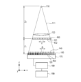
- FIG. 1 An example of the configuration of an X-ray imaging apparatus using Talbot interference is shown in FIG. A process until obtaining a phase image using an X-ray imaging apparatus will be specifically described.
- X-ray source X-rays 111 generated from the X-ray source 110 pass through the subject 120.
- X-ray 111 passes through the subject 120, a change in phase and absorption according to the composition, shape, and the like of the subject 120 occur.
- the X-ray either a continuous X-ray or a characteristic X-ray may be used.
- the wavelength is appropriately selected from about 0.1 to 5 mm.
- a wavelength selection filter or a grating for the radiation source may be provided as appropriate.
- phase grating When the X-ray 111 transmitted through the subject 120 passes through the phase grating 130, an interference intensity distribution 140 is formed by the Talbot effect.
- the phase grating 130 is arranged on the upstream side or the downstream side of the subject 120.
- the phase grating 130 includes a phase advance portion 131 and a phase delay portion 132 that are configured by periodically changing the thickness of the X-ray transmitting member.
- the phase progression unit 131 and the phase delay unit 132 may be formed so as to have a phase difference with respect to the transmitted X-ray.
- the configuration is such that the phase of the X-ray transmitted through the phase advancer 131 advances by ⁇ with respect to the phase of the X-ray transmitted through the phase delay unit 132.
- the amount of change in thickness is determined by the wavelength and member of the X-ray used.
- the phase grating 130 modulates the phase of the X-ray transmitted through the phase delay unit 132 by ⁇ or ⁇ / 2 with respect to the phase of the X-ray transmitted through the phase delay unit 132.
- the former may be referred to as a ⁇ phase grating and the latter as a ⁇ / 2 phase grating.
- the phase modulation amount may be periodic, and may be, for example, ⁇ / 3 modulated.
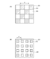
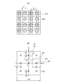
- the phase grating 130 may have a one-dimensional linear shape, or may be configured with a two-dimensional checkered pattern as shown in FIG. Moreover, you may be comprised by the screen door-like pattern as shown to FIG. 2 (B).
- d is a period
- 201 is a two-dimensional phase grating
- 210 is a phase progression unit
- 220 is a phase delay unit.
- phase advance part 210 or the phase delay part 220 is a square in FIG. 2 (A) and FIG. 2 (B)
- an outer edge may deform
- it can be used as a phase grating.
- phase grating 130 When the phase grating 130 has a one-dimensional period, only the phase gradient information of the subject 120 in the one-dimensional direction can be acquired. However, when the phase grating 130 has a two-dimensional period, it is advantageous in that phase gradient information in a two-dimensional direction can be acquired.
- the material constituting the phase grating 130 is preferably a substance that transmits X-rays.
- silicon or the like can be used.
- the interference intensity distribution formed after transmission through the phase grating 130 is the distance Z 0 between the X-ray source and the phase grating 130, the distance Z 1 from the absorption grating 150 satisfies the following formula (1). Appears most clearly.
- the “interference intensity distribution” is a periodic intensity distribution reflecting the grating period of the phase grating 130.
- ⁇ is the wavelength of the X-ray
- d is the grating period of the phase grating 130.
- N is a different value depending on the form of the phase grating, and is a real number that can be expressed as follows. Note that n is a natural number.
- One-dimensional array of ⁇ phase grating: N n / 4 ⁇ 1 / 8
- Two-dimensional checkered pattern ⁇ phase grating: N n / 4 ⁇ 1 / 8
- Two-dimensional checkered pattern ⁇ / 2 phase grating: N n / 2 ⁇ 1 / 4
- Absorption grid Since the period of the interference intensity distribution is generally smaller than the pixel size of the X-ray detector 170, the interference intensity distribution cannot be detected as it is. Therefore, by using the absorption grating 150, moire having a period larger than the pixel size of the X-ray detector 170 is generated, and the moire intensity distribution is detected by the X-ray detector 170.
- Absorption grating 150 is preferably provided apart from the phase grating 130 by the distance Z 1 position.
- the absorption grating 150 includes a transmission portion 151 and a light shielding portion 152 that are periodically arranged, and is arranged so as to shield a part of a bright portion of the interference intensity distribution 140 formed by the phase grating 130.
- the transmission part 151 should just be comprised so that a part of X-rays can permeate
- the material constituting the absorption grating 150 may be any material that absorbs X-rays well, and for example, gold can be used.
- the period of the absorption grating 150 is the same as or slightly different from the interference intensity distribution.
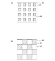
- the transmission portions 151 may be arranged one-dimensionally or two-dimensionally.
- the transmission part 351 and the light shielding part 352 are two-dimensionally arranged as shown in FIG.
- a screen door-shaped absorption grating 300 is used.
- the checkered ⁇ / 2 phase grating shown in FIG. 2A is used, a checkered pattern in which the transmission part 351 and the light shielding part 352 are two-dimensionally arranged as shown in FIG. 3B.
- the absorption grating 300 is used.
- phase grating and the absorption grating are possible.
- the X-ray detector 170 is an element that can detect information on the X-ray interference intensity distribution.
- an FPD Full Panel Detector
- FPD Full Panel Detector
- the arithmetic device 180 has, for example, a CPU (Central Processing Unit).
- the interference intensity distribution When the interference intensity distribution is formed, a large number of diffracted lights interfere and interfere with each other, and therefore include a fundamental frequency (hereinafter referred to as a carrier frequency) and a number of harmonic components thereof.
- a carrier frequency a fundamental frequency
- the moire since the moire has a shape in which the carrier frequency component of the interference intensity distribution is spatially enlarged, the moire can be expressed by equation (2) when a one-dimensional phase grating whose score line is orthogonal to the x axis is used. it can.
- Equation (2) indicates that moire is represented by the sum of the first term of the background and the second term having periodicity.
- a (x, y) represents the background
- b (x, y) represents the amplitude of the carrier frequency component.
- F 0 represents the carrier frequency of the interference fringes
- ⁇ (x, y) represents the phase of the carrier frequency component.
- the carrier frequency component is generated by the interference between the 0th-order diffracted light and the + 1st-order diffracted light, and the interference between the 0th-order diffracted light and the ⁇ 1st-order diffracted light. Further, when a checkered ⁇ phase grating is used as the phase grating 130, a carrier frequency component is generated due to interference between the + 1st order diffracted light and the ⁇ 1st order diffracted light.
- these interferences are shearing interference in which a shear amount s is Nd in the case of a ⁇ / 2 phase grating and a shear amount s is 2Nd in the case of a ⁇ phase grating.
- phase image of the subject 120 at the position of the phase grating 130 is W (x, y)
- the phase ⁇ (x, y) and the phase image W (x, y) have the following relationship.
- phase ⁇ (x, y) is information obtained by differentiating the phase image W (x, y) of the subject 120. Therefore, the phase image W (x, y) of the subject 120 can be obtained by integrating ⁇ (x, y).
- FIG. 4 is a spectrum pattern of the interference intensity distribution when a one-dimensional grating is used. Usually, three peaks occur as shown in FIG. Central peak is the peak derived from predominantly A (f x, f y) to. On the other hand, the both sides of each peak C (f x, f y) and C * (f x, f y ) is the carrier frequency peak derived from, these peaks occur at the position of ⁇ f 0.
- the peaks derived from f y ) or C * (f x , f y ) are separated.
- phase ⁇ (x, y) that is, differential phase information is obtained from complex number information obtained by inverse Fourier transform.
- 5A shows a checkered ⁇ / 2 phase grating (FIG. 2A) and a screened absorption grating (FIG. 3A), or a checkered absorption grating (FIG. 3A).
- B)) is an example of the intensity distribution of moiré
- 510 is a bright portion of moiré
- 520 is a dark portion of moiré.
- a checkered ⁇ phase grating (FIG. 2A) and a checkered absorption grating (FIG. 3B) are used, a moire intensity distribution is generated in such an oblique direction.
- FIG. 5B shows the intensity distribution of moiré when a checkered ⁇ phase grating (FIG. 2A) and a screened absorption grating (FIG. 3A) are used.
- Moire light part 540 is a moire dark part. In this case, a moire intensity distribution is generated in the vertical and horizontal directions.
- moiré intensity distribution as described above can also be obtained using a screen door-shaped phase grating (FIG. 2B).
- FIGS. 5C and 5D are spatial frequencies obtained by performing FFT (Fast Fourier Transform) processing, which is a kind of Fourier transform, on the moire intensity distribution shown in FIGS. 5A and 5B, respectively. It is a spectrum.
- the maximum spatial frequency that can be calculated by FFT is 1 / (2P), where P is the pixel period of the X-ray detector 170.
- Each of the two peaks 570 and 571 and 580 and 581 at orthogonal positions is cut out in the same manner as in the above-described one-dimensional case, and moved to the origin to perform inverse Fourier transform.
- a broken line indicates a cutout region. Then, differential phase information in two orthogonal directions is obtained from the complex number information obtained by the inverse Fourier transform.
- the differential phase information is in the direction of ⁇ 45 degrees
- the differential phase information is in the X and Y directions.
- the differential phase information obtained in this way is often convoluted (wrapped) between 2 ⁇ regions. That is, if the true phase at any point on a screen is ⁇ (x, y) and the convolved phase is ⁇ wrap (x, y)
- n is an integer
- ⁇ wrap (x, y) is determined so as to be in a region having a width of 2 ⁇ , for example, between 0 to 2 ⁇ and ⁇ to + ⁇ .
- phase connection (unwrapping) of ⁇ (x, y) wrap is performed to restore the original ⁇ (x, y).
- phase image W (x, y) of the subject can be obtained by integrating ⁇ (x, y) restored by the equation (8).
- the integration direction can only be a direction orthogonal to the grid engraving direction. Therefore, in order to correctly measure the phase image W (x, y), the phase image is set so that one side parallel to the engraving direction of the X-ray detector 170 is irradiated with X-rays that do not pass through the subject 120. It is necessary to provide a portion where W (x, y) is known.
- phase image W (x, y) can be correctly measured even when the entire surface of the X-ray detector 170 is irradiated with X-rays passing through the subject 120.
- a peak separation step of cutting out a spectrum corresponding to the carrier frequency (a spectrum carrying the phase information) is performed (S631).
- a peak separation step of cutting out a spectrum corresponding to the carrier frequency (a spectrum carrying the phase information) is performed (S631).
- phase ⁇ (x, y) that is a differential phase image is obtained from the complex number information obtained in S632 (S633).
- S631, S632, and S633 may be referred to as a phase recovery step (S630).
- ⁇ (x, y) is wrapped, unwrap processing is performed to obtain true ⁇ (x, y) (S640). This is sometimes referred to as a phase connection process. If ⁇ (x, y) is not wrapped, this S640 can be omitted.
- ⁇ (x, y) is differential phase information (differential phase image).
- phase image W (x, y) is acquired by integrating ⁇ (x, y) (S650).
- an X-ray imaging apparatus and an X-ray imaging method capable of acquiring a phase image of a subject from at least one imaging. It is also possible to provide a program that causes a computer to execute the above steps.
- FIG. 7B shows the spatial frequency spectrum described in the present embodiment.
- the basic period of the two-dimensional moire generated in the interference intensity distribution and the absorption grating is set to the pixel period of the X-ray detector.
- the moiré direction is adjusted to be inclined 45 degrees with respect to the pixel array.
- FIG. 7A is a diagram showing the moire intensity distribution on the X-ray detector in such a state.
- 710 is a light receiving surface of the X-ray detector
- 720 is a bright portion of moire
- d is a moire cycle
- P is a pixel cycle of the X-ray detector.
- a checkered ⁇ / 2 phase grating (FIG. 2A) and a checkered absorption grating (FIG. 3B) are used.
- other phase gratings and absorption gratings may be used.
- FIG. 7B is a spatial frequency spectrum obtained by performing FFT processing on the moiré intensity distribution of FIG. 7A. If the number of pixel arrays is n both vertically and horizontally, the spectrum space obtained by FFT also becomes n ⁇ n discrete data. The maximum frequency that can be expressed is 1 / (2P) where P is the pixel period of the X-ray detector 170.
- a carrier peak 711 that is a peak corresponding to the carrier frequency of the moiré intensity distribution is generated at the position.
- the phase image of the subject can be restored.
- the spatial resolution can be increased by cutting out the spectral region as wide as possible.
- an unnecessary peak 721 that is the peak of the high frequency component and the DC component exists at the position of the sum or difference of the peak coordinates of the carrier frequency component.
- the cutout spectrum region is a cutout region 731 inside the intermediate line between the carrier frequency peak and the unnecessary peak 721.
- the spatial frequency of the phase image that can be restored in the present embodiment is 1 ⁇ 2 of the size of the cutout region 731. Therefore, as can be seen from FIG. 7B, the maximum frequency in the pixel array direction is 1 / (4P), and the maximum frequency in the 45 degree direction is
- the cutout region in FIG. 7B is wider than the cutout region in FIG. Therefore, according to the present embodiment, it is possible to improve the spatial resolution as compared with the above embodiment.
- FIG. 3 A third embodiment of the X-ray imaging apparatus according to the present invention will be described with reference to FIG. This embodiment is also devised to improve the spatial resolution compared to the spatial frequency spectrum of FIG. 5D described in the first embodiment.
- FIG. 8B shows the spatial frequency spectrum described in the present embodiment.
- the basic period of the two-dimensional moire generated in the interference intensity distribution and the absorption grating is set to three times the pixel period of the X-ray detector, and the direction of moire coincides with the pixel array.
- FIG. 8 (A) is a diagram showing the moire intensity distribution on the X-ray detector in such a state.
- 810 is a light receiving surface of the X-ray detector
- 820 is a bright portion of moire
- d is a moire cycle
- P is a pixel cycle of the X-ray detector.
- a checkered ⁇ phase grating (FIG. 2A) and a screen door absorption grating (FIG. 3A) are used.
- other phase gratings and absorption gratings may be used.
- FIG. 8A is a spatial frequency spectrum obtained by performing FFT processing on the moire intensity distribution shown in FIG. 8B.
- the absolute value of the carrier frequency is 1 / (3P). Therefore, in spectral space
- a carrier peak 811 that is a peak corresponding to the carrier frequency in the intensity distribution of the moire occurs.
- the process described in the first embodiment is performed. The phase image of the subject can be restored.
- the cutout spectral region is a cutout region 831 inside the intermediate line between the carrier frequency peak and the unnecessary peak 821.
- the spatial frequency of the phase image that can be restored in this embodiment is 1 ⁇ 2 of the size of the cutout region 831. Therefore, from FIG. 8B, the maximum frequency in the pixel array direction is 1 / (6P), and the maximum frequency in the 45 degree direction is
- the present embodiment is superior to the second embodiment in the spatial resolution in the direction of 45 degrees with respect to the pixel array.
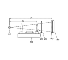
- the X-ray imaging apparatus according to the present embodiment is an X-ray imaging apparatus according to any one of Embodiments 1 to 3 equipped with an inspection object moving device 900.
- the subject moving device 900 can move the subject 920 in the X-ray optical axis direction.
- the imaging magnification of the subject 920 in the X-ray detector is L1 / L2 if the distance between the X-ray source 910 and the absorption grating 940 is L1, and the distance between the X-ray source 910 and the absorption grating 940 is L2.
- L2 becomes large, so that imaging can be performed at a low magnification.
- L2 becomes small, so that imaging can be performed at a high magnification.
Abstract
Description
タルボ干渉を用いたX線撮像装置の構成の一例を図1に示す。X線撮像装置を用いて位相像を得るまでの工程を具体的に説明する。 (Embodiment 1)
An example of the configuration of an X-ray imaging apparatus using Talbot interference is shown in FIG. A process until obtaining a phase image using an X-ray imaging apparatus will be specifically described.
X線源110から発生したX線111が被検体120を透過する。X線111は、被検体120を透過する際に、被検体120の組成や形状等に応じた位相の変化及び吸収を生じる。 (X-ray source)
前記被検体120を透過したX線111は、位相格子130を透過すると、タルボ効果により干渉強度分布140を形成する。 (Phase grating)
When the

1次元配列のπ位相格子:N=n/4-1/8
1次元配列のπ/2位相格子:N=n-1/2
2次元配列の市松模様π位相格子:N=n/4-1/8
2次元で市松模様π/2位相格子:N=n/2-1/4
One-dimensional array of π phase grating: N = n / 4−1 / 8
One-dimensional array of π / 2 phase gratings: N = n−1 / 2
Two-dimensional checkered pattern π phase grating: N = n / 4−1 / 8
Two-dimensional checkered pattern π / 2 phase grating: N = n / 2−1 / 4
干渉強度分布の周期は、一般にX線検出器170の画素サイズより小さいため、そのままでは干渉強度分布を検出できない。そこで、吸収格子150を用いることによって、X線検出器170の画素サイズより大きな周期のモアレを発生させ、モアレの強度分布をX線検出器170で検出する。吸収格子150は、位相格子130から距離Z1だけ離れた位置に設けることが好ましい。 (Absorption grid)
Since the period of the interference intensity distribution is generally smaller than the pixel size of the
前記吸収格子140を透過したX線の干渉強度分布の情報はモアレの強度分布として、X線検出器170によって検出される。X線検出器170は、X線の干渉強度分布の情報を検出することのできる素子である。例えば、デジタル信号への変換が可能な、FPD(Flat Panel Detector)等を用いることができる。 (Detector)
Information on the interference intensity distribution of the X-rays transmitted through the absorption grating 140 is detected by the
前記X線検出器170で検出されたモアレの強度分布の情報は、後述の解析方法による演算装置180によって解析され、微分位相像や位相像を画像化する。取得された微分位相像や位相像は、表示部190に表示するための出力画像である。演算装置180は例えばCPU(Central Processing Unit)を有する。 (Arithmetic unit)
Information on the intensity distribution of moire detected by the
干渉強度分布が形成される際には多数の回折光が重なって干渉するため、基本周波数(以後キャリア周波数と呼ぶ)と数多くのその高調波成分を含んでいる。しかし、モアレは干渉強度分布のキャリア周波数成分を空間的に拡大した形状を持つので、刻線がx軸に直交する1次元の位相格子を使用した場合にモアレは(2)式で表すことができる。 (analysis method)
When the interference intensity distribution is formed, a large number of diffracted lights interfere and interfere with each other, and therefore include a fundamental frequency (hereinafter referred to as a carrier frequency) and a number of harmonic components thereof. However, since the moire has a shape in which the carrier frequency component of the interference intensity distribution is spatially enlarged, the moire can be expressed by equation (2) when a one-dimensional phase grating whose score line is orthogonal to the x axis is used. it can.


上記を踏まえて、前記演算装置180において実行する処理フローの一例を図6に示す。 (Processing steps to be performed by the arithmetic unit)
Based on the above, an example of a processing flow executed in the
本発明によるX線撮像装置の第2の実施形態を図7を用いて説明する。本実施形態では、実施形態1で説明した図5(C)の空間周波数スペクトルよりも空間分解能を向上させる工夫がなされている。 (Embodiment 2)
A second embodiment of the X-ray imaging apparatus according to the present invention will be described with reference to FIG. In the present embodiment, a device for improving the spatial resolution as compared with the spatial frequency spectrum of FIG. 5C described in the first embodiment is devised.

本発明によるX線撮像装置の第3の実施形態を図8を用いて説明する。本実施形態も、実施形態1で説明した図5(D)の空間周波数スペクトルよりも空間分解能を向上させる工夫がなされている。 (Embodiment 3)
A third embodiment of the X-ray imaging apparatus according to the present invention will be described with reference to FIG. This embodiment is also devised to improve the spatial resolution compared to the spatial frequency spectrum of FIG. 5D described in the first embodiment.

本発明によるX線撮像装置の第3の実施形態を図9を用いて説明する。本実施形態のX線撮像装置は、実施形態1から3記載のX線撮像装置に検査物移動装置900を装備したものである。検査物移動装置900によって被検体920をX線の光軸方向に移動させることができる。 (Embodiment 4)
A third embodiment of the X-ray imaging apparatus according to the present invention will be described with reference to FIG. The X-ray imaging apparatus according to the present embodiment is an X-ray imaging apparatus according to any one of
111 X線
120 被検体
130 位相格子
150 吸収格子
151 透過部
152 遮光部
170 X線検出器
180 演算装置 DESCRIPTION OF
Claims (13)
- X線源と、
前記X線源からのX線を透過させることにより、タルボ効果による干渉強度分布を形成する位相格子と、
前記位相格子により形成された干渉強度分布の一部を遮光することによりモアレを生じさせる吸収格子と、
前記吸収格子により生じたモアレの強度分布を検出する検出器と、
前記検出器により検出されたモアレの強度分布から被検体の情報を画像化し、出力する演算装置を有し、
前記演算装置は、
前記検出器で取得したモアレの強度分布をフーリエ変換することにより、空間周波数スペクトルを取得するフーリエ変換工程と、
前記フーリエ変換工程により得られた空間周波数スペクトルから、キャリア周波数に対応したスペクトルを分離し、逆フーリエ変換を用いて微分位相像を取得する位相回復工程と、を実行するように構成されていることを特徴とするX線撮像装置。 An X-ray source;
A phase grating that forms an interference intensity distribution due to the Talbot effect by transmitting X-rays from the X-ray source;
An absorption grating that causes moiré by shielding part of the interference intensity distribution formed by the phase grating; and
A detector for detecting the intensity distribution of moire produced by the absorption grating;
From the intensity distribution of the moire detected by the detector, the information of the subject is imaged, and an arithmetic unit that outputs the information,
The arithmetic unit is:
Fourier transform step of acquiring a spatial frequency spectrum by Fourier transforming the intensity distribution of moire acquired by the detector;
A phase recovery step of separating a spectrum corresponding to the carrier frequency from the spatial frequency spectrum obtained by the Fourier transform step and acquiring a differential phase image using an inverse Fourier transform; An X-ray imaging apparatus characterized by the above. - 前記演算装置は、前記位相回復工程により得られた微分位相像を積分することにより位相像を取得する工程を実行するように構成されている請求項1に記載のX線撮像装置。 The X-ray imaging apparatus according to claim 1, wherein the arithmetic unit is configured to execute a step of acquiring a phase image by integrating the differential phase image obtained by the phase recovery step.
- 前記演算装置は、前記位相回復工程により得られた微分位相像に対してアンラップ処理を行なう位相接続工程を実行するように構成されている請求項1に記載のX線撮像装置。 The X-ray imaging apparatus according to claim 1, wherein the arithmetic unit is configured to execute a phase connection step of performing an unwrap process on the differential phase image obtained by the phase recovery step.
- 前記位相格子は、位相進行部と位相遅延部とが2次元的に周期的に配されている請求項1に記載のX線撮像装置。 The X-ray imaging apparatus according to claim 1, wherein the phase grating includes a phase progression unit and a phase delay unit that are periodically and two-dimensionally arranged.
- 前記位相格子は、前記位相進行部と前記位相遅延部とが市松状に配されている請求項4に記載のX線撮像装置。 The X-ray imaging apparatus according to claim 4, wherein the phase progression unit and the phase delay unit are arranged in a checkered pattern in the phase grating.
- 前記位相格子は、前記位相進行部を透過したX線と、前記位相遅延部を透過したX線との位相差がπ/2またはπとなるように構成されている請求項4に記載のX線撮像装置。 5. The X according to claim 4, wherein the phase grating is configured such that a phase difference between the X-ray transmitted through the phase advancing unit and the X-ray transmitted through the phase delay unit is π / 2 or π. Line imaging device.
- 前記フーリエ変換工程で得られたスペクトル空間上において、前記検出器の画素周期をPとしたときに、

- 前記吸収格子は、前記モアレの周期が

前記演算装置は、前記キャリア周波数に対応したスペクトルを分離するために、検出器で得られたモアレ画像の周波数空間から1辺が

In order to separate the spectrum corresponding to the carrier frequency, the arithmetic unit has one side from the frequency space of the moire image obtained by the detector.
- 前記フーリエ変換工程で得られたスペクトル空間上において、前記検出器の画素周期をPとしたときに、

- 前記吸収格子は、前記モアレの周期が3Pでモアレの方位が検出器の画素配列に一致するように配置され、
前記演算装置は、前記キャリア周波数に対応したスペクトルを分離するために、検出器で得られたモアレ画像の周波数空間から1辺が1/(3P)で、画素配列方向に対し正立した2つの正方形領域を切り出す工程を実行する請求項9に記載のX線撮像装置。 The absorption grating is arranged such that the period of the moire is 3P and the orientation of the moire coincides with the pixel arrangement of the detector.
In order to separate the spectrum corresponding to the carrier frequency, the arithmetic unit has two 1 / (3P) sides upright from the frequency space of the moiré image obtained by the detector and upright with respect to the pixel arrangement direction. The X-ray imaging apparatus according to claim 9, wherein a step of cutting out a square area is executed. - 前記被検体をX線の光軸方向に移動させることが可能な検査物移動装置を有する請求項1に記載のX線撮像装置。 The X-ray imaging apparatus according to claim 1, further comprising an inspection object moving apparatus capable of moving the subject in the X-ray optical axis direction.
- X線撮像装置において用いるX線撮像方法であって、
X線を透過させることにより、タルボ効果による干渉強度分布を形成する工程と、
前記干渉強度分布の一部を遮光することによりモアレを生じさせる工程と、
前記モアレの強度分布を検出する工程と、
前記モアレの強度分布をフーリエ変換することにより、空間周波数スペクトルを取得する工程と、
前記空間周波数スペクトルから、キャリア周波数に対応したスペクトルを分離し、逆フーリエ変換を用いて微分位相像を取得する工程と、
前記微分位相像を積分することにより、位相像を得る工程とを有することを特徴とするX線撮像方法。 An X-ray imaging method used in an X-ray imaging apparatus,
Forming an interference intensity distribution by the Talbot effect by transmitting X-rays;
Producing a moire by shielding a part of the interference intensity distribution;
Detecting the intensity distribution of the moire;
Obtaining a spatial frequency spectrum by Fourier-transforming the intensity distribution of the moire;
Separating a spectrum corresponding to a carrier frequency from the spatial frequency spectrum, and obtaining a differential phase image using inverse Fourier transform;
And a step of obtaining a phase image by integrating the differential phase image. - コンピュータに、
X線を透過させることにより、タルボ効果による干渉強度分布を形成する工程と、
前記干渉強度分布の一部を遮光することによりモアレを生じさせる工程と、
前記モアレの強度分布を検出する工程と、
前記モアレの強度分布をフーリエ変換することにより、空間周波数スペクトルを取得する工程と、
前記空間周波数スペクトルから、キャリア周波数に対応したスペクトルを分離し、逆フーリエ変換を用いて微分位相像を得る工程と、
前記微分位相像を積分することにより、位相像を得る工程と、
を実行させることを特徴とするプログラム。 On the computer,
Forming an interference intensity distribution by the Talbot effect by transmitting X-rays;
Producing a moire by shielding a part of the interference intensity distribution;
Detecting the intensity distribution of the moire;
Obtaining a spatial frequency spectrum by Fourier-transforming the intensity distribution of the moire;
Separating a spectrum corresponding to a carrier frequency from the spatial frequency spectrum, and obtaining a differential phase image using inverse Fourier transform;
Integrating the differential phase image to obtain a phase image;
A program characterized by having executed.
Priority Applications (9)
| Application Number | Priority Date | Filing Date | Title |
|---|---|---|---|
| DE112009002606.0T DE112009002606B4 (en) | 2008-10-29 | 2009-10-27 | X-ray imaging apparatus and X-ray imaging method |
| EP09823593.0A EP2343537B1 (en) | 2008-10-29 | 2009-10-27 | X-ray imaging device and x-ray imaging method |
| JP2010535804A JP5174180B2 (en) | 2008-10-29 | 2009-10-27 | X-ray imaging apparatus and X-ray imaging method |
| CN2009801428377A CN102197303A (en) | 2008-10-29 | 2009-10-27 | X-ray imaging device and X-ray imaging method |
| KR1020117011759A KR101258927B1 (en) | 2008-10-29 | 2009-10-27 | X-ray imaging device and x-ray imaging method |
| US12/842,937 US8009797B2 (en) | 2008-10-29 | 2010-07-23 | X-ray imaging apparatus, X-ray imaging method, and X-ray imaging program |
| US13/085,199 US8559594B2 (en) | 2008-10-29 | 2011-04-12 | Imaging apparatus and imaging method |
| US13/190,770 US8340243B2 (en) | 2008-10-29 | 2011-07-26 | X-ray imaging apparatus, X-ray imaging method, and X-ray imaging program |
| US13/682,445 US8537966B2 (en) | 2008-10-29 | 2012-11-20 | X-ray imaging apparatus, X-ray imaging method, and X-ray imaging program |
Applications Claiming Priority (2)
| Application Number | Priority Date | Filing Date | Title |
|---|---|---|---|
| JP2008-278425 | 2008-10-29 | ||
| JP2008278425 | 2008-10-29 |
Related Child Applications (1)
| Application Number | Title | Priority Date | Filing Date |
|---|---|---|---|
| US12/842,937 Continuation US8009797B2 (en) | 2008-10-29 | 2010-07-23 | X-ray imaging apparatus, X-ray imaging method, and X-ray imaging program |
Publications (1)
| Publication Number | Publication Date |
|---|---|
| WO2010050483A1 true WO2010050483A1 (en) | 2010-05-06 |
Family
ID=41664696
Family Applications (2)
| Application Number | Title | Priority Date | Filing Date |
|---|---|---|---|
| PCT/JP2009/068434 WO2010050483A1 (en) | 2008-10-29 | 2009-10-27 | X-ray imaging device and x-ray imaging method |
| PCT/JP2009/068863 WO2010050611A1 (en) | 2008-10-29 | 2009-10-28 | Analysis method, radiation imaging apparatus using analysis method, and analysis program for executing analysis method |
Family Applications After (1)
| Application Number | Title | Priority Date | Filing Date |
|---|---|---|---|
| PCT/JP2009/068863 WO2010050611A1 (en) | 2008-10-29 | 2009-10-28 | Analysis method, radiation imaging apparatus using analysis method, and analysis program for executing analysis method |
Country Status (8)
| Country | Link |
|---|---|
| US (5) | US8520799B2 (en) |
| EP (2) | EP2343537B1 (en) |
| JP (4) | JP5174180B2 (en) |
| KR (1) | KR101258927B1 (en) |
| CN (3) | CN103876761B (en) |
| DE (1) | DE112009002606B4 (en) |
| RU (1) | RU2519663C2 (en) |
| WO (2) | WO2010050483A1 (en) |
Cited By (34)
| Publication number | Priority date | Publication date | Assignee | Title |
|---|---|---|---|---|
| JP2012005820A (en) * | 2010-05-27 | 2012-01-12 | Canon Inc | X-ray imaging apparatus |
| WO2012023356A1 (en) * | 2010-08-19 | 2012-02-23 | 富士フイルム株式会社 | Radiography system and image-processing method therefor |
| WO2012038857A1 (en) * | 2010-09-20 | 2012-03-29 | Koninklijke Philips Electronics N.V. | Phase gradient unwrapping in differential phase contrast imaging |
| WO2012056724A1 (en) * | 2010-10-29 | 2012-05-03 | 富士フイルム株式会社 | Phase contrast radiation imaging device |
| JP2012103237A (en) * | 2010-10-14 | 2012-05-31 | Canon Inc | Imaging apparatus |
| JP2012108098A (en) * | 2010-10-20 | 2012-06-07 | Canon Inc | Imaging device using talbot interference and adjustment method of imaging device |
| JP2012143553A (en) * | 2010-12-24 | 2012-08-02 | Fujifilm Corp | Radiographic apparatus and radiation image detector |
| WO2012128335A1 (en) * | 2011-03-23 | 2012-09-27 | コニカミノルタエムジー株式会社 | Medical image display system |
| WO2012133553A1 (en) * | 2011-03-29 | 2012-10-04 | 富士フイルム株式会社 | Radiography system and radiography method |
| JP2012187341A (en) * | 2011-03-14 | 2012-10-04 | Canon Inc | X-ray imaging apparatus |
| US20120275564A1 (en) * | 2011-04-26 | 2012-11-01 | Fujifilm Corporation | Radiation imaging apparatus |
| WO2012147749A1 (en) * | 2011-04-25 | 2012-11-01 | 富士フイルム株式会社 | Radiography system and radiography method |
| JP2012228371A (en) * | 2011-04-26 | 2012-11-22 | Canon Inc | Imaging apparatus |
| WO2012169427A1 (en) * | 2011-06-10 | 2012-12-13 | 富士フイルム株式会社 | Radiography system |
| WO2012169426A1 (en) * | 2011-06-08 | 2012-12-13 | 富士フイルム株式会社 | Radiography system |
| JP2013002845A (en) * | 2011-06-13 | 2013-01-07 | Canon Inc | Imaging apparatus, interference fringe analysis program and interference fringe analysis method |
| WO2013027519A1 (en) * | 2011-08-22 | 2013-02-28 | 富士フイルム株式会社 | Radiography device and unwrapping method |
| JP2013050441A (en) * | 2011-08-03 | 2013-03-14 | Canon Inc | Wavefront measuring apparatus, wavefront measuring method, program and x-ray imaging apparatus |
| WO2013038881A1 (en) * | 2011-09-12 | 2013-03-21 | 富士フイルム株式会社 | Radiography device and image processing method |
| WO2013047011A1 (en) * | 2011-09-30 | 2013-04-04 | 富士フイルム株式会社 | Radiographic image detector, method of manufacturing same, and radiography system employing radiographic image detector |
| EP2578156A1 (en) | 2011-10-04 | 2013-04-10 | Fujifilm Corporation | Radiation imaging apparatus and image processing method |
| JP2013102951A (en) * | 2011-11-14 | 2013-05-30 | Canon Inc | Imaging apparatus and image processing method |
| JP2013536723A (en) * | 2010-09-03 | 2013-09-26 | コーニンクレッカ フィリップス エヌ ヴェ | Normalized phase recovery in differential phase contrast imaging |
| JP2013540031A (en) * | 2010-10-19 | 2013-10-31 | コーニンクレッカ フィリップス エヌ ヴェ | Differential phase contrast imaging |
| JP2014108358A (en) * | 2012-11-30 | 2014-06-12 | Canon Inc | Combining differential images by inverse riesz transformation |
| WO2014092206A1 (en) | 2012-12-13 | 2014-06-19 | Canon Kabushiki Kaisha | Object information obtaining apparatus, program, and imaging system |
| US8767916B2 (en) | 2011-04-20 | 2014-07-01 | Fujifilm Corporation | Radiation imaging apparatus and image processing method |
| JP2014121614A (en) * | 2012-12-24 | 2014-07-03 | Canon Inc | Phase image reconstruction method, computer readable storage media, and apparatus |
| EP2827339A1 (en) | 2013-07-16 | 2015-01-21 | Canon Kabushiki Kaisha | Source grating, interferometer, and object information acquisition system |
| EP2924972A1 (en) | 2014-03-27 | 2015-09-30 | Canon Kabushiki Kaisha | Image processing apparatus and imaging system |
| US9855018B2 (en) | 2013-04-08 | 2018-01-02 | Konica Minolta, Inc. | Diagnostic medical image system and method of introducing Talbot capturing device to diagnostic medical image system used for general capturing |
| EP3530189A1 (en) | 2018-02-23 | 2019-08-28 | Konica Minolta, Inc. | X-ray imaging system |
| WO2019240165A1 (en) | 2018-06-12 | 2019-12-19 | 国立大学法人筑波大学 | Phase image capturing method and phase image capturing device using same |
| US10725186B2 (en) | 2016-02-23 | 2020-07-28 | Canon Kabushiki Kaisha | Scintillator plate, radiation detector, and radiation measurement system |
Families Citing this family (65)
| Publication number | Priority date | Publication date | Assignee | Title |
|---|---|---|---|---|
| JP5339975B2 (en) * | 2008-03-13 | 2013-11-13 | キヤノン株式会社 | Phase grating used for X-ray phase imaging, X-ray phase contrast image imaging apparatus using the phase grating, X-ray computed tomography system |
| JP5174180B2 (en) * | 2008-10-29 | 2013-04-03 | キヤノン株式会社 | X-ray imaging apparatus and X-ray imaging method |
| CN101943668B (en) * | 2009-07-07 | 2013-03-27 | 清华大学 | X-ray dark-field imaging system and method |
| JP5586899B2 (en) * | 2009-08-26 | 2014-09-10 | キヤノン株式会社 | X-ray phase grating and manufacturing method thereof |
| US8532252B2 (en) * | 2010-01-27 | 2013-09-10 | Canon Kabushiki Kaisha | X-ray shield grating, manufacturing method therefor, and X-ray imaging apparatus |
| JP5631013B2 (en) * | 2010-01-28 | 2014-11-26 | キヤノン株式会社 | X-ray imaging device |
| JP5725870B2 (en) * | 2010-02-22 | 2015-05-27 | キヤノン株式会社 | X-ray imaging apparatus and X-ray imaging method |
| JP5935693B2 (en) * | 2010-09-29 | 2016-06-15 | コニカミノルタ株式会社 | Medical image display method |
| JP6228457B2 (en) * | 2010-10-19 | 2017-11-08 | コーニンクレッカ フィリップス エヌ ヴェKoninklijke Philips N.V. | Differential phase contrast imaging |
| JP2012095865A (en) * | 2010-11-02 | 2012-05-24 | Fujifilm Corp | Radiographic apparatus and radiographic system |
| JP2012200567A (en) * | 2011-03-28 | 2012-10-22 | Fujifilm Corp | Radiographic system and radiographic method |
| JP2013024731A (en) | 2011-07-21 | 2013-02-04 | Canon Inc | Radiation detection instrument |
| US20130108015A1 (en) * | 2011-10-28 | 2013-05-02 | Csem Centre Suisse D'electronique Et De Microtechnique S.A - Recherche Et Developpement | X-ray interferometer |
| US20150117599A1 (en) * | 2013-10-31 | 2015-04-30 | Sigray, Inc. | X-ray interferometric imaging system |
| US9597050B2 (en) * | 2012-01-24 | 2017-03-21 | Koninklijke Philips N.V. | Multi-directional phase contrast X-ray imaging |
| WO2013151342A1 (en) * | 2012-04-05 | 2013-10-10 | 단국대학교 산학협력단 | Radiation phase difference imaging apparatus |
| JP2014006247A (en) * | 2012-05-28 | 2014-01-16 | Canon Inc | Specimen information acquisition device, specimen information acquisition method, and program |
| JP6079204B2 (en) * | 2012-12-18 | 2017-02-15 | コニカミノルタ株式会社 | Medical imaging system |
| US10096098B2 (en) * | 2013-12-30 | 2018-10-09 | Carestream Health, Inc. | Phase retrieval from differential phase contrast imaging |
| US9357975B2 (en) | 2013-12-30 | 2016-06-07 | Carestream Health, Inc. | Large FOV phase contrast imaging based on detuned configuration including acquisition and reconstruction techniques |
| US10578563B2 (en) | 2012-12-21 | 2020-03-03 | Carestream Health, Inc. | Phase contrast imaging computed tomography scanner |
| US9364191B2 (en) * | 2013-02-11 | 2016-06-14 | University Of Rochester | Method and apparatus of spectral differential phase-contrast cone-beam CT and hybrid cone-beam CT |
| KR20140111818A (en) | 2013-03-12 | 2014-09-22 | 삼성전자주식회사 | X-ray imaging apparatus and control method for the same |
| JP2014171799A (en) * | 2013-03-12 | 2014-09-22 | Canon Inc | X-ray imaging apparatus, and x-ray imaging system |
| JP2014178130A (en) * | 2013-03-13 | 2014-09-25 | Canon Inc | X-ray imaging device and x-ray imaging system |
| US10295485B2 (en) | 2013-12-05 | 2019-05-21 | Sigray, Inc. | X-ray transmission spectrometer system |
| DE102013221818A1 (en) * | 2013-10-28 | 2015-04-30 | Siemens Aktiengesellschaft | Imaging system and method for imaging |
| KR101668219B1 (en) * | 2013-10-31 | 2016-10-20 | 도호쿠 다이가쿠 | Non-destructive inspection device |
| USRE48612E1 (en) | 2013-10-31 | 2021-06-29 | Sigray, Inc. | X-ray interferometric imaging system |
| JP6396472B2 (en) | 2013-12-17 | 2018-09-26 | コーニンクレッカ フィリップス エヌ ヴェKoninklijke Philips N.V. | Phase recovery for scanning differential phase contrast systems |
| AU2013273822A1 (en) | 2013-12-23 | 2015-07-09 | Canon Kabushiki Kaisha | Modulation guided phase unwrapping |
| EP3105763B1 (en) | 2014-02-14 | 2019-09-11 | Canon Kabushiki Kaisha | X-ray talbot interferometer and x-ray talbot interferometer system |
| JP2015166676A (en) * | 2014-03-03 | 2015-09-24 | キヤノン株式会社 | X-ray imaging system |
| JP6362914B2 (en) * | 2014-04-30 | 2018-07-25 | キヤノンメディカルシステムズ株式会社 | X-ray diagnostic apparatus and image processing apparatus |
| US10401309B2 (en) | 2014-05-15 | 2019-09-03 | Sigray, Inc. | X-ray techniques using structured illumination |
| CN104111120B (en) * | 2014-07-25 | 2017-05-31 | 中国科学院上海光学精密机械研究所 | Phase extraction method based on bright strange shearing interferometer |
| JP2016032573A (en) * | 2014-07-31 | 2016-03-10 | キヤノン株式会社 | Talbot interferometer, talbot interference system and fringe scanning method |
| RU2708816C2 (en) * | 2014-11-24 | 2019-12-11 | Конинклейке Филипс Н.В. | Detector and visualization system for x-ray phase-contrast imaging of tomosynthesis |
| US10117629B2 (en) | 2014-12-03 | 2018-11-06 | Board Of Supervisors Of Louisiana State University And Agricultural And Mechanical College | High energy grating techniques |
| KR101636438B1 (en) * | 2015-03-18 | 2016-07-05 | 제이피아이헬스케어 주식회사 | Phase-contrast X-ray imaging(PCXI) method using a single grid and the apparatus thereof |
| JP6604772B2 (en) * | 2015-08-05 | 2019-11-13 | キヤノン株式会社 | X-ray Talbot interferometer |
| JP6608246B2 (en) * | 2015-10-30 | 2019-11-20 | キヤノン株式会社 | X-ray diffraction grating and X-ray Talbot interferometer |
| DE102015226571B4 (en) * | 2015-12-22 | 2019-10-24 | Carl Zeiss Smt Gmbh | Device and method for wavefront analysis |
| JP6613988B2 (en) * | 2016-03-30 | 2019-12-04 | コニカミノルタ株式会社 | Radiography system |
| DE102016206559B3 (en) * | 2016-04-19 | 2017-06-08 | Siemens Healthcare Gmbh | Method for correcting an X-ray image for effects of a scattered radiation grid, X-ray device, computer program and electronically readable data carrier |
| US10247683B2 (en) | 2016-12-03 | 2019-04-02 | Sigray, Inc. | Material measurement techniques using multiple X-ray micro-beams |
| WO2018175570A1 (en) | 2017-03-22 | 2018-09-27 | Sigray, Inc. | Method of performing x-ray spectroscopy and x-ray absorption spectrometer system |
| CN109087348B (en) * | 2017-06-14 | 2022-04-29 | 北京航空航天大学 | Single-pixel imaging method based on adaptive area projection |
| JP6838531B2 (en) * | 2017-09-06 | 2021-03-03 | 株式会社島津製作所 | Radiation phase difference imaging device |
| WO2019073760A1 (en) * | 2017-10-11 | 2019-04-18 | 株式会社島津製作所 | X-ray phase difference imaging system and phase contrast image correction method |
| US10578566B2 (en) | 2018-04-03 | 2020-03-03 | Sigray, Inc. | X-ray emission spectrometer system |
| JP7195341B2 (en) | 2018-06-04 | 2022-12-23 | シグレイ、インコーポレイテッド | Wavelength dispersive X-ray spectrometer |
| JP7117452B2 (en) | 2018-07-26 | 2022-08-12 | シグレイ、インコーポレイテッド | High brightness reflection type X-ray source |
| US10656105B2 (en) | 2018-08-06 | 2020-05-19 | Sigray, Inc. | Talbot-lau x-ray source and interferometric system |
| WO2020051061A1 (en) | 2018-09-04 | 2020-03-12 | Sigray, Inc. | System and method for x-ray fluorescence with filtering |
| CN112823280A (en) | 2018-09-07 | 2021-05-18 | 斯格瑞公司 | System and method for depth-selectable X-ray analysis |
| DE102019111463A1 (en) * | 2019-05-03 | 2020-11-05 | Wipotec Gmbh | X-ray detector device and device for X-ray inspection of products, in particular food |
| CN114729907B (en) | 2019-09-03 | 2023-05-23 | 斯格瑞公司 | System and method for computed tomography |
| CN111089871B (en) * | 2019-12-12 | 2022-12-09 | 中国科学院苏州生物医学工程技术研究所 | Phase information separation method and system of X-ray grating phase contrast image, storage medium and equipment |
| US11175243B1 (en) | 2020-02-06 | 2021-11-16 | Sigray, Inc. | X-ray dark-field in-line inspection for semiconductor samples |
| JP7395775B2 (en) | 2020-05-18 | 2023-12-11 | シグレイ、インコーポレイテッド | Systems and methods for X-ray absorption spectroscopy using a crystal analyzer and multiple detector elements |
| US11549895B2 (en) | 2020-09-17 | 2023-01-10 | Sigray, Inc. | System and method using x-rays for depth-resolving metrology and analysis |
| JP2024501623A (en) | 2020-12-07 | 2024-01-15 | シグレイ、インコーポレイテッド | High-throughput 3D X-ray imaging system using transmission X-ray source |
| US11885755B2 (en) | 2022-05-02 | 2024-01-30 | Sigray, Inc. | X-ray sequential array wavelength dispersive spectrometer |
| CN117475172B (en) * | 2023-12-28 | 2024-03-26 | 湖北工业大学 | Deep learning-based high-noise environment phase diagram wrapping method and system |
Citations (8)
| Publication number | Priority date | Publication date | Assignee | Title |
|---|---|---|---|---|
| JP2003090807A (en) * | 2001-09-19 | 2003-03-28 | Hitachi Ltd | Radiography |
| WO2004058070A1 (en) * | 2002-12-26 | 2004-07-15 | Atsushi Momose | X-ray imaging system and imaging method |
| US20050117699A1 (en) | 2003-11-28 | 2005-06-02 | Akio Yoneyama | X-ray imaging apparatus and x-ray imaging method |
| DE102006037257A1 (en) | 2006-02-01 | 2007-08-02 | Siemens Ag | Focus-detector system on X-ray equipment for generating projective or tomographic X-ray phase-contrast exposures of an object under examination uses an anode with areas arranged in strips |
| JP2008026098A (en) * | 2006-07-20 | 2008-02-07 | Hitachi Ltd | X-ray imaging apparatus and x-ray imaging method |
| JP2008200360A (en) * | 2007-02-21 | 2008-09-04 | Konica Minolta Medical & Graphic Inc | Radiographic system |
| JP2008200359A (en) * | 2007-02-21 | 2008-09-04 | Konica Minolta Medical & Graphic Inc | Radiographic system |
| JP2009244260A (en) * | 2008-03-13 | 2009-10-22 | Canon Inc | Phase grating used for x-ray phase imaging, imaging equipment for picking up x-ray phase contrast image using such phase grating and x-ray computer tomography system |
Family Cites Families (14)
| Publication number | Priority date | Publication date | Assignee | Title |
|---|---|---|---|---|
| SU1673933A1 (en) * | 1988-12-28 | 1991-08-30 | Ереванский политехнический институт им.К.Маркса | Method of studying crystals with x-ray interferometry |
| SU1748030A1 (en) * | 1990-06-07 | 1992-07-15 | Ереванский политехнический институт им.К.Маркса | Method of obtaining of roentgen projecting topograms |
| US5424743A (en) * | 1994-06-01 | 1995-06-13 | U.S. Department Of Energy | 2-D weighted least-squares phase unwrapping |
| US5812629A (en) | 1997-04-30 | 1998-09-22 | Clauser; John F. | Ultrahigh resolution interferometric x-ray imaging |
| JP2000088772A (en) * | 1998-09-11 | 2000-03-31 | Hitachi Ltd | X-ray imaging apparatus |
| US7268891B2 (en) * | 2003-01-15 | 2007-09-11 | Asml Holding N.V. | Transmission shear grating in checkerboard configuration for EUV wavefront sensor |
| JP2006263180A (en) * | 2005-03-24 | 2006-10-05 | Fuji Photo Film Co Ltd | Image processor and radiography system employing it |
| EP1731099A1 (en) | 2005-06-06 | 2006-12-13 | Paul Scherrer Institut | Interferometer for quantitative phase contrast imaging and tomography with an incoherent polychromatic x-ray source |
| CN101013613B (en) * | 2006-02-01 | 2011-10-19 | 西门子公司 | X-ray optical transmission grating of a focus-detector arrangement of an X-ray apparatus |
| DE102006063048B3 (en) * | 2006-02-01 | 2018-03-29 | Siemens Healthcare Gmbh | Focus / detector system of an X-ray apparatus for producing phase-contrast images |
| JP2008197593A (en) * | 2007-02-16 | 2008-08-28 | Konica Minolta Medical & Graphic Inc | Transmission type diffraction grating for x-ray, x-ray talbot interferometer and x-ray imaging apparatus |
| WO2008102598A1 (en) * | 2007-02-21 | 2008-08-28 | Konica Minolta Medical & Graphic, Inc. | Radiographic imaging device and radiographic imaging system |
| JP5174180B2 (en) * | 2008-10-29 | 2013-04-03 | キヤノン株式会社 | X-ray imaging apparatus and X-ray imaging method |
| JP2010253157A (en) * | 2009-04-28 | 2010-11-11 | Konica Minolta Medical & Graphic Inc | X-ray interferometer imaging apparatus and x-ray interferometer imaging method |
-
2009
- 2009-10-27 JP JP2010535804A patent/JP5174180B2/en active Active
- 2009-10-27 WO PCT/JP2009/068434 patent/WO2010050483A1/en active Application Filing
- 2009-10-27 EP EP09823593.0A patent/EP2343537B1/en active Active
- 2009-10-27 KR KR1020117011759A patent/KR101258927B1/en not_active IP Right Cessation
- 2009-10-27 CN CN201410089754.9A patent/CN103876761B/en active Active
- 2009-10-27 CN CN2009801428377A patent/CN102197303A/en active Pending
- 2009-10-27 DE DE112009002606.0T patent/DE112009002606B4/en active Active
- 2009-10-28 WO PCT/JP2009/068863 patent/WO2010050611A1/en active Application Filing
- 2009-10-28 JP JP2011514216A patent/JP5456032B2/en not_active Expired - Fee Related
- 2009-10-28 US US13/060,112 patent/US8520799B2/en not_active Expired - Fee Related
- 2009-10-28 CN CN2009801423636A patent/CN102197302B/en not_active Expired - Fee Related
- 2009-10-28 EP EP09788095A patent/EP2342551A1/en not_active Withdrawn
-
2010
- 2010-07-23 US US12/842,937 patent/US8009797B2/en active Active
-
2011
- 2011-07-26 US US13/190,770 patent/US8340243B2/en not_active Expired - Fee Related
-
2012
- 2012-09-05 RU RU2012137875/28A patent/RU2519663C2/en not_active IP Right Cessation
- 2012-11-20 US US13/682,445 patent/US8537966B2/en active Active
- 2012-12-27 JP JP2012284424A patent/JP5595473B2/en active Active
-
2013
- 2013-07-17 US US13/943,932 patent/US8681934B2/en not_active Expired - Fee Related
-
2014
- 2014-08-07 JP JP2014161638A patent/JP2014205079A/en active Pending
Patent Citations (10)
| Publication number | Priority date | Publication date | Assignee | Title |
|---|---|---|---|---|
| JP2003090807A (en) * | 2001-09-19 | 2003-03-28 | Hitachi Ltd | Radiography |
| WO2004058070A1 (en) * | 2002-12-26 | 2004-07-15 | Atsushi Momose | X-ray imaging system and imaging method |
| US20050286680A1 (en) | 2002-12-26 | 2005-12-29 | Atsushi Momose | X-ray imaging system and imaging method |
| US20050117699A1 (en) | 2003-11-28 | 2005-06-02 | Akio Yoneyama | X-ray imaging apparatus and x-ray imaging method |
| JP2005152500A (en) * | 2003-11-28 | 2005-06-16 | Hitachi Ltd | X-ray imaging device and its method |
| DE102006037257A1 (en) | 2006-02-01 | 2007-08-02 | Siemens Ag | Focus-detector system on X-ray equipment for generating projective or tomographic X-ray phase-contrast exposures of an object under examination uses an anode with areas arranged in strips |
| JP2008026098A (en) * | 2006-07-20 | 2008-02-07 | Hitachi Ltd | X-ray imaging apparatus and x-ray imaging method |
| JP2008200360A (en) * | 2007-02-21 | 2008-09-04 | Konica Minolta Medical & Graphic Inc | Radiographic system |
| JP2008200359A (en) * | 2007-02-21 | 2008-09-04 | Konica Minolta Medical & Graphic Inc | Radiographic system |
| JP2009244260A (en) * | 2008-03-13 | 2009-10-22 | Canon Inc | Phase grating used for x-ray phase imaging, imaging equipment for picking up x-ray phase contrast image using such phase grating and x-ray computer tomography system |
Non-Patent Citations (2)
| Title |
|---|
| M. JIANG ET AL.: "X-Ray Phase-Contrast Imaging with Three 2D Gratings", INTERNATIONAL JOURNAL OF BIOMEDICAL IMAGING, vol. 2008, 24 March 2008 (2008-03-24), pages 1 - 8, XP002671455, DOI: doi:10.1155/2008/827152 |
| See also references of EP2343537A4 |
Cited By (46)
| Publication number | Priority date | Publication date | Assignee | Title |
|---|---|---|---|---|
| JP2012005820A (en) * | 2010-05-27 | 2012-01-12 | Canon Inc | X-ray imaging apparatus |
| US8824629B2 (en) | 2010-08-19 | 2014-09-02 | Fujifilm Corporation | Radiation imaging system and image processing method |
| WO2012023356A1 (en) * | 2010-08-19 | 2012-02-23 | 富士フイルム株式会社 | Radiography system and image-processing method therefor |
| JP2012061300A (en) * | 2010-08-19 | 2012-03-29 | Fujifilm Corp | Radiographic system and image processing method for the same |
| CN103068311A (en) * | 2010-08-19 | 2013-04-24 | 富士胶片株式会社 | Radiography system and image-processing method therefor |
| JP2013536723A (en) * | 2010-09-03 | 2013-09-26 | コーニンクレッカ フィリップス エヌ ヴェ | Normalized phase recovery in differential phase contrast imaging |
| WO2012038857A1 (en) * | 2010-09-20 | 2012-03-29 | Koninklijke Philips Electronics N.V. | Phase gradient unwrapping in differential phase contrast imaging |
| JP2012103237A (en) * | 2010-10-14 | 2012-05-31 | Canon Inc | Imaging apparatus |
| JP2013540031A (en) * | 2010-10-19 | 2013-10-31 | コーニンクレッカ フィリップス エヌ ヴェ | Differential phase contrast imaging |
| JP2012108098A (en) * | 2010-10-20 | 2012-06-07 | Canon Inc | Imaging device using talbot interference and adjustment method of imaging device |
| US9194825B2 (en) | 2010-10-20 | 2015-11-24 | Canon Kabushiki Kaisha | Imaging apparatus using talbot interference and adjusting method for imaging apparatus |
| CN103188996A (en) * | 2010-10-29 | 2013-07-03 | 富士胶片株式会社 | Phase contrast radiation imaging device |
| US8781069B2 (en) | 2010-10-29 | 2014-07-15 | Fujifilm Corporation | Radiographic phase-contrast imaging apparatus |
| WO2012056724A1 (en) * | 2010-10-29 | 2012-05-03 | 富士フイルム株式会社 | Phase contrast radiation imaging device |
| JP5796908B2 (en) * | 2010-10-29 | 2015-10-21 | 富士フイルム株式会社 | Radiation phase imaging device |
| JP2012143553A (en) * | 2010-12-24 | 2012-08-02 | Fujifilm Corp | Radiographic apparatus and radiation image detector |
| JP2012187341A (en) * | 2011-03-14 | 2012-10-04 | Canon Inc | X-ray imaging apparatus |
| WO2012128335A1 (en) * | 2011-03-23 | 2012-09-27 | コニカミノルタエムジー株式会社 | Medical image display system |
| JP5915645B2 (en) * | 2011-03-23 | 2016-05-11 | コニカミノルタ株式会社 | Medical image display system |
| WO2012133553A1 (en) * | 2011-03-29 | 2012-10-04 | 富士フイルム株式会社 | Radiography system and radiography method |
| US8767916B2 (en) | 2011-04-20 | 2014-07-01 | Fujifilm Corporation | Radiation imaging apparatus and image processing method |
| WO2012147749A1 (en) * | 2011-04-25 | 2012-11-01 | 富士フイルム株式会社 | Radiography system and radiography method |
| JP2012228371A (en) * | 2011-04-26 | 2012-11-22 | Canon Inc | Imaging apparatus |
| US20120275564A1 (en) * | 2011-04-26 | 2012-11-01 | Fujifilm Corporation | Radiation imaging apparatus |
| WO2012169426A1 (en) * | 2011-06-08 | 2012-12-13 | 富士フイルム株式会社 | Radiography system |
| WO2012169427A1 (en) * | 2011-06-10 | 2012-12-13 | 富士フイルム株式会社 | Radiography system |
| JP2013002845A (en) * | 2011-06-13 | 2013-01-07 | Canon Inc | Imaging apparatus, interference fringe analysis program and interference fringe analysis method |
| JP2013050441A (en) * | 2011-08-03 | 2013-03-14 | Canon Inc | Wavefront measuring apparatus, wavefront measuring method, program and x-ray imaging apparatus |
| WO2013027519A1 (en) * | 2011-08-22 | 2013-02-28 | 富士フイルム株式会社 | Radiography device and unwrapping method |
| WO2013038881A1 (en) * | 2011-09-12 | 2013-03-21 | 富士フイルム株式会社 | Radiography device and image processing method |
| WO2013047011A1 (en) * | 2011-09-30 | 2013-04-04 | 富士フイルム株式会社 | Radiographic image detector, method of manufacturing same, and radiography system employing radiographic image detector |
| EP2578156A1 (en) | 2011-10-04 | 2013-04-10 | Fujifilm Corporation | Radiation imaging apparatus and image processing method |
| JP2013102951A (en) * | 2011-11-14 | 2013-05-30 | Canon Inc | Imaging apparatus and image processing method |
| JP2014108358A (en) * | 2012-11-30 | 2014-06-12 | Canon Inc | Combining differential images by inverse riesz transformation |
| JP2014117336A (en) * | 2012-12-13 | 2014-06-30 | Canon Inc | Arithmetic unit, program and imaging system |
| WO2014092206A1 (en) | 2012-12-13 | 2014-06-19 | Canon Kabushiki Kaisha | Object information obtaining apparatus, program, and imaging system |
| US20150308967A1 (en) * | 2012-12-13 | 2015-10-29 | Canon Kabushiki Kaisha | Object information obtaining apparatus, program, and imaging system |
| US9702831B2 (en) | 2012-12-13 | 2017-07-11 | Canon Kabushiki Kaisha | Object information obtaining apparatus, program, and imaging system |
| JP2014121614A (en) * | 2012-12-24 | 2014-07-03 | Canon Inc | Phase image reconstruction method, computer readable storage media, and apparatus |
| US9855018B2 (en) | 2013-04-08 | 2018-01-02 | Konica Minolta, Inc. | Diagnostic medical image system and method of introducing Talbot capturing device to diagnostic medical image system used for general capturing |
| EP2827339A1 (en) | 2013-07-16 | 2015-01-21 | Canon Kabushiki Kaisha | Source grating, interferometer, and object information acquisition system |
| EP2924972A1 (en) | 2014-03-27 | 2015-09-30 | Canon Kabushiki Kaisha | Image processing apparatus and imaging system |
| US10725186B2 (en) | 2016-02-23 | 2020-07-28 | Canon Kabushiki Kaisha | Scintillator plate, radiation detector, and radiation measurement system |
| EP3530189A1 (en) | 2018-02-23 | 2019-08-28 | Konica Minolta, Inc. | X-ray imaging system |
| WO2019240165A1 (en) | 2018-06-12 | 2019-12-19 | 国立大学法人筑波大学 | Phase image capturing method and phase image capturing device using same |
| US11181487B2 (en) | 2018-06-12 | 2021-11-23 | University Of Tsukuba | Phase imaging method and phase imaging apparatus using phase imaging method |
Also Published As
Similar Documents
| Publication | Publication Date | Title |
|---|---|---|
| JP5595473B2 (en) | Subject information acquisition apparatus, X-ray imaging apparatus, subject information acquisition method, and program | |
| JP6422123B2 (en) | Radiation image generator | |
| JP5777360B2 (en) | X-ray imaging device | |
| JP4445397B2 (en) | X-ray imaging apparatus and imaging method | |
| JP5586986B2 (en) | X-ray imaging device | |
| JP2013063099A (en) | X-ray imaging device | |
| JP2011153969A (en) | X-ray imaging apparatus and wavefront measuring apparatus | |
| JP2012005820A (en) | X-ray imaging apparatus | |
| CN105992557B (en) | X-ray Talbot interferometer and X-ray Talbot interferometer system | |
| JP6673188B2 (en) | X-ray phase imaging device | |
| JP2013164339A (en) | X-ray imaging device | |
| WO2015156379A1 (en) | Image processing unit and control method for image processing unit | |
| JP7180566B2 (en) | X-ray imaging device and X-ray imaging method | |
| JP2017090414A (en) | Two-dimensional interference pattern imaging device | |
| RU2472137C1 (en) | Device and method of x-ray imaging | |
| WO2018168621A1 (en) | Radiographic image generating device | |
| JP2013042983A (en) | Tomosynthesis imaging device and imaging method of tomosynthesis image | |
| WO2013051647A1 (en) | Radiography device and image processing method | |
| JP2011237773A (en) | Imaging apparatus and imaging method |
Legal Events
| Date | Code | Title | Description |
|---|---|---|---|
| WWE | Wipo information: entry into national phase |
Ref document number: 200980142837.7 Country of ref document: CN |
|
| 121 | Ep: the epo has been informed by wipo that ep was designated in this application |
Ref document number: 09823593 Country of ref document: EP Kind code of ref document: A1 |
|
| ENP | Entry into the national phase |
Ref document number: 2010535804 Country of ref document: JP Kind code of ref document: A |
|
| WWE | Wipo information: entry into national phase |
Ref document number: 2009823593 Country of ref document: EP |
|
| WWE | Wipo information: entry into national phase |
Ref document number: 1120090026060 Country of ref document: DE |
|
| ENP | Entry into the national phase |
Ref document number: 20117011759 Country of ref document: KR Kind code of ref document: A |
|
| WWE | Wipo information: entry into national phase |
Ref document number: 3616/CHENP/2011 Country of ref document: IN |
|
| WWE | Wipo information: entry into national phase |
Ref document number: 2011121670 Country of ref document: RU |