WO2010146693A1 - Non-combustion smoking article having carbonaceous heat source - Google Patents
Non-combustion smoking article having carbonaceous heat source Download PDFInfo
- Publication number
- WO2010146693A1 WO2010146693A1 PCT/JP2009/061125 JP2009061125W WO2010146693A1 WO 2010146693 A1 WO2010146693 A1 WO 2010146693A1 JP 2009061125 W JP2009061125 W JP 2009061125W WO 2010146693 A1 WO2010146693 A1 WO 2010146693A1
- Authority
- WO
- WIPO (PCT)
- Prior art keywords
- heat source
- smoking article
- carbonaceous heat
- combustion
- carbonaceous
- Prior art date
Links
Images


Classifications
-
- A—HUMAN NECESSITIES
- A24—TOBACCO; CIGARS; CIGARETTES; SIMULATED SMOKING DEVICES; SMOKERS' REQUISITES
- A24B—MANUFACTURE OR PREPARATION OF TOBACCO FOR SMOKING OR CHEWING; TOBACCO; SNUFF
- A24B15/00—Chemical features or treatment of tobacco; Tobacco substitutes, e.g. in liquid form
- A24B15/10—Chemical features of tobacco products or tobacco substitutes
- A24B15/16—Chemical features of tobacco products or tobacco substitutes of tobacco substitutes
- A24B15/165—Chemical features of tobacco products or tobacco substitutes of tobacco substitutes comprising as heat source a carbon fuel or an oxidized or thermally degraded carbonaceous fuel, e.g. carbohydrates, cellulosic material
-
- A—HUMAN NECESSITIES
- A24—TOBACCO; CIGARS; CIGARETTES; SIMULATED SMOKING DEVICES; SMOKERS' REQUISITES
- A24D—CIGARS; CIGARETTES; TOBACCO SMOKE FILTERS; MOUTHPIECES FOR CIGARS OR CIGARETTES; MANUFACTURE OF TOBACCO SMOKE FILTERS OR MOUTHPIECES
- A24D1/00—Cigars; Cigarettes
- A24D1/22—Cigarettes with integrated combustible heat sources, e.g. with carbonaceous heat sources
Definitions
- the present invention relates to a non-combustion smoking article provided with a carbonaceous heat source.
- non-combustion smoking articles In recent years, instead of cigarettes, non-combustion smoking articles have been developed that taste flavor without burning tobacco.
- the non-combustion type smoking article includes a heat source part which is a heat generating member attached to the tip, and a flavor generating part including a flavor generating material in which a flavor component is held on a suitable base material.
- a carbonaceous heat source is mainly used as the heat source.
- Conventional carbonaceous heat sources are provided with a plurality of through-holes provided in the axial direction to function as an air flow path when the aerosol generating unit is heated and to exhibit initial combustion characteristics (US) Patent No. 4,881,556, US Pat. No. 4,967,774, US Pat. No. 4,989,619, US Pat. No. 4,991,606, US Pat. No. 5,067,499).
- the heat source part is formed in a special structure (US Pat. No. 5,183,062).
- the carbonaceous heat source for many of these non-combustible smoking articles is wrapped with wrapping paper or insulation.
- it is expedient for conventional carbonaceous heat sources to contain more than 60% by weight, preferably more than 80% by weight of carbon.
- the conventional carbonaceous heat source is certainly improved in that it efficiently transfers heat to the aerosol generating part.
- the heat source composed of an extrusion-molded product of the heat source composition is a solid article except for a plurality of air flow paths, and is difficult to ignite as compared with a normal cigarette.
- the large amount of carbon used may cause the carbonaceous heat source to shrink during combustion and fall off the smoking article.
- the heat source part is mostly covered with a heat insulating material or the like.
- an object of the present invention is to provide a non-combustion type smoking article having a carbonaceous heat source that has improved ignitability, is less likely to fall off during smoking, and does not require a packaging material such as a heat insulating material. .
- a carbonaceous heat source having a cylindrical outer wall and a partition wall provided inside the partition wall and having a cross section forming a lattice, an air flow path partitioned by the partition wall, and an aerosol generation unit are provided.
- a non-combustible smoking article is provided.
- a non-combustion smoking article includes a cylindrical outer wall and a carbonaceous heat source having an air flow path partitioned by the partition, the partition wall having a cylindrical outer wall and a cross section forming a lattice.
- a generator for generating a generator.
- the above lattice may have any form, and examples thereof include a square lattice, a hexagonal lattice, and a triangular lattice.
- 1 is a square lattice
- 2 is a triangular lattice
- 3 is a hexagonal lattice
- 4 is an end face of a carbonaceous heat source having partition walls formed into a radial lattice.
- the partition wall provided in the carbonaceous heat source does not need to be formed so that the cross section thereof is a uniform lattice, and includes an unevenly distributed lattice. It may be formed into.
- the porosity of the carbonaceous heat source can be 50% or more.
- the “porosity of the carbonaceous heat source” means the ratio of the space per cross-sectional area of the heat source, which is generated by being partitioned by the partition wall in the cross section of the heat source.
- the upper limit of the porosity is limited by the design of the mold when extruding the heat source composition.
- the porosity of the carbonaceous heat source is preferably 50% to 78%, more preferably 60 to 78%. The ignitability of the non-combustion smoking article of the present invention provided with the carbonaceous heat source having such a large porosity is improved.
- the channel circumference of the carbonaceous heat source is preferably 70 mm or more. If the flow path circumference is less than 70 mm, the ignitability tends to decrease.
- the upper limit of the flow path circumference is also limited by the mold design.
- the “flow path circumferential length” means, for example, the total length of the partition walls 10 forming a lattice on the end face of the heat source shown in FIG.
- the circumferential length of the carbonaceous heat source is preferably 100 to 180 mm.
- the cross-sectional area of the carbonaceous heat source is preferably 9 mm 2 or more. If the cross-sectional area is less than 9 mm 2, it is not preferable for product design.
- the circumferential length of the flow path per cross-sectional area of the carbonaceous heat source is preferably 4 mm / mm 2 or more. As will be described in detail below, it has been found that there is a certain relationship between the perimeter of the flow path and the ignition rate. It was found that if the flow path perimeter per cross-sectional area is less than 4 mm / mm 2 , the ordinary ignition method is inferior in ignitability.
- the heat source composition constituting the carbonaceous heat source preferably contains 10 to 60% by weight of carbon. If the amount of carbon is less than 10% by weight, the flammability of the heat source is poor, which is not preferable. If 60% by weight of carbon is contained, both ignitability and combustibility are sufficient. There is no restriction
- the heat source composition can contain calcium carbonate (particles) and other inorganic additives for lowering the maximum temperature of the carbonaceous heat source and reducing the amount of carbon monoxide generated.
- the inorganic additive is generally blended in a proportion of up to 98% by weight, preferably in a proportion of up to 8.0% by weight, and more preferably in a proportion of 0.100 to 3.75% by weight with respect to 1% by weight of carbon. be able to.
- Binder is included to bind calcium carbonate and carbon.
- the binder is generally 0.010 to 50% by weight, preferably 0.017 to 2.0% by weight, more preferably 0.10 to 0.75% by weight, based on 1% by weight of carbon. Can be blended.
- alginate, carboxymethylcellulose or a salt thereof, pectin or a salt thereof, carrageenan or a salt thereof, guar gum, or the like can be used.
- the heat source composition can contain an aerosol-generating substance such as a polyhydric alcohol in order to facilitate the generation of aerosol in the initial puff.
- the aerosol-generating substance that can be contained in the heat source composition is generally up to 98% by weight, preferably up to 3.0% by weight, more preferably 1.5% by weight with respect to 1% by weight of carbon. Can be blended.
- the heat source composition can also include pulp, tobacco fine powder, and the like.
- the total amount of pulp and tobacco fine powder is generally up to 98% by weight, preferably up to 3.0% by weight, more preferably 0.50% by weight with respect to 1% by weight of carbon. can do.
- carbonaceous heat sources include boron, aluminum, silicon, titanium, iron, cobalt, nickel, zinc, germanium, zirconium, niobium, molybdenum, ruthenium, rhodium, palladium, silver, tin, cerium, hafnium, tantalum, tungsten
- a carbon monoxide reducing catalyst such as rhenium, osmium, iridium, platinum, gold, oxides thereof, or a mixture thereof can be mixed with the raw material before forming the carbonaceous heat source.
- the carbonaceous heat source it is possible to coat a desired substance on a part or all of the axial surface of the air flow path. In particular, it is possible to make the carbonaceous heat source substantially air impermeable by coating a layer of particles.
- the coating material desirably has low thermal conductivity, is thermally stable, and is nonflammable at the temperature at which the carbonaceous heat source burns.
- Suitable coating materials include clays and metal oxides such as iron oxide, alumina, titania, silica, silica alumina, zirconia, ceria, zeolite, zirconium phosphate, other ceramics and combinations thereof. These coating materials preferably contain clay and iron oxide.
- These coating materials can also contain a catalyst having a function of promoting an oxidation reaction from carbon monoxide to carbon dioxide. Examples of these catalysts include platinum, palladium, other transition metals, and oxides thereof.
- a coating solution or suspension can be sprayed, wetted or painted.
- a liner made of a coating substance may be inserted into part or all of the axial surface of the air flow path.
- a substantially air impermeable hollow tube may be inserted in the axial direction of each air flow path.
- the carbonaceous heat source used in the non-combustion type smoking article of the present invention burns while maintaining the shape of the partition wall whose cross section forms a lattice. This is presumably because the carbon content of the heat source composition is suppressed as compared with the conventional case. Therefore, even if the heat source is not covered with a heat insulating material or the like as described below, it is possible to prevent the heat source from dropping from the smoking article during smoking.
- the above-mentioned carbonaceous heat source can be molded by a molding means such as extrusion molding using a mold corresponding to a desired lattice.
- the carbonaceous heat source used in the present invention does not need to be provided with a heat insulating material, a wrapping paper, or the like around it like a normal non-combustion type smoking article, and is sufficiently burned and not easily dropped off.
- the step of providing a heat insulating material or the like around the carbonaceous heat source can be omitted, which is very advantageous in terms of cost.
- an aerosol generating part can be provided in a form physically separated from a carbonaceous heat source.
- the aerosol generating substance contained in the aerosol generating part include polyhydric alcohols such as glycerin, propylene glycol, triethylene glycol, and tetraethylene glycol, and carboxylic acid fats such as methyl stearate, dimethyl dodecanedioate, and dimethyl tetradecanedioate. Group esters can be used.
- the aerosol generating substance is usually carried on a suitable carrier.
- a porous material such as paper or activated carbon can be used.
- the aerosol generating material is adjusted by absorbing or adsorbing the aerosol generating material on the porous material.
- glucan gel such as curdlan described in Japanese Patent No. 3118462 can be used as the carrier. That is, an aerosol generating substance is added to an aqueous dispersion of heat irreversibly solidified glucan, and cast into a thin film sheet on a stainless steel belt, for example, and then dried by heating to gel the glucan.
- the glucan gel holding the aerosol generating substance can be cut or powdered and used as an aerosol generating material.
- the smoking article of the present invention can be provided with a flavor generating part including a flavor generating material at the rear end of the aerosol generating part in order to impart a flavor to the aerosol generated from the aerosol generating part.
- a flavor generating material tobacco cutting or a flavor generating medium described in Japanese Patent No. 3118462 can be used.
- the flavor generating material is accommodated in a cylindrical body similar to the cylindrical body of the aerosol generating portion.
- the smoking article of the present invention can have a filter used for a normal cigarette at the rear end.
- the smoking article 100 shown in FIG. 2 includes an aerosol generation unit 11, a carbonaceous heat source 12 provided at the tip of the aerosol generation unit 11, a flavor generation unit 36 provided at the rear end of the aerosol generation unit 11, and a flavor generation.
- the filter part 14 provided in the rear end of the part 36 is provided.
- the aerosol generating unit 11 has a cylindrical body 111 made of a non-combustible material.
- a particulate aerosol generating material 112 made of a carrier carrying an aerosol generating substance is accommodated.
- the carbonaceous heat source 12 has a circular outer shape and can be in various lattice forms as described above.
- the flavor generating part 36 has a cylindrical body 361 made of a non-combustible material, and the flavor generating material 362 is accommodated in the cylindrical body 361.
- the filter unit 14 is configured by a filter member 141 (for example, cellulose acetate fiber tow) used in a normal cigarette, and the outer periphery thereof is wound around a web 142.
- a filter member 141 for example, cellulose acetate fiber tow
- the aerosol generating unit 11, the flavor generating unit 36, and the filter unit 14 cover the outer periphery of the rear end of the aerosol generating unit 11 and the entire outer periphery of the flavor generating unit 36 and the filter unit 14, for example, a paper sheet 20 such as cigarette wrapping paper. Connected by.
- the smoking article 100 may have an opening for taking in air during smoking in order to dilute mainstream smoke components (for example, carbon dioxide).
- mainstream smoke components for example, carbon dioxide
- an opening OP is formed through the paper sheet 20 and the web 142 in the filter unit 14.
- Such a non-combustion smoking article 100 may have a normal cigarette appearance.
- Example 1 The relationship between the porosity of the carbonaceous heat source, the channel circumference of the carbonaceous heat source, the heat source cross-sectional area, and the channel circumference per heat source cross-sectional area and the ignitability were investigated.
- the same composition as the heat source composition used in a conventional non-combustion smoking article that is, 59.6% carbon particles, 12% calcium carbonate, 8
- a heat source composition was prepared using 4 wt% graphite and 10 wt% tobacco fine powder as raw materials. This heat source composition was molded using various molds so that the wall thickness of the partition walls and the lattice spacing were different, and the carbonaceous heat sources of Samples 1 to 6 having the form of the end faces shown in Table 1 were produced.
- the heat source and the heat insulating material surrounding it were extracted from the Ayers product, and the carbonaceous heat sources of Samples 1 to 6 prepared as described above were inserted. That is, the configuration of the smoking article other than the heat source is the same as that of the Ayers product.
- Conventional example 1 As Conventional Example 1, a non-combustion-type basic smoking article, which is a trade name Ayers manufactured by Nippon Tobacco Inc., was used.
- Example 2 In order to confirm only the influence of the number of lattices (flow path circumference) among the parameters shown in Table 1 above, the test was performed by changing the flow path circumference while keeping the porosity and the heat source cross-sectional area constant.
- Heat source compositions similar to those of Samples 1 to 6 were prepared, and carbonaceous heat sources of Samples 7 to 11 shown in Table 2 were prepared using various molds. That is, the perimeter of the flow path was changed by changing the combination of the wall thickness and the interval of the lattice so that the heat source cross-sectional area and the porosity were constant.
- the heat source and the surrounding heat insulating material were extracted from the Ayers product, and the heat sources of the produced samples 7 to 11 were inserted. That is, the configuration of the non-combustion smoking article other than the heat source is the same as that of the Ayers product.
- Fig. 4 shows the relationship of the ignition rate to the flow path circumference per cross-sectional area of the carbonaceous heat source.
- the case where 2 seconds and 3 seconds are used as preheating time is shown, respectively. It can be seen from FIG. 4 that the ignition rate when preheated for 3 seconds is sufficiently high at 60% or more.
- the relationship in which the ignition rate was improved by increasing the “circumference of the flow path per heat source cross-sectional area” was confirmed as in Samples 1 to 6.
- the circumference of the flow path can be increased by reducing the thickness of the partition walls as much as possible, narrowing the lattice spacing and increasing the number of lattices. It was confirmed that it was effective for improving the ignitability.
Abstract
Disclosed is a non-combustion smoking article characterized by comprising: a carbonaceous heat source including a cylindrical outer wall, a partition disposed on the inside of the outer wall and having a cross section of a grid, and air passages defined by the partition; and an aerosol generating section.
Description
本発明は、炭素質熱源を備えた非燃焼型喫煙物品に関する。
The present invention relates to a non-combustion smoking article provided with a carbonaceous heat source.
近年、シガレットに代わり、タバコを燃焼させることなく、香味を味わう非燃焼型喫煙物品が開発されている。非燃焼型喫煙物品は、先端に取付けた発熱部材である熱源部と、適当な基材に香味成分を保持させた香味発生材を含む香味発生部を備える。熱源部としては主に炭素質熱源が用いられている。
In recent years, instead of cigarettes, non-combustion smoking articles have been developed that taste flavor without burning tobacco. The non-combustion type smoking article includes a heat source part which is a heat generating member attached to the tip, and a flavor generating part including a flavor generating material in which a flavor component is held on a suitable base material. A carbonaceous heat source is mainly used as the heat source.
これまでの炭素質熱源には、エアロゾル発生部が加熱される際の空気流路として機能し、初期の燃焼特性を発揮させるために設けられる複数の貫通孔が軸方向に設けられている(米国特許第4,881,556号明細書、米国特許第4,967,774号明細書、米国特許第4,989,619号明細書、米国特許第4,991,606号明細書、米国特許第5,067,499号明細書)。また、熱源部分を特殊な構造に形成している例もある(米国特許第5,183,062号明細書)。これらの多くの非燃焼型喫煙物品用の炭素質熱源は巻紙や断熱材により巻かれている。さらに、従来の炭素質熱源は、60重量%、好ましくは80重量%を超えるカーボンを含むことが好都合であるとされている。
Conventional carbonaceous heat sources are provided with a plurality of through-holes provided in the axial direction to function as an air flow path when the aerosol generating unit is heated and to exhibit initial combustion characteristics (US) Patent No. 4,881,556, US Pat. No. 4,967,774, US Pat. No. 4,989,619, US Pat. No. 4,991,606, US Pat. No. 5,067,499). There is also an example in which the heat source part is formed in a special structure (US Pat. No. 5,183,062). The carbonaceous heat source for many of these non-combustible smoking articles is wrapped with wrapping paper or insulation. Furthermore, it is expedient for conventional carbonaceous heat sources to contain more than 60% by weight, preferably more than 80% by weight of carbon.
従来の炭素質熱源は、確かに熱を効率よくエアロゾル発生部に伝えるという点において改善されている。しかし、熱源組成物の押し出し成形品からなる加熱源は、複数設けられた空気の流路以外は中実の物品であり、通常のシガレットに比べて、着火させることが困難である。また、用いるカーボン量が多いことで、燃焼中に炭素質熱源が収縮し、喫煙物品から脱落するおそれがある。さらに、熱を効率よくエアロゾル発生部に伝え、かつ脱落を防止するために、熱源部を断熱材等で覆うことが殆どである。
The conventional carbonaceous heat source is certainly improved in that it efficiently transfers heat to the aerosol generating part. However, the heat source composed of an extrusion-molded product of the heat source composition is a solid article except for a plurality of air flow paths, and is difficult to ignite as compared with a normal cigarette. In addition, the large amount of carbon used may cause the carbonaceous heat source to shrink during combustion and fall off the smoking article. Furthermore, in order to efficiently transfer heat to the aerosol generating part and to prevent falling off, the heat source part is mostly covered with a heat insulating material or the like.
従って、本発明は、着火性が向上し、喫煙中に脱落しにくく、その周囲に断熱材等の包装材を必要としない炭素質熱源を有する非燃焼型喫煙物品を提供することを目的とする。
Accordingly, an object of the present invention is to provide a non-combustion type smoking article having a carbonaceous heat source that has improved ignitability, is less likely to fall off during smoking, and does not require a packaging material such as a heat insulating material. .
本発明によれば、円筒状の外壁とその内部に設けられ横断面が格子をなす隔壁とを有し、前記隔壁により区画された空気流路を有する炭素質熱源と、エアロゾル発生部とを備えることを特徴とする非燃焼型喫煙物品が提供される。
According to the present invention, a carbonaceous heat source having a cylindrical outer wall and a partition wall provided inside the partition wall and having a cross section forming a lattice, an air flow path partitioned by the partition wall, and an aerosol generation unit are provided. A non-combustible smoking article is provided.
以下、本発明を詳しく説明する。
Hereinafter, the present invention will be described in detail.
本発明に係る非燃焼型喫煙物品は、円筒状の外壁とその内部に設けられ横断面が格子をなす隔壁とを有し、前記隔壁により区画された空気流路を有する炭素質熱源と、エアロゾル発生部とを備える。
A non-combustion smoking article according to the present invention includes a cylindrical outer wall and a carbonaceous heat source having an air flow path partitioned by the partition, the partition wall having a cylindrical outer wall and a cross section forming a lattice. A generator.
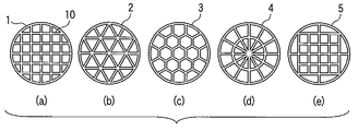
上記格子はいかなる形態であってもよいが、たとえば正方格子、六角格子、三角格子を挙げることができる。図1の1は正方格子、2は三角格子、および3は六角格子、4は放射状の格子に成形された隔壁をもつ炭素質熱源の端面を示す。また、図1の5の炭素質熱源のように、炭素質熱源内に設けられた隔壁はその横断面が均一な格子となるように形成されている必要はなく、偏在化した格子を含むように成形されていてもよい。
The above lattice may have any form, and examples thereof include a square lattice, a hexagonal lattice, and a triangular lattice. In FIG. 1, 1 is a square lattice, 2 is a triangular lattice, 3 is a hexagonal lattice, and 4 is an end face of a carbonaceous heat source having partition walls formed into a radial lattice. Further, unlike the carbonaceous heat source 5 in FIG. 1, the partition wall provided in the carbonaceous heat source does not need to be formed so that the cross section thereof is a uniform lattice, and includes an unevenly distributed lattice. It may be formed into.
炭素質熱源の空隙率は50%以上とすることができる。ここで、「炭素質熱源の空隙率」とは、熱源の横断面において、隔壁により区画されることにより生じる、熱源の断面積あたりの空間の割合を意味する。空隙率が50%未満であると、着火時の着火性が大幅には向上しない傾向にある。空隙率の上限は、熱源組成物を押出成形する際の金型の設計により制限される。炭素質熱源の空隙率は、好ましくは50%~78%、より好ましくは60~78%である。このように大きな空隙率をもつ炭素質熱源を備えた本発明の非燃焼型喫煙物品は着火性が向上する。
The porosity of the carbonaceous heat source can be 50% or more. Here, the “porosity of the carbonaceous heat source” means the ratio of the space per cross-sectional area of the heat source, which is generated by being partitioned by the partition wall in the cross section of the heat source. When the porosity is less than 50%, the ignitability at the time of ignition tends not to be significantly improved. The upper limit of the porosity is limited by the design of the mold when extruding the heat source composition. The porosity of the carbonaceous heat source is preferably 50% to 78%, more preferably 60 to 78%. The ignitability of the non-combustion smoking article of the present invention provided with the carbonaceous heat source having such a large porosity is improved.
炭素質熱源の流路周長は70mm以上であることが好ましい。流路周長が70mm未満であると着火性が落ちる傾向にある。流路周長の上限も金型の設計により制限される。ここで、「流路周長」とは、たとえば図1に示す熱源の端面において格子をなす隔壁10の空気流路に面する長さの合計を意味する。炭素質熱源の流路周長は、好ましくは100~180mmである。
The channel circumference of the carbonaceous heat source is preferably 70 mm or more. If the flow path circumference is less than 70 mm, the ignitability tends to decrease. The upper limit of the flow path circumference is also limited by the mold design. Here, the “flow path circumferential length” means, for example, the total length of the partition walls 10 forming a lattice on the end face of the heat source shown in FIG. The circumferential length of the carbonaceous heat source is preferably 100 to 180 mm.
炭素質熱源の断面積は9mm2以上であることが好ましい。断面積が9mm2未満であると、製品設計上好ましくない。
The cross-sectional area of the carbonaceous heat source is preferably 9 mm 2 or more. If the cross-sectional area is less than 9 mm 2, it is not preferable for product design.
炭素質熱源の断面積当たりの流路周長は、4mm/mm2以上であることが好ましい。下記に詳細に述べるが、断面積当たりの流路周長と着火率には一定の関係が認められることがわかった。断面積当たりの流路周長が4mm/mm2未満であると、通常の着火法では着火性に劣ることがわかった。
The circumferential length of the flow path per cross-sectional area of the carbonaceous heat source is preferably 4 mm / mm 2 or more. As will be described in detail below, it has been found that there is a certain relationship between the perimeter of the flow path and the ignition rate. It was found that if the flow path perimeter per cross-sectional area is less than 4 mm / mm 2 , the ordinary ignition method is inferior in ignitability.
上記炭素質熱源を構成する熱源組成物は、好ましくは、カーボンを10~60重量%含む。カーボン量が10重量%未満であると熱源の燃焼性が乏しく好ましくない。60重量%のカーボンを含んでいれば、着火性、燃焼性ともに十分である。使用するカーボンの由来に特に制限はなく、既知のカーボンを用いることができる。本発明の非燃焼型喫煙物品に用いられる炭素質熱源を構成する熱源組成物はこのように従来と比べて低いカーボン量でも十分な着火率を有する。
The heat source composition constituting the carbonaceous heat source preferably contains 10 to 60% by weight of carbon. If the amount of carbon is less than 10% by weight, the flammability of the heat source is poor, which is not preferable. If 60% by weight of carbon is contained, both ignitability and combustibility are sufficient. There is no restriction | limiting in particular in the origin of the carbon to be used, A known carbon can be used. As described above, the heat source composition constituting the carbonaceous heat source used in the non-combustion smoking article of the present invention has a sufficient ignition rate even when the amount of carbon is lower than that in the prior art.
また、熱源組成物は、炭素質熱源の最高温度を低下させて一酸化炭素の発生量を減少させるための炭酸カルシウム(粒子)、その他の無機添加剤を含有することができる。無機添加剤は、カーボン1重量%に対し、一般に98重量%までの割合で、好ましくは8.0重量%までの割合で、より好ましくは0.100~3.75重量%の割合で配合することができる。
Further, the heat source composition can contain calcium carbonate (particles) and other inorganic additives for lowering the maximum temperature of the carbonaceous heat source and reducing the amount of carbon monoxide generated. The inorganic additive is generally blended in a proportion of up to 98% by weight, preferably in a proportion of up to 8.0% by weight, and more preferably in a proportion of 0.100 to 3.75% by weight with respect to 1% by weight of carbon. be able to.
バインダは炭酸カルシウムとカーボンを結着させるために含まれている。バインダはカーボン1重量%に対し、一般に0.010~50重量%の割合で、好ましくは0.017~2.0重量%の割合で、より好ましくは0.10~0.75重量%の割合で配合することができる。バインダとしては、アルギン酸塩、カルボキシメチルセルロース又はその塩、ペクチン又はその塩、カラギーナン又はその塩、グアーガム等を用いることができる。
Binder is included to bind calcium carbonate and carbon. The binder is generally 0.010 to 50% by weight, preferably 0.017 to 2.0% by weight, more preferably 0.10 to 0.75% by weight, based on 1% by weight of carbon. Can be blended. As the binder, alginate, carboxymethylcellulose or a salt thereof, pectin or a salt thereof, carrageenan or a salt thereof, guar gum, or the like can be used.
熱源組成物は、初期のパフにおけるエアロゾルの発生を容易にするために、エアロゾル発生物質、例えば多価アルコール等を含有することができる。熱源組成物に含まれ得るエアロゾル発生物質はカーボン1重量%に対し、一般に98重量%までの割合で、好ましくは3.0重量%までの割合で、より好ましくは1.5重量%の割合で配合することができる。
The heat source composition can contain an aerosol-generating substance such as a polyhydric alcohol in order to facilitate the generation of aerosol in the initial puff. The aerosol-generating substance that can be contained in the heat source composition is generally up to 98% by weight, preferably up to 3.0% by weight, more preferably 1.5% by weight with respect to 1% by weight of carbon. Can be blended.
さらに、熱源組成物は、パルプ、タバコ細粉などを含むこともできる。パルプ、タバコ細粉は、合計で、カーボン1重量%に対し、一般に98重量%までの割合で、好ましくは3.0重量%までの割合で、より好ましくは0.50重量%の割合で配合することができる。
Furthermore, the heat source composition can also include pulp, tobacco fine powder, and the like. The total amount of pulp and tobacco fine powder is generally up to 98% by weight, preferably up to 3.0% by weight, more preferably 0.50% by weight with respect to 1% by weight of carbon. can do.
さらにまた、炭素質熱源には、ホウ素、アルミニウム、ケイ素、チタン、鉄、コバルト、ニッケル、亜鉛、ゲルマニウム、ジルコニウム、ニオブ、モリブデン、ルテニウム、ロジウム、パラジウム、銀、スズ、セリウム、ハフニウム、タンタル、タングステン、レニウム、オスミウム、イリジウム、白金、金、それらの酸化物あるいはそれらの混合物のような一酸化炭素低減触媒を、炭素質熱源の成形前の原料に混合することができる。
Furthermore, carbonaceous heat sources include boron, aluminum, silicon, titanium, iron, cobalt, nickel, zinc, germanium, zirconium, niobium, molybdenum, ruthenium, rhodium, palladium, silver, tin, cerium, hafnium, tantalum, tungsten A carbon monoxide reducing catalyst such as rhenium, osmium, iridium, platinum, gold, oxides thereof, or a mixture thereof can be mixed with the raw material before forming the carbonaceous heat source.
同炭素質熱源については、空気流路の軸方向の表面の一部もしくは全てに所望の物質をコーティングすることも可能である。特に、粒子の層をコーティングすることにより、炭素質熱源を実質的に空気不透過性とすることも可能である。コーティング物質は、熱伝導度が低く、熱的に安定であり、炭素質熱源が燃焼する温度においても不燃性であることが望ましい。好適なコーティング物質として、粘土や金属酸化物、例えば酸化鉄、アルミナ、チタニア、シリカ、シリカアルミナ、ジルコニア、セリア、ゼオライト、リン酸ジルコニウム、その他セラミックスおよびこれらの組み合わせが挙げられる。これらのコーティング物質は、粘土や酸化鉄を含むことが望ましい。また、これらのコーティング物質は、一酸化炭素から二酸化炭素への酸化反応を促進する機能を有する触媒を含むこともできる。それらの触媒として、例えば白金、パラジウム、その他遷移金属およびその酸化物が挙げられる。
For the carbonaceous heat source, it is possible to coat a desired substance on a part or all of the axial surface of the air flow path. In particular, it is possible to make the carbonaceous heat source substantially air impermeable by coating a layer of particles. The coating material desirably has low thermal conductivity, is thermally stable, and is nonflammable at the temperature at which the carbonaceous heat source burns. Suitable coating materials include clays and metal oxides such as iron oxide, alumina, titania, silica, silica alumina, zirconia, ceria, zeolite, zirconium phosphate, other ceramics and combinations thereof. These coating materials preferably contain clay and iron oxide. These coating materials can also contain a catalyst having a function of promoting an oxidation reaction from carbon monoxide to carbon dioxide. Examples of these catalysts include platinum, palladium, other transition metals, and oxides thereof.
空気流路の軸方向の表面の一部もしくは全てに所望の物質をコーティングするために、米国特許第5,040,551号明細書に記載されるような種々の方法を用いることができる。例えば、コーティング物質の溶液あるいは懸濁液を散布するか(spray)、濡らすか(wet)、塗る(paint)こともできる。あるいは、コーティング物質からなるライナーを空気流路の軸方向の表面の一部もしくは全てに挿入してもよい。例えば、実質的に空気不透過性の中空管を各々の空気流路の軸方向に挿入してもよい。
Various methods as described in US Pat. No. 5,040,551 can be used to coat a desired substance on part or all of the axial surface of the air flow path. For example, a coating solution or suspension can be sprayed, wetted or painted. Alternatively, a liner made of a coating substance may be inserted into part or all of the axial surface of the air flow path. For example, a substantially air impermeable hollow tube may be inserted in the axial direction of each air flow path.
本発明の非燃焼型喫煙物品に用いられる炭素質熱源は、横断面が格子をなす隔壁の形態を保ったまま燃焼する。これは上記の通り熱源組成物のカーボン量が従来よりも抑えられているためと考えられる。従って、以下の通り断熱材等により熱源が覆われていなくても、喫煙時に喫煙物品から熱源が脱落することを防ぐことができる。
The carbonaceous heat source used in the non-combustion type smoking article of the present invention burns while maintaining the shape of the partition wall whose cross section forms a lattice. This is presumably because the carbon content of the heat source composition is suppressed as compared with the conventional case. Therefore, even if the heat source is not covered with a heat insulating material or the like as described below, it is possible to prevent the heat source from dropping from the smoking article during smoking.
上記した炭素質熱源は、所望の格子に対応する金型を用いて、押し出し成形等の成形手段により成形することができる。本発明において用いられる炭素質熱源は、通常の非燃焼型喫煙物品のようにその周囲に断熱材や巻紙等を設ける必要がなく、むき出しのままで十分に燃焼し、また脱落しにくい。このように炭素質熱源の周囲に断熱材等を設ける工程を省くことができ、コスト的にも非常に有利である。
The above-mentioned carbonaceous heat source can be molded by a molding means such as extrusion molding using a mold corresponding to a desired lattice. The carbonaceous heat source used in the present invention does not need to be provided with a heat insulating material, a wrapping paper, or the like around it like a normal non-combustion type smoking article, and is sufficiently burned and not easily dropped off. Thus, the step of providing a heat insulating material or the like around the carbonaceous heat source can be omitted, which is very advantageous in terms of cost.
本発明の非燃焼型喫煙物品には、たとえば、炭素質熱源と物理的に分離した形態で、エアロゾル発生部を設けることができる。エアロゾル発生部に含まれるエアロゾル発生物質としては、たとえば、グリセリン、プロピレングリコール、トリエチレングリコール、テトラエチレングリコール等の多価アルコール、ステアリン酸メチル、ドデカン二酸ジメチル、テトラデカン二酸ジメチル等のカルボン酸脂肪族エステルを用いることができる。エアロゾル発生物質は、通常、適当な担体に担持される。担体としては、紙、活性炭等の多孔質材料を用いることができる。エアロゾル発生物質を多孔質材料に吸収ないし吸着させてエアロゾル発生材を調整する。あるいは、担体として、特許第3118462号明細書に記載されている、カードラン等のグルカンゲルを用いることができる。すなわち、熱不可逆凝固性グルカンの水中分散液にエアロゾル発生物質を添加し、たとえばステンレス鋼製ベルト上に薄膜シート状にキャスティングした後、加熱乾燥してグルカンをゲル化させる。このエアロゾル発生物質を保持したグルカンゲルは、裁刻しまたは粉末化してエアロゾル発生材として用いることができる。
In the non-combustion type smoking article of the present invention, for example, an aerosol generating part can be provided in a form physically separated from a carbonaceous heat source. Examples of the aerosol generating substance contained in the aerosol generating part include polyhydric alcohols such as glycerin, propylene glycol, triethylene glycol, and tetraethylene glycol, and carboxylic acid fats such as methyl stearate, dimethyl dodecanedioate, and dimethyl tetradecanedioate. Group esters can be used. The aerosol generating substance is usually carried on a suitable carrier. As the carrier, a porous material such as paper or activated carbon can be used. The aerosol generating material is adjusted by absorbing or adsorbing the aerosol generating material on the porous material. Alternatively, glucan gel such as curdlan described in Japanese Patent No. 3118462 can be used as the carrier. That is, an aerosol generating substance is added to an aqueous dispersion of heat irreversibly solidified glucan, and cast into a thin film sheet on a stainless steel belt, for example, and then dried by heating to gel the glucan. The glucan gel holding the aerosol generating substance can be cut or powdered and used as an aerosol generating material.
エアロゾル発生物質を担体に保持させたエアロゾル発生材を、ガラス繊維を含有する紙シート、セラミック、金属箔で内張りされた紙シート等の不燃性材料で形成された円筒体内に収容してエアロゾル発生部を構成することができる。
An aerosol generating material in which an aerosol generating material having an aerosol generating substance held on a carrier is contained in a cylindrical body formed of a nonflammable material such as a paper sheet containing glass fiber, a ceramic, or a paper sheet lined with a metal foil. Can be configured.
本発明の喫煙物品は、エアロゾル発生部から発生したエアロゾルに香喫味を付与するために、エアロゾル発生部の後端に香喫味発生材を含む香喫味発生部を付設することができる。香喫味発生材としては、タバコ刻、あるいは特許第3118462号明細書に記載されている香味発生媒体を用いることができる。香喫味発生材は、エアロゾル発生部の円筒体と同様の円筒体内に収容される。
The smoking article of the present invention can be provided with a flavor generating part including a flavor generating material at the rear end of the aerosol generating part in order to impart a flavor to the aerosol generated from the aerosol generating part. As a flavor generating material, tobacco cutting or a flavor generating medium described in Japanese Patent No. 3118462 can be used. The flavor generating material is accommodated in a cylindrical body similar to the cylindrical body of the aerosol generating portion.
さらに、本発明の喫煙物品は、最後端部に、通常のシガレットに用いられているフィルタを有することができる。
Furthermore, the smoking article of the present invention can have a filter used for a normal cigarette at the rear end.
以下、本発明の炭素質熱源組成物からなる熱源を用いた非燃焼型喫煙物品の一例を、図2を参照して説明する。
Hereinafter, an example of a non-combustion smoking article using a heat source composed of the carbonaceous heat source composition of the present invention will be described with reference to FIG.
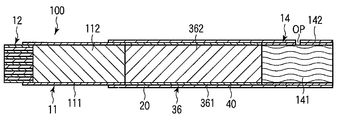
図2に示す喫煙物品100は、エアロゾル発生部11、エアロゾル発生部11の先端に設けられた炭素質熱源12、エアロゾル発生部11の後端に設けられた香喫味発生部36、および香喫味発生部36の後端に設けられたフィルタ部14を備える。
The smoking article 100 shown in FIG. 2 includes an aerosol generation unit 11, a carbonaceous heat source 12 provided at the tip of the aerosol generation unit 11, a flavor generation unit 36 provided at the rear end of the aerosol generation unit 11, and a flavor generation. The filter part 14 provided in the rear end of the part 36 is provided.
エアロゾル発生部11は、不燃性材料で形成された円筒体111を有し、円筒体111内にはエアロゾル発生物質を担持する担体からなる例えば粒子状のエアロゾル発生材112が収容されている。
The aerosol generating unit 11 has a cylindrical body 111 made of a non-combustible material. In the cylindrical body 111, for example, a particulate aerosol generating material 112 made of a carrier carrying an aerosol generating substance is accommodated.
炭素質熱源12は、外形が円形であり、上記した通り種々の格子の形態にあり得る。
The carbonaceous heat source 12 has a circular outer shape and can be in various lattice forms as described above.
次に、香喫味発生部36は、不燃性材料で形成された円筒体361を有し、円筒体361内には香喫味発生材362が収容されている。
Next, the flavor generating part 36 has a cylindrical body 361 made of a non-combustible material, and the flavor generating material 362 is accommodated in the cylindrical body 361.
フィルタ部14は、通常のシガレットに用いられているフィルタ部材141(例えば、セルロースアセテート繊維トウ)により構成され、その外周は、巻取紙142により巻かれている。
The filter unit 14 is configured by a filter member 141 (for example, cellulose acetate fiber tow) used in a normal cigarette, and the outer periphery thereof is wound around a web 142.
エアロゾル発生部11と香喫味発生部36とフィルタ部14は、エアロゾル発生部11の後端部外周と、香喫味発生部36およびフィルタ部14の外周全体を覆うたとえばシガレット巻紙のような紙シート20により接続されている。
The aerosol generating unit 11, the flavor generating unit 36, and the filter unit 14 cover the outer periphery of the rear end of the aerosol generating unit 11 and the entire outer periphery of the flavor generating unit 36 and the filter unit 14, for example, a paper sheet 20 such as cigarette wrapping paper. Connected by.
なお、喫煙物品100には、主流煙成分(例えば、二酸化炭素)を希釈するために、喫煙時に空気を取り入れるための開口を有することができる。図2に示す喫煙物品100では、フィルタ部14において紙シート20と巻取紙142を貫通して開口OPが形成されている。
The smoking article 100 may have an opening for taking in air during smoking in order to dilute mainstream smoke components (for example, carbon dioxide). In the smoking article 100 shown in FIG. 2, an opening OP is formed through the paper sheet 20 and the web 142 in the filter unit 14.
このような非燃焼型喫煙物品100は、通常のシガレットの外観を有し得る。
Such a non-combustion smoking article 100 may have a normal cigarette appearance.
以下、実施例を用いてさらに詳しく説明するが、本発明はこれらに限定されるものでない。
Hereinafter, although it demonstrates in detail using an Example, this invention is not limited to these.
実施例1
炭素質熱源の空隙率、炭素質熱源の流路周長、熱源断面積、および熱源断面積当たりの流路周長と着火性との関係を検討した。 Example 1
The relationship between the porosity of the carbonaceous heat source, the channel circumference of the carbonaceous heat source, the heat source cross-sectional area, and the channel circumference per heat source cross-sectional area and the ignitability were investigated.
従来の非燃焼型喫煙物品(日本たばこ産業株式会社製;商品名エアーズ)に使用されている熱源組成物と同一の組成、すなわち59.6重量%のカーボン粒子、12重量%の炭酸カルシウム、8.4重量%のグラファイトおよび10重量%のタバコ細粉を原料として熱源組成物を調製した。この熱源組成物を、種々の金型を用いて隔壁の肉厚および格子の間隔が異なるように成形し、表1に示す端面の形態を有するサンプル1~6の炭素質熱源を作製した。

The same composition as the heat source composition used in a conventional non-combustion smoking article (manufactured by Nippon Tobacco Inc .; trade name Ayers), that is, 59.6% carbon particles, 12% calcium carbonate, 8 A heat source composition was prepared using 4 wt% graphite and 10 wt% tobacco fine powder as raw materials. This heat source composition was molded using various molds so that the wall thickness of the partition walls and the lattice spacing were different, and the carbonaceous heat sources of Samples 1 to 6 having the form of the end faces shown in Table 1 were produced.
次いで、上記エアーズ製品から熱源およびこれを取り巻く断熱材を抜き取り、上記の通り作製したサンプル1~6の炭素質熱源を挿入した。すなわち、熱源以外の喫煙物品の構成はエアーズ製品と同一である。
Next, the heat source and the heat insulating material surrounding it were extracted from the Ayers product, and the carbonaceous heat sources of Samples 1 to 6 prepared as described above were inserted. That is, the configuration of the smoking article other than the heat source is the same as that of the Ayers product.
従来例1
従来例1として、上記した日本たばこ産業株式会社製の商品名エアーズである非燃焼型基喫煙物品を用いた。 Conventional example 1
As Conventional Example 1, a non-combustion-type basic smoking article, which is a trade name Ayers manufactured by Nippon Tobacco Inc., was used.
従来例1として、上記した日本たばこ産業株式会社製の商品名エアーズである非燃焼型基喫煙物品を用いた。 Conventional example 1
As Conventional Example 1, a non-combustion-type basic smoking article, which is a trade name Ayers manufactured by Nippon Tobacco Inc., was used.
着火性試験は次の通り行なった。電気式ライターで3秒間予備加熱後、35ml/2秒で吸煙させた。次に、58秒後に再度吸煙させ(即ち、60秒の喫煙サイクル)、その際に熱源全体が赤熱するかを目視で確認し、赤熱したものを「着火可」、赤熱しなかったものを「着火不可」として判定した。サンプル1~6、従来例1についてそれぞれ10本の喫煙物品を用いて試験を行い、そのうち「着火可」と確認されたものの本数をAとして、「着火率=A÷10×100(%)」より着火率を算出した。
The ignitability test was conducted as follows. After preheating with an electric lighter for 3 seconds, smoke was absorbed at 35 ml / 2 seconds. Next, smoke is absorbed again after 58 seconds (that is, a smoking cycle of 60 seconds). At that time, it is visually confirmed whether the entire heat source is red-hot, the red-hot one is “ignitable”, and the one that is not red-hot is “ It was determined as "Ignition is impossible" Samples 1 to 6 and Conventional Example 1 were tested using 10 smoking articles, and the number of items that were confirmed to be “ignitable” was A, and “ignition rate = A ÷ 10 × 100 (%)” From this, the ignition rate was calculated.
着火率の解析に当たり、炭素質熱源の断面積当たりの流路周長に対する着火率を検討した。その結果を図3に示す。丸印はサンプル1~6の炭素質熱源の着火率を示し、三角印は従来例1の炭素質熱源の着火率を示している。本条件ではサンプル1~2では、従来例1とあまり着火率について差が見られなかったが、サンプル3では着火率が約60%と大きく向上した。つまり、着火性を向上するためには、表1に示す炭素質熱源の各パラメータの設計が重要であることがわかった。また、横断面が格子をなす隔壁により区画された空気流路を有する炭素質熱源を用いることにより、従来の開孔パターンを有する炭素質熱源に比べ、空隙率および流路周長を大幅に増加することが可能となり、結果として着火性が向上することが確認できた。
In the analysis of the ignition rate, the ignition rate with respect to the flow path circumference per cross-sectional area of the carbonaceous heat source was examined. The result is shown in FIG. Circles indicate the ignition rates of the carbonaceous heat sources of Samples 1 to 6, and triangles indicate the ignition rates of the carbonaceous heat source of Conventional Example 1. Under these conditions, the samples 1 and 2 did not show much difference in the ignition rate from the conventional example 1, but in the sample 3, the ignition rate was greatly improved to about 60%. That is, in order to improve the ignitability, it was found that the design of each parameter of the carbonaceous heat source shown in Table 1 is important. In addition, by using a carbonaceous heat source with an air flow path partitioned by partition walls whose cross section forms a lattice, the porosity and flow path circumference are greatly increased compared to a carbonaceous heat source with a conventional aperture pattern. As a result, it was confirmed that the ignitability was improved.
実施例2
上記表1に示す各パラメータのうち、格子数(流路周長)の影響のみを確認するため、空隙率と熱源断面積を一定にし、流路周長を変化させて試験を行なった。 Example 2
In order to confirm only the influence of the number of lattices (flow path circumference) among the parameters shown in Table 1 above, the test was performed by changing the flow path circumference while keeping the porosity and the heat source cross-sectional area constant.
サンプル1~6と同様の熱源組成物を調製し、各種金型を用いて表2に示すサンプル7~11の炭素質熱源を作製した。即ち、熱源断面積および空隙率が一定になるように、格子の肉厚と間隔の組み合わせを変更し、流路周長を変化させた。
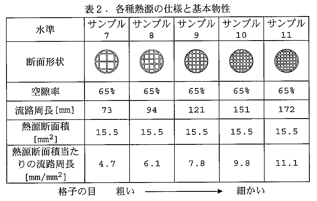
Heat source compositions similar to those of Samples 1 to 6 were prepared, and carbonaceous heat sources of Samples 7 to 11 shown in Table 2 were prepared using various molds. That is, the perimeter of the flow path was changed by changing the combination of the wall thickness and the interval of the lattice so that the heat source cross-sectional area and the porosity were constant.
次に、エアーズ製品から熱源およびその周囲の断熱材を抜き取り、作製したサンプル7~11の熱源を挿入した。即ち、熱源以外の非燃焼型喫煙物品の構成はエアーズ製品と同一である。
Next, the heat source and the surrounding heat insulating material were extracted from the Ayers product, and the heat sources of the produced samples 7 to 11 were inserted. That is, the configuration of the non-combustion smoking article other than the heat source is the same as that of the Ayers product.
本例では、着火性試験として、電気式ライターで2秒間予備加熱後、35ml/2秒で吸煙させた。実施例2の炭素質熱源は着火しやすく、実施例1の条件下では差が出にくいため、予備加熱時間を3秒間から2秒間に短縮して着火率に差が出るようにした。
In this example, as an ignitability test, smoke was absorbed at 35 ml / 2 seconds after preheating with an electric lighter for 2 seconds. The carbonaceous heat source of Example 2 is easy to ignite, and it is difficult to make a difference under the conditions of Example 1. Therefore, the preheating time was shortened from 3 seconds to 2 seconds so that the ignition rates differed.
図4に炭素質熱源の断面積当たりの流路周長に対する着火率の関係を示す。ここで、予備加熱時間として2秒間および3秒間を用いた場合をそれぞれ示す。図4から3秒間予備加熱した場合の着火率は60%以上と十分に高いことがわかる。また、予備加熱時間を2秒間に短縮したものについては、サンプル1~6と同様に、「熱源断面積当たりの流路周長」の増加により着火率が向上する関係が確認された。これと共に、熱源断面積および空隙率がほぼ一定となる条件下において、隔壁の厚さを極力薄くし、格子の間隔を狭くして格子数を増やすことにより、流路周長を増加させることが、着火性の向上に対して有効であることが認められた。
Fig. 4 shows the relationship of the ignition rate to the flow path circumference per cross-sectional area of the carbonaceous heat source. Here, the case where 2 seconds and 3 seconds are used as preheating time is shown, respectively. It can be seen from FIG. 4 that the ignition rate when preheated for 3 seconds is sufficiently high at 60% or more. In addition, in the case where the preheating time was shortened to 2 seconds, the relationship in which the ignition rate was improved by increasing the “circumference of the flow path per heat source cross-sectional area” was confirmed as in Samples 1 to 6. At the same time, under the condition that the cross section of the heat source and the porosity are almost constant, the circumference of the flow path can be increased by reducing the thickness of the partition walls as much as possible, narrowing the lattice spacing and increasing the number of lattices. It was confirmed that it was effective for improving the ignitability.
Claims (6)
- 円筒状の外壁とその内部に設けられ横断面が格子をなす隔壁とを有し、前記隔壁により区画された空気流路を有する炭素質熱源と、エアロゾル発生部とを備えることを特徴とする非燃焼型喫煙物品。 A non-circular outer wall having a cylindrical outer wall and a partition wall having a lattice cross section formed inside thereof, comprising a carbonaceous heat source having an air flow path partitioned by the partition wall, and an aerosol generation unit Combustion-type smoking article.
- 前記炭素質熱源の空隙率が50%以上であることを特徴とする請求項1に記載の非燃焼型喫煙物品。 The non-combustion smoking article according to claim 1, wherein the porosity of the carbonaceous heat source is 50% or more.
- 前記炭素質熱源において、前記隔壁の前記空気流路に面する長さの合計である流路周長が70mm以上であることを特徴とする請求項1に記載の非燃焼型喫煙物品。 The non-combustion type smoking article according to claim 1, wherein in the carbonaceous heat source, a channel circumferential length, which is a total length of the partition walls facing the air channel, is 70 mm or more.
- 前記炭素質熱源の断面積が9mm2以上であることを特徴とする請求項1に記載の非燃焼型喫煙物品。 The non-combustion smoking article according to claim 1, wherein a cross-sectional area of the carbonaceous heat source is 9 mm 2 or more.
- 前記炭素質熱源の断面積当たりの流路周長が4mm/mm2以上であることを特徴とする請求項1に記載の非燃焼型喫煙物品。 The non-burning type smoking article according to claim 1, wherein the perimeter of the flow path per cross-sectional area of the carbonaceous heat source is 4 mm / mm 2 or more.
- 前記炭素質熱源を構成する熱源組成物中のカーボン量が10~60重量%であることを特徴とする請求項1に記載の非燃焼型喫煙物品。 2. The non-combustion smoking article according to claim 1, wherein the amount of carbon in the heat source composition constituting the carbonaceous heat source is 10 to 60% by weight.
Priority Applications (6)
| Application Number | Priority Date | Filing Date | Title |
|---|---|---|---|
| JP2011519371A JP5372151B2 (en) | 2009-06-18 | 2009-06-18 | Non-combustible smoking article with carbonaceous heat source |
| CN2009801599169A CN102458165A (en) | 2009-06-18 | 2009-06-18 | Non-combustion smoking article having carbonaceous heat source |
| PCT/JP2009/061125 WO2010146693A1 (en) | 2009-06-18 | 2009-06-18 | Non-combustion smoking article having carbonaceous heat source |
| EP09846186.6A EP2443947A4 (en) | 2009-06-18 | 2009-06-18 | Non-combustion smoking article having carbonaceous heat source |
| TW098125310A TW201100029A (en) | 2009-06-18 | 2009-07-28 | Non-combustion smoking object having carbonaceous heat source |
| US13/325,836 US20120080042A1 (en) | 2009-06-18 | 2011-12-14 | Non-combustion smoking article having carbonaceous heat source |
Applications Claiming Priority (1)
| Application Number | Priority Date | Filing Date | Title |
|---|---|---|---|
| PCT/JP2009/061125 WO2010146693A1 (en) | 2009-06-18 | 2009-06-18 | Non-combustion smoking article having carbonaceous heat source |
Related Child Applications (1)
| Application Number | Title | Priority Date | Filing Date |
|---|---|---|---|
| US13/325,836 Continuation US20120080042A1 (en) | 2009-06-18 | 2011-12-14 | Non-combustion smoking article having carbonaceous heat source |
Publications (1)
| Publication Number | Publication Date |
|---|---|
| WO2010146693A1 true WO2010146693A1 (en) | 2010-12-23 |
Family
ID=43356031
Family Applications (1)
| Application Number | Title | Priority Date | Filing Date |
|---|---|---|---|
| PCT/JP2009/061125 WO2010146693A1 (en) | 2009-06-18 | 2009-06-18 | Non-combustion smoking article having carbonaceous heat source |
Country Status (6)
| Country | Link |
|---|---|
| US (1) | US20120080042A1 (en) |
| EP (1) | EP2443947A4 (en) |
| JP (1) | JP5372151B2 (en) |
| CN (1) | CN102458165A (en) |
| TW (1) | TW201100029A (en) |
| WO (1) | WO2010146693A1 (en) |
Cited By (14)
| Publication number | Priority date | Publication date | Assignee | Title |
|---|---|---|---|---|
| WO2012090294A1 (en) * | 2010-12-28 | 2012-07-05 | 日本たばこ産業株式会社 | Smoking article provided with carbon heat source |
| WO2013146951A3 (en) * | 2012-03-30 | 2013-11-21 | 日本たばこ産業株式会社 | Carbon heat source and flavour inhalation tool |
| WO2013183761A1 (en) * | 2012-06-08 | 2013-12-12 | 日本たばこ産業株式会社 | Flavor-suctioning implement |
| WO2014016961A1 (en) * | 2012-07-27 | 2014-01-30 | 日本たばこ産業株式会社 | Smoking article |
| CN103619198A (en) * | 2011-06-02 | 2014-03-05 | 菲利普莫里斯生产公司 | Combustible heat source for smoking article |
| WO2014136722A1 (en) | 2013-03-08 | 2014-09-12 | 日本たばこ産業株式会社 | Flavor inhaler |
| WO2014142079A1 (en) | 2013-03-11 | 2014-09-18 | 日本たばこ産業株式会社 | Combustion heat source and flavour inhaler |
| WO2015098447A1 (en) * | 2013-12-25 | 2015-07-02 | 日本たばこ産業株式会社 | Method for manufacturing tobacco compact |
| WO2015098445A1 (en) * | 2013-12-25 | 2015-07-02 | 日本たばこ産業株式会社 | Tobacco compact and flavor plunger |
| US9125217B2 (en) | 2008-12-01 | 2015-09-01 | Qualcomm Incorporated | Blank subframe uplink design |
| CN105301033A (en) * | 2015-10-21 | 2016-02-03 | 中国烟草总公司郑州烟草研究院 | Experimental device for simulating outer heat source of heated non-burned cigarette |
| US9629393B2 (en) | 2011-11-15 | 2017-04-25 | Philip Morris Products S.A. | Smoking article comprising a combustible heat source with a rear barrier coating |
| JP2021137014A (en) * | 2017-06-16 | 2021-09-16 | 株式会社東亜産業 | Electronic cigarette cartridge and method for producing the same |
| JP2021184772A (en) * | 2017-03-30 | 2021-12-09 | ニコベンチャーズ トレーディング リミテッド | Article used with device for heating aerosol generation agent |
Families Citing this family (17)
| Publication number | Priority date | Publication date | Assignee | Title |
|---|---|---|---|---|
| RU2635078C2 (en) | 2012-07-04 | 2017-11-08 | Филип Моррис Продактс С.А. | Combustible heat source with improved binding material |
| CN203015838U (en) * | 2012-12-28 | 2013-06-26 | 陈志平 | Electronic atomizing inhalation device |
| US10064430B2 (en) | 2013-08-21 | 2018-09-04 | Jt International S.A. | Smoking article for a water-pipe |
| US20150157052A1 (en) * | 2013-12-05 | 2015-06-11 | R. J. Reynolds Tobacco Company | Smoking article and associated manufacturing method |
| CN103767079B (en) * | 2014-01-21 | 2017-03-01 | 深圳市凯神科技股份有限公司 | Electronic cigarette oil solvent |
| CN103844360B (en) * | 2014-03-19 | 2016-08-17 | 川渝中烟工业有限责任公司 | For heating the spontaneous heat source type aspirator of smokeless tobacco articles |
| EP3000339B1 (en) * | 2014-09-23 | 2017-03-01 | Fontem Holdings 1 B.V. | Electronic smoking device |
| CN104585884B (en) * | 2015-01-20 | 2018-04-17 | 四川中烟工业有限责任公司 | A kind of charcoal heats the aspirator of not burning tobacco |
| EP3075266A1 (en) | 2015-04-02 | 2016-10-05 | PT. Gudang Garam Tbk. | Method of producing an aerosol-generating article containing reconstituted tobacco material, an aerosol-generating article containing reconstituted tobacco material and use of an aerosol-generating article containing reconstituted tobacco material |
| CN105533800B (en) * | 2015-12-03 | 2019-04-30 | 安徽中烟工业有限责任公司 | A kind of cigarette energetic material and low-temperature heat type cigarette |
| CN105433430B (en) * | 2015-12-04 | 2017-08-29 | 河南中烟工业有限责任公司 | A kind of tobacco-containing material for being applied to heating non-burning device and preparation method thereof |
| US10851994B2 (en) | 2017-03-14 | 2020-12-01 | Lions' Share Capital Solutions, Llc | Electronic cigar lighter |
| CN108077992B (en) * | 2017-12-18 | 2019-01-18 | 山东精彩香料科技开发有限公司 | It is a kind of to heat do not burn cigarette suction particle and manufacturing method |
| CN108041687B (en) | 2017-12-22 | 2020-11-27 | 安徽中烟工业有限责任公司 | Aerosol-generating article with low temperature combustion heat source |
| CN108669662A (en) * | 2018-05-31 | 2018-10-19 | 赵雪 | It is a kind of to heat the cigarette that do not burn |
| CA3114268C (en) * | 2018-12-06 | 2023-02-28 | Philip Morris Products S.A. | Aerosol-generating article with laminated wrapper |
| CN113876026B (en) * | 2021-10-25 | 2023-04-28 | 湖北中烟工业有限责任公司 | Application of carbonaceous heat source material in heating type tobacco products |
Citations (12)
| Publication number | Priority date | Publication date | Assignee | Title |
|---|---|---|---|---|
| JPS5863791A (en) * | 1981-10-13 | 1983-04-15 | Matsushita Electric Ind Co Ltd | Solid fuel |
| US4881556A (en) | 1988-06-06 | 1989-11-21 | R. J. Reynolds Tobacco Company | Low CO smoking article |
| US4967774A (en) | 1989-10-11 | 1990-11-06 | R. J. Reynolds Tobacco Company | Smoking article with improved means for retaining the fuel element |
| JPH0253026B2 (en) * | 1985-08-26 | 1990-11-15 | Reynolds Tobacco Co R | |
| US4989619A (en) | 1985-08-26 | 1991-02-05 | R. J. Reynolds Tobacco Company | Smoking article with improved fuel element |
| US4991606A (en) | 1988-07-22 | 1991-02-12 | Philip Morris Incorporated | Smoking article |
| US5040551A (en) | 1988-11-01 | 1991-08-20 | Catalytica, Inc. | Optimizing the oxidation of carbon monoxide |
| US5067499A (en) | 1984-09-14 | 1991-11-26 | R. J. Reynolds Tobacco Company | Smoking article |
| US5183062A (en) | 1990-02-27 | 1993-02-02 | R. J. Reynolds Tobacco Company | Cigarette |
| JP3118462B2 (en) | 1994-01-26 | 2000-12-18 | 日本たばこ産業株式会社 | Flavored goods |
| JP2001507576A (en) * | 1996-12-30 | 2001-06-12 | ブラウン アンド ウィリアムソン タバコ カンパニー | Smokeless method and product for controlling products of combustion using a contact heat source |
| WO2007119678A1 (en) * | 2006-04-11 | 2007-10-25 | Japan Tobacco Inc. | Carbonaceous heat source composition for non-combustible smoking article and non-combustible smoking article |
Family Cites Families (6)
| Publication number | Priority date | Publication date | Assignee | Title |
|---|---|---|---|---|
| US3922412A (en) * | 1971-05-18 | 1975-11-25 | Nippon Toki Kk | Thin-walled carbonaceous honeycomb structures |
| US4793365A (en) * | 1984-09-14 | 1988-12-27 | R. J. Reynolds Tobacco Company | Smoking article |
| IN166122B (en) * | 1985-08-26 | 1990-03-17 | Reynolds Tobacco Co R | |
| US5159940A (en) * | 1988-07-22 | 1992-11-03 | Philip Morris Incorporated | Smoking article |
| JP4759523B2 (en) * | 2005-01-06 | 2011-08-31 | 日本たばこ産業株式会社 | Carbonaceous heat source composition for non-combustible smoking articles |
| US9220301B2 (en) * | 2006-03-16 | 2015-12-29 | R.J. Reynolds Tobacco Company | Smoking article |
-
2009
- 2009-06-18 EP EP09846186.6A patent/EP2443947A4/en not_active Withdrawn
- 2009-06-18 JP JP2011519371A patent/JP5372151B2/en active Active
- 2009-06-18 WO PCT/JP2009/061125 patent/WO2010146693A1/en active Application Filing
- 2009-06-18 CN CN2009801599169A patent/CN102458165A/en active Pending
- 2009-07-28 TW TW098125310A patent/TW201100029A/en unknown
-
2011
- 2011-12-14 US US13/325,836 patent/US20120080042A1/en not_active Abandoned
Patent Citations (12)
| Publication number | Priority date | Publication date | Assignee | Title |
|---|---|---|---|---|
| JPS5863791A (en) * | 1981-10-13 | 1983-04-15 | Matsushita Electric Ind Co Ltd | Solid fuel |
| US5067499A (en) | 1984-09-14 | 1991-11-26 | R. J. Reynolds Tobacco Company | Smoking article |
| JPH0253026B2 (en) * | 1985-08-26 | 1990-11-15 | Reynolds Tobacco Co R | |
| US4989619A (en) | 1985-08-26 | 1991-02-05 | R. J. Reynolds Tobacco Company | Smoking article with improved fuel element |
| US4881556A (en) | 1988-06-06 | 1989-11-21 | R. J. Reynolds Tobacco Company | Low CO smoking article |
| US4991606A (en) | 1988-07-22 | 1991-02-12 | Philip Morris Incorporated | Smoking article |
| US5040551A (en) | 1988-11-01 | 1991-08-20 | Catalytica, Inc. | Optimizing the oxidation of carbon monoxide |
| US4967774A (en) | 1989-10-11 | 1990-11-06 | R. J. Reynolds Tobacco Company | Smoking article with improved means for retaining the fuel element |
| US5183062A (en) | 1990-02-27 | 1993-02-02 | R. J. Reynolds Tobacco Company | Cigarette |
| JP3118462B2 (en) | 1994-01-26 | 2000-12-18 | 日本たばこ産業株式会社 | Flavored goods |
| JP2001507576A (en) * | 1996-12-30 | 2001-06-12 | ブラウン アンド ウィリアムソン タバコ カンパニー | Smokeless method and product for controlling products of combustion using a contact heat source |
| WO2007119678A1 (en) * | 2006-04-11 | 2007-10-25 | Japan Tobacco Inc. | Carbonaceous heat source composition for non-combustible smoking article and non-combustible smoking article |
Non-Patent Citations (1)
| Title |
|---|
| See also references of EP2443947A4 |
Cited By (32)
| Publication number | Priority date | Publication date | Assignee | Title |
|---|---|---|---|---|
| US9125217B2 (en) | 2008-12-01 | 2015-09-01 | Qualcomm Incorporated | Blank subframe uplink design |
| WO2012090294A1 (en) * | 2010-12-28 | 2012-07-05 | 日本たばこ産業株式会社 | Smoking article provided with carbon heat source |
| US9578897B2 (en) | 2011-06-02 | 2017-02-28 | Philip Morris Products S.A. | Combustible heat source for a smoking article |
| CN103619198A (en) * | 2011-06-02 | 2014-03-05 | 菲利普莫里斯生产公司 | Combustible heat source for smoking article |
| JP2014515932A (en) * | 2011-06-02 | 2014-07-07 | フィリップ・モーリス・プロダクツ・ソシエテ・アノニム | Combustible heat source for smoking articles |
| US9629393B2 (en) | 2011-11-15 | 2017-04-25 | Philip Morris Products S.A. | Smoking article comprising a combustible heat source with a rear barrier coating |
| CN104203017A (en) * | 2012-03-30 | 2014-12-10 | 日本烟草产业株式会社 | Carbon heat source and flavour inhalation tool |
| US9883695B2 (en) | 2012-03-30 | 2018-02-06 | Japan Tobacco Inc. | Flavor inhaler |
| US9877506B2 (en) | 2012-03-30 | 2018-01-30 | Japan Tobacco, Inc. | Flavor inhaler |
| JPWO2013146951A1 (en) * | 2012-03-30 | 2015-12-14 | 日本たばこ産業株式会社 | Carbon heat source and flavor suction tool |
| WO2013146951A3 (en) * | 2012-03-30 | 2013-11-21 | 日本たばこ産業株式会社 | Carbon heat source and flavour inhalation tool |
| JP2016163585A (en) * | 2012-03-30 | 2016-09-08 | 日本たばこ産業株式会社 | Carbon heat source and flavor suction tool |
| WO2013183761A1 (en) * | 2012-06-08 | 2013-12-12 | 日本たばこ産業株式会社 | Flavor-suctioning implement |
| JPWO2013183761A1 (en) * | 2012-06-08 | 2016-02-01 | 日本たばこ産業株式会社 | Flavor suction tool |
| WO2014016961A1 (en) * | 2012-07-27 | 2014-01-30 | 日本たばこ産業株式会社 | Smoking article |
| WO2014136722A1 (en) | 2013-03-08 | 2014-09-12 | 日本たばこ産業株式会社 | Flavor inhaler |
| JP6076461B2 (en) * | 2013-03-11 | 2017-02-08 | 日本たばこ産業株式会社 | Combustion heat source and flavor inhaler |
| EP3300616A1 (en) | 2013-03-11 | 2018-04-04 | Japan Tobacco Inc. | Burning type heat source and flavor inhaler |
| US10524506B2 (en) | 2013-03-11 | 2020-01-07 | Japan Tobacco Inc. | Burning type heat source and flavor inhaler |
| EP3446581A1 (en) | 2013-03-11 | 2019-02-27 | Japan Tobacco Inc. | Burning type heat source and flavor inhaler |
| JPWO2014142079A1 (en) * | 2013-03-11 | 2017-02-16 | 日本たばこ産業株式会社 | Combustion heat source and flavor inhaler |
| WO2014142079A1 (en) | 2013-03-11 | 2014-09-18 | 日本たばこ産業株式会社 | Combustion heat source and flavour inhaler |
| WO2015098447A1 (en) * | 2013-12-25 | 2015-07-02 | 日本たばこ産業株式会社 | Method for manufacturing tobacco compact |
| WO2015098445A1 (en) * | 2013-12-25 | 2015-07-02 | 日本たばこ産業株式会社 | Tobacco compact and flavor plunger |
| CN105301033A (en) * | 2015-10-21 | 2016-02-03 | 中国烟草总公司郑州烟草研究院 | Experimental device for simulating outer heat source of heated non-burned cigarette |
| JP2021184772A (en) * | 2017-03-30 | 2021-12-09 | ニコベンチャーズ トレーディング リミテッド | Article used with device for heating aerosol generation agent |
| CN114403497A (en) * | 2017-03-30 | 2022-04-29 | 尼科创业贸易有限公司 | Articles, systems, and kits for use with devices for heating aerosol generating agents |
| JP7311569B2 (en) | 2017-03-30 | 2023-07-19 | ニコベンチャーズ トレーディング リミテッド | Articles for use with devices for heating aerosol-forming agents |
| JP2021137014A (en) * | 2017-06-16 | 2021-09-16 | 株式会社東亜産業 | Electronic cigarette cartridge and method for producing the same |
| JP2021151237A (en) * | 2017-06-16 | 2021-09-30 | 株式会社東亜産業 | Electronic cigarette cartridge |
| JP2021180659A (en) * | 2017-06-16 | 2021-11-25 | 株式会社東亜産業 | Electronic tobacco cartridge |
| JP7078297B2 (en) | 2017-06-16 | 2022-05-31 | Future Technology株式会社 | Electronic cigarette cartridge and its manufacturing method |
Also Published As
| Publication number | Publication date |
|---|---|
| EP2443947A1 (en) | 2012-04-25 |
| TW201100029A (en) | 2011-01-01 |
| JPWO2010146693A1 (en) | 2012-11-29 |
| JP5372151B2 (en) | 2013-12-18 |
| EP2443947A4 (en) | 2017-03-15 |
| CN102458165A (en) | 2012-05-16 |
| US20120080042A1 (en) | 2012-04-05 |
Similar Documents
| Publication | Publication Date | Title |
|---|---|---|
| JP5372151B2 (en) | Non-combustible smoking article with carbonaceous heat source | |
| AU2021202574B2 (en) | Heat generation segment for an aerosol-generation system of a smoking article | |
| US8528568B2 (en) | Non-combustible smoking article with carbonaceous heat source | |
| RU2672007C2 (en) | Smoking article comprising a combustible heat source with at least one airflow channel | |
| RU2649257C2 (en) | Smoking article with dual heat-conducting elements and improved airflow | |
| JP6163497B2 (en) | Smoking goods | |
| RU2671756C2 (en) | Smoking article with single radially separated heat conducting element | |
| RU2668859C2 (en) | Smoking article comprising insulated combustible heat source | |
| KR102047720B1 (en) | Combustible heat source for a smoking article | |
| TWI592101B (en) | Smoking article comprising a combustible heat source with a rear barrier coating | |
| JP5459813B2 (en) | Smokeless flavor suction tool | |
| JP2019509730A (en) | Smoking articles containing airgel | |
| PL153229B1 (en) | Method for preparation of substrate materials being aerosol carrier for fuel products | |
| KR102660703B1 (en) | Heating elements for aerosol-generating systems in smoking articles | |
| TW201132299A (en) | Combustion element for a non-combustion type smoking article and method for making the same |
Legal Events
| Date | Code | Title | Description |
|---|---|---|---|
| WWE | Wipo information: entry into national phase |
Ref document number: 200980159916.9 Country of ref document: CN |
|
| 121 | Ep: the epo has been informed by wipo that ep was designated in this application |
Ref document number: 09846186 Country of ref document: EP Kind code of ref document: A1 |
|
| WWE | Wipo information: entry into national phase |
Ref document number: 2011519371 Country of ref document: JP |
|
| WWE | Wipo information: entry into national phase |
Ref document number: 2009846186 Country of ref document: EP |
|
| NENP | Non-entry into the national phase |
Ref country code: DE |