WO2011043368A1 - Lancing device - Google Patents
Lancing device Download PDFInfo
- Publication number
- WO2011043368A1 WO2011043368A1 PCT/JP2010/067529 JP2010067529W WO2011043368A1 WO 2011043368 A1 WO2011043368 A1 WO 2011043368A1 JP 2010067529 W JP2010067529 W JP 2010067529W WO 2011043368 A1 WO2011043368 A1 WO 2011043368A1
- Authority
- WO
- WIPO (PCT)
- Prior art keywords
- lancet
- holder
- trigger member
- puncture
- puncture device
- Prior art date
Links
Images


Classifications
-
- A—HUMAN NECESSITIES
- A61—MEDICAL OR VETERINARY SCIENCE; HYGIENE
- A61B—DIAGNOSIS; SURGERY; IDENTIFICATION
- A61B5/00—Measuring for diagnostic purposes; Identification of persons
- A61B5/14—Devices for taking samples of blood ; Measuring characteristics of blood in vivo, e.g. gas concentration within the blood, pH-value of blood
- A61B5/1405—Devices for taking blood samples
- A61B5/1411—Devices for taking blood samples by percutaneous method, e.g. by lancet
-
- A—HUMAN NECESSITIES
- A61—MEDICAL OR VETERINARY SCIENCE; HYGIENE
- A61B—DIAGNOSIS; SURGERY; IDENTIFICATION
- A61B5/00—Measuring for diagnostic purposes; Identification of persons
- A61B5/15—Devices for taking samples of blood
- A61B5/150007—Details
- A61B5/150206—Construction or design features not otherwise provided for; manufacturing or production; packages; sterilisation of piercing element, piercing device or sampling device
- A61B5/150259—Improved gripping, e.g. with high friction pattern or projections on the housing surface or an ergonometric shape
-
- A—HUMAN NECESSITIES
- A61—MEDICAL OR VETERINARY SCIENCE; HYGIENE
- A61B—DIAGNOSIS; SURGERY; IDENTIFICATION
- A61B5/00—Measuring for diagnostic purposes; Identification of persons
- A61B5/14—Devices for taking samples of blood ; Measuring characteristics of blood in vivo, e.g. gas concentration within the blood, pH-value of blood
- A61B5/1405—Devices for taking blood samples
-
- A—HUMAN NECESSITIES
- A61—MEDICAL OR VETERINARY SCIENCE; HYGIENE
- A61B—DIAGNOSIS; SURGERY; IDENTIFICATION
- A61B5/00—Measuring for diagnostic purposes; Identification of persons
- A61B5/15—Devices for taking samples of blood
- A61B5/150007—Details
- A61B5/150015—Source of blood
- A61B5/150022—Source of blood for capillary blood or interstitial fluid
-
- A—HUMAN NECESSITIES
- A61—MEDICAL OR VETERINARY SCIENCE; HYGIENE
- A61B—DIAGNOSIS; SURGERY; IDENTIFICATION
- A61B5/00—Measuring for diagnostic purposes; Identification of persons
- A61B5/15—Devices for taking samples of blood
- A61B5/150007—Details
- A61B5/150175—Adjustment of penetration depth
- A61B5/15019—Depth adjustment mechanism using movable stops located inside the piercing device housing and limiting the travel of the drive mechanism
-
- A—HUMAN NECESSITIES
- A61—MEDICAL OR VETERINARY SCIENCE; HYGIENE
- A61B—DIAGNOSIS; SURGERY; IDENTIFICATION
- A61B5/00—Measuring for diagnostic purposes; Identification of persons
- A61B5/15—Devices for taking samples of blood
- A61B5/150007—Details
- A61B5/150374—Details of piercing elements or protective means for preventing accidental injuries by such piercing elements
- A61B5/150381—Design of piercing elements
- A61B5/150412—Pointed piercing elements, e.g. needles, lancets for piercing the skin
- A61B5/150435—Specific design of proximal end
-
- A—HUMAN NECESSITIES
- A61—MEDICAL OR VETERINARY SCIENCE; HYGIENE
- A61B—DIAGNOSIS; SURGERY; IDENTIFICATION
- A61B5/00—Measuring for diagnostic purposes; Identification of persons
- A61B5/15—Devices for taking samples of blood
- A61B5/150007—Details
- A61B5/150374—Details of piercing elements or protective means for preventing accidental injuries by such piercing elements
- A61B5/150381—Design of piercing elements
- A61B5/150503—Single-ended needles
- A61B5/150519—Details of construction of hub, i.e. element used to attach the single-ended needle to a piercing device or sampling device
-
- A—HUMAN NECESSITIES
- A61—MEDICAL OR VETERINARY SCIENCE; HYGIENE
- A61B—DIAGNOSIS; SURGERY; IDENTIFICATION
- A61B5/00—Measuring for diagnostic purposes; Identification of persons
- A61B5/15—Devices for taking samples of blood
- A61B5/150007—Details
- A61B5/150374—Details of piercing elements or protective means for preventing accidental injuries by such piercing elements
- A61B5/150534—Design of protective means for piercing elements for preventing accidental needle sticks, e.g. shields, caps, protectors, axially extensible sleeves, pivotable protective sleeves
- A61B5/150541—Breakable protectors, e.g. caps, shields or sleeves, i.e. protectors separated destructively, e.g. by breaking a connecting area
- A61B5/150549—Protectors removed by rotational movement, e.g. torsion or screwing
-
- A—HUMAN NECESSITIES
- A61—MEDICAL OR VETERINARY SCIENCE; HYGIENE
- A61B—DIAGNOSIS; SURGERY; IDENTIFICATION
- A61B5/00—Measuring for diagnostic purposes; Identification of persons
- A61B5/15—Devices for taking samples of blood
- A61B5/150007—Details
- A61B5/150374—Details of piercing elements or protective means for preventing accidental injuries by such piercing elements
- A61B5/150534—Design of protective means for piercing elements for preventing accidental needle sticks, e.g. shields, caps, protectors, axially extensible sleeves, pivotable protective sleeves
- A61B5/15058—Joining techniques used for protective means
- A61B5/150618—Integrally moulded protectors, e.g. protectors simultaneously moulded together with a further component, e.g. a hub, of the piercing element
-
- A—HUMAN NECESSITIES
- A61—MEDICAL OR VETERINARY SCIENCE; HYGIENE
- A61B—DIAGNOSIS; SURGERY; IDENTIFICATION
- A61B5/00—Measuring for diagnostic purposes; Identification of persons
- A61B5/15—Devices for taking samples of blood
- A61B5/150007—Details
- A61B5/150885—Preventing re-use
- A61B5/150916—Preventing re-use by blocking components, e.g. piston, driving device or fluid passageway
-
- A—HUMAN NECESSITIES
- A61—MEDICAL OR VETERINARY SCIENCE; HYGIENE
- A61B—DIAGNOSIS; SURGERY; IDENTIFICATION
- A61B5/00—Measuring for diagnostic purposes; Identification of persons
- A61B5/15—Devices for taking samples of blood
- A61B5/151—Devices specially adapted for taking samples of capillary blood, e.g. by lancets, needles or blades
- A61B5/15101—Details
- A61B5/15103—Piercing procedure
- A61B5/15107—Piercing being assisted by a triggering mechanism
- A61B5/15111—Semi-automatically triggered, e.g. at the end of the cocking procedure, for instance by biasing the main drive spring or when reaching sufficient contact pressure, the piercing device is automatically triggered without any deliberate action by the user
-
- A—HUMAN NECESSITIES
- A61—MEDICAL OR VETERINARY SCIENCE; HYGIENE
- A61B—DIAGNOSIS; SURGERY; IDENTIFICATION
- A61B5/00—Measuring for diagnostic purposes; Identification of persons
- A61B5/15—Devices for taking samples of blood
- A61B5/151—Devices specially adapted for taking samples of capillary blood, e.g. by lancets, needles or blades
- A61B5/15101—Details
- A61B5/15103—Piercing procedure
- A61B5/15107—Piercing being assisted by a triggering mechanism
- A61B5/15113—Manually triggered, i.e. the triggering requires a deliberate action by the user such as pressing a drive button
-
- A—HUMAN NECESSITIES
- A61—MEDICAL OR VETERINARY SCIENCE; HYGIENE
- A61B—DIAGNOSIS; SURGERY; IDENTIFICATION
- A61B5/00—Measuring for diagnostic purposes; Identification of persons
- A61B5/15—Devices for taking samples of blood
- A61B5/151—Devices specially adapted for taking samples of capillary blood, e.g. by lancets, needles or blades
- A61B5/15101—Details
- A61B5/15115—Driving means for propelling the piercing element to pierce the skin, e.g. comprising mechanisms based on shape memory alloys, magnetism, solenoids, piezoelectric effect, biased elements, resilient elements, vacuum or compressed fluids
- A61B5/15117—Driving means for propelling the piercing element to pierce the skin, e.g. comprising mechanisms based on shape memory alloys, magnetism, solenoids, piezoelectric effect, biased elements, resilient elements, vacuum or compressed fluids comprising biased elements, resilient elements or a spring, e.g. a helical spring, leaf spring, or elastic strap
-
- A—HUMAN NECESSITIES
- A61—MEDICAL OR VETERINARY SCIENCE; HYGIENE
- A61B—DIAGNOSIS; SURGERY; IDENTIFICATION
- A61B5/00—Measuring for diagnostic purposes; Identification of persons
- A61B5/15—Devices for taking samples of blood
- A61B5/151—Devices specially adapted for taking samples of capillary blood, e.g. by lancets, needles or blades
- A61B5/15142—Devices intended for single use, i.e. disposable
- A61B5/15144—Devices intended for single use, i.e. disposable comprising driving means, e.g. a spring, for retracting the piercing unit into the housing
-
- F—MECHANICAL ENGINEERING; LIGHTING; HEATING; WEAPONS; BLASTING
- F16—ENGINEERING ELEMENTS AND UNITS; GENERAL MEASURES FOR PRODUCING AND MAINTAINING EFFECTIVE FUNCTIONING OF MACHINES OR INSTALLATIONS; THERMAL INSULATION IN GENERAL
- F16F—SPRINGS; SHOCK-ABSORBERS; MEANS FOR DAMPING VIBRATION
- F16F1/00—Springs
- F16F1/02—Springs made of steel or other material having low internal friction; Wound, torsion, leaf, cup, ring or the like springs, the material of the spring not being relevant
- F16F1/04—Wound springs
- F16F1/12—Attachments or mountings
- F16F1/122—Attachments or mountings where coils, e.g. end coils, of the spring are rigidly clamped or similarly fixed
-
- F—MECHANICAL ENGINEERING; LIGHTING; HEATING; WEAPONS; BLASTING
- F16—ENGINEERING ELEMENTS AND UNITS; GENERAL MEASURES FOR PRODUCING AND MAINTAINING EFFECTIVE FUNCTIONING OF MACHINES OR INSTALLATIONS; THERMAL INSULATION IN GENERAL
- F16F—SPRINGS; SHOCK-ABSORBERS; MEANS FOR DAMPING VIBRATION
- F16F1/00—Springs
- F16F1/02—Springs made of steel or other material having low internal friction; Wound, torsion, leaf, cup, ring or the like springs, the material of the spring not being relevant
- F16F1/04—Wound springs
- F16F1/12—Attachments or mountings
- F16F1/123—Attachments or mountings characterised by the ends of the spring being specially adapted, e.g. to form an eye for engagement with a radial insert
-
- A—HUMAN NECESSITIES
- A61—MEDICAL OR VETERINARY SCIENCE; HYGIENE
- A61B—DIAGNOSIS; SURGERY; IDENTIFICATION
- A61B5/00—Measuring for diagnostic purposes; Identification of persons
- A61B5/15—Devices for taking samples of blood
- A61B5/151—Devices specially adapted for taking samples of capillary blood, e.g. by lancets, needles or blades
- A61B5/15101—Details
- A61B5/15103—Piercing procedure
- A61B5/15107—Piercing being assisted by a triggering mechanism
-
- A—HUMAN NECESSITIES
- A61—MEDICAL OR VETERINARY SCIENCE; HYGIENE
- A61B—DIAGNOSIS; SURGERY; IDENTIFICATION
- A61B5/00—Measuring for diagnostic purposes; Identification of persons
- A61B5/15—Devices for taking samples of blood
- A61B5/151—Devices specially adapted for taking samples of capillary blood, e.g. by lancets, needles or blades
- A61B5/15101—Details
- A61B5/15115—Driving means for propelling the piercing element to pierce the skin, e.g. comprising mechanisms based on shape memory alloys, magnetism, solenoids, piezoelectric effect, biased elements, resilient elements, vacuum or compressed fluids
Definitions
- the present invention relates to a puncture device. More particularly, the present invention relates to a lancet puncture device that is used to collect body fluid such as blood.
- a puncture device capable of collecting a small amount of blood is used for measuring the blood sugar level.
- a puncture device is generally composed of a lancet (for example, Patent Document 1) provided with a puncture needle for puncturing a predetermined part of the body and an injector.
- the injector has a function of firing the lancet toward a predetermined location. In use, after the lancet is loaded into the injector, the lancet is fired using the plunger in the injector to puncture a predetermined location.
- the puncture device used for blood collection of diabetic patients is required to have excellent operability and high safety.
- the device has a simple operation at the time of puncture and a safety measure for handling the lancet after puncture.
- the blood of the blood sample is usually attached to the puncture needle, and a person other than the blood sample (for example, the body of a medical worker such as a nurse or a doctor who performs blood collection) May accidentally touch the body with a puncture needle. If so, there is a risk that the blood of the blood sample will enter the body through the wound and get infected.
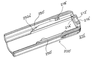
- FIG. 50 shows the external appearance of the lancet assembly 1000
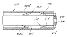
- FIG. 51 shows the external appearance of the injector 2000.
- the lancet assembly 1000 includes a lancet 1010 and a protective cover 1020.
- the lancet 1010 includes a lancet body 1040, a lancet cap 1060, and a puncture needle 1050.
- the metal puncture needle 1050 exists across the resin lancet body 1040 and the lancet cap 1060.
- the tip of puncture needle 1050 is covered with lancet cap 1060, and lancet cap 1060 and lancet body 1040 are integrally coupled via weakening member 1080.
- the protective cover 1020 is provided so as to surround a part of the lancet body 1040. After such a lancet assembly 1000 is loaded into the injector 2000, the lancet cap 1060 is removed. Thereby, since the front-end
- the injector 2000 shown in FIG. 51 is a device that can be used in combination with the lancet assembly 1000 to fire the lancet body with the tip of the puncture needle 1050 exposed.
- the injector 2000 includes a “plunger 2040 that can be engaged with the rear end of the lancet body and that fires the lancet body in the puncture direction” (see FIG. 54).
- the lancet assembly 1000 is inserted from the front end opening 2140 of the injector 2000 as shown in FIG.
- the rear portion 1160 of the lancet assembly 1000 is gripped by the distal end portion 2640 and the flange 2660 of the plunger 2040.
- FIG. 56 shows the injector 2000 in a state where the plunger is retracted and the firing energy is accumulated.
- the lancet cap 1060 When the loading of the lancet assembly 1000 into the injector 2000 is completed, the lancet cap 1060 is removed and the tip of the puncture needle 1050 is exposed.
- the removal of the lancet cap 1060 will be described as follows. As shown in FIGS. 52 and 53, the lancet body 1040 and the lancet cap 1060 are integrally coupled by a weakened portion 1080 positioned therebetween.
- the weakening member 1080 can be broken by rotating the lancet body 1040 and the lancet cap 1060 in the opposite directions around the puncture needle (FIG. 56 shows a mode of turning in the G direction). Thereby, the lancet cap 1060 can be removed.
- the front end opening 2140 of the injector 2000 is applied to a predetermined site to be punctured, such as a fingertip, and then the press portion 5420 of the trigger member 5140 is pressed (see FIG. 57).
- the press portion 5420 By pressing the press portion 5420, the plunger 2040 is fired forward (that is, the compressed spring is released), and puncture is performed by the puncture needle.
- the lancet assembly 1000 needs to be loaded into the injector 2000 at the time of puncture, and the user is burdened accordingly.
- the puncture device described above includes at least two elements, “lancet assembly” and “injector”, as a component, it is difficult to say that the entire device is a compact size (especially the size of the injector is relatively large). As a whole, a compact size is desired.
- the present invention has been made in view of the above circumstances. That is, the subject of this invention is providing the compact puncture device excellent in operativity. Yet another problem is to provide a puncture device that is excellent in safety after puncture.
- a lancet puncture device comprising a lancet, an injection spring, a trigger member and a holder (lancet holder) for accommodating them,
- the lancet comprises a lancet body, a lancet cap and a puncture needle, the puncture needle being present in these across the lancet body and the lancet cap;
- the trigger member has a pair of arm portions located inside the holder,
- the injection spring is attached to the lancet body, and the lancet body is locked to the arm part of the trigger member so that the compression state of the injection spring is maintained before puncturing,
- the trigger member Before the lancet cap is removed from the lancet, the trigger member cannot be pushed into the holder.On the other hand, when the lancet cap is removed from the lancet, the trigger member can be pushed into the holder.
- the lancet puncture device is provided in which the arm portion is bent and the locking of the lancet body is released.
- a lancet puncture device when the lock of the lancet body is released, the “lancet body with an exposed puncture needle” is fired in the puncture direction due to the extension of the compressed injection spring.
- a slope portion is provided on the inner wall of the holder (in particular, the inner wall surface on the front side or the rear side of the holder), and the arm portion rubs the slope portion when the trigger member is pushed. The arm portion bends by moving.
- One of the features of the lancet puncture device according to the present invention is substantially composed of four members such as “lancet”, “trigger member”, “holder (lancet holder)”, and “injection spring”. Is simple. Also, the so-called “injector” is not used, and the size of the entire lancet puncture device is relatively small. In particular, the lancet body of the lancet, the puncture needle, and the injection spring are all located inside or inside the trigger member without protruding from the trigger member, and thereby a compact puncture device is effectively realized.
- the lancet puncture device has the injection mechanism suitably incorporated in the lancet itself, thereby realizing a compact device size.
- the lancet body is locked to the arm portion of the trigger member so that the compression state of the injection spring is maintained before puncturing, but such locking can be released through removal of the lancet cap.
- This is one of the features of the present invention. Specifically, when the lancet puncture device of the present invention is in a state before the puncture operation (that is, a state where the tip of the puncture needle is covered by the lancet cap), the portion other than the grip portion of the lancet cap is in contact with the holder. It serves to prevent the trigger member from being pushed in due to the interaction.
- a state before the puncture operation that is, a state where the tip of the puncture needle is covered by the lancet cap
- the portion other than the grip portion of the lancet cap is in contact with the holder. It serves to prevent the trigger member from being pushed in due to the interaction.
- the portion other than the grip portion of the lancet cap is in contact with the holder. It serves to prevent the trigger member from being pushed in due to
- the tip of the arm part of the trigger member is between the "tip part of the cap arm part provided on the lancet cap” and the "slope part provided on the holder”.
- “pushing of the trigger member into the holder” is prevented.
- the tip of the arm part of the trigger member abuts both the tip part of the cap arm part of the lancet cap and the slope part ( That is, since the arm portion of the trigger member and the cap arm portion of the lancet cap are competing at the slope portion), the trigger member cannot be pushed into the lancet holder.
- the term “flexure” used in relation to the arm portion of the trigger member substantially means all kinds of modes in which the arm portion is displaced in the space in the holder. Therefore, for example, as an example, “deflection” means that the arm portion is displaced outward in the lancet holder, in particular, the arm portion so that the free ends of the tip portions of the pair of arm portions move away from each other. Means a mode of opening outward as a whole.
- the injection spring is attached to “the spring attachment portion provided on the inner wall surface (the inner wall surface of the rear end) on the rear side of the trigger member”, and the spring attachment portion includes a free end and A long member having a fixed end has a curved shape.
- the lancet puncture device having the above-described characteristics can be realized in various modes.
- a type lancet lancing device has a free end on the front side of the pair of arm portions of the trigger member, and a fixed end on the rear side thereof, and applies an external force to the trigger member from the rear side.
- the A type lancet puncture device is The rear end portion of the trigger member protrudes outward from the rear end opening (especially the rear opening end) of the holder, and the outer arm portion of the pair of trigger members extending forward from the rear end portion is the holder.
- the trigger member is arranged in the holder as a whole so as to be located on the outer surface of the side wall,
- the front part of the lancet cap protrudes outward from the front end opening of the holder, and a pair of parts provided on the side of the front part is located at the front end of the holder so that the lancet does not move backward with respect to the holder.
- Adjacent or other part of the front part is adjacent to the front opening of the holder,
- the lancet body and puncture needle of the lancet and the injection spring are all located inside and inside the pair of arm portions without protruding from the pair of trigger member arms, and each of the pair of arm portions is located in front of it. While the side forms a free end, the back side forms a fixed end, and before puncturing, it engages each side of the lancet body, thereby maintaining the compressed state of the injection spring
- the trigger member is moved forward with respect to the holder when the trigger member is pushed during the puncturing operation, the pair of arm portions expands outward, thereby engaging each side of the lancet body with each arm portion. It is characterized by being released.
- the trigger member when the lancet cap is removed from the lancet, the trigger member can be pushed forward. Specifically, the trigger member is moved into the holder so that the trigger member moves forward relative to the holder due to an external force applied to the rear end of the trigger member or the pair of outer arms. Can be pushed in.
- each arm portion (especially its free end) is placed on the slope portion provided on the front inner wall of the holder. As a result, each arm part automatically spreads outward.
- the lancet cap has a pair of cap arm portions extending rearward from a pair of front portions thereof.
- a trigger is provided between the tip of each cap arm portion of the lancet cap and the slope portion of the holder. It is preferable that the tip part of each arm part of the member is located.
- a reuse prevention wing is provided on the outer side of the arm portion of the trigger member so as to extend obliquely rearward, while the holder inner wall is prevented from being reused.
- a protrusion is provided, When pushing the trigger member at the time of puncturing operation, the reuse prevention wing of the arm part will rub on the reuse prevention protrusion of the holder and move forward until it exceeds it, After the puncture, the reuse prevention wing and the reuse prevention protrusion can be locked, thereby restricting the rearward movement of the trigger member and returning the trigger member after the puncture to the state before the puncture. I can't do it.
- B type lancet lancing device In the B type lancet puncture device, the front side of the pair of arm portions of the trigger member forms a fixed end, while the front side forms a free end, and the arm portion is caused by applying an external force to the trigger member from the front.
- the B-type lancet puncture device is The trigger member is disposed in the holder as a whole so that only the puncture opening at the front end of the trigger member protrudes outward from the front end opening (particularly the front opening end) of the holder,
- the front part of the lancet cap protrudes outward from the front end opening of the holder, and the pair of parts provided on the side of the front part is the front end opening of the holder so that the lancet does not move backward with respect to the holder Is adjacent to
- Each of the arm portions of the pair of trigger members has a fixed end on the front side and a free end on the rear side, and before the puncture, engages each side of the lancet body, thereby
- the injection spring is maintained in a compressed state, and when the trigger member is moved backward with respect to the holder when the trigger member is pushed during the puncturing operation, each arm portion of the pair spreads outward.
- each arm portion of the pair spreads outward.
- the trigger member when the lancet cap is removed from the lancet, the trigger member can be pushed backward. Specifically, the trigger member can be pushed into the holder so that the trigger member moves backward relative to the holder due to an external force applied to the puncture opening at the front end of the trigger member. it can.
- each arm portion when the trigger member moves rearward with respect to the holder, each arm portion (particularly, its free end) is placed on the slope portion provided on the inner wall on the rear side of the holder. As a result, each arm part automatically spreads outward.
- each arm portion includes a member that applies a force to each arm portion of the trigger member in the lateral direction of the lancet body.
- a member that exerts a force on each arm part of the trigger member in the lateral direction of the lancet body pushes the inner wall of the holder, or pushes the inner wall of the holder when each arm part starts to spread outward.
- the pushback portion may be in the form of an arm that protrudes obliquely outward from each arm portion.
- a reuse prevention wing is provided on the outer side of the rear side wall surface of the trigger member so as to extend obliquely forward, while the holder inner wall is reused. Prevention protrusions are provided, When pushing the trigger member during the puncture operation, the reuse prevention wing of the trigger member will rub on the reuse prevention protrusion of the holder and move backward until it exceeds, After the puncture, the reuse prevention wing and the reuse prevention projection can be locked, thereby restricting the forward movement of the trigger member and returning the trigger member after the puncture to the state before the puncture. I can't do it.
- the C-type lancet puncture device has a fixed end on the front side of the pair of arm portions of the trigger member, and a free end on the rear side thereof, and applies an external force to the trigger member from the rear side.
- the C-type lancet puncture device is The trigger member is arranged in the holder as a whole so that only the pressing portion at the rear end of the trigger member protrudes outward from the rear end opening (particularly the rear opening end) of the holder,
- the front part of the lancet cap protrudes outward from the front end opening of the holder, and a pair of parts provided on the side of the front part is located at the front end of the holder so that the lancet does not move backward with respect to the holder.
- Each of the arm portions of the pair of trigger members has a fixed end on the front side and a free end on the rear side, and before the puncture, engages each side of the lancet body, thereby
- the injection spring is maintained in a compressed state, and when the trigger member is moved forward with respect to the holder when the trigger member is pushed during the puncture operation, each arm portion spreads outward, thereby The engagement of each arm portion with each side of the lancet body is released.
- the lancet cap when the lancet cap is removed from the lancet, it can be pushed forward of the trigger member. Specifically, the trigger member can be pushed into the holder so that the trigger member moves forward relative to the holder due to an external force applied to the pressing portion at the rear end of the trigger member. it can.
- each arm portion when the trigger member moves forward relative to the holder, each arm portion (particularly, its free end) is placed on the slope portion provided on the front inner wall of the holder. As a result, each arm part automatically spreads outward.
- the trigger member has a flexible member (or flexible portion) on the side surface of the main body, and the lancet cap is attached to the lancet.
- the flexible member of the trigger member In a state where the lancet cap is removed from the lancet (ie, a state before the lancet cap is removed), the flexible member of the trigger member is located between the main body portion of the lancet cap and the wall portion of the holder.
- the flexible member of the trigger member is preferably positioned so as to be accommodated in a concave portion provided in the wall portion of the holder.
- a reuse prevention wing is provided on the outer side of the front side wall surface of the trigger member so as to extend obliquely rearward, while the holder inner wall is reused. Prevention protrusions are provided, When the trigger member is pushed during the puncture operation, the reuse prevention wing of the trigger member moves on the reuse prevention protrusion of the holder and moves forward until it exceeds it, After the puncture, the reuse prevention wing and the reuse prevention protrusion can be locked, thereby restricting the rearward movement of the trigger member and returning the trigger member after the puncture to the state before the puncture. I can't do it.
- the present invention also provides a lancet puncture device with a suitable firing spring attachment.
- a lancet puncture device is A lancet puncture device comprising a lancet, an injection spring, a trigger member and a holder for receiving them, An injection spring is attached to the spring mounting portion provided on the rear side inner wall of the trigger member,
- the spring mounting portion is characterized in that a long member having a free end and a fixed end (in particular, a “substantially plate-like member having a generally rectangular shape”) is curved.
- a long member having a free end and a fixed end has a hook shape such as a fishhook shape or a U-shaped shape.
- Such an injection spring mounting portion can facilitate the assembly of the lancet puncture device (in particular, the provision of such an injection spring mounting portion makes it easy to attach the injection spring to the trigger member. )
- the present invention also provides a “holder”, “lancet”, and “trigger member” that constitute the puncture device of the present invention described above and below, and includes “a holder, a lancet, a trigger member, and an injection spring”.
- a puncture device kit for assembling the puncture device of the present invention is also provided.
- the lancet puncture device of the present invention is substantially composed of four elements such as “lancet”, “trigger member”, “holder” and “injection spring”, so that the device configuration is very simple. It has become.
- the lancet puncture device of the present invention has a relatively simple configuration due to the fact that “lancet”, “trigger member”, and “injection spring” connected thereto are accommodated in the holder. Yes.
- the other elements can be easily manufactured by injection molding resin (note that although the injection spring is usually made of metal, it may be made of resin, such as a helical spring, a wave, etc. It may be a resin spring in the form of a square spring or the like).
- the overall size of the lancet puncture device is mainly determined by the size of the holder, the holder itself can be made compact by making the elements accommodated in it as small as possible.
- the puncture device of the present invention as a whole Can be made compact. Because of such a compact size, the lancet puncture device of the present invention is excellent in terms of transportation efficiency and storage space. Moreover, since it can be made into a size that can be picked with a finger, operability during actual use is improved.
- the lancet puncture device of the present invention prevents the lancet body from being locked with the trigger member of the lancet body and cannot fire the lancet in a state before the lancet cap is attached. Has been.
- the lancet puncture device of the present invention has a structure in which the puncture needle once provided for puncture cannot be used again, it is excellent in terms of hygiene, safety, and the like.
- the user of the lancet puncture device can only use the device as a “disposable type”, and the used lancet puncture device of the present invention is mistakenly used for blood collection of other blood collection subjects. There is no.
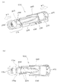
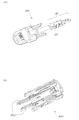
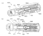
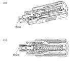
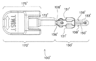
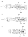
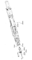
- FIGS. 1A and 1B are external views of an A type lancet puncture device.
- FIG. 2 is an external view of an A-type lancet puncture device.
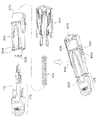
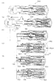
- FIG. 3 is an external view and an exploded perspective view of an A type lancet puncture device.
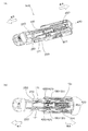
- FIGS. 4A and 4B are a perspective view and a top view showing the internal structure of an A-type lancet puncture device.
- FIG. 5A shows a lancet (especially a locking part of the lancet body) in the A type
- FIG. 5B shows a trigger member (especially a locked part of the arm part) in the A type.
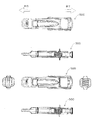
- 6 (a) and 6 (b) are external views of a lancet holder used for an A type lancet puncture device.
- FIG. 1A and 1B are external views of an A type lancet puncture device.
- FIG. 2 is an external view of an A-type lancet puncture device.
- FIG. 3 is an external view and an exploded perspective view
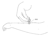
- FIGS. 7 is a diagram schematically illustrating a puncture operation performed by the user.
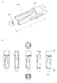
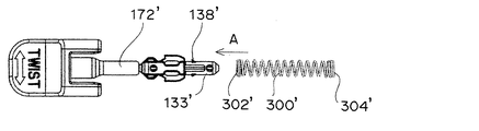
- FIGS. 8A and 8B are external views of a lancet used in an A type lancet puncture device.
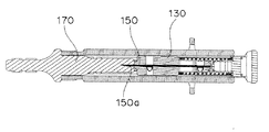
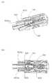
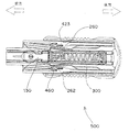
- FIG. 9 is a cross-sectional view of an A-type lancet puncture device.
- FIGS. 10A and 10B are external views of a trigger member used in an A type lancet puncture device.
- FIG. 11 is an external view of an injection spring used for an A type lancet puncture device.
- FIGS. 12A and 12B are a perspective view and a top view showing the internal structure of an A-type lancet puncture device before use.
- FIGS. 13A and 13B are a perspective view and a top view showing the internal structure of the A-type lancet puncture device with the cap removed.
- FIGS. 14A and 14B are a perspective view and a top view showing an aspect at the time when the lancet body is unlocked from the arm portion of the trigger member in the A type.
- FIGS. 15A to 15D are diagrams schematically showing a change with time of the arm portion when the trigger member is pushed in the A type.
- FIGS. 16A and 16B are a perspective view and a top view showing a state in which “a lancet body having an exposed puncture needle” is fired in the puncture direction in the A type.
- FIGS. 17A and 17B are a perspective view and a top view showing an aspect of puncture of an A type lancet puncture device.
- FIGS. 18A to 18C are schematic diagrams for explaining a puncture depth adjusting mechanism in the A type.
- FIG. 19 is a top view for explaining a reuse prevention mechanism in the A type.
- 20 (a) to 20 (f) are top views schematically showing a change with time of the A-type lancet puncture device in use.
- FIGS. 21A to 21F are side cross-sectional views schematically showing a change with time of the A-type lancet puncture device in use.
- 22 (a) to 22 (c) are schematic views showing a temporal aspect of the spring mounting portion during assembly of the lancet puncture device of the present invention.
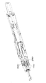
- FIG. 23A and 23B are external views of a B-type lancet puncture device.
- FIG. 24 is an external view of a B-type lancet puncture device.
- FIG. 25 is an external view and an exploded perspective view of a B-type lancet puncture device.
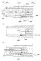
- Fig.26 (a) is the perspective view which showed the holder which comprises a B type puncture device.
- FIG. 26B is a perspective view showing a state in which the upper half of the holder shown in FIG.
- FIG.26 (c) is the top view which showed the state which cut off the upper half of the holder shown to Fig.26 (a).
- Fig.27 (a) is the perspective view which showed the trigger member which comprises a B type lancet puncture device.
- FIG. 26 (a) is the perspective view which showed the trigger member which comprises a B type lancet puncture device.
- FIG. 27B is a top view showing a trigger member constituting the B-type lancet puncture device.
- FIG. 28A is a perspective view showing a lancet constituting a B-type lancet puncture device.
- FIG. 28B is a top view showing a lancet constituting a B-type lancet puncture device.
- FIG. 29 is a perspective view showing the internal structure of a B-type lancet puncture device before use.
- FIG. 30 schematically shows how the injection spring is attached to the lancet in the B type, using these top views.
- FIG. 31 schematically shows how the injection spring with the lancet attached is attached to the trigger member in the B type, using these top views.
- FIG. 32 schematically shows a state in which the puncture device of the present invention is formed by incorporating a lancet and a trigger member attached to an injection spring into the holder in the B type, using these top views.
- FIG. 33 schematically shows the puncture device of the present invention formed as shown in FIG. 32 in a perspective view.
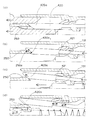
- FIG. 34 (a) is a series of FIG. 34 sequentially showing a process of puncturing a target site using a B-type lancet puncture device, and shows a top view of the puncture device in an assembled state in the state shown in FIG. And it shows typically so that the state of the inside can be understood in the state where the upper half of the trigger member is cut off.
- FIG. 34 (b) is a series of FIG.
- FIG. 34 shows the process of puncturing a target site using a B-type lancet puncture device, in a state where the lancet cap is removed from the lancet after the state of FIG. However, a state in which the upper half of the front end portion of the trigger member is cut off is schematically shown.
- FIG. 34 (c) is a series of FIG. 34 showing the process of puncturing a target site using a B type lancet puncture device in order, and punctures the front end opening of the trigger member after the state of FIG. 34 (b).
- FIG. 35 schematically shows a state in which a target site is assigned (the device itself is the same as in the state of FIG. 34B).
- FIG. 34 (d) is a series of FIGS.
- FIG. 34 (e) is a series of FIG. 34 showing the process of puncturing a target site using a B-type lancet puncture device in order, and after the state of FIG. 34 (d), the arm portion is engaged with the lancet body.
- FIG. 34 (f) is a series of FIG. 34 that sequentially shows the process of puncturing a target site using a B-type lancet puncture device.
- the extended injection spring has its original length.
- FIG. 35 corresponds to a series of FIG. 34 that sequentially shows a process of puncturing a target site using a B-type lancet puncture device
- FIG. 35 (a) is a schematic perspective view corresponding to FIG. 34 (a). Shown in FIG. 35 corresponds to a series of FIG. 34 that sequentially shows the process of puncturing a target site using a B-type lancet puncture device
- FIG. 35 (b) is a schematic perspective view corresponding to FIG. 34 (b). Shown in FIG. 35 corresponds to a series of FIG.
- FIG. 35 (c) is a schematic perspective view corresponding to FIG. 34 (c). Shown in FIG. 35 corresponds to a series of FIGS. 34 sequentially illustrating the process of puncturing a target site using a B-type lancet puncture device, and FIG. 35 (d) is a schematic perspective view corresponding to FIG. 34 (d). Shown in FIG. 35 corresponds to a series of FIGS. 34 sequentially illustrating a process of puncturing a target site using a B-type lancet puncture device, and FIG. 35 (e) is a schematic perspective view corresponding to FIG. 34 (e). Shown in FIG. 35 corresponds to a series of FIGS. 34 sequentially illustrating a process of puncturing a target site using a B-type lancet puncture device, and FIG. 35 (e) is a schematic perspective view corresponding to FIG. 34 (e). Shown in FIG. 35 corresponds to a series of FIGS. 34 sequentially illustrating a process of puncturing a target site using a B-
- FIG. 35 corresponds to a series of FIG. 34 sequentially illustrating the process of puncturing a target site using a B-type lancet puncture device
- FIG. 35 (f) is a schematic perspective view corresponding to FIG. 34 (f).
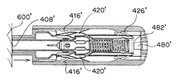
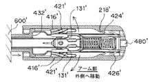
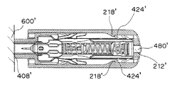
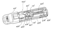
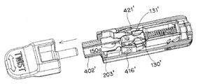
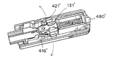
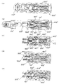
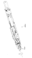
- FIGS. 36A and 36B are external views of a C-type lancet puncture device.
- FIG. 37 is an external view of a C-type lancet puncture device.
- FIG. 38 is an external view and an exploded perspective view of a C-type lancet puncture device.
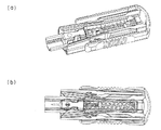
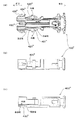
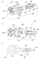
- FIG. 39 (a) is a perspective view of a holder constituting a C-type puncture device.
- FIG. 39 (b) and 39 (c) are a perspective view and a top view showing a state where the upper half of the holder shown in FIG. 39 (a) is cut away.
- FIG. 40A is a perspective view showing a trigger member constituting a C-type lancet puncture device.
- FIG. 40B is a perspective view showing the back side of the trigger member shown in FIG.
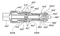
- FIGS. 41A to 41C are a top view, a side view, and a side sectional view showing a trigger member constituting a C-type lancet puncture device.
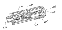
- FIGS. 42A to 42C are a perspective view, a top view, and a cross-sectional view showing a lancet constituting a C-type lancet puncture device.
- FIG. 43 is a perspective view showing the internal structure of a C-type lancet puncture device before use.
- FIG. 44 is a schematic view showing an aspect of the injection spring and the spring mounting portion when assembling the puncture device together with an assembly aspect of the entire device.
- FIG. 45 is a schematic diagram for explaining a trigger member push-in prevention mechanism.
- 46 (a) to 46 (e) are perspective views schematically showing a change with time of a C-type lancet puncture device in use.
- 47 (a) to 47 (e) are top views schematically showing the change with time of the C-type lancet puncture device during use.
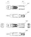
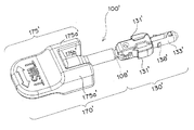
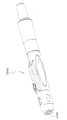
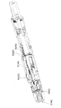
- FIG. 48 is a top view, a side view, a bottom view, and an end view schematically showing a modification example of the appearance of the lancet puncture device according to the present invention.
- 49 is a perspective view of the lancet puncture device shown in FIG. 48.
- FIG. FIG. 50 is a perspective view showing the appearance of the lancet assembly.
- FIG. 51 is a perspective view showing the appearance of the injector.
- FIG. 52 is a perspective view showing the appearance of the lancet.
- FIG. 53 is a perspective view of the lancet assembly shown in FIG. 50 divided in half so that the inside of the lancet can be seen.
- FIG. 54 is a perspective view showing a state before the lancet assembly is loaded into the injector.
- FIG. 55 is a perspective view showing a state in which the lancet is gripped by the tip of the plunger by loading the lancet assembly.
- FIG. 56 is a perspective view showing a state where the lancet assembly is completely loaded and the plunger cannot be retracted.
- FIG. 57 is a perspective view showing a state in which the lancet cap is removed and puncture is possible.
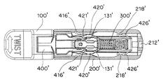
- a type lancet lancing device 100 lancet 130 lancet body 131 Locking part (engagement part) provided on the lancet body 133 Rear end of lancet 134 Puncture depth adjustment wing a provided on lancet body 150 puncture needle 150a tip of puncture needle 170 lancet cap 171 cap arm part of lancet cap 171a tip part of cap arm part 175 front part of lancet cap 175a pair part 175b cap region between pair part (central region) 200 holder (lancet holder) 203 Open end of holder (puncture opening) 220 Inner wall surface of the holder 222 Space generated around the tip of the arm portion of the trigger member 230 Slope portion 250 Slope portion provided on the inner wall surface of the holder 250a Slope surface 260 Protrusion d provided on the inner wall surface of the holder 280 Projection 280a Front side of the projection (slope surface) 280b Rear side surface of protrusion (puncture depth adjustment surface) 300 Injection spring 400 Trigger member
- lancet puncture device of the present invention will be described in detail with reference to the accompanying drawings. Along with these explanations, a holder, a trigger member, a lancet and an injection spring constituting the lancet puncture device, and a puncture device kit comprising them will also be explained.
- lancet puncture devices having the following characteristics will be described as “A type”, “B type”, and “C type”, respectively.
- -A type The front side of the arm part of the pair of trigger members forms a free end, while the rear side forms a fixed end, and the arm part bends due to external force applied to the trigger member from the rear. With a device.
- -B type While the front side of the arm part of the pair of trigger members forms a fixed end, the rear side forms a free end, which bends the arm part by applying external force to the trigger member from the front.
- -C type The front side of the arm part of the pair of trigger members forms a fixed end, while the rear side forms a free end. The arm part bends when an external force is applied to the trigger member from the rear.
- the “A type” lancet puncture device will be described, and then the “B type” and “C type” lancet puncture devices will be described in order. It should be noted that items that are not specifically described or items that are not unique to each type apply to all of “A type”, “B type”, and “C type”.
- the “direction” used in this specification is defined as follows.
- the direction in which the puncture needle is fired during puncturing is the “front” direction, and the opposite direction is the “rear” direction.
- the direction away from the lancet puncture device is the “out” direction, and the opposite direction (ie, the direction toward the inside of the device) is the “in” direction or the “inside” direction.
- a type lancet lancing device ] ⁇ Basic configuration of lancet puncture mechanism ⁇ (Basic configuration) 1-3 show an A type lancet lancing device 500. 1 and 2 show an external view of an A type lancet puncture device 500, and FIG. 3 also shows an exploded view and an exploded view of the A type lancet puncture device 500.
- the lancet puncture device 500 according to the present invention is mainly composed of “lancet 100”, “holder (particularly lancet holder) 200”, “injection spring 300”, and “trigger member 400”. .
- the lancet puncture device 500 has a structure in which a lancet 100, an injection spring 300, and a trigger member 400 are accommodated in a lancet holder 200.
- the injection spring 300 is accommodated in the lancet holder 200 so that the injection spring 300 is sandwiched between the rear end of the lancet 100 and the rear end of the trigger member 400.
- FIG. 4B in the lancet holder 200, one end of the injection spring 300 is attached to the rear end 133 of the lancet 100, and the injection spring 300 The other end is attached to “the fitting portion 450 between the pair of arm portions 420 of the trigger member 400”.
- the injection spring 300 in the lancet holder 200 is compressed between the “lancet 100” and the “fitting portion 450 between the pair of arm portions 420”. It has become.
- the lancet puncture device 500 of the present invention the lancet body 130 is locked to the arm portion 420 of the trigger member 400 so that the injection spring 300 attached to the lancet body 130 is in a compressed state ( For example, see FIG.
- the rear end 470 of the trigger member has a rear end opening 270 (particularly rearward as shown). It protrudes outward from the opening end.
- the pair of outer arm portions 440 of the trigger member extending forward from the rear end portion 470 of the trigger member is located on the outer surface of the side wall of the holder 200.
- the lancet cap 170 of the lancet has a front portion 175 protruding outward from the front end opening 203 of the holder.
- the paired portion 175a provided on the side of the front portion 175 of the lancet cap is adjacent to the front end 204 of the holder and / or the other portion of the front portion 175 of the lancet cap (especially The cap central region 175b between the paired portions 175a) is adjacent to the trigger member front end opening 203 (ie, the puncture opening), thereby preventing the lancet 100 from moving backward relative to the holder 200. ing.
- the lancet cap when the lancet cap is removed from the lancet, an external force is applied to the rear end portion 470 of the trigger member or the pair of outer arm portions 440.
- the trigger member can be pushed into the holder so that the member 400 moves forward relative to the holder 200.
- the holder 200 (particularly, “lancet holder” from the viewpoint of housing the lancet) has, for example, a rectangular tube shape as a whole.
- a holder 200 is relatively small.
- the shape of the holder 200 is not necessarily limited to the rectangular tube shape, and may be, for example, a cylindrical shape.
- the holder 200 may be formed of any kind of resin material as long as it is a resin material used for a general lancet. As shown, the holder 200 has an open end 203 in front of it. The open end 203 is a portion where the holder of the lancet 100 is inserted when the puncture device is assembled, and is also a portion which is applied to a portion to be punctured (for example, a fingertip).
- the inner wall surface of the holder 200 is provided with a “slope portion” that functions in cooperation with the trigger member.
- the “slope portion” is indicated by the reference number 250 in FIGS. 4A and 4B, for example.
- the slope portion is a portion where the tip of the arm portion of the trigger member slides or slides when the trigger member is pushed in, and allows the arm portion to bend during a puncture operation.
- a collar portion 230 is provided on the outer surface of the holder 200 (particularly on the rear side of the outer surface). The user can put his / her finger on the heel part 230 during the puncturing operation, and therefore the heel part 230 contributes to a smooth puncturing operation (see FIG. 7).
- the lancet 100 used for the lancet puncture device 500 is shown in FIGS. 8 (a) and 8 (b).
- FIG. 8B shows the lancets 100 from different sides.
- the size of the lancet 100 is as small as the holder 200 and is large enough to be accommodated in the holder 200.
- the lancet 100 includes a lancet body 130, a lancet cap 170, and a puncture needle 150 (see FIG. 9 for the puncture needle 150).
- the puncture needle 150 may be a metal needle, for example.
- the puncture needle 150 is present in the lancet body 130 and the lancet cap 170 made of resin, and the tip 150 a of the puncture needle 150 is covered by the lancet cap 170. ing. It is preferable that the lancet body 130 and the lancet cap 170 are integrally coupled via a few contact points.
- Such a lancet 100 can be manufactured by so-called insert molding in which a puncture needle 150 is inserted into a mold and a resin (for example, polyethylene, polypropylene, etc.) is molded, and the contact portion is combined with the insert molding. Can be manufactured. Therefore, the contact portion can be formed from the same resin material as the lancet cap 170 and the lancet body 130. Such contact portions are required to be destroyed during the cap removal operation, and therefore the contact portions can also be referred to as “weakened portions” or “easy breakable portions”. In addition, you may provide a notch in a contact part so that a contact part may be destroyed more easily. In some cases, the contact portion may be cut in advance, or may not have the contact portion.
- a resin for example, polyethylene, polypropylene, etc.
- the “lancet body 130 with the distal end 150a of the puncture needle 150 exposed” may be formed by “grinding operation” of the lancet cap. As long as it can be obtained.
- the front portion 175 of the lancet cap 170 has a flat front end, and the user can grasp the portion with a finger and perform a twisting operation such as twisting or rotating around the puncture needle. The portion that can be picked by the finger corresponds to the “gripping portion”.
- the lancet cap 170 has a cap arm portion 171 extending rearward. As shown in FIGS. 8A and 8B, the cap arm portion 171 has a pair of arm portions extending rearward from the pair portion 175a of the front portion 175 of the lancet cap. preferable. Moreover, it is preferable that the cap arm part 171 is comprised from the elongate part which makes a pair so that it may be illustrated. In such a cap arm portion 171, as shown in the drawing, each cap arm portion 171 is rearward so as to be symmetric about the central axis of the lancet 100 (that is, the central axis in the longitudinal direction of the lancet 100 or the puncture needle 150.
- the cap arm portion 171 As for the extension of the cap arm portion 171, when the cap arm portion 171 is incorporated in the holder 200, it needs to extend backward until reaching the inside of the holder 200. (See FIG. 4A.) In other words, in the A type lancet puncture device 500, the tip end portion of the cap arm portion 171 of the lancet cap 170 is positioned in the holder 200.
- Such features are as follows. As a result, “pushing of the trigger member into the holder” is prevented (detailed in a later paragraph).
- the body of the puncture needle 150 is fixed. Accordingly, at the time of puncturing, the lancet body 130 is fired forward together with the puncture needle 150. Further, the lancet body 130 is provided with “a locking portion 131 for locking the lancet to the trigger member” on its side, and “a wing a (for adjusting the puncture depth during puncture) ( 134) "(see FIG. 8A).
- FIGS. 10 (a) and 10 (b) The trigger member 400 used in the lancet puncture device 500 is shown in FIGS. 10 (a) and 10 (b).
- FIG. 10B shows the trigger members 400 from different sides.
- the size of the trigger member 400 is also small like the holder 200 and the lancet 100 and has a size that can be accommodated in the holder 200. For example, the lengths (L 3 , L 4 , W 3 , W 4 , H 1 ) shown in FIG.
- the trigger member 400 has at least a pair of arm portions 420 that are positioned inside the holder. As shown in FIG. 10, each of the pair of arm portions 420 has a free end on the front side and a fixed end on the rear side.
- the trigger member 400 includes a further arm portion in addition to the arm portion 420.
- the trigger member 400 has two arm portions (420, 440) each composed of a pair of long portions as shown in the drawing. More specifically, the trigger member 400 includes a pair of arm portions 420 provided inside the holder and a pair of outer arm portions 440 provided on the outer surface of the lancet holder. It can be said that the trigger member 400 includes a pair of arm portions 420 on the inner side and a pair of second arm portions 440 on the outer side.
- a trigger member 400 may be formed from the same resin as the lancet 100 (for example, polyethylene, polypropylene, etc.).
- the arm part 420 to be positioned inside the holder has flexibility as a whole.
- the front end portions 420a of the arm portions 420 forming a pair that is, the free end portions (see FIG. 10B) bend outward in a direction away from each other.
- the arm portion 420 functions favorably so that the lancet body is unlocked.
- the second outer arm portion 440 is provided on the outer surface of the holder (particularly, the outer surface of the side wall of the holder), and is a portion that can be gripped at the time of puncturing or the like, and therefore needs to be particularly flexible. There is no.
- the tip portions 420a of the pair of arm portions 420 that are to be positioned inside the holder preferably have a tapered shape as shown in FIG. 10 (a).
- the surface 420a 1 of the distal end portion 420a is preferably to have the surface of the slope portion 250 of the holder 200 (e.g., FIGS. 4 (a) refer) and a complementary shape, thus, pushing the trigger member
- the distal end portion 420a of the arm portion 420 can be suitably slid or slid on the slope portion 250.
- the arm portion 420 to be positioned inside the holder is provided with a locked portion to which the lancet body 130 is locked before puncturing. Specifically, as shown in FIG. 10A, a raised locking portion 421 is formed on the inner side surfaces of the pair of arm portions 420.
- a spring mounting portion 450 for mounting an injection spring is provided between the pair of arm portions 420.
- the injection spring attached to the trigger member is present inside the pair of arm portions 420.
- the injection spring 300 is shown in a perspective view in FIG.
- the injection spring 300 is used for “injection” or “firing” as the name suggests.
- the ejection spring 300 is a spring that applies a propelling force for firing or puncturing to the puncture needle 150, that is, the “lancet body having an exposed puncture needle”.
- the injection spring 300 is provided in a compressed state between the “mounting portion 450 between the pair of arm portions 420” and the “lancet 100” (see FIG. 4).
- the injection spring 300 is preferably made of metal, for example, a metal coil spring.
- the size of the injection spring 300 is not particularly limited as long as it is accommodated in the holder.
- the lancet body 130, the puncture needle 150, and the injection spring 300 are all inside the pair of arm portions 420 without protruding from the pair of arm portions 420 of the trigger member 400. Is located.
- the lancet 100 (or the injection spring 300 attached thereto) is inserted from the holder front opening end 203, and the trigger member 400 (and the injection spring 300 attached thereto) is inserted from the rear opening of the holder. It is obtained by inserting and connecting the lancet 100 and the trigger member 400 to each other in a state where the injection spring 300 is compressed (see FIG. 3). Incidentally, a force acts backward on the trigger member 400 due to the compressed injection spring, but the prevention wing 460 of the trigger member 400 is formed on the protrusion d (or the protrusion d) (260) on the inner wall surface of the lancet holder. In order to abut (see FIG. 12B), the trigger member is prevented from coming off from the holder.
- the lancet body 130 is locked to the arm portion 420 of the trigger member as shown in FIG. 12 (b), as “wing 460 of the trigger member 400” and “projection d (260) on the inner wall surface of the lancet holder”. It can be understood that the contact is made through the contact with the "engagement part 131 of the lancet body 130" and the "abutment part 421 of the arm part 420 of the trigger member 400". In such an embodiment, a forward force is applied to the lancet 100 due to the compressed injection spring 300 in the lancet holder 200, and the lancet 100 tries to move forward, but the locking portion of the lancet body 130.
- the lancet body 130 is locked or fixed to the trigger member 400, whereas the lancet cap 170 is not locked or fixed to the trigger member 400. Therefore, the lancet cap 170 is punctured. It can be removed.
- the injection spring 300 is attached to the trigger member 400, but in the present invention, the spring attachment portion 450 of the trigger member can function suitably.
- the spring mounting portion 450 of the trigger member is formed of a long member having a curved shape having a free end and a fixed end. Assembly (i.e., mounting of the injection spring 300) is effectively assisted. That is, if the spring mounting portion 450 has a hook shape such as a fishhook shape or a U-shape as shown in FIGS. 10 and 22, the spring mounting portion 450 can be easily bent inward. (See FIGS. 22 (a) and (b)), the engagement of the firing spring with the coil can be effectively assisted.
- Such spring mounting portion 450, the second protrusion to the first protrusion 450a 1 and the fixed end to the free end side as shown in preferably has a protrusion 450a that protrudes outward (in particular FIG. 22 (a) 450a 2 is preferably provided).
- a protrusion 450a that protrudes outward
- FIG. 22 (a) 450a 2 is preferably provided.
- the cap arm portion of the lancet is positioned in the holder 200.
- the tip portion 171 a of the cap arm portion 171 of the cap is located in the holder 200.
- the tip end portion 171a of the cap arm portion 171 is positioned in the vicinity thereof along the inner wall of the lancet holder. More specifically, the tip end portion 171 a of the cap arm portion 171 extends so as to pass through the space between the “inner wall surface 220 of the holder” and the slope portion 250 of the holder.
- the tip 420a of the arm 420 of the trigger member 400 is positioned between the “tip 171a of the cap arm 171 of the lancet cap 170” and the “slope 250 of the holder”. As a result, “pushing of the trigger member into the holder” is prevented.
- the tip end portion 420a of the arm portion 420 of the trigger member 400 is moved to the tip end portion 171a of the cap arm portion 171 of the lancet cap 170 (more specifically, Is in contact with both the slope portion 250 (more specifically, the slope surface of the slope portion), so that the trigger member 400 cannot be pushed into the lancet holder.
- the cap arm portion is also removed, so that a space is created around the tip portion 420 a of the arm portion 420 of the trigger member 400. (See especially reference number 222 in FIG. 13B for “space”).
- the tip part 420a of the arm part 420 can be bent so as to move into the space.
- the portion 131 "and the" locked portion 421 of the arm portion 420 of the trigger member 400 "are unlocked (see FIGS. 14A and 14B).
- the slope angle ⁇ (see FIG. 13A) of the slope portion 250 is preferably about 10 ° to 50 °, more preferably about 20 ° to 40 °.
- the slope surface 250a of the front end surface 420a 1 is the holder of the slope portion 250 of the arm portion 420
- the arm portion 420 automatically spreads outward in the direction in which the tip portions 420a of the pair of arm portions 420 are separated from each other. By bending in this way, the “locking portion 131 of the lancet body 130” and the “locked portion 421 of the arm portion 420 of the trigger member 400” are reliably released (see FIG. 14).
- the lancet puncture device 500 of the present invention is preferably provided with a puncture depth adjustment mechanism.
- the lancet body 130 is provided with a puncture depth adjustment wing a (134), while the holder 200 is provided with a puncture depth adjustment protrusion b (260).
- the wing a (134) of the lancet body collides with the protrusion b (260) of the holder at the time of puncturing, whereby the open end of the holder at the time of puncturing.
- the length of the puncture needle exposed from (1) is limited (see “L 6 ” in FIG.
- the “puncture depth” can be adjusted by appropriately changing “the installation position of the wing a (134) in the lancet body 130” and / or “the installation position of the protrusion b (260) in the holder 200”. .
- the protrusion b (260) in the holder 200 is preferably formed integrally with the slope portion 250.
- the lancet puncture device 500 of the present invention is preferably provided with a reuse prevention mechanism.
- FIG. 19 shows an embodiment of the lancet puncture device 500 after puncture.
- the main parts contributing to the reuse prevention mechanism are “a reuse prevention wing c (423) provided outside the arm portion (420) of the trigger member 400” and “a reuse prevention protrusion d (provided on the inner wall of the holder). Or convex part d) (260) ".
- the wing c (423) of the trigger member 400 connected to the lancet body 130 is protruded from the holder even when the lancet body 130 is moved backward to obtain the compressed state of the injection spring 300 again after puncturing.
- the lancet puncture device of the present invention can also be referred to as a “single use device”.
- the “wing 460 of the trigger member 400” that functioned to “prevent falling out” of the trigger member before the puncture comes into contact with the “stepped portion 262 provided on the inner wall of the holder”.
- the reuse prevention function is strengthened.
- FIG. 20 and FIG. 21 show changes over time of the lancet lancing device 500, respectively.
- FIGS. 20 (a) to 20 (f) and FIGS. 21 (a) to 21 (f) indicate states at the same time as long as the alphabet parts are the same. I want to be.
- the lancet puncture device 500 of the present invention in a state before puncturing is shown in FIGS. 20 (a) and 21 (a).
- the lancet cap 170 is removed from the lancet, as can be seen from the modes shown in FIGS. 20 (b) and 21 (b).
- the lancet cap 170 (particularly the gripping portion 172) is rotated to destroy the “contact portion between the lancet body 130 and the lancet cap 170”, and then the lancet cap 170 is pulled forward.
- the grip part 172 of the lancet cap 170 is pulled out while twisting with the other finger.
- “the lancet body 130 including the exposed puncture needle 150” can be obtained in the holder 200 (see FIGS. 20C and 21C).
- a predetermined site for example, fingertip
- an operation of pushing the trigger portion 400 toward the inside of the holder is performed (see FIGS. 20D and 21D).
- the trigger portion may be pushed in by pressing the rear end portion of the trigger portion forward while holding the holder 200.
- the second outer arm portion 440 of the trigger member provided on the outer surface of the holder may be pinched with a finger, and the puncture device may be pressed against a “predetermined site to be punctured” (ie, “seal” It may be an operation like “press”.)
- a “predetermined site to be punctured” ie, “seal” It may be an operation like “press”.
- the tip of the inner arm portion 420 of the trigger member rubs the slope portion, causing the inner arm portion 420 to bend outward.
- the locking portion 131 and the arm portion of the lancet body are bent.
- the contact state of 420 with the locked portion 421 is released (FIGS. 20D and 21D show the mode when the contact state is released).
- the lock of the lancet body with respect to the arm part 420 of the trigger member 400 is released.
- the lancet body is unlocked, the compressed injection spring 300 is extended, and the lancet body 130 having the exposed puncture needle 150 is fired in the puncture direction.
- the lancet body 130 moves in the puncturing direction, and the puncture needle 150 is exposed from the opening end 203 of the holder, and a predetermined part applied to the opening end 203 is punctured (FIG. 20 ( e) and FIG. 21 (e)).
- the extended injection spring 300 tries to return to the original shape, so that the puncture needle 150 retracts quickly.
- the lancet body 130 having the exposed puncture needle 150 is attached to the injection spring 300, the lancet body 130 is retracted in a form pulled by the injection spring, and finally The puncture needle 150 is housed in the holder 200.
- the state after puncturing is shown in FIGS. 20 (f) and 21 (f).
- the push-in of the trigger part is added.
- the puncture device of the present invention it can be performed by pressing the rear end part of the trigger part forward while holding the holder.
- it can also be performed by pressing the puncture device to a “predetermined portion to be punctured” while pinching the second outer arm portion of the trigger member with a finger. That is, in a more specific mode, the following three “push-in modes” are possible, and it can be said that operability is excellent also in this respect.
- the rear end portion 470 of the trigger portion is pressed with the thumb while the index finger and the middle finger are put on the collar portion 230 (see FIGS. 7 and 1).
- the rear end portion 470 of the trigger portion is pressed with the index finger while the thumb and the middle finger are put on the buttocks.
- the puncture device is pressed as it is to a “predetermined portion to be punctured” (that is, an operation such as imprinting is performed).
- the diversity of the “pressing mode” is mainly due to the relatively short pressing stroke of the trigger member. For example, the stroke distance L 7 as shown in FIG. It is about 3-7mm.
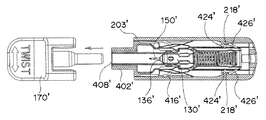
- [ B type lancet lancing device ] ⁇ Basic configuration of lancet puncture mechanism ⁇ (Basic configuration) 23 to 25 show a B type lancet lancing device 500 ′.
- FIGS. 23 and 24 show an external view of a B-type lancet puncture device 500 ′
- FIG. 25 also shows an exploded view and an exploded view of the B-type lancet puncture device 500 ′.
- the lancet puncture device 500 ′ according to the present invention is mainly composed of “lancet 100 ′”, “injection spring 300 ′”, “trigger member 400 ′” and “holder (particularly lancet holder) 200 ′”. It is configured.
- FIG. 26 shows a holder 200 ′ constituting a B type lancet puncture device
- FIG. 27 shows a trigger member 400 ′ constituting a B type lancet puncture device
- FIG. 28 shows a B type lancet puncture device.
- a lancet 100 ′ constituting the device is shown.
- FIG. 29 shows the lancet puncture device 500 ′ with the upper half of the holder 200 ′ cut away.
- the lancet puncture device 500 ′ has a structure in which a lancet 100 ′, an injection spring 300 ′, and a trigger member 400 ′ are accommodated in a holder 200 ′.
- the injection spring 300 ′ is inserted into the holder 200 ′ so that the injection spring 300 ′ is sandwiched between the rear end of the lancet 100 ′ and the rear end 451 ′ of the trigger member 400 ′. Is housed inside. More specifically, as shown in FIG.
- one end of the injection spring 300 ′ is attached to the rear end 133 ′ of the lancet 100 ′, and the injection spring 300 is provided.
- the other end of ' is attached to the fitting portion 450' of the trigger member 400 '.
- the injection spring 300 ′ in the holder 200 ′ is compressed between “lancet 100 ′” and “fitting portion 450 ′ at the rear end of the trigger member 400 ′”. It has become a state.
- the lancet body 130 ′ is placed against the arm portion 420 ′ of the trigger member 400 ′ so that the injection spring 300 ′ attached to the lancet body 130 ′ is compressed. It is locked (see, for example, FIG. 29). Note that “locking portion 131 ′ of lancet body 130 ′” and “locked portion 421 ′ of arm portion 420 ′ of trigger member 400 ′” involved in such locking are shown in FIGS. 27 (a) and 28. See also (a).
- the puncture opening 410 ′ at the front end of the trigger member 400 ′ is the front end opening 203 ′ of the holder 200 ′.
- the trigger member 400 ′ is disposed in the holder 200 ′ as a whole so as to protrude outward from the rear opening end (particularly the rear opening as shown). Further, as can be seen from the modes shown in FIGS. 23 and 29, with regard to the lancet cap 170 ', its front portion 175' projects outward from the front end opening 203 'of the holder.
- the paired portion 175a ′ provided on the side of the front portion 175 ′ is adjacent to the front end opening 203 ′ of the holder so that the lancet 100 ′ does not move backward with respect to the holder 200 ′. It has become.
- the trigger member can be pushed backward when the lancet cap is removed from the lancet. Specifically, the trigger member 400 ′ moves backward relative to the holder 200 ′ due to an external force applied to the puncture opening 410 ′ at the front end of the trigger member 400 ′. Can be pushed into the holder.
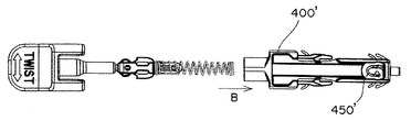
- the front end portion 302 ′ of the injection spring 300 ′ is connected to the rear portion of the lancet 100 ′ to be in the state shown in FIG.
- the rear end portion 304 ′ of the injection spring 300 ′ in that state is connected to the rear end portion of the trigger member 400 ′ as shown by an arrow B in FIG. That is, the injection spring is compressed to a state of a preliminary assembly in which the arm portion of the trigger member is engaged with the side of the lancet body; then, the preliminary assembly of the trigger member, the lancet and the injection spring connecting them is set.
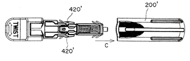
- the puncture device assembly of the present invention (by inserting it into the inner space of the holder 200 ′ except for the front portion of the lancet ( Chi, assembly) is completed.
- the puncture device of the present invention thus assembled is schematically shown in a perspective view in FIG.
- FIG. 26 schematically shows a preferred embodiment of a holder 200 ′ constituting a B-type puncture device.
- the holder 200 ′ is generally cylindrical, and the cross section perpendicular to the puncturing direction is substantially rectangular.
- the front end 202 ′ has an opening 203 ′, and a preliminary assembly composed of a trigger member, a lancet and an injection spring is inserted through the opening.
- a slope portion 250 ' is provided on the inner wall on the side of the holder 200'.
- the slope portion 250 ′ has a slope surface 250 a ′ inclined forward (inward) toward the center of the holder toward the front.
- the slope portions are provided on the upper and lower sides of the side surfaces on both sides of the holder (only the lower slope surface is shown).
- a part of the arm portion of the trigger member slides or rubs on the slope surface 250a '.
- the free end of the arm portion 420 ′ slides or slides on the slope surface 250a ′ from the front to the rear, and as a result. ,
- the arms automatically expand outward.
- the holder 200 ′ has a space portion 212 ′ opened at the rear end portion 210 ′.
- the rear end portion of the trigger member is fitted into the space portion 212 ′, as will be described later, and the rear end portion is defined on the wall portion 214 ′ that defines the space portion 212 ′.
- the step portion to be abutted comes into contact.
- it is preferable that the end face of the rear end is visible from the opening 216 ′ that defines the space, and the opening 216 ′ and the end face are substantially flush or close to each other.
- the holder 200 ' has a projection (convex portion) 218' on the rear side of the slope portion 250 '.
- the protrusion 218 ′ cooperates with the pull-out prevention wing 426 ′ or the reuse prevention wing 424 ′ of the trigger member 400 ′ to prevent the trigger member 400 ′ from coming out of the holder 200 ′ before use.
- the shape of the holder 200 ′ is not limited to the illustrated embodiment, and may be any other suitable shape as long as it can accommodate the spare assembly as described above and has the slope portion and the protrusion.
- it may be in the form of a cylinder.
- the holder 200 ′ may be formed of any appropriate resin material as long as it is a resin material used for a general lancet.
- it is particularly preferable to form from a resin such as polyethylene or polypropylene.
- FIG. 28 schematically shows a preferred embodiment of the lancet constituting the B-type lancet puncture device.
- the illustrated lancet 100 ′ has a lancet cap 170 ′ and a lancet body 130 ′. They are connected together by a weakened portion 108 ′ located between them, and a puncture needle 150 ′ (partially visible in FIG. 28 (b)) extends between them. .
- the tip portion 150a ′ of the puncture needle is covered with a lancet cap 170 ′, and the lancet cap is removed by destroying the weakened portion 108 ′ upon puncturing, so that the needle tip portion 150a ′ becomes the front end surface 136 ′ of the lancet body 130 ′. The state which protruded toward from the front is obtained.
- the lancet body 130 ' has a locking portion for locking the trigger member with respect to the arm portion.
- it has engaging portions 131 ′ (for example, step-shaped portions or square-shaped portions) that can be engaged with the locked portions of the trigger member on the sides on both sides.
- the lancet body 130 ' has a protrusion 138' on the rear portion 133 'that can be engaged with the front end of the injection spring 300'.
- the lancet cap 170 ′ has a rear portion 172 ′ including a portion covering the distal end portion 150 a ′ of the puncture needle and a front portion 175 ′ located in front thereof.
- the rear end portion of the rear portion 172 ' surrounds the tip portion of the puncture needle and faces the front end surface of the lancet body 130' via the weakened portion 108 '.
- the front portion 175 'of the lancet cap is provided with a paired portion 175a' on its side. More specifically, the front portion 175 ′ of the lancet cap has a paired portion 175a ′ protruding rearward on both sides, and a central portion 175b ′ as the other portion between the paired portions. is doing.
- the pair portion 175a ′ and / or the central portion 175b ′ are arranged at the front end of the holder 200 ′. It is adjacent to the opening 203 ′ or opposed to the front end opening 203 ′ through a slight gap.
- the pair portion 175a ′ and / or the center portion 175b ′ abuts against the wall defining the front end opening 203 ′ of the holder 200 ′, As a result, it cannot be further retracted.
- the front portion 175 'of the lancet cap 170' has a flat shape at its front end, and the weakened portion 108 'is obtained by picking that portion with a finger and twisting or rotating around the puncture needle. Can be destroyed (that is, the part that can be picked with a finger in this way is the “gripping part”).
- the lancet body 130 ' can be positioned within the holder and trigger, but cannot be rotated around the puncture needle as a whole in the form of a prism, while the rear portion 172' of the lancet cap 170 '. Is preferably in the form of a column that can rotate within the cylindrical front end 402 'of the trigger member.
- the weakened portion 108 ′ can be more suitably destroyed by twisting or rotating by appropriately selecting the thickness of the resin covering the puncture needle in the weakened portion or by appropriately selecting the resin forming the lancet. become.
- the trigger member 400 ′ shown in the figure has a space portion 406 ′ that accommodates the lancet 100 ′ and the injection spring 300 ′ in the center in the state of the puncture device before puncture.
- the space is preferably in the form of a box having a bottom as a whole, and a cylindrical front end 402 ′ projects forward from the front end of the space 406 ′.
- a predetermined object to be punctured is applied to the opening 408 ′ of the front end portion 402 ′.
- the trigger member 400 ′ has a pair of arm portions 420 ′ that extend rearward on both sides of the trigger member 400 ′. As shown in FIG. 27, each of the pair of arm portions 420 'has a front end forming a fixed end, and a rear side forming a free end.
- the arm portion 420 ′ preferably has flexibility as a whole.
- Each arm portion 420 ′ forms an engaging portion 421 ′ (for example, a step-like portion or a square-like portion to which the lancet body locking portion 131 ′ can be locked) that can engage with the lancet locking portion 131 ′. (Locked part).
- each arm portion 420 ′ has a sliding portion 422 ′ above and below the engaging portion 421 ′.
- the sliding portion 422 ′ slides or rubs on the slope portion 250 ′ provided on the inner wall of the holder, specifically on the slope surface 250a ′. It is configured to move.
- the arm portion 420 ′ is moved around the front root (ie, the fixed end) as a fulcrum. Will spread in the direction.
- Each arm portion 420 'of the illustrated trigger member 400' has a pushback portion 416 'on the outside thereof.
- the pushback portion 416 ' preferably protrudes outward from the arm portion 420', and particularly preferably protrudes obliquely forward as shown.
- the distal end of the pushback portion 416 ' is in contact with the inner wall of the holder or with a slight gap.
- the pushback portion 416 ′ is pressed toward the inner wall of the holder, and by the reaction, the arm portion tries to push back inward (ie, push back). It works to apply power.
- Such a pushback portion is preferably in the form of an auxiliary arm that protrudes outward from the arm portion, preferably obliquely outward, as shown.
- the B-type trigger member 400 ′ has a rear end portion 480 ′ protruding rearward at the rear end of the space portion.
- the rear end 480 ′ is fitted into the space 212 ′ of the holder 200 ′, and the step 482 ′ that defines the rear end is a wall that defines the space 212 ′. 214 '.
- the rear end portion 480 ′ slightly protrudes from the space portion 212 ′, and the end surface is further colored, it indicates that the puncture device has been used. The user can recognize it more easily.
- the trigger member 400 ′ has a protrusion-shaped or arm-shaped re-use prevention on the outer surface of the side wall surface (particularly, the outer surface of the side wall surface located on the rear side). It has a wing 424 ′ and a protruding or arm-shaped escape prevention wing 426 ′ on the rear side. These wings (424 ', 426') perform their respective functions by cooperating with protrusions 218 'provided on the side inner walls on both sides of the holder 200'.
- the front portion 217 ′ has an inclined surface (that is, a tapered surface) that spreads outward toward the front. Is preferred.
- the pull-out prevention wing 426 ′ contacts the front part of the protrusion 218 ′ provided on the side inner wall of the holder and faces upward on the inclined surface 217 ′. While being deformed, it is rubbed and gets over the protrusion 218 '. After overriding in this way, the wing 426 'returns to its original shape and the assembly of the puncture device of the present invention is complete.
- the rear end surface 219 'of the protrusion 218' extends at an angle perpendicular to or close to the puncture direction as shown.
- the wing 426 ′ that has once moved over the protrusion 218 ′ and moved backward cannot move over the protrusion 218 ′ and move forward. That is, in the puncture device before use, the pull-out prevention wing 426 ′ of the trigger member 400 ′ is located behind the protrusion 218 ′ of the holder 200 ′, and as a result, the trigger 400 ′ is moved forward with respect to the holder 200 ′. Accordingly, the trigger member 400 ′ can be effectively prevented from coming off from the holder 200 ′.
- the reuse prevention wing 424 ′ on the front side of the pull-out prevention wing 426 ′ is restored to its original shape even if it is deformed in the same manner as the above-mentioned getting over,
- the state is after overcoming the protrusion 218 ′ provided on the inner side wall of the holder 200 ′.
- the trigger 400 ′ cannot be moved forward with respect to the holder 200 ′. Therefore, the positional relationship between the holder 200 ′ and the trigger member 400 ′ cannot be returned to the state before puncturing.
- the arm part of the trigger member in the opened state cannot be closed, and therefore the engaging part 421 'of the trigger member cannot be engaged again with the engaging part 131' of the lancet body.
- the lancet body cannot be recharged and used for puncture.
- Such deformation of the wings 424 ′ and 426 ′ and recovery of the original shape can be easily achieved by forming the trigger member 400 ′ with a resin (for example, a resin such as polyethylene or polypropylene) and utilizing its elasticity. Therefore, it can be said that these wings preferably have flexibility as a whole.
- the trigger member 400 ′ includes a spring attachment portion 450 ′, but this spring attachment portion can function suitably when the lancet puncture device is assembled.
- the spring mounting portion 450 ′ of the trigger member is formed of a long member having a curved shape having a free end and a fixed end.
- the assembly of the lancet lancing device i.e. attachment of the firing spring 300 '
- the spring mounting portion 450 ′ can be easily moved inward. It can bend (see FIGS.
- the spring mounting portion 450 ′ preferably has a protrusion 450a ′ protruding outward (particularly, as shown in FIG. 22A, the first protrusion 450a 1 ′ is on the free end side and the fixed end side is on the fixed end side. And a second protrusion 450a 2 ′ is preferably provided).
- a protrusion 450a ′ protruding outward
- the coil diameter of the injection spring 300 ′ is once increased and gets over the protrusion 450a ′ and then returns to the original diameter, the fitting between the injection spring 300 ′ and the spring mounting portion 450 ′ cannot be easily released. (See FIGS. 22A to 22C).
- the injection spring 300 ′ is used for “injection” or “fire” of the lancet body, more specifically, the lancet body where the tip of the puncture needle is exposed.
- the ejection spring 300 ′ is a spring (for example, made of metal) that gives a thrust for firing or puncturing to the puncture needle 150 ′, that is, “the lancet body including the puncture needle with the tip portion exposed”. Coil spring).
- B-type puncture device 500 'formed by assembling as described with reference to FIGS. 30 to 32 is shown in a perspective view in FIG.
- the front portion 175 'of the lancet cap is in contact with or adjacent to the front end opening 203' of the holder 200 '(with a slight gap).
- the paired portion 175a ′ of the front portion is in contact with the wall defining the front end opening 203 ′ of the holder 200 ′ and cannot be further retracted. It has become.
- the holder 200 is held with the finger of one hand, the front end of the lancet is picked with the finger of the other hand, and as shown by the arrow in FIG.
- the “weakened part” can be destroyed.
- the puncture needle is pulled away along the extending direction of the puncture needle, the tip of the puncture needle is exposed in the holder.
- FIG. 34 (a) schematically shows the internal state of the puncture device 500 'shown in FIG.
- the trigger member 400 ′ is positioned in the holder 200 ′, and the escape prevention wing 426 ′ is in contact with the protrusion 218 ′ provided on the side inner wall of the holder 200 ′ from the rear. Therefore, the trigger member 400 'cannot be pulled out from the holder 200', i.e., the trigger member is held in the holder.
- the engaging portion 421 ′ of the trigger member 400 ′ in such a state is engaged with the engaging portion 131 ′ of the lancet.
- the lancet 100 ′ is held in the holder 200 due to the engagement between the engaging portion 421 ′ of the trigger member 400 ′ and the engaging portion 131 ′ of the lancet.
- 'Injection spring 300' is held in a compressed state.
- the pushback portion 416 ′ is in the form of an additional or auxiliary arm that protrudes obliquely forward from the arm portion 420 ′, and the tip portion of the pushback portion 416 ′ is the side inner wall of the holder 200 ′. Is in contact.
- the weakened portion 108 ′ of the lancet is destroyed by twisting as described above in the holder 200 ′ of the B type lancet puncture device 500 ′ in the state shown in FIGS. 34 (a) and 35 (a).
- the lancet cap 170 ′ is moved away from the lancet body 130 ′, and the tip portion 150a ′ of the puncture needle protrudes forward from the lancet body.
- the front end portion 402' of the trigger member 400 ' protrudes forward from the front end opening 203' of the holder 200 '.
- the lancet body 130 ′ from which the distal end portion 150a ′ of the puncture needle protrudes depends on the engagement relationship between the locking portion 131 ′ and the locked portion 421 ′. It is securely held in the space 406 ′ of the trigger member 400 ′.
- FIGS. 34 (b) and 35 (b) the target site 600 ′ to be punctured is applied to the front end opening 408 ′ of the protruding trigger member.
- FIG. 34 (c) and FIG. 35 (c) show a state where the target site is assigned in this way.
- the holder 200 ′ is pressed against the target site 600 ′ so that the puncture device approaches the target site 600 ′. That is, an operation such as stamping is performed. As a result, a force is applied to the holder 200 'so as to retract the trigger member 400'.
- the arm portion 420 ′ of the trigger member 400 ′ has a pushback portion 416 ′, which suppresses the spread of the arm portion, that is, the arm portion is located on the side of the lancet body. It will act to push it towards you. Accordingly, the force applied is greater than the force applied by the pushback portion 416 'to retract the trigger member.
- the sliding portion 422 ′ of the arm portion 420 ′ moves backward on the slope portion 250 ′ provided on the side inner wall of the holder 200 ′. Since the slope portion 250 ′ has a slope surface 250a ′ approaching the side inner wall of the holder toward the rear, the sliding portion 422 ′ is moved outwardly (specifically, obliquely rearward outward as the trigger member 400 ′ moves rearward). Move to). Since the sliding portion 422 'is a part of the arm portion 420', the arm portion 420 'as a whole also moves rearward and outward in the same manner. That is, as shown by an arrow in FIG. 34 (d), the arm portion spreads outward. As can be easily understood by comparing the shape of the pushback portion 416 ′ in FIGS. 34 (c) and 34 (d), the pushback portion 416 ′ in FIG. It is deformed slightly inward.
- FIGS. 34 (d) and 35 (d) show how the engaged state is released in this way.
- the engagement state is released, there is no thing that prevents “the lancet body 130 ′ is moved forward due to the compressed injection spring 300 ′ being extended”, so that the lancet body from which the tip portion protrudes is removed. 130 'momentarily moves forward.
- the injection spring 300 ′ expands in an instant from the compressed state, it extends beyond the original shape of the injection spring 300 ′ (ie, the shape of the spring when no force is substantially applied), and punctures. At least a portion of the needle tip 150a ′ protrudes from the front end opening 408 ′ of the trigger member 400 ′. Since the target site is assigned to the front end opening 408 ′, the protruding tip portion pierces the target site. Note that a part of the lancet body (engagement portion 131 ′ in the illustrated embodiment) collides with the wall surface 432 ′ located behind the front end portion of the trigger member 400 ′, and the forward movement of the lancet body 130 ′ is stopped. Has been. FIG. 34 (e) and FIG. 35 (e) show a state where the target site is punctured in this way.
- the injection spring 300 ′ In the state shown in FIG. 34 (e) and FIG. 35 (e), the injection spring 300 ′ is in an extended state as described above, so that the wall surface 432 ′ is instantly stopped when the lancet body advances. The lancet body starts to move rearward due to the reaction at, and the injection spring 300 ′ finally returns to its original shape.
- FIG. 34 (f) and FIG. 35 (f) show how the original shape is restored.
- the injection spring 300 ′ should be selected so that the tip of the puncture needle protruding from the lancet body is located sufficiently rearward from the front end opening 408 ′ of the trigger member 400 ′. Is preferred.
- the trigger member reuse prevention wing 424 ′ moves backward over the protrusion 218 ′ provided on the side inner wall of the holder 200 ′. ing. Further, the rearmost end portion 480 ′ of the trigger member 400 ′ is fitted into the space portion 212 ′ located at the rear end of the holder 200 ′, and the step portion 482 ′ is a wall portion that defines the rear end of the holder 200 ′. 214 '(see also FIGS. 26 (b) and 27 (b)).
- the B-type lancet puncture device can also be referred to as a “single-use device” like the A-type.
- [ C type lancet lancing device ] ⁇ Basic configuration of lancet puncture mechanism ⁇ (Basic configuration) 36 to 38 show a C-type lancet puncture device 500 ′′.
- FIGS. 36 and 37 show an external view of a C-type lancet puncture device 500 ′′
- FIG. 38 shows a C-type lancet puncture device 500 ′′.
- An exploded view and a developed view of the device 500 are also shown.
- the lancet lancing device 500" according to the present invention includes a "lancet 100", an "injection spring 300", and a "holder ( In particular, it is mainly composed of a lancet holder) 200 "" and a "trigger member 400"”.
- FIG. 39 shows a holder 200 ′′ constituting a C-type lancet puncture device
- FIGS. 40 and 41 show a trigger member 400 ′′ constituting a C-type lancet puncture device
- FIG. 42 shows a C-type lancet puncture device.
- a lancet 100 ′′ constituting the device is shown.
- FIG. 43 shows a C-type lancet puncture device 500 ′′ with the upper half of the holder 200 ′′ removed.
- the lancet puncture device 500 ′′ has a structure in which a lancet 100 ′′, an injection spring 300 ′′ and a trigger member 400 ′′ are accommodated in a holder 200 ′′.
- the injection spring 300 is accommodated in the holder 200" so that the injection spring 300 "is sandwiched between the rear end 133" of the lancet 100 "and the rear end 451" of the trigger member 400 ". ing. More specifically, as shown in FIG.
- the injection spring 300 ′′ in the holder 200 ′′ includes the “lancet 100 ′′” and the “trigger member”. It is in a compressed state with the fitting portion 450 "" at the rear end of 400 ".
- the lancet puncture device 500 ′′ of the present invention the lancet body 130 ′′ is placed against the arm portion 420 ′′ of the trigger member 400 ′′ so that the injection spring 300 ′′ attached to the lancet body 130 ′′ is compressed. Locked. Note that the “locking portion 131 ′′ of the lancet body 130 ′′” and the “locked portion 421 ′ of the arm portion 420 ′′ of the trigger member 400” involved in the locking are shown in FIGS. See also (a).
- the pressing portion 470 ′′ at the rear end of the trigger member 400 ′′ is the rear end opening 270 of the holder 200 ′′.
- the trigger member 400 is disposed in the holder 200 "as a whole so as to project outward from (in particular, the rear opening end as shown in the figure). Further, as can be seen from the embodiment shown in FIG. For the lancet cap 170 ′′, its front portion 175 ′′ projects outwardly from the front end opening 203 ′′ of the holder.
- a paired portion 175a "provided on the side of the front portion 175" is adjacent to the front end opening 203 "of the holder and / or the other portion of the front portion 175" of the lancet cap. (Especially the cap central region 175b "between the paired portions 175a") is adjacent to the front end opening 203 "of the holder (i.e. the puncture opening) so that the lancet 100" is rearward relative to the holder 200 " Cannot be moved to.
- the trigger member can be pushed forward when the lancet cap is removed from the lancet. Specifically, the trigger member 400 ′′ moves forward relative to the holder 200 ′′ due to an external force applied to the pressing portion 470 ′′ at the rear end of the trigger member 400 ′′. Can be pushed into the holder.
- the assembly of the C type lancet puncture device is substantially the same as the A type and B type.
- the lancet 100 ′′, the injection spring 300 ′′, the holder 200 ′′, and the trigger member 400 ′′ are assembled with each other so that the injection spring 300 ′′ is held in a compressed state, whereby a puncture device is obtained (see FIG. 38 or Fig. 44)
- FIG. 39 schematically shows a preferred embodiment of a holder 200 ′′ constituting a C-type puncture device.
- the holder 200 ′′ is generally cylindrical and has a cross section perpendicular to the puncture direction. It is substantially rectangular.
- a slope portion 250 ′′ is provided on the inner wall on the side of the holder 200 ′′.
- the slope portion 250 ′′ has a slope surface 250a ′ inclined outward (outward) from the holder toward the front.
- the slope portion is an upper side surface on both sides of the holder. (Only the lower slope surface is shown.)
- a part of the arm portion 420 ′′ of the trigger member slides or rubs on the slope surface 250a ′′. Specifically, when the trigger member 400 ′′ is moved forward with respect to the holder 200 ′′, the free end of the arm portion 420 ′′ slides or slides on the slope surface 250a ′′ from the rear to the front, The arm automatically expands outward.
- the holder 200 ′′ has a protrusion (convex portion) 218 ′′ on the front side of the slope portion 250 ′′. As will be described later, this protrusion 218 ′′ is used to prevent the trigger member 400 ′′ from slipping out or to be reused. In cooperation with the prevention wing 424 ′′, it contributes to preventing the trigger member 400 ′′ before use from coming out of the holder 200 ′′, and after use, the “trigger member 400 ′′ is moved forward with respect to the holder 200 ′′. It is prevented in advance that the device is moved to the state where it can be punctured.
- the shape of the holder 200 ′′ is not limited to the illustrated embodiment, and can be any as long as it can accommodate the trigger member, the injection spring, and the lancet, and has the slope portion and the protrusion.
- the holder 200 may be formed of any suitable resin material as long as it is a resin material used in a general lancet. Also good. For example, it is particularly preferable to form from a resin such as polyethylene or polypropylene.
- FIG. 42 schematically shows a preferred embodiment of the lancet constituting the C-type lancet puncture device.
- the lancet 100 “comprises a lancet cap 170" and a lancet body 130 ". They are connected together by a weakened portion 108" located therebetween, and straddle between them.
- the puncture needle 150 ′′ (see FIG. 42 (c)) is extended.
- the tip portion 150a ′′ of the puncture needle is covered with a lancet cap 170 ′′, and the weakened portion 108 ′′ is broken during puncture to remove the lancet cap. By removing, the needle tip portion 150a "protrudes forward from the front end surface 136" of the lancet body 130 ".
- the lancet body 130 ′′ has a locking portion that serves to lock the trigger member with respect to the arm portion. That is, the engaging portion 131 ′′ (for example, a stepped portion or a corner) that can engage with the locked portion of the trigger member. ) On the sides on both sides.
- the lancet body 130 ′′ has a protrusion 138 ′′ on the rear portion 133 ′′ that can engage the front end of the injection spring 300 ′′.
- the lancet cap 170 ′′ has a rear portion 172 ′′ including a portion covering the distal end portion 150a ′′ of the puncture needle and a front portion 175 ′′ positioned in front thereof.
- the rear end of the rear portion 172 ′′ surrounds the tip of the puncture needle and faces the front end surface of the lancet body 130 ′′ via the weakened portion 108 ′′.
- the front portion 175 ′′ of the lancet cap The lancet cap front portion 175 "has a pair of 175a" projecting rearward on both sides, and between the pair of portions. Has a central part 175b "as the other part.
- the paired portion 175a ′′ and / or the central portion 175b ′′ is located at the front end of the holder 200 ′′. Adjacent to the opening 203 "or facing the front end opening 203" with a slight gap. Therefore, even if the lancet 100 "is to be retracted with respect to the holder 200", the pair 175a "And / or the central part 175b" abuts against the wall defining the front end opening 203 "of the holder 200" so that it cannot be further retracted.
- the front portion 175 ′′ of the lancet cap 170 ′′ has a flat front end, and is weakened by the user picking that portion with a finger and twisting or rotating it around the puncture needle.
- the lancet body 130" The rear portion 172 "of the lancet cap 170” can be rotated within the cylindrical front end 203 "of the holder, while it can be positioned within the trigger but cannot rotate around the puncture needle as a whole.
- the lancet body does not rotate, since the lancet cap can be rotated, weakening 108 "is destroyed.
- Trigger member 40 and 41 schematically show a preferred embodiment of the trigger member constituting the C-type puncture device.
- the illustrated trigger member 400 ′′ has a space portion 406 ′′ that accommodates the lancet 100 ′′ and the injection spring 300 ′′ in the center in the state of the puncture device before puncture.
- the space is preferably in the form of a box having a bottom as a whole.
- the trigger member 400 ′′ has a pair of arm portions 420 ′′ extending rearward on the sides on both sides thereof. As shown in FIGS. 40 and 41, each of the pair of arm portions 420 "has a fixed end at the front end thereof and a free end at the rear side thereof. It is preferable to have flexibility.
- Each arm portion 420 ′′ includes an engaging portion 421 ′′ (for example, a step-shaped portion or a square-shaped portion to which the lancet body locking portion 131 ′′ can be locked) that can be engaged with the lancet locking portion 131 ′′. (Locked part).
- each arm portion 420 “has a sliding portion 422" above and below the engaging portion 421 ".
- the C-type lancet puncture device has a trigger 400" with respect to the holder 200 ".
- the sliding portion 422 ′′ slides or rubs on the slope portion 250 ′′ provided on the inner wall of the holder, specifically on the slope surface 250a ′′.
- the arm portion 420 ′′ is moved around its front base (that is, the fixed end) as a fulcrum. Will spread in the direction.
- the trigger member 400 ′′ has a protrusion-like shape on the outer surface of its side wall surface (especially the outer surface of the side wall surface located on the front side) It has an arm-shaped anti-reuse wing 424 ′′ and a protruding or arm-shaped anti-retraction wing 426 ′′ on its front side.
- These wings (424 ′′, 426 ′′)
- Each function is achieved by cooperating with the protrusions 218 ′′ provided on the inner side walls on both sides of the holder 200 ′′.
- the protrusions 218 ′′ provided on the inner wall of the holder are shown in FIG.
- the rear portion has an inclined surface 217 ′ (that is, a tapered surface) that extends outward toward the rear.
- the protrusion 218 ′′ of the holder preferably has its front end surface 219 ′′ extending at an angle perpendicular to or close to the puncture direction as shown.
- the trigger member wing 426 "that has once moved over the protrusion 218" during assembly of the device cannot move backward over the protrusion 218 ", i.e., in the puncture device prior to use.
- the pull-out prevention wing 426 ′′ of the trigger member 400 ′′ is located in front of the protrusion 218 ′′ of the holder 200 ′′, so that the trigger 400 ′′ cannot be moved backward relative to the holder 200 ′′.
- the trigger member 400 ′′ is effectively prevented from coming off from the holder 200 ′′.
- the reuse prevention wing 424 "on the rear side of the pull-out prevention wing 426" is restored to its original shape even if it is deformed in the same manner as the above-mentioned getting over,
- the state is after overcoming the protrusion 218 ′′ provided on the side inner wall of the holder 200 ′′.
- the trigger 400 ′′ cannot be moved backward with respect to the holder 200 ′′, and therefore the positional relationship between the holder 200 ′′ and the trigger member 400 ′′ cannot be returned to the state before puncturing.
- the arm portion of the trigger member in the open state cannot be closed, and therefore, the engaging portion 421 ′′ of the trigger member cannot be engaged again with the engaging portion 131 ′′ of the lancet body.
- the lancet body cannot be recharged and used for puncture.
- Such deformation of the wings 424 ′′ and 426 ′′ and the restoration of the original shape can be easily performed by forming the trigger member 400 ′′ from a resin (for example, a resin such as polyethylene or polypropylene) and utilizing its elasticity. Therefore, it can be said that these wings preferably have flexibility as a whole.
- the trigger member 400 ′′ includes a spring mounting portion 450 ′′.
- the spring mounting portion can suitably function when the lancet puncture device is assembled. This is the same as A type and B type.
- the spring mounting portion 450 "of the trigger member is formed of a long member having a curved shape having a free end and a fixed end, and hence the lancet puncture is performed.
- the assembly of the device i.e. the attachment of the injection spring 300 " is effectively assisted. That is, if the spring mounting portion 450 ′′ has a hook shape such as a fishhook shape or a U-shape as shown in FIG.
- the spring mounting portion 450 ′′ can be easily bent inward ( 22 (a) and 22 (b)), the engagement of the firing spring with the coil can be effectively assisted.
- the spring mounting portion 450 ′′ preferably has an outwardly projecting protrusion 450a ′′ (particularly, as shown in FIG. 22A, the first protrusion 450a 1 ′′ on the free end side and the fixed end side on the fixed end side. It is preferable that a second protrusion 450a 2 ′′ is provided).
- FIG. 44 shows an aspect of the injection spring 300 ′′ and the spring mounting portion 450 ′′ at the time of assembling the puncture device, together with the assembly aspect of the entire device.
- the injection spring 300 is used for" injection “or” fire “of the lancet, more specifically, the lancet body with the tip of the puncture needle exposed.
- the injection spring 300" A puncture needle 150 ", that is, a spring (for example, a coil spring) that gives a propulsive force for firing or puncturing to" a lancet body having a puncture needle with an exposed tip ".
- the “trigger member push-in prevention mechanism” of the C-type lancet puncture device will be described.
- the portions other than the grip portion of the lancet cap have an effect of preventing the trigger member from being pushed in due to the interaction with the holder, as in the A type and the B type.
- the C-type lancet puncture device has a trigger member 400 ′′ on the side surface 430 ′′ of the main body 430 ′′ as shown in FIGS. 40 and 41 (particularly FIG. 40 (b)).
- the flexible member 490 has a feature of cooperating with "a portion other than the grip portion of the lancet cap" and "holder".
- such a flexible member 490 " is preferably provided integrally with the trigger side wall surface (and may therefore be integrally formed with the trigger member), and the front side.
- the flexible member 490 " is substantially substantially flat with the plane that forms the side wall surface, as shown in FIG. Although provided flush, it is preferable that at least a part (particularly the free end) slightly protrudes outward from the side wall surface (see particularly FIG. 41 (c)).
- the “flexibility” in the “flexible member 490 ′′” refers to a mode in which the member 490 ′′ can be displaced in the inner direction (that is, the inside of the trigger member). The aspect which the part can move toward an inner side is pointed out.
- the main body portion 172 ′′ of the lancet cap ie, the portion surrounding the tip 150a ′′ of the puncture needle
- the holder A trigger member flexible member 490 "is located between the wall 290" and the trigger member flexible member 490 ", particularly, as shown. It is preferably positioned so as to be accommodated in the provided recess 295 ′′ (see also FIG. 39 (b) for “recess 295 ′′”).
- the flexible member 490 "and the recess 295" have a substantially complementary shape as a whole. Therefore, the flexible member 490 "has an elongated shape, while the recess 295 “” Preferably has a groove form.
- the flexible member 490 is "the wall surface 172a” of the cap body 172 “and” the wall surface 295a “” of the groove-shaped recess 295 ").
- the trigger member 400 “cannot be pushed into the holder. This means that the lancet body is engaged when the lancet cap is attached. This means that the release / engagement cannot be performed, that is, the puncture needle is not fired, whereas if the lancet cap is removed as shown in FIG. As a result, the trigger member can be pushed into the holder in response to the pressure from the outside.
- the flexible member 490 ′′ moves the front slope portion 295 b ′′ of the groove-shaped recess 295 ′′. So that the flexible member 490 "can move forward, as a result of the fact that the flexible member 490" can move forward.
- the trigger member can be pushed into the holder (see Fig. 45 (b)), so that the "locking portion 131" of the lancet body 130 "and the locked portion of the arm portion 420" of the "trigger member 400".
- the locking with 421 ′′ ′′ is released, and the puncture needle 150 ′′ is fired (see FIG. 45 (c)).
- the lancet body 130 ′′ from which the distal end portion 150a ′′ of the puncture needle protrudes depends on the engagement relationship between the locking portion 131 ′′ and the locked portion 421 ′′. It is securely held in the internal space 406 ′′ of the trigger member 400 ′′.
- a target site to be punctured is assigned to the protruding puncture opening, that is, the front end opening 203 ′′ of the holder.
- an external force is applied forward to the pressing portion 470 ′′ at the rear end of the trigger member. That is, the trigger member 400 ′′ is applied to the holder 200 ′′. Applying force to move forward.
- the sliding portion 422 ′′ of the arm portion 420 ′′ moves forward on the slope portion 250 ′′ provided on the side inner wall of the holder 200 ′′. Since the slope portion 250 ′′ has a slope surface that approaches the outside of the holder toward the front, as the trigger member 400 ′′ moves forward, the sliding portion 422 ′′ moves toward the front outside (specifically, diagonally forward outside). Since the sliding portion 422 ′′ is a part of the arm portion 420 ′′, the arm portion 420 ′′ as a whole also moves forward and outward. That is, as the trigger portion is pushed, the arm portion 420 ′′ automatically expands outward.
- the injection spring 300 Since the injection spring 300 "expands in an instant from the compressed state, it extends beyond the original shape of the injection spring 300" (i.e., the shape of the spring when no force is substantially applied) and punctures. At least a portion of the needle tip 150a "projects from the front opening 203" of the holder. Since the target portion is assigned to the front end opening 203 ′′, the protruding tip portion sticks into the target portion. Note that the lancet is placed on the holder inner wall surface 232 ′′ that forms the front end opening 203 ′′ of the holder 200 ′′. A part of the body (engagement portion 131 ′ in the illustrated embodiment) collides so that the forward movement of the lancet body 130 ′′ is stopped (see FIGS. 46 (d) and 47 (d)).
- the trigger member reuse prevention wing 424 ′′ moves forward over the protrusion 218 ′′ provided on the side inner wall of the holder. Has moved. Therefore, in the state shown in FIGS. 46 (e) and 47 (e), even if the trigger member is moved backward with respect to the holder, the reuse preventing wing 424 ′′ abuts against the protrusion 218 ′′. Cannot be moved backwards.
- the C-type lancet puncture device is also “single” as in the A-type and B-type. - it can be referred to as a youth device ".
- the puncture needle (150, 150 ′, 150 ”) has a“ needle shape ”having a sharp tip, but is not necessarily limited to such a shape.
- the needles (150, 150 ′, 150 ′′) may be “blade” with one side of the tip sharpened.
- the lancet puncture device of the present invention is not limited to the appearances shown in the A type, B type, and C type, and can be realized in various appearances.
- the lancet puncture device of the present invention can be realized with an appearance as shown in FIGS.
- a flange-like or hook-like protrusion 290 ′ ′′ is provided on the outer surface of the holder.
- Such a flange-like or hook-like protrusion 290 ′ ′′ has an effect of providing a gripping force suitable for puncturing by a “stamping operation”, particularly with a B-type puncturing device or the like.
- the protrusion 290 ′ ′′ can grip the holder securely when the G portion shown in the figure is picked with the finger without the finger sliding on the outer surface of the holder. Can be performed to effectively hold down the puncture device.
- such a flange-like or bowl-like protrusion 290 ′ ′′ also provides a grip positioning effect that can guide a finger to an appropriate position when holding the holder. In other words, even when the holder is held only by relying on the contact feeling of the finger with the holder, the position to be held can be indirectly grasped by touching the finger with the hook-shaped protrusion 290 ′′ ′. it can.
- Such a flange-shaped or bowl-shaped protrusion 290 ′ ′′ may be provided by integral molding with a holder (particularly the holder wall), and may be made of the same resin as the raw material resin of the holder.
- the flange-shaped or hook-shaped protrusion 290 ′ ′′ is provided from an ergonomic point of view.
- the protrusion angle ⁇ of the protrusion 290 ′ ′′ shown in FIG. 48 is preferably 10 °. It is ⁇ 90 °, more preferably 30 ° -60 °, for example about 45 °.
- the protrusion 290 ′ ′′ is provided on the front outer surface of the holder, for example, at a position about 10 mm to about 20 mm away from the puncture opening end (for example, a position about 15 mm away).
- the protrusion 290 ′ ′′ or its rear side surface may be provided with a round (R) so that the finger fits more suitably with respect to the rear side surface of the protrusion 290 ′ ′′, for example, 50R or 20R. Etc. may be attached.
- the holder wall may be provided with a window (window opening) 299 ′ ′′ through which the inside of the holder can be seen from the outside.
- the lancet puncture needle becomes visible when the lancet cap is removed. That is, the puncture needle can be seen from the outside through the window (window opening) 299 ′ ′′ in the device before puncture and before launch.
- the lancet body is located on the front side as a whole due to the injection spring (especially the uncompressed injection spring that has been unlocked). Part) The lancet body can be seen from the outside through 299 '''.
- the lancet puncture device of the present invention is not only compact and excellent in operability, but also excellent in hygiene and safety. Therefore, the lancet puncture device of the present invention can be suitably used in various applications that require blood collection, as well as being usable for blood collection of diabetic patients.
Abstract
Description
ランセットが、ランセットボディ、ランセットキャップおよび穿刺針を有して成り、穿刺針がランセットボディおよびランセットキャップにまたがってこれらの中に存在しており、
トリガー部材が、ホルダー内部に位置する対のアーム部を有して成り、
射出バネがランセットボディに取り付けられ、穿刺前では射出バネの圧縮状態が維持されるようにランセットボディがトリガー部材のアーム部に係止しており、
ランセットキャップがランセットから取り外される前の状態ではトリガー部材をホルダー内部に押し込むことができない一方、ランセットからランセットキャップが取り外されるとトリガー部材をホルダー内部に向かって押し込むことができ、
トリガー部材の前記押込みに際してはアーム部が撓んでランセットボディの前記係止が解除されることを特徴とする、ランセット穿刺デバイスが提供される。 In order to solve the above problems, in the present invention, a lancet puncture device comprising a lancet, an injection spring, a trigger member and a holder (lancet holder) for accommodating them,
The lancet comprises a lancet body, a lancet cap and a puncture needle, the puncture needle being present in these across the lancet body and the lancet cap;
The trigger member has a pair of arm portions located inside the holder,
The injection spring is attached to the lancet body, and the lancet body is locked to the arm part of the trigger member so that the compression state of the injection spring is maintained before puncturing,
Before the lancet cap is removed from the lancet, the trigger member cannot be pushed into the holder.On the other hand, when the lancet cap is removed from the lancet, the trigger member can be pushed into the holder.
When the trigger member is pushed in, the lancet puncture device is provided in which the arm portion is bent and the locking of the lancet body is released.
Aタイプのランセット穿刺デバイスは、トリガー部材の対のアーム部の前方側が自由端を成す一方、その後方側が固定端を成しており、後方からトリガー部材に外力を加えることに起因してアーム部を撓ます特徴を有したデバイスであって、本願の請求項19~24に規定されている。 (A type lancet lancing device)
The A type lancet puncture device has a free end on the front side of the pair of arm portions of the trigger member, and a fixed end on the rear side thereof, and applies an external force to the trigger member from the rear side. A device having the characteristic of bending, as defined in claims 19 to 24 of the present application.
トリガー部材の後端部がホルダーの後端開口部(特に後方開口端)から外向きに突出すると共に、該後端部から前方に向かって延在するトリガー部材の対の外側アーム部がホルダーの側壁外面上に位置するように、トリガー部材が全体としてホルダー内に配置されており、
ランセットキャップの前方部分がホルダーの前端開口部から外向きに突出すると共に、ランセットがホルダーに対して後方に移動しないように、該前方部分の側方に設けられた対部分がホルダーの前端部に隣接し、あるいは該前方部分の他の部分がホルダーの前端開口部に隣接しており、
ランセットのランセットボディおよび穿刺針ならびに射出バネの全てがトリガー部材の対のアーム部からはみ出すことなく該対のアーム部の内側・内部に位置していると共に、対のアーム部の各々は、その前方側が自由端を成す一方、その後方側が固定端を成しており、穿刺前においては、ランセットボディの各々の側方に係合し、それによって、射出バネが圧縮された状態を維持しており、また
穿刺操作時のトリガー部材の押込みに際してトリガー部材をホルダーに対して前方へと移動させると、対のアーム部が外向きに広がり、それによって、各アーム部のランセットボディの各側方に対する係合が解除されることを特徴としている。 Specifically, the A type lancet puncture device is
The rear end portion of the trigger member protrudes outward from the rear end opening (especially the rear opening end) of the holder, and the outer arm portion of the pair of trigger members extending forward from the rear end portion is the holder. The trigger member is arranged in the holder as a whole so as to be located on the outer surface of the side wall,
The front part of the lancet cap protrudes outward from the front end opening of the holder, and a pair of parts provided on the side of the front part is located at the front end of the holder so that the lancet does not move backward with respect to the holder. Adjacent or other part of the front part is adjacent to the front opening of the holder,
The lancet body and puncture needle of the lancet and the injection spring are all located inside and inside the pair of arm portions without protruding from the pair of trigger member arms, and each of the pair of arm portions is located in front of it. While the side forms a free end, the back side forms a fixed end, and before puncturing, it engages each side of the lancet body, thereby maintaining the compressed state of the injection spring In addition, when the trigger member is moved forward with respect to the holder when the trigger member is pushed during the puncturing operation, the pair of arm portions expands outward, thereby engaging each side of the lancet body with each arm portion. It is characterized by being released.
穿刺操作時のトリガー部材の押込みに際しては、アーム部の再使用防止ウイングがホルダーの再使用防止突起上を擦動してそれを超えるまで前方へと移動することになり、
穿刺後においては、再使用防止ウイングと再使用防止突起とが係止可能な状態となり、それによって、トリガー部材の後方移動が制限され、穿刺後のトリガー部材を穿刺前の状態へと戻すことができないようになっている。 In another preferred embodiment of the A-type lancet puncture device, a reuse prevention wing is provided on the outer side of the arm portion of the trigger member so as to extend obliquely rearward, while the holder inner wall is prevented from being reused. A protrusion is provided,
When pushing the trigger member at the time of puncturing operation, the reuse prevention wing of the arm part will rub on the reuse prevention protrusion of the holder and move forward until it exceeds it,
After the puncture, the reuse prevention wing and the reuse prevention protrusion can be locked, thereby restricting the rearward movement of the trigger member and returning the trigger member after the puncture to the state before the puncture. I can't do it.
Bタイプのランセット穿刺デバイスは、トリガー部材の対のアーム部の前方側が固定端を成す一方、その前方側が自由端を成しており、前方からトリガー部材に外力を加えることに起因してアーム部を撓ます特徴を有したデバイスであって、本願の請求項12~18に規定されている。 (B type lancet lancing device)
In the B type lancet puncture device, the front side of the pair of arm portions of the trigger member forms a fixed end, while the front side forms a free end, and the arm portion is caused by applying an external force to the trigger member from the front. A device having the characteristic of bending, as defined in claims 12 to 18 of the present application.
トリガー部材の前端の穿刺開口部のみがホルダーの前端開口部(特に前方開口端)から外向きに突出するように、トリガー部材が全体としてホルダー内に配置されており、
ランセットキャップの前方部分がホルダーの前端開口部から外向きに突出すると共に、ランセットがホルダーに対して後方に移動しないように、該前方部分の側方に設けられた対部分がホルダーの前端開口部に隣接しており、
トリガー部材の対のアーム部の各々は、その前方側が固定端を成す一方、その後方側が自由端を成しており、穿刺前においては、ランセットボディの各々の側方に係合し、それによって、射出バネが圧縮された状態を維持しており、また
穿刺操作時のトリガー部材の押込みに際してトリガー部材をホルダーに対して後方へと移動させると、対の各アーム部が外向きに広がり、それによって、各アーム部のランセットボディの各側方に対する係合が解除されることを特徴としている。 Specifically, the B-type lancet puncture device is
The trigger member is disposed in the holder as a whole so that only the puncture opening at the front end of the trigger member protrudes outward from the front end opening (particularly the front opening end) of the holder,
The front part of the lancet cap protrudes outward from the front end opening of the holder, and the pair of parts provided on the side of the front part is the front end opening of the holder so that the lancet does not move backward with respect to the holder Is adjacent to
Each of the arm portions of the pair of trigger members has a fixed end on the front side and a free end on the rear side, and before the puncture, engages each side of the lancet body, thereby The injection spring is maintained in a compressed state, and when the trigger member is moved backward with respect to the holder when the trigger member is pushed during the puncturing operation, each arm portion of the pair spreads outward. Thus, the engagement of each arm portion with each side of the lancet body is released.
穿刺操作時のトリガー部材の押込みに際しては、トリガー部材の再使用防止ウイングがホルダーの再使用防止突起上を擦動してそれを超えるまで後方へと移動することになり、
穿刺後においては、再使用防止ウイングと再使用防止突起とが係止可能な状態となり、それによって、トリガー部材の前方移動が制限され、穿刺後のトリガー部材を穿刺前の状態へと戻すことができないようになっている。 In another preferred embodiment of the B-type lancet puncture device, a reuse prevention wing is provided on the outer side of the rear side wall surface of the trigger member so as to extend obliquely forward, while the holder inner wall is reused. Prevention protrusions are provided,
When pushing the trigger member during the puncture operation, the reuse prevention wing of the trigger member will rub on the reuse prevention protrusion of the holder and move backward until it exceeds,
After the puncture, the reuse prevention wing and the reuse prevention projection can be locked, thereby restricting the forward movement of the trigger member and returning the trigger member after the puncture to the state before the puncture. I can't do it.
Cタイプのランセット穿刺デバイスは、トリガー部材の対のアーム部の前方側が固定端を成す一方、その後方側が自由端を成しており、後方からトリガー部材に外力を加えることに起因してアーム部を撓ます特徴を有したデバイスであって、本願の請求項5~11に規定されている。 (C type lancet lancing device)
The C-type lancet puncture device has a fixed end on the front side of the pair of arm portions of the trigger member, and a free end on the rear side thereof, and applies an external force to the trigger member from the rear side. A device having the characteristic of flexing, and is defined in
トリガー部材の後端の押圧部のみがホルダーの後端開口部(特に後方開口端)から外向きに突出するように、トリガー部材が全体としてホルダー内に配置されており、
ランセットキャップの前方部分がホルダーの前端開口部から外向きに突出すると共に、ランセットがホルダーに対して後方に移動しないように、該前方部分の側方に設けられた対部分がホルダーの前端部に隣接し、あるいは該前方部分の他の部分がホルダーの前端開口部に隣接しており、
トリガー部材の対のアーム部の各々は、その前方側が固定端を成す一方、その後方側が自由端を成しており、穿刺前においては、ランセットボディの各々の側方に係合し、それによって、射出バネが圧縮された状態を維持しており、また
穿刺操作時のトリガー部材の押込みに際してトリガー部材をホルダーに対して前方へと移動させると、各アーム部が外向きに広がり、それによって、各アーム部のランセットボディの各側方に対する係合が解除されることを特徴としている。 Specifically, the C-type lancet puncture device is
The trigger member is arranged in the holder as a whole so that only the pressing portion at the rear end of the trigger member protrudes outward from the rear end opening (particularly the rear opening end) of the holder,
The front part of the lancet cap protrudes outward from the front end opening of the holder, and a pair of parts provided on the side of the front part is located at the front end of the holder so that the lancet does not move backward with respect to the holder. Adjacent or other part of the front part is adjacent to the front opening of the holder,
Each of the arm portions of the pair of trigger members has a fixed end on the front side and a free end on the rear side, and before the puncture, engages each side of the lancet body, thereby The injection spring is maintained in a compressed state, and when the trigger member is moved forward with respect to the holder when the trigger member is pushed during the puncture operation, each arm portion spreads outward, thereby The engagement of each arm portion with each side of the lancet body is released.
穿刺操作時のトリガー部材の押込みに際しては、トリガー部材の再使用防止ウイングがホルダーの再使用防止突起上を擦動してそれを超えるまで前方へと移動することになり、
穿刺後においては、再使用防止ウイングと再使用防止突起とが係止可能な状態となり、それによって、トリガー部材の後方移動が制限され、穿刺後のトリガー部材を穿刺前の状態へと戻すことができないようになっている。 In another preferred aspect of the C-type lancet puncture device, a reuse prevention wing is provided on the outer side of the front side wall surface of the trigger member so as to extend obliquely rearward, while the holder inner wall is reused. Prevention protrusions are provided,
When the trigger member is pushed during the puncture operation, the reuse prevention wing of the trigger member moves on the reuse prevention protrusion of the holder and moves forward until it exceeds it,
After the puncture, the reuse prevention wing and the reuse prevention protrusion can be locked, thereby restricting the rearward movement of the trigger member and returning the trigger member after the puncture to the state before the puncture. I can't do it.
ランセット、射出バネ、トリガー部材およびそれらを収容するホルダーから成るランセット穿刺デバイスであって、
トリガー部材の後方側内壁に設けられたバネ取付け部に対して射出バネが取り付けられており、
バネ取付け部が、自由端と固定端とを有する長尺部材(特に“全体が矩形状の略板状部材”)が湾曲して成る形態を有していることを特徴とする。例えば、バネ取付け部においては、自由端と固定端とを有する長尺部材が釣針形態やU字状形態などのフック形態を有している。このような射出バネ取付け部は、ランセット穿刺デバイスの組立てを容易にさせ得る(特に、かかる射出バネ取付け部が設けられていることによって、射出バネをトリガー部材に取り付ける際に容易な取り付けが実現される)。 The present invention also provides a lancet puncture device with a suitable firing spring attachment. Such a lancet puncture device is
A lancet puncture device comprising a lancet, an injection spring, a trigger member and a holder for receiving them,
An injection spring is attached to the spring mounting portion provided on the rear side inner wall of the trigger member,
The spring mounting portion is characterized in that a long member having a free end and a fixed end (in particular, a “substantially plate-like member having a generally rectangular shape”) is curved. For example, in the spring mounting portion, a long member having a free end and a fixed end has a hook shape such as a fishhook shape or a U-shaped shape. Such an injection spring mounting portion can facilitate the assembly of the lancet puncture device (in particular, the provision of such an injection spring mounting portion makes it easy to attach the injection spring to the trigger member. )
100 ランセット
130 ランセットボディ
131 ランセットボディに設けられた係止部(係合部)
133 ランセットの後端
134 ランセットボディに設けられた穿刺深さ調整ウイングa
150 穿刺針
150a 穿刺針の先端
170 ランセットキャップ
171 ランセットキャップのキャップアーム部
171a キャップアーム部の先端部
175 ランセットキャップの前方部分
175a 対部分
175b 対部分の間のキャップ領域(中央領域)
200 ホルダー(ランセットホルダー)
203 ホルダーの開口端(穿刺開口部)
220 ホルダーの内壁面
222 トリガー部材のアーム部の先端部の周囲に生じた空間
230 鍔部
250 ホルダー内壁面に設けられたスロープ部
250a スロープ面
260 ホルダー内壁面に設けられた突起d
280 突出部
280a 突出部の前方側面(スロープ面)
280b 突出部の後方側面(穿刺深さ調整面)
300 射出バネ
400 トリガー部材
420 トリガー部材のアーム部(トリガー部材の内側アーム部)
420a アーム部の先端部
420a1 アーム部の先端部の面
421 トリガー部材のアーム部に設けられた被係止部(係合部)
423 トリガー部材に設けられた再使用防止ウイングc
440 トリガー部材の第2のアーム部(トリガー部材の外側アーム部)
450 トリガー部材の嵌合部(射出バネの取付け部)
450a バネ取付け部の自由端側に設けられた突起
450a1 バネ取付け部の自由端側に設けられた第1突起
450a2 バネ取付け部の固定端側に設けられた第2突起
455 トリガー部材の後端側の内壁面
460 トリガー部材に設けられた抜け防止ウイング
500 Aタイプのランセット穿刺デバイス
(Bタイプのランセット穿刺デバイス)
100’ ランセット
108’ 弱化部分
130’ ランセットボディ
131’ ランセットボディに設けられた係止部(係合部)
133’ 後方部分
136’ 前端面
138’ 突起
150’ 穿刺針
150a’ 穿刺針の先端部
170’ ランセットキャップ
172’ ランセットキャップの後方部分
175’ ランセットキャップの前方部分
175a’ 対部分
175b’ 対部分の間のキャップ領域(中央領域)
200’ ホルダー(ランセットホルダー)
202’ 前端
203’ 開口部
210’ 後方端部
212’ 空間部
214’ 壁部
216’ 開口部
217’ 前方端面(傾斜面)
218’ 突起(凸部)
219’ 後方端面
250’ スロープ部
250a’ スロープ部のスロープ面
300’ 射出バネ
302’ 前端
304’ 後端
400’ トリガー部材
402’ 前端部
404’ 後方部分
406’ 空間部
408’ 前端開口部
416’ プッシュバック部
420’ アーム部
421’ トリガー部材のアーム部に設けられた被係止部(係合部)
422’ 滑動部
424’ 再使用防止ウイング
426’ 抜け出し防止ウイング
432’ 壁面
450’ フック形態のバネ係合部
450a’ 突起
450a1’ バネ取付け部の自由端側に設けられた第1突起
450a2’ バネ取付け部の固定端側に設けられた第2突起
480’ 最後端部
482’ ステップ部
500’ Bタイプのランセット穿刺デバイス
600’ 穿刺すべき対象部位
(Cタイプのランセット穿刺デバイス)
100” ランセット
108” 弱化部分
130” ランセットボディ
133” ランセットボディの後方部分
136” ランセットボディの前端面
138” 突起
150” 穿刺針
150a” 穿刺針の先端部
170” ランセットキャップ
172” ランセットキャップの後方部分(即ち、キャップ本体部)
172a” キャップ本体部の側壁面
175” ランセットキャップの前方部分
175a” 対部分
175b” 対部分の間のキャップ領域(中央領域)
131” ランセットボディに設けられた係止部(係合部)
133” ランセットの後端
200” ホルダー(ランセットホルダー)
203” ホルダーの前端開口部
217” 傾斜面
218” 突起(凸部)
219” 突起の後方端面
250” ホルダーのスロープ部
250a” スロープ部のスロープ面
270” ホルダーの後端開口部
290” ホルダー壁部
295” ホルダー壁部に設けられた凹部
295a” 凹部を成す壁面
295b” 凹部の前方スロープ面
300” 射出バネ
400” トリガー部材
406” トリガー部材の空間部
420” トリガー部材のアーム部
421” トリガー部材のアーム部に設けられた被係止部(係合部)
422” 滑動部
424” 再使用防止ウイング
426” 抜け出し防止ウイング
430” トリガー部材の本体側面
450” トリガー部材の嵌合部(フック形態のバネ係合部)
450a” 突起
450a1” バネ取付け部の自由端側に設けられた第1突起
450a2” バネ取付け部の固定端側に設けられた第2突起
451” トリガー部材の後端
470” トリガー部材の後端の押圧部
490” トリガー部材の可撓部材・可撓性部分(ベロ部)
500” Cタイプのランセット穿刺デバイス
(関連技術)
1000 ランセットアッセンブリ
1010 ランセット
1020 保護カバー
1040 ランセットボディ
1050 穿刺針
1060 ランセットキャップ
1080 弱化部材
1140 ランセットボディの前方部分
1160 ランセットボディの後方部分
2000 インジェクター
2040 プランジャー
2140 インジェクターの前端開口部
2640,2660 プランジャーの先端部
5140 トリガー部材
5240 プランジャーに設けられた突起
5260 トリガー部材の後方部分端部
5420 トリガー部材のプレス部分
(A type lancet lancing device)
100
133 Rear end of
150
200 holder (lancet holder)
203 Open end of holder (puncture opening)
220 Inner wall surface of the
280 Projection 280a Front side of the projection (slope surface)
280b Rear side surface of protrusion (puncture depth adjustment surface)
300
420a Front end portion of arm portion 420a1 Front end surface of
423 Reuse prevention wing c provided on trigger member
440 Second arm portion of trigger member (outer arm portion of trigger member)
450 Trigger member fitting part (injection spring mounting part)
450a Projection provided on the free end side of the spring mounting portion 450a1 First projection provided on the free end side of the spring mounting portion 450a2 Second projection provided on the fixed end side of the spring mounting portion 455 Rear end side of the trigger
(B type lancet lancing device)
100 'lancet 108' weakened part 130 'lancet body 131' locking part (engagement part) provided on the lancet body
133 'rear part 136' front end surface 138 'protrusion 150'
200 'holder (lancet holder)
202 ′
218 'protrusion (convex)
219 ′
422 'Sliding part 424' Re-use prevention wing 426 'Pull-out prevention wing 432' Wall surface 450 'Hook-shaped
(C type lancet lancing device)
100 "
172a "Cap body
131 "Locking part (engagement part) provided on the lancet body
133 "rear end of
203 "front end opening of
219 "Rear end face of
422 "sliding
450a "projection 450a1" first projection provided on the free end side of the spring mounting portion 450a2 "second projection provided on the fixed end side of the
500 "C type lancet lancing device
(Related technology)
1000
・Aタイプ:トリガー部材の対のアーム部の前方側が自由端を成す一方、その後方側が固定端を成しており、後方からトリガー部材に外力を加えることに起因してアーム部を撓ます特徴を有したデバイス。
・Bタイプ:トリガー部材の対のアーム部の前方側が固定端を成す一方、その後方側が自由端を成しており、前方からトリガー部材に外力を加えることに起因してアーム部を撓ます特徴を有したデバイス。
・Cタイプ:トリガー部材の対のアーム部の前方側が固定端を成す一方、その後方側が自由端を成しており、後方からトリガー部材に外力を加えることに起因してアーム部を撓ます特徴を有したデバイス。
まず、「Aタイプ」のランセット穿刺デバイスについて説明し、その後、「Bタイプ」および「Cタイプ」のランセット穿刺デバイスを順に説明する。特に説明を付していない事項または各タイプに固有でない事項については、「Aタイプ」、「Bタイプ」および「Cタイプ」の全てに当てはまることに留意されたい。 The lancet puncture device of the present invention will be described in detail with reference to the accompanying drawings. Along with these explanations, a holder, a trigger member, a lancet and an injection spring constituting the lancet puncture device, and a puncture device kit comprising them will also be explained. As described above, lancet puncture devices having the following characteristics will be described as “A type”, “B type”, and “C type”, respectively.
-A type : The front side of the arm part of the pair of trigger members forms a free end, while the rear side forms a fixed end, and the arm part bends due to external force applied to the trigger member from the rear. With a device.
-B type : While the front side of the arm part of the pair of trigger members forms a fixed end, the rear side forms a free end, which bends the arm part by applying external force to the trigger member from the front. With a device.
-C type : The front side of the arm part of the pair of trigger members forms a fixed end, while the rear side forms a free end. The arm part bends when an external force is applied to the trigger member from the rear. With a device.
First, the “A type” lancet puncture device will be described, and then the “B type” and “C type” lancet puncture devices will be described in order. It should be noted that items that are not specifically described or items that are not unique to each type apply to all of “A type”, “B type”, and “C type”.
《ランセット穿刺機構の基本的構成》
(基本構成)
図1~図3は、Aタイプのランセット穿刺デバイス500を示している。図1および図2はAタイプのランセット穿刺デバイス500の外観図を示しており、図3はAタイプのランセット穿刺デバイス500の分解図・展開図も併せて示している。図3に示すように、本発明に係るランセット穿刺デバイス500は、「ランセット100」、「ホルダー(特にランセットホルダー)200」、「射出バネ300」および「トリガー部材400」から主に構成されている。 [ A type lancet lancing device ]
《Basic configuration of lancet puncture mechanism》
(Basic configuration)
1-3 show an A type
ホルダー(特に、ランセットを収納する観点からいうと“ランセットホルダー”)200は、図6に示すように、例えば全体として角筒の形態を有している。かかるホルダー200は比較的小さく、例えば図6に示される長さ(L、H、W、D)は、L=31~34mm(例えば約32mm)、H=5~7mm(例えば約6mm)、W=8~11mm(例えば約9mm)、D=4~6mm(例えば約5mm)とすることができる。ホルダー200の形状については必ずしも角筒の形態に限定されるものではなく、例えば円筒の形態であってもよい。ホルダー200は、一般的なランセットに用いられる樹脂材料であれば、いずれの種類の樹脂材料から形成してもよい。図示するように、ホルダー200は、その前方に開口端203を有している。かかる開口端203は、穿刺デバイスの組立てに際してランセット100のホルダー挿入が行われる部分であると共に、穿刺に際して穿刺すべき部位(例えば指先)にあてがわれる部分でもある。 (holder)
As shown in FIG. 6, the holder 200 (particularly, “lancet holder” from the viewpoint of housing the lancet) has, for example, a rectangular tube shape as a whole. Such a
ランセット穿刺デバイス500に用いるランセット100は、図8(a)および(b)にて示される。特に図8(b)には、ランセット100がそれぞれ異なる側方から示されている。かかるランセット100のサイズも、ホルダー200と同様に小さく、ホルダー200内に収容される大きさを有している。例えば図8(a)に示される長さ(L1、L2、W1、W2)は、L1=36~38mm(例えば約37mm)、L2=13~16mm(例えば約14mm)、W1=8~11mm(例えば約9mm)、W2=2~3mm(例えば2.5mm)とすることができる。ランセット100は、図示するように、ランセットボディ130、ランセットキャップ170および穿刺針150を有して成る(穿刺針150については図9を参照のこと)。穿刺針150は例えば金属製の針であってよい。穿刺針150は、図9の断面図に示すように、樹脂製のランセットボディ130、ランセットキャップ170にまたがってこれらの中に存在しており、穿刺針150の先端150aがランセットキャップ170によってカバーされている。ランセットボディ130とランセットキャップ170とは、僅かな接点を介して一体的に結合されていることが好ましい。このようなランセット100は、穿刺針150を金型にインサートして樹脂(例えばポリエチレン、ポリプロピレン等)を成型するいわゆるインサート成形によって製造することができ、接点部分は、このインサート成形の際に併せて製造することができる。従って、接点部分は、ランセットキャップ170およびランセットボディ130と同じ樹脂材料から形成され得る。かかる接点部分は、キャップ取り外し操作時にて破壊されることが求められ、それゆえ、接点部分を「弱化部分」または「易破壊部分」と呼ぶこともできる。尚、接点部分がより容易に破壊されるように、接点部分にノッチを設けてもよい。場合によっては、接点部分が予め切断されている形態、更には接点部分が存在しない形態であってもよく、ランセットキャップの“もぎり操作”によって、「穿刺針150の先端150aが露出したランセットボディ130」を得ることができるのであれば、いずれの形態であっても構わない。ちなみに、ランセットキャップ170の前方部分175は、その前方端がフラットな形態となっており、その部分を使用者が指で摘まんで穿刺針の周囲でツイストまたは回転などのもぎり操作を行うことができ、この指で摘める部分が“把持部”に相当する。 (Lancet)
The
ランセット穿刺デバイス500に用いるトリガー部材400は、図10(a)および(b)にて示される。特に図10(b)には、トリガー部材400がそれぞれ異なる側方から示されている。かかるトリガー部材400のサイズも、ホルダー200およびランセット100と同様に小さく、ホルダー200内に収容される大きさを有している。例えば図10(a)に示される長さ(L3、L4、W3、W4、H1)は、L3=29~31mm(例えば約30mm)、L4=22~24mm(例えば約23mm)、W3=11~14mm(例えば約12mm)、W4=6~9mm(例えば約7mm)、H1=3~5mm(例えば4mm)とすることができる。トリガー部材400は、少なくとも、ホルダー内部に位置することになる一対のアーム部420を有している。図10に示すように、一対のアーム部420の各々は、その前方側が自由端を成す一方、後方側が固定端を成している。トリガー部材400は、かかるアーム部420に加えて更に別のアーム部を備えている。即ち、トリガー部材400は、図示するように、それぞれ対を成す長尺部から構成される2つのアーム部(420,440)を有して成ることが好ましい。より具体的には、トリガー部材400は、ホルダー内部に設けられる一対のアーム部420およびランセットホルダー外面に設けられる一対の外側アーム部440を有して成る。これは、トリガー部材400が、より内側に一対のアーム部420を備えると共に、より外側に一対の第2のアーム部440を備えているといえる。このようなトリガー部材400は、ランセット100と同様の樹脂(例えばポリエチレン、ポリプロピレン等)から成形したものであってよい。 (Trigger member)
The
射出バネ300は、図11にて斜視図で示されている。射出バネ300は、その名の通り“射出”ないしは“発射”に供するものである。換言すれば、射出バネ300は、穿刺針150、即ち、「露出した穿刺針を備えたランセットボディ」に対して発射または穿刺のための推進力を与えるバネである。かかる射出バネ300は、上述したように、「一対のアーム部420の間の取付け部450」と「ランセット100」との間にて圧縮された状態で設けられる(図4参照)。かかる射出バネ300は金属製であることが好ましく、例えば金属製のコイルバネである。射出バネ300のサイズは、ホルダー内に収容されるものではあれば、特に制限なく、例えば図11に示される非圧縮時における長さ(L5、D1)は、L5=15~20mm(例えば約17mm)、D1=2.7~3.5mm(例えば約3mm)であってよい。 (Injection spring)
The
(ランセットボディの係止)
Aタイプのランセット穿刺デバイス500は、図12(a)および(b)に示すように、射出バネ300の圧縮状態が維持されるようにランセットボディ130がトリガー部材400のアーム部420に係止している。図示する態様から分かるように、ランセットのランセットボディ130および穿刺針150ならびに射出バネ300の略全てがトリガー部材400からはみ出すことなく該トリガー部材の内側に位置している。特にAタイプのランセット穿刺デバイス500では、図示されるように、ランセットボディ130および穿刺針150ならびに射出バネ300の全てがトリガー部材400の対のアーム部420からはみ出すことなく対のアーム部420の内側に位置している。 <Overall configuration / function of lancet lancing device>
(Lancet body locking)
In the A-type
本発明のランセット穿刺デバイス500には好ましくは穿刺深さ調整機構が備わっている。具体的には、図18に示すように、ランセットボディ130に穿刺深さ調整ウイングa(134)が設けられている一方、ホルダー200に穿刺深さ調整突起b(260)が設けられている。図18(a)~(c)に示すように、穿刺に際してはランセットボディのウイングa(134)がホルダーの突起b(260)に衝突することになり、それによって、穿刺時にてホルダーの開口端から露出する穿刺針長さが制限される(「開口端から露出する穿刺針長さ」については図18(b)の“L6”を参照のこと)。つまり、ウイングa(134)と突起b(260)との衝突によって穿刺針の前方向の動きが制限され、その結果、穿刺深さ(即ち、ホルダーの開口端203から露出する穿刺針の長さ)が規定されることになる。それゆえ、「ランセットボディ130におけるウイングa(134)の設置位置」および/または「ホルダー200における突起b(260)の設置位置」を適宜変更することによって“穿刺深さ”を調整することができる。尚、ホルダー200における突起b(260)は、スロープ部250と一体的に形成されていることが好ましい。 (Puncture depth adjustment mechanism)
The
本発明のランセット穿刺デバイス500には好ましくは再使用防止機構が備わっている。図19は穿刺後のランセット穿刺デバイス500の態様を示している。再使用防止機構に寄与する主たる部分は、「トリガー部材400のアーム部(420)の外側に設けられた再使用防止ウイングc(423)」と「ホルダー内壁に設けられた再使用防止突起d(または凸部d)(260)」である。図示する態様から分かるように、穿刺後に射出バネ300の圧縮状態を再度得るべくランセットボディ130を後退させようとしても、ランセットボディ130に連結されたトリガー部材400のウイングc(423)がホルダーの突起d(260)に当接することになり、トリガー部材400の後方移動が制限され、穿刺後のトリガー部材400を穿刺前の状態へと戻すことができないようになっている。つまり、使用済み穿刺デバイスを穿刺前の状態へと戻すことはできない。これにより、使用済み穿刺針が再使用される虞がなく、衛生面や安全性の点でも望ましいものとなる。このような再使用防止機構を有するデバイスの態様から、本発明のランセット穿刺デバイスを「シングル・ユース・デバイス」と称すこともできる。ちなみに、図示する態様から分かるように、穿刺前にてトリガー部材の“抜け落ち防止”に機能していた「トリガー部材400のウイング460」が「ホルダー内壁に設けられた段差部262」に当接することによってもランセットボディの後退が阻止されるので、その点で再使用防止機能の強化が図られている。 (Reuse prevention mechanism)
The
以下では、本発明のランセット穿刺デバイスの使用態様について説明しておく。図20および図21は、それぞれランセット穿刺デバイス500の経時変化を示している。ここで、図20(a)~20(f)と図21(a)~21(f)とは、アルファベット部分が同じものであれば、それぞれ相互に同じ時点の状態を示していることに留意されたい。 << Usage of puncture device >>
Below, the usage aspect of the lancet puncture device of this invention is demonstrated. FIG. 20 and FIG. 21 show changes over time of the
(2)親指と中指とを鐔部にかけた状態で人差し指によりトリガー部の後端部470を押圧する。
(3)親指と人差し指とによってトリガー部材の第2の外側アーム部440をつまんだ状態でそのまま穿刺デバイスを「穿刺すべき所定の部位」へと押さえ付ける(即ち、押印するような操作を行う)。
このように“押込み態様”に多様性があることは、トリガー部材の押込みストロークが比較的短いことに主に起因しており、例えば、図20(d)に示すようなストローク距離L7は約3~7mm程度となっている。 (1) The
(2) The
(3) While holding the second
The diversity of the “pressing mode” is mainly due to the relatively short pressing stroke of the trigger member. For example, the stroke distance L 7 as shown in FIG. It is about 3-7mm.
《ランセット穿刺機構の基本的構成》
(基本構成)
図23~図25は、Bタイプのランセット穿刺デバイス500’を示している。図23および図24はBタイプのランセット穿刺デバイス500’の外観図を示しており、図25はBタイプのランセット穿刺デバイス500’の分解図・展開図も併せて示している。図25に示すように、本発明に係るランセット穿刺デバイス500’は、「ランセット100’」、「射出バネ300’」、「トリガー部材400’」および「ホルダー(特にランセットホルダー)200’」から主に構成されている。尚、図26は、Bタイプのランセット穿刺デバイスを構成するホルダー200’を示し、図27は、Bタイプのランセット穿刺デバイスを構成するトリガー部材400’を示し、図28は、Bタイプのランセット穿刺デバイスを構成するランセット100’を示している。 [ B type lancet lancing device ]
《Basic configuration of lancet puncture mechanism》
(Basic configuration)
23 to 25 show a B type
図26に、Bタイプの穿刺デバイスを構成するホルダー200’の好ましい態様を模式的に示す。図示するように、ホルダー200’は全体としては筒状であり、穿刺方向に対して垂直な断面は実質的に矩形である。その前端202’に開口部203’を有し、この開口部を経て、トリガー部材、ランセットおよび射出バネで構成された予備アッセンブリが挿入されることになる。 (holder)
FIG. 26 schematically shows a preferred embodiment of a
図28に、Bタイプのランセット穿刺デバイスを構成するランセットの好ましい態様を模式的に示す。図示したランセット100’は、ランセットキャップ170’およびランセットボディ130’を有して成る。これらは、その間に位置する弱化部分108’によって一体に接続され、また、これらの間に跨って穿刺針150’((図28(b))では一部分が見えている)が延在している。穿刺針の先端部150a’は、ランセットキャップ170’によって覆われ、穿刺に際して弱化部分108’を破壊してランセットキャップを除去することによって、針先端部150a’がランセットボディ130’の前端面136’から前方に向かって突出した状態が得られる。 (Lancet)
FIG. 28 schematically shows a preferred embodiment of the lancet constituting the B-type lancet puncture device. The illustrated
図27に、Bタイプの穿刺デバイスを構成するトリガー部材の好ましい態様を模式的に示す。図示するトリガー部材400’は、穿刺前の穿刺デバイスの状態において、その中央部にランセット100’および射出バネ300’を収容する空間部406’を有している。かかる空間部は、全体としては底部を有する箱の形態となっていることが好ましく、空間部406’の前端から筒状の前端部402’が前向きに突出している。前端部402’の開口部408’には穿刺すべき所定の対象があてがわれることになる。 (Trigger member)
In FIG. 27, the preferable aspect of the trigger member which comprises a B type puncture device is shown typically. The
射出バネ300’は、ランセット、より詳しくは穿刺針の先端部が露出したランセットボディの“射出”ないしは“発射”に用いる。換言すれば、射出バネ300’は、穿刺針150’、即ち、「先端部が露出した穿刺針を備えたランセットボディ」に対して発射または穿刺のための推進力を与えるバネ(例えば金属製のコイルバネ)である。 (Injection spring)
The
《ランセット穿刺機構の基本的構成》
(基本構成)
図36~図38は、Cタイプのランセット穿刺デバイス500”を示している。図36および図37はCタイプのランセット穿刺デバイス500”の外観図を示しており、図38はCタイプのランセット穿刺デバイス500”の分解図・展開図も併せて示している。図38に示すように、本発明に係るランセット穿刺デバイス500”は、「ランセット100”」、「射出バネ300”」、「ホルダー(特にランセットホルダー)200”」および「トリガー部材400”」から主に構成されている。図39は、Cタイプのランセット穿刺デバイスを構成するホルダー200”を示し、図40および41は、Cタイプのランセット穿刺デバイスを構成するトリガー部材400”を示し、図42は、Cタイプのランセット穿刺デバイスを構成するランセット100”を示している。 [ C type lancet lancing device ]
《Basic configuration of lancet puncture mechanism》
(Basic configuration)
36 to 38 show a C-type
図39に、Cタイプの穿刺デバイスを構成するホルダー200”の好ましい態様を模式的に示す。図示するように、ホルダー200”は全体としては筒状であり、穿刺方向に対して垂直な断面は実質的に矩形である。 (holder)
FIG. 39 schematically shows a preferred embodiment of a
図42に、Cタイプのランセット穿刺デバイスを構成するランセットの好ましい態様を模式的に示す。図示するように、ランセット100”は、ランセットキャップ170”およびランセットボディ130”を有して成る。これらは、その間に位置する弱化部分108”によって一体に接続され、また、これらの間に跨って穿刺針150”((図42(c)参照)が延在している。穿刺針の先端部150a”は、ランセットキャップ170”によって覆われ、穿刺に際して弱化部分108”を破壊してランセットキャップを除去することによって、針先端部150a”がランセットボディ130”の前端面136”から前方に向かって突出した状態が得られることになる。 (Lancet)
FIG. 42 schematically shows a preferred embodiment of the lancet constituting the C-type lancet puncture device. As shown, the
図40および41に、Cタイプの穿刺デバイスを構成するトリガー部材の好ましい態様を模式的に示す。図示するトリガー部材400”は、穿刺前の穿刺デバイスの状態において、その中央部にランセット100”および射出バネ300”を収容する空間部406”を有している。かかる空間部は、全体としては底部を有する箱の形態となっていることが好ましい。 (Trigger member)
40 and 41 schematically show a preferred embodiment of the trigger member constituting the C-type puncture device. The illustrated
射出バネ300”は、AタイプとBタイプと同様、ランセット、より詳しくは穿刺針の先端部が露出したランセットボディの“射出”ないしは“発射”に用いる。換言すれば、射出バネ300”は、穿刺針150”、即ち、「先端部が露出した穿刺針を備えたランセットボディ」に対して発射または穿刺のための推進力を与えるバネ(例えばコイルバネ)である。 (Injection spring)
Like the A type and the B type, the
次に、Cタイプのランセット穿刺デバイスの“トリガー部材の押し込み防止機構”について説明する。Cタイプのランセット穿刺デバイスであっても、AタイプおよびBタイプと同様、ランセットキャップの把持部以外の部分が、ホルダーとの相互作用に起因してトリガー部材の押込みを防止する作用を奏している。特に、Cタイプのランセット穿刺デバイスは、図40および図41(特に図40(b))に示すようにトリガー部材400”がその本体の側面430”に可撓性部材(または可撓部分)490”を備えており、その可撓性部材490”が、「ランセットキャップの把持部以外の部分」および「ホルダー」と協働する特徴を有している。 (Trigger member push-in prevention mechanism)
Next, the “trigger member push-in prevention mechanism” of the C-type lancet puncture device will be described. Even in the C type lancet puncture device, the portions other than the grip portion of the lancet cap have an effect of preventing the trigger member from being pushed in due to the interaction with the holder, as in the A type and the B type. . In particular, the C-type lancet puncture device has a
このようなフランジ状または鍔状の突出部290'''は、ホルダー(特にホルダー壁部)と一体成形によって設けてよく、ホルダーの原料樹脂と同じ樹脂から成るものであってよい。特に本発明ではフランジ状または鍔状の突出部290'''が、人間工学的な見地から設けられており、例えば図48に示す突出部290'''の突出角度αは、好ましくは10°~90°、より好ましくは30°~60°、例えば約45°となっている。また、同様の見地から、突出部290'''が、ホルダーの前方側外面に設けられており、例えば穿刺開口端から約10mm~約20mm離れた位置(例えば約15mm離れた位置)に設けられている。また、突出部290'''の後方側面に対して指がより好適にフィットするように、突出部290'''またはその後方側面にアール(R)が付けられていてよく、例えば50Rや20Rなどのアールが付けられていてよい。
ちなみに、図48および図49で示すように、ホルダー壁には、ホルダー内部を外側から目視できるウインドウ(ウインドウ開口部)299'''が設けられていてよい。特に、図示するような位置においてウインドウ(ウインドウ開口部)299'''が設けられている場合では、ランセットキャップを取り外すと、ランセットの穿刺針が見えるようになる。つまり、穿刺前・発射前のデバイスにおいてはウインドウ(ウインドウ開口部)299'''を介して外側から穿刺針を見ることができるようになっている。その一方、穿刺後・発射後のデバイスにおいては、射出バネ(特に係止解除された圧縮されていない射出バネ)に起因してランセットボディが全体として前側に位置しているので、ウインドウ(ウインドウ開口部)299'''を介して外側からランセットボディを見ることができるようになる。つまり、使用者にとってみれば、ウインドウ299'''から見えるものが「穿刺針」であるか、或いは「ランセットボディ」であるかによって、“穿刺前”か“穿刺後”であるかを容易に判別することができる。 The lancet puncture device of the present invention is not limited to the appearances shown in the A type, B type, and C type, and can be realized in various appearances. For example, the lancet puncture device of the present invention can be realized with an appearance as shown in FIGS. In the embodiment shown in FIGS. 48 and 49, a flange-like or hook-
Such a flange-shaped or bowl-shaped
Incidentally, as shown in FIGS. 48 and 49, the holder wall may be provided with a window (window opening) 299 ′ ″ through which the inside of the holder can be seen from the outside. In particular, when a window (window opening) 299 ′ ″ is provided at the position shown in the figure, the lancet puncture needle becomes visible when the lancet cap is removed. That is, the puncture needle can be seen from the outside through the window (window opening) 299 ′ ″ in the device before puncture and before launch. On the other hand, in the post-puncture and post-launch devices, the lancet body is located on the front side as a whole due to the injection spring (especially the uncompressed injection spring that has been unlocked). Part) The lancet body can be seen from the outside through 299 '''. In other words, for the user, it is easy to determine whether it is “before puncture” or “after puncture” depending on whether the object seen from the
Claims (29)
- ランセット、射出バネ、トリガー部材およびそれらを収容するホルダーから成るランセット穿刺デバイスであって、
ランセットが、ランセットボディ、ランセットキャップおよび穿刺針を有して成り、穿刺針がランセットボディおよびランセットキャップにまたがってこれらの中に存在しており、
トリガー部材が、ホルダー内部に位置する対のアーム部を有して成り、
射出バネがランセットボディに取り付けられ、穿刺前では射出バネの圧縮状態が維持されるようにランセットボディがトリガー部材のアーム部に係止しており、
ランセットキャップがランセットから取り外される前の状態ではトリガー部材をホルダー内部に押し込むことができない一方、ランセットからランセットキャップが取り外されるとトリガー部材をホルダー内部に向かって押し込むことができ、
トリガー部材の前記押込みに際してはアーム部が撓んでランセットボディの前記係止が解除されることを特徴とする、ランセット穿刺デバイス。 A lancet puncture device comprising a lancet, an injection spring, a trigger member and a holder for receiving them,
The lancet comprises a lancet body, a lancet cap and a puncture needle, the puncture needle being present in these across the lancet body and the lancet cap;
The trigger member has a pair of arm portions located inside the holder,
The injection spring is attached to the lancet body, and the lancet body is locked to the arm part of the trigger member so that the compression state of the injection spring is maintained before puncturing,
Before the lancet cap is removed from the lancet, the trigger member cannot be pushed into the holder.On the other hand, when the lancet cap is removed from the lancet, the trigger member can be pushed into the holder.
The lancet puncture device is characterized in that when the trigger member is pushed, the arm portion is bent and the locking of the lancet body is released. - ランセットキャップが、その前端側に把持部を有して成り、
ランセットキャップがランセットから取り外される前の状態では、前記把持部以外のランセットキャップ部分が、ホルダーとの相互作用に起因してトリガー部材の前記押込みを防止していることを特徴とする、請求項1に記載のランセット穿刺デバイス。 The lancet cap has a grip on the front end side,
The lancet cap portion other than the grip portion prevents the push-in of the trigger member due to the interaction with the holder in a state before the lancet cap is removed from the lancet. The lancet puncture device according to. - ランセットのランセットボディおよび穿刺針ならびに射出バネの全てがトリガー部材からはみ出すことなく該トリガー部材の内側に位置していることを特徴とする、請求項1または2に記載のランセット穿刺デバイス。 The lancet puncture device according to claim 1 or 2, wherein the lancet body, puncture needle, and injection spring of the lancet are all located inside the trigger member without protruding from the trigger member.
- トリガー部材の後方側内壁に設けられたバネ取付け部に対して射出バネが取り付けられており、
バネ取付け部が、自由端と固定端とを有する長尺部材が湾曲して成る形態を有していることを特徴とする、請求項1~3のいずれかに記載のランセット穿刺デバイス。 An injection spring is attached to the spring mounting portion provided on the rear side inner wall of the trigger member,
The lancet puncture device according to any one of claims 1 to 3, wherein the spring mounting portion has a form in which a long member having a free end and a fixed end is curved. - トリガー部材の後端の押圧部のみがホルダーの後端開口部から外向きに突出するように、トリガー部材が全体としてホルダー内に配置されており、
ランセットキャップの前方部分がホルダーの前端開口部から外向きに突出すると共に、ランセットがホルダーに対して後方に移動しないように、該前方部分の側方に設けられた対部分がホルダーの前端部に隣接し、あるいは該前方部分の他の部分がホルダーの前端開口部に隣接しており、
トリガー部材の対のアーム部の各々は、その前方側が固定端を成す一方、その後方側が自由端を成しており、穿刺前においては、ランセットボディの各々の側方に係合し、それによって、射出バネが圧縮された状態を維持しており、また
トリガー部材の前記押込みに際してトリガー部材をホルダーに対して前方へと移動させると、各アーム部が外向きに広がり、それによって、各アーム部のランセットボディの各側方に対する前記係合が解除されることを特徴とする、請求項1~4のいずれかに記載のランセット穿刺デバイス。 The trigger member is arranged in the holder as a whole so that only the pressing portion at the rear end of the trigger member protrudes outward from the rear end opening of the holder,
The front part of the lancet cap protrudes outward from the front end opening of the holder, and a pair of parts provided on the side of the front part is located at the front end of the holder so that the lancet does not move backward with respect to the holder. Adjacent or other part of the front part is adjacent to the front opening of the holder,
Each of the arm portions of the pair of trigger members has a fixed end on the front side and a free end on the rear side, and before the puncture, engages each side of the lancet body, thereby The injection spring is maintained in a compressed state, and when the trigger member is moved forward with respect to the holder when the trigger member is pushed in, each arm portion spreads outward, whereby each arm portion The lancet puncture device according to any one of claims 1 to 4, wherein the engagement with each side of the lancet body is released. - トリガー部材がホルダーに対して前方に移動する際に、ホルダーの前方側内壁に設けられたスロープ部上を各アーム部の自由端が滑動することになり、その結果、各アーム部が自動的に外向きに広がることを特徴とする、請求項5に記載のランセット穿刺デバイス。 When the trigger member moves forward with respect to the holder, the free end of each arm part slides on the slope part provided on the inner wall on the front side of the holder, and as a result, each arm part automatically The lancet puncture device according to claim 5, which spreads outward.
- ランセットキャップがランセットから取り外された状態においては、トリガー部材の後端の押圧部に対して外力が加えられることに起因して、トリガー部材がホルダーに対して前方へと移動するようにトリガー部材がホルダー内部へと押し込まれることを特徴とする、請求項5または6に記載のランセット穿刺デバイス。 When the lancet cap is removed from the lancet, the trigger member is moved forward relative to the holder due to an external force applied to the pressing portion at the rear end of the trigger member. The lancet puncture device according to claim 5 or 6, wherein the lancet puncture device is pushed into the holder.
- トリガー部材が、その本体の側面に、可撓性部材を有して成り、
ランセットキャップがランセットから取り外される前の状態においては、ランセットキャップの本体部とホルダーの壁部との間にトリガー部材の可撓性部材が位置していることを特徴とする、請求項5~7のいずれかに記載のランセット穿刺デバイス。 The trigger member has a flexible member on the side surface of the main body,
The flexible member of the trigger member is located between the main body portion of the lancet cap and the wall portion of the holder in a state before the lancet cap is removed from the lancet. The lancet puncture device according to any one of the above. - ランセットキャップがランセットから取り外される前の状態においては、トリガー部材の可撓性部材が、ホルダーの壁部に設けられた凹部分に収納されるように位置付けられていることを特徴とする、請求項8に記載のランセット穿刺デバイス。 The state in which the flexible member of the trigger member is positioned so as to be accommodated in the concave portion provided in the wall portion of the holder in a state before the lancet cap is removed from the lancet. 9. The lancet puncture device according to 8.
- ランセットキャップがランセットから取り外される前の状態では、外からの押圧によりトリガー部材をホルダー内部へと押し込もうとしても、トリガー部材の可撓性部材がランセットキャップの本体部とホルダーの壁部との双方に当接し、それによって、トリガー部材をホルダー内部へと押し込むことができない一方、
ランセットキャップがランセットから取り外された状態では、外からトリガー部材が押圧されると、可撓性部材が撓むことに起因して、トリガー部材をホルダー内部へと押し込むことができることを特徴とする、請求項8または9に記載のランセット穿刺デバイス。 In a state before the lancet cap is removed from the lancet, even if the trigger member is pushed into the holder by pressing from the outside, the flexible member of the trigger member does not move between the body portion of the lancet cap and the wall portion of the holder. While abutting on both sides, the trigger member cannot be pushed into the holder,
In a state where the lancet cap is removed from the lancet, when the trigger member is pressed from outside, the trigger member can be pushed into the holder due to bending of the flexible member. The lancet puncture device according to claim 8 or 9. - トリガー部材の前方側壁面の外側に再使用防止ウイングが斜め後方に延在するように設けられている一方、ホルダー内壁には再使用防止突起が設けられており、
穿刺操作時のトリガー部材の押込みに際しては、トリガー部材の再使用防止ウイングがホルダーの再使用防止突起上を擦動してそれを超えるまで前方へと移動することになり、
穿刺後においては、再使用防止ウイングと再使用防止突起とが係止可能な状態となり、それによって、トリガー部材の後方移動が制限され、穿刺後のトリガー部材を穿刺前の状態へと戻すことができないことを特徴とする、請求項5~10のいずれかに記載のランセット穿刺デバイス。 A reuse prevention wing is provided on the outside of the front side wall surface of the trigger member so as to extend obliquely rearward, while a reuse prevention projection is provided on the inner wall of the holder,
When the trigger member is pushed during the puncture operation, the reuse prevention wing of the trigger member moves on the reuse prevention protrusion of the holder and moves forward until it exceeds it,
After the puncture, the reuse prevention wing and the reuse prevention protrusion can be locked, thereby restricting the rearward movement of the trigger member and returning the trigger member after the puncture to the state before the puncture. The lancet puncture device according to any one of claims 5 to 10, wherein the lancet puncture device is not possible. - トリガー部材の前端の穿刺開口部のみがホルダーの前端開口部から外向きに突出するように、トリガー部材が全体としてホルダー内に配置されており、
ランセットキャップの前方部分がホルダーの前端開口部から外向きに突出すると共に、ランセットがホルダーに対して後方に移動しないように、該前方部分の側方に設けられた対部分がホルダーの前端開口部に隣接しており、
トリガー部材の対のアーム部の各々は、その前方側が固定端を成す一方、その後方側が自由端を成しており、穿刺前においては、ランセットボディの各々の側方に係合し、それによって、射出バネが圧縮された状態を維持しており、また
トリガー部材の前記押込みに際してトリガー部材をホルダーに対して後方へと移動させると、対の各アーム部が外向きに広がり、それによって、各アーム部のランセットボディの各側方に対する前記係合が解除されることを特徴とする、請求項1~4のいずれかに記載のランセット穿刺デバイス。 The trigger member is arranged in the holder as a whole so that only the puncture opening at the front end of the trigger member protrudes outward from the front end opening of the holder,
The front part of the lancet cap protrudes outward from the front end opening of the holder, and the pair of parts provided on the side of the front part is the front end opening of the holder so that the lancet does not move backward with respect to the holder Adjacent to
Each of the arm portions of the pair of trigger members has a fixed end on the front side and a free end on the rear side, and before the puncture, engages each side of the lancet body, thereby The injection spring is maintained in a compressed state, and when the trigger member is moved backward with respect to the holder when the trigger member is pushed, each arm portion of the pair spreads outward, thereby The lancet puncture device according to any one of claims 1 to 4, wherein the engagement of the arm portion with each side of the lancet body is released. - トリガー部材がホルダーに対して後方に移動する際に、ホルダーの後方側内壁に設けられたスロープ部上を各アーム部の自由端が滑動することになり、その結果、各アーム部が自動的に外向きに広がることを特徴とする、請求項12に記載のランセット穿刺デバイス。 When the trigger member moves backward with respect to the holder, the free end of each arm part slides on the slope part provided on the inner wall on the rear side of the holder, and as a result, each arm part automatically 13. A lancet puncture device according to claim 12, characterized in that it spreads outward.
- ランセットキャップがランセットから取り外された状態においては、トリガー部材の前端の穿刺開口部に対して外力が加えられることに起因して、トリガー部材がホルダーに対して後方へと移動するようにトリガー部材がホルダー内部へと押し込まれることを特徴とする、請求項13に記載のランセット穿刺デバイス。 When the lancet cap is removed from the lancet, the trigger member is moved rearward with respect to the holder due to an external force applied to the puncture opening at the front end of the trigger member. The lancet puncture device according to claim 13, wherein the lancet puncture device is pushed into the holder.
- トリガー部材の各アーム部は、ランセットボディの側方向きにおいて該各アーム部に力を作用させる部材を有して成ることを特徴とする、請求項12~14のいずれかに記載のランセット穿刺デバイス。 The lancet puncture device according to any one of claims 12 to 14, wherein each arm portion of the trigger member includes a member that applies a force to each arm portion in a lateral direction of the lancet body. .
- ランセットボディの側方向きにおいてトリガー部材の各アーム部に力を作用させる部材は、ホルダーの内壁を押すか、あるいは各アーム部が外向きに広がり始めるとホルダーの内壁を押すプッシュバック部であることを特徴とする、請求項15に記載のランセット穿刺デバイス。 The member that applies force to each arm part of the trigger member in the lateral direction of the lancet body is a pushback part that pushes the inner wall of the holder or pushes the inner wall of the holder when each arm part starts to spread outward The lancet puncture device according to claim 15, characterized in that:
- プッシュバック部は、各アーム部から斜め外向きに突出するアームの形態であることを特徴とする、請求項16に記載のランセット穿刺デバイス。 The lancet puncture device according to claim 16, wherein the pushback portion is in the form of an arm protruding obliquely outward from each arm portion.
- トリガー部材の後方側壁面の外側に再使用防止ウイングが斜め前方に延在するように設けられている一方、ホルダー内壁には再使用防止突起が設けられており、
穿刺操作時のトリガー部材の押込みに際しては、トリガー部材の再使用防止ウイングがホルダーの再使用防止突起上を擦動してそれを超えるまで後方へと移動することになり、
穿刺後においては、再使用防止ウイングと再使用防止突起とが係止可能な状態となり、それによって、トリガー部材の前方移動が制限され、穿刺後のトリガー部材を穿刺前の状態へと戻すことができないことを特徴とする、請求項12~17のいずれかに記載のランセット穿刺デバイス。 A reuse prevention wing is provided on the outside of the rear side wall surface of the trigger member so as to extend obliquely forward, while a reuse prevention projection is provided on the inner wall of the holder,
When pushing the trigger member during the puncture operation, the reuse prevention wing of the trigger member will rub on the reuse prevention protrusion of the holder and move backward until it exceeds,
After the puncture, the reuse prevention wing and the reuse prevention projection can be locked, thereby restricting the forward movement of the trigger member and returning the trigger member after the puncture to the state before the puncture. The lancet puncture device according to any one of claims 12 to 17, characterized in that it cannot. - トリガー部材の後端部がホルダーの後端開口部から外向きに突出すると共に、該後端部から前方に向かって延在するトリガー部材の対の外側アーム部がホルダーの側壁外面上に位置するように、トリガー部材が全体としてホルダー内に配置されており、
ランセットキャップの前方部分がホルダーの前端開口部から外向きに突出すると共に、ランセットがホルダーに対して後方に移動しないように、該前方部分の側方に設けられた対部分がホルダーの前端部に隣接し、あるいは該前方部分の他の部分がホルダーの前端開口部に隣接しており、
ランセットのランセットボディおよび穿刺針ならびに射出バネの全てがトリガー部材の対のアーム部からはみ出すことなく該対のアーム部の内側に位置していると共に、該対のアーム部の各々は、その前方側が自由端を成す一方、その後方側が固定端を成しており、穿刺前においては、ランセットボディの各々の側方に係合し、それによって、射出バネが圧縮された状態を維持しており、また
トリガー部材の前記押込みに際してトリガー部材をホルダーに対して前方へと移動させると、対のアーム部が外向きに広がり、それによって、各アーム部のランセットボディの各側方に対する前記係合が解除されることを特徴とする、請求項1~4のいずれかに記載のランセット穿刺デバイス。 The rear end portion of the trigger member protrudes outward from the rear end opening of the holder, and the outer arm portion of the pair of trigger members extending forward from the rear end portion is positioned on the outer surface of the side wall of the holder. The trigger member is arranged in the holder as a whole,
The front part of the lancet cap protrudes outward from the front end opening of the holder, and a pair of parts provided on the side of the front part is located at the front end of the holder so that the lancet does not move backward with respect to the holder. Adjacent or other part of the front part is adjacent to the front opening of the holder,
The lancet body of the lancet and the puncture needle and the injection spring are all located inside the pair of arm portions without protruding from the pair of arm portions of the trigger member, and each of the pair of arm portions has a front side thereof. While forming the free end, its rear side is a fixed end, and before puncturing, it engages each side of the lancet body, thereby maintaining the compressed state of the injection spring, When the trigger member is moved forward with respect to the holder when the trigger member is pushed in, the pair of arm portions spread outwardly, thereby releasing the engagement of each arm portion with each side of the lancet body. The lancet puncture device according to any one of claims 1 to 4, wherein: - トリガー部材がホルダーに対して前方に移動する際に、ホルダーの前方側内壁に設けられたスロープ部上を各アーム部の自由端が滑動することになり、その結果、各アーム部が自動的に外向きに広がることを特徴とする、請求項19に記載のランセット穿刺デバイス。 When the trigger member moves forward with respect to the holder, the free end of each arm part slides on the slope part provided on the inner wall on the front side of the holder, and as a result, each arm part automatically The lancet puncture device according to claim 19, characterized in that it spreads outward.
- ランセットキャップがランセットから取り外された状態においては、トリガー部材の後端部または対の外側アーム部に対して外力が加えられることに起因して、トリガー部材がホルダーに対して前方へと移動するようにトリガー部材がホルダー内部へと押し込まれることを特徴とする、請求項19または20に記載のランセット穿刺デバイス。 When the lancet cap is detached from the lancet, the trigger member moves forward relative to the holder due to an external force applied to the rear end of the trigger member or the pair of outer arms. The lancet puncture device according to claim 19 or 20, wherein the trigger member is pushed into the holder.
- ランセットキャップが、その前方部分の前記対部分から後方に向かって延在する対のキャップアーム部を有して成り、
ランセットキャップがランセットから取り外される前の状態においては、ランセットキャップの各キャップアーム部の先端部とホルダーのスロープ部との間にトリガー部材の各アーム部の先端部が位置していることを特徴とする、請求項19~21のいずれかに記載のランセット穿刺デバイス。 The lancet cap has a pair of cap arm portions extending rearward from the paired portion of the front portion thereof;
In the state before the lancet cap is removed from the lancet, the tip of each arm portion of the trigger member is positioned between the tip of each cap arm portion of the lancet cap and the slope portion of the holder. The lancet puncture device according to any one of claims 19 to 21. - ランセットキャップがランセットから取り外される前の状態では、外からの押圧によりトリガー部材をホルダー内部へと押し込もうとしても、トリガー部材の各アーム部の先端部がランセットキャップの各キャップアーム部の先端部とスロープ部との双方に当接し、それによって、トリガー部材をホルダー内部へと押し込むことができないことを特徴とする、請求項22に記載のランセット穿刺デバイス。 In the state before the lancet cap is removed from the lancet, even if you try to push the trigger member into the holder by pressing from the outside, the tip of each arm part of the trigger member is the tip of each cap arm part of the lancet cap 23. The lancet puncture device according to claim 22, wherein the lancet puncture device is in contact with both the slope portion and the slope portion, whereby the trigger member cannot be pushed into the holder.
- トリガー部材の各アーム部の外側に再使用防止ウイングが斜め後方に延在するように設けられている一方、ホルダー内壁には再使用防止突起が設けられており、
穿刺操作時のトリガー部材の押込みに際しては、各アーム部の再使用防止ウイングがホルダーの再使用防止突起上を擦動してそれを超えるまで前方へと移動することになり、
穿刺後においては、再使用防止ウイングと再使用防止突起とが係止可能な状態となり、それによって、トリガー部材の後方移動が制限され、穿刺後のトリガー部材を穿刺前の状態へと戻すことができないことを特徴とする、請求項19~23のいずれかに記載のランセット穿刺デバイス。 On the outside of each arm part of the trigger member, a reuse prevention wing is provided so as to extend obliquely backward, while a holder prevention wall is provided with a reuse prevention projection,
When pushing the trigger member during puncture operation, the reuse prevention wing of each arm part moves forward until it rubs on the reuse prevention protrusion of the holder and exceeds it,
After the puncture, the reuse prevention wing and the reuse prevention protrusion can be locked, thereby restricting the rearward movement of the trigger member and returning the trigger member after the puncture to the state before the puncture. The lancet puncture device according to any one of claims 19 to 23, characterized in that it cannot. - ランセット、射出バネ、トリガー部材およびそれらを収容するホルダーから成るランセット穿刺デバイスであって、
トリガー部材の後方側内壁に設けられたバネ取付け部に対して射出バネが取り付けられており、
バネ取付け部が、自由端と固定端とを有する長尺部材が湾曲して成る形態を有していることを特徴とする、ランセット穿刺デバイス。 A lancet puncture device comprising a lancet, an injection spring, a trigger member and a holder for receiving them,
An injection spring is attached to the spring mounting portion provided on the rear side inner wall of the trigger member,
The lancet puncture device, wherein the spring mounting portion has a shape formed by bending a long member having a free end and a fixed end. - 請求項1~25のいずれかに記載の穿刺デバイスを構成するホルダー。 A holder constituting the puncture device according to any one of claims 1 to 25.
- 請求項1~25のいずれかに記載の穿刺デバイスを構成するトリガー部材。 A trigger member constituting the puncture device according to any one of claims 1 to 25.
- 請求項1~25のいずれかに記載の穿刺デバイスを構成するランセット。 A lancet constituting the puncture device according to any one of claims 1 to 25.
- 請求項26に記載のホルダー、請求項27に記載のトリガー部材、請求項28に記載のランセットおよび射出バネを有して成る、穿刺デバイスを構成するためのキット。 A kit for constituting a puncture device, comprising the holder according to claim 26, the trigger member according to claim 27, the lancet according to claim 28, and an injection spring.
Priority Applications (6)
| Application Number | Priority Date | Filing Date | Title |
|---|---|---|---|
| JP2011535417A JP5336601B2 (en) | 2009-10-07 | 2010-10-06 | Lancet lancing device |
| EP10822038.5A EP2486852B1 (en) | 2009-10-07 | 2010-10-06 | Lancing device |
| US13/500,127 US9044177B2 (en) | 2009-10-07 | 2010-10-06 | Lancet pricking device |
| CN201080045532.7A CN102665551B (en) | 2009-10-07 | 2010-10-06 | Lancet pricking device |
| US14/330,764 US9282919B2 (en) | 2009-10-07 | 2014-07-14 | Lancet pricking device |
| US14/497,831 US9693712B2 (en) | 2009-10-07 | 2014-09-26 | Lancet pricking device |
Applications Claiming Priority (4)
| Application Number | Priority Date | Filing Date | Title |
|---|---|---|---|
| JP2009233428 | 2009-10-07 | ||
| JP2009-233428 | 2009-10-07 | ||
| JP2009241385 | 2009-10-20 | ||
| JP2009-241385 | 2009-10-20 |
Related Child Applications (2)
| Application Number | Title | Priority Date | Filing Date |
|---|---|---|---|
| US13/500,127 A-371-Of-International US9044177B2 (en) | 2009-10-07 | 2010-10-06 | Lancet pricking device |
| US14/330,764 Division US9282919B2 (en) | 2009-10-07 | 2014-07-14 | Lancet pricking device |
Publications (1)
| Publication Number | Publication Date |
|---|---|
| WO2011043368A1 true WO2011043368A1 (en) | 2011-04-14 |
Family
ID=43856821
Family Applications (1)
| Application Number | Title | Priority Date | Filing Date |
|---|---|---|---|
| PCT/JP2010/067529 WO2011043368A1 (en) | 2009-10-07 | 2010-10-06 | Lancing device |
Country Status (5)
| Country | Link |
|---|---|
| US (3) | US9044177B2 (en) |
| EP (2) | EP2653745B1 (en) |
| JP (2) | JP5336601B2 (en) |
| CN (2) | CN102665551B (en) |
| WO (1) | WO2011043368A1 (en) |
Cited By (4)
| Publication number | Priority date | Publication date | Assignee | Title |
|---|---|---|---|---|
| WO2012064933A1 (en) | 2010-11-11 | 2012-05-18 | Facet Technologies, Llc | Safety lancets having angled grips |
| CN103179903A (en) * | 2011-07-26 | 2013-06-26 | 株式会社Gmmc | Safety lancet having a fail-safe reuse preventing function |
| WO2015111693A1 (en) * | 2014-01-24 | 2015-07-30 | 二プロ株式会社 | Puncturing instrument |
| USD884879S1 (en) | 2018-05-31 | 2020-05-19 | Asahi Polyslider Company, Limited | Blood collecting device |
Families Citing this family (18)
| Publication number | Priority date | Publication date | Assignee | Title |
|---|---|---|---|---|
| JP5938403B2 (en) | 2010-07-02 | 2016-06-22 | サノフィ−アベンティス・ドイチュラント・ゲゼルシャフト・ミット・ベシュレンクテル・ハフツング | Safety devices for drug-filled syringes and injection devices |
| US9430465B2 (en) * | 2013-05-13 | 2016-08-30 | Facebook, Inc. | Hybrid, offline/online speech translation system |
| FR3010625A1 (en) * | 2013-09-18 | 2015-03-20 | Jyb Distrib | BODY FLUID ANALYSIS REQUIREMENTS, COMPRISING A FLUID COLLECTION DEVICE |
| TW201513832A (en) * | 2013-10-11 | 2015-04-16 | Ysp Co Ltd | Blood collecting apparatus, lancet and lancing device |
| CN203619566U (en) * | 2013-10-28 | 2014-06-04 | 北京瑞成医疗器械有限公司 | Press-type safety blood lancet |
| USD746458S1 (en) | 2014-04-11 | 2015-12-29 | Asahi Polyslider Co., Ltd. | Lancet |
| GB2533620B (en) * | 2014-12-23 | 2018-06-06 | Owen Mumford Ltd | Skin pricking device |
| CN104665845A (en) * | 2015-03-10 | 2015-06-03 | 王振民 | Improved structure of top trigger disposable safety blood collector |
| CN106175796B (en) * | 2016-08-30 | 2023-03-14 | 苏州施莱医疗器械有限公司 | Head-shrinking type head pressing type disposable hemostix |
| CN106264562B (en) * | 2016-08-30 | 2023-12-12 | 苏州施莱医疗器械有限公司 | Retracting type head pressing type disposable hemostix |
| US20190275261A1 (en) * | 2017-01-12 | 2019-09-12 | SPIRATION, INC., d/b/a OLYMPUS RESPIRATORY AMERICA | Safety locked needle |
| GB201703833D0 (en) * | 2017-03-10 | 2017-04-26 | Marldell Ltd | Lancing devices |
| CN108186029B (en) * | 2018-02-24 | 2019-12-27 | 苏州施莱医疗器械有限公司 | Tail pressing type disposable safety hemostix |
| JP1627345S (en) * | 2018-05-31 | 2019-03-25 | ||
| USD998151S1 (en) * | 2018-11-27 | 2023-09-05 | Christopher A. Jacobs | Lancet |
| JP7140007B2 (en) | 2019-03-12 | 2022-09-21 | 株式会社デンソー | storage system |
| USD910849S1 (en) * | 2019-05-08 | 2021-02-16 | Sterilance Medical (Suzhou) Inc. | Mini-type safety lancet |
| WO2022103325A1 (en) * | 2020-11-16 | 2022-05-19 | Medipurpose Pte. Ltd. | Lancet assembly |
Citations (6)
| Publication number | Priority date | Publication date | Assignee | Title |
|---|---|---|---|---|
| US5385571A (en) | 1992-08-28 | 1995-01-31 | Apls Co., Ltd. | Lancet |
| WO2007018215A1 (en) | 2005-08-10 | 2007-02-15 | Izumi-Cosmo Company, Limited | Needle insertion device, and lancet assembly and injector assembly that form the same |
| WO2009035084A1 (en) * | 2007-09-12 | 2009-03-19 | Izumi-Cosmo Company, Limited | Lancet assembly |
| WO2009041110A1 (en) * | 2007-09-28 | 2009-04-02 | Izumi-Cosmo Company, Limited | Lancet assembly and piercing device |
| JP2009233428A (en) | 2009-07-22 | 2009-10-15 | Sophia Co Ltd | Game machine |
| JP2009241385A (en) | 2008-03-31 | 2009-10-22 | Toppan Printing Co Ltd | Inkjet printer |
Family Cites Families (52)
| Publication number | Priority date | Publication date | Assignee | Title |
|---|---|---|---|---|
| US1275318A (en) | 1916-12-02 | 1918-08-13 | Spring & Wire Company | Cushion-spring. |
| US2737666A (en) | 1955-02-14 | 1956-03-13 | Rockwell Spring & Axle Co | Coil spring retainer and assembly |
| US4371154A (en) | 1980-12-31 | 1983-02-01 | Kuhlman Corporation | Spring assembly and method for manufacture thereof |
| US4553541A (en) * | 1981-03-23 | 1985-11-19 | Becton, Dickinson And Co. | Automatic retractable lancet assembly |
| US4388925A (en) * | 1981-03-23 | 1983-06-21 | Becton Dickinson And Company | Automatic retractable lancet assembly |
| US4521005A (en) | 1983-09-01 | 1985-06-04 | General Motors Corporation | Spring retainer |
| US4653513A (en) * | 1985-08-09 | 1987-03-31 | Dombrowski Mitchell P | Blood sampler |
| GB8624672D0 (en) | 1986-10-15 | 1986-11-19 | Christie & Grey Ltd W | Vibration/noise isolating device |
| US5147375A (en) * | 1991-05-31 | 1992-09-15 | Ann Sullivan | Safety finger prick instrument |
| DE69229180T2 (en) * | 1991-11-12 | 1999-10-14 | Urs A Ramel | LANCETTE DEVICE |
| GB9207120D0 (en) * | 1992-04-01 | 1992-05-13 | Owen Mumford Ltd | Improvements relating to blood sampling devices |
| US5439473A (en) * | 1993-12-13 | 1995-08-08 | Modulohm A/S | Safety lancet |
| US5350392A (en) * | 1994-02-03 | 1994-09-27 | Miles Inc. | Lancing device with automatic cocking |
| KR0135178Y1 (en) * | 1995-06-26 | 1999-03-20 | 김인환 | Lancet device for obtaining blood samples |
| GB9616953D0 (en) * | 1996-08-13 | 1996-09-25 | Owen Mumford Ltd | Improvements relating to skin prickers |
| AU7713598A (en) * | 1997-06-02 | 1998-12-21 | Viranyi, Paul | Skin pricker |
| GB9713077D0 (en) * | 1997-06-21 | 1997-08-27 | Owen Mumford Ltd | Improvements relating to skin prickers |
| SG85117A1 (en) * | 1999-06-18 | 2001-12-19 | Surgilance Pte Ltd | Lancet assembly |
| US6258112B1 (en) * | 1999-11-02 | 2001-07-10 | Steven Schraga | Single use lancet assembly |
| US20020087180A1 (en) * | 2000-12-29 | 2002-07-04 | Searle Stephen D. | Blood lancet |
| DE10222235A1 (en) | 2002-05-16 | 2003-11-27 | Roche Diagnostics Gmbh | Blood Collection system |
| US6852119B1 (en) * | 2002-09-09 | 2005-02-08 | Ramzi F. Abulhaj | Adjustable disposable lancet and method |
| KR200315777Y1 (en) * | 2003-03-24 | 2003-06-11 | 김용필 | Lancing device |
| CN2613234Y (en) * | 2003-05-12 | 2004-04-28 | 施国平 | Self-destroyed disposable safety automatic blood sampling needle |
| US7303573B2 (en) * | 2003-05-29 | 2007-12-04 | Abbott Laboratories | Lancet device |
| JP4077375B2 (en) | 2003-07-02 | 2008-04-16 | 株式会社パイオラックス | Manufacturing method of spring assembly |
| US20050085840A1 (en) * | 2003-10-15 | 2005-04-21 | Surgilance Pte Ltd | Lancet assembly |
| US20050143771A1 (en) * | 2003-12-02 | 2005-06-30 | Stout Jeffrey T. | Lancing device with combination depth and activation control |
| CN2705119Y (en) * | 2004-04-16 | 2005-06-22 | 施国平 | Shell self locking disposable safety automatic blood taking needle |
| EP2135551B1 (en) * | 2004-05-07 | 2011-10-12 | Becton, Dickinson and Company | Contact activated lancet device |
| AU2005244170B2 (en) * | 2004-05-07 | 2011-10-13 | Becton, Dickinson And Company | Rotary-actuated medical puncturing device |
| US9380975B2 (en) * | 2004-05-07 | 2016-07-05 | Becton, Dickinson And Company | Contact activated lancet device |
| CN102613977B (en) * | 2004-05-07 | 2014-12-31 | 贝克顿·迪金森公司 | Cam-actuated medical puncturing device and method |
| US8066728B2 (en) * | 2004-11-30 | 2011-11-29 | Stat Medical Devices, Inc. | Disposable or single-use lancet device and method |
| US20060178686A1 (en) * | 2005-02-07 | 2006-08-10 | Steven Schraga | Single use lancet device |
| JP5058971B2 (en) * | 2005-04-07 | 2012-10-24 | ベクトン・ディキンソン・アンド・カンパニー | Lancet device |
| US7775991B2 (en) * | 2005-08-31 | 2010-08-17 | Kimberly-Clark Worldwide, Inc. | Device for sampling blood |
| KR20080049769A (en) * | 2005-09-29 | 2008-06-04 | 이즈미 가부시키가이샤 | Lancet assembly and pricking device |
| US8469984B2 (en) * | 2005-10-25 | 2013-06-25 | Bayer Healthcare Llc | Single use lancing device |
| ATE399504T1 (en) * | 2006-01-10 | 2008-07-15 | Hoffmann La Roche | LIVING DEVICE WITH REUSE PROTECTION |
| US20070162065A1 (en) * | 2006-01-12 | 2007-07-12 | Mu-Shen Chen | Disposable lancet device |
| WO2007123509A2 (en) | 2006-03-22 | 2007-11-01 | Stat Medical Devices, Inc. | Disposable or single-use lancet device and method |
| JP4995810B2 (en) * | 2006-03-27 | 2012-08-08 | テルモ株式会社 | Puncture device |
| CN101410058A (en) * | 2006-04-03 | 2009-04-15 | 泉株式会社 | Lancet assembly |
| JPWO2007145204A1 (en) | 2006-06-13 | 2009-10-29 | 泉株式会社 | Lancet assembly |
| GB2440119A (en) * | 2006-07-18 | 2008-01-23 | Owen Mumford Ltd | Skin Pricking Device |
| CN200945164Y (en) * | 2006-08-14 | 2007-09-12 | 施国平 | Disposable safety blood taking needle capable of adjusting puncture depth |
| US8043318B2 (en) * | 2007-02-08 | 2011-10-25 | Stat Medical Devices, Inc. | Push-button lance device and method |
| EP1970007B1 (en) * | 2007-03-14 | 2009-07-01 | Roche Diagnostics GmbH | Lancet device |
| PL213006B1 (en) * | 2007-04-19 | 2012-12-31 | Htl Strefa Spolka Akcyjna | Device for needling of patient's skin |
| TWM377203U (en) * | 2009-09-16 | 2010-04-01 | Profession Entpr Co Ltd | Structure of blood collection needle |
| WO2011158669A1 (en) * | 2010-06-17 | 2011-12-22 | 株式会社旭ポリスライダー | Lancet and puncture device using same |
-
2010
- 2010-10-06 WO PCT/JP2010/067529 patent/WO2011043368A1/en active Application Filing
- 2010-10-06 CN CN201080045532.7A patent/CN102665551B/en active Active
- 2010-10-06 EP EP20130175872 patent/EP2653745B1/en active Active
- 2010-10-06 CN CN201510069286.3A patent/CN104825173B/en active Active
- 2010-10-06 JP JP2011535417A patent/JP5336601B2/en active Active
- 2010-10-06 EP EP10822038.5A patent/EP2486852B1/en active Active
- 2010-10-06 US US13/500,127 patent/US9044177B2/en active Active
-
2013
- 2013-06-24 JP JP2013131742A patent/JP5596823B2/en active Active
-
2014
- 2014-07-14 US US14/330,764 patent/US9282919B2/en active Active
- 2014-09-26 US US14/497,831 patent/US9693712B2/en active Active
Patent Citations (6)
| Publication number | Priority date | Publication date | Assignee | Title |
|---|---|---|---|---|
| US5385571A (en) | 1992-08-28 | 1995-01-31 | Apls Co., Ltd. | Lancet |
| WO2007018215A1 (en) | 2005-08-10 | 2007-02-15 | Izumi-Cosmo Company, Limited | Needle insertion device, and lancet assembly and injector assembly that form the same |
| WO2009035084A1 (en) * | 2007-09-12 | 2009-03-19 | Izumi-Cosmo Company, Limited | Lancet assembly |
| WO2009041110A1 (en) * | 2007-09-28 | 2009-04-02 | Izumi-Cosmo Company, Limited | Lancet assembly and piercing device |
| JP2009241385A (en) | 2008-03-31 | 2009-10-22 | Toppan Printing Co Ltd | Inkjet printer |
| JP2009233428A (en) | 2009-07-22 | 2009-10-15 | Sophia Co Ltd | Game machine |
Non-Patent Citations (1)
| Title |
|---|
| See also references of EP2486852A4 |
Cited By (5)
| Publication number | Priority date | Publication date | Assignee | Title |
|---|---|---|---|---|
| WO2012064933A1 (en) | 2010-11-11 | 2012-05-18 | Facet Technologies, Llc | Safety lancets having angled grips |
| CN103179903A (en) * | 2011-07-26 | 2013-06-26 | 株式会社Gmmc | Safety lancet having a fail-safe reuse preventing function |
| WO2015111693A1 (en) * | 2014-01-24 | 2015-07-30 | 二プロ株式会社 | Puncturing instrument |
| JP2015136601A (en) * | 2014-01-24 | 2015-07-30 | ニプロ株式会社 | Puncture instrument |
| USD884879S1 (en) | 2018-05-31 | 2020-05-19 | Asahi Polyslider Company, Limited | Blood collecting device |
Also Published As
| Publication number | Publication date |
|---|---|
| CN104825173A (en) | 2015-08-12 |
| CN102665551A (en) | 2012-09-12 |
| EP2486852A1 (en) | 2012-08-15 |
| EP2653745B1 (en) | 2014-12-10 |
| JP5336601B2 (en) | 2013-11-06 |
| US9282919B2 (en) | 2016-03-15 |
| JP2013215607A (en) | 2013-10-24 |
| US20150012029A1 (en) | 2015-01-08 |
| JPWO2011043368A1 (en) | 2013-03-04 |
| CN104825173B (en) | 2018-03-06 |
| US9044177B2 (en) | 2015-06-02 |
| CN102665551B (en) | 2015-03-04 |
| EP2486852A4 (en) | 2013-02-20 |
| US20120215246A1 (en) | 2012-08-23 |
| EP2486852B1 (en) | 2014-04-09 |
| EP2653745A1 (en) | 2013-10-23 |
| US20150112375A1 (en) | 2015-04-23 |
| JP5596823B2 (en) | 2014-09-24 |
| US9693712B2 (en) | 2017-07-04 |
Similar Documents
| Publication | Publication Date | Title |
|---|---|---|
| JP5596823B2 (en) | Lancet lancing device | |
| JP4642082B2 (en) | Lancet assembly and lancing device | |
| JP5753071B2 (en) | Lancet assembly and lancing device | |
| JPWO2007018215A1 (en) | Puncture device and lancet assembly and injector assembly constituting the same | |
| WO2005110225A1 (en) | Lancet assembly | |
| EP2033578A1 (en) | Lancet assembly | |
| EP2008587A1 (en) | Lancet assembly | |
| JP5713907B2 (en) | Lancet lancing device | |
| EP2008586A1 (en) | Lancet assembly | |
| WO2007145102A1 (en) | Lancet assembly and piercing device | |
| JP5615125B2 (en) | Lancet lancing device | |
| WO2012046851A1 (en) | Puncture device, and lancet assembly and injector assembly constituting same | |
| RU2339307C2 (en) | Instrument for skin pricking | |
| WO2011158669A1 (en) | Lancet and puncture device using same | |
| JP2008295476A (en) | Lancet assembly | |
| JP5948256B2 (en) | Lancet device | |
| WO2013172268A1 (en) | Injector | |
| WO2010147148A1 (en) | Lancing mechanism |
Legal Events
| Date | Code | Title | Description |
|---|---|---|---|
| WWE | Wipo information: entry into national phase |
Ref document number: 201080045532.7 Country of ref document: CN |
|
| 121 | Ep: the epo has been informed by wipo that ep was designated in this application |
Ref document number: 10822038 Country of ref document: EP Kind code of ref document: A1 |
|
| WWE | Wipo information: entry into national phase |
Ref document number: 2011535417 Country of ref document: JP |
|
| NENP | Non-entry into the national phase |
Ref country code: DE |
|
| WWE | Wipo information: entry into national phase |
Ref document number: 2010822038 Country of ref document: EP |
|
| WWE | Wipo information: entry into national phase |
Ref document number: 13500127 Country of ref document: US |